
Fire Safety Operations Booklet SOLAS Reg.16.2.pdf - NAFTES ...
220
-
Upload
khangminh22 -
Category
Documents
-
view
1 -
download
0
Transcript of Fire Safety Operations Booklet SOLAS Reg.16.2.pdf - NAFTES ...


INDEX
Section A Structural Fire Protection Page Fire Doors 01 Fire Dampers 04 Means of Escape 06 Section B The Nature of Fire Page 10 The Nature of Fire 13 Principles of Fire Extinguishing 18 Fire Prevention 22 Raising the Alarm Section C Portable Fire Fighting Equipment
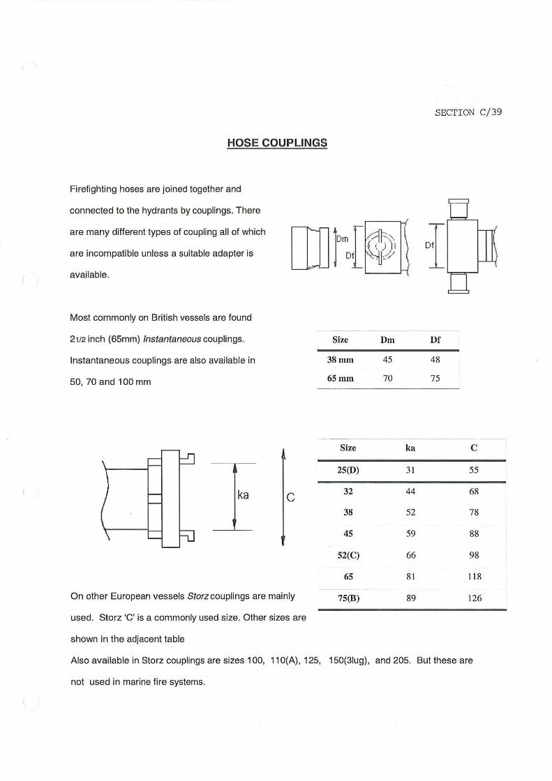
Page 26 Extinguishers (Portable) 35 Extinguishers (Fixed & Wheeled Units) 37 Hoses 39 Hose Coupling 41 Nozzles 41A/B/C Hydrojet Firefighting Gun 43 International Shore Connection 44 Hose Reels 46 Foam Making Equipment 51 Fire Buckets 52 Fireman’s Outfit – Protective Clothing 54 Fireman’s Outfit – Axes 55 Fireman’s Outfit – Safety Lamps 56 Fireman’s Outfit – Breathing Apparatus 64 Emergency Escape Breathing Devices 65 Heli-Deck Equipment Section D Fixed Fire Systems Page 67 Fixed Fire Extinguishing Systems 75 Cargo Hold Sample Smoke Extraction 78 Fixed Foam Fire Extinguishing Systems 84 Fixed Powder Fire Extinguishing Systems 86 Fixed Water Fire Extinguishing Systems 93 Fire Detection & Alarm Systems


SECTION A/2
need to meet the requirements for limiting the passage of smoke and flame nor limitations
relative to temperature rise. Combustible veneers are permitted provided they meet other
requirements.
Fire resistance of doors and doorframes fitted to bulkheads and decks is to be, as far as is
practicable, at least equivalent to the bulkhead or deck in which they are fitted. Watertight
doors need not be insulated.
All Ships’ Accommodation Doors
Doors in Class “A” bulkheads
Each door must be capable of being opened and closed from both sides by one person only.
Fire doors in main vertical zone bulkheads, galley boundaries and stairway
enclosures (provided they are not power-operated watertight doors and those which are
normally locked) must comply with the following conditions:
Self- closing (up to 3.5 angle of inclination opposing the closure)
Close in not more than 40 seconds and not less than 10 seconds
If a sliding door the closing rate shall be between 0.1 and 0.2m/sec.
When held open able to be remotely released from a manned central control position.
Able to be released from its hold back position on both sides of the door
The release switches must incorporate a system that prevents automatic resetting of
the system
Hold back devices not controllable from the central station are not permitted
If closed from the central control station it must be possible to re-open the door from
both sides locally. After such opening the door must automatically close again.
Have an indication at the central control as to whether it is closed or open
Automatically close in the event of a power failure to the hold back system
In the event of a power failure power operated doors must be operable at least ten
times using local power accumulators
When released from a remote station a sliding or power operated door must have an
alarm that sounds for between 5 and 10 seconds before the door begins to move and

SECTION A/3
continuers sounding until the door is completely closed. Doors to certain special category
compartments do not require alarms.
All Ships’ Accommodation Doors
Doors in Class “B” bulkheads
Ventilation openings may be allowed in the lower part of the door
Cabin doors are to be self-closing without any hold back device
Cargo Ships
Doors in Fire- Resisting Divisions
In “A” class divisions must be constructed of steel and doors in “B” class divisions
must be non-combustible
In boundaries of category A machinery spaces are to be self-closing and reasonably
gas-tight
Self-closing doors are not to be fitted with any hold back device, unless it is capable
of remote release and of the fail safe type
Ventilation is permitted through the lower part or beneath a door that leads between a
corridor and a public space or cabin
Watertight doors are not required to be insulated


SECTION C /41A
HYDROJET Firefighting Gun
DESCRIPTION The Hydro jet Nozzle is operated by a combination of water and compressed air system. The combined built-up of air and water forces will ultimately generate a bolt of powerful water propelling more than 35 mtrs. Works on normal fire line and working airline on-board. Supply high water volume were needed. Easy to use and transport. Training should be made during Fire drill. Water supply Ensure that a minimum 51mm (2.0”) bore water hose is used and that all couplings are secure, leak free and in good condition. Recommended water pressure 6 bar. Air Supply Ensure that a minimum 19mm (3/4”) bore air hose is used and that all couplings are secure, leak free and in good condition. Recommended air pressure 7 bar.
Hydro Jet cannon assembly
1.- Attach the Hydro jet to its tripod. 2.- Connect the water supply hose to the hydro jet cannon and the ship’s water supply. 3.- Connect the air supply hose) to the hydro jet cannon and the ship’s air supply. General Information Before operating, performing maintenance or repairing the Hydro Jet cannon these instructions must be read and understood by the operator, if in any doubt, ask your supervisor before using this equipment. Safety regulations must be followed at all times. Failure to follow these instructions could result in damage to the Hydro Jet cannon and/or result in personal injury. Safety
• Do wear Personal Protective Equipment including safety goggles, footwear, ear defenders and gloves. In some environments it will be necessary to wear facemasks or breathing apparatus.
• Do be aware that this tool is not electrically insulated.

SECTION C /41B
• Do be aware that this tool can create flying debris.
• Do be aware of others working personnel around you. • Do store this tool in a secure and dry place. • Always observe safe working practices and safety regulations at all
times.
• Never aim the Hydro Jet cannon at any person, this equipment produces a very powerful jet of water and can cause serious injury if misused.
• Do not operate the Hydro Jet cannon, unless it is securely fixed to its tripod or base and situated on a flat surface.
• Do not modify this tool in any way, as this will invalidate the warranty and could lead to serious injury.
• Do not drag this tool by the water or air hose. Please note: Unrestrained air and water hoses can whip if they become detached. Pre-Start Check Prior to operating the tool check:
• That all fittings are secure, free from leaks and air hoses are in good condition. • That the air pressure is correct for this tool 7 bar (100 psi). • That the water pressure is correct for this tool 6 bar (85psi). • Safe use of this tool requires that the operator adopt a solid stance and secure
foothold. • Gloves and personal protective equipment must be worn when using this tool.
• Care must be taken to avoid damaging or tripping over the air or water hose. • Take precautions to ensure that the area to be cleaned is completely free of
personnel and of any electrical equipment that is exposed or is not protected against water ingress.
Starting Operation With one operator securely holding and controlling the Hydro Jet cannon, and the water control valve on the Hydro Jet cannon, fully open, a second person should slowly open the water valve at the water main. It is very important that the Hydro Jet cannon, be held securely while the water is being turned on and while it is in use. The air valve should now be adjusted carefully to produce a tight hard-hitting jet of water. Excessive air will cause the jet of water to break up and spread, becoming less effective. In an emergency or once job operation has been completed, close the Cleaning Jet water valve and then the air valve. If job has been completed, instruct the second operator to shut off the main water supply. Slowly open the Hydro Jet cannon water control valve again to release the water pressure in the hose. Disconnect the air and water hose. Washing the Hydro Jet cannon with fresh water and store it in safe room.

SECTION C /41C
EXAMPLE OF HYDRO JET CANNON
Remarks: In case the Hydro Jet cannon you have on board is of a different type of above photo you may replace the photo with the correct one.


Fire-fighting Piercing Rod
DESCRIPTION
The Firefighting Piercing Rod is designed to deliver water to areas inaccessible to the fire fighter (inside of the cntr), fig (a). It is designed to penetrate the container, aided by use of a sledge hammer. It is primarily constructed of chrome-plated stainless steel. At the end, constructed with a hardened steel flat head for using & driving by a sledge hammer, fig (b). At the piercing side it is constructed
by a hardened steel material in wedge style for easy penetration, followed by a series of nozzles in order to inject inside the hole, a dense fog pattern fig(c). A small fire hose with swivel coupling from one side and specified coupling of vessel’s fire hoses from the other side, fig (d).
Fig (a) Fig (b)
Fig (c) Fig (d).
GENERAL INFORMATION/ MAINTENANCE The piercing rod is designed and manufactured to be damage resistant and requires minimal maintenance. Ensure all fire water hoses used are in good condition and that all couplings are secure, leak free. Thoroughly clean all parts and accessories with fresh water after each use. Make sure all components are clean, and the nozzles are free of debris. Safety regulations must be followed at all times. Failure to follow these instructions could result in damage to the Piercing Rod and/or in personal injury.

SAFETY
���� Wear Fireman outfit with breathing apparatus.
���� Be aware that this tool is not electrically insulated.
���� Be aware of others working personnel around you.
���� Store this tool in a secure and dry place.
���� Always observe safe working practices and safety regulations at all times.
���� Always inspect all parts for damage before using.
���� Do not modify this tool in any way because could lead to serious injury.
OPERATION
1) Locate the place of use 2) Open fire hydrant to wash out any debris which might clog the piercing rod.
3) Connect the water supply hose to the piercing rod and the ship’s water supply. 4) First Operator trying to achieve proper piercing rod angle and direction.
5) Begin driving Piercing Rod striking with a sledge hammer by a second operator. 6) When the Piercing Rod penetrates the container, start water supply by opening fire
hydrant. 7) When fire-fighting is completed, stop supply of the water and remove Piercing Rod.
Remark: The above pictures intend to demonstrate only the use of piercing rod and do not represent
an actual emergency or a drill where the firefighters should be protected by a fireman outfit and
breathing apparatus.


![La traduzione italiana dell'ufficio liturgico ortodosso slavonico [SOC 16.2 (2012)]](https://static.fdokumen.com/doc/165x107/63188333d93a162f9c0e92a8/la-traduzione-italiana-dellufficio-liturgico-ortodosso-slavonico-soc-162-2012.jpg)


![Reg. No. [TITTITT 15] - Sims Library](https://static.fdokumen.com/doc/165x107/631b195a19373759090eb4a3/reg-no-tittitt-15-sims-library.jpg)

