
FinePix S7000 - Photo-parts
126
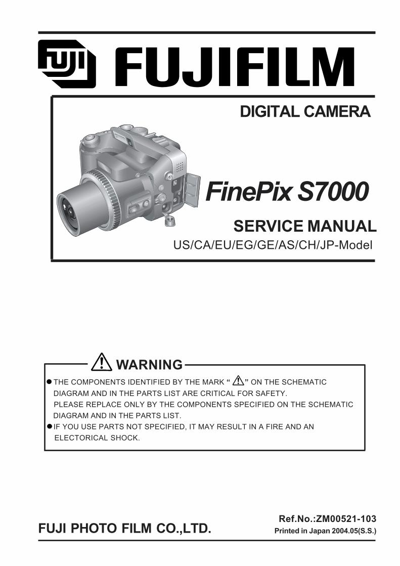
WARNING THE COMPONENTS IDENTIFIED BY THE MARK ON THE SCHEMATIC DIAGRAM AND IN THE PARTS LIST ARE CRITICAL FOR SAFETY. PLEASE REPLACE ONLY BY THE COMPONENTS SPECIFIED ON THE SCHEMATIC DIAGRAM AND IN THE PARTS LIST. IF YOU USE PARTS NOT SPECIFIED, IT MAY RESULT IN A FIRE AND AN ELECTORICAL SHOCK. FUJI PHOTO FILM CO.,LTD. Ref.No.:ZM00521-103 Printed in Japan 2004.05(S.S.) US/CA/EU/EG/GE/AS/CH/JP-Model SERVICE MANUAL DIGITAL CAMERA FinePix S7000
-
Upload
khangminh22 -
Category
Documents
-
view
0 -
download
0
Transcript of FinePix S7000 - Photo-parts
WARNING THE COMPONENTS IDENTIFIED BY THE MARK ON THE SCHEMATIC DIAGRAM AND IN THE PARTS LIST ARE CRITICAL FOR SAFETY. PLEASE REPLACE ONLY BY THE COMPONENTS SPECIFIED ON THE SCHEMATIC DIAGRAM AND IN THE PARTS LIST. IF YOU USE PARTS NOT SPECIFIED, IT MAY RESULT IN A FIRE AND AN ELECTORICAL SHOCK.
FUJI PHOTO FILM CO.,LTD.Ref.No.:ZM00521-103
Printed in Japan 2004.05(S.S.)
US/CA/EU/EG/GE/AS/CH/JP-ModelSERVICE MANUAL
DIGITAL CAMERA
FinePix S7000
2
FinePix S7000 Service Manual
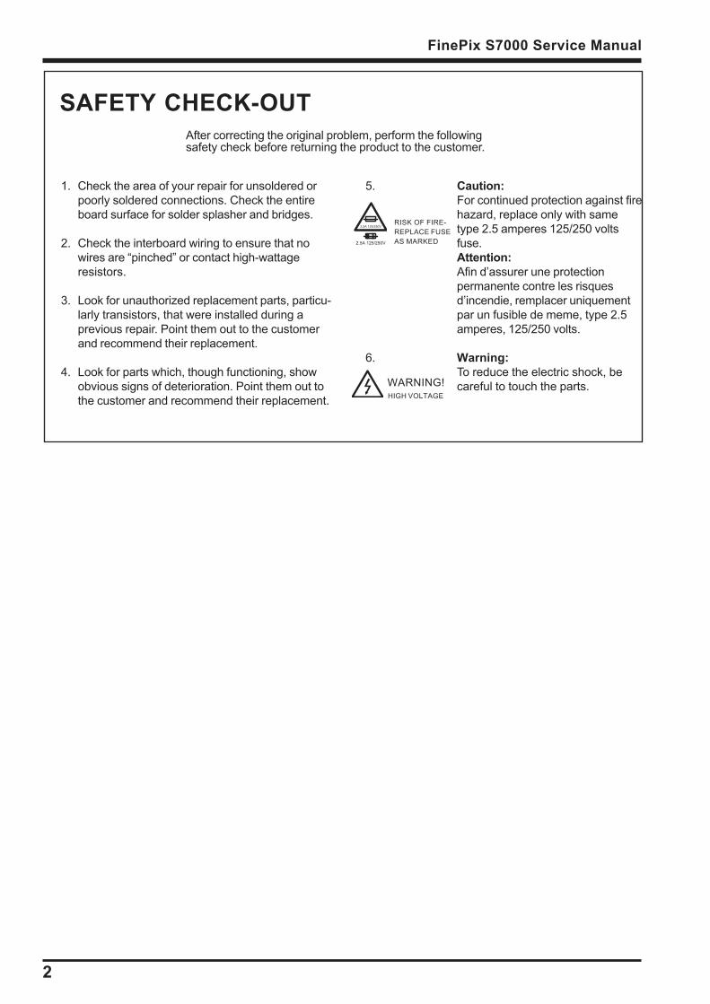
1. Check the area of your repair for unsoldered orpoorly soldered connections. Check the entireboard surface for solder splasher and bridges.
2. Check the interboard wiring to ensure that nowires are pinched or contact high-wattageresistors.
3. Look for unauthorized replacement parts, particu-larly transistors, that were installed during aprevious repair. Point them out to the customerand recommend their replacement.
4. Look for parts which, though functioning, showobvious signs of deterioration. Point them out tothe customer and recommend their replacement.
5. Caution:For continued protection against firehazard, replace only with sametype 2.5 amperes 125/250 voltsfuse.Attention:Afin dassurer une protectionpermanente contre les risquesdincendie, remplacer uniquementpar un fusible de meme, type 2.5amperes, 125/250 volts.
6. Warning:To reduce the electric shock, becareful to touch the parts.
SAFETY CHECK-OUTAfter correcting the original problem, perform the followingsafety check before returning the product to the customer.
WARNING!HIGH VOLTAGE
RISK OF FIRE-REPLACE FUSEAS MARKED
2.5A 125/250V
2.5A 125/250V
3
FinePix S7000 Service Manual TABLE OF CONTENTS
TABLE OF CONTENTS
1.General ................................................................ 41-1. Product specification ..................................................... 41-2.Names of External Components ................................... 8
2. Disassembly .................................................... 102-1. Names of Internal Components .................................. 102-2. How to remove R CABI CONST ................................. 112-3. Decomposition of R CABI CONST .............................. 122-4. How to remove LCD ASSY ........................................ 132-5. How to remove TOP CABI CONST ............................. 142-6. Decomposition of TOP CABI CONST ......................... 182-7. How to remove LCD FRAME CONST ......................... 202-8. Decomposition of LCD FRAME CONST ..................... 212-9. Decomposition of MAIN PWB ASY ............................ 212-10. How to remove SHEET FRAME ................................ 222-11. How to remove BATTERY LID ................................. 222-12. How to remove BATTERY HOLDER UNIT ............... 232-13. How to remove CAM PWB ASSY ............................ 232-14. How to remove LENS FRAME .................................. 242-15. How to remove LENS CONST .................................. 242-16. How to remove LENS CABI ASSY .......................... 252-17. How to remove SIDE MODULE UNIT ........................ 262-18. How to remove AF SENSOR UNIT ........................... 27
3. Schematics ...................................................... 283-1. Cautions ........................................................................ 283-2. Basic Block Names and Functions ............................ 283-3. Functions of Primary Blocks ...................................... 29
3-3-1.Technical Outline ................................................... 293-3-2.CAM Board Block Functions ................................ 293-3-3.MAIN Board Block Functions ............................... 293-3-4.DCTS Board Block Functions ............................... 29
3-4. Block Diagram ............................................................... 303-5. Overall connection Diagram ....................................... 313-6. CCD BLOCK Schematic Diagram ............................... 323-7. CAMERA BLOCK Schematic Diagram ....................... 333-8. PROCESS BLOCK Schematic Diagram ...................... 343-9. POWER BLOCK Schematic Diagram .......................... 353-10. LCD-EVF BLOCK Schematic Diagram ..................... 363-11. MC-FPC BLOCK Schematic Diagram ....................... 373-12. BL BLOCK Schematic Diagram ................................ 373-13. KEY SW BLOCK Schematic Diagram ...................... 383-14. MOTOR BLOCK Schematic Diagram ........................ 393-15. POWER ON BLOCK Schematic Diagram ................. 403-16. FLASH BLOCK Schematic Diagram ......................... 413-17. AUDIO BLOCK Schematic Diagram ......................... 423-18. MAIN I/F BLOCK Schematic Diagram ....................... 433-19. USB2.0 BLOCK Schematic Diagram ........................ 443-20. CCD FPC ASSY Component Locations ................... 453-21. CAM PWB ASSY Component Locations ................. 453-22. KEY PWB ASSY Component Locations ................. 463-23. MAIN PWB ASSY Component Locations ................ 473-24. DCST PWB ASSY Component Locations ............... 49
4. Adjustments ..................................................... 514-1. Adjustment Procedure of Parts Replacement .......... 514-2. Measuring Devices ...................................................... 524-3. Jigs ................................................................................. 524-4. Jig Connections ............................................................ 534-5. Environment Setup ....................................................... 534-6. Installing the Jig Drivers on the PC ........................... 564-7. Installing and Starting the Adjustment Software .... 564-8. Initializing the Adjustment Software ......................... 644-9. Starting the Adjustment Software ............................ 674-10.[F-9]: AF Sensor Adjustment .................................... 704-11. [F4] : CCD data input ................................................. 754-12. [F5] : Camera adjustment .......................................... 774-13. [F6] : AF adjustment .................................................. 804-14. [F7] : Flash adjustment .............................................. 834-15. [F1] : Battery voltage adjustment ............................ 854-16. [F11] : VIDEO Adjustment ......................................... 884-17. [F8] : Firmware Download ........................................ 904-18. [F12] : End Setting ..................................................... 924-19. Shading adjustment ................................................... 99
5. Inspection ....................................................... 1065-1. Required Measuring Equipment ............................... 1065-2. Connection of Measuring Equipment ...................... 1065-3. Inspection and Factory Settings .............................. 106
6. Parts List ....................................................... 1086-1.Packing and Accessories .......................................... 108
6-1-1.For US model ........................................................ 1086-1-2.For CA model ........................................................ 1096-1-3.For EU model ........................................................ 1106-1-4.For EG model ........................................................ 1116-1-5.For GE model ........................................................ 1126-1-6.For AS model ........................................................ 1136-1-7.For CH model ........................................................ 1146-1-8.For JP model ......................................................... 115
6-2.Cabinet F block ............................................................ 1166-3.Internal parts ................................................................ 1176-4.Cabinet R block ............................................................ 1186-5.External Parts .............................................................. 119
6-5-1.For US/CA/EU/EG/GE/AS model ......................... 1196-5-2.For CH model ........................................................ 1206-5-3.For JP model ......................................................... 121
6-6.Electrical parts ............................................................ 122
7. Appendix ........................................................ 1247-1. Function of display for Firmware Version ............ 1247-2.List of Related Technical Updates Issued .............. 125
4
1. General FinePix S7000 Service Manual
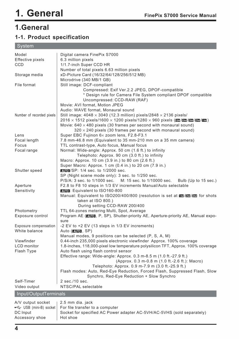
1.General1-1. Product specificationSystem
Model Digital camera FinePix S7000Effective pixels 6.3 million pixelsCCD 1/1.7-inch Super CCD HR
Number of total pixels 6.63 million pixelsStorage media xD-Picture Card (16/32/64/128/256/512 MB)
Microdrive (340 MB/1 GB)File format Still image: DCF-compliant
Compressed: Exif Ver.2.2 JPEG, DPOF-compatible* Design rule for Camera File System compliant DPOF compatibleUncompressed: CCD-RAW (RAF)
Movie: AVI format, Motion JPEGAudio: WAVE format, Monaural sound
Number of recorded pixels Still image: 4048 × 3040 (12.3 million) pixels/2848 × 2136 pixels/2016 × 1512 pixels/1600 × 1200 pixels/1280 × 960 pixels ( / / / / )Movie: 640 × 480 pixels (30 frames per second with monaural sound)
320 × 240 pixels (30 frames per second with monaural sound)Lens Super EBC Fujinon 6× zoom lens, F2.8-F3.1Focal length 7.8 mm-46.8 mm (Equivalent to 35 mm-210 mm on a 35 mm camera)Focus TTL contrast-type, Auto focus, Manual focusFocal range Normal: Wide-angle: Approx. 50 cm (1.6 ft.) to infinity
Telephoto: Approx. 90 cm (3.0 ft.) to infinityMacro: Approx. 10 cm (3.9 in.) to 80 cm (2.6 ft.)Super Macro: Approx. 1 cm (0.4 in.) to 20 cm (7.9 in.)
Shutter speed /SP: 1/4 sec. to 1/2000 sec.SP (Night scene mode only): 3 sec. to 1/250 sec.P/S/A: 3 sec. to 1/1000 sec. M: 15 sec. to 1/10000 sec. Bulb (Up to 15 sec.)
Aperture F2.8 to F8 10 steps in 1/3 EV increments Manual/Auto selectableSensitivity : Equivalent to ISO160-800
Manual: Equivalent to ISO200/400/800 (resolution is set at / / for shotstaken at ISO 800.)
During setting CCD-RAW 200/400Photometry TTL 64-zones metering Multi, Spot, AverageExposure control Program AE ( , P, SP), Shutter-priority AE, Aperture-priority AE, Manual expo-
sureExposure compensation -2 EV to +2 EV (13 steps in 1/3 EV increments)White balance Auto ( , SP)
Manual modes, 9 positions can be selected (P, S, A, M)Viewfinder 0.44-inch 235,000 pixels electronic viewfinder Approx. 100% coverageLCD monitor 1.8-inches, 118,000-pixel low temperature polysilicon TFT, Approx. 100% coverageFlash Type Auto flash using flash control sensor
Effective range: Wide-angle: Approx. 0.3 m-8.5 m (1.0 ft.-27.9 ft.) (Approx. 0.3 m-0.8 m (1.0 ft.-2.6 ft.): Macro)
Telephoto: Approx. 0.9 m-7.9 m (3.0 ft.-25.9 ft.)Flash modes: Auto, Red-Eye Reduction, Forced Flash, Suppressed Flash, Slow
Synchro, Red-Eye Reduction + Slow SynchroSelf-Timer 2 sec./10 sec.Video output NTSC/PAL selectable
Input/Output Terminals
A/V output socket 2.5 mm dia. jack USB (mini-B) socket For file transfer to a computer
DC Input Socket for specified AC Power adapter AC-5VH/AC-5VHS (sold separately)Accessory shoe Hot shoe
5
1. GeneralFinePix S7000 Service Manual
Power Supply and OthersPower supply Use one of the following:
4× AA-size alkaline batteries 4× AA-size Ni-MH (Nickel-Metal Hydride) batteries (sold separately) AC Power Adapter AC-5VH/AC-5VHS (sold separately)
Conditions for use Temperature: 0oC to +40oC (+32oF to +104oF) 80% humidity or less (no condensation)
The number of available frames for battery operation given here is a guide to thenumber of consecutive shots that can be taken under FUJIFILM test conditions. Batteries used: alkaline batteries bundled with the camera fully charged Ni-MH batteries Shooting conditions: Measured at normal temperature with 50% flash use Note: Because the number of available frames that can be taken varies depend-
ing on the capacities of alkaline batteries and the amount of charge in Ni-MH batteries, the figures given here for the number of frames that can betaken using batteries are not guaranteed. At low temperatures, fewer pic-tures can be taken when the camera is running on batteries.
Camera dimensions 121.0 mm × 81.5 mm × 97.0 mm/4.8 in. × 3.2 in. × 3.8 in.(W × H × D) (not including accessories and attachments)Camera mass (weight) 500 g/17.6 oz. (not including accessories, batteries, xD-Picture Card and Microdrive)Weight for photography Approx. 600 g/21.2 oz. (including batteries and xD-Picture Card)Accessories ! 16 MB, xD-Picture Card (1) Included with: Anti-static case (1)
! AA-size alkaline batteries (4) ! Shoulder Strap (1)! Protective cover (2) ! Metal strap clip (2) ! Clip attaching tool (1)! Lens cap (1) ! Lens cap holder (1)! A/V (audio-visual) cable (included) (1) (plug (2.5 mm dia.) to pin-plug cable × 2)! USB cable (mini-B) (1) ! CD-ROM (1) Software for FinePix SX! Owners Manual (1)
Optional Accessories ! xD-Picture CardDPC-16 (16 MB)/DPC-32 (32 MB)/DPC-64 (64 MB)/DPC-128 (128 MB)/DPC-256 (256 MB)/DPC-512 (512 MB)
! AC Power Adapter AC-5VH/AC-5VHS ! Fujifilm Rechargeable Battery 2HR-3UF! Fujifilm Battery charger with Battery BK-NH/BK-NH2 (With Euro type or UK type plug)! SC-FX602! Wide conversion lens WL-FX9/WL-FX9B ! Teleconversion lens TL-FX9/TL-FX9B! Image Memory Card Reader DPC-R1
Compatible with Windows 98/98 SE, Windows Me, Windows 2000 Profes-sional, Windows XP or iMac, Mac OS 8.6 to 9.2.2, Mac OS X (10.1.2 to10.2.2) and models that support USB as standard.
Compatible with xD-Picture Card of 16 MB to 512 MB, and SmartMedia of3.3V, 4 MB to 128 MB.
! PC Card Adapter DPC-AD Compatible with xD-Picture Card of 16 MB to 512 MB, and SmartMedia of
3.3V, 2 MB to 128 MB.! CompactFlash Card Adapter DPC-CF
Windows 95/98/98 SE/Me/2000 Professional/XP Mac OS 8.6 to 9.2/X (10.1.2 to 10.1.5)
Guide to the numberof available framesfor battery operation
Alkaline batteriesNi-MH batteries HR-3UF (2100)
xD-Picture Card
Battery Type
Media type
Using LCD monitor
Using EVF
Approx. 210 frames
Approx. 220 frames
Approx. 340 frames
Approx. 350 frames
MicrodriveUsing LCD monitor
Using EVF
Approx. 200 frames
Approx. 210 frames
Approx. 310 frames
Approx. 320 frames
Standard number of frames per Media
Quality F N
Number of recorded pixels 4048 3040
Image Data Size 4.9 MB
DPC-16 (16 MB) 3
2.5 MB
6
2848 2136
1.5 MB
10
2016 1512
760 KB
20
6 12 20 41
12 26 42 82
26 52 84 166
52 105 169 332
1600 1200
630 KB
25
50
101
204
409
1280 960
470 KB
33
68
137
275
550
13 MB
1
2
4
9
19
DPC-32 (32 MB)
DPC-64 (64 MB)
DPC-128 (128 MB)
DPC-256 (256 MB)
105 211 339 665 818 1101 39DPC-512 (512 MB)
72 144 232 459 559 752 27Microdrive 340 MB
217 432 698 1368 1642 2190 81Microdrive 1 GB
4048 3040
6
1. General FinePix S7000 Service Manual
Standard recording Times for Media
Quality mode
Number of recorded pixels
DPC-16 (16 MB)
(30 fps)
640 480
13 sec.
27 sec.
55 sec.
111 sec.
223 sec.
(30 fps)
26 sec.
54 sec.
109 sec.
219 sec.
7.3 min.
DPC-32 (32 MB)
DPC-64 (64 MB)
DPC-128 (128 MB)
DPC-256 (256 MB)
7.4 min. 14.6 min.DPC-512 (512 MB)
5.0 min. 10.0 min.Microdrive 340 MB
15.3 min. 30.1 min.Microdrive 1 GB
320 240
* The number of available frames, recording time or file size varies slightly de-pending on the subjects photographed. Note also that the difference betweenstandard number of frames and the actual number of frames is greater for mediawith higher capacities.
7
1. GeneralFinePix S7000 Service Manual
Explanation of Terms
AF/AE Lock : On the FinePix S7000, pressing the shutter button down half way locks the focusand exposure settings (AF and AE lock). If you want to focus on a subject that isnot centered in the frame or change the picture composition after the exposure isset, you can obtain good results by changing the composition after the AF andAE settings are locked.
Auto Power Save Function : If the camera is not used in any way for 30 seconds, this function turnsfeatures such as the LCD monitor off (Sleep mode) to prevent battery depletionand the waste of power when the AC power adapter is connected. If the camera isthen left unused for a further period, the Auto Power Save function turns the cam-era off. This period can be set to 2 minutes or 5 minutes on this camera.! The Auto Power Off function does not operate in PC mode, during automatic
playback, or if it is disabled during setup.Deactivated batteries: Leaving an Ni-MH battery unused in storage for a long period may cause a rise in
the level of substances that inhibit current flow inside the battery and result in adormant battery. A battery in this state is referred to as deactivated.Because current flow is inhibited in a deactivated Ni-MH battery, the batterysoriginal level of performance cannot be achieved.
DPOF: Digital Print Order FormatDPOF is a format used for recording information on a storage media (imagememory card, etc.) that allows you to specify which of the frames shot using adigital camera are to be printed and how many prints are made of each image.
EV: A number that denotes Exposure Value. The EV is determined by the brightnessof the subject and sensitivity (speed) of the film or CCD. The number is larger forbright subjects and smaller for dark subjects. As the brightness of the subjectchanges, a digital camera maintains the amount of light hitting the CCD at aconstant level by adjusting the aperture and shutter speed.When the amount of light striking the CCD doubles, the EV increases by 1. Like-wise, when the light is halved, the EV decreases by 1.
Frame rate (fps) : The frame rate refers to the number of images (frames) that are photographed orplayed back per second. For example, when 10 frames are continuously photo-graphed in a 1-second interval, the frame rate is expressed as 10 fps.For reference, TV images are displayed at 30 fps.
JPEG : Joint Photographics Experts GroupA file format used for compressing and saving color images. The higher the com-pression rate, the greater the loss of quality in the decompressed (restored) image.
Memory effect: If an Ni-MH battery is repeatedly charged without first being fully discharged, itsperformance may drop below its original level. This is referred to as the memoryeffect.
Motion JPEG: A type of AVI (Audio Video Interleave) file format that handles images and soundas a single file. Images in the file are recorded in JPEG format. Motion JPEG canbe played back by QuickTime 3.0 or later.
PC Card: A generic term for cards that meet the PC Card Standard.PC Card Standard: A standard for PC cards determined by the PCMCIA.PCMCIA: Personal Computer Memory Card International Association (US).Smear : A phenomenon specific to CCDs whereby white streaks appear on the image
when there is a very strong light source, such as the sun or reflected sunlight, inthe photography screen.
WAVE : A standard format used on Windows systems for saving audio data. WAVE fileshave the .WAV file extension and the data can be saved in either compressed oruncompressed format. Uncompressed recording is used on this camera.WAVE files can be played back on a personal computer using the following software:Windows: MediaPlayerMacintosh: QuickTime Player *QuickTime 3.0 or later
White Balance: Whatever the kind of the light, the human eye adapts to it so that a white objectstill looks white. On the other hand, devices such as digital cameras see a whitesubject as white by first adjusting the color balance to suit the color of the ambi-ent light around the subject. This adjustment is called matching the white bal-ance. A function that automatically matches the white balance is called an Auto-matic White Balance function.
Exif Print: Exif Print Format is a newly revised digital camera file format that contains avariety of shooting information for optimal printing.
8
1. General FinePix S7000 Service Manual
1-2.Names of External Components
Command dial
Continuous shooting button
Exposure compensation
button
Flash button
Release socket
Shutter button
Self-timer lamp
Hot shoe FZ ring(Focus/Zoom ring)
Mode dial
Power switch
Strap mount
Zoom button
AE-L (AE lock) button
BACK button
Photo mode ( ) button
DISP (display)button
Viewfinder (EVF)
Diopter adjustment dial
(Focus Check) button
Slot cover
MENU/OK button
4-direction ( ) button
Battery cover
LCD monitor
Indicator lamp
EVF/LCD(viewfinder/monitor) button
Tripod mount
xD-Picture Card slot
Microdrive slot
Microdrive eject button
9
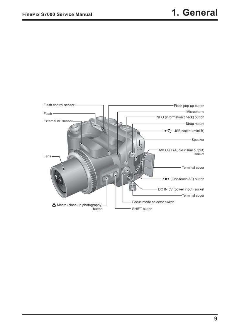
1. GeneralFinePix S7000 Service Manual
Flash pop-up button
(One-touch AF) button
SHIFT button
Speaker
Microphone
A/V OUT (Audio visual output) socket
DC IN 5V (power input) socket
Terminal cover
Focus mode selector switch
Terminal cover
INFO (information check) button
Strap mount
USB socket (mini-B)
Lens
Macro (close-up photography) button
Flash control sensor
Flash
External AF sensor
2. Disassembly
10
FinePix S7000 Service Manual
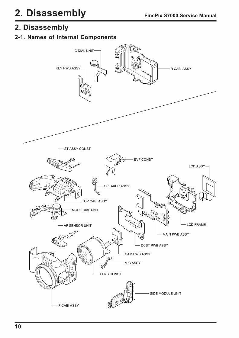
2. Disassembly2-1. Names of Internal Components
R CABI ASSY
ST ASSY CONST
EVF CONST
SPEAKER ASSY
TOP CABI ASSY
MODE DIAL UNIT
AF SENSOR UNIT
F CABI ASSY
SIDE MODULE UNIT
LENS CONST
MIC ASSY
CAM PWB ASSY
DCST PWB ASSY
MAIN PWB ASSY
LCD FRAME
LCD ASSY
KEY PWB ASSY
C DIAL UNIT
2. Disassembly
11
FinePix S7000 Service Manual
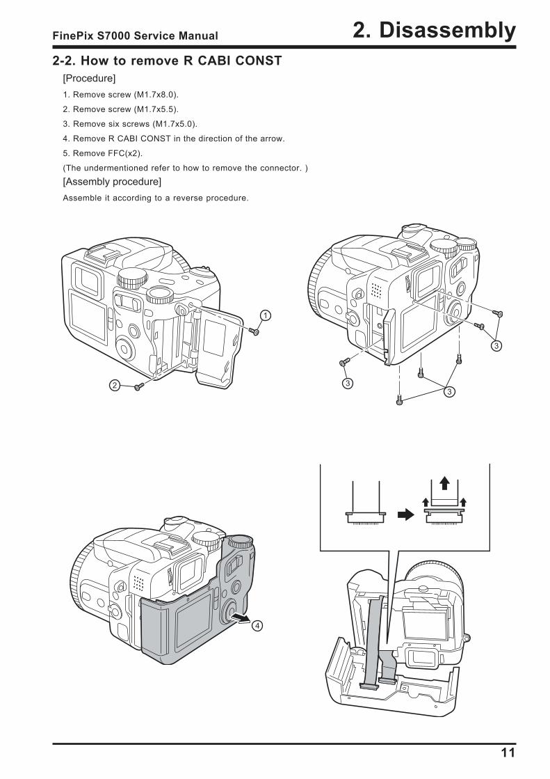
2-2. How to remove R CABI CONST[Procedure]1. Remove screw (M1.7x8.0).
2. Remove screw (M1.7x5.5).
3. Remove six screws (M1.7x5.0).
4. Remove R CABI CONST in the direction of the arrow.
5. Remove FFC(x2).
(The undermentioned refer to how to remove the connector. )
[Assembly procedure]Assemble it according to a reverse procedure.
1
2 33
3
4
2. Disassembly
12
FinePix S7000 Service Manual
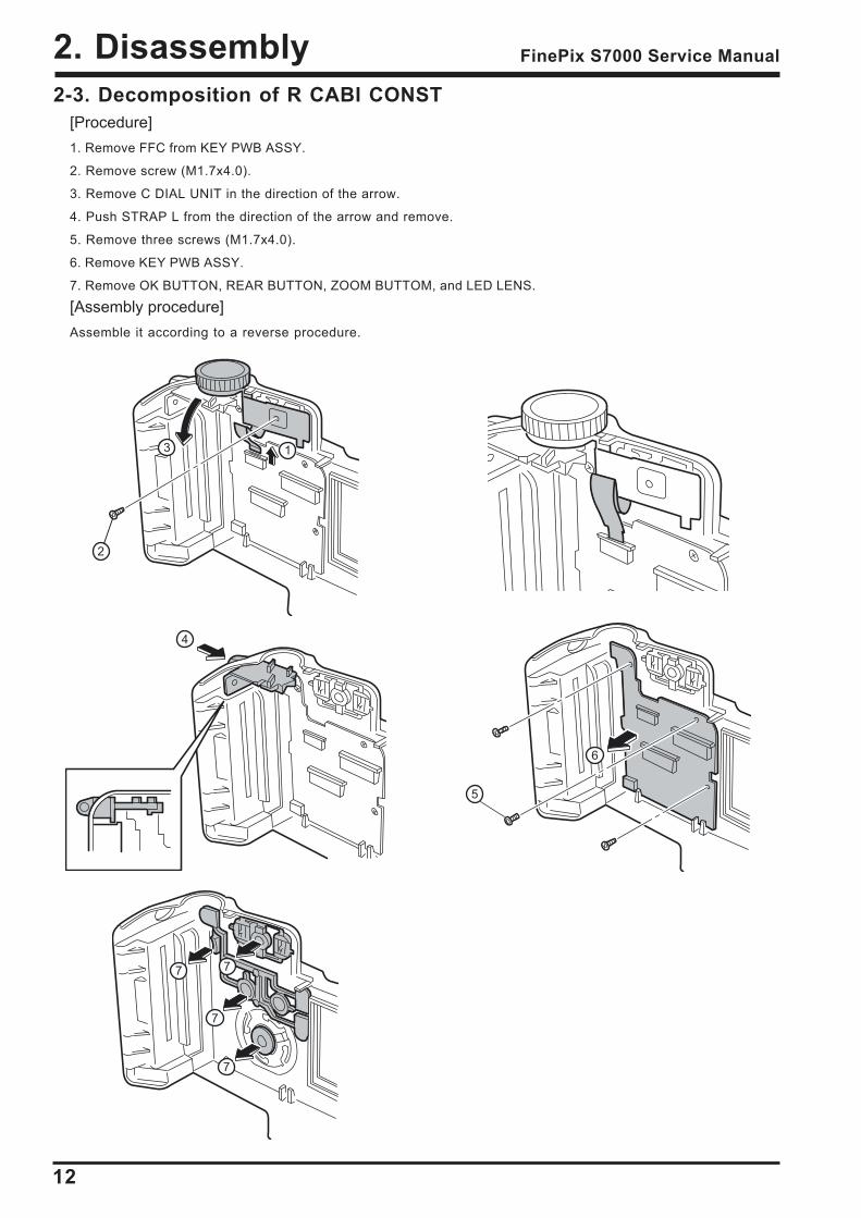
2-3. Decomposition of R CABI CONST[Procedure]1. Remove FFC from KEY PWB ASSY.
2. Remove screw (M1.7x4.0).
3. Remove C DIAL UNIT in the direction of the arrow.
4. Push STRAP L from the direction of the arrow and remove.
5. Remove three screws (M1.7x4.0).
6. Remove KEY PWB ASSY.
7. Remove OK BUTTON, REAR BUTTON, ZOOM BUTTOM, and LED LENS.
[Assembly procedure]Assemble it according to a reverse procedure.
1
2
3
4
6
5
7
7 7
7
2. Disassembly
13
FinePix S7000 Service Manual
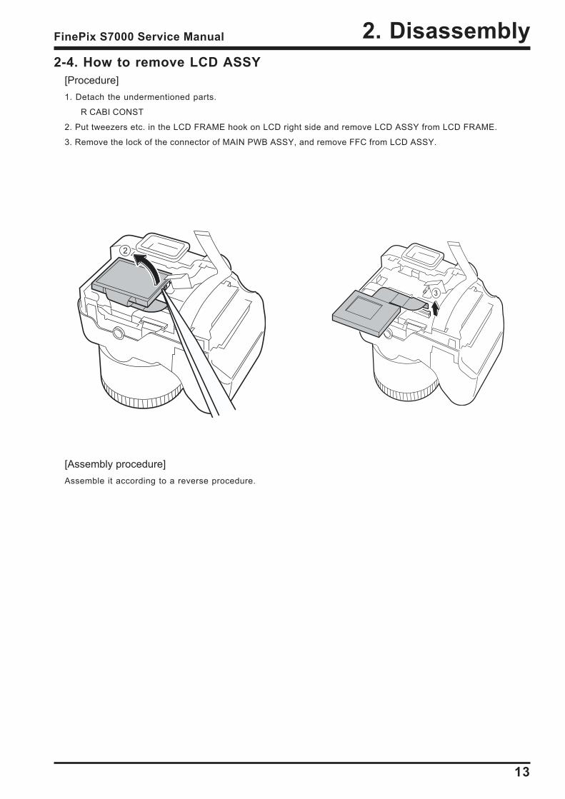
2-4. How to remove LCD ASSY[Procedure]1. Detach the undermentioned parts.
R CABI CONST
2. Put tweezers etc. in the LCD FRAME hook on LCD right side and remove LCD ASSY from LCD FRAME.
3. Remove the lock of the connector of MAIN PWB ASSY, and remove FFC from LCD ASSY.
[Assembly procedure]Assemble it according to a reverse procedure.
2
3
2. Disassembly
14
FinePix S7000 Service Manual
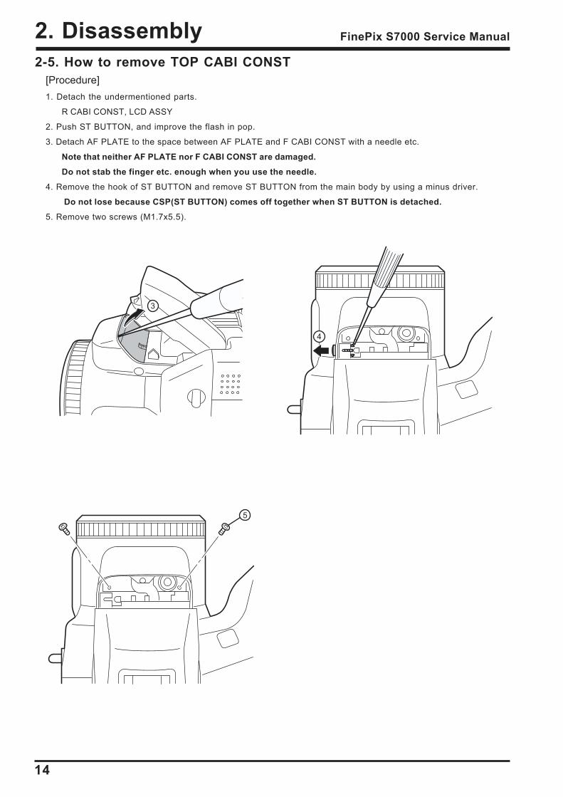
2-5. How to remove TOP CABI CONST[Procedure]1. Detach the undermentioned parts.
R CABI CONST, LCD ASSY
2. Push ST BUTTON, and improve the flash in pop.
3. Detach AF PLATE to the space between AF PLATE and F CABI CONST with a needle etc.
Note that neither AF PLATE nor F CABI CONST are damaged.
Do not stab the finger etc. enough when you use the needle.
4. Remove the hook of ST BUTTON and remove ST BUTTON from the main body by using a minus driver.
Do not lose because CSP(ST BUTTON) comes off together when ST BUTTON is detached.
5. Remove two screws (M1.7x5.5).
3
4
5
2. Disassembly
15
FinePix S7000 Service Manual
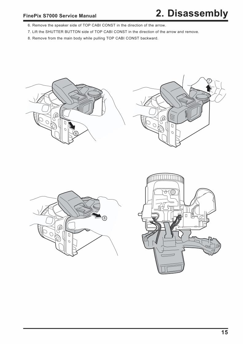
6. Remove the speaker side of TOP CABI CONST in the direction of the arrow.
7. Lift the SHUTTER BUTTON side of TOP CABI CONST in the direction of the arrow and remove.
8. Remove from the main body while pulling TOP CABI CONST backward.
6
7
8
2. Disassembly
16
FinePix S7000 Service Manual
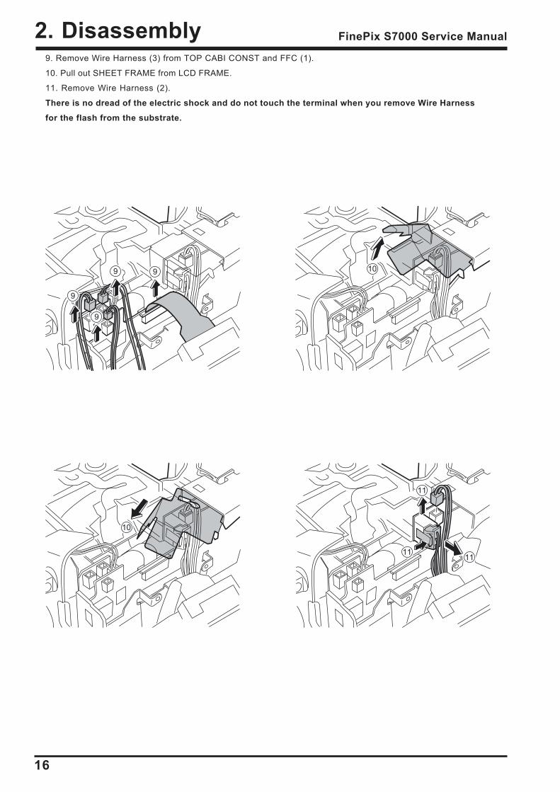
9. Remove Wire Harness (3) from TOP CABI CONST and FFC (1).
10. Pull out SHEET FRAME from LCD FRAME.
11. Remove Wire Harness (2).
There is no dread of the electric shock and do not touch the terminal when you remove Wire Harness
for the flash from the substrate.
9 9
9
9
10
11
1111
10
2. Disassembly
17
FinePix S7000 Service Manual
[Assembly procedure]Assemble it according to a reverse procedure.
1. Combine intuition on the tip of the AF sensor when you connect all Wire Harness with FFC.
2. Combine the speaker side of TOP CABI CONST in intuition in the hook of F CABI CONST.
3. Combine the grip part in intuition surely. At this time, confirm grip rubber is turned over and not transformed.
4. Confirm TOP CABI CONST and confirm Wire Harness has been installed after it clings surely in SHEET FRAME.
5. Note that it is at the top and bottom (The gate is the above) in ST BUTTON at assembly.
2
3
1
5
Gate position
Note the scissors crowding of Wire Harness.4
2. Disassembly
18
FinePix S7000 Service Manual
2-6. Decomposition of TOP CABI CONST[Procedure]1. Remove two screws (M1.7x4.0), and remove HOLDER EVF.
2. Remove four screws (M1.7x4.0), and remove MODE DIAL UNIT.
3. Remove EVF CONST.
4. Remove SPEAKER ASSY.
5. Remove two screws (M1.7x4.0), and remove ST TOP.
1
2
3
4
5
5
2. Disassembly
19
FinePix S7000 Service Manual
6
6
7
7
6. Remove ST SHUFT(x2).
7. Lift while pressing ST ASSY CONST against the SHUTTER BUTTON side and remove.
[Assembly procedure]Assemble it according to a reverse procedure.
[Notes of assembly]Note the taking turning of the flash hiss harness.
Pass the flash hiss harness and the flash harness through the fingernail of HOLDER EVF.
Do not float on the flash hiss harness and the flash harness.
<harness> do not interfere in flash pop up detection SW.
Flash pop up detection SW
2. Disassembly
20
FinePix S7000 Service Manual
22
2
2
2
2
A
B
3
2-7. How to remove LCD FRAME CONST[Procedure]1. Detach the undermentioned parts.
R CABI CONST, LCD ASSY, ST PLATE, ST BUTTON, TOP CABI CONST
2. Remove FFC Wire Haness (4)(2).
3. Remove main body A and part B, and remove LCD FRAME CONST.
4. Discharge electricity from the main capacitor of DCST PWB ASSY.
[Assembly procedure]Assemble it according to a reverse procedure.
2. Disassembly
21
FinePix S7000 Service Manual
2-8. Decomposition of LCD FRAME CONST[Procedure]Confirm the main capacitor of DCST PWB ASSY has been discharged without fail before work is started.
1. Remove two screws (M1.7x3.0), and remove CONTACT PLT and DCST PWB ASSY.
2. Remove two screws (M1.7x3.0), and remove MAIN PWB ASSY.
[Assembly procedure]Assemble it according to a reverse procedure.
2-9. Decomposition of MAIN PWB ASY[Procedure]1. Remove EJECTER in the direction of the arrow.
2. Remove SHEET CF.
[Assembly procedure]Assemble it according to a reverse procedure.
1
1
2
2
1
2

2. Disassembly
22
FinePix S7000 Service Manual
2-10. How to remove SHEET FRAME[Procedure]1. Remove SHEET FRAME from LCD FRAME.
[Assembly procedure]Assemble it according to a reverse procedure.
[Notes of assembly]Note the damage of SHEET FRAME when you install SHEET FRAME in LCD FRAME.
2-11. How to remove BATTERY LID[Procedure]1. Lift the hook of BATTERY LID, and remove BATTERY LID.
[Assembly procedure]Assemble it according to a reverse procedure.
2
2. Disassembly
23
FinePix S7000 Service Manual
2-12. How to remove BATTERY HOLDER UNIT[Procedure]1. Detach the undermentioned parts.
R CABI CONST, LCD ASSY, ST PLATE, ST BUTTON, TOP CABI CONST, LCD FRAME CONST
BATTERY LID
2. Remove screw (M1.7x5.0).
3. Remove BATTERY HOLDER UNIT from the main body while opening the main body grip part.
[Assembly procedure]Assemble it according to a reverse procedure.
2-13. How to remove CAM PWB ASSY[Procedure]1. Detach the undermentioned parts.
R CABI CONST, LCD ASSY, ST PLATE, ST BUTTON, TOP CABI CONST, LCD FRAME CONST
2. Remove screw (M1.7x5.0).
3. Open the hook of LENS FRAME, and remove CAM PWB ASSY in the direction of the arrow.
4. Remove FPC from LENS CONST, and remove CAM PWB ASSY from the main body.
[Assembly procedure]Assemble it according to a reverse procedure.
2
2
3
4
2. Disassembly
24
FinePix S7000 Service Manual
2-14. How to remove LENS FRAME[Procedure]1. Detach the undermentioned parts.
R CABI CONST, LCD ASSY, ST PLATE, ST BUTTON, TOP CABI CONST, LCD FRAME CONST
BATTERY LID, BATTERY HOLDER UNIT, CAM PWB ASSY
2. Remove FFC from LENS FRAME.
3. Remove screw (M1.7x5.0), and remove LENS FRAME from the main body.
[Assembly procedure]Assemble it according to a reverse procedure.
[Notes of assembly]Do so as not to cut FFC adding impossible power when you build FFC into LENS FRAME noting it.
2-15. How to remove LENS CONST[Procedure]1. Detach the undermentioned parts.
R CABI CONST, LCD ASSY, ST PLATE, ST BUTTON, TOP CABI CONST, LCD FRAME CONST
BATTERY LID, BATTERY HOLDER UNIT, CAM PWB ASSY, LENS FRAME
2. Remove LENS CONST from F CABI UNIT.
2
3
2

2. Disassembly
25
FinePix S7000 Service Manual
2-16. How to remove LENS CABI ASSY[Procedure]1. Detach the undermentioned parts.
R CABI CONST, LCD ASSY, ST PLATE, ST BUTTON, TOP CABI CONST, LCD FRAME CONST
BATTERY LID, BATTERY HOLDER UNIT, CAM PWB ASSY, LENS FRAME, LENS CONST
2. Remove three screws (M1.7X3.5), and remove LENS CABI ASSY.
[Assembly procedure]Assemble it according to a reverse procedure.
[Attention]Because the torque is managed as for FOCUS RING of LENS CABI ASSY, it is not possible to decompose.
2
[Assembly procedure]Assemble it according to a reverse procedure.
[Notes of assembly]Make the cutting lack of the rib and LENS CONST of F CABI CONST combined in intuition,
and build it in when you build in LENS CONST.
2. Disassembly
26
FinePix S7000 Service Manual
2-17. How to remove SIDE MODULE UNIT[Procedure]1. Detach the undermentioned parts.
R CABI CONST, LCD ASSY, ST PLATE, ST BUTTON, TOP CABI CONST, LCD FRAME CONST
BATTERY LID, BATTERY HOLDER UNIT, CAM PWB ASSY, LENS FRAME, LENS CONST
LENS CABI ASSY
2. Remove screw (M1.7x5.0), and remove STRAP R.
3. Remove SIDE MODILE UNIT from F CABI ASSY.
2
3
C-AF
S-AF
[Assembly procedure]Assemble it according to a reverse procedure.
[Notes of assembly]Match and build in the position of the FOCUS switch lever of FOCUS switch SW and F CABI ASSY
of SIDE MODILE UNIT.
2. Disassembly
27
FinePix S7000 Service Manual
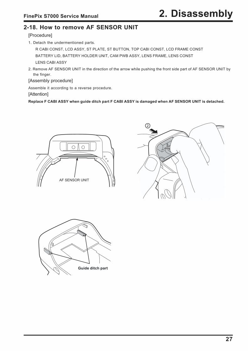
2-18. How to remove AF SENSOR UNIT[Procedure]1. Detach the undermentioned parts.
R CABI CONST, LCD ASSY, ST PLATE, ST BUTTON, TOP CABI CONST, LCD FRAME CONST
BATTERY LID, BATTERY HOLDER UNIT, CAM PWB ASSY, LENS FRAME, LENS CONST
LENS CABI ASSY
2. Remove AF SENSOR UNIT in the direction of the arrow while pushing the front side part of AF SENSOR UNIT bythe finger.
[Assembly procedure]Assemble it according to a reverse procedure.
[Attention]Replace F CABI ASSY when guide ditch part F CABI ASSY is damaged when AF SENSOR UNIT is detached.
2
AF SENSOR UNIT
Guide ditch part
28
3. Schematics FinePix S7000 Service Manual
3. Schematics3-1. Cautions
<Cautions when replacing parts> Do not reuse removed parts. Always use new parts. Note that the -ve side of tantalum condensers is readily damaged by heat. Except for chemical condensers and tantalum condensers, voltage is not displayed on condensers with a
voltage resistance of 50V or less. Resistors not marked are 1/16W chip resistors. KW = 1000Ω, MW = 1000KΩ B characteristics of variable resistors and semi-fixed resistors are not displayed.
3-2. Basic Block Names and FunctionsPart name Block name Function
LENS CONST CCD BLOCK CCD output
MAIN PWB ASSY CAMERA BLOCK CCD output A/D conversion (IC102)
CCD driver ( IC101,IC103)
PROCESS BLOCK Image signal processing, USB communications,system control (IC210)
LCD/EVF BLOCK LCD/EVF output control. (IC850)
AUDIO BLOCK Audio IN/OUT(IC400)
DCST PWB ASSY DC/DC BLOCK Power supply generation (IC500)
POWER ON BLOCK Power supply management ,Key function(IC300)
FLASH BLOCK Flash charging control (IC601)
MOTOR BLOCK Shutter/iris/AF/zoom drive (IC353)
RSW PWB ASSY RSW BLOCK Power SW,Shutter SW
KSW PWB ASSY KEY SWICH BLOCK Key SW
MSW PWB ASSY MODE SWICH BLOCK Mode SW
FLASH UNIT FLASH BLOCK Flash
29
3. SchematicsFinePix S7000 Service Manual
3-3.Functions of Primary Blocks3-3-1.Technical Outline
Use of [the 4th Generation Super CCD Honeycomb HR] has improved still photography performance. The 6.3million effective pixels, and [the Honeycomb Signal Processing System], allows recording and reproduction of high-quality images of up to 4048 x 3040 (1.23 million) pixels. These features permit [Candle Shots] at ISO1600/800 inthe 1Mega mode, a capability facilitated by the use of the unique honeycomb picture element which receives lightover a wide area, technical developments in pixel summing signal processing*1, and noise reduction technology. Movie photography performance is improved. Horizontal/vertical pixel mixing*2 inside the CCD using a new datatransfer system is the first to provide 30 frames per second in VGA format at greater than 3 megapixels. [High-speed Twin AF] uses both an external AF sensor (passive phase difference) and the CCD AF for higher-speedautofocus. The [Super Macro] feature allows photography of a subject at distances down to one centimeter. The [Double Slot] feature provides for both xD media and microdrives, allowing both recording of the large volumesof image data in the high image quality mode, and long movies.
*1 : Image data obtained with honeycomb signal processing from twice the number of effective pixels. Shrinks fourpixels into one. This processing increases the signal level (sensitivity) by a factor of four, and the S/N ratio (signal-to-noise ratio) by a factor of two, to permit photography at ISO1600.
*2 : Mixes two pixels on the vertical axis, and two pixels on the horizontal axis, of the CCD. This processing increases the signal level by a factor of four, and the S/N ratio by a factor of two, to provide high
sensitivity and high quality images, while at the same time allowing data to be read at high-speed (30 frames persecond in VGA format).
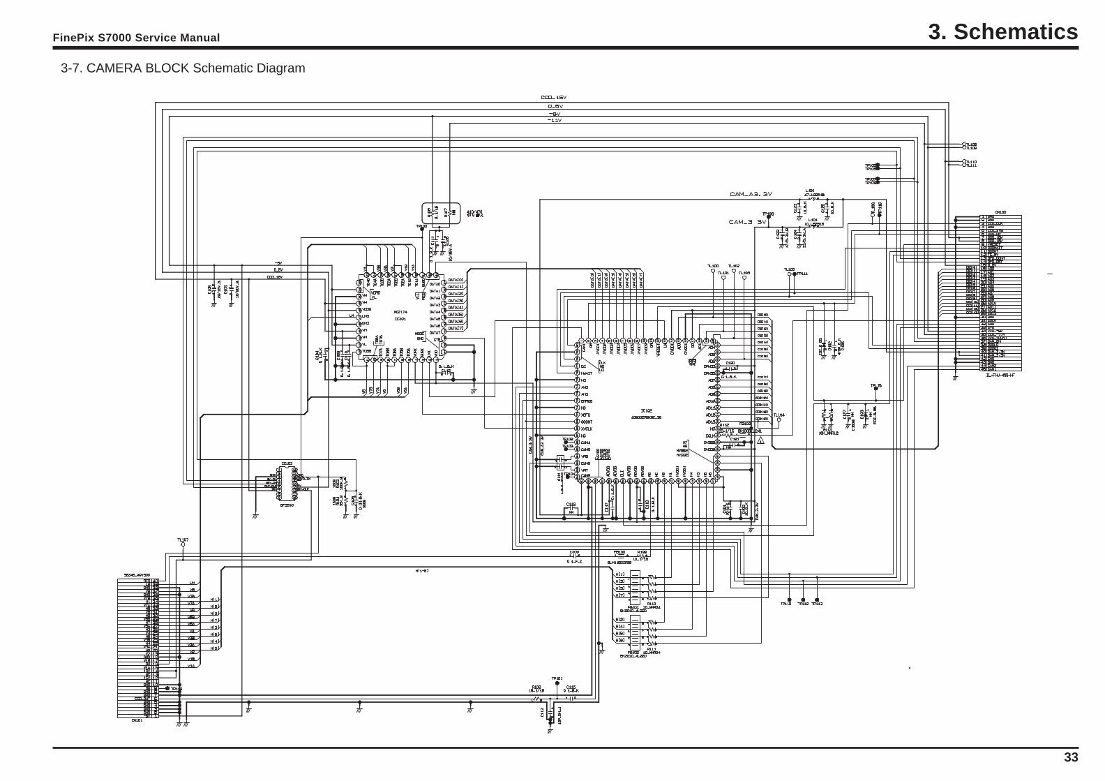
3-3-2.CAM Board Block FunctionsPhotography Circuit Functions (CAM BLOCK)
The analog video signal output from the newly developed CCD (1/1.7, 6.3 million effective pixels, square pixelhoneycomb array, primary color CCD) is processed (pseudo-color compensation, adaptive interpolation, amplifica-tion, and signal mixing) in ACS_IC (IC102:CSP_IC), and subsequently converted to a 12-bit digital signal. The digitalsignal is then sent to the single chip image signal processing LSI : UCS2_IC (IC210 : CSP_IC*).
* CSP_IC=Chip Size Packege IC
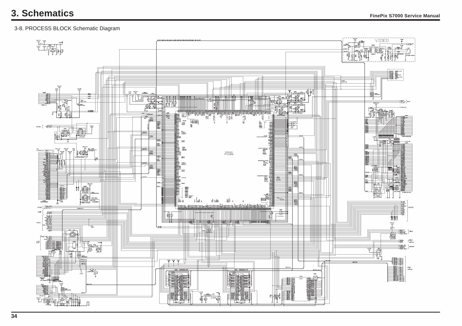
3-3-3.MAIN Board Block FunctionsImage Signal Processing Functions (PROCESS BLOCK)
Data input from CCD* The 12-bit digital image data (1H equivalent) output from the CAM BLOCK is sent to UCS2_IC, buffered in the IBUF,
and converted to 32-bit (16-bit x 2) data. The 32-bit image data is then sent from the [I/O Buffer] in UCS2_IC andstored in the SDRAM_IC (IC208, IC209 : 40 Mbyte). A single frame (4080 pixels x 3040 lines) of image data is tempo-rarily stored in the SDRAM_IC.
* At the same time, AE multiplies the 12-bit image data input from the UCS2_IC in [AUTO], and sends the data requiredfor AE/AWB/AF to the SDRAM_IC. To provide the appropriate data for AE/AWB/AF, this data is then sent from theSDRAM_IC in serial format to the ACS_IC via the UCS2_IC. Recording in the xD media
The image data stored in the SDRAM_IC is converted from 32-bit to 12-bit data one line at a time in the [IBUF] in theUCS2_IC, and sent to [YC PRO]. The image data is then converted to 8-bit Y and C signals in [YC PRO], and then sentagain to [IBUF]. The 8-bit Y and C signals are then converted to 8-bit Y, Y, Cb, and Cr signals and sent to the SDRAM_IC.The image data stored in the SDRAM_IC is compressed with [JPEG] in the UCS2_IC and again stored in theSDRAM_IC. The image data following compression is recorded sequentially in the xD media in the UCS2_IC. Image Replay from the xD media
The compressed image data from the xD media is sent to UCS2_IC, and stored in the SDRAM_IC via [MEDIA]. Thecompressed image data stored in the SDRAM_IC is expanded with JPEG and stored again in the SDRAM_IC. Theexpanded image data is sent to [YC PRO] via [IBUF]. Gain control for the luminance and color difference signals, andaperture processing, are performed in [YC PRO] and the image data then sent again to the SDRAM_IC. The imagedata is then displayed via [ENCD] and [D/A]. Movie Mode
The 12 bit digital image data output from the (CAM BLOCK) is converted to 8-bit Y and C signals in the USC2_IC [YCPRO], and sent to the SDRAM_IC. The image data stored in the SDRAM_IC is compressed with [JPEG] in theUCS2_IC and again stored in the SDRAM_IC. The image data following compression is recorded sequentially in theSSFDC via [MEDIA] in the UCS2_IC. The photography adjustment data is stored in the FLASH_ROM (In the IC210). The FLASH_ROM also incorporatesfirmware.
LCD Control Functions (LCD CONTROL BLOCK) The R, G, and B signals processed in the image signal processing UCS2_IC are output to the LCD panel via [LCD CONT]. A low-temperature polysilicon TFT color LCD monitor (1.8, 118,000 pixels) is used.
EVF Control Functions (EVF CONTROL BLOCK) The R, G, and B signals processed in the image signal processing UCS2_IC are output to the EVF panel via [EVF CONT]. A high-temperature polysilicon TFT color monitor (0.44, 235,000 pixels) is used in the viewfinder.
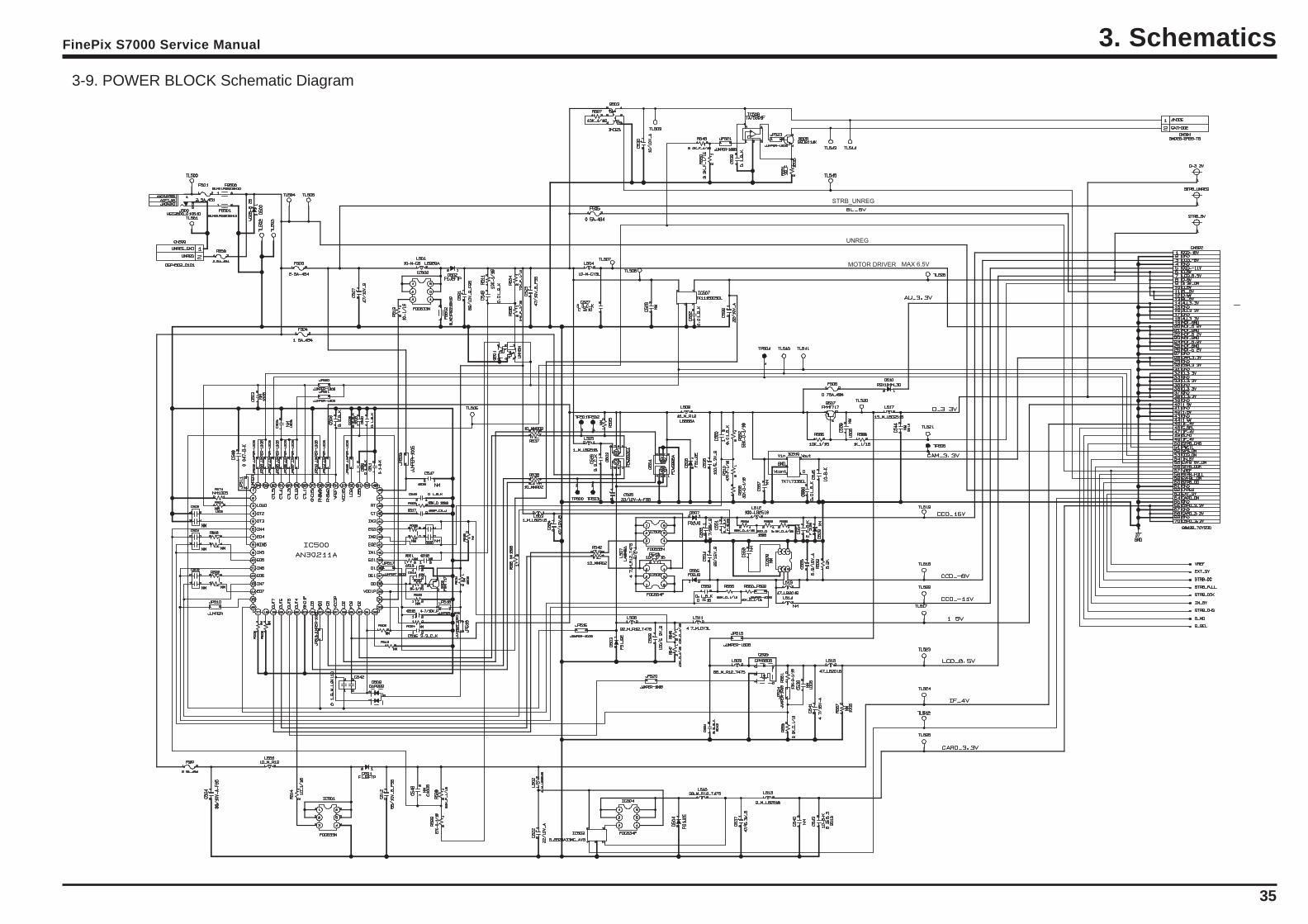
3-3-4.DCTS Board Block FunctionsPower Supply Functions
The power supply circuit on the DCST board generates the -8V/-11V/16V (CCD), 1.5V (UCS2_IC), 3.3V (ACS_IC/UCS2_IC/SDRAM/SDRAM/ROM/LED/KEY), MOT_5.0V (lens/flash), D_5V (AUDO), LCD_13V (LCD/EVF
backlight), D_3.3V (LCD circuit), and AD_3.3V (video circuit) voltages.
30
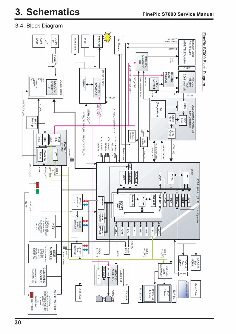
3. Schematics FinePix S7000 Service Manual
3-4. Block DiagramF
inePix S
7000 Block D
iagram
6xZO
OM
LEN
Z
IRIS
13Steps
WID
E/T
ELE
Variable
O.LPF
HA
-CC
D
MS
3891 1/1.7inch
6.5millon pixels
V D
rv. M
D2174
OF
D/R
G
BIA
S
MO
DU
LE
AC
S A
D80057A
KB
C_36
3.3V O
peration
CD
S
AD
C
14bit
T
G
(Program
ble)
Motor D
rv. M
50233HP
6ch
UC
S2
LIBR
A
3.3V O
peration
TX
49 CP
U C
ore T
X49 C
PU
Core
DE
BU
G I/F
DE
BU
G I/F
CP
U C
oreC
PU
Core
I-cache 16kI-cache 16k
BU
S C
ont. S
DR
AM
C
DM
AC
BU
S C
ont. S
DR
AM
C
DM
AC
Peripheral BUS 96MHz Peripheral BUS 96MHz
US
B
SIO
SIO
MF
TM
FT
ICU
ICU
DA
C
PO
RT
PO
RT
CLK
CC
LKC
Internal eD
RA
MA
Internal eD
RA
MA
Internal eD
RA
MB
Internal eD
RA
MB
I/O B
uffer I/O
Buffer
SD
RA
M
256Mb x16
X2
JPE
G
JPE
G
Audio(A
/D)
Audio(A
/D)
Audio(S
eriul)A
udio(Seriul)
CG
EN
CG
EN
EN
CD
EN
CD
TF
DC
TF
DC
ME
DIA
ME
DIA
YC
PR
O
YC
PR
O
CC
DIF
CC
DIF
AU
TO
AU
TO
RE
CC
R
EC
C
IBF
C
WD
T
FLA
SH
4M
B
(IN U
CS
2)
A/D
EV
F/LC
D
Cont
CX
M4006R
.
LCD
Panel
1.8inch
BL LE
D x3
xD C
ard S
lot (20P
IN)
ST
RB
-XE
DC
/DC
Block
D
C/D
C IC
. A
N30211A
7ch
DC
IN
5V
BA
TT
. A
Ax4
FU
SE
AU
DIO
IC
BH
6415KN
CT
L
MIC
SP
EA
KE
R
MIC
_AM
P
SP
_AM
P
SIO
_1 (U
2_SIO
) S
IO_2
(EV
R_S
IO)
ST
RB
BLO
CK
ST
RB
-CP
-TR
ST
RB
IC
UP
C5023G
R
PW
ON
IC
FF
1166
PIO
RT
C
EV
R
8ch
Pow
er on
Reset
SIO
CT
L
BA
TT
B
ackup
VI_C
ON
T,V
F_C
ON
T,V
Z_C
ON
T
OF
D_C
ON
T
G_N
O,G
_SE
L,S
TR
B_C
HG
X’TA
L CX
-101F
48.000MH
z
VI,H
I,AD
CK
,ST
B,
LD,D
I,WA
IT,R
W
Cont.
Pulses
SH
T PU
LSE
V
H
CCDIN
CC
D[13-0]
Zoom position Zoom HP
Focus HP
KE
Y
R
/L/D/U
SW
O
K/B
AC
K/D
ISP
SW
F M
ode SW
E
VF
/LCD
SW
P
inP S
W
AE
L SW
CF
Card
Slot
(50PIN
) M
icro Drive
xD P
ictureCard
DR_SW
Focus,Iris,Z
oom P
ulse
1.5V
3.3V
5V
CC
D16V
,-8V
LCD
8.5V
Etc.
Detect system
VR
ES
ET
,OC
ON
T
ST
RB
CO
NT
Video
Driver
CC
D_O
N,
PW
ON
_AC
T
RE
SE
T
PW
CT
L,3.3V_O
N
ST
RB
_DIS
,ST
RB
_FU
LL,ST
RB
_CO
K,S
TR
B_C
C
STRB_SY
LED
LED
BE
EP
LED
_R, LE
D_G
VID
EO
_ON
VB
S_O
UT
AU
DIO
_OU
T
EV
F B
L
EV
F
0.44inch
AV
Jack
MO
DE
MO
DU
LE
MO
DE
DIA
L P
OW
ER
/CA
M/P
B S
W
RE
LEA
SE
SW
(S1/S
2) D
RIV
E S
W
ST
RO
BE
+/-
PO
PU
P S
W
LE
DS
ELF
TIM
ER
CO
MM
AN
D
MO
DU
LE
CO
MM
AN
D D
IAL
TE
LE/W
IDE
SW
LED
_ST
SID
E
MO
DU
LE
C
-AF
/S-A
F/M
F S
W
INF
O S
W
OP
AF
SW
S
HIF
T S
W
MA
CR
O S
W
FO
CU
S S
W
UB
S2.0
Cont
M66591G
P
AF
Sensor
SIO
_1 (U
2_SIO
)
IST
,GS
1,GS
2,EN
D,S
/S,C
P
SIO
_1 (U
2_SIO
)
SIO
_1 (U
2_SIO
)
X’TA
L
CX
-101F 24.00MHz
Digital
Gain
Gray
Code X
’TAL C
X-101F
24.375MH
z
X’TA
L CX
-101F
24.545MH
z CA
M_O
N
36MH
z
OS
C
36.00Mhz
32.768kHz
US
B Jack
HO
T S
hoe
1/4 Dividing
frequency
V P
ulse
( S I P
)
31
3. SchematicsFinePix S7000 Service Manual
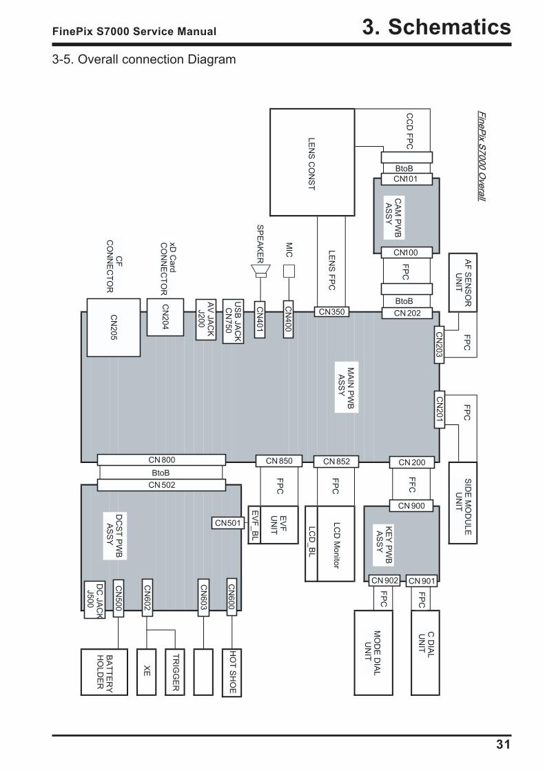
3-5. Overall connection DiagramFineP
ix S7000 O
verallFineP
ix S7000 O
verall
LCD
_BL
EV
F_B
L
HO
T S
HO
E
BtoB
BtoB
CN
203
CN101
CN100
BtoBCN 202CN350
CN
201
CN 200
CN 900
CN 901CN 902
C D
IAL
UN
IT
MO
DE
DIA
L U
NIT
SID
E M
OD
ULE
UN
ITA
F S
EN
SO
R U
NIT
FP
C
FF
C
FP
C
FP
C
FP
C
FP
C
LEN
S F
PC
CC
D F
PC
CN 852CN 850
LCD
Monitor
EV
FU
NIT
CN
401
CN
400M
IC
SP
EA
KE
R
US
B JA
CK
CN
750
AV
JAC
KJ200
CN
204
CN
205
xD C
ardC
ON
NE
CT
OR
CF
CO
NN
EC
TO
R
CN 800
CN 502
CN501
DC
JAC
KJ500
CN
500B
AT
TE
RY
HO
LDE
R
XE
TR
IGG
ER
CN
602
CN
603
CN
600
FP
C
FP
C
LEN
S C
ON
ST
CA
M P
WB
AS
SY
MA
IN P
WB
AS
SY
KE
Y P
WB
AS
SY
DC
ST
PW
B A
SS
Y

32
3. Schematics FinePix S7000 Service Manual
3-6. CCD BLOCK Schematic Diagram
33
FinePix S7000 Service Manual 3. Schematics
3-7. CAMERA BLOCK Schematic Diagram
34
FinePix S7000 Service Manual3. Schematics
3-8. PROCESS BLOCK Schematic Diagram
35
FinePix S7000 Service Manual 3. Schematics
3-9. POWER BLOCK Schematic Diagram
MOTOR DRIVER
UNREG
STRB_UNREG
MAX 6.5V
36
FinePix S7000 Service Manual3. Schematics
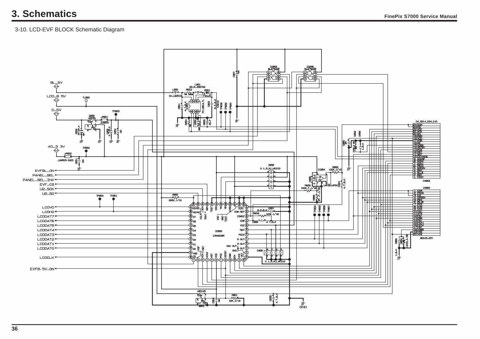
3-10. LCD-EVF BLOCK Schematic Diagram
37
3. SchematicsFinePix S7000 Service Manual
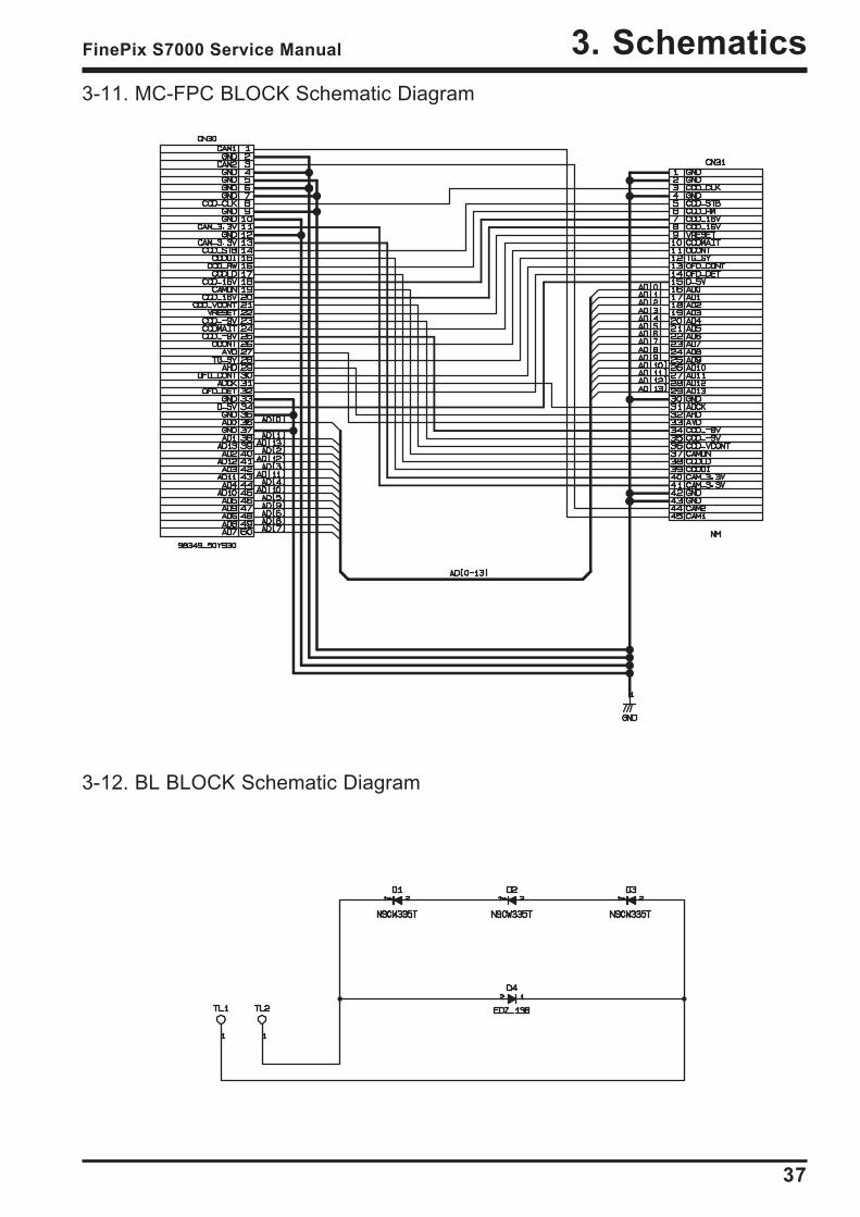
3-11. MC-FPC BLOCK Schematic Diagram
3-12. BL BLOCK Schematic Diagram
38
3. Schematics FinePix S7000 Service Manual
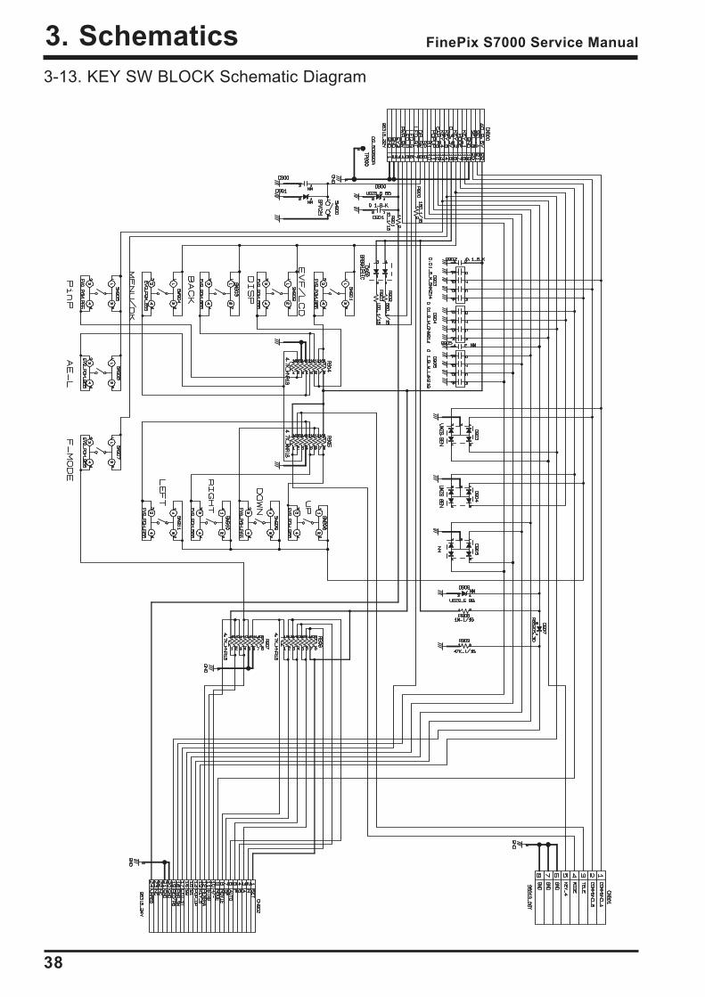
3-13. KEY SW BLOCK Schematic Diagram
39
3. SchematicsFinePix S7000 Service Manual
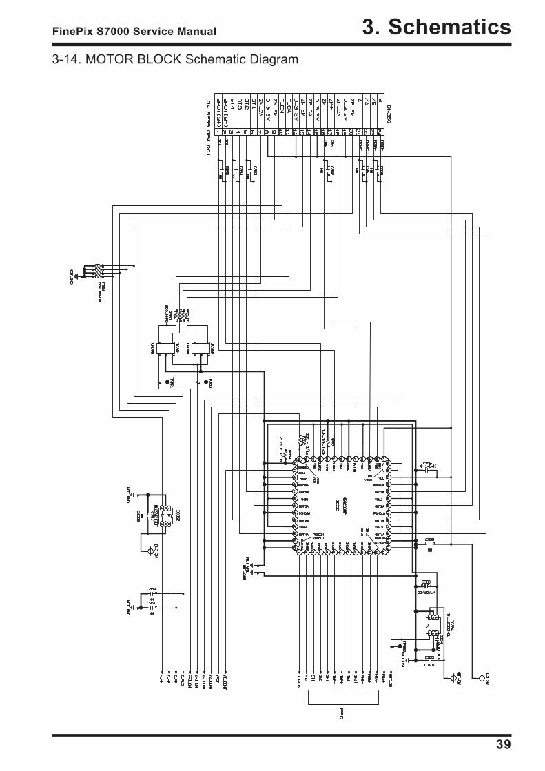
3-14. MOTOR BLOCK Schematic Diagram
40
3. Schematics FinePix S7000 Service Manual
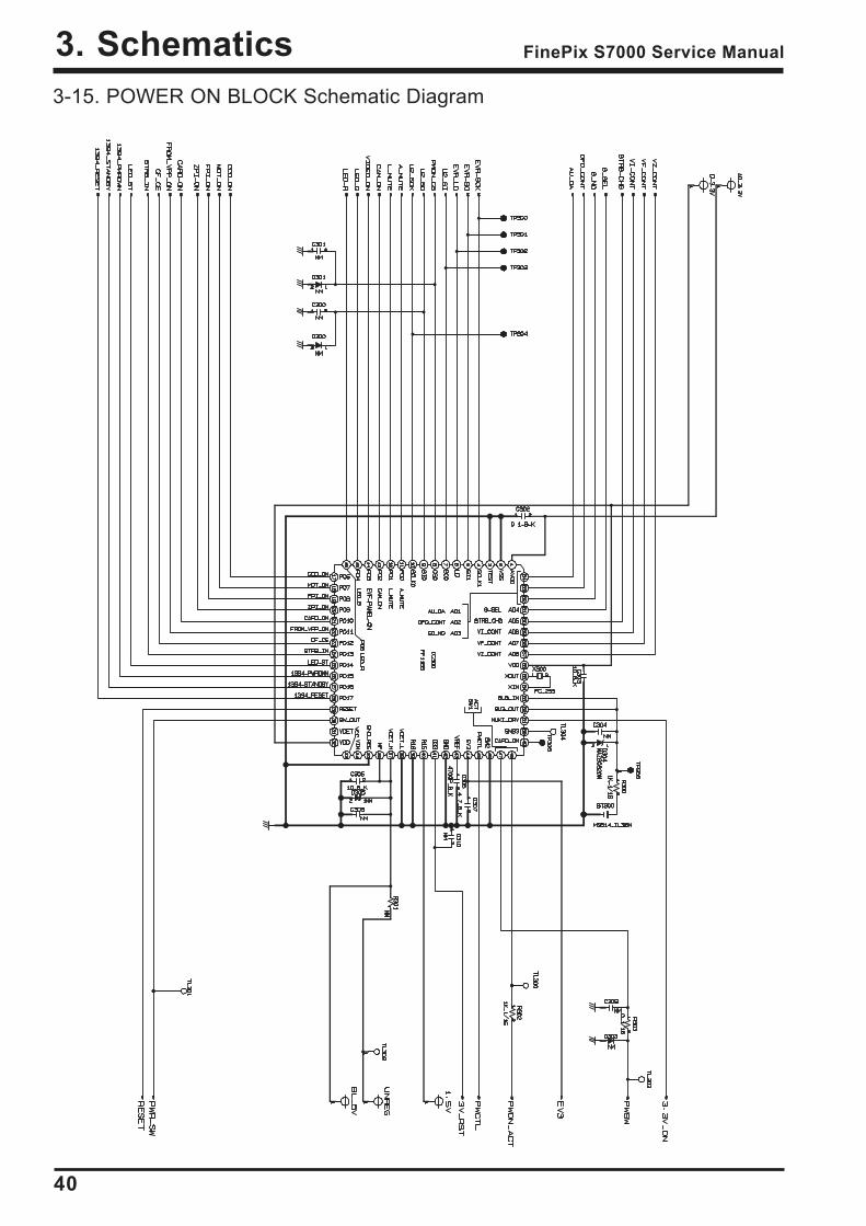
3-15. POWER ON BLOCK Schematic Diagram

41
3. SchematicsFinePix S7000 Service Manual
3-16. FLASH BLOCK Schematic Diagram
42
3. Schematics FinePix S7000 Service Manual
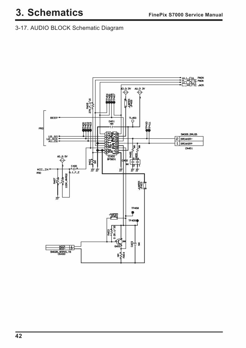
3-17. AUDIO BLOCK Schematic Diagram
43
3. SchematicsFinePix S7000 Service Manual
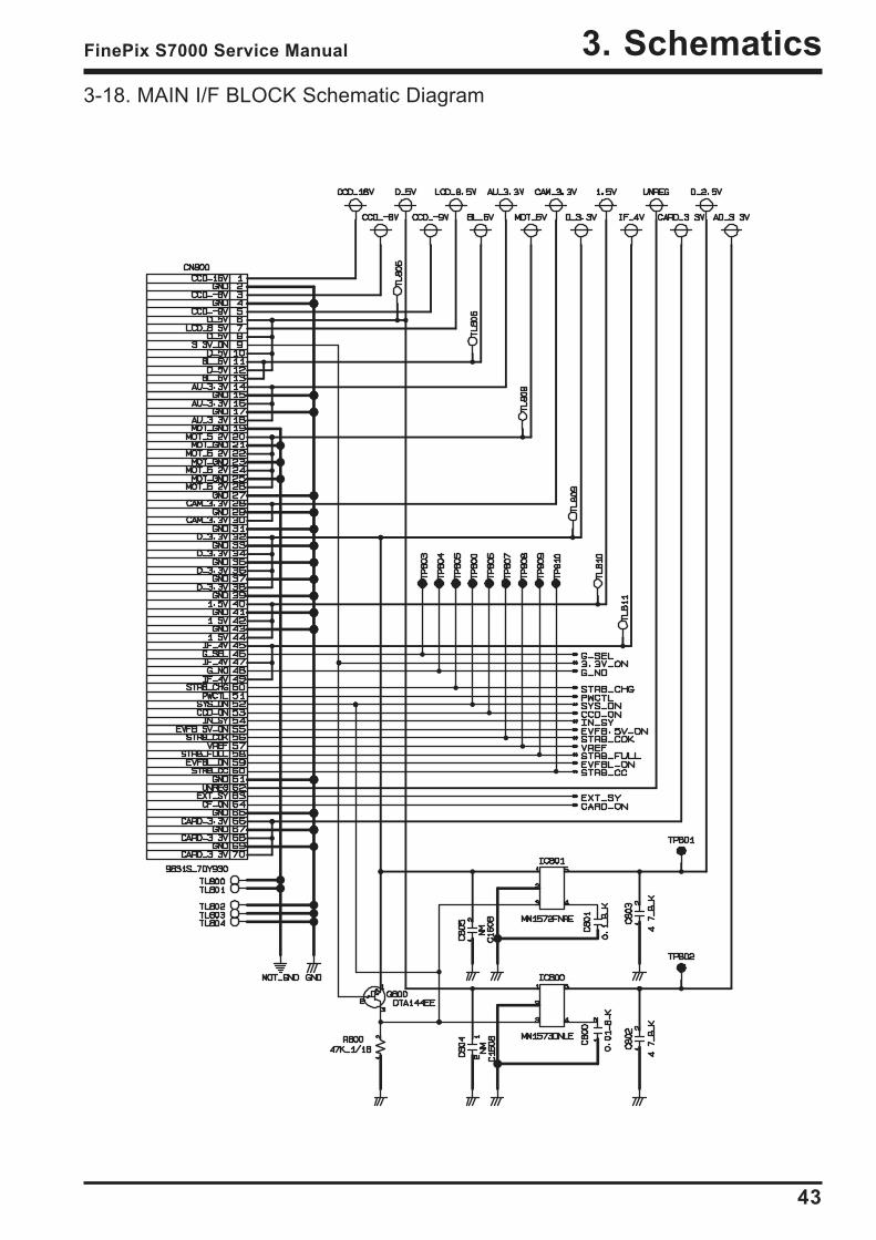
3-18. MAIN I/F BLOCK Schematic Diagram
44
3. Schematics FinePix S7000 Service Manual
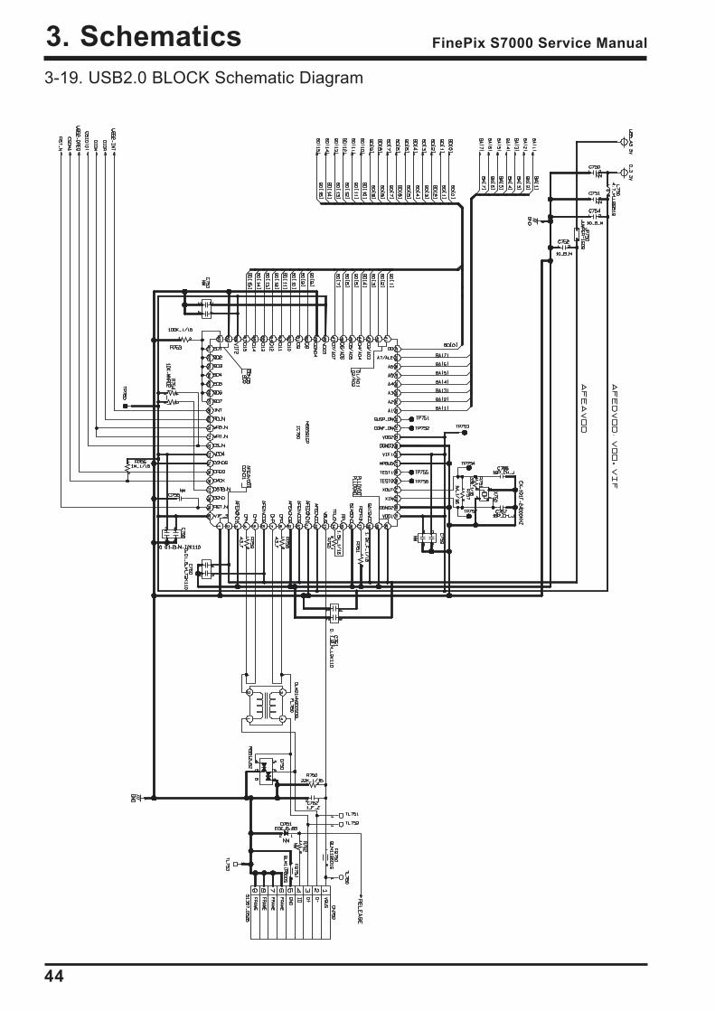
3-19. USB2.0 BLOCK Schematic Diagram
45
3. SchematicsFinePix S7000 Service Manual
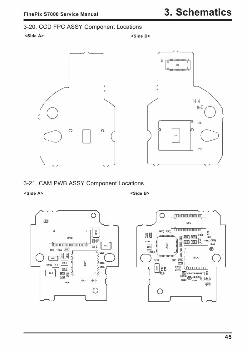
3-20. CCD FPC ASSY Component Locations<Side A> <Side B>
3-21. CAM PWB ASSY Component Locations<Side A> <Side B>
46
3. Schematics FinePix S7000 Service Manual
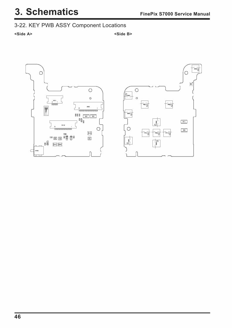
3-22. KEY PWB ASSY Component Locations<Side A> <Side B>
47
3. SchematicsFinePix S7000 Service Manual
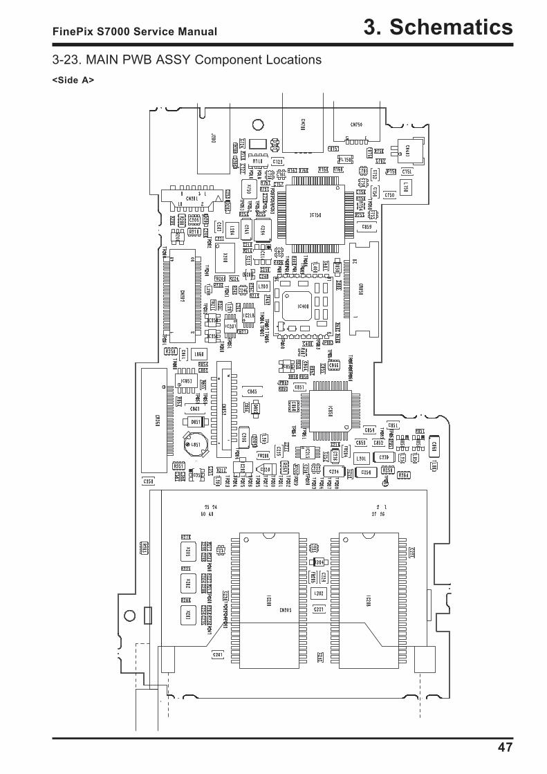
3-23. MAIN PWB ASSY Component Locations<Side A>
48
3. Schematics FinePix S7000 Service Manual
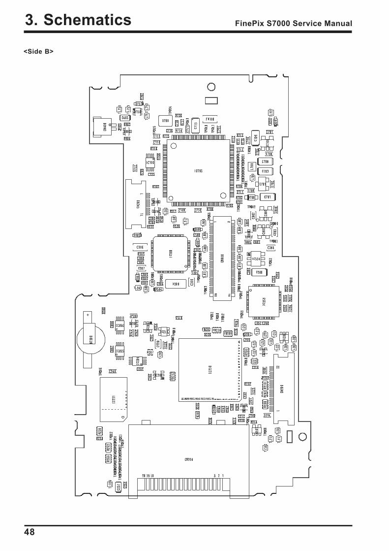
<Side B>
49
3. SchematicsFinePix S7000 Service Manual
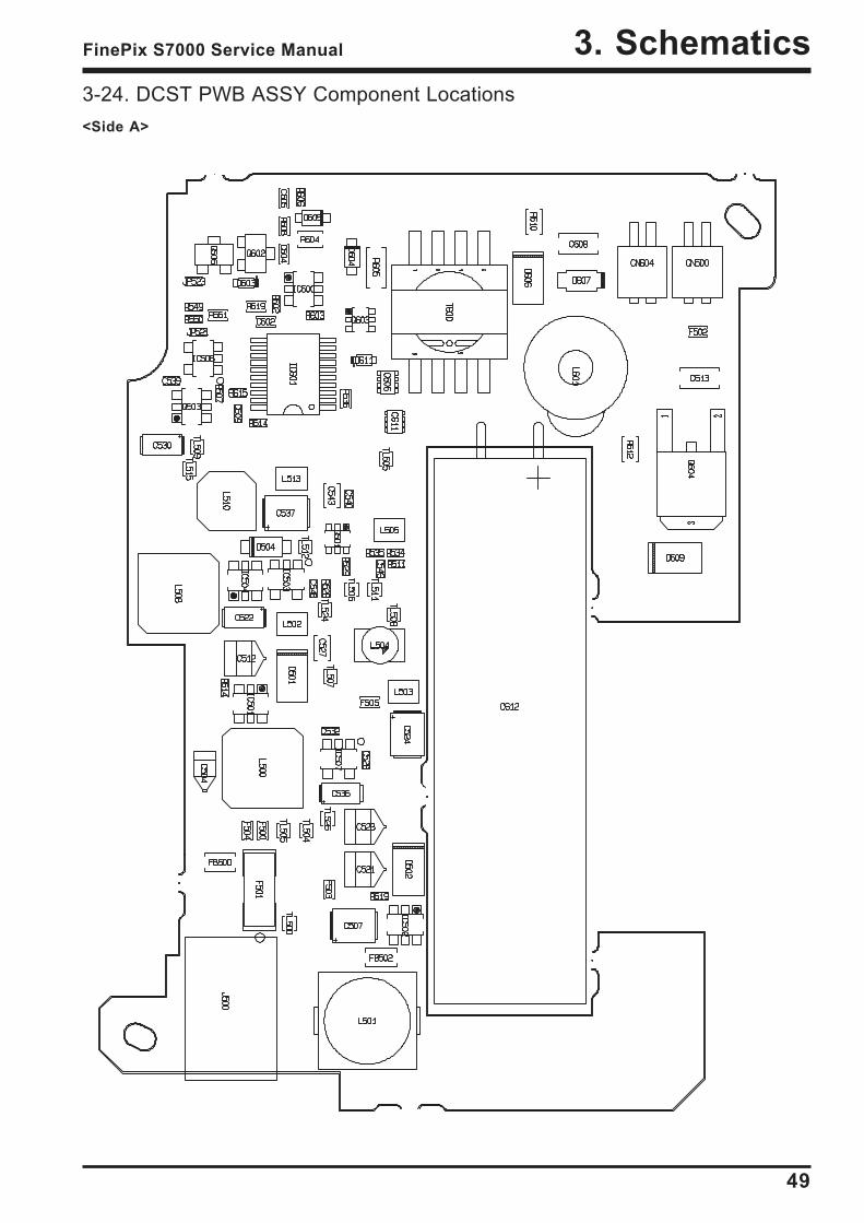
3-24. DCST PWB ASSY Component Locations<Side A>
50
3. Schematics FinePix S7000 Service Manual
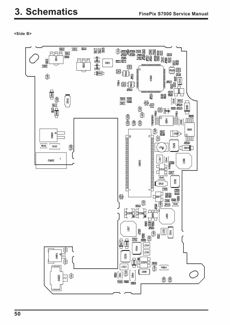
<Side B>
51
4. AdjustmentFinePix S7000 Service Manual
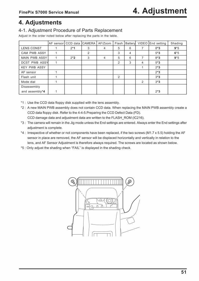
4. Adjustments4-1. Adjustment Procedure of Parts ReplacementAdjust in the order noted below after replacing the parts in the table.
*1 : Use the CCD data floppy disk supplied with the lens assembly.*2 : A new MAIN PWB assembly does not contain CCD data. When replacing the MAIN PWB assembly create a
CCD data floppy disk. Refer to the 4-4-5.Preparing the CCD Defect Data (FD).CCD damage data and adjustment data are written to the FLASH_ROM (IC216).
*3 : The camera will remain in the Jig mode unless the End settings are entered. Always enter the End settings afteradjustment is complete.
*4 : Irrespective of whether or not components have been replaced, if the two screws (M1.7 x 5.5) holding the AFsensor in place are removed, the AF sensor will be displaced horizontally and vertically in relation to thelens, and AF Sensor Adjustment is therefore always required. The screws are located as shown below.
*5 : Only adjust the shading when FAIL is displayed in the shading check.
AF sensor CCD data CAMERA AF/Zoom Flash Battery VIDEO End setting ShadingLENS CONST 1 2*1 3 4 5 6 7 8*3 9*5CAM PWB ASSY 1 2 3 4 5*3 6*5MAIN PWB ASSY 1 2*2 3 4 5 6 7 8*3 9*5DCST PWB ASSY 1 2 3 4 5*3KEY PWB ASSY 1 2*3AF sensor 1 2*3Flash unit 1 2 3*3Mode dial 1 2 3*3Disassembly
and assembly*4 1 2*3
52
4. Adjustment FinePix S7000 Service Manual
*1 : Data available from WEB site *2 : Select one of the power cable suitable for each country.
53
4. AdjustmentFinePix S7000 Service Manual
4-4. Jig Connections
* Always measure input voltage close to the DC_IN pin when making adjustments.
4-5. Environment Setup(1)Setup for camera adjustment (Fig.A)
<<All white pattern>>Set the distance between the camera reference face (*1)and the pattern box to within approximately 50mm.Filter (LB140) and reference face in direct contact.
1. Color temperature: 6100±50K (with LB140 filter)Measurement position : middle of pattern boxMeasuring device : Minolta Color Meter III F or equivalent
*Color temperature measurement(1)Filter (LB140) and pattern box in direct contact.(2)Filter (LB140) and color meter in direct contact.(3)Adjust color temperature of pattern box to 6100±50K.
2. Luminance: 160±5cd/m2 (with LB140 filter)Measurement position : middle of pattern boxMeasuring device : Minolta Luminance Meter LS-110 orequivalent
*Luminance measurement(1)Filter (LB140) and pattern box in direct contact.(2)Filter (LB140) and Luminance meter in direct contact.(3)Adjust luminance of pattern box to 160±5cd/m2.
(*1)Front face of LENS ASSY used as camera reference face.
<Fig.A> Setup for Camera Adjustment
AC-100-240V
To PCI-2746C Board
VIDEO ADJ. JIG
USB CABLE
POWER CABLE JIG
TV MONITOR
PATTERN
BOX
Within 80mm
FinePix S7000
LB140 FILTER
LB140
Pattern BOX
(All white)
54
4. Adjustment FinePix S7000 Service Manual
<Fig.B> Setup for AF Adjustment
<Fig.C> Setup for Flash Adjustment
Lens holder
Stand
Base plate
When assembling theconversion lens, take care toensure that the protrudingside is towards the subject,and the flat side is towardsthe camera lens.
(2)Setup for AF adjustment (Fig.B)1. Set the distance between the conversion lens and
the tip of the lens to 900mm±2mm.2. Use a light source to illuminate the AF chart.
Ensure that the luminance of the surface of the AFchart is between 9.0Ev and 11.0Ev.
3. Ensure that the conversion lens is concentric withthe camera lens.
(3)Setup for Flash Adjustment (Fig.C)Strobe adjustment is readily influenced by external light.The periphery of the gray chart should therefore be asdark as possible to minimize this influence.Ensure that the gray chart is at a distance of 1000mmfrom the camera reference face (*1). Use a SuperiorOxford Gray (No.22) chart, or a chart with reflectivity of18±0.7%.
FinePix S7000
40mm+-5mm
TV Monitor
PC
Siemens
star chart
Light(Fluorescent lamp stand)
INF Adjustment: :900mm+-5mm
(with f=900mm conversion lens)
900mm Adjustment :940mm+-5mm
500mm Adjustment :540mm+-5mm
1000mm
FinePix S7000
Gray chart
Surface of flash
55
4. AdjustmentFinePix S7000 Service Manual
f=900mm
Conversion lens
FinePix S7000
AF Sensor Chart(1000mm)
AF Chart
(700mm)
100mm+-5mm
Light Sourse
(Fluorescent lamp)
Light Sourse
(Fluorescent lamp)
TV monitor
Adjustment PC
700mm Adjustment:1000mm+-5mm
1000mm Adjustment:1000mm+-5mm
Position of f=900mm Conversion Lens
Front face of
AF sensor window
Top
Bottom
+
(4)Preparations for AF Sensor Adjustment1. Prepare as follows using non-defective equipment.2. Mount the camera on a tripod, and place the AF sensor chart (for 1000mm) at a distance of 1000mm from the
front face of the AF sensor window.3. Set the camera power lever to the Photography mode, and display the through screen on the TV monitor.4. Set the lens position to TELE END while holding the camera zoom button [T] down.5. Adjust the camera position so that the AF target symbol (yellow) displayed on the TV monitor overlaps the '+'
symbol (red) near the center of the AF sensor chart (for 1000mm).6. Attach an OHP sheet to the TV monitor.7. Place a mark in the center of the target mark displayed on the TV monitor.8. Draw a circle on the OHP sheet with the marked point as the center.
The size of the circle will differ from the TV monitor used. The circle sizes for the various TV monitors are as follows.14" to 16" : 5mm radius17" to 19" : 6mm radius20" to 21" : 7mm radius
9. This completes preparations for AF Sensor Adjustment.
(5)Environmental Settings for AF Sensor Adjustment1. Set up the conversion lens (f=900 mm) and the two types of AF sensor chart as shown below.2. Illuminate the AF sensor chart (1000mm) using one or two light sources. Adjustment is impossible if the
illumination does not match.The distance between the light sources and the AF sensor chart must be approximately 5cm.AF sensor chart reflective luminance : 8.0Ev to 10.0Ev
3. Place the conversion lens concentric with the front face of the AF sensor window.4. If the center of the conversion lens and the center of the AF sensor window are significantly misaligned, an
error will occur during AF Sensor Adjustment, and adjustment will become impossible.

56
4. Adjustment FinePix S7000 Service Manual
<Fig.E>
4-7. Installing and Starting the Adjustment Software
<Fig.D>
4-6. Installing the Jig Drivers on the PC * As this device uses a USB interface for communica-
tions with the PC, the [USB Jig Driver] must first beinstalled on the PC before the PC adjustment soft-ware can be run.
* As the USB Jig Driver is the same for all models afterMarch 2003, this jig driver is already installed on thePC. This driver software need not be installed on PCsin which the USB device is already been adjusted.
<Step 1>DSC jig driver(ZJ00684-100.ZIP) is downloaded fromWeb server (http://fujifilm-di.intranets.com/).
<Step 2>Extract the downloaded compression software
<Step 3>Double-click setup.exe in the folder of extractedZJ00684-100 and install Fuji FILM DSC Jig Driveras follows.
<Step 4>Install the software in [C:\ProgramFiles\Fjig]according to the instructions on the PC's screen.
4-7-1. Adjustment software setupThe PC adjustment software are in a specified Webserver, and both of these are the compression of ZIPform files.Therefore, after downloading these compression filesfrom the Web server, the extraction of the file is neces-sary.In the extraction software, if the extraction of the ZIPform can be done, any software is OK. (Please prepare one of the extraction software.)The extraction and the preservation method of the PCadjustment software and the firmware are describedto the following.* The PC adjustment soft extraction and preservation
method
<Step1>Download compressed PC adjustment software
(ZJ00691-502.ZIP) from Web server(http://fujifilm-di.intranets.com/).<Fig.E>
<Step2>Extract the downloaded compression software.(Note)
* Specify the preservation drive for C drive if it isextraction software which can specify the preserva-tion drive.
* Similarly, extract without making a new folder if it isextraction software which can be extracted withoutmaking a new folder.
* Extract simply if the extraction software which youhave cannot specify the drive specification and thefolder making.
57
4. AdjustmentFinePix S7000 Service Manual
<Step3>The folder named ZJ00691-502 can be made byextracting without specifying anything. <Fig. F>The following folders are stored in the extracted folder ofZJ00691-502.1. FinePix_S7000_W : (Use for general adjustment and
shading adjustment.)2. Shading_CHECK : Use for shading inspection
software installation.3. Shading_ADJ : Use for shading adjustment software
installation.
(Caution)[Important](a) PC adjustment software can not start when there is folder of
FinePix_S7000_W in folder named ZJ00691-502.(Fig. 4)Please preserve the folder of FinePix_S7000_W right under C drive.(Fig. 4)
(b) Please do not change the foldername named FinePix_S7000_W.PC adjustment software can not start when foldername is changed.
<Step4>Copy the folder named FinePix_S7000_W in thisfolder in C drive.<Fig. G>
<Fig. F>
<Fig. G>
58
4. Adjustment FinePix S7000 Service Manual
4-7-2. Shading Check Program Setup
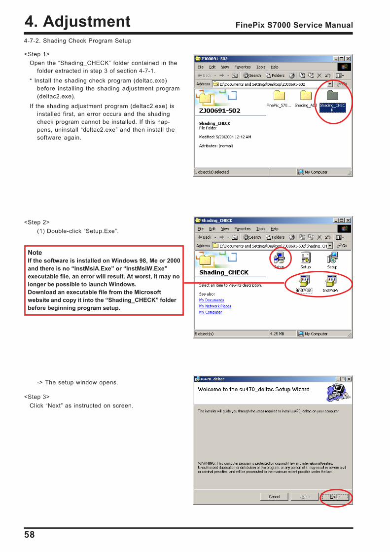
<Step 1>Open the Shading_CHECK folder contained in the
folder extracted in step 3 of section 4-7-1.* Install the shading check program (deltac.exe)
before installing the shading adjustment program(deltac2.exe).
If the shading adjustment program (deltac2.exe) isinstalled first, an error occurs and the shadingcheck program cannot be installed. If this hap-pens, uninstall deltac2.exe and then install thesoftware again.
<Step 2>(1) Double-click Setup.Exe.
-> The setup window opens.
<Step 3>Click Next as instructed on screen.
NoteIf the software is installed on Windows 98, Me or 2000and there is no InstMsiA.Exe or InstMsiW.Exeexecutable file, an error will result. At worst, it may nolonger be possible to launch Windows.Download an executable file from the Microsoftwebsite and copy it into the Shading_CHECK folderbefore beginning program setup.
59
4. AdjustmentFinePix S7000 Service Manual
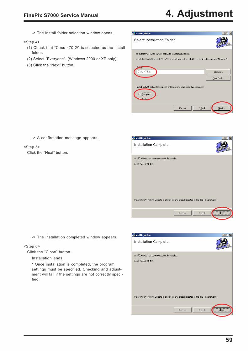
-> The install folder selection window opens.
<Step 4>(1) Check that C:\su-470-2\ is selected as the install
folder.(2) Select Everyone. (Windows 2000 or XP only)(3) Click the Next button.
-> A confirmation message appears.
<Step 5>Click the Next button.
-> The installation completed window appears.
<Step 6>Click the Close button.
Installation ends.* Once installation is completed, the programsettings must be specified. Checking and adjust-ment will fail if the settings are not correctly speci-fied.
60
4. Adjustment FinePix S7000 Service Manual
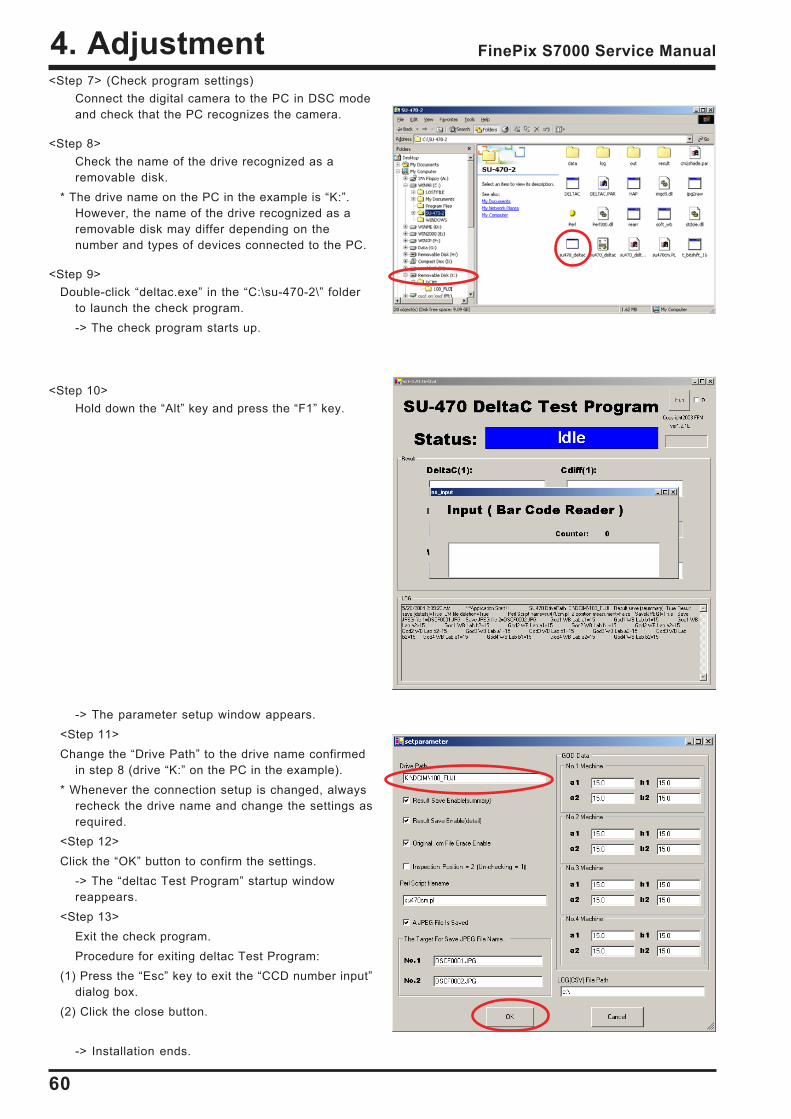
<Step 7> (Check program settings)Connect the digital camera to the PC in DSC modeand check that the PC recognizes the camera.
<Step 8>Check the name of the drive recognized as aremovable disk.
* The drive name on the PC in the example is K:.However, the name of the drive recognized as aremovable disk may differ depending on thenumber and types of devices connected to the PC.
<Step 9>Double-click deltac.exe in the C:\su-470-2\ folder
to launch the check program.-> The check program starts up.
<Step 10>Hold down the Alt key and press the F1 key.
-> The parameter setup window appears.<Step 11>Change the Drive Path to the drive name confirmed
in step 8 (drive K: on the PC in the example).* Whenever the connection setup is changed, always
recheck the drive name and change the settings asrequired.
<Step 12>Click the OK button to confirm the settings.
-> The deltac Test Program startup windowreappears.
<Step 13>Exit the check program.Procedure for exiting deltac Test Program:
(1) Press the Esc key to exit the CCD number inputdialog box.
(2) Click the close button.
-> Installation ends.
61
4. AdjustmentFinePix S7000 Service Manual
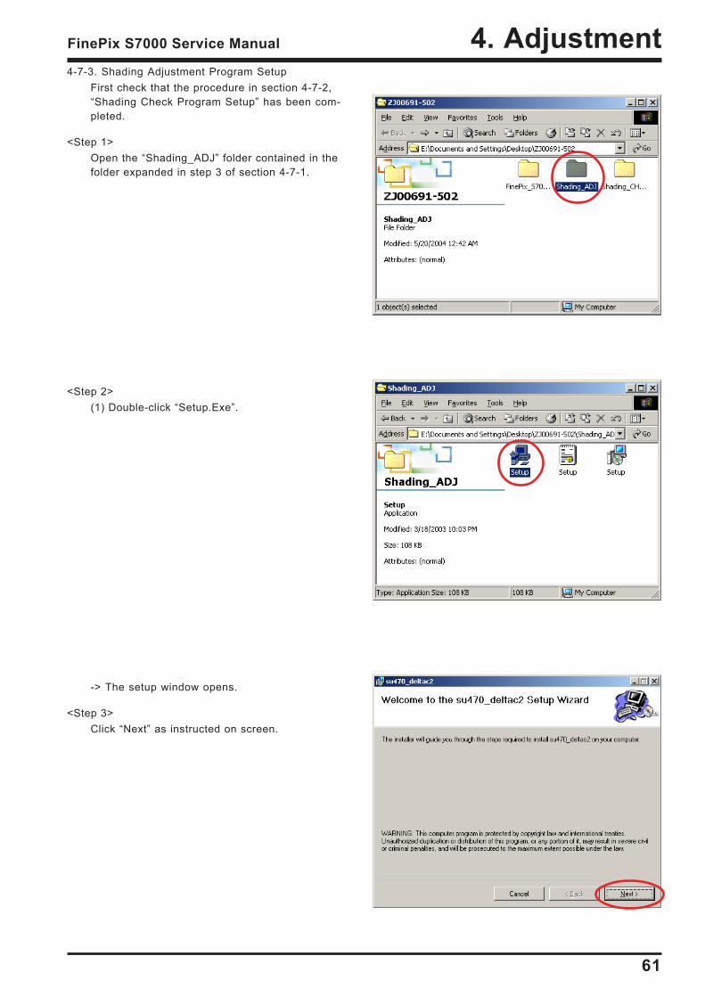
4-7-3. Shading Adjustment Program SetupFirst check that the procedure in section 4-7-2,Shading Check Program Setup has been com-pleted.
<Step 1>Open the Shading_ADJ folder contained in thefolder expanded in step 3 of section 4-7-1.
<Step 2>(1) Double-click Setup.Exe.
-> The setup window opens.
<Step 3>Click Next as instructed on screen.
62
4. Adjustment FinePix S7000 Service Manual
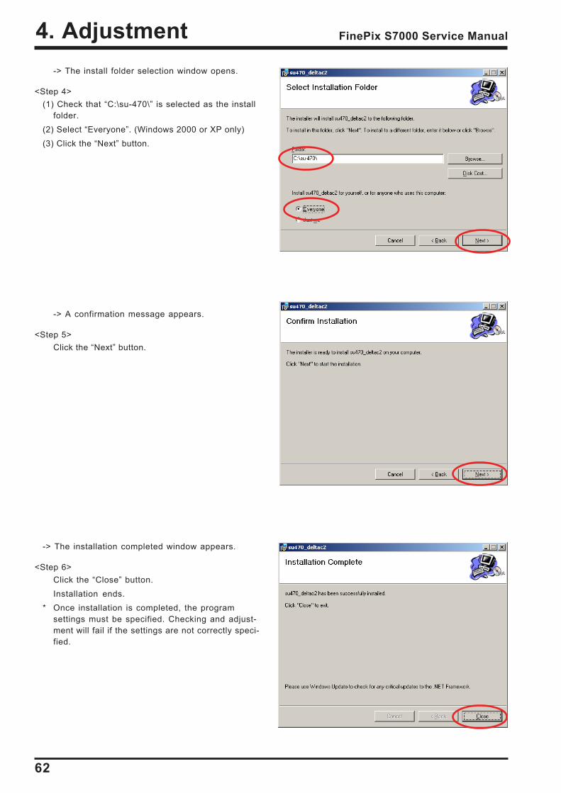
-> The install folder selection window opens.
<Step 4>(1) Check that C:\su-470\ is selected as the install
folder.(2) Select Everyone. (Windows 2000 or XP only)(3) Click the Next button.
-> A confirmation message appears.
<Step 5>Click the Next button.
-> The installation completed window appears.
<Step 6>Click the Close button.Installation ends.
* Once installation is completed, the programsettings must be specified. Checking and adjust-ment will fail if the settings are not correctly speci-fied.
63
4. AdjustmentFinePix S7000 Service Manual
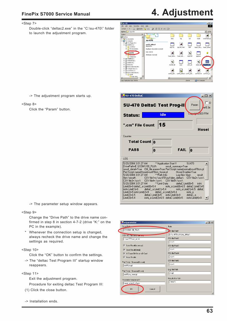
<Step 7>Double-click deltac2.exe in the C:\su-470\ folderto launch the adjustment program.
-> The adjustment program starts up.
<Step 8>Click the Param button.
-> The parameter setup window appears.
<Step 9>Change the Drive Path to the drive name con-firmed in step 8 in section 4-7-2 (drive K: on thePC in the example).
* Whenever the connection setup is changed,always recheck the drive name and change thesettings as required.
<Step 10>Click the OK button to confirm the settings.
-> The deltac Test Program III startup windowreappears.
<Step 11>Exit the adjustment program.Procedure for exiting deltac Test Program III:
(1) Click the close button.
-> Installation ends.
64
4. Adjustment FinePix S7000 Service Manual
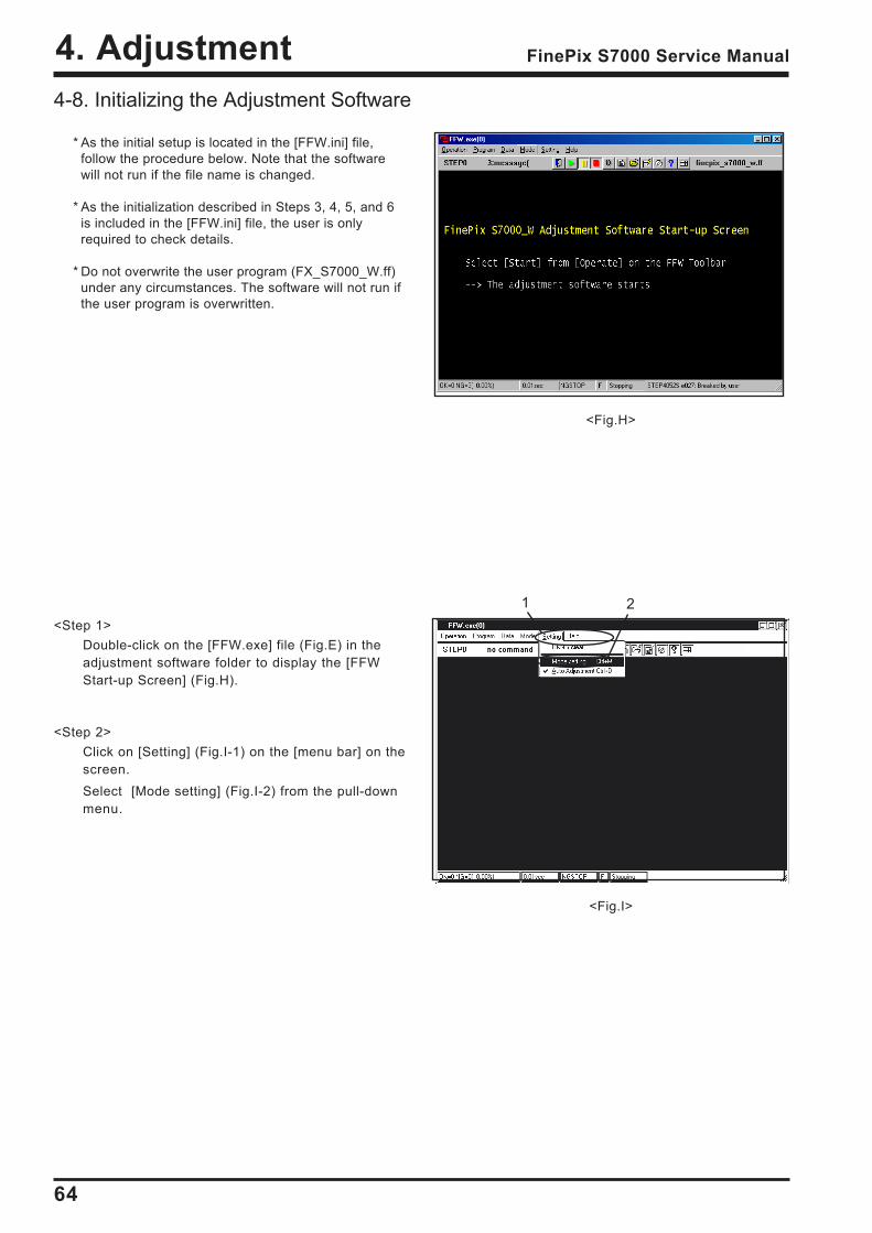
<Step 1>Double-click on the [FFW.exe] file (Fig.E) in theadjustment software folder to display the [FFWStart-up Screen] (Fig.H).
<Step 2>Click on [Setting] (Fig.I-1) on the [menu bar] on thescreen.Select [Mode setting] (Fig.I-2) from the pull-downmenu.
<Fig.I>
1 2
4-8. Initializing the Adjustment Software
* As the initial setup is located in the [FFW.ini] file,follow the procedure below. Note that the softwarewill not run if the file name is changed.
* As the initialization described in Steps 3, 4, 5, and 6is included in the [FFW.ini] file, the user is onlyrequired to check details.
* Do not overwrite the user program (FX_S7000_W.ff)under any circumstances. The software will not run ifthe user program is overwritten.
<Fig.H>
65
4. AdjustmentFinePix S7000 Service Manual
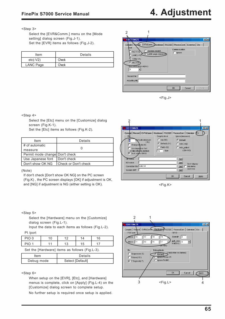
<Fig.J>
<Fig.K>
<Fig.L>
<Step 4>Select the [Etc] menu on the [Customize] dialogscreen (Fig.K-1).Set the [Etc] items as follows (Fig.K-2).
Item Details# of automaticmeasure 0
Permit mode change Don't checkUse Japanese font Don't checkDon't show OK NG Check or Don't check
(Note)If don't check [Don't show OK NG] on the PC screen(Fig.K) , the PC screen displays [OK] if adjustment is OK,and [NG] if adjustment is NG (either setting is OK).
2 1
1
1
2
2
43
<Step 3>Select the [EVR&Comm.] menu on the [Modesetting] dialog screen (Fig.J-1).Set the [EVR] items as follows (Fig.J-2).
Item Detailsetc(-V2) Check
LANC Page Check
<Step 5>Select the [Hardware] menu on the [Customize]dialog screen (Fig.L-1).Input the data to each items as follows (Fig.L-2).
PI /portPIO 0 10 12 14 16PIO 1 11 13 15 17
Set the [Hardware] items as follows (Fig.L-3).
Item DetailsDebug mode Select [Default]
<Step 6>When setup on the [EVR], [Etc], and [Hardware]menus is complete, click on [Apply] (Fig.L-4) on the[Customize] dialog screen to complete setup.No further setup is required once setup is applied.
66
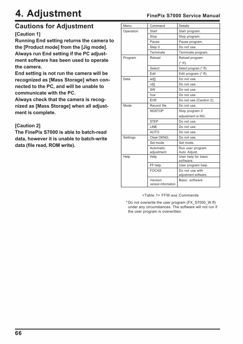
4. Adjustment FinePix S7000 Service Manual
Menu Command DetailsOperation Start Start program.
Stop Stop program.Pause Pause program.Step 0 Do not use.Terminate Terminate program.
Program Reload Reload program(*.ff).
Select Select program (*.ff).Edit Edit program (*.ff).
Data ad[] Do not use.rd[] Do not use.SW Do not use.fsw Do not use.EVR Do not use (Caution 2).
Mode Record file Do not use.NGSTOP Stop program if
adjustment is NG.STEP Do not use.LINE Do not use.AUTO Do not use.
Settings Clear OKNG. Do not use.Set mode Set mode.Automatic Run user programadjustment Auto Adjust.
Help Help User help for basicsoftware.
FF help User program help.FOCAS Do not use with
adjustment software.Version Basic softwareversion information.
Cautions for Adjustment[Caution 1]Running End setting returns the camera tothe [Product mode] from the [Jig mode].Always run End setting if the PC adjust-ment software has been used to operatethe camera.End setting is not run the camera will berecognized as [Mass Storage] when con-nected to the PC, and will be unable tocommunicate with the PC.Always check that the camera is recog-nized as [Mass Storage] when all adjust-ment is complete.
[Caution 2]The FinePix S7000 is able to batch-readdata, however it is unable to batch-writedata (file read, ROM write).
<Table 1> FFW.exe Commands
* Do not overwrite the user program (FX_S7000_W.ff)under any circumstances. The software will not run ifthe user program is overwritten.
67
4. AdjustmentFinePix S7000 Service Manual
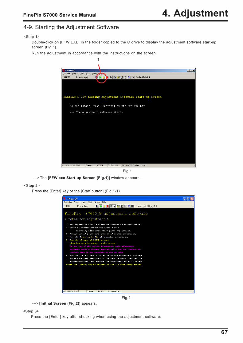
4-9. Starting the Adjustment Software<Step 1>
Double-click on [FFW.EXE] in the folder copied to the C drive to display the adjustment software start-upscreen [Fig.1].Run the adjustment in accordance with the instructions on the screen.
Fig.2
---> The [FFW.exe Start-up Screen (Fig.1)] window appears.
<Step 2>Press the [Enter] key or the [Start button] (Fig.1-1).
Fig.1
---> [Inithal Screen (Fig.2)] appears.
<Step 3>Press the [Enter] key after checking when using the adjustment software.
1
68
4. Adjustment FinePix S7000 Service Manual
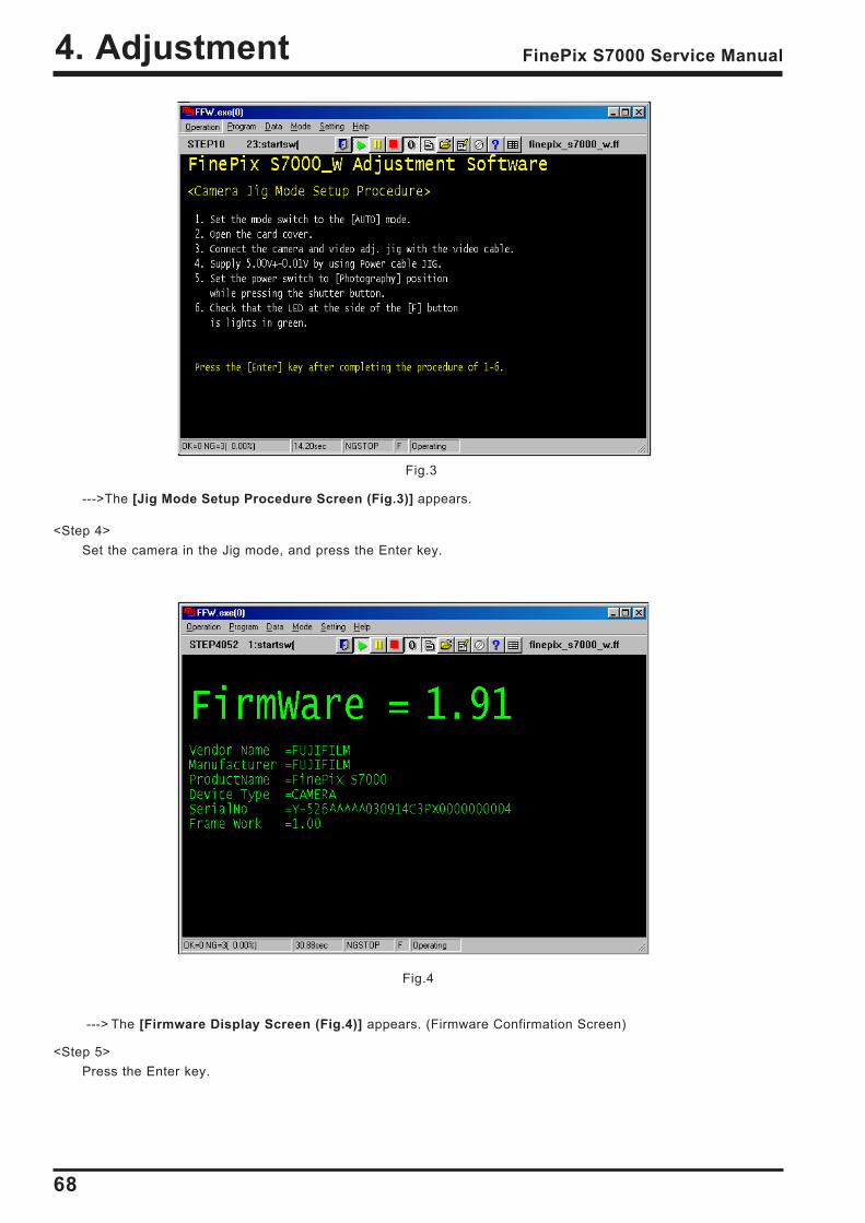
--->The [Jig Mode Setup Procedure Screen (Fig.3)] appears.
<Step 4>Set the camera in the Jig mode, and press the Enter key.
---> The [Firmware Display Screen (Fig.4)] appears. (Firmware Confirmation Screen)
<Step 5>Press the Enter key.
Fig.4
Fig.3
69
4. AdjustmentFinePix S7000 Service Manual
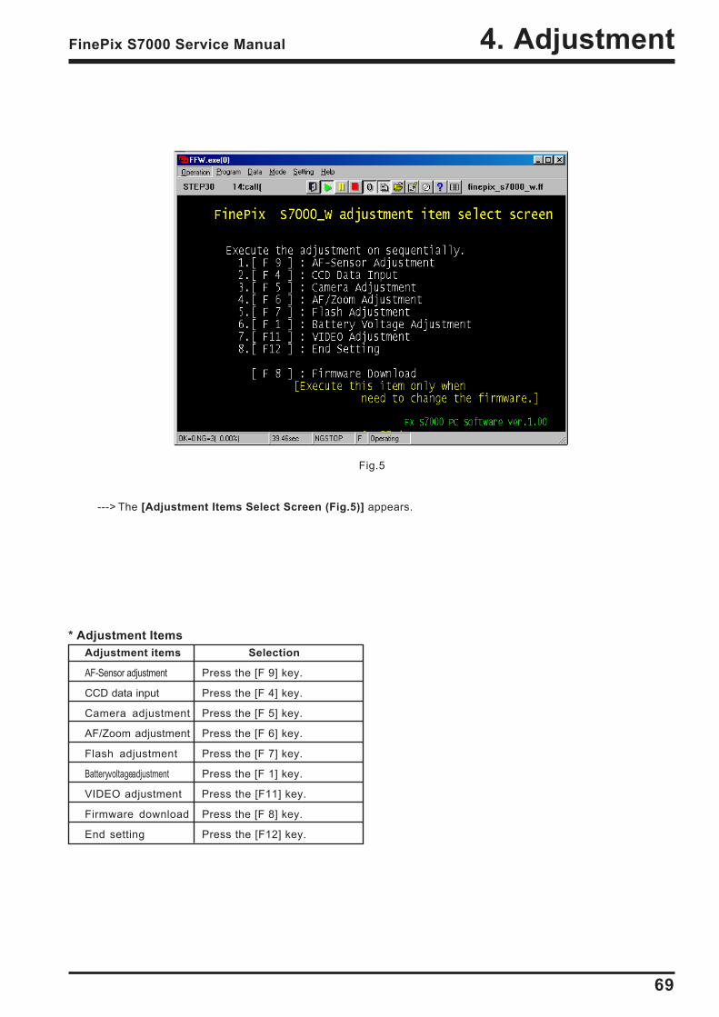
---> The [Adjustment Items Select Screen (Fig.5)] appears.
* Adjustment ItemsAdjustment items Selection
AF-Sensor adjustment Press the [F 9] key.
CCD data input Press the [F 4] key.
Camera adjustment Press the [F 5] key.
AF/Zoom adjustment Press the [F 6] key.
Flash adjustment Press the [F 7] key.
Battery voltage adjustment Press the [F 1] key.
VIDEO adjustment Press the [F11] key.
Firmware download Press the [F 8] key.
End setting Press the [F12] key.
Fig.5
70
4. Adjustment FinePix S7000 Service Manual
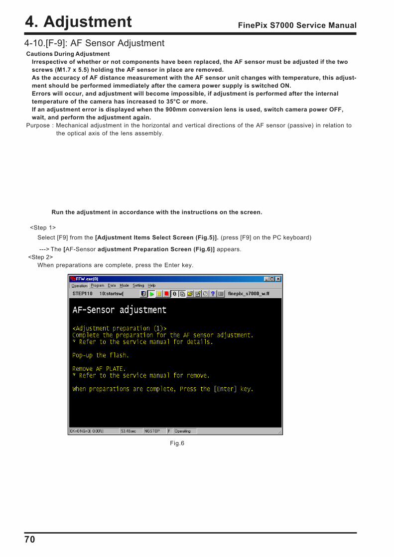
4-10.[F-9]: AF Sensor AdjustmentCautions During Adjustment
Irrespective of whether or not components have been replaced, the AF sensor must be adjusted if the twoscrews (M1.7 x 5.5) holding the AF sensor in place are removed.As the accuracy of AF distance measurement with the AF sensor unit changes with temperature, this adjust-ment should be performed immediately after the camera power supply is switched ON.Errors will occur, and adjustment will become impossible, if adjustment is performed after the internaltemperature of the camera has increased to 35°C or more.If an adjustment error is displayed when the 900mm conversion lens is used, switch camera power OFF,wait, and perform the adjustment again.
Purpose : Mechanical adjustment in the horizontal and vertical directions of the AF sensor (passive) in relation tothe optical axis of the lens assembly.
<Step 1>Select [F9] from the [Adjustment Items Select Screen (Fig.5)]. (press [F9] on the PC keyboard)
---> The [AF-Sensor adjustment Preparation Screen (Fig.6)] appears.<Step 2>
When preparations are complete, press the Enter key.
Fig.6
Run the adjustment in accordance with the instructions on the screen.
71
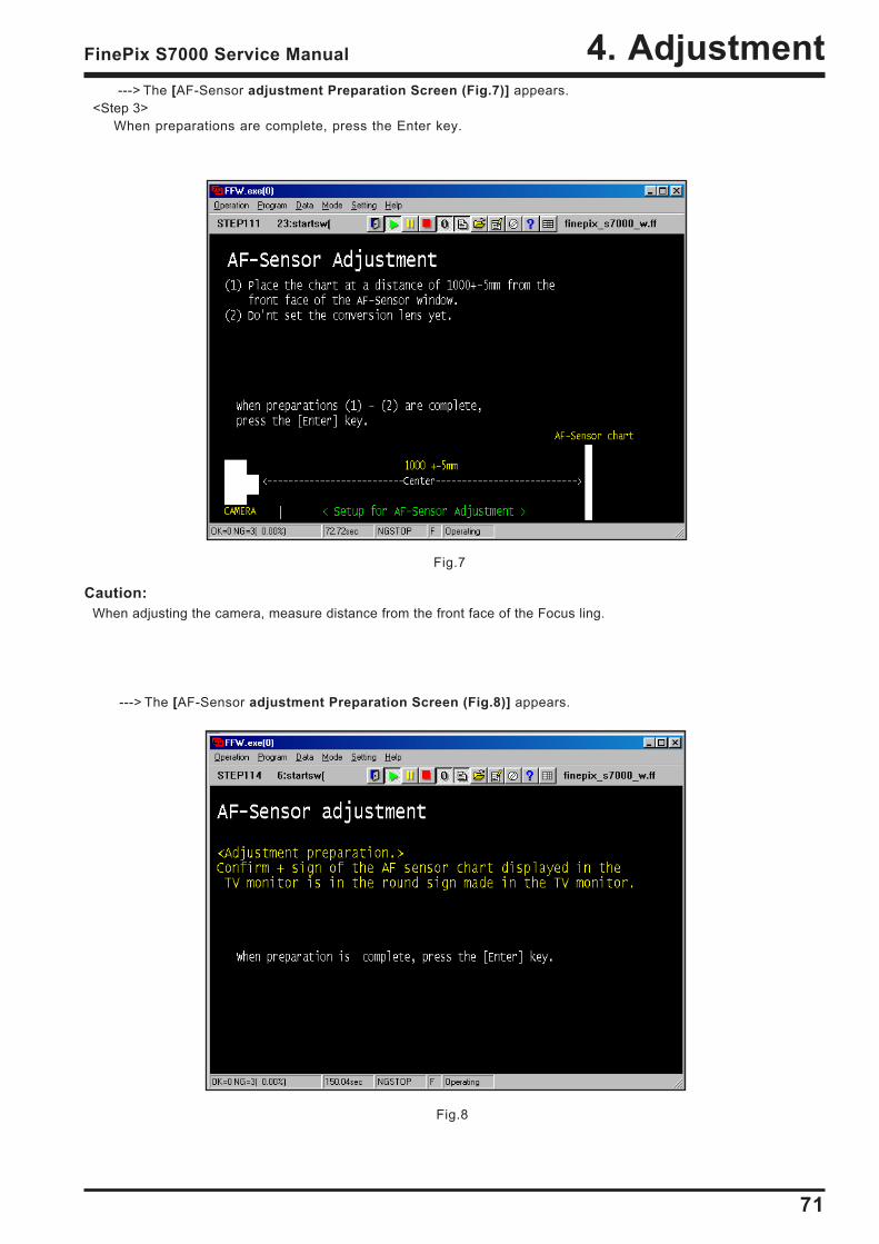
4. AdjustmentFinePix S7000 Service Manual
Fig.8
---> The [AF-Sensor adjustment Preparation Screen (Fig.8)] appears.
---> The [AF-Sensor adjustment Preparation Screen (Fig.7)] appears.<Step 3>
When preparations are complete, press the Enter key.
Fig.7
Caution:When adjusting the camera, measure distance from the front face of the Focus ling.
72
4. Adjustment FinePix S7000 Service Manual
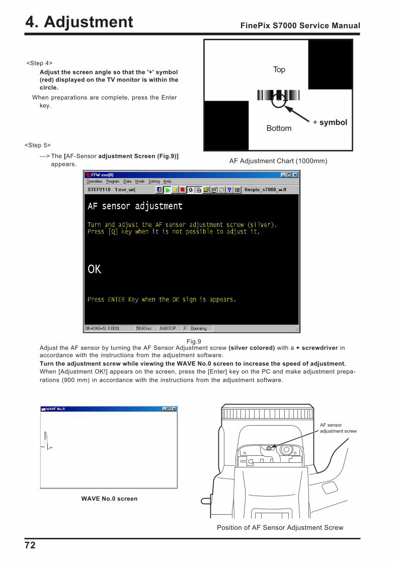
Fig.9
<Step 4>Adjust the screen angle so that the '+' symbol(red) displayed on the TV monitor is within thecircle.
When preparations are complete, press the Enterkey.
Adjust the AF sensor by turning the AF Sensor Adjustment screw (silver colored) with a + screwdriver inaccordance with the instructions from the adjustment software.Turn the adjustment screw while viewing the WAVE No.0 screen to increase the speed of adjustment.When [Adjustment OK!] appears on the screen, press the [Enter] key on the PC and make adjustment prepa-rations (900 mm) in accordance with the instructions from the adjustment software.
AF Adjustment Chart (1000mm)
+
Top
Bottom+ symbol
<Step 5>
---> The [AF-Sensor adjustment Screen (Fig.9)]appears.
Position of AF Sensor Adjustment Screw
+
AF sensoradjustment screw
WAVE No.0 screen
73
4. AdjustmentFinePix S7000 Service Manual
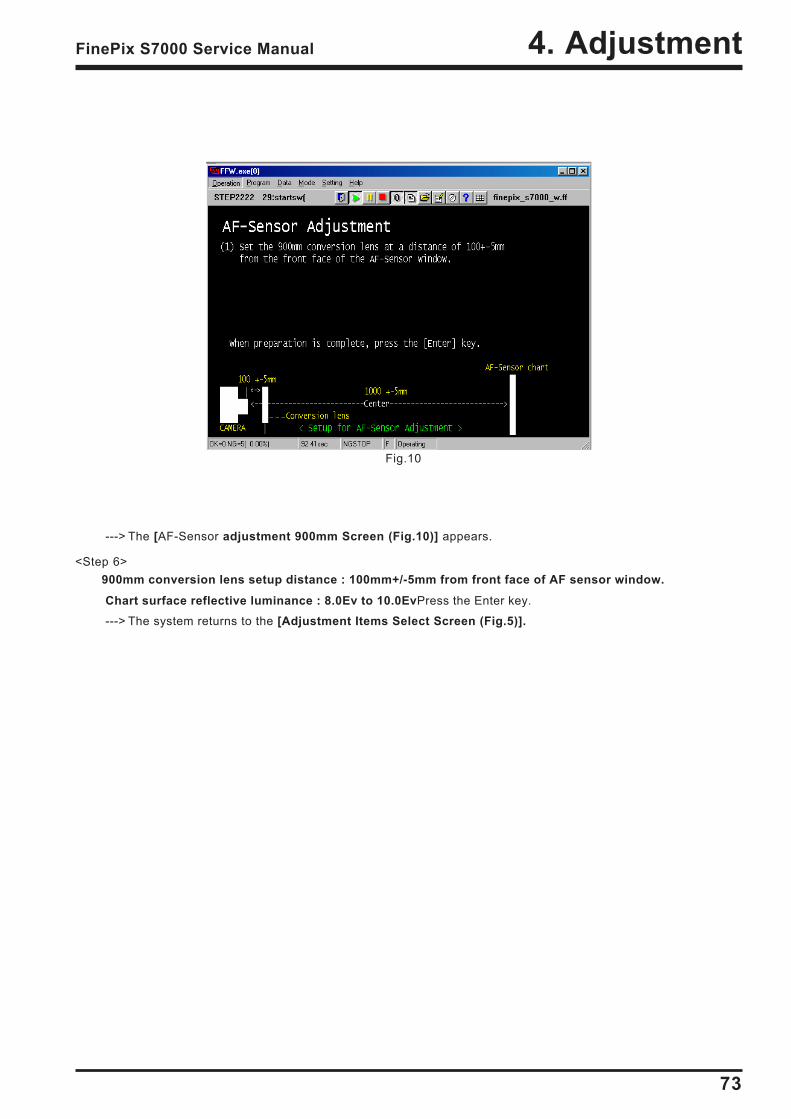
Fig.10
---> The [AF-Sensor adjustment 900mm Screen (Fig.10)] appears.
<Step 6>900mm conversion lens setup distance : 100mm+/-5mm from front face of AF sensor window.
Chart surface reflective luminance : 8.0Ev to 10.0EvPress the Enter key.
---> The system returns to the [Adjustment Items Select Screen (Fig.5)].
74
4. Adjustment FinePix S7000 Service Manual
Fig.12
Fig.11
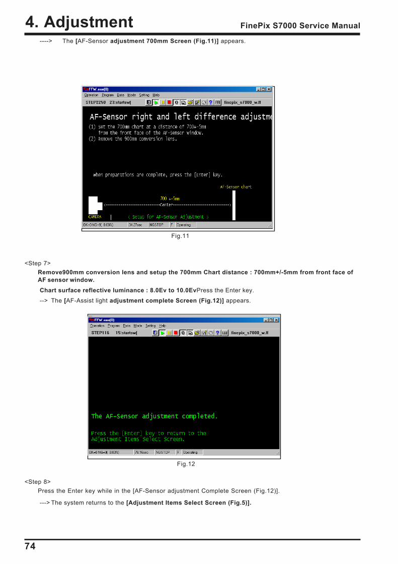
----> The [AF-Sensor adjustment 700mm Screen (Fig.11)] appears.
<Step 7>Remove900mm conversion lens and setup the 700mm Chart distance : 700mm+/-5mm from front face ofAF sensor window.Chart surface reflective luminance : 8.0Ev to 10.0EvPress the Enter key.
--> The [AF-Assist light adjustment complete Screen (Fig.12)] appears.
<Step 8>Press the Enter key while in the [AF-Sensor adjustment Complete Screen (Fig.12)].
---> The system returns to the [Adjustment Items Select Screen (Fig.5)].
75
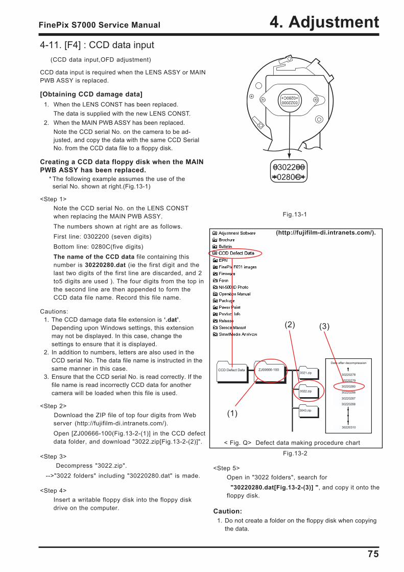
4. AdjustmentFinePix S7000 Service Manual
CCD Defect Data ZJ00666-1003021.zip
3022.zip
3043.zip
Data after decompression
30220279
30220286
30220280
30220287
30220288
30220278
30220310
4-11. [F4] : CCD data input(CCD data input,OFD adjustment)
CCD data input is required when the LENS ASSY or MAINPWB ASSY is replaced.
[Obtaining CCD damage data]1. When the LENS CONST has been replaced.
The data is supplied with the new LENS CONST.2. When the MAIN PWB ASSY has been replaced.
Note the CCD serial No. on the camera to be ad-justed, and copy the data with the same CCD SerialNo. from the CCD data file to a floppy disk.
Creating a CCD data floppy disk when the MAINPWB ASSY has been replaced.
* The following example assumes the use of theserial No. shown at right.(Fig.13-1)
<Step 1>Note the CCD serial No. on the LENS CONSTwhen replacing the MAIN PWB ASSY.The numbers shown at right are as follows.First line: 0302200 (seven digits)Bottom line: 0280C(five digits)The name of the CCD data file containing thisnumber is 30220280.dat (ie the first digit and thelast two digits of the first line are discarded, and 2to5 digits are used ). The four digits from the top inthe second line are then appended to form theCCD data file name. Record this file name.
Cautions:1. The CCD damage data file extension is .dat.
Depending upon Windows settings, this extensionmay not be displayed. In this case, change thesettings to ensure that it is displayed.
2. In addition to numbers, letters are also used in theCCD serial No. The data file name is instructed in thesame manner in this case.
3. Ensure that the CCD serial No. is read correctly. If thefile name is read incorrectly CCD data for anothercamera will be loaded when this file is used.
<Step 2> Download the ZIP file of top four digits from Web
server (http://fujifilm-di.intranets.com/).Open [ZJ00666-100(Fig.13-2-(1)] in the CCD defectdata folder, and download "3022.zip[Fig.13-2-(2)]".
<Step 3> Decompress "3022.zip".
-->"3022 folders" including "30220280.dat" is made.
<Step 4>Insert a writable floppy disk into the floppy diskdrive on the computer.
(2) (3)
(1)
< Fig. Q> Defect data making procedure chart
(http://fujifilm-di.intranets.com/).
Fig.13-2
<Step 5>Open in "3022 folders", search for "30220280.dat[Fig.13-2-(3)] ", and copy it onto thefloppy disk.
Caution:1. Do not create a folder on the floppy disk when copying
the data.
Fig.13-1
0322000+0280C+
0302200
+0280C+
76
4. Adjustment FinePix S7000 Service Manual
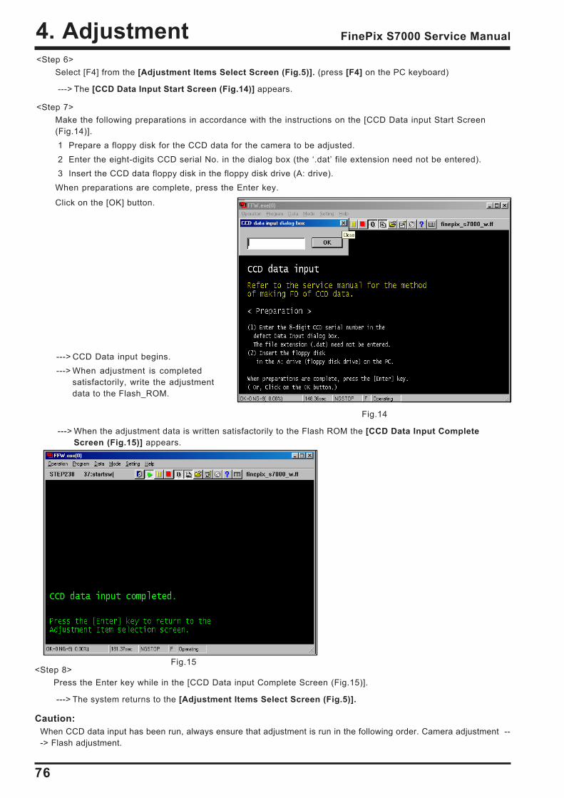
<Step 6>Select [F4] from the [Adjustment Items Select Screen (Fig.5)]. (press [F4] on the PC keyboard)
---> The [CCD Data Input Start Screen (Fig.14)] appears.
<Step 7>Make the following preparations in accordance with the instructions on the [CCD Data input Start Screen(Fig.14)].1 Prepare a floppy disk for the CCD data for the camera to be adjusted.2 Enter the eight-digits CCD serial No. in the dialog box (the .dat file extension need not be entered).3 Insert the CCD data floppy disk in the floppy disk drive (A: drive).
When preparations are complete, press the Enter key.
Click on the [OK] button.
---> CCD Data input begins.---> When adjustment is completed
satisfactorily, write the adjustmentdata to the Flash_ROM.
---> When the adjustment data is written satisfactorily to the Flash ROM the [CCD Data Input CompleteScreen (Fig.15)] appears.
<Step 8>Press the Enter key while in the [CCD Data input Complete Screen (Fig.15)].
---> The system returns to the [Adjustment Items Select Screen (Fig.5)].
Caution:When CCD data input has been run, always ensure that adjustment is run in the following order. Camera adjustment ---> Flash adjustment.
Fig.14
Fig.15

77
4. AdjustmentFinePix S7000 Service Manual
4-12. [F5] : Camera adjustment(shutter adjustment/aperture sensitivity reduction rate adjustment/ISO sensitivity adjustment/white balance adjust-ment/AE shading adjustment/offset level adjustment)
<Step 1>Select [F5] from the [Adjustment Items Select Screen (Fig.5)]. (press [F5] on the PC keyboard)
---> The [Shutter Adjustment Preparation Screen (Fig.16)] appears.
Caution:When adjusting the camera, measure distance from the front face of the camera lens.<Step 2>
When preparations are complete, press the Enter key.
---> Camera adjustment begins.
Run the adjustment in accordance with the instructions on the screen.
Fig.16
Fig.17
78
4. Adjustment FinePix S7000 Service Manual
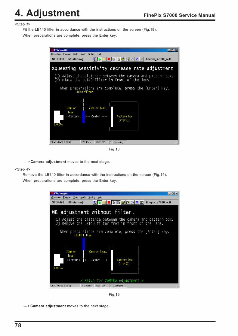
<Step 3>Fit the LB140 filter in accordance with the instructions on the screen (Fig.18).When preparations are complete, press the Enter key.
---> Camera adjustment moves to the next stage.
<Step 4>Remove the LB140 filter in accordance with the instructions on the screen (Fig.19).When preparations are complete, press the Enter key.
---> Camera adjustment moves to the next stage.
Fig.18
Fig.19
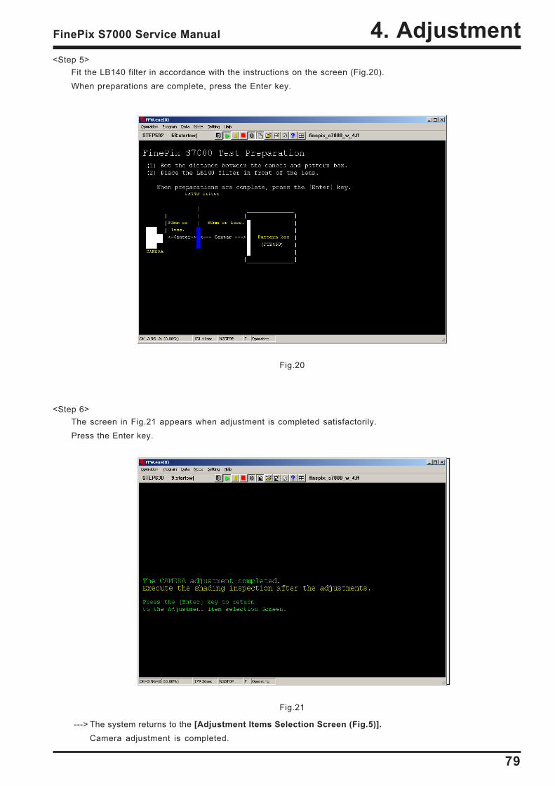
79
4. AdjustmentFinePix S7000 Service Manual
<Step 6>The screen in Fig.21 appears when adjustment is completed satisfactorily.Press the Enter key.
---> The system returns to the [Adjustment Items Selection Screen (Fig.5)].Camera adjustment is completed.
Fig.20
Fig.21
<Step 5>Fit the LB140 filter in accordance with the instructions on the screen (Fig.20).When preparations are complete, press the Enter key.
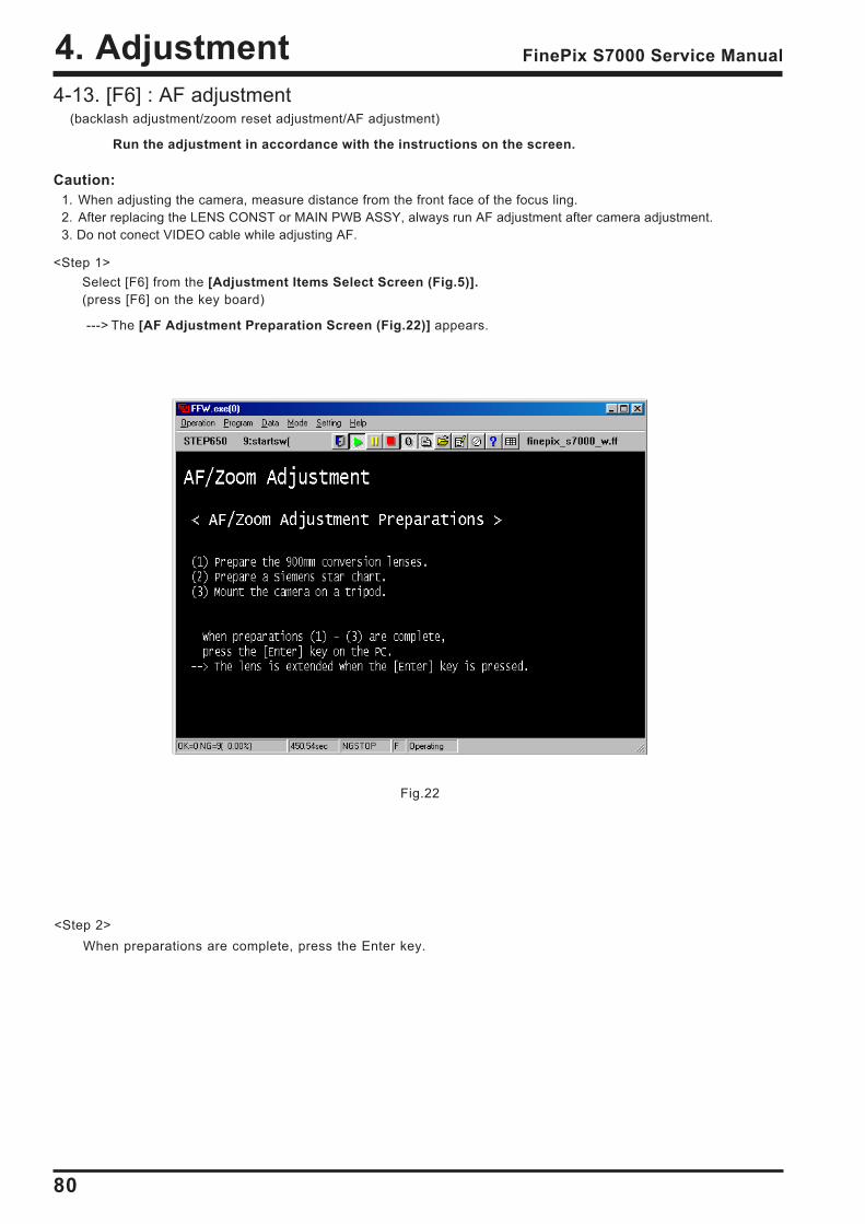
80
4. Adjustment FinePix S7000 Service Manual
4-13. [F6] : AF adjustment(backlash adjustment/zoom reset adjustment/AF adjustment)
Caution:1. When adjusting the camera, measure distance from the front face of the focus ling.2. After replacing the LENS CONST or MAIN PWB ASSY, always run AF adjustment after camera adjustment.3. Do not conect VIDEO cable while adjusting AF.
<Step 1>Select [F6] from the [Adjustment Items Select Screen (Fig.5)].(press [F6] on the key board)
---> The [AF Adjustment Preparation Screen (Fig.22)] appears.
<Step 2>When preparations are complete, press the Enter key.
Fig.22
Run the adjustment in accordance with the instructions on the screen.
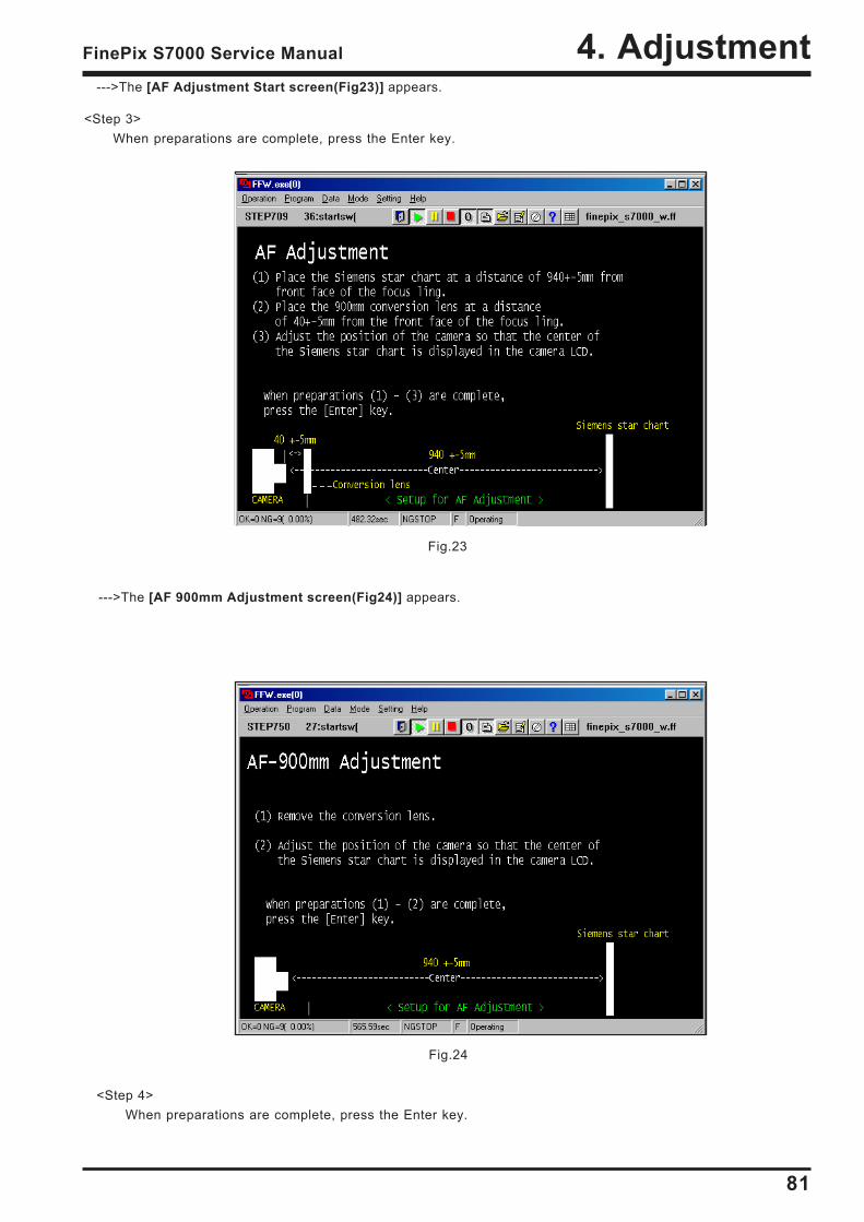
81
4. AdjustmentFinePix S7000 Service Manual
--->The [AF Adjustment Start screen(Fig23)] appears.
<Step 3>When preparations are complete, press the Enter key.
--->The [AF 900mm Adjustment screen(Fig24)] appears.
Fig.23
Fig.24
<Step 4>When preparations are complete, press the Enter key.
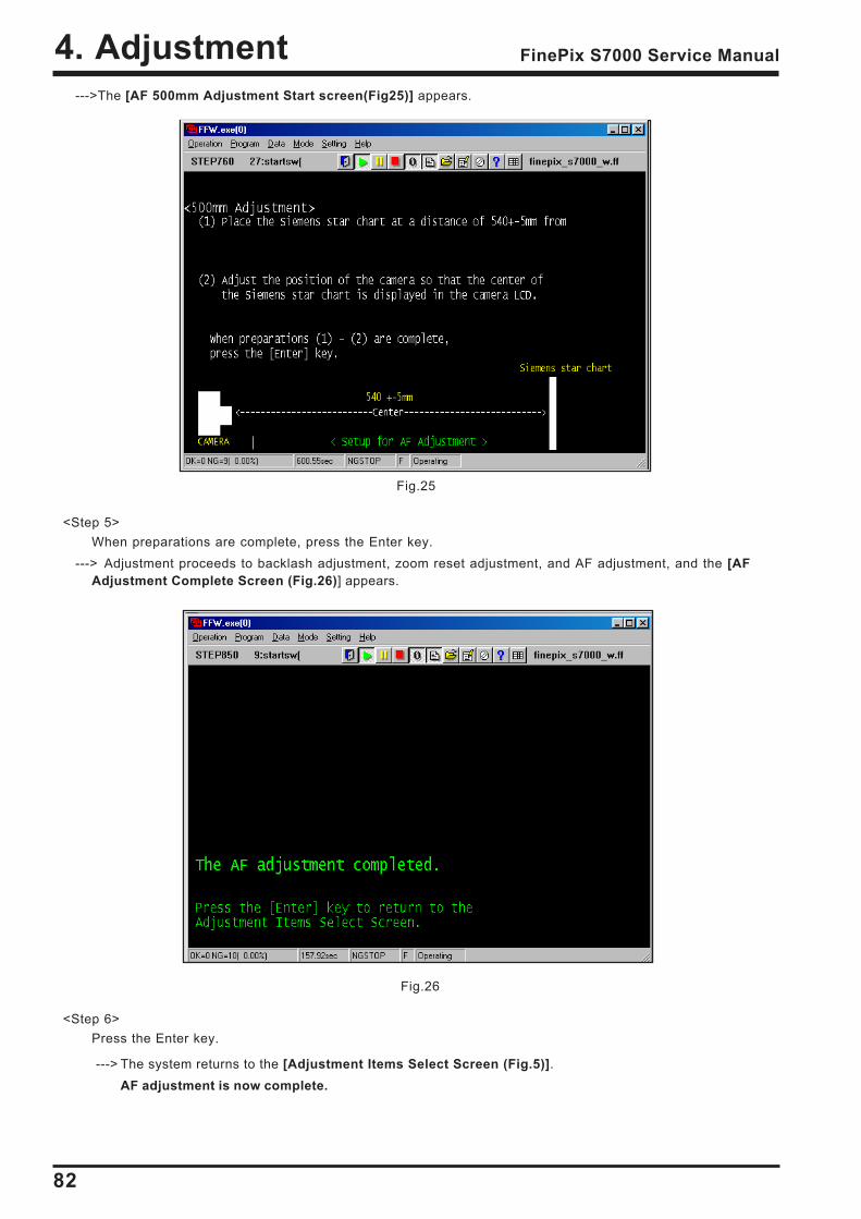
82
4. Adjustment FinePix S7000 Service Manual
Fig.25
Fig.26
--->The [AF 500mm Adjustment Start screen(Fig25)] appears.
<Step 5>When preparations are complete, press the Enter key.
---> Adjustment proceeds to backlash adjustment, zoom reset adjustment, and AF adjustment, and the [AFAdjustment Complete Screen (Fig.26)] appears.
<Step 6>Press the Enter key.
---> The system returns to the [Adjustment Items Select Screen (Fig.5)].AF adjustment is now complete.
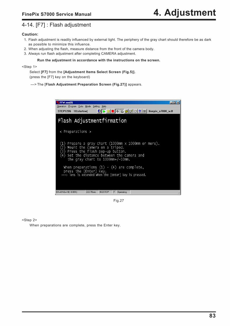
83
4. AdjustmentFinePix S7000 Service Manual
Fig.27
4-14. [F7] : Flash adjustmentCaution:
1. Flash adjustment is readily influenced by external light. The periphery of the gray chart should therefore be as darkas possible to minimize this influence.
2. When adjusting the flash, measure distance from the front of the camera body.3. Always run flash adjustment after completing CAMERA adjustment.
<Step 1>Select [F7] from the [Adjustment Items Select Screen (Fig.5)].(press the [F7] key on the keyboard)
---> The [Flash Adjustment Preparation Screen (Fig.27)] appears.
Run the adjustment in accordance with the instructions on the screen.
<Step 2>When preparations are complete, press the Enter key.
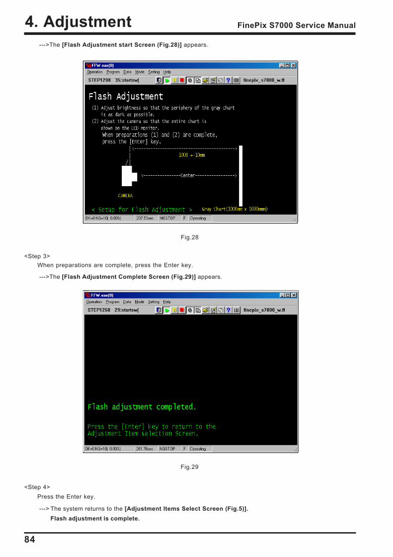
84
4. Adjustment FinePix S7000 Service Manual
Fig.28
--->The [Flash Adjustment start Screen (Fig.28)] appears.
Fig.29
<Step 3>When preparations are complete, press the Enter key.
--->The [Flash Adjustment Complete Screen (Fig.29)] appears.
<Step 4>Press the Enter key.
---> The system returns to the [Adjustment Items Select Screen (Fig.5)].Flash adjustment is complete.
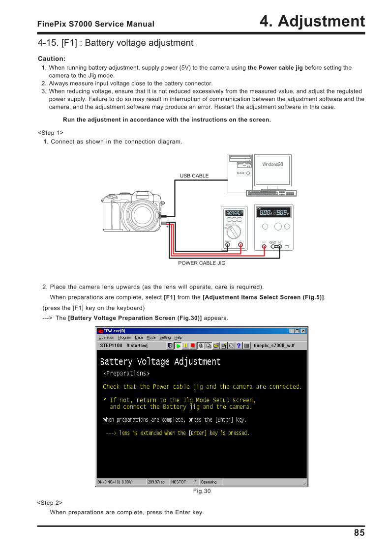
85
4. AdjustmentFinePix S7000 Service Manual
Fig.30
4-15. [F1] : Battery voltage adjustmentCaution:
1. When running battery adjustment, supply power (5V) to the camera using the Power cable jig before setting thecamera to the Jig mode.
2. Always measure input voltage close to the battery connector.3. When reducing voltage, ensure that it is not reduced excessively from the measured value, and adjust the regulated
power supply. Failure to do so may result in interruption of communication between the adjustment software and thecamera, and the adjustment software may produce an error. Restart the adjustment software in this case.
<Step 1>1. Connect as shown in the connection diagram.
Run the adjustment in accordance with the instructions on the screen.
2. Place the camera lens upwards (as the lens will operate, care is required).
When preparations are complete, select [F1] from the [Adjustment Items Select Screen (Fig.5)].
(press the [F1] key on the keyboard)
---> The [Battery Voltage Preparation Screen (Fig.30)] appears.
<Step 2>When preparations are complete, press the Enter key.
USB CABLE
POWER CABLE JIG
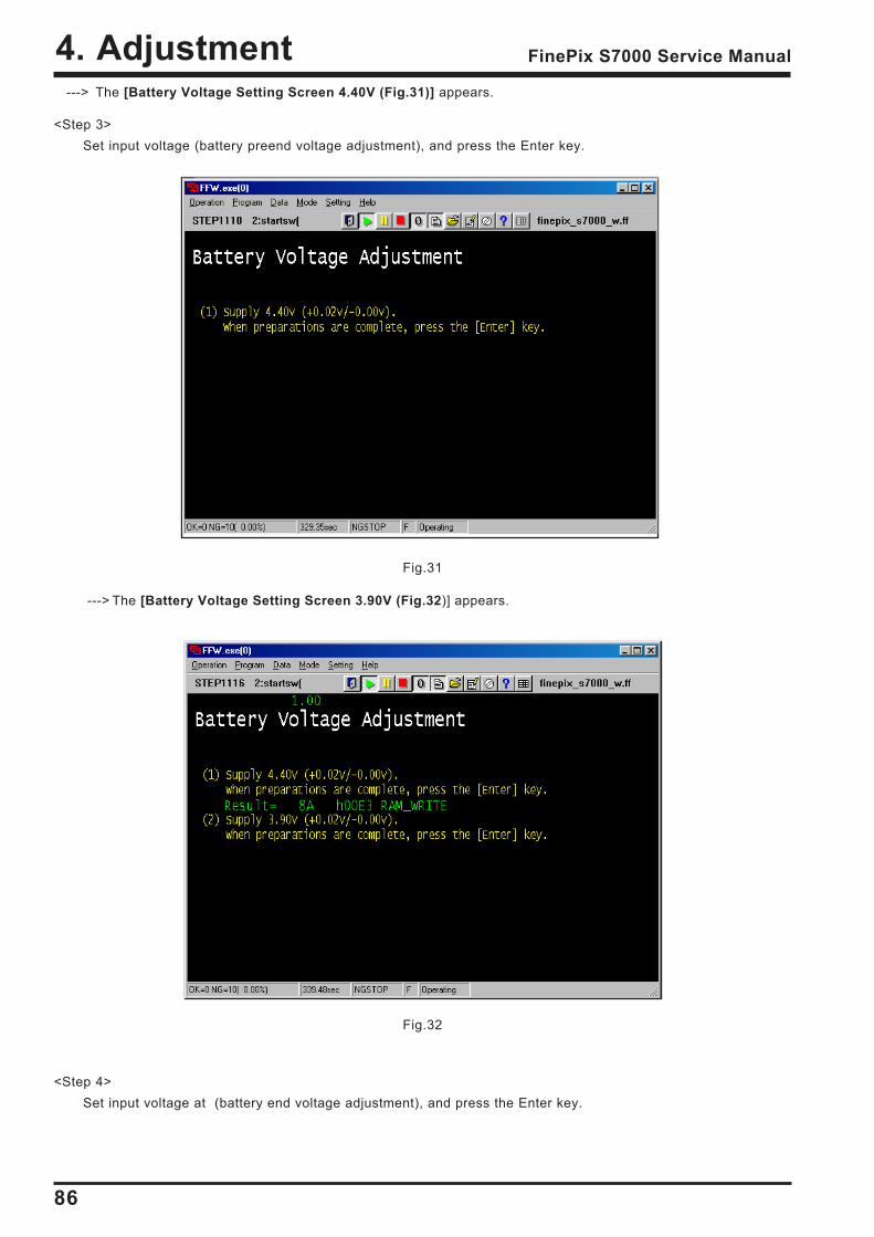
86
4. Adjustment FinePix S7000 Service Manual
Fig.31
---> The [Battery Voltage Setting Screen 4.40V (Fig.31)] appears.
<Step 3>Set input voltage (battery preend voltage adjustment), and press the Enter key.
---> The [Battery Voltage Setting Screen 3.90V (Fig.32)] appears.
Fig.32
<Step 4>Set input voltage at (battery end voltage adjustment), and press the Enter key.
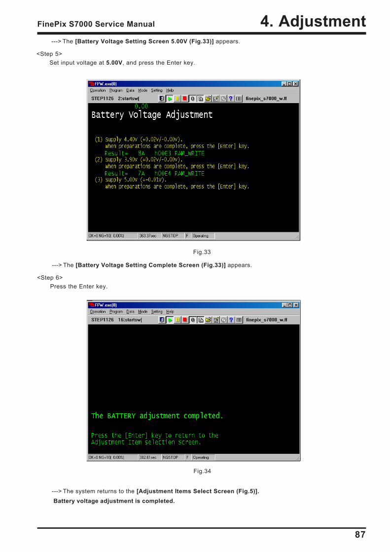
87
4. AdjustmentFinePix S7000 Service Manual
Fig.34
---> The [Battery Voltage Setting Screen 5.00V (Fig.33)] appears.
<Step 5>Set input voltage at 5.00V, and press the Enter key.
Fig.33
---> The [Battery Voltage Setting Complete Screen (Fig.33)] appears.
<Step 6>Press the Enter key.
---> The system returns to the [Adjustment Items Select Screen (Fig.5)]. Battery voltage adjustment is completed.
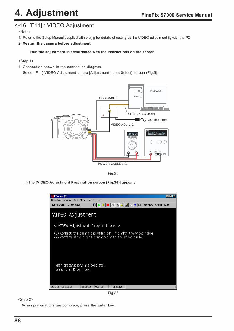
88
4. Adjustment FinePix S7000 Service Manual
Fig.36
Fig.35
4-16. [F11] : VIDEO Adjustment<Note>1. Refer to the Setup Manual supplied with the jig for details of setting up the VIDEO adjustment jig with the PC.2. Restart the camera before adjustment.
<Step 1>1. Connect as shown in the connection diagram.
Select [F11] VIDEO Adjustment on the [Adjustment Items Select] screen (Fig.5).
--->The [VIDEO Adjustment Preparation screen (Fig.36)] appears.
Run the adjustment in accordance with the instructions on the screen.
AC-100-240V
To PCI-2746C Board
VIDEO ADJ. JIG
USB CABLE
POWER CABLE JIG
<Step 2>When preparations are complete, press the Enter key.
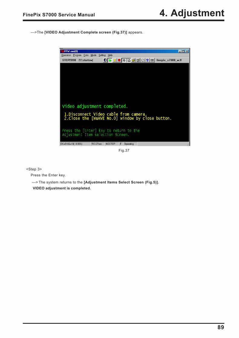
89
4. AdjustmentFinePix S7000 Service Manual
--->The [VIDEO Adjustment Complete screen (Fig.37)] appears.
Fig.37
<Step 3>Press the Enter key.
---> The system returns to the [Adjustment Items Select Screen (Fig.5)]. VIDEO adjustment is completed.
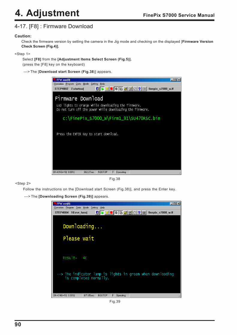
90
4. Adjustment FinePix S7000 Service Manual
Fig.38
4-17. [F8] : Firmware DownloadCaution:
Check the firmware version by setting the camera in the Jig mode and checking on the displayed [Firmware VersionCheck Screen (Fig.4)].
<Step 1>Select [F8] from the [Adjustment Items Select Screen (Fig.5)].(press the [F8] key on the keyboard)
---> The [Download start Screen (Fig.38)] appears.
<Step 2>Follow the instructions on the [Download start Screen (Fig.38)], and press the Enter key.
---> The [Downloading Screen (Fig.39)] appears.
Fig.39
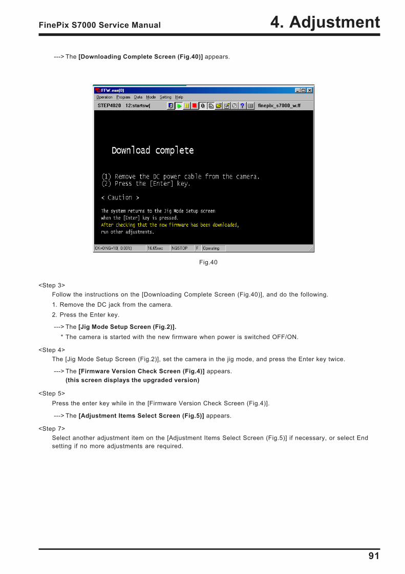
91
4. AdjustmentFinePix S7000 Service Manual
Fig.40
---> The [Downloading Complete Screen (Fig.40)] appears.
<Step 3>Follow the instructions on the [Downloading Complete Screen (Fig.40)], and do the following.1. Remove the DC jack from the camera.2. Press the Enter key.
---> The [Jig Mode Setup Screen (Fig.2)]. * The camera is started with the new firmware when power is switched OFF/ON.
<Step 4>The [Jig Mode Setup Screen (Fig.2)], set the camera in the jig mode, and press the Enter key twice.
---> The [Firmware Version Check Screen (Fig.4)] appears.(this screen displays the upgraded version)
<Step 5>Press the enter key while in the [Firmware Version Check Screen (Fig.4)].
---> The [Adjustment Items Select Screen (Fig.5)] appears.
<Step 7>Select another adjustment item on the [Adjustment Items Select Screen (Fig.5)] if necessary, or select Endsetting if no more adjustments are required.
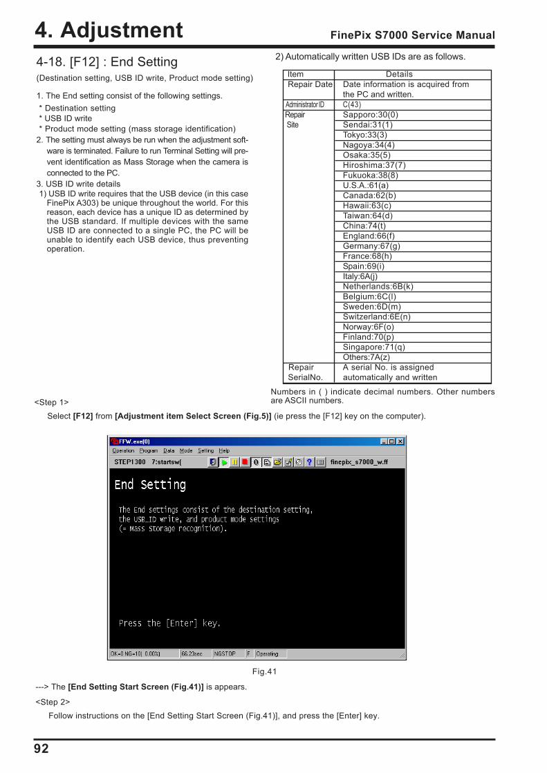
92
4. Adjustment FinePix S7000 Service Manual
Fig.41
4-18. [F12] : End Setting(Destination setting, USB ID write, Product mode setting)
1. The End setting consist of the following settings.* Destination setting* USB ID write* Product mode setting (mass storage identification)
2. The setting must always be run when the adjustment soft-ware is terminated. Failure to run Terminal Setting will pre-vent identification as Mass Storage when the camera isconnected to the PC.
3. USB ID write details1) USB ID write requires that the USB device (in this case
FinePix A303) be unique throughout the world. For thisreason, each device has a unique ID as determined bythe USB standard. If multiple devices with the sameUSB ID are connected to a single PC, the PC will beunable to identify each USB device, thus preventingoperation.
<Step 1>Select [F12] from [Adjustment item Select Screen (Fig.5)] (ie press the [F12] key on the computer).
---> The [End Setting Start Screen (Fig.41)] is appears.
<Step 2>Follow instructions on the [End Setting Start Screen (Fig.41)], and press the [Enter] key.
Numbers in ( ) indicate decimal numbers. Other numbersare ASCII numbers.
2) Automatically written USB IDs are as follows.
Item Details Repair Date Date information is acquired from
the PC and written. Administrator ID C(43) Repair Sapporo:30(0) Site Sendai:31(1)
Tokyo:33(3)Nagoya:34(4)Osaka:35(5)Hiroshima:37(7)Fukuoka:38(8)U.S.A.:61(a)Canada:62(b)Hawaii:63(c)Taiwan:64(d)China:74(t)England:66(f)Germany:67(g)France:68(h)Spain:69(i)Italy:6A(j)Netherlands:6B(k)Belgium:6C(l)Sweden:6D(m)Switzerland:6E(n)Norway:6F(o)Finland:70(p)Singapore:71(q)Others:7A(z)
Repair A serial No. is assigned SerialNo. automatically and written
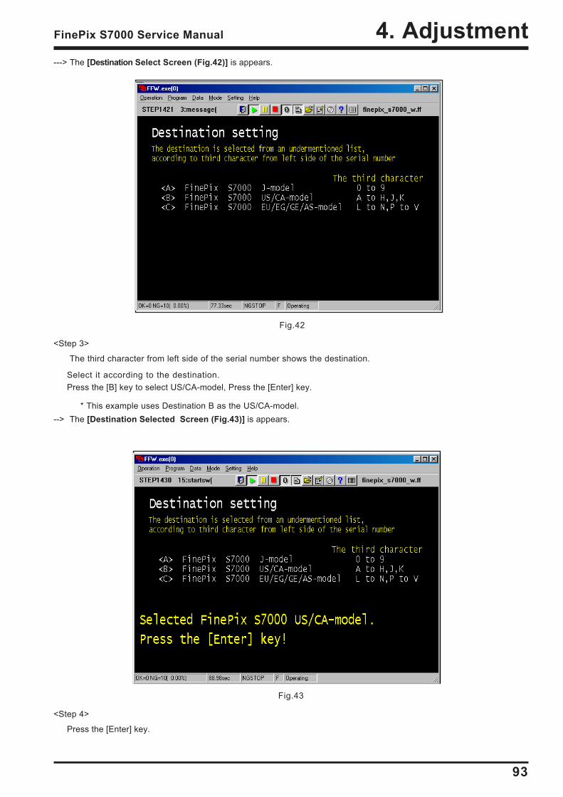
93
4. AdjustmentFinePix S7000 Service Manual
Fig.42
---> The [Destination Select Screen (Fig.42)] is appears.
Fig.43
<Step 4>
Press the [Enter] key.
<Step 3>
The third character from left side of the serial number shows the destination.
Select it according to the destination.Press the [B] key to select US/CA-model, Press the [Enter] key.
* This example uses Destination B as the US/CA-model.--> The [Destination Selected Screen (Fig.43)] is appears.
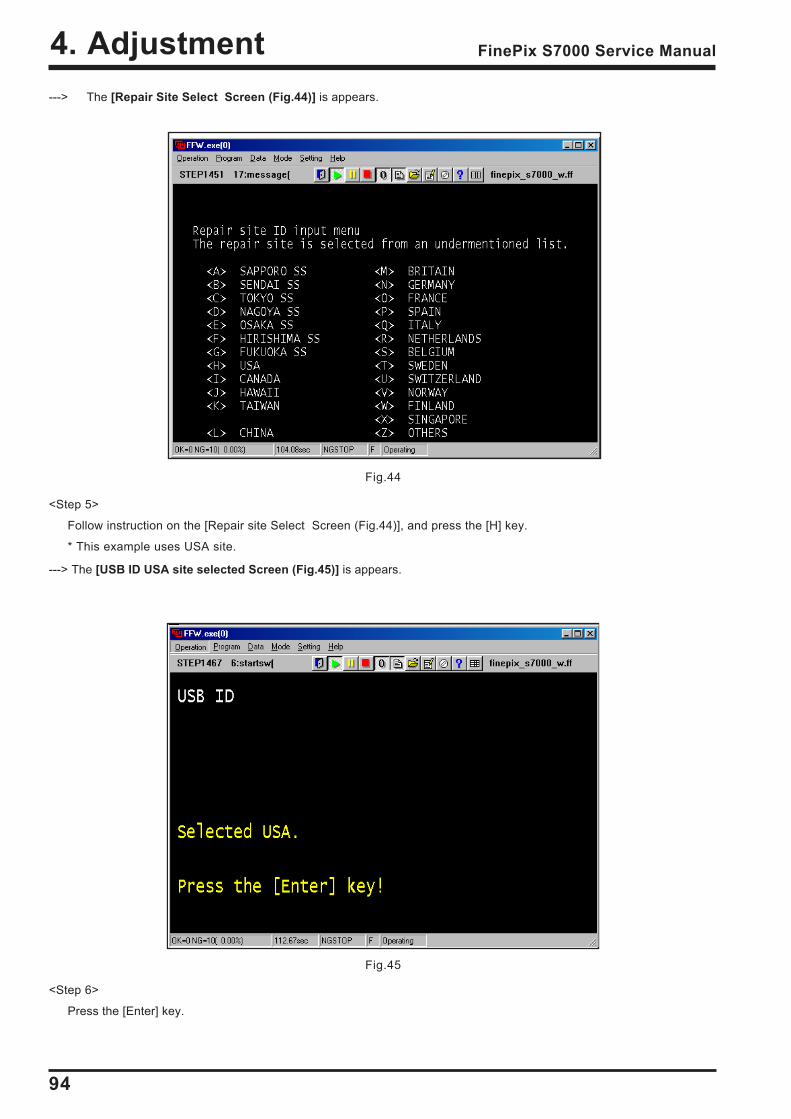
94
4. Adjustment FinePix S7000 Service Manual
Fig.44
Fig.45
---> The [Repair Site Select Screen (Fig.44)] is appears.
<Step 5>
Follow instruction on the [Repair site Select Screen (Fig.44)], and press the [H] key.
* This example uses USA site.
---> The [USB ID USA site selected Screen (Fig.45)] is appears.
<Step 6>
Press the [Enter] key.
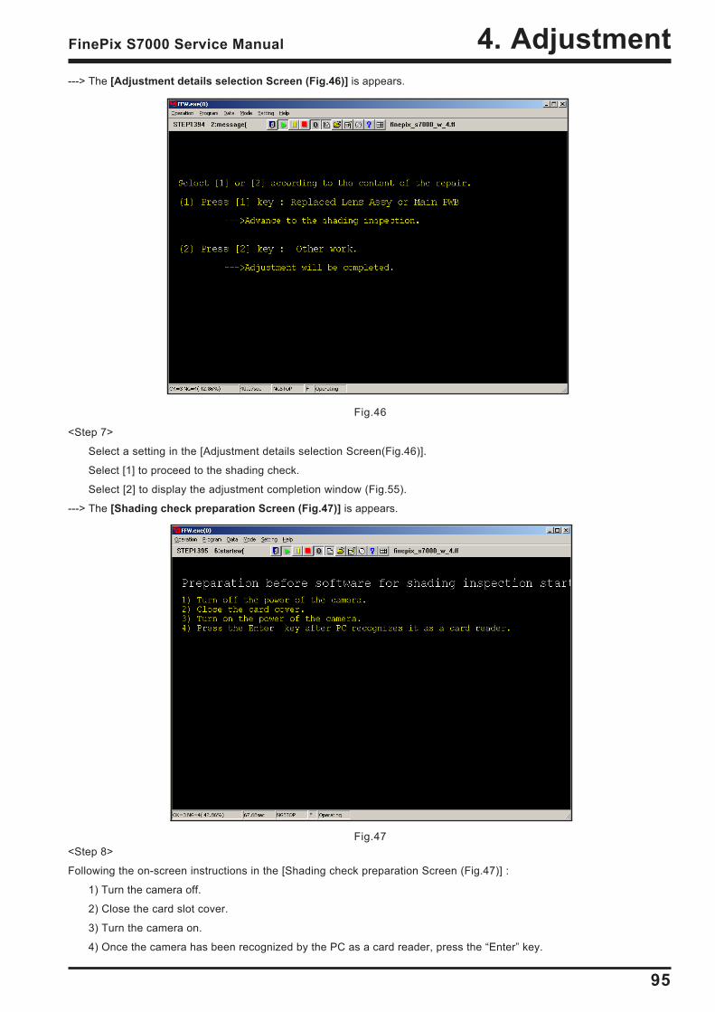
95
4. AdjustmentFinePix S7000 Service Manual
Fig.46
Fig.47
---> The [Adjustment details selection Screen (Fig.46)] is appears.
<Step 7>
Select a setting in the [Adjustment details selection Screen(Fig.46)].
Select [1] to proceed to the shading check.
Select [2] to display the adjustment completion window (Fig.55).
---> The [Shading check preparation Screen (Fig.47)] is appears.
<Step 8>
Following the on-screen instructions in the [Shading check preparation Screen (Fig.47)] :
1) Turn the camera off.
2) Close the card slot cover.
3) Turn the camera on.
4) Once the camera has been recognized by the PC as a card reader, press the Enter key.
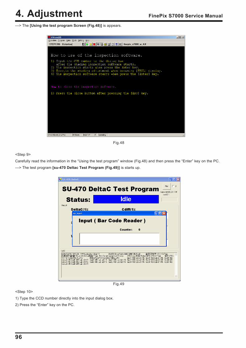
96
4. Adjustment FinePix S7000 Service Manual
---> The [Using the test program Screen (Fig.48)] is appears.
<Step 9>
Carefully read the information in the Using the test program window (Fig.48) and then press the Enter key on the PC.
---> The test program [su-470 Deltac Test Program (Fig.49)] is starts up.
<Step 10>
1) Type the CCD number directly into the input dialog box.
2) Press the Enter key on the PC.
Fig.48
Fig.49
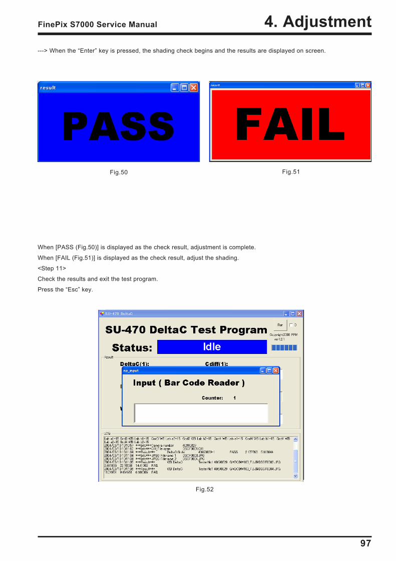
97
4. AdjustmentFinePix S7000 Service Manual
---> When the Enter key is pressed, the shading check begins and the results are displayed on screen.
When [PASS (Fig.50)] is displayed as the check result, adjustment is complete.
When [FAIL (Fig.51)] is displayed as the check result, adjust the shading.
<Step 11>
Check the results and exit the test program.
Press the Esc key.
Fig.50 Fig.51
Fig.52
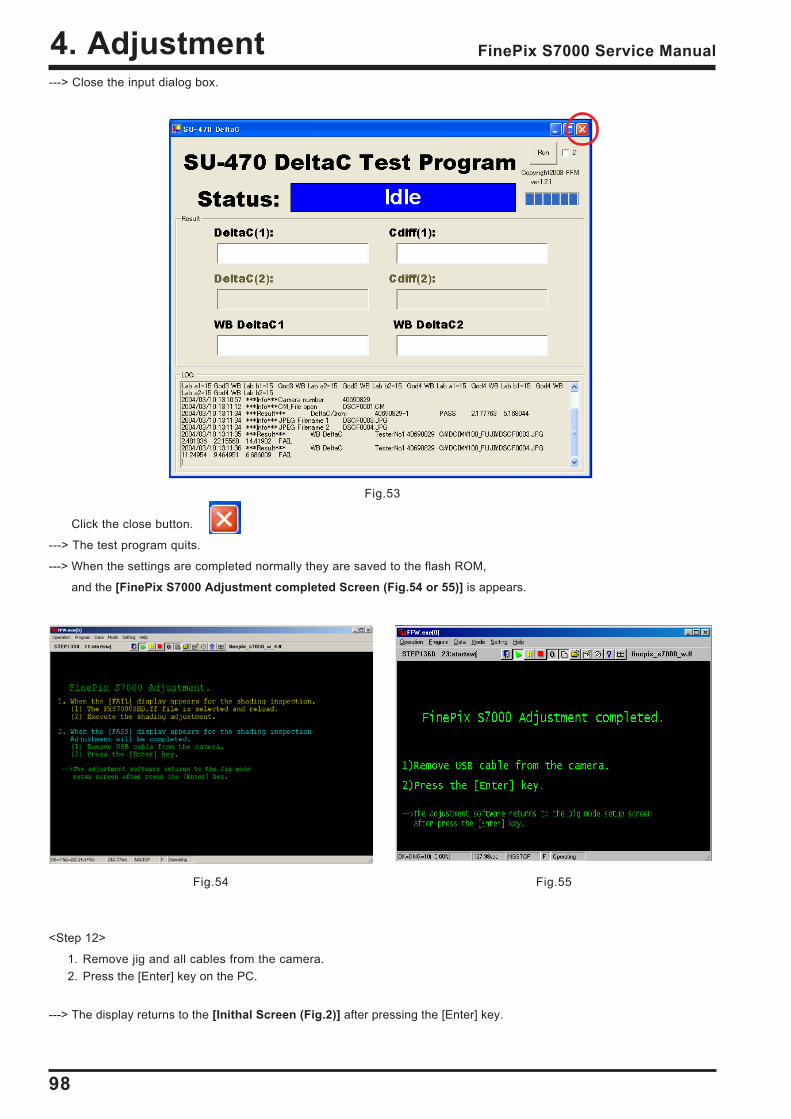
98
4. Adjustment FinePix S7000 Service Manual
Fig.54 Fig.55
---> Close the input dialog box.
Click the close button.
---> The test program quits.
---> When the settings are completed normally they are saved to the flash ROM,
and the [FinePix S7000 Adjustment completed Screen (Fig.54 or 55)] is appears.
Fig.53
<Step 12>
1. Remove jig and all cables from the camera.2. Press the [Enter] key on the PC.
---> The display returns to the [Inithal Screen (Fig.2)] after pressing the [Enter] key.
99
4. AdjustmentFinePix S7000 Service Manual
4-19. Shading adjustment
* Only adjust the shading when FAIL is displayed in the shading check.
<Step 1> (Exiting the general adjustment program and switching to the shading adjustment program)
Click Programs -> Select in the menu bar.
<Step 2>
Select FXS7000SHD_J.ff in the user program selection window and then click Open.
Fig.56
Fig.57
100
4. Adjustment FinePix S7000 Service Manual
Fig.58
<Step 3>
(1) Click Programs -> Reload in the menu bar.
(2) Click the zero button.
101
4. AdjustmentFinePix S7000 Service Manual
Fig.59
Fig.60
---> The shading adjustment startup window appears.
<Step 4>
Proceed as directed by the on-screen instructions or press the Enter key.
---> The precautions window appears.
<Step 5>
(1) Insert an xD-Picture Card with a capacity of at least 256MB into the camera.
* The adjustment program formats the card before starting the adjustment.
Take care not to insert a user card by mistake.
(2) When the preparations are completed, press the Enter key.
102
4. Adjustment FinePix S7000 Service Manual
Fig.61
Fig.62
---> The jig mode settings window appears.
<Step 6>
(1) Start the camera up in jig mode as directed by the on-screen instructions.
(2) Press the Enter key.
---> A format confirmation message appears.
<Step 7>
Check the details and then press the Enter key.
103
4. AdjustmentFinePix S7000 Service Manual
Fig.63
Fig.64
---> Once formatting is completed, the adjustment preparation window appears.
<Step 8>
(1) Set the camera in front of the pattern box as directed by the on-screen instructions
(2) Press the Enter key.
---> Shading correction begins.
---> Once correction is completed, the checking preparation window appears.
<Step 9>
(1) Start the camera up in DSC mode as directed by the on-screen instructions.
(2) Once the PC has recognized the camera as a card reader, press the Enter key.
104
4. Adjustment FinePix S7000 Service Manual
Fig.65
Fig.66 Fig.67
---> The shading check program starts up and checking begins.
---> When checking is completed, the results are displayed.
<Step 10>
Check the results of the checking and then exit the check program.
* The check program (deltac2.exe) automatically readjusts the shading as required based on the check results. Even wherePASS is displayed as the check result, the results of readjustment may be recorded in the next process. For thisreason, completion settings must always be specified.
If FAIL is displayed as the check result, there is a lens defect. Replace the lens and then perform all the adjustments again.
105
4. AdjustmentFinePix S7000 Service Manual
Fig.68
Fig.69 Fig.70
---> The completion settings preparation window appears.
<Step 11>
(1) Start the camera up in jig mode as directed by the on-screen instructions.
(2) Press the Enter key.
---> Once the adjustment results have been recorded, the completion screen appears.
<Step 12-1>
(1) Exit the adjustment program.
Select Operation -> Exit to exit the adjustment program.
<Step 12-2>
(1) Replace the lens and then perform all the adjustmentsagain.
106
5. Inspection FinePix S7000 Service Manual
5. Inspection5-1. Required Measuring Equipment
5-3. Inspection and Factory Settings
5-2. Connection of Measuring Equipment
Measuring equipment RemarksPower supply AC adapter (AC-5V), Regurated power supplyDigital voltmeter For general useAmmeter For general use (able to measure 1mA or less)power cable jig For general usexD-Picture card For general use
Sequemnce Item Mode Preparations for adjustment(measurement points, subject, other)
Method of adjustment(VRs, waveforms, required values)
Measuringequipment and jigs
Measurement points(VRs, positions)
1
2
3
4
Check appear-ance
Power supplyswitch
Check Moviemode shock noise
Check macrophotographyCheck focus
Visual check of camera
(1) Place battery in camera.(2) Insert card and close card
cover.(3) Set mode dial to still
photography mode.(4) Turn power ON.
(5) If the date set messageappears, press Cancel.
(1) Apply an appropriateshock to the camera.
* Do not apply shockdirectly to the lens or cardcover.
(1) Macro photographydistance (approximately10~80cm).
(2) Press shutter button totake photographs.
No problem with click actionof switches.No dust or fogging of finder.
(1) Applied voltage:4 AAbatteries or equivalent jigmay be used.
(2) Recording check card.
(4) Power supply LED isgreen and beeps.
(5) Live image screen and textdisplay in LCD monitor.
(1) No problem with displayon LCD monitor.Restoration possibledespite disruption of sync.
(1) Macro icon appears inLCD monitor.
(2) LED beside viewfinderchanges from green toorange (recording) togreen.
AutophotographyLCD_ON
AutophotographyLCD_ON
AutophotographyLCD_ON
LCD monitor
Ammeter Regurated powersupply
Volt meter
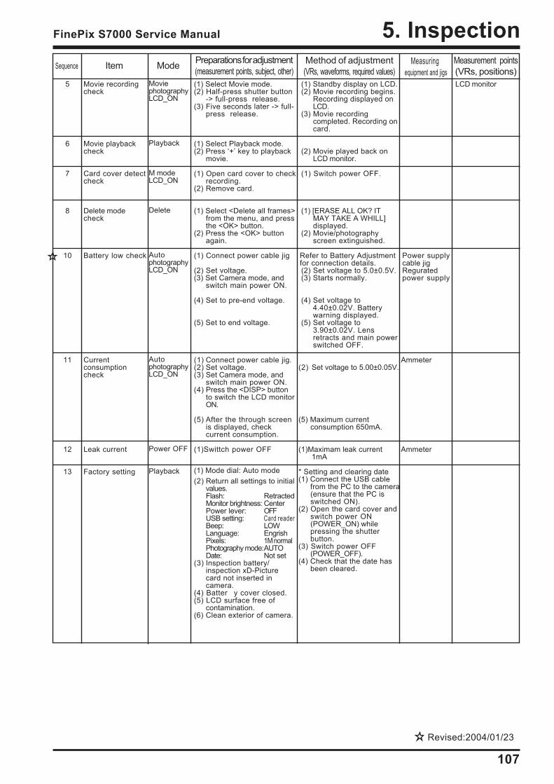
107
5. InspectionFinePix S7000 Service Manual
5
6
7
8
10
11
12
13
Movie recordingcheck
Movie playbackcheck
Card cover detectcheck
Delete modecheck
Battery low check
Currentconsumptioncheck
Leak current
Factory setting
MoviephotographyLCD_ON
Playback
M modeLCD_ON
Delete
AutophotographyLCD_ON
AutophotographyLCD_ON
Power OFF
Playback
(1) Select Movie mode.(2) Half-press shutter button
-> full-press release.(3) Five seconds later -> full-
press release.
(1) Select Playback mode.(2) Press + key to playback
movie.
(1) Open card cover to checkrecording.
(2) Remove card.
(1) Select <Delete all frames>from the menu, and pressthe <OK> button.
(2) Press the <OK> buttonagain.
(1) Connect power cable jig
(2) Set voltage.(3) Set Camera mode, and
switch main power ON.
(4) Set to pre-end voltage.
(5) Set to end voltage.
(1) Connect power cable jig.(2) Set voltage.(3) Set Camera mode, and
switch main power ON.(4) Press the <DISP> button
to switch the LCD monitorON.
(5) After the through screenis displayed, checkcurrent consumption.
(1)Swittch power OFF
(1) Mode dial: Auto mode(2) Return all settings to initial
values.Flash: RetractedMonitor brightness: CenterPower lever: OFFUSB setting: Card readerBeep: LOWLanguage: EngrishPixels: 1M normalPhotography mode:AUTODate: Not set
(3) Inspection battery/inspection xD-Picturecard not inserted incamera.
(4) Batter y cover closed.(5) LCD surface free of
contamination.(6) Clean exterior of camera.
(1) Standby display on LCD.(2) Movie recording begins.
Recording displayed onLCD.
(3) Movie recordingcompleted. Recording oncard.
(2) Movie played back onLCD monitor.
(1) Switch power OFF.
(1) [ERASE ALL OK? ITMAY TAKE A WHILL]displayed.
(2) Movie/photographyscreen extinguished.
Refer to Battery Adjustmentfor connection details.(2) Set voltage to 5.0±0.5V.(3) Starts normally.
(4) Set voltage to4.40±0.02V. Batterywarning displayed.
(5) Set voltage to3.90±0.02V. Lensretracts and main powerswitched OFF.
(2) Set voltage to 5.00±0.05V.
(5) Maximum currentconsumption 650mA.
(1)Maximam leak current1mA
* Setting and clearing date(1) Connect the USB cable
from the PC to the camera(ensure that the PC isswitched ON).
(2) Open the card cover andswitch power ON(POWER_ON) whilepressing the shutterbutton.
(3) Switch power OFF(POWER_OFF).
(4) Check that the date hasbeen cleared.
LCD monitor
Power supplycable jigReguratedpower supply
Ammeter
Ammeter
Sequence Item Mode Preparations for adjustment(measurement points, subject, other)
Method of adjustment(VRs, waveforms, required values)
Measuringequipment and jigs
Measurement points(VRs, positions)
Revised:2004/01/23
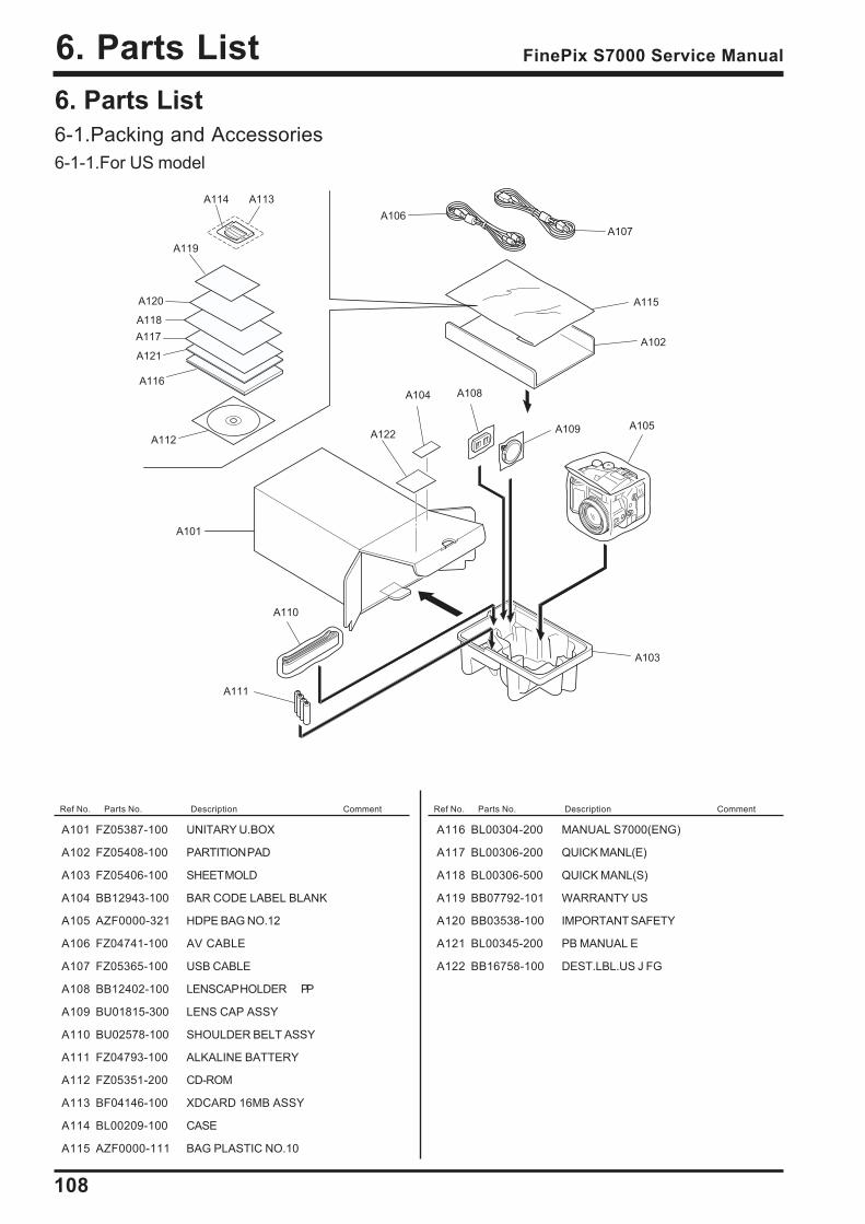
108
6. Parts List FinePix S7000 Service Manual
Ref No. Parts No. Description Comment Ref No. Parts No. Description Comment
6. Parts List6-1.Packing and Accessories6-1-1.For US model
A101
A102
A103
A104
A105
A106
A107
A108
A111
A112A122
A121
A120
A119
A118
A117
A116
A115
A114 A113
A109
A110
A101 FZ05387-100 UNITARY U.BOX
A102 FZ05408-100 PARTITION PAD
A103 FZ05406-100 SHEET MOLD
A104 BB12943-100 BAR CODE LABEL BLANK
A105 AZF0000-321 HDPE BAG NO.12
A106 FZ04741-100 AV CABLE
A107 FZ05365-100 USB CABLE
A108 BB12402-100 LENSCAP HOLDER PP
A109 BU01815-300 LENS CAP ASSY
A110 BU02578-100 SHOULDER BELT ASSY
A111 FZ04793-100 ALKALINE BATTERY
A112 FZ05351-200 CD-ROM
A113 BF04146-100 XDCARD 16MB ASSY
A114 BL00209-100 CASE
A115 AZF0000-111 BAG PLASTIC NO.10
A116 BL00304-200 MANUAL S7000(ENG)
A117 BL00306-200 QUICK MANL(E)
A118 BL00306-500 QUICK MANL(S)
A119 BB07792-101 WARRANTY US
A120 BB03538-100 IMPORTANT SAFETY
A121 BL00345-200 PB MANUAL E
A122 BB16758-100 DEST.LBL.US J FG

109
6. Parts ListFinePix S7000 Service Manual
Ref No. Parts No. Description Comment Ref No. Parts No. Description Comment
6-1-2.For CA model
A101
A102
A103
A104
A105
A106
A107
A108
A111
A112
A122
A121
A120
A119
A118
A117
A116
A115
A114 A113
A109
A110
A101 FZ05387-100 UNITARY U.BOX
A102 FZ05408-100 PARTITION PAD
A103 FZ05406-100 SHEET MOLD
A104 BB12943-100 BAR CODE LABEL BLANK
A105 AZF0000-321 HDPE BAG NO.12
A106 FZ04741-100 AV CABLE
A107 FZ05365-100 USB CABLE
A108 BB12402-100 LENSCAP HOLDER PP
A109 BU01815-300 LENS CAP ASSY
A110 BU02578-100 SHOULDER BELT ASSY
A111 FZ04793-100 ALKALINE BATTERY
A112 FZ05351-200 CD-ROM
A113 BF04146-100 XDCARD 16MB ASSY
A114 BL00209-100 CASE
A115 AZF0000-111 BAG PLASTIC NO.10
A116 BL00304-200 MANUAL S7000(ENG)
A117 BL00304-300 MANUAL S7000(FRE)
A118 BL00306-200 QUICK MANL(E)
A119 BL00306-300 QUICK MANL(F)
A120 BL00345-200 PB MANUAL E
A121 BL00345-300 PB MANUAL F
A122 BB16758-400 DEST.LBL.CA J FG
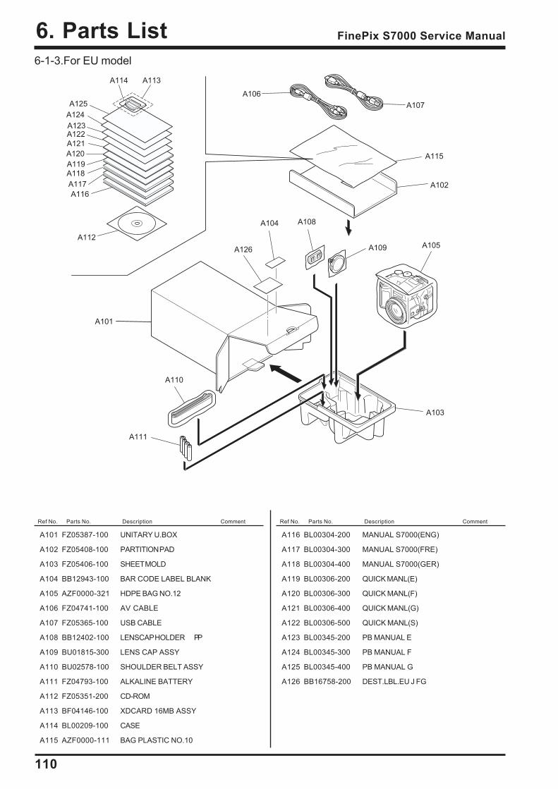
110
6. Parts List FinePix S7000 Service Manual
6-1-3.For EU model
Ref No. Parts No. Description Comment Ref No. Parts No. Description Comment
A101
A102
A103
A104
A105
A106
A107
A108
A111
A112
A120
A119
A118
A117
A116
A115
A109
A110
A121
A122A123
A124
A125
A126
A114 A113
A101 FZ05387-100 UNITARY U.BOX
A102 FZ05408-100 PARTITION PAD
A103 FZ05406-100 SHEET MOLD
A104 BB12943-100 BAR CODE LABEL BLANK
A105 AZF0000-321 HDPE BAG NO.12
A106 FZ04741-100 AV CABLE
A107 FZ05365-100 USB CABLE
A108 BB12402-100 LENSCAP HOLDER PP
A109 BU01815-300 LENS CAP ASSY
A110 BU02578-100 SHOULDER BELT ASSY
A111 FZ04793-100 ALKALINE BATTERY
A112 FZ05351-200 CD-ROM
A113 BF04146-100 XDCARD 16MB ASSY
A114 BL00209-100 CASE
A115 AZF0000-111 BAG PLASTIC NO.10
A116 BL00304-200 MANUAL S7000(ENG)
A117 BL00304-300 MANUAL S7000(FRE)
A118 BL00304-400 MANUAL S7000(GER)
A119 BL00306-200 QUICK MANL(E)
A120 BL00306-300 QUICK MANL(F)
A121 BL00306-400 QUICK MANL(G)
A122 BL00306-500 QUICK MANL(S)
A123 BL00345-200 PB MANUAL E
A124 BL00345-300 PB MANUAL F
A125 BL00345-400 PB MANUAL G
A126 BB16758-200 DEST.LBL.EU J FG
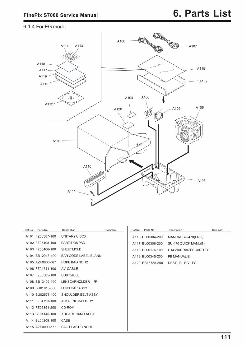
111
6. Parts ListFinePix S7000 Service Manual
Ref No. Parts No. Description Comment Ref No. Parts No. Description Comment
6-1-4.For EG model
A101
A102
A103
A104
A105
A106
A107
A108
A111
A112
A120
A119
A118
A117
A116
A115
A114 A113
A109
A110
A101 FZ05387-100 UNITARY U.BOX
A102 FZ05408-100 PARTITION PAD
A103 FZ05406-100 SHEET MOLD
A104 BB12943-100 BAR CODE LABEL BLANK
A105 AZF0000-321 HDPE BAG NO.12
A106 FZ04741-100 AV CABLE
A107 FZ05365-100 USB CABLE
A108 BB12402-100 LENSCAP HOLDER PP
A109 BU01815-300 LENS CAP ASSY
A110 BU02578-100 SHOULDER BELT ASSY
A111 FZ04793-100 ALKALINE BATTERY
A112 FZ05351-200 CD-ROM
A113 BF04146-100 XDCARD 16MB ASSY
A114 BL00209-100 CASE
A115 AZF0000-111 BAG PLASTIC NO.10
A116 BL00304-200 MANUAL SU-470(ENG)
A117 BL00306-200 SU-470 QUICK MANL(E)
A118 BL00176-100 H14 WARRANTY CARD EG
A119 BL00345-200 PB MANUAL E
A120 BB16758-300 DEST.LBL.EG J FG
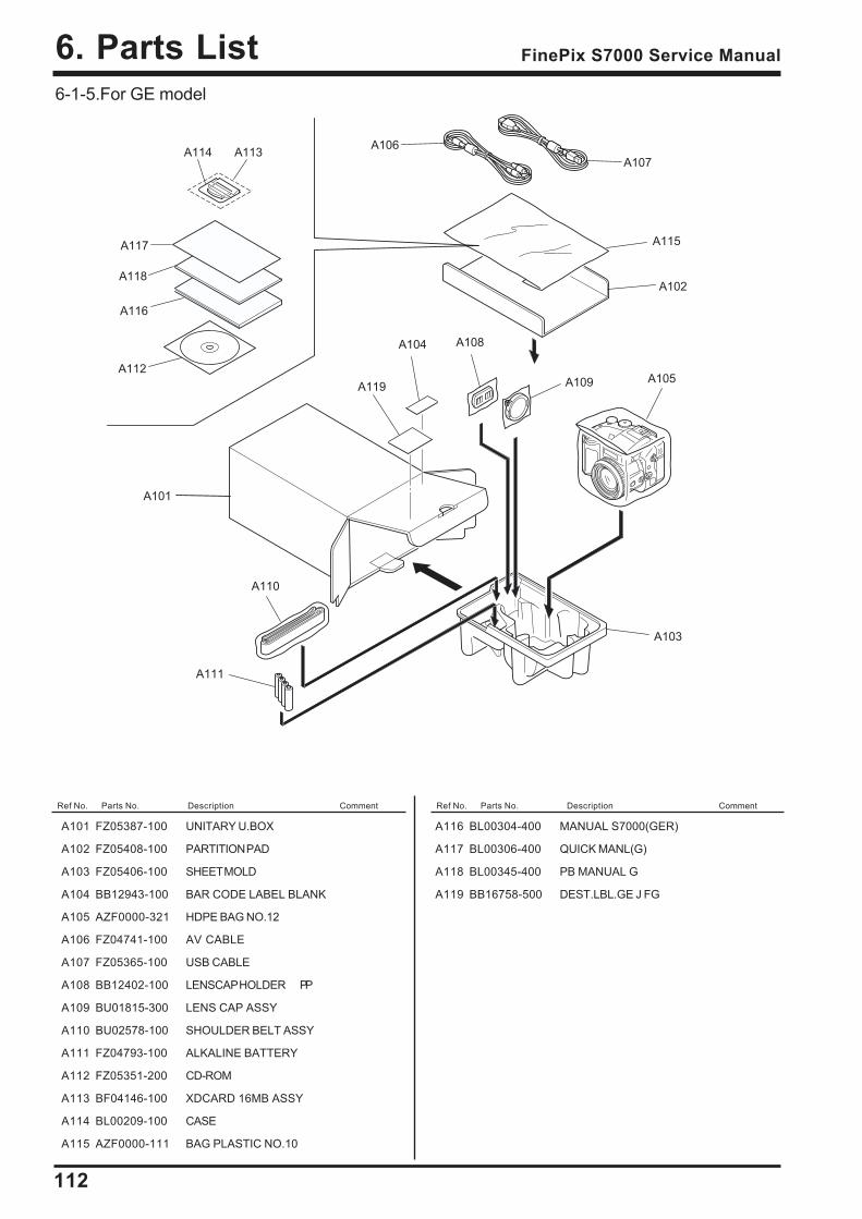
112
6. Parts List FinePix S7000 Service Manual
6-1-5.For GE model
Ref No. Parts No. Description Comment Ref No. Parts No. Description Comment
A101
A102
A103
A104
A105
A106
A107
A108
A111
A112
A119
A118
A117
A116
A115
A114 A113
A109
A110
A101 FZ05387-100 UNITARY U.BOX
A102 FZ05408-100 PARTITION PAD
A103 FZ05406-100 SHEET MOLD
A104 BB12943-100 BAR CODE LABEL BLANK
A105 AZF0000-321 HDPE BAG NO.12
A106 FZ04741-100 AV CABLE
A107 FZ05365-100 USB CABLE
A108 BB12402-100 LENSCAP HOLDER PP
A109 BU01815-300 LENS CAP ASSY
A110 BU02578-100 SHOULDER BELT ASSY
A111 FZ04793-100 ALKALINE BATTERY
A112 FZ05351-200 CD-ROM
A113 BF04146-100 XDCARD 16MB ASSY
A114 BL00209-100 CASE
A115 AZF0000-111 BAG PLASTIC NO.10
A116 BL00304-400 MANUAL S7000(GER)
A117 BL00306-400 QUICK MANL(G)
A118 BL00345-400 PB MANUAL G
A119 BB16758-500 DEST.LBL.GE J FG
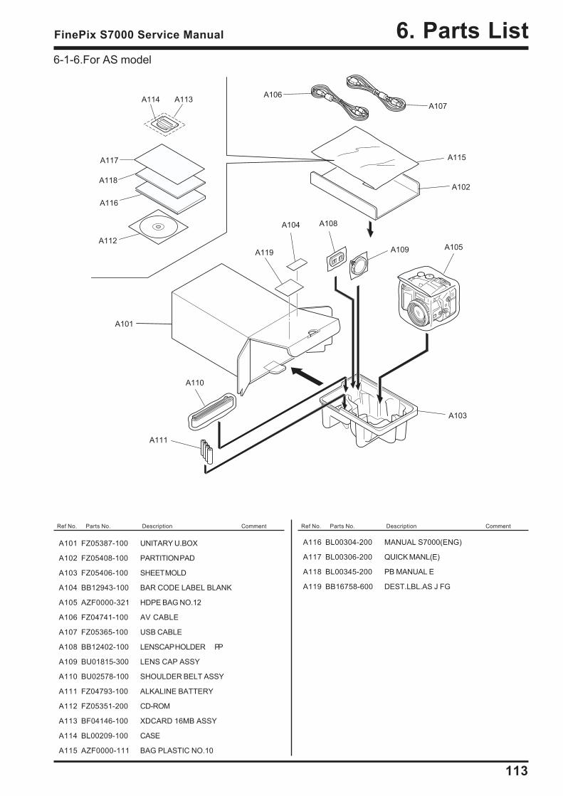
113
6. Parts ListFinePix S7000 Service Manual
6-1-6.For AS model
Ref No. Parts No. Description Comment Ref No. Parts No. Description Comment
A101
A102
A103
A104
A105
A106
A107
A108
A111
A112
A119
A118
A117
A116
A115
A114 A113
A109
A110
A101 FZ05387-100 UNITARY U.BOX
A102 FZ05408-100 PARTITION PAD
A103 FZ05406-100 SHEET MOLD
A104 BB12943-100 BAR CODE LABEL BLANK
A105 AZF0000-321 HDPE BAG NO.12
A106 FZ04741-100 AV CABLE
A107 FZ05365-100 USB CABLE
A108 BB12402-100 LENSCAP HOLDER PP
A109 BU01815-300 LENS CAP ASSY
A110 BU02578-100 SHOULDER BELT ASSY
A111 FZ04793-100 ALKALINE BATTERY
A112 FZ05351-200 CD-ROM
A113 BF04146-100 XDCARD 16MB ASSY
A114 BL00209-100 CASE
A115 AZF0000-111 BAG PLASTIC NO.10
A116 BL00304-200 MANUAL S7000(ENG)
A117 BL00306-200 QUICK MANL(E)
A118 BL00345-200 PB MANUAL E
A119 BB16758-600 DEST.LBL.AS J FG
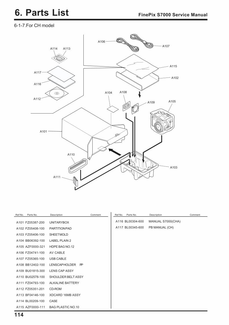
114
6. Parts List FinePix S7000 Service Manual
6-1-7.For CH model
Ref No. Parts No. Description Comment Ref No. Parts No. Description Comment
A101 FZ05387-200 UNITARYBOX
A102 FZ05408-100 PARTITION PAD
A103 FZ05406-100 SHEET MOLD
A104 BB06392-100 LABEL PLAIN 2
A105 AZF0000-321 HDPE BAG NO.12
A106 FZ04741-100 AV CABLE
A107 FZ05365-100 USB CABLE
A108 BB12402-100 LENSCAP HOLDER PP
A109 BU01815-300 LENS CAP ASSY
A110 BU02578-100 SHOULDER BELT ASSY
A111 FZ04793-100 ALKALINE BATTERY
A112 FZ05351-201 CD-ROM
A113 BF04146-100 XDCARD 16MB ASSY
A114 BL00209-100 CASE
A115 AZF0000-111 BAG PLASTIC NO.10
A116 BL00304-600 MANUAL S7000(CHA)
A117 BL00345-600 PB MANUAL (CH)
A101
A102
A103
A104
A105
A106
A107
A108
A111
A112
A117
A116
A115
A114 A113
A109
A110
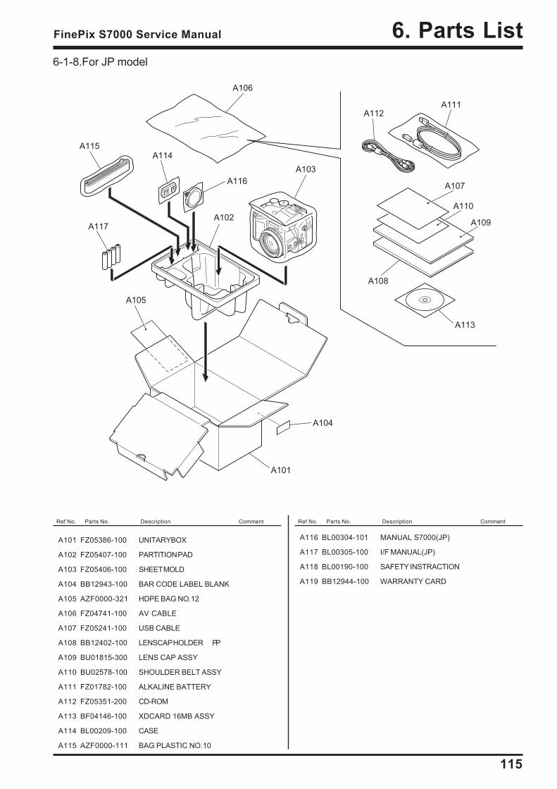
115
6. Parts ListFinePix S7000 Service Manual
Ref No. Parts No. Description Comment Ref No. Parts No. Description Comment
A101 FZ05386-100 UNITARYBOX
A102 FZ05407-100 PARTITION PAD
A103 FZ05406-100 SHEET MOLD
A104 BB12943-100 BAR CODE LABEL BLANK
A105 AZF0000-321 HDPE BAG NO.12
A106 FZ04741-100 AV CABLE
A107 FZ05241-100 USB CABLE
A108 BB12402-100 LENSCAP HOLDER PP
A109 BU01815-300 LENS CAP ASSY
A110 BU02578-100 SHOULDER BELT ASSY
A111 FZ01782-100 ALKALINE BATTERY
A112 FZ05351-200 CD-ROM
A113 BF04146-100 XDCARD 16MB ASSY
A114 BL00209-100 CASE
A115 AZF0000-111 BAG PLASTIC NO.10
A116 BL00304-101 MANUAL S7000(JP)
A117 BL00305-100 I/F MANUAL(JP)
A118 BL00190-100 SAFETY INSTRACTION
A119 BB12944-100 WARRANTY CARD
6-1-8.For JP model
A101
A106
A103
A108
A111
A109
A105
A102
A112
A116
A114
A104
A107
A110
A113
A115
A117
116
6. Parts List FinePix S7000 Service Manual
Ref No. Parts No. Description Comment Ref No. Parts No. Description Comment
6-2.Cabinet F block
M214
M210
M211
M216
M209
M204
M207
M202
M201
M202 M215
M203
M208
M205
M206
M212
M213
M210
M217
M218
M219
M221
M220
M222
ZS
ZS
M201 BU02856-100 LENS CABI ASSY
M202 BB13148-100 BL SCREW M1.7X3.5BC
M203 BU02853-100 F CABI ASSY
M204 FZ04690-100 MIC ASSY
M205 FZ05223-100 SIDE MODULE UNIT
M206 UBFZZ0020A DC JACK COVER
M207 BB13205-100 STRAP R
M208 BB13148-200 BL SCREW M1.7X5.0BC
M209 BU02933-100 Y-525 LENS CONST
M210 BB13149-200 BT2P1.7X5.0BC GN
M211 BU02974-100 LENS FRAME ASSY
M212 CB1134-A100 CAM PWB ASSY
M213 CB1135-A100 MC PWB ASSY
M214 FZ05222-100 BATT HOLDER UNIT
M215 BU02857-100 BATTERY LID ASSY
M216 FZ05364-100 AF SENSOR UNIT
M217 BB17205-100 GASKET CCD 2
M218 FZ05587-100 EMI SHEET AF
M219 FZ05613-100 EMI SHEET LENS
M220 FZ05044-100 BUSTERAID
M221 FZ05585-100 FERRITE CORE
M222 FZ05609-100 EMI SHEET CAM
117
6. Parts ListFinePix S7000 Service Manual
Ref No. Parts No. Description Comment Ref No. Parts No. Description Comment
6-3.Internal parts
M301 BB16308-100 LCD FRAME
M302 BB13207-100 TRIPOD SCREW
M303 CB1131-A100 MAIN PWB ASSY
M304 BB13177-100 SHEET CF PC
M305 FZ05382-100 EJECTOR
M306 BB12548-100 SP SCREW M1.7X3.0
M307 FZ04700-100 FFC
M308 CB1132-A100 DCST PWB ASSY
M309 BB16310-100 INSLATING TUBE PET
M310 BB13183-200 CONTACT PLT
M311 BF04624-100 Y525 LCD MOTHER ASSY
M312 BB16309-100 SHEET FRAME PET
M313 BB17202-100 LCD SHEET
M314 BU02855-100 TOP CABI ASSY
M315 BU02932-100 Y525 ST ASSY CONST
M316 BB11621-100 ST SHAFT
M317 BB13193-300 ST TOP PC
M318 BB13149-100 BT2P1.7X4.0BC GN
M319 FZ04694-500 MODE DIAL UNIT
M320 BU02935-100 EVF CONST
M321 BB16311-100 HOLDER EVF ABS
M322 FZ05358-100 SPEAKER ASSY
M323 FZ05588-100 EMI SHEET LCD
M324 FZ05590-100 EMI SHEET FFC
M325 FZ05610-100 EMI SHEET EVF
M317
M316
M315
M318
M314
M323
M316
M322
M318
M320
M304
M321
M305
M312M311
M301
M302
M303
M306M319
M318
M306
M308M306
M309M310
M313
M306
M307
M323
M325
M324
118
6. Parts List FinePix S7000 Service Manual
Ref No. Parts No. Description Comment Ref No. Parts No. Description Comment
6-4.Cabinet R block
M401 BU02854-100 R CABI ASSY
M402 BB16307-100 LCD CUSHION PE-URETHAN
M403 BB13170-100 ZOOM BUTTON AEPS
M404 BB13172-500 REAR BUTTON AEPS
M405 BB13174-100 LED LENS
M406 BB13178-100 SHEET SW
M407 BB13169-100 OK BUTTON
M408 CB1133-A100 KEY PWB ASSY
M409 BB13149-100 BT2P1.7X4.0BC GN
M410 BB13206-100 STRAP L
M411 FZ04696-101 C DIAL UNIT
M401
M403
M406
M402
M405
M404
M411
M410
N.S
M409
M409
M408
M407
119
6. Parts ListFinePix S7000 Service Manual
M501 BB13148-200 BL SCREW M1.7X5.0BC
M502 BB13148-300 BL SCREW M1.7X8.0BC
M503 BB13149-300 BT2P1.7X5.5BC GN
M504 BB13134-200 ST BUTTON
M505 BB13160-100 CSP(ST BUTTON)
M506 BB16582-100 LCD WINDOW ABS
M507 BB13212-100 AF PLATE ABS
M508 BB16321-100 CCD BADGE S
M509 BB09250-200 PL SEAL (U)
M510 BB16323-200 PRODUCT LABEL
M507
M502
M503M501
M506
M501
M505
M504
M509
M510
M501
M508
6-5.External Parts6-5-1.For US/CA/EU/EG/GE/AS model
Ref No. Parts No. Description Comment Ref No. Parts No. Description Comment
Revised:2004/01/23
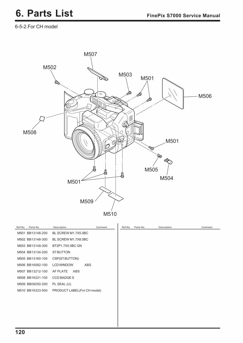
120
6. Parts List FinePix S7000 Service Manual
M501 BB13148-200 BL SCREW M1.7X5.0BC
M502 BB13148-300 BL SCREW M1.7X8.0BC
M503 BB13149-300 BT2P1.7X5.5BC GN
M504 BB13134-200 ST BUTTON
M505 BB13160-100 CSP(ST BUTTON)
M506 BB16582-100 LCD WINDOW ABS
M507 BB13212-100 AF PLATE ABS
M508 BB16321-100 CCD BADGE S
M509 BB09250-200 PL SEAL (U)
M510 BB16323-500 PRODUCT LABEL(For CH model)
M507
M502
M503M501
M506
M501
M505
M504
M509
M510
M501
M508
6-5-2.For CH model
Ref No. Parts No. Description Comment Ref No. Parts No. Description Comment
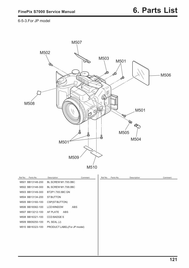
121
6. Parts ListFinePix S7000 Service Manual
M501 BB13148-200 BL SCREW M1.7X5.0BC
M502 BB13148-300 BL SCREW M1.7X8.0BC
M503 BB13149-300 BT2P1.7X5.5BC GN
M504 BB13134-200 ST BUTTON
M505 BB13160-100 CSP(ST BUTTON)
M506 BB16582-100 LCD WINDOW ABS
M507 BB13212-100 AF PLATE ABS
M508 BB16321-100 CCD BADGE S
M509 BB09250-100 PL SEAL (J)
M510 BB16323-100 PRODUCT LABEL(For JP model)
M507
M502
M503M501
M506
M501
M505
M504
M509
M510
M501
M508
6-5-3.For JP model
Ref No. Parts No. Description Comment Ref No. Parts No. Description Comment
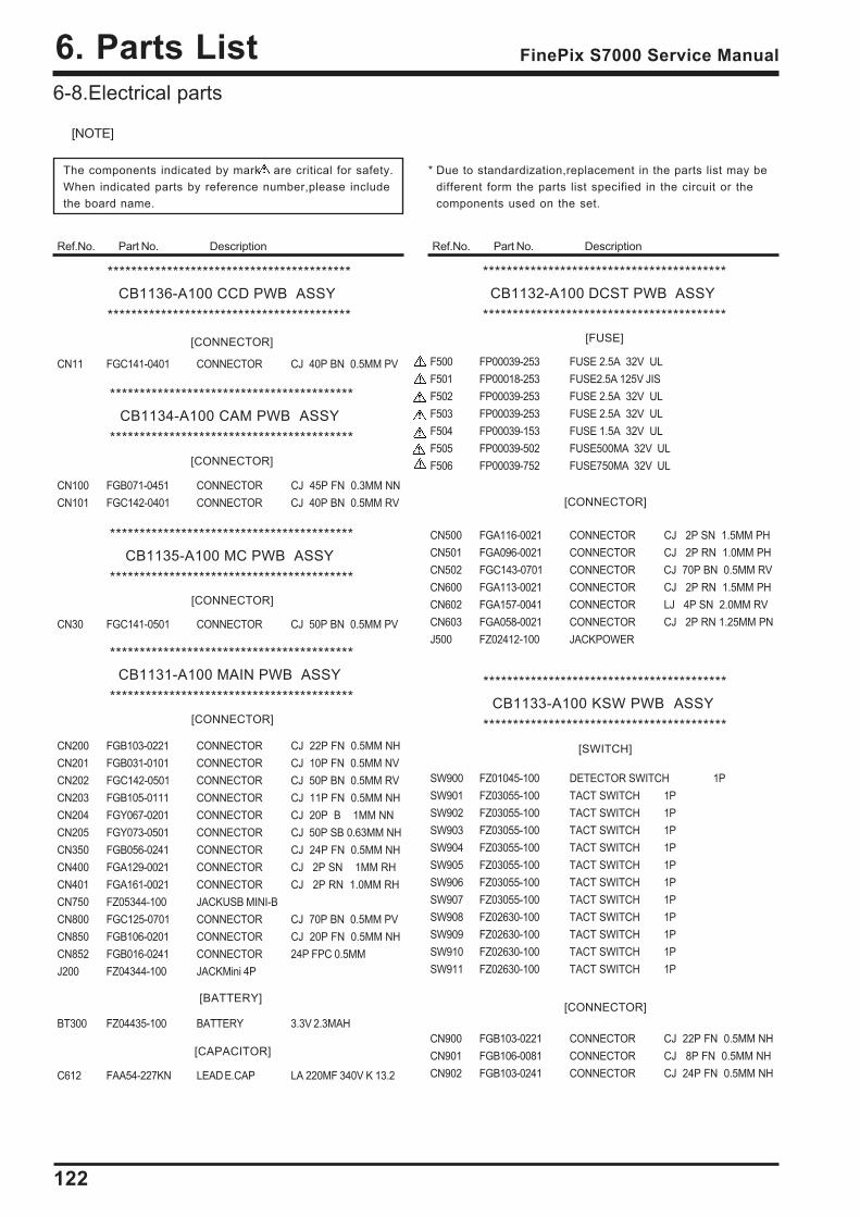
122
6. Parts List FinePix S7000 Service Manual
[NOTE]
The components indicated by mark are critical for safety.When indicated parts by reference number,please includethe board name.
Ref.No. Part No. Description
* Due to standardization,replacement in the parts list may bedifferent form the parts list specified in the circuit or thecomponents used on the set.
Ref.No. Part No. Description
6-8.Electrical parts
*****************************************CB1136-A100 CCD PWB ASSY
*****************************************
CN11 FGC141-0401 CONNECTOR CJ 40P BN 0.5MM PV
CN100 FGB071-0451 CONNECTOR CJ 45P FN 0.3MM NNCN101 FGC142-0401 CONNECTOR CJ 40P BN 0.5MM RV
CN30 FGC141-0501 CONNECTOR CJ 50P BN 0.5MM PV
CN200 FGB103-0221 CONNECTOR CJ 22P FN 0.5MM NHCN201 FGB031-0101 CONNECTOR CJ 10P FN 0.5MM NVCN202 FGC142-0501 CONNECTOR CJ 50P BN 0.5MM RVCN203 FGB105-0111 CONNECTOR CJ 11P FN 0.5MM NHCN204 FGY067-0201 CONNECTOR CJ 20P B 1MM NNCN205 FGY073-0501 CONNECTOR CJ 50P SB 0.63MM NHCN350 FGB056-0241 CONNECTOR CJ 24P FN 0.5MM NHCN400 FGA129-0021 CONNECTOR CJ 2P SN 1MM RHCN401 FGA161-0021 CONNECTOR CJ 2P RN 1.0MM RHCN750 FZ05344-100 JACKUSB MINI-BCN800 FGC125-0701 CONNECTOR CJ 70P BN 0.5MM PVCN850 FGB106-0201 CONNECTOR CJ 20P FN 0.5MM NHCN852 FGB016-0241 CONNECTOR 24P FPC 0.5MMJ200 FZ04344-100 JACKMini 4P
BT300 FZ04435-100 BATTERY 3.3V 2.3MAH
C612 FAA54-227KN LEAD E.CAP LA 220MF 340V K 13.2
[CONNECTOR]
*****************************************CB1134-A100 CAM PWB ASSY
*****************************************[CONNECTOR]
*****************************************CB1135-A100 MC PWB ASSY
*****************************************[CONNECTOR]
*****************************************CB1131-A100 MAIN PWB ASSY
*****************************************
[CAPACITOR]
[BATTERY]
[CONNECTOR]
F500 FP00039-253 FUSE 2.5A 32V ULF501 FP00018-253 FUSE2.5A 125V JISF502 FP00039-253 FUSE 2.5A 32V ULF503 FP00039-253 FUSE 2.5A 32V ULF504 FP00039-153 FUSE 1.5A 32V ULF505 FP00039-502 FUSE500MA 32V ULF506 FP00039-752 FUSE750MA 32V UL
CN500 FGA116-0021 CONNECTOR CJ 2P SN 1.5MM PHCN501 FGA096-0021 CONNECTOR CJ 2P RN 1.0MM PHCN502 FGC143-0701 CONNECTOR CJ 70P BN 0.5MM RVCN600 FGA113-0021 CONNECTOR CJ 2P RN 1.5MM PHCN602 FGA157-0041 CONNECTOR LJ 4P SN 2.0MM RVCN603 FGA058-0021 CONNECTOR CJ 2P RN 1.25MM PNJ500 FZ02412-100 JACKPOWER
SW900 FZ01045-100 DETECTOR SWITCH 1PSW901 FZ03055-100 TACT SWITCH 1PSW902 FZ03055-100 TACT SWITCH 1PSW903 FZ03055-100 TACT SWITCH 1PSW904 FZ03055-100 TACT SWITCH 1PSW905 FZ03055-100 TACT SWITCH 1PSW906 FZ03055-100 TACT SWITCH 1PSW907 FZ03055-100 TACT SWITCH 1PSW908 FZ02630-100 TACT SWITCH 1PSW909 FZ02630-100 TACT SWITCH 1PSW910 FZ02630-100 TACT SWITCH 1PSW911 FZ02630-100 TACT SWITCH 1P
CN900 FGB103-0221 CONNECTOR CJ 22P FN 0.5MM NHCN901 FGB106-0081 CONNECTOR CJ 8P FN 0.5MM NHCN902 FGB103-0241 CONNECTOR CJ 24P FN 0.5MM NH
*****************************************CB1132-A100 DCST PWB ASSY
*****************************************[FUSE]
[CONNECTOR]
[SWITCH]
[CONNECTOR]
*****************************************CB1133-A100 KSW PWB ASSY
*****************************************

123
6. Parts ListFinePix S7000 Service Manual
<MEMO>
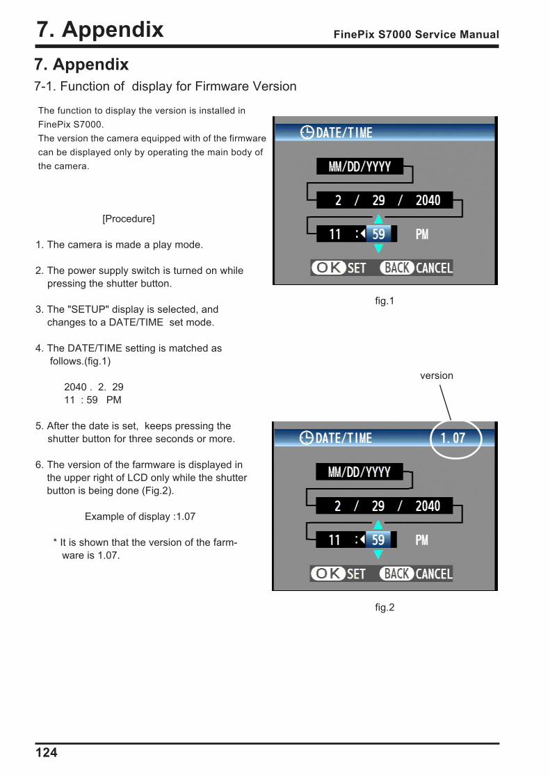
124
7. Appendix FinePix S7000 Service Manual
The function to display the version is installed inFinePix S7000.The version the camera equipped with of the firmwarecan be displayed only by operating the main body ofthe camera.
[Procedure]
1. The camera is made a play mode.
2. The power supply switch is turned on while pressing the shutter button.
3. The "SETUP" display is selected, and changes to a DATE/TIME set mode.
4. The DATE/TIME setting is matched as follows.(fig.1)
2040 . 2. 29 11 : 59 PM
5. After the date is set, keeps pressing the shutter button for three seconds or more.
6. The version of the farmware is displayed in the upper right of LCD only while the shutter button is being done (Fig.2).
Example of display :1.07
* It is shown that the version of the farm- ware is 1.07.
fig.1
fig.2
7. Appendix7-1. Function of display for Firmware Version
version

125
7. AppendixFinePix S7000 Service Manual
7-2.List of Related Technical Updates IssuedTo ensure that after-sales srevice is performed accuratety, keep a record here of the technical updates is-sued that cover this device.
Technical Update No. Date Title Details/Other

26-30, Nishiazabu 2-chome, Minato-ku, Tokyo 106-8620, Japan.
FUJI PHOTO FILM CO., LTD.