Ferran Lozano Rocabeyera Títol TFG: Study of a feasible
137
Titulació: Grau en Enginyeria en Tecnologies Aeroespacials Alumne: Ferran Lozano Rocabeyera Títol TFG: Study of a feasible solution for a specific mission with unmanned aerial vehicles(UAV/RPAS) Director/a del TFG: Aitor Martín Sierra Convocatòria de lliurament del TFG: Juny 2016 Contingut d’aquest volum: REPORT
-
Upload
khangminh22 -
Category
Documents
-
view
3 -
download
0
Transcript of Ferran Lozano Rocabeyera Títol TFG: Study of a feasible

Titulació:
Grau en Enginyeria en Tecnologies Aeroespacials
Alumne:
Ferran Lozano Rocabeyera
Títol TFG:
Study of a feasible solution for a specific mission with unmanned aerial
vehicles(UAV/RPAS)
Director/a del TFG:
Aitor Martín Sierra
Convocatòria de lliurament del TFG: Juny 2016
Contingut d’aquest volum: REPORT

Study of a feasible solution for a specific
mission with unmanned aerial
vehicles(UAV/RPAS)
Escola Superior d’Enginyeries Industrial, Aeroespacial i Audiovisual de
Terrassa
ESEIAAT
Grau en Enginyeria en Tecnologies Aeroespacials
Autor: Ferran Lozano Rocabeyera
Director del TFG: Aitor Martín Sierra
Juny 2016

Abstract
Due to the recent popularity of civil Unmanned Aerial Vehicles (UAV) and the expectation
that are generating, the idea of developing a study related to the topic emerged.
The aim of the study is to propose a solution with UAV for surveillance applications and
determine if is feasible for future implementation.
First of all, as an introduction, the legal framework and the state of the art of the UAV
industry has been studied in order to define the background of the project. Then, the
design requirements have been implemented in order to provide a solution that can
accomplish the objectives of the mission.
The second part is based on the description of the solution proposed. From the
information obtained in the background study and taking into account the design
requirements, the most general aspects of an Unmanned Aerial System have been
analysed and some decisions have been chosen.
Finally, by means of a technical and economical approach, the feasibility study has been
made. Some conclusions concerning the implementation of the solution proposed in the
actual market have been drawn.

Preface
Unmanned Aerial Vehicles (UAV) are aircrafts without a human pilot aboard and they
have been used for military applications for decades. However, due to the effectiveness
as an aircraft and sensor and also because of the automatic technology involved, its use
is expanding in commercial, scientific and recreational applications. The UAV industry is
expected to grow very fast in the next 10 years and therefore is an interesting sector to
study.
One of the commercial applications in which the UAV will play an important role is
surveillance. Thus, the general objective is to design a solution with Unmanned Aerial
Systems for surveillance applications and determine if it is feasible.
At the present time, multi-copter drones with photography applications are beginning to
success. However, UAV with commercial functions are not very usual and they are
starting to be implemented. For this reasons, new solutions must be proposed in order
to promote the use of these aerial vehicles for commercial purposes.
The expectation generated in the last years regarding UAVs, have created a potential
market in which lot of stuff have not yet been developed. Thus, this industry can be
considered as one of the most attractive for aeronautical engineers.

I
List of contents
List of figures ............................................................................................................... IV
List of tables ................................................................................................................ VI
List of Abbreviations .................................................................................................. VIII
Nomenclature .............................................................................................................. IX
1. Aim of the study ..................................................................................................... 1
2. Justification ............................................................................................................ 2
3. Scope .................................................................................................................... 3
4. Basic requirements ................................................................................................ 4
5. Background ........................................................................................................... 5
5.1. Regulations..................................................................................................... 5
5.1.1. Regulations at International level ............................................................. 5
5.1.2. Regulations at the EU level ...................................................................... 6
5.1.3. Regulations at Spain level ....................................................................... 6
5.2. State of the art of the UAV industry ................................................................. 7
5.2.1. Multirotor UAS ......................................................................................... 7
5.2.2. Fixed Wing UAS ...................................................................................... 9
6. Analysis of Design requirements .......................................................................... 13
6.1. Problem understanding ................................................................................. 13
6.2. Justification ................................................................................................... 13
6.3. Conceptual design ........................................................................................ 14
6.3.1. Design Requirements ............................................................................ 14
6.3.2. Operability and functional requirements ................................................. 14
6.3.3. Capabilities ............................................................................................ 15
6.4. Initial sizing ................................................................................................... 16
6.4.1. Type of UAV selection ........................................................................... 16
6.4.2. Design Point .......................................................................................... 17
6.4.3. Weight Estimation .................................................................................. 23
7. UAV Solution Proposal ........................................................................................ 25
7.1. Propulsion System ........................................................................................ 25
7.1.1. Thrust Generation theory ....................................................................... 25

II
7.1.2. Power Source ........................................................................................ 26
7.1.3. Propeller ................................................................................................ 35
7.1.4. Engine and propeller location ................................................................ 38
7.2. Aerodynamics ............................................................................................... 38
7.2.1. Airfoil selection ...................................................................................... 38
7.2.2. Wing configuration ................................................................................. 40
7.2.3. Wing position ......................................................................................... 42
7.2.4. Tail configuration ................................................................................... 43
7.2.5. Wing Geometry ...................................................................................... 45
7.2.6. Stability and control ............................................................................... 51
7.3. Communication system and Ground Control Station ..................................... 60
7.3.1. Communication Media ........................................................................... 60
7.3.2. Data link ................................................................................................ 61
7.3.3. Ground Control Station .......................................................................... 66
7.4. Payload ........................................................................................................ 69
7.4.1. Introduction ............................................................................................ 69
7.4.2. Mission requirements ............................................................................. 69
7.4.3. Description of the payload ..................................................................... 69
7.4.4. Market research ..................................................................................... 71
7.5. Flight Control System ................................................................................... 75
7.5.1. Introduction ............................................................................................ 75
7.5.2. Sensors ................................................................................................. 75
7.5.3. Autopilot ................................................................................................ 77
7.5.4. Architecture ........................................................................................... 77
7.5.5. Market study .......................................................................................... 78
7.6. Power supply ................................................................................................ 83
7.6.1. Power requirements ............................................................................... 83
7.6.2. Battery selection .................................................................................... 83
7.7. Landing Gear ................................................................................................ 84
7.8. Structure ....................................................................................................... 85
7.8.1. Wings .................................................................................................... 85

III
7.8.2. Fuselage ................................................................................................ 86
7.8.3. Tail ........................................................................................................ 86
7.9. Assembly system .......................................................................................... 86
7.10. Performance ............................................................................................. 87
7.10.1. Weight budget .................................................................................... 87
7.10.2. Stall Velocity ...................................................................................... 90
7.10.3. Range and endurance ........................................................................ 90
7.10.4. Turning ............................................................................................... 92
7.10.5. Take-off .............................................................................................. 95
7.10.6. Landing .............................................................................................. 98
8. Feasibility study ................................................................................................. 102
8.1. Technical approach .................................................................................... 102
8.1.1. Functional factors ................................................................................ 102
8.2. Economical approach ................................................................................. 104
8.2.1. Raw Materials Cost and pre-design cost .............................................. 104
8.2.2. Estimation of UAV cost ........................................................................ 105
8.2.3. Positioning in the actual market ........................................................... 108
9. Environmental impact study ............................................................................... 110
10. Security considerations .................................................................................. 111
11. Organization and planning of the future work ................................................. 112
12. Conclusions and future work .......................................................................... 113
13. References ..................................................................................................... 117

IV
List of figures
Figure 1: Expected growth of the UAV market [2] ......................................................... 2
Figure 2: Catapult launch speed vs UAV weight [20]................................................... 20
Figure 3: Take-off distance as function of thrust .......................................................... 21
Figure 4: Constraint analysis diagram ......................................................................... 22
Figure 5: Wing Surface versus take-off mass .............................................................. 24
Figure 6: Output power versus take-off mass .............................................................. 24
Figure 7: Bernoulli’s principle in an airfoil[22] .............................................................. 25
Figure 8: Airfoil on a propeller blade[23]...................................................................... 26
Figure 9: Different propulsion systems comparison[25] ............................................... 28
Figure 10: Two-cycle engine process [26] ................................................................... 29
Figure 11: Rotatory cycle scheme[29] ......................................................................... 30
Figure 12: Simple two-pole brushed DC motor scheme[30] ........................................ 31
Figure 13: Brushless DC motor components[31] ......................................................... 31
Figure 14: Thrust vs speed and altitude effect[32] ....................................................... 32
Figure 15: Comparison between eGallon Price and gasoline Price in the US[33] ........ 33
Figure 16: Propeller pitch scheme[37] ......................................................................... 36
Figure 17: Blade angle of attack[38] ............................................................................ 37
Figure 18: Difference between effective and geometrical pitch[38].............................. 37
Figure 19: Propeller selector software ......................................................................... 37
Figure 20: Lift-to-Drag vs wingspan graph .................................................................. 47
Figure 21: Stall speed vs wingspan graph ................................................................... 48
Figure 22: Wing geometry model ................................................................................ 49
Figure 23: Lift-to-Drag ratio variation with the AR of the wing ...................................... 50
Figure 24: Variation of the stall speed with the AR of the wing .................................... 50
Figure 25: Final Wing Design ...................................................................................... 51
Figure 26: Example of UAV with conventional configuration tail[44] ............................ 52
Figure 27: Spartan Phoenix horizontal and vertical stabilizer dimensions[45] ............. 52
Figure 28: Horizontal stabilizer first iteration geometry ................................................ 53
Figure 29: Wing and horizontal stabilizer simulation ................................................... 54

V
Figure 30: Cm - 𝛼 graph for the configuration wing - horizontal tail with tilt angle of -2.05°
................................................................................................................................... 56
Figure 31: Simulation for selecting the vertical stabilizer airfoil .................................... 57
Figure 32: Final tail configuration ................................................................................ 59
Figure 33: Data-link functions[26] ............................................................................... 62
Figure 34: Frequencies generally used for UAV applications ...................................... 63
Figure 35: Radio Telemetry kit for 2.4 GHz[54] ........................................................... 66
Figure 36: Example of portable GCS [55] .................................................................... 67
Figure 37: Comparison between image enhancement (left) and thermal imaging
(right)[58] .................................................................................................................... 70
Figure 38: Epsilon 140 [60] ......................................................................................... 71
Figure 39: CM100 [62] ................................................................................................ 72
Figure 40: Zenmuse XT[63] ........................................................................................ 74
Figure 41: Vibrating structure gyroscope scheme[65] ................................................. 75
Figure 42: IMU[67] ...................................................................................................... 76
Figure 43: Flight control system architecture ............................................................... 77
Figure 44: UAV Navigation VECTOR Autopilot[69] ..................................................... 78
Figure 45: APO4 Autopilot[70] .................................................................................... 79
Figure 46: Paparazzi components[72] ......................................................................... 82
Figure 47: Lisa autopilot[73] ....................................................................................... 82
Figure 48: Example of landing gear [76] ..................................................................... 85
Figure 49: Example of the internal structure of an UAV wing[79] ................................ 86
Figure 50: Assembly system of the Penguin B UAV[82] .............................................. 87
Figure 51: Fuselage estimated dimensions (dimensions in mm) ................................. 88
Figure 52: Distribution of forces during a turn[85] ........................................................ 93
Figure 53: Different stages during take-off[86] ............................................................ 95
Figure 54: Landing phase scheme [86] ....................................................................... 98
Figure 55: Parachute landing method[88] ................................................................. 100
Figure 56: Patent regarding a net recovery system[89] ............................................. 100

VI
List of tables
Table 1: Multirotor UAS State of the art......................................................................... 8
Table 2: Fixed wing UAS state of the art ....................................................................... 9
Table 3: Fixed wing and multirotor comparison ........................................................... 16
Table 4: OWA method for configuration decision ........................................................ 17
Table 5: Payload – MTOW ratio from different UAVs in the market ............................. 23
Table 6: ICE and Electric Motor Comparison .............................................................. 27
Table 7: ICE 2-stroke and 4-stroke comparison[28] .................................................... 29
Table 8: OWA method for selecting the power source ................................................ 34
Table 9: Comparison of UAV engines ......................................................................... 35
Table 10: Simulation conditions .................................................................................. 39
Table 11: Results of airfoil simulation .......................................................................... 40
Table 12: Decision matrix Wing configuration ............................................................. 42
Table 13: Decision matrix for tail configuration ............................................................ 45
Table 14: Study of the different planforms ................................................................... 46
Table 15: Study of the wingspan ................................................................................. 47
Table 16: Results of the simulation for different wing geometries ................................ 49
Table 17: Final wing parameters ................................................................................. 51
Table 18: Horizontal stabilizer airfoil siimulation .......................................................... 53
Table 19: Simulation wing and horizontal tail changing taper ratio .............................. 55
Table 20: Airfoil vertical stabilizer simulation for the configuration wing, horizontal and
vertical stab ................................................................................................................ 57
Table 21: Results of the simulation for different vertical tail geometries ...................... 58
Table 22: RF spectrum ............................................................................................... 63
Table 23: Advantages and disadvantages of RF bands[49] ........................................ 64
Table 24: Market research Antennas .......................................................................... 65
Table 25: Epsilon 140 specifications[60] ..................................................................... 72
Table 26: CM100 Specifications[62] ............................................................................ 73
Table 27: CM100 prices .............................................................................................. 73
Table 28: Zenmuse XT Specifications[63] ................................................................... 74
Table 29: VECTOR specifications [69] ....................................................................... 79

VII
Table 30: AP04 specifications[70] ............................................................................... 80
Table 31: Veronte Autopilot list of sensors[71] ............................................................ 81
Table 32: Veronte Autopilot specifications[71] ............................................................ 81
Table 33: Lisa/S specifications[74] .............................................................................. 83
Table 34: Power supply specifications ........................................................................ 83
Table 35: Tattu LiPo battery pack specifations [75] ..................................................... 84
Table 36: Surfaces calculated in the XFLR5 software ................................................. 89
Table 37: Weight estimation ........................................................................................ 89
Table 38: Turn rate study for a bank angle of 45° ....................................................... 94
Table 39: Turn rate study for a bank angle of 45° at an altitude of 1000 m .................. 95
Table 40: UAV Factory Catapult specifications[20] ..................................................... 98
Table 41: Aeromapper UAV launcher specifications[87] ............................................. 98
Table 42: Main dimensions considered for the UAV proposed .................................. 103
Table 43: Costs of the solution proposed .................................................................. 104
Table 44: Cost engineering of the pre-design phase ................................................. 105
Table 45: Engineering cost of the design phase ........................................................ 106
Table 46: Professional UAV prices ............................................................................ 108
Table 47: Planning scheduling of future tasks ........................................................... 112

VIII
List of Abbreviations
AoA: Angle of attack
AR: Aspect Ratio
BLDC: Brush-less DC motors
CFRP: Caron Fibre Reinforced Polymer
DC: Direct Current
GCS: Ground Control Station
GFRP: Glass Fibre Reinforced Polymer
GPS: Global Positioning System
ICE: Internal Combustion Engine
LOS: Line of Sight
MTOM: Maximum Take-Off Mass
MTOW: Maximum Take-Off Weight
PLW: Payload Weight
RF: Radio Frequency
ROC: Rate of Climb
RPAS: Remotely Piloted Aircraft Systems
SL: Sea Level
UAS: Unmanned Aerial System
UAV: Unmanned Aerial Vehicle

IX
Nomenclature
P: Power
W: weight
𝜂: Efficiency
𝐶𝐷0: Parasitic drag coefficient
S: Wing surface
n: load factor
𝜌: density
V: speed
g: gravity acceleration
𝑑𝑇𝑂: Take-off distance
h: altitude
e: Oswald efficiency
A: Aspect Ratio
PA: Available power
PR: Required power
T: Thrust
Dp: Propeller diameter
Pbl: Power loading per blade
𝑛𝑝: Number of propeller blades
Re: Reynolds number
𝜇: air viscosity
Vstall: Stall speed
CL: Lift coefficient
CD: Drag coefficient
Cm: pitching moment coefficient
CL/CD: Lift-to-drag ratio
𝐶𝑚𝛼: pitching moment slope
Ctip: chord at the tip
Croot: chord at the root

X
D: Drag Force
L: Lift Force
t: endurance
𝜑: Mass flow rate
�̇�: Turn rate
𝜙: Bank angle
Lv: Distance between leading edges of wing and elevator
Vv: Tail volume coefficient
SV: Elevator surface
b: wingspan


1
1. Aim of the study
The aim of the study is to propose a solution with unmanned aerial vehicles (UAV/RPAS)
for surveillance applications taking into account the basic requirements. Apart from that,
a feasibility study has to be done in order to determine if the solution can be implemented.

2
2. Justification
The unmanned air vehicles (UAV) has been used for decades due to the effectiveness
as an aircraft and sensor and also because of the automatic technology involved.
Consequently, the potential benefits of this systems are being extended to civil
applications – the first application was military- and in a near future the main utilizations
will be settled. This is why the FAA (Federal Aviation Administration) estimates that in a
five-year time, 7500 UAV would be operational in the U.S airspace.[1]
Nowadays the regulation is limiting the development of the UAS sector. However, it is
expected that in less than 2 years the legislation will change enabling new applications.
Hence, it has been predicted that the UAV sector will experience a considerable growth
in the next decade. The UAV market evolution expected can be represented in Figure 1
with the amount of US dollars that will be spent.
Figure 1: Expected growth of the UAV market [2]
Due to the expected growth of the sector, a UAV project ensures entering to a new
market in which there are new issues to develop and consequently future feasibility can
be easily guaranteed.
One of the main commercial applications of the UAVs is surveillance. The actual security
systems are quite limited and in some scenarios, like large extensions or difficult access
areas, there are practically useless. However, drones1 have the potential to solve these
problems and create a new concept of security.
1 Drone has been used as a synonym of UAV

3
3. Scope
The points that this study covers are:
Study of the legal framework
State of the art of the UAV industry
Analysis of the design requirements
UAV solution proposal
- Definition of the type of system
- Analysis of the different subsystems of the UAV (propulsion, aerodynamics,
communication and flight control)
- Payload
- Performance
Technical approach
Economical approach
Conclusions and future improvements

4
4. Basic requirements
The UAV solution proposed must meet the following requirements:
Surveillance applications
Flight time between 2h and 12 h
Mass below 25 kg
Operation during day and night
Payload: camera

5
5. Background
The first step in an engineering project is to study the legal framework in order to design
a solution that meets with the regulation involved. The international, European and
Spanish legislations related to UAV/RPAS will be mentioned and a general idea of the legal
background will be shown. Another important aspect to take into account is the actual
market and what technologies have been developed until the moment. This aspect will be
treated with a state of the art of the UAV industry. Having an idea of the actual UAV
industry will help to focus the study and also to purpose a feasible solution.
5.1. Regulations
5.1.1. Regulations at International level
The ICAO (International Civil Aviation Organization) is a United Nations agency
responsible of setting up the principles and regulations of the international air navigation
with the objective of promote the development of a secure international air transport. In
order to assist the State Members of the Organization to develop national aviation
regulations, ICAO publishes the Standards and Recommended Practices (SARPSs).[3]
According to the Article 8 of the Chicago Convention in 1944, pilotless aircrafts can’t fly
over the territory of a contracting State without special authorization by that State. The
contracting State is responsible of insuring that the flight is controlled so that danger to
civil aircraft is avoided.
Due to the increasing of UAS technology at the beginning of the new century, in 2007
ICAO build up an Unmanned Aircraft Systems Study Group (UASSG) formed by experts
from the Member States, industries and stakeholder groups in order to discuss the
impact of RPAS on aviation regulation.
In March of 2011, UASSG published the Circular 328 with the following purposes [4]:
Inform the global UAS community of the emerging ICAO perspective on the
integration of UAS into non-segregated airspace and at aerodromes
Consider the fundamental differences from manned aviation that such integration
will involved
Encourage other countries to help with the development of ICAO policy on UAS
by providing information on their own experiences associated with UAS.
The UASSG were not allowed to publish SARPs due to the status of study group.
However, in response to the rapid developments in RPAS technology, in November 2014
the UASSG was elevated to the status of a Panel with the main objective of publishing
SARPs on unmanned aircraft by 2018. These SARPs will include guidance on
airworthiness, operations and pilot licensing.[5]

6
5.1.2. Regulations at the EU level
The aviation regulator in Europe is the European Aviation Safety Agency (EASA) that is
responsible of the airworthiness and the aircrafts operations in the EU.
The EU Regulations 216/2008 establishes that the EASA is responsible of civil RPAS
over 150 kg whereas the Member State authorities are responsible for RPAS – military
and civil- below 150 kg.
EASA has already published some documents related with the regulatory frame of
UAS[6]:
Guidance material to support approved Design Organisations that have the
objective of selecting the appropriate specifications in order to build the
certification basis for RPAS design.
NPA 2012-10 to transpose the ICAO circulars into Standard European Rules of
the Air (SERA).
Since NPA 2012-10 was radically changed, EASA decided to publish a second NPA on
the same matter. This new text is the NPA 2014-09.
To propose changes to the existing aviation rules in order to take into consideration the
latest developments of drones, EASA has develop the A-NPA 2015-10.
The A-NPA is a proposal for the creation of common European safety rules for operating
drones regardless of their weight. It contains 33 proposals with the objective of collecting
the safety regulations for commercial and non-commercial activities. It also introduces
three categories of operations based on the risk the operation is posing to third parties[7]:
Open category (low risk)
Specific category (medium risk)
Certified category (high risk)
5.1.3. Regulations at Spain level
According to the AESA (Agencia Estatal de Seguridad Aérea) the RPAS activity has
increased the last months. Therefore, this agency has developed a legal framework to
ensure security.
AESA is responsible of regulate drones until 150 kg whereas for drones with a weight
above 150 kg the regulator is EASA.
The basic regulations for the professional use are mentioned below [8]:
The drone must be registered in AESA
A specific liability insurance for aircrafts is necessary
Have the pilot license
Have a valid medical certificate
It is banned to operate in urban zones

7
It is banned to overfly crowds of people
It is banned to fly at night
It is banned to fly in controlled airspace
It is banned to fly close to airports
It is banned to endanger third parties
For the professional use of drones with MTOW2 under 25 kg, there is a process that must
be followed and delivered maximum 5 days before the start of the operation (art.50.6 Ley
18/2014) in order to be enabled as RPAS operator. The steps that have to be followed
are described [9]:
Request for the realization of test flights that can demonstrate the intended
operation according to art. 50.6 of the Law 18/2014 that ensures security.
Realization of test flights
Presentation of the prior communication and responsible statement to be enabled
as RPAS operator for scientific and technical applications
5.2. State of the art of the UAV industry
The development of the state of the art has been done in order to deeply analyse and
evaluate the current technologies involved on UAVs in the actual market as well as study
the specifications provided. The most important characteristic of the drones studied can
be seen at the following tables. The information has been divided into multirotor and fixed
wing UAVs.
Since the UAV market is starting to grow at the present time, most of these models have
been developed in the last few years and also some are even starting to be
commercialized. Nevertheless, the basic specifications have been tabulated.
The UAVs present very different specifications and different configurations are observed.
In terms of propulsion there are two distinct groups: electric and internal combustion
propulsion. However, the market trend is the environmental-friendly solution of the
electric motor.
An extended review of the state of the art of the UAV industry can be seen in the Annex.
5.2.1. Multirotor UAS
2 Although the technical differences between weight (N) and mass (kg) they have been treated as synonyms

8
Table 1: Multirotor UAS State of the art
Manufacturer DJI DJI 3D Robotics
Model Phantom series Inspire series SOLO
Application Aerial photography and
video streaming
Aerial photography and
video streaming
Aerial photography and
video streaming
MTOW (kg) 1.28 2.94 1.8
Dimensions 350 mm (Diagonal size) 438x451x301 mm 46 cm (Diagonal size)
25 cm (height)
Speeds
5 m/s (ascent)
3 m/s (descent)
16 m/s (Max.)
5 m/s (ascent)
4 m/s (descent)
22 m/s
10 m/s (ascent)
25 m/s (Max.)
Payload weight - - 420 g
Propulsion system Electric motor Electric motor 880 kV electric motor
Endurance 23 min 18 min 20 min
Range 3500 m 5 km 8 km
GNSS Yes Yes Yed
Operating frequency 2.4 GHz 2.4 GHz
5.8 GHz 2.4 GHz
Price 1 199 € (Phantom 3
Professional) 2 299 € 812 €
Manufacturer SenseFly CARTOUAV Parrot
Model eXom MD4-1000 Bebop
Application
High-resolution mapping,
3D modelling and
inspection
(HD and thermal video
imagery)
Traffic control,
inspection, audio-visuals,
agriculture
Live video streaming and
photography
MTOW (kg) 1.8 4.3 0.42
Dimensions 56x80x17 cm 109 cm (between axes) 28x32x3.6 cm

9
Speeds (m/s) 7 m/s (max. climb rate)
12 m/s (max. speed) - 13
Payload weight - 1.2 kg -
Propulsion system 4 electric brushless
motors Electric motor 4 Brushless engines
Endurance 22 min 60 min 22 min
Range (m) 800 - 300
GNSS Yes Yes Yes
Operating frequency 2.4 & 5 GHz - 2.4 and 5 GHz
Price ~ 30 000 € -
399 €
499 € (with control
station)
5.2.2. Fixed Wing UAS
Table 2: Fixed wing UAS state of the art
Manufacturer Brocktek Brocktek Latitude
Model Havoc Spear Hybrid UAV
Application
Surveillance, search &
rescue, agriculture and
infrastructure
management
Surveillance, search &
rescue, agriculture and
infrastructure
management
Prototype
Wingspan (m) 4.9 3 – 4.3 -
MTOW (kg) 79 17 16.7
Launch Manual or Auto Rolling Manual -
Take-off distance - - -
Cruise speeds - - 20.6 m/s
Stall speed 18 m/s 12.8 m/s -
Payload weight 20 kg 1 kg (Electric) / 4.5 kg
(ICE) 3.6 – 5.4 kg

10
Propulsion system ICE Electric or ICE
Hybrid (0.5 hp 4-stroke
gas engine + electric
motor)
Endurance 8 – 18 h 1 h (Electric) / 2.8 h (ICE) 12 – 24 h
Range - - -
Price - - -
Manufacturer Zala Aero Zala Aero Zala Aero
Model 421-08 421-04M 421-16
Application Surveillance Video and infrared vision Monitoring, search &
rescue, detection
Wingspan (m) 0.81 1.6 1.62
MTOW (kg) 2.1 4.2 18
Launch Hand Catapult Catapult
Take-off distance - - -
Cruise speeds 65 – 130 km/h 65 – 120 km/h 150 km/h
Stall speed - - -
Payload weight 1 kg 1 kg 3 kg
Propulsion system Electric motor Electric motor ICE
Endurance 100 min 120 min 7 h
Range 15 km 40 km 50 km
Price - - -
Manufacturer Aeraccess Thales Group UAV Factory
Model GOSHAWK W200 FULMAR Penguin C
Application Surveillance and
reconnaissance
Search & rescue,
surveillance Surveillance
Wingspan (m) 2 3 3.3

11
MTOW (kg) 6 20 22.5
Launch Catapult Catapult Catapult
Take-off distance - - -
Cruise speeds 90 km/h 100 km/h 19 – 22 m/s
Stall speed - - -
Payload weight 1 kg 8 kg -
Propulsion system Electric motor ICE ICE
Endurance 90 – 120 min 6 – 12 h 20 h
Range - - 100 km
Price - - -
Manufacturer UAV Factory Insitu Draganfly
Model Penguin B Integrator Tango
Application Surveillance
Inspection, agriculture,
wildfire management, Oil
and gas operations, border
patrol
Prototype
Wingspan (m) 3.3 4.9 1.5
MTOW (kg) 21.5 61.2 3.94
Launch Catapult, Runway, Car
top launch - Catapult
Take-off distance 30 m - -
Cruise speeds 22 m/s 28.3 m/s 50 – 60 km/h
Stall speed 13 m/s - 35 km/h
Payload weight 10 kg (ICE) / 6.6 kg
(Electric motor) 18 kg 1.14 kg
Propulsion system 2.5 HP engine / brushless
electric motor ICE Electric motor

12
Endurance 20 h (ICE) / 110 min
(electric motor) 24+ h 50 min
Range - - -
Price 14 500 € - -
Manufacturer Sensefly Lehmann Aviation Lehmann Aviation
Model eBee L-A series L-M series
Application Agriculture and 3D
mapping
Mapping, agriculture,
aerial photography Short range surveillance
Wingspan (m) 0.96 0.92 0.92
MTOW (kg) 0.69 1.15 1.25
Launch Hand launch Hand launch Hand launch
Take-off distance - - -
Cruise speeds 40 – 90 km/h 20 – 80 km/h 20 – 80 km/h
Stall speed - - -
Payload weight - 350 g
Propulsion system Electric Brushless DC
motor Electric motor Electric motor
Endurance 50 min 45 min 45 min
Range 3 km 5 km 5 km
Price 10 560 € 8 990 € 6 990 €

13
6. Analysis of Design requirements
The first step of the study is to understand the problem in order to justify the need of the
product that it is supposed to be developed. Then, the basic requirements need to be
identified so that a conceptual design can be done.
6.1. Problem understanding
The current situation of video surveillance systems is not as good as people think. The
efficiency of this security systems had been called into doubt recently. Furthermore, in
some environments the use of ground security systems is non-viable. Some of this
scenarios are large out-door areas that usually are difficult to access.
6.2. Justification
A solution to the problem described above, is the use of UAVs. The main idea is that the
security staff can monitor large areas in a short periods of time by using the camera
installed on a drone. Also, in environments where it is difficult to access by a ground
vehicle the use of surveillance UAVs can facilitate the security tasks. Therefore, the
combination of the ground security systems and surveillance drones can create a new
concept of security.
The advantages of having UAVs in surveillance applications have been mentioned in
order to justify the potential of this study with the objective of solving the limitations of
the actual security systems:
1. Aerial surveillance
With drones the opportunity of having aerial cameras is achieved, increasing the
effectiveness and solving the limitations of ground systems. One of the most basic
problems that ground camera has is the range of vision. However, having a camera in
the air provides a new perspective in which is faster and easier to monitor, a feature that
is impossible to achieve with the ground security systems.
2. High tech Cameras
Usually, the camera technology used for UAS is more developed that the ones installed
at ground security systems. Gimbal stabilisation, EO sensors, object tracking software,
360º HD cameras and thermal imaging for night vision are examples of this state of the
art camera technology.
3. Autonomous control
One of the most interesting capabilities that UAV offers is the autonomous control. The
flight path can be programmed before the drone takes off, and different flight modes can
be set up. This methodology opens an extend range of opportunities like flying around a
specific area if something needs to be monitored with closer attention.

14
This advantages will solve the actual limitations of modern security. However, the design
of the UAS needs to be done in order to determine if these capabilities can be
accomplished.
6.3. Conceptual design
6.3.1. Design Requirements
In order to develop a conceptual design, the basic requirements need to be analysed in
detail. Furthermore, after analysing the problem that is expected to be solved, some
design requirements have been added to the ones defined at the beginning of the
document:
Flight time
One of the most important factors for any type of UAV is the flight time. For surveillance
applications it is quite important to provide large periods of flight so that the main
application of watching out is accomplished even in large areas. As a design
requirement, the flight time will be between 2h and 12 h.
Payload
The payload is the equipment that will allow accomplishing the specific mission. In a
surveillance drone, the payload is composed basically by a camera and sensors. For
security applications, it is quite important to equip the drone with 360º cameras and also
thermals cameras for night surveillance. So as a basic payload requirement, a 360º
vision and a thermal imaging camera will be equipped.
Automatic and manual control
One of the most important innovations that UAV technology provides is the automatic
control. As mentioned above, it is vital to be able to program the flight path that the drone
must cover before take-off so that later it could fly automatically. However, for
surveillance applications, it is also interesting to be able to change automatic control to
manual control so that the security staff can control the vehicle in case of an emergency
or other special situations. Therefore, as a design requirement, both flight modes need
to be provided.
Weight
Taking into account the regulation study, UAVs with masses below 25 kg have an easier
regulation process. Therefore, as a design requirement the UAV will have a mass below
25 kg.
6.3.2. Operability and functional requirements
In order to define what the drone is supposed to do, the different functional requirements
have been analysed. Firstly, defining in which environments the UAV is expected to work
will help understanding the principal functions. Some possible scenarios have been
described:

15
Railway network
It is quite often that criminals stole rail cable from the railway network in order to sell
copper [10]. This type of crime is very difficult to be prevented due to the large extension
of the railway. With the use of a surveillance drone, the railway could be monitored in a
short period of time.
Infrastructures
Any kind of infrastructure such as aqueducts or power stations needs an efficiency
security system. Most of this infrastructures are state property so state-owned
enterprises are possible targets for using surveillance drones.
After some principal scenarios are mentioned, the functional requirements are described
as following:
- Reconnaissance and detection
- Remote monitoring day and night imagery
- Sending emergency signals to ground station
6.3.3. Capabilities
Portability
Portability is an important aspect to take into account in order to ease the transportation
and therefore to promote the use of surveillance drones in different environments. The
portability aspect is related to the weight and also to the assembly system in case is
implemented.
GPS Connectivity
In order to have autonomous flight and be able to establish waypoints on the ground
station, a GPS connectivity must be provided. It is also needed for the flight control
system.
Performance: Loiter
For surveillance drones, loiter is an interesting flight mode that enables focusing in a
small region. The idea of loiter when an anomaly is detected may improve security
efficiency.
Reliability
For any project, reliability is an aspect that should be provided in order to give a good
image of the product. Furthermore, for aerial vehicles the importance of avoiding failures
increases due to the possible danger that an uncalculated error can produce.

16
6.4. Initial sizing
6.4.1. Type of UAV selection
Drones can be classified in many categories in reference to different aspects. However,
the basic classification is in reference to how the aerodynamic forces are generated. The
two possible solutions are fixed-wing and rotary wing drones. In order to start with an
initial sizing, it is crucial to decide the configuration of the UAV.
A comparison between both drone configurations has been made taking into account the
design requirements for the surveillance application. In the following table, a comparison
between rotatory and fixed wing drone can be seen[11]:
Table 3: Fixed wing and multirotor comparison
Fixed Wing Rotary wing
Advantages
- Higher speeds
- Longer distances
- Can carry heavier payload
- Low risk of mechanical failure
- Minimal maintenance and repair
process
- Higher endurance
- Higher wind resistance
- Vertical take-off and landing
- Capacity to hover
- Better manoeuvrability
- Great object resolution
(mm/pixel)
- Ease of transport
Disadvantages
- Unable to hover
- Need of a runway or launcher to
take-off
- Due to higher speeds, it has more
problems concerning security
- It requires a greater maintenance
due to mechanical and electrical
complexity
- Low endurance
Taking into account the information above, an Ordered Weighted Average (OWA)
analysis is performed. The parameters that had been selected for the decision criteria
are:
Endurance
In order to accomplish the design requirement, the flight time must be minimum of 2h.
This aspect is critical due to the poor endurances that actual drones in the market have.
Payload weight
The more payload weight the UAV is capable of carry; the better sensors it will have.
The sensors and the camera are the instruments that will ensure the mission success
so this factor is essential.

17
Price
Providing a competitive price, it is significant when entering to a new market. So the
idea of minimising the price has to be taken into account.
Maintenance cost
Ensuring a low maintenance cost, increases the feasibility of the product. Consequently,
is a relevant factor for any aerial vehicle.
Maneuverability
Another factor that will ensure a better performance is the UAV maneuverability. The
possibility of hovering is a very interesting capability that will increase the efficiency of
the surveillance operation.
The OWA analysis is presented in the following table:
Table 4: OWA method for configuration decision
Weight Fixed wing Rotary wing
Criteria g p p·g p p·g
Endurance 80 2 160 1 80
Payload weight 80 2 160 1 80
Price 70 1 70 2 140
Maintenance
cost
50 2 100 1 50
Maneuverability 70 1 70 2 140
SUM (p·g) 350 560 490
OWA 0.8 0.7
6.4.2. Design Point
In order to develop the initial sizing, some parameters need a starting point value. A
realistic approach needs to be develop and consequently, the specifications collected
during the state of the art has been taken into account.
To define a feasible range of values for sizing the UAV, the design point is usually found
by means of plotting the relations between thrust ratio (T/W) and wing load (W/S) using
the equations presented below. Since the UAVs are usually powered using a propeller
instead of jet engines, the equivalent term to thrust ratio is power ratio (P/W).[12][13]

18
- Maximum load/turn
𝑃
𝑊=
1
550𝜂[1
2𝜌𝑉3𝐶𝐷0 (
𝑆
𝑊) + 2𝐾
𝑛2
𝜌𝑉 (𝑊
𝑆)] ( 1)
- Endurance
𝑃
𝑊=
4
550𝜂𝐶𝐷0
14 (𝐾
3)
34(2
𝜌
𝑊
𝑆)1/2
( 2)
- Cruise
𝑃
𝑊=𝑃𝑇𝑂𝑃𝐶𝑟
𝜌𝑉
𝑊𝑆 𝜂 [
𝐶𝐷0 +(
(𝑊𝑆𝑊 𝑊𝑇𝑂
)2
𝑞2𝜋𝐴𝑒)
] ( 3)
- Take-off Distance
𝑃
𝑊=2.44
550𝜂
1
𝑔𝑑𝑡𝑜 (
1
𝜌𝑆𝐿𝐶𝐿𝑚𝑎𝑥
𝑊
𝑆)
3/2
( 4)
- Stall condition
𝑊
𝑆=𝜌
2 𝐶𝐿𝑚𝑎𝑥𝑉𝑆0
2 ( 5)
Where 𝜂 is the efficiency, 𝜌 the air density, V the speed, 𝐶𝐷0 the parasitic drag
coefficient, n the load factor, 𝑉𝑆0the stall speed, 𝑑𝑡𝑜the take-off distance, e the
Oswald efficiency, A the aspect ratio, 𝑊𝑇𝑂 the take-off weight and g the gravity
accelereation.
Taking into account the actual market and some common values, the following
parameters have been decided:
Efficiency
For a low Reynolds number framework, like UAV applications, the propellers
efficiency is between 0.6 and 0.8. Therefore, the following value have been
decided:
𝜂 = 0.7

19
Density
The density has been calculated at a realistic altitude operation. Taking into
account the maximum height of 150 m that European regulations enables[14] and
making the assumption of operating at SL, the following density has been
calculated according to ISA equations[15]:
𝜌(ℎ) = 𝜌0 (𝑇0 + 𝑎(ℎ − ℎ0)
𝑇0)
−𝑔𝑎𝑅−1
( 6)
where a is the thermal gradient in K/m, R the gas constant of the air in m2 /s2 K, T0
the temperature at sea level, 𝜌0 the density at sea level and finally g the
gravitational acceleration.
𝜌(150 𝑚) = 1.225(288.15 − 6.5 ∗ 10−3(150 − 0)
288.15)
−9.8
−6.5∗10−3∗287−1
= 1.21𝑘𝑔
𝑚3
Speed
The speed used for the design point of view is the cruise speed. According to the
table of the UAVs studied, an average value is around 50 km/h.
𝑉 = 14 𝑚/𝑠
Parasitic drag
A typical range of CD0 for low Reynolds number is 0.018.[16]
𝐶𝐷0 = 0.018
K parameter
The definition of the K parameter of the drag coefficient equation its function of the
Aspect Ratio of the wing and the Oswald factor as can be seen in the following
equation:
𝐾 =1
𝜋𝐴𝑒 ( 7)
The Oswald efficiency factor for a typical joined wing configuration for UAV is
between 1.1 and 1.6. An average value of 1.3 has been taken.[16]
𝑒 = 1.3
Usually, for long-endurance UAV, the aspect ratio is high. According to a report of
a study regarding the effect of aspect ratio in UAV wings [17], an optimal design
for high aspect ratio UAV is of 17.5.
𝐴 = 17.5

20
Using the previous values, the K parameter can be found as follows:
𝐾 =1
𝜋 ∗ 17.5 ∗ 1.3= 0.014
Load factor
One of the man advantages of the UAVs are the capability to realise high load
factor manoeuvres that pilots are not even to bear. The load factor it depends
basically of the bank angle of the manoeuver. According to a performance flight
testing of a small UAV[18], a possible bank angle achieved is about 69°. Therefore,
for this bank angle the load factor is around 3[19].
𝑛 = 3
Take-off distance
Most of the actual fixed wings UAV have a catapult launch system. Therefore, an
equivalent take-off distance must be computed.
UAV factory also manufacturers catapults and as a first approximation, we will use
the following function that describes the launch speed as function of the UAV mass:
Figure 2: Catapult launch speed vs UAV weight [20]
According to the design requirements, the UAV mass must be below 25 kg. For a
20 kg UAV, the launch speed is 24 m/s. For determine the take-off distance, an
energy balance has been made. Knowing that the kinetic energy at the launch
instant must be equal to the work made by the power of the motor, it is possible to
compute a function that relates the force made by the engine (F) and the take-off
distance:
1
2𝑚𝑣2 = 𝐹 ∆𝑥 ( 8)

21
It is important to take into account that friction forces have been neglected. Using
the MATLAB code presented in the Annex, the following graph is obtained:
Figure 3: Take-off distance as function of thrust
Although we have an estimated relation between thrust and take-off distance,
taking an estimated value of the thrust obtained from the engine will introduce a
considerable error. Therefore, a typical value from the market research have been
selected. For a 20 kg UAV a realistic take-off distance is[21]:
𝑑𝑇𝑂 = 30 𝑚
- CL max
According to the market research, a typical value for the maximum CL is:
𝐶𝐿𝑚𝑎𝑥 = 1.3
- Stall speed
For some of the actual UAV models commented above, the stall speed is between
10 and 15 m/s. So an intermediate value has been chosen:
𝑉𝑠𝑡𝑎𝑙𝑙 = 13 𝑚/𝑠
- W/WTO ratio
This ratio quantifies the relation between the weight just after the take-off and the
take-off weight. Usually an unfavourable value is considered:[12]
𝑊
𝑊𝑇𝑂= 0.95

22
- PTO/P ratio
This ratio quantifies the power extra needed for take-off. A constant power
demanding has been considered:
𝑃𝑇𝑜𝑃= 1;
With the MATLAB code presented at the Annex, the constraint analysis diagram
has been plotted:
Figure 4: Constraint analysis diagram
As can be seen in Figure 4, the cruise and endurance requirements are not
restrictive for the pre-design phase. However, take-off, load and stall conditions
had to be taken into account.
The importance of this graph is that the design space is defined. A general
tendency used to select the design point is to maximize the wing loading. This is
due to the fact that for higher wing loadings, better performance against
perturbations. Therefore, the following design point has been selected:
𝑃
𝑊= 15
𝑊
𝑁
𝑊
𝑆= 120
𝑁
𝑚2

23
6.4.3. Weight Estimation
Once the design point has been defined, a weight estimation has been made. First,
the relation between payload and take-off weight from some fixed-wings drones on
the market has been calculated:
Table 5: Payload – MTOW ratio from different UAVs in the market
UAV Model Propulsion System PLW/MTOW
Spear Electric 0,06
Spear ICE 0,265
Latitude Hybrid 0,32
Zala 421-08 Electric 0,4762
Zala 421-04M Electric 0,238
Zala 421-16 ICE 0,167
W200 Electric 0,167
Fulmar ICE 0,4
Penguin B ICE 0,465
Penguin BE Electric 0,31
Tango Electric 0,29
Although is a compromise solution, the average value has been taken as the pre-
design value:
𝑃𝐿𝑊
𝑀𝑇𝑂𝑊= 0.29
Then, the MTOW can be calculated for different values of payload weight as the
following equation shows:
𝑀𝑇𝑂𝑊 =𝑃𝐿𝑊
0.29
Using the design point, a study of the dependence of MTOW with the wing surface
and output power has been done:

24
Figure 5: Wing Surface versus take-off mass
Figure 6: Output power versus take-off mass
With the plots above, a pre-design range of values have been obtained.
y = 0,0817x + 2E-15
0
0,5
1
1,5
2
2,5
3
0 5 10 15 20 25 30 35 40
S (m
2 )
MTOM (kg)
y = 147x + 2E-12
0
1000
2000
3000
4000
5000
6000
0 5 10 15 20 25 30 35 40
P (
W)
MTOM (kg)

25
7. UAV Solution Proposal
Once the preliminary study had been made, a solution proposal is presented taking
into account the design requirements, specifications and constraint analysis. Some
important aspects such as the propulsion system, airfoil selection, control station
among others had to be studied and propose the best option.
7.1. Propulsion System
There are two aspects to consider when the propulsion system is analysed. First,
it is important to study and decide how the thrust will be generated and secondly
what will be the power source.
7.1.1. Thrust Generation theory
Most UAVs use propellers to generate thrust. It is important to understand how this
type of propulsion system works and consequently a brief description had been
made.
The main purpose of the propeller is to transform rotational energy into thrust.
There are two basic principles that describes how this energy transformation is
done: Newton’s third law and Bernoulli’s principle.
Newton’s third law states that for every action there is an equal and opposite
reaction. This principle explains the fact that when the air is pushed downward by
the propeller, an upward force is generated. This force is thrust.
The cross section of a propeller blade is an airfoil and therefore, we can apply
Bernoulli’s principle. The air that flows over the top surface is accelerated and
consequently the pressure decreases whereas the air that flows along the low
surface of the airfoil increases pressure. This difference of pressure between the
upper and lower surfaces generates a lifting force. [22]
Figure 7: Bernoulli’s principle in an airfoil[22]

26
Figure 8: Airfoil on a propeller blade[23]
7.1.2. Power Source
The element that most influences in the mission performance of a UAV is the power
source. The two basic aspects to take into account are power and energy density.
In order to make clear the difference between both concepts, they have been
defined:
Power density: amount of power per unit of volume or mass. In other words,
is the ability to deliver power.
Energy density: amount of energy stored in a system per unit of volume or
mass. In simpler words, is the capacity to store energy.
For a better interpretation, the power density has a decisive effect in maximum
speed, flight altitude, rate of climbing and payload capacity. Whereas the energy
density has a main impact in the endurance.
The two principal options are internal combustion engines or electrical motors.
Powering an UAV with an internal combustion engine is the best option in terms of
performance due to the higher power and energy densities in comparison to
electrical motors. However, electrical motors provide higher efficiency, quiet
operations, low cost investment, and higher reliability.
A summary of advantages and disadvantages between the ICE and the electric
motor has been made:

27
Table 6: ICE and Electric Motor Comparison
POWER SOURCES
TYPE ICE ELECTRIC MOTOR
ADVANTAGES
Higher Power Density High efficiency
Higher Energy density Quiet operations
Long flight times Low cost maintenance
More payload capacity High reliability
Higher speeds
Environmentally friendly Maximum torque
No vibrations
DISADVANTAGES
Noisy operations Less payload capacity
More costs Poor flight times
Pollution Time to recharge battery
Nowadays, the hybrid technology is being developed and there are some studies
about this new concept of propulsion system for UAV. A hybrid propulsion system
provides quiet operations, better heat conditions, the battery is able to recharge
during flight, need of a smaller ICE than a total gas engine UAV, higher reliability
due to the fact of having a back-up power source and also higher efficiencies than
ICE and similar to electric motors[24].
In Figure 9, a comparison between different types of electric propulsion system can
be seen:

28
Figure 9: Different propulsion systems comparison[25]
The LiPo batteries are used in 95% of today’s UAV. Therefore, by comparing the
energy densities, the improvements that hybrid technology is expected to provide
are really demanding. This technology is being built up nowadays and
consequently it has not been totally developed at the present time. Although this
technology is very attractive, it is important to take into account this fact.
Before deciding which type of propulsion system, a brief description of the different
types has been made in order to go deeper in the topic.
7.1.2.1. Internal combustion engine
The internal combustion engines can be divided into 4-stroke and 2-stroke engines
and in air cooled or water cooled. Also, the rotary engine will be treated separately.
4-stroke engine
The four cycle internal combustion engine is the most well-known engine due to
the widespread use in the automotive sector. The cycle is made up four processes,
as the name implies. The four process are: induction, compression, combustion
and exhaust.
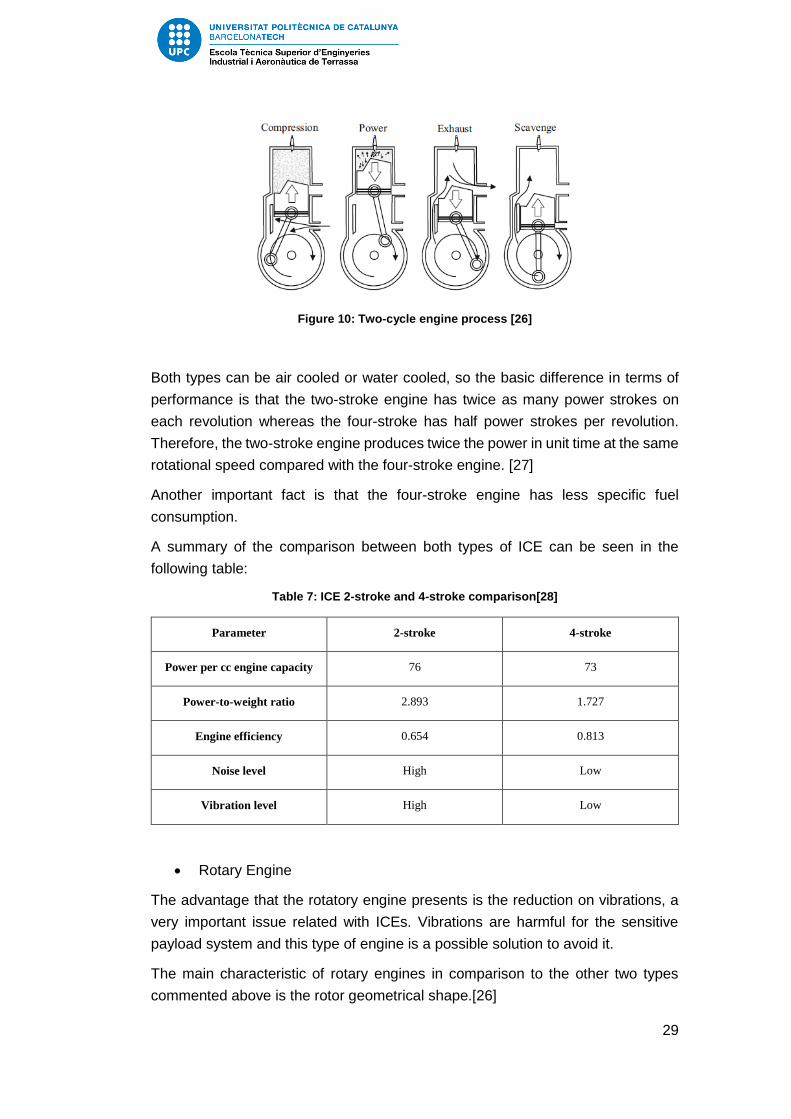
2-stroke engine
The two-cycle engine is common used in model airplanes although are not as well
understood as four-cycle engines. The processes during the cycle are the same
but some of them occur simultaneously, as can be seen in Figure 10.
29
Figure 10: Two-cycle engine process [26]
Both types can be air cooled or water cooled, so the basic difference in terms of
performance is that the two-stroke engine has twice as many power strokes on
each revolution whereas the four-stroke has half power strokes per revolution.
Therefore, the two-stroke engine produces twice the power in unit time at the same
rotational speed compared with the four-stroke engine. [27]
Another important fact is that the four-stroke engine has less specific fuel
consumption.
A summary of the comparison between both types of ICE can be seen in the
following table:
Table 7: ICE 2-stroke and 4-stroke comparison[28]
Parameter 2-stroke 4-stroke
Power per cc engine capacity 76 73
Power-to-weight ratio 2.893 1.727
Engine efficiency 0.654 0.813
Noise level High Low
Vibration level High Low
Rotary Engine
The advantage that the rotatory engine presents is the reduction on vibrations, a
very important issue related with ICEs. Vibrations are harmful for the sensitive
payload system and this type of engine is a possible solution to avoid it.
The main characteristic of rotary engines in comparison to the other two types
commented above is the rotor geometrical shape.[26]
30
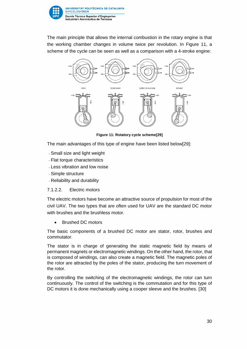
The main principle that allows the internal combustion in the rotary engine is that
the working chamber changes in volume twice per revolution. In Figure 11, a
scheme of the cycle can be seen as well as a comparison with a 4-stroke engine:
Figure 11: Rotatory cycle scheme[29]
The main advantages of this type of engine have been listed below[29]:
- Small size and light weight
- Flat torque characteristics
- Less vibration and low noise
- Simple structure
- Reliability and durability
7.1.2.2. Electric motors
The electric motors have become an attractive source of propulsion for most of the
civil UAV. The two types that are often used for UAV are the standard DC motor
with brushes and the brushless motor.
Brushed DC motors
The basic components of a brushed DC motor are stator, rotor, brushes and
commutator.
The stator is in charge of generating the static magnetic field by means of
permanent magnets or electromagnetic windings. On the other hand, the rotor, that
is composed of windings, can also create a magnetic field. The magnetic poles of
the rotor are attracted by the poles of the stator, producing the turn movement of
the rotor.
By controlling the switching of the electromagnetic windings, the rotor can turn
continuously. The control of the switching is the commutation and for this type of
DC motors it is done mechanically using a cooper sleeve and the brushes. [30]

31
Figure 12: Simple two-pole brushed DC motor scheme[30]
Brush-less DC motors
This type of motor is used in a wide range of sectors such as aerospace and
automotive industry. Compared to the brushed DC motor, the commutation is
made electronically.
BLDC motors are a type of synchronous motor, which means that the magnetic
field generated by the rotor rotates at the same frequency. The stator consists of
electrical steel laminations and windings placed at the slots whereas the rotor is
made up of permanent magnets.
The basic configuration of this type of motors can be seen in the following figure:
Figure 13: Brushless DC motor components[31]
The main advantages of the brushless motor in comparison to the brushed motor
are listed below:[31]
- Better speed vs torque characteristics
- High dynamic response
- High efficiency
- Long operating life
- Noiseless operation
- Higher speed ranges
For all this advantages, and as the market research shows, the brushless DC motor
is the most used electric motor for UAV applications.

32
7.1.2.3. Estimation of the required thrust
The first step to estimate the specifications of the required motor is analysing the
specifications.
The first parameter to estimate is the minimum required thrust. This parameter is
independent of the altitude, however, it depends on the speed as can be seen in
the following figure. For higher speeds, higher is the altitude to reach the minimum
required thrust.
Figure 14: Thrust vs speed and altitude effect[32]
For estimating the thrust, the rate of climb is used. The rate of climb it depends on
difference between available power and required power as can be seen in the
following equation:
𝑅𝑂𝐶 =𝑃𝐴 − 𝑃𝑅𝑊
(9)
For propeller aircrafts, the available power is usually considered constant, so for a
UAV it will also be used such simplification. Therefore, the highest ROC take place
when the power required is lowest, in other words, at the point of maximum
efficiency (L/D).
To calculate the required thrust the following equations can be used:
𝑅𝑂𝐶 =𝑇 · 𝑉 − 𝐷 · 𝑉
𝑊 ⇒ 𝑇 =
𝑅𝑂𝐶 · 𝑊
𝑉+ 𝐷 (10)
𝑃 = 𝑇 · 𝑉 (11)
However, the rate of climb is a difficult parameter to estimate. Therefore, the design
point is used for determine the maximum thrust required.
Considering a maximum weight of 20 kg, so that the maximum weight allowed of
25 kg in not overpassed, the following data from the aerodynamic study and the
constraint analysis is obtained:
𝑉max(
𝐿𝐷)= 33
𝑚
𝑠

33
𝑃20 𝑘𝑔 ≅ 3 𝑘𝑊
Then, the estimated required thrust at maximum L/D is calculated:
𝑇 =𝑃
𝑉=3000 𝑊
33𝑚𝑠
≅ 90 𝑁
7.1.2.4. Decision
Once the different possibilities have been studied, selecting the option that best
fits within the design requirements can be made. A simple method to schematically
show the best option is by means of an OWA analysis.
First we describe the parameters that need to be taken into account:
Endurance
One of the design requirements is to ensure a flight time between 2 and 12 h.
Therefore, is important to select an option that allows this requirement.
Efficiency
Efficiency is always a main parameter that needs to be maximized in propulsion
systems.
Performance
Selecting the option that allows a better performance, in other words, the type of
system that will ensure better power loading.
Price
How much it will cost is always an issue that need to be taken into account in order
to design the best solution with minimum cost.
Maintenance cost
The cost of fuel or electricity needs to be taken into account. A comparison
between the prices of fuel and electric eGallon can be seen in Figure 15.
Figure 15: Comparison between eGallon Price and gasoline Price in the US[33]

34
Payload capacity
The power source is directly related to the payload capacity. So it is quite
important to select a solution that ensures a great payload capacity in order to
install better sensors and cameras.
The results of the OWA analysis can be seen in the following table:
Table 8: OWA method for selecting the power source
Weight ICE Electric Motor
Criteria g p p·g p p·g
Endurance 80 2 160 1 80
Efficiency 60 1 60 2 120
Performance 70 2 140 1 70
Price 70 1 70 2 140
Payload capacity 70 2 140 1 70
Maintenance Cost 60 1 60 2 120
SUM (p·g) 410 630 600
OWA 0,77 0,73
The most critical design requirement for selecting the propulsion system is the
endurance. Electric motors are gaining importance in the actual UAV market,
however for ensuring a minimum of 2h of flight time the only feasible solution is an
internal combustion engine or a hybrid propulsion system. As was mentioned
before, the hybrid technology is being developed at the present time so it has not
been considered.
As was described before, the possible internal combustion engines are 2-stroke,
4-stroke and rotary engines. The rotary engines for UAV are quite heavy in
comparison with the pistons engines. In order to keep the weight as low as
possible, the rotary engines have been discarded.
From Table 7, it can be observed that the 2-stroke engine has better power-to-
weight ratio and power capacity than the 4-stroke, ergo, it is a better option in terms
of power specifications. However, the 4-stroke engine is a better option in terms of
efficiency, fuel consumption, noise level and vibrations. For a surveillance drone,
minimising the vibrations that the engine produces will provoke less damage
generated by vibration.

35
Although the better power specifications of 2 -stroke engines, using a 4-stroke has
been decided.
Taking into account that the MTOW needs to be lower than 25 kg and according
to Figure 6, an approximated value of 3000 W engine have to be chosen. Another
important aspect is the engine weight. In order to limit the search, the maximum
weight allowed is about 3 kg.
The market research of 4-stroke engines can be seen in the Annex. The
specifications of the engines considered adequate for the study can be seen in the
following table:
Table 9: Comparison of UAV engines
FT-300[34] RCV Engine[35]
Capacity 49 cc 70 cc
Speed range - 2000 – 10 000 rpm
Power Output 3 kW at 7000 rpm 4 kWat 8500 rpm
Fuel Consumption - 330 g/kW h
Weight (kg) 1.828 2.7
Due to power requirements, a minimum of 3 KW for the power output is needed.
Comparing the engines that meet the restriction, it can be observed that the FT-
300 has the best power-to-weight ratio. However, the RCV 70 cc UAV engine, has
been selected due to the wider range of speeds.
7.1.3. Propeller
The design of the propeller is one of the most difficult tasks due to the complexity
of rotor aerodynamics. However, some basic parameters have to be defined.
The most common way to classify the propellers is by the number of blades. From
a general point of view, the lower the number of blades the higher is the propeller
efficiency. Discarding the one-blade propeller due to balance problems, the best
option in terms of aerodynamics is the two-blade propeller. However, if the
demanding thrust is high more blades will be needed thereby decreasing
efficiency.
Some estimations should be made in order to determine the number of blades, the
diameter and the pitch.

36
From Roskam Airplane Design book[36], the following equation to estimate the
propeller diameter is used:
𝐷𝑝 = √4 𝑃𝑚𝑎𝑥𝜋 𝑛𝑝 𝑃𝑏𝑙
(12)
Where Pmax is the maximum power, np the number of propeller blades and Pbl the
power loading per blade. To estimate the Pbl value, some different ranges are
defines depending on the type of aircraft. The aircrafts that appear in Roskam that
resembles more to UAV are the homebuilt airplanes, with a Pbl between 1 and 3,2
hp/ft2. An average value of 2 hp/ft2 have been considered. For having a high
efficiency propeller, the number of propeller blades have been set at 2. Finally, the
Pmax considered is 4 hp taken into account the weight estimation.
The diameter obtained is:
𝐷𝑝 = √
4 · 4 ℎ𝑝
𝜋 · 2 · 2ℎ𝑝𝑓𝑡2 = 1.3 𝑓𝑡
⇒𝐷𝑝 = 0.4 𝑚
Another important parameter to take into account is the propeller pitch, defined as
the distance that the propeller advances in one revolution[37]. The following figure
schematizes the propeller pitch definition:
Figure 16: Propeller pitch scheme[37]
The propeller pitch is directly related to the blade angle of attack and there are two
types: geometrical pitch and effective pitch. The geometrical pitch is the theoretical
distance that the propeller makes in one revolution and the effective pitch the real
distance that makes. The effective pitch is lower than the geometrical due to
propeller slippage in the air.

37
Figure 17: Blade angle of attack[38]
Figure 18: Difference between effective and geometrical pitch[38]
The angle of attack seen by the blades of the propeller changes with the aircraft
velocity so that selection the pitch value is a complex decision. Thus, the pitch will
be selected so that the main requirements are ensured, although it is not the most
effective solution.
From section 3.1.2.3., the estimated required thrust is 90 N. Using a propeller
selector software, the following specifications have been calculated[39]:
Figure 19: Propeller selector software
The UAV propeller manufacturers do not provide many information of their
products due to the fact that they design it taking into account the client
requirements. Therefore, it should be decided in future considerations.

38
7.1.4. Engine and propeller location
The two basic options regarding the location of the propulsion system are pusher
and tractor configuration. A brief description of the advantages and disadvantages
of each configuration have been done.
Pusher configuration
In this configuration the propeller is situated at the back of the fuselage. The main
advantage that provides good stability due to the fact that the wings are not
affected by the propeller wash. However, since the clean air does not arrive to the
propeller, the thrust is affected.
Tractor configuration
The main advantage of having the propeller situated at the front of the UAV is that
a non-disturbed air arrives directly and consequently a more efficient thrust is
generated. The drawback of this configuration is that the propeller wash affects the
aerodynamic efficiency and also the surface controls.
The contribution of the tractor configuration disadvantage is more important than
the pusher configuration drawbacks. Therefore, the pusher configuration is
selected.
7.2. Aerodynamics
7.2.1. Airfoil selection
The purpose of this section is finding the most efficient airfoil in order to obtain the
best performance of the UAV. The first step is to define the simulation conditions.
Simulation conditions
A possible range of Reynolds number needs to be computed with equation (13).
Taking into account the market research and some assumptions, some maximum
and minimum values for the parameters of the following equation have been taken.
𝑅𝑒 =𝜌𝑉𝑐
𝜇 (13)
- Density
The sea level density has been considered as the maximum value. The minimum
value is the density at the maximum height allowed by regulations, approx. 150
m.
- Speed
According to the market research, a maximum speed of 40 m/s and a minimum of
13 m/s have been taken.

39
- Chord
The chord depends on the wing configuration. However, since the UAV have to be
as small as possible so that the maximum weight allowed is not overpassed, a
range between 0.2 m and 0.6 m has been considered.
- Viscosity
As viscosity is usually expressed as function of temperature, a range of
temperatures has been taken. The maximum is sea level temperature, 288.15 K,
and to take aware of the possibility of flying in extremely cold conditions a minimum
of 270 K has been considered. Using a gas viscosity calculator, the air viscosity
values have been calculated.[40]
The following table summarizes all the simulation conditions:
Table 10: Simulation conditions
Velocity (m/s) Height (m) Density (kg/m3) Chord (m)
Minimum value 13 1500 1,06 0,2
Maximum value 40 0 1,225 0,6
Temperature(K) Viscosity(kg/m·s) Reynolds
Minimum value 270 1,72·10-5 1,6·105
Maximum value 288,15 1,812·10-5 1,6·106
Decision criteria
The criteria used for selecting the best airfoils is:
- Thickness greater as possible due to structural restrictions
- Having a consistent angle of attack for maximum efficiency
- Level of efficiency as high as possible
- Stall speed as much different as possible to cruise speeds
Airfoil simulation
For UAV applications, the low Reynolds airfoils are the most commonly used.
Using the XFLR5 software, the following low Reynolds airfoils have been analysed.

40
For analysing the airfoils a wing of 3 m of wingspan and 0.2 m of chord has been
used. The results are shown in the following table.
Table 11: Results of airfoil simulation
Airfoils AoA max
Cl/CD
Max
CL/CD CL CD Cm Vstall (m/s) Thickness
(%)
NACA
4415 1,5 34,869 0,54 0,015 -0,231 31,45 15
NACA
4418 2 32,372 0,598 0,018 -0,246 29,88 18
NACA
2415 2,5 34,679 0,44 0,013 -0,158 34,84 15
NACA
2418 3 32,535 0,496 0,015 -0,173 32,8 18
NACA
23012 4,5 32,254 0,538 0,017 -0,144 31,5 12
NACA
23015 4 30,164 0,499 0,017 -0,135 32,71 15
NACA
23018 3,5 28,934 0,458 0,016 -0,125 34,13 18
Clark-Y 1,5 38,599 0,48 0,012 -0,198 33,34 11,72
Gemini 3 35,027 0,477 0,014 -0,161 33,46 15,37
e169 5,5 33,529 0,53 0,016 -0,132 31,73 14,4
e205 2,5 37,595 0,463 0,012 -0,16 33,98 10,47
e387 1,5 38,529 0,469 0,012 -0,192 33,74 9,07
s8036 3,5 34,26 0,516 0,015 -0,165 32,17 16
In terms of aerodynamic performance, the Clark-Y is the best airfoil and has a
thickness greater than 10%. For this reasons, it has been selected as the UAV
airfoil.
7.2.2. Wing configuration
The different possible wing configurations have been described in order to analyse
them and chose the better option.

41
7.2.2.1. Canard configuration
This configuration is characteristic for having the wings and vertical stabilizer at the
rear and a smaller horizontal stabilizer in the front. Canard configuration increases
performance against stall, however they are complex to design and it may
experience stability problems.
7.2.2.2. Flying wing
It consists on a tailless fixed-wing aircraft without fuselage that produced a low
drag profile. The main problem for this type of aircrafts are controllability and
stability issues.
7.2.2.3. Conventional
This is the simplest configuration and the most used one due to the resemble with
standard aircrafts. It has a fixed wing near the front of the fuselage and vertical and
horizontal surfaces in the rear of the vehicle.
7.2.2.4. Blended wing
It is a type of fixed wing aircraft were the wings are smoothly blended into the
fuselage and so there is no clear dividing line between fuselages and wing. It can
be tailless or not. This configuration performs a good lift to drag ratio. However, the
complexity of the design makes it difficult to manufacture.
7.2.2.5. Tandem
This configuration consists of two wings, one at the front and other at the rear. The
main advantage of this wing configuration is that produces high values of lift.
However, the main drawback is the weight.
7.2.2.6. Biplane
As the tandem configuration, it consists of two wings but stacked one above the
other. With this configuration high lift is produced but as the tandem, weight is the
main issue.
7.2.2.7. Decision matrix
In order to select the best option, a decision matrix has been made. The
parameters that have been taken into account are listed below:
- Weight
One of the design requirements is to keep the total weight under 25 kg. Therefore,
it is the most important parameter.
- Portability
The wing configuration should be one that allows easy transportation of the vehicle.

42
- Complexity
It is important to design a low complex vehicle in order to reduce manufacturing
costs.
- Performance
The wing configuration needs to allow the design requirements and so issues like
take-off, maneuverability, stall speed, etc are taken into account.
- Stability and controllability
The wing configuration needs to be as stable as possible in order to ensure the
success of the mission without experiencing problems.
The following table illustrate the final decision.
Table 12: Decision matrix Wing configuration
Weight Canard
Flying
Wing Conventional
Blended
Wing Tandem Biplane
UAV Weight 30 6 9 7 8 5 5
Portability 20 7 6 7 5 7 8
Complexity 20 7 6 9 5 8 8
Performance 20 7 6 7 5 7 8
Stability and
controllability 10 7 6 8 5 6 7
TOTAL 100 67 69 75 59 65 70
The best configuration option taking into account the parameters described above
is conventional. The advantages that this configuration enables are a combination
of simplicity and good performance and a light structure.
7.2.3. Wing position
There are three possible configurations:
High wing
This configuration is the best option in regards of high lift and consequently for
short take-off. In terms of stability, is stable against perturbations.
Mid wing
Mid wings are the most used configuration in civil aviation due to highest velocities
and good lift and stability performances.

43
Low wing
In comparison to high wings, low wings have higher speeds and good
maneuverability. However, for take-off are not the better options and they need
high take-off distances.
According to the market research, the most common used position is high wing.
This is due to simplicity, easy to assemble and high lift that helps to take-off easily.
Therefore, the high wing configuration have been selected.
7.2.4. Tail configuration
The tail configuration is an important part of the UAV that have the objective of
provide stability. However, there are some related issues such as weight and
portability that need to be taken into account.
Some typical UAV tail configurations are described:
Cruciform tail
This configuration consists of a horizontal tail that intersects the vertical tail
approximately by the middle. One of the principal advantages is reducing the
effects of the downwash.
V tail
The V tail is a non-conventional configuration that replaces the horizontal and
vertical tail with two surfaces set in V-shape. Although it is not the better option in
terms of stability, is a good option to minimise weight. Another advantage is that
produces less drag.[41]
T-tail
The t-tail configuration consists of a vertical tail and the horizontal tail mounted at
the top, forming a T-shape. With this configuration, the tail is well kept out from the
disturbed airflow behind wing and fuselage and therefore downwash effects are
avoided. The main drawback for this configuration is the more complex design and
it does not work so good in low speed vehicles.
Twin tail
The twin tail, also known as H-tail, it consists on a horizontal surface just at the
rear of the fuselage and two vertical surfaces located each one at the edge of the
horizontal tail forming a H-shape. The main advantage of the H-tail configuration
is that keeps both vertical surfaces out of the current of air created by the propeller
allowing better control of the vehicle.

44
Conventional tail
The conventional tail is the most used configuration due to good results in stability
and easy design. It consists of a vertical tail mounted on the fuselage and a
horizontal stabilizer crossing the fuselage.
Inverted-V tail
It is very similar to the V-tail design but can be a good option to minimize weight.
Another principal advantage is that provides stabilisation in cross wind situations,
increases structure rigidity and allows coordinated turns without ailerons.[42]
In order to choose one of the tail configurations explained above, a decision matrix
have been made. The decision criteria parameters are described:
- Stability and control
The main function of the tail is to provide control surfaces so that the aircraft can
be stabilised. Some of the configurations are more stabilised than others and
therefore needs to be taken into account.
- Weight
Minimizing the weight is always an important factor. A maximum weight of 25 kg is
allowed so a tail configuration as lighter as possible need to be chosen.
- Portability
Some configurations can ensure an easy assembly system in order to facilitate
transportation.
- Complexity
It is important to find simplicity in the designs of the different part of the UAV so
that manufacturing costs can be keep it as low as possible.
- Performance
For tail selection, the performance will take into account if the configuration avoids
downwash effects and other aspects. In other words, that the UAV can operate
without experiencing problems.
The decision matrix can be seen below:

45
Table 13: Decision matrix for tail configuration
Weight Cruciform V-tail T-tail Twin
tail Conventional
Inverted-
V
UAV Weight 25 7 9 7 6 7 8
Portability 15 7 6 9 5 8 6
Complexity 10 5 7 5 6 8 7
Performance 20 7 7 7 8 8 7
Stability and
controllability 30 7 7 8 8 8 7
TOTAL 100 68 73,5 74 68,5 77,5 71
The conventional configuration is the best option due the combination of simplicity,
lightweight tail and good stabilising performance.
7.2.5. Wing Geometry
7.2.5.1. Selection of the planform
There are many different planforms in the market and the selection is not trivial.
Therefore, a brief study of the different options has been made. Although the
criteria for selecting the planform is based on aerodynamic purposes, structural
problems need to be taken into account. The following table summarizes the
advantages and disadvantages of each wing planform.[43]

46
Table 14: Study of the different planforms
Planform Advantages Disadvantages
Rectangular - Easy to manufacture
- Most commonly used
- Bad aerodynamic and
structural performance
Elliptical
- Minimum induced drag
planform
- Good structural behaviour
- Complex manufacturing
process (expensive)
Tapered
- Almost the same efficiency as
the elliptical wing
- Low induced drag
- Easy to manufacture
- Requires less reinforcements in
the wing tip allowing weight
reduction
- Stall stars at the wing tips
Mix3
- Trade-off between tapered and
rectangular planform (good
structural and aerodynamic
behaviour combined with the
property that stall is displaced
to the central area of the wing)
- Used for propeller aircrafts
- Worst behaviour against stall
than elliptical wings
The mix planform is the best option for propeller propulsion UAVs and it is also
characterised for having good aerodynamic and structural behaviour. In the actual
market, this planform is commonly used, so we can prove that is a feasible solution.
Due to this reasons, the mix planform is selected for the UAV study.
7.2.5.2. Wingspan
For selecting the wingspan, some simulations with the XFLR5 software has been
done. The range of wingspans simulated corresponds to the maximum and
minimum values of the market research. The results are presented in the following
table:
3 Rectangular shape from the root to a certain point and then a tapered section until the wing tip

47
Table 15: Study of the wingspan
Wingspan
(m)
Max
CL/CD
AoA (°)
Max
CL/CD CL CD Cm
Vstall
(m/s)
Vstall
AoA (°)
0.8 1 18.08 0.257 0.014 -0.126 33.51 20
1 1 20.115 0.284 0.014 -0.136 29.65 17.5
1.5 1.5 25.062 0.367 0.015 -0.160 24.09 14
2 1.5 28.933 0.401 0.014 -0.171 21.03 12
2.5 1 31.927 0.382 0.012 -0.168 18.83 11
3 1 34.197 0.397 0.012 -0.173 17.11 10.5
3.5 1 35.962 0.409 0.011 -0.177 15.86 10
4 1 37.433 0.419 0.011 -0.180 14.66 10
4.5 1.5 38.635 0.474 0.012 -0.194 13.94 9.5
The results show that the lift-to-drag ratio increases with wingspan whereas the
stall velocity decreases. These tendencies and the rate of change can be seen in
the following graphs:
Figure 20: Lift-to-Drag vs wingspan graph
0
5
10
15
20
25
30
35
40
45
0 1 2 3 4 5
CL/
CD
Wingspan (m)
Lift-to-Drag ratio vs Wingspan

48
Figure 21: Stall speed vs wingspan graph
The rate of change of the values decreases with the wingspan. In other words, the
curves decrease more rapidly for lower wingspan values. Between 3 and 4 m of
wingspan, the curve is smoother.
For aerodynamic purposes, the best option is 4.5 m. However, the higher the
wingspan the higher the wing surface and consequently more weight. In order to
keep the weight as low as possible and taking into account the smooth change in
values from approximately 3 m, a wingspan around 3 m has been taken.
7.2.5.3. Aspect ratio
Once the wingspan is selected, the effect of the aspect ratio in the UAV
performance can be studied. The aspect ratio is defined as follows:
𝐴𝑅 =𝑏
𝑐=𝑏2
𝑆 (14)
where b is the wingspan, c the average chord and S the wing area.
The wingspan value is fixed from 7.2.5.2 so for different chords combinations, the
AR effect will be studied. The wing is divided in 2 sections: one rectangular and
the other tapered as can be seen in Figure 22.
0
5
10
15
20
25
30
35
40
0 1 2 3 4 5
Stal
l sp
eed
(m
/s)
Wingspan (m)
Stall speed vs Wingspan

49
Figure 22: Wing geometry model
The rectangular section length has been fixed to 1.5 m. The following table
summarizes the results of the simulations:
Table 16: Results of the simulation for different wing geometries
croot
(m) ctip (m) AR
Max
CL/CD
AoA
(°)
Max
CL/CD CL CD Cm
Vstall
(m/s)
Vstall
AoA
(°)
0.3 0.2 10.9 1 36.364 0.413 0.011 -0.21 17.5 10.5
0.3 0.15 11.4 1 37.273 0.420 0.011 -0.22 17.77 10.5
0.3 0.1 12 1 37.945 0.425 0.011 -0.24 18.41 10
0.3 0.05 12.6 1 38.424 0.427 0.011 -0.24 19.95 8.5
0.25 0.2 12.6 1 37.656 0.421 0.011 -0.2 18.97 10
0.25 0.15 13.3 1 38.780 0.429 0.011 -0.22 19.3 10
0.25 0.1 14.1 1 39.697 0.436 0.011 -0.24 19.7 10
0.25 0.05 15 1.5 40.356 0.488 0.012 -0.27 21.41 8.5
0.2 0.15 16 1.5 40.161 0.486 0.012 -0.23 21.3 9.5
0.2 0.1 17.2 2 41.432 0.546 0.013 -0.27 21.43 10
0.2 0.05 18.5 2.5 42.456 0.603 0.014 -0.31 22.94 9
0.15 0.1 21.8 2.5 43.874 0.608 0.014 -0.27 24.34 9.5
0.15 0.05 24 2.5 45.475 0.619 0.014 -0.31 25.78 9
In order to analyse the tendency and the rate of change of different parameters
with the AR, the following graphs can be seen:

50
Figure 23: Lift-to-Drag ratio variation with the AR of the wing
Figure 24: Variation of the stall speed with the AR of the wing
The tendency is to maximise the CL/CD and minimise the stall speed. The higher
the AR the higher the CL/CD but also the higher the stall speed is. For wings with
aspect ratios between 15 and 17, a stabilization in the stall speed can be observed.
Therefore, an AR of 17 is the best option in order to obtain the best aerodynamic
performance. The final wing design parameters can be seen in the table below.
0
5
10
15
20
25
30
35
40
45
50
0 5 10 15 20 25 30
CL/
CD
AR
0
5
10
15
20
25
30
0 5 10 15 20 25 30
Stal
l sp
eed
(m
/s)
AR

51
Table 17: Final wing parameters
croot
(m) ctip (m) AR
Max
CL/CD
AoA
(°)
Max
CL/CD CL CD Cm
Vstall
(m/s)
Vstall
AoA
(°)
0.2 0.1 17.2 2 41.432 0.546 0.013 -0.27 21.43 10
Figure 25: Final Wing Design
7.2.6. Stability and control
Stabilizers have an essential role in a UAS. For any type of aerial vehicle, the
vertical and horizontal stabilizers need to be well design in order to ensure stability
during flight as well as control. For a UAV, the control operations are done
automatically by means of the autopilot calculations. In the following points, a
solution for both stabilizers have been provided. These stability and control
proposals have been calculated and designed using the 3D Panel Method, that the
XFLR5 software provides.
7.2.6.1. Conventional configuration tail
In 7.2.4, the conventional tail configuration was selected due to the simplicity,
lightweight configuration and it is known that it provides good stability performance.
It consists of a vertical tail mounted on the fuselage and a horizontal stabilizer
crossing the fuselage.

52
Figure 26: Example of UAV with conventional configuration tail[44]
7.2.6.2. Horizontal stabilizer
The horizontal stabilizer can be considered as a small wing that has the purpose
of providing longitudinal static stability. As a starting point, an example of a UAV
with conventional tail configuration and with similar wingspan and reasonable
weight values has been taken as a model. The UAV taken as reference is the
Spartan Phoenix, a fire surveillance drone designed by San Jose State University.
This UAV has a wingspan of 3.1 m and a weight of 11.3 kg. The dimensions of the
horizontal and vertical stabilizer can be seen in Figure 27.
Figure 27: Spartan Phoenix horizontal and vertical stabilizer dimensions[45]
The next step is to select an airfoil. For Low-Reynolds numbers, the horizontal
stabilizer airfoils are usually symmetrical. This is due to the fact that the
symmetrical airfoil is a solution of compromise when the aerial vehicle needs to fly
at different speed ranges and attitudes like UAVs. The following airfoils have been
simulated with the same conditions as the wing and with a fixed geometry in order
to compare them in equal conditions. The best known symmetrical airfoils are

53
NACA ones. Therefore, the study has been limited to NACA airfoils. The fixed
geometry used for the airfoils study can be seen in the following figure.
Figure 28: Horizontal stabilizer first iteration geometry
Table 18: Horizontal stabilizer airfoil siimulation
Airfoils
AoA max
CL/CD
(°)
max
CL/CD CL CD Cm
Vstall
(m/s) CL max
NACA
0012 4.5 22.7 0.30 0.013 -0.157 37.54 1.122
NACA
0015 4 21.9 0.27 0.012 -0.141 36.42 1.193
NACA
0018 4 20.6 0.27 0.013 -0.142 36.24 1.205
NACA
0021 4.5 19.5 0.31 0.016 -0.162 36.52 1.186
NACA
0024 4.5 18.4 0.31 0.017 -0.163 36.83 1.166
The stall speed values are approximately the same for all the NACA airfoils
simulated. However, the difference between the maximum CL/CD values have to be
taken into account. Therefore, the selection of the horizontal stabilizer will only be

54
determined by comparing the different efficiency values. The result of the
simulation shows that the most efficient airfoil is NACA 0012.
Once the airfoil is selected, the geometry of the horizontal tail needs to be studied.
The length has been fixed to 0.9 m, the same value as Spartan Phoenix UAV, in
order to simplify the study. So the variable parameter in this second simulation is
the taper ratio. The taper ratio is defined as follows:
𝜆 =𝑐𝑡𝑖𝑝𝑐𝑟𝑜𝑜𝑡
(15)
Different combination of tip chord and tip root have been proved. Furthermore, the
wing has been added to the simulation so that the contribution of both can be taken
into account. The distance between the wing and the horizontal stabilizer has been
fixed to 1,6 m, that t is coinciding with the Spartan Phoenix UAV.
Figure 29: Wing and horizontal stabilizer simulation
The results of the simulation can be seen in the following table.

55
Table 19: Simulation wing and horizontal tail changing taper ratio
Croot
(m)
Ctip
(m)
AoA
max
CL/CD
(°)
max
CL/CD CL CD Cm
Vstall
(m/s)
Vstall
angle
(°)
0.3 0.2 3.5 37.810 0.718 0.019 -0.643 20.36 10
0.3 0.15 3.5 37.920 0.714 0.019 -0.617 20.44 10
0.3 0.10 3 37.957 0.653 0.017 -0.490 20.54 10
0.25 0.2 3.5 38.130 0.714 0.019 -0.597 20.44 10
0.25 0.15 3.5 38.203 0.710 0.019 -0.570 20.53 10
0.25 0.10 3 38.216 0.649 0.017 -0.451 20.63 10
0.2 0.15 3.5 38.504 0.706 0.018 -0.519 20.64 10
0.2 0.10 3 38.469 0.645 0.017 -0.408 20.75 10
The stall speed does not change appreciably, therefore the stall speed is not
considered on the criteria for selecting the horizontal stabilizer. However, in terms
of efficiency the best chord combinations are 0.2 m for the root and 0.15 m for the
tip. Finally, in order to provide longitudinal stabilization, the Cm should be null for
the angle of maximum efficiency of the wing and tail configuration. Furthermore,
the slope of the Cm - 𝛼 graph should be negative. In order to adjust the Cm so that
it goes null for the angle of maximum efficiency, the tilt angle has been modified by
the trial and error method.
The tilt angle that adjust the Cm to 0 at the maximum angle of efficiency is -2.55°.
The following Cm - 𝛼 graph has been obtained with this simulation and it can be
observed that at 3.5° (angle of maximum efficiency) the Cm is almost null.

56
Figure 30: Cm - 𝜶 graph for the configuration wing - horizontal tail with tilt angle of -2.05°
The slope of the graph above is negative. Therefore, it can be concluded that is a
stable configuration. The slope of the linear function has been calculated:
𝐶𝑚𝛼 =−0.4 − 0
6 − 3.5= −0.16 (16)
The slope calculated is quite high. This means that the reaction to perturbations
will no occurred too smoothly. However, it is stable and for a pre-design phase is
an affordable value.
7.2.6.3. Vertical stabilizer
As in the horizontal stabilizer, the first step is selecting the airfoil. It is quite common
in general aircrafts that the airfoils used for vertical and horizontal stabilizers are
both NACA symmetric airfoils.[46] So the following NACA airfoils have been
simulated with XFLR5 and the results obtained have been tabulated in the table
below. The geometry of the vertical tail has been fixed using the values of the
Spartan Phoenix and the wing and the horizontal tail have been considered in the
simulation.

57
Figure 31: Simulation for selecting the vertical stabilizer airfoil
Table 20: Airfoil vertical stabilizer simulation for the configuration wing, horizontal and vertical stab
Airfoils
AoA max
CL/CD
(°)
max
CL/CD CL CD Cm
Vstall
(m/s)
Vstall
angle
(°)
NACA
0008 4 33.990 0.705 0.021 -0.084 20.66 10.5
NACA
0009 4 33.881 0.705 0.021 -0.084 20.66 10.5
NACA
0010 4 33.746 0.705 0.021 -0.084 20.66 10.5
NACA
0012 4 33.439 0.705 0.021 -0.084 20.66 10.5
The results for the different airfoils tested are quite similar. This is due to the fact
that the vertical stabilizer does not have a considerable effect in the whole UAV
configuration. However, it is interested to note that the Cm is close to 0 for the angle
of maximum efficiency. Although the difference between these airfoils is almost
negligible, the most efficient solution is using NACA 0008.

58
Once the airfoil is fixed, the geometry has been studied. An important parameter
to take into account for the vertical stabilizer is the tail volume coefficient. This
coefficient is expressed as follows:
𝑣𝑣 =𝑆𝑣 · 𝐿𝑣𝑆𝑤 · 𝑏
(17)
Where Sv is the elevator surface, Lv is the distance between the leading edge of
the wing and the leading edge of the elevator, Sw is the wing surface and finally b
the wingspan. The values fixed in equation (17) are:
Sw = 0.525 m2
b=3 m
The unknown parameters are the elevator surface and the distance between
leading edges. Since the length of the vertical stabilizer has been decided to be
fixed at the same value as the reference UAV model, the taper ratio is the variable
parameter regarding to the elevator surface. Before, starting to analyse the effect
of the vertical taper ratio tail, an experimental consideration has been taken into
account. It is proved that for gliders the tail volume coefficient must be between
0.02 and 0.025 [36]. Therefore, for a UAV the tail volume coefficient needs to have
the same order of magnitude.
Some combinations for the root and tip chords with different Lv values have been
studied in order to select one that can give a reasonable value for the tail volume
coefficient. For further information of the results of the study, see the Annex.
The criteria for selecting the vertical tail configurations that will be simulated is
trying to minimize the tail volume coefficient in order to provide a feasible design
based on the limited glider range commented above. The geometries selected and
their corresponding simulation results can be seen in the following table.
Table 21: Results of the simulation for different vertical tail geometries
Croot
(m)
Ctip
(m)
Lv
(m)
AoA
max
CL/CD
(°)
max
CL/CD CL CD Cm
Vstall
(m/s)
Vstall
angle
(°)
0.25 0.15 1.3 3.5 35.264 0.653 0.019 -0.002 20.60 10.5
0.25 0.1 1.3 3.5 35.383 0.653 0.018 -0.002 20.60 10.5
0.25 0.1 1.4 3.5 35.383 0.653 0.018 -0.002 20.60 10.5
0.25 0.1 1.5 3.5 35.383 0.653 0.018 -0.002 20.60 10.5

59
The most efficient geometry is the 0.25 – 0.1 m chord combination. Since the
distance between leading edges does not affect to the results of the simulation, the
one that has the minimum tail volume coefficient has been selected.
Figure 32: Final tail configuration
7.2.6.4. Control surfaces
Aileron
The ailerons are responsible of the roll control movement. This lateral control is
achieved through the deflexion of control surfaces in the trailing edge of the wing.
This deflection allows a change in the airfoil curvature, that it is translated in a
reduction or increment of lift. For example, if the desired roll movement is toward
the right, the aileron of the left will be deflected downward to increase curvature
and consequently increase the lift produced by the left wing. Whereas the right
aileron will be deflected upward so that the lift is reduced in the right wing, creating
a roll moment towards the right. The deflections of the ailerons are done
automatically by the commands transmitted by the autopilot based on
instantaneous calculations.
The design of the ailerons follows a complex method and it can be considered out
of the scope for a preliminary solution proposal.
Elevator
The elevators are the control surfaces situated on the final section of the horizontal
stabilizer. There are responsible of generating a pitch control moment. The

60
longitudinal control is achieved by deflecting the horizontal tail surface upwards or
downwards. For creating a pitch moment that increases the angle of attack, the
elevator should be deflected upwards so that it produces a lift reduction in the tail
and consequently the tail will fall ant the nose of the UAV will move upwards. If the
desired control moment is decreasing the angle of attack the reverse process is
needed.
The design of the elevator follows a complex method and it can be considered out
of the scope for a preliminary solution proposal.
Rudder
The rudder is the control surface responsible of the yaw control. It is situated at the
final part of the vertical stabilizer. For turning the nose of the aircraft to the right,
the rudder should be deflected to the right so that a force in left direction is created
generating a yaw moment to the right.
The design of the rudder follows a complex method and it can be considered out
of the scope for a preliminary solution proposal.
7.3. Communication system and Ground Control Station
The communication system is one of the most critical subsystems of the UAS. A
failure in the communication links between the air vehicle and the control station
will be traduced un the inability to accomplish the objectives of the UAV mission.
The communication system consists of an uplink that transmits commands from
the ground control station to the UAV and a down-link that transmits the data from
the UAV to the ground station.
The main functions of the communications links are:
- Controlling the flight of the UAV
- Receive and process the data from the payload sensors
- Ability to control the operation of the payload
The basic specifications that should be defined for the UAS communication system
are[27]:
- Data rate: amount of data transferred per second by a communication channel.
It is measured in bytes per second (BPS)
- Bandwidth: difference between the highest and lowest frequency. In other words,
the width of the band of frequencies that the communication channel uses
7.3.1. Communication Media
The communication media is the communication channel used for linking the aerial
vehicle with the ground control station[47]. There are different possibilities[27]:

61
Fibre-optics
Fibre-optics communications are a good option to take into account due to the
efficient and fast way to transmit large amount of data. The fibre-optic is usually
used to communicate the ground control station and the antenna. The information
sent to and from the UAV is a critical parameter that determines the success of the
mission. Therefore, high bandwidth and rapid transmissions over long distances
need to be provided. Fibre-optics can provide the bandwidth and transmission
capabilities required so it is a well-positioned candidate. [48]
By Laser
This communication media consists on propagating light in the air so that data can
be transmitted wirelessly. Although the advantages that this type of communication
provides, it has some important drawbacks such as atmospheric absorption that
limits the range. This technology is being developed in order to reach a feasible
solution but nowadays is not often used.
Radio communications
The radio communications are the most common solution for this type of systems.
In other words, is the most feasible wireless solution. This is the main reason why
it will be the communication media implemented.
7.3.2. Data link
As was mentioned before, the data link is one of the most critical parts of the
systems. Therefore, it is quite important to define the main functions of the data
link and make a preliminary study. The communication media selected for the data
link is radio frequencies as can be seen in 7.3.1.
Functions
The data-links functions for an UAV are illustrated in Figure 33 and described as
follows:
- Uplink: is the communication link in which the ground control station is the
transmitter and the UAV the receiver. A bandwidth of a few kHz is needed and it
is basically used for sending controls to the aerial vehicle.
- Downlink: is the communication link in which the UAV acts as the transmitter
and the ground control station as the receiver.
- GPS link: in order to provide a navigation system so that information about the
position is obtained, a GPS link needs to be ensured.

62
Figure 33: Data-link functions[26]
Subsystems
The data-link is typically divided into different subsystems described as follows:
- UAV subsystems
In the UAV there 2 subsystems placed, the Air Data Terminal (ADT) and the
antennas. The ADT consists of a radio frequency (RF) receiver and transmitter,
modems to encode the digital information for transmission and processors if
compressing the data is required. [26]
- Ground control station subsystems
The ground data terminal consists of antennas, RF receiver and transmitter,
modems and processors to reconstruct the data compressed.
Frequency selection
In UAV missions, the rates of data that are usually transmitted are high and
consequently higher radio frequencies are needed. These higher radio frequencies
have the disadvantage that they not have the ability to be refracted, requiring a
direct and uninterrupted line-of-sight (LOS) between the transmitter and the
receiving antennas. [26]
For selecting the range of frequencies is important to take into account that low
frequencies are easier to propagate but with a poor data rate. On the other hand,
the higher the frequencies the higher the capability of carrying data rates. However,
the LOS increases and consequently the power required to transmit the data is
also higher.
Before selecting the range of frequencies, the RF spectrum has been studied. The
width of the RF spectrum goes from 3 kHz to 300 GHz and it can be divided as
follows[26]:

63
Table 22: RF spectrum
Band Name Frequency Wavelength Applications
Very Low Frequency
(VLF) 3 – 30 kHz 100 – 10 km
Maritime Navigation
signals
Low Frequency (LF) 30 – 300 kHz 10 – 1 km Navigational aids
Medium Frequency
(MF) 300-3000 kHz 1 km – 100 m AM radio
High Frequency (HF) 3 – 30 MHz 100 – 10 m Aircraft communications
Very High Frequency
(VHF) 30 – 300 MHz 10 – 1 m Aircraft communications
Ultra High Frequency
(UHF) 300 – 3000 MHz 1 m – 100 mm
Aircraft radars, TV
broadcast, Wireless
LAN, Mobile phones
Super High Frequency
(SHF) 3 – 30 GHz 100 – 10 mm
Space and satellites
communications,
Microwave systems
Extremely High
Frequency (EHF) 30 – 300 GHz 10 mm – 1 mm Radio Astronomy
For a civil UAS, the typical frequencies used for the different data links and
transmission can be seen in Figure 34.
Figure 34: Frequencies generally used for UAV applications
In order to select a feasible frequency band, the following table summarizes the
advantages and disadvantages of the most used in communication systems.

64
Table 23: Advantages and disadvantages of RF bands[49]
Frequency Band Advantages Disadvantages
430 MHz
- Multiple channels
- Less range distortion due to
weather
- Less multipath distortion
- Do not enable video broadcast
- Legal power transmitted
restrictions
900 MHz - Enables video broadcast
- Low cost
- EU legal power transmitted
restrictions
- Interferences due to wide use
(WLAN, phones, etc.)
2.4 GHz - Enables video broadcast
- Low cost
- Interferences due to wide use
- LOS operational requirement
- Legal restrictions
5,8 GHz
- Enables video broadcast
- Small transmitting antennas
- LOS operational requirement
- Range affected by air humidity
- Expensive cost
Due to the high data rate needed for the UAV mission (Video broadcast), high
frequencies are needed. The typical ones used in the market are 2.4 GHz and 5.8
GHz. The most potential problems that need to be avoided are interference issues,
that can cause loss of control and flyways. A feasible solution is to avoid having
two frequencies in the same band. Therefore, the most typical configuration used
for civil UAV are combining 2.4 GHz with a 5.8 GHz link.[50]
Data rate
The data rate is the number of bits transmitted per second through a digital
transmission system, so is the speed of data transmission. For video streaming,
the data rate needed is quite high. The minimum data rate for a good performance
surveillance camera is 20 Mbps, however if more definition is needed the data rate
can reach values of 2 Gbps. Therefore, the data rate depends on the camera and
a value can’t be assumed.
The bandwidth is the difference between the highest and the lowest frequency of
a signal. This concept is very related to data rate and in some fields of
communication can be used as synonyms[51]. The higher is the bandwidth, the
higher needs to be the data rate. In applications where video streaming is the main
function to be developed, the bandwidths are excessive and consequently, a data
processing task has to be provided in order to accomplish bandwidth compression.

65
The analysis of the data processing system has been contemplated as out of the
project scope and therefore it is an issue that can be developed in future
considerations.
UAV Antenna
Regarding to the direction of propagation, there are two types of antennas:
- Omnidirectional: antenna that transmits signals in all directions with uniform
power.
- Gain antenna: it concentrates the beam power in one direction. With this antenna
the effective radiated power increases. However, the antenna must be always
sending the data in the direction of the receiver, that will be mounted in the aerial
vehicle. This requirement introduces complexity to the system due to the fact that
pointing commands need to be send.
In order to avoid complex solutions and after a brief market research,
omnidirectional antennas are the most used for civil applications. The main
parameters to select the antenna are the frequency band in which they can send
signals, the gain and finally the weight. Taking into account the range of
frequencies selected for the data link (2.4 GHz and 5.8 GHz), some antennas in
the market can be seen below. The main manufacturers consulted are Cobham[52]
and Pharad[53].
Table 24: Market research Antennas
Frequency (GHz) Gain (dBi) Weight (g) Size (mm)
1 - 6 2 (Nominal) 190 134x59 ᴓ
2 - 18 2 (Nominal) 600 104x39 ᴓ
1.7 - 6 1.3 (1.8 GHz)
3.1 (4.2 GHz) 5.7 63.5x35.5x0.2
0.8 - 6
2.4 (0.8 GHz)
4.3 (1.5 GHz)
5 (6 GHz)
75 130x23x114
0.8 - 6
2.4 (0.8 GHz)
4.3 (2.4 GHz)
5.2 (5.8 GHz)
5.7 125x51x0.2
0.225 - 6
0 (200 MHz)
2.1 (0.6 GHz)
2.7 (0.9 GHz)
3.1 (2 GHz)
29 340x260x0.2

66
4.1 (3.6 GHz)
5.7 (5.8 GHz)
Radio Modem
It is necessary to provide an on-board radio modem in order to transfer and receive
the data. Therefore, the data link between the aerial vehicle and the ground control
station is established.
The idea is to have a transceiver on-board and at the ground control station so the
data communications are accomplished. The less expensive solution is using
XBee telemetry kit, an open-source telemetry module. It requires configuration and
installation but is a low cost solution for creating Radio Private Networks.
Figure 35: Radio Telemetry kit for 2.4 GHz[54]
The price for the radio telemetry kit is of 115€. [54]
7.3.3. Ground Control Station
7.3.3.1. Functions and components
The ground control station is the main subsystem for controlling unmanned
vehicles. The functions of a GCS can be divided into planning and operation
functions[26]. The planning functions are:
- Design of flight routes (waypoints)
- Study of the mission area using maps
- Imposing mission requirements such as altitude, speed, etc.
- Process the planning messages
On the other hand, the operation functions are listed below:
- Launch, control and recover the UAV
- Control and monitoring of the payload
- Monitoring UAV position (GPS)
- Change mission planning requirements
- Display sensor data received from the UAV

67
- Save useful data
The basic components for a GCS can be seen in the following figure:
Figure 36: Example of portable GCS [55]
For civil applications, the most used GCS are portable and are composed by the
following items:
- Antennas to receive and transmit data
- Computer where the software would be installed
- Screen Display for monitoring some sensor data
- Batteries to provide power to the GCS and the corresponding power status
display
- Joystick to control the UAV
- GPS antenna
- Electronic compartment where data links, video receivers, data acquisition
devices and data storage drives can be installed
- Set of interfaces for other devices: USBs, Ethernet, video inputs, serial ports,
VGA, microphone, audio
3.3.3.2. Software
The software selection depends on the flights modes desired and mission
requirements such as video streaming, flight planning, return to launch site among
others. In order to have a first approximation of what the software should provide,
the principal functions and flight modes have been described.[56]

68
Map planner
As was commented above, the possibility to design the route before starting the
mission is one of the main functions of the GCS. By using waypoints, the route can
be programmed and, in some cases, some basic parameters can also be fixed.
Camera control
Capturing images manually or generate a photo/video survey plan so that the
camera can do it automatically.
Stabilize mode and automatic mode
Changing from autonomous flight to manual control flight needs to be ensured.
This allows inspection when an alarm is activated.
Altitude hold mode
This flight mode maintains the UAV altitude constant.
Return to launch mode
The purpose of this flight mode is that the UAV can return autonomously to the
launch site if it gets out of the line of sight. It is a security measure.
Landing mode
A function that sends the command of landing the UAV.
Alarm mode
If the UAV detects an anomaly, an alarm signal needs to be sent to the GCS. Then
the software should provide a sensory stimulation so that the user can act to
prevent any trouble.
There are different types of ground control station. The most used ones are RC
that use a smartphone or a tablet as the device for the software and video
streaming. As a more professional option, there are GCS that use laptops, extra
screens, etc. An example of these last GCS can be seen in Figure 36. In order to
maintain the costs as low as possible the simpler control stations have been
selected.
The problem of selecting it from a market research is that the manufacturers design
their own controllers and in consequence they only work with specific drones.
However, in order to estimate the cost of the GCS, it has been considered a 1000
€ laptop, a 1000 € data link and a 1000€ software.

69
7.4. Payload
7.4.1. Introduction
The payload consists of all the instruments needed for the development of the
mission. Therefore, all the equipment necessary to fly, navigate and recover are
not considered as payload. The most common payloads are cameras.
The payload selection criteria is based on the mission requirements. Therefore,
the objectives of the mission needs to be clearly detailed. Furthermore, the weight
is the most critical parameter while selecting the instruments. The trend is
minimising the weight but generally better quality instruments are heavier. Due to
this inconsistency, the decision of the payload is not trivial.
7.4.2. Mission requirements
As commented in 6.3, the typical mission requirements for a surveillance UAS are:
Recognition: Determining which class an object belongs to. For example,
the sensor needs to differentiate a tank from a person.
Detection: Determining objects of interest. As an example, if there is some
movement, the UAV needs to measured it and detect it.
Video streaming during day and night: Allowing the user to watch the video
recorded by the camera.
Panoramic view of 360°
7.4.3. Description of the payload
According to the mission requirements, the principal payload for a surveillance
UAS are day and night-vision cameras with IR imaging. The technology related
with camera sensors had experienced a rapid growth in the last years. Therefore,
in the actual market it can be found both cameras, day and IR night-vision, in one
device. They also incorporate object tracking software and HD streaming.
Taking into account the mission requirements, the following characteristics should
be provided by the camera:
Gyro-stabilized gimbal
Nowadays, nearly all UAV cameras are gyro-stabilized. This means that by using
a gimbal, the image is stabilized automatically due to the free rotation about a
single axis.

70
Multi-sensor
As commented above, in the actual market multi-sensor cameras can be found.
The main sensors that needs to be provided are the Electro-Optical sensor and the
IR sensor.
The EO sensors are able to convert light rays into electronic signals so that it can
be read by an instrument. This type of sensor enables the UAV to detect
movement. [57]
On the other hand, the IR sensors are necessary for night surveillance. There are
two types of night-vision cameras based on IR sensors: image enhancement and
thermal imaging.
Figure 37: Comparison between image enhancement (left) and thermal imaging (right)[58]
Both types of night vision work in different ways. Thermal imaging captures the
upper portion of the infrared light spectrum. Any object emits in this infrared light
as heat. In this way, hotter objects emit more of this light than cooler ones. Thermal
imaging is achieved by using lens that are able to focus the infrared light emitted
by all the objects in view and by using a phase array of infrared detector elements,
a temperature pattern called thermogram is created. This temperature pattern is
transformed into electric impulses and finally into data for the display.
Image enhancement is able to collect tiny amounts of light, including the lower
portion of the infrared light spectrum, and amplifies it. These type of cameras uses
a photocathode to convert the light photons into electrons. Then, then electrons
are amplified by means of a microchannel plate and finally hit a screen coated with
phosphors that transforms the electrons again into photons. The green image is
due to the phosphors. [59]
Regarding to surveillance applications, the thermal imaging cameras are one of
the most effective devices. While image enhancement only amplifies the tiny light
of objects during night, thermal imaging enables detection in many different

71
scenarios[58]. For example, it can detect persons that are hidden or view through
smoke. The different in effectiveness can be seen in Figure 37.
Once the different night-vision sensors are described, it can be concluded that
thermal imaging is the best option.
On-board Image processing
This specification is related to the communication system. The on-board
processing enables reducing data rate so that the data link requires lower
bandwidths.
Electronic video stabilization
It is of extreme importance that the camera includes electronic video stabilization.
Electronic video stabilization consists on algorithms that modules the camera
motion in order to correct the images. Therefore, it removes all the vibrations
generated by the UAV and the wind.
Object tracking
The function of video tracking is to allocate a moving object over time. While
tracking a target, the camera is able to hold it in the centre of the vision and zoom
it. This is done by means of localization algorithms.
7.4.4. Market research
Taking into account the payload description, a market study for different UAV
cameras has been done.
Epsilon 140 dual Sensor Payload
Figure 38: Epsilon 140 [60]

72
Table 25: Epsilon 140 specifications[60]
UAV VISION CM100
Figure 39: CM100 [62]
Epsilon 140 Specifications
Weight (kg) 1.5
Size (mm) ∅140 x 189
Camera Rotation 360 ° (Azimuth)
-90° to +45 ° (Elevation)
Power 8 W (15 W peak)
Input Voltage 10 – 16 V
Digital Video Output 720p HD output
Object Tracking Yes
Software stabilization Yes
Resolution 720p HD
EO sensor Yes
Optical zoom 30x
IR night sensor Yes
IR resolution 640x480
Human target detectability 2000 m
Price[61] ≈ 40 000 €

73
Table 26: CM100 Specifications[62]
The price of the CM100 was requested to the manufacturer UAV Vision and the
information received can be seen in the table below:
Table 27: CM100 prices
CM100 Specifications
Weight (kg) 0.8
Size (mm) ∅100 x 129
Camera Rotation 360 ° (Azimuth)
±115 ° (Elevation)
Power 12 W
Input Voltage 9 – 36 V
Digital Video Output 1280 x 720
Object Tracking Yes
Software stabilization Yes
Resolution 1280 x 720
EO sensor Yes
Optical zoom 30x
IR night sensor Yes
IR resolution 640x480

74
Zenmuse XT Thermal camera
The Zenmuse camera was designed for the DJI Inspire UAV. However, FLIR
Systems Inc. had developed a new version that incorporates thermal vision. The
specifications can be seen in the following table.
Figure 40: Zenmuse XT[63]
Table 28: Zenmuse XT Specifications[63]
Zenmuse XT Specifications
Weight (kg) 0.6
Size 136 mm (W) x 125 mm (H) x 131 mm (D)
Camera Rotation 360 ° (Azimuth)
Power 19.5 W (25 W peak)
Digital Video Output 4096x2160
Resolution 4608x3456
CMOS sensor Yes
Digital zoom 4x
IR night sensor Yes
IR resolution 640x512
Price[64] 10 170 €

75
As can be seen, the technology involved in these type of cameras is really
demanding. Therefore, the prices can reach values of 20 000€. Although the type
of camera that should be implemented in the solution have been described, for the
economical approach study will be considered as an extra equipment.
7.5. Flight Control System
7.5.1. Introduction
The flight control system consists of all the sensors and hardware/software needed
for perform a controlled flight. It consists of a microprocessor, sensors and
input/output pins.
The sensors such as gyroscopes, accelerometers, barometer and GPS collects
data and by means of a microprocessor, calculations are made and if any
correction is needed, it is done automatically.
7.5.2. Sensors
The sensors used for the flight control system are described below:
Gyroscope
The main application of the gyroscope is to measure angular changes in the three
angular axes and later by using a software this information is transform into a
position. The most commonly used are the vibrating structure gyroscopes due to
the affordable price, the small size and the ease to buy. It is based in Coriolis
acceleration, that is induced when the system is rotating. [65]
Figure 41: Vibrating structure gyroscope scheme[65]
The mass is pushed up or down by the Coriolis force. When the mass is closer to
a Coriolis sense finger, a potential difference is produced and consequently the
angular velocity is measured.

76
Accelerometer
This sensor is used for measure linear acceleration in the three axis. In stationary
conditions the accelerometers mark 9.8 m/s, due to the force of gravity that all
object on Earth experience. The measurement unit used by the accelerometer are
g’s that is equal to 9.8 m/s2. Therefore, at stationary conditions the accelerometer
should mark 1 g. Due to the fact that they can detect gravity, the accelerometers
can inform to the computer of which direction is down. In this way, as an
inclinometer, the accelerometer plays an important role for stabilizing the UAV. [66]
Compass
Compass are used for detect the direction of the drone with respect to the north
magnetic. As the sensors explained above, this sensor can also be used in the
three axis. [66]
Inertia Measurement Unit
The IMU is an electronic device that combines the three sensors explained above.
It contains 3-axis accelerometers, 3-axis gyroscope and in some cases 3-axis
magnetometers. The accelerometer is in charge of measuring the non-gravitational
acceleration in the three axis and combined with the gyroscope, that measures
pitch, yaw and roll, the UAV current position can be measured by means of a
computer that is constantly calculating. The main drawback of this type of device
is the cumulative error. Due to the fact that the system is continually uploading the
data, if there is a measurement error this is accumulated. The most common
solution is to add the magnetometers to assist calibration and consequently a
better performance for dynamic orientation calculation is achieved.[67]
Figure 42: IMU[67]

77
GPS
As was commented in 7.3, the GPS uses the signals transmitted by a number of
satellites in order to determine the geographical location. It is quite often that the
flight control system incorporates a GPS chip that acts as a receiver.
Barometer
The barometer can be used for calculating height from atmospheric pressure
measurements. Most flight controllers combine the pressure measurements with
the GPS altitude to calculate an accurate height.
7.5.3. Autopilot
The autopilot or flight computer collects the information through the sensors and
directs automatically the flight by monitoring using the control surfaces.
7.5.4. Architecture
A simplified way to schematize the different connections in a flight control system
is by means of a block diagram. The following diagram is a simplification that shows
how the flight control system works.
Figure 43: Flight control system architecture
The GPS receives from the satellite latitude, longitude and speed data.
Furthermore, by using the barometer, accurate height data of the vehicle is
measured. This data is transferred to the IMU that calculates the angular velocities
and the accelerations. Finally, all the data is received by the flight computer that

78
monitors the trajectory and calculate the corrections needed. These corrections
are implemented and therefore an autonomous control is achieved.
7.5.5. Market study
Commercial Autopilots
A market study of autopilots for UAV have been developed in order to analyse what
specifications provide. It is quite often that the autopilot includes all the sensors
commented above, therefore the term autopilot it refers to the computer and
sensors.
In Spain there are important companies that manufacturer autopilots worldwide.
One of these industries are UAV Navigation located in Madrid. The autopilots that
this company manufactures have been proved in really extreme conditions such
as controlling drones that reach 700 km/h. Therefore, the technology involved on
their products is quite innovative and very well considered in the global market.
[68]
The specifications of two basic autopilots from this company have been
summarized.
Vector
The Vector is the most advanced autopilot that UAV Navigation have designed.
The characteristic that makes this autopilot so special is reliability. Although a
sensor failure takes place, the vector can continue developed his functions by
estimations of attitude and position.
Figure 44: UAV Navigation VECTOR Autopilot[69]
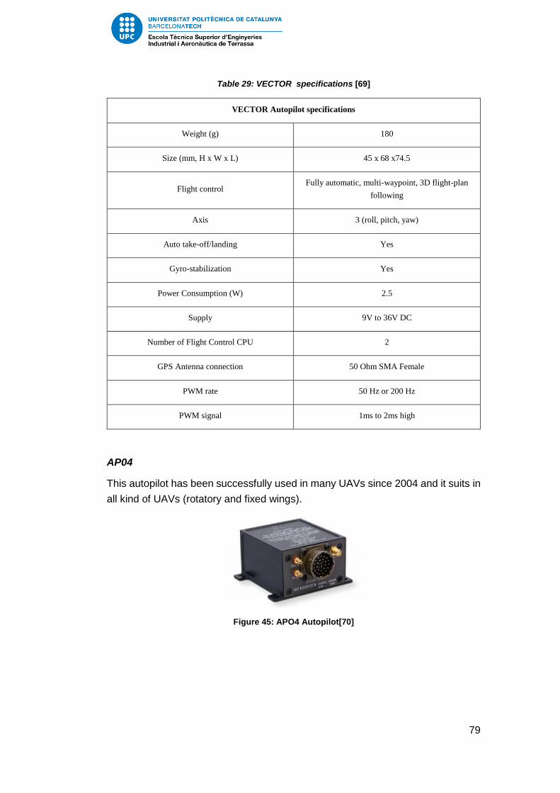
79
Table 29: VECTOR specifications [69]
VECTOR Autopilot specifications
Weight (g) 180
Size (mm, H x W x L) 45 x 68 x74.5
Flight control Fully automatic, multi-waypoint, 3D flight-plan
following
Axis 3 (roll, pitch, yaw)
Auto take-off/landing Yes
Gyro-stabilization Yes
Power Consumption (W) 2.5
Supply 9V to 36V DC
Number of Flight Control CPU 2
GPS Antenna connection 50 Ohm SMA Female
PWM rate 50 Hz or 200 Hz
PWM signal 1ms to 2ms high
AP04
This autopilot has been successfully used in many UAVs since 2004 and it suits in
all kind of UAVs (rotatory and fixed wings).
Figure 45: APO4 Autopilot[70]

80
Table 30: AP04 specifications[70]
AP04 Autopilot specifications
Weight (g) 173
Size (mm, H x W x L) 45 x 68 x74.5
Flight control Fully automatic, multi-waypoint, 3D flight-plan
following
Axis 3 (roll, pitch, yaw)
Auto take-off/landing Yes
Gyro-stabilization Yes
Power Consumption (W) 2.5
Supply 9V to 36V DC
Number of Flight Control CPU 2
GPS Antenna connection 50 Ohm SMA Female
PWM rate 50 Hz or 200 Hz
PWM signal 1ms to 2ms high
Altimeter (AIR DATA SYSTEM) 0 to 6000m
Max acceleration 10G
Max angular rate 300°/s
Magnetometer attitude compensation Yes
Another important Spanish manufacturer is Embention, based in Alicante. This
company started its activity by designing autonomous bombs. However, this
technology was later applied to designing UAVs and nowadays they are one of the
references in the industry.
Veronte Autopilot
The autopilot they have designed it is composed of the flight computer and all the
sensors needed. Therefore, they manufacture the complete flight control system.
The sensors included in the Veronte autopilot have been tabulated:

81
Table 31: Veronte Autopilot list of sensors[71]
Veronte Autopilot sensors
Static pressure 15 – 115 kPa
Dynamic pressure 4 kPa (@290 km/h & SL)
Accelerometers (3 axes) ±6 g in maintained maneouvre
Rate-gyroscopes (3 axes) ±300°/s
Magnetometers (3 axes) ±6 Gauss (compensated)
GPS 4 Hz receiver
Voltage sensor -
Temperature sensor -
The specifications can be seen in the following table:
Table 32: Veronte Autopilot specifications[71]
Veronte Autopilot specifications
Weight (g) 200
Size (mm, L x W x H) 69 x 53 x 49
Control surfaces Aileron, flap, elevator, rudder, gas, etc.
Flight modes Fully autonomous flight, assisted control and
manual control
Data Links 900 mHz/ 2.4 GHz/ Other
Power Consumption (W) 4
Supply 6.5V to 36V DC
Number of Flight Control CPU 2
Open-source Autopilots
The purpose of the open-source autopilot projects is to create a start point data
about the flight control system so that the UAV industry can grow faster. Uploading
the autopilot code and explaining how to build it up, they promote the interest of

82
UAV in society. Nowadays, there are a lot of people who design their own UAV
and they use the open-source autopilot design. One of these open-source project
has been described below.
Paparazzi UAV
Paparazzi is a complete open-source hardware and software for UAS. The
autopilot, GCS and monitoring software using a bi-directional datalink is included.
A scheme of the different components that the Paparazzi project include in the
design can be seen in Figure 46.
Figure 46: Paparazzi components[72]
There are many different autopilot versions. One of the most completed versions
is Lisa/S, developed by Delft University of Technology. The specifications of Lisa/S
can be seen in the following table.
Figure 47: Lisa autopilot[73]

83
Table 33: Lisa/S specifications[74]
Lisa/S Autopilot specifications
Sensors
IMU (3 axis)
Magnetometers
Barometer
GPS
Weight (g) 2.8
Size (mm, L x W x H) 20 x 20 x 5
Price 385 €
Supply 2.3V to 5.5V
The Autopilot system considered for the solution is the Lisa/S due to the low price
in comparison with the commercial ones.
7.6. Power supply
7.6.1. Power requirements
Providing an on-board generator system is of crucial importance due to the energy
consumption that the flight control system and payload have. Taking into account
the market research on payload cameras and autopilots, the following power
requirements are needed:
Table 34: Power supply specifications
Supply 9 – 36 V
Power Consumption 15 W
7.6.2. Battery selection
For a UAV application, the batteries that supply power to the different instruments
such as payload cameras and the flight computer need to combine high capacity
with lightweight design. The actual batteries that offer these two characteristics are
lithium polymer batteries.
For selecting the battery, some calculations need to be done. The specification of
a LiPo battery designed for UAV applications can be seen in the following table:

84
Table 35: Tattu LiPo battery pack specifations [75]
Tattu LiPo Battery Pack specifications
Capacity 9000 mAh
Voltage 14.8 V
Weight 809 g
Dimensions 208x73x25 mm
Price 120 €
With the power supply requirements, the following calculation have been made:
𝑃𝑜𝑤𝑒𝑟 𝑠𝑦𝑠𝑡𝑒𝑚 𝑟𝑒𝑞𝑢𝑖𝑟𝑒𝑚𝑒𝑛𝑡 = 15 𝑊
𝐵𝑎𝑡𝑡𝑒𝑟𝑦 𝑣𝑜𝑙𝑡𝑎𝑡𝑔𝑒 = 14.8 𝑉
𝐵𝑎𝑡𝑡𝑒𝑟𝑦 𝑐𝑎𝑝𝑎𝑐𝑖𝑡𝑦 = 9 𝐴ℎ
𝑉𝑜𝑙𝑡𝑎𝑡𝑔𝑒 𝑠𝑦𝑠𝑡𝑒𝑚 =15 𝑊
14.8 𝐴ℎ= 1.0135 𝐴
𝑇𝑖𝑚𝑒 𝑜𝑓 𝑝𝑜𝑤𝑒𝑟 𝑠𝑢𝑝𝑝𝑙𝑦 =9 𝐴ℎ
1.0135 𝐴= 8.9 ℎ
It can be concluded that the battery is able to supply power to the UAV for a large
duration mission.
7.7. Landing Gear
The function of the landing gear is to bear the impact loads during the landing
phase and to provide directional control during take-off. In terms of performance,
the landing gear increases drag during flight.
According to the market study, one of the most frequently method for launching is
the use of catapult. Therefore, the landing gear needs to be removable in case the
take-off is done by catapult.
The different types of landing gear have been described below:
Tricycle
This configuration provides the UAV of good stability when rolling. However, it has
the drawback that aerodynamically introduces a source of drag considerable.

85
Conventional landing gear
It consists of two main wheels at the forward part of the fuselage, by the centre of
gravity and a small wheel or skid at the tail. It is compatible with catapult launcher.
The main drawback is that the directional control is not as good as for the tricycle.
In order to save weight and to have the most efficient configuration, the
conventional landing gear has been selected.
After a brief market research, the possibility to buy the landing gear separately has
been difficult to find. Therefore, needs to be design it for the specific mission.
Although it has been considered out of the scope, a description of the materials
used and a weight estimation has been done.
The materials used for an UAV landing gear are basically aluminium for the bars
and the wheels.
Figure 48: Example of landing gear [76]
Taking into account the typical density of the aluminium 6061(2.7 g/cm3)[77] and
the possible dimensions of the landing gear (70 cm x 5 cm x 0.5 cm), a 0.5 kg is
obtained for the main bars. Adding a 100 g per wheel, an estimated weight of 0.7
kg is obtained.[78]
7.8. Structure
The design of the internal structure is considered out of the scope of the study.
However, the materials that are used for the UAV construction have been
described.
7.8.1. Wings
The structure of the wing consists basically on a front spar, a rear spar, the ribs
and the skin panel. The internal structure of an UAV wing can be seen in Figure
49.

86
Figure 49: Example of the internal structure of an UAV wing[79]
One of the materials that suits better for the front spar is the carbon fibre. The main
advantage related to the carbon fibre is that it has high strength and low weight.
For the ribs and the rear spar, balsa wood is commonly used. This type of wood
can be very lightweight and conserves a high strength. It also absorbs the
vibrations quite well and can be easily worked. [80]
Finally, the internal structure is covered by a composite skin. The most used
composites are fiberglass and carbon fibre. However, due to the fact that carbon
fibre is much more expensive, the fiberglass is a better option. [81]
The material used for the reinforcements is also fiberglass composite.
7.8.2. Fuselage
The fuselage consists of a semimonocoque structure that consists on the formers
linked longitudinally by the stringers and finally the skin that covers all this internal
structure. The materials used are the same as the wings. Thus, composite
materials predominate.
7.8.3. Tail
Finally, the tail can be considered as a wing so the internal structure is equal.
However, only one spar is needed. Regarding to the tailboom that goes from the
fuselage to the tail, a carbon fibre tube can be used.
7.9. Assembly system
The design of the assembly system it is also considered to be out of the scope.
However, a main description has been made in order to provide the general idea
that needs to be developed in future works.

87
The high wing configuration allows the independence between the fuselage and
the wing. Therefore, an assembly system for putting together the wing with in the
fuselage needs to be ensure it. The wing itself, needs to be separated between 2
parts as the 3 m wingspan is difficult to transport.
Regarding to the tail, the tailboom that connects it with the fuselage has to be able
to be disassembled so that they can be transported separately. This needs to be
ensured due to the length of the tailboom. Also an assembly system between the
horizontal and vertical tail will facilitate the carrying.
An example is presented in order to illustrate a feasible assembly system. The
following UAV is Penguin B model, commented at the market research.
Figure 50: Assembly system of the Penguin B UAV[82]
7.10. Performance
Some performance parameters must be calculated in order to study later the
feasibility of the solution proposed by comparing with other UAS on the market.
The following parameters will be studied:
1) Stall velocity
2) Range and Autonomy
3) Turning
4) Take-off
5) Landing
7.10.1. Weight budget
In order to calculate the different parameters, a weight estimation is needed. The
MTOW was fixed at 20 kg. This value was selected taken into account the market

88
research and trying to design a UAV similar to Penguin B, the fixed-wing UAV with
the higher endurance. However, after the solution is proposed a weight budget
needs to be done in order to verify the MTOW considered at the beginning of the
study.
The most important weight related to the critical parameter of flight time is fuel
weight. For Penguin B UAV, the fuel tank is about 7.5 L. The engine selected works
with JP8 fuel, that has a density approximately of 0.8 kg/L.[83] So an estimated
fuel weight has been calculated:
𝑊𝑓 = 7.5 𝐿 · 0.8𝑘𝑔
𝐿= 6 𝑘𝑔 (18)
Some considerations regarding the materials weight have been taken in order to
calculate an approximate weight of the UAV.
Fuselage
Taking into account the dimensions of the fuel tank, the payload camera and the
flight control system, the following fuselage has been considered in order to
estimate a price:
Figure 51: Fuselage estimated dimensions (dimensions in mm)
The approximated fuselage surface that needs to be covered by GFRP is of 2.3
m2. Considering a thickness of 0.7 mm we obtain a volume of 0.0016 m3. Since the
GFRP has a density of 2100 kg/m3, the skin weights 3.38 kg.

89
The internal structure cannot be estimated without a previous design. However, an
internal structure mass of 2 kg has been considered. The material used for the
semimonocoque structure is CFRP. This assumption is a guess that can introduce
a source of error. Thus, a verification needs to be done in future improvements.
The total weight of the fuselage is of 5.38 kg. This total weight includes the CFRP
tube that joints the tail with the fuselage.
Wing and tail
The surfaces for the wing and tail calculated by the XFLR5 software can be seen
in the following table:
Table 36: Surfaces calculated in the XFLR5 software
Wing 0.525 m2
Vertical stabilizer 0.07 m2
Horizontal stabilizer 0.16 m2
Considering a skin thickness of 0.7 mm, a total GFRP volume of 5.29 ·10-4 m3 is
obtained. Taking into account the GFRP density, the total skin weights 1,1 kg. For
the internal structure, 2 carbon fibre front spars of 1.5 m each with a cross section
of 2 cm of diameter has been considered. Thus, the total volume is 942 cm3. Taking
into account the CFRP density of 1600 kg/m3, a total spar weight of 1.5 kg is
obtained. For the ribs and the rear spars, that are made of balsa wood, an
estimation cannot be done. Thus, the assumption of 2 kg of balsa wood is done.
Table 37: Weight estimation
Payload weight 1.5 kg
Flight control system 0.2 kg
UAV modem 0.15 kg
Fuel weight 6 kg
Engine 2.7 kg
Power supply 0.8 kg
Structure estimated weight
Fuselage 5,4 kg
Wing and tail 4.6 kg

90
TOTAL 21.35 kg
Since the estimated weight is close to the MTOW fixed at the beginning of the
study, for the following performance calculations it has been used a 20 kg value.
7.10.2. Stall Velocity
The stall velocity is the velocity achieved in the point where an increase of angle
of attack leads to a decrease of lift coefficient. The angle of attack at which this
occurs is the critical angle of attack and the lift coefficient is maximum. The
unexpected fall of the lift coefficient is due to the fact that the boundary layer is
detached, producing an extreme increase of drag and lift loss.
To calculate the stall speed, the lift equation is used. It is determined by calculating
the speed for the maximum lift coefficient as (19) shows. The lift force can be
considered equal to the weight for a horizontal flight.
𝑊 = 𝐿 =1
2· 𝜌 · 𝑆 · 𝑉2 · 𝐶𝐿 (19)
and the stall speed can be expressed as:
𝑉𝑠𝑡𝑎𝑙𝑙 = √2 · 𝑊
𝑆 · 𝜌 · 𝐶𝐿𝑚𝑎𝑥 (20)
The stall speed can be calculated using the sea level air density, the weight
estimated and the maximum lift coefficient from the last XFLR5 simulation.
𝑉𝑠𝑡𝑎𝑙𝑙 = √2 · 20 𝑘𝑔 · 9,81
𝑚𝑠2
0,525 𝑚2 · 1,225𝑘𝑔𝑚3· 1.4328
= 20.636𝑚
𝑠
7.10.3. Range and endurance
A simply way for calculating the maximum range and endurance of the UAV is
using the Breguet equations for a propeller aircraft. Although this method is an
idealization, it gives an approximated idea of the capabilities of the UAV. The
Breguet equations are[84]:
𝑥𝑒𝑚𝑎𝑥 =𝐸𝑚𝑐𝑝· 𝜂𝑝 · ln(
1
1 −𝑊𝑓𝑊
) (21)

91
𝑡𝑚𝑎𝑥 =𝐸𝑚
𝑐𝑝 · 𝑉𝐵𝑖· 33/4 ·
(
1
√1 −𝑊𝑓𝑊
− 1
)
(22)
Where:
𝑥𝑒𝑚𝑎𝑥 is the maximum range
Em =CL/CD is the maximum efficiency
Cp is the specific consumption of the engine
𝜂𝑝 is the propeller efficiency
𝑊𝑓 is the fuel weight
𝑡𝑚𝑎𝑥 is the endurance
𝑉𝐵𝑖 is the velocity at maximum efficiency
The specific consumption data can be founded in the engine specifications, the
maximum efficiency is known from the last XFLR5 simulation, the propeller
efficiency has been fixed to 70%, the fuel weight ratio from the weight estimation
and the velocity at maximum efficiency from the XFLR5 simulation. Therefore, the
endurance and range are calculated.
First, the specific power consumption is calculated by using the following
equation[84]:
𝑐𝑝 = 𝜑 · 𝑔
𝑃𝑚 (23)
where 𝜑 is the mass consumption, g the gravitational acceleration and Pm the
engine power.
Using the engine information presented in 7.1.2.4, the specific power consumption
is calculated:
𝑐𝑝 = 𝜑 · 𝑔
𝑃𝑚= 330
𝑔
𝑘𝑊 ℎ·1 𝑘𝑔
103𝑔·1 𝑘𝑊
103 𝑊·1 ℎ
3600 𝑠· 9.8
𝑚
𝑠2= 9 · 10−7
1
𝑚
Therefore,
𝑥𝑒𝑚𝑎𝑥 =35.383
9 · 10−7· 0.7 · ln (
1
1 − 0.3) = 9.8 · 106 𝑚 ≅ 9800 𝑘𝑚
𝑡𝑚𝑎𝑥 =35.383
9 · 10−7 · 30.57· 33/4 · (
1
√1 − 0.3− 1) = 5.72 · 105 𝑠 ≅ 160 ℎ

92
The results obtained are not realistic. This inconsistency in the results may be due
to the fact that the Breguet equation is not a good approximation for UAVs, that
operates at low Reynolds number and does not necessary perform large horizontal
flights during the mission.
In order to have a more realistic view of the endurance that of the UAV proposed
will ensure, a conceptual and simplified calculation has been made. Considering
that the engine works all the time at maximum power, the mass flow rate for the
JP-8 fuel is:
𝜑 = 330𝑔
𝑘𝑊ℎ· 4 𝑘𝑊 = 1320 𝑔
The maximum fuel weight is about 6 kg according to the weight budget. Therefore,
the endurance at maximum power requirement is:
𝑡𝑃𝑚𝑎𝑥 =6000 𝑔
1320𝑔ℎ
= 4.5 ℎ
Half power requirement has been also studied:
𝑡12𝑃𝑚𝑎𝑥
=6000 𝑔
330𝑔𝑘𝑊ℎ
· 2 𝑘𝑊 = 9 ℎ
This flight time is an approximation and it only gives the idea that the design
requirement of having an autonomy between 2 and 12 h is accomplished. In real
performance, there are many different factors that have to be taken into account.
However, for a preliminary study this value can be considered.
Considering that the UAV flies at constant speed, a very simple calculation can be
made to give an idea of the range. Taken into account the market study, a general
cruise speed of 60 km/h has been considered:
𝑅𝑎𝑛𝑔𝑒 = 4.5 ℎ · 60𝑘𝑚
ℎ= 270 𝑘𝑚
This value is an ideal range that it is impossible to be reached. The range in a UAV
is determined by the range of the communication link. However, if the
communication link is interrupted, the UAV will be able to travel this distance and
therefore needs to be taken into account.
7.10.4. Turning
As was commented during the design requirements, the UAV has to be able to
loiter. A way to analyse the maneuverability of the vehicle is calculating the turn
rate and the turn radio.

93
Figure 52: Distribution of forces during a turn[85]
An important parameter to take into account for the turning analysis is the load
factor:
𝑛 =𝐿
𝑊=
𝐿
𝐿 · 𝑐𝑜𝑠𝜙=
1
𝑐𝑜𝑠𝜙 (24)
where 𝜙 is the bank angle.
The turn rate can be expressed as[86]:
�̇� =𝑔√𝑛2 − 1
𝑉 (25)
Finally, from Figure 52, the equation for the turn radius is obtained:
𝐿 sin𝜙 = 𝑚𝑉2
𝑅 ⇒ 𝑅 =
𝑊
𝐿
𝑉2
𝑔 sin 𝜙=1
𝑛
𝑉2
𝑔 sin 𝜙sin𝜙= √1−
1
𝑛2
⇒ 𝑅 =𝑉2
𝑔√𝑛2 − 1
(26)
With the results obtained in the last XFLR5 simulation, an analysis of the turn rates
and turn radius have been done. The values for SL altitude and different bank angle
angles can be seen in the Annex. However, the following table have been attached
in order to comment the results obtained.

94
Table 38: Turn rate study for a bank angle of 45°
𝝓 = 45 °
AoA (°) V (m/s) �̇� (°/s) R (m)
0 49.41 11.38 248.86
0.5 44.53 12.62 202.13
1 40.86 13.76 170.19
1.5 37.98 14.80 147.04
2 35.63 15.78 129.41
2.5 33.67 16.69 115.56
3 32.01 17.56 104.45
3.5 30.57 18.39 95.26
4 29.31 19.18 87.57
With these results, an idea on how much it will take the UAV to loiter a specific
area is obtained. As an example, for a turn of 45° with an angle of attack of 4 ° it
takes 20 s to perform a complete turn. It can be considered a good time for
overlooking a target during the UAV mission.
In order to study the effect of altitude in the turn radius, the following modification
has been made:
𝑅 =2𝑊
𝜌𝑆𝐶𝐿𝑔√𝑛2 − 1
(27)
The modification done consists on expressing the speed as function of the altitude
by the lift coefficient equation. For an altitude of 1000 m the results obtained are
the followings:

95
Table 39: Turn rate study for a bank angle of 45° at an altitude of 1000 m
𝝓 = 45 °
AoA (°) V (m/s) �̇� (°/s) R (m)
2 35.63 4.23 139.93
4 29.31 5.14 94.80
6 25.51 5.90 71.83
8 22.92 6.57 57.93
The higher the UAV flies, the higher the turn radius. However, the difference
between both turn radius is about less than 10 m.
7.10.5. Take-off
According to the UAV market study, the most used launch method is by catapult.
However, a first approximation of the take-off distance has been made.
7.10.5.1. Take-off distance
Take-off can be divided into three stages: ground roll, transition to climb and climb
as can be seen in Figure 53. In order to compute the whole take-off distance, the
three different stages need to be computed separately.
Figure 53: Different stages during take-off[86]
Ground roll segment
The ground roll segment is divided in two distances: SG and SR. SG can be
calculated using the equation presented in [86]:

96
𝑆𝐺 =1
2𝑔∫
𝑑(𝑉2)
𝐾𝑇 +𝐾𝐴𝑉2
𝑉𝑓
𝑉𝑖
=1
2𝑔𝐾𝐴ln (𝐾𝑇 + 𝐾𝐴𝑉𝑓
2
𝐾𝑇 + 𝐾𝐴𝑉𝑖2) (28)
Where:
𝐾𝑇 =𝑇
𝑊− 𝜇 (29)
𝐾𝐴 =𝜌
2𝑊𝑆
(𝜇𝐶𝐿 − 𝐶𝐷) (30)
Since the integration is solved for a constant thrust, an average value needs to be
taken. This average value is the thrust at 70% of VTO.
For small aircrafts, the time spent in the rotate stage can be approximated to 1s,
therefore the SR is equal to VTO.
According to [86], the typical values for the friction coefficient 𝜇 of an asphalt
runway are between 0.03 and 0.05.
Transition to climb
For general aircrafts, the climb speed during the transition segment is 1.3Vstall.
During this stage, the UAV describes a circular trajectory. The radius of this turn
can be computed by the following equation:
𝑅 =𝑉𝑇𝑅2
𝑔(𝑛 − 1)=𝑉𝑇𝑅2
0.2𝑔 ≈ 0.205𝑉𝑠𝑡𝑎𝑙𝑙
2 (31)
For calculate the distance ST, the climb angle at the end of the transition needs to
be computed. The following equation is used:
sin 𝛾 =𝑇 − 𝐷
𝑊≅𝑇
𝑊−1
𝐿/𝐷 (32)
While the transition distance is:
𝑆𝑇 = 𝑅 sin𝛾 = 𝑅 (𝑇
𝑊−1
𝐿𝐷
) (33)
The horizontal distance travelled is:
ℎ𝑇𝑅 = 𝑅(1 − cos𝛾) (34)

97
Climb
Finally, the last segment is calculated. The horizontal distance travelled during the
transition stage is used for calculating SC:
𝑆𝐶 =ℎ𝑜𝑏𝑠𝑡𝑎𝑐𝑙𝑒 − ℎ𝑇𝑅
tan 𝛾 (35)
For a UAV application, the Sc can be considered null due to the fact that there is
not obstacle that force the drone to overpass it.
The MATLAB code attached at the annex has been implemented in order to
calculate the whole take-off distance.
The results obtained are:
𝑆𝐺𝑟𝑜𝑢𝑛𝑑 𝑅𝑜𝑙𝑙 = 28.73 𝑚
𝑆𝑇𝑟𝑎𝑛𝑠𝑖𝑡𝑖𝑜𝑛 = 63.94 𝑚
𝑑𝑇𝑂 = 92.66 𝑚
The ground roll segment obtained is very similar to the roll distance for the UAV
Penguin B, therefore it can be concluded that the results are realistic.
7.10.5.2. Catapult
As was commented above, the more used method for launching commercial UAVs
is by means of a catapult. When the catapult is used for the take-off, the landing
gear is no longer used, allowing a lighter TOW. Also, using it instead of a normal
take-off, increases reliability due to the fact that the UAV will not suffer the friction
loads and will avoid damages occurred by possibly obstacles in the runway.
Therefore, is the most secure take-off method. Thus, the life of the product can be
extended.
There are many different catapults in the market. Some examples have been
studied:
UAV Factory 6 KJ Portable Pneumatic Catapult

98
Table 40: UAV Factory Catapult specifications[20]
Rail Length 4 m
Maximum Launching Energy 6000 J
Maximum UAV weight 35 kg
Maximum Launch speed 24 m/s
Input Voltage 11 – 16 VDC
Weight 110 kg
Aeromapper UAV Launcher
Table 41: Aeromapper UAV launcher specifications[87]
Rail Length 2.8 m
Weight 5 kg
Price $1400
7.10.6. Landing
7.10.6.1. Landing distance
For the calculation of the landing distance, the equations used for the take-off
distance are used. The scheme of the landing phase can be seen in the following
figure:
Figure 54: Landing phase scheme [86]

99
The first stage is approach. The approach distance can be calculated using
equation (35) with a speed equal to 1.3 times the stall speed. For the take-off
analysis, the hobstacle was considered zero. However, for landing calculations the
approach distance is of special interest. Therefore, a hobstacle of 15 m have been
considered.
The second stage is flare. During the flare the UAV changes from the approach
speed to the touchdown speed that can be assumed 1.15 times the stall speed.
Thus, the flare speed can be estimated in 1.23Vstall. Finally, by means of the
equations used for the transition to climb in the take-off analysis, the flare distance
is calculated.
The ls stage is the ground roll that can be divided into the free roll and the breaking
distance. The initial velocity during this phase is the touchdown speed and the
finally velocity is zero. By using the same equations as in the take-off ground roll,
the landing ground roll distance is calculated. The thrust generated in the ground
roll segment has been considered zero and the friction coefficient has been
increased to 0.5 due to the effect of brakes.
For the calculations, the landing weight considered is 85% of the MTOW and since
the thrust and the drag at the starting point of the approach are unknown so a
normal approach angle of 3° has been taken.
Using the MATLAB code presented in the Annex, the following results are
obtained:
𝑆𝑎𝑝𝑝𝑟𝑜𝑎𝑐ℎ = 277.63 𝑚
𝑆𝑓𝑙𝑎𝑟𝑒 = 17.19 𝑚
𝑆𝐺𝑟𝑜𝑢𝑛𝑑 𝑅𝑜𝑙𝑙 = 26.18 𝑚
𝑑𝑇𝑂 = 321 𝑚
7.10.6.2. Alternative methods for landing
The landing phase is a critical issue for an UAV. According to the market study and
as commented above, UAV are usually design to operate without the use of a
landing gear. This is due to the fact that having a large runway is not available in
most of the cases. Therefore, alternative methods for landing need to be studied.
Two of these methods have been described.
Parachute
One possible method is the use of parachute in order to descent to ground with
low speed so that the UAV does not suffer damage. This solution needs to be taken
into account while designing the fuselage due to the fact that the parachute has to

100
be stored on-board. It is a feasible solution but it also risky due to the dependence
in weather conditions.
Figure 55: Parachute landing method[88]
Vertical Net
This recovery method consists of a net suspended between two poles. The net is
also suspended by a structure to hold the UAV above the ground when gets
trapped into it. The design of the net is not trivial due to the fact that it needs to
distribute the forces that the UAV generates when get trapped. Although is a more
complex solution than the parachute, it is more secure and do not depend in
uncontrollable factors such as weather conditions. Also extra weight and possible
structure modifications are avoided.
Figure 56: Patent regarding a net recovery system[89]
Belly landing
It is quite often the use of the underside of the fuselage for landing when a landing
gear is not incorporated. This type of landing introduces a risk of damage.
However, reinforcements of composite materials on the belly of the fuselage are

101
used in order to reduce this damage. Since this landing configuration is the
lightweight solution, it has been decided to classify the landing gear as an extra
equipment and to provide reinforcements to the UAV so that it can land with this
method.

102
8. Feasibility study
Once the solution is proposed, analysing if it is possible to be implemented is
essential for any project. There are two approaches while studying a project
feasibility: the technical and economical.
8.1. Technical approach
Before starting to manufacture a product, a study that determines if the proposed
solution can be carried out with the actual technologies have to be done.
8.1.1. Functional factors
Utility
The fundamental utility of the UAS proposed is aerial surveillance. This objective
is basically accomplished by providing a camera and a communication system that
ensures video streaming. Although the principal idea is simple, its design is not
trivial. However, video streaming communications is a well-studied technology and
by means of a modem and antennas, the data link can be stablished. Therefore,
the main purpose of the UAS is feasible to be achieved. Furthermore, as the market
study showed, this video streaming is already implemented in some of the most
used drones at the present time. The development of camera technologies has
experienced a tremendous growth in the last 10 years and nowadays buying
lightweight cameras with good image quality is affordable to almost everyone.
The principal utility needs to be complemented with the design of an aerial vehicle.
This is not any impediment to the project due to the fact that the aircraft design is
an engineering field highly developed and the wide available information and
software facilitates the task. However, in unmanned vehicles there is an extra
complexity due to the lack of pilot that requires the implementation of an on-board
flight computer and sensor system so that corrections during flight can be done
automatically.
The technical knowledge involving sensors is also highly developed due to the fact
that there are used in almost all the engineering fields. Regarding the flight
computer, there are enterprises that are dedicated to write the algorithms that
allows the corrections needed during the flight as well as following waypoints,
obstacle avoidance among others. Therefore, the actual technology related to
automatic control is within the reach of a UAS project.
With respect to the ground control station, the actual laptops or even a mobile
phone are able to monitor the UAV during flight with the use of specific software.
As was described in the solution proposal point, open-source software is an
example of the feasibility of the ground control segment.

103
To sum up, one of the reasons why the application of UAV is experiencing a growth
is due to the simplicity involved in their designs. Therefore, it can be concluded that
with the actual technology, the UAV solution proposed can be implemented.
Monitoring and maintenance
UAV maintenance and equipment monitoring is an important factor to take into
account for security purposes. For any flying machine safety and reliability need to
be ensured. Therefore, the UAV needs to be designed so that the different parts
can be easily tested as well as replaced in case of failure. Then, an assembly
system should be provided so that the maintenance and monitoring can be done.
However, it is considered out of the scope of the project and needs to be develop
in future works.
Ergonomic factors
The UAV will have an estimated empty weight about 11 – 14 kg and a maximum
take-off weight of 20 kg. The main dimensions are:
Table 42: Main dimensions considered for the UAV proposed
Wingspan 3 m
Length ≅ 2 – 2.5 m (depending on the fuselage)
Height ≅ 1 m (depending on fuselage and landing gear)
Although the high values of the dimensions, the assembly and disassembly system
will be able to facilitate its transportation, making feasible the use of the UAV in
many different scenarios.
Legal factors
The main requirement that facilitates the legal adaption of the UAV is to have a
mass below 25 kg. As was commented below, the MTOW was fixed to 20 kg.
Therefore, the design is adapted to the legal requirements regarding weight
aspects.
Another important aspect concerning legislation is the frequency used for the
communication link. In the communication system description, the frequencies
selected for the data link were 2.4 GHz and 5.8 GHz. According to the CNAF, the
Spanish legal instrument that assigns the different radio services to a frequency
band, these frequencies are reserved to industrial, scientific and medical
applications.[90]
Since the UAV has been designed for surveillance, it can be considered as an
industrial application and consequently it fits in the legal framework.

104
8.2. Economical approach
In order to analyse whether the solution proposed can fit into the UAV market, the
costs have to be calculated so that the sale price can be estimated. Then, by
comparing with other UAS projects it will be determined whether it is possible to
manufacture it at an affordable price.
8.2.1. Raw Materials Cost and pre-design cost
The cost of the items presented on the UAV solution proposal section have been
tabulated. Some of the prices have to be estimated due to lack of information.
Table 43: Costs of the solution proposed
Item Price
UAV
Propulsion system
RCV engine 500 €
Propeller 29 €
Fuel tank[61] 1200 €
Raw materials
Balsa wood 15,625€
kg· 2 kg = 31,3 €
GFRP[91] 3,44
€
kg· 4,5 kg = 15,5 €
CFRP[91] 97€
kg· 3,5 kg = 339,5 €
Flight Control System and Communication System
Autopilot (Lisa/S) 385 €
XBee modem 28 €
Power supply
On board generator system 120 €
UAV platform 2 639 €

105
Payload
Payload camera 26 300 €
UAV with payload 28 939 €
Ground Control Station
Ground Control Station 3 000 €
TOTAL GCS 3 000 €
TOTAL UAS 31 939 €
TOTAL UAS without payload 5 589 €
Extra equipment
Pneumatic catapult 20 950 €
Landing gear[61] 910 €
The cost of the hours worked during the development of the study are also
considered.
Table 44: Cost engineering of the pre-design phase
Hours worked 300 h
Price per hour 15 €/h
Total 4 500 €
8.2.2. Estimation of UAV cost
For the calculation of the price, the payload as well as the extra equipment, has
not been considered due to the increase of the final costs. Therefore, a basic UAV
platform without its payload will be offered to the client as the main product. Since
the GCS do not involve any manufacturing process, the price will be added to the
final price but with a benefit percentage.
For the calculation of the total cost of the project, the method considered in Roskam
book[36] have been followed. However, due to the fact that this book was published
1986 and it is for commercial and military aviation, the calculations have been
estimated in a more realistic way.

106
8.2.2.1. Investment
The investment needed for the development of the project can be estimated as the
research, development, test and evaluation cost. It involves all expenses from
preliminary design until the certification. The following estimations have been
done:
Engineering cost
The pre-design phase costs were estimated in Table 44. A total of 4500 € was
obtained.
Considering a 2 aeronautical engineer team, the expected time for the
development of the final design is of 2 years. The tasks that need to be done in the
future have been described in section 11.
The engineering cost can be seen in the following table.
Table 45: Engineering cost of the design phase
Engineering cost of the design phase
Number of engineers 2
Salary 42 000 €/year
Time 2 years
TOTAL 168 000 €
Development support and testing cost
The development support and testing costs involves the material, propulsion and
wind tunnel tests. In order to calculate it, the experimental equation proposed in
Roskam book [36] have been used:
𝐶𝑡𝑒𝑠𝑡 = 0.008325(𝑊𝑎𝑚𝑝𝑟)0.873
(𝑉𝑐)1.89(𝑁𝑟𝑑𝑡𝑒)
0.346(𝐹𝑑𝑖𝑓𝑓) (36)
where 𝑊𝑎𝑚𝑝𝑟 is the Aeronautical Manufacturers Planning Report and can be
calculated as the empty weight minus the battery, engine and flight computer
weights; the 𝑉𝑐 represents the cruise speed of the aerial vehicle that in the case of
the UAV is considered the maximum efficiency speed (30.57 m/s); 𝑁𝑟𝑑𝑡𝑒 is the
number of UAV used for testing and 4 units have been considered and finally 𝐹𝑑𝑖𝑓𝑓
is a factor that takes into account the difficulty of the project that can be equal to 1.
After making the calculations, the following result is obtained:
𝐶𝑡𝑒𝑠𝑡 = 2085 €
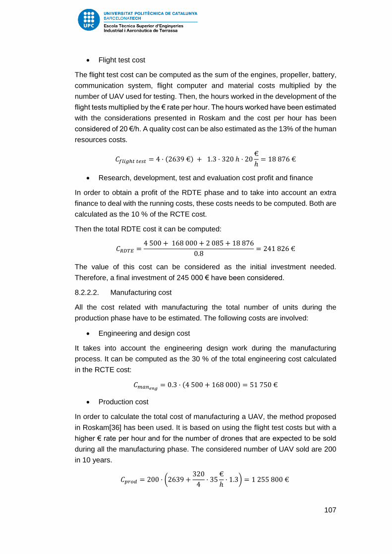
107
Flight test cost
The flight test cost can be computed as the sum of the engines, propeller, battery,
communication system, flight computer and material costs multiplied by the
number of UAV used for testing. Then, the hours worked in the development of the
flight tests multiplied by the € rate per hour. The hours worked have been estimated
with the considerations presented in Roskam and the cost per hour has been
considered of 20 €/h. A quality cost can be also estimated as the 13% of the human
resources costs.
𝐶𝑓𝑙𝑖𝑔ℎ𝑡 𝑡𝑒𝑠𝑡 = 4 · (2639 €) + 1.3 · 320 ℎ · 20€
ℎ= 18 876 €
Research, development, test and evaluation cost profit and finance
In order to obtain a profit of the RDTE phase and to take into account an extra
finance to deal with the running costs, these costs needs to be computed. Both are
calculated as the 10 % of the RCTE cost.
Then the total RDTE cost it can be computed:
𝐶𝑅𝐷𝑇𝐸 =4 500 + 168 000 + 2 085 + 18 876
0.8= 241 826 €
The value of this cost can be considered as the initial investment needed.
Therefore, a final investment of 245 000 € have been considered.
8.2.2.2. Manufacturing cost
All the cost related with manufacturing the total number of units during the
production phase have to be estimated. The following costs are involved:
Engineering and design cost
It takes into account the engineering design work during the manufacturing
process. It can be computed as the 30 % of the total engineering cost calculated
in the RCTE cost:
𝐶𝑚𝑎𝑛𝑒𝑛𝑔 = 0.3 · (4 500 + 168 000) = 51 750 €
Production cost
In order to calculate the total cost of manufacturing a UAV, the method proposed
in Roskam[36] has been used. It is based on using the flight test costs but with a
higher € rate per hour and for the number of drones that are expected to be sold
during all the manufacturing phase. The considered number of UAV sold are 200
in 10 years.
𝐶𝑝𝑟𝑜𝑑 = 200 · (2639 +320
4· 35
€
ℎ· 1.3) = 1 255 800 €

108
Financial cost
As in the RDTE cost, the 10% of the total manufacturing costs is added.
The total cost for the manufacturing process is:
𝐶𝑀𝐴𝑁 =1 225 800 + 51 750
0.9= 1 419 500 €
8.2.2.3. Estimation of the UAV price
An approximated value for the sale price can be calculated as follows:
𝑃𝑟𝑖𝑐𝑒 =𝐶𝑅𝐷𝑇𝐸 + 𝐶𝑀𝐴𝑁
200=241 826 + 1 419 500
200= 8 307 €
This price corresponds to the price only of the UAV without payload and GCS.
Adding the costs of the GCS and adding a 20 % of benefits, the price for the whole
UAS but without a payload is:
𝑃𝑟𝑖𝑐𝑒𝑈𝐴𝑉+𝐺𝐶𝑆 = 8 300 + 1.2 · 3 000 = 11 900 €
8.2.3. Positioning in the actual market
Some professional UAS prices that have similar mission requirements have been
tabulated in order to compare them with the costs of the solution proposed.
Table 46: Professional UAV prices
Penguin B [92] 14 500 € (without payload)
LP960 full system [93] 6 990 €
Lehmann Aviation L-A series full system[94] 8 990 €
HBS Skywalker UAV[95] 4 000 €
HBS FX61 PRO[95] 3 100 €
SenseFly eBee UAV [92] 10 560 €
NOVA F7200[96] 13 480 €
Professional UAVs are really demanding in economic terms. The minimum price
for a complete UAV system is around 4000 €. Furthermore, these prices are mostly
for electric propulsion UAVs that performs between 30 min and 2 h of flight. If a
higher flight time is desired, ICE propulsion is needed and the price can exceed
the 15 000 €.
It can be concluded that the price of the solution proposed fits on the market, with
a competitive price. However, the payload camera proposed during the

109
development can increase two times the price calculated. Although it is the best
option for professional surveillance applications, giving the chance of selecting a
more affordable camera is the most feasible solution.

110
9. Environmental impact study
The main objective of an environmental impact study is to decide to proceed with
the project or not by taking into account the environmental impacts. There are
different areas that needs to be considered while studying the drones
environmental impact. The first point is about the pollution created by the UAV due
to the ICE. Then, a study of how the drones can be used for the environmental
sector has been done.
Pollution
Since the UAV proposed works with an ICE, contaminating gases are emitted. Due
to this reason, the general market trend is electric propulsion. However, the
autonomy that ICE provides is necessary for some applications.
Moreover, this type of drones can substitute operations that generally are carried
out by ground vehicles. Thus, since the UAV engines contaminates less than a car,
it can be understood as a decrease of contaminating emissions.
However, an increase of the technology involved in electric propulsion needs to
done in order to make electric UAV have a large endurance.
Environmental monitoring
The civil applications of drones are innumerable and some of them are related to
environmental monitoring. The first application is agriculture drones. This drones
are capable of increasing the efficiency of the farms and, most important, to reduce
the use of pesticides.
On the other hand, surveillance UAV can be also used for wildlife conservation.
One example of the efficiency of drones for the sake of environmental monitoring
is the Ranger Drone[97]. This drone has succeeded in the prevention of poaching.
To sum up, the use of drones for environmental applications have to be promoted
in order to raise public awareness about the benefits that this type of industry can
provide.
Another important issue is materials recycling. The materials used in the solution
proposed are composites. Although there are more difficult to recycle than others,
the possibility of manufacturing the composite waste can be considered.

111
10. Security considerations
While developing a project, the security is an important issue to take into account.
In the UAV sector, the security problems are creating an international debate. The
recent incidents involving drones with commercial aircrafts are an example of
security mechanisms that must be incorporated.
The no-fly zones include basically airports and flying fields where manned aircrafts
operate at low altitude [98]. Some UAV manufacturers, like DJI, offers a flight mode
that avoids entering in such banned zones. The idea is to be able to set in the
software of the GCS the banned areas. Then, when the drone detects that is
entering to one of these zones, using the GPS receiver, it will automatically land.
Regulation are in process of building up a new legal framework in order to avoid
such dangerous operations. Drones need to be used in areas where the probability
of harming others is very low, and this no-fly mode proposed is a feasible solution.
Therefore, the implementation of security mechanisms need to developed in future
improvements.
Furthermore, the communication system is a critical issue while developing a UAV.
Interferences can make unable the telemetry link and therefore loss the complete
control of the aerial vehicle. In order to avoid this interference problems, the data
links used in the communication system have different band frequency. Thus, if
one of the links becomes inoperable the other can still be used. Furthermore, a
study of the different risks involving the communication links have to be done.

112
11. Organization and planning of the future work
During the development of the proposed solution, there are many aspects that
have been considered for future improvements. However, an organization and
planning scheduling needs to be done in order to make clear the future of the study.
Table 47: Planning scheduling of future tasks
Task Preceding Task(s) Approximated duration (h)
Structural Design - 200
Design of control surfaces - 150
Validation of the aerodynamic
results - 100
Design of the assembly system Structural Design 100
Data compression and treatment
analysis - 150
Study of the risks in the
communication system - 100
Electrical system design - 200
3D Model All previous tasks 200
Construction of prototypes All previous tasks 400
Flight tests All previous tasks 100
Design modifications All previous tasks 300
After all the tasks described in the table above are done, the manufacturing
process will be able to start. The estimated duration until the start of manufacturing
is 2 years.
113
12. Conclusions and future work
During the development of the study, some conclusions have been drawn. The
most important ones concerning specific and general aspects have been outlined.
First, a brief study of the legal framework was made in order to obtain a general
idea of the environments in which an UAV can operate. It has been found that the
actual regulations cover general aspects regarding the operation of drones but do
not differentiate between the types of UAV neither the applications that are able to
perform. Furthermore, they limit the use of UAV to very restrictive zones due to the
fact that flying in urban areas or near an airport is totally banned. Another important
feature that has to be taken into account regarding surveillance applications is that
night operations are illegal. It is clear that with the actual regulation, implementing
a surveillance UAV is a very complex task. Therefore, a change in the legal
framework needs to be done in order to promote the expected growth of the UAV
industry and also to make feasible the use of drones for commercial purposes.
Another aspect to consider before the solution proposal is the state of the art of the
UAV industry. With the market research, a general idea of the technology involved
in the design of a UAV was obtained. It also shows the market trends towards the
multirotor configuration and the electric propulsion. Moreover, the analysis of the
different specifications is essential in order to give some initial values, that have
been used as a starting point during the pre-design phase.
Once the background has been studied, the analysis of the design requirements
and the initial sizing has been made. The first step is to understand the problem
that is expected to be solved. The main innovation that a surveillance drone
provides is the opportunity of monitoring a specific zone from a more effective point
of view as well as operability in areas of difficult access. Then, taking into account
the capabilities that must be ensured, the design requirements have been defined.
The conceptual design consisted of selecting the type of UAV. The two possible
alternatives are multirotor and fixed wing drones. Concerning the design
requirements, the most critical parameter to fulfil is endurance. A minimum of 2h
needs to be ensured. After studying the advantages and drawbacks of each
configuration, it has been found that fixed wing UAV has higher flight times.
The selection of the type of drone, allowed the development of an initial sizing. By
means of a constraint analysis, a range of values concerning power and weight
specifications has been established. It is important to note that the maximum
weight available is 25 kg in order to facilitate the regulation process.
The second part of the study is the UAV solution proposal. During this section, the
different subsystems have been presented and the alternatives have been studied.
Then, the solution that best fits within the design requirements has been selected.

114
The first subsystem studied is propulsion. There are two very different alternatives:
internal combustion engines and electric motors. From the state of the art, it can
be observed that the most usual option is electric propulsion. However, since the
endurance needs to be minimum of 2h, the ICE was the only viable option.
Nevertheless, this decision is the most demanding in terms of weight and price.
The propeller has also been considered and the basic specifications such as the
diameter and blade pitch have been determined.
An aerodynamic study has been developed in order to propose an efficient wing
and tail configurations. The methodology followed has been to simulate the
different possibilities with the XFLR5 software, that is based on the 3D panel
method. With this method the airfoil, wingspan, planform and geometry of the wing
and tail has been decided. Taking into account the results of the simulation, a mix
planform with a 3 m of wingspan has been obtained. However, some
characteristics have been determined by analysing the different options and
choosing the one that better meets the design requirements. An example is the
wing position, that in order to ensure an assembly system, the high wing was the
most appropriate configuration.
Another crucial design studied is the communication system. It has been observed
that the communication media used for establishing the data links are radio
communications. A study of the advantages and drawbacks of the different
frequencies has been made in order to select the best one. It has been determined
that the best frequency band for surveillance applications where video broadcast
has to be ensured, is 2.4 GHz. However, due to security considerations, providing
a second link in a different frequency band (5.8 GHz) has been decided.
In order to develop the mission requirements, a payload has to be installed in the
UAV. For surveillance applications, it consists of a camera. Taking into account the
UAV capabilities, some specifications such as 360° panoramic view and thermal
imaging need to be ensured. After a brief market research, it can be observed that
the camera prices are along the 20 000 €. Thus, the payload is the most critical
subsystem regarding economical purposes.
One of the main characteristics that makes drones such an attractive technology
is the automatic control system. The basic working principle has been analysed
and some examples in the market have been described. In order to keep the costs
as low as possible, the most economical autopilot has been selected.
Although the structural design has been considered out of the scope of the study,
the materials used for designing a UAV have been described. It can be observed
that the structure is made totally of composite materials, where carbon fibre and
fiberglass are the most commonly used.

115
With all the decisions made during the solution proposal, some calculations
concerning the performance of the drone have been made. First, an estimated
weight has been calculated. A maximum take-off mass of 20 kg was considered.
Then, the different phases of the flight have been studied. For take-off and landing
the possibility of adding a landing gear as an extra equipment has been
considered. Thus, the take-off and landing distances have been calculated.
However, catapult and belly landing are the methods considered for the solution
proposed.
In order to verify the design requirement of endurance, the autonomy has been
calculated. Although some simplifications have been made, the value obtained
verifies the fulfilment of the requirements considered at the beginning of the study.
As an example of the results obtained, for a half power requirement the estimated
flight time is about 9 h.
On the other hand, a feasibility study has been developed in order to determine if
the implementation of the solution proposed is possible. Regarding technical
aspects, the technology involved in the UAV is viable. In fact, one of the
characteristic that makes UAV such an attractive sector is the simplicity involved.
After proposing the solution, an economical study has been made. By estimating
the costs of the raw materials and the manufacturing process, the total price of the
UAV has been calculated. It has to be noted that the catapult, the landing gear and
the payload had been considered as extra equipment. By comparing with other
UAS prices in the market, it can be concluded that the solution proposed fits in the
UAV market. A price about 12 000 € for the UAV with the ground control station
has been obtained.
Last but not least, the environmental impact study and the security considerations
have been taken into account. The most important fact concerning this last section
of the study is that the UAS proposed can be used for environmental applications
such as the prevention of poaching.
As a final conclusion, the study can be considered satisfactory due to the fact that
the different objectives proposed have been accomplished. However, some
important points of the design of a UAS remain outstanding for future
improvements.
First, the internal structure has to be designed and simulated with Finite Element
Method. Regarding to the internal structure, the assembly system needs to be
developed and tested.
Then, the aerodynamic results obtained during the study need to be verified by
means of a CFD software. Also the control surfaces have to be designed in order
to ensure control.

116
Besides, a 3D model using CATIA or SolidWorks needs to be build up so that the
drawings can be obtained. Moreover, the communication system is a relevant
aspect that has to be analysed carefully. Thus, a study of the data compression
and treatment as well as an appraisal of risks has to be done.
117
13. References
[1] FAA, “Busting Myths about the FAA and Unmanned Aircraft.” [Online]. Available: https://www.faa.gov/news/updates/?newsId=76240. [Accessed: 05-Mar-2016].
[2] Livescience, “The Future of Drones: Uncertain, Promising and Pretty Awesome.” [Online]. Available: http://www.livescience.com/52701-future-of-drones-uncertain-but-promising.html. [Accessed: 01-Mar-2016].
[3] “International Civil Aviation Organization.” [Online]. Available: https://en.wikipedia.org/wiki/International_Civil_Aviation_Organization. [Accessed: 15-Mar-2016].
[4] International Civil Aviation Organization-Cir 328 AN/190, Unmanned Aircraft Systems ( UAS ). .
[5] House of Lords, “Civilian Use of Drones in the EU,” no. February, p. 82, 2015.
[6] EASA, “Unmanned Aircraft Systems (UAS) and Remotely Piloted Aircraft Systems (RPAS).” [Online]. Available: https://www.easa.europa.eu/unmanned-aircraft-systems-uas-and-remotely-piloted-aircraft-systems-rpas. [Accessed: 10-Sep-2016].
[7] EASA, “A proposal to create common rules for operating drones in Europe,” no. September, 2015.
[8] AESA, “Folleto Informativo uso drones como herramientas de trabajo.” .
[9] Gobierno de España, “Royal Law-Decree 8/2014, Jule 4th,” Inia.Es, pp. 52544–52715, 2014.
[10] L. Dean, “Network Rail £1m theft: Notorious Smith family from Doncaster stole rail cable to sell copper,” International Business Times, 2016.
[11] Doheny Drones, “The drone for you: fixed wing versus rotatory wing.” [Online]. Available: http://www.dohenydrones.com/news-fixed-wing-versus-rotary-wing. [Accessed: 15-Apr-2016].
[12] ETSIA Aircraft Design Department, “Cálculo de aviones,” 2014.
[13] G. Landolfo, “Aerodynamic and Structural Design of a Small Nonplanar Wing UAV,” Mech. Eng., no. May, p. 132, 2008.
[14] European Aviation Safety Agency, “Concept of Operations for Drones A risk based approach to regulation of unmanned aircraft,” pp. 1–8, 2015.
[15] ISO, “Standard Atmosphere,” 1975.
[16] D. Verstraete, M. Coatanea, and P. Hendrick, “Preliminary design of a joined wing hale uav,” ICAS Secr. - 26th Congr. Int. Counc. Aeronaut. Sci. 2008, ICAS 2008, vol. 5, pp. 859–868, 2008.
[17] K. Park, J. Han, and H. Lim, “Optimal Design of Airfoil with High Aspect Ratio in Unmanned Aerial Vehicles.,” Proc. World …, vol. 2007, no. 20070129, pp. 182–188, 2008.
[18] J. N. Ostler, W. J. Bowman, D. O. Snyder, and T. W. McLain, “Performance Flight Testing of Small, Electric Powered Unmanned Aerial Vehicles,” Int. J. Micro Air Veh., vol. 1, no. 3, pp. 155–171, 2009.

118
[19] M. Cavcar, “Load Factor and Maneuvering Limitations,” no. 1, pp. 2–5, 2004.
[20] UAV Factory, “6 kJ Portable Pneumatic Catapult.” [Online]. Available: http://www.uavfactory.com/product/21. [Accessed: 05-Jun-2016].
[21] UAV Factory, “Penguin B.” [Online]. Available: http://www.uavfactory.com/product/46. [Accessed: 10-Apr-2016].
[22] Federal Aviation Administration of the U.S. Department of Transportation, Rotorcraft Flying Handbook. 2000.
[23] Curtiss-Wright, “Propeller Theory,” Propeller Theory. p. 37, 1944.
[24] J. Lieh and E. Spahr, “Design of Hybrid Propulsion Systems for Unmanned Aerial Vehicles,” 47th AIAA/ASME/SAE/ASEE Jt. Propuls. Conf. Exhib., no. August, pp. 1–14, 2011.
[25] “Top Flight Technologies.” [Online]. Available: http://www.tflighttech.com/products.html. [Accessed: 04-May-2016].
[26] P. G. Fahlstrom and Thomas James Gleason, Introduction to UAV Systems. 2012.
[27] R. Austin, Unmanned Aircraft Systems. 2010.
[28] Barnard Microsystems, “Engines for use in Unmanned Aircraft.” [Online]. Available: http://www.barnardmicrosystems.com/UAV/engines/engines.html. [Accessed: 10-May-2016].
[29] “Structure and Working Principles of the Rotary Engine,” pp. 6–7, 1846.
[30] Microchip Technology Inc., “Brushed DC Motor Fundamentals,” pp. 1–10, 2004.
[31] P. Yedamale, “Brushless DC (BLDC) motor fundamentals,” Microchip Technol. Inc, pp. 1–20, 2003.
[32] J.D. Anderson Jr., Aircraft performance and design. 1999.
[33] “eGallon.” [Online]. Available: http://www.motorpasionfuturo.com/coches-electricos/egallon-o-cuanto-cuesta-un-litro-de-electricidad. [Accessed: 08-May-2016].
[34] Barnard Microsystems, “4-stroke engines.” [Online]. Available: http://www.barnardmicrosystems.com/UAV/engines/4_stroke.html. [Accessed: 18-May-2016].
[35] RCV engines, “Heavy Fuel UAV Engines.”
[36] J. Roskam, Airplane Design. 1986.
[37] E. Reyes, “What is Propeller Pitch?” [Online]. Available: http://www.propellerpages.com/?c=articles&f=2006-03-08_what_is_propeller_pitch. [Accessed: 18-May-2016].
[38] Federal Aviation Administration of the U.S. Department of Transportation, Flight Training Handbook. 2003.
[39] “Aerodesign Propeller Selector.” [Online]. Available: http://www.hoppenbrouwer-home.nl/ikarus/software/propselector.htm. [Accessed: 18-May-2016].
[40] L. LMNO Engineering, Research, and Software, “Gas viscosity calculator.”

119
[Online]. Available: http://www.lmnoeng.com/Flow/GasViscosity.php. [Accessed: 14-May-2016].
[41] “Advantages of V-Tail.” [Online]. Available: http://www.rcgroups.com/forums/showthread.php?t=1342419. [Accessed: 15-May-2016].
[42] “Inverted V-tail advantages.” [Online]. Available: http://diydrones.com/profiles/blogs/inverted-vtail-advantages. [Accessed: 16-May-2016].
[43] UPC ETSEIAT, “Diseño de alas,” .
[44] “UAV Conventional tail image.” [Online]. Available: http://www.militaryfactory.com/aircraft/detail.asp?aircraft_id=1044. [Accessed: 02-Jun-2016].
[45] L. E. Casas, J. M. Hall, S. a Montgomery, H. G. Patel, S. S. Samra, J. S. Tou, O. Quijano, N. J. Mourtos, and P. P. Papadopoulos, “Preliminary Design and CFD Analysis of a Fire Surveillance Unmanned Aerial Vehicle,” pp. 1–19, 2008.
[46] G. Tulapurkara, “Chapter 6 Fuselage and tail sizing - 7 Lecture 29 Topics,” pp. 1–11.
[47] Techopedia, “Communication Media.” [Online]. Available: https://www.techopedia.com/definition/14462/communication-media. [Accessed: 19-May-2016].
[48] Timbercon, “Fiber Optics for Unmanned Aerial Vehicles (UAV).” [Online]. Available: http://www.timbercon.com/unmanned-aerial-vehicles-uav/. [Accessed: 20-May-2016].
[49] F. Dimc and T. Magister, “Mini UAV communication link systems,” Promet Glob. Zb. Ref. Conf. Proc., p. 9, 2006.
[50] “Basics of Radio Frequencies for FPV Quadcopter Drones.” [Online]. Available: http://www.droneflyers.com/2014/11/basics-radio-frequencies-fpv-quadcopter-drones/. [Accessed: 26-May-2016].
[51] M. Rouse, “Bandwidth definition.” [Online]. Available: http://searchenterprisewan.techtarget.com/definition/bandwidth. [Accessed: 26-May-2016].
[52] “COBHAM antennas.” [Online]. Available: http://www.european-antennas.co.uk/products/ultra-wideband-uwb/. [Accessed: 28-May-2016].
[53] “PHARAD antennas.” [Online]. Available: http://www.pharad.com/1700-6000-mhz-peel-stick-applique-antenna.html#. [Accessed: 28-May-2016].
[54] “Xbee Telemetry kit 2.4 GHz.” [Online]. Available: http://www.buildyourowndrone.co.uk/xbee-telemetry-kit-2-4-ghz.html. [Accessed: 25-May-2016].
[55] UAV Factory, “Ground Control Station,” USA Today, vol. 1, no. 914, pp. 1–7.
[56] ArduPilot, “Flight Modes.” [Online]. Available: http://ardupilot.org/copter/docs/flight-modes.html. [Accessed: 28-May-2016].
[57] J. Keller, “Electro-optical sensor payloads for small UAVs.” [Online].

120
Available: http://www.militaryaerospace.com/articles/print/volume-24/issue-10/technology-focus/electro-optical-sensor-payloads-for-small-uavs.html. [Accessed: 31-May-2016].
[58] OpticsPlanet, “Thermal Imaging vs. Night Vision Devices.” [Online]. Available: http://www.opticsplanet.com/howto/how-to-thermal-imaging-vs-night-vision-devices.html. [Accessed: 01-Jun-2016].
[59] N. Gerbis, “How Night-vision Cameras Work.” [Online]. Available: http://electronics.howstuffworks.com/night-vision-cameras2.htm. [Accessed: 31-May-2016].
[60] “EPSILON 140 DUAL SENSOR PAYLOAD THE MOST ADVANCED MICRO GIMBAL FOR LONG-RANGE SURVEILLANCE EPSILON 140 DUAL SENSOR PAYLOAD.”
[61] A. Makris and M. Tzivanis, “Development of A Remotely Piloted Aircraft System (RPAS) Company,” no. January, 2016.
[62] U. VISION, “CM100,” vol. 61, no. 0.
[63] DJI, “ZENMUSE XT.” [Online]. Available: http://www.dji.com/es/product/zenmuse-xt. [Accessed: 07-Jun-2016].
[64] “Zenmuse XT Price.” [Online]. Available: http://www.dronesmadeeasy.com/Zenmuse-XT-640X512-Thermal-Camera-and-Gimbal-p/zxt_640x512_gimbal_camera.htm. [Accessed: 07-Jun-2016].
[65] “Gyroscope.” [Online]. Available: http://www.sensorwiki.org/doku.php/sensors/gyroscope. [Accessed: 01-Jun-2016].
[66] B. Coleman, “How to Make a Drone / UAV – Lesson 4: Flight Controller.” [Online]. Available: http://www.robotshop.com/blog/en/how-to-make-a-drone-uav-lesson-4-flight-controller-15191. [Accessed: 20-May-2016].
[67] Wikipedia, “Inertial Measurement Unit.” [Online]. Available: https://en.wikipedia.org/wiki/Inertial_measurement_unit. [Accessed: 01-Jun-2016].
[68] UAV Navigation, “About UAV Navigation.” [Online]. Available: http://www.uavnavigation.com/company/about-uavn. [Accessed: 02-Jun-2016].
[69] UAV Navigation, “VECTOR.” [Online]. Available: http://www.uavnavigation.com/products/autopilots/vector. [Accessed: 02-Jun-2016].
[70] UAV Navigation, “AP04.” [Online]. Available: http://www.uavnavigation.com/products/autopilots/ap04. [Accessed: 02-Jun-2016].
[71] Embention, “Veronte Autopilot.” [Online]. Available: http://products.embention.com/veronte-autopilot.html. [Accessed: 02-Jun-2016].
[72] Paparazzi UAV, “Paparazzi Project.” [Online]. Available: https://wiki.paparazziuav.org/wiki/Overview. [Accessed: 02-Jun-2016].
[73] Paparazzi UAV, “Lisa/S.” [Online]. Available:

121
https://wiki.paparazziuav.org/wiki/Lisa/S. [Accessed: 02-Jun-2016].
[74] Paparazzi UAV, “Autopilots.” [Online]. Available: https://wiki.paparazziuav.org/wiki/Autopilots. [Accessed: 02-Jun-2016].
[75] “TATTU Lipo Battery Pack.” [Online]. Available: http://www.gensace.de/voltage-cell-count/lipo-14-8v-4s/tattu-12000mah-14-8v-15-30c-4s1p-lipo-battery-pack.html. [Accessed: 08-Jun-2016].
[76] “Landing gear.” [Online]. Available: http://www.ebay.com/itm/RC-Remote-Control-Fixed-Wing-Plane-Spare-Parts-Landing-Gear-Set-/272205563367. [Accessed: 06-Jun-2016].
[77] Aerospace Specification Metals, “Aluminium 6061.” [Online]. Available: http://asm.matweb.com/search/SpecificMaterial.asp?bassnum=MA6061t6. [Accessed: 06-Jun-2016].
[78] “Wheel weights.” [Online]. Available: http://www.hobbyking.com/hobbyking/store/__595__594__Hardware_Accessories-Landing_Gear.html. [Accessed: 06-Jun-2016].
[79] Y.-B. Park, K.-H. Nguyen, J.-H. Kweon, J.-H. Choi, and J.-S. Han, “Structural Analysis of a Composite Target-drone,” Int. J. Aeronaut. Sp. Sci., vol. 12, no. 1, pp. 84–91, 2011.
[80] S. Ramos, “Construction and Analysis of a Lightweight UAV Wing Prototype,” 2015.
[81] D. J. Thompson, J. Feys, M. D. Filewich, S. Abdel-magid, D. Dalli, and F. Goto, “The Design and Construction of a Blended Wing Body UAV,” 49th AIAA Aerosp. Sci. Meet., no. 4–7 January, pp. 1–11, 2011.
[82] UAV Factory, “Penguin B Assembly System.”
[83] Repsol, “JP-8.” [Online]. Available: https://www.repsol.com/es_es/productos-servicios/aviacion/productos/jp-8/. [Accessed: 04-Jun-2016].
[84] M. A. Gómez Tierno, Mecánica del Vuelo. .
[85] “Aircraft Performance and Flight Mechanics.” [Online]. Available: http://people.clarkson.edu/~pmarzocc/AE429/AE-429-12.pdf. [Accessed: 04-Jun-2016].
[86] D. P. Raymer, Aircraft design: a conceptual approach. 2012.
[87] Unmanned Systems Source, “Aeromapper UAV Launcher.” [Online]. Available: https://www.unmannedsystemssource.com/shop/uav-launcher/. [Accessed: 05-Jun-2016].
[88] Aeromao, “Aeromapper EV2.” [Online]. Available: http://www.aeromao.com/aeromapper_uav. [Accessed: 05-Jun-2016].
[89] M. C. Allen, D. D. Hallerberg, and G. P. Timm, “UAV Recovery System,” 2011.
[90] Ministerio de Industria Energía y Turismo, “Notas UN CNAF 2013,” vol. 2013, pp. 5–17, 2015.
[91] D. R. Tobergte and S. Curtis, “Materials cost,” J. Chem. Inf. Model., vol. 53, no. 9, pp. 1689–1699, 2013.
[92] S. Payne, “7 High Tech Drones for sale today.” [Online]. Available:

122
http://www.thecoolist.com/7-high-tech-drones-for-sale-today/. [Accessed: 08-Jun-2016].
[93] “Lehmann Aviation Store.” [Online]. Available: http://store.lehmannaviation.com/. [Accessed: 08-Jun-2016].
[94] Lehmann Aviation, “L-A Series.” [Online]. Available: http://www.lehmannaviation.com/l-a-series.html. [Accessed: 20-May-2016].
[95] “Hornbill Surveys.” [Online]. Available: https://hornbillsurveys.com/equipment/. [Accessed: 08-Jun-2016].
[96] “Altavian Drones.” [Online]. Available: https://www.altavian.com/Drones. [Accessed: 08-Jun-2016].
[97] “Alumnos de la UPC crean un dron para salvar rinocerontes y elefantes de la caza furtiva,” El Periódico.
[98] “Phantom 3 Professional- Flight Limits and No-Fly Zones.” [Online]. Available: http://wiki.dji.com/en/index.php/Phantom_3_Professional-_Flight_Limits_and_No-Fly_Zones. [Accessed: 08-Jun-2016].