
Verification of Boolean programs with unbounded thread creation

The Nucleus 51, No. 1 (2014) 93-107
FBOS: Frequency based optimization strategy for thread pool system 93
Paki stan
The Nucleus
The Nucleus A Quarterly Scientific Journal of Pakistan
Atomic Energy Commission
N C LE AM , I SSN 0 02 9- 5 69 8
FBOS: FREQUENCY BASED OPTIMIZATION STRATEGY
FOR THREAD POOL SYSTEM
*F. BAHADUR, M. NAEEM, M. JAVED and A. WAHAB1
Department of Information Technology, Hazara University, Mansehra, Pakistan
1Department of Mathematics, Hazara University Mansehra, Pakistan
(Received November 04, 2013 and accepted in revised form January 15, 2014)
Competitive multithreading models for constructing server side applications are thread-per-request and thread pool. Thread pool architecture is more efficient because of its pre-spawning and recycling a pool of threads. But tuning the thread pool system at the optimal level and dynamically changing its size is still a challenging task. This paper presents a Thread Pool System which is
equipped with a dynamic optimization strategy named Frequency Based Optimization Strategy (FBOS) that reacts on the basis of client’s request frequencies. In this paper we also presented a comparison between the two best pool techniques and FBOS strategy with the help of a Request Simulator and the results of simulation have proved that FBOS is more responsive and efficient than other strategies.
Keywords : Thread, Multithreading, Frequency based optimization startegy, Thread pool, Inter-process communication, Thread-per-request, Pre-spawning.
1 Introduction
Concurrency is desirable in server side
programming, and two basic approaches to develop
concurrent programs are single-threaded approach and
Multithreading approach. The former one is heavy
weight form of concurrency as every process has its
own code segment, data segment, stack, resources (files)
and registers, that’s why process creation for every new
request is very costly and since each process has its own
address space, the communication between processes is
difficult and involves explicit Inter-Process
Communicat ions (IPC) mechanism. The second
approach is encouraged because of its light weight
nature. If a server is designed by this approach then a
single process within a server will spawn a new thread
to handle new request arrived at the server and all the
threads will share the resources of the process with the
constraint that each thread will have its own stack and
register set and since all the threads share the address
space of a single process so they can easily
communicate d irectly with each other [1].
1.1 Multithreading Architectures
Multithreading is more desirable form of
concurrency model than process due to a number of
reasons. Firstly, light weight nature (easy to create and
maintain threads). For example, in Solaris 2 creating a
thread is 30 times faster than creating a process and
context switching of threads is five t imes faster than
process context switching [1]. Secondly, the architecture
used to implement multithreading can significantly
affect the performance of server. Two basic
architectures to implement multithreading are thread-
per-request and thread pool [2]. Thread-per-request
architecture creates a new thread for every request
arrived at the server. Both operations creation and
destruction after finishing the task take time alongwith
extra resources utilization, when user request volume is
high. In Windows NT and Solaris operating systems,
creation of a single thread involves allocation of one
megabyte virtual memory for thread stack and this
operation will obviously take time, so high request rate
will result in frequent memory allocation and de-
allocation and that will ult imately result in performance
bottleneck [3]. Thread-per-request architecture also
increases response time as a thread must be created first
before servicing the request which involves thread
creation time overhead. Thread pool model on the other
hand avoids these overheads by pre-spawning a reserve
number of threads at system start-up that are wait ing in
the pool to service incoming requests. On each request a
free thread allocated and deallocated after finishing job
and returned back to the pool. So, thre is no overhead of
thread creation and delation. As a result thread pool
architecture is more efficient than thread per-request [4].
1.2. Thread Pool Tuning
Due to the run-time overheads of thread-per-request
architecture, large number of server applications
including Web servers, mail servers, file servers,
database servers, and distributed object computing
(DOC) infrastructures also known as distributed object
Corresponding author : [email protected]

The Nucleus 51, No. 1 (2014)
94 F. Bahadur et al.
computing middleware are build around thread pool
architecture [2] but the difficulty with this approach is
to point out those factors on the basis of which the pool
can be dynamically optimized and we can set the size of
pool at an ideal level so that the pool can give high
performance and improve Quality of Serv ice. We are
going to present such a technique called Frequency
Based Optimization Strategy (FBOS).
The rest of the paper is structured as follows:
Section 2 present a brief survey on existing Thread
Pooling strategies and selected two strategies for
analysis purposes, whereas Section 3 contains the
contribution of this paper. In section 4 we have provided
the anlysis of our work, whilechers the Section 5
concludes and gives a glimpse of future work.
2. Related Work
This section discusses the prior work done in
dynamic management of thread pool systems.
Following is a brief survey of thread pool systems used
by popular server applicat ions.
2.1 Hierarchical Thread Pool for DSM
It was designed to make use of non blocking
queues to enhance the performance of Distributed
Shared Memory (DSM) Programming. In
multithreaded programming the traditional approach to
access a shared resource is to make use of locks to
synchronize access to the shared resource. Each thread,
when need shared recource, first acquires a lock on
it but if that is alaredy locked then new thread has
to wait and the result is performance degradation.
The notion of a Non-Blocking Queue guarantees
that the threads competing for a shared resource
will never block. This system was designed to
actually increase the efficiency when the threads
executes in a DSM environment. The system
fetches the information of application threads and
allots them to certain processors with fewer loads
for their execution. The various incoming
application threads are first placed in a Non-
Blocking Queue. These threads are sorted priority
wised by Hierarchical Thread Pool Executor
(thread with highest priorty at the head and with
lowest at the tail) [5].
2.2 Dynamic Requests Scheduling Model in Multi-
core Web Server
It is a dynamic requests scheduling model for those
web servers that are running on mult i-core CPU. By
single thread pool system, optimum performance cannot
be gained on multi-core CPU. If threads running on
different cores have shared data then OS has to
continuously transmit their shared data between their
private L1 caches that results in ping pong effect which
causes performance degradation even if the system is
equipped with the thread pool sys tems. First-come first-
served (FCFS) based thread pool system does not
distribute time, while allocated to dynamic request (each
dynamic request has different service time). Hence, this
technique does not use FCFS, rather scheduling model
does not use FCFS queue but it schedules the incoming
requests based on weight-fair-queuing (WFQ) and
solves the ping pong effect using hard affinity in OS. In
WFQ approach there are more than one request queues
having particular priority that will store a particular
class of request i.e request type, request service time,
and URL of request. Processing time allocated on the
basis of priorty and weight of the queue. Moreover,
each request queue has a thread pool. Ping pong effect
is removed by allocating same core to those threads that
are sharing the data and this is done by hard affinity
method in OS. This model also improved the
performance of handling dynamic requests [6].
2.3 HDTP-QS Thread Pool
It is Heuristic and Dynamic Thread Pooling based
on Queuing System. HDTP-QS dynamically optimize
the size of thread pool by heuristic factors (e.g. average
number of requests and average response time). The
strategy makes use of two kinds of pools called basic
and extended thread pool. Master thread is responsible
to pick a particular thread from the pools to execute user
request. Master thread always refers to the basic thread
pool to execute a request and when all the threads inside
basic thread are busy it will then contact the extended
thread to execute new request meanwhile the basic
thread pool is expanded by one thread in the
background, extended pool is expanded by one thread
only when all the threads inside extended pool are busy.
The strategy suffers from overhead of managing two
different kinds of pools and their dynamic tuning at the
same time [7].
2.4 A Rendering System based on Thread Pool
It is thread pool based rendering process of game
engines. Game engine designs are evolving with respect
to the evolution of hardware. Central p rocessing unit
(CPU) manufactures are evolving the hardware to multi-
core solutions. This technique is to attain maximum
potential of hardware by the game engine designer. This
rendering system distributes its tasks among different
cores of a multi-core processor. The former game
engines were using a single thread to execute the draw
calls to the graphic card that cannot fully ut ilize the
power of multi-core processors, but the rendering

The Nucleus 51, No. 1 (2014)
FBOS: Frequency based optimization strategy for thread pool system 95
system architecture uses a thread pool system in which
objects to be rendered are placed in a request queue and
threads inside the pool will pick up an object, render it
and go to the pool again for the next assignment. The
thread pool system in this architecture is static. At the
system start up the treads initialized equal to the number
of cores in CPU [8].
2.5 Thread Pool for Multi-Core Media Processor
By this scheme, scheduler in mult i-core p rocessor
based application is responsible to assign the threads to
different cores in appropriate order so that an operation
cannot be affected, so the thread scheduler of proposed
scheme is responsible for performance scalability. To
achieve this goal the scheduler aims at reduction of
scheduling overhead for better efficiency. In
multithreaded applications that uses producer/consumer
threads the suspension and resumption of threads is
common to control the synchronization of threads that
utilizes share data. This suspension and resumption of
threads involves context switching overhead. This
scheme aims at removing this overhead of context
switching by adopting a policy that it never suspends a
thread and that the scheme starts a thread only when all
the data belongs to a thread are available. The thread
scheduler in this scheme consists of three components:
the dependency controller, the thread pool and the
thread dispatcher. Each core in the multi-core p rocessor
is loaded with the thread dispatcher which is responsible
to load a ready thread from the pool to the
corresponding core. An application that needs to make
use of a consumer thread will not start the consumer but
first it will reg ister the consumer with the dependency
controller alongwith the data needed by the consumer.
Every time the producer thread sends the consumer’s
data in a particular buffer it will also send a message to
dependency controller about the transfer of data and the
dependency controller is responsible to track the amount
of data availability for consumer and when all the data
is available it will make the corresponding consumer
thread ready and transfers it to the thread pool. So the
thread pool in this scheme contains only ready thread.
The thread pool is always monitored by thread
dispatchers that run on every core [9].
2.6 For Authorization of Credit Card System
It is a framework and prototype of credit card
authorization system that makes use of two thread pool
systems that are static but use a divide and conquers
approach to perform card validation process. The
proposed system aims at making the authorization
process fast and reliable. The card validation process
consists of two steps namely card restriction validation
and online fraud validation. In the past the whole card
validation process was considered to be a single unit as
a result server’s performace degraded. In this paper, the
card validation process is handled by two thread pool
systems concurrently, the worker thread pool system
will perform card restriction validation and the child
thread pool will perform online fraud validation. The
worker thread pool system consists of a request queue
and a pool of worker threads and the child thread pool
system consists of a request queue and a pool of child
threads. Each new request enters from the payment
gateway will be put in the request queue of worker
thread pool system. The worker thread will only
perform card restrict ion validation whereas the online
fraud validation is handed over to child thread pool
system by worker thread. Since the online fraud
validation process consists of several cryptographic
operations so each operation is inserted as a request by
the worker thread inside the request queue of child
thread pool system and the child threads will grab each
request to perform a particu lar cryptographic operation.
All the child threads will be running in parallel with the
worker thread. When the worker thread finishes the card
restriction validation it will wait for the completion
signal from the child’s threads that are performing fraud
validation [10].
2.7 Prediction Scheme for Thread Pool
By this technique it can be predict required number
of threads in advance using exponential average scheme
and the predicted number of threads are created by
watcher thread in advance to decrease response time fo r
the clients. A record being maintained for current
number of thread in the pool at regular intervals and
based on these recorder patterns of threads, it predicts
the required number of threads in advance that can be
used in the future and add the required threads in the
pool in advance. But the scheme cannot predict the
optimal size of thread pool when the request patterns are
irregular continuously for long period of t ime [11].
2.8 Heuristic Thread Pool
It is heuristic algorithm based technique that
dynamically determines the optimal thread pool size of
a thread pool system based on AIT(average job idle
time) in the request queue and the experiments are
performed using different init ial pool size to verify that
the strategy can respond at any initial pool size. The
performance metrics used in this paper for dynamic
optimization are response time and id le time of requests.
An algorithm presented in this paper for dynamic
optimization, that is executed after completion of five
tasks and the algorithm computes AIT of idle requests
and compare it with the previous AIT and if the
modulus of percentage of difference is greater than 1%
than the optimization of the pool is performed and the

The Nucleus 51, No. 1 (2014)
96 F. Bahadur et al.
pool size is increased by a fixed number called stride
(value=2) which is constant [12].
2.9 Watermark Thread Pool
It is a dynamic thread pooling mechanis m used in
middle ware servers [17] and it is also a standard
strategy adopted by Java language in its
ThreadPoolExecutor class [18]. Watermark Thread pool
initially have static threads called low watermark that
can dynamically grow up to a maximum value called
high watermark and these watermark values are
specified by the server developer. When a server starts it
will pre-allocate in itial number of threads in the pool
specified by the server developer and when all the
threads are busy at new request arrivals and the size o f
request queue becomes greater than the s ize of thread
pool than the server will g row the thread pool by
creating a new thread and when threads have been
spawned gradually up to high watermark then no more
threads will be spawned and new requests are then
queued in requests queue until a thread is available [13,
17].
2.10 Dynamic Thread Pool by Ling
It is a mathemat ical model to determine an optimal
pool size for thread pool system in which the size is
predicted on- the- fly by a formula. This thread pool
system does not specify an initial and maximum number
of threads and the formula used in the strategy can grow
the pool at any level. Thread creation overhead (C1) and
thread maintenance overhead (C2) are used as a metric
for dynamic tuning of thread pool and probability
distribution of these overheads is used to calculate an
optimal size of the pool. This paper contributes to
determine a significant relationship between pool size,
system load and associated overheads but the formula
used in the paper can’t model the actual performance of
the thread pool system because the strategy suffers from
overhead of creating additional threads whenever
incoming requests exceeds the thread pool size and the
strategy cannot detect and overcome this problem [14].
2.11 Static Thread Pool by Schmidt
Schmidt evaluated different ORB multithreading
models that are used by a specific CORBA
implementations and he presented a new thread pool
model which is different from Chang’s thread pool
architecture in such a way that an I/O thread first put
each incoming request at the tail of request queue and a
worker thread from the pool dequeues the request from
the head of queue. But unfortunately this model suffered
from context switching and synchronization overheads
at request queue level as no dynamic optimization
strategy of threads is adopted that can decrease the
burden of request handling. In Chang’s thread pool
model a request arrived at the server may be executed
directly by an available thread in the pool without
putting the request in the request queue first that
decreases the client’s response time but in Schmidt’s
thread pool model placing client’s requests first in the
ready queue is mandatory that makes this model less
responsive as compared to Chang’s model. Thread pool
architectures of Chang and Schmidt were s tatic models
[15].
2.12 Static Thread Pool by Chang
It is a design of a multithreaded Object Request
Broker (ORB) that follows CORBA2.0 specification
and ORB is based on a thread pool to service incoming
requests. In the past, different Object models have been
proposed to develop distributed applications. ORB is a
main facilitator in CORBA that enable communication
between distributed objects on the network. In the initial
specifications of CORBA the ORB was not using thread
pool architecture. At the ORB in itializat ion, daemon
creates a static pool of threads with reserve size which is
absolute and each incoming request to the ORB by a
client is received by Daemon thread that hand over it to
an idle thread in the pool and when the number of
requests exceed the number of threads in the pool
then requests are placed in the request queue until a
thread becomes available and no more threads are
spawned. [16].
2.13 Drawbacks of Existing Systems
1. Most of the thread pool systems discussed above
are platform dependent, e.g. [5] is designed to
actually increase the efficiency when the threads
executes in a Distributed Shared Memory (DSM)
environment, while [6, 8, 9] proposed thread pool
systems for only mult i-core systems.
2. In reference [7, 10] there are two thread pools to
handle multip le clients but these strategies suffers
from overhead of managing two different kinds of
pools at the same time.
3. The prediction based scheme [11] cannot predict
the optimal size of thread pool when the request
patterns are irregular continuously for long period
of time.
4. The thread pool architectures presented by [15, 16] are static, having no dynamic optimization scheme.
5. In reference [12, 13] dynamic optimization is performed by a constant value.
6. The Watermark thread pool architecture [13] and
Heuristic thread pool model [12] are better than
other approaches as these approaches are platform
independent and light weight, so the proposed
FBOS strategy is analysed against these two approaches.
The Nucleus 51, No. 1 (2014)
FBOS: Frequency based optimization strategy for thread pool system 97
2.14 FBOS’s Target Operating Environments
Any server side infrastructure that is constrained by
thread pool to optimize server’s performance may be
equipped with FBOS strategy. Thread pools are using in
many server side applications including web and
application servers [20-25] File servers, distributed
object computing (DOC) in frastructures [26-27]. All
these infrastructures receive requests from clients,
dispatch them to threads to run the code that
corresponds to the request types, and send the calculated
data back to the clients. But these infrastructures expand
the pool only when all the threads are busy at new
request arrivals and the size of request queue becomes
greater than the size of thread pool and when threads
have been spawned gradually up to a restricted
maximum size then no more threads will be spawned
and new requests have to do wait in the request queue
until a thread is available. These infrastructures do not
expand pool size by request frequency. FBOS can
greatly improves the performance of these
infrastructures because FBOS performs dynamic
optimization of the thread pool when it finds that the
turnaround time of jobs involves wait ing time and it
then reacts by increasing the pool size according to
current request frequency and then recycles the threads
for incoming requests efficiently and also FBOS does
not restrict the pool size to a maximum level.
3. Frequency Based Optimization Strategy (FBOS)
This section discusses the detailed design and
implementation of proposed thread pool system.
3.1 System Design
This section will d iscuss the object oriented design
of proposed optimized thread pool system which is
based on certain assumptions that may be relaxed in the
future. Following are the assumptions taken for thread
pool system in this thesis.
3.1.1. Assumptions
1. Thread pool system considers all of its clients to be of the same priority.
2. The proposed dynamic optimized thread pool system is build for I/O intensive applications.
3.1.2. Thread Pool System Architecture
This section presents the design of thread pool
system which is organized by collection of classes.
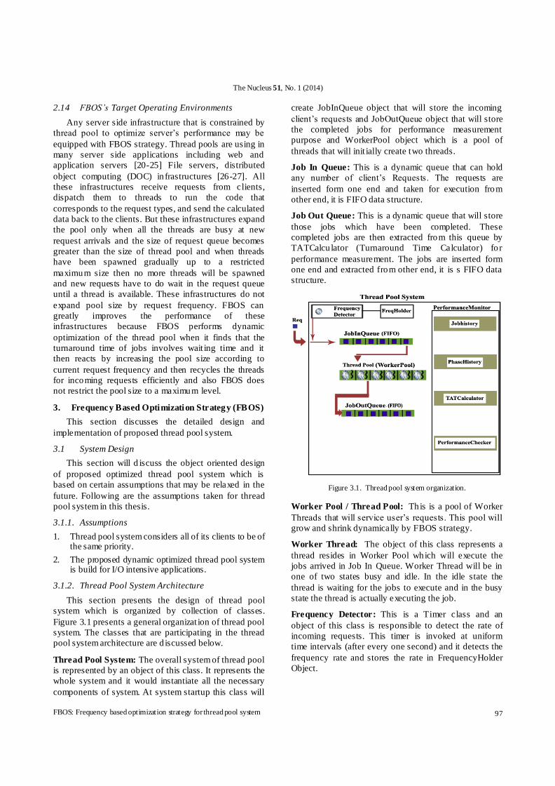
Figure 3.1 presents a general organizat ion of thread pool
system. The classes that are participating in the thread
pool system architecture are d iscussed below.
Thread Pool System: The overall system of thread pool
is represented by an object of this class. It represents the
whole system and it would instantiate all the necessary
components of system. At system startup this class will
create JobInQueue object that will store the incoming
client’s requests and JobOutQueue object that will store
the completed jobs for performance measurement
purpose and WorkerPool object which is a pool of
threads that will init ially create two threads.
Job In Queue: This is a dynamic queue that can hold
any number of client’s Requests. The requests are
inserted form one end and taken for execution from
other end, it is FIFO data structure.
Job Out Queue: This is a dynamic queue that will store
those jobs which have been completed. These
completed jobs are then extracted from this queue by
TATCalcu lator (Turnaround Time Calculator) fo r
performance measurement. The jobs are inserted form
one end and extracted from other end, it is s FIFO data
structure.
Figure 3.1. Thread pool system organization.
Worker Pool / Thread Pool: Th is is a pool of Worker
Threads that will service user’s requests. This pool will
grow and shrink dynamically by FBOS strategy.
Worker Thread: The object of this class represents a
thread resides in Worker Pool which will execute the
jobs arrived in Job In Queue. Worker Thread will be in
one of two states busy and idle. In the idle state the
thread is waiting for the jobs to execute and in the busy
state the thread is actually executing the job.
Frequency Detector: This is a Timer class and an
object of this class is responsible to detect the rate of
incoming requests. This timer is invoked at uniform
time intervals (after every one second) and it detects the
frequency rate and stores the rate in FrequencyHolder
Object.

The Nucleus 51, No. 1 (2014)
98 F. Bahadur et al.
Frequency Holder: An object of this class will store
frequency rate. Frequency Detector’s object will update
this object after every one seconds.
Average Wait Detector: This is a Timer class and an
object of this class is responsible to periodically (after
every 200 millisecond) calculate the average wait times
of requests waiting inside Job In Queue for their turn of
execution.
Throughput Detector: This is a Timer class and an
object of this class is invoked at uniform time intervals
(after 1 second) to detect the total completed requests by
the thread pool system.
Job Completion Count: Object of this class will
maintain total number of jobs and phases that has been
executed. This is a synchronized object ie when a thread
will complete a job it will first obtain a lock on this
object so that no other thread can hold it and then its
values would be updated.
Performance Monitor: An object of this class is
responsible to maintain performance statistics of the
system. Thread Pool System will activate this object
after complet ing a phase (two jobs).
PerformanceMonitor will maintain history of all the
completed jobs and phases. It will monitor the system
performance at the end of each phase (completion of 2
jobs). TAT Calculator and Performance Checker are the
objects inside PerformanceMonitor used for dynamic
optimization.
TAT Calculator: An object of this class is called by
PerformanceMonitor to calculate the sum of turnaround
times of two jobs. The completed jobs are extracted
from JobOutQueue.
Performance Checker: An object of this class is called
by Performance Monitor at the end of each phase to
check the performance of most recent completed phase
and expand the WorkerPool if necessary.
Phase: An object of this class will represent a phase that
will store statistics of last two completed jobs.
Phase History: It will store objects of all the phases
that have been completed so far.
Job: An object of this class will represent a client’s
request. This object would be stamped by thread pool
system at different stages.
Job History: It will store objects of all the jobs that
have been completed so far.
I/O Bound Job: An object of this class represents an
I/O bond request; it will extend the Job object to absorb
its behaviors. IO boundness is simulated through sleep
(milliseconds) method.
Pool Reducer: This is a timer object and an object of
this class is embedded inside each WorkerThread to
calculate the idle t ime of WorkerThread. This timer
object is responsible to delete the corresponding thread
if the idle t ime of thread will become four seconds. In
this way this object is responsible to reduce the pool
size.
System Initialization:
At system startup the object of class Thread Pool
System will in itialize all its components. Worker Thread
and Job are the two most important objects of Thread
Pool System. Worker Pool and Job In Queue are two
data structures used to hold the references to Worker
Thread and Job entities. Worker Thread will be in any
one of two states called busy and idle. At system startup
there will be two objects of WorkerThread in the
Worker Pool in the waiting state. The dynamic
optimization strategy discussed later will increase and
decrease the number of Worker Thead in the Worker
Pool as needed. These two objects are wait ing for the
job arrival in the Job In Queue. Job In Queue is a
monitor object and only one Worker Thread can access
it at any time (called Active thread) and all other
Worker Thread in the Worker Pool must wait until the
active thread will release the lock from this
synchronized object. When a request will arrive, the
JobIn Queue will send a notificat ion signal to all the
wait ing threads in Worker Pool and they will start
competition to grab the job inside JobIn Queue but only
one will be the winner and the winner thread will start
the job execution and after job completion the thread
will place the job inside Job Out Queue for performance
measurement purposes, and then the thread will again
go into the waiting state inside WorkerPool to execute
other jobs.
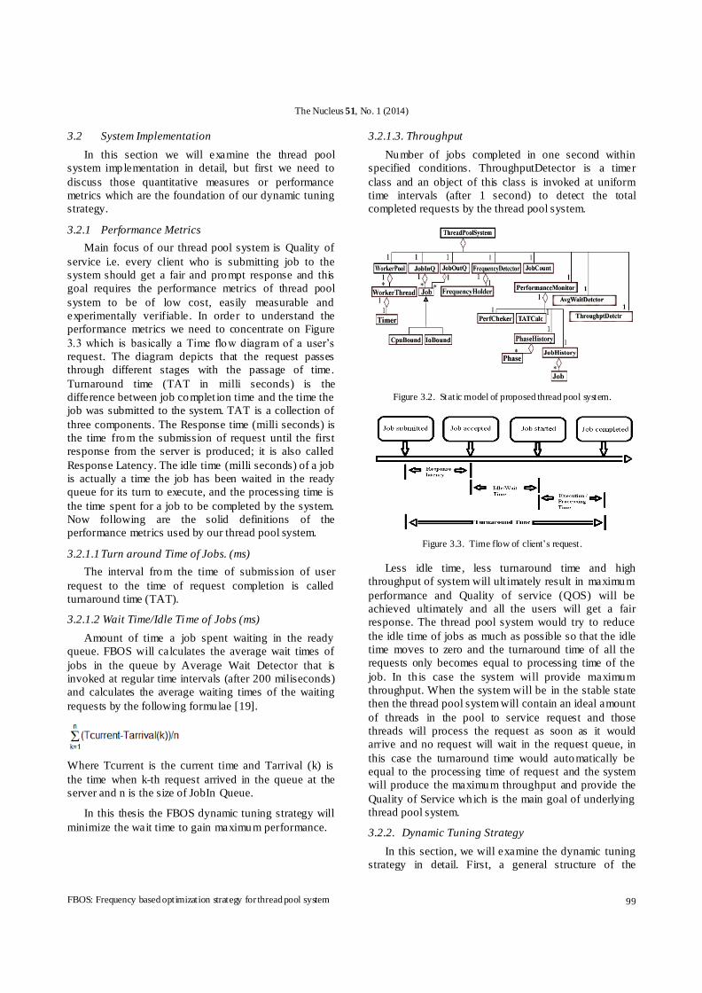
3.1.3 Static Model of Thread Pool System
Figure 3.2 shows the relationship between the
classes of the system. Thread Pool System class will
create one instance of Job In Queue, Job Out Que,
Worker Pool, Performance Monitor, Throughput
Detector, Average Wait Detector and Frequency
Detector ie it has one to one association with other
classes. Worker Pool has many Worker Threads and
each Worker Thread has one Timer object to count the
idle t ime of corresponding thread and delete the
corresponding thread if Total id le t ime is equal to 4
seconds. JobIn Queue and Job Out Queue may have
many jobs. Frequency Detector has a single Frequency
Holder object. Performance Monitor has single objects
of Phase History, Job History, TAT Calc and
Performance Checker classes. Phase History has many
objects of Phase and Job History has many Objects of
Job.
The Nucleus 51, No. 1 (2014)
FBOS: Frequency based optimization strategy for thread pool system 99
3.2 System Implementation
In this section we will examine the thread pool
system implementation in detail, but first we need to
discuss those quantitative measures or performance
metrics which are the foundation of our dynamic tuning
strategy.
3.2.1 Performance Metrics
Main focus of our thread pool system is Quality of
service i.e. every client who is submitting job to the
system should get a fair and prompt response and this
goal requires the performance metrics of thread pool
system to be of low cost, easily measurable and
experimentally verifiable. In order to understand the
performance metrics we need to concentrate on Figure
3.3 which is basically a Time flow diagram of a user’s
request. The diagram depicts that the request passes
through different stages with the passage of time.
Turnaround time (TAT in milli seconds) is the
difference between job complet ion time and the time the
job was submitted to the system. TAT is a collection of
three components. The Response time (milli seconds) is
the time from the submission of request until the first
response from the server is produced; it is also called
Response Latency. The idle time (milli seconds) of a job
is actually a time the job has been waited in the ready
queue for its turn to execute, and the processing time is
the time spent for a job to be completed by the system.
Now following are the solid definitions of the
performance metrics used by our thread pool system.
3.2.1.1 Turn around Time of Jobs. (ms)
The interval from the time of submission of user
request to the time of request completion is called
turnaround time (TAT).
3.2.1.2 Wait Time/Idle Time of Jobs (ms)
Amount of time a job spent waiting in the ready
queue. FBOS will calculates the average wait times of
jobs in the queue by Average Wait Detector that is
invoked at regular time intervals (after 200 miliseconds)
and calculates the average waiting times of the waiting
requests by the following formulae [19].
Where Tcurrent is the current time and Tarrival (k) is
the time when k-th request arrived in the queue at the
server and n is the size of JobIn Queue.
In this thesis the FBOS dynamic tuning strategy will
minimize the wait time to gain maximum performance.
3.2.1.3. Throughput
Number of jobs completed in one second within
specified conditions. ThroughputDetector is a timer
class and an object of this class is invoked at uniform
time intervals (after 1 second) to detect the total
completed requests by the thread pool system.
Figure 3.2. Static model of proposed thread pool system.
Figure 3.3. Time flow of client’s request.
Less idle time, less turnaround time and high
throughput of system will ult imately result in maximum
performance and Quality of service (QOS) will be
achieved ultimately and all the users will get a fair
response. The thread pool system would try to reduce
the idle time of jobs as much as possible so that the idle
time moves to zero and the turnaround time of all the
requests only becomes equal to processing time of the
job. In th is case the system will provide maximum
throughput. When the system will be in the stable state
then the thread pool system will contain an ideal amount
of threads in the pool to service request and those
threads will process the request as soon as it would
arrive and no request will wait in the request queue, in
this case the turnaround time would automatically be
equal to the processing time of request and the system
will produce the maximum throughput and provide the
Quality of Service which is the main goal of underlying
thread pool system.
3.2.2. Dynamic Tuning Strategy
In this section, we will examine the dynamic tuning
strategy in detail. First, a general structure of the
The Nucleus 51, No. 1 (2014)
100 F. Bahadur et al.
strategy is presented and then we will separately discuss
each and every component of the strategy.
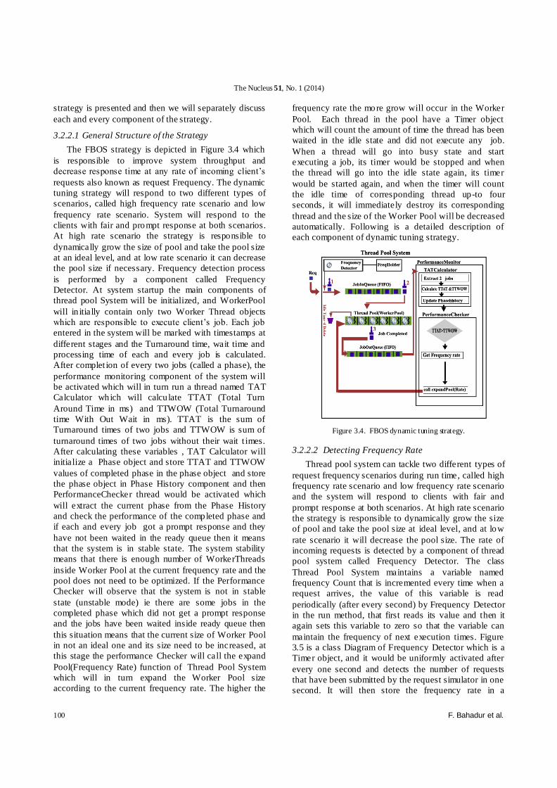
3.2.2.1 General Structure of the Strategy
The FBOS strategy is depicted in Figure 3.4 which
is responsible to improve system throughput and
decrease response time at any rate of incoming client’s
requests also known as request Frequency. The dynamic
tuning strategy will respond to two different types of
scenarios, called high frequency rate scenario and low
frequency rate scenario. System will respond to the
clients with fair and prompt response at both scenarios.
At high rate scenario the strategy is responsible to
dynamically grow the size of pool and take the pool size
at an ideal level, and at low rate scenario it can decrease
the pool size if necessary. Frequency detection process
is performed by a component called Frequency
Detector. At system startup the main components of
thread pool System will be initialized, and WorkerPool
will in itially contain only two Worker Thread objects
which are responsible to execute client’s job. Each job
entered in the system will be marked with timestamps at
different stages and the Turnaround time, wait time and
processing time of each and every job is calculated.
After complet ion of every two jobs (called a phase), the
performance monitoring component of the system will
be activated which will in turn run a thread named TAT
Calculator which will calcu late TTAT (Total Turn
Around Time in ms) and TTWOW (Total Turnaround
time With Out Wait in ms). TTAT is the sum of
Turnaround times of two jobs and TTWOW is sum of
turnaround times of two jobs without their wait t imes.
After calculating these variables , TAT Calculator will
initialize a Phase object and store TTAT and TTWOW
values of completed phase in the phase object and store
the phase object in Phase History component and then
PerformanceChecker thread would be activated which
will extract the current phase from the Phase History
and check the performance of the completed phase and
if each and every job got a prompt response and they
have not been waited in the ready queue then it means
that the system is in stable state. The system stability
means that there is enough number of WorkerThreads
inside Worker Pool at the current frequency rate and the
pool does not need to be optimized. If the Performance
Checker will observe that the system is not in stable
state (unstable mode) ie there are some jobs in the
completed phase which did not get a prompt response
and the jobs have been waited inside ready queue then
this situation means that the current size of Worker Pool
in not an ideal one and its size need to be increased, at
this stage the performance Checker will call the expand
Pool(Frequency Rate) function of Thread Pool System
which will in turn expand the Worker Pool size
according to the current frequency rate. The higher the
frequency rate the more grow will occur in the Worker
Pool. Each thread in the pool have a Timer object
which will count the amount of time the thread has been
waited in the idle state and did not execute any job.
When a thread will go into busy state and start
executing a job, its timer would be stopped and when
the thread will go into the idle state again, its timer
would be started again, and when the timer will count
the idle time of corresponding thread up-to four
seconds, it will immediately destroy its corresponding
thread and the size of the Worker Pool will be decreased
automatically. Following is a detailed description of
each component of dynamic tuning strategy.
Figure 3.4. FBOS dynamic tuning strategy.
3.2.2.2 Detecting Frequency Rate
Thread pool system can tackle two different types of
request frequency scenarios during run time, called high
frequency rate scenario and low frequency rate scenario
and the system will respond to clients with fair and
prompt response at both scenarios. At high rate scenario
the strategy is responsible to dynamically grow the size
of pool and take the pool size at ideal level, and at low
rate scenario it will decrease the pool size. The rate of
incoming requests is detected by a component of thread
pool system called Frequency Detector. The class
Thread Pool System maintains a variable named
frequency Count that is incremented every time when a
request arrives, the value of this variable is read
periodically (after every second) by Frequency Detector
in the run method, that first reads its value and then it
again sets this variable to zero so that the variable can
maintain the frequency of next execution times. Figure
3.5 is a class Diagram of Frequency Detector which is a
Timer object, and it would be uniformly activated after
every one second and detects the number of requests
that have been submitted by the request simulator in one
second. It will then store the frequency rate in a

The Nucleus 51, No. 1 (2014)
FBOS: Frequency based optimization strategy for thread pool system 101
synchronized object of class called Frequency Holder
which is a synchronized object and Frequency Detector
will update this object after every one second.
3.2.2.3 Job’s Time Stamping
A Job or a request is an important entity of thread
pool system submitted by the Request Simulator to our
thread pool system at a specific frequency. In the thread
pool system a job is represented by a class named Job.
The class diagram is shown in Figure 3.6 with its
attributes and some of its methods. The description of
each instance variable is given in Table 3.1.
Thread pool system needs to know different types of
time intervals (listed in Table 3.1) about a job and for
this purpose the thread pool system will use time
stamping. During run t ime the System will mark time
stamps on a job at different stages. When a job is
submitted to the thread pool system, it is marked by its
submission time with the first time stamp and the job is
entered into the ready queue (JobIn Queue) which
follows the FIFO policy. If the system is in stable state
then the job will be picked by an id le Worker Thread
immediately and its execution will be started otherwis e
the job will do wait in the queue for its turn of
execution. When the job is extracted by a Worker
Thread from ready queue for its execution, it is marked
by it’s dequeue time with second time stamp and then
its execution will be started. When the job is completed
it is again marked by its completion time with third time
stamp and then the job is inserted into another queue
(Job Out Queue) for performance analysis. At this stage
the job can be examined by the system about its timing
intervals. Following three important variables about
every job will be calculated by the system for
performance measurement.
Frequency Detector
fH : Frequency Holder
run 0
Figure 3.5. Class diagram of frequency detector.
Wait Time= deQueue Time – inQue Time (1)
Turn Around Time = complet ion Time –
in Que Time (2)
Turn Around TimeWOW = turn Around Time –
wait Time (3)
If the system is in stable state then the job’s wait
Time would be zero and the values of both equation 1
and equation 2 would be same, and if the system was in
unstable state then the job’s wait Time variable will be
greater than zero and value of turn Around Time would
greater then value of turn Around Time WOW.
Figure 3.6. Class diagram of job.
Table 3.1. Job’s attributes and description
Attribute Description
inQueTime The time of job submitted to the system.
deQueueTime The time of extracting the job from ready queue.
completionTime The time of job completion.
phaseNo Phase ID of a job.
jobNo Job ID.
waitT ime(ms) The total idle time of a job: deQueueTime - inQueTime
turnAroundTime(ms) completionTime - inQueTime
turnAroundTimeWOW (ms)
turnAroundTime - waitTime
3.2.2.4 Phase (Cycle) Explaination
The thread pool system will monitor the system
performance for dynamic optimization concern at the
end of each cycle, which is defined as two completed
jobs in our system called a phase. A cycle or a phase
contains the detail of two completed jobs that have been
executed by the system. Thread Pool System will call
the performance monitoring component after
complet ion of a phase. A phase is represented by an
object of class Phase depicted in Figure 3.7. The
description of attributes of class Phase is given in Table
3.2. The detail of phases that have been executed so far
is stored in an object of class Phase History. Phase
object is instantiated by a thread called TAT Calculator

The Nucleus 51, No. 1 (2014)
102 F. Bahadur et al.
which is called by Performance Monitoring component.
A further detail of calculating TTAT and TTWOW is
discussed in the next section.
3.2.2.5. Performance Monitoring and Pool Expansion
The performance of the thread pool system is
examined and tuned by an object of class Performance
Monitor which would be activated after every phase
(two jobs). Performance Monitor will launch its two
helper threads parallel named TAT Calculator and
Performance Checker. Performance Checker thread
will join TAT Calculator which means that Performance
Checker will pause its execution until completion of
thread TAT Calculator. Both of these helper threads are
discussed below.
TAT Calculator
This thread is responsible to calculate the values of
those variables that will be later used by the
Performance Checker thread to expand the Worker
Pool. TAT Calculator is the first thread launched by
Performance Monitor which will perform two main
tasks. It will first extract top two completed jobs from
Job Out Queue, The second task performed by TAT
Calculator is to calculate TTAT, TTWOW discussed
below.
Figure 3.7. Class diagram of phase.
Table 3.2. Description of attributes of class phase
Attribute Description
ID Phase ID.
poolSize
Size of WorkerPool.
OR Total number of WorkerThread that have been completed this phase.
TTAT(Total TturnAroundTime ms)
Sum of turnAroundTime of two jobs.
TotalWait ms Sum of wait t imes of two jobs.
TTWOW(Total
TturnAroundTime Without wait ms)
Sum of turnAroundTimeWOW of two jobs.
TTAT (Total Turn Around Time ms)
It is the sum of processing times and wait times of
two jobs in a phase. TTAT is initialized with sum of
turnaround Time of two jobs completed so far as
follows.
TTAT= turn Around Time1 + turn Around Time 2.(1)
Where turnAroundTime1 and turn Around Time 2 are
the turnaround times of two completed jobs.
TTWOW (Total Turnaround time Without
Wait ms)
TTWOW is the sum of processing times of two jobs
of a phase, i.e. it contains the sum of turnaround times
of two jobs excluding their wait t imes.
TTWOW= turn Around Time WOW 1+ turn Around Time WOW2 (2)
Where turn Around Time WOW1 and turn Around
Time WOW 2 are the turnaround times without waits of
two completed jobs that belong to the current phase.
PerformanceChecker
This thread is responsible to expand the pool size on
low performance. After completion of TAT Calculator
thread, the Performance Checker thread will start its
execution which is responsible to measure the
performance of thread pool system and expand the pool
according to request frequency, if necessary.
Performance Checker thread will ext ract the most recent
completed phase from the Phase History and check the
performance of the phase. The variables related to
performance measurement of thread pool system in the
phase have just been calculated by TAT Calculator and
now Performance Checker thread will ext ract the
current phase from the Phase History and check the
performance to make decisions of dynamic tuning of
thread pool. Performance Checker will compare TTAT
and TTWOW and if TTAT is greater than TTWOW the
Performance Checker will get the current frequency rate
from Frequency Holder object and call the expand Pool
(Frequency Rate) function of Thread Pool System that
will set the size of pool equal to the current request
frequency. The pseudo code of pool expansion
according to the request frequency is given below.
If (TTAT > TTWOW) then
{
frequency= Frequency Holder.get Frequency
create a thread and add to the pool until the size of the
pool equals to frequency
}
The Nucleus 51, No. 1 (2014)
FBOS: Frequency based optimization strategy for thread pool system 103
If the system will be in a stable mode then it means
that the WorkerPool will have an ideal number o f
Worker Threads so each job of phase will get a prompt
response and no one will spend an idle time so TTAT
and TTWOW values would be same and the pool will
not be expanded.
If the system will be in an unstable mode then some
of the jobs will spend time in ready queue in idle mode
and wait time of some of the jobs will be greater than
zero and TTAT value of phase must be greater than
TTWOW value. This situation means that the current
size of WorkerPool in not an ideal one and its size need
to be increased and the performance Checker will call
the expand Pool (Frequency Rate) function of Thread
Pool System which will in turn expand the WorkerPool
size according to the current Frequency Rate. At higher
frequency rate the pool expansion rate would be h igher
and vice versa.
3.2.2.6. Shrinking Pool Size
The dynamic tuning strategy will not only expand
the pool at ideal level but it will also decrease the size of
WorkerPool at low frequency rate scenario. From high
request frequency mode to low request frequency mode
the job arrival rate inside ready queue would be slow
and the Worker Threads that have been increased
previously on high frequency rate scenario will now
have less number of jobs to execute so only limited
number of Worker Threads would be in busy mode
executing client’s job and there would be some threads
remain id le most of the time. In this case the timer
objects inside idle threads will count the idle time and
when the idle time of thread will be equal to four
seconds then the timer will delete its corresponding
thread that would result in reduction of pool size. This
reduction may continue until the size of Worker Pool
reduces to two, i.e. there would be at least two Worker
Threads in the pool.
4. Analysis of FBOS
This section discusses the experimental environment
and analysis of thread pool system.
4.1. Request Simulator
In order to measure the performance of thread pool
system a Java based request simulator is constructed
that will behave as a multithreaded server to the thread
pool system. It will submit requests to the thread pool
system at random frequencies. The request is not a real
I/O request but just a simulat ion of I/O request by
sleeping for a specific interval of time defined as
intensity level. The intensity level is random for each
request from 500 milliseconds to 1500 milliseconds.
The general architecture of the Request simulator is
given in Figure 4.1 with the following three
components.
i) Job Creator: This component will create a set of five
hundred requests with random I/O intensities and then
create its two more clones so that same set of jobs can
be send to three strategies for experiment.
ii) Request Sender Component: This is a Timer object
that will send requests to the thread pool system at
random frequencies .
ii) GUI Component: This object is responsible to
display the performance statistics related to each request
and each phase that have been completed.
The Request simulator will show us the complete
informat ion of each job submitted to the system
including information of time stamps of the job and it
will show us the performance statistics of average waits,
throughput per second and the thread pool size at
different intervals.
4.2. Experimental Environment
For the experiments, the Request simulator and the
thread pool system are running on same machine. The
operating system is Microsoft Windows 7 and the
processor is Pentium IV 2.80 GH with 1MB L2 cache.
The physical RAM size is 1GB. Figure 4.2 is the
client’s request burst used for the experiments. The
simulation is performed for twenty seconds with
different frequencies as shown in the Figure 4.2. Same
client’s load is used for three strategies separately and
the data collected from simulat ions is plotted for
analysis discussed next.
4.3. Analysis and Results
This section presents a comparative analysis of
FBOS strategy with Heuristic and Waterfall strategy on
the basis of average waits of queued requests and
throughputs gained per second. The data collected from
experiments is presented in the form of tables and their
corresponding graphs are also presented as figures.
FBOS and Heuristic strategies are phase based
strategies in which the performance of system is
analyzed after completion of a phase and then, tuning is
performed if needed, whereas Waterfall is not a phase
based strategy it doesn’t analyze performance of system,
but it increases the pool size according to the amount of
requests ,when there is a low request arrival it acts as a
static thread pool but when the frequency increases and
there are too many requests in the queue and all of the
low watermark threads are busy ,then size of request
queue becomes greater than thread pool size it starts
increasing its pool size by one thread to execute the
wait ing requests and behaves like thread per request
model. The value of low watermark is set to two threads

The Nucleus 51, No. 1 (2014)
104 F. Bahadur et al.
for all experiments. The pool size of three strategies in
different execution times is presented in Table 4.1 and
corresponding data is plotted in Figure 4.3 which shows
that FBOS strategy keeps its pool size accord ing to the
client’s request frequency whereas other two strategies
keep no relation of pool size and request frequency and
this is the reason that FBOS outperforms other two
strategies. For example in Figure 4.2 the request
frequency is 18 in execution times of 2 to 5 seconds and
the pool size of FBOS in Figure 4.3 is also 18 in theses
execution times and when the request frequency
becomes 24 in execution t imes of 10 to 13 seconds the
pool size of FBOS also grows to 24.
Now we will discuss the throughput gain of three
strategies. The data of throughput gain from each
strategy is presented in Table 4.2 and the throughput
data is also plotted in form of graph in Figure 4.4. The
x-axis shows the execution times in seconds and y-axis
shows the number of requests that have been processed.
Figure 4.4 shows that FBOS strategy outperforms other
two strategies in terms of throughput per second.
Heuristic strategy produces less throughput than other
two strategies because of two reasons, first it performs
its optimizat ion after completion of five completed jobs
where as FBOS performs optimization after two jobs,
second it increases the pool size by a constant value i.e.
two threads whereas FBOS increases its pool size
according to the ongoing request frequency. For
example in Figure 4.3 when the execution times was
10 seconds the pool size was 18 but when the
frequency increased up to 24 requests per second in the
next time interval then FBOS found that TTAT became
greater than TTWOW than it created six more threads to
keep its pool size equals to request frequency i.e. 24.
Watermark is giving more throughput than FBOSS in
initial execution times as it grew its pool size to six very
early on initial client’s burst that can be seen in Figure
4.4, but when the client’s load is continuously
increasing the watermark strategy started behaving like
thread per request model and it faced thread creation
overhead that ultimately resulted in low throughput. The
smartness of FBOSS strategy is that whenever the
request frequency increases, TTAT obviously becomes
greater than TTWOW and FBOS immediately grows its
pool size and keep it equal to frequency and then
recycles its threads in the subsequent execution times
whereas Watermark faces thread per request creation
overhead whenever its queue size becomes greater than
its pool size i.e. fo r every new request it first creates a
thread because all other threads are busy and in this way
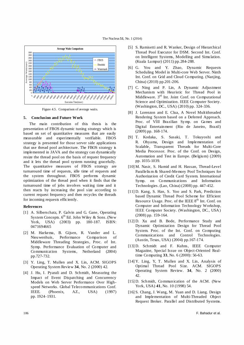
it gains less throughput. The comparison of average
waits of three strategies is presented in Table 4.3 and
the data of average waits is also plotted in form of graph
in Figure 4.5.
The x-axis shows the execution times in
milliseconds and y-axis shows the average waits in
milliseconds. FBOS strategy overall produces less
average waits than other two strategies. Heuristic is
producing higher average waits than other two strategies
because of its slow optimization process as discussed
before. Watermark is giving less average waits than
FBOS in the initial execution times as it grew its pool
size to six very early on initial client’s burst as shown in
Figure 4.3 while FBOS uses two initial threads but in
the execution times of 10 second and 18 second when
the client’s burst become 24 requests per second and 30
requests per second, the average wait times of
Watermark are h igher than FBOS because FBOS
strategy has kept the pool size equal to the request
frequency and recycling its threads efficiently and its
pool size is more than watermark strategy, whereas
watermark is facing thread creation overhead and its
pool size is smaller than pool size of FBOS and that’s
why average waits of queued requests in case of
Watermark strategy are higher than FBOS strategy.
The analysis results have been proved that FBOS is
more performance efficient than Watermark and
Heuristic strategies. FBOS produces less idle time fo r
the queued requests and produces higher throughput
than Watermark and Heuristic strategy.
Figure 4.1. General architecture of request simulator.
Figure 4.2. Client’s load on the server.

The Nucleus 51, No. 1 (2014)
FBOS: Frequency based optimization strategy for thread pool system 105
Table 4.1. Pool size comparison of three strategies
Execution
Time (sec)
FBOS Heuristic Watermark
1 2 2 6
2 18 2 12
3 18 2 12
4 18 2 18
5 18 2 18
6 18 4 18
7 18 6 18
8 18 10 18
9 18 14 18
10 18 18 18
11 24 18 21
12 24 18 21
13 24 18 21
14 24 18 21
15 24 18 21
16 24 22 21
17 24 24 21
18 24 24 22
19 30 24 22
20 30 24 22
Figure 4.3. Comparison of pool size.
Figure 4.4 Comparison of throughput.
Table 4.2. Throughput comparison of three strategie
Execution
Time(sec) FBOS Heuristic Watermark
1 2 2 6
2 4 4 20
3 24 7 36
4 47 10 56
5 72 13 78
6 94 18 92
7 108 27 112
8 129 40 130
9 150 60 140
10 161 85 161
11 185 110 186
12 209 134 210
13 244 160 236
14 253 180 253
15 272 205 272
16 289 240 287
17 300 270 300
18 327 305 326
19 358 335 352
Table 4.3. Average wait comparison of three strategies
Execution
Time(msec) FBOS Heuristic Watermark
0 0 0 0
800 487 497 282
1600 669 679 63
2400 749.0909 1190.7894 360
3200 472.75 1383.415 141
4000 728.2632 1879 438
4800 56 2040.5555 0
5600 0 2150.75 0
6400 0 2553.9639 0
7200 0 2477.721 0
8000 0 2736.238 0
8800 0 2286.4578 0
9600 0 2327.0247 0
10400 209 1859.7561 141
11200 0 1452.0632 32
12000 0 1049 313
12800 0 1100 0
13600 0 1211 0
14400 0 945 0
15200 0 729 0
16000 0 602 0
16800 0 381 0
17600 0 249 0
18400 0 187 110
19200 0 67 407
Pool Size Comparison
2468
10121416182022242628303234363840
1 2 3 4 5 6 7 8 9 10 11 12 13 14 15 16 17 18 19 20
Execution Time(sec)
Po
ol
Siz
e
FBOSHeuristicWatermark
Throughput Comparison
2
2242
62
82102
122142
162
182202
222
242262
282302
322
342
1 2 3 4 5 6 7 8 9 10 11 12 13 14 15 16 17 18 19
Execution Time(sec)
Th
rou
gh
pu
t
FBOS
Heuristic
Watermark
The Nucleus 51, No. 1 (2014)
106 F. Bahadur et al.
Figure 4.5. Comparison of average waits.
5. Conclusion and Future Work
The main contribution of this thesis is the
presentation of FBOS dynamic tuning strategy which is
based on set of quantitative measures that are easily
measurable and experimentally verifiable. FBOS
strategy is presented for those server side applications
that use thread pool architecture. The FBOS strategy is
implemented in JAVA and the strategy can dynamically
resize the thread pool on the basis of request frequency
and it lets the thread pool system running gracefully.
The quantitative measures of FBOS s trategy are
turnaround time of requests, idle time of requests and
the system throughout. FBOS performs dynamic
optimization of the thread pool when it finds that the
turnaround time of jobs involves wait ing time and it
then reacts by increasing the pool s ize according to
current request frequency and then recycles the threads
for incoming requests efficiently.
References
[1] A. Silberschatz, P. Galvin and G. Gane, Operating
System Concepts. 6th
Ed. John Wiley & Sons. (New
York, USA) (2003) pp. 180-187. ISBN:
0471694665
[2] M. Harkema, B. Gijsen, R. Vander and L.
Nieuwenhuis, Performance Comparison of
Middleware Threading Strategies , Proc. of Int.
Symp. Performance Evaluation of Computer and
Communicat ion Systems, Netherland (2004)
pp.727-732.
[3] Y. Ling, T. Mullen and X. Lin, ACM. SIGOPS
Operating System Review 34, No. 2 (2000) 42.
[4] J. Hu, I. Pyarali and D. Schmidt, Measuring the
Impact of Event Dispatching and Concurrency
Models on Web Server Performance Over High-
speed Networks. Global Telecommunications Conf.
IEEE. (Phoenix, AZ., USA) (1997)
pp. 1924–1931.
[5] S. Ramisetti and R. Wanker, Design of Hierarchical
Thread Pool Executor for DSM. Second Int. Conf.
on Intelligent Systems, Modelling and Simulation.
(Kuala Lumpur) (2011) pp.284-288.
[6] G. You and Y. Zhao, Dynamic Requests
Scheduling Model in Multi-core Web Server. Ninth
Int. Conf. on Grid and Cloud Computing. (Nanjing,
China) (2010) pp.201-206.
[7] C. Ning and P. Lin, A Dynamic Adjustment
Mechanism with Heuristic for Thread Pool in
Middleware. 3rd
Int. Joint Conf. on Computational
Science and Optimization. IEEE Computer Society.
(Washington, DC., USA) (2010) pp. 324-336.
[8] J. Lorenzon and E. Clua, A Novel Mult ithreaded
Rendering System based on a Deferred Approach.
Proc. of VIII Brazilian Symp. on Ga mes and
Dig ital Entertainment (Rio de Janeiro, Brazil)
(2009) pp. 168-174.
[9] T. Kodaka, S. Sasaki, T. Tokuyoshi and
R. Ohyama, Design and Implementation of
Scalable, Transparent Threads for Multi-Core
Media Processor. Proc. of the Conf. on Design,
Automation and Test in Europe. (Belgium) (2009)
pp. 1035-1039.
[10] M. Nasir, S. Hamid and H. Hassan, Thread-Level
Parallelis m & Shared-Memory Pool Techniques for
Authorizat ion of Credit Card System. International
Symp. on Communicat ions and Information
Technologies. (Lao, China) (2008) pp. 447-452.
[11] D. Kang, S. Han, S. Yoo and S. Park, Prediction
based Dynamic Thread Pool Scheme for Efficient
Resource Usage. Proc. of the IEEE 8th
Int. Conf. on
Computer and Informat ion Technology Workshop,
IEEE Computer Society. (Washington, DC., USA)
(2008) pp. 159-164.
[12] D. Xu and B. Bode, Performance Study and
Dynamic Optimizat ion Design for Thread Pool
System. Proc. of the Int. Conf. on Computing
Communicat ions and Control Technologies.
(Austin, Texas, USA) (2004) pp.167-174.
[13] D. Schmidt and F. Kuhns, IEEE Computer
Magazine, Special Issue on Object-Oriented Real-
time Computing 33, No. 6 (2000): 56-63.
[14] Y. Ling, Y, T. Mullen and X. Lin, Analysis of
Optimal Thread Pool Size. ACM. SIGOPS
Operating System Review. 34, No. 2 (2000)
42.
[15] D. Schmidt, Communication of the ACM. (New
York, USA) 41, No. 10 (1998) 54.
[16] S. Chang, J. Wang, M. Yuan and D. Liang. Design
and Implementation of Multi-Threaded Object
Request Broker. Parallel and Distributed Systems.
Average Waits Comparison
0
200
400
600
800
1000
1200
1400
1600
1800
2000
2200
2400
2600
2800
3000
080
0
1600
2400
3200
4000
4800
5600
6400
7200
8000
8800
9600
1040
0
1120
0
1200
0
1280
0
1360
0
1440
0
1520
0
1600
0
1680
0
1760
0
1840
0
1920
0
Execution Time(msec)
Average W
ait
(m
sec)
FBOS
Heuristic
Watermark

The Nucleus 51, No. 1 (2014)
FBOS: Frequency based optimization strategy for thread pool system 107
Int. Conf. on Parallel and Distributed Systems.
(Washington, DC., USA) (1998) pp. 740-747.
[17] Dynamic TAO Documentation, http://choices.
cs.uiuc.edu/2k/dynamicTAO/doc/ (May 2013).
[18] Java API Documentation, http://docs.oracle.
com/javase/7/docs/api/ (May 2013).
[19] T. Ogaswara. Dynamic thread Couint
Adoptation for Multiple Services in SMP
Environment, Int. Conf. on web services, IEEE
Computer Society (Tokyo, Japan) (2008) pp.
585–592.
[20] JBOSS AZ7.1 Documentation. https://docs.
jboss.org/author/display/AS71/Threads+subsystem+
configuration (May 2013).
[21] Apache Tomcat 6.0. The Executor (thread
pool), http://tomcat.apache.org/tomcat-6.0-
doc/config/executor.html (May 2013).
[22] Sun Java System Applicat ion Server 9.1
Admin istration Guide. Thread pools, http://docs.
oracle.com/cd/E19159-01/819-3671/ (May 2013).
[23] Oracle®Containers for J2EE Configuration and
Admin istration Guide 10g (10.1.3.1.0). Configuring
OC4J thread pools. http://docs.oracle.com
/html/B32204_05/oc4j.htm (May 2013).
[24] WebLogic Server®Performance and Tuning.
Tune pool sizes, http://docs.oracle.com/cd/
E11035_01/wls100/perform/ (May 2013).
[25] WebSphere®Application Server Network
Deployment, Version 6.1. Thread pool settings.
http://www-01.ibm.com/software/ webservers/
appserv/was/library/ (May 2013.)
[26] Object Management Group, CORBA
Messaging Specification. http://www.omg.
org/spec/ (May 2013).
[27] Object Management Group, Realtime CORBA
Joint Revised Submission http://www.cs.
wustl.edu/~schmidt/PDF/RT-ORB-std-new.pdf (May 2013).
Copyright © 2022 FDOKUMEN