FASTflo (internal) - Goto Gas Docs
48
Working towards a cleaner future FASTflo ( internal ) Installation Guide, Operation and Maintenance Manual This manual must be kept with the appliance October 2010 Part No E791 Continuous Flow Wall Hung Balanced Flue Water Heaters for Natural Gas and LPG WH42, WH56, LWH42, LWH56
-
Upload
khangminh22 -
Category
Documents
-
view
6 -
download
0
Transcript of FASTflo (internal) - Goto Gas Docs

Working towards a cleaner future
FASTflo (internal)Installation Guide, Operation and Maintenance Manual
This manual must be kept with the appliance October 2010Part No E791
Continuous Flow Wall Hung Balanced FlueWater Heaters for Natural Gas and LPGWH42, WH56, LWH42, LWH56
SECTION XX • 2
Reproduction of any information in this publication by any method is not permittedunless prior written approval has been obtained from Andrews Water Heaters.
Andrews Storage Water Heaters have been designed and manufactured to complywith current international standards of safety. In the interests of the health and safety ofpersonnel and the continued safe, reliable operation of the equipment, safe workingpractices must be employed at all times. The attention of UK users is drawn to theirresponsibilities under the Health and Safety Regulations 1993.
All installation and service on Andrews Water Heaters must be carried out by properlyqualified personnel and, therefore, no liability can be accepted for any damage ormalfunction caused as a result of intervention by unauthorised personnel.
Andrews Water Heaters’ policy is one of continuous product improvement and,therefore, the information in this manual, whilst completely up to date at the time ofpublication, may be subject to revision without prior notice.
Further information and assistance can be obtained from:
Andrews Water HeatersWood Lane, Erdington, Birmingham B24 9QP
Tel: 0845 070 1055Fax: 0845 070 1059Email: [email protected]: www.andrewswaterheaters.com
Copyright Andrews Water Heaters 2010
INTRODUCTION2
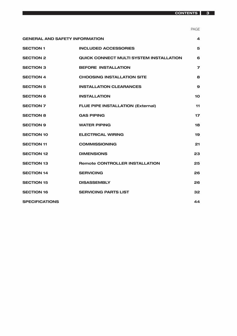
3CONTENTS
PAGE
GENERAL AND SAFETY INFORMATION 4
SECTION 1 INCLUDED ACCESSORIES 5
SECTION 2 QUICK CONNECT MULTI SYSTEM INSTALLATION 6
SECTION 3 BEFORE INSTALLATION 7
SECTION 4 CHOOSING INSTALLATION SITE 8
SECTION 5 INSTALLATION CLEARANCES 9
SECTION 6 INSTALLATION 10
SECTION 7 FLUE PIPE INSTALLATION (External) 11
SECTION 8 GAS PIPING 17
SECTION 9 WATER PIPING 18
SECTION 10 ELECTRICAL WIRING 19
SECTION 11 COMMISSIONING 21
SECTION 12 DIMENSIONS 23
SECTION 13 Remote CONTROLLER INSTALLATION 25
SECTION 14 SERVICING 26
SECTION 15 DISASSEMBLY 26
SECTION 16 SERVICING PARTS LIST 32
SPECIFICATIONS 44
3
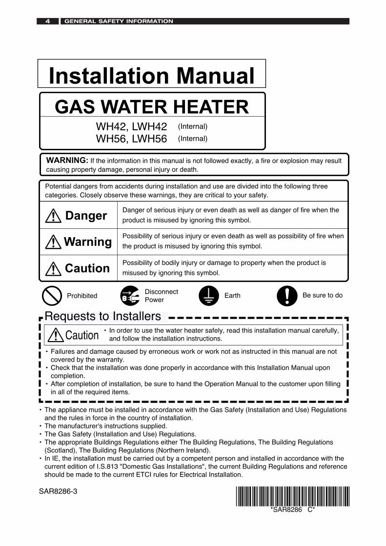
Potential dangers from accidents during installation and use are divided into the following threecategories. Closely observe these warnings, they are critical to your safety.
ProhibitedDisconnectPower
Earth Be sure to do
• Failures and damage caused by erroneous work or work not as instructed in this manual are notcovered by the warranty.
• Check that the installation was done properly in accordance with this Installation Manual uponcompletion.
• After completion of installation, be sure to hand the Operation Manual to the customer upon fillingin all of the required items.
Requests to Installers• In order to use the water heater safely, read this installation manual carefully,
and follow the installation instructions.Caution
WARNING: If the information in this manual is not followed exactly, a fire or explosion may resultcausing property damage, personal injury or death.
Warning
Caution
DangerDanger of serious injury or even death as well as danger of fire when the
product is misused by ignoring this symbol.
Possibility of serious injury or even death as well as possibility of fire when
the product is misused by ignoring this symbol.
Possibility of bodily injury or damage to property when the product is
misused by ignoring this symbol.
• The appliance must be installed in accordance with the Gas Safety (Installation and Use) Regulationsand the rules in force in the country of installation.
• The manufacturer's instructions supplied.• The Gas Safety (Installation and Use) Regulations.• The appropriate Buildings Regulations either The Building Regulations, The Building Regulations
(Scotland), The Building Regulations (Northern lreland).• In IE, the installation must be carried out by a competent person and installed in accordance with the
current edition of I.S.813 "Domestic Gas Installations", the current Building Regulations and referenceshould be made to the current ETCI rules for Electrical Installation.
SAR8286-3
*SAR8286 C*
Installation ManualGAS WATER HEATER
WH42, LWH42 (Internal)
WH56, LWH56 (Internal)
GENERAL SAFETY INFORMATION4
INCLUDED ACCESSORIES 5
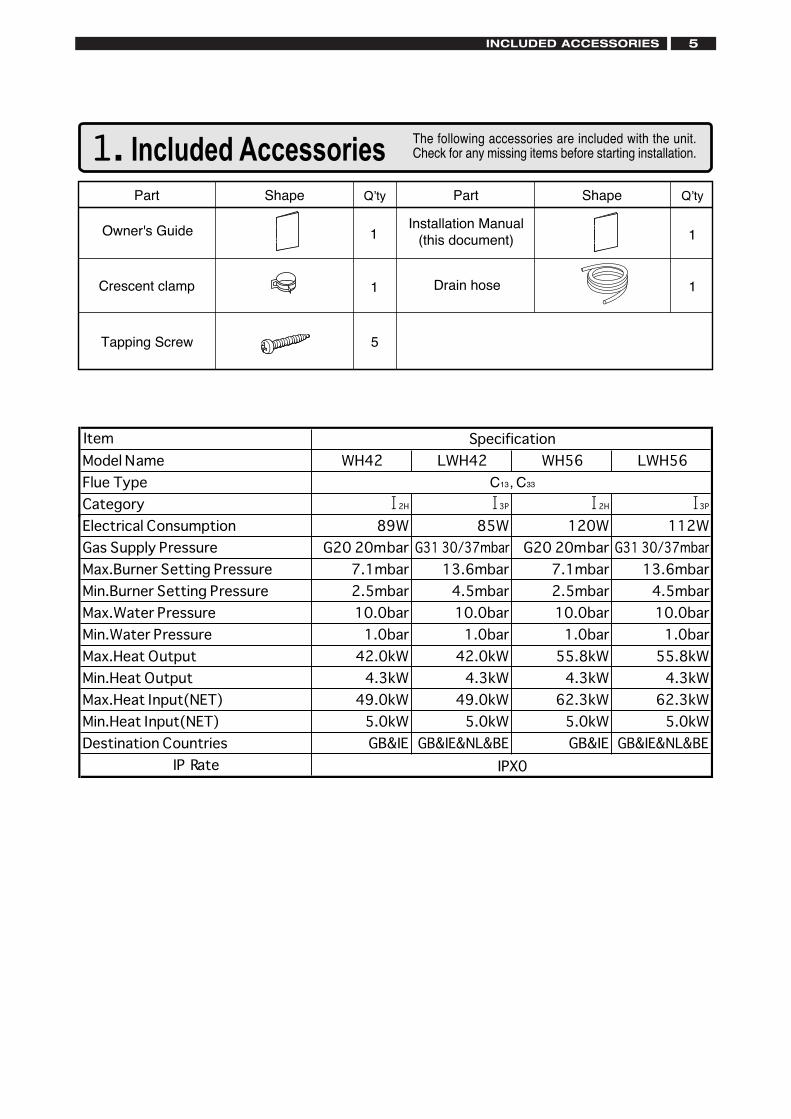
1. Included Accessories The following accessories are included with the unit.Check for any missing items before starting installation.
Q’tyShapePart
Tapping Screw
1
Part Shape Q’ty
5
Installation Manual(this document)
1
1Owner's Guide
Crescent clamp 1 Drain hose
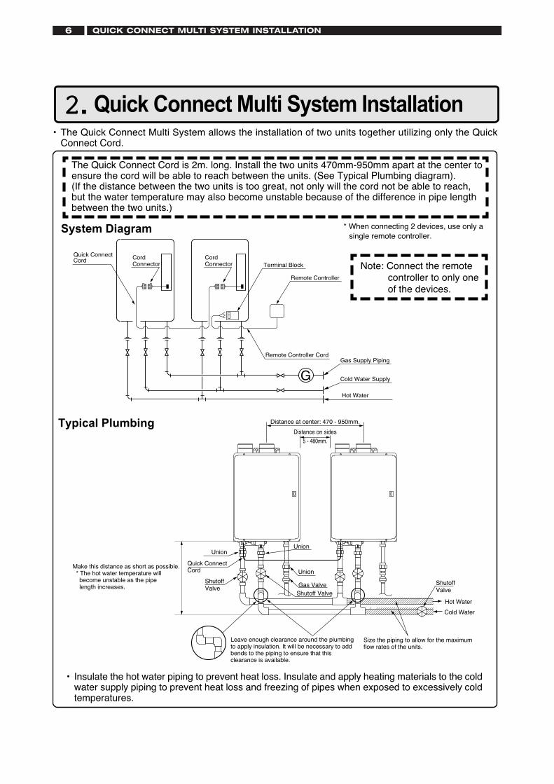
2. Quick Connect Multi System Installation• The Quick Connect Multi System allows the installation of two units together utilizing only the Quick
Connect Cord.
Typical Plumbing
The Quick Connect Cord is 2m. long. Install the two units 470mm-950mm apart at the center toensure the cord will be able to reach between the units. (See Typical Plumbing diagram).(If the distance between the two units is too great, not only will the cord not be able to reach,but the water temperature may also become unstable because of the difference in pipe lengthbetween the two units.)
* When connecting 2 devices, use only asingle remote controller.
Note: Connect the remotecontroller to only oneof the devices.
System Diagram
• Insulate the hot water piping to prevent heat loss. Insulate and apply heating materials to the coldwater supply piping to prevent heat loss and freezing of pipes when exposed to excessively coldtemperatures.
G
Quick Connect Cord
Remote Controller CordGas Supply Piping
Cold Water Supply
Hot Water
Remote Controller
Terminal BlockCord Connector
Cord Connector
Leave enough clearance around the plumbing to apply insulation. It will be necessary to add bends to the piping to ensure that this clearance is available.
Size the piping to allow for the maximum flow rates of the units.
Union
Distance at center: 470 - 950mm.
Quick ConnectCord Union
Gas Valve
Union
ShutoffValve
Shutoff ValveHot Water
Shutoff Valve
Cold Water
Distance on sides
5 - 480mm.
Make this distance as short as possible. * The hot water temperature will become unstable as the pipe length increases.
QUICK CONNECT MULTI SYSTEM INSTALLATION6
BEFORE INSTALLATION 7
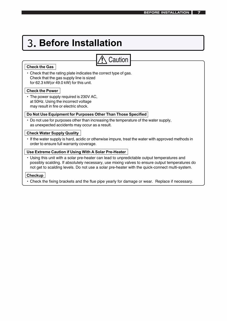
Check the Gas
• Check that the rating plate indicates the correct type of gas.Check that the gas supply line is sizedfor 62.3 kW(or 49.0 kW) for this unit.
Check the Power
• The power supply required is 230V AC,at 50Hz. Using the incorrect voltagemay result in fire or electric shock.
Do Not Use Equipment for Purposes Other Than Those Specified
• Do not use for purposes other than increasing the temperature of the water supply,as unexpected accidents may occur as a result.
Check Water Supply Quality
• If the water supply is hard, acidic or otherwise impure, treat the water with approved methods inorder to ensure full warranty coverage.
Use Extreme Caution if Using With A Solar Pre-Heater
• Using this unit with a solar pre-heater can lead to unpredictable output temperatures and possibly scalding. If absolutely necessary, use mixing valves to ensure output temperatures do
not get to scalding levels. Do not use a solar pre-heater with the quick-connect multi-system.
Checkup
• Check the fixing brackets and the flue pipe yearly for damage or wear. Replace if necessary.
3. Before Installation
Caution
6
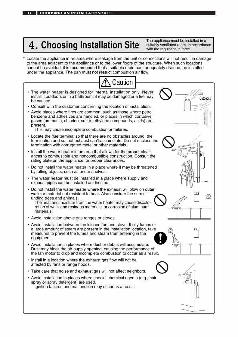
Caution• The water heater is designed for internal installation only. Never
install it outdoors or in a bathroom, it may be damaged or a fire maybe caused.
• Consult with the customer concerning the location of installation.• Avoid places where fires are common, such as those where petrol,
benzene and adhesives are handled, or places in which corrosivegases (ammonia, chlorine, sulfur, ethylene compounds, acids) arepresent. This may cause incomplete combustion or failures.
• Locate the flue terminal so that there are no obstacles around thetermination and so that exhaust can't accumulate. Do not enclose thetermination with corrugated metal or other materials.
• Install the water heater in an area that allows for the proper clear-ances to combustible and noncombustible construction. Consult therating plate on the appliance for proper clearances.
• Do not install the water heater in a place where it may be threatenedby falling objects, such as under shelves.
• The water heater must be installed in a place where supply andexhaust pipes can be installed as directed.
• Do not install the water heater where the exhaust will blow on outerwalls or material not resistant to heat. Also consider the surro-unding trees and animals.
The heat and moisture from the water heater may cause discolo-ration of walls and resinous materials, or corrosion of aluminummaterials.
• Avoid installation above gas ranges or stoves.
• Avoid installation between the kitchen fan and stove. If oily fumes ora large amount of steam are present in the installation location, takemeasures to prevent the fumes and steam from entering in theequipment.
• Avoid installation in places where dust or debris will accumulate.Dust may block the air-supply opening, causing the performance ofthe fan motor to drop and incomplete combustion to occur as a result.
• Install in a location where the exhaust gas flow will not beaffected by fans or range hoods.
• Take care that noise and exhaust gas will not affect neighbors.
• Avoid installation in places where special chemical agents (e.g., hairspray or spray detergent) are used.
Ignition failures and malfunction may occur as a result.
4. Choosing Installation Site* Locate the appliance in an area where leakage from the unit or connections will not result in damage
to the area adjacent to the appliance or to the lower floors of the structure. When such locationscannot be avoided, it is recommended that a suitable drain pan, adequately drained, be installedunder the appliance. The pan must not restrict combustion air flow.
The appliance must be installed in asuitably ventilated room, in accordancewith the regulatins in force.
CHOOSING AN INSTALLATION SITE8
INSTALLATION CLEARANCES 9
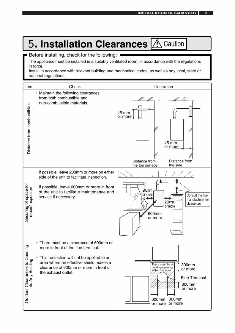
5. Installation ClearancesBefore installing, check for the following:The appliance must be installed in a suitably ventilated room, in accordance with the regulationsin force.Install in accordance with relevant building and mechanical codes, as well as any local, state ornational regulations.
Item
selbitsubmoc
morf ecnatsiD
• Maintain the following clearancesfrom both combustible andnon-combustible materials.
• There must be a clearance of 600mm ormore in front of the flue terminal.
• This restriction will not be applied to anarea where an effective shield makes aclearance of 600mm or more in front ofthe exhaust outlet.
noitartsullIkcehC
Caution
• If possible, leave 200mm or more on eitherside of the unit to facilitate inspection.
• If possible, leave 600mm or more in frontof the unit to facilitate maintenance andservice if necessary.
rof ecaps fo gnir uceSnoit cepsni/ri aper
600mmor more
200mmor more
gninepO ot secnar ael
C r oodtuO
gni dli uB ynA ot ni
Distance fromthe top surface
Distance fromthe side
45 mmor more
45 mmor more
Consult the fluemanufacturer forclearances
300mmor more
300mmor more
300mmor more
There must be nobuilding openingwithin this area.
300mmor more
Flue Terminal
200mmor more
Illustration
6. Installation
Check
4. Drill holes for the remaining four screws.
5. Hang the unit again by the first screw, and theninsert and tighten the remaining four screws.
6. Take waterproofing measures so that water doesnot enter the building from screws mounting thedevice.
• Make sure the unit is installed securely so that it willnot fall or move due to vibrations or earth-quakes.
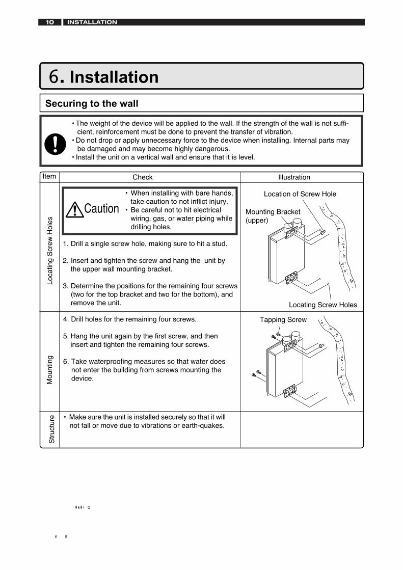
Securing to the wall
Mounting Bracket(upper)
Tapping Screw
Location of Screw Hole
1. Drill a single screw hole, making sure to hit a stud.
2. Insert and tighten the screw and hang the unit bythe upper wall mounting bracket.
3. Determine the positions for the remaining four screws(two for the top bracket and two for the bottom), andremove the unit.
• The weight of the device will be applied to the wall. If the strength of the wall is not suffi- cient, reinforcement must be done to prevent the transfer of vibration.• Do not drop or apply unnecessary force to the device when installing. Internal parts may
be damaged and may become highly dangerous.• Install the unit on a vertical wall and ensure that it is level.
Locating Screw Holes
Loca
ting
Scr
ew H
oles
Mou
ntin
gS
truc
ture
Caution• When installing with bare hands,
take caution to not inflict injury.• Be careful not to hit electrical
wiring, gas, or water piping whiledrilling holes.
Item
@���@�
��@&@+�Q��
INSTALLATION 10
FLUE PIPE INSTALLATION 11
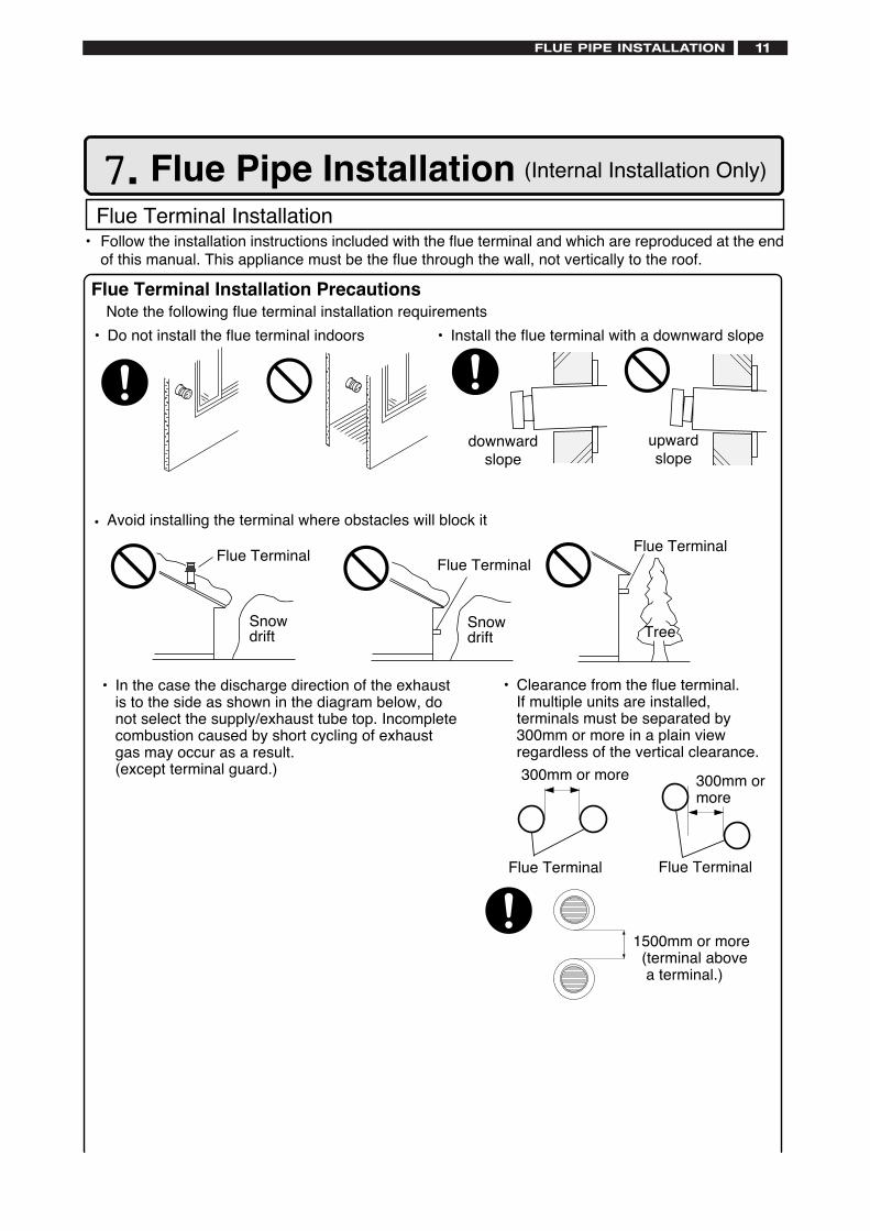
Flue Terminal Installation PrecautionsNote the following flue terminal installation requirements
• Do not install the flue terminal indoors • Install the flue terminal with a downward slope
upwardslope
downwardslope
Flue TerminalFlue Terminal
Snowdrift Tree
• Avoid installing the terminal where obstacles will block it
• Clearance from the flue terminal. If multiple units are installed,
terminals must be separated by300mm or more in a plain viewregardless of the vertical clearance.
Flue Terminal Flue Terminal
300mm or more 300mm ormore
• In the case the discharge direction of the exhaustis to the side as shown in the diagram below, donot select the supply/exhaust tube top. Incompletecombustion caused by short cycling of exhaustgas may occur as a result.
(except terminal guard.)
7. Flue Pipe Installation (Internal Installation Only)
Flue Terminal Installation• Follow the installation instructions included with the flue terminal and which are reproduced at the end
of this manual. This appliance must be the flue through the wall, not vertically to the roof.
1500mm or more (terminal above
a terminal.)
Flue Terminal
Snowdrift
Detailed recommendations for the flue installations are given in BS 5440:1:2000. The followingnotes are for general guidance only.Note: An adapter is always required on top of the heater.
For the vertical flue set up, offset adapter will be supplied for the air intake.
a) The flue system must be constructed using only ANDREWS WATER HEATERS approvedcomponents.
b) It is important that the position of the terminal allows free passage of air across it at all times.
c) It is ESSENTIAL TO ENSURE that products of combustion discharging from the terminalcannot reenter the building, or any other adjacent building, through ventilators, windows, doors,other sources of natural air infiltration, or forced ventilation / air conditioning.
d) The minimum acceptable dimensions from the flue terminal to obstructions and ventilationopenings are specified in Figs. 4& 5 opposite.
e) If the flue terminal discharges into a pathway or passageway check that combustion productswill not cause nuisance and that the terminal will not obstruct the passageway.
a. Measure and cut the first pair of the flue pipes away from the appliance. Push pipes fully intothe sockets on top of the boiler whilst also fitting the flue duct prepared as above.
b. Measure and cut next pair of the air/flue pipes.
c. Prepare pipe support brackets as required before engaging pipes with the socket of preced-ing pipes or bends.
d. Push pipes together as before taking care not to dislodge seals. When cutting and fitting theflue pipes on extended the flue systems, allow approx. 5 mm clearance at the bottom of eachjoint - see Fig. 8.
e. Repeat above procedure to reach terminal. Ensure that air inlet and the flue gas connectionsare correctly made and are not inadvertently reversed.
f. Fix pipe supports to masonry or woodwork so that the flue/air pipes are held securely inposition.
g. Check especially that all joints within any duct or other void are correctly engaged and sealedbefore fixing the ductwork.
The flue pipes must be assembled with the plain end of pipe or fitting nearest the boiler and thefemale (socket) end furthest from the boiler. Check that a seal is fitted in every socket.
Always adjust length of pipes by cutting and de-burring plain end so that it does not damage ordisturb the seal. Remove burrs from inside and outside of pipe and ensure the pipe is clean andfree from oil and grease.
Any generally "horizontal" run of the flue pipe MUST NOT FORM A LOW POINT at whichcondensate could accumulate.
Assembling Air/Flue Pipes
FLUE PIPE INSTALLATION12
FLUE PIPE INSTALLATION 13
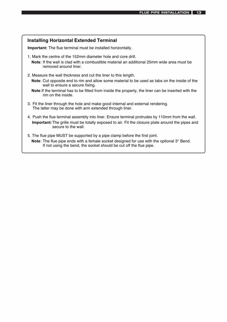
Important: The flue terminal must be installed horizontally.
1. Mark the centre of the 152mm diameter hole and core drill.Note: If the wall is clad with a combustible material an additional 25mm wide area must be
removed around liner.
2. Measure the wall thickness and cut the liner to this length.Note: Cut opposite end to rim and allow some material to be used as tabs on the inside of the
wall to ensure a secure fixing.Note:If the terminal has to be fitted from inside the property, the liner can be inserted with the
rim on the inside.
3. Fit the liner through the hole and make good internal and external rendering.The latter may be done with arm extended through liner.
4. Push the flue terminal assembly into liner. Ensure terminal protrudes by 110mm from the wall.Important:The grille must be totally exposed to air. Fit the closure plate around the pipes and
secure to the wall.
5. The flue pipe MUST be supported by a pipe clamp before the first joint.Note: The flue pipe ends with a female socket designed for use with the optional 3° Bend.
If not using the bend, the socket should be cut off the flue pipe.
Installing Horizontal Extended Terminal
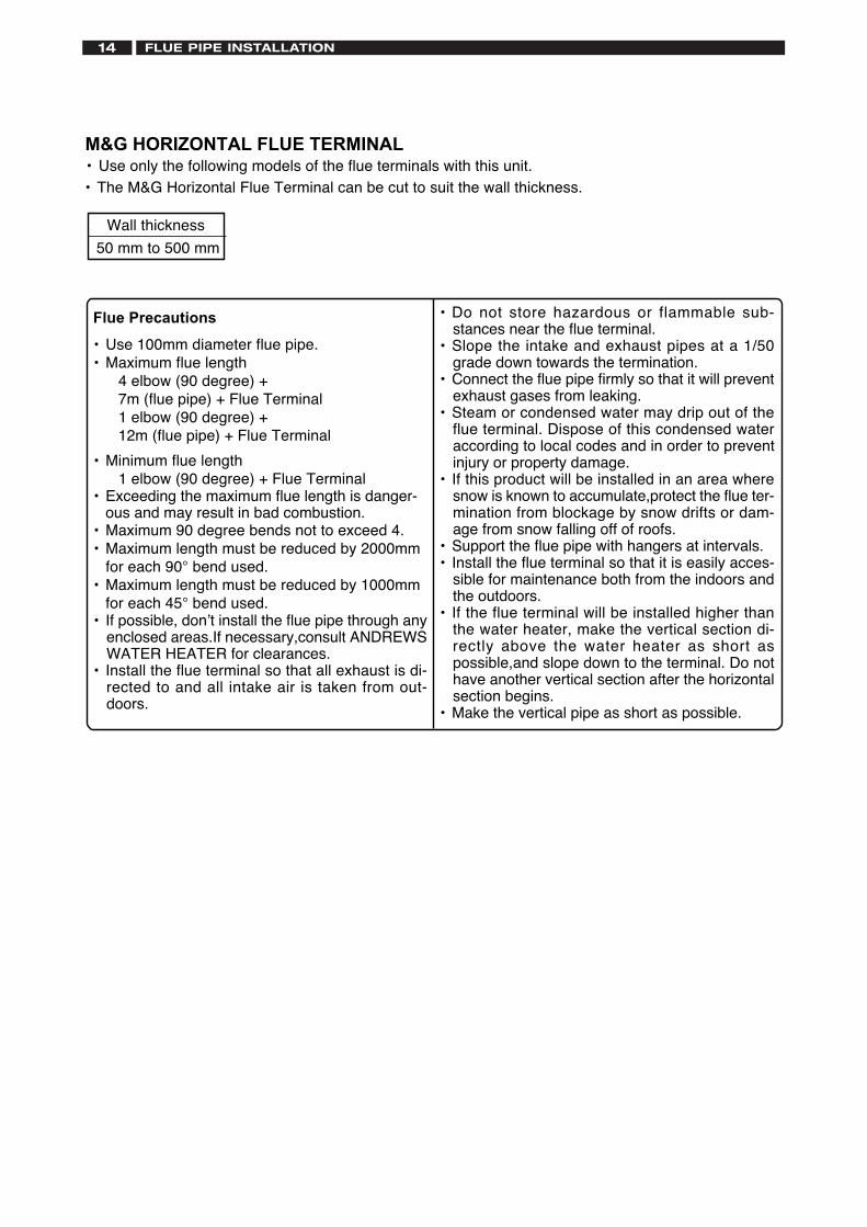
M&G HORIZONTAL FLUE TERMINAL• Use only the following models of the flue terminals with this unit.• The M&G Horizontal Flue Terminal can be cut to suit the wall thickness.
Wall thickness
50 mm to 500 mm
FLUE PIPE INSTALLATION14
• Do not store hazardous or flammable sub-stances near the flue terminal.
• Slope the intake and exhaust pipes at a 1/50grade down towards the termination.
• Connect the flue pipe firmly so that it will preventexhaust gases from leaking.
• Steam or condensed water may drip out of theflue terminal. Dispose of this condensed wateraccording to local codes and in order to preventinjury or property damage.
• If this product will be installed in an area wheresnow is known to accumulate,protect the flue ter-mination from blockage by snow drifts or dam-age from snow falling off of roofs.
• Support the flue pipe with hangers at intervals.• Install the flue terminal so that it is easily acces-
sible for maintenance both from the indoors andthe outdoors.
• If the flue terminal will be installed higher thanthe water heater, make the vertical section di-rectly above the water heater as short aspossible,and slope down to the terminal. Do nothave another vertical section after the horizontalsection begins.
• Make the vertical pipe as short as possible.
Flue Precautions
• Use 100mm diameter flue pipe.• Maximum flue length 4 elbow (90 degree) + 7m (flue pipe) + Flue Terminal 1 elbow (90 degree) + 12m (flue pipe) + Flue Terminal
• Minimum flue length 1 elbow (90 degree) + Flue Terminal• Exceeding the maximum flue length is danger-
ous and may result in bad combustion.• Maximum 90 degree bends not to exceed 4.• Maximum length must be reduced by 2000mm
for each 90° bend used.• Maximum length must be reduced by 1000mm
for each 45° bend used.• If possible, don’t install the flue pipe through any
enclosed areas.If necessary,consult ANDREWSWATER HEATER for clearances.
• Install the flue terminal so that all exhaust is di-rected to and all intake air is taken from out-doors.
FLUE PIPE INSTALLATION 15
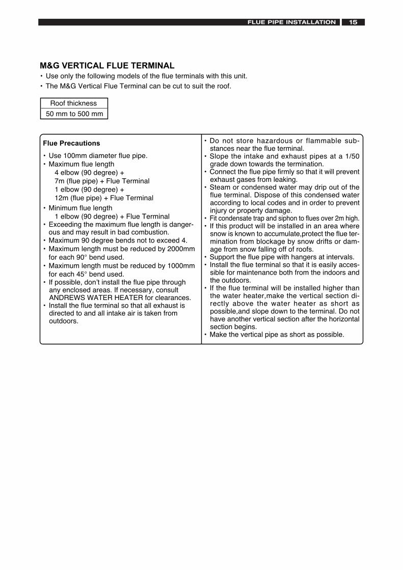
M&G VERTICAL FLUE TERMINAL• Use only the following models of the flue terminals with this unit.• The M&G Vertical Flue Terminal can be cut to suit the roof.
Roof thickness
50 mm to 500 mm
• Do not store hazardous or flammable sub-stances near the flue terminal.
• Slope the intake and exhaust pipes at a 1/50grade down towards the termination.
• Connect the flue pipe firmly so that it will preventexhaust gases from leaking.
• Steam or condensed water may drip out of theflue terminal. Dispose of this condensed wateraccording to local codes and in order to preventinjury or property damage.
• Fit condensate trap and siphon to flues over 2m high.• If this product will be installed in an area where
snow is known to accumulate,protect the flue ter-mination from blockage by snow drifts or dam-age from snow falling off of roofs.
• Support the flue pipe with hangers at intervals.• Install the flue terminal so that it is easily acces-
sible for maintenance both from the indoors andthe outdoors.
• If the flue terminal will be installed higher thanthe water heater,make the vertical section di-rectly above the water heater as short aspossible,and slope down to the terminal. Do nothave another vertical section after the horizontalsection begins.
• Make the vertical pipe as short as possible.
Flue Precautions
• Use 100mm diameter flue pipe.• Maximum flue length 4 elbow (90 degree) + 7m (flue pipe) + Flue Terminal 1 elbow (90 degree) + 12m (flue pipe) + Flue Terminal• Minimum flue length 1 elbow (90 degree) + Flue Terminal• Exceeding the maximum flue length is danger-
ous and may result in bad combustion.• Maximum 90 degree bends not to exceed 4.• Maximum length must be reduced by 2000mm
for each 90° bend used.• Maximum length must be reduced by 1000mm
for each 45° bend used.• If possible, don’t install the flue pipe through
any enclosed areas. If necessary, consultANDREWS WATER HEATER for clearances.
• Install the flue terminal so that all exhaust isdirected to and all intake air is taken fromoutdoors.
1234567890123456789123456789012345678 9123456789012345678 9123456789012345678 9123456789012345678 9123456789012345678 9123456789012345678 912345678901234567891234567890123123456789012 3123456789012 3123456789012 3123456789012 312345678901231234567123456 71234567
(Combustible material)
Intake pipe
External wall,combustible material
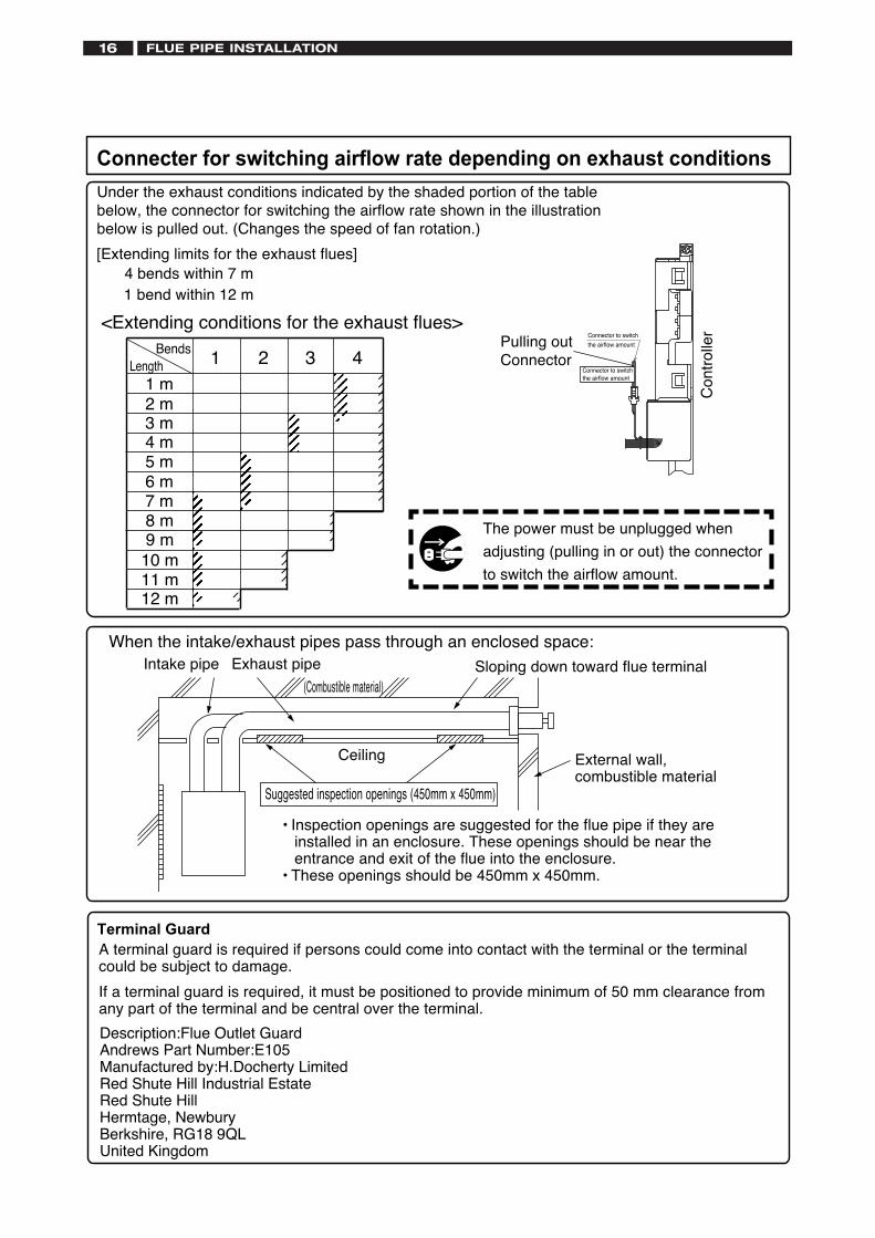
• Inspection openings are suggested for the flue pipe if they areinstalled in an enclosure. These openings should be near theentrance and exit of the flue into the enclosure.
• These openings should be 450mm x 450mm.
Suggested inspection openings (450mm x 450mm)
When the intake/exhaust pipes pass through an enclosed space:
Ceiling
Sloping down toward flue terminalExhaust pipe
Under the exhaust conditions indicated by the shaded portion of the tablebelow, the connector for switching the airflow rate shown in the illustrationbelow is pulled out. (Changes the speed of fan rotation.)
Connecter for switching airflow rate depending on exhaust conditions
The power must be unplugged when
adjusting (pulling in or out) the connector
to switch the airflow amount.
<Extending conditions for the exhaust flues>
4 bends within 7 m[Extending limits for the exhaust flues]
Pulling outConnector
Connector to switch
the airflow amount
Connector to switch the airflow amount
1234567890123123456789012 3123456789012 3123456789012 3123456789012 3123456789012 3123456789012 3123456789012 31234567890123
1234567123456 7123456 7123456 7123456 7123456 71234567
1234567890123456789123456789012345678 9123456789012345678 9123456789012345678 9123456789012345678 9123456789012345678 9123456789012345678 91234567890123456789
1 m
1Bends
Length
2 m3 m4 m5 m6 m7 m
2 3 4
Con
trol
ler
Description:Flue Outlet GuardAndrews Part Number:E105Manufactured by:H.Docherty LimitedRed Shute Hill Industrial EstateRed Shute HillHermtage, NewburyBerkshire, RG18 9QLUnited Kingdom
Terminal GuardA terminal guard is required if persons could come into contact with the terminal or the terminalcould be subject to damage.
If a terminal guard is required, it must be positioned to provide minimum of 50 mm clearance fromany part of the terminal and be central over the terminal.
8 m9 m10 m11 m12 m
1 bend within 12 m
FLUE PIPE INSTALLATION16
GAS PIPING 17
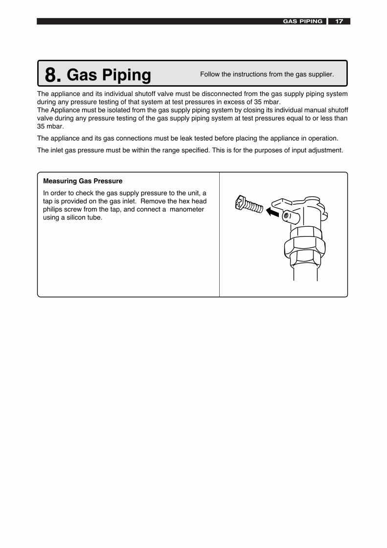
Measuring Gas PressureIn order to check the gas supply pressure to the unit, atap is provided on the gas inlet. Remove the hex headphilips screw from the tap, and connect a manometerusing a silicon tube.
Follow the instructions from the gas supplier.8. Gas PipingThe appliance and its individual shutoff valve must be disconnected from the gas supply piping systemduring any pressure testing of that system at test pressures in excess of 35 mbar.The Appliance must be isolated from the gas supply piping system by closing its individual manual shutoffvalve during any pressure testing of the gas supply piping system at test pressures equal to or less than35 mbar.The appliance and its gas connections must be leak tested before placing the appliance in operation.The inlet gas pressure must be within the range specified. This is for the purposes of input adjustment.
9. Water PipingThis appliance is suitable for potable water. Do not use this appliance if any part has been underwater. Immediatelycall a qualified service technician to inspect the appliance and replace any part of the control system and gas controlwhich has been under water.
If the water heater is installed in a closed water supply system, such as one having a backflow preventer in the coldwater supply line, means shall be provided to control thermal expansion. Contact ANDREWS WATER HEATERSTECHNICAL DEPARTMENT FOR ADVICE.
Piping and components connected to the water heater shall be suitable for use with potable water.Toxic chemicals, such as those used for boiler treatment, shall not be introduced into the potable water.A water heater used to supply potable water may not be connected to any heating system or components previouslyused with a nonpotable water heating appliance.When water is required in one part of the system at a higher temperature than in the rest of the system, means suchas a mixing valve shall be installed to temper the water to reduce the scalding hazard.
• Flush water through the pipe to clean out metal powder, sand and dirt before connecting it.• Take appropriate heat insulation measures (e.g., wrapping with heat insulation materials, using electric heaters)
according to the climate of the region to prevent the pipe from freezing.• Use a union coupling or flexible pipe for connecting the pipes to reduce the force applied to the piping.• Do not use piping with a diameter smaller than the coupling.• When feed water pressure is too high, insert a depressurizing valve, or take water hammer prevention measures.• Avoid using joints as much as possible to keep the piping simple.• Avoid piping in which an air holdup can occur.• Use approved piping materials.• If installing the unit on a roof:
If the unit is installed on a roof to supply water to the levels below, make sure that the water pressure supplied tothe unit does not drop below 2000 mbar. It may be necessary to install a pump system to ensure that the waterpressure is maintained at this level.Check the pressure before putting the unit into operation.Failing to supply the proper pressure to the unit may result in noisy operation, shorter lifetime of the unit, andmay cause the unit to shut down frequently.
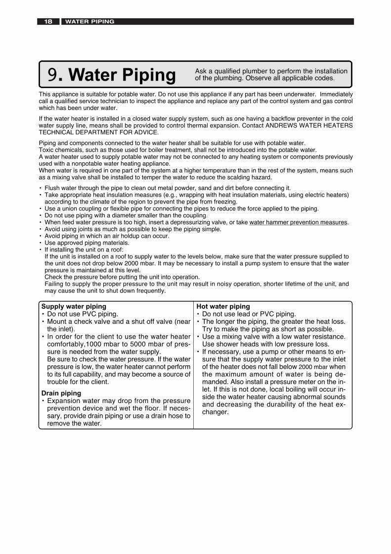
Supply water piping• Do not use PVC piping.• Mount a check valve and a shut off valve (near
the inlet).• In order for the client to use the water heater
comfortably,1000 mbar to 5000 mbar of pres-sure is needed from the water supply.Be sure to check the water pressure. If the waterpressure is low, the water heater cannot performto its full capability, and may become a source oftrouble for the client.
Drain piping• Expansion water may drop from the pressure
prevention device and wet the floor. If neces-sary, provide drain piping or use a drain hose toremove the water.
Hot water piping• Do not use lead or PVC piping.• The longer the piping, the greater the heat loss.
Try to make the piping as short as possible.• Use a mixing valve with a low water resistance.
Use shower heads with low pressure loss.• If necessary, use a pump or other means to en-
sure that the supply water pressure to the inletof the heater does not fall below 2000 mbar whenthe maximum amount of water is being de-manded. Also install a pressure meter on the in-let. If this is not done, local boiling will occur in-side the water heater causing abnormal soundsand decreasing the durability of the heat ex-changer.
Ask a qualified plumber to perform the installationof the plumbing. Observe all applicable codes.
WATER PIPING18
ELECTRICAL WIRING 19
Do not connect electrical power to the unit until all electrical wiring has been completed.
Consult a qualified electricianfor the electrical work.10. Electrical Wiring
Do not turn on the power until the electrical wiring is finished.This may cause electrical shock or damage to the equipment to occur.
i) "A means of disconnection from the supply mains having a contact separation in all poles must be pro-vided to allow for full disconnection".
ii) Under voltage Cat III conditions should be incorporated in the fixed wiring in accordance with the wiringregulations.
iii) "If the supply cord is damaged, it must be replaced by the manufacturer or its service agent".
This appliance must be electrically grounded in accordance with Electrical Authority Regulations.
External wiring must be correctly earthed, polarised and in accordance with the relevant standards.
In GB this is BS 6891.
In IE this is the current edition of I.S.813 "Domestic Gas Installations".
The boiler must be connected to a permanent 230 V ac, 50Hz supply.
Connection of the whole electrical system of the boiler, including any heating controls, to the electrical supplymust be through one common isolator and must be fused 10 Amp maximum.
Isolation should be by a double pole switched fused spur box, with a minimum gap of 3 mm for both poles.The fused spur box should be readily accessible and preferably adjacent to the appliance. It should beidentified as to its use.
Caution: Label all wires prior to disconnection when servicing controls. Wiring errors can cause improperand dangerous operation.
Verify proper operation after servicing.
Field wiring to be performed at time of appliance installation.
Caution
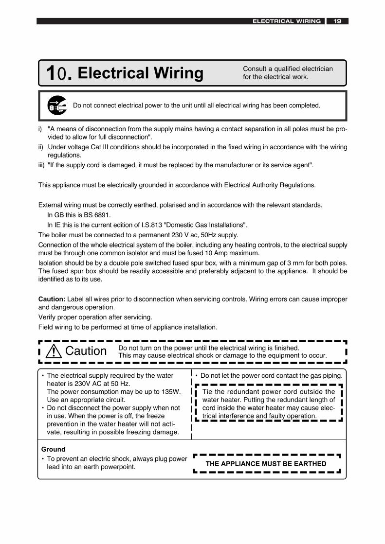
• The electrical supply required by the waterheater is 230V AC at 50 Hz.The power consumption may be up to 135W.Use an appropriate circuit.
• Do not disconnect the power supply when notin use. When the power is off, the freezeprevention in the water heater will not acti-vate, resulting in possible freezing damage.
• Do not let the power cord contact the gas piping.
Tie the redundant power cord outside thewater heater. Putting the redundant length ofcord inside the water heater may cause elec-trical interference and faulty operation.
Ground• To prevent an electric shock, always plug power
lead into an earth powerpoint. THE APPLIANCE MUST BE EARTHED
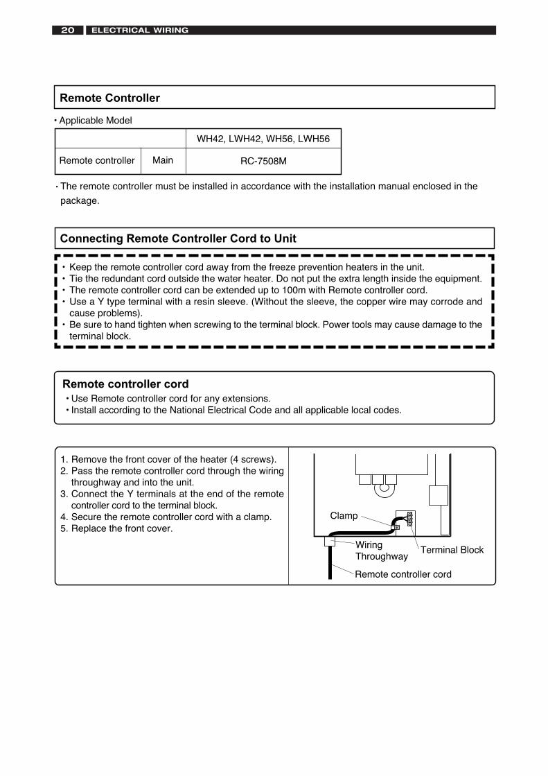
1. Remove the front cover of the heater (4 screws).2. Pass the remote controller cord through the wiring
throughway and into the unit.3. Connect the Y terminals at the end of the remote
controller cord to the terminal block.4. Secure the remote controller cord with a clamp.5. Replace the front cover.
Remote controller cord
Remote controller cord• Use Remote controller cord for any extensions.• Install according to the National Electrical Code and all applicable local codes.
Connecting Remote Controller Cord to Unit
• Keep the remote controller cord away from the freeze prevention heaters in the unit.• Tie the redundant cord outside the water heater. Do not put the extra length inside the equipment.• The remote controller cord can be extended up to 100m with Remote controller cord.• Use a Y type terminal with a resin sleeve. (Without the sleeve, the copper wire may corrode and
cause problems).• Be sure to hand tighten when screwing to the terminal block. Power tools may cause damage to the
terminal block.
Clamp
Terminal BlockWiringThroughway
• Applicable Model
Remote Controller
Remote controller RC-7508M
WH42, LWH42, WH56, LWH56
Main
• The remote controller must be installed in accordance with the installation manual enclosed in the
package.
ELECTRICAL WIRING20
COMMISSIONING 21
20
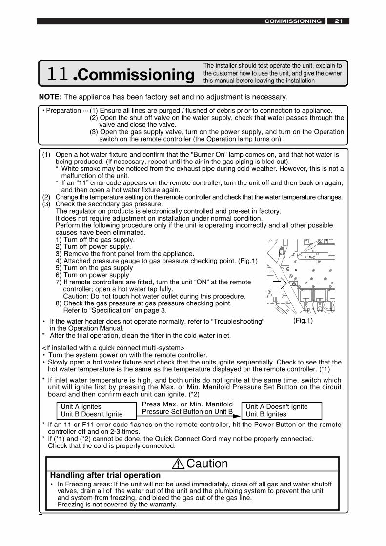
Handling after trial operation• In Freezing areas: If the unit will not be used immediately, close off all gas and water shutoff
valves, drain all of the water out of the unit and the plumbing system to prevent the unitand system from freezing, and bleed the gas out of the gas line.Freezing is not covered by the warranty.
Caution
(1) Open a hot water fixture and confirm that the "Burner On" lamp comes on, and that hot water isbeing produced. (If necessary, repeat until the air in the gas piping is bled out).* White smoke may be noticed from the exhaust pipe during cold weather. However, this is not a
malfunction of the unit.* If an “11” error code appears on the remote controller, turn the unit off and then back on again,
and then open a hot water fixture again.(2) Change the temperature setting on the remote controller and check that the water temperature changes.(3) Check the secondary gas pressure.
The regulator on products is electronically controlled and pre-set in factory.It does not require adjustment on installation under normal condition.Perform the following procedure only if the unit is operating incorrectly and all other possiblecauses have been eliminated.1) Turn off the gas supply.2) Turn off power supply.3) Remove the front panel from the appliance.4) Attached pressure gauge to gas pressure checking point. (Fig.1)5) Turn on the gas supply6) Turn on power supply7) If remote controllers are fitted, turn the unit “ON” at the remote
controller; open a hot water tap fully. Caution: Do not touch hot water outlet during this procedure.
8) Check the gas pressure at gas pressure checking point. Refer to “Specification” on page 3.
• If the water heater does not operate normally, refer to "Troubleshooting"in the Operation Manual.
* After the trial operation, clean the filter in the cold water inlet.
11. CommissioningThe installer should test operate the unit, explain tothe customer how to use the unit, and give the ownerthis manual before leaving the installation
• Preparation ... (1) Ensure all lines are purged / flushed of debris prior to connection to appliance.(2) Open the shut off valve on the water supply, check that water passes through the
valve and close the valve.(3) Open the gas supply valve, turn on the power supply, and turn on the Operation
switch on the remote controller (the Operation lamp turns on) .
NOTE: The appliance has been factory set and no adjustment is necessary.
<If installed with a quick connect multi-system>• Turn the system power on with the remote controller.• Slowly open a hot water fixture and check that the units ignite sequentially. Check to see that the
hot water temperature is the same as the temperature displayed on the remote controller. (*1)
* If inlet water temperature is high, and both units do not ignite at the same time, switch whichunit will ignite first by pressing the Max. or Min. Manifold Pressure Set Button on the circuitboard and then confirm each unit can ignite. (*2)
* If an 11 or F11 error code flashes on the remote controller, hit the Power Button on the remotecontroller off and on 2-3 times.
* If (*1) and (*2) cannot be done, the Quick Connect Cord may not be properly connected.Check that the cord is properly connected.
(Fig.1)
Unit A IgnitesUnit B Doesn't Ignite
Press Max. or Min. ManifoldPressure Set Button on Unit B
Unit A Doesn't IgniteUnit B Ignites
Lighting InstructionsThis water heater does not have a pilot. It is equipped with an ignition device that automatically lightsthe burner.1. Read the safety information in the installation manual or on the front of the water heater.2. Turn off all electrical power to the unit.3. Do not attempt to light the burner by hand.4. Turn the gas control manual valve (external to the unit) clockwise to the off position.5. Wait five minutes to clear out any gas. If the smell of gas remains, stop, and follow the instructions
on page 3 of owner's guide.6. Turn the gas control manual valve counterclockwise to the on position.7. Turn on electric power to the unit.8. The unit will now operate whenever hot water is called for. If the unit will not operate, follow the
shutdown instructions and call a service technician.
Shutdown Instructions1. Stop any water demand.2. Turn off electric power.3. Turn the gas control manual valve clockwise to the off position.
Should overheating occur, or the gas supply fail to shut off, turn off the gas control manual valve to theappliance.
COMMISSIONING22
DIMENSIONS 23
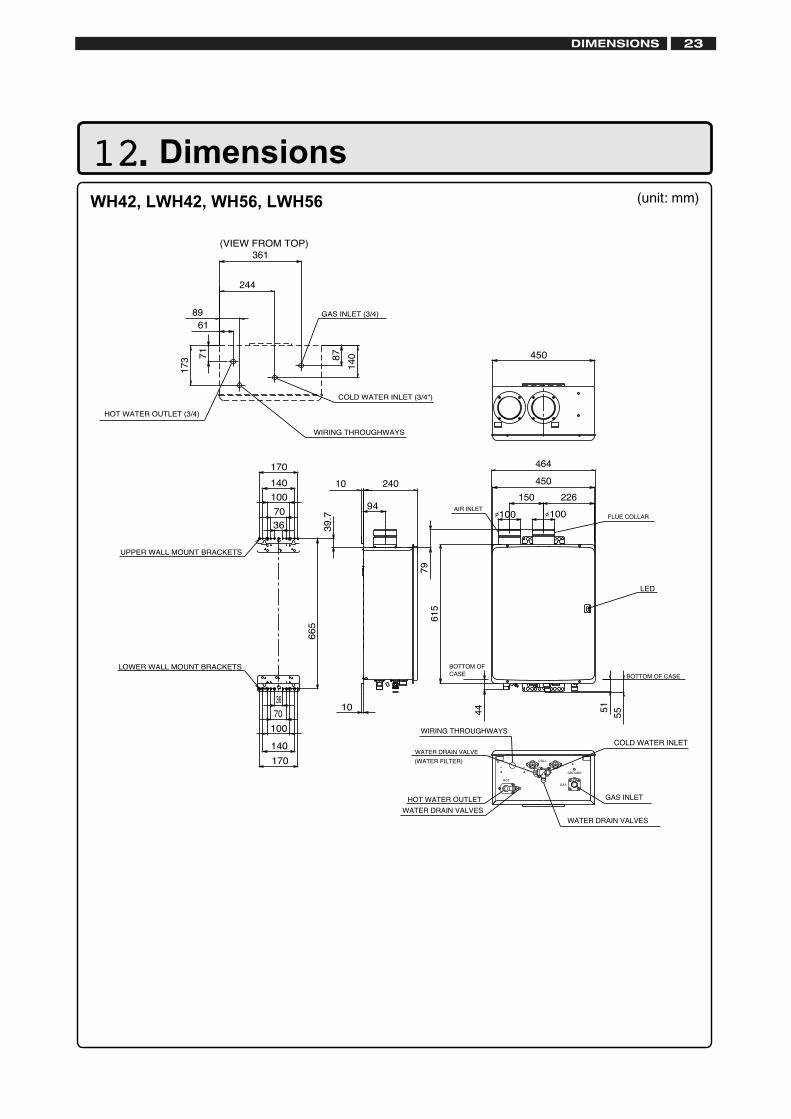
12. Dimensions WH42, LWH42, WH56, LWH56 (unit: mm)
COLL
GROUND
GAS
HOT
39
.7
66
5
LOWER WALL MOUNT BRACKETS
UPPER WALL MOUNT BRACKETS
GAS INLET (3/4)
71
HOT WATER OUTLET (3/4)
COLD WATER INLET (3/4")
WIRING THROUGHWAYS
450
10
87
170
140
100
70
36
70
170
140
100
36
150 226
100AIR INLET
WATER DRAIN VALVE
(WATER FILTER)
464
450
361
89
FLUE COLLAR
LED
173
HOT WATER OUTLET GAS INLET
COLD WATER INLET
WATER DRAIN VALVES
WIRING THROUGHWAYS
WATER DRAIN VALVES
7961
5
BOTTOM OFCASE
44 5155
BOTTOM OF CASE
10 240
94100
140
61
244
(VIEW FROM TOP)
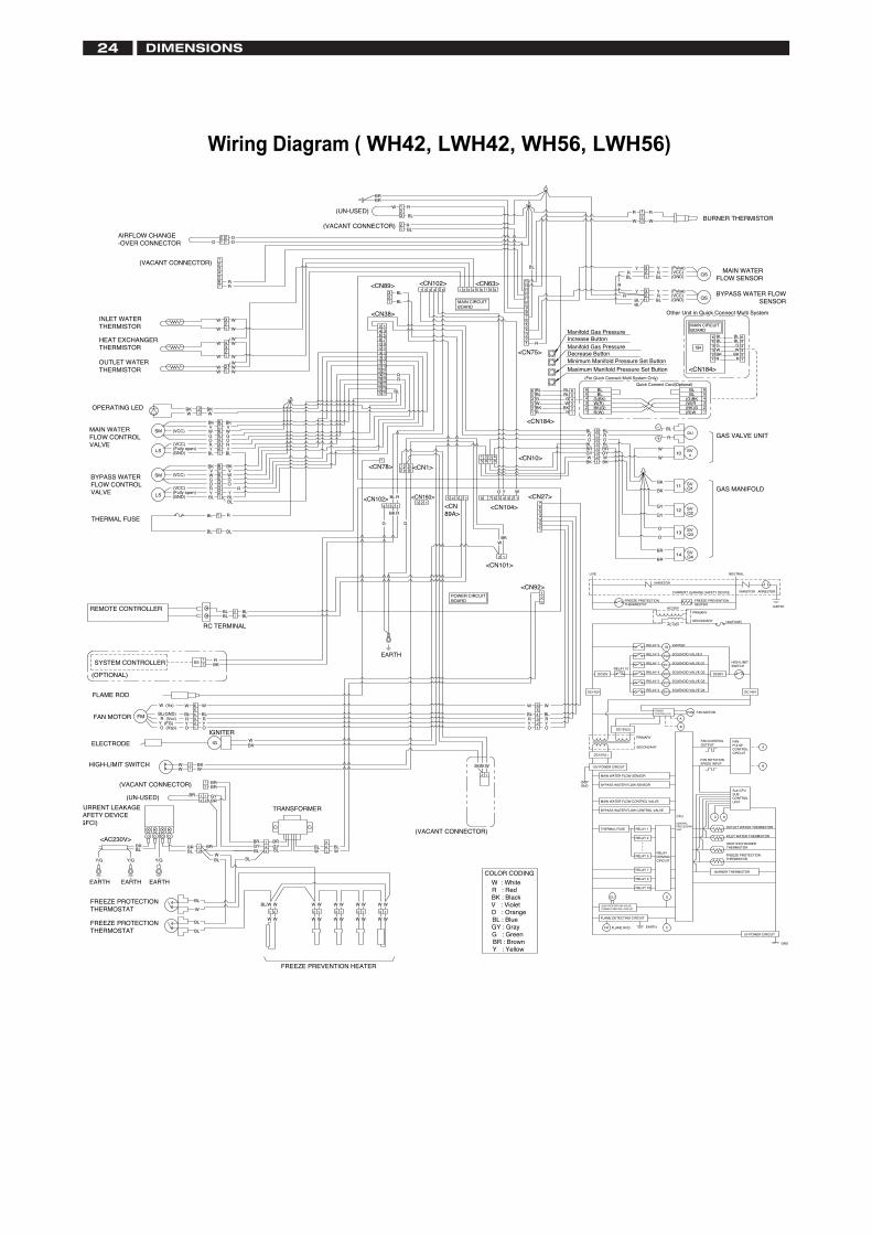
Wiring Diagram ( WH42, LWH42, WH56, LWH56)
(VACANT CONNECTOR)
BURNER THERMISTOR
BYPASS WATER FLOW SENSOR
MAIN WATERFLOW SENSOR
BL
WG
BLBLGW
BL
RRBKBK
GAS VALVE UNIT
EARTH
GAS MANIFOLD
NEUTRAL
VARISTOR
PRIMARY
FREEZE PREVENTION HEATER
CURRENT LEAKAGE SAFETY DEVICE ARRESTER
10A(FUSE)
HIGH LIMIT SWITCH
SECONDARYAC100V
IGNITER
SOLENOID VALVE Q4
SOLENOID VALVE Q3
SOLENOID VALVE Q2
SOLENOID VALVE Q1
SOLENOID VALVE 0
DC90V
A
B
FAN PULSE CONTROL CIRCUIT
FAN MOTOR
A
B
FAN
FAN ROTATION SPEED INPUT
FAN CONTROL OUTPUT
DC140V
Sub-CPU SUB CONTROL UNIT
D
INLET WATER THERMISTOR
CCPU
CENTRAL PROCESSING UNIT
FREEZE PROTECTION THERMISTOR
D
BURNER THERMISTOR
HEAT EXCHANGER THERMISTOR
OUTLET WATER THERMISTOR
GND
C
5V POWER CIRCUIT
R
W
R
W
RY (Pulse)
(VCC)
Y
BLR
(Pulse)(VCC)(GND)
(GND)BL
YR
Y
BLBL
R
R
BL
<CN63>
BL
R
BLR
BL
BR
W 1
1
2
2
3
321
12345678910
12 1114 1316 15
151413121110987
54321
6
18 1720 1922 2124 2326 2528 2730 2932 31
BR
<CN102>BL
BL
<CN89>
(UN-USED)
(VACANT CONNECTOR)
MAIN CIRCUIT BOARD
BLBL
(G)BK
(BK)G(W)R
(R)W
BLBL
G(BK)
BK(G)W(R)
R(W)
Quick Connect Cord(Optional)
BL
W
W
R
BL
BL
GY
O
BR
BKW
R
R
BLBL
<CN75>
WG
RBKBK
W
R
G
R
<CN10>
<CN184>
BLBL
(For Quick Connect Multi System Only)
BK
BL
WGY
BL
O
BR
Minimum Manifold Pressure Set Button
Maximum Manifold Pressure Set Button
Increase ButtonManifold Gas Pressure
Decrease ButtonManifold Gas Pressure
BK
BK
GY
O
BR
O
GY
FREEZE PROTECTION THERMOSTAT
LIVE
BR
WYO
<CN104>
WBK
<CN27>
<CN101>
<CN92>
BL
RR
<CN78> <CN1>
<CN89A>R
RBL
BK
GG
<CN160><CN102>
POWER CIRCUIT BOARD
<CN38>
OO
R
11
1234567
321
34
21
21
21
21
43
65
87
21
1
1
43
65
87
22
R
OAIRFLOW CHANGE -OVER CONNECTOR
(VACANT CONNECTOR)
W
W
WW
W
W
W
WWW
WW
W W
WVBK
WBK
BKVW
BL
RO
Y
BKV
BLY
OR
VBK
GG
BKW
(VCC)SM
LS
SM
LS
(GND)
(VCC)(Fully open)
HEAT EXCHANGER THERMISTOR
OUTLET WATER THERMISTOR
MAIN WATERFLOW CONTROLVALVE
OPERATING LED
RY
GO
BLBL
ROG
YBL
BLBL
RBL
(VCC)
(GND)(Fully open)
BLBLBLBL
REMOTE CONTROLLER
THERMAL FUSE
BYPASS WATER FLOW CONTROL VALVE
(VCC) W W
INLET WATER THERMISTOR
RELAY 9
RELAY 1
RELAY 5
RELAY 2
RELAY 4RELAY 10
RELAY 3
DC90V
SECONDARY
PRIMARY
DC15V(2)
DC15V(1)
DC140V
BL
W
BL
W
OY
OY
BKBK W
R R
RELAY 2
RELAY 1
GND
THERMAL FUSE
BYPASS WATER FLOW SENSOR
MAIN WATER FLOW CONTROL VALVE
BYPASS WATER FLOW CONTROL VALVE
MAIN WATER FLOW SENSOR
RELAY 7
RELAY 5
RELAY 9
RELAY 10
DU
FLAME DETECTING CIRCUIT
GAS PROPORTION VALVE POWER CONTROL CIRCUIT
COLOR CODING
W : White
O : OrangeV : VioletBK : BlackR : Red
GY : Gray
Y : YellowBR : BrownG : Green
BL : Blue
15V POWER CIRCUIT
EARTH
WW
WW
BLW
BLW
GYBR
BL
BR
BLGY
TRANSFORMER
WWW W W
W W WW W
WBL/W
WW
W
W
(VACANT CONNECTOR)
EARTHFLAME RODFR
FREEZE PREVENTION HEATER
RBK
BL
WW
BL
W (Vs)
BL(GND)
OY
BKW
BRBR
YO
Y (FG)O (Vsp)
WW
RR (Vcc) R
FLAME ROD
(OPTIONAL)
ELECTRODE
FAN MOTOR
HIGH-LIMIT SWITCH
SYSTEM CONTROLLER
BR
BR
BLW
Y/G
BLBR
W
BL
BL
BL
EARTH
URRENT LEAKAGE AFETY DEVICE
GFCI)
Y/G
<AC230V>
EARTH
Y/G
EARTH
BRBL
FREEZE PROTECTION THERMOSTAT
FREEZE PROTECTION THERMOSTAT
GYBR(UN-USED)
BKW
BL
IGNITER
RC TERMINAL
RELAY DRIVING CIRCUIT
POWER CONTROLLER
SV3
SV4
AC230V
SV0
SV1
SV2
VARISTOR
IG
Other Unit in Quick Connect Multi System
MAIN CIRCUIT BOARD
<CN184>
5 61 2 3 4 5 61 2 3 4 8 97
1
2 1
B5
IG
12
21
QS
QS
12
1 12 2
2
32
456
32
456
11
184
6
4
123
56
4
123
5
6
45
3
12
54
6
21
3FM
123
123
123
56
4
123
56
4
21
3
DU
10
11
12
SV0
SVQ1
SVQ2
SVQ3
SVQ4
13
14
123
321
5678
4
123
567
4
1
1
123
2
123451231
1 3 52 4 6
234
1234
5 67
87654321
9
23
21
1
12122 1121 2
DIMENSIONS24
REMOTE CONTROLLER INSTALLATION 25
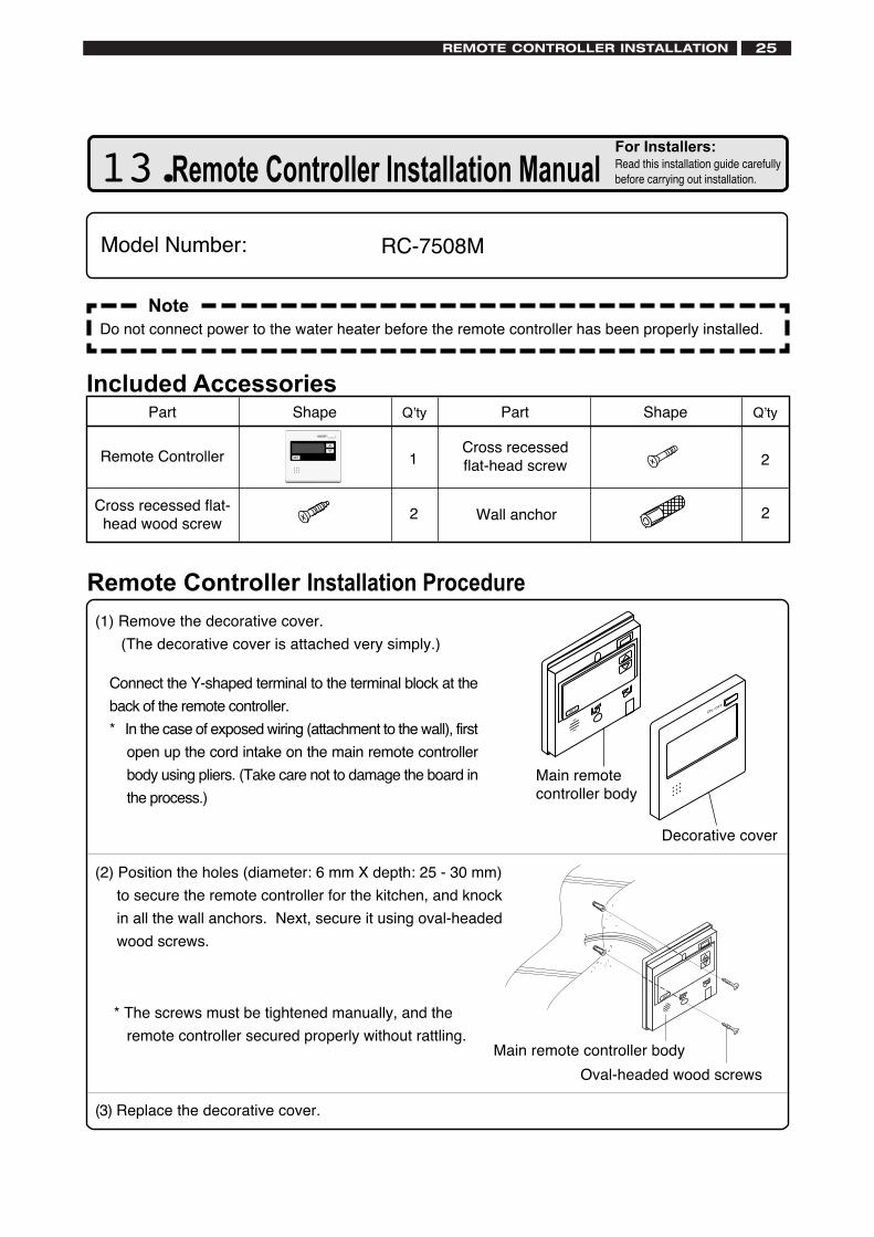
NoteDo not connect power to the water heater before the remote controller has been properly installed.
SETON / O
FF
SET
(1) Remove the decorative cover.
(The decorative cover is attached very simply.)
Connect the Y-shaped terminal to the terminal block at the
back of the remote controller.
* In the case of exposed wiring (attachment to the wall), first
open up the cord intake on the main remote controller
body using pliers. (Take care not to damage the board in
the process.)
Main remotecontroller body
Decorative cover
(2) Position the holes (diameter: 6 mm X depth: 25 - 30 mm)
to secure the remote controller for the kitchen, and knock
in all the wall anchors. Next, secure it using oval-headed
wood screws.
(3) Replace the decorative cover.
Oval-headed wood screws
* The screws must be tightened manually, and the
remote controller secured properly without rattling.Main remote controller body
13. Remote Controller Installation Manual
RC-7508MModel Number:
Included AccessoriesQ’tyShapePart
2
Part Shape Q’ty
Cross recessedflat-head screw
2
1
Cross recessed flat-head wood screw
2 Wall anchor
Remote Controller
Remote Controller Installation Procedure
For Installers:Read this installation guide carefullybefore carrying out installation.
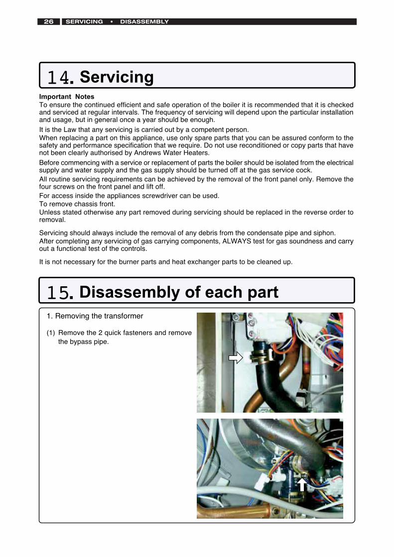
1. Removing the transformer
(1) Remove the 2 quick fasteners and removethe bypass pipe.
14. Servicing
15. Disassembly of each part
Important NotesTo ensure the continued efficient and safe operation of the boiler it is recommended that it is checkedand serviced at regular intervals. The frequency of servicing will depend upon the particular installationand usage, but in general once a year should be enough.It is the Law that any servicing is carried out by a competent person.When replacing a part on this appliance, use only spare parts that you can be assured conform to thesafety and performance specification that we require. Do not use reconditioned or copy parts that havenot been clearly authorised by Andrews Water Heaters.Before commencing with a service or replacement of parts the boiler should be isolated from the electricalsupply and water supply and the gas supply should be turned off at the gas service cock.All routine servicing requirements can be achieved by the removal of the front panel only. Remove thefour screws on the front panel and lift off.For access inside the appliances screwdriver can be used.To remove chassis front.Unless stated otherwise any part removed during servicing should be replaced in the reverse order toremoval.
Servicing should always include the removal of any debris from the condensate pipe and siphon.After completing any servicing of gas carrying components, ALWAYS test for gas soundness and carryout a functional test of the controls.
It is not necessary for the burner parts and heat exchanger parts to be cleaned up.
SERVICING • DISASSEMBLY26
DISASSEMBLY 27
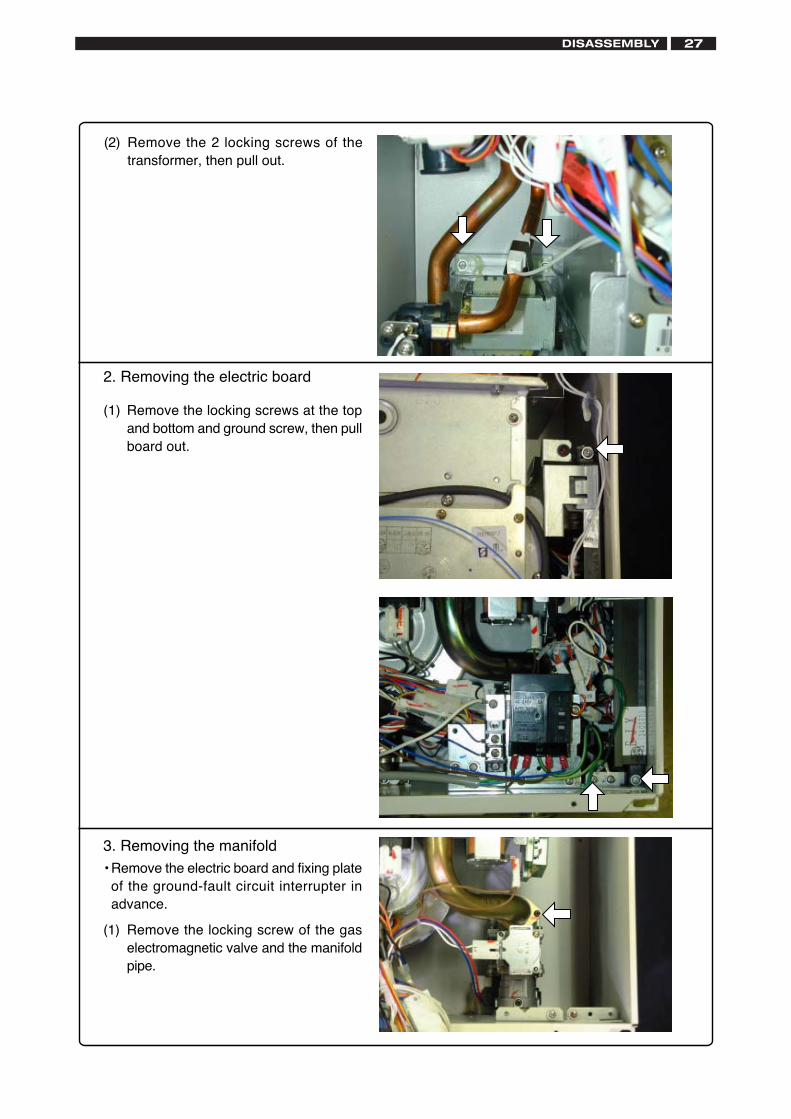
2. Removing the electric board
(1) Remove the locking screws at the topand bottom and ground screw, then pullboard out.
3. Removing the manifold• Remove the electric board and fixing plate
of the ground-fault circuit interrupter inadvance.
(1) Remove the locking screw of the gaselectromagnetic valve and the manifoldpipe.
(2) Remove the 2 locking screws of thetransformer, then pull out.
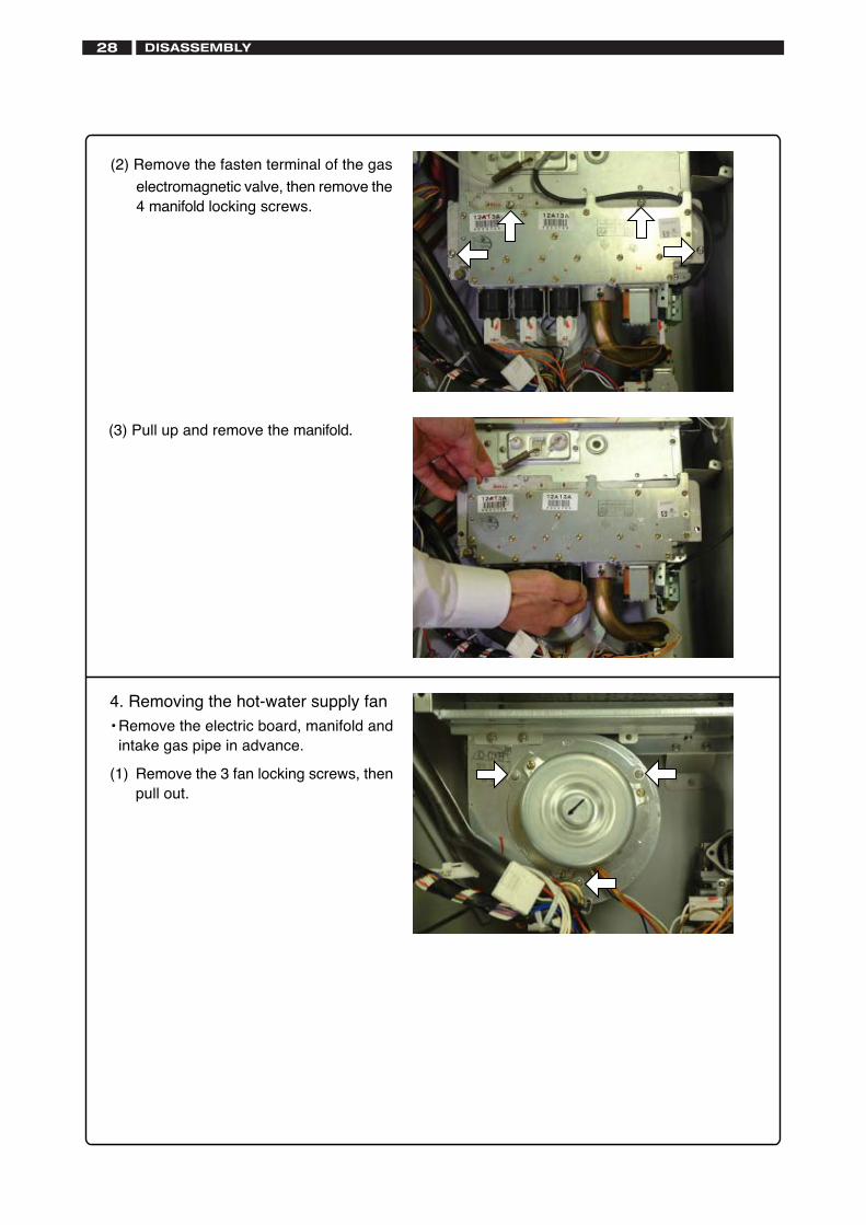
(2) Remove the fasten terminal of the gas
electromagnetic valve, then remove the4 manifold locking screws.
4. Removing the hot-water supply fan• Remove the electric board, manifold and
intake gas pipe in advance.
(1) Remove the 3 fan locking screws, thenpull out.
(3) Pull up and remove the manifold.
DISASSEMBLY28
DISASSEMBLY 29
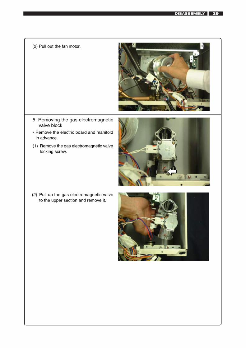
5. Removing the gas electromagneticvalve block
• Remove the electric board and manifoldin advance.
(1) Remove the gas electromagnetic valvelocking screw.
(2) Pull out the fan motor.
(2) Pull up the gas electromagnetic valveto the upper section and remove it.
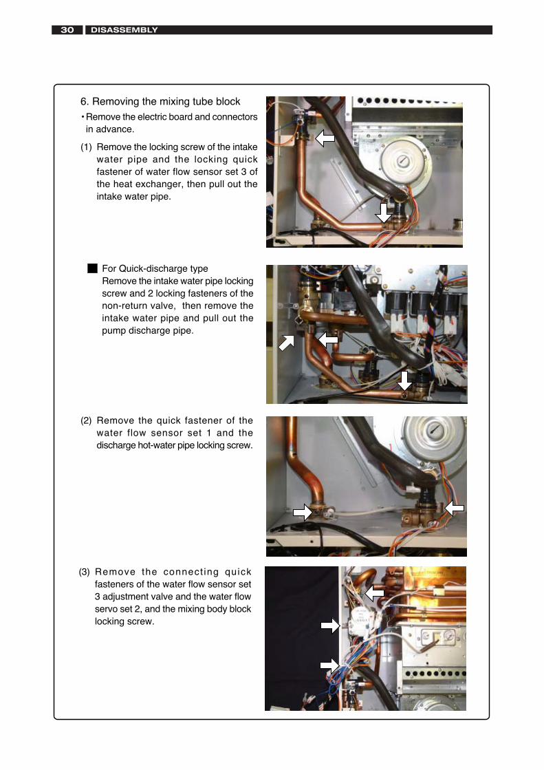
For Quick-discharge typeRemove the intake water pipe lockingscrew and 2 locking fasteners of thenon-return valve, then remove theintake water pipe and pull out thepump discharge pipe.
6. Removing the mixing tube block• Remove the electric board and connectors
in advance.
(1) Remove the locking screw of the intakewater pipe and the locking quickfastener of water flow sensor set 3 ofthe heat exchanger, then pull out theintake water pipe.
(2) Remove the quick fastener of thewater flow sensor set 1 and thedischarge hot-water pipe locking screw.
(3) Remove the connect ing quickfasteners of the water flow sensor set3 adjustment valve and the water flowservo set 2, and the mixing body blocklocking screw.
DISASSEMBLY30
DISASSEMBLY 31
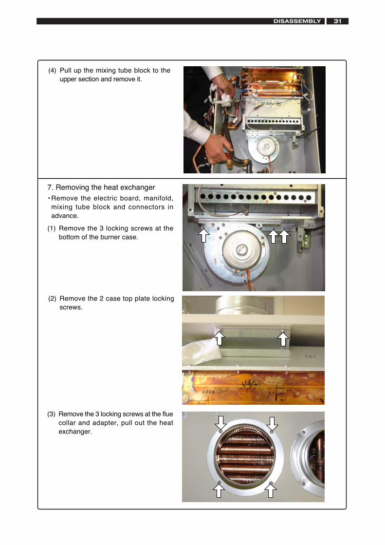
7. Removing the heat exchanger• Remove the electric board, manifold,
mixing tube block and connectors inadvance.
(1) Remove the 3 locking screws at thebottom of the burner case.
(2) Remove the 2 case top plate lockingscrews.
(4) Pull up the mixing tube block to theupper section and remove it.
(3) Remove the 3 locking screws at the fluecollar and adapter, pull out the heatexchanger.
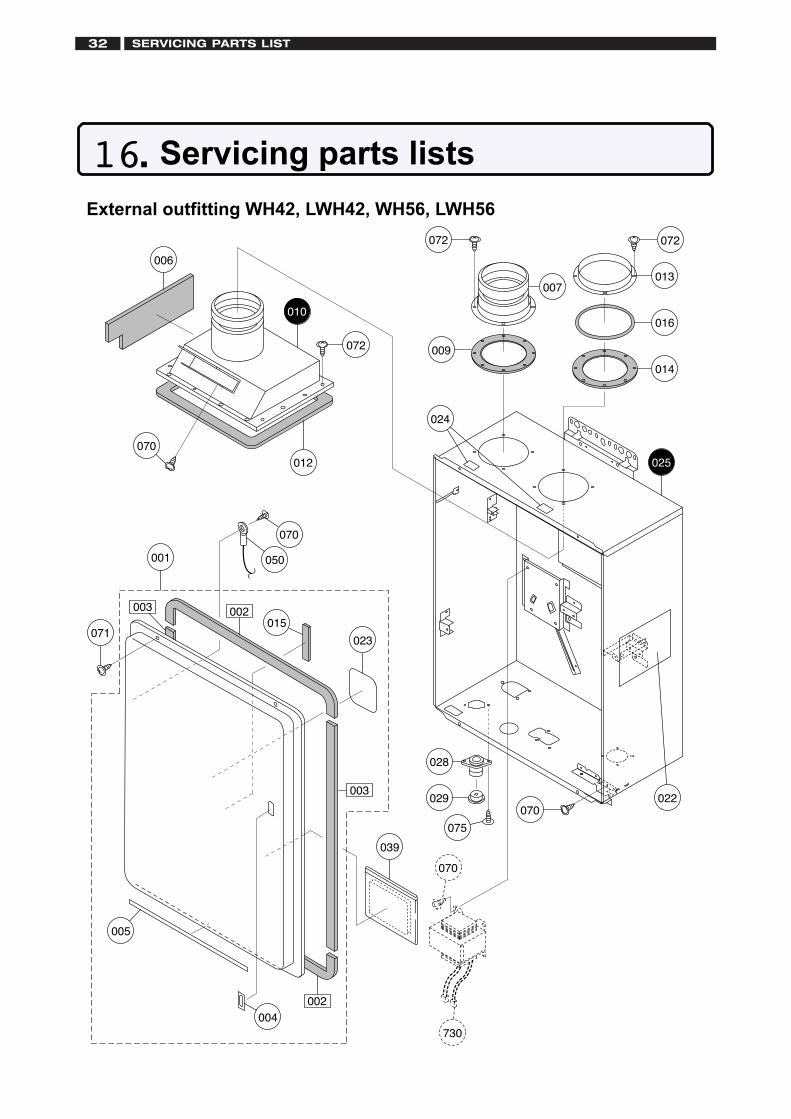
External outfitting WH42, LWH42, WH56, LWH56
001
003
003
023
004
015
025
070
071
006
009
010
012
072
072
070
039
022
070
730
002
002
024
028
075
070
050
005
029
007013
072
014
016
16. Servicing parts lists
SERVICING PARTS LIST32
SERVICING PARTS LIST 33
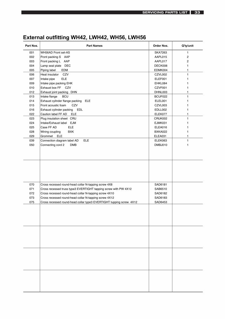
External outfitting WH42, LWH42, WH56, LWH56
001 WH56AD Front set-AS SKA7263 1
002 Front packing S AAP AAPL015 2
003 Front packing L AAP AAPL017 2
004 Lamp seal plate DEC DECK008 1
005 Piping label EDM EDMK004 1
006 Heat insulator CZV CZVL002 1
007 Intake pipe ELE ELEF001 1
009 Intake pipe packing EHK EHKL084 1
010 Exhaust box FF CZV CZVF001 1
012 Exhaust joint packing DHN DHNL003 1
013 Intake flange BCU BCUF022 1
014 Exhaust cylinder flange packing ELE ELEL001 1
015 Front acoustic foam CZV CZVL003 1
016 Exhaust cylinder packing EDL EDLL002 1
022 Caution label FF AD ELE ELEK077 1
023 Plug insulation sheet CRU CRUK002 1
024 Intake/Exhaust label EJM EJMK031 1
025 Case FF AD ELE ELEA016 1
028 Wiring coupling BXK BXKA022 1
029 ELEA031 1
039 Connection diagram label AD ELE ELEK063 1
050 Connecting cord 2 DMB DMBJ010 1
070 Cross recessed round-head collar N-tapping screw 4X8 SAD6181
071 Cross recessed truss type3 EVERTIGHT tapping screw with PW 4X12 SAB6510
072 Cross recessed round-head collar N-tapping screw 4X10 SAD6182
073 Cross recessed round-head collar N-tapping screw 4X12 SAD6183
075 Cross recessed round-head collar type3 EVERTIGHT tupping screw 4X12 SAD6453
Grommet ELE
Part Nos. Part Names Order Nos. Q'ty/unit

Combustion unit and gas route WH42, LWH42, WH56, LWH56
100
109
126
173
170
070
119
125
070173
122
123
121
120172
172
075
124171
121
110
116
117
117
118
171172
175 175
112111
115114
127
070
073
070 132
131
129
128
072
103
104
101
102
105
070
141
070
133
For LWH42 3P
For LWH56 3P
SERVICING PARTS LIST34
SERVICING PARTS LIST 35
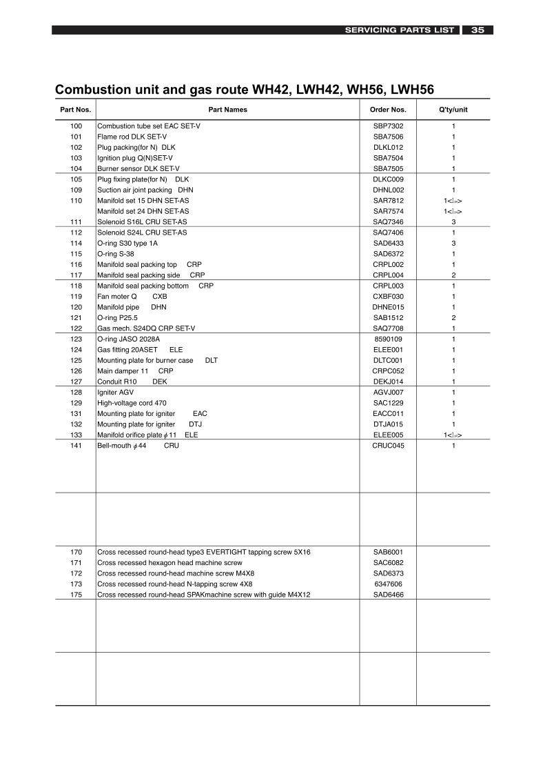
Combustion unit and gas route WH42, LWH42, WH56, LWH56
100 Combustion tube set EAC SET-V SBP7302 1
101 Flame rod DLK SET-V SBA7506 1
102 Plug packing(for N) DLK DLKL012 1
103 Ignition plug Q(N)SET-V SBA7504 1
104 Burner sensor DLK SET-V SBA7505 1
105 Plug fixing plate(for N) DLK DLKC009 1
109 Suction air joint packing DHN DHNL002 1
110 Manifold set 15 DHN SET-AS SAR7812
Manifold set 24 DHN SET-AS SAR7574
111 Solenoid S16L CRU SET-AS SAQ7346 3
112 Solenoid S24L CRU SET-AS SAQ7406 1
114 O-ring S30 type 1A SAD6433 3
115 O-ring S-38 SAD6372 1
116 Manifold seal packing top CRP CRPL002 1
117 Manifold seal packing side CRP CRPL004 2
118 Manifold seal packing bottom CRP CRPL003 1
119 Fan moter Q CXB CXBF030 1
120 Manifold pipe DHN DHNE015 1
121 O-ring P25.5 SAB1512 2
122 Gas mech. S24DQ CRP SET-V SAQ7708 1
123 O-ring JASO 2028A 8590109 1
124 Gas fitting 20ASET ELE ELEE001 1
125 Mounting plate for burner case DLT DLTC001 1
126 Main damper 11 CRP CRPC052 1
127 Conduit R10 DEK DEKJ014 1
128 Igniter AGV AGVJ007 1
129 High-voltage cord 470 SAC1229 1
131 Mounting plate for igniter EAC EACC011 1
132 Mounting plate for igniter DTJ DTJA015 1
133 Manifold orifice plate 11 ELE ELEE005
141 Bell-mouth 44 CRU CRUC045 1
170 Cross recessed round-head type3 EVERTIGHT tapping screw 5X16 SAB6001
171 Cross recessed hexagon head machine screw SAC6082
172 Cross recessed round-head machine screw M4X8 SAD6373
173 Cross recessed round-head N-tapping screw 4X8 6347606
175 Cross recessed round-head SPAKmachine screw with guide M4X12 SAD6466
1< >
1< >
Part Nos. Part Names Order Nos. Q'ty/unit
3P
1< >3P
2H
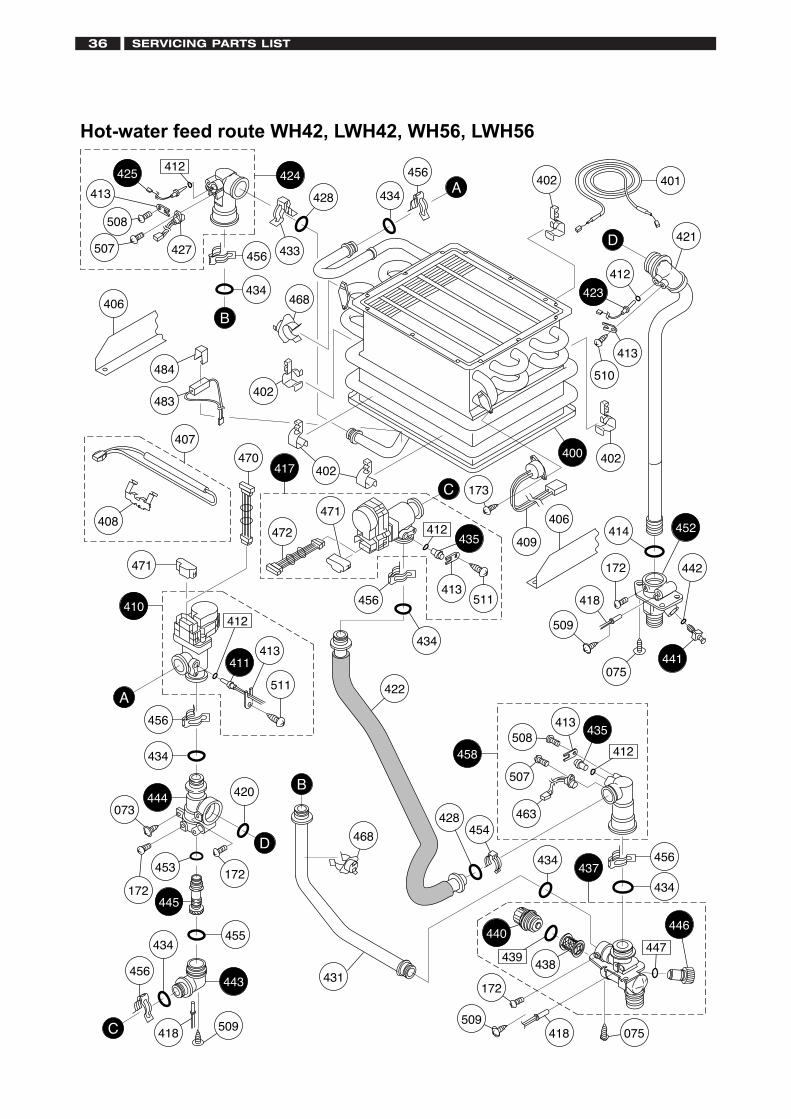
Hot-water feed route WH42, LWH42, WH56, LWH56
401424
433
428
402483
484
406
402
407
408
402
173
409
406
471
470
511
411413
410
434
073
453
172
420
172
455
443
445
509418
434
456
456
434
431
468
456
412
417
456
B
B
438439
440
434
172
509418 075
446
472
471
434
456A
A
C
C
D
D
435
412
463
507
508413
458
423
412
510
402
413
418
172
509
442
441075
414
454428
456
434
400
412
511413
435
421
422
434
437
444
447
452
412425
413
508
427507
468
SERVICING PARTS LIST36
SERVICING PARTS LIST 37
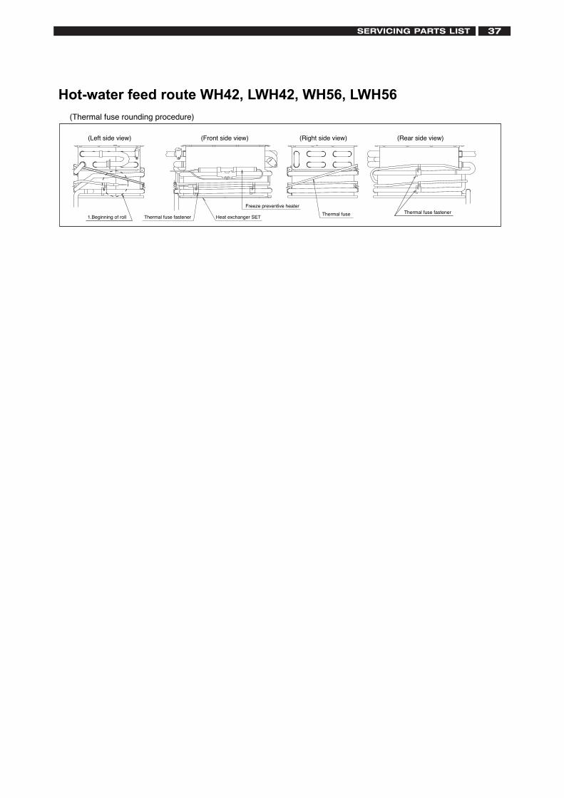
Hot-water feed route WH42, LWH42, WH56, LWH56
Thermal fuseHeat exchanger SETThermal fuse fastener
(Rear side view)(Left side view) (Right side view)(Front side view)
(Thermal fuse rounding procedure)
Freeze preventive heater
1.Beginning of rollThermal fuse fastener
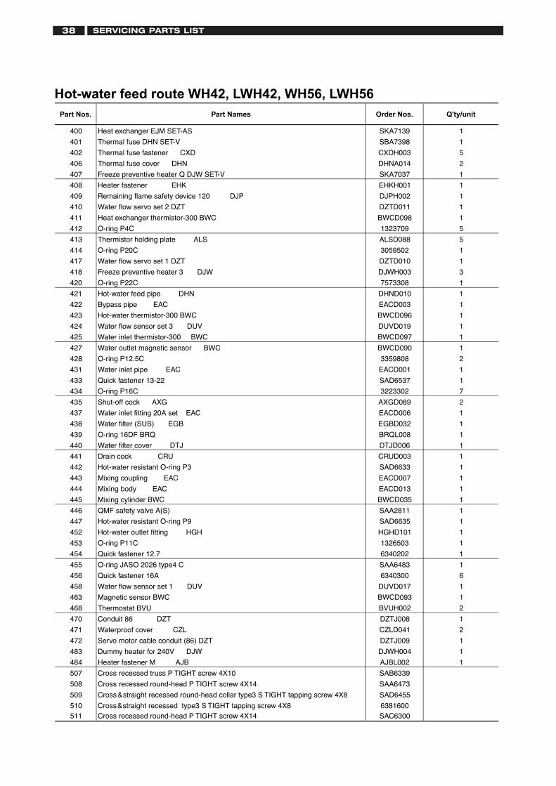
Hot-water feed route WH42, LWH42, WH56, LWH56
400 Heat exchanger EJM SET-AS SKA7139 1
401 Thermal fuse DHN SET-V SBA7398 1
402 Thermal fuse fastener CXD CXDH003 5
406 Thermal fuse cover DHN DHNA014 2
407 Freeze preventive heater Q DJW SET-V SKA7037 1
408 Heater fastener EHK EHKH001 1
409 Remaining flame safety device 120 DJP DJPH002 1
410 Water flow servo set 2 DZT DZTD011 1
411 Heat exchanger thermistor-300 BWC BWCD098 1
412 O-ring P4C 1323709 5
413 Thermistor holding plate ALS ALSD088 5
414 O-ring P20C 3059502 1
417 Water flow servo set 1 DZT DZTD010 1
418 Freeze preventive heater 3 DJW DJWH003 3
420 O-ring P22C 7573308 1
421 Hot-water feed pipe DHN DHND010 1
422 Bypass pipe EAC EACD003 1
423 Hot-water thermistor-300 BWC BWCD096 1
424 Water flow sensor set 3 DUV DUVD019 1
425 Water inlet thermistor-300 BWC BWCD097 1
427 Water outlet magnetic sensor BWC BWCD090 1
428 O-ring P12.5C 3359808 2
431 Water inlet pipe EAC EACD001 1
433 Quick fastener 13-22 SAD6537 1
434 O-ring P16C 3223302 7
435 Shut-off cock AXG AXGD089 2
437 Water inlet fitting 20A set EAC EACD006 1
438 Water filter (SUS) EGB EGBD032 1
439 O-ring 16DF BRQ BRQL008 1
440 Water filter cover DTJ DTJD006 1
441 Drain cock CRU CRUD003 1
442 Hot-water resistant O-ring P3 SAD6633 1
443 Mixing coupling EAC EACD007 1
444 Mixing body EAC EACD013 1
445 Mixing cylinder BWC BWCD035 1
446 QMF safety valve A(S) SAA2811 1
447 Hot-water resistant O-ring P9 SAD6635 1
452 Hot-water outlet fitting HGH HGHD101 1
453 O-ring P11C 1326503 1
454 Quick fastener 12.7 6340202 1
455 O-ring JASO 2026 type4 C SAA6483 1
456 Quick fastener 16A 6340300 6
458 Water flow sensor set 1 DUV DUVD017 1
463 Magnetic sensor BWC BWCD093 1
468 Thermostat BVU BVUH002 2
470 Conduit 86 DZT DZTJ008 1
471 Waterproof cover CZL CZLD041 2
472 Servo motor cable conduit (86) DZT DZTJ009 1
483 Dummy heater for 240V DJW DJWH004 1
484 Heater fastener M AJB AJBL002 1
507 Cross recessed truss P TIGHT screw 4X10 SAB6339
508 Cross recessed round-head P TIGHT screw 4X14 SAA6473
509 Cross&straight recessed round-head collar type3 S TIGHT tapping screw 4X8 SAD6455
510 Cross&straight recessed type3 S TIGHT tapping screw 4X8 6381600511 Cross recessed round-head P TIGHT screw 4X14 SAC6300
Part Nos. Part Names Order Nos. Q'ty/unit
SERVICING PARTS LIST38
SERVICING PARTS LIST 39
Electronic control unit WH42, LWH42, WH56, LWH56
703
705
700
073
710
732070
070
714
715
717
722070
073721
721
733
730731
713
711
070
070
FG
H
701
H
F
G
712
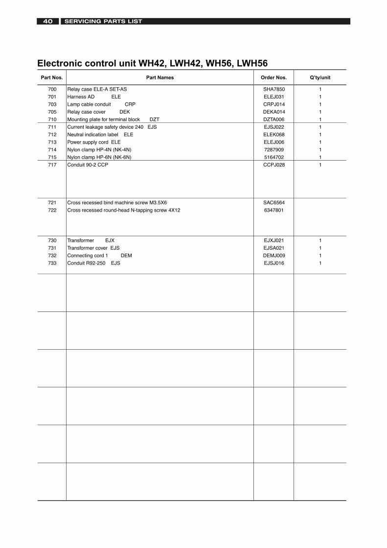
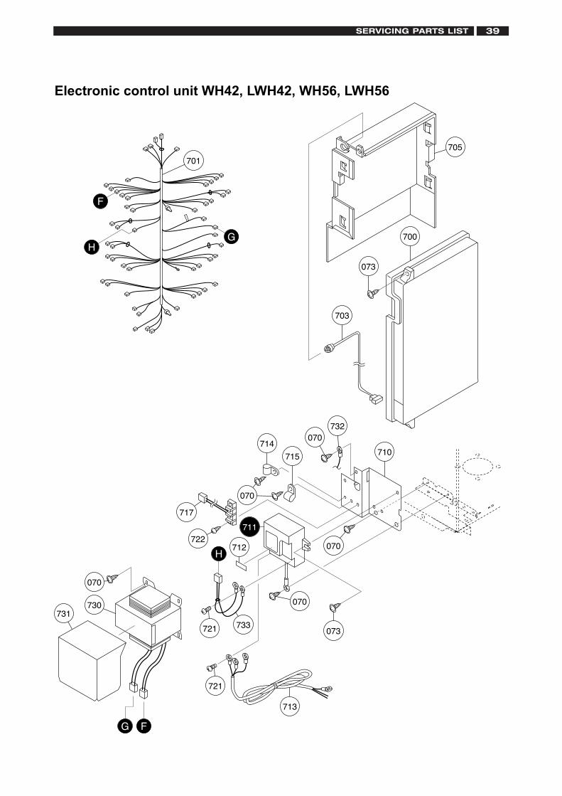
Electronic control unit WH42, LWH42, WH56, LWH56
700 Relay case ELE-A SET-AS SHA7850 1
701 Harness AD ELE ELEJ031 1
703 Lamp cable conduit CRP CRPJ014 1
705 Relay case cover DEK DEKA014 1
710 Mounting plate for terminal block DZT DZTA006 1
711 Current leakage safety device 240 EJS EJSJ022 1
712 Neutral indication label ELE ELEK068 1
713 Power supply cord ELE ELEJ006 1
714 Nylon clamp HP-4N (NK-4N) 7287909 1
715 Nylon clamp HP-6N (NK-6N) 5164702 1
717 Conduit 90-2 CCP CCPJ028 1
721 Cross recessed bind machine screw M3.5X6 SAC6564
722 Cross recessed round-head N-tapping screw 4X12 6347801
730 Transformer EJX EJXJ021 1
731 Transformer cover EJS EJSA021 1
732 Connecting cord 1 DEM DEMJ009 1
733 Conduit R92-250 EJS EJSJ016 1
Part Nos. Part Names Order Nos. Q’ty/unit
SERVICING PARTS LIST40
SERVICING PARTS LIST 41
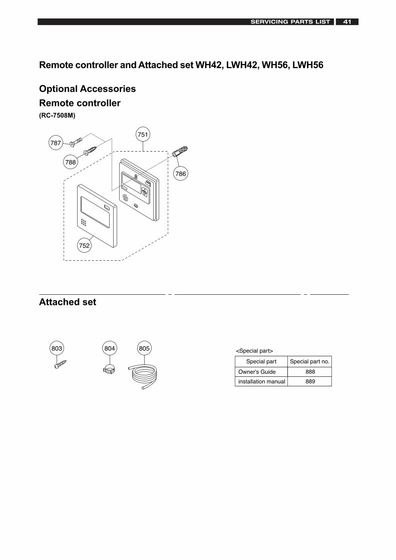
Optional Accessories
Remote controller(RC-7508M)
Attached set
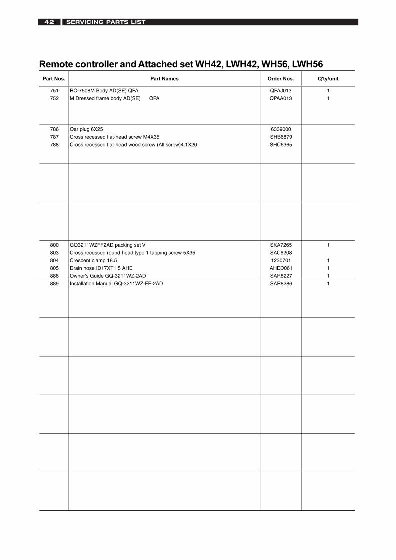
Remote controller and Attached set WH42, LWH42, WH56, LWH56
803
751
752
786
788
787
805804
Special part Special part no.
<Special part>
Owner's Guide 888
installation manual 889
Remote controller and Attached set WH42, LWH42, WH56, LWH56
751 RC-7508M Body AD(SE) QPA QPAJ013 1
752 M Dressed frame body AD(SE) QPA QPAA013 1
786 Oar plug 6X25 6339000
787 Cross recessed flat-head screw M4X35 SHB6879
788 Cross recessed flat-head wood screw (All screw)4.1X20 SHC6365
800 GQ3211WZFF2AD packing set V SKA7265 1
803 Cross recessed round-head type 1 tapping screw 5X35 SAC6208
804 Crescent clamp 18.5 1230701 1
805 Drain hose ID17XT1.5 AHE AHED061 1
888 Owner's Guide GQ-3211WZ-2AD SAR8227 1
889 Installation Manual GQ-3211WZ-FF-2AD SAR8286 1
Part Nos. Part Names Order Nos. Q'ty/unit
SERVICING PARTS LIST42
SPECIFICATIONS 43
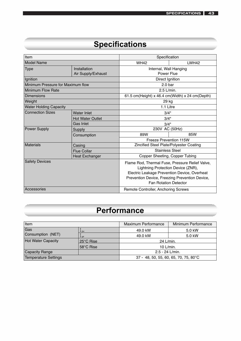
ItemGasConsumption (NET)
Hot Water Capacity
Capacity RangeTemperature Settings
12H
13P
25°C Rise
58°C Rise
24 L/min.
10 L/min.2.5 - 24 L/min.
37 - 48, 50, 55, 60, 65, 70, 75, 80°C
Maximum Performance Minimum Performance
Specification
Internal, Wall HangingPower Flue
Direct Ignition2.0 bar
2.5 L/min.61.5 cm(Height) x 46.4 cm(Width) x 24 cm(Depth)
29 kg1.1 Litre
3/4"3/4"
3/4"230V AC (50Hz)
Zincified Steel Plate/Polyester CoatingStainless Steel
Copper Sheeting, Copper Tubing
Flame Rod, Thermal Fuse, Pressure Relief Valve,Lightning Protection Device (ZNR),
Electric Leakage Prevention Device, OverheatPrevention Device, Freezing Prevention Device,
Fan Rotation Detector
Remote Controller, Anchoring Screws
Specifications
Performance
ItemModel Name
Type
IgnitionMinimum Pressure for Maximum flowMinimum Flow RateDimensionsWeightWater Holding Capacity
Accessories
InstallationAir Supply/Exhaust
Connection Sizes
Power Supply
Materials
Water InletHot Water OutletGas Inlet
Supply
Consumption
Casing
Flue CollarHeat Exchanger
Safety Devices
WH42 LWH42
49.0 kW49.0 kW
5.0 kW5.0 kW
89WFreeze Prevention 115W
85W
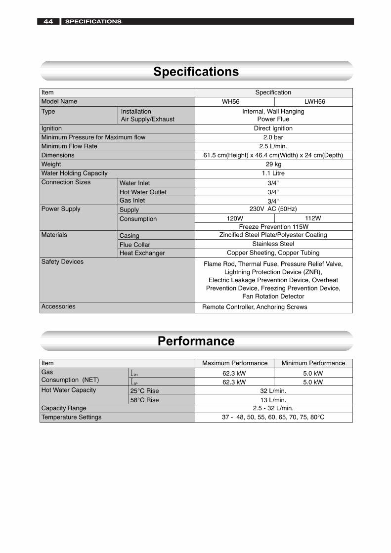
ItemGasConsumption (NET)
Hot Water Capacity
Capacity RangeTemperature Settings
12H
13P
25°C Rise
58°C Rise
32 L/min.
13 L/min.2.5 - 32 L/min.
37 - 48, 50, 55, 60, 65, 70, 75, 80°C
Maximum Performance Minimum Performance
Specification
Internal, Wall HangingPower Flue
Direct Ignition2.0 bar
2.5 L/min.61.5 cm(Height) x 46.4 cm(Width) x 24 cm(Depth)
29 kg1.1 Litre
3/4"3/4"
3/4"230V AC (50Hz)
120W
Zincified Steel Plate/Polyester CoatingStainless Steel
Copper Sheeting, Copper Tubing
Flame Rod, Thermal Fuse, Pressure Relief Valve,Lightning Protection Device (ZNR),
Electric Leakage Prevention Device, OverheatPrevention Device, Freezing Prevention Device,
Fan Rotation Detector
Remote Controller, Anchoring Screws
Specifications
Performance
ItemModel Name
Type
IgnitionMinimum Pressure for Maximum flowMinimum Flow RateDimensionsWeightWater Holding Capacity
Accessories
InstallationAir Supply/Exhaust
Connection Sizes
Power Supply
Materials
Water InletHot Water OutletGas Inlet
Supply
Consumption
Casing
Flue CollarHeat Exchanger
Safety Devices
62.3 kW62.3 kW
5.0 kW5.0 kW
WH56 LWH56
112WFreeze Prevention 115W
SPECIFICATIONS44

45

46

47

Baxi Commercial DivisionWood Lane, Erdington, Birmingham B24 9QP Email: [email protected]
Sales:
0845 070 1056Technical:
0845 070 1057