FastCAM® QuiCk-guide - EX-TRACK
22
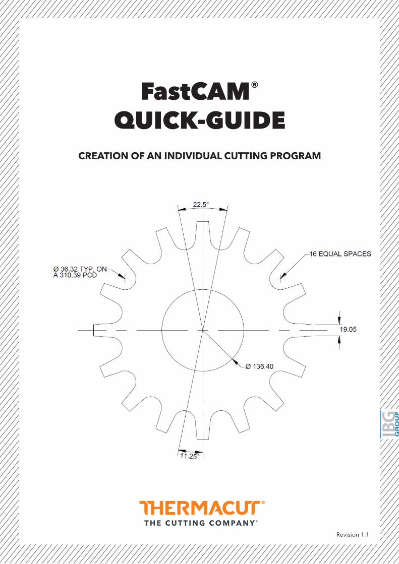
FastCAM ® QUICK-GUIDE CREATION OF AN INDIVIDUAL CUTTING PROGRAM Revision 1.1
-
Upload
khangminh22 -
Category
Documents
-
view
1 -
download
0
Transcript of FastCAM® QuiCk-guide - EX-TRACK
FastCAM®
QuiCk-guideCreation of an individual Cutting program
Revision 1.1

FASTCAM® Quick guide
2
SeCtion 1: installing fastCam® software �����������������������������������������������������3
SeCtion 2: Creating a simple cutting program ��������������������������������������������6
SeCtion 3: nesting ������������������������������������������������������������������������������������14
indeX
FASTCAM® Quick guide
3
SeCtion 1�
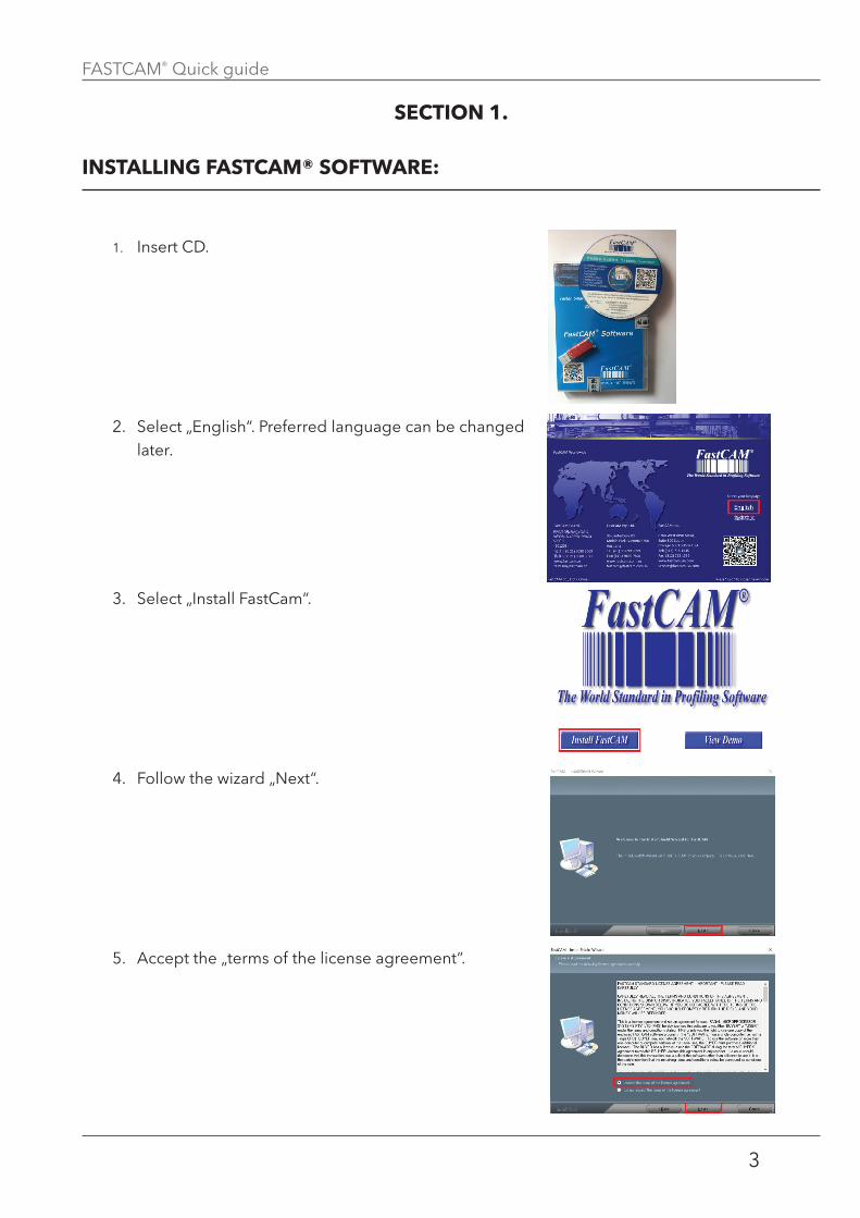
inStalling faStCam® Software:
1. Insert CD.
2. Select „English“. Preferred language can be changed later.
3. Select „Install FastCam“.
4. Follow the wizard „Next“.
5. Accept the „terms of the license agreement”.
SECTION 1: Installing FastCAM® software
FASTCAM® Quick guide
4
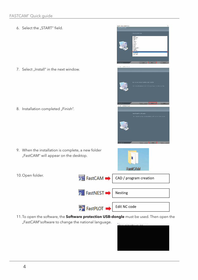
6. Select the „START“ field.
7. Select „Install“ in the next window.
8. Installation completed „Finish“.
9. When the installation is complete, a new folder „FastCAM“ will appear on the desktop.
10. Open folder.
11. To open the software, the Software protection uSB-dongle must be used. Then open the „FastCAM”software to change the national language.
FASTCAM® Quick guide
5
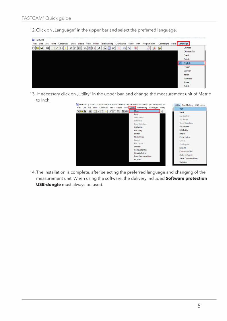
12. Click on „Language“ in the upper bar and select the preferred language.
13. If necessary click on „Utility“ in the upper bar, and change the measurement unit of Metric to Inch.
14. The installation is complete, after selecting the preferred language and changing of the measurement unit. When using the software, the delivery included Software protection uSB-dongle must always be used.
FASTCAM® Quick guide
6
SeCtion 2
Creating a Simple Cutting program:
SECTION 2: Creating a simple cutting program
This quick guide is an example of how to create a cutting program easily and quickly. There could be also be other ways to create a cutting program.
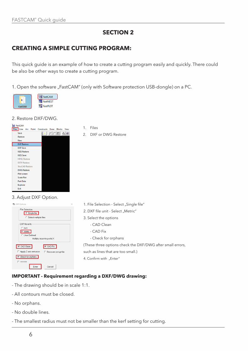
1. Open the software „FastCAM“ (only with Software protection USB-dongle) on a PC.
2. Restore DXF/DWG.
3. Adjust DXF Option.
important - requirement regarding a dXf/dwg drawing:
- The drawing should be in scale 1:1.
- All contours must be closed.
- No orphans.
- No double lines.
- The smallest radius must not be smaller than the kerf setting for cutting.
1. Files
2. DXF or DWG Restore
1. File Selection - Select „Single file“
2. DXF file unit - Select „Metric“
3. Select the options
- CAD Clean
- CAD Fix
- Check for orphans
(These three options check the DXF/DWG after small errors,
such as lines that are too small.)
4. Confirm with „Enter“

FASTCAM® Quick guide
7
4. Select DXF / DWG on the hard disk.
5. Import the DXF drawing and verify it by the previous „Option“ selections.
Confirm the preset value with
„Enter”.
It ask for the maximum gap in the
contour.
Everything smaller than 0,2mm is
automatically deleted.
6 orphanes cutting units were
found. Confirm the selection for
erasure with “yes” (Ja).
When checking the drawing, the
FastCAM found 6 small points
that would have caused problems
when cutting later.
The cleaned drawing is shown.
6. If necessary, save the clean DXF/DWG drawing on the PC, as seen below.
1. Files
2. DXF Save
3. Select the directory on the
PC and save (Speichern).
FASTCAM® Quick guide
8
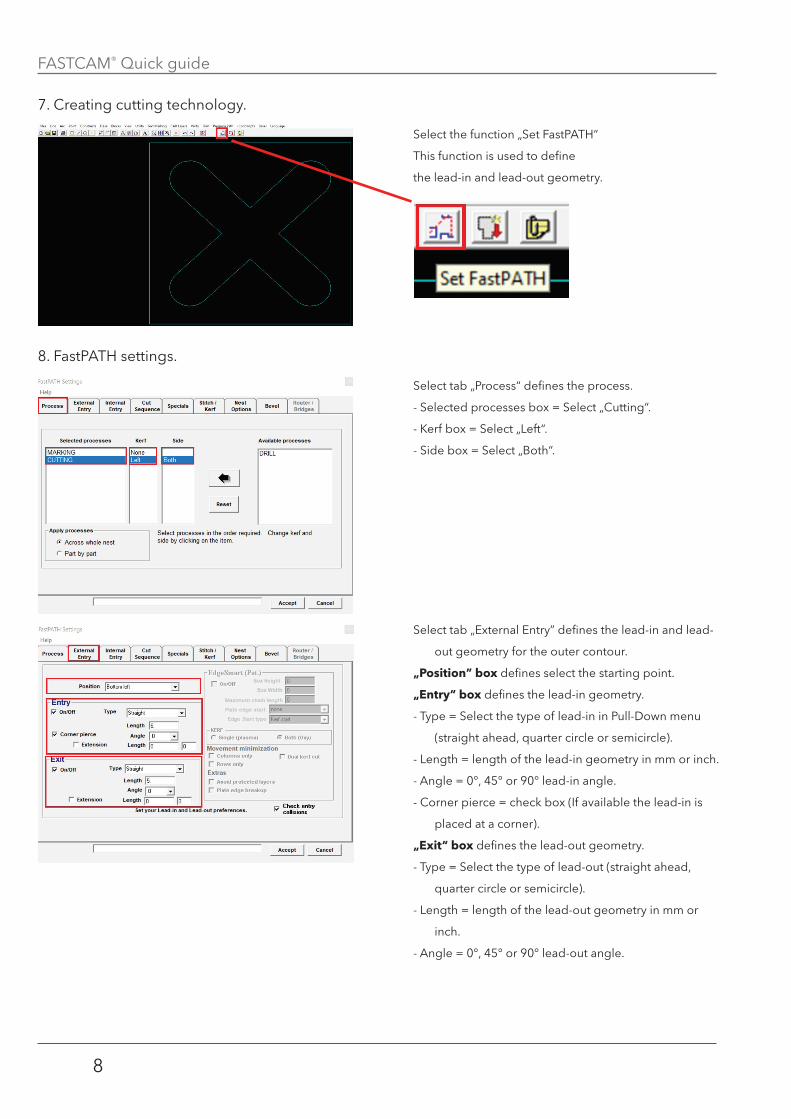
7. Creating cutting technology.
8. FastPATH settings.
Select the function „Set FastPATH“
This function is used to define
the lead-in and lead-out geometry.
Select tab „Process“ defines the process.
- Selected processes box = Select „Cutting“.
- Kerf box = Select „Left“.
- Side box = Select „Both“.
Select tab „External Entry” defines the lead-in and lead-
out geometry for the outer contour.
„position” box defines select the starting point.
„entry“ box defines the lead-in geometry.
- Type = Select the type of lead-in in Pull-Down menu
(straight ahead, quarter circle or semicircle).
- Length = length of the lead-in geometry in mm or inch.
- Angle = 0°, 45° or 90° lead-in angle.
- Corner pierce = check box (If available the lead-in is
placed at a corner).
„exit“ box defines the lead-out geometry.
- Type = Select the type of lead-out (straight ahead,
quarter circle or semicircle).
- Length = length of the lead-out geometry in mm or
inch.
- Angle = 0°, 45° or 90° lead-out angle.
FASTCAM® Quick guide
9
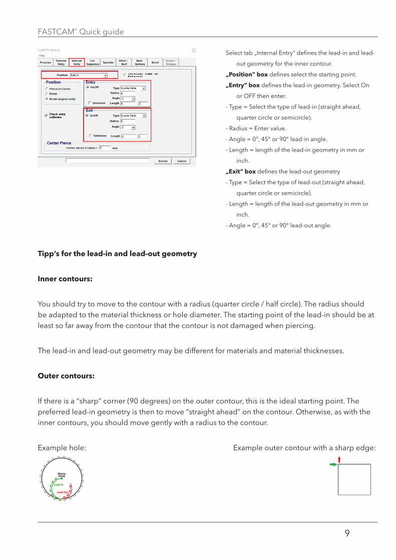
tipp’s for the lead-in and lead-out geometry
inner contours:
You should try to move to the contour with a radius (quarter circle / half circle). The radius should be adapted to the material thickness or hole diameter. The starting point of the lead-in should be at least so far away from the contour that the contour is not damaged when piercing.
The lead-in and lead-out geometry may be different for materials and material thicknesses.
outer contours:
If there is a “sharp” corner (90 degrees) on the outer contour, this is the ideal starting point. The preferred lead-in geometry is then to move “straight ahead” on the contour. Otherwise, as with the inner contours, you should move gently with a radius to the contour.
Example hole: Example outer contour with a sharp edge:
Select tab „Internal Entry“ defines the lead-in and lead-
out geometry for the inner contour.
„position” box defines select the starting point.
„entry“ box defines the lead-in geometry. Select On
or OFF then enter.
- Type = Select the type of lead-in (straight ahead,
quarter circle or semicircle).
- Radius = Enter value.
- Angle = 0°, 45° or 90° lead-in angle.
- Length = length of the lead-in geometry in mm or
inch.
„exit“ box defines the lead-out geometry
- Type = Select the type of lead-out (straight ahead,
quarter circle or semicircle).
- Length = length of the lead-out geometry in mm or
inch.
- Angle = 0°, 45° or 90° lead-out angle.
FASTCAM® Quick guide
10
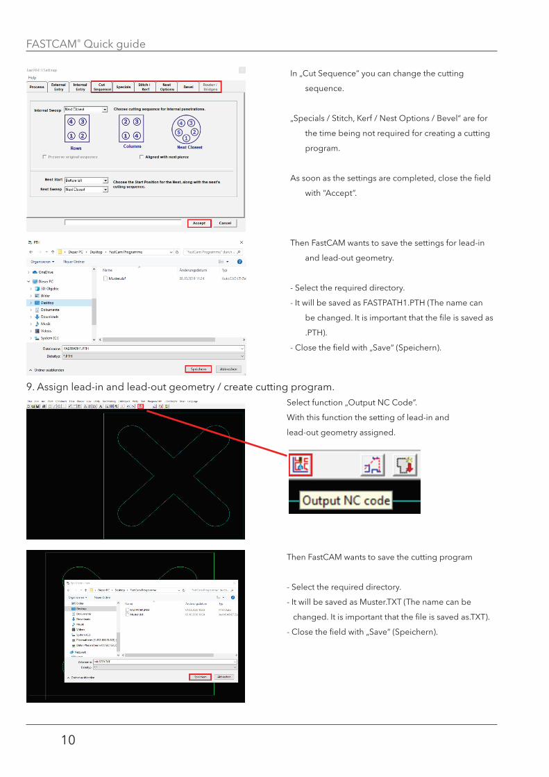
9. Assign lead-in and lead-out geometry / create cutting program.
In „Cut Sequence“ you can change the cutting
sequence.
„Specials / Stitch, Kerf / Nest Options / Bevel“ are for
the time being not required for creating a cutting
program.
As soon as the settings are completed, close the field
with “Accept”.
Then FastCAM wants to save the settings for lead-in
and lead-out geometry.
- Select the required directory.
- It will be saved as FASTPATH1.PTH (The name can
be changed. It is important that the file is saved as
.PTH).
- Close the field with „Save“ (Speichern).
Select function „Output NC Code”.
With this function the setting of lead-in and
lead-out geometry assigned.
Then FastCAM wants to save the cutting program
- Select the required directory.
- It will be saved as Muster.TXT (The name can be
changed. It is important that the file is saved as.TXT).
- Close the field with „Save“ (Speichern).
FASTCAM® Quick guide
11
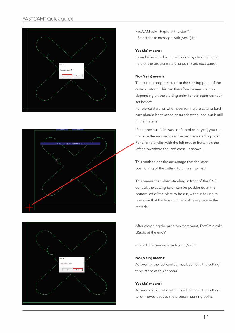
FastCAM asks „Rapid at the start“?
- Select these message with „yes“ (Ja).
Yes (Ja) means:
It can be selected with the mouse by clicking in the
field of the program starting point (see next page).
no (nein) means:
The cutting program starts at the starting point of the
outer contour. This can therefore be any position,
depending on the starting point for the outer contour
set before.
For pierce starting, when positioning the cutting torch,
care should be taken to ensure that the lead-out is still
in the material.
If the previous field was confirmed with “yes”, you can
now use the mouse to set the program starting point.
For example, click with the left mouse button on the
left below where the “red cross” is shown.
This method has the advantage that the later
positioning of the cutting torch is simplified.
This means that when standing in front of the CNC
control, the cutting torch can be positioned at the
bottom left of the plate to be cut, without having to
take care that the lead-out can still take place in the
material.
After assigning the program start point, FastCAM asks
„Rapid at the end?“
- Select this message with „no“ (Nein).
no (nein) means:
As soon as the last contour has been cut, the cutting
torch stops at this contour.
Yes (Ja) means:
As soon as the last contour has been cut, the cutting
torch moves back to the program starting point.
FASTCAM® Quick guide
12
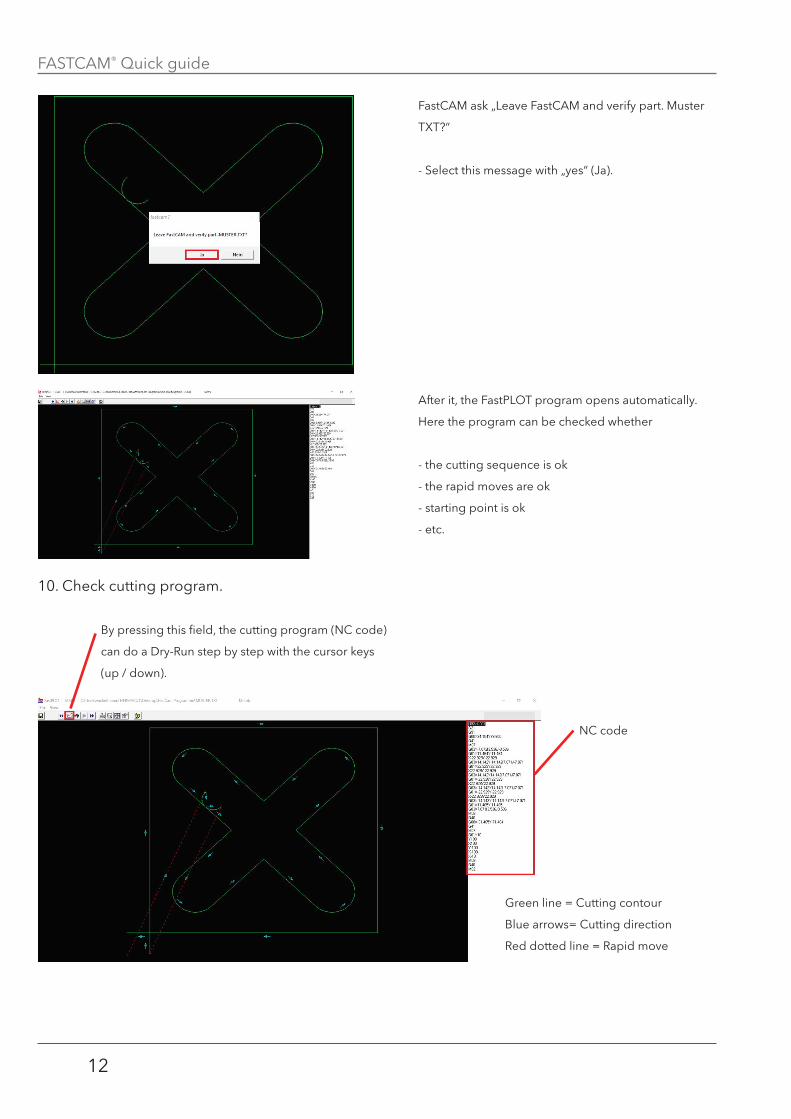
10. Check cutting program.
FastCAM ask „Leave FastCAM and verify part. Muster
TXT?“
- Select this message with „yes“ (Ja).
After it, the FastPLOT program opens automatically.
Here the program can be checked whether
- the cutting sequence is ok
- the rapid moves are ok
- starting point is ok
- etc.
By pressing this field, the cutting program (NC code)
can do a Dry-Run step by step with the cursor keys
(up / down).
NC code
Green line = Cutting contour
Blue arrows= Cutting direction
Red dotted line = Rapid move
FASTCAM® Quick guide
13
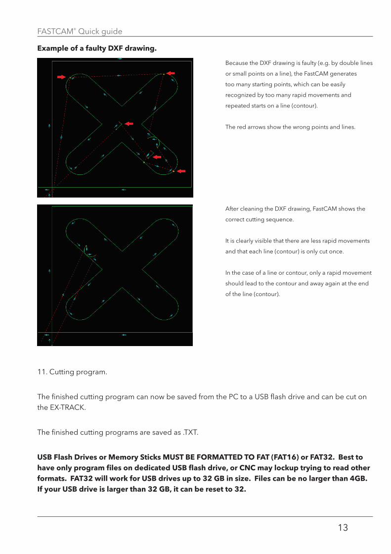
example of a faulty dXf drawing�
11. Cutting program.
The finished cutting program can now be saved from the PC to a USB flash drive and can be cut on the EX-TRACK.
The finished cutting programs are saved as .TXT.
uSB flash drives or memory Sticks muSt Be formatted to fat (fat16) or fat32� Best to have only program files on dedicated uSB flash drive, or CnC may lockup trying to read other formats� fat32 will work for uSB drives up to 32 gB in size� files can be no larger than 4gB� if your uSB drive is larger than 32 gB, it can be reset to 32�
Because the DXF drawing is faulty (e.g. by double lines
or small points on a line), the FastCAM generates
too many starting points, which can be easily
recognized by too many rapid movements and
repeated starts on a line (contour).
The red arrows show the wrong points and lines.
After cleaning the DXF drawing, FastCAM shows the
correct cutting sequence.
It is clearly visible that there are less rapid movements
and that each line (contour) is only cut once.
In the case of a line or contour, only a rapid movement
should lead to the contour and away again at the end
of the line (contour).
FASTCAM® Quick guide
14
SeCtion 3�
neSting:
SECTION 3: Nesting
When nesting, different contours can be nested in a define plate size.
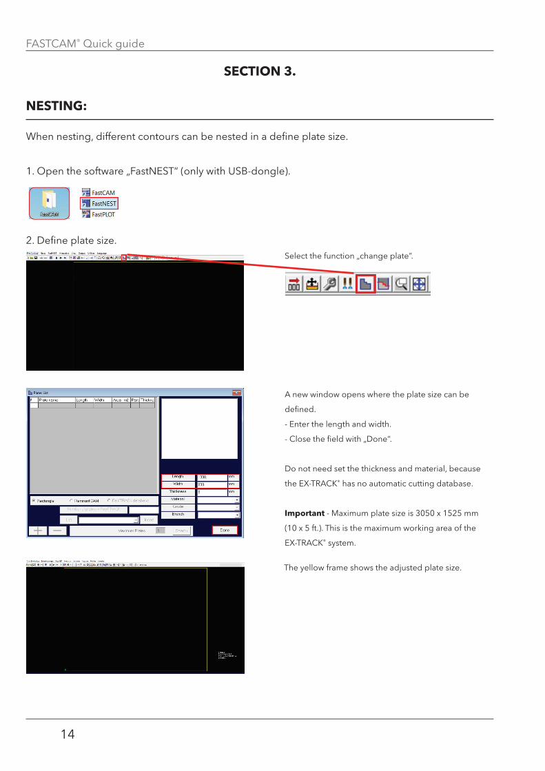
1. Open the software „FastNEST“ (only with USB-dongle).
2. Define plate size.Select the function „change plate”.
A new window opens where the plate size can be
defined.
- Enter the length and width.
- Close the field with „Done“.
Do not need set the thickness and material, because
the EX-TRACK® has no automatic cutting database.
important - Maximum plate size is 3050 x 1525 mm
(10 x 5 ft.). This is the maximum working area of the
EX-TRACK® system.
The yellow frame shows the adjusted plate size.

FASTCAM® Quick guide
15
3. Set nesting distance.
4. Set file type.
Select the „Nests“ menu and then „Nest Parameters“.
In this menu, the nesting distance of the plate edge to
the cutting part as well as between the individual
cutting parts can be adjusted.
The distances can be set in the “Sundry” section.
- Part to part = Nesting distance between the parts to
be cut.
- Part to plate = Nesting distance between plate edge
and the part to be cut.
The nesting distance depends on the parts to be cut
and the material thickness and can be different..
Select the function „DXF - NC“.
FASTCAM® Quick guide
16
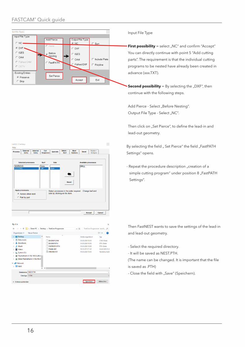
Input File Type
first possibility = select „NC“ and confirm “Accept”
You can directly continue with point 5 “Add cutting
parts”. The requirement is that the individual cutting
programs to be nested have already been created in
advance (xxx.TXT).
Second possibility = By selecting the „DXF“, then
continue with the following steps.
Add Pierce - Select „Before Nesting“.
Output File Type - Select „NC“.
Then click on „Set Pierce“, to define the lead-in and
lead-out geometry.
By selecting the field „ Set Pierce“ the field „FastPATH
Settings“ opens.
- Repeat the procedure description „creation of a
simple cutting program“ under position 8 „FastPATH
Settings“.
Then FastNEST wants to save the settings of the lead-in
and lead-out geometry.
- Select the required directory.
- It will be saved as NEST.PTH.
(The name can be changed. It is important that the file
is saved as .PTH)
- Close the field with „Save“ (Speichern).
FASTCAM® Quick guide
17
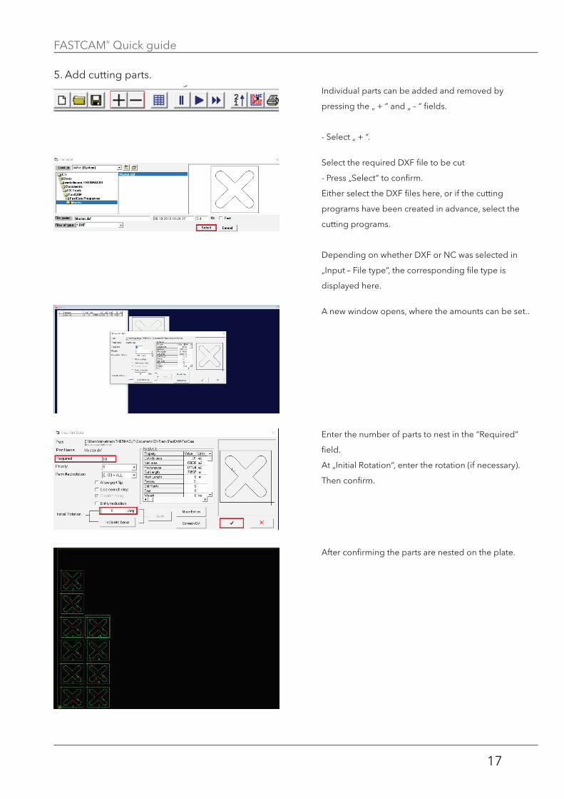
5. Add cutting parts.Individual parts can be added and removed by
pressing the „ + “ and „ – “ fields.
- Select „ + “.
Select the required DXF file to be cut
- Press „Select“ to confirm.
Either select the DXF files here, or if the cutting
programs have been created in advance, select the
cutting programs.
Depending on whether DXF or NC was selected in
„Input – File type”, the corresponding file type is
displayed here.
A new window opens, where the amounts can be set..
Enter the number of parts to nest in the “Required”
field.
At „Initial Rotation“, enter the rotation (if necessary).
Then confirm.
After confirming the parts are nested on the plate.
FASTCAM® Quick guide
18
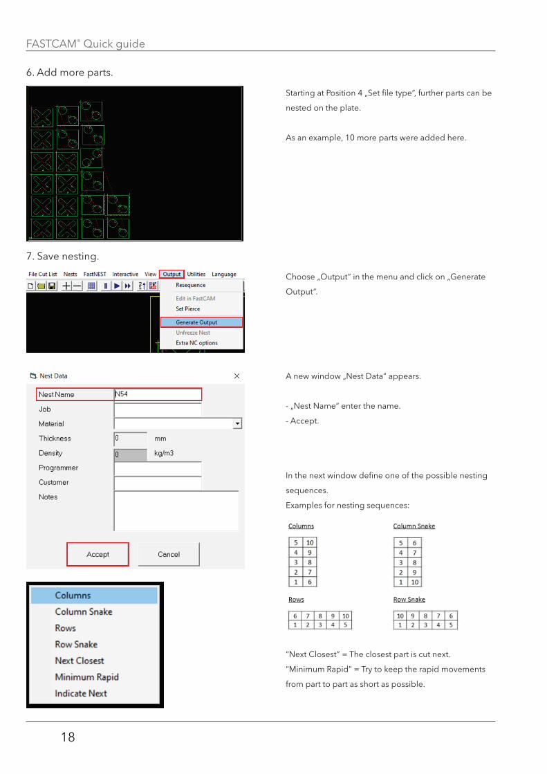
6. Add more parts.
7. Save nesting.
Starting at Position 4 „Set file type”, further parts can be
nested on the plate.
As an example, 10 more parts were added here.
Choose „Output“ in the menu and click on „Generate
Output“.
A new window „Nest Data“ appears.
- „Nest Name“ enter the name.
- Accept.
In the next window define one of the possible nesting
sequences.
Examples for nesting sequences:
“Next Closest” = The closest part is cut next.
“Minimum Rapid” = Try to keep the rapid movements
from part to part as short as possible.
FASTCAM® Quick guide
19
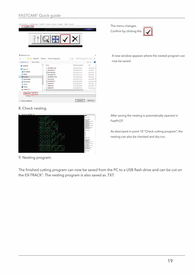
8. Check nesting.
9. Nesting program.
The finished cutting program can now be saved from the PC to a USB flash drive and can be cut on the EX-TRACK®. The nesting program is also saved as .TXT.
The menu changes.
Confirm by clicking the
A new window appears where the nested program can
now be saved.
After saving the nesting is automatically opened in
FastPLOT.
As descriped in point 10 “Check cutting program“, the
nesting can also be checked and dry-run.
FASTCAM® Quick guide
20
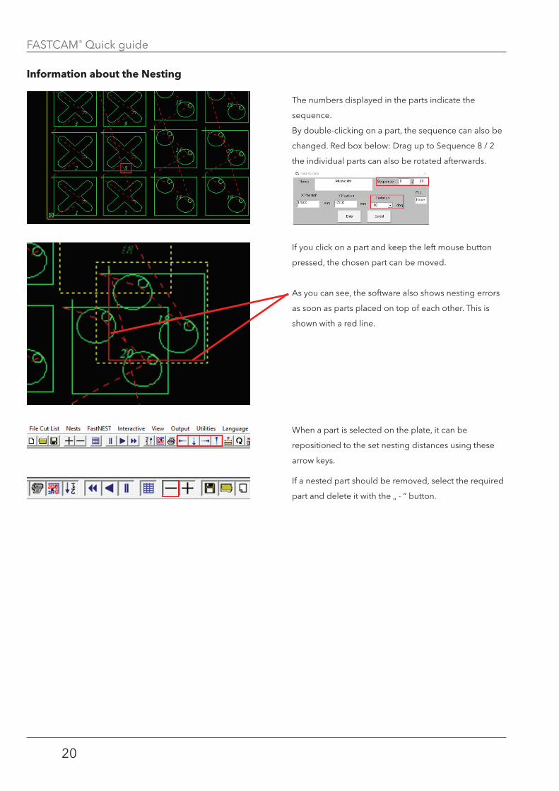
information about the nesting
The numbers displayed in the parts indicate the
sequence.
By double-clicking on a part, the sequence can also be
changed. Red box below: Drag up to Sequence 8 / 2
the individual parts can also be rotated afterwards.
If you click on a part and keep the left mouse button
pressed, the chosen part can be moved.
As you can see, the software also shows nesting errors
as soon as parts placed on top of each other. This is
shown with a red line.
When a part is selected on the plate, it can be
repositioned to the set nesting distances using these
arrow keys.
If a nested part should be removed, select the required
part and delete it with the „ - “ button.

FASTCAM® Quick guide
21
noteS:

FASTCAM® Quick guide
22
thermacut, k�s�
Sokolovská 574, mařatice
686 01, uherské Hradiště
Czech republic
www�thermacut�com
tHermaCut®, fHt-eX®, eX-trafire®, eX-traCK® and eX-traflame® are registered
trademarks of thermacut, k�s� and may be registered in Czech republic and/or other
countries� all other trademarks are properties of their respective owners�
tHermaCut® is no way affiliated with fastCam®�