fall detection system for the elderly people
57
VISVESWARAYA TECHNOLOGICAL UNIVERSITY, BELAGAVI NEW HORIZON COLLEGE OF ENGINEERING, BANGALORE Autonomous College Permanently Affiliated to VTU Approved by AICTE Accredited by NAAC with ‘A’ grade PROJECT REPORT ON “FALL DETECTION SYSTEM FOR THE ELDERLY PEOPLE” Submitted in partial fulfilment as a requirement for the award of degree of BACHELOR OF ENGINEERING IN ELECTRONICS AND COMMUNICATION UNDER THE GUIDANCE OF Senior Asst Prof. JAYANTHI M SUBMITTED BY ANTONITA AISHWARYA A 1NH14EC742 PRIYANKA P 1NH15EC415 JAYASHREE R 1NH14EC746 JAYASHREE DEVI K 1NH15EC408 2017-2018
-
Upload
khangminh22 -
Category
Documents
-
view
3 -
download
0
Transcript of fall detection system for the elderly people

VISVESWARAYA TECHNOLOGICAL UNIVERSITY, BELAGAVI
NEW HORIZON COLLEGE OF ENGINEERING, BANGALORE
Autonomous College Permanently Affiliated to VTU Approved by AICTE Accredited by NAAC
with ‘A’ grade
PROJECT REPORT ON
“FALL DETECTION SYSTEM FOR THE ELDERLY PEOPLE”
Submitted in partial fulfilment as a requirement for the award of degree of
BACHELOR OF ENGINEERING
IN
ELECTRONICS AND COMMUNICATION
UNDER THE GUIDANCE OF
Senior Asst Prof. JAYANTHI M
SUBMITTED BY
ANTONITA AISHWARYA A 1NH14EC742
PRIYANKA P 1NH15EC415
JAYASHREE R 1NH14EC746
JAYASHREE DEVI K 1NH15EC408
2017-2018

VISVESWARAYA TECHNOLOGICAL UNIVERSITY, BELAGAVI
NEW HORIZON COLLEGE OF ENGINEERING, BANGALORE
Autonomous College Permanently Affiliated to VTU Approved by AICTE Accredited by
NAAC with ‘A’ grade
DEPARTMENT OF ELECTRONICS AND COMMUNICATION
ENGINEERING
CERTIFICATE
This is to certify that the project work entitled “ FALL DETECTION SYSTEM FOR THE ELDERLY
PEOPLE” is a bonafide work carried out by student ANTONITA AISHWARYA A (1NH14EC742),
PRIYANKA P (1NH15EC415), JAYASHREE R (1NH14EC746), JAYASHREE DEVI K (1NH15EC408)
submitted in partial Fulfilment for the award of Bachelor of Engineering degree in VIII semester of the
Visvesvaraya Technological University, Belagavi during the academic year 2017-18. It is certified that all the
corrections and suggestions indicated for Internal Assessment have been incorporated in the report deposited in
the Department library. The project work has been approved as it satisfies the academic requirement in respect
of Project Work (10ECP85) prescribed for BACHELOR OF ENGINEERING DEGREE IN ELECTRONICS
AND COMMUNICATION ENGINEERING.
GUIDE HOD PRINCIPAL
NAME NAME NAME
Senior Asst Prof. Jayanthi M Prof. Aravinda K Dr. Manjunatha
………………………… ……………………....... …………………………
NAME OF THE EXAMINERS SIGN WITH DATE
1. …………………………………………. ……………………………….
2. …………………………………………. ……………………………….

ACKNOWLEDGEMENT
Gratitude takes three forms –“A feeling from heart, an expression in words and a giving in return”.
We take this opportunity to express our heart-feelings.
A project is never a solo effort. It is an outcome of long process of dedicated, devoted and sustained effort
by every participant and the material, technical and even physiological support of many people, during the
course of project, which needs due acknowledgement.
First and foremost, we take this opportunity to express our profound gratitude to our respected Principal
Dr. MANJUNATHA, for providing all the facilities in the college.
We would like to express our sincere thanks to Prof. ARAVINDA K, Head of the department of
Electronics and Communication Engineering for his continuous support and encouragement during our
academic progression.
We feel deeply indebted to our esteemed guide Senior Asst Prof. JAYANTHI M for her guidance, right
from the conception and visualization to the very presentation of the project. Her encouragement, guidance
and suggestions made our project work an enjoyable experience.
We are greatly indebted to our faculties, both teaching and supporting staff, Department of Electronics and Communication Engineering, who took great interest in our project work. They motivated and guided us throughout the accomplishment of this goal. We express our profound thanks for their meticulous guidance.
Finally, we would like to express our heartfelt thanks to our beloved parents for their blessings, our friends
for their help and wishes for the successful completion of this project work.
Project Associates:
ANTONITA AISHWARYA A
PRIYANKA P
JAYASHREE R
JAYASHREE DEVI K

TABLE OF CONTENTS
Abstract
Chapter 1: Introduction 1
1.1 Introduction 1
1.2 Related Work 2
Chapter 2: Components Description 4
2.1 Power Supply Unit 4
2.2 Interfacing Bluetooth Receiver 5
2.2.1 HC05 hardware features 5
2.2.2 Applications 6
2.2.3 App Instructions 7
2.3 Interfacing Push Button 7
2.4 LCD Interfacing 8
2.4.1 LCD Pin Descriptions 9
2.4.2 LCD Interfacing 10
2.4.3 LCD Pin Functions 10
2.5 Accelerometer 11
2.6 Control unit (LPC2148) 13

2.6.1 Features 14
2.6.2 LPC2148 Block Diagram 15
2.6.3 LPC2148 Pin Diagram 16
2.6.4 Memory 17
2.6.5 I/O Ports 17
2.7 Voice Playback Kit 18
2.7.1 Features 18
2.8 Comparator (LM324) 20
2.8.1 Features 20
2.8.2 LM324 Pin Functions 21
Chapter 3: Block diagram and Flow Chart 22
3.1 Block Diagram 22
3.2 Circuit Diagram 23
3.3 Flow Chart 24
3.3.1 Working of the flowchart 25
Chapter 4: Software Requirements 27
4.1 Keil 27
4.2 Advantages 29
Chapter 5: Conclusion and Future Scope 30
5.2 Conclusion and Future scope 30
References 31
Appendix 32

ABSTRACT
As per the records of the World Health Organization, Falls are one of the fatal reasons which cause
deaths. Adults aged more than 65 experience the hugest number of fatal falls. Fall-related injuries can thus be
prevented or decreased by employing fall detection systems. Therefore, the standard of life of the older adults
can be monitored and enhanced with the aid of an automatic fall reduction system. Our project includes a fall
detection system that supervises an older adult in the real time. Fall is basically an utmost communal health issue,
it not only causes many damaging breakages but also several other dramatic psychological consequences which
reduce the autonomy of people. It is noticed that as early as the fall is reported, the lower will be the rate of
harmfulness-temporality. Fall detection is a captivating scientific issue since it is a vague process which one can
approximate to using a variety of methods. The fall detection system basically includes two important elements:
a wearable instrument and an android mobile phone. This wearable instrument has the ability of communicating
with an android mobile phone that is located within 100ft radius. Once, the wearable instrument identifies a fall,
it sends an alert to the mobile phone, then the mobile phone will then send an alert to the contacts provided
initially by the user.. In addition, our system has a unique button called the panic button which is used to alert the
contacts if at all the user feels that a fall may happen or if he/she wants to be monitored immediately. A voice
play-back kit is ensured to make the person feel comfortable in case if the person forgets to press the interrupt
button if he/she is alright and doesn’t want any alert to be sent to the guardian or the emergency unit and the voice
playback kit also informs the user regarding his/her tablet timings.
Fall Detection System For The Elderly People 2017-2018
1
CHAPTER 1
INTRODUCTION
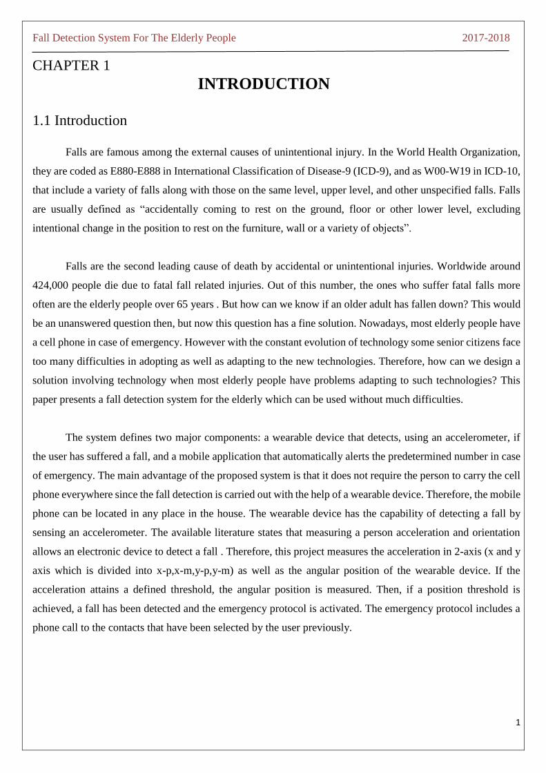
1.1 Introduction
Falls are famous among the external causes of unintentional injury. In the World Health Organization,
they are coded as E880-E888 in International Classification of Disease-9 (ICD-9), and as W00-W19 in ICD-10,
that include a variety of falls along with those on the same level, upper level, and other unspecified falls. Falls
are usually defined as “accidentally coming to rest on the ground, floor or other lower level, excluding
intentional change in the position to rest on the furniture, wall or a variety of objects”.
Falls are the second leading cause of death by accidental or unintentional injuries. Worldwide around
424,000 people die due to fatal fall related injuries. Out of this number, the ones who suffer fatal falls more
often are the elderly people over 65 years . But how can we know if an older adult has fallen down? This would
be an unanswered question then, but now this question has a fine solution. Nowadays, most elderly people have
a cell phone in case of emergency. However with the constant evolution of technology some senior citizens face
too many difficulties in adopting as well as adapting to the new technologies. Therefore, how can we design a
solution involving technology when most elderly people have problems adapting to such technologies? This
paper presents a fall detection system for the elderly which can be used without much difficulties.
The system defines two major components: a wearable device that detects, using an accelerometer, if
the user has suffered a fall, and a mobile application that automatically alerts the predetermined number in case
of emergency. The main advantage of the proposed system is that it does not require the person to carry the cell
phone everywhere since the fall detection is carried out with the help of a wearable device. Therefore, the mobile
phone can be located in any place in the house. The wearable device has the capability of detecting a fall by
sensing an accelerometer. The available literature states that measuring a person acceleration and orientation
allows an electronic device to detect a fall . Therefore, this project measures the acceleration in 2-axis (x and y
axis which is divided into x-p,x-m,y-p,y-m) as well as the angular position of the wearable device. If the
acceleration attains a defined threshold, the angular position is measured. Then, if a position threshold is
achieved, a fall has been detected and the emergency protocol is activated. The emergency protocol includes a
phone call to the contacts that have been selected by the user previously.

Fall Detection System For The Elderly People 2017-2018
2
A functional prototype was implemented and tested for this project. This prototype includes the wearable
device, and an Android application which is used to activate the emergency protocol which gives an alert to the
respective guardian. In addition, our system allows the user to activate the emergency protocol when required,
pressing a panic button as well as to cancel an alert being sent by using an interrupt button in order to avoid
false alerts.
1.2 Related Work
Generally fall detection systems are based on wearable sensors. However, in the paper we are just
focusing on the methods based on wearable sensors. Most of the fall detection systems using mobile devices,
use accelerometers, as the primary sensor. Accelerometry is a useful mechanism to measure the acceleration of
different parts of the Human Body, and thus can be used as an effective tool for fall detection. Threshold-based
methods are one the most popular techniques for fall detection using wearable sensors. Here, a fall is reported
when the acceleration goes beyond a pre-defined thresholds.
Following a similar approach, Kangas used specific locations in the user’s body to compute different
thresholds with data collected from a three-axis accelerometer, and gyroscope. Sensor locations with the greatest
fall recognition accuracy included places such as the user’s waist and head. In addition, the study found that the
features with significant contribution for fall recognition were the sum vector, dynamic sum vector, vertical
acceleration, and maximum and minimum values. Finally, et al presents a fall detection system based on the
accelerometry. Here, the sensor is located in the user’s pelvis. The solution is based on scenarios, namely stand
still, sit to stand, stand to sit, walking, walking backwards, stoop, jump and lie on the bed. Fall detection is then
carry out in the context of this scenarios.
The following features were extracted from motion data: sum vector, magnitude of acceleration,
acceleration on the horizontal plane and reference velocity. By using these features, the system was able to find
out spatial changes of the acceleration while a fall occurred. Results showed that there was a high level of fall
detection when using the treasure-based approach.
A different category of wearable sensor approaches for fall detection includes the systems based on
machine learning techniques. The general architecture of these systems include a data collection Module for
gathering motion data; a feature extraction module that selects the most relevant characteristics from the motion
that are useful for fall prediction; and an inference learning module that finds relationships from the extracted
features to come up with a descriptive model for fall detection.

Fall Detection System For The Elderly People 2017-2018
3
Projects on this category include the work of Vallejo et al, who proposes a method based on artificial
neural networks. The system uses an accelerometer on the user’s waist, a microcontroller, and a ZigBee module.
The neural network is able to learn the falling events. In a similar Work, but this time using decision trees
Bianchi et al used a method that combines acceleration and air pressure. The air pressure data was collected
from a wearable sensor, located in the user’s waist, the two input signals, namely acceleration, and air pressure
were used to build a decision tree for fall detection.
Lindeman et al made a study on a fall detector system placed at the head level. The detection technique
that he followed was based on TBM- threshold based method( in which a fall is reported when the acceleration
peaks, valleys or other shape features reach predefined thresholds) considering the spatial direction of the head,
the velocity right before the initial contact with the ground and the impacts. The fall types were Falls to the
front, side with a 90° turn, back, back with hip flexion and Falls backwards against a wall, while picking up an
object and collapse. It was basically tested on A young volunteer and an elderly woman (83 years).This device
was placed behind the ear. Accelerometers were integrated into a hearing-aid housing. It had high sensitivity
and specificity.
Bourke et al made an investigation into the ability to discriminate between falls and ADL. This was
based on the TBM, using the information from the impact. The fall types were : Forward falls, backward falls
and lateral falls left and right, performed with legs straight and flexed. It was tested on 10 subjects (ages 21–
29) and 10 community-dwelling elderly subjects (3 females, 7 males, ages 70–83). People were supposed to
wear it on either trunk or thigh. The trunk appears to be the optimum location for a fall sensor. Bangala et al
made a study on the performance of published fall-detection methods when they are applied to real-world falls.
It was based on TBM. The fall types were: Real-world falls: indoor or outdoor, forward or backward or
sideward, impact against the floor or wall or locker before hitting the floor or sofa or bed or the desk. It could
be worn on the lower back. It was tested on older people too. Algorithms that were successful at detecting
simulated falls did not perform well when attempting to detect real-world falls
And now, in 2018, along with the fall detection using the accelerometer , we have also included a voice
playback kit which will help the user with his/ her tablet timings and whenever the user has pressed the panic
button the voice playback kit will inform the user that an alert has been sent to the guardian and suppose the
person doesn’t know which button to press if he/ she is alright after a fall, the voice playback kit will play a
voice informing the user regarding the button

Fall Detection System For The Elderly People 2017-2018
4
CHAPTER 2
COMPONENTS DESCRIPTION
Hardware Components Specification:
Power supply unit
Interfacing Bluetooth Receiver
Interfacing Push Button
LCD Interfacing
Accelerometer
Control unit (LPC2148)
Voice playback kit
Comparator(LM 324)
The hardware components specification specifies the hardware components required for the project. It basically
includes the major as well as the basic components used in the project.
2.1 Power Supply Unit
Power Supply:
Power supply is required for all the electronic circuits. Say you have a 8V power supply and you want
to use it as a 5V power supply. Then we can use the 8v to 5v dc-dc converter circuit diagram to convert 12 volt
to 5 volt. This DC converter circuit provide 5V, 1Amp at the output. A voltage regulator is designed to
automatically maintain a constant voltage level.
This DC-DC converter is based on IC LM7805. The LM 7805 is a 3-terminal fixed output positive
voltage regulator IC. The output current of this circuit is up to 1 Amp. We use a heat sink with LM7805 to
protect the IC from overheating.
Fall Detection System For The Elderly People 2017-2018
5
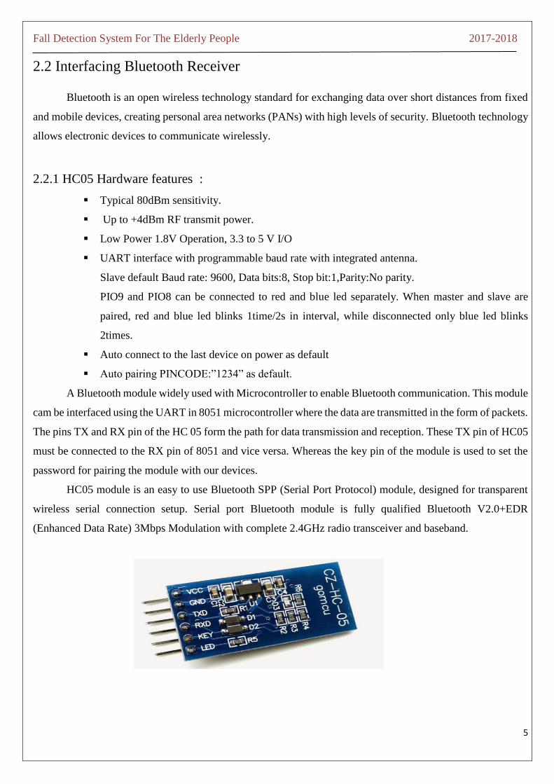
2.2 Interfacing Bluetooth Receiver
Bluetooth is an open wireless technology standard for exchanging data over short distances from fixed
and mobile devices, creating personal area networks (PANs) with high levels of security. Bluetooth technology
allows electronic devices to communicate wirelessly.
2.2.1 HC05 Hardware features :
Typical 80dBm sensitivity.
Up to +4dBm RF transmit power.
Low Power 1.8V Operation, 3.3 to 5 V I/O
UART interface with programmable baud rate with integrated antenna.
Slave default Baud rate: 9600, Data bits:8, Stop bit:1,Parity:No parity.
PIO9 and PIO8 can be connected to red and blue led separately. When master and slave are
paired, red and blue led blinks 1time/2s in interval, while disconnected only blue led blinks
2times.
Auto connect to the last device on power as default
Auto pairing PINCODE:”1234” as default.
A Bluetooth module widely used with Microcontroller to enable Bluetooth communication. This module
cam be interfaced using the UART in 8051 microcontroller where the data are transmitted in the form of packets.
The pins TX and RX pin of the HC 05 form the path for data transmission and reception. These TX pin of HC05
must be connected to the RX pin of 8051 and vice versa. Whereas the key pin of the module is used to set the
password for pairing the module with our devices.
HC05 module is an easy to use Bluetooth SPP (Serial Port Protocol) module, designed for transparent
wireless serial connection setup. Serial port Bluetooth module is fully qualified Bluetooth V2.0+EDR
(Enhanced Data Rate) 3Mbps Modulation with complete 2.4GHz radio transceiver and baseband.

Fall Detection System For The Elderly People 2017-2018
6
2.2.2 Application:
Bluetooth-terminal-application
Snapshot of BT terminal Application
Our devices such as mobile and PC's need special applications known as "Bluetooth Terminal" to
communicate with our microcontrollers via Bluetooth. Not to worry, there are plenty of apps you can find in
the internet. These apps are available in plenty irrespective of the you device OS Android, Windows , Mac
whatever it may be. Just run a search such as Bluetooth Terminal for "OS name" and search engines will take
you to the destination.
These applications are developed in such a way to send characters through your device BT which was
received by the BT module connected with our controller. Even some apps offer some interactive GUI(graphical
user interface) buttons which transmits specific characters with the press of each buttons. Later the received
character can be processed in our code and force the controller to perform tasks based on the received character.
We can use the Bluetooth communication in two ways, either we can use it to receive data from the Controller
or control the system using our device Bluetooth

Fall Detection System For The Elderly People 2017-2018
7
2.2.3 App Instructions
First make sure your HC-05 Bluetooth Module is paired with your mobile. The default password for
pairing is "1234" or "0000". Check the manual of Bluetooth module.
Click on Select Device to select paired Bluetooth module.
Click on Disconnect to disconnect paired Bluetooth module.
2.3 Interfacing Push Button
Keypad is a widely used input device with lots of application in our everyday life. From a simple
telephone to keyboard of a computer, ATM, electronic lock, etc., keypad is used to take input from the user for
further processing.
To interface a push button or switch to the Controller, all we need is just the push button or the switch
itself and an accompanying pull-up resistor as shown below.
In this configuration, the bit that will enter to the Controller’s port is HIGH (1) if the push button is not
pressed. If the push button is pressed, the bit that goes inside the computer is LOW (0). This is so since the
input port will be connected directly to ground if the push button is pressed.

Fall Detection System For The Elderly People 2017-2018
8
2.4 LCD Interfacing
Liquid Crystal Display which is also called as LCD is very helpful in providing user interface as well as
for debugging purpose. The most common type of LCD controller is HITACHI 44780 which provides a simple
interface between the controller & an LCD.
These LCD's are very simple to interface with the controller as well as are cost effective. The most
commonly used ALPHANUMERIC displays are 1x16 (Single Line & 16 characters), 2x16 (Double Line & 16
character per line), 4x20 (four lines & Twenty characters per line). The LCD is a level board show or other
electronically tweaked optical gadget that uses the light-balancing properties of light specifically, rather utilizing
a backdrop illumination or reflector to deliver pictures in shading. LCDs are accessible to show settled pictures
with low data content, that can be shown, for example, 7 fragment shows, as in an advanced clock.
LCDs are used as a part of extensive variety of utilizations including LCD TVs, PC screens, instrument
boards, air ship cockpit shows, indoor and open air signage. The LCD screens don't utilize phosphors; they don't
endure picture copy in when a static picture is shown on a screen for quite a while. The LCD screen is more
vitality effective and can be arranged on more securely than a CRT filter.
The LCD is isolated into little pixels, the littlest segment of the screen, which can be controlled and
captivated. A pixel is little speck on the screen. Every one of these pixels is joined to make a piece. For instance,
in a 16x2 LCD one square has 5x8 spots.

Fall Detection System For The Elderly People 2017-2018
9
2.4.1 Pin Descriptions:
Vcc, Vss and Vee:
While Vcc and Vss provide +5V and ground respectively, Vee is used for controlling
LCD contrast.
RS Register Select:
There are two very important registers inside the LCD. The RS pin is used for their
selection as follows. If RS=0, the instruction command code register is selected, allowing the user to send a
command such as clear display, cursor at home, etc. If RS=1, the data register is selected, allowing the user to
send data to be displayed on the LCD.
R/W, read/write:
R/W input allows the user to write information to the LCD or read information from it.
R/W = 1 for reading.
R/W= 0 for writing.
EN, enable:
The LCD to latch information presented to its data pins uses the enable pin. When data
is supplied to data pins, a high–to-low pulse must be applied to this pin in order for the LCD to latch in the data
present at the data pins. This pulse must be a minimum of 450 ns wide.
D0 – D7:
The 8–bit data pins, DO – D7, are used to send information to the LCD or read the
contents of the LCD’s internal registers.
To display letters and numbers, we send ASCII codes for the letters A–Z, a-z numbers 0-
9 to these pins while making RS=1.
There are also instruction command codes that can be sent to the LCD to clear the display or force the
cursor to home position or blink the instruction command codes.
We also use RS = 0 to check the busy flag bit to see if the LCD is ready to receive information. The
busy flag is D7 and can be read when R/W=1 and RS=0, as follows: if R/W = 1, RS = 0. When D7= 1 (busy
flag = 1), the LCD is busy taking care of internal operations and will not accept any information.
Fall Detection System For The Elderly People 2017-2018
10
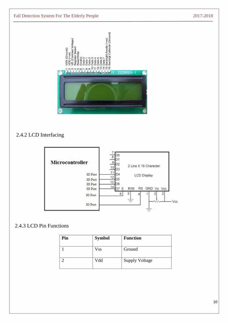
2.4.2 LCD Interfacing
2.4.3 LCD Pin Functions
Pin Symbol Function
1 Vss Ground
2 Vdd Supply Voltage
Fall Detection System For The Elderly People 2017-2018
11
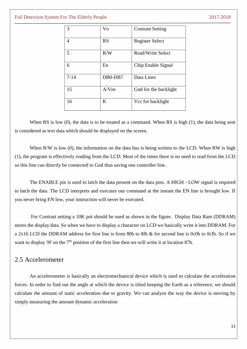
3 Vo Contrast Setting
4 RS Register Select
5 R/W Read/Write Select
6 En Chip Enable Signal
7-14 DB0-DB7 Data Lines
15 A/Vee Gnd for the backlight
16 K Vcc for backlight
When RS is low (0), the data is to be treated as a command. When RS is high (1), the data being sent
is considered as text data which should be displayed on the screen.
When R/W is low (0), the information on the data bus is being written to the LCD. When RW is high
(1), the program is effectively reading from the LCD. Most of the times there is no need to read from the LCD
so this line can directly be connected to Gnd thus saving one controller line.
The ENABLE pin is used to latch the data present on the data pins. A HIGH - LOW signal is required
to latch the data. The LCD interprets and executes our command at the instant the EN line is brought low. If
you never bring EN low, your instruction will never be executed.
For Contrast setting a 10K pot should be used as shown in the figure. Display Data Ram (DDRAM)
stores the display data. So when we have to display a character on LCD we basically write it into DDRAM. For
a 2x16 LCD the DDRAM address for first line is from 80h to 8fh & for second line is 0c0h to 0cfh. So if we
want to display 'H' on the 7th position of the first line then we will write it at location 87h.
2.5 Accelerometer
An accelerometer is basically an electromechanical device which is used to calculate the acceleration
forces. In order to find out the angle at which the device is tilted keeping the Earth as a reference, we should
calculate the amount of static acceleration due to gravity. We can analyze the way the device is moving by
simply measuring the amount dynamic acceleration

Fall Detection System For The Elderly People 2017-2018
12
The ADXL335 is the latest and greatest from Analog Devices, known for their exceptional quality
MEMS devices. It calculates acceleration with a minimum full scale range of +/-3g.The VCC takes up to 5V in
and regulates it to 3.3V with an output pin. The analog outputs are ratio metric: that means that 0g measurement
output is always at half of the 3.3V output (1.65V), -3g is at 0v and 3g is at 3.3V with full scaling in between.
The ADXL335 is typically a small, thin, low power, and a complete tri-axis accelerometer with signal
conditioned voltage outputs. This product calculates acceleration with a minimum full-scale range of ±3 g. It
can measure the static acceleration of gravity in tilt-sensing applications, along with this it can also measure the
dynamic acceleration resulting from motion, shock, or vibration. It is cost efficient and it requires low power.
ADXL335 (tri-axis accelerometer analog output)
Output is x-axis, y-axis and z-axis in analog voltage
Measures acceleration with a minimum full-scale range of +/-3g
Board comes with an on-board voltage regulator and works at 3.3V & 5V (3-5V).
Interfacing with Microcontroller
Connect +5v and GND properly.
Connect X_out, Y_out, Z_out to A0, A1 and A2 input of ADC.
Read ADC data.
It has several applications in today’s world such as motion- and tilt-sensing applications, Mobile
devices, Gaming systems, Disk drive protection, Image stabilization, Sports and health devices.

Fall Detection System For The Elderly People 2017-2018
13
2.6 Control Unit (LPC2148)
The important criteria in choosing the microcontrollers are:
Availability of software development tools like compilers, debuggers, assemblers.
Meeting the computing needs of the given task efficiently and at low cost.
Reliable manufacturers.
Amount of RAM and ROM on chip.
Number of I/O pins.
Supporting protocols: UART, USB, SP1,SSP AND CAN etc.
Power Consumption.
Cost per unit.
ARM-7 LPC2148 is the widely used IC from the ARM-7 family. It is manufactured by Philips and it is
pre-loaded with many inbuilt peripherals which makes it increasingly efficient and a more reliable option for
the beginners as well as for the high end application developers. The main function of this control unit is to
monitor all the inputs and control output units accordingly.
It offers high execution and low power consumption. The LPC 2148 microcontrollers depend on a 16-
bit/32-bit ARM7TDMI-S CPU with continuous copying and installed follow bolster, that join microcontroller
with implanted rapid glimmer memory going from 32 kB to 512 kB.
A 128-piece wide memory interface and a one of a kind quickening agent design empower 32-bit code
execution at the most extreme clock rate. For basic code measure applications, the elective 16-bit Thumb mode
decreases code by more than 30 % with negligible execution punishment.
Due to their small size and low power utilization, LPC2148 is perfect for applications where scaling
down is a key necessity, for example, get to control and purpose of-offer. Serial correspondences interfaces
running from a USB 2.0 Full-speed gadget, different UARTs, SPI, SSP to I2C-transport and on-chip SRAM of
8 kB up to 40 kB, make these gadgets extremely appropriate for correspondence entryways and convention
converters, delicate modems, voice acknowledgment and low end imaging, giving both substantial support size
and high preparing power.
Different 32-bit clocks, single or double 10-bit ADC(s), 10-bit DAC, PWM channels and 45 quick GPIO
lines with up to nine edge or level touchy outer interfere with pins make these microcontrollers appropriate for
mechanical control and restorative framework.

Fall Detection System For The Elderly People 2017-2018
14
2.6.1 Features:
CPU operating voltage range of 3.0 V to 3.6 V (3.3 V ± 10 %) with 5 V tolerant I/O pads
64-pin High-Performance ARM Microcontroller
Flash Program Memory: 512 Kbytes
SRAM Data Memory: 32 Kbytes
GPIO Pins: 45
Timers: Two 32-bit
Up to nine edge or level sensitive external interrupt pins available
A/D Converter: 10-bit Fourteen Channels
DAC: 10-bit
Real-Time Clock (RTC): Independent Power and Dedicated 32kHz Input
I²C: Two Modules with Master or Slave Operation
SPI: Full Duplex Serial Operation
UART: Two Modules
USB: 2.0B Fully Compliant Controller with RAM
External Oscillator: up to 25MHz with integrated PLL for 60MHz Operation
Fall Detection System For The Elderly People 2017-2018
15
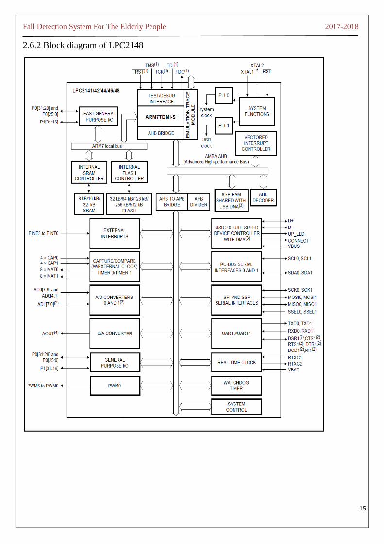
2.6.2 Block diagram of LPC2148
Fall Detection System For The Elderly People 2017-2018
16
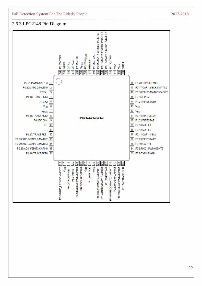
2.6.3 LPC2148 Pin Diagram:

Fall Detection System For The Elderly People 2017-2018
17
2.6.4 Memory
LPC2148 has 32kB on chip SRAM and 512 kB on chip FLASH memory. It has inbuilt support up to
2kB end point USB RAM also. This huge amount of memory is well suited for almost all the applications.The
LPC2148 On chip FLASH memory system incorporates a 512 KB Flash memory system. This memory may be
used for both code and data storage. The FLASH memory can be programmed by means of
1. Serial built-in JTAG interface
2. Using In System Programming (ISP) and UART0
3. By means of In-Application Programming (IAP) capabilities.
The application program, using the IAP functions, may also erase and/or program the Flash while the
application is running, allowing a great degree of flexibility for data storage field firmware upgrades, etc. When
the LPC2148 on-chip boot loader is used, 500 KB of Flash memory is available for user code. The LPC2148
Flash memory provides minimum of 100,000 erase/write cycles and 20 years of data-retention. The LPC2148
provides 32 KB of static RAM which may be used for code and/or data storage. It may be accessed as 8-bits,
16-bits, and 32-bits.
2.6.5 I/O Ports
LPC 2148 has two I/O Ports each of 32 bit wide giving us a total of 64 I/O Pins. Ports are named as P0
and P1.Pins of each port are labelled as PX.Y where X stands for port number, 0 or 1 where else Y stands for
pin number 0 to 31.Each pin can perform alternate functions also. For eg. P0.8 serves as GPIO as well as
transmitter pin of UART1, PWM4 and AD1.1.On RESET, each pin is configured as GPIO. For any of the other
use, programmer must configure it properly.
PORT0:
Total of 30 input/output and a single output only pin out of 32 pins are available on PORT0.
PORT1:
PORT1 has up to 16 pins available for GPIO functions.
PORT0 and PORT1 are controlled via groups of registers explained below:
1. IOPIN:
It is GPIO Port Pin value register. The current state of the GPIO configured port pins can always be read
from this register, regardless of pin direction.

Fall Detection System For The Elderly People 2017-2018
18
2. IODIR:
GPIO Port Direction control register. This register individually controls the direction of each port pin.
3. IOCLR:
GPIO Port Output Clear registers. This register controls the state of output pins. Writing ones produces
lows at the corresponding port pins and clears the corresponding bits in the IOSET register. Writing zeroes has
no effect.
4. IOSET:
GPIO Port Output Set registers. This register controls the state of output pins in conjunction with the
IOCLR register. Writing ones produces highs at the corresponding port pins. Writing zeroes has no effect.
2.7 Voice Playback Kit
The APR33A series are a powerful audio processor along with high performance audio analog-to-digital
converters (ADCs) and digital-to-analog converters (DACs). There are a fully integrated solution offering high
performance and unparalleled integration with the analog input, digital processing and analog output
functionality.
The APR33A series C2.0 is specially designed for simple key triggering, user can easily record and
playback the message averagely for about 1, 2,4, or 8 voice messages by switching.
It offers true solid state storage capability and requires neither software nor microcontroller support. It
provides high quality recording and playback with 11 minutes and audio at 8 kHz sampling rate with 16 bit
resolution.
2.7.1 Features:
Operating Voltage Range: 3V ~ 6.5V Single Chip
High Quality Audio/Voice Recording & Playback Solution
No External ICs Required
Minimum External Components
User Friendly
Easy to Use Operation
Programming & Development Systems Not Required
170/ 340/ 680 sec Voice Recording Length in aPR33A1/aPR33A2/aPR33A3
Powerful 16-Bits Digital Audio Processor
Fall Detection System For The Elderly People 2017-2018
19
Non-volatile Flash Memory Technology
No Battery Backup Required External Reset pin.
Powerful Power Management Unit
Very Low Standby Current: 1uA
Low Power-Down Current: 15uA
Supports Power-Down Mode for Power Saving
Built-in Audio-Recording Microphone Amplifier
No External OPAMP or BJT Required
Easy to PCB layout
Configurable analog interface
Differential-ended MIC pre-amp for Low Noise
High Quality Line Receiver
High Quality Analog to Digital, DAC and PWM module and Resolution up to 16-bits
Simple And Direct User Interface
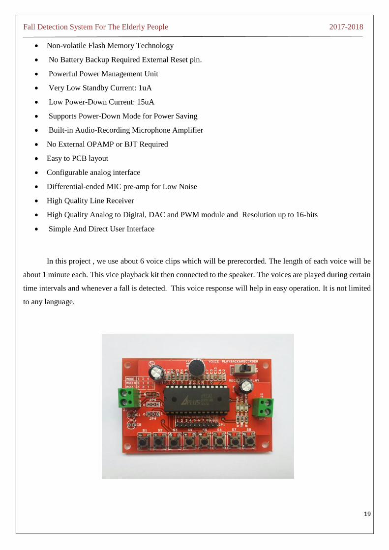
In this project , we use about 6 voice clips which will be prerecorded. The length of each voice will be
about 1 minute each. This vice playback kit then connected to the speaker. The voices are played during certain
time intervals and whenever a fall is detected. This voice response will help in easy operation. It is not limited
to any language.
Fall Detection System For The Elderly People 2017-2018
20
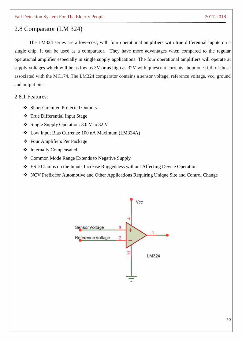
2.8 Comparator (LM 324)
The LM324 series are a low−cost, with four operational amplifiers with true differential inputs on a
single chip. It can be used as a comparator. They have more advantages when compared to the regular
operational amplifier especially in single supply applications. The four operational amplifiers will operate at
supply voltages which will be as low as 3V or as high as 32V with quiescent currents about one fifth of those
associated with the MC174. The LM324 comparator contains a sensor voltage, reference voltage, vcc, ground
and output pins.
2.8.1 Features:
Short Circuited Protected Outputs
True Differential Input Stage
Single Supply Operation: 3.0 V to 32 V
Low Input Bias Currents: 100 nA Maximum (LM324A)
Four Amplifiers Per Package
Internally Compensated
Common Mode Range Extends to Negative Supply
ESD Clamps on the Inputs Increase Ruggedness without Affecting Device Operation
NCV Prefix for Automotive and Other Applications Requiring Unique Site and Control Change

Fall Detection System For The Elderly People 2017-2018
21
2.8.2 LM324 Pin Functions :
Pin1: It is the ouput of the first comparator
Pin2: It is the inverting input of the first comparator
Pin3: It is the non-inverting input of the first comparator
Pin4: It is the supply voltage 5V
Pin5: It is the non-inverting input of the second comparator
Pin6: It is the inverting input of the second comparator
Pin6: It is the Output of the second comparator
Pin7: It is the output of the third comparator
Pin8: It is the inverting input of the third comparator
Pin9: It is the non- inverting input of the third comparator
Pin10: It is the ground
Pin11: It is the non-inverting input of the fourth comparator
Pin12: It is the inverting input of the fourth comparator
Pin13: It is the output of the fourth comparator
Fall Detection System For The Elderly People 2017-2018
22
CHAPTER 3
BLOCK DIAGRAM & FLOW CHART
3.1 Block Diagram
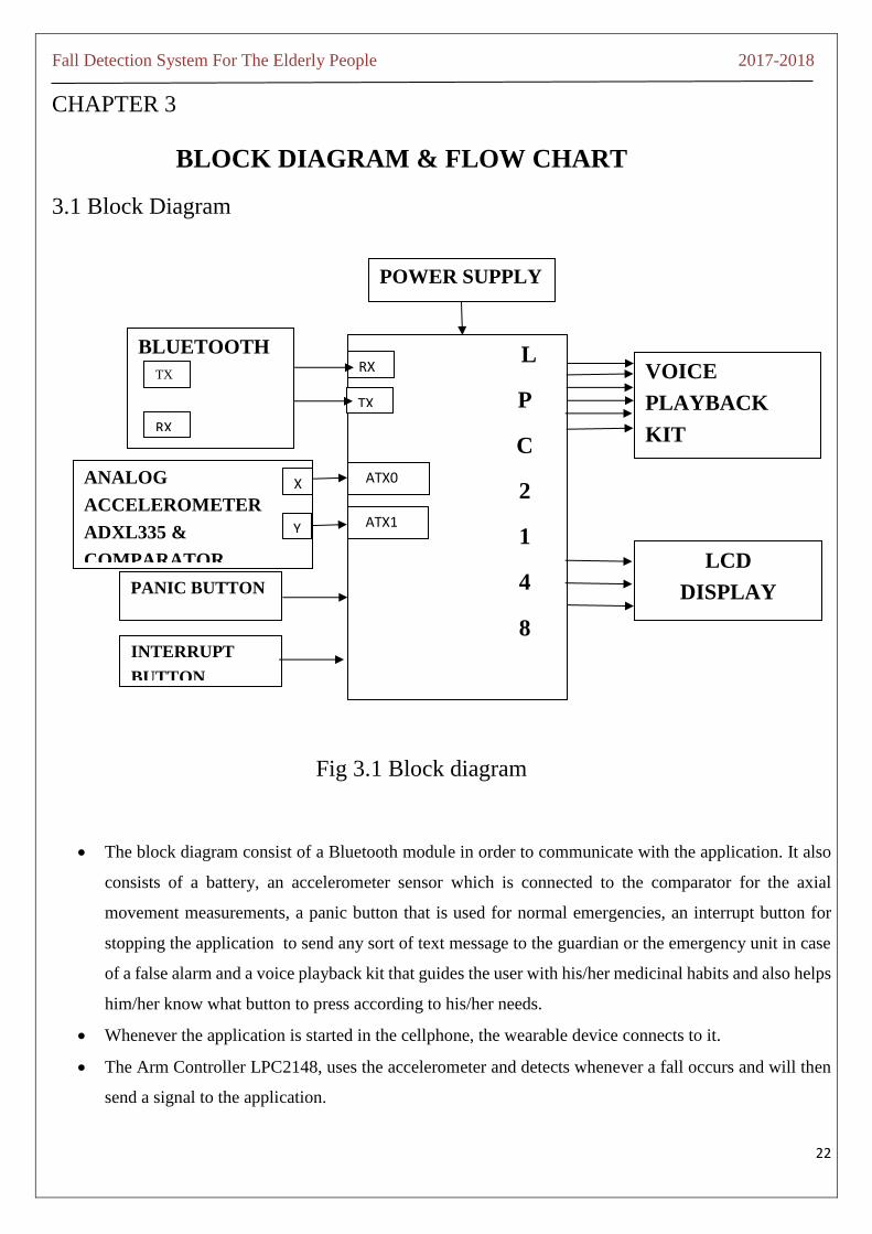
Fig 3.1 Block diagram
The block diagram consist of a Bluetooth module in order to communicate with the application. It also
consists of a battery, an accelerometer sensor which is connected to the comparator for the axial
movement measurements, a panic button that is used for normal emergencies, an interrupt button for
stopping the application to send any sort of text message to the guardian or the emergency unit in case
of a false alarm and a voice playback kit that guides the user with his/her medicinal habits and also helps
him/her know what button to press according to his/her needs.
Whenever the application is started in the cellphone, the wearable device connects to it.
The Arm Controller LPC2148, uses the accelerometer and detects whenever a fall occurs and will then
send a signal to the application.
L
P
C
2
1
4
8
POWER SUPPLY
RX
TX
VOICE
PLAYBACK
KIT
LCD
DISPLAY
BLUETOOTH
ANALOG
ACCELEROMETER
ADXL335 &
COMPARATOR
PANIC BUTTON
ATX0
ATX1
INTERRUPT
BUTTON
TX
RX
X
Y

Fall Detection System For The Elderly People 2017-2018
23
The comparator used in our project is an LM324 series operational amplifier
Once the start button is pressed, the user is able to select the emergency contact information from the
phone directory.
Then by pressing the setup button, the mobile application starts listening to the wearable device.
The moment the mobile application receives a request for sending an alert from the wearable device
indicating a fall detected.
It then alerts to the guardian or the emergency unit indicating that the person has fallen or he/she is
asking for help.
In case the person wants to cancel the alert being sent, he/she can press the interrupt button. If this is the
case then the mobile application will return to it listening state.
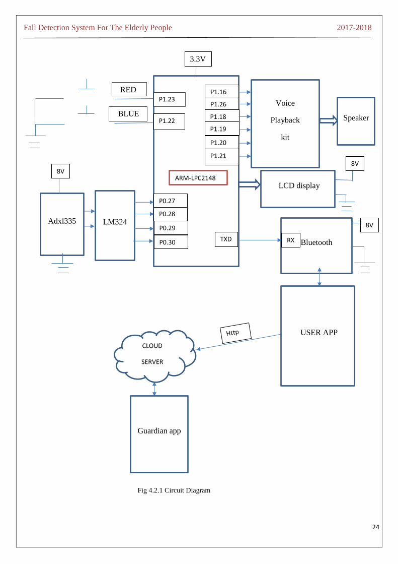
3.2 Circuit Diagram
o There is a blue interrupt button connected to P1.23 of the arm controller
o The red panic button connected to P1.22 of the arm controller
o The accelerometer ADXL335 is connected to the Comparator LM324
o The accelerometer is provided with an 8V power supply
o The comparator is connected to P0.27, P0.28, P0.29, P0.30 of the arm
o The arm controller LPC2148 is provided with a power supply of 3.3V
o The TXD of the arm is given to the RXD of the Bluetooth
o The Bluetooth is provided with 8V power supply
o The LCD Display is connected to the Port 0 of the arm controller ,it is also provided with 8 power
supply
o The voice playback kit is connected to the Port 1 of the arm controller, it is also provided with 8 power
supply
Fall Detection System For The Elderly People 2017-2018
24
Voice
Playback
kit
Speaker
LCD display
Bluetooth
USER APP
Guardian app
LM324 Adxl335
P1.23
P1.22
P0.28
P0.27
P0.29
P0.30
P1.16
P1.26
P1.18
P1.19
P1.20
P1.21
TXD RX
8V
8V
v
8V
v
CLOUD
SERVER
RED
red BLUE
ARM-LPC2148
3.3V
Fig 4.2.1 Circuit Diagram
Fall Detection System For The Elderly People 2017-2018
25
3.3 Flow Chart
start
T1
T2
T3
Interrupt button
Fall
detected
Panic
alert
Read
accelerometer
7 seconds & play
voice
Play voice 6
Send alert
V
Play voice 1
Play voice 2
Play voice 3
Play voice5

Fall Detection System For The Elderly People 2017-2018
26
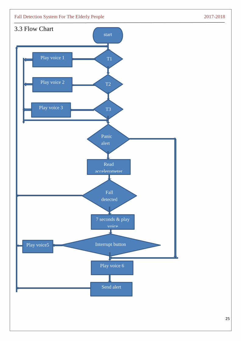
3.3.1 Working of the flowchart:
When the device is started, it goes through several loops.
If time=T1 is true then, the voice playback kit will play the respective voice that has been already stored
in it.
If time =T1 is false then, the device will then do its next job, ie.,, it checks if the time=T2, if it is true
then the voice playback kit will play the respective voice informing the user his/her tablet timings and
suppose it is not true, then the device will check if it is time=T, if it is true then the voice playback kit
will play the necessary voice informing the user his/her medicinal habit.
Suppose it is not true, then the device will then check if the panic button is pressed, if the panic button
is pressed, then ,The voice play back kit will play voice 6 which informs the user that an alert will be
sent to the guardian or the emergency unit
If the panic button is not pressed, then the device will read the accelerometer to find out if a fall has
occurred
If the fall is detected, then the device will wait for 7seconds to play voice 4 which informs the user to
press the interrupt button if he/she is alright
If the interrupt button is pressed within 7seconds of the given time then the device will play voice 6
which informs the user that an alert will be sent to the guardian or the emergency unit in the form of a
text message.
After sending the alert, the device will repeat this cycle infinite amount of time. This can be achieved in
the code by using the while(1) loop
In the meanwhile, the various medicinal habits of the user that is stored in the device and recorded in
the voice play back kit will also take place during the respective time slots.

Fall Detection System For The Elderly People 2017-2018
27
CHAPTER 4
SOFTWARE REQUIREMENTS
Programming necessity manages all the product or portable application utilized as a part of the project. It
incorporates the product utilized for composing the code and in addition dumping programming.
An assembler is used to assemble the arm controller’s assembly language to the .hex file.
A compiler is used to convert a human understandable language into machine understandable language
(high level language into machine level language).
The compiler that we are using is Keil micro vision 4.
The programming language is Embedded-C.
The size of the code is about 6Khz.
The programming tool being used is LPC2000 Flash Utility V.2.2.3
For the app we used Android Studio 2.3. Front end design is done using XML and the
back end operation is done using java
To have a database to store the GPS we use my SQL
The script to access database is PHP(Hypertext pre-processor)
4.1 Keil
Keil is basically a cross compiler/ cross assembler which is used to write and execute our embedded c code.
The expected output of keil is the .hex file which we will flash in our arm controller LPC2148. A cross
compiler is nothing but a normal compiler but the only difference is that we will write a program for the arm
controller LPC2148 on the computer of the x86,Pentium processor etc.). Keil is typically a German based
software development company. It provides a variety of software tools such as
1. IDE (Integrated Development Environment)
2. Project Manager
3. Debugger
4. Simulator
5. C Cross Assembler ,Cross Compiler, and Linker/Locator

Fall Detection System For The Elderly People 2017-2018
28
The steps to be followed while using the Keil used as a cross assembler:
Step1: We must first create a new project
Step2: Then we must select the target controller
Step3:We should then save the project
Step4:We must then write our respective code
Step5:We should then select the operating frequency
Step6:Later we must select a program memory
Step7:Then we must select the output format
Step8:We must then save the code
Step9:Press F11 in order to debug and compile
The steps to be followed while using the Keil used as a cross compiler:
Step1: We must first create a new project
Step2: Then we must select the target controller
Step3:We should then save the project
Step4:We must then write our respective code
Step5:We should then select the operating frequency
Step6:Later we must select a program memory
Step7:Then we must select the output format
Step8:We must then save the code
Step9:Press F11 in order to debug and compile
The steps to be followed for programming LPC2148:
Step1: First connect LPC2148- COM0/ISP port to PC via RS232 Port. If RS232 Port is not available in your
PC , use the USB to UART converter
Step2: In the Flash Utility, select the correct COM Port number, baud rate which is 9600 and XTAL , and the
frequency (12,000Hz).We should not select the device, part id and bootloader id, it will automatically identify.
Then disable DTR/RTS for reset and boot loader selection
Fall Detection System For The Elderly People 2017-2018
29
Step3:In order to enter into the ISP mode manually a few steps are to be followed:
Click Read Device Id
If the port 0 of the arm controller LPC2148, p0.14 is pulled low during Reset , it will enter into the ISP
mode
In the ISP mode only we can flash , read and verify the hex file. Now, click Read Device Id
Step4: Now that we have an hex file, select it and click upload to FLASH and after uploading , press Reset
Switch (sw1) for Returning the LPC2148 Board into Application mode.
4.2 Advantages:
Continuous and efficient monitoring of the elderly people is possible in an easy way.
It gives a voice response through voice playback kit for easy operation.
The voice playback kit is not limited to any language.
It helps the older people to be independent when they go out and at home.
This wearable device helps the older people to alleviate the fear of falling.
It is light weight and can easily be used by anybody even if they are not aware of newly booming
technology.

Fall Detection System For The Elderly People 2017-2018
30
Chapter 5
CONCULSION AND FUTURE SCOPE
Fall detection system is like a boon to a lot of elderly people, not just the elderly people even for children
and also the youth as they can be monitored in an easy and efficient way. Incase of emergency, this device can
be of greater help especially when there is no one around. The fall detection system for the older people was
developed to detect sideway falls, backward and forward falls with a great accuracy. It is of a great help to those
older people who are not monitored throughout. Even if the older people are not aware of the new technologies
they don’t have to worry because this wearable device can be easily used and not that complicated. The working
individuals need not worry about the elderly people because this device will easily help them to monitor them.
Future scope involves including airbags in the device which will inflate whenever a fall is detected and this will
easily prevent any sort of injuries, but care should be taken such that the wearable device doesn’t get bulky. If
at all the older person is not able to press the panic button, the device should sense that the older person is not
in a healthy condition and automatically alert the guardian. The wearable device should automatically play
music or any video on the user’s phone whenever it is requested of the device, it should also make calls to
anybody from the user’s phone as requested by the user. The accuracy should also be increased to about 100%.

Fall Detection System For The Elderly People 2017-2018
31
REFERENCES
1. W. H. O, “Falls,” World Health Organization http://www.who.int/mediacentre/factsheets/fs344/en/,
September 2016.
2. A. Smith, “Older adults and technology use,” Pew Research Center.
3. Y. S. Delahoz and M. A. Labrador, “Survey on fall detection and fall prevention using wearable and
external sensors,” Sensors, vol. 14, no. 10, pp. 19806–19842, 2014.
4. A. Bourke and G. Lyons, “A threshold-based fall-detection algorithm using a bi-axial gyroscope sensor,”
Medical Engineering and Physics, vol. 30, no. 1, pp. 84 – 90, 2008.
5. L. G. Jaimes, M. Llofriu, and A. Raij, “Calma, an algorithm framework for mobile just in time
interventions,” in SoutheastCon 2015, pp. 1–5, IEEE, 2015.
6. O. D. Lara and M. A. Labrador, “A survey on human activity recognition using wearable sensors,” IEEE
Communications Surveys & Tutorials, vol. 15, no. 3, pp. 1192–1209, 2013.
7. L. G. Jaimes, T. Murray, and A. Raij, “Increasing trust in personal informatics tools,” in International
Conference of Design, User Experience, and Usability, pp. 520–529, Springer, 2013.
8. L. G. Jaimes and I. J. Vergara-Laurens, “Corredor, a mobile human centric sensing system for activity
recognition,” 2015.
9. L. G. Jaimes, Y. De La Hoz, C. Eggert, and I. J. Vergara-Laurens, “Pat: A power-aware decision tree
algorithm for mobile activity recognition,” in 2016 13th IEEE Annual Consumer Communications &
Networking Conference (CCNC), pp. 54–59, IEEE, 2016.
10. M. Kangas, A. Konttila, P. Lindgren, I. Winblad, and T. Jams ¨ a, “Com- ¨ parison of low-complexity
fall detection algorithms for body attached accelerometers,” Gait & posture, vol. 28, no. 2, pp. 285–291,
2008.
11. L. Valcourt, Y. De La Hoz, and M. Labrador, “Smartphone-based human fall detection system,” IEEE
Latin America Transactions, vol. 14, no. 2, pp. 1011–1017, 2016.
12. G.-C. Chen, C.-N. Huang, C.-Y. Chiang, C.-J. Hsieh, and C.-T. Chan, “A reliable fall detection system
based on wearable sensor and signal magnitude area for elderly residents,” in International Conference
on Smart Homes and Health Telematics, pp. 267–270, Springer, 2010
13. . F. Bianchi, S. J. Redmond, M. R. Narayanan, S. Cerutti, and N. H. Lovell, “Barometric pressure and
triaxial accelerometry-based falls event detection,” IEEE Transactions on Neural Systems.

Fall Detection System For The Elderly People 2017-2018
32
APPENDIX
Program Code:
#include<LPC214x.h> // Define LPC2148 Header File
#include <stdio.h>
#include "uart.h"
#include "uart0.c"
#include "uart1.c"
#define DONE 0x80000000
#define START 0x01000000
#define PRESET 0x00230600
#define interrupt_btn 22
#define emergency_btn 23
#define voice_1 16
#define voice_2 26
#define voice_3 18
#define voice_4 19
#define voice_5 20
#define voice_6 21
#define x_plus 25
#define x_minus 28
#define y_plus 29
#define y_minus 30
#define x_axis_max 580 //530
#define x_axis_min 480
#define y_axis_max 540 //490

Fall Detection System For The Elderly People 2017-2018
33
#define y_axis_min 440
#define wrong 0
#define correct 1
#define safe 1
#define unsafe 2
int fall_status = safe;
int i;
#define LCD_RS 0x00000400 //P0.10 // P0.8(0000 0000 0000 000x 0000 0000 0000
0000)
#define LCD_EN 0x00002000 //P0.13 // P0.10(0000 0000 0000 00x0 0000 0000 0000
0000) 0x00000800
#define LCD_D4 0x00100000 //P0.20-23 // P1.18(0000 0000 0000 0x00 0000 0000 0000
0000)
#define LCD_D5 0x00200000 // P1.19(0000 0000 0000 x000 0000 0000 0000
0000)
#define LCD_D6 0x00400000 // P1.20(0000 0000 000x 0000 0000 0000 0000
0000)
#define LCD_D7 0x00800000
#define LCD_DATA (LCD_D7|LCD_D6|LCD_D5|LCD_D4)
#define LCD_IOALL (LCD_D7|LCD_D6|LCD_D5|LCD_D4|LCD_RS|LCD_EN)
#define lcd_rs_set() IOSET0 = LCD_RS //RS = 1 (Select Instruction)
#define lcd_rs_clr() IOCLR0 = LCD_RS // RS = 0 (Select Data)
#define lcd_en_set() IOSET0 = LCD_EN // EN = 1 (Enable)
#define lcd_en_clr() IOCLR0 = LCD_EN // EN = 0 (Disable)// xxxx xxx0 0000 0000 0000
0000 0000 0000
//#define lcd_dir_write() IODIR0 |= 0x01FFFFFF // LCD Data Bus = Write
#define lcd_dir_write() IODIR0 |= 0x00F02400 // LCD Data Bus = Write

Fall Detection System For The Elderly People 2017-2018
34
//#define lcd_dir_read() IODIR1 &= 0xFFC3FFFF // LCD Data Bus = Read
#define lcd_clear() lcd_write_control(0x01) // Clear Display
#define lcd_cursor_home() lcd_write_control(0x02) // Set Cursor = 0
#define lcd_display_on() lcd_write_control(0x0E) // LCD Display Enable
#define lcd_display_off() lcd_write_control(0x08) // LCD Display Disable
#define lcd_cursor_blink() lcd_write_control(0x0F) // Set Cursor = Blink
#define lcd_cursor_on() lcd_write_control(0x0E) // Enable LCD Cursor
#define lcd_cursor_off() lcd_write_control(0x0C) // Disable LCD Cursor
#define lcd_cursor_left() lcd_write_control(0x10) // Shift Left Cursor
#define lcd_cursor_right() lcd_write_control(0x14) // Shift Right Cursor
#define lcd_display_sleft() lcd_write_control(0x18) // Shift Left Display
#define lcd_display_sright() lcd_write_control(0x1C) // Shift Right Display
/* prototype section */
void lcd_init(void); // Initial LCD
void lcd_out_data4(unsigned char); // Strobe 4-Bit Data to LCD
void lcd_write_byte(unsigned char); // Write 1 Byte Data to LCD
void lcd_write_control(unsigned char); // Write Instruction
void lcd_write_ascii(unsigned char); // Write LCD Display(ASCII)
void goto_cursor(unsigned char); // Set Position Cursor LCD
void lcd_print(unsigned char*); // Print Display to LCD
//char busy_lcd(void); // Read Busy LCD Status
void enable_lcd(void); // Enable Pulse
void delay_2(unsigned long int); // Delay Function
void read_accelerometer(void);
void turn_off_all_voice(void);

Fall Detection System For The Elderly People 2017-2018
35
void check_interrupt(void);
char hh_h='0', hh_l='0', mm_h='0';
unsigned int x_axis;
unsigned int y_axis;
void delay(int n) /* generates one milisecond delay */
{ int i,j;
for (i=1; i<=n; i++)
for(j=0; j<=10000; j++);
}
void port_int()
{ IODIR1 &= ~((1<<interrupt_btn)); //configuring port pin as INPUT
IODIR1 &= ~((1<<emergency_btn)); //configuring port pin as INPUT
IODIR0 &= ~((1<<x_plus)); //configuring port pin as INPUT
IODIR0 &= ~((1<<x_minus)); //configuring port pin as INPUT
IODIR0 &= ~((1<<y_plus)); //configuring port pin as INPUT
IODIR0 &= ~((1<<y_minus)); //configuring port pin as INPUT
IODIR1 |= (1<<voice_1);
IODIR1 |= (1<<voice_2);
IODIR1 |= (1<<voice_3);
IODIR1 |= (1<<voice_4);
IODIR1 |= (1<<voice_5);
IODIR1 |= (1<<voice_6);
IOSET1 |= (1<<voice_1);
IOSET1 |= (1<<voice_2);
IOSET1 |= (1<<voice_3);

Fall Detection System For The Elderly People 2017-2018
36
IOSET1 |= (1<<voice_4);
IOSET1 |= (1<<voice_5);
IOSET1 |= (1<<voice_6);
//delay(1000);
//Initialzing ADC
//VPBDIV = 0x02;pclk @ 30MHz
/*PINSEL0 &= 0x000F000F;
PINSEL1 |= 0x01 << 24; //P0.28 configure as ADC0.1
PINSEL1 |= 0x01 << 26; //P0.29 configure as ADC0.2
PINSEL1 |= 0x01 << 28; //P0.30 configure as ADC0.3
IODIR0 &= 0xFFFF3FFF; // 1111 1111 1111 1111 0011 1111 1111 1111*/
//PINSEL1 |= 0X15000000; //enable ADC0. 1,2,3 }
int main()
{ //PINSEL1 |= 0x01 << 24;
//PINSEL1 |= 0x01 << 26;
port_int();
init_serial0(); // Initilial UART1 = 9600,N,8,0
init_serial1();
lcd_init();
lcd_write_control(0x01); // Clear Display (Clear Display,Set DD RAM
Address=0)
goto_cursor(0x00); // Set Cursor Line-1
lcd_print(" WELCOME TO "); // Display LCD Line-1
goto_cursor(0x40); // Set Cursor = Line-2
lcd_print(" New Horizon "); // Display LCD Line-

Fall Detection System For The Elderly People 2017-2018
37
delay(2000);
sprintf(uart0_buf,"Welcome $");
print_uart0();
while(1) // Loop Continue
{ mm_h++;
If (mm_h == '6')
{mm_h = '0';
hh_l++;
}
if(hh_h == '2')
{
If (hh_l == '4')
{ hh_l = '0';
hh_h = '0';
}}
If (hh_l > '9')
{ hh_l = '0';
If (hh_h == '2')
{ hh_h = '0';
}
Else
{hh_h++;
}}
goto_cursor(0x00); // Set Cursor Line-1
lcd_write_ascii(' ');
Fall Detection System For The Elderly People 2017-2018
38
lcd_write_ascii('(');
lcd_write_ascii('H');
lcd_write_ascii('H');
lcd_write_ascii(':');
lcd_write_ascii('M');
lcd_write_ascii('M');
lcd_write_ascii(')');
lcd_write_ascii(' ');
lcd_write_ascii(hh_h);
lcd_write_ascii(hh_l);
lcd_write_ascii(':');
lcd_write_ascii(mm_h);
lcd_write_ascii('0');
lcd_print(" "); // Display LCD Line-1
goto_cursor(0x40); // Set Cursor = Line-2
lcd_print(" "); // Display LCD Line-2
//read_accelerometer();
if((hh_h == '0') && (hh_l == '8') && (mm_h == '0'))
{
IOCLR1 |= (1<<voice_4);
goto_cursor(0x40); // Set Cursor = Line-2
lcd_print("Medicine time: 1"); // Display LCD Line-2
delay(500);
goto_cursor(0x0C);
lcd_write_ascii('1');
Fall Detection System For The Elderly People 2017-2018
39
delay(500);
goto_cursor(0x0C);
lcd_write_ascii('2');
delay(500);
goto_cursor(0x0C);
lcd_write_ascii('3');
delay(500);
goto_cursor(0x0C);
lcd_write_ascii('4');
delay(500);
goto_cursor(0x0C);
lcd_write_ascii('5');
hh_l = '9';
mm_h = '0';
turn_off_all_voice();
goto_cursor(0x40); // Set Cursor = Line-2
lcd_print(" "); // Display LCD Line-2
}
If ((hh_h == '1') && (hh_l == '3') && (mm_h == '0'))
{
IOCLR1 |= (1<<voice_5);
goto_cursor(0x40); // Set Cursor = Line-2
lcd_print("Medicine time: 2"); // Display LCD Line-2
delay(500);
goto_cursor(0x0C);

Fall Detection System For The Elderly People 2017-2018
40
lcd_write_ascii('1');
delay(500);
goto_cursor(0x0C);
lcd_write_ascii('2');
delay(500);
goto_cursor(0x0C);
lcd_write_ascii('3');
delay(500);
goto_cursor(0x0C);
lcd_write_ascii('4');
delay(500);
goto_cursor(0x0C);
lcd_write_ascii('5');
hh_l = '4';
mm_h = '0';
turn_off_all_voice();
goto_cursor(0x40); // Set Cursor = Line-2
lcd_print(" "); // Display LCD Line-2
}
If ((hh_h == '2') && (hh_l == '0') && (mm_h == '0'))
{
IOCLR1 |= (1<<voice_6);
goto_cursor(0x40); // Set Cursor = Line-2
lcd_print("Medicine time: 3"); // Display LCD Line-2
delay(500);

Fall Detection System For The Elderly People 2017-2018
41
goto_cursor(0x0C);
lcd_write_ascii('1');
delay(500);
goto_cursor(0x0C);
lcd_write_ascii('2');
delay(500);
goto_cursor(0x0C);
lcd_write_ascii('3');
delay(500);
goto_cursor(0x0C);
lcd_write_ascii('4');
delay(500);
goto_cursor(0x0C);
lcd_write_ascii('5');
hh_l = '1';
mm_h = '0';
turn_off_all_voice();
goto_cursor(0x40); // Set Cursor = Line-2
lcd_print(" "); // Display LCD Line-2
}
If ((hh_h == '8') && (hh_l == '0') && (mm_h == '0'))
{
IOCLR1 |= (1<<voice_4);
delay(4000);
turn_off_all_voice();

Fall Detection System For The Elderly People 2017-2018
42
}
If ((hh_h == '8') && (hh_l == '0') && (mm_h == '0'))
{ IOCLR1 |= (1<<voice_4);
delay(4000);
turn_off_all_voice();
}
If (!(IOPIN1 & (1<<emergency_btn)))
{goto_cursor(0x00); // Set Cursor Line-1
lcd_print("Emergency alert "); // Display LCD Line-1
goto_cursor(0x40); // Set Cursor = Line-2
lcd_print("SMS sent "); // Display LCD Line-2
sprintf(uart0_buf,"Emergency alert $");
print_uart0();
sprintf(uart1_buf,"Emergency alert $");
print_uart1();
IOCLR1 |= (1<<voice_2);
delay(1000);
turn_off_all_voice();
delay(1000);
}
If (IOPIN0 & (1<<x_plus)) // Evaluates to True for HIGH' on poisonous_gas pin
{ if (fall_status == safe)
{ delay(500);
If (IOPIN0 & (1<<x_plus))
{

Fall Detection System For The Elderly People 2017-2018
43
goto_cursor(0x00); // Set Cursor Line-1
lcd_print("Fall detected "); // Display LCD Line-1
goto_cursor(0x40); // Set Cursor = Line-2
lcd_print("X-axis (P) "); // Display LCD Line-2
check_interrupt();
}}}
else if (IOPIN0 & (1<<x_minus)) // Evaluates to True for HIGH' on poisonous_gas pin
{ if (fall_status == safe)
{ delay(500);
If (IOPIN0 & (1<<x_minus))
{ goto_cursor(0x00); // Set Cursor Line-1
lcd_print("Fall detected "); // Display LCD Line-1
goto_cursor(0x40); // Set Cursor = Line-2
lcd_print("X-axis (M) "); // Display LCD Line-2
check_interrupt();
}}}
else if (IOPIN0 & (1<<y_minus)) // Evaluates to True for HIGH' on poisonous_gas pin
{ If (fall_status == safe)
{ delay(500);
If (IOPIN0 & (1<<y_minus))
{
goto_cursor(0x00); // Set Cursor Line-1
lcd_print("Fall detected "); // Display LCD Line-1
goto_cursor(0x40); // Set Cursor = Line-2
lcd_print("Y-axis (P) "); // Display LCD Line-2
Fall Detection System For The Elderly People 2017-2018
44
check_interrupt();
}}}
else if(IOPIN0 & (1<<y_plus)) // Evaluates to True for HIGH' on poisonous_gas pin
{
If (fall_status == safe)
{ delay(500);
If (IOPIN0 & (1<<y_plus))
{ goto_cursor(0x00); // Set Cursor Line-1
lcd_print("Fall detected "); // Display LCD Line-1
goto_cursor(0x40); // Set Cursor = Line-2
lcd_print("Y-axis (M) "); // Display LCD Line-2
check_interrupt();
}}}
else
{
goto_cursor(0x00); // Set Cursor Line-1
lcd_print(" "); // Display LCD Line-1
goto_cursor(0x40); // Set Cursor = Line-2
lcd_print(" "); // Display LCD Line-2
fall_status = safe;
}}}
/****************************/
/* Strobe 4-Bit Data to LCD */
/****************************/
void lcd_out_data4(unsigned char val)
Fall Detection System For The Elderly People 2017-2018
45
{ IOCLR0 = (LCD_DATA); //Reset 4-Bit Pin Data
IOSET0 = (val<<20); //EN,0,RW,RS:DDDD:0000:0000:0000:0000:0000:0000
}
/****************************/
/* Write Data 1 Byte to LCD */
/****************************/
void lcd_write_byte(unsigned char val)
{ lcd_out_data4((val>>4)&0x0F); //Strobe 4-Bit High-Nibble to LCD
enable_lcd(); // Enable Pulse
lcd_out_data4(val&0x0F); //Strobe 4-Bit Low-Nibble to LCD
enable_lcd(); //Enable Pulse
delay_2(1000); //while(busy_lcd());
//Wait LCD Execute Complete
}
/****************************/
/* Write Instruction to LCD */
/****************************/
void lcd_write_control(unsigned char val)
{
lcd_rs_clr(); //RS = 0 = Instruction Select
lcd_write_byte(val); //Strobe Command Byte
}
/****************************/
/* Write Data(ASCII) to LCD */
/****************************/
Fall Detection System For The Elderly People 2017-2018
46
void lcd_write_ascii(unsigned char c)
{ lcd_rs_set(); //RS = 1 = Data Select
lcd_write_byte(c); //Strobe 1 Byte to LCD
}
/*******************************/
/* Initial 4-Bit LCD Interface */
/*******************************/
void lcd_init()
{ unsigned int i; // LCD Initial Delay Count
PINSEL1 = 0x00000000; // GPIO1[31..26] = I/O Function
lcd_dir_write(); // LCD Data Bus = Write
for (i=0;i<1000;i++); // Power-On Delay (15 mS)
IOCLR0 = (LCD_IOALL); // Reset (RS,RW,EN,4-Bit Data) Pin
IOSET0 = (LCD_D5|LCD_D4); // DDDD:EN,RW,RS,0:0000:0000:0000:0000:0000:0000
enable_lcd(); // Enable Pulse
for (i=0;i<100;i++); // Delay 4.1mS
IOCLR0 = (LCD_IOALL); // Reset (RS,RW,EN,4-Bit Data) Pin
IOSET0 = (LCD_D5|LCD_D4); // DDDD:EN,RW,RS,0:0000:0000:0000:0000:0000:0000
enable_lcd(); // Enable Pulse
for (i=0;i<100;i++); // delay 100uS
IOCLR0 = (LCD_IOALL); // Reset (RS,RW,EN,4-Bit Data) Pin
IOSET0 = (LCD_D5|LCD_D4); // DDDD:EN,RW,RS,0:0000:0000:0000:0000:0000:0000
enable_lcd(); // Enable Pulse
delay_2(10000); //while(busy_lcd());
// Wait LCD Execute Complete
IOCLR0 = (LCD_IOALL); // Reset (RS,RW,EN,4-Bit Data) Pin

Fall Detection System For The Elderly People 2017-2018
47
IOSET0 = (LCD_D5); // DDDD:EN,RW,RS,0:0000:0000:0000:0000:0000:0000
enable_lcd(); // Enable Pulse
delay_2(10000); // while(busy_lcd());
// Wait LCD Execute Complete
lcd_write_control(0x28); // Function Set (DL=0 4-Bit,N=1 2 Line,F=0 5X7)
lcd_write_control(0x0C); // Display on/off Control (Entry Display,Cursor
off,Cursor not Blink)
lcd_write_control(0x06); // Entry Mode Set (I/D=1 Increment,S=0 Cursor Shift)
lcd_write_control(0x01); // Clear Display (Clear Display,Set DD RAM
Address=0)
for (i=0;i<100000;i++); // Wait Command Ready
}
/***************************/
/* Set LCD Position Cursor */
/***************************/
void goto_cursor(unsigned char i)
{ i |= 0x80; // Set DD-RAM Address Command
lcd_write_control(i); }
/************************************/
/* Print Display Data(ASCII) to LCD */
/************************************/
void lcd_print(unsigned char* str)
{ int i;
for (i=0;i<16 && str[i]!=0;i++) // 16 Character Print
{ lcd_write_ascii(str[i]); // Print Byte to LCD
}}
Fall Detection System For The Elderly People 2017-2018
48
/***********************/
/* Enable Pulse to LCD */
/***********************/
void enable_lcd(void) // Enable Pulse
{ unsigned int i; // Delay Count
lcd_en_set(); // Enable ON
for (i=0;i<40000;i++);
lcd_en_clr(); // Enable OFF
}
/***********************/
/* Delay Time Function */
/* 1-4294967296 */
/***********************/
void delay_2(unsigned long int count1)
{ while(count1 > 0) {count1--;} // Loop Decrease Counter
}
void UART_TxNumber(unsigned int num)
{ // putchar0((num/10000)+0x30);
// num=num%10000;
putchar0((num/1000)+0x30);
num=num%1000;
putchar0((num/100)+0x30);
num=num%100;
putchar0((num/10)+0x30);
putchar0((num%10)+0x30);

Fall Detection System For The Elderly People 2017-2018
49
}
void check_interrupt()
{ fall_status = unsafe;
turn_off_all_voice();
IOCLR1 |= (1<<voice_1);
for(i=0; i<=6; i++)
{ If (i == 3)
{ turn_off_all_voice();
}
If ( !(IOPIN1 & (1<<interrupt_btn)) ) // Evaluates to True for a 'LOW' on poisonous_gas pin
{ goto_cursor(0x00); // Set Cursor Line-1
lcd_print(" "); // Display LCD Line-1
goto_cursor(0x40); // Set Cursor = Line-2
lcd_print(" "); // Display LCD Line-2
i =11;
fall_status = 3;
}
If (IOPIN0 & (1<<x_plus)) // Evaluates to True for HIGH' on poisonous_gas pin
{ ;
}
else if(IOPIN0 & (1<<x_minus)) // Evaluates to True for HIGH' on poisonous_gas pin
{ ;
}
else if(IOPIN0 & (1<<y_minus)) // Evaluates to True for HIGH' on poisonous_gas pin
{ ;
Fall Detection System For The Elderly People 2017-2018
50
}
else if(IOPIN0 & (1<<y_plus)) // Evaluates to True for HIGH' on poisonous_gas pin
{ ;
}
Else
{ goto_cursor(0x00); // Set Cursor Line-1
lcd_print("Thank you. "); // Display LCD Line-1
goto_cursor(0x40); // Set Cursor = Line-2
lcd_print("You are safe "); // Display LCD Line-2
fall_status = safe;
i =11;
}
delay(1000);
}
turn_off_all_voice();
if (fall_status == unsafe)
{ sprintf(uart0_buf,"Fall detected $");
print_uart0();
sprintf(uart1_buf,"Fall detected $");
print_uart1();
IOCLR1 |= (1<<voice_2);
goto_cursor(0x00); // Set Cursor Line-1
lcd_print("Sending alert "); // Display LCD Line-1
goto_cursor(0x40); // Set Cursor = Line-2
lcd_print("SMS "); // Display LCD Line-2

Fall Detection System For The Elderly People 2017-2018
51
delay(2000);
turn_off_all_voice();
delay(1000);
fall_status = unsafe;
}
Else
{ goto_cursor(0x00); // Set Cursor Line-1
lcd_print("Thank you. "); // Display LCD Line-1
goto_cursor(0x40); // Set Cursor = Line-2
lcd_print("You are safe "); // Display LCD Line-2
IOCLR1 |= (1<<voice_3);
delay(2000);
turn_off_all_voice();
delay(1000);
}If (fall_status == 3)
{ fall_status = unsafe;
}}
void turn_off_all_voice()
{ IOSET1 |= (1<<voice_1);
IOSET1 |= (1<<voice_2);
IOSET1 |= (1<<voice_3);
IOSET1 |= (1<<voice_4);
IOSET1 |= (1<<voice_5);
IOSET1 |= (1<<voice_6);
delay(1000);}