Exterior - Porsche 986 Boxster Electronic Workshop Manuals
275
TechnicalManual -~~s::~ TechnicalInformation www.WorkshopManuals.co.uk Purchased from www.WorkshopManuals.co.uk
-
Upload
khangminh22 -
Category
Documents
-
view
5 -
download
0
Transcript of Exterior - Porsche 986 Boxster Electronic Workshop Manuals

Technical Manual
-~~s::~
Technical Information
www.WorkshopManuals.co.uk
Purchased from www.WorkshopManuals.co.uk

Boxster (986) Body equipment, exterior
Supplement Overview
Supple-ment
Edition Topic Article number
05/1996 Basic edition WKD 483521
2 08/1996 General changes WKD 483521.02
7 11/1996 General changes WKD 483521.07
10 04/1997 Assembly instructions for hardtop assembly fix-ture
WKD 483521.10
12 07/1997
08/1997
08/1997
11/1997
01/1998
03/1998
07/1998
General remarks on the airbag WKD483521.12
WKD 483521.1414 General changes
Folder separation Groups 5 and 6 WKD483521.1515
16
18
WKD 483521.16General supplement
WKD 483521.18General remarks on the airbag
WKD 483521.2020
23
General supplement
WKD 483521.23Assembly instructions for hardtop assembly fix-ture
WKD 483521.2525
26
29
General supplement
WKD 483521.26General supplement
WKD 483521.29
02/1999
04/1999
07/1999
07/1999
08/1999
09/1999
General supplement
WKD 483521.30Changes in model year 200030
31 Folder separation Groups 6 and 7 WKD 483521.31
Removing and installing convertible-top roofliner
WKD 483521.3232
WKD 483521.3612/199936 Removing and installing the side airbag unit
WKD 483521.37OS/200037 General supplement
WKD 483521.3807/2000 General supplement38
39
40
WKD 483521.39Changes in model year 200108/2000WKD 483521.40Replacing folder 609/2000
Supplement OverviewPrinted in Germany -40, 2000 Master6
www.WorkshopManuals.co.uk
Purchased from www.WorkshopManuals.co.uk

Boxster (986) Foreword
Table of Contents
0 Foreword
Foreword
Foreword Use . 11
-1 page
-2 page
Table of Contents
Printed in Germany -37,2000 masterY
www.WorkshopManuals.co.uk
Purchased from www.WorkshopManuals.co.uk

Boxster (~86) Foreword
Foreword
This manurl contains T echnicallnformation as well as instructionson repairs for Porsche vehicles. It is intended for the sole use ofworkshop belonging to Porsche AG.
The deSC~Ptions form the basis for professional and correct mainte-nance and repair work. The content of the work proceduresdescribed is based on the level of training of a fitter who has com-pleted vo ational training and has a sound knowledge of the prod-uct. This level of knowledge is necessary in order to carry out thework described.
Warning notes
The warning notes and safety instructions are classified by therespective signalising word (Danger, Warning, Caution) beside the
warning symbol.
To prevent injury and restricted operating and traffic safety of thevehicle, or damage to the vehicle as the result of incorrect work,read these instructions carefully and observe them without fail.
It is not possible for Porsche AG to give a detailed evaluation of alldanger situations for the persons carrying out the work. It is there-fore imperative that all persons carrying out repair and maintenancework on Porsche vehicles use their specialist knowledge to ensurethat their own safety is not at risk and the procedure chosen will nothave any negative effects on the vehicle -especially with regard to
safety.
It is therefore expressly specifiedprocedures described should be cthe valid guidelines and regulation.ble with respect to health and acc
-1 page 1ForewordPrinted in Germany -37, 2000 vorwort
Warns against death or very serious injury which will cer-
tainly occur if the instructions are not observed.
Warns against death or very serious injury which may occurif the instructions are not observed.
Warns against minor injury or damage to property if the
instructions are not observed.
that all work involved in the workarried out only in accordance with
s of the local authorities responsi-ident prevention and environmen-
www.WorkshopManuals.co.uk
Purchased from www.WorkshopManuals.co.uk

Boxster (986)Foreword
,~
tal protection, and in compliance with the legal requirements ofindividual countries.
Notes
Notes contain advisory information related to the work procedurewhich makes the fitter's work easier. The following pictogram indi.cates this information:
[IJ Note!Contains advisory information which makes the work procedure eas-ter.
Due to the continuous development and improvement of our vehi-cles, there may be discrepancies between the actual technical sta-tus of the vehicles and the work descriptions. Any existingdeviations are corrected by means of supplements, and the scopeof the descriptions is extended with supplements.
Porsche AG retains the right to implement changes at any time andwithout prior notice.
www.WorkshopManuals.co.uk
Purchased from www.WorkshopManuals.co.uk

Boxster (98G) Foreword
Use
The workshop documentation for the Boxster (986) model has the
designation
-"Boxster (986)" Technical Manual- and contains TechnicalInformation as well as instructions on repairs.
The integration of the technical information published in the "Boxster(986)" Technical Manual with the descriptive matter on repairs pro-vides the user with a complex reference work that combines intoone book associated or cross-referenced material of relevance toworkshops and originating from various information media.
The "Boxster (986)" Technical Manual consists of 15 folders, subdi-vided into the following Groups
.0 Entire vehicle -General
.0 Diagnosis, 1 Engine, part 1 (up to Repair Group 45)
.0 Diagnosis, 1 Engine, part 2 (as of Repair Group 69)
.1 Engine, part 1 (up to Repair Group 13)
.1 Engine, part 2 (as of Repair Group 15)
.2 Fuel, exhaust, engine electronics
.3 Transmission, manual transmission
.3 Transmission, automatic transmission
.4 Running gear
.5 Body
.6 Body equipment, exterior
.7 Body equipment, interior
.8 / 9 Air conditioning / Electrics
.9 Circuit diagrams, part 1 (up to and including '99 model)
.9 Circuit diagrams, part 2 (as of and including '00 model)
The two folders with Group 0 are to be regarded as one folder; i.e,file the "T echnicallnformation" notices only in the folder "Group 0Diagnosis, part I" -up to Repair Group 45-.
The second folder Group 0 Engine, part 2 -as of Repair Group69- includes the further Repair Groups belonging to Group 1.
The two folders with Group 1 are to be regarded as one folder; i.e.file the liT echnicallnformation" only in front of the repair descriptionsin the folder Group 1 -Engine, part 1 -up to Repair Group 13-.
-2 page 1Use
Printed in Germany -37 I 2000 handhabung
www.WorkshopManuals.co.uk
Purchased from www.WorkshopManuals.co.uk

Boxster (986)Foreword
The second folder Group 1 -Engine, part 2 -as of Repair Group15- includes the further Repair Groups belonging to Group 1.
The two folders with Group 9 are to be regarded as one folder; i.e.file the "T echnicallnformation" notices only in the folder Group 9 Cir-cuit diagrams, part 1 -up to '99 model-,
The second folder Group 9 Engine, part 2 -as of '00 model-includes the further Repair Groups belonging to Group 9.
The "Boxster (986)" Technical Manual has the same structure ineach folder, with the following breakdown for all Groups:
Title page: "Boxster (986)" Technical Manual
> Foreword
Title page: "Technical information'
> Table of contents, Technical information> Technical information
Title page: "Repair"
> Repair Groups: overview> Table of contents, repairs> General/technical data> Instructions on repairs
As can be seen from the breakdown, the published Technicallnfor-mation is in the front part of each folder -numbered according tothe Groups. The Table of Contents assigned to each Group will be
periodically updated.
Following the Technical Information, separated by a title page, theinstructions on repairs -assigned according to the Groups or bro-ken down into Repair Groups -are included in the folders.
The instructions on repairs will be extended and updated by means
of supplements.
rn Note!Sheets that already exist in the "Boxster (986)" Technical Manualand are updated or revised and thereby exchanged by a supplementare designated in the footer with the supplement number corre-sponding to the current version: e.g. "Printed in Germany -2,-
2000"
[IJ Note!Due to a system modification in the Technical Literature production,the following procedures have changed in model year 2000!
www.WorkshopManuals.co.uk
Purchased from www.WorkshopManuals.co.uk

Boxster (986) Foreword
1 -The previous record sheet in the folder "O-Genera!" and
the supplement contents sheet -red sheet- have been
omitted. A supplement overview now appears sepa-
rately in each folder. The new supplement contents
sheet can be destroyed after the supplement is filed in
the folder.
rn Note!The supplement overview sheet is replaced with the relevantsupplement in the corresponding folder and must no longer bemaintained by hand.
2 -The page numbering in the new and the replaced chap-
ters are no longer continuous. Each new chapter is now
given an additional chapter number followed by the
page number e.g.-2 Page 11 ~ Rep. Gr. 0; General
3 -The old page numbering still applies to existing chap-
ters and those that are not replaced.
-2 page 3Use
Printed in Germany -37, 2000 handhabung
www.WorkshopManuals.co.uk
Purchased from www.WorkshopManuals.co.uk

Group 0: Entire vehicle -GeneralMaintenance
003
Group 0: DiagnosisSales checkOn-board diagnosisDME diagnosisTiptronic diagnosisABS diagnosis
00103243745
Group 0: 069728090919194
DiagnosisAirbag diagnosisSeat memory diagnosisHeating diagnosisAlarm system diagnosisPCM diagnosisParkAssistent diagnosisHBA diagnosis
Group 1: 11013
EngineEngine -Crankcase, suspensionEngine -Crankshaft, pistons
Group 1: 1151719
EngineEngine -Cylinder head, valve driveEngine -LubricationEngine-Cooling
Group 2: 220212425262728
Fuel, exhaust, engine electronicsFuel supply, controlExhaust system, turbochargingFuel system, electronic injectionFuel system, K-JetronicExhaust systemStarter, power supply, cruise controlIgnition system
Group 3: 330343539
Transmission, manual transmissionClutch, controlManual transmission -Actuation, housingManual transmission -Gears, shafts, into gearsh,Final drive, differential, differential lock
Group 3: 332373839
Transmission, automatic transmissionTorque converterAutomatic transmission -Actuation, housingAutomatic transmission -Gears, controlFinal drive, differential, differential lock
Overview of repair groupsPrinted in Germany -34, October 1999 REPGRU.CHP
www.WorkshopManuals.co.uk
Purchased from www.WorkshopManuals.co.uk

Overview of repair groups Boxster
C;roup 4: 440424445464748
Running gearFront wheel suspension, drive shaftsRear wheel suspension, drive shaftsWheels, tires, suspension alignmentAnti-Lock Brake System (ABS)Brakes -Brake mechanicsBrakes -Hydraulics, regulator, boosterSteering
(~roup 5: 55051535557
BodyBody frontBody center, roof, frameBody rearLids, flapsDoor front, central locking system
(iroup 6: 660616364666869
Body equipment, exteriorSliding roofConvertible top, hardtopBumpersGlazing, window controlExterior equipmentInterior equipmentPassenger protection
(~roup 7: Body equipment, interiorLinings, insulationSeat framesSeat upholsteries, covers
7707274
880858788
Ciroup 8: Air conditioningHeatingVentilationAir conditioningAuxiliary air conditioning system
99091929496
C;roup 9 ElectricsInstruments, alarm systemRadio, telephone, on-board computer, navigationWindshield wiper and washer systemLights., lamps, switches exteriorLights, lamps, switches interior, theft protection
997
C;roup 9: Circuit diagramsWiring (up to and including the '99 model)
997
C;roup 9: Circuit diagramsWiring (from the '00 model)
Overview of repair groupsPrinted in Germany -34, October 1999REPGRU.CHP
www.WorkshopManuals.co.uk
Purchased from www.WorkshopManuals.co.uk

Boxster (986) Body equipment, exterior
Table of Contents
6 Body equipment, exterior
6
66666
6-1
6-3
6-5
6-7
6-8
6-8
6-8
6-9
6-9
6-9
6-9
1121111
6
Body equipment
Colour range for 1997 models Colour range for 1998 models Colour range for 1999 models Colour range for 2000 models Processing of Porsche 2-component window bonding agents
Overview of tools and materials Mixing procedure Colour range for 2001 models Exterior paintwork solid Exterior paintwork metallic/pearl Special paintwork metallic/pearl
61
610119
612855
61-1 page 161-1 page 261-1 page 461-1 page 561-1 page 761-1 page 961-1 page 13
61-11 page 161-11 page 361-11 page 561-11 page 661-11 page 1161-11 page 1361-11 page 1461-27 page 161-27 page 261-27 page 461-27 page 661-27 page 861-27 page 9
613055
61-27 page 15
61-27 page 1661-43610219
Convertible top, hardtop
Removing and installing convertible top Diagram of convertible top Overview of convertible-top components up to model year 1999 Overview of microswitch test plan up to model year 1999 Overview of convertible-top components as of model year 2000 Removing convertible top Installing convertible top Replacing convertible-top covering """""""""""""""""."""""""
Removal overview of the convertible-top covering components, part 1 Removal overview of the convertible-top covering components, part 2 Removing convertible-top covering Installation overview of the convertible-top covering components, part 1 Installation overview of the convertible-top covering components, part 2 Installing the convertible-top covering Replacing convertible-top frame """""""".""""""""""""""""",
Overview of replacing convertible-top frame, part 1 Overview of replacing convertible-top frame, part 2 Overview of replacing convertible-top frame, part 3 Overview of replacing convertible-top frame, part 4 , Replacing convertible-top frame Conversion measure on the tension bow for the tension strap in vehicles
produced before 12.04.2000 Conversion measure on the tension bow for the roof liner in vehicles produced
before 12.04.2000 Removing and installing hardtop
Table of Contents
Printed in Germany -40, 2000 Master6
page
page
pagepage
page
page
page
www.WorkshopManuals.co.uk
Purchased from www.WorkshopManuals.co.uk

Boxster (986)Body equipment, exterior
6102376102617705610115610101611719610215610919
61-49
61-69
61-81
61-85
61-89
61-95
61-101
61-107 page
61-107 page
61-107 page
61-107 page
61-107 page
61-108 page
61-108 page
61-108 page
61-109 page
61-109 page
61-109 page
61-109 page
123671121123
614356
612830
Disassembling and assembling hardtop ,
Removal instructions for hardtop assembly fixture
Adjusting convertible top gear ,
Adjusting Cabriolet convertible top. ,
Troubleshooting in convertible top operation ,
Removing and installing hardtop fastening. ,
Adjusting the hardtop ,
Removing and installing roof liner. ,
Removal overview of roof liner ,
Removing roof liner Installation overview of roof liner. ,
Installing roof liner Re'placingthetensioncable Removing the tension cable Installing the tension cable Care and cleaning of the convertible top. Cleaning the convertible top Care of convertible top Care of convertible-top seals
63
631519 63.1 page
63.1 page
63-1 page
63-7
63-15 page
63-15 page
63-15 page
63-16 page
63-16 page
63-16 page
63-17 page
124
635519631537 1
24
124
1
631537
631019
Bumpers
Removing and installing front spoiler. Removing front spoiler Installing front spoiler Removing and installing rear spoiler Disassembling and assembling front spoiler. Disassemblingfrontspoiler Assembling front spoiler Disassembling and assembling front spoiler -Boxster S
Disassemblingfrontspoiler Assembling front spoiler Removing and installing bumper and accessories.
64641219 1
257
64-1 page
64-1 page
64-1 page
64-1 page
64-9
64-17
64-19
Glazing, window control
Removing and installing the windscreen.. Removing the windscreen. Fittingthewindscreen Overview of tools and materials.. Removing and installing rear window (hardtop)
Removing and installing power window motor
Checking function of heating for rear window
648619645419648601
66668937 66-1
Exterior equipment
Disassembling and assembling the rearview mirror
Table of ContentsPrinted in Germany -40, 2000
IIMaster6
www.WorkshopManuals.co.uk
Purchased from www.WorkshopManuals.co.uk
Boxster (986) Body equipment, exterior
665819665619667801
66-566-11
66-15
Removing and installing rear spoiler. Removing and installing the engine compartment vent
Checking function of heating for mirror glass.
68682719682713681719681719681737
68-1
68-5
68-9 page
68-13 page
68-14 page
68-14 page
68-15 page
68-15 page
68-15 page
68-16 page
68-16 page
68-16 page
1
4124
680519
Interior equipment
Removing and installing the interior rearview mirror. ,
Bonding on the interior rearview mirror ,
Removing and installing centre console (front section) ,
Removing and installing centre console ,
Disassembling and assembling centre console ,
Disassembling and assembling cover for the oddments tray
Removing and installing inner sill (passenger's side) "'.""'.'
Removing inner sill ,
Installing inner sill Removing and installing inner sill (driver's side) Disassemblingreleaseforfrontlid Assembling release for front lid
68051924
69,
696959695819695419695319695919696319697219
69-169-369-9
69-1169-1369-1569-1769-51
Passenger protection
Safety regulations for airbag vehicles. Disposal of airbag units """"""""""""""""'"
Removing and installing the driver's airbag unit Removing and installing the contact unit. Removing and installing the triggering unit for the airbag
Removing and installing the passenger's airbag unit Removing and installing the side airbag unit.. Removing and installing roll-over bar.
Table of Contents
Printed in Germany -40, 2000 Master6
www.WorkshopManuals.co.uk
Purchased from www.WorkshopManuals.co.uk
Body equipment, exteriorBoxster
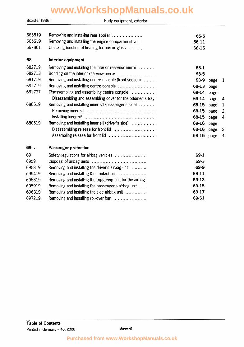
Colour range for 1997 models6
Exterior paintwork metallic / pearl:Exterior paintwork solid:
CodeDesignation Code Designation
92TSnow white 3AT Arctic silver metallic
92U*3AU. Arctic silver metallicSnow white
3AW747 Azure metallicBlack
3AX*Black 741* Azure metallic
74680K Black pearlIndian red
744*84A* Black pearlIndian red
3AY3AR Ocean blue metallicTurquoise blue
3AZ.3AS* Ocean blue metallicTurquoise blue
Arena red pearl 84R12LPastel yellow
84S*12M* Arena red pearlPastel yellow
25HDragonfly turquoise metallic
Dragonfly turquoise metallic 25K*
= Water-based paints
6.019866_O1
Color rangePrinted in Germany, 1996
www.WorkshopManuals.co.uk
Purchased from www.WorkshopManuals.co.uk

Body equipment, exteriorBoxster
6 Colour range for 1999 models
Exterior paintwork solid:
Designation Code
3ATGlacier white
3AU*Glacier white
Black 747
Black 741*
Guards red 80K
Guards red 84A*
12LPastel yellow
Pastel yellow 12M*
Speed yellow 12G
Speed yellow 12H*
Dark blue 374
Dark blue 3C7*
= Water-based paints
6 -05Colour range
Printed in Germany -26, 1999 9866_O5
www.WorkshopManuals.co.uk
Purchased from www.WorkshopManuals.co.uk

t5 Body equipment, exterior Boxster
Exterior paintwork metallic / pearl:
Designation Designation CodeCode
Arctic silver metallic 92T Wimbledon green metallic 231
Arctic silver metallic 92U. Wimbledon green metallic 286*
Pine-green metallic 22EZenith blue metallic 3AW
Pine-green metallic 284*Zenith blue metallic 3AX*
Violet metallic 39GBlack pearl 746
Violet metallic 3AE*Black pearl 744*
Cobalt blue metallic 37UOcean blue metallic 3AY
Cobalt blue metallic 3GB.Ocean blue metallic 3AZ*
Polar silver metallic 92EArena red pearl 84R
Polar silver metallic 92M*Arena red pearl 84S*
Slate metallic 22DOcean jade metallic 25H
Slate metallic 23F*Ocean jade metallic 25K*
Midnight blue metallic 37WIris blue metallic 39N
Midnight blue metallic 39CF*39V.Iris blue metallic
= Water-based paints
6 -06 Colour range
Printed in Germany -26, 19999866_O5
www.WorkshopManuals.co.uk
Purchased from www.WorkshopManuals.co.uk

6Boxster Body equipment, exterior
6 Colour range for 2000 models
Exterior paintwork solid: Exterior paintwork metallic / pearl:
Designation Code Designation Code
Biarritz white 9A3 Arctic silver metallic 92T
Biarritz white 9A2* Arctic silver metallic 92U*
Black 747 Zenith blue metallic 3AW
Black 741* Zenith blue metallic 3AX*
Guards red 80K Black metallic 746
Guards red 84A* Black metallic 744*
Speed yellow 12G Ocean blue metallic 3AY
Speed yellow 12H* Ocean blue metallic 3AZ*
Arena red metallic 84R
Arena red metallic 845*
Jungle green metallic 2A2
Jungle green metallic 2Al*
Vesuvio metallic 40W
Vesuvio metallic 40X*
Paladio metallic 554
Paladio metallic 555*
= Water-based paints
6 -07Colour rangePrinted in Germany -30, 1999 9866_O7
www.WorkshopManuals.co.uk
Purchased from www.WorkshopManuals.co.uk

6Boxster (986) Body equipment
Overview of tools and materials
H12
~H10
H8~.
r'(@),--=:::::::"
.H5
H1 H2 H3 H4
Mixing rod 9528
-8- Bonding gun 9586
~ Rep. Gr. 2.2; Workshop EquipmentManual
~ Rep. Gr. 2.2; Workshop EquipmentManual
Contains set components HI-H12-H- Adhesive set 000.043.204.34
6 Processing of Porsche 2-component window bonding agents
Printed in Germany -38, 2000 a6xxxxx56-8 page 1
www.WorkshopManuals.co.uk
Purchased from www.WorkshopManuals.co.uk

Boxster (986)Body equipment
Mixiing procedure
6 Processing of Porsche 2-component window bonding agentsa6xxxxx5 Printed in Germany -38, 2000
6-8. page 2
www.WorkshopManuals.co.uk
Purchased from www.WorkshopManuals.co.uk

6Boxster (986) Body equipment
rn Note!In addition to this manual, observe the relevant job descriptions forinsta:llingcar windows (Group 64) in the Technical Manual!
No. Procedure Instructions
1 Preparing cartridge component A -H4-
2 Transferring contents of component A
3 Preparing cartridge component B -H5-
Transferring contents of component B4
5 Screwing mixing rod -A- into place
Mixing component A and component B
Clamp an adjustible electric power drill in a conventionalhorizontal clamp. Pre-set a speed of 900 -1,200 rpm.
Pierce the membrane in the nozzle connection of compo-nent A (aluminium cartridge) -H4- with a screwdriver andextend the opening. Remove the flanged cover from theend of the cartridge.Screw the short filler nozzle (blue) -H8- on to the nozzleconnection of component A.
Unscrew the screw cap -HIO- on the empty mixing car-tridge -H6-, insert the prepared cartridge (component A)-H4- in to the bonding gun -B- and insert the filler nozzle-H8- as far as possible into the mixing cartridge -H6-.Press component A fully into the mixing cartridge.After transferring the contents, pull the filler nozzle of thecartridge (component A) -H8- out of the mixing cartridge.
Cut off the point of the nozzle connection of component B(plastic cartridge) -H5- with a knife.Screw the injection nozzle (yellow) -H9- on to the nozzleconnection of component B.
Insert the prepared cartridge (component B) -H5- in to thebonding gun -B- and insert the injector nozzle -H9- as faras possible into the mixing cartridge -H6-. Press compo-nent B fully into the mixing cartridge.After transferring the contents, pull the injector nozzle ofthe cartridge (component B) -H9- out of the mixing car-tridge.
Close the mixing cartridge -H6- with a screw cap -HIO-and screw the mixing rod -A- by hand into the mixer of themixing cartridge.
Clamp the mixing rod in the prepared power drill. Switchthe power drill on and allow it to turn at a speed of 900 -
1,200 rpm. During operation, move the mixing cartridgeaxially from one end stop to the other 25 times -arrows-.Note: perform the stroke movements rapidly. The car-tridge piston is secured at the rear and can not fall out dur-ing the mixing procedure.
6
6 Processing of Porsche 2-component window bonding agents
Printed in Germany -38. 2000 a6xxxxx56-8 page 3
.Observe the safety instructions of the individual adhesive
set components.
www.WorkshopManuals.co.uk
Purchased from www.WorkshopManuals.co.uk

Boxster (986)Body equipment
8
Concluding the mixing procedure and To conclude the mixing procedure, pull the mixer during itsengaging the mixer in the piston last stroke so strongly towards the rear against the piston
that a rattling noise becomes audible. Then switch off thepower drill and unscrew the mixing rod from the mixer; themixer then engages in the piston.
Inserting the mixing cartridge in the bonding Unscrew the screw cap on the mixing cartridge and screwgun and affixing the car window within -15 on the processing nozzle (grey) -Hll-. Insert the mixingmin- cartridge -H6- in the bonding gun -B-.
Note: the bonding material has an open time of -15 min-,which means that the bonding material must be appliedand the car window must be assembled within this periodof time.
www.WorkshopManuals.co.uk
Purchased from www.WorkshopManuals.co.uk
Boxster (986) Body equipment
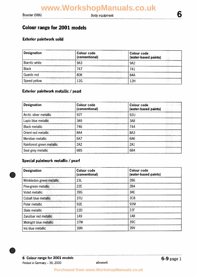
Colour range for 2001 models
Exterior paintwork solid
Designation Colour codeI
(conventional)
Colour code!
(water-based paints)
Biarritz white
Black
Guards red
9A3 ~~~112H
747
180K
1mSpeed yellow
Exterior paintwork metallic / pearl
I Designation Colour code
(conventional)
Colour code(water-based paints)
92T
3A9
I Arctic silver metallic 92U
3A8
744
I
Lapis blue metallic
Black metallic
I Orient red metallicI
Meridian metallicI
Rainforest green metallicI
Seal grey metallic
746
8A4
6A7
2A2
685
18A3i""6A6~
1684
Special paintwork metallic / pearl
Designation Colour code(conventional)
I
Colour code(water-based paints)
123L122E
j"""39G
37U" 192E
,-22D
286
284
3AE
3C8
92M
23F
lA8
39C
39V
I
Wimbledon green metallic
Pine-green metallicI
Violet metallic
Cobalt blue metallici
I Polar metallic
Slate metallic
Zanzibar red metallic
Midnight blue metallic
Iris blue metallic
~ A9 37W
39N
6 Colour range for 2001 models
Printed in Germany -39, 20006-9 page 1
a6xxxxx6
www.WorkshopManuals.co.uk
Purchased from www.WorkshopManuals.co.uk
Boxster (986) Convertible top, hardtop
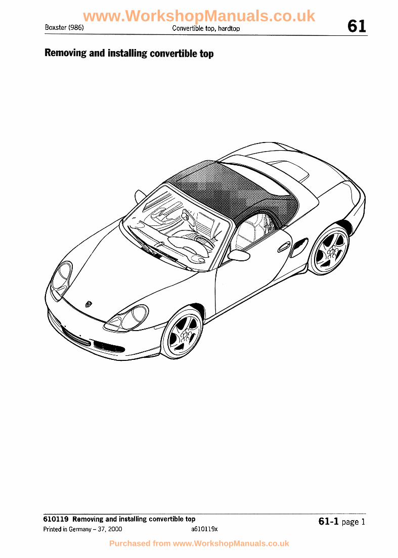
610119 Removing and installing convertible top
Printed in Germany- 37,2000 a610119x61-1 page 1
www.WorkshopManuals.co.uk
Purchased from www.WorkshopManuals.co.uk

Boxster (986)Convertible top, hardtop
Diaigram of convertible top
610119 Removing and installing convertible top
a610119x Printed in Germany- 37,200061..1 page 2
www.WorkshopManuals.co.uk
Purchased from www.WorkshopManuals.co.uk

Boxster (986) Convertible top, hardtop
1 -Roof frame
2 -Main bow
3 -Main bow push bar
4 -Tension bow
5 -Convertible-top support
6 -Drive lever (convertible-top gear)
7 -Tension bow steering lever
8 -B-pillar
9 -Push bar
10 -Guide arm
11 -Hinge lever
12 -Push-bar spring
13 -Drive lever
14 -Convertible-top compartment lid
610119 Removing and installing convertible top
Printed in Germany -37.2000 a610119x61-1 page 3
www.WorkshopManuals.co.uk
Purchased from www.WorkshopManuals.co.uk

Boxster (986)Convertible top, hardtop
Overview of convertible-top components up to model year 1999
610119 Removing and installing convertible top
a610119x Printed in Germany -37,200061-1 page 4
www.WorkshopManuals.co.uk
Purchased from www.WorkshopManuals.co.uk
Boxster (986) Convertible top, hardtop
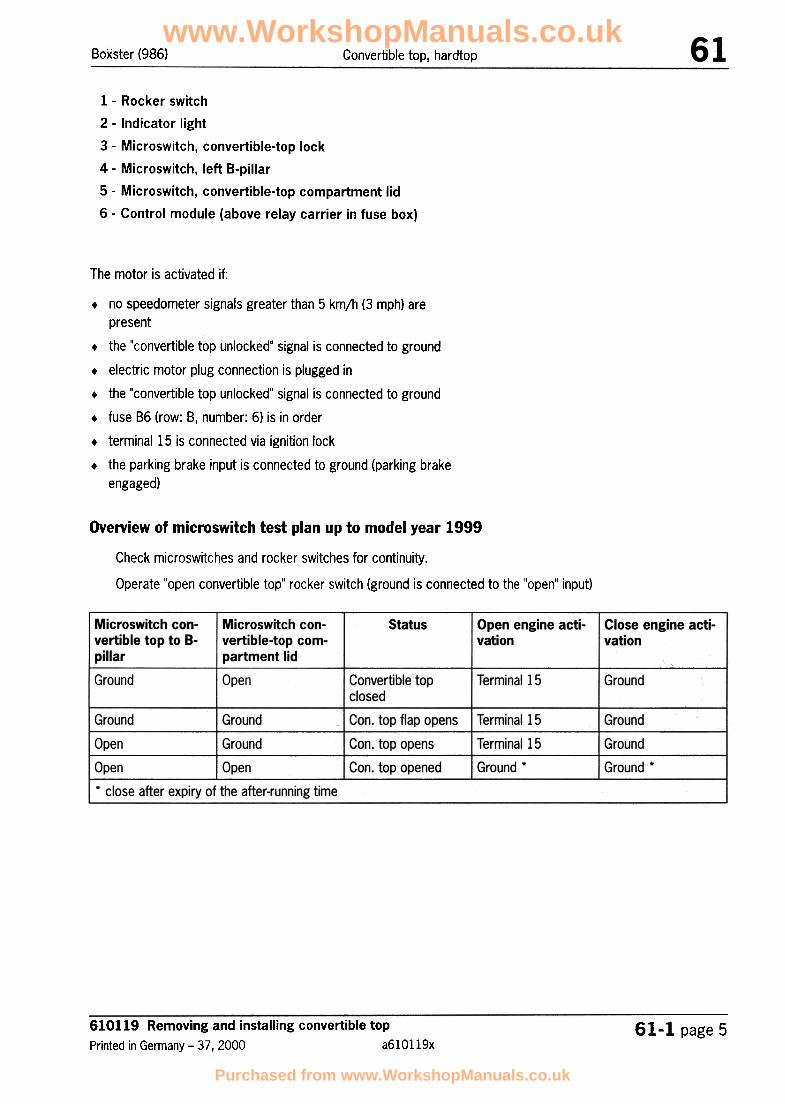
1 -Rocker switch
2 -Indicator light
3 -Microswitch, convertible-top lock
4 -Microswitch, left B-pillar
5 -Microswitch, convertible-top compartment lid
6 -Control module (above relay carrier in fuse box)
The motor is activated if:
.no speedometer signals greater than 5 km/h (3 mph) are
present
.the "convertible top unlocked" signal is connected to ground
.electric motor plug connection is plugged in
.the "convertible top unlocked" signal is connected to ground
.fuse 86 (row: 8, number: 6) is in order
.terminal 15 is connected via ignition lock
.the parking brake input is connected to ground (parking brake
engaged)
Overview of microswitch test plan up to model year 1999
Check microswitches and rocker switches for continuity.
Operate "open convertible top" rocker switch (ground is connected to the "open" input)
610119 Removing and installing convertible top
Printed in Germany -37,2000 a610119x61-1 page 5
www.WorkshopManuals.co.uk
Purchased from www.WorkshopManuals.co.uk

Boxster (986)Convertible top, hardtop
Check microswitches and rocker switches for continuity.
-Operate "close convertible top" rocker switch (ground is connected to the "open" input)
www.WorkshopManuals.co.uk
Purchased from www.WorkshopManuals.co.uk

Boxster (986) Convertible top, hardtop
Overview of convertible-top components as of model year 2000
610119 Removing and installing convertible top
Printed in Germany -37,2000 a610119x61-1 page 7
www.WorkshopManuals.co.uk
Purchased from www.WorkshopManuals.co.uk

Boxster (986)Convertible top, hardtop
1 -Rocker switch
2 -Indicator light
3 -Microswitch, convertible-top lock
4 -Microswitch convertible-top gear
5 -Control module (above relay carrier in fuse box)
www.WorkshopManuals.co.uk
Purchased from www.WorkshopManuals.co.uk

Boxster (986) Convertible top, hardtop
Removing convertible top
www.WorkshopManuals.co.uk
Purchased from www.WorkshopManuals.co.uk

Boxster (986)Convertible top, hardtop
rn Note!The cabriolet convertible top must be unlocked and the convertible-top compartment lid must be raised to its top
position!
No. Procedure Instructions
Removing side-panel linings
2 Detaching cloth covering
3 Detaching tension cable
4 Convertible top in service position
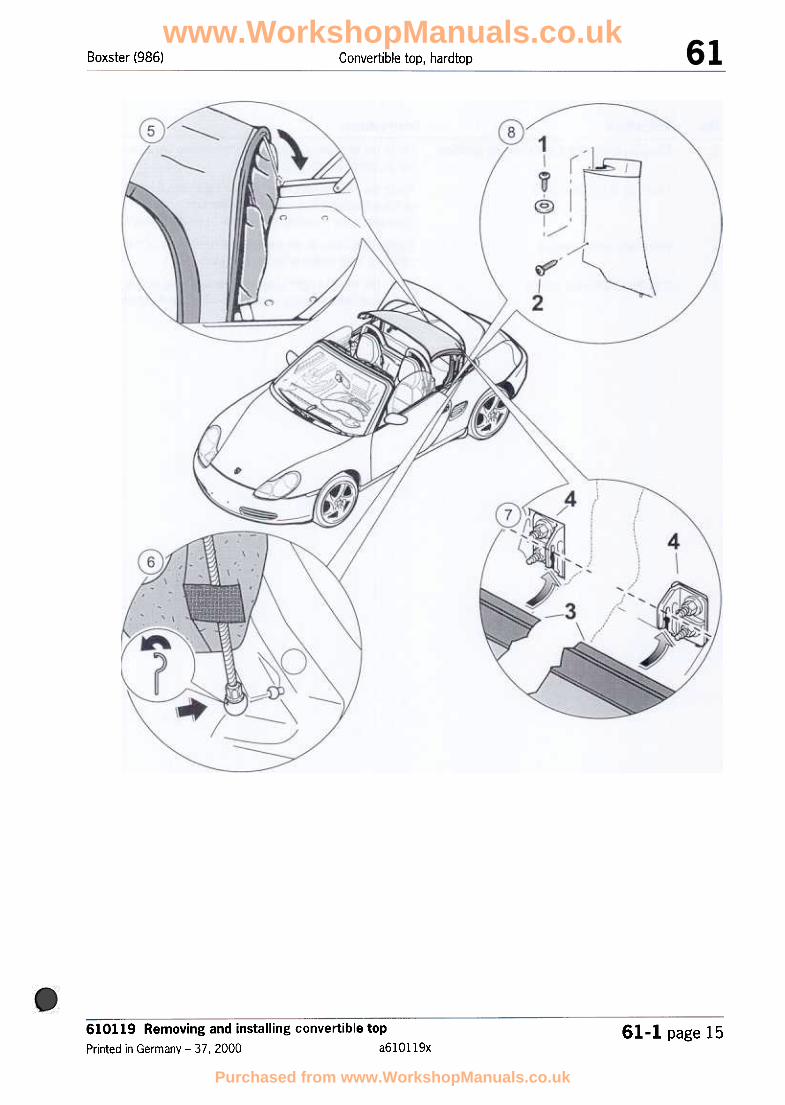
Unscrew the top fastening screw -1- by two turns. Undothe bottom fastening screw -2-.Lift side-panel lining up and off.
Disengage the strip -3- on the left and right sides of thecloth covering in downward direction out of the brackets-4-.
Pull the retaining pin -inset- out of the ball socket.Then press the ball socket of the tension cable out of theball head of the adjusting piece.
Press tension bow of the convertible top upwards at themain bow until it engages.
www.WorkshopManuals.co.uk
Purchased from www.WorkshopManuals.co.uk

www.WorkshopManuals.co.uk
Purchased from www.WorkshopManuals.co.uk
Boxster (986)Convertible top, hardtop
No. Procedure Instructions
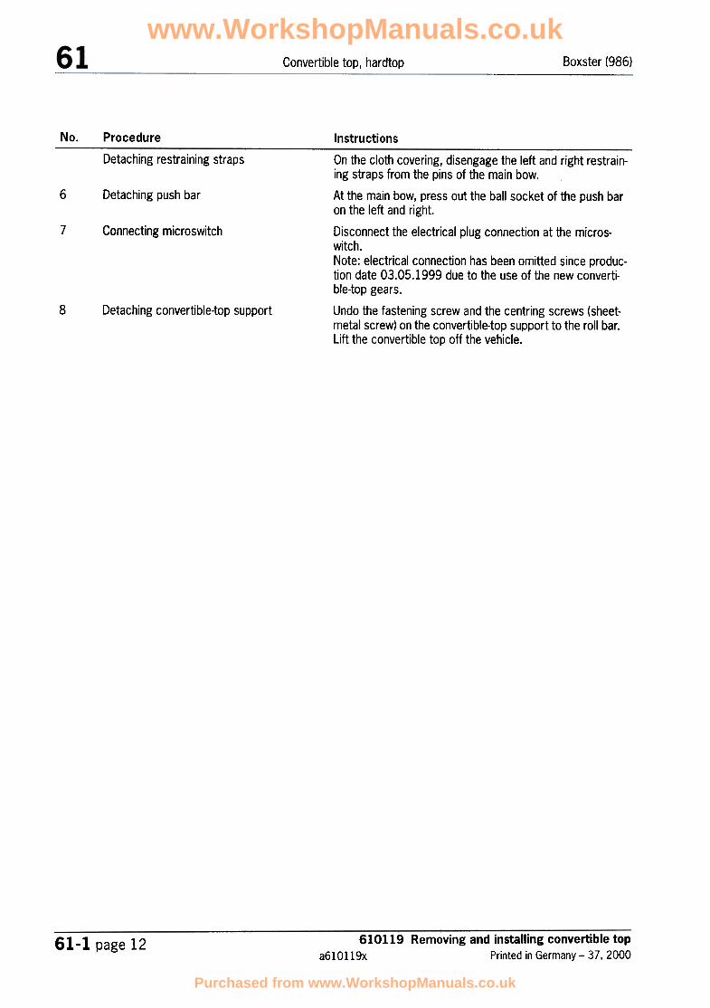
Detaching restraining straps
6 Detaching push bar
7 Connecting microswitch
8 Detaching convertible-top support
On the cloth covering, disengage the left and right restrain-ing straps from the pins of the main bow.
At the main bow, press out the ball socket of the push baron the left and right.
Disconnect the electrical plug connection at the micros-witch.Note: electrical connection has been omitted since produc-tion date 03.05.1999 due to the use of the new converti-ble-top gears.
Undo the fastening screw and the centring screws (sheet-metal screw) on the convertible-top support to the roll bar.Lift the convertible top off the vehicle.
610119 Removing and installing convertible topa610119x Printed in Germany -37, 2000
61-1 page 12
www.WorkshopManuals.co.uk
Purchased from www.WorkshopManuals.co.uk

Boxster (986) Convertible top, hardtop
Installing convertible top
www.WorkshopManuals.co.uk
Purchased from www.WorkshopManuals.co.uk

Boxster (986)Convertible top, hardtop
2
Screwing convertible top to the roll-over bar Position the convertible-top support to the roll bar andscrew tight with the fastening screw and the centringscrews (sheetmetal screw).
Connecting microswitch Connect the electrical plug connection at the microswitch.Note: electrical connection has been omitted since produc-tion date 03.05.1999 due to the use of the new converti-ble-top gears.
On the cloth covering, engage the left and right restrainingstraps in the pins of the main bow.
At the main bow, press out the ball socket of the push baron the left and right.
3 Attaching restraining straps
4 Detaching push bar
610119 Removing and installing convertible topa610119x Printed in Germany -37, 2000
61-1 page 14
www.WorkshopManuals.co.uk
Purchased from www.WorkshopManuals.co.uk
Boxster (986) Convertible top, hardtop
610119 Removing and installing convertible top
Printed in Germany -37.2000 a610119x61-1 page 15
www.WorkshopManuals.co.uk
Purchased from www.WorkshopManuals.co.uk

Boxster (98G)Convertible top, hardtop
Moving convertible top to service position
6 Pressing in tension cable
7 Attaching cloth covering
8 Installing side-lining panels
Press the tensioning bow of the convertible top down-wards out of the locking element.
Press the ball socket of the tension cable into the ball headat-the adjusting piece on the roll-over bar.Then press the retaining pin -inset- in to the ball socket.
Engage the strip -3- on the left and right sides of the clothcovering from below in to the brackets -4-.
Insert the left and right side-lining panels from above andfasten with the fastening screws -1- at top and bottom -2-.
610119 Removing and installing convertible top
a610119x Printed in Germany- 37,200061-1 page 16
www.WorkshopManuals.co.uk
Purchased from www.WorkshopManuals.co.uk

Boxster (986) Convertible top, hardtop
rn Note!.The following convertible-top covering spare parts are required
for replacement of the convertible-top covering!
.The spare parts contained in the "convertible-top covering"scope of parts must always be replaced!
.The convertible-top covering must be replaced at a room tem-perature of at least 15 degrees Celsius (59 Fahrenheit)!
.The roof liner must be removed when replacing the convertible-top covering on the model version with roof liner!
.The centre cover moulding is characterised by a second groovefor the connection to the roof liner which must be ordered sepa-
rately!
F C
""~
- ,, A0
\III "
D
612855 Replacing convertible-top covering
Printed in Germany -37 I 2000
61-JL 1 page 1a612855x
www.WorkshopManuals.co.uk
Purchased from www.WorkshopManuals.co.uk

Boxster (986)Convertible top, hardtop
A = Convertible-top covering D = Tension strap G = Tension bow seal
B = Slider / rail E = Tension strap cover H = Seal
I = Side sealC = Plastic plug F = Tubular rivets
www.WorkshopManuals.co.uk
Purchased from www.WorkshopManuals.co.uk

Boxster (986) Convertible top, hardtop
Removal overview of the convertible-top covering components, part 1
'"'""'"
.,.
i
---A
~""
0/
612855 Replacing convertible-top covering
Printed in Germany -37, 200061-11 page 3
a612855x
www.WorkshopManuals.co.uk
Purchased from www.WorkshopManuals.co.uk
Boxster (986)Convertible top, hardtop
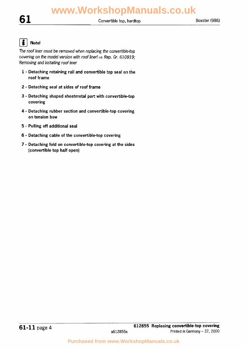
[!J Note!The roof liner must be removed when replacing the convertible-topcovering on the model version with roof liner! => Rep. Gr. 610919;Removing and installing roof liner
1 -Detaching retaining rail and convertible top seal on the
roof frame
2 -Detaching seal at sides of roof frame
3 -Detaching shaped sheetmetal part with convertible-top
covering
4 -Detaching rubber section and convertible-top covering
on tension bow
5 -Pulling off additional seal
6 -Detaching cable of the convertible-top covering
7 -Detaching fold on convertible-top covering at the sides
(convertible top half open)
612855 Replacing convertible-top coveringPrinted in Germany -37, 2000
61-11 page 4a612855x
www.WorkshopManuals.co.uk
Purchased from www.WorkshopManuals.co.uk
Boxster (98G) Convertible top, hardtop
Removal overview of the convertible-top covering components, part 2
612855 Replacing convertible-top covering
Printed in Germany -37,2000
61-11 page 5a612855x
www.WorkshopManuals.co.uk
Purchased from www.WorkshopManuals.co.uk

Boxster (986)Convertible top, hardtop
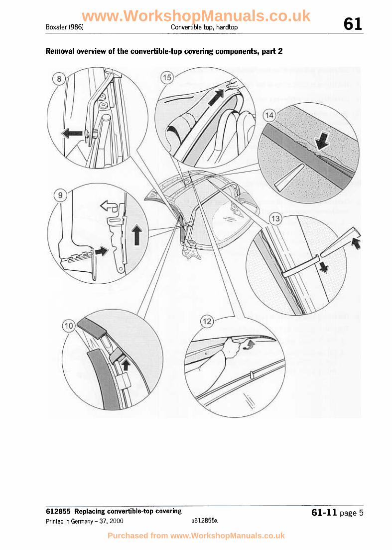
8 -Removing clamping rail and slider
9 -Detaching pull strip from the clamping rail and slider
10 -Detaching holding strap of the convertible-top covering
11 -Detaching convertible-top covering at the roof frame
12 -Model version without roof liner: pressing retaining clips
and cover moulding out of roof frame
13 -Model version with roof liner: pulling out convertible-top
covering and pressing out cover moulding
14 -Pulling out convertible-top covering at the main bow
Removing convertible-top covering
1 -Detaching retaining rail and convertible-top seal on the ...
roof frame (convertible top half open)
1. Unscrew the fastening screws from the retaining rail orthe fastening screws from the left and right of the con-vertible-top seal.
2. Pull out the convertible-top seal corners on the left andon the right to the front.
~
2 -Detaching seal at sides of roof frame
The seal on the roof frame consists of two parts.
1. Pull the lower seal out of the profile of the retaining strip.
2. On the upper seal with the retaining rail, unscrew the fas-tening screws and remove the seal and the retaining railfrom the roof frame.
www.WorkshopManuals.co.uk
Purchased from www.WorkshopManuals.co.uk

Boxster (986) Convertible top, hardtop
3 -Detaching shaped sheetmetal part with convertible-top covering
-Undo the fastening screws on the roof frame and raisethe shaped sheetmetal part together with the convertible-
top covering.
4 -Detaching rubber section and convertible-top covering ...on tension bow
Pull the rubber section out of the profile strip of the ten-
sion bow and detach the convertible-top end piece fromthe tension bow.
~
5 -Pulling off additional seal
-Pull the additional seal out of the lower groove of the ten-sion bow, pull the seal on the convertible-top covering outof the upper groove of the tension bow and pull the con-vertible-top covering down and off.
612855 Replacing convertible-top covering
Printed in Germany -37, 200061-11 page 7
a612855x
www.WorkshopManuals.co.uk
Purchased from www.WorkshopManuals.co.uk

Boxster (986)Convertible top, hardtop
...6 -Detaching cable of the convertible-top covering
-At the front B-pillar (main bow), undo the fastening screwfrom the cable eye and clamping rail.
...7 -Detaching fold at the rear sides (convertible top half
open)
1. Undo the fold of the convertible-top covering edge.
2. Pull the convertible-top covering out of the clamping railsat the bottom sides.
3. Unscrew the fastening screw at the rear of the clampingrail.
..
8 -Removing clamping rail and slider
1. Press the plastic plugs in the clamping rail out of the mainbow from the inside.
Removal tool ~ No. 21; Rep. Gr. 2.4; Workshop EquipmentManual
1. Pull clamping rail with slider out of the main bow at thetop and bottom.
www.WorkshopManuals.co.uk
Purchased from www.WorkshopManuals.co.uk

Boxster (986) Convertible top, hardtop
9 -Detaching pull strip from the clamping rail and slider
1. Pull the horizontal pull strip of the convertible-top coveringout of the groove in the clamping rail and pull the verticalpull strip out of the groove in the slider.
~
10 -Detaching holding strap of the convertible-top covering -Detach the Velcro fastening of the holding strap around
the push bar.
...11 -Detaching convertible-top covering at the roof frame
-Detach the convertible-top covering on the roof frame at
the front and lay it down to the rear.
612855 Replacing convertible-top covering
Printed in Germany -37, 200061-11 page 9
a612855x
www.WorkshopManuals.co.uk
Purchased from www.WorkshopManuals.co.uk

Convertible top, hardtop Boxster (986)
~
12 -Model version without roof liner
1. Press retaining clips and centre cover moulding out ofroof frame.
2. Press the retaining clips out of the groove of the centrecover moulding.
3. Press the centre cover moulding out of the roof frame
using a plastic spatula.
..13 -Model version with roof liner
1. Pullout convertible-top covering and press out cover
moulding.
2. Pull the tightening strip of the convertible-top covering outof the cover moulding.
3. Press the centre cover moulding out of the roof frameusing a plastic spatula.
...14 -Pulling out convertible-top covering at the main bow
1. Detach the tightening strip on the left and right sides onthe main bow and pull the tightening strip of the converti-ble-top covering out of the groove of the main bow.
2. Remove the convertible-top covering from the convertible-top frame.
612855 Replacing convertible-top coveringPrinted in Germany -37. 2000
61-11 page 10a612855x
www.WorkshopManuals.co.uk
Purchased from www.WorkshopManuals.co.uk
Boxster (986) Convertible top, hardtop
Installation overview of the convertible-top covering components, part 1
612855 Replacing convertible-top covering
Printed in Germany -37, 200061-11 page 11
a612855x
www.WorkshopManuals.co.uk
Purchased from www.WorkshopManuals.co.uk

Convertible top, hardtop Boxster (986)
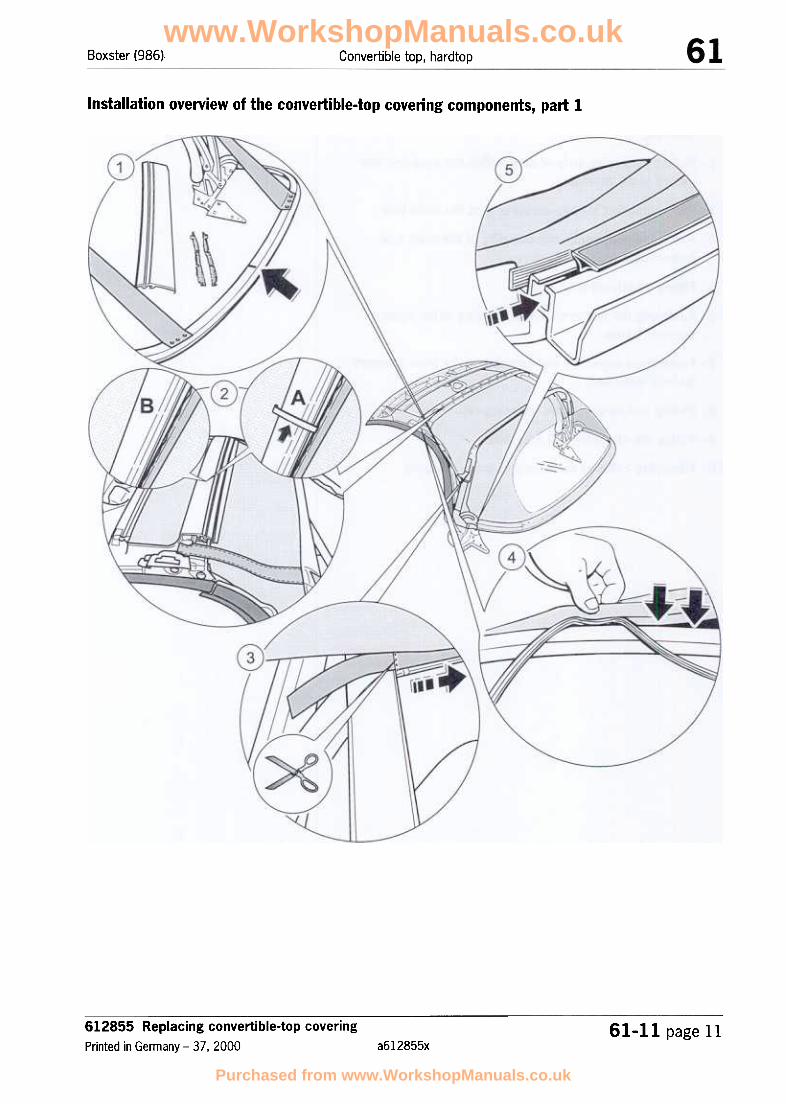
1 -Preparing convertible-top frame and convertible-top
covering
2 -Pulling tightening strip of convertible-top covering into
centre cover moulding
3 -Pulling convertible-top covering in at the main bow
4 -Fastening convertible-top covering at the main bow
(convertible top unlocked)
5 -Fitting additional seal
6 -Fastening the convertible-top covering at the sides of
the roof frame
7 -Fastening convertible-top covering at the front (convert-
ible top unlocked)
8 -Pulling pull strip into the clamping rail
9 -Fitting the clamping rail with slider
10 -Fastening cable of the convertible-top covering
612855 Replacing convertible-top coveringPrinted in Germany -37, 2000
61-11 page 12a612855x
www.WorkshopManuals.co.uk
Purchased from www.WorkshopManuals.co.uk

Boxster (986) Convertible top, hardtop
Installation overview of the convertible-top covering components, part 2
www.WorkshopManuals.co.uk
Purchased from www.WorkshopManuals.co.uk
Boxster (986)Convertible top, hardtop
11 -Securing the clamping rail
12 -Fastening convertible-top covering at the sides
13 -Fastening holding strap of the convertible-top covering
14 -Fastening the retaining rail and convertible-top seal on
the roof frame
15 -Fastening seal at the sides of the roof frame
16 -Fastening convertible-top covering end piece on the
tension bow (convertible top closed)
17 -Fitting retaining clips, pull strip and centre cover mould-
ing in the roof frame
18 -Fastening rubber pull strap on the tension strap of the
convertible-top covering (convertible top closed)
19 -Fitting tension bow seal
Installing the convertible-top covering
.Introduction on 13.04.2000 of a new convertible-top cov-
ering with modified rear window!
.Necessary conversion measure for tensioning bow in
vehicles up to production date 12.04.2000
.In vehicles with a roof liner produced before 12.04.2000,
a new roof liner with a new cut must be installed when the
convertible-top covering with a smaller rear window is
replaced.
.=> Rep. Gr. 613055; Replacing convertible-top frame
(conversion measure at tensioning bow for the tension
strap and the roof liner on vehicles produced up to
12.04.2000).
[IJ Note!.All pins and screw joints must be checked for tightness before
the convertible-top covering is installed!
.When setting down the convertible top for the first time, supportthe folding of the convertible-top window with your hand!
612855 Replacing convertible-top coveringPrinted in Germany -37 I 2000
61-11 page 14a612855x
.Damage to the convertible-top covering and the flexible
rear window may be caused by incorrect removal with the
convertible top open!
www.WorkshopManuals.co.uk
Purchased from www.WorkshopManuals.co.uk

Boxster (986) Convertible top, hardtop
.It is important that no creasing occurs in the convertible-top win-dow when folding it for the first time!
.If the convertible-top covering is very taut (with new convertible-top covering), close the convertible top and heat the convertible-top covering evenly using a heating lamp!
.Ensure that the convertible-top covering is not heated for longerthan 1 hour!
.Maintain a safe distance from the heating lamp of approx. 50cm, then leave the vehicle overnight with the convertible topclosed!
.In order to avoid abrasions when the convertible top is set downfor a long period (hardtop operation), insert protective fleecebetween the folds of the convertible-top window!
~
1 -Preparing convertible-top frame and convertible-top
covering (convertible top locked)
1. Measure the centre between the restraining straps and
mark it on the tension bow.
2. Replace the seals contained in the scope of parts on the
left and right of the roof frame, and replace the centre
cover moulding.
3. Replace the tension strap. => Rep. Gr. 613055; Replac-
ing convertible-top frame
2 -Pulling tightening strip of convertible-top covering into ...
centre cover moulding
Inset A = model version without roof liner
1. Pull tightening strip of convertible-top covering into cover
moulding.
2. Position the retaining clips in the groove of the centrecover moulding.
Inset B = model version with roof liner
-Pull tightening strip of convertible-top covering into cover
moulding.
612855 Replacing convertible-top covering
Printed in Germany -37. 200061-11 page 15
a612855x
www.WorkshopManuals.co.uk
Purchased from www.WorkshopManuals.co.uk

Boxster (986)Convertible top, hardtop
...3 -Pulling convertible-top covering in at the main bow
1. Lay the convertible-top covering on the convertible-topframe, fit the tightening strip of the convertible-top cover-ing in the groove of the main bow and centre.
2. For vehicles and convertible-top coverings with extendedtightening strips on the left and right, cut off the tighten-ing strips flush at the tension strap.
~
4 -Fastening convertible-top covering at the main bow
(convertible top unlocked)
1. Press the centre of the convertible-top covering that coin-cides with the marking on the tension bow into the uppergroove of the tension bow.
2. Centre the middle of the seal and tap into the groove ofthe tension bow.
~
5 -Fitting additional seal
1. Press the tension bow seal in the centred groove of thetension bow.
2. Pull the protective paper off the self-adhesive strip of theconvertible-top covering and the tension bow seal.
3. Position convertible-top covering on the tension bow sealand press into place.
www.WorkshopManuals.co.uk
Purchased from www.WorkshopManuals.co.uk

Boxster (986) Convertible top, hardtop
...6 -Fastening the convertible-top covering at the sides of
the roof frame
1. Lay the convertible-top covering to the front and guide theshaped sheetmetal part into the roof frame from above.
2. Fasten the convertible-top covering with the fasteningscrews, starting from the rear bottom side of the roofframe.
...7 -Fastening convertible-top covering at the front (con-
vertible top unlocked)
A cardboard strip and a self-adhesive strip are affixed at thefront of the convertible-top covering.
1. Pull the protective paper off the adhesive tape and foldthe convertible-top material around the roof frame into thegroove without wrinkles.
2. The fold is initially held with fixing clips.
~
8 -Pulling pull strip into the clamping rail
1. Pull the horizontal pull strip of the convertible-top coveringinto the groove of the clamping rail.
2. Fold the cardboard insert underneath around the clamp-ing rail.
""---
612855 Replacing convertible-top covering
Printed in Germany -37.200061-11 page 17
a612855x
www.WorkshopManuals.co.uk
Purchased from www.WorkshopManuals.co.uk

Boxster (986)Convertible top, hardtop
~
9 -Fitting the clamping rail with slider
-Pull the vertical pull strip of the conve'rtible-top covering
into the slider, turn it inward and push it into the main bowtogether with the clamping rail.
...10 -Fastening cable of the convertible-top covering
-Position the cable with the clamping rail at the B-pillar
(main bow) and screw in place with the fastening screw.
~
11 -Securing the clamping rail
-The clamping rail is secured by pressing the plastic plugs
into the clamping rail from the inside.
www.WorkshopManuals.co.uk
Purchased from www.WorkshopManuals.co.uk

Convertible top, hardtopBoxster (986)
...12 -Fastening convertible-top covering at the sides
-Clamp the outer pull strip of the convertible-top covering
behind the leaf spring.
13 -Fastening holding strap of the convertible-top covering ...
-,- Guide the Velcro seal of the holding strap around the push
bar and close.
14 -Fastening the retaining rail and convertible-top seal on ...
the roof frame
1. Remove the fixing clips and clip the convertible-top sealinto the roof frame at the corners from the front.
2. Fasten the retaining rail at the front on the roof frame
using the fastening screws.
3. Close and lock the convertible top.
612855 Replacing convertible-top covering
Printed in Germany -37, 200061-1 Jl page 19
a612855x
www.WorkshopManuals.co.uk
Purchased from www.WorkshopManuals.co.uk

Boxster (986)Convertible top, hardtop
~
15 -Fastening seal at the sides of the roof frame
1. The seal on the roof frame at the sides consists of two
parts.
2. Screw the upper seal to the roof frame together with aretaining rail using the fastening screws.
3. Press the lower seal into the profile of the retaining rail
...16 -Fastening convertible-top covering end piece on the
tension bow (convertible top closed)
-Apply adhesive over approx. 300 mm on the left and right
sides of the convertible-top covering end piece and fold itover.
17 -Fitting retaining clips, pull strip and centre cover mould- ...
ing in the roof frame
Model version with roof liner
1. When pressing the centre cover moulding into the roofframe, make sure that the top side of the convertible topis free from wrinkles.
2. If necessary, shift the pull strip to the left or right.
Model version without roof liner
The centre cover moulding is additionally secured using a
retaining clip (small inset).
-Press the retaining clip into the groove of the centrecover moulding and pull downwards over the roof frame
edge.
www.WorkshopManuals.co.uk
Purchased from www.WorkshopManuals.co.uk

Boxster (986) Convertible top, hardtop
...18 -Fitting tension bow seal
-Press the tension bow seal into the outer groove of the
tension bow.
612855 Replacing convertible-top coveringPrinted in Germany -37 I 2000
61-11 page 21a612855x
www.WorkshopManuals.co.uk
Purchased from www.WorkshopManuals.co.uk

613055 Replacing convertible-top frame
Printed in Germany -38. 200061-:~7 page 1
a613055x
www.WorkshopManuals.co.uk
Purchased from www.WorkshopManuals.co.uk

Boxster (986)Convertible top, hardtop
Ovel"View of replacing convertible-top frame, part 1
www.WorkshopManuals.co.uk
Purchased from www.WorkshopManuals.co.uk

Boxster (986) Convertible top, hardtop
1 -Placing the roll-over bar on assembly fixture
2 -Fastening the adjusting piece and strips of adhesive
tape
3 -Fastening water collection tray
4 -Fitting convertible-top support
5 -Fitting seat belt
613055 Replacing convertible-top frame
Printed in Germany -38, 200061-27 page 3
a613055x
www.WorkshopManuals.co.uk
Purchased from www.WorkshopManuals.co.uk

Boxster (986)Convertible top, hardtop
Overview of replacing convertible-top frame, part 2
613055 Replacing convertible-top framePrinted in Germany -38, 2000
61..27 page 4a613055x
www.WorkshopManuals.co.uk
Purchased from www.WorkshopManuals.co.uk
Boxster (98G) Convertible top, hardtop
6 -Fitting stop buffer
7 -Fastening the roof frame on the B-pillar
8 -Fitting convertible-top lock
9 -Fitting the cover on the roof frame
613055 Replacing convertible-top frame
Printed in Germany -38, 200061-27 page 5
a613055x
www.WorkshopManuals.co.uk
Purchased from www.WorkshopManuals.co.uk

Boxster (986)Convertible top, hardtop
Ovel'View of replacing convertible-top frame, part 3
www.WorkshopManuals.co.uk
Purchased from www.WorkshopManuals.co.uk

Boxster (986) Convertible top, hardtop
10 -Fitting the drive lever on the B-pillar
11 -Fitting the roof frame with the B-pillar
12 -Fitting the main bow
13 -Fitting the connection piece with steering lever on the
tension bow
14 -Fitting the tension bow
613055 Replacing convertible-top frame
Printed in Germany -38, 200061-27 page 7
a613055x
www.WorkshopManuals.co.uk
Purchased from www.WorkshopManuals.co.uk

Overview of replacing convertible-top frame, part 4
/"
www.WorkshopManuals.co.uk
Purchased from www.WorkshopManuals.co.uk

Boxster (986) Convertible top, hardtop
15 -Fitting the tension cable
16 -Riveting the tension strap to the tension bow
17 -Fitting tension strap on the main bow
18 -Fitting the tension strap on the roof frame
Replacing convertible-top frame
...1 -Placing the roll-over bar on assembly fixture
-Place the roll-over bar outside the vehicle on a workbench
or assembly fixture and secure.
"
2 -Fastening the adjusting piece and strips of adhesive
tape
~
1. Insert the adjusting piece, which is used to brace the ten-sion bow, into the guides of the roll-over bar and fastenthe adjusting piece with the fastening screw.
2. Affix two strips of double-sided adhesive tape in the areaof the convertible-top support fastening point.
The strips of tape are used to fasten the water collection tray.
~3 -Fastening water collection tray
-Position the hole pattern of the water collection tray on
the hole pattern of the roll-over bar, and press the trayonto the two strips of double-sided adhesive tape.
613055 Replacing convertible-top frame
Printed in Germany -38. 200061-27 page 9
a613055x
www.WorkshopManuals.co.uk
Purchased from www.WorkshopManuals.co.uk

Convertible top, hardtop Boxster (986)
~4 -Fitting convertible-top support
-Position the convertible-top support on the roll-over barand fasten it with the fastening screws.
~
5 -Fitting seat belt
-Position the belt reel at the bottom and the deflector atthe top on the roll-over bar and fasten with the fasteningscrews.
Tightening torque 50 Nm (37 ftlb.)
...6 -Fitting stop buffer on the roll-over bar
-Fasten the buffer for the convertible-top rest on the roll-
over bar with the fastening screws.
www.WorkshopManuals.co.uk
Purchased from www.WorkshopManuals.co.uk
Boxster (986) Convertible top, hardtop
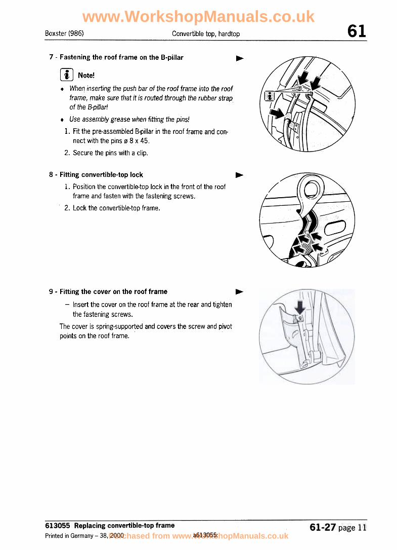
7 -Fastening the roof frame on the B-pillar
~
rn Note!.When inserting the push bar of the roof frame into the roof
frame, make sure that it is routed through the rubber strapof the B-pillar!
.Use assembly grease when fitting the pins!
1. Fit the pre-assembled B-pillar in the roof frame and con-nect with the pins .0 8 x 45.
2. Secure the pins with a clip.
...8 -Fitting convertible-top lock
1. Position the convertible-top lock in the front of the roofframe and fasten with the fastening screws.
2. Lock the convertible-top frame.
...9 -Fitting the cover on the roof frame
-Insert the cover on the roof frame at the rear and tighten
the fastening screws.
The cover is spring-supported and covers the screw and pivotpoints on the roof frame.
www.WorkshopManuals.co.uk
Purchased from www.WorkshopManuals.co.uk

Boxster (986)Convertible top, hardtop
10 -Fitting the drive lever on the B-pillar
~
rn Note!Use assembly grease when fitting the pins!
1. Position the drive lever on the B-pillar and join it with thepin, ~ 8 x 45.
2. Position the push bar on the centre of the drive lever andjoin it with the pin, ~ 8 x 45.
3. Press retaining clips into the pins => No.131;Rep. Gr. 2.4; Workshop Equipment Manual.
11 -Fitting the roof frame with the B-pillar
~
[JJ Note!Use assembly grease when fitting the pins!
1. Position the roof frame with the B-pillar on the convertible-top support and join it with the pin, ~ 8 x 45.
2. Press retaining clips into the pins.
12 -Fitting the main bow ~
rn Note!Use assembly grease when fitting the pins!
1. Position the main bow on the convertible-top support anddrive lever. Then join with the pins, 08 x 70 and 0 8 x 45.
2. Press retaining clips into the pins.
613055 Replacing convertible-top framePrinted in Germany -38, 2000
61-27 page 12a613055x
www.WorkshopManuals.co.uk
Purchased from www.WorkshopManuals.co.uk

Convertible top, hardtopBoxster (986)
13 -Fitting the connection piece with steering lever on the
tension bow
~
-Insert the pre-assembled connecting piece with steering
lever in the tension bow and fasten with the fasteningscrews.
The connecting piece contains a clip in which the pin of thesteering lever engages and thereby produces the position "ten-sion bow closed" or "tension bow open" (service position).
...14 -Fitting the tension bow
rn Note!Use assembly grease when fitting the pins!
1. Position the tension bow with connection piece on themain bow and join the parts with the pin ~ 8 x 25.
2. Position the steering lever on the convertible-top supportand join the parts with the pin ~ 8 x 30.
3. Press retaining clips into the pins.
...15 -Fitting the tension cable
-Press the ball socket of the tension cable into the ball
head of the adjusting piece on the roll-over bar.
www.WorkshopManuals.co.uk
Purchased from www.WorkshopManuals.co.uk

Boxster (986)Convertible top, hardtop
~16 -Fitting tension strap on the tension bow
-Position the tension strap on the tension bow and rivet theparts together with the 5.0 x 8 pop rivets.
~17 -Fitting tension strap on the main bow
-Position tension strap with the strap cover on the main
bow and press in.
18 -Fitting the tension strap on the roof frame (convertible- top frame locked)
-Position the tension strap on the roof frame at the rear,
and fasten the tension strap with the fastening screws.
www.WorkshopManuals.co.uk
Purchased from www.WorkshopManuals.co.uk

Boxster (986) Convertible top, hardtop
Conversion measure on the tension bow for the tension strap in vehicles produced before12.04.2000
rn Note!.Introduction on 13.04.2000 of a new convertible-top covering with modified rear window and wider tension strap
for improved setting down of the convertible-top covering!
.In vehicles with production date up to 12.04.2000, the holes for the tension strap connection must be re-meas-ured and re-drilled!
.The rivet connection on the tension bow has changed from a 2-point to a 3-point rivet connection!
613055 Replacing convertible-top frame
Printed in Germany -38. 200061-27 page 15
a613055x
www.WorkshopManuals.co.uk
Purchased from www.WorkshopManuals.co.uk

Convertible top, hardtop Boxster (986)
1 -Measuring and drilling the rivet holes for the tension strap
-Measure the dimensions -A = 10 mm- centrally starting from the old rivet holes -X- of the tension bow
on the left and right. .
-Measure the dimension -8 = 30 mm- centrally starting from the measured dimension -A- of the tension
bow on the left and right.
-Centre the measured dimensions using a prick punch. Drill the centrings with a drill bit (25 5 mm.
Conversion measure on the tension bow for the roof liner in vehicles produced before12.04.2000
rn Note!.In vehicles with a roof liner produced before 12.04.2000, a new roof liner with a new cut must be installed when
the convertible-top covering with a smaller rear window is replaced.
.In vehicles with production date up to 12.04.2000, the holes for the roof liner connection must be re-measuredand re-drilled!
.The roof liner connection on the tension bow has been modified from a 1-point clip (threaded part) to a 2-point
clip
/.""~/4
t'///y
~
)/
II
A"
.",
~
613055 Replacing convertible-top framePrinted in Germany -38, 2000
61-27 page 16a613055x
www.WorkshopManuals.co.uk
Purchased from www.WorkshopManuals.co.uk

Boxster (986) Convertible top, hardtop
1 -Measuring and drilling the holes for the roof liner
1. Measure the dimensions -A = 10 mm- centrally starting from the inner edge of the tension bow.
2. Measure the dimension -8 = 128 mm- starting from the beginning of the tension bow.
3. Measure the dimension -C = 193 mm- starting from the centre of the hole for dimension B.
4. Centre the measured dimensions using a prick punch. Drill the centrings with a drill bit 0 5 mm.
613055 Replacing convertible-top frame
Printed in Germany -38, 200061-27 page 17
a613055x
www.WorkshopManuals.co.uk
Purchased from www.WorkshopManuals.co.uk

Boxster Convertible top, hardtop
No. Procedure Instructions
9 Fitting clamping rail with slider
Pull the vertical pull strip of the convertible-top coveringinto the slider, turn it inward and push it into the main bowtogether with the clamping rail.
545_H_96
10 Fastening cable of the convertible-top covering
Position the cable with the clamping rail on the B-pillar(main bow) and fasten with the T25 x 8 Torx screw.
\
/
545_1_96
Securing clamping rail
The clamping rail is secured by pressing the plastic plugsinto the clamping rail from the inside.
\\
/
545_K_96
61 28 55 Replacing convertible-top coveringPrinted in Germany. 30, 1999 9866111
61 -29
www.WorkshopManuals.co.uk
Purchased from www.WorkshopManuals.co.uk

Convertible top, hardtop Boxster
r~o. Procedure Instructions
12 Fastening the convertible-top covering at the sides
Clamp the outer pull strip of the convertible-top coveringbehind the leaf spring.
I
545_L_96
13 Fastening holding strap of the convertible-top covering
Guide the Velcro closure of the holding strap around thepush bar and close.
545_M_96
14 Fastening retaining rail and convertible-top seal on the roofframe
Remove the fixing clips and clip the convertible-top sealinto the roof frame at the corners from the front. Fastenthe retaining rail at the front on the roof frame usingT25 x 8 Torx screws. Close and lock the convertible top.
545_N_96
61 -30 61 28 55 Replacing convertible-top covering9866111 Printed in Germany -30. 1999
www.WorkshopManuals.co.uk
Purchased from www.WorkshopManuals.co.uk

Boxster Conver1ible top, hardtop
No. Procedure Instructions
15 Fastening seal at sides of roof frame
The seal on the roof frame consists of two parts. Screwthe upper seal to the roof frame together with a retainingrail using the T15 x 9 Torx screws. Press the lower sealinto the profile of the retaining rail.
545_O_96
16 Fastening convertible-top covering end piece on the tensionbow (convertible top closed)
Apply adhesive over approx. 300 mm on the left and rightsides of the convertible-top covering end piece and fold itover.
545_O_96
17 Fitting retaining clips, pull strip and centre cover mouldingin the roof frame
Model version with roof linerWhen pressing the centre cover moulding into the roofframe, make sure that the top side of the convertible-topcovering is free from wrinkles. If necessary, shift the pullstrip to the left or right.Model version without roof linerThe centre cover moulding is additionally secured using aretaining clip (small inset). Press the retaining clip into thegroove of the centre cover moulding and pull downwardsover the roof frame edge.
61270003
61 28 55 Replacing convertible-top covering
Printed in Germany -30, 1999 9866111
61- 31
www.WorkshopManuals.co.uk
Purchased from www.WorkshopManuals.co.uk

No. Procedure Instructions
18 Fastening rubber pull strap on the tension strap of the
convertible-top covering (convertible top closed)
A rubber pull strap is additionally attached on the tensionstrap. This is joined with the pull strip of the convertible-topwindow. Two retaining clips are placed on the left and rightof the bores in the convertible-top window. The clippositions are covered by the strap. Their position inrelation to each other is identified in colour on the rubberpull strap. The rubber pull strap ensures that theconvertible-top window is positioned correctly when theconvertible top is opened.
19 Fitting tension bow seal'"\
Press the tension bow seal into the outer groove of thetension bow.
//
,1280034
6Jl -32 61 28 55 Replacing convertible-top covering9866111 Printed in Germany -30,1999
www.WorkshopManuals.co.uk
Purchased from www.WorkshopManuals.co.uk

Boxster Convertible top, hardtop
61 30 55 Replacing convertible top frame
517_96
61 -3361 30 55 Replacing convertible top frame
Printed in Germany -14, 1997 9866111
www.WorkshopManuals.co.uk
Purchased from www.WorkshopManuals.co.uk

Convertible top, hardtop Boxster
544_1_96
61 30 55 Replacing convertible top framePrinted in Germany -14, 1997
6:1 -34
9866111
www.WorkshopManuals.co.uk
Purchased from www.WorkshopManuals.co.uk

Boxster Convertible top, hardtop
5 1 Placing roll-over bar on the assembly fixture
2 Fastening adjusting piece and adhesive strips
3 Fastening water collection tray
4 Fitting convertible top support
5 Fitting seat belt
6 Fitting stop buffer
7 Fastening roof frame on the B-pillar
8 Fitting convertible top lock
9 Fitting cover flap on the roof frame
61 30 55 Replacing convertible top frame
Printed in Germany -14, 1997
61 -35
9866111
www.WorkshopManuals.co.uk
Purchased from www.WorkshopManuals.co.uk

Convertible top, hardtop Box~;ter
544_2_96
61 30 55 Replacing convertible top framePrinted in Germany -14, 1997
61 -36
9866111
www.WorkshopManuals.co.uk
Purchased from www.WorkshopManuals.co.uk
www.WorkshopManuals.co.uk
Purchased from www.WorkshopManuals.co.uk

Convertible top, hardtop Boxster
Replacing convertible top frame
No. Procedure Instructions
Placing rol/-over bar on the assembly fixture
Place the roll-over bar outside the vehicle on a workbenchor assembly fixture and fasten.
~
-544_a_96
2 Affixing adjusting piece and adhesive strips
Insert the adjusting piece, which is used to brace thetension bow, into the guides of the roll-over bar and fastenthe adjusting piece with the M 8 x 60 hexagon-head bolt.Affix two strips of double-sided adhesive tape in the area ofthe convertible top support fastening point. The strips oftape are used to fasten the water collection tray.
/
'"
--""
~
544_b_96
3 Fastening water collection tray
Position the hole pattern of the water collection tray on thehole pattern of the roll-over bar and press the tray onto thetwo strips of double-sided adhesive tape.! I~~~~~
~=~:~~:~~""',
"'\
~=:==:::;.,
544_o_96
61 -38 61 30 55 Replacing convertible top frame
Printed in Gennanv -14. 19979866111
www.WorkshopManuals.co.uk
Purchased from www.WorkshopManuals.co.uk

Boxster Convertible top, hardtop
No. Procedure Instructions
4 Fitting convertible top support
Position the convertible top support on the rol~over barand fasten it with the M 8 x 25 screws.
'
--
544_d_96
5 Fitting seat belt
I Position the belt reel at the bottom and the deflector at thetop on the roll-over bar and fasten with the hexagon-headbolt. (Tightening torque 50 Nm)
\\
"'"
544_9_96
6 Fitting stop buffer on the rol/-over bar
Fasten the buffer for the convertible top rest on theroll-over bar with a 3.5 x 8 oval-head screw.
544_1_96
61 3055 Replacing convertible top frame
Printed in Germany -14, 1997
61 -39
9866111
www.WorkshopManuals.co.uk
Purchased from www.WorkshopManuals.co.uk

Convertible top, hardtop Boxster
Replacing convertible top frame
No. Procedure Instructions
Placing roll-over bar on the assembly fixture
Place the roll-over bar outside the vehicle on a workbenchor assembly fixture and fasten.
~
544_8_96
2 Affixing adjusting piece and adhesive strips
Insert the adjusting piece, which is used to brace thetension bow, into the guides of the roll-over bar and fastenthe adjusting piece with the M 8 x 60 hexagon-head bolt.Affix two strips of double-sided adhesive tape in the area ofthe convertible top support fastening point. The strips oftape are used to fasten the water collection tray.
//
"'""
544_b_96
3 Fastening water collection tray
Position the hole pattern of the water collection tray on thehole pattern of the roll-over bar and press the tray onto thetwo strips of double-sided adhesive tape.
544_c_96
61 -38 61 30 55 Replacing convertible top frame
Printed in Germany -14, 1!~979866111
www.WorkshopManuals.co.uk
Purchased from www.WorkshopManuals.co.uk

Convertible top, hardtopBoxster
No. Procedure Instructions
10 Fitting drive lever on the B-pil/ar
\ Position the drive lever on the B-pillar and join with the pin," 8 x 45. Position the push bar on the centre of the drivelever and join it with the pin, " 8 x 45. Press retaining clipsinto the pins.Assembly tool, see: Workshop Equipment
Manual, Chapter 2.4, No. 131
544_k_96
Fitting roof frame with B-pil/ar11
'"
\ Position the roof frame with B-pillar on the convertible topsupport and join with the pin 0 8 x 45.Press retaining clip into the pin.
/
544_1_96
Fitting main bow12
Position the main bow on the convertible top support anddrive lever. Then join with the pins, ~ 8 x 70 and ~ 8 x 45.Press retaining clips into the pins.
1
/
544_m_96
61 -4161 3055 Replacing convertible top frame
Printed in Germany -14, 1997 9866111
www.WorkshopManuals.co.uk
Purchased from www.WorkshopManuals.co.uk

Convertible top, hardtop Box~;ter
No. Procedure Instructions
~
13 ""'" Fitting connecting piece with steering lever on the tensionbow
I Insert the preassembled connecting piece with steeringlever in the tension bow and fasten with two M 6 x 12hexagon-head bolts. The connecting piece contains a clipin which the pin of the steering lever engages and therebyproduces the position "tension bow closed" or "tension bow
open" (service position).
\
,/
'
544_"_96
14 Fitting tension bow
Position the tension bow with connection piece on the mainbow and join the parts with the pin ~ 8 x 25. Position thesteering lever on the convertible top support and join theparts with the pin ~ 8 x 30. Press retaining clips into the
pins.
544_o_96
Fitting tension cable15
Press the ball socket of the tension cable into the ballhead of the adjusting piece on the roll-over bar.
/
544--p_96
61 30 55 Replacing convertible top frame
Printed in Germany -14, 1997
61 -429866111
www.WorkshopManuals.co.uk
Purchased from www.WorkshopManuals.co.uk

Boxster Convertible top, hardtop
No. Procedure Instructions
16 Fitting tension strap on the tension bow
Position the tension strap on the tension bow and rivet theparts together with the 5.0 x 8 pop rivets.
544_q_96
17 Fitting tension strap on the main bow
Position the tension strap with the strap cover on the main
bow and press in.
544_,_96
Fittting tension strap on the roof frame
(convertible top frame locked)Position the tension strap at the rear on the roof frame,and fasten the tension strap with the 5.0 x 12 oval-head
screws.
/
'
~
544_5_96
61 -42a61 3055 Replacing convertible top framePrinted in Germany -14, 1997 9866142a
www.WorkshopManuals.co.uk
Purchased from www.WorkshopManuals.co.uk

Boxster Convertible top, hardtop
61 02 19 Removing and installing hardtop
ill
518.96
61 -4361 02 19 Removing and installing hardtopPrinted in Germany -2, 1996 9866143
www.WorkshopManuals.co.uk
Purchased from www.WorkshopManuals.co.uk

Convertible top, hardtop Boxster
Removing hardtop
8
61 02 199866143
Removing and installing hardtopPrinted in Germanv -2. 1996
61 -44
www.WorkshopManuals.co.uk
Purchased from www.WorkshopManuals.co.uk

Boxster Convertible top, hardtop
Removing and installing hardtop
Removing hardtop
No. Procedure Instructions
1 Pull off cover of the locking lever. Pull the cover of the front locking lever down and off.
2 Open the locking lever. Press red locking button on the front locking lever andfully open the latch.
3 Open the rear latching lever Swivel the latching lever forward until the pivot locks lift.
Disconnect the electrical plug connection of the rear win-dow heater I push on the plastic cover of the rear windowheater plug connection.
4 Disconnect the electrical plugconnection of the rearwindow heater.
5 Remove the hardtop. Carefully lift the hardtop at the rear window and lift off tothe rear.
6 Press plastic cover into the pivot-pin locks. Assemblyinstructions for pivot-pin locks on Page 61 -48
Press in plastic cover.
61 -4561 02 19 Removing and installing hardtopPrinted in Germany -7, 1996
9866143
www.WorkshopManuals.co.uk
Purchased from www.WorkshopManuals.co.uk

Convertible top, hardtop Boxster
Installing the hardtop
Removing and installing hardtop
Printed in Germany -7. 1996
61 02 1961 -469866143
www.WorkshopManuals.co.uk
Purchased from www.WorkshopManuals.co.uk
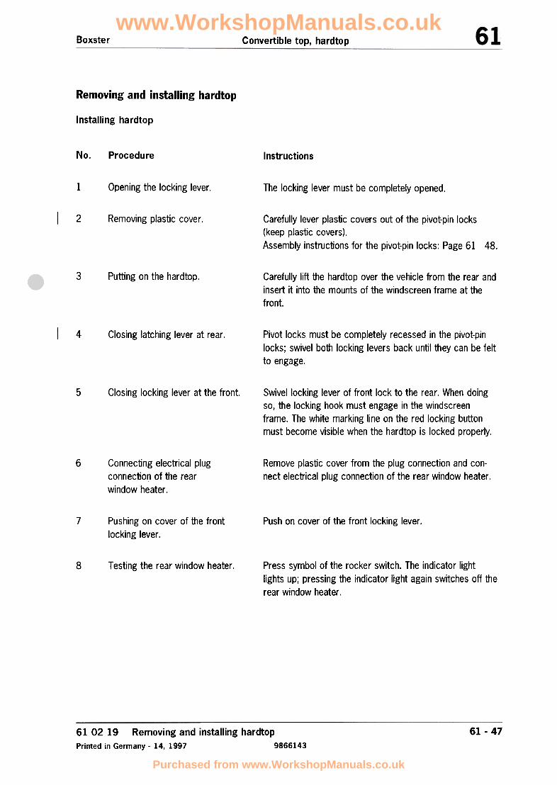
Boxster Convertible top. hardtop
Removing and installing hardtop
Installing hardtop
No. Procedure Instructions
1 Opening the locking lever. The locking lever must be completely opened.
2 Removing plastic cover. Carefully lever plastic covers out of the pivot-pin locks
(keep plastic covers).Assembly instructions for the pivot-pin locks: Page 61 48.
3 Putting on the hardtop. Carefully lift the hardtop over the vehicle from the rear andinsert it into the mounts of the windscreen frame at thefront.
4 Pivot locks must be completely recessed in the pivot-pinlocks; swivel both locking levers back until they can be feltto engage.
Closing latching lever at rear.
5 Swivel locking lever of front lock to the rear. When doingso, the locking hook must engage in the windscreenframe. The white marking line on the red locking buttonmust become visible when the hardtop is locked properly.
Closing locking lever at the front.
6 Connecting electrical plug
connection of the rearwindow heater.
Remove plastic cover from the plug connection and con-nect electrical plug connection of the rear window heater.
7 Push on cover of the front locking lever.Pushing on cover of the frontlocking lever.
Press symbol of the rocker switch. The indicator lightlights up; pressing the indicator light again switches off therear window heater.
8 Testing the rear window heater.
61 02 19 Removing and installing hardtop
Printed in Germany -14, 1997 9866143
61 -47
www.WorkshopManuals.co.uk
Purchased from www.WorkshopManuals.co.uk

Convertible top, hardtop Boxster
Removing and installing hardtop
Installing pivot-pin locks
Note: Insert the pivot-pin locks (8) with theconvertible top open. The fitting bolt (C) can bescrewed in only with the convertible top closed.
653_96
The pivot-pin lock (B) is fitted in the bracket (A).Bear in mind here that there are left-handed andright-handed pivot-pin locks (observe the L or Ridentification on the pivot-pin lock).The locking tab of the bracket must line up withthe recess of the pivot-pin lock. The pivot-pinlock (B) is clamped in the bracket (A) when thefitting bolt (C) is tightened.
61 -48 61 02 199866143
Removing and installing hardtop
Printed in Germany -14, 1!~97
www.WorkshopManuals.co.uk
Purchased from www.WorkshopManuals.co.uk

Convertible top, hardtopBoxster
61 02 37 Disassembling and assembling hardtop
601-96
61 02 37 Disassembling and assembling hardtopPrinted in Germany -7, 1996 9866149
61 -49
www.WorkshopManuals.co.uk
Purchased from www.WorkshopManuals.co.uk

Removal overview of the hardtop components
61 -50 Inside page
9866149
www.WorkshopManuals.co.uk
Purchased from www.WorkshopManuals.co.uk

Convertible top, hardtop Boxster
61 02 379866149
Disassembling and assembling hardtopPrinted in Germany -7, 1996
www.WorkshopManuals.co.uk
Purchased from www.WorkshopManuals.co.uk
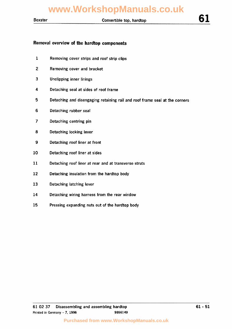
Boxster Convertible top, hardtop
Removal overview of the hardtop components
1 Removing cover strips and roof strip clips
2 Removing cover and bracket
3 Unclipping inner linings
4 Detaching seal at sides of roof frame
5 Detaching and disengaging retaining rail and roof frame seal at the corners
6 Detaching rubber seal
7 Detaching centring pin
8 Detaching locking lever
9 Detaching roof liner at front
10 Detaching roof liner at sides
11 Detaching roof liner at rear and at transverse struts
12 Detaching insulation from the hardtop body
13 Detaching latching lever
14 Detaching wiring harness from the rear window
15 Pressing expanding nuts out of the hardtop body
61 02 37 Disassembling and assembling hardtopPrinted in Germany -7, 1996 9866149
61 -51
www.WorkshopManuals.co.uk
Purchased from www.WorkshopManuals.co.uk

Disassembling hardtop
No. Procedure Instructions
Set down hardtop Place hardtop on the assembly fixture and lock with thelatching levers and the locking lever at front.
1 Removing cover strips and roof strip clips
Lift cover strip at the left and right with a plastic spatulaand pull off. The roof strip clips are destroyed when theyare removed and must always be replaced.
/
"-.,..
? Removing cover and bracket
Pull off cover and press out the bracket at the top and bot-tom with a plastic spatula.
'"
""'"
~---
Remove rear window See: Repair Group 64, Page 64 -9
Turn hardtop Place outer side of hardtop on the assembly fixture.
61 -52 61 02 379866149
Disassembling and assembling hardtopPrinted in Germany -7,1996
www.WorkshopManuals.co.uk
Purchased from www.WorkshopManuals.co.uk
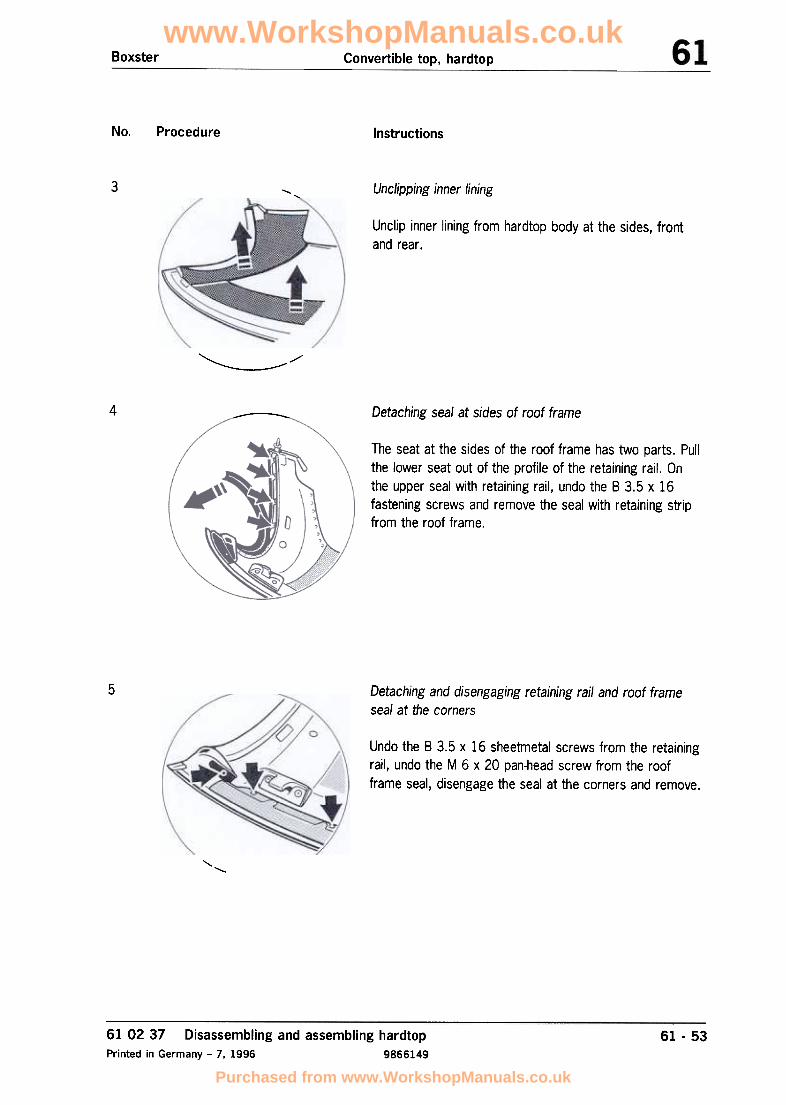
Boxster Convertible top, hardtop
No. Procedure Instructions
3 Un clipping inner lining
~
"Unclip inner lining from hardtop body at the sides, frontand rear.
"'"
/'
,,
4 Detaching seal at sides of roof frame
~
The seat at the sides of the roof frame has two parts. Pullthe lower seat out of the profile of the retaining rail. Onthe upper seal with retaining rail, undo the B 3.5 x 16fastening screws and remove the seal with retaining stripfrom the roof frame.
5 Detaching and disengaging retaining rail and roof frameseal at the corners
Undo the 8 3.5 x 16 sheetmetal screws from the retainingrail, undo the M 6 x 20 pan-head screw from the roofframe seal, disengage the seal at the corners and remove.
'"
'-..
61 02 37 Disassembling and assembling hardtop
Printed in Germany -7, 1996 9866149
61 -53
www.WorkshopManuals.co.uk
Purchased from www.WorkshopManuals.co.uk

Convertible top, hardtop Boxster
No. Procedure Instructions
6
-
Detaching rubber seal/"'
"
/Pull off the all-round rubber seal at the rear.
\\
7 Detaching centring pin
Undo the M 6 x 20 pan-head screws from the centring pinand remove.
8 Detaching locking lever
Undo the M 6 x 20 countersunk screws from the lockinglever and remove.
Disassembling and assembling hardtopPrinted in Germany -7, 1996
61 02 379866149
61 -54
www.WorkshopManuals.co.uk
Purchased from www.WorkshopManuals.co.uk

Convertible top, hardtopBoxster
No. Procedure Instructions
9
~
,Detaching roof liner at front
~
Lift the front retaining rail of the roof liner with a plasticspatula and pull off.
10 Detaching roof liner at sides
Lift the roof liner on the left and right sides with a plasticspatula and disengage from the sheetmetal clips.
'~~~
',j~jj,~
~
'~Ci'i!'i;;;i;!';'i,
1 Detaching roof liner at rear and transverse struts
Pull back and disengage the plastic rail on the roof liner.Pull out the transverse struts with the plastic sleeves andremove the roof liner.
61 -5561 02 37 Disassembling and assembling hardtopPrinted in Germany -7, 1996 9866149
www.WorkshopManuals.co.uk
Purchased from www.WorkshopManuals.co.uk

No. Procedure Instructions
12 Detaching insulation from the hardtop body
Detach insulation from the hardtop body with a spatula.
13 Detaching latching lever
Undo M 6 x 20 collar screws from the latching lever onthe hardtop body and remove the latching lever./
14 Detaching wiring harness from the rear window
6Drill open tubular rivet with a ~ 3.2 mm drill bit. Discon-nect electrical plug connection and unclip wiring harnessfrom the hardtop body.
\"
61 -56 61 02 379866149
Disassembling and assembling hardtopPrinted in Germany -7, 1996
www.WorkshopManuals.co.uk
Purchased from www.WorkshopManuals.co.uk

Boxster Convertible top, hardtop
No. Procedure Instructions
15 Pressing expanding nuts out of the hardtop body
Press out the expanding nuts on the sides and front of theroof frame.
61 02 37 Disassembling and assembling hardtopPrinted in Germany -7, 1996 9866149
61 -57
www.WorkshopManuals.co.uk
Purchased from www.WorkshopManuals.co.uk

Boxster Convertible top, hardtop
Disassembling and assembling hardtop
~
,~
.~
658.96
61 02 37 Disassembling and assembling hardtopPrinted in Germany -7, 1996 9866149
61 -59
www.WorkshopManuals.co.uk
Purchased from www.WorkshopManuals.co.uk

Installation overview of hardtop components
61 -60 Inside page
9866149
www.WorkshopManuals.co.uk
Purchased from www.WorkshopManuals.co.uk

www.WorkshopManuals.co.uk
Purchased from www.WorkshopManuals.co.uk

Convertible top, hardtopBoxster
Installation overview of hardtop components
1 Pressing expanding nuts into the hardtop body
2 Fitting wiring harness for the rear window heater
Adhering insulation in the hardtop body3
Inserting roof liner at rear and the transverse struts4
5 Engaging roof liner at sides
6 Engaging roof liner at front
Adhering Nito tape on roof frame seal7
Engaging roof frame seal at corners and fitting retaining rail8
Fitting roof frame seal at sides9
10 Fitting rubber seal
Fitting latching lever11
12 Fitting locking lever
Fitting centring pin13
Clipping in inner linings14
Fitting cover and bracket15
Filling roof ends16
Fitting cover strips and roof strip clips17
61 -6161 02 37 Disassembling and assembling hardtopPrinted in Germany -7. 1996 9866149
www.WorkshopManuals.co.uk
Purchased from www.WorkshopManuals.co.uk

Convertible top, hardtop Boxster
Assembling hardtop
No. Procedure Instructions
Set down hardtop Place outer side of the hardtop on the assembly fixture.Pressing expanding nuts into the hardtop body1
Press the expanding nuts into the roof frame at the sidesand front until they engage.
'"
/
~~
2 Fitting wiring harness for the rear window heater
Clip the wiring harness in the hardtop body. Rivet the flatconnector to the hardtop body with a ~ 3.2 mm tubularrivet and connect the flat connector and the cable lug.
3 Adhering insulation in the hardtop body
Position the self-adhesive insulation in the hardtop bodyand firmly press into place.
Disassembling and assembling hardtopPrinted in Germany -7, 1996
61 02 379866149
61 -62
www.WorkshopManuals.co.uk
Purchased from www.WorkshopManuals.co.uk

Boxster Convertible top, hardtop
No. Procedure Instructions
4 Inserting roof liner at rear and the transverse struts~ ",/
Insert the transverse struts with the plastic sleeves intothe hardtop body, pull back the plastic rail of the roof linerand engage it in the hardtop body.
5 Engaging roof liner at sides
Engage roof liner in the sheetmetal clips at the sides.Note:If the hardtop body is new, the sheetmetal clips on the left
and right must be bent over to the outside using a plastichammer.
6 Fitting roof liner at front
Position and clip in the front retaining rail of the roof liner.
61 02 37 Disassembling and assembling hardtopPrinted in Germany -7, 1996 9866149
61 -63
www.WorkshopManuals.co.uk
Purchased from www.WorkshopManuals.co.uk

NI[). Procedure Instructions
7 Adhering Nito tape on the roof frame seal
~"
On the roof frame seal at the sides, affix a strip of self-ad-hesive Nito tape centred over the screw fastening pointsof the seal.
8 Engaging roof frame seal at corners and fitting retaining rail
Engage the roof frame seal at the corners, position it, andscrew in in place with the M 6 x 20 pan-head screw. Posi-tion the retaining rail on the roof frame at front and screwin place with the B 3.5 x 16 sheetmetal screws.
"'
9 Fitting roof frame seal at sides
~~
/" '"/
/The seal on the roof frame at the sides consists of twoparts. Position the upper seal with retaining rail on the hard-top body and fasten the retaining rail with the B 3.5 x 16fastening screws. Press the lower seal into the profile ofthe retaining rail.
\
""
61 02 379866149
Disassembling and assembling hardtopPrinted in Germany -7,1996
61 -64
www.WorkshopManuals.co.uk
Purchased from www.WorkshopManuals.co.uk

Boxster Convertible top, hardtop
No. Procedure Instructions
10 Fitting rubber seal,
'"
Position the self-adhesive all-round rubber seal at the rearand firmly press into place.\
//
11 Fitting latching lever
~~"
Position the latching lever on the hardtop body and fastenwith the M 6 x 20 collar screw.
\
12 Fitting locking lever
Position the locking lever on the hardtop body and fastenwith the M 6 x 20 countersunk screws.
61 02 37 Disassembling and assembling hardtopPrinted in Germany -7, 1996 9866149
61 -65
www.WorkshopManuals.co.uk
Purchased from www.WorkshopManuals.co.uk

Convertible top, hardtop Boxster
No. Procedure Instructions
13 Fitting centring pin
Position centring pin on the hardtop body and fasten withthe M 6 x 20 pan-head screws.
~
Turn hardtop Place hardtop on the assembly fixture and lock with thelatching levers at the rear and the locking lever at the front.
See: Repair Group 64, Page 64 -9Fit rear window
Place outer side of the hardtop on the assembly fixture,Turn hardtop
14 Clipping in inner linings
~~
Clip the inner linings into the hardtop body at the rear Isides and front.
Turn hardtop Place hardtop on the assembly fixture and lock with thelatching levers at the rear and the locking lever at the front.
61 02 379866149
Disassembling and assembling hardtop
Printed in Germany -7. 1996
61 -66
www.WorkshopManuals.co.uk
Purchased from www.WorkshopManuals.co.uk
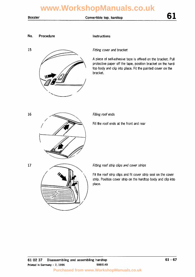
Boxster Convertible top, hardtop
No. Procedure Instructions
15 Fitting cover and bracket
A piece of self-adhesive tape is affixed on the bracket. Pullprotective paper off the tape, position bracket on the hard-top body and clip into place. Fit the painted cover on thebracket.
'"~~
16 Filling roof ends
Fill the roof ends at the front and rear,
17 Fitting roof strip clips and cover strips
Fit the roof strip clips and fit cover strip seal on the coverstrip. Position cover strip on the hardtop body and clip into
place.
\\
""
'
~~/
61 02 37 Disassembling and assembling hardtopPrinted in Germany -7, 1996 9866149
61 -67
www.WorkshopManuals.co.uk
Purchased from www.WorkshopManuals.co.uk
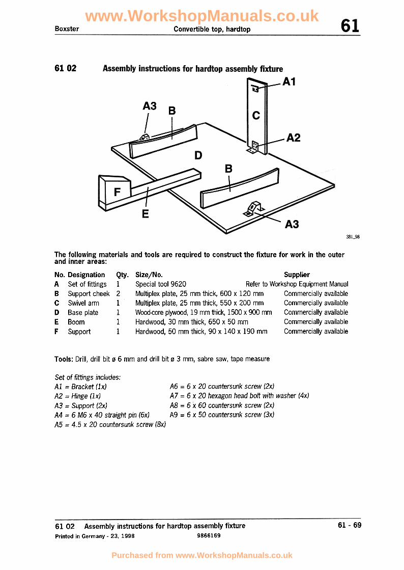
Boxster Convertible top, hardtop
6102
381_98
The following materials and tools are required to construct the fixture for work in the outerand inner areas:
No. Designation Qty. SizejNo. Supplier
A Set of fittings 1 Special tool 9620 Refer to Workshop Equipment ManualB Support cheek 2 Multiplex plate, 25 mm thick, 600 x 120 mm Commercially availableC Swivel arm 1 Multiplex plate, 25 mm thick, 550 x 200 mm Commercially availableD Base plate 1 Wood-core plywood, 19 mm thick, 1500 x 900 mm Commercially availableE Boom 1 Hardwood, 30 mm thick, 650 x 50 mm Commercially availableF Support 1 Hardwood, 50 mm thick, 90 x 140 x 190 mm Commercially available
Tools: Drill, drill bit 06 mm and drill bit 03 mm, sabre saw, tape measure
A6 = 6 x 20 countersunk screw (2x)A7 = 6 x 20 hexagon head bolt with washer (4x)AB = 6 x 60 countersunk screw (2x)A9 = 6 x 50 countersunk screw (3x)
Set of fittings includes:Al = Bracket (Ix)A2 = Hinge (Ix)A3 = Support (2x)A4 = 6 M6 x 40 straight pin (6x)A5 = 4.5 x 20 countersunk screw (8x)
61 -6961 02 Assembly instructions for hardtop assembly fixturePrinted in Germany -23, 1998 9866169
www.WorkshopManuals.co.uk
Purchased from www.WorkshopManuals.co.uk

Convertible top, hardtop Boxster
fttaking support cheeks (B)
B:asic material: Multiplex plate 600 x 120 mm, 25 mm thick
EE!
§I~
a:
B0(\I~
0~L.~ I I I ' I ' II IIII 0 I A4"' <'J .
T1 00 ,..
600
A4 = Straight pin 6 M6 x 40 /B = Support cheek
21_97
Procedure:
1. Transfer 160 mm radius to the multiplex
plates.
4. Drill three ~ 6 mm holes, 20 mm deep,in the support cheeks (8) to accommodatethe straight pins (A4) M6 x 40 from the set
of fittings (A).2. Saw multiplex plates along the traced radius.The foot of the sabre saw must be tiltedby 150 for this purpose.
3. Drill four 0 6 mm holes in the support radiiof each support cheek to provide clearancefor the Tucker bolts on the hardtop body.Obtain the dimensions from the hardtop
body.
Assembly instructions for hardtop assembly fixture9866169 Printed in Germany -23, 1998
610261 -70
www.WorkshopManuals.co.uk
Purchased from www.WorkshopManuals.co.uk
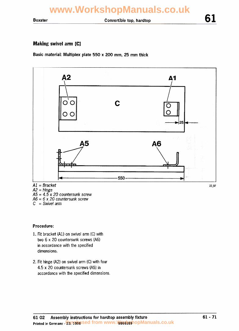
Boxster Convertible top, hardtop
Making swivel arm (C)
Basic material: Multiplex plate 550 x 200 mm, 25 mm thick
A2
A1
2~97Al = BracketA2 = HingeA5 = 4.5 x 20 countersunk screwA6 = 6 x 20 countersunk screwC = Swivel arm
Procedure:
1. Fit bracket (AI) on swivel arm (C) withtwo 6 x 20 countersunk screws (A6)in accordance with the specifieddimensions.
2. Fit hinge (A2) on swivel arm (C) with four4.5 x 20 countersunk screws (A5) inaccordance with the specified dimensions.
61 -7161 02 Assembly instructions for hardtop assembly fixturePrinted in Germanv -23. 1998 9866169
www.WorkshopManuals.co.uk
Purchased from www.WorkshopManuals.co.uk

f~itting the swivel arm (C) and support cheeks (B) on the base plate (0)
Elasic material: Wood-core plywood 1500 x 900 mm, 19 mm thick
23_97A3 = SupportB = Support cheekC = Swivel arm0 = Base plate
Procedure:
During assembly, all parts are positioned from the centre line!
1. Measure and mark centre of the base 3. Transfer hole pattern of the support cheeks
plate (0). (8) onto the base plate (0) in accordance withthe specified dimensions and drill holes using
2. Fasten hinge (A2) of the completed swivel arm a ~ 6 mm drill bit.(C) on the base plate (0) with four 4.5 x 20countersunk screws (A5) in accordance withthe specified dimensions.
4. Fit the support cheeks (8) on the base plate(0) by means of the pre-fitted straight pins(A4) 6 M6 x 40.
61 -72 6102 Assembly instructions for hardtop assembly fixture9866169 Printed in Germany -23, 1998
www.WorkshopManuals.co.uk
Purchased from www.WorkshopManuals.co.uk

Fitting supports (A3) for the hardtop latching levers on the base plate
BA3
"D.,/
".
b.~195
~/'O
A724~7A3 = Support
A7 = Hexagon head bolt 6 x 20 with washerB = Support cheekD = Base plate
Procedure:
1. Fit the supports (A3) on the base plate (0)with two 6 x 20 hexagon head bolts (A7) eachin accordance with the specified dimensions.
61 -7361 02 Assembly instructions for hardtop assembly fixturePrinted in Germany -23, 1998 9866169
www.WorkshopManuals.co.uk
Purchased from www.WorkshopManuals.co.uk

Convertible top, hardtop Boxster
I=itting the boom (E) and the support (F) on the base plate (D)
650
190
E AS/"", R
~D 0C\I..-
0(Y)
~420
361_98D = Base plateE = BoomF = SupportAB = 6 x 60 countersunk screw (2x)A9 = 6 x 50 countersunk screw (3x)
IPlace boom in the centre!
1. Measure and mark centre of the base
plate (0).
2. Fit boom (E) on the base plate (0) withthe three countersunk screws (A9)in accordance with the specifieddimensions.
3. Fit support (F) on the boom (E) with the twocountersunk screws (A8) in accordancewith the specified dimensions.
6il -74 6102 Assembly instructions for hardtop assembly fixture9866169 Printed in Germany -23, 1998
www.WorkshopManuals.co.uk
Purchased from www.WorkshopManuals.co.uk

Boxster Convertible top, hardtop
61 90 19 Removing and installing convertible top compartment lid
458_96
61 90 19 Removing and installing convertible top compartment lidPrinted in Germany -26, 1999 9866175
61 -75
www.WorkshopManuals.co.uk
Purchased from www.WorkshopManuals.co.uk

www.WorkshopManuals.co.uk
Purchased from www.WorkshopManuals.co.uk

Convertible top, hardtopBoxster
Removing and installing convertible top compartment lid
For removal of the convertible top compartment lid, the convertible top must be unlocked and theconvertible top compartment lid must be in its highest position.
No. Designation Qty. RemovalNote:
Installation
Collar nut 4
2 Remove convertible top
compartment.
Convertible top
compartment
1 Position convertible topcompartment on theguide arm (Item 40) andfasten with the collar nuts
(Item 1).
Push on3 Edge guard, left Pull off
4 Edge guard, right P"ull off Push on
5 Sheetmetal screwst 3.5 x 9.5
2
6 Rail 1 Pull rail off lid, Position rail on lid andfasten with thest 3.5 x 9.5 sheetmetalscrews (Item 5).
7 Rubber seal 1 Pull rubber seal out of therail (Item 6).
Retainer SLB 8 68 Press out retainer
Press rubber seal into the
rail (Item 6).
Replace retainer
Removal tool
see: Workshop
Equipment Manual,Chapter 2.4, No. 131
9 Push-bar spring 1 Push ball socket of thepush-bar spring out of theball head of the drive lever(Item 27). Push out theretainer (Item 8). Removepush-bar spring from thehinged lever (Item 10).
Insert push-bar spring inthe hinged lever (Item 10)and press in with theretainer (Item 8). Pressball socket of thepush-bar spring into theball head of the drivelever (Item 27).
61 90 19 Removing and installing convertible top compartment lid
Printed in Germany -26, 1999 9866175
61 -77
www.WorkshopManuals.co.uk
Purchased from www.WorkshopManuals.co.uk
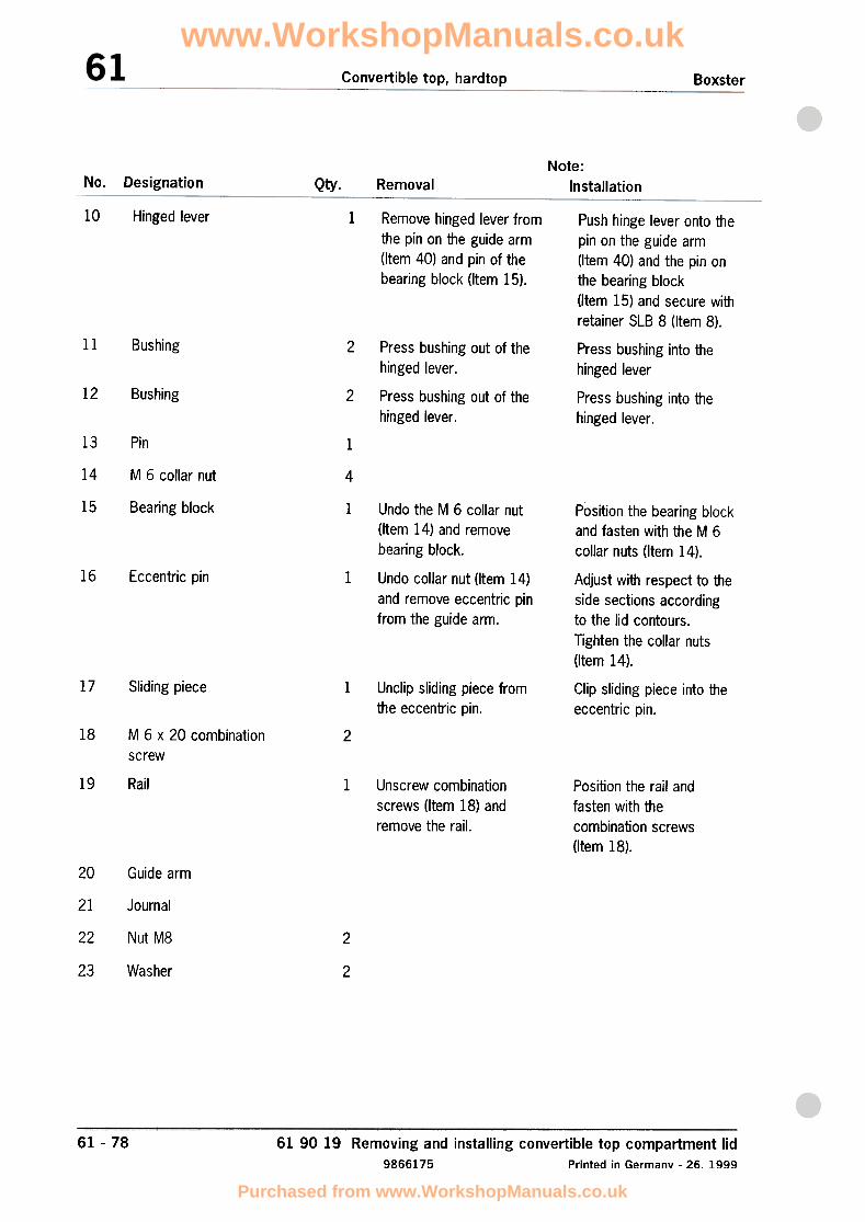
Convertible top, hardtop Boxster
No. Designation Qty. RemovalNote:
Installation
10 Hinged lever 1 Remove hinged lever fromthe pin on the guide arm(Item 40) and pin of thebearing block (Item 15).
Push hinge lever onto thepin on the guide arm(Item 40) and the pin onthe bearing block(Item 15) and secure withretainer SLB 8 (Item 8).
11 Bushing 2 Press bushing into thehinged lever
12 Bushing 2
Press bushing out of thehinged lever.
Press bushing out of thehinged lever.
Press bushing into thehinged lever.
13 Pin 1
14 M 6 collar nut 4
15 Bearing block 1 Position the bearing blockand fasten with the M 6collar nuts (Item 14).
16 Eccentric pin 1
Undo the M 6 collar nut(Item 14) and removebearing block.
Undo collar nut (Item 14)and remove eccentric pinfrom the guide arm.
17 Sliding piece 1 Unclip sliding piece fromthe eccentric pin.
Adjust with respect to theside sections accordingto the lid contours.Tighten the collar nuts
(Item 14).
Clip sliding piece into theeccentric pin.
18 M 6 x 20 combination
screw2
19 Rail 1 Unscrew combinationscrews (Item 18) andremove the rail.
Position the rail andfasten with thecombination screws(Item 18).
20 Guide arm
21 Journal
22 Nut M8 2
23 Washer 2
61 -78 61 90 19 Removing and installing convertible top compartment lid
9866175 Printed in Germanv -26. 1999
www.WorkshopManuals.co.uk
Purchased from www.WorkshopManuals.co.uk

Convertible top, hardtopBoxster
24 2Adjusting element Unscrew M8 nut (Item 22)and remove the adjustingelement.
Position the adjustingelement, screw in withthe M8 nut (Item 22) andclose lid.Align the lid contours andjoining gap to the sidesections using theadjusting element.
25 Seal 1 Pull off Position and push on theseal.
26 Hexagon-head boltM 12 x 30
1
27 Drive lever 1
Replace,tightening torque:80 Nm (59 ftlb.)
Position the drive leverand fasten with theM 12 x 30 hexagon-headbolt (Item 26).
28A Friction plate 2
288 Install friction plate only inconnection with thenew (8) components.
2
29 M 8 x 25 screw 1
Install friction plate only inconnection with gear(Item 348), the spacerpin (Item 358) and theflexible shaft (Item 368).
Tightening torque:13 Nm (10 ftlb.)
30 Spacer sleeve 1
31 Push bar 1
32 Ball journal 1
33 3 Tightening torque:22 Nm (16 ftlb.)
M 8 collar nut
61 90 19 Removing and installing convertible top compartment lid
Printed in Germany -26, 1999 9866175
61 -79
www.WorkshopManuals.co.uk
Purchased from www.WorkshopManuals.co.uk
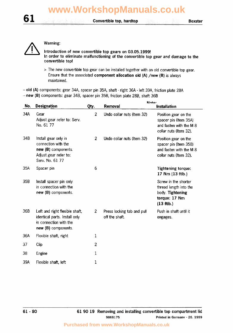
A Warning:
ill Introduction of new convertible top gears on 03.05.1999!In order to eliminate malfunctioning of the convertible top gear and damage to theconvertible top!
> The new convertible top gear can be installed together with an old convertible top gear.
Ensure that the associated component allocation old (A) jnew (B) is always
maintained.
-old (A) components: gear 34A, spacer pin 35A, shaft -right 36A -left 39A, friction plate 28A-new (8) components: gear 348, spacer pin 358, friction plate 288, shaft 368
Note:No. Designation Qty. Removal Installation
34A Gear 2 Undo collar nuts (Item 32) Position gear on theAdjust gear refer to: Servo spacer pin (Item 35A)No. 61 77 and fasten with the M 8
collar nuts (Item 32).
348 2 Undo collar nuts (Item 32) Position gear on the
spacer pin (Item 358)and fasten with the M 8collar nuts (Item 32),
Install gear only inconnection with thenew (B) components,Adjust gear refer to:Servo No. 61 77
35A Spacer pin 6 Tightening torque:17 Nm (13 ftlb.)
358 Install spacer pin onlyin connection with thenew (B) components.
368
2 Press locking tab and pulloff the shaft.
Screw in the shorterthread length into the
body. Tighteningtorque: 17 Nm
(13 ftlb.)
Push in shaft until it
engages.
36A
Left and right flexible shaft,identical parts. Install onlyin connection with thenew (8) components.
Flexible shaft, right .1
37 Clip 2
38 Engine 1
39A Flexible shaft, left .1
61 -80 61 90 19 Removing and installing convertible top compartment lid
9866175 Printed in Germany -26. 1999
www.WorkshopManuals.co.uk
Purchased from www.WorkshopManuals.co.uk

Boxster Convertible top, hardtop
.
61 7705 Adjusting convertible top gear
402_97
61 -8161 77 05 Adjusting convertible top gear
Printed in Germany -14, 1997 9866181
www.WorkshopManuals.co.uk
Purchased from www.WorkshopManuals.co.uk

Convertible top, hardtop Boxster
Adjusting convertible top gear
2/
QI
/
I/
/
~~
~
~
;y-_1I
/
~~
4A
"0'-
..!:J.. \ "6
/..:::::::==::::=.",
/'
Q
48
~
403_97
61 .82 61 77 05 Adjusting convertible top gear
Printed in Gemlany -14, 19979866181
'--.:..-
..0..
www.WorkshopManuals.co.uk
Purchased from www.WorkshopManuals.co.uk

Boxster Convertible top, hardtop
Adjusting convertible top gear
Basic adjustment of the convertible top gear
For adjustment of the convertible top drive, unlock the convertible top and press out the left and right ballsockets of the push rod out of the ball head of the drive lever.
No. Procedure Instructions
1 Unscrewing hexagon-head bolts
(micro-encapsulated)
Unscrew the M12 x 30 hexagon-head bolts from the drivelever and remove cover from the convertible top drive.
Unclip clip from the flexible shaft and remove shaft from
the drive motor.
2 Disengaging flexible shaft
3 Fitting drive lever Fit drive lever on the convertible top gear.
4 Version: APositioning drive lever onmarking
Insert the flexible shaft of the convertible top gear to beadjusted into the drive motor and set the drive lever to thecentre of the marking notches with the rocker switch(adjust convertible top gear on left and right synchronously),
4 Version: BMeasuring drive lever
Insert the flexible shaft of the convertible top gear to beadjusted into the drive motor and use the rocker switch toadjust the centre of the drive lever ball head with respectto the side section sealing channel (upper edge).Dimension: 195 :to,S mm.(Adjust convertible top gear on left and right
synchronously.)
Position the cover and drive lever on the convertible topgear and fasten with the M12 x 30 hexagon-head bolt
(micro-encapsulatedJ,Tightening torque: 80 Nm
5 Fitting drive lever, cover
Insert the flexible shaft into the drive motor and securewith the clip.
6 Inserting flexible shaft
61 -8361 77 05 Adjusting convertible top gearPrinted in Germany -14, 1997 9866181
www.WorkshopManuals.co.uk
Purchased from www.WorkshopManuals.co.uk

Convertible top, hardtopBoxster
61 01 15 Adjusting convertible top
(
~r'\'
J...,
IA
52O_97
61 -8561 01 15 Adjusting convertible topPrinted in Germany -14, 1997 9866185
www.WorkshopManuals.co.uk
Purchased from www.WorkshopManuals.co.uk
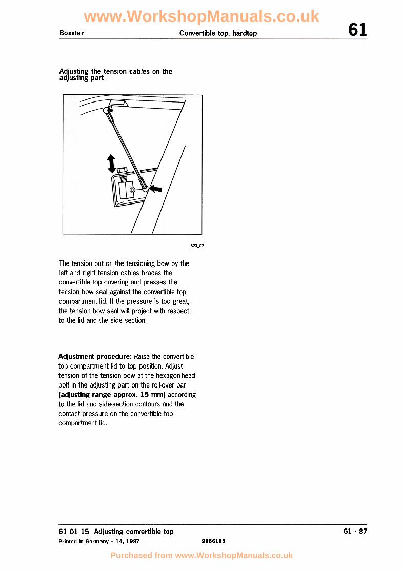
Boxster Convertible top, hardtop
Adjusting the tension cables on theadjusting part
:::::::::-
A
~,::=
523_97
The tension put on the tensioning bow by theleft and right tension cables braces theconvertible top covering and presses thetension bow seal against the convertible topcompartment lid. If the pressure is too great,the tension bow seal will project with respectto the lid and the side section.
Adjustment procedure: Raise the convertibletop compartment lid to top position. Adjusttension of the tension bow at the hexagon-headbolt in the adjusting part on the roll-over bar(adjusting range approx. 15 mm) accordingto the lid and side-section contours and thecontact pressure on the convertible topcompartment lid.
61 01 15 Adjusting convertible top
Printed in Germany -14, 1997
61 -87
9866185
www.WorkshopManuals.co.uk
Purchased from www.WorkshopManuals.co.uk

Convel1ible top, hardtopBoxster
Troubleshooting in convertible top operation61 01 01
Troubleshooting:
The control relay (double relay) is located atsockets 14 and 15 on relay carrier 1 in the
footwell.
Note
Except for manual unlocking and locking of theconvertible top, the opening and closingprocesses must take place automatically.Pressing a button in the centre console causesthe drive elements to execute the preselectedmotion. Various micro-switches ensure that
these processes take place smoothly.
The motor is activated only if the followingconditions are met:
no speedometer signals greater than 5 km/h,
electric motor plug connection is plugged in,
terminal 15 connected via ignition lock,
fuse B 6 (row B, number 6) and fuse D 3(row D, number 3) are OK,
parking brake is engaged.
595_97The vehicle must be on a horizontal surface andthere must not be any defect in the convertible
top actuating mechanism.
61 -8961 01 01 Troubleshooting in convertible top operation
Printed in Germany -16, 1997 9866189
www.WorkshopManuals.co.uk
Purchased from www.WorkshopManuals.co.uk

Boxster Convertible top, hardtop
Troubleshooting on the relay carrier
Note
Control relay pulled off. Terminal designationon the relay carrier (Figure 596_97) is from thebottom side of the control relay.
7. Convertible top locked. Connect measuringinstrument to terminal 23 and terminal 29
(B-pillar micro-switch).
Display = battery voltage1. Connect measuring instrument (voltmeter) toterminal 22 (ground) and terminal 23 (positive30) on the carrier plate.
8. Convertible top unlocked. Connect
measuring instrument to terminal 23 and
terminal 13 (micro-switch closed, convertible
top compartment lid CTCL open).Display = battery voltage
2. Connect measuring instrument to terminal 22(ground) and terminal 26. Switch on ignition.
Display = battery voltage
9. Convertible top unlocked. Connectmeasuring instrument to terminal 23 andterminal 19 (cowl panel frame micro-switch).
Display = battery voltage
3. Connect measuring instrument to terminal 23(positive) and terminal 15 (parking brake
engaged),
Display = battery voltage
Display = battery voltage
4. Connect measuring instrument to terminal 23and terminal 16 ("close convertible top"button). Press "close" button.
Plug control relay onto relay carrier. Open
convertible top compartment lid and pull
off electrical plug connection on the
convertible top drive motor.
10. Connect positive lead of measuringinstrument to terminal 1 (black wire) andnegative lead of measuring instrument toterminal 4 (green wire). Use an auxiliary leadto jumper terminal 2 and terminal 3 at theplug connection. Switch on ignition and press"Open" button.
Display = battery voltage
5. Connect measuring instrument to terminal 23and terminal 17 ("open convertible top"button), Press "open" button. Display = battery voltage
11. Connect positive lead of measuring instru-ment to terminal 4 (green wire) and negativelead of measuring instrument to terminal 1(black wire). Use an auxiliary lead to jumperterminal 2 and terminal 3. Switch on ignitionand press "Close" button.
Display = battery voltage
6. Convertible top locked. Connect measuringinstrument to terminal 23 and terminal 14(cowl panel frame micro-switch),
Display = battery voltageDisplay = battery voltage
61 01 01 Troubleshooting in convertible top operation
Printed in Germany -16, 1997 9866189
61- 91
www.WorkshopManuals.co.uk
Purchased from www.WorkshopManuals.co.uk

Convertible top, hardtopBoxster
Convertible top compartment lidmicro-switch
621_97
The micro-switch is riveted onto the drive-motorbracket. The drive motor with bracket can beremoved by unscrewing the three M6 fasteningnuts.
Note
If it is not possible to open the convertible topcompartment lid electrically (convertible topopen), carefully press the ball socket of thepush-bar springs (left and right) out of the ballhead of the drive lever.
Manually open the convertible top compartmentlid and remove the drive motor.
If the convertible top is closed, the drive motorcan be removed from the inside by taking outthe cover for the convertible top rest.
61 01 01 Troubleshooting in convertible top operation
Printed in Germany -16, 1997 9866189
61 -93
www.WorkshopManuals.co.uk
Purchased from www.WorkshopManuals.co.uk

Boxster Convertible top, hardtop
61 17 19 Removing and installing hardtop fastening
61170001
61 -9561 17 19 Removing and installing hardtop fastening
Printed in Germany -29, 1999 9866195
www.WorkshopManuals.co.uk
Purchased from www.WorkshopManuals.co.uk

Convertible top, hardtop Boxster
Removing hardtop fastening
'" /
~~
318_99
61 17 19 Removing and installing hardtop fastening9866195 Printed in Germany -29. 1999
61 -96
www.WorkshopManuals.co.uk
Purchased from www.WorkshopManuals.co.uk
Convertible top, hardtopBoxster
Removing hardtop fastening
No. Procedure Instructions
Open convertible top completely
1 Lift side panel lining up and off.Removing side-panel lining
2 Detaching cloth covering Disengage the strip on the left and right sides of the clothcovering in downward direction.
3 Detaching tension cable Press the ball socket of the tension cable off the ball headof the adjusting piece.
4 Partially closing the convertible top Both screws of the bracket are accessible in this position.
5 Detaching push bar Press the ball socket of the push bar off the ball head ofthe adjusting piece.
6 Unscrewing the fastening screws(A, B) on the bracket
Fastening screw "A" is accessible via the convertible topcompartment when the tension bow is raised.
Open convertible top completely Note: When operating the convertible top, make sure thatthe unclipped push bar does not jam in the convertible topmechanism.
Remove the bracket
61 -9761 17 19 Removing and installing hardtop fastening
Printed in Germany -29, 1999 9866195
www.WorkshopManuals.co.uk
Purchased from www.WorkshopManuals.co.uk

Convertible top, hardtop Boxster
Installing hardtop fastening
319_99
61 17 19 Removing and installing hardtop fastening
9866195 Printed in Germany -29, 1999
61 -98
www.WorkshopManuals.co.uk
Purchased from www.WorkshopManuals.co.uk

Convertible top, hardtopBoxster
Installing hardtop fastening
No. Procedure Instructions
Open convertible top completely
Insert bracket
1 Partially closing the convertible top Note: When operating the convertible top, make sure thatthe unclipped push bar does not jam in the convertible topmechanism.Both screws of the bracket are accessible in this position.
? Screwing on the bracket Note: Replace self~ocking screws. Tightening torque:
23:!: 2 Nm (17:!: 1.5 ftlb.). Install bracket at a distance
of "x" = 8 mm from the top edge of the door seal.
3 Engaging push bar Press the ball socket of the push bar onto the ball head ofthe main bow.
4 Engaging tension cable Press the ball socket of the tension cable onto the ballhead of the adjusting piece.
5 Attaching cloth covering Engage the strips on the left and right sides of the clothcovering from below.
Open convertible top completely
Installing side-panellining Insert side-panellining from above.6
Refer to Servo No. 61 02 15.Set gaps on hardtop
61 -9961 17 19 Removing and installing hardtop fastening
Printed in Germany -29. 1999 9866195
www.WorkshopManuals.co.uk
Purchased from www.WorkshopManuals.co.uk

Convertible top, hardtopBoxster
61 02 15 Adjusting the hardtop
61020003
61 -10161 02 15 Adjusting the hardtop
Printed in Germany -29, 1999 98661101
www.WorkshopManuals.co.uk
Purchased from www.WorkshopManuals.co.uk
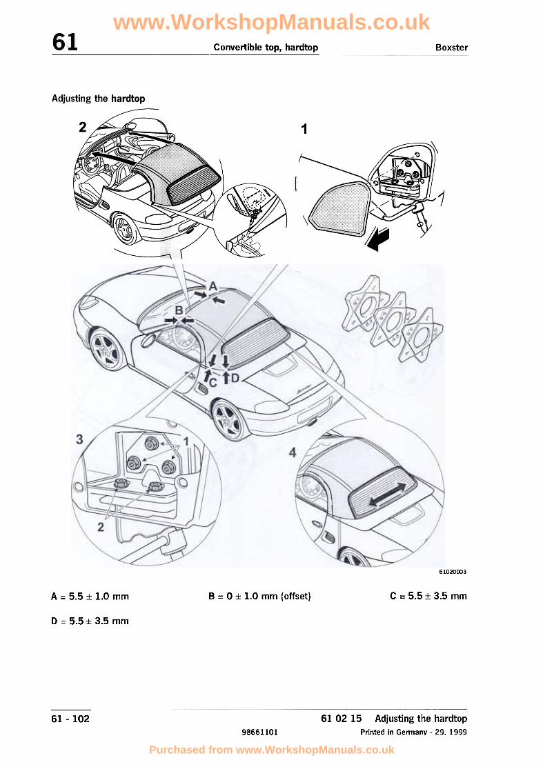
Convertible top, hardtop Boxster
1
1
61020003
A = 5.5:t 1.0 mm B = O:t 1.0 mm (offset) C = 5.5 :t 3.5 mm
D = 5.5 :t 3.5 mm
61 -102 61 02 15 Adjusting the hardtop
Printed in Germany -29. 199998661101
www.WorkshopManuals.co.uk
Purchased from www.WorkshopManuals.co.uk

Convertible top, hardtopBoxster
Adjusting the hardtop
> Note: Use star gauges to adjust or check the gap dimensions,see Workshop Equipment Technical Manual, Chapter 2.4 No. 127 -1
No. Procedure Instructions
Removing trim panels of the rearhardtop locks
Un clip trim panels.1
Refer to Service No. 61 02 192 Installing hardtop
Undo screws of the fastening plate (1) and screws ofthe latch plate (2). Move locking pin to assembly position
(unlock).
3 Releasing rear hardtop locks
By shifting the hardtop laterally at the rear lockingelements, set a parallel gap "A" at the windscreen frame.
4 Laterally aligning the hardtop
61 -10361 02 15 Adjusting the hardtop
Printed in Germany -29, 1999 98661101
www.WorkshopManuals.co.uk
Purchased from www.WorkshopManuals.co.uk

Convertible top, hardtop Boxster
61020004
B = O::!: 1.0 mm (offset) C = 5.5 :t: 3.5 mmA = 5.5::!: 1.0 mm
D = 5.5 ::t 3.5 mm
61 02 15 Adjusting the hardtop
Printed in Germany -29, 1999
61 -10498661101
www.WorkshopManuals.co.uk
Purchased from www.WorkshopManuals.co.uk

Convertible top, hardtopBoxster
Adjusting the hardtop
No. Procedure Instructions
5 Setting the lateral offset of thehardtop at the front
The offset between the hardtop cowl panel at the front(dimension "8") can be corrected by adjusting theconvertible top housing.Note: Change setting on the convertible top pin housingonly after checking the adjusting dimensions with theconvertible top closed. Also see Servo No. 61 01 15"Adjusting the convertible top"
Tightening fastening screws oflatch plate (2)
Tighten screws to 10 Nm (7.5 ftlb.6
7 Set gap "D" at both sides of the vehicle. Tighten fasteningscrews of the fastening plate (1) to 10 Nm (7.5 ftlb.).
Setting gap between hardtop
and convertible
top compartment lid
Check for smooth operation and freedom from leaks;readjust the channel strips on the hardtop if necessary.
8 Closing all side windows
Note: Readjust the side windows if necessary. Beforeadjustment, check position of the side windows in relationto the convertible top (see Service No. 5751 37).It might be possible to avoid adjusting the side windows byvarying the gap at the hardtop at the rear. If the windowsare in contact with the hardtop at their end position,correct the gap at the hardtop at rear toward the max.value. If the side windows leak, correct the gap at thehardtop at rear toward the min. value.
Installing trim panels of the rearhardtop locks
Clip in the trim panels.9
61 -10561 02 15 Adjusting the hardtop
Printed in Germany -29, 1999 98661101
www.WorkshopManuals.co.uk
Purchased from www.WorkshopManuals.co.uk

Boxster (986) Convertible top, hardtop
Removing and installing roof liner
"~
\'"
~
/
~
~
~/~!
610919 Removing and installing roof liner
Printed in Germany -38, 200061-107 page 1
a610919x
www.WorkshopManuals.co.uk
Purchased from www.WorkshopManuals.co.uk

Boxster (986)Convertible top, hardtop
Removal overview of roof liner
'"\
'"
\.I
""
/
"
./
A B~
/"
~
., ,,""
~II "
\\\~..
~~
\\""
\
~
:>q/
I \I
"
\ fi,),/\
"""
~
"
~
/
610919 Removing and installing roof linerPrinted in Germany -38. 2000
61-107 page 2a610919x
www.WorkshopManuals.co.uk
Purchased from www.WorkshopManuals.co.uk

Boxster (986) Convertible top, hardtop
1 -Convertible top in service position
2 -Detaching roof liner connection to tension bow
3 -Opening the Velcro fastening on the push bar
4 -Disengaging tension hook on main bow
5 -Pressing out plastic clip on roof frame
6 -Detaching roof frame front connection
7 -Pull tightening strip out of the main bow and centre
cover moulding
Removing roof liner
... /"... ""/
I
1 -Convertible top in service position
-Unlock convertible top and raise convertible-top compart-ment lid to its top position. Disengage the strip on thecloth covering in downward direction. Press the ballsocket of the left and right tension cables out of the ballhead of the adjusting piece. Fold tension cable upwardsat the main bow until it engages.
2 -Detaching roof liner connection to tension bow
-Use a plastic spatula to press the plastic clips for roof
liner connection out of the tension bow on the left and
right.
610919 Removing and installing roof liner
Printed in Germany -38. 200061-107 page 3
a610919x
www.WorkshopManuals.co.uk
Purchased from www.WorkshopManuals.co.uk

Boxster (986)Convertible top, hardtop
...3 -Opening the Velcro fastening on the push bar
-Open the Velcro fastening on the push bar.
.../
4 -Disengaging tension hook on main bow
-Disengage the tension hook from the pin of the converti-
ble-top support/main bow. 1\
~~//
/
...5 -Pressing out plastic clip on roof frame
-Carefully press out plastic clip on roof frame at the sides
using a plastic spatula.
~
www.WorkshopManuals.co.uk
Purchased from www.WorkshopManuals.co.uk

Boxster (986) Convertible top, hardtop
...
~
6 -Detaching roof frame front connection
-Pull the roof liner connection (plastic U-rail) at the front of
the roof frame to the rear./
...7 -Pulling out tightening strips of main bow and centre
cover moulding
8 -Vehicles with riveted roof liner clamping strips on the
roof frame
rn Note!In 20 vehicles, the headliner clamping strip was riveted to theroof frame. These vehicles are identified by the Vehicle Identifi-cation Numbers 98 ZY S 64 0086 to 98 ZY S 64 109.Observe the following roof liner removal procedure:
1. Detach the convertible top covering -inset A- at the frontand sides of the roof frame and fold to the rear
~ Rep. Gr. 612855; Replacing convertible-top covering
2. Drill out the four rivets connecting the roof liner clampingstrip to the roof frame -inset B- using a .0 4 mm drill bit.
3. Pull the roof liner clamping strip rearward out of the roof
frame.
4. Fit convertible-top covering on the roof frame
~ Rep. Gr. 612855; Replacing convertible-top covering
5. Install new roof liner ~ Rep. Gr. 610919; Removing and
installing roof liner
610919 Removing and installing roof liner
Printed in Germany -38, 200061-107 page 5
a610919x
Push convertible-top button in closed direction until the con-vertible-top compartment lid is in half-closed position.
-Pullout tightening strips of main bow and centre cover
moulding simultaneously.
www.WorkshopManuals.co.uk
Purchased from www.WorkshopManuals.co.uk

Convertible top, hardtop Boxster (986)
Installation overview of roof liner
/ ~~~/
'""'"
\
(6')r~~"'. A 8
~
"\\\
,
:/ '""'\\
'Z
-
~
;>
"...
(4)~ "'\ ""~IJ ""
I,.
\\
I"';;:;
"
/'
~
' / /"'"
www.WorkshopManuals.co.uk
Purchased from www.WorkshopManuals.co.uk
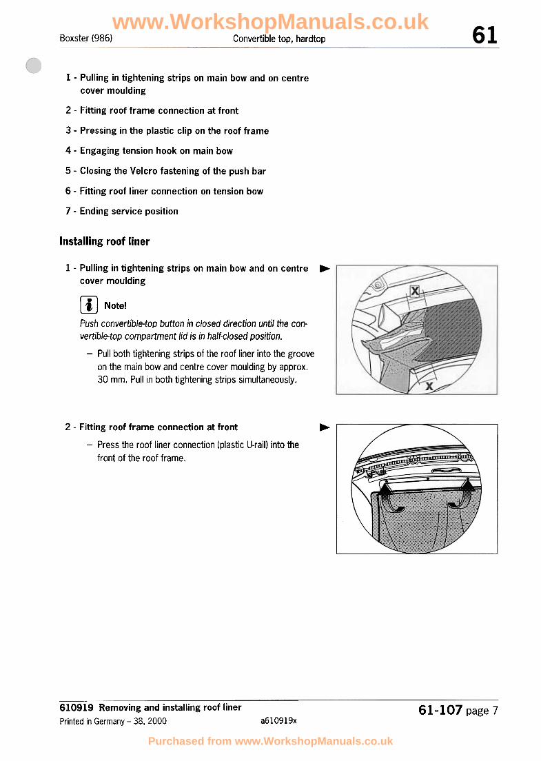
Boxster (986) Convertible top, hardtop
1 -Pulling in tightening strips on main bow and on centre
cover moulding
2 -Fitting roof frame connection at front
3 -Pressing in the plastic clip on the roof frame
4 -Engaging tension hook on main bow
5 -Closing the Velcro fastening of the push bar
6 -Fitting roof liner connection on tension bow
7 -Ending service position
Installing roof liner
1 -Pulling in tightening strips on main bow and on centre
cover moulding...
[IJ Note!Push convertible-top button in closed direction until the con-vertible-top compartment lid is in half-closed position.
-Pull both tightening strips of the roof liner into the grooveon the main bow and centre cover moulding by approx.30 mm. Pull in both tightening strips simultaneously.
~ /" ""/'/
2 -Fitting roof frame connection at front
-Press the roof liner connection (plastic U-rail) into the
front of the roof frame.
\.
610919 Removing and installing roof liner
Printed in Germany -38, 200061-107 page 7
a610919x
www.WorkshopManuals.co.uk
Purchased from www.WorkshopManuals.co.uk

Boxster (986)Convertible top, hardtop
3 -Pressing in the plastic clip at sides of roof frame
-Press in the plastic clip at the sides of the roof frame.
...
"
... <;4 -Engaging tension hook on main bow
-Use the assembly tool to engage the tension hook intothe pin of the convertible-top supporVmain bow. Assem-bly tool => No. 21; Rep. Gr. 2.4,; Workshop EquipmentManual
\\
~
5 -Closing the Velcro fastening of the push bar
-Close the Velcro fastening of the push bar.
...
www.WorkshopManuals.co.uk
Purchased from www.WorkshopManuals.co.uk

Boxster (986) Convertible top, hardtop
6 -Fitting roof liner connection on tension bow ...rn Note!In vehicles with a roof liner produced before 12.04.2000, anew roof liner with a new cut must be installed when the con-vertible-top covering with a small rear window is replaced~ Rep. Gr. 613055; Conversion measure on the tension bowfor he roof liner
-Position the roof liner connection and cloth covering onthe tension bow. Secure the connection by pressing in theplastic clips into the tension bow on the left and right.
A = up to production date 12.04.2000
B = as from production date 13.04.2000
... /",
~
"/
7 -Ending service position
-End service position and press the ball socket of the ten-
sion cable into the ball head of the adjusting element onthe left and right. Engage the strip on the cloth coveringin the rear wall of the convertible-top compartment lid.
'\I
610919 Removing and installing roof liner
Printed in Germany -38, 200061-107 page 9
a610919x
www.WorkshopManuals.co.uk
Purchased from www.WorkshopManuals.co.uk

Boxster (986) Convertible top, hardtop
The following spare parts and tools are required for the repair"Replacing the tension cable":
A -Tension cable
B -Eyelet
C -Crimping pliers
Removing the tension cable
rn Note!.In order to replace the tension cable, the convertible-top cover-
ing must be detached to a certain extent on the relevant side!
.To do so, undo the convertible-top covering at the front and theside of the roof frame => Rep. Gr. 612855; Replacing converti-
ble-top covering.
614356 Replacing the tension cable
Printed in Germany -37. 200061-108 page 1
a6143561
www.WorkshopManuals.co.uk
Purchased from www.WorkshopManuals.co.uk

Boxster (986)Convertible top, hardtop
~
1 -Disconnecting the tension cable from the main bow
-At the front B-pillar (main bow), undo the fastening screw-1- from the tension cable eye and clamping rail. ~
1
2 -Disengaging the tension cable at the shaped sheetmetal part
1. Cut the plastic sleeve -2- open with a pair of scissors.
2. Disengage the tension cable -3- from the tension spring-4- at the shaped sheetmetal part.
3. Pull the tension cable -3- out of the seal -5-.
Inst;~lling the tension cable
.,
\.:J3
5\ 4
1 -Fitting the tension cable at the shaped sheetmetal part 1. Pull the tension cable -3- in to the seal -5-.
2. Push the heat-shrinking tube -2- over the tension cable-3-.
3. Engage the tension cable -3- in the tension spring -4- at
the shaped sheetmetal part.
4. Pull the heat-shrinking tube -2- over the tension spring.Shrink the heat-shrinking tube to the diameter of the ten-sion spring by heating it with a hot-air gun.
\
3
www.WorkshopManuals.co.uk
Purchased from www.WorkshopManuals.co.uk

Boxster (986) Convertible top, hardtop
2 -Placing the eyelet on the tension cable and measuring the total length
1. Push the eyelet fully on to the end of the tension cable.
2. Measure the total length of the tension cable from eyeletto eyelet with a tape measure -dimension X = 655mm-.
...3 -Pressing the tension cable and the eyelet together
-Using commercially available crimping pliers -7-, press
the eyelet -5- together with the tension cable -6- in two
places -inset-.
/7/
~_l 0
""~~(Q)oo O-6
~
...
1
4 -Fitting the tension cable to the main bow
1. Position the tension cable with the clamping rail at the B-pillar (main bow) and screw in place with the fasteningscrew -1-.
2. Fit the convertible-top cover at the front and side of theroof frame => Rep. Gr. 612855; Replacing convertible-
top covering.
0
614356 Replacing the tension cable
Printed in Germany -37, 200061-108 page 3
a6143561
www.WorkshopManuals.co.uk
Purchased from www.WorkshopManuals.co.uk

Boxster (986) Convertible top, hardtop
Care and cleaning of the convertible top
For the care and cleaning of the convertible top, use the Tequipment care case,
Tequipment.
C!d(1>
.Never remove snow and ice
.Never affix adhesive strips,
rear window or cover it with
-The service life and the appearance of the convertible top are
largely dependent on proper care and operation.
-The car should be parked in the shade whenever possible, as
the fabric, rubber material and colour can be harmed by longexposure to sunlight.
Cleaning the convertible top
-Do not wash the convertible top every time the car is washed.It is normally sufficient to wash or rinse the convertible top withclear water. Only in the case of heavy soiling, moisten the con-vertible top with luke-warm water and Porsche "Wash-Shampo&" convertible-top cleaner and rub gently with a sponge or soft
612830 Care and cleaning of the convertible top
Printed in Germany -38.. 2000 a612830161-109 page 1
The convertible top and the flexible rear window may be
damaged or discoloured by improper care or handling.
with sharp-edged objects.stickers,
etc. to the flexible
plastic film.
www.WorkshopManuals.co.uk
Purchased from www.WorkshopManuals.co.uk

Boxster (986)Convertible top, hardtop
brush. Then rinse off the convertible top with pure water untilno traces of the Porsche "Wash-Shampo &" convertible-topcleaner remain.
-Remove bird droppings immediately, because the acids they
contain will cause the rubber material to swell and will make theconvertible top leak.
-Only open the convertible top when it is completely dry,
because otherwise damp stains and abrasions may occurwhich can not be removed afterwards.
-In the case of light soiling/always before washing, brush the
convertible top with a soft brush or with a stiff convertible-topcovering (cut out of a replaced convertible-top covering) in thedirection of the cut of the material.
-In order to prevent scratches on the flexible rear window, first
remove all impurities from the exterior with plenty of water.
CarE! of convertible top
-Light scratches and dull areas on the flexible rear window can
be removed with the Porsche Polyglas window cleaner.
-Do not apply Porsche Polyglas window cleaner to the converti-
ble-top material.
-In the case of leaks in the convertible-top covering or seams or
in the folded sections, use Porsche convertible-top care prod-uct.
-Do not bring Porsche convertible-top care product into contact
with painted surfaces, glass or the flexible rear window; if thereis contact, remove the product immediately.
-Do not remove stains on the convertible top and on the flexible
rear window with petrol, stain remover I benzene, paint thinneror other solvents; they attack the rubber layer between the fab-rics and diminish the water-tightness and the service life of the
convertible top.
-Recommendation: treat the convertible top with Porsche con-vertible-top care product twice a year or before installing the
hardtop (winter driving),
612830 Care and cleaning of the convertible topa6128301 Printed in Germany -38, 2000
61.,109 page 2
www.WorkshopManuals.co.uk
Purchased from www.WorkshopManuals.co.uk

Convertible top, hardtopBoxster (986)
Care of convertible-top seals
-Clean soiled seals with clear water.
-It is only possible to rinse the convertible top or to use an auto-
matic car wash after the flocked seals have dried.
612830 Care and cleaning of the convertible top
Printed in Germany -38,2000 a6128301
61-109 page 3
.The convertible-top seals have an anti-friction coating or areflocked and do not require any special care.
.Never grease or lubricate or spray on seals that are flocked or
have an anti-friction coating.
www.WorkshopManuals.co.uk
Purchased from www.WorkshopManuals.co.uk

Boxster (986) Bumpers
Removing and installing front spoiler
~
~
I
."
/"
~~,
"
"
--
I
"'Y'~,~
~ 1-~
/
" ..~
631519 Removing and installing front spoiler
Printed in Germany -39, 200063-1 page 1
a6315191
www.WorkshopManuals.co.uk
Purchased from www.WorkshopManuals.co.uk

Boxster (986)Bumpers
Remloving front spoiler
www.WorkshopManuals.co.uk
Purchased from www.WorkshopManuals.co.uk
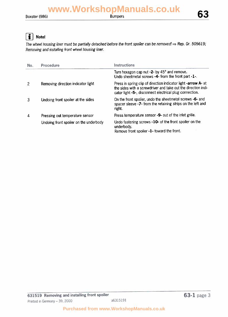
BumpersBoxster (986)
[IJ Note!The wheel housing liner must be partially detached before the front spoiler can be removed! => Rep. Gr. 505619;
Removing and installing front wheel housing liner.
2 Removing direction indicator light
Undoing front spoiler at the sides3
4 Pressing out temperature sensor
Undoing front spoiler on the underbody
Turn hexagon cap nut -2- by 450 and remove.Undo sheetmetal screws -4- from the front part -1-.
Press in spring clip of direction indicator light -arrow A- atthe sides with a screwdriver and take out the direction indi-cator light -5-, disconnect electrical plug connection.
On the front spoiler, undo the sheetmetal screws -6- andspacer sleeve -7- from the retaining strips on the left and
right.Press temperature sensor -9- out of the inlet grille.
Undo fastening screws -10- of the front spoiler on the
underbody.Remove front spoiler -1- toward the front.
www.WorkshopManuals.co.uk
Purchased from www.WorkshopManuals.co.uk

Boxster (986)Bumpers
Ins1talling front spoiler
www.WorkshopManuals.co.uk
Purchased from www.WorkshopManuals.co.uk

Boxster (986) Bumpers
No. Procedure Instructions
fitting front spoiler on the underbody
2 Fitting front spoiler at the sides
3 Fitting cover
4 Fitting direction indicator light
Position front spoiler over the bumper mount on the vehi-cle. Screw in the fastening screws onto the underbody-10-.
Affix front spoiler to the retaining strip and fasten it withthe sheetmetal screw -6- and spacer sleeve -7-.
Fasten the front end -1- with the sheetmetal screws -4-and the spacer sleeves -7-.Affix cover -3-, turn hexagon cap nuts -2- by 45°.
Insert electrical plug connection of the direction indicatorlight -5-.Insert locking tab -arrow- of the direction indicator light
into the front end -1- and clip in the sheetmetal clip.
Press temperature sensor -9- into the inlet grille.5 fressing in temperature sensor
631519 Removing and installing front spoiler
Printed in Germany -39, 200063-1 page 5
a6315191
www.WorkshopManuals.co.uk
Purchased from www.WorkshopManuals.co.uk

BumpersBoxster
63 55 19 Removing and installing rear spoiler
204-i.-96
63 -763 55 19 Removing and installing rear spoilerPrinted in Germany -29, 1999 986637
www.WorkshopManuals.co.uk
Purchased from www.WorkshopManuals.co.uk

Bumpers Boxster
Removing and installing rear spoiler
.
362_99
63 55 19 Removing and installing rear spoiler
986637 Printed in Germany -29. 1999
63 -8
www.WorkshopManuals.co.uk
Purchased from www.WorkshopManuals.co.uk

BumpersBoxster
Removing and installing rear spoiler
&Caution!
Damage will result if deformed heat shields are fitted!
> Damaged or distorted heat shields must be straightened or replaced.
The gurney flap must be removed before the rear spoiler can be removed.
No. Designation Qty. RemovalNote:
Installation
1
Countersunk screw 4.8 x 15 3 Remove, and take retainingstrip off
Fix the retaining strip andtighten the countersunkscrews
2 Retaining strip 1
3 Oval-head screw 4.8 x 15 8 Remove from rear spoiler
Fix retaining strip withrear end on the holder(Item 14) and fasten with4.8 x 15 countersunkscrew (Item 1)
Fix sheetmetal nut (Item23) with rear spoiler andtighten sheetmetal screw
4 Spacer sleeve 5.2 x 14 6
5 4
6
Sheetmetal screwSt 4.2 x 16
Number plate light 2 Pull down and off, anddisconnect the electricalplug connection
Plug in the electrical plugconnection, press in thenumber plate light andfasten with sheetmetalscrews 4.8 x 15
Clip in2 Unclip7 Base
63- 963 55 19 Removing and installing rear spoilerPrinted in Germany -29, 1999 986637
www.WorkshopManuals.co.uk
Purchased from www.WorkshopManuals.co.uk

Bumpers Boxster
~Io. Designation Qty. RemovalNote:
Installation
8 Rea~ end 1 Remove
9 Wiring harness 1
Push on. Set anadjusting dimension of39 mm between loweredge of the lid and thetop edge of the rear endThere must be at least30 mm clearancebetween the rear endcut-out and the exhaustpipe cover
Connect electrical plugconnection
10 Pop ~ivet A3.2 x 7.9 4
Disconnect electrical plugconnection
Separate riveted jointbetween the retaining strips(Items 11 J 12) and frontend (drill ~ 3 mm)
Remove11 Retai:ning strip, left 1
12 Retaining strip, right 1 Remove.
Fix retaining strip on rearend and rivet with poprivet A3.2 x 7.9
Fix retainer on rear endand rivet with pop rivetA3.2 x 7.9
13 Collar nut M6 11 Undo collar nut of holder
(Item 14)
Remove14 Holder 1 Fix holder with collar nuts
(Item 13). Set a vertical
adjusting distance of
54 mm between the top
edge of the holder and
lower edge of the lid.
Tighten collar nuts
15 Hexagon-head boltM12 x 15 x 100
2 Undo hexagon-head boltfrom bumper mount
6355 19 Removing and installing rear spoiler986637 Printed in Gemlany -29, 1999
63 -10
www.WorkshopManuals.co.uk
Purchased from www.WorkshopManuals.co.uk

Boxster Bumpers
Note:InstallationNo. Designation Qty. Removal
16 1 RemoveBumper mount Attach to the impactpipes (Item 27). Set avertical adjusting
distance of 190 mm
between the top edge ofthe bumper and top edgeof the holder (Item 14)Fasten with thehexagon-head boltM12 x 1.5 x 100
17A USA version, bumper mount 1
18 Hexagon-head bolt M5 x 12 1 Remove hexagon-head boltsfrom heat shield andbumper mount
19 Washer 5 x 26 x 1 1
20 Combination screw M6 x 22 2 Remove combination screw
from rear support, heat
shield and bumper mount
Remove221 Rear support Fix rear support and heatshield on bumper mountand tighten combinationscrew M6 x 22
22 Heat shield
1
Pull off
Straighten or replace
the centre heat shield
if damaged
Inspect and replace ifnecessary. Adjust thesheetmetal nut, centrehole
23 Sheetmetal nut St 4.8 11
624 Spacer sleeve
63 -1163 55 19 Removing and installing rear spoilerPrinted in Germany -29, 1999 986637
www.WorkshopManuals.co.uk
Purchased from www.WorkshopManuals.co.uk

Bumpers Boxster
No. Designation Qty. RemovalNote:
Installation
25 Left wheel housing trim 1 Lift wheel housing trim upas far as it will go againstthe wing, fix it in placeand fasten with M6 collarnut (Item 13)Straighten or replace
the wheel housing trim
heat shield if damaged
26 Combination screw M8 x 30 4
27 Imp~ct pipe 2
Undo and remove impact
pipe (Item 27)
Remove the impact pipeand seal
Fix the impact pipe to thebody with the seal andfasten with thecombination screwM8 x 30
27A 2
28
USA version, impact
absqrber
Seal, impact pipe 2 Inspect and replace if
necessary
28A 2USA version, impactabsqrber seal
Inspect and replace if
necessary
29 Combination screw 4.2 x 16 2
30 Rubber washer 2
31 Expanding nut 4.22 Press out Inspect and replace if
necessary
32A Sheetmetal screw84.2 x 22
2
33A Holder 1
34A Rubber washer 2
235A 84.2 sheetmetal screw
36A Washer 2
63 55 19 Removing and installing rear spoiler
986637 Printed in Gennany -29, 1999
63 -12
www.WorkshopManuals.co.uk
Purchased from www.WorkshopManuals.co.uk

BumpersBoxster
Note:InstallationNo. Designation Qty. Removal
37A 2St 4.2 plug-in nut Inspect and replace if
necessary
38A Combination screw 2 Undo the combinationscrew and remove theimpact horn
Unclip39 Cap 1 Clip in
40A USA version, left impact
horn1 Remove
41A USA version, right impacthorn
1 Remove
42 2
Fix impact horn on therear spoiler and fastenwith the combinationscrew (Item 38A)
Fix impact horn on therear spoiler and fastenwith the combinationscrew (Item 38A)
Inspect and replace if
necessary
Adhesive tape
43 2Plastic nut
44 Wiring harness holder 4 Clean marked areas inthe rear spoiler. Replaceholder
45 4ParkAssistent sensor Refer toServo No. 91 75 19
Refer toServo No. 91 75 19
63 -1363 55 19 Removing and installing rear spoiler
Printed in Germany -29, 1999 986637
www.WorkshopManuals.co.uk
Purchased from www.WorkshopManuals.co.uk

Bumpers Boxster
A,dditional instructions for replacing the rear spoiler
361_99
Vehicles with ParkAssistent USA vehicle model
Note: Additional holes must be drilled for theParkAssistent sensors in the rear spoiler beforethis component is painted.
Note: Additional cut-outs must be made for theimpact horns in the rear spoiler before thiscomponent is painted.
Drill holed in accordance with the markings
inside the rear spoiler.
1. Saw out cut-outs "C" in accordance with themarkings inside the rear spoiler.
1. Drill holes "A" with 13 6 mm.
2. Enlarge holes "B" to 0' 35 mm using a steppeddrill or a centre bit.
3. Check bores by putting on a disc of theParkAssistent sensor or by inserting thesensor. I
4. Rework the holes if necessary.
63 55 19 Removing and installing rear spoiler
986637 Printed in Germany -29, 1999
63 -14
www.WorkshopManuals.co.uk
Purchased from www.WorkshopManuals.co.uk

Boxster (986) Bumpers
front spoiler
'-./
10
-631537 Disassembling and assembling front spoiler
Printed in Germany -39, 2000 a631537163-15 page 1
www.WorkshopManuals.co.uk
Purchased from www.WorkshopManuals.co.uk

Boxster (986)Bumpers
Disalssembling front spoiler
/'
'"~'"
/
~~~
i-
~
631537 Disassembling and assembling front spoilera6315371 Printed in Germany -39, 2000
63-15 page 2
www.WorkshopManuals.co.uk
Purchased from www.WorkshopManuals.co.uk

Boxster (986) Bumpers
Removing covering cap -2-
2 Installing grille frame .4-
3 'Removing covering frame -5- at the side
Carefully press out covering cap -2- with a screwdriver.Cut through the securing cord -3- of the covering cap -2-and the front end -1-.
Carefully disengage the lugs of the grille frame -4- on allsides using a screwdriver.
Carefully press in the lugs of the covering frame at the side-5- with a screwdriver -A-. Firstly remove the coveringframe -5- downwards -direction of arrow C-. Afterwardspull rearward -direction of arrow B- out of the frontend-I-.
8.~
631537 Disassembling and assembling front spoiler
Printed in Germany -39,2000 a631537163-15 page 3
www.WorkshopManuals.co.uk
Purchased from www.WorkshopManuals.co.uk

Boxster (986)Bumpers
Assembling front spoiler
@
\I/
'\."'"
/'" /'
"
/"
~"'"
""" ~
~~
,t::======::=::
\\
/I\ /
'"
/
"'"'-.
./
~:
www.WorkshopManuals.co.uk
Purchased from www.WorkshopManuals.co.uk

Boxster (986) Bumpers
No. Procedure Instructions
,nstalling covering frame -5-
2
3
'nstalling grille frame -4-
,nstalling covering cap
Insert covering frame -5- at the side -direction of arrowB-.Afterwards lock the covering frame -5- upwards -direc-tion of arrow C- into the front end -1-.
Lock grille frame -4- on all sides into the front end -1-.
Pull the securing cord -3- into the eyelet of the coveringcap -2- and front end -I-,Clip covering cap -2- into front end -1-.
631537 Disassembling and assembling front spoiler
Printed in Germany -39.2000 a631537163-15 page 5
www.WorkshopManuals.co.uk
Purchased from www.WorkshopManuals.co.uk

Boxster (986) Bumpers
631537 Disassembling and assembling front spoiler -Boxster S
Printed in Germany -39.2000 a631537263-16 page 1
www.WorkshopManuals.co.uk
Purchased from www.WorkshopManuals.co.uk

Boxster (98G)Bumpers
Disassembling front spoiler
~~~~====~==:::::::::::.'"
~~G)//
'\
2 ,. :\,
/\
/§£" ~N "'"..."
~
/'7I3 /
/\ , '""" /'" /""' ~~-~_/
0 ;;/~;:=- ~I
"
'"
" ::::~ ~0"
'"
I \
D
0/"" ~ ~/
""~
'"/
rrII'./ /"
1
I "'-..,--",~
~
~
41/"" /""
~
" ~~ ,~~~.../
www.WorkshopManuals.co.uk
Purchased from www.WorkshopManuals.co.uk

Boxster (98G) Bumpers
No, Procedure Instructions
Removing covering cap -2-
2 Outer middle frame -4-
3 Separating the frames from one another
4 Removing grille frame -6-
5 Removing covering frame -7- at the side
Carefully press out covering cap -2- with a screwdriver.Cut through the securing cord .3- of the covering cap -2-and the front end -1-.
The outer middle frame -4- must be destroyed, in order tobe removed. In addition cut off the fused pegs (hot-meltfusion) with a cutting knife -Inset D-.
Separate the outer middle frame -4- from the inner frame.5. .
Carefully disengage the lugs of the grille frame .6- on allsides using a screwdriver.
Carefully press in the lugs of the covering frame at the side-7- with a screwdriver -A-. Firstly remove the coveringframe -7- downwards -direction of arrow C-. Afterwardspull rearward -direction of arrow B- out of the front end-1-.
631537 Disassembling and assembling front spoiler -Boxster S
Printed in Germany -39.2000 a631537263-16 page 3
www.WorkshopManuals.co.uk
Purchased from www.WorkshopManuals.co.uk

Boxster (98G)Bumpers
Assembling front spoiler
www.WorkshopManuals.co.uk
Purchased from www.WorkshopManuals.co.uk

Boxster (986) Bumpers
No. Procedure Instructions
Ipstalling covering frame -7-
2
3
4
Ihstalling grille frame -6-II
Ihstalling outer middle frame/inner frame-4,5-
Fitting fastening clips -8-
5 I~stalling covering cap -2-
Insert covering frame -7- at the side -direction of arrowB-.Afterwards lock the covering frame -7- upwards -direc-tion of arrow B- into the front end -direction of arrowA-.
Lock grille frame -6- on all sides into the front end -1-.
Position the outer middle frame -4- and inner frame -5- onthe front end.
Push on the fastening clips -8- above and at the side onthe pegs of the outer middle frame -4-.
Pull the securing cord -3- into the eyelet of the coveringcap -2- and front end -1-.Clip covering cap -2- into the front end -1-.
~-
631537 Disassembling and assembling front spoiler -Boxster 5
Printed in Germany -39,2000 a631537263-16 page 5
www.WorkshopManuals.co.uk
Purchased from www.WorkshopManuals.co.uk

www.WorkshopManuals.co.uk
Purchased from www.WorkshopManuals.co.uk

Boxster(986)Bumpers
www.WorkshopManuals.co.uk
Purchased from www.WorkshopManuals.co.uk

Boxster (98G) Bumpers
No.1
Designation
Collar nut
Qty.
9
Removal
2 Retaining strip, centre 1
Installation
Tightening torque: -10 Nm(7.5 ftlb.)-.
Fix retaining strip onto thetransverse lock panel and fas-ten with the collar nuts -1-.Tightening torque:-IO Nm(7.5 ftlb.)-.
Undo collar nut -1- andremove centre retaining strip,
3 2
4
Spacer sleeve5.2 x 14
Support, left or right. 1
5 Left and right retaining
strip
6 Sheetmetal nut ST 4.8 4
7 Sheetmetal screwSt 4.8 x 19
Protective foil left, trans-parent foil on right
Hexagon-head boltM12x1.5x100
Bumper mount -10-
2
8 2
9 2
10 1
411 Combination screwM8 x 30
Impact pipe 212
Unscrew the collar nut -1- outof the support -4- and unclipfrom the retaining strip.
Unscrew the collar nut -l-and sheetmetal screw -7- outof the retaining strip.
Unscrew hexagon-head bolt-9- from the bumper mount-10- and remove.
Unscrew.
Undo combination screw -11-and remove impact pipe andseal.
Undo combination screw -11-and remove impact absorberand seal.
12A USA version, impactabsorber
2
Clip onto the retaining stripand tightly screw onto theside member with the collarnut -1-.
Position retaining strip on thewing upward so that the clear-ance rib rests against theside section without gaps,and then tighten with the col-lar nuts -1- and the sheet-metal screw -7-.Tightening torque:-IO Nm(7.5 ftlb.)-.
Inspect and replace if neces-sary.
Tightening torque: -3 Nm (2ftlb.)-.
Inspect and replace if neces-sary.
Tightening torque: -85 Nm(63 ftlb.)-.
Attach the bumper mount-10- to the impact pipes -12,I2A- and fix it into position.Fasten it with the hexagon-head bolt -11-.
Tightening torque: -23 Nm(17 ftlb.)-.
Fix the impact pipe to thebody with the seal -13- andfasten with combinationscrew -11-.
Fix the impact absorber tothe body with the seal -I3A-and fasten with combinationscrew -11-.
www.WorkshopManuals.co.uk
Purchased from www.WorkshopManuals.co.uk

Boxster (986)Bumpers
No.
13Designation
Seal
Qty.2
Removal
13A USA version, impactabsorber seal
2
Installation
Inspect and replace if neces-sary.
Inspect and replace if neces-sary.
631019 Removing and installing bumper and accessories
a6310191 Printed in Germany -39,200063-17 page 4
www.WorkshopManuals.co.uk
Purchased from www.WorkshopManuals.co.uk

Boxster Bumpers
Removing and installing front spoiler
The wheel housing liners Servo No. 50 56 must be partially detached at the front before the
front spoiler can be removed.
Note:InstallationNo. Designation Qty. Removal
1 Hexagon cap nut 4 Turn and remove
2 Cover 1 Fix the cover and turn thehexagon cap nuts
3 Spacer sleeve 5.2 x 14 2
4 Countersunk screw 4.8 x 19 2 Detach from front spoiler Screw down in the centreof the retaining strip
5 Direction indicator light 1 Press in spring clip at theside and pull out directionindicator light; disconnectelectrical connection
6 Ventilation holder (for
headlight ventilation)1
Connect electrical plugconnection, insert lugsand clip in the directionindicator light
Position front spoiler andventilation holder on thebody and fasten with thesheetmetal screwSt4.8x 19
7 Sheetmetal screwSt 4.8 x 19
15
8 Spacer sleeve 5.2 x 14 15
9 Front spoiler 1 On the front spoiler, undothe sheetrnetal screwsSt 4.8 x 19 (Items 7, 8)from the retaining strips onthe left and right. Removefront end
Attach the front spoiler tothe retaining strip andfasten it with thesheetmetal screwSt 4.8 x 19
10 Sheetmetal nut St 4.8 16 Adjust the sheetmetalnut, centre hole
11 Frame, centre 1 Unclip Clip in
12
1
Unclip Clip inFrame, centre
13 Cover
1
63 15 19 Removing and installing front spoiler -Boxster S
Printed in Germany -30, 1999 9866315
63 -17
www.WorkshopManuals.co.uk
Purchased from www.WorkshopManuals.co.uk

Note:Installationrljo. Designation Qty. Removal
14 Sheetmetal screw 4.2 x 9.5 6
15 Washer 6
16 Expanding nut 10
17A 2
18A
USA version, sheetmetalscrew 84.2 x 30
USA version, holder 1
19A USA version, holder 1
20 USA version, rubber holder 2
21 Combination screw 4.2 x 16 2
22 Holder, RoW 1
23 Grille frame 1 Unclip from the front spoiler Clip into the front spoiler
24 Panel 1 Cut off pegs on the inside Replace, press into thefront spoiler
25 Temperature sensor 1 Insert
26 Collar nut 11
27 Retaining strip, left 1 Fix the centre retainingstrip to the transverselock panel and fastenwith the collar nuts M6
(Item 26)
28 Left support 1 Undo collar nut M6
(Item 26) and unclip
support from left retaining
clip
Clip support into retaining
strip on the left and
tighten collar nut M6
(Item 26) on the side
member
6~~ -18 63 15 19 Removing and installing front spoiler -Boxster S
9866315 Printed in Germany -30, 1999
www.WorkshopManuals.co.uk
Purchased from www.WorkshopManuals.co.uk

BumpersBoxster
Note:InstallationRemovalDesignation Qty.No.
129 Retaining strip, centre Undo the collar nut M6
(Item 26)and remove the centre
retaining strip.Undo the collar nut M6(Item 26) and thesheetmetal screwSt 4.8 x 19 (Item 7) from
the retaining strip
Fix retaining strip on thewing upward to the stopand fasten with the collarnut M6 (Item 26) and thesheetmetal screwSt 4.8 x 19 (Item 7)
930 Spacer sleeve
231 Adhesive film
232 Hexagon-head boltM12 x 1.5 x 100
(Replace) and attach1 Is destroyed upon
separation33A USA version, foam part
Undo hexagon-head boltM12 x 1.5 x 100 (Item 32)from the bumper mountand remove
134 Bumper mount Attach the bumper mountto the impact pipes(Item 36, 38A) and fix itin position. Fasten it withthe hexagon-head boltM12 x 1.5 x 100
(Item 32)
Undo and remove impact
pipe (Item 36, 38A)Combination screw M8 x 30 435
Fix the impact pipe to thebody with the seal andfasten with thecombination screwM8 x 30 (Item 35)
2 Undo combination screwM8 x 30 (Item 35) andremove impact pipe and
seal
36 Impact pipe
Inspect and replace if
necessary2Seal, impact pipe37
63 -1963 15 19 Removing and installing front spoiler -Boxster S
Printed in Germany -3D, 1999 9866315
www.WorkshopManuals.co.uk
Purchased from www.WorkshopManuals.co.uk

Bumpers Boxster
Note:InstallationINo. Designation Qty. Removal
38A 2USA version, impactabsorber
Undo combination screwM8 x 30 (Item 35) andremove impact absorberand seal
Fix the impact absorberto the body with the sealand fasten with thecombination screwM8 x 30 (Item 35)
39A 2USA version, impactabsorber seal
Inspect and replace if
necessary
63 15 19 Removing and installing front spoiler -Boxster S
9866315 Printed in Germany -30, 1999
6,3 -20
www.WorkshopManuals.co.uk
Purchased from www.WorkshopManuals.co.uk

Boxster (986) Glazing, window control
Removing and installing the windscreen
--::::::-- "
" 1/
f'
~ -
~~
~/"
~ ~~::c;
~-~
641219 Removing and installing the windscreen
Printed in Germany -37, 2000 a641219164-1 page 1
www.WorkshopManuals.co.uk
Purchased from www.WorkshopManuals.co.uk
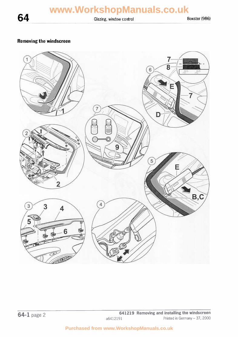
Boxster (986)Glazing, window control
Removing the windscreen
www.WorkshopManuals.co.uk
Purchased from www.WorkshopManuals.co.uk

Boxster (986) Glazing, window control
During removal and installation, wear protective glasses and
leather gloves.
Masking the wing corners
1
2
Pulling off cover trim -1-
Removing cowl panel cover -2-
Removing inner A-pillar trim
Removing the interior rearview mirror
3 Removing defroster covers -4, 5-
Wind down the door windows.Note:the door windows must not be closed until after the curingtime has elapsed.
Mask the wing corners with adhesive tape in the area ofthe cowl panel in order to protect the paintwork.
Undo and remove the cover trim -1-.
~ Rep. Gr. 702219; Removing and installing cowl panelcover
~ Rep. Gr. 705719; Removing and installing trim of A, Band C-pillars
~ Rep. Gr. 682719; Removing and installing the interiorrearview mirror
Lift the alarm readiness light -3- and unclip it to the rear.Lift the defroster covers on the left and right -4, 5- andunclip them. Check fastening clips -6-, replace if neces-
sary.
4
5
Disconnecting the windscreen antenna plugconnection
Cutting out the windscreen Fit a U-type cutting knife to the cutter -E-. Set the vibrationfrequency controller to 5. Cut through the bond betweenthe body and the windscreen at the top and sides. Fit a U-type cutting knife -B- to the cutter -E-. Cut through thebond between the body and the windscreen at the bot-tom. Reomve the windscreen.Note:when cutting out the windscreen, ensure that the labelwith the vehicle identification number and the surroundingsection is not damaged.
Carefully detach the surrounding section from the wind-screen. If the surrounding section is removed from thewindscreen undamaged, it can be re-used.
Removing the windscreen
Pulling off surrounding section
Danger of injury caused by loose glass splinters and sharp
window edges.
www.WorkshopManuals.co.uk
Purchased from www.WorkshopManuals.co.uk

Boxster (986)Glazing, window control
Removing adhesive from the body
Removing adhesive from the windscreen
.Only if the windscreen is re-installed
7 Cleaning and priming paint damage ornewly built-up paint areas in the windowaperture of the body
Remove adhesive residues -7- from the body with the cut-ter -E- and flashing knife -D-, ensuring that a residual cov-ering of adhesive remains -8-.Note:the residual covering of adhesive acts as an adhesivefoundation for new bonding material. Keep cut surfacesclean and free of grease and do not clean with cleaningsolution.
Equip the cutter -E- with the flashing knife -D- and removethe adhesive remains on the pre-coated bonding sectionof the windscreen so that as much as possible of thebonding section of the pre-coating is preserved.Note:the bonding section of the pre-coating acts as an adhesivefoundation for new bonding material. Keep cut surfacesclean and free of grease and do not clean with cleaningsolution.
Clean new paint surfaces and damage to the roof paint inthe non-visible area of the window aperture of the bodywith cleaning solution -Hl- and improve with primer -H2-.Note:observe the drying time of 10 minutes minimum aftercleaning! No cleaning solution residues may remain on thebody.
641219 Removing and installing the windscreen
a6412191 Printed in Germany -37,200064-1 page 4
www.WorkshopManuals.co.uk
Purchased from www.WorkshopManuals.co.uk

Boxster (986) Glazing, window control
Fitting the windscreen
~
641219 Removing and installing the windscreen
Printed in Germany -37.2000 a641219164-1 page 5
www.WorkshopManuals.co.uk
Purchased from www.WorkshopManuals.co.uk

Boxster (986)Glazing, window control
~~ Caution!The bonded joint does not have its final strength immediately.
The vehicle must not be used until the curing time has elapsed.
In order to ensure that the bonded joint is sufficiently strong, the following boundary conditions must be
adhlered to;
.Time between applying adhesive and inserting windscreen: max. 10 min
.Temperature: at least 10°C
.f'ixing time: approx. 1 hour
.C;uring time: 3 hours
rn Note!The removed windscreen can be reinstalled if there is no prior damage to the windscreen and the windscreen was
removed without damage.
No. InstructionsProcedure
Fitting surrounding section -1- and covertrim -2-
2
Fitting spacer blocks
Fitting defroster covers -4, 5- and alarmreadiness light -3-
3 Marking the bonding area
.Only with new windscreens
4 Activating the bonding section of the wind-screen
.Only with new windscreens
Position the surrounding section -1- on the windscreenand press the cover trim -2- into the groove of the sur-rounding section.Note:if the surrounding section and the cover trim have beenremoved from the windscreen without damage, they canbe re-used.
Clip in spacer blocks and press in body-bound rivets.
Check the fastening clips -6-, replace if necessary. Insertthe defroster covers left and right -4, 5- and clip in underthe alarm readiness lug. Engage alarm readiness light -3-.
Before applying the adhesive material, mark the course ofthe adhesive bead in accordance with the dimensions -A-160 mm, -8- = 30 mm on the left and right on the loweredge of the windscreen.
Apply activator -H3- to the bonding section of the pre-coated windscreen.Note:pre-coated windows must not be treated with cleaningsolutions. Do not apply activator to painted surfaces.Allow a drying time of at least 10 minutes!
www.WorkshopManuals.co.uk
Purchased from www.WorkshopManuals.co.uk

Boxster (986) Glazing, window control
Preparing 2<omponent bonding materialfor processing
6 Applying bonding material to the wind-screen
7 Inserting the windscreen into the body
Cleaning the fields of vision
8 Attaching the windscreen antenna
Installing the A-pillar trim
Installing cowl panel cover
Removing masking of wing corners
Bonding on the interior rearview mirror
=> 6-5 "Processing of Porsche 2-component windowbonding agents"Note:observe open time of 15 minutes! The open time is thetime within which the bonding material must be appliedand within which the windscreen must be put into thebody.
Using the bonding gun, apply 2-component bonding mate-rial to the windscreen along the cover trim in the form of atriangular bead. Apply the adhesive material in accord-ance with the markings in the lower part of the wind-screen. Dimension -X- = approx. 15 mm.When applying the adhesive, it is essential to ensure that itoverlaps.Note:two persons are needed to insert and adjust the wind-screen!
Apply suction cups -F- to the windscreen and insert thewindscreen into the window aperture. Press the wind-screen up as far as it will go. When doing so, press thelower edge of the glass against the spacer blocks.
Adhesive which has oozed out must be removed immedi-ately and the affected fields of vision must be cleanedusing cleaning agent -HI-.
Insert the plug of the windscreen antenna into the antennaamplifier.
=> Rep. Gr. 705719; Removing and installing trim of A, Band C-pillars
=> Rep. Gr. 702219; Removing and installing cowl panelcover
Pull adhesive tape off wing corners.
=> Rep. Gr. 682719; Removing and installing the interiorrearvlew mirror
.Only if the windscreen is replaced
Installing the interior rearview mirror ~ 68-1 "Removing and installing the interior rearview mir-ror"Note:the interior rearview mirror may only be installed after acuring time of 3 hours!
Closing the door window
Overview of tools and materials
www.WorkshopManuals.co.uk
Purchased from www.WorkshopManuals.co.uk

Boxster (986)Glazing, window control
The following tools and materials are required for removing and installing the windscreen with 2-component adhe-sive:
ExplanationDesignation of the special toolItem
=:} Rep. Gr. 2.2; Workshop EquipmentManual
Mixing rod 9528
-8-
-c-
-E-
-E-
-F-
-G-
Cutting knife, U-type 639.030.760.16
Cutting knife, U-type 639.031.540.10
Flashing knife, U-type 639.031.130.22
Cutter VAG 1561
Twin-cup suction lifter VAG 1344
Bonding gun 9586 ~ Rep. Gr. 2.2; Workshop EquipmentManual
Contains set components HI-H12Adhesive set 000.043.203.42-H-
Swab
Filler nozzle
Injector nozzle
Cleaning solution
Primer
Activator
www.WorkshopManuals.co.uk
Purchased from www.WorkshopManuals.co.uk
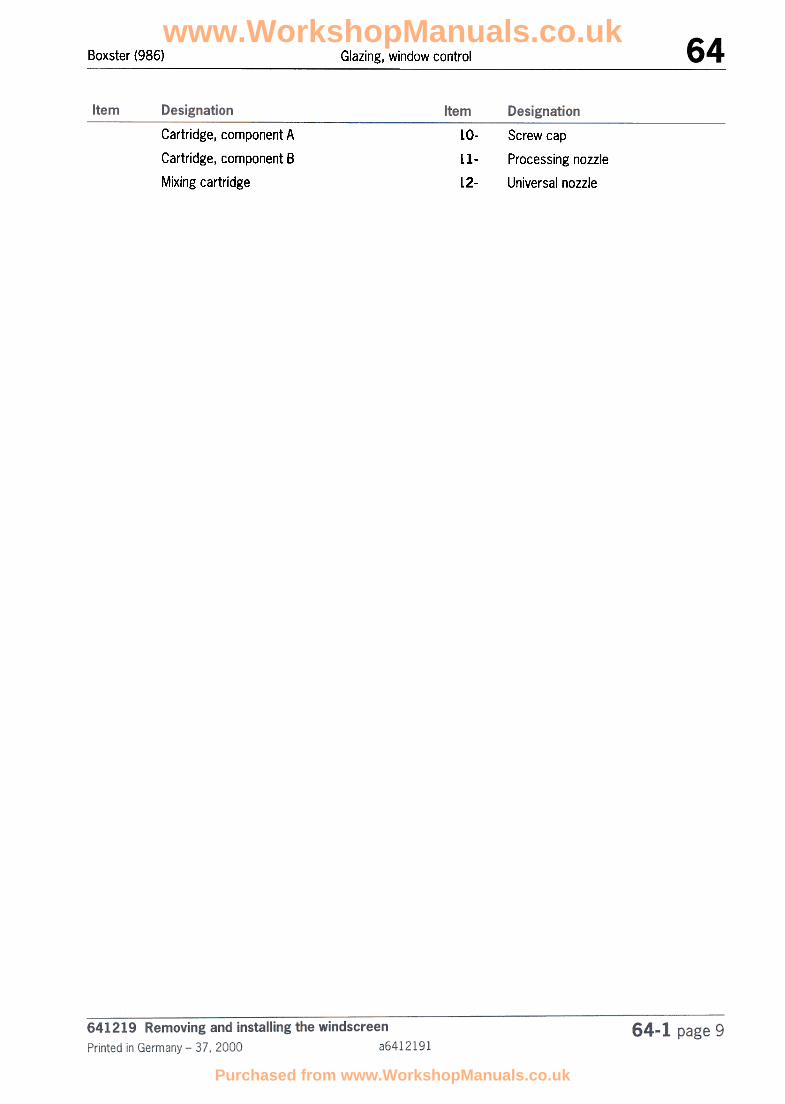
Boxster (986) Glazing, window control
Cartridge, component A
Cartridge, component B
Mixing cartridge
Screw cap
Processing nozzle
Universal nozzle
LO-
Ll-L2-
www.WorkshopManuals.co.uk
Purchased from www.WorkshopManuals.co.uk
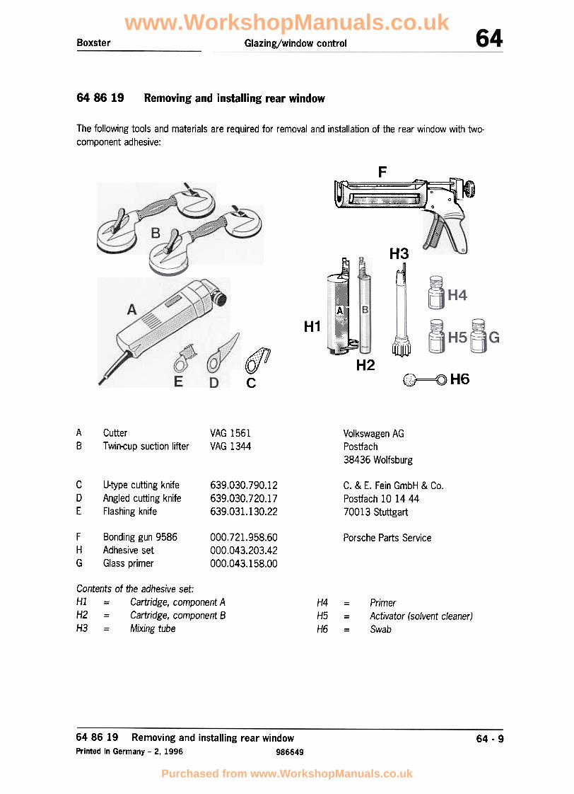
Boxster Glazing/window control
64 86 19 Removing and installing rear window
The following tools and materials are required for removal and installation of the rear window with two-component adhesive:
F
B
H3
rlA
~
H1
lU1U)J
E
~J
"
,,
j
~JH2(Ql7/
c"'"'D
r"., H\@~=Q) 6
A8
VAG 1561VAG 1344
Volkswagen AGPostfach38436 Wolfsburg
CutterTwin-cup suction lifter
c0E
U-type cutting knifeAngled cutting knifeFlashing knife
639.030.790.12639.030.720.17639.031.130.22
C. & E. Fein GmbH & Co.Postfach 10 14 4470013 Stuttgart
FHG
Bonding gun 9586
Adhesive setGlass primer
000.721.958.60000.043.203.42000.043.158.00
Porsche Parts Service
Contents of the adhesive set:Hl = Cartridge, component AH2 = Cartridge, component BH3 = Mixing tube
H4H5H6
- PrimerActivator (solvent cleaner)Swab
64 86 19 Removing and installing rear windowPrinted in Germany -2, 1996 986649
64 -9
www.WorkshopManuals.co.uk
Purchased from www.WorkshopManuals.co.uk
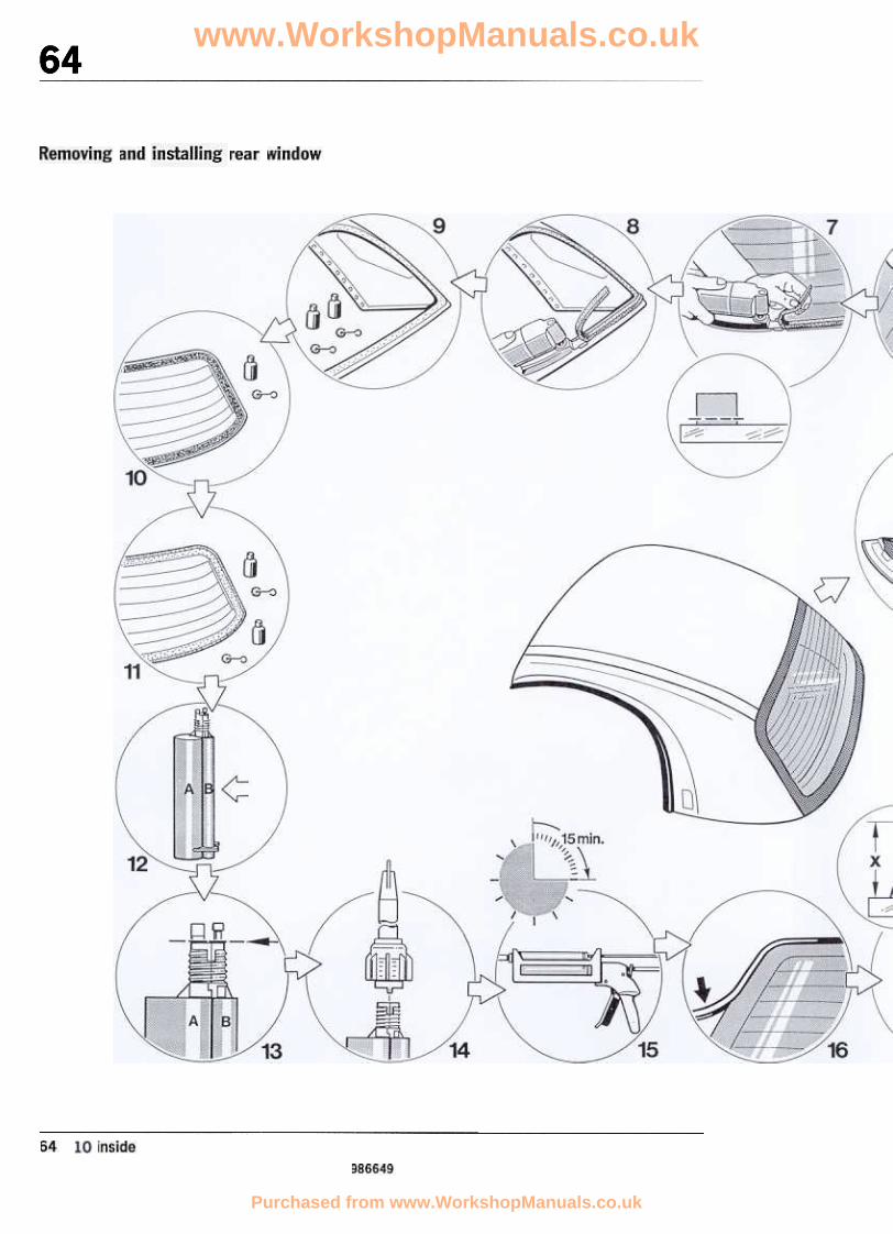
www.WorkshopManuals.co.uk
Purchased from www.WorkshopManuals.co.uk

Glazing/window control Boxster
64 86 19986649
Removing and installing rear windowPrinted in Germany -2, 1996
www.WorkshopManuals.co.uk
Purchased from www.WorkshopManuals.co.uk

Boxster Glazing/window control
Removing rear window
Note
The removed window can be re-installed if
no prior damage is can be recognised on the rear window
the rear window was removed without being damaged.
No. Procedure Instructions
Remove the hardtop Unlock the hardtop and remove it from the vehicle.
Set down the hardtop Set the hardtop down on the assembly fixture on the outerside.
Unclip interior trim parts Unclip interior trim parts at the front, sides and rear of the
hardtop body.
2 Disengage the headliner Disengage headliner at the rear window to the rear.
3 Disconnect the rear-window heater Disconnect the electrical plug connection on the left andright of the rear window heater. Affix wire to the rear wirrdow with adhesive tape. (The wire would otherwise be se-vered when the rear window is cut out.)
4 Turn the hardtop Set down pivot locks and locking levers of the hardtop onthe assembly fixture and lock.
5 Pull off cover profile Detach and pull off the cover profile.
6 Cut out the rearwindow
Equip cutter (A) with the U-type cutting knife (C). Set the os-cillation-speed control to Stage 5. Cut through the adhesivejoint between the body and rear window at the top andsides.Important: Observe note on the next page!
6486 19 Removing and installing rear windowPrinted in Germany -2, 1996 986649
64 -11
www.WorkshopManuals.co.uk
Purchased from www.WorkshopManuals.co.uk

Glazing/window control Boxster
No. Procedure Instructions
Note
Take care to cut close to the rear window. The hardtopbody components are riveted together; the riveted jointswill be destroyed if the rear window is cut out improperly.
7 Equip the cutter (A) with the flashing knife (E) and use it toremove the adhesive residues on the rear window. How-ever, stop when a layer of approx. 2 to 3 mm remains sothat the screen-printed border is not destroyed.
Only if the rear window isre-installed:Remove adhesive on therear window
8 Remove adhesive on the hardtopbody
Use the cutter (A) and the flashing knife (E) to remove ad-hesive residues on the hardtop body, leaving a layer of ad-hesive all around.
Note
Remove adhesive residues between the riveted joints asthoroughly as possible without damaging the riveted joints.
Paint damage in the window aperture must be repaired
9 Clean and prime the windowaperture of the hardtopbody
Clean window aperture of the hardtop body with cleaningsolvent (H5). Prime repaired areas of the paintwork in theconcealed part of the window aperture with primer (H4).Use the swabs (H6) intended for this purpose. 8Note
Always allow a drying time of at least 10 minutes after
cleaning!Cleaning solvent residues must not remain on the hardtop
body.
64 -12 64 86 19986649
Removing and installing rear windowPrinted in Germany -2, 1996
www.WorkshopManuals.co.uk
Purchased from www.WorkshopManuals.co.uk

Boxster Glazing/window control
Installing the rear window
No. Procedure Instructions
10 Apply activator (H5) to the adhesive profile of the rear wirrdow using the swab (H6).
Only if the rear window isre-installed:Activate adhesive profile ofthe rear window
11 Only when installing a newrear window: Clean andprime the screen print
Apply activator in the area of the screen print, let dry andprime the screen print of the rear window with glass
primer (G).
Note
Always allow a drying time of at least 10 minutes!
12 Clip together cartridges of theA and B components
Clip cartridge with component B to the cartridge with com-ponent A.
13 Open the completed cartridge Evenly cut off the outlets of the completed cartridge with aknife.
14 Attach the mixing tube Slide the mixing tube (H3) into the groove over the com-pleted cartridge and fasten with the union nut.
15 Insert the cartridge in the
bonding gun
Insert the completed cartridge, including mixing tube, intothe bonding gun (F).
Note
Observe open time of 15 minutes!
The open time is the time within which the adhesive mustbe applied and the rear window inserted in the hardtop
body.
6486 19 Removing and installing rear windowPrinted in Germany -2, 1996 986649
64 -13
www.WorkshopManuals.co.uk
Purchased from www.WorkshopManuals.co.uk

Glazing/window control Boxster
No. Procedure Instructions
16 Fit the cover profile Push the cover profile onto the rear window
17 Apply adhesive on the hardtopbody in the area of thewindow aperture
Use the bonding gun to apply a triangular bead of 2-compo-nent adhesive on the window aperture of the hardtop body-along the riveted joint.Dimension "X" = approx. 12 mm
Take care when applying the adhesive to ensure that theadhesive bead overlaps.
Note
Two persons are necessary to install and adjust the rearwindow!
18 Insert the rear window in the
hardtop body
Insert the rear window at the top of the window apertureand carefully lay it down.
19 Fix the rear window Push the rear window all of the way up and press thelower window edge into place. Secure the rear windowagainst sliding out of place with adhesive tape at the sidesand top.
Clean the visible areas Any emerging adhesive must be removed immediately, andthe affected visible areas must be cleaned with the clean-ing solution (H5).
20 Plug in the rear window heater Plug in electrical plug connections on the left and right-hand sides of the rear window.
21 Fit the interior Position interior trim parts at the rear, sides and front andclip into place.
864 86 19
986649
Removing and installing rear windowPrinted in Germany -2, 1996
64 -14
www.WorkshopManuals.co.uk
Purchased from www.WorkshopManuals.co.uk

Important
The adhesive joint does not attain its final strength immediately. The following conditions must be ob-served in order to ensure adequate strength of the glued joint:
Curing time 3 hours
at least 10 °CTemperature
Fixing time approx. 1 hour
The hardtop must not be used on the vehicle before the curing time has elapsed!
64 86 19 Removing and installing rear windowPrinted in Germany -2, 1996 986649
64 -15
www.WorkshopManuals.co.uk
Purchased from www.WorkshopManuals.co.uk

Boxster Glazing, window control
64 54 19 Removing and installing power window motor
Removal
Close door window.
& Warning:Airbag could inflate. Danger ofinjury or damage during fitting
> 1. Remove ignition key.
> 2. Disconnect and cover thenegative terminal of the battery.
> 3. After the battery is
disconnected, assembly workor work on the vehicle may bestarted after a waiting periodof 1 minute.
056_99
4. Press the power window'unit out of the innerdoor panel until the fastening pins are free.
2. Remove door panel and loudspeaker unit.Carefully remove (do not crack) the frontmoulded foam part from the inside of thedoor near the power window motor andthe loudspeaker cut-out. Disassemblingand assembling door trim panel, seeServo No. 5751 37.
5. Unlock and remove the electrical plugconnection on both sides.
6. Unscrew fastening pins of power windowmotor. Remove power window unit from thetoothing and take out through the loudspeakercut-out.
3. Remove fastening nuts (3 M6 nuts) fromthe power window motor.
64 -176454 19 Removing and installing power window motorPrinted in Germany -25, 1999 9866417
www.WorkshopManuals.co.uk
Purchased from www.WorkshopManuals.co.uk

Glazing, window control Boxster
Installation
1. Install power window motor and engage
electrical plug connection.
Tightening torque of the
fastening bolts M6 10 Nm (7.5 ftlb)
fastening nuts M6 10 Nm (7.5 ftlb)
2. The moulded foam part must be carefullyglued onto the inside of the door (protectsagainst water leaking in).
3. Install loudspeaker unit and door panel.
Connect the battery.
4. Standardising the new power window motor
Switch ignition on.
Open door window completely bycontinuously actuating the powerwindow operating button, and thenclose window. Press button until thewindow is closed and is switched offby the blockage detection functionof the power window motor. Thiscompletes standardisation.
Perform a function test.
64 54 19 Removing and installing power window motor9866417 Printed in Germany -25, 1999
64 -18
www.WorkshopManuals.co.uk
Purchased from www.WorkshopManuals.co.uk

Glazing, window controlBoxster
64 86 01 Checking function of heating for rear window
Note
The function of the heating for the rear window(hardtop) can be checked with a temperatureprobe with digital display (see WorkshopEquipment Manual). The indicator light in therocker switch also lights up if a fault is presentand the heating wires in the rear window do notwarm up.
Check with the temperature probe
1. The tip of the sensor is used to measure fromthe outside on the centre of the rear window.
2. One of the heating wires on the rear windowmust run exactly under the tip of the sensorfor this procedure.
3. After switching on at room temperature and a
period of 2 minutes, the temperature must
increase by approx. 3 degrees.
4. If no temperature increase is shown, the faultmust be detected on the basis of the wiring
diagram.
64 -1964 86 01 Checking function of heating for rear window
Printed in Germany -26, 1999 9866419
www.WorkshopManuals.co.uk
Purchased from www.WorkshopManuals.co.uk

Boxster Exterior equipment
66 89 37 Disassembling and assembling the rearview mirror
//
//
/
122 -96
66 89 37 Disassembling and assembling the rearview mirrorPrinted in Germany, 1996 986661
66 -1
/
www.WorkshopManuals.co.uk
Purchased from www.WorkshopManuals.co.uk

Exterior equipment Boxster
Disassembling and assembling the rearview mirror
121 -96
66 89 37 Disassembling and assembling the rearview mirror986661 Printed in Germany, 1996
66 -2
www.WorkshopManuals.co.uk
Purchased from www.WorkshopManuals.co.uk

Boxster Exterior equipment
Disassembling and assembling the rearview mirror
Note:No. Designation Qty. Removal Installation
1 Cover 1 Unclip. Clip in.
2 Oval head screw 83.5 1
3 tv15 x 30 screw TI0 3 Oval head
4 Filler piece 1
5 Mirror glass Insert and clip in plug corr
tacts.Unclip,pull off plug contacts.
6 1Mirror shell bottom section
7 Countersunk screw 3
8 Mirror base 1 Undo countersunk screws Securely tighten counter-sunk screws
9 Mirror shell 1
10 Plug 1 Detach plug connection. Replace, make plug cOr}-nection.
11 Oval head screw M5 x 14 1
12 1 Screw hexagon nut tightSpring clamp Undo hexagon nut
13 Hexagon nut M5 1
14 3 Detach positioning motor Securely screw position-ing motor
15 1
Oval head screwM3 x 30
Positioning motor
66 89 37 Disassembling and assembling the rearview mirrorPrinted in Germany, 1996 986661
66 -3
www.WorkshopManuals.co.uk
Purchased from www.WorkshopManuals.co.uk

Boxster Exterior equipment
66 58 19 Removing and installing rear spoiler
264 -96
6658 19 Removing and installing rear spoilerPrinted in Germany -2, 1996 986665
66 -5
www.WorkshopManuals.co.uk
Purchased from www.WorkshopManuals.co.uk

BoxsterExterior equipment
Removing and installing rear spoiler
66 58 19 Removing and installing rear spoiler986665 Printed in Germany -2, 1996
66 -6
www.WorkshopManuals.co.uk
Purchased from www.WorkshopManuals.co.uk

Boxster Exterior equipment
Removing and installing rear spoiler
Note:No. Designation Qty. Removal Installation
1 Oval-head screwB 3.5 x 10
3 Loosen oval-head screwfrom the upper part of the
spoiler.
Screw oval-head screwwith washer (Item 2) intothe upper part of the
spoiler.
2 Washer 3
3 Upper part of spoiler 1 Remove upper part ofspoiler.
4 Hexagon socket head boltM6 x 15
2
5 Bottom part of spoiler 1
Loosen hexagon sockethead bolt from the bottompart of the spoiler.
Remove the bottom part ofthe spoiler from the extend-
ing components.
Position upper part ofspoiler and screw tightwith the oval-head screw
(Item 1).
Screw the bottom part ofthe spoiler tight with thehexagon socket head bolt.
Position the bottom partof the spoiler on the ex-
tending components,align with rear side panelon the left and right andscrew tight with the hexa-gon socket head bolt
(Item 4).
Clip in6 Left side cover 1 Unclip
7 4M6 x 20hexagon socket head bolt
8 6Collar nut
9 1 Unscrew. Screw the hexagon-headbolt with holder (Item 10)onto the body.
M6 x 20hexagon-head bolt
66 -766 58 19 Removing and installing rear spoilerPrinted in Germany -2, 1996 986665
www.WorkshopManuals.co.uk
Purchased from www.WorkshopManuals.co.uk

Exterior equipment Boxster
Note:
No. Designation Qty. Removal Installation
10 Holder 1 Undo the collar nut (Item 8)on the holder.
11 Angle piece 2 Undo collar nuts (Item 8)from the angle pieces.
12 Plug connection 1 Disconnect
Position holder on thespoiler element andfasten the holder with col-lar nuts (Item 8) and hexa-gorrhead bolt (Item 9).
Position angle piece onthe spoiler element andfasten with the collar nuts
(Item 8).
Connect
13 Sliding piece 1 Twist and pull out. Insert and twist.
14 Spoiler element 1 Retract and position.Screw in hexagon sockethead bolt (Item 7), alignspoiler element to the leftand right with the rearside part, and tighten thehexagon socket head bolt
(Item 7).
Move spoiler element in-wards.
15 3M5 x 55hexagon-head bolt
Motor16 1 Undo hexagon-head bolts(Item 15) and remove themotor.
Position motor on thespoiler element andfasten with the hexagon-head bolts (Item 15).
17 Spur gear 1
18 Grooved axle
19 Plate 2
20 Cover 1 Unclip Clip in
21 a-ring
66 -8 66 58 19 Removing and installing rear spoiler986665 Printed in Germany -2, 1996
www.WorkshopManuals.co.uk
Purchased from www.WorkshopManuals.co.uk

Boxster E:xterior equipment
Note:No. Designation Qty. Removal Installation
22 1Lifting element Position lifting element onthe spoiler element andfasten with the oval-headscrews (Item 23).
Undo oval-headscrew (Item 23) andremove lifting element.
23 Oval-head screw 3
24 Corner piece 2 Pull off water drain hose. Push on water drain hose.
25 Hexagorrhead bolt 2
26 Actuator 1 Disconnect electrical plugconnection.
Connect electrical plugconnection.
27 Guide 1
28 Pin 1
29 Retainer 1
66 -966 58 19 Removing and installing rear spoilerPrinted in Germany -2, 1996 986665
www.WorkshopManuals.co.uk
Purchased from www.WorkshopManuals.co.uk

66 56 19 Removing and installing the engine compartment vent
"
"
'"y/,
~
,Y'
I
"' d?,,~~
/ ::
'~
II~"
If
~~~
...
~
/"
/ ~
-/
~~f~-6656001
~
www.WorkshopManuals.co.uk
Purchased from www.WorkshopManuals.co.uk

Exterior equipment Boxster
R:emoving and installing the engine compartment vent
7' /~ --<---
~
';.-:---
M~j
""-/, ""-./, -
Y
~
"'-
e//
... /
AI:
/
5
;>
...j, //...,
/
""
,./
./
/ ~
4A~
~ 3848
"'""
\
B
/\
/ 2A28
"""
~- ---6656002
61> -12 6656 19 Removing and installing the engine compartment vent
9866611 Printed in Germany -30, 1999
~3C
www.WorkshopManuals.co.uk
Purchased from www.WorkshopManuals.co.uk

Boxster Exterior equipment
Removing and installing the engine compartment vent
Note:InstallationNo. Designation Qty. Removal
1 Oval-head screw 1
2 A,B Air guide2A air guide until modelyear 1999
28 air guide
(installed on left only) asof model year 2000
Screw the B 4.2 x 14oval-head screw into theair guide (Item 2)
Note: The air guide andair inlet grille can beinstalled only inassembled state.Press the air inlet grille(Item 4) into the 3 springclips (Item 6). Press air
guide diagonally upwardfrom the locking web.
(Figure B)Insert locking web of theair guide (Item 2) into theside section.Screw the B 4.2 x 14oval-head screw into theair guide (Item 2)
Remove the B 4.2 x 14oval-head screw from theair guide (Item 2)
Insert a narrow plasticwedge into the locking tabsof the air inlet grille (Item 4)-at the 1st and 4th ribsfrom the top, on the leftand right sides. Carefullypress the plastic wedgeoutward toward the air
guide (Figure A).Press air guide diagonallyupward from the lockingweb. Pull locking web(Figure B) from the sidesection.Simultaneously pull off theair guide outwardat the locking tab to bepressed out
Pull off3A 1Foam strip Inspect and replace ifnecessary .Note: Affix the sealunder slight tension,without any space withrespect to the lockingweb. The distance fromthe seal to the outeredge of the air guidemust be 1.5 mm
66 -1366 56 19 Removing and installing the engine compartment ventPrinted in Germany -30, 1999 9866611
www.WorkshopManuals.co.uk
Purchased from www.WorkshopManuals.co.uk

Exterior equipment Boxster
I~o. Designation Qty. RemovalNote:
Installation
38 1 Pull offMoulded rubber part
(installed on left only) as
of model year 2000
Inspect and replace if
necessary .
Note: Coat the corner
points of the moulded
rubber part with Loctite
454 and glue into the rim
of the air guide from the
rear
3C Pull off1Moulded rubber corner
piece(installed on left only) asof model year 2000
Inspect and replace ifnecessary .Note: Coat the surfaceof the moulded rubberpart with Loctite 454 andglue into the rim of theair guide from the rear
4J~ Air inlet grille until model
year 1999
1 Press the air inlet grille offthe spring clips (Item 6).
Press the air inlet grille offthe spring clips (Item 6).
Clip air inlet grille (Item 4)
together with the air
guide (Item 2)
Clip air inlet grille (Item 4)
together with the air
guide (Item 2)
413 1Air inlet grille
(installed on left only) as
of model year 2000
5 1 Press rubber tabs out ofthe sheebnetallugs of theside section and removeflow duct.
Position flow duct andpress the rubber tabsinto the sheetmetallugsof the side section
Flow duct
Spring clips 3 Unclip Inspect and replace ifnecessary
6
615 -14 66 56 19 Removing and installing the engine compartment vent9866611 Printed in Germany -30, 1999
www.WorkshopManuals.co.uk
Purchased from www.WorkshopManuals.co.uk

Boxster Exterior equipment
66 78 01 Checking function of heating for mirror glass
Note
The function of the heating for the mirror glasscan be checked with a temperature probe with
digital display (see Workshop EquipmentManual). The indicator light in the rocker switchalso lights up if a fault is present and theheating wires in the mirror glass do not warm
up.
Check with the temperature probe
1. The tip of the sensor is used to measure from
the outside on the centre of the mirror glass.
"'~--
[j
~~
151_99
2. After switching on at room temperature anda period of 1 minute, the temperature mustincrease by approx. 2 degrees.
3. If no temperature increase is shown, the faultmust be detected on the basis of the wiring
diagram.
66 -1566 78 01 Checking function of heating for mirror glassPrinted in Germany -26, 1999 9866615
www.WorkshopManuals.co.uk
Purchased from www.WorkshopManuals.co.uk

Boxster Interior equipment
68 27 19 Removing and installing the interior rearview mirror
The following special tools are required to remove and install the interior rearview mirror:
~
/T
:-- -~~ --:: ---~
:~0
A = Pliers, special tool 9578
68 27 19 Removing and installing the interior rearview mirror
Printed in Germany -7, 1996 986681
68 -1
www.WorkshopManuals.co.uk
Purchased from www.WorkshopManuals.co.uk

Interior equipment Boxster
Removing and installing the interior rearview mirror
. 68 27 19 Removing and installing the interior rearview mirror986681 Printed in Germany -7, 1996
68 -2
www.WorkshopManuals.co.uk
Purchased from www.WorkshopManuals.co.uk

Boxster Interior equipment
Removing and installing the interior rearview mirror
Removing the interior rearview mirror
No. Procedure Instruction
1 Secure the pliers Set the pliers with the projecting plastic parts to the wind-screen to the diameter of the mirror base and secure tothe mirror base.
Turn the interior rearview mirror by the mirror base usingthe pliers special tool 9578 through 90°, Release thepliers from the mirror base.
2 Detach the mirror
3 Remove the mirror Unclip the base of the interior rearview mirror from the re-
tainer plate on the windscreen.
After removing the interior mirror from its base,
remove the small aluminium chip in the locking
area. Otherwise, secure seating cannot be ensured
when the mirror is fitted. If a mirror is being fitted
for the second or third time, check the locking area
for the mirror base for signs of wear and replace the
mirror if necessary.
Installing the interior rearview mirror
No. InstructionProcedure
4 Insert the mirror Clip the base of the interior rearview mirror, rotatedthrough 90°, into the retainer plate on the windscreen,
5 Fasten the mirror Fasten the pliers (special tool 9578) on the mirror basewith the projecting plastic parts facing the windscreen.Press the mirror base against the retaining plate and simul-taneously turn by 900 with the pliers. The mirror mustnot be turned past the locking point.Detach pliers from the mirror base.
68 -368 27 19 Removing and installing the interior rearview mirrorPrinted in Germany -7, 1996 986681
www.WorkshopManuals.co.uk
Purchased from www.WorkshopManuals.co.uk

Bonding on the interior rearview mirror68 27 13
E
c/
( B
,~~~1981 -68
Cleaning solution (000.043.157.00)*=A
Primer (000.043.158.00) *=
8
Cover film (000.043.177.01)*=cActivator (000.043.052.00)*=
DBonder (000.043.051.00) *
=E
Porsche part number
www.WorkshopManuals.co.uk
Purchased from www.WorkshopManuals.co.uk

Interior equipment Boxster
E:onding on the interior rearview mirror
Bonding the assembled rearview mirror onto the windscreen
68 27 13 Bonding on the interior rearview mirror
986681 Printed in Germany, 1996
68-6
www.WorkshopManuals.co.uk
Purchased from www.WorkshopManuals.co.uk
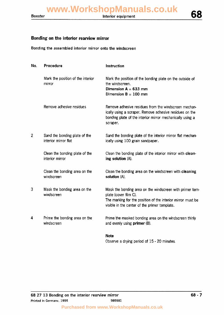
Boxster Interior equipment
Bonding on the interior rearview mirror
Bonding the assembled interior mirror onto the windscreen
No. Procedure Instruction
Mark the position of the interiormirror
Mark the position of the bonding plate on the outside ofthe windscreen.Dimension A = 633 mm
Dimension B = 100 mm
Remove adhesive residues Remove adhesive residues from the windscreen mechan-ically using a scraper. Remove adhesive residues on thebonding plate of the interior mirror mechanically using ascraper.
2 Sand the bonding plate of theinterior mirror flat
Sand the bonding plate of the interior mirror flat mechan-ically using 100 grain sandpaper.
Clean the bonding plate of theinterior mirror
Clean the bonding plate of the interior mirror with clean-ing solution (A).
Clean the bonding area on thewindscreen
Clean the bonding area on the windscreen with cleaningsolution (A).
3 Mask the bonding area on thewindscreen
Mask the bonding area on the windscreen with primer tem-plate (cover film C).The marking for the position of the interior mirror must bevisible in the center of the primer template.
4 Prime the bonding area on thewindscreen
Prime the masked bonding area on the windscreen thinlyand evenly using primer (8).
NoteObserve a drying period of 15 .20 minutes,
68 27 13 Bonding on the interior rearview mirror
Printed in Germany. 1996 986681
68 -7
www.WorkshopManuals.co.uk
Purchased from www.WorkshopManuals.co.uk

Interior equipment Boxster
No. Procedure Instruction
5 Activate the bonding area on thewindscreen
Spray activator (0) onto the bonding area of the wind-screen.
NoteObserve a drying time of 2 minutes.
Remove the primer template
6 Apply a drop of adhesive (E) to the bonding plate of theinterior mirror.
Apply adhesive to the bonding
plate
7 Stick on the interior mirror Press the interior mirror with the bonding plate onto theprimed and activated area of the windscreen.
NotePress-on duration approx. 40 -50 seconds.
Note
Bonding strength60 % after 1 hour
100 % after 24 hours
6:~ -8 68 27 13 Bonding on the interior rearview mirror986681 Printed in Germany, 1996
www.WorkshopManuals.co.uk
Purchased from www.WorkshopManuals.co.uk

www.WorkshopManuals.co.uk
Purchased from www.WorkshopManuals.co.uk

Boxster (986)lnterior equipment
/i!iJ1
"
\\-
1t1-'---;;Z-i/~ t(",!/'"
~I.1
l7r
8 /.g/I~I I
Irv
,-I
~~/ ,/
6
/"
/J?'-I
,/
ol
~.,
--(
:;-1
12c::..;.'~J
3'~l\~ ,-14
"'7''" /'"
www.WorkshopManuals.co.uk
Purchased from www.WorkshopManuals.co.uk

Boxster (986) Interior equipment
Cover, front left Unclip the front left cover-1- at the sides.
2 1 Unclip the front right cover-2- at the sides.
Cover, front right
Position the front cover -I-on thefront centre console -15- and clip itlaterally into the clips -3-.
Position the front cover -2-on thefront centre console -15- and clip itlaterally into the clips -3-.
Inspect clip -3- and replace if neces-sary.
3 Clip 10
14
9
Insert a wire into the hole Insert the locking tabs of the tele-of the cover cap -4- and phone trim panel into the front coverpull off the cover cap to the -8- and screw it in place with therear. Undo the fastening fastening screws -5-, Tighteningscrews -5- and lift the tele- torque: -2.3 Nm (1.5 ftlb.)-phone trim panel off the Press in cover cap -4-,front cover -8-.
6
Cover cap(telephone
Fastening
Telephone 1
7 Installation frame for(telephone handset)
Cover, front left(telephone carrier)
1
8 1 Position cover at the centre consoleat the front, clip in at the side andfasten with the fastening screws -5-Tightening torque: -2.3 Nm (1.5ftlb.)-Position the adapter at the centreconsole at the front -9- and fastenwith the fastening screws -5-.Tightening torque: -2.3 Nm (1.5ftlb.)-
9 1Adapter
Unscrew fastening screws-5-, unclip the cover fromthe centre console at theside and remove to therear.
Unscrew fastening screws-5- and remove theadapter from the centreconsole at front.
10 Combi-single CD drivefor navigation
1
11 Heating/air-conditioningcontrol
1
See: =:} Rep. Gr. 911219;Removing and installingnavigation unit CD drive
See: =:} Rep. Gr. 870219;Removing and installing theheatingjair-conditioningcontrol
Unclip the front trim -12-towards the front and dis-connect the plug connec-tion of the rocker switchfor the seat heating.
Connect the electrical connection,position the front trim -12- on thecentre console -15- and press intoplace.
12 1Front trim
681719 Removing and installing center console (front section)
Printed in Germany -37,2000 a681719168-9 page 3
trim panel)
screw
trim panel
www.WorkshopManuals.co.uk
Purchased from www.WorkshopManuals.co.uk

Boxster (986)Interior equipment
Unclip the right cover -14- Position the right cover -14- on theat the side and pull out to centre console or on the coverthe rear. panel of the support frame at the
front and clip the cover into the clips-3- at the side.
Undo fastening screws -5- Position the front of the centre con-and lift the front of the cen- sole -15- on the holder -18- or ontre console -15- off. the dashboard frame and secure
with the fastening screws -5-.
Inspect and replace if necessary.
Tightening torque: -10 Nm (7.5ftlb.)-
15 1Centre console (frontsection)
16
17
Plug-in nut
Collar nut
4
4
18 Holder 1
www.WorkshopManuals.co.uk
Purchased from www.WorkshopManuals.co.uk

Boxster (986) Interior equipment
681719 Removing and installing centre console
Printed in Germany- 37,2000 a681719268-13 page 1
www.WorkshopManuals.co.uk
Purchased from www.WorkshopManuals.co.uk

www.WorkshopManuals.co.uk
Purchased from www.WorkshopManuals.co.uk

Boxster (986) Interior equipment
[IJ Note!Before removal of the centre console, the centre console (front) must be partly disassembled. For this purpose,remove both the front covers and the front trim. => 68-9 "Removing and installing center console (front section)"
Shift lever knob Disengage from the clips -2-all the way round. Pull theshift lever knob -1- upwardsand out.
2 Clip 4
3
4
5
6
3
1
2
1
Fastening screws
Ashtray insert
Expanding nut
Ashtray retaining bracket
Undo.
Lift out.
Press out.
Unclip the ashtray retainingbracket -6- upwards from thecentre console and discon-nect the electrical plug con-nections.
7
8
1
1 Undo fastening screw -3-from the floor oddments tray-8-,
Rubber insert
Floor oddments tray
9 1 Unclip the coin box -9- andundo the fastening screw -3-underneath.
Position the floor oddmentstray -8- in the centre consoleand fasten with the fasteningscrew -3-.
Tighten the fastening screw-3- and clip the coin box -9-into place.
Coin box
681719 Removing and installing centre console
Printed in Germany -37. 2000 a681719268-13 page 3
Inspect and replace if neces-sary.
Screw in.
Press in.
Press in.
Connect the electrical plugconnections, secure the ash-tray retaining bracket -6- inthe centre console and fastenwith the fastening screws -3-.
www.WorkshopManuals.co.uk
Purchased from www.WorkshopManuals.co.uk

Boxster (986) Interior equipment
::-~
'"
/"
~~
(~~~..~
"
~..:
'"
~
""
~~~~~~
~;
~'.
4
www.WorkshopManuals.co.uk
Purchased from www.WorkshopManuals.co.uk

www.WorkshopManuals.co.uk
Purchased from www.WorkshopManuals.co.uk

Boxster (986) Interior equipment
No. Designation Qty. Removal Installation
Cover, front left
Clip
Clip in.
Inspect and replace if neces-sary
Clip in.3
4
5
6
Cover, centre left
Fastening screws
Lock support
Plastic nuts
Microswitch
1
3Unclip.
7
1
8 Console 1
9 1Lock barrel
From the console -8- (see:-inset A-), raise the lockingtab with a screwdriver andunclip the microswitch -7-,
Press the locking tabs of theconsole -8- together withpointed-nose pliers -inset B-and guide out of the lock sup-port -5-.
Press in the locking tabs in-inset C- and guide the lockbarrel -9- upwards out of thelock support -5-,
Unclip,10 Cover, rear left 1
681737 Disassembling and assembling centre console
Printed in Germany -39. 2000 a681737168-14 page 3
Clip the microswitch -7- intothe console -8-.
Position console -8- on thelock support -5- and clip intoplace.Ensure that the locking tabsengage properly.
Press the lock barrel -9- intothe lock support -5- until thelatter engages into the lock-ing tabs.
Clip in.
www.WorkshopManuals.co.uk
Purchased from www.WorkshopManuals.co.uk
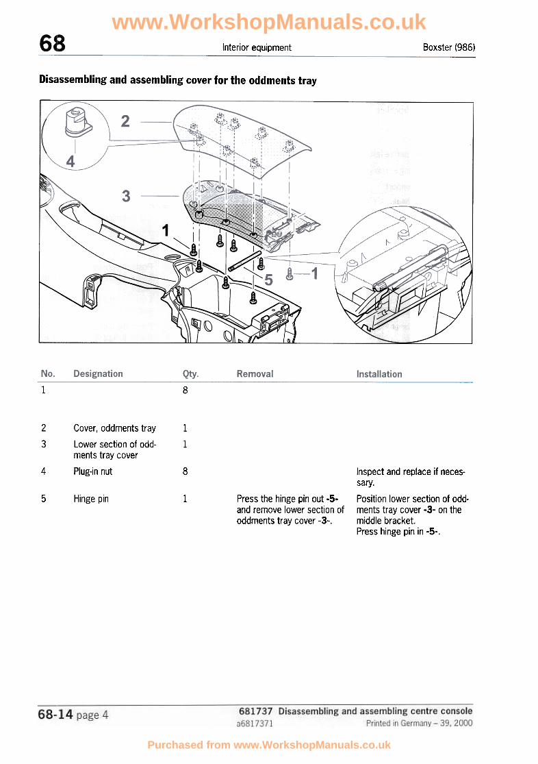
Boxster (986)Interior equipment
Dis~lssembling and assembling cover for the oddments tray
~"
1
i"
..J::::~::~~:_..l_.~'
'"
;::;::::~--
'/ t/" ,
~
IV
~
~,
1
2
3
8
Cover, oddments tray
Lower section of odd-ments tray cover
Plug-in nut
1
1
4 8
5 Hinge pin 1 Press the hinge pin out -S-and remove lower section ofoddments tray cover -3-.
Inspect and replace if neces-sary.Position lower section of odd-ments tray cover -3- on themiddle bracket.Press hinge pin in -5-.
&
www.WorkshopManuals.co.uk
Purchased from www.WorkshopManuals.co.uk
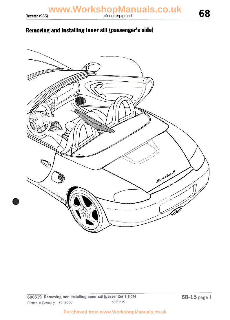
Boxster (98G) Interior equipment
Removing and installing inner sill (passenger's side)
/"/
/'-
--
~
(
~
"/"
~
'"
v
~'~~
/ /
~
~
~--~
www.WorkshopManuals.co.uk
Purchased from www.WorkshopManuals.co.uk

Boxster (986)Interior equipment
Renl1oving inner sill
" /'
~
'(
~
:7
~
' ~
~'"
www.WorkshopManuals.co.uk
Purchased from www.WorkshopManuals.co.uk

Boxster (986) Interior equipment
No. Procedure Instructions
Undoing fastening screws -2-
2 Removing sill-I-
Lift rubber mat -2- upward out of the oddments tray andunscrew the fastening screws -3- from the sill.
Lift sill-I- upwards out of the bottom support with a plas-tic spatula and press out. Check fastening clips -4-,replace if necessary.
680519 Removing and installing inner sill (passenger's side)
Printed in Germany -39.2000 a680519168-15 page 3
www.WorkshopManuals.co.uk
Purchased from www.WorkshopManuals.co.uk

Boxster (986)Interior equipment
Inst:alling inner sill
"
~
~
680519 Removing and installing inner sill (passenger's side)a6805191 Printed in Germany -39, 2000
68-15 page 4
www.WorkshopManuals.co.uk
Purchased from www.WorkshopManuals.co.uk

Boxster (986) Interior equipment
2 Fastening sill -1-
Clip in new fastening clips -4- if necessary. Insert sill -1-downward into the lower support and engage.
Screw in fastening screws -3- and lay rubber mat -2- intothe oddments tray.
680519 Removing and installing inner sill (passenger's side)
Printed in Germany -39.2000 a680519168-15 page 5
www.WorkshopManuals.co.uk
Purchased from www.WorkshopManuals.co.uk

Boxster (986) Interior equipment
'"
...;
'"
,
~
~
~
-~\ \.
www.WorkshopManuals.co.uk
Purchased from www.WorkshopManuals.co.uk

Boxster (986)Interior equipment
Disalssembling release for front lid
1
www.WorkshopManuals.co.uk
Purchased from www.WorkshopManuals.co.uk

Boxster (986) Interior equipment
No. Procedure Instructions
Undoing hexagon socket head bolts -2-
2 Removing sill-l-
3
4
Pulling off plug connections -5, 6- of theactuating switches
Removing actuating switches of front lid -7,8-
Remove plastic plugs -3- and undo the hexagon sockethead bolts -2- from the sill by approx. 4 -5 threads.
Lift sill -1- upwards out of the bottom support with a plas-tic spatula and press out. Check fastening clips -4-,replace if necessary.
Pull off plug connections -5, 6- on the actuating switchesof the lids.
Press the fastening ribs of the sill -arrOW5- outward with ascrewdriver and unclip the actuating switches of the frontlid -7-.
680519 Removing and installing inner sill (driver's side)
Printed in Germany -39,2000 a680519268-16 page 3
www.WorkshopManuals.co.uk
Purchased from www.WorkshopManuals.co.uk

www.WorkshopManuals.co.uk
Purchased from www.WorkshopManuals.co.uk

Boxster (986) Interior equipment
No. Procedure Instructions
Installing actuating switches of front lid -7-
2 Joining plug connections -5, 6- of the actu-ating switches
Putting on sill-I-3
4 Tightening hexagon socket head bolts -2-
Clip the actuating switches of the front lid -7- with lockingtabs into the fastening ribs of the sill.
Push plug connections -5, 6- onto the actuating switchesof the lids.
Clip in new fastening clips -4- if necessary. Insert sill -1-downward into the lower support and engage.
Screw in hexagon socket head bolts -2- of the sill byapprox. 4 -5 threads. Seal holes of the sill with plasticplugs -3-.
680519 Removing and installing inner sill (driver's side)
Printed in Germany -39.2000 a680519268-16 page 5
www.WorkshopManuals.co.uk
Purchased from www.WorkshopManuals.co.uk

Boxster Passenger protection
69 Safety regulations for airbag vehicles
The airbag units are pyrotechnical items inhazard class T 1. Handling, transport andstorage of these units must conform to the
explosives legislation.
According to the Explosives Storage Directive ofAugust 1997, these quantities are max. 10 kg(net) in a work room and max. 100 kg (net) in astorage room in the case of Class T 1
pyrotechnical objects. Airbag units must be keptin a locked place.The listed statutory requirements refer to the
Federal Republic of Germany. The relevant validregulations must be observed in all othercountries.
When storing airbag units, ensure that theairbag opening faces upwards (risk of injury dueto airbag units being flung upward in the eventof accidental ignition),The commencement of work with pyrotechnical
items must be reported 14 days in advance tothe Trade Supervisory Office (responsible
authority),
Airbag units must be stored in a dry place andmust not be stored together with otherhazardous goods (varnishes etc.),
SaleDispatch
Airbag units may only be dispatched in transportpackaging officially approved for that purpose.Airbag units may not be transported with otherhazardous goods.
Loose airbag units -referred to as airbagmodules below -or airbag modules installed ina loose steering wheel must never become theactual (physical) property of the customer. Thepossession of loose airbag modules not installedin the vehicle is not permissible in the privatesector.
Internally, they must always be transported inthe luggage compartment or cargo hold of avehicle using the above-mentioned transportpackaging. They must not be transported inthe passenger's compartment.
Airbag modules may become the property of thecustomer only when installed in the vehicle.Storage
Airbag units must be stored in accordance withthe second ordinance of the explosiveslegislation. This ordinance stipulates that smallquantities of materials and objects may bestored at certain locations without special
storage approval.
69 Safety regulations for airbag vehicles
Printed in Germany. 16, 1997
69 -1
986691
www.WorkshopManuals.co.uk
Purchased from www.WorkshopManuals.co.uk

Passenger protection Boxster
Assembly and adjustment work
Inspection and assembly work may only becarried out by specialist staff.
Airbag units and control units which have fallenfrom a height of more than 0.5 m may nolonger be installed.
Before working on the airbag system and alsowhen working on neighboring parts where thereis a risk because live parts are close to theairbag system, always implement the followingsafety measures:
No additional linings, stickers or similar may beattached to the steering wheel and in the vicinityof the passenger's airbag.
No changes may be made to the wiring and tothe components of the airbag system.1. Remove ignition key.
2. Disconnect and cover the negative terminal ofthe battery.
The battery must always be disconnectedbefore starting straightening and welding workwith an electrical welding unit.
The battery must be removed in advance if youhave to perform welding in the immediatevicinity of the control module.
After the battery is disconnected, assemblywork or work on the vehicle with a hammer orsimilar tools may not be started until after awaiting period of 1 minute. This is necessary inorder to interrupt the power supply to the airbagsystem and to ensure it is not triggered
accidentally.
Airbag components may not be repaired. Theymust always be replaced.
Note
Wash your hands after touching ignited airbagunits.
Airbag units must be fitted immediately afterbeing removed from their storage location. Onno account may they be left lying aroundunsupervised. If work is interrupted, airbag unitsmust immediately be locked away again.
Airbag units must not come into contact withgrease, oil, cleaning agents or similarsubstances.
Airbag units may not be exposed totemperatures above 90 °C -even fora short time.
69 Safety regulations for airbag vehicles
Printed in Germany -16, 1997
69 -2
986691
www.WorkshopManuals.co.uk
Purchased from www.WorkshopManuals.co.uk

Passenger protectionBoxster
General information
The airbag system is constantly monitored by
a diagnosis unit in the triggering unit. Any fault
is signalled by a warning light.
Exchanged airbag units or airbag modules mustbe taken into possession by the Porsche Centreor by dealers authorised by Porsche and mustnot be handed over to the customer (customerhas no right to possess them). They must bedestroyed, disposed of or returned to themanufacturer in accordance with the explosivesordinance and the hazardous materialsordinance.
The warning light for the airbag system lightsup in the event of a fault.
The airbag warning light lights for approx.3 seconds after the ignition is switched onand goes out if no fault has been enteredin the fault memory. When the steering wheel is exchanged, e.g.
to install a steering wheel from the T equipmentproduct range, the airbag unit of the replacedsteering wheel must be removed and destroyed,disposed of or returned to the manufacturerbefore the steering wheel is handed over tothe customer.
If it lights up again, this indicates a fault inthe system. The fault can be read out withthe Porsche System Tester 2.
Component exchange after airbag triggeringNote
A period of 10 seconds is required to enablethe triggering unit to identify all faults in thesystem. In order to guarantee that everypossible fault source is checked duringthe vehicle test, the ignition must beswitched on for at least 10 seconds.
The following components must be removed andreplaced after the airbag system is triggered:
After trig~ering of the airbag unit on thedriver's side
-Contact unitThe fault memory must be cleared followinga fault in the airbag system and after ithas been remedied. Airbag unit, driver's side
The replacement of a component must benoted in the Guarantee and Maintenancebooklet. To do this, attach the documentationnumber in a free panel intended for thatpurpose. The documentation number isattached to the replacement part asa tear-off sticker.
After triggering of the airbag unit onthe passenger's side
-Airbag unit, passenger's side
Triggering unit after the third time the
airbag is triggered
69 Safety regulations for airbag vehiclesPrinted in Germany -25, 1999
69 -2a
986692a
www.WorkshopManuals.co.uk
Purchased from www.WorkshopManuals.co.uk

Passenger protection Boxster
After triggering of the side airbag unit
Side airbag unit
Sensor for the side airbag unit after
the third time the side airbag is
triggered
69 -2b 69 Safety regulations for airbag vehiclesPrinted in Germany -25, 1999986692a
www.WorkshopManuals.co.uk
Purchased from www.WorkshopManuals.co.uk

Boxster Passenger protection
6968 Disposal of airbag units
Airbag units are pyrotechnical items and canpose an environmental hazard.
For this reason, non-ignited airbag units or entirevehicles must not be disposed of as normalscrap, refuse or in other final storage facilities.
The airbag units must first be rendered harm-less by electrical ignition and while observing all
precautionary measures, thereby preventingthem being used incorrectly.
If the vehicle had suffered fire damage which
caused the passenger's airbag to be ignited, ad-ditional ignition with the special tool 9257 mustbe carried out in order to ensure that only partswithout pyrotechnical contents are scrapped.
In the case of airbag units which cannot be ig-nited or if the conditions for safe ignition are irl-sufficient, always return the airbag units to Por-sche or the respective importer in their original
packaging.
Note
Country-specific statutory regulations and legisla-tion based on them which go beyond these in-structions must always be observed and takeprecedence over these instructions.
69 68 Disposal of airbag unitsPrinted in Germanv. 1996
69 -3
986691
www.WorkshopManuals.co.uk
Purchased from www.WorkshopManuals.co.uk

Passenger protection Boxster
Safety measures when igniting airbag units
Ignition and preparations may only be carriedout by skilled staff, supervised by a second re-
sponsible person.
Other normal accident prevention regulationsmust also be observed.
Fire airbag units only in their securely installed,original condition.
Carry out ignition only in suitable, free areas.
Use only the ignition tool intended for that pur-
pose.
All loose objects must first be removed from theexpansion area of the air bag.
Persons possibly affected must be informed ofthe resulting noise beforehand. Use ear protec-tors.
Maintain a safety distance by utilizing the entirecable length of the ignition tool.
Do not connect the voltage source until all otherpreparations are complete.
Choose a place in front of the vehicle. This alsoapplies to persons not involved.
Perform ignition with the doors closed and theside windows open.
Do not approach the vehicle until after a waitingperiod (approx. 3 minutes) if ignition fails.
Allow airbag units to cool down under obser-vation following ignition.
Avoid skin contact with ignited airbag units.
69 68 Disposal of airbag unitsPrinted in Germany, 1996
69 -4
986691
www.WorkshopManuals.co.uk
Purchased from www.WorkshopManuals.co.uk

Boxster Passenger protection
Tools
c-
~---
'~::=:::::~:::(:::::~
c-..;.,
45_97
No. Designation Special tool Explanation
A Ignition device 9257*
9567B
C
Ignition cable
Ignition cable 9566
9257/2D Ignition cable
Order if required
69 59 Disposal of airbag units
Printed in Germany -18, 1998
69 -5
986695
www.WorkshopManuals.co.uk
Purchased from www.WorkshopManuals.co.uk

Passenger protection Boxster
Connecting ignition tool
Driver's side Side airbag
@\~
~~-"I,~I
1. I-.:> ~!
96-032 97.163
To plug connection with special tool 9257/2.Place the ignition device in front of the vehiclethrough the door gap.
Directly to the 2-pole plug of the contact unit(below the steering column).
Passenger's side
96-098
To plug connection with special tools 9567and 9566.Place the ignition device in front of the vehiclethrough the door gap.
6959 Disposal of airbag units
Printed in Gennany -18, 1998
69-6986695
www.WorkshopManuals.co.uk
Purchased from www.WorkshopManuals.co.uk

Passenger protectionBoxster
Ignition
"'" IN.000-,~ ' --~
-([./-_~=:- ->::7
~
"".y"L' ' \;
'""".,." -,_.,",
.>
'"~'.'.:f;:.. .,
10096g
Attach the ignition device to a vehicle battery
and press the button.
Note
The driver's and passenger's airbags andside airbags must be ignited separately.
69 -769 59 Disposal of airbag unitsPrinted in Germany -18, 1998 986695
--C 3 .,\0 """
www.WorkshopManuals.co.uk
Purchased from www.WorkshopManuals.co.uk

Passenger protectionBoxster
69 58 19 Remo"ing and installing the driver's airbag unit
Removal
1. Remove ignition key. 4. Disconnect the electrical plug connection.
2. Disconnect the battery and cover terminal
or battery.
3. Undo the fastening screws (2 ea.)with a socket wrench insert for insideT orx T 30 (at least 50 mm long).
~~ .11 r",~
m\96-029
-
a
\ 2_d ::;:::;-Note
The airbag unit must always be depositedso that the airbag opening faces upwards.\
~
If removed for an extended period, the airbagunit must be kept in a locked place.Observe the safety regulations.
96-028
Note
The self-locking screws must be replacedevery time they are undone. To do this,undo the retaining bracket of the airbagunit (4 screws) in the steering wheel.
Installation
1. Tightening torque for fastening screws
(2 screws M6 x 16): 10 Nm (1.5 ftlb.).
2. Tightening torque for retaining bracket
(4 screws M5 x 20): 5 Nm (3.5 ftlb.).
69 -969 58 19 Removing and installing the driver's airbag unit
Printed in Germany -18, 1998 986695
~
www.WorkshopManuals.co.uk
Purchased from www.WorkshopManuals.co.uk

Boxster Passenger protection
69 66 19 Removing and installing the contact unit
Removal
1. Remove the airbag steering wheel
(see repair group 48).
4. Pull forward and disconnect the electrical plugconnections.Remove the contact unit.
2. Undo and remove the panel Note
To prevent unintentional turning of the contactunit (CU) with the steering wheel removed, theCU locks itself when the steering wheel is pulledback. Automatic unlocking of the CU also occurswhen the steering wheel is placed in position.
~
/
c;;gJ _/,-/./
~"Installation
1. With the front wheels still in straight-ahead po-sition, remove the airbag steering wheel as de-scribed in point 1.
,---
2. Ensure that the exact center position (arrows)of the contact unit is maintained.\.
30-96
3. Undo the fastening screws of the contact unit.
~=IO
gl- '/-~' II
' 1
0
I==-~
1718-68
31-96
69 -1169 66 19 Removing and installing the contact unit
Printed in Germany. 1996 986691
www.WorkshopManuals.co.uk
Purchased from www.WorkshopManuals.co.uk

Boxster Passenger protection
69 63 19 Removing and installing the ignition unit for the airbag
Removal 4. Undo the shear-off nut with the special tool9259.
Note
The airbag ignition unit must not be removedwith the plug plugged in. Waiting timefollowing ignition off (battery disconnection) anddetachment of the plug connection during workon the airbag system at least 1 minute. Theignition unit is located above the center console.
1. R~move the ignition key.
2. Di~connect the battery and cover the terminaloribattery.
3. R~move the front cover of the center console.FO'd up the safety bracket from the driver'ssi~e. Disconnect the plug connection from theignition unit.
281-68
5. From the passenger's side, undo the shear-offnuts and M6 hexagon nut and remove theignition unit.
\\~ Installation~
c Note
The fastening points on the body must be
metallically bright.
Use a 1/4 inch Allen key to tighten the shear-off
nuts.\
Tightening torque of the M6 hexagon nut:10 Nm (7.5 ftlb.).
75-96
After installation of a new ignition unit, theignition unit must be locked.Please refer to Technical Manual Boxster,Volume 0 -Diagnosis, 69 01 Airbag diagnosis.
69 -136963 19 Removing and installing the ignition unit for the airbagPrinted in Germany -12, 1997 986691
www.WorkshopManuals.co.uk
Purchased from www.WorkshopManuals.co.uk

Passenger protectionBoxster
69 68 19 Removing and installing the passenger's airbag
6. Pull out the hinge axis on the airbag unit andremove the panel.
Removal
1. Rerpove the ignition key.
2. Dis~onnect the battery and cover the terminalor ~attery.
3. Rerrove the air guide at the bottom right.
4. Un~o the airbag unit from below and removeit at the back to the passenger's seat.
11- ~ 73-96
Note
The airbag unit must always be deposited sothat the airbag opening faces upwards.
,b'[::.-f"..,j
/~,
72-96
5. Disbonnect the electrical plug connection.
74-96
69 68 19 Removing and installing the passenger's airbagPrinted in Germany, 1996 986691
69 -15
www.WorkshopManuals.co.uk
Purchased from www.WorkshopManuals.co.uk

Passenger protection Boxster
If removed f~r an extended period, the airbagunit must be kept in a locked place. Observe thesafety regul tions.
Installation
Tightening torque for fastening screws
(2 screws M8 x 95): 20 Nm (15 ftlb).
www.WorkshopManuals.co.uk
Purchased from www.WorkshopManuals.co.uk

Passenger protectionBoxster
69 63 19 Removil1g and installing the side airbag unit
NoteRemo~al
1. Remlove ignition key.
2. Oiscpnnect the battery and cover terminal or
batt~ry.
Since 03.11.1999, the fastening screws aremicro-encapsulated. The fastening screws mustalways be replaced after removal.
3. Renl°ve door panel(ref~r to Servo No. 57 51 37).
The airbag unit must always be deposited sothat the airbag opening faces upwards.
I
Note
Behind the "Airbag" inscription lies a screwM5 x 1 that is fastened on the fastening clip ofthe sid airbag unit.Remov cover with "Airbag" inscription andunscre the screw.
.lAI4. Disi nnect electrical plug connection and
und fastening screws. Carefully remove sideairb g unit from the door.
049_97
The airbag unit should bor packed in film and, ifextended period, storeda locked room. Observe
1 01
1Q
~J
(Q)
~
-~I~ , 1'-" r~ I
161_97
69 -1769 63 19 Removing and installing the side airbag unitPrinted in Germany -36, 1999 9866917
e
placed in a packageremoved for anunder dry conditions inthe safety regulations.
www.WorkshopManuals.co.uk
Purchased from www.WorkshopManuals.co.uk

Passenger protection Boxster
Sensor for side airbag unitInstallation
Left/right identification of the side airbag unit
Inscription
R = Right doorNote
Sensors for triggering the side airbag unit arefastened on the inner lower side member on theleft and right-hand sides in the vehicle.
Inscription L = Left door
Locking pin (Figure A) must always point tothe rear!
The wire connection point (Figure B) mustalways face the front!
Removal
1. The cover strip and the support on the lowerside member must be removed first.
Fasteni1ng clip M5 (Figure C) always to therear!
8
162_97
2. After an accident, the sensor of the triggeredside airbag unit must be examined for damage.
050_97
1. The cover film behind the side airbag unitmust not be damaged (protects against water
leaking in).
Note
The sensor must be replaced after the airbaghas been triggered for the third time.
2. Install airbag unit with the inscription "R" in the
right-hand door and fasten. Engage electrical
plug connection.
3. Tightening torque for fastening screws(4 screws M6 x 16): 10 Nm (7.5 ftlb.)(1 screw M5 x 10): 6 Nm (4.5 ftlb.)Reinstall door trim panel.
69 -18 69 63 199866917
Removing and installing the side airbag unit
Printed in Germany -36, 1999
www.WorkshopManuals.co.uk
Purchased from www.WorkshopManuals.co.uk

Boxster Passenger protection
69 72 19 Removing and installing roll-over bar
262.96
69 -5169 72 19 Removing and installing roll-over barPrinted In Germany -2, 1996 9866951
www.WorkshopManuals.co.uk
Purchased from www.WorkshopManuals.co.uk

Passenger protection Boxster
Removing and installing roll-over bar
14~
. 69 72 19 Removing and installing roll-over bar9866951 Printed in Germany -2, 1996
69 -52
www.WorkshopManuals.co.uk
Purchased from www.WorkshopManuals.co.uk

Boxster Passenger protection
Removing and installing roll-over bar
When installing the roll-over bar, comply with the special instructions and adjustment dimen-sions on Page 69 -55.
Note:No. Designation Qty. Removal Installation
1 Windstop, right 1 Unclip from the roll-over barto the rear
2 Windstop, left 1 Unclip from the roll-over barto the rear
3 Window 1 Open both locking levers onthe roll-over bar andremove the window to therear
4 Plastic nut 8 Press out
5 Cover I right 1 Remove
6 Cover, left Pull off cover1
7 1 Pull off coverCover, centre
8 Roll-over bar 1 Undo collar nut (item 9)
Push in from the rearuntil the plastic tongueson the roll-over bar en-
gage
Push in from the rearuntil the plastic tongueson the roll-over bar en-
gage
Insert the window into theguides and push it for-ward into the locking de-vices until the window en-
gages
Check and replace if
necessary.
Position the cover at theplastic nuts and press in.
Position the cover at theplastic nuts and press in.
Position the cover at theplastic nuts and press in.
Insert roll-over bar withshim plates (item 10), cali-brate and screw tightwith collar nut (item 9).Use correct adjustmentdimensions.
9 8 UnscrewCollar nut Tightening torque:23 Nm (17 ftlb.)
69 72 19 Removing and installing roll-over barPrinted In Germany -2, 1996 9866951
69-53
www.WorkshopManuals.co.uk
Purchased from www.WorkshopManuals.co.uk

Passenger protection Boxster
Note:No. Designation Qty. Removal Installation
10 Shim plates, front 0-7 When removing, note thenumber of shim plates.
When removing, note thenumber of shim plates.
11 Shim plates, rear 0-7
12 4
Use correctdimensions,
Use correctdimensions,
Replace
13 1
Double-sided adhesive tapeapproximately 5x150mm
Water tray Carefully pull off from roll-over bar.
14 1 Remove
Position the predefinedscrewing points on thewater tray with double-sided adhesive tape atthe roll-over bar andpress on.
AttachCover cap
315 Hexagon-head bolt Undo Tightening torque:50 Nm (37 ftlb.).
16 1Plastic washer
17 Sleeve 1
18 Cover cap 1
19 Belt 1
20 Retainer 1
Screw tight with the hexa-gon-head bolt (item 15).
Position it on the centrecover (Item 7) and secureit with 3.2 mm tubularrivets.
21 Right-hand locking device 1 Position locking device atthe hole provided and se-cure it with 3.2 mm tubu-lar rivets.
22 Tubular rivets 6
69 72 19 Removing and installing roll-over bar9866951 Printed in Germany -2, 1996
69 -54
adjustmentPage 69 -55
adjustmentPage 69 -55
www.WorkshopManuals.co.uk
Purchased from www.WorkshopManuals.co.uk

Passenger protectionBoxster
Additional Notes on Adjustment of the Roll-over Bar
Adjusting the roll-over bar in the vehicle After fitting the rol~over bar into the vehicle,it is necessary to adjust the roll-over bar.This is achieved by inserting shim plates at thefront and rear screwed points until dimensions Aand B are achieved.
B
~h
373_96
Dimension A = 799 :t 1 mm522_97
The roll-over bar was measured for the vehicleand fixed with locating pins at the factory.
Dimension A (slant measure) is measured fromthe centre of the threaded bore for the beltdeflector fastening point to the centre of theconvertible top pin housing (see figure),Adjustment procedure: Unscrew the collar
nuts (Item A) at the front and rear screwmounting points. Lift the roll-over bar and add orremove lining plates (Item B) according to therequired adjustment. The sleeves (Item C) mustnot be removed. The oval-head screw and the fit-ting pin (Item D) may be removed only if the roll-over bar is replaced.
Dimension B = 39 :t 1 mm
Dimension B is measured from the centre of thethreaded bore for the belt deflector fasteningpoint to the upper edge of the rear side panel
(see figure),
Tighten the collar nuts (Item A).Tightening torque: 23 Nm
69 72 19 Removing and installing roll-over bar
Printed in Germany -14, 1997 9866951
69 -55
www.WorkshopManuals.co.uk
Purchased from www.WorkshopManuals.co.uk