
Experimental investigations of timber–glass composite wall panels
12
Experimental investigations of timber–glass composite wall panels Boštjan Ber a,b,⇑ , Miroslav Premrov b , Andrej Štrukelj b , Milan Kuhta b a Kager hiša d.o.o., SI-2250 Ptuj, Slovenia b University of Maribor, Faculty of Civil Engineering, SI-2000 Maribor, Slovenia highlights We present experimental research of adhesive bonded timber–glass composite shear walls. Research results are compared to previous research on timber-frame walls sheathed with glass as well as OSB and FPB boards. Stiffness of timber–glass walls is lower comparing to timber-frame walls with OSB and FPB boards. Walls show higher stiffness with epoxy adhesive, while silicone and PU adhesive make the wall element more ductile. Innovative load-bearing wall element can contribute to the energy efficiency with solar gains. article info Article history: Received 1 December 2013 Received in revised form 14 April 2014 Accepted 15 May 2014 Available online 14 June 2014 Keywords: Adhesive Glass Wood Bonded joint Timber-frame structures Experiment Mechanical testing Energy efficiency Timber–glass element Composite structures abstract The importance of building large-size glazing into timber structures has significantly grown over the last decade due to the enhanced physical characteristics of glass panels and owing to the fact that proper integration of both materials, timber and glass, has a positive impact on the energy efficiency of buildings, which was one of the major reasons for carrying out our investigation. This paper presents the results of the experimental research on timber–glass wall elements where glass panes are directly bonded to the timber frame, leading to a load-bearing and visually interesting wall element which is suitable for lightweight timber structures. Ó 2014 Elsevier Ltd. All rights reserved. 1. Introduction The design of modern houses is orientated towards occupants’ comfort and low energy consumption. In their decisions relevant to the orientation of a building and its transparent areas, investors and architects aim at maximising the use of natural solar radiation gains. With suitable technological development and appropriate use, timber and glass are nowadays becoming essential construction materials as far as the energy efficiency is concerned. Integration of large and properly oriented glazed areas into timber structures represents a great potential for the construction of environment-friendly and energy-efficient buildings, Fig. 1. The appropriate positioning of large glass areas enables better energy performance of a building, where the solar gains obtained through the glazing can be evidently higher than the transmission losses through the same glazing areas. A comparison of transmission losses through the building envelope and possible solar gains through the glazing is of great importance in defining the optimal size of the glazing areas and performing a suitable selection of the glazing type [1]. However, the use of both materials in a composite way can be rather complicated, from both the constructional point of view as well as from the aspect of energy efficiency. The main concerns are long term behaviour and deformations of the structural ele- ment. A good knowledge of advantages and drawbacks of tim- ber–glass structures is thus vitally important. When designing with glass it is necessary to focus on the connection between the glass element and the substructure to avoid stress concentration. http://dx.doi.org/10.1016/j.conbuildmat.2014.05.044 0950-0618/Ó 2014 Elsevier Ltd. All rights reserved. ⇑ Corresponding author at: University of Maribor, Faculty of Civil Engineering, SI-2000 Maribor, Slovenia. Tel.: +386 31 588 278. E-mail address: [email protected] (B. Ber). Construction and Building Materials 66 (2014) 235–246 Contents lists available at ScienceDirect Construction and Building Materials journal homepage: www.elsevier.com/locate/conbuildmat
Transcript of Experimental investigations of timber–glass composite wall panels
Construction and Building Materials 66 (2014) 235–246
Contents lists available at ScienceDirect
Construction and Building Materials
journal homepage: www.elsevier .com/locate /conbui ldmat
Experimental investigations of timber–glass composite wall panels
http://dx.doi.org/10.1016/j.conbuildmat.2014.05.0440950-0618/� 2014 Elsevier Ltd. All rights reserved.
⇑ Corresponding author at: University of Maribor, Faculty of Civil Engineering,SI-2000 Maribor, Slovenia. Tel.: +386 31 588 278.
E-mail address: [email protected] (B. Ber).
Boštjan Ber a,b,⇑, Miroslav Premrov b, Andrej Štrukelj b, Milan Kuhta b
a Kager hiša d.o.o., SI-2250 Ptuj, Sloveniab University of Maribor, Faculty of Civil Engineering, SI-2000 Maribor, Slovenia
h i g h l i g h t s
�We present experimental research of adhesive bonded timber–glass composite shear walls.� Research results are compared to previous research on timber-frame walls sheathed with glass as well as OSB and FPB boards.� Stiffness of timber–glass walls is lower comparing to timber-frame walls with OSB and FPB boards.� Walls show higher stiffness with epoxy adhesive, while silicone and PU adhesive make the wall element more ductile.� Innovative load-bearing wall element can contribute to the energy efficiency with solar gains.
a r t i c l e i n f o
Article history:Received 1 December 2013Received in revised form 14 April 2014Accepted 15 May 2014Available online 14 June 2014
Keywords:AdhesiveGlassWoodBonded jointTimber-frame structuresExperimentMechanical testingEnergy efficiencyTimber–glass elementComposite structures
a b s t r a c t
The importance of building large-size glazing into timber structures has significantly grown over the lastdecade due to the enhanced physical characteristics of glass panels and owing to the fact that properintegration of both materials, timber and glass, has a positive impact on the energy efficiency of buildings,which was one of the major reasons for carrying out our investigation. This paper presents the results ofthe experimental research on timber–glass wall elements where glass panes are directly bonded to thetimber frame, leading to a load-bearing and visually interesting wall element which is suitable forlightweight timber structures.
� 2014 Elsevier Ltd. All rights reserved.
1. Introduction
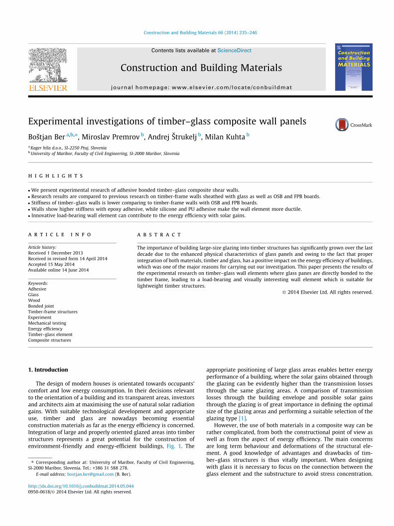
The design of modern houses is orientated towards occupants’comfort and low energy consumption. In their decisions relevantto the orientation of a building and its transparent areas, investorsand architects aim at maximising the use of natural solar radiationgains. With suitable technological development and appropriateuse, timber and glass are nowadays becoming essentialconstruction materials as far as the energy efficiency is concerned.Integration of large and properly oriented glazed areas into timberstructures represents a great potential for the construction ofenvironment-friendly and energy-efficient buildings, Fig. 1. The
appropriate positioning of large glass areas enables better energyperformance of a building, where the solar gains obtained throughthe glazing can be evidently higher than the transmission lossesthrough the same glazing areas. A comparison of transmissionlosses through the building envelope and possible solar gainsthrough the glazing is of great importance in defining the optimalsize of the glazing areas and performing a suitable selection of theglazing type [1].
However, the use of both materials in a composite way can berather complicated, from both the constructional point of view aswell as from the aspect of energy efficiency. The main concernsare long term behaviour and deformations of the structural ele-ment. A good knowledge of advantages and drawbacks of tim-ber–glass structures is thus vitally important. When designingwith glass it is necessary to focus on the connection between theglass element and the substructure to avoid stress concentration.
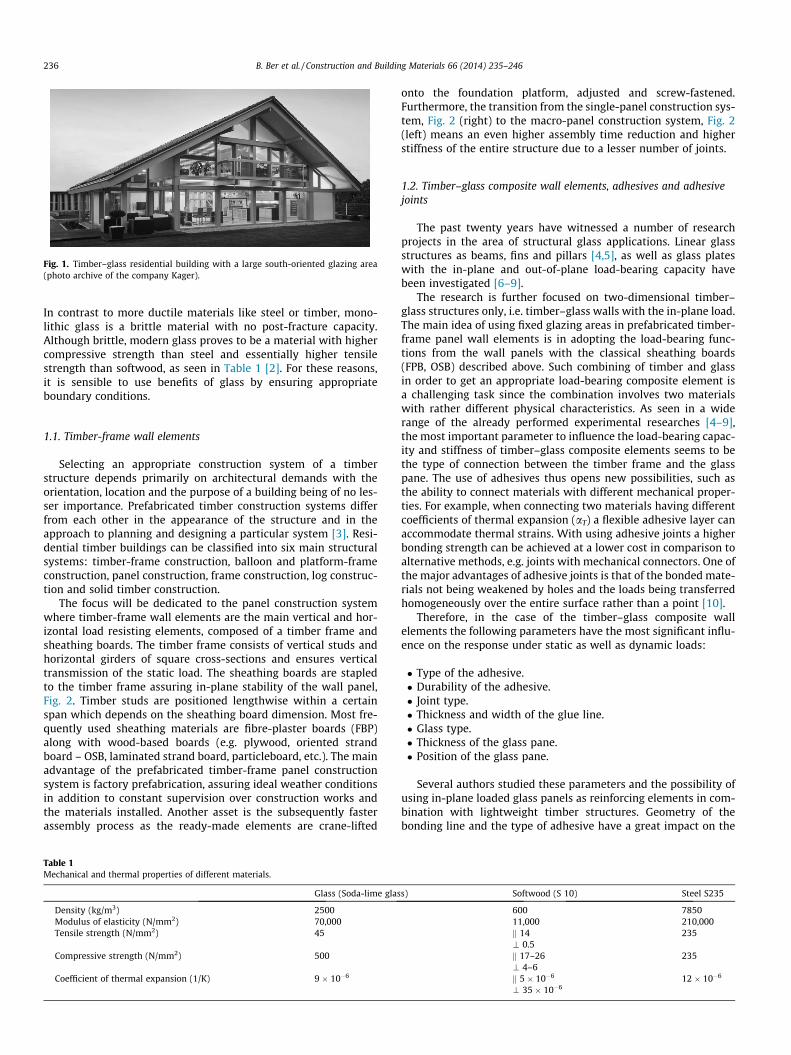
Fig. 1. Timber–glass residential building with a large south-oriented glazing area(photo archive of the company Kager).
236 B. Ber et al. / Construction and Building Materials 66 (2014) 235–246
In contrast to more ductile materials like steel or timber, mono-lithic glass is a brittle material with no post-fracture capacity.Although brittle, modern glass proves to be a material with highercompressive strength than steel and essentially higher tensilestrength than softwood, as seen in Table 1 [2]. For these reasons,it is sensible to use benefits of glass by ensuring appropriateboundary conditions.
1.1. Timber-frame wall elements
Selecting an appropriate construction system of a timberstructure depends primarily on architectural demands with theorientation, location and the purpose of a building being of no les-ser importance. Prefabricated timber construction systems differfrom each other in the appearance of the structure and in theapproach to planning and designing a particular system [3]. Resi-dential timber buildings can be classified into six main structuralsystems: timber-frame construction, balloon and platform-frameconstruction, panel construction, frame construction, log construc-tion and solid timber construction.
The focus will be dedicated to the panel construction systemwhere timber-frame wall elements are the main vertical and hor-izontal load resisting elements, composed of a timber frame andsheathing boards. The timber frame consists of vertical studs andhorizontal girders of square cross-sections and ensures verticaltransmission of the static load. The sheathing boards are stapledto the timber frame assuring in-plane stability of the wall panel,Fig. 2. Timber studs are positioned lengthwise within a certainspan which depends on the sheathing board dimension. Most fre-quently used sheathing materials are fibre-plaster boards (FBP)along with wood-based boards (e.g. plywood, oriented strandboard – OSB, laminated strand board, particleboard, etc.). The mainadvantage of the prefabricated timber-frame panel constructionsystem is factory prefabrication, assuring ideal weather conditionsin addition to constant supervision over construction works andthe materials installed. Another asset is the subsequently fasterassembly process as the ready-made elements are crane-lifted
Table 1Mechanical and thermal properties of different materials.
Glass (Soda-lime glas
Density (kg/m3) 2500Modulus of elasticity (N/mm2) 70,000Tensile strength (N/mm2) 45
Compressive strength (N/mm2) 500
Coefficient of thermal expansion (1/K) 9 � 10�6
onto the foundation platform, adjusted and screw-fastened.Furthermore, the transition from the single-panel construction sys-tem, Fig. 2 (right) to the macro-panel construction system, Fig. 2(left) means an even higher assembly time reduction and higherstiffness of the entire structure due to a lesser number of joints.
1.2. Timber–glass composite wall elements, adhesives and adhesivejoints
The past twenty years have witnessed a number of researchprojects in the area of structural glass applications. Linear glassstructures as beams, fins and pillars [4,5], as well as glass plateswith the in-plane and out-of-plane load-bearing capacity havebeen investigated [6–9].
The research is further focused on two-dimensional timber–glass structures only, i.e. timber–glass walls with the in-plane load.The main idea of using fixed glazing areas in prefabricated timber-frame panel wall elements is in adopting the load-bearing func-tions from the wall panels with the classical sheathing boards(FPB, OSB) described above. Such combining of timber and glassin order to get an appropriate load-bearing composite element isa challenging task since the combination involves two materialswith rather different physical characteristics. As seen in a widerange of the already performed experimental researches [4–9],the most important parameter to influence the load-bearing capac-ity and stiffness of timber–glass composite elements seems to bethe type of connection between the timber frame and the glasspane. The use of adhesives thus opens new possibilities, such asthe ability to connect materials with different mechanical proper-ties. For example, when connecting two materials having differentcoefficients of thermal expansion (aT) a flexible adhesive layer canaccommodate thermal strains. With using adhesive joints a higherbonding strength can be achieved at a lower cost in comparison toalternative methods, e.g. joints with mechanical connectors. One ofthe major advantages of adhesive joints is that of the bonded mate-rials not being weakened by holes and the loads being transferredhomogeneously over the entire surface rather than a point [10].
Therefore, in the case of the timber–glass composite wallelements the following parameters have the most significant influ-ence on the response under static as well as dynamic loads:
� Type of the adhesive.� Durability of the adhesive.� Joint type.� Thickness and width of the glue line.� Glass type.� Thickness of the glass pane.� Position of the glass pane.
Several authors studied these parameters and the possibility ofusing in-plane loaded glass panels as reinforcing elements in com-bination with lightweight timber structures. Geometry of thebonding line and the type of adhesive have a great impact on the
s) Softwood (S 10) Steel S235
600 785011,000 210,000k 14 235\ 0.5k 17–26 235\ 4–6k 5 � 10�6 12 � 10�6
\ 35 � 10�6
h
bFh
h
Fh,tot = n × Fh
n x bbopeningbb
opening
sheathing board�mber frame
Ft Fc Ft Fc Ft Fc Ft Fc
sheathingboard
�mber frame
stud
bo�om plate
top plate
Fh,rFh,r
Fh
Fig. 2. Composition of a macro-panel (left) and a single timber frame wall (right) showing the distribution of horizontal load.
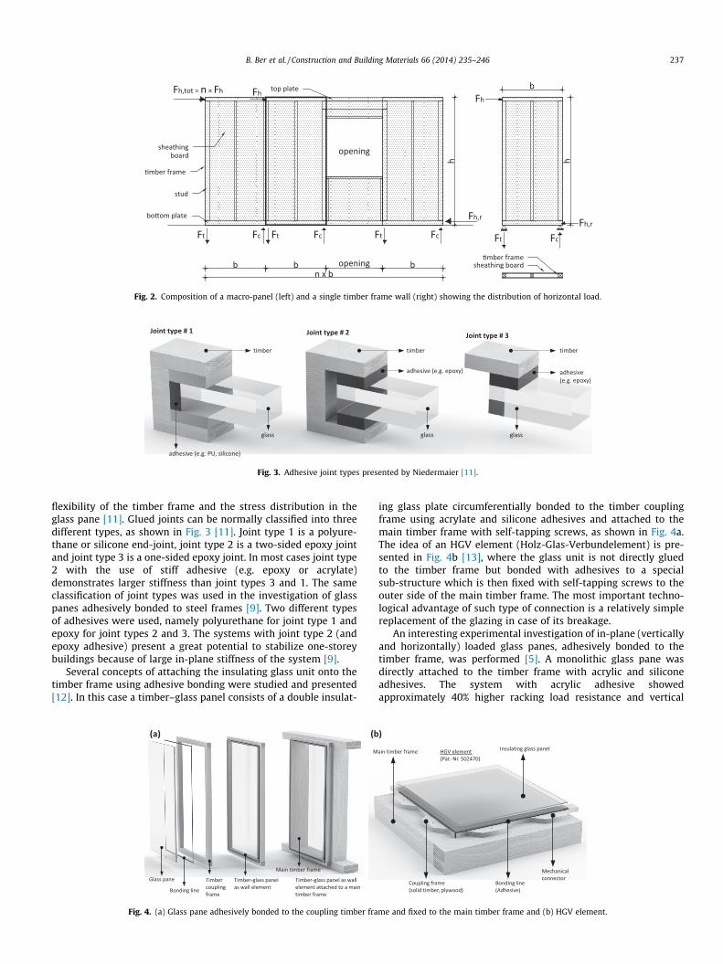
Fig. 3. Adhesive joint types presented by Niedermaier [11].
B. Ber et al. / Construction and Building Materials 66 (2014) 235–246 237
flexibility of the timber frame and the stress distribution in theglass pane [11]. Glued joints can be normally classified into threedifferent types, as shown in Fig. 3 [11]. Joint type 1 is a polyure-thane or silicone end-joint, joint type 2 is a two-sided epoxy jointand joint type 3 is a one-sided epoxy joint. In most cases joint type2 with the use of stiff adhesive (e.g. epoxy or acrylate)demonstrates larger stiffness than joint types 3 and 1. The sameclassification of joint types was used in the investigation of glasspanes adhesively bonded to steel frames [9]. Two different typesof adhesives were used, namely polyurethane for joint type 1 andepoxy for joint types 2 and 3. The systems with joint type 2 (andepoxy adhesive) present a great potential to stabilize one-storeybuildings because of large in-plane stiffness of the system [9].
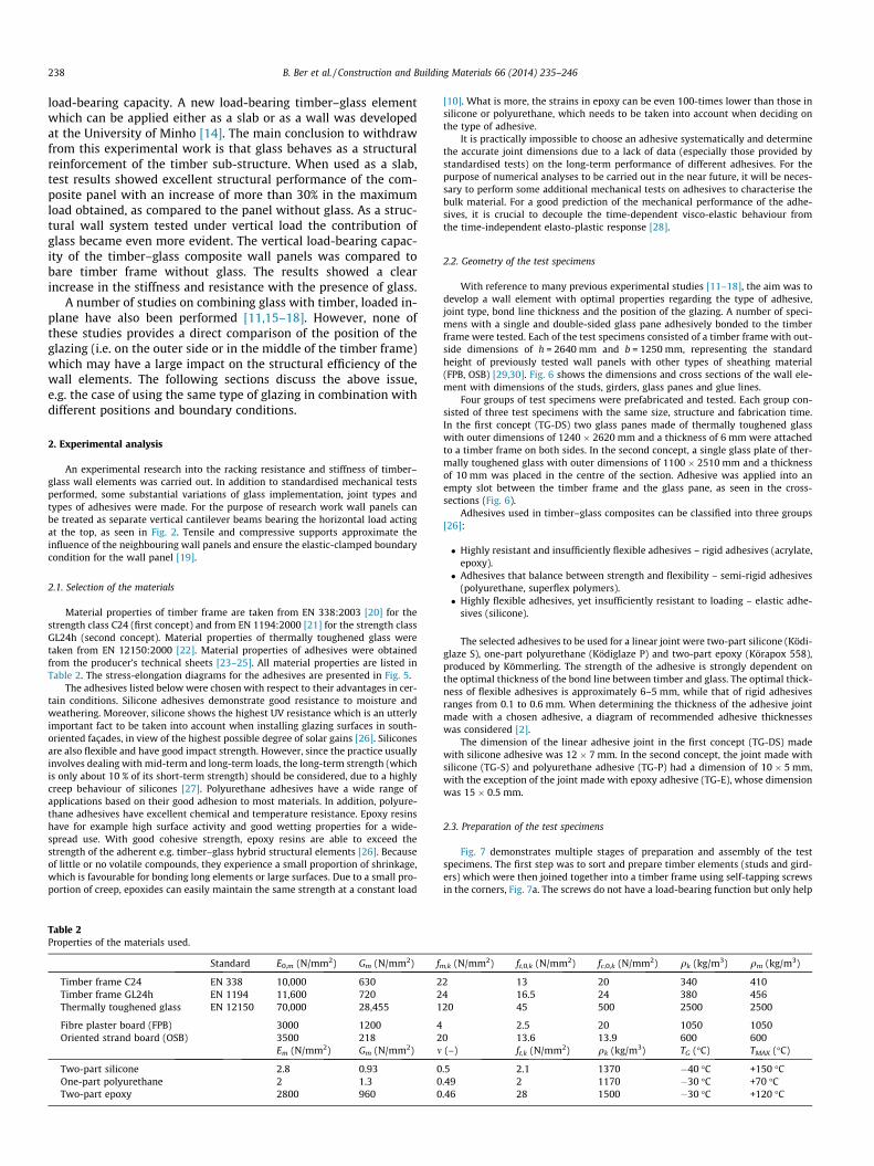
Several concepts of attaching the insulating glass unit onto thetimber frame using adhesive bonding were studied and presented[12]. In this case a timber–glass panel consists of a double insulat-
(a) (b
Fig. 4. (a) Glass pane adhesively bonded to the coupling timber fra
ing glass plate circumferentially bonded to the timber couplingframe using acrylate and silicone adhesives and attached to themain timber frame with self-tapping screws, as shown in Fig. 4a.The idea of an HGV element (Holz-Glas-Verbundelement) is pre-sented in Fig. 4b [13], where the glass unit is not directly gluedto the timber frame but bonded with adhesives to a specialsub-structure which is then fixed with self-tapping screws to theouter side of the main timber frame. The most important techno-logical advantage of such type of connection is a relatively simplereplacement of the glazing in case of its breakage.
An interesting experimental investigation of in-plane (verticallyand horizontally) loaded glass panes, adhesively bonded to thetimber frame, was performed [5]. A monolithic glass pane wasdirectly attached to the timber frame with acrylic and siliconeadhesives. The system with acrylic adhesive showedapproximately 40% higher racking load resistance and vertical
)
me and fixed to the main timber frame and (b) HGV element.
238 B. Ber et al. / Construction and Building Materials 66 (2014) 235–246
load-bearing capacity. A new load-bearing timber–glass elementwhich can be applied either as a slab or as a wall was developedat the University of Minho [14]. The main conclusion to withdrawfrom this experimental work is that glass behaves as a structuralreinforcement of the timber sub-structure. When used as a slab,test results showed excellent structural performance of the com-posite panel with an increase of more than 30% in the maximumload obtained, as compared to the panel without glass. As a struc-tural wall system tested under vertical load the contribution ofglass became even more evident. The vertical load-bearing capac-ity of the timber–glass composite wall panels was compared tobare timber frame without glass. The results showed a clearincrease in the stiffness and resistance with the presence of glass.
A number of studies on combining glass with timber, loaded in-plane have also been performed [11,15–18]. However, none ofthese studies provides a direct comparison of the position of theglazing (i.e. on the outer side or in the middle of the timber frame)which may have a large impact on the structural efficiency of thewall elements. The following sections discuss the above issue,e.g. the case of using the same type of glazing in combination withdifferent positions and boundary conditions.
2. Experimental analysis
An experimental research into the racking resistance and stiffness of timber–glass wall elements was carried out. In addition to standardised mechanical testsperformed, some substantial variations of glass implementation, joint types andtypes of adhesives were made. For the purpose of research work wall panels canbe treated as separate vertical cantilever beams bearing the horizontal load actingat the top, as seen in Fig. 2. Tensile and compressive supports approximate theinfluence of the neighbouring wall panels and ensure the elastic-clamped boundarycondition for the wall panel [19].
2.1. Selection of the materials
Material properties of timber frame are taken from EN 338:2003 [20] for thestrength class C24 (first concept) and from EN 1194:2000 [21] for the strength classGL24h (second concept). Material properties of thermally toughened glass weretaken from EN 12150:2000 [22]. Material properties of adhesives were obtainedfrom the producer’s technical sheets [23–25]. All material properties are listed inTable 2. The stress-elongation diagrams for the adhesives are presented in Fig. 5.
The adhesives listed below were chosen with respect to their advantages in cer-tain conditions. Silicone adhesives demonstrate good resistance to moisture andweathering. Moreover, silicone shows the highest UV resistance which is an utterlyimportant fact to be taken into account when installing glazing surfaces in south-oriented façades, in view of the highest possible degree of solar gains [26]. Siliconesare also flexible and have good impact strength. However, since the practice usuallyinvolves dealing with mid-term and long-term loads, the long-term strength (whichis only about 10 % of its short-term strength) should be considered, due to a highlycreep behaviour of silicones [27]. Polyurethane adhesives have a wide range ofapplications based on their good adhesion to most materials. In addition, polyure-thane adhesives have excellent chemical and temperature resistance. Epoxy resinshave for example high surface activity and good wetting properties for a wide-spread use. With good cohesive strength, epoxy resins are able to exceed thestrength of the adherent e.g. timber–glass hybrid structural elements [26]. Becauseof little or no volatile compounds, they experience a small proportion of shrinkage,which is favourable for bonding long elements or large surfaces. Due to a small pro-portion of creep, epoxides can easily maintain the same strength at a constant load
Table 2Properties of the materials used.
Standard E0,m (N/mm2) Gm (N/mm2) f
Timber frame C24 EN 338 10,000 630 2Timber frame GL24h EN 1194 11,600 720 2Thermally toughened glass EN 12150 70,000 28,455 1
Fibre plaster board (FPB) 3000 1200 4Oriented strand board (OSB) 3500 218 2
Em (N/mm2) Gm (N/mm2) m
Two-part silicone 2.8 0.93 0One-part polyurethane 2 1.3 0Two-part epoxy 2800 960 0
[10]. What is more, the strains in epoxy can be even 100-times lower than those insilicone or polyurethane, which needs to be taken into account when deciding onthe type of adhesive.
It is practically impossible to choose an adhesive systematically and determinethe accurate joint dimensions due to a lack of data (especially those provided bystandardised tests) on the long-term performance of different adhesives. For thepurpose of numerical analyses to be carried out in the near future, it will be neces-sary to perform some additional mechanical tests on adhesives to characterise thebulk material. For a good prediction of the mechanical performance of the adhe-sives, it is crucial to decouple the time-dependent visco-elastic behaviour fromthe time-independent elasto-plastic response [28].
2.2. Geometry of the test specimens
With reference to many previous experimental studies [11–18], the aim was todevelop a wall element with optimal properties regarding the type of adhesive,joint type, bond line thickness and the position of the glazing. A number of speci-mens with a single and double-sided glass pane adhesively bonded to the timberframe were tested. Each of the test specimens consisted of a timber frame with out-side dimensions of h = 2640 mm and b = 1250 mm, representing the standardheight of previously tested wall panels with other types of sheathing material(FPB, OSB) [29,30]. Fig. 6 shows the dimensions and cross sections of the wall ele-ment with dimensions of the studs, girders, glass panes and glue lines.
Four groups of test specimens were prefabricated and tested. Each group con-sisted of three test specimens with the same size, structure and fabrication time.In the first concept (TG-DS) two glass panes made of thermally toughened glasswith outer dimensions of 1240 � 2620 mm and a thickness of 6 mm were attachedto a timber frame on both sides. In the second concept, a single glass plate of ther-mally toughened glass with outer dimensions of 1100 � 2510 mm and a thicknessof 10 mm was placed in the centre of the section. Adhesive was applied into anempty slot between the timber frame and the glass pane, as seen in the cross-sections (Fig. 6).
Adhesives used in timber–glass composites can be classified into three groups[26]:
� Highly resistant and insufficiently flexible adhesives – rigid adhesives (acrylate,epoxy).� Adhesives that balance between strength and flexibility – semi-rigid adhesives
(polyurethane, superflex polymers).� Highly flexible adhesives, yet insufficiently resistant to loading – elastic adhe-
sives (silicone).
The selected adhesives to be used for a linear joint were two-part silicone (Ködi-glaze S), one-part polyurethane (Ködiglaze P) and two-part epoxy (Körapox 558),produced by Kömmerling. The strength of the adhesive is strongly dependent onthe optimal thickness of the bond line between timber and glass. The optimal thick-ness of flexible adhesives is approximately 6–5 mm, while that of rigid adhesivesranges from 0.1 to 0.6 mm. When determining the thickness of the adhesive jointmade with a chosen adhesive, a diagram of recommended adhesive thicknesseswas considered [2].
The dimension of the linear adhesive joint in the first concept (TG-DS) madewith silicone adhesive was 12 � 7 mm. In the second concept, the joint made withsilicone (TG-S) and polyurethane adhesive (TG-P) had a dimension of 10 � 5 mm,with the exception of the joint made with epoxy adhesive (TG-E), whose dimensionwas 15 � 0.5 mm.
2.3. Preparation of the test specimens
Fig. 7 demonstrates multiple stages of preparation and assembly of the testspecimens. The first step was to sort and prepare timber elements (studs and gird-ers) which were then joined together into a timber frame using self-tapping screwsin the corners, Fig. 7a. The screws do not have a load-bearing function but only help
m,k (N/mm2) ft,0,k (N/mm2) fc,0,k (N/mm2) qk (kg/m3) qm (kg/m3)
2 13 20 340 4104 16.5 24 380 45620 45 500 2500 2500
2.5 20 1050 10500 13.6 13.9 600 600(–) ft,k (N/mm2) qk (kg/m3) TG (�C) TMAX (�C)
.5 2.1 1370 �40 �C +150 �C
.49 2 1170 �30 �C +70 �C
.46 28 1500 �30 �C +120 �C
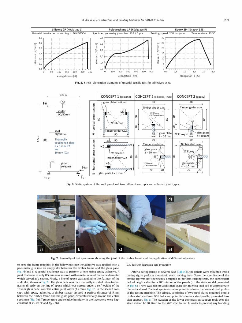
Fig. 5. Stress–elongation diagrams of uniaxial tensile test for adhesives used.
2.64
m
1.25 m
girder90/80mm
Fig. 6. Static system of the wall panel and two different concepts and adhesive joint types.
Fig. 7. Assembly of test specimens showing the joint of the timber frame and the application of different adhesives.
B. Ber et al. / Construction and Building Materials 66 (2014) 235–246 239
to keep the frame together. In the following stage the adhesive was applied with apneumatic gun into an empty slot between the timber frame and the glass pane,Fig. 7b and c. A special challenge was to perform a joint using epoxy adhesive. Ajoint thickness of only 0.5 mm was assured with a metal wire of the same diameterwhich served as a spacer. Firstly, a line of epoxy was applied to the flat part of thewide slot, shown in Fig. 7d. The glass pane was then manually inserted into a timberframe, directly on the line of epoxy which was spread under a self-weight of the10 mm glass pane, over the entire joint width (15 mm), Fig. 7e. In the second con-cept with epoxy adhesive, a timber spacer assured a perfect distance of 5 mmbetween the timber frame and the glass pane, circumferentially around the entirespecimen (Fig. 7e). Temperature and relative humidity in the laboratory were keptconstant at T = 23 �C and RH = 26%.
2.4. Test configuration and procedure
After a curing period of several days (Table 3), the panels were mounted into atesting rig to perform monotonic static racking tests. Since the steel frame of thetesting rig was not specifically designed to perform racking tests, the consequentlack of height called for a 90� rotation of the panels (c.f. the static model presentedin Fig. 6). There was also no additional space for an extra load cell to approximatethe vertical load. The test specimens were point fixed onto the vertical steel profileof the testing machine. The stirrup, consisting of two steel plates mounted onto atimber stud via three U16 bolts and point fixed onto a steel profile, presented ten-sion support, Fig. 8. The reaction of the lower compression support took over thesteel section I-180, fixed to the stiff steel frame. In order to prevent any buckling

Table 3Test groups and experimental results.
Groupname
Number ofspecimens
Specimenname
Timber–glassjoint concept
Adhesive Curing time of theadhesive (days)
Glass platethickness (mm)
Fu,i (kN) wu,i
(mm)Fu,mean
(kN)wu,mean
(mm)
TG-TS 3 ST-O1 Concept 1 Two-partsilicone
8 6 + 6 (17.8)41.06
(44.5)63.29
ST-O2 3 (16.3)17.47
(49.9)49.85
(17.3)28.3
(47.2)61.8
ST-O3 10 (17.9)26.32
(47.5)72.25
TG-S 3 ST-S1 Concept 2 Two-partsilicone
9 10 11.89 49.45
ST-S2 16 12.45 42.26 11.58 44.58ST-S3 21 10.39 42.04
TG-P 3 ST-P1 Concept 2 One-partpolyurethane
12 10 11.92 53.54
ST-P2 16 13.59 52.49 13.43 53.57ST-P3 20 14.78 54.67
TG-E 3 ST-E1 Concept 2 Two-partepoxy
12 10 44.97 47.18
ST-E2 15 33.45 30.97 37.35 35.51ST-E3 19 33.64 28.37
240 B. Ber et al. / Construction and Building Materials 66 (2014) 235–246
of the test specimens, movable supports were installed onto the auxiliary steelstructure. The test specimens were exposed to a static load F approximating thehorizontal load, ranging from point 0 to the failure point by the load protocol ofEN 594:2011 [31]. The load increase rate on the panels was 8 N/s from 0 to 10 kNand 10 N/s thereafter. To define cantilever wall deflection induced by load F weused a strain-gage incorporated in the load cell, while the value of slip in the con-necting plane between the timber frame and the glass pane was defined by LVDTattached in the middle of the wall panel. One representative from each of the testgroups (TG-S, TG-P, and TG-E) was equipped with an additional instrumentation.Strain gages were mounted on the outer edge of the timber frame (6 measuringpoints) and 45 degrees strain rosettes (8 measuring points) to a glass pane to mea-sure the strains. The stress–strain state in wall elements is not further discussed inthis paper.
3. Results and observations
The results for all specimen groups are summarised in this sec-tion and listed in Table 3, where the normalised values of verticaldisplacements wu.i for each of the specimens and mean values of ver-tical displacements wu.mean relative to force F, are presented. The FU
values demonstrate the force at which the rupture of the adhesiveor the fracture of glass occurred. FU values are also divided into FU,i
for a single specimen and FU,mean for a group of specimens.
3.1. Results of the mechanical tests
The results of the mechanical tests are presented by a force–displacement diagram in Figs. 9–11, separately for each specimen.
Fig. 8. Test configuration and the static system rotate
The FU values given in legend demonstrate ultimate force atwhich the failure occurred and the experiment had to be stopped.Values of loads and displacements for the first test group TG-DS,given in brackets, indicate the yielding, i.e. large plastic deforma-tions of the adhesive, while the other (ultimate) values presentfailure of individual specimens. The FU values of the test groupTG-DS were attained at the point of explosive two-sided fractureof glass panes, which resembled the response of the glass paneglued to the steel frames by means of soft adhesives [9]. In addi-tion, the curves in Fig. 9 show similar behaviour of all three testspecimens until the yielding point of the adhesive whichappeared at forces ranging from 16.3 kN to 17.9 kN. Noticeabledifferences appeared only after the adhesive yielding point. Incase of ST-O1 a sudden increase of stiffness (after reaching18 kN and 45 mm) was provoked by activation of the compres-sion diagonal in the glass due to an unexpected blocking of glassagainst the steel element in compression support of the testingrig. Behaviour of the ST-O1 test specimen can be labelled asthree-linear with phase 1: linear, i.e. elastic behaviour until thepoint of yielding of the adhesive; phase 2: yielding of the adhe-sive; phase 3: increased slips in the glue line i.e. rupture of theadhesive, causing glass panes to lean on the steel substructureand collapse. Tests that followed were improved by eliminatingthe defect of the support. Test specimen ST-O2 of the group TG-DS with the shortest curing time (t = 3 days) failed soon afterthe onset of yielding of the adhesive.
d by 90� due to the dimensions of the testing rig.

0
5
10
15
20
25
30
35
40
45
0 5 10 15 20 25 30 35 40 45 50 55 60 65 70 75
Load
F (k
N)
Displacement w (mm)
ST-O1 Fu = 41.06 kN
ST-O2 Fu = 17.47 kN
ST-O3 Fu = 26.32 kN
Adhesive failure
Glass plate stranded on a steel support
Large scale displacements caused glass plates to strand on a steel support and collapse
Fig. 9. Load–displacement diagram for timber–glass test specimens of the test group TG-DS.
B. Ber et al. / Construction and Building Materials 66 (2014) 235–246 241
Specimens of the epoxy group TG-E displayed rather differentbehaviour. The inclination of the ST-E2 and ST-E3 curves is almostidentical, ending at the point of glass fracture. With specimens ST-E2 and ST-E3 we witnessed almost linear behaviour ending upwith an instantaneous fracture of the glass panes, Fig. 12a. Identi-cal failure mode occurred with the entire TG-DS group. The excep-tion was ST-E1 which was slightly stiffer and exhibited failure ofthe timber element at tension support while glass remained intact,Fig. 12b. However, when using highly resistant and stiff adhesivesthe glass elements usually collapse [26].
In the TG-S and TG-P test groups, failure occurred due to thecollapse of upper left corner of the timber frame, as seen inFig. 12c. A relatively low ultimate load ranging from 10 kN to15 kN with the corresponding displacements from 40 mm to55 mm was the cause of using more flexible adhesives and aweaker joint type. If we compare both test groups using siliconeadhesive (TG-DS and TG-S), we observe no major difference inthe load-bearing capacity. The only difference was seen in higherinitial stiffness of the TG-DS group which had a double glazingand adhesive joint of a different type. Figs. 11 and 12c represent
0
5
10
15
20
25
30
35
40
45
0 5 10 15 20
Load
F (k
N)
Displacem
ST-E1 Fu = 44.97 kN
ST-E2 Fu = 33.45 kN
ST-E3 Fu = 33.64 kN
ST-E (FEM) Fu = 32 kN
Fig. 10. Load–displacement diagram for timber–
a typical failure mode of the test groups TG-S and TG-P. Cohesiverupture of the adhesive joint occurred due to low shear resistanceof the silicone and polyurethane adhesive. In order to amelioratethe composite action of the latter specimens the stud-girderconnection would need to be improved in the first place (e.g. rein-forcement with nail plates).
3.2. Numerical results and validation with experimental data
A 3-dimensional FE model was constructed for two test groups,namely for the TG-E and TG-P. The aim was to model a timber–glass panel in close-to-reality conditions regarding materials andboundary conditions. Timber frame was modelled as orthotropicmaterial with different mechanical properties in longitudinal andtransversal direction. All other parts (i.e. glass pane, screws,supports etc.) were modelled as linear perfectly elastic withmechanical properties given in Tables 1 and 2.
The simulation of connection between timber and glass in caseof ST-E specimen was very simple. Since the thickness of epoxyadhesive is 0.5 mm, and according to the fact that the measured
25 30 35 40 45 50
ent w (mm)
ST-E2 / C2 / epoxy
Glass fracture
Glass fracture while the bond line remains intact
Timber failure at tension support
glass test specimens of the test group TG-E.
0
2
4
6
8
10
12
14
16
0 5 10 15 20 25 30 35 40 45 50 55 60
Load
F (k
N)
Displacement w (mm)
ST-P1 Fu = 11.92 kN
ST-P2 Fu = 13.59 kN
ST-P3 Fu = 14.78 kN
ST-P (FEM) Fu = 14 kN
ST-S1 Fu = 11.89 kN
ST-S2 Fu = 12.45 kN
ST-S3 Fu = 10.39 kN
ST-S1 / C2 / silicone
Timber frame corner joint collapse
Cohesive failure of the glue line
Mixed adhesive and cohesive failure of the glue line
Fig. 11. Load–displacement diagram for timber–glass test specimens of the test groups TG-S and TG-P.
242 B. Ber et al. / Construction and Building Materials 66 (2014) 235–246
relative displacements between glass and timber frame were neg-ligible, glass and timber were bonded together on all surfaceswhere bonding was foreseen. The model was then meshed withtetrahedral finite elements. Calculated results for displacements,strains and stresses are very close to those obtained from measure-ments of the specimens tested mechanically. Fig. 13a is showingthe results of stress component rx for the ST-E specimen. InFig. 14 the comparison between normal stresses rx obtained fromstrain measurements during the test and the same stress compo-nent obtained from computer simulation is shown, confirmingthe relevance of the numerical model. A load displacement curve(ST-E-FEM) from the FE analysis was plotted in Fig. 10 showinggood agreement with the mechanical test results.
FE simulation of ST-P specimen on the other hand proved to bemore challenging. A Mooney–Rivlin hyper-elastic material modelwas used to simulate the behaviour of polyurethane adhesive. Aload displacement curve (ST-P-FEM) from the FE analysis is plottedin Fig. 11. Numerical solution shows good agreement with theexperimental results. Slope of the curve indicates a slightly higherstiffness of the numerical model. However, to achieve betternumerical results some additional mechanical tests on adhesivesshould be performed to characterise the bulk material moreprecisely. Fig. 13b is showing the results of stress component rx
for the ST-P specimen, where concentration of stresses in the glasspane at the corners can be observed.
4. Comparison of test results and discussion
Five groups with a total of 14 specimens having the samedimensions, boundary conditions and loading protocols weretested in the past [29,30]. Fig. 15 shows wall specimens with
Fig. 12. Different failure modes: (a) glass failure, (b) timber fail
different types of sheathing boards. Fig. 15a and b represent wallspecimens with FPB and OSB sheathing boards with a differentdisposition of fasteners. Fig. 15c demonstrates a wall specimenwith FPB sheathing boards and an opening where variations ofthe opening width were made. Table 4 introduces the results ofthe force forming the first crack (Fcr) and the correspondingdeflection (wcr).
The labels of the test specimens from Table 4 mean thefollowing:
� G2 – single FPB on both sides of the timber frame (Fig. 15a).� G2D – double FPB on both sides of the timber frame (Fig. 15a).� G2O – single OSB on both sides of the timber frame (Fig. 15b).� O1 – single FPB on both sides of the timber frame with an empty
window opening of 1272 � 842 mm (Fig. 15c).� O2 – single FPB on both sides of the timber frame with an empty
window opening of 1272 � 572 mm (Fig. 15c).
As presented in Fig. 16, although the test group TG-DS can becompared to G2 in its load-bearing capacity (until the appearanceof the first crack), its flexibility was nevertheless much higher. Asimilar comparison of the load-bearing capacity can be madebetween the test groups TG-E and G2O, where the latter displayedapproximately 30% higher stiffness in the linear-elastic behaviourrange. Almost the same initial stiffness was exhibited in the testgroups TG-E and O2, while the load at the first crack appearancewas much lower in the O2 group. Specimens of the ST-S, ST-Pand O1 groups showed almost identical stiffness and strength. Fur-thermore, it is clear that G2, G2D and G2O specimens displayedalmost linear-elastic behaviour until the appearance of the firstcracks. In the finishing stage of the test a decrease observed inthe stiffness of G2 and G2D was due to the increased slip in the
ure at tension support, (c) stud-girder connection opening.

(a) (b)
Fig. 13. FE analysis results of stress component rx for (a) ST-E specimen at 32 kN of FH and for (b) ST-P specimen at 3.0 kN of FH.
Fig. 14. Comparison of normal stresses (rx) obtained from strain measurements and those obtained with FE analysis for the section positioned in the middle of the span of ST-E specimen (epoxy adhesive).
Fig. 15. Previous research projects on timber frame walls with FPB, OSB and FPB with openings compared with a timber–glass panel.
B. Ber et al. / Construction and Building Materials 66 (2014) 235–246 243

Table 4Groups of timber frame wall specimens with FPB and OSB sheathing, from previous experimental investigations.
Group name Number of specimens Sheathing board type Distance between staples (mm) Board thickness (mm) Fcr (kN) wcr (mm)
G2 4 FPB 75 15 16.9 18.0G2D 1 FPB 75 2 � 15 21.7 21.6G2O 3 OSB 75 15 41.6 66.6O1 3 FPB 75 15 3.9 8.2O2 3 FPB 75 15 7.1 12.3
0
5
10
15
20
25
30
35
40
45
0 5 10 15 20 25 30 35 40 45
Load
F (k
N)
Displacement w (mm)
G2D
G2
G2O
TG-E
O2
TG-DS
O1
TG-S
TG-P
Fig. 16. Load–displacement curves for timber-frame walls with different sheathing material.
0
5
10
15
20
25
30
35
40
0.0 0.2 0.4 0.6 0.8 1.0 1.2 1.4 1.6 1.8 2.0
Load
F (k
N)
Slip Δtension (mm)
TG-ETG-DSG2DG2OG2O2O1TG-STG-P
�mber-glass /
LVDT for measuring slips between �mber stud
C2 / epoxy
(between the �mber stud and a glass pane)
Slip Δtension (mm)
Fig. 17. Values of the slip in the glue line between the timber frame and a glass pane for test groups with different sheathing material.
244 B. Ber et al. / Construction and Building Materials 66 (2014) 235–246
connecting plane caused by the yielding of the fasteners (i.e.staples). When using more flexible adhesives (TG-DS, TG-S andTG-P), the stiffness of timber–glass walls is significantly lower, incomparison to the conventional sheathing material, which wouldmean difficulty in satisfying the serviceability limit state condi-tions in practice.
Test specimens of the testing groups TG-DS (elastic phase withno adhesive yielding) and TG-E demonstrated a higher level of
stiffness in the connecting plane than those with classic FPB orOSB sheathing, as seen in Fig. 17. Focus was laid on the tensionzone because of significantly higher values of slip occurring there.It should be emphasised that tension slips of the TG-E group wereactually deformations of timber parallel to the grain. Based onrelatively low value of the tension slip of approximately0.05 mm, the measurement was made at the resolution limit ofthe instrument. Nevertheless these particular values are plotted
0
5
10
15
20
25
30
35
0 5 10 15 20 25 30 35 40 45
Load
F (k
N)
Displacement w (mm)
TG-E
HGV 19/3
TG-DS
HGV 14/3
TG-S
TG-P
�mber-glass / C2 / epoxy
�mber-glass / C2 / silicone
Fig. 18. Force–displacement diagram of different timber–glass structural wall panels.
0
500
1000
1500
2000
2500
TG-DS TG-S TG-P TG-E G2O HGV 14/3 HGV 19/3
485373 324
1544
2132
594
1022
REN
594,
AVE
RAG
E(N
/mm
)
Fig. 19. Racking stiffness diagram for different test groups.
B. Ber et al. / Construction and Building Materials 66 (2014) 235–246 245
in the diagram in order to get the information about the jointstiffness.
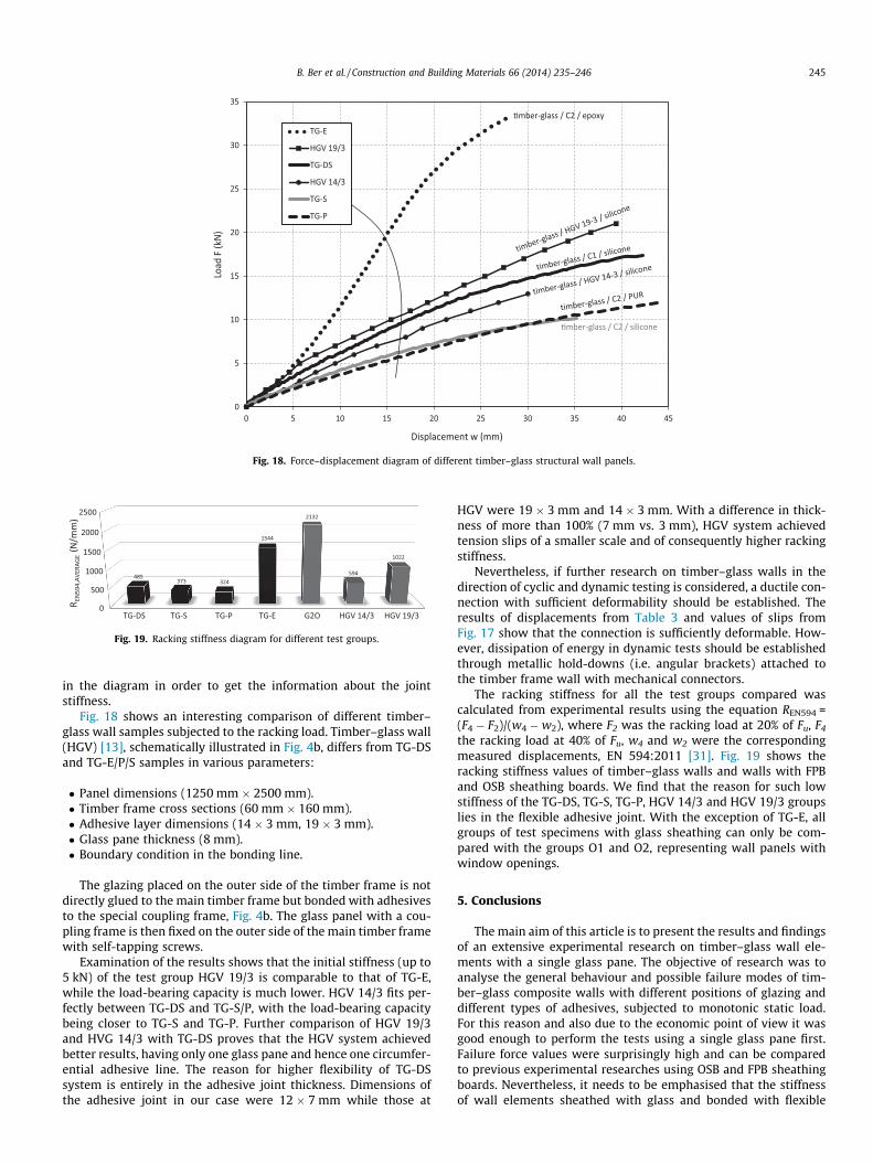
Fig. 18 shows an interesting comparison of different timber–glass wall samples subjected to the racking load. Timber–glass wall(HGV) [13], schematically illustrated in Fig. 4b, differs from TG-DSand TG-E/P/S samples in various parameters:
� Panel dimensions (1250 mm � 2500 mm).� Timber frame cross sections (60 mm � 160 mm).� Adhesive layer dimensions (14 � 3 mm, 19 � 3 mm).� Glass pane thickness (8 mm).� Boundary condition in the bonding line.
The glazing placed on the outer side of the timber frame is notdirectly glued to the main timber frame but bonded with adhesivesto the special coupling frame, Fig. 4b. The glass panel with a cou-pling frame is then fixed on the outer side of the main timber framewith self-tapping screws.
Examination of the results shows that the initial stiffness (up to5 kN) of the test group HGV 19/3 is comparable to that of TG-E,while the load-bearing capacity is much lower. HGV 14/3 fits per-fectly between TG-DS and TG-S/P, with the load-bearing capacitybeing closer to TG-S and TG-P. Further comparison of HGV 19/3and HVG 14/3 with TG-DS proves that the HGV system achievedbetter results, having only one glass pane and hence one circumfer-ential adhesive line. The reason for higher flexibility of TG-DSsystem is entirely in the adhesive joint thickness. Dimensions ofthe adhesive joint in our case were 12 � 7 mm while those at
HGV were 19 � 3 mm and 14 � 3 mm. With a difference in thick-ness of more than 100% (7 mm vs. 3 mm), HGV system achievedtension slips of a smaller scale and of consequently higher rackingstiffness.
Nevertheless, if further research on timber–glass walls in thedirection of cyclic and dynamic testing is considered, a ductile con-nection with sufficient deformability should be established. Theresults of displacements from Table 3 and values of slips fromFig. 17 show that the connection is sufficiently deformable. How-ever, dissipation of energy in dynamic tests should be establishedthrough metallic hold-downs (i.e. angular brackets) attached tothe timber frame wall with mechanical connectors.
The racking stiffness for all the test groups compared wascalculated from experimental results using the equation REN594 =(F4 � F2)/(w4 � w2), where F2 was the racking load at 20% of Fu, F4
the racking load at 40% of Fu, w4 and w2 were the correspondingmeasured displacements, EN 594:2011 [31]. Fig. 19 shows theracking stiffness values of timber–glass walls and walls with FPBand OSB sheathing boards. We find that the reason for such lowstiffness of the TG-DS, TG-S, TG-P, HGV 14/3 and HGV 19/3 groupslies in the flexible adhesive joint. With the exception of TG-E, allgroups of test specimens with glass sheathing can only be com-pared with the groups O1 and O2, representing wall panels withwindow openings.
5. Conclusions
The main aim of this article is to present the results and findingsof an extensive experimental research on timber–glass wall ele-ments with a single glass pane. The objective of research was toanalyse the general behaviour and possible failure modes of tim-ber–glass composite walls with different positions of glazing anddifferent types of adhesives, subjected to monotonic static load.For this reason and also due to the economic point of view it wasgood enough to perform the tests using a single glass pane first.Failure force values were surprisingly high and can be comparedto previous experimental researches using OSB and FPB sheathingboards. Nevertheless, it needs to be emphasised that the stiffnessof wall elements sheathed with glass and bonded with flexible

246 B. Ber et al. / Construction and Building Materials 66 (2014) 235–246
adhesives tends to be significantly lower than that of classicsheathing materials (Fig. 19), which could in practice cause prob-lems in satisfying the serviceability limit state requirements. Thereason for such low stiffness is to be found in a rather high levelof flexibility of the joint between the glass sheathing and the tim-ber frame of specimens with silicone and polyurethane adhesives(Fig. 17). However, a certain amount of deformability needs to beprovided, particularly at high temperatures and relative humiditychanges, as the two materials have substantially different mechan-ical properties. Temperature and relative humidity were moni-tored and kept constant the entire time of investigation mainlybecause of measuring equipment. In practice, it is necessary to takeinto account volume changes (i.e. swelling) of structural elementsmade from timber (especially in the direction perpendicular to thegrain) due to changes of relative humidity. It should also be consid-ered that timber–glass wall elements are placed mostly in thesouth-oriented façade and are therefore exposed to high tempera-ture differences. Consequently, temperature differences causethermal strains between timber frame and glass pane, whichshould be accommodated by a sufficiently flexible adhesive joint.
When designing timber–glass wall elements resistant to seis-mic loads, deformation capacity and ductility need be assured. Aductile connection between glass and timber should be establishedto prevent brittle failure of glass. The latter can be achieved byusing flexible adhesives like silicones or polyurethanes on theone hand or by allowing a composite wall panel to dissipate seis-mic energy elsewhere (e.g. connection with the neighbouringwalls, anchorage to the foundations, connection to the ceilingstructure), when stiff adhesives like epoxy are applied.
More work is needed primarily on the numerical analysis ofalready tested timber–glass walls. In order to create as accuratenumerical model as possible, the visco-elastic and elasto-plasticproperties of adhesives should be examined and precisely deter-mined. Furthermore, a parametric study of crucial parameters, likethickness of adhesive line or thickness of glass pane will beperformed, which can significantly influence stiffness and load-bearing capacity of the panels. It would be sensible to pay attentionalso to variations of glazing position, i.e. to the possibility of posi-tioning the glazing on the outer plane of timber frame when usinga single glass pane. In the following stage of the research,timber–glass walls with three-pane insulating glass units will beexposed to racking and cyclic loading protocols. Different one-and two-storey full-scale structures assembled from timber–glasswall elements will also be tested on the shaking table. Models willbe subjected to a series of ground motions, namely sinus sweeptesting, natural and modified ground motion accelerograms, inorder to experience the possibility of using three-pane insulatingtimber–glass walls which actually will have to be used for reasonsof energy efficiency in seismically active areas.
Acknowledgements
The research support provided by the EU through the EuropeanSocial Fund ‘Investing in your future’ and by the ‘‘Wood Wisdom’’research project ‘‘Load-bearing timber–glass composites’’ is grate-fully acknowledged.
References
[1] Zegarac Leskovar V, Premrov M. An approach in architectural design of energy-efficient timber buildings with a focus on the optimal glazing size in the south-oriented façade. Energy Build 2011;43(3):410–8.
[2] Wurm J. Glass structures – design and construction of self-supporting skins.Basel – Boston – Berlin: Birkhäuser Verlag AG; 2007.
[3] Kolb J. Systems in timber engineering. Basel - Boston – Berlin: BirkhäuserVerlag AG; 2008.
[4] Louter C, Veer F, Belis J. Redundancy of reinforced glass beams; temperature,moisture and time dependent behaviour of the adhesive bond. In: Bos, Louter,Veer, editors. Challenging glass – conference on architectural and structuralapplications of glass. TU Delft, Netherlands; 2008.
[5] Blyberg L. Timber/glass adhesive bonds for structural applications. LicentiateThesis, Linnaeus University, School of Engineering, Report No. 10, Växjö; 2011.
[6] Luible A. Stabilität von Tragelementen aus Glas. PhD Thesis Nr. 3014, EPFL,Lausanne, Switzerland; 2004.
[7] Wellershoff F. Nutzung der Verglasung zur Aussteifung von Gebäudehüllen.PhD Thesis, Schriftenreihe – Stahlbau RWTH Aachen, Heft 57, Shaker Verlag,Aachen, Germany; 2006.
[8] Mocibob D. Glass Panel under Shear Loading – Use of Glass Envelopes inBuilding Stabilization. PhD Thesis Nr. 4185, EPFL, Lausanne, Switzerland; 2008.
[9] Huveners EMP. Circumferentially adhesive bonded glass panes for bracingsteel frames in facades. PhD Thesis, University of Technology Eindhoven,Netherlands; 2009.
[10] Habenicht G. Applied adhesive bonding. a practical guide for flawless results.Weinheim: Wiley-VCH Verlag GmbH & Co. KGaA; 2009.
[11] Niedermaier P. Holz-Glas-Verbundkonstruktionen. Ein Beitrag zur Aussteifungvon filigranen Holztragwerken. PhD Thesis, Germany: University ofTechnology Munich; 2005.
[12] Schober KP, Leitl D, Edl T. Holz-Glas-verbundkonstruktionen zurGebäudeaussteifung, Magazin für den Holzbereich, Heft 1. Vienna, Austria:Holzforschung Austria; 2006.
[13] Neubauer G, Schober KP. Holz-Glas-Verbundkonstruktionen,Weiterentwicklung und Herstellung von Holz-Glas-Verbundkonstruktionendurch statisch wirksames Verkleben von Holz und Glas zum Praxiseinsatz imHolzhausbau, Impulsprojekt V2 des Kind Holztechnologie. Vienna: Endbericht,Holzforschung Austria; 2008.
[14] Cruz P, Pequeno J. Timber–glass composite structural panels: experimentalstudies & architectural applications. In: Bos, Louter, Veer, Editors. Challengingglass – conference on architectural and structural applications of glass. TUDelft, Netherlands; 2008.
[15] Hamm J. Tragverhalten von Holz und Holzwerkstoffen im statischen Verbundmit Glas. PhD Thesis. Switzerland: EPFL, Lausanne; 1999.
[16] Edl T. Entwicklung von wandartigen verklebten Holz-Glas-Verbundelementenund Beurteilung des Tragverhaltens als Aussteifungsscheibe. PhD Thesis.Vienna: Vienna University of Technology; 2008.
[17] Neubauer G. Entwicklung und Bemessung von statisch wirksamen Holz-Glas-Verbundkonstruktionen zum Einsatz im Fassadenbereich. PhD Thesis. Vienna:Vienna University of Technology; 2011.
[18] Hochhauser W. A contribution to the calculation and sizing of glued andembedded timber–glass composite panes. PhD Thesis. Vienna: ViennaUniversity of Technology; 2011.
[19] European Committe for Standardization. Eurocode 5: design of timberstructures. Part 1–1 General rules and rules for buildings. EN 1995-1-1.Brussels; 2005.
[20] European Committee for Standardization. EN 338:2003: structural timber –strength classes. Brussels; 2003.
[21] European Committee for Standardization. EN 1194:2000: timber structures –glued laminated timber strength classes and determination of characteristicvalues. Brussels; 2000.
[22] European Committee for Standardization. EN 12150-1:2000: glass in building– thermally toughened soda lime silicate safety glass. Part 1: definition anddescription. Brussels; 2000.
[23] F&E Kömmerling Chemische Fabrik GmbH. Stress–elongation-curve KödiglazeS. Germany; 2011.
[24] F&E Kömmerling Chemische Fabrik GmbH. Stress–elongation-curve KödiglazeP/Ködiglaze P hv. Germany; 2011.
[25] F&E Kömmerling Chemische Fabrik GmbH. Stress–elongation-curve Körapox558/Körapox 560. Germany; 2012.
[26] Cruz P, Pequeno J. Structural timber–glass adhesive bonding. In: Bos, Louter,Veer, editors. Challenging glass – conference on architectural and structuralapplications of glass. TU Delft, Netherlands; 2008.
[27] Haldimann M, Luible A, Overend M. Structural use of glass. IABSE; 2008.[28] Overend M, Jin Q, Watson J. The selection and performance of adhesives for a
steel–glass connection. Int J Adhes Adhes 2011;31:587–97.[29] Kuhta M. Numerical modeling of fastener disposition on behaviour of timber-
framed walls. PhD Thesis (in Slovene), University of Maribor, Faculty of CivilEngineering, Slovenia; 2010.
[30] Kozem Šilih E, Premrov M. Influence of openings on horizontal load-carryingcapacity of timber-frame wall elements with fibre-plaster sheathing boards.Adv Eng Softw 2011;43(2012):19–26.
[31] European Committee for Standardization. EN 594:2011: timber structures –test methods – racking strength and stiffness of timber frame wall panels.Brussels; 2011.