Study on Approximate Gradient Projection (AGP) Property in Nonlinear Programming
Upload
khangminh22Category
view
1download
0
Setup-Operation
ExactaBlend™ AGP Advanced Glazing Proportioner 3A2894U
EN
For dispensing two component silicone, polysulfide, and urethane materials.For professional use only.Not approved for use in explosive atmospheres or hazardous locations.
See page 4 for model information, including maximum working pressure and approvals.
Important Safety InstructionsRead all warnings and instructions in this manual. Save these instructions.
S100 Shown

Contents
2 3A2894U
ContentsContents . . . . . . . . . . . . . . . . . . . . . . . . . . . . . . . . . . 2Related Manuals . . . . . . . . . . . . . . . . . . . . . . . . . . . 3Models . . . . . . . . . . . . . . . . . . . . . . . . . . . . . . . . . . . 4
Base Machines . . . . . . . . . . . . . . . . . . . . . . . . . . 4Dispense Valves . . . . . . . . . . . . . . . . . . . . . . . . . 5
Warnings . . . . . . . . . . . . . . . . . . . . . . . . . . . . . . . . . 6Important Isocyanate (ISO) Information . . . . . . . . 8
Isocyanate Conditions . . . . . . . . . . . . . . . . . . . . 8Material Self-ignition . . . . . . . . . . . . . . . . . . . . . . 8Keep Components A and B Separate . . . . . . . . . 8Moisture Sensitivity of Isocyanates . . . . . . . . . . 9Changing Materials . . . . . . . . . . . . . . . . . . . . . . . 9
Component Identification . . . . . . . . . . . . . . . . . . . 10S100 Models - 55 Gallon/5 Gallon (200 Liter/20
Liter) . . . . . . . . . . . . . . . . . . . . . . . . . . . . . . 10S100 Model - 5 Gallon/5Gallon (20 Liter/20 Liter) . . . . . . . . . . . . . . . . . . . . . . . . . . . . . . . . . . . . . . 11U100 Models . . . . . . . . . . . . . . . . . . . . . . . . . . . 12P100 Models . . . . . . . . . . . . . . . . . . . . . . . . . . . 13Electrical Enclosure . . . . . . . . . . . . . . . . . . . . . . 14Display Module (DM) . . . . . . . . . . . . . . . . . . . . . 15User Interface . . . . . . . . . . . . . . . . . . . . . . . . . . 15Main Display Components . . . . . . . . . . . . . . . . 17DM Screen Navigation Diagram . . . . . . . . . . . . 18Integrated Air Controls . . . . . . . . . . . . . . . . . . . 19Fluid Control Module (FCM) . . . . . . . . . . . . . . . 21Light Tower 24R824 . . . . . . . . . . . . . . . . . . . . . 22
Installation . . . . . . . . . . . . . . . . . . . . . . . . . . . . . . . 24Grounding . . . . . . . . . . . . . . . . . . . . . . . . . . . . . 34
Setup . . . . . . . . . . . . . . . . . . . . . . . . . . . . . . . . . . . . 35Startup . . . . . . . . . . . . . . . . . . . . . . . . . . . . . . . . . . 44Base Purge . . . . . . . . . . . . . . . . . . . . . . . . . . . . . . . 46Pressure Relief Procedure . . . . . . . . . . . . . . . . . . 47Shutdown . . . . . . . . . . . . . . . . . . . . . . . . . . . . . . . . 49Calibration Check . . . . . . . . . . . . . . . . . . . . . . . . . 50Maintenance . . . . . . . . . . . . . . . . . . . . . . . . . . . . . 53
Adjust Packing Nuts . . . . . . . . . . . . . . . . . . . . . 53Filters . . . . . . . . . . . . . . . . . . . . . . . . . . . . . . . . 53Seals . . . . . . . . . . . . . . . . . . . . . . . . . . . . . . . . . 53DM - Battery Replacement and Screen Cleaning 54Software Update Procedure . . . . . . . . . . . . . . . 55
Troubleshooting . . . . . . . . . . . . . . . . . . . . . . . . . . . 56Mechanical and Electrical . . . . . . . . . . . . . . . . . 56Display Module . . . . . . . . . . . . . . . . . . . . . . . . . 59
Accessories and Kits . . . . . . . . . . . . . . . . . . . . . . . 61Low Level Sensors, 24R935
(S100 and P100 only) . . . . . . . . . . . . . . . . . 61Calibration Check Assembly, 24R777 . . . . . . . . 61USB Kit, 24R936 . . . . . . . . . . . . . . . . . . . . . . . . 61MD2 Nose Pieces . . . . . . . . . . . . . . . . . . . . . . . 61Catalyst (B) Hoses . . . . . . . . . . . . . . . . . . . . . . . 62Restrictor Kit, 24R804 . . . . . . . . . . . . . . . . . . . . 62Restrictor Kit 24W146 . . . . . . . . . . . . . . . . . . . . 62Caster Kit, 24T091 . . . . . . . . . . . . . . . . . . . . . . . 62Mixer Elements for MD2 . . . . . . . . . . . . . . . . . . 63
Appendix A - DM Icons Overview . . . . . . . . . . . . . 64Setup Screen Icons . . . . . . . . . . . . . . . . . . . . . . 64Run Screen Icons . . . . . . . . . . . . . . . . . . . . . . . 65
Appendix B - DM Setup Screens Overview . . . . . 66Appendix C - DM Run Screens Overview . . . . . . 68Appendix D - DM Error Codes . . . . . . . . . . . . . . . 70Schematics . . . . . . . . . . . . . . . . . . . . . . . . . . . . . . . 72Dimensions . . . . . . . . . . . . . . . . . . . . . . . . . . . . . . . 76Technical Data . . . . . . . . . . . . . . . . . . . . . . . . . . . . 78California Proposition 65 . . . . . . . . . . . . . . . . . . . . 78Graco Standard Warranty . . . . . . . . . . . . . . . . . . . 80

Related Manuals
3A2894U 3
Related ManualsManuals are available at www.graco.com. Component manuals below are in English:
System Manuals
332452 ExactaBlend AGP Advanced Glazing Proportioner, Parts332453 ExactaBlend AGP Advanced Glazing Proportioner - Accessory Kits, Kit Instructions
Ram Manuals
3A0233 Air-Powered Ram, Instructions-Parts
Pump Manuals
312375 Check-Mate® Displacement Pumps, Instructions-Parts312376 Check-Mate® Pump Packages, Instructions-Parts
Air Motor Manuals
3A1211 SaniForce™ Air Motors, Instructions-Parts311238 NXT® Air Motor, Instructions-Parts333007 ExactaBlend AGP Air Motor, Instructions-Parts
Displacement Pump Manuals
309577 Displacement Pump, Repair-Parts
Dispense Valve Manuals
312185 MD2 Valve, Instructions-Parts308253 Ultra-lite™ Pistol Grip Flo-Gun, Instructions-Parts
Flow Meter Manuals
308778 Volumetric Fluid Flow Meter, Instructions-Parts309834 Helical Gear Fluid Flow Meters, Instructions-Parts
Fluid Filters Manuals
307273 Fluid Outlet Filter, Instructions-Parts List
Fluid Regulators Manuals
307517 Mastic Fluid Regulators, Instructions-Parts List308647 Fluid Pressure Regulators, Instructions-Parts List
Pressure Pot Manuals
308369 5-, 10-, and 15-Gallon Pressure Tanks, Instructions-Parts List
Heated Platen Manuals
332511 ExactaBlend AGP Advanced Glazing Proportioner - Heated Platen Kit, Kit Instructions
Reference Manuals
3A1244 Graco Control Architecture™ Module Programming
Valve Manuals
313342 Dosing Valve, Instructions-Parts

Models
4 3A2894U
Models
Base Machines
* An agitator is recommended for urethane applications utilizing a pressure pot. Set the agitator to 25-50 rpm.
Part No.ChemicalIndustry Description
Ratio(by Weight)
Maximum Working Pressurepsi (MPa, bar)
25E001
Silicone
AGP-S100 System, 5 gallon/5 gallon (20 liter/20 liter) machine 1:1
MD2:3000 (21, 207)
Ultra-lite with flexible hose mixer:3000 (21, 207)
Ultra-lite with Tri-core mixer:4000 (28, 276)
24R809AGP-S100 System, 55 gallon/5 gallon (200 liter/20 liter) machine with boom. Low volume platen single wiper.
6:1 to 14:1
25A476AGP-S100 System, 55 gallon/5 gallon (200 liter/20 liter) machine with boom.Low volume platen dual wiper.
24R810AGP-S100 System, 55 gallon/5 gallon (200 liter/20 liter) machine.Low volume platen single wiper.
24X098AGP-S100 System, 55 gallon/5 gallon (200 liter/20 liter) machineLow volume platen dual wiper.
24R811
Urethane*
AGP-U100 System, 55 gallon/5 gallon (200 liter/20 liter) machine with boom
24R812 AGP-U100 System, 55 gallon/5 gallon (200 liter/20 liter) machine
24R813AGP-U100 System, 55 gallon/5 gallon (200 liter/20 liter) machine with boom and pressure pot
24R814AGP-U100 System, 55 gallon/5 gallon (200 liter/20 liter) machine with pres-sure pot
24R815Polysulfide
AGP-P100 System, 55 gallon/5 gallon (200 liter/20 liter) machine with boom
24R816 AGP-P100 System, 55 gallon/5 gallon (200 liter/20 liter) machine
Models
3A2894U 5
Hose Kits
Dispense Valves
Part No.
Hose Kit Reference
No.Base Hose
in. (cm)Catalyst Hose 1
in. (cm)Catalyst Hose 2
in. (cm)Catalyst Hose 3
in. (cm)24R832 #1
5/8 x 120 (1.6 x 305)
1/8 x 60 (0.3 x 152) 1/8 x 60 (0.3 x 152) NA24R833 #2 1/4 x 60 (0.6 x 152) 1/8 x 60 (0.3 x 152) NA24R834 #3 1/4 x 60 (0.6 x 152) 1/4 x 60 (0.6 x 152) NA24T092 #4 3/8 x 60 (1.0 x 152) 1/4 x 60 (0.6 x 152) NA24T094 #6 1/2 x 60 (1.3 x 152) 3/8 x 60 (1.0 x 152) NA24U253 #7 3/32 x 60 (0.2 x 152) 3/32 x 60 (0.2 x 152) NA24T093 #5 1/8 x 60 (0.3 x 152) 3/32 x 60 (0.2 x 152) NA24X094 #8 1/4 x 120 (0.6 x 305) NA NA
25A426 #9 3/4 x 53 (1.9 x 135) + 5/8 x 120 (1.6 x 305) 3/32 x 180 (0.2 x 457) NA NA
25C238 #10 5/8 x 120 (1.6 x 305) 3/8 x 60 (1.0 x 152) 1/8 x 60 (0.3 x 152) NA25C239 #11 3/4 x 53 (1.9 x 135) +
5/8 x 120 (1.6 x 305)1/4 x 60 (0.6 x 152) 1/4 x 60 (0.6 x 152) 1/4 x 60 (0.6 x 152)
25C240 #12 1/4 x 60 (0.6 x 152) 1/4 x 60 (0.6 x 152) 1/8 x 60 (0.3 x 152)
Part No. Description24P217 MD2 dispense valve with handle24P223 Ultra-lite 6000 with 36 element flexible hose mixer24P221 Ultra-lite 6000 with 36 element Tri-core mixer

Warnings
6 3A2894U
WarningsThe following warnings are for the setup, use, grounding, maintenance, and repair of this equipment. The exclama-tion point symbol alerts you to a general warning and the hazard symbols refer to procedure-specific risks. When these symbols appear in the body of this manual, refer back to these Warnings. Product-specific hazard symbols and warnings not covered in this section may appear throughout the body of this manual where applicable.
WARNINGWARNINGWARNINGWARNINGELECTRIC SHOCK HAZARDThis equipment must be grounded. Improper grounding, setup, or usage of the system can cause elec-tric shock.• Turn off and disconnect power cord before servicing equipment.• Connect only to grounded electrical outlets.• Use only 3-wire extension cords.• Ensure ground prongs are intact on power and extension cords.• Do not expose to rain. Store indoorsSKIN INJECTION HAZARDHigh-pressure fluid from dispensing device, hose leaks, or ruptured components will pierce skin. This may look like just a cut, but it is a serious injury that can result in amputation. Get immediate surgical treatment.• Do not point dispensing device at anyone or at any part of the body.• Do not put your hand over the fluid outlet.• Do not stop or deflect leaks with your hand, body, glove, or rag.• Follow the Pressure Relief Procedure when you stop dispensing and before cleaning, checking,
or servicing equipment. • Tighten all fluid connections before operating the equipment.• Check hoses and couplings daily. Replace worn or damaged parts immediately.
MOVING PARTS HAZARDMoving parts can pinch, cut or amputate fingers and other body parts.• Keep clear of moving parts.• Do not operate equipment with protective guards or covers removed.• Pressurized equipment can start without warning. Before checking, moving, or servicing equip-
ment, follow the Pressure Relief Procedure and disconnect all power sources.

Warnings
3A2894U 7
FIRE AND EXPLOSION HAZARDFlammable fumes, such as solvent and paint fumes, in work area can ignite or explode. To help pre-vent fire and explosion:• Use equipment only in well ventilated area.• Eliminate all ignition sources; such as pilot lights, cigarettes, portable electric lamps, and plastic
drop cloths (potential static arc). • Keep work area free of debris, including solvent, rags and gasoline.• Do not plug or unplug power cords, or turn power or light switches on or off when flammable fumes
are present.• Ground all equipment in the work area. See Grounding instructions.• Use only grounded hoses.• Hold gun firmly to side of grounded pail when triggering into pail. Do not use pail liners unless they
are antistatic or conductive.• Stop operation immediately if static sparking occurs or you feel a shock. Do not use equipment
until you identify and correct the problem.• Keep a working fire extinguisher in the work area.EQUIPMENT MISUSE HAZARDMisuse can cause death or serious injury.• Do not operate the unit when fatigued or under the influence of drugs or alcohol.• Do not exceed the maximum working pressure or temperature rating of the lowest rated system
component. See Technical Data in all equipment manuals.• Use fluids and solvents that are compatible with equipment wetted parts. See Technical Data in all
equipment manuals. Read fluid and solvent manufacturer’s warnings. For complete information about your material, request MSDS from distributor or retailer.
• Do not leave the work area while equipment is energized or under pressure.• Turn off all equipment and follow the Pressure Relief Procedure when equipment is not in use.• Check equipment daily. Repair or replace worn or damaged parts immediately with genuine manu-
facturer’s replacement parts only.• Do not alter or modify equipment. Alterations or modifications may void agency approvals and cre-
ate safety hazards.• Make sure all equipment is rated and approved for the environment in which you are using it.• Use equipment only for its intended purpose. Call your distributor for information.• Route hoses and cables away from traffic areas, sharp edges, moving parts, and hot surfaces.• Do not kink or over bend hoses or use hoses to pull equipment.• Keep children and animals away from work area.• Comply with all applicable safety regulations.
TOXIC FLUID OR FUMES HAZARDToxic fluids or fumes can cause serious injury or death if splashed in the eyes or on skin, inhaled, or swallowed.• Read MSDSs to know the specific hazards of the fluids you are using.• Route exhaust away from work area. If diaphragm ruptures, fluid may be exhausted into the air.• Store hazardous fluid in approved containers, and dispose of it according to applicable guidelines.
WARNINGWARNINGWARNINGWARNING

Important Isocyanate (ISO) Information
8 3A2894U
Important Isocyanate (ISO) InformationIsocyanates (ISO) are catalysts used in some two component materials.
Isocyanate Conditions Material Self-ignition
Keep Components A and B Separate
PERSONAL PROTECTIVE EQUIPMENTWear appropriate protective equipment when in the work area to help prevent serious injury, including eye injury, hearing loss, inhalation of toxic fumes, and burns. This protective equipment includes but is not limited to:• Protective eyewear, and hearing protection.• Respirators, protective clothing, and gloves as recommended by the fluid and solvent manufac-
turer.
PRESSURIZED ALUMINUM PARTS HAZARDUse of fluids that are incompatible with aluminum in pressurized equipment can cause serious chemical reaction and equipment rupture. Failure to follow this warning can result in death, serious injury, or property damage.• Do not use 1,1,1-trichloroethane, methylene chloride, other halogenated hydrocarbon solvents or
fluids containing such solvents.• Many other fluids may contain chemicals that can react with aluminum. Contact your material sup-
plier for compatibility.
WARNINGWARNINGWARNINGWARNING
Spraying or dispensing materials containing isocya-nates creates potentially harmful mists, vapors, and atomized particulates.Read material manufacturer’s warnings and material MSDS to know specific hazards and precautions related to isocyanates.Prevent inhalation of isocyanate mists, vapors, and atomized particulates by providing sufficient ventila-tion in the work area. If sufficient ventilation is not available, a supplied-air respirator is required for everyone in the work area.To prevent contact with isocyanates, appropriate personal protective equipment, including chemically impermeable gloves, boots, aprons, and goggles, is also required for everyone in the work area.
Some materials may become self-igniting if applied too thick. Read material manufacturer’s warnings and material MSDS.
Cross-contamination can result in cured material in fluid lines which could cause serious injury or dam-age equipment. To prevent cross-contamination:• Never interchange component A and component
B wetted parts.• Never use solvent on one side if it has been con-
taminated from the other side.

Important Isocyanate (ISO) Information
3A2894U 9
Moisture Sensitivity of IsocyanatesExposure to moisture (such as humidity) will cause ISO to partially cure; forming small, hard, abrasive crystals, which become suspended in the fluid. Eventually a film will form on the surface and the ISO will begin to gel, increasing in viscosity.
NOTE: The amount of film formation and rate of crystal-lization varies depending on the blend of ISO, the humidity, and the temperature.
Changing Materials
NOTICEPartially cured ISO will reduce performance and the life of all wetted parts.
• Always use a sealed container with a desiccant dryer in the vent, or a nitrogen atmosphere. Never store ISO in an open container.
• Keep the ISO pump wet cup or reservoir (if installed) filled with appropriate lubricant. The lubricant creates a barrier between the ISO and the atmosphere.
• Use only moisture-proof hoses compatible with ISO.
• Never use reclaimed solvents, which may contain moisture. Always keep solvent containers closed when not in use.
• Always lubricate threaded parts with an appropri-ate lubricant when reassembling.
NOTICEChanging the material types used in your equipment requires special attention to avoid equipment damage and downtime.
• When changing materials, flush the equipment multiple times to ensure it is thoroughly clean.
• Always clean the fluid inlet strainers after flushing.
• Check with your material manufacturer for chemi-cal compatibility.

Component Identification
10 3A2894U
Component Identification
S100 Models - 55 Gallon/5 Gallon (200 Liter/20 Liter)
Key:A Display Module (DM)B Boom✿
C Ram - Base (A) Chemical*D Ram - Catalyst (B) Chemical*E Dispense Valve*F Integrated Air ControlsG Electrical Enclosure
H Flow Meters*J Fluid Regulator*K Calibration Check Assembly✿L Fluid Control Module (FCM)M Material Pressure GaugesN Catalyst (B) Filter✿P Fluid Regulator Adjustment
Controls the pressure to the base (A) fluid regulator.R Pressure Pot (U100 only)*S Air Motor (U100 only)*T Displacement Pump (U100 only)*U Dosing Valve (P100 only)*V Light Tower
* Refer to specific component manual for more detailed information.
✿ Where applicable.
FIG. 1: S100 55/5 Gallon Models
A
B
C
E
G
F
H
DF
J K
L
M
J
MH
PV

Component Identification
3A2894U 11
S100 Model - 5 Gallon/5Gallon (20 Liter/20 Liter)
NOTE: Refer to key found on page 10.
FIG. 2: S100 5/5 Gallon Models
A
C
G
F
M
P
D
H
H
V
J
J
L
M

Component Identification
12 3A2894U
U100 Models
NOTE: Refer to key found on page 10.
FIG. 3: U100 Models
A
B
C
E
G
F
H
F
J K
L
M
J
MH
P
R
S
N
T
V

Component Identification
3A2894U 13
P100 Models
NOTE: Refer to key found on page 10.
FIG. 4: U100 Models
A
B
C
E
G
F
H
F
K
L
M
J
MH
P
R
N
U
D
V

Component Identification
14 3A2894U
Electrical Enclosure
Key:DA Power Switch
Turns electrical power on or off.DB 24VDC Power Supply
Converts input power to 24 VDC.
FIG. 5: Electrical Enclosure
DA
DB

Component Identification
3A2894U 15
Display Module (DM)
User Interface
Key:BA System Enable/ Disable
Enables/disables the system. When the system is disabled, dispense operation is disabled.
BB Soft KeysDefined by application using the DM.
BC CancelCancel a selection or number entry while in the process of entering a number or making a selection.
BD EnterAcknowledge changing a value or making a selection.
BE Lock/SetupToggle between run and setup screens. If setup screens are password protected, button toggles between run and password entry screen.
BF Field SelectionNavigate to another field when the DM is in setup mode. These buttons have no function when the DM is in run mode.
BG Increase / Decrease / Field SelectionIncrease or decrease the selected value. Navigate to another field.
FIG. 6: DM Component Identification - Front
BA BE BC
BB
BFBD
BG

Component Identification
16 3A2894U
BH Model NumberIdentification tag for the DM.
BJ CAN Cable ConnectionsElectrical connection for power and communication to other GCA devices.
BK Module Status LEDsVisual indicators to show the status of the DM:Green Solid - Power provided.Green Off - No power.Yellow Flashing - Communication with other GCA devices occurring.Red Solid - Bad DM or machine is in critical statusRed Flashing - Wrong program uploaded.
BL Token/Battery Access CoverAccess cover for token and battery.
FIG. 7: DM Component Identification - Rear
BL
BH
BK
BJ

Component Identification
3A2894U 17
Main Display Components
The following figure calls out the navigational, status, and general informational components of each screen.
FIG. 8: Main Display Components
Current date and time
Current screen
Selection screen
Previous screen
Next screen
Function display
Faults, Status

Component Identification
18 3A2894U
DM Screen Navigation Diagram
FIG. 9: Screen Navigation Diagram
Home Purge/Prime Screen
Information Screen
Alarm Log Screen
Calibration Check Screen
Totalizer Screen
or
Screen 2Calibration/
Material Settings
Screen 1System Settings
Screen 4*USB Settings
Screen 5Part Number/Version
Screen 3Display/Date/Time
Run Screens
Setup Screens
PasswordEntry
(if enabled)
+ + + + + +
* This applies only if a USB is installed. If a USB
is not installed, Part Number/Version becomesScreen 4 and there is no Screen 5.
or
+ softkey moves between screens in ascending ordersoftkey moves between screens in descending order

Component Identification
3A2894U 19
Integrated Air Controls
Key:CA Main Air Slider Valve
Turns air on and off to the entire system. When closed, the valve relieves pressure downstream.
CB Ram Air RegulatorControls the ram up and down pressure and blowoff pressure.
CC Ram Director ValveControls the ram direction.
CD Exhaust Port with MufflerCE Air Motor Regulator
Controls the air pressure to the motor.CF Air Motor Slider Valve
Turns air on and off to the air motor. When closed, the valve relieves air trapped between it and the motor. Push the valve in to shutoff.
CG Blowoff ButtonTurns air on and off to push the platen out of an empty drum.
CJ Catalyst Air Slider ValveTurns air on and off to the catalyst motor only. When closed, the valve relieves pressure down stream.
CK Voltage to Pneumatic Regulator (V/P)Electrically controlled air regulator.
FIG. 10: Integrated Air Controls
CB
CC
CD
CE
CF
CA
CG
Base (A) SideAll Models
Catalyst (B) SideS100 Models
CB
CC
CD
CG
CJ
CE
CF

Component Identification
20 3A2894U
NOTE: Refer to key found on page 19.
FIG. 11: Integrated Air Controls
CE
CF
Catalyst (B) SideU100 Models
Catalyst (B) SideP100 Models
CB
CC
CD
CE
CF
CG
CJ
CK

Component Identification
3A2894U 21
Fluid Control Module (FCM)
Key:EA Port 1 - Air Shut off Valve
Controls the air to the base (A) material regulator.Port 1 - Low Level Sensors (Optional)Low level input for the both materials. Refer to Accessories and Kits, page 61, for more details. Includes splitter.
EB Port 2 - Flow MetersBase (A) and Catalyst (B) flow meter input. Includes splitter
EC Port 3 - Solenoid Valve (P100 only)To open and close the dosing valve.
ED Port 4 - Voltage to Pneumatic (V/P) RegulatorControls the air to the catalyst (B) material regulator.
EE Port 5 - Audible Light Tower Visual and audible indicator of machine status. Refer to page 21 for more details.
EF Port 6 - Not UsedEG Port 7 - Not Used
EH CAN ConnectionSupplies power and communication to GCA components.
FIG. 12: FCM
EG
EF
EE
EC
EA
EB
ED
EH

Component Identification
22 3A2894U
Light Tower 24R824Visual and audible indicator of machine status.
Status DescriptionRed - Solid An error has occurred and
requires maintenance.Red and Green - Solid Allows a dispense but notifies
the user of an uncleared error (e.g. low level).
Green - Solid Machine is ready to dispenseGreen - Flashing Machine is okay. Gel timer
has expired.
FIG. 13: Light Tower

Component Identification
3A2894U 23
FIG. 14: Component Connection Reference from FCM
EE
EA
EB
ED
EB
EA
Component Connection Reference from FCM (S100 Model Shown)
EC

Installation
24 3A2894U
Installation
1. Locate the Machine Base.Locate the machine on a level surface. Refer to Dimen-sions, page 78, for space requirements.
2. Assemble the Hose Clamps and Swivel Assembly onto the Boom Base.
a. Torque the swivel assembly fasteners to 24 ft-lb (33 N•m).
b. Hand tighten all hose clamps.
NOTE: Refer to steps 9 and 11 for visual clarity of hose clamp placement.
NOTICETo avoid flow meter malfunction, do not use PTFE tape on NPT threads. Only apply pipe sealant, Loc-tite® #565 or equivalent, to all NPT threads when installing.
S100 Shown
Calibration Check only
SwivelAssembly

Installation
3A2894U 25
3. Install the Boom Base onto the Machine Base.
Slide the boom base into the machine base mast.
4. Assemble the Hose Clamps onto the Front Boom Arm.
Hand tighten all hose clamps.
NOTE: Refer to steps 9 and 11 for visual clarity of hose clamp placement.
5. Install the Front Boom Arm onto the Boom Base.
Torque all fasteners to 24 ft-lb (33 N•m).
6. Install the Fluid Plate onto the Front Boom Arm.
7. Light Tower Installationa. Fasten the light tower bracket to the boom
assembly. Torque the nut to 24 ft-lb (33 N•m).
Calibration check only
Resin Hose Clamp
NOTICEInjury may occur if the fluid plate is lifted by only one person. Use a hoist, multiple people, or remove the fluid regulators prior to installation.
(3) Places

Installation
26 3A2894U
b. Mount the light tower to the bracket. Hand tighten the light tower nut.
c. Connect the cable from the light tower to port 5 located on the Fluid Control Module (FCM).
d. Torque the fluid plate fasteners to 24 ft-lb (33 N•m).
e. Install the fluid regulators if removed for instal-lation.
8. Calibration Check Only: Install the Calibration Check Assem-bly and Material Tubes onto the Boom Assembly.
a. Tighten all fittings to prevent leaking.
b. Tighten all hose clamps to secure material lines.
NOTE: For additional assembly details, refer to the ExactaBlend AGP Advanced Glazing Proportioner - Accessories, Instructions manual.

Installation
3A2894U 27
9. Route and Connect the Base (A) Material Hoses.
a. Tighten all fittings to prevent leaking.
b. Tighten all hose clamps to secure material lines.
10.P100 Only: Install the Dosing Valve.
a. Tighten all fittings to prevent leaking.
b. Install the air supply from the catalyst inte-grated air controls.
c. Connect the solenoid cable from port “3” of the FCM. Refer to Fluid Control Module (FCM), page 21. Allow enough length for lifting the ram out of material container.
S100 Shown
Label “100”

Installation
28 3A2894U
11.Route and Connect the Cata-lyst (B) Material Hose.
a. Tighten all fittings to prevent leaking.
b. Tighten all hose clamps to secure material lines.
S100 Shown
U100 Shown
P100 Shown

Installation
3A2894U 29
12.Route and Connect the Air Hoses and Electrical Lines.
Secure the electrical lines to the boom using electrical tape or zip ties.
NOTE: Securing the ground cable to the fluid plate is required for the proper grounding of the machine.
NOTE: S100 and U100 models are shown below. For P100 models, the V/P is located on the catalyst air con-trols. Refer to Integrated Air Controls, page 19.
13.Assemble the Base (A) Mate-rial Whip Hose.
Tighten all fittings to prevent leaking.
Label “102”
Label “103”
CAN Cable
Ground Cable
S100 Shown
Dispense End
Machine End

Installation
30 3A2894U
14.Assemble the Catalyst (B) Material Whip Hose.Refer to PKE 2863 found at http://graco.custhelp.com/app/answers/detail/a_id/2863 or by utilizing the QR code below for recommended hose size configurations, pin sizes, and calibration numbers. Tighten all fittings to prevent leaking.
NOTE: Refer to Restrictor Kit, 24R804, page 62, for purchase. Restrictor pin size is for typical applications and are for reference only. It may be necessary to install other pins or configurations to obtain balanced pressures.#1 = 0.094 in. (2.4 mm) • #2 = 0.098 in. (2.5 mm) • #3 = 0.102 in. (2.6 mm)
NOTE: Refer to Catalyst (B) Hoses, page 62, for additional hose sizes available.
a. Select the fluid plate to restrictor housing hose. Install the adapter.
b. Select the restrictor pin or union. U100 with MD2: Install the union to the fluid plate to restrictor housing hose. If utilizing the restrictor pin assembly, the restrictor pin assembly will be installed in step d.All other Configurations: Install the restrictor pin assembly or union to the fluid plate to restrictor housing hose.
c. Select the restrictor housing to dispense valve hose. Install the restrictor housing to dispense valve hose to the restrictor pin assembly or union.
d. U100 with MD2: If utilizing the restrictor pin assembly, replace the swivel union found on the MD2 with the restrictor pin assembly.
Note the orientation of pin and pin housing.

Installation
3A2894U 31
15.Connect the Catalyst (B) and Base (A) Material Whip Hoses to the Fluid Plate.
a. Tighten all fittings to prevent leaking.
b. Slide protective sleeve over base and catalyst hoses.
c. MD2: Tape sleeve 8 in. (20 cm) behind the high volume fitting to allow adequate movement of the gun handle.
Ultra-Lite: Tape sleeve just behind manifold block.
d. Pull the other end of the protective sleeve tightly and secure with electrical tape.
NOTICEDamage to the moisture-lok hoses may result in moisture sensitive material to cure within the hose. To avoid machine damage, avoid damaging the pro-tective coating on the moisture-lok hoses.
CatalystBase
8 in. (20 cm)

Installation
32 3A2894U
16.MD2 Only: Connect the Air Fitting and Route the Air Hose.
a. Remove the plug located on the catalyst (B) integrated air control.
b. Install the air fitting if required. Use sealant on the threads and tighten to prevent leaking.
c. Route the air line beside the other air hoses that were routed in step 12.
S100 Shown U100 Shown P100 Shown
S100 Shown U100 Shown P100 Shown

Installation
3A2894U 33
17.Ultra-lite Tri-core Only: Replace the Relief Valve on Both Integrated Air Controls.
Replace the standard relief valve found on both the base (A) and catalyst (B) integrated air controls with the relief valve for the Ultra-lite Tri-core dispense valve.
18.U100 Models Only: Locate and Connect the Pressure Pot
a. Locate the pressure pot on the machine base.
b. Connect the chemical line from the pressure pot to the fluid filter inlet using fitting provided.
c. Connect the air line from the Base (A) Inte-grated Air Controls to the pressure pot.
U100 Shown
S100 Shown

Installation
34 3A2894U
19.Install Accessories.Refer to the ExactaBlend AGP Advanced Glazing Pro-portioner - Accessory Kits manual for details.
20.Connect Air to the Machine.NOTE: Air inlet port size is 3/4 npt (f).
21.Connect Electrical Power to Machine.
Connect the power cord to the electrical enclosure.
Grounding
Machine: Grounded through customer supplied power cord.
Fluid supply container: follow local code.
Solvent pails used when flushing: follow local code. Use only conductive metal pails, placed on a grounded surface. Do not place the pail on a nonconductive sur-face, such as paper or cardboard, which interrupts grounding continuity.
To maintain grounding continuity when flushing or relieving pressure: hold metal part of the gun/dis-pense valve firmly to the side of a grounded metal pail, then trigger the gun/valve.
The equipment must be grounded to reduce the risk of static sparking and electric shock. Electric or static sparking can cause fumes to ignite or explode. Improper grounding can cause electric shock. Grounding provides an escape wire for the electric current.

Setup
3A2894U 35
Setup
When software is updated on the DM, the software is then automatically updated on all connected GCA com-ponents. A status screen is shown while the software is updating to indicate the progress. When the status bar
is complete, press to continue.
When the main electrical power is turned on, the splash screen will be displayed until communication and initial-ization is complete.
The DM will display an error message when initialization is complete. This error occurs because the machine
has not been calibrated. Press to acknowledge the error and continue with the setup procedure.
NOTICE
To prevent damage to soft key buttons, do not press the buttons with sharp objects such as pens, plastic cards, or fingernails.

Setup
36 3A2894U
1. Purge Material Lines.
a. Load material.Ram: Perform the “Change Drums” procedure in the Air-Powered Ram manual.Pressure Pot: Perform “Filling the Tank” pro-cedure in the 5-, 10-, and 15-Gallon Pressure Tanks manual. An agitator is recommended for urethane applications utilizing a pressure pot. Set the agitator to 25-50 rpm.
b. Calibration Check Assembly Only: Close the calibration check assembly.
c. Close the base (A) air motor slider valve.
d. Open the base (A) main air slider valve.
e. Set the base (A) air motor regulators to 10 psi (70 kPa, 0.7 bar).
f. Set the fluid regulator adjustment to 40 psi (280 kPa, 2.8 bar).
g. Place the base (A) hose end into a waste con-tainer.
To avoid personal injury or machine damage, adjust all air regulators counter-clockwise prior to turning the main air on.
To avoid personal injury or machine damage, do not exceed 25 psi on the base (A) material until a steady flow of material has been established.

Setup
3A2894U 37
h. Activate on the DM.
i. Open the base (A) air motor slider valve.
j. Increase the base (A) air motor regulator as required to have material flow out of the hose.
k. Dispense the material into the waste container until the base (A) material hose is purged and free of air.
l. Deactivate on the DM.
m. Close the base (A) air motor slider valve.
n. Repeat steps a through m for the catalyst (B) hose. Refer to Integrated Air Controls, page 19, for visual clarity.
NOTE: Activate on the DM when prompted and all
slider valves refer to the catalyst (B) air controls.
Setup
38 3A2894U
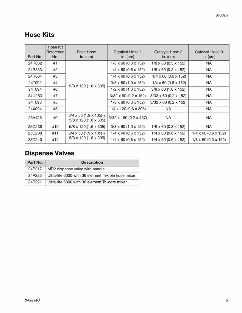
2. Connect the dispense appli-cator.
MD2:a. Connect both base (A) and catalyst (B) material
hoses to the dispense applicator.
b. Activate both and on the DM.
c. Open the catalyst (B) ball valve and dispense material into a waste container until the dis-pense valve has been purged and is free of air.
d. Activate on the DM.
Ultra-lite:a. Connect the base (A) hose to the base (A) inlet
fitting.
b. Connect the catalyst (B) hose to the catalyst (B) inlet fitting.
c. Open the catalyst (B) ball valve and dispense material into a waste container until the dis-pense valve has been purged and is free of air.
d. Close the catalyst (B) ball valve and dispense material into a waste container until only base (A) is present.

Setup
3A2894U 39
3. Calibration Check Assembly Only: Purge material lines to the calibration check assem-bly.
a. Open the base (A) and catalyst (B) air motor slider valves.
b. Activate both and on the DM.
c. Place a waste container underneath the cali-bration check assembly.
d. Remove the JIC caps from the calibration check assembly.
e. Open the calibration check assembly.

Setup
40 3A2894U
f. Dispense the material into the waste container until both the base (A) and catalyst (B) material lines have been purged and are free of air.
g. Close the calibration check assembly.
h. Clean the nozzles of the calibration check assembly and install the JIC caps.
i. Activate on the DM.
4. Calibrate the machine.Perform the following procedure during initial setup of the machine, if the flow meters were replaced, or if the machine needs to be recalibrated.
a. Engage the trigger lock.
b. Open the base (A) and catalyst (B) air motor slider valves.
c. Set the base (A) and catalyst (B) air motor regu-lators.
MD2 or Ultra-lite with flexible hose:70 psi (480 kPa, 4.8 bar).Ultra-lite with Tri-core:85 psi (586 kPa, 5.9 bar)

Setup
3A2894U 41
d. Set the fluid regulator adjustment to 40 psi (280 kPa, 2.8 bar).
e. Place two separate containers on two separate scales and zero the scales. These containers will be used in step j.
NOTE: Weight units of the scales are to be set as grams.
f. Navigate to setup Screen 2.
NOTE: Screen 2 is already shown if this procedure is performed during the initial setup of the machine.
g. Activate to signal the machine of the fol-lowing calibration shot.
h. MD2: Install the calibration nozzle onto the dis-pense applicator.
i. Disengage the trigger lock.
Screen 2 - Recalibration
Screen 2 - Initial Calibration

Setup
42 3A2894U
j. Dispense the chemicals into two separate con-tainers.MD2: Chemical will be dispensed through the applicator.Ultra-lite: Chemical will be dispensed through the calibration check assembly.
k. Continue to dispense the chemical into the containers until both status bars are complete.
NOTE: If the light tower is installed, a green light will be illuminated when the status bars are complete.
l. Weigh both containers separately and input the values of both chemicals into setup Screen 2.
NOTE: To change a value in a desired field, perform the following.
• Press or to highlight the
desired field to be changed.
• Press to activate the desired field or to activate/deactivate an option.
• Press or to change the value of the
selected field.
• Press to set the value.
NOTE: Weight units are in grams.

Setup
3A2894U 43
m. Press to signal the machine that the cali-bration procedure is complete. The machine will automatically calculate the K factor of both materials.
n. Engage the trigger lock.
o. MD2: Remove the calibration nozzle and install a static mixer on the dispense valve.
p. Navigate to the Home screen.
5. Set the Display Module (DM).Perform the following tasks to fully setup the DM. Refer to Appendix A - DM Icons Overview, page 64, for clarity.
a. Define general system settings. See Screen 3, page 67.
b. Define specific system settings. See Screen 1, page 67.
c. P100 with Ultra-Lite Tri-core Mixer: Select the 85 psi (5.9 bar) option box. See Screen 1, page 67.

Startup
44 3A2894U
Startup
1. Engage the trigger lock.
2. Install the static mixer or nozzle onto the dispense applicator. See specific applicator manual for details.
NOTE: Cutting more than two outlet steps on the static mixer may increase the chance of the mixing elements being pushed out of the static mixer.
NOTE: If using the mixer element kit 24T035, assemble the sleeve onto the MD2 dispense applicator prior to fastening the 1/4 NPT outlet adapter. Hand tighten the 1/4 NPT outlet adapter.
3. Turn the power on at the electrical enclosure.
4. Open the base (A) and catalyst (B) main air slider valves.
5. Open the base (A) and catalyst (B) air motor slider valves.
6. Verify the base (A) and catalyst (B) air motor regula-tors are set to the correct pressure.
MD2 or Ultra-lite with flexible hose:70 psi (480 kPa, 4.8 bar).Ultra-lite with Tri-core:85 psi (586 kPa, 5.9 bar)
Do not operate machine without all covers and shrouds in place.

Startup
3A2894U 45
7. P100 with Ultra-Lite Tri-core Mixer: Verify that the 85 psi (5.9 bar) option box is selected. Refer to Screen 1, page 67.
8. Verify the ram director valve is set to lower the ram.
9. The DM will show a standby screen when power is
first supplied to the machine. Press to go to the Home screen.
NOTE: The Home screen will indicate “Not OK” and the light tower, if installed, will illuminate red until the next step is completed.
10. Disengage the trigger lock.
NOTE: If a new static mixer has been installed, a base purge is recommended to prevent side walling. Perform Base Purge, page 46.
11. Hold a metal part of the gun firmly to a grounded metal pail. Trigger the gun until the Display Module
shows “OK” and the light tower, if installed, illumi-nates green.
NOTE: Additional dispensing may be required in order to ensure a good mixture.
r_255179_purge
Base Purge
46 3A2894U
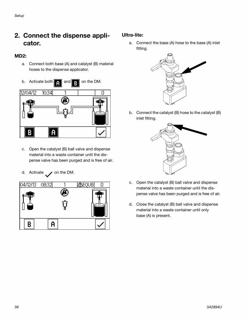
Base PurgeBase purge results in the purging of the base (A) chem-ical through the dispense valve. Base purging prevents mixed material within the dispense applicator from cur-ing. The machine will remain pressurized and electri-cally connected.
1. Navigate to the Purge/Prime screen.
NOTE: Verify both pumps are activate.
2. Close the catalyst (B) ball valve located near the dispense applicator.
3. Dispense material into a waste container until only the base (A) chemical is present.
4. Engage the trigger lock.

Pressure Relief Procedure
3A2894U 47
Pressure Relief Procedure
1. If electrical power is supplied to the machine, perform Base Purge, page 46.
If electrical power is not supplied to the machine, continue to the next step.
2. S100 and P100: Close the base (A) and catalyst (B) air motor slider valves.U100: Close the base (A) air motor slider valve and the supply ball valve on the pressure pot. Bleed the air from the pressure pot by opening the manual bleed valve.
MD2:
a. Remove the static mixer.
b. Open the catalyst (B) ball valve located near the dispense applicator.
c. Disengage the trigger lock.
d. Trigger the gun to relieve pressure into a waste container.
e. Verify the pressure gauges display “0”.
This equipment stays pressurized until pressure is manually relieved. To help prevent serious injury from pressurized fluid, such as skin injection, splashing fluid and moving parts, follow the Pressure Relief Procedure when you stop dispensing and before cleaning, checking, or servicing the equipment.

Pressure Relief Procedure
48 3A2894U
f. Close the base (B) and catalyst (A) main air slider valves.
g. If electrical power is not supplied to the machine, place a waste container underneath the pump bleed valves. Open the pump bleed valves.
NOTE: For U100 systems, the catalyst bleed valve is located on the pump outlet filter.
h. Clean the nose of the dispense valve or bleed valve.
i. Install the night cap onto the MD2.
Ultra-lite:
a. Remove the JIC caps from the calibration check assembly.
b. Place a waste container underneath the cali-bration check assembly.
c. Open the calibration check assembly to relieve pressure into a waste container.
d. Verify the pressure gauges display “0”.

Shutdown
3A2894U 49
e. Close the calibration check assembly.
f. Clean the nozzles of the calibration check assembly and install the JIC caps.
g. Close the base (A) and catalyst (B) main air slider valves.
h. If electrical power is not supplied to the machine, place a waste container underneath the pump bleed valves. Open the pump bleed valves. Clean the pump bleed valves once complete.
NOTE: For U100 systems, the catalyst bleed valve is located on the pump outlet filter.
Shutdown
1. Perform Pressure Relief Procedure, page 47.
2. Turn the power off at the electrical enclosure.

Calibration Check
50 3A2894U
Calibration CheckPerform the calibration check procedure to verify the calibration of the flow meters are correct.
1. Perform Base Purge, page 46.
2. Navigate to the Home screen.
3. Activate on the DM.
4. Remove the static mixer.
5. MD2 Only: Install the calibration nozzle onto the dispense applicator.
6. Open the catalyst (B) ball valve located near the dispense applicator.

Calibration Check
3A2894U 51
7. Calibration Check Assembly Only: Dispense material into a waste container at the calibration check assembly to verify the V/P shown on the DM is at the correct value.
NOTE: A restrictor pin for the catalyst (B) restrictor housing may be required to obtain 5 psi (35 kPa, 0.3 bar) or above for the V/P shown on the DM.
8. Disengage the trigger lock.
9. Hold a metal part of the gun firmly to a grounded metal pail. Trigger the gun until the Display Module shows “OK”.
10. Place two separate containers on two separate scales and zero the scales. These containers will be used in step 11.
NOTE: Weight units of the scales are to be set as grams.

Calibration Check
52 3A2894U
11. Dispense the chemicals into two separate contain-ers.
MD2: Chemical will be dispensed through the applicator.Ultra-lite: Chemical will be dispensed through the calibration check assembly.
12. Continue to dispense the chemical into the contain-ers until a 400 gram shot has been dispensed.
NOTE: A value will be shown on the DM when a dis-pense is complete. This is the value the machine was running at based on the flow meter values.
13. Weigh both containers separately and calculate the ratio (A/B) of the two chemicals.
14. Compare the ratio calculated from the weighed containers with the ratio shown on the DM.
15. If the ratio comparison is acceptable, press on the DM or repeat steps 10 through 14
twice if more verification is required. Press to clear all values if more than three samples are required.
16. If the ratio comparison is unacceptable, perform Calibrate the machine. page 40.

Maintenance
3A2894U 53
Maintenance
Adjust Packing Nuts
NOTE: There must be no pressure when adjusting the packing nuts. Air pressure in the feed tanks is too much.
1. Follow Pressure Relief Procedure, page 47, including relieving air pressure in the tanks.
2. Fill metering pump packing nuts with throat seal liq-uid (TSL).
3. After TSL is added, torque metering pump packing nuts to 50 ft-lb (67.5 N•m). Follow instructions in Xtreme Lowers manual 311762.
4. Fill dosing valve packing nut with throat seal liquid (TSL).
5. After TSL is added, tighten dosing valve packing nuts 1/4 turn after nut contacts packings; about 145-155 in-lb (16-18 N•m).
FiltersOnce a week check, clean, and replace (if needed) the following filters.
• S100 and U100 Models:Catalyst pump outlet filter comes with a 60 mesh filter. Two pack 60 mesh filter replacement kit, 224459, is available.
• P100 Models:Catalyst pump outlet filter comes with a 30 mesh filter. Two pack 30 mesh filter replacement kit, 224458, is available.
SealsOnce a week, check and tighten throat seals on the pumps and dosing valve.
Task Schedule
Refer to specific component manual for more detailed infor-mation.
As Required
Check catalyst (B) filter assembly to prevent crystallization. Weekly
Verify calibration check assembly outlets are clear and unob-structed.
Weekly
Check desiccant. Weekly
Check restrictor housing and pin assembly to prevent crystalliza-tion.
Weekly
U100: Check iso lube bottle for discoloration. Daily
Perform Shutdown and install nightcap. Daily
Adjust packing nuts. When TSL has seeped through the packing nut
TSL

Maintenance
54 3A2894U
DM - Battery Replacement and Screen Cleaning
Battery ReplacementA lithium battery maintains the DM clock when power is not connected.
To replace the battery:
1. Disconnect power to the DM.
NOTE: This can be done by removing the CAN cable from the bottom of the DM.
2. Remove rear access panel.
3. Remove the old battery and replace with a new CR2032 battery.
4. Properly dispose the old lithium battery according to local codes.
5. Replace rear access panel.
6. Connect the power to the DM and reset the clock through Screen 3. Refer to Appendix B - DM Setup Screens Overview for more detail.
CleaningUse any alcohol-based household cleaner, such as glass cleaner, to clean the DM. Spray on the rag then wipe DM. Do not directly spray the DM. Replaceable screen protectors, 15M483, are available.

Maintenance
3A2894U 55
Software Update ProcedureWhen software is updated on the DM, the software is then automatically updated on all connected GCA com-ponents. A status screen is shown while the software is updating to indicate the progress.
Refer to PKE 2823 found at http://graco.cus-thelp.com/app/answers/detail/a_id/2823/ or by utiliz-ing the QR code below for software version history.
1. Turn the power switch to OFF.
2. Remove the DM from the bracket.
3. Remove the token access panel.
4. Insert and press software upgrade token (Token part no.16V853) firmly into the slot.
5. Install the DM onto the bracket.
6. Turn the power switch to ON.
NOTE: When the screen turns on, the following screen will appear.
7. Remove the token.
8. Replace the token access panel.
9. Press to continue.
FIG. 15: Remove Access Cover
NOTICEA status is shown while software is updating to indi-cate progress. To prevent corrupting the software load, do not remove token until the status screen disappears.
Icon Description
Update successful.
Update unsuccessful.
Update complete, no changes necessary
Update was successful/complete but one or more GCA modules did not have a CAN boot-loader, so the software was not updated in that module.

Troubleshooting
56 3A2894U
Troubleshooting
1. Follow Pressure Relief Procedure, page 47, before checking or repairing a dispense valve.
2. Check all possible problems and causes before disassembling the dispense valve.
Mechanical and ElectricalPROBLEM CAUSE SOLUTION
Dispense ApplicatorNo flow of catalyst (B). Clogged gun nose. Clean or replace the gun nose.
Clogged injector housing (Ultra-lite only). Clean or replace the injector housing.
Clogged restrictor housing Clean or replace the restrictor housing and pin.
Ball valve is closed. Open the ball valve.V/P is off. Ensure the power is on.
Ensure the machine is in dispense mode.Ensure V/P is turned on when machine enters Purge/Prime mode.
No air to catalyst (B) pump. Turn air on.
No catalyst ram down pressure.Ensure that there is pressure to the catalyst ram and that the control lever is in the down position.
Dosing valve leaking at rod. Loose or worn packings. Tighten packing nut. If leak continues, replace the packings.
Dosing valve between main housing and outlet housing. Bad o-ring. Replace both o-rings on the seat.
Dosing valve not cycling Bad cable. Replace the cable.Bad power valve. Replace the power valve.
Dispense valve will not dis-pense material. Trigger lock engaged. Disengage the trigger lock.
No air to MD2. Connect air to the MD2.Turn on the air.
Clogged mixer. Clean or replace Tri-core or Flex mixer.
Ultra-lite has cured material in it. Clean or replace.Dispense valve will not stop material dispense. No air to MD2. Connect air to the MD2.
Turn on the air.
Bad seal in MD2. Repair the MD2. Refer to the MD2 for more details
Ultra-lite seal is worn Replace the seal.

Troubleshooting
3A2894U 57
No material flow. Material supply is off. Ensure the base (A) solenoid valve is on and has pressure.Ensure the catalyst (B) V/P is on and has pressure.Ensure the motor(s) have air pressure.Ensure there is sufficient down pres-sure and the control lever is in the down position.
Clogged mixer. Replace the static mixer.Clean or replace the Tri-core or hose mixer.
Clogged restrictor Clean or replace the restrictor.Fluid Plate
V/P won't turn on.
NOTE: The V/P turns off after 30 seconds of no activity. It will turn on during dispense or when entering Purge/Prime mode.
Bad cable. Replace the cable.
Disconnected cable. Connect the cable.V/P reads “0”. Air supply to V/P shut off. Turn on the air supply to the V/P.V/P does not match information on the information screen. Air supply is restricted. Replace with a minimum 3/4 in. ID
hose.Faulty V/P. Replace V/P
V/P obtains 85 psi (586 kPa, 5.86 bar) and then alarms. Flow rate is too high. Reduce the flow rate.
Too much restriction in the catalyst (B) hose. Resize the hoses to reduce restriction.
Flowmeter clogged. Clean or replace the flow meter.Bad flowmeter. Replace the flowmeter.Catalyst (B) air motor pressure is too low.
Catalyst (B) air motor pressure is too low.
Clogged restrictor housing. Clean or replace restrictor housing and pin.
Abnormal pressures during operation or after dispense Pressures not balanced. Change catalyst hose size.
Ball/seat not seating properly in fluid regulator(s). Clean or replace ball/seat.
Restrictor pin not seating in housing.Use a fitting behind the restrictor housing with an inner diameter that will not allow the pin to back out.
Light TowerLight does not blink green, red, and off in sequence when the machine is first turned on.
Bad connection or cable Ensure cable is connected or replace the cable.
Bad light stack. Replace light stack.
PROBLEM CAUSE SOLUTION

Troubleshooting
58 3A2894U
PumpAbnormal pump pressures during operation. Worn or damaged packings. Replace the packings.
Bad check valves. Clean or replace the check valves.Pump moves during stall. Malfunctioning check valves. Clean or replace the check valves.
Pump does not run. No air supply to the pump. Turn on the air or increase the air pres-sure.
Catalyst (B) ball valve is closed. Open the ball valve.Clogged mixer. Replace or clean the mixer.Ultra-lite has cured material in it. Clean or replace.Clogged restrictor Clean or replace the restrictor.
PROBLEM CAUSE SOLUTION
Troubleshooting
3A2894U 59
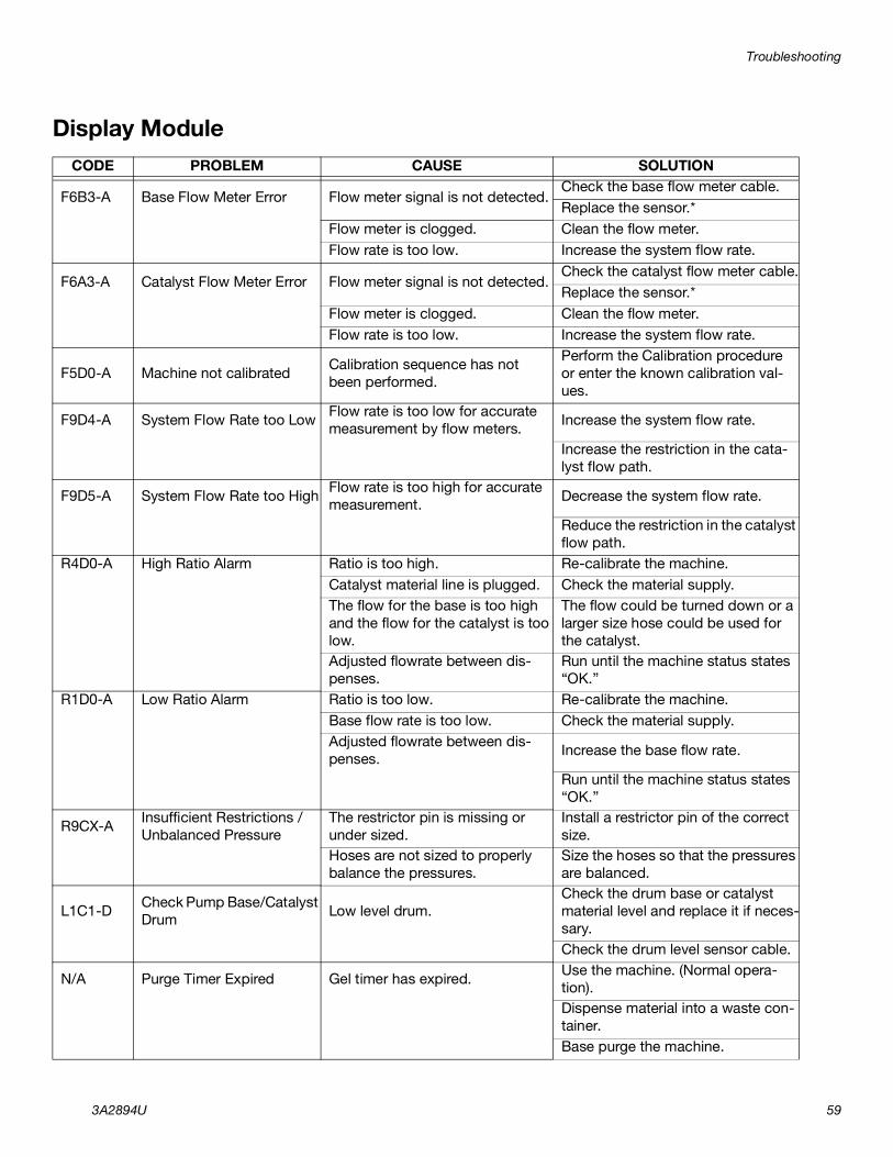
Display ModuleCODE PROBLEM CAUSE SOLUTION
F6B3-A Base Flow Meter Error Flow meter signal is not detected.Check the base flow meter cable.Replace the sensor.*
Flow meter is clogged. Clean the flow meter.Flow rate is too low. Increase the system flow rate.
F6A3-A Catalyst Flow Meter Error Flow meter signal is not detected.Check the catalyst flow meter cable.Replace the sensor.*
Flow meter is clogged. Clean the flow meter.Flow rate is too low. Increase the system flow rate.
F5D0-A Machine not calibrated Calibration sequence has not been performed.
Perform the Calibration procedure or enter the known calibration val-ues.
F9D4-A System Flow Rate too Low Flow rate is too low for accurate measurement by flow meters. Increase the system flow rate.
Increase the restriction in the cata-lyst flow path.
F9D5-A System Flow Rate too High Flow rate is too high for accurate measurement. Decrease the system flow rate.
Reduce the restriction in the catalyst flow path.
R4D0-A High Ratio Alarm Ratio is too high. Re-calibrate the machine.Catalyst material line is plugged. Check the material supply.The flow for the base is too high and the flow for the catalyst is too low.
The flow could be turned down or a larger size hose could be used for the catalyst.
Adjusted flowrate between dis-penses.
Run until the machine status states “OK.”
R1D0-A Low Ratio Alarm Ratio is too low. Re-calibrate the machine.Base flow rate is too low. Check the material supply.Adjusted flowrate between dis-penses. Increase the base flow rate.
Run until the machine status states “OK.”
R9CX-A Insufficient Restrictions / Unbalanced Pressure
The restrictor pin is missing or under sized.
Install a restrictor pin of the correct size.
Hoses are not sized to properly balance the pressures.
Size the hoses so that the pressures are balanced.
L1C1-D Check Pump Base/Catalyst Drum Low level drum.
Check the drum base or catalyst material level and replace it if neces-sary.Check the drum level sensor cable.
N/A Purge Timer Expired Gel timer has expired. Use the machine. (Normal opera-tion).Dispense material into a waste con-tainer.Base purge the machine.

Troubleshooting
60 3A2894U
* Verify the sensor is working by going to the information screen and removing the flow meter sensor from the flow meter body. Wave a small metallic object back and forth over the sensor. A flow rate should be displayed on the screen for the sensor being tested.
CUCX-V Duplicate Node Found Unknown Software Error. Cycle the system power.
Unintended module plugged into the system.
Verify that only necessary GCA modules are plugged into the sys-tem.
CACX-A FCM Missing FCM unplugged from CAN bus. Verify the FCM CAN cable is plugged in.
Damaged FCM. Replace the FCM.Damaged FCM Base. Replace the FCM base.
CAUX-A USB Disconnected USB unplugged from CAN bus. Verify the USB CAN cable is plugged in.
Damaged USB. Replace the USB.Damaged USB Base. Replace the USB base.
CODE PROBLEM CAUSE SOLUTION

Accessories and Kits
3A2894U 61
Accessories and Kits
Low Level Sensors, 24R935(S100 and P100 only)Alerts the user when material drums are empty.
Calibration Check Assembly, 24R777Allows the user to watch the DM while performing the Calibration Check procedure. Kit is required for all Ultra-lite dispense valve applications.
USB Kit, 24R936Allows the user to monitor and download information of the machine status.
MD2 Nose Pieces
Ref Part Description201 15V628 10:1 Nightcap202 15K688 Retaining Nut203 24P850 10:1 Ratio Check204 256793 Assembly Tool
203
201
202
204

Accessories and Kits
62 3A2894U
Catalyst (B) HosesAllows the user to balance material pressure in the cat-alyst (B) line by changing the hose diameter.
Restrictor Kit, 24R804Allows the user to balance material pressure in the cat-alyst (B) line by changing the pin size.
Restrictor Kit 24W146Allows the user to balance material pressure in the cat-alyst (B) line by changing the pin size without removal of the catalyst line.
Caster Kit, 24T091Includes four casters.
Part Description16W047 HOSE, assy, 3/32”x60”, 6k, nylon16V531 HOSE, assy, 1/8”x60”, 6k, nylon16V219 HOSE, assy, 1/4”x60”, 5k, ss, braid16V220 HOSE, assy, 3/8”x60”, 5k, ss, braid16V221 HOSE, assy, 1/2”x60”, 5k, ss, braid
Ref Part Description101 16V360 HOUSING, restrictor, 1/4npt102 16V356 PIN, restrictor, #1, 0.094 in.103 16V359 PIN, restrictor, #2, 0.098 in.104 16V357 PIN, restrictor, #3, 0.102 in.105 124961 FITTING, 04jic x 1/4npt106 124846 FITTING, 03jic x 1/4npt107 119400 SEALANT, pipe, sst, pack
101
102,103,104105
105
106
106
Ref Part Description301 17B762 HOUSING, Restrictor, 3 Port302 16V356 PIN, Restrictor, 0.094”303 16V359 PIN, Restrictor, 0.98”304 16V357 PIN, Restrictor, 0.102”305 124961 FITTING, 04jic x 1/4 npt306 17B763 PLUG, Restrictor, Pin307 17B765 FITTING, Elbow, 0451C308 111516 PACKING, O-Ring309 124846 FITTING, 03jic x 1/4npt310 061701 FITTING, 03jic x 04jic311 119400 SEALANT, pipe, sst, pack
310
305,309
301
302,303,304308
306
307

Accessories and Kits
3A2894U 63
Mixer Elements for MD2
10 mm Mixer Elements
1/2 in. Mixer Elements
Ref Part Description
001 24T250 MIXER, assy, 10mm x 12 element - 25 count
24T251 MIXER, assy, 10mm x 12 element - 50 count
002 16V841 SLEEVE, mixer, no front thread
003 24T035 SLEEVE, mixer, thread x 1/4 NPT outlet
Ref Part Description001 512288 MIXER, assy, 1/2 x 24 element
512289 MIXER, assy, 1/2 x 30 element512286 MIXER, assy, 1/2 x 36 element
002 16T001 SLEEVE, mixer, 24 element16T002 SLEEVE, mixer, 30 element16T003 SLEEVE, mixer, 36 element
001
002
003

Appendix A - DM Icons Overview
64 3A2894U
Appendix A - DM Icons Overview
Setup Screen IconsIcon Description
Return to Home Screen
Left NavigationNavigates to the previous screen.
Right NavigationNavigates to the next screen.
Set Purge TimerAllow the machine to remind the operator to take a shot before the chemical hardens in the gun. Timer starts once a dispense is complete.
Lock Ratio SetpointLock the current ratio set-point. Ratio setpoint will not be able to be adjusted when activated. Icon shown represents that it is not locked.
Low Level Sensor OptionToggle if a low level sensor is installed or not installed on the machine. Icon shown represents not installed.
Base (A) Pump
Catalyst (B) Pump
WeightSystem units are in grams
Flow MeterShows the calibration fac-tor (K) after calibration has been performed.
Start Calibration
Confirmation
Calendar / DateSet the date format and current date.
TimeSet the current time in 24 hour format.
PasswordSet a password to lock sys-tem settings. Password “0000” disables the lock.
Backlight TimeSet how long the screen will illuminate when idle before darkening. Entering “0” disables the timer.
Audible AlarmAllow the machine to sound an alarm when an error occurs.
Download DepthSet how many hours of data the system will down-load.
Log IntervalsSet the time interval that the system will record the machine status.
Display Module
Icon Description

Appendix A - DM Icons Overview
3A2894U 65
Advanced Fluid Control Module
Ultra-Lite Tri-core Mixer(P100 Model Only)Toggle if an ultra-lite tri-core mixer is installed on a P100 machine.
Ratio AlarmI- Standard tolerance
Ratio AlarmII - Wider tolerance
Ratio AlarmIII - Widest tolerance
Icon Description

Appendix A - DM Icons Overview
66 3A2894U
Run Screen IconsIcon Description
Return to Home Screen
Navigate to Purge/Prime Screen
Navigate to Alarm Log Screen
Navigate to Information Screen
Calibration CheckChanges the machine status to not okay in order to perform the calibra-tion check procedure.
Calibration ResetClears all data and resets all sam-ples to “0”.
Purge Timer CounterVisual indicator to show the user the remaining idle time before another shot needs to be taken. The timer will begin to flash when expired.
Base (A) Pump SelectIcon will appear white when not activated, black when activated.
Catalyst (B) Pump SelectIcon will appear white when not activated, black when activated.
Error Number / Event Number
Date
Time
Error / Event Code
Navigate to Totalizer Screen

Appendix B - DM Setup Screens Overview
3A2894U 67
Appendix B - DM Setup Screens OverviewIf the DM is showing a Run screen, press to
access the Setup screens, which have a black header. See the DM Screen Navigation Diagram on page 18.
Screen 1
This screen allows you to set the purge timer, lock the ratio setpoint, toggle if low level sensors are installed, and toggle if an Ultra-lite with Tri-core mixer is installed on a P100 machine.
In addition, system token version 1.12.001 and above includes an alarm ratio sensitivity tolerance option. By default, the setting is “I” (standard for AGP since its release). From the drop down menu you can select “II” ( ) to set the tolerance for a wider sensitivity level or “III” ( ) for the widest sensitivity level. If adjustment from the original software is not needed, leave the set-ting on .
Screen 2
This screen allows you to calibrate the machine. See Calibrate the machine. page 40, for more details.
Screen 3
This screen allows you to format and set the current date and time, reset the password, adjust the backlight timer, and toggle sound/silent operation.S100 and U100 Models
P100 Models

Appendix B - DM Setup Screens Overview
68 3A2894U
Screen 4
This screen is only displayed when the USB option is installed. The screen allows the user to enable down-loading of USB logs, set log intervals, and set how many hours of data to download.
Screen 5
This screen is displayed as Screen 4 when the USB option is not installed. The screen displays information of part numbers and software versions that are cur-rently found within the system. The USB information is only displayed when the USB option is installed.

Appendix C - DM Run Screens Overview
3A2894U 69
Appendix C - DM Run Screens OverviewIf the DM is showing a Setup screen, press to
access the Run screens. See the DM Screen Naviga-tion Diagram on page 18.
NOTE: You can also press or to access the
Run screens.
Home
This screen shows the current ratio and allows the user to access other screens.
• Press or to increase or decrease the
ratio.
• Press the corresponding to access another
screen or to toggle an option.
• Shows the current state of the machine (okay/not okay).
Purge/Prime
This screen allows the pumps to be run independently.
NOTE: All machine alarms are disabled when this screen is displayed on the DM.
• Press the corresponding to deactivate or acti-
vate the desired pump for operation.
NOTE: The screen below shows only the catalyst (B) pump selected.

Appendix C - DM Run Screens Overview
70 3A2894U
Alarm Log
This screen displays the last 70 errors that have occurred.
• Press or to show other errors.
Totalizer
This screen displays the total amount of material (in kilograms) dispensed for each pump.
Information
This screen displays diagnostic information useful in troubleshooting.
Calibration Check
This screen displays the ratio after a calibration check dispense.
NOTE: Production material cannot be dispensed from this screen.

Appendix D - DM Error Codes
3A2894U 71
Appendix D - DM Error CodesError Code Error Name Error Type0000-0 No Active Errors AlarmCA00-A Unrecognized Error AlarmF6B3-A Pump A Check Flow Meter AlarmF6A3-A Pump B Check Flow Meter AlarmF5D0-A Machine has not been calibrated AlarmF9D4-A System Flow Rate is too Low AlarmF9D5-A System Flow Rate is too High AlarmR4D0-A High Ratio Alarm AlarmR1D0-A Low Ratio Alarm AlarmL1C1-D Check Pump A Drum DeviationEHD0-R Purge Timer Expired Record OnlyE9D0-R System not ok for dispense Record OnlyELM0-R System Power On Record OnlyEMM0-R System Power Off Record OnlyENB6-R Begin Flowmeter Calibration, Pump A Record OnlyENA6-R Begin Flowmeter Calibration, Pump B Record OnlyENB7-R End Flowmeter Calibration, Pump A Record OnlyENA7-R End Flowmeter Calibration, Pump B Record OnlyENB8-R Abort Flowmeter Calibration, Pump A Record OnlyENA8-R Abort Flowmeter Calibration, Pump B Record OnlyEGC6-R Enter Purge/Prime Screen Record OnlyEGB9-R Purge On, Pump A Record OnlyEGBA-R Purge Off, Pump A Record OnlyEGA9-R Purge On, Pump B Record OnlyEGAA-R Purge Off, Pump B Record OnlyEGC7-R Exit Purge/Prime Screen Record OnlyECCX-R Ratio Changed Record OnlyEADX-R Start Dispense Record OnlyEBDX-R End Dispense Record OnlyCUCX-V Duplicate Node Found AdvisoryCACX-A FCM Missing AlarmCAUX-A USB Disconnected AlarmECB3-R Pump A K-factor Changed Record OnlyECA3-R Pump B k-factor Changed Record OnlyECDC-R Gel Timer Changed Record OnlyECFB-R Pressure Transducer Installed Record OnlyEQU0-R USB Logs Downloaded Record OnlyEQU0-D No Configuration DeviationEQU8-D Disk Removed Too Early DeviationR9CX-A Insufficient Restriction / Unbalanced Pressures Alarm

Schematics
72 3A2894U
Schematics
140
149
147
145
142
110
138
136
134
132
130
128
126
124
122
120
118
114
116
112
108
106
104
102
100
14
1
148
144
146
143
11
1
139
137
135
133
13
1
129
127
125
123
12
1
119
115
117
113
109
107
105
103
10
1
150
155
152
15
1
154
153
159
157
158
156
160
165
162
16
1
164
163
HA
RNES
S16
U01
22.
5M
120V
/240
V IN
PUT
PS14
812
6453
LN
GRD
V-V+24
VDC
OU
TPU
T
M12
5 P
INC
AN
CA
BLE
BLK
M12
5 P
INFE
MA
LE
1209
524M
RED
160
161
V-V+
FLU
ID C
ON
TRO
L M
OD
ULE
FRO
NT
VIEW
FCM
232
M8
4 PI
NFE
MA
LE
M12
5 P
INFE
MA
LEM
12 5
PIN
FEM
ALE
M8
4 PI
NFE
MA
LE
CA
N C
OM
1C
AN
CO
M 2
TO G
ROU
ND
LU
G
HA
RNES
S16
U13
2SP
L335
1265
20
HV
FLO
WM
ETER
2466
52
HA
RNES
S12
2030
.5M
LV
FLO
WM
ETER
2898
14
HA
RNES
S17
E304
.5M
BLK
HA
RNES
S12
6996 0.5M
LABE
LEP
370
LABE
L J4
LABE
L J2
ALA
BEL
J2A
LABE
L J2
B
LABE
L J2
B
M8
4 PI
NM
ALE
SOL
1 2 3
HA
RNES
S12
3395 1.5M
DV3
20H
V A
IR D
UM
P12
7032
LABE
L SO
L410
LA
BEL
J1
N
L
GND
N
L
GND
CORD
SET
1215
98(U
SA)
L
N
GND
SW12
512
0910
FUSE
S4A
11
4835
50-6
0HZ
1PH
/22
0V/
TO G
ROU
ND
LUG
TO G
ROU
ND
LUG
CA
N C
OM
1C
AN
CO
M 2
DIS
PLAY
MO
DU
LE24
F493
M12
5 P
INFE
MA
LE
HA
RNES
S16
V097
HA
RNES
S16
V096
HA
RNES
S16
V094
HA
RNES
S16
V094
ON
FLU
ID P
LATE
135
136
TO G
ROU
ND
LU
G
HA
RNES
S16
V151
ON
RA
M B
OX
TO G
ROU
ND
LU
GO
N F
LUID
PLA
TE
FCM
SEL
ECTO
R SW
ITC
H
1
FOR
SILI
CON
E M
AC
HIN
ES: 2
4R80
9 A
ND
24R
810
SET
DIA
L TO
"1"
FOR
POLY
URE
THA
NE
MA
CH
INES
: 24R
811
AN
D 2
4R81
2 SE
T D
IAL
TO "2
"FO
R PO
LYSU
LFID
E M
AC
HIN
ES: 2
4R81
5 A
ND
24R
816
SET
DIA
L TO
"3"
TO G
ROU
ND
LUG
HA
RNES
S16
V096
CH
AN
GIN
G T
HIS
DO
CU
MEN
T M
AY A
FFEC
TA
GEN
CY
APP
ROVA
L A
ND
/OR
TEC
HN
ICA
L FI
LESE
E G
RACO
EN
GIN
EERI
NG
STD
. 2.7
001
AG
ENC
Y:
CE,
ETL
COM
PLIA
NC
E D
OC
UM
ENT
SOL
1 2 3
HA
RNES
S12
7399 4.5M
PW
R VA
LVE
1273
56
LABE
L SO
LXM
LA
BEL
J3
M8
4 PI
NM
ALE
M12
5 P
INM
ALE
POLY
SULF
IDE
OPT
ION
HA
RNES
S12
3657
4M
M12
5 P
INFE
MA
LEM
12 5
PIN
MA
LEM
12 5
PIN
FEM
ALE
POLY
SULF
IDE
OPT
ION
43214321 554321 4321
43
21
54
32
15
43
21
54
32
15
4321 5
4321 5 4321 5
2 1
321
4321 54321 5
CBA
4321 5
3214 5
42 31 5
42 31
4321 5
43
21
54
32
15
43
21
5
4321
4321 54321 5
11
11

Schematics
3A2894U 73
210
234
232
230
228
226
224
222
220
218
214
216
212
208
206
204
202
200
21
1
235
233
23
1
22
9
227
225
223
22
1
21
9
215
217
213
20
9
207
205
203
20
1
256
254
252
250
248
246
244
242
240
236
238
257
255
253
25
1
24
9
247
245
243
24
1
237
23
9
264
262
260
258
265
263
26
1
25
9
OP
TIO
NA
L LO
W L
EV
EL
SE
NS
OR
24R
935
M12
5 P
INM
ALE
PX
353
LOW
LE
VE
L D
RU
M S
EN
SO
RH
V R
AM
FLU
ID C
ON
TR
OL
MO
DU
LE B
AC
K V
IEW
M12
5 P
INF
EM
ALE
M12
8 P
INF
EM
ALE
M12
5 P
INF
EM
ALE
PX
353
LOW
LE
VE
L D
RU
M S
EN
SO
RLV
RA
M
HA
RN
ES
S12
7137
LAB
EL
J1B
LAB
EL
J1B
B
LAB
EL
J1B
AS
PL3
3512
6520
TO J
1
M12
4 P
INM
ALE
LI
GH
T T
RE
E24
R82
4 G R
M12
4 P
INF
EM
ALE
M12
8 P
INM
ALE
J5
HA
RN
ES
S12
7184
0.5M
J5
J5
OP
TIO
NA
L U
SB
AD
AP
TE
R24
R93
6
CA
N C
OM
1C
AN
CO
M 2
US
B M
OD
ULE
2899
00
M12
5 P
INF
EM
ALE
HA
RN
ES
S12
0952
M12
5 P
INF
EM
ALE
AD
AP
TE
R16
T07
2A
4321
3 41 2 554321 54321876
5 2 431 5
4321 5 4321 5
4321 5
4321 5 4321 5
1 24321 5
4321
4321
4321
43
21
54
32
15
43
21
5
43
21
5
43
21
5
43
21
5
8765
11
1
118

Schematics
74 3A2894U
340
34
9
347
345
342
310
338
336
334
332
330
328
326
324
322
320
318
314
316
312
308
306
304
302
300
34
1
348
344
346
343
31
1
33
9
337
335
333
33
1
32
9
327
325
323
32
1
31
9
315
317
313
30
9
307
305
303
30
1
350
35
1
360
358
356
353
352
35
9
355
357
354
36
136
2
36
9
367
364
363
370
366
368
365
80 P
SIG
MIN
PLA
NT
AIR
SIL
ICO
NE
MD
2 P
NU
EM
ATIC
GU
N80
PS
IG M
INP
LAN
T A
IRP
OLY
SU
LFID
E O
PT
ION
HV
RA
M /
PU
MP
(R
ED
)
HV
RA
M P
RE
SS
UR
E
LV R
AM
/ P
UM
P (
BLU
E)
LV R
AM
PR
ES
SU
RE
EP
370
HV
AIR
MO
TOR
RA
M U
P/D
OW
N
RA
M U
P/D
OW
N
MA
IN A
IRS
HU
T-O
FF
SO
L320
RE
GU
LATO
RH
V M
ATE
RIA
LR
EG
ULA
TOR
AIR
MO
TOR
SH
UT-
OF
F
ON
/OF
F3-
WAY
VA
LVE
1270
32
MA
IN A
IRS
HU
T-O
FF
RE
GU
LATO
RH
V A
IR M
OTO
R
100
100
MD
2 P
NE
UM
ATIC
GU
N
HV
RA
M C
YLI
ND
ER
S
100
LV A
IR M
OTO
RA
IR M
OTO
RS
HU
T-O
FF
RE
GU
LATO
RLV
AIR
MO
TOR
100
RE
GU
LATO
RLV
MAT
ER
IAL
RE
GU
LATO
R
E/P
R
EG
VA
LVE
1270
29
LV F
LUID
RE
GU
LATO
R10
0
LV R
AM
CY
LIN
DE
R
100
100
(DE
LET
E T
HIS
LIN
E F
OR
6K
GU
N)
SA
FE
TY
VA
LVE
85 P
SI
HV
FLU
ID R
EG
ULA
TOR
SA
FE
TY
VA
LVE
85 P
SI
SA
FE
TY
VA
LVE
75 P
SI F
OR
300
0 P
SI S
YS
TE
M90
PS
I FO
R 4
000
PS
I SY
ST
EM
SA
FE
TY
VA
LVE
75 P
SI F
OR
300
0 P
SI S
YS
TE
M90
PS
I FO
R 4
000
PS
I SY
ST
EM
102 10
3
HV
RA
M /
PU
MP
(R
ED
)
HV
RA
M P
RE
SS
UR
E
LV R
AM
/ P
UM
P (
BLU
E)
LV R
AM
PR
ES
SU
RE
EP
370H
V A
IR M
OTO
R
RA
M U
P/D
OW
N
RA
M U
P/D
OW
N
MA
IN A
IRS
HU
T-O
FF
SO
L320
RE
GU
LATO
RH
V M
ATE
RIA
LR
EG
ULA
TOR
AIR
MO
TOR
SH
UT-
OF
F
ON
/OF
F3-
WAY
VA
LVE
1270
32
MA
IN A
IRS
HU
T-O
FF
RE
GU
LATO
RH
V A
IR M
OTO
R
100
100
MD
2 P
NE
UM
ATIC
GU
N
HV
RA
M C
YLI
ND
ER
S
100
LV A
IR M
OTO
RA
IR M
OTO
RS
HU
T-O
FF
RE
GU
LATO
RLV
AIR
MO
TOR
100
E/P
R
EG
VA
LVE
1273
96
XM
VA
LVE
LV R
AM
CY
LIN
DE
R
100
100
(DE
LET
E T
HIS
LIN
E F
OR
6K
GU
N)
HV
FLU
ID R
EG
ULA
TOR
SA
FE
TY
VA
LVE
85 P
SI
SA
FE
TY
VA
LVE
75 P
SI F
OR
300
0 P
SI S
YS
TE
M90
PS
I FO
R 4
000
PS
I SY
ST
EM
SA
FE
TY
VA
LVE
75 P
SI F
OR
300
0 P
SI S
YS
TE
M90
PS
I FO
R 4
000
PS
I SY
ST
EM
102
QU
ICK
EX
HA
US
T12
7415
OP
EN
CLO
SE
D
SO
LXM
1273
56

Schematics
3A2894U 75
80 P
SIG
MIN
PLA
NT
AIR
PO
LYU
RE
TH
AN
E O
PT
ION
440
449
447
445
442
410
438
436
434
432
430
428
426
424
422
420
418
414
416
412
408
406
404
402
400
44
1
448
444
446
443
41
1
439
437
435
433
43
1
429
427
425
423
42
1
419
415
417
413
409
407
405
403
40
1
450
45
1
460
458
456
453
452
459
455
457
454
46
146
2
469
467
464
463
470
466
468
465
HV
RA
M /
PU
MP
(R
ED
)
HV
RA
M P
RE
SS
UR
E
LV R
AM
/ P
UM
P (
BLU
E)
HV
AIR
MO
TOR
RA
M U
P/D
OW
N
MA
IN A
IRS
HU
T-O
FF
SO
L320
RE
GU
LATO
RH
V M
ATE
RIA
LR
EG
ULA
TOR
AIR
MO
TOR
SH
UT-
OF
F
ON
/OF
F3-
WAY
VA
LVE
1270
32
RE
GU
LATO
RH
V A
IR M
OTO
R
100
100
MD
2 P
NE
UM
ATIC
GU
N
HV
RA
M C
YLI
ND
ER
S
100
LV A
IR M
OTO
RA
IR M
OTO
RS
HU
T-O
FF
RE
GU
LATO
RLV
AIR
MO
TOR
100
100
100
(DE
LET
E T
HIS
LIN
E F
OR
6K
GU
N)
HV
FLU
ID R
EG
ULA
TOR
SA
FE
TY
VA
LVE
85 P
SI
SA
FE
TY
VA
LVE
75 P
SI F
OR
300
0 P
SI S
YS
TE
M90
PS
I FO
R 4
000
PS
I SY
ST
EM
SA
FE
TY
VA
LVE
75 P
SI F
OR
300
0 P
SI S
YS
TE
M90
PS
I FO
R 4
000
PS
I SY
ST
EM
102
103
QU
ICK
EX
HA
US
T12
7415
RE
GU
LATO
RLV
AIR
MO
TOR
SA
FE
TY
VA
LVE
100
PS
I
104
LV P
RE
SS
UR
E P
OT
PR
ES
SU
RE
PO
TS
HU
T-O
FF
PR
ES
SU
RE
RE
LIE
F

Dimensions
76 3A2894U
Dimensions
AB
C
DimensionUS(ft)
Metric(m)
A (Length) 3.3 1.0B (Width) 3.5 1.1C (Height) 9.0
(with boom)2.7
5.3(without boom)
1.6
S100 55/5 Gal. (200/20 L) Shown

Dimensions
3A2894U 77
S100 5/5 Gal. (20/20 L)
B
C
A
DimensionUS(ft)
Metric(m)
A (Length) 3.3 1.0B (Width) 2.3 0.7C (Height) 4.6 1.4
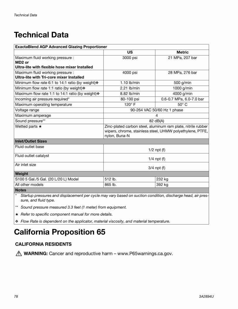
Technical Data
78 3A2894U
Technical Data
California Proposition 65
ExactaBlend AGP Advanced Glazing ProportionerUS Metric
Maximum fluid working pressure :MD2 orUltra-lite with flexible hose mixer Installed
3000 psi 21 MPa, 207 bar
Maximum fluid working pressure :Ultra-lite with Tri-core mixer Installed
4000 psi 28 MPa, 276 bar
Minimum flow rate 6:1 to 14:1 ratio (by weight)❖ 1.10 lb/min 500 g/minMinimum flow rate 1:1 ratio (by weight)❖ 2.21 lb/min 1000 g/minMaximum flow rate 1:1 to 14:1 ratio (by weight)❖ 8.82 lb/min 4000 g/minIncoming air pressure required* 80-100 psi 0.6-0.7 MPa, 6.0-7.0 barMaximum operating temperature 120° F 50° CVoltage range 90-264 VAC 50/60 Hz 1 phaseMaximum amperage 4Sound pressure** 82 dB(A)Wetted parts ★ Zinc-plated carbon steel, aluminum ram plate, nitrile rubber
wipers, chrome, stainless steel, UHMW polyethylene, PTFE, nylon, Buna-N
Inlet/Outlet SizesFluid outlet base
1/2 npt (f)Fluid outlet catalyst
1/4 npt (f)Air inlet size
3/4 npt (f)WeightS100 5 Gal./5 Gal. (20 L/20 L) Model 512 lb. 232 kgAll other models 865 lb. 392 kgNotes* Startup pressures and displacement per cycle may vary based on suction condition, discharge head, air pres-
sure, and fluid type.
** Sound pressure measured 3.3 feet (1 meter) from equipment.
★ Refer to specific component manual for more details.
❖ Flow Rate is dependent on the applicator, material viscosity, and material temperature.
CALIFORNIA RESIDENTS
WARNING: Cancer and reproductive harm – www.P65warnings.ca.gov.

Technical Data
3A2894U 79
NOTES:

All written and visual data contained in this document reflects the latest product information available at the time of publication. Graco reserves the right to make changes at any time without notice.
Original instructions. This manual contains English. MM 3A2894
Graco Headquarters: MinneapolisInternational Offices: Belgium, China, Japan, Korea
GRACO INC. AND SUBSIDIARIES • P.O. BOX 1441 • MINNEAPOLIS MN 55440-1441 • USACopyright 2013, Graco Inc. All Graco manufacturing locations are registered to ISO 9001.
www.graco.comRevision U, November 2021
Graco Standard WarrantyGraco warrants all equipment referenced in this document which is manufactured by Graco and bearing its name to be free from defects in material and workmanship on the date of sale to the original purchaser for use. With the exception of any special, extended, or limited warranty published by Graco, Graco will, for a period of twelve months from the date of sale, repair or replace any part of the equipment determined by Graco to be defective. This warranty applies only when the equipment is installed, operated and maintained in accordance with Graco’s written recommendations.
This warranty does not cover, and Graco shall not be liable for general wear and tear, or any malfunction, damage or wear caused by faulty installation, misapplication, abrasion, corrosion, inadequate or improper maintenance, negligence, accident, tampering, or substitution of non-Graco component parts. Nor shall Graco be liable for malfunction, damage or wear caused by the incompatibility of Graco equipment with structures, accessories, equipment or materials not supplied by Graco, or the improper design, manufacture, installation, operation or maintenance of structures, accessories, equipment or materials not supplied by Graco.
This warranty is conditioned upon the prepaid return of the equipment claimed to be defective to an authorized Graco distributor for verification of the claimed defect. If the claimed defect is verified, Graco will repair or replace free of charge any defective parts. The equipment will be returned to the original purchaser transportation prepaid. If inspection of the equipment does not disclose any defect in material or workmanship, repairs will be made at a reasonable charge, which charges may include the costs of parts, labor, and transportation.
THIS WARRANTY IS EXCLUSIVE, AND IS IN LIEU OF ANY OTHER WARRANTIES, EXPRESS OR IMPLIED, INCLUDING BUT NOT LIMITED TO WARRANTY OF MERCHANTABILITY OR WARRANTY OF FITNESS FOR A PARTICULAR PURPOSE.
Graco’s sole obligation and buyer’s sole remedy for any breach of warranty shall be as set forth above. The buyer agrees that no other remedy (including, but not limited to, incidental or consequential damages for lost profits, lost sales, injury to person or property, or any other incidental or consequential loss) shall be available. Any action for breach of warranty must be brought within two (2) years of the date of sale.
GRACO MAKES NO WARRANTY, AND DISCLAIMS ALL IMPLIED WARRANTIES OF MERCHANTABILITY AND FITNESS FOR A PARTICULAR PURPOSE, IN CONNECTION WITH ACCESSORIES, EQUIPMENT, MATERIALS OR COMPONENTS SOLD BUT NOT MANUFACTURED BY GRACO. These items sold, but not manufactured by Graco (such as electric motors, switches, hose, etc.), are subject to the warranty, if any, of their manufacturer. Graco will provide purchaser with reasonable assistance in making any claim for breach of these warranties.
In no event will Graco be liable for indirect, incidental, special or consequential damages resulting from Graco supplying equipment hereunder, or the furnishing, performance, or use of any products or other goods sold hereto, whether due to a breach of contract, breach of warranty, the negligence of Graco, or otherwise.
FOR GRACO CANADA CUSTOMERSThe Parties acknowledge that they have required that the present document, as well as all documents, notices and legal proceedings entered into, given or instituted pursuant hereto or relating directly or indirectly hereto, be drawn up in English. Les parties reconnaissent avoir convenu que la rédaction du présente document sera en Anglais, ainsi que tous documents, avis et procédures judiciaires exécutés, donnés ou intentés, à la suite de ou en rapport, directement ou indirectement, avec les procédures concernées.
Graco InformationSealant and Adhesive Dispensing EquipmentFor the latest information about Graco products, visit www.graco.com.For patent information, see www.graco.com/patents.TO PLACE AN ORDER, contact your Graco distributor, go to www.graco.com, or call to identify the nearest distributor.
If calling from the USA: 1-800-746-1334If calling from outside the USA: 0-1-330-966-3000
Copyright © 2022 FDOKUMEN