ERTMS L2 - Generic Operational Test Cases Data Sheets
421
SP-EMO-P2-002008 v3.2 1 The Signalling Programme ERTMS L2 - Generic Operational Test Cases Data Sheets Definition of the ETCS Operational Scenarios for the Danish ERTMS Program 1. INTRODUCTION .......................................................................................................................... 11 1.1. Purpose ......................................................................................................................................11 1.2. SCOPE .........................................................................................................................................11 1.3. Abbreviations .............................................................................................................................11 1.4. References .................................................................................................................................13 2. OTC DATA SHEETS ...................................................................................................................... 14 2.1. SoM ............................................................................................................................................15 2.1.1. SoM1 ..................................................................................................................................15 2.1.2. SoM2 ..................................................................................................................................18 2.1.3. SoM3 ..................................................................................................................................22 2.1.4. SoM5 ..................................................................................................................................25 2.1.5. SoM6 ..................................................................................................................................28 2.1.6. SoM8 ..................................................................................................................................31 2.1.7. SoM8b................................................................................................................................34 2.1.8. SoM9 ..................................................................................................................................37 2.1.9. SoM11 ................................................................................................................................39 2.1.10. SoM12 ................................................................................................................................41 2.1.11. SoM13 ................................................................................................................................43 2.1.12. SoM14 ................................................................................................................................45 2.1.13. SoM14b..............................................................................................................................48 2.2. OMA ...........................................................................................................................................51 2.2.1. OMA2 .................................................................................................................................51 2.2.2. OMA3 .................................................................................................................................53 2.2.3. OMA4 .................................................................................................................................55 2.2.4. OMA5 .................................................................................................................................57
-
Upload
khangminh22 -
Category
Documents
-
view
8 -
download
0
Transcript of ERTMS L2 - Generic Operational Test Cases Data Sheets
SP-EMO-P2-002008 v3.2 1
The Signalling Programme
ERTMS L2 - Generic Operational Test Cases Data Sheets
Definition of the ETCS Operational Scenarios for the Danish ERTMS Program
1. INTRODUCTION .......................................................................................................................... 11
1.1. Purpose ......................................................................................................................................11
1.2. SCOPE .........................................................................................................................................11
1.3. Abbreviations .............................................................................................................................11
1.4. References .................................................................................................................................13
2. OTC DATA SHEETS ...................................................................................................................... 14
2.1. SoM ............................................................................................................................................15
2.1.1. SoM1 ..................................................................................................................................15
2.1.2. SoM2 ..................................................................................................................................18
2.1.3. SoM3 ..................................................................................................................................22
2.1.4. SoM5 ..................................................................................................................................25
2.1.5. SoM6 ..................................................................................................................................28
2.1.6. SoM8 ..................................................................................................................................31
2.1.7. SoM8b ................................................................................................................................34
2.1.8. SoM9 ..................................................................................................................................37
2.1.9. SoM11 ................................................................................................................................39
2.1.10. SoM12 ................................................................................................................................41
2.1.11. SoM13 ................................................................................................................................43
2.1.12. SoM14 ................................................................................................................................45
2.1.13. SoM14b ..............................................................................................................................48
2.2. OMA ...........................................................................................................................................51
2.2.1. OMA2 .................................................................................................................................51
2.2.2. OMA3 .................................................................................................................................53
2.2.3. OMA4 .................................................................................................................................55
2.2.4. OMA5 .................................................................................................................................57
SP-EMO-P2-002008 v3.2 2
2.2.5. OMA6 .................................................................................................................................59
2.2.6. OMA7 .................................................................................................................................60
2.2.7. OMA8 .................................................................................................................................62
2.3. SH ...............................................................................................................................................64
2.3.1. SH1 .....................................................................................................................................64
2.3.2. SH2 .....................................................................................................................................66
2.3.3. SH3 .....................................................................................................................................68
2.3.4. SH4 .....................................................................................................................................71
2.3.5. SH5 .....................................................................................................................................73
2.3.6. SH8 .....................................................................................................................................75
2.3.7. SH9 .....................................................................................................................................77
2.3.8. SH11 ...................................................................................................................................79
2.3.9. SH13 ...................................................................................................................................81
2.3.10. SH14 ...................................................................................................................................83
2.3.11. SH15 ...................................................................................................................................85
2.3.12. SH16 ...................................................................................................................................88
2.3.13. SH17 ...................................................................................................................................90
2.3.14. SH19 ...................................................................................................................................92
2.3.15. SH21 ...................................................................................................................................94
2.3.16. SH22 ...................................................................................................................................96
2.3.17. SH23 ...................................................................................................................................98
2.3.18. SH24 .................................................................................................................................101
2.3.19. SH25 .................................................................................................................................103
2.3.20. SH26 .................................................................................................................................105
2.3.21. SH27 .................................................................................................................................107
2.3.22. SH28 .................................................................................................................................109
2.4. SJ ..............................................................................................................................................112
2.4.1. SJ1 ....................................................................................................................................112
2.4.2. SJ2 ....................................................................................................................................115
2.4.3. SJ3 ....................................................................................................................................117
2.4.4. SJ4 ....................................................................................................................................119
2.5. OSP ...........................................................................................................................................122
SP-EMO-P2-002008 v3.2 3
2.5.1. OSP1.................................................................................................................................122
2.5.2. OSP4.................................................................................................................................124
2.5.3. OSP5.................................................................................................................................126
2.5.4. OSP6.................................................................................................................................128
2.5.5. OSP7.................................................................................................................................130
2.5.6. OSP8.................................................................................................................................132
2.6. TSR ...........................................................................................................................................134
2.6.1. TSR1 .................................................................................................................................134
2.6.2. TSR3 .................................................................................................................................137
2.6.3. TSR4 .................................................................................................................................139
2.6.4. TSR5 .................................................................................................................................142
2.6.5. TSR6 .................................................................................................................................145
2.6.6. TSR7 .................................................................................................................................147
2.6.7. TSR8 .................................................................................................................................149
2.6.8. TSR9 .................................................................................................................................151
2.6.9. TSR11 ...............................................................................................................................153
2.7. MAD .........................................................................................................................................155
2.7.1. MAD1 ...............................................................................................................................155
2.7.2. MAD2 ...............................................................................................................................158
2.7.3. MAD3 ...............................................................................................................................160
2.7.4. MAD4 ...............................................................................................................................161
2.7.5. MAD5 ...............................................................................................................................163
2.7.6. MAD6 ...............................................................................................................................165
2.7.7. MAD8 ...............................................................................................................................167
2.7.8. MAD9 ...............................................................................................................................169
2.7.9. MAD11 .............................................................................................................................171
2.7.10. MAD12 .............................................................................................................................173
2.8. SMA ..........................................................................................................................................175
2.8.1. SMA1................................................................................................................................175
2.8.2. SMA2................................................................................................................................177
2.8.3. SMA3................................................................................................................................179
2.8.4. SMA4................................................................................................................................181
SP-EMO-P2-002008 v3.2 4
2.8.5. SMA5................................................................................................................................183
2.8.6. SMA6................................................................................................................................185
2.8.7. SMA7................................................................................................................................187
2.8.8. SMA8................................................................................................................................189
2.8.9. SMA9................................................................................................................................191
2.8.10. SMA10..............................................................................................................................193
2.8.11. SMA11..............................................................................................................................197
2.8.12. SMA12..............................................................................................................................200
2.8.13. SMA13..............................................................................................................................202
2.8.14. SMA14..............................................................................................................................204
2.8.15. SMA15..............................................................................................................................206
2.8.16. SMA16..............................................................................................................................208
2.8.17. SMA17..............................................................................................................................210
2.8.18. SMA18..............................................................................................................................213
2.9. RFB ...........................................................................................................................................216
2.9.1. RFB1 .................................................................................................................................216
2.10. LINK ..........................................................................................................................................218
2.10.1. LINK1 ................................................................................................................................218
2.10.2. LINK2 ................................................................................................................................220
2.10.3. LINK3 ................................................................................................................................222
2.10.4. LINK4 ................................................................................................................................224
2.11. DEG ..........................................................................................................................................226
2.11.1. DEG1 ................................................................................................................................226
2.11.2. DEG2 ................................................................................................................................228
2.11.3. DEG4 ................................................................................................................................231
2.11.4. DEG5 ................................................................................................................................234
2.11.5. DEG6 ................................................................................................................................237
2.11.6. DEG7 ................................................................................................................................240
2.11.7. DEG8 ................................................................................................................................243
2.11.8. DEG9 ................................................................................................................................245
2.11.9. DEG10 ..............................................................................................................................247
2.12. OV ............................................................................................................................................249
SP-EMO-P2-002008 v3.2 5
2.12.1. OV1 ..................................................................................................................................249
2.12.2. OV2 ..................................................................................................................................251
2.12.3. OV3 ..................................................................................................................................253
2.12.4. OV4 ..................................................................................................................................255
2.13. RBCH ........................................................................................................................................257
2.13.1. RBCH1 ..............................................................................................................................257
2.13.2. RBCH2 ..............................................................................................................................260
2.13.3. RBCH3 ..............................................................................................................................263
2.13.4. RBCH4 ..............................................................................................................................265
2.13.5. RBCH5 ..............................................................................................................................267
2.13.6. RBCH6 ..............................................................................................................................269
2.13.7. RBCH7 ..............................................................................................................................274
2.13.8. RBCH8 ..............................................................................................................................277
2.14. MPV ..........................................................................................................................................280
2.14.1. MPV1 ...............................................................................................................................280
2.14.2. MPV3 ...............................................................................................................................282
2.15. LX ..............................................................................................................................................284
2.15.1. LX1 ...................................................................................................................................284
2.15.2. LX2 ...................................................................................................................................286
2.15.3. LX3 ...................................................................................................................................288
2.15.4. LX4 ...................................................................................................................................290
2.15.5. LX6 ...................................................................................................................................292
2.15.6. LX7 ...................................................................................................................................293
2.15.7. LX8 ...................................................................................................................................295
2.15.8. LX9 ...................................................................................................................................297
2.15.9. LX10 .................................................................................................................................299
2.15.10. LX11 .................................................................................................................................301
2.15.11. LX12 .................................................................................................................................303
2.15.12. LX13 .................................................................................................................................305
2.15.13. LX14 .................................................................................................................................307
2.15.14. LX15 .................................................................................................................................310
2.15.15. LX16 .................................................................................................................................312
SP-EMO-P2-002008 v3.2 6
2.15.16. LX17 .................................................................................................................................315
2.16. TC .............................................................................................................................................317
2.16.1. TC1 ...................................................................................................................................317
2.16.2. TC3 ...................................................................................................................................319
2.16.3. TC4 ...................................................................................................................................322
2.16.4. TC5 ...................................................................................................................................324
2.16.5. TC6 ...................................................................................................................................326
2.16.6. TC10 .................................................................................................................................327
2.16.7. TC11 .................................................................................................................................329
2.17. LT ..............................................................................................................................................331
2.17.1. LT1 ...................................................................................................................................331
2.17.2. LT2 ...................................................................................................................................334
2.17.3. LT3 ...................................................................................................................................336
2.17.4. LT5 ...................................................................................................................................339
2.17.5. LT6 ...................................................................................................................................342
2.17.6. LT7 ...................................................................................................................................344
2.17.7. LT8 ...................................................................................................................................347
2.17.8. LT10 .................................................................................................................................349
2.17.9. LT11 .................................................................................................................................351
2.17.10. LT12 .................................................................................................................................353
2.17.11. LT13 .................................................................................................................................355
2.17.12. LT14 .................................................................................................................................358
2.17.13. LT15 .................................................................................................................................360
2.17.14. LT17 .................................................................................................................................363
2.17.15. LT18 .................................................................................................................................365
2.17.16. LT19 .................................................................................................................................367
2.17.17. LT20 .................................................................................................................................369
2.17.18. LT22 .................................................................................................................................371
2.17.19. LT29 .................................................................................................................................373
2.17.20. LT35 .................................................................................................................................375
2.17.21. LT36 .................................................................................................................................377
2.17.22. LT37 .................................................................................................................................378
2.17.23. LT38 .................................................................................................................................379
SP-EMO-P2-002008 v3.2 7
2.17.24. LT39 .................................................................................................................................381
2.18. TM ............................................................................................................................................383
2.18.1. TM1 ..................................................................................................................................383
2.18.2. TM2 ..................................................................................................................................385
2.18.3. TM3 ..................................................................................................................................387
2.18.4. TM4 ..................................................................................................................................389
2.19. KM ............................................................................................................................................391
2.19.1. KM1-RBC ..........................................................................................................................391
2.19.2. KM1-EVC ..........................................................................................................................392
2.19.3. KM2-RBC ..........................................................................................................................394
2.19.4. KM2-EVC ..........................................................................................................................395
2.19.5. KM3-RBC ..........................................................................................................................397
2.19.6. KM3-EVC ..........................................................................................................................398
2.19.7. KM4-RBC ..........................................................................................................................401
2.19.8. KM4-EVC ..........................................................................................................................402
2.20. NV ............................................................................................................................................403
2.20.1. NV1 ..................................................................................................................................403
2.21. OTH ..........................................................................................................................................406
2.21.1. OTH1 ................................................................................................................................406
2.21.2. OTH3 ................................................................................................................................408
2.21.3. OTH4 ................................................................................................................................410
2.21.4. OTH5 ................................................................................................................................412
2.21.5. OTH6 ................................................................................................................................414
2.21.6. OTH8 ................................................................................................................................415
2.22. EoM ..........................................................................................................................................418
2.22.1. EoM1 ................................................................................................................................418
2.22.2. EoM2 ................................................................................................................................420
SP-EMO-P2-002008 v3.2 8
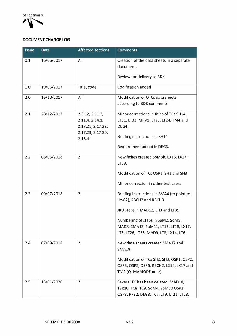
DOCUMENT CHANGE LOG
Issue Date Affected sections Comments
0.1 16/06/2017 All Creation of the data sheets in a separate
document.
Review for delivery to BDK
1.0 19/06/2017 Title, code Codification added
2.0 16/10/2017 All Modification of OTCs data sheets
according to BDK comments
2.1 28/12/2017 2.3.12, 2.11.3,
2.11.4, 2.14.1,
2.17.21, 2.17.22,
2.17.29, 2.17.30,
2.18.4
Minor corrections in titles of TCs SH14,
LT31, LT32, MPV1, LT23, LT24, TM4 and
DEG4.
Briefing instructions in SH14
Requirement added in DEG3.
2.2 08/06/2018 2 New fiches created SoM8b, LX16, LX17,
LT39.
Modification of TCs OSP1, SH1 and SH3
Minor correction in other test cases
2.3 09/07/2018 2 Briefing instructions in SMA4 (to point to
Hz-82), RBCH2 and RBCH3
JRU steps in MAD12, SH3 and LT39
Numbering of steps in SoM2, SoM9,
MAD8, SMA12, SoM11, LT13, LT18, LX17,
LT3, LT26, LT38, MAD9, LT8, LX14, LT6
2.4 07/09/2018 2 New data sheets created SMA17 and
SMA18
Modification of TCs SH2, SH3, OSP1, OSP2,
OSP3, OSP5, OSP6, RBCH2, LX16, LX17 and
TM2 (Q_MAMODE note)
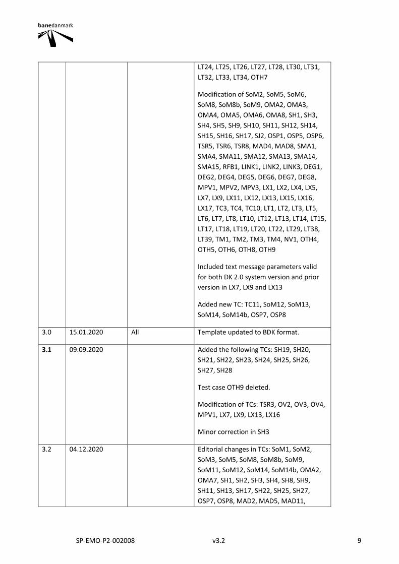
2.5 13/01/2020 2 Several TC has been deleted: MAD10,
TSR10, TC8, TC9, SoM4, SoM10 OSP2,
OSP3, RFB2, DEG3, TC7, LT9, LT21, LT23,
SP-EMO-P2-002008 v3.2 9
LT24, LT25, LT26, LT27, LT28, LT30, LT31,
LT32, LT33, LT34, OTH7
Modification of SoM2, SoM5, SoM6,
SoM8, SoM8b, SoM9, OMA2, OMA3,
OMA4, OMA5, OMA6, OMA8, SH1, SH3,
SH4, SH5, SH9, SH10, SH11, SH12, SH14,
SH15, SH16, SH17, SJ2, OSP1, OSP5, OSP6,
TSR5, TSR6, TSR8, MAD4, MAD8, SMA1,
SMA4, SMA11, SMA12, SMA13, SMA14,
SMA15, RFB1, LINK1, LINK2, LINK3, DEG1,
DEG2, DEG4, DEG5, DEG6, DEG7, DEG8,
MPV1, MPV2, MPV3, LX1, LX2, LX4, LX5,
LX7, LX9, LX11, LX12, LX13, LX15, LX16,
LX17, TC3, TC4, TC10, LT1, LT2, LT3, LT5,
LT6, LT7, LT8, LT10, LT12, LT13, LT14, LT15,
LT17, LT18, LT19, LT20, LT22, LT29, LT38,
LT39, TM1, TM2, TM3, TM4, NV1, OTH4,
OTH5, OTH6, OTH8, OTH9
Included text message parameters valid
for both DK 2.0 system version and prior
version in LX7, LX9 and LX13
Added new TC: TC11, SoM12, SoM13,
SoM14, SoM14b, OSP7, OSP8
3.0 15.01.2020 All Template updated to BDK format.
3.1 09.09.2020 Added the following TCs: SH19, SH20,
SH21, SH22, SH23, SH24, SH25, SH26,
SH27, SH28
Test case OTH9 deleted.
Modification of TCs: TSR3, OV2, OV3, OV4,
MPV1, LX7, LX9, LX13, LX16
Minor correction in SH3
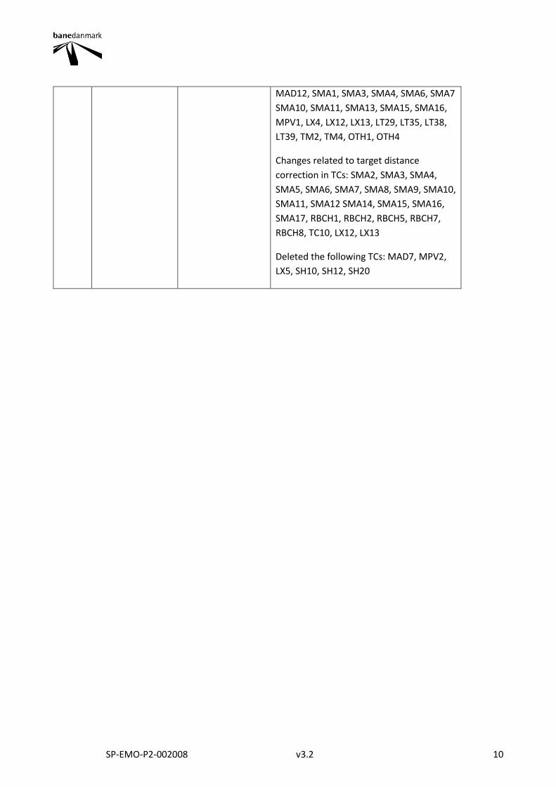
3.2 04.12.2020 Editorial changes in TCs: SoM1, SoM2,
SoM3, SoM5, SoM8, SoM8b, SoM9,
SoM11, SoM12, SoM14, SoM14b, OMA2,
OMA7, SH1, SH2, SH3, SH4, SH8, SH9,
SH11, SH13, SH17, SH22, SH25, SH27,
OSP7, OSP8, MAD2, MAD5, MAD11,
SP-EMO-P2-002008 v3.2 10
MAD12, SMA1, SMA3, SMA4, SMA6, SMA7
SMA10, SMA11, SMA13, SMA15, SMA16,
MPV1, LX4, LX12, LX13, LT29, LT35, LT38,
LT39, TM2, TM4, OTH1, OTH4
Changes related to target distance
correction in TCs: SMA2, SMA3, SMA4,
SMA5, SMA6, SMA7, SMA8, SMA9, SMA10,
SMA11, SMA12 SMA14, SMA15, SMA16,
SMA17, RBCH1, RBCH2, RBCH5, RBCH7,
RBCH8, TC10, LX12, LX13
Deleted the following TCs: MAD7, MPV2,
LX5, SH10, SH12, SH20
SP-EMO-P2-002008 v3.2 11
1. INTRODUCTION
1.1. PURPOSE
The purpose of this document is to deliver the Operational Test Cases (OTCs) data sheets of the Operation
Test Cases listed in document SP-EMO-P2-001959_ERTMS L2 - Generic Operational Test Cases List_v5.2
1.2. SCOPE
The data sheets presented in this document correspond to the OTCs listed in document SP-EMO-P2-
001959_ERTMS L2 - Generic Operational Test Cases List. These test cases correspond to F-bane applications
EAST and WEST.
The OTCs marked as intentionally deleted are not developed.
1.3. ABBREVIATIONS
Abbreviation Description
ATAF Automatic Track Ahead Free
ATC Automatic Train Control
BG Balise Group
CER Common Engineering Rules
CES Conditional Emergency Stop
CR Control Room
DEF Definition
DEG Degraded Scenarios
DMI Driver Machine Interface
DP Danger Point
EoA End of Authority
EoM End of Mission
Abbreviation Description
ERA European Railway Agency
ERTMS European Rail Traffic
Management System
ETCS European Train Control System
EVC European Vital Computer
FS Full Supervision mode
GP Gradient Profile
HO Handover
HZ Hazard
ID Identification
IP Internet Protocol
IxL Interlocking
SP-EMO-P2-002008 v3.2 12
Abbreviation Description
JRU Juridical Recording Unit
KM Key Management
KMC Key Management Centre
LINK Linking Information
LNTC Level NTC
LoA Limit of Authority
LRBG Last Relevant Balise Group
LT Level Transitions
LX Level Crossing
MA Movement Authority
MAD Movement Authority
Description
MB Marker Board
MPV
Specific Requirements for ETCS
messages, packets and
variables
MRDT Most Restrictive Displayed
Target
MRSP Most Restrictive Speed Profile
NR Not Relevant
NTC National Train Control
NV National Values
OB On-board
OBU On-board Unit
Abbreviation Description
OMA Obtaining Moving Authority
OPS Operational Concept
OR Operational Rule
OS On Sight mode
OSP On-Sight Protection
OTC Operational Test Case
OTH Others
OV Override (either authorised or
not)
PSA Permanent Shunting Area
PT Post Trip mode
PWS Passenger Warning System
RAMS Reliability, Availability,
Maintainability, Safety
RBC Radio Block Centre
RBCH RBC/RBC Handover
RFB Rules for Balises
SB Stand By mode
SBI Service Brake Intervention
supervision limit
SH Shunting
SJ Splitting/Joining
SL Sleeping mode
SP-EMO-P2-002008 v3.2 13
Abbreviation Description
SMA Shortening of Movement
Authority
SN System National mode
SoM Start of Mission
SPAD Signal passed at danger
SR Staff Responsible mode
SSP Static Speed Profile
SvL Supervision Limit
SX Staff Crossing
TAF Track Ahead Free
TC Test Case
Abbreviation Description
TC Track Conditions
TM Text Messages
TMS Traffic Management System
TR Trip mode
TSA Temporary Shunting Area
TSR Temporary Speed Restriction
UES Unconditional Emergency Stop
UN Unfitted mode
VBC Virtual Balise Cover
1.4. REFERENCES
[1] Denmark Fjernbane Operational Concept
[2] Banedanmark Signalling Programme Operational Rules (Fjernbane OR version 20.4, ORF-20-4)
[3] F-bane Infrastructure Common Engineering Rules (version 3.5, SP-FB-ON-006631)
[4] SP-FIW-GD-000693 – Functional Requirements (current DOORS version)
[5] SP-FIW-GD-000777 -- Non Funct Reqs (current DOORS version)
[6] BDK National Values -- SP-FB-FD-008858
[7] SP-FIW-GD-000649 – LX v 1.0, 31-01-2012
[8] Customer Test Expectations (version 0.18, SP-EMO-P2-001334)
[9] ERTMS-ETCS test format for operational testing v1 2. ERA. 24/05/2011
[10] Subset 026 System requirement specification v3.4.0
[11] SP-EMO-P2-001959_ERTMS L2 - Generic Operational Test Cases List v5.2
[12] Subset 113 – ETCS Hazard Log v1.3.0
SP-EMO-P2-002008 v3.2 14
2. OTC DATA SHEETS
The data sheets have been developed using the format in [9].
The following are the OTC data sheets:
SP-EMO-P2-002008 v3.2 15
2.1. SOM
2.1.1. SOM1
TEST CASE DESCRIPTION
Code Version Title
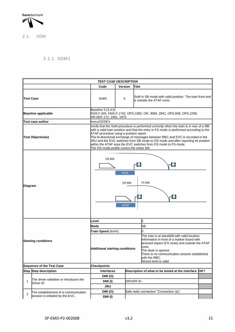
Test Case SoM1 5 SoM in SB mode with valid position. The train front end is outside the ATAF zone.
Baseline applicable Baseline 3 (3.4.0) FbIS.F.345, FbIS.F.1742, OPS.1082, OR. 3084, 2841, OPS.848, OPS.1059, OR.DEF.172, 1961, 1970
Test case author Ineco/CEDEX
Test Objective(s)
Verify that the SoM procedure is performed correctly when the train is in rear of a MB with a valid train position and that the entry in FS mode is performed according to the ATAF procedure using a position report. The bi-directional exchange of messages between RBC and EVC is recorded in the JRU and the EVC switches from SB mode to OS mode and after reporting its position within the ATAF area the EVC switches from OS mode to FS mode. The OS mode profile covers the entire MA.
Diagram
Starting conditions
Level 2
Mode SB
Train Speed (km/h) 0
Additional starting conditions
The train is at standstill with valid location information in front of a marker board with proceed aspect (FS route) and outside the ATAF zone. The desk is opened. There is no communication session established with the RBC. Stored level is valid
Sequence of the Test Case Checkpoints
Step Step description Interfaces Description of what to be tested at the interface OK?
1 The driver validates or introduces the Driver ID
DMI (O)
DMI (I) DRIVER ID
JRU
2 The establishment of a communication session is initiated by the EVC.
DMI (O) Safe radio connection “Connection Up”;
DMI (I)
ATAF
OS MA
ATAF
FS MA OS MA
SP-EMO-P2-002008 v3.2 16
A position report with valid position is sent to the RBC
JRU
Message 155 Message 32 Message 159 Message 157 Q_STATUS = 1 (valid) Packet 0/1 NID_LRBG ≠ 16777215 Q_DIRLRBG ≠ 2 Q_DLRBG ≠ 2 DMI_SYMB_STATUS ST03
3 The driver selects train data entry. Train data and train running number is entered or revalidated.
DMI (O)
DMI (I) Driver selects Data Entry Driver enters the train running number
JRU
M_DRIVERACTION = 20 M_DRIVERACTION = 21 Message 129 Packet 11 Message 8 Message 136 Packet 5 NID_OPERATIONAL ADDITIONAL DATA NID_OPERATIONAL
4 Driver selects START
DMI (O)
DMI (I) Driver selects Start
JRU
M_DRIVERACTION = 19 Message 132 Q_MARQSTREASON =xxxx1 (Start selected by driver) Packet 0/1
5
The RBC sends a Movement authority with an OS mode profile and the position report parameters. The OS mode profile covers the full extent of the MA. The max safe front end of the train is at or in advance of the beginning of the OS area.
DMI (O)
DMI (I)
JRU
Message 3/33 LRBG1 Packet 15 L_ENDSECTION=L1 Packet 21 Packet 27 Packet 80 D_MAMODE=D2 M_MAMODE=0 L_MAMODE=L2 Message 3/24/33 Packet 58 D_LOC=D3 (D3=Location inside the ATAF zone) (L1>D3) Q_LGTLOC=1
6 The EVC shows the acknowledgment request to OS.
DMI (O) OS mode transition acknowledgement
DMI (I)
JRU M_MODE=6 DMI_SYMB_STATUS MO08
7 Acknowledgement of OS
DMI (O)
DMI (I) Acknowledgement of OS mode
JRU M_DRIVERACTIONS = 0
8 The EVC switches to OS mode and reports to the RBC the train position
DMI (O) OS symbol
DMI (I)
JRU
M_MODE=1 DMI_SYMB_STATUS MO07 Message 136 Packet 0/1 M_MODE=1
9 DMI (O) OS symbol
DMI (I)
SP-EMO-P2-002008 v3.2 17
The train sends a position report when its front end position is inside the ATAF zone.
JRU
M_MODE=1 Message 136 Packet 0/1 D_LRBG D_LRBG(=Estimated front end)=D3-L_DOUBTUNDER
10 The RBC sends an updated MA to the train
DMI (O)
DMI (I)
JRU
Message 3/33 Packet 15 L_ENDSECTION=L1 Packet 21 Packet 27 Packet 80 D_MAMODE=D4 M_MAMODE=0 L_MAMODE=L4 (L1>D4+L4=Location of the replacement section limit )
11
The train passes the end of the OS mode profile (the track section limit) with its "min safe front end" and switches to FS mode.
DMI (O) FS symbol
DMI (I)
JRU
Estimated front end > D4 + L4 + L_DOUBTOVER M_LEVEL=3 M_MODE=0 DMI_SYMB_STATUS MO11
12 The EVC reports to the RBC the train position
DMI (O)
DMI (I)
JRU Message 136 Packet 0/1 M_MODE=0
Final state
Level 2
Mode FS
Train Speed (km/h) NR
Other parameters
Final Test Result
Field of Application F-bane EAST
Briefing instructions The train data number can be introduced or validated when the driver ID is entered (step 1) instead of when the train data is entered or validated (step 4)
ADDITIONAL TEST CASE REPORTING INFORMATION
System configuration
Test location
Date and time (Start/End)
Names
Test log reference
Observations
SP-EMO-P2-002008 v3.2 18
2.1.2. SOM2
TEST CASE DESCRIPTION
Code Version Title
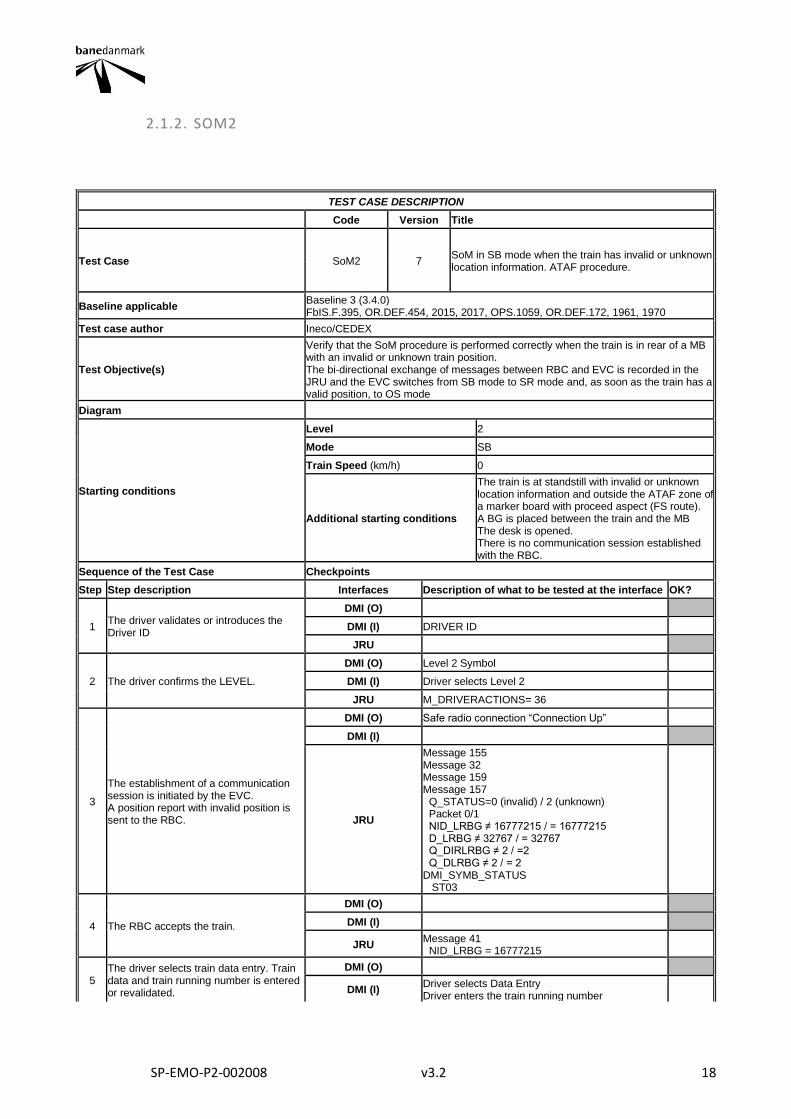
Test Case SoM2 7 SoM in SB mode when the train has invalid or unknown location information. ATAF procedure.
Baseline applicable Baseline 3 (3.4.0) FbIS.F.395, OR.DEF.454, 2015, 2017, OPS.1059, OR.DEF.172, 1961, 1970
Test case author Ineco/CEDEX
Test Objective(s)
Verify that the SoM procedure is performed correctly when the train is in rear of a MB with an invalid or unknown train position. The bi-directional exchange of messages between RBC and EVC is recorded in the JRU and the EVC switches from SB mode to SR mode and, as soon as the train has a valid position, to OS mode
Diagram
Starting conditions
Level 2
Mode SB
Train Speed (km/h) 0
Additional starting conditions
The train is at standstill with invalid or unknown location information and outside the ATAF zone of a marker board with proceed aspect (FS route). A BG is placed between the train and the MB The desk is opened. There is no communication session established with the RBC.
Sequence of the Test Case Checkpoints
Step Step description Interfaces Description of what to be tested at the interface OK?
1 The driver validates or introduces the Driver ID
DMI (O)
DMI (I) DRIVER ID
JRU
2 The driver confirms the LEVEL.
DMI (O) Level 2 Symbol
DMI (I) Driver selects Level 2
JRU M_DRIVERACTIONS= 36
3
The establishment of a communication session is initiated by the EVC. A position report with invalid position is sent to the RBC.
DMI (O) Safe radio connection “Connection Up”
DMI (I)
JRU
Message 155 Message 32 Message 159 Message 157 Q_STATUS=0 (invalid) / 2 (unknown) Packet 0/1 NID_LRBG ≠ 16777215 / = 16777215 D_LRBG ≠ 32767 / = 32767 Q_DIRLRBG ≠ 2 / =2 Q_DLRBG ≠ 2 / = 2 DMI_SYMB_STATUS ST03
4 The RBC accepts the train.
DMI (O)
DMI (I)
JRU Message 41 NID_LRBG = 16777215
5 The driver selects train data entry. Train data and train running number is entered or revalidated.
DMI (O)
DMI (I) Driver selects Data Entry Driver enters the train running number
SP-EMO-P2-002008 v3.2 19
JRU
M_DRIVERACTION = 20 M_DRIVERACTION = 21 Message 129 Packet 11 Message 8 Message 136 Packet 5 NID_OPERATIONAL ADDITIONAL DATA NID_OPERATIONAL
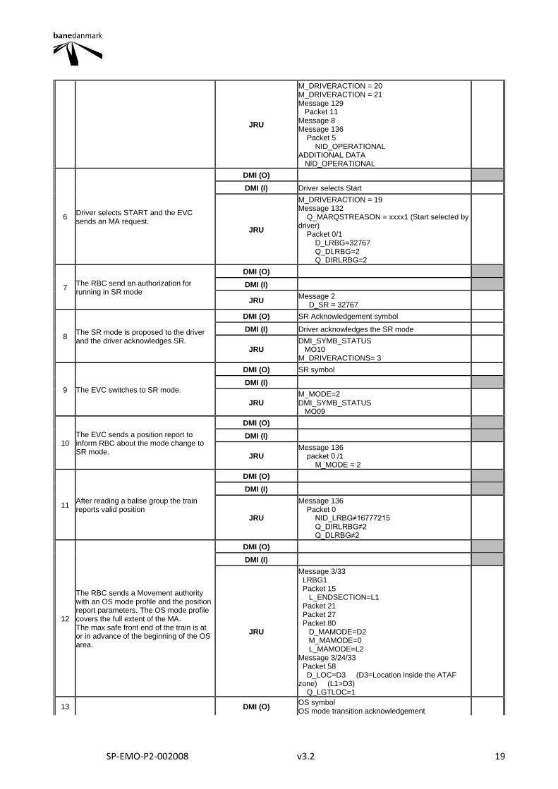
6 Driver selects START and the EVC sends an MA request.
DMI (O)
DMI (I) Driver selects Start
JRU
M_DRIVERACTION = 19 Message 132 Q_MARQSTREASON = xxxx1 (Start selected by driver) Packet 0/1 D_LRBG=32767 Q_DLRBG=2 Q_DIRLRBG=2
7 The RBC send an authorization for running in SR mode
DMI (O)
DMI (I)
JRU Message 2 D_SR = 32767
8 The SR mode is proposed to the driver and the driver acknowledges SR.
DMI (O) SR Acknowledgement symbol
DMI (I) Driver acknowledges the SR mode
JRU DMI_SYMB_STATUS MO10 M_DRIVERACTIONS= 3
9 The EVC switches to SR mode.
DMI (O) SR symbol
DMI (I)
JRU M_MODE=2 DMI_SYMB_STATUS MO09
10 The EVC sends a position report to inform RBC about the mode change to SR mode.
DMI (O)
DMI (I)
JRU Message 136 packet 0 /1 M_MODE = 2
11 After reading a balise group the train reports valid position
DMI (O)
DMI (I)
JRU
Message 136 Packet 0 NID_LRBG≠16777215 Q_DIRLRBG≠2 Q_DLRBG≠2
12
The RBC sends a Movement authority with an OS mode profile and the position report parameters. The OS mode profile covers the full extent of the MA. The max safe front end of the train is at or in advance of the beginning of the OS area.
DMI (O)
DMI (I)
JRU
Message 3/33 LRBG1 Packet 15 L_ENDSECTION=L1 Packet 21 Packet 27 Packet 80 D_MAMODE=D2 M_MAMODE=0 L_MAMODE=L2 Message 3/24/33 Packet 58 D_LOC=D3 (D3=Location inside the ATAF zone) (L1>D3) Q_LGTLOC=1
13 DMI (O) OS symbol OS mode transition acknowledgement
SP-EMO-P2-002008 v3.2 20
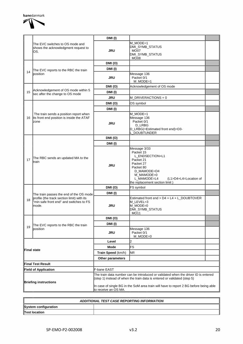
The EVC switches to OS mode and shows the acknowledgment request to OS.
DMI (I)
JRU
M_MODE=1 DMI_SYMB_STATUS MO07 DMI_SYMB_STATUS MO08
14 The EVC reports to the RBC the train position
DMI (O)
DMI (I)
JRU Message 136 Packet 0/1 M_MODE=1
15 Acknowledgement of OS mode within 5 sec after the change to OS mode
DMI (O) Acknowledgement of OS mode
DMI (I)
JRU M_DRIVERACTIONS = 0
16 The train sends a position report when its front end position is inside the ATAF zone
DMI (O) OS symbol
DMI (I)
JRU
M_MODE=1 Message 136 Packet 0/1 D_LRBG D_LRBG(=Estimated front end)=D3-L_DOUBTUNDER
17 The RBC sends an updated MA to the train
DMI (O)
DMI (I)
JRU
Message 3/33 Packet 15 L_ENDSECTION=L1 Packet 21 Packet 27 Packet 80 D_MAMODE=D4 M_MAMODE=0 L_MAMODE=L4 (L1>D4+L4=Location of the replacement section limit )
18
The train passes the end of the OS mode profile (the track section limit) with its "min safe front end" and switches to FS mode.
DMI (O) FS symbol
DMI (I)
JRU
Estimated front end > D4 + L4 + L_DOUBTOVER M_LEVEL=3 M_MODE=0 DMI_SYMB_STATUS MO11
19 The EVC reports to the RBC the train position
DMI (O)
DMI (I)
JRU Message 136 Packet 0/1 M_MODE=0
Final state
Level 2
Mode FS
Train Speed (km/h) NR
Other parameters
Final Test Result
Field of Application F-bane EAST
Briefing instructions
The train data number can be introduced or validated when the driver ID is entered (step 1) instead of when the train data is entered or validated (step 5) In case of single BG in the SoM area train will have to report 2 BG before being able to receive an OS MA.
ADDITIONAL TEST CASE REPORTING INFORMATION
System configuration
Test location

SP-EMO-P2-002008 v3.2 21
Date and time (Start/End)
Names
Test log reference
Observations
SP-EMO-P2-002008 v3.2 22
2.1.3. SOM3
TEST CASE DESCRIPTION
Code Version Title
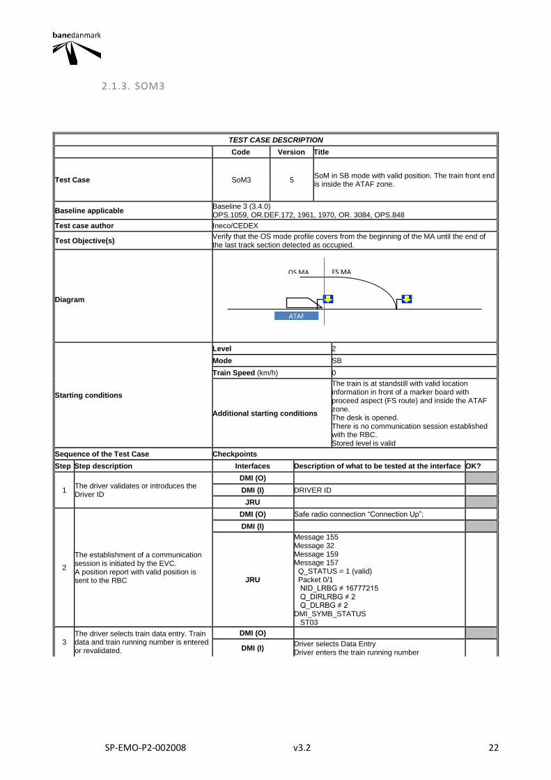
Test Case SoM3 5 SoM in SB mode with valid position. The train front end is inside the ATAF zone.
Baseline applicable Baseline 3 (3.4.0) OPS.1059, OR.DEF.172, 1961, 1970, OR. 3084, OPS.848
Test case author Ineco/CEDEX
Test Objective(s) Verify that the OS mode profile covers from the beginning of the MA until the end of the last track section detected as occupied.
Diagram
Starting conditions
Level 2
Mode SB
Train Speed (km/h) 0
Additional starting conditions
The train is at standstill with valid location information in front of a marker board with proceed aspect (FS route) and inside the ATAF zone. The desk is opened. There is no communication session established with the RBC. Stored level is valid
Sequence of the Test Case Checkpoints
Step Step description Interfaces Description of what to be tested at the interface OK?
1 The driver validates or introduces the Driver ID
DMI (O)
DMI (I) DRIVER ID
JRU
2
The establishment of a communication session is initiated by the EVC. A position report with valid position is sent to the RBC
DMI (O) Safe radio connection “Connection Up”;
DMI (I)
JRU
Message 155 Message 32 Message 159 Message 157 Q_STATUS = 1 (valid) Packet 0/1 NID_LRBG ≠ 16777215 Q_DIRLRBG ≠ 2 Q_DLRBG ≠ 2 DMI_SYMB_STATUS ST03
3 The driver selects train data entry. Train data and train running number is entered or revalidated.
DMI (O)
DMI (I) Driver selects Data Entry Driver enters the train running number
ATAF
FS MA OS MA
SP-EMO-P2-002008 v3.2 23
JRU
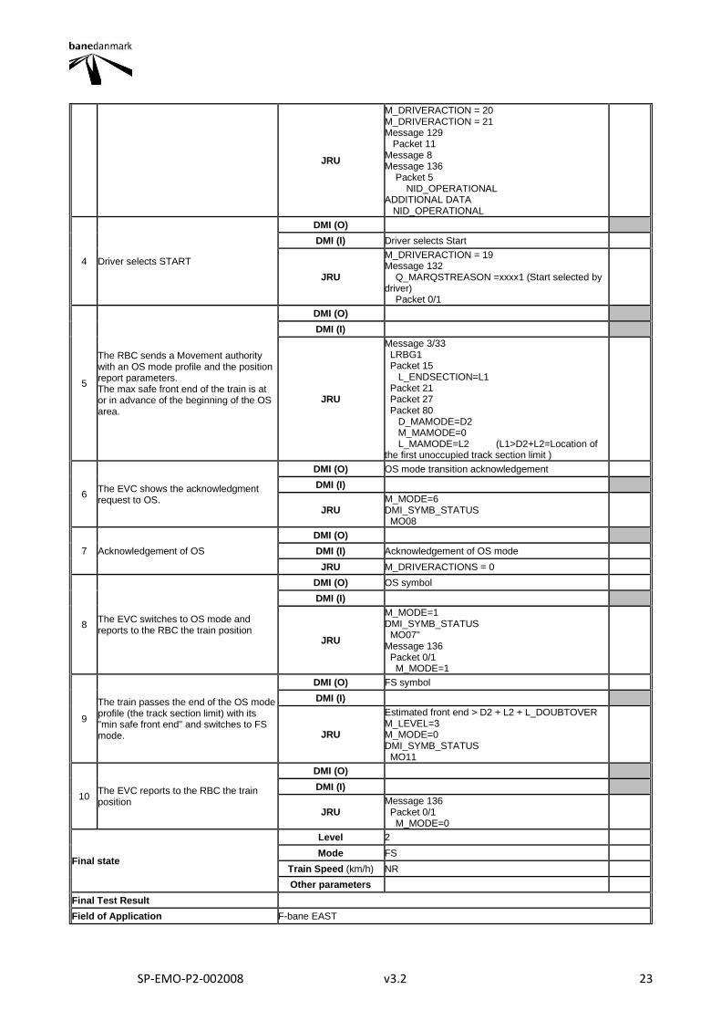
M_DRIVERACTION = 20 M_DRIVERACTION = 21 Message 129 Packet 11 Message 8 Message 136 Packet 5 NID_OPERATIONAL ADDITIONAL DATA NID_OPERATIONAL
4 Driver selects START
DMI (O)
DMI (I) Driver selects Start
JRU
M_DRIVERACTION = 19 Message 132 Q_MARQSTREASON =xxxx1 (Start selected by driver) Packet 0/1
5
The RBC sends a Movement authority with an OS mode profile and the position report parameters. The max safe front end of the train is at or in advance of the beginning of the OS area.
DMI (O)
DMI (I)
JRU
Message 3/33 LRBG1 Packet 15 L_ENDSECTION=L1 Packet 21 Packet 27 Packet 80 D_MAMODE=D2 M_MAMODE=0 L_MAMODE=L2 (L1>D2+L2=Location of the first unoccupied track section limit )
6 The EVC shows the acknowledgment request to OS.
DMI (O) OS mode transition acknowledgement
DMI (I)
JRU M_MODE=6 DMI_SYMB_STATUS MO08
7 Acknowledgement of OS
DMI (O)
DMI (I) Acknowledgement of OS mode
JRU M_DRIVERACTIONS = 0
8 The EVC switches to OS mode and reports to the RBC the train position
DMI (O) OS symbol
DMI (I)
JRU
M_MODE=1 DMI_SYMB_STATUS MO07" Message 136 Packet 0/1 M_MODE=1
9
The train passes the end of the OS mode profile (the track section limit) with its "min safe front end" and switches to FS mode.
DMI (O) FS symbol
DMI (I)
JRU
Estimated front end > D2 + L2 + L_DOUBTOVER M_LEVEL=3 M_MODE=0 DMI_SYMB_STATUS MO11
10 The EVC reports to the RBC the train position
DMI (O)
DMI (I)
JRU Message 136 Packet 0/1 M_MODE=0
Final state
Level 2
Mode FS
Train Speed (km/h) NR
Other parameters
Final Test Result
Field of Application F-bane EAST
SP-EMO-P2-002008 v3.2 24
Briefing instructions The train data number can be introduced or validated when the driver ID is entered (step 1) instead of when the train data is entered or validated (step 4)
ADDITIONAL TEST CASE REPORTING INFORMATION
System configuration
Test location
Date and time (Start/End)
Names
Test log reference
Observations
SP-EMO-P2-002008 v3.2 25
2.1.4. SOM5
TEST CASE DESCRIPTION
Code Version Title
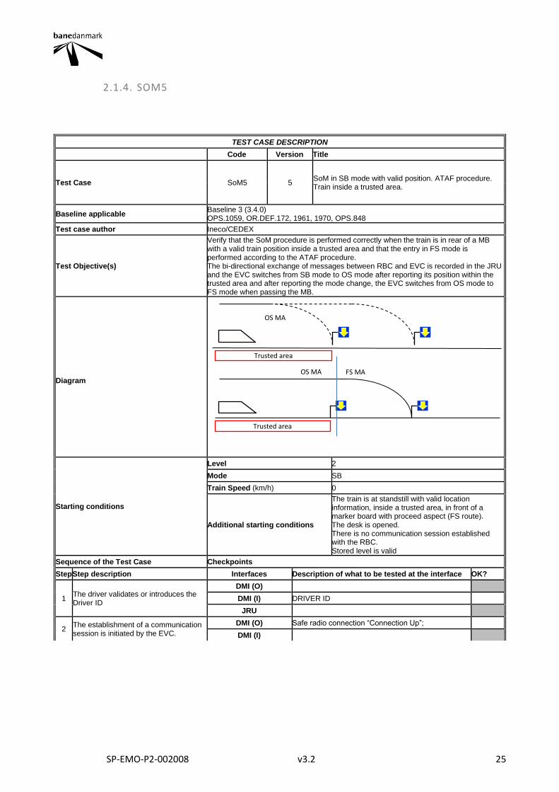
Test Case SoM5 5 SoM in SB mode with valid position. ATAF procedure. Train inside a trusted area.
Baseline applicable Baseline 3 (3.4.0) OPS.1059, OR.DEF.172, 1961, 1970, OPS.848
Test case author Ineco/CEDEX
Test Objective(s)
Verify that the SoM procedure is performed correctly when the train is in rear of a MB with a valid train position inside a trusted area and that the entry in FS mode is performed according to the ATAF procedure. The bi-directional exchange of messages between RBC and EVC is recorded in the JRU and the EVC switches from SB mode to OS mode after reporting its position within the trusted area and after reporting the mode change, the EVC switches from OS mode to FS mode when passing the MB.
Diagram
Starting conditions
Level 2
Mode SB
Train Speed (km/h) 0
Additional starting conditions
The train is at standstill with valid location information, inside a trusted area, in front of a marker board with proceed aspect (FS route). The desk is opened. There is no communication session established with the RBC. Stored level is valid
Sequence of the Test Case Checkpoints
Step Step description Interfaces Description of what to be tested at the interface OK?
1 The driver validates or introduces the Driver ID
DMI (O)
DMI (I) DRIVER ID
JRU
2 The establishment of a communication session is initiated by the EVC.
DMI (O) Safe radio connection “Connection Up”;
DMI (I)
Trusted area
OS MA
FS MA OS MA
Trusted area
SP-EMO-P2-002008 v3.2 26
A position report with valid position inside a trusted area is sent to the RBC.
JRU
Message 155 Message 32 Message 159 Message 157 Q_STATUS = 1 (valid) Packet 0/1 NID_LRBG ≠ 16777215 Q_DIRLRBG ≠ 2 Q_DLRBG ≠ 2 DMI_SYMB_STATUS ST03
3
The driver selects train data entry. Train data and train running number is entered or revalidated. Once the train data has been introduced, the driver can select Start.
DMI (O)
DMI (I) Driver selects Data Entry Driver enters the train running number
JRU
M_DRIVERACTION = 20 M_DRIVERACTION = 21 Message 129 Packet 11 Message 8 Message 136 Packet 5 NID_OPERATIONAL ADDITIONAL DATA NID_OPERATIONAL
4 Driver selects START
DMI (O)
DMI (I) Driver selects Start
JRU
M_DRIVERACTION = 19 Message 132 Q_MARQSTREASON = Start selected by driver Packet 0/1
5
The RBC sends a Movement authority with an OS mode profile. The OS mode profile goes at least until the marker board. The max safe front end of the train is at or in advance of the beginning of the OS area.
DMI (O)
DMI (I)
JRU
Message 3/33 LRBG1 Packet 15 L_ENDSECTION=L1 Packet 21 Packet 27 Packet 80 D_MAMODE=D2 M_MAMODE=0 L_MAMODE=L2 (D2+L2≥distance to the marker board)
6 The EVC shows the acknowledgment request to OS.
DMI (O) OS mode transition acknowledgement
DMI (I)
JRU M_MODE=6 DMI_SYMB_STATUS MO08
7 Acknowledgement of OS
DMI (O)
DMI (I) Acknowledgement of OS mode
JRU M_DRIVERACTIONS = 0
8 The EVC switches to OS mode and reports to the RBC the train position
DMI (O) OS symbol
DMI (I)
JRU
M_MODE=1 DMI_SYMB_STATUS MO07" Message 136 Packet 0/1 M_MODE=1
9 DMI (O)
DMI (I)
SP-EMO-P2-002008 v3.2 27
The RBC sends an updated MA to the train: OS MA to the replacement section and FS onwards.
JRU
Message 3/33 Packet 15 L_ENDSECTION = L3 (L3>D4+L4) Packet 21 Packet 27 Packet 80 D_MAMODE=D4 M_MAMODE=0 L_MAMODE=L4 (D4+L4=distance to the replacement section)
10
The train approaches to the marker board and when it occupies the replacement section the RBC sends a CES to the train. (*)
DMI (O)
DMI (I)
JRU
Message 15 LRBG1 NID_EM=EM1 D_EMERGENCYSTOP = D3
11
The train has already passed with its "min safe front end" the new stop location therefore the train ignores the CES. (*)
DMI (O)
DMI (I)
JRU
Estimated front end > D3 + L_DOUBTOVER Message 147 NID_EM=EM1 Q_EMERGENCYSTOP=3
12
The train passes the end of the OS mode profile (the track section limit) with its "min safe front end" and switches to FS mode.
DMI (O) FS symbol
DMI (I)
JRU
M_LEVEL=3 M_MODE=0 DMI_SYMB_STATUS MO11
13 The EVC reports to the RBC the train position
DMI (O)
DMI (I)
JRU Message 136 Packet 0/1 M_MODE=0
Final state
Level 2
Mode FS
Train Speed (km/h) NR
Other parameters
Final Test Result
Field of Application F-bane WEST
Briefing instructions
The train data number can be introduced or validated when the driver ID is entered (step 1) instead of when the train data is entered or validated (step 4) (*) If when the RBC has detected that the replacement circuit has been occupied the train has already passed with its "min safe front end" the location of the marker board the RBC could not send a CES.
ADDITIONAL TEST CASE REPORTING INFORMATION
System configuration
Test location
Date and time (Start/End)
Names
Test log reference
Observations
SP-EMO-P2-002008 v3.2 28
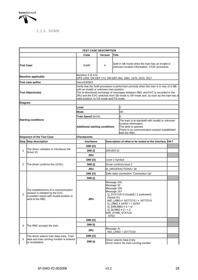
2.1.5. SOM6
TEST CASE DESCRIPTION
Code Version Title
Test Case SoM6 4 SoM in SB mode when the train has an invalid or unknown location information. ATAF procedure
Baseline applicable Baseline 3 (3.4.0) OPS.1059, OR.DEF.172, OR.DEF.454, 1961, 1970, 2015, 2017
Test case author Ineco/CEDEX
Test Objective(s)
Verify that the SoM procedure is performed correctly when the train is in rear of a MB with an invalid or unknown train position. The bi-directional exchange of messages between RBC and EVC is recorded in the JRU and the EVC switches from SB mode to SR mode and, as soon as the train has a valid position, to OS mode and FS mode.
Diagram
Starting conditions
Level 2
Mode SB
Train Speed (km/h) 0
Additional starting conditions
The train is at standstill with invalid or unknown location information. The desk is opened. There is no communication session established with the RBC.
Sequence of the Test Case Checkpoints
Step Step description Interfaces Description of what to be tested at the interface OK?
1 The driver validates or introduces the Driver ID
DMI (O)
DMI (I) DRIVER ID
JRU
2 The driver confirms the LEVEL.
DMI (O) Level 2 Symbol
DMI (I) Driver confirms level 2
JRU M_DRIVERACTIONS= 36
3
The establishment of a communication session is initiated by the EVC. A position report with invalid position is sent to the RBC
DMI (O) Safe radio connection “Connection Up”
DMI (I)
JRU
Message 155 Message 32 Message 159 Message 157 Q_STATUS=0 (invalid) / 2 (unknown) Packet 0/1 NID_LRBG ≠ 16777215 / = 16777215 D_LRBG ≠ 32767 / = 32767 Q_DIRLRBG ≠ 2 / =2 Q_DLRBG ≠ 2 / = 2 DMI_SYMB_STATUS ST03
4 The RBC accepts the train.
DMI (O)
DMI (I)
JRU Message 41 NID_LRBG = 16777215
5 The driver selects train data entry. Train data and train running number is entered or revalidated.
DMI (O)
DMI (I) Driver selects Data Entry Driver enters the train running number
SP-EMO-P2-002008 v3.2 29
JRU
M_DRIVERACTION = 20 M_DRIVERACTION = 21 Message 129 Packet 11 Message 8 Message 136 Packet 5 NID_OPERATIONAL ADDITIONAL DATA NID_OPERATIONAL
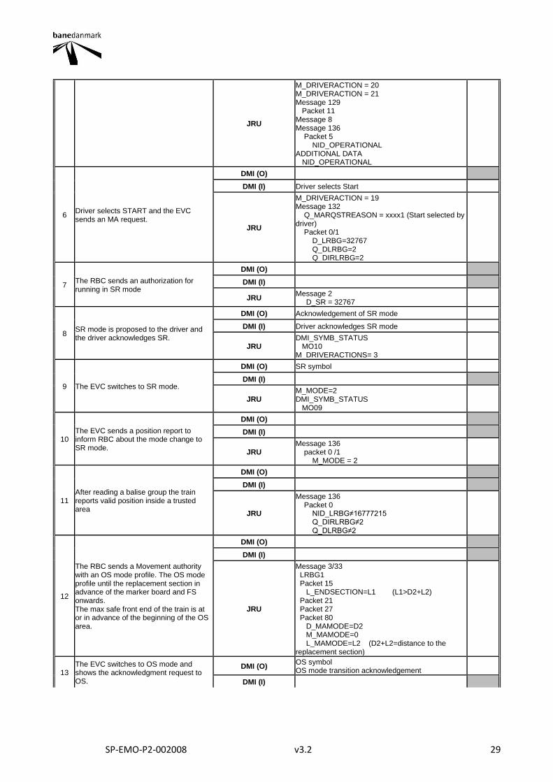
6 Driver selects START and the EVC sends an MA request.
DMI (O)
DMI (I) Driver selects Start
JRU
M_DRIVERACTION = 19 Message 132 Q_MARQSTREASON = xxxx1 (Start selected by driver) Packet 0/1 D_LRBG=32767 Q_DLRBG=2 Q_DIRLRBG=2
7 The RBC sends an authorization for running in SR mode
DMI (O)
DMI (I)
JRU Message 2 D_SR = 32767
8 SR mode is proposed to the driver and the driver acknowledges SR.
DMI (O) Acknowledgement of SR mode
DMI (I) Driver acknowledges SR mode
JRU DMI_SYMB_STATUS MO10 M_DRIVERACTIONS= 3
9 The EVC switches to SR mode.
DMI (O) SR symbol
DMI (I)
JRU M_MODE=2 DMI_SYMB_STATUS MO09
10 The EVC sends a position report to inform RBC about the mode change to SR mode.
DMI (O)
DMI (I)
JRU Message 136 packet 0 /1 M_MODE = 2
11 After reading a balise group the train reports valid position inside a trusted area
DMI (O)
DMI (I)
JRU
Message 136 Packet 0 NID_LRBG≠16777215 Q_DIRLRBG≠2 Q_DLRBG≠2
12
The RBC sends a Movement authority with an OS mode profile. The OS mode profile until the replacement section in advance of the marker board and FS onwards. The max safe front end of the train is at or in advance of the beginning of the OS area.
DMI (O)
DMI (I)
JRU
Message 3/33 LRBG1 Packet 15 L_ENDSECTION=L1 (L1>D2+L2) Packet 21 Packet 27 Packet 80 D_MAMODE=D2 M_MAMODE=0 L_MAMODE=L2 (D2+L2=distance to the replacement section)
13 The EVC switches to OS mode and shows the acknowledgment request to OS.
DMI (O) OS symbol OS mode transition acknowledgement
DMI (I)
SP-EMO-P2-002008 v3.2 30
JRU
M_MODE=1 DMI_SYMB_STATUS MO07 DMI_SYMB_STATUS MO08
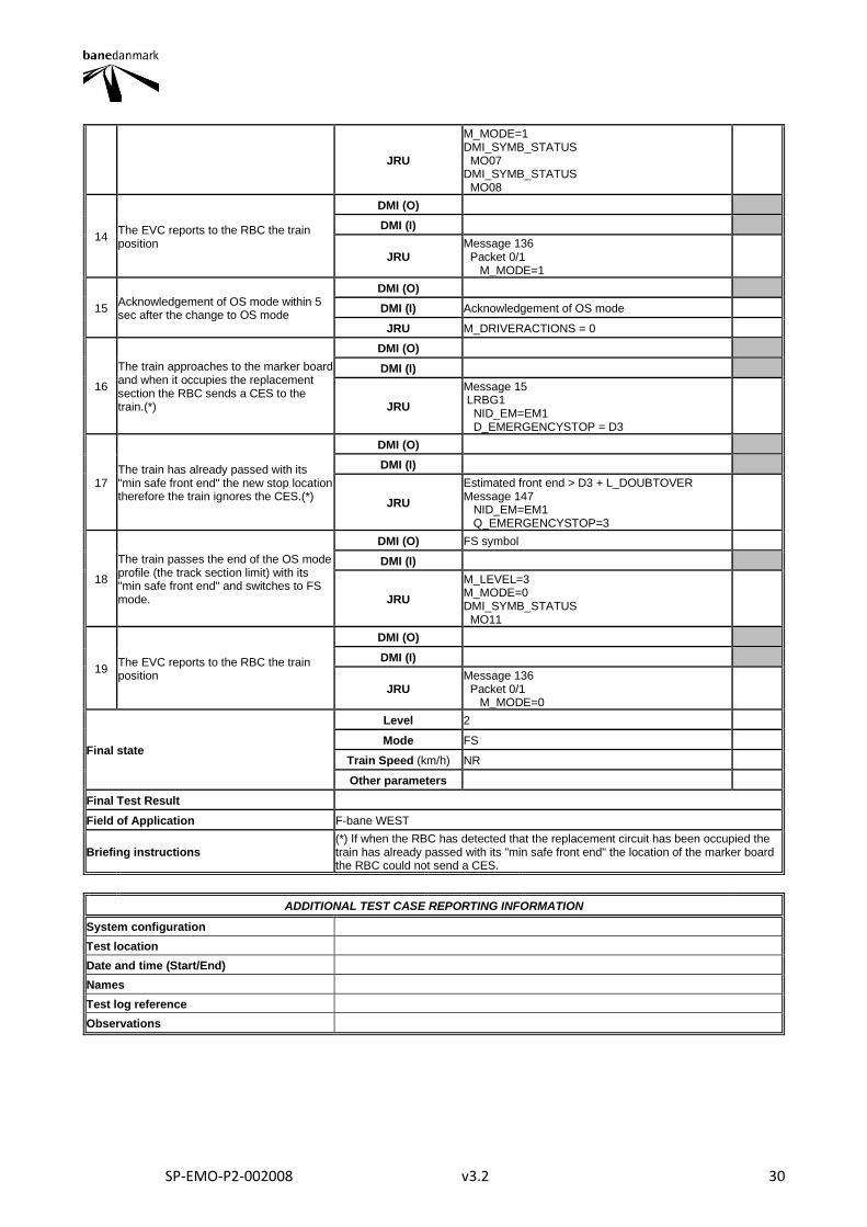
14 The EVC reports to the RBC the train position
DMI (O)
DMI (I)
JRU Message 136 Packet 0/1 M_MODE=1
15 Acknowledgement of OS mode within 5 sec after the change to OS mode
DMI (O)
DMI (I) Acknowledgement of OS mode
JRU M_DRIVERACTIONS = 0
16
The train approaches to the marker board and when it occupies the replacement section the RBC sends a CES to the train.(*)
DMI (O)
DMI (I)
JRU
Message 15 LRBG1 NID_EM=EM1 D_EMERGENCYSTOP = D3
17 The train has already passed with its "min safe front end" the new stop location therefore the train ignores the CES.(*)
DMI (O)
DMI (I)
JRU
Estimated front end > D3 + L_DOUBTOVER Message 147 NID_EM=EM1 Q_EMERGENCYSTOP=3
18
The train passes the end of the OS mode profile (the track section limit) with its "min safe front end" and switches to FS mode.
DMI (O) FS symbol
DMI (I)
JRU
M_LEVEL=3 M_MODE=0 DMI_SYMB_STATUS MO11
19 The EVC reports to the RBC the train position
DMI (O)
DMI (I)
JRU Message 136 Packet 0/1 M_MODE=0
Final state
Level 2
Mode FS
Train Speed (km/h) NR
Other parameters
Final Test Result
Field of Application F-bane WEST
Briefing instructions (*) If when the RBC has detected that the replacement circuit has been occupied the train has already passed with its "min safe front end" the location of the marker board the RBC could not send a CES.
ADDITIONAL TEST CASE REPORTING INFORMATION
System configuration
Test location
Date and time (Start/End)
Names
Test log reference
Observations
SP-EMO-P2-002008 v3.2 31
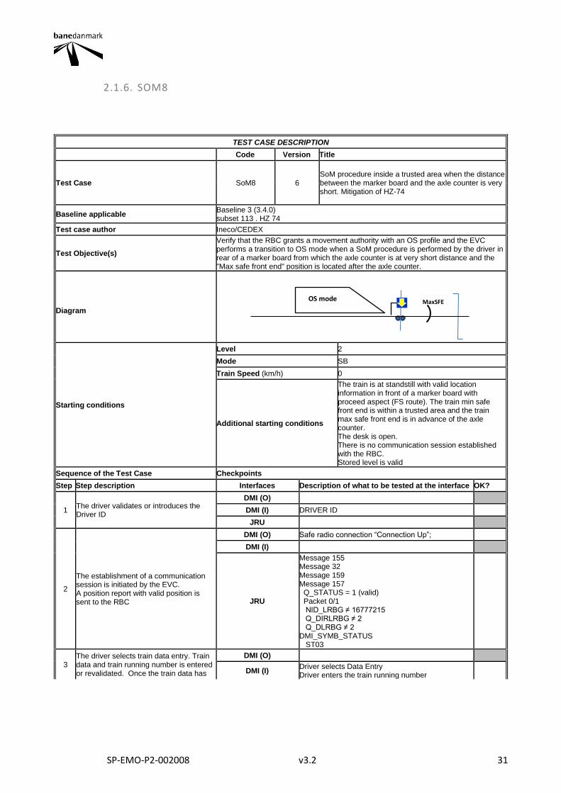
2.1.6. SOM8
TEST CASE DESCRIPTION
Code Version Title
Test Case SoM8 6 SoM procedure inside a trusted area when the distance between the marker board and the axle counter is very short. Mitigation of HZ-74
Baseline applicable Baseline 3 (3.4.0) subset 113 . HZ 74
Test case author Ineco/CEDEX
Test Objective(s)
Verify that the RBC grants a movement authority with an OS profile and the EVC performs a transition to OS mode when a SoM procedure is performed by the driver in rear of a marker board from which the axle counter is at very short distance and the "Max safe front end" position is located after the axle counter.
Diagram
Starting conditions
Level 2
Mode SB
Train Speed (km/h) 0
Additional starting conditions
The train is at standstill with valid location information in front of a marker board with proceed aspect (FS route). The train min safe front end is within a trusted area and the train max safe front end is in advance of the axle counter. The desk is open. There is no communication session established with the RBC. Stored level is valid
Sequence of the Test Case Checkpoints
Step Step description Interfaces Description of what to be tested at the interface OK?
1 The driver validates or introduces the Driver ID
DMI (O)
DMI (I) DRIVER ID
JRU
2
The establishment of a communication session is initiated by the EVC. A position report with valid position is sent to the RBC
DMI (O) Safe radio connection “Connection Up”;
DMI (I)
JRU
Message 155 Message 32 Message 159 Message 157 Q_STATUS = 1 (valid) Packet 0/1 NID_LRBG ≠ 16777215 Q_DIRLRBG ≠ 2 Q_DLRBG ≠ 2 DMI_SYMB_STATUS ST03
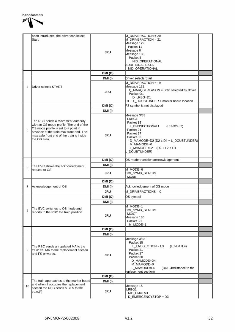
3 The driver selects train data entry. Train data and train running number is entered or revalidated. Once the train data has
DMI (O)
DMI (I) Driver selects Data Entry Driver enters the train running number
OS mode MaxSFE
SP-EMO-P2-002008 v3.2 32
been introduced, the driver can select Start.
JRU
M_DRIVERACTION = 20 M_DRIVERACTION = 21 Message 129 Packet 11 Message 8 Message 136 Packet 5 NID_OPERATIONAL ADDITIONAL DATA NID_OPERATIONAL
4 Driver selects START
DMI (O)
DMI (I) Driver selects Start
JRU
M_DRIVERACTION = 19 Message 132 Q_MARQSTREASON = Start selected by driver Packet 0/1 D_LRBG=D1 D1 + L_DOUBTUNDER > marker board location
5
The RBC sends a Movement authority with an OS mode profile. The end of the OS mode profile is set to a point in advance of the train max front end. The max safe front end of the train is inside the OS area.
DMI (O) FS symbol is not displayed
DMI (I)
JRU
Message 3/33 LRBG1 Packet 15 L_ENDSECTION=L1 (L1>D2+L2) Packet 21 Packet 27 Packet 80 D_MAMODE=D2 (D2 ≤ D1 + L_DOUBTUNDER) M_MAMODE=0 L_MAMODE=L2 (D2 + L2 > D1 + L_DOUBTUNDER)
6 The EVC shows the acknowledgment request to OS.
DMI (O) OS mode transition acknowledgement
DMI (I)
JRU M_MODE=6 DMI_SYMB_STATUS MO08
7 Acknowledgement of OS
DMI (O)
DMI (I) Acknowledgement of OS mode
JRU M_DRIVERACTIONS = 0
8 The EVC switches to OS mode and reports to the RBC the train position
DMI (O) OS symbol
DMI (I)
JRU
M_MODE=1 DMI_SYMB_STATUS MO07" Message 136 Packet 0/1 M_MODE=1
9 The RBC sends an updated MA to the train: OS MA to the replacement section and FS onwards.
DMI (O)
DMI (I)
JRU
Message 3/33 Packet 15 L_ENDSECTION = L3 (L3>D4+L4) Packet 21 Packet 27 Packet 80 D_MAMODE=D4 M_MAMODE=0 L_MAMODE=L4 (D4+L4=distance to the replacement section)
10
The train approaches to the marker board and when it occupies the replacement section the RBC sends a CES to the train.(*)
DMI (O)
DMI (I)
JRU
Message 15 LRBG1 NID_EM=EM1 D_EMERGENCYSTOP = D3
SP-EMO-P2-002008 v3.2 33
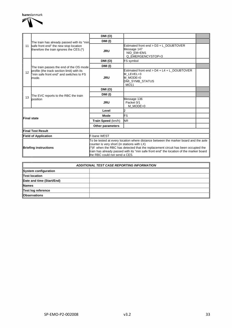
11 The train has already passed with its "min safe front end" the new stop location therefore the train ignores the CES.(*)
DMI (O)
DMI (I)
JRU
Estimated front end > D3 + L_DOUBTOVER Message 147 NID_EM=EM1 Q_EMERGENCYSTOP=3
12
The train passes the end of the OS mode profile (the track section limit) with its "min safe front end" and switches to FS mode.
DMI (O) FS symbol
DMI (I)
JRU
Estimated front end > D4 + L4 + L_DOUBTOVER M_LEVEL=3 M_MODE=0 DMI_SYMB_STATUS MO11
13 The EVC reports to the RBC the train position
DMI (O)
DMI (I)
JRU Message 136 Packet 0/1 M_MODE=0
Final state
Level 2
Mode FS
Train Speed (km/h) NR
Other parameters
Final Test Result
Field of Application F-bane WEST
Briefing instructions
To be tested at every location where distance between the marker board and the axle counter is very short (in stations with LX) (*)If when the RBC has detected that the replacement circuit has been occupied the train has already passed with its "min safe front end" the location of the marker board the RBC could not send a CES.
ADDITIONAL TEST CASE REPORTING INFORMATION
System configuration
Test location
Date and time (Start/End)
Names
Test log reference
Observations
SP-EMO-P2-002008 v3.2 34
2.1.7. SOM8B
TEST CASE DESCRIPTION
Code Version Title
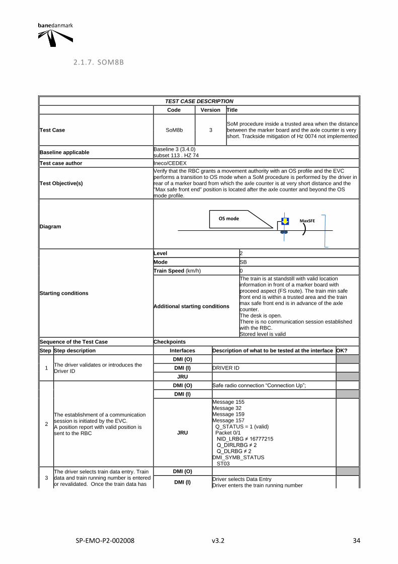
Test Case SoM8b 3 SoM procedure inside a trusted area when the distance between the marker board and the axle counter is very short. Trackside mitigation of Hz 0074 not implemented
Baseline applicable Baseline 3 (3.4.0) subset 113 . HZ 74
Test case author Ineco/CEDEX
Test Objective(s)
Verify that the RBC grants a movement authority with an OS profile and the EVC performs a transition to OS mode when a SoM procedure is performed by the driver in rear of a marker board from which the axle counter is at very short distance and the "Max safe front end" position is located after the axle counter and beyond the OS mode profile.
Diagram
Starting conditions
Level 2
Mode SB
Train Speed (km/h) 0
Additional starting conditions
The train is at standstill with valid location information in front of a marker board with proceed aspect (FS route). The train min safe front end is within a trusted area and the train max safe front end is in advance of the axle counter. The desk is open. There is no communication session established with the RBC. Stored level is valid
Sequence of the Test Case Checkpoints
Step Step description Interfaces Description of what to be tested at the interface OK?
1 The driver validates or introduces the Driver ID
DMI (O)
DMI (I) DRIVER ID
JRU
2
The establishment of a communication session is initiated by the EVC. A position report with valid position is sent to the RBC
DMI (O) Safe radio connection “Connection Up”;
DMI (I)
JRU
Message 155 Message 32 Message 159 Message 157 Q_STATUS = 1 (valid) Packet 0/1 NID_LRBG ≠ 16777215 Q_DIRLRBG ≠ 2 Q_DLRBG ≠ 2 DMI_SYMB_STATUS ST03
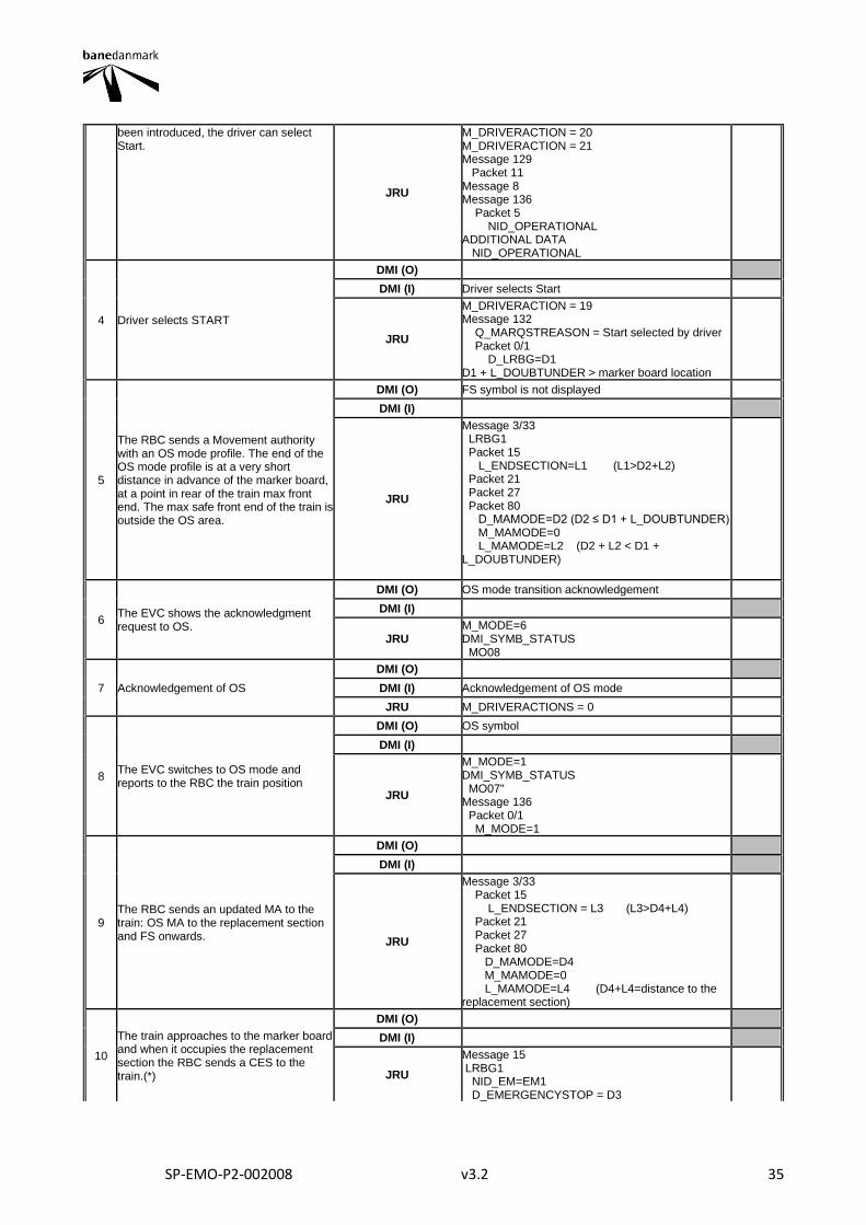
3 The driver selects train data entry. Train data and train running number is entered or revalidated. Once the train data has
DMI (O)
DMI (I) Driver selects Data Entry Driver enters the train running number
OS mode MaxSFE
SP-EMO-P2-002008 v3.2 35
been introduced, the driver can select Start.
JRU
M_DRIVERACTION = 20 M_DRIVERACTION = 21 Message 129 Packet 11 Message 8 Message 136 Packet 5 NID_OPERATIONAL ADDITIONAL DATA NID_OPERATIONAL
4 Driver selects START
DMI (O)
DMI (I) Driver selects Start
JRU
M_DRIVERACTION = 19 Message 132 Q_MARQSTREASON = Start selected by driver Packet 0/1 D_LRBG=D1 D1 + L_DOUBTUNDER > marker board location
5
The RBC sends a Movement authority with an OS mode profile. The end of the OS mode profile is at a very short distance in advance of the marker board, at a point in rear of the train max front end. The max safe front end of the train is outside the OS area.
DMI (O) FS symbol is not displayed
DMI (I)
JRU
Message 3/33 LRBG1 Packet 15 L_ENDSECTION=L1 (L1>D2+L2) Packet 21 Packet 27 Packet 80 D_MAMODE=D2 (D2 ≤ D1 + L_DOUBTUNDER) M_MAMODE=0 L_MAMODE=L2 (D2 + L2 < D1 + L_DOUBTUNDER)
6 The EVC shows the acknowledgment request to OS.
DMI (O) OS mode transition acknowledgement
DMI (I)
JRU M_MODE=6 DMI_SYMB_STATUS MO08
7 Acknowledgement of OS
DMI (O)
DMI (I) Acknowledgement of OS mode
JRU M_DRIVERACTIONS = 0
8 The EVC switches to OS mode and reports to the RBC the train position
DMI (O) OS symbol
DMI (I)
JRU
M_MODE=1 DMI_SYMB_STATUS MO07" Message 136 Packet 0/1 M_MODE=1
9 The RBC sends an updated MA to the train: OS MA to the replacement section and FS onwards.
DMI (O)
DMI (I)
JRU
Message 3/33 Packet 15 L_ENDSECTION = L3 (L3>D4+L4) Packet 21 Packet 27 Packet 80 D_MAMODE=D4 M_MAMODE=0 L_MAMODE=L4 (D4+L4=distance to the replacement section)
10
The train approaches to the marker board and when it occupies the replacement section the RBC sends a CES to the train.(*)
DMI (O)
DMI (I)
JRU
Message 15 LRBG1 NID_EM=EM1 D_EMERGENCYSTOP = D3

SP-EMO-P2-002008 v3.2 36
11 The train has already passed with its "min safe front end" the new stop location therefore the train ignores the CES.(*)
DMI (O)
DMI (I)
JRU
Estimated front end > D3 + L_DOUBTOVER Message 147 NID_EM=EM1 Q_EMERGENCYSTOP=3
12
The train passes the end of the OS mode profile (the track section limit) with its "min safe front end" and switches to FS mode.
DMI (O) FS symbol
DMI (I)
JRU
Estimated front end > D4 + L4 + L_DOUBTOVER M_LEVEL=3 M_MODE=0 DMI_SYMB_STATUS MO11
13 The EVC reports to the RBC the train position
DMI (O)
DMI (I)
JRU Message 136 Packet 0/1 M_MODE=0
Final state
Level 2
Mode FS
Train Speed (km/h) NR
Other parameters
Final Test Result
Field of Application F-bane WEST
Briefing instructions
To be tested at every location where distance between the marker board and the axle counter is very short (in stations with LX) (*)If when the RBC has detected that the replacement circuit has been occupied the train has already passed with its "min safe front end" the location of the marker board the RBC could not send a CES.
ADDITIONAL TEST CASE REPORTING INFORMATION
System configuration
Test location
Date and time (Start/End)
Names
Test log reference
Observations
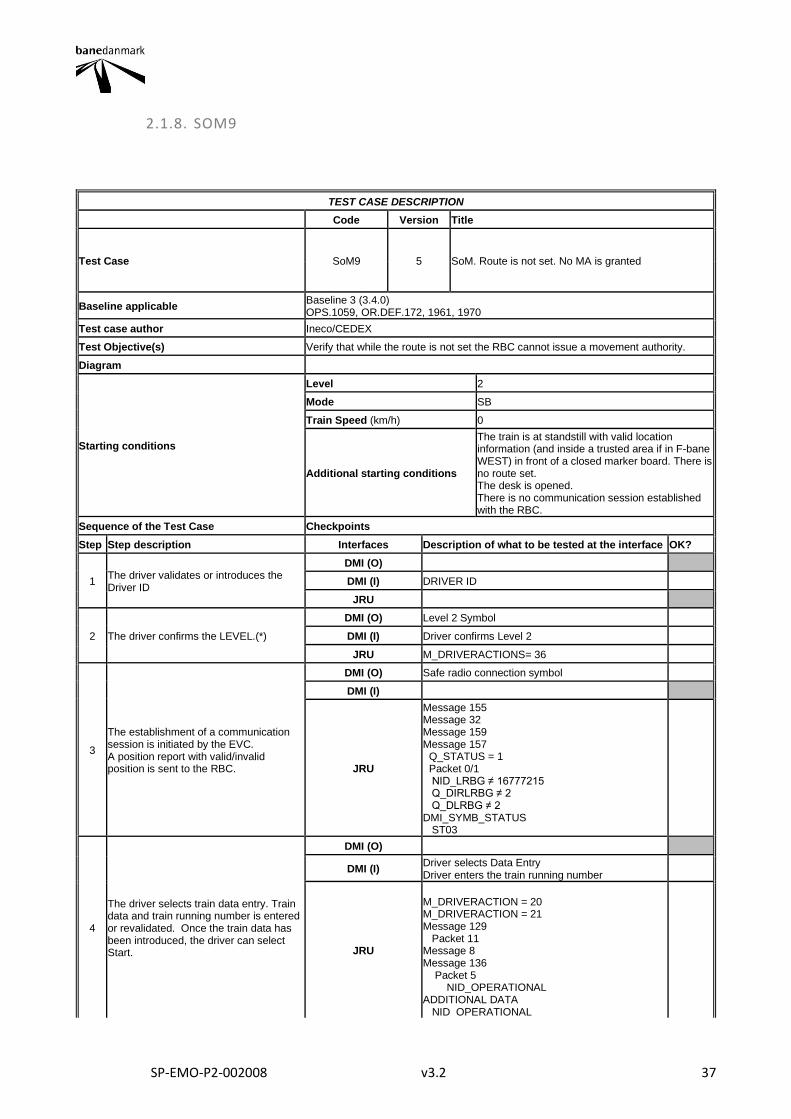
SP-EMO-P2-002008 v3.2 37
2.1.8. SOM9
TEST CASE DESCRIPTION
Code Version Title
Test Case SoM9 5 SoM. Route is not set. No MA is granted
Baseline applicable Baseline 3 (3.4.0) OPS.1059, OR.DEF.172, 1961, 1970
Test case author Ineco/CEDEX
Test Objective(s) Verify that while the route is not set the RBC cannot issue a movement authority.
Diagram
Starting conditions
Level 2
Mode SB
Train Speed (km/h) 0
Additional starting conditions
The train is at standstill with valid location information (and inside a trusted area if in F-bane WEST) in front of a closed marker board. There is no route set. The desk is opened. There is no communication session established with the RBC.
Sequence of the Test Case Checkpoints
Step Step description Interfaces Description of what to be tested at the interface OK?
1 The driver validates or introduces the Driver ID
DMI (O)
DMI (I) DRIVER ID
JRU
2 The driver confirms the LEVEL.(*)
DMI (O) Level 2 Symbol
DMI (I) Driver confirms Level 2
JRU M_DRIVERACTIONS= 36
3
The establishment of a communication session is initiated by the EVC. A position report with valid/invalid position is sent to the RBC.
DMI (O) Safe radio connection symbol
DMI (I)
JRU
Message 155 Message 32 Message 159 Message 157 Q_STATUS = 1 Packet 0/1 NID_LRBG ≠ 16777215 Q_DIRLRBG ≠ 2 Q_DLRBG ≠ 2 DMI_SYMB_STATUS ST03
4
The driver selects train data entry. Train data and train running number is entered or revalidated. Once the train data has been introduced, the driver can select Start.
DMI (O)
DMI (I) Driver selects Data Entry Driver enters the train running number
JRU
M_DRIVERACTION = 20 M_DRIVERACTION = 21 Message 129 Packet 11 Message 8 Message 136 Packet 5 NID_OPERATIONAL ADDITIONAL DATA NID_OPERATIONAL
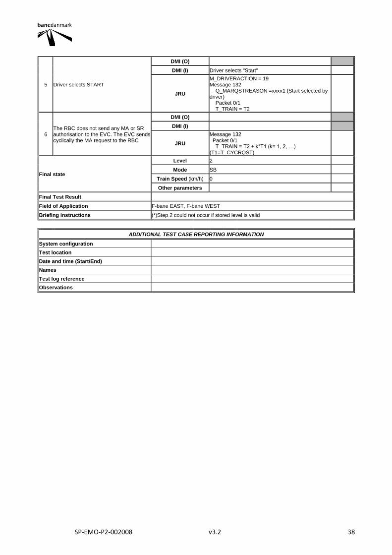
SP-EMO-P2-002008 v3.2 38
5 Driver selects START
DMI (O)
DMI (I) Driver selects "Start"
JRU
M_DRIVERACTION = 19 Message 132 Q_MARQSTREASON =xxxx1 (Start selected by driver) Packet 0/1 T_TRAIN = T2
6 The RBC does not send any MA or SR authorisation to the EVC. The EVC sends cyclically the MA request to the RBC
DMI (O)
DMI (I)
JRU
Message 132 Packet 0/1 T_TRAIN = T2 + k*T1 (k= 1, 2, …) (T1=T_CYCRQST)
Final state
Level 2
Mode SB
Train Speed (km/h) 0
Other parameters
Final Test Result
Field of Application F-bane EAST, F-bane WEST
Briefing instructions (*)Step 2 could not occur if stored level is valid
ADDITIONAL TEST CASE REPORTING INFORMATION
System configuration
Test location
Date and time (Start/End)
Names
Test log reference
Observations
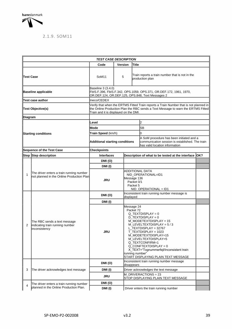
SP-EMO-P2-002008 v3.2 39
2.1.9. SOM11
TEST CASE DESCRIPTION
Code Version Title
Test Case SoM11 5 Train reports a train number that is not in the production plan
Baseline applicable Baseline 3 (3.4.0) FbIS.F.396, FbIS.F.342, OPS.1059, OPS.371, OR.DEF.172, 1961, 1970, OR.DEF.124, OR.DEF.125, OPS.848, Text Messages 2
Test case author Ineco/CEDEX
Test Objective(s) Verify that when the ERTMS Fitted Train reports a Train Number that is not planned in the Online Production Plan the RBC sends a Text Message to warn the ERTMS Fitted Train and it is displayed on the DMI.
Diagram
Starting conditions
Level 2
Mode SB
Train Speed (km/h) 0
Additional starting conditions A SoM procedure has been initiated and a communication session is established. The train has valid location information
Sequence of the Test Case Checkpoints
Step Step description Interfaces Description of what to be tested at the interface OK?
1 The driver enters a train running number not planned in the Online Production Plan
DMI (O)
DMI (I)
JRU
ADDITIONAL DATA NID_OPERATIONAL=ID1 Message 136 Packet 0/1 Packet 5 NID_OPERATIONAL = ID1
2 The RBC sends a text message indicating train running number inconsistency
DMI (O) Inconsistent train running number message is displayed
DMI (I)
JRU
Message 24 Packet 72 Q_TEXTDISPLAY = 0 D_TEXTDISPLAY = 0 M_MODETEXTDISPLAY = 15 M_LEVELTEXTDISPLAY = 5 / 3 L_TEXTDISPLAY = 32767 T_TEXTDISPLAY = 1023 M_MODETEXTDISPLAY=15 M_LEVELTEXTDISPLAY=5 Q_TEXTCONFIRM=1 Q_CONFTEXTDISPLAY = 0 X_TEXT=“Tognummerfejl/Inconsistent train running number” START DISPLAYING PLAIN TEXT MESSAGE
3 The driver acknowledges text message
DMI (O) Inconsistent train running number message disappears
DMI (I) Driver acknowledges the text message
JRU M_DRIVERACTIONS = 23 STOP DISPLAYING PLAIN TEXT MESSAGE
4 The driver enters a train running number planned in the Online Production Plan.
DMI (O)
DMI (I) Driver enters the train running number
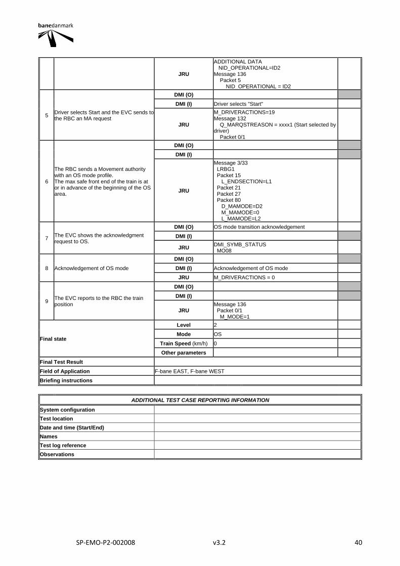
SP-EMO-P2-002008 v3.2 40
JRU
ADDITIONAL DATA NID_OPERATIONAL=ID2 Message 136 Packet 5 NID_OPERATIONAL = ID2
5 Driver selects Start and the EVC sends to the RBC an MA request
DMI (O)
DMI (I) Driver selects "Start"
JRU
M_DRIVERACTIONS=19 Message 132 Q_MARQSTREASON = xxxx1 (Start selected by driver) Packet 0/1
6
The RBC sends a Movement authority with an OS mode profile. The max safe front end of the train is at or in advance of the beginning of the OS area.
DMI (O)
DMI (I)
JRU
Message 3/33 LRBG1 Packet 15 L_ENDSECTION=L1 Packet 21 Packet 27 Packet 80 D_MAMODE=D2 M_MAMODE=0 L_MAMODE=L2
7 The EVC shows the acknowledgment request to OS.
DMI (O) OS mode transition acknowledgement
DMI (I)
JRU DMI_SYMB_STATUS MO08
8 Acknowledgement of OS mode
DMI (O)
DMI (I) Acknowledgement of OS mode
JRU M_DRIVERACTIONS = 0
9 The EVC reports to the RBC the train position
DMI (O)
DMI (I)
JRU Message 136 Packet 0/1 M_MODE=1
Final state
Level 2
Mode OS
Train Speed (km/h) 0
Other parameters
Final Test Result
Field of Application F-bane EAST, F-bane WEST
Briefing instructions
ADDITIONAL TEST CASE REPORTING INFORMATION
System configuration
Test location
Date and time (Start/End)
Names
Test log reference
Observations
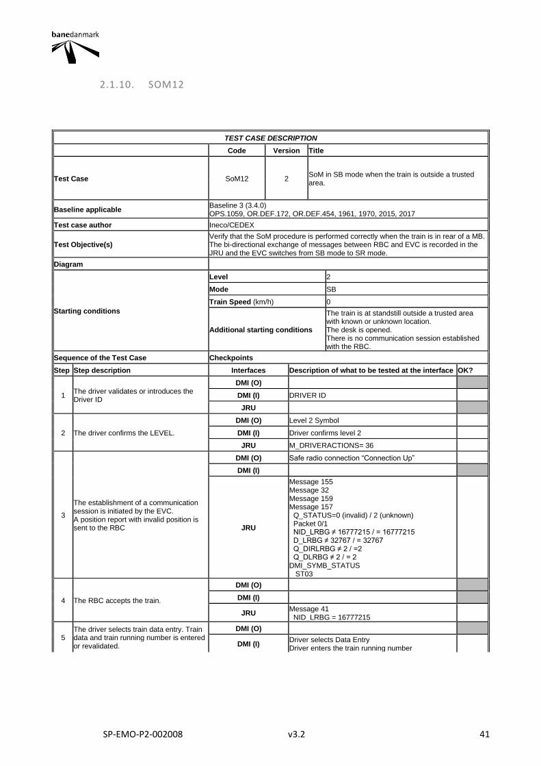
SP-EMO-P2-002008 v3.2 41
2.1.10. SOM12
TEST CASE DESCRIPTION
Code Version Title
Test Case SoM12 2 SoM in SB mode when the train is outside a trusted area.
Baseline applicable Baseline 3 (3.4.0) OPS.1059, OR.DEF.172, OR.DEF.454, 1961, 1970, 2015, 2017
Test case author Ineco/CEDEX
Test Objective(s) Verify that the SoM procedure is performed correctly when the train is in rear of a MB. The bi-directional exchange of messages between RBC and EVC is recorded in the JRU and the EVC switches from SB mode to SR mode.
Diagram
Starting conditions
Level 2
Mode SB
Train Speed (km/h) 0
Additional starting conditions
The train is at standstill outside a trusted area with known or unknown location. The desk is opened. There is no communication session established with the RBC.
Sequence of the Test Case Checkpoints
Step Step description Interfaces Description of what to be tested at the interface OK?
1 The driver validates or introduces the Driver ID
DMI (O)
DMI (I) DRIVER ID
JRU
2 The driver confirms the LEVEL.
DMI (O) Level 2 Symbol
DMI (I) Driver confirms level 2
JRU M_DRIVERACTIONS= 36
3
The establishment of a communication session is initiated by the EVC. A position report with invalid position is sent to the RBC
DMI (O) Safe radio connection “Connection Up”
DMI (I)
JRU
Message 155 Message 32 Message 159 Message 157 Q_STATUS=0 (invalid) / 2 (unknown) Packet 0/1 NID_LRBG ≠ 16777215 / = 16777215 D_LRBG ≠ 32767 / = 32767 Q_DIRLRBG ≠ 2 / =2 Q_DLRBG ≠ 2 / = 2 DMI_SYMB_STATUS ST03
4 The RBC accepts the train.
DMI (O)
DMI (I)
JRU Message 41 NID_LRBG = 16777215
5 The driver selects train data entry. Train data and train running number is entered or revalidated.
DMI (O)
DMI (I) Driver selects Data Entry Driver enters the train running number
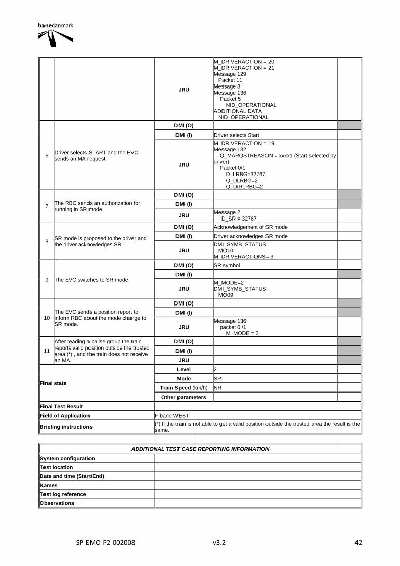
SP-EMO-P2-002008 v3.2 42
JRU
M_DRIVERACTION = 20 M_DRIVERACTION = 21 Message 129 Packet 11 Message 8 Message 136 Packet 5 NID_OPERATIONAL ADDITIONAL DATA NID_OPERATIONAL
6 Driver selects START and the EVC sends an MA request.
DMI (O)
DMI (I) Driver selects Start
JRU
M_DRIVERACTION = 19 Message 132 Q_MARQSTREASON = xxxx1 (Start selected by driver) Packet 0/1 D_LRBG=32767 Q_DLRBG=2 Q_DIRLRBG=2
7 The RBC sends an authorization for running in SR mode
DMI (O)
DMI (I)
JRU Message 2 D_SR = 32767
8 SR mode is proposed to the driver and the driver acknowledges SR.
DMI (O) Acknowledgement of SR mode
DMI (I) Driver acknowledges SR mode
JRU DMI_SYMB_STATUS MO10 M_DRIVERACTIONS= 3
9 The EVC switches to SR mode.
DMI (O) SR symbol
DMI (I)
JRU M_MODE=2 DMI_SYMB_STATUS MO09
10 The EVC sends a position report to inform RBC about the mode change to SR mode.
DMI (O)
DMI (I)
JRU Message 136 packet 0 /1 M_MODE = 2
11
After reading a balise group the train reports valid position outside the trusted area (*) , and the train does not receive an MA.
DMI (O)
DMI (I)
JRU
Final state
Level 2
Mode SR
Train Speed (km/h) NR
Other parameters
Final Test Result
Field of Application F-bane WEST
Briefing instructions (*) If the train is not able to get a valid position outside the trusted area the result is the same.
ADDITIONAL TEST CASE REPORTING INFORMATION
System configuration
Test location
Date and time (Start/End)
Names
Test log reference
Observations
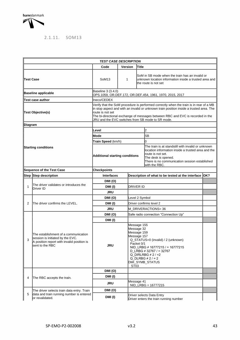
SP-EMO-P2-002008 v3.2 43
2.1.11. SOM13
TEST CASE DESCRIPTION
Code Version Title
Test Case SoM13 1 SoM in SB mode when the train has an invalid or unknown location information inside a trusted area and the route is not set
Baseline applicable Baseline 3 (3.4.0) OPS.1059, OR.DEF.172, OR.DEF.454, 1961, 1970, 2015, 2017
Test case author Ineco/CEDEX
Test Objective(s)
Verify that the SoM procedure is performed correctly when the train is in rear of a MB in stop aspect and with an invalid or unknown train position inside a trusted area. The route is not set The bi-directional exchange of messages between RBC and EVC is recorded in the JRU and the EVC switches from SB mode to SR mode.
Diagram
Starting conditions
Level 2
Mode SB
Train Speed (km/h) 0
Additional starting conditions
The train is at standstill with invalid or unknown location information inside a trusted area and the route is not set. The desk is opened. There is no communication session established with the RBC.
Sequence of the Test Case Checkpoints
Step Step description Interfaces Description of what to be tested at the interface OK?
1 The driver validates or introduces the Driver ID
DMI (O)
DMI (I) DRIVER ID
JRU
2 The driver confirms the LEVEL.
DMI (O) Level 2 Symbol
DMI (I) Driver confirms level 2
JRU M_DRIVERACTIONS= 36
3
The establishment of a communication session is initiated by the EVC. A position report with invalid position is sent to the RBC
DMI (O) Safe radio connection “Connection Up”
DMI (I)
JRU
Message 155 Message 32 Message 159 Message 157 Q_STATUS=0 (invalid) / 2 (unknown) Packet 0/1 NID_LRBG ≠ 16777215 / = 16777215 D_LRBG ≠ 32767 / = 32767 Q_DIRLRBG ≠ 2 / =2 Q_DLRBG ≠ 2 / = 2 DMI_SYMB_STATUS ST03
4 The RBC accepts the train.
DMI (O)
DMI (I)
JRU Message 41 NID_LRBG = 16777215
5 The driver selects train data entry. Train data and train running number is entered or revalidated.
DMI (O)
DMI (I) Driver selects Data Entry Driver enters the train running number
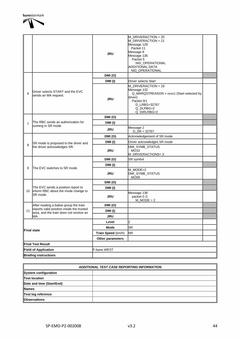
SP-EMO-P2-002008 v3.2 44
JRU
M_DRIVERACTION = 20 M_DRIVERACTION = 21 Message 129 Packet 11 Message 8 Message 136 Packet 5 NID_OPERATIONAL ADDITIONAL DATA NID_OPERATIONAL
6 Driver selects START and the EVC sends an MA request.
DMI (O)
DMI (I) Driver selects Start
JRU
M_DRIVERACTION = 19 Message 132 Q_MARQSTREASON = xxxx1 (Start selected by driver) Packet 0/1 D_LRBG=32767 Q_DLRBG=2 Q_DIRLRBG=2
7 The RBC sends an authorization for running in SR mode
DMI (O)
DMI (I)
JRU Message 2 D_SR = 32767
8 SR mode is proposed to the driver and the driver acknowledges SR.
DMI (O) Acknowledgement of SR mode
DMI (I) Driver acknowledges SR mode
JRU DMI_SYMB_STATUS MO10 M_DRIVERACTIONS= 3
9 The EVC switches to SR mode.
DMI (O) SR symbol
DMI (I)
JRU M_MODE=2 DMI_SYMB_STATUS MO09
10 The EVC sends a position report to inform RBC about the mode change to SR mode.
DMI (O)
DMI (I)
JRU Message 136 packet 0 /1 M_MODE = 2
11
After reading a balise group the train reports valid position inside the trusted area, and the train does not receive an MA.
DMI (O)
DMI (I)
JRU
Final state
Level 2
Mode SR
Train Speed (km/h) NR
Other parameters
Final Test Result
Field of Application F-bane WEST
Briefing instructions
ADDITIONAL TEST CASE REPORTING INFORMATION
System configuration
Test location
Date and time (Start/End)
Names
Test log reference
Observations
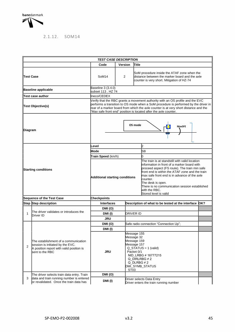
SP-EMO-P2-002008 v3.2 45
2.1.12. SOM14
TEST CASE DESCRIPTION
Code Version Title
Test Case SoM14 2 SoM procedure inside the ATAF zone when the distance between the marker board and the axle counter is very short. Mitigation of HZ-74
Baseline applicable Baseline 3 (3.4.0) subset 113 . HZ 74
Test case author Ineco/CEDEX
Test Objective(s)
Verify that the RBC grants a movement authority with an OS profile and the EVC performs a transition to OS mode when a SoM procedure is performed by the driver in rear of a marker board from which the axle counter is at very short distance and the "Max safe front end" position is located after the axle counter.
Diagram
Starting conditions
Level 2
Mode SB
Train Speed (km/h) 0
Additional starting conditions
The train is at standstill with valid location information in front of a marker board with proceed aspect (FS route). The train min safe front end is within the ATAF zone and the train max safe front end is in advance of the axle counter. The desk is open. There is no communication session established with the RBC. Stored level is valid
Sequence of the Test Case Checkpoints
Step Step description Interfaces Description of what to be tested at the interface OK?
1 The driver validates or introduces the Driver ID
DMI (O)
DMI (I) DRIVER ID
JRU
2
The establishment of a communication session is initiated by the EVC. A position report with valid position is sent to the RBC
DMI (O) Safe radio connection “Connection Up”;
DMI (I)
JRU
Message 155 Message 32 Message 159 Message 157 Q_STATUS = 1 (valid) Packet 0/1 NID_LRBG ≠ 16777215 Q_DIRLRBG ≠ 2 Q_DLRBG ≠ 2 DMI_SYMB_STATUS ST03
3 The driver selects train data entry. Train data and train running number is entered or revalidated. Once the train data has
DMI (O)
DMI (I) Driver selects Data Entry Driver enters the train running number
OS mode MaxSFE
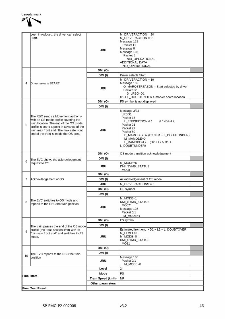
SP-EMO-P2-002008 v3.2 46
been introduced, the driver can select Start.
JRU
M_DRIVERACTION = 20 M_DRIVERACTION = 21 Message 129 Packet 11 Message 8 Message 136 Packet 5 NID_OPERATIONAL ADDITIONAL DATA NID_OPERATIONAL
4 Driver selects START
DMI (O)
DMI (I) Driver selects Start
JRU
M_DRIVERACTION = 19 Message 132 Q_MARQSTREASON = Start selected by driver Packet 0/1 D_LRBG=D1 D1 + L_DOUBTUNDER > marker board location
5
The RBC sends a Movement authority with an OS mode profile covering the train location. The end of the OS mode profile is set to a point in advance of the train max front end. The max safe front end of the train is inside the OS area.
DMI (O) FS symbol is not displayed
DMI (I)
JRU
Message 3/33 LRBG1 Packet 15 L_ENDSECTION=L1 (L1>D2+L2) Packet 21 Packet 27 Packet 80 D_MAMODE=D2 (D2 ≤ D1 + L_DOUBTUNDER) M_MAMODE=0 L_MAMODE=L2 (D2 + L2 > D1 + L_DOUBTUNDER)
6 The EVC shows the acknowledgment request to OS.
DMI (O) OS mode transition acknowledgement
DMI (I)
JRU M_MODE=6 DMI_SYMB_STATUS MO08
7 Acknowledgement of OS
DMI (O)
DMI (I) Acknowledgement of OS mode
JRU M_DRIVERACTIONS = 0
8 The EVC switches to OS mode and reports to the RBC the train position
DMI (O) OS symbol
DMI (I)
JRU
M_MODE=1 DMI_SYMB_STATUS MO07" Message 136 Packet 0/1 M_MODE=1
9
The train passes the end of the OS mode profile (the track section limit) with its "min safe front end" and switches to FS mode.
DMI (O) FS symbol
DMI (I)
JRU
Estimated front end > D2 + L2 + L_DOUBTOVER M_LEVEL=3 M_MODE=0 DMI_SYMB_STATUS MO11
10 The EVC reports to the RBC the train position
DMI (O)
DMI (I)
JRU Message 136 Packet 0/1 M_MODE=0
Final state
Level 2
Mode FS
Train Speed (km/h) NR
Other parameters
Final Test Result
SP-EMO-P2-002008 v3.2 47
Field of Application F-bane EAST
Briefing instructions
To be tested at every location where distance between the marker board and the axle counter is very short (in stations with LX) The train data number can be introduced or validated when the driver ID is entered (step 1) instead of when the train data is entered or validated (step 4)
ADDITIONAL TEST CASE REPORTING INFORMATION
System configuration
Test location
Date and time (Start/End)
Names
Test log reference
Observations
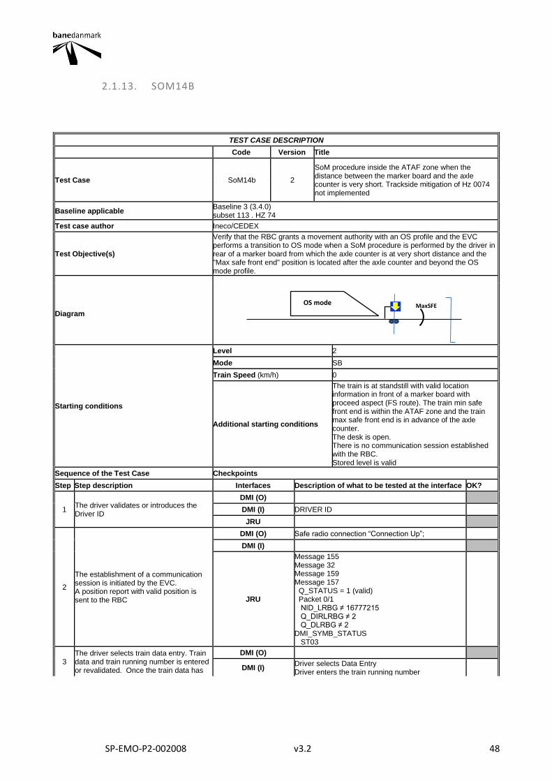
SP-EMO-P2-002008 v3.2 48
2.1.13. SOM14B
TEST CASE DESCRIPTION
Code Version Title
Test Case SoM14b 2
SoM procedure inside the ATAF zone when the distance between the marker board and the axle counter is very short. Trackside mitigation of Hz 0074 not implemented
Baseline applicable Baseline 3 (3.4.0) subset 113 . HZ 74
Test case author Ineco/CEDEX
Test Objective(s)
Verify that the RBC grants a movement authority with an OS profile and the EVC performs a transition to OS mode when a SoM procedure is performed by the driver in rear of a marker board from which the axle counter is at very short distance and the "Max safe front end" position is located after the axle counter and beyond the OS mode profile.
Diagram
Starting conditions
Level 2
Mode SB
Train Speed (km/h) 0
Additional starting conditions
The train is at standstill with valid location information in front of a marker board with proceed aspect (FS route). The train min safe front end is within the ATAF zone and the train max safe front end is in advance of the axle counter. The desk is open. There is no communication session established with the RBC. Stored level is valid
Sequence of the Test Case Checkpoints
Step Step description Interfaces Description of what to be tested at the interface OK?
1 The driver validates or introduces the Driver ID
DMI (O)
DMI (I) DRIVER ID
JRU
2
The establishment of a communication session is initiated by the EVC. A position report with valid position is sent to the RBC
DMI (O) Safe radio connection “Connection Up”;
DMI (I)
JRU
Message 155 Message 32 Message 159 Message 157 Q_STATUS = 1 (valid) Packet 0/1 NID_LRBG ≠ 16777215 Q_DIRLRBG ≠ 2 Q_DLRBG ≠ 2 DMI_SYMB_STATUS ST03
3 The driver selects train data entry. Train data and train running number is entered or revalidated. Once the train data has
DMI (O)
DMI (I) Driver selects Data Entry Driver enters the train running number
OS mode MaxSFE
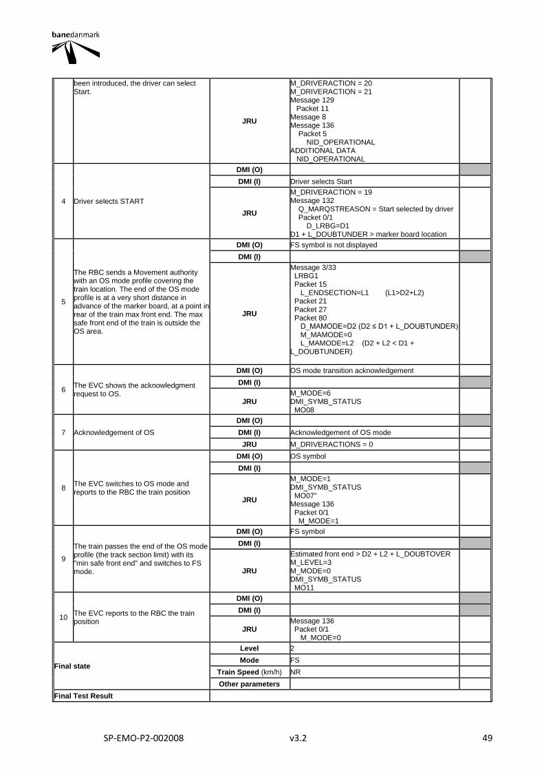
SP-EMO-P2-002008 v3.2 49
been introduced, the driver can select Start.
JRU
M_DRIVERACTION = 20 M_DRIVERACTION = 21 Message 129 Packet 11 Message 8 Message 136 Packet 5 NID_OPERATIONAL ADDITIONAL DATA NID_OPERATIONAL
4 Driver selects START
DMI (O)
DMI (I) Driver selects Start
JRU
M_DRIVERACTION = 19 Message 132 Q_MARQSTREASON = Start selected by driver Packet 0/1 D_LRBG=D1 D1 + L_DOUBTUNDER > marker board location
5
The RBC sends a Movement authority with an OS mode profile covering the train location. The end of the OS mode profile is at a very short distance in advance of the marker board, at a point in rear of the train max front end. The max safe front end of the train is outside the OS area.
DMI (O) FS symbol is not displayed
DMI (I)
JRU
Message 3/33 LRBG1 Packet 15 L_ENDSECTION=L1 (L1>D2+L2) Packet 21 Packet 27 Packet 80 D_MAMODE=D2 (D2 ≤ D1 + L_DOUBTUNDER) M_MAMODE=0 L_MAMODE=L2 (D2 + L2 < D1 + L_DOUBTUNDER)
6 The EVC shows the acknowledgment request to OS.
DMI (O) OS mode transition acknowledgement
DMI (I)
JRU M_MODE=6 DMI_SYMB_STATUS MO08
7 Acknowledgement of OS
DMI (O)
DMI (I) Acknowledgement of OS mode
JRU M_DRIVERACTIONS = 0
8 The EVC switches to OS mode and reports to the RBC the train position
DMI (O) OS symbol
DMI (I)
JRU
M_MODE=1 DMI_SYMB_STATUS MO07" Message 136 Packet 0/1 M_MODE=1
9
The train passes the end of the OS mode profile (the track section limit) with its "min safe front end" and switches to FS mode.
DMI (O) FS symbol
DMI (I)
JRU
Estimated front end > D2 + L2 + L_DOUBTOVER M_LEVEL=3 M_MODE=0 DMI_SYMB_STATUS MO11
10 The EVC reports to the RBC the train position
DMI (O)
DMI (I)
JRU Message 136 Packet 0/1 M_MODE=0
Final state
Level 2
Mode FS
Train Speed (km/h) NR
Other parameters
Final Test Result

SP-EMO-P2-002008 v3.2 50
Field of Application F-bane EAST
Briefing instructions
To be tested at every location where distance between the marker board and the axle counter is very short (in stations with LX) The train data number can be introduced or validated when the driver ID is entered (step 1) instead of when the train data is entered or validated (step 4)
ADDITIONAL TEST CASE REPORTING INFORMATION
System configuration
Test location
Date and time (Start/End)
Names
Test log reference
Observations
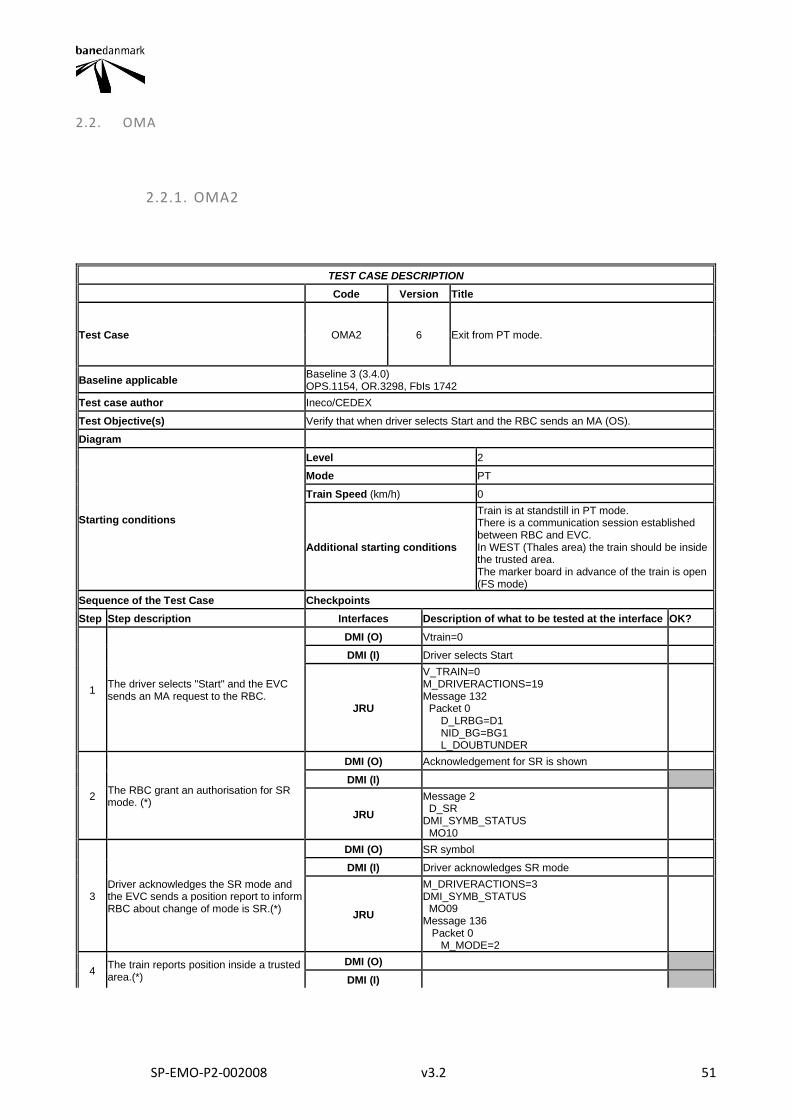
SP-EMO-P2-002008 v3.2 51
2.2. OMA
2.2.1. OMA2
TEST CASE DESCRIPTION
Code Version Title
Test Case OMA2 6 Exit from PT mode.
Baseline applicable Baseline 3 (3.4.0) OPS.1154, OR.3298, FbIs 1742
Test case author Ineco/CEDEX
Test Objective(s) Verify that when driver selects Start and the RBC sends an MA (OS).
Diagram
Starting conditions
Level 2
Mode PT
Train Speed (km/h) 0
Additional starting conditions
Train is at standstill in PT mode. There is a communication session established between RBC and EVC. In WEST (Thales area) the train should be inside the trusted area. The marker board in advance of the train is open (FS mode)
Sequence of the Test Case Checkpoints
Step Step description Interfaces Description of what to be tested at the interface OK?
1 The driver selects "Start" and the EVC sends an MA request to the RBC.
DMI (O) Vtrain=0
DMI (I) Driver selects Start
JRU
V_TRAIN=0 M_DRIVERACTIONS=19 Message 132 Packet 0 D_LRBG=D1 NID_BG=BG1 L_DOUBTUNDER
2 The RBC grant an authorisation for SR mode. (*)
DMI (O) Acknowledgement for SR is shown
DMI (I)
JRU
Message 2 D_SR DMI_SYMB_STATUS MO10
3 Driver acknowledges the SR mode and the EVC sends a position report to inform RBC about change of mode is SR.(*)
DMI (O) SR symbol
DMI (I) Driver acknowledges SR mode
JRU
M_DRIVERACTIONS=3 DMI_SYMB_STATUS MO09 Message 136 Packet 0 M_MODE=2
4 The train reports position inside a trusted area.(*)
DMI (O)
DMI (I)
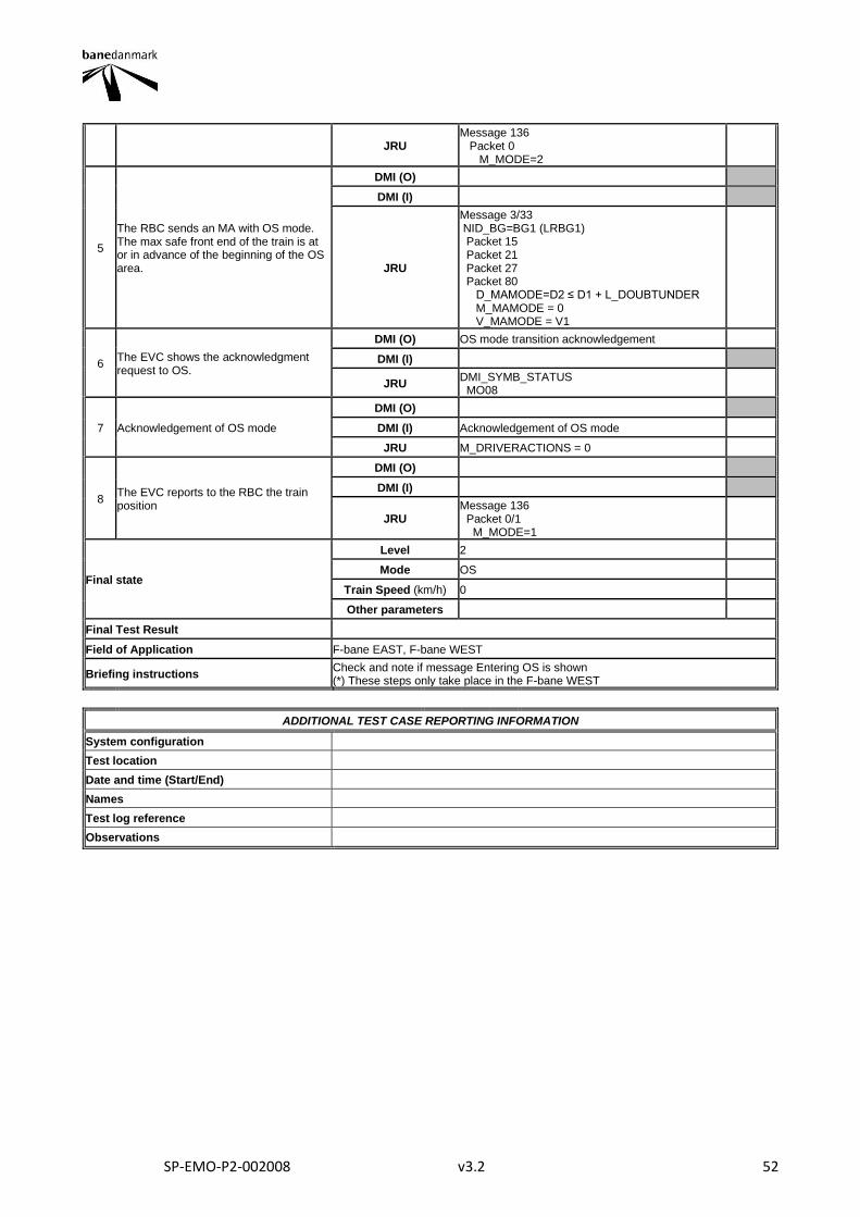
SP-EMO-P2-002008 v3.2 52
JRU Message 136 Packet 0 M_MODE=2
5
The RBC sends an MA with OS mode. The max safe front end of the train is at or in advance of the beginning of the OS area.
DMI (O)
DMI (I)
JRU
Message 3/33 NID_BG=BG1 (LRBG1) Packet 15 Packet 21 Packet 27 Packet 80 D_MAMODE=D2 ≤ D1 + L_DOUBTUNDER M_MAMODE = 0 V_MAMODE = V1
6 The EVC shows the acknowledgment request to OS.
DMI (O) OS mode transition acknowledgement
DMI (I)
JRU DMI_SYMB_STATUS MO08
7 Acknowledgement of OS mode
DMI (O)
DMI (I) Acknowledgement of OS mode
JRU M_DRIVERACTIONS = 0
8 The EVC reports to the RBC the train position
DMI (O)
DMI (I)
JRU Message 136 Packet 0/1 M_MODE=1
Final state
Level 2
Mode OS
Train Speed (km/h) 0
Other parameters
Final Test Result
Field of Application F-bane EAST, F-bane WEST
Briefing instructions Check and note if message Entering OS is shown (*) These steps only take place in the F-bane WEST
ADDITIONAL TEST CASE REPORTING INFORMATION
System configuration
Test location
Date and time (Start/End)
Names
Test log reference
Observations
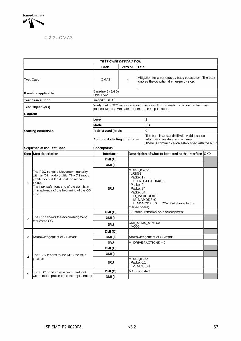
SP-EMO-P2-002008 v3.2 53
2.2.2. OMA3
TEST CASE DESCRIPTION
Code Version Title
Test Case OMA3 4 Mitigation for an erroneous track occupation. The train ignores the conditional emergency stop.
Baseline applicable Baseline 3 (3.4.0) FbIs 1742
Test case author Ineco/CEDEX
Test Objective(s) Verify that a CES message is not considered by the on-board when the train has passed with its "Min safe front end" the stop location.
Diagram
Starting conditions
Level 2
Mode SB
Train Speed (km/h) 0
Additional starting conditions The train is at standstill with valid location information inside a trusted area. There is communication established with the RBC
Sequence of the Test Case Checkpoints
Step Step description Interfaces Description of what to be tested at the interface OK?
1
The RBC sends a Movement authority with an OS mode profile. The OS mode profile goes at least until the marker board. The max safe front end of the train is at or in advance of the beginning of the OS area.
DMI (O)
DMI (I)
JRU
Message 3/33 LRBG1 Packet 15 L_ENDSECTION=L1 Packet 21 Packet 27 Packet 80 D_MAMODE=D2 M_MAMODE=0 L_MAMODE=L2 (D2+L2≥distance to the marker board)
2 The EVC shows the acknowledgment request to OS.
DMI (O) OS mode transition acknowledgement
DMI (I)
JRU DMI_SYMB_STATUS MO08
3 Acknowledgement of OS mode
DMI (O)
DMI (I) Acknowledgement of OS mode
JRU M_DRIVERACTIONS = 0
4 The EVC reports to the RBC the train position
DMI (O)
DMI (I)
JRU Message 136 Packet 0/1 M_MODE=1
5 The RBC sends a movement authority with a mode profile up to the replacement
DMI (O) MA is updated
DMI (I)
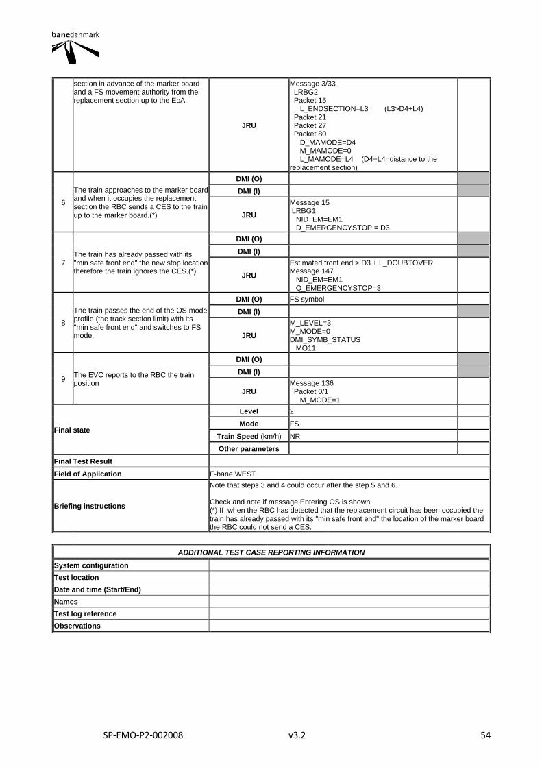
SP-EMO-P2-002008 v3.2 54
section in advance of the marker board and a FS movement authority from the replacement section up to the EoA.
JRU
Message 3/33 LRBG2 Packet 15 L_ENDSECTION=L3 (L3>D4+L4) Packet 21 Packet 27 Packet 80 D_MAMODE=D4 M_MAMODE=0 L_MAMODE=L4 (D4+L4=distance to the replacement section)
6
The train approaches to the marker board and when it occupies the replacement section the RBC sends a CES to the train up to the marker board.(*)
DMI (O)
DMI (I)
JRU
Message 15 LRBG1 NID_EM=EM1 D_EMERGENCYSTOP = D3
7 The train has already passed with its "min safe front end" the new stop location therefore the train ignores the CES.(*)
DMI (O)
DMI (I)
JRU
Estimated front end > D3 + L_DOUBTOVER Message 147 NID_EM=EM1 Q_EMERGENCYSTOP=3
8
The train passes the end of the OS mode profile (the track section limit) with its "min safe front end" and switches to FS mode.
DMI (O) FS symbol
DMI (I)
JRU
M_LEVEL=3 M_MODE=0 DMI_SYMB_STATUS MO11
9 The EVC reports to the RBC the train position
DMI (O)
DMI (I)
JRU Message 136 Packet 0/1 M_MODE=1
Final state
Level 2
Mode FS
Train Speed (km/h) NR
Other parameters
Final Test Result
Field of Application F-bane WEST
Briefing instructions
Note that steps 3 and 4 could occur after the step 5 and 6. Check and note if message Entering OS is shown (*) If when the RBC has detected that the replacement circuit has been occupied the train has already passed with its "min safe front end" the location of the marker board the RBC could not send a CES.
ADDITIONAL TEST CASE REPORTING INFORMATION
System configuration
Test location
Date and time (Start/End)
Names
Test log reference
Observations
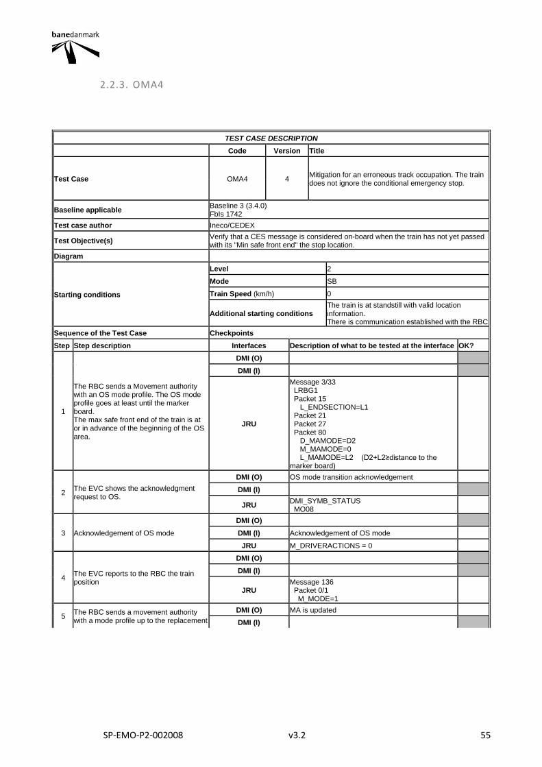
SP-EMO-P2-002008 v3.2 55
2.2.3. OMA4
TEST CASE DESCRIPTION
Code Version Title
Test Case OMA4 4 Mitigation for an erroneous track occupation. The train does not ignore the conditional emergency stop.
Baseline applicable Baseline 3 (3.4.0) FbIs 1742
Test case author Ineco/CEDEX
Test Objective(s) Verify that a CES message is considered on-board when the train has not yet passed with its "Min safe front end" the stop location.
Diagram
Starting conditions
Level 2
Mode SB
Train Speed (km/h) 0
Additional starting conditions The train is at standstill with valid location information. There is communication established with the RBC
Sequence of the Test Case Checkpoints
Step Step description Interfaces Description of what to be tested at the interface OK?
1
The RBC sends a Movement authority with an OS mode profile. The OS mode profile goes at least until the marker board. The max safe front end of the train is at or in advance of the beginning of the OS area.
DMI (O)
DMI (I)
JRU
Message 3/33 LRBG1 Packet 15 L_ENDSECTION=L1 Packet 21 Packet 27 Packet 80 D_MAMODE=D2 M_MAMODE=0 L_MAMODE=L2 (D2+L2≥distance to the marker board)
2 The EVC shows the acknowledgment request to OS.
DMI (O) OS mode transition acknowledgement
DMI (I)
JRU DMI_SYMB_STATUS MO08
3 Acknowledgement of OS mode
DMI (O)
DMI (I) Acknowledgement of OS mode
JRU M_DRIVERACTIONS = 0
4 The EVC reports to the RBC the train position
DMI (O)
DMI (I)
JRU Message 136 Packet 0/1 M_MODE=1
5 The RBC sends a movement authority with a mode profile up to the replacement
DMI (O) MA is updated
DMI (I)
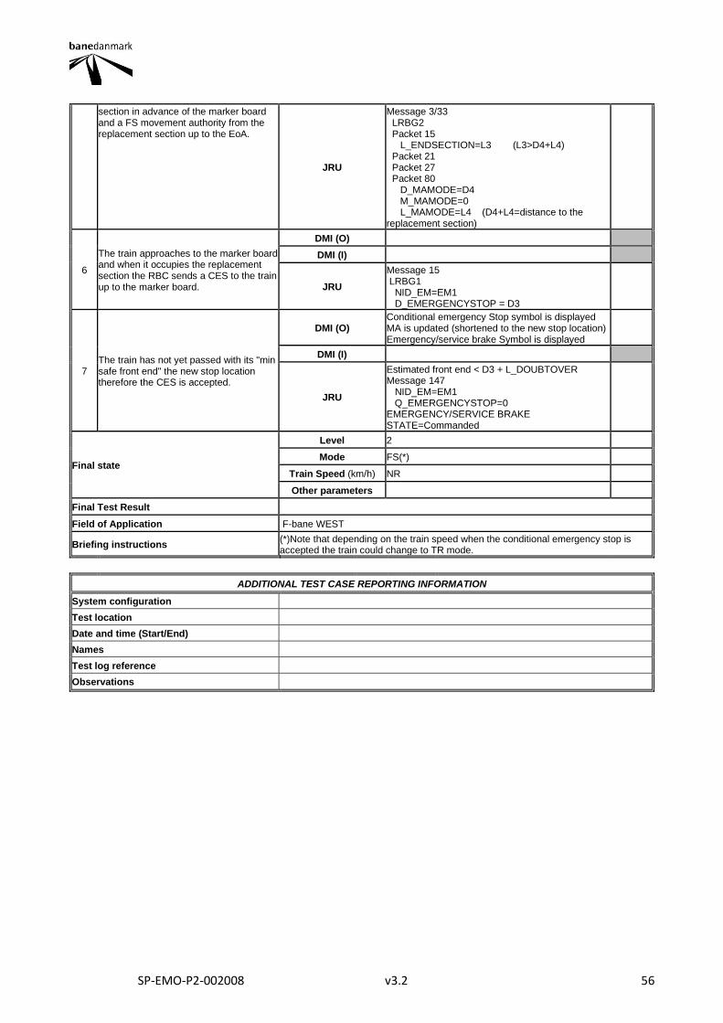
SP-EMO-P2-002008 v3.2 56
section in advance of the marker board and a FS movement authority from the replacement section up to the EoA.
JRU
Message 3/33 LRBG2 Packet 15 L_ENDSECTION=L3 (L3>D4+L4) Packet 21 Packet 27 Packet 80 D_MAMODE=D4 M_MAMODE=0 L_MAMODE=L4 (D4+L4=distance to the replacement section)
6
The train approaches to the marker board and when it occupies the replacement section the RBC sends a CES to the train up to the marker board.
DMI (O)
DMI (I)
JRU
Message 15 LRBG1 NID_EM=EM1 D_EMERGENCYSTOP = D3
7 The train has not yet passed with its "min safe front end" the new stop location therefore the CES is accepted.
DMI (O) Conditional emergency Stop symbol is displayed MA is updated (shortened to the new stop location) Emergency/service brake Symbol is displayed
DMI (I)
JRU
Estimated front end < D3 + L_DOUBTOVER Message 147 NID_EM=EM1 Q_EMERGENCYSTOP=0 EMERGENCY/SERVICE BRAKE STATE=Commanded
Final state
Level 2
Mode FS(*)
Train Speed (km/h) NR
Other parameters
Final Test Result
Field of Application F-bane WEST
Briefing instructions (*)Note that depending on the train speed when the conditional emergency stop is accepted the train could change to TR mode.
ADDITIONAL TEST CASE REPORTING INFORMATION
System configuration
Test location
Date and time (Start/End)
Names
Test log reference
Observations
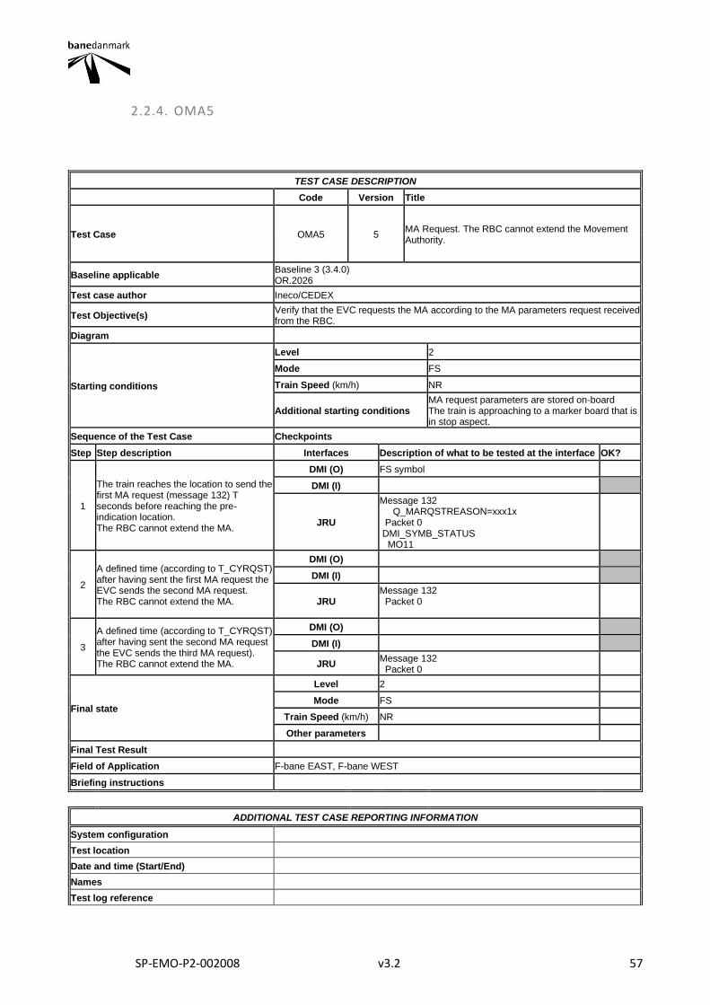
SP-EMO-P2-002008 v3.2 57
2.2.4. OMA5
TEST CASE DESCRIPTION
Code Version Title
Test Case OMA5 5 MA Request. The RBC cannot extend the Movement Authority.
Baseline applicable Baseline 3 (3.4.0) OR.2026
Test case author Ineco/CEDEX
Test Objective(s) Verify that the EVC requests the MA according to the MA parameters request received from the RBC.
Diagram
Starting conditions
Level 2
Mode FS
Train Speed (km/h) NR
Additional starting conditions MA request parameters are stored on-board The train is approaching to a marker board that is in stop aspect.
Sequence of the Test Case Checkpoints
Step Step description Interfaces Description of what to be tested at the interface OK?
1
The train reaches the location to send the first MA request (message 132) T seconds before reaching the pre-indication location. The RBC cannot extend the MA.
DMI (O) FS symbol
DMI (I)
JRU
Message 132 Q_MARQSTREASON=xxx1x Packet 0 DMI_SYMB_STATUS MO11
2
A defined time (according to T_CYRQST) after having sent the first MA request the EVC sends the second MA request. The RBC cannot extend the MA.
DMI (O)
DMI (I)
JRU Message 132 Packet 0
3
A defined time (according to T_CYRQST) after having sent the second MA request the EVC sends the third MA request). The RBC cannot extend the MA.
DMI (O)
DMI (I)
JRU Message 132 Packet 0
Final state
Level 2
Mode FS
Train Speed (km/h) NR
Other parameters
Final Test Result
Field of Application F-bane EAST, F-bane WEST
Briefing instructions
ADDITIONAL TEST CASE REPORTING INFORMATION
System configuration
Test location
Date and time (Start/End)
Names
Test log reference

SP-EMO-P2-002008 v3.2 58
Observations
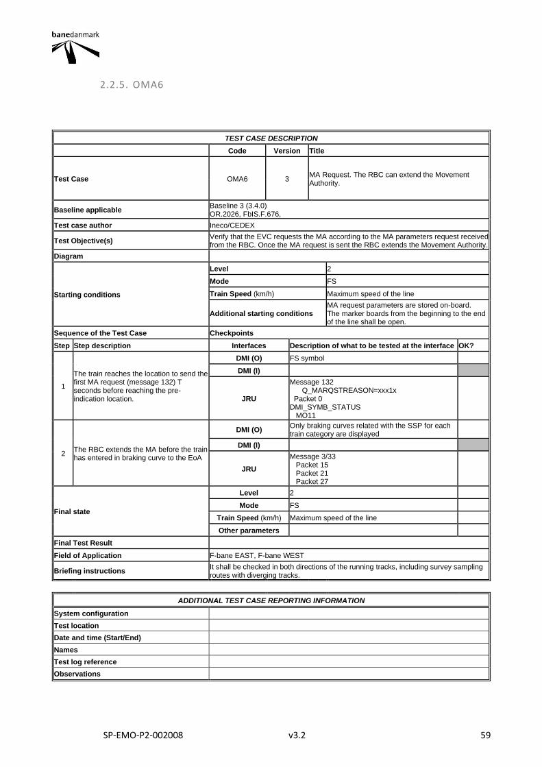
SP-EMO-P2-002008 v3.2 59
2.2.5. OMA6
TEST CASE DESCRIPTION
Code Version Title
Test Case OMA6 3 MA Request. The RBC can extend the Movement Authority.
Baseline applicable Baseline 3 (3.4.0) OR.2026, FbIS.F.676,
Test case author Ineco/CEDEX
Test Objective(s) Verify that the EVC requests the MA according to the MA parameters request received from the RBC. Once the MA request is sent the RBC extends the Movement Authority.
Diagram
Starting conditions
Level 2
Mode FS
Train Speed (km/h) Maximum speed of the line
Additional starting conditions MA request parameters are stored on-board. The marker boards from the beginning to the end of the line shall be open.
Sequence of the Test Case Checkpoints
Step Step description Interfaces Description of what to be tested at the interface OK?
1
The train reaches the location to send the first MA request (message 132) T seconds before reaching the pre-indication location.
DMI (O) FS symbol
DMI (I)
JRU
Message 132 Q_MARQSTREASON=xxx1x Packet 0 DMI_SYMB_STATUS MO11
2 The RBC extends the MA before the train has entered in braking curve to the EoA
DMI (O) Only braking curves related with the SSP for each train category are displayed
DMI (I)
JRU
Message 3/33 Packet 15 Packet 21 Packet 27
Final state
Level 2
Mode FS
Train Speed (km/h) Maximum speed of the line
Other parameters
Final Test Result
Field of Application F-bane EAST, F-bane WEST
Briefing instructions It shall be checked in both directions of the running tracks, including survey sampling routes with diverging tracks.
ADDITIONAL TEST CASE REPORTING INFORMATION
System configuration
Test location
Date and time (Start/End)
Names
Test log reference
Observations
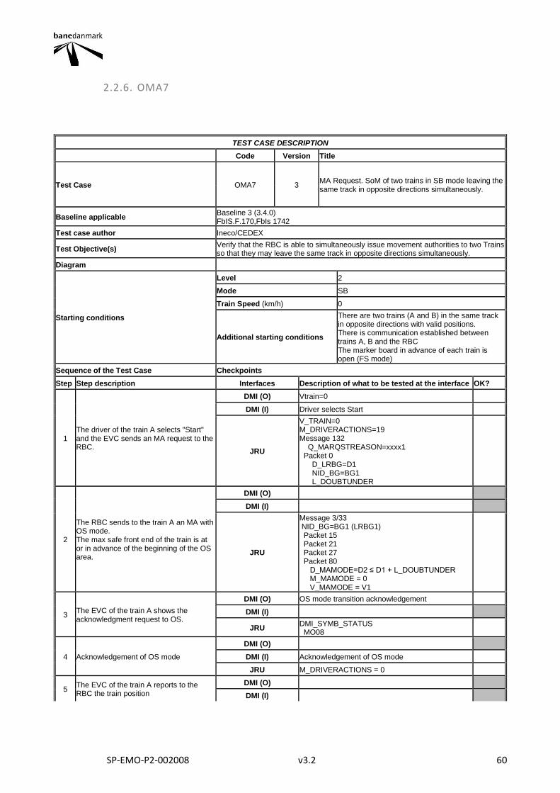
SP-EMO-P2-002008 v3.2 60
2.2.6. OMA7
TEST CASE DESCRIPTION
Code Version Title
Test Case OMA7 3 MA Request. SoM of two trains in SB mode leaving the same track in opposite directions simultaneously.
Baseline applicable Baseline 3 (3.4.0) FbIS.F.170,FbIs 1742
Test case author Ineco/CEDEX
Test Objective(s) Verify that the RBC is able to simultaneously issue movement authorities to two Trains so that they may leave the same track in opposite directions simultaneously.
Diagram
Starting conditions
Level 2
Mode SB
Train Speed (km/h) 0
Additional starting conditions
There are two trains (A and B) in the same track in opposite directions with valid positions. There is communication established between trains A, B and the RBC The marker board in advance of each train is open (FS mode)
Sequence of the Test Case Checkpoints
Step Step description Interfaces Description of what to be tested at the interface OK?
1 The driver of the train A selects "Start" and the EVC sends an MA request to the RBC.
DMI (O) Vtrain=0
DMI (I) Driver selects Start
JRU
V_TRAIN=0 M_DRIVERACTIONS=19 Message 132 Q_MARQSTREASON=xxxx1 Packet 0 D_LRBG=D1 NID_BG=BG1 L_DOUBTUNDER
2
The RBC sends to the train A an MA with OS mode. The max safe front end of the train is at or in advance of the beginning of the OS area.
DMI (O)
DMI (I)
JRU
Message 3/33 NID_BG=BG1 (LRBG1) Packet 15 Packet 21 Packet 27 Packet 80 D_MAMODE=D2 ≤ D1 + L_DOUBTUNDER M_MAMODE = 0 V_MAMODE = V1
3 The EVC of the train A shows the acknowledgment request to OS.
DMI (O) OS mode transition acknowledgement
DMI (I)
JRU DMI_SYMB_STATUS MO08
4 Acknowledgement of OS mode
DMI (O)
DMI (I) Acknowledgement of OS mode
JRU M_DRIVERACTIONS = 0
5 The EVC of the train A reports to the RBC the train position
DMI (O)
DMI (I)
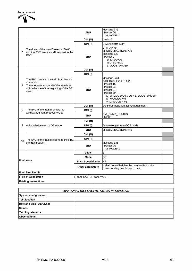
SP-EMO-P2-002008 v3.2 61
JRU Message 136 Packet 0/1 M_MODE=1
6 The driver of the train B selects "Start" and the EVC sends an MA request to the RBC.
DMI (O) Vtrain=0
DMI (I) Driver selects Start
JRU
V_TRAIN=0 M_DRIVERACTIONS=19 Message 132 Packet 0 D_LRBG=D3 NID_BG=BG2 L_DOUBTUNDER
7
The RBC sends to the train B an MA with OS mode. The max safe front end of the train is at or in advance of the beginning of the OS area.
DMI (O)
DMI (I)
JRU
Message 3/33 NID_BG=BG2 (LRBG2) Packet 15 Packet 21 Packet 27 Packet 80 D_MAMODE=D4 ≤ D3 + L_DOUBTUNDER M_MAMODE = 0 V_MAMODE = V1
8 The EVC of the train B shows the acknowledgment request to OS.
DMI (O) OS mode transition acknowledgement
DMI (I)
JRU DMI_SYMB_STATUS MO08
9 Acknowledgement of OS mode
DMI (O)
DMI (I) Acknowledgement of OS mode
JRU M_DRIVERACTIONS = 0
10 The EVC of the train b reports to the RBC the train position
DMI (O)
DMI (I)
JRU Message 136 Packet 0/1 M_MODE=1
Final state
Level 2
Mode OS
Train Speed (km/h) NR
Other parameters It shall be verified that the received MA is the corresponding one for each train.
Final Test Result
Field of Application F-bane EAST, F-bane WEST
Briefing instructions
ADDITIONAL TEST CASE REPORTING INFORMATION
System configuration
Test location
Date and time (Start/End)
Names
Test log reference
Observations
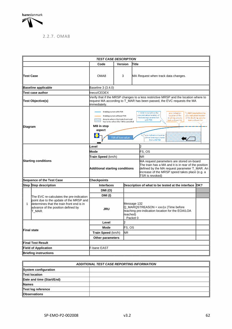
SP-EMO-P2-002008 v3.2 62
2.2.7. OMA8
TEST CASE DESCRIPTION
Code Version Title
Test Case OMA8 3 MA Request when track data changes.
Baseline applicable Baseline 3 (3.4.0)
Test case author Ineco/CEDEX
Test Objective(s) Verify that if the MRSP changes to a less restrictive MRSP and the location where to request MA according to T_MAR has been passed, the EVC requests the MA immediately.
Diagram
Starting conditions
Level 2
Mode FS, OS
Train Speed (km/h) NR
Additional starting conditions
MA request parameters are stored on-board The train has a MA and it is in rear of the position defined by the MA request parameter T_MAR. An increase of the MRSP speed takes place (e.g. a TSR is revoked)
Sequence of the Test Case Checkpoints
Step Step description Interfaces Description of what to be tested at the interface OK?
1
The EVC re-calculates the pre-indication point due to the update of the MRSP and determines that the train front end is in advance of the position defined by T_MAR.
DMI (O)
DMI (I)
JRU
Message 132 Q_MARQSTREASON = xxx1x (Time before reaching pre-indication location for the EOA/LOA reached) Packet 0
Final state
Level 2
Mode FS, OS
Train Speed (km/h) NR
Other parameters
Final Test Result
Field of Application F-bane EAST
Briefing instructions
ADDITIONAL TEST CASE REPORTING INFORMATION
System configuration
Test location
Date and time (Start/End)
Names
Test log reference
Observations

SP-EMO-P2-002008 v3.2 63
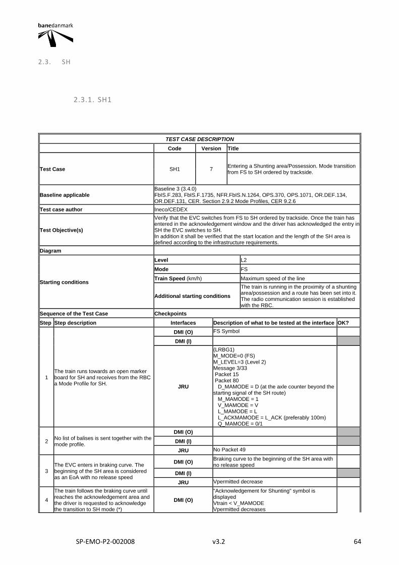
SP-EMO-P2-002008 v3.2 64
2.3. SH
2.3.1. SH1
TEST CASE DESCRIPTION
Code Version Title
Test Case SH1 7 Entering a Shunting area/Possession. Mode transition from FS to SH ordered by trackside.
Baseline applicable Baseline 3 (3.4.0) FbIS.F.283, FbIS.F.1735, NFR.FbIS.N.1264, OPS.370, OPS.1071, OR.DEF.134, OR.DEF.131, CER. Section 2.9.2 Mode Profiles, CER 9.2.6
Test case author Ineco/CEDEX
Test Objective(s)
Verify that the EVC switches from FS to SH ordered by trackside. Once the train has entered in the acknowledgement window and the driver has acknowledged the entry in SH the EVC switches to SH. In addition it shall be verified that the start location and the length of the SH area is defined according to the infrastructure requirements.
Diagram
Starting conditions
Level L2
Mode FS
Train Speed (km/h) Maximum speed of the line
Additional starting conditions
The train is running in the proximity of a shunting area/possession and a route has been set into it. The radio communication session is established with the RBC.
Sequence of the Test Case Checkpoints
Step Step description Interfaces Description of what to be tested at the interface OK?
1 The train runs towards an open marker board for SH and receives from the RBC a Mode Profile for SH.
DMI (O) FS Symbol
DMI (I)
JRU
(LRBG1) M_MODE=0 (FS) M_LEVEL=3 (Level 2) Message 3/33 Packet 15 Packet 80 D_MAMODE = D (at the axle counter beyond the starting signal of the SH route) M_MAMODE = 1 V_MAMODE = V L_MAMODE = L L_ACKMAMODE = L_ACK (preferably 100m) Q_MAMODE = 0/1
2 No list of balises is sent together with the mode profile.
DMI (O)
DMI (I)
JRU No Packet 49
3 The EVC enters in braking curve. The beginning of the SH area is considered as an EoA with no release speed
DMI (O) Braking curve to the beginning of the SH area with no release speed
DMI (I)
JRU Vpermitted decrease
4
The train follows the braking curve until reaches the acknowledgement area and the driver is requested to acknowledge the transition to SH mode (*)
DMI (O)
"Acknowledgement for Shunting" symbol is displayed Vtrain < V_MAMODE Vpermitted decreases
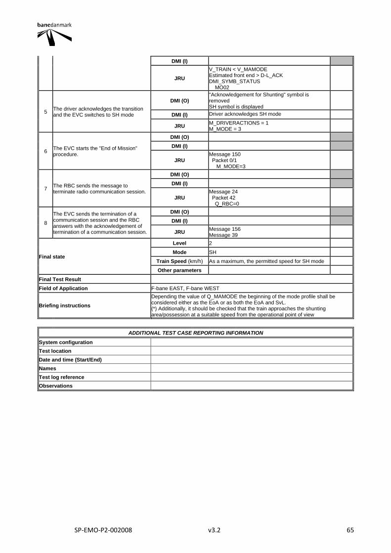
SP-EMO-P2-002008 v3.2 65
DMI (I)
JRU
V_TRAIN < V_MAMODE Estimated front end > D-L_ACK DMI_SYMB_STATUS MO02
5 The driver acknowledges the transition and the EVC switches to SH mode
DMI (O) "Acknowledgement for Shunting" symbol is removed SH symbol is displayed
DMI (I) Driver acknowledges SH mode
JRU M_DRIVERACTIONS = 1 M_MODE = 3
6 The EVC starts the "End of Mission" procedure.
DMI (O)
DMI (I)
JRU Message 150 Packet 0/1 M_MODE=3
7 The RBC sends the message to terminate radio communication session.
DMI (O)
DMI (I)
JRU Message 24 Packet 42 Q_RBC=0
8
The EVC sends the termination of a communication session and the RBC answers with the acknowledgement of termination of a communication session.
DMI (O)
DMI (I)
JRU Message 156 Message 39
Final state
Level 2
Mode SH
Train Speed (km/h) As a maximum, the permitted speed for SH mode
Other parameters
Final Test Result
Field of Application F-bane EAST, F-bane WEST
Briefing instructions
Depending the value of Q_MAMODE the beginning of the mode profile shall be considered either as the EoA or as both the EoA and SvL. (*) Additionally, it should be checked that the train approaches the shunting area/possession at a suitable speed from the operational point of view
ADDITIONAL TEST CASE REPORTING INFORMATION
System configuration
Test location
Date and time (Start/End)
Names
Test log reference
Observations
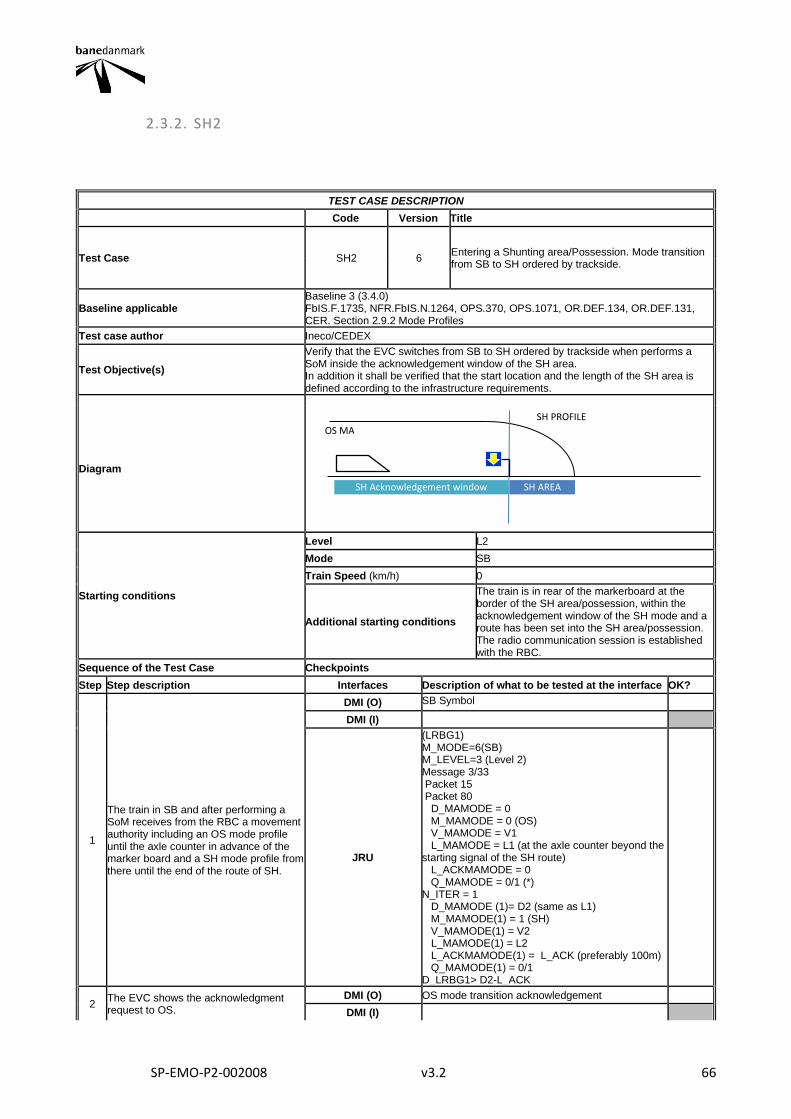
SP-EMO-P2-002008 v3.2 66
2.3.2. SH2
TEST CASE DESCRIPTION
Code Version Title
Test Case SH2 6 Entering a Shunting area/Possession. Mode transition from SB to SH ordered by trackside.
Baseline applicable Baseline 3 (3.4.0) FbIS.F.1735, NFR.FbIS.N.1264, OPS.370, OPS.1071, OR.DEF.134, OR.DEF.131, CER. Section 2.9.2 Mode Profiles
Test case author Ineco/CEDEX
Test Objective(s)
Verify that the EVC switches from SB to SH ordered by trackside when performs a SoM inside the acknowledgement window of the SH area. In addition it shall be verified that the start location and the length of the SH area is defined according to the infrastructure requirements.
Diagram
Starting conditions
Level L2
Mode SB
Train Speed (km/h) 0
Additional starting conditions
The train is in rear of the markerboard at the border of the SH area/possession, within the acknowledgement window of the SH mode and a route has been set into the SH area/possession. The radio communication session is established with the RBC.
Sequence of the Test Case Checkpoints
Step Step description Interfaces Description of what to be tested at the interface OK?
1
The train in SB and after performing a SoM receives from the RBC a movement authority including an OS mode profile until the axle counter in advance of the marker board and a SH mode profile from there until the end of the route of SH.
DMI (O) SB Symbol
DMI (I)
JRU
(LRBG1) M_MODE=6(SB) M_LEVEL=3 (Level 2) Message 3/33 Packet 15 Packet 80 D_MAMODE = 0 M_MAMODE = 0 (OS) V_MAMODE = V1 L_MAMODE = L1 (at the axle counter beyond the starting signal of the SH route) L_ACKMAMODE = 0 Q_MAMODE = 0/1 (*) N_ITER = 1 D_MAMODE (1)= D2 (same as L1) M_MAMODE(1) = 1 (SH) V_MAMODE(1) = V2 L_MAMODE(1) = L2 L_ACKMAMODE(1) = L_ACK (preferably 100m) Q_MAMODE(1) = 0/1 D_LRBG1> D2-L_ACK
2 The EVC shows the acknowledgment request to OS.
DMI (O) OS mode transition acknowledgement
DMI (I)
OS MA SH PROFILE
SH AREA SH Acknowledgement window
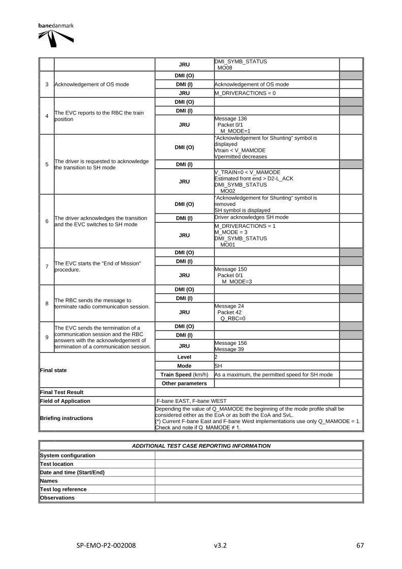
SP-EMO-P2-002008 v3.2 67
JRU DMI_SYMB_STATUS MO08
3 Acknowledgement of OS mode
DMI (O)
DMI (I) Acknowledgement of OS mode
JRU M_DRIVERACTIONS = 0
4 The EVC reports to the RBC the train position
DMI (O)
DMI (I)
JRU Message 136 Packet 0/1 M_MODE=1
5 The driver is requested to acknowledge the transition to SH mode
DMI (O)
"Acknowledgement for Shunting" symbol is displayed Vtrain < V_MAMODE Vpermitted decreases
DMI (I)
JRU
V_TRAIN=0 < V_MAMODE Estimated front end > D2-L_ACK DMI_SYMB_STATUS MO02
6 The driver acknowledges the transition and the EVC switches to SH mode
DMI (O) "Acknowledgement for Shunting" symbol is removed SH symbol is displayed
DMI (I) Driver acknowledges SH mode
JRU
M_DRIVERACTIONS = 1 M_MODE = 3 DMI_SYMB_STATUS MO01
7 The EVC starts the "End of Mission" procedure.
DMI (O)
DMI (I)
JRU Message 150 Packet 0/1 M_MODE=3
8 The RBC sends the message to terminate radio communication session.
DMI (O)
DMI (I)
JRU Message 24 Packet 42 Q_RBC=0
9
The EVC sends the termination of a communication session and the RBC answers with the acknowledgement of termination of a communication session.
DMI (O)
DMI (I)
JRU Message 156 Message 39
Final state
Level 2
Mode SH
Train Speed (km/h) As a maximum, the permitted speed for SH mode
Other parameters
Final Test Result
Field of Application F-bane EAST, F-bane WEST
Briefing instructions
Depending the value of Q_MAMODE the beginning of the mode profile shall be considered either as the EoA or as both the EoA and SvL. (*) Current F-bane East and F-bane West implementations use only Q_MAMODE = 1. Check and note if Q_MAMODE ≠ 1.
ADDITIONAL TEST CASE REPORTING INFORMATION
System configuration
Test location
Date and time (Start/End)
Names
Test log reference
Observations
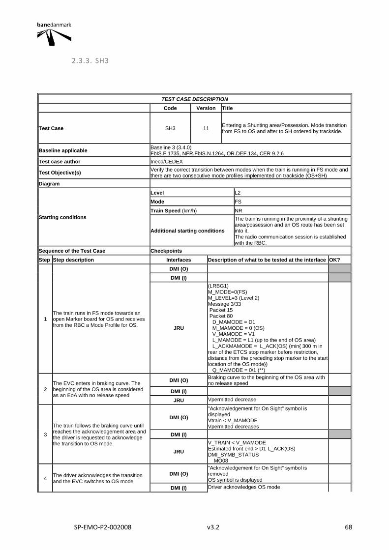
SP-EMO-P2-002008 v3.2 68
2.3.3. SH3
TEST CASE DESCRIPTION
Code Version Title
Test Case SH3 11 Entering a Shunting area/Possession. Mode transition from FS to OS and after to SH ordered by trackside.
Baseline applicable Baseline 3 (3.4.0) FbIS.F.1735, NFR.FbIS.N.1264, OR.DEF.134, CER 9.2.6
Test case author Ineco/CEDEX
Test Objective(s) Verify the correct transition between modes when the train is running in FS mode and there are two consecutive mode profiles implemented on trackside (OS+SH)
Diagram
Starting conditions
Level L2
Mode FS
Train Speed (km/h) NR
Additional starting conditions
The train is running in the proximity of a shunting area/possession and an OS route has been set into it. The radio communication session is established with the RBC.
Sequence of the Test Case Checkpoints
Step Step description Interfaces Description of what to be tested at the interface OK?
1 The train runs in FS mode towards an open Marker board for OS and receives from the RBC a Mode Profile for OS.
DMI (O)
DMI (I)
JRU
(LRBG1) M_MODE=0(FS) M_LEVEL=3 (Level 2) Message 3/33 Packet 15 Packet 80 D_MAMODE = D1 M_MAMODE = 0 (OS) V_MAMODE = V1 L_MAMODE = L1 (up to the end of OS area) L_ACKMAMODE = L_ACK(OS) (min{ 300 m in rear of the ETCS stop marker before restriction, distance from the preceding stop marker to the start location of the OS mode}) Q_MAMODE = 0/1 (**)
2 The EVC enters in braking curve. The beginning of the OS area is considered as an EoA with no release speed
DMI (O) Braking curve to the beginning of the OS area with no release speed
DMI (I)
JRU Vpermitted decrease
3
The train follows the braking curve until reaches the acknowledgement area and the driver is requested to acknowledge the transition to OS mode.
DMI (O)
"Acknowledgement for On Sight" symbol is displayed Vtrain < V_MAMODE Vpermitted decreases
DMI (I)
JRU
V_TRAIN < V_MAMODE Estimated front end > D1-L_ACK(OS) DMI_SYMB_STATUS MO08
4 The driver acknowledges the transition and the EVC switches to OS mode
DMI (O) "Acknowledgement for On Sight" symbol is removed OS symbol is displayed
DMI (I) Driver acknowledges OS mode
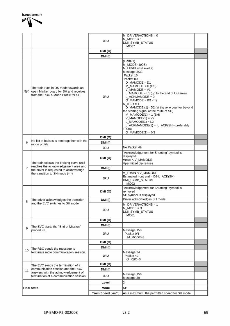
SP-EMO-P2-002008 v3.2 69
JRU
M_DRIVERACTIONS = 0 M_MODE = 1 DMI_SYMB_STATUS MO07
5(*) The train runs in OS mode towards an open Marker board for SH and receives from the RBC a Mode Profile for SH.
DMI (O)
DMI (I)
JRU
(LRBG1) M_MODE=1(OS) M_LEVEL=3 (Level 2) Message 3/33 Packet 15 Packet 80 D_MAMODE = D1 M_MAMODE = 0 (OS) V_MAMODE = V1 L_MAMODE = L1 (up to the end of OS area) L_ACKMAMODE = 0 Q_MAMODE = 0/1 (**) N_ITER = 1 D_MAMODE (1)= D2 (at the axle counter beyond the starting signal of the route of SH) M_MAMODE(1) = 1 (SH) V_MAMODE(1) = V2 L_MAMODE(1) = L2 L_ACKMAMODE(1) = L_ACK(SH) (preferably 100m) Q_MAMODE(1) = 0/1
6 No list of balises is sent together with the mode profile.
DMI (O)
DMI (I)
JRU No Packet 49
7
The train follows the braking curve until reaches the acknowledgement area and the driver is requested to acknowledge the transition to SH mode (***)
DMI (O)
"Acknowledgement for Shunting" symbol is displayed Vtrain < V_MAMODE Vpermitted decreases
DMI (I)
JRU
V_TRAIN < V_MAMODE Estimated front end > D2-L_ACK(SH) DMI_SYMB_STATUS MO02
8 The driver acknowledges the transition and the EVC switches to SH mode
DMI (O) "Acknowledgement for Shunting" symbol is removed SH symbol is displayed
DMI (I) Driver acknowledges SH mode
JRU
M_DRIVERACTIONS = 1 M_MODE = 3 DMI_SYMB_STATUS MO01
9 The EVC starts the "End of Mission" procedure.
DMI (O)
DMI (I)
JRU Message 150 Packet 0/1 M_MODE=3
10 The RBC sends the message to terminate radio communication session.
DMI (O)
DMI (I)
JRU Message 24 Packet 42 Q_RBC=0
11
The EVC sends the termination of a communication session and the RBC answers with the acknowledgement of termination of a communication session.
DMI (O)
DMI (I)
JRU Message 156 Message 39
Final state
Level 2
Mode SH
Train Speed (km/h) As a maximum, the permitted speed for SH mode
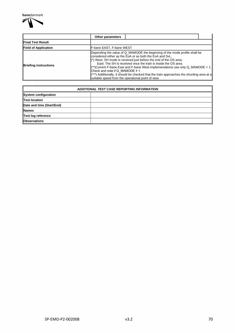
SP-EMO-P2-002008 v3.2 70
Other parameters
Final Test Result
Field of Application F-bane EAST, F-bane WEST
Briefing instructions
Depending the value of Q_MAMODE the beginning of the mode profile shall be considered either as the EoA or as both the EoA and SvL. (*) West: SH mode is received just before the end of the OS area. East: The SH is received once the train is inside the OS area. (**)Current F-bane East and F-bane West implementations use only Q_MAMODE = 1. Check and note if Q_MAMODE ≠ 1. (***) Additionally, it should be checked that the train approaches the shunting area at a suitable speed from the operational point of view
ADDITIONAL TEST CASE REPORTING INFORMATION
System configuration
Test location
Date and time (Start/End)
Names
Test log reference
Observations
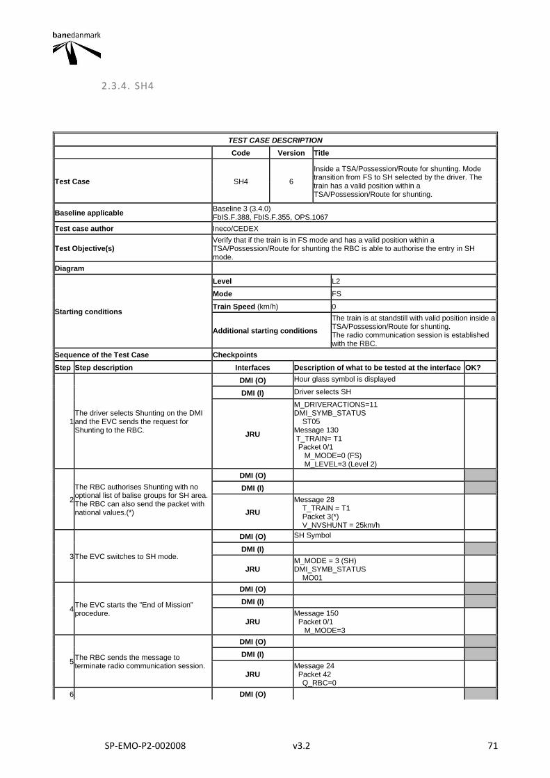
SP-EMO-P2-002008 v3.2 71
2.3.4. SH4
TEST CASE DESCRIPTION
Code Version Title
Test Case SH4 6
Inside a TSA/Possession/Route for shunting. Mode transition from FS to SH selected by the driver. The train has a valid position within a TSA/Possession/Route for shunting.
Baseline applicable Baseline 3 (3.4.0) FbIS.F.388, FbIS.F.355, OPS.1067
Test case author Ineco/CEDEX
Test Objective(s) Verify that if the train is in FS mode and has a valid position within a TSA/Possession/Route for shunting the RBC is able to authorise the entry in SH mode.
Diagram
Starting conditions
Level L2
Mode FS
Train Speed (km/h) 0
Additional starting conditions
The train is at standstill with valid position inside a TSA/Possession/Route for shunting. The radio communication session is established with the RBC.
Sequence of the Test Case Checkpoints
Step Step description Interfaces Description of what to be tested at the interface OK?
1 The driver selects Shunting on the DMI and the EVC sends the request for Shunting to the RBC.
DMI (O) Hour glass symbol is displayed
DMI (I) Driver selects SH
JRU
M_DRIVERACTIONS=11 DMI_SYMB_STATUS ST05 Message 130 T_TRAIN= T1 Packet 0/1 M_MODE=0 (FS) M_LEVEL=3 (Level 2)
2
The RBC authorises Shunting with no optional list of balise groups for SH area. The RBC can also send the packet with national values.(*)
DMI (O)
DMI (I)
JRU
Message 28 T_TRAIN = T1 Packet 3(*) V_NVSHUNT = 25km/h
3 The EVC switches to SH mode.
DMI (O) SH Symbol
DMI (I)
JRU M_MODE = 3 (SH) DMI_SYMB_STATUS MO01
4 The EVC starts the "End of Mission" procedure.
DMI (O)
DMI (I)
JRU Message 150 Packet 0/1 M_MODE=3
5 The RBC sends the message to terminate radio communication session.
DMI (O)
DMI (I)
JRU Message 24 Packet 42 Q_RBC=0
6 DMI (O)
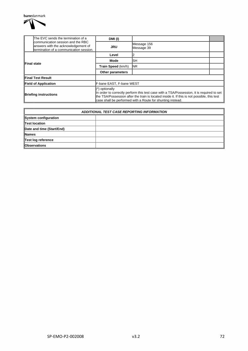
SP-EMO-P2-002008 v3.2 72
The EVC sends the termination of a communication session and the RBC answers with the acknowledgement of termination of a communication session.
DMI (I)
JRU Message 156 Message 39
Final state
Level 2
Mode SH
Train Speed (km/h) NR
Other parameters
Final Test Result
Field of Application F-bane EAST, F-bane WEST
Briefing instructions
(*) optionally In order to correctly perform this test case with a TSA/Possession, it is required to set the TSA/Possession after the train is located inside it. If this is not possible, this test case shall be performed with a Route for shunting instead.
ADDITIONAL TEST CASE REPORTING INFORMATION
System configuration
Test location
Date and time (Start/End)
Names
Test log reference
Observations
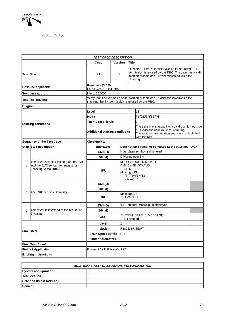
SP-EMO-P2-002008 v3.2 73
2.3.5. SH5
TEST CASE DESCRIPTION
Code Version Title
Test Case SH5 5
Outside a TSA/ Possession/Route for shunting. SH permission is refused by the RBC. The train has a valid position outside of a TSA/Possession/Route for shunting.
Baseline applicable Baseline 3 (3.4.0) FbIS.F.389, FbIS.F.356
Test case author Ineco/CEDEX
Test Objective(s) Verify that if a train has a valid position outside of a TSA/Possession/Route for shunting the SH permission is refused by the RBC.
Diagram
Starting conditions
Level L2
Mode FS/OS/SR/SB/PT
Train Speed (km/h) 0
Additional starting conditions
The train is at standstill with valid position outside a TSA/Possesion/Route for shunting. The radio communication session is established with the RBC.
Sequence of the Test Case Checkpoints
Step Step description Interfaces Description of what to be tested at the interface OK?
1 The driver selects Shunting on the DMI and the EVC sends the request for Shunting to the RBC.
DMI (O) Hour glass symbol is displayed
DMI (I) Driver selects SH
JRU
M_DRIVERACTIONS = 11 DMI_SYMB_STATUS ST05 Message 130 T_TRAIN = T1 Packet 0/1
2 The RBC refuses Shunting.
DMI (O)
DMI (I)
JRU Message 27 T_TRAIN= T1
3 The driver is informed of the refusal of Shunting.
DMI (O) "SH refused" message is displayed.
DMI (I)
JRU SYSTEM_STATUS_MESSAGE SH refused
Final state
Level 2
Mode FS/OS/SR/SB/PT
Train Speed (km/h) NR
Other parameters
Final Test Result
Field of Application F-bane EAST, F-bane WEST
Briefing instructions
ADDITIONAL TEST CASE REPORTING INFORMATION
System configuration
Test location
Date and time (Start/End)
Names

SP-EMO-P2-002008 v3.2 74
Test log reference
Observations
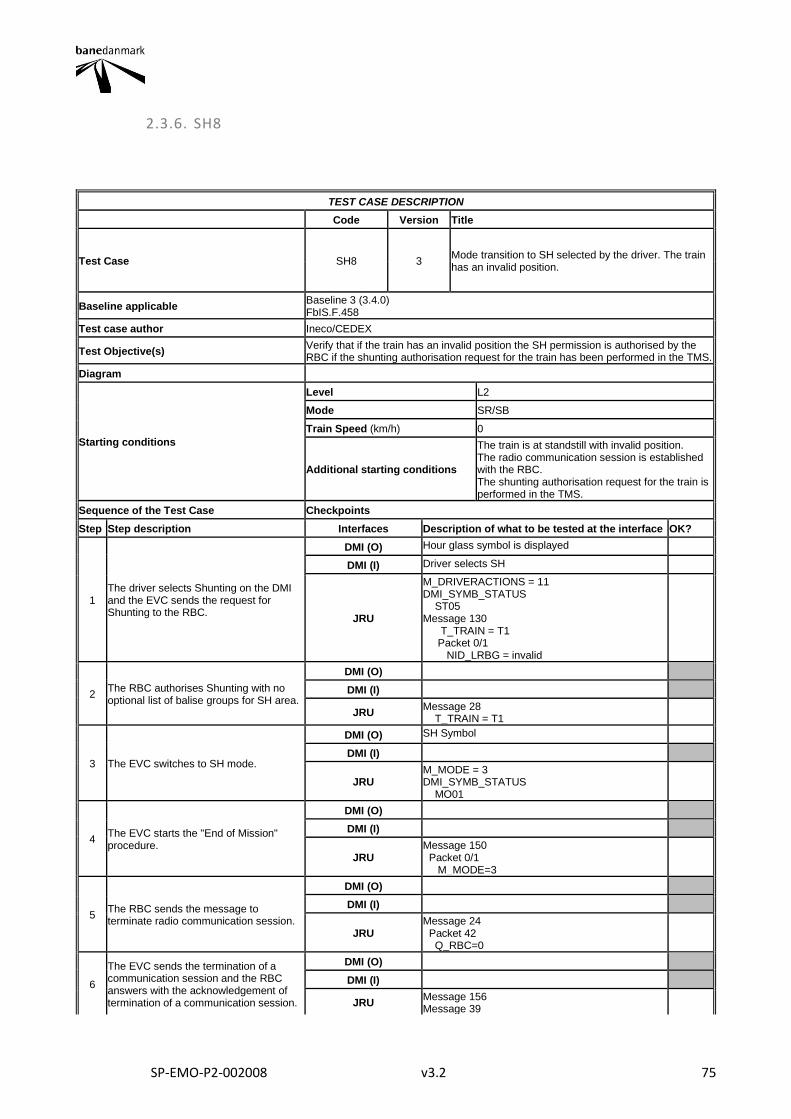
SP-EMO-P2-002008 v3.2 75
2.3.6. SH8
TEST CASE DESCRIPTION
Code Version Title
Test Case SH8 3 Mode transition to SH selected by the driver. The train has an invalid position.
Baseline applicable Baseline 3 (3.4.0) FbIS.F.458
Test case author Ineco/CEDEX
Test Objective(s) Verify that if the train has an invalid position the SH permission is authorised by the RBC if the shunting authorisation request for the train has been performed in the TMS.
Diagram
Starting conditions
Level L2
Mode SR/SB
Train Speed (km/h) 0
Additional starting conditions
The train is at standstill with invalid position. The radio communication session is established with the RBC. The shunting authorisation request for the train is performed in the TMS.
Sequence of the Test Case Checkpoints
Step Step description Interfaces Description of what to be tested at the interface OK?
1 The driver selects Shunting on the DMI and the EVC sends the request for Shunting to the RBC.
DMI (O) Hour glass symbol is displayed
DMI (I) Driver selects SH
JRU
M_DRIVERACTIONS = 11 DMI_SYMB_STATUS ST05 Message 130 T_TRAIN = T1 Packet 0/1 NID_LRBG = invalid
2 The RBC authorises Shunting with no optional list of balise groups for SH area.
DMI (O)
DMI (I)
JRU Message 28 T_TRAIN = T1
3 The EVC switches to SH mode.
DMI (O) SH Symbol
DMI (I)
JRU M_MODE = 3 DMI_SYMB_STATUS MO01
4 The EVC starts the "End of Mission" procedure.
DMI (O)
DMI (I)
JRU Message 150 Packet 0/1 M_MODE=3
5 The RBC sends the message to terminate radio communication session.
DMI (O)
DMI (I)
JRU Message 24 Packet 42 Q_RBC=0
6
The EVC sends the termination of a communication session and the RBC answers with the acknowledgement of termination of a communication session.
DMI (O)
DMI (I)
JRU Message 156 Message 39
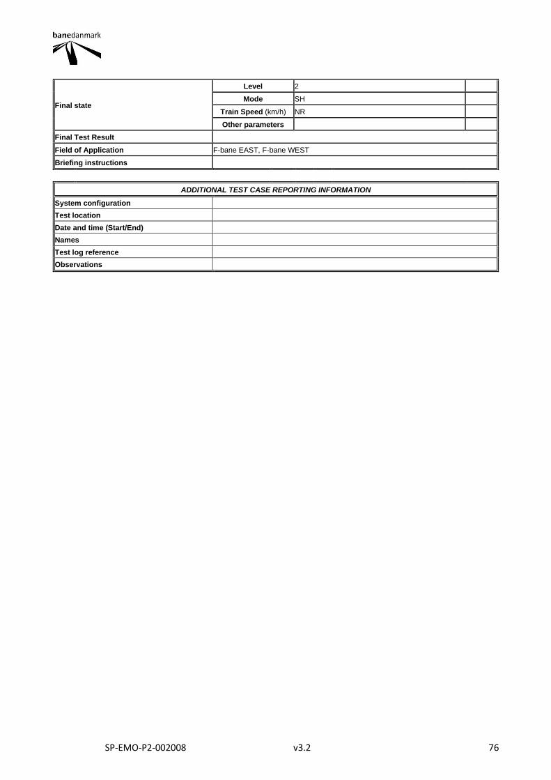
SP-EMO-P2-002008 v3.2 76
Final state
Level 2
Mode SH
Train Speed (km/h) NR
Other parameters
Final Test Result
Field of Application F-bane EAST, F-bane WEST
Briefing instructions
ADDITIONAL TEST CASE REPORTING INFORMATION
System configuration
Test location
Date and time (Start/End)
Names
Test log reference
Observations
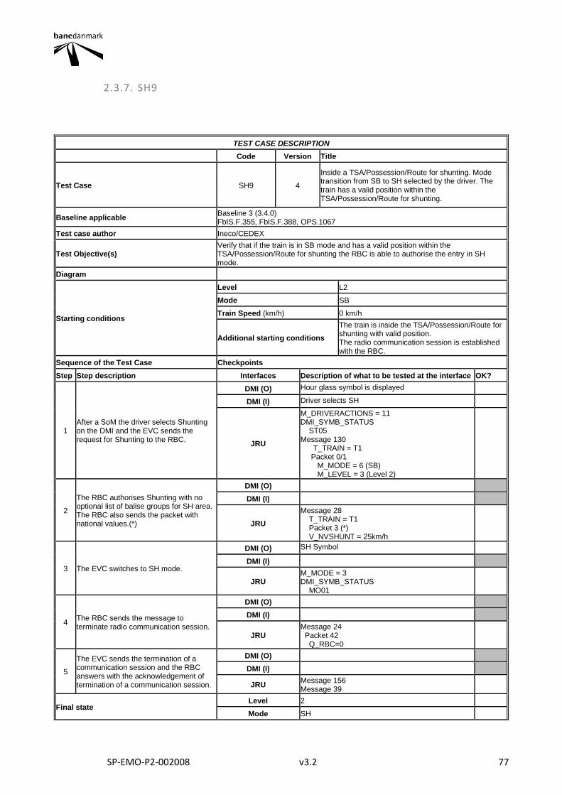
SP-EMO-P2-002008 v3.2 77
2.3.7. SH9
TEST CASE DESCRIPTION
Code Version Title
Test Case SH9 4
Inside a TSA/Possession/Route for shunting. Mode transition from SB to SH selected by the driver. The train has a valid position within the TSA/Possession/Route for shunting.
Baseline applicable Baseline 3 (3.4.0) FbIS.F.355, FbIS.F.388, OPS.1067
Test case author Ineco/CEDEX
Test Objective(s) Verify that if the train is in SB mode and has a valid position within the TSA/Possession/Route for shunting the RBC is able to authorise the entry in SH mode.
Diagram
Starting conditions
Level L2
Mode SB
Train Speed (km/h) 0 km/h
Additional starting conditions
The train is inside the TSA/Possession/Route for shunting with valid position. The radio communication session is established with the RBC.
Sequence of the Test Case Checkpoints
Step Step description Interfaces Description of what to be tested at the interface OK?
1 After a SoM the driver selects Shunting on the DMI and the EVC sends the request for Shunting to the RBC.
DMI (O) Hour glass symbol is displayed
DMI (I) Driver selects SH
JRU
M_DRIVERACTIONS = 11 DMI_SYMB_STATUS ST05 Message 130 T_TRAIN = T1 Packet 0/1 M_MODE = 6 (SB) M_LEVEL = 3 (Level 2)
2
The RBC authorises Shunting with no optional list of balise groups for SH area. The RBC also sends the packet with national values.(*)
DMI (O)
DMI (I)
JRU
Message 28 T_TRAIN = T1 Packet 3 (*) V_NVSHUNT = 25km/h
3 The EVC switches to SH mode.
DMI (O) SH Symbol
DMI (I)
JRU M_MODE = 3 DMI_SYMB_STATUS MO01
4 The RBC sends the message to terminate radio communication session.
DMI (O)
DMI (I)
JRU Message 24 Packet 42 Q_RBC=0
5
The EVC sends the termination of a communication session and the RBC answers with the acknowledgement of termination of a communication session.
DMI (O)
DMI (I)
JRU Message 156 Message 39
Final state Level 2
Mode SH
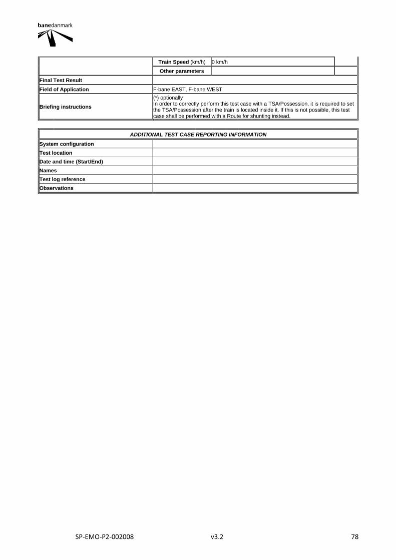
SP-EMO-P2-002008 v3.2 78
Train Speed (km/h) 0 km/h
Other parameters
Final Test Result
Field of Application F-bane EAST, F-bane WEST
Briefing instructions
(*) optionally In order to correctly perform this test case with a TSA/Possession, it is required to set the TSA/Possession after the train is located inside it. If this is not possible, this test case shall be performed with a Route for shunting instead.
ADDITIONAL TEST CASE REPORTING INFORMATION
System configuration
Test location
Date and time (Start/End)
Names
Test log reference
Observations
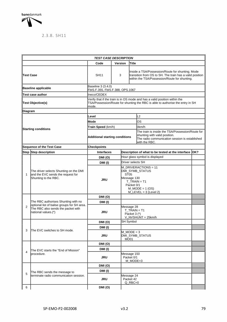
SP-EMO-P2-002008 v3.2 79
2.3.8. SH11
TEST CASE DESCRIPTION
Code Version Title
Test Case SH11 3 Inside a TSA/Possession/Route for shunting. Mode transition from OS to SH. The train has a valid position within the TSA/Possession/Route for shunting.
Baseline applicable Baseline 3 (3.4.0) FbIS.F.355, FbIS.F.388, OPS.1067
Test case author Ineco/CEDEX
Test Objective(s) Verify that if the train is in OS mode and has a valid position within the TSA/Possession/Route for shunting the RBC is able to authorise the entry in SH mode.
Diagram
Starting conditions
Level L2
Mode OS
Train Speed (km/h) 0km/h
Additional starting conditions
The train is inside the TSA/Possession/Route for shunting with valid position. The radio communication session is established with the RBC.
Sequence of the Test Case Checkpoints
Step Step description Interfaces Description of what to be tested at the interface OK?
1 The driver selects Shunting on the DMI and the EVC sends the request for Shunting to the RBC.
DMI (O) Hour glass symbol is displayed
DMI (I) Driver selects SH
JRU
M_DRIVERACTIONS = 11 DMI_SYMB_STATUS ST05 Message 130 T_TRAIN = T1 Packet 0/1 M_MODE = 1 (OS) M_LEVEL = 3 (Level 2)
2
The RBC authorises Shunting with no optional list of balise groups for SH area. The RBC also sends the packet with national values.(*)
DMI (O)
DMI (I)
JRU
Message 28 T_TRAIN = T1 Packet 3 (*) V_NVSHUNT = 25km/h
3 The EVC switches to SH mode.
DMI (O) SH Symbol
DMI (I)
JRU M_MODE = 3 DMI_SYMB_STATUS MO01
4 The EVC starts the "End of Mission" procedure.
DMI (O)
DMI (I)
JRU Message 150 Packet 0/1 M_MODE=3
5 The RBC sends the message to terminate radio communication session.
DMI (O)
DMI (I)
JRU Message 24 Packet 42 Q_RBC=0
6 DMI (O)

SP-EMO-P2-002008 v3.2 80
The EVC sends the termination of a communication session and the RBC answers with the acknowledgement of termination of a communication session.
DMI (I)
JRU Message 156 Message 39
Final state
Level 2
Mode SH
Train Speed (km/h) NR
Other parameters
Final Test Result
Field of Application F-bane EAST, F-bane WEST
Briefing instructions
(*) Optionally In order to correctly perform this test case with a TSA/Possession, it is required to set the TSA/Possession after the train is located inside it. If this is not possible, this test case shall be performed with a Route for shunting instead
ADDITIONAL TEST CASE REPORTING INFORMATION
System configuration
Test location
Date and time (Start/End)
Names
Test log reference
Observations
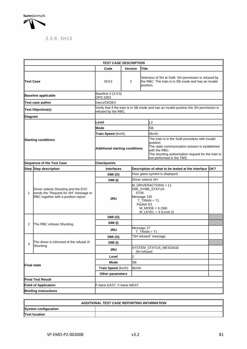
SP-EMO-P2-002008 v3.2 81
2.3.9. SH13
TEST CASE DESCRIPTION
Code Version Title
Test Case SH13 2 Selection of SH at SoM. SH permission is refused by the RBC. The train is in SB mode and has an invalid position.
Baseline applicable Baseline 3 (3.4.0) OPS.1053
Test case author Ineco/CEDEX
Test Objective(s) Verify that if the train is in SB mode and has an invalid position the SH permission is refused by the RBC.
Diagram
Starting conditions
Level L2
Mode SB
Train Speed (km/h) 0km/h
Additional starting conditions
The train is in the SoM procedure with invalid position The radio communication session is established with the RBC. The shunting authorisation request for the train is not performed in the TMS.
Sequence of the Test Case Checkpoints
Step Step description Interfaces Description of what to be tested at the interface OK?
1 Driver selects Shunting and the EVC sends the "Request for SH" message to RBC together with a position report.
DMI (O) Hour glass symbol is displayed
DMI (I) Driver selects SH
JRU
M_DRIVERACTIONS = 11 DMI_SYMB_STATUS ST05 Message 130 T_TRAIN = T1 Packet 0/1 M_MODE = 6 (SB) M_LEVEL = 3 (Level 2)
2 The RBC refuses Shunting.
DMI (O)
DMI (I)
JRU Message 27 T_TRAIN = T1
3 The driver is informed of the refusal of Shunting.
DMI (O) "SH refused" message.
DMI (I)
JRU SYSTEM_STATUS_MESSAGE SH refused
Final state
Level 2
Mode SB
Train Speed (km/h) 0km/h
Other parameters
Final Test Result
Field of Application F-bane EAST, F-bane WEST
Briefing instructions
ADDITIONAL TEST CASE REPORTING INFORMATION
System configuration
Test location

SP-EMO-P2-002008 v3.2 82
Date and time (Start/End)
Names
Test log reference
Observations
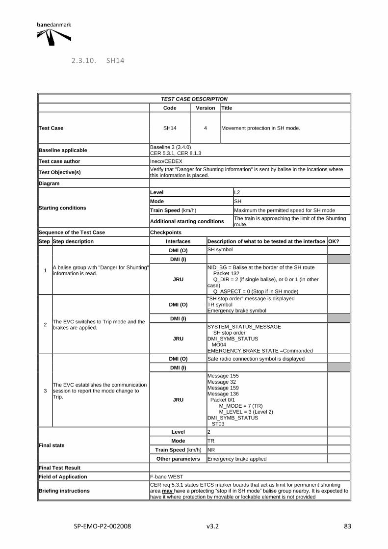
SP-EMO-P2-002008 v3.2 83
2.3.10. SH14
TEST CASE DESCRIPTION
Code Version Title
Test Case SH14 4 Movement protection in SH mode.
Baseline applicable Baseline 3 (3.4.0) CER 5.3.1, CER 8.1.3
Test case author Ineco/CEDEX
Test Objective(s) Verify that "Danger for Shunting information" is sent by balise in the locations where this information is placed.
Diagram
Starting conditions
Level L2
Mode SH
Train Speed (km/h) Maximum the permitted speed for SH mode
Additional starting conditions The train is approaching the limit of the Shunting route.
Sequence of the Test Case Checkpoints
Step Step description Interfaces Description of what to be tested at the interface OK?
1 A balise group with "Danger for Shunting" information is read.
DMI (O) SH symbol
DMI (I)
JRU
NID_BG = Balise at the border of the SH route Packet 132 Q_DIR = 2 (if single balise), or 0 or 1 (in other case) Q_ASPECT = 0 (Stop if in SH mode)
2 The EVC switches to Trip mode and the brakes are applied.
DMI (O) "SH stop order" message is displayed TR symbol Emergency brake symbol
DMI (I)
JRU
SYSTEM_STATUS_MESSAGE SH stop order DMI_SYMB_STATUS MO04 EMERGENCY BRAKE STATE =Commanded
3 The EVC establishes the communication session to report the mode change to Trip.
DMI (O) Safe radio connection symbol is displayed
DMI (I)
JRU
Message 155 Message 32 Message 159 Message 136 Packet 0/1 M_MODE = 7 (TR) M_LEVEL = 3 (Level 2) DMI_SYMB_STATUS ST03
Final state
Level 2
Mode TR
Train Speed (km/h) NR
Other parameters Emergency brake applied
Final Test Result
Field of Application F-bane WEST
Briefing instructions CER req 5.3.1 states ETCS marker boards that act as limit for permanent shunting area may have a protecting “stop if in SH mode” balise group nearby. It is expected to have it where protection by movable or lockable element is not provided

SP-EMO-P2-002008 v3.2 84
ADDITIONAL TEST CASE REPORTING INFORMATION
System configuration
Test location
Date and time (Start/End)
Names
Test log reference
Observations

SP-EMO-P2-002008 v3.2 85
2.3.11. SH15
TEST CASE DESCRIPTION
Code Version Title
Test Case SH15 3 Leaving a SH area. Exit shunting mode inside a trusted area
Baseline applicable Baseline 3 (3.4.0)
Test case author Ineco/CEDEX
Test Objective(s) Verify the exit from shunting mode and the correct SoM procedure when the train is inside a trusted area
Diagram
Starting conditions
Level L2
Mode SH
Train Speed (km/h) 0
Additional starting conditions Train is at standstill inside a trusted area and with known location.
Sequence of the Test Case Checkpoints
Step Step description Interfaces Description of what to be tested at the interface OK?
1 Train is at standstill inside a trusted area The driver selects "Exit from SH mode"
DMI (O)
Vtrain=0 SH symbol disappears SB symbol is displayed Hour glass symbol is displayed
DMI (I) Driver selects Exit of Shunting
JRU
V_TRAIN=0 M_DRIVERACTIONS=17 M_MODE = 6 DMI_SYMB_STATUS ST05, MO13
2 The driver validates or introduces the Driver ID
DMI (O)
DMI (I) DRIVER ID
JRU
3
The establishment of a communication session is initiated by the EVC. A position report with valid position is sent to the RBC.
DMI (O) Safe radio connection “Connection Up”;
DMI (I)
JRU
Message 155 Message 32 Message 159 Message 157 Q_STATUS = 1 (valid) Packet 0/1 NID_LRBG ≠ 16777215 Q_DIRLRBG ≠ 2 Q_DLRBG ≠ 2 DMI_SYMB_STATUS ST03
4 The driver selects train data entry. Train data and train running number is entered or revalidated.
DMI (O) Train data and train running number windows are shown.
DMI (I) Driver selects Data Entry Driver enters the train running number
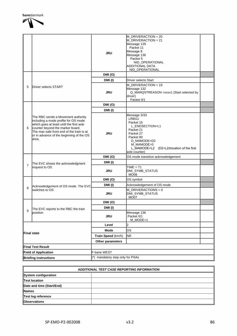
SP-EMO-P2-002008 v3.2 86
JRU
M_DRIVERACTION = 20 M_DRIVERACTION = 21 Message 129 Packet 11 Message 8 Message 136 Packet 5 NID_OPERATIONAL ADDITIONAL DATA NID_OPERATIONAL
5 Driver selects START
DMI (O)
DMI (I) Driver selects Start
JRU
M_DRIVERACTION = 19 Message 132 Q_MARQSTREASON =xxxx1 (Start selected by driver) Packet 0/1
6
The RBC sends a Movement authority including a mode profile for OS mode which goes at least until the first axle counter beyond the marker board. The max safe front end of the train is at or in advance of the beginning of the OS area.
DMI (O)
DMI (I)
JRU
Message 3/33 LRBG1 Packet 15 L_ENDSECTION=L1 Packet 21 Packet 27 Packet 80 D_MAMODE=D2 M_MAMODE=0 L_MAMODE=L2 (D2+L2≥location of the first axle counter)
7 The EVC shows the acknowledgment request to OS
DMI (O) OS mode transition acknowledgement
DMI (I)
JRU TIME = T1 DMI_SYMB_STATUS MO08
8 Acknowledgement of OS mode. The EVC switches to OS
DMI (O) OS symbol
DMI (I) Acknowledgement of OS mode
JRU M_DRIVERACTIONS = 0 DMI_SYMB_STATUS MO07
9 The EVC reports to the RBC the train position
DMI (O)
DMI (I)
JRU Message 136 Packet 0/1 M_MODE=1
Final state
Level 2
Mode OS
Train Speed (km/h) NR
Other parameters
Final Test Result
Field of Application F-bane WEST
Briefing instructions (*) mandatory step only for PSAs
ADDITIONAL TEST CASE REPORTING INFORMATION
System configuration
Test location
Date and time (Start/End)
Names
Test log reference
Observations

SP-EMO-P2-002008 v3.2 87
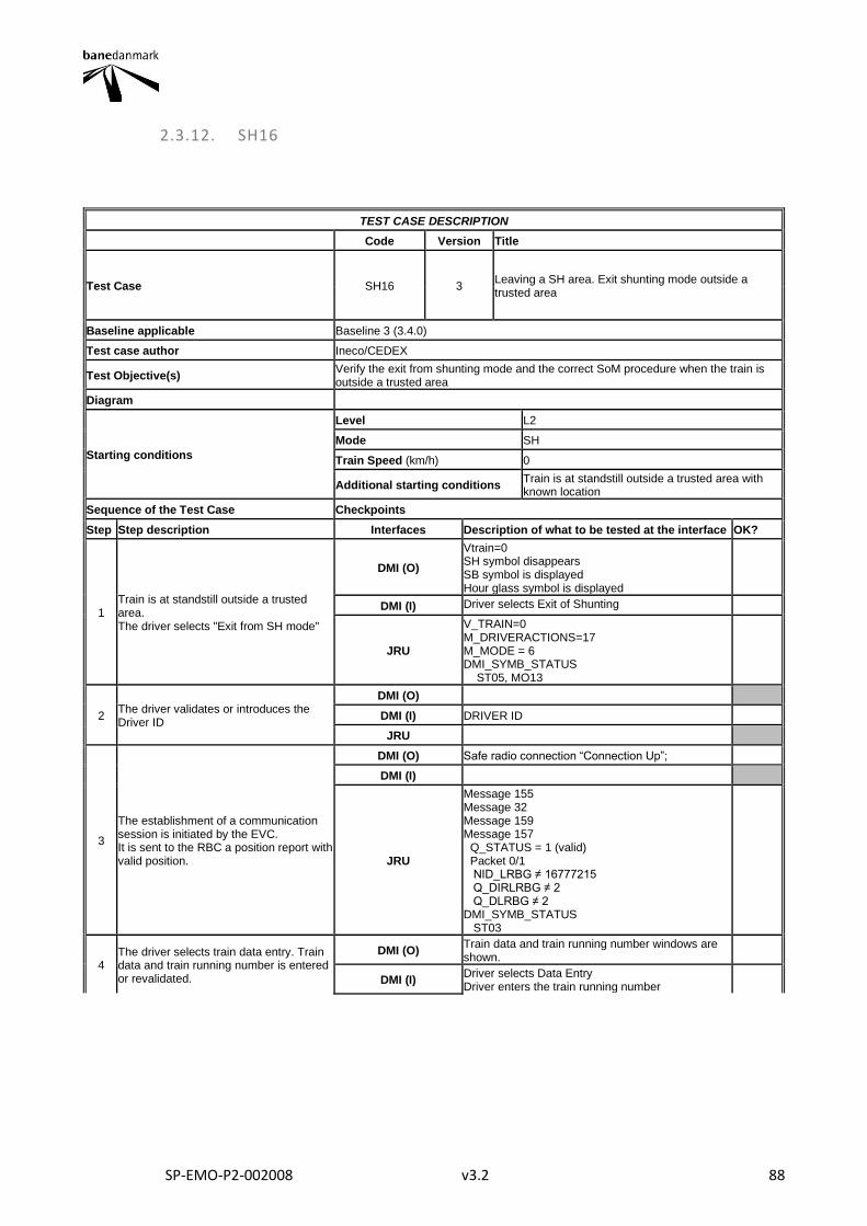
SP-EMO-P2-002008 v3.2 88
2.3.12. SH16
TEST CASE DESCRIPTION
Code Version Title
Test Case SH16 3 Leaving a SH area. Exit shunting mode outside a trusted area
Baseline applicable Baseline 3 (3.4.0)
Test case author Ineco/CEDEX
Test Objective(s) Verify the exit from shunting mode and the correct SoM procedure when the train is outside a trusted area
Diagram
Starting conditions
Level L2
Mode SH
Train Speed (km/h) 0
Additional starting conditions Train is at standstill outside a trusted area with known location
Sequence of the Test Case Checkpoints
Step Step description Interfaces Description of what to be tested at the interface OK?
1 Train is at standstill outside a trusted area. The driver selects "Exit from SH mode"
DMI (O)
Vtrain=0 SH symbol disappears SB symbol is displayed Hour glass symbol is displayed
DMI (I) Driver selects Exit of Shunting
JRU
V_TRAIN=0 M_DRIVERACTIONS=17 M_MODE = 6 DMI_SYMB_STATUS ST05, MO13
2 The driver validates or introduces the Driver ID
DMI (O)
DMI (I) DRIVER ID
JRU
3
The establishment of a communication session is initiated by the EVC. It is sent to the RBC a position report with valid position.
DMI (O) Safe radio connection “Connection Up”;
DMI (I)
JRU
Message 155 Message 32 Message 159 Message 157 Q_STATUS = 1 (valid) Packet 0/1 NID_LRBG ≠ 16777215 Q_DIRLRBG ≠ 2 Q_DLRBG ≠ 2 DMI_SYMB_STATUS ST03
4 The driver selects train data entry. Train data and train running number is entered or revalidated.
DMI (O) Train data and train running number windows are shown.
DMI (I) Driver selects Data Entry Driver enters the train running number
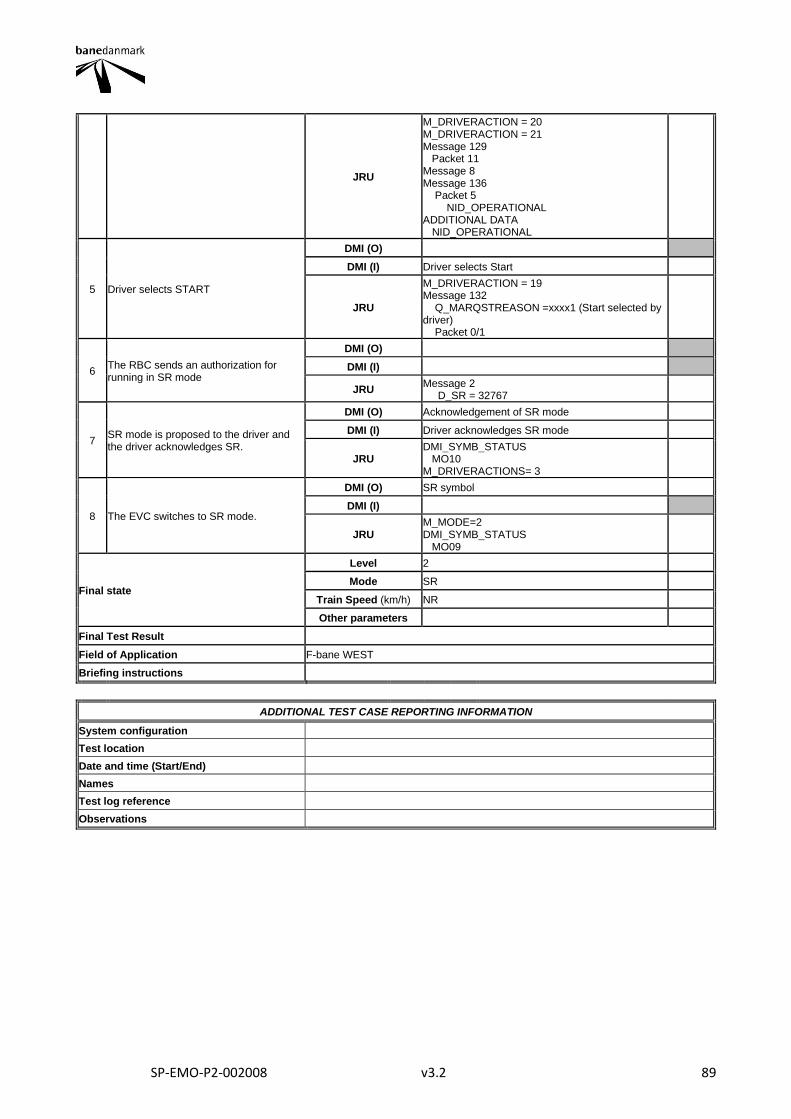
SP-EMO-P2-002008 v3.2 89
JRU
M_DRIVERACTION = 20 M_DRIVERACTION = 21 Message 129 Packet 11 Message 8 Message 136 Packet 5 NID_OPERATIONAL ADDITIONAL DATA NID_OPERATIONAL
5 Driver selects START
DMI (O)
DMI (I) Driver selects Start
JRU
M_DRIVERACTION = 19 Message 132 Q_MARQSTREASON =xxxx1 (Start selected by driver) Packet 0/1
6 The RBC sends an authorization for running in SR mode
DMI (O)
DMI (I)
JRU Message 2 D_SR = 32767
7 SR mode is proposed to the driver and the driver acknowledges SR.
DMI (O) Acknowledgement of SR mode
DMI (I) Driver acknowledges SR mode
JRU DMI_SYMB_STATUS MO10 M_DRIVERACTIONS= 3
8 The EVC switches to SR mode.
DMI (O) SR symbol
DMI (I)
JRU M_MODE=2 DMI_SYMB_STATUS MO09
Final state
Level 2
Mode SR
Train Speed (km/h) NR
Other parameters
Final Test Result
Field of Application F-bane WEST
Briefing instructions
ADDITIONAL TEST CASE REPORTING INFORMATION
System configuration
Test location
Date and time (Start/End)
Names
Test log reference
Observations
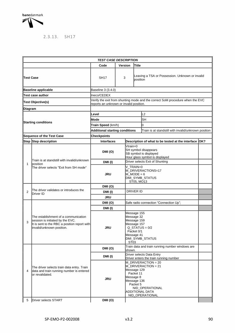
SP-EMO-P2-002008 v3.2 90
2.3.13. SH17
TEST CASE DESCRIPTION
Code Version Title
Test Case SH17 3 Leaving a TSA or Possession. Unknown or invalid position
Baseline applicable Baseline 3 (3.4.0)
Test case author Ineco/CEDEX
Test Objective(s) Verify the exit from shunting mode and the correct SoM procedure when the EVC reports an unknown or invalid position.
Diagram
Starting conditions
Level L2
Mode SH
Train Speed (km/h) 0
Additional starting conditions Train is at standstill with invalid/unknown position
Sequence of the Test Case Checkpoints
Step Step description Interfaces Description of what to be tested at the interface OK?
1 Train is at standstill with invalid/unknown position The driver selects "Exit from SH mode"
DMI (O)
Vtrain=0 SH symbol disappears SB symbol is displayed Hour glass symbol is displayed
DMI (I) Driver selects Exit of Shunting
JRU
V_TRAIN=0 M_DRIVERACTIONS=17 M_MODE = 6 DMI_SYMB_STATUS ST05, MO13
2 The driver validates or introduces the Driver ID
DMI (O)
DMI (I) DRIVER ID
JRU
3
The establishment of a communication session is initiated by the EVC. It is sent to the RBC a position report with invalid/unknown position.
DMI (O) Safe radio connection “Connection Up”;
DMI (I)
JRU
Message 155 Message 32 Message 159 Message 157 Q_STATUS = 0/2 Packet 0/1 Message 41 DMI_SYMB_STATUS ST03
4 The driver selects train data entry. Train data and train running number is entered or revalidated.
DMI (O) Train data and train running number windows are shown.
DMI (I) Driver selects Data Entry Driver enters the train running number
JRU
M_DRIVERACTION = 20 M_DRIVERACTION = 21 Message 129 Packet 11 Message 8 Message 136 Packet 5 NID_OPERATIONAL ADDITIONAL DATA NID_OPERATIONAL
5 Driver selects START DMI (O)

SP-EMO-P2-002008 v3.2 91
DMI (I) Driver selects Start
JRU
M_DRIVERACTION = 19 Message 132 Q_MARQSTREASON =xxxx1 (Start selected by driver) Packet 0/1 NID_BG=16383 Q_DIRLRBG=2 Q_DIRTRAIN=2
6 The RBC grant an authorisation for SR mode.
DMI (O) Acknowledgement for SR is shown
DMI (I)
JRU
Message 2 D_SR DMI_SYMB_STATUS MO10
7 Driver acknowledges the SR mode
DMI (O) SR symbol
DMI (I) Driver acknowledges SR mode
JRU M_DRIVERACTIONS=3 DMI_SYMB_STATUS MO09
Final state
Level 2
Mode SR
Train Speed (km/h) NR
Other parameters
Final Test Result
Field of Application F-bane EAST, F-bane WEST
Briefing instructions
ADDITIONAL TEST CASE REPORTING INFORMATION
System configuration
Test location
Date and time (Start/End)
Names
Test log reference
Observations
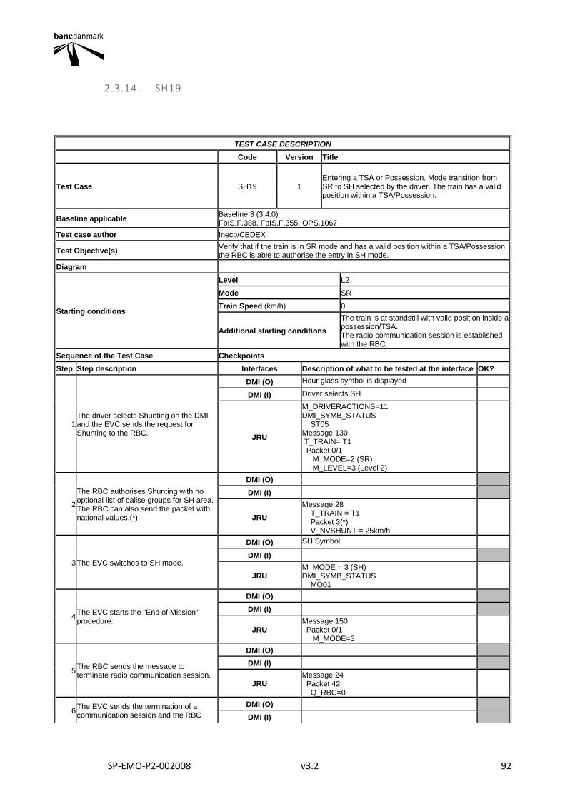
SP-EMO-P2-002008 v3.2 92
2.3.14. SH19
TEST CASE DESCRIPTION
Code Version Title
Test Case SH19 1 Entering a TSA or Possession. Mode transition from SR to SH selected by the driver. The train has a valid position within a TSA/Possession.
Baseline applicable Baseline 3 (3.4.0) FbIS.F.388, FbIS.F.355, OPS.1067
Test case author Ineco/CEDEX
Test Objective(s) Verify that if the train is in SR mode and has a valid position within a TSA/Possession the RBC is able to authorise the entry in SH mode.
Diagram
Starting conditions
Level L2
Mode SR
Train Speed (km/h) 0
Additional starting conditions
The train is at standstill with valid position inside a possession/TSA. The radio communication session is established with the RBC.
Sequence of the Test Case Checkpoints
Step Step description Interfaces Description of what to be tested at the interface OK?
1 The driver selects Shunting on the DMI and the EVC sends the request for Shunting to the RBC.
DMI (O) Hour glass symbol is displayed
DMI (I) Driver selects SH
JRU
M_DRIVERACTIONS=11 DMI_SYMB_STATUS ST05 Message 130 T_TRAIN= T1 Packet 0/1 M_MODE=2 (SR) M_LEVEL=3 (Level 2)
2
The RBC authorises Shunting with no optional list of balise groups for SH area. The RBC can also send the packet with national values.(*)
DMI (O)
DMI (I)
JRU
Message 28 T_TRAIN = T1 Packet 3(*) V_NVSHUNT = 25km/h
3 The EVC switches to SH mode.
DMI (O) SH Symbol
DMI (I)
JRU M_MODE = 3 (SH) DMI_SYMB_STATUS MO01
4 The EVC starts the "End of Mission" procedure.
DMI (O)
DMI (I)
JRU Message 150 Packet 0/1 M_MODE=3
5 The RBC sends the message to terminate radio communication session.
DMI (O)
DMI (I)
JRU Message 24 Packet 42 Q_RBC=0
6 The EVC sends the termination of a communication session and the RBC
DMI (O)
DMI (I)
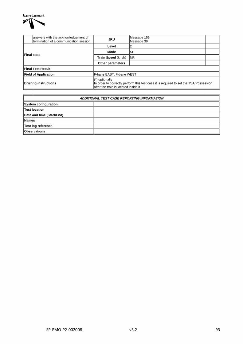
SP-EMO-P2-002008 v3.2 93
answers with the acknowledgement of termination of a communication session.
JRU Message 156 Message 39
Final state
Level 2
Mode SH
Train Speed (km/h) NR
Other parameters
Final Test Result
Field of Application F-bane EAST, F-bane WEST
Briefing instructions (*) optionally In order to correctly perform this test case it is required to set the TSA/Possession after the train is located inside it
ADDITIONAL TEST CASE REPORTING INFORMATION
System configuration
Test location
Date and time (Start/End)
Names
Test log reference
Observations
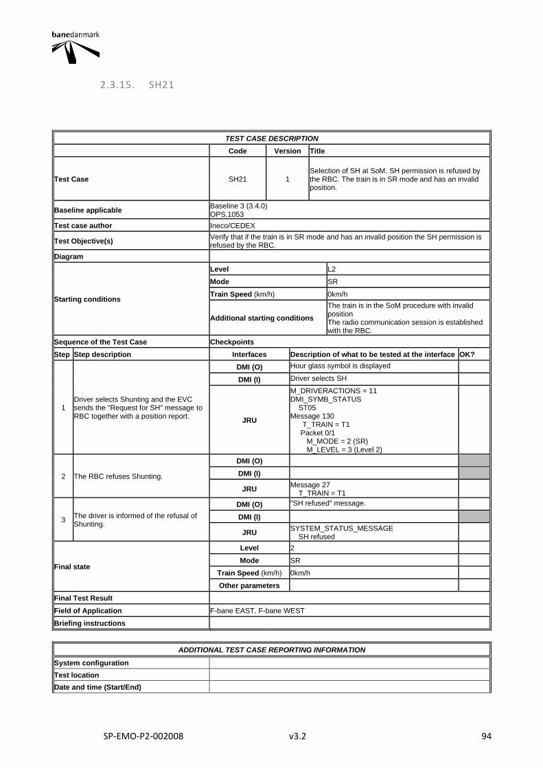
SP-EMO-P2-002008 v3.2 94
2.3.15. SH21
TEST CASE DESCRIPTION
Code Version Title
Test Case SH21 1 Selection of SH at SoM. SH permission is refused by the RBC. The train is in SR mode and has an invalid position.
Baseline applicable Baseline 3 (3.4.0) OPS.1053
Test case author Ineco/CEDEX
Test Objective(s) Verify that if the train is in SR mode and has an invalid position the SH permission is refused by the RBC.
Diagram
Starting conditions
Level L2
Mode SR
Train Speed (km/h) 0km/h
Additional starting conditions
The train is in the SoM procedure with invalid position The radio communication session is established with the RBC.
Sequence of the Test Case Checkpoints
Step Step description Interfaces Description of what to be tested at the interface OK?
1 Driver selects Shunting and the EVC sends the "Request for SH" message to RBC together with a position report.
DMI (O) Hour glass symbol is displayed
DMI (I) Driver selects SH
JRU
M_DRIVERACTIONS = 11 DMI_SYMB_STATUS ST05 Message 130 T_TRAIN = T1 Packet 0/1 M_MODE = 2 (SR) M_LEVEL = 3 (Level 2)
2 The RBC refuses Shunting.
DMI (O)
DMI (I)
JRU Message 27 T_TRAIN = T1
3 The driver is informed of the refusal of Shunting.
DMI (O) "SH refused" message.
DMI (I)
JRU SYSTEM_STATUS_MESSAGE SH refused
Final state
Level 2
Mode SR
Train Speed (km/h) 0km/h
Other parameters
Final Test Result
Field of Application F-bane EAST, F-bane WEST
Briefing instructions
ADDITIONAL TEST CASE REPORTING INFORMATION
System configuration
Test location
Date and time (Start/End)

SP-EMO-P2-002008 v3.2 95
Names
Test log reference
Observations
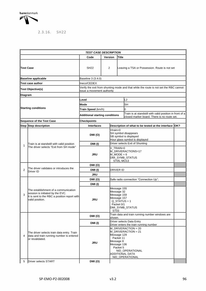
SP-EMO-P2-002008 v3.2 96
2.3.16. SH22
TEST CASE DESCRIPTION
Code Version Title
Test Case SH22 2 Leaving a TSA or Possession. Route is not set
Baseline applicable Baseline 3 (3.4.0)
Test case author Ineco/CEDEX
Test Objective(s) Verify the exit from shunting mode and that while the route is not set the RBC cannot issue a movement authority
Diagram
Starting conditions
Level L2
Mode SH
Train Speed (km/h) 0
Additional starting conditions Train is at standstill with valid position in front of a closed marker board. There is no route set.
Sequence of the Test Case Checkpoints
Step Step description Interfaces Description of what to be tested at the interface OK?
1 Train is at standstill with valid position The driver selects "Exit from SH mode"
DMI (O)
Vtrain=0 SH symbol disappears SB symbol is displayed Hour glass symbol is displayed
DMI (I) Driver selects Exit of Shunting
JRU
V_TRAIN=0 M_DRIVERACTIONS=17 M_MODE = 6 DMI_SYMB_STATUS ST05, MO13
2 The driver validates or introduces the Driver ID
DMI (O)
DMI (I) DRIVER ID
JRU
3
The establishment of a communication session is initiated by the EVC. It is sent to the RBC a position report with valid position.
DMI (O) Safe radio connection “Connection Up”;
DMI (I)
JRU
Message 155 Message 32 Message 159 Message 157 Q_STATUS = 1 Packet 0/1 DMI_SYMB_STATUS ST03
4 The driver selects train data entry. Train data and train running number is entered or revalidated.
DMI (O) Train data and train running number windows are shown.
DMI (I) Driver selects Data Entry Driver enters the train running number
JRU
M_DRIVERACTION = 20 M_DRIVERACTION = 21 Message 129 Packet 11 Message 8 Message 136 Packet 5 NID_OPERATIONAL ADDITIONAL DATA NID_OPERATIONAL
5 Driver selects START DMI (O)
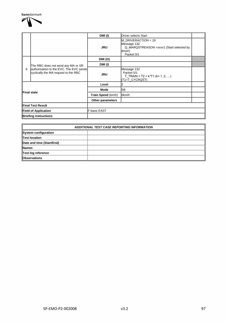
SP-EMO-P2-002008 v3.2 97
DMI (I) Driver selects Start
JRU
M_DRIVERACTION = 19 Message 132 Q_MARQSTREASON =xxxx1 (Start selected by driver) Packet 0/1
6 The RBC does not send any MA or SR authorisation to the EVC. The EVC sends cyclically the MA request to the RBC
DMI (O)
DMI (I)
JRU
Message 132 Packet 0/1 T_TRAIN = T2 + k*T1 (k= 1, 2, …) (T1=T_CYCRQST)
Final state
Level 2
Mode SB
Train Speed (km/h) 0km/h
Other parameters
Final Test Result
Field of Application F-bane EAST
Briefing instructions
ADDITIONAL TEST CASE REPORTING INFORMATION
System configuration
Test location
Date and time (Start/End)
Names
Test log reference
Observations
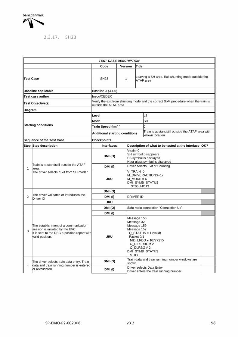
SP-EMO-P2-002008 v3.2 98
2.3.17. SH23
TEST CASE DESCRIPTION
Code Version Title
Test Case SH23 1 Leaving a SH area. Exit shunting mode outside the ATAF area
Baseline applicable Baseline 3 (3.4.0)
Test case author Ineco/CEDEX
Test Objective(s) Verify the exit from shunting mode and the correct SoM procedure when the train is outside the ATAF area
Diagram
Starting conditions
Level L2
Mode SH
Train Speed (km/h) 0
Additional starting conditions Train is at standstill outside the ATAF area with known location
Sequence of the Test Case Checkpoints
Step Step description Interfaces Description of what to be tested at the interface OK?
1 Train is at standstill outside the ATAF area. The driver selects "Exit from SH mode"
DMI (O)
Vtrain=0 SH symbol disappears SB symbol is displayed Hour glass symbol is displayed
DMI (I) Driver selects Exit of Shunting
JRU
V_TRAIN=0 M_DRIVERACTIONS=17 M_MODE = 6 DMI_SYMB_STATUS ST05, MO13
2 The driver validates or introduces the Driver ID
DMI (O)
DMI (I) DRIVER ID
JRU
3
The establishment of a communication session is initiated by the EVC. It is sent to the RBC a position report with valid position.
DMI (O) Safe radio connection “Connection Up”;
DMI (I)
JRU
Message 155 Message 32 Message 159 Message 157 Q_STATUS = 1 (valid) Packet 0/1 NID_LRBG ≠ 16777215 Q_DIRLRBG ≠ 2 Q_DLRBG ≠ 2 DMI_SYMB_STATUS ST03
4 The driver selects train data entry. Train data and train running number is entered or revalidated.
DMI (O) Train data and train running number windows are shown.
DMI (I) Driver selects Data Entry Driver enters the train running number
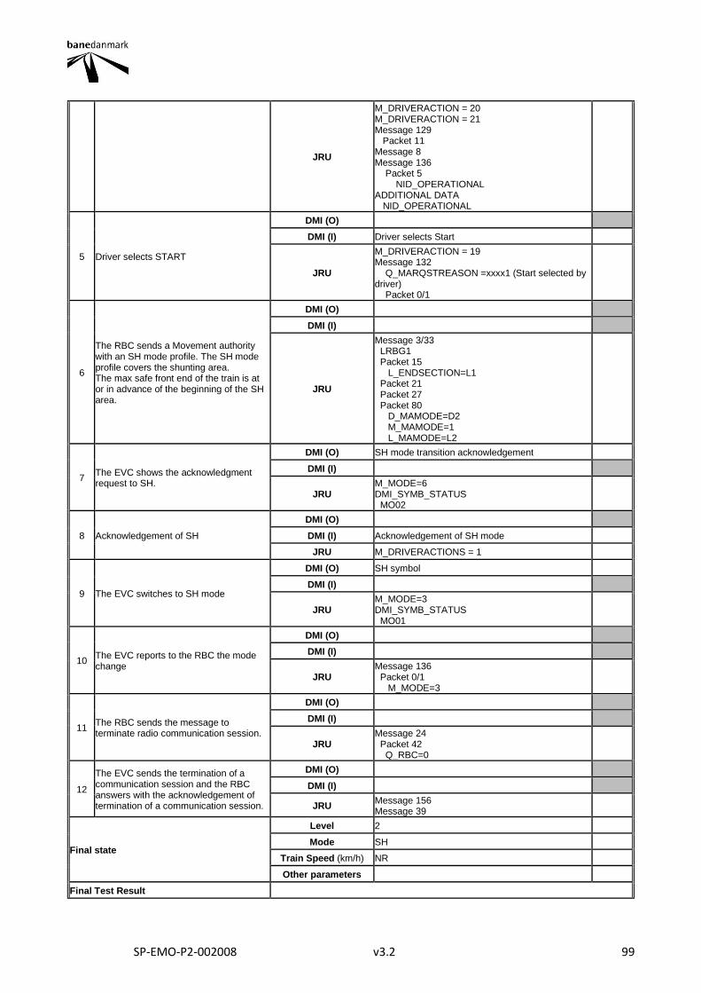
SP-EMO-P2-002008 v3.2 99
JRU
M_DRIVERACTION = 20 M_DRIVERACTION = 21 Message 129 Packet 11 Message 8 Message 136 Packet 5 NID_OPERATIONAL ADDITIONAL DATA NID_OPERATIONAL
5 Driver selects START
DMI (O)
DMI (I) Driver selects Start
JRU
M_DRIVERACTION = 19 Message 132 Q_MARQSTREASON =xxxx1 (Start selected by driver) Packet 0/1
6
The RBC sends a Movement authority with an SH mode profile. The SH mode profile covers the shunting area. The max safe front end of the train is at or in advance of the beginning of the SH area.
DMI (O)
DMI (I)
JRU
Message 3/33 LRBG1 Packet 15 L_ENDSECTION=L1 Packet 21 Packet 27 Packet 80 D_MAMODE=D2 M_MAMODE=1 L_MAMODE=L2
7 The EVC shows the acknowledgment request to SH.
DMI (O) SH mode transition acknowledgement
DMI (I)
JRU M_MODE=6 DMI_SYMB_STATUS MO02
8 Acknowledgement of SH
DMI (O)
DMI (I) Acknowledgement of SH mode
JRU M_DRIVERACTIONS = 1
9 The EVC switches to SH mode
DMI (O) SH symbol
DMI (I)
JRU M_MODE=3 DMI_SYMB_STATUS MO01
10 The EVC reports to the RBC the mode change
DMI (O)
DMI (I)
JRU Message 136 Packet 0/1 M_MODE=3
11 The RBC sends the message to terminate radio communication session.
DMI (O)
DMI (I)
JRU Message 24 Packet 42 Q_RBC=0
12
The EVC sends the termination of a communication session and the RBC answers with the acknowledgement of termination of a communication session.
DMI (O)
DMI (I)
JRU Message 156 Message 39
Final state
Level 2
Mode SH
Train Speed (km/h) NR
Other parameters
Final Test Result
SP-EMO-P2-002008 v3.2 100
Field of Application F-bane EAST
Briefing instructions
ADDITIONAL TEST CASE REPORTING INFORMATION
System configuration
Test location
Date and time (Start/End)
Names
Test log reference
Observations

SP-EMO-P2-002008 v3.2 101
2.3.18. SH24
TEST CASE DESCRIPTION
Code Version Title
Test Case SH24 1 Leaving a SH area. Exit shunting mode inside the ATAF area
Baseline applicable Baseline 3 (3.4.0)
Test case author Ineco/CEDEX
Test Objective(s) Verify the exit from shunting mode and the correct SoM procedure when the train is inside the ATAF area
Diagram
Starting conditions
Level L2
Mode SH
Train Speed (km/h) 0
Additional starting conditions Train is at standstill inside the ATAF area and with known location.
Sequence of the Test Case Checkpoints
Step Step description Interfaces Description of what to be tested at the interface OK?
1 Train is at standstill inside the ATAF area The driver selects "Exit from SH mode"
DMI (O)
Vtrain=0 SH symbol disappears SB symbol is displayed Hour glass symbol is displayed
DMI (I) Driver selects Exit of Shunting
JRU
V_TRAIN=0 M_DRIVERACTIONS=17 M_MODE = 6 DMI_SYMB_STATUS ST05, MO13
2 The driver validates or introduces the Driver ID
DMI (O)
DMI (I) DRIVER ID
JRU
3
The establishment of a communication session is initiated by the EVC. A position report with valid position is sent to the RBC.
DMI (O) Safe radio connection “Connection Up”;
DMI (I)
JRU
Message 155 Message 32 Message 159 Message 157 Q_STATUS = 1 (valid) Packet 0/1 NID_LRBG ≠ 16777215 Q_DIRLRBG ≠ 2 Q_DLRBG ≠ 2 DMI_SYMB_STATUS ST03
4 The driver selects train data entry. Train data and train running number is entered or revalidated.
DMI (O) Train data and train running number windows are shown.
DMI (I) Driver selects Data Entry Driver enters the train running number
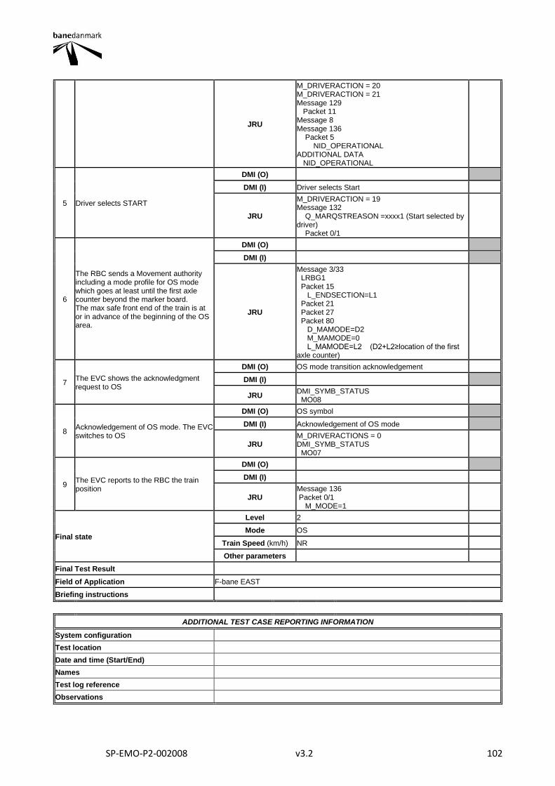
SP-EMO-P2-002008 v3.2 102
JRU
M_DRIVERACTION = 20 M_DRIVERACTION = 21 Message 129 Packet 11 Message 8 Message 136 Packet 5 NID_OPERATIONAL ADDITIONAL DATA NID_OPERATIONAL
5 Driver selects START
DMI (O)
DMI (I) Driver selects Start
JRU
M_DRIVERACTION = 19 Message 132 Q_MARQSTREASON =xxxx1 (Start selected by driver) Packet 0/1
6
The RBC sends a Movement authority including a mode profile for OS mode which goes at least until the first axle counter beyond the marker board. The max safe front end of the train is at or in advance of the beginning of the OS area.
DMI (O)
DMI (I)
JRU
Message 3/33 LRBG1 Packet 15 L_ENDSECTION=L1 Packet 21 Packet 27 Packet 80 D_MAMODE=D2 M_MAMODE=0 L_MAMODE=L2 (D2+L2≥location of the first axle counter)
7 The EVC shows the acknowledgment request to OS
DMI (O) OS mode transition acknowledgement
DMI (I)
JRU DMI_SYMB_STATUS MO08
8 Acknowledgement of OS mode. The EVC switches to OS
DMI (O) OS symbol
DMI (I) Acknowledgement of OS mode
JRU M_DRIVERACTIONS = 0 DMI_SYMB_STATUS MO07
9 The EVC reports to the RBC the train position
DMI (O)
DMI (I)
JRU Message 136 Packet 0/1 M_MODE=1
Final state
Level 2
Mode OS
Train Speed (km/h) NR
Other parameters
Final Test Result
Field of Application F-bane EAST
Briefing instructions
ADDITIONAL TEST CASE REPORTING INFORMATION
System configuration
Test location
Date and time (Start/End)
Names
Test log reference
Observations
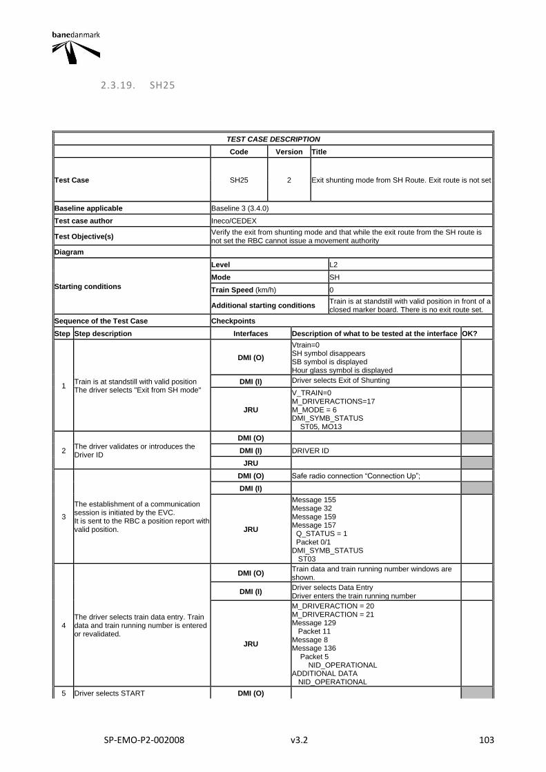
SP-EMO-P2-002008 v3.2 103
2.3.19. SH25
TEST CASE DESCRIPTION
Code Version Title
Test Case SH25 2 Exit shunting mode from SH Route. Exit route is not set
Baseline applicable Baseline 3 (3.4.0)
Test case author Ineco/CEDEX
Test Objective(s) Verify the exit from shunting mode and that while the exit route from the SH route is not set the RBC cannot issue a movement authority
Diagram
Starting conditions
Level L2
Mode SH
Train Speed (km/h) 0
Additional starting conditions Train is at standstill with valid position in front of a closed marker board. There is no exit route set.
Sequence of the Test Case Checkpoints
Step Step description Interfaces Description of what to be tested at the interface OK?
1 Train is at standstill with valid position The driver selects "Exit from SH mode"
DMI (O)
Vtrain=0 SH symbol disappears SB symbol is displayed Hour glass symbol is displayed
DMI (I) Driver selects Exit of Shunting
JRU
V_TRAIN=0 M_DRIVERACTIONS=17 M_MODE = 6 DMI_SYMB_STATUS ST05, MO13
2 The driver validates or introduces the Driver ID
DMI (O)
DMI (I) DRIVER ID
JRU
3
The establishment of a communication session is initiated by the EVC. It is sent to the RBC a position report with valid position.
DMI (O) Safe radio connection “Connection Up”;
DMI (I)
JRU
Message 155 Message 32 Message 159 Message 157 Q_STATUS = 1 Packet 0/1 DMI_SYMB_STATUS ST03
4 The driver selects train data entry. Train data and train running number is entered or revalidated.
DMI (O) Train data and train running number windows are shown.
DMI (I) Driver selects Data Entry Driver enters the train running number
JRU
M_DRIVERACTION = 20 M_DRIVERACTION = 21 Message 129 Packet 11 Message 8 Message 136 Packet 5 NID_OPERATIONAL ADDITIONAL DATA NID_OPERATIONAL
5 Driver selects START DMI (O)

SP-EMO-P2-002008 v3.2 104
DMI (I) Driver selects Start
JRU
M_DRIVERACTION = 19 Message 132 Q_MARQSTREASON =xxxx1 (Start selected by driver) Packet 0/1
6 The RBC does not send any MA or SR authorisation to the EVC. The EVC sends cyclically the MA request to the RBC
DMI (O)
DMI (I)
JRU
Message 132 Packet 0/1 T_TRAIN = T2 + k*T1 (k= 1, 2, …) (T1=T_CYCRQST)
Final state
Level 2
Mode SB
Train Speed (km/h) 0
Other parameters
Final Test Result
Field of Application F-bane EAST
Briefing instructions
ADDITIONAL TEST CASE REPORTING INFORMATION
System configuration
Test location
Date and time (Start/End)
Names
Test log reference
Observations
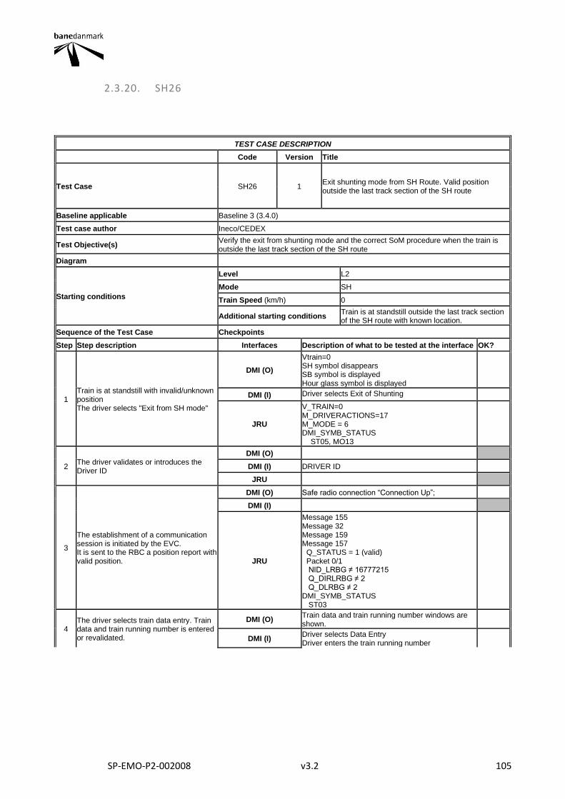
SP-EMO-P2-002008 v3.2 105
2.3.20. SH26
TEST CASE DESCRIPTION
Code Version Title
Test Case SH26 1 Exit shunting mode from SH Route. Valid position outside the last track section of the SH route
Baseline applicable Baseline 3 (3.4.0)
Test case author Ineco/CEDEX
Test Objective(s) Verify the exit from shunting mode and the correct SoM procedure when the train is outside the last track section of the SH route
Diagram
Starting conditions
Level L2
Mode SH
Train Speed (km/h) 0
Additional starting conditions Train is at standstill outside the last track section of the SH route with known location.
Sequence of the Test Case Checkpoints
Step Step description Interfaces Description of what to be tested at the interface OK?
1 Train is at standstill with invalid/unknown position The driver selects "Exit from SH mode"
DMI (O)
Vtrain=0 SH symbol disappears SB symbol is displayed Hour glass symbol is displayed
DMI (I) Driver selects Exit of Shunting
JRU
V_TRAIN=0 M_DRIVERACTIONS=17 M_MODE = 6 DMI_SYMB_STATUS ST05, MO13
2 The driver validates or introduces the Driver ID
DMI (O)
DMI (I) DRIVER ID
JRU
3
The establishment of a communication session is initiated by the EVC. It is sent to the RBC a position report with valid position.
DMI (O) Safe radio connection “Connection Up”;
DMI (I)
JRU
Message 155 Message 32 Message 159 Message 157 Q_STATUS = 1 (valid) Packet 0/1 NID_LRBG ≠ 16777215 Q_DIRLRBG ≠ 2 Q_DLRBG ≠ 2 DMI_SYMB_STATUS ST03
4 The driver selects train data entry. Train data and train running number is entered or revalidated.
DMI (O) Train data and train running number windows are shown.
DMI (I) Driver selects Data Entry Driver enters the train running number
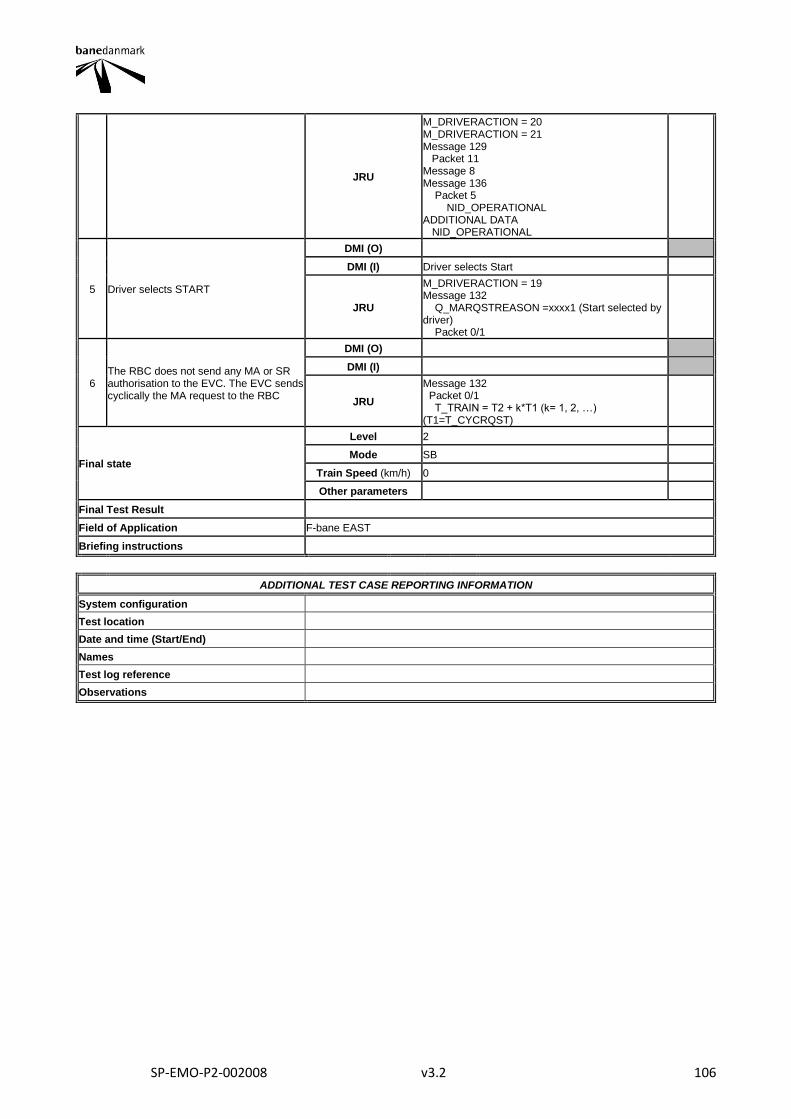
SP-EMO-P2-002008 v3.2 106
JRU
M_DRIVERACTION = 20 M_DRIVERACTION = 21 Message 129 Packet 11 Message 8 Message 136 Packet 5 NID_OPERATIONAL ADDITIONAL DATA NID_OPERATIONAL
5 Driver selects START
DMI (O)
DMI (I) Driver selects Start
JRU
M_DRIVERACTION = 19 Message 132 Q_MARQSTREASON =xxxx1 (Start selected by driver) Packet 0/1
6 The RBC does not send any MA or SR authorisation to the EVC. The EVC sends cyclically the MA request to the RBC
DMI (O)
DMI (I)
JRU
Message 132 Packet 0/1 T_TRAIN = T2 + k*T1 (k= 1, 2, …) (T1=T_CYCRQST)
Final state
Level 2
Mode SB
Train Speed (km/h) 0
Other parameters
Final Test Result
Field of Application F-bane EAST
Briefing instructions
ADDITIONAL TEST CASE REPORTING INFORMATION
System configuration
Test location
Date and time (Start/End)
Names
Test log reference
Observations
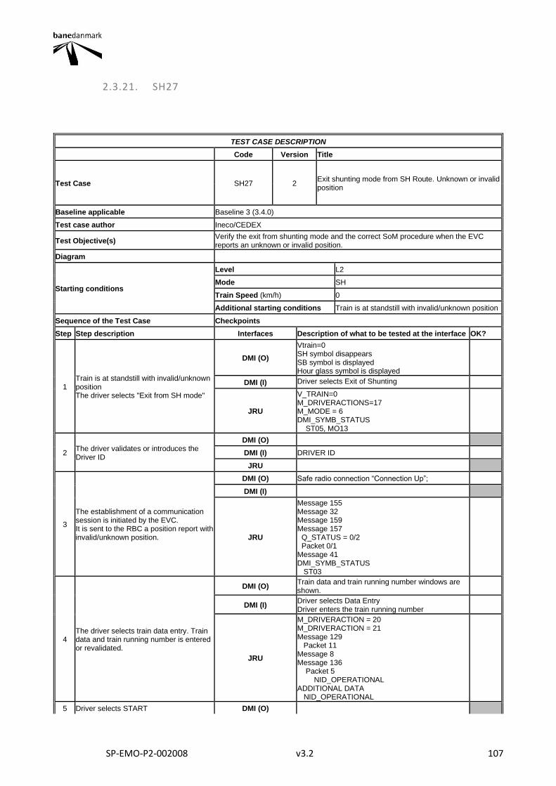
SP-EMO-P2-002008 v3.2 107
2.3.21. SH27
TEST CASE DESCRIPTION
Code Version Title
Test Case SH27 2 Exit shunting mode from SH Route. Unknown or invalid position
Baseline applicable Baseline 3 (3.4.0)
Test case author Ineco/CEDEX
Test Objective(s) Verify the exit from shunting mode and the correct SoM procedure when the EVC reports an unknown or invalid position.
Diagram
Starting conditions
Level L2
Mode SH
Train Speed (km/h) 0
Additional starting conditions Train is at standstill with invalid/unknown position
Sequence of the Test Case Checkpoints
Step Step description Interfaces Description of what to be tested at the interface OK?
1 Train is at standstill with invalid/unknown position The driver selects "Exit from SH mode"
DMI (O)
Vtrain=0 SH symbol disappears SB symbol is displayed Hour glass symbol is displayed
DMI (I) Driver selects Exit of Shunting
JRU
V_TRAIN=0 M_DRIVERACTIONS=17 M_MODE = 6 DMI_SYMB_STATUS ST05, MO13
2 The driver validates or introduces the Driver ID
DMI (O)
DMI (I) DRIVER ID
JRU
3
The establishment of a communication session is initiated by the EVC. It is sent to the RBC a position report with invalid/unknown position.
DMI (O) Safe radio connection “Connection Up”;
DMI (I)
JRU
Message 155 Message 32 Message 159 Message 157 Q_STATUS = 0/2 Packet 0/1 Message 41 DMI_SYMB_STATUS ST03
4 The driver selects train data entry. Train data and train running number is entered or revalidated.
DMI (O) Train data and train running number windows are shown.
DMI (I) Driver selects Data Entry Driver enters the train running number
JRU
M_DRIVERACTION = 20 M_DRIVERACTION = 21 Message 129 Packet 11 Message 8 Message 136 Packet 5 NID_OPERATIONAL ADDITIONAL DATA NID_OPERATIONAL
5 Driver selects START DMI (O)
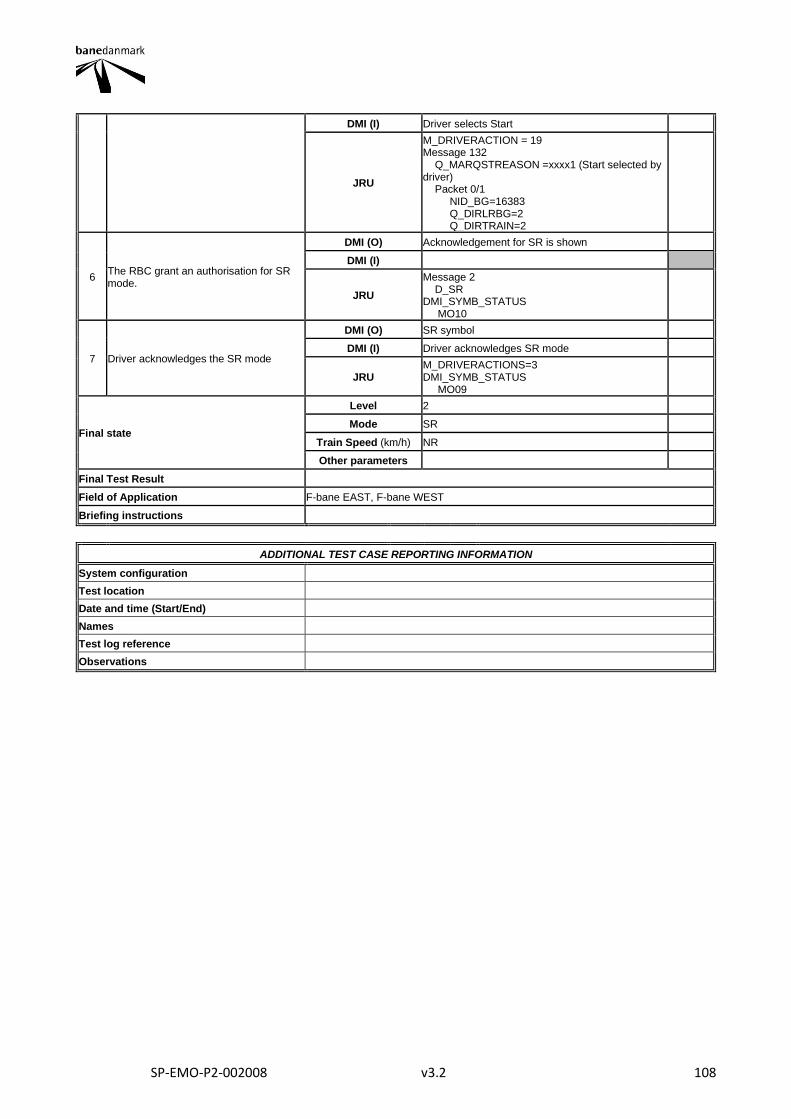
SP-EMO-P2-002008 v3.2 108
DMI (I) Driver selects Start
JRU
M_DRIVERACTION = 19 Message 132 Q_MARQSTREASON =xxxx1 (Start selected by driver) Packet 0/1 NID_BG=16383 Q_DIRLRBG=2 Q_DIRTRAIN=2
6 The RBC grant an authorisation for SR mode.
DMI (O) Acknowledgement for SR is shown
DMI (I)
JRU
Message 2 D_SR DMI_SYMB_STATUS MO10
7 Driver acknowledges the SR mode
DMI (O) SR symbol
DMI (I) Driver acknowledges SR mode
JRU M_DRIVERACTIONS=3 DMI_SYMB_STATUS MO09
Final state
Level 2
Mode SR
Train Speed (km/h) NR
Other parameters
Final Test Result
Field of Application F-bane EAST, F-bane WEST
Briefing instructions
ADDITIONAL TEST CASE REPORTING INFORMATION
System configuration
Test location
Date and time (Start/End)
Names
Test log reference
Observations

SP-EMO-P2-002008 v3.2 109
2.3.22. SH28
TEST CASE DESCRIPTION
Code Version Title
Test Case SH28 1 Exit shunting mode from SH Route. Valid position inside the last track section of the SH route
Baseline applicable Baseline 3 (3.4.0)
Test case author Ineco/CEDEX
Test Objective(s) Verify the exit from shunting mode and the correct SoM procedure when the train is inside the last track section of the SH route
Diagram
Starting conditions
Level L2
Mode SH
Train Speed (km/h) 0
Additional starting conditions Train is at standstill inside the last track section of the SH route and with known location.
Sequence of the Test Case Checkpoints
Step Step description Interfaces Description of what to be tested at the interface OK?
1 Train is at standstill inside the last track section of the SH route The driver selects "Exit from SH mode"
DMI (O)
Vtrain=0 SH symbol disappears SB symbol is displayed Hour glass symbol is displayed
DMI (I) Driver selects Exit of Shunting
JRU
V_TRAIN=0 M_DRIVERACTIONS=17 M_MODE = 6 DMI_SYMB_STATUS ST05, MO13
2 The driver validates or introduces the Driver ID
DMI (O)
DMI (I) DRIVER ID
JRU
3
The establishment of a communication session is initiated by the EVC. A position report with valid position is sent to the RBC.
DMI (O) Safe radio connection “Connection Up”;
DMI (I)
JRU
Message 155 Message 32 Message 159 Message 157 Q_STATUS = 1 (valid) Packet 0/1 NID_LRBG ≠ 16777215 Q_DIRLRBG ≠ 2 Q_DLRBG ≠ 2 DMI_SYMB_STATUS ST03
4 The driver selects train data entry. Train data and train running number is entered or revalidated.
DMI (O) Train data and train running number windows are shown.
DMI (I) Driver selects Data Entry Driver enters the train running number
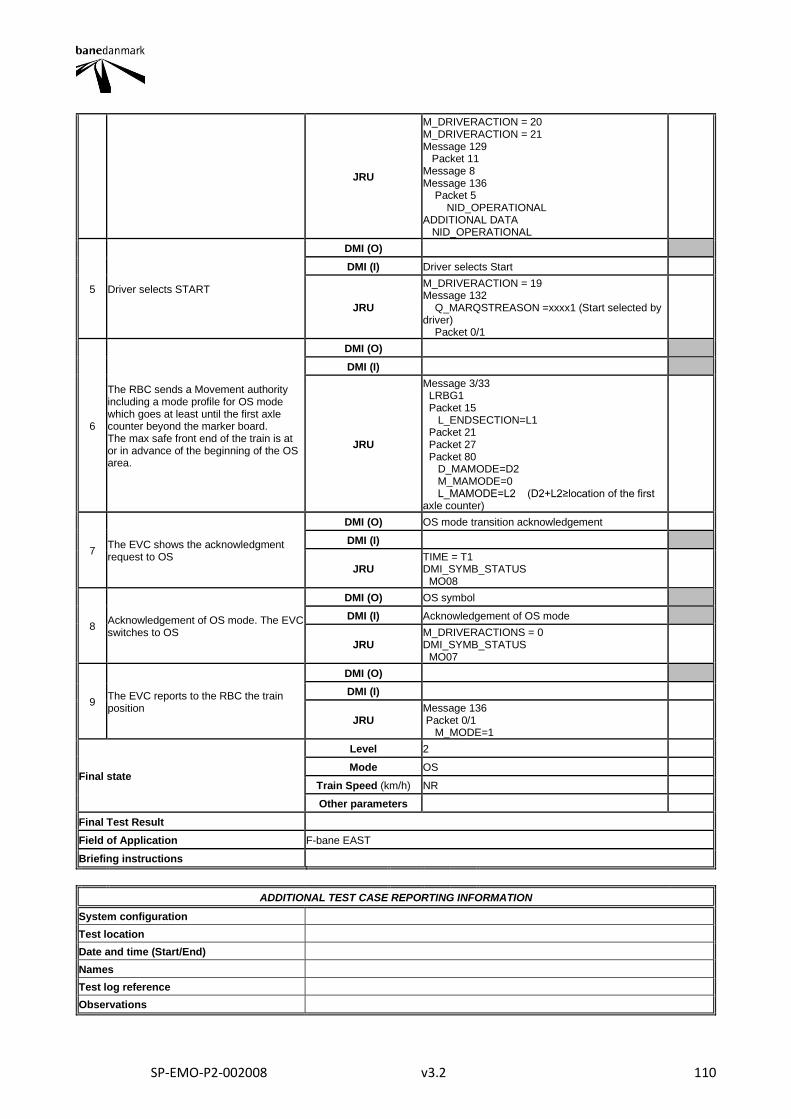
SP-EMO-P2-002008 v3.2 110
JRU
M_DRIVERACTION = 20 M_DRIVERACTION = 21 Message 129 Packet 11 Message 8 Message 136 Packet 5 NID_OPERATIONAL ADDITIONAL DATA NID_OPERATIONAL
5 Driver selects START
DMI (O)
DMI (I) Driver selects Start
JRU
M_DRIVERACTION = 19 Message 132 Q_MARQSTREASON =xxxx1 (Start selected by driver) Packet 0/1
6
The RBC sends a Movement authority including a mode profile for OS mode which goes at least until the first axle counter beyond the marker board. The max safe front end of the train is at or in advance of the beginning of the OS area.
DMI (O)
DMI (I)
JRU
Message 3/33 LRBG1 Packet 15 L_ENDSECTION=L1 Packet 21 Packet 27 Packet 80 D_MAMODE=D2 M_MAMODE=0 L_MAMODE=L2 (D2+L2≥location of the first axle counter)
7 The EVC shows the acknowledgment request to OS
DMI (O) OS mode transition acknowledgement
DMI (I)
JRU TIME = T1 DMI_SYMB_STATUS MO08
8 Acknowledgement of OS mode. The EVC switches to OS
DMI (O) OS symbol
DMI (I) Acknowledgement of OS mode
JRU M_DRIVERACTIONS = 0 DMI_SYMB_STATUS MO07
9 The EVC reports to the RBC the train position
DMI (O)
DMI (I)
JRU Message 136 Packet 0/1 M_MODE=1
Final state
Level 2
Mode OS
Train Speed (km/h) NR
Other parameters
Final Test Result
Field of Application F-bane EAST
Briefing instructions
ADDITIONAL TEST CASE REPORTING INFORMATION
System configuration
Test location
Date and time (Start/End)
Names
Test log reference
Observations

SP-EMO-P2-002008 v3.2 111
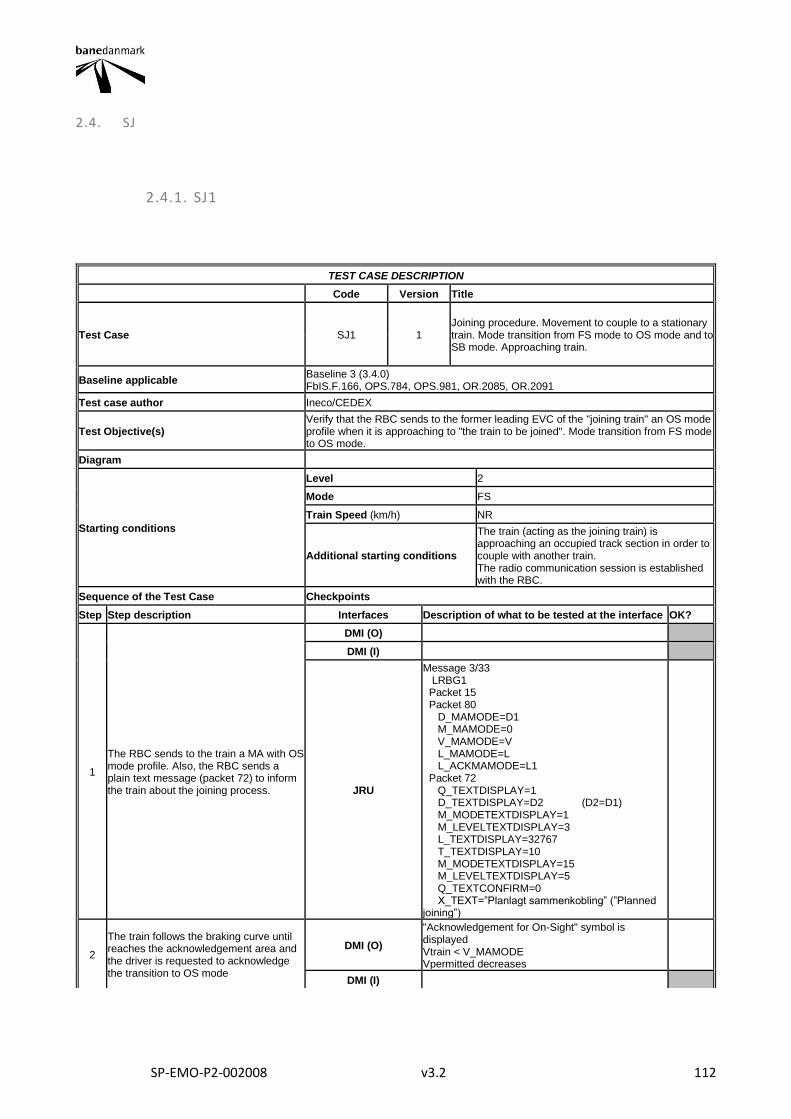
SP-EMO-P2-002008 v3.2 112
2.4. SJ
2.4.1. SJ1
TEST CASE DESCRIPTION
Code Version Title
Test Case SJ1 1 Joining procedure. Movement to couple to a stationary train. Mode transition from FS mode to OS mode and to SB mode. Approaching train.
Baseline applicable Baseline 3 (3.4.0) FbIS.F.166, OPS.784, OPS.981, OR.2085, OR.2091
Test case author Ineco/CEDEX
Test Objective(s) Verify that the RBC sends to the former leading EVC of the "joining train" an OS mode profile when it is approaching to "the train to be joined". Mode transition from FS mode to OS mode.
Diagram
Starting conditions
Level 2
Mode FS
Train Speed (km/h) NR
Additional starting conditions
The train (acting as the joining train) is approaching an occupied track section in order to couple with another train. The radio communication session is established with the RBC.
Sequence of the Test Case Checkpoints
Step Step description Interfaces Description of what to be tested at the interface OK?
1
The RBC sends to the train a MA with OS mode profile. Also, the RBC sends a plain text message (packet 72) to inform the train about the joining process.
DMI (O)
DMI (I)
JRU
Message 3/33 LRBG1 Packet 15 Packet 80 D_MAMODE=D1 M_MAMODE=0 V_MAMODE=V L_MAMODE=L L_ACKMAMODE=L1 Packet 72 Q_TEXTDISPLAY=1 D_TEXTDISPLAY=D2 (D2=D1) M_MODETEXTDISPLAY=1 M_LEVELTEXTDISPLAY=3 L_TEXTDISPLAY=32767 T_TEXTDISPLAY=10 M_MODETEXTDISPLAY=15 M_LEVELTEXTDISPLAY=5 Q_TEXTCONFIRM=0 X_TEXT=”Planlagt sammenkobling” (”Planned joining”)
2
The train follows the braking curve until reaches the acknowledgement area and the driver is requested to acknowledge the transition to OS mode
DMI (O)
"Acknowledgement for On-Sight" symbol is displayed Vtrain < V_MAMODE Vpermitted decreases
DMI (I)
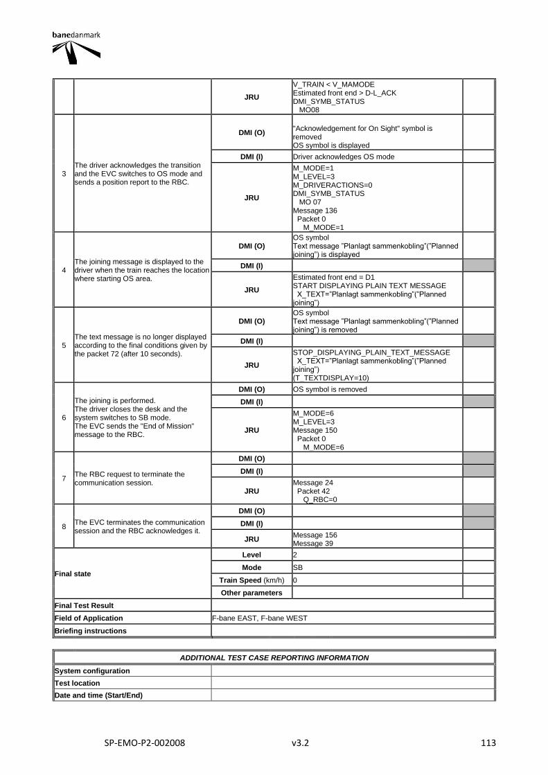
SP-EMO-P2-002008 v3.2 113
JRU
V_TRAIN < V_MAMODE Estimated front end > D-L_ACK DMI_SYMB_STATUS MO08
3 The driver acknowledges the transition and the EVC switches to OS mode and sends a position report to the RBC.
DMI (O)
"Acknowledgement for On Sight" symbol is removed OS symbol is displayed
DMI (I) Driver acknowledges OS mode
JRU
M_MODE=1 M_LEVEL=3 M_DRIVERACTIONS=0 DMI_SYMB_STATUS MO 07 Message 136 Packet 0 M_MODE=1
4 The joining message is displayed to the driver when the train reaches the location where starting OS area.
DMI (O) OS symbol Text message ”Planlagt sammenkobling”(”Planned joining”) is displayed
DMI (I)
JRU
Estimated front end = D1 START DISPLAYING PLAIN TEXT MESSAGE X_TEXT=”Planlagt sammenkobling”(”Planned joining”)
5 The text message is no longer displayed according to the final conditions given by the packet 72 (after 10 seconds).
DMI (O) OS symbol Text message ”Planlagt sammenkobling”(”Planned joining”) is removed
DMI (I)
JRU
STOP_DISPLAYING_PLAIN_TEXT_MESSAGE X_TEXT=”Planlagt sammenkobling”(”Planned joining”) (T_TEXTDISPLAY=10)
6
The joining is performed. The driver closes the desk and the system switches to SB mode. The EVC sends the "End of Mission" message to the RBC.
DMI (O) OS symbol is removed
DMI (I)
JRU
M_MODE=6 M_LEVEL=3 Message 150 Packet 0 M_MODE=6
7 The RBC request to terminate the communication session.
DMI (O)
DMI (I)
JRU Message 24 Packet 42 Q_RBC=0
8 The EVC terminates the communication session and the RBC acknowledges it.
DMI (O)
DMI (I)
JRU Message 156 Message 39
Final state
Level 2
Mode SB
Train Speed (km/h) 0
Other parameters
Final Test Result
Field of Application F-bane EAST, F-bane WEST
Briefing instructions
ADDITIONAL TEST CASE REPORTING INFORMATION
System configuration
Test location
Date and time (Start/End)

SP-EMO-P2-002008 v3.2 114
Names
Test log reference
Observations
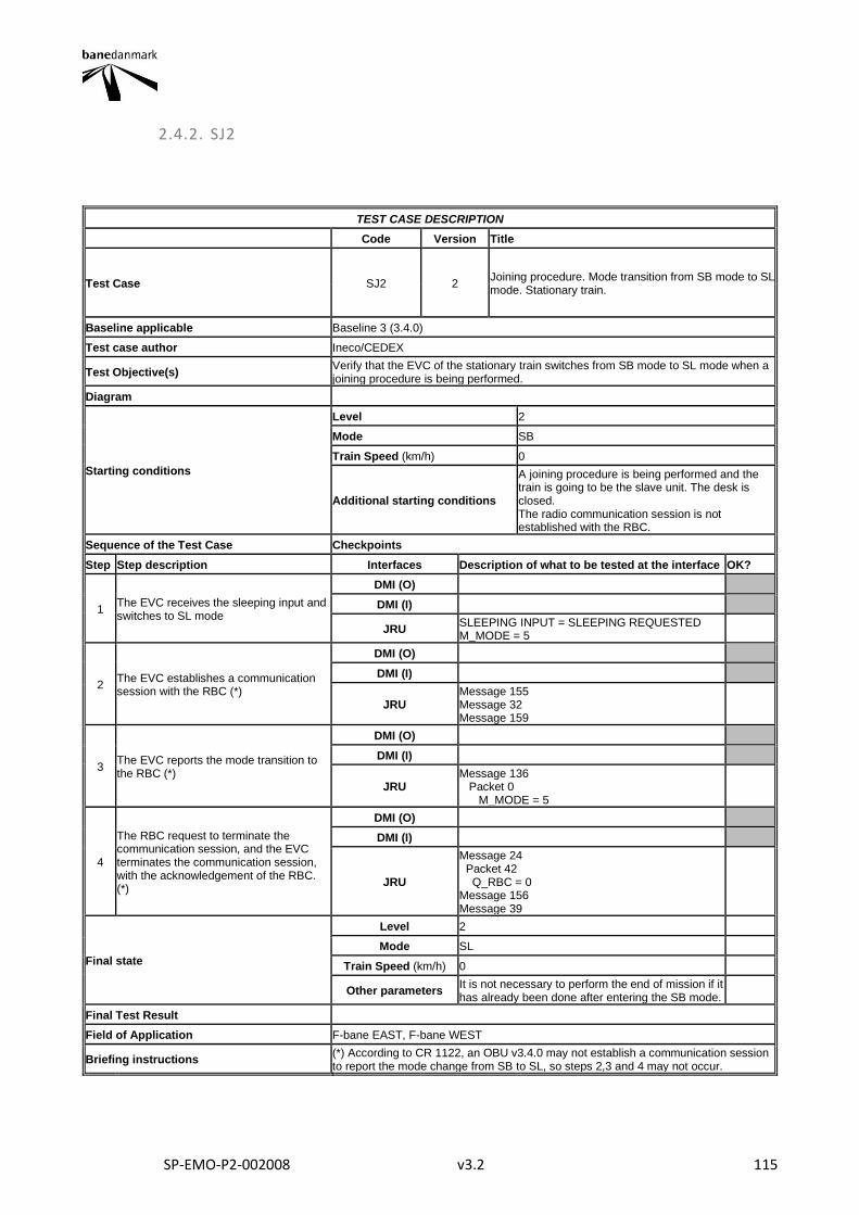
SP-EMO-P2-002008 v3.2 115
2.4.2. SJ2
TEST CASE DESCRIPTION
Code Version Title
Test Case SJ2 2 Joining procedure. Mode transition from SB mode to SL mode. Stationary train.
Baseline applicable Baseline 3 (3.4.0)
Test case author Ineco/CEDEX
Test Objective(s) Verify that the EVC of the stationary train switches from SB mode to SL mode when a joining procedure is being performed.
Diagram
Starting conditions
Level 2
Mode SB
Train Speed (km/h) 0
Additional starting conditions
A joining procedure is being performed and the train is going to be the slave unit. The desk is closed. The radio communication session is not established with the RBC.
Sequence of the Test Case Checkpoints
Step Step description Interfaces Description of what to be tested at the interface OK?
1 The EVC receives the sleeping input and switches to SL mode
DMI (O)
DMI (I)
JRU SLEEPING INPUT = SLEEPING REQUESTED M_MODE = 5
2 The EVC establishes a communication session with the RBC (*)
DMI (O)
DMI (I)
JRU Message 155 Message 32 Message 159
3 The EVC reports the mode transition to the RBC (*)
DMI (O)
DMI (I)
JRU Message 136 Packet 0 M_MODE = 5
4
The RBC request to terminate the communication session, and the EVC terminates the communication session, with the acknowledgement of the RBC. (*)
DMI (O)
DMI (I)
JRU
Message 24 Packet 42 Q_RBC = 0 Message 156 Message 39
Final state
Level 2
Mode SL
Train Speed (km/h) 0
Other parameters It is not necessary to perform the end of mission if it has already been done after entering the SB mode.
Final Test Result
Field of Application F-bane EAST, F-bane WEST
Briefing instructions (*) According to CR 1122, an OBU v3.4.0 may not establish a communication session to report the mode change from SB to SL, so steps 2,3 and 4 may not occur.

SP-EMO-P2-002008 v3.2 116
ADDITIONAL TEST CASE REPORTING INFORMATION
System configuration
Test location
Date and time (Start/End)
Names
Test log reference
Observations
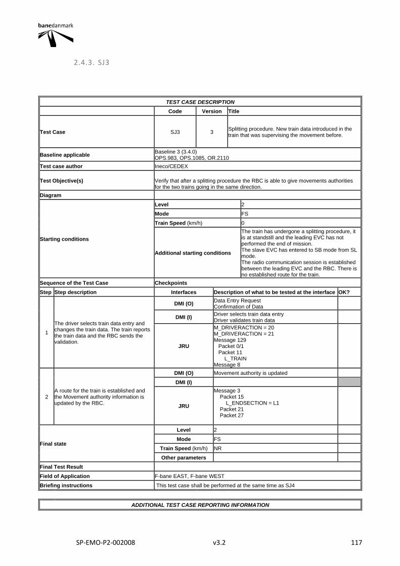
SP-EMO-P2-002008 v3.2 117
2.4.3. SJ3
TEST CASE DESCRIPTION
Code Version Title
Test Case SJ3 3 Splitting procedure. New train data introduced in the train that was supervising the movement before.
Baseline applicable Baseline 3 (3.4.0) OPS.983, OPS.1085, OR.2110
Test case author Ineco/CEDEX
Test Objective(s) Verify that after a splitting procedure the RBC is able to give movements authorities for the two trains going in the same direction.
Diagram
Starting conditions
Level 2
Mode FS
Train Speed (km/h) 0
Additional starting conditions
The train has undergone a splitting procedure, it is at standstill and the leading EVC has not performed the end of mission. The slave EVC has entered to SB mode from SL mode. The radio communication session is established between the leading EVC and the RBC. There is no established route for the train.
Sequence of the Test Case Checkpoints
Step Step description Interfaces Description of what to be tested at the interface OK?
1
The driver selects train data entry and changes the train data. The train reports the train data and the RBC sends the validation.
DMI (O) Data Entry Request Confirmation of Data
DMI (I) Driver selects train data entry Driver validates train data
JRU
M_DRIVERACTION = 20 M_DRIVERACTION = 21 Message 129 Packet 0/1 Packet 11 L_TRAIN Message 8
2 A route for the train is established and the Movement authority information is updated by the RBC.
DMI (O) Movement authority is updated
DMI (I)
JRU
Message 3 Packet 15 L_ENDSECTION = L1 Packet 21 Packet 27
Final state
Level 2
Mode FS
Train Speed (km/h) NR
Other parameters
Final Test Result
Field of Application F-bane EAST, F-bane WEST
Briefing instructions This test case shall be performed at the same time as SJ4
ADDITIONAL TEST CASE REPORTING INFORMATION

SP-EMO-P2-002008 v3.2 118
System configuration
Test location
Date and time (Start/End)
Names
Test log reference
Observations
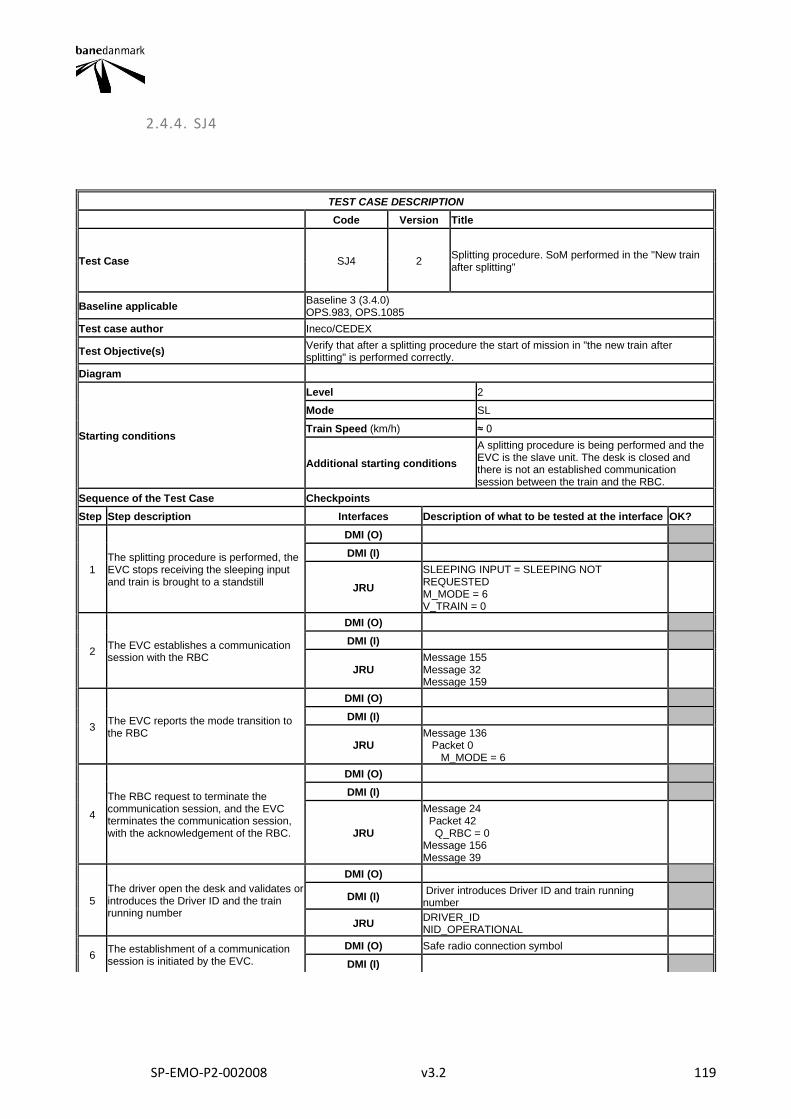
SP-EMO-P2-002008 v3.2 119
2.4.4. SJ4
TEST CASE DESCRIPTION
Code Version Title
Test Case SJ4 2 Splitting procedure. SoM performed in the "New train after splitting"
Baseline applicable Baseline 3 (3.4.0) OPS.983, OPS.1085
Test case author Ineco/CEDEX
Test Objective(s) Verify that after a splitting procedure the start of mission in "the new train after splitting" is performed correctly.
Diagram
Starting conditions
Level 2
Mode SL
Train Speed (km/h) ≈ 0
Additional starting conditions
A splitting procedure is being performed and the EVC is the slave unit. The desk is closed and there is not an established communication session between the train and the RBC.
Sequence of the Test Case Checkpoints
Step Step description Interfaces Description of what to be tested at the interface OK?
1 The splitting procedure is performed, the EVC stops receiving the sleeping input and train is brought to a standstill
DMI (O)
DMI (I)
JRU
SLEEPING INPUT = SLEEPING NOT REQUESTED M_MODE = 6 V_TRAIN = 0
2 The EVC establishes a communication session with the RBC
DMI (O)
DMI (I)
JRU Message 155 Message 32 Message 159
3 The EVC reports the mode transition to the RBC
DMI (O)
DMI (I)
JRU Message 136 Packet 0 M_MODE = 6
4
The RBC request to terminate the communication session, and the EVC terminates the communication session, with the acknowledgement of the RBC.
DMI (O)
DMI (I)
JRU
Message 24 Packet 42 Q_RBC = 0 Message 156 Message 39
5 The driver open the desk and validates or introduces the Driver ID and the train running number
DMI (O)
DMI (I) Driver introduces Driver ID and train running number
JRU DRIVER_ID NID_OPERATIONAL
6 The establishment of a communication session is initiated by the EVC.
DMI (O) Safe radio connection symbol
DMI (I)
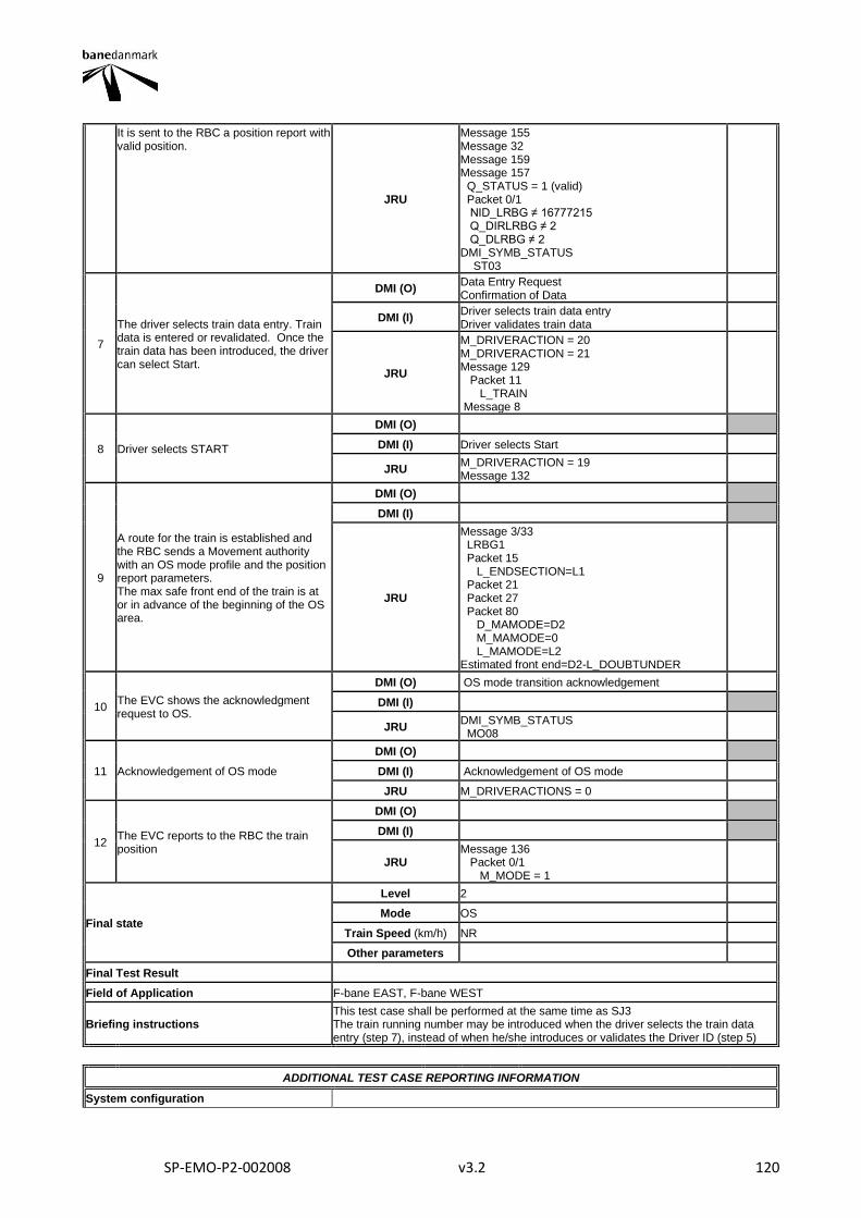
SP-EMO-P2-002008 v3.2 120
It is sent to the RBC a position report with valid position.
JRU
Message 155 Message 32 Message 159 Message 157 Q_STATUS = 1 (valid) Packet 0/1 NID_LRBG ≠ 16777215 Q_DIRLRBG ≠ 2 Q_DLRBG ≠ 2 DMI_SYMB_STATUS ST03
7
The driver selects train data entry. Train data is entered or revalidated. Once the train data has been introduced, the driver can select Start.
DMI (O) Data Entry Request Confirmation of Data
DMI (I) Driver selects train data entry Driver validates train data
JRU
M_DRIVERACTION = 20 M_DRIVERACTION = 21 Message 129 Packet 11 L_TRAIN Message 8
8 Driver selects START
DMI (O)
DMI (I) Driver selects Start
JRU M_DRIVERACTION = 19 Message 132
9
A route for the train is established and the RBC sends a Movement authority with an OS mode profile and the position report parameters. The max safe front end of the train is at or in advance of the beginning of the OS area.
DMI (O)
DMI (I)
JRU
Message 3/33 LRBG1 Packet 15 L_ENDSECTION=L1 Packet 21 Packet 27 Packet 80 D_MAMODE=D2 M_MAMODE=0 L_MAMODE=L2 Estimated front end=D2-L_DOUBTUNDER
10 The EVC shows the acknowledgment request to OS.
DMI (O) OS mode transition acknowledgement
DMI (I)
JRU DMI_SYMB_STATUS MO08
11 Acknowledgement of OS mode
DMI (O)
DMI (I) Acknowledgement of OS mode
JRU M_DRIVERACTIONS = 0
12 The EVC reports to the RBC the train position
DMI (O)
DMI (I)
JRU Message 136 Packet 0/1 M_MODE = 1
Final state
Level 2
Mode OS
Train Speed (km/h) NR
Other parameters
Final Test Result
Field of Application F-bane EAST, F-bane WEST
Briefing instructions This test case shall be performed at the same time as SJ3 The train running number may be introduced when the driver selects the train data entry (step 7), instead of when he/she introduces or validates the Driver ID (step 5)
ADDITIONAL TEST CASE REPORTING INFORMATION
System configuration

SP-EMO-P2-002008 v3.2 121
Test location
Date and time (Start/End)
Names
Test log reference
Observations
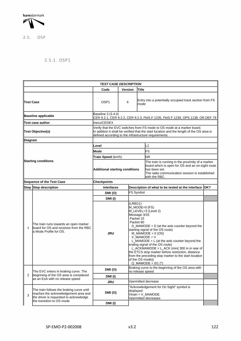
SP-EMO-P2-002008 v3.2 122
2.5. OSP
2.5.1. OSP1
TEST CASE DESCRIPTION
Code Version Title
Test Case OSP1 6 Entry into a potentially occupied track section from FS mode
Baseline applicable Baseline 3 (3.4.0) CER 9.2.1, CER 9.2.2, CER 9.2.3, FbIS.F.1235, FbIS.F.1239, OPS.1138, OR.DEF.79
Test case author Ineco/CEDEX
Test Objective(s) Verify that the EVC switches from FS mode to OS mode at a marker board. In addition it shall be verified that the start location and the length of the OS area is defined according to the infrastructure requirements.
Diagram
Starting conditions
Level L2
Mode FS
Train Speed (km/h) NR
Additional starting conditions
The train is running in the proximity of a marker board which is open for OS and an on-sight route has been set. The radio communication session is established with the RBC.
Sequence of the Test Case Checkpoints
Step Step description Interfaces Description of what to be tested at the interface OK?
1 The train runs towards an open marker board for OS and receives from the RBC a Mode Profile for OS.
DMI (O) FS Symbol
DMI (I)
JRU
(LRBG1) M_MODE=0 (FS) M_LEVEL=3 (Level 2) Message 3/33 Packet 15 Packet 80 D_MAMODE = D (at the axle counter beyond the starting signal of the OS route) M_MAMODE = 0 (OS) V_MAMODE = V L_MAMODE = L (at the axle counter beyond the ending signal of the OS route) L_ACKMAMODE = L_ACK (min{ 300 m in rear of the ETCS stop marker before restriction, distance from the preceding stop marker to the start location of the OS mode}) Q_MAMODE = 0/1 (*)
2 The EVC enters in braking curve. The beginning of the OS area is considered as an EoA with no release speed
DMI (O) Braking curve to the beginning of the OS area with no release speed
DMI (I)
JRU Vpermitted decrease
3
The train follows the braking curve until reaches the acknowledgement area and the driver is requested to acknowledge the transition to OS mode
DMI (O)
"Acknowledgement for On Sight" symbol is displayed Vtrain < V_MAMODE Vpermitted decreases
DMI (I)
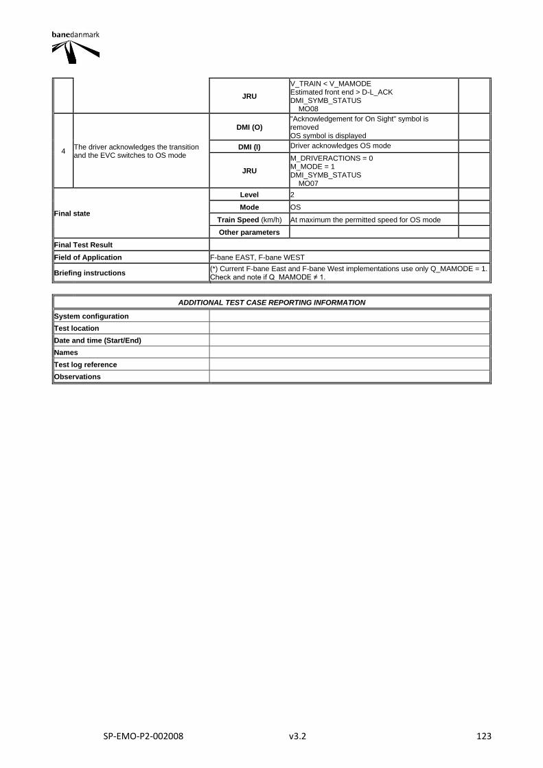
SP-EMO-P2-002008 v3.2 123
JRU
V_TRAIN < V_MAMODE Estimated front end > D-L_ACK DMI_SYMB_STATUS MO08
4 The driver acknowledges the transition and the EVC switches to OS mode
DMI (O) "Acknowledgement for On Sight" symbol is removed OS symbol is displayed
DMI (I) Driver acknowledges OS mode
JRU
M_DRIVERACTIONS = 0 M_MODE = 1 DMI_SYMB_STATUS MO07
Final state
Level 2
Mode OS
Train Speed (km/h) At maximum the permitted speed for OS mode
Other parameters
Final Test Result
Field of Application F-bane EAST, F-bane WEST
Briefing instructions (*) Current F-bane East and F-bane West implementations use only Q_MAMODE = 1. Check and note if Q_MAMODE ≠ 1.
ADDITIONAL TEST CASE REPORTING INFORMATION
System configuration
Test location
Date and time (Start/End)
Names
Test log reference
Observations
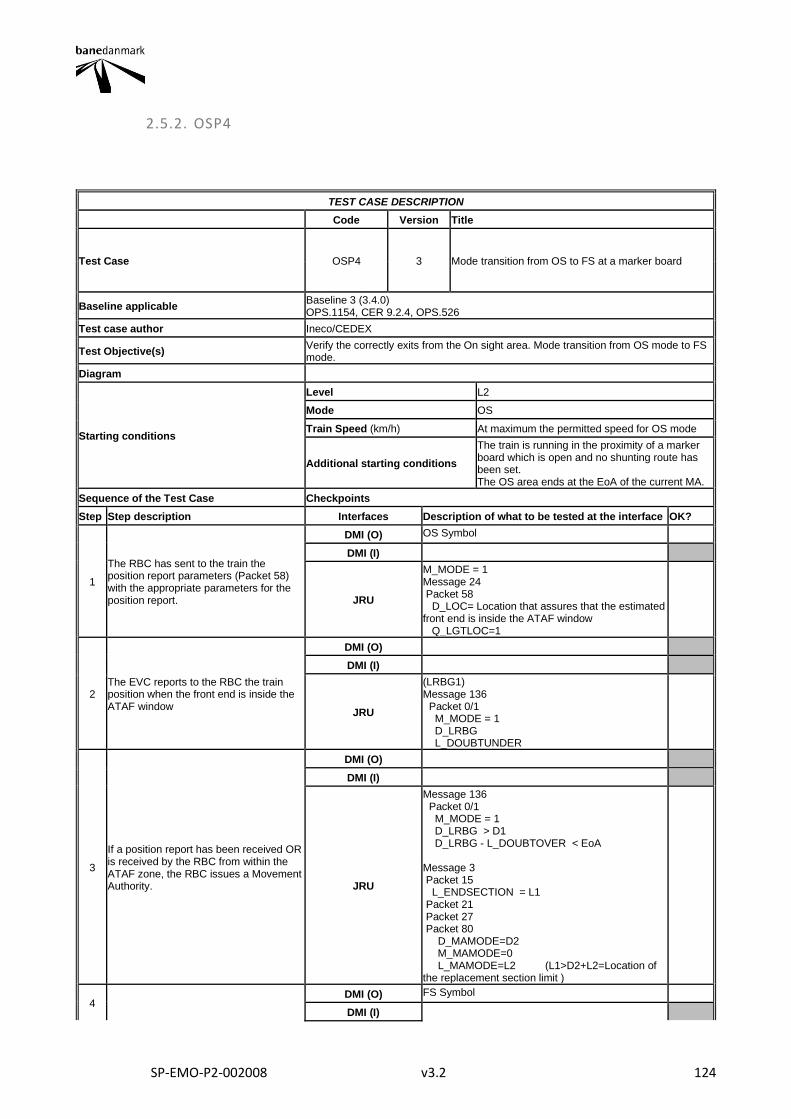
SP-EMO-P2-002008 v3.2 124
2.5.2. OSP4
TEST CASE DESCRIPTION
Code Version Title
Test Case OSP4 3 Mode transition from OS to FS at a marker board
Baseline applicable Baseline 3 (3.4.0) OPS.1154, CER 9.2.4, OPS.526
Test case author Ineco/CEDEX
Test Objective(s) Verify the correctly exits from the On sight area. Mode transition from OS mode to FS mode.
Diagram
Starting conditions
Level L2
Mode OS
Train Speed (km/h) At maximum the permitted speed for OS mode
Additional starting conditions
The train is running in the proximity of a marker board which is open and no shunting route has been set. The OS area ends at the EoA of the current MA.
Sequence of the Test Case Checkpoints
Step Step description Interfaces Description of what to be tested at the interface OK?
1
The RBC has sent to the train the position report parameters (Packet 58) with the appropriate parameters for the position report.
DMI (O) OS Symbol
DMI (I)
JRU
M_MODE = 1 Message 24 Packet 58 D_LOC= Location that assures that the estimated front end is inside the ATAF window Q_LGTLOC=1
2 The EVC reports to the RBC the train position when the front end is inside the ATAF window
DMI (O)
DMI (I)
JRU
(LRBG1) Message 136 Packet 0/1 M_MODE = 1 D_LRBG L_DOUBTUNDER
3
If a position report has been received OR is received by the RBC from within the ATAF zone, the RBC issues a Movement Authority.
DMI (O)
DMI (I)
JRU
Message 136 Packet 0/1 M_MODE = 1 D_LRBG > D1 D_LRBG - L_DOUBTOVER < EoA Message 3 Packet 15 L_ENDSECTION = L1 Packet 21 Packet 27 Packet 80 D_MAMODE=D2 M_MAMODE=0 L_MAMODE=L2 (L1>D2+L2=Location of the replacement section limit )
4 DMI (O) FS Symbol
DMI (I)
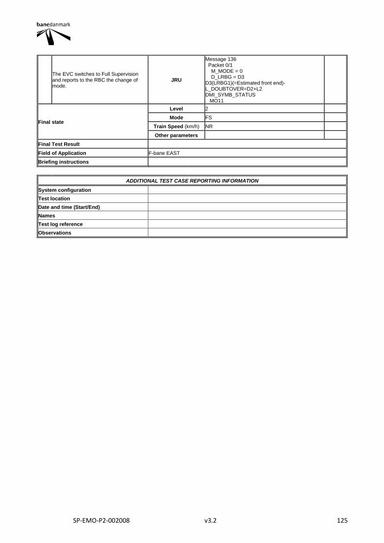
SP-EMO-P2-002008 v3.2 125
The EVC switches to Full Supervision and reports to the RBC the change of mode.
JRU
Message 136 Packet 0/1 M_MODE = 0 D_LRBG = D3 D3(LRBG1)(=Estimated front end)-L_DOUBTOVER=D2+L2 DMI_SYMB_STATUS MO11
Final state
Level 2
Mode FS
Train Speed (km/h) NR
Other parameters
Final Test Result
Field of Application F-bane EAST
Briefing instructions
ADDITIONAL TEST CASE REPORTING INFORMATION
System configuration
Test location
Date and time (Start/End)
Names
Test log reference
Observations
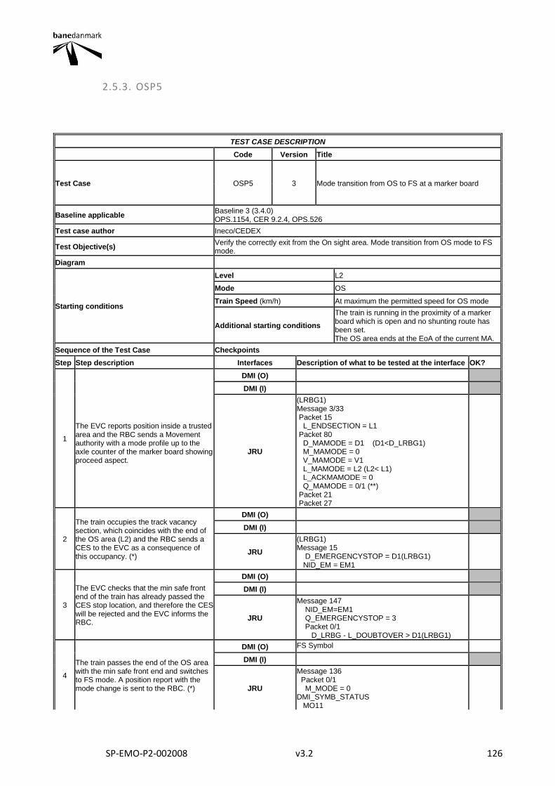
SP-EMO-P2-002008 v3.2 126
2.5.3. OSP5
TEST CASE DESCRIPTION
Code Version Title
Test Case OSP5 3 Mode transition from OS to FS at a marker board
Baseline applicable Baseline 3 (3.4.0) OPS.1154, CER 9.2.4, OPS.526
Test case author Ineco/CEDEX
Test Objective(s) Verify the correctly exit from the On sight area. Mode transition from OS mode to FS mode.
Diagram
Starting conditions
Level L2
Mode OS
Train Speed (km/h) At maximum the permitted speed for OS mode
Additional starting conditions
The train is running in the proximity of a marker board which is open and no shunting route has been set. The OS area ends at the EoA of the current MA.
Sequence of the Test Case Checkpoints
Step Step description Interfaces Description of what to be tested at the interface OK?
1
The EVC reports position inside a trusted area and the RBC sends a Movement authority with a mode profile up to the axle counter of the marker board showing proceed aspect.
DMI (O)
DMI (I)
JRU
(LRBG1) Message 3/33 Packet 15 L_ENDSECTION = L1 Packet 80 D_MAMODE = D1 (D1<D_LRBG1) M_MAMODE = 0 V_MAMODE = V1 L_MAMODE = L2 (L2< L1) L_ACKMAMODE = 0 Q_MAMODE = 0/1 (**) Packet 21 Packet 27
2
The train occupies the track vacancy section, which coincides with the end of the OS area (L2) and the RBC sends a CES to the EVC as a consequence of this occupancy. (*)
DMI (O)
DMI (I)
JRU
(LRBG1) Message 15 D_EMERGENCYSTOP = D1(LRBG1) NID_EM = EM1
3
The EVC checks that the min safe front end of the train has already passed the CES stop location, and therefore the CES will be rejected and the EVC informs the RBC.
DMI (O)
DMI (I)
JRU
Message 147 NID_EM=EM1 Q_EMERGENCYSTOP = 3 Packet 0/1 D_LRBG - L_DOUBTOVER > D1(LRBG1)
4
The train passes the end of the OS area with the min safe front end and switches to FS mode. A position report with the mode change is sent to the RBC. (*)
DMI (O) FS Symbol
DMI (I)
JRU
Message 136 Packet 0/1 M_MODE = 0 DMI_SYMB_STATUS MO11
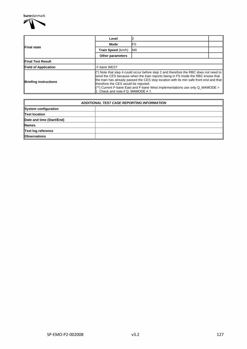
SP-EMO-P2-002008 v3.2 127
Final state
Level 2
Mode FS
Train Speed (km/h) NR
Other parameters
Final Test Result
Field of Application F-bane WEST
Briefing instructions
(*) Note that step 4 could occur before step 2 and therefore the RBC does not need to send the CES because when the train reports being in FS mode the RBC knows that the train has already passed the CES stop location with its min safe front end and that therefore the CES would be rejected. (**) Current F-bane East and F-bane West implementations use only Q_MAMODE = 1. Check and note if Q_MAMODE ≠ 1.
ADDITIONAL TEST CASE REPORTING INFORMATION
System configuration
Test location
Date and time (Start/End)
Names
Test log reference
Observations
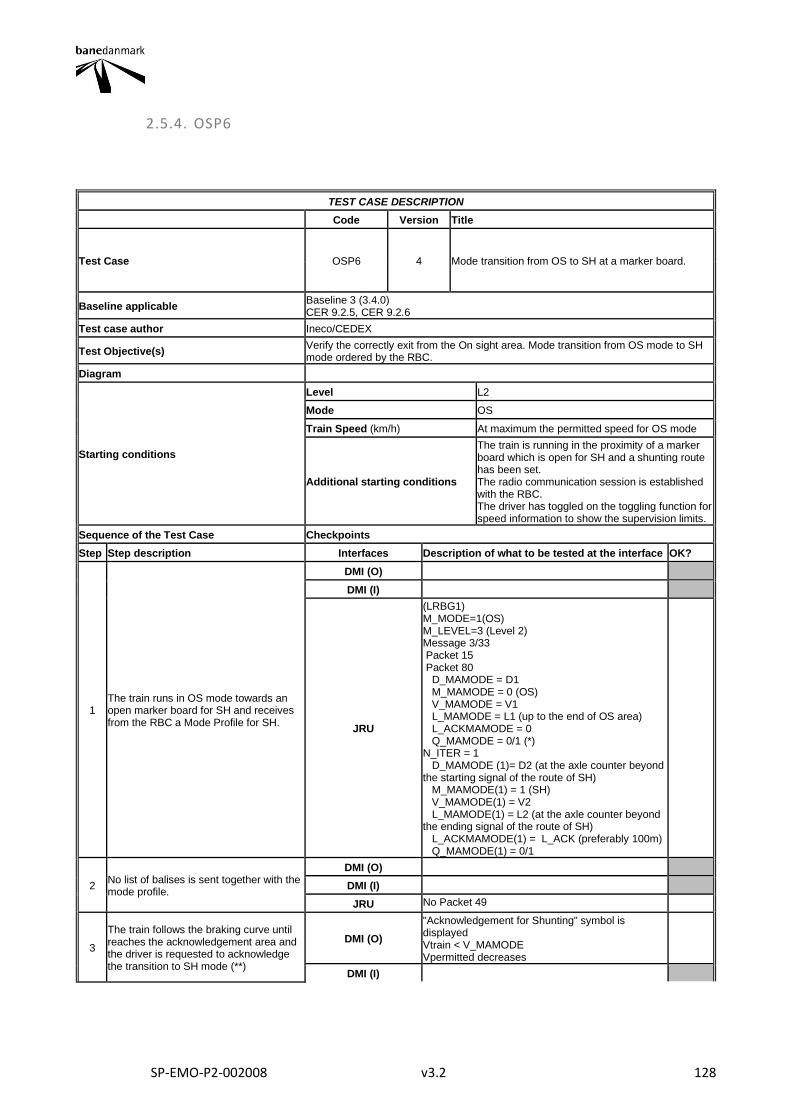
SP-EMO-P2-002008 v3.2 128
2.5.4. OSP6
TEST CASE DESCRIPTION
Code Version Title
Test Case OSP6 4 Mode transition from OS to SH at a marker board.
Baseline applicable Baseline 3 (3.4.0) CER 9.2.5, CER 9.2.6
Test case author Ineco/CEDEX
Test Objective(s) Verify the correctly exit from the On sight area. Mode transition from OS mode to SH mode ordered by the RBC.
Diagram
Starting conditions
Level L2
Mode OS
Train Speed (km/h) At maximum the permitted speed for OS mode
Additional starting conditions
The train is running in the proximity of a marker board which is open for SH and a shunting route has been set. The radio communication session is established with the RBC. The driver has toggled on the toggling function for speed information to show the supervision limits.
Sequence of the Test Case Checkpoints
Step Step description Interfaces Description of what to be tested at the interface OK?
1 The train runs in OS mode towards an open marker board for SH and receives from the RBC a Mode Profile for SH.
DMI (O)
DMI (I)
JRU
(LRBG1) M_MODE=1(OS) M_LEVEL=3 (Level 2) Message 3/33 Packet 15 Packet 80 D_MAMODE = D1 M_MAMODE = 0 (OS) V_MAMODE = V1 L_MAMODE = L1 (up to the end of OS area) L_ACKMAMODE = 0 Q_MAMODE = 0/1 (*) N_ITER = 1 D_MAMODE (1)= D2 (at the axle counter beyond the starting signal of the route of SH) M_MAMODE(1) = 1 (SH) V_MAMODE(1) = V2 L_MAMODE(1) = L2 (at the axle counter beyond the ending signal of the route of SH) L_ACKMAMODE(1) = L_ACK (preferably 100m) Q_MAMODE(1) = 0/1
2 No list of balises is sent together with the mode profile.
DMI (O)
DMI (I)
JRU No Packet 49
3
The train follows the braking curve until reaches the acknowledgement area and the driver is requested to acknowledge the transition to SH mode (**)
DMI (O)
"Acknowledgement for Shunting" symbol is displayed Vtrain < V_MAMODE Vpermitted decreases
DMI (I)
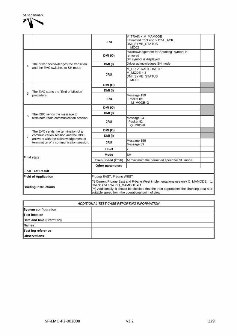
SP-EMO-P2-002008 v3.2 129
JRU
V_TRAIN < V_MAMODE Estimated front end > D2-L_ACK DMI_SYMB_STATUS MO02
4 The driver acknowledges the transition and the EVC switches to SH mode
DMI (O) "Acknowledgement for Shunting" symbol is removed SH symbol is displayed
DMI (I) Driver acknowledges SH mode
JRU
M_DRIVERACTIONS = 1 M_MODE = 3 DMI_SYMB_STATUS MO01
5 The EVC starts the "End of Mission" procedure.
DMI (O)
DMI (I)
JRU Message 150 Packet 0/1 M_MODE=3
6 The RBC sends the message to terminate radio communication session.
DMI (O)
DMI (I)
JRU Message 24 Packet 42 Q_RBC=0
7
The EVC sends the termination of a communication session and the RBC answers with the acknowledgement of termination of a communication session.
DMI (O)
DMI (I)
JRU Message 156 Message 39
Final state
Level 2
Mode SH
Train Speed (km/h) At maximum the permitted speed for SH mode
Other parameters
Final Test Result
Field of Application F-bane EAST, F-bane WEST
Briefing instructions
(*) Current F-bane East and F-bane West implementations use only Q_MAMODE = 1. Check and note if Q_MAMODE ≠ 1. (**) Additionally, it should be checked that the train approaches the shunting area at a suitable speed from the operational point of view
ADDITIONAL TEST CASE REPORTING INFORMATION
System configuration
Test location
Date and time (Start/End)
Names
Test log reference
Observations
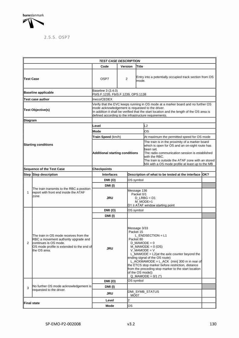
SP-EMO-P2-002008 v3.2 130
2.5.5. OSP7
TEST CASE DESCRIPTION
Code Version Title
Test Case OSP7 2 Entry into a potentially occupied track section from OS mode.
Baseline applicable Baseline 3 (3.4.0) FbIS.F.1235, FbIS.F.1239, OPS.1138
Test case author Ineco/CEDEX
Test Objective(s)
Verify that the EVC keeps running in OS mode at a marker board and no further OS mode acknowledgement is requested to the driver. In addition it shall be verified that the start location and the length of the OS area is defined according to the infrastructure requirements.
Diagram
Starting conditions
Level L2
Mode OS
Train Speed (km/h) At maximum the permitted speed for OS mode
Additional starting conditions
The train is in the proximity of a marker board which is open for OS and an on-sight route has been set. The radio communication session is established with the RBC. The train is outside the ATAF zone with an stored MA with a OS mode profile at least up to the MB
Sequence of the Test Case Checkpoints
Step Step description Interfaces Description of what to be tested at the interface OK?
1 The train transmits to the RBC a position report with front end inside the ATAF zone
DMI (O) OS symbol
DMI (I)
JRU
Message 136 Packet 0/1 D_LRBG = D1 M_MODE=1 D1 ≥ ATAF window starting point
2
The train in OS mode receives from the RBC a movement authority upgrade and continues is OS mode. OS mode profile is extended to the end of the OS area.
DMI (O) OS symbol
DMI (I)
JRU
Message 3/33 Packet 15 L_ENDSECTION = L1 Packet 80 D_MAMODE = 0 M_MAMODE = 0 (OS) V_MAMODE = V L_MAMODE = L2(at the axle counter beyond the ending signal of the OS route) L_ACKMAMODE = L_ACK (min{ 300 m in rear of the ETCS stop marker before restriction, distance from the preceding stop marker to the start location of the OS mode}) Q_MAMODE = 0/1 (*)
3 No further OS mode acknowledgement is requested to the driver.
DMI (O) OS symbol
DMI (I)
JRU DMI_SYMB_STATUS MO07
Final state Level 2
Mode OS

SP-EMO-P2-002008 v3.2 131
Train Speed (km/h) At maximum the permitted speed for OS mode
Other parameters
Final Test Result
Field of Application F-bane EAST
Briefing instructions (*) Current F-bane East and F-bane West implementations use only Q_MAMODE = 1. Check and note if Q_MAMODE ≠ 1.
ADDITIONAL TEST CASE REPORTING INFORMATION
System configuration
Test location
Date and time (Start/End)
Names
Test log reference
Observations
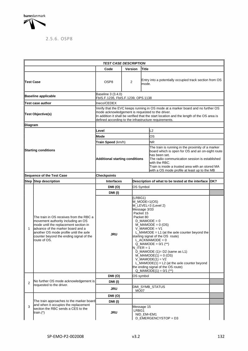
SP-EMO-P2-002008 v3.2 132
2.5.6. OSP8
TEST CASE DESCRIPTION
Code Version Title
Test Case OSP8 2 Entry into a potentially occupied track section from OS mode.
Baseline applicable Baseline 3 (3.4.0) FbIS.F.1235, FbIS.F.1239, OPS.1138
Test case author Ineco/CEDEX
Test Objective(s)
Verify that the EVC keeps running in OS mode at a marker board and no further OS mode acknowledgement is requested to the driver. In addition it shall be verified that the start location and the length of the OS area is defined according to the infrastructure requirements.
Diagram
Starting conditions
Level L2
Mode OS
Train Speed (km/h) NR
Additional starting conditions
The train is running in the proximity of a marker board which is open for OS and an on-sight route has been set. The radio communication session is established with the RBC. Train is inside a trusted area with an stored MA with a OS mode profile at least up to the MB
Sequence of the Test Case Checkpoints
Step Step description Interfaces Description of what to be tested at the interface OK?
1
The train in OS receives from the RBC a movement authority including an OS mode until the replacement section in advance of the marker board and a another OS mode profile until the axle counter beyond the ending signal of the route of OS.
DMI (O) OS Symbol
DMI (I)
JRU
(LRBG1) M_MODE=1(OS) M_LEVEL=3 (Level 2) Message 3/33 Packet 15 Packet 80 D_MAMODE = 0 M_MAMODE = 0 (OS) V_MAMODE = V1 L_MAMODE = L1 (at the axle counter beyond the starting signal of the OS route) L_ACKMAMODE = 0 Q_MAMODE = 0/1 (**) N_ITER = 1 D_MAMODE (1)= D2 (same as L1) M_MAMODE(1) = 0 (OS) V_MAMODE(1) = V2 L_MAMODE(1) = L2 (at the axle counter beyond the ending signal of the OS route) Q_MAMODE(1) = 0/1 (**)
2 No further OS mode acknowledgement is requested to the driver.
DMI (O) OS symbol
DMI (I)
JRU DMI_SYMB_STATUS MO07
3
The train approaches to the marker board and when it occupies the replacement section the RBC sends a CES to the train.(*)
DMI (O)
DMI (I)
JRU
Message 15 LRBG1 NID_EM=EM1 D_EMERGENCYSTOP = D3
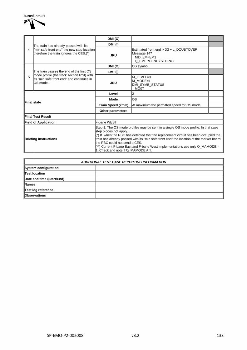
SP-EMO-P2-002008 v3.2 133
4 The train has already passed with its "min safe front end" the new stop location therefore the train ignores the CES.(*)
DMI (O)
DMI (I)
JRU
Estimated front end > D3 + L_DOUBTOVER Message 147 NID_EM=EM1 Q_EMERGENCYSTOP=3
5
The train passes the end of the first OS mode profile (the track section limit) with its "min safe front end" and continues in OS mode.
DMI (O) OS symbol
DMI (I)
JRU
M_LEVEL=3 M_MODE=1 DMI_SYMB_STATUS MO07
Final state
Level 2
Mode OS
Train Speed (km/h) At maximum the permitted speed for OS mode
Other parameters
Final Test Result
Field of Application F-bane WEST
Briefing instructions
Step 1: The OS mode profiles may be sent in a single OS mode profile. In that case step 5 does not apply. (*) If when the RBC has detected that the replacement circuit has been occupied the train has already passed with its "min safe front end" the location of the marker board the RBC could not send a CES. (**) Current F-bane East and F-bane West implementations use only Q_MAMODE = 1. Check and note if Q_MAMODE ≠ 1.
ADDITIONAL TEST CASE REPORTING INFORMATION
System configuration
Test location
Date and time (Start/End)
Names
Test log reference
Observations
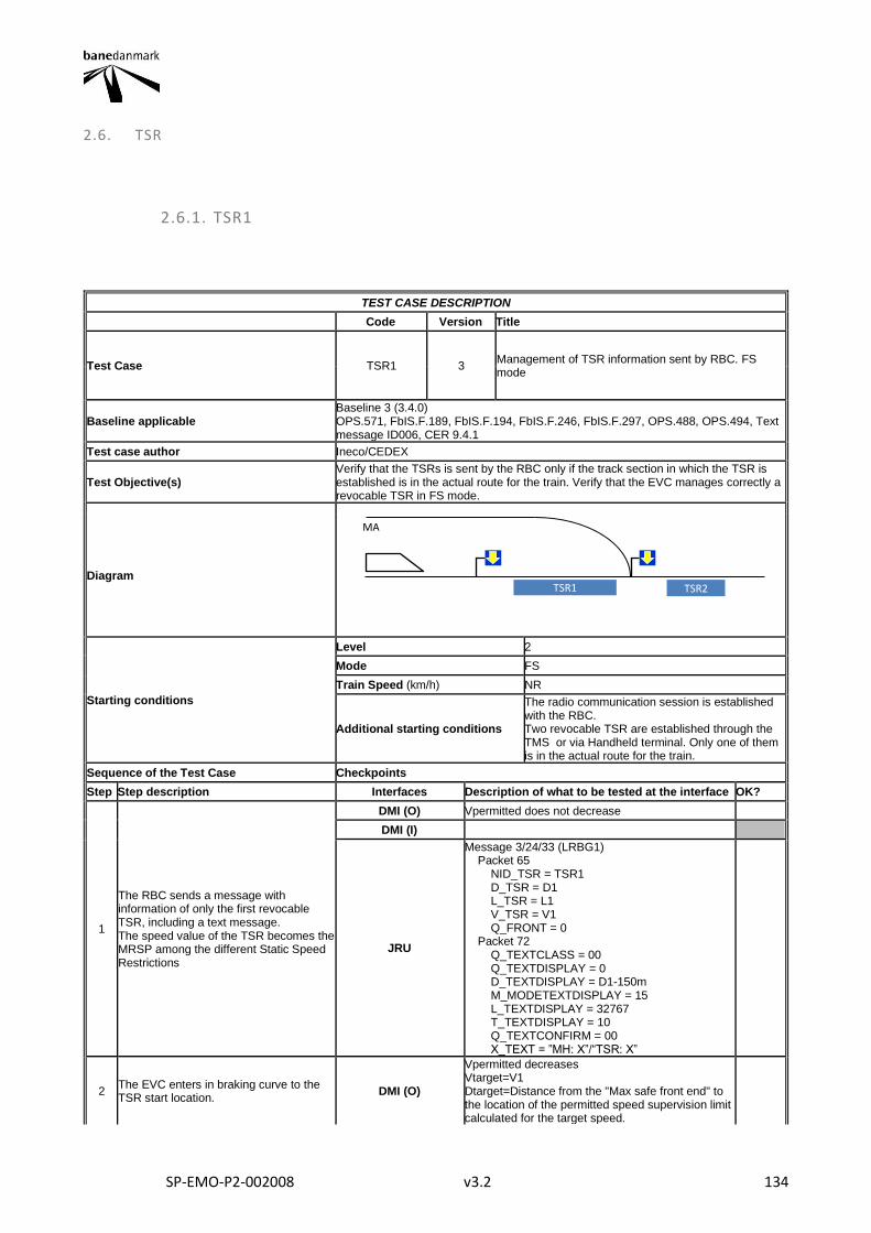
SP-EMO-P2-002008 v3.2 134
2.6. TSR
2.6.1. TSR1
TEST CASE DESCRIPTION
Code Version Title
Test Case TSR1 3 Management of TSR information sent by RBC. FS mode
Baseline applicable Baseline 3 (3.4.0) OPS.571, FbIS.F.189, FbIS.F.194, FbIS.F.246, FbIS.F.297, OPS.488, OPS.494, Text message ID006, CER 9.4.1
Test case author Ineco/CEDEX
Test Objective(s) Verify that the TSRs is sent by the RBC only if the track section in which the TSR is established is in the actual route for the train. Verify that the EVC manages correctly a revocable TSR in FS mode.
Diagram
Starting conditions
Level 2
Mode FS
Train Speed (km/h) NR
Additional starting conditions
The radio communication session is established with the RBC. Two revocable TSR are established through the TMS or via Handheld terminal. Only one of them is in the actual route for the train.
Sequence of the Test Case Checkpoints
Step Step description Interfaces Description of what to be tested at the interface OK?
1
The RBC sends a message with information of only the first revocable TSR, including a text message. The speed value of the TSR becomes the MRSP among the different Static Speed Restrictions
DMI (O) Vpermitted does not decrease
DMI (I)
JRU
Message 3/24/33 (LRBG1) Packet 65 NID_TSR = TSR1 D_TSR = D1 L_TSR = L1 V_TSR = V1 Q_FRONT = 0 Packet 72 Q_TEXTCLASS = 00 Q_TEXTDISPLAY = 0 D_TEXTDISPLAY = D1-150m M_MODETEXTDISPLAY = 15 L_TEXTDISPLAY = 32767 T_TEXTDISPLAY = 10 Q_TEXTCONFIRM = 00 X_TEXT = ”MH: X”/“TSR: X”
2 The EVC enters in braking curve to the TSR start location.
DMI (O)
Vpermitted decreases Vtarget=V1 Dtarget=Distance from the "Max safe front end" to the location of the permitted speed supervision limit calculated for the target speed.
TSR1 TSR2
MA
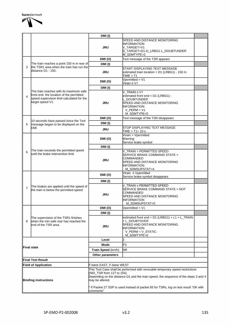
SP-EMO-P2-002008 v3.2 135
DMI (I)
JRU
SPEED AND DISTANCE MONITORING INFORMATION V_TARGET=V1 D_TARGET<D1-D_LRBG1-L_DOUBTUNDER M_SDMTYPE=2
3 The train reaches a point 150 m in rear of the TSR1 area when the train has run the distance D1 - 150.
DMI (O) Text message of the TSR appears
DMI (I)
JRU START DISPLAYING TEXT MESSAGE estimated train location = D1 (LRBG1) - 150 m TIME = T1
4
The train reaches with its maximum safe front end the location of the permitted speed supervision limit calculated for the target speed V1.
DMI (O) Vpermitted = V1 Vtrain ≤ V1
DMI (I)
JRU
V_TRAIN ≤ V1 estimated front end < D1 (LRBG1) - L_DOUBTUNDER SPEED AND DISTANCE MONITORING INFORMATION V_PERM = V1 M_SDMTYPE=0
5 10 seconds have passed since the Text message began to be displayed on the DMI
DMI (O) Text message of the TSR disappears
DMI (I)
JRU STOP DISPLAYING TEXT MESSAGE TIME = T1+ 10 s
6 The train exceeds the permitted speed until the brake intervention limit.
DMI (O) Vtrain > Vpermitted Warning Service brake symbol
DMI (I)
JRU
V_TRAIN > PERMITTED SPEED SERVICE BRAKE COMMAND STATE = COMMANDED SPEED AND DISTANCE MONITORING INFORMATION M_SDMSUPSTAT=4
7 The brakes are applied until the speed of the train is below the permitted speed.
DMI (O) Vtrain ≤ Vpermitted Service brake symbol disappears
DMI (I)
JRU
V_TRAIN ≤ PERMITTED SPEED SERVICE BRAKE COMMAND STATE = NOT COMMANDED SPEED AND DISTANCE MONITORING INFORMATION M_SDMSUPSTAT=0
8 The supervision of the TSR1 finishes when the min safe rear has reached the end of the TSR area.
DMI (O) Vpermitted > V1
DMI (I)
JRU
estimated front end = D1 (LRBG1) + L1 + L_TRAIN + L_DOUBTOVER SPEED AND DISTANCE MONITORING INFORMATION V_PERM = V_STATIC M_SDMTYPE=0
Final state
Level 2
Mode FS
Train Speed (km/h) NR
Other parameters
Final Test Result
Field of Application F-bane EAST, F-bane WEST
Briefing instructions
This Test Case shall be performed with revocable temporary speed restrictions (NID_TSR from 127 to 254). Depending on the distance D1 and the train speed, the sequence of the steps 3 and 4 may be altered. * If Packet 27 SSP is used instead of packet 65 for TSRs, log on test result "OK with comments"
SP-EMO-P2-002008 v3.2 136
ADDITIONAL TEST CASE REPORTING INFORMATION
System configuration
Test location
Date and time (Start/End)
Names
Test log reference
Observations
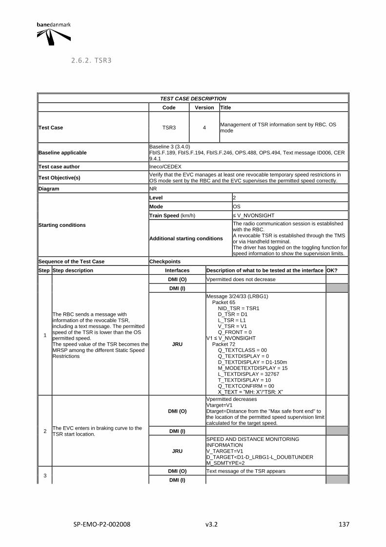
SP-EMO-P2-002008 v3.2 137
2.6.2. TSR3
TEST CASE DESCRIPTION
Code Version Title
Test Case TSR3 4 Management of TSR information sent by RBC. OS mode
Baseline applicable Baseline 3 (3.4.0) FbIS.F.189, FbIS.F.194, FbIS.F.246, OPS.488, OPS.494, Text message ID006, CER 9.4.1
Test case author Ineco/CEDEX
Test Objective(s) Verify that the EVC manages at least one revocable temporary speed restrictions in OS mode sent by the RBC and the EVC supervises the permitted speed correctly.
Diagram NR
Starting conditions
Level 2
Mode OS
Train Speed (km/h) ≤ V_NVONSIGHT
Additional starting conditions
The radio communication session is established with the RBC. A revocable TSR is established through the TMS or via Handheld terminal. The driver has toggled on the toggling function for speed information to show the supervision limits.
Sequence of the Test Case Checkpoints
Step Step description Interfaces Description of what to be tested at the interface OK?
1
The RBC sends a message with information of the revocable TSR, including a text message. The permitted speed of the TSR is lower than the OS permitted speed. The speed value of the TSR becomes the MRSP among the different Static Speed Restrictions
DMI (O) Vpermitted does not decrease
DMI (I)
JRU
Message 3/24/33 (LRBG1) Packet 65 NID_TSR = TSR1 D_TSR = D1 L_TSR = L1 V_TSR = V1 Q_FRONT = 0 V1 ≤ V_NVONSIGHT Packet 72 Q_TEXTCLASS = 00 Q_TEXTDISPLAY = 0 D_TEXTDISPLAY = D1-150m M_MODETEXTDISPLAY = 15 L_TEXTDISPLAY = 32767 T_TEXTDISPLAY = 10 Q_TEXTCONFIRM = 00 X_TEXT = ”MH: X”/“TSR: X”
2 The EVC enters in braking curve to the TSR start location.
DMI (O)
Vpermitted decreases Vtarget=V1 Dtarget=Distance from the "Max safe front end" to the location of the permitted speed supervision limit calculated for the target speed.
DMI (I)
JRU
SPEED AND DISTANCE MONITORING INFORMATION V_TARGET=V1 D_TARGET<D1-D_LRBG1-L_DOUBTUNDER M_SDMTYPE=2
3 DMI (O) Text message of the TSR appears
DMI (I)
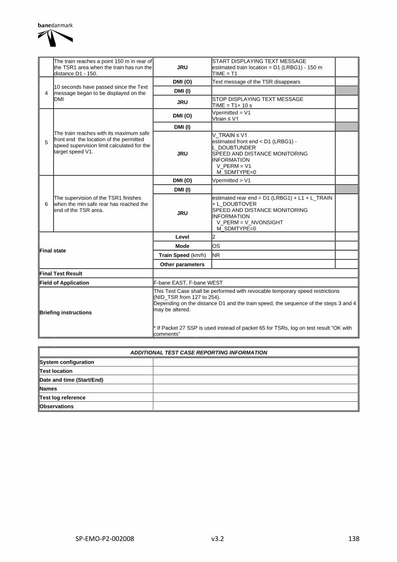
SP-EMO-P2-002008 v3.2 138
The train reaches a point 150 m in rear of the TSR1 area when the train has run the distance D1 - 150.
JRU START DISPLAYING TEXT MESSAGE estimated train location = D1 (LRBG1) - 150 m TIME = T1
4 10 seconds have passed since the Text message began to be displayed on the DMI
DMI (O) Text message of the TSR disappears
DMI (I)
JRU STOP DISPLAYING TEXT MESSAGE TIME = T1+ 10 s
5
The train reaches with its maximum safe front end the location of the permitted speed supervision limit calculated for the target speed V1.
DMI (O) Vpermitted = V1 Vtrain ≤ V1
DMI (I)
JRU
V_TRAIN ≤ V1 estimated front end < D1 (LRBG1) - L_DOUBTUNDER SPEED AND DISTANCE MONITORING INFORMATION V_PERM = V1 M_SDMTYPE=0
6 The supervision of the TSR1 finishes when the min safe rear has reached the end of the TSR area.
DMI (O) Vpermitted > V1
DMI (I)
JRU
estimated rear end = D1 (LRBG1) + L1 + L_TRAIN + L_DOUBTOVER SPEED AND DISTANCE MONITORING INFORMATION V_PERM = V_NVONSIGHT M_SDMTYPE=0
Final state
Level 2
Mode OS
Train Speed (km/h) NR
Other parameters
Final Test Result
Field of Application F-bane EAST, F-bane WEST
Briefing instructions
This Test Case shall be performed with revocable temporary speed restrictions (NID_TSR from 127 to 254). Depending on the distance D1 and the train speed, the sequence of the steps 3 and 4 may be altered. * If Packet 27 SSP is used instead of packet 65 for TSRs, log on test result "OK with comments"
ADDITIONAL TEST CASE REPORTING INFORMATION
System configuration
Test location
Date and time (Start/End)
Names
Test log reference
Observations
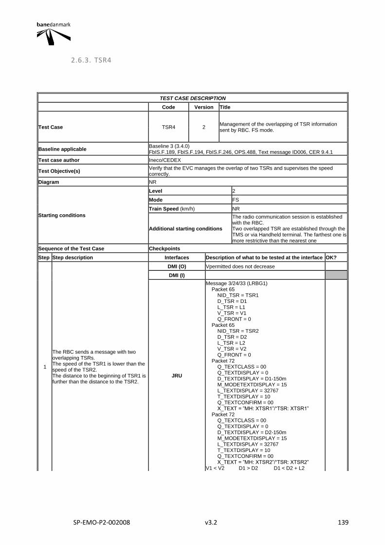
SP-EMO-P2-002008 v3.2 139
2.6.3. TSR4
TEST CASE DESCRIPTION
Code Version Title
Test Case TSR4 2 Management of the overlapping of TSR information sent by RBC. FS mode.
Baseline applicable Baseline 3 (3.4.0) FbIS.F.189, FbIS.F.194, FbIS.F.246, OPS.488, Text message ID006, CER 9.4.1
Test case author Ineco/CEDEX
Test Objective(s) Verify that the EVC manages the overlap of two TSRs and supervises the speed correctly.
Diagram NR
Starting conditions
Level 2
Mode FS
Train Speed (km/h) NR
Additional starting conditions
The radio communication session is established with the RBC. Two overlapped TSR are established through the TMS or via Handheld terminal. The farthest one is more restrictive than the nearest one
Sequence of the Test Case Checkpoints
Step Step description Interfaces Description of what to be tested at the interface OK?
1
The RBC sends a message with two overlapping TSRs. The speed of the TSR1 is lower than the speed of the TSR2. The distance to the beginning of TSR1 is further than the distance to the TSR2.
DMI (O) Vpermitted does not decrease
DMI (I)
JRU
Message 3/24/33 (LRBG1) Packet 65 NID_TSR = TSR1 D_TSR = D1 L_TSR = L1 V_TSR = V1 Q_FRONT = 0 Packet 65 NID_TSR = TSR2 D_TSR = D2 L_TSR = L2 V_TSR = V2 Q_FRONT = 0 Packet 72 Q_TEXTCLASS = 00 Q_TEXTDISPLAY = 0 D_TEXTDISPLAY = D1-150m M_MODETEXTDISPLAY = 15 L_TEXTDISPLAY = 32767 T_TEXTDISPLAY = 10 Q_TEXTCONFIRM = 00 X_TEXT = ”MH: XTSR1”/“TSR: XTSR1” Packet 72 Q_TEXTCLASS = 00 Q_TEXTDISPLAY = 0 D_TEXTDISPLAY = D2-150m M_MODETEXTDISPLAY = 15 L_TEXTDISPLAY = 32767 T_TEXTDISPLAY = 10 Q_TEXTCONFIRM = 00 X_TEXT = ”MH: XTSR2”/“TSR: XTSR2” V1 < V2 D1 > D2 D1 < D2 + L2
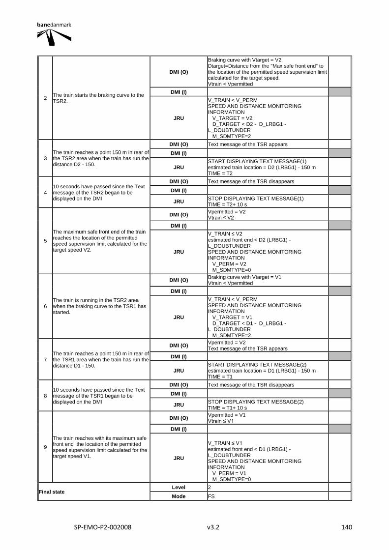
SP-EMO-P2-002008 v3.2 140
2 The train starts the braking curve to the TSR2.
DMI (O)
Braking curve with Vtarget = V2 Dtarget=Distance from the "Max safe front end" to the location of the permitted speed supervision limit calculated for the target speed. Vtrain < Vpermitted
DMI (I)
JRU
V_TRAIN < V_PERM SPEED AND DISTANCE MONITORING INFORMATION V_TARGET = V2 D_TARGET < D2 - D_LRBG1 - L_DOUBTUNDER M_SDMTYPE=2
3 The train reaches a point 150 m in rear of the TSR2 area when the train has run the distance D2 - 150.
DMI (O) Text message of the TSR appears
DMI (I)
JRU START DISPLAYING TEXT MESSAGE(1) estimated train location = D2 (LRBG1) - 150 m TIME = T2
4 10 seconds have passed since the Text message of the TSR2 began to be displayed on the DMI
DMI (O) Text message of the TSR disappears
DMI (I)
JRU STOP DISPLAYING TEXT MESSAGE(1) TIME = T2+ 10 s
5
The maximum safe front end of the train reaches the location of the permitted speed supervision limit calculated for the target speed V2.
DMI (O) Vpermitted = V2 Vtrain ≤ V2
DMI (I)
JRU
V_TRAIN ≤ V2 estimated front end < D2 (LRBG1) - L_DOUBTUNDER SPEED AND DISTANCE MONITORING INFORMATION V_PERM = V2 M_SDMTYPE=0
6 The train is running in the TSR2 area when the braking curve to the TSR1 has started.
DMI (O) Braking curve with Vtarget = V1 Vtrain < Vpermitted
DMI (I)
JRU
V_TRAIN < V_PERM SPEED AND DISTANCE MONITORING INFORMATION V_TARGET = V1 D_TARGET < D1 - D_LRBG1 - L_DOUBTUNDER M_SDMTYPE=2
7 The train reaches a point 150 m in rear of the TSR1 area when the train has run the distance D1 - 150.
DMI (O) Vpermitted = V2 Text message of the TSR appears
DMI (I)
JRU START DISPLAYING TEXT MESSAGE(2) estimated train location = D1 (LRBG1) - 150 m TIME = T1
8 10 seconds have passed since the Text message of the TSR1 began to be displayed on the DMI
DMI (O) Text message of the TSR disappears
DMI (I)
JRU STOP DISPLAYING TEXT MESSAGE(2) TIME = T1+ 10 s
9
The train reaches with its maximum safe front end the location of the permitted speed supervision limit calculated for the target speed V1.
DMI (O) Vpermitted = V1 Vtrain ≤ V1
DMI (I)
JRU
V_TRAIN ≤ V1 estimated front end < D1 (LRBG1) - L_DOUBTUNDER SPEED AND DISTANCE MONITORING INFORMATION V_PERM = V1 M_SDMTYPE=0
Final state Level 2
Mode FS
SP-EMO-P2-002008 v3.2 141
Train Speed (km/h) V_TRAIN ≤ V1
Other parameters The train runs inside the overlapping TSR area.
Final Test Result
Field of Application F-bane EAST, F-bane WEST
Briefing instructions
Depending on the distances D1 and D2, the TSR speeds V1 and V2 and the train speed, the sequence of the steps 4, 5, 6, 7, 8 and 9 may be altered. * If Packet 27 SSP is used instead of packet 65 for TSRs, log on test result "OK with comments"
ADDITIONAL TEST CASE REPORTING INFORMATION
System configuration
Test location
Date and time (Start/End)
Names
Test log reference
Observations
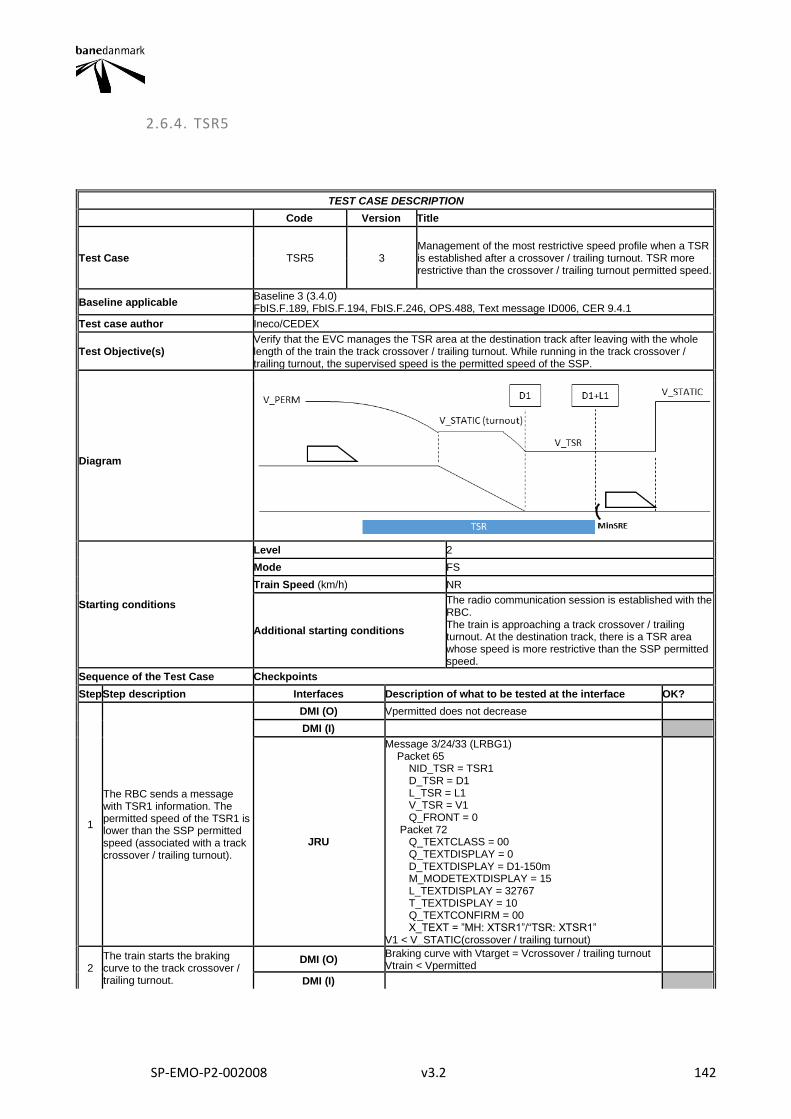
SP-EMO-P2-002008 v3.2 142
2.6.4. TSR5
TEST CASE DESCRIPTION
Code Version Title
Test Case TSR5 3 Management of the most restrictive speed profile when a TSR is established after a crossover / trailing turnout. TSR more restrictive than the crossover / trailing turnout permitted speed.
Baseline applicable Baseline 3 (3.4.0) FbIS.F.189, FbIS.F.194, FbIS.F.246, OPS.488, Text message ID006, CER 9.4.1
Test case author Ineco/CEDEX
Test Objective(s) Verify that the EVC manages the TSR area at the destination track after leaving with the whole length of the train the track crossover / trailing turnout. While running in the track crossover / trailing turnout, the supervised speed is the permitted speed of the SSP.
Diagram
Starting conditions
Level 2
Mode FS
Train Speed (km/h) NR
Additional starting conditions
The radio communication session is established with the RBC. The train is approaching a track crossover / trailing turnout. At the destination track, there is a TSR area whose speed is more restrictive than the SSP permitted speed.
Sequence of the Test Case Checkpoints
Step Step description Interfaces Description of what to be tested at the interface OK?
1
The RBC sends a message with TSR1 information. The permitted speed of the TSR1 is lower than the SSP permitted speed (associated with a track crossover / trailing turnout).
DMI (O) Vpermitted does not decrease
DMI (I)
JRU
Message 3/24/33 (LRBG1) Packet 65 NID_TSR = TSR1 D_TSR = D1 L_TSR = L1 V_TSR = V1 Q_FRONT = 0 Packet 72 Q_TEXTCLASS = 00 Q_TEXTDISPLAY = 0 D_TEXTDISPLAY = D1-150m M_MODETEXTDISPLAY = 15 L_TEXTDISPLAY = 32767 T_TEXTDISPLAY = 10 Q_TEXTCONFIRM = 00 X_TEXT = ”MH: XTSR1”/“TSR: XTSR1” V1 < V_STATIC(crossover / trailing turnout)
2 The train starts the braking curve to the track crossover / trailing turnout.
DMI (O) Braking curve with Vtarget = Vcrossover / trailing turnout Vtrain < Vpermitted
DMI (I)
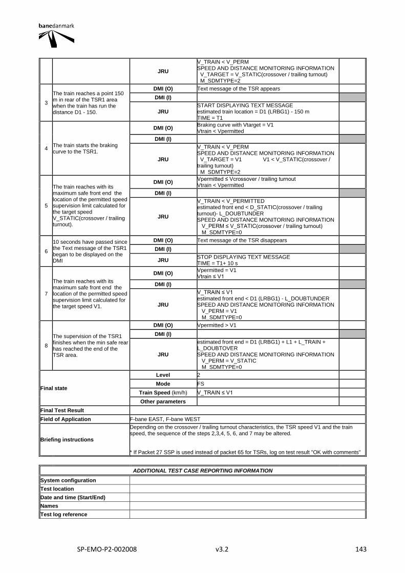
SP-EMO-P2-002008 v3.2 143
JRU
V_TRAIN < V_PERM SPEED AND DISTANCE MONITORING INFORMATION V_TARGET = V_STATIC(crossover / trailing turnout) M_SDMTYPE=2
3
The train reaches a point 150 m in rear of the TSR1 area when the train has run the distance D1 - 150.
DMI (O) Text message of the TSR appears
DMI (I)
JRU START DISPLAYING TEXT MESSAGE estimated train location = D1 (LRBG1) - 150 m TIME = T1
4 The train starts the braking curve to the TSR1.
DMI (O) Braking curve with Vtarget = V1 Vtrain < Vpermitted
DMI (I)
JRU
V_TRAIN < V_PERM SPEED AND DISTANCE MONITORING INFORMATION V_TARGET = V1 V1 < V_STATIC(crossover / trailing turnout) M_SDMTYPE=2
5
The train reaches with its maximum safe front end the location of the permitted speed supervision limit calculated for the target speed V_STATIC(crossover / trailing turnout).
DMI (O) Vpermitted ≤ Vcrossover / trailing turnout Vtrain < Vpermitted
DMI (I)
JRU
V_TRAIN < V_PERMITTED estimated front end < D_STATIC(crossover / trailing turnout)- L_DOUBTUNDER SPEED AND DISTANCE MONITORING INFORMATION V_PERM ≤ V_STATIC(crossover / trailing turnout) M_SDMTYPE=0
6
10 seconds have passed since the Text message of the TSR1 began to be displayed on the DMI
DMI (O) Text message of the TSR disappears
DMI (I)
JRU STOP DISPLAYING TEXT MESSAGE TIME = T1+ 10 s
7
The train reaches with its maximum safe front end the location of the permitted speed supervision limit calculated for the target speed V1.
DMI (O) Vpermitted = V1 Vtrain ≤ V1
DMI (I)
JRU
V_TRAIN ≤ V1 estimated front end < D1 (LRBG1) - L_DOUBTUNDER SPEED AND DISTANCE MONITORING INFORMATION V_PERM = V1 M_SDMTYPE=0
8
The supervision of the TSR1 finishes when the min safe rear has reached the end of the TSR area.
DMI (O) Vpermitted > V1
DMI (I)
JRU
estimated front end = D1 (LRBG1) + L1 + L_TRAIN + L_DOUBTOVER SPEED AND DISTANCE MONITORING INFORMATION V_PERM = V_STATIC M_SDMTYPE=0
Final state
Level 2
Mode FS
Train Speed (km/h) V_TRAIN ≤ V1
Other parameters
Final Test Result
Field of Application F-bane EAST, F-bane WEST
Briefing instructions
Depending on the crossover / trailing turnout characteristics, the TSR speed V1 and the train speed, the sequence of the steps 2,3,4, 5, 6, and 7 may be altered. * If Packet 27 SSP is used instead of packet 65 for TSRs, log on test result "OK with comments"
ADDITIONAL TEST CASE REPORTING INFORMATION
System configuration
Test location
Date and time (Start/End)
Names
Test log reference
SP-EMO-P2-002008 v3.2 144
Observations
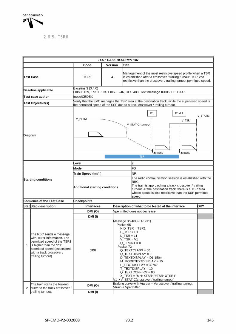
SP-EMO-P2-002008 v3.2 145
2.6.5. TSR6
TEST CASE DESCRIPTION
Code Version Title
Test Case TSR6 4 Management of the most restrictive speed profile when a TSR is established after a crossover / trailing turnout. TSR less restrictive than the crossover / trailing turnout permitted speed.
Baseline applicable Baseline 3 (3.4.0) FbIS.F.189, FbIS.F.194, FbIS.F.246, OPS.488, Text message ID006, CER 9.4.1
Test case author Ineco/CEDEX
Test Objective(s) Verify that the EVC manages the TSR area at the destination track, while the supervised speed is the permitted speed of the SSP due to a track crossover / trailing turnout.
Diagram
Starting conditions
Level 2
Mode FS
Train Speed (km/h) NR
Additional starting conditions
The radio communication session is established with the RBC. The train is approaching a track crossover / trailing turnout. At the destination track, there is a TSR area whose speed is less restrictive than the SSP permitted speed.
Sequence of the Test Case Checkpoints
Step Step description Interfaces Description of what to be tested at the interface OK?
1
The RBC sends a message with TSR1 information. The permitted speed of the TSR1 is higher than the SSP permitted speed (associated with a track crossover / trailing turnout).
DMI (O) Vpermitted does not decrease
DMI (I)
JRU
Message 3/24/33 (LRBG1) Packet 65 NID_TSR = TSR1 D_TSR = D1 L_TSR = L1 V_TSR = V1 Q_FRONT = 0 Packet 72 Q_TEXTCLASS = 00 Q_TEXTDISPLAY = 0 D_TEXTDISPLAY = D1-150m M_MODETEXTDISPLAY = 15 L_TEXTDISPLAY = 32767 T_TEXTDISPLAY = 10 Q_TEXTCONFIRM = 00 X_TEXT = ”MH: XTSR1”/“TSR: XTSR1” V1 > V_STATIC(crossover / trailing turnout)
2 The train starts the braking curve to the track crossover / trailing turnout.
DMI (O) Braking curve with Vtarget = Vcrossover / trailing turnout Vtrain < Vpermitted
DMI (I)
SP-EMO-P2-002008 v3.2 146
JRU
V_TRAIN < V_PERM SPEED AND DISTANCE MONITORING INFORMATION V_TARGET = V_STATIC(crossover / trailing turnout) M_SDMTYPE=2
3
The train reaches a point 150 m in rear of the TSR1 area when the train has run the distance D1 - 150.
DMI (O) Text message of the TSR appears
DMI (I)
JRU START DISPLAYING TEXT MESSAGE estimated train location = D1 (LRBG1) - 150 m TIME = T1
4
The train reaches with its maximum safe front end the location of the permitted speed supervision limit calculated for the target speed V_STATIC(crossover / trailing turnout).
DMI (O) Vpermitted = Vcrossover / trailing turnout Vtrain ≤ Vpermitted
DMI (I)
JRU
V_TRAIN ≤ V_STATIC(crossover / trailing turnout) estimated front end < D_STATIC(crossover / trailing turnout)- L_DOUBTUNDER SPEED AND DISTANCE MONITORING INFORMATION V_PERM = V_STATIC(crossover / trailing turnout) M_SDMTYPE=0
5
10 seconds have passed since the Text message of the TSR1 began to be displayed on the DMI
DMI (O) Vpermitted does not decrease Text message of the TSR disappears
DMI (I)
JRU STOP DISPLAYING TEXT MESSAGE TIME = T1+ 10 s
6
The supervision of the SSP finishes when the min safe rear has reached the end of the track crossover / trailing turnout. The EVC starts to supervise the TSR1.
DMI (O) Vpermitted = V1 Vtrain ≤ V1
DMI (I)
JRU
V_TRAIN ≤ V1 estimated front end = D_STATIC(crossover / trailing turnout) + L(crossover / trailing turnout) + L_TRAIN + L_DOUBTOVER SPEED AND DISTANCE MONITORING INFORMATION V_PERM = V1 M_SDMTYPE=0
7
The supervision of the TSR1 finishes when the min safe rear end has reached the end of the TSR area.
DMI (O) Vpermitted > V1
DMI (I)
JRU
estimated front end = D1 (LRBG1) + L1 + L_TRAIN + L_DOUBTOVER SPEED AND DISTANCE MONITORING INFORMATION V_PERM = V_STATIC M_SDMTYPE=0
Final state
Level 2
Mode FS
Train Speed (km/h) V_TRAIN ≤ V1
Other parameters
Final Test Result
Field of Application F-bane EAST, F-bane WEST
Briefing instructions
Depending on the crossover / trailing turnout characteristics, the distance D1, the TSR speed V1 and the train speed, the sequence of the steps 2,3,4, 5, 6, and 7 may be altered. * If Packet 27 SSP is used instead of packet 65 for TSRs, log on test result "OK with comments"
ADDITIONAL TEST CASE REPORTING INFORMATION
System configuration
Test location
Date and time (Start/End)
Names
Test log reference
Observations
SP-EMO-P2-002008 v3.2 147
2.6.6. TSR7
TEST CASE DESCRIPTION
Code Version Title
Test Case TSR7 3 TSR revocation before reaching the TSR area.
Baseline applicable Baseline 3 (3.4.0) FbIS.F.246, Text message ID006, CER 9.4.1
Test case author Ineco/CEDEX
Test Objective(s) Verify the EVC reaction when a TSR is revoked once it has been sent.
Diagram NR
Starting conditions
Level 2
Mode FS/OS
Train Speed (km/h) NR
Additional starting conditions
The radio communication session is established with the RBC. A revocable TSR is established through the TMS or via Handheld terminal.
Sequence of the Test Case Checkpoints
Step Step description Interfaces Description of what to be tested at the interface OK?
1 The RBC sends a message with TSR information, including a text message.
DMI (O) Vpermitted does not decrease
DMI (I)
JRU
Message 3/24/33 (LRBG1) Packet 65 NID_TSR = TSR1 D_TSR = D1 L_TSR = L1 V_TSR = V1 Q_FRONT = 0 Packet 72 Q_TEXTCLASS = 00 Q_TEXTDISPLAY = 0 D_TEXTDISPLAY = D1-150m M_MODETEXTDISPLAY = 15 L_TEXTDISPLAY = 32767 T_TEXTDISPLAY = 10 Q_TEXTCONFIRM = 00 X_TEXT = ”MH: XTSR1”/“TSR: XTSR1”
2 The train starts a braking curve to the TSR1.
DMI (O) Braking curve with Vtarget = V1 Vtrain < Vpermitted
DMI (I)
JRU
V_TRAIN < V_PERMITTED SPEED AND DISTANCE MONITORING INFORMATION V_TARGET = V1 D_TARGET<D1-D_LRBG1-L_DOUBTUNDER M_SDMTYPE=2
3 The signalman revokes the TSR1. The EVC receives a message from the RBC with the TSR1 revocation
DMI (O) Braking curve with Vtarget = V1 disappears Vpermitted = Vstatic
DMI (I)
JRU
Message 3/24/33 Packet 66 NID_TSR = TSR1 SPEED AND DISTANCE MONITORING INFORMATION V_PERM=V_STATIC M_SDMTYPE=0
SP-EMO-P2-002008 v3.2 148
4 The train reaches a point 150 m in rear of the TSR1 area when the train has run the distance D1 - 150.
DMI (O) Vpermitted does not decrease Text message of the TSR appears
DMI (I)
JRU START DISPLAYING TEXT MESSAGE estimated train location = D1 (LRBG1) - 150 m TIME = T1
5 The train reaches the TSR1 area after its revocation. The TSR1 is not supervised by the train
DMI (O) Vpermitted ≠ V1
DMI (I)
JRU V_PERM ≠ V1 V_PERM = V_STATIC
6 10 seconds have passed since the Text message of the TSR1 began to be displayed on the DMI
DMI (O) Vpermitted does not decrease Text message of the TSR disappears
DMI (I)
JRU STOP DISPLAYING TEXT MESSAGE TIME = T1+ 10 s
Final state
Level 2
Mode FS/OS
Train Speed (km/h) NR
Other parameters
Final Test Result
Field of Application F-bane EAST, F-bane WEST
Briefing instructions
This Test Case shall be performed with revocable temporary speed restrictions (NID_TSR from 127 to 254). Depending on the distance D1, the moment when the signalman revokes the TSR and thus the RBC send the revocation (step 3) and the train speed, steps 3 and 6 may be altered in the step sequence. * If Packet 27 SSP is used instead of packet 65 and 66 for TSRs, log on test result "OK with comments"
ADDITIONAL TEST CASE REPORTING INFORMATION
System configuration
Test location
Date and time (Start/End)
Names
Test log reference
Observations
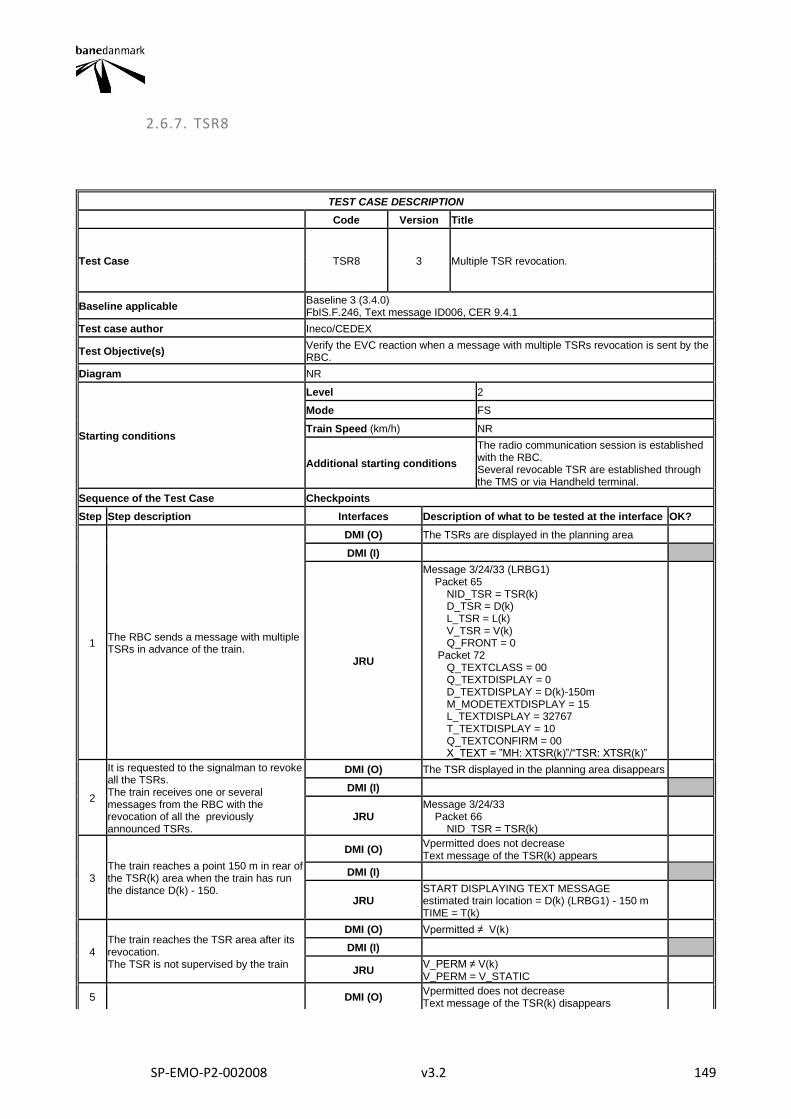
SP-EMO-P2-002008 v3.2 149
2.6.7. TSR8
TEST CASE DESCRIPTION
Code Version Title
Test Case TSR8 3 Multiple TSR revocation.
Baseline applicable Baseline 3 (3.4.0) FbIS.F.246, Text message ID006, CER 9.4.1
Test case author Ineco/CEDEX
Test Objective(s) Verify the EVC reaction when a message with multiple TSRs revocation is sent by the RBC.
Diagram NR
Starting conditions
Level 2
Mode FS
Train Speed (km/h) NR
Additional starting conditions
The radio communication session is established with the RBC. Several revocable TSR are established through the TMS or via Handheld terminal.
Sequence of the Test Case Checkpoints
Step Step description Interfaces Description of what to be tested at the interface OK?
1 The RBC sends a message with multiple TSRs in advance of the train.
DMI (O) The TSRs are displayed in the planning area
DMI (I)
JRU
Message 3/24/33 (LRBG1) Packet 65 NID_TSR = TSR(k) D_TSR = D(k) L_TSR = L(k) V_TSR = V(k) Q_FRONT = 0 Packet 72 Q_TEXTCLASS = 00 Q_TEXTDISPLAY = 0 D_TEXTDISPLAY = D(k)-150m M_MODETEXTDISPLAY = 15 L_TEXTDISPLAY = 32767 T_TEXTDISPLAY = 10 Q_TEXTCONFIRM = 00 X_TEXT = ”MH: XTSR(k)”/“TSR: XTSR(k)”
2
It is requested to the signalman to revoke all the TSRs. The train receives one or several messages from the RBC with the revocation of all the previously announced TSRs.
DMI (O) The TSR displayed in the planning area disappears
DMI (I)
JRU Message 3/24/33 Packet 66 NID_TSR = TSR(k)
3 The train reaches a point 150 m in rear of the TSR(k) area when the train has run the distance D(k) - 150.
DMI (O) Vpermitted does not decrease Text message of the TSR(k) appears
DMI (I)
JRU START DISPLAYING TEXT MESSAGE estimated train location = D(k) (LRBG1) - 150 m TIME = T(k)
4 The train reaches the TSR area after its revocation. The TSR is not supervised by the train
DMI (O) Vpermitted ≠ V(k)
DMI (I)
JRU V_PERM ≠ V(k) V_PERM = V_STATIC
5 DMI (O) Vpermitted does not decrease Text message of the TSR(k) disappears
SP-EMO-P2-002008 v3.2 150
10 seconds have passed since the Text message of the TSR(k) began to be displayed on the DMI
DMI (I)
JRU STOP DISPLAYING TEXT MESSAGE TIME = T(k)+ 10 s
Final state
Level 2
Mode FS
Train Speed (km/h) NR
Other parameters
Final Test Result
Field of Application F-bane EAST
Briefing instructions
This Test Case shall be performed with revocable temporary speed restrictions (NID_TSR from 127 to 254). Depending on the distance D(k), the moment when the step 2 takes place and the train speed, the sequence of the steps 2, 3, 4, 5, and 6 may be altered. * If Packet 27 SSP is used instead of packet 65 and 66 for TSRs, log on test result "OK with comments"
ADDITIONAL TEST CASE REPORTING INFORMATION
System configuration
Test location
Date and time (Start/End)
Names
Test log reference
Observations
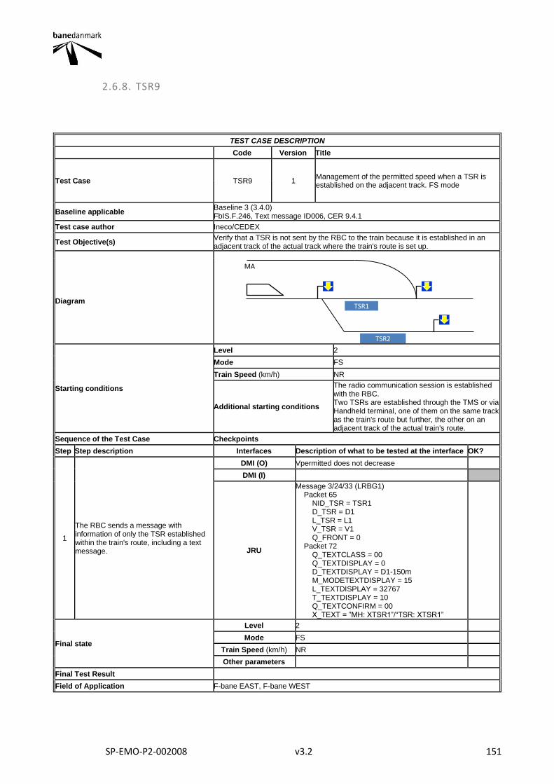
SP-EMO-P2-002008 v3.2 151
2.6.8. TSR9
TEST CASE DESCRIPTION
Code Version Title
Test Case TSR9 1 Management of the permitted speed when a TSR is established on the adjacent track. FS mode
Baseline applicable Baseline 3 (3.4.0) FbIS.F.246, Text message ID006, CER 9.4.1
Test case author Ineco/CEDEX
Test Objective(s) Verify that a TSR is not sent by the RBC to the train because it is established in an adjacent track of the actual track where the train's route is set up.
Diagram
Starting conditions
Level 2
Mode FS
Train Speed (km/h) NR
Additional starting conditions
The radio communication session is established with the RBC. Two TSRs are established through the TMS or via Handheld terminal, one of them on the same track as the train's route but further, the other on an adjacent track of the actual train's route.
Sequence of the Test Case Checkpoints
Step Step description Interfaces Description of what to be tested at the interface OK?
1
The RBC sends a message with information of only the TSR established within the train's route, including a text message.
DMI (O) Vpermitted does not decrease
DMI (I)
JRU
Message 3/24/33 (LRBG1) Packet 65 NID_TSR = TSR1 D_TSR = D1 L_TSR = L1 V_TSR = V1 Q_FRONT = 0 Packet 72 Q_TEXTCLASS = 00 Q_TEXTDISPLAY = 0 D_TEXTDISPLAY = D1-150m M_MODETEXTDISPLAY = 15 L_TEXTDISPLAY = 32767 T_TEXTDISPLAY = 10 Q_TEXTCONFIRM = 00 X_TEXT = ”MH: XTSR1”/“TSR: XTSR1”
Final state
Level 2
Mode FS
Train Speed (km/h) NR
Other parameters
Final Test Result
Field of Application F-bane EAST, F-bane WEST
TSR1
TSR2
MA
SP-EMO-P2-002008 v3.2 152
Briefing instructions
This Test Case shall be performed with revocable temporary speed restrictions (NID_TSR from 127 to 254). * If Packet 27 SSP is used instead of packet 65 and 66 for TSRs, log on test result "OK with comments"
ADDITIONAL TEST CASE REPORTING INFORMATION
System configuration
Test location
Date and time (Start/End)
Names
Test log reference
Observations
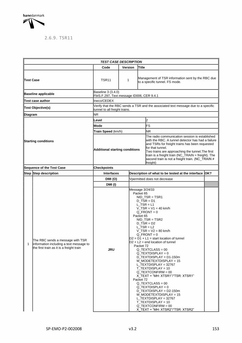
SP-EMO-P2-002008 v3.2 153
2.6.9. TSR11
TEST CASE DESCRIPTION
Code Version Title
Test Case TSR11 1 Management of TSR information sent by the RBC due to a specific tunnel. FS mode.
Baseline applicable Baseline 3 (3.4.0) FbIS.F.297, Text message ID006, CER 9.4.1
Test case author Ineco/CEDEX
Test Objective(s) Verify that the RBC sends a TSR and the associated text message due to a specific tunnel to all freight trains.
Diagram NR
Starting conditions
Level 2
Mode FS
Train Speed (km/h) NR
Additional starting conditions
The radio communication session is established with the RBC. A tunnel detector has had a failure and TSRs for freight trains has been requested for that tunnel. Two trains are approaching the tunnel.The first train is a freight train (NC_TRAIN = freight). The second train is not a freight train. (NC_TRAIN ≠ freight)
Sequence of the Test Case Checkpoints
Step Step description Interfaces Description of what to be tested at the interface OK?
1 The RBC sends a message with TSR information including a text message to the first train as it is a freight train
DMI (O) Vpermitted does not decrease
DMI (I)
JRU
Message 3/24/33 Packet 65 NID_TSR = TSR1 D_TSR = D1 L_TSR = L1 V_TSR = V1 = 40 km/h Q_FRONT = 0 Packet 65 NID_TSR = TSR2 D_TSR = D2 L_TSR = L2 V_TSR = V2 = 80 km/h Q_FRONT = 0 D2 = D1 + L1 = start location of tunnel D2 + L2 = end location of tunnel Packet 72 Q_TEXTCLASS = 00 Q_TEXTDISPLAY = 0 D_TEXTDISPLAY = D1-150m M_MODETEXTDISPLAY = 15 L_TEXTDISPLAY = 32767 T_TEXTDISPLAY = 10 Q_TEXTCONFIRM = 00 X_TEXT = ”MH: XTSR1”/“TSR: XTSR1” Packet 72 Q_TEXTCLASS = 00 Q_TEXTDISPLAY = 0 D_TEXTDISPLAY = D2-150m M_MODETEXTDISPLAY = 15 L_TEXTDISPLAY = 32767 T_TEXTDISPLAY = 10 Q_TEXTCONFIRM = 00 X_TEXT = ”MH: XTSR2”/“TSR: XTSR2”
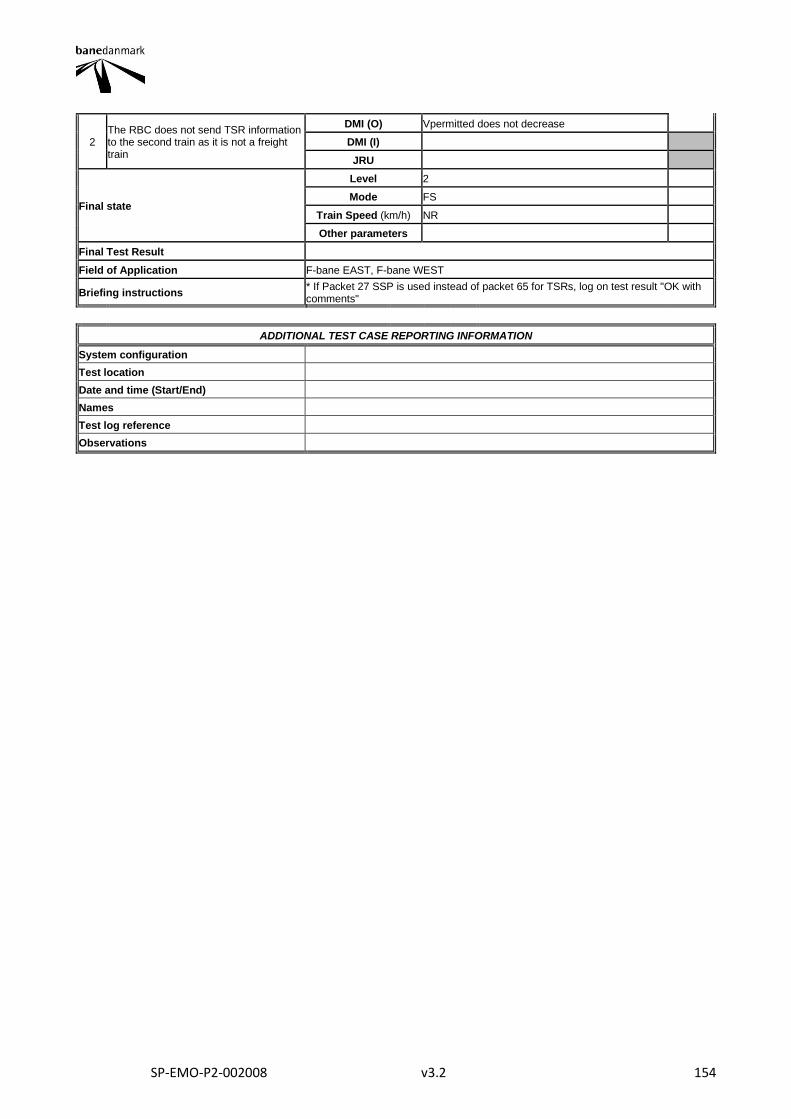
SP-EMO-P2-002008 v3.2 154
2 The RBC does not send TSR information to the second train as it is not a freight train
DMI (O) Vpermitted does not decrease
DMI (I)
JRU
Final state
Level 2
Mode FS
Train Speed (km/h) NR
Other parameters
Final Test Result
Field of Application F-bane EAST, F-bane WEST
Briefing instructions * If Packet 27 SSP is used instead of packet 65 for TSRs, log on test result "OK with comments"
ADDITIONAL TEST CASE REPORTING INFORMATION
System configuration
Test location
Date and time (Start/End)
Names
Test log reference
Observations
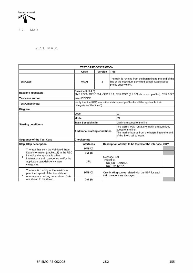
SP-EMO-P2-002008 v3.2 155
2.7. MAD
2.7.1. MAD1
TEST CASE DESCRIPTION
Code Version Title
Test Case MAD1 3 The train is running from the beginning to the end of the line at the maximum permitted speed. Static speed profile supervision.
Baseline applicable Baseline 3 (3.4.0) FbIS.F.350, OPS.1094, CER 9.3.1, CER COM (2.9.3 Static speed profiles), CER 9.3.2
Test case author Ineco/CEDEX
Test Objective(s) Verify that the RBC sends the static speed profiles for all the applicable train categories of the line.(*)
Diagram
Starting conditions
Level L2
Mode FS
Train Speed (km/h) Maximum speed of the line
Additional starting conditions
The train should run at the maximum permitted speed of the line. The marker boards from the beginning to the end of the line shall be open.
Sequence of the Test Case Checkpoints
Step Step description Interfaces Description of what to be tested at the interface OK?
1
The train has sent the Validated Train Data information (packet 11) to the RBC including the applicable other international train categories and/or the applicable cant deficiency train categories.
DMI (O)
DMI (I)
JRU
Message 129 Packet 11 NC_CDTRAIN=N1 NC_TRAIN=N2
2
The train is running at the maximum permitted speed of the line while no unnecessary braking curves to an EoA are shown to the driver.
DMI (O) Only braking curves related with the SSP for each train category are displayed
DMI (I)
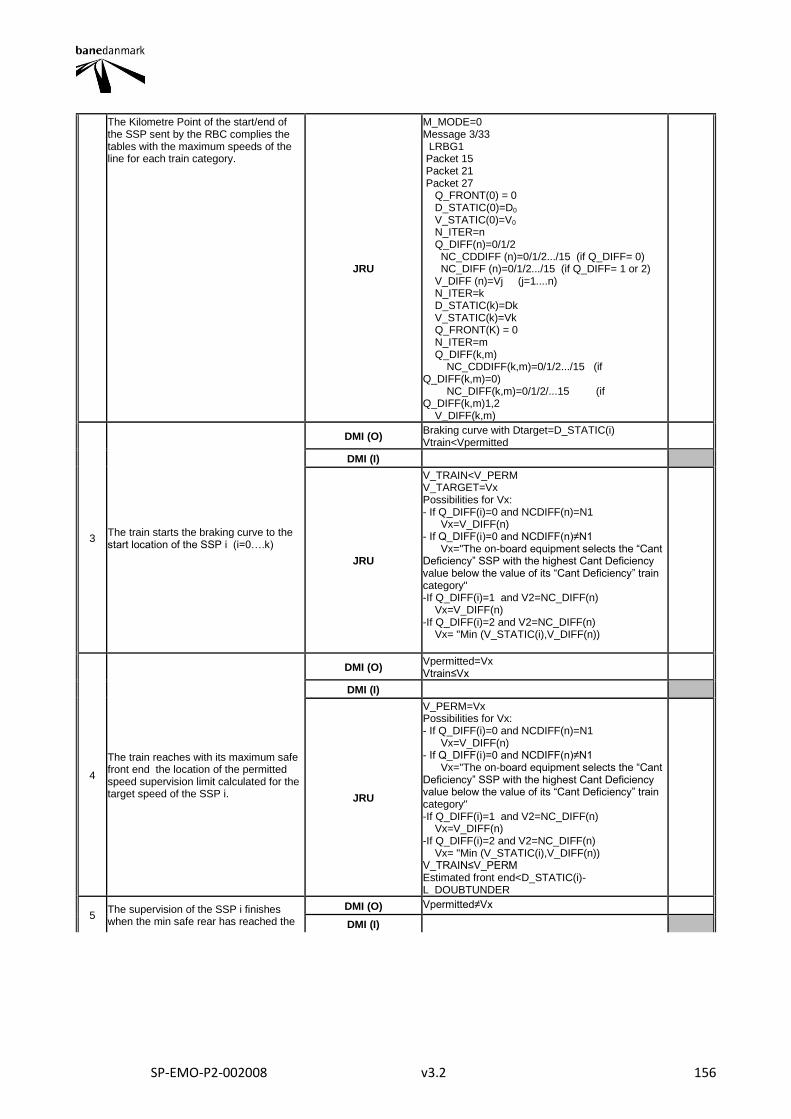
SP-EMO-P2-002008 v3.2 156
The Kilometre Point of the start/end of the SSP sent by the RBC complies the tables with the maximum speeds of the line for each train category.
JRU
M_MODE=0 Message 3/33 LRBG1 Packet 15 Packet 21 Packet 27 Q_FRONT(0) = 0 D_STATIC(0)=D0 V_STATIC(0)=V0 N_ITER=n Q_DIFF(n)=0/1/2 NC_CDDIFF (n)=0/1/2.../15 (if Q_DIFF= 0) NC_DIFF (n)=0/1/2.../15 (if Q_DIFF= 1 or 2) V_DIFF (n)=Vj (j=1....n) N_ITER=k D_STATIC(k)=Dk V_STATIC(k)=Vk Q_FRONT(K) = 0 N_ITER=m Q_DIFF(k,m) NC_CDDIFF(k,m)=0/1/2.../15 (if Q_DIFF(k,m)=0) NC_DIFF(k,m)=0/1/2/...15 (if Q_DIFF(k,m)1,2 V_DIFF(k,m)
3 The train starts the braking curve to the start location of the SSP i (i=0….k)
DMI (O) Braking curve with Dtarget=D_STATIC(i) Vtrain<Vpermitted
DMI (I)
JRU
V_TRAIN<V_PERM V_TARGET=Vx Possibilities for Vx: - If Q_DIFF(i)=0 and NCDIFF(n)=N1 Vx=V_DIFF(n) - If Q_DIFF(i)=0 and NCDIFF(n)≠N1 Vx="The on-board equipment selects the “Cant Deficiency” SSP with the highest Cant Deficiency value below the value of its “Cant Deficiency” train category" -If Q_DIFF(i)=1 and V2=NC_DIFF(n) Vx=V_DIFF(n) -If Q_DIFF(i)=2 and V2=NC_DIFF(n) Vx= "Min (V_STATIC(i),V_DIFF(n))
4
The train reaches with its maximum safe front end the location of the permitted speed supervision limit calculated for the target speed of the SSP i.
DMI (O) Vpermitted=Vx Vtrain≤Vx
DMI (I)
JRU
V_PERM=Vx Possibilities for Vx: - If Q_DIFF(i)=0 and NCDIFF(n)=N1 Vx=V_DIFF(n) - If Q_DIFF(i)=0 and NCDIFF(n)≠N1 Vx="The on-board equipment selects the “Cant Deficiency” SSP with the highest Cant Deficiency value below the value of its “Cant Deficiency” train category" -If Q_DIFF(i)=1 and V2=NC_DIFF(n) Vx=V_DIFF(n) -If Q_DIFF(i)=2 and V2=NC_DIFF(n) Vx= "Min (V_STATIC(i),V_DIFF(n)) V_TRAIN≤V_PERM Estimated front end<D_STATIC(i)-L_DOUBTUNDER
5 The supervision of the SSP i finishes when the min safe rear has reached the
DMI (O) Vpermitted≠Vx
DMI (I)
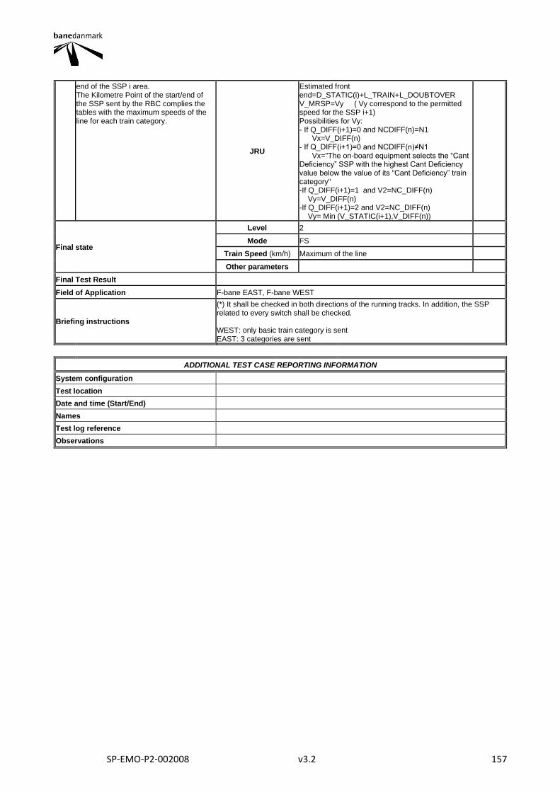
SP-EMO-P2-002008 v3.2 157
end of the SSP i area. The Kilometre Point of the start/end of the SSP sent by the RBC complies the tables with the maximum speeds of the line for each train category.
JRU
Estimated front end=D_STATIC(i)+L_TRAIN+L_DOUBTOVER V_MRSP=Vy ( Vy correspond to the permitted speed for the SSP i+1) Possibilities for Vy: - If Q_DIFF(i+1)=0 and NCDIFF(n)=N1 Vx=V_DIFF(n) - If Q_DIFF(i+1)=0 and NCDIFF(n)≠N1 Vx="The on-board equipment selects the “Cant Deficiency” SSP with the highest Cant Deficiency value below the value of its “Cant Deficiency” train category" -If Q_DIFF(i+1)=1 and V2=NC_DIFF(n) Vy=V_DIFF(n) -If Q_DIFF(i+1)=2 and V2=NC_DIFF(n) Vy= Min (V_STATIC(i+1),V_DIFF(n))
Final state
Level 2
Mode FS
Train Speed (km/h) Maximum of the line
Other parameters
Final Test Result
Field of Application F-bane EAST, F-bane WEST
Briefing instructions
(*) It shall be checked in both directions of the running tracks. In addition, the SSP related to every switch shall be checked. WEST: only basic train category is sent EAST: 3 categories are sent
ADDITIONAL TEST CASE REPORTING INFORMATION
System configuration
Test location
Date and time (Start/End)
Names
Test log reference
Observations
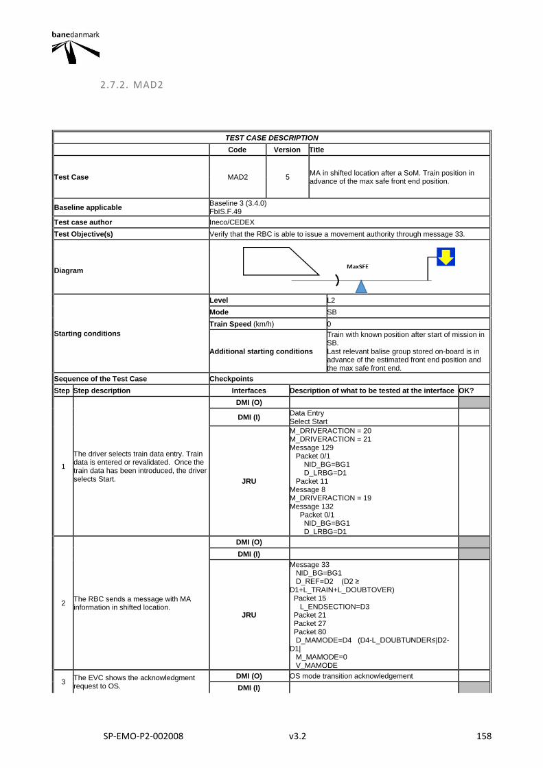
SP-EMO-P2-002008 v3.2 158
2.7.2. MAD2
TEST CASE DESCRIPTION
Code Version Title
Test Case MAD2 5 MA in shifted location after a SoM. Train position in advance of the max safe front end position.
Baseline applicable Baseline 3 (3.4.0) FbIS.F.49
Test case author Ineco/CEDEX
Test Objective(s) Verify that the RBC is able to issue a movement authority through message 33.
Diagram
Starting conditions
Level L2
Mode SB
Train Speed (km/h) 0
Additional starting conditions
Train with known position after start of mission in SB. Last relevant balise group stored on-board is in advance of the estimated front end position and the max safe front end.
Sequence of the Test Case Checkpoints
Step Step description Interfaces Description of what to be tested at the interface OK?
1
The driver selects train data entry. Train data is entered or revalidated. Once the train data has been introduced, the driver selects Start.
DMI (O)
DMI (I) Data Entry Select Start
JRU
M_DRIVERACTION = 20 M_DRIVERACTION = 21 Message 129 Packet 0/1 NID_BG=BG1 D_LRBG=D1 Packet 11 Message 8 M_DRIVERACTION = 19 Message 132 Packet 0/1 NID_BG=BG1 D_LRBG=D1
2 The RBC sends a message with MA information in shifted location.
DMI (O)
DMI (I)
JRU
Message 33 NID_BG=BG1 D_REF=D2 (D2 ≥ D1+L_TRAIN+L_DOUBTOVER) Packet 15 L_ENDSECTION=D3 Packet 21 Packet 27 Packet 80 D_MAMODE=D4 (D4-L_DOUBTUNDER≤|D2-D1| M_MAMODE=0 V_MAMODE
3 The EVC shows the acknowledgment request to OS.
DMI (O) OS mode transition acknowledgement
DMI (I)

SP-EMO-P2-002008 v3.2 159
JRU DMI_SYMB_STATUS MO08
4 Acknowledgement of OS mode
DMI (O)
DMI (I) Acknowledgement of OS mode
JRU M_DRIVERACTIONS = 0
5 The EVC reports to the RBC the train position
DMI (O)
DMI (I)
JRU Message 136 Packet 0/1 M_MODE=1
Final state
Level 2
Mode OS
Train Speed (km/h) NR
Other parameters
Final Test Result
Field of Application F-bane EAST, F-bane WEST
Briefing instructions
ADDITIONAL TEST CASE REPORTING INFORMATION
System configuration
Test location
Date and time (Start/End)
Names
Test log reference
Observations
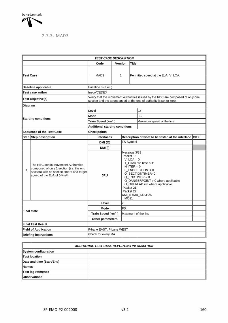
SP-EMO-P2-002008 v3.2 160
2.7.3. MAD3
TEST CASE DESCRIPTION
Code Version Title
Test Case MAD3 1 Permitted speed at the EoA. V_LOA.
Baseline applicable Baseline 3 (3.4.0)
Test case author Ineco/CEDEX
Test Objective(s) Verify that the movement authorities issued by the RBC are composed of only one section and the target speed at the end of authority is set to zero.
Diagram
Starting conditions
Level L2
Mode FS
Train Speed (km/h) Maximum speed of the line
Additional starting conditions
Sequence of the Test Case Checkpoints
Step Step description Interfaces Description of what to be tested at the interface OK?
1
The RBC sends Movement Authorities composed of only 1 section (i.e. the end section) with no section timers and target speed of the EoA of 0 Km/h.
DMI (O) FS Symbol
DMI (I)
JRU
Message 3/33 Packet 15 V_LOA = 0 T_LOA= "no time out" N_ITER = 0 L_ENDSECTION ≠ 0 Q_SECTIONTIMER=0 Q_ENDTIMER = 0 Q_DANGERPOINT ≠ 0 where applicable Q_OVERLAP ≠ 0 where applicable Packet 21 Packet 27 DMI_SYMB_STATUS MO11
Final state
Level 2
Mode FS
Train Speed (km/h) Maximum of the line
Other parameters
Final Test Result
Field of Application F-bane EAST, F-bane WEST
Briefing instructions Check for every MA
ADDITIONAL TEST CASE REPORTING INFORMATION
System configuration
Test location
Date and time (Start/End)
Names
Test log reference
Observations
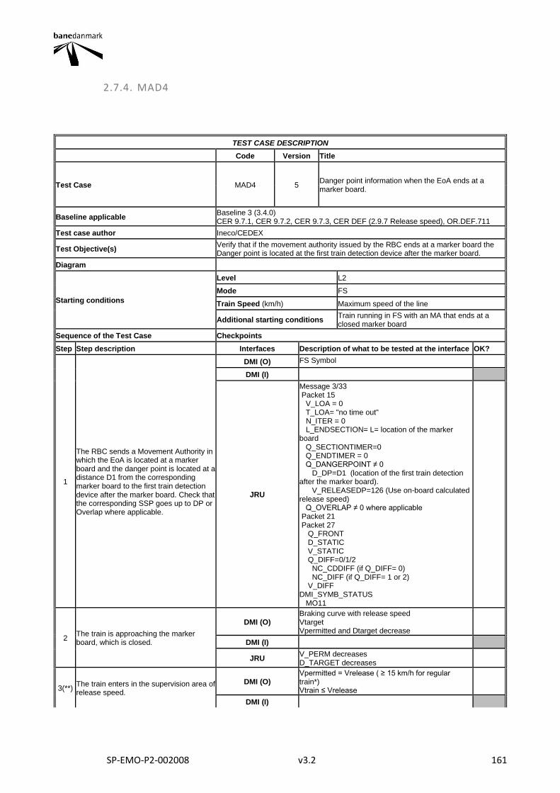
SP-EMO-P2-002008 v3.2 161
2.7.4. MAD4
TEST CASE DESCRIPTION
Code Version Title
Test Case MAD4 5 Danger point information when the EoA ends at a marker board.
Baseline applicable Baseline 3 (3.4.0) CER 9.7.1, CER 9.7.2, CER 9.7.3, CER DEF (2.9.7 Release speed), OR.DEF.711
Test case author Ineco/CEDEX
Test Objective(s) Verify that if the movement authority issued by the RBC ends at a marker board the Danger point is located at the first train detection device after the marker board.
Diagram
Starting conditions
Level L2
Mode FS
Train Speed (km/h) Maximum speed of the line
Additional starting conditions Train running in FS with an MA that ends at a closed marker board
Sequence of the Test Case Checkpoints
Step Step description Interfaces Description of what to be tested at the interface OK?
1
The RBC sends a Movement Authority in which the EoA is located at a marker board and the danger point is located at a distance D1 from the corresponding marker board to the first train detection device after the marker board. Check that the corresponding SSP goes up to DP or Overlap where applicable.
DMI (O) FS Symbol
DMI (I)
JRU
Message 3/33 Packet 15 V_LOA = 0 T_LOA= "no time out" N_ITER = 0 L_ENDSECTION= L= location of the marker board Q_SECTIONTIMER=0 Q_ENDTIMER = 0 Q_DANGERPOINT ≠ 0 D_DP=D1 (location of the first train detection after the marker board). V_RELEASEDP=126 (Use on-board calculated release speed) Q_OVERLAP ≠ 0 where applicable Packet 21 Packet 27 Q_FRONT D_STATIC V_STATIC Q_DIFF=0/1/2 NC_CDDIFF (if Q_DIFF= 0) NC_DIFF (if Q_DIFF= 1 or 2) V_DIFF DMI_SYMB_STATUS MO11
2 The train is approaching the marker board, which is closed.
DMI (O) Braking curve with release speed Vtarget Vpermitted and Dtarget decrease
DMI (I)
JRU V_PERM decreases D_TARGET decreases
3(**) The train enters in the supervision area of release speed.
DMI (O) Vpermitted = Vrelease ( ≥ 15 km/h for regular train*) Vtrain ≤ Vrelease
DMI (I)
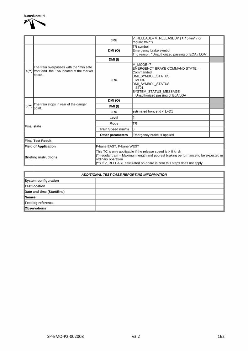
SP-EMO-P2-002008 v3.2 162
JRU V_RELEASE= V_RELEASEDP ( ≥ 15 km/h for regular train*)
4(**) The train overpasses with the "min safe front end" the EoA located at the marker board.
DMI (O) TR symbol Emergency brake symbol Trip reason: "Unauthorized passing of EOA / LOA"
DMI (I)
JRU
M_MODE=7 EMERGENCY BRAKE COMMAND STATE = Commanded DMI_SYMBOL_STATUS MO04 DMI_SYMBOL_STATUS ST01 SYSTEM_STATUS_MESSAGE Unauthorized passing of EoA/LOA
5(**) The train stops in rear of the danger point.
DMI (O)
DMI (I)
JRU estimated front end < L+D1
Final state
Level 2
Mode TR
Train Speed (km/h) 0
Other parameters Emergency brake is applied
Final Test Result
Field of Application F-bane EAST, F-bane WEST
Briefing instructions
This TC is only applicable if the release speed is > 0 km/h (*) regular train = Maximum length and poorest braking performance to be expected in ordinary operation (**) If V_RELEASE calculated on-board is zero this steps does not apply.
ADDITIONAL TEST CASE REPORTING INFORMATION
System configuration
Test location
Date and time (Start/End)
Names
Test log reference
Observations
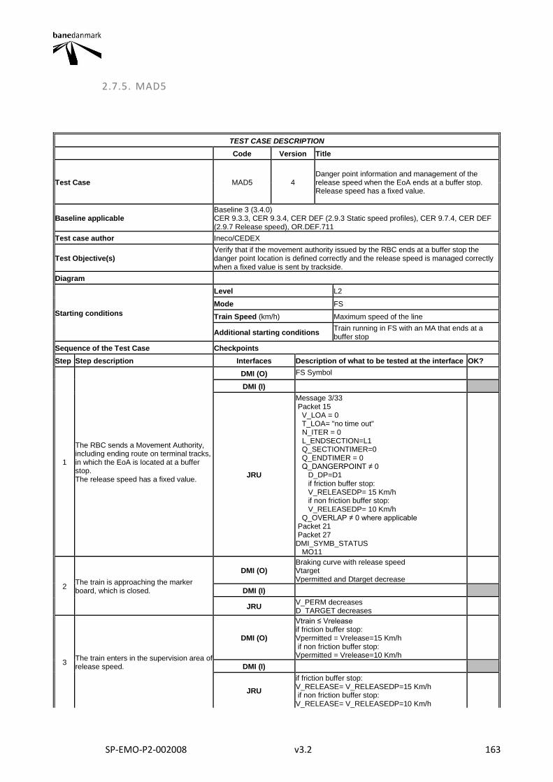
SP-EMO-P2-002008 v3.2 163
2.7.5. MAD5
TEST CASE DESCRIPTION
Code Version Title
Test Case MAD5 4 Danger point information and management of the release speed when the EoA ends at a buffer stop. Release speed has a fixed value.
Baseline applicable Baseline 3 (3.4.0) CER 9.3.3, CER 9.3.4, CER DEF (2.9.3 Static speed profiles), CER 9.7.4, CER DEF (2.9.7 Release speed), OR.DEF.711
Test case author Ineco/CEDEX
Test Objective(s) Verify that if the movement authority issued by the RBC ends at a buffer stop the danger point location is defined correctly and the release speed is managed correctly when a fixed value is sent by trackside.
Diagram
Starting conditions
Level L2
Mode FS
Train Speed (km/h) Maximum speed of the line
Additional starting conditions Train running in FS with an MA that ends at a buffer stop
Sequence of the Test Case Checkpoints
Step Step description Interfaces Description of what to be tested at the interface OK?
1
The RBC sends a Movement Authority, including ending route on terminal tracks, in which the EoA is located at a buffer stop. The release speed has a fixed value.
DMI (O) FS Symbol
DMI (I)
JRU
Message 3/33 Packet 15 V_LOA = 0 T_LOA= "no time out" N_ITER = 0 L_ENDSECTION=L1 Q_SECTIONTIMER=0 Q_ENDTIMER = 0 Q_DANGERPOINT ≠ 0 D_DP=D1 if friction buffer stop: V_RELEASEDP= 15 Km/h if non friction buffer stop: V_RELEASEDP= 10 Km/h Q_OVERLAP ≠ 0 where applicable Packet 21 Packet 27 DMI_SYMB_STATUS MO11
2 The train is approaching the marker board, which is closed.
DMI (O) Braking curve with release speed Vtarget Vpermitted and Dtarget decrease
DMI (I)
JRU V_PERM decreases D_TARGET decreases
3 The train enters in the supervision area of release speed.
DMI (O)
Vtrain ≤ Vrelease if friction buffer stop: Vpermitted = Vrelease=15 Km/h if non friction buffer stop: Vpermitted = Vrelease=10 Km/h
DMI (I)
JRU
if friction buffer stop: V_RELEASE= V_RELEASEDP=15 Km/h if non friction buffer stop: V_RELEASE= V_RELEASEDP=10 Km/h
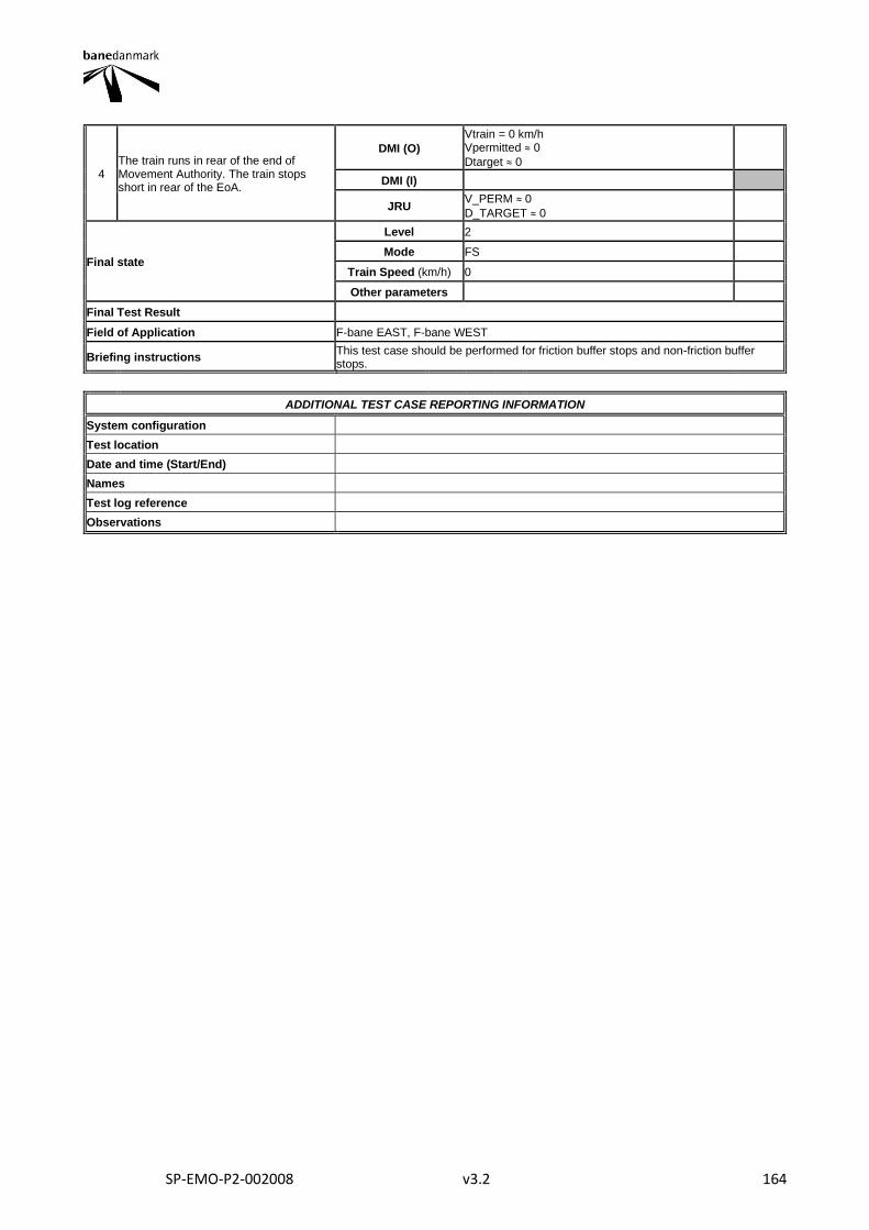
SP-EMO-P2-002008 v3.2 164
4 The train runs in rear of the end of Movement Authority. The train stops short in rear of the EoA.
DMI (O)
Vtrain = 0 km/h Vpermitted ≈ 0
Dtarget ≈ 0
DMI (I)
JRU V_PERM ≈ 0
D_TARGET ≈ 0
Final state
Level 2
Mode FS
Train Speed (km/h) 0
Other parameters
Final Test Result
Field of Application F-bane EAST, F-bane WEST
Briefing instructions This test case should be performed for friction buffer stops and non-friction buffer stops.
ADDITIONAL TEST CASE REPORTING INFORMATION
System configuration
Test location
Date and time (Start/End)
Names
Test log reference
Observations
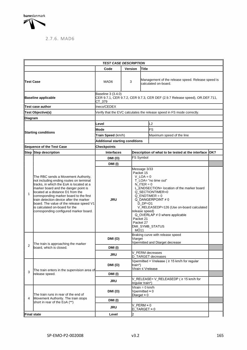
SP-EMO-P2-002008 v3.2 165
2.7.6. MAD6
TEST CASE DESCRIPTION
Code Version Title
Test Case MAD6 3 Management of the release speed. Release speed is calculated on-board.
Baseline applicable Baseline 3 (3.4.0) CER 9.7.1, CER 9.7.2, CER 9.7.3, CER DEF (2.9.7 Release speed), OR.DEF.711, CT_379
Test case author Ineco/CEDEX
Test Objective(s) Verify that the EVC calculates the release speed in FS mode correctly.
Diagram
Starting conditions
Level L2
Mode FS
Train Speed (km/h) Maximum speed of the line
Additional starting conditions
Sequence of the Test Case Checkpoints
Step Step description Interfaces Description of what to be tested at the interface OK?
1
The RBC sends a Movement Authority, not including ending routes on terminal tracks, in which the EoA is located at a marker board and the danger point is located at a distance D1 from the corresponding marker board to the first train detection device after the marker board. The value of the release speed V1 is calculated on-board for the corresponding configured marker board.
DMI (O) FS Symbol
DMI (I)
JRU
Message 3/33 Packet 15 V_LOA = 0 T_LOA= "no time out" N_ITER = 0 L_ENDSECTION= location of the marker board Q_SECTIONTIMER=0 Q_ENDTIMER = 0 Q_DANGERPOINT ≠ 0 D_DP=D1 V_RELEASEDP=126 (Use on-board calculated release speed) Q_OVERLAP ≠ 0 where applicable Packet 21 Packet 27 DMI_SYMB_STATUS MO11
2 The train is approaching the marker board, which is closed.
DMI (O) Braking curve with release speed Vtarget Vpermitted and Dtarget decrease
DMI (I)
JRU V_PERM decreases D_TARGET decreases
3 The train enters in the supervision area of release speed.
DMI (O) Vpermitted = Vrelease ( ≥ 15 km/h for regular train*) Vtrain ≤ Vrelease
DMI (I)
JRU V_RELEASE= V_RELEASEDP ( ≥ 15 km/h for regular train*)
4 The train runs in rear of the end of Movement Authority. The train stops short in rear of the EoA (**)
DMI (O) Vtrain = 0 km/h Vpermitted ≈ 0 Dtarget ≈ 0
DMI (I)
JRU V_PERM ≈ 0 D_TARGET ≈ 0
Final state Level 2
SP-EMO-P2-002008 v3.2 166
Mode FS
Train Speed (km/h) 0
Other parameters
Final Test Result
Field of Application F-bane EAST, F-bane WEST
Briefing instructions
(*) regular train = Maximum length and poorest braking performance to be expected in ordinary operation. (**) It shall be verify that the release speed calculated on-board allows the train to approach close enough to the marker board.
ADDITIONAL TEST CASE REPORTING INFORMATION
System configuration
Test location
Date and time (Start/End)
Names
Test log reference
Observations
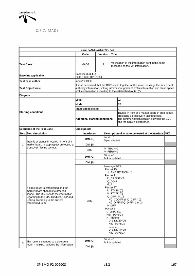
SP-EMO-P2-002008 v3.2 167
2.7.7. MAD8
TEST CASE DESCRIPTION
Code Version Title
Test Case MAD8 2 Verification of the information sent in the same message as the MA information.
Baseline applicable Baseline 3 (3.4.0) FbIS.F.350, OPS.1094
Test case author Ineco/CEDEX
Test Objective(s) It shall be verified that the RBC sends together at the same message the movement authority information, linking information, gradient profile information and static speed profile information according to the established route. (*)
Diagram
Starting conditions
Level L2
Mode FS
Train Speed (km/h) 0
Additional starting conditions
Train is in front of a marker board in stop aspect protecting a crossover / facing turnout. The communication session between the EVC and the RBC is established.
Sequence of the Test Case Checkpoints
Step Step description Interfaces Description of what to be tested at the interface OK?
1 Train is at standstill located in front of a marker board in stop aspect protecting a crossover / facing turnout.
DMI (O) Vtrain=0 Vpermitted≈0
DMI (I)
JRU V_TRAIN=0 V_PERM≈0
2
A direct route is established and the marker board changes to proceed aspect. The RBC sends the information regarding to the MA, Gradient, SSP and Linking according to the current established route.
DMI (O) Vtrain=0 MA is updated
DMI (I)
JRU
Message 3/33 Packet 15 L_ENDSECTION=L1 Packet 21 D_GRADIENT Q_GDIR G_A Packet 27 D_STATIC(0) V_STATIC(0) Q_DIFF=0/1/2 NC_CDDIFF (if Q_DIFF= 0) NC_DIFF (if Q_DIFF= 1 or 2) V_DIFF Packet 5 D_LINK=Da NID_BG=BGa N_ITER=n D_LINK(1)=Db NID_BG=BGb ........... D_LINK(n)=Dn NID_BG=BGn
3 The route is changed to a divergent route. The RBC updates the information
DMI (O) Vtrain=0 MA is updated
DMI (I)
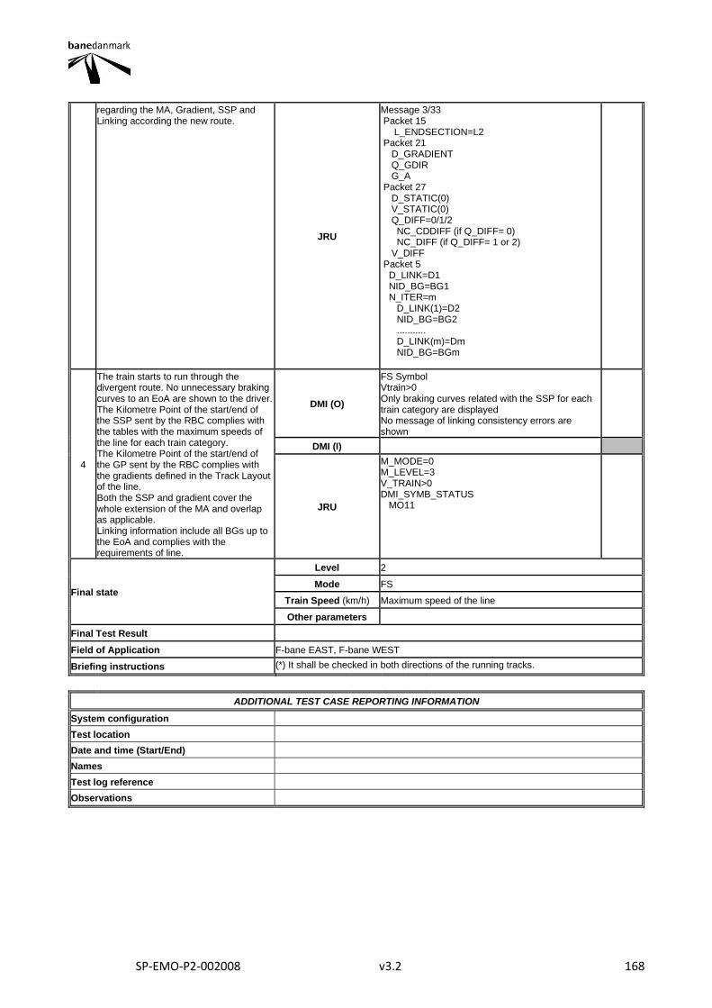
SP-EMO-P2-002008 v3.2 168
regarding the MA, Gradient, SSP and Linking according the new route.
JRU
Message 3/33 Packet 15 L_ENDSECTION=L2 Packet 21 D_GRADIENT Q_GDIR G_A Packet 27 D_STATIC(0) V_STATIC(0) Q_DIFF=0/1/2 NC_CDDIFF (if Q_DIFF= 0) NC_DIFF (if Q_DIFF= 1 or 2) V_DIFF Packet 5 D_LINK=D1 NID_BG=BG1 N_ITER=m D_LINK(1)=D2 NID_BG=BG2 ........... D_LINK(m)=Dm NID_BG=BGm
4
The train starts to run through the divergent route. No unnecessary braking curves to an EoA are shown to the driver. The Kilometre Point of the start/end of the SSP sent by the RBC complies with the tables with the maximum speeds of the line for each train category. The Kilometre Point of the start/end of the GP sent by the RBC complies with the gradients defined in the Track Layout of the line. Both the SSP and gradient cover the whole extension of the MA and overlap as applicable. Linking information include all BGs up to the EoA and complies with the requirements of line.
DMI (O)
FS Symbol Vtrain>0 Only braking curves related with the SSP for each train category are displayed No message of linking consistency errors are shown
DMI (I)
JRU
M_MODE=0 M_LEVEL=3 V_TRAIN>0 DMI_SYMB_STATUS MO11
Final state
Level 2
Mode FS
Train Speed (km/h) Maximum speed of the line
Other parameters
Final Test Result
Field of Application F-bane EAST, F-bane WEST
Briefing instructions (*) It shall be checked in both directions of the running tracks.
ADDITIONAL TEST CASE REPORTING INFORMATION
System configuration
Test location
Date and time (Start/End)
Names
Test log reference
Observations
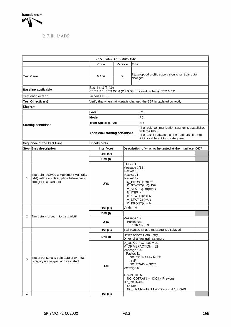
SP-EMO-P2-002008 v3.2 169
2.7.8. MAD9
TEST CASE DESCRIPTION
Code Version Title
Test Case MAD9 2 Static speed profile supervision when train data changes.
Baseline applicable Baseline 3 (3.4.0) CER 9.3.1, CER COM (2.9.3 Static speed profiles), CER 9.3.2
Test case author Ineco/CEDEX
Test Objective(s) Verify that when train data is changed the SSP is updated correctly
Diagram
Starting conditions
Level L2
Mode FS
Train Speed (km/h) NR
Additional starting conditions
The radio communication session is established with the RBC. The track in advance of the train has different SSP for different train categories
Sequence of the Test Case Checkpoints
Step Step description Interfaces Description of what to be tested at the interface OK?
1 The train receives a Movement Authority (MA) with track description before being brought to a standstill
DMI (O)
DMI (I)
JRU
(LRBG1) Message 3/33 Packet 15 Packet 21 Packet 27 Q_FRONT(k=0) = 0 D_STATIC(k=0)=D0k V_STATIC(k=0)=V0k N_ITER=k D_STATIC(k)=Dk V_STATIC(k)=Vk Q_FRONT(k) = 0
2 The train is brought to a standstill
DMI (O) Vtrain = 0
DMI (I)
JRU Message 136 Packet 0/1 V_TRAIN = 0
3 The driver selects train data entry. Train category is changed and validated.
DMI (O) Train data changed message is displayed
DMI (I) Driver selects Data Entry Driver changes train category
JRU
M_DRIVERACTION = 20 M_DRIVERACTION = 21 Message 129 Packet 11 NC_CDTRAIN = NCC1 and/or NC_TRAIN = NCT1 Message 8 TRAIN DATA NC_CDTRAIN = NCC1 ≠ Previous NC_CDTRAIN and/or NC_TRAIN = NCT1 ≠ Previous NC_TRAIN
4 DMI (O)
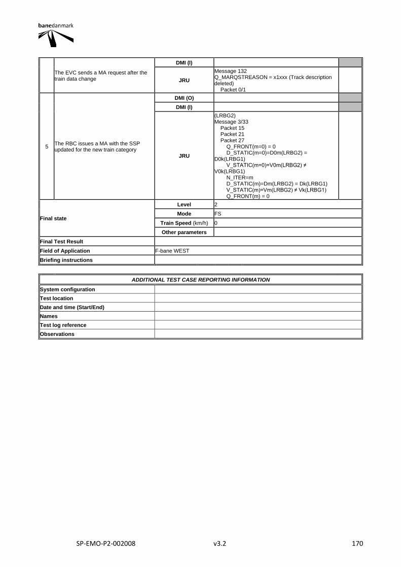
SP-EMO-P2-002008 v3.2 170
The EVC sends a MA request after the train data change
DMI (I)
JRU
Message 132 Q_MARQSTREASON = x1xxx (Track description deleted) Packet 0/1
5 The RBC issues a MA with the SSP updated for the new train category
DMI (O)
DMI (I)
JRU
(LRBG2) Message 3/33 Packet 15 Packet 21 Packet 27 Q_FRONT(m=0) = 0 D_STATIC(m=0)=D0m(LRBG2) = D0k(LRBG1) V_STATIC(m=0)=V0m(LRBG2) ≠ V0k(LRBG1) N_ITER=m D_STATIC(m)=Dm(LRBG2) = Dk(LRBG1) V_STATIC(m)=Vm(LRBG2) ≠ Vk(LRBG1) Q_FRONT(m) = 0
Final state
Level 2
Mode FS
Train Speed (km/h) 0
Other parameters
Final Test Result
Field of Application F-bane WEST
Briefing instructions
ADDITIONAL TEST CASE REPORTING INFORMATION
System configuration
Test location
Date and time (Start/End)
Names
Test log reference
Observations
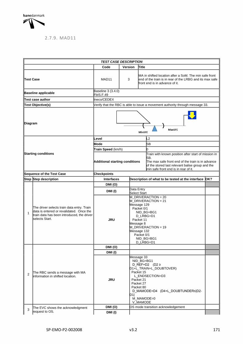
SP-EMO-P2-002008 v3.2 171
2.7.9. MAD11
TEST CASE DESCRIPTION
Code Version Title
Test Case MAD11 3 MA in shifted location after a SoM. The min safe front end of the train is in rear of the LRBG and its max safe front end is in advance of it.
Baseline applicable Baseline 3 (3.4.0) FbIS.F.49
Test case author Ineco/CEDEX
Test Objective(s) Verify that the RBC is able to issue a movement authority through message 33.
Diagram
Starting conditions
Level L2
Mode SB
Train Speed (km/h) 0
Additional starting conditions
Train with known position after start of mission in SB. The max safe front end of the train is in advance of the stored last relevant balise group and the min safe front end is in rear of it.
Sequence of the Test Case Checkpoints
Step Step description Interfaces Description of what to be tested at the interface OK?
1
The driver selects train data entry. Train data is entered or revalidated. Once the train data has been introduced, the driver selects Start.
DMI (O)
DMI (I) Data Entry Select Start
JRU
M_DRIVERACTION = 20 M_DRIVERACTION = 21 Message 129 Packet 0/1 NID_BG=BG1 D_LRBG=D1 Packet 11 Message 8 M_DRIVERACTION = 19 Message 132 Packet 0/1 NID_BG=BG1 D_LRBG=D1
2 The RBC sends a message with MA information in shifted location.
DMI (O)
DMI (I)
JRU
Message 33 NID_BG=BG1 D_REF=D2 (D2 ≥ D1+L_TRAIN+L_DOUBTOVER) Packet 15 L_ENDSECTION=D3 Packet 21 Packet 27 Packet 80 D_MAMODE=D4 (D4+L_DOUBTUNDER≤|D2-D1| M_MAMODE=0 V_MAMODE
3 The EVC shows the acknowledgment request to OS.
DMI (O) OS mode transition acknowledgement
DMI (I)
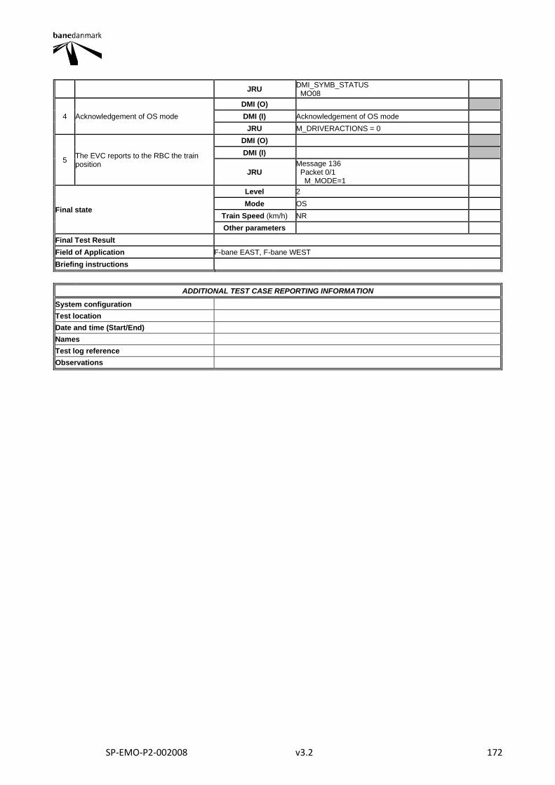
SP-EMO-P2-002008 v3.2 172
JRU DMI_SYMB_STATUS MO08
4 Acknowledgement of OS mode
DMI (O)
DMI (I) Acknowledgement of OS mode
JRU M_DRIVERACTIONS = 0
5 The EVC reports to the RBC the train position
DMI (O)
DMI (I)
JRU Message 136 Packet 0/1 M_MODE=1
Final state
Level 2
Mode OS
Train Speed (km/h) NR
Other parameters
Final Test Result
Field of Application F-bane EAST, F-bane WEST
Briefing instructions
ADDITIONAL TEST CASE REPORTING INFORMATION
System configuration
Test location
Date and time (Start/End)
Names
Test log reference
Observations
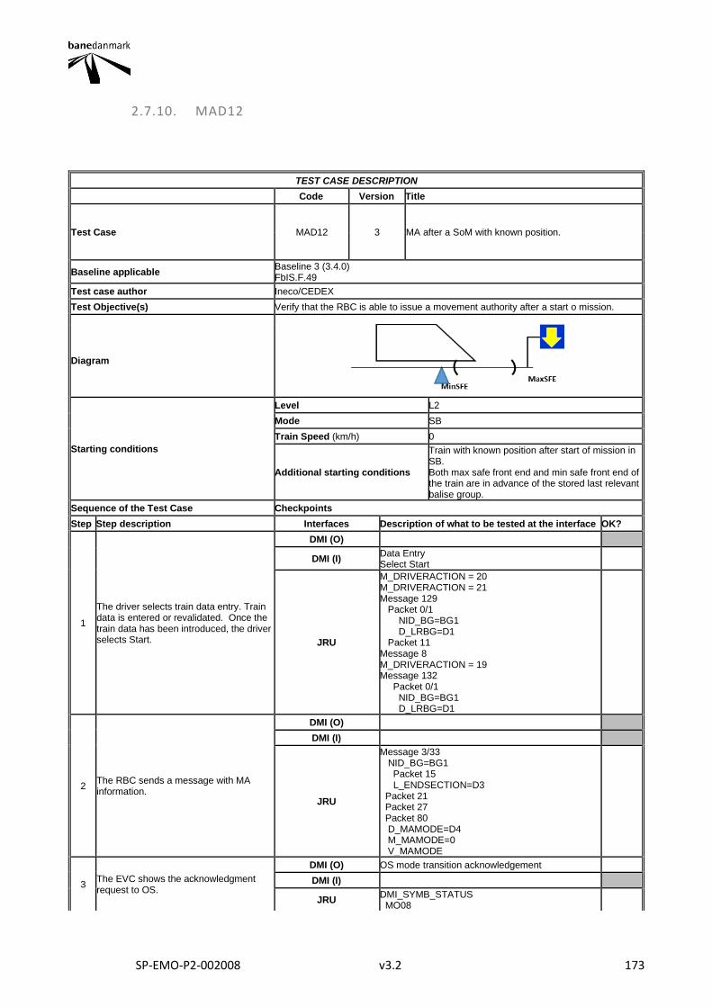
SP-EMO-P2-002008 v3.2 173
2.7.10. MAD12
TEST CASE DESCRIPTION
Code Version Title
Test Case MAD12 3 MA after a SoM with known position.
Baseline applicable Baseline 3 (3.4.0) FbIS.F.49
Test case author Ineco/CEDEX
Test Objective(s) Verify that the RBC is able to issue a movement authority after a start o mission.
Diagram
Starting conditions
Level L2
Mode SB
Train Speed (km/h) 0
Additional starting conditions
Train with known position after start of mission in SB. Both max safe front end and min safe front end of the train are in advance of the stored last relevant balise group.
Sequence of the Test Case Checkpoints
Step Step description Interfaces Description of what to be tested at the interface OK?
1
The driver selects train data entry. Train data is entered or revalidated. Once the train data has been introduced, the driver selects Start.
DMI (O)
DMI (I) Data Entry Select Start
JRU
M_DRIVERACTION = 20 M_DRIVERACTION = 21 Message 129 Packet 0/1 NID_BG=BG1 D_LRBG=D1 Packet 11 Message 8 M_DRIVERACTION = 19 Message 132 Packet 0/1 NID_BG=BG1 D_LRBG=D1
2 The RBC sends a message with MA information.
DMI (O)
DMI (I)
JRU
Message 3/33 NID_BG=BG1 Packet 15 L_ENDSECTION=D3 Packet 21 Packet 27 Packet 80 D_MAMODE=D4 M_MAMODE=0 V_MAMODE
3 The EVC shows the acknowledgment request to OS.
DMI (O) OS mode transition acknowledgement
DMI (I)
JRU DMI_SYMB_STATUS MO08
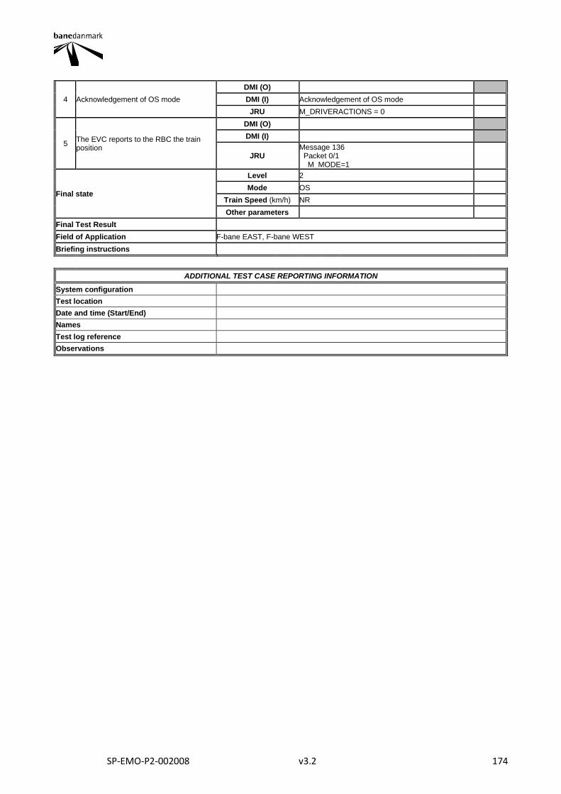
SP-EMO-P2-002008 v3.2 174
4 Acknowledgement of OS mode
DMI (O)
DMI (I) Acknowledgement of OS mode
JRU M_DRIVERACTIONS = 0
5 The EVC reports to the RBC the train position
DMI (O)
DMI (I)
JRU Message 136 Packet 0/1 M_MODE=1
Final state
Level 2
Mode OS
Train Speed (km/h) NR
Other parameters
Final Test Result
Field of Application F-bane EAST, F-bane WEST
Briefing instructions
ADDITIONAL TEST CASE REPORTING INFORMATION
System configuration
Test location
Date and time (Start/End)
Names
Test log reference
Observations
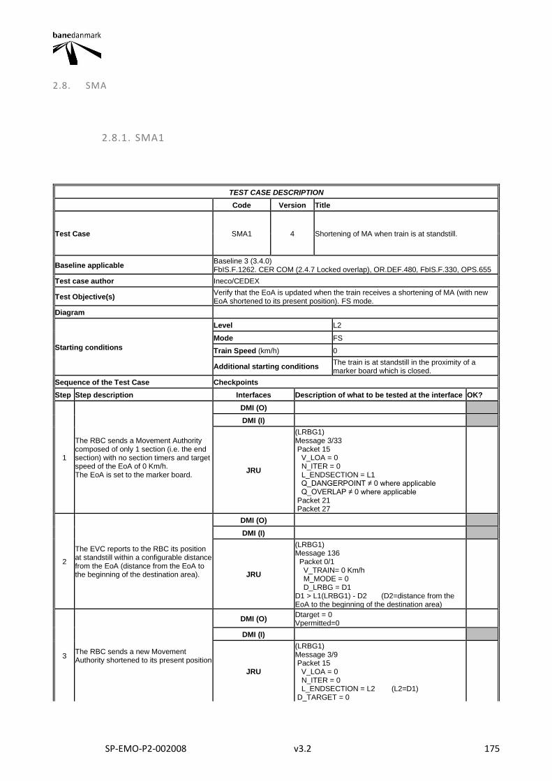
SP-EMO-P2-002008 v3.2 175
2.8. SMA
2.8.1. SMA1
TEST CASE DESCRIPTION
Code Version Title
Test Case SMA1 4 Shortening of MA when train is at standstill.
Baseline applicable Baseline 3 (3.4.0) FbIS.F.1262. CER COM (2.4.7 Locked overlap), OR.DEF.480, FbIS.F.330, OPS.655
Test case author Ineco/CEDEX
Test Objective(s) Verify that the EoA is updated when the train receives a shortening of MA (with new EoA shortened to its present position). FS mode.
Diagram
Starting conditions
Level L2
Mode FS
Train Speed (km/h) 0
Additional starting conditions The train is at standstill in the proximity of a marker board which is closed.
Sequence of the Test Case Checkpoints
Step Step description Interfaces Description of what to be tested at the interface OK?
1
The RBC sends a Movement Authority composed of only 1 section (i.e. the end section) with no section timers and target speed of the EoA of 0 Km/h. The EoA is set to the marker board.
DMI (O)
DMI (I)
JRU
(LRBG1) Message 3/33 Packet 15 V_LOA = 0 N_ITER = 0 L_ENDSECTION = L1 Q_DANGERPOINT ≠ 0 where applicable Q_OVERLAP ≠ 0 where applicable Packet 21 Packet 27
2
The EVC reports to the RBC its position at standstill within a configurable distance from the EoA (distance from the EoA to the beginning of the destination area).
DMI (O)
DMI (I)
JRU
(LRBG1) Message 136 Packet 0/1 V_TRAIN= 0 Km/h M_MODE = 0 D_LRBG = D1 D1 > L1(LRBG1) - D2 (D2=distance from the EoA to the beginning of the destination area)
3 The RBC sends a new Movement Authority shortened to its present position
DMI (O) Dtarget = 0 Vpermitted=0
DMI (I)
JRU
(LRBG1) Message 3/9 Packet 15 V_LOA = 0 N_ITER = 0 L_ENDSECTION = L2 (L2=D1) D_TARGET = 0
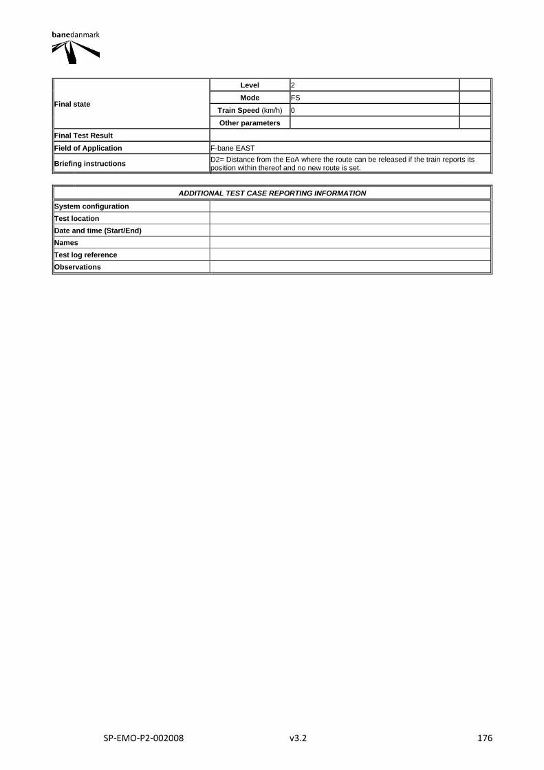
SP-EMO-P2-002008 v3.2 176
Final state
Level 2
Mode FS
Train Speed (km/h) 0
Other parameters
Final Test Result
Field of Application F-bane EAST
Briefing instructions D2= Distance from the EoA where the route can be released if the train reports its position within thereof and no new route is set.
ADDITIONAL TEST CASE REPORTING INFORMATION
System configuration
Test location
Date and time (Start/End)
Names
Test log reference
Observations
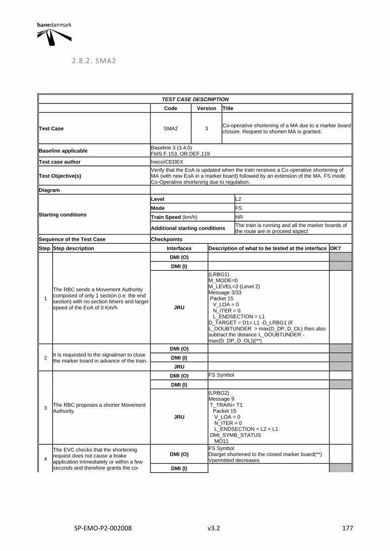
SP-EMO-P2-002008 v3.2 177
2.8.2. SMA2
TEST CASE DESCRIPTION
Code Version Title
Test Case SMA2 3 Co-operative shortening of a MA due to a marker board closure. Request to shorten MA is granted.
Baseline applicable Baseline 3 (3.4.0) FbIS.F.153, OR.DEF.119
Test case author Ineco/CEDEX
Test Objective(s) Verify that the EoA is updated when the train receives a Co-operative shortening of MA (with new EoA in a marker board) followed by an extension of the MA. FS mode. Co-Operative shortening due to regulation.
Diagram
Starting conditions
Level L2
Mode FS
Train Speed (km/h) NR
Additional starting conditions The train is running and all the marker boards of the route are in proceed aspect
Sequence of the Test Case Checkpoints
Step Step description Interfaces Description of what to be tested at the interface OK?
1
The RBC sends a Movement Authority composed of only 1 section (i.e. the end section) with no section timers and target speed of the EoA of 0 Km/h.
DMI (O)
DMI (I)
JRU
(LRBG1) M_MODE=0 M_LEVEL=3 (Level 2) Message 3/33 Packet 15 V_LOA = 0 N_ITER = 0 L_ENDSECTION = L1 D_TARGET = D1= L1 -D_LRBG1 (if L_DOUBTUNDER > max(D_DP, D_OL) then also subtract the distance L_DOUBTUNDER - max(D_DP, D_OL))(**)
2 It is requested to the signalman to close the marker board in advance of the train.
DMI (O)
DMI (I)
JRU
3 The RBC proposes a shorter Movement Authority.
DMI (O) FS Symbol
DMI (I)
JRU
(LRBG2) Message 9 T_TRAIN= T1 Packet 15 V_LOA = 0 N_ITER = 0 L_ENDSECTION = L2 < L1 DMI_SYMB_STATUS MO11
4
The EVC checks that the shortening request does not cause a brake application immediately or within a few seconds and therefore grants the co-
DMI (O) FS Symbol Dtarget shortened to the closed marker board(**) Vpermitted decreases
DMI (I)
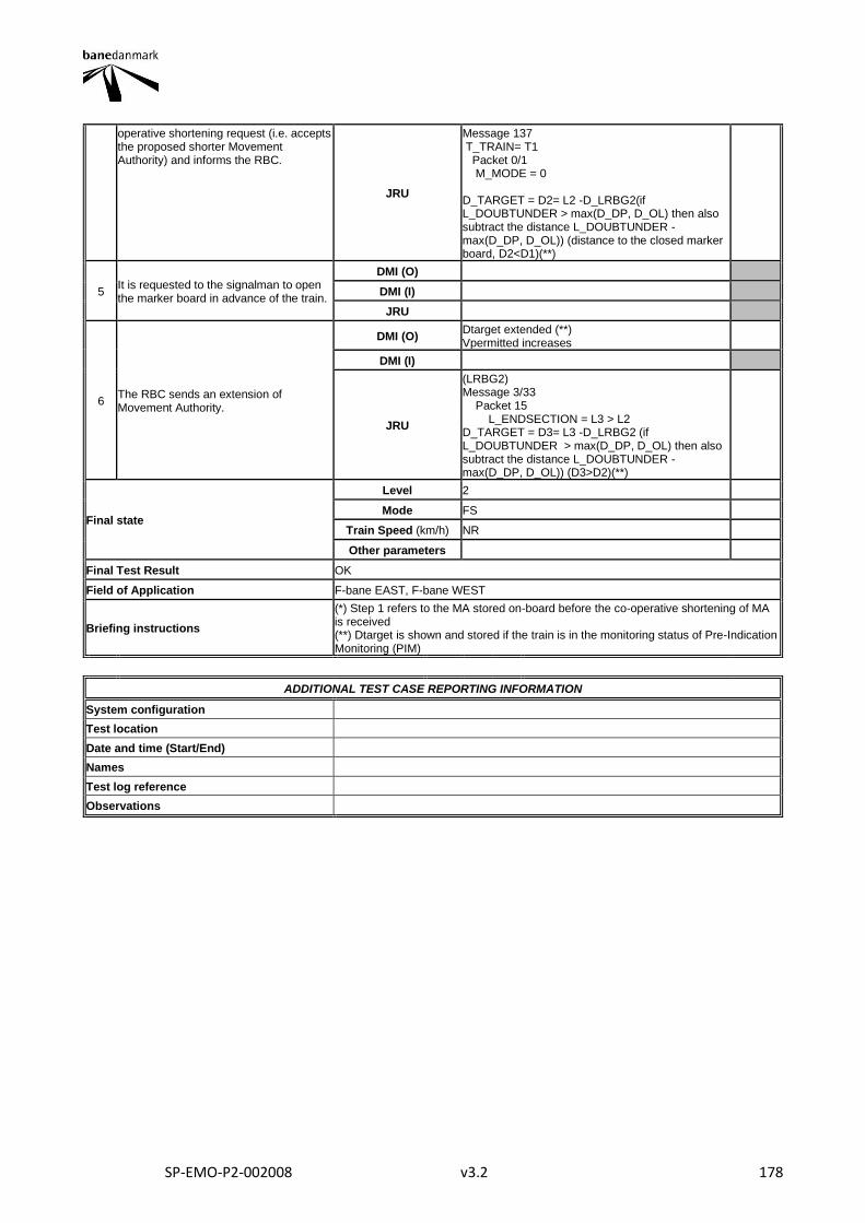
SP-EMO-P2-002008 v3.2 178
operative shortening request (i.e. accepts the proposed shorter Movement Authority) and informs the RBC.
JRU
Message 137 T_TRAIN= T1 Packet 0/1 M_MODE = 0 D_TARGET = D2= L2 -D_LRBG2(if L_DOUBTUNDER > max(D_DP, D_OL) then also subtract the distance L_DOUBTUNDER - max(D_DP, D_OL)) (distance to the closed marker board, D2<D1)(**)
5 It is requested to the signalman to open the marker board in advance of the train.
DMI (O)
DMI (I)
JRU
6 The RBC sends an extension of Movement Authority.
DMI (O) Dtarget extended (**) Vpermitted increases
DMI (I)
JRU
(LRBG2) Message 3/33 Packet 15 L_ENDSECTION = L3 > L2 D_TARGET = D3= L3 -D_LRBG2 (if L_DOUBTUNDER > max(D_DP, D_OL) then also subtract the distance L_DOUBTUNDER - max(D_DP, D_OL)) (D3>D2)(**)
Final state
Level 2
Mode FS
Train Speed (km/h) NR
Other parameters
Final Test Result OK
Field of Application F-bane EAST, F-bane WEST
Briefing instructions
(*) Step 1 refers to the MA stored on-board before the co-operative shortening of MA is received (**) Dtarget is shown and stored if the train is in the monitoring status of Pre-Indication Monitoring (PIM)
ADDITIONAL TEST CASE REPORTING INFORMATION
System configuration
Test location
Date and time (Start/End)
Names
Test log reference
Observations
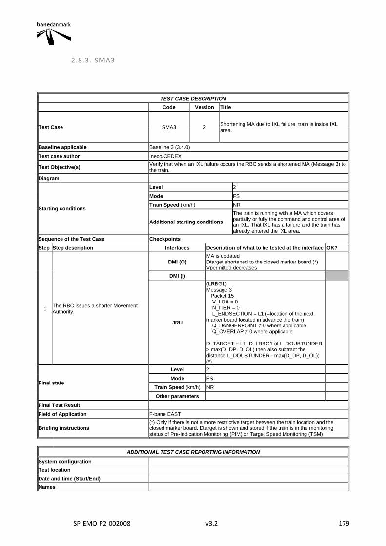
SP-EMO-P2-002008 v3.2 179
2.8.3. SMA3
TEST CASE DESCRIPTION
Code Version Title
Test Case SMA3 2 Shortening MA due to IXL failure: train is inside IXL area.
Baseline applicable Baseline 3 (3.4.0)
Test case author Ineco/CEDEX
Test Objective(s) Verify that when an IXL failure occurs the RBC sends a shortened MA (Message 3) to the train.
Diagram
Starting conditions
Level 2
Mode FS
Train Speed (km/h) NR
Additional starting conditions
The train is running with a MA which covers partially or fully the command and control area of an IXL. That IXL has a failure and the train has already entered the IXL area.
Sequence of the Test Case Checkpoints
Step Step description Interfaces Description of what to be tested at the interface OK?
1 The RBC issues a shorter Movement Authority.
DMI (O) MA is updated Dtarget shortened to the closed marker board (*) Vpermitted decreases
DMI (I)
JRU
(LRBG1) Message 3 Packet 15 V_LOA = 0 N_ITER = 0 L_ENDSECTION = L1 (=location of the next marker board located in advance the train) Q_DANGERPOINT ≠ 0 where applicable Q_OVERLAP ≠ 0 where applicable D_TARGET = L1 -D_LRBG1 (if L_DOUBTUNDER > max(D_DP, D_OL) then also subtract the distance L_DOUBTUNDER - max(D_DP, D_OL)) (*)
Final state
Level 2
Mode FS
Train Speed (km/h) NR
Other parameters
Final Test Result
Field of Application F-bane EAST
Briefing instructions (*) Only if there is not a more restrictive target between the train location and the closed marker board. Dtarget is shown and stored if the train is in the monitoring status of Pre-Indication Monitoring (PIM) or Target Speed Monitoring (TSM)
ADDITIONAL TEST CASE REPORTING INFORMATION
System configuration
Test location
Date and time (Start/End)
Names
SP-EMO-P2-002008 v3.2 180
Test log reference
Observations
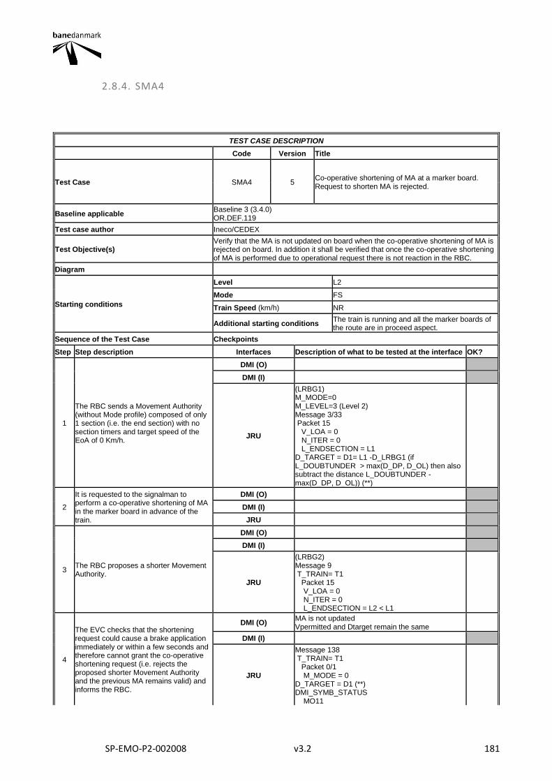
SP-EMO-P2-002008 v3.2 181
2.8.4. SMA4
TEST CASE DESCRIPTION
Code Version Title
Test Case SMA4 5 Co-operative shortening of MA at a marker board. Request to shorten MA is rejected.
Baseline applicable Baseline 3 (3.4.0) OR.DEF.119
Test case author Ineco/CEDEX
Test Objective(s) Verify that the MA is not updated on board when the co-operative shortening of MA is rejected on board. In addition it shall be verified that once the co-operative shortening of MA is performed due to operational request there is not reaction in the RBC.
Diagram
Starting conditions
Level L2
Mode FS
Train Speed (km/h) NR
Additional starting conditions The train is running and all the marker boards of the route are in proceed aspect.
Sequence of the Test Case Checkpoints
Step Step description Interfaces Description of what to be tested at the interface OK?
1
The RBC sends a Movement Authority (without Mode profile) composed of only 1 section (i.e. the end section) with no section timers and target speed of the EoA of 0 Km/h.
DMI (O)
DMI (I)
JRU
(LRBG1) M_MODE=0 M_LEVEL=3 (Level 2) Message 3/33 Packet 15 V_LOA = 0 N_ITER = 0 L_ENDSECTION = L1 D_TARGET = D1= L1 -D_LRBG1 (if L_DOUBTUNDER > max(D_DP, D_OL) then also subtract the distance L_DOUBTUNDER - max(D_DP, D_OL)) (**)
2
It is requested to the signalman to perform a co-operative shortening of MA in the marker board in advance of the train.
DMI (O)
DMI (I)
JRU
3 The RBC proposes a shorter Movement Authority.
DMI (O)
DMI (I)
JRU
(LRBG2) Message 9 T_TRAIN= T1 Packet 15 V_LOA = 0 N_ITER = 0 L_ENDSECTION = L2 < L1
4
The EVC checks that the shortening request could cause a brake application immediately or within a few seconds and therefore cannot grant the co-operative shortening request (i.e. rejects the proposed shorter Movement Authority and the previous MA remains valid) and informs the RBC.
DMI (O) MA is not updated Vpermitted and Dtarget remain the same
DMI (I)
JRU
Message 138 T_TRAIN= T1 Packet 0/1 M_MODE = 0 D_TARGET = D1 (**) DMI_SYMB_STATUS MO11
SP-EMO-P2-002008 v3.2 182
Final state
Level 2
Mode FS
Train Speed (km/h) NR
Other parameters
Final Test Result
Field of Application F-bane EAST, F-bane WEST
Briefing instructions
(*) Step 1 refers to the MA stored on-board before the co-operative shortening of MA is received (**) Dtarget is shown and stored if the train is in the monitoring status of Pre-Indication Monitoring (PIM) or Target Speed Monitoring (TSM)
ADDITIONAL TEST CASE REPORTING INFORMATION
System configuration
Test location
Date and time (Start/End)
Names
Test log reference
Observations
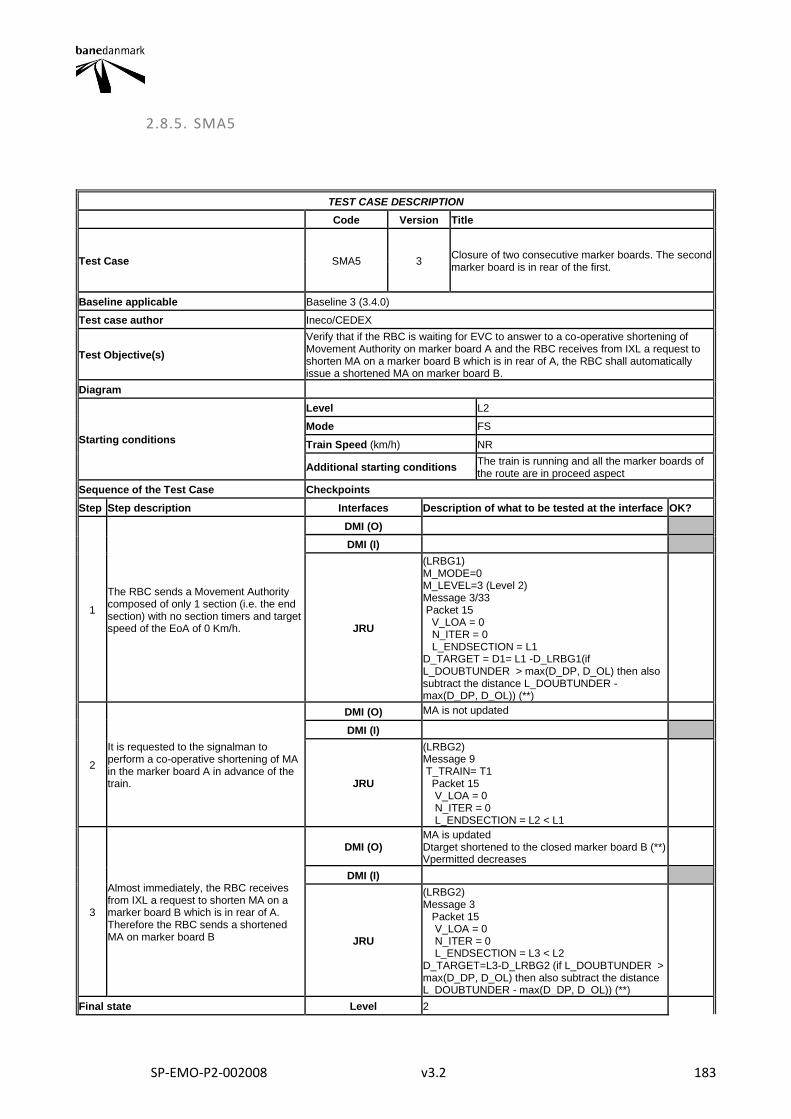
SP-EMO-P2-002008 v3.2 183
2.8.5. SMA5
TEST CASE DESCRIPTION
Code Version Title
Test Case SMA5 3 Closure of two consecutive marker boards. The second marker board is in rear of the first.
Baseline applicable Baseline 3 (3.4.0)
Test case author Ineco/CEDEX
Test Objective(s)
Verify that if the RBC is waiting for EVC to answer to a co-operative shortening of Movement Authority on marker board A and the RBC receives from IXL a request to shorten MA on a marker board B which is in rear of A, the RBC shall automatically issue a shortened MA on marker board B.
Diagram
Starting conditions
Level L2
Mode FS
Train Speed (km/h) NR
Additional starting conditions The train is running and all the marker boards of the route are in proceed aspect
Sequence of the Test Case Checkpoints
Step Step description Interfaces Description of what to be tested at the interface OK?
1
The RBC sends a Movement Authority composed of only 1 section (i.e. the end section) with no section timers and target speed of the EoA of 0 Km/h.
DMI (O)
DMI (I)
JRU
(LRBG1) M_MODE=0 M_LEVEL=3 (Level 2) Message 3/33 Packet 15 V_LOA = 0 N_ITER = 0 L_ENDSECTION = L1 D_TARGET = D1= L1 -D_LRBG1(if L_DOUBTUNDER > max(D_DP, D_OL) then also subtract the distance L_DOUBTUNDER - max(D_DP, D_OL)) (**)
2
It is requested to the signalman to perform a co-operative shortening of MA in the marker board A in advance of the train.
DMI (O) MA is not updated
DMI (I)
JRU
(LRBG2) Message 9 T_TRAIN= T1 Packet 15 V_LOA = 0 N_ITER = 0 L_ENDSECTION = L2 < L1
3
Almost immediately, the RBC receives from IXL a request to shorten MA on a marker board B which is in rear of A. Therefore the RBC sends a shortened MA on marker board B
DMI (O) MA is updated Dtarget shortened to the closed marker board B (**) Vpermitted decreases
DMI (I)
JRU
(LRBG2) Message 3 Packet 15 V_LOA = 0 N_ITER = 0 L_ENDSECTION = L3 < L2 D_TARGET=L3-D_LRBG2 (if L_DOUBTUNDER > max(D_DP, D_OL) then also subtract the distance L_DOUBTUNDER - max(D_DP, D_OL)) (**)
Final state Level 2
SP-EMO-P2-002008 v3.2 184
Mode FS
Train Speed (km/h) NR
Other parameters
Final Test Result
Field of Application F-bane EAST
Briefing instructions
(*) Step 1 refers to the MA stored on-board before the co-operative shortening of MA is received (**) Dtarget is shown and stored if the train is in the monitoring status of Pre-Indication Monitoring (PIM) or Target Speed Monitoring (TSM)
ADDITIONAL TEST CASE REPORTING INFORMATION
System configuration
Test location
Date and time (Start/End)
Names
Test log reference
Observations
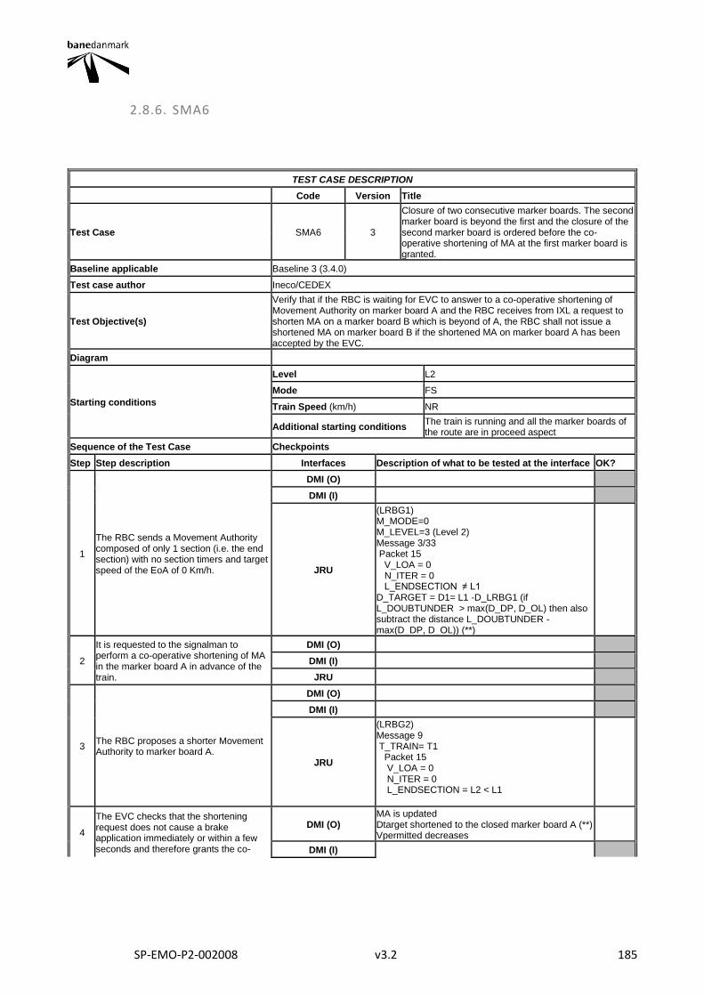
SP-EMO-P2-002008 v3.2 185
2.8.6. SMA6
TEST CASE DESCRIPTION
Code Version Title
Test Case SMA6 3
Closure of two consecutive marker boards. The second marker board is beyond the first and the closure of the second marker board is ordered before the co-operative shortening of MA at the first marker board is granted.
Baseline applicable Baseline 3 (3.4.0)
Test case author Ineco/CEDEX
Test Objective(s)
Verify that if the RBC is waiting for EVC to answer to a co-operative shortening of Movement Authority on marker board A and the RBC receives from IXL a request to shorten MA on a marker board B which is beyond of A, the RBC shall not issue a shortened MA on marker board B if the shortened MA on marker board A has been accepted by the EVC.
Diagram
Starting conditions
Level L2
Mode FS
Train Speed (km/h) NR
Additional starting conditions The train is running and all the marker boards of the route are in proceed aspect
Sequence of the Test Case Checkpoints
Step Step description Interfaces Description of what to be tested at the interface OK?
1
The RBC sends a Movement Authority composed of only 1 section (i.e. the end section) with no section timers and target speed of the EoA of 0 Km/h.
DMI (O)
DMI (I)
JRU
(LRBG1) M_MODE=0 M_LEVEL=3 (Level 2) Message 3/33 Packet 15 V_LOA = 0 N_ITER = 0 L_ENDSECTION ≠ L1 D_TARGET = D1= L1 -D_LRBG1 (if L_DOUBTUNDER > max(D_DP, D_OL) then also subtract the distance L_DOUBTUNDER - max(D_DP, D_OL)) (**)
2
It is requested to the signalman to perform a co-operative shortening of MA in the marker board A in advance of the train.
DMI (O)
DMI (I)
JRU
3 The RBC proposes a shorter Movement Authority to marker board A.
DMI (O)
DMI (I)
JRU
(LRBG2) Message 9 T_TRAIN= T1 Packet 15 V_LOA = 0 N_ITER = 0 L_ENDSECTION = L2 < L1
4
The EVC checks that the shortening request does not cause a brake application immediately or within a few seconds and therefore grants the co-
DMI (O) MA is updated Dtarget shortened to the closed marker board A (**) Vpermitted decreases
DMI (I)
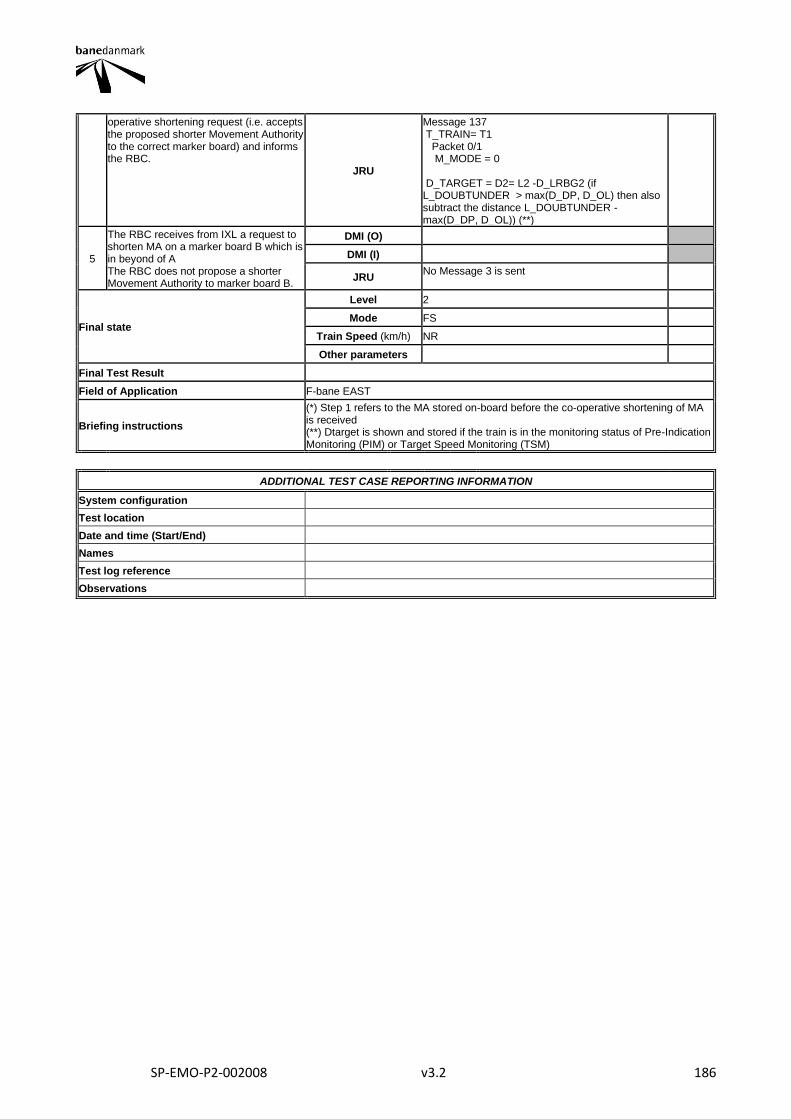
SP-EMO-P2-002008 v3.2 186
operative shortening request (i.e. accepts the proposed shorter Movement Authority to the correct marker board) and informs the RBC.
JRU
Message 137 T_TRAIN= T1 Packet 0/1 M_MODE = 0 D_TARGET = D2= L2 -D_LRBG2 (if L_DOUBTUNDER > max(D_DP, D_OL) then also subtract the distance L_DOUBTUNDER - max(D_DP, D_OL)) (**)
5
The RBC receives from IXL a request to shorten MA on a marker board B which is in beyond of A The RBC does not propose a shorter Movement Authority to marker board B.
DMI (O)
DMI (I)
JRU No Message 3 is sent
Final state
Level 2
Mode FS
Train Speed (km/h) NR
Other parameters
Final Test Result
Field of Application F-bane EAST
Briefing instructions
(*) Step 1 refers to the MA stored on-board before the co-operative shortening of MA is received (**) Dtarget is shown and stored if the train is in the monitoring status of Pre-Indication Monitoring (PIM) or Target Speed Monitoring (TSM)
ADDITIONAL TEST CASE REPORTING INFORMATION
System configuration
Test location
Date and time (Start/End)
Names
Test log reference
Observations
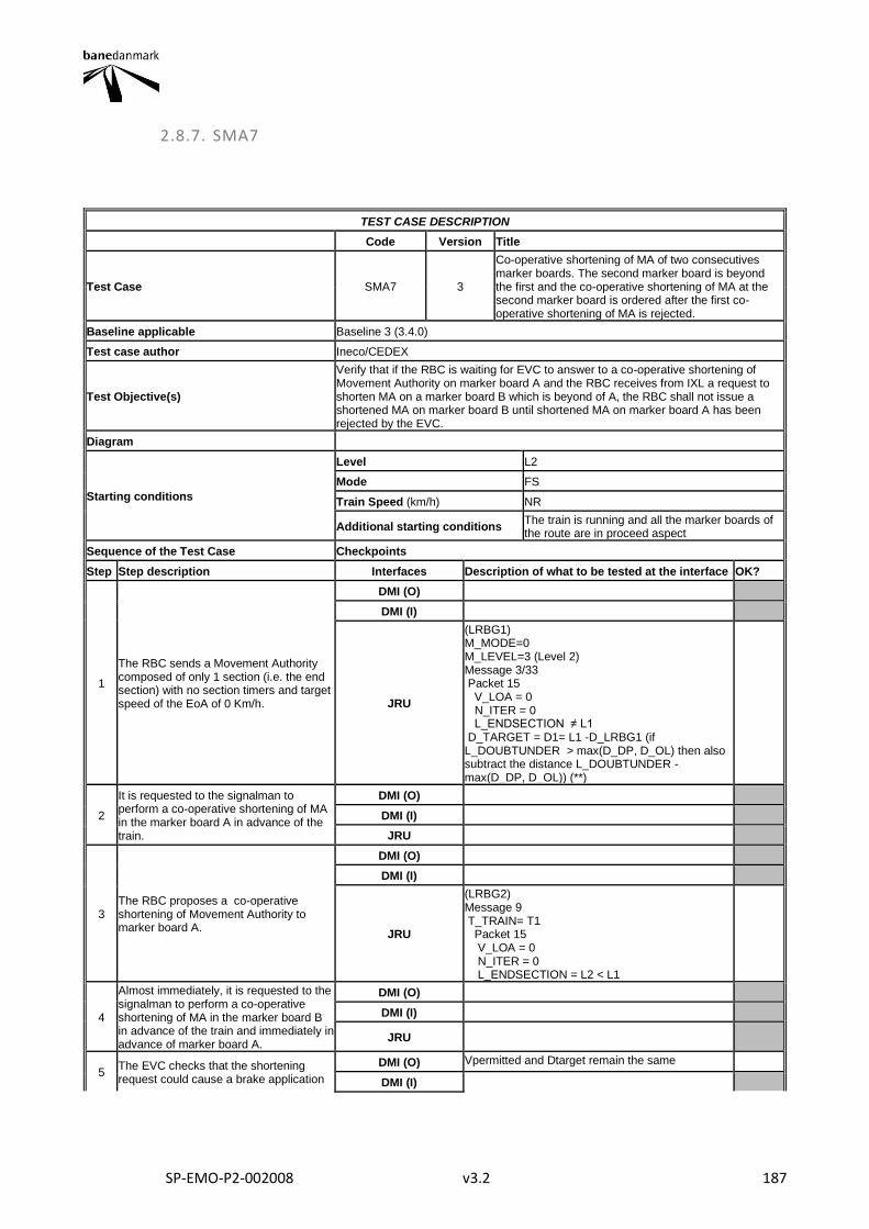
SP-EMO-P2-002008 v3.2 187
2.8.7. SMA7
TEST CASE DESCRIPTION
Code Version Title
Test Case SMA7 3
Co-operative shortening of MA of two consecutives marker boards. The second marker board is beyond the first and the co-operative shortening of MA at the second marker board is ordered after the first co-operative shortening of MA is rejected.
Baseline applicable Baseline 3 (3.4.0)
Test case author Ineco/CEDEX
Test Objective(s)
Verify that if the RBC is waiting for EVC to answer to a co-operative shortening of Movement Authority on marker board A and the RBC receives from IXL a request to shorten MA on a marker board B which is beyond of A, the RBC shall not issue a shortened MA on marker board B until shortened MA on marker board A has been rejected by the EVC.
Diagram
Starting conditions
Level L2
Mode FS
Train Speed (km/h) NR
Additional starting conditions The train is running and all the marker boards of the route are in proceed aspect
Sequence of the Test Case Checkpoints
Step Step description Interfaces Description of what to be tested at the interface OK?
1
The RBC sends a Movement Authority composed of only 1 section (i.e. the end section) with no section timers and target speed of the EoA of 0 Km/h.
DMI (O)
DMI (I)
JRU
(LRBG1) M_MODE=0 M_LEVEL=3 (Level 2) Message 3/33 Packet 15 V_LOA = 0 N_ITER = 0 L_ENDSECTION ≠ L1 D_TARGET = D1= L1 -D_LRBG1 (if L_DOUBTUNDER > max(D_DP, D_OL) then also subtract the distance L_DOUBTUNDER - max(D_DP, D_OL)) (**)
2
It is requested to the signalman to perform a co-operative shortening of MA in the marker board A in advance of the train.
DMI (O)
DMI (I)
JRU
3 The RBC proposes a co-operative shortening of Movement Authority to marker board A.
DMI (O)
DMI (I)
JRU
(LRBG2) Message 9 T_TRAIN= T1 Packet 15 V_LOA = 0 N_ITER = 0 L_ENDSECTION = L2 < L1
4
Almost immediately, it is requested to the signalman to perform a co-operative shortening of MA in the marker board B in advance of the train and immediately in advance of marker board A.
DMI (O)
DMI (I)
JRU
5 The EVC checks that the shortening request could cause a brake application
DMI (O) Vpermitted and Dtarget remain the same
DMI (I)
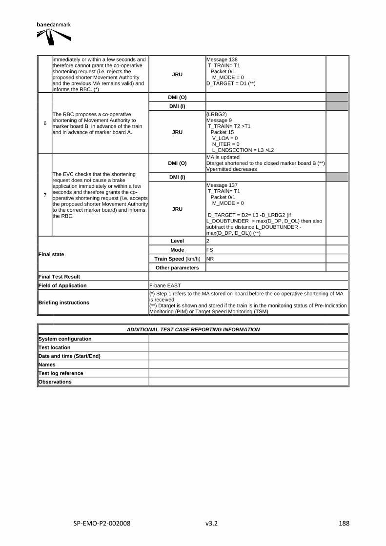
SP-EMO-P2-002008 v3.2 188
immediately or within a few seconds and therefore cannot grant the co-operative shortening request (i.e. rejects the proposed shorter Movement Authority and the previous MA remains valid) and informs the RBC. (*)
JRU
Message 138 T_TRAIN= T1 Packet 0/1 M_MODE = 0 D_TARGET = D1 (**)
6
The RBC proposes a co-operative shortening of Movement Authority to marker board B, in advance of the train and in advance of marker board A.
DMI (O)
DMI (I)
JRU
(LRBG2) Message 9 T_TRAIN= T2 >T1 Packet 15 V_LOA = 0 N_ITER = 0 L_ENDSECTION = L3 >L2
7
The EVC checks that the shortening request does not cause a brake application immediately or within a few seconds and therefore grants the co-operative shortening request (i.e. accepts the proposed shorter Movement Authority to the correct marker board) and informs the RBC.
DMI (O) MA is updated Dtarget shortened to the closed marker board B (**) Vpermitted decreases
DMI (I)
JRU
Message 137 T_TRAIN= T1 Packet 0/1 M_MODE = 0 D_TARGET = D2= L3 -D_LRBG2 (if L_DOUBTUNDER > max(D_DP, D_OL) then also subtract the distance L_DOUBTUNDER - max(D_DP, D_OL)) (**)
Final state
Level 2
Mode FS
Train Speed (km/h) NR
Other parameters
Final Test Result
Field of Application F-bane EAST
Briefing instructions
(*) Step 1 refers to the MA stored on-board before the co-operative shortening of MA is received (**) Dtarget is shown and stored if the train is in the monitoring status of Pre-Indication Monitoring (PIM) or Target Speed Monitoring (TSM)
ADDITIONAL TEST CASE REPORTING INFORMATION
System configuration
Test location
Date and time (Start/End)
Names
Test log reference
Observations
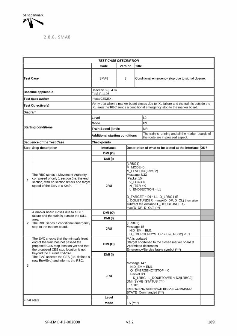
SP-EMO-P2-002008 v3.2 189
2.8.8. SMA8
TEST CASE DESCRIPTION
Code Version Title
Test Case SMA8 3 Conditional emergency stop due to signal closure.
Baseline applicable Baseline 3 (3.4.0) FbIS.F.1106
Test case author Ineco/CEDEX
Test Objective(s) Verify that when a marker board closes due to IXL failure and the train is outside the IXL area the RBC sends a conditional emergency stop to the marker board.
Diagram
Starting conditions
Level L2
Mode FS
Train Speed (km/h) NR
Additional starting conditions The train is running and all the marker boards of the route are in proceed aspect.
Sequence of the Test Case Checkpoints
Step Step description Interfaces Description of what to be tested at the interface OK?
1
The RBC sends a Movement Authority composed of only 1 section (i.e. the end section) with no section timers and target speed of the EoA of 0 Km/h.
DMI (O)
DMI (I)
JRU
(LRBG1) M_MODE=0 M_LEVEL=3 (Level 2) Message 3/33 Packet 15 V_LOA = 0 N_ITER = 0 L_ENDSECTION = L1 D_TARGET = D1= L1 -D_LRBG1 (if L_DOUBTUNDER > max(D_DP, D_OL) then also subtract the distance L_DOUBTUNDER - max(D_DP, D_OL)) (**)
2
A marker board closes due to a IXL1 failure and the train is outside the IXL1 area. The RBC sends a conditional emergency stop to the marker board.
DMI (O)
DMI (I)
JRU
(LRBG2) Message 15 NID_EM = EM1 D_EMERGENCYSTOP = D2(LRBG2) < L1
3
The EVC checks that the min safe front end of the train has not passed the proposed CES stop location yet and that the proposed CES stop location is not beyond the current EoA/SvL. The EVC accepts the CES (i.e. defines a new EoA/SvL) and informs the RBC.
DMI (O)
MA is updated Dtarget shortened to the closed marker board B Vpermitted decreases Emergency/Service brake symbol (***)
DMI (I)
JRU
Message 147 NID_EM = EM1 Q_EMERGENCYSTOP = 0 Packet 0/1 D_LRBG - L_DOUBTOVER < D2(LRBG2) DMI_SYMB_STATUS (***) ST01 EMERGENCY/SERVICE BRAKE COMMAND STATE=Commanded (***)
Final state Level 2
Mode FS (****)
SP-EMO-P2-002008 v3.2 190
Train Speed (km/h) NR
Other parameters
Final Test Result
Field of Application F-bane WEST
Briefing instructions
(*) Step 1 refers to the MA stored on-board before the co-operative shortening of MA is received (**) Dtarget is shown and stored if the train is in the monitoring status of Pre-Indication Monitoring (PIM) or Target Speed Monitoring (TSM) (***) Only if Vtrain>Vpermitted (****) Depending the train speed when the conditional emergency stop is accepted and the distance to the Stop location the train could pass the stop location given by the conditional emergency stop message. In this case the EVC will change to TR mode.
ADDITIONAL TEST CASE REPORTING INFORMATION
System configuration
Test location
Date and time (Start/End)
Names
Test log reference
Observations
SP-EMO-P2-002008 v3.2 191
2.8.9. SMA9
TEST CASE DESCRIPTION
Code Version Title
Test Case SMA9 5 Conditional emergency stop due to signal closure. The new stop location is beyond the current EoA.
Baseline applicable Baseline 3 (3.4.0) FbIS.F.1106
Test case author Ineco/CEDEX
Test Objective(s)
Verify that when a marker board closes due to IXL failure and the train is outside the IXL area the RBC sends a conditional emergency stop to the marker board. In addition it shall be verified that if the new stop location is beyond the current EoA, although the conditional emergency stop is accepted no update of EoA is applied on board.
Diagram
Starting conditions
Level L2
Mode FS
Train Speed (km/h) NR
Additional starting conditions
The train is running and all the marker boards of the route are in proceed aspect. The route ends before the first marker board controlled by the IXL1
Sequence of the Test Case Checkpoints
Step Step description Interfaces Description of what to be tested at the interface OK?
1
A marker board closes due to a IXL1 failure and the train is outside the IXL1 area. The train receives a request to shorten MA (message 9) composed of only 1 section (i.e. the end section) with no section timers and target speed of the EoA of 0 Km/h.
DMI (O)
DMI (I)
JRU
(LRBG1) M_MODE=0 M_LEVEL=3 (Level 2) Message 9 Packet 15 V_LOA = 0 N_ITER = 0 L_ENDSECTION = L1 D_TARGET = D1= L1 -D_LRBG1 (if L_DOUBTUNDER > max(D_DP, D_OL) then also subtract the distance L_DOUBTUNDER - max(D_DP, D_OL)) (**)
2
The EVC checks that the shortening request does not cause a brake application immediately or within a few seconds and therefore grants the co-operative shortening request (i.e. accepts the proposed shorter Movement Authority) and informs the RBC.
DMI (O) MA is updated Dtarget shortened to the closed marker board(**) Vpermitted decreases
DMI (I)
JRU
Message 137 T_TRAIN= T1 Packet 0/1 M_MODE = 0 D_TARGET = D1= L1 -D_LRBG1 (if L_DOUBTUNDER > max(D_DP, D_OL) then also subtract the distance L_DOUBTUNDER - max(D_DP, D_OL)) (**)
3
Just after having received the request to shorten MA the RBC sends a conditional emergency stop with an EoA beyond the EoA defined by the message 9.
DMI (O)
DMI (I)
JRU
(LRBG2) Message 15 NID_EM = EM1 D_EMERGENCYSTOP = D2(LRBG2) > L1
4 DMI (O) MA is not updated
SP-EMO-P2-002008 v3.2 192
The EVC checks that the min safe front end of the train has not passed the proposed CES stop location yet and that the proposed CES stop location is not beyond the current EoA/SvL. The EVC accepts the CES (i.e. defines a new EoA/SvL) and informs the RBC.
DMI (I)
JRU
Message 147 NID_EM = EM1 Q_EMERGENCYSTOP = 0 Packet 0/1 D_LRBG - L_DOUBTOVER < D2(LRBG2)
Final state
Level 2
Mode FS
Train Speed (km/h) NR
Other parameters
Final Test Result
Field of Application F-bane WEST
Briefing instructions (**) Dtarget is shown and stored if the train is in the monitoring status of Pre-Indication Monitoring (PIM) or Target Speed Monitoring (TSM)
ADDITIONAL TEST CASE REPORTING INFORMATION
System configuration
Test location
Date and time (Start/End)
Names
Test log reference
Observations
SP-EMO-P2-002008 v3.2 193
2.8.10. SMA10
TEST CASE DESCRIPTION
Code Version Title
Test Case SMA10 4 MA shortening in RBC/RBC Handover area.
Baseline applicable Baseline 3 (3.4.0) FbIS.F.1899, OPS.1200
Test case author Ineco/CEDEX
Test Objective(s) Verify that the RBC shortens the MA up to the transition border when the RBC/RBC Handover marker board is closed.
Diagram
Starting conditions
Level L2
Mode FS
Train Speed (km/h) Maximum speed of the line
Additional starting conditions
The train runs in L2 FS towards the RBC-RBC transition border Two communication session can be handled simultaneously by the EVC. A radio communication session is established with the Handing Over RBC.
Sequence of the Test Case Checkpoints
Step Step description Interfaces Description of what to be tested at the interface OK?
1 RBC1 gives a MA including the RBC-RBC Handover border.
DMI (O)
DMI (I)
JRU Message 3/33 (LRBG1) Packet 15 L_ENDSECTION=L1
2
The RBC1 sends an announcement to perform a handover from RBC1 (Handing Over RBC) to the RBC2 (Accepting RBC).
DMI (O)
DMI (I)
JRU
Message 3/24/33 (LRBG1) (*) Packet 131 D_RBCTR=D1 NID_RBC = RBC2 NID_RADIO = RADIO2 Q_SLEEPSESSION=0 (D1≤L1)
3 The EVC establishes a communication session with the RBC2.
DMI (O)
DMI (I)
JRU
Message 155 Message 32 Message 159 Message 129 Message 8
4
The RBC1 updates the MA (beyond the border) when a route has been established across the border up to the first ETCS stop marker of the receiving system.
DMI (O) MA is updated
DMI (I)
JRU
V_PERM=V_STATIC Message 3/33 (LRBG2) Packet 15 L_ENDSECTION=L2 D_TARGET = D2 = L2- D_LRBG2 (if L_DOUBTUNDER > max(D_DP, D_OL) then also subtract the distance L_DOUBTUNDER - max(D_DP, D_OL)) (L2(LRBG2)>D1(LRBG1)) (**)
5 DMI (O)
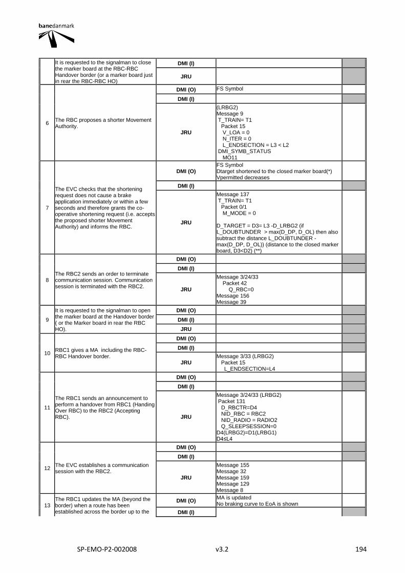
SP-EMO-P2-002008 v3.2 194
It is requested to the signalman to close the marker board at the RBC-RBC Handover border (or a marker board just in rear the RBC-RBC HO)
DMI (I)
JRU
6 The RBC proposes a shorter Movement Authority.
DMI (O) FS Symbol
DMI (I)
JRU
(LRBG2) Message 9 T_TRAIN= T1 Packet 15 V_LOA = 0 N_ITER = 0 L_ENDSECTION = L3 < L2 DMI_SYMB_STATUS MO11
7
The EVC checks that the shortening request does not cause a brake application immediately or within a few seconds and therefore grants the co-operative shortening request (i.e. accepts the proposed shorter Movement Authority) and informs the RBC.
DMI (O) FS Symbol Dtarget shortened to the closed marker board(*) Vpermitted decreases
DMI (I)
JRU
Message 137 T_TRAIN= T1 Packet 0/1 M_MODE = 0 D_TARGET = D3= L3 -D_LRBG2 (if L_DOUBTUNDER > max(D_DP, D_OL) then also subtract the distance L_DOUBTUNDER - max(D_DP, D_OL)) (distance to the closed marker board, D3<D2) (**)
8 The RBC2 sends an order to terminate communication session. Communication session is terminated with the RBC2.
DMI (O)
DMI (I)
JRU
Message 3/24/33 Packet 42 Q_RBC=0 Message 156 Message 39
9
It is requested to the signalman to open the marker board at the Handover border ( or the Marker board in rear the RBC HO).
DMI (O)
DMI (I)
JRU
10 RBC1 gives a MA including the RBC-RBC Handover border.
DMI (O)
DMI (I)
JRU Message 3/33 (LRBG2) Packet 15 L_ENDSECTION=L4
11
The RBC1 sends an announcement to perform a handover from RBC1 (Handing Over RBC) to the RBC2 (Accepting RBC).
DMI (O)
DMI (I)
JRU
Message 3/24/33 (LRBG2) Packet 131 D_RBCTR=D4 NID_RBC = RBC2 NID_RADIO = RADIO2 Q_SLEEPSESSION=0 D4(LRBG2)=D1(LRBG1) D4≤L4
12 The EVC establishes a communication session with the RBC2.
DMI (O)
DMI (I)
JRU
Message 155 Message 32 Message 159 Message 129 Message 8
13 The RBC1 updates the MA (beyond the border) when a route has been established across the border up to the
DMI (O) MA is updated No braking curve to EoA is shown
DMI (I)
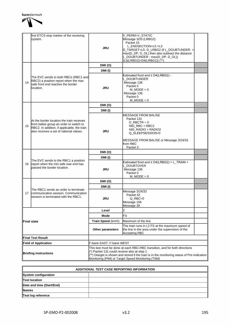
SP-EMO-P2-002008 v3.2 195
first ETCS stop marker of the receiving system.
JRU
V_PERM=V_STATIC Message 3/33 (LRBG2) Packet 15 L_ENDSECTION=L5 >L3 D_TARGET=L5- D_LRBG2 (if L_DOUBTUNDER > max(D_DP, D_OL) then also subtract the distance L_DOUBTUNDER - max(D_DP, D_OL)) (L5(LRBG2)>D4(LRBG1)) (**)
14
The EVC sends to both RBCs (RBC1 and RBC2) a position report when the max safe front end reaches the border location.
DMI (O)
DMI (I)
JRU
Estimated front end ≥ D4(LRBG2) - L_DOUBTUNDER Message 136 Packet 0 M_MODE = 0 Message 136 Packet 0 M_MODE = 0
15
At the border location the train receives from balise group an order to switch to RBC2. In addition, if applicable, the train also receives a set of national values.
DMI (O)
DMI (I)
JRU
MESSAGE FROM BALISE Packet 131 D_RBCTR = 0 NID_RBC = RBC2 NID_RADIO = RADIO2 Q_SLEEPSESSION=0 MESSAGE FROM BALISE or Message 3/24/33 from RBC Packet 3
16 The EVC sends to the RBC1 a position report when the min safe rear end has passed the border location.
DMI (O)
DMI (I)
JRU
Estimated front end ≥ D4(LRBG2) + L_TRAIN + L_DOUBTOVER Message 136 Packet 0 M_MODE = 0
17 The RBC1 sends an order to terminate communication session. Communication session is terminated with the RBC1.
DMI (O)
DMI (I)
JRU
Message 3/24/33 Packet 42 Q_RBC=0 Message 156 Message 39
Final state
Level 2
Mode FS
Train Speed (km/h) Maximum of the line
Other parameters The train runs in L2 FS at the maximum speed of the line in the area under the supervision of the Accepting RBC
Final Test Result
Field of Application F-bane EAST, F-bane WEST
Briefing instructions
This test must be done at each RBC-RBC transition, and for both directions (*) Packet 131 could receive also at step 1 (**) Dtarget is shown and stored if the train is in the monitoring status of Pre-Indication Monitoring (PIM) or Target Speed Monitoring (TSM)
ADDITIONAL TEST CASE REPORTING INFORMATION
System configuration
Test location
Date and time (Start/End)
Names
Test log reference

SP-EMO-P2-002008 v3.2 196
Observations
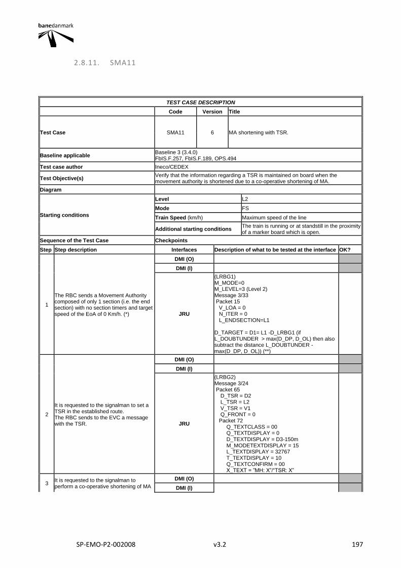
SP-EMO-P2-002008 v3.2 197
2.8.11. SMA11
TEST CASE DESCRIPTION
Code Version Title
Test Case SMA11 6 MA shortening with TSR.
Baseline applicable Baseline 3 (3.4.0) FbIS.F.257, FbIS.F.189, OPS.494
Test case author Ineco/CEDEX
Test Objective(s) Verify that the information regarding a TSR is maintained on board when the movement authority is shortened due to a co-operative shortening of MA.
Diagram
Starting conditions
Level L2
Mode FS
Train Speed (km/h) Maximum speed of the line
Additional starting conditions The train is running or at standstill in the proximity of a marker board which is open.
Sequence of the Test Case Checkpoints
Step Step description Interfaces Description of what to be tested at the interface OK?
1
The RBC sends a Movement Authority composed of only 1 section (i.e. the end section) with no section timers and target speed of the EoA of 0 Km/h. (*)
DMI (O)
DMI (I)
JRU
(LRBG1) M_MODE=0 M_LEVEL=3 (Level 2) Message 3/33 Packet 15 V_LOA = 0 N_ITER = 0 L_ENDSECTION=L1 D_TARGET = D1= L1 -D_LRBG1 (if L_DOUBTUNDER > max(D_DP, D_OL) then also subtract the distance L_DOUBTUNDER - max(D_DP, D_OL)) (**)
2
It is requested to the signalman to set a TSR in the established route. The RBC sends to the EVC a message with the TSR.
DMI (O)
DMI (I)
JRU
(LRBG2) Message 3/24 Packet 65 D_TSR = D2 L_TSR = L2 V_TSR = V1 Q_FRONT = 0 Packet 72 Q_TEXTCLASS = 00 Q_TEXTDISPLAY = 0 D_TEXTDISPLAY = D3-150m M_MODETEXTDISPLAY = 15 L_TEXTDISPLAY = 32767 T_TEXTDISPLAY = 10 Q_TEXTCONFIRM = 00 X_TEXT = ”MH: X”/“TSR: X”
3 It is requested to the signalman to perform a co-operative shortening of MA
DMI (O)
DMI (I)
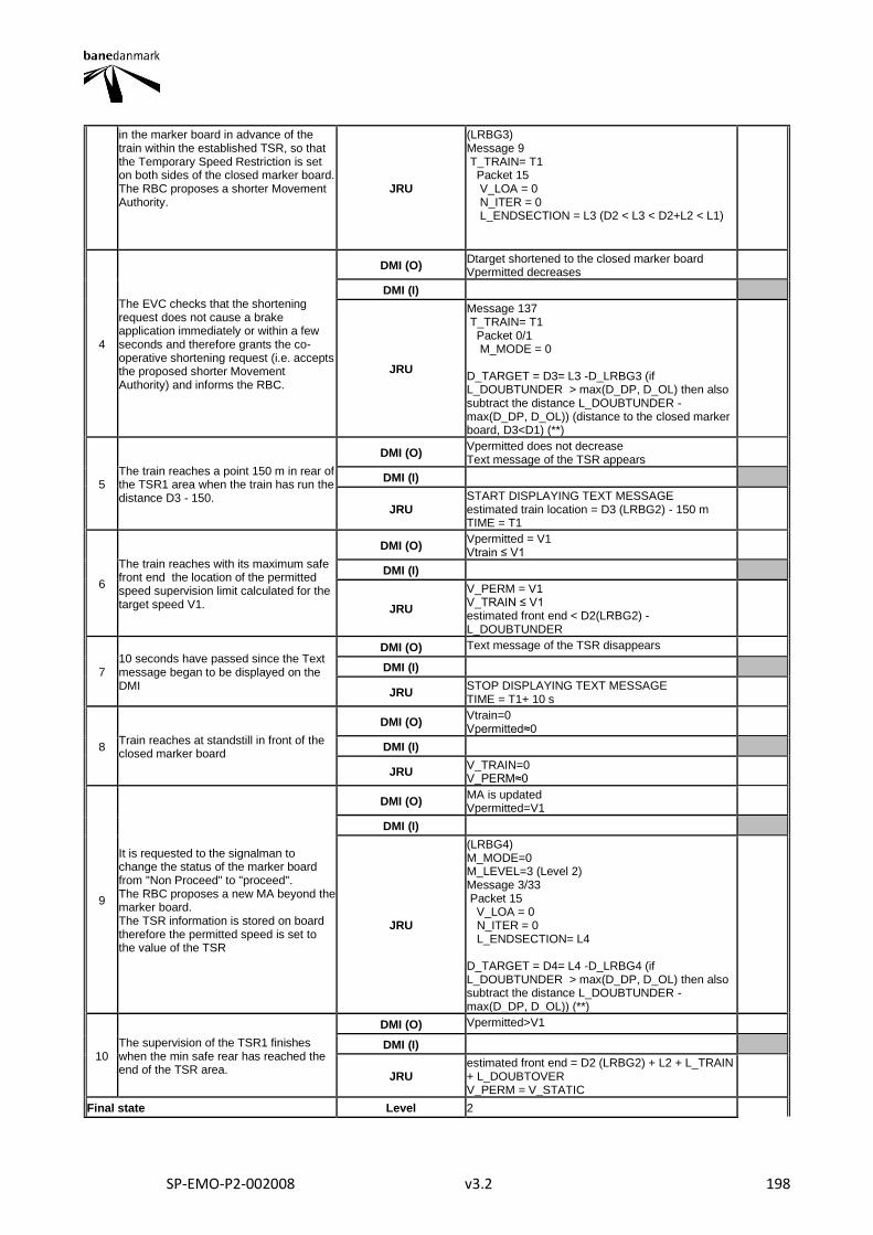
SP-EMO-P2-002008 v3.2 198
in the marker board in advance of the train within the established TSR, so that the Temporary Speed Restriction is set on both sides of the closed marker board. The RBC proposes a shorter Movement Authority.
JRU
(LRBG3) Message 9 T_TRAIN= T1 Packet 15 V_LOA = 0 N_ITER = 0 L_ENDSECTION = L3 (D2 < L3 < D2+L2 < L1)
4
The EVC checks that the shortening request does not cause a brake application immediately or within a few seconds and therefore grants the co-operative shortening request (i.e. accepts the proposed shorter Movement Authority) and informs the RBC.
DMI (O) Dtarget shortened to the closed marker board Vpermitted decreases
DMI (I)
JRU
Message 137 T_TRAIN= T1 Packet 0/1 M_MODE = 0 D_TARGET = D3= L3 -D_LRBG3 (if L_DOUBTUNDER > max(D_DP, D_OL) then also subtract the distance L_DOUBTUNDER - max(D_DP, D_OL)) (distance to the closed marker board, D3<D1) (**)
5 The train reaches a point 150 m in rear of the TSR1 area when the train has run the distance D3 - 150.
DMI (O) Vpermitted does not decrease Text message of the TSR appears
DMI (I)
JRU START DISPLAYING TEXT MESSAGE estimated train location = D3 (LRBG2) - 150 m TIME = T1
6
The train reaches with its maximum safe front end the location of the permitted speed supervision limit calculated for the target speed V1.
DMI (O) Vpermitted = V1 Vtrain ≤ V1
DMI (I)
JRU
V_PERM = V1 V_TRAIN ≤ V1 estimated front end < D2(LRBG2) - L_DOUBTUNDER
7 10 seconds have passed since the Text message began to be displayed on the DMI
DMI (O) Text message of the TSR disappears
DMI (I)
JRU STOP DISPLAYING TEXT MESSAGE TIME = T1+ 10 s
8 Train reaches at standstill in front of the closed marker board
DMI (O) Vtrain=0 Vpermitted≈0
DMI (I)
JRU V_TRAIN=0 V_PERM≈0
9
It is requested to the signalman to change the status of the marker board from "Non Proceed" to "proceed". The RBC proposes a new MA beyond the marker board. The TSR information is stored on board therefore the permitted speed is set to the value of the TSR
DMI (O) MA is updated Vpermitted=V1
DMI (I)
JRU
(LRBG4) M_MODE=0 M_LEVEL=3 (Level 2) Message 3/33 Packet 15 V_LOA = 0 N_ITER = 0 L_ENDSECTION= L4 D_TARGET = D4= L4 -D_LRBG4 (if L_DOUBTUNDER > max(D_DP, D_OL) then also subtract the distance L_DOUBTUNDER - max(D_DP, D_OL)) (**)
10 The supervision of the TSR1 finishes when the min safe rear has reached the end of the TSR area.
DMI (O) Vpermitted>V1
DMI (I)
JRU estimated front end = D2 (LRBG2) + L2 + L_TRAIN + L_DOUBTOVER V_PERM = V_STATIC
Final state Level 2
SP-EMO-P2-002008 v3.2 199
Mode FS
Train Speed (km/h) NR
Other parameters
Final Test Result
Field of Application F-bane EAST, F-bane WEST
Briefing instructions
Depending on the distance D3 and the train speed, the sequence of the steps 5 and 6 may be altered. If Packet 27 SSP is used instead of packet 65 for TSRs, log on test result "OK with comments". In this case in addition it shall be verified that at step 9 the RBC sends packet 27 with the correct TSR information. (*) In F-bane WEST, the TSR has to be set before the train receives the MA (**) Dtarget is shown and stored if the train is in the monitoring status of Pre-Indication Monitoring (PIM) or Target Speed Monitoring (TSM)
ADDITIONAL TEST CASE REPORTING INFORMATION
System configuration
Test location
Date and time (Start/End)
Names
Test log reference
Observations
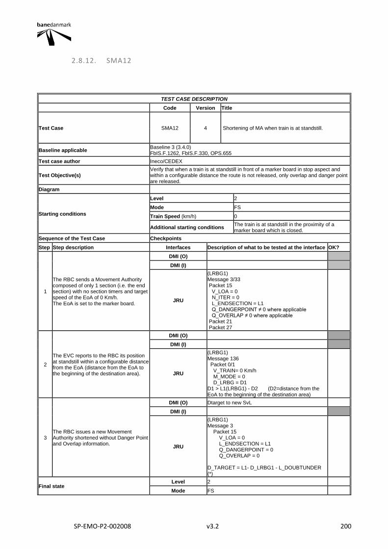
SP-EMO-P2-002008 v3.2 200
2.8.12. SMA12
TEST CASE DESCRIPTION
Code Version Title
Test Case SMA12 4 Shortening of MA when train is at standstill.
Baseline applicable Baseline 3 (3.4.0) FbIS.F.1262, FbIS.F.330, OPS.655
Test case author Ineco/CEDEX
Test Objective(s) Verify that when a train is at standstill in front of a marker board in stop aspect and within a configurable distance the route is not released, only overlap and danger point are released.
Diagram
Starting conditions
Level 2
Mode FS
Train Speed (km/h) 0
Additional starting conditions The train is at standstill in the proximity of a marker board which is closed.
Sequence of the Test Case Checkpoints
Step Step description Interfaces Description of what to be tested at the interface OK?
1
The RBC sends a Movement Authority composed of only 1 section (i.e. the end section) with no section timers and target speed of the EoA of 0 Km/h. The EoA is set to the marker board.
DMI (O)
DMI (I)
JRU
(LRBG1) Message 3/33 Packet 15 V_LOA = 0 N_ITER = 0 L_ENDSECTION = L1 Q_DANGERPOINT ≠ 0 where applicable Q_OVERLAP ≠ 0 where applicable Packet 21 Packet 27
2
The EVC reports to the RBC its position at standstill within a configurable distance from the EoA (distance from the EoA to the beginning of the destination area).
DMI (O)
DMI (I)
JRU
(LRBG1) Message 136 Packet 0/1 V_TRAIN= 0 Km/h M_MODE = 0 D_LRBG = D1 D1 > L1(LRBG1) - D2 (D2=distance from the EoA to the beginning of the destination area)
3 The RBC issues a new Movement Authority shortened without Danger Point and Overlap information.
DMI (O) Dtarget to new SvL
DMI (I)
JRU
(LRBG1) Message 3 Packet 15 V_LOA = 0 L_ENDSECTION = L1 Q_DANGERPOINT = 0 Q_OVERLAP = 0 D_TARGET = L1- D_LRBG1 - L_DOUBTUNDER (*)
Final state Level 2
Mode FS

SP-EMO-P2-002008 v3.2 201
Train Speed (km/h) 0
Other parameters
Final Test Result
Field of Application F-bane WEST
Briefing instructions
The signaller shall execute the proper command to release the overlap D2 = Distance from the EoA where the overlap can be released if the train reports its position within thereof and no new route is set. (*) Dtarget is shown and stored if the train is in the monitoring status of Pre-Indication Monitoring (PIM) or Target Speed Monitoring (TSM)
ADDITIONAL TEST CASE REPORTING INFORMATION
System configuration
Test location
Date and time (Start/End)
Names
Test log reference
Observations
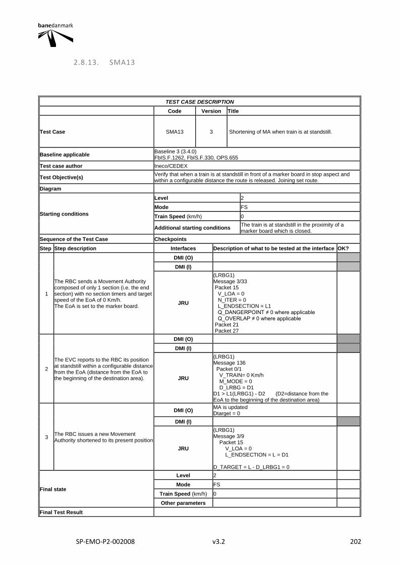
SP-EMO-P2-002008 v3.2 202
2.8.13. SMA13
TEST CASE DESCRIPTION
Code Version Title
Test Case SMA13 3 Shortening of MA when train is at standstill.
Baseline applicable Baseline 3 (3.4.0) FbIS.F.1262, FbIS.F.330, OPS.655
Test case author Ineco/CEDEX
Test Objective(s) Verify that when a train is at standstill in front of a marker board in stop aspect and within a configurable distance the route is released. Joining set route.
Diagram
Starting conditions
Level 2
Mode FS
Train Speed (km/h) 0
Additional starting conditions The train is at standstill in the proximity of a marker board which is closed.
Sequence of the Test Case Checkpoints
Step Step description Interfaces Description of what to be tested at the interface OK?
1
The RBC sends a Movement Authority composed of only 1 section (i.e. the end section) with no section timers and target speed of the EoA of 0 Km/h. The EoA is set to the marker board.
DMI (O)
DMI (I)
JRU
(LRBG1) Message 3/33 Packet 15 V_LOA = 0 N_ITER = 0 L_ENDSECTION = L1 Q_DANGERPOINT ≠ 0 where applicable Q_OVERLAP ≠ 0 where applicable Packet 21 Packet 27
2
The EVC reports to the RBC its position at standstill within a configurable distance from the EoA (distance from the EoA to the beginning of the destination area).
DMI (O)
DMI (I)
JRU
(LRBG1) Message 136 Packet 0/1 V_TRAIN= 0 Km/h M_MODE = 0 D_LRBG = D1 D1 > L1(LRBG1) - D2 (D2=distance from the EoA to the beginning of the destination area)
3 The RBC issues a new Movement Authority shortened to its present position
DMI (O) MA is updated Dtarget = 0
DMI (I)
JRU
(LRBG1) Message 3/9 Packet 15 V_LOA = 0 L_ENDSECTION = L = D1 D_TARGET = L - D_LRBG1 = 0
Final state
Level 2
Mode FS
Train Speed (km/h) 0
Other parameters
Final Test Result
SP-EMO-P2-002008 v3.2 203
Field of Application F-bane WEST
Briefing instructions
The signaller shall execute the proper command to release the route D2 = Distance from the EoA where the overlap can be released if the train reports its position within thereof and no new route is set. (*) In case the shortening of MA is performed through message 9 it shall be verified this message is granted on board.
ADDITIONAL TEST CASE REPORTING INFORMATION
System configuration
Test location
Date and time (Start/End)
Names
Test log reference
Observations
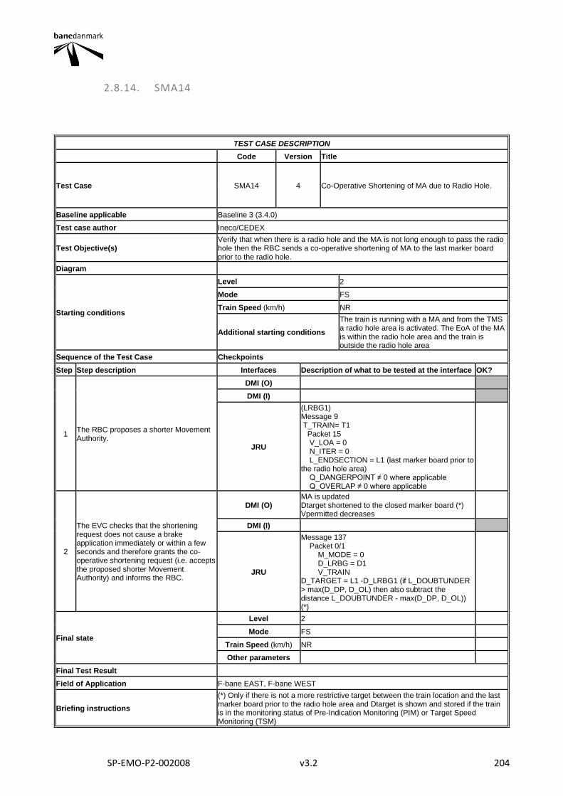
SP-EMO-P2-002008 v3.2 204
2.8.14. SMA14
TEST CASE DESCRIPTION
Code Version Title
Test Case SMA14 4 Co-Operative Shortening of MA due to Radio Hole.
Baseline applicable Baseline 3 (3.4.0)
Test case author Ineco/CEDEX
Test Objective(s) Verify that when there is a radio hole and the MA is not long enough to pass the radio hole then the RBC sends a co-operative shortening of MA to the last marker board prior to the radio hole.
Diagram
Starting conditions
Level 2
Mode FS
Train Speed (km/h) NR
Additional starting conditions
The train is running with a MA and from the TMS a radio hole area is activated. The EoA of the MA is within the radio hole area and the train is outside the radio hole area
Sequence of the Test Case Checkpoints
Step Step description Interfaces Description of what to be tested at the interface OK?
1 The RBC proposes a shorter Movement Authority.
DMI (O)
DMI (I)
JRU
(LRBG1) Message 9 T_TRAIN= T1 Packet 15 V_LOA = 0 N_ITER = 0 L_ENDSECTION = L1 (last marker board prior to the radio hole area) Q_DANGERPOINT ≠ 0 where applicable Q_OVERLAP ≠ 0 where applicable
2
The EVC checks that the shortening request does not cause a brake application immediately or within a few seconds and therefore grants the co-operative shortening request (i.e. accepts the proposed shorter Movement Authority) and informs the RBC.
DMI (O) MA is updated Dtarget shortened to the closed marker board (*) Vpermitted decreases
DMI (I)
JRU
Message 137 Packet 0/1 M_MODE = 0 D_LRBG = D1 V_TRAIN D_TARGET = L1 -D_LRBG1 (if L_DOUBTUNDER > max(D_DP, D_OL) then also subtract the distance L_DOUBTUNDER - max(D_DP, D_OL)) (*)
Final state
Level 2
Mode FS
Train Speed (km/h) NR
Other parameters
Final Test Result
Field of Application F-bane EAST, F-bane WEST
Briefing instructions
(*) Only if there is not a more restrictive target between the train location and the last marker board prior to the radio hole area and Dtarget is shown and stored if the train is in the monitoring status of Pre-Indication Monitoring (PIM) or Target Speed Monitoring (TSM)

SP-EMO-P2-002008 v3.2 205
ADDITIONAL TEST CASE REPORTING INFORMATION
System configuration
Test location
Date and time (Start/End)
Names
Test log reference
Observations
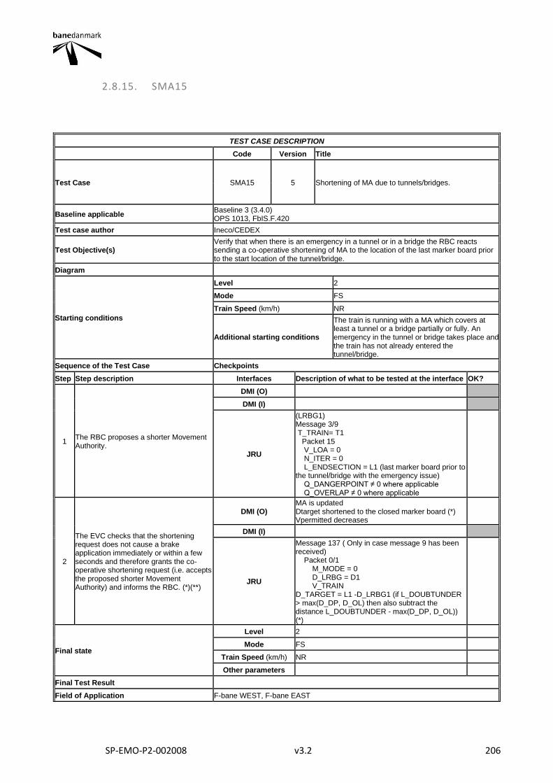
SP-EMO-P2-002008 v3.2 206
2.8.15. SMA15
TEST CASE DESCRIPTION
Code Version Title
Test Case SMA15 5 Shortening of MA due to tunnels/bridges.
Baseline applicable Baseline 3 (3.4.0) OPS 1013, FbIS.F.420
Test case author Ineco/CEDEX
Test Objective(s) Verify that when there is an emergency in a tunnel or in a bridge the RBC reacts sending a co-operative shortening of MA to the location of the last marker board prior to the start location of the tunnel/bridge.
Diagram
Starting conditions
Level 2
Mode FS
Train Speed (km/h) NR
Additional starting conditions
The train is running with a MA which covers at least a tunnel or a bridge partially or fully. An emergency in the tunnel or bridge takes place and the train has not already entered the tunnel/bridge.
Sequence of the Test Case Checkpoints
Step Step description Interfaces Description of what to be tested at the interface OK?
1 The RBC proposes a shorter Movement Authority.
DMI (O)
DMI (I)
JRU
(LRBG1) Message 3/9 T_TRAIN= T1 Packet 15 V_LOA = 0 N_ITER = 0 L_ENDSECTION = L1 (last marker board prior to the tunnel/bridge with the emergency issue) Q_DANGERPOINT ≠ 0 where applicable Q_OVERLAP ≠ 0 where applicable
2
The EVC checks that the shortening request does not cause a brake application immediately or within a few seconds and therefore grants the co-operative shortening request (i.e. accepts the proposed shorter Movement Authority) and informs the RBC. (*)(**)
DMI (O) MA is updated Dtarget shortened to the closed marker board (*) Vpermitted decreases
DMI (I)
JRU
Message 137 ( Only in case message 9 has been received) Packet 0/1 M_MODE = 0 D_LRBG = D1 V_TRAIN D_TARGET = L1 -D_LRBG1 (if L_DOUBTUNDER > max(D_DP, D_OL) then also subtract the distance L_DOUBTUNDER - max(D_DP, D_OL)) (*)
Final state
Level 2
Mode FS
Train Speed (km/h) NR
Other parameters
Final Test Result
Field of Application F-bane WEST, F-bane EAST

SP-EMO-P2-002008 v3.2 207
Briefing instructions
(*) Only if there is not a more restrictive target between the train location and the last marker board prior to the tunnel/bridge with the emergency issue and Dtarget is shown and stored if the train is in the monitoring status of Pre-Indication Monitoring (PIM) or Target Speed Monitoring (TSM) (**) This step could not occur if the shortening of the MA is rejected by the train. In this case no further action is taken by the RBC.
ADDITIONAL TEST CASE REPORTING INFORMATION
System configuration
Test location
Date and time (Start/End)
Names
Test log reference
Observations
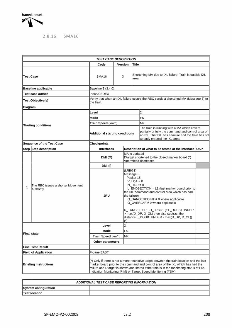
SP-EMO-P2-002008 v3.2 208
2.8.16. SMA16
TEST CASE DESCRIPTION
Code Version Title
Test Case SMA16 3 Shortening MA due to IXL failure. Train is outside IXL area.
Baseline applicable Baseline 3 (3.4.0)
Test case author Ineco/CEDEX
Test Objective(s) Verify that when an IXL failure occurs the RBC sends a shortened MA (Message 3) to the train.
Diagram
Starting conditions
Level 2
Mode FS
Train Speed (km/h) NR
Additional starting conditions
The train is running with a MA which covers partially or fully the command and control area of an IxL. That IXL has a failure and the train has not already entered the IXL area.
Sequence of the Test Case Checkpoints
Step Step description Interfaces Description of what to be tested at the interface OK?
1 The RBC issues a shorter Movement Authority.
DMI (O) MA is updated Dtarget shortened to the closed marker board (*) Vpermitted decreases
DMI (I)
JRU
(LRBG1) Message 3 Packet 15 V_LOA = 0 N_ITER = 0 L_ENDSECTION = L1 (last marker board prior to the IXL command and control area which has had the failure) Q_DANGERPOINT ≠ 0 where applicable Q_OVERLAP ≠ 0 where applicable D_TARGET = L1 -D_LRBG1 (if L_DOUBTUNDER > max(D_DP, D_OL) then also subtract the distance L_DOUBTUNDER - max(D_DP, D_OL)) (*)
Final state
Level 2
Mode FS
Train Speed (km/h) NR
Other parameters
Final Test Result
Field of Application F-bane EAST
Briefing instructions
(*) Only if there is not a more restrictive target between the train location and the last marker board prior to the command and control area of the IXL which has had the failure and Dtarget is shown and stored if the train is in the monitoring status of Pre-Indication Monitoring (PIM) or Target Speed Monitoring (TSM)
ADDITIONAL TEST CASE REPORTING INFORMATION
System configuration
Test location

SP-EMO-P2-002008 v3.2 209
Date and time (Start/End)
Names
Test log reference
Observations
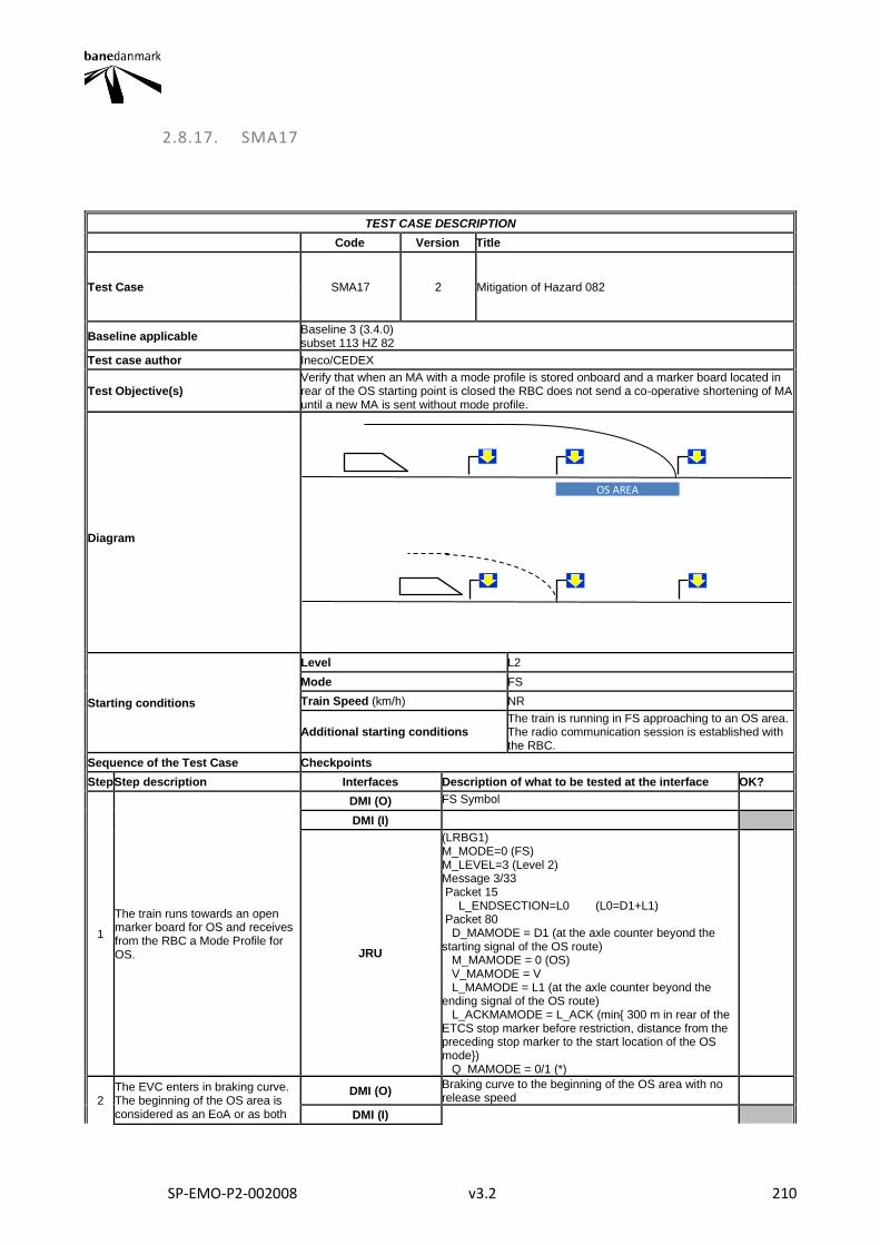
SP-EMO-P2-002008 v3.2 210
2.8.17. SMA17
TEST CASE DESCRIPTION
Code Version Title
Test Case SMA17 2 Mitigation of Hazard 082
Baseline applicable Baseline 3 (3.4.0) subset 113 HZ 82
Test case author Ineco/CEDEX
Test Objective(s) Verify that when an MA with a mode profile is stored onboard and a marker board located in rear of the OS starting point is closed the RBC does not send a co-operative shortening of MA until a new MA is sent without mode profile.
Diagram
Starting conditions
Level L2
Mode FS
Train Speed (km/h) NR
Additional starting conditions The train is running in FS approaching to an OS area. The radio communication session is established with the RBC.
Sequence of the Test Case Checkpoints
Step Step description Interfaces Description of what to be tested at the interface OK?
1
The train runs towards an open marker board for OS and receives from the RBC a Mode Profile for OS.
DMI (O) FS Symbol
DMI (I)
JRU
(LRBG1) M_MODE=0 (FS) M_LEVEL=3 (Level 2) Message 3/33 Packet 15 L_ENDSECTION=L0 (L0=D1+L1) Packet 80 D_MAMODE = D1 (at the axle counter beyond the starting signal of the OS route) M_MAMODE = 0 (OS) V_MAMODE = V L_MAMODE = L1 (at the axle counter beyond the ending signal of the OS route) L_ACKMAMODE = L_ACK (min{ 300 m in rear of the ETCS stop marker before restriction, distance from the preceding stop marker to the start location of the OS mode}) Q_MAMODE = 0/1 (*)
2 The EVC enters in braking curve. The beginning of the OS area is considered as an EoA or as both
DMI (O) Braking curve to the beginning of the OS area with no release speed
DMI (I)
OS AREA
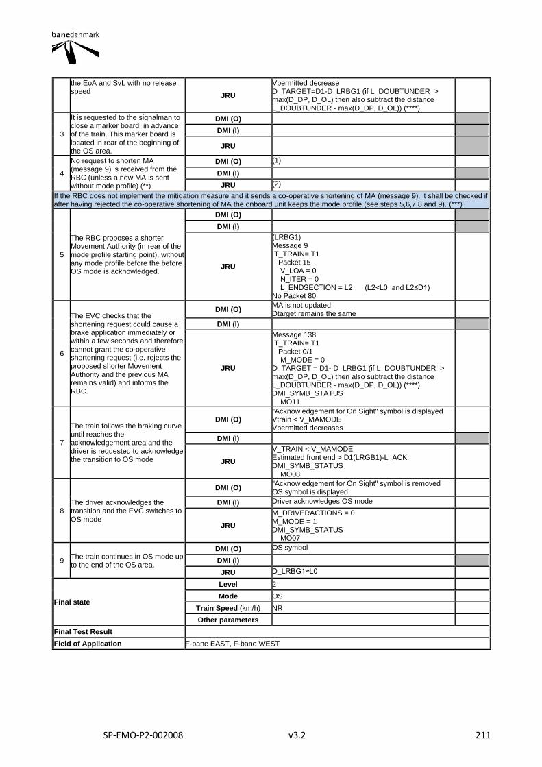
SP-EMO-P2-002008 v3.2 211
the EoA and SvL with no release speed
JRU
Vpermitted decrease D_TARGET=D1-D_LRBG1 (if L_DOUBTUNDER > max(D_DP, D_OL) then also subtract the distance L_DOUBTUNDER - max(D_DP, D_OL)) (****)
3
It is requested to the signalman to close a marker board in advance of the train. This marker board is located in rear of the beginning of the OS area.
DMI (O)
DMI (I)
JRU
4
No request to shorten MA (message 9) is received from the RBC (unless a new MA is sent without mode profile) (**)
DMI (O) (1)
DMI (I)
JRU (2)
If the RBC does not implement the mitigation measure and it sends a co-operative shortening of MA (message 9), it shall be checked if after having rejected the co-operative shortening of MA the onboard unit keeps the mode profile (see steps 5,6,7,8 and 9). (***)
5
The RBC proposes a shorter Movement Authority (in rear of the mode profile starting point), without any mode profile before the before OS mode is acknowledged.
DMI (O)
DMI (I)
JRU
(LRBG1) Message 9 T_TRAIN= T1 Packet 15 V_LOA = 0 N_ITER = 0 L_ENDSECTION = L2 (L2<L0 and L2≤D1) No Packet 80
6
The EVC checks that the shortening request could cause a brake application immediately or within a few seconds and therefore cannot grant the co-operative shortening request (i.e. rejects the proposed shorter Movement Authority and the previous MA remains valid) and informs the RBC.
DMI (O) MA is not updated Dtarget remains the same
DMI (I)
JRU
Message 138 T_TRAIN= T1 Packet 0/1 M_MODE = 0 D_TARGET = D1- D_LRBG1 (if L_DOUBTUNDER > max(D_DP, D_OL) then also subtract the distance L_DOUBTUNDER - max(D_DP, D_OL)) (****) DMI_SYMB_STATUS MO11
7
The train follows the braking curve until reaches the acknowledgement area and the driver is requested to acknowledge the transition to OS mode
DMI (O) "Acknowledgement for On Sight" symbol is displayed Vtrain < V_MAMODE Vpermitted decreases
DMI (I)
JRU
V_TRAIN < V_MAMODE Estimated front end > D1(LRGB1)-L_ACK DMI_SYMB_STATUS MO08
8 The driver acknowledges the transition and the EVC switches to OS mode
DMI (O) "Acknowledgement for On Sight" symbol is removed OS symbol is displayed
DMI (I) Driver acknowledges OS mode
JRU
M_DRIVERACTIONS = 0 M_MODE = 1 DMI_SYMB_STATUS MO07
9 The train continues in OS mode up to the end of the OS area.
DMI (O) OS symbol
DMI (I)
JRU D_LRBG1≈L0
Final state
Level 2
Mode OS
Train Speed (km/h) NR
Other parameters
Final Test Result
Field of Application F-bane EAST, F-bane WEST

SP-EMO-P2-002008 v3.2 212
Briefing instructions
(*) Current F-bane East and F-bane West implementations use only Q_MAMODE = 1. Check and note if Q_MAMODE ≠ 1. (**) According to the proposed mitigation described for the Hazard 082 the RBC should not send a request to shorten MA until a new MA is sent without mode profile. (1) and (2). It is not possible to specify which information is going to be received from the RBC because it depends on the supplier implementation. In any case, it shall be verified that the RBC reaction is such that no hazardous situation can arise (i.e: For example at this step the RBC could send a shorter MA (message 3 with packet 15) up to the closed marker board). (***) Note that steps 5,6,7,8 and 9 have been created only to check the behavior of the onboard unit in case the infrastructure does not implement the mitigation measure proposed for Hazard 082. (****) Dtarget is shown and stored if the train is in the monitoring status of Pre-Indication Monitoring (PIM) or Target Speed Monitoring (TSM)
ADDITIONAL TEST CASE REPORTING INFORMATION
System configuration
Test location
Date and time (Start/End)
Names
Test log reference
Observations
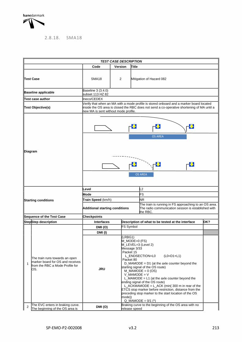
SP-EMO-P2-002008 v3.2 213
2.8.18. SMA18
TEST CASE DESCRIPTION
Code Version Title
Test Case SMA18 2 Mitigation of Hazard 082
Baseline applicable Baseline 3 (3.4.0) subset 113 HZ 82
Test case author Ineco/CEDEX
Test Objective(s) Verify that when an MA with a mode profile is stored onboard and a marker board located inside the OS area is closed the RBC does not send a co-operative shortening of MA until a new MA is sent without mode profile.
Diagram
Starting conditions
Level L2
Mode FS
Train Speed (km/h) NR
Additional starting conditions The train is running in FS approaching to an OS area. The radio communication session is established with the RBC.
Sequence of the Test Case Checkpoints
Step Step description Interfaces Description of what to be tested at the interface OK?
1
The train runs towards an open marker board for OS and receives from the RBC a Mode Profile for OS.
DMI (O) FS Symbol
DMI (I)
JRU
(LRBG1) M_MODE=0 (FS) M_LEVEL=3 (Level 2) Message 3/33 Packet 15 L_ENDSECTION=L0 (L0=D1+L1) Packet 80 D_MAMODE = D1 (at the axle counter beyond the starting signal of the OS route) M_MAMODE = 0 (OS) V_MAMODE = V L_MAMODE = L1 (at the axle counter beyond the ending signal of the OS route) L_ACKMAMODE = L_ACK (min{ 300 m in rear of the ETCS stop marker before restriction, distance from the preceding stop marker to the start location of the OS mode}) Q_MAMODE = 0/1 (*)
2 The EVC enters in braking curve. The beginning of the OS area is
DMI (O) Braking curve to the beginning of the OS area with no release speed
OS AREA
OS AREA
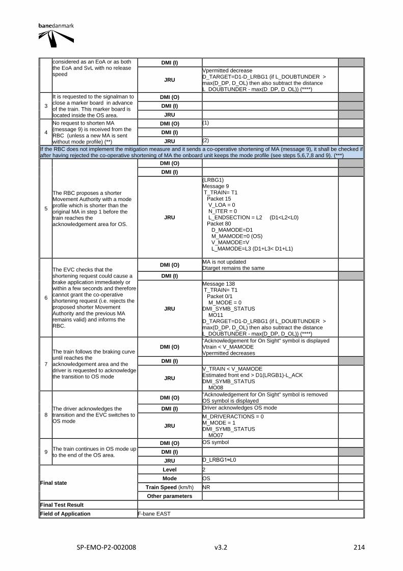
SP-EMO-P2-002008 v3.2 214
considered as an EoA or as both the EoA and SvL with no release speed
DMI (I)
JRU
Vpermitted decrease D_TARGET=D1-D_LRBG1 (if L_DOUBTUNDER > max(D_DP, D_OL) then also subtract the distance L_DOUBTUNDER - max(D_DP, D_OL)) (****)
3
It is requested to the signalman to close a marker board in advance of the train. This marker board is located inside the OS area.
DMI (O)
DMI (I)
JRU
4
No request to shorten MA (message 9) is received from the RBC (unless a new MA is sent without mode profile) (**)
DMI (O) (1)
DMI (I)
JRU (2)
If the RBC does not implement the mitigation measure and it sends a co-operative shortening of MA (message 9), it shall be checked if after having rejected the co-operative shortening of MA the onboard unit keeps the mode profile (see steps 5,6,7,8 and 9). (***)
5
The RBC proposes a shorter Movement Authority with a mode profile which is shorter than the original MA in step 1 before the train reaches the acknowledgement area for OS.
DMI (O)
DMI (I)
JRU
(LRBG1) Message 9 T_TRAIN= T1 Packet 15 V_LOA = 0 N_ITER = 0 L_ENDSECTION = L2 (D1<L2<L0) Packet 80 D_MAMODE=D1 M_MAMODE=0 (OS) V_MAMODE=V L_MAMODE=L3 (D1+L3< D1+L1)
6
The EVC checks that the shortening request could cause a brake application immediately or within a few seconds and therefore cannot grant the co-operative shortening request (i.e. rejects the proposed shorter Movement Authority and the previous MA remains valid) and informs the RBC.
DMI (O) MA is not updated Dtarget remains the same
DMI (I)
JRU
Message 138 T_TRAIN= T1 Packet 0/1 M_MODE = 0 DMI_SYMB_STATUS MO11 D_TARGET=D1-D_LRBG1 (if L_DOUBTUNDER > max(D_DP, D_OL) then also subtract the distance L_DOUBTUNDER - max(D_DP, D_OL)) (****)
7
The train follows the braking curve until reaches the acknowledgement area and the driver is requested to acknowledge the transition to OS mode
DMI (O) "Acknowledgement for On Sight" symbol is displayed Vtrain < V_MAMODE Vpermitted decreases
DMI (I)
JRU
V_TRAIN < V_MAMODE Estimated front end > D1(LRGB1)-L_ACK DMI_SYMB_STATUS MO08
8 The driver acknowledges the transition and the EVC switches to OS mode
DMI (O) "Acknowledgement for On Sight" symbol is removed OS symbol is displayed
DMI (I) Driver acknowledges OS mode
JRU
M_DRIVERACTIONS = 0 M_MODE = 1 DMI_SYMB_STATUS MO07
9 The train continues in OS mode up to the end of the OS area.
DMI (O) OS symbol
DMI (I)
JRU D_LRBG1≈L0
Final state
Level 2
Mode OS
Train Speed (km/h) NR
Other parameters
Final Test Result
Field of Application F-bane EAST
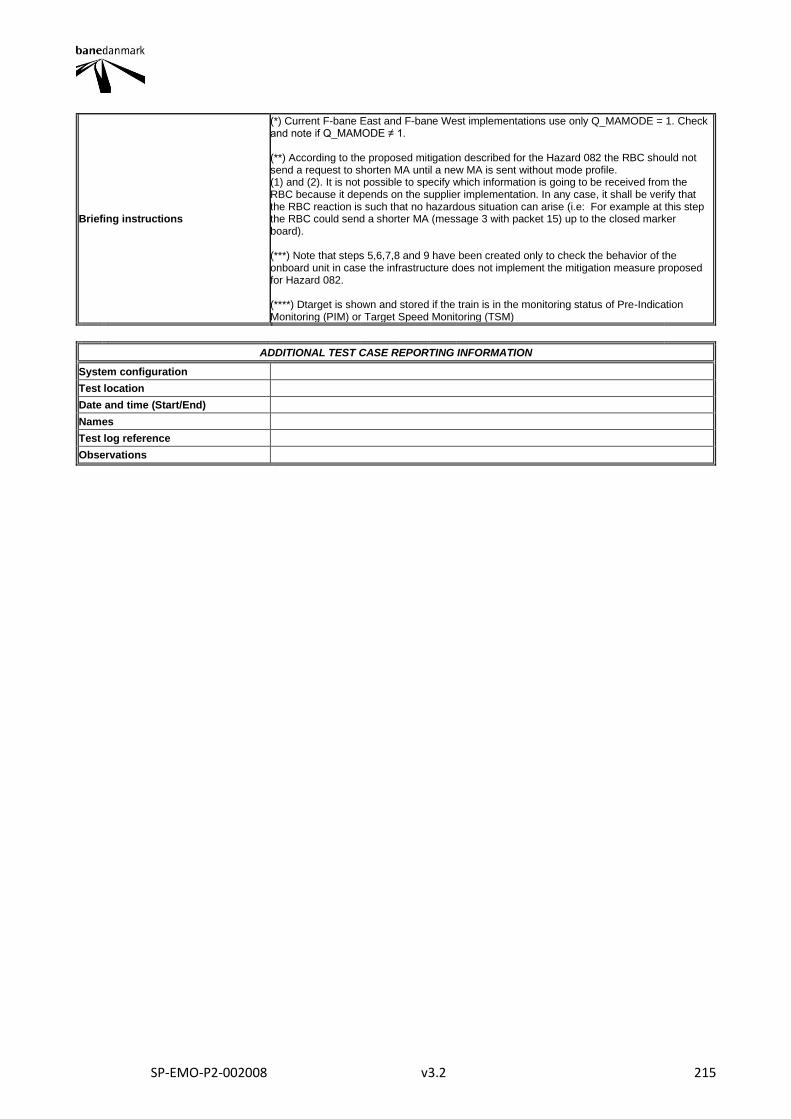
SP-EMO-P2-002008 v3.2 215
Briefing instructions
(*) Current F-bane East and F-bane West implementations use only Q_MAMODE = 1. Check and note if Q_MAMODE ≠ 1. (**) According to the proposed mitigation described for the Hazard 082 the RBC should not send a request to shorten MA until a new MA is sent without mode profile. (1) and (2). It is not possible to specify which information is going to be received from the RBC because it depends on the supplier implementation. In any case, it shall be verify that the RBC reaction is such that no hazardous situation can arise (i.e: For example at this step the RBC could send a shorter MA (message 3 with packet 15) up to the closed marker board). (***) Note that steps 5,6,7,8 and 9 have been created only to check the behavior of the onboard unit in case the infrastructure does not implement the mitigation measure proposed for Hazard 082. (****) Dtarget is shown and stored if the train is in the monitoring status of Pre-Indication Monitoring (PIM) or Target Speed Monitoring (TSM)
ADDITIONAL TEST CASE REPORTING INFORMATION
System configuration
Test location
Date and time (Start/End)
Names
Test log reference
Observations
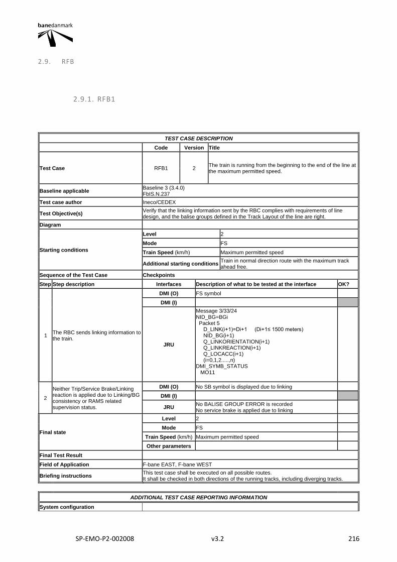
SP-EMO-P2-002008 v3.2 216
2.9. RFB
2.9.1. RFB1
TEST CASE DESCRIPTION
Code Version Title
Test Case RFB1 2 The train is running from the beginning to the end of the line at the maximum permitted speed.
Baseline applicable Baseline 3 (3.4.0) FbIS.N.237
Test case author Ineco/CEDEX
Test Objective(s) Verify that the linking information sent by the RBC complies with requirements of line design, and the balise groups defined in the Track Layout of the line are right.
Diagram
Starting conditions
Level 2
Mode FS
Train Speed (km/h) Maximum permitted speed
Additional starting conditions Train in normal direction route with the maximum track ahead free.
Sequence of the Test Case Checkpoints
Step Step description Interfaces Description of what to be tested at the interface OK?
1 The RBC sends linking information to the train.
DMI (O) FS symbol
DMI (I)
JRU
Message 3/33/24 NID_BG=BGi Packet 5 D_LINK(i+1)=Di+1 (Di+1≤ 1500 meters) NID_BG(i+1) Q_LINKORIENTATION(i+1) Q_LINKREACTION(i+1) Q_LOCACC(i+1) (i=0,1,2.....,n) DMI_SYMB_STATUS MO11
2
Neither Trip/Service Brake/Linking reaction is applied due to Linking/BG consistency or RAMS related supervision status.
DMI (O) No SB symbol is displayed due to linking
DMI (I)
JRU No BALISE GROUP ERROR is recorded No service brake is applied due to linking
Final state
Level 2
Mode FS
Train Speed (km/h) Maximum permitted speed
Other parameters
Final Test Result
Field of Application F-bane EAST, F-bane WEST
Briefing instructions This test case shall be executed on all possible routes. It shall be checked in both directions of the running tracks, including diverging tracks.
ADDITIONAL TEST CASE REPORTING INFORMATION
System configuration
SP-EMO-P2-002008 v3.2 217
Test location
Date and time (Start/End)
Names
Test log reference
Observations
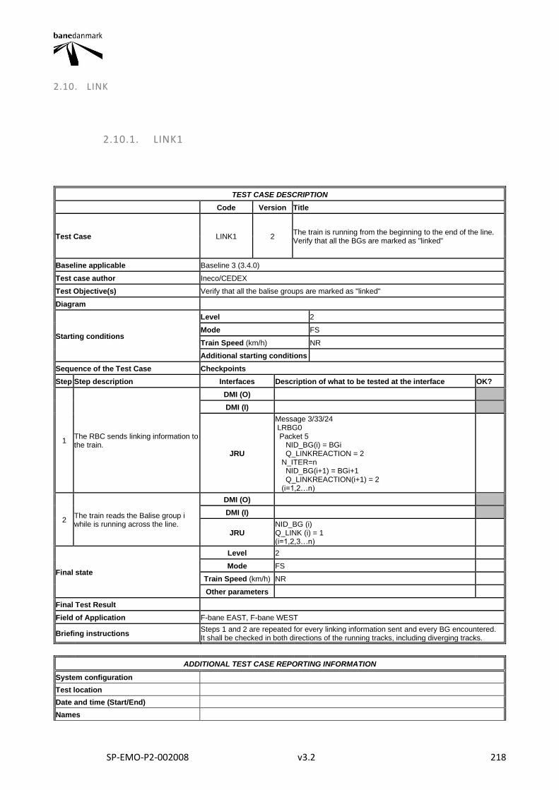
SP-EMO-P2-002008 v3.2 218
2.10. LINK
2.10.1. LINK1
TEST CASE DESCRIPTION
Code Version Title
Test Case LINK1 2 The train is running from the beginning to the end of the line. Verify that all the BGs are marked as "linked"
Baseline applicable Baseline 3 (3.4.0)
Test case author Ineco/CEDEX
Test Objective(s) Verify that all the balise groups are marked as "linked"
Diagram
Starting conditions
Level 2
Mode FS
Train Speed (km/h) NR
Additional starting conditions
Sequence of the Test Case Checkpoints
Step Step description Interfaces Description of what to be tested at the interface OK?
1 The RBC sends linking information to the train.
DMI (O)
DMI (I)
JRU
Message 3/33/24 LRBG0 Packet 5 NID_BG(i) = BGi Q_LINKREACTION = 2 N_ITER=n NID_BG(i+1) = BGi+1 Q_LINKREACTION(i+1) = 2 (i=1,2…n)
2 The train reads the Balise group i while is running across the line.
DMI (O)
DMI (I)
JRU NID_BG (i) Q_LINK (i) = 1 (i=1,2,3…n)
Final state
Level 2
Mode FS
Train Speed (km/h) NR
Other parameters
Final Test Result
Field of Application F-bane EAST, F-bane WEST
Briefing instructions Steps 1 and 2 are repeated for every linking information sent and every BG encountered. It shall be checked in both directions of the running tracks, including diverging tracks.
ADDITIONAL TEST CASE REPORTING INFORMATION
System configuration
Test location
Date and time (Start/End)
Names

SP-EMO-P2-002008 v3.2 219
Test log reference
Observations
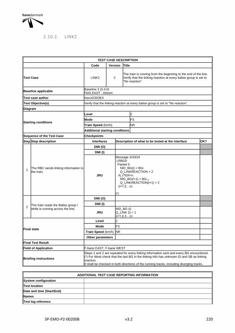
SP-EMO-P2-002008 v3.2 220
2.10.2. LINK2
TEST CASE DESCRIPTION
Code Version Title
Test Case LINK2 2 The train is running from the beginning to the end of the line. Verify that the linking reaction at every balise group is set to "No reaction".
Baseline applicable Baseline 3 (3.4.0) FbIS EAST - Alstom
Test case author Ineco/CEDEX
Test Objective(s) Verify that the linking reaction at every balise group is set to "No reaction".
Diagram
Starting conditions
Level 2
Mode FS
Train Speed (km/h) NR
Additional starting conditions
Sequence of the Test Case Checkpoints
Step Step description Interfaces Description of what to be tested at the interface OK?
1 The RBC sends linking information to the train.
DMI (O)
DMI (I)
JRU
Message 3/33/24 LRBG0 Packet 5 NID_BG(i) = BGi Q_LINKREACTION = 2 N_ITER=n NID_BG(i+1) = BGi+1 Q_LINKREACTION(i+1) = 2 (i=1,2…n) (*)
2 The train reads the Balise group i while is running across the line.
DMI (O)
DMI (I)
JRU NID_BG (i) Q_LINK (i) = 1 (i=1,2,3…n)
Final state
Level 2
Mode FS
Train Speed (km/h) NR
Other parameters
Final Test Result
Field of Application F-bane EAST, F-bane WEST
Briefing instructions
Steps 1 and 2 are repeated for every linking information sent and every BG encountered. (*) For West check that the last BG in the linking info has unknown ID and SB as linking reaction. It shall be checked in both directions of the running tracks, including diverging tracks.
ADDITIONAL TEST CASE REPORTING INFORMATION
System configuration
Test location
Date and time (Start/End)
Names
Test log reference

SP-EMO-P2-002008 v3.2 221
Observations
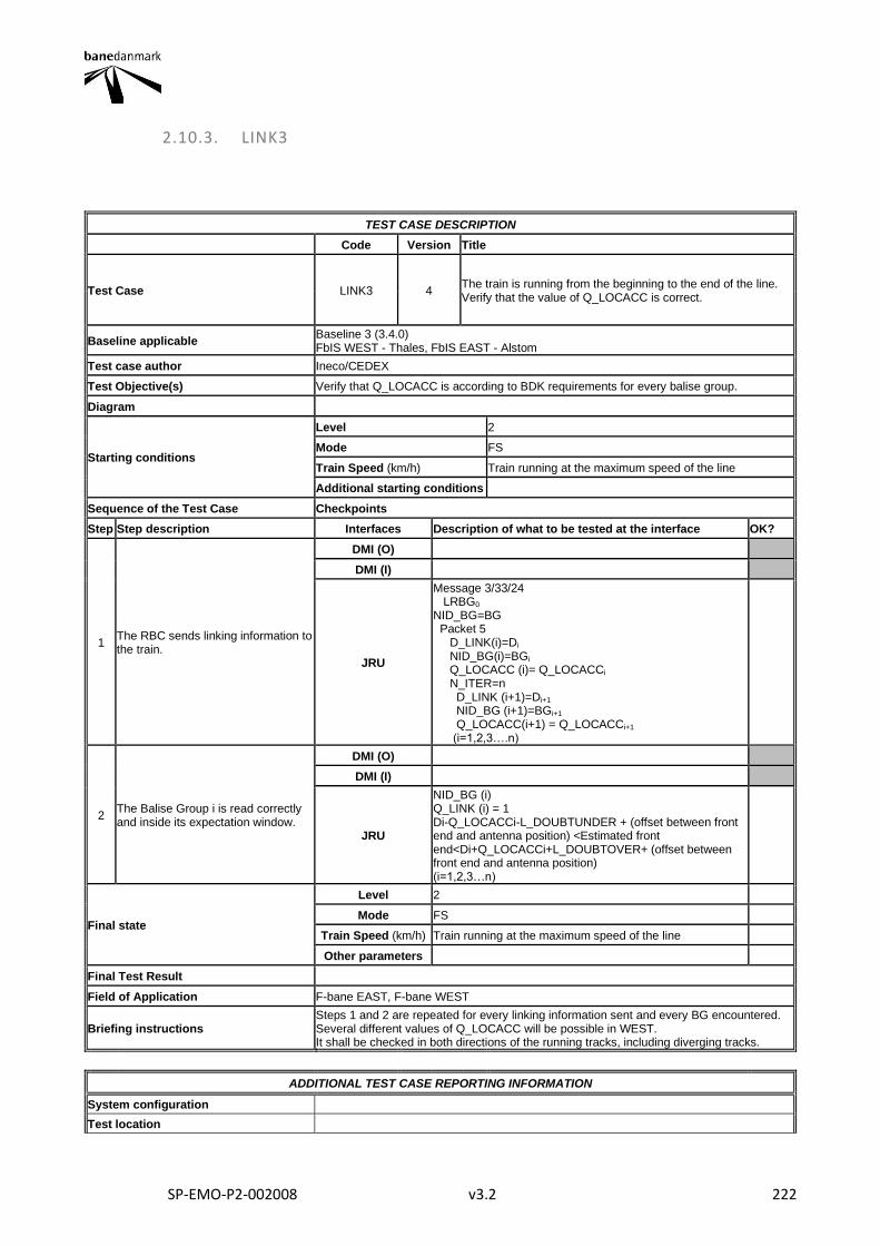
SP-EMO-P2-002008 v3.2 222
2.10.3. LINK3
TEST CASE DESCRIPTION
Code Version Title
Test Case LINK3 4 The train is running from the beginning to the end of the line. Verify that the value of Q_LOCACC is correct.
Baseline applicable Baseline 3 (3.4.0) FbIS WEST - Thales, FbIS EAST - Alstom
Test case author Ineco/CEDEX
Test Objective(s) Verify that Q_LOCACC is according to BDK requirements for every balise group.
Diagram
Starting conditions
Level 2
Mode FS
Train Speed (km/h) Train running at the maximum speed of the line
Additional starting conditions
Sequence of the Test Case Checkpoints
Step Step description Interfaces Description of what to be tested at the interface OK?
1 The RBC sends linking information to the train.
DMI (O)
DMI (I)
JRU
Message 3/33/24 LRBG0 NID_BG=BG Packet 5 D_LINK(i)=Di NID_BG(i)=BGi Q_LOCACC (i)= Q_LOCACCi N_ITER=n D_LINK (i+1)=Di+1 NID_BG (i+1)=BGi+1 Q_LOCACC(i+1) = Q_LOCACCi+1 (i=1,2,3….n)
2 The Balise Group i is read correctly and inside its expectation window.
DMI (O)
DMI (I)
JRU
NID_BG (i) Q_LINK (i) = 1 Di-Q_LOCACCi-L_DOUBTUNDER + (offset between front end and antenna position) <Estimated front end<Di+Q_LOCACCi+L_DOUBTOVER+ (offset between front end and antenna position) (i=1,2,3…n)
Final state
Level 2
Mode FS
Train Speed (km/h) Train running at the maximum speed of the line
Other parameters
Final Test Result
Field of Application F-bane EAST, F-bane WEST
Briefing instructions Steps 1 and 2 are repeated for every linking information sent and every BG encountered. Several different values of Q_LOCACC will be possible in WEST. It shall be checked in both directions of the running tracks, including diverging tracks.
ADDITIONAL TEST CASE REPORTING INFORMATION
System configuration
Test location

SP-EMO-P2-002008 v3.2 223
Date and time (Start/End)
Names
Test log reference
Observations

SP-EMO-P2-002008 v3.2 224
2.10.4. LINK4
TEST CASE DESCRIPTION
Code Version Title
Test Case LINK4 2 Linking - 2 consecutive linked balises are not found in the expectation window. Service Brake to be applied. CT_058
Baseline applicable Baseline 3 (3.4.0)
Test case author Ineco/CEDEX
Test Objective(s) Verify the reaction on board when two consecutive linked balise groups are not found in the expectation window.
Diagram
Starting conditions
Level 2
Mode FS
Train Speed (km/h) NR
Additional starting conditions Two consecutive linked balise groups are covered.
Sequence of the Test Case Checkpoints
Step Step description Interfaces Description of what to be tested at the interface OK?
1 Linking information is received on board
DMI (O)
DMI (I)
JRU
Message 3/24/33 LRBG0 Packet 5 D_LINK(i)=Di NID_BG(i)=BGi Q_LOCACC(i)=Qi Q_LINKREACTION(i)=2 N_ITER=n D_LINK (i+1)=Di+1 NID_BG (i+1)=BGi+1
Q_LOCACC(i+1) = Qi+1
Q_LINKREACTION(i+1)=2 (i=1,2,3….n)
2 Loss of the Balise Group i included in the linking information. No reaction is applied on board.
DMI (O) FS symbol
DMI (I)
JRU
BALISE GROUP ERROR NID_ERRORBG=BGi M_ERROR=0 Estimated front end>Di+Q_LOCACCi+L_DOUBTOVER+ (offset between front end and antenna position) DMI_SYMB_STATUS MO11
3 The EVC sends the error message to the RBC.
DMI (O)
DMI (I)
JRU Message 136 Packet 4 M_ERROR=0
4
Loss of the Balise Group i+1 included in the linking information. Service brake is applied. Driver is informed concerning the application of SB
DMI (O) FS symbol Balise error message Service Brake icon
DMI (I)
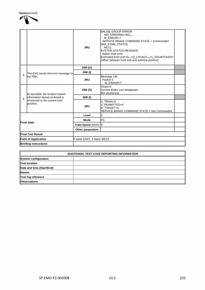
SP-EMO-P2-002008 v3.2 225
JRU
BALISE GROUP ERROR NID_ERRORBG=BGi+1 M_ERROR=7 SERVICE BRAKE COMMAND STATE = Commanded DMI_SYMB_STATUS MO11 SYSTEM STATUS MESSAGE Balise read error Estimated front end>Di+1+Q_LOCACCi+1+L_DOUBTOVER+ (offset between front end and antenna position)
5 The EVC sends the error message to the RBC.
DMI (O)
DMI (I)
JRU Message 136 Packet 4 M_ERROR=7
6
At standstill, the location based information stored on-board is shortened to the current train position.
DMI (O) Vtrain=0 Service Brake icon disappears MA shortening
DMI (I)
JRU
V_TRAIN=0 V_PERMITTED=0 D_TARGET=0 SERVICE BRAKE COMMAND STATE = Not Commanded
Final state
Level 2
Mode FS
Train Speed (km/h) 0
Other parameters
Final Test Result
Field of Application F-bane EAST, F-bane WEST
Briefing instructions
ADDITIONAL TEST CASE REPORTING INFORMATION
System configuration
Test location
Date and time (Start/End)
Names
Test log reference
Observations
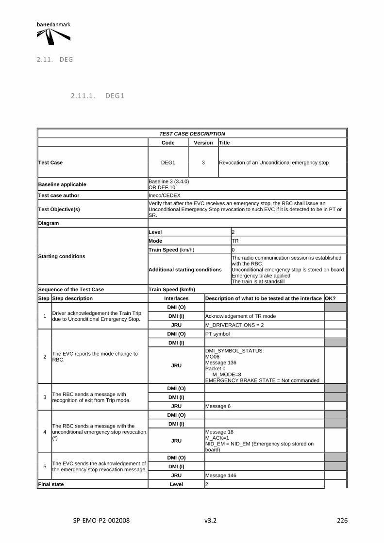
SP-EMO-P2-002008 v3.2 226
2.11. DEG
2.11.1. DEG1
TEST CASE DESCRIPTION
Code Version Title
Test Case DEG1 3 Revocation of an Unconditional emergency stop
Baseline applicable Baseline 3 (3.4.0) OR.DEF.10
Test case author Ineco/CEDEX
Test Objective(s) Verify that after the EVC receives an emergency stop, the RBC shall issue an Unconditional Emergency Stop revocation to such EVC if it is detected to be in PT or SR.
Diagram
Starting conditions
Level 2
Mode TR
Train Speed (km/h) 0
Additional starting conditions
The radio communication session is established with the RBC. Unconditional emergency stop is stored on board. Emergency brake applied The train is at standstill
Sequence of the Test Case Train Speed (km/h)
Step Step description Interfaces Description of what to be tested at the interface OK?
1 Driver acknowledgement the Train Trip due to Unconditional Emergency Stop.
DMI (O)
DMI (I) Acknowledgement of TR mode
JRU M_DRIVERACTIONS = 2
2 The EVC reports the mode change to RBC.
DMI (O) PT symbol
DMI (I)
JRU
DMI_SYMBOL_STATUS MO06 Message 136 Packet 0 M_MODE=8 EMERGENCY BRAKE STATE = Not commanded
3 The RBC sends a message with recognition of exit from Trip mode.
DMI (O)
DMI (I)
JRU Message 6
4 The RBC sends a message with the unconditional emergency stop revocation. (*)
DMI (O)
DMI (I)
JRU
Message 18 M_ACK=1 NID_EM = NID_EM (Emergency stop stored on board)
5 The EVC sends the acknowledgement of the emergency stop revocation message.
DMI (O)
DMI (I)
JRU Message 146
Final state Level 2
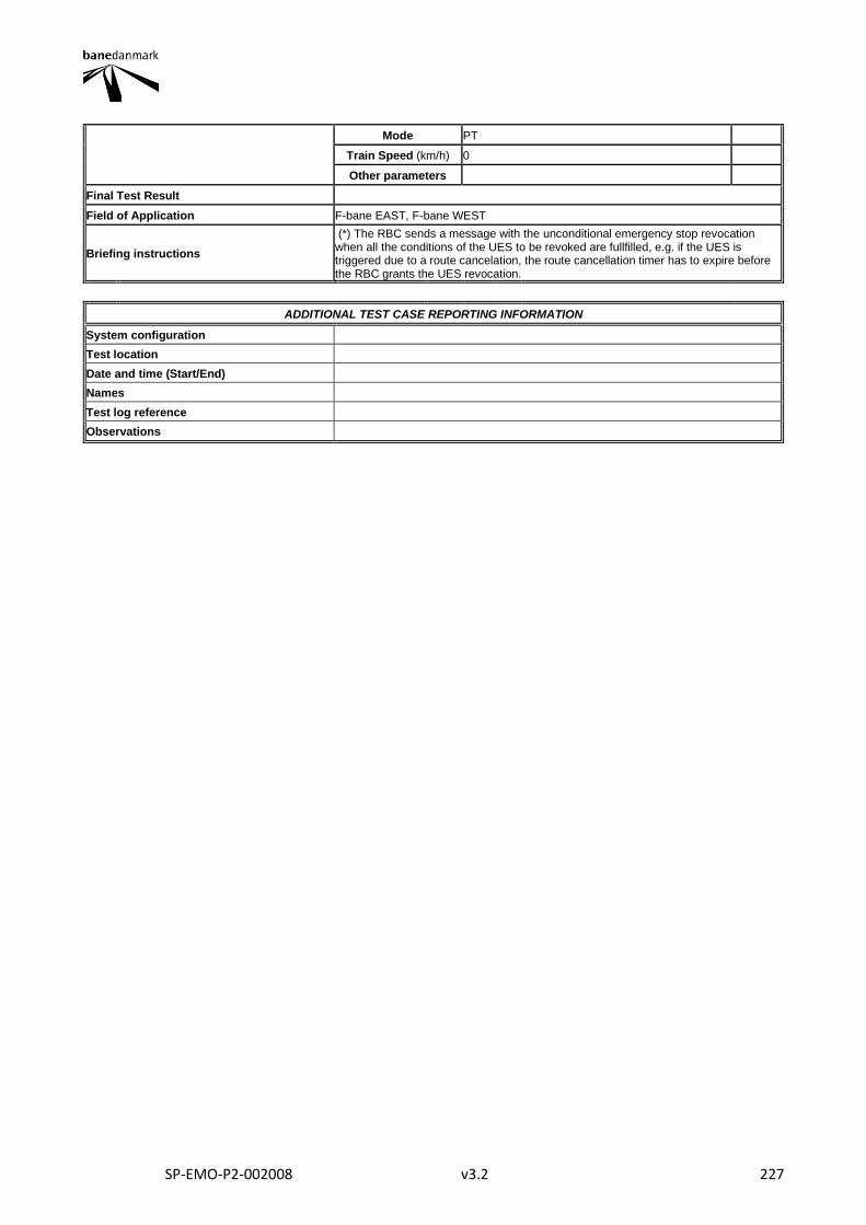
SP-EMO-P2-002008 v3.2 227
Mode PT
Train Speed (km/h) 0
Other parameters
Final Test Result
Field of Application F-bane EAST, F-bane WEST
Briefing instructions
(*) The RBC sends a message with the unconditional emergency stop revocation when all the conditions of the UES to be revoked are fullfilled, e.g. if the UES is triggered due to a route cancelation, the route cancellation timer has to expire before the RBC grants the UES revocation.
ADDITIONAL TEST CASE REPORTING INFORMATION
System configuration
Test location
Date and time (Start/End)
Names
Test log reference
Observations
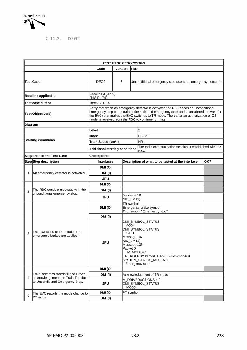
SP-EMO-P2-002008 v3.2 228
2.11.2. DEG2
TEST CASE DESCRIPTION
Code Version Title
Test Case DEG2 5 Unconditional emergency stop due to an emergency detector
Baseline applicable Baseline 3 (3.4.0) FbIS.F.1742
Test case author Ineco/CEDEX
Test Objective(s)
Verify that when an emergency detector is activated the RBC sends an unconditional emergency stop to the train (if the activated emergency detector is considered relevant for the EVC) that makes the EVC switches to TR mode. Thereafter an authorization of OS mode is received from the RBC to continue running.
Diagram
Starting conditions
Level 2
Mode FS/OS
Train Speed (km/h) NR
Additional starting conditions The radio communication session is established with the RBC.
Sequence of the Test Case Checkpoints
Step Step description Interfaces Description of what to be tested at the interface OK?
1 An emergency detector is activated.
DMI (O)
DMI (I)
JRU
2 The RBC sends a message with the unconditional emergency stop.
DMI (O)
DMI (I)
JRU Message 16 NID_EM (1)
3 Train switches to Trip mode. The emergency brakes are applied.
DMI (O) TR symbol Emergency brake symbol Trip reason: "Emergency stop"
DMI (I)
JRU
DMI_SYMBOL_STATUS MO04 DMI_SYMBOL_STATUS ST01 Message 147 NID_EM (1) Message 136 Packet 0 M_MODE=7 EMERGENCY BRAKE STATE =Commanded SYSTEM_STATUS_MESSAGE Emergency stop
4 Train becomes standstill and Driver acknowledgement the Train Trip due to Unconditional Emergency Stop.
DMI (O)
DMI (I) Acknowledgement of TR mode
JRU M_DRIVERACTIONS = 2 DMI_SYMBOL_STATUS MO05
5 The EVC reports the mode change to PT mode.
DMI (O) PT symbol
DMI (I)
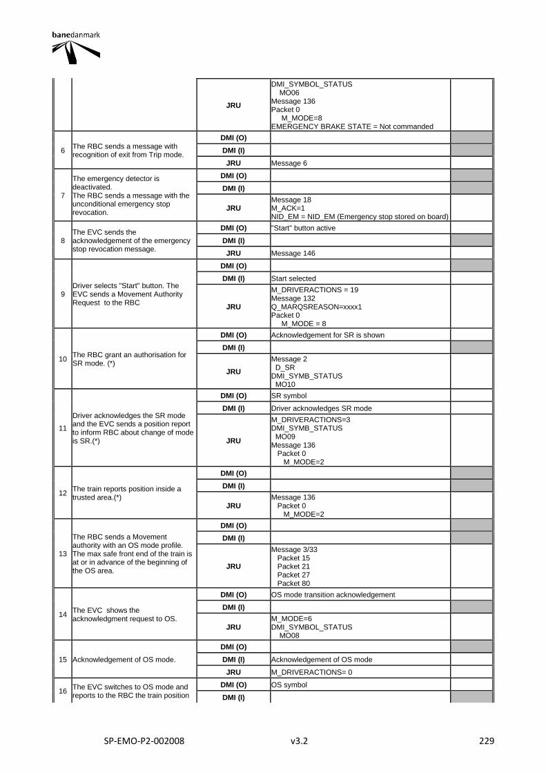
SP-EMO-P2-002008 v3.2 229
JRU
DMI_SYMBOL_STATUS MO06 Message 136 Packet 0 M_MODE=8 EMERGENCY BRAKE STATE = Not commanded
6 The RBC sends a message with recognition of exit from Trip mode.
DMI (O)
DMI (I)
JRU Message 6
7
The emergency detector is deactivated. The RBC sends a message with the unconditional emergency stop revocation.
DMI (O)
DMI (I)
JRU Message 18 M_ACK=1 NID_EM = NID_EM (Emergency stop stored on board)
8 The EVC sends the acknowledgement of the emergency stop revocation message.
DMI (O) "Start" button active
DMI (I)
JRU Message 146
9 Driver selects "Start" button. The EVC sends a Movement Authority Request to the RBC
DMI (O)
DMI (I) Start selected
JRU
M_DRIVERACTIONS = 19 Message 132 Q_MARQSREASON=xxxx1 Packet 0 M_MODE = 8
10 The RBC grant an authorisation for SR mode. (*)
DMI (O) Acknowledgement for SR is shown
DMI (I)
JRU
Message 2 D_SR DMI_SYMB_STATUS MO10
11
Driver acknowledges the SR mode and the EVC sends a position report to inform RBC about change of mode is SR.(*)
DMI (O) SR symbol
DMI (I) Driver acknowledges SR mode
JRU
M_DRIVERACTIONS=3 DMI_SYMB_STATUS MO09 Message 136 Packet 0 M_MODE=2
12 The train reports position inside a trusted area.(*)
DMI (O)
DMI (I)
JRU Message 136 Packet 0 M_MODE=2
13
The RBC sends a Movement authority with an OS mode profile. The max safe front end of the train is at or in advance of the beginning of the OS area.
DMI (O)
DMI (I)
JRU
Message 3/33 Packet 15 Packet 21 Packet 27 Packet 80
14 The EVC shows the acknowledgment request to OS.
DMI (O) OS mode transition acknowledgement
DMI (I)
JRU M_MODE=6 DMI_SYMBOL_STATUS MO08
15 Acknowledgement of OS mode.
DMI (O)
DMI (I) Acknowledgement of OS mode
JRU M_DRIVERACTIONS= 0
16 The EVC switches to OS mode and reports to the RBC the train position
DMI (O) OS symbol
DMI (I)
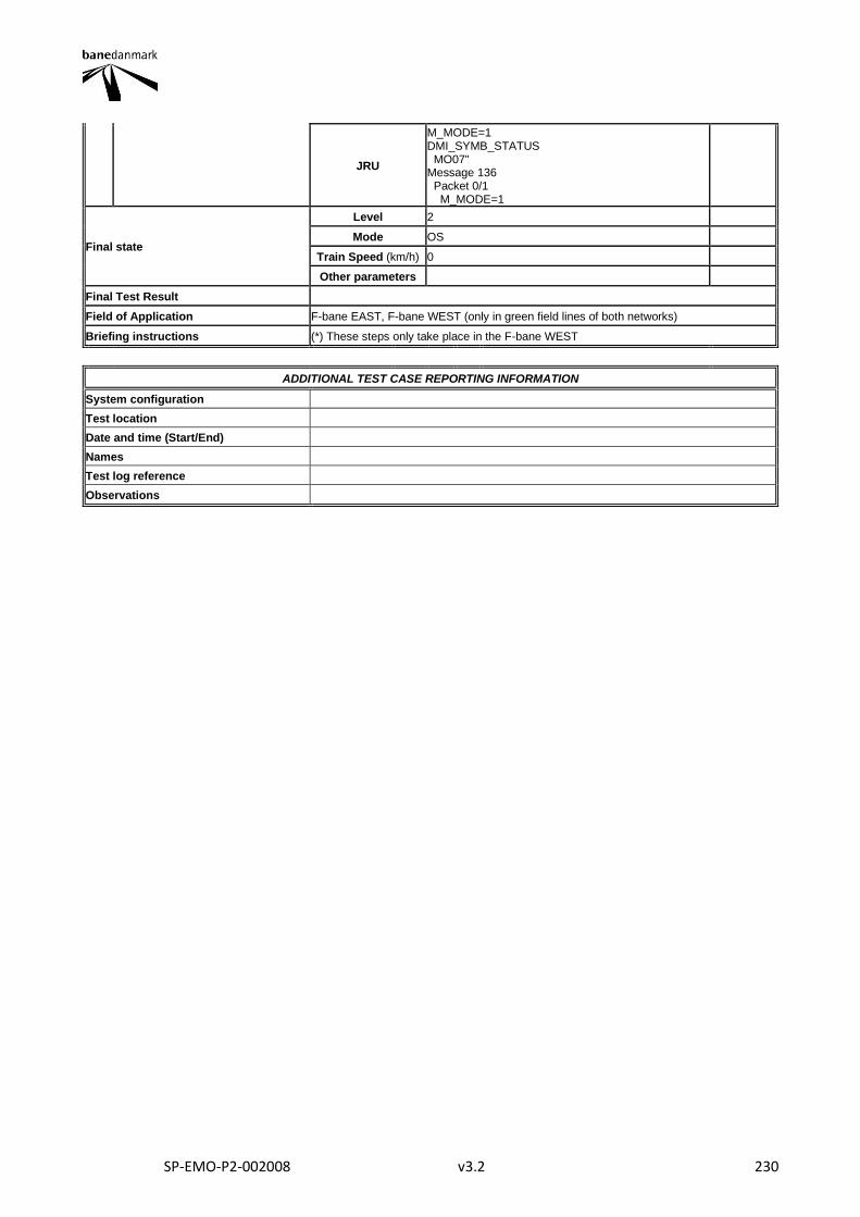
SP-EMO-P2-002008 v3.2 230
JRU
M_MODE=1 DMI_SYMB_STATUS MO07" Message 136 Packet 0/1 M_MODE=1
Final state
Level 2
Mode OS
Train Speed (km/h) 0
Other parameters
Final Test Result
Field of Application F-bane EAST, F-bane WEST (only in green field lines of both networks)
Briefing instructions (*) These steps only take place in the F-bane WEST
ADDITIONAL TEST CASE REPORTING INFORMATION
System configuration
Test location
Date and time (Start/End)
Names
Test log reference
Observations
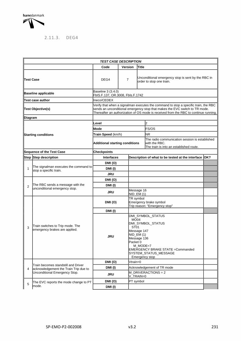
SP-EMO-P2-002008 v3.2 231
2.11.3. DEG4
TEST CASE DESCRIPTION
Code Version Title
Test Case DEG4 7 Unconditional emergency stop is sent by the RBC in order to stop one train.
Baseline applicable Baseline 3 (3.4.0) FbIS.F.137, OR.3008, FbIs.F.1742
Test case author Ineco/CEDEX
Test Objective(s) Verify that when a signalman executes the command to stop a specific train, the RBC sends an unconditional emergency stop that makes the EVC switch to TR mode. Thereafter an authorization of OS mode is received from the RBC to continue running.
Diagram
Starting conditions
Level 2
Mode FS/OS
Train Speed (km/h) NR
Additional starting conditions The radio communication session is established with the RBC. The train is into an established route.
Sequence of the Test Case Checkpoints
Step Step description Interfaces Description of what to be tested at the interface OK?
1 The signalman executes the command to stop a specific train.
DMI (O)
DMI (I)
JRU
2 The RBC sends a message with the unconditional emergency stop.
DMI (O)
DMI (I)
JRU Message 16 NID_EM (1)
3 Train switches to Trip mode. The emergency brakes are applied.
DMI (O) TR symbol Emergency brake symbol Trip reason: "Emergency stop"
DMI (I)
JRU
DMI_SYMBOL_STATUS MO04 DMI_SYMBOL_STATUS ST01 Message 147 NID_EM (1) Message 136 Packet 0 M_MODE=7 EMERGENCY BRAKE STATE =Commanded SYSTEM_STATUS_MESSAGE Emergency stop
4 Train becomes standstill and Driver acknowledgement the Train Trip due to Unconditional Emergency Stop.
DMI (O) Vtrain=0
DMI (I) Acknowledgement of TR mode
JRU M_DRIVERACTIONS = 2 V_TRAIN=0
5 The EVC reports the mode change to PT mode.
DMI (O) PT symbol
DMI (I)
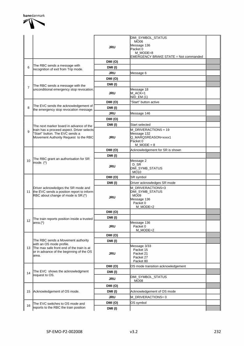
SP-EMO-P2-002008 v3.2 232
JRU
DMI_SYMBOL_STATUS MO06 Message 136 Packet 0 M_MODE=8 EMERGENCY BRAKE STATE = Not commanded
6 The RBC sends a message with recognition of exit from Trip mode.
DMI (O)
DMI (I)
JRU Message 6
7 The RBC sends a message with the unconditional emergency stop revocation.
DMI (O)
DMI (I)
JRU Message 18 M_ACK=1 NID_EM (1)
8 The EVC sends the acknowledgement of the emergency stop revocation message.
DMI (O) "Start" button active
DMI (I)
JRU Message 146
9
The next marker board in advance of the train has a proceed aspect. Driver selects "Start" button. The EVC sends a Movement Authority Request to the RBC
DMI (O)
DMI (I) Start selected
JRU
M_DRIVERACTIONS = 19 Message 132 Q_MARQSREASON=xxxx1 Packet 0 M_MODE = 8
10 The RBC grant an authorisation for SR mode. (*)
DMI (O) Acknowledgement for SR is shown
DMI (I)
JRU
Message 2 D_SR DMI_SYMB_STATUS MO10
11 Driver acknowledges the SR mode and the EVC sends a position report to inform RBC about change of mode is SR.(*)
DMI (O) SR symbol
DMI (I) Driver acknowledges SR mode
JRU
M_DRIVERACTIONS=3 DMI_SYMB_STATUS MO09 Message 136 Packet 0 M_MODE=2
12 The train reports position inside a trusted area.(*)
DMI (O)
DMI (I)
JRU Message 136 Packet 0 M_MODE=2
13
The RBC sends a Movement authority with an OS mode profile. The max safe front end of the train is at or in advance of the beginning of the OS area.
DMI (O)
DMI (I)
JRU
Message 3/33 Packet 15 Packet 21 Packet 27 Packet 80
14 The EVC shows the acknowledgment request to OS.
DMI (O) OS mode transition acknowledgement
DMI (I)
JRU DMI_SYMBOL_STATUS MO08
15 Acknowledgement of OS mode.
DMI (O)
DMI (I) Acknowledgement of OS mode
JRU M_DRIVERACTIONS= 0
16 The EVC switches to OS mode and reports to the RBC the train position
DMI (O) OS symbol
DMI (I)

SP-EMO-P2-002008 v3.2 233
JRU
M_MODE=1 DMI_SYMB_STATUS MO07" Message 136 Packet 0/1 M_MODE=1
Final state
Level 2
Mode OS
Train Speed (km/h) 0
Other parameters
Final Test Result
Field of Application F-bane EAST, F-bane WEST
Briefing instructions (*) These steps only take place in the F-bane WEST if the train is outside a trustworthy area
ADDITIONAL TEST CASE REPORTING INFORMATION
System configuration
Test location
Date and time (Start/End)
Names
Test log reference
Observations
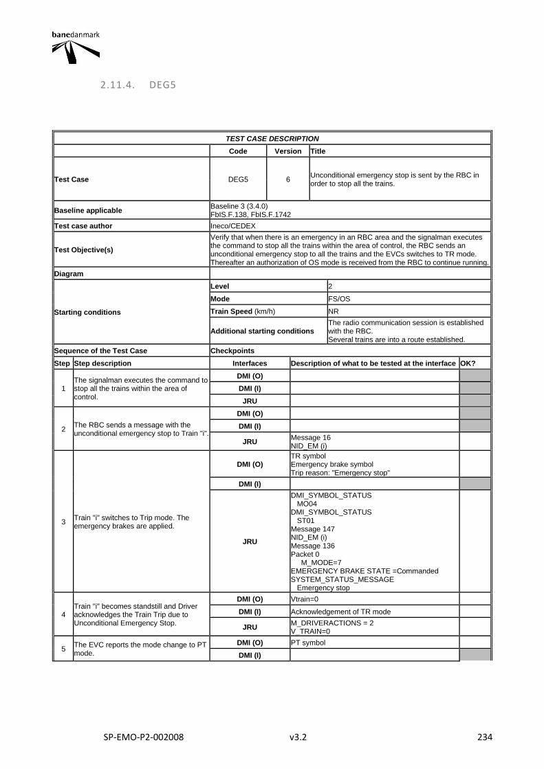
SP-EMO-P2-002008 v3.2 234
2.11.4. DEG5
TEST CASE DESCRIPTION
Code Version Title
Test Case DEG5 6 Unconditional emergency stop is sent by the RBC in order to stop all the trains.
Baseline applicable Baseline 3 (3.4.0) FbIS.F.138, FbIS.F.1742
Test case author Ineco/CEDEX
Test Objective(s)
Verify that when there is an emergency in an RBC area and the signalman executes the command to stop all the trains within the area of control, the RBC sends an unconditional emergency stop to all the trains and the EVCs switches to TR mode. Thereafter an authorization of OS mode is received from the RBC to continue running.
Diagram
Starting conditions
Level 2
Mode FS/OS
Train Speed (km/h) NR
Additional starting conditions The radio communication session is established with the RBC. Several trains are into a route established.
Sequence of the Test Case Checkpoints
Step Step description Interfaces Description of what to be tested at the interface OK?
1 The signalman executes the command to stop all the trains within the area of control.
DMI (O)
DMI (I)
JRU
2 The RBC sends a message with the unconditional emergency stop to Train "i".
DMI (O)
DMI (I)
JRU Message 16 NID_EM (i)
3 Train "i" switches to Trip mode. The emergency brakes are applied.
DMI (O) TR symbol Emergency brake symbol Trip reason: "Emergency stop"
DMI (I)
JRU
DMI_SYMBOL_STATUS MO04 DMI_SYMBOL_STATUS ST01 Message 147 NID_EM (i) Message 136 Packet 0 M_MODE=7 EMERGENCY BRAKE STATE =Commanded SYSTEM_STATUS_MESSAGE Emergency stop
4 Train "i" becomes standstill and Driver acknowledges the Train Trip due to Unconditional Emergency Stop.
DMI (O) Vtrain=0
DMI (I) Acknowledgement of TR mode
JRU M_DRIVERACTIONS = 2 V_TRAIN=0
5 The EVC reports the mode change to PT mode.
DMI (O) PT symbol
DMI (I)
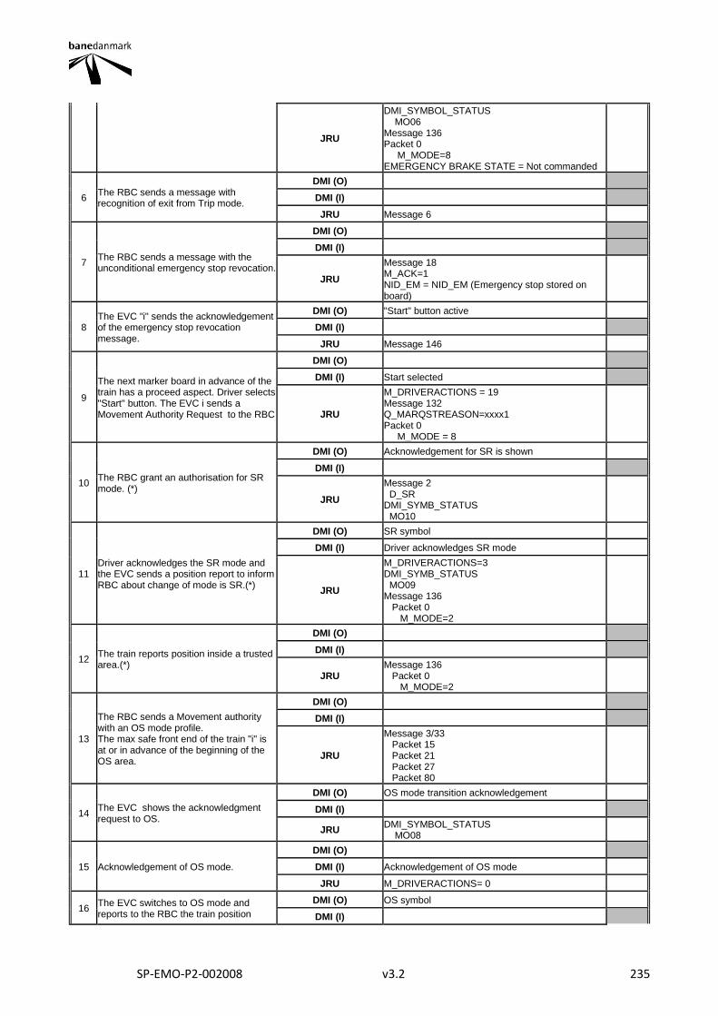
SP-EMO-P2-002008 v3.2 235
JRU
DMI_SYMBOL_STATUS MO06 Message 136 Packet 0 M_MODE=8 EMERGENCY BRAKE STATE = Not commanded
6 The RBC sends a message with recognition of exit from Trip mode.
DMI (O)
DMI (I)
JRU Message 6
7 The RBC sends a message with the unconditional emergency stop revocation.
DMI (O)
DMI (I)
JRU
Message 18 M_ACK=1 NID_EM = NID_EM (Emergency stop stored on board)
8 The EVC "i" sends the acknowledgement of the emergency stop revocation message.
DMI (O) "Start" button active
DMI (I)
JRU Message 146
9
The next marker board in advance of the train has a proceed aspect. Driver selects "Start" button. The EVC i sends a Movement Authority Request to the RBC
DMI (O)
DMI (I) Start selected
JRU
M_DRIVERACTIONS = 19 Message 132 Q_MARQSTREASON=xxxx1 Packet 0 M_MODE = 8
10 The RBC grant an authorisation for SR mode. (*)
DMI (O) Acknowledgement for SR is shown
DMI (I)
JRU
Message 2 D_SR DMI_SYMB_STATUS MO10
11 Driver acknowledges the SR mode and the EVC sends a position report to inform RBC about change of mode is SR.(*)
DMI (O) SR symbol
DMI (I) Driver acknowledges SR mode
JRU
M_DRIVERACTIONS=3 DMI_SYMB_STATUS MO09 Message 136 Packet 0 M_MODE=2
12 The train reports position inside a trusted area.(*)
DMI (O)
DMI (I)
JRU Message 136 Packet 0 M_MODE=2
13
The RBC sends a Movement authority with an OS mode profile. The max safe front end of the train "i" is at or in advance of the beginning of the OS area.
DMI (O)
DMI (I)
JRU
Message 3/33 Packet 15 Packet 21 Packet 27 Packet 80
14 The EVC shows the acknowledgment request to OS.
DMI (O) OS mode transition acknowledgement
DMI (I)
JRU DMI_SYMBOL_STATUS MO08
15 Acknowledgement of OS mode.
DMI (O)
DMI (I) Acknowledgement of OS mode
JRU M_DRIVERACTIONS= 0
16 The EVC switches to OS mode and reports to the RBC the train position
DMI (O) OS symbol
DMI (I)
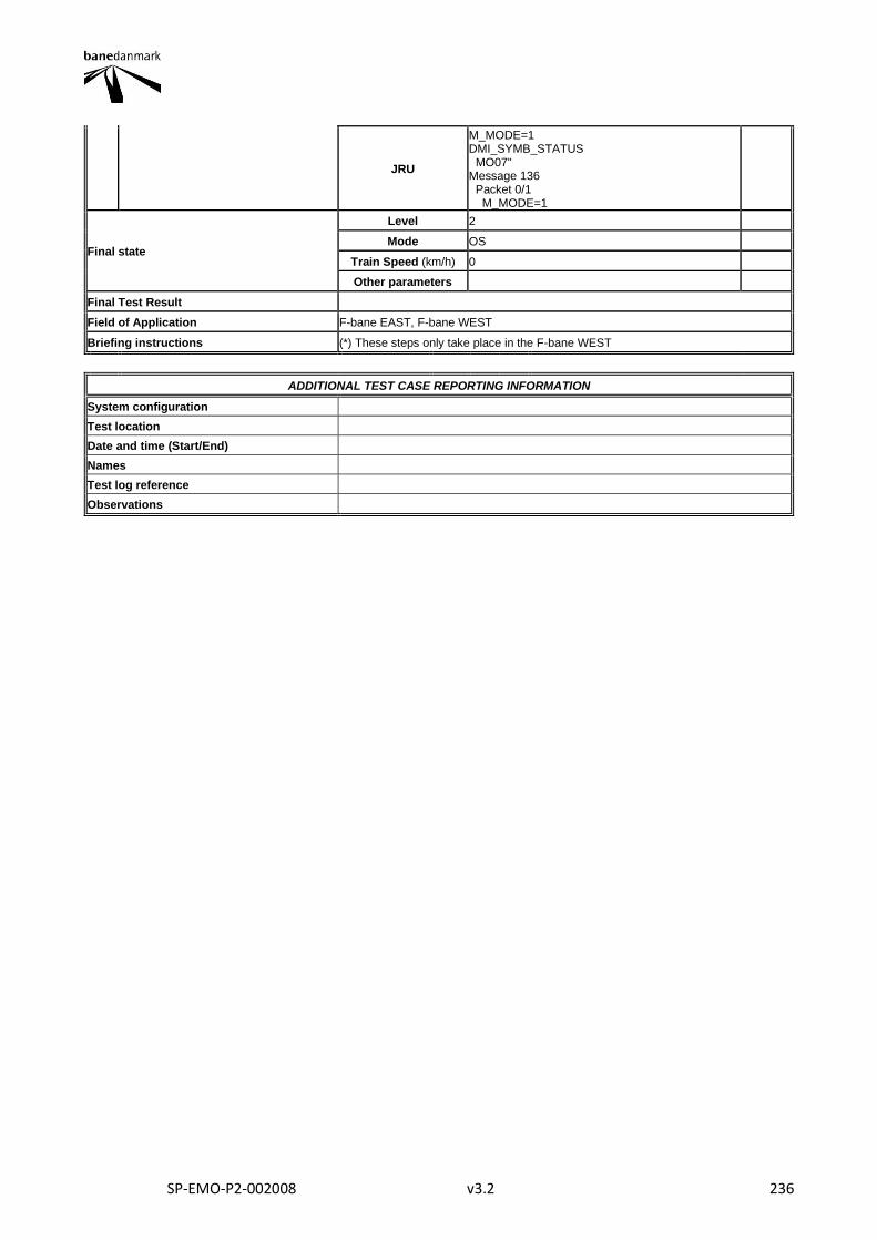
SP-EMO-P2-002008 v3.2 236
JRU
M_MODE=1 DMI_SYMB_STATUS MO07" Message 136 Packet 0/1 M_MODE=1
Final state
Level 2
Mode OS
Train Speed (km/h) 0
Other parameters
Final Test Result
Field of Application F-bane EAST, F-bane WEST
Briefing instructions (*) These steps only take place in the F-bane WEST
ADDITIONAL TEST CASE REPORTING INFORMATION
System configuration
Test location
Date and time (Start/End)
Names
Test log reference
Observations
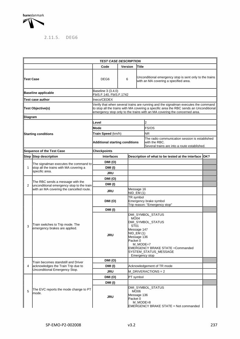
SP-EMO-P2-002008 v3.2 237
2.11.5. DEG6
TEST CASE DESCRIPTION
Code Version Title
Test Case DEG6 6 Unconditional emergency stop is sent only to the trains with an MA covering a specified area.
Baseline applicable Baseline 3 (3.4.0) FbIS.F.140, FbIS.F.1742
Test case author Ineco/CEDEX
Test Objective(s) Verify that when several trains are running and the signalman executes the command to stop all the trains with MA covering a specific area the RBC sends an Unconditional emergency stop only to the trains with an MA covering the concerned area.
Diagram
Starting conditions
Level 2
Mode FS/OS
Train Speed (km/h) NR
Additional starting conditions The radio communication session is established with the RBC. Several trains are into a route established.
Sequence of the Test Case Checkpoints
Step Step description Interfaces Description of what to be tested at the interface OK?
1 The signalman executes the command to stop all the trains with MA covering a specific area.
DMI (O)
DMI (I)
JRU
2 The RBC sends a message with the unconditional emergency stop to the train with an MA covering the cancelled route.
DMI (O)
DMI (I)
JRU Message 16 NID_EM (1)
3 Train switches to Trip mode. The emergency brakes are applied.
DMI (O) TR symbol Emergency brake symbol Trip reason: "Emergency stop"
DMI (I)
JRU
DMI_SYMBOL_STATUS MO04 DMI_SYMBOL_STATUS ST01 Message 147 NID_EM (1) Message 136 Packet 0 M_MODE=7 EMERGENCY BRAKE STATE =Commanded SYSTEM_STATUS_MESSAGE Emergency stop
4 Train becomes standstill and Driver acknowledges the Train Trip due to Unconditional Emergency Stop.
DMI (O)
DMI (I) Acknowledgement of TR mode
JRU M_DRIVERACTIONS = 2
5 The EVC reports the mode change to PT mode.
DMI (O) PT symbol
DMI (I)
JRU
DMI_SYMBOL_STATUS MO06 Message 136 Packet 0 M_MODE=8 EMERGENCY BRAKE STATE = Not commanded
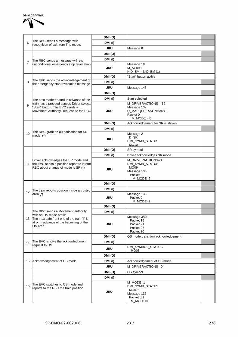
SP-EMO-P2-002008 v3.2 238
6 The RBC sends a message with recognition of exit from Trip mode.
DMI (O)
DMI (I)
JRU Message 6
7 The RBC sends a message with the unconditional emergency stop revocation.
DMI (O)
DMI (I)
JRU Message 18 M_ACK=1 NID_EM = NID_EM (1)
8 The EVC sends the acknowledgement of the emergency stop revocation message.
DMI (O) "Start" button active
DMI (I)
JRU Message 146
9
The next marker board in advance of the train has a proceed aspect. Driver selects "Start" button. The EVC sends a Movement Authority Request to the RBC
DMI (O)
DMI (I) Start selected
JRU
M_DRIVERACTIONS = 19 Message 132 Q_MARQSREASON=xxxx1 Packet 0 M_MODE = 8
10 The RBC grant an authorisation for SR mode. (*)
DMI (O) Acknowledgement for SR is shown
DMI (I)
JRU
Message 2 D_SR DMI_SYMB_STATUS MO10
11 Driver acknowledges the SR mode and the EVC sends a position report to inform RBC about change of mode is SR.(*)
DMI (O) SR symbol
DMI (I) Driver acknowledges SR mode
JRU
M_DRIVERACTIONS=3 DMI_SYMB_STATUS MO09 Message 136 Packet 0 M_MODE=2
12 The train reports position inside a trusted area.(*)
DMI (O)
DMI (I)
JRU Message 136 Packet 0 M_MODE=2
13
The RBC sends a Movement authority with an OS mode profile. The max safe front end of the train "i" is at or in advance of the beginning of the OS area.
DMI (O)
DMI (I)
JRU
Message 3/33 Packet 15 Packet 21 Packet 27 Packet 80
14 The EVC shows the acknowledgment request to OS.
DMI (O) OS mode transition acknowledgement
DMI (I)
JRU DMI_SYMBOL_STATUS MO08
15 Acknowledgement of OS mode.
DMI (O)
DMI (I) Acknowledgement of OS mode
JRU M_DRIVERACTIONS= 0
16 The EVC switches to OS mode and reports to the RBC the train position
DMI (O) OS symbol
DMI (I)
JRU
M_MODE=1 DMI_SYMB_STATUS MO07" Message 136 Packet 0/1 M_MODE=1
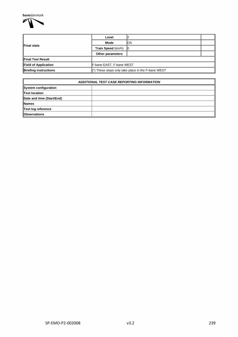
SP-EMO-P2-002008 v3.2 239
Final state
Level 2
Mode OS
Train Speed (km/h) 0
Other parameters
Final Test Result
Field of Application F-bane EAST, F-bane WEST
Briefing instructions (*) These steps only take place in the F-bane WEST
ADDITIONAL TEST CASE REPORTING INFORMATION
System configuration
Test location
Date and time (Start/End)
Names
Test log reference
Observations
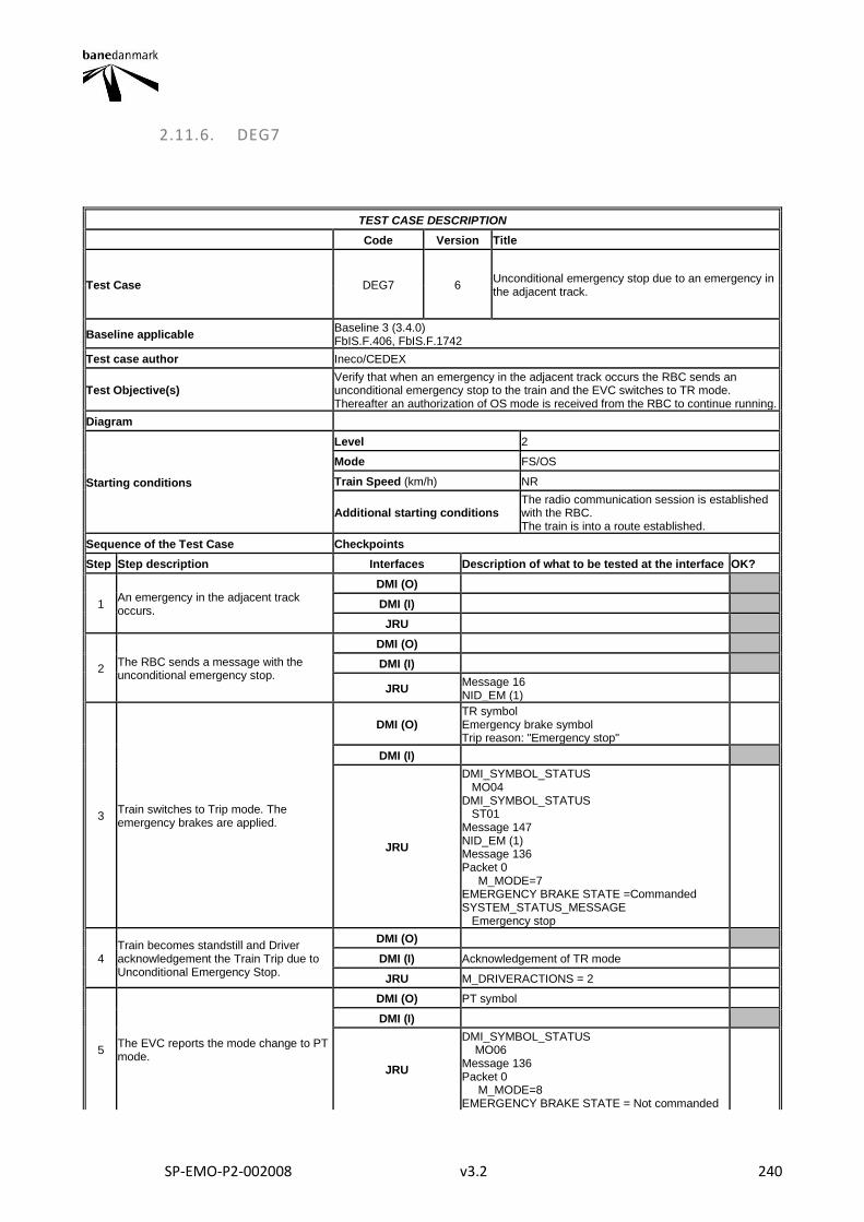
SP-EMO-P2-002008 v3.2 240
2.11.6. DEG7
TEST CASE DESCRIPTION
Code Version Title
Test Case DEG7 6 Unconditional emergency stop due to an emergency in the adjacent track.
Baseline applicable Baseline 3 (3.4.0) FbIS.F.406, FbIS.F.1742
Test case author Ineco/CEDEX
Test Objective(s) Verify that when an emergency in the adjacent track occurs the RBC sends an unconditional emergency stop to the train and the EVC switches to TR mode. Thereafter an authorization of OS mode is received from the RBC to continue running.
Diagram
Starting conditions
Level 2
Mode FS/OS
Train Speed (km/h) NR
Additional starting conditions The radio communication session is established with the RBC. The train is into a route established.
Sequence of the Test Case Checkpoints
Step Step description Interfaces Description of what to be tested at the interface OK?
1 An emergency in the adjacent track occurs.
DMI (O)
DMI (I)
JRU
2 The RBC sends a message with the unconditional emergency stop.
DMI (O)
DMI (I)
JRU Message 16 NID_EM (1)
3 Train switches to Trip mode. The emergency brakes are applied.
DMI (O) TR symbol Emergency brake symbol Trip reason: "Emergency stop"
DMI (I)
JRU
DMI_SYMBOL_STATUS MO04 DMI_SYMBOL_STATUS ST01 Message 147 NID_EM (1) Message 136 Packet 0 M_MODE=7 EMERGENCY BRAKE STATE =Commanded SYSTEM_STATUS_MESSAGE Emergency stop
4 Train becomes standstill and Driver acknowledgement the Train Trip due to Unconditional Emergency Stop.
DMI (O)
DMI (I) Acknowledgement of TR mode
JRU M_DRIVERACTIONS = 2
5 The EVC reports the mode change to PT mode.
DMI (O) PT symbol
DMI (I)
JRU
DMI_SYMBOL_STATUS MO06 Message 136 Packet 0 M_MODE=8 EMERGENCY BRAKE STATE = Not commanded

SP-EMO-P2-002008 v3.2 241
6 The RBC sends a message with recognition of exit from Trip mode.
DMI (O)
DMI (I)
JRU Message 6
7 The RBC sends a message with the unconditional emergency stop revocation.
DMI (O)
DMI (I)
JRU Message 18 M_ACK=1 NID_EM = NID_EM(1)
8 The EVC sends the acknowledgement of the emergency stop revocation message.
DMI (O) "Start" button active
DMI (I)
JRU Message 146
9
The next marker board in advance of the train has a proceed aspect. Driver selects "Start" button. The EVC sends a Movement Authority Request to the RBC
DMI (O)
DMI (I) Start selected
JRU
M_DRIVERACTIONS = 19 Message 132 Q_MARSREASON=xxxx1 Packet 0 M_MODE = 8
10 The RBC grant an authorisation for SR mode. (*)
DMI (O) Acknowledgement for SR is shown
DMI (I)
JRU
Message 2 D_SR DMI_SYMB_STATUS MO10
11 Driver acknowledges the SR mode and the EVC sends a position report to inform RBC about change of mode is SR.(*)
DMI (O) SR symbol
DMI (I) Driver acknowledges SR mode
JRU
M_DRIVERACTIONS=3 DMI_SYMB_STATUS MO09 Message 136 Packet 0 M_MODE=2
12 The train reports position inside a trusted area.(*)
DMI (O)
DMI (I)
JRU Message 136 Packet 0 M_MODE=2
13
The RBC sends a Movement authority with an OS mode profile. The max safe front end of the train "i" is at or in advance of the beginning of the OS area.
DMI (O)
DMI (I)
JRU
Message 3/33 Packet 15 Packet 21 Packet 27 Packet 80
14 The EVC shows the acknowledgment request to OS.
DMI (O) OS mode transition acknowledgement
DMI (I)
JRU M_MODE=6 DMI_SYMBOL_STATUS MO08
15 Acknowledgement of OS mode.
DMI (O)
DMI (I) Acknowledgement of OS mode
JRU M_DRIVERACTIONS= 0
16 The EVC switches to OS mode and reports to the RBC the train position
DMI (O) OS symbol
DMI (I)
JRU
M_MODE=1 DMI_SYMB_STATUS MO07" Message 136 Packet 0/1 M_MODE=1

SP-EMO-P2-002008 v3.2 242
Final state
Level 2
Mode OS
Train Speed (km/h) 0
Other parameters
Final Test Result
Field of Application F-bane EAST, F-bane WEST
Briefing instructions (*) These steps only take place in the F-bane WEST
ADDITIONAL TEST CASE REPORTING INFORMATION
System configuration
Test location
Date and time (Start/End)
Names
Test log reference
Observations
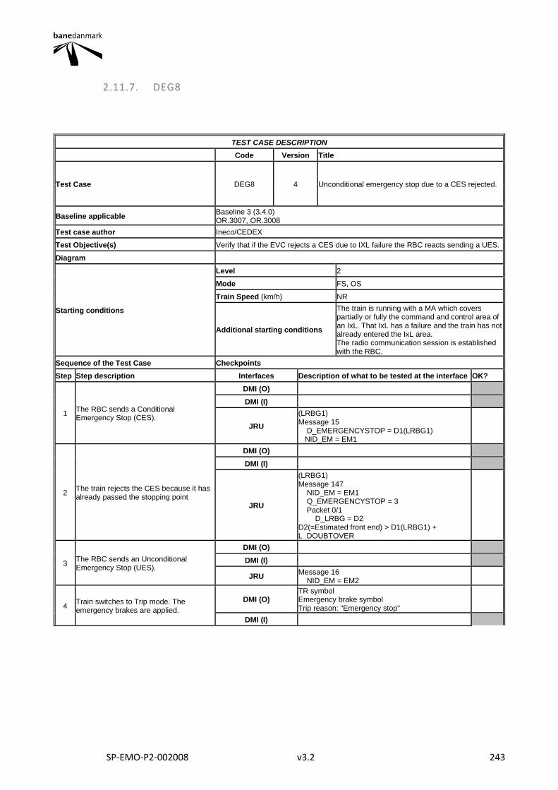
SP-EMO-P2-002008 v3.2 243
2.11.7. DEG8
TEST CASE DESCRIPTION
Code Version Title
Test Case DEG8 4 Unconditional emergency stop due to a CES rejected.
Baseline applicable Baseline 3 (3.4.0) OR.3007, OR.3008
Test case author Ineco/CEDEX
Test Objective(s) Verify that if the EVC rejects a CES due to IXL failure the RBC reacts sending a UES.
Diagram
Starting conditions
Level 2
Mode FS, OS
Train Speed (km/h) NR
Additional starting conditions
The train is running with a MA which covers partially or fully the command and control area of an IxL. That IxL has a failure and the train has not already entered the IxL area. The radio communication session is established with the RBC.
Sequence of the Test Case Checkpoints
Step Step description Interfaces Description of what to be tested at the interface OK?
1 The RBC sends a Conditional Emergency Stop (CES).
DMI (O)
DMI (I)
JRU
(LRBG1) Message 15 D_EMERGENCYSTOP = D1(LRBG1) NID_EM = EM1
2 The train rejects the CES because it has already passed the stopping point
DMI (O)
DMI (I)
JRU
(LRBG1) Message 147 NID_EM = EM1 Q_EMERGENCYSTOP = 3 Packet 0/1 D_LRBG = D2 D2(=Estimated front end) > D1(LRBG1) + L_DOUBTOVER
3 The RBC sends an Unconditional Emergency Stop (UES).
DMI (O)
DMI (I)
JRU Message 16 NID_EM = EM2
4 Train switches to Trip mode. The emergency brakes are applied.
DMI (O) TR symbol Emergency brake symbol Trip reason: "Emergency stop"
DMI (I)
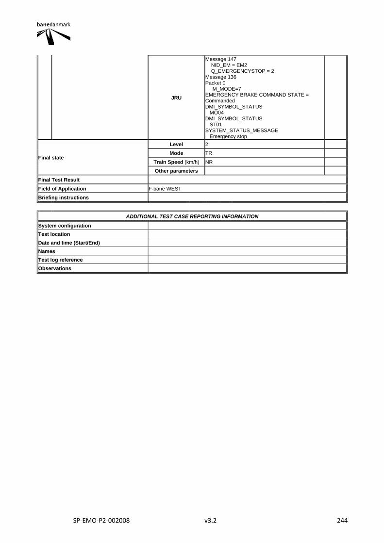
SP-EMO-P2-002008 v3.2 244
JRU
Message 147 NID_EM = EM2 Q_EMERGENCYSTOP = 2 Message 136 Packet 0 M_MODE=7 EMERGENCY BRAKE COMMAND STATE = Commanded DMI_SYMBOL_STATUS MO04 DMI_SYMBOL_STATUS ST01 SYSTEM_STATUS_MESSAGE Emergency stop
Final state
Level 2
Mode TR
Train Speed (km/h) NR
Other parameters
Final Test Result
Field of Application F-bane WEST
Briefing instructions
ADDITIONAL TEST CASE REPORTING INFORMATION
System configuration
Test location
Date and time (Start/End)
Names
Test log reference
Observations
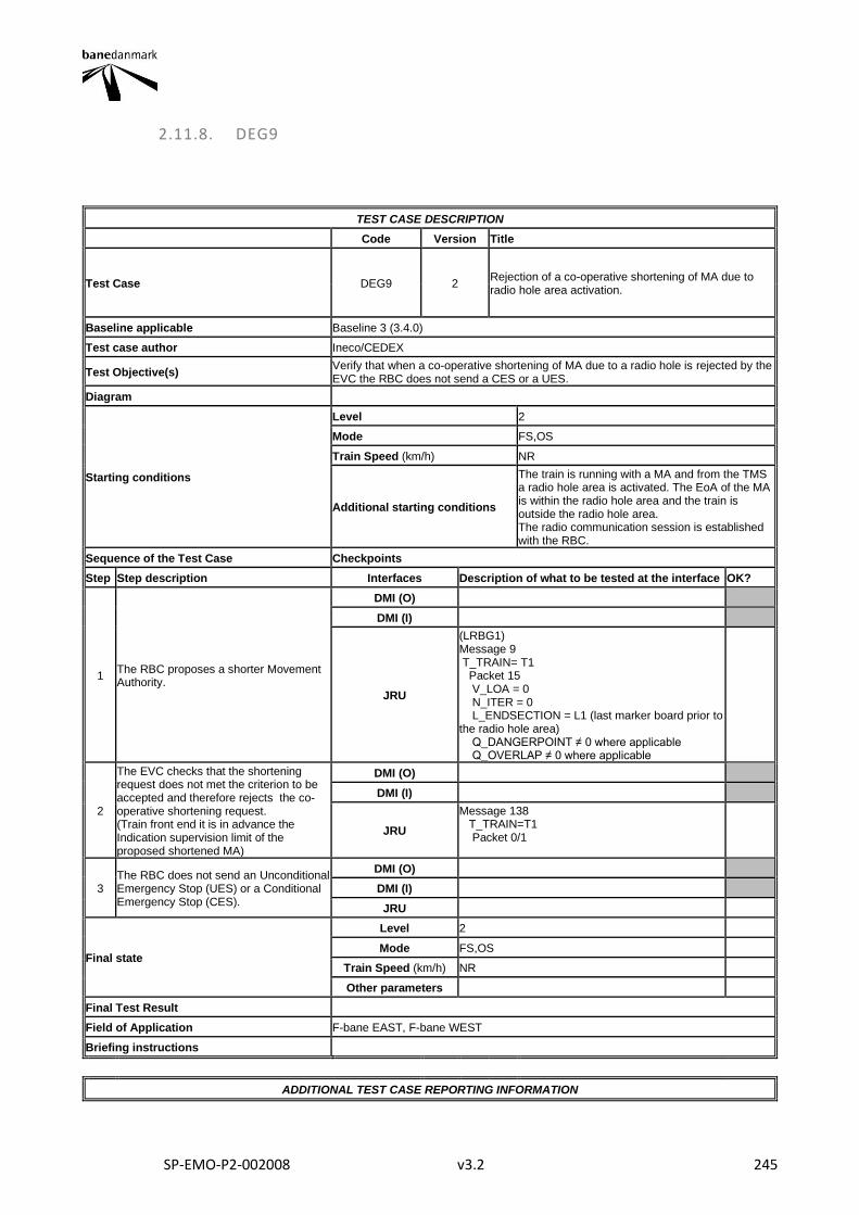
SP-EMO-P2-002008 v3.2 245
2.11.8. DEG9
TEST CASE DESCRIPTION
Code Version Title
Test Case DEG9 2 Rejection of a co-operative shortening of MA due to radio hole area activation.
Baseline applicable Baseline 3 (3.4.0)
Test case author Ineco/CEDEX
Test Objective(s) Verify that when a co-operative shortening of MA due to a radio hole is rejected by the EVC the RBC does not send a CES or a UES.
Diagram
Starting conditions
Level 2
Mode FS,OS
Train Speed (km/h) NR
Additional starting conditions
The train is running with a MA and from the TMS a radio hole area is activated. The EoA of the MA is within the radio hole area and the train is outside the radio hole area. The radio communication session is established with the RBC.
Sequence of the Test Case Checkpoints
Step Step description Interfaces Description of what to be tested at the interface OK?
1 The RBC proposes a shorter Movement Authority.
DMI (O)
DMI (I)
JRU
(LRBG1) Message 9 T_TRAIN= T1 Packet 15 V_LOA = 0 N_ITER = 0 L_ENDSECTION = L1 (last marker board prior to the radio hole area) Q_DANGERPOINT ≠ 0 where applicable Q_OVERLAP ≠ 0 where applicable
2
The EVC checks that the shortening request does not met the criterion to be accepted and therefore rejects the co-operative shortening request. (Train front end it is in advance the Indication supervision limit of the proposed shortened MA)
DMI (O)
DMI (I)
JRU
Message 138 T_TRAIN=T1 Packet 0/1
3 The RBC does not send an Unconditional Emergency Stop (UES) or a Conditional Emergency Stop (CES).
DMI (O)
DMI (I)
JRU
Final state
Level 2
Mode FS,OS
Train Speed (km/h) NR
Other parameters
Final Test Result
Field of Application F-bane EAST, F-bane WEST
Briefing instructions
ADDITIONAL TEST CASE REPORTING INFORMATION

SP-EMO-P2-002008 v3.2 246
System configuration
Test location
Date and time (Start/End)
Names
Test log reference
Observations
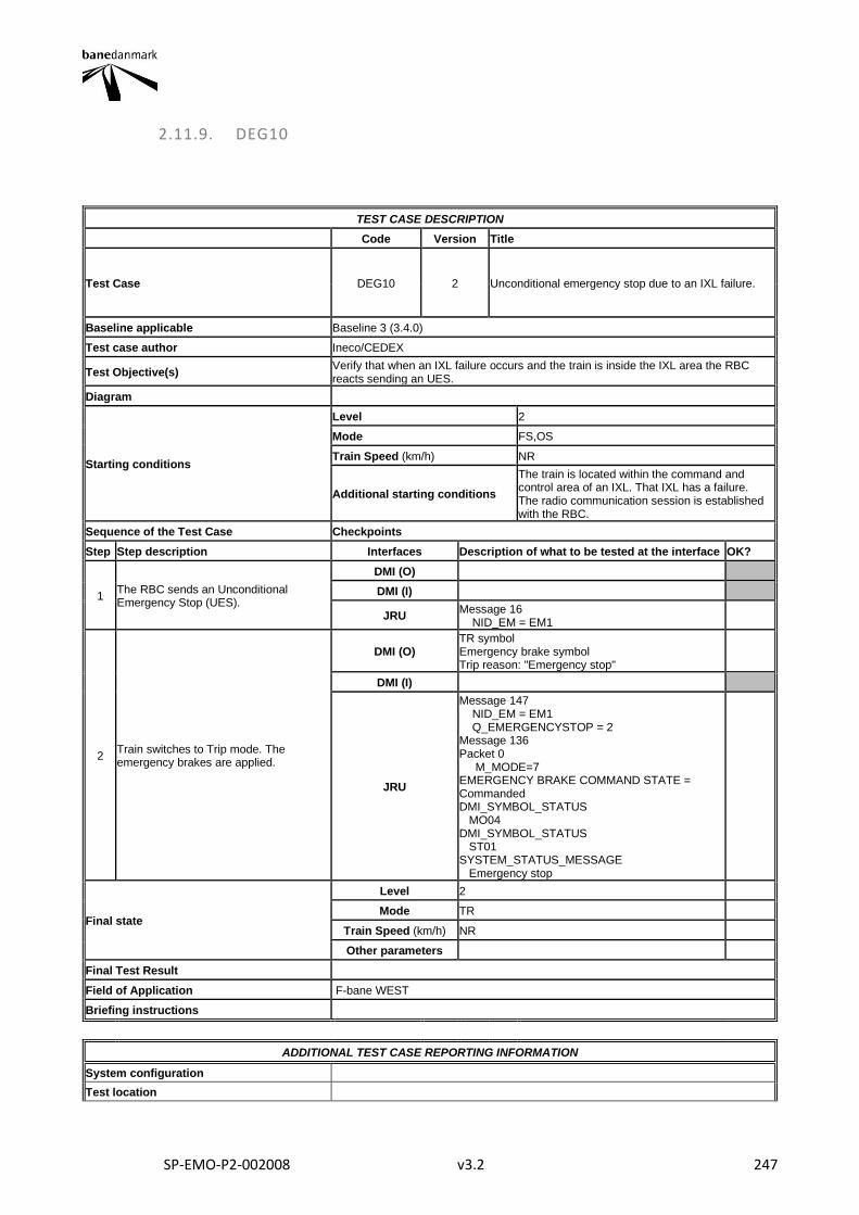
SP-EMO-P2-002008 v3.2 247
2.11.9. DEG10
TEST CASE DESCRIPTION
Code Version Title
Test Case DEG10 2 Unconditional emergency stop due to an IXL failure.
Baseline applicable Baseline 3 (3.4.0)
Test case author Ineco/CEDEX
Test Objective(s) Verify that when an IXL failure occurs and the train is inside the IXL area the RBC reacts sending an UES.
Diagram
Starting conditions
Level 2
Mode FS,OS
Train Speed (km/h) NR
Additional starting conditions
The train is located within the command and control area of an IXL. That IXL has a failure. The radio communication session is established with the RBC.
Sequence of the Test Case Checkpoints
Step Step description Interfaces Description of what to be tested at the interface OK?
1 The RBC sends an Unconditional Emergency Stop (UES).
DMI (O)
DMI (I)
JRU Message 16 NID_EM = EM1
2 Train switches to Trip mode. The emergency brakes are applied.
DMI (O) TR symbol Emergency brake symbol Trip reason: "Emergency stop"
DMI (I)
JRU
Message 147 NID_EM = EM1 Q_EMERGENCYSTOP = 2 Message 136 Packet 0 M_MODE=7 EMERGENCY BRAKE COMMAND STATE = Commanded DMI_SYMBOL_STATUS MO04 DMI_SYMBOL_STATUS ST01 SYSTEM_STATUS_MESSAGE Emergency stop
Final state
Level 2
Mode TR
Train Speed (km/h) NR
Other parameters
Final Test Result
Field of Application F-bane WEST
Briefing instructions
ADDITIONAL TEST CASE REPORTING INFORMATION
System configuration
Test location

SP-EMO-P2-002008 v3.2 248
Date and time (Start/End)
Names
Test log reference
Observations
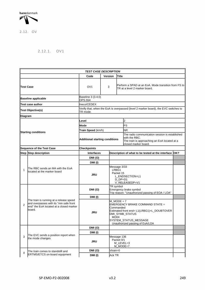
SP-EMO-P2-002008 v3.2 249
2.12. OV
2.12.1. OV1
TEST CASE DESCRIPTION
Code Version Title
Test Case OV1 3 Perform a SPAD at an EoA. Mode transition from FS to TR at a level 2 marker board.
Baseline applicable Baseline 3 (3.4.0) OPS.554
Test case author Ineco/CEDEX
Test Objective(s) Verify that, when the EoA is overpassed (level 2 marker board), the EVC switches to TR mode.
Diagram
Starting conditions
Level 2
Mode FS
Train Speed (km/h) NR
Additional starting conditions
The radio communication session is established with the RBC. The train is approaching an EoA located at a closed marker board.
Sequence of the Test Case Checkpoints
Step Step description Interfaces Description of what to be tested at the interface OK?
1 The RBC sends an MA with the EoA located at the marker board
DMI (O)
DMI (I)
JRU
Message 3/33 LRBG1 Packet 15 L_ENDSECTION=L1 D_DP=D1 V_RELEASEDP=V1
2
The train is running at a release speed and overpasses with its "min safe front end" the EoA located at a closed marker board.
DMI (O) TR symbol Emergency brake symbol Trip reason: "Unauthorized passing of EOA / LOA"
DMI (I)
JRU
M_MODE = 7 EMERGENCY BRAKE COMMAND STATE = Commanded Estimated front end= L1(LRBG1)+L_DOUBTOVER DMI_SYMB_STATUS MO04 SYSTEM_STATUS_MESSAGE Unauthorized passing of EoA/LOA
3 The EVC sends a position report when the mode changes
DMI (O)
DMI (I)
JRU
Message 136 Packet 0/1 M_LEVEL=3 M_MODE=7
4 The train comes to standstill and ERTMS/ETCS on-board equipment
DMI (O) Vtrain=0
DMI (I) Ack TR
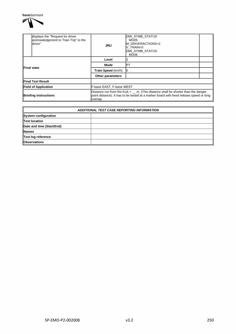
SP-EMO-P2-002008 v3.2 250
displays the "Request for driver acknowledgement to Train Trip" to the driver"
JRU
DMI_SYMB_STATUS MO05 M_DRIVERACTIONS=2 V_TRAIN=0 DMI_SYMB_STATUS MO06
Final state
Level 2
Mode PT
Train Speed (km/h) 0
Other parameters
Final Test Result
Field of Application F-bane EAST, F-bane WEST
Briefing instructions Distance run from the EoA = __ m. (This distance shall be shorter than the danger point distance). It has to be tested at a marker board with fixed release speed or long overlap.
ADDITIONAL TEST CASE REPORTING INFORMATION
System configuration
Test location
Date and time (Start/End)
Names
Test log reference
Observations

SP-EMO-P2-002008 v3.2 251
2.12.2. OV2
TEST CASE DESCRIPTION
Code Version Title
Test Case OV2 3 Override with authorization. FS mode.
Baseline applicable Baseline 3 (3.4.0) OR.DEF.720
Test case author Ineco/CEDEX
Test Objective(s) Verify that the "Override" function is available in FS mode and it is managed correctly.
Diagram
Starting conditions
Level 2
Mode FS
Train Speed (km/h) 0
Additional starting conditions
The train is at a standstill in rear of the EoA. National values are stored on board. The radio communication session is established with the RBC.
Sequence of the Test Case Checkpoints
Step Step description Interfaces Description of what to be tested at the interface OK?
1 Override function is activated Driver selects override
DMI (O) Vtrain = 0
DMI (I) Override EoA selected
JRU
M_DRIVERACTIONS = 14 V_TRAIN = 0 (LRBG1) D_LRBG = D1
2 Transition to SR (OV) mode. The driver toggles on the supervision limits
DMI (O) Override EoA symbol Vperm = V_NVSUPOVTRP
DMI (I) Supervision limits are toggled on
JRU
M_MODE = 2 M_DRIVERACTIONS = 27 V_PERM = V_NVSUPOVTRP DMI_SYMB_STATUS MO03
3 The EVC reports to the RBC the train position when the mode transition is performed.
DMI (O)
DMI (I)
JRU Message 136 Packet 0 M_MODE = 2
4 The EVC does not switch to TR while the override function is active.
DMI (O) Override EoA symbol Vperm = V_NVSUPOVTRP
DMI (I)
JRU
M_MODE = 2 V_PERM = V_NVSUPOVTRP DMI_SYMB_STATUS MO03
5
The train overpasses with the min safe antenna position the former EoA and the override function is deactivated (transition to TR mode is re-activated).
DMI (O) Override EoA symbol is removed SR symbol Vpermitted = V_NVSTFF
DMI (I)

SP-EMO-P2-002008 v3.2 252
JRU
V_PERM = V_NVSTFF D_LRBG-L_DOUBTOVER-(offset between front end and antenna position) > former EoA D_NVOVTRP > D_LRBG - D1(LRBG1) T_NVOVTRP > T_ov (Time in seconds since override function was selected) DMI_SYMB_STATUS MO09
Final state
Level 2
Mode SR
Train Speed (km/h) ≤ 40
Other parameters
Final Test Result
Field of Application F-bane EAST, F-bane WEST
Briefing instructions
ADDITIONAL TEST CASE REPORTING INFORMATION
System configuration
Test location
Date and time (Start/End)
Names
Test log reference
Observations
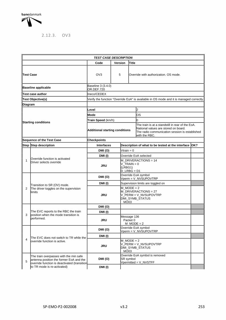
SP-EMO-P2-002008 v3.2 253
2.12.3. OV3
TEST CASE DESCRIPTION
Code Version Title
Test Case OV3 5 Override with authorization. OS mode.
Baseline applicable Baseline 3 (3.4.0) OR.DEF.720
Test case author Ineco/CEDEX
Test Objective(s) Verify the function "Override EoA" is available in OS mode and it is managed correctly.
Diagram
Starting conditions
Level 2
Mode OS
Train Speed (km/h) 0
Additional starting conditions
The train is at a standstill in rear of the EoA. National values are stored on board. The radio communication session is established with the RBC.
Sequence of the Test Case Checkpoints
Step Step description Interfaces Description of what to be tested at the interface OK?
1 Override function is activated Driver selects override
DMI (O) Vtrain = 0
DMI (I) Override EoA selected
JRU
M_DRIVERACTIONS = 14 V_TRAIN = 0 (LRBG1) D_LRBG = D1
2 Transition to SR (OV) mode. The driver toggles on the supervision limits
DMI (O) Override EoA symbol Vperm = V_NVSUPOVTRP
DMI (I) Supervision limits are toggled on
JRU
M_MODE = 2 M_DRIVERACTIONS = 27 V_PERM = V_NVSUPOVTRP DMI_SYMB_STATUS MO03
3 The EVC reports to the RBC the train position when the mode transition is performed.
DMI (O)
DMI (I)
JRU Message 136 Packet 0 M_MODE = 2
4 The EVC does not switch to TR while the override function is active.
DMI (O) Override EoA symbol Vperm = V_NVSUPOVTRP
DMI (I)
JRU
M_MODE = 2 V_PERM = V_NVSUPOVTRP DMI_SYMB_STATUS MO03
5
The train overpasses with the min safe antenna position the former EoA and the override function is deactivated (transition to TR mode is re-activated)
DMI (O) Override EoA symbol is removed SR symbol Vpermitted = V_NVSTFF
DMI (I)
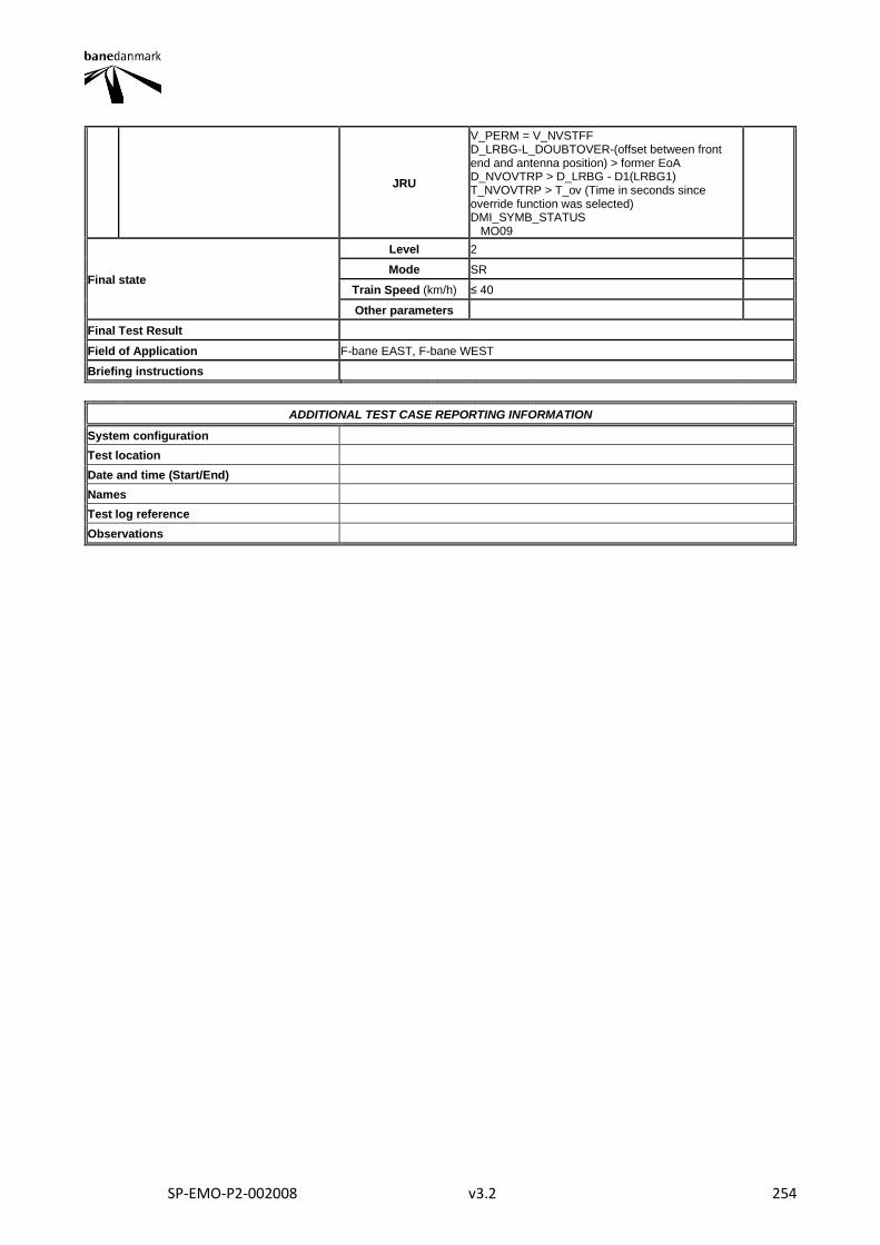
SP-EMO-P2-002008 v3.2 254
JRU
V_PERM = V_NVSTFF D_LRBG-L_DOUBTOVER-(offset between front end and antenna position) > former EoA D_NVOVTRP > D_LRBG - D1(LRBG1) T_NVOVTRP > T_ov (Time in seconds since override function was selected) DMI_SYMB_STATUS MO09
Final state
Level 2
Mode SR
Train Speed (km/h) ≤ 40
Other parameters
Final Test Result
Field of Application F-bane EAST, F-bane WEST
Briefing instructions
ADDITIONAL TEST CASE REPORTING INFORMATION
System configuration
Test location
Date and time (Start/End)
Names
Test log reference
Observations
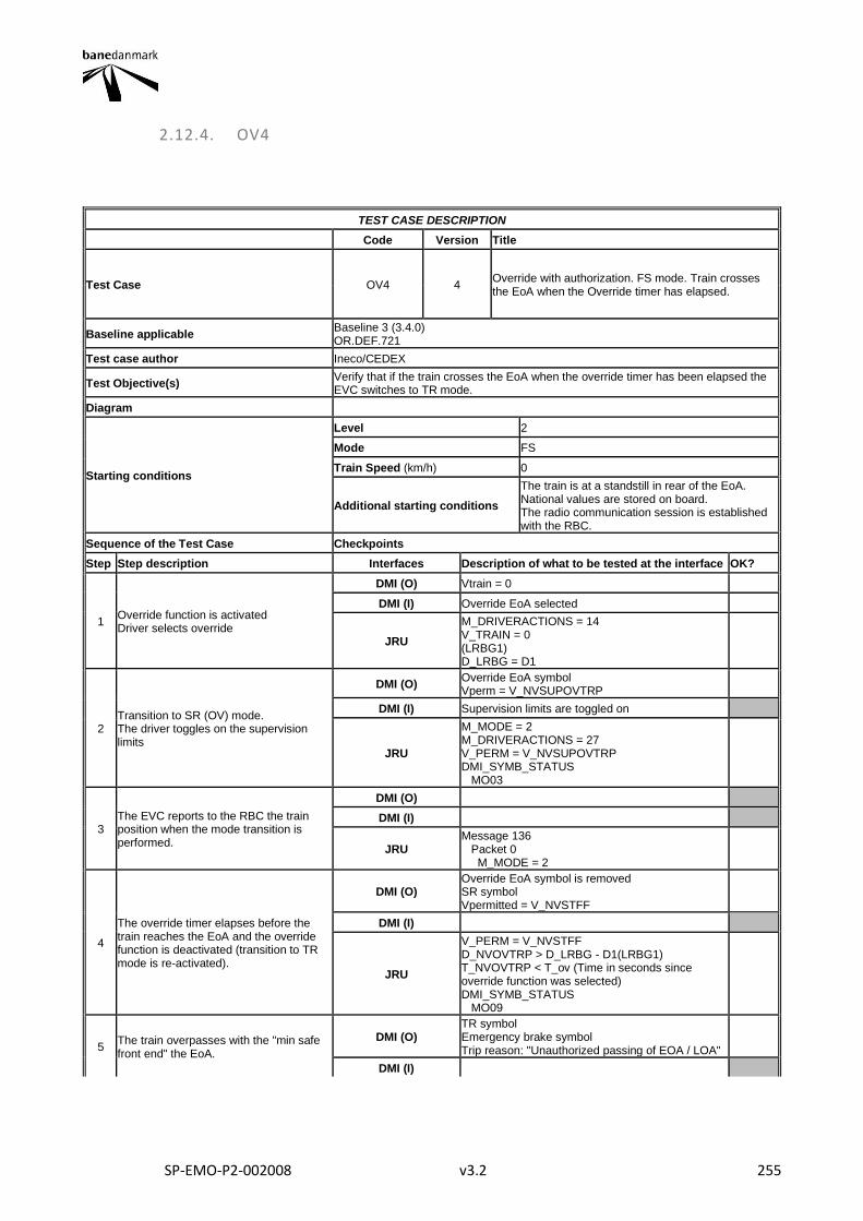
SP-EMO-P2-002008 v3.2 255
2.12.4. OV4
TEST CASE DESCRIPTION
Code Version Title
Test Case OV4 4 Override with authorization. FS mode. Train crosses the EoA when the Override timer has elapsed.
Baseline applicable Baseline 3 (3.4.0) OR.DEF.721
Test case author Ineco/CEDEX
Test Objective(s) Verify that if the train crosses the EoA when the override timer has been elapsed the EVC switches to TR mode.
Diagram
Starting conditions
Level 2
Mode FS
Train Speed (km/h) 0
Additional starting conditions
The train is at a standstill in rear of the EoA. National values are stored on board. The radio communication session is established with the RBC.
Sequence of the Test Case Checkpoints
Step Step description Interfaces Description of what to be tested at the interface OK?
1 Override function is activated Driver selects override
DMI (O) Vtrain = 0
DMI (I) Override EoA selected
JRU
M_DRIVERACTIONS = 14 V_TRAIN = 0 (LRBG1) D_LRBG = D1
2 Transition to SR (OV) mode. The driver toggles on the supervision limits
DMI (O) Override EoA symbol Vperm = V_NVSUPOVTRP
DMI (I) Supervision limits are toggled on
JRU
M_MODE = 2 M_DRIVERACTIONS = 27 V_PERM = V_NVSUPOVTRP DMI_SYMB_STATUS MO03
3 The EVC reports to the RBC the train position when the mode transition is performed.
DMI (O)
DMI (I)
JRU Message 136 Packet 0 M_MODE = 2
4
The override timer elapses before the train reaches the EoA and the override function is deactivated (transition to TR mode is re-activated).
DMI (O) Override EoA symbol is removed SR symbol Vpermitted = V_NVSTFF
DMI (I)
JRU
V_PERM = V_NVSTFF D_NVOVTRP > D_LRBG - D1(LRBG1) T_NVOVTRP < T_ov (Time in seconds since override function was selected) DMI_SYMB_STATUS MO09
5 The train overpasses with the "min safe front end" the EoA.
DMI (O) TR symbol Emergency brake symbol Trip reason: "Unauthorized passing of EOA / LOA"
DMI (I)
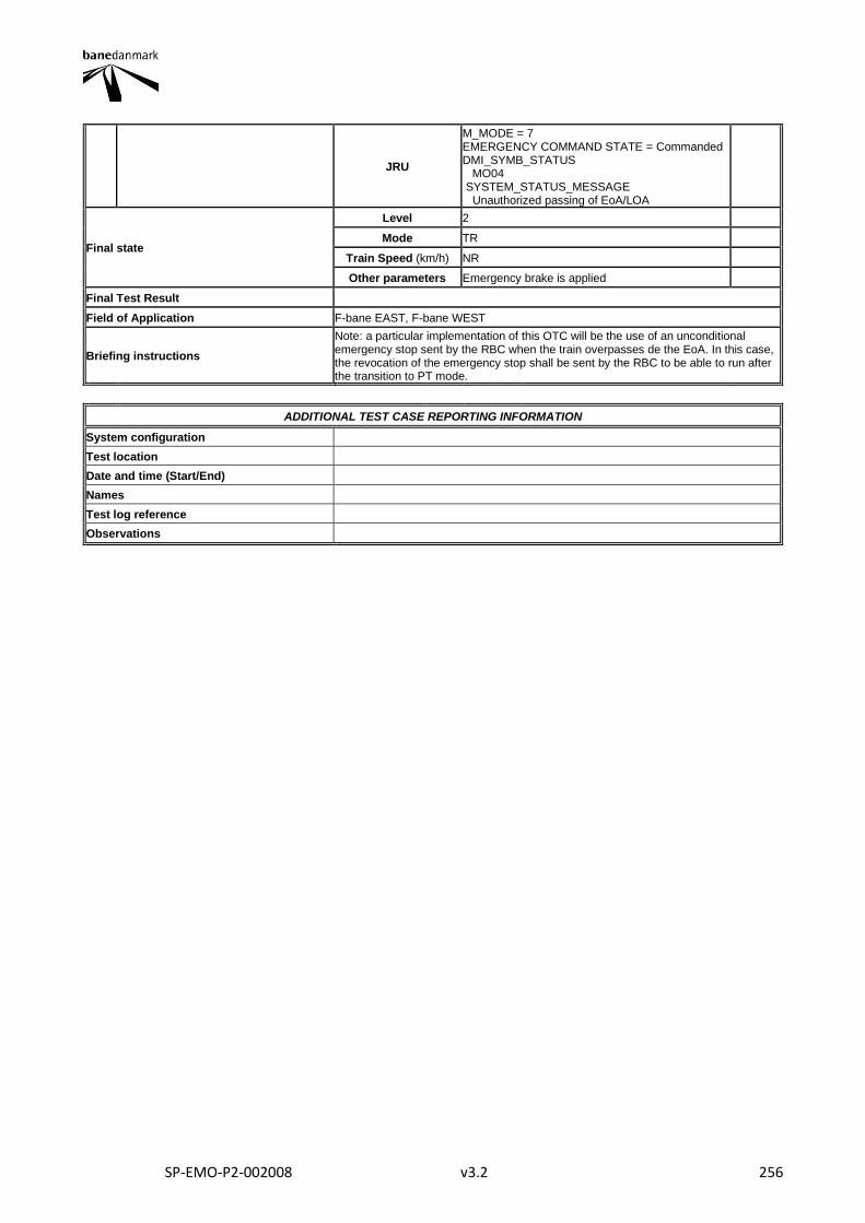
SP-EMO-P2-002008 v3.2 256
JRU
M_MODE = 7 EMERGENCY COMMAND STATE = Commanded DMI_SYMB_STATUS MO04 SYSTEM_STATUS_MESSAGE Unauthorized passing of EoA/LOA
Final state
Level 2
Mode TR
Train Speed (km/h) NR
Other parameters Emergency brake is applied
Final Test Result
Field of Application F-bane EAST, F-bane WEST
Briefing instructions
Note: a particular implementation of this OTC will be the use of an unconditional emergency stop sent by the RBC when the train overpasses de the EoA. In this case, the revocation of the emergency stop shall be sent by the RBC to be able to run after the transition to PT mode.
ADDITIONAL TEST CASE REPORTING INFORMATION
System configuration
Test location
Date and time (Start/End)
Names
Test log reference
Observations
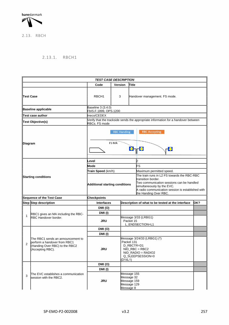
SP-EMO-P2-002008 v3.2 257
2.13. RBCH
2.13.1. RBCH1
TEST CASE DESCRIPTION
Code Version Title
Test Case RBCH1 3 Handover management. FS mode.
Baseline applicable Baseline 3 (3.4.0) FbIS.F.1899, OPS.1200
Test case author Ineco/CEDEX
Test Objective(s) Verify that the trackside sends the appropriate information for a handover between RBCs. FS mode
Diagram
Starting conditions
Level 2
Mode FS
Train Speed (km/h) Maximum permitted speed.
Additional starting conditions
The train runs in L2 FS towards the RBC-RBC transition border. Two communication sessions can be handled simultaneously by the EVC. A radio communication session is established with the Handing Over RBC.
Sequence of the Test Case Checkpoints
Step Step description Interfaces Description of what to be tested at the interface OK?
1 RBC1 gives an MA including the RBC-RBC Handover border.
DMI (O)
DMI (I)
JRU Message 3/33 (LRBG1) Packet 15 L_ENDSECTION=L1
2
The RBC1 sends an announcement to perform a handover from RBC1 (Handing Over RBC) to the RBC2 (Accepting RBC).
DMI (O)
DMI (I)
JRU
Message 3/24/33 (LRBG1) (*) Packet 131 D_RBCTR=D1 NID_RBC = RBC2 NID_RADIO = RADIO2 Q_SLEEPSESSION=0 (D1≤L1)
3 The EVC establishes a communication session with the RBC2.
DMI (O)
DMI (I)
JRU
Message 155 Message 32 Message 159 Message 129 Message 8
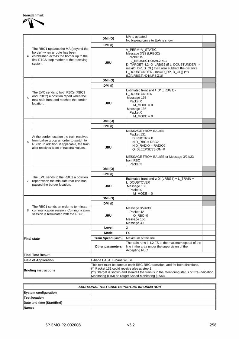
SP-EMO-P2-002008 v3.2 258
4
The RBC1 updates the MA (beyond the border) when a route has been established across the border up to the first ETCS stop marker of the receiving system.
DMI (O) MA is updated No braking curve to EoA is shown
DMI (I)
JRU
V_PERM=V_STATIC Message 3/33 (LRBG2) Packet 15 L_ENDSECTION=L2 >L1 D_TARGET=L2 -D_LRBG2 (if L_DOUBTUNDER > max(D_DP, D_OL) then also subtract the distance L_DOUBTUNDER - max(D_DP, D_OL)) (**) (L2(LRBG2)>D1(LRBG1))
5
The EVC sends to both RBCs (RBC1 and RBC2) a position report when the max safe front end reaches the border location.
DMI (O)
DMI (I)
JRU
Estimated front end ≥ D1(LRBG1) - L_DOUBTUNDER Message 136 Packet 0 M_MODE = 0 Message 136 Packet 0 M_MODE = 0
6
At the border location the train receives from balise group an order to switch to RBC2. In addition, if applicable, the train also receives a set of national values.
DMI (O)
DMI (I)
JRU
MESSAGE FROM BALISE Packet 131 D_RBCTR = 0 NID_RBC = RBC2 NID_RADIO = RADIO2 Q_SLEEPSESSION=0 MESSAGE FROM BALISE or Message 3/24/33 from RBC Packet 3
7 The EVC sends to the RBC1 a position report when the min safe rear end has passed the border location.
DMI (O)
DMI (I)
JRU
Estimated front end ≥ D1(LRBG1) + L_TRAIN + L_DOUBTOVER Message 136 Packet 0 M_MODE = 0
8 The RBC1 sends an order to terminate communication session. Communication session is terminated with the RBC1.
DMI (O)
DMI (I)
JRU
Message 3/24/33 Packet 42 Q_RBC=0 Message 156 Message 39
Final state
Level 2
Mode FS
Train Speed (km/h) Maximum of the line
Other parameters The train runs in L2 FS at the maximum speed of the line in the area under the supervision of the Accepting RBC
Final Test Result
Field of Application F-bane EAST, F-bane WEST
Briefing instructions
This test must be done at each RBC-RBC transition, and for both directions. (*) Packet 131 could receive also at step 1 (**) Dtarget is shown and stored if the train is in the monitoring status of Pre-Indication Monitoring (PIM) or Target Speed Monitoring (TSM)
ADDITIONAL TEST CASE REPORTING INFORMATION
System configuration
Test location
Date and time (Start/End)
Names

SP-EMO-P2-002008 v3.2 259
Test log reference
Observations
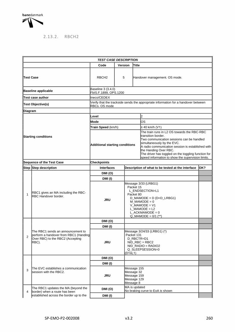
SP-EMO-P2-002008 v3.2 260
2.13.2. RBCH2
TEST CASE DESCRIPTION
Code Version Title
Test Case RBCH2 5 Handover management. OS mode.
Baseline applicable Baseline 3 (3.4.0) FbIS.F.1899, OPS.1200
Test case author Ineco/CEDEX
Test Objective(s) Verify that the trackside sends the appropriate information for a handover between RBCs. OS mode
Diagram
Starting conditions
Level 2
Mode OS
Train Speed (km/h) ≤ 40 km/h (V1)
Additional starting conditions
The train runs in L2 OS towards the RBC-RBC transition border. Two communication sessions can be handled simultaneously by the EVC. A radio communication session is established with the Handing Over RBC. The driver has toggled on the toggling function for speed information to show the supervision limits.
Sequence of the Test Case Checkpoints
Step Step description Interfaces Description of what to be tested at the interface OK?
1 RBC1 gives an MA including the RBC-RBC Handover border.
DMI (O)
DMI (I)
JRU
Message 3/33 (LRBG1) Packet 15 L_ENDSECTION=L1 Packet 80 D_MAMODE = D (D<D_LRBG1) M_MAMODE = 0 V_MAMODE = V1 L_MAMODE = L2 L_ACKMAMODE = 0 Q_MAMODE = 0/1 (**)
2
The RBC1 sends an announcement to perform a handover from RBC1 (Handing Over RBC) to the RBC2 (Accepting RBC).
DMI (O)
DMI (I)
JRU
Message 3/24/33 (LRBG1) (*) Packet 131 D_RBCTR=D1 NID_RBC = RBC2 NID_RADIO = RADIO2 Q_SLEEPSESSION=0 (D1≤L1)
3 The EVC establishes a communication session with the RBC2.
DMI (O)
DMI (I)
JRU
Message 155 Message 32 Message 159 Message 129 Message 8
4 The RBC1 updates the MA (beyond the border) when a route has been established across the border up to the
DMI (O) MA is updated No braking curve to EoA is shown
DMI (I)
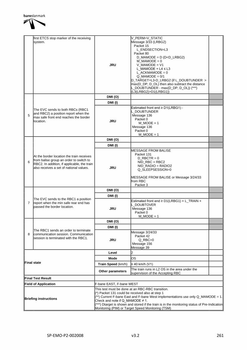
SP-EMO-P2-002008 v3.2 261
first ETCS stop marker of the receiving system.
JRU
V_PERM=V_STATIC Message 3/33 (LRBG2) Packet 15 L_ENDSECTION=L3 Packet 80 D_MAMODE = D (D<D_LRBG2) M_MAMODE = 0 V_MAMODE = V1 L_MAMODE = L4 ≤ L3 L_ACKMAMODE = 0 Q_MAMODE = 0/1 D_TARGET=L3-D_LRBG2 (if L_DOUBTUNDER > max(D_DP, D_OL) then also subtract the distance L_DOUBTUNDER - max(D_DP, D_OL)) (***) (L3(LRBG2)>D1(LRBG1))
5
The EVC sends to both RBCs (RBC1 and RBC2) a position report when the max safe front end reaches the border location.
DMI (O)
DMI (I)
JRU
Estimated front end ≥ D1(LRBG1) - L_DOUBTUNDER Message 136 Packet 0 M_MODE = 1 Message 136 Packet 0 M_MODE = 1
6
At the border location the train receives from balise group an order to switch to RBC2. In addition, if applicable, the train also receives a set of national values.
DMI (O)
DMI (I)
JRU
MESSAGE FROM BALISE Packet 131 D_RBCTR = 0 NID_RBC = RBC2 NID_RADIO = RADIO2 Q_SLEEPSESSION=0 MESSAGE FROM BALISE or Message 3/24/33 from RBC Packet 3
7 The EVC sends to the RBC1 a position report when the min safe rear end has passed the border location.
DMI (O)
DMI (I)
JRU
Estimated front end ≥ D1(LRBG1) + L_TRAIN + L_DOUBTOVER Message 136 Packet 0 M_MODE = 1
8 The RBC1 sends an order to terminate communication session. Communication session is terminated with the RBC1.
DMI (O)
DMI (I)
JRU
Message 3/24/33 Packet 42 Q_RBC=0 Message 156 Message 39
Final state
Level 2
Mode OS
Train Speed (km/h) ≤ 40 km/h (V1)
Other parameters The train runs in L2 OS in the area under the supervision of the Accepting RBC
Final Test Result
Field of Application F-bane EAST, F-bane WEST
Briefing instructions
This test must be done at an RBC-RBC transition. (*) Packet 131 could be received also at step 1 (**) Current F-bane East and F-bane West implementations use only Q_MAMODE = 1. Check and note if Q_MAMODE ≠ 1. (***) Dtarget is shown and stored if the train is in the monitoring status of Pre-Indication Monitoring (PIM) or Target Speed Monitoring (TSM)

SP-EMO-P2-002008 v3.2 262
ADDITIONAL TEST CASE REPORTING INFORMATION
System configuration
Test location
Date and time (Start/End)
Names
Test log reference
Observations
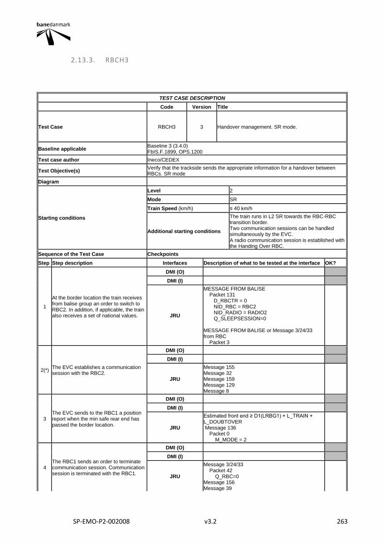
SP-EMO-P2-002008 v3.2 263
2.13.3. RBCH3
TEST CASE DESCRIPTION
Code Version Title
Test Case RBCH3 3 Handover management. SR mode.
Baseline applicable Baseline 3 (3.4.0) FbIS.F.1899, OPS.1200
Test case author Ineco/CEDEX
Test Objective(s) Verify that the trackside sends the appropriate information for a handover between RBCs. SR mode
Diagram
Starting conditions
Level 2
Mode SR
Train Speed (km/h) ≤ 40 km/h
Additional starting conditions
The train runs in L2 SR towards the RBC-RBC transition border. Two communication sessions can be handled simultaneously by the EVC. A radio communication session is established with the Handing Over RBC.
Sequence of the Test Case Checkpoints
Step Step description Interfaces Description of what to be tested at the interface OK?
1
At the border location the train receives from balise group an order to switch to RBC2. In addition, if applicable, the train also receives a set of national values.
DMI (O)
DMI (I)
JRU
MESSAGE FROM BALISE Packet 131 D_RBCTR = 0 NID_RBC = RBC2 NID_RADIO = RADIO2 Q_SLEEPSESSION=0 MESSAGE FROM BALISE or Message 3/24/33 from RBC Packet 3
2(*) The EVC establishes a communication session with the RBC2.
DMI (O)
DMI (I)
JRU
Message 155 Message 32 Message 159 Message 129 Message 8
3 The EVC sends to the RBC1 a position report when the min safe rear end has passed the border location.
DMI (O)
DMI (I)
JRU
Estimated front end ≥ D1(LRBG1) + L_TRAIN + L_DOUBTOVER Message 136 Packet 0 M_MODE = 2
4 The RBC1 sends an order to terminate communication session. Communication session is terminated with the RBC1.
DMI (O)
DMI (I)
JRU
Message 3/24/33 Packet 42 Q_RBC=0 Message 156 Message 39
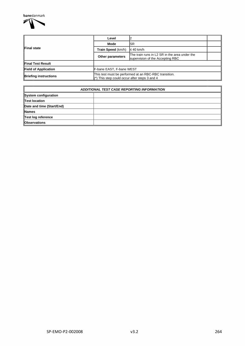
SP-EMO-P2-002008 v3.2 264
Final state
Level 2
Mode SR
Train Speed (km/h) ≤ 40 km/h
Other parameters The train runs in L2 SR in the area under the supervision of the Accepting RBC
Final Test Result
Field of Application F-bane EAST, F-bane WEST
Briefing instructions This test must be performed at an RBC-RBC transition. (*) This step could occur after steps 3 and 4
ADDITIONAL TEST CASE REPORTING INFORMATION
System configuration
Test location
Date and time (Start/End)
Names
Test log reference
Observations
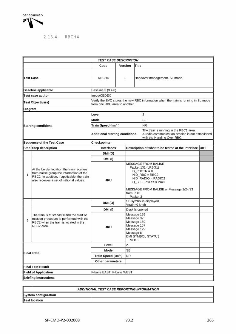
SP-EMO-P2-002008 v3.2 265
2.13.4. RBCH4
TEST CASE DESCRIPTION
Code Version Title
Test Case RBCH4 1 Handover management. SL mode.
Baseline applicable Baseline 3 (3.4.0)
Test case author Ineco/CEDEX
Test Objective(s) Verify the EVC stores the new RBC information when the train is running in SL mode from one RBC area to another.
Diagram
Starting conditions
Level 2
Mode SL
Train Speed (km/h) NR
Additional starting conditions The train is running in the RBC1 area. A radio communication session is not established with the Handing Over RBC.
Sequence of the Test Case Checkpoints
Step Step description Interfaces Description of what to be tested at the interface OK?
1
At the border location the train receives from balise group the information of the RBC2. In addition, if applicable, the train also receives a set of national values.
DMI (O)
DMI (I)
JRU
MESSAGE FROM BALISE Packet 131 (LRBG1) D_RBCTR = 0 NID_RBC = RBC2 NID_RADIO = RADIO2 Q_SLEEPSESSION=0 MESSAGE FROM BALISE or Message 3/24/33 from RBC Packet 3
2
The train is at standstill and the start of mission procedure is performed with the RBC2 when the train is located in the RBC2 area.
DMI (O) SB symbol is displayed Vtrain=0 km/h
DMI (I) Desk is opened
JRU
Message 155 Message 32 Message 159 Message 157 Message 129 Message 8 DMI SYMBOL STATUS MO13
Final state
Level 2
Mode SB
Train Speed (km/h) NR
Other parameters
Final Test Result
Field of Application F-bane EAST, F-bane WEST
Briefing instructions
ADDITIONAL TEST CASE REPORTING INFORMATION
System configuration
Test location
SP-EMO-P2-002008 v3.2 266
Date and time (Start/End)
Names
Test log reference
Observations
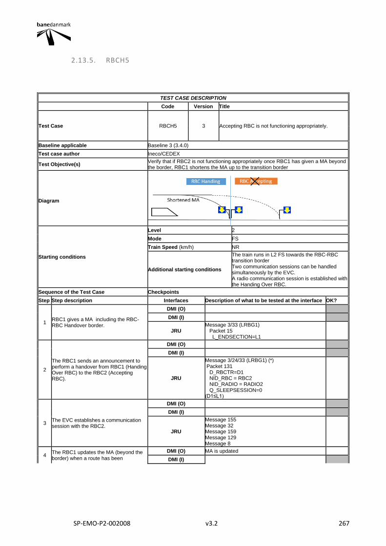
SP-EMO-P2-002008 v3.2 267
2.13.5. RBCH5
TEST CASE DESCRIPTION
Code Version Title
Test Case RBCH5 3 Accepting RBC is not functioning appropriately.
Baseline applicable Baseline 3 (3.4.0)
Test case author Ineco/CEDEX
Test Objective(s) Verify that if RBC2 is not functioning appropriately once RBC1 has given a MA beyond the border, RBC1 shortens the MA up to the transition border
Diagram
Starting conditions
Level 2
Mode FS
Train Speed (km/h) NR
Additional starting conditions
The train runs in L2 FS towards the RBC-RBC transition border Two communication sessions can be handled simultaneously by the EVC. A radio communication session is established with the Handing Over RBC.
Sequence of the Test Case Checkpoints
Step Step description Interfaces Description of what to be tested at the interface OK?
1 RBC1 gives a MA including the RBC-RBC Handover border.
DMI (O)
DMI (I)
JRU Message 3/33 (LRBG1) Packet 15 L_ENDSECTION=L1
2
The RBC1 sends an announcement to perform a handover from RBC1 (Handing Over RBC) to the RBC2 (Accepting RBC).
DMI (O)
DMI (I)
JRU
Message 3/24/33 (LRBG1) (*) Packet 131 D_RBCTR=D1 NID_RBC = RBC2 NID_RADIO = RADIO2 Q_SLEEPSESSION=0 (D1≤L1)
3 The EVC establishes a communication session with the RBC2.
DMI (O)
DMI (I)
JRU
Message 155 Message 32 Message 159 Message 129 Message 8
4 The RBC1 updates the MA (beyond the border) when a route has been
DMI (O) MA is updated
DMI (I)
SP-EMO-P2-002008 v3.2 268
established across the border up to the first ETCS stop marker of the receiving system.
JRU
V_PERM=V_STATIC Message 3/33 (LRBG2) Packet 15 L_ENDSECTION=L2 D_TARGET=L2-D_LRBG2 (if L_DOUBTUNDER > max(D_DP, D_OL) then also subtract the distance L_DOUBTUNDER - max(D_DP, D_OL)) (**) (L2(LRBG2)>D1(LRBG1))
5
RBC2 malfunctions before the train reaches the transition border. RBC1 sends a MA with End of Authority at the HO transition border.
DMI (O) MA is shortened to the Handover transition point
DMI (I)
JRU
Message 3/33 (LRBG3) Packet 15 L_ENDSECTION=L3 D_TARGET=L3-D_LRBG3 (if L_DOUBTUNDER > max(D_DP, D_OL) then also subtract the distance L_DOUBTUNDER - max(D_DP, D_OL)) (**) L3(LRBG3)=D1(LRBG1)
Final state
Level 2
Mode FS
Train Speed (km/h) NR
Other parameters
Final Test Result
Field of Application F-bane EAST, F-bane WEST
Briefing instructions
It shall be checked all the different situations that could produce a loss of communication between the Handing RBC and the Accepting RBC. (*) Packet 131 could receive also at step 1 (**) Dtarget is shown and stored if the train is in the monitoring status of Pre-Indication Monitoring (PIM) or Target Speed Monitoring (TSM)
ADDITIONAL TEST CASE REPORTING INFORMATION
System configuration
Test location
Date and time (Start/End)
Names
Test log reference
Observations
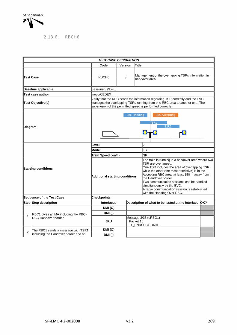
SP-EMO-P2-002008 v3.2 269
2.13.6. RBCH6
TEST CASE DESCRIPTION
Code Version Title
Test Case RBCH6 3 Management of the overlapping TSRs information in handover area.
Baseline applicable Baseline 3 (3.4.0)
Test case author Ineco/CEDEX
Test Objective(s) Verify that the RBC sends the information regarding TSR correctly and the EVC manages the overlapping TSRs running from one RBC area to another one. The supervision of the permitted speed is performed correctly.
Diagram
Starting conditions
Level 2
Mode FS
Train Speed (km/h) NR
Additional starting conditions
The train is running in a handover area where two TSR are overlapped. One TSR includes the area of overlapping TSR while the other (the most restrictive) is in the Accepting RBC area, at least 150 m away from the Handover border. Two communication sessions can be handled simultaneously by the EVC. A radio communication session is established with the Handing Over RBC.
Sequence of the Test Case Checkpoints
Step Step description Interfaces Description of what to be tested at the interface OK?
1 RBC1 gives an MA including the RBC-RBC Handover border.
DMI (O)
DMI (I)
JRU Message 3/33 (LRBG1) Packet 15 L_ENDSECTION=L
2 The RBC1 sends a message with TSR1 including the Handover border and an
DMI (O)
DMI (I)
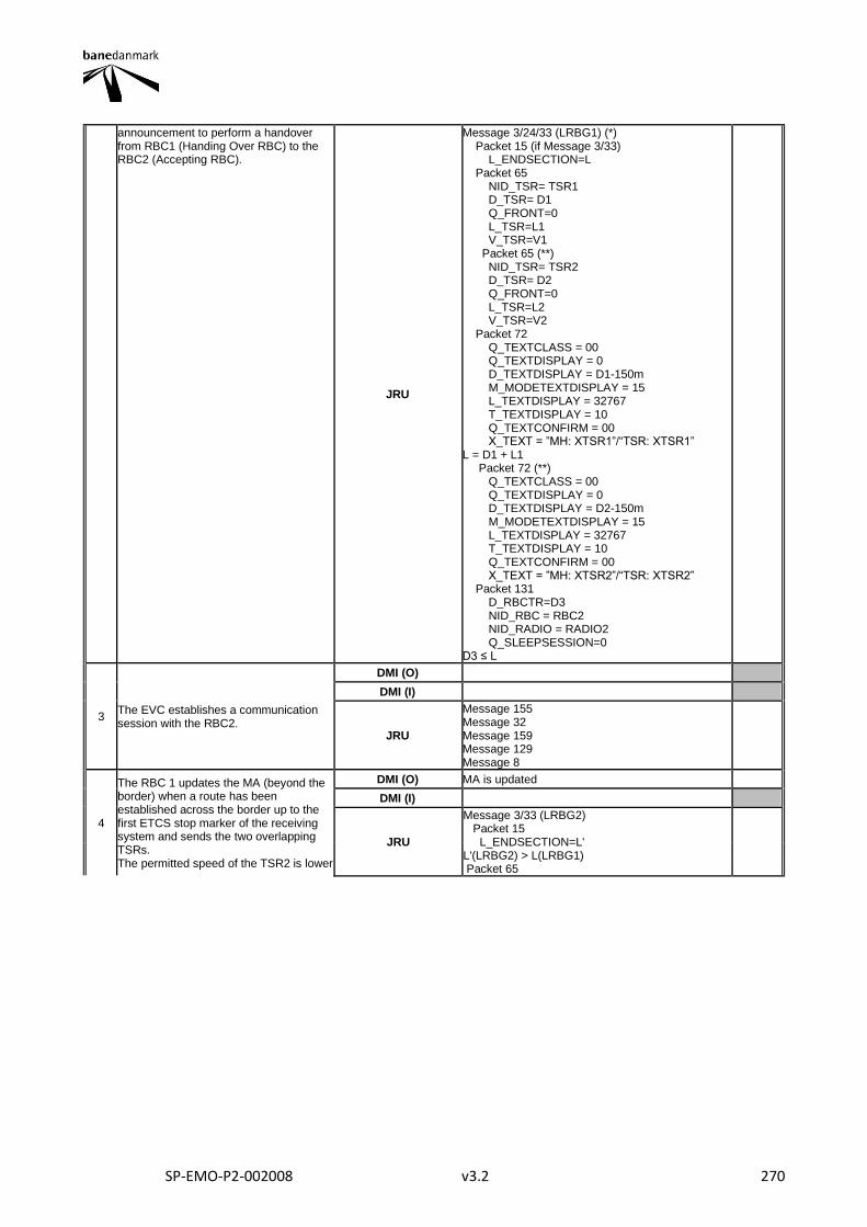
SP-EMO-P2-002008 v3.2 270
announcement to perform a handover from RBC1 (Handing Over RBC) to the RBC2 (Accepting RBC).
JRU
Message 3/24/33 (LRBG1) (*) Packet 15 (if Message 3/33) L_ENDSECTION=L Packet 65 NID_TSR= TSR1 D_TSR= D1 Q_FRONT=0 L_TSR=L1 V_TSR=V1 Packet 65 (**) NID_TSR= TSR2 D_TSR= D2 Q_FRONT=0 L_TSR=L2 V_TSR=V2 Packet 72 Q_TEXTCLASS = 00 Q_TEXTDISPLAY = 0 D_TEXTDISPLAY = D1-150m M_MODETEXTDISPLAY = 15 L_TEXTDISPLAY = 32767 T_TEXTDISPLAY = 10 Q_TEXTCONFIRM = 00 X_TEXT = ”MH: XTSR1”/“TSR: XTSR1” L = D1 + L1 Packet 72 (**) Q_TEXTCLASS = 00 Q_TEXTDISPLAY = 0 D_TEXTDISPLAY = D2-150m M_MODETEXTDISPLAY = 15 L_TEXTDISPLAY = 32767 T_TEXTDISPLAY = 10 Q_TEXTCONFIRM = 00 X_TEXT = ”MH: XTSR2”/“TSR: XTSR2” Packet 131 D_RBCTR=D3 NID_RBC = RBC2 NID_RADIO = RADIO2 Q_SLEEPSESSION=0 D3 ≤ L
3 The EVC establishes a communication session with the RBC2.
DMI (O)
DMI (I)
JRU
Message 155 Message 32 Message 159 Message 129 Message 8
4
The RBC 1 updates the MA (beyond the border) when a route has been established across the border up to the first ETCS stop marker of the receiving system and sends the two overlapping TSRs. The permitted speed of the TSR2 is lower
DMI (O) MA is updated
DMI (I)
JRU
Message 3/33 (LRBG2) Packet 15 L_ENDSECTION=L' L'(LRBG2) > L(LRBG1) Packet 65
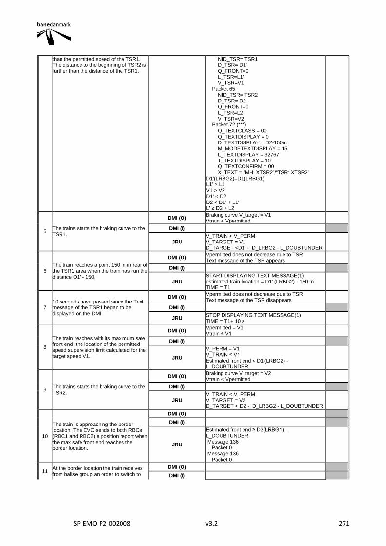
SP-EMO-P2-002008 v3.2 271
than the permitted speed of the TSR1. The distance to the beginning of TSR2 is further than the distance of the TSR1.
NID_TSR= TSR1 D_TSR= D1' Q_FRONT=0 L_TSR=L1' V_TSR=V1 Packet 65 NID_TSR= TSR2 D_TSR= D2 Q_FRONT=0 L_TSR=L2 V_TSR=V2 Packet 72 (***) Q_TEXTCLASS = 00 Q_TEXTDISPLAY = 0 D_TEXTDISPLAY = D2-150m M_MODETEXTDISPLAY = 15 L_TEXTDISPLAY = 32767 T_TEXTDISPLAY = 10 Q_TEXTCONFIRM = 00 X_TEXT = ”MH: XTSR2”/“TSR: XTSR2” D1'(LRBG2)=D1(LRBG1) L1' > L1 V1 > V2 D1' < D2 D2 < D1' + L1' L' ≥ D2 + L2
5 The trains starts the braking curve to the TSR1.
DMI (O) Braking curve V_target = V1 Vtrain < Vpermitted
DMI (I)
JRU V_TRAIN < V_PERM V_TARGET = V1 D_TARGET <D1' - D_LRBG2 - L_DOUBTUNDER
6 The train reaches a point 150 m in rear of the TSR1 area when the train has run the distance D1' - 150.
DMI (O) Vpermitted does not decrease due to TSR Text message of the TSR appears
DMI (I)
JRU START DISPLAYING TEXT MESSAGE(1) estimated train location = D1' (LRBG2) - 150 m TIME = T1
7 10 seconds have passed since the Text message of the TSR1 began to be displayed on the DMI.
DMI (O) Vpermitted does not decrease due to TSR Text message of the TSR disappears
DMI (I)
JRU STOP DISPLAYING TEXT MESSAGE(1) TIME = T1+ 10 s
8
The train reaches with its maximum safe front end the location of the permitted speed supervision limit calculated for the target speed V1.
DMI (O) Vpermitted = V1 Vtrain ≤ V1
DMI (I)
JRU
V_PERM = V1 V_TRAIN ≤ V1 Estimated front end < D1'(LRBG2) -L_DOUBTUNDER
9 The trains starts the braking curve to the TSR2.
DMI (O) Braking curve V_target = V2 Vtrain < Vpermitted
DMI (I)
JRU V_TRAIN < V_PERM V_TARGET = V2 D_TARGET < D2 - D_LRBG2 - L_DOUBTUNDER
10
The train is approaching the border location. The EVC sends to both RBCs (RBC1 and RBC2) a position report when the max safe front end reaches the border location.
DMI (O)
DMI (I)
JRU
Estimated front end ≥ D3(LRBG1)-L_DOUBTUNDER Message 136 Packet 0 Message 136 Packet 0
11 At the border location the train receives from balise group an order to switch to
DMI (O)
DMI (I)
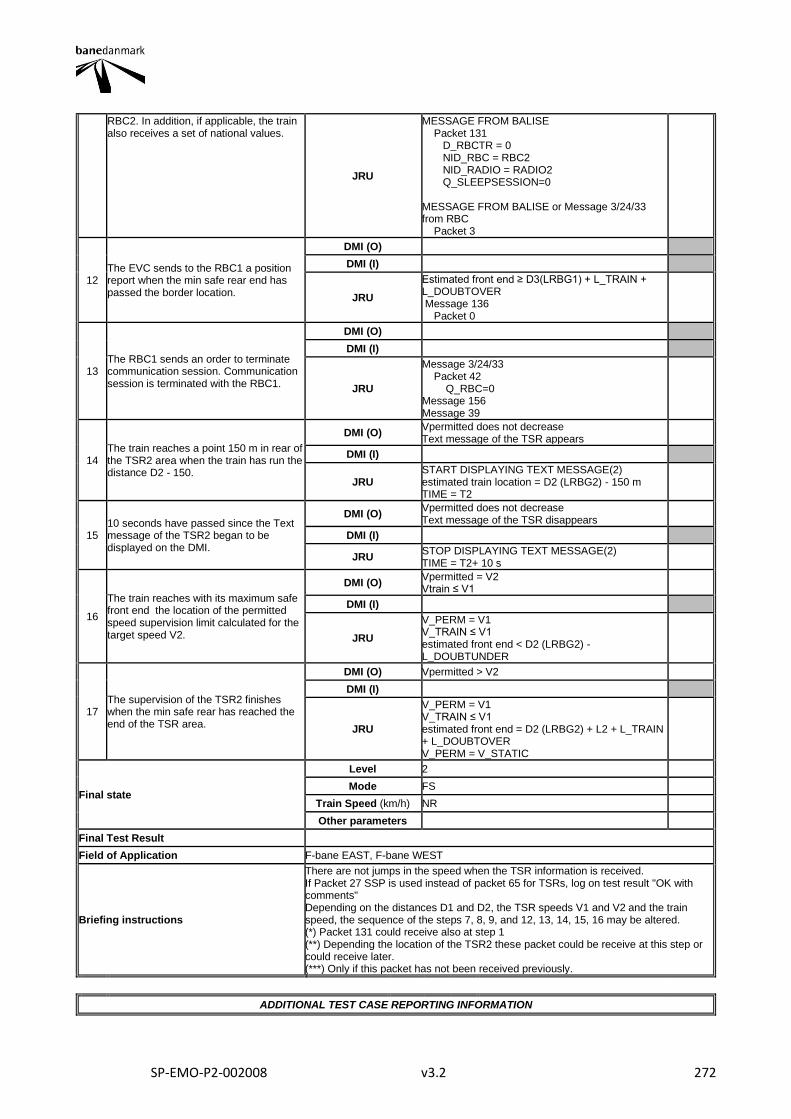
SP-EMO-P2-002008 v3.2 272
RBC2. In addition, if applicable, the train also receives a set of national values.
JRU
MESSAGE FROM BALISE Packet 131 D_RBCTR = 0 NID_RBC = RBC2 NID_RADIO = RADIO2 Q_SLEEPSESSION=0 MESSAGE FROM BALISE or Message 3/24/33 from RBC Packet 3
12 The EVC sends to the RBC1 a position report when the min safe rear end has passed the border location.
DMI (O)
DMI (I)
JRU
Estimated front end ≥ D3(LRBG1) + L_TRAIN + L_DOUBTOVER Message 136 Packet 0
13 The RBC1 sends an order to terminate communication session. Communication session is terminated with the RBC1.
DMI (O)
DMI (I)
JRU
Message 3/24/33 Packet 42 Q_RBC=0 Message 156 Message 39
14 The train reaches a point 150 m in rear of the TSR2 area when the train has run the distance D2 - 150.
DMI (O) Vpermitted does not decrease Text message of the TSR appears
DMI (I)
JRU START DISPLAYING TEXT MESSAGE(2) estimated train location = D2 (LRBG2) - 150 m TIME = T2
15 10 seconds have passed since the Text message of the TSR2 began to be displayed on the DMI.
DMI (O) Vpermitted does not decrease Text message of the TSR disappears
DMI (I)
JRU STOP DISPLAYING TEXT MESSAGE(2) TIME = T2+ 10 s
16
The train reaches with its maximum safe front end the location of the permitted speed supervision limit calculated for the target speed V2.
DMI (O) Vpermitted = V2 Vtrain ≤ V1
DMI (I)
JRU
V_PERM = V1 V_TRAIN ≤ V1 estimated front end < D2 (LRBG2) - L_DOUBTUNDER
17 The supervision of the TSR2 finishes when the min safe rear has reached the end of the TSR area.
DMI (O) Vpermitted > V2
DMI (I)
JRU
V_PERM = V1 V_TRAIN ≤ V1 estimated front end = D2 (LRBG2) + L2 + L_TRAIN + L_DOUBTOVER V_PERM = V_STATIC
Final state
Level 2
Mode FS
Train Speed (km/h) NR
Other parameters
Final Test Result
Field of Application F-bane EAST, F-bane WEST
Briefing instructions
There are not jumps in the speed when the TSR information is received. If Packet 27 SSP is used instead of packet 65 for TSRs, log on test result "OK with comments" Depending on the distances D1 and D2, the TSR speeds V1 and V2 and the train speed, the sequence of the steps 7, 8, 9, and 12, 13, 14, 15, 16 may be altered. (*) Packet 131 could receive also at step 1 (**) Depending the location of the TSR2 these packet could be receive at this step or could receive later. (***) Only if this packet has not been received previously.
ADDITIONAL TEST CASE REPORTING INFORMATION

SP-EMO-P2-002008 v3.2 273
System configuration
Test location
Date and time (Start/End)
Names
Test log reference
Observations
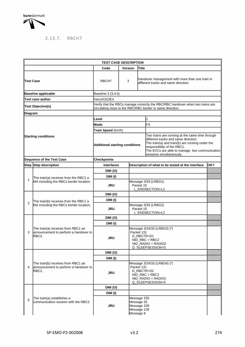
SP-EMO-P2-002008 v3.2 274
2.13.7. RBCH7
TEST CASE DESCRIPTION
Code Version Title
Test Case RBCH7 3 Handover management with more than one train in different tracks and same direction.
Baseline applicable Baseline 3 (3.4.0)
Test case author Ineco/CEDEX
Test Objective(s) Verify that the RBCs manage correctly the RBC/RBC handover when two trains are circulating close to the RBC/RBC border in same direction.
Diagram
Starting conditions
Level 2
Mode FS
Train Speed (km/h)
Additional starting conditions
Two trains are running at the same time through different tracks and same direction. The train(a) and train(b) are running under the responsibility of the RBC1. The EVCs are able to manage two communication sessions simultaneously.
Sequence of the Test Case Checkpoints
Step Step description Interfaces Description of what to be tested at the interface OK?
1 The train(a) receives from the RBC1 a MA including the RBCs border location.
DMI (O)
DMI (I)
JRU Message 3/33 (LRBG1) Packet 15 L_ENDSECTION=L1
2 The train(b) receives from the RBC1 a MA including the RBCs border location.
DMI (O)
DMI (I)
JRU Message 3/33 (LRBG2) Packet 15 L_ENDSECTION=L2
3 The train(a) receives from RBC1 an announcement to perform a handover to RBC2.
DMI (O)
DMI (I)
JRU
Message 3/24/33 (LRBG3) (*) Packet 131 D_RBCTR=D1 NID_RBC = RBC2 NID_RADIO = RADIO2 Q_SLEEPSESSION=0
4 The train(b) receives from RBC1 an announcement to perform a handover to RBC2.
DMI (O)
DMI (I)
JRU
Message 3/24/33 (LRBG4) (*) Packet 131 D_RBCTR=D2 NID_RBC = RBC2 NID_RADIO = RADIO2 Q_SLEEPSESSION=0
5 The train(a) establishes a communication session with the RBC2.
DMI (O)
DMI (I)
JRU
Message 155 Message 32 Message 159 Message 129 Message 8
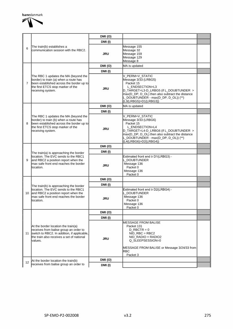
SP-EMO-P2-002008 v3.2 275
6 The train(b) establishes a communication session with the RBC2.
DMI (O)
DMI (I)
JRU
Message 155 Message 32 Message 159 Message 129 Message 8
7
The RBC 1 updates the MA (beyond the border) to train (a) when a route has been established across the border up to the first ETCS stop marker of the receiving system.
DMI (O) MA is updated
DMI (I)
JRU
V_PERM=V_STATIC Message 3/33 (LRBG5) Packet 15 L_ENDSECTION=L3 D_TARGET=L3-D_LRBG5 (if L_DOUBTUNDER > max(D_DP, D_OL) then also subtract the distance L_DOUBTUNDER - max(D_DP, D_OL)) (**) (L3(LRBG5)>D1(LRBG3))
8
The RBC 1 updates the MA (beyond the border) to train (b) when a route has been established across the border up to the first ETCS stop marker of the receiving system.
DMI (O) MA is updated
DMI (I)
JRU
V_PERM=V_STATIC Message 3/33 (LRBG6) Packet 15 L_ENDSECTION=L4 D_TARGET=L4-D_LRBG6 (if L_DOUBTUNDER > max(D_DP, D_OL) then also subtract the distance L_DOUBTUNDER - max(D_DP, D_OL)) (**) (L4(LRBG6)>D2(LRBG4))
9
The train(a) is approaching the border location. The EVC sends to the RBC1 and RBC2 a position report when the max safe front end reaches the border location.
DMI (O)
DMI (I)
JRU
Estimated front end ≥ D1(LRBG3) - L_DOUBTUNDER Message 136 Packet 0 Message 136 Packet 0
10
The train(b) is approaching the border location. The EVC sends to the RBC1 and RBC2 a position report when the max safe front end reaches the border location.
DMI (O)
DMI (I)
JRU
Estimated front end ≥ D2(LRBG4) - L_DOUBTUNDER Message 136 Packet 0 Message 136 Packet 0
11
At the border location the train(a) receives from balise group an order to switch to RBC2. In addition, if applicable, the train also receives a set of national values.
DMI (O)
DMI (I)
JRU
MESSAGE FROM BALISE Packet 131 D_RBCTR = 0 NID_RBC = RBC2 NID_RADIO = RADIO2 Q_SLEEPSESSION=0 MESSAGE FROM BALISE or Message 3/24/33 from RBC Packet 3
12 At the border location the train(b) receives from balise group an order to
DMI (O)
DMI (I)

SP-EMO-P2-002008 v3.2 276
switch to RBC2. In addition, if applicable, the train also receives a set of national values.
JRU
MESSAGE FROM BALISE Packet 131 D_RBCTR = 0 NID_RBC = RBC2 NID_RADIO = RADIO2 Q_SLEEPSESSION=0 MESSAGE FROM BALISE or Message 3/24/33 from RBC Packet 3
13 The train(a) sends to the RBC1 a position report when the min safe rear end has passed the border location.
DMI (O)
DMI (I)
JRU
Estimated front end ≥ D1(LRBG3) + L_TRAIN(a) + L_DOUBTOVER Message 136 Packet 0
14 The train(b) sends to the RBC1 a position report when the min safe rear end has passed the border location.
DMI (O)
DMI (I)
JRU
Estimated front end ≥ D2(LRBG4) + L_TRAIN(b) + L_DOUBTOVER Message 136 Packet 0
15
The train(a) receives from RBC1 an order to terminate communication session. Communication session is terminated with the RBC1.
DMI (O)
DMI (I)
JRU
Message 3/24/33 Packet 42 Q_RBC=0 Message 156 Message 39
16
The train(b) receives from RBC1 an order to terminate communication session. Communication session is terminated with the RBC1.
DMI (O)
DMI (I)
JRU
Message 3/24/33 Packet 42 Q_RBC=0 Message 156 Message 39
Final state
Level 2
Mode FS
Train Speed (km/h) NR
Other parameters
Final Test Result
Field of Application F-bane EAST, F-bane WEST
Briefing instructions (*) Packet 131 could receive also at steps 1 and 2 respectively (**) Dtarget is shown and stored if the train is in the monitoring status of Pre-Indication Monitoring (PIM) or Target Speed Monitoring (TSM)
ADDITIONAL TEST CASE REPORTING INFORMATION
System configuration
Test location
Date and time (Start/End)
Names
Test log reference
Observations
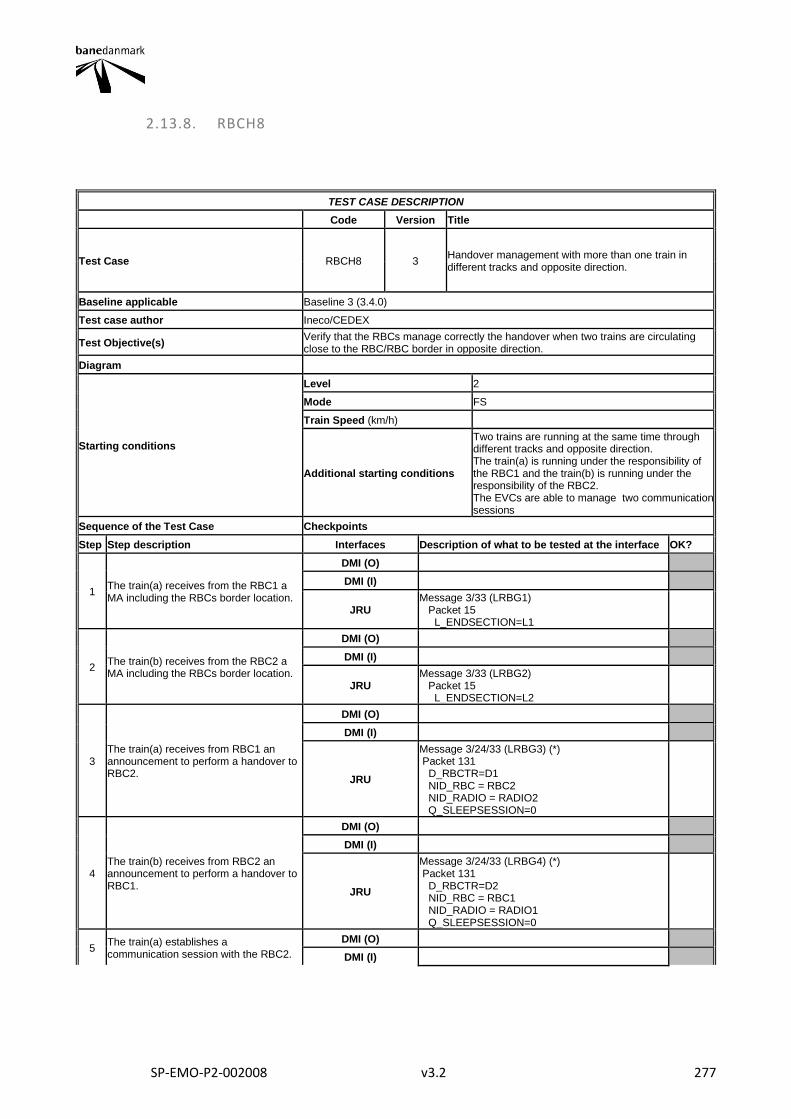
SP-EMO-P2-002008 v3.2 277
2.13.8. RBCH8
TEST CASE DESCRIPTION
Code Version Title
Test Case RBCH8 3 Handover management with more than one train in different tracks and opposite direction.
Baseline applicable Baseline 3 (3.4.0)
Test case author Ineco/CEDEX
Test Objective(s) Verify that the RBCs manage correctly the handover when two trains are circulating close to the RBC/RBC border in opposite direction.
Diagram
Starting conditions
Level 2
Mode FS
Train Speed (km/h)
Additional starting conditions
Two trains are running at the same time through different tracks and opposite direction. The train(a) is running under the responsibility of the RBC1 and the train(b) is running under the responsibility of the RBC2. The EVCs are able to manage two communication sessions
Sequence of the Test Case Checkpoints
Step Step description Interfaces Description of what to be tested at the interface OK?
1 The train(a) receives from the RBC1 a MA including the RBCs border location.
DMI (O)
DMI (I)
JRU Message 3/33 (LRBG1) Packet 15 L_ENDSECTION=L1
2 The train(b) receives from the RBC2 a MA including the RBCs border location.
DMI (O)
DMI (I)
JRU Message 3/33 (LRBG2) Packet 15 L_ENDSECTION=L2
3 The train(a) receives from RBC1 an announcement to perform a handover to RBC2.
DMI (O)
DMI (I)
JRU
Message 3/24/33 (LRBG3) (*) Packet 131 D_RBCTR=D1 NID_RBC = RBC2 NID_RADIO = RADIO2 Q_SLEEPSESSION=0
4 The train(b) receives from RBC2 an announcement to perform a handover to RBC1.
DMI (O)
DMI (I)
JRU
Message 3/24/33 (LRBG4) (*) Packet 131 D_RBCTR=D2 NID_RBC = RBC1 NID_RADIO = RADIO1 Q_SLEEPSESSION=0
5 The train(a) establishes a communication session with the RBC2.
DMI (O)
DMI (I)
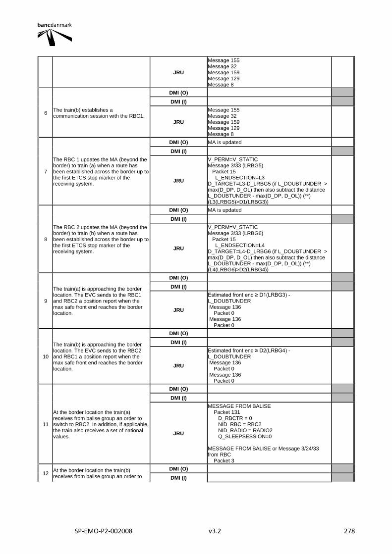
SP-EMO-P2-002008 v3.2 278
JRU
Message 155 Message 32 Message 159 Message 129 Message 8
6 The train(b) establishes a communication session with the RBC1.
DMI (O)
DMI (I)
JRU
Message 155 Message 32 Message 159 Message 129 Message 8
7
The RBC 1 updates the MA (beyond the border) to train (a) when a route has been established across the border up to the first ETCS stop marker of the receiving system.
DMI (O) MA is updated
DMI (I)
JRU
V_PERM=V_STATIC Message 3/33 (LRBG5) Packet 15 L_ENDSECTION=L3 D_TARGET=L3-D_LRBG5 (if L_DOUBTUNDER > max(D_DP, D_OL) then also subtract the distance L_DOUBTUNDER - max(D_DP, D_OL)) (**) (L3(LRBG5)>D1(LRBG3))
8
The RBC 2 updates the MA (beyond the border) to train (b) when a route has been established across the border up to the first ETCS stop marker of the receiving system.
DMI (O) MA is updated
DMI (I)
JRU
V_PERM=V_STATIC Message 3/33 (LRBG6) Packet 15 L_ENDSECTION=L4 D_TARGET=L4-D_LRBG6 (if L_DOUBTUNDER > max(D_DP, D_OL) then also subtract the distance L_DOUBTUNDER - max(D_DP, D_OL)) (**) (L4(LRBG6)>D2(LRBG4))
9
The train(a) is approaching the border location. The EVC sends to the RBC1 and RBC2 a position report when the max safe front end reaches the border location.
DMI (O)
DMI (I)
JRU
Estimated front end ≥ D1(LRBG3) - L_DOUBTUNDER Message 136 Packet 0 Message 136 Packet 0
10
The train(b) is approaching the border location. The EVC sends to the RBC2 and RBC1 a position report when the max safe front end reaches the border location.
DMI (O)
DMI (I)
JRU
Estimated front end ≥ D2(LRBG4) - L_DOUBTUNDER Message 136 Packet 0 Message 136 Packet 0
11
At the border location the train(a) receives from balise group an order to switch to RBC2. In addition, if applicable, the train also receives a set of national values.
DMI (O)
DMI (I)
JRU
MESSAGE FROM BALISE Packet 131 D_RBCTR = 0 NID_RBC = RBC2 NID_RADIO = RADIO2 Q_SLEEPSESSION=0 MESSAGE FROM BALISE or Message 3/24/33 from RBC Packet 3
12 At the border location the train(b) receives from balise group an order to
DMI (O)
DMI (I)
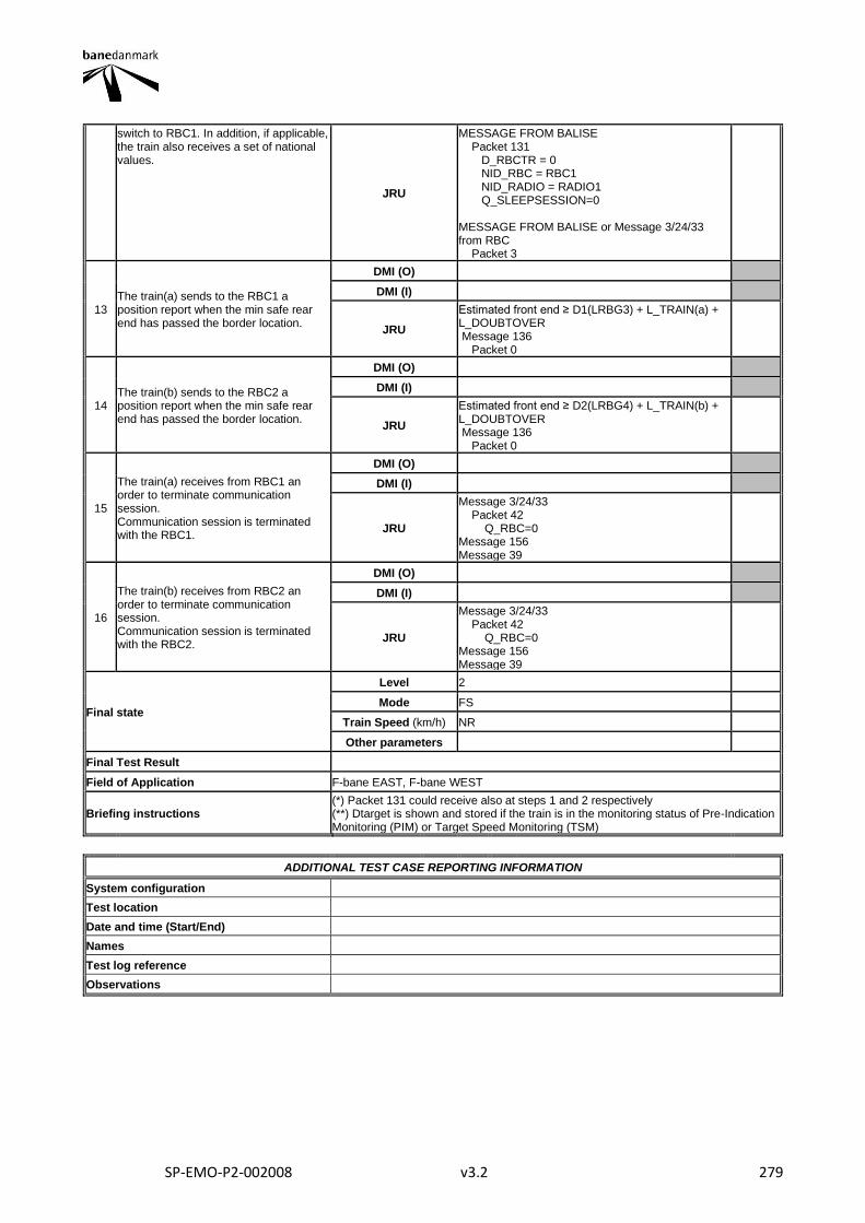
SP-EMO-P2-002008 v3.2 279
switch to RBC1. In addition, if applicable, the train also receives a set of national values.
JRU
MESSAGE FROM BALISE Packet 131 D_RBCTR = 0 NID_RBC = RBC1 NID_RADIO = RADIO1 Q_SLEEPSESSION=0 MESSAGE FROM BALISE or Message 3/24/33 from RBC Packet 3
13 The train(a) sends to the RBC1 a position report when the min safe rear end has passed the border location.
DMI (O)
DMI (I)
JRU
Estimated front end ≥ D1(LRBG3) + L_TRAIN(a) + L_DOUBTOVER Message 136 Packet 0
14 The train(b) sends to the RBC2 a position report when the min safe rear end has passed the border location.
DMI (O)
DMI (I)
JRU
Estimated front end ≥ D2(LRBG4) + L_TRAIN(b) + L_DOUBTOVER Message 136 Packet 0
15
The train(a) receives from RBC1 an order to terminate communication session. Communication session is terminated with the RBC1.
DMI (O)
DMI (I)
JRU
Message 3/24/33 Packet 42 Q_RBC=0 Message 156 Message 39
16
The train(b) receives from RBC2 an order to terminate communication session. Communication session is terminated with the RBC2.
DMI (O)
DMI (I)
JRU
Message 3/24/33 Packet 42 Q_RBC=0 Message 156 Message 39
Final state
Level 2
Mode FS
Train Speed (km/h) NR
Other parameters
Final Test Result
Field of Application F-bane EAST, F-bane WEST
Briefing instructions (*) Packet 131 could receive also at steps 1 and 2 respectively (**) Dtarget is shown and stored if the train is in the monitoring status of Pre-Indication Monitoring (PIM) or Target Speed Monitoring (TSM)
ADDITIONAL TEST CASE REPORTING INFORMATION
System configuration
Test location
Date and time (Start/End)
Names
Test log reference
Observations
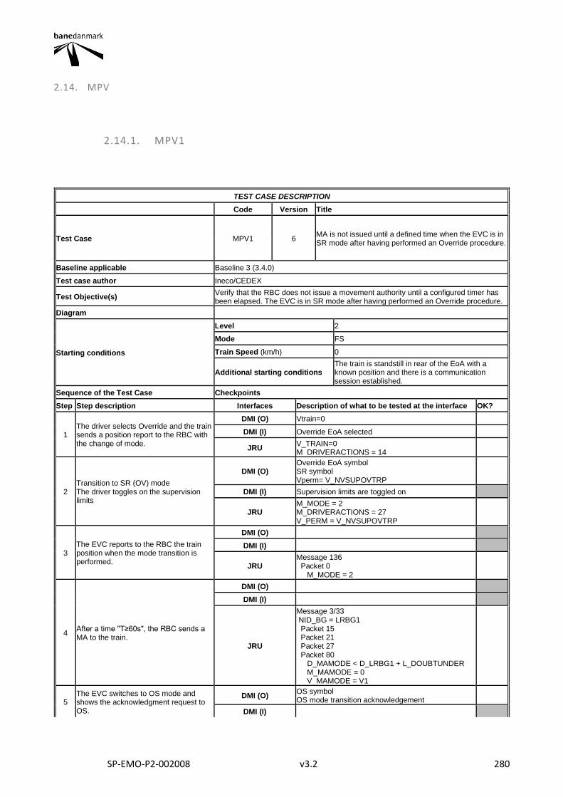
SP-EMO-P2-002008 v3.2 280
2.14. MPV
2.14.1. MPV1
TEST CASE DESCRIPTION
Code Version Title
Test Case MPV1 6 MA is not issued until a defined time when the EVC is in SR mode after having performed an Override procedure.
Baseline applicable Baseline 3 (3.4.0)
Test case author Ineco/CEDEX
Test Objective(s) Verify that the RBC does not issue a movement authority until a configured timer has been elapsed. The EVC is in SR mode after having performed an Override procedure.
Diagram
Starting conditions
Level 2
Mode FS
Train Speed (km/h) 0
Additional starting conditions The train is standstill in rear of the EoA with a known position and there is a communication session established.
Sequence of the Test Case Checkpoints
Step Step description Interfaces Description of what to be tested at the interface OK?
1 The driver selects Override and the train sends a position report to the RBC with the change of mode.
DMI (O) Vtrain=0
DMI (I) Override EoA selected
JRU V_TRAIN=0 M_DRIVERACTIONS = 14
2 Transition to SR (OV) mode The driver toggles on the supervision limits
DMI (O) Override EoA symbol SR symbol Vperm= V_NVSUPOVTRP
DMI (I) Supervision limits are toggled on
JRU M_MODE = 2 M_DRIVERACTIONS = 27 V_PERM = V_NVSUPOVTRP
3 The EVC reports to the RBC the train position when the mode transition is performed.
DMI (O)
DMI (I)
JRU Message 136 Packet 0 M_MODE = 2
4 After a time "T≥60s", the RBC sends a MA to the train.
DMI (O)
DMI (I)
JRU
Message 3/33 NID_BG = LRBG1 Packet 15 Packet 21 Packet 27 Packet 80 D_MAMODE < D_LRBG1 + L_DOUBTUNDER M_MAMODE = 0 V_MAMODE = V1
5 The EVC switches to OS mode and shows the acknowledgment request to OS.
DMI (O) OS symbol OS mode transition acknowledgement
DMI (I)
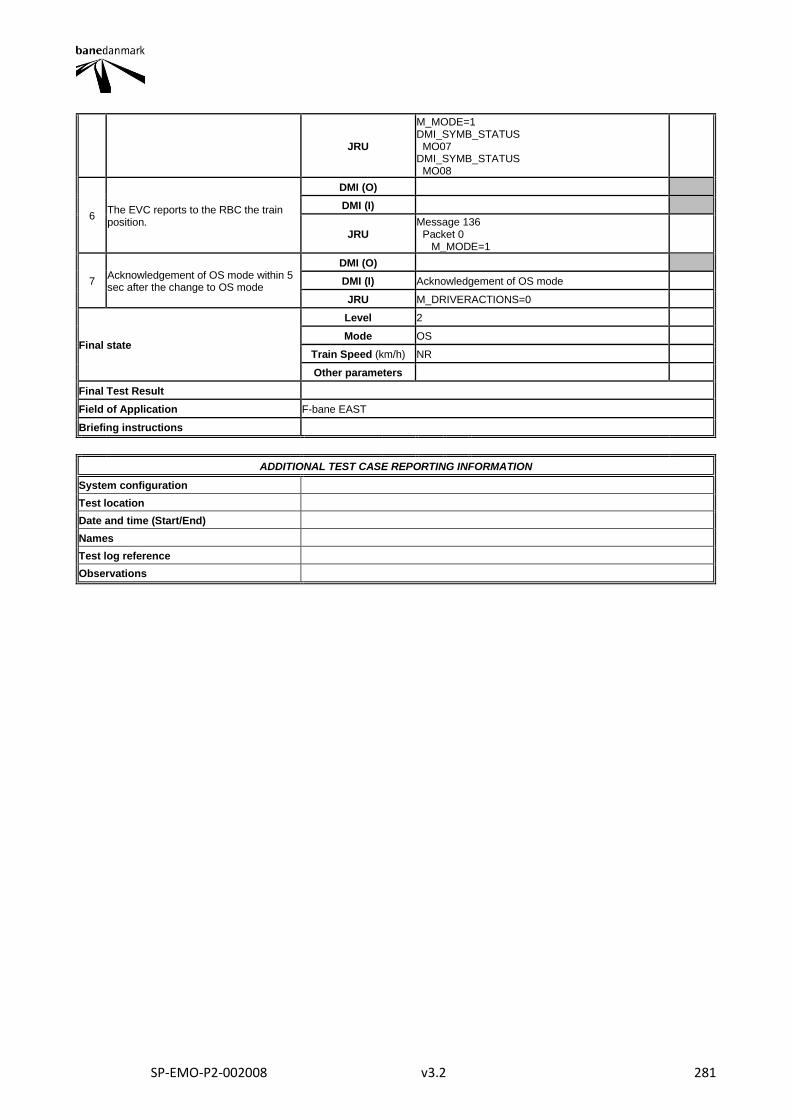
SP-EMO-P2-002008 v3.2 281
JRU
M_MODE=1 DMI_SYMB_STATUS MO07 DMI_SYMB_STATUS MO08
6 The EVC reports to the RBC the train position.
DMI (O)
DMI (I)
JRU Message 136 Packet 0 M_MODE=1
7 Acknowledgement of OS mode within 5 sec after the change to OS mode
DMI (O)
DMI (I) Acknowledgement of OS mode
JRU M_DRIVERACTIONS=0
Final state
Level 2
Mode OS
Train Speed (km/h) NR
Other parameters
Final Test Result
Field of Application F-bane EAST
Briefing instructions
ADDITIONAL TEST CASE REPORTING INFORMATION
System configuration
Test location
Date and time (Start/End)
Names
Test log reference
Observations
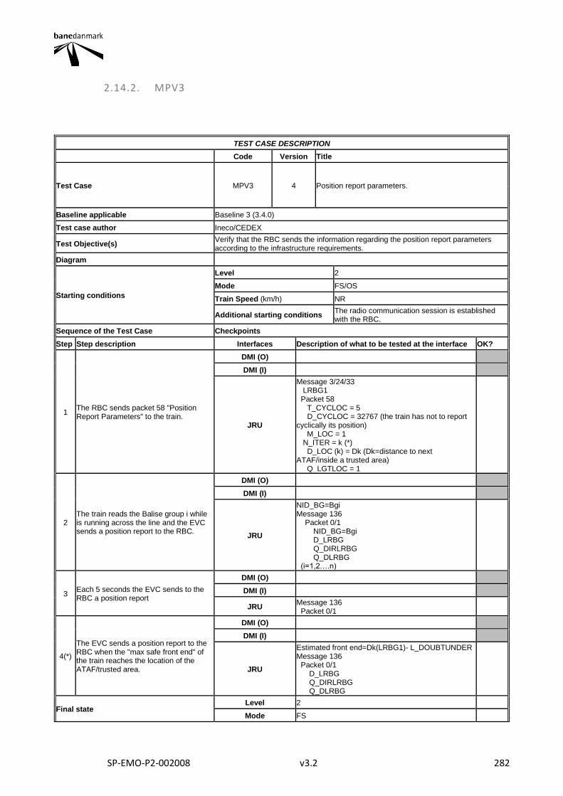
SP-EMO-P2-002008 v3.2 282
2.14.2. MPV3
TEST CASE DESCRIPTION
Code Version Title
Test Case MPV3 4 Position report parameters.
Baseline applicable Baseline 3 (3.4.0)
Test case author Ineco/CEDEX
Test Objective(s) Verify that the RBC sends the information regarding the position report parameters according to the infrastructure requirements.
Diagram
Starting conditions
Level 2
Mode FS/OS
Train Speed (km/h) NR
Additional starting conditions The radio communication session is established with the RBC.
Sequence of the Test Case Checkpoints
Step Step description Interfaces Description of what to be tested at the interface OK?
1 The RBC sends packet 58 "Position Report Parameters" to the train.
DMI (O)
DMI (I)
JRU
Message 3/24/33 LRBG1 Packet 58 T_CYCLOC = 5 D_CYCLOC = 32767 (the train has not to report cyclically its position) M_LOC = 1 N_ITER = k (*) D_LOC (k) = Dk (Dk=distance to next ATAF/inside a trusted area) Q_LGTLOC = 1
2 The train reads the Balise group i while is running across the line and the EVC sends a position report to the RBC.
DMI (O)
DMI (I)
JRU
NID_BG=Bgi Message 136 Packet 0/1 NID_BG=Bgi D_LRBG Q_DIRLRBG Q_DLRBG (i=1,2….n)
3 Each 5 seconds the EVC sends to the RBC a position report
DMI (O)
DMI (I)
JRU Message 136 Packet 0/1
4(*)
The EVC sends a position report to the RBC when the "max safe front end" of the train reaches the location of the ATAF/trusted area.
DMI (O)
DMI (I)
JRU
Estimated front end=Dk(LRBG1)- L_DOUBTUNDER Message 136 Packet 0/1 D_LRBG Q_DIRLRBG Q_DLRBG
Final state Level 2
Mode FS
SP-EMO-P2-002008 v3.2 283
Train Speed (km/h) NR
Other parameters
Final Test Result
Field of Application F-bane EAST, F-bane WEST
Briefing instructions Can be also tested in SR when the train has a valid position (*) Optional functionality
ADDITIONAL TEST CASE REPORTING INFORMATION
System configuration
Test location
Date and time (Start/End)
Names
Test log reference
Observations
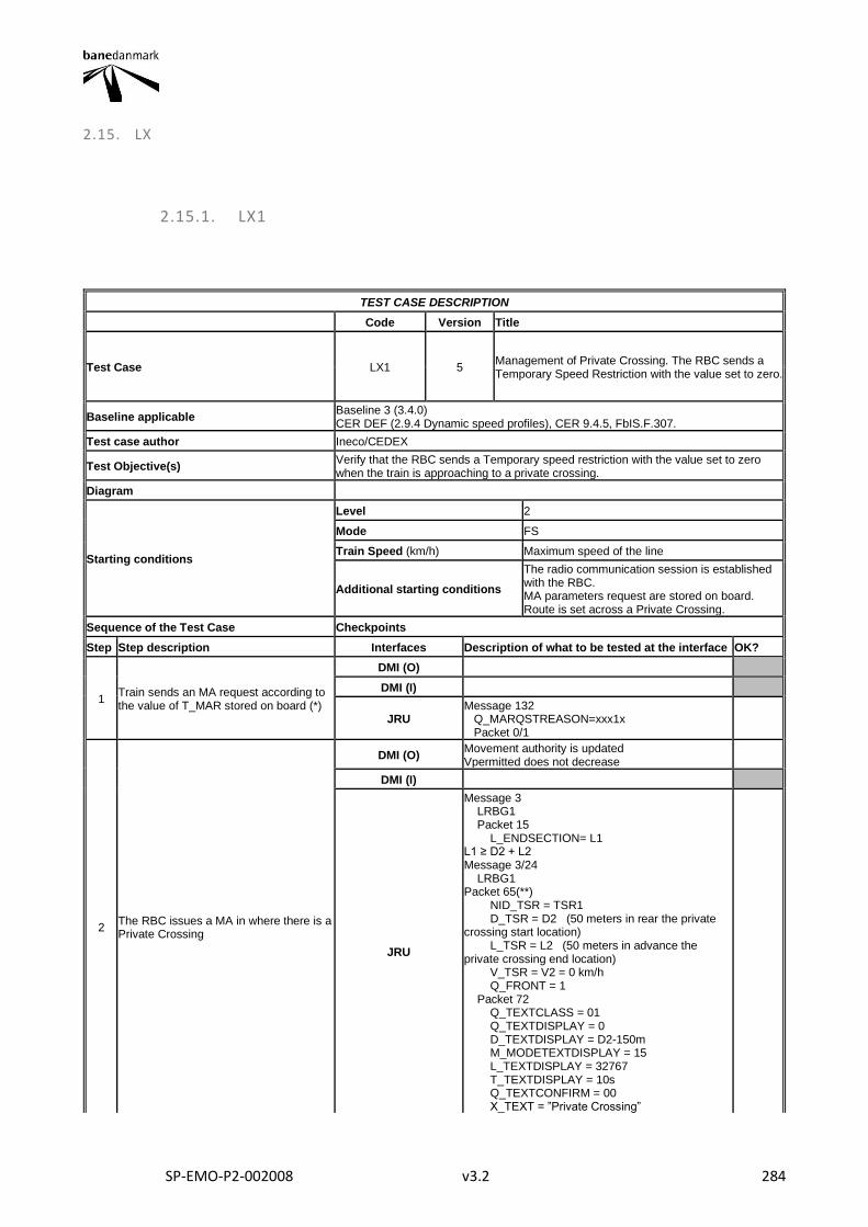
SP-EMO-P2-002008 v3.2 284
2.15. LX
2.15.1. LX1
TEST CASE DESCRIPTION
Code Version Title
Test Case LX1 5 Management of Private Crossing. The RBC sends a Temporary Speed Restriction with the value set to zero.
Baseline applicable Baseline 3 (3.4.0) CER DEF (2.9.4 Dynamic speed profiles), CER 9.4.5, FbIS.F.307.
Test case author Ineco/CEDEX
Test Objective(s) Verify that the RBC sends a Temporary speed restriction with the value set to zero when the train is approaching to a private crossing.
Diagram
Starting conditions
Level 2
Mode FS
Train Speed (km/h) Maximum speed of the line
Additional starting conditions
The radio communication session is established with the RBC. MA parameters request are stored on board. Route is set across a Private Crossing.
Sequence of the Test Case Checkpoints
Step Step description Interfaces Description of what to be tested at the interface OK?
1 Train sends an MA request according to the value of T_MAR stored on board (*)
DMI (O)
DMI (I)
JRU Message 132 Q_MARQSTREASON=xxx1x Packet 0/1
2 The RBC issues a MA in where there is a Private Crossing
DMI (O) Movement authority is updated Vpermitted does not decrease
DMI (I)
JRU
Message 3 LRBG1 Packet 15 L_ENDSECTION= L1 L1 ≥ D2 + L2 Message 3/24 LRBG1 Packet 65(**) NID_TSR = TSR1 D_TSR = D2 (50 meters in rear the private crossing start location) L_TSR = L2 (50 meters in advance the private crossing end location) V_TSR = V2 = 0 km/h Q_FRONT = 1 Packet 72 Q_TEXTCLASS = 01 Q_TEXTDISPLAY = 0 D_TEXTDISPLAY = D2-150m M_MODETEXTDISPLAY = 15 L_TEXTDISPLAY = 32767 T_TEXTDISPLAY = 10s Q_TEXTCONFIRM = 00 X_TEXT = ”Private Crossing”
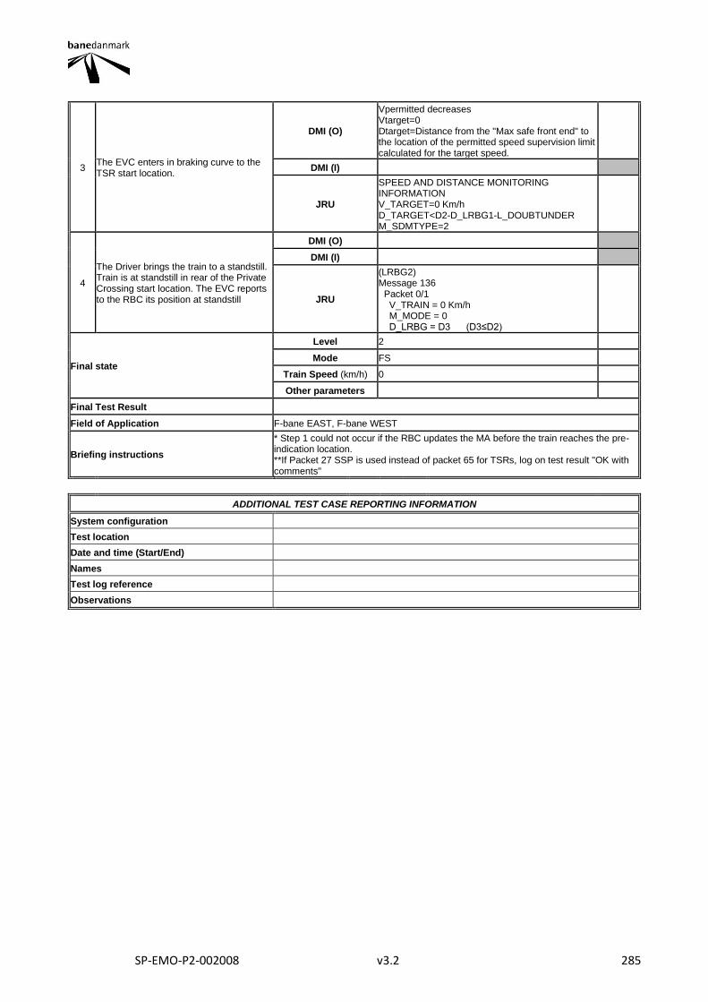
SP-EMO-P2-002008 v3.2 285
3 The EVC enters in braking curve to the TSR start location.
DMI (O)
Vpermitted decreases Vtarget=0 Dtarget=Distance from the "Max safe front end" to the location of the permitted speed supervision limit calculated for the target speed.
DMI (I)
JRU
SPEED AND DISTANCE MONITORING INFORMATION V_TARGET=0 Km/h D_TARGET<D2-D_LRBG1-L_DOUBTUNDER M_SDMTYPE=2
4
The Driver brings the train to a standstill. Train is at standstill in rear of the Private Crossing start location. The EVC reports to the RBC its position at standstill
DMI (O)
DMI (I)
JRU
(LRBG2) Message 136 Packet 0/1 V_TRAIN = 0 Km/h M_MODE = 0 D_LRBG = D3 (D3≤D2)
Final state
Level 2
Mode FS
Train Speed (km/h) 0
Other parameters
Final Test Result
Field of Application F-bane EAST, F-bane WEST
Briefing instructions
* Step 1 could not occur if the RBC updates the MA before the train reaches the pre-indication location. **If Packet 27 SSP is used instead of packet 65 for TSRs, log on test result "OK with comments"
ADDITIONAL TEST CASE REPORTING INFORMATION
System configuration
Test location
Date and time (Start/End)
Names
Test log reference
Observations
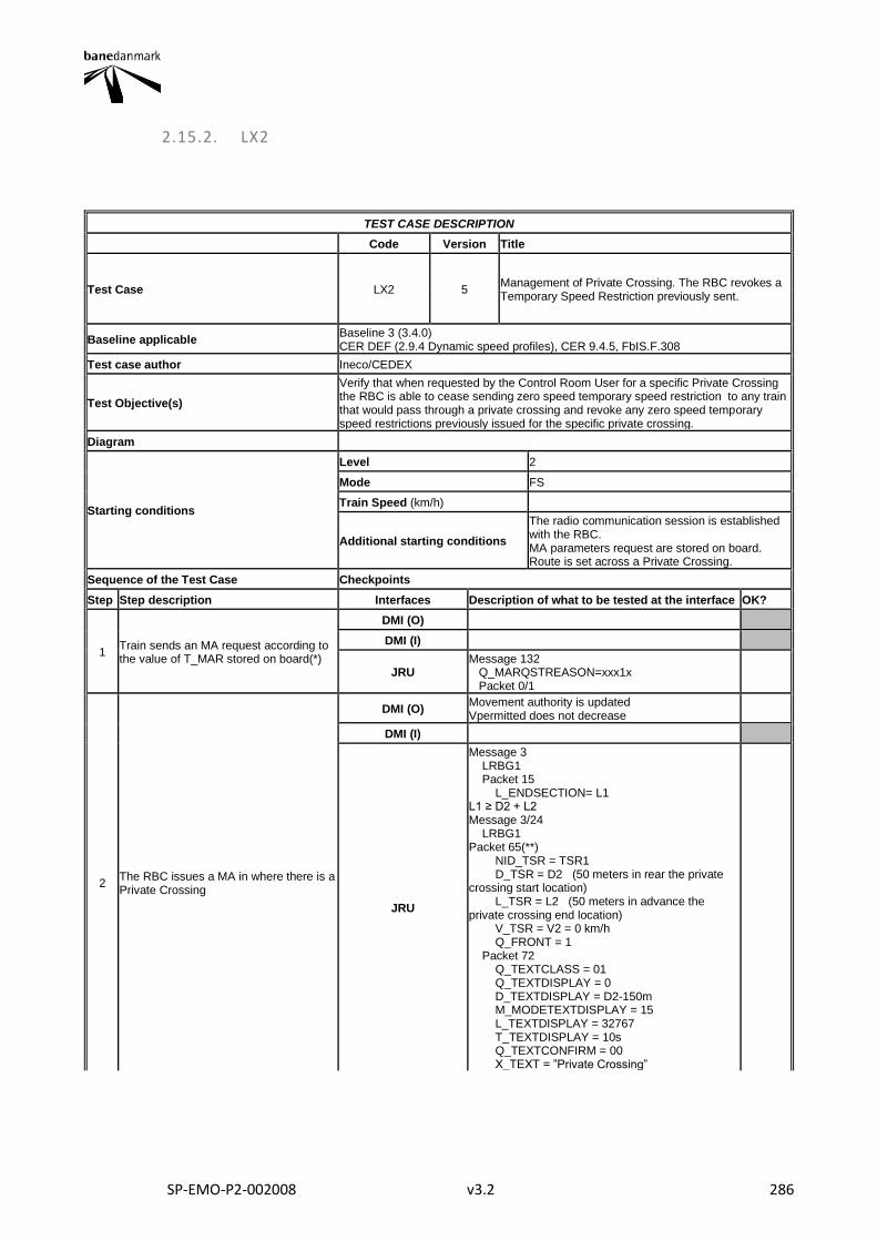
SP-EMO-P2-002008 v3.2 286
2.15.2. LX2
TEST CASE DESCRIPTION
Code Version Title
Test Case LX2 5 Management of Private Crossing. The RBC revokes a Temporary Speed Restriction previously sent.
Baseline applicable Baseline 3 (3.4.0) CER DEF (2.9.4 Dynamic speed profiles), CER 9.4.5, FbIS.F.308
Test case author Ineco/CEDEX
Test Objective(s)
Verify that when requested by the Control Room User for a specific Private Crossing the RBC is able to cease sending zero speed temporary speed restriction to any train that would pass through a private crossing and revoke any zero speed temporary speed restrictions previously issued for the specific private crossing.
Diagram
Starting conditions
Level 2
Mode FS
Train Speed (km/h)
Additional starting conditions
The radio communication session is established with the RBC. MA parameters request are stored on board. Route is set across a Private Crossing.
Sequence of the Test Case Checkpoints
Step Step description Interfaces Description of what to be tested at the interface OK?
1 Train sends an MA request according to the value of T_MAR stored on board(*)
DMI (O)
DMI (I)
JRU Message 132 Q_MARQSTREASON=xxx1x Packet 0/1
2 The RBC issues a MA in where there is a Private Crossing
DMI (O) Movement authority is updated Vpermitted does not decrease
DMI (I)
JRU
Message 3 LRBG1 Packet 15 L_ENDSECTION= L1 L1 ≥ D2 + L2 Message 3/24 LRBG1 Packet 65(**) NID_TSR = TSR1 D_TSR = D2 (50 meters in rear the private crossing start location) L_TSR = L2 (50 meters in advance the private crossing end location) V_TSR = V2 = 0 km/h Q_FRONT = 1 Packet 72 Q_TEXTCLASS = 01 Q_TEXTDISPLAY = 0 D_TEXTDISPLAY = D2-150m M_MODETEXTDISPLAY = 15 L_TEXTDISPLAY = 32767 T_TEXTDISPLAY = 10s Q_TEXTCONFIRM = 00 X_TEXT = ”Private Crossing”
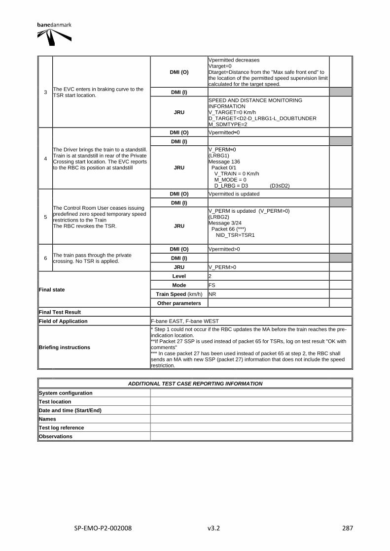
SP-EMO-P2-002008 v3.2 287
3 The EVC enters in braking curve to the TSR start location.
DMI (O)
Vpermitted decreases Vtarget=0 Dtarget=Distance from the "Max safe front end" to the location of the permitted speed supervision limit calculated for the target speed.
DMI (I)
JRU
SPEED AND DISTANCE MONITORING INFORMATION V_TARGET=0 Km/h D_TARGET<D2-D_LRBG1-L_DOUBTUNDER M_SDMTYPE=2
4
The Driver brings the train to a standstill. Train is at standstill in rear of the Private Crossing start location. The EVC reports to the RBC its position at standstill
DMI (O) Vpermitted≈0
DMI (I)
JRU
V_PERM≈0 (LRBG1) Message 136 Packet 0/1 V_TRAIN = 0 Km/h M_MODE = 0 D_LRBG = D3 (D3≤D2)
5
The Control Room User ceases issuing predefined zero speed temporary speed restrictions to the Train The RBC revokes the TSR.
DMI (O) Vpermitted is updated
DMI (I)
JRU
V_PERM is updated (V_PERM>0) (LRBG2) Message 3/24 Packet 66 (***) NID_TSR=TSR1
6 The train pass through the private crossing. No TSR is applied.
DMI (O) Vpermitted>0
DMI (I)
JRU V_PERM>0
Final state
Level 2
Mode FS
Train Speed (km/h) NR
Other parameters
Final Test Result
Field of Application F-bane EAST, F-bane WEST
Briefing instructions
* Step 1 could not occur if the RBC updates the MA before the train reaches the pre-indication location. **If Packet 27 SSP is used instead of packet 65 for TSRs, log on test result "OK with comments" *** In case packet 27 has been used instead of packet 65 at step 2, the RBC shall sends an MA with new SSP (packet 27) information that does not include the speed restriction.
ADDITIONAL TEST CASE REPORTING INFORMATION
System configuration
Test location
Date and time (Start/End)
Names
Test log reference
Observations
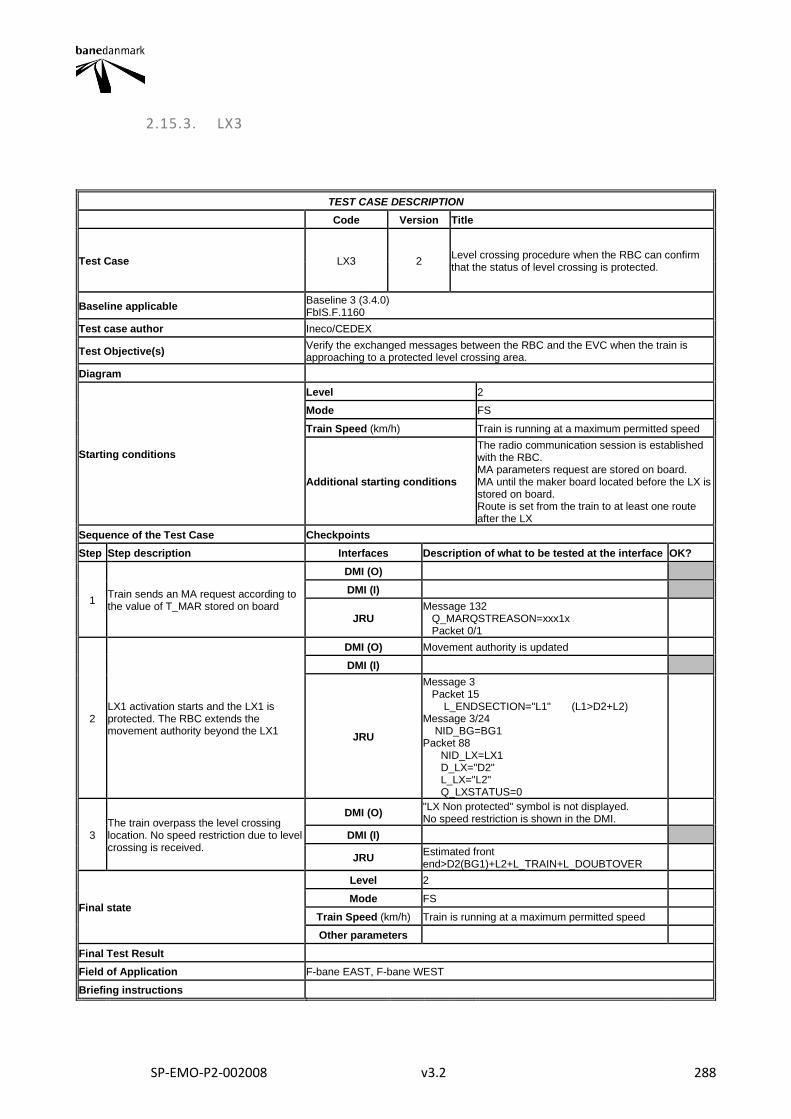
SP-EMO-P2-002008 v3.2 288
2.15.3. LX3
TEST CASE DESCRIPTION
Code Version Title
Test Case LX3 2 Level crossing procedure when the RBC can confirm that the status of level crossing is protected.
Baseline applicable Baseline 3 (3.4.0) FbIS.F.1160
Test case author Ineco/CEDEX
Test Objective(s) Verify the exchanged messages between the RBC and the EVC when the train is approaching to a protected level crossing area.
Diagram
Starting conditions
Level 2
Mode FS
Train Speed (km/h) Train is running at a maximum permitted speed
Additional starting conditions
The radio communication session is established with the RBC. MA parameters request are stored on board. MA until the maker board located before the LX is stored on board. Route is set from the train to at least one route after the LX
Sequence of the Test Case Checkpoints
Step Step description Interfaces Description of what to be tested at the interface OK?
1 Train sends an MA request according to the value of T_MAR stored on board
DMI (O)
DMI (I)
JRU Message 132 Q_MARQSTREASON=xxx1x Packet 0/1
2 LX1 activation starts and the LX1 is protected. The RBC extends the movement authority beyond the LX1
DMI (O) Movement authority is updated
DMI (I)
JRU
Message 3 Packet 15 L_ENDSECTION="L1" (L1>D2+L2) Message 3/24 NID_BG=BG1 Packet 88 NID_LX=LX1 D_LX="D2" L_LX="L2" Q_LXSTATUS=0
3 The train overpass the level crossing location. No speed restriction due to level crossing is received.
DMI (O) "LX Non protected" symbol is not displayed. No speed restriction is shown in the DMI.
DMI (I)
JRU Estimated front end>D2(BG1)+L2+L_TRAIN+L_DOUBTOVER
Final state
Level 2
Mode FS
Train Speed (km/h) Train is running at a maximum permitted speed
Other parameters
Final Test Result
Field of Application F-bane EAST, F-bane WEST
Briefing instructions

SP-EMO-P2-002008 v3.2 289
ADDITIONAL TEST CASE REPORTING INFORMATION
System configuration
Test location
Date and time (Start/End)
Names
Test log reference
Observations
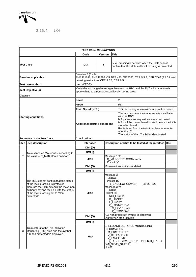
SP-EMO-P2-002008 v3.2 290
2.15.4. LX4
TEST CASE DESCRIPTION
Code Version Title
Test Case LX4 5 Level crossing procedure when the RBC cannot confirm that the status of level crossing is protected.
Baseline applicable Baseline 3 (3.4.0) FbIS.F.1698, FbIS.F.326, OR.DEF.456, OR.3095, CER 9.5.2, CER COM (2.9.5 Level crossing restriction), CER 9.5.3, CER 9.5.1
Test case author Ineco/CEDEX
Test Objective(s) Verify the exchanged messages between the RBC and the EVC when the train is approaching to a non-protected level crossing area.
Diagram
Starting conditions
Level 2
Mode FS
Train Speed (km/h) Train is running at a maximum permitted speed
Additional starting conditions
The radio communication session is established with the RBC. MA parameters request are stored on board. MA until the maker board located before the LX is stored on board. Route is set from the train to at least one route after the LX The status of the LX is failed/deactivated
Sequence of the Test Case Checkpoints
Step Step description Interfaces Description of what to be tested at the interface OK?
1 Train sends an MA request according to the value of T_MAR stored on board
DMI (O)
DMI (I)
JRU Message 132 Q_MARQSTREASON=xxx1x Packet 0/1
2
The RBC cannot confirm that the status of the level crossing is protected therefore the RBC extends the movement authority beyond the LX1 with the status of the level crossing set to "Non protected"
DMI (O) Movement authority is updated
DMI (I)
JRU
Message 3 LRBG1 Packet 15 L_ENDSECTION="L1" (L1>D2+L2) Message 3/24 LRBG1 Packet 88 NID_LX=LX1 D_LX="D2" L_LX="L2" Q_LXSTATUS=1 V_LX=10 Km/h Q_STOPLX=0
3 Train enters to the Pre-Indication Monitoring (PIM) area and the symbol "LX non protected" is displayed.
DMI (O) "LX Non protected" symbol is displayed Dtarget=LX start location
DMI (I)
JRU
SPEED AND DISTANCE MONITORING INFORMATION M_SDMTYPE = 1 V_RELEASE = 0 V_TARGET=0 D_TARGET=D2-L_DOUBTUNDER-D_LRBG1 DMI_SYMB_STATUS LX01
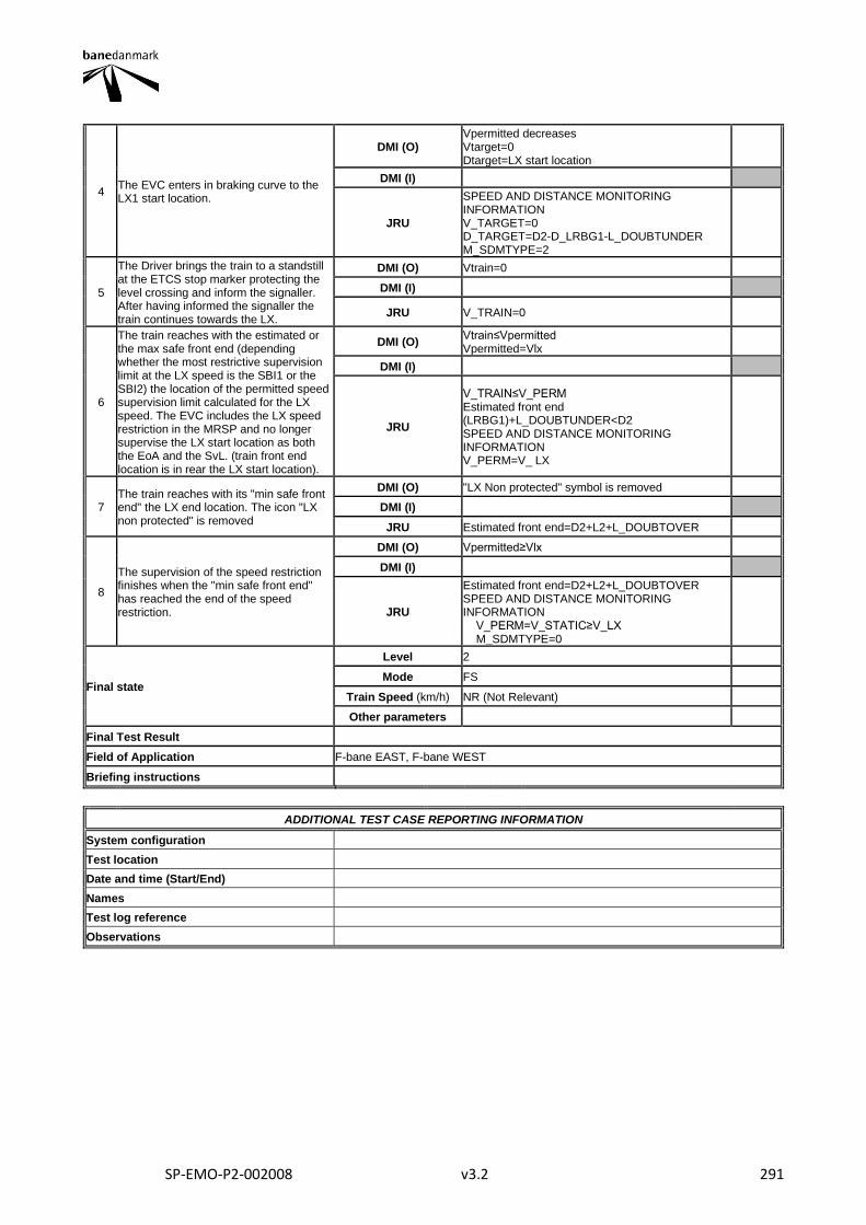
SP-EMO-P2-002008 v3.2 291
4 The EVC enters in braking curve to the LX1 start location.
DMI (O) Vpermitted decreases Vtarget=0 Dtarget=LX start location
DMI (I)
JRU
SPEED AND DISTANCE MONITORING INFORMATION V_TARGET=0 D_TARGET=D2-D_LRBG1-L_DOUBTUNDER M_SDMTYPE=2
5
The Driver brings the train to a standstill at the ETCS stop marker protecting the level crossing and inform the signaller. After having informed the signaller the train continues towards the LX.
DMI (O) Vtrain=0
DMI (I)
JRU V_TRAIN=0
6
The train reaches with the estimated or the max safe front end (depending whether the most restrictive supervision limit at the LX speed is the SBI1 or the SBI2) the location of the permitted speed supervision limit calculated for the LX speed. The EVC includes the LX speed restriction in the MRSP and no longer supervise the LX start location as both the EoA and the SvL. (train front end location is in rear the LX start location).
DMI (O) Vtrain≤Vpermitted Vpermitted=Vlx
DMI (I)
JRU
V_TRAIN≤V_PERM Estimated front end (LRBG1)+L_DOUBTUNDER<D2 SPEED AND DISTANCE MONITORING INFORMATION V_PERM=V_ LX
7 The train reaches with its "min safe front end" the LX end location. The icon "LX non protected" is removed
DMI (O) "LX Non protected" symbol is removed
DMI (I)
JRU Estimated front end=D2+L2+L_DOUBTOVER
8
The supervision of the speed restriction finishes when the "min safe front end" has reached the end of the speed restriction.
DMI (O) Vpermitted≥Vlx
DMI (I)
JRU
Estimated front end=D2+L2+L_DOUBTOVER SPEED AND DISTANCE MONITORING INFORMATION V_PERM=V_STATIC≥V_LX M_SDMTYPE=0
Final state
Level 2
Mode FS
Train Speed (km/h) NR (Not Relevant)
Other parameters
Final Test Result
Field of Application F-bane EAST, F-bane WEST
Briefing instructions
ADDITIONAL TEST CASE REPORTING INFORMATION
System configuration
Test location
Date and time (Start/End)
Names
Test log reference
Observations
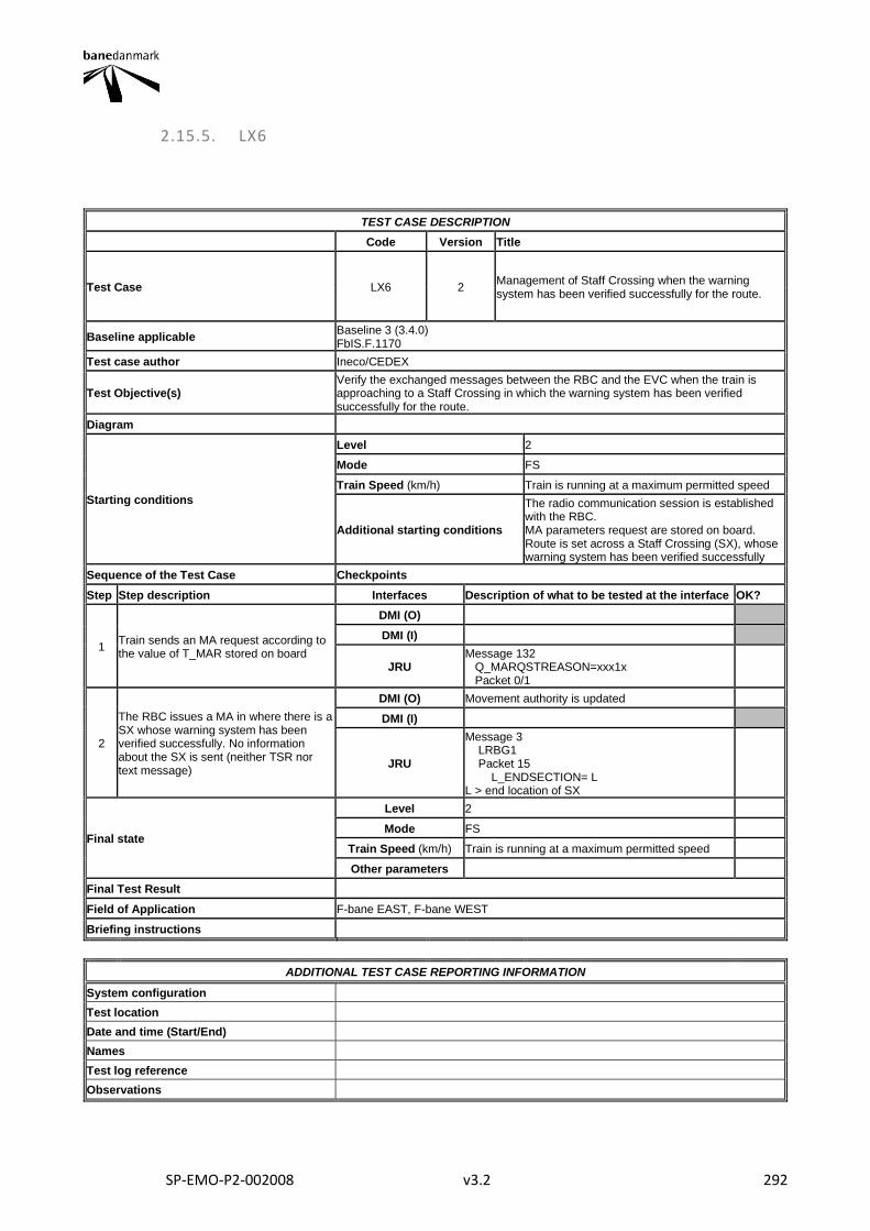
SP-EMO-P2-002008 v3.2 292
2.15.5. LX6
TEST CASE DESCRIPTION
Code Version Title
Test Case LX6 2 Management of Staff Crossing when the warning system has been verified successfully for the route.
Baseline applicable Baseline 3 (3.4.0) FbIS.F.1170
Test case author Ineco/CEDEX
Test Objective(s) Verify the exchanged messages between the RBC and the EVC when the train is approaching to a Staff Crossing in which the warning system has been verified successfully for the route.
Diagram
Starting conditions
Level 2
Mode FS
Train Speed (km/h) Train is running at a maximum permitted speed
Additional starting conditions
The radio communication session is established with the RBC. MA parameters request are stored on board. Route is set across a Staff Crossing (SX), whose warning system has been verified successfully
Sequence of the Test Case Checkpoints
Step Step description Interfaces Description of what to be tested at the interface OK?
1 Train sends an MA request according to the value of T_MAR stored on board
DMI (O)
DMI (I)
JRU Message 132 Q_MARQSTREASON=xxx1x Packet 0/1
2
The RBC issues a MA in where there is a SX whose warning system has been verified successfully. No information about the SX is sent (neither TSR nor text message)
DMI (O) Movement authority is updated
DMI (I)
JRU
Message 3 LRBG1 Packet 15 L_ENDSECTION= L L > end location of SX
Final state
Level 2
Mode FS
Train Speed (km/h) Train is running at a maximum permitted speed
Other parameters
Final Test Result
Field of Application F-bane EAST, F-bane WEST
Briefing instructions
ADDITIONAL TEST CASE REPORTING INFORMATION
System configuration
Test location
Date and time (Start/End)
Names
Test log reference
Observations
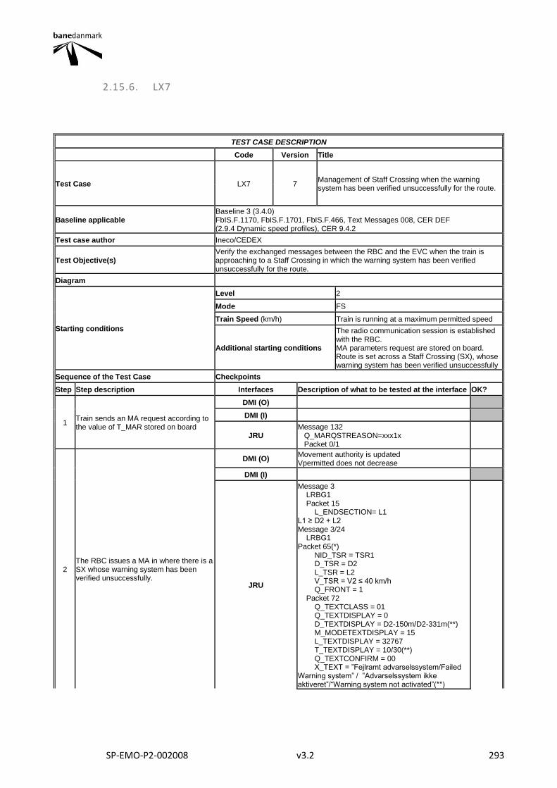
SP-EMO-P2-002008 v3.2 293
2.15.6. LX7
TEST CASE DESCRIPTION
Code Version Title
Test Case LX7 7 Management of Staff Crossing when the warning system has been verified unsuccessfully for the route.
Baseline applicable Baseline 3 (3.4.0) FbIS.F.1170, FbIS.F.1701, FbIS.F.466, Text Messages 008, CER DEF (2.9.4 Dynamic speed profiles), CER 9.4.2
Test case author Ineco/CEDEX
Test Objective(s) Verify the exchanged messages between the RBC and the EVC when the train is approaching to a Staff Crossing in which the warning system has been verified unsuccessfully for the route.
Diagram
Starting conditions
Level 2
Mode FS
Train Speed (km/h) Train is running at a maximum permitted speed
Additional starting conditions
The radio communication session is established with the RBC. MA parameters request are stored on board. Route is set across a Staff Crossing (SX), whose warning system has been verified unsuccessfully
Sequence of the Test Case Checkpoints
Step Step description Interfaces Description of what to be tested at the interface OK?
1 Train sends an MA request according to the value of T_MAR stored on board
DMI (O)
DMI (I)
JRU Message 132 Q_MARQSTREASON=xxx1x Packet 0/1
2 The RBC issues a MA in where there is a SX whose warning system has been verified unsuccessfully.
DMI (O) Movement authority is updated Vpermitted does not decrease
DMI (I)
JRU
Message 3 LRBG1 Packet 15 L_ENDSECTION= L1 L1 ≥ D2 + L2 Message 3/24 LRBG1 Packet 65(*) NID_TSR = TSR1 D_TSR = D2 L_TSR = L2 V_TSR = V2 ≤ 40 km/h Q_FRONT = 1 Packet 72 Q_TEXTCLASS = 01 Q_TEXTDISPLAY = 0 D_TEXTDISPLAY = D2-150m/D2-331m(**) M_MODETEXTDISPLAY = 15 L_TEXTDISPLAY = 32767 T_TEXTDISPLAY = 10/30(**) Q_TEXTCONFIRM = 00 X_TEXT = ”Fejlramt advarselssystem/Failed Warning system” / ”Advarselssystem ikke aktiveret”/“Warning system not activated”(**)

SP-EMO-P2-002008 v3.2 294
3 The EVC enters in braking curve to the TSR start location.
DMI (O)
Vpermitted decreases Vtarget=V2 Dtarget=Distance from the "Max safe front end" to the location of the permitted speed supervision limit calculated for the target speed.
DMI (I)
JRU
SPEED AND DISTANCE MONITORING INFORMATION V_TARGET=V2 D_TARGET<D2-D_LRBG1-L_DOUBTUNDER M_SDMTYPE=2
4
The train moves towards the SX and reaches a point 150/331(**) m in rear of the TSR1 area of the failed SX when the train has run the distance D2 - 150 / D2 - 331(**).
DMI (O) Text message of the failed SX appears
DMI (I)
JRU
estimated train location = D2 (LRBG1) - 150 m / D2 (LRBG1) - 331 m(**) START DISPLAYING TEXT MESSAGE TIME = T1
5
The train reaches with its maximum safe front end the location of the permitted speed supervision limit calculated for the target speed 40 Km/h.
DMI (O) Vpermitted = V2 Vtrain ≤ V2
DMI (I)
JRU
V_PERM = V2 V_TRAIN ≤ V2 estimated front end < D2 (LRBG1) - L_DOUBTUNDER
6 10/30(**) seconds have passed since the Text message began to be displayed on the DMI
DMI (O) Text message of the failed SX disappears
DMI (I)
JRU STOP DISPLAYING TEXT MESSAGE TIME = T1+ 10 s / T1+ 30 s(**)
7
The supervision of the TSR1 area of the failed SX finishes when the min safe front end has reached the end of the TSR area.
DMI (O) Vpermitted > 40 km/h (if possible)
DMI (I)
JRU
estimated front end = D2 (LRBG1) + L2 + L_DOUBTOVER SPEED AND DISTANCE MONITORING INFORMATION V_PERM=V_STATIC M_SDMTYPE=0
Final state
Level 2
Mode FS
Train Speed (km/h) Train is running at a maximum permitted speed
Other parameters
Final Test Result
Field of Application F-bane EAST, F-bane WEST
Briefing instructions
Depending on the distance D2, L2 and the train speed, the sequence of the steps 4, 5 and 6 may be altered. * If Packet 27 SSP is used instead of packet 65 for TSRs, log on test result "OK with comments" ** Applicable to EDL WEST DK2.0
ADDITIONAL TEST CASE REPORTING INFORMATION
System configuration
Test location
Date and time (Start/End)
Names
Test log reference
Observations
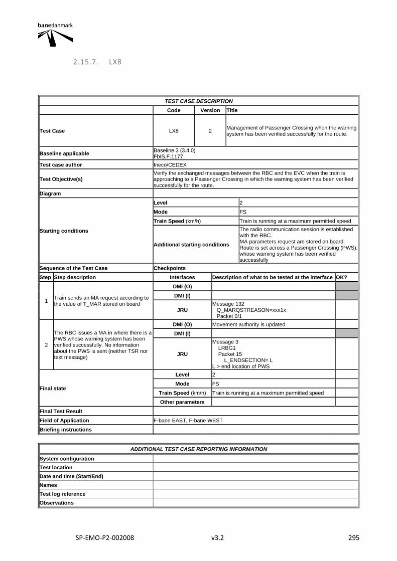
SP-EMO-P2-002008 v3.2 295
2.15.7. LX8
TEST CASE DESCRIPTION
Code Version Title
Test Case LX8 2 Management of Passenger Crossing when the warning system has been verified successfully for the route.
Baseline applicable Baseline 3 (3.4.0) FbIS.F.1177
Test case author Ineco/CEDEX
Test Objective(s) Verify the exchanged messages between the RBC and the EVC when the train is approaching to a Passenger Crossing in which the warning system has been verified successfully for the route.
Diagram
Starting conditions
Level 2
Mode FS
Train Speed (km/h) Train is running at a maximum permitted speed
Additional starting conditions
The radio communication session is established with the RBC. MA parameters request are stored on board. Route is set across a Passenger Crossing (PWS), whose warning system has been verified successfully
Sequence of the Test Case Checkpoints
Step Step description Interfaces Description of what to be tested at the interface OK?
1 Train sends an MA request according to the value of T_MAR stored on board
DMI (O)
DMI (I)
JRU Message 132 Q_MARQSTREASON=xxx1x Packet 0/1
2
The RBC issues a MA in where there is a PWS whose warning system has been verified successfully. No information about the PWS is sent (neither TSR nor text message)
DMI (O) Movement authority is updated
DMI (I)
JRU
Message 3 LRBG1 Packet 15 L_ENDSECTION= L L > end location of PWS
Final state
Level 2
Mode FS
Train Speed (km/h) Train is running at a maximum permitted speed
Other parameters
Final Test Result
Field of Application F-bane EAST, F-bane WEST
Briefing instructions
ADDITIONAL TEST CASE REPORTING INFORMATION
System configuration
Test location
Date and time (Start/End)
Names
Test log reference
Observations

SP-EMO-P2-002008 v3.2 296
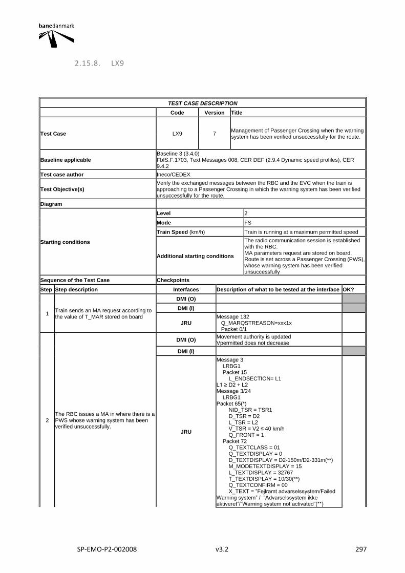
SP-EMO-P2-002008 v3.2 297
2.15.8. LX9
TEST CASE DESCRIPTION
Code Version Title
Test Case LX9 7 Management of Passenger Crossing when the warning system has been verified unsuccessfully for the route.
Baseline applicable Baseline 3 (3.4.0) FbIS.F.1703, Text Messages 008, CER DEF (2.9.4 Dynamic speed profiles), CER 9.4.2
Test case author Ineco/CEDEX
Test Objective(s) Verify the exchanged messages between the RBC and the EVC when the train is approaching to a Passenger Crossing in which the warning system has been verified unsuccessfully for the route.
Diagram
Starting conditions
Level 2
Mode FS
Train Speed (km/h) Train is running at a maximum permitted speed
Additional starting conditions
The radio communication session is established with the RBC. MA parameters request are stored on board. Route is set across a Passenger Crossing (PWS), whose warning system has been verified unsuccessfully
Sequence of the Test Case Checkpoints
Step Step description Interfaces Description of what to be tested at the interface OK?
1 Train sends an MA request according to the value of T_MAR stored on board
DMI (O)
DMI (I)
JRU Message 132 Q_MARQSTREASON=xxx1x Packet 0/1
2 The RBC issues a MA in where there is a PWS whose warning system has been verified unsuccessfully.
DMI (O) Movement authority is updated Vpermitted does not decrease
DMI (I)
JRU
Message 3 LRBG1 Packet 15 L_ENDSECTION= L1 L1 ≥ D2 + L2 Message 3/24 LRBG1 Packet 65(*) NID_TSR = TSR1 D_TSR = D2 L_TSR = L2 V_TSR = V2 ≤ 40 km/h Q_FRONT = 1 Packet 72 Q_TEXTCLASS = 01 Q_TEXTDISPLAY = 0 D_TEXTDISPLAY = D2-150m/D2-331m(**) M_MODETEXTDISPLAY = 15 L_TEXTDISPLAY = 32767 T_TEXTDISPLAY = 10/30(**) Q_TEXTCONFIRM = 00 X_TEXT = ”Fejlramt advarselssystem/Failed Warning system” / ”Advarselssystem ikke aktiveret”/“Warning system not activated”(**)
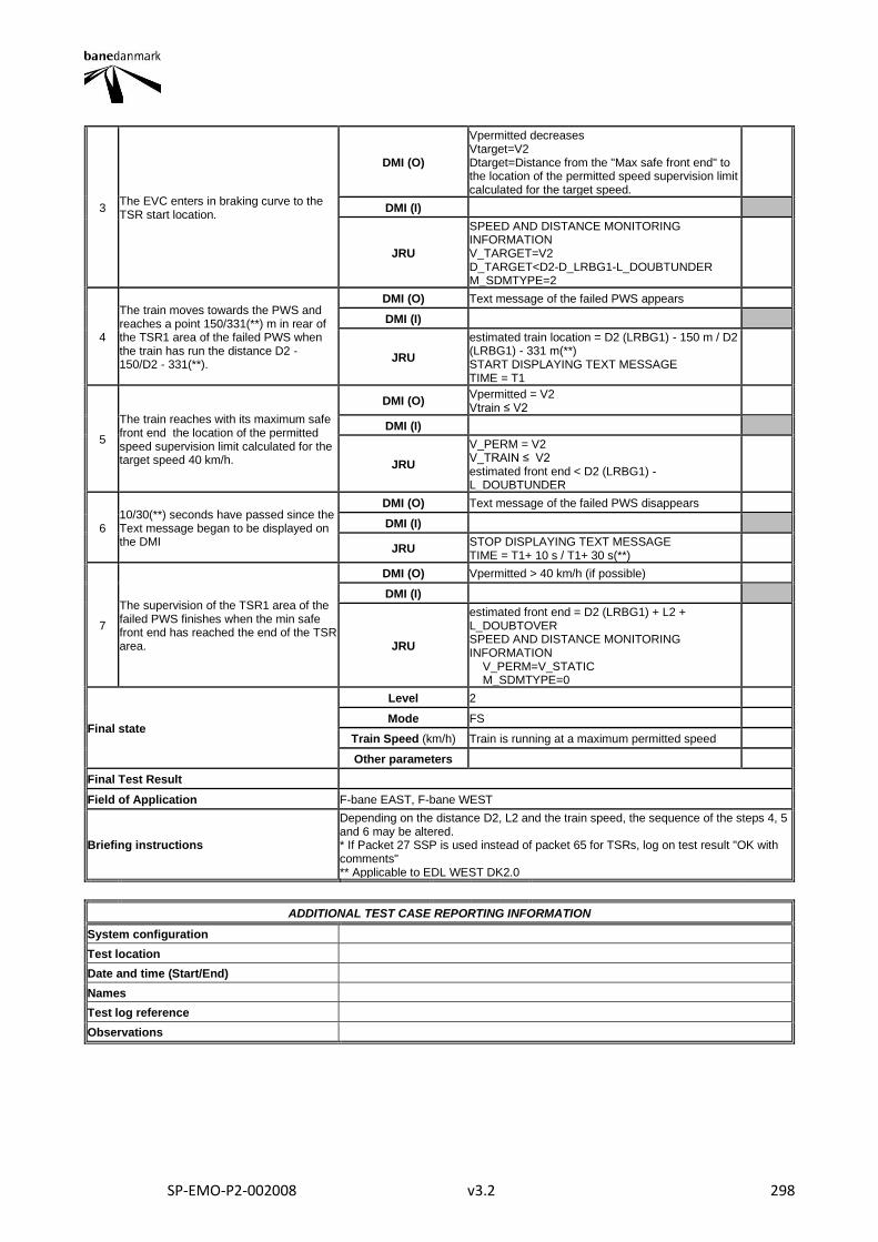
SP-EMO-P2-002008 v3.2 298
3 The EVC enters in braking curve to the TSR start location.
DMI (O)
Vpermitted decreases Vtarget=V2 Dtarget=Distance from the "Max safe front end" to the location of the permitted speed supervision limit calculated for the target speed.
DMI (I)
JRU
SPEED AND DISTANCE MONITORING INFORMATION V_TARGET=V2 D_TARGET<D2-D_LRBG1-L_DOUBTUNDER M_SDMTYPE=2
4
The train moves towards the PWS and reaches a point 150/331(**) m in rear of the TSR1 area of the failed PWS when the train has run the distance D2 - 150/D2 - 331(**).
DMI (O) Text message of the failed PWS appears
DMI (I)
JRU
estimated train location = D2 (LRBG1) - 150 m / D2 (LRBG1) - 331 m(**) START DISPLAYING TEXT MESSAGE TIME = T1
5
The train reaches with its maximum safe front end the location of the permitted speed supervision limit calculated for the target speed 40 km/h.
DMI (O) Vpermitted = V2 Vtrain ≤ V2
DMI (I)
JRU
V_PERM = V2 V_TRAIN ≤ V2 estimated front end < D2 (LRBG1) - L_DOUBTUNDER
6 10/30(**) seconds have passed since the Text message began to be displayed on the DMI
DMI (O) Text message of the failed PWS disappears
DMI (I)
JRU STOP DISPLAYING TEXT MESSAGE TIME = T1+ 10 s / T1+ 30 s(**)
7
The supervision of the TSR1 area of the failed PWS finishes when the min safe front end has reached the end of the TSR area.
DMI (O) Vpermitted > 40 km/h (if possible)
DMI (I)
JRU
estimated front end = D2 (LRBG1) + L2 + L_DOUBTOVER SPEED AND DISTANCE MONITORING INFORMATION V_PERM=V_STATIC M_SDMTYPE=0
Final state
Level 2
Mode FS
Train Speed (km/h) Train is running at a maximum permitted speed
Other parameters
Final Test Result
Field of Application F-bane EAST, F-bane WEST
Briefing instructions
Depending on the distance D2, L2 and the train speed, the sequence of the steps 4, 5 and 6 may be altered. * If Packet 27 SSP is used instead of packet 65 for TSRs, log on test result "OK with comments" ** Applicable to EDL WEST DK2.0
ADDITIONAL TEST CASE REPORTING INFORMATION
System configuration
Test location
Date and time (Start/End)
Names
Test log reference
Observations
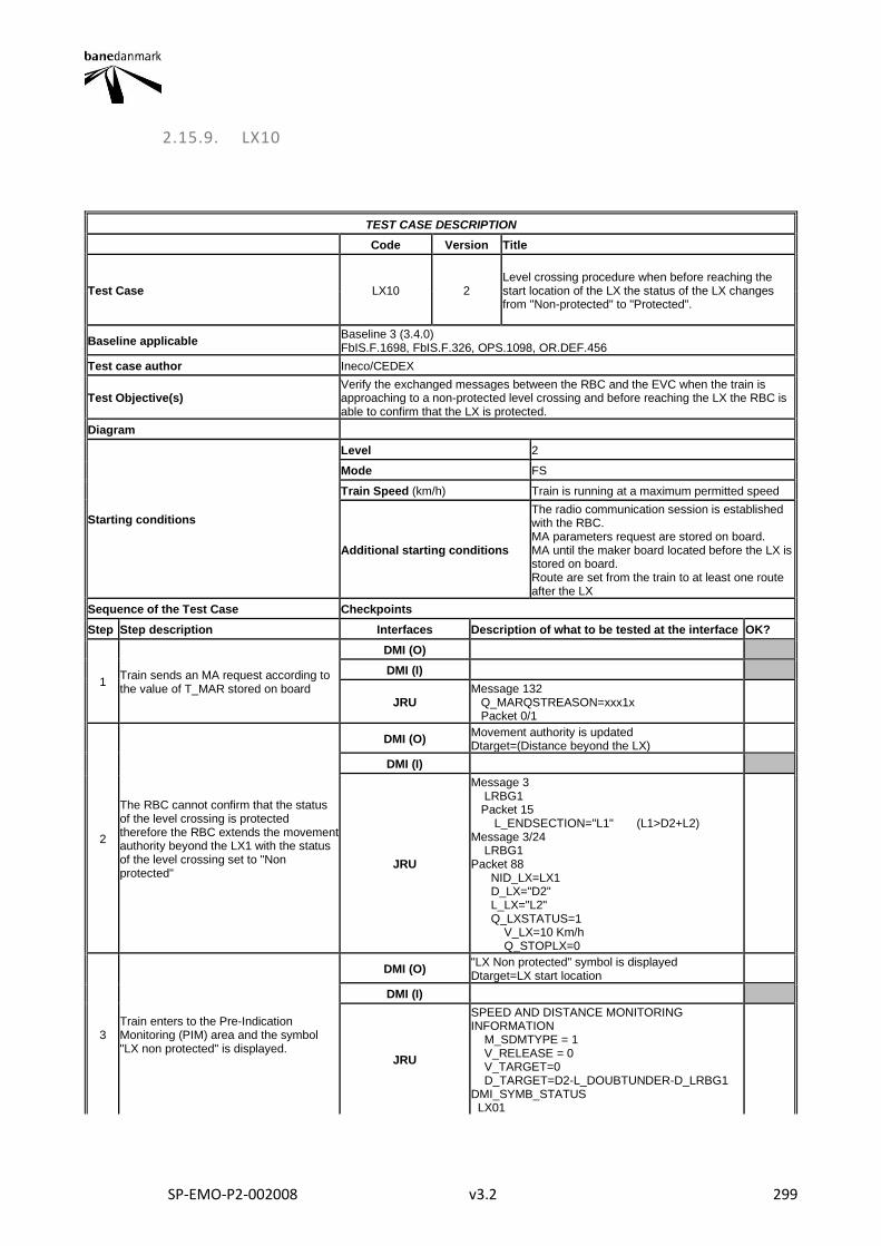
SP-EMO-P2-002008 v3.2 299
2.15.9. LX10
TEST CASE DESCRIPTION
Code Version Title
Test Case LX10 2 Level crossing procedure when before reaching the start location of the LX the status of the LX changes from "Non-protected" to "Protected".
Baseline applicable Baseline 3 (3.4.0) FbIS.F.1698, FbIS.F.326, OPS.1098, OR.DEF.456
Test case author Ineco/CEDEX
Test Objective(s) Verify the exchanged messages between the RBC and the EVC when the train is approaching to a non-protected level crossing and before reaching the LX the RBC is able to confirm that the LX is protected.
Diagram
Starting conditions
Level 2
Mode FS
Train Speed (km/h) Train is running at a maximum permitted speed
Additional starting conditions
The radio communication session is established with the RBC. MA parameters request are stored on board. MA until the maker board located before the LX is stored on board. Route are set from the train to at least one route after the LX
Sequence of the Test Case Checkpoints
Step Step description Interfaces Description of what to be tested at the interface OK?
1 Train sends an MA request according to the value of T_MAR stored on board
DMI (O)
DMI (I)
JRU Message 132 Q_MARQSTREASON=xxx1x Packet 0/1
2
The RBC cannot confirm that the status of the level crossing is protected therefore the RBC extends the movement authority beyond the LX1 with the status of the level crossing set to "Non protected"
DMI (O) Movement authority is updated Dtarget=(Distance beyond the LX)
DMI (I)
JRU
Message 3 LRBG1 Packet 15 L_ENDSECTION="L1" (L1>D2+L2) Message 3/24 LRBG1 Packet 88 NID_LX=LX1 D_LX="D2" L_LX="L2" Q_LXSTATUS=1 V_LX=10 Km/h Q_STOPLX=0
3 Train enters to the Pre-Indication Monitoring (PIM) area and the symbol "LX non protected" is displayed.
DMI (O) "LX Non protected" symbol is displayed Dtarget=LX start location
DMI (I)
JRU
SPEED AND DISTANCE MONITORING INFORMATION M_SDMTYPE = 1 V_RELEASE = 0 V_TARGET=0 D_TARGET=D2-L_DOUBTUNDER-D_LRBG1 DMI_SYMB_STATUS LX01
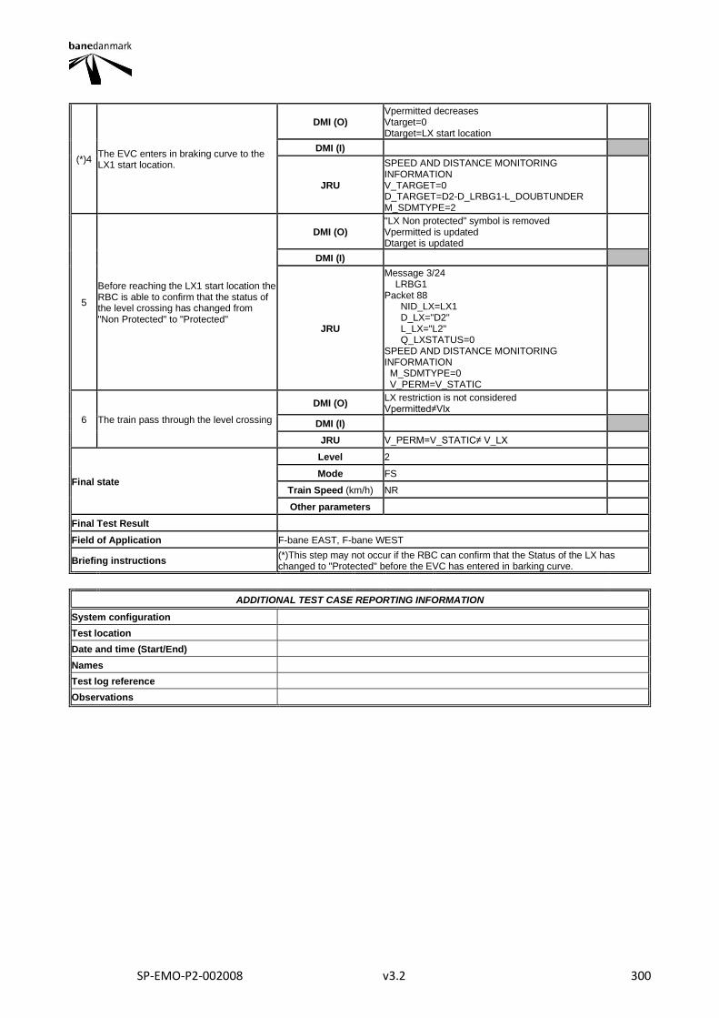
SP-EMO-P2-002008 v3.2 300
(*)4 The EVC enters in braking curve to the LX1 start location.
DMI (O) Vpermitted decreases Vtarget=0 Dtarget=LX start location
DMI (I)
JRU
SPEED AND DISTANCE MONITORING INFORMATION V_TARGET=0 D_TARGET=D2-D_LRBG1-L_DOUBTUNDER M_SDMTYPE=2
5
Before reaching the LX1 start location the RBC is able to confirm that the status of the level crossing has changed from "Non Protected" to "Protected"
DMI (O) "LX Non protected" symbol is removed Vpermitted is updated Dtarget is updated
DMI (I)
JRU
Message 3/24 LRBG1 Packet 88 NID_LX=LX1 D_LX="D2" L_LX="L2" Q_LXSTATUS=0 SPEED AND DISTANCE MONITORING INFORMATION M_SDMTYPE=0 V_PERM=V_STATIC
6 The train pass through the level crossing
DMI (O) LX restriction is not considered Vpermitted≠Vlx
DMI (I)
JRU V_PERM=V_STATIC≠ V_LX
Final state
Level 2
Mode FS
Train Speed (km/h) NR
Other parameters
Final Test Result
Field of Application F-bane EAST, F-bane WEST
Briefing instructions (*)This step may not occur if the RBC can confirm that the Status of the LX has changed to "Protected" before the EVC has entered in barking curve.
ADDITIONAL TEST CASE REPORTING INFORMATION
System configuration
Test location
Date and time (Start/End)
Names
Test log reference
Observations
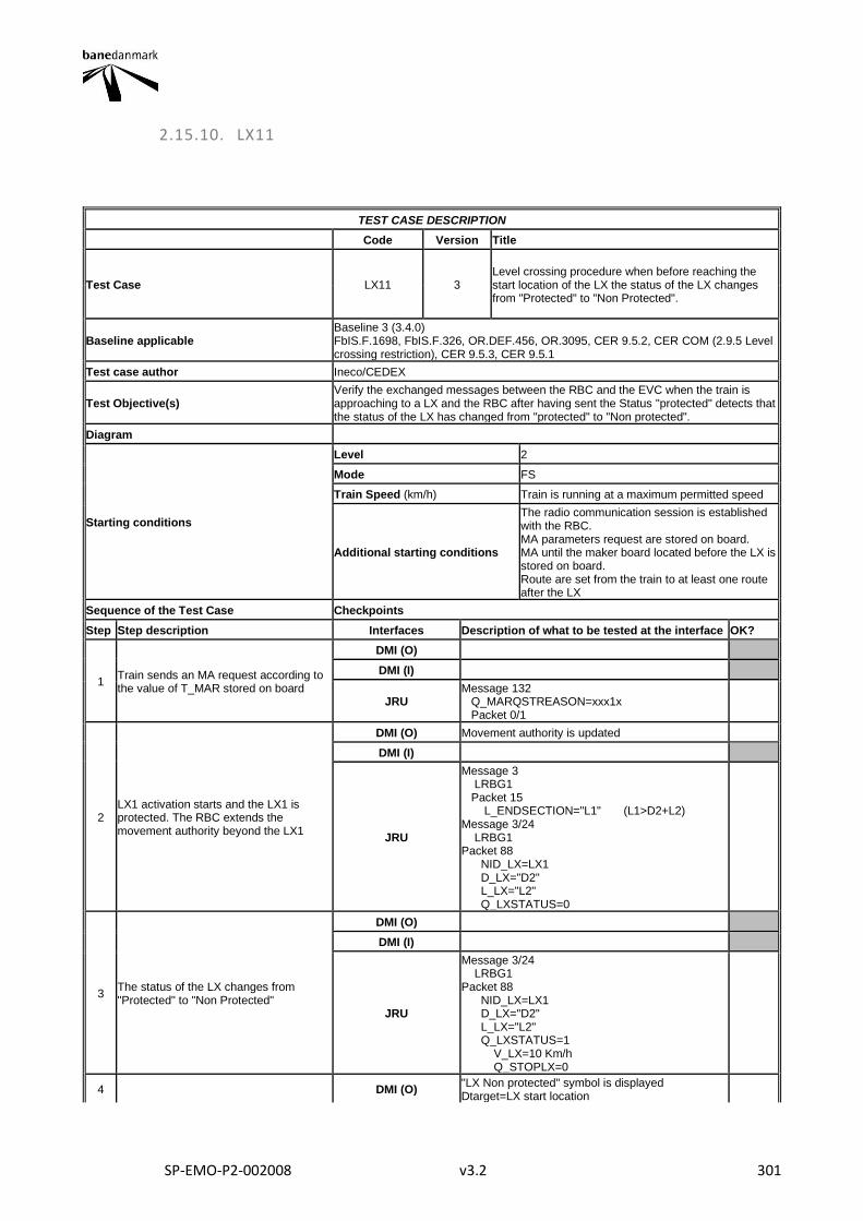
SP-EMO-P2-002008 v3.2 301
2.15.10. LX11
TEST CASE DESCRIPTION
Code Version Title
Test Case LX11 3 Level crossing procedure when before reaching the start location of the LX the status of the LX changes from "Protected" to "Non Protected".
Baseline applicable Baseline 3 (3.4.0) FbIS.F.1698, FbIS.F.326, OR.DEF.456, OR.3095, CER 9.5.2, CER COM (2.9.5 Level crossing restriction), CER 9.5.3, CER 9.5.1
Test case author Ineco/CEDEX
Test Objective(s) Verify the exchanged messages between the RBC and the EVC when the train is approaching to a LX and the RBC after having sent the Status "protected" detects that the status of the LX has changed from "protected" to "Non protected".
Diagram
Starting conditions
Level 2
Mode FS
Train Speed (km/h) Train is running at a maximum permitted speed
Additional starting conditions
The radio communication session is established with the RBC. MA parameters request are stored on board. MA until the maker board located before the LX is stored on board. Route are set from the train to at least one route after the LX
Sequence of the Test Case Checkpoints
Step Step description Interfaces Description of what to be tested at the interface OK?
1 Train sends an MA request according to the value of T_MAR stored on board
DMI (O)
DMI (I)
JRU Message 132 Q_MARQSTREASON=xxx1x Packet 0/1
2 LX1 activation starts and the LX1 is protected. The RBC extends the movement authority beyond the LX1
DMI (O) Movement authority is updated
DMI (I)
JRU
Message 3 LRBG1 Packet 15 L_ENDSECTION="L1" (L1>D2+L2) Message 3/24 LRBG1 Packet 88 NID_LX=LX1 D_LX="D2" L_LX="L2" Q_LXSTATUS=0
3 The status of the LX changes from "Protected" to "Non Protected"
DMI (O)
DMI (I)
JRU
Message 3/24 LRBG1 Packet 88 NID_LX=LX1 D_LX="D2" L_LX="L2" Q_LXSTATUS=1 V_LX=10 Km/h Q_STOPLX=0
4 DMI (O) "LX Non protected" symbol is displayed Dtarget=LX start location
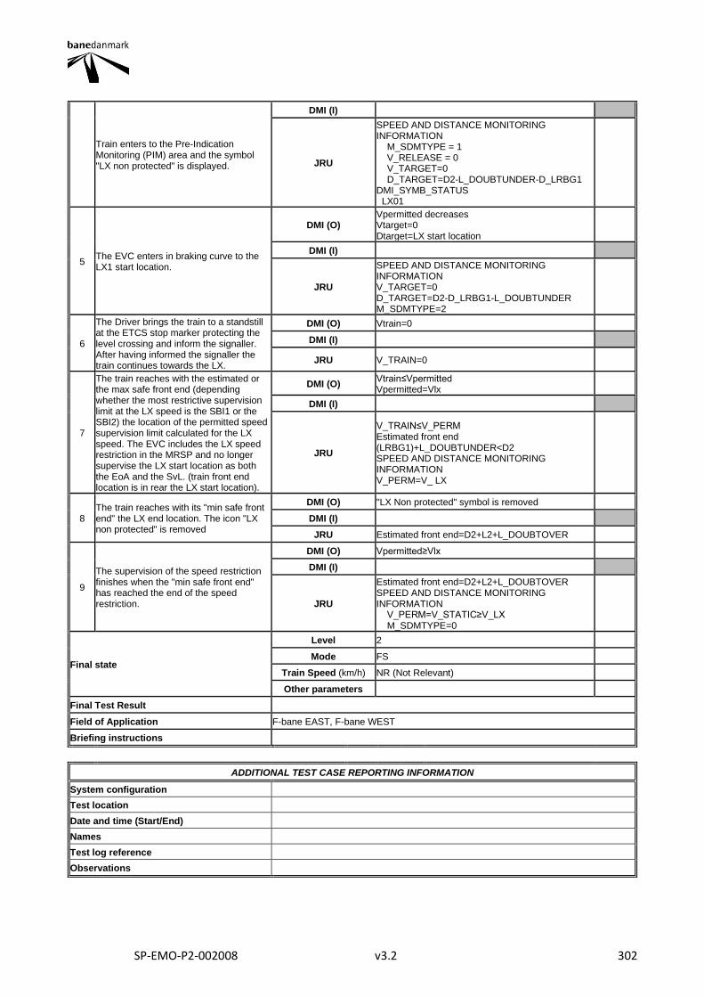
SP-EMO-P2-002008 v3.2 302
Train enters to the Pre-Indication Monitoring (PIM) area and the symbol "LX non protected" is displayed.
DMI (I)
JRU
SPEED AND DISTANCE MONITORING INFORMATION M_SDMTYPE = 1 V_RELEASE = 0 V_TARGET=0 D_TARGET=D2-L_DOUBTUNDER-D_LRBG1 DMI_SYMB_STATUS LX01
5 The EVC enters in braking curve to the LX1 start location.
DMI (O) Vpermitted decreases Vtarget=0 Dtarget=LX start location
DMI (I)
JRU
SPEED AND DISTANCE MONITORING INFORMATION V_TARGET=0 D_TARGET=D2-D_LRBG1-L_DOUBTUNDER M_SDMTYPE=2
6
The Driver brings the train to a standstill at the ETCS stop marker protecting the level crossing and inform the signaller. After having informed the signaller the train continues towards the LX.
DMI (O) Vtrain=0
DMI (I)
JRU V_TRAIN=0
7
The train reaches with the estimated or the max safe front end (depending whether the most restrictive supervision limit at the LX speed is the SBI1 or the SBI2) the location of the permitted speed supervision limit calculated for the LX speed. The EVC includes the LX speed restriction in the MRSP and no longer supervise the LX start location as both the EoA and the SvL. (train front end location is in rear the LX start location).
DMI (O) Vtrain≤Vpermitted Vpermitted=Vlx
DMI (I)
JRU
V_TRAIN≤V_PERM Estimated front end (LRBG1)+L_DOUBTUNDER<D2 SPEED AND DISTANCE MONITORING INFORMATION V_PERM=V_ LX
8 The train reaches with its "min safe front end" the LX end location. The icon "LX non protected" is removed
DMI (O) "LX Non protected" symbol is removed
DMI (I)
JRU Estimated front end=D2+L2+L_DOUBTOVER
9
The supervision of the speed restriction finishes when the "min safe front end" has reached the end of the speed restriction.
DMI (O) Vpermitted≥Vlx
DMI (I)
JRU
Estimated front end=D2+L2+L_DOUBTOVER SPEED AND DISTANCE MONITORING INFORMATION V_PERM=V_STATIC≥V_LX M_SDMTYPE=0
Final state
Level 2
Mode FS
Train Speed (km/h) NR (Not Relevant)
Other parameters
Final Test Result
Field of Application F-bane EAST, F-bane WEST
Briefing instructions
ADDITIONAL TEST CASE REPORTING INFORMATION
System configuration
Test location
Date and time (Start/End)
Names
Test log reference
Observations
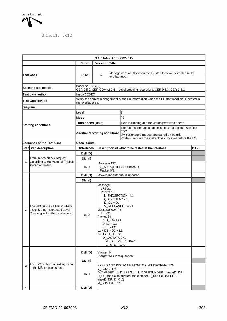
SP-EMO-P2-002008 v3.2 303
2.15.11. LX12
TEST CASE DESCRIPTION
Code Version Title
Test Case LX12 5 Management of LXs when the LX start location is located in the overlap area.
Baseline applicable Baseline 3 (3.4.0) CER 9.5.2, CER COM (2.9.5 Level crossing restriction), CER 9.5.3, CER 9.5.1
Test case author Ineco/CEDEX
Test Objective(s) Verify the correct management of the LX information when the LX start location is located in the overlap area.
Diagram
Starting conditions
Level 2
Mode FS
Train Speed (km/h) Train is running at a maximum permitted speed
Additional starting conditions
The radio communication session is established with the RBC. MA parameters request are stored on board. Route is set until the maker board located before the LX
Sequence of the Test Case Checkpoints
Step Step description Interfaces Description of what to be tested at the interface OK?
1 Train sends an MA request according to the value of T_MAR stored on board
DMI (O)
DMI (I)
JRU Message 132 Q_MARQSTREASON=xxx1x Packet 0/1
2 The RBC issues a MA in where there is a non-protected Level Crossing within the overlap area
DMI (O) Movement authority is updated
DMI (I)
JRU
Message 3 LRBG1 Packet 15 L_ENDSECTION= L1 Q_OVERLAP = 1 D_OL = D1 V_RELEASEOL = V1 Message 3/24 (*) LRBG1 Packet 88 NID_LX= LX1 D_LX= D2 L_LX= L2 L1 + D1 > D2 > L1 D2+L2 ≤ L1 + D1 Q_LXSTATUS=1 V_LX = V2 = 15 Km/h Q_STOPLX=0
3 The EVC enters in braking curve to the MB in stop aspect.
DMI (O) Vtarget=0 Dtarget=MB in stop aspect
DMI (I)
JRU
SPEED AND DISTANCE MONITORING INFORMATION V_TARGET=0 D_TARGET=L1-D_LRBG1 (if L_DOUBTUNDER > max(D_DP, D_OL) then also subtract the distance L_DOUBTUNDER - max(D_DP, D_OL)) M_SDMTYPE=2
4 DMI (O)
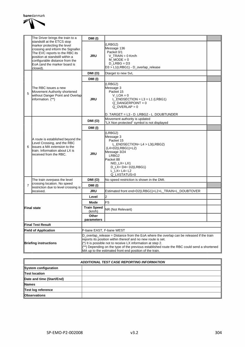
SP-EMO-P2-002008 v3.2 304
The Driver brings the train to a standstill at the ETCS stop marker protecting the level crossing and inform the Signaller. The EVC reports to the RBC its position at standstill within a configurable distance from the EoA (and the marker board is closed).
DMI (I)
JRU
(LRBG2) Message 136 Packet 0/1 V_TRAIN = 0 Km/h M_MODE = 0 D_LRBG = D3 D3 > L1(LRBG1) - D_overlap_release
5
The RBC issues a new Movement Authority shortened without Danger Point and Overlap information. (**)
DMI (O) Dtarget to new SvL
DMI (I)
JRU
(LRBG2) Message 3 Packet 15 V_LOA = 0 L_ENDSECTION = L3 = L1 (LRBG1) Q_DANGERPOINT = 0 Q_OVERLAP = 0 D_TARGET = L3 - D_LRBG2 - L_DOUBTUNDER
6
A route is established beyond the Level Crossing, and the RBC issues a MA extension to the train. Information about LX is received from the RBC.
DMI (O) Movement authority is updated "LX Non protected" symbol is not displayed
DMI (I)
JRU
(LRBG2) Message 3 Packet 15 L_ENDSECTION= L4 > L3(LRBG2) (L4>D2(LRBG1)+L2) Message 3/24 LRBG2 Packet 88 NID_LX= LX1 D_LX= D4= D2(LRBG1) L_LX= L4= L2 Q_LXSTATUS=0
7
The train overpass the level crossing location. No speed restriction due to level crossing is received.
DMI (O) No speed restriction is shown in the DMI.
DMI (I)
JRU Estimated front end>D2(LRBG1)+L2+L_TRAIN+L_DOUBTOVER
Final state
Level 2
Mode FS
Train Speed (km/h)
NR (Not Relevant)
Other parameters
Final Test Result
Field of Application F-bane EAST, F-bane WEST
Briefing instructions
D_overlap_release = Distance from the EoA where the overlap can be released if the train reports its position within thereof and no new route is set. (*) It is possible not to receive LX information at step 2. (**) Depending on the type of the previous established route the RBC could send a shortened MA up to the estimated front end position of the train.
ADDITIONAL TEST CASE REPORTING INFORMATION
System configuration
Test location
Date and time (Start/End)
Names
Test log reference
Observations
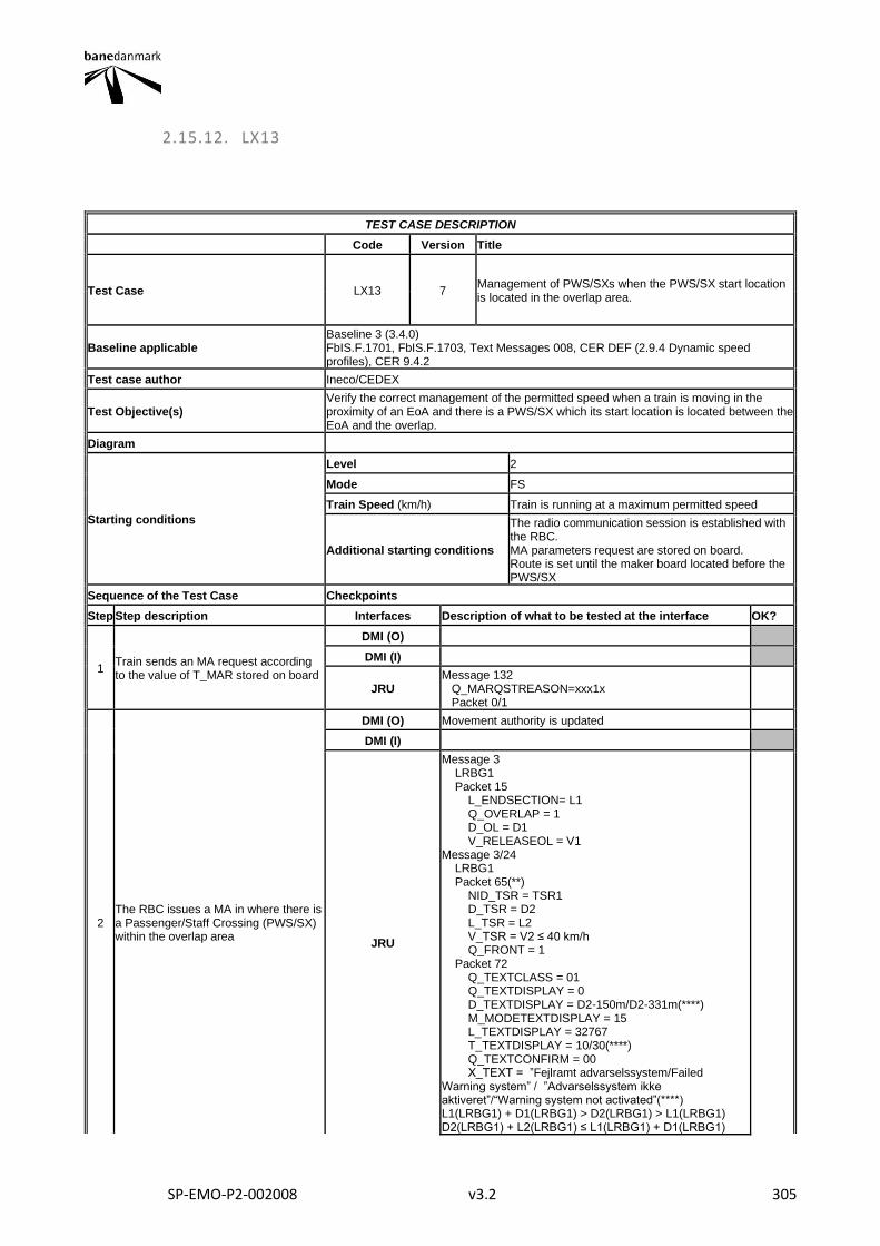
SP-EMO-P2-002008 v3.2 305
2.15.12. LX13
TEST CASE DESCRIPTION
Code Version Title
Test Case LX13 7 Management of PWS/SXs when the PWS/SX start location is located in the overlap area.
Baseline applicable Baseline 3 (3.4.0) FbIS.F.1701, FbIS.F.1703, Text Messages 008, CER DEF (2.9.4 Dynamic speed profiles), CER 9.4.2
Test case author Ineco/CEDEX
Test Objective(s) Verify the correct management of the permitted speed when a train is moving in the proximity of an EoA and there is a PWS/SX which its start location is located between the EoA and the overlap.
Diagram
Starting conditions
Level 2
Mode FS
Train Speed (km/h) Train is running at a maximum permitted speed
Additional starting conditions
The radio communication session is established with the RBC. MA parameters request are stored on board. Route is set until the maker board located before the PWS/SX
Sequence of the Test Case Checkpoints
Step Step description Interfaces Description of what to be tested at the interface OK?
1 Train sends an MA request according to the value of T_MAR stored on board
DMI (O)
DMI (I)
JRU Message 132 Q_MARQSTREASON=xxx1x Packet 0/1
2 The RBC issues a MA in where there is a Passenger/Staff Crossing (PWS/SX) within the overlap area
DMI (O) Movement authority is updated
DMI (I)
JRU
Message 3 LRBG1 Packet 15 L_ENDSECTION= L1 Q_OVERLAP = 1 D_OL = D1 V_RELEASEOL = V1 Message 3/24 LRBG1 Packet 65(**) NID_TSR = TSR1 D_TSR = D2 L_TSR = L2 V_TSR = V2 ≤ 40 km/h Q_FRONT = 1 Packet 72 Q_TEXTCLASS = 01 Q_TEXTDISPLAY = 0 D_TEXTDISPLAY = D2-150m/D2-331m(****) M_MODETEXTDISPLAY = 15 L_TEXTDISPLAY = 32767 T_TEXTDISPLAY = 10/30(****) Q_TEXTCONFIRM = 00 X_TEXT = ”Fejlramt advarselssystem/Failed Warning system” / ”Advarselssystem ikke aktiveret”/“Warning system not activated”(****) L1(LRBG1) + D1(LRBG1) > D2(LRBG1) > L1(LRBG1) D2(LRBG1) + L2(LRBG1) ≤ L1(LRBG1) + D1(LRBG1)
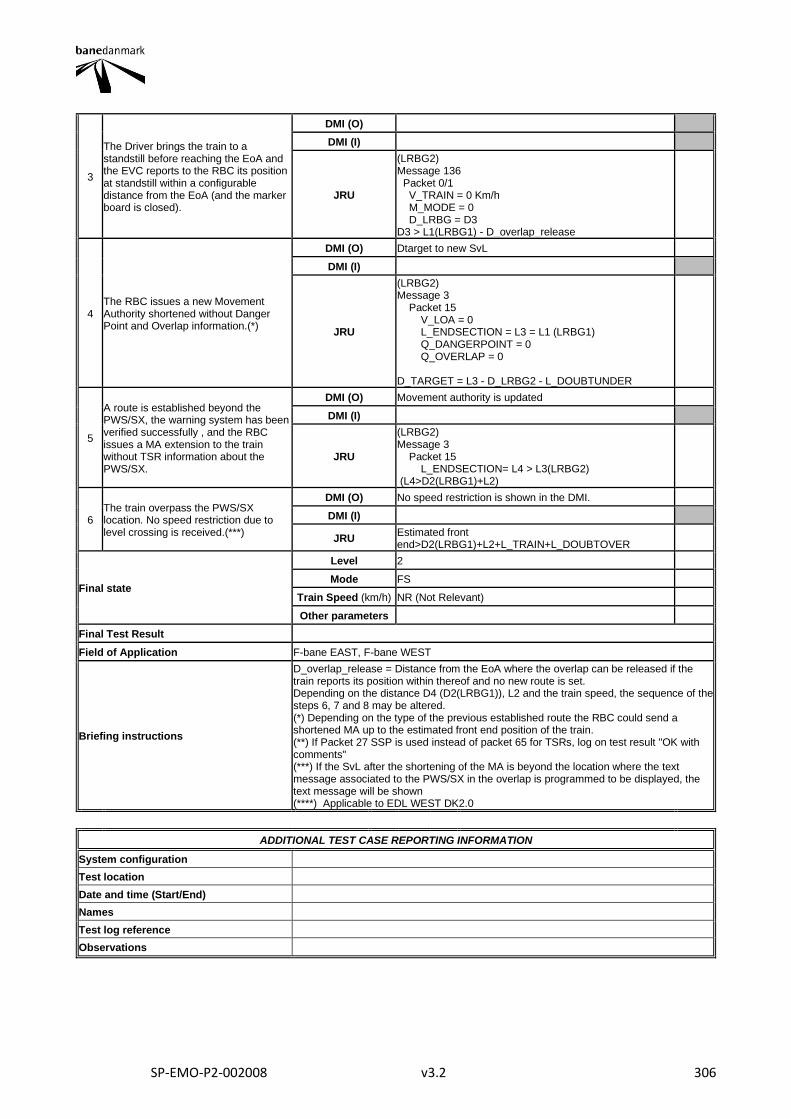
SP-EMO-P2-002008 v3.2 306
3
The Driver brings the train to a standstill before reaching the EoA and the EVC reports to the RBC its position at standstill within a configurable distance from the EoA (and the marker board is closed).
DMI (O)
DMI (I)
JRU
(LRBG2) Message 136 Packet 0/1 V_TRAIN = 0 Km/h M_MODE = 0 D_LRBG = D3 D3 > L1(LRBG1) - D_overlap_release
4 The RBC issues a new Movement Authority shortened without Danger Point and Overlap information.(*)
DMI (O) Dtarget to new SvL
DMI (I)
JRU
(LRBG2) Message 3 Packet 15 V_LOA = 0 L_ENDSECTION = L3 = L1 (LRBG1) Q_DANGERPOINT = 0 Q_OVERLAP = 0 D_TARGET = L3 - D_LRBG2 - L_DOUBTUNDER
5
A route is established beyond the PWS/SX, the warning system has been verified successfully , and the RBC issues a MA extension to the train without TSR information about the PWS/SX.
DMI (O) Movement authority is updated
DMI (I)
JRU
(LRBG2) Message 3 Packet 15 L_ENDSECTION= L4 > L3(LRBG2) (L4>D2(LRBG1)+L2)
6 The train overpass the PWS/SX location. No speed restriction due to level crossing is received.(***)
DMI (O) No speed restriction is shown in the DMI.
DMI (I)
JRU Estimated front end>D2(LRBG1)+L2+L_TRAIN+L_DOUBTOVER
Final state
Level 2
Mode FS
Train Speed (km/h) NR (Not Relevant)
Other parameters
Final Test Result
Field of Application F-bane EAST, F-bane WEST
Briefing instructions
D_overlap_release = Distance from the EoA where the overlap can be released if the train reports its position within thereof and no new route is set. Depending on the distance D4 (D2(LRBG1)), L2 and the train speed, the sequence of the steps 6, 7 and 8 may be altered. (*) Depending on the type of the previous established route the RBC could send a shortened MA up to the estimated front end position of the train. (**) If Packet 27 SSP is used instead of packet 65 for TSRs, log on test result "OK with comments" (***) If the SvL after the shortening of the MA is beyond the location where the text message associated to the PWS/SX in the overlap is programmed to be displayed, the text message will be shown (****) Applicable to EDL WEST DK2.0
ADDITIONAL TEST CASE REPORTING INFORMATION
System configuration
Test location
Date and time (Start/End)
Names
Test log reference
Observations
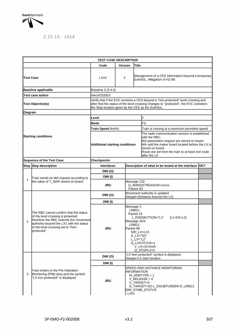
SP-EMO-P2-002008 v3.2 307
2.15.13. LX14
TEST CASE DESCRIPTION
Code Version Title
Test Case LX14 2 Management of a CES information beyond a temporary EoA/SvL. Mitigation of HZ-68.
Baseline applicable Baseline 3 (3.4.0)
Test case author Ineco/CEDEX
Test Objective(s) Verify that if the EVC receives a CES beyond a "non-protected" level crossing and after that the status of the level crossing changes to "protected", the EVC considers the Stop location given by the CES as the EoA/SvL.
Diagram
Starting conditions
Level 2
Mode FS
Train Speed (km/h) Train is running at a maximum permitted speed
Additional starting conditions
The radio communication session is established with the RBC. MA parameters request are stored on board. MA until the maker board located before the LX is stored on board. Route are set from the train to at least one route after the LX
Sequence of the Test Case Checkpoints
Step Step description Interfaces Description of what to be tested at the interface OK?
1 Train sends an MA request according to the value of T_MAR stored on board
DMI (O)
DMI (I)
JRU Message 132 Q_MARQSTREASON=xxx1x Packet 0/1
2
The RBC cannot confirm that the status of the level crossing is protected therefore the RBC extends the movement authority beyond the LX1 with the status of the level crossing set to "Non-protected"
DMI (O) Movement authority is updated Dtarget=(Distance beyond the LX)
DMI (I)
JRU
Message 3 LRBG1 Packet 15 L_ENDSECTION="L1" (L1>D2+L2) Message 3/24 LRBG1 Packet 88 NID_LX=LX1 D_LX="D2" L_LX="L2" Q_LXSTATUS=1 V_LX=10 Km/h Q_STOPLX=0
3 Train enters to the Pre-Indication Monitoring (PIM) area and the symbol "LX non protected" is displayed.
DMI (O) "LX Non protected" symbol is displayed Dtarget=LX start location
DMI (I)
JRU
SPEED AND DISTANCE MONITORING INFORMATION M_SDMTYPE = 1 V_RELEASE = 0 V_TARGET=0 D_TARGET=D2-L_DOUBTUNDER-D_LRBG1 DMI_SYMB_STATUS LX01
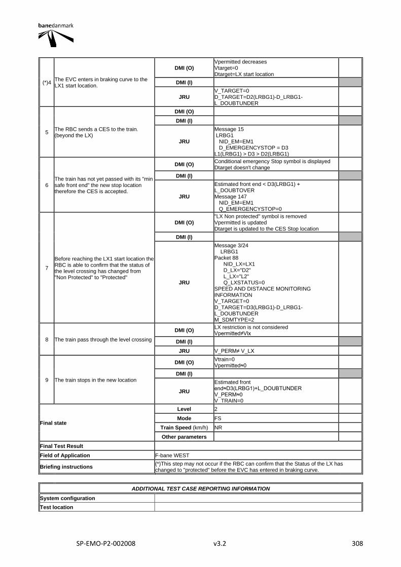
SP-EMO-P2-002008 v3.2 308
(*)4 The EVC enters in braking curve to the LX1 start location.
DMI (O) Vpermitted decreases Vtarget=0 Dtarget=LX start location
DMI (I)
JRU V_TARGET=0 D_TARGET=D2(LRBG1)-D_LRBG1-L_DOUBTUNDER
5 The RBC sends a CES to the train. (beyond the LX)
DMI (O)
DMI (I)
JRU
Message 15 LRBG1 NID_EM=EM1 D_EMERGENCYSTOP = D3 L1(LRBG1) > D3 > D2(LRBG1)
6 The train has not yet passed with its "min safe front end" the new stop location therefore the CES is accepted.
DMI (O) Conditional emergency Stop symbol is displayed Dtarget doesn't change
DMI (I)
JRU
Estimated front end < D3(LRBG1) + L_DOUBTOVER Message 147 NID_EM=EM1 Q_EMERGENCYSTOP=0
7
Before reaching the LX1 start location the RBC is able to confirm that the status of the level crossing has changed from "Non Protected" to "Protected"
DMI (O) "LX Non protected" symbol is removed Vpermitted is updated Dtarget is updated to the CES Stop location
DMI (I)
JRU
Message 3/24 LRBG1 Packet 88 NID_LX=LX1 D_LX="D2" L_LX="L2" Q_LXSTATUS=0 SPEED AND DISTANCE MONITORING INFORMATION V_TARGET=0 D_TARGET=D3(LRBG1)-D_LRBG1-L_DOUBTUNDER M_SDMTYPE=2
8 The train pass through the level crossing
DMI (O) LX restriction is not considered Vpermitted≠Vlx
DMI (I)
JRU V_PERM≠ V_LX
9 The train stops in the new location
DMI (O) Vtrain=0 Vpermitted≈0
DMI (I)
JRU
Estimated front end≈D3(LRBG1)+L_DOUBTUNDER V_PERM≈0 V_TRAIN=0
Final state
Level 2
Mode FS
Train Speed (km/h) NR
Other parameters
Final Test Result
Field of Application F-bane WEST
Briefing instructions (*)This step may not occur if the RBC can confirm that the Status of the LX has changed to "protected" before the EVC has entered in braking curve.
ADDITIONAL TEST CASE REPORTING INFORMATION
System configuration
Test location

SP-EMO-P2-002008 v3.2 309
Date and time (Start/End)
Names
Test log reference
Observations
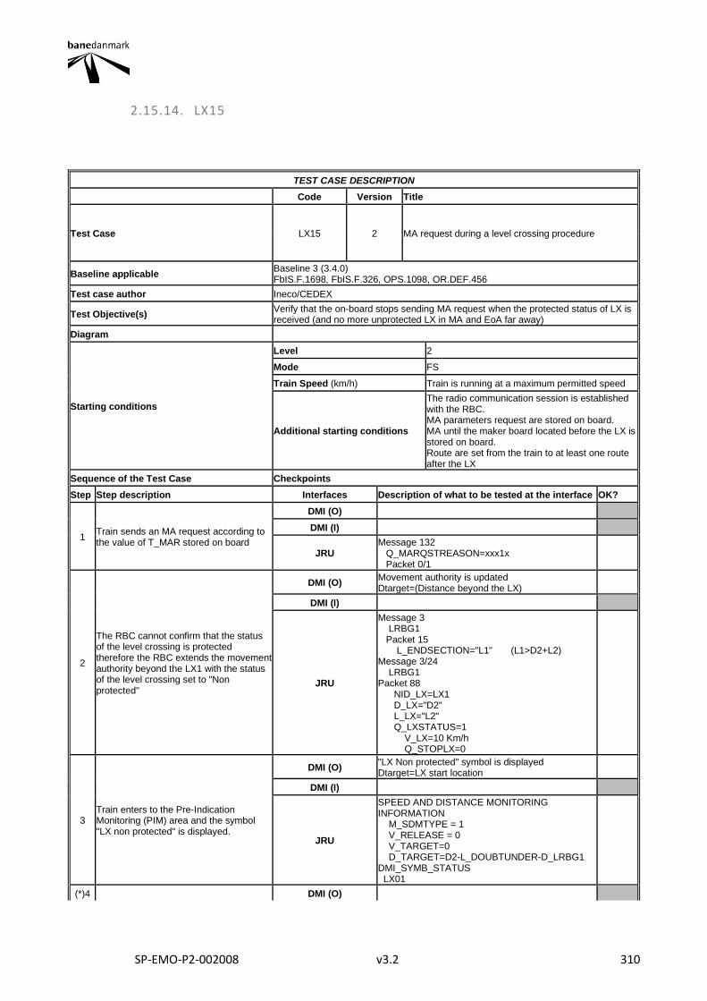
SP-EMO-P2-002008 v3.2 310
2.15.14. LX15
TEST CASE DESCRIPTION
Code Version Title
Test Case LX15 2 MA request during a level crossing procedure
Baseline applicable Baseline 3 (3.4.0) FbIS.F.1698, FbIS.F.326, OPS.1098, OR.DEF.456
Test case author Ineco/CEDEX
Test Objective(s) Verify that the on-board stops sending MA request when the protected status of LX is received (and no more unprotected LX in MA and EoA far away)
Diagram
Starting conditions
Level 2
Mode FS
Train Speed (km/h) Train is running at a maximum permitted speed
Additional starting conditions
The radio communication session is established with the RBC. MA parameters request are stored on board. MA until the maker board located before the LX is stored on board. Route are set from the train to at least one route after the LX
Sequence of the Test Case Checkpoints
Step Step description Interfaces Description of what to be tested at the interface OK?
1 Train sends an MA request according to the value of T_MAR stored on board
DMI (O)
DMI (I)
JRU Message 132 Q_MARQSTREASON=xxx1x Packet 0/1
2
The RBC cannot confirm that the status of the level crossing is protected therefore the RBC extends the movement authority beyond the LX1 with the status of the level crossing set to "Non protected"
DMI (O) Movement authority is updated Dtarget=(Distance beyond the LX)
DMI (I)
JRU
Message 3 LRBG1 Packet 15 L_ENDSECTION="L1" (L1>D2+L2) Message 3/24 LRBG1 Packet 88 NID_LX=LX1 D_LX="D2" L_LX="L2" Q_LXSTATUS=1 V_LX=10 Km/h Q_STOPLX=0
3 Train enters to the Pre-Indication Monitoring (PIM) area and the symbol "LX non protected" is displayed.
DMI (O) "LX Non protected" symbol is displayed Dtarget=LX start location
DMI (I)
JRU
SPEED AND DISTANCE MONITORING INFORMATION M_SDMTYPE = 1 V_RELEASE = 0 V_TARGET=0 D_TARGET=D2-L_DOUBTUNDER-D_LRBG1 DMI_SYMB_STATUS LX01
(*)4 DMI (O)
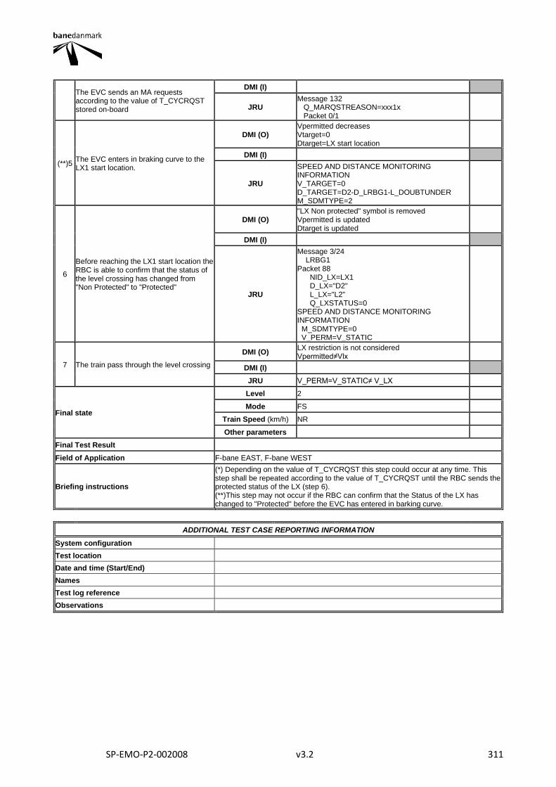
SP-EMO-P2-002008 v3.2 311
The EVC sends an MA requests according to the value of T_CYCRQST stored on-board
DMI (I)
JRU Message 132 Q_MARQSTREASON=xxx1x Packet 0/1
(**)5 The EVC enters in braking curve to the LX1 start location.
DMI (O) Vpermitted decreases Vtarget=0 Dtarget=LX start location
DMI (I)
JRU
SPEED AND DISTANCE MONITORING INFORMATION V_TARGET=0 D_TARGET=D2-D_LRBG1-L_DOUBTUNDER M_SDMTYPE=2
6
Before reaching the LX1 start location the RBC is able to confirm that the status of the level crossing has changed from "Non Protected" to "Protected"
DMI (O) "LX Non protected" symbol is removed Vpermitted is updated Dtarget is updated
DMI (I)
JRU
Message 3/24 LRBG1 Packet 88 NID_LX=LX1 D_LX="D2" L_LX="L2" Q_LXSTATUS=0 SPEED AND DISTANCE MONITORING INFORMATION M_SDMTYPE=0 V_PERM=V_STATIC
7 The train pass through the level crossing
DMI (O) LX restriction is not considered Vpermitted≠Vlx
DMI (I)
JRU V_PERM=V_STATIC≠ V_LX
Final state
Level 2
Mode FS
Train Speed (km/h) NR
Other parameters
Final Test Result
Field of Application F-bane EAST, F-bane WEST
Briefing instructions
(*) Depending on the value of T_CYCRQST this step could occur at any time. This step shall be repeated according to the value of T_CYCRQST until the RBC sends the protected status of the LX (step 6). (**)This step may not occur if the RBC can confirm that the Status of the LX has changed to "Protected" before the EVC has entered in barking curve.
ADDITIONAL TEST CASE REPORTING INFORMATION
System configuration
Test location
Date and time (Start/End)
Names
Test log reference
Observations
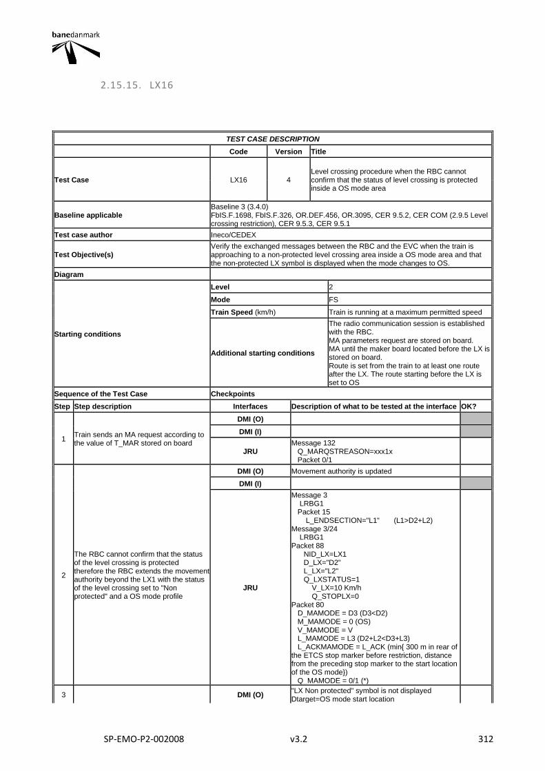
SP-EMO-P2-002008 v3.2 312
2.15.15. LX16
TEST CASE DESCRIPTION
Code Version Title
Test Case LX16 4 Level crossing procedure when the RBC cannot confirm that the status of level crossing is protected inside a OS mode area
Baseline applicable Baseline 3 (3.4.0) FbIS.F.1698, FbIS.F.326, OR.DEF.456, OR.3095, CER 9.5.2, CER COM (2.9.5 Level crossing restriction), CER 9.5.3, CER 9.5.1
Test case author Ineco/CEDEX
Test Objective(s) Verify the exchanged messages between the RBC and the EVC when the train is approaching to a non-protected level crossing area inside a OS mode area and that the non-protected LX symbol is displayed when the mode changes to OS.
Diagram
Starting conditions
Level 2
Mode FS
Train Speed (km/h) Train is running at a maximum permitted speed
Additional starting conditions
The radio communication session is established with the RBC. MA parameters request are stored on board. MA until the maker board located before the LX is stored on board. Route is set from the train to at least one route after the LX. The route starting before the LX is set to OS
Sequence of the Test Case Checkpoints
Step Step description Interfaces Description of what to be tested at the interface OK?
1 Train sends an MA request according to the value of T_MAR stored on board
DMI (O)
DMI (I)
JRU Message 132 Q_MARQSTREASON=xxx1x Packet 0/1
2
The RBC cannot confirm that the status of the level crossing is protected therefore the RBC extends the movement authority beyond the LX1 with the status of the level crossing set to "Non protected" and a OS mode profile
DMI (O) Movement authority is updated
DMI (I)
JRU
Message 3 LRBG1 Packet 15 L_ENDSECTION="L1" (L1>D2+L2) Message 3/24 LRBG1 Packet 88 NID_LX=LX1 D_LX="D2" L_LX="L2" Q_LXSTATUS=1 V_LX=10 Km/h Q_STOPLX=0 Packet 80 D_MAMODE = D3 (D3<D2) M_MAMODE = 0 (OS) V_MAMODE = V L_MAMODE = L3 (D2+L2<D3+L3) L_ACKMAMODE = L_ACK (min{ 300 m in rear of the ETCS stop marker before restriction, distance from the preceding stop marker to the start location of the OS mode}) Q_MAMODE = 0/1 (*)
3 DMI (O) "LX Non protected" symbol is not displayed Dtarget=OS mode start location
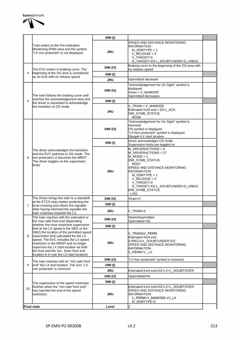
SP-EMO-P2-002008 v3.2 313
Train enters to the Pre-Indication Monitoring (PIM) area and the symbol "LX non protected" is not displayed.
DMI (I)
JRU
SPEED AND DISTANCE MONITORING INFORMATION M_SDMTYPE = 1 V_RELEASE = 0 V_TARGET=0 D_TARGET=D2-L_DOUBTUNDER-D_LRBG1
4 The EVC enters in braking curve. The beginning of the OS area is considered as an EoA with no release speed
DMI (O) Braking curve to the beginning of the OS area with no release speed
DMI (I)
JRU Vpermitted decrease
5
The train follows the braking curve until reaches the acknowledgement area and the driver is requested to acknowledge the transition to OS mode
DMI (O)
"Acknowledgement for On Sight" symbol is displayed Vtrain < V_MAMODE Vpermitted decreases
DMI (I)
JRU
V_TRAIN < V_MAMODE Estimated front end > D3-L_ACK DMI_SYMB_STATUS MO08
6
The driver acknowledges the transition and the EVC switches to OS mode. The non protected LX becomes the MRDT The driver toggles on the supervision limits
DMI (O)
"Acknowledgement for On Sight" symbol is removed OS symbol is displayed "LX Non protected" symbol is displayed Dtarget=LX start location
DMI (I) Driver acknowledges OS mode Supervision limits are toggled on
JRU
M_DRIVERACTIONS = 0 M_DRIVERACTIONS = 27 M_MODE = 1 DMI_SYMB_STATUS MO07 SPEED AND DISTANCE MONITORING INFORMATION M_SDMTYPE = 1 V_RELEASE = 0 V_TARGET=0 D_TARGET=D2-L_DOUBTUNDER-D_LRBG1 DMI_SYMB_STATUS LX01
7
The Driver brings the train to a standstill at the ETCS stop marker protecting the level crossing and inform the signaller. After having informed the signaller the train continues towards the LX.
DMI (O) Vtrain=0
DMI (I)
JRU V_TRAIN=0
8
The train reaches with the estimated or the max safe front end (depending whether the most restrictive supervision limit at the LX speed is the SBI1 or the SBI2) the location of the permitted speed supervision limit calculated for the LX speed. The EVC includes the LX speed restriction in the MRSP and no longer supervise the LX start location as both the EoA and the SvL. (train front end location is in rear the LX start location).
DMI (O) Vtrain≤Vpermitted Vpermitted=Vlx
DMI (I)
JRU
V_TRAIN≤V_PERM Estimated front end (LRBG1)+L_DOUBTUNDER<D2 SPEED AND DISTANCE MONITORING INFORMATION V_PERM=V_ LX
9 The train reaches with its "min safe front end" the LX end location. The icon "LX non protected" is removed
DMI (O) "LX Non protected" symbol is removed
DMI (I)
JRU Estimated front end=D2+L2+L_DOUBTOVER
10
The supervision of the speed restriction finishes when the "min safe front end" has reached the end of the speed restriction.
DMI (O) Vpermitted≥Vlx
DMI (I)
JRU
Estimated front end=D2+L2+L_DOUBTOVER SPEED AND DISTANCE MONITORING INFORMATION V_PERM=V_MAMODE ≥V_LX M_SDMTYPE=0
Final state Level 2
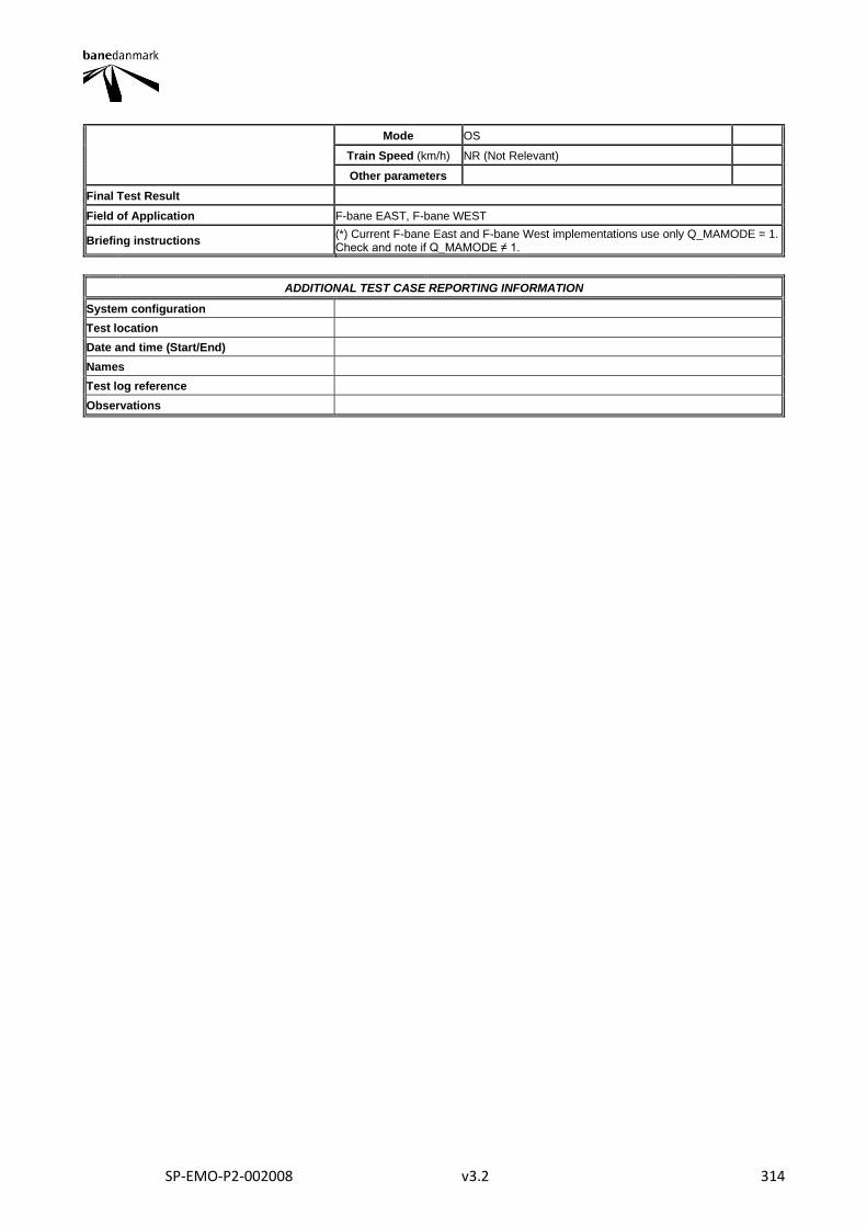
SP-EMO-P2-002008 v3.2 314
Mode OS
Train Speed (km/h) NR (Not Relevant)
Other parameters
Final Test Result
Field of Application F-bane EAST, F-bane WEST
Briefing instructions (*) Current F-bane East and F-bane West implementations use only Q_MAMODE = 1. Check and note if Q_MAMODE ≠ 1.
ADDITIONAL TEST CASE REPORTING INFORMATION
System configuration
Test location
Date and time (Start/End)
Names
Test log reference
Observations
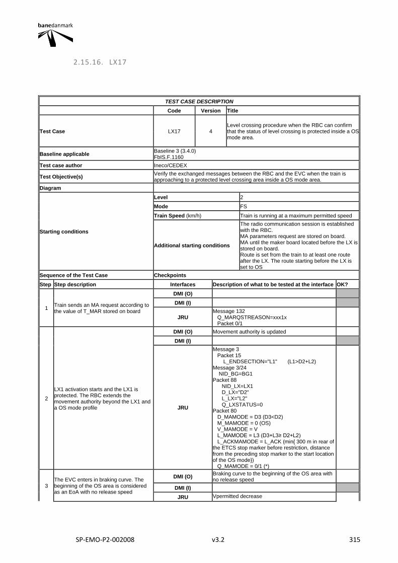
SP-EMO-P2-002008 v3.2 315
2.15.16. LX17
TEST CASE DESCRIPTION
Code Version Title
Test Case LX17 4 Level crossing procedure when the RBC can confirm that the status of level crossing is protected inside a OS mode area.
Baseline applicable Baseline 3 (3.4.0) FbIS.F.1160
Test case author Ineco/CEDEX
Test Objective(s) Verify the exchanged messages between the RBC and the EVC when the train is approaching to a protected level crossing area inside a OS mode area.
Diagram
Starting conditions
Level 2
Mode FS
Train Speed (km/h) Train is running at a maximum permitted speed
Additional starting conditions
The radio communication session is established with the RBC. MA parameters request are stored on board. MA until the maker board located before the LX is stored on board. Route is set from the train to at least one route after the LX. The route starting before the LX is set to OS
Sequence of the Test Case Checkpoints
Step Step description Interfaces Description of what to be tested at the interface OK?
1 Train sends an MA request according to the value of T_MAR stored on board
DMI (O)
DMI (I)
JRU Message 132 Q_MARQSTREASON=xxx1x Packet 0/1
2
LX1 activation starts and the LX1 is protected. The RBC extends the movement authority beyond the LX1 and a OS mode profile
DMI (O) Movement authority is updated
DMI (I)
JRU
Message 3 Packet 15 L_ENDSECTION="L1" (L1>D2+L2) Message 3/24 NID_BG=BG1 Packet 88 NID_LX=LX1 D_LX="D2" L_LX="L2" Q_LXSTATUS=0 Packet 80 D_MAMODE = D3 (D3<D2) M_MAMODE = 0 (OS) V_MAMODE = V L_MAMODE = L3 (D3+L3≥ D2+L2) L_ACKMAMODE = L_ACK (min{ 300 m in rear of the ETCS stop marker before restriction, distance from the preceding stop marker to the start location of the OS mode}) Q_MAMODE = 0/1 (*)
3 The EVC enters in braking curve. The beginning of the OS area is considered as an EoA with no release speed
DMI (O) Braking curve to the beginning of the OS area with no release speed
DMI (I)
JRU Vpermitted decrease
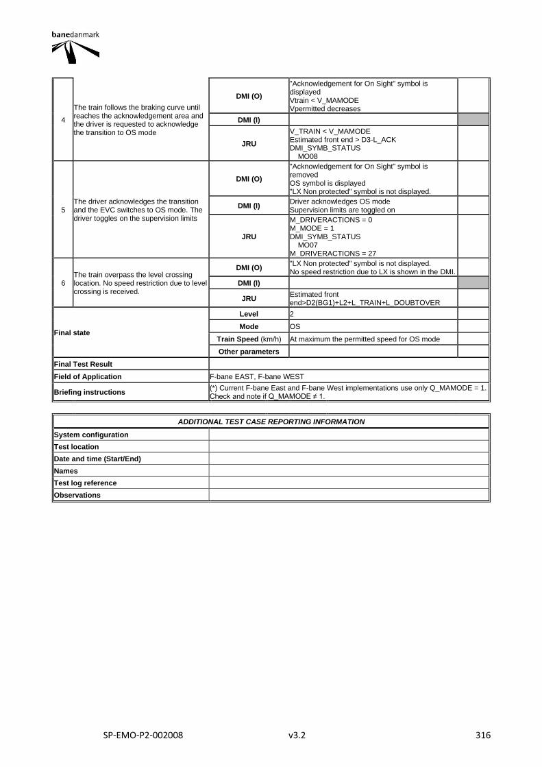
SP-EMO-P2-002008 v3.2 316
4
The train follows the braking curve until reaches the acknowledgement area and the driver is requested to acknowledge the transition to OS mode
DMI (O)
"Acknowledgement for On Sight" symbol is displayed Vtrain < V_MAMODE Vpermitted decreases
DMI (I)
JRU
V_TRAIN < V_MAMODE Estimated front end > D3-L_ACK DMI_SYMB_STATUS MO08
5 The driver acknowledges the transition and the EVC switches to OS mode. The driver toggles on the supervision limits
DMI (O)
"Acknowledgement for On Sight" symbol is removed OS symbol is displayed "LX Non protected" symbol is not displayed.
DMI (I) Driver acknowledges OS mode Supervision limits are toggled on
JRU
M_DRIVERACTIONS = 0 M_MODE = 1 DMI_SYMB_STATUS MO07 M_DRIVERACTIONS = 27
6 The train overpass the level crossing location. No speed restriction due to level crossing is received.
DMI (O) "LX Non protected" symbol is not displayed. No speed restriction due to LX is shown in the DMI.
DMI (I)
JRU Estimated front end>D2(BG1)+L2+L_TRAIN+L_DOUBTOVER
Final state
Level 2
Mode OS
Train Speed (km/h) At maximum the permitted speed for OS mode
Other parameters
Final Test Result
Field of Application F-bane EAST, F-bane WEST
Briefing instructions (*) Current F-bane East and F-bane West implementations use only Q_MAMODE = 1. Check and note if Q_MAMODE ≠ 1.
ADDITIONAL TEST CASE REPORTING INFORMATION
System configuration
Test location
Date and time (Start/End)
Names
Test log reference
Observations
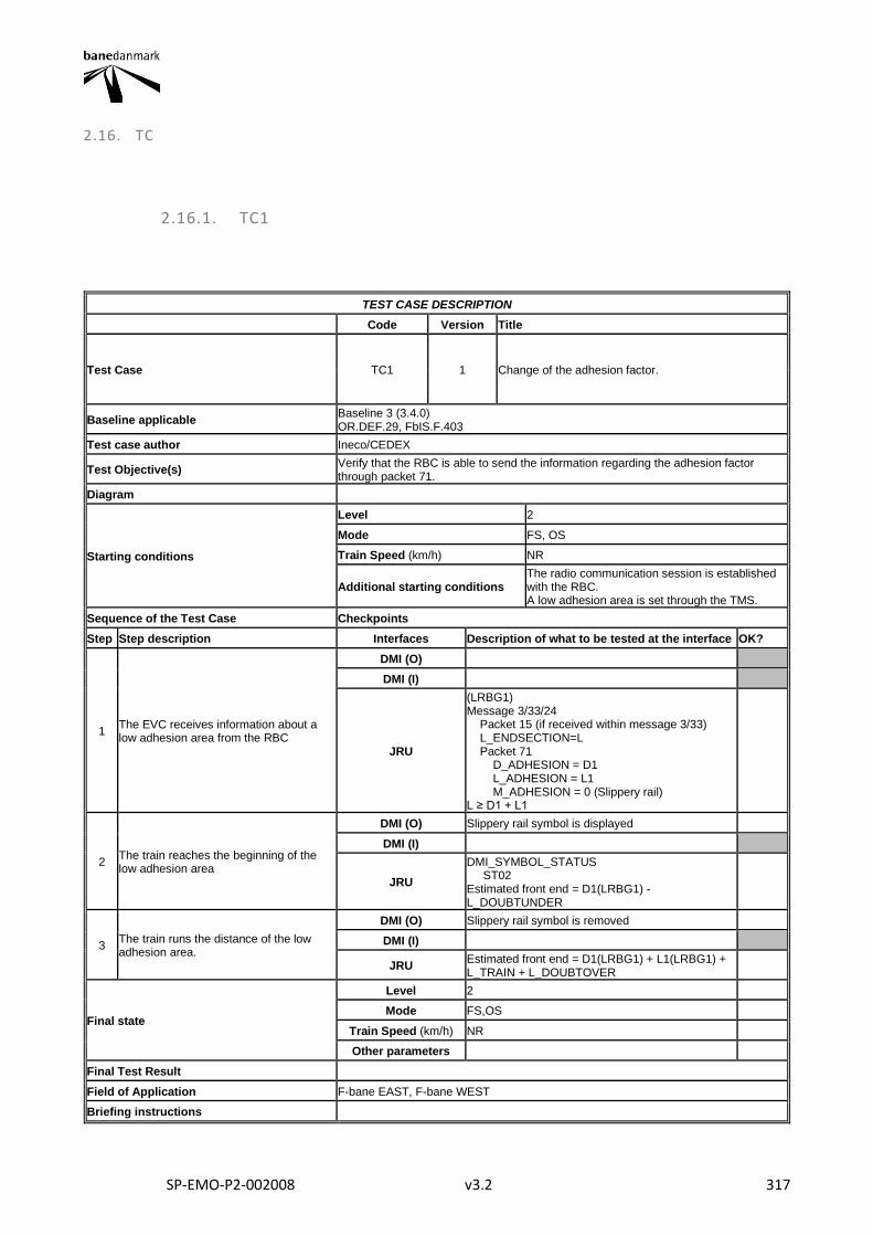
SP-EMO-P2-002008 v3.2 317
2.16. TC
2.16.1. TC1
TEST CASE DESCRIPTION
Code Version Title
Test Case TC1 1 Change of the adhesion factor.
Baseline applicable Baseline 3 (3.4.0) OR.DEF.29, FbIS.F.403
Test case author Ineco/CEDEX
Test Objective(s) Verify that the RBC is able to send the information regarding the adhesion factor through packet 71.
Diagram
Starting conditions
Level 2
Mode FS, OS
Train Speed (km/h) NR
Additional starting conditions The radio communication session is established with the RBC. A low adhesion area is set through the TMS.
Sequence of the Test Case Checkpoints
Step Step description Interfaces Description of what to be tested at the interface OK?
1 The EVC receives information about a low adhesion area from the RBC
DMI (O)
DMI (I)
JRU
(LRBG1) Message 3/33/24 Packet 15 (if received within message 3/33) L_ENDSECTION=L Packet 71 D_ADHESION = D1 L_ADHESION = L1 M_ADHESION = 0 (Slippery rail) L ≥ D1 + L1
2 The train reaches the beginning of the low adhesion area
DMI (O) Slippery rail symbol is displayed
DMI (I)
JRU
DMI_SYMBOL_STATUS ST02 Estimated front end = D1(LRBG1) - L_DOUBTUNDER
3 The train runs the distance of the low adhesion area.
DMI (O) Slippery rail symbol is removed
DMI (I)
JRU Estimated front end = D1(LRBG1) + L1(LRBG1) + L_TRAIN + L_DOUBTOVER
Final state
Level 2
Mode FS,OS
Train Speed (km/h) NR
Other parameters
Final Test Result
Field of Application F-bane EAST, F-bane WEST
Briefing instructions
SP-EMO-P2-002008 v3.2 318
ADDITIONAL TEST CASE REPORTING INFORMATION
System configuration
Test location
Date and time (Start/End)
Names
Test log reference
Observations
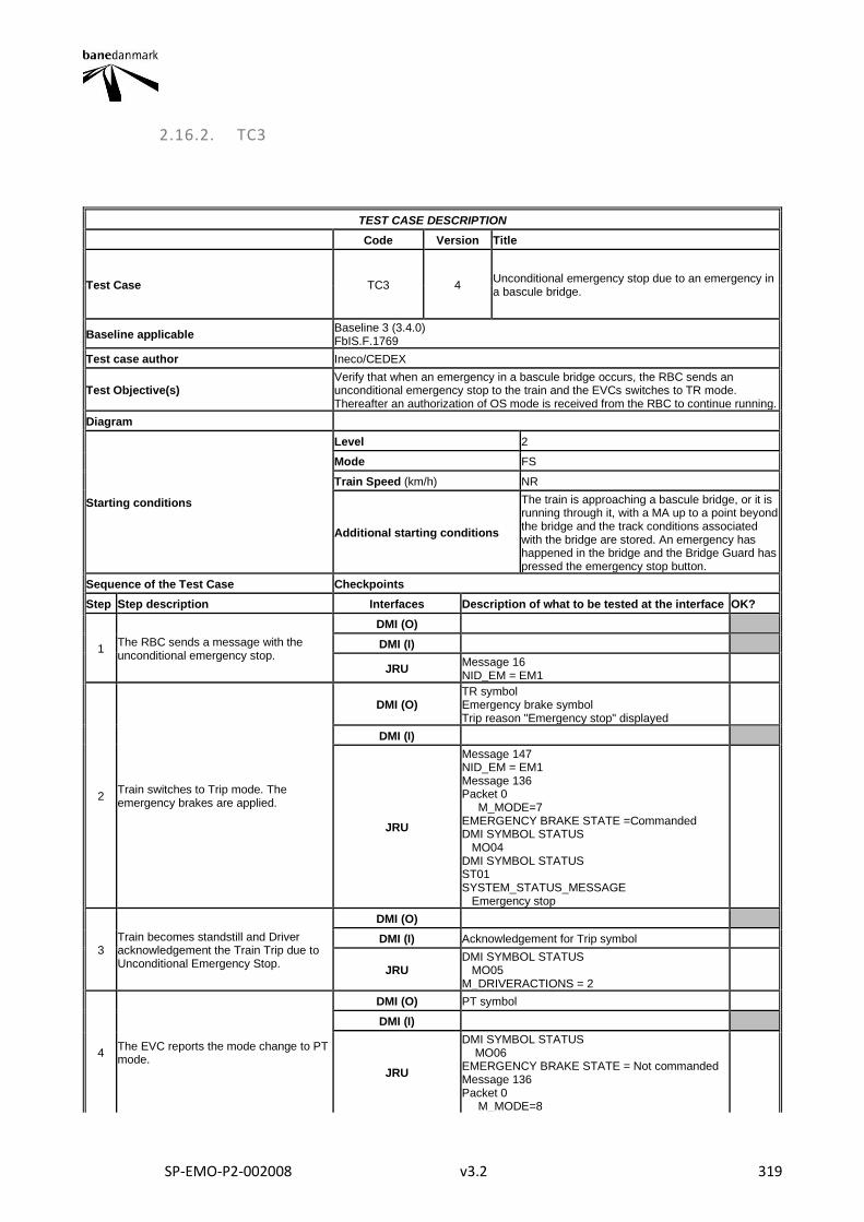
SP-EMO-P2-002008 v3.2 319
2.16.2. TC3
TEST CASE DESCRIPTION
Code Version Title
Test Case TC3 4 Unconditional emergency stop due to an emergency in a bascule bridge.
Baseline applicable Baseline 3 (3.4.0) FbIS.F.1769
Test case author Ineco/CEDEX
Test Objective(s) Verify that when an emergency in a bascule bridge occurs, the RBC sends an unconditional emergency stop to the train and the EVCs switches to TR mode. Thereafter an authorization of OS mode is received from the RBC to continue running.
Diagram
Starting conditions
Level 2
Mode FS
Train Speed (km/h) NR
Additional starting conditions
The train is approaching a bascule bridge, or it is running through it, with a MA up to a point beyond the bridge and the track conditions associated with the bridge are stored. An emergency has happened in the bridge and the Bridge Guard has pressed the emergency stop button.
Sequence of the Test Case Checkpoints
Step Step description Interfaces Description of what to be tested at the interface OK?
1 The RBC sends a message with the unconditional emergency stop.
DMI (O)
DMI (I)
JRU Message 16 NID_EM = EM1
2 Train switches to Trip mode. The emergency brakes are applied.
DMI (O) TR symbol Emergency brake symbol Trip reason "Emergency stop" displayed
DMI (I)
JRU
Message 147 NID_EM = EM1 Message 136 Packet 0 M_MODE=7 EMERGENCY BRAKE STATE =Commanded DMI SYMBOL STATUS MO04 DMI SYMBOL STATUS ST01 SYSTEM_STATUS_MESSAGE Emergency stop
3 Train becomes standstill and Driver acknowledgement the Train Trip due to Unconditional Emergency Stop.
DMI (O)
DMI (I) Acknowledgement for Trip symbol
JRU DMI SYMBOL STATUS MO05 M_DRIVERACTIONS = 2
4 The EVC reports the mode change to PT mode.
DMI (O) PT symbol
DMI (I)
JRU
DMI SYMBOL STATUS MO06 EMERGENCY BRAKE STATE = Not commanded Message 136 Packet 0 M_MODE=8
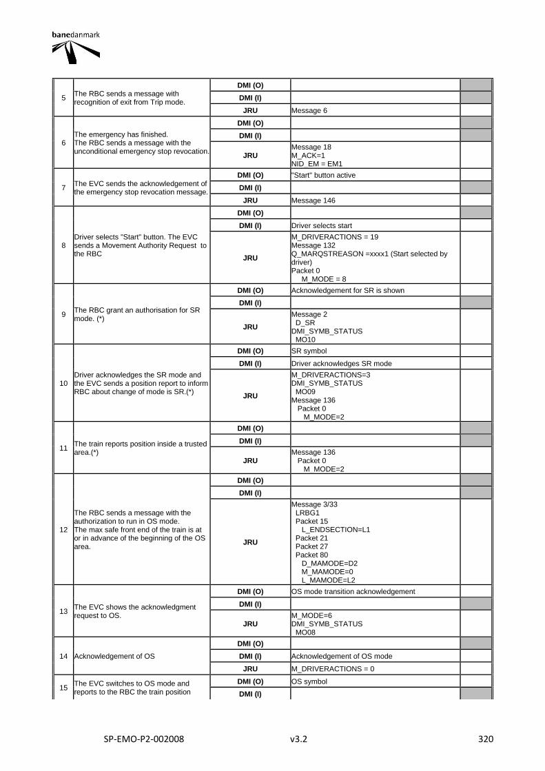
SP-EMO-P2-002008 v3.2 320
5 The RBC sends a message with recognition of exit from Trip mode.
DMI (O)
DMI (I)
JRU Message 6
6 The emergency has finished. The RBC sends a message with the unconditional emergency stop revocation.
DMI (O)
DMI (I)
JRU Message 18 M_ACK=1 NID_EM = EM1
7 The EVC sends the acknowledgement of the emergency stop revocation message.
DMI (O) "Start" button active
DMI (I)
JRU Message 146
8 Driver selects "Start" button. The EVC sends a Movement Authority Request to the RBC
DMI (O)
DMI (I) Driver selects start
JRU
M_DRIVERACTIONS = 19 Message 132 Q_MARQSTREASON =xxxx1 (Start selected by driver) Packet 0 M_MODE = 8
9 The RBC grant an authorisation for SR mode. (*)
DMI (O) Acknowledgement for SR is shown
DMI (I)
JRU
Message 2 D_SR DMI_SYMB_STATUS MO10
10 Driver acknowledges the SR mode and the EVC sends a position report to inform RBC about change of mode is SR.(*)
DMI (O) SR symbol
DMI (I) Driver acknowledges SR mode
JRU
M_DRIVERACTIONS=3 DMI_SYMB_STATUS MO09 Message 136 Packet 0 M_MODE=2
11 The train reports position inside a trusted area.(*)
DMI (O)
DMI (I)
JRU Message 136 Packet 0 M_MODE=2
12
The RBC sends a message with the authorization to run in OS mode. The max safe front end of the train is at or in advance of the beginning of the OS area.
DMI (O)
DMI (I)
JRU
Message 3/33 LRBG1 Packet 15 L_ENDSECTION=L1 Packet 21 Packet 27 Packet 80 D_MAMODE=D2 M_MAMODE=0 L_MAMODE=L2
13 The EVC shows the acknowledgment request to OS.
DMI (O) OS mode transition acknowledgement
DMI (I)
JRU M_MODE=6 DMI_SYMB_STATUS MO08
14 Acknowledgement of OS
DMI (O)
DMI (I) Acknowledgement of OS mode
JRU M_DRIVERACTIONS = 0
15 The EVC switches to OS mode and reports to the RBC the train position
DMI (O) OS symbol
DMI (I)

SP-EMO-P2-002008 v3.2 321
JRU
M_MODE=1 DMI_SYMB_STATUS MO07" Message 136 Packet 0/1 M_MODE=1
Final state
Level 2
Mode OS
Train Speed (km/h) NR
Other parameters
Final Test Result
Field of Application F-bane EAST, F-bane WEST
Briefing instructions (*) These steps only take place in the F-bane WEST if the train is outside a trustworthy area
ADDITIONAL TEST CASE REPORTING INFORMATION
System configuration
Test location
Date and time (Start/End)
Names
Test log reference
Observations
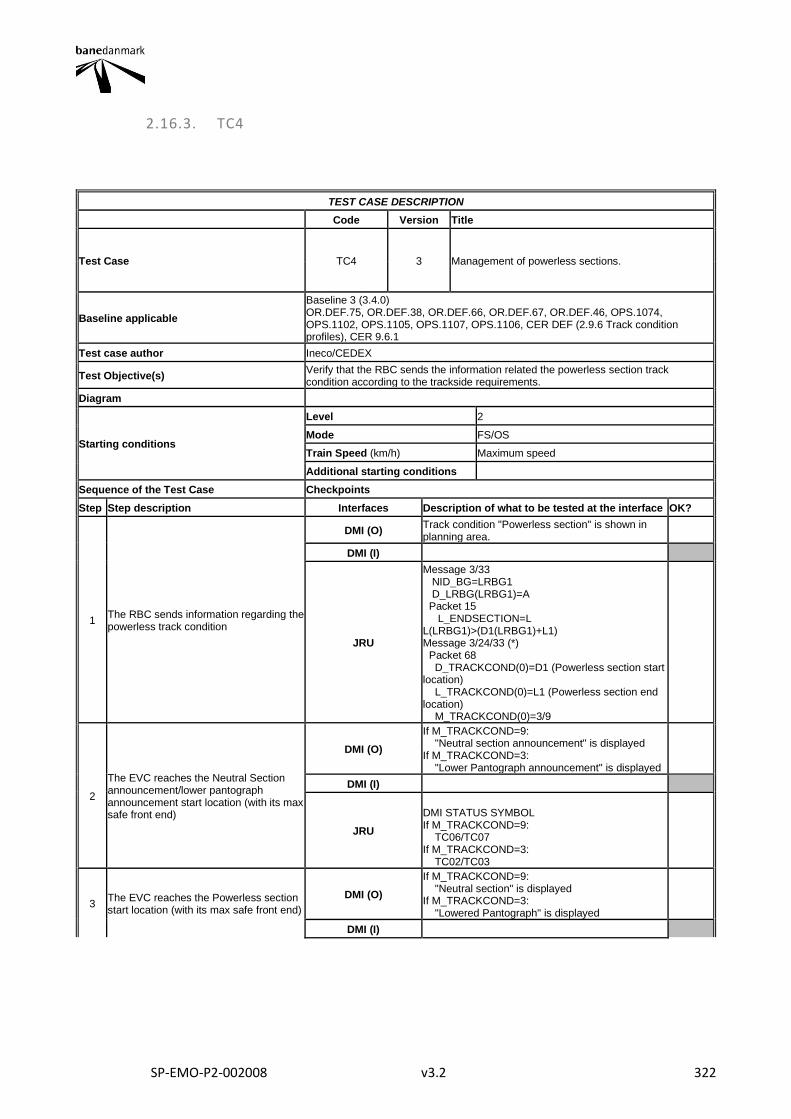
SP-EMO-P2-002008 v3.2 322
2.16.3. TC4
TEST CASE DESCRIPTION
Code Version Title
Test Case TC4 3 Management of powerless sections.
Baseline applicable
Baseline 3 (3.4.0) OR.DEF.75, OR.DEF.38, OR.DEF.66, OR.DEF.67, OR.DEF.46, OPS.1074, OPS.1102, OPS.1105, OPS.1107, OPS.1106, CER DEF (2.9.6 Track condition profiles), CER 9.6.1
Test case author Ineco/CEDEX
Test Objective(s) Verify that the RBC sends the information related the powerless section track condition according to the trackside requirements.
Diagram
Starting conditions
Level 2
Mode FS/OS
Train Speed (km/h) Maximum speed
Additional starting conditions
Sequence of the Test Case Checkpoints
Step Step description Interfaces Description of what to be tested at the interface OK?
1 The RBC sends information regarding the powerless track condition
DMI (O) Track condition "Powerless section" is shown in planning area.
DMI (I)
JRU
Message 3/33 NID_BG=LRBG1 D_LRBG(LRBG1)=A Packet 15 L_ENDSECTION=L L(LRBG1)>(D1(LRBG1)+L1) Message 3/24/33 (*) Packet 68 D_TRACKCOND(0)=D1 (Powerless section start location) L_TRACKCOND(0)=L1 (Powerless section end location) M_TRACKCOND(0)=3/9
2
The EVC reaches the Neutral Section announcement/lower pantograph announcement start location (with its max safe front end)
DMI (O)
If M_TRACKCOND=9: "Neutral section announcement" is displayed If M_TRACKCOND=3: "Lower Pantograph announcement" is displayed
DMI (I)
JRU
DMI STATUS SYMBOL If M_TRACKCOND=9: TC06/TC07 If M_TRACKCOND=3: TC02/TC03
3 The EVC reaches the Powerless section start location (with its max safe front end)
DMI (O)
If M_TRACKCOND=9: "Neutral section" is displayed If M_TRACKCOND=3: "Lowered Pantograph" is displayed
DMI (I)
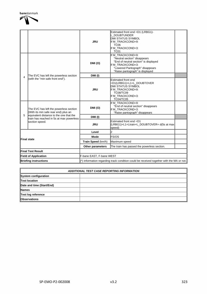
SP-EMO-P2-002008 v3.2 323
JRU
Estimated front end =D1 (LRBG1)-L_DOUBTUNDER DMI STATUS SYMBOL If M_TRACKCOND=9: TC06 If M_TRACKCOND=3: TC01
4 The EVC has left the powerless section (with the "min safe front end").
DMI (O)
If M_TRACKCOND=9: "Neutral section" disappears "End of neutral section" is displayed If M_TRACKCOND=3: "Lowered Pantograph" disappears "Raise pantograph" is displayed
DMI (I)
JRU
Estimated front end =D1(LRBG1)+L1+L_DOUBTOVER DMI STATUS SYMBOL If M_TRACKCOND=9: TC08/TC09 If M_TRACKCOND=3: TC04/TC05
5
The EVC has left the powerless section (With its min safe rear end) plus an equivalent distance to the one that the train has reached in 5s at max powerless section speed.
DMI (O)
If M_TRACKCOND=9: "End of neutral section" disappears If M_TRACKCOND=3: "Raise pantograph" disappears
DMI (I)
JRU Estimated front end =D1 (LRBG1)+L1+Ltrain+L_DOUBTOVER+ d(5s at max speed)
Final state
Level 2
Mode FS/OS
Train Speed (km/h) Maximum speed
Other parameters The train has passed the powerless section.
Final Test Result
Field of Application F-bane EAST, F-bane WEST
Briefing instructions (*) information regarding track condition could be received together with the MA or not.
ADDITIONAL TEST CASE REPORTING INFORMATION
System configuration
Test location
Date and time (Start/End)
Names
Test log reference
Observations
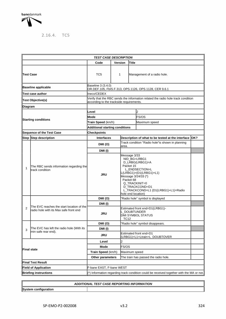
SP-EMO-P2-002008 v3.2 324
2.16.4. TC5
TEST CASE DESCRIPTION
Code Version Title
Test Case TC5 1 Management of a radio hole.
Baseline applicable Baseline 3 (3.4.0) OR.DEF.105, FbIS.F.313, OPS.1126, OPS.1128, CER 9.6.1
Test case author Ineco/CEDEX
Test Objective(s) Verify that the RBC sends the information related the radio hole track condition according to the trackside requirements.
Diagram
Starting conditions
Level 2
Mode FS/OS
Train Speed (km/h) Maximum speed
Additional starting conditions
Sequence of the Test Case Checkpoints
Step Step description Interfaces Description of what to be tested at the interface OK?
1 The RBC sends information regarding the track condition
DMI (O) Track condition "Radio hole"is shown in planning area.
DMI (I)
JRU
Message 3/33 NID_BG=LRBG1 D_LRBG(LRBG1)=A Packet 15 L_ENDSECTION=L L(LRBG1)>(D1(LRBG1)+L1) Message 3/24/33 (*) Packet 68 Q_TRACKINIT=0 D_TRACKCOND=D1 L_TRACKCOND=L1 (D1(LRBG1)+L1)=Radio hole end location)
2 The EVC reaches the start location of the radio hole with its Max safe front end
DMI (O) "Radio hole" symbol is displayed
DMI (I)
JRU
Estimated front end=D1(LRBG1)-L_DOUBTUNDER DMI SYMBOL STATUS TC12
3 The EVC has left the radio hole (With its min safe rear end).
DMI (O) "Radio hole" symbol disappears.
DMI (I)
JRU Estimated front end=D1 (LRBG1)+L1+Ltrain+L_DOUBTOVER
Final state
Level 2
Mode FS/OS
Train Speed (km/h) Maximum speed
Other parameters The train has passed the radio hole.
Final Test Result
Field of Application F-bane EAST, F-bane WEST
Briefing instructions (*) Information regarding track condition could be received together with the MA or not.
ADDITIONAL TEST CASE REPORTING INFORMATION
System configuration
SP-EMO-P2-002008 v3.2 325
Test location
Date and time (Start/End)
Names
Test log reference
Observations
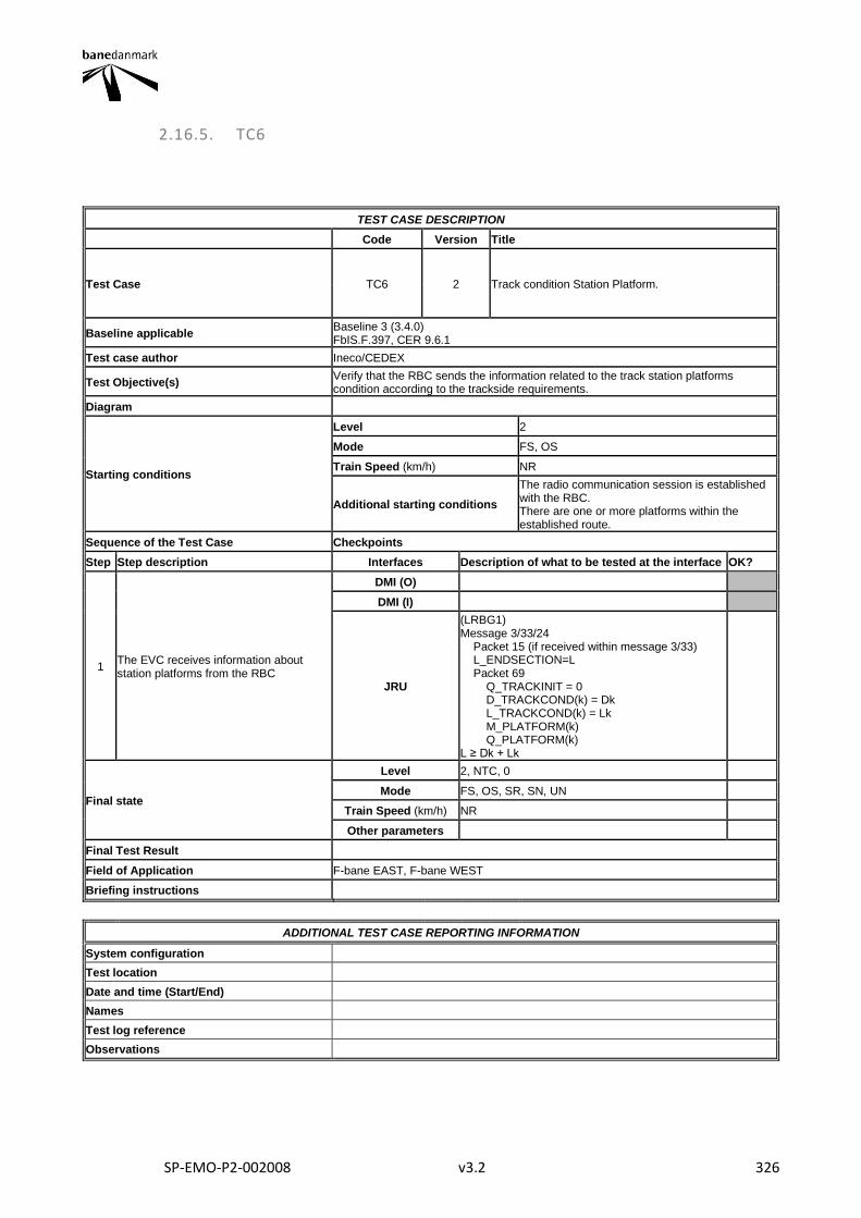
SP-EMO-P2-002008 v3.2 326
2.16.5. TC6
TEST CASE DESCRIPTION
Code Version Title
Test Case TC6 2 Track condition Station Platform.
Baseline applicable Baseline 3 (3.4.0) FbIS.F.397, CER 9.6.1
Test case author Ineco/CEDEX
Test Objective(s) Verify that the RBC sends the information related to the track station platforms condition according to the trackside requirements.
Diagram
Starting conditions
Level 2
Mode FS, OS
Train Speed (km/h) NR
Additional starting conditions
The radio communication session is established with the RBC. There are one or more platforms within the established route.
Sequence of the Test Case Checkpoints
Step Step description Interfaces Description of what to be tested at the interface OK?
1 The EVC receives information about station platforms from the RBC
DMI (O)
DMI (I)
JRU
(LRBG1) Message 3/33/24 Packet 15 (if received within message 3/33) L_ENDSECTION=L Packet 69 Q_TRACKINIT = 0 D_TRACKCOND(k) = Dk L_TRACKCOND(k) = Lk M_PLATFORM(k) Q_PLATFORM(k) L ≥ Dk + Lk
Final state
Level 2, NTC, 0
Mode FS, OS, SR, SN, UN
Train Speed (km/h) NR
Other parameters
Final Test Result
Field of Application F-bane EAST, F-bane WEST
Briefing instructions
ADDITIONAL TEST CASE REPORTING INFORMATION
System configuration
Test location
Date and time (Start/End)
Names
Test log reference
Observations
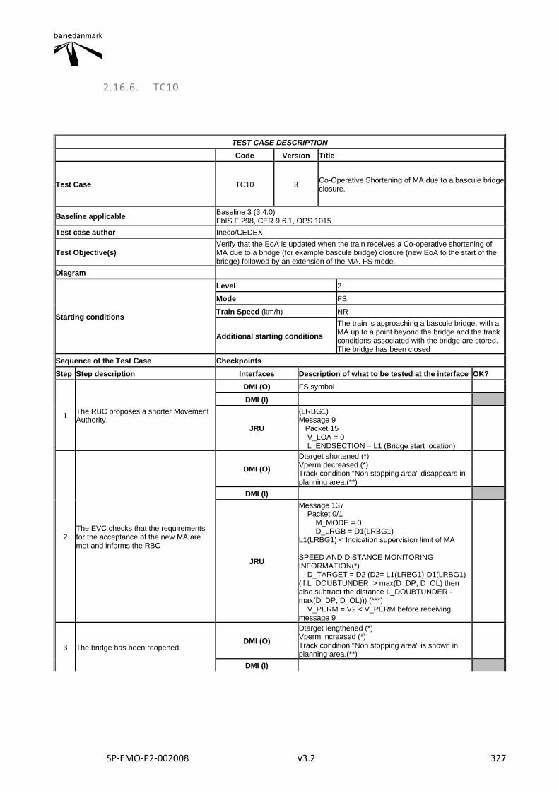
SP-EMO-P2-002008 v3.2 327
2.16.6. TC10
TEST CASE DESCRIPTION
Code Version Title
Test Case TC10 3 Co-Operative Shortening of MA due to a bascule bridge closure.
Baseline applicable Baseline 3 (3.4.0) FbIS.F.298, CER 9.6.1, OPS 1015
Test case author Ineco/CEDEX
Test Objective(s) Verify that the EoA is updated when the train receives a Co-operative shortening of MA due to a bridge (for example bascule bridge) closure (new EoA to the start of the bridge) followed by an extension of the MA. FS mode.
Diagram
Starting conditions
Level 2
Mode FS
Train Speed (km/h) NR
Additional starting conditions
The train is approaching a bascule bridge, with a MA up to a point beyond the bridge and the track conditions associated with the bridge are stored. The bridge has been closed
Sequence of the Test Case Checkpoints
Step Step description Interfaces Description of what to be tested at the interface OK?
1 The RBC proposes a shorter Movement Authority.
DMI (O) FS symbol
DMI (I)
JRU
(LRBG1) Message 9 Packet 15 V_LOA = 0 L_ENDSECTION = L1 (Bridge start location)
2 The EVC checks that the requirements for the acceptance of the new MA are met and informs the RBC
DMI (O)
Dtarget shortened (*) Vperm decreased (*) Track condition "Non stopping area" disappears in planning area.(**)
DMI (I)
JRU
Message 137 Packet 0/1 M_MODE = 0 D_LRGB = D1(LRBG1) L1(LRBG1) < Indication supervision limit of MA SPEED AND DISTANCE MONITORING INFORMATION(*) D_TARGET = D2 (D2= L1(LRBG1)-D1(LRBG1) (if L_DOUBTUNDER > max(D_DP, D_OL) then also subtract the distance L_DOUBTUNDER - max(D_DP, D_OL))) (***) V_PERM = V2 < V_PERM before receiving message 9
3 The bridge has been reopened DMI (O)
Dtarget lengthened (*) Vperm increased (*) Track condition "Non stopping area" is shown in planning area.(**)
DMI (I)
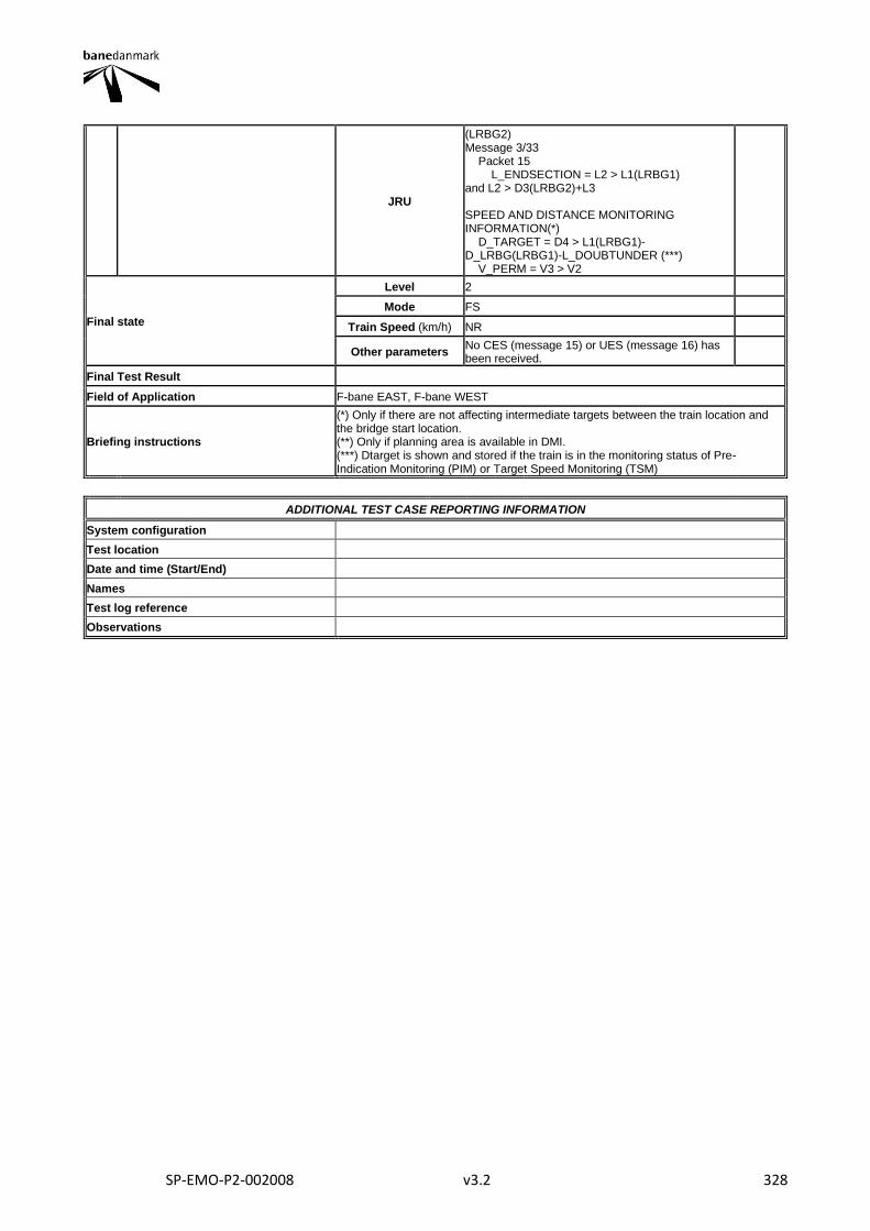
SP-EMO-P2-002008 v3.2 328
JRU
(LRBG2) Message 3/33 Packet 15 L_ENDSECTION = L2 > L1(LRBG1) and L2 > D3(LRBG2)+L3 SPEED AND DISTANCE MONITORING INFORMATION(*) D_TARGET = D4 > L1(LRBG1)-D_LRBG(LRBG1)-L_DOUBTUNDER (***) V_PERM = V3 > V2
Final state
Level 2
Mode FS
Train Speed (km/h) NR
Other parameters No CES (message 15) or UES (message 16) has been received.
Final Test Result
Field of Application F-bane EAST, F-bane WEST
Briefing instructions
(*) Only if there are not affecting intermediate targets between the train location and the bridge start location. (**) Only if planning area is available in DMI. (***) Dtarget is shown and stored if the train is in the monitoring status of Pre-Indication Monitoring (PIM) or Target Speed Monitoring (TSM)
ADDITIONAL TEST CASE REPORTING INFORMATION
System configuration
Test location
Date and time (Start/End)
Names
Test log reference
Observations
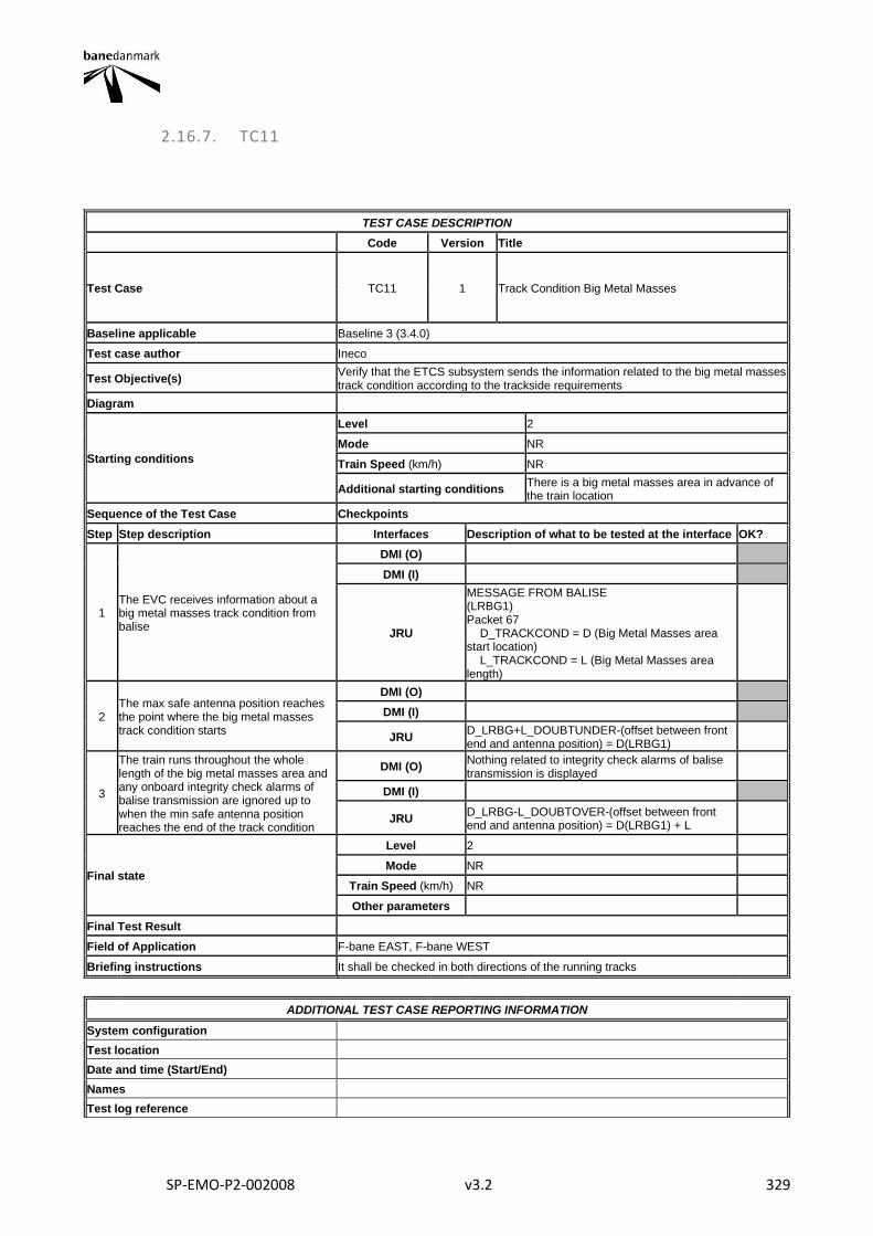
SP-EMO-P2-002008 v3.2 329
2.16.7. TC11
TEST CASE DESCRIPTION
Code Version Title
Test Case TC11 1 Track Condition Big Metal Masses
Baseline applicable Baseline 3 (3.4.0)
Test case author Ineco
Test Objective(s) Verify that the ETCS subsystem sends the information related to the big metal masses track condition according to the trackside requirements
Diagram
Starting conditions
Level 2
Mode NR
Train Speed (km/h) NR
Additional starting conditions There is a big metal masses area in advance of the train location
Sequence of the Test Case Checkpoints
Step Step description Interfaces Description of what to be tested at the interface OK?
1 The EVC receives information about a big metal masses track condition from balise
DMI (O)
DMI (I)
JRU
MESSAGE FROM BALISE (LRBG1) Packet 67 D_TRACKCOND = D (Big Metal Masses area start location) L_TRACKCOND = L (Big Metal Masses area length)
2 The max safe antenna position reaches the point where the big metal masses track condition starts
DMI (O)
DMI (I)
JRU D_LRBG+L_DOUBTUNDER-(offset between front end and antenna position) = D(LRBG1)
3
The train runs throughout the whole length of the big metal masses area and any onboard integrity check alarms of balise transmission are ignored up to when the min safe antenna position reaches the end of the track condition
DMI (O) Nothing related to integrity check alarms of balise transmission is displayed
DMI (I)
JRU D_LRBG-L_DOUBTOVER-(offset between front end and antenna position) = D(LRBG1) + L
Final state
Level 2
Mode NR
Train Speed (km/h) NR
Other parameters
Final Test Result
Field of Application F-bane EAST, F-bane WEST
Briefing instructions It shall be checked in both directions of the running tracks
ADDITIONAL TEST CASE REPORTING INFORMATION
System configuration
Test location
Date and time (Start/End)
Names
Test log reference

SP-EMO-P2-002008 v3.2 330
Observations
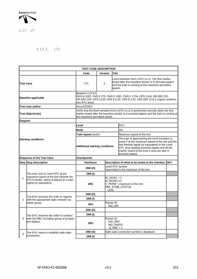
SP-EMO-P2-002008 v3.2 331
2.17. LT
2.17.1. LT1
TEST CASE DESCRIPTION
Code Version Title
Test Case LT1 2
Level transition from LNTC to L2. The first marker board after the transition border is in proceed aspect and the train is running at the maximum permitted speed.
Baseline applicable
Baseline 3 (3.4.0) FbIS.N.1002, FbIS.F.275, FbIS.F.1081, FbIS.F.1734, OPS.1146, OR.DEF.201, OR.DEF.204, OPS.1118, CER 8.2.20, CER 8.2.23, CER DEF (2.8.2 Legacy systems, non-ATC area)
Test case author Ineco/CEDEX
Test Objective(s) Verify that the level transition from LNTC to L2 is performed correctly when the first marker board after the transition border is in proceed aspect and the train is running at the maximum permitted speed.
Diagram
Starting conditions
Level NTC
Mode SN
Train Speed (km/h) Maximum speed of the line
Additional starting conditions
The train is approaching the level transition to Level 2 at the maximum speed of the line and the last lineside signal (or equivalent) in the Level ATC area displays proceed aspect and all the marker board at the level 2 area are also in proceed aspect.
Sequence of the Test Case Checkpoints
Step Step description Interfaces Description of what to be tested at the interface OK?
1
The train runs in Level NTC at the maximum speed of the line towards the ETCS border, which is placed at a main signal (or equivalent).
DMI (O) Level ATC symbol Vpermitted is the maximum of the line
DMI (I)
JRU
M_LEVEL = 1 M_MODE=13 V_PERM = maximum of the line DMI_SYMB_STATUS LE02
2 The EVC receives the order to register with the appropriate radio network via balise group.
DMI (O)
DMI (I)
JRU Packet 45 NID_MN
3 The EVC receives the order to connect with the RBC via balise group of at least two balises.
DMI (O)
DMI (I)
JRU
Packet 42 NID_RBC NID_RADIO Q_RBC = 1
4 The EVC starts to establish safe radio connection.
DMI (O) Safe radio connection symbol is displayed
DMI (I)
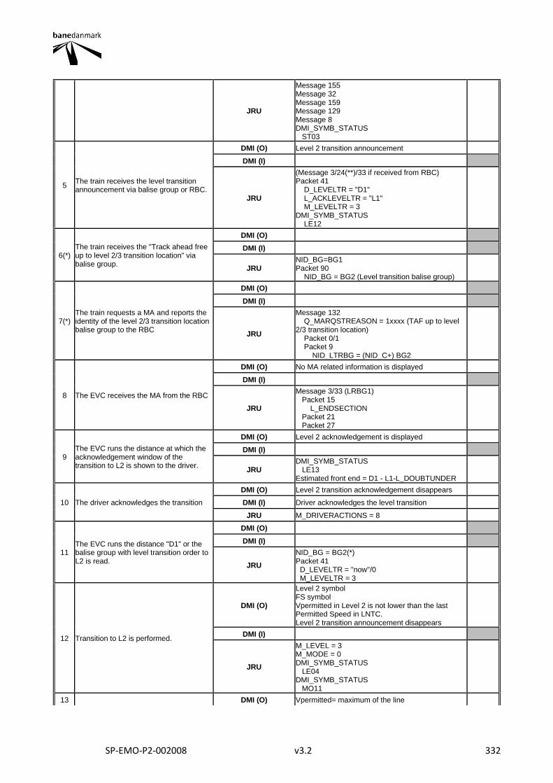
SP-EMO-P2-002008 v3.2 332
JRU
Message 155 Message 32 Message 159 Message 129 Message 8 DMI_SYMB_STATUS ST03
5 The train receives the level transition announcement via balise group or RBC.
DMI (O) Level 2 transition announcement
DMI (I)
JRU
(Message 3/24(**)/33 if received from RBC) Packet 41 D_LEVELTR = "D1" L_ACKLEVELTR = "L1" M_LEVELTR = 3 DMI_SYMB_STATUS LE12
6(*) The train receives the "Track ahead free up to level 2/3 transition location" via balise group.
DMI (O)
DMI (I)
JRU NID_BG=BG1 Packet 90 NID_BG = BG2 (Level transition balise group)
7(*) The train requests a MA and reports the identity of the level 2/3 transition location balise group to the RBC
DMI (O)
DMI (I)
JRU
Message 132 Q_MARQSTREASON = 1xxxx (TAF up to level 2/3 transition location) Packet 0/1 Packet 9 NID_LTRBG = (NID_C+) BG2
8 The EVC receives the MA from the RBC
DMI (O) No MA related information is displayed
DMI (I)
JRU
Message 3/33 (LRBG1) Packet 15 L_ENDSECTION Packet 21 Packet 27
9 The EVC runs the distance at which the acknowledgement window of the transition to L2 is shown to the driver.
DMI (O) Level 2 acknowledgement is displayed
DMI (I)
JRU DMI_SYMB_STATUS LE13 Estimated front end = D1 - L1-L_DOUBTUNDER
10 The driver acknowledges the transition
DMI (O) Level 2 transition acknowledgement disappears
DMI (I) Driver acknowledges the level transition
JRU M_DRIVERACTIONS = 8
11 The EVC runs the distance "D1" or the balise group with level transition order to L2 is read.
DMI (O)
DMI (I)
JRU
NID_BG = BG2(*) Packet 41 D_LEVELTR = "now"/0 M_LEVELTR = 3
12 Transition to L2 is performed.
DMI (O)
Level 2 symbol FS symbol Vpermitted in Level 2 is not lower than the last Permitted Speed in LNTC. Level 2 transition announcement disappears
DMI (I)
JRU
M_LEVEL = 3 M_MODE = 0 DMI_SYMB_STATUS LE04 DMI_SYMB_STATUS MO11
13 DMI (O) Vpermitted= maximum of the line
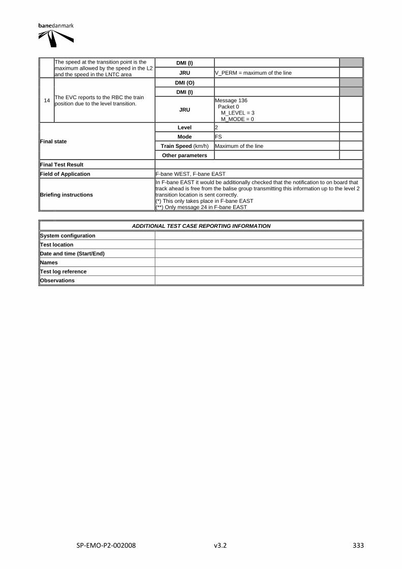
SP-EMO-P2-002008 v3.2 333
The speed at the transition point is the maximum allowed by the speed in the L2 and the speed in the LNTC area
DMI (I)
JRU V_PERM = maximum of the line
14 The EVC reports to the RBC the train position due to the level transition.
DMI (O)
DMI (I)
JRU
Message 136 Packet 0 M_LEVEL = 3 M_MODE = 0
Final state
Level 2
Mode FS
Train Speed (km/h) Maximum of the line
Other parameters
Final Test Result
Field of Application F-bane WEST, F-bane EAST
Briefing instructions
In F-bane EAST it would be additionally checked that the notification to on board that track ahead is free from the balise group transmitting this information up to the level 2 transition location is sent correctly. (*) This only takes place in F-bane EAST (**) Only message 24 in F-bane EAST
ADDITIONAL TEST CASE REPORTING INFORMATION
System configuration
Test location
Date and time (Start/End)
Names
Test log reference
Observations
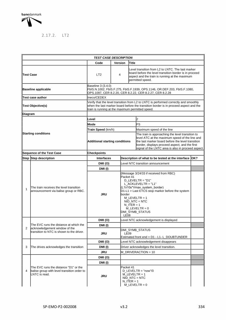
SP-EMO-P2-002008 v3.2 334
2.17.2. LT2
TEST CASE DESCRIPTION
Code Version Title
Test Case LT2 4
Level transition from L2 to LNTC. The last marker board before the level transition border is in proceed aspect and the train is running at the maximum permitted speed.
Baseline applicable Baseline 3 (3.4.0) FbIS.N.1002, FbIS.F.275, FbIS.F.1939, OPS.1146, OR.DEF.203, FbIS.F.1080, OPS.1097, CER 8.2.20, CER 8.2.22, CER 8.2.27, CER 8.2.28
Test case author Ineco/CEDEX
Test Objective(s) Verify that the level transition from L2 to LNTC is performed correctly and smoothly when the last marker board before the transition border is in proceed aspect and the train is running at the maximum permitted speed.
Diagram
Starting conditions
Level 2
Mode FS
Train Speed (km/h) Maximum speed of the line
Additional starting conditions
The train is approaching the level transition to level ATC at the maximum speed of the line and the last marker board before the level transition border, displays proceed aspect, and the first signal of the LNTC area is also in proceed aspect.
Sequence of the Test Case Checkpoints
Step Step description Interfaces Description of what to be tested at the interface OK?
1 The train receives the level transition announcement via balise group or RBC.
DMI (O) Level NTC transition announcement
DMI (I)
JRU
(Message 3/24/33 if received from RBC) Packet 41 D_LEVELTR = "D1" L_ACKLEVELTR = "L1" (L1≥10s*Vmax_system_border) D1-L1 > Last ETCS stop marker before the system border M_LEVELTR = 1 NID_NTC = NTC N_ITER = 1 M_LEVELTR = 0 DMI_SYMB_STATUS LE08
2 The EVC runs the distance at which the acknowledgement window of the transition to NTC is shown to the driver.
DMI (O) Level NTC acknowledgement is displayed
DMI (I)
JRU DMI_SYMB_STATUS LE09 Estimated front end = D1 - L1- L_DOUBTUNDER
3 The drives acknowledges the transition
DMI (O) Level NTC acknowledgement disappears
DMI (I) Driver acknowledges the level transition.
JRU M_DRIVERACTION = 10
4 The EVC runs the distance "D1" or the balise group with level transition order to LNTC is read.
DMI (O)
DMI (I)
JRU
Packet 41 D_LEVELTR = "now"/0 M_LEVELTR = 1 NID_NTC = NTC N_ITER = 1 M_LEVELTR = 0
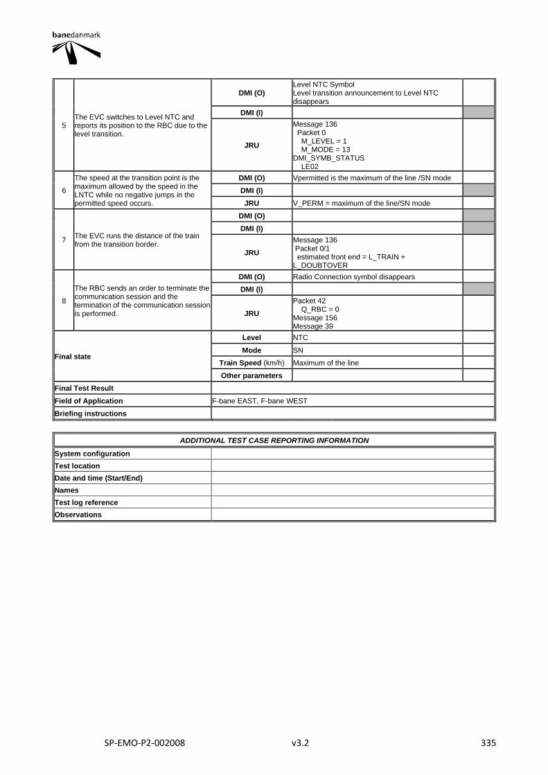
SP-EMO-P2-002008 v3.2 335
5 The EVC switches to Level NTC and reports its position to the RBC due to the level transition.
DMI (O) Level NTC Symbol Level transition announcement to Level NTC disappears
DMI (I)
JRU
Message 136 Packet 0 M_LEVEL = 1 M_MODE = 13 DMI_SYMB_STATUS LE02
6
The speed at the transition point is the maximum allowed by the speed in the LNTC while no negative jumps in the permitted speed occurs.
DMI (O) Vpermitted is the maximum of the line /SN mode
DMI (I)
JRU V_PERM = maximum of the line/SN mode
7 The EVC runs the distance of the train from the transition border.
DMI (O)
DMI (I)
JRU
Message 136 Packet 0/1 estimated front end = L_TRAIN + L_DOUBTOVER
8
The RBC sends an order to terminate the communication session and the termination of the communication session is performed.
DMI (O) Radio Connection symbol disappears
DMI (I)
JRU
Packet 42 Q_RBC = 0 Message 156 Message 39
Final state
Level NTC
Mode SN
Train Speed (km/h) Maximum of the line
Other parameters
Final Test Result
Field of Application F-bane EAST, F-bane WEST
Briefing instructions
ADDITIONAL TEST CASE REPORTING INFORMATION
System configuration
Test location
Date and time (Start/End)
Names
Test log reference
Observations
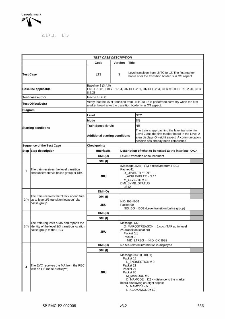
SP-EMO-P2-002008 v3.2 336
2.17.3. LT3
TEST CASE DESCRIPTION
Code Version Title
Test Case LT3 3 Level transition from LNTC to L2. The first marker board after the transition border is in OS aspect.
Baseline applicable Baseline 3 (3.4.0) FbIS.F.1081, FbIS.F.1734, OR.DEF.201, OR.DEF.204, CER 9.2.8, CER 8.2.20, CER 8.2.23
Test case author Ineco/CEDEX
Test Objective(s) Verify that the level transition from LNTC to L2 is performed correctly when the first marker board after the transition border is in OS aspect.
Diagram
Starting conditions
Level NTC
Mode SN
Train Speed (km/h) NR
Additional starting conditions
The train is approaching the level transition to Level 2 and the first marker board in the Level 2 area displays On-sight aspect. A communication session has already been established
Sequence of the Test Case Checkpoints
Step Step description Interfaces Description of what to be tested at the interface OK?
1 The train receives the level transition announcement via balise group or RBC.
DMI (O) Level 2 transition announcement
DMI (I)
JRU
(Message 3/24(**)/33 if received from RBC) Packet 41 D_LEVELTR = "D1" L_ACKLEVELTR = "L1" M_LEVELTR = 3 DMI_SYMB_STATUS LE12
2(*) The train receives the "Track ahead free up to level 2/3 transition location" via balise group.
DMI (O)
DMI (I)
JRU NID_BG=BG1 Packet 90 NID_BG = BG2 (Level transition balise group)
3(*) The train requests a MA and reports the identity of the level 2/3 transition location balise group to the RBC
DMI (O)
DMI (I)
JRU
Message 132 Q_MARQSTREASON = 1xxxx (TAF up to level 2/3 transition location) Packet 0/1 Packet 9 NID_LTRBG = (NID_C+) BG2
4 The EVC receives the MA from the RBC, with an OS mode profile(***)
DMI (O) No MA related information is displayed
DMI (I)
JRU
Message 3/33 (LRBG1) Packet 15 L_ENDSECTION ≠ 0 Packet 21 Packet 27 Packet 80 M_MAMODE = 0 D_MAMODE = D2 -> distance to the marker board displaying on-sight aspect V_MAMODE= V L_ACKMAMODE= L2
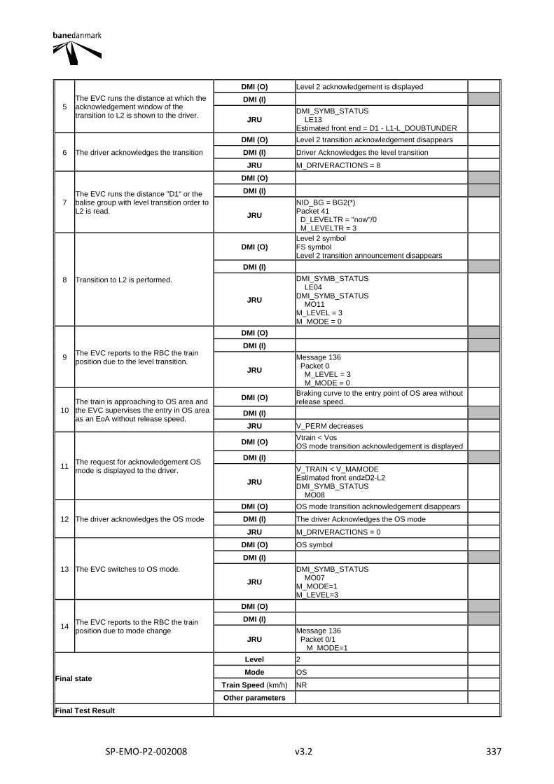
SP-EMO-P2-002008 v3.2 337
5 The EVC runs the distance at which the acknowledgement window of the transition to L2 is shown to the driver.
DMI (O) Level 2 acknowledgement is displayed
DMI (I)
JRU DMI_SYMB_STATUS LE13 Estimated front end = D1 - L1-L_DOUBTUNDER
6 The driver acknowledges the transition
DMI (O) Level 2 transition acknowledgement disappears
DMI (I) Driver Acknowledges the level transition
JRU M_DRIVERACTIONS = 8
7 The EVC runs the distance "D1" or the balise group with level transition order to L2 is read.
DMI (O)
DMI (I)
JRU
NID_BG = BG2(*) Packet 41 D_LEVELTR = "now"/0 M_LEVELTR = 3
8 Transition to L2 is performed.
DMI (O) Level 2 symbol FS symbol Level 2 transition announcement disappears
DMI (I)
JRU
DMI_SYMB_STATUS LE04 DMI_SYMB_STATUS MO11 M_LEVEL = 3 M_MODE = 0
9 The EVC reports to the RBC the train position due to the level transition.
DMI (O)
DMI (I)
JRU
Message 136 Packet 0 M_LEVEL = 3 M_MODE = 0
10 The train is approaching to OS area and the EVC supervises the entry in OS area as an EoA without release speed.
DMI (O) Braking curve to the entry point of OS area without release speed.
DMI (I)
JRU V_PERM decreases
11 The request for acknowledgement OS mode is displayed to the driver.
DMI (O) Vtrain < Vos OS mode transition acknowledgement is displayed
DMI (I)
JRU
V_TRAIN < V_MAMODE Estimated front end≥D2-L2 DMI_SYMB_STATUS MO08
12 The driver acknowledges the OS mode
DMI (O) OS mode transition acknowledgement disappears
DMI (I) The driver Acknowledges the OS mode
JRU M_DRIVERACTIONS = 0
13 The EVC switches to OS mode.
DMI (O) OS symbol
DMI (I)
JRU
DMI_SYMB_STATUS MO07 M_MODE=1 M_LEVEL=3
14 The EVC reports to the RBC the train position due to mode change
DMI (O)
DMI (I)
JRU Message 136 Packet 0/1 M_MODE=1
Final state
Level 2
Mode OS
Train Speed (km/h) NR
Other parameters
Final Test Result
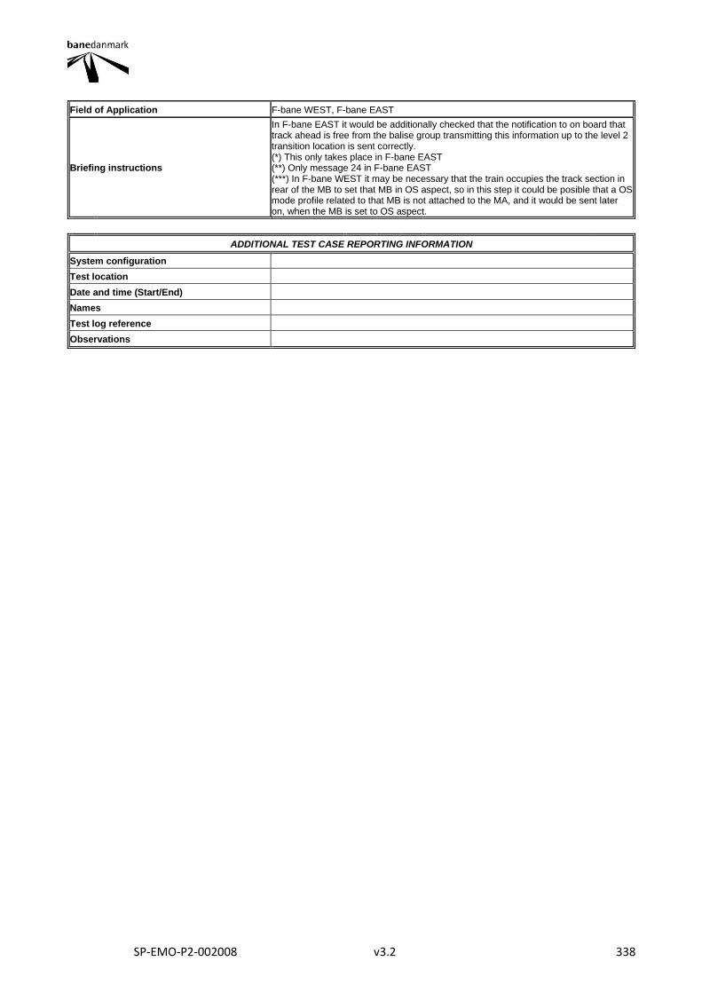
SP-EMO-P2-002008 v3.2 338
Field of Application F-bane WEST, F-bane EAST
Briefing instructions
In F-bane EAST it would be additionally checked that the notification to on board that track ahead is free from the balise group transmitting this information up to the level 2 transition location is sent correctly. (*) This only takes place in F-bane EAST (**) Only message 24 in F-bane EAST (***) In F-bane WEST it may be necessary that the train occupies the track section in rear of the MB to set that MB in OS aspect, so in this step it could be posible that a OS mode profile related to that MB is not attached to the MA, and it would be sent later on, when the MB is set to OS aspect.
ADDITIONAL TEST CASE REPORTING INFORMATION
System configuration
Test location
Date and time (Start/End)
Names
Test log reference
Observations
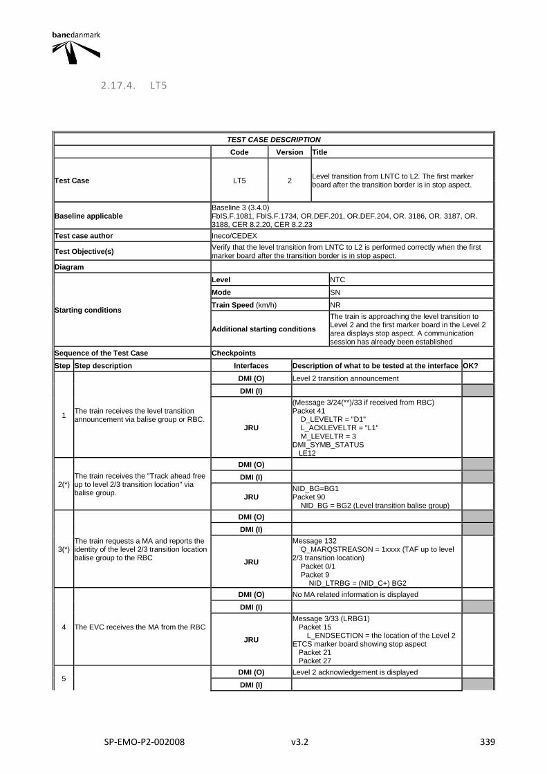
SP-EMO-P2-002008 v3.2 339
2.17.4. LT5
TEST CASE DESCRIPTION
Code Version Title
Test Case LT5 2 Level transition from LNTC to L2. The first marker board after the transition border is in stop aspect.
Baseline applicable Baseline 3 (3.4.0) FbIS.F.1081, FbIS.F.1734, OR.DEF.201, OR.DEF.204, OR. 3186, OR. 3187, OR. 3188, CER 8.2.20, CER 8.2.23
Test case author Ineco/CEDEX
Test Objective(s) Verify that the level transition from LNTC to L2 is performed correctly when the first marker board after the transition border is in stop aspect.
Diagram
Starting conditions
Level NTC
Mode SN
Train Speed (km/h) NR
Additional starting conditions
The train is approaching the level transition to Level 2 and the first marker board in the Level 2 area displays stop aspect. A communication session has already been established
Sequence of the Test Case Checkpoints
Step Step description Interfaces Description of what to be tested at the interface OK?
1 The train receives the level transition announcement via balise group or RBC.
DMI (O) Level 2 transition announcement
DMI (I)
JRU
(Message 3/24(**)/33 if received from RBC) Packet 41 D_LEVELTR = "D1" L_ACKLEVELTR = "L1" M_LEVELTR = 3 DMI_SYMB_STATUS LE12
2(*) The train receives the "Track ahead free up to level 2/3 transition location" via balise group.
DMI (O)
DMI (I)
JRU NID_BG=BG1 Packet 90 NID_BG = BG2 (Level transition balise group)
3(*) The train requests a MA and reports the identity of the level 2/3 transition location balise group to the RBC
DMI (O)
DMI (I)
JRU
Message 132 Q_MARQSTREASON = 1xxxx (TAF up to level 2/3 transition location) Packet 0/1 Packet 9 NID_LTRBG = (NID_C+) BG2
4 The EVC receives the MA from the RBC
DMI (O) No MA related information is displayed
DMI (I)
JRU
Message 3/33 (LRBG1) Packet 15 L_ENDSECTION = the location of the Level 2 ETCS marker board showing stop aspect Packet 21 Packet 27
5 DMI (O) Level 2 acknowledgement is displayed
DMI (I)
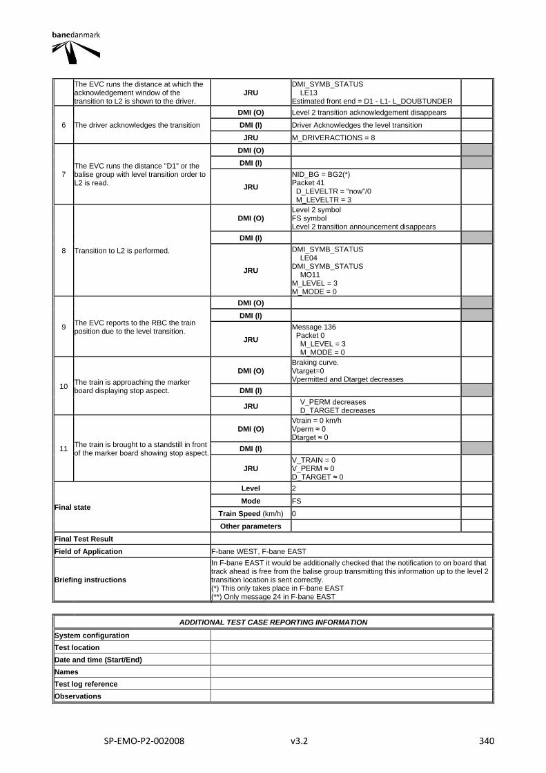
SP-EMO-P2-002008 v3.2 340
The EVC runs the distance at which the acknowledgement window of the transition to L2 is shown to the driver.
JRU DMI_SYMB_STATUS LE13 Estimated front end = D1 - L1- L_DOUBTUNDER
6 The driver acknowledges the transition
DMI (O) Level 2 transition acknowledgement disappears
DMI (I) Driver Acknowledges the level transition
JRU M_DRIVERACTIONS = 8
7 The EVC runs the distance "D1" or the balise group with level transition order to L2 is read.
DMI (O)
DMI (I)
JRU
NID_BG = BG2(*) Packet 41 D_LEVELTR = "now"/0 M_LEVELTR = 3
8 Transition to L2 is performed.
DMI (O) Level 2 symbol FS symbol Level 2 transition announcement disappears
DMI (I)
JRU
DMI_SYMB_STATUS LE04 DMI_SYMB_STATUS MO11 M_LEVEL = 3 M_MODE = 0
9 The EVC reports to the RBC the train position due to the level transition.
DMI (O)
DMI (I)
JRU
Message 136 Packet 0 M_LEVEL = 3 M_MODE = 0
10 The train is approaching the marker board displaying stop aspect.
DMI (O) Braking curve. Vtarget=0 Vpermitted and Dtarget decreases
DMI (I)
JRU V_PERM decreases D_TARGET decreases
11 The train is brought to a standstill in front of the marker board showing stop aspect.
DMI (O) Vtrain = 0 km/h Vperm ≈ 0 Dtarget ≈ 0
DMI (I)
JRU V_TRAIN = 0 V_PERM ≈ 0 D_TARGET ≈ 0
Final state
Level 2
Mode FS
Train Speed (km/h) 0
Other parameters
Final Test Result
Field of Application F-bane WEST, F-bane EAST
Briefing instructions
In F-bane EAST it would be additionally checked that the notification to on board that track ahead is free from the balise group transmitting this information up to the level 2 transition location is sent correctly. (*) This only takes place in F-bane EAST (**) Only message 24 in F-bane EAST
ADDITIONAL TEST CASE REPORTING INFORMATION
System configuration
Test location
Date and time (Start/End)
Names
Test log reference
Observations

SP-EMO-P2-002008 v3.2 341
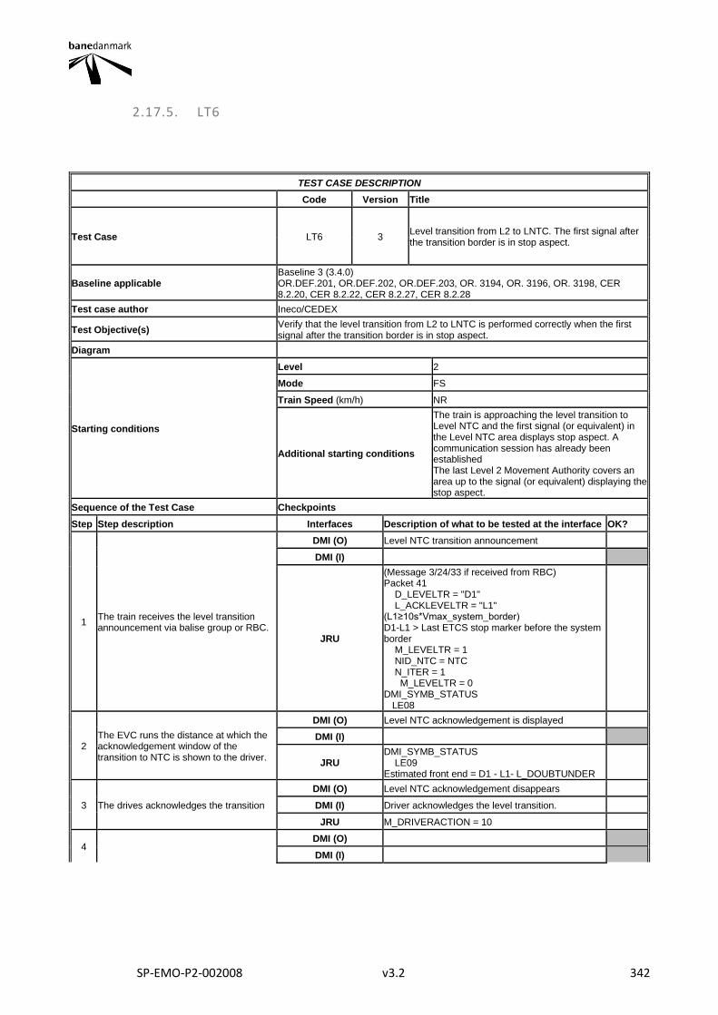
SP-EMO-P2-002008 v3.2 342
2.17.5. LT6
TEST CASE DESCRIPTION
Code Version Title
Test Case LT6 3 Level transition from L2 to LNTC. The first signal after the transition border is in stop aspect.
Baseline applicable Baseline 3 (3.4.0) OR.DEF.201, OR.DEF.202, OR.DEF.203, OR. 3194, OR. 3196, OR. 3198, CER 8.2.20, CER 8.2.22, CER 8.2.27, CER 8.2.28
Test case author Ineco/CEDEX
Test Objective(s) Verify that the level transition from L2 to LNTC is performed correctly when the first signal after the transition border is in stop aspect.
Diagram
Starting conditions
Level 2
Mode FS
Train Speed (km/h) NR
Additional starting conditions
The train is approaching the level transition to Level NTC and the first signal (or equivalent) in the Level NTC area displays stop aspect. A communication session has already been established The last Level 2 Movement Authority covers an area up to the signal (or equivalent) displaying the stop aspect.
Sequence of the Test Case Checkpoints
Step Step description Interfaces Description of what to be tested at the interface OK?
1 The train receives the level transition announcement via balise group or RBC.
DMI (O) Level NTC transition announcement
DMI (I)
JRU
(Message 3/24/33 if received from RBC) Packet 41 D_LEVELTR = "D1" L_ACKLEVELTR = "L1" (L1≥10s*Vmax_system_border) D1-L1 > Last ETCS stop marker before the system border M_LEVELTR = 1 NID_NTC = NTC N_ITER = 1 M_LEVELTR = 0 DMI_SYMB_STATUS LE08
2 The EVC runs the distance at which the acknowledgement window of the transition to NTC is shown to the driver.
DMI (O) Level NTC acknowledgement is displayed
DMI (I)
JRU DMI_SYMB_STATUS LE09 Estimated front end = D1 - L1- L_DOUBTUNDER
3 The drives acknowledges the transition
DMI (O) Level NTC acknowledgement disappears
DMI (I) Driver acknowledges the level transition.
JRU M_DRIVERACTION = 10
4 DMI (O)
DMI (I)
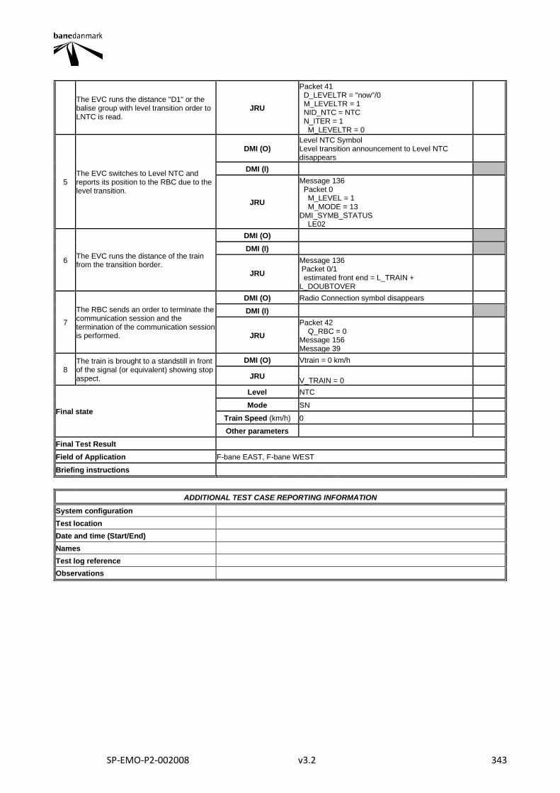
SP-EMO-P2-002008 v3.2 343
The EVC runs the distance "D1" or the balise group with level transition order to LNTC is read.
JRU
Packet 41 D_LEVELTR = "now"/0 M_LEVELTR = 1 NID_NTC = NTC N_ITER = 1 M_LEVELTR = 0
5 The EVC switches to Level NTC and reports its position to the RBC due to the level transition.
DMI (O) Level NTC Symbol Level transition announcement to Level NTC disappears
DMI (I)
JRU
Message 136 Packet 0 M_LEVEL = 1 M_MODE = 13 DMI_SYMB_STATUS LE02
6 The EVC runs the distance of the train from the transition border.
DMI (O)
DMI (I)
JRU
Message 136 Packet 0/1 estimated front end = L_TRAIN + L_DOUBTOVER
7
The RBC sends an order to terminate the communication session and the termination of the communication session is performed.
DMI (O) Radio Connection symbol disappears
DMI (I)
JRU
Packet 42 Q_RBC = 0 Message 156 Message 39
8 The train is brought to a standstill in front of the signal (or equivalent) showing stop aspect.
DMI (O) Vtrain = 0 km/h
JRU V_TRAIN = 0
Final state
Level NTC
Mode SN
Train Speed (km/h) 0
Other parameters
Final Test Result
Field of Application F-bane EAST, F-bane WEST
Briefing instructions
ADDITIONAL TEST CASE REPORTING INFORMATION
System configuration
Test location
Date and time (Start/End)
Names
Test log reference
Observations
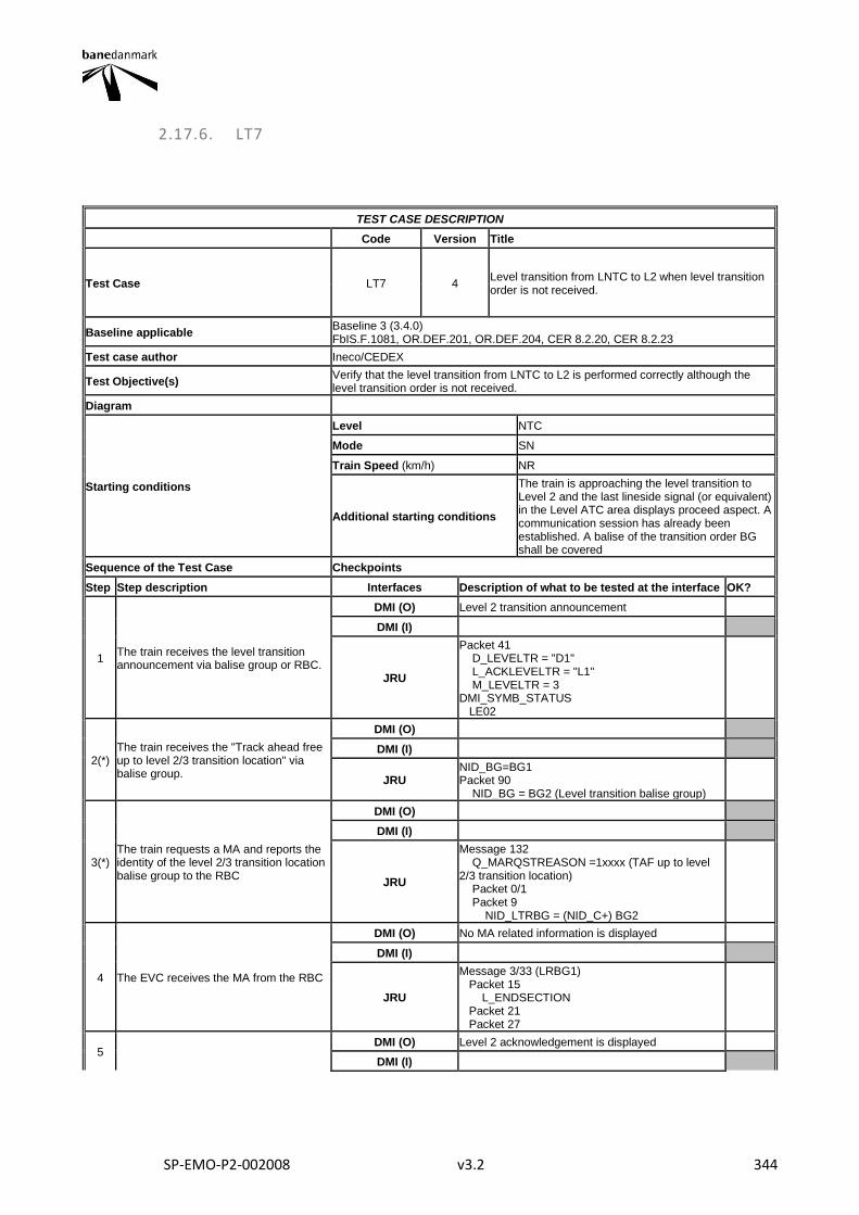
SP-EMO-P2-002008 v3.2 344
2.17.6. LT7
TEST CASE DESCRIPTION
Code Version Title
Test Case LT7 4 Level transition from LNTC to L2 when level transition order is not received.
Baseline applicable Baseline 3 (3.4.0) FbIS.F.1081, OR.DEF.201, OR.DEF.204, CER 8.2.20, CER 8.2.23
Test case author Ineco/CEDEX
Test Objective(s) Verify that the level transition from LNTC to L2 is performed correctly although the level transition order is not received.
Diagram
Starting conditions
Level NTC
Mode SN
Train Speed (km/h) NR
Additional starting conditions
The train is approaching the level transition to Level 2 and the last lineside signal (or equivalent) in the Level ATC area displays proceed aspect. A communication session has already been established. A balise of the transition order BG shall be covered
Sequence of the Test Case Checkpoints
Step Step description Interfaces Description of what to be tested at the interface OK?
1 The train receives the level transition announcement via balise group or RBC.
DMI (O) Level 2 transition announcement
DMI (I)
JRU
Packet 41 D_LEVELTR = "D1" L_ACKLEVELTR = "L1" M_LEVELTR = 3 DMI_SYMB_STATUS LE02
2(*) The train receives the "Track ahead free up to level 2/3 transition location" via balise group.
DMI (O)
DMI (I)
JRU NID_BG=BG1 Packet 90 NID_BG = BG2 (Level transition balise group)
3(*) The train requests a MA and reports the identity of the level 2/3 transition location balise group to the RBC
DMI (O)
DMI (I)
JRU
Message 132 Q_MARQSTREASON =1xxxx (TAF up to level 2/3 transition location) Packet 0/1 Packet 9 NID_LTRBG = (NID_C+) BG2
4 The EVC receives the MA from the RBC
DMI (O) No MA related information is displayed
DMI (I)
JRU
Message 3/33 (LRBG1) Packet 15 L_ENDSECTION Packet 21 Packet 27
5 DMI (O) Level 2 acknowledgement is displayed
DMI (I)
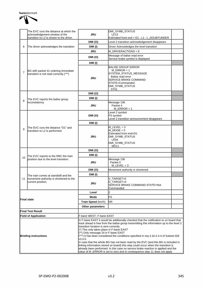
SP-EMO-P2-002008 v3.2 345
The EVC runs the distance at which the acknowledgement window of the transition to L2 is shown to the driver.
JRU DMI_SYMB_STATUS LE13 Estimated front end = D1 - L1 - L_DOUBTUNDER
6 The driver acknowledges the transition
DMI (O) Level 2 transition acknowledgement disappears
DMI (I) Driver Acknowledges the level transition
JRU M_DRIVERACTIONS = 8
7 BG with packet 41 ordering immediate transition is not read correctly.(***)
DMI (O) Message of balise read error Service brake symbol is displayed
DMI (I)
JRU
BALISE GROUP ERROR M_ERROR = 1 SYSTEM_STATUS_MESSAGE Balise read error SERVICE BRAKE COMMAND STATE=Commanded DMI_SYMB_STATUS ST01
8 The EVC reports the balise group inconsistency
DMI (O)
DMI (I)
JRU Message 136 Packet 4 M_ERROR = 1
9 The EVC runs the distance "D1" and transition to L2 is performed.
DMI (O) Level 2 symbol FS symbol Level 2 transition announcement disappears
DMI (I)
JRU
M_LEVEL = 3 M_MODE = 0 Estimated front end=D1 DMI_SYMB_STATUS LE04 DMI_SYMB_STATUS MO11
10 The EVC reports to the RBC the train position due to the level transition.
DMI (O)
DMI (I)
JRU Message 136 Packet 0 M_LEVEL = 3
11 The train comes at standstill and the movement authority is shortened to the current position.
DMI (O) Movement authority is shortened
DMI (I)
JRU
V_TARGET=0 D_TARGET=0 SERVICE BRAKE COMMAND STATE=Not Commanded
Final state
Level 2
Mode FS
Train Speed (km/h) NR
Other parameters
Final Test Result
Field of Application F-bane WEST, F-bane EAST
Briefing instructions
In F-bane EAST it would be additionally checked that the notification to on board that track ahead is free from the balise group transmitting this information up to the level 2 transition location is sent correctly. (*) This only takes place in F-bane EAST (**) Only message 24 in F-bane EAST (***) It has been considered the conditions specified in req 3.16.2.4.4 of Subset 026 v3.4.0. In case that the whole BG has not been read by the EVC (and this BG is included in linking information stored on board) this step could occur when the transition is already been performed. In this case no service brake reaction is applied and the value of M_ERROR is set to zero and in consequence step 11 does not apply

SP-EMO-P2-002008 v3.2 346
ADDITIONAL TEST CASE REPORTING INFORMATION
System configuration
Test location
Date and time (Start/End)
Names
Test log reference
Observations
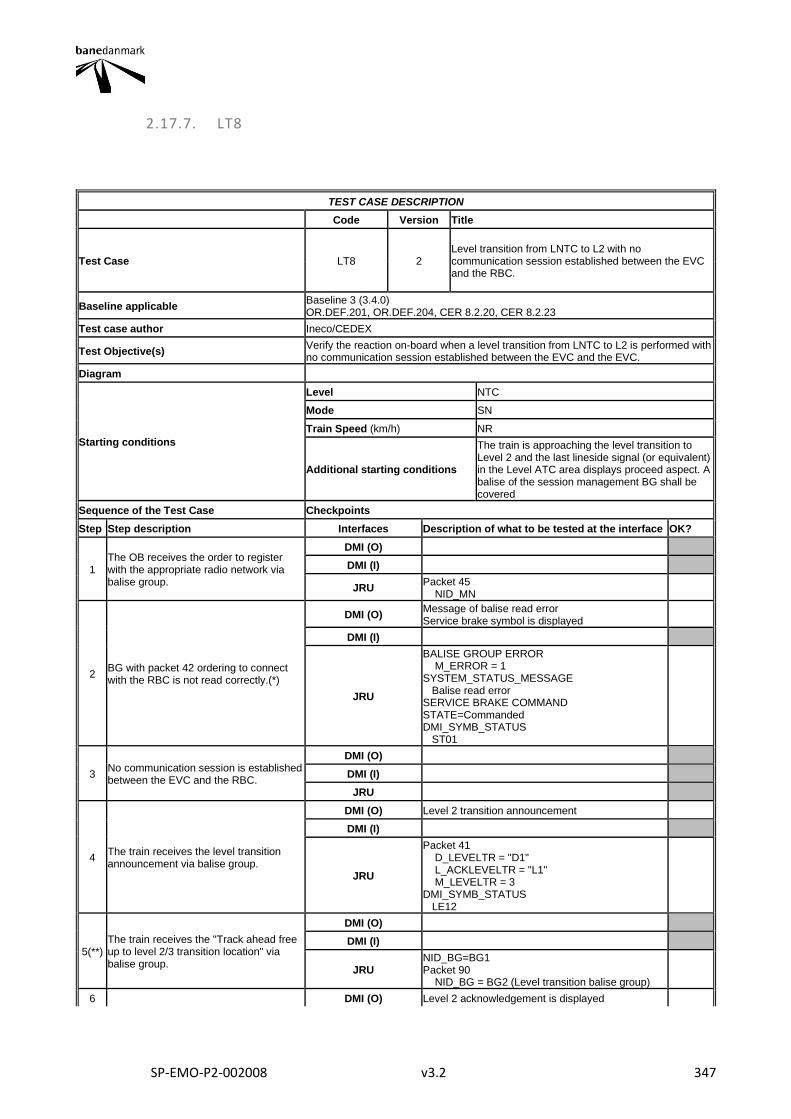
SP-EMO-P2-002008 v3.2 347
2.17.7. LT8
TEST CASE DESCRIPTION
Code Version Title
Test Case LT8 2 Level transition from LNTC to L2 with no communication session established between the EVC and the RBC.
Baseline applicable Baseline 3 (3.4.0) OR.DEF.201, OR.DEF.204, CER 8.2.20, CER 8.2.23
Test case author Ineco/CEDEX
Test Objective(s) Verify the reaction on-board when a level transition from LNTC to L2 is performed with no communication session established between the EVC and the EVC.
Diagram
Starting conditions
Level NTC
Mode SN
Train Speed (km/h) NR
Additional starting conditions
The train is approaching the level transition to Level 2 and the last lineside signal (or equivalent) in the Level ATC area displays proceed aspect. A balise of the session management BG shall be covered
Sequence of the Test Case Checkpoints
Step Step description Interfaces Description of what to be tested at the interface OK?
1 The OB receives the order to register with the appropriate radio network via balise group.
DMI (O)
DMI (I)
JRU Packet 45 NID_MN
2 BG with packet 42 ordering to connect with the RBC is not read correctly.(*)
DMI (O) Message of balise read error Service brake symbol is displayed
DMI (I)
JRU
BALISE GROUP ERROR M_ERROR = 1 SYSTEM_STATUS_MESSAGE Balise read error SERVICE BRAKE COMMAND STATE=Commanded DMI_SYMB_STATUS ST01
3 No communication session is established between the EVC and the RBC.
DMI (O)
DMI (I)
JRU
4 The train receives the level transition announcement via balise group.
DMI (O) Level 2 transition announcement
DMI (I)
JRU
Packet 41 D_LEVELTR = "D1" L_ACKLEVELTR = "L1" M_LEVELTR = 3 DMI_SYMB_STATUS LE12
5(**) The train receives the "Track ahead free up to level 2/3 transition location" via balise group.
DMI (O)
DMI (I)
JRU NID_BG=BG1 Packet 90 NID_BG = BG2 (Level transition balise group)
6 DMI (O) Level 2 acknowledgement is displayed
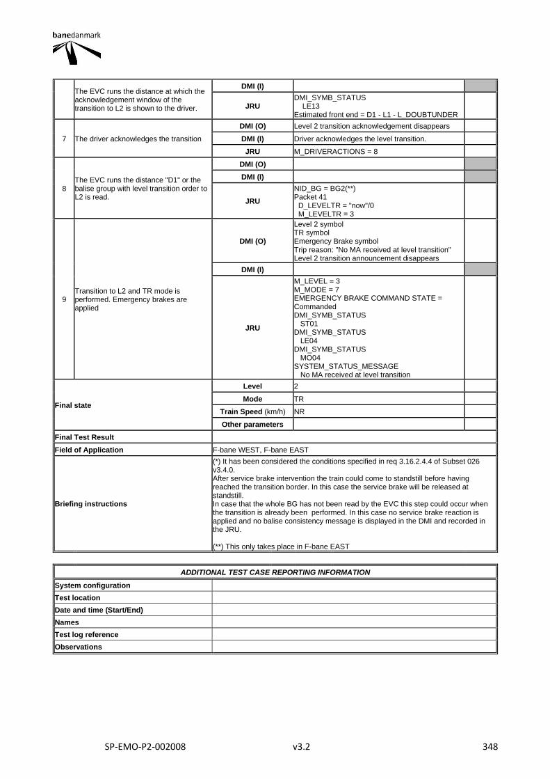
SP-EMO-P2-002008 v3.2 348
The EVC runs the distance at which the acknowledgement window of the transition to L2 is shown to the driver.
DMI (I)
JRU DMI_SYMB_STATUS LE13 Estimated front end = D1 - L1 - L_DOUBTUNDER
7 The driver acknowledges the transition
DMI (O) Level 2 transition acknowledgement disappears
DMI (I) Driver acknowledges the level transition.
JRU M_DRIVERACTIONS = 8
8 The EVC runs the distance "D1" or the balise group with level transition order to L2 is read.
DMI (O)
DMI (I)
JRU
NID_BG = BG2(**) Packet 41 D_LEVELTR = "now"/0 M_LEVELTR = 3
9 Transition to L2 and TR mode is performed. Emergency brakes are applied
DMI (O)
Level 2 symbol TR symbol Emergency Brake symbol Trip reason: "No MA received at level transition" Level 2 transition announcement disappears
DMI (I)
JRU
M_LEVEL = 3 M_MODE = 7 EMERGENCY BRAKE COMMAND STATE = Commanded DMI_SYMB_STATUS ST01 DMI_SYMB_STATUS LE04 DMI_SYMB_STATUS MO04 SYSTEM_STATUS_MESSAGE No MA received at level transition
Final state
Level 2
Mode TR
Train Speed (km/h) NR
Other parameters
Final Test Result
Field of Application F-bane WEST, F-bane EAST
Briefing instructions
(*) It has been considered the conditions specified in req 3.16.2.4.4 of Subset 026 v3.4.0. After service brake intervention the train could come to standstill before having reached the transition border. In this case the service brake will be released at standstill. In case that the whole BG has not been read by the EVC this step could occur when the transition is already been performed. In this case no service brake reaction is applied and no balise consistency message is displayed in the DMI and recorded in the JRU. (**) This only takes place in F-bane EAST
ADDITIONAL TEST CASE REPORTING INFORMATION
System configuration
Test location
Date and time (Start/End)
Names
Test log reference
Observations
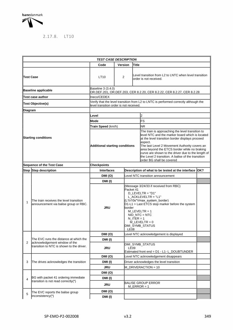
SP-EMO-P2-002008 v3.2 349
2.17.8. LT10
TEST CASE DESCRIPTION
Code Version Title
Test Case LT10 2 Level transition from L2 to LNTC when level transition order is not received.
Baseline applicable Baseline 3 (3.4.0) OR.DEF.201, OR.DEF.203, CER 8.2.20, CER 8.2.22, CER 8.2.27, CER 8.2.28
Test case author Ineco/CEDEX
Test Objective(s) Verify that the level transition from L2 to LNTC is performed correctly although the level transition order is not received.
Diagram
Starting conditions
Level 2
Mode FS
Train Speed (km/h) NR
Additional starting conditions
The train is approaching the level transition to level NTC and the marker board which is located at the level transition border displays proceed aspect. The last Level 2 Movement Authority covers an area beyond the ETCS border while no braking curve are shown to the driver due to the length of the Level 2 transition. A balise of the transition order BG shall be covered
Sequence of the Test Case Checkpoints
Step Step description Interfaces Description of what to be tested at the interface OK?
1 The train receives the level transition announcement via balise group or RBC.
DMI (O) Level NTC transition announcement
DMI (I)
JRU
(Message 3/24/33 if received from RBC) Packet 41 D_LEVELTR = "D1" L_ACKLEVELTR = "L1" (L1≥10s*Vmax_system_border) D1-L1 > Last ETCS stop marker before the system border M_LEVELTR = 1 NID_NTC = NTC N_ITER = 1 M_LEVELTR = 0 DMI_SYMB_STATUS LE08
2 The EVC runs the distance at which the acknowledgement window of the transition to NTC is shown to the driver.
DMI (O) Level NTC acknowledgement is displayed
DMI (I)
JRU DMI_SYMB_STATUS LE09 Estimated front end = D1 - L1- L_DOUBTUNDER
3 The drives acknowledges the transition
DMI (O) Level NTC acknowledgement disappears
DMI (I) Driver acknowledges the level transition
JRU M_DRIVERACTION = 10
4 BG with packet 41 ordering immediate transition is not read correctly(*)
DMI (O)
DMI (I)
JRU BALISE GROUP ERROR M_ERROR = 1
5 The EVC reports the balise group inconsistency(*)
DMI (O)
DMI (I)
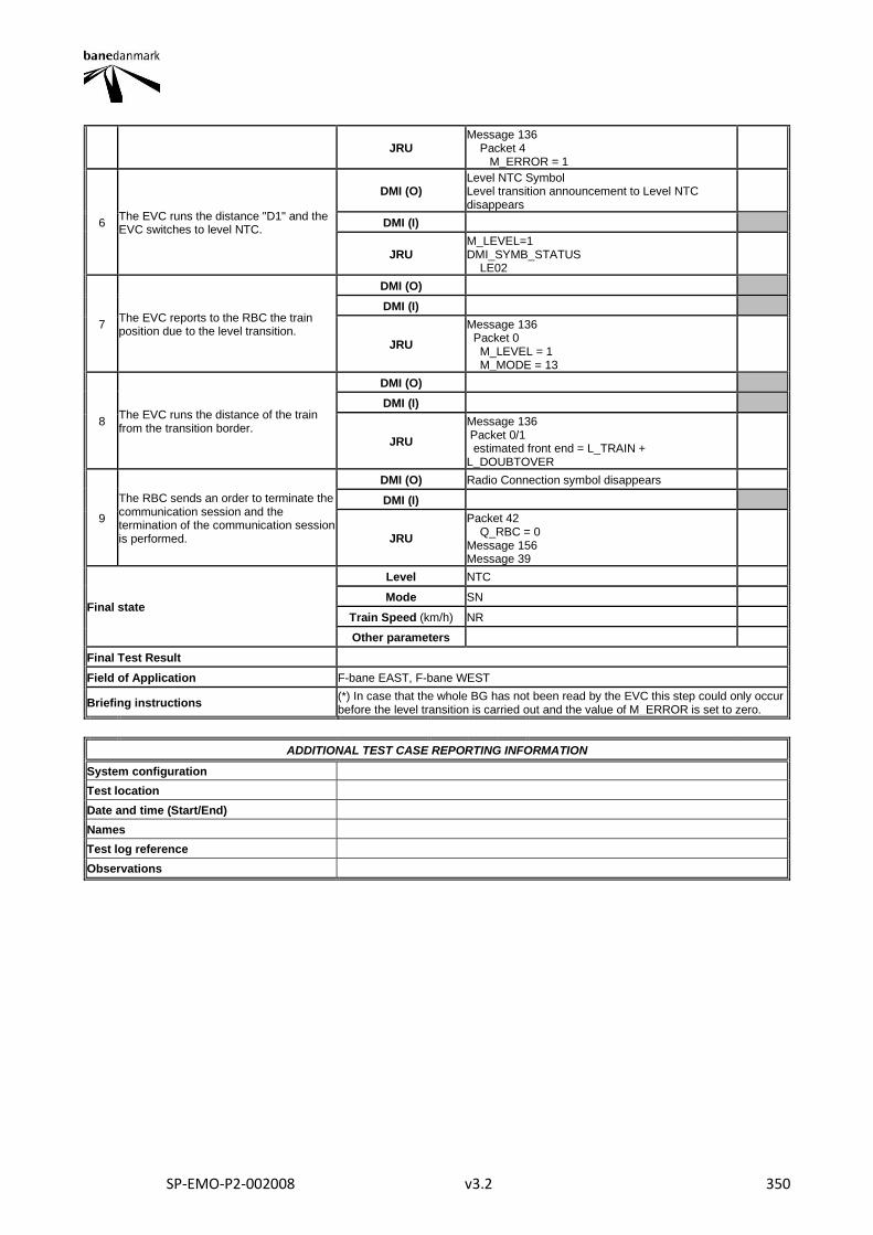
SP-EMO-P2-002008 v3.2 350
JRU Message 136 Packet 4 M_ERROR = 1
6 The EVC runs the distance "D1" and the EVC switches to level NTC.
DMI (O) Level NTC Symbol Level transition announcement to Level NTC disappears
DMI (I)
JRU M_LEVEL=1 DMI_SYMB_STATUS LE02
7 The EVC reports to the RBC the train position due to the level transition.
DMI (O)
DMI (I)
JRU
Message 136 Packet 0 M_LEVEL = 1 M_MODE = 13
8 The EVC runs the distance of the train from the transition border.
DMI (O)
DMI (I)
JRU
Message 136 Packet 0/1 estimated front end = L_TRAIN + L_DOUBTOVER
9
The RBC sends an order to terminate the communication session and the termination of the communication session is performed.
DMI (O) Radio Connection symbol disappears
DMI (I)
JRU
Packet 42 Q_RBC = 0 Message 156 Message 39
Final state
Level NTC
Mode SN
Train Speed (km/h) NR
Other parameters
Final Test Result
Field of Application F-bane EAST, F-bane WEST
Briefing instructions (*) In case that the whole BG has not been read by the EVC this step could only occur before the level transition is carried out and the value of M_ERROR is set to zero.
ADDITIONAL TEST CASE REPORTING INFORMATION
System configuration
Test location
Date and time (Start/End)
Names
Test log reference
Observations
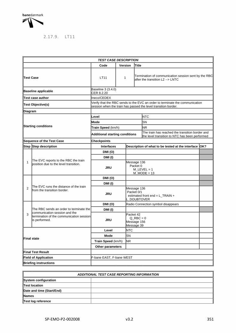
SP-EMO-P2-002008 v3.2 351
2.17.9. LT11
TEST CASE DESCRIPTION
Code Version Title
Test Case LT11 1 Termination of communication session sent by the RBC after the transition L2 --> LNTC
Baseline applicable Baseline 3 (3.4.0) CER 8.2.20
Test case author Ineco/CEDEX
Test Objective(s) Verify that the RBC sends to the EVC an order to terminate the communication session when the train has passed the level transition border.
Diagram
Starting conditions
Level NTC
Mode SN
Train Speed (km/h) NR
Additional starting conditions The train has reached the transition border and the level transition to NTC has been performed
Sequence of the Test Case Checkpoints
Step Step description Interfaces Description of what to be tested at the interface OK?
1 The EVC reports to the RBC the train position due to the level transition.
DMI (O)
DMI (I)
JRU
Message 136 Packet 0 M_LEVEL = 1 M_MODE = 13
2 The EVC runs the distance of the train from the transition border.
DMI (O)
DMI (I)
JRU
Message 136 Packet 0/1 estimated front end = L_TRAIN + L_DOUBTOVER
3
The RBC sends an order to terminate the communication session and the termination of the communication session is performed.
DMI (O) Radio Connection symbol disappears
DMI (I)
JRU
Packet 42 Q_RBC = 0 Message 156 Message 39
Final state
Level NTC
Mode SN
Train Speed (km/h) NR
Other parameters
Final Test Result
Field of Application F-bane EAST, F-bane WEST
Briefing instructions
ADDITIONAL TEST CASE REPORTING INFORMATION
System configuration
Test location
Date and time (Start/End)
Names
Test log reference

SP-EMO-P2-002008 v3.2 352
Observations
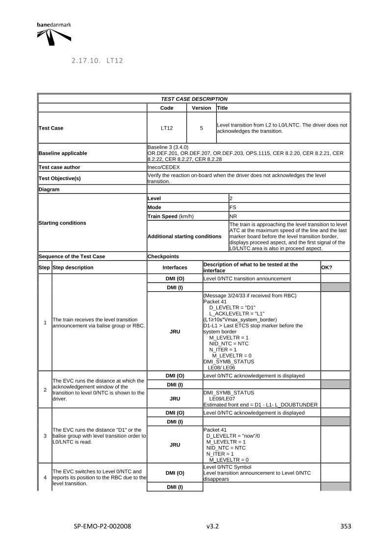
SP-EMO-P2-002008 v3.2 353
2.17.10. LT12
TEST CASE DESCRIPTION
Code Version Title
Test Case LT12 5 Level transition from L2 to L0/LNTC. The driver does not acknowledges the transition.
Baseline applicable Baseline 3 (3.4.0) OR.DEF.201, OR.DEF.207, OR.DEF.203, OPS.1115, CER 8.2.20, CER 8.2.21, CER 8.2.22, CER 8.2.27, CER 8.2.28
Test case author Ineco/CEDEX
Test Objective(s) Verify the reaction on-board when the driver does not acknowledges the level transition.
Diagram
Starting conditions
Level 2
Mode FS
Train Speed (km/h) NR
Additional starting conditions
The train is approaching the level transition to level ATC at the maximum speed of the line and the last marker board before the level transition border, displays proceed aspect, and the first signal of the L0/LNTC area is also in proceed aspect.
Sequence of the Test Case Checkpoints
Step Step description Interfaces Description of what to be tested at the interface
OK?
1 The train receives the level transition announcement via balise group or RBC.
DMI (O) Level 0/NTC transition announcement
DMI (I)
JRU
(Message 3/24/33 if received from RBC) Packet 41 D_LEVELTR = "D1" L_ACKLEVELTR = "L1" (L1≥10s*Vmax_system_border) D1-L1 > Last ETCS stop marker before the system border M_LEVELTR = 1 NID_NTC = NTC N_ITER = 1 M_LEVELTR = 0 DMI_SYMB_STATUS LE08/ LE06
2
The EVC runs the distance at which the acknowledgement window of the transition to level 0/NTC is shown to the driver.
DMI (O) Level 0/NTC acknowledgement is displayed
DMI (I)
JRU DMI_SYMB_STATUS LE09/LE07 Estimated front end = D1 - L1- L_DOUBTUNDER
3 The EVC runs the distance "D1" or the balise group with level transition order to L0/LNTC is read.
DMI (O) Level 0/NTC acknowledgement is displayed
DMI (I)
JRU
Packet 41 D_LEVELTR = "now"/0 M_LEVELTR = 1 NID_NTC = NTC N_ITER = 1 M_LEVELTR = 0
4 The EVC switches to Level 0/NTC and reports its position to the RBC due to the level transition.
DMI (O) Level 0/NTC Symbol Level transition announcement to Level 0/NTC disappears
DMI (I)
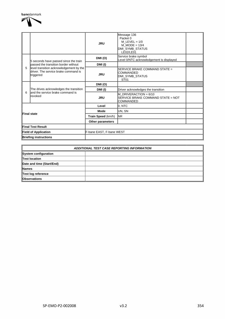
SP-EMO-P2-002008 v3.2 354
JRU
Message 136 Packet 0 M_LEVEL = 1/0 M_MODE = 13/4 DMI_SYMB_STATUS LE02/LE01
5
5 seconds have passed since the train passed the transition border without level transition acknowledgement by the driver. The service brake command is triggered
DMI (O) Service brake symbol Level 0/NTC acknowledgement is displayed
DMI (I)
JRU
SERVICE BRAKE COMMAND STATE = COMMANDED DMI_SYMB_STATUS ST01
6 The drives acknowledges the transition and the service brake command is revoked
DMI (O)
DMI (I) Driver acknowledges the transition
JRU M_DRIVERACTION = 6/10 SERVICE BRAKE COMMAND STATE = NOT COMMANDED
Final state
Level 0, NTC
Mode UN, SN
Train Speed (km/h) NR
Other parameters
Final Test Result
Field of Application F-bane EAST, F-bane WEST
Briefing instructions
ADDITIONAL TEST CASE REPORTING INFORMATION
System configuration
Test location
Date and time (Start/End)
Names
Test log reference
Observations
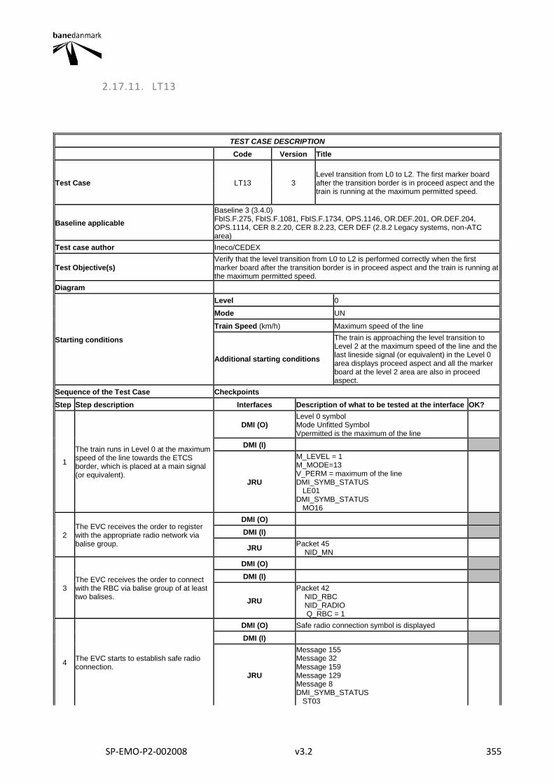
SP-EMO-P2-002008 v3.2 355
2.17.11. LT13
TEST CASE DESCRIPTION
Code Version Title
Test Case LT13 3 Level transition from L0 to L2. The first marker board after the transition border is in proceed aspect and the train is running at the maximum permitted speed.
Baseline applicable
Baseline 3 (3.4.0) FbIS.F.275, FbIS.F.1081, FbIS.F.1734, OPS.1146, OR.DEF.201, OR.DEF.204, OPS.1114, CER 8.2.20, CER 8.2.23, CER DEF (2.8.2 Legacy systems, non-ATC area)
Test case author Ineco/CEDEX
Test Objective(s) Verify that the level transition from L0 to L2 is performed correctly when the first marker board after the transition border is in proceed aspect and the train is running at the maximum permitted speed.
Diagram
Starting conditions
Level 0
Mode UN
Train Speed (km/h) Maximum speed of the line
Additional starting conditions
The train is approaching the level transition to Level 2 at the maximum speed of the line and the last lineside signal (or equivalent) in the Level 0 area displays proceed aspect and all the marker board at the level 2 area are also in proceed aspect.
Sequence of the Test Case Checkpoints
Step Step description Interfaces Description of what to be tested at the interface OK?
1
The train runs in Level 0 at the maximum speed of the line towards the ETCS border, which is placed at a main signal (or equivalent).
DMI (O) Level 0 symbol Mode Unfitted Symbol Vpermitted is the maximum of the line
DMI (I)
JRU
M_LEVEL = 1 M_MODE=13 V_PERM = maximum of the line DMI_SYMB_STATUS LE01 DMI_SYMB_STATUS MO16
2 The EVC receives the order to register with the appropriate radio network via balise group.
DMI (O)
DMI (I)
JRU Packet 45 NID_MN
3 The EVC receives the order to connect with the RBC via balise group of at least two balises.
DMI (O)
DMI (I)
JRU
Packet 42 NID_RBC NID_RADIO Q_RBC = 1
4 The EVC starts to establish safe radio connection.
DMI (O) Safe radio connection symbol is displayed
DMI (I)
JRU
Message 155 Message 32 Message 159 Message 129 Message 8 DMI_SYMB_STATUS ST03
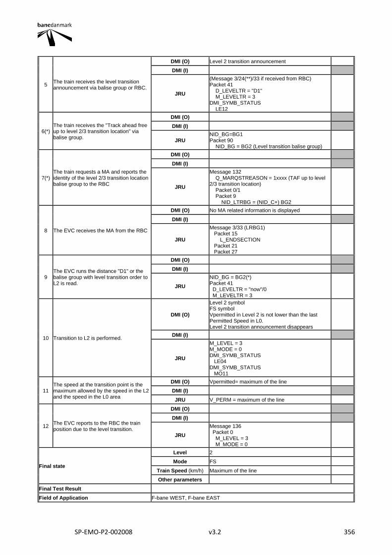
SP-EMO-P2-002008 v3.2 356
5 The train receives the level transition announcement via balise group or RBC.
DMI (O) Level 2 transition announcement
DMI (I)
JRU
(Message 3/24(**)/33 if received from RBC) Packet 41 D_LEVELTR = "D1" M_LEVELTR = 3 DMI_SYMB_STATUS LE12
6(*) The train receives the "Track ahead free up to level 2/3 transition location" via balise group.
DMI (O)
DMI (I)
JRU NID_BG=BG1 Packet 90 NID_BG = BG2 (Level transition balise group)
7(*) The train requests a MA and reports the identity of the level 2/3 transition location balise group to the RBC
DMI (O)
DMI (I)
JRU
Message 132 Q_MARQSTREASON = 1xxxx (TAF up to level 2/3 transition location) Packet 0/1 Packet 9 NID_LTRBG = (NID_C+) BG2
8 The EVC receives the MA from the RBC
DMI (O) No MA related information is displayed
DMI (I)
JRU
Message 3/33 (LRBG1) Packet 15 L_ENDSECTION Packet 21 Packet 27
9 The EVC runs the distance "D1" or the balise group with level transition order to L2 is read.
DMI (O)
DMI (I)
JRU
NID_BG = BG2(*) Packet 41 D_LEVELTR = "now"/0 M_LEVELTR = 3
10 Transition to L2 is performed.
DMI (O)
Level 2 symbol FS symbol Vpermitted in Level 2 is not lower than the last Permitted Speed in L0. Level 2 transition announcement disappears
DMI (I)
JRU
M_LEVEL = 3 M_MODE = 0 DMI_SYMB_STATUS LE04 DMI_SYMB_STATUS MO11
11 The speed at the transition point is the maximum allowed by the speed in the L2 and the speed in the L0 area
DMI (O) Vpermitted= maximum of the line
DMI (I)
JRU V_PERM = maximum of the line
12 The EVC reports to the RBC the train position due to the level transition.
DMI (O)
DMI (I)
JRU
Message 136 Packet 0 M_LEVEL = 3 M_MODE = 0
Final state
Level 2
Mode FS
Train Speed (km/h) Maximum of the line
Other parameters
Final Test Result
Field of Application F-bane WEST, F-bane EAST
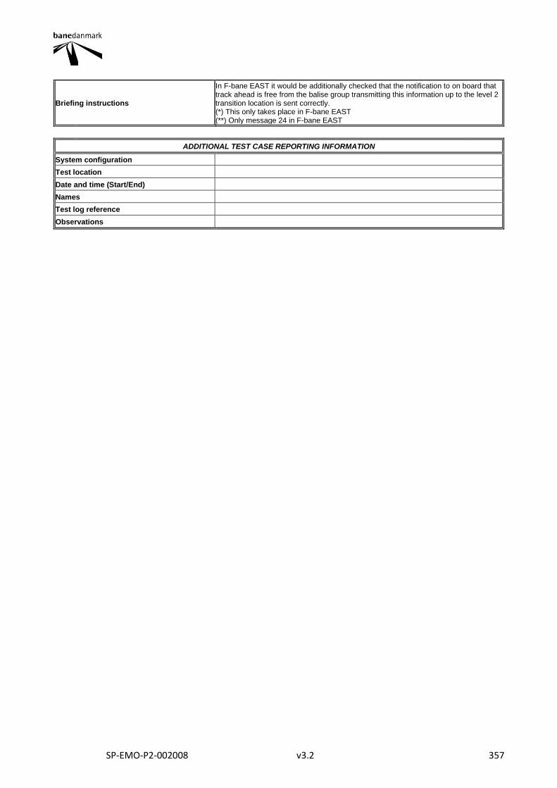
SP-EMO-P2-002008 v3.2 357
Briefing instructions
In F-bane EAST it would be additionally checked that the notification to on board that track ahead is free from the balise group transmitting this information up to the level 2 transition location is sent correctly. (*) This only takes place in F-bane EAST (**) Only message 24 in F-bane EAST
ADDITIONAL TEST CASE REPORTING INFORMATION
System configuration
Test location
Date and time (Start/End)
Names
Test log reference
Observations
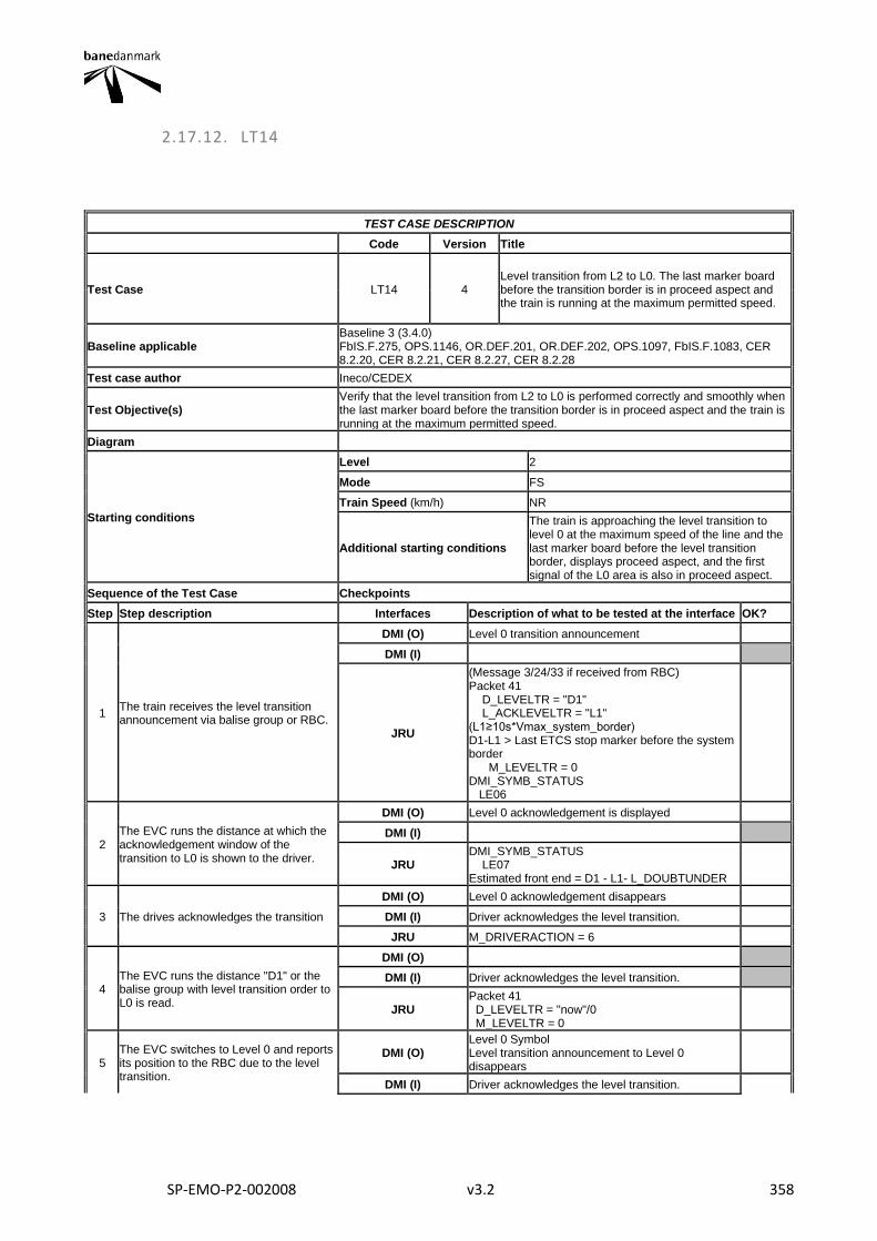
SP-EMO-P2-002008 v3.2 358
2.17.12. LT14
TEST CASE DESCRIPTION
Code Version Title
Test Case LT14 4 Level transition from L2 to L0. The last marker board before the transition border is in proceed aspect and the train is running at the maximum permitted speed.
Baseline applicable Baseline 3 (3.4.0) FbIS.F.275, OPS.1146, OR.DEF.201, OR.DEF.202, OPS.1097, FbIS.F.1083, CER 8.2.20, CER 8.2.21, CER 8.2.27, CER 8.2.28
Test case author Ineco/CEDEX
Test Objective(s) Verify that the level transition from L2 to L0 is performed correctly and smoothly when the last marker board before the transition border is in proceed aspect and the train is running at the maximum permitted speed.
Diagram
Starting conditions
Level 2
Mode FS
Train Speed (km/h) NR
Additional starting conditions
The train is approaching the level transition to level 0 at the maximum speed of the line and the last marker board before the level transition border, displays proceed aspect, and the first signal of the L0 area is also in proceed aspect.
Sequence of the Test Case Checkpoints
Step Step description Interfaces Description of what to be tested at the interface OK?
1 The train receives the level transition announcement via balise group or RBC.
DMI (O) Level 0 transition announcement
DMI (I)
JRU
(Message 3/24/33 if received from RBC) Packet 41 D_LEVELTR = "D1" L_ACKLEVELTR = "L1" (L1≥10s*Vmax_system_border) D1-L1 > Last ETCS stop marker before the system border M_LEVELTR = 0 DMI_SYMB_STATUS LE06
2 The EVC runs the distance at which the acknowledgement window of the transition to L0 is shown to the driver.
DMI (O) Level 0 acknowledgement is displayed
DMI (I)
JRU DMI_SYMB_STATUS LE07 Estimated front end = D1 - L1- L_DOUBTUNDER
3 The drives acknowledges the transition
DMI (O) Level 0 acknowledgement disappears
DMI (I) Driver acknowledges the level transition.
JRU M_DRIVERACTION = 6
4 The EVC runs the distance "D1" or the balise group with level transition order to L0 is read.
DMI (O)
DMI (I) Driver acknowledges the level transition.
JRU Packet 41 D_LEVELTR = "now"/0 M_LEVELTR = 0
5 The EVC switches to Level 0 and reports its position to the RBC due to the level transition.
DMI (O) Level 0 Symbol Level transition announcement to Level 0 disappears
DMI (I) Driver acknowledges the level transition.
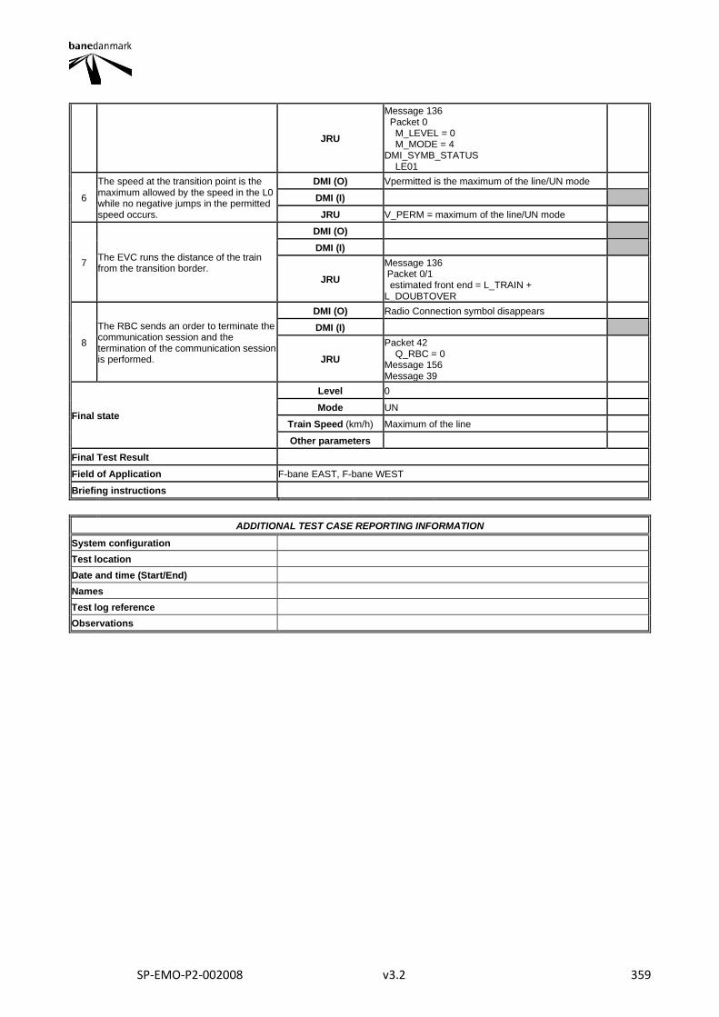
SP-EMO-P2-002008 v3.2 359
JRU
Message 136 Packet 0 M_LEVEL = 0 M_MODE = 4 DMI_SYMB_STATUS LE01
6
The speed at the transition point is the maximum allowed by the speed in the L0 while no negative jumps in the permitted speed occurs.
DMI (O) Vpermitted is the maximum of the line/UN mode
DMI (I)
JRU V_PERM = maximum of the line/UN mode
7 The EVC runs the distance of the train from the transition border.
DMI (O)
DMI (I)
JRU
Message 136 Packet 0/1 estimated front end = L_TRAIN + L_DOUBTOVER
8
The RBC sends an order to terminate the communication session and the termination of the communication session is performed.
DMI (O) Radio Connection symbol disappears
DMI (I)
JRU
Packet 42 Q_RBC = 0 Message 156 Message 39
Final state
Level 0
Mode UN
Train Speed (km/h) Maximum of the line
Other parameters
Final Test Result
Field of Application F-bane EAST, F-bane WEST
Briefing instructions
ADDITIONAL TEST CASE REPORTING INFORMATION
System configuration
Test location
Date and time (Start/End)
Names
Test log reference
Observations
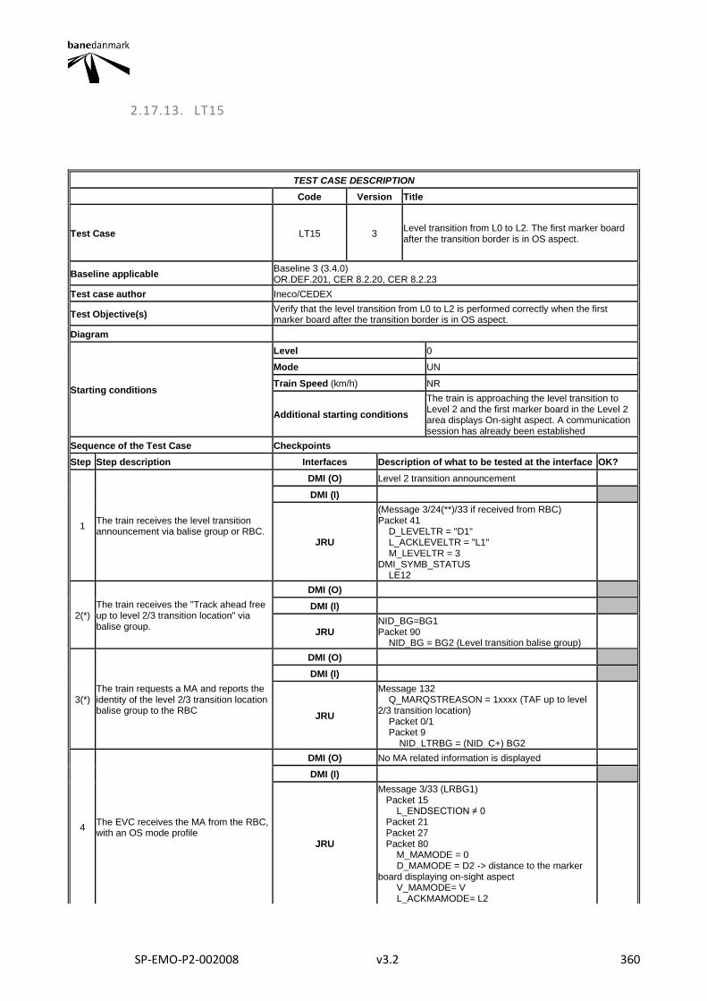
SP-EMO-P2-002008 v3.2 360
2.17.13. LT15
TEST CASE DESCRIPTION
Code Version Title
Test Case LT15 3 Level transition from L0 to L2. The first marker board after the transition border is in OS aspect.
Baseline applicable Baseline 3 (3.4.0) OR.DEF.201, CER 8.2.20, CER 8.2.23
Test case author Ineco/CEDEX
Test Objective(s) Verify that the level transition from L0 to L2 is performed correctly when the first marker board after the transition border is in OS aspect.
Diagram
Starting conditions
Level 0
Mode UN
Train Speed (km/h) NR
Additional starting conditions
The train is approaching the level transition to Level 2 and the first marker board in the Level 2 area displays On-sight aspect. A communication session has already been established
Sequence of the Test Case Checkpoints
Step Step description Interfaces Description of what to be tested at the interface OK?
1 The train receives the level transition announcement via balise group or RBC.
DMI (O) Level 2 transition announcement
DMI (I)
JRU
(Message 3/24(**)/33 if received from RBC) Packet 41 D_LEVELTR = "D1" L_ACKLEVELTR = "L1" M_LEVELTR = 3 DMI_SYMB_STATUS LE12
2(*) The train receives the "Track ahead free up to level 2/3 transition location" via balise group.
DMI (O)
DMI (I)
JRU NID_BG=BG1 Packet 90 NID_BG = BG2 (Level transition balise group)
3(*) The train requests a MA and reports the identity of the level 2/3 transition location balise group to the RBC
DMI (O)
DMI (I)
JRU
Message 132 Q_MARQSTREASON = 1xxxx (TAF up to level 2/3 transition location) Packet 0/1 Packet 9 NID_LTRBG = (NID_C+) BG2
4 The EVC receives the MA from the RBC, with an OS mode profile
DMI (O) No MA related information is displayed
DMI (I)
JRU
Message 3/33 (LRBG1) Packet 15 L_ENDSECTION ≠ 0 Packet 21 Packet 27 Packet 80 M_MAMODE = 0 D_MAMODE = D2 -> distance to the marker board displaying on-sight aspect V_MAMODE= V L_ACKMAMODE= L2
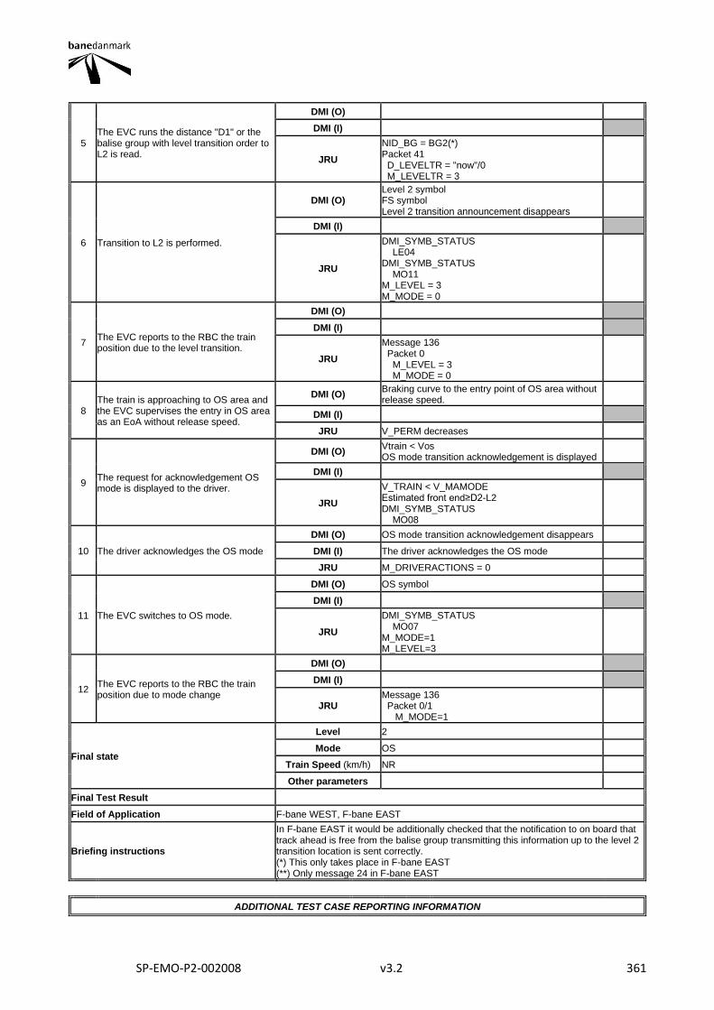
SP-EMO-P2-002008 v3.2 361
5 The EVC runs the distance "D1" or the balise group with level transition order to L2 is read.
DMI (O)
DMI (I)
JRU
NID_BG = BG2(*) Packet 41 D_LEVELTR = "now"/0 M_LEVELTR = 3
6 Transition to L2 is performed.
DMI (O) Level 2 symbol FS symbol Level 2 transition announcement disappears
DMI (I)
JRU
DMI_SYMB_STATUS LE04 DMI_SYMB_STATUS MO11 M_LEVEL = 3 M_MODE = 0
7 The EVC reports to the RBC the train position due to the level transition.
DMI (O)
DMI (I)
JRU
Message 136 Packet 0 M_LEVEL = 3 M_MODE = 0
8 The train is approaching to OS area and the EVC supervises the entry in OS area as an EoA without release speed.
DMI (O) Braking curve to the entry point of OS area without release speed.
DMI (I)
JRU V_PERM decreases
9 The request for acknowledgement OS mode is displayed to the driver.
DMI (O) Vtrain < Vos OS mode transition acknowledgement is displayed
DMI (I)
JRU
V_TRAIN < V_MAMODE Estimated front end≥D2-L2 DMI_SYMB_STATUS MO08
10 The driver acknowledges the OS mode
DMI (O) OS mode transition acknowledgement disappears
DMI (I) The driver acknowledges the OS mode
JRU M_DRIVERACTIONS = 0
11 The EVC switches to OS mode.
DMI (O) OS symbol
DMI (I)
JRU
DMI_SYMB_STATUS MO07 M_MODE=1 M_LEVEL=3
12 The EVC reports to the RBC the train position due to mode change
DMI (O)
DMI (I)
JRU Message 136 Packet 0/1 M_MODE=1
Final state
Level 2
Mode OS
Train Speed (km/h) NR
Other parameters
Final Test Result
Field of Application F-bane WEST, F-bane EAST
Briefing instructions
In F-bane EAST it would be additionally checked that the notification to on board that track ahead is free from the balise group transmitting this information up to the level 2 transition location is sent correctly. (*) This only takes place in F-bane EAST (**) Only message 24 in F-bane EAST
ADDITIONAL TEST CASE REPORTING INFORMATION

SP-EMO-P2-002008 v3.2 362
System configuration
Test location
Date and time (Start/End)
Names
Test log reference
Observations
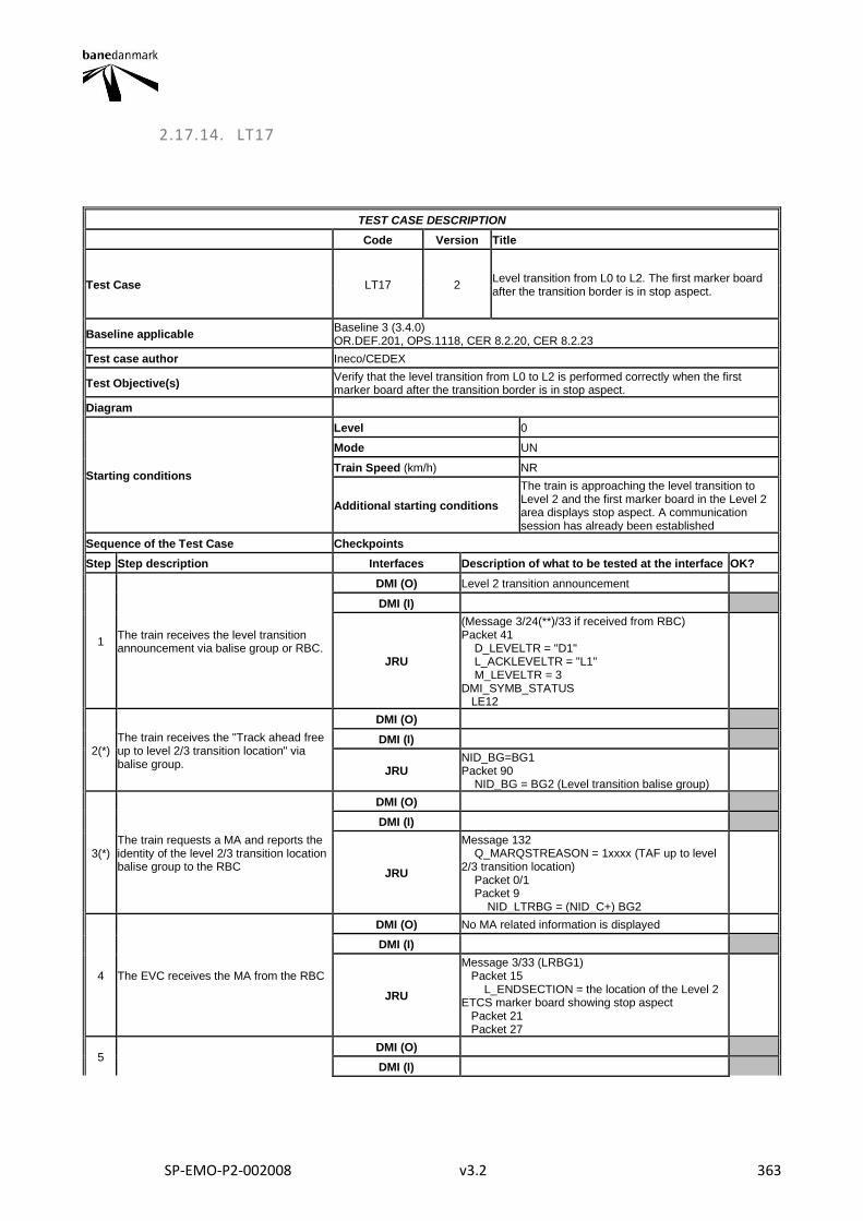
SP-EMO-P2-002008 v3.2 363
2.17.14. LT17
TEST CASE DESCRIPTION
Code Version Title
Test Case LT17 2 Level transition from L0 to L2. The first marker board after the transition border is in stop aspect.
Baseline applicable Baseline 3 (3.4.0) OR.DEF.201, OPS.1118, CER 8.2.20, CER 8.2.23
Test case author Ineco/CEDEX
Test Objective(s) Verify that the level transition from L0 to L2 is performed correctly when the first marker board after the transition border is in stop aspect.
Diagram
Starting conditions
Level 0
Mode UN
Train Speed (km/h) NR
Additional starting conditions
The train is approaching the level transition to Level 2 and the first marker board in the Level 2 area displays stop aspect. A communication session has already been established
Sequence of the Test Case Checkpoints
Step Step description Interfaces Description of what to be tested at the interface OK?
1 The train receives the level transition announcement via balise group or RBC.
DMI (O) Level 2 transition announcement
DMI (I)
JRU
(Message 3/24(**)/33 if received from RBC) Packet 41 D_LEVELTR = "D1" L_ACKLEVELTR = "L1" M_LEVELTR = 3 DMI_SYMB_STATUS LE12
2(*) The train receives the "Track ahead free up to level 2/3 transition location" via balise group.
DMI (O)
DMI (I)
JRU NID_BG=BG1 Packet 90 NID_BG = BG2 (Level transition balise group)
3(*) The train requests a MA and reports the identity of the level 2/3 transition location balise group to the RBC
DMI (O)
DMI (I)
JRU
Message 132 Q_MARQSTREASON = 1xxxx (TAF up to level 2/3 transition location) Packet 0/1 Packet 9 NID_LTRBG = (NID_C+) BG2
4 The EVC receives the MA from the RBC
DMI (O) No MA related information is displayed
DMI (I)
JRU
Message 3/33 (LRBG1) Packet 15 L_ENDSECTION = the location of the Level 2 ETCS marker board showing stop aspect Packet 21 Packet 27
5 DMI (O)
DMI (I)
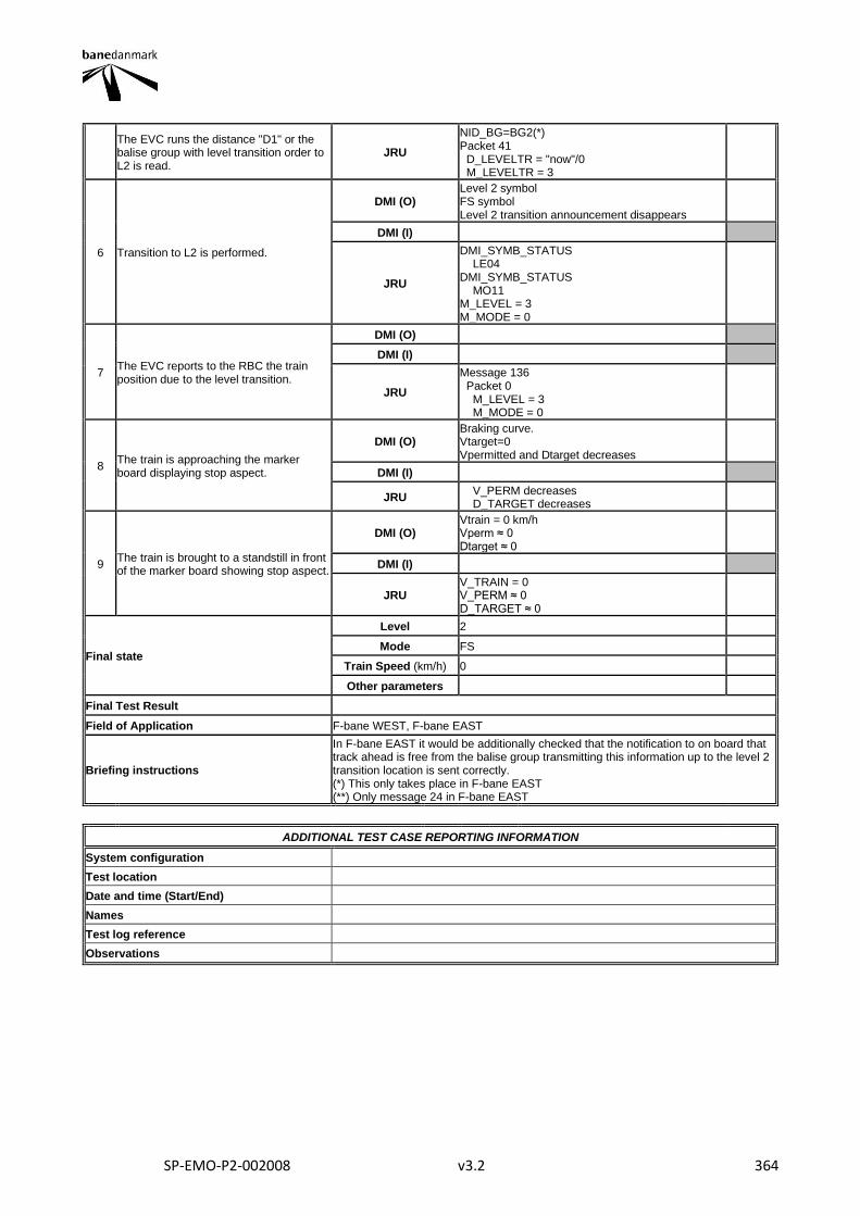
SP-EMO-P2-002008 v3.2 364
The EVC runs the distance "D1" or the balise group with level transition order to L2 is read.
JRU
NID_BG=BG2(*) Packet 41 D_LEVELTR = "now"/0 M_LEVELTR = 3
6 Transition to L2 is performed.
DMI (O) Level 2 symbol FS symbol Level 2 transition announcement disappears
DMI (I)
JRU
DMI_SYMB_STATUS LE04 DMI_SYMB_STATUS MO11 M_LEVEL = 3 M_MODE = 0
7 The EVC reports to the RBC the train position due to the level transition.
DMI (O)
DMI (I)
JRU
Message 136 Packet 0 M_LEVEL = 3 M_MODE = 0
8 The train is approaching the marker board displaying stop aspect.
DMI (O) Braking curve. Vtarget=0 Vpermitted and Dtarget decreases
DMI (I)
JRU V_PERM decreases D_TARGET decreases
9 The train is brought to a standstill in front of the marker board showing stop aspect.
DMI (O) Vtrain = 0 km/h Vperm ≈ 0 Dtarget ≈ 0
DMI (I)
JRU V_TRAIN = 0 V_PERM ≈ 0 D_TARGET ≈ 0
Final state
Level 2
Mode FS
Train Speed (km/h) 0
Other parameters
Final Test Result
Field of Application F-bane WEST, F-bane EAST
Briefing instructions
In F-bane EAST it would be additionally checked that the notification to on board that track ahead is free from the balise group transmitting this information up to the level 2 transition location is sent correctly. (*) This only takes place in F-bane EAST (**) Only message 24 in F-bane EAST
ADDITIONAL TEST CASE REPORTING INFORMATION
System configuration
Test location
Date and time (Start/End)
Names
Test log reference
Observations
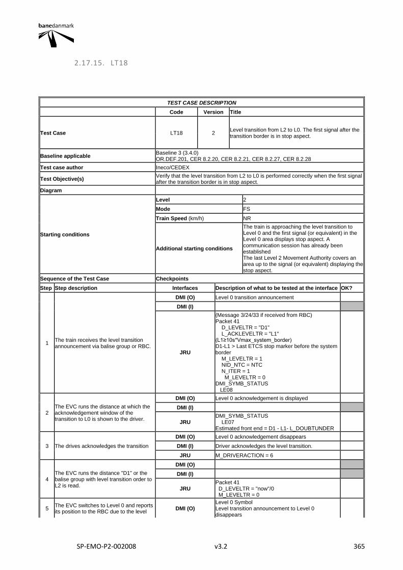
SP-EMO-P2-002008 v3.2 365
2.17.15. LT18
TEST CASE DESCRIPTION
Code Version Title
Test Case LT18 2 Level transition from L2 to L0. The first signal after the transition border is in stop aspect.
Baseline applicable Baseline 3 (3.4.0) OR.DEF.201, CER 8.2.20, CER 8.2.21, CER 8.2.27, CER 8.2.28
Test case author Ineco/CEDEX
Test Objective(s) Verify that the level transition from L2 to L0 is performed correctly when the first signal after the transition border is in stop aspect.
Diagram
Starting conditions
Level 2
Mode FS
Train Speed (km/h) NR
Additional starting conditions
The train is approaching the level transition to Level 0 and the first signal (or equivalent) in the Level 0 area displays stop aspect. A communication session has already been established The last Level 2 Movement Authority covers an area up to the signal (or equivalent) displaying the stop aspect.
Sequence of the Test Case Checkpoints
Step Step description Interfaces Description of what to be tested at the interface OK?
1 The train receives the level transition announcement via balise group or RBC.
DMI (O) Level 0 transition announcement
DMI (I)
JRU
(Message 3/24/33 if received from RBC) Packet 41 D_LEVELTR = "D1" L_ACKLEVELTR = "L1" (L1≥10s*Vmax_system_border) D1-L1 > Last ETCS stop marker before the system border M_LEVELTR = 1 NID_NTC = NTC N_ITER = 1 M_LEVELTR = 0 DMI_SYMB_STATUS LE08
2 The EVC runs the distance at which the acknowledgement window of the transition to L0 is shown to the driver.
DMI (O) Level 0 acknowledgement is displayed
DMI (I)
JRU DMI_SYMB_STATUS LE07 Estimated front end = D1 - L1- L_DOUBTUNDER
3 The drives acknowledges the transition
DMI (O) Level 0 acknowledgement disappears
DMI (I) Driver acknowledges the level transition.
JRU M_DRIVERACTION = 6
4 The EVC runs the distance "D1" or the balise group with level transition order to L2 is read.
DMI (O)
DMI (I)
JRU Packet 41 D_LEVELTR = "now"/0 M_LEVELTR = 0
5 The EVC switches to Level 0 and reports its position to the RBC due to the level
DMI (O) Level 0 Symbol Level transition announcement to Level 0 disappears
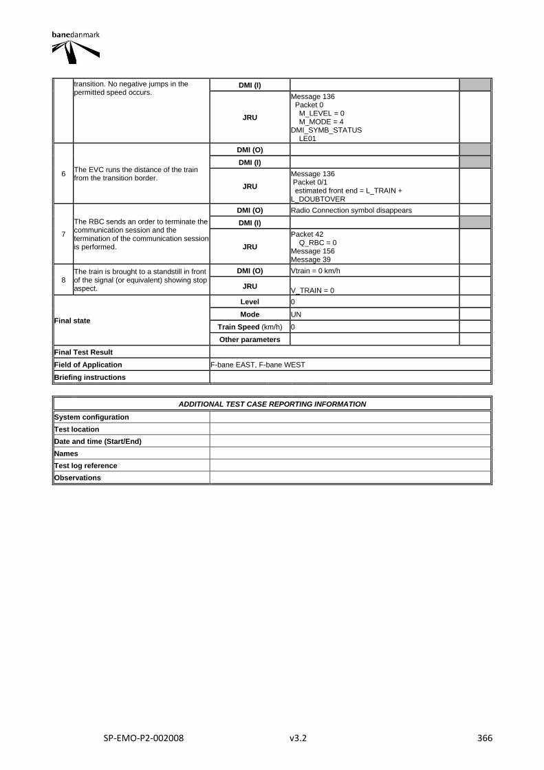
SP-EMO-P2-002008 v3.2 366
transition. No negative jumps in the permitted speed occurs.
DMI (I)
JRU
Message 136 Packet 0 M_LEVEL = 0 M_MODE = 4 DMI_SYMB_STATUS LE01
6 The EVC runs the distance of the train from the transition border.
DMI (O)
DMI (I)
JRU
Message 136 Packet 0/1 estimated front end = L_TRAIN + L_DOUBTOVER
7
The RBC sends an order to terminate the communication session and the termination of the communication session is performed.
DMI (O) Radio Connection symbol disappears
DMI (I)
JRU
Packet 42 Q_RBC = 0 Message 156 Message 39
8 The train is brought to a standstill in front of the signal (or equivalent) showing stop aspect.
DMI (O) Vtrain = 0 km/h
JRU V_TRAIN = 0
Final state
Level 0
Mode UN
Train Speed (km/h) 0
Other parameters
Final Test Result
Field of Application F-bane EAST, F-bane WEST
Briefing instructions
ADDITIONAL TEST CASE REPORTING INFORMATION
System configuration
Test location
Date and time (Start/End)
Names
Test log reference
Observations
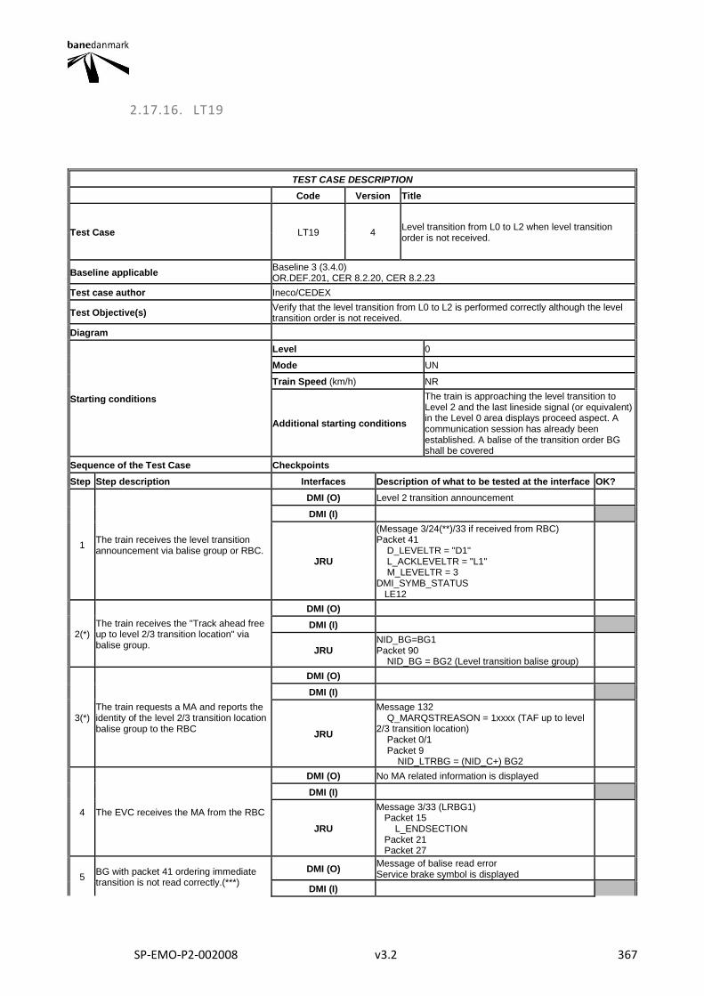
SP-EMO-P2-002008 v3.2 367
2.17.16. LT19
TEST CASE DESCRIPTION
Code Version Title
Test Case LT19 4 Level transition from L0 to L2 when level transition order is not received.
Baseline applicable Baseline 3 (3.4.0) OR.DEF.201, CER 8.2.20, CER 8.2.23
Test case author Ineco/CEDEX
Test Objective(s) Verify that the level transition from L0 to L2 is performed correctly although the level transition order is not received.
Diagram
Starting conditions
Level 0
Mode UN
Train Speed (km/h) NR
Additional starting conditions
The train is approaching the level transition to Level 2 and the last lineside signal (or equivalent) in the Level 0 area displays proceed aspect. A communication session has already been established. A balise of the transition order BG shall be covered
Sequence of the Test Case Checkpoints
Step Step description Interfaces Description of what to be tested at the interface OK?
1 The train receives the level transition announcement via balise group or RBC.
DMI (O) Level 2 transition announcement
DMI (I)
JRU
(Message 3/24(**)/33 if received from RBC) Packet 41 D_LEVELTR = "D1" L_ACKLEVELTR = "L1" M_LEVELTR = 3 DMI_SYMB_STATUS LE12
2(*) The train receives the "Track ahead free up to level 2/3 transition location" via balise group.
DMI (O)
DMI (I)
JRU NID_BG=BG1 Packet 90 NID_BG = BG2 (Level transition balise group)
3(*) The train requests a MA and reports the identity of the level 2/3 transition location balise group to the RBC
DMI (O)
DMI (I)
JRU
Message 132 Q_MARQSTREASON = 1xxxx (TAF up to level 2/3 transition location) Packet 0/1 Packet 9 NID_LTRBG = (NID_C+) BG2
4 The EVC receives the MA from the RBC
DMI (O) No MA related information is displayed
DMI (I)
JRU
Message 3/33 (LRBG1) Packet 15 L_ENDSECTION Packet 21 Packet 27
5 BG with packet 41 ordering immediate transition is not read correctly.(***)
DMI (O) Message of balise read error Service brake symbol is displayed
DMI (I)
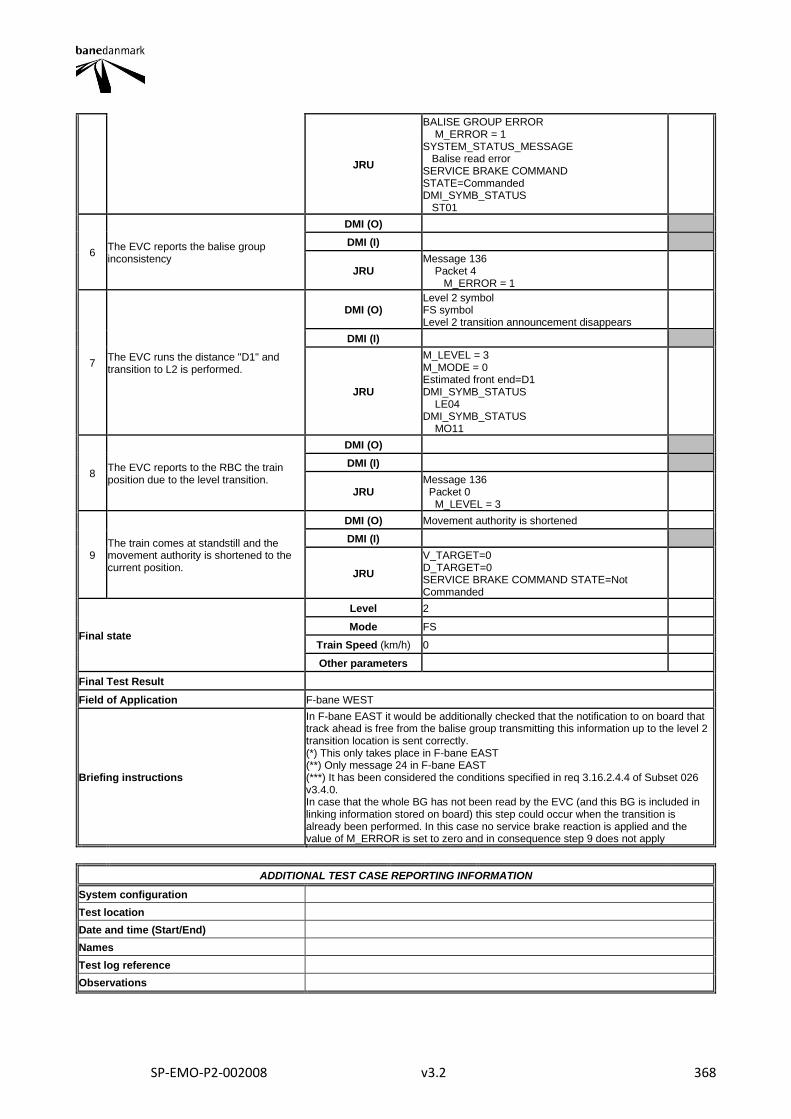
SP-EMO-P2-002008 v3.2 368
JRU
BALISE GROUP ERROR M_ERROR = 1 SYSTEM_STATUS_MESSAGE Balise read error SERVICE BRAKE COMMAND STATE=Commanded DMI_SYMB_STATUS ST01
6 The EVC reports the balise group inconsistency
DMI (O)
DMI (I)
JRU Message 136 Packet 4 M_ERROR = 1
7 The EVC runs the distance "D1" and transition to L2 is performed.
DMI (O) Level 2 symbol FS symbol Level 2 transition announcement disappears
DMI (I)
JRU
M_LEVEL = 3 M_MODE = 0 Estimated front end=D1 DMI_SYMB_STATUS LE04 DMI_SYMB_STATUS MO11
8 The EVC reports to the RBC the train position due to the level transition.
DMI (O)
DMI (I)
JRU Message 136 Packet 0 M_LEVEL = 3
9 The train comes at standstill and the movement authority is shortened to the current position.
DMI (O) Movement authority is shortened
DMI (I)
JRU
V_TARGET=0 D_TARGET=0 SERVICE BRAKE COMMAND STATE=Not Commanded
Final state
Level 2
Mode FS
Train Speed (km/h) 0
Other parameters
Final Test Result
Field of Application F-bane WEST
Briefing instructions
In F-bane EAST it would be additionally checked that the notification to on board that track ahead is free from the balise group transmitting this information up to the level 2 transition location is sent correctly. (*) This only takes place in F-bane EAST (**) Only message 24 in F-bane EAST (***) It has been considered the conditions specified in req 3.16.2.4.4 of Subset 026 v3.4.0. In case that the whole BG has not been read by the EVC (and this BG is included in linking information stored on board) this step could occur when the transition is already been performed. In this case no service brake reaction is applied and the value of M_ERROR is set to zero and in consequence step 9 does not apply
ADDITIONAL TEST CASE REPORTING INFORMATION
System configuration
Test location
Date and time (Start/End)
Names
Test log reference
Observations
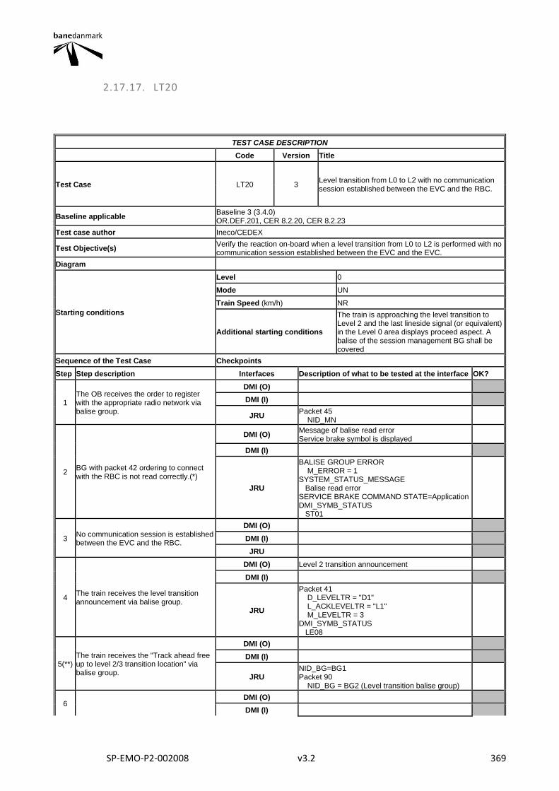
SP-EMO-P2-002008 v3.2 369
2.17.17. LT20
TEST CASE DESCRIPTION
Code Version Title
Test Case LT20 3 Level transition from L0 to L2 with no communication session established between the EVC and the RBC.
Baseline applicable Baseline 3 (3.4.0) OR.DEF.201, CER 8.2.20, CER 8.2.23
Test case author Ineco/CEDEX
Test Objective(s) Verify the reaction on-board when a level transition from L0 to L2 is performed with no communication session established between the EVC and the EVC.
Diagram
Starting conditions
Level 0
Mode UN
Train Speed (km/h) NR
Additional starting conditions
The train is approaching the level transition to Level 2 and the last lineside signal (or equivalent) in the Level 0 area displays proceed aspect. A balise of the session management BG shall be covered
Sequence of the Test Case Checkpoints
Step Step description Interfaces Description of what to be tested at the interface OK?
1 The OB receives the order to register with the appropriate radio network via balise group.
DMI (O)
DMI (I)
JRU Packet 45 NID_MN
2 BG with packet 42 ordering to connect with the RBC is not read correctly.(*)
DMI (O) Message of balise read error Service brake symbol is displayed
DMI (I)
JRU
BALISE GROUP ERROR M_ERROR = 1 SYSTEM_STATUS_MESSAGE Balise read error SERVICE BRAKE COMMAND STATE=Application DMI_SYMB_STATUS ST01
3 No communication session is established between the EVC and the RBC.
DMI (O)
DMI (I)
JRU
4 The train receives the level transition announcement via balise group.
DMI (O) Level 2 transition announcement
DMI (I)
JRU
Packet 41 D_LEVELTR = "D1" L_ACKLEVELTR = "L1" M_LEVELTR = 3 DMI_SYMB_STATUS LE08
5(**) The train receives the "Track ahead free up to level 2/3 transition location" via balise group.
DMI (O)
DMI (I)
JRU NID_BG=BG1 Packet 90 NID_BG = BG2 (Level transition balise group)
6 DMI (O)
DMI (I)
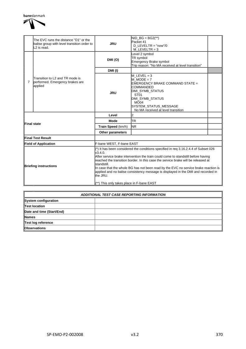
SP-EMO-P2-002008 v3.2 370
The EVC runs the distance "D1" or the balise group with level transition order to L2 is read.
JRU
NID_BG = BG2(**) Packet 41 D_LEVELTR = "now"/0 M_LEVELTR = 3
7 Transition to L2 and TR mode is performed. Emergency brakes are applied
DMI (O)
Level 2 symbol TR symbol Emergency Brake symbol Trip reason: "No MA received at level transition"
DMI (I)
JRU
M_LEVEL = 3 M_MODE = 7 EMERGENCY BRAKE COMMAND STATE = COMMANDED DMI_SYMB_STATUS ST01 DMI_SYMB_STATUS MO04 SYSTEM_STATUS_MESSAGE No MA received at level transition
Final state
Level 2
Mode TR
Train Speed (km/h) NR
Other parameters
Final Test Result
Field of Application F-bane WEST, F-bane EAST
Briefing instructions
(*) It has been considered the conditions specified in req 3.16.2.4.4 of Subset 026 v3.4.0. After service brake intervention the train could come to standstill before having reached the transition border. In this case the service brake will be released at standstill. In case that the whole BG has not been read by the EVC no service brake reaction is applied and no balise consistency message is displayed in the DMI and recorded in the JRU. (**) This only takes place in F-bane EAST
ADDITIONAL TEST CASE REPORTING INFORMATION
System configuration
Test location
Date and time (Start/End)
Names
Test log reference
Observations
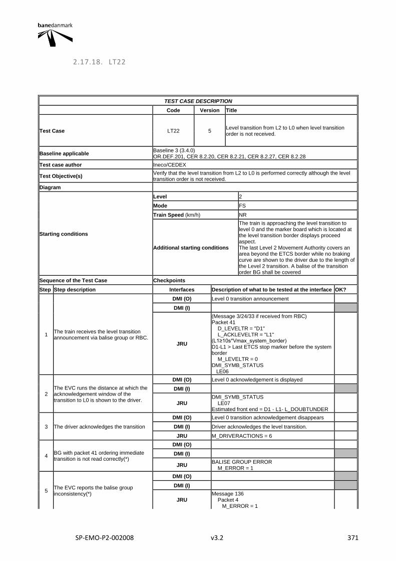
SP-EMO-P2-002008 v3.2 371
2.17.18. LT22
TEST CASE DESCRIPTION
Code Version Title
Test Case LT22 5 Level transition from L2 to L0 when level transition order is not received.
Baseline applicable Baseline 3 (3.4.0) OR.DEF.201, CER 8.2.20, CER 8.2.21, CER 8.2.27, CER 8.2.28
Test case author Ineco/CEDEX
Test Objective(s) Verify that the level transition from L2 to L0 is performed correctly although the level transition order is not received.
Diagram
Starting conditions
Level 2
Mode FS
Train Speed (km/h) NR
Additional starting conditions
The train is approaching the level transition to level 0 and the marker board which is located at the level transition border displays proceed aspect. The last Level 2 Movement Authority covers an area beyond the ETCS border while no braking curve are shown to the driver due to the length of the Level 2 transition. A balise of the transition order BG shall be covered
Sequence of the Test Case Checkpoints
Step Step description Interfaces Description of what to be tested at the interface OK?
1 The train receives the level transition announcement via balise group or RBC.
DMI (O) Level 0 transition announcement
DMI (I)
JRU
(Message 3/24/33 if received from RBC) Packet 41 D_LEVELTR = "D1" L_ACKLEVELTR = "L1" (L1≥10s*Vmax_system_border) D1-L1 > Last ETCS stop marker before the system border M_LEVELTR = 0 DMI_SYMB_STATUS LE06
2 The EVC runs the distance at which the acknowledgement window of the transition to L0 is shown to the driver.
DMI (O) Level 0 acknowledgement is displayed
DMI (I)
JRU DMI_SYMB_STATUS LE07 Estimated front end = D1 - L1- L_DOUBTUNDER
3 The driver acknowledges the transition
DMI (O) Level 0 transition acknowledgement disappears
DMI (I) Driver acknowledges the level transition.
JRU M_DRIVERACTIONS = 6
4 BG with packet 41 ordering immediate transition is not read correctly(*)
DMI (O)
DMI (I)
JRU BALISE GROUP ERROR M_ERROR = 1
5 The EVC reports the balise group inconsistency(*)
DMI (O)
DMI (I)
JRU Message 136 Packet 4 M_ERROR = 1
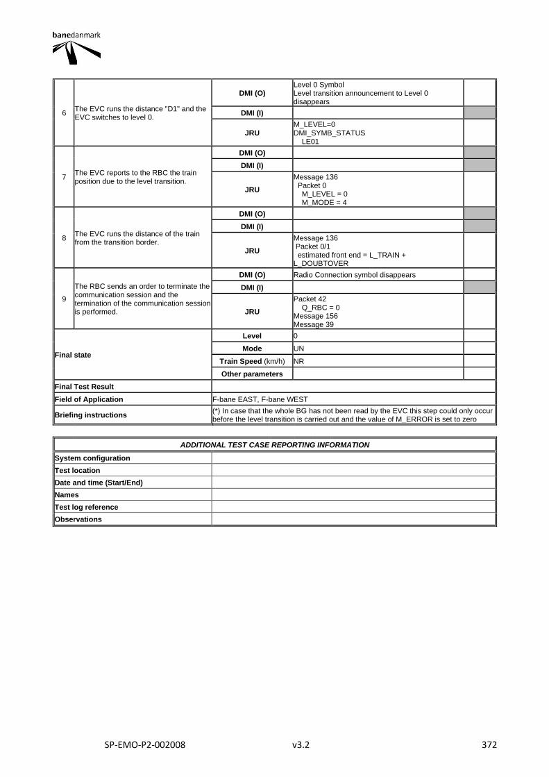
SP-EMO-P2-002008 v3.2 372
6 The EVC runs the distance "D1" and the EVC switches to level 0.
DMI (O) Level 0 Symbol Level transition announcement to Level 0 disappears
DMI (I)
JRU M_LEVEL=0 DMI_SYMB_STATUS LE01
7 The EVC reports to the RBC the train position due to the level transition.
DMI (O)
DMI (I)
JRU
Message 136 Packet 0 M_LEVEL = 0 M_MODE = 4
8 The EVC runs the distance of the train from the transition border.
DMI (O)
DMI (I)
JRU
Message 136 Packet 0/1 estimated front end = L_TRAIN + L_DOUBTOVER
9
The RBC sends an order to terminate the communication session and the termination of the communication session is performed.
DMI (O) Radio Connection symbol disappears
DMI (I)
JRU
Packet 42 Q_RBC = 0 Message 156 Message 39
Final state
Level 0
Mode UN
Train Speed (km/h) NR
Other parameters
Final Test Result
Field of Application F-bane EAST, F-bane WEST
Briefing instructions (*) In case that the whole BG has not been read by the EVC this step could only occur before the level transition is carried out and the value of M_ERROR is set to zero
ADDITIONAL TEST CASE REPORTING INFORMATION
System configuration
Test location
Date and time (Start/End)
Names
Test log reference
Observations
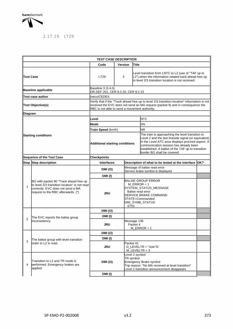
SP-EMO-P2-002008 v3.2 373
2.17.19. LT29
TEST CASE DESCRIPTION
Code Version Title
Test Case LT29 3 Level transition from LNTC to L2 (use of "TAF up to L2") when the information related track ahead free up to level 2/3 transition location is not received.
Baseline applicable Baseline 3 (3.4.0) OR.DEF.201, CER 8.2.20, CER 8.2.23
Test case author Ineco/CEDEX
Test Objective(s) Verify that if the "Track ahead free up to level 2/3 transition location" information is not received the EVC does not send an MA request (packet 9) and in consequence the RBC is not able to send a movement authority.
Diagram
Starting conditions
Level NTC
Mode SN
Train Speed (km/h) NR
Additional starting conditions
The train is approaching the level transition to Level 2 and the last lineside signal (or equivalent) in the Level ATC area displays proceed aspect. A communication session has already been established. A balise of the TAF up to transition border BG shall be covered
Sequence of the Test Case Checkpoints
Step Step description Interfaces Description of what to be tested at the interface OK?
1
BG with packet 90 "Track ahead free up to level 2/3 transition location" is not read correctly. EVC does not send a MA request to the RBC afterwards. (*)
DMI (O) Message of balise read error Service brake symbol is displayed
DMI (I)
JRU
BALISE GROUP ERROR M_ERROR = 1 SYSTEM_STATUS_MESSAGE Balise read error SERVICE BRAKE COMMAND STATE=Commanded DMI_SYMB_STATUS ST01
2 The EVC reports the balise group inconsistency
DMI (O)
DMI (I)
JRU Message 136 Packet 4 M_ERROR = 1
3 The balise group with level transition order to L2 is read.
DMI (O)
DMI (I)
JRU Packet 41 D_LEVELTR = "now"/0 M_LEVELTR = 3
4 Transition to L2 and TR mode is performed. Emergency brakes are applied
DMI (O)
Level 2 symbol TR symbol Emergency Brake symbol Trip reason: "No MA received at level transition" Level 2 transition announcement disappears
DMI (I)
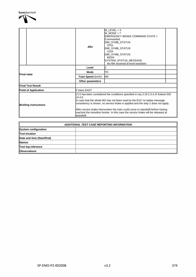
SP-EMO-P2-002008 v3.2 374
JRU
M_LEVEL = 3 M_MODE = 7 EMERGENCY BRAKE COMMAND STATE = Commanded DMI_SYMB_STATUS ST01 DMI_SYMB_STATUS LE04 DMI_SYMB_STATUS MO04 SYSTEM_STATUS_MESSAGE No MA received at level transition
Final state
Level 2
Mode TR
Train Speed (km/h) NR
Other parameters
Final Test Result
Field of Application F-bane EAST
Briefing instructions
(*) It has been considered the conditions specified in req 3.16.2.4.4 of Subset 026 v3.4.0. In case that the whole BG has not been read by the EVC no balise message consistency is shown, no service brake is applied and the step 2 does not apply. After service brake intervention the train could come to standstill before having reached the transition border. In this case the service brake will be released at standstill.
ADDITIONAL TEST CASE REPORTING INFORMATION
System configuration
Test location
Date and time (Start/End)
Names
Test log reference
Observations
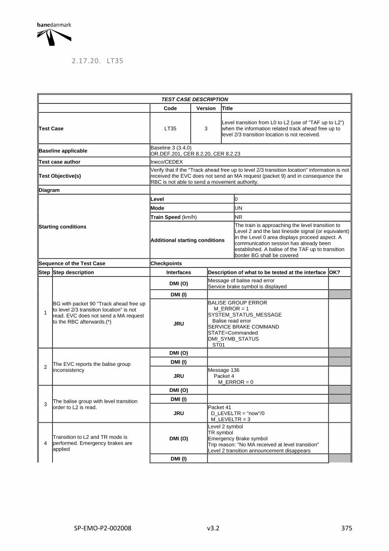
SP-EMO-P2-002008 v3.2 375
2.17.20. LT35
TEST CASE DESCRIPTION
Code Version Title
Test Case LT35 3 Level transition from L0 to L2 (use of "TAF up to L2") when the information related track ahead free up to level 2/3 transition location is not received.
Baseline applicable Baseline 3 (3.4.0) OR.DEF.201, CER 8.2.20, CER 8.2.23
Test case author Ineco/CEDEX
Test Objective(s) Verify that if the "Track ahead free up to level 2/3 transition location" information is not received the EVC does not send an MA request (packet 9) and in consequence the RBC is not able to send a movement authority.
Diagram
Starting conditions
Level 0
Mode UN
Train Speed (km/h) NR
Additional starting conditions
The train is approaching the level transition to Level 2 and the last lineside signal (or equivalent) in the Level 0 area displays proceed aspect. A communication session has already been established. A balise of the TAF up to transition border BG shall be covered
Sequence of the Test Case Checkpoints
Step Step description Interfaces Description of what to be tested at the interface OK?
1
BG with packet 90 "Track ahead free up to level 2/3 transition location" is not read. EVC does not send a MA request to the RBC afterwards.(*)
DMI (O) Message of balise read error Service brake symbol is displayed
DMI (I)
JRU
BALISE GROUP ERROR M_ERROR = 1 SYSTEM_STATUS_MESSAGE Balise read error SERVICE BRAKE COMMAND STATE=Commanded DMI_SYMB_STATUS ST01
2 The EVC reports the balise group inconsistency
DMI (O)
DMI (I)
JRU Message 136 Packet 4 M_ERROR = 0
3 The balise group with level transition order to L2 is read.
DMI (O)
DMI (I)
JRU Packet 41 D_LEVELTR = "now"/0 M_LEVELTR = 3
4 Transition to L2 and TR mode is performed. Emergency brakes are applied
DMI (O)
Level 2 symbol TR symbol Emergency Brake symbol Trip reason: "No MA received at level transition" Level 2 transition announcement disappears
DMI (I)
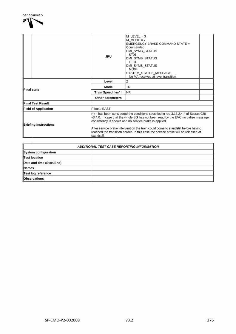
SP-EMO-P2-002008 v3.2 376
JRU
M_LEVEL = 3 M_MODE = 7 EMERGENCY BRAKE COMMAND STATE = Commanded DMI_SYMB_STATUS ST01 DMI_SYMB_STATUS LE04 DMI_SYMB_STATUS MO04 SYSTEM_STATUS_MESSAGE No MA received at level transition
Final state
Level 2
Mode TR
Train Speed (km/h) NR
Other parameters
Final Test Result
Field of Application F-bane EAST
Briefing instructions
(*) It has been considered the conditions specified in req 3.16.2.4.4 of Subset 026 v3.4.0. In case that the whole BG has not been read by the EVC no balise message consistency is shown and no service brake is applied. After service brake intervention the train could come to standstill before having reached the transition border. In this case the service brake will be released at standstill.
ADDITIONAL TEST CASE REPORTING INFORMATION
System configuration
Test location
Date and time (Start/End)
Names
Test log reference
Observations
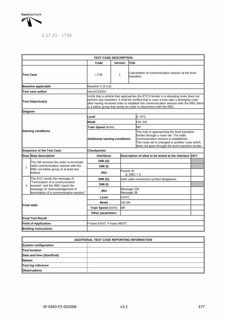
SP-EMO-P2-002008 v3.2 377
2.17.21. LT36
TEST CASE DESCRIPTION
Code Version Title
Test Case LT36 1 Cancelation of communication session at the level transition.
Baseline applicable Baseline 3 (3.4.0)
Test case author Ineco/CEDEX
Test Objective(s)
Verify that a vehicle that approaches the ETCS border in a diverging route does not perform any transition. It shall be verified that in case a train take a diverging route after having received order to establish the communication session with the RBC there is a balise group that sends an order to disconnect with the RBC.
Diagram
Starting conditions
Level 0, NTC
Mode UN, SN
Train Speed (km/h) NR
Additional starting conditions
The train is approaching the level transition border through a route set. The radio communication session is established. The route set is changed to another route which does not goes through the level transition border.
Sequence of the Test Case Checkpoints
Step Step description Interfaces Description of what to be tested at the interface OK?
1
The OB receives the order to terminate radio communication session with the RBC via balise group of at least two balises.
DMI (O)
DMI (I)
JRU Packet 42 Q_RBC = 0
2
The EVC sends the message of "Termination of a communication session" and the RBC report the message of "Acknowledgement of termination of a communication session"
DMI (O) Safe radio connection symbol disappears
DMI (I)
JRU Message 156 Message 39
Final state
Level 0,NTC
Mode UN,SN
Train Speed (km/h) NR
Other parameters
Final Test Result
Field of Application F-bane EAST, F-bane WEST
Briefing instructions
ADDITIONAL TEST CASE REPORTING INFORMATION
System configuration
Test location
Date and time (Start/End)
Names
Test log reference
Observations
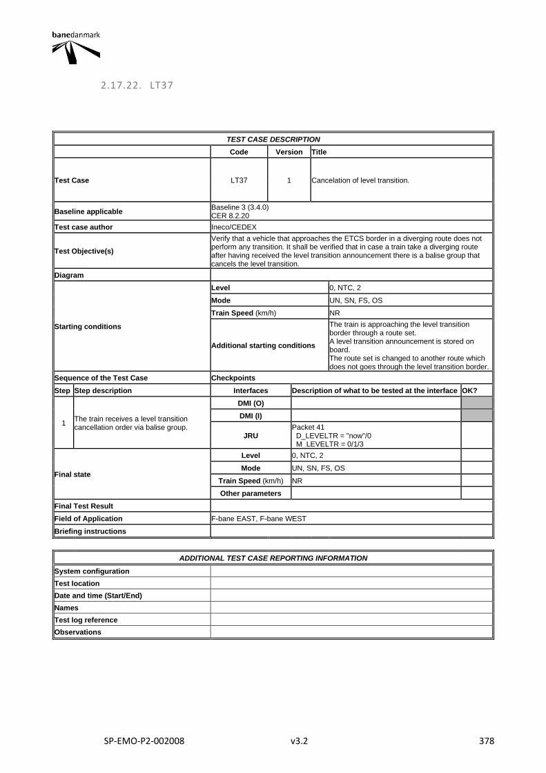
SP-EMO-P2-002008 v3.2 378
2.17.22. LT37
TEST CASE DESCRIPTION
Code Version Title
Test Case LT37 1 Cancelation of level transition.
Baseline applicable Baseline 3 (3.4.0) CER 8.2.20
Test case author Ineco/CEDEX
Test Objective(s)
Verify that a vehicle that approaches the ETCS border in a diverging route does not perform any transition. It shall be verified that in case a train take a diverging route after having received the level transition announcement there is a balise group that cancels the level transition.
Diagram
Starting conditions
Level 0, NTC, 2
Mode UN, SN, FS, OS
Train Speed (km/h) NR
Additional starting conditions
The train is approaching the level transition border through a route set. A level transition announcement is stored on board. The route set is changed to another route which does not goes through the level transition border.
Sequence of the Test Case Checkpoints
Step Step description Interfaces Description of what to be tested at the interface OK?
1 The train receives a level transition cancellation order via balise group.
DMI (O)
DMI (I)
JRU Packet 41 D_LEVELTR = "now"/0 M_LEVELTR = 0/1/3
Final state
Level 0, NTC, 2
Mode UN, SN, FS, OS
Train Speed (km/h) NR
Other parameters
Final Test Result
Field of Application F-bane EAST, F-bane WEST
Briefing instructions
ADDITIONAL TEST CASE REPORTING INFORMATION
System configuration
Test location
Date and time (Start/End)
Names
Test log reference
Observations
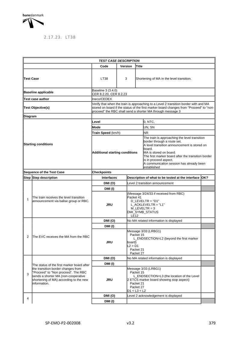
SP-EMO-P2-002008 v3.2 379
2.17.23. LT38
TEST CASE DESCRIPTION
Code Version Title
Test Case LT38 3 Shortening of MA in the level transition.
Baseline applicable Baseline 3 (3.4.0) CER 8.2.20, CER 8.2.23
Test case author Ineco/CEDEX
Test Objective(s) Verify that when the train is approaching to a Level 2 transition border with and MA stored on board if the status of the first marker board changes from "Proceed" to "non-proceed" the RBC shall send a shorter MA through message 3
Diagram
Starting conditions
Level 0, NTC,
Mode UN, SN
Train Speed (km/h) NR
Additional starting conditions
The train is approaching the level transition border through a route set. A level transition announcement is stored on board. MA is stored on board. The first marker board after the transition border is in proceed aspect. A communication session has already been established
Sequence of the Test Case Checkpoints
Step Step description Interfaces Description of what to be tested at the interface OK?
1 The train receives the level transition announcement via balise group or RBC.
DMI (O) Level 2 transition announcement
DMI (I)
JRU
(Message 3/24/33 if received from RBC) Packet 41 D_LEVELTR = "D1" L_ACKLEVELTR = "L1" M_LEVELTR = 3 DMI_SYMB_STATUS LE12
2 The EVC receives the MA from the RBC
DMI (O) No MA related information is displayed
DMI (I)
JRU
Message 3/33 (LRBG1) Packet 15 L_ENDSECTION=L2 (beyond the first marker board) L2 > D1 Packet 21 Packet 27
3
The status of the first marker board after the transition border changes from "Proceed" to "Non proceed". The RBC sends a shorter MA (non-cooperative shortening of MA) according to the new information.
DMI (O) No MA related information is displayed
DMI (I)
JRU
Message 3/33 (LRBG1) Packet 15 L_ENDSECTION=L3 (the location of the Level 2 ETCS marker board showing stop aspect) Packet 21 Packet 27 D1 < L3 < L2
4 DMI (O) Level 2 acknowledgement is displayed
DMI (I)
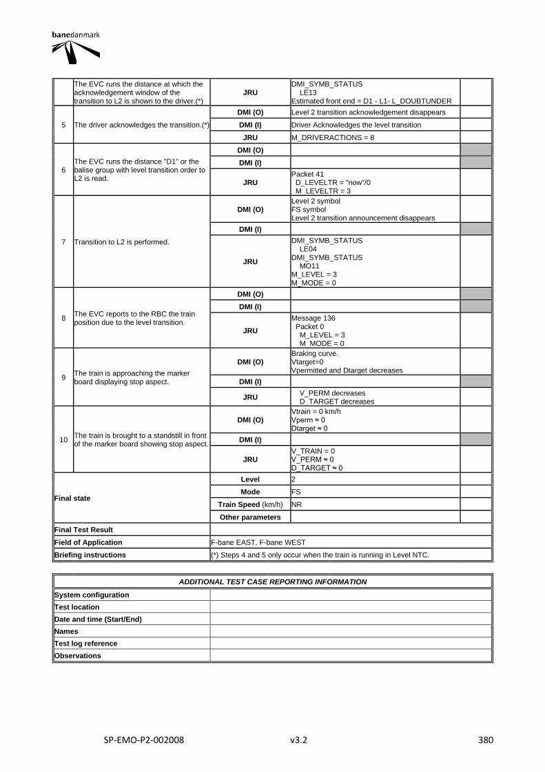
SP-EMO-P2-002008 v3.2 380
The EVC runs the distance at which the acknowledgement window of the transition to L2 is shown to the driver.(*)
JRU DMI_SYMB_STATUS LE13 Estimated front end = D1 - L1- L_DOUBTUNDER
5 The driver acknowledges the transition.(*)
DMI (O) Level 2 transition acknowledgement disappears
DMI (I) Driver Acknowledges the level transition
JRU M_DRIVERACTIONS = 8
6 The EVC runs the distance "D1" or the balise group with level transition order to L2 is read.
DMI (O)
DMI (I)
JRU Packet 41 D_LEVELTR = "now"/0 M_LEVELTR = 3
7 Transition to L2 is performed.
DMI (O) Level 2 symbol FS symbol Level 2 transition announcement disappears
DMI (I)
JRU
DMI_SYMB_STATUS LE04 DMI_SYMB_STATUS MO11 M_LEVEL = 3 M_MODE = 0
8 The EVC reports to the RBC the train position due to the level transition.
DMI (O)
DMI (I)
JRU
Message 136 Packet 0 M_LEVEL = 3 M_MODE = 0
9 The train is approaching the marker board displaying stop aspect.
DMI (O) Braking curve. Vtarget=0 Vpermitted and Dtarget decreases
DMI (I)
JRU V_PERM decreases D_TARGET decreases
10 The train is brought to a standstill in front of the marker board showing stop aspect.
DMI (O) Vtrain = 0 km/h Vperm ≈ 0 Dtarget ≈ 0
DMI (I)
JRU V_TRAIN = 0 V_PERM ≈ 0 D_TARGET ≈ 0
Final state
Level 2
Mode FS
Train Speed (km/h) NR
Other parameters
Final Test Result
Field of Application F-bane EAST, F-bane WEST
Briefing instructions (*) Steps 4 and 5 only occur when the train is running in Level NTC.
ADDITIONAL TEST CASE REPORTING INFORMATION
System configuration
Test location
Date and time (Start/End)
Names
Test log reference
Observations
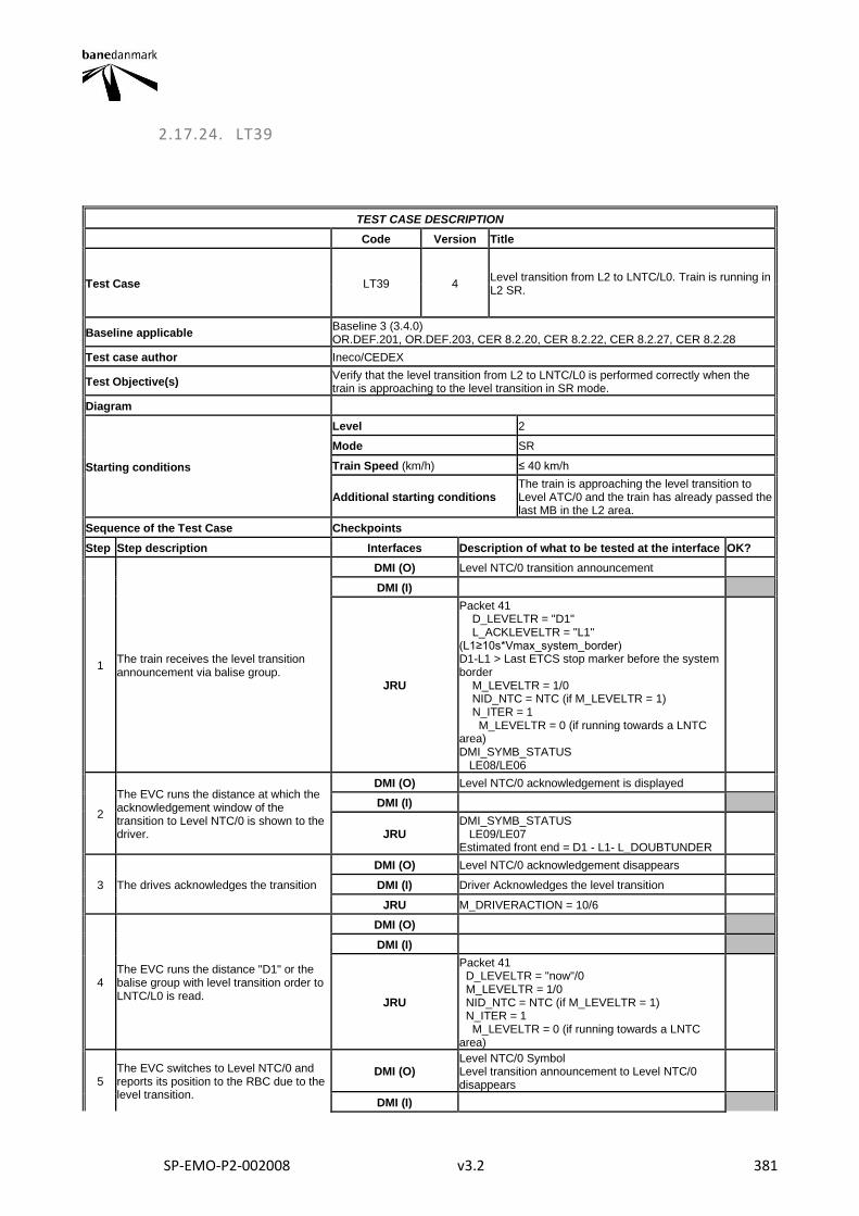
SP-EMO-P2-002008 v3.2 381
2.17.24. LT39
TEST CASE DESCRIPTION
Code Version Title
Test Case LT39 4 Level transition from L2 to LNTC/L0. Train is running in L2 SR.
Baseline applicable Baseline 3 (3.4.0) OR.DEF.201, OR.DEF.203, CER 8.2.20, CER 8.2.22, CER 8.2.27, CER 8.2.28
Test case author Ineco/CEDEX
Test Objective(s) Verify that the level transition from L2 to LNTC/L0 is performed correctly when the train is approaching to the level transition in SR mode.
Diagram
Starting conditions
Level 2
Mode SR
Train Speed (km/h) ≤ 40 km/h
Additional starting conditions The train is approaching the level transition to Level ATC/0 and the train has already passed the last MB in the L2 area.
Sequence of the Test Case Checkpoints
Step Step description Interfaces Description of what to be tested at the interface OK?
1 The train receives the level transition announcement via balise group.
DMI (O) Level NTC/0 transition announcement
DMI (I)
JRU
Packet 41 D_LEVELTR = "D1" L_ACKLEVELTR = "L1" (L1≥10s*Vmax_system_border) D1-L1 > Last ETCS stop marker before the system border M_LEVELTR = 1/0 NID_NTC = NTC (if M_LEVELTR = 1) N_ITER = 1 M_LEVELTR = 0 (if running towards a LNTC area) DMI_SYMB_STATUS LE08/LE06
2
The EVC runs the distance at which the acknowledgement window of the transition to Level NTC/0 is shown to the driver.
DMI (O) Level NTC/0 acknowledgement is displayed
DMI (I)
JRU DMI_SYMB_STATUS LE09/LE07 Estimated front end = D1 - L1- L_DOUBTUNDER
3 The drives acknowledges the transition
DMI (O) Level NTC/0 acknowledgement disappears
DMI (I) Driver Acknowledges the level transition
JRU M_DRIVERACTION = 10/6
4 The EVC runs the distance "D1" or the balise group with level transition order to LNTC/L0 is read.
DMI (O)
DMI (I)
JRU
Packet 41 D_LEVELTR = "now"/0 M_LEVELTR = 1/0 NID_NTC = NTC (if M_LEVELTR = 1) N_ITER = 1 M_LEVELTR = 0 (if running towards a LNTC area)
5 The EVC switches to Level NTC/0 and reports its position to the RBC due to the level transition.
DMI (O) Level NTC/0 Symbol Level transition announcement to Level NTC/0 disappears
DMI (I)
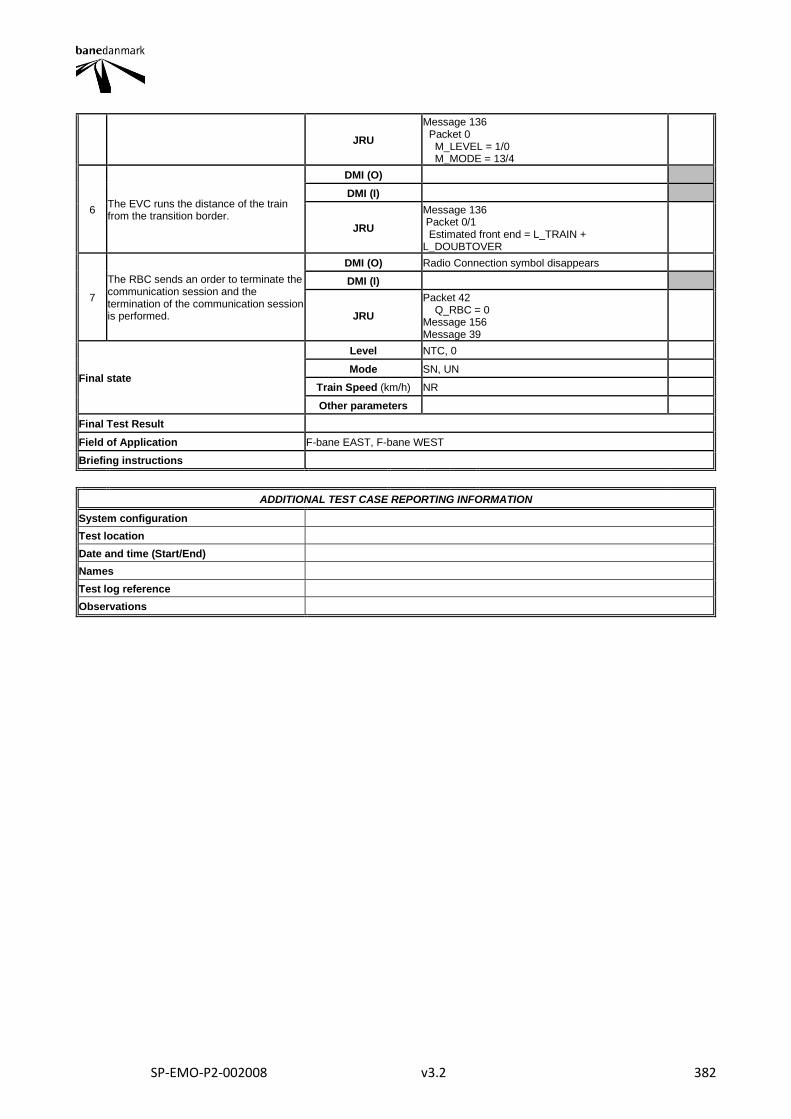
SP-EMO-P2-002008 v3.2 382
JRU
Message 136 Packet 0 M_LEVEL = 1/0 M_MODE = 13/4
6 The EVC runs the distance of the train from the transition border.
DMI (O)
DMI (I)
JRU
Message 136 Packet 0/1 Estimated front end = L_TRAIN + L_DOUBTOVER
7
The RBC sends an order to terminate the communication session and the termination of the communication session is performed.
DMI (O) Radio Connection symbol disappears
DMI (I)
JRU
Packet 42 Q_RBC = 0 Message 156 Message 39
Final state
Level NTC, 0
Mode SN, UN
Train Speed (km/h) NR
Other parameters
Final Test Result
Field of Application F-bane EAST, F-bane WEST
Briefing instructions
ADDITIONAL TEST CASE REPORTING INFORMATION
System configuration
Test location
Date and time (Start/End)
Names
Test log reference
Observations
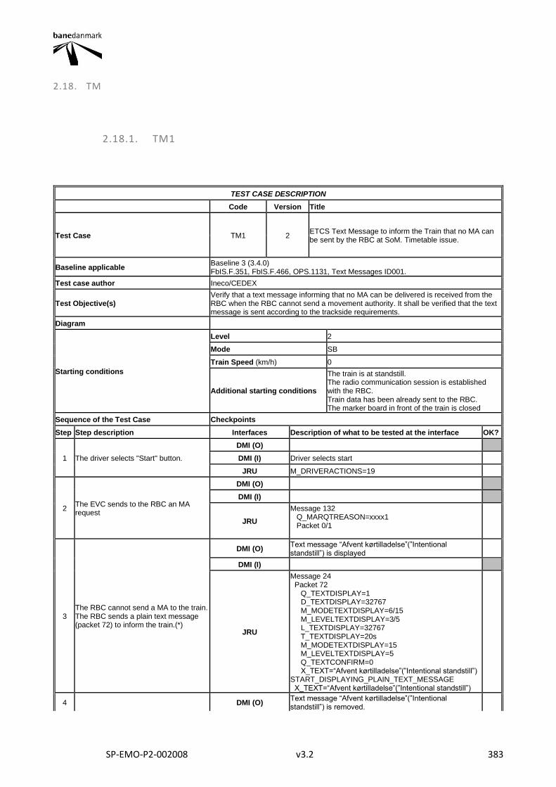
SP-EMO-P2-002008 v3.2 383
2.18. TM
2.18.1. TM1
TEST CASE DESCRIPTION
Code Version Title
Test Case TM1 2 ETCS Text Message to inform the Train that no MA can be sent by the RBC at SoM. Timetable issue.
Baseline applicable Baseline 3 (3.4.0) FbIS.F.351, FbIS.F.466, OPS.1131, Text Messages ID001.
Test case author Ineco/CEDEX
Test Objective(s) Verify that a text message informing that no MA can be delivered is received from the RBC when the RBC cannot send a movement authority. It shall be verified that the text message is sent according to the trackside requirements.
Diagram
Starting conditions
Level 2
Mode SB
Train Speed (km/h) 0
Additional starting conditions
The train is at standstill. The radio communication session is established with the RBC. Train data has been already sent to the RBC. The marker board in front of the train is closed
Sequence of the Test Case Checkpoints
Step Step description Interfaces Description of what to be tested at the interface OK?
1 The driver selects "Start" button.
DMI (O)
DMI (I) Driver selects start
JRU M_DRIVERACTIONS=19
2 The EVC sends to the RBC an MA request
DMI (O)
DMI (I)
JRU
Message 132 Q_MARQTREASON=xxxx1 Packet 0/1
3 The RBC cannot send a MA to the train. The RBC sends a plain text message (packet 72) to inform the train.(*)
DMI (O) Text message “Afvent kørtilladelse”(”Intentional standstill”) is displayed
DMI (I)
JRU
Message 24 Packet 72 Q_TEXTDISPLAY=1 D_TEXTDISPLAY=32767 M_MODETEXTDISPLAY=6/15 M_LEVELTEXTDISPLAY=3/5 L_TEXTDISPLAY=32767 T_TEXTDISPLAY=20s M_MODETEXTDISPLAY=15 M_LEVELTEXTDISPLAY=5 Q_TEXTCONFIRM=0 X_TEXT=“Afvent kørtilladelse”(”Intentional standstill”) START_DISPLAYING_PLAIN_TEXT_MESSAGE X_TEXT=“Afvent kørtilladelse”(”Intentional standstill”)
4 DMI (O) Text message “Afvent kørtilladelse”(”Intentional standstill”) is removed.
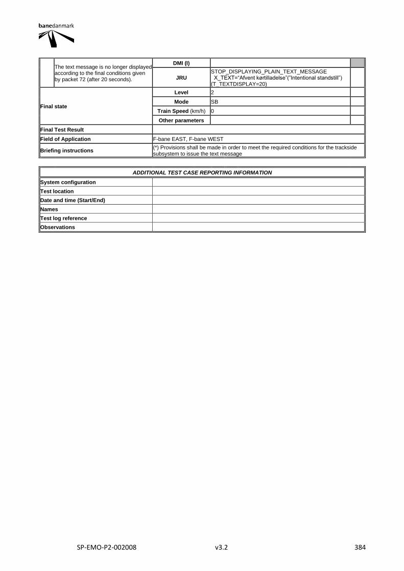
SP-EMO-P2-002008 v3.2 384
The text message is no longer displayed according to the final conditions given by packet 72 (after 20 seconds).
DMI (I)
JRU STOP_DISPLAYING_PLAIN_TEXT_MESSAGE X_TEXT=“Afvent kørtilladelse”(”Intentional standstill”) (T_TEXTDISPLAY=20)
Final state
Level 2
Mode SB
Train Speed (km/h) 0
Other parameters
Final Test Result
Field of Application F-bane EAST, F-bane WEST
Briefing instructions (*) Provisions shall be made in order to meet the required conditions for the trackside subsystem to issue the text message
ADDITIONAL TEST CASE REPORTING INFORMATION
System configuration
Test location
Date and time (Start/End)
Names
Test log reference
Observations
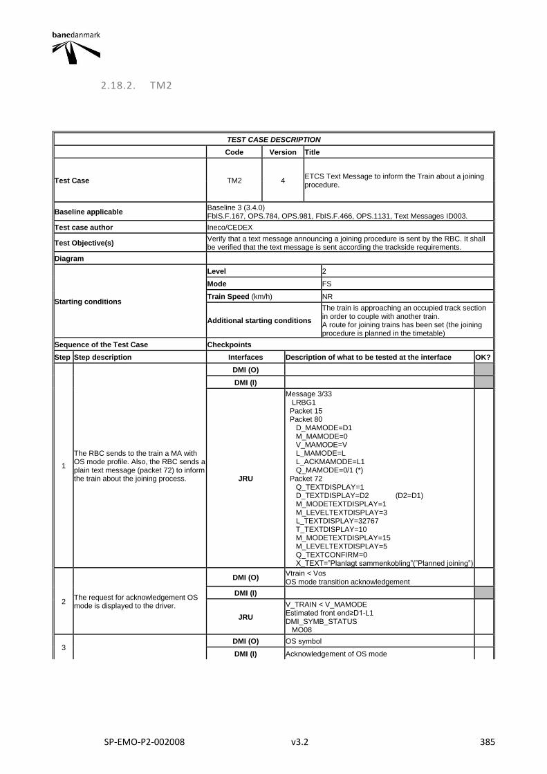
SP-EMO-P2-002008 v3.2 385
2.18.2. TM2
TEST CASE DESCRIPTION
Code Version Title
Test Case TM2 4 ETCS Text Message to inform the Train about a joining procedure.
Baseline applicable Baseline 3 (3.4.0) FbIS.F.167, OPS.784, OPS.981, FbIS.F.466, OPS.1131, Text Messages ID003.
Test case author Ineco/CEDEX
Test Objective(s) Verify that a text message announcing a joining procedure is sent by the RBC. It shall be verified that the text message is sent according the trackside requirements.
Diagram
Starting conditions
Level 2
Mode FS
Train Speed (km/h) NR
Additional starting conditions
The train is approaching an occupied track section in order to couple with another train. A route for joining trains has been set (the joining procedure is planned in the timetable)
Sequence of the Test Case Checkpoints
Step Step description Interfaces Description of what to be tested at the interface OK?
1
The RBC sends to the train a MA with OS mode profile. Also, the RBC sends a plain text message (packet 72) to inform the train about the joining process.
DMI (O)
DMI (I)
JRU
Message 3/33 LRBG1 Packet 15 Packet 80 D_MAMODE=D1 M_MAMODE=0 V_MAMODE=V L_MAMODE=L L_ACKMAMODE=L1 Q_MAMODE=0/1 (*) Packet 72 Q_TEXTDISPLAY=1 D_TEXTDISPLAY=D2 (D2=D1) M_MODETEXTDISPLAY=1 M_LEVELTEXTDISPLAY=3 L_TEXTDISPLAY=32767 T_TEXTDISPLAY=10 M_MODETEXTDISPLAY=15 M_LEVELTEXTDISPLAY=5 Q_TEXTCONFIRM=0 X_TEXT=”Planlagt sammenkobling”(”Planned joining”)
2 The request for acknowledgement OS mode is displayed to the driver.
DMI (O) Vtrain < Vos OS mode transition acknowledgement
DMI (I)
JRU
V_TRAIN < V_MAMODE Estimated front end≥D1-L1 DMI_SYMB_STATUS MO08
3 DMI (O) OS symbol
DMI (I) Acknowledgement of OS mode
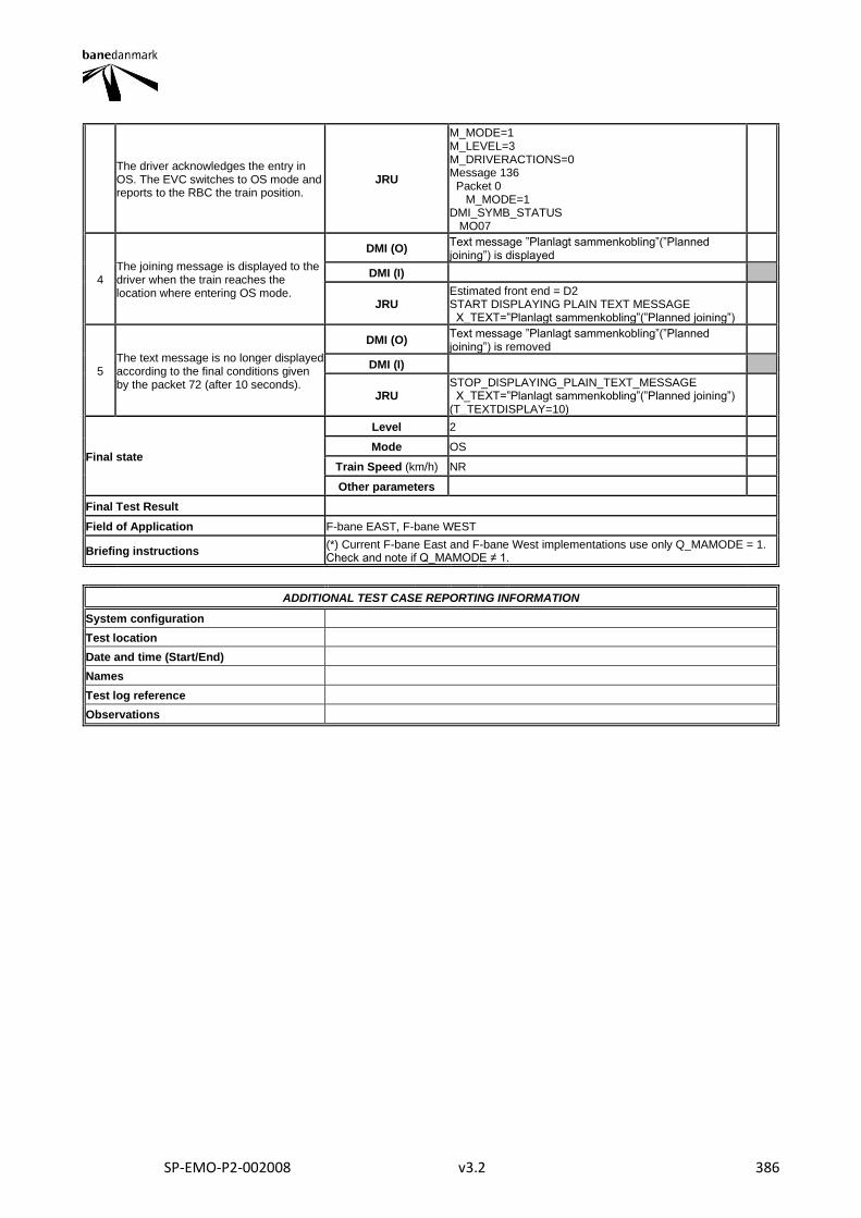
SP-EMO-P2-002008 v3.2 386
The driver acknowledges the entry in OS. The EVC switches to OS mode and reports to the RBC the train position.
JRU
M_MODE=1 M_LEVEL=3 M_DRIVERACTIONS=0 Message 136 Packet 0 M_MODE=1 DMI_SYMB_STATUS MO07
4 The joining message is displayed to the driver when the train reaches the location where entering OS mode.
DMI (O) Text message ”Planlagt sammenkobling”(”Planned joining”) is displayed
DMI (I)
JRU Estimated front end = D2 START DISPLAYING PLAIN TEXT MESSAGE X_TEXT=”Planlagt sammenkobling”(”Planned joining”)
5 The text message is no longer displayed according to the final conditions given by the packet 72 (after 10 seconds).
DMI (O) Text message ”Planlagt sammenkobling”(”Planned joining”) is removed
DMI (I)
JRU STOP_DISPLAYING_PLAIN_TEXT_MESSAGE X_TEXT=”Planlagt sammenkobling”(”Planned joining”) (T_TEXTDISPLAY=10)
Final state
Level 2
Mode OS
Train Speed (km/h) NR
Other parameters
Final Test Result
Field of Application F-bane EAST, F-bane WEST
Briefing instructions (*) Current F-bane East and F-bane West implementations use only Q_MAMODE = 1. Check and note if Q_MAMODE ≠ 1.
ADDITIONAL TEST CASE REPORTING INFORMATION
System configuration
Test location
Date and time (Start/End)
Names
Test log reference
Observations
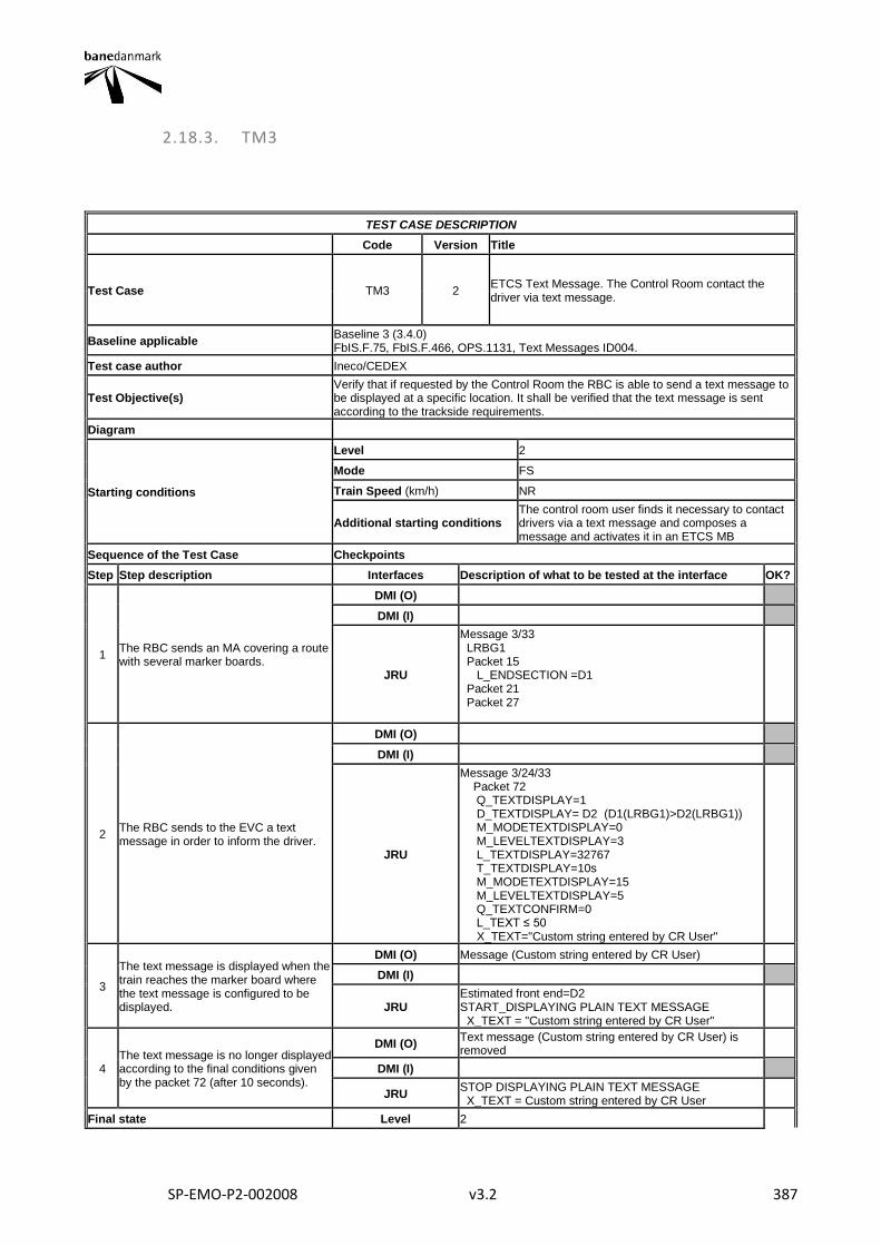
SP-EMO-P2-002008 v3.2 387
2.18.3. TM3
TEST CASE DESCRIPTION
Code Version Title
Test Case TM3 2 ETCS Text Message. The Control Room contact the driver via text message.
Baseline applicable Baseline 3 (3.4.0) FbIS.F.75, FbIS.F.466, OPS.1131, Text Messages ID004.
Test case author Ineco/CEDEX
Test Objective(s) Verify that if requested by the Control Room the RBC is able to send a text message to be displayed at a specific location. It shall be verified that the text message is sent according to the trackside requirements.
Diagram
Starting conditions
Level 2
Mode FS
Train Speed (km/h) NR
Additional starting conditions The control room user finds it necessary to contact drivers via a text message and composes a message and activates it in an ETCS MB
Sequence of the Test Case Checkpoints
Step Step description Interfaces Description of what to be tested at the interface OK?
1 The RBC sends an MA covering a route with several marker boards.
DMI (O)
DMI (I)
JRU
Message 3/33 LRBG1 Packet 15 L_ENDSECTION =D1 Packet 21 Packet 27
2 The RBC sends to the EVC a text message in order to inform the driver.
DMI (O)
DMI (I)
JRU
Message 3/24/33 Packet 72 Q_TEXTDISPLAY=1 D_TEXTDISPLAY= D2 (D1(LRBG1)>D2(LRBG1)) M_MODETEXTDISPLAY=0 M_LEVELTEXTDISPLAY=3 L_TEXTDISPLAY=32767 T_TEXTDISPLAY=10s M_MODETEXTDISPLAY=15 M_LEVELTEXTDISPLAY=5 Q_TEXTCONFIRM=0 L_TEXT ≤ 50 X_TEXT="Custom string entered by CR User"
3
The text message is displayed when the train reaches the marker board where the text message is configured to be displayed.
DMI (O) Message (Custom string entered by CR User)
DMI (I)
JRU Estimated front end=D2 START_DISPLAYING PLAIN TEXT MESSAGE X_TEXT = "Custom string entered by CR User"
4 The text message is no longer displayed according to the final conditions given by the packet 72 (after 10 seconds).
DMI (O) Text message (Custom string entered by CR User) is removed
DMI (I)
JRU STOP DISPLAYING PLAIN TEXT MESSAGE X_TEXT = Custom string entered by CR User
Final state Level 2

SP-EMO-P2-002008 v3.2 388
Mode FS
Train Speed (km/h) NR
Other parameters
Final Test Result
Field of Application F-bane EAST, F-bane WEST
Briefing instructions
ADDITIONAL TEST CASE REPORTING INFORMATION
System configuration
Test location
Date and time (Start/End)
Names
Test log reference
Observations
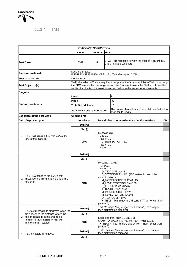
SP-EMO-P2-002008 v3.2 389
2.18.4. TM4
TEST CASE DESCRIPTION
Code Version Title
Test Case TM4 4 ETCS Text Message to warn the train as it enters in a platform that is too short.
Baseline applicable Baseline 3 (3.4.0) FbIS.F.433, FbIS.F.466, OPS.1131, Text Messages ID005.
Test case author Ineco/CEDEX
Test Objective(s) Verify that when a Train is required to stop at a Platform for which the Train is too long the RBC sends a text message to warn the Train as it enters the Platform. It shall be verified that the text message is sent according to the trackside requirements.
Diagram
Starting conditions
Level 2
Mode FS
Train Speed (km/h) NR
Additional starting conditions The train is planned to stop at a platform that is too short for its length.
Sequence of the Test Case Checkpoints
Step Step description Interfaces Description of what to be tested at the interface OK?
1 The RBC sends a MA with EoA at the end of the platform
DMI (O)
DMI (I)
JRU
Message 3/33 LRBG1 Packet 15 L_ENDSECTION = L1 Packet 21 Packet 27
2 The RBC sends to the EVC a text message informing that the platform is too short
DMI (O)
DMI (I)
JRU
Message 3/24/33 LRBG2 Packet 72 Q_TEXTDISPLAY=1 D_TEXTDISPLAY= D1 (100 meters in rear of the start of platform) M_MODETEXTDISPLAY=0 / 15 M_LEVELTEXTDISPLAY=3 / 5 L_TEXTDISPLAY=32767 T_TEXTDISPLAY=10s M_MODETEXTDISPLAY=15 M_LEVELTEXTDISPLAY=5 Q_TEXTCONFIRM=0 X_TEXT=“Tog længere end perron”(”Train longer than platform”)
3
The text message is displayed when the train reaches the distance where the text message is configured to be displayed (100 meters in rear the platform start location)
DMI (O) Text Message “Tog længere end perron”(”Train longer than platform”) is displayed
DMI (I)
JRU
Estimated front end=D1(LRBG2) START_DISPLAYING_PLAIN_TEXT_MESSAGE X_TEXT = “Tog længere end perron”(”Train longer than platform”)
4 Text message is removed DMI (O)
Text message “Tog længere end perron”(”Train longer than platform”) is removed
DMI (I)
SP-EMO-P2-002008 v3.2 390
JRU
STOP_DISPLAYING_PLAIN_TEXT_MESSAGE X_TEXT=“Tog længere end perron”(”Train longer than platform”) (T_TEXTDISPLAY=10)
Final state
Level 2
Mode FS
Train Speed (km/h) NR
Other parameters
Final Test Result
Field of Application F-bane EAST, F-bane WEST
Briefing instructions
ADDITIONAL TEST CASE REPORTING INFORMATION
System configuration
Test location
Date and time (Start/End)
Names
Test log reference
Observations
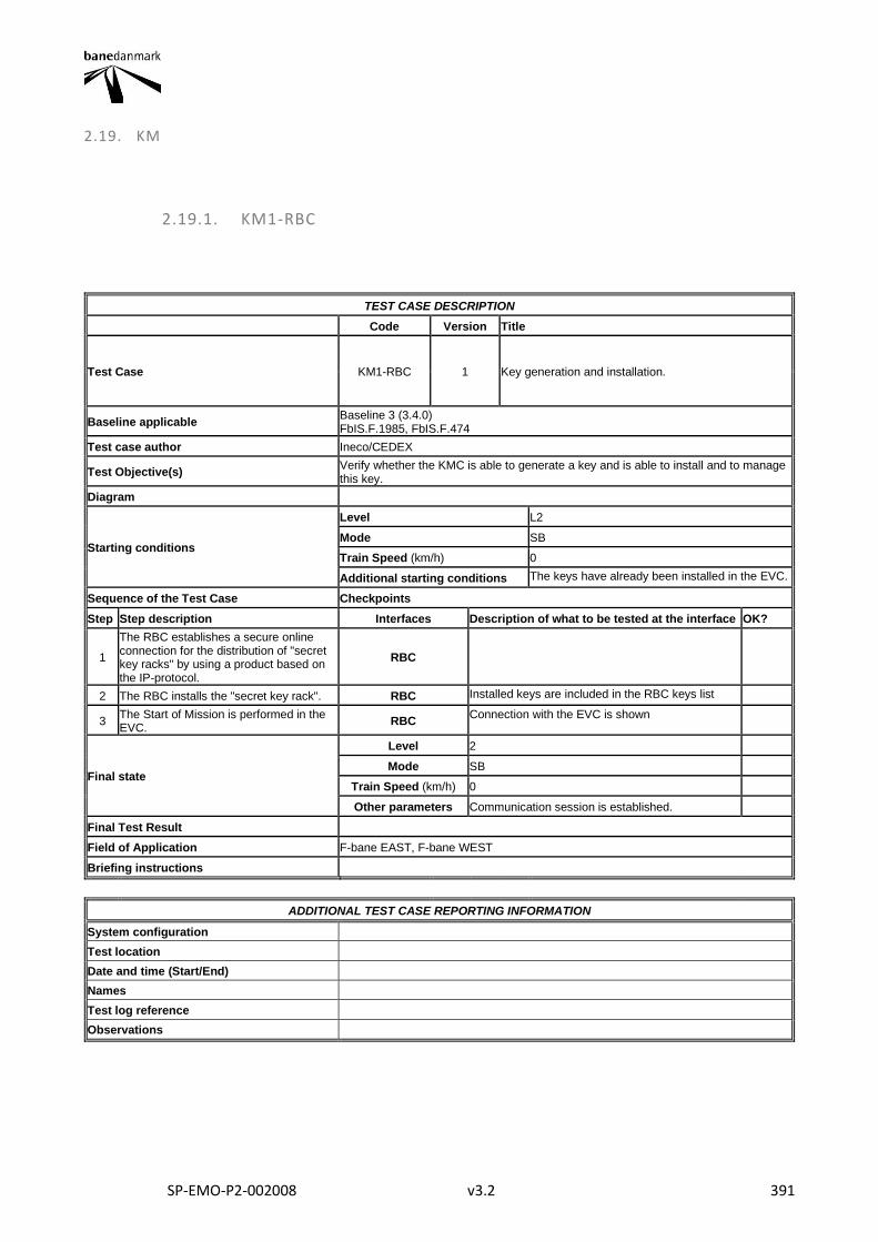
SP-EMO-P2-002008 v3.2 391
2.19. KM
2.19.1. KM1-RBC
TEST CASE DESCRIPTION
Code Version Title
Test Case KM1-RBC 1 Key generation and installation.
Baseline applicable Baseline 3 (3.4.0) FbIS.F.1985, FbIS.F.474
Test case author Ineco/CEDEX
Test Objective(s) Verify whether the KMC is able to generate a key and is able to install and to manage this key.
Diagram
Starting conditions
Level L2
Mode SB
Train Speed (km/h) 0
Additional starting conditions The keys have already been installed in the EVC.
Sequence of the Test Case Checkpoints
Step Step description Interfaces Description of what to be tested at the interface OK?
1
The RBC establishes a secure online connection for the distribution of "secret key racks" by using a product based on the IP-protocol.
RBC
2 The RBC installs the "secret key rack". RBC Installed keys are included in the RBC keys list
3 The Start of Mission is performed in the EVC.
RBC Connection with the EVC is shown
Final state
Level 2
Mode SB
Train Speed (km/h) 0
Other parameters Communication session is established.
Final Test Result
Field of Application F-bane EAST, F-bane WEST
Briefing instructions
ADDITIONAL TEST CASE REPORTING INFORMATION
System configuration
Test location
Date and time (Start/End)
Names
Test log reference
Observations
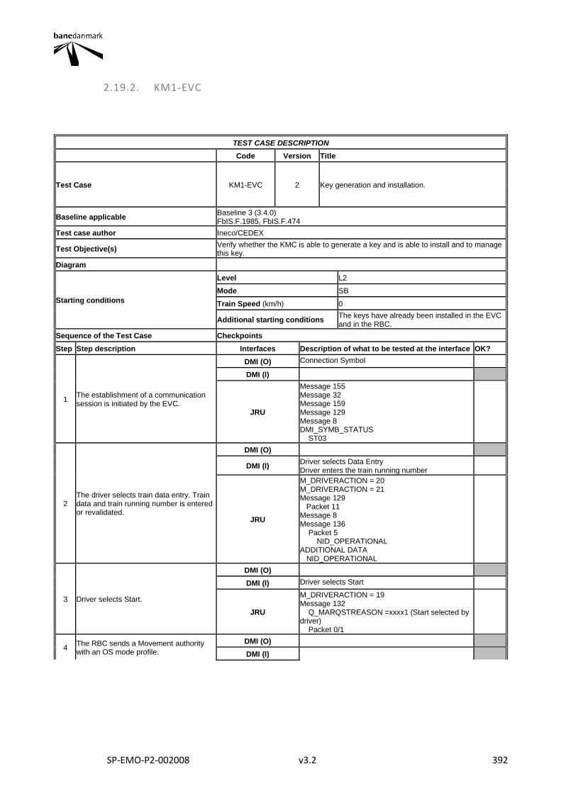
SP-EMO-P2-002008 v3.2 392
2.19.2. KM1-EVC
TEST CASE DESCRIPTION
Code Version Title
Test Case KM1-EVC 2 Key generation and installation.
Baseline applicable Baseline 3 (3.4.0) FbIS.F.1985, FbIS.F.474
Test case author Ineco/CEDEX
Test Objective(s) Verify whether the KMC is able to generate a key and is able to install and to manage this key.
Diagram
Starting conditions
Level L2
Mode SB
Train Speed (km/h) 0
Additional starting conditions The keys have already been installed in the EVC and in the RBC.
Sequence of the Test Case Checkpoints
Step Step description Interfaces Description of what to be tested at the interface OK?
1 The establishment of a communication session is initiated by the EVC.
DMI (O) Connection Symbol
DMI (I)
JRU
Message 155 Message 32 Message 159 Message 129 Message 8 DMI_SYMB_STATUS ST03
2 The driver selects train data entry. Train data and train running number is entered or revalidated.
DMI (O)
DMI (I) Driver selects Data Entry Driver enters the train running number
JRU
M_DRIVERACTION = 20 M_DRIVERACTION = 21 Message 129 Packet 11 Message 8 Message 136 Packet 5 NID_OPERATIONAL ADDITIONAL DATA NID_OPERATIONAL
3 Driver selects Start.
DMI (O)
DMI (I) Driver selects Start
JRU
M_DRIVERACTION = 19 Message 132 Q_MARQSTREASON =xxxx1 (Start selected by driver) Packet 0/1
4 The RBC sends a Movement authority with an OS mode profile.
DMI (O)
DMI (I)
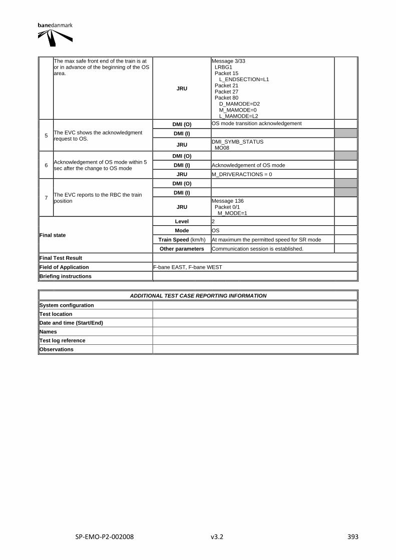
SP-EMO-P2-002008 v3.2 393
The max safe front end of the train is at or in advance of the beginning of the OS area.
JRU
Message 3/33 LRBG1 Packet 15 L_ENDSECTION=L1 Packet 21 Packet 27 Packet 80 D_MAMODE=D2 M_MAMODE=0 L_MAMODE=L2
5 The EVC shows the acknowledgment request to OS.
DMI (O) OS mode transition acknowledgement
DMI (I)
JRU DMI_SYMB_STATUS MO08
6 Acknowledgement of OS mode within 5 sec after the change to OS mode
DMI (O)
DMI (I) Acknowledgement of OS mode
JRU M_DRIVERACTIONS = 0
7 The EVC reports to the RBC the train position
DMI (O)
DMI (I)
JRU Message 136 Packet 0/1 M_MODE=1
Final state
Level 2
Mode OS
Train Speed (km/h) At maximum the permitted speed for SR mode
Other parameters Communication session is established.
Final Test Result
Field of Application F-bane EAST, F-bane WEST
Briefing instructions
ADDITIONAL TEST CASE REPORTING INFORMATION
System configuration
Test location
Date and time (Start/End)
Names
Test log reference
Observations
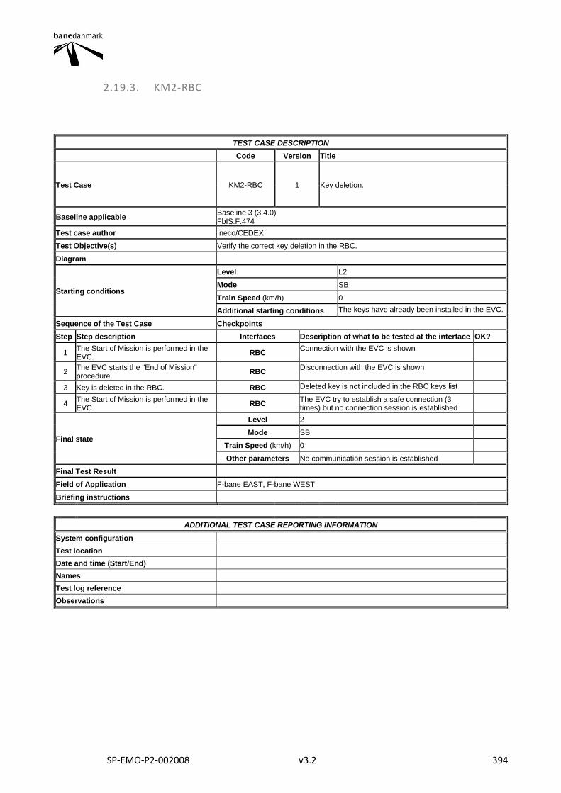
SP-EMO-P2-002008 v3.2 394
2.19.3. KM2-RBC
TEST CASE DESCRIPTION
Code Version Title
Test Case KM2-RBC 1 Key deletion.
Baseline applicable Baseline 3 (3.4.0) FbIS.F.474
Test case author Ineco/CEDEX
Test Objective(s) Verify the correct key deletion in the RBC.
Diagram
Starting conditions
Level L2
Mode SB
Train Speed (km/h) 0
Additional starting conditions The keys have already been installed in the EVC.
Sequence of the Test Case Checkpoints
Step Step description Interfaces Description of what to be tested at the interface OK?
1 The Start of Mission is performed in the EVC.
RBC Connection with the EVC is shown
2 The EVC starts the "End of Mission" procedure.
RBC Disconnection with the EVC is shown
3 Key is deleted in the RBC. RBC Deleted key is not included in the RBC keys list
4 The Start of Mission is performed in the EVC.
RBC The EVC try to establish a safe connection (3 times) but no connection session is established
Final state
Level 2
Mode SB
Train Speed (km/h) 0
Other parameters No communication session is established
Final Test Result
Field of Application F-bane EAST, F-bane WEST
Briefing instructions
ADDITIONAL TEST CASE REPORTING INFORMATION
System configuration
Test location
Date and time (Start/End)
Names
Test log reference
Observations
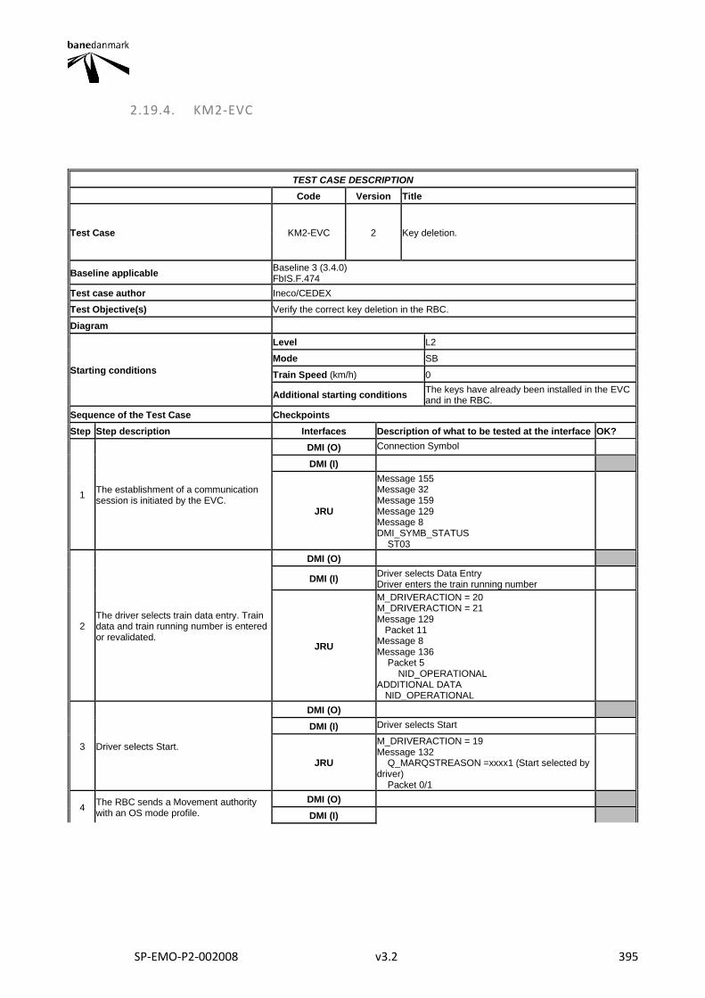
SP-EMO-P2-002008 v3.2 395
2.19.4. KM2-EVC
TEST CASE DESCRIPTION
Code Version Title
Test Case KM2-EVC 2 Key deletion.
Baseline applicable Baseline 3 (3.4.0) FbIS.F.474
Test case author Ineco/CEDEX
Test Objective(s) Verify the correct key deletion in the RBC.
Diagram
Starting conditions
Level L2
Mode SB
Train Speed (km/h) 0
Additional starting conditions The keys have already been installed in the EVC and in the RBC.
Sequence of the Test Case Checkpoints
Step Step description Interfaces Description of what to be tested at the interface OK?
1 The establishment of a communication session is initiated by the EVC.
DMI (O) Connection Symbol
DMI (I)
JRU
Message 155 Message 32 Message 159 Message 129 Message 8 DMI_SYMB_STATUS ST03
2 The driver selects train data entry. Train data and train running number is entered or revalidated.
DMI (O)
DMI (I) Driver selects Data Entry Driver enters the train running number
JRU
M_DRIVERACTION = 20 M_DRIVERACTION = 21 Message 129 Packet 11 Message 8 Message 136 Packet 5 NID_OPERATIONAL ADDITIONAL DATA NID_OPERATIONAL
3 Driver selects Start.
DMI (O)
DMI (I) Driver selects Start
JRU
M_DRIVERACTION = 19 Message 132 Q_MARQSTREASON =xxxx1 (Start selected by driver) Packet 0/1
4 The RBC sends a Movement authority with an OS mode profile.
DMI (O)
DMI (I)
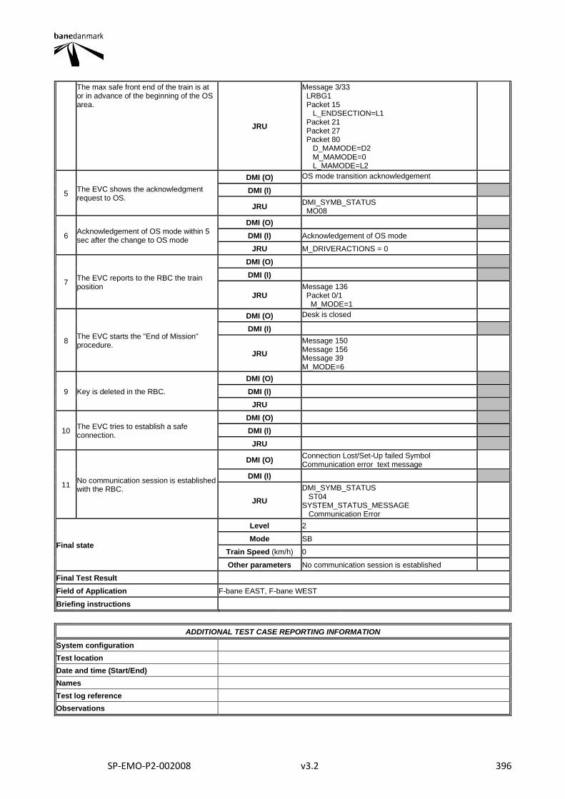
SP-EMO-P2-002008 v3.2 396
The max safe front end of the train is at or in advance of the beginning of the OS area.
JRU
Message 3/33 LRBG1 Packet 15 L_ENDSECTION=L1 Packet 21 Packet 27 Packet 80 D_MAMODE=D2 M_MAMODE=0 L_MAMODE=L2
5 The EVC shows the acknowledgment request to OS.
DMI (O) OS mode transition acknowledgement
DMI (I)
JRU DMI_SYMB_STATUS MO08
6 Acknowledgement of OS mode within 5 sec after the change to OS mode
DMI (O)
DMI (I) Acknowledgement of OS mode
JRU M_DRIVERACTIONS = 0
7 The EVC reports to the RBC the train position
DMI (O)
DMI (I)
JRU Message 136 Packet 0/1 M_MODE=1
8 The EVC starts the "End of Mission" procedure.
DMI (O) Desk is closed
DMI (I)
JRU
Message 150 Message 156 Message 39 M_MODE=6
9 Key is deleted in the RBC.
DMI (O)
DMI (I)
JRU
10 The EVC tries to establish a safe connection.
DMI (O)
DMI (I)
JRU
11 No communication session is established with the RBC.
DMI (O) Connection Lost/Set-Up failed Symbol Communication error text message
DMI (I)
JRU
DMI_SYMB_STATUS ST04 SYSTEM_STATUS_MESSAGE Communication Error
Final state
Level 2
Mode SB
Train Speed (km/h) 0
Other parameters No communication session is established
Final Test Result
Field of Application F-bane EAST, F-bane WEST
Briefing instructions
ADDITIONAL TEST CASE REPORTING INFORMATION
System configuration
Test location
Date and time (Start/End)
Names
Test log reference
Observations
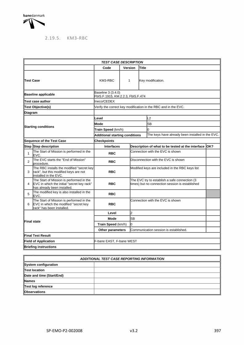
SP-EMO-P2-002008 v3.2 397
2.19.5. KM3-RBC
TEST CASE DESCRIPTION
Code Version Title
Test Case KM3-RBC 1 Key modification.
Baseline applicable Baseline 3 (3.4.0) FbIS.F.1915, KM.2.2.3, FbIS.F.474
Test case author Ineco/CEDEX
Test Objective(s) Verify the correct key modification in the RBC and in the EVC.
Diagram
Starting conditions
Level L2
Mode SB
Train Speed (km/h) 0
Additional starting conditions The keys have already been installed in the EVC.
Sequence of the Test Case Checkpoints
Step Step description Interfaces Description of what to be tested at the interface OK?
1 The Start of Mission is performed in the EVC.
RBC Connection with the EVC is shown
2 The EVC starts the "End of Mission" procedure.
RBC Disconnection with the EVC is shown
3 The RBC installs the modified "secret key rack", but this modified keys are not installed in the EVC.
RBC Modified keys are included in the RBC keys list
4 The Start of Mission is performed in the EVC in which the initial "secret key rack" has already been installed.
RBC The EVC try to establish a safe connection (3 times) but no connection session is established
5 The modified key is also installed in the EVC.
RBC
6 The Start of Mission is performed in the EVC in which the modified "secret key rack" has been installed.
RBC Connection with the EVC is shown
Final state
Level 2
Mode SB
Train Speed (km/h) 0
Other parameters Communication session is established.
Final Test Result
Field of Application F-bane EAST, F-bane WEST
Briefing instructions
ADDITIONAL TEST CASE REPORTING INFORMATION
System configuration
Test location
Date and time (Start/End)
Names
Test log reference
Observations
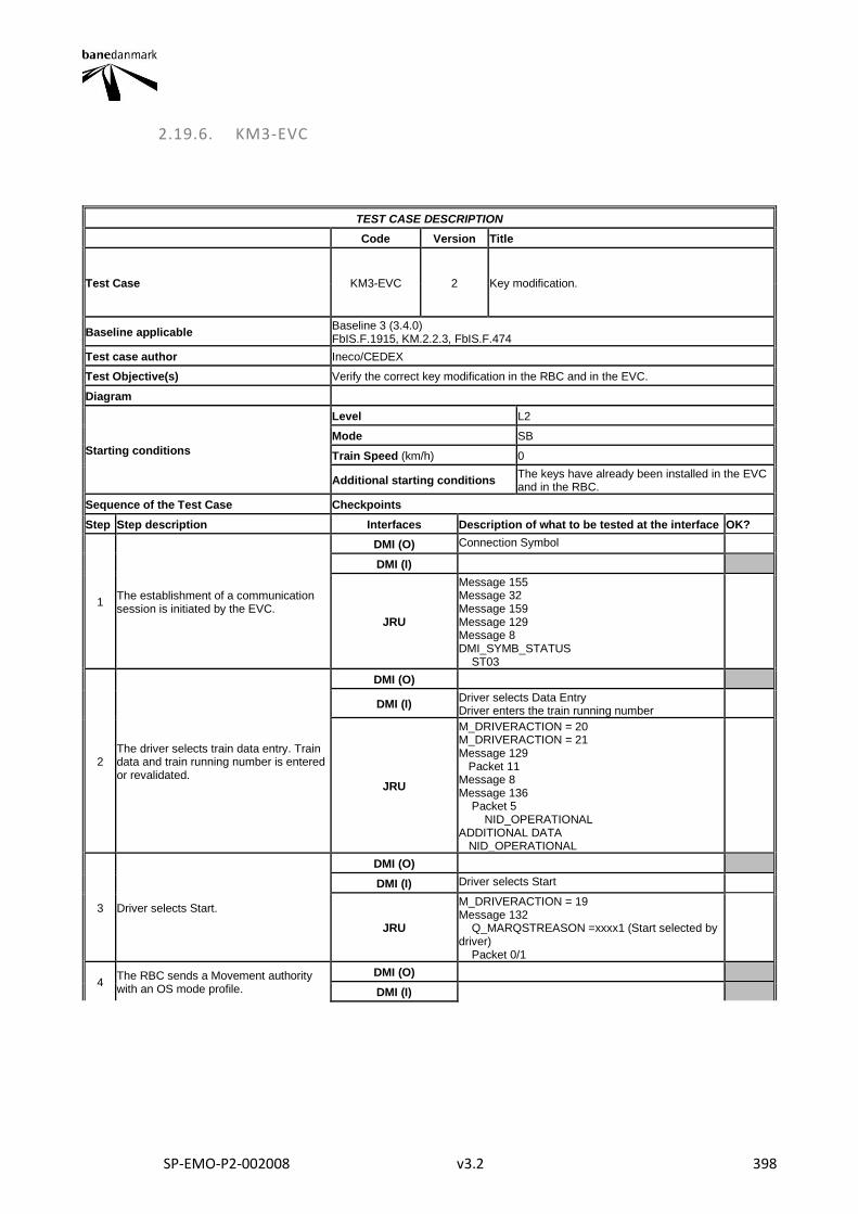
SP-EMO-P2-002008 v3.2 398
2.19.6. KM3-EVC
TEST CASE DESCRIPTION
Code Version Title
Test Case KM3-EVC 2 Key modification.
Baseline applicable Baseline 3 (3.4.0) FbIS.F.1915, KM.2.2.3, FbIS.F.474
Test case author Ineco/CEDEX
Test Objective(s) Verify the correct key modification in the RBC and in the EVC.
Diagram
Starting conditions
Level L2
Mode SB
Train Speed (km/h) 0
Additional starting conditions The keys have already been installed in the EVC and in the RBC.
Sequence of the Test Case Checkpoints
Step Step description Interfaces Description of what to be tested at the interface OK?
1 The establishment of a communication session is initiated by the EVC.
DMI (O) Connection Symbol
DMI (I)
JRU
Message 155 Message 32 Message 159 Message 129 Message 8 DMI_SYMB_STATUS ST03
2 The driver selects train data entry. Train data and train running number is entered or revalidated.
DMI (O)
DMI (I) Driver selects Data Entry Driver enters the train running number
JRU
M_DRIVERACTION = 20 M_DRIVERACTION = 21 Message 129 Packet 11 Message 8 Message 136 Packet 5 NID_OPERATIONAL ADDITIONAL DATA NID_OPERATIONAL
3 Driver selects Start.
DMI (O)
DMI (I) Driver selects Start
JRU
M_DRIVERACTION = 19 Message 132 Q_MARQSTREASON =xxxx1 (Start selected by driver) Packet 0/1
4 The RBC sends a Movement authority with an OS mode profile.
DMI (O)
DMI (I)
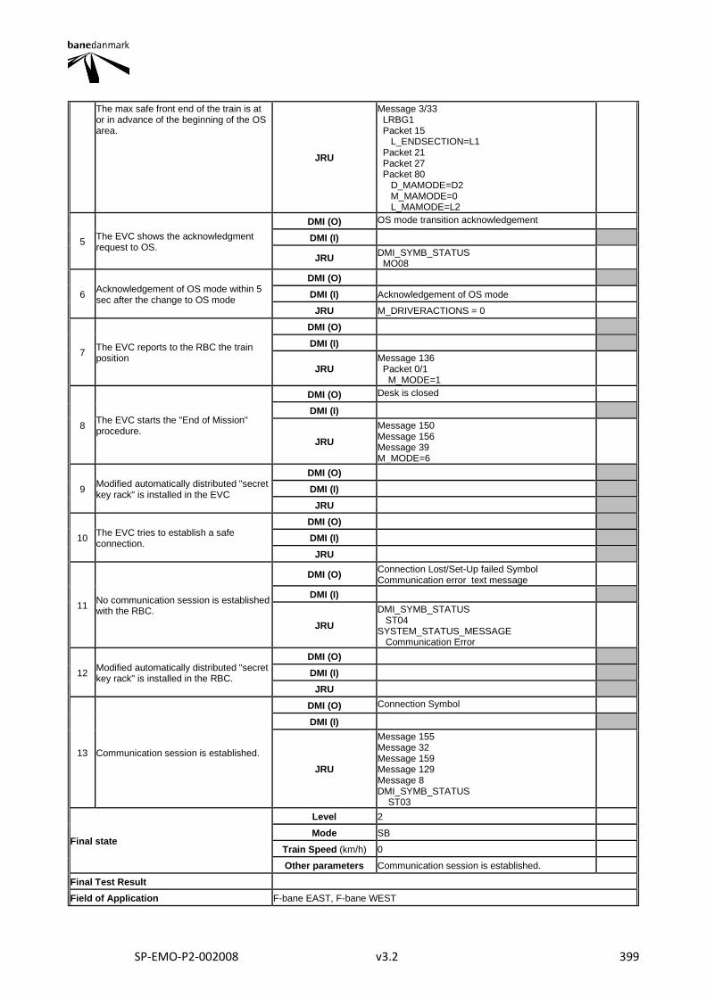
SP-EMO-P2-002008 v3.2 399
The max safe front end of the train is at or in advance of the beginning of the OS area.
JRU
Message 3/33 LRBG1 Packet 15 L_ENDSECTION=L1 Packet 21 Packet 27 Packet 80 D_MAMODE=D2 M_MAMODE=0 L_MAMODE=L2
5 The EVC shows the acknowledgment request to OS.
DMI (O) OS mode transition acknowledgement
DMI (I)
JRU DMI_SYMB_STATUS MO08
6 Acknowledgement of OS mode within 5 sec after the change to OS mode
DMI (O)
DMI (I) Acknowledgement of OS mode
JRU M_DRIVERACTIONS = 0
7 The EVC reports to the RBC the train position
DMI (O)
DMI (I)
JRU Message 136 Packet 0/1 M_MODE=1
8 The EVC starts the "End of Mission" procedure.
DMI (O) Desk is closed
DMI (I)
JRU
Message 150 Message 156 Message 39 M_MODE=6
9 Modified automatically distributed "secret key rack" is installed in the EVC
DMI (O)
DMI (I)
JRU
10 The EVC tries to establish a safe connection.
DMI (O)
DMI (I)
JRU
11 No communication session is established with the RBC.
DMI (O) Connection Lost/Set-Up failed Symbol Communication error text message
DMI (I)
JRU
DMI_SYMB_STATUS ST04 SYSTEM_STATUS_MESSAGE Communication Error
12 Modified automatically distributed "secret key rack" is installed in the RBC.
DMI (O)
DMI (I)
JRU
13 Communication session is established.
DMI (O) Connection Symbol
DMI (I)
JRU
Message 155 Message 32 Message 159 Message 129 Message 8 DMI_SYMB_STATUS ST03
Final state
Level 2
Mode SB
Train Speed (km/h) 0
Other parameters Communication session is established.
Final Test Result
Field of Application F-bane EAST, F-bane WEST
SP-EMO-P2-002008 v3.2 400
Briefing instructions
ADDITIONAL TEST CASE REPORTING INFORMATION
System configuration
Test location
Date and time (Start/End)
Names
Test log reference
Observations
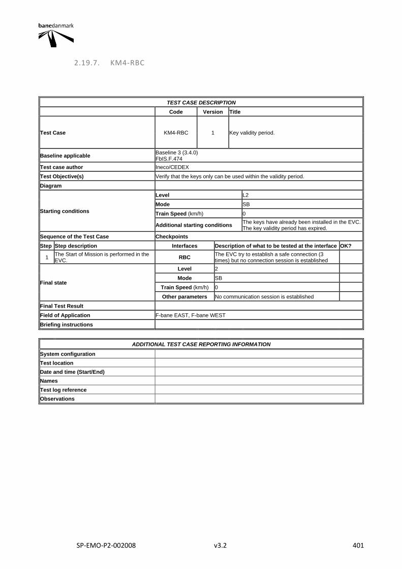
SP-EMO-P2-002008 v3.2 401
2.19.7. KM4-RBC
TEST CASE DESCRIPTION
Code Version Title
Test Case KM4-RBC 1 Key validity period.
Baseline applicable Baseline 3 (3.4.0) FbIS.F.474
Test case author Ineco/CEDEX
Test Objective(s) Verify that the keys only can be used within the validity period.
Diagram
Starting conditions
Level L2
Mode SB
Train Speed (km/h) 0
Additional starting conditions The keys have already been installed in the EVC. The key validity period has expired.
Sequence of the Test Case Checkpoints
Step Step description Interfaces Description of what to be tested at the interface OK?
1 The Start of Mission is performed in the EVC.
RBC The EVC try to establish a safe connection (3 times) but no connection session is established
Final state
Level 2
Mode SB
Train Speed (km/h) 0
Other parameters No communication session is established
Final Test Result
Field of Application F-bane EAST, F-bane WEST
Briefing instructions
ADDITIONAL TEST CASE REPORTING INFORMATION
System configuration
Test location
Date and time (Start/End)
Names
Test log reference
Observations
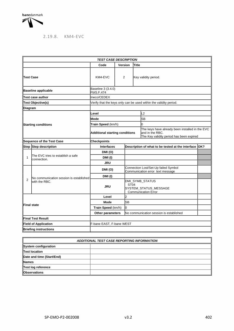
SP-EMO-P2-002008 v3.2 402
2.19.8. KM4-EVC
TEST CASE DESCRIPTION
Code Version Title
Test Case KM4-EVC 2 Key validity period.
Baseline applicable Baseline 3 (3.4.0) FbIS.F.474
Test case author Ineco/CEDEX
Test Objective(s) Verify that the keys only can be used within the validity period.
Diagram
Starting conditions
Level L2
Mode SB
Train Speed (km/h) 0
Additional starting conditions The keys have already been installed in the EVC and in the RBC. The Key validity period has been expired
Sequence of the Test Case Checkpoints
Step Step description Interfaces Description of what to be tested at the interface OK?
1 The EVC tries to establish a safe connection.
DMI (O)
DMI (I)
JRU
2 No communication session is established with the RBC.
DMI (O) Connection Lost/Set-Up failed Symbol Communication error text message
DMI (I)
JRU
DMI_SYMB_STATUS ST04 SYSTEM_STATUS_MESSAGE Communication Error
Final state
Level 2
Mode SB
Train Speed (km/h) 0
Other parameters No communication session is established
Final Test Result
Field of Application F-bane EAST, F-bane WEST
Briefing instructions
ADDITIONAL TEST CASE REPORTING INFORMATION
System configuration
Test location
Date and time (Start/End)
Names
Test log reference
Observations
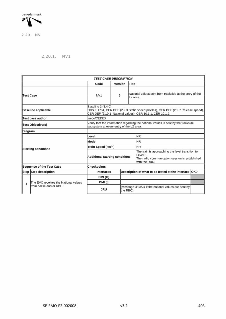
SP-EMO-P2-002008 v3.2 403
2.20. NV
2.20.1. NV1
TEST CASE DESCRIPTION
Code Version Title
Test Case NV1 3 National values sent from trackside at the entry of the L2 area.
Baseline applicable Baseline 3 (3.4.0) FbIS.F.1734, CER DEF (2.9.3 Static speed profiles), CER DEF (2.9.7 Release speed), CER DEF (2.10.1 National values), CER 10.1.1, CER 10.1.2
Test case author Ineco/CEDEX
Test Objective(s) Verify that the information regarding the national values is sent by the trackside subsystem at every entry of the L2 area.
Diagram
Starting conditions
Level NR
Mode NR
Train Speed (km/h) NR
Additional starting conditions
The train is approaching the level transition to Level 2. The radio communication session is established with the RBC.
Sequence of the Test Case Checkpoints
Step Step description Interfaces Description of what to be tested at the interface OK?
1 The EVC receives the National values from balise and/or RBC.
DMI (O)
DMI (I)
JRU (Message 3/33/24 if the national values are sent by the RBC)
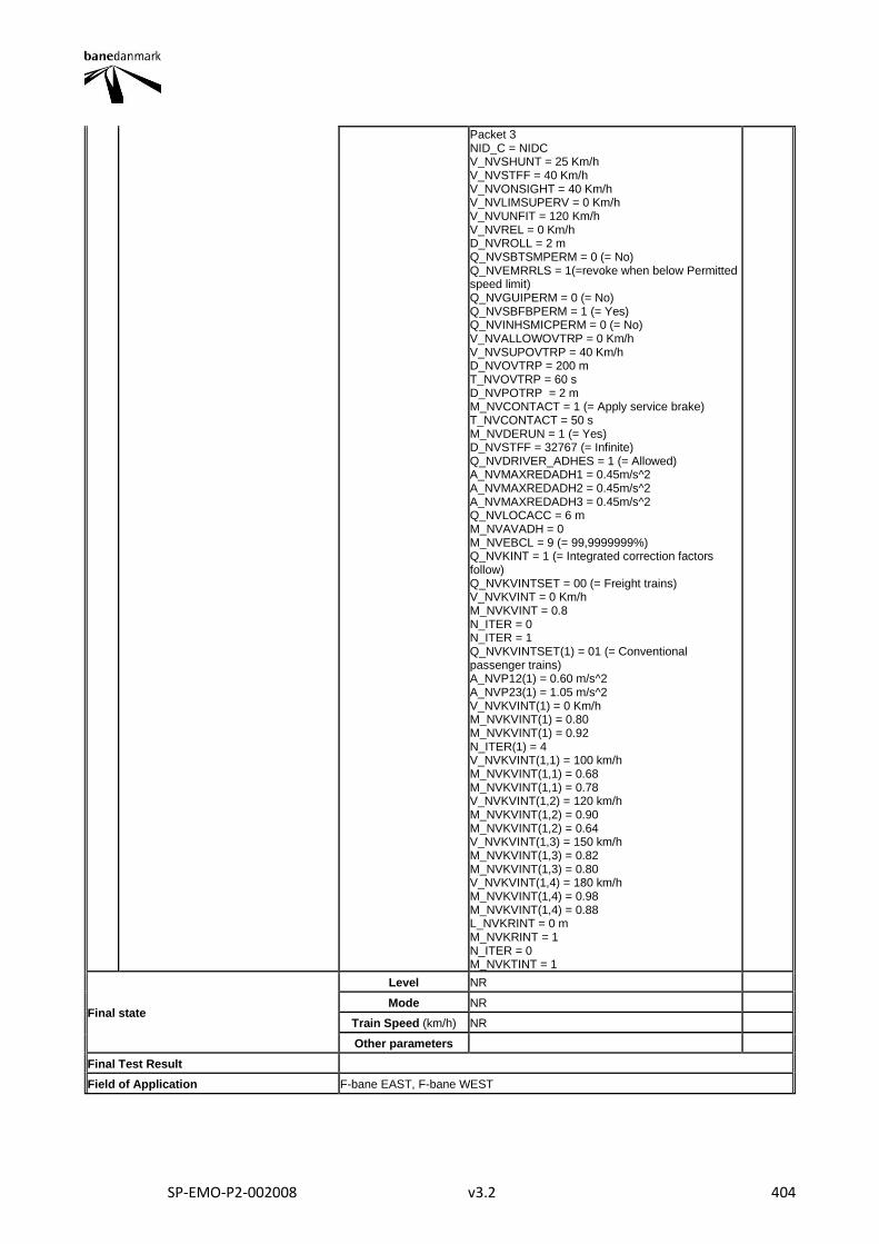
SP-EMO-P2-002008 v3.2 404
Packet 3 NID_C = NIDC V_NVSHUNT = 25 Km/h V_NVSTFF = 40 Km/h V_NVONSIGHT = 40 Km/h V_NVLIMSUPERV = 0 Km/h V_NVUNFIT = 120 Km/h V_NVREL = 0 Km/h D_NVROLL = 2 m Q_NVSBTSMPERM = 0 (= No) Q_NVEMRRLS = 1(=revoke when below Permitted speed limit) Q_NVGUIPERM = 0 (= No) Q_NVSBFBPERM = 1 (= Yes) Q_NVINHSMICPERM = 0 (= No) V_NVALLOWOVTRP = 0 Km/h V_NVSUPOVTRP = 40 Km/h D_NVOVTRP = 200 m T_NVOVTRP = 60 s D_NVPOTRP = 2 m M_NVCONTACT = 1 (= Apply service brake) T_NVCONTACT = 50 s M_NVDERUN = 1 (= Yes) D_NVSTFF = 32767 (= Infinite) Q_NVDRIVER_ADHES = 1 (= Allowed) A_NVMAXREDADH1 = 0.45m/s^2 A_NVMAXREDADH2 = 0.45m/s^2 A_NVMAXREDADH3 = 0.45m/s^2 Q_NVLOCACC = 6 m M_NVAVADH = 0 M_NVEBCL = 9 (= 99,9999999%) Q_NVKINT = 1 (= Integrated correction factors follow) Q_NVKVINTSET = 00 (= Freight trains) V_NVKVINT = 0 Km/h M_NVKVINT = 0.8 N_ITER = 0 N_ITER = 1 Q_NVKVINTSET(1) = 01 (= Conventional passenger trains) A_NVP12(1) = 0.60 m/s^2 A_NVP23(1) = 1.05 m/s^2 V_NVKVINT(1) = 0 Km/h M_NVKVINT(1) = 0.80 M_NVKVINT(1) = 0.92 N_ITER(1) = 4 V_NVKVINT(1,1) = 100 km/h M_NVKVINT(1,1) = 0.68 M_NVKVINT(1,1) = 0.78 V_NVKVINT(1,2) = 120 km/h M_NVKVINT(1,2) = 0.90 M_NVKVINT(1,2) = 0.64 V_NVKVINT(1,3) = 150 km/h M_NVKVINT(1,3) = 0.82 M_NVKVINT(1,3) = 0.80 V_NVKVINT(1,4) = 180 km/h M_NVKVINT(1,4) = 0.98 M_NVKVINT(1,4) = 0.88 L_NVKRINT = 0 m M_NVKRINT = 1 N_ITER = 0 M_NVKTINT = 1
Final state
Level NR
Mode NR
Train Speed (km/h) NR
Other parameters
Final Test Result
Field of Application F-bane EAST, F-bane WEST

SP-EMO-P2-002008 v3.2 405
Briefing instructions
Also verify that packet 3 is sent by the balise groups at repair shops and wherever there is a change in NID_C or similar parameters to ensure that all vehicles receive the proper national values when entering the ETCS level 2 infrastructure, or being restarted from repair or maintenance. For F-bane East NID_C = 345, for F-bane West NID_C = 344
ADDITIONAL TEST CASE REPORTING INFORMATION
System configuration
Test location
Date and time (Start/End)
Names
Test log reference
Observations
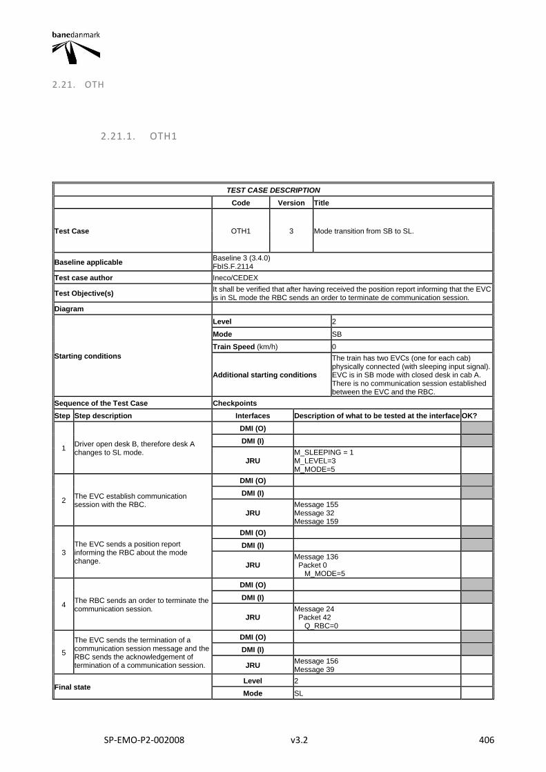
SP-EMO-P2-002008 v3.2 406
2.21. OTH
2.21.1. OTH1
TEST CASE DESCRIPTION
Code Version Title
Test Case OTH1 3 Mode transition from SB to SL.
Baseline applicable Baseline 3 (3.4.0) FbIS.F.2114
Test case author Ineco/CEDEX
Test Objective(s) It shall be verified that after having received the position report informing that the EVC is in SL mode the RBC sends an order to terminate de communication session.
Diagram
Starting conditions
Level 2
Mode SB
Train Speed (km/h) 0
Additional starting conditions
The train has two EVCs (one for each cab) physically connected (with sleeping input signal). EVC is in SB mode with closed desk in cab A. There is no communication session established between the EVC and the RBC.
Sequence of the Test Case Checkpoints
Step Step description Interfaces Description of what to be tested at the interface OK?
1 Driver open desk B, therefore desk A changes to SL mode.
DMI (O)
DMI (I)
JRU M_SLEEPING = 1 M_LEVEL=3 M_MODE=5
2 The EVC establish communication session with the RBC.
DMI (O)
DMI (I)
JRU Message 155 Message 32 Message 159
3 The EVC sends a position report informing the RBC about the mode change.
DMI (O)
DMI (I)
JRU Message 136 Packet 0 M_MODE=5
4 The RBC sends an order to terminate the communication session.
DMI (O)
DMI (I)
JRU Message 24 Packet 42 Q_RBC=0
5
The EVC sends the termination of a communication session message and the RBC sends the acknowledgement of termination of a communication session.
DMI (O)
DMI (I)
JRU Message 156 Message 39
Final state Level 2
Mode SL
SP-EMO-P2-002008 v3.2 407
Train Speed (km/h) 0
Other parameters
Final Test Result
Field of Application F-bane EAST, F-bane WEST
Briefing instructions In order to perform this TC in the lab it may be needed to execute specific actions other than opening a different desk in another cab to trigger the sleeping input signal.
ADDITIONAL TEST CASE REPORTING INFORMATION
System configuration
Test location
Date and time (Start/End)
Names
Test log reference
Observations
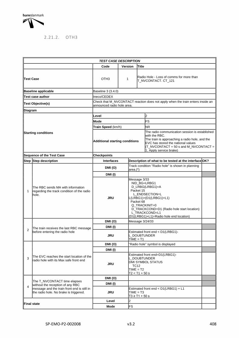
SP-EMO-P2-002008 v3.2 408
2.21.2. OTH3
TEST CASE DESCRIPTION
Code Version Title
Test Case OTH3 1 Radio Hole - Loss of comms for more than T_NVCONTACT. CT_121
Baseline applicable Baseline 3 (3.4.0)
Test case author Ineco/CEDEX
Test Objective(s) Check that M_NVCONTACT reaction does not apply when the train enters inside an announced radio hole area.
Diagram
Starting conditions
Level 2
Mode FS
Train Speed (km/h) NR
Additional starting conditions
The radio communication session is established with the RBC. The train is approaching a radio hole, and the EVC has stored the national values (T_NVCONTACT = 50 s and M_NVCONTACT = 1, Apply service brake)
Sequence of the Test Case Checkpoints
Step Step description Interfaces Description of what to be tested at the interface OK?
1 The RBC sends MA with information regarding the track condition of the radio hole.
DMI (O) Track condition "Radio hole" is shown in planning area.(*)
DMI (I)
JRU
Message 3/33 NID_BG=LRBG1 D_LRBG(LRBG1)=A Packet 15 L_ENDSECTION=L L(LRBG1)>(D1(LRBG1)+L1) Packet 68 Q_TRACKINIT=0 D_TRACKCOND=D1 (Radio hole start location) L_TRACKCOND=L1 (D1(LRBG1)+L1)=Radio hole end location)
2 The train receives the last RBC message before entering the radio hole
DMI (O) Message 3/24/33
DMI (I)
JRU Estimated front end < D1(LRBG1)-L_DOUBTUNDER TIME = T1
3 The EVC reaches the start location of the radio hole with its Max safe front end
DMI (O) "Radio hole" symbol is displayed
DMI (I)
JRU
Estimated front end=D1(LRBG1)-L_DOUBTUNDER DMI SYMBOL STATUS TC12 TIME = T2 T2 < T1 + 50 s
4
The T_NVCONTACT time elapses without the reception of any RBC message and the train front end is still in the radio hole. No brake is triggered.
DMI (O)
DMI (I)
JRU Estimated front end < D1(LRBG1) + L1 TIME = T3 T3 ≥ T1 + 50 s
Final state Level 2
Mode FS
SP-EMO-P2-002008 v3.2 409
Train Speed (km/h) NR
Other parameters
Final Test Result
Field of Application F-bane EAST, F-bane WEST
Briefing instructions
ADDITIONAL TEST CASE REPORTING INFORMATION
System configuration
Test location
Date and time (Start/End)
Names
Test log reference
Observations
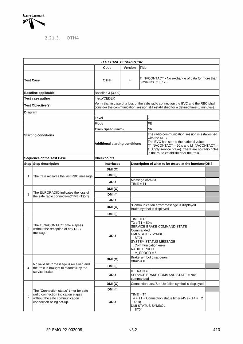
SP-EMO-P2-002008 v3.2 410
2.21.3. OTH4
TEST CASE DESCRIPTION
Code Version Title
Test Case OTH4 4 T_NVCONTACT - No exchange of data for more than 5 minutes. CT_173
Baseline applicable Baseline 3 (3.4.0)
Test case author Ineco/CEDEX
Test Objective(s) Verify that in case of a loss of the safe radio connection the EVC and the RBC shall consider the communication session still established for a defined time (5 minutes).
Diagram
Starting conditions
Level 2
Mode FS
Train Speed (km/h) NR
Additional starting conditions
The radio communication session is established with the RBC. The EVC has stored the national values (T_NVCONTACT = 50 s and M_NVCONTACT = 1, Apply service brake). There are no radio holes in the route established for the train.
Sequence of the Test Case Checkpoints
Step Step description Interfaces Description of what to be tested at the interface OK?
1 The train receives the last RBC message
DMI (O)
DMI (I)
JRU Message 3/24/33 TIME = T1
2 The EURORADIO indicates the loss of the safe radio connection(TIME=T2)(*)
DMI (O)
DMI (I)
JRU
3 The T_NVCONTACT time elapses without the reception of any RBC message.
DMI (O) "Communication error" message is displayed Brake symbol is displayed
DMI (I)
JRU
TIME = T3 T3 ≥ T1 + 50 s SERVICE BRAKE COMMAND STATE = Commanded DMI STATUS SYMBOL ST01 SYSTEM STATUS MESSAGE Communication error RADIO ERROR M_ERROR = 5
4 No valid RBC message is received and the train is brought to standstill by the service brake.
DMI (O) Brake symbol disappears Vtrain = 0
DMI (I)
JRU V_TRAIN = 0 SERVICE BRAKE COMMAND STATE = Not commanded
5
The “Connection status” timer for safe radio connection indication elapse, without the safe communication connection being set-up.
DMI (O) Connection Lost/Set-Up failed symbol is displayed
DMI (I)
JRU
TIME = T4 T4 > T1 + Connection status timer (45 s) (T4 = T2 + 45 s) DMI STATUS SYMBOL ST04
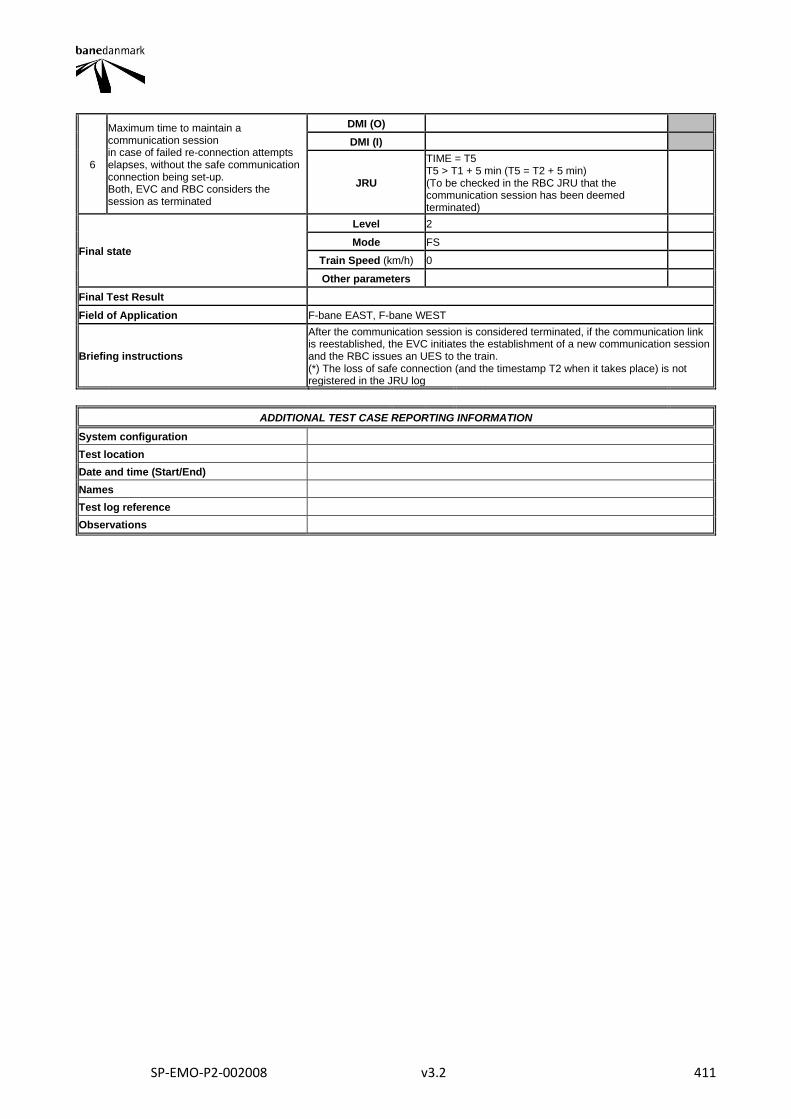
SP-EMO-P2-002008 v3.2 411
6
Maximum time to maintain a communication session in case of failed re-connection attempts elapses, without the safe communication connection being set-up. Both, EVC and RBC considers the session as terminated
DMI (O)
DMI (I)
JRU
TIME = T5 T5 > T1 + 5 min (T5 = T2 + 5 min) (To be checked in the RBC JRU that the communication session has been deemed terminated)
Final state
Level 2
Mode FS
Train Speed (km/h) 0
Other parameters
Final Test Result
Field of Application F-bane EAST, F-bane WEST
Briefing instructions
After the communication session is considered terminated, if the communication link is reestablished, the EVC initiates the establishment of a new communication session and the RBC issues an UES to the train. (*) The loss of safe connection (and the timestamp T2 when it takes place) is not registered in the JRU log
ADDITIONAL TEST CASE REPORTING INFORMATION
System configuration
Test location
Date and time (Start/End)
Names
Test log reference
Observations
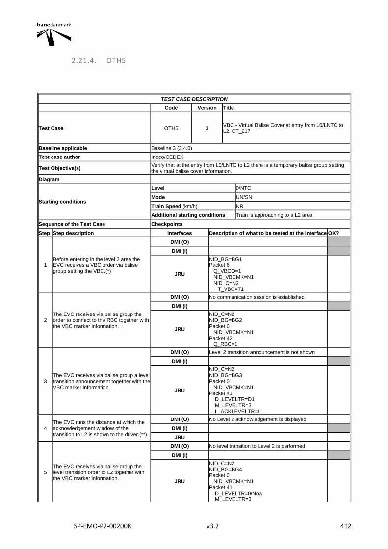
SP-EMO-P2-002008 v3.2 412
2.21.4. OTH5
TEST CASE DESCRIPTION
Code Version Title
Test Case OTH5 3 VBC - Virtual Balise Cover at entry from L0/LNTC to L2. CT_217
Baseline applicable Baseline 3 (3.4.0)
Test case author Ineco/CEDEX
Test Objective(s) Verify that at the entry from L0/LNTC to L2 there is a temporary balise group setting the virtual balise cover information.
Diagram
Starting conditions
Level 0/NTC
Mode UN/SN
Train Speed (km/h) NR
Additional starting conditions Train is approaching to a L2 area
Sequence of the Test Case Checkpoints
Step Step description Interfaces Description of what to be tested at the interface OK?
1 Before entering in the level 2 area the EVC receives a VBC order via balise group setting the VBC.(*)
DMI (O)
DMI (I)
JRU
NID_BG=BG1 Packet 6 Q_VBCO=1 NID_VBCMK=N1 NID_C=N2 T_VBC=T1
2 The EVC receives via balise group the order to connect to the RBC together with the VBC marker information.
DMI (O) No communication session is established
DMI (I)
JRU
NID_C=N2 NID_BG=BG2 Packet 0 NID_VBCMK=N1 Packet 42 Q_RBC=1
3 The EVC receives via balise group a level transition announcement together with the VBC marker information
DMI (O) Level 2 transition announcement is not shown
DMI (I)
JRU
NID_C=N2 NID_BG=BG3 Packet 0 NID_VBCMK=N1 Packet 41 D_LEVELTR=D1 M_LEVELTR=3 L_ACKLEVELTR=L1
4 The EVC runs the distance at which the acknowledgement window of the transition to L2 is shown to the driver.(**)
DMI (O) No Level 2 acknowledgement is displayed
DMI (I)
JRU
5 The EVC receives via balise group the level transition order to L2 together with the VBC marker information.
DMI (O) No level transition to Level 2 is performed
DMI (I)
JRU
NID_C=N2 NID_BG=BG4 Packet 0 NID_VBCMK=N1 Packet 41 D_LEVELTR=0/Now M_LEVELTR=3
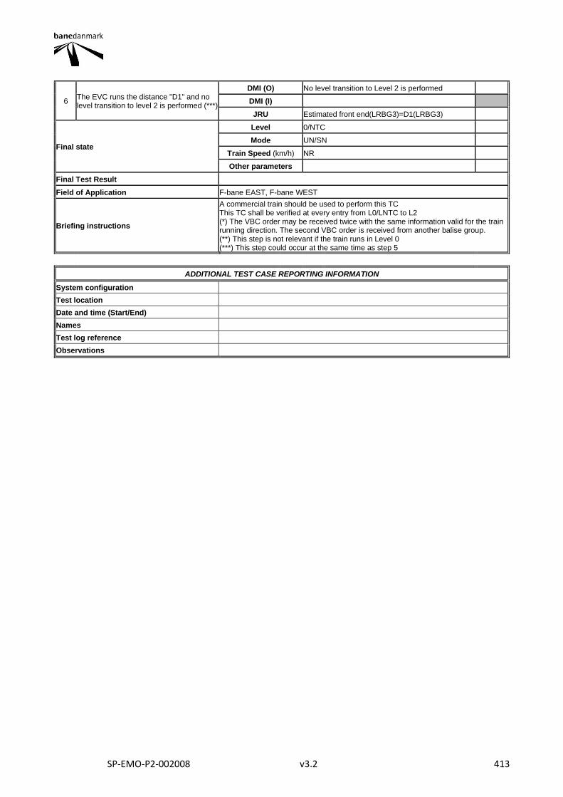
SP-EMO-P2-002008 v3.2 413
6 The EVC runs the distance "D1" and no level transition to level 2 is performed (***)
DMI (O) No level transition to Level 2 is performed
DMI (I)
JRU Estimated front end(LRBG3)=D1(LRBG3)
Final state
Level 0/NTC
Mode UN/SN
Train Speed (km/h) NR
Other parameters
Final Test Result
Field of Application F-bane EAST, F-bane WEST
Briefing instructions
A commercial train should be used to perform this TC This TC shall be verified at every entry from L0/LNTC to L2 (*) The VBC order may be received twice with the same information valid for the train running direction. The second VBC order is received from another balise group. (**) This step is not relevant if the train runs in Level 0 (***) This step could occur at the same time as step 5
ADDITIONAL TEST CASE REPORTING INFORMATION
System configuration
Test location
Date and time (Start/End)
Names
Test log reference
Observations
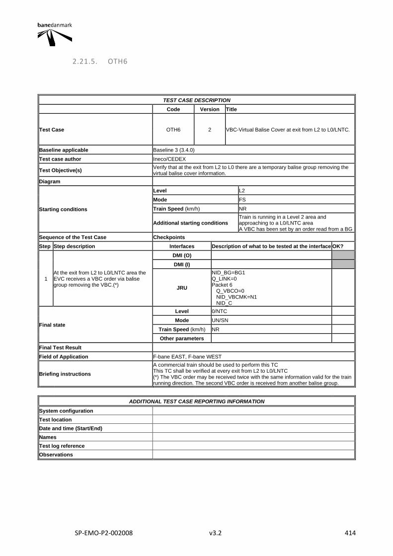
SP-EMO-P2-002008 v3.2 414
2.21.5. OTH6
TEST CASE DESCRIPTION
Code Version Title
Test Case OTH6 2 VBC-Virtual Balise Cover at exit from L2 to L0/LNTC.
Baseline applicable Baseline 3 (3.4.0)
Test case author Ineco/CEDEX
Test Objective(s) Verify that at the exit from L2 to L0 there are a temporary balise group removing the virtual balise cover information.
Diagram
Starting conditions
Level L2
Mode FS
Train Speed (km/h) NR
Additional starting conditions Train is running in a Level 2 area and approaching to a L0/LNTC area A VBC has been set by an order read from a BG
Sequence of the Test Case Checkpoints
Step Step description Interfaces Description of what to be tested at the interface OK?
1 At the exit from L2 to L0/LNTC area the EVC receives a VBC order via balise group removing the VBC.(*)
DMI (O)
DMI (I)
JRU
NID_BG=BG1 Q_LINK=0 Packet 6 Q_VBCO=0 NID_VBCMK=N1 NID_C
Final state
Level 0/NTC
Mode UN/SN
Train Speed (km/h) NR
Other parameters
Final Test Result
Field of Application F-bane EAST, F-bane WEST
Briefing instructions
A commercial train should be used to perform this TC This TC shall be verified at every exit from L2 to L0/LNTC (*) The VBC order may be received twice with the same information valid for the train running direction. The second VBC order is received from another balise group.
ADDITIONAL TEST CASE REPORTING INFORMATION
System configuration
Test location
Date and time (Start/End)
Names
Test log reference
Observations
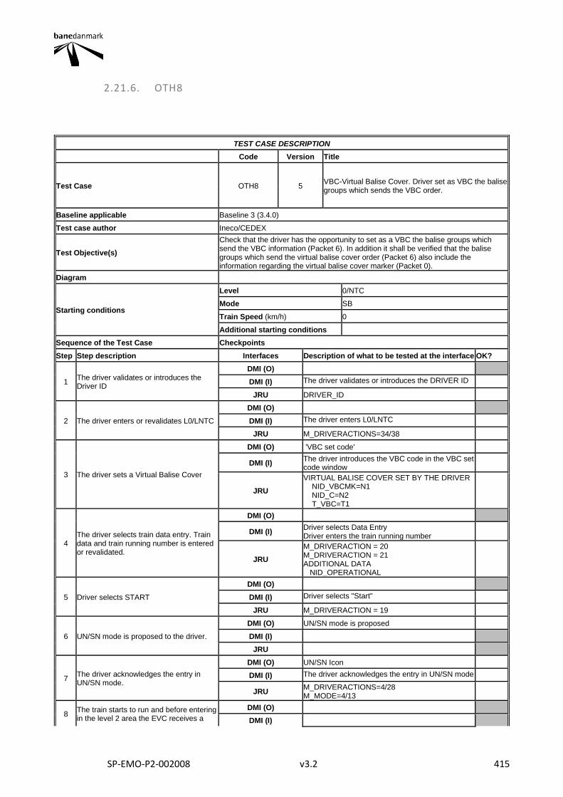
SP-EMO-P2-002008 v3.2 415
2.21.6. OTH8
TEST CASE DESCRIPTION
Code Version Title
Test Case OTH8 5 VBC-Virtual Balise Cover. Driver set as VBC the balise groups which sends the VBC order.
Baseline applicable Baseline 3 (3.4.0)
Test case author Ineco/CEDEX
Test Objective(s)
Check that the driver has the opportunity to set as a VBC the balise groups which send the VBC information (Packet 6). In addition it shall be verified that the balise groups which send the virtual balise cover order (Packet 6) also include the information regarding the virtual balise cover marker (Packet 0).
Diagram
Starting conditions
Level 0/NTC
Mode SB
Train Speed (km/h) 0
Additional starting conditions
Sequence of the Test Case Checkpoints
Step Step description Interfaces Description of what to be tested at the interface OK?
1 The driver validates or introduces the Driver ID
DMI (O)
DMI (I) The driver validates or introduces the DRIVER ID
JRU DRIVER_ID
2 The driver enters or revalidates L0/LNTC
DMI (O)
DMI (I) The driver enters L0/LNTC
JRU M_DRIVERACTIONS=34/38
3 The driver sets a Virtual Balise Cover
DMI (O) 'VBC set code'
DMI (I) The driver introduces the VBC code in the VBC set code window
JRU
VIRTUAL BALISE COVER SET BY THE DRIVER NID_VBCMK=N1 NID_C=N2 T_VBC=T1
4 The driver selects train data entry. Train data and train running number is entered or revalidated.
DMI (O)
DMI (I) Driver selects Data Entry Driver enters the train running number
JRU
M_DRIVERACTION = 20 M_DRIVERACTION = 21 ADDITIONAL DATA NID_OPERATIONAL
5 Driver selects START
DMI (O)
DMI (I) Driver selects "Start"
JRU M_DRIVERACTION = 19
6 UN/SN mode is proposed to the driver.
DMI (O) UN/SN mode is proposed
DMI (I)
JRU
7 The driver acknowledges the entry in UN/SN mode.
DMI (O) UN/SN Icon
DMI (I) The driver acknowledges the entry in UN/SN mode
JRU M_DRIVERACTIONS=4/28 M_MODE=4/13
8 The train starts to run and before entering in the level 2 area the EVC receives a
DMI (O)
DMI (I)
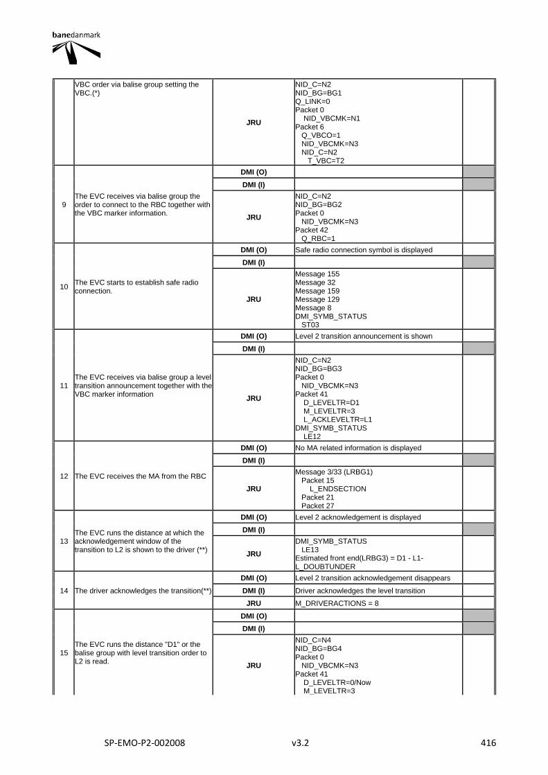
SP-EMO-P2-002008 v3.2 416
VBC order via balise group setting the VBC.(*)
JRU
NID_C=N2 NID_BG=BG1 Q_LINK=0 Packet 0 NID_VBCMK=N1 Packet 6 Q_VBCO=1 NID_VBCMK=N3 NID_C=N2 T_VBC=T2
9 The EVC receives via balise group the order to connect to the RBC together with the VBC marker information.
DMI (O)
DMI (I)
JRU
NID_C=N2 NID_BG=BG2 Packet 0 NID_VBCMK=N3 Packet 42 Q_RBC=1
10 The EVC starts to establish safe radio connection.
DMI (O) Safe radio connection symbol is displayed
DMI (I)
JRU
Message 155 Message 32 Message 159 Message 129 Message 8 DMI_SYMB_STATUS ST03
11 The EVC receives via balise group a level transition announcement together with the VBC marker information
DMI (O) Level 2 transition announcement is shown
DMI (I)
JRU
NID_C=N2 NID_BG=BG3 Packet 0 NID_VBCMK=N3 Packet 41 D_LEVELTR=D1 M_LEVELTR=3 L_ACKLEVELTR=L1 DMI_SYMB_STATUS LE12
12 The EVC receives the MA from the RBC
DMI (O) No MA related information is displayed
DMI (I)
JRU
Message 3/33 (LRBG1) Packet 15 L_ENDSECTION Packet 21 Packet 27
13 The EVC runs the distance at which the acknowledgement window of the transition to L2 is shown to the driver (**)
DMI (O) Level 2 acknowledgement is displayed
DMI (I)
JRU
DMI_SYMB_STATUS LE13 Estimated front end(LRBG3) = D1 - L1-L_DOUBTUNDER
14 The driver acknowledges the transition(**)
DMI (O) Level 2 transition acknowledgement disappears
DMI (I) Driver acknowledges the level transition
JRU M_DRIVERACTIONS = 8
15 The EVC runs the distance "D1" or the balise group with level transition order to L2 is read.
DMI (O)
DMI (I)
JRU
NID_C=N4 NID_BG=BG4 Packet 0 NID_VBCMK=N3 Packet 41 D_LEVELTR=0/Now M_LEVELTR=3
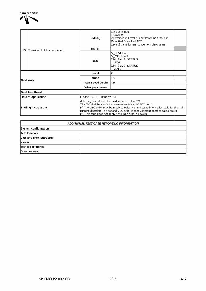
SP-EMO-P2-002008 v3.2 417
16 Transition to L2 is performed.
DMI (O)
Level 2 symbol FS symbol Vpermitted in Level 2 is not lower than the last Permitted Speed in LNTC. Level 2 transition announcement disappears
DMI (I)
JRU
M_LEVEL = 3 M_MODE = 0 DMI_SYMB_STATUS LE04 DMI_SYMB_STATUS MO11
Final state
Level 2
Mode FS
Train Speed (km/h) NR
Other parameters
Final Test Result
Field of Application F-bane EAST, F-bane WEST
Briefing instructions
A testing train should be used to perform this TC This TC shall be verified at every entry from L0/LNTC to L2 (*) The VBC order may be received twice with the same information valid for the train running direction. The second VBC order is received from another balise group. (**) This step does not apply if the train runs in Level 0
ADDITIONAL TEST CASE REPORTING INFORMATION
System configuration
Test location
Date and time (Start/End)
Names
Test log reference
Observations
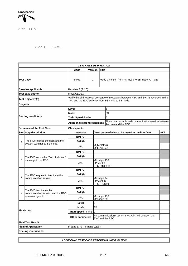
SP-EMO-P2-002008 v3.2 418
2.22. EOM
2.22.1. EOM1
TEST CASE DESCRIPTION
Code Version Title
Test Case EoM1 1 Mode transition from FS mode to SB mode. CT_027
Baseline applicable Baseline 3 (3.4.0)
Test case author Ineco/CEDEX
Test Objective(s) Verify the bi-directional exchange of messages between RBC and EVC is recorded in the JRU and the EVC switches from FS mode to SB mode.
Diagram
Starting conditions
Level 2
Mode FS
Train Speed (km/h) 0
Additional starting conditions There is an established communication session between the train and the RBC.
Sequence of the Test Case Checkpoints
Step Step description Interfaces Description of what to be tested at the interface OK?
1 The driver closes the desk and the system switches to SB mode.
DMI (O)
DMI (I)
JRU M_MODE=6 M_LEVEL=3
2 The EVC sends the "End of Mission" message to the RBC.
DMI (O)
DMI (I)
JRU Message 150 Packet 0 M_MODE=6
3 The RBC request to terminate the communication session.
DMI (O)
DMI (I)
JRU Message 24 Packet 42 Q_RBC=0
4 The EVC terminates the communication session and the RBC acknowledges it.
DMI (O)
DMI (I)
JRU Message 156 Message 39
Final state
Level 2
Mode SB
Train Speed (km/h) 0
Other parameters No communication session is established between the EVC and the RBC
Final Test Result
Field of Application F-bane EAST, F-bane WEST
Briefing instructions
ADDITIONAL TEST CASE REPORTING INFORMATION
SP-EMO-P2-002008 v3.2 419
System configuration
Test location
Date and time (Start/End)
Names
Test log reference
Observations
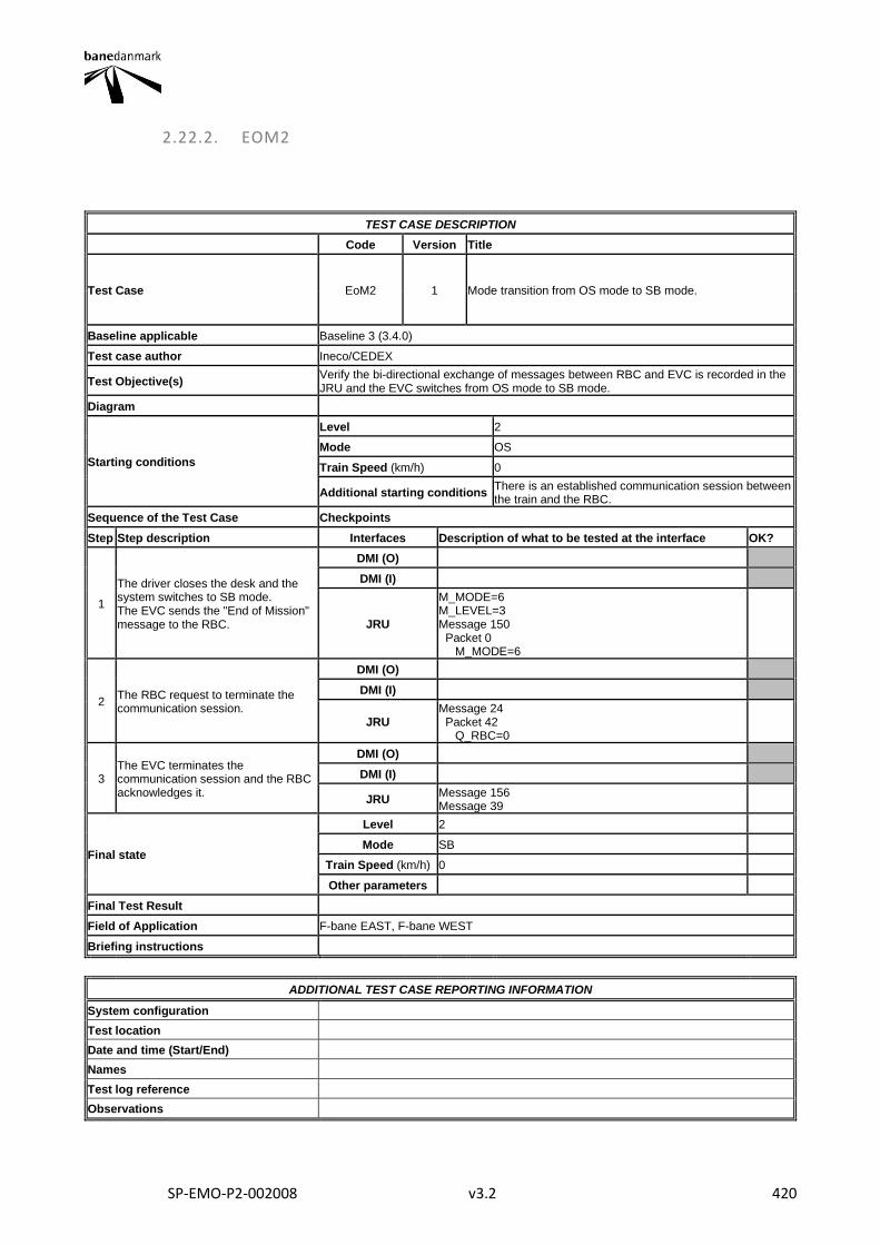
SP-EMO-P2-002008 v3.2 420
2.22.2. EOM2
TEST CASE DESCRIPTION
Code Version Title
Test Case EoM2 1 Mode transition from OS mode to SB mode.
Baseline applicable Baseline 3 (3.4.0)
Test case author Ineco/CEDEX
Test Objective(s) Verify the bi-directional exchange of messages between RBC and EVC is recorded in the JRU and the EVC switches from OS mode to SB mode.
Diagram
Starting conditions
Level 2
Mode OS
Train Speed (km/h) 0
Additional starting conditions There is an established communication session between the train and the RBC.
Sequence of the Test Case Checkpoints
Step Step description Interfaces Description of what to be tested at the interface OK?
1
The driver closes the desk and the system switches to SB mode. The EVC sends the "End of Mission" message to the RBC.
DMI (O)
DMI (I)
JRU
M_MODE=6 M_LEVEL=3 Message 150 Packet 0 M_MODE=6
2 The RBC request to terminate the communication session.
DMI (O)
DMI (I)
JRU Message 24 Packet 42 Q_RBC=0
3 The EVC terminates the communication session and the RBC acknowledges it.
DMI (O)
DMI (I)
JRU Message 156 Message 39
Final state
Level 2
Mode SB
Train Speed (km/h) 0
Other parameters
Final Test Result
Field of Application F-bane EAST, F-bane WEST
Briefing instructions
ADDITIONAL TEST CASE REPORTING INFORMATION
System configuration
Test location
Date and time (Start/End)
Names
Test log reference
Observations

SP-EMO-P2-002008 v3.2 421