Environmental Assessment for the - Patrick Space Force Base
520
DRAFT Environmental Assessment for the Reconstitution and Enhancement of Space Launch Complex 20 Multi-User Launch Operations at Cape Canaveral Air Force Station Florida Prepared for Space Florida September 2020
-
Upload
khangminh22 -
Category
Documents
-
view
1 -
download
0
Transcript of Environmental Assessment for the - Patrick Space Force Base

DRAFT Environmental Assessment for the
Reconstitution and Enhancement of Space Launch Complex 20 Multi-User Launch Operations at Cape Canaveral Air Force Station
Florida
Prepared for Space Florida
September 2020

This page is intentionally left blank.

Environmental Assessment Reconstitution and Enhancement of Launch Complex 20 Multi-user Launch Operations
Table of Contents i
Table of Contents 1
EXECUTIVE SUMMARY ........................................................................................................................... xiii 2
1.0 Purpose and Need for the Proposed Action .............................................................................. 1-1 3
1.1 Introduction ................................................................................................................ 1-1 4
1.2 Location and Background ............................................................................................ 1-2 5
1.3 Purpose and Need for the Proposed Action ................................................................. 1-7 6
1.4 Scope of the Environmental Assessment ..................................................................... 1-8 7
1.4.1 Lead and Cooperating Agency Actions ............................................................. 1-8 8
2.0 Description of the Proposed Action and Alternatives ............................................................... 2-1 9
2.1 Proposed Action .......................................................................................................... 2-1 10
2.1.1 Proposed Location ........................................................................................... 2-1 11
2.1.2 Launch Vehicles ............................................................................................... 2-2 12
2.1.3 Launch Site Operations .................................................................................... 2-5 13
2.1.4 Launch Trajectory ............................................................................................ 2-8 14
2.1.5 Frequency of Launches .................................................................................... 2-8 15
2.1.6 Vehicle Assembly and Transportation .............................................................. 2-9 16
2.1.7 Support Facilities ............................................................................................. 2-9 17
2.2 Alternatives Considered ............................................................................................ 2-13 18
2.2.1 No Action Alternative..................................................................................... 2-14 19
2.2.2 Alternatives Considered but Eliminated from Further Consideration .............. 2-14 20
2.2.3 Preferred Action Alternative .......................................................................... 2-14 21
3.0 Affected Environment .............................................................................................................. 3-1 22
3.1 Land Use/Visual Resources .......................................................................................... 3-1 23
3.2 Noise ........................................................................................................................... 3-3 24
3.2.1 General Description ......................................................................................... 3-3 25
3.2.2 Ambient Noise Levels ....................................................................................... 3-4 26
3.2.3 Construction Related Noise Description and Considerations ............................ 3-4 27
3.2.4 Launch Operations Related Noise Description and Considerations.................... 3-4 28
3.3 Biological Resources .................................................................................................... 3-5 29
3.3.1 Vegetation ....................................................................................................... 3-6 30
3.3.2 Wildlife ............................................................................................................ 3-9 31
3.4 Cultural Resources ..................................................................................................... 3-24 32
3.4.1 Archaeological and Historic Resources ........................................................... 3-24 33

Reconstitution and Enhancement of Launch Environmental Assessment Complex 20 Multi-user Launch Operations
ii Table of Contents
3.5 Air Quality ................................................................................................................. 3-27 1
3.6 Climate ...................................................................................................................... 3-28 2
3.6.1 Regional Conditions ....................................................................................... 3-28 3
3.6.2 Global Climate ............................................................................................... 3-29 4
3.7 Hazardous Materials and Hazardous Waste ............................................................... 3-29 5
3.7.1 Hazardous Material and Hazardous Waste ..................................................... 3-29 6
3.7.2 Solid Waste .................................................................................................... 3-32 7
3.7.3 Installation Restoration Program ................................................................... 3-32 8
3.7.4 Pollution Prevention ...................................................................................... 3-34 9
3.8 Water Resources ....................................................................................................... 3-35 10
3.8.1 Surface Waters .............................................................................................. 3-35 11
3.8.2 Groundwater ................................................................................................. 3-35 12
3.8.3 Wetlands ....................................................................................................... 3-35 13
3.8.4 Floodplains .................................................................................................... 3-36 14
3.9 Geology and Soils ...................................................................................................... 3-36 15
3.10 Transportation .......................................................................................................... 3-41 16
3.10.1 Regional Access ............................................................................................. 3-41 17
3.10.2 Local Access ................................................................................................... 3-41 18
3.11 Utilities ...................................................................................................................... 3-43 19
3.11.1 Water Supply, Treatment, and Distribution ................................................... 3-43 20
3.11.2 Wastewater Collection and Treatment ........................................................... 3-43 21
3.11.3 Electrical Supply ............................................................................................. 3-44 22
3.11.4 Natural Resources and Energy Supply ............................................................ 3-44 23
3.11.5 Stormwater Collection ................................................................................... 3-44 24
3.12 Health and Safety ...................................................................................................... 3-44 25
3.13 Socioeconomics ......................................................................................................... 3-45 26
3.14 Environmental Justice................................................................................................ 3-46 27
3.15 Section 4(f) Properties ............................................................................................... 3-46 28
4.0 Environmental Consequences .................................................................................................. 4-1 29
4.1 Land Use/Visual Resources .......................................................................................... 4-2 30
4.1.1 Proposed Action............................................................................................... 4-2 31
4.1.2 No-Action Alternative ...................................................................................... 4-3 32

Environmental Assessment Reconstitution and Enhancement of Launch Complex 20 Multi-user Launch Operations
Table of Contents iii
4.2 Noise ........................................................................................................................... 4-3 1
4.2.1 Proposed Action .............................................................................................. 4-3 2
4.2.2 No-Action Alternative ...................................................................................... 4-6 3
4.3 Biological Resources .................................................................................................... 4-6 4
4.3.1 Vegetation ....................................................................................................... 4-7 5
4.3.2 Wildlife and Migratory Birds ............................................................................ 4-7 6
4.3.3 Threatened and Endangered Species ............................................................. 4-10 7
4.3.4 Florida Scrub-Jay ............................................................................................ 4-12 8
4.4 Cultural Resources ..................................................................................................... 4-22 9
4.4.1 Proposed Action ............................................................................................ 4-22 10
4.4.2 No-Action Alternative .................................................................................... 4-23 11
4.5 Air Quality ................................................................................................................. 4-24 12
4.5.1 Proposed Action ............................................................................................ 4-24 13
4.5.1.1 Construction .................................................................................................. 4-24 14
4.5.1.2 Operations ..................................................................................................... 4-24 15
4.5.1.3 Launch Vehicles ............................................................................................. 4-25 16
4.5.2 No-Action Alternative .................................................................................... 4-26 17
4.6 Climate ...................................................................................................................... 4-26 18
4.6.1 Proposed Action ............................................................................................ 4-26 19
4.6.2 No-Action Alternative .................................................................................... 4-28 20
4.7 Hazardous Materials, Hazardous Waste, and solid waste ........................................... 4-28 21
4.7.1 Proposed Action ............................................................................................ 4-28 22
4.8 Water Resources ....................................................................................................... 4-29 23
4.8.1 Proposed Action ............................................................................................ 4-30 24
4.9 Geology and Soils ...................................................................................................... 4-31 25
4.9.1 Proposed Action ............................................................................................ 4-32 26
4.9.2 No-Action Alternative .................................................................................... 4-32 27
4.10 Transportation .......................................................................................................... 4-32 28
4.10.1 Proposed Action ............................................................................................ 4-32 29
4.10.2 No-Action Alternative .................................................................................... 4-33 30
4.11 Utilities ...................................................................................................................... 4-33 31
4.11.1 Proposed Action ............................................................................................ 4-33 32
4.11.2 No-Action Alternative .................................................................................... 4-34 33
Reconstitution and Enhancement of Launch Environmental Assessment Complex 20 Multi-user Launch Operations
iv Table of Contents
4.12 Health and Safety ...................................................................................................... 4-35 1
4.12.1 Proposed Action ............................................................................................ 4-35 2
4.12.2 No-Action Alternative .................................................................................... 4-40 3
4.13 Socioeconomics ......................................................................................................... 4-40 4
4.13.1 Proposed Action ............................................................................................ 4-40 5
4.13.2 No-Action Alternative .................................................................................... 4-41 6
4.14 Environmental Justice................................................................................................ 4-41 7
4.14.1 Proposed Action ............................................................................................ 4-41 8
4.14.2 No-Action Alternative .................................................................................... 4-42 9
4.15 Section 4(f) Properties ............................................................................................... 4-42 10
4.15.1 Proposed Action ............................................................................................ 4-42 11
4.15.2 No-Action Alternative .................................................................................... 4-43 12
5.0 Cumulative Impacts ................................................................................................................. 5-1 13
5.1 Definition of Cumulative IMpacts ................................................................................ 5-1 14
5.2 Actions Affecting Resources of Concern ....................................................................... 5-1 15
5.2.1 Past Actions ..................................................................................................... 5-2 16
5.2.2 Present and Reasonably Foreseeable Actions ................................................... 5-2 17
5.3 Cumulative Impact Analysis on Resource Areas ........................................................... 5-3 18
5.3.1 Land Use/Visual Resources .............................................................................. 5-3 19
5.3.2 Noise ............................................................................................................... 5-4 20
5.3.3 Biological Resources ........................................................................................ 5-4 21
5.3.4 Cultural Resources ........................................................................................... 5-5 22
5.3.5 Air Quality........................................................................................................ 5-5 23
5.3.6 Climate ............................................................................................................ 5-6 24
5.3.7 Hazardous Materials and Hazardous Waste ..................................................... 5-6 25
5.3.8 Water Resources.............................................................................................. 5-6 26
5.3.9 Geology and Soils ............................................................................................. 5-7 27
5.3.10 Transportation ................................................................................................. 5-7 28
5.3.11 Utilities ............................................................................................................ 5-7 29
5.3.12 Health and Safety ............................................................................................ 5-8 30
5.3.13 Socioeconomics ............................................................................................... 5-8 31
5.3.14 Environmental Justice ...................................................................................... 5-9 32
5.3.15 Section 4(f) Properties ..................................................................................... 5-9 33

Environmental Assessment Reconstitution and Enhancement of Launch Complex 20 Multi-user Launch Operations
Table of Contents v
6.0 Persons and Agencies Contacted .............................................................................................. 6-1 1
7.0 List of Preparers ....................................................................................................................... 7-1 2
8.0 References ............................................................................................................................... 8-1 3
4
List of Tables 5
Table 2-1 Existing SLC-20 Facilities .............................................................................................. 2-1 6
Table 2-2 Launch Vehicle Specifications ...................................................................................... 2-2 7
Table 2-3 Maximum Potential Propellant Quantities – Central Pad ............................................. 2-3 8
Table 2-4 Maximum Potential Propellant Quantities – Concept B Variant 1 ................................. 2-4 9
Table 2-5 Maximum Potential Propellant Quantities – Concept B Variant 2 ................................. 2-4 10
Table 2-6 Maximum Potential Propellant Quantities – Concept B Variant 3 ................................. 2-5 11
Table 2-7 Transportation Route from Exploration Park to SLC-20* .............................................. 2-9 12
Table 2-8 Support Facility Construction Requirements .............................................................. 2-12 13
Table 3-1 Noise Descriptions and Definitions .............................................................................. 3-3 14
Table 3-2 Summary of Natural Vegetation Communities on CCAFS ............................................. 3-8 15
Table 3-3 Protected Species Fauna Found in the Vicinity of the Proposed Action ...................... 3-11 16
Table 3-4 Federal National Ambient Air Quality Standards ........................................................ 3-27 17
Table 3-5 History of Actual Annual Emissions (Tons per Year) at CCAFS ..................................... 3-28 18
Table 3-6 Brevard County Population Data................................................................................ 3-45 19
Table 3-7 Brevard County Racial Distribution ............................................................................ 3-46 20
Table 4-1 Summary of Potential Impacts to Federally Listed Wildlife Species for 21 Proposed Action ........................................................................................................ 4-10 22
Table 5-1 Past Vehicle Launches at KSC and CCAFS ..................................................................... 5-2 23
Table 5-2 Active Commercial Space Transportation Licenses at CCAFS ........................................ 5-2 24
Table 5-3 Future Planned and Projected Vehicle Launches at CCAFS ........................................... 5-3 25
26

Reconstitution and Enhancement of Launch Environmental Assessment Complex 20 Multi-user Launch Operations
vi Table of Contents
List of Figures 1
Figure 1-1 Site Location Map ........................................................................................................ 1-4 2
Figure 1-2 Proposed SLC-20 Total RPA Boundary Map .................................................................. 1-5 3
Figure 1-3 Existing SLC-20 Facilities .............................................................................................. 1-6 4
Figure 2-1 Transportation Route from Exploration Park to SLC-20 .............................................. 2-10 5
Figure 2-2 Proposed Site Construction ....................................................................................... 2-11 6
Figure 3-1 Existing Land Cover Map.............................................................................................. 3-7 7
Figure 3-2 DEM Map of Proposal Action Site ................................................................................ 3-9 8
Figure 3-3 2018 Florida Scrub-Jay Census Map ........................................................................... 3-15 9
Figure 3-4 CCAFS Florida Scrub-Jay Annual Census Totals (45 Space Wing 2019) ........................ 3-16 10
Figure 3-5 Proposed Florida Scrub-Jay Habitat Impacts and Census Data .................................... 3-17 11
Figure 3-6 2018 Southeastern Beach Mice Detection Location Map ........................................... 3-18 12
Figure 3-7 Land Management Units (Blue), Long-Term Grids (Green), and Random Coastal 13 Points (Red) on CCAFS Where Small Mammal Trapping Occurred in Fall 2011 and 14 Spring 2012 ............................................................................................................... 3-19 15
Figure 3-8 All Sea Turtle Nests Deposited at CCAFS and PAFB ..................................................... 3-20 16
Figure 3-9 Proposed Action Boundary PO Gopher Tortoise Burrow Location Map ...................... 3-22 17
Figure 3-10 Proposed RPA Boundary Area PO Gopher Tortoise Burrow Location Map .................. 3-23 18
Figure 3-11 Soil Contamination Location Map for SWMU No. C043 (USAF 2013) .......................... 3-34 19
Figure 3-12 Floodplain Map ......................................................................................................... 3-38 20
Figure 3-13 Soils Map (USAF 2018) ............................................................................................... 3-39 21
Figure 3-14 Soils Map................................................................................................................... 3-40 22
Figure 3-15 Regional Road Map ................................................................................................... 3-42 23
Figure 4-1 Noise Contour ............................................................................................................. 4-5 24
Figure 4-2 DNL Contours .............................................................................................................. 4-6 25
Figure 4-3 Habitat Enhancement Location Map .......................................................................... 4-15 26
Figure 4-4 Concept A Vehicle Nominal Siting Map (A-P-T Research, Inc., 2020)........................... 4-38 27
Figure 4-5 Concept B Vehicle Nominal Siting Map (A-P-T Research, Inc. 2020)............................ 4-39 28
Figure 5-1 Past and Reasonably Foreseeable Vehicle Launches .................................................... 5-3 29
30
31

Environmental Assessment Reconstitution and Enhancement of Launch Complex 20 Multi-user Launch Operations
Table of Contents vii
List of Appendices 1
A Exploration Park Phase I Record of Environmental Consideration 2
B BRRC Noise Report 3
C USFWS Biological Opinion 4
D Biological Assessment 5
E NMFS Consultation 6
F Cultural Resource Documents 7
G Transportation Concurrence Correspondence 8
H Florida State Clearinghouse Correspondence 9
Environmental Assessment Reconstitution and Enhancement of Launch Complex 20 Multi-user Launch Operations
Acronyms and Abbreviations viii
Acronyms and Abbreviations 1
oC degree Celsius 2 oF degree Fahrenheit 3
45 SW 45th Space Wing 4
AASHTO American Association of State Highway and Transportation Officials 5
ACHP Advisory Council on Historic Preservation 6
AFI Air Force Instruction 7
AFSPCI Air Force Space Command Instruction 8
AFSPCMAN Air Force Space Command Manual 9
AIRFA American Indian Religious Freedom Act 10
ANSI American National Standards Institute 11
ARPA Archaeological Resources Protection Act 12
ASME American Society of Mechanical Engineers 13
AST Aboveground Storage Tank 14
ASW Aquifer Storage Wells 15
ATDC Advanced Technology Development Center 16
BA Biological Assessment 17
BDC Bulk Destruct Charges 18
BMP Best Management Practices 19
BO Biological Opinion 20
BRL Banana River Lagoon 21
BRRC Blue Ridge Research and Consulting, LLC 22
CAA Clean Air Act 23
CCAFS Cape Canaveral Air Force Station 24
CCBIC Cape Canaveral Barrier Island Complex 25
CCS Cape Canaveral Spaceport 26
CDNL C-Weighted Day-Night Level 27
CES/CEIE Civil Engineering Squadron/Installation Management and Environmental Element 28
CEQ Council on Environmental Quality 29
CERCLA Comprehensive Environmental Response, Compensation, and Liability Act 30
CFR Code of Federal Regulations 31
CH4 Methane 32
cm centimeter 33
CNS Canaveral National Seashore 34
CO Carbon Monoxide 35
CO2 Carbon Dioxide 36
CO2e Carbon-Dioxide Equivalent 37
COPV composite overwrapped pressure vessel 38
CRA Cultural Resource Assessment 39
CRM Cultural Resource Manager 40
CSEL C-Weighted Sound Exposure Level 41
CZMA Coastal Zone Management Act 42
dB Decibel 43

Environmental Assessment Reconstitution and Enhancement of Launch Complex 20 Multi-user Launch Operations
Acronyms and Abbreviations ix
dBA A-weighted Decibels 1
dBC C-weighted Decibels 2
DEM Digital Elevation Model 3
DNL Day-Night Average Noise Level 4
DoD Department of Defense 5
DOT Department of Transportation 6
EA Environmental Assessment 7
EBS Environmental Baseline Survey 8
EELV Evolved Expendable Launch Vehicle 9
EFH Essential Fish Habitat 10
EIAP Environmental Impact Analysis Process 11
EIS Environmental Impact Statement 12
EO Executive Order 13
EPCRA Environmental Planning and Community Right-to-Know Act 14
ERP Environmental Resource Permit 15
ESA Endangered Species Act 16
EWR Eastern and Western Range 17
FAA Federal Aviation Administration 18
Fac Facility 19
FAC Florida Administrative Code 20
FCMP Florida Coastal Management Plan 21
FDEP Florida Department of Environmental Protection 22
FDOT Florida Department of Transportation 23
FEMA Federal Emergency Management Agency 24
FIRM Flood Insurance Rate Map 25
FNAI The Florida National Area Inventory 26
FONSI Finding of No Significant Impact 27
FPL Florida Power & Light 28
ft feet/foot 29
FWC Florida Fish and Wildlife Commission 30
g gram 31
gal gallon 32
gal/d gallon per day 33
GCTL Groundwater Cleanup Target Level 34
GHG Greenhouse Gases 35
H2O Water 36
ha hectares 37
HAP Hazardous Air Pollutant 38
HIF Horizontal Integration Facility 39
Hz Hertz 40
IBD Inhabited Building Distance 41
ICRMP Installation Cultural Resource Management Plan 42
ILD Intraline Distance 43
IM interim measure 44

Reconstitution and Enhancement of Launch Environmental Assessment Complex 20 Multi-user Launch Operations
x Acronyms and Abbreviations
INRMP Integrated Natural Resources Management Plan 1
IRL Indian River Lagoon 2
IRP Installation Restoration Program 3
ISOPAR isoparaffinic hydrocarbon fluid 4
kg kilogram 5
KHB KSC Handbook 6
km kilometer 7
kN kilonewton 8
KSC Kennedy Space Center 9
KV Kilovolt 10
kW Kilowatt 11
L liter 12
L/d liters per day 13
LAea Level Equivalent A-Weighted 14
LAmax A-weight Maximum Sound Level 15
lbf pound-force 16
lb pounds 17
LBS Load Break Switch 18
LCH4 liquid methane 19
LMP Light Management Plan 20
LMU Land Management Unit 21
LOX liquid oxygen 22
LSOL Launch Site Operators License 23
m meter 24
MBTA Migratory Bird Treaty Act 25
MGD Million Gallons per Day 26
MINWR Merritt Island National Wildlife Refuge 27
MMPA Marine Mammal Protection Act 28
MSFCMA Magnuson-Stevens Fishery Conservation & Management Act 29
MSL Mean Sea Level 30
MVA Mega Volt/Amperes 31
MWH Mega Watt/Hour 32
N2O Nitrous Oxide 33
NAAQS National Ambient Air Quality Standards 34
NAGRA Native American Graves Protection Act 35
NASA National Aeronautics and Space Administration 36
NEPA National Environmental Policy Act 37
NFA No Further Action 38
NHPA National Historic Preservation Act 39
NMFS National Marine Fisheries Service 40
NO2 Nitrogen Dioxide 41
NOAA National Oceanic and Atmospheric Administration 42
NOTAM Notice to Airmen 43
NOx Oxides of Nitrogen 44

Environmental Assessment Reconstitution and Enhancement of Launch Complex 20 Multi-user Launch Operations
Acronyms and Abbreviations xi
NPDES National Pollutant Discharge Elimination System 1
NPS National Park Service 2
NRCS National Resources Conservation Service 3
NRHP National Register of Historic Places 4
NOTMAR Notice to Mariners 5
O3 Oxone 6
ODC Ozone Depleting Chemical 7
ODS Ozone Depleting Substance 8
OLV Orbital Launch Vehicle 9
OSHA Occupational Safety and Health Administration 10
Pb Lead 11
PAFB Patrick Air Force Base 12
PCB Polychlorinated Biphenyls 13
PM Particulate Matter 14
PO Potentially Occupied 15
ppb parts per billion 16
ppm parts per million 17
PRL Potential Release Location 18
psf pounds per square foot 19
PTR Public Transport Route 20
RCRA Resource Conservation and Recovery Act 21
REC Record of Environmental Consideration 22
RFI Resource Conservation and Recovery Act Facility Investigation 23
RLV Reusable Launch Vehicle 24
ROI region of influence 25
RP-1 Rocket Propellant 1 26
RPA Real Property Agreement 27
SAA Space Act Agreement 28
SAS Surficial Aquifer System 29
SCTL Soil Cleanup Target Level 30
SEL Sound Exposure Level 31
SF6 Sulfur Hexafluoride 32
SFHA Special Flood Hazard Area 33
SHPO State Historic Preservation Office 34
SJRWMD St. Johns River Water Management District 35
SLC Space Launch Complex 36
SO2 Sulfur Dioxide 37
SOx Sulfur Oxides 38
SPCCP Spill Prevention, Control, and Countermeasure Plan 39
SR State Road 40
SSC Species of Special Concern 41
STD Standard 42
SW Space Wing 43
SWI Space Wing Instruction 44

Reconstitution and Enhancement of Launch Environmental Assessment Complex 20 Multi-user Launch Operations
xii Acronyms and Abbreviations
SWMU Solid Waste Management Unit 1
SWPPP Stormwater Erosion and Pollution Prevention Plan 2
T&E Threatened and Endangered 3
TCP Traditional Cultural Properties 4
TEA/TEB triethylaluminum/triethylborane 5
TEL transport erector launcher 6
THPO Tribal Historic Preservation Officer 7
TM Technical Memorandum 8
TSCA Toxic Substances Control Act 9
US United States Highway 10
USACE United States Army Corps of Engineers 11
USAF United States Air Force 12
USC United States Code 13
USEPA United States Environmental Protection Agency 14
USFWS United States Fish and Wildlife Service 15
USSF United States Space Force 16
UST Underground Storage Tank 17
VOC Volatile Organic Compound 18
WMD Water Management Districts 19
WMO World Meteorological Organization 20
WWTP Waste Water Treatment Plant 21

Environmental Assessment Reconstitution and Enhancement of Launch Complex 20 Multi-user Launch Operations
Executive Summary xiii
EXECUTIVE SUMMARY 1
Space Florida has prepared this Environmental Assessment (EA) to evaluate the potential 2
environmental impacts associated with the Real Property transfer, via an agreement, of 3
approximately 220 acres (89 hectares [ha]) of land, to include Space Launch Complex 20 (SLC-20) 4
and all facilities contained thereon, at Cape Canaveral Air Force Station (CCAFS) by the US Air 5
Force (USAF) to Space Florida. Space Florida would develop and provide for use the 220 acres 6
(89 ha) to meet current and future commercial, national, and state space transportation needs 7
through the expansion and modernization of space transportation facilities within Space Florida’s 8
Cape Canaveral Spaceport (CCS) territories to include areas within CCAFS. 9
This EA focuses on the Real Property Agreement (RPA) to transfer the 220 acres (89 ha), to include 10
SLC-20 and transportation routes, from USAF to Space Florida, to develop a multi-user launch 11
capability that includes the refurbishment and enhancement of an existing launch pad, the 12
operation of small- and medium-lift launch vehicles by commercial users such as Firefly 13
Aerospace, Inc., under an agreement with Space Florida, and the transportation of vehicle stages 14
from Exploration Park to SLC-20. The majority of customers for rocket launch missions from this 15
site are expected to be from the commercial sector and government agencies such as the 16
National Aeronautics and Space Administration (NASA) and the Department of Defense (DoD). 17
The Federal Aviation Administration (FAA) is a cooperating agency due to their launch licensing 18
authority, and NASA is a cooperating agency because of their space vehicle expertise and the 19
construction of an associated manufacturing facility at Exploration Park on NASA property and 20
because NASA is a potential customer for SLC-20 operators. The manufacturing facility is a 21
separate action from this EA previously addressed in a 2008 NASA Environmental Assessment 22
(EA)and a 2019 Kennedy Space Center (KSC) Environmental Checklist/Record of Environmental 23
Consideration (REC). 24
PURPOSE AND NEED 25
The purpose of the Proposed Action is to provide multiple launch pads for commercial users in 26
support of Space Florida’s CCS Master Plan in accordance with Florida Statutes Section 331 (Space 27
Florida 2017). Specifically, Space Florida must meet current and future commercial, national, and 28
state space transportation requirements through expansion and modernization of space 29
transportation facilities within its Spaceport territories. The territories include, but are not 30
limited to, areas within CCAFS. The Proposed Action would allow commercial launch providers 31
such as Firefly to assemble, process, test, and launch vehicles to meet the demand for lower cost 32
access to space. The Proposed Action would provide the continued capability of space 33
exploration by commercial users and improve the return on taxpayer investment of CCAFS 34
facilities through expanded use and improved utilization. The Proposed Action would also 35
continue to provide economic and technical benefits to the government and the private sector 36
following the retirement of the Space Shuttle Program in 2011. On November 27, 2018, the Space 37
Florida Board of Directors approved the request to proceed with negotiations and agreements 38
for the redevelopment of SLC-20 to meet Florida’s commercial space transportation industry 39
needs. 40
41

Reconstitution and Enhancement of Launch Environmental Assessment Complex 20 Multi-user Launch Operations
xiv Executive Summary
The Proposed Action is needed to test and launch vehicles efficiently in the United States for use 1
by commercial space launch enterprises. The Proposed Action will contribute to meeting the 2
goals of the CCS Master Plan consistent with the National Space Transportation Policy, NASA’s 3
Space Act Agreement (SAA), and DoD policy pursuant to DoD Directive 3230.3. 4
The FAA expects to receive a license application from Space Florida to operate a commercial 5
space launch site at SLC-20. Also, the FAA expects to receive a license application from Firefly to 6
conduct launch operations at SLC-20. Therefore, the FAA’s proposed actions of issuing a launch 7
site operator license to Space Florida and a launch license to Firefly for launch operations at SLC-8
20 are considered part of the Proposed Action analyzed in this EA. The FAA’s purpose of its action 9
is to fulfill the FAA’s responsibilities as authorized by the Commercial Space Launch Act (51 U.S.C. 10
Subtitle V, ch. 509, §§ 50901-50923) for oversight of commercial space launch activities, including 11
licensing launch activities. The need for FAA’s action results from the statutory direction from 12
Congress under the U.S. Commercial Space Launch Act, 51 U.S.C 50901(b), to, in part, “protect 13
the public health and safety, safety of property, and national security and foreign policy interests 14
of the United States” while “strengthening and [expanding] the United States space 15
transportation infrastructure, including the enhancement of United States launch sites and 16
launch-site support facilities, and development of reentry sites, with Government, State, and 17
private sector involvement, to support the full range of United States space-related activities.” 18
PROPOSED ACTION 19
The Proposed Action is to transfer, by an RPA, approximately 220 acres (89 ha) of land, to include 20
SLC-20 and all facilities contained thereon, at CCAFS by USAF to Space Florida (Figure 1-1); 21
provide use of 33 acres (13.3 ha) of the 220 acres, to include the existing launch site infrastructure 22
to a commercial user on a dedicated basis; refurbish and enhance existing SLC-20 facilities; test 23
and operate small- and medium-lift launch vehicles; and transport vehicle stages from a 24
proposed manufacturing facility at Exploration Park, KSC to SLC-20. The proposed manufacturing 25
facility was analyzed in a previous NASA KSC Environmental Impact Statement (EIS) and 26
environmental checklist/REC. In addition to the agreement noted above, this EA will include in 27
the cumulative analysis section that Space Florida will be requesting, at some point in the future, 28
that USAF provide an access road easement to allow entry to SLC-20 from the south via SLC-19 29
(refer to cross-hatched area shown in Figure 1-2). The details of this access into SLC-20 via the 30
SLC-19 access road are not sufficiently developed at this time to be analyzed in this EA and will 31
be analyzed when additional site development is planned. 32
Space Florida proposes to establish a multi-user launch capability at SLC-20. Firefly, one of the 33
potential launch providers, proposes to launch Alpha, a small-lift class launch vehicle, and future 34
Beta, a small- to medium-lift class launch vehicle, from SLC-20. Firefly’s Alpha and Beta launch 35
vehicles will be used as representative vehicles for the Proposed Action and are referred to as 36
Concept A and Concept B, respectively. Both representative launch vehicles are expendable and 37
provide satellite delivery services with the future opportunity for lunar surface delivery services. 38
The major elements of the Proposed Action are Concept A and B launch pads and horizontal 39
integration facilities. 40

Environmental Assessment Reconstitution and Enhancement of Launch Complex 20 Multi-user Launch Operations
Executive Summary xv
ALTERNATIVE ACTIONS CONSIDERED BUT REMOVED FROM FURTHER CONSIDERATION 1
In accordance with the statutory constraints of Space Florida’s charter, other launch sites within 2
Florida were considered; however, none of these sites were considered reasonable as they did 3
not meet the screening criteria. Specifically, Space Florida has a statutory constraint to provide 4
service within the territory of Florida and the unique requirements to access orbital launch range 5
assets (Space Florida 2018). Therefore, space launch sites located in states other than Florida 6
were not considered. In addition, operational support facilities and personnel are required to be 7
close to the space launch site. Exploration Park, a dedicated aerospace manufacturing and 8
research office park, is outside the gates at KSC, has 48 engineers per 1,000 workers, and ranks 9
in the top 30-most engineer-populated metros in the country, providing commercial aerospace 10
users with a uniquely skilled work-force to support their missions close to their actual launch sites 11
(Space Florida 2019). 12
Other launch sites within the CCAFS territory were considered, such as SLC-15 and SLC-16; 13
however, these sites were dismissed because they do not meet the availability screening criteria 14
(planned or potential development by other users) and cannot as readily meet the schedule 15
criteria as SLC-20, as this complex has been used to support NASA programs in recent years. 16
NO ACTION ALTERNATIVE 17
Under the No Action Alternative, USAF would not transfer by an RPA approximately 220 acres 18
(89 ha) of land to include SLC-20 and all facilities contained thereon at CCAFS, and Space Florida 19
would not reuse SLC-20 for the testing of rocket engines and would not redevelop SLC-20 into a 20
launch facility. Space Florida would not be able to test engines for future use by the government 21
or commercial users and would not be able to launch vehicles from SLC-20 at CCAFS. Space 22
Florida and any tenants would not apply for a commercial space launch license from the FAA for 23
launch operations at SLC-20. Thus, the National Space Transportation Policy of 2005 stated goal 24
of assuring reliable and affordable access to space through U.S. space transportation capabilities 25
would also be limited. The No Action Alternative does not meet the Purpose and Need. 26
SUMMARY OF POTENTIAL ENVIRONMENTAL EFFECTS 27
This EA assesses the following 15 resource areas, which were considered to provide a context for 28
understanding the potential environmental effects of the Proposed Action and alternatives: land 29
use/visual resources (including coastal resources), noise, biological resources, cultural resources, 30
air quality, climate, hazardous materials/hazardous waste (including solid waste and pollution 31
prevention), water resources, geology and soils, transportation, utilities, health and safety, 32
socioeconomics, environmental justice, and Section 4(f) properties. Additional resources 33
required to be assessed in accordance with FAA Order 1050.1F, including natural resources and 34
energy supply, farmlands, and children’s environmental health and safety risks, are considered 35
but dismissed from detailed evaluation as impacts to these resources are not expected. The 36
environmental consequences associated with the Proposed Action and the No Action Alternative 37
were analyzed for the appropriate Region of Influence (ROI) for each resource area. The following 38
table summarizes the resources considered and the potential impacts that may result from the 39
Proposed Action on those resources. Section 4 provides additional information regarding the 40
environmental effects of the construction and operation of the Proposed Action. 41

Reconstitution and Enhancement of Launch Environmental Assessment Complex 20 Multi-user Launch Operations
xvi Executive Summary
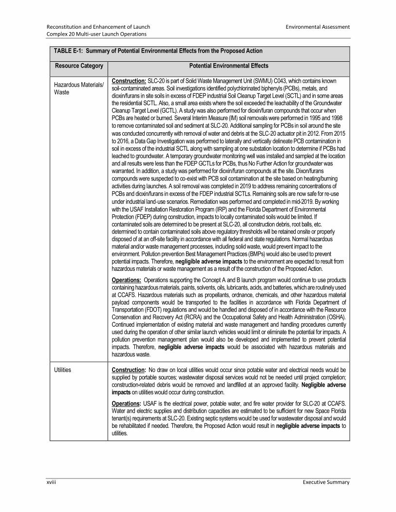
TABLE E-1: Summary of Potential Environmental Effects from the Proposed Action
Resource Category Potential Environmental Effects
Land Use / Visual Resources
Construction: Negligible adverse impacts are expected to land use (including coastal resources) and visual resources. The Proposed Action is consistent with the land use and visual character of the ROI given the other numerous launch complexes nearby. No significant impacts are expected to land use compatibility as a result of the renovation and construction of launch facilities since CCAFS and SLC-20 land use is and has historically been used for launch operations. Operations: Negligible adverse impacts are expected to land use (including coastal resources) and visual resources. No significant impacts are expected to land use compatibility since CCAFS and historically SLC-20 uses include launching space launch vehicles. Visual impacts would only include the normally seen and short-lived vehicle contrails that result from each launch event.
Noise Construction: There would be minor adverse impacts at CCAFS from the operation of construction equipment; however, these impacts would be limited to the immediate vicinity of SLC-20. There would be no impacts to communities near CCAFS due to noise associated with construction activities. Operations: Noise impacts to biological resources are discussed below. Sonic booms would occur from launches at SLC-20 but only over the ocean, so no impacts on the mainland from sonic booms would occur. The Proposed Action is not expected to generate propulsion noise impacts greater than what the surrounding community has been exposed to as a result of previous launches from CCAFS and KSC. Therefore, there would be minor adverse impacts to the surrounding environment as a result of the proposed launches at SLC-20.
Biological Resources Construction: Clearing of land would impact approximately 0.3 acre of low-quality potential scrub-jay habitat. The renovation of the Blockhouse and other existing structures, construction of new facilities, and site clearing would also impact southeastern beach mouse, indigo snake, and gopher tortoise habitat. Impacts would be mitigated by funding restoration/enhancement of southeastern beach mouse habitat as discussed in the attached Biological Assessment (BA) and the subsequent US Fish and Wildlife Service (USFWS) Biological Opinion (BO). As a result, minor adverse impacts would occur. Operations: The Proposed Action has the potential to result in adverse impacts to five species of marine turtles. However, a Light Management Plan would be developed and approved by USAF and USFWS to reduce or eliminate night-time impact to the sea turtle nesting/hatchling process. Other than the sea turtles, noise from the operation of the Proposed Action would elicit a common “startle response.” Minor adverse impacts on wildlife and vegetation (including federal and state-listed wildlife species) are expected due to the need to relocate numerous gopher tortoises and the associated impact on their habitat.
Cultural Resources Construction: The 45th Space Wing (45 SW) Cultural Resources Manager evaluated the areas that would be affected by the Proposed Action, and no historical or cultural resource issues were found within the Proposed Action boundaries or surrounding areas with the exception of the Blockhouse. The Blockhouse was determined to be potentially eligible for listing but the Proposed Action to use that facility as it was originally intended and to maintain the exterior similar to its original construction was determined to be a beneficial impact.
Operations: Negligible adverse to beneficial impacts are expected due to the lack of historical and cultural resources in the ROI.

Environmental Assessment Reconstitution and Enhancement of Launch Complex 20 Multi-user Launch Operations
Executive Summary xvii
TABLE E-1: Summary of Potential Environmental Effects from the Proposed Action
Resource Category Potential Environmental Effects
Air Quality Construction: Construction activities associated with the Proposed Action would cause a minor increase in emissions of particulate matter (PM) due to demolition and related activities. Minor emissions related to CO, CO2, hydrocarbons, and NOx would occur due to equipment and vehicular emissions. As such, negligible adverse impacts would occur. Operations: The Proposed Action is not considered to be a major source of air pollutants and does not require a Title V permit. Brevard County is in attainment for all criteria pollutants; therefore, a General Conformity analysis is not required. As documented in numerous EAs and EISs performed for launch vehicles at CCAFS and elsewhere, emissions from nominal launches, catastrophic failures, or spills of liquid propellants would not significantly alter ambient air conditions. Air emissions for the LOX/RP-1 version of the Beta concept launch vehicle would have the maximum potential for air quality impacts; however, these impacts on air quality are expected to have minor adverse impacts on air quality.
Climate Emissions of greenhouse gases (GHGs) from the construction, operations, and launches at SLC-20 would not cause any appreciable global effects. The incremental emissions for the Proposed Action would be similar to the Falcon 1 and have negligible adverse impacts on global climate change.
Water Resources Construction: No impacts to groundwater resources or groundwater quality would occur. No US Army Corps of Engineers (USACE) or St. Johns River Water Management District (SJRWMD) wetlands occur within the Proposed Action site and no impacts to wetlands would occur. A 0.19-acre upland cut surface water would remain or be regraded and additional surface water treatment areas will be constructed. Therefore, negligible adverse impacts to surface water are expected. Operations: Operations would result in negligible adverse impacts to surface water, groundwater resources, groundwater quality, wetlands, or floodplains. A 45 SW approved Spill Prevention, Control, and Countermeasures Plan (SPCCP) would be implemented by the tenant, which would minimize the potential for adverse impacts to water resources.
Geology and Soils Construction: Contaminated soils in excess of the industrial SCTs have been removed from the site; however, contaminated soil in excess of the residential SCTLs is still present. Soils would be disturbed for site construction activities. Normal hazardous material and/or waste management processes, including solid waste, would prevent impact to the environment. Pollution prevention BMPs would also be used to prevent potential impacts. Negligible adverse impacts would occur to geology and soils. Operations: Daily operations and launches would not affect existing geology and soils; therefore, no adverse impacts are expected.
Transportation Construction: Vehicle and truck traffic would increase slightly during facility construction and renovations. However, it would result in negligible adverse impacts to CCAFS traffic and roadways. Operations: Operational traffic associated with Proposed Action would increase slightly as a result of up to 24 launch vehicle transports and employee trips. Transporting launch vehicles would slow KSC and CCAFS traffic but would occur during non-peak hours. Therefore, the Proposed Action would result in minor adverse impacts to transportation.
Reconstitution and Enhancement of Launch Environmental Assessment Complex 20 Multi-user Launch Operations
xviii Executive Summary
TABLE E-1: Summary of Potential Environmental Effects from the Proposed Action
Resource Category Potential Environmental Effects
Hazardous Materials/ Waste
Construction: SLC-20 is part of Solid Waste Management Unit (SWMU) C043, which contains known soil-contaminated areas. Soil investigations identified polychlorinated biphenyls (PCBs), metals, and dioxin/furans in site soils in excess of FDEP industrial Soil Cleanup Target Level (SCTL) and in some areas the residential SCTL. Also, a small area exists where the soil exceeded the leachability of the Groundwater Cleanup Target Level (GCTL). A study was also performed for dioxin/furan compounds that occur when PCBs are heated or burned. Several Interim Measure (IM) soil removals were performed in 1995 and 1998 to remove contaminated soil and sediment at SLC-20. Additional sampling for PCBs in soil around the site was conducted concurrently with removal of water and debris at the SLC-20 actuator pit in 2012. From 2015 to 2016, a Data Gap Investigation was performed to laterally and vertically delineate PCB contamination in soil in excess of the industrial SCTL along with sampling at one substation location to determine if PCBs had leached to groundwater. A temporary groundwater monitoring well was installed and sampled at the location and all results were less than the FDEP GCTLs for PCBs, thus No Further Action for groundwater was warranted. In addition, a study was performed for dioxin/furan compounds at the site. Dixon/furans compounds were suspected to co-exist with PCB soil contamination at the site based on heating/burning activities during launches. A soil removal was completed in 2019 to address remaining concentrations of PCBs and dioxin/furans in excess of the FDEP industrial SCTLs. Remaining soils are now safe for re-use under industrial land-use scenarios. Remediation was performed and completed in mid-2019. By working with the USAF Installation Restoration Program (IRP) and the Florida Department of Environmental Protection (FDEP) during construction, impacts to locally contaminated soils would be limited. If contaminated soils are determined to be present at SLC-20, all construction debris, root balls, etc. determined to contain contaminated soils above regulatory thresholds will be retained onsite or properly disposed of at an off-site facility in accordance with all federal and state regulations. Normal hazardous material and/or waste management processes, including solid waste, would prevent impact to the environment. Pollution prevention Best Management Practices (BMPs) would also be used to prevent potential impacts. Therefore, negligible adverse impacts to the environment are expected to result from hazardous materials or waste management as a result of the construction of the Proposed Action. Operations: Operations supporting the Concept A and B launch program would continue to use products containing hazardous materials, paints, solvents, oils, lubricants, acids, and batteries, which are routinely used at CCAFS. Hazardous materials such as propellants, ordnance, chemicals, and other hazardous material payload components would be transported to the facilities in accordance with Florida Department of Transportation (FDOT) regulations and would be handled and disposed of in accordance with the Resource Conservation and Recovery Act (RCRA) and the Occupational Safety and Health Administration (OSHA). Continued implementation of existing material and waste management and handling procedures currently used during the operation of other similar launch vehicles would limit or eliminate the potential for impacts. A pollution prevention management plan would also be developed and implemented to prevent potential impacts. Therefore, negligible adverse impacts would be associated with hazardous materials and hazardous waste.
Utilities Construction: No draw on local utilities would occur since potable water and electrical needs would be supplied by portable sources; wastewater disposal services would not be needed until project completion; construction-related debris would be removed and landfilled at an approved facility. Negligible adverse impacts on utilities would occur during construction. Operations: USAF is the electrical power, potable water, and fire water provider for SLC-20 at CCAFS. Water and electric supplies and distribution capacities are estimated to be sufficient for new Space Florida tenant(s) requirements at SLC-20. Existing septic systems would be used for wastewater disposal and would be rehabilitated if needed. Therefore, the Proposed Action would result in negligible adverse impacts to utilities.

Environmental Assessment Reconstitution and Enhancement of Launch Complex 20 Multi-user Launch Operations
Executive Summary xix
TABLE E-1: Summary of Potential Environmental Effects from the Proposed Action
Resource Category Potential Environmental Effects
Health and Safety Construction: Space Florida tenant(s) would follow all USAF and OSHA and applicable USAF regulations (as determined by 45 SW/SE and or 45 SW/CONS) during construction activities; therefore, negligible adverse impact to the health and safety of workers is expected. In addition, Space Florida tenant(s) would follow all USAF and OSHA regulations during construction activities; therefore, negligible adverse impact to the health and safety of workers is expected. Operations: The operation and launch of Concept A and B vehicles would be in compliance with all current and standard health and safety local, state, and federal procedures during operation and launch; therefore, no significant impact to the health and safety of workers is expected. Operational safety of the nearby airfield (Skid-Strip) should not be affected by the Proposed Action as SLC-20 is approximately 14,000 feet from the edge of the Skid-Strip. Lightning protection at the Proposed Action site will be less than the 1:20 conical surface height restrictions. However, a waiver from FAA, in coordination with USAF, will be obtained for any unexpected objects exceeding the 14 CFR Part 77 surfaces from the Skid-Strip. Accordingly, negligible adverse impacts are expected. Explosive Site Safety was also assessed. Like all launch and hazardous operations at CCAFS, operations must account for public safety clear distances and may require temporary road closures and evacuation of some CCAFS facilities on launch days. Space Florida tenant(s) will implement engineering design controls to minimize road closures to occur only on launch days. The launch pad site design would be developed to locate explosive hazards so as to minimize the impacts to inhabited buildings on CCAFS when the launch vehicle is fueled and ready for launch. Accordingly, negligible adverse impacts are expected.
Socioeconomics Construction: Construction and rehabilitation activities conducted in support of the Proposed Action would generate employment opportunities for the local workforce. Construction and workforce increases would not significantly affect the local housing market or economy. Therefore, the Proposed Action would not result in significant impacts to socioeconomics in the region and may generate a negligible positive impact. Operations: The negligible workforce increase expected as a result of the operation of the Proposed Action would not significantly affect the local housing market or economy. Therefore, the Proposed Action would not result in significant impacts to socioeconomics in the region and may generate a negligible positive impact.
Environmental Justice
Construction: Construction would occur in the SLC-20 area. Since the Proposed Action would be constructed within existing facilities at CCAFS, negligible adverse impacts are expected. Operations: Since the Proposed Action would operate from the existing facilities at CCAFS, negligible adverse impacts are expected.
4(f) Properties Construction: No designated 4(f) properties, including public parks, recreation areas, or wildlife refuges, exist within the boundaries of CCAFS. Therefore, no impact is expected to result from construction. Operations: No designated 4(f) properties, including public parks, recreation areas, or wildlife refuges, exist within the boundaries of CCAFS. Although several public parks, recreation areas, and wildlife refuges are outside CCAFS, operation and launches would not result in a use or change in use of a Section 4(f) property. Therefore, negligible adverse impacts are expected to result from operation.
1
2

Reconstitution and Enhancement of Launch Environmental Assessment Complex 20 Multi-user Launch Operations
xx Executive Summary
CUMULATIVE IMPACTS 1
Cumulative impacts are defined by the Council on Environmental Quality (CEQ) in 40 CFR §1508.7 2
as impacts on the environment that result from the incremental impact of the action when added 3
to other past, present, and reasonably foreseeable future actions regardless of what agency 4
(Federal or non-Federal) or person undertakes such other actions. The CEQ regulations further 5
require that National Environmental Policy Act (NEPA) environmental analyses address 6
connected, cumulative, and similar actions in the same document (40 CFR 1508.25). The 7
cumulative impact analysis for this EA focuses on the incremental interaction the Proposed 8
Action may have with other past, present, and reasonably foreseeable future actions and 9
evaluates cumulative impacts potentially resulting from these interactions. Implementation of 10
the Proposed Action would not cause any significant cumulative impacts to the resource areas 11
analyzed in this EA.12
Environmental Assessment Reconstitution and Enhancement of Launch Complex 20 Multi-user Launch Operations
Section 1: Purpose and Need for the Proposed Action 1-1
1.0 PURPOSE AND NEED FOR THE PROPOSED ACTION 1
1.1 INTRODUCTION 2
Space Florida was created pursuant to Chapter 331, Part II, Florida Statutes as an independent 3
special district and subdivision of the State of Florida. The purpose of Space Florida is to foster 4
the growth and development of a sustainable and world-leading aerospace industry in Florida. 5
Space Florida leverages Florida’s highly skilled workforce and existing infrastructure to attract 6
and expand the next generation of space industry businesses. The Cape Canaveral Spaceport 7
(CCS), in which Space Florida has an operational spaceport authority role, is the premiere 8
transportation hub for global space commerce. Space Florida oversees management and 9
operation of key elements of Florida’s existing space transportation capability. 10
Space Florida has prepared this Environmental Assessment (EA) to evaluate the potential 11
environmental impacts associated with obtaining a commercial launch site operator license from 12
the Federal Aviation Administration (FAA) and supporting the Real Property transfer, via an 13
agreement, of approximately 220 acres (89 hectares [ha]) of land, to include Space Launch 14
Complex 20 (SLC-20) and all facilities contained thereon, at Cape Canaveral Air Force Station 15
(CCAFS) by the US Air Force (USAF) to Space Florida. Space Florida would develop and provide for 16
use the 220 acres (89 ha) to meet current and future commercial, national, and state space 17
transportation needs through the expansion and modernization of space transportation facilities 18
within Space Florida’s CCS territories to include areas within CCAFS. 19
This EA focuses on the transfer, via a Real Property Agreement (RPA), of 220 acres (89 ha), to 20
include SLC-20 and transportation routes, from USAF to Space Florida to develop a multi-user 21
launch capability that includes the refurbishment and enhancement of an existing launch pad, 22
the operation of small- and medium-lift launch vehicles by commercial users such as Firefly 23
Aerospace, Inc., under an agreement with Space Florida, and the transportation of vehicle stages 24
from Exploration Park to SLC-20. The majority of customers for rocket-launch missions from this 25
site are expected to be from the commercial sector and government agencies such as the 26
National Aeronautics and Space Administration (NASA) and the Department of Defense (DoD). 27
Space Florida cannot predict with any fidelity regarding the timing of other emerging commercial 28
launch vehicle operators or prospective developers for the entire 220-acre (89-ha) parcel; 29
therefore, potential future development and use of this property by other entities are assessed 30
qualitatively in the Cumulative Impacts section of this EA. Future environmental review for use 31
of the property by other entities will be required once more specific construction and operational 32
details are defined. 33
This EA was prepared in accordance with the National Environmental Policy Act (NEPA) of 1969, 34
as amended (Title 42 of the United States Code [USC] 4321–4347), the Council on Environmental 35
Quality (CEQ) regulations for implementing NEPA (40 Code of Federal Regulations [CFR] Parts 36
1500–1508), USAF’s Environmental Impact Analysis Process (32 CFR Part 989), and Federal 37
Aviation Administration (FAA) Order 1050.1F, Environmental Impacts: Policies and Procedures. In 38
accordance with agreements between USAF, NASA, and FAA, USAF is the lead agency for the 39
preparation and coordination of the EA (40 CFR §1501.5), and NASA and FAA are acting as 40

Reconstitution and Enhancement of Launch Environmental Assessment Complex 20 Multi-user Launch Operations
Section 1: Purpose and Need for the Proposed Action 1-2
cooperating agencies (40 CFR §1501.6). As noted below in Section 1.4.1, the FAA’s role is licensing 1
commercial space launch operations. 2
1.2 LOCATION AND BACKGROUND 3
CCAFS occupies approximately 15,800 acres (6,394 ha) of land on Florida’s Cape Canaveral barrier 4
island (Figure 1-1). 5
The Cape Canaveral barrier island is on the east coast of Brevard County, Florida, approximately 6
150 miles (241 kilometers [km]) south of Jacksonville, 210 miles (337 km) north of Miami, and 7
60 miles (97 km) east of Orlando. The island is 4.5 miles (7 km) wide at its widest point. CCAFS 8
has 81 miles (130 km) of paved roads connecting various launch support facilities with the 9
centralized Industrial Area. The north boundary of CCAFS adjoins the Kennedy Space Center (KSC) 10
boundary on the Merritt Island barrier island. As defined in Florida Statute 313.304, the Space 11
Florida Spaceport territory includes areas within KSC and CCAFS; this territory is referred to as 12
the CCS. 13
The Banana River separates CCAFS from KSC to the west. Port Canaveral adjoins CCAFS to the 14
south. CCAFS’s east boundary is the Atlantic Ocean. The base is accessible primarily from State 15
Road 528 to the south and from KSC to the west and north. 16
Thirty-three launch complexes have been constructed and used at CCAFS; however, there are 17
currently four active and 12 inactive launch pads at 12 launch complexes. Along with the various 18
launch and support facilities, CCAFS maintains a centralized industrial complex to support the 19
technical, mechanical, and administrative needs of each launch program. USAF’s 45th Space Wing 20
(45 SW) is currently the host wing, under the USAF’s United States Space Force (USSF), and 21
conducts east coast military, civil, and commercial launch operations. 22
The existing SLC-20 developed launch site is approximately 33 acres (13 ha), consists of 23
14 facilities, and is within the northeast portion of CCAFS, off ICBM Road, between SLC-19 and 24
SLC-34. SLC-20 is surrounded by dense live oak/saw palmetto (Figure 1-2). The facility was 25
constructed in 1958 and 1959 for the Titan Missile Program, modified in 1964 for the Titan III 26
Missile Program, and deactivated in 1966. Following deactivation, site responsibilities were 27
transferred to NASA. In addition to launch activities, the south portion of SLC-20 (area occupied 28
near Facility [Fac] 15531; (Figure 1-3) was reportedly the location of a drum-crushing operation 29
and a waste-liquid storage area for approximately 10 years from the late 1970s to the late 1980s. 30
Following abandonment of the site in the late 1980s, site responsibilities reverted back to USAF. 31
SLC-20 as a whole is not considered a historic complex, and no known archeological sites are 32
inside or outside the complex boundary (USAF 2015a). Although the entire SLC-20 complex is not 33
considered historic, the Blockhouse may be eligible for listing on the National Register of Historic 34
Places (NRHP). 35
The Proposed Action boundary consists of the 33acre (13 ha) developed launch site and the RPA 36
boundary consists of approximately 220 acres (89 ha) (see Figures 1-2 and 1-3). The areas outside 37
the Proposed Action boundary are not contemplated for development at this time and any 38

Environmental Assessment Reconstitution and Enhancement of Launch Complex 20 Multi-user Launch Operations
Executive Summary 1-3
proposed future development outside the Proposed Action boundary will be reviewed under 1
NEPA. 2
SLC-19, immediately south of SLC-20, is a historic site. In 1999, SLC-20 was reactivated to be 3
operated under the direction of Space Florida for commercial launches. This reactivation included 4
upgrades to Launch Pad A (Fac 15540) and the construction of a new building along the perimeter 5
road, northeast of the Blockhouse (Fac 15500A). In 2000, three Super Loki flights were launched 6
from SLC-20. 7

Environmental Assessment Reconstitution and Enhancement of Launch Complex 20 Multi-user Launch Operations
Section 1: Purpose and Need for the Proposed Action 1-4
1
Figure 1-1 Site Location Map 2

Reconstitution and Enhancement of Launch Environmental Assessment Complex 20 Multi-user Launch Operations
1-5 Section 1: Purpose and Need for the Proposed Action
1
Figure 1-2 Proposed SLC-20 Total RPA Boundary Map 2
3

Reconstitution and Enhancement of Launch Environmental Assessment Complex 20 Multi-user Launch Operations
1-6 Section 1: Purpose and Need for the Proposed Action
1
Figure 1-3 Existing SLC-20 Facilities 2

Environmental Assessment Reconstitution and Enhancement of Launch Complex 20 Multi-user Launch Operations
Section 1: Purpose and Need for the Proposed Action 1-7
Facilities 22101 (215-foot WINDS Tower 006) and 22100 (006 Support Building) are located 1
outside the RPA Boundary but inside the Proposed Action Boundary. As part of the Proposed 2
Action, 45 SW Weather would continue to be provided access through the RPA to these two 3
facilities. 4
In 2001, NASA prepared the Environmental Assessment for the Advanced Technology 5
Development Center at Cape Canaveral Spaceport, Florida for the proposed development of an 6
Advanced Technology Development Center (ATDC) at SLC-20 to provide a test area for Spaceport 7
technologies including Cryogenic systems, launch structures, umbilicals, sensors and electronics, 8
integrated vehicles, and process engineering and range systems (NASA 2001a). NASA issued a 9
Finding of No Significant Impact (FONSI) in 2001 and construction of the ATDC Phase 1 facility 10
was completed in 2002 (NASA 2001b). ATDC used the Blockhouse for office space and data 11
acquisition. The complex reverted to USAF in the 2010-timeframe (Space Florida and 45 SW 12
2019). 13
In December 2008, NASA prepared the Final Environmental Assessment for Exploration Park – 14
Phase 1 for Space Florida and Kennedy Space Center to analyze the impacts associated with the 15
development and operation of approximately 60 acres (24 ha) of land leased from KSC and 16
referred to as Exploration Park Phase 1 (NASA 2008). NASA issued a Record of Environmental 17
Consideration (REC) for the additional construction at Exploration Park Phase 1 on August 20, 18
2019, which includes the area to be used for the launch vehicle manufacturing facility associated 19
with the SLC-20 development (Appendix A). Therefore, Exploration Park Phase 1 construction and 20
operation activities for the manufacturing facility are not included in this EA. However, the 21
transportation of manufactured stages from the Exploration Park Phase 1 manufacturing facility 22
to the SLC-20 launch site for assembly, processing, and launch is included in this EA. 23
1.3 PURPOSE AND NEED FOR THE PROPOSED ACTION 24
The purpose of the Proposed Action is to provide multiple launch pads for commercial users in 25
support of Space Florida’s CCS Master Plan in accordance with Florida Statutes Section 331 (Space 26
Florida 2017). Specifically, Space Florida must meet current and future commercial, national, and 27
state space transportation requirements through expansion and modernization of space 28
transportation facilities within its Spaceport territories. The territories include, but are not 29
limited to, areas within CCAFS. The Proposed Action would allow commercial launch providers, 30
such as Firefly, to assemble, process, test, and launch vehicles to meet the demand for lower-31
cost access to space. The Proposed Action would provide the continued capability of space 32
exploration by commercial users and improve the return on taxpayer investment of CCAFS 33
facilities through expanded use and improved utilization. The Proposed Action would also 34
continue to provide economic and technical benefits to the government and the private sector 35
following the retirement of the Space Shuttle Program in 2011. On November 27, 2018, the Space 36
Florida Board of Directors approved the request to proceed with negotiations and agreements 37
for the redevelopment of SLC-20 for the purposes of meeting Florida’s commercial space 38
transportation industry needs. 39
The Proposed Action is needed to test and launch vehicles efficiently in the United States for use 40
by commercial space launch enterprises. The Proposed Action would contribute to meeting the 41
goals of the CCS Master Plan consistent with the National Space Transportation Policy; NASA’s 42

Reconstitution and Enhancement of Launch Environmental Assessment Complex 20 Multi-user Launch Operations
1-8 Section 1: Purpose and Need for the Proposed Action
Space Act Agreement (SAA); and DoD policy pursuant to DoD Directive 3230.3, DoD Support for 1
Commercial Space Launch Activities. 2
The FAA expects to receive a license application from Space Florida to operate a commercial 3
space launch site at SLC-20. Also, the FAA expects to receive a license application from Firefly to 4
conduct launch operations at SLC-20. Therefore, the FAA’s proposed actions of issuing a launch 5
site operator license to Space Florida and a launch license to Firefly for launch operations at 6
SLC-20 are considered part of the Proposed Action analyzed in this EA. The FAA’s purpose of its 7
action is to fulfill the FAA’s responsibilities as authorized by the Commercial Space Launch Act 8
(51 U.S.C. Subtitle V, ch. 509, §§ 50901-50923) for oversight of commercial space launch 9
activities, including licensing launch activities. The need for FAA’s action results from the 10
statutory direction from Congress under the U.S. Commercial Space Launch Act, 51 U.S.C 11
50901(b), to, in part, “protect the public health and safety, safety of property, and national 12
security and foreign policy interests of the United States” while “strengthening and [expanding] 13
the United States space transportation infrastructure, including the enhancement of United 14
States launch sites and launch-site support facilities, and development of reentry sites, with 15
Government, State, and private sector involvement, to support the full range of United States 16
space-related activities.” 17
1.4 SCOPE OF THE ENVIRONMENTAL ASSESSMENT 18
This EA addresses the potential environmental impacts from the RPA to transfer approximately 19
220 acres (89 ha) from USAF to Space Florida, the refurbishment and enhancement of SLC-20 20
facilities, the operation of small- and medium-lift launch vehicles on 33 (13 ha) of the 220 acres 21
(89 ha), and the proposed transportation of vehicle stages from Exploration Park to SLC-20. For 22
the reasons stated in Section 1.2, the proposed construction and operation of the manufacturing 23
facility in Exploration Park Phase 1 are not included in the scope of this EA. 24
1.4.1 Lead and Cooperating Agency Actions 25
This EA was prepared by Space Florida as the proponent of the Proposed Action. Space Florida is 26
the dedicated state governmental authority for launch and landing operations at CCS. USAF is the 27
lead federal agency for the Proposed Action. If, after the public’s review of the EA, USAF 28
determines the Proposed Action would not individually or cumulatively result in significant 29
impacts on the human or natural environments, USAF would issue a final FONSI and proceed with 30
implementing the Proposed Action. 31
The FAA is a cooperating agency because of its role in licensing commercial space launch 32
operations in the United States. The FAA intends to adopt this EA to support its environmental 33
review when evaluating the license applications. If, after reviewing a license application and this 34
EA, the FAA determines that the proposed operations fall within the scope of this EA and the 35
action would not individually or cumulatively result in significant impacts on the human 36
environment, the FAA would adopt this EA and issue its own FONSI to support the issuance of 37
the license to Space Florida and/or Firefly. The FAA will draw its own conclusions from the 38
analysis presented in this EA and assume responsibility for its environmental decision and any 39
related mitigation measures. For the FAA to completely rely on this EA to satisfy its NEPA 40

Environmental Assessment Reconstitution and Enhancement of Launch Complex 20 Multi-user Launch Operations
Section 1: Purpose and Need for the Proposed Action 1-9
obligations, the EA must meet the requirements of FAA Order 1050.1F, which contains the FAA’s 1
policies and procedures for NEPA compliance. 2
NASA is also a cooperating agency because of its special expertise and potential need to rely on 3
the analysis contained in this EA to support its environmental review process as a potential future 4
Firefly customer. 5


Environmental Assessment Reconstitution and Enhancement of Launch Complex 20 Multi-user Launch Operations
Section 2: Description of the Proposed Action and Alternatives 2-1
2.0 DESCRIPTION OF THE PROPOSED ACTION AND ALTERNATIVES 1
This section describes the Proposed Action (which is the Preferred Alternative), the No Action 2
Alternative, and alternatives considered but not carried forward for further analysis. 3
2.1 PROPOSED ACTION 4
The Proposed Action is to transfer, by a Real Property Agreement (RPA, likely in the form of a 5
long-term lease) , approximately 220 acres (89 ha) of land, to include SLC-20 and all facilities 6
contained thereon, at CCAFS by USAF to Space Florida; provide use of 33 acres (13 ha) of the 220 7
acres (89 ha), to include the existing launch site infrastructure to Firefly on a dedicated basis; 8
refurbish and enhance existing SLC-20 facilities; test and operate small- and medium-lift launch 9
vehicles by Firefly; and transport vehicle stages from Exploration Park to SLC-20. The Proposed 10
Action is the preferred alternative. 11
In addition to the agreement noted above, this EA includes in the cumulative analysis section that 12
Space Florida will be requesting, at some point in the future, that USAF provide an access road 13
easement to allow entry to SLC-20 from the south via SLC-19 (refer to the blue area shown in 14
Figure 1-2). The details of this access into SLC-20 via the SLC-19 access road are not sufficiently 15
developed at this time to be analyzed in detail in this EA and will be analyzed in the future when 16
additional site development is planned. 17
2.1.1 Proposed Location 18
The project location consists of existing SLC-20 and surrounding areas, an area totaling 220 acres 19
(89 ha). The existing SLC-20 developed launch site is in the northeast portion of CCAFS, off ICBM 20
Road, between SLC-19 and SLC-34 and contains numerous existing facilities (Figure 1-3). Most of 21
the 220 acres (89 ha) is covered in relatively dense live oak/saw palmetto with scattered 22
herbaceous wetlands. Table 2-1 describes the facilities. 23
Table 2-1 Existing SLC-20 Facilities 24
Original Site Facility Name Current Name Year
Built Status
Fac 15500, Control Cableway
15500, Control Cableway
1959 The structure’s setting and design remains intact.
Fac 15500AD, Fuel Holding Area
15500AD, Liquid Hydrogen Holding Area
1963 All that remains today is the earthen berm, concrete walls, aboveground storage tank (AST) holding area, and truck parking area.
Fac 15500AF, Oxidizer Holding Area
15531, Retaining Wall
1962 All that remains of the original facility is the earthen berms and concrete retaining walls.
Fac 15500B, Launch Stand and Ramp
15500B, Launch Stand and Ramp
1959 Very little of the original components remain.
Fac 15540, Launch Pad A – Ballistic Missile Development Office
15540, Launch Pad A – Ballistic Missile Development Office
1989 The facility is now abandoned in-place and essentially unchanged. The launch rail has been removed and only the mounting ring remains.
Fac 15541, Equipment Building Pad A
15541, Equipment Building
1989 The facility remains abandoned in-place and essentially unchanged.
Fac 15608, Power Center
15608, Power Center
2003

Reconstitution and Enhancement of Launch Environmental Assessment Complex 20 Multi-user Launch Operations
Section 2: Description of the Proposed Action and Alternatives 2-2
Original Site Facility Name Current Name Year
Built Status
Fac 15609, Control Center
15609, Control Center
2003 Both structures served as instrumentation facilities until they were abandoned in-place in 2010.
Fac 15640, Launch Pad B – Ballistic Missile Development Office
15640, Launch Pad B – Ballistic Missile Development Office
1989 The facility remains abandoned in-place and essentially unchanged. The launch rail has been removed and only the mounting ring remains.
Fac 15641, Equipment Building Pad A
15641, Equipment Building
1989 The facility remains intact.
Fac 18705, HIF 18705, HIF 1999 The building remains intact. Fac 15500A, Blockhouse
18800, Blockhouse
1959 Although abandoned in-place in 2012, the building remains intact.
Fac 18803, Guard House 18803, Guard House 1999 This structure is in a ruinous state of condition. Fac 15500C, Ready Building
18806, Payload Assembly Building
1959 This building is abandoned and in disrepair.
Source: USAF 2015b. 1
2.1.2 Launch Vehicles 2
Space Florida proposes to establish multi-user launch capability at SLC-20. Firefly, one of the 3
potential launch providers, proposes to launch Alpha, a small-lift class launch vehicle, and future 4
Beta, a small- to medium-lift class launch vehicle, from SLC-20. Firefly’s Alpha and Beta launch 5
vehicles are used as representative vehicles for the Proposed Action and are subsequently 6
referred to as Concept A and Concept B, respectively. Both representative launch vehicles are 7
expendable and provide satellite delivery services with the future opportunity for lunar surface 8
delivery services. Table 2-2 lists the general specifications for both launch vehicles. Table 2-3 lists 9
maximum potential propellant quantities. Specific details of each launch vehicle, to include first 10
and second stages and flight termination system, are included in subsequent sections. 11
Table 2-2 Launch Vehicle Specifications 12
Specification Concept A Concept B (Future) Length 95 ft (29 m) 140 ft (43 m) Diameter 6 ft (2 m) 10 ft (3.1 m) Stages 2 2 Recoverable First Stage? No No Parachute Required? No No First Stage Propellant LOX/RP-1 LOX/RP-1/LCH4 Total Wet Mass 120,000 lb (54,000 kg) 470,000 lb (214,000 kg) First Stage Thrust 730 kN (163,888 lbf) 2,760 kN (620,000 lbf)
Notes: ft = feet; kg = kilogram; kN = kilonewtons; lbf = pound-force; lb = pounds; LCH4 = liquid methane; LOX = liquid oxygen; 13 m = meter; RP-1 = Rocket Propellant 1 14 Source: 30 CES 2018. 15 16

Environmental Assessment Reconstitution and Enhancement of Launch Complex 20 Multi-user Launch Operations
Section 2: Description of the Proposed Action and Alternatives 2-3
Table 2-3 Maximum Potential Propellant Quantities – Central Pad 1
Launch Vehicle Storage Type Propellant Type Max Quantity
Concept A
Oxidizer Storage LOX 180,000 lb (81,647 kg) Fuel Storage RP-1 83,000 lb (37,648 kg) Combined Vehicle LOX/RP-1 109,000 lb (49,442 kg)
Concept B
Oxidizer Storage LOX 570,000 lb (258,548 kg) Variant 1 Fuel Storage RP- 1 170,000 lb (77,111 kg) Variant 1 Combined Vehicle LOX/RP-1 435,000 lb (197,312 kg) Variant 2 Fuel Storage RP-1 (Stage 1) 126,000 lb (57,153 kg) Variant 2 Fuel Storage LCH4 (Stage 2) 36,000 lb (16,329 kg) Variant 2 Combined Vehicle LOX/RP-1 & LOX/LCH4 (Stage 2) 419,000 lb (190,055 kg) Variant 3 Fuel Storage LCH4 170,000 lb (77,111 kg) Variant 3 Combined Vehicle LOX/LCH4 402,000 lb (182,344 kg)
Concept A Launch Vehicle 2
The Concept A launch vehicle is a small, unmanned, light-lift, two-stage, liquid-fueled launch 3
vehicle with a gross lift-off weight of approximately 120,000 lb (81,647 kg) that can carry payloads 4
of between 1,323 lb (600 kg) and 2,205 lb (1,000 kg), depending on the orbit. The first and second 5
stages use only liquid propellants (liquid oxygen [LOX] and RP-1; highly refined kerosene). 6
The first stage consists of a cylindrical structure containing LOX and RP-1 tanks separated by an 7
intertank. This first stage is powered by four, 182-kN (40,972-lbf) thrust LOX/RP-1 engines. Roll 8
control and thrust vector control use hydraulic actuators and use the on-board RP-1 for its fuel. 9
The propellant tanks can hold 6,715 gallons (gal) (25,419 liters [L]) of LOX and 4,346 gal (16,451 L) 10
of RP-1. The second stage consists of a cylindrical structure containing LOX and RP-1 tanks 11
separated by an intertank. The engine is a 70-kN (15,714-lbf) thrust engine with hot helium 12
attitude control and hydraulic actuators for thrust vector control. The propellant tanks hold 13
1,065 gal (4,031 L) of LOX and 670 gal (2,536 L) of RP-1. 14
Concept A may carry small payloads of up to 2,205 lb (1,000 kg) consisting mostly of non-15
hazardous materials. Some payloads may use small amounts of hazardous propellants for on-16
orbit maneuvering. These payload propellants may include hypergolic fuels such as hydrazine, 17
pressurized gases including helium and nitrogen, and some solid propellants. Hazardous material 18
quantities would vary. In addition, a small amount of ordnance, such as small explosive bolts and 19
on-board batteries are typical. Payload propellants will be stored before use in a certified facility 20
near the payload processing facility where the loading will occur. Residual propellants for 21
payloads will be returned to the storage facilities. Payload plans do not currently include 22
radioactive materials but, if future plans for payloads were to include radioactive materials, they 23
would be in de minimis amounts. 24
Commercial launch providers would develop a Preliminary Flight Data Package before any launch, 25
which takes into consideration a trajectory that avoids over-flights of known structures and 26
establishes a potential debris corridor for the vehicle. The reliability of the Concept A vehicle is 27
expected to be above 95 percent (30 CES 2018). 28

Reconstitution and Enhancement of Launch Environmental Assessment Complex 20 Multi-user Launch Operations
Section 2: Description of the Proposed Action and Alternatives 2-4
Two potential paths for flight termination exist. If the Concept A launch vehicle varies from its 1
planned trajectory, the launch vehicle will be equipped with a destructive flight termination 2
system. The Preliminary Flight Safety analysis will determine the flight termination system type. 3
The expected destructive termination system includes one Bulk Destruct Charges (BDC) that is 4
intended to rupture the vehicle tanks when commanded to destruct, thereby dispersing 5
propellants and breaking up the vehicle to minimize the impact to ground assets. The total weight 6
of the ordnance charges for either vehicle would be small and total approximately 0.1 lb 7
(200 grams [g]). Commercial space entities licensed to use SLC-20 will have agreements in place 8
with 45 SW, which allows ordnance to be stored at the 45 SW Ordnance Storage Area and 9
delivered on a real-time basis to the launch complex during vehicle integration to avoid the need 10
for long-term storage of this type of hazardous material on site. 11
A thrust termination system is activated by an autonomous on-board command and disables 12
power to the vehicle engines. Upon activation of the thrust termination system, the Concept A 13
launch vehicle would fall to the ocean intact and may explode upon impact, depending on the 14
circumstances and time in the flight of the termination. 15
The Proposed Action includes non-destructive software and telemetry testing of the flight 16
termination systems. No ascent abort testing of the launch vehicle or destructive testing of the 17
ordnance flight termination system or thrust termination system is proposed. 18
Concept B Launch Vehicle 19
Concept B shares the same basic design as the Concept A launch vehicle with higher thrust, 20
providing a higher payload capacity that can carry between 7,275 lb (3,300 kg) and 12,787 lb 21
(5,800 kg) depending on orbit. Estimated propellant quantities for the Concept B launch vehicle 22
are provided in Table 2-4, Table 2-5, and Table 2-6. 23
Table 2-4 Maximum Potential Propellant Quantities – Concept B Variant 1 24
Name Concept B Stage 1 (RP-1) Concept B Stage 2 (RP-1) Payload Fuel Volume (RP-1) 16,000 gal (60,567 L) 2,900 gal (10,978 L) - Fuel Mass (RP-1) 109,000 lb (49,442 kg) 20,000 lb (9,072 kg) - Oxidizer Volume (LOX) 26,000 gal (98,421 L) 7,100 gal (26,876 L) - Oxidizer Mass (LOX) 240,000 lb (108,862 kg) 67,000 lb (30,391 kg) - Hydrazine Volume - - 78 gal (295 L) Hydrazine Mass - - 650 lb (295 kg)
Table 2-5 Maximum Potential Propellant Quantities – Concept B Variant 2 25
Name Concept B Stage 1 (RP-1) Concept B Stage 2 (LCH4) Payload Fuel Volume (RP-1/LCH4) 16,000 gal (60,567 L) 5,300 gal (20,063 L) - Fuel Mass (RP-1/LCH4) 105,000 lb (47,627 kg) 19,000 lb (8,618 kg) - Oxidizer Volume (LOX) 25,000 gal (94,635 L) 6,800 gal (25,741 L) - Oxidizer Mass (LOX) 231,000 lb
(104,780 kg) 65,000 lb (29,483 kg) -
Hydrazine Volume - - 78 gal (295 L) Hydrazine Mass - - 650 lb (295 kg)

Environmental Assessment Reconstitution and Enhancement of Launch Complex 20 Multi-user Launch Operations
Section 2: Description of the Proposed Action and Alternatives 2-5
Table 2-6 Maximum Potential Propellant Quantities – Concept B Variant 3 1
Name Concept B Stage 1 (LCH4) Concept B Stage 2 (LCH4) Payload Fuel Volume (LCH4) 21,000 gal (79,494 L) 5,100 gal (19,306 L) - Fuel Mass (LCH4) 74,000 lb (33,566 kg) 18,000 lb (8,165 kg) - Oxidizer Volume (LOX) 27,000 gal (10,221 L) 6,500 gal (24,605 L) - Oxidizer Mass (LOX) 250,000 lb (113,398 kg) 62,000 lb (28,123 kg) - Hydrazine Volume - - 78 gal (295 L) Hydrazine Mass - - 650 lb (295 kg)
2.1.3 Launch Site Operations 2
Payload preparation activities would be conducted in parallel with most launch vehicle 3
preparations. Payload activities include payload checkout, spacecraft propellant loading (if 4
required), and payload encapsulation in the fairings. The encapsulated payload would then be 5
transported to SLC-20. Non-hazardous and hazardous payload processing and encapsulation 6
would take place in the existing Horizontal Integration Facility (HIF) for the Concept A launch 7
vehicle. However, following construction of the new HIF, hazardous payload processing would 8
transition to the new facility. 9
All launch vehicle stages would arrive from the manufacturing facility in Exploration Park via truck 10
and would be placed in the HIF for storage. There, the stages will be checked out and prepared 11
for mating. When ready, the encapsulated payload will be in a horizontal orientation and mated 12
to the launch vehicle that is already installed on the transport erector launcher (TEL). 13
Approximately 7 days before launch, the launch vehicle will be moved to and connected to the 14
launch stand using an aircraft tug or tractor with an internal combustion engine. The launch 15
vehicle will then undergo an additional series of tests while horizontal or vertical at the pad, such 16
as wet dress rehearsal and static fire. The launch vehicle may be erected and de-erected several 17
times before launch; the TEL is designed to streamline this operation. On the day of launch, the 18
vehicle will be erected and final checks completed. For cargo or satellite missions, the payload 19
accommodations would have been pre-loaded in the HIF. Approximately 20 to 25 people would 20
be involved in launch preparation activities. 21
LOX would be trucked in and stored on SLC-20 in multiple tanks with a maximum storage of 22
60,000 gal (227,125 L). RP-1 would be trucked in and stored on SLC-20 in multiple tanks with a 23
maximum storage of 22,000 gal (83,279 L). LCH4 would be trucked in and stored on SLC-20 in 24
multiple tanks with a maximum storage of 33,000 gal (124,919 L). All tanks and containment 25
systems will be inspected before use; as required, all tanks and containment systems will be 26
tested for adherence to American Society of Mechanical Engineers (ASME) Section VIII, Boiler 27
and Pressure Vessel Code. 28
A nitrogen and proposed helium pipeline are not expected to be required to support the 29
proposed actions; however, tie-ins to these systems may be constructed in the future under a 30
separate initiative should an opportunity become available. Liquid nitrogen would be trucked in 31
and stored on SLC-20 in 15,000 gal (56,781 L) cryogenic liquid-nitrogen tanks. Gaseous nitrogen 32
would be transferred to the site and stored in ASME storage vessels on SLC-20. Helium would be 33
trucked in using standard DOT tube trailers then pumped and stored in ASME storage vessels on 34

Reconstitution and Enhancement of Launch Environmental Assessment Complex 20 Multi-user Launch Operations
Section 2: Description of the Proposed Action and Alternatives 2-6
SLC-20. Permanent over-ground lines will be installed at the launch pad area to connect the new 1
launch pad infrastructure. These piping systems will be designed, installed, and tested in 2
accordance with ASME B31.3 Piping Code requirements. 3
After final systems checkout, a mission rehearsal will typically be performed without propellants 4
on board (dry) plus a mission rehearsal with propellants loaded on the vehicle (wet) to verify full 5
launch readiness. Two dress rehearsals are typical in the launch preparation schedule to allow 6
for team training and coordination of activities between the launch vehicle crew and CCAFS. As 7
required, wet dress rehearsals, which include fully fueling the launch vehicle, may be conducted. 8
Static fire tests may be conducted at the launch site, where the vehicle is fully fueled and the 9
engine ignited and ran for up to 5 seconds as a thorough test of all systems. Static fire tests may 10
be discontinued as the program matures. In addition, two-stage acceptance testing would occur 11
at SLC-20 approximately once or twice per month. Stage 1 would occur with four Reaver engines 12
for 30 seconds, and Stage 2 would occur with one lighting engine for 60 seconds. 13
First- and second-stage propellant loading of fuel and oxidizer would be done with standard zero-14
leak quick disconnect fittings typically used in the aircraft industry. Gaseous nitrogen would be 15
used for pneumatics and purges. Gaseous helium would be used to fill the launch vehicle 16
composite overwrapped pressure vessels (COPVs) for pneumatics and purges during flight. Up to 17
45 gal (170 L) of triethylaluminum-triethylborane (TEA/TEB), used for engine ignitions, would be 18
stored in an ASME-approved storage tank. In addition, 55-gal (208 L) of isopropyl alcohol would 19
be available onsite for cleaning operations; however, only 5 gal (19 L) are estimated to be 20
required for various cleaning operations during the launch preparation. Lastly, 55-gal (208 L) of 21
isoparaffinic hydrocarbon fluid (ISOPAR) would be available onsite for flushes of the TEA/TEB 22
ignition system. 23
On a per-mission basis, launch campaigns (preparation for and launch) are expected to last from 24
2 to 4 weeks initially. During a launch campaign, an average of 20 to 25 launch-provider 25
employees, with a peak of 35 personnel for about 1 week, would be present at SLC-20, not 26
including payload support personnel. Ground transportation support during a launch campaign 27
would be minimal, consisting of three trucks to deliver the first stage, second stage, and payload 28
and four trucks to deliver RP-1, LOX, liquid nitrogen, and helium. Between launch campaigns, 29
20 to 25 employees would be present at the site, using personal vehicles to commute on and off 30
site. 31
All launch operations would continue to comply with the necessary notification requirements, 32
including issuance of Notices to Airmen (NOTAMs) and Local Notices to Mariners (NOTMARs), 33
consistent with current procedures. A NOTAM provides notice of unanticipated or temporary 34
changes to components of, or hazards in, the National Airspace System (FAA Order JO 7930.2S, 35
Notices to Airmen). A NOTMAR provides notice of temporary changes in conditions or hazards in 36
navigable waterways. Eastern Range operations (which include the proposed launches from SLC-37
20) currently follow the procedures stated in a Letter of Agreement (LOA) (dated May 1, 2020) 38
between the 45th SW and FAA. The LOA establishes responsibilities and describes procedures for 39
the 45th SW, Eastern Range operations, within airspace common to the Miami Center, 40
Jacksonville Center, New York Center, San Juan Center Radar Approach Control, Central Florida 41
Terminal Radar Approach Control, NASA Shuttle Landing facility, Fleet Area Control and 42

Environmental Assessment Reconstitution and Enhancement of Launch Complex 20 Multi-user Launch Operations
Section 2: Description of the Proposed Action and Alternatives 2-7
Surveillance Facility Jacksonville, Air Traffic Control System Command Center, and Central 1
Altitude Reservation Function areas of jurisdiction. The LOA defines responsibilities and 2
procedures applicable to operations, which require the use of Restricted Areas, Warning Areas, 3
Air Traffic Controlled Assigned Airspace, and/or altitude reservations within Eastern Range 4
airspace. 5
The Proposed Action does not include altering the dimensions (shape and altitude) of the 6
airspace. However, temporary closures of existing airspace and navigable waters would be 7
necessary to ensure public safety during launch operations. Advance notice via NOTAMs and 8
NOTMARs would assist general aviation pilots and mariners in scheduling around any temporary 9
disruption of flight or shipping activities in the area of operation. Launches would be of short 10
duration and scheduled in advance to minimize interruption to airspace and waterways. For 11
these reasons, significant environmental impacts of the temporary closures of airspace and 12
waterways, and the issuance of NOTAMS and NOTMARs under the Proposed Action, are not 13
anticipated. 14
15
16

Reconstitution and Enhancement of Launch Environmental Assessment Complex 20 Multi-user Launch Operations
Section 2: Description of the Proposed Action and Alternatives 2-8
A specific safety plan would be developed for the Launch Vehicle Program to ensure that launch 1
operations comply with applicable regulations, including but not limited to the following: 2
• AFSPC Manual (AFSPCMAN) 91-710, Range Safety Requirements, as tailored for the Firefly 3
Program 4
• Defense Explosives Safety Regulation (DESR) 6055.09 in accordance with AFSPCMAN 91-710 5
• Air Force Instruction (AFI) 31-101, Air Force Installation Security Program 6
• DoD 5220.22-M, National Industrial Security Program Operating Manual (for DoD missions 7
only) 8
• AFI 32-1023, Design and Construction Standards and Execution of Facility Construction 9
Projects 10
• Air Force Occupational Safety and Health Standards (for DoD missions only) 11
• National Fire Protection Association, National Fire Codes 12
• American National Standards Institute (ANSI) 13
• Occupational Safety and Health Administration (OSHA) 14
2.1.4 Launch Trajectory 15
Launch vehicle trajectories will be specific to each particular mission based on customer needs. 16
All launches are expected to be conducted to the east over the Atlantic Ocean between the 17
allowable azimuths of 44 degrees to the northeast and 110 degrees to the southeast. As part of 18
the licensing evaluation process, the FAA conducts a policy review, payload review, financial 19
determination, and safety review. Space Florida would complete a Flight Safety Analysis as part 20
of their launch site operator license application, which would include an Expected Casualty 21
calculation and Operational Restrictions, and the FAA would evaluate this analysis as part of the 22
safety review to ensure that the results meet 14 CFR 420 regulations. The launch operator will 23
also complete the Flight Safety Analysis and define specific trajectories as part of their launch 24
operator license. All approved trajectories are based on specific launch vehicle performance and 25
characteristics and would satisfy 14 CFR 420, as well as 14 CFR 415/417 regulations. 26
2.1.5 Frequency of Launches 27
Space Florida expects up to 24 annual Concept A/B launches. Initially, launches will primarily 28
consist of Concept A vehicles, with Concept B launches gradually increasing as the program 29
develops. Of the 24 annual launches, it is anticipated that a maximum of 18 of those launches 30
will consist of Concept B launches. For the purposes of assessing noise-related impacts in this EA, 31
the analysis conservatively models 10 Concept A launches and the maximum number of 18 32
Concept B launches. This assumption will yield the maximum noise exposure anticipated from 33
launches. It is expected that 70 percent of the launches would occur during daylight hours and 34
30 percent of the launches would occur during nighttime hours. For this EA, nighttime is defined 35
as any event occurring after 10 PM and before 7 AM. 36

Environmental Assessment Reconstitution and Enhancement of Launch Complex 20 Multi-user Launch Operations
Section 2: Description of the Proposed Action and Alternatives 2-9
2.1.6 Vehicle Assembly and Transportation 1
The Proposed Action’s Launch Vehicle Program is designed for minimal vehicle assembly or 2
processing on the launch pad, and the majority of the vehicle assembly would occur at 3
Exploration Park. Launch vehicle stages and payloads would arrive at SLC-20 from Exploration 4
Park via standard tractor-trailer (no longer than 80 ft [24 m]). Oversized load movements are 5
coordinated through CCAFS Cape Support. The roads at CCAFS were designed to Florida 6
Department of Transportation (FDOT) standards. Specifically, this standard is to support an 7
HS-20 truck with an axle load of 32,000 lb (14,515 kg) for the rear axles. Two trips are assumed 8
to be required for each Concept A vehicle launch and up to three trips for each Concept B vehicle 9
launch. Launch providers will conform to HS-20 FDOT specifications. These specifications permit 10
a maximum axle loading of 8,000 lb (3,628 kg) on the cab axle and 32,000 lb (14,515 kg) on the 11
rear axles, for an overall maximum weight of 80,000 lb (36,287 kg). No roadway improvements 12
to support this route would be required for the delivery of launch components to SLC-20. Table 13
2-7 and Figure 2-1 show this planned transportation route. The Alternative Route would only be 14
used if the Primary Route were not available for use and the use of this route is rarely anticipated. 15
Table 2-7 Transportation Route from Exploration Park to SLC-20* 16
Segment Start End 1 Manufacturing Site Space Commerce Way
2 Space Commerce Way State Highway 405 (NASA Parkway)
3 State Highway 405 (NASA Parkway) KSC Gate 3 4 KSC Gate 3 NASA Parkway 5 NASA Parkway Samuel C. Phillips Parkway 6 Samuel C. Phillips Parkway Heavy Launch Road 7 Heavy Launch Road ICBM Road 8 ICBM Road SLC-20
* Cape Support will be notified before transportation of articles along the route to coordinate movements of any oversized loads 17 before delivery. 18
2.1.7 Support Facilities 19
Space Florida intends to refurbish, enhance, and use the existing SLC-20 support shop, HIF, and 20
Blockhouse. In addition, a potential future deluge containment area is sited north of Launch 21
Pad A (Figure 2-2). Specific to the potentially historic Blockhouse, exterior repairs would include 22
fixing select portions of the top-layer roof and other items to maintain good working order. All 23
exterior repairs will be coordinated with USAF and the State Historic Preservation Office (SHPO). 24
New construction near SLC-20 would occur in three phases with the final phase illustrated in 25
Figure 2-2 and as summarized in Table 2-8 from 2020 through 2021. 26

Reconstitution and Enhancement of Launch Environmental Assessment Complex 20 Multi-user Launch Operations
Section 2: Description of the Proposed Action and Alternatives 2-10
1
Figure 2-1 Transportation Route from Exploration Park to SLC-20 2

Reconstitution and Enhancement of Launch Environmental Assessment Complex 20 Multi-user Launch Operations
2-11 Section 2: Description of Proposed Action and Alternatives
Figure 2-2 Proposed Site Construction 1

Reconstitution and Enhancement of Launch Environmental Assessment Complex 20 Multi-user Launch Operations
Section 2: Description of the Proposed Action and Alternatives 2-12
Table 2-8 Support Facility Construction Requirements 1
Phase New Facility Existing Site
Phase 1
Concept A Pad Fac 15540, Launch Pad A Concept A Launch Equipment Fac 15541, Equipment Building Pad A Deluge Containment New Construction Near Former Fac 15540 and Fac 15541 Concept A Environmental Conditioning System (ECS) New Construction
RP-1 and Gaseous Nitrogen Storage Fac 15500AD, Fuel Holding Area Ordnance Storage New Construction Near Former Fac 15640, Launch Pad B
LOX, Liquid Nitrogen, and Gaseous Helium
Fac 15608, Power Center; Fac 15609, Control Center; and Fac 15531, Retaining Wall (Former Oxidizer Holding Area)
Generators New Construction Near Fac 18800, Blockhouse Launch Communication Equipment and Pad Office New Construction Near Fac 18800, Blockhouse
Support Shop Fac 18806, Payload Assembly Building Pad Security Fac 18803, Guard House Non-hazardous Payload Process Facility
Fac 18705, Warehouse Horizontal Integration Facility
Phase 2
Complex Support Building/Office New Construction Deluge Containment
Fac 15500B, Launch Stand and Ramp Concept A/B Pad Concept B ECS Concept B Launch Equipment New Horizontal Integration Facility/Hazardous Payload Processing Facility
New Construction
Water Pump House New Construction Phase 3 Customer Support Building/Office New Construction
The initial construction phase would only include infrastructure needed to support the Concept A 2
launch vehicle with the existing HIF and a deluge containment system. Phase 2 would add a 3
combined Concept A/B pad in the center of SLC-20 and a new HIF/hazardous payload processing 4
facility. The maximum deluge containment system size at full buildout is expected to include 5
approximately 45,000-gal (170,344 L) of deluge water containment storage. In addition, a 6
complex support building/office would be added outside the main gate. In Phase 3, Concept A 7
and B launches would occur at the center launch pad with the addition of a new customer support 8
building outside the main gate and adjacent to the operations support building. 9
Explosive safety quantity-distance criteria would be used to establish safe distances from all 10
onsite facilities and adjoining roadways. Launch providers would be compliant with 11
AFSPCMAN 91-710, which specifies that all facilities, including launch complexes, used to store, 12
handle, or process ordnance or propellants shall be properly sited and approved in accordance 13
with DoD quantity-distance criteria and explosive safety standards specified in DoD 6055.9-STD 14
and implemented in Air Force Manual 91-201. 15
With exception of the new HIF/hazardous payload processing facility, all construction would 16
occur in previously disturbed areas. In support of the proposed construction, it is expected that 17
the guard house and electrical shed would be demolished and replaced. The existing lightning 18

Environmental Assessment Reconstitution and Enhancement of Launch Complex 20 Multi-user Launch Operations
Section 2: Description of the Proposed Action and Alternatives 2-13
protection towers at Concept Pad A would remain in place, and new lightning protection towers 1
would be added during the construction of the Concept A/B pads during Phase 2 construction. 2
Onsite infrastructure improvements would also be completed to ensure adequate water, 3
wastewater, and electrical requirements are met to accommodate up to 45 people. Domestic 4
water service to accommodate this demand is estimated to be approximately 1,500 to 5
2,000 gallons per day (gal/d) (5,678 to 7,570 liters per day [L/d]), with domestic sanitary service 6
estimated to be 1,200 to 1,700 gal/d (4,542 to 6,435 L/d) during peak launch operations with the 7
full complement of 45 people present at the site. However, these demands and adequacy of 8
existing systems would be confirmed upon design development. Currently, 12-inch combined 9
water and fire protection lines serve the facility, and sewer service is provided via several onsite 10
septic systems and drain fields. Initially, minor maintenance and renovation of these septic 11
systems may be required for initial operations. However, if offsite sanitary collection services 12
become available along ICBM Road, an onsite lift station, force main, and sewer service lines may 13
be installed to connect to the offsite system. Electrical equipment such as transformers will be 14
sized and specified at the time of design. Location and size of these transformers would be 15
coordinated with 45 SW at the time of design for incorporation into the CCAFS Spill Prevention, 16
Control, and Countermeasure Plan (SPCCP). In support of emergency generators near the 17
Blockhouse, one AST to store approximately 3,200 gal (12,113 L) of diesel fuel will be required. 18
The AST will also be included in the site’s SPCCP. 19
2.2 ALTERNATIVES CONSIDERED 20
CEQ Regulations (40 CFR §1502.14) require agencies to consider a reasonable range of 21
alternatives. Reasonable alternatives include those alternatives that meet the purpose and need 22
of the Proposed Action. Alternatives were evaluated for reasonableness using the following 23
criteria: 24
• Safety – Location that provides the maximum safety to the public and workers while ensuring 25
maximum operational performance. 26
• Multi-User Capability – Ability to handle and launch small- to medium-lift class launch vehicles 27
with multi-user expansion capability to maximize the utility of the launch complex in the 28
future. Note that only one user has expressed interest in operating from the Proposed Action 29
area at this time. 30
• Geographic Location – An existing launch complex in Florida that complies with Space 31
Florida’s statutory mandate of providing commercial space services within the territory of 32
Florida. 33
• Operational Flexibility – Avoids and/or minimizes impacts to the following: launch scheduling 34
conflicts, known cultural resources where reconstruction would be prohibited, excessively 35
contaminated soils and/or groundwater whose cleanup is cost-prohibitive, known biological 36
species critical habitat, proximal distance to Exploration Park, and populated areas. 37
• Availability – A launch complex that is available, requires relatively limited reconstruction to 38
be put into service, and is not currently planned for use by others. 39

Reconstitution and Enhancement of Launch Environmental Assessment Complex 20 Multi-user Launch Operations
Section 2: Description of the Proposed Action and Alternatives 2-14
• Long-term Operational Costs – Controlling long-term operational costs associated with local 1
wages, utility rates, logistical costs, real estate occupancy costs, construction costs, taxes, 2
insurance, etc. 3
• Schedule – Ability to complete construction-related tasks in support of 2020 Alpha launch. 4
• Workforce Availability – Ability to acquire skilled workers from regional workforce supply. 5
• Ability to handle and launch small- to medium-lift class launch vehicles. 6
• Compatibility with CCS Master Plan for launches intended for small- to medium-lift capacity. 7
2.2.1 No Action Alternative 8
CEQ regulations (40 CFR §1502.14) require agencies to consider a “no action” alternative in the 9
NEPA analyses to compare the effects of not taking action with the effects of the action 10
alternative(s). The No Action Alternative serves as a baseline for comparing the impacts of the 11
Proposed Action. Under the No Action Alternative, approximately 220 acres (89 ha) would not be 12
transferred from USAF to Space Florida via an agreement, 33 acres (13 ha) of the 214 acres (87 ha) 13
would not be available for use from Space Florida, and commercial aerospace tenants would not 14
conduct small- and medium-lift launch vehicle operations at SLC-20. Moreover, Space Florida and 15
any tenants would not apply for a commercial launch license from the FAA for commercial space 16
launch operations at SLC-20. SLC-20 would remain unused. The No Action Alternative would not 17
meet the purpose and need as stated in Section 1.3. 18
2.2.2 Alternatives Considered but Eliminated from Further Consideration 19
Other launch sites within Florida, in accordance with the statutory constraints of Space Florida’s 20
charter, were considered; however, none of these sites were considered reasonable as they did 21
not meet the screening criteria. Specifically, Space Florida has a statutory constraint to provide 22
service within the territory of Florida and the unique requirements to access orbital launch range 23
assets (Space Florida 2018). Therefore, space launch sites in states other than Florida were not 24
considered. In addition, operational support facilities and personnel are required to be located 25
close to the space launch site. Exploration Park, a dedicated aerospace manufacturing, research, 26
and office park, is outside the gates at KSC, has 48 engineers per 1,000 workers, and ranks in the 27
top 30-most engineer populated metros in the country providing commercial aerospace users 28
with a uniquely skilled workforce to support their missions close to their actual launch sites 29
(Space Florida 2019). 30
Other launch sites within the CCAFS territory were considered, such as SLC-15 and SLC-16; 31
however, these sites were dismissed as they do not meet the Availability screening criteria 32
(planned or potential development by other users) and cannot as readily meet the Schedule 33
criteria as SLC-20, as this complex has been utilized to support NASA programs in recent years. 34
2.2.3 Preferred Action Alternative 35
The Proposed Action has been identified as the Preferred Action Alternative for the following 36
reasons: 37
• Meets safety criteria. Specifically, it does not overfly populated areas or operational facilities 38
at CCAFS. 39

Environmental Assessment Reconstitution and Enhancement of Launch Complex 20 Multi-user Launch Operations
Section 2: Description of the Proposed Action and Alternatives 2-15
• Has the multi-user expansion capability to support small- to medium-lift class commercial 1
aerospace launch vehicles. 2
• Meets the statutory mandate that requires Space Florida to support commercial aerospace 3
development on lands within Florida. 4
• Meets the operational flexibility criteria list of requirements above. 5
• Uses an existing launch complex that is not committed to others and would require limited 6
reconstruction to be put into service. 7
• Meets the long-term operational cost criteria due to its existing launch complex status and 8
location of available space for long-term expansion as a multi-user launch complex proximal 9
to a variety of commodity pipelines that could be available in the future if tie-ins were 10
beneficial to its operations. 11
• Meets the schedule criteria to be ready for an Alpha or Alpha-size launch in 2020. 12
• Meets the workforce criteria. 13
• Located within 10 miles (1.6 km) of Exploration Park and close to a manufacturing location. 14
• Uses an existing launch complex facility. 15
• Compatible with the CCS Master Plan, which requires that Space Florida-supported launch 16
locations be within Florida. 17
• Aligns with DoD Directive 3230.3. 18
• Supports the screening criteria described in Section 2.2 to include avoiding known cultural 19
resources where reconstruction would be prohibited and biological species critical habitat. 20


Environmental Assessment Reconstitution and Enhancement of Launch Complex 20 Multi-user Launch Operations
Section 3: Affected Environment 3-1
3.0 AFFECTED ENVIRONMENT 1
In compliance with NEPA and CEQ regulations, this Section describes the existing environment at 2
CCAFS associated with the Proposed Action and the No-Action Alternative. Each sub-section 3
summarizes the affected environment for the resource areas analyzed in detail in this EA. Fifteen 4
broad environmental resource areas were considered to provide context for understanding the 5
potential effects of the Proposed Action and as a basis for assessing the significance of these 6
potential impacts. The areas which were reviewed include land use/visual resources (which 7
includes coastal resources), noise, biological resources, cultural resources, air quality, climate, 8
hazardous materials/hazardous waste (which includes solid waste and pollution prevention), 9
water resources, geology and soils, transportation, utilities, health and safety, socioeconomics, 10
environmental justice, and Section 4(f). 11
Additional resources required to be assessed by FAA Order 1050.1F, including natural resources 12
and energy supply, farmlands and children’s environmental health and safety risks, were 13
considered but are dismissed from detailed evaluation since these resources have no potential 14
to be affected by the Proposed Action. The lands at CCAFS do not include prime farmland. 15
Therefore, this resource area is not addressed in detail. Risks to children are not addressed for 16
this action as no child-care facilities or other children-related activities occur on CCAFS. 17
For each resource area, a region of influence (ROI) was established. The ROI is the area within 18
which the Proposed Action may cause either an adverse or beneficial impact. The land area within 19
the Proposed Action in Figure 1-2 shows that the area of SLC-20 has been previously disturbed. 20
3.1 LAND USE/VISUAL RESOURCES 21
Compatible land uses are those that fit within the land use patterns (vehicle launches, residential, 22
commercial, industrial, recreational, etc.), land ownership (federal, state, private), and land use 23
management plans. Zoning, management plans, and policies regulate how land is used. Visual 24
resources are any naturally occurring or manmade feature that contributes to the aesthetic value 25
of an area. Areas such as coastlines and national parks are usually considered to have high visual 26
sensitivity. The term coastal zone is defined as the coastal waters (including the lands therein and 27
thereunder) and the adjacent shorelands (including the waters therein and thereunder) strongly 28
influenced by each other and proximate to the shorelines of the several coastal states and 29
includes islands, transitional and intertidal areas, salt marshes, wetlands, and beaches (16 USC 30
Part 1453). 31
The ROI for land use and visual resources includes the viewshed around SLC-20, such as adjacent 32
lands at and surrounding CCAFS that would be able to view the launch pad, buildings, and/or 33
vehicles during launches, such as off-station lands within launch safety clear zones. The ROI for 34
coastal resources encompasses the station boundaries and potentially affected adjacent lands, 35
including off-station lands within launch safety clear zones or land uses that may be affected by 36
activities on the station. 37
CCAFS comprises 15,800 acres (6,394 ha), which is approximately 2 percent of the total land area 38
of Brevard County. The dominant land uses at CCAFS are launch and landing operations, range 39
support, airfield, port operations, station support areas, and open space. 40

Reconstitution and Enhancement of Launch Environmental Assessment Complex 20 Multi-user Launch Operations
3-2 Section 3: Affected Environment
Launch operations land use areas that are present along the Atlantic Ocean shoreline include 1
both inactive and active launch sites and support facilities. These sites also include lightning 2
protection towers, tall integration buildings, and other launch-related structures. The CCAFS Skid 3
Strip has always supported landing operations of “horizontal” vehicles like airplanes, jets, and 4
unguided missiles. CCAFS operations also include Reusable Launch Vehicle (RLV) landings 5
supported by a 2014 EA (USAF 2014). Open space occurs throughout CCAFS, and there are no 6
public beaches. 7
The area surrounding SLC-20 is generally flat and dominated by live oak/saw palmetto hammock. 8
The Proposed Action site is on the east side of CCAFS, off ICBM Road, and the Atlantic Ocean is 9
to the east. SLC-34 is to the north and SLC-19 is to the south. The site is already extensively 10
developed and has been designated by CCAFS for use as a launch complex since the late 1950s 11
(Figure 1-3 and Figure 2-2). 12
KSC, which is north and west of CCAFS, includes predominantly industrial uses associated with 13
NASA launch programs and open space associated with the Merritt Island National Wildlife 14
Refuge (MINWR), located approximately 1.5 miles (2.4 km) from the SLC-20 site. Uses of the river 15
and ocean water areas surrounding CCAFS include commercial fishing, marine recreation, and 16
marine transportation. The Canaveral National Seashore (CNS) is north of CCAFS, approximately 17
10 miles north of the SLC-20 area and is operated by the National Park Service (NPS). No noise 18
sensitive areas (public parks, libraries, churches, etc.) exist near the site. The closest residential 19
area to the site is Cape Canaveral and is approximately 8 miles (13 km) to the south of the launch 20
site (Figure 1-1). The Cape Canaveral area also includes Jetty Park and cruise terminals. Currently, 21
no light sources are at the launch site. 22
The entire State of Florida is defined as being part of a coastal zone (National Oceanic and 23
Atmospheric Administration [NOAA] 2004). A federal agency must ensure that proposed 24
activities within the coastal zone are consistent with that state’s Coastal Zone Management Act 25
(CZMA). Federal activity in or affecting a coastal zone requires preparation of a Coastal Zone 26
Consistency Determination, in accordance with the federal CZMA of 1972. The Proposed Action 27
is subject to the requirements of the federal CZMA. 28
Responsibility for administering the Coastal Zone Management Plan has been delegated to states 29
that have developed state-specific guidelines and requirements. The NOAA Office of Ocean and 30
Coastal Resource Management administers individual state programs. Federal property is 31
exempt from the definition of states’ coastal zones, but activities occurring on federal property 32
that directly affect state coastal zones must comply with the CZMA. 33
Brevard County and the City of Cape Canaveral are the local planning authorities for incorporated 34
and unincorporated areas near CCAFS. However, neither Brevard County nor the City of Cape 35
Canaveral has land use or zoning authority over CCAFS land because it is federally owned. CCAFS 36
has developed a general plan that defines the installation’s land uses and zoning. FDEP is the 37
state’s lead coastal zone management agency, but USAF is responsible for making the final 38
coastal zone consistency determinations for its activities within the state. The EA will be 39
submitted to the Florida Clearinghouse who will then coordinate review of the proposed action 40
by FDEP and Florida Coastal Management Plan (FCMP) member agencies 41

Environmental Assessment Reconstitution and Enhancement of Launch Complex 20 Multi-user Launch Operations
Section 3: Affected Environment 3-3
3.2 NOISE 1
3.2.1 General Description 2
Any unwanted sound that interferes with normal activities or the natural environment is defined 3
as noise. The measurement and human perception of sound are based on three principal physical 4
characteristics: intensity, frequency, and duration. Intensity is a measure of a sound’s acoustic 5
energy and is related to sound pressure. The greater the sound pressure, the more energy is 6
carried by the sound and the louder the perception of that sound. Frequency, which is measured 7
in terms of cycles per second, also called hertz (Hz), determines how the pitch of the sound is 8
perceived. Low-frequency sounds are characterized as rumbles or roars, while typical high-9
frequency sounds are sirens or screeches. Duration is the length of time a sound can be detected. 10
The decibel (dB), which is a logarithmic unit that accounts for the large variation in sound 11
pressure amplitudes, is the standard unit for the measurement of sound. Sound levels that have 12
been adjusted to correspond to the frequency response of the human ear are referred to as 13
A‑weighted (dBA) sound pressure levels. Environmental noise is often expressed in terms of dBA. 14
Descriptors are used to assess and correlate the various effects of noise on humans, including 15
land use compatibility, sleep and speech interference, annoyance, hearing loss, and startle 16
effects. These descriptors can also be used to qualitatively assess the effects of noise on wildlife. 17
Day-Night Average Sound Level (DNL) represents the average sound level exposure for annual 18
average daily events. FAA Order 1050.1F requires that the assessment of noise impacts on noise-19
sensitive areas uses the DNL metric to determine if significant impacts would occur. Typically, 20
noise sensitive areas include residential, educational, health, and religious structures and sites, 21
and parks or recreational areas (including areas with wilderness characteristics), wildlife refuges, 22
and cultural and historical sites. 23
Table 3-1 provides common sound level descriptors. 24
Table 3-1 Noise Descriptions and Definitions 25
Description Definition
A-Weighted Sound Level The momentary magnitude of sound weighted to approximate the human ear’s frequency and sensitivity. A-weighted sound levels typically measure between 20 Hz and 20 kilohertz.
Level Equivalent A‑Weighted Sound Level (LAeq)
An A-weighted sound level that is “equivalent” to an actual time‑varying sound level.
Day-Night Average Sound Level (DNL)
An A-weighted equivalent sound level averaged over a 24-hour period with a 10-dB “penalty” added to nighttime sounds. The DNL has been adopted by federal agencies as the standard for measuring environmental noise.
C-Weighted Sound Level
Measures sound levels in dB, with no adjustment to the noise level over most of the audible frequency range except for a slight de‑emphasis of the signal below 100 Hz and above 3,000 Hz. It is used as a descriptor of low-frequency noise sources, such as blast noise and sonic booms.
C-Weighted Day-Night Level (CDNL)
The C-weighted sound level averaged over a 24-hour period; with a 10-dB penalty added to nighttime sounds. CDNL is similar to DNL, except that C-weighting is used rather than A-weighting.
C-Weighted Sound Exposure Level (CSEL)
C-weighted SEL. The same as SEL except the measurement is in C‑weighting rather than A-weighting.

Reconstitution and Enhancement of Launch Environmental Assessment Complex 20 Multi-user Launch Operations
3-4 Section 3: Affected Environment
Description Definition LAmax LAmax is the A-weighted, maximum, sound level. (Maximum is not peak.)
Peak Overpressure
A measure of changes in air pressure and is often measured in units of pounds per square foot (psf). Peak overpressure is often used to measure the magnitude of sonic booms, particularly with respect to evaluating the potential for structural damage.
Sound Exposure Level (SEL)
A-weighted SEL. The total sound energy in a sound event if that event could be compressed into 1 second. SEL converts the total sound energy in a given noise event with a given duration into a 1‑second equivalent and therefore allows direct comparison between sounds with varying magnitudes and durations.
1
3.2.2 Ambient Noise Levels 2
The ROI for noise includes the area around SLC-20, CCAFS, KSC, and the closest populated areas, 3
which are Cape Canaveral and Cocoa Beach to the south and Merritt Island to the west and 4
southwest. Noise levels around industrial facilities at CCAFS and KSC are comparable to those of 5
an urban industrial area, reaching levels of 60 to 80 dBA. The aircraft landing facilities and CCAFS 6
Skid Strip are additional on-site sources of noise. 7
Other less frequent but more intense sources of noise are launches from CCAFS and KSC. The 8
largest portion of the total acoustic energy produced by a launch vehicle is usually contained in 9
the low-frequency end of the spectrum. Launch vehicles also generate sonic booms, which are 10
shock waves that result from the displacement of air in supersonic flight. 11
Merritt Island, Cocoa Beach, and Cape Canaveral are more than 7 miles (11 km) from CCAFS and 12
KSC. The distance between CCAFS, KSC, and adjacent communities reduces the noise effects 13
experienced in residential areas. Typical sound levels in these areas are usually low with higher 14
levels occurring in industrial areas near Port Canaveral or along transportation corridors. 15
Residential areas and resorts along the beach would be expected to have low overall noise levels, 16
normally about 45 to 55 dBA. Infrequent aircraft fly-overs and rocket launches from CCAFS and 17
KSC would be expected to increase noise levels for short periods of time. 18
3.2.3 Construction Related Noise Description and Considerations 19
Temporary noise from the operation of construction equipment (e.g., earth-moving machinery, 20
dump trucks, and power tools) is usually limited to a distance of 1,000 feet (305 m) or less. 21
Vehicles associated with construction typically generate between 65 and 100 dBA at a distance 22
of 50 feet (15 m). In addition, noise diminishes at a rate about 6 dBA for each doubling of distance 23
from the source. CCAFS has no sensitive receptors (e.g., schools, hospitals) in its vicinity. 24
3.2.4 Launch Operations Related Noise Description and Considerations 25
Launch operations-related noise refers to noise generated from activities such as actual launches 26
and also temporary noise during maintenance or refurbishment activities and ongoing noise 27
generated from worker traffic to and from the selected site. The highest recorded noise levels at 28
KSC were produced by Space Shuttle launches, which could exceed 160 dBA. Actual launch 29
activities are the major source of all operational noise. Three distinct noise events are associated 30

Environmental Assessment Reconstitution and Enhancement of Launch Complex 20 Multi-user Launch Operations
Section 3: Affected Environment 3-5
with launch and ascent of a launch vehicle: (1) on-pad engine noise, (2) in-flight engine noise, and 1
(3) sonic booms. Operations-related noise from the actual launches are summarized below. 2
On-Pad Noise 3
On-pad engine noise occurs when engines are firing but the vehicle is still on the pad. The engine 4
exhaust is diverted horizontally by a flame deflector or flame duct. Noise levels in the immediate 5
vicinity of the launch vehicle and within the launch complex are high. Since the sound source is 6
at or near ground level, propagation from the launch vehicle to off-site locations is along the 7
ground with substantial attenuation over distance. Accordingly, on-pad noise levels are typically 8
much lower than inflight noise levels. 9
In-Flight Engine Noise 10
In-flight noise occurs when the vehicle is in the air, clear of the launch pad, and the engine 11
exhaust plume is in line with the vehicle. In the early part of the flight, when the vehicle's motion 12
is primarily vertical, noise contours are circular, particularly for the higher levels near the center. 13
The outer noise contours tend to be somewhat distorted. They can be stretched out in the launch 14
direction or broadened across the launch direction, depending on specific details of the launch. 15
Because the contours are approximately circular, it is often adequate to summarize noise by 16
giving the sound levels at a few distances from the launch site. The in-flight sound source is also 17
well above the ground; therefore, less attenuation of the sound occurs as it propagates to large 18
distances. 19
The emitted acoustic power from a rocket engine and the frequency spectrum of the noise can 20
be calculated from the number of engines, their size and thrust, and their flow characteristics. 21
Normally, the largest portion of the total acoustic energy is contained in the low frequency end 22
of the spectrum (1 to 100 Hz). 23
Sonic Booms 24
Sonic booms occur when vehicles reach supersonic speeds. A sonic boom is the shock wave 25
resulting from the displacement of air in supersonic flight. Sonic booms are considered 26
low‑frequency impulsive noise events with durations lasting a fraction of a second. The intensity 27
of a sonic boom is quantified with physical pressure units rather than levels. Intensities of sonic 28
booms are traditionally described by the amplitude of the front shock wave, referred to as the 29
peak overpressure, and measured in psf. 30
In many cases, an ascending launch vehicle’s orientation at the Mach 1 (speed of sound) is nearly 31
vertical, and therefore the sonic boom ray cone would not impinge on the Earth’s surface and 32
would not be heard. Conversely, a descending launch vehicle’s orientation often would cause a 33
sonic boom to impinge on the Earth’s surface and be heard. 34
3.3 BIOLOGICAL RESOURCES 35
This section describes the vegetation and animal species that occur or could potentially occur 36
within the ROI. For biological resources, the ROI includes the Proposed Action boundary and 37
areas within the proposed RPA boundary that could be affected by construction activities and 38
launch operations. Biological resources include native plants and animals and the habitats in 39

Reconstitution and Enhancement of Launch Environmental Assessment Complex 20 Multi-user Launch Operations
3-6 Section 3: Affected Environment
which they exist. Sensitive and protected biological resources include plant and animal species 1
that are threatened or endangered (T&E) and species of special concern (SSC) as listed by USFWS 2
and the Florida Fish & Wildlife Conservation Commission (FWC). 3
USAF 45 SW is committed to the long-term management of all-natural areas on its installations 4
as directed by AFI 32-7064, Integrated Natural Resources Management. Long-term management 5
objectives are identified in the 45 SW’s 2018 Integrated Natural Resources Management Plan 6
(INRMP) with specific land management objectives identified in the Scrub-Jay and Sea Turtle 7
Management Plans in the appendices of the INRMP. 8
The following sections were derived from several sources, including the 45 SW 2018 INRMP and 9
a recently completed Biological Assessment (BA) for the site. The BA was completed and 10
submitted to USFWS on January 10, 2020. In response to this BA, Appendix C provides April 23, 11
2020 correspondence from the USFWS stating that they concur with the BA and the July 2020 BO 12
that was subsequently issued. 13
3.3.1 Vegetation 14
Vegetation Communities 15
Thirteen natural vegetation communities occur on CCAFS (USAF, 2018a), which are summarized 16
in Table 3-2. Many of these natural communities are high quality despite the communities being 17
fragmented by mission-related construction and clearing activities. These communities range 18
from scrub to mangrove swamps (Figure 3-1). The dominant native vegetation communities on 19
CCAFS consist of maritime hammock, coastal strand, and live oak/palmetto. Eight species of 20
state-listed plant species have been documented on CCAFS. None of the eight species have been 21
identified within the boundaries of the Proposed Action. No federally listed plant species have 22
been documented on CCAFS. 23
Vegetation within the Proposed Action area has been periodically maintained by mowing/24
trimming and is dominated by herbaceous species with a few scattered shrubs and short trees. 25
As a result, the majority of the Proposed Action area is not comprised of native vegetation 26
communities. Figure 3-1 shows that the Proposed Action area is composed of two upland and 27
one wetland communities, and Figure 3-2 provides a topographic map of the area. 28
Uplands – The following two upland habitats are found within the Proposed Action boundary: 29
(1) Maintained Grasses and (2) Live Oak/Saw Palmetto Hammock. Maintained Grasses comprise 30
33 acres of existing SLC-20 and refers to vegetated areas and areas of impervious surface such as 31
roads, buildings that have been maintained inconsistently (Figure 3-1). Vegetated areas within 32
the Proposed Action area are dominated by a diversity of native and exotic species such as 33
ragweed (Ambrosia artemisiifolia), beggars tick (Bidens alba), frogfruit (Phyla nodiflora), muhly 34
grass (Muhlenbergia capillaris), Bermuda grass (Cynodon dactylon), bahia grass (Paspalum 35
notatum), alamo vine (Merremia dissecta), mother of thousands (Kalanchoe daigremontiana), 36

Environmental Assessment Reconstitution and Enhancement of Launch Complex 20 Multi-user Launch Operations
Section 3: Affected Environment 3-7
1
Figure 3-1 Existing Land Cover Map 2

Reconstitution and Enhancement of Launch Environmental Assessment Complex 20 Multi-user Launch Operations
3-8 Section 3: Affected Environment
Table 3-2 Summary of Natural Vegetation Communities on CCAFS 1
Natural Vegetation Community Acres (Hectares) Beach Dune (acreage not available) Not Available
Coastal Grassland Included in Coast Strand Acreage Coastal Strand 1,728 (698)
Basin Marsh 75 (30) Coastal Interdunal Swale 142 (57)
Maritime Hammock 2,291 (928) Live Oak/Saw Palmetto Hammock 1,237 (501) Live Oak/Saw Palmetto Shrubland 1,477 (598)
Xeric Hammock 556 (225) Scrub 1,083 (438)
Tropical Hammock 113 (46) Hydric Hammock 9 (4)
Mangrove or Exotics 901 (365) Source: USAF 2018a.
2
sunflower (Helianthus debilis), lantana (Lantana sp.), century plant (Agave americana), prickly 3
pear cactus (Opuntia humifusa), morning glory (Ipomea sp.), partridge pea (Chamaecrista 4
fasciculata), and winged loosestrife (Lythrum alatum). Several large clumps of Brazilian pepper 5
(Schinus terebinthifolius) are also found in the central and south region with a few live oak 6
(Quercus virginiana) and hog plum (Ximenia americana). In addition, several large areas of 7
St. Augustine grass (Stenotaphrum secundatum) exist throughout the site as well as a large 8
monoculture of guinea grass (Megathyrsus maximus). 9
The second upland community, Live Oak/Saw Palmetto Hammock, is found in the southwest 10
region of the Proposed Action area and comprises approximately 0.3 acre (Figure 3-1). This area 11
is dominated by live oak, cabbage palm (Sabal palmetto), saw palmetto (Serenoa repens), 12
greenbriar (Smilax sp.), and grapevine (Vitis rotundifolia). 13
Surface Water – A small surface water community, comprising 0.19 acre, is found in one location 14
within the Proposed Action boundary (Figure 3-1 and 15
Figure 3-2). This feature is likely man-made stormwater treatment system excavated to store 16
and/or treat road or site runoff. It is dominated by St. Augustine grass, sedges (Cyperus sp.), 17
frogfruit, pennywort (Hydrocotyle umbellata), and winged loosestrife. Surface water was not 18
present, soils were extremely dry, and hydric soil indicators consisted of sandy redox. Due to the 19
lack of an organic horizon at the surface, this surface water likely does not experience prolonged 20
inundation during the wet seasons; rather, the water table is found at or below grade. 21
22

Environmental Assessment Reconstitution and Enhancement of Launch Complex 20 Multi-user Launch Operations
Section 3: Affected Environment 3-9
1
Figure 3-2 DEM Map of Proposal Action Site 2
3.3.2 Wildlife 3
CCAFS is on a barrier island that supports many plants, animals, and natural communities. Barrier 4
islands along the Atlantic coast are especially important to nesting sea turtles and populations of 5
small mammals and as foraging and roosting habitat for a variety of resident and migratory birds. 6
Specifically, more than 25 mammalian species, more than 50 amphibian and reptile species, and 7
more than 200 bird species are known to occur on or in the vicinity of CCAFS. 8
The coastal scrub and associated woodlands provide habitat for a wide range of wildlife including 9
raccoon, long-tailed weasel, round-tailed muskrat, southeastern beach mouse, migratory birds, 10
and mammals such as the white-tailed deer, armadillo, bobcat, and feral hog. Numerous marine 11
mammals populate the coastal and lagoon waters including the bottlenose dolphin, the spotted 12
dolphin, and the manatee, which is protected. 13
Amphibians documented on CCAFS include the spade foot and eastern narrow-mouth toads, 14
southern leopard frogs, Florida gopher frog, and green and squirrel tree frogs. Reptiles observed 15
include the American alligator, Florida box turtle, gopher tortoise, Florida softshell, green anole, 16
six-lined racerunner, broadhead skink, southern ringneck snake, everglades racer, eastern 17
coachwhip, diamondback rattlesnake, indigo snake, and pine snake. 18

Reconstitution and Enhancement of Launch Environmental Assessment Complex 20 Multi-user Launch Operations
3-10 Section 3: Affected Environment
The seagrass beds in the north Indian River Lagoon (IRL) system provide important nursery areas, 1
shelter, and foraging habitat for a wide variety of fish and invertebrates, manatees, and green 2
sea turtles. The inland rivers and lagoons provide habitat for marine worms, mollusks, and 3
crustaceans. The Mosquito Lagoon is an important shrimp nursery area. The beaches and off-4
shore area are inhabited by five species of marine turtles. 5
A number of saltwater fish species can be found within Indian and Banana River Systems including 6
the bay anchovy, pipefish, goby, silver perch, lined sole, spotted sea trout, and oyster fish. The 7
small freshwater habitats found on CCAFS contain bluegill, garfish, largemouth bass, killifishes, 8
sailfin molly, and top minnow (USAF 1998). 9
Migratory Birds 10
Cape Canaveral is situated along a major flyway route for migratory birds and therefore home to 11
numerous birds listed on the USFWS migratory bird list, all of which are protected by the 12
Migratory Bird Treaty Act (MBTA). All but a few bird species (e.g., pigeons, European starlings) 13
found on CCAFS are on this list. Executive Order (EO) 13186, signed in 2001, requires federal 14
agencies to protect migratory birds and their habitats. This requires that if nests may be 15
impacted, the nest must be empty of eggs or young before relocation or removal. 16
CCAFS also supports a large population of ospreys and can support the bald eagle. Ospreys are 17
most often found near water, nesting near the top of large trees, bore-sight towers, utility poles, 18
antennas, and gantries. The osprey is federally protected by the MBTA, which makes it illegal to 19
destroy a nest without the proper permits. Currently, ospreys are not nesting on or in any trees 20
or structures at the Proposed Action site or in the RPA boundary area. US Congress had ensured 21
the bald eagle’s protection under the MBTA and the Eagle Act. The bald eagle was delisted from 22
the endangered species list in 1995 and the threatened species list in 2007. It is still protected by 23
the State of Florida through the FWC and Florida Statute (68A-16.002, FAC). A review of 24
http://myfwc.maps.arcgis.com/apps/webappviewer/index.html?id=253604118279431984e8bc25
3ebf1cc8e9 in August 2019 determined that a bald eagle nest is not present within 6 miles 26
(9.7 km) of SLC-20. 27
Threatened and Endangered Species 28
CCAFS contains habitat utilized by a large number of federally listed and state-listed species. The 29
Florida Natural Areas Inventory (FNAI) conducted a comprehensive biological survey of CCAFS for 30
the 45 SW. This 2-year survey was completed in December 1997 to document rare, threatened, 31
and endangered flora and fauna, migratory birds, and outstanding natural communities. Survey 32
efforts at CCAFS since this time (Gulledge et al. 2009; Reyier et al. 2010; 2011; Oddy et al. 2012; 33
Fleming and Greenwade 2007; Hankla 2008) have identified additional federally and state-listed 34
sensitive species occurring at the installation. Federally or state-listed species occurring within 35
CCAFS include five fish, nine reptiles, 15 birds, three mammals, and 11 plants. No federally 36
designated critical land habitat under Section 4 of the Endangered Species Act (ESA) is mapped 37
on the installation. However, critical in-water habitat for the West Indian manatee is mapped 38
within the Banana River and within inlets/bays of CCAFS that connect to the Banana River. 39
Federally designated critical habitat for the loggerhead sea turtle and North Atlantic right whale 40
is also mapped along the Atlantic Coast. USAF negotiated with USFWS to avoid critical habitat 41

Environmental Assessment Reconstitution and Enhancement of Launch Complex 20 Multi-user Launch Operations
Section 3: Affected Environment 3-11
designation on land at CCAFS for the loggerhead sea turtle (79 FR 39756, 398051). This USFWS 1
exemption was granted on 10 October 2012 (USFWS 2012). 2
Table 3-3 presents listed species that are known to be present or near (within 100 ft [30.5 m]) 3
the Proposed Action. USAF (2018a) provides a list of federal and state regulatory requirements, 4
which address vegetation and wildlife that may be present on CCAFS and a more detailed 5
description of protected species present at CCAFS. 6
Table 3-3 Protected Species Fauna Found in the Vicinity of the Proposed Action 7
Common Name Scientific Name Status
Federal State Atlantic Sturgeon* Acipenser oxyrinchus E Oceanic Whitetip Shark* Carcharinus lonigmanus T Nassau Grouper Epinephalus striatus T Giant Manta Ray* Manta birostris T Smalltooth Sawfish* Pristis pectinata E Amphibians None listed Reptiles American Alligator Alligator mississippiensis T(S/A) Loggerhead Sea Turtle Caretta T Green Sea Turtle Chelonia mydas T Leatherback Sea Turtle Dermochelys coriacea E Eastern Indigo Snake Drymarchon couperi T Hawksbill Sea Turtle Eretmochelys imbricata E Gopher Tortoise Gopherus polyphemus C T Kemp's Ridley Sea Turtle Lepidochelys kempii E Florida Pine Snake Pituophis melanoleucus mugitus T Birds Florida Scrub-Jay Aphelocoma coerulescens T Red Knot Calidris canutus rufa T Crested Caracara Caracara cheriway T Piping Plover Charadrius melodus T Snowy Plover Charadrius nivosus T Little Blue Heron Egretta caerulea T Reddish Egret Egretta rufescens T Tricolored Heron Egretta tricolor T Southeastern American Kestrel Falco sparverius paulus T American Oystercatcher Haematopus palliatus T Wood Stork Mycteria americana T Roseate Spoonbill Platalea ajaja T Black Skimmer Rynchops niger T Roseate Tern Sterna dougallii T Least Tern Sternula antillarum T

Reconstitution and Enhancement of Launch Environmental Assessment Complex 20 Multi-user Launch Operations
3-12 Section 3: Affected Environment
Common Name Scientific Name Status
Federal State Mammals North Atlantic Right Whale* Eubalaena glacialis E Southeastern Beach Mouse Peromyscus polionotus niveiventris T West Indian Manatee Trichechus manatus T Plants Sea-Lavender Argusia gnaphalodes E Curtiss's Milkweed Asclepias curtissii E Sand Dune Spurge Chamaesyce cumulicola E Satin-Leaf Chyrsophyllum oliviforme T Coastal Vervain Glandularia maritima E Pineland Florida Lantana Lantana depressa var. floridana E Simpson’s Stopper Myrcianthes fragrans T Shell Mound Prickly-Pear Cactus Opuntia stricta T Beach-Star Remirea maritima E Inkberry Scaevola plumieri T Notes: * Species does not occur on 45 SW properties, but occurs in water adjacent to 45 SW properties. C = Candidate species. E = Endangered species. S/A = Species listed due to similarity of appearance to American crocodile. T = Threatened species.
Of the species listed in Table 3-3 that could potentially be found in the vicinity of the Proposed 1
Action area, the following five listed wildlife species of concern have been identified based on 2
their documented presence or potential to utilize habitats within the Proposed Action 3
boundary or adjacent to it: 4
• Florida scrub-jay (Aphelocoma coerulescens) 5
• Southeastern beach mouse (Peromyscus polionotus niveiventris) 6
• Eastern indigo snake (Drymarchon corais couperi) 7
• Marine turtles 8
• Gopher tortoise (Gopherus polyphemus) 9
The following paragraphs give a broad overview for these five species of concern. Additional 10
information on these species, as well as others that can be found in the vicinity of the Proposed 11
Action area but not within the Proposed Action Boundary, is provided in the BA (Appendix D). 12
Florida Scrub-Jay 13
The Florida scrub-jay is a federally threatened bird endemic to open, oak-dominated scrub 14
habitats of Florida. Widespread destruction and degradation of scrub habitat over the last 15
century have resulted in dramatic declines in the distribution and abundance of this species. 16
Because the scrub-jay is intimately tied to open, oak-dominated scrub, conservation of the 17

Environmental Assessment Reconstitution and Enhancement of Launch Complex 20 Multi-user Launch Operations
Section 3: Affected Environment 3-13
species depends upon restoration of sufficient optimal habitat to support large populations. 1
Populations of this species that remain are small, demographically isolated, and likely to decline. 2
One of three core populations that contains over half of the State’s remaining scrub-jays is found 3
at KSC/CCAFS (45 SW 2018). 4
Since the majority of CCAFS is or could be scrub-jay habitat, land-clearing activities have the 5
potential to adversely impact scrub-jays and their habitat. Management actions for scrub-jays on 6
CCAFS are primarily oriented toward habitat improvement. USFWS has designated CCAFS as part 7
of a core scrub-jay area, indicating that all scrub habitat on CCAFS is highly valuable to the 8
recovery of the species. Consultations between USFWS and USAF led to the development of a 9
Scrub-Jay Management Plan for CCAFS and includes a requirement to mitigate loss of scrub or 10
potential scrub at a ratio of 2:1. A Scrub Habitat Restoration Plan was developed subsequent to 11
the management plan and provides a strategy for restoring the scrub habitat needed by this 12
species. The CCAFS land area is divided into Land Management Units (LMU), which are used to 13
account for and manage many items including scrub-jay populations and burn strategies. The 14
objective of scrub habitat restoration on CCAFS is to restore the over-mature scrub to a condition 15
suitable to support the Florida scrub-jay. The main methods used for habitat restoration are 16
mechanical treatment and prescribed burning of mechanically treated sites within the LMU. No 17
land management has occurred east of ICBM Road near the Proposed Action area. 18
USAF conducts a yearly census of the Cape Canaveral population of scrub-jays in all suitable 19
accessible jay habitat. In 2018, 136 Florida scrub-jay groups were identified, which has varied 20
from 104 groups in 2000 to 157 groups in 1996 and 1997 (Figure 3-3 and Figure 3-4). Data from 21
the 2018 census did document a single group just east of ICBM Road but over 1,300 feet west of 22
the Proposed Action boundary (Figure 3-5). 23
Southeastern Beach Mouse 24
The southeastern beach mouse is a federally threatened subspecies that historically existed on 25
coastal dunes and coastal strand communities from Ponce Inlet (Volusia County) south to 26
Hollywood, Florida (Broward County) (Humphrey et al. 1987). Currently, the southeastern beach 27
mouse is restricted to predominantly federal lands encompassing and adjacent to CCAFS, KSC, 28
CNS, MINWR, and a few locations on Pelican Island National Wildlife Refuge and Sebastian Inlet 29
State Park (Oddy et al., 2012). Reasons for decline in southeastern beach mouse populations 30
include habitat loss due to development and erosion, habitat fragmentation, isolation, 31
competition from the house mouse, and predation from domesticated cats (Stout, 1992). This 32
species is a high priority for management on federal lands encompassing the Cape Canaveral 33
Barrier Island Complex (CCBIC), which includes KSC/MINWR, CCAFS, and CNS. 34
On CCAFS, the mice occur from the coastal dunes inland to the west side of Samuel C. Phillips 35
Parkway and are generally found where the sand is suitable for burrows, coastal scrub is present, 36
and the water table is not close to the surface. While inland populations may be more stable, 37
their abundance varies from site to site inland of the dune system. However, nearly every coastal 38
scrub site surveyed on CCAFS could support the beach mouse. 39
A long-term sampling grid (BG3) is north of the Proposed Action area but within the RPA 40
Boundary as well as a 2011 to 2012 random coastal point referred to as 18 (Figure 3-6). 41

Reconstitution and Enhancement of Launch Environmental Assessment Complex 20 Multi-user Launch Operations
3-14 Section 3: Affected Environment
Southeastern beach mice were captured at these locations during the 2011 to 2012 sampling 1
period (Oddy et al. 2012). Sampling conducted in 2018 did not detect the presence of this species 2
(Oddy and Stolen 2018) (Figure 3-7), and results of the sampling determined a habitat occupancy 3
rate of 0.72 percent of CCBIC coastal habitat was occupied. More importantly, several 4
southeastern beach mice were captured inside the SLC-20 Blockhouse (Facility 18800) in 2001 5
(ESC, 2002). As a result, the presence of this species has been confirmed within the Proposed 6
Action boundary as well as within the RPA boundary area. 7
Eastern Indigo Snake 8
The eastern indigo snake is a federally threatened species and the longest of North American 9
snakes, reaching a length of over 8 feet. It is found in a diversity of habitats and is closely 10
associated with gopher tortoise burrows, which it uses for shelter during cold weather and 11
extremely dry periods. Major threats to the indigo snake on CCAFS are habitat loss and vehicle 12
traffic. The eastern indigo snake is a top carnivore and feeds on other snakes, frogs, salamanders, 13
toads, small mammals, and birds and can have a home range of over 200 acres (USAF, 2018a). 14
The eastern indigo snake has been observed on CCAFS and likely occurs throughout the 15
installation; however, exact numbers are not known. The breeding season occurs between 16
November and April with egg-laying occurring May through June with hatchlings emerging in late 17
July through October. An installation-wide census for the eastern indigo snake has not been 18
completed. 19
This species has the potential to occur within the Proposed Action boundary based on the 20
abundance of gopher tortoise burrows. This species is also likely to occur within the RPA 21
boundary area due to the habitat type and presence of gopher tortoise burrows. 22
Marine Turtles 23
Four species of federally protected sea turtles have been documented as nesting on CCAFS: the 24
loggerhead (Caretta caretta), green (Chelona mydas), leatherback (Dermocheyls coriacea), and 25
the Kemp’s ridley (Lepidochelys kempii) sea turtle. Nests are deposited on CCAFS each year 26
between April and September. Each year, between 1,400 to 3,600 sea turtle nests are deposited 27
on the 13 miles of beach at CCAFS based on nest surveys at CCAFS from 1986 through 2018 28
(Figure 3-8) (USAF 2018b). 29

Environmental Assessment Reconstitution and Enhancement of Launch Complex 20 Multi-user Launch Operations
Section 3: Affected Environment 3-15
1
Figure 3-3 2018 Florida Scrub-Jay Census Map2

Reconstitution and Enhancement of Launch Environmental Assessment Complex 20 Multi-user Launch Operations
3-16 Section 3: Affected Environment
1
Figure 3-4 CCAFS Florida Scrub-Jay Annual Census Totals (45 Space Wing 2019) 2

Environmental Assessment Reconstitution and Enhancement of Launch Complex 20 Multi-user Launch Operations
Section 3: Affected Environment 3-17
1
Figure 3-5 Proposed Florida Scrub-Jay Habitat Impacts and Census Data 2

Reconstitution and Enhancement of Launch Environmental Assessment Complex 20 Multi-user Launch Operations
3-18 Section 3: Affected Environment
1
Figure 3-6 2018 Southeastern Beach Mice Detection Location Map 2
(Green circles indicate that beach mice were detected at a site, and red circles indicate no detection at a 3 site. Numbers indicate site locations.) (Oddy and Stolen 2018) 4

Environmental Assessment Reconstitution and Enhancement of Launch Complex 20 Multi-user Launch Operations
Section 3: Affected Environment 3-19
1
Figure 3-7 Land Management Units (Blue), Long-Term Grids (Green), and Random Coastal 2 Points (Red) on CCAFS Where Small Mammal Trapping Occurred in Fall 2011 and Spring 2012 3
4

Reconstitution and Enhancement of Launch Environmental Assessment Complex 20 Multi-user Launch Operations
3-20 Section 3: Affected Environment
1
Figure 3-8 All Sea Turtle Nests Deposited at CCAFS and PAFB 2
Although sea turtles spend much of their lives in the ocean, females come ashore each year to 3
nest. Preliminary research indicates that lights adjacent to sea turtle nesting beaches may hinder 4
the beach nest site selection of nesting females. Regarding sea turtle hatchlings, extensive 5
research has demonstrated that the principal component of the emergent sea turtle hatchlings’ 6
orientation behavior is visual (Carr and Ogren, 1960; Dickerson and Nelson, 1989; Witherington 7
and Bjorndal, 1991). Artificial beachfront lighting has been documented to cause disorientation 8
(loss of bearings) and misorientation (incorrect bearing) of hatchling turtles. 9
In 1988, in compliance with Section 7 of the ESA, USAF developed Light Management Plans 10
(LMPs) for various areas and facilities on CCAFS to protect sea turtles. A BO issued by USFWS in 11
April 1991, with several subsequent revisions, requires LMPs for any new facilities that are close 12
to the beach, are not constructed in accordance with 45 Space Wing Instruction (SWI) 32-7001, 13
have lighting directly visible from the beach, and/or may cause significant sky glow. The BO was 14
modified again in 2008 and authorized a 3-percent take of nesting females and up to 3 percent 15
of all hatchlings disoriented/misoriented from a representative sample of all surveyed marked 16
nests. The BO also requires at least five night-light surveys at CCAFS and PAFB during the peak of 17
nesting season (May 1 through October 31). Currently, no exterior lighting operates at SLC-20, 18
and no disorientation has been documented on the beach in this area for several years. 19
Gopher Tortoise 20
The gopher tortoise is a State-listed threatened species by FWC and is protected by State law, 21
Chapter 68A-27, Florida Administrative Code (FAC). The gopher tortoise is also currently classified 22
as a Category 2 Candidate Species by USFWS under the ESA. The basis of the Threatened 23
classification by FWC for the gopher tortoise is due to habitat loss and destruction of burrows. 24
The gopher tortoise can live up to 80 years in the wild and occurs in upland habitats such as 25
sandhills, pine flatwoods, scrub, scrubby flatwoods, dry prairies, xeric hammock, pine-mixed 26
0
500
1000
1500
2000
2500
3000
3500
4000
1986 1988 1990 1992 1994 1996 1998 2000 2002 2004 2006 2008 2010 2012 2014 2016 2018
CCAFS
PAFB

Environmental Assessment Reconstitution and Enhancement of Launch Complex 20 Multi-user Launch Operations
Section 3: Affected Environment 3-21
hardwoods, and coastal dunes. Gopher tortoises will dig and use several burrows during the 1
warm months and burrows can range from 3 to over 50 feet (0.9 to 15 m) long. These burrows 2
provide refuge for more than 350 other commensal species such as small mammals, frogs, mice, 3
snakes, and insects. 4
In July 2019, a pedestrian gopher tortoise survey was completed for approximately 90 percent of 5
the Proposed Action area and approximately 60 percent of high probability habitat in the RPA 6
boundary. Within the Proposed Action area, a diversity of burrow sizes was observed, from 7
juveniles to large adults, with over 160 potentially occupied (PO) burrows observed within the 8
boundary and 35 observed outside the boundary (Figure 3-9). 9
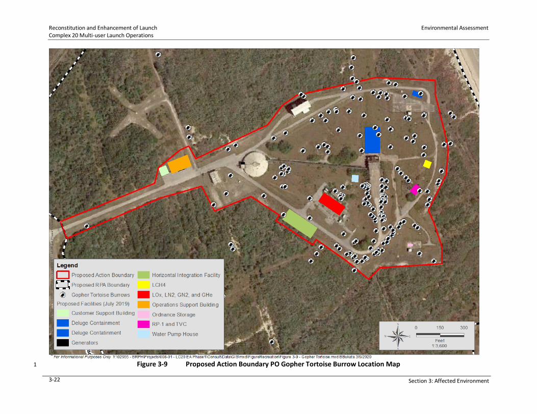
Reconstitution and Enhancement of Launch Environmental Assessment Complex 20 Multi-user Launch Operations
3-22 Section 3: Affected Environment
Figure 3-9 Proposed Action Boundary PO Gopher Tortoise Burrow Location Map 1

Environmental Assessment Reconstitution and Enhancement of Launch Complex 20 Multi-user Launch Operations
Section 3: Affected Environment 3-23
1
Figure 3-10 Proposed RPA Boundary Area PO Gopher Tortoise Burrow Location Map 2

Reconstitution and Enhancement of Launch Environmental Assessment Complex 20 Multi-user Launch Operations
3-24 Section 3: Affected Environment
3.4 CULTURAL RESOURCES 1
Historical and cultural resources include prehistoric and historic sites, man-made structures, 2
buildings, and remnants of legacy launch vehicles districts, artifacts, or any other physical 3
evidence of human activity considered important to a culture or community for scientific, 4
traditional, religious, or any other reasons. The ROI for the historical and cultural resources for 5
the Proposed Action includes the legacy SLC-20 area and extends to the balance of the entire 6
220 acres (89 ha) area proposed for the real property transfer between 45 SW and Space Florida. 7
An extensive array of federal and state laws exist that require analyses of possible effects to 8
cultural resources during the planning, design, and construction on federal lands and elsewhere. 9
These laws and regulations prescribe the responsibilities and coordination between the federal 10
agency where the Proposed Action would occur and stakeholder agencies having review and 11
comment authority over the Proposed Action. These agencies include the State Historic 12
Preservation Officer (SHPO), Tribal Historic Preservation Officers (THPOs), and Advisory Council 13
on Historic Preservation (ACHP). Specific laws pertaining to the treatment of cultural resources 14
are Sections 106 and 110 of the National Historic Preservation Act (NHPA), Archaeological 15
Resources Protection Act (ARPA), American Indian Religious Freedom Act (AIRFA), and Native 16
American Graves Protection Act (NAGRA). AFI 32-7065, Cultural Resources Management, 17
provides guidelines for the protection and management on USAF-managed lands. 18
Only those cultural resources that are determined to be significant or potentially significant 19
under the regulations cited are subject to protection from adverse impacts from a Proposed 20
Action. To be considered significant, a cultural resource must meet one or more of the criteria 21
established by the NPS that would make the resource eligible for inclusion in the NRHP. The 22
phrase “eligible for inclusion” includes all properties that meet the NRHP listing criteria, which 23
are specified in the Department of the Interior regulations cited in Title 36 CFR 60.4 and NRHP 24
Bulletin 15. Any property considered prehistoric, historic, or considered to be traditionally 25
significant are collectively referred to as “historic properties.” 26
3.4.1 Archaeological and Historic Resources 27
Archaeological 28
Research suggests that Florida experienced its first human occupation as early as 15,000 years 29
ago. Cape Canaveral has a long record of human occupation, which is reflected by the presence 30
of numerous prehistoric and historic sites that are part of the area’s rich archaeological heritage. 31
Human occupation at Cape Canaveral spans from the first Native Americans approximately 32
5,000 years ago (Doran et al. 2014). This early settlement had its focus within the Banana River 33
Lagoon (BRL) salt-marsh area with evidence of a wider distribution of inhabitance into the entire 34
peninsula with utilization of marine, estuarine, and terrestrial resources. Prehistoric inhabitance 35
in the vicinity of CCAFS include the following periods: Archaic Period, Mt. Taylor Period, Orange 36
Period, Transitional Period, Malabar I, IIA, and IIB Periods, and Protohistoric or Seminole Period. 37
In Florida, the Middle Archaic (circa 5,000 BC) witnessed increased population growth and 38
reliance on marine resources. Sites were expanded into the St. Johns River area, along the 39
Atlantic coastal strand, and along the southwest Florida coast into south Florida (Milanich 1995). 40
Maritime adaptations become increasingly apparent from 7,000 BC. Shellfish resources first 41

Environmental Assessment Reconstitution and Enhancement of Launch Complex 20 Multi-user Launch Operations
Section 3: Affected Environment 3-25
appear in the archaeological record during the Middle Archaic. Extensive shell middens along the 1
coast and canal systems connecting mangrove swamps were constructed by humans using the 2
coastal zone. Middle Archaic sites, specifically shell middens, are plentiful and are found in a 3
variety of locations in Florida (Milanich 1994). The Orange Period (2,000 to 500 BC) was noted 4
for the first appearance of ceramics and, while still hunter-gatherers, saw increased sedentism 5
with middens becoming commonplace. Malabar I saw villages with special use camps and even 6
larger populations. Malabar II (AD 900 to 1565) saw the beginning of non-local objects, European 7
artifacts, and evidence of wreck salvaging introducing the “Contact Period” (1500 to 1565). 8
Regarding the “Contact Period”, the Florida peninsula first appeared in cartography in 1502 on 9
the Cantino map and in 1507 on the Waldseemuller map (Lydecker et al. 2011). 10
11
While it is unknown when Europeans first made contact with Florida’s native tribes, Juan Ponce 12
de León made the first “authorized discovery” of Florida in 1513 (Griffin 1983; Turner 2013). 13
Before that documented voyage, it is virtually certain that Spaniards were using Florida as a 14
staging ground to capture slaves and possibly provision their ships, as had been practiced 15
extensively in the Bahamas for some time. The exact location of Juan Ponce de León’s initial 16
landfall remains unknown, but judging from the latitude recorded in his log the prior day it would 17
have been somewhere close to present-day Ponte Vedra, north of St. Augustine. He claimed the 18
“island” for Spain and named it La Florida because it was the season of Pascua Florida (“Flowery 19
Easter”) and because much of the vegetation was in bloom. 20
Like other conquistadors in the Americas, Ponce de León was likely looking primarily for gold, 21
Indians to enslave, and land to govern under the Spanish crown. Accounts of the Ponce de Leon 22
voyage describe interactions with the Ais Indians, the tribe occupying the Central East Coast of 23
Florida, including Cape Canaveral, at the time (Rouse 1951). The Ais were one of the most 24

Reconstitution and Enhancement of Launch Environmental Assessment Complex 20 Multi-user Launch Operations
3-26 Section 3: Affected Environment
powerful tribes in Florida at the time of the first Spanish contact. Their settlements were 1
numerous but dwellings temporary, reflective of their hunter-gatherer lifestyle. 2
Traditional resources associated with the Ais include archaeological sites, mounds, burial sites, 3
ceremonial areas, caves, and plant habitat and gathering areas including any sites that would 4
have religious or heritage significance. These traditional resources could be considered significant 5
traditional cultural properties (TCPs), are subject to the same regulations as other historic 6
properties, and are therefore afforded the same protection. No Ais Indians remain, but their 7
traditional culture is represented by the Seminole and Miccosukee Tribes of Indians in Florida. 8
During a site visit to CCAFS in 2011, the Seminole Tribe of Florida and Seminole Nation of 9
Oklahoma verbally stated that they have no TCPs on CCAFS. (45 SW Cultural Resource Manager 10
[CRM], personal communication to W. Puckett, September 2019) The 45 SW updated its 11
Installation Cultural Resource Management Plan (ICRMP) in 2015, which also stated that no TCPs 12
are present at CCAFS. 13
Historic 14
Cape Canaveral played a role as a prominent landmark in nearly every era of recorded history in 15
the New World but was not permanently occupied to any great extent until relatively recently. 16
As a sign of its ephemeral early occupation, a Town of Canaveral is shown in different locations 17
on maps in the last 150 years, following the focus of residential development. Historical 18
occupations include First Spanish (1513 to 1763), British (1763 to 1783), Second Spanish (1783 to 19
1821), American Territorial (1821 to 1842), Early Statehood (1842 to 1861), Civil War (1861 to 20
1865), Reconstruction and Late Nineteenth Century (1865 to 1899), and Twentieth Century 21
(1900+). 22
Cape Canaveral is now in Brevard County, which has changed boundaries several times. Brevard 23
County was formed on March 14, 1844, from a segment of Mosquito County (Orange County). 24
Brevard County, called St. Lucie County until 1854, was named for the Florida State Comptroller 25
at the time, Theodore W. Brevard. Titusville, the County seat, had early roots as the community 26
of Sand Point, which was formed to serve early settlers lured to the area by homestead land 27
grants through the Armed Occupation Act of 1842. 28
According to the 45 SW ICRMP, the federal government began buying land from the state in Cape 29
Canaveral in the late 1940s to establish a long-range proving ground. A committee was formed 30
by the DoD in 1946 with the task of finding a suitable missile test center; subsequently, the Long-31
Range Proving Ground on Cape Canaveral was established in 1949 under the jurisdiction of USAF 32
(USAF 2015a). Important factors for the committee choosing Cape Canaveral included the 33
weather, geographical isolation, low land prices, existence of government-owned property in the 34
area, and proximity to islands in the West Indies and South Atlantic, which could be used for 35
tracking missiles. By 1948, CCAFS was firmly established as a launch site for USAF (USAF 2015a). 36
An extensive history of CCAFS space operations can be found in works by USAF and Pan American 37
World Airways, Inc. (1974) and Mark C. Cleary (1994). This land has had numerous names under 38
government ownership including Cape Canaveral (1950 to 1963), Cape Kennedy (1963 to 1974), 39
Cape Canaveral (1974 to 1994), and CCAFS (1994 to present). 40

Environmental Assessment Reconstitution and Enhancement of Launch Complex 20 Multi-user Launch Operations
Section 3: Affected Environment 3-27
3.5 AIR QUALITY 1
Air quality at CCAFS is regulated under Federal Clean Air Act regulations (Title 40 CFR Parts 50 2
through 99) and FAC Chapters 62-200 through 62-299. The US Environmental Protection Agency 3
(USEPA), under the authority of the Clean Air Act, as amended, has established nationwide air 4
quality standards known as the National Ambient Air Quality Standards (NAAQS). The NAAQS 5
represent the maximum allowable atmospheric concentrations of health-based criteria and are 6
referred to as “criteria pollutants.” These criteria pollutants include carbon monoxide (CO), lead 7
(Pb), nitrogen dioxide (NO2), ozone (O3), sulfur dioxide SO2), particulate matter (PM) 8
10 micrometers or less in diameter (PM10), and PM 2.5 micrometers or less in diameter (PM2.5). 9
The NAAQS are further broken down into two categories, the National Primary Standards and 10
National Secondary Standards. The Primary NAAQS provide public health protection including 11
the health of “sensitive” populations including the elderly, children, and persons with asthma. 12
The Secondary NAAQS provide general public welfare protection against decreased visibility, 13
damage to animals, crops, vegetation, and buildings. Table 3-4 lists the NAAQS. 14
Table 3-4 Federal National Ambient Air Quality Standards 15
Pollutant Average Time Federal Primary NAAQS Federal Secondary NAAQS
CO 8-hour 9 ppm N/A 1-hour 35 ppm N/A
Pb Rolling 3-month Average 0.15 µg/m3 0.15 µg/m3
NO2 1-hour 100 ppb N/A Annual 53 ppb 53 ppb
O3 8-hour 0.07 ppm 0.07 ppm
PM2.5 Annual 12 µg/m3 15 µg/m3 24-hour 35 µg/m3 35 µg/m3
PM10 24-hour 150 µg/m3 150 µg/m3
SO2 1-hour 75 ppb N/A 3-hour N/A 0.5 ppm
Source: USEPA 2019. 16
Notes: µg/m3 = micrograms per cubic meter of air; ppb = parts per billion; ppm = parts per million 17
The State of Florida has a statewide network of air-quality monitoring. The focus of this network 18
is the management of air quality throughout the state with a focus on those areas where ambient 19
air quality standards are at risk of being violated and areas where the ambient standards are 20
being met but are at risk due to potential growth in the populations of those areas or industrial 21
growth. Regional air quality in Florida is assessed at county level; Brevard County is designated 22
as “in attainment” with the NAAQS. The term “in attainment” refers to areas with concentrations 23
of criteria pollutants that are below the levels established by the NAAQS. If the concentration of 24
one or more criteria pollutant in an area exceeds the levels established by the NAAQS, the area 25
may be classified as a “non-attainment” area. Since Brevard County is in attainment for all 26
regulated criteria pollutants, no conformity determination is required for the Proposed Action. 27
Table 3-5 summarizes air emissions for 2012 through 2016 for CCAFS of actual tons per year of 28
the NAAQS-regulated criteria pollutants and total hazardous air pollutants (HAPs). 29

Reconstitution and Enhancement of Launch Environmental Assessment Complex 20 Multi-user Launch Operations
3-28 Section 3: Affected Environment
Table 3-5 History of Actual Annual Emissions (Tons per Year) at CCAFS 1
Pollutant Year 2016 2015 2014 2013 2012
CO 11.66 10.75 9.83 10.95 19.47 Pb 0.000033 - - - - NO2 42.21 36.28 33.56 35.79 73.58 PM2.5 3.00 2.59 2.66 2.63 5.20 PM10 2.76 2.31 2.21 2.29 5.03 HAPs 0.02 0.03 0.03 0.03 0.15 VOCs 3.35 2.86 2.69 2.84 6.22
Source: FDEP 2019. 2
Notes: VOCs = volatile organic compounds. 3
With respect to ozone depleting chemicals (ODCs), use of ODCs at CCAFS is strictly prohibited and 4
will not be used as part of any construction or operation occurring at the proposed reconstruction 5
of SLC-20. 6
3.6 CLIMATE 7
3.6.1 Regional Conditions 8
Climate is a term which refers to the long-term regional and/or global average of temperature, 9
humidity, and rainfall patterns over long periods. In the mid-latitudes where Brevard County is 10
located, the meteorological conditions result in one of the most diverse ecosystems in North 11
America due to the rare combination of climates. Brevard County is exposed to a temperate 12
climate from the north and a warm subtropical climate to the south creating favorable conditions 13
for a wide variety of floral and faunal ecosystems. The climate in the region is characterized by 14
hot, humid, summers with temperatures in the mid-to-upper 90 degrees Fahrenheit (°F) 15
(32 degrees Celsius [°C]). Winters are mild with daytime temperatures ranging from 60 to 70°F 16
(15 to 21°C); occasionally, temperatures fall to freezing levels in January and February. 17
Hurricane season occurs from June through November with a majority of hurricanes developing 18
between August and October. The peninsula of Florida is surrounded by the Atlantic Ocean and 19
Gulf of Mexico; therefore, oceanic currents contribute to the State's weather, creating 20
atmospheric conditions suitable for spawning thunderstorms, lightning, and periodically 21
hurricanes. Humidity in the region is highly variable with relative humidity in the summer being 22
between 70 and 90 percent. During non-summer months, the relative humidity is high in the 23
morning, averaging 90 percent, but dropping to between 55 and 65 percent in the afternoons. 24
Regarding precipitation, average annual rainfall in the Brevard County area is approximately 25
52 inches per year (125 cm) with 70 percent occurring between May and October primarily due 26
to afternoon thunderstorms (NASA 2013). The maximum rainfall months are August and 27
September with an average of 7.6 inches (17.5 cm) of rain; conversely, the least amount of rain 28
falls in January with an average of 2.3 inches (5.8 cm) (Weather Atlas 2019). 29
The principal meteorological conditions that control dispersion are winds and turbulence (or 30
mixing ability) of the lower atmosphere. In the mid-latitudes where CCAFS is located, the lower 31
atmosphere (troposphere) extends 6.2 to 7.5 miles, (10 to 12 km) above the earth’s surface to 32

Environmental Assessment Reconstitution and Enhancement of Launch Complex 20 Multi-user Launch Operations
Section 3: Affected Environment 3-29
the bottom of the stratosphere. Wind speed and direction are variable and correlated with 1
seasonal meteorological conditions. Winds during the summer are predominantly from the south 2
and southeast and become more easterly in the fall. During the winter, winds are typically from 3
the north and northwest. Uneven solar heating of land and water during the summer causes a 4
sea breeze (from ocean to land) during the day and a land breeze (from land to ocean) at night. 5
Wind speed, along with the degree of turbulence, controls the volume of air available for 6
pollutant dilution. Atmospheric stability is a measure of the mixing ability of the atmosphere and, 7
therefore, its ability to disperse pollutants. Greater turbulence and mixing are possible as the 8
atmosphere becomes less stable, and therefore pollutant dispersion increases. In general, stable 9
conditions occur most frequently during the nighttime and early morning. 10
3.6.2 Global Climate 11
Greenhouse gases (GHGs) are gases that trap heat in the atmosphere. The primary GHGs of 12
concern are CO2, methane (CH4), nitrous oxide (N2O), hydrofluorocarbons, perfluorocarbons, and 13
sulfur hexafluoride (SF6). These emissions occur from natural processes and human activities. 14
According to the FAA Order 1050.1F Desk Reference, climate change is a global phenomenon that 15
can have local impacts (FAA 2015). Scientific measurements show that the earth’s climate is 16
warming, with concurrent impacts including warmer air temperatures, increased sea-level rise, 17
increased storm activity, and an increased intensity in precipitation events. 18
The six reporting facilities in Brevard County had a total of 3,222,445 metric tons of carbon-19
dioxide equivalent (CO2e) emissions in 2017 (USEPA 2020). (GHG emissions are often measured 20
in carbon-dioxide equivalent, which is calculated by multiplying emissions by the gas’s global 21
warming potential.) The majority (i.e., 97 percent) of those emissions in Brevard County, 22
specifically 3,124,301 metric tons of CO2e, were associated with the power plant and waste 23
sectors (USEPA 2020). 24
3.7 HAZARDOUS MATERIALS AND HAZARDOUS WASTE 25
The ROI for potential impacts from hazardous material, solid waste, and pollution prevention 26
includes the areas within and around SLC-20. 27
3.7.1 Hazardous Material and Hazardous Waste 28
Hazardous materials are any substance or material that has been determined to pose substantial 29
or potential threats to public health or the environment when transported in commerce 30
(49 CFR Part 172). This includes a subset of solid wastes that meet the criteria identified in 31
40 CFR Parts 260 and 261, hazardous substances and hazardous wastes. Hazardous substances 32
are any element, compound, mixture, solution, or substance defined as a hazardous substance 33
under the Comprehensive Environmental Response, Compensation, and Liability Act (CERCLA) 34
and listed in 40 CFR Part 302. If released into the environment, hazardous substances may pose 35
substantial harm to human health or the environment. Hazardous wastes have characteristics as 36
defined by the RCRA in 40 CFR Part 261 which … may (a) cause, or significantly contribute to, an 37
increase in mortality or an increase in…illness or (b) pose a substantial present or potential hazard 38
to human health or the environment when improperly treated, stored, transported, or disposed 39
of or otherwise managed. Hazardous waste is further defined as any solid waste that possesses 40

Reconstitution and Enhancement of Launch Environmental Assessment Complex 20 Multi-user Launch Operations
3-30 Section 3: Affected Environment
hazardous characteristics of toxicity, ignitability, corrosivity, or reactivity, or is specifically listed 1
as a hazardous waste in Subpart D of 40 CFR Part 261. 2
USEPA regulates hazardous chemicals, substances, and wastes under RCRA, CERCLA, and the 3
Toxic Substances Control Act (TSCA). These regulations provide requirements for the generation, 4
storage, transportation, treatment, handling, and disposal of hazardous materials and hazardous 5
waste. USEPA and various states also have regulations regarding the operation and maintenance 6
of underground storage tanks and ASTs. In addition, OSHA has definitions and workplace safety-7
related requirements and thresholds for approximately 400 hazardous and toxic substances, and 8
DOT has definitions and requirements for the safe transportation of hazardous materials. 9
Numerous types of hazardous materials are currently used at CCAFS to support various space 10
missions and general maintenance operations. 11
Individual contractors and organizations maintain their own hazardous waste satellite 12
accumulation points and 90-day hazardous waste accumulation areas in accordance with RCRA. 13
Any amount of hazardous waste can be stored at a 90-day hazardous waste accumulation area, 14
but wastes must be disposed of off-site within 90 days. Under current RPAs, Space Florida would 15
be responsible for the collection and transportation of hazardous wastes (including propellant 16
waste) from the satellite accumulation areas to a 90-day hazardous waste accumulation area, 17
then to an off-site permitted treatment, storage, and disposal facility. As specified under lease 18
agreements and contracts, the contractors are under contract to reduce, where possible, the use 19
of Class II Ozone-Depleting Substance and Environmental Planning and Community Right-to-20
Know Act (EPCRA) 313 chemicals. 21
Environmental Baseline Surveys (EBS) performed in 1998 and 2018 indicated that no hazardous 22
substances were used or stored on site from 1998 through 2001 and according to the 2018 EBS, 23
no hazardous waste was used or stored on site through 2018. No record of any spills exists in 24
both EBSs. The 1998 EBS reported that in the early 1990s, SLC-20 was designated as a SWMU 25
(# 043), which is discussed in further detail in Section 3.7.3. Since operations began in 1959 until 26
at least 1965, hazardous materials were used on site. Storage and release of non-hazardous 27
waste was also reported to have occurred from approximately 1978 to 1988. The UST 28
(Facility 15500A-1) installed in 1966 (680 gallons) was removed as part of the RFI/IM efforts at 29
the site. The IM included the excavation of 20 tons of associated petroleum- and metal-30
contaminated soils in addition to the removal of the UST. A complete list of all the materials used 31
or stored on site is not available. However, the following items were documented to be 32
associated with SLC-20: 33
• Diesel Fuel No 2. 34
• Hydrazine. 35
• LOX. 36
• Nitrogen Tetroxide. 37
• Kerosene. 38
• Trichloroethylene. 39

Environmental Assessment Reconstitution and Enhancement of Launch Complex 20 Multi-user Launch Operations
Section 3: Affected Environment 3-31
• Hydraulic fluid. 1
• Petroleum and petroleum products. 2
Paint used on the facilities and structures at this site is assumed likely to contain lead and PCBs. 3
The presence of hazardous materials in the soil and groundwater is discussed more thoroughly 4
in Section 3.7.3. 5
Future tenants would have operations that use products that could contain hazardous materials, 6
including paints, solvents, oils, lubricants, acids, batteries, propellants, ordnance, and chemicals, 7
which are routinely used at CCAFS. Proposed operations do not deviate from current CCAFS 8
operations or introduce new or different hazardous materials or operations. Hazardous materials 9
are transported in accordance with FDOT regulations for shipping hazardous substances. 10
Ordnance is transported to and stored at Fuel Storage Area 2 until ready for use. Hazardous 11
materials, such as liquid rocket propellant, are transported and stored in specially designed 12
containers to reduce the potential of an exposure. 13
Management of hazardous materials and petroleum-related fuels is the responsibility of each 14
organization on CCAFS. RCRA requirements would be accomplished by the directives listed in the 15
respective permits issued to KSC or CCAFS (Installation Emergency Management Plan 10-2, 45 SW 16
Management Plan 19-14, and KSC Handbook [KHB] 8800.6). No sites at CCAFS are listed or under 17
consideration for listing on the National Priorities List (USEPA 2013). 18
USAF provides emergency spill response that is beyond the user’s response. Space Florida’s 19
tenant will prepare an Emergency Response Plan for its launch program in accordance with the 20
CCAFS Hazardous Materials Emergency Response Plan. The CCAFS Hazardous Materials 21
Emergency Response Plan ensures that adequate and appropriate guidance, policies, and 22
protocols regarding hazardous material incidents and associated emergency response are 23
available to and followed by all personnel and commercial entities. 24
In addition, Space Florida’s tenant(s) would develop a site-specific SPCCP for petroleum-related 25
storage tanks and systems, including USTs or ASTs containing petroleum and diesel at SLC-20. 26
According to the 1998 EBS, no ASTs or USTs are on site. However, the 2018 EBS found that one 27
large white AST used to hold pressurized gases was on the paved access road near the guard 28
shack. ASTs were known to be used to support the Titan Launch program and were installed 29
behind protective berms. The 2018 EBS suspects that these tanks may have contained hydrazine, 30
nitrogen-tetroxide, kerosene, or hydraulic fluid. The 2018 EBS also noted that three USTs were 31
installed in 1959. A 280-gallon (1,060-L) steel tank and a 300-gallon (1,136-L) steel tank, both 32
containing Fuel Oil No. 2, were removed in 1991. One 2,000-gallon (7,571-L) steel tank also 33
containing Fuel Oil No. 2 was removed in 1998. The 1998 EBS also documented a 680-gallon 34
(2,574-L) UST used with the Blockhouse boiler that has been inactive since 1966 and was 35
scheduled for removal under the IRP. Whether this tank has been removed is unknown. 36
A generator would be needed to support the tenant’s operations and keep critical equipment 37
working and is estimated to support a duration of 3 days. This would require an AST sized to hold 38
3,200 gallons (12,113 L) of diesel fuel. As this AST is greater than 500 gallons (1,893 L), FDEP tank 39
registration would be required, and the SPCCP discussed above would also include 40
countermeasure plans for this tank. 41

Reconstitution and Enhancement of Launch Environmental Assessment Complex 20 Multi-user Launch Operations
3-32 Section 3: Affected Environment
3.7.2 Solid Waste 1
Solid waste, including non-hazardous refuse, trash, or garbage, consists of everyday items such 2
as product packaging, grass clippings, furniture, clothing, bottles, food scraps, newspapers, and 3
appliances. Alkaline batteries are considered universal waste and are handled separately. 4
General solid refuse at CCAFS is collected by a private contractor and disposed of off-site at the 5
Brevard County Landfill, a Class I landfill at 2250 Adamson Road in the City of Cocoa, Florida. 6
According to the Brevard County website, the existing facility is expanding to develop additional 7
capacity that can meet the needs for future decades. 45 SW also manages a recycling program 8
for appropriate waste material from CCAFS sites. During the 2018 EBS, piles of old piping and 9
refrigerant compressors were found near the former ready room. 10
3.7.3 Installation Restoration Program 11
The DoD established the IRP to identify, characterize, and evaluate past disposal sites and 12
remediate associated contamination as needed to protect human health and the environment. 13
The IRP was initiated at CCAFS in 1984. The IRP efforts at CCAFS have been conducted in parallel 14
with the program at PAFB and in close coordination with the USEPA, FDEP, and NASA KSC. CCAFS 15
is not a National Priorities List site, and the IRP sites are being evaluated and remediated under 16
RCRA authority while meeting the CERCLA regulations. FDEP has approved the 2019 soil 17
remediation program at SLC-20. 18
The environmental status of each launch complex ranges from the identification of an area as an 19
active potential release location (PRL), to an active SWMU, and then through assessment and 20
remediation if required, to a closed or “no further action” (NFA) unit. A SWMU can be defined as 21
any site that has had historical operations that had the potential to impact the environment. A 22
RCRA Facility Assessment identifies releases or migration of contaminants from a SWMU. Figure 23
3-11 shows the locations of SWMU 043 and soil measurement of contaminants. The following 24
provides a brief history of the remedial activities at SLC-20. 25
During launch activities from 1959 through 1965, several hazardous chemicals were stored and 26
used at SLC-20, including trichloroethylene, fuels, hydrazine, LOX, nitrogen tetroxide, kerosene, 27
hydraulic fluid, paints, lubricants, Freon, and PCBs. Based on generator knowledge, historical 28
paint formulations used on launch structures included PCBs and lead. Routine sand-blasting 29
activities following launches dispersed the PCBs throughout site surface soils. Additionally, paint 30
delamination from the launch structure also contributed to PCB and lead contamination 31
throughout the site. 32
Since SLC-20 became a SWMU in the early 1990s, numerous environmental assessments and 33
remediation activities have occurred under the RCRA Facility Investigation (RFI) program. Since 34
2008, the IRP has conducted 5-year reviews of past investigation and data gaps. The 2013 review 35
noted that PCBs in soils were above the industrial SCTL. These soils were generally around the 36
former launch stand area. An ongoing dioxin/furan (compounds that occur when PCBs are heated 37
or burned) study was also documented in the 2013 review. A Preliminary Assessment and Site 38
Investigation were completed at SLC-20 from 1992 to 1995. Based on the results, a Resource 39
Conservation and Recovery Act Facility Investigation (RFI) was initiated to fully evaluate the 40
nature and extent of contamination at the site. Several IM soil removals were performed 41

Environmental Assessment Reconstitution and Enhancement of Launch Complex 20 Multi-user Launch Operations
Section 3: Affected Environment 3-33
concurrently with the RFI in 1995 and 1998 to remove contaminated soil and sediment at 1
SLC-20. Based on the RFI results, No Further Action was recommended for groundwater, surface 2
water, and sediment, which was approved by FDEP on September 17, 1999. Based on 3
recommendations from the Five-Year Review in 2008, additional soil sampling was performed to 4
assess for PCBs and metals associated with paint coatings on historical launch structures at the 5
site. Additional soil sampling was conducted along with removal of water and debris at the 6
SLC-20 actuator pit in 2012. From 2015 to 2016, a Data Gap Investigation was performed to 7
laterally and vertically delineate PCB contamination in soil in excess of the industrial SCTL along 8
with sampling at one former substation location to determine if PCBs had leached to 9
groundwater. A temporary groundwater monitoring well was installed and sampled at the 10
location, and all results were less than the FDEP GCTLs for PCBs, thus No Further Action for 11
groundwater was warranted. In addition, a study was performed for dioxin/furan compounds at 12
the site. Dixon/furans compounds were suspected to co-exist with PCB soil contamination at the 13
site based on heating/burning activities during launches. A soil removal was completed in 2019 14
to address remaining concentrations of PCBs and dioxin/furans in excess of the FDEP industrial 15
SCTLs. Remaining soils are now safe for re-use under industrial land-use scenarios. An interim 16
remediation action was developed and published in 2017, which outlined removal of those soils 17
above the SCTL (Figure 3-11). Under the RFI program and managed by USAF IRP, soil remediation 18
activities were completed in mid-2019. 19

Reconstitution and Enhancement of Launch Environmental Assessment Complex 20 Multi-user Launch Operations
3-34 Section 3: Affected Environment
1
Figure 3-11 Soil Contamination Location Map for SWMU No. C043 (USAF 2013) 2
3.7.4 Pollution Prevention 3
Pollution prevention is any practice that reduces, eliminates, or prevents pollution at its source. 4
This can be done by modifying production processes, promoting the use of non-toxic or less toxic 5
substances, implementing conservation techniques, and re-using materials rather than putting 6
them into the waste stream. EO 12088, Federal Compliance with Pollution Control Standards, 7
directs federal agencies to comply with applicable pollution control standards in prevention, 8
control, and abatement of environmental pollution and to consult with USEPA, state, and local 9
agencies concerning the best techniques and methods available for prevention, control, and 10
abatement of environmental pollution. 11
Environmental implications of all projects must be considered during the design phase, and 12
designs must be developed that minimize or eliminate environmental liability. Pollution 13
prevention environmental analysis for a project must be included and performed early in the 14
design phase. The environmental analysis should focus on any potential pollution that may result 15
from the proposed project and must include requirements in the design that promote pollution 16
prevention measures whenever feasible. Designs could also include sustainability initiatives 17
including but not limited to energy conservation, water conservation, and use of recycled or 18
reclaimed content. Where pollution cannot be prevented, the environmental analysis would 19

Environmental Assessment Reconstitution and Enhancement of Launch Complex 20 Multi-user Launch Operations
Section 3: Affected Environment 3-35
include requirements that promote recycling, energy recovery, treatment, and environmentally 1
safe waste disposal practices. 2
Space Florida’s tenant(s) will develop a pollution prevention plan containing methods and 3
processes that meet USAF and local requirements. 4
3.8 WATER RESOURCES 5
3.8.1 Surface Waters 6
Water resources include groundwater, surface waters, wetlands, and floodplains and their 7
physical, chemical, and biological characteristics. CCAFS is within the Florida Middle East Coast 8
Basin watershed and situated on a barrier island that separates the BRL from the Atlantic Ocean. 9
This basin contains three major water bodies: the BRL to the immediate west, Mosquito Lagoon 10
to the north, and the IRL to the west of Merritt Island. The BRL has been designated a Class III 11
surface water; a designation under the Clean Water Act that intends for a level of water quality 12
suitable for recreation and the production of fish and wildlife communities. In addition, several 13
water bodies in the Middle East Coast Basin have been designated as Outstanding Florida Waters 14
in Chapter 62-3, FAC, including most of the Mosquito Lagoon and the BRL, Indian River Aquatic 15
Preserve, Banana River State Aquatic Preserve, Pelican Island National Wildlife Refuge, and the 16
CNS. As a result of this designation, these water bodies are afforded a higher level of regulatory 17
protection. In addition, in 1990 the IRL system was designated as an Estuary of National 18
Significance under the USEPA’s National Estuary Program. 19
Figure 3-1 depicts a small man-made surface water that historically served as a stormwater 20
treatment swale. No other surface waters occur within the existing SLC-20 boundary. 21
3.8.2 Groundwater 22
The surficial and the Floridan aquifer systems underlie CCAFS. The surficial aquifer system (SAS), 23
which is comprised generally of sand and marl, is unconfined and approximately 70 feet (21.3 m) 24
thick. The SAS is recharged by infiltration of precipitation through the thin vadose zone. Assuming 25
negligible runoff, the amount of recharge is approximately equal to the amount of precipitation 26
minus the amount returned to the atmosphere through evaporation and transpiration 27
(NASA 2013). Overall SAS groundwater flow direction at SLC-20 is predominantly to the south 28
and southwest under a relatively flat hydraulic gradient. Depth to the SAS varies but is 29
approximately 3.3 feet (1 m) (GEAR 2019). 30
The Floridan aquifer is the primary source of potable water in central Florida and contains water 31
under artesian conditions. It is confined by the clays, sands, and limestones of the overlying 32
Hawthorn Formation which is approximately 80 to 120 feet (24.4 to 36.6 m) thick. Water enters 33
the Floridan aquifer near the center of the Florida peninsula and moves laterally toward the 34
coasts. In the vicinity of CCAFS, groundwater in the Floridan aquifer flows to the northeast. 35
3.8.3 Wetlands 36
Wetlands are defined in AFI 32-1067, Water and Fuel Systems (February 2015), as those areas 37
…that are inundated by surface or ground waters that support plants and animals that need 38
saturated or seasonally saturated soil to grow and reproduce. Wetlands include swamps, 39
marshes, bogs, sloughs, mud flats and natural or manmade ponds. Wetlands are some of the 40

Reconstitution and Enhancement of Launch Environmental Assessment Complex 20 Multi-user Launch Operations
3-36 Section 3: Affected Environment
most biologically productive of all habitats. Wetlands are protected under Section 404, Waters 1
of the US, the Clean Water Act via the US Army Corps of Engineers (USACE), as well as by the 2
State of Florida via the state water management districts (WMDs) and FDEP. EO 11990 requires 3
avoidance, to the extent possible, of the long- and short-term adverse impacts associated with 4
the destruction or modification of wetlands and to avoid direct or indirect support of new 5
construction in wetlands wherever a practicable alternative exists. 6
No USACE or St. Johns River Water Management District (SJRWMD) jurisdictional wetlands occur 7
within the Proposed Action boundary. 8
3.8.4 Floodplains 9
Floodplains are lowland and relatively flat areas adjoining inland and coastal waters and other 10
flood-prone areas such as offshore islands. These flood hazard areas are identified on Federal 11
Emergency Management Agency (FEMA) Flood Insurance Rate Maps (FIRMs) and are referred to 12
as a Special Flood Hazard Area (SFHA). SFHAs are defined as the area that will be inundated by 13
the flood event having a 1-percent chance of being equaled or exceeded in any given year. The 14
1-percent annual chance flood is also referred to as the base flood or 100-year flood. SFHAs are 15
labeled as ‘Zones,’ several of which are east of, but not within, the Proposed Action area: 16
• Zone AE – The base floodplain where base flood elevations are provided. AE Zones are now 17
used on new format FIRMs instead of A1-A30 Zones. 18
• Zone AO – River or stream flood hazard areas, and areas with a 1 percent or greater chance 19
of shallow flooding each year, usually in the form of sheet flow, with an average depth ranging 20
from 1 to 3 feet. These areas have a 26 percent chance of flooding over the life of a 30-year 21
mortgage. Average flood depths derived from detailed analyses are shown within these 22
zones. 23
• Zone VE – Coastal areas with a 1 percent or greater chance of flooding and an additional 24
hazard associated with storm waves. These areas have a 26 percent chance of flooding over 25
the life of a 30-year mortgage. Base flood elevations derived from detailed analyses are 26
shown at selected intervals within these zones. 27
• Zone X – Area of minimal flood hazard, usually depicted on FIRMs as above the 500-year flood 28
level. 29
DOT has implemented EO 11988 through policies and procedures documented in DOT 30
Order 5650.2, Floodplain Management and Protection. DOT Order 5650.2 defines the natural and 31
beneficial values provided by floodplains to include natural moderation of floods, water quality 32
maintenance, groundwater recharge, fish, wildlife, plants, open space, natural beauty, scientific 33
study, outdoor recreation, agriculture, aquaculture, and forestry. No floodplains occur within the 34
Proposed Action boundary (Figure 3-12). 35
3.9 GEOLOGY AND SOILS 36
CCAFS topography consists of a series of relic dune ridges formed by wind and wave action. The 37
higher naturally occurring elevations occur along the east portion of CCAFS, with a gentle slope 38
to lower elevations toward the marshlands along the BRL. Topography at CCAFS is relatively flat 39
with elevations that range from sea level to 15 feet (4.6 m) above mean sea level (MSL). The 40

Environmental Assessment Reconstitution and Enhancement of Launch Complex 20 Multi-user Launch Operations
Section 3: Affected Environment 3-37
geology underlying CCAFS can be generally defined by four stratigraphic units: surficial sands, 1
Caloosahatchee Marl, Hawthorn Formation, and limestone formations of the Floridan aquifer. 2
The surficial sands immediately underlying the surface are marine deposits that are typically 3
approximately 10 to 30 feet (3 to 9.1 m) below the surface. The Caloosahatchee Marl underlies 4
the surficial sands and consists of sandy shell marl that extends to 70 feet (21.3 m) below the 5
surface. The Hawthorn Formation, which consists of sandy limestone and clays, underlies the 6
Caloosahatchee Marl and is the regional confining unit for the Floridan aquifer. This formation is 7
generally 80 to 120 feet (24.4 to 36.6 m) thick, typically extending to approximately 180 feet 8
(54.9 m) below the surface. Beneath the Hawthorn Formation lie the limestone formations of the 9
Floridan aquifer, which extend several thousand feet below the surface of CCAFS (USAF 2005). 10
The National Resources Conservation Service (NRCS 2014) identifies 11 different soil types within 11
CCAFS, with the three dominant soil series being (1) Canaveral-Anclote Complex (48 percent), 12
Canaveral-Urban Complex (11 percent), Welaka Sand (10 percent), and Palm Beach Sand 13
(9 percent) (Figure 3-13). The most prevalent type of soil is Canaveral Sand. Canaveral soils are 14
on moderately low ridges and consist of a mixture of light-colored quartz sand grains and 15
multicolored shell fragments. 16
These dominant soil series are made up of nearly level and gently sloping ridges interspersed 17
with narrow wet sloughs that generally parallel the ridges and extend the entire length of the 18
County along the coast near the Atlantic Ocean. These soils are moderately well drained to 19
excessively drained, and sandy throughout and exceptionally dry, even though the water table is 20
often near the surface during rainy periods. Figure 3-14 provides an NRCS soils map of the 21
Proposed Action site. 22

Reconstitution and Enhancement of Launch Environmental Assessment Complex 20 Multi-user Launch Operations
3-38 Section 3: Affected Environment
1
Figure 3-12 Floodplain Map 2
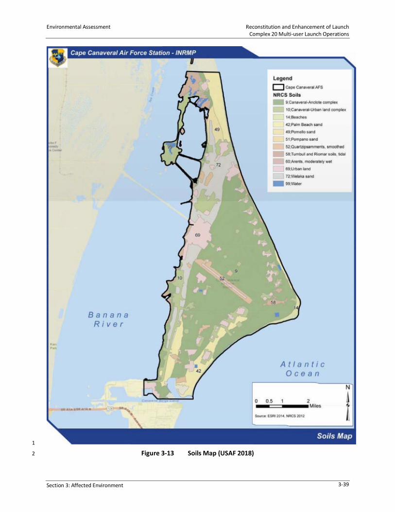
Environmental Assessment Reconstitution and Enhancement of Launch Complex 20 Multi-user Launch Operations
Section 3: Affected Environment 3-39
1
Figure 3-13 Soils Map (USAF 2018) 2

Reconstitution and Enhancement of Launch Environmental Assessment Complex 20 Multi-user Launch Operations
3-40 Section 3: Affected Environment
1
Figure 3-14 Soils Map 2

Environmental Assessment Reconstitution and Enhancement of Launch Complex 20 Multi-user Launch Operations
Section 3: Affected Environment 3-41
3.10 TRANSPORTATION 1
3.10.1 Regional Access 2
CCAFS is approximately 150 miles (241 km) south of Jacksonville, 50 miles (80 km) east of 3
Orlando, and 187 miles (301 km) north of Miami. The general region can be accessed from north 4
and south Florida via I-95 or US Highway (US) 1, and from the west via State Route (SR) 528. 5
Access to CCAFS can occur from the south via SR 528 (A1A) through Port Canaveral to Samuel C. 6
Phillips Parkway, from the north along two access routes through KSC; one via SR 405 (NASA 7
Parkway) or another via SR 402 (Max Brewer Memorial Parkway) (Figure 3-15). 8
3.10.2 Local Access 9
The majority of the employees and other related support service providers for CCAFS reside in 10
the unincorporated areas of Brevard County and in the cities of Cape Canaveral, Cocoa, Cocoa 11
Beach, and Rockledge, which are all within 14 miles (22.5 km) of CCAFS. The key roads providing 12
access to CCAFS from the surrounding local communities include SR A1A, SR 520, SR 528, SR 401, 13
SR 405, and SR 3. NASA Causeway (SR 405) connects CCAFS with KSC, the inner barrier islands, 14
and the mainland. South access into CCAFS occurs through Gate 1, which is accessed by SR 401 15
via SR A1A and SR 528. West access into CCAFS is provided by NASA Parkway East and SR 405. 16
From the north, CCAFS can be accessed through Gate 4 and Gate 6 at KSC along Cape Road. Since 17
the Shuttle Program was terminated in 2011, the general workforce that would be using these 18
roadways has substantially declined. 19
The main on-site roadway on CCAFS is Samuel C. Phillips Parkway, a two-lane road in some areas, 20
and a four-lane divided highway in other areas that accommodates most of north-south traffic 21
and connects with KSC to the north. SLC-20 is on ICBM Road, which also runs north and south but 22
further east, closer to the beach. It can be accessed from Samuel C. Phillips Parkway by Central 23
Control Road to the south and by Heavy Launch Road to the north. ICBM Road is a lightly traveled 24
road. 25
Available data indicate that the roads and supporting structures (culverts, bridges, pavement) 26
were constructed to meet FDOT standards. The condition of roadways within CCAFS were most 27
recently assessed in 2013 in a report titled Roads and Parking Lots Pavement Condition Index 28
Survey Report at Cape Canaveral Air Force Station, December 2013 (AMEC 2013). Most road 29
pavement conditions were indexed as good or fair. However, a section of Samuel C Phillips 30
Parkway (Section ID 01A) was assigned an index condition of poor. This section extends from 31
approximately SLC-41 north to the turnoff to KSC Pad 39A. The transportation study indicated 32
that while conditions of most culverts that may be transited appeared to be in good condition, 33
some older culverts may require replacement because their conditions cannot be 34
deterministically calculated due to age and condition. Roadways on KSC property from 35
Commerce Way to Cape Road also appear to be in good or fair condition. However, pavement 36
rehabilitation programs are on-going within KSC and the condition will vary over time. 37
The Proposed Action would transport small- and medium-lift launch vehicles from proposed 38
manufacturing facilities at Exploration Park, KSC to SLC-20 using a standard tractor-trailer and 39
will stay within FDOT maximum weights for an HS-20 vehicle loading (8 kips on front axle, 32 kips 40
for rear axles), for a maximum allowable weight of 80,000 lb (36,287 kg). 41

Reconstitution and Enhancement of Launch Environmental Assessment Complex 20 Multi-user Launch Operations
3-42 Section 3: Affected Environment
1
Figure 3-15 Regional Road Map 2

Environmental Assessment Reconstitution and Enhancement of Launch Complex 20 Multi-user Launch Operations
Section 3: Affected Environment 3-43
Existing pavement geometries indicate that roadway widths along the access route options are 1
at least 24 feet (7 m)wide and can accommodate the expected transport vehicles (American 2
Association of State Highway and Transportation Officials [AASHTO] WB-96 or WB-114 vehicles, 3
80 feet (24 m) maximum length, 21 feet (6 m) inside turning radii, and 66 feet (20 m) outside 4
turning radii). Key intersections also appear to be sufficient for FDOT-permitted vehicles; with 5
NASA Parkway at Samuel C. Phillips Parkway having a minimum inside turning radius of 24 feet 6
(7 m), Samuel C. Phillips Parkway at Heavy Launch Road having a slight horizontal alignment 7
deflection with a 100-foot (30-m) radii, Heavy Launch Road at ICBM Road having an inside radius 8
exceeding 60 feet (18 m), and ICBM Road at SLC-20 having an inside radius greater than 90 feet 9
(27 m). Transport of over-sized loads are coordinated with Cape Support before delivery. 10
3.11 UTILITIES 11
Operations at SLC-20 were provided by CCAFS from the late 1950s until the site was deactivated 12
in 1996. During demolition activities, many piping and cabling systems were abandoned-in-place; 13
however, SLC-20 has recently been in use and continues to have additional active distribution 14
and collection systems in operation. 15
3.11.1 Water Supply, Treatment, and Distribution 16
CCAFS water supply is provided by the City of Cocoa through the City’s municipal potable water 17
distribution system. The City pumps groundwater from the Intermediate and Floridan aquifers 18
from well fields in east Orange County. The water is treated by the City at a potable water 19
treatment facility at the same location. Additionally, the City has Aquifer Storage Wells (ASWs) 20
for storage during low usage and the Taylor Creek Reservoir, a surface water storage facility. 21
CCAFS receives potable and fire protection water from all three sources, as it is blended together 22
after treatment (City of Cocoa, 2018). 23
The US Federal Government has contracted with the City to provide water to KSC, CCAFS, and 24
PAFB. PAFB and CCAFS have a combined total of 6.5 million gallons per day (MGD) allocation and 25
KSC has an additional 2.5 MGD. In 2018, the total daily consumption of water for CCAFS and 26
KCS averaged was 0.7 MGD. Water is used at CCAFS for potable and non-potable purposes. 27
Non-potable use includes hydrant flushing, fire protection, limited irrigation, and launch-related 28
demands. CCAFS recently improved portions of its distribution facilities by separating certain 29
water mains for fire protection only. This improved water quality in the potable distribution 30
system by limiting water age. LC-20 is currently fed from a single 12-inch (30.5-cm) potable line. 31
No separation between fire protection and potable water currently exists. 32
3.11.2 Wastewater Collection and Treatment 33
Wastewater at SLC-20 is currently treated in four septic tanks and drainfields. SLC-20 would 34
continue to use this onsite wastewater treatment system in the short-term. If offsite sanitary 35
collection services become available along ICBM Road, an onsite lift station, force main, and 36
sewer service lines may be installed to connect to the offsite system to the CCAFS wastewater 37
treatment plant (WWTP) in the long-term. The WWTP at CCAFS accepts domestic and industrial 38
wastewater. The most recent permit issued for the WWTF was in April 2020 and expires 39

Reconstitution and Enhancement of Launch Environmental Assessment Complex 20 Multi-user Launch Operations
3-44 Section 3: Affected Environment
April 2025. The CCAFS WWTP has a permitted capacity of 0.8 MGD and in 2018 0.454 MGD or 1
57 percent of the capacity was used. 2
3.11.3 Electrical Supply 3
Historically, CCAFS electrical use represents only 0.4 percent of Brevard County’s demand. 4
Electrical transmission lines served by Florida Power & Light (FPL) enter CCAFS at three locations: 5
from the southwest boundary, across NASA Causeway, and from Merritt Island. The three feeds 6
are capable of providing 59 Mega Volt/Amperes (MVA) to CCAFS, which is well in excess of that 7
required. Electrical usage in 2015 was 140,352 Mega Watts/Hour (MWH). 8
The local electrical distribution system is maintained by CCAFS and provides medium-voltage 9
distribution power to SLC-20. Running at 13.2 kilovolts (KV), this medium-voltage distribution 10
system is fed into the site from Load Brake Switch (LBS) BMCG2 through a duct-bank system of 11
conduit and manholes. On site, this medium-voltage power is stepped down through LBS CX20G1 12
to the various low-voltage distribution transformers, which supplies required power for the 13
existing facilities. The distribution system appears to be capable of supplying electricity to the 14
existing launch facilities. Excess capacity is available should the need arise. 15
3.11.4 Natural Resources and Energy Supply 16
As previously stated, launch complexes on CCAFS draw required electrical power and water from 17
the City of Cocoa. No renewable energy resources or local energy sources are available in the 18
area of SLC-20. However, a large FPL solar farm is south of Exploration Park Phase I, and a large 19
500-acre (202-ha) solar farm is in the planning stages north of the KSC Visitor Center. 20
3.11.5 Stormwater Collection 21
Impervious areas constructed after 1992 are subject to the FAC and the SJRWMD stormwater 22
regulations via the State-Wide Environmental Resource Permit (ERP) process that requires new 23
site developments to capture, attenuate, and treat stormwater. As facilities are improved or 24
built, stormwater systems must be built or upgraded to be consistent with the requirements of 25
SJRWMD Rule 40C-4, FAC. Space Florida’s tenant would be required to submit engineering design 26
plans that present the proposed site development (e.g., civil design, grading) and the stormwater 27
management system as well as stormwater modeling calculations, all of which will be reviewed 28
and approved by SJRWMD before issuance of an ERP. 29
Current stormwater flow from impervious surfaces within SLC-20 follows pre-existing flow paths 30
to roadside swales and depressions where it infiltrates and does not appear to discharge off-site. 31
3.12 HEALTH AND SAFETY 32
Health and safety issues are managed at CCAFS by organizations that review the planning, 33
construction, pre-flight processing, and launch-day operations. The objective of range safety is 34
to ensure that the general public, launch-area personnel, surrounding launch complexes and 35
personnel, and areas of overflight are compliant with USAF requirements, adhere to the 36
AFSPCMAN 91-710, and all public laws. The AFSPCMAN 91-710 is the document that implements 37
the AFI, Space Safety and Mishap Prevention Program, and the Memorandum of Agreement 38
between USAF and the FAA on Safety for Space Transportation and Range Activities. This manual 39
specifies responsibilities and authorities, delineates policies, processes, required approvals, and 40

Environmental Assessment Reconstitution and Enhancement of Launch Complex 20 Multi-user Launch Operations
Section 3: Affected Environment 3-45
approval/waiver levels for all activities from or onto USSF ranges including commercial users 1
(AFSPCMAN 2016). 2
Operational health and safety concerns are primarily the areas in and around CCAFS that could 3
be affected by launch vehicle, equipment, and materials transport to and from the launch 4
complex, payload processing, vehicle safing, and launch operations. As noted above, range 5
safety organizations review, approve, monitor, and impose safety holds, when necessary, on all 6
pre -launch and launch operations in accordance with AFSPCMAN 91-710. 7
Any hazardous materials, including liquid fuels, that must be transported to the launch 8
complex, must be compliant with FDOT regulations regarding interstate shipment of those 9
materials governed by 49 CFR 100-199. 10
Explosive safety quantity-distance criteria and regulations established by DoD and USAF 11
Explosive Safety Standards are used to establish safe distances from launch complexes and 12
associated support facilities to non-related facilities and roadways. Explosive safety quantity 13
distance criteria will be used to establish safe distances from all onsite facilities and adjoining 14
roadways. 15
3.13 SOCIOECONOMICS 16
SLC-20 is in Brevard County. Total population, median household income, households below 17
poverty level, and unemployment rates for Brevard County were used as a basis for identifying 18
existing conditions. Data was obtained from the US Census Bureau 2013 to 2017 American 19
Community Survey 5-Year Estimates. 20
Table 3-6 compares the total population and median household income in Brevard County in 21
2010 and 2017. The data show that 10.2 percent of households were living below the poverty 22
level in 2017 and that the unemployment rate was 7.6 percent. 23
Table 3-6 Brevard County Population Data 24
2010 2017 Percent Increase Population 543,376 568,183 4.6 Median Household Income $49,523 $51,536 4.1
Source: US Census Bureau, 2013 to 2017 American Community Survey 5-Year Estimate. 25
In general, the economic influence of the aerospace industry in Florida has declined somewhat 26
with the termination of the Shuttle program. However, commercial space launch companies such 27
as SpaceX, Blue Origin, and several others have had a positive impact of the economics of Brevard 28
County. According to SpaceFlorida.gov, Florida is ranked among the top five US states for 29
aerospace industry employment, with more than 130,000 employees in 2017. More than 30
17,144 aerospace-related companies are in Florida, which contribute over $19 billion per year in 31
revenues to Florida’s economy. 32

Reconstitution and Enhancement of Launch Environmental Assessment Complex 20 Multi-user Launch Operations
3-46 Section 3: Affected Environment
3.14 ENVIRONMENTAL JUSTICE 1
Environmental justice is defined by the USEPA as “The fair treatment and meaningful involvement 2
of all people regardless of race, color, national origin, or income with respect to the development, 3
implementation, and enforcement of environmental laws, regulations, and policies.” EO 12898, 4
Federal Actions to Address Environmental Justice in Minority Populations and Low-Income 5
Populations, requires all federal agencies to adopt strategies to address environmental justice 6
concerns within the context of agency operations. Section 989.33 of AFI 32-7061, Environmental 7
Impact Analysis Process, requires that a project proponent comply with EO 12898 to ensure that 8
these types of impacts are considered in EAs and other environmental documents. 9
Minority populations included in the US Census Bureau 2013 to 2017 American Community 10
Survey 5-Year Estimates are identified as White, not Hispanic, Black or African American, 11
Hispanic, Asian, or Other (American Indian and Alaskan Native, Native Hawaiian or other Pacific 12
Islander, some other race, or two or more races). Table 3-7 presents data based on the US Census 13
Bureau 2017, which shows that Brevard County had a population of 568,183 persons and details 14
the racial distribution in the County. The closest population centers to CCAFS are Titusville and 15
Port St. John. 16
Table 3-7 Brevard County Racial Distribution 17
Race Distribution White, not Hispanic 82.9%
Black or African American 10.2% Hispanic 9.7%
Asian 2.4% Other 4.5%
Source: US Census Bureau. 18
3.15 SECTION 4(f) PROPERTIES 19
Section 4(f) of the US Department of Transportation Act of 1966 (now codified at 49 USC § 303) 20
protects significant publicly owned parks, recreational areas, wildlife and waterfowl refuges, and 21
public and private historic sites listed or eligible for listing on the National Register of Historic 22
Places. Section 4(f) provides that the Secretary of Transportation may approve a transportation 23
program or project requiring the use of publicly owned land of a public park, recreation area, or 24
wildlife or waterfowl refuge of national, state, or local significance, or land of an historic site of 25
national, state, or local significance, only if there is no feasible and prudent alternative to using 26
that land and the program or project includes all possible planning to minimize harm resulting 27
from its use. I 28
No designated 4(f) properties, including public parks, recreation areas, or wildlife refuges, exist 29
within the boundaries of CCAFS. The MINWR is adjacent to KSC and CCAFS and the CNS is adjacent 30
to KSC and north of CCAFS. The MINWR overlaps the northwest portion of KSC, and all areas not 31
directly used for NASA operations are managed by MINWR and NPS. The nearest public park, 32
Jetty Park, is approximately 5 miles (8 km) south of SLC-20 in the City of Cape Canaveral. Other 33
public parks within an approximate 15-mile (24.1 km) radius of SLC-20 include Kelly Park, KARS 34
Park, Kings Park, and Manatee Cove Park. 35

Environmental Assessment Reconstitution and Enhancement of Launch Complex 20 Multi-user Launch Operations
Section 3: Affected Environment 3-47
This page is intentionally left blank. 1

Environmental Assessment Reconstitution and Enhancement of Launch Complex 20 Multi-user Launch Operations
Section 4: Environmental Consequences 4-1
4.0 ENVIRONMENTAL CONSEQUENCES 1
The analysis in this section focuses on the potential environmental impacts from construction 2
and operation activities at SLC-20. Changes to the natural and human environment that could 3
result from the Proposed Action are evaluated relative to the existing environmental conditions 4
as described in Section 3.0. Four levels of impact may be identified: 5
• Negligible – The impact is barely perceptible or measurable, remains confined to a single 6
location, and would not result in a sustained recovery time for the resource impacted. 7
• Minor – The impact is readily perceptible and measurable; however, the impact would be 8
temporary and the resource should recover in a relatively short period. 9
• Moderate – The impact is perceptible and measurable, and may not remain localized, 10
impacting areas adjacent to the Proposed Action area; adverse impacts to a resource may 11
require several years to recover. 12
• Significant – An impact is predicted that meets the intensity/context significance criteria for 13
the specified resource. 14
Under NEPA (42 USC Part 4321 et seq.), significant impacts are those that have potential to 15
significantly affect the quality of the human environment. Human environment is a 16
comprehensive phrase that includes the natural and physical environments and the relationship 17
of people to those environments (40 CFR §1508.14). The CEQ regulations specify that in 18
determining the significance of effects, consideration must be given to context and intensity 19
(40 CFR § 1508.27). 20
Context means that the significance of an action must be analyzed in several contexts, such as 21
society as a whole, to an affected region, to affected interests, or to just the locality. In other 22
words, the context measures how far the effect would be felt. 23
The intensity of an action (i.e., the severity of the impact) regionally and locally may be 24
determined by whether it is beneficial or adverse. Intensity refers to the severity of the effect 25
within the context involved. The intensity of an action may be determined by: 26
• Unique characteristics in the area (i.e., wetlands, parklands, ecologically critical areas, cultural 27
resources, and other similar factors). 28
• Overall beneficial project effect versus individual adverse effect(s). 29
• Public health and safety. 30
• Degree of controversy. 31
• Degree of unique or unknown risks. 32
• Precedent-setting effects for future actions. 33
• Cumulatively significant effects. 34
• Cultural or historic resources. 35

Reconstitution and Enhancement of Launch Environmental Assessment Complex 20 Multi-user Launch Operations
4-2 Section 4: Environmental Consequences
• Special-status species or habitats. 1
• Compliance with federal, state, or local environmental laws. 2
Thresholds for determining impact significance are based on the applicable compliance standard, 3
federal or state recommended guidance, or professional standards/best professional judgment. 4
In addition, the FAA uses thresholds that serve as specific indicators of significant impact for some 5
impact categories. FAA actions that would result in impacts at or above these thresholds require 6
the preparation of an EIS, unless impacts can be reduced below threshold levels. Quantitative 7
significance thresholds do not exist for all impact categories; however, consistent with the CEQ 8
regulations, the FAA has identified factors that should be considered in evaluating the context 9
and intensity of potential environmental impacts (FAA Order 1050.1F, Paragraph 4-3.3). Since the 10
FAA plans to adopt this EA to support its environmental review of license application(s), the FAA’s 11
significance thresholds are considered in the assessment of potential environmental 12
consequences in this EA. 13
4.1 LAND USE/VISUAL RESOURCES 14
An impact may be considered significant if the project results in nonconformance with approved 15
land use plans or a conflict with existing uses or values of the project area or other properties. 16
Proposed changes to visual resources can be assessed in terms of visual dominance and visual 17
sensitivity. Visual dominance describes noticeable physical changes in an area. The magnitude 18
of visual dominance may vary depending on the degree of change in an area. Visual sensitivity 19
is attributed to a particular setting and the desire to maintain the current visual resources in 20
a viewshed. Areas such as coastlines and national parks are usually considered to have high visual 21
sensitivity. When evaluating visual impact, the ability of the general public to view the area 22
where the proposed action or change to the visual resource would occur must also be assessed. 23
Issuance of a federal license or permit for an activity in or affecting a coastal zone must be 24
consistent with the CZMA, which is managed by the Florida Department of Environmental 25
Protection (FDEP). 26
4.1.1 Proposed Action 27
Land Use 28
The Proposed Action would occur at SLC-20, which has been and is currently designated for space 29
launch activities. Reusing the launch complex, renovating existing facilities, constructing related 30
facilities, and conducting launch operations would be consistent with the 45 SW General Plan 31
and the USAF mission at CCAFS. Activities at SLC-20 would be in conformance with its designated 32
use for space vehicle launches. Coordination with KSC, FAA, MINWR, FDEP, and FCMP member 33
agencies would be conducted as required at the time of permitting to ensure the Proposed Action 34
is consistent with meeting the Florida CZMA plan objectives. Therefore, the Proposed Action 35
would generate negligible adverse impacts on land use. 36
Visual Resources 37
The existing and proposed SLC-20 facilities and launch vehicle would not be visible by the public 38
except possibly from the ocean. However, OLV launches and associated exhaust contrail would 39
be visible in the sky by the public. The contrail visual impact would be similar to all other vehicle 40

Environmental Assessment Reconstitution and Enhancement of Launch Complex 20 Multi-user Launch Operations
Section 4: Environmental Consequences 4-3
launches and would dissipate quickly as wind and air currents affect the trail. Local communities 1
to the south and west have been acclimated to frequent launches of similar or larger size. Launch-2
related visual impacts would be temporary and relatively infrequent, with up to 24 launches per 3
year. Therefore, the Proposed Action would generate negligible adverse impacts on visual 4
resources within the flight range of the OLV vehicle. Section 4.3 discusses light impacts on nesting 5
sea turtles. 6
4.1.2 No-Action Alternative 7
Under the No-Action Alternative, the reuse of SLC-20 and launch of OLVs would not be 8
implemented. Therefore, no impacts to land use, visual resources, or coastal resources would 9
occur. 10
4.2 NOISE 11
Noise impact criteria are based on land use compatibility guidelines and on factors related to the 12
duration and magnitude of noise level changes. Annoyance effects are the primary consideration 13
for most noise impact assessments on humans. Noise impacts on wildlife are discussed in 14
Section 4.3, Biological Resources. 15
The Noise Control Act of 1972 (40 CFR part 209) identifies 65 DNL (dBA) or a CDNL of 61 dB 16
relative to the carrier (dBC) as an acceptable noise level for compatible land uses for sonic booms 17
or rocket noise. This level does not represent a noise standard; rather, it is a basis to set 18
appropriate standards that should also factor in local considerations and issues. 19
In accordance with FAA Order 1050.1F, significant noise impacts would occur if the Proposed 20
Action would increase noise by DNL 1.5 dB or more for a noise sensitive area that is exposed to 21
noise at or above the DNL 65 dB noise exposure level, or that will be exposed at or above the DNL 22
65 dB level due to a DNL 1.5 dB or greater increase, when compared to the No Action Alternative 23
for the same timeframe. 24
For project-related overpressures at 1 psf, the probability of a window breaking ranges from one 25
in one billion to one in one million. In general, the threshold for building damage due to sonic 26
booms is 2 psf, below which damage is unlikely. 27
4.2.1 Proposed Action 28
The Proposed Action includes noise generated by construction and launch operations. 29
Clearing and Construction-Related Noise 30
A temporary increase in ambient noise levels would occur at SLC-20 and the surrounding area 31
during the refurbishment and enhancement of existing facilities and construction of new 32
facilities. Noise impacts from the operation of construction equipment are typically limited to a 33
distance of 1,000 feet (305 m) or less. Construction vehicles that would be used in support of the 34
Proposed Action typically have noise levels between 65 dBA and 100 dBA at a distance of 50 feet 35
(15 m). No residential areas or other sensitive receptors occur at or near SLC-20; therefore, 36
refurbishment and construction noise would not impact either public or sensitive receptors 37
(USAF 2019). 38

Reconstitution and Enhancement of Launch Environmental Assessment Complex 20 Multi-user Launch Operations
4-4 Section 4: Environmental Consequences
Temporary noise sources, such as refurbishment and demolition, would be considered significant 1
if they resulted in noise levels 10 dB or more above 85 dB—a noise threshold limit value for 2
construction workers in an 8-hour day. Pursuant to 29 CFR part 1910, worker protection against 3
the effects of noise exposure would be provided. Feasible administrative and/or engineering 4
controls would be used when workers are subjected to elevated sound levels from construction 5
activities. If these controls would not reduce sound levels sufficiently, hearing protection would 6
be provided and used to reduce exposure. Noise-level impacts on workers would be regulated by 7
compliance with OSHA requirements to limit noise impacts, and OSHA standards would be 8
followed to protect worker safety related to noise levels. Monitoring of worker exposure to noise 9
would also be conducted, as required by OSHA. Accordingly, construction-related noise impacts 10
are anticipated to be temporary and minor. 11
Operations and Launch Vehicle Related Noise 12
Blue Ridge Research and Consulting, LLC (BRRC) developed a 2019 technical report, Noise Study 13
for Firefly’s Cape Canaveral Orbital Launch Site Environmental Assessment, to assess launch and 14
sonic boom noise as a result of the Proposed Action at SLC-20 (BRRC 2019). The potential impacts 15
from propulsion noise and sonic booms were evaluated on a single-event and cumulative basis 16
in relation to hearing conservation, structural damage, and human annoyance. Appendix B 17
contains the report and the results are summarized below. BRRC developed and used their 18
Launch Vehicle Acoustic Simulation Model (RUMBLE) noise model to predict the noise associated 19
with the proposed Firefly launch operations. Based on BRRC’s analysis, launch and sonic boom 20
noise is not expected to be significant. 21
An upper limit noise level of LAmax 115 dBA is used as a guideline to protect human hearing from 22
long-term continuous daily exposures to high noise levels. LAmax is the maximum A-weighted 23
sound pressure level recorded over the period stated and is often used as a measure of the most 24
obtrusive facet of the noise, even though it may only occur for a very short time. 25
A single Firefly Alpha launch event may generate levels at or above LAmax 115 dBA within 26
0.3 mile (0.5 km) of the launch site. A single Firefly Beta launch event may generate levels at or 27
above LAmax 115 dBA within 0.5 mile (0.8 km) of the launch site. The 115 dBA contours 28
associated with the launch and static fire events are entirely within the boundaries of CCAFS 29
(Figure 4-1). 30
Structural damage claims were assessed by analyzing the 111 dB and 120 dB LAmax contours 31
generated by Firefly Alpha and Beta launch events. The potential for structural damage claims is 32
approximately one damage claim per 100 households exposed at 120 dB, and one in 33
1,000 households at 111 dB (Guest and Slone 1972). For the Alpha launch event, the modeled 34
120 dB and 111 dB LAmax contours are limited to radii of 0.6 mile (1 km) and 1.6 miles (2.6 km) 35
from the launch site, respectively. For the Beta launch event, the modeled 120 dB and 111 dB 36
LAmax contours are limited to radii of 1.5 miles (2.4 km) and 4.0 miles (6.4 km) from the launch 37
site, respectively. The entire land area encompassed by the 111 dB noise contours resulting from 38
the Alpha and Beta launch or static fire events lies within the CCAFS and KSC boundaries. 39
For impulsive noise events such as sonic booms, noise impacts to human annoyance and health 40
and safety are not expected. There is potential for structural damage to glass, plaster, roofs, and 41

Environmental Assessment Reconstitution and Enhancement of Launch Complex 20 Multi-user Launch Operations
Section 4: Environmental Consequences 4-5
ceilings for well-maintained structures for overpressure levels greater than 2 psf. Sonic booms 1
resulting from Alpha and Beta launch operations are predicted to occur over the Atlantic Ocean 2
for all proposed launch azimuths between 44 degrees and 110 degrees. Modeled sonic boom 3
overpressure levels between 2 and 7.4 psf are directed easterly out over the Atlantic Ocean in 4
the direction of the launch azimuth, making them inaudible on the mainland. Accordingly, noise 5
impacts with respect to human annoyance, health and safety, or structural damage are not 6
expected to result from the sonic booms produced by Alpha and Beta launch operations. 7
8
Figure 4-1 Noise Contour 9
As identified in the BRRC technical report, the DNL 65 and 60 dBA contours extend approximately 10
1.2 and 1.8 miles (1.9 and 2.9 km) from the launch site, respectively. This area does not 11
encompass land outside the boundaries of CCAFS and KSC; therefore, no impact to residences 12
would occur (Figure 4-2). 13
Airspace closures associated with launches could result in temporarily grounded aircraft at 14
affected airports and re-routing of en-route flights on established alternate flight paths. The FAA 15
has rarely, if ever, received reportable departure delays associated with launches at CCAFS and 16
KSC. Aircraft could be temporarily grounded if airspace above or around the airport is closed. 17
Ground delays are also used under some circumstances to avoid airborne reroutes. If aircraft 18
were grounded, noise levels at the airport could temporarily increase as the planes sit idle. Also, 19
depending on the altitude at which aircraft approach an airport, there could be temporarily 20
increases in noise levels in communities around the airports. However, aircraft would travel on 21
existing en-routes and flight paths that are used on a daily basis to account for weather and other 22
temporary restrictions. Re-routing associated with launch-related closures represents a small 23

Reconstitution and Enhancement of Launch Environmental Assessment Complex 20 Multi-user Launch Operations
4-6 Section 4: Environmental Consequences
fraction of the total amount of re-routing that occurs from all other reasons in any given year. 1
Any incremental increases in noise levels at individual airports would only last the duration of the 2
airspace closure on a periodic basis and are not expected to meaningfully change existing day-3
night average sound levels at the affected airports and surrounding areas. Therefore, airspace 4
closures due to launches are not expected to result in significant noise impacts. Advancements 5
in airspace management are expected to further reduce the number of aircraft that would 6
contribute to noise at the affected airports and surrounding areas. 7
Accordingly, minor adverse impacts from noise generated by Firefly Alpha and Beta launch 8
operations is anticipated. 9
4.2.2 No-Action Alternative 10
Under the No-Action Alternative, the reuse of SLC-20 and launch of OLVs would not be 11
implemented. Therefore, no impacts to noise would occur. 12
13
Figure 4-2 DNL Contours 14
4.3 BIOLOGICAL RESOURCES 15
An impact to biological resources may be considered significant if USFWS or the National Marine 16
Fisheries Service (NMFS) determines that the action would be likely to jeopardize the continued 17
existence of a federally listed threatened or endangered species, or would result in the 18
destruction or adverse modification of federally designated critical habitat (FAA Order 1050.1F). 19
Also, a biological resource impact may be considered significant if the action would substantially 20
diminish habitat for a plant or animal species, substantially diminish a regionally or locally 21
important plant or animal species, interfere substantially with wildlife movement or reproductive 22
behavior, and/or result in a substantial infusion of exotic plant or animal species. 23

Environmental Assessment Reconstitution and Enhancement of Launch Complex 20 Multi-user Launch Operations
Section 4: Environmental Consequences 4-7
Any action that may affect federally listed species or their critical habitats requires consultation 1
with USFWS under Section 7 of the ESA of 1973 (as amended). Also, the Marine Mammal 2
Protection Act (MMPA) of 1972 prohibits the taking of marine mammals, including harassing 3
them, and may require consultation with the NMFS. The NMFS is also responsible for evaluating 4
potential impacts to Essential Fish Habitat (EFH) and enforcing the provisions of the 1996 5
amendments to the Magnuson-Stevens Fishery Conservation and Management Act (MSFCMA) 6
(50 CFR 600.905 et seq.). A Biological Assessment is provided in Appendix D and provides 7
descriptions and analysis of listed wildlife species. 8
4.3.1 Vegetation 9
Construction 10
The Proposed Action would result in the clearing of approximately 0.3 acre (0.1 ha) of native live 11
oak/saw palmetto hammock vegetation to accommodate construction of the new HIF. Previously 12
cleared and maintained areas, which are dominated by primarily exotic herbaceous vegetation, 13
would be removed for the construction of new facilities, and remaining areas would be graded 14
with heavy equipment or mowed more frequently. Once vegetation is removed from this area 15
using heavy machinery, much of it would be graded using large, heavy-tracked bulldozers. 16
Material would be disposed of off-site or burned on location in accordance with USAF 17
regulations. 18
Converting 0.3 acre (0.1 ha) of low-quality potential Florida scrub-jay habitat to allow for the 19
construction of a new HIF would be compensated through the habitat improvements in LMU 22, 20
which would compensate for potential take of beach mice and benefit scrub-jays. Section 4.3.3 21
provides additional information. 22
Launch Operations 23
Proposed Action launch activities could have some small impacts near the launch pad in 24
association with the resulting fire and heat. Schmalzer et al. (1998) found vegetation scorching 25
was limited to small areas (less than 2.5 acres [1 ha]) within 492 feet (150 m) of the launch pad 26
for 14 Delta, 20 Atlas, and eight Titan launches from CCAFS. 27
The Proposed Action Concept A and B launch vehicles use liquid fuel (LOX, RP-1, and Liquid 28
Natural Gas), which produce very little acid or particulate deposition. As a result, impacts to 29
vegetation resulting from acid deposition are not expected with the Proposed Action. 30
4.3.2 Wildlife and Migratory Birds 31
4.3.2.1 Construction 32
Clearing and construction activities associated with the Proposed Action would occur over 33
approximately 2 years. Wildlife present in the area also could be affected by construction noise. 34
Wildlife response to noise can be physiological or behavioral. Physiological responses can range 35
from mild, such as an increase in heart rate, to more damaging effects on metabolism and 36
hormone balance. Behavioral responses to man-made noise include attraction, tolerance, and 37
aversion. Each has the potential for negative and positive effects, which vary among species and 38
among individuals of a particular species due to temperament, sex, age, and prior experience 39
with noise. Responses to noise are species-specific; therefore, making exact predictions about 40

Reconstitution and Enhancement of Launch Environmental Assessment Complex 20 Multi-user Launch Operations
4-8 Section 4: Environmental Consequences
hearing thresholds of a particular species based on data from another species is not possible, 1
even those with similar hearing patterns (USAF 2010). Noise generated during construction 2
activities of the Proposed Action would potentially have discernible, but temporary effects on 3
wildlife occurring nearby. Buffering of noise with attenuation rates of up to 10 A-weighted 4
decibels (dBA) per 328 feet (100 m) have been demonstrated in vegetated areas. Given that rate, 5
noise would be expected to carry 984 to 1,312 feet (300 to 400 m) away from the construction 6
sites. Most wildlife occurring closer to noise sources would be free to move away or find shelter 7
(e.g., burrows). Therefore, the impacts would be expected to be minimal (NASA 2013). 8
In addition to construction-related noise, clearing would eliminate potential habitat for wildlife. 9
The moderate level of noise generated from construction activities would be expected to act as 10
a warning mechanism for wildlife within the construction site and should help minimize impacts 11
to animals inhabiting land affected by the Proposed Action. 12
Mammals 13
Potential noise-related impacts to mammalian species during construction activities would 14
include disruption of normal activities due to noise and ground disturbances. These impacts 15
would be minor and short-term, and therefore would not cause significant impact to mammalian 16
populations within the vicinity of the project area. 17
Reptiles and Amphibians 18
Potential impacts to reptiles and amphibians resulting from construction-and human-generated 19
noise would primarily be a disruption in foraging. Reptile and amphibian hearing is poorly 20
studied. However, reptiles and amphibians are sensitive to vibrations, which provide information 21
about approaching predators and prey. As a result, vibration and noise associated with 22
construction activities would potentially cause a temporary disturbance to amphibians and 23
reptiles. These impacts would be short-term and would not cause a significant impact to reptilian 24
and amphibian populations within the vicinity of the project area (USAF 2010). 25
Migratory Birds 26
Potential impacts to birds resulting from construction- and human-generated noise include 27
disruption in foraging, roosting, and courtship activities. If construction was scheduled to occur 28
during the avian breeding season, construction would occur in accordance with the MBTA to 29
avoid impacts to nesting migratory birds. Despite the paucity of nest-site availability due to the 30
lack of shrubs and trees, biological surveys would occur before commencement of construction 31
activities and bird nests would be marked. In compliance with the MBTA, construction workers 32
would not directly or indirectly disturb the nest or an adjacent area until a biologist determines 33
that the nest is no longer in use. Impacts to migratory birds would be short-term and only affect 34
individuals at or near the construction site. Thus, construction would not cause a significant 35
impact to migratory bird populations. Monitoring during construction activities would identify 36
any potential disturbances of nests so that measures could be implemented to avoid adverse 37
effects, including take of migratory birds. 38
4.3.2.2 Launch Operations 39
Terrestrial and Avian Species 40

Environmental Assessment Reconstitution and Enhancement of Launch Complex 20 Multi-user Launch Operations
Section 4: Environmental Consequences 4-9
Launch operations would not be expected to significantly impact biological resources around 1
SLC-20 including terrestrial native vegetation or listed wildlife species. Noise from launches and 2
sonic booms have been studied for several avian species and beach mice; however, no adverse 3
or direct impacts were observed (KSC 2003). Even the maximum number of 24 launches per year 4
expected with the Proposed Action would result in only interrupting normal behavior 5
approximately twice per month. No animal mortality has been observed at CCAFS that could be 6
attributed to Delta, Atlas, or Titan launches (Schmalzer et al. 1998). Additionally, no negative 7
effects have been observed after the Falcon 9 launches. Extrapolating these results to future 8
Proposed Action launch vehicles is appropriate until further studies are completed at CCAFS. 9
Marine Life 10
Although spring and fall migration will see periodic groups of migrating North Atlantic right 11
whales that follow the U.S. coastline to as far south as Cape Canaveral, since the sonic boom 12
footprint occurs over 30 miles from CCAFS the sonic booms are not expected to negatively affect 13
the survival of any marine species (USAF 1998). Because these sonic booms are infrequent, and 14
the marine species in the ocean’s surface waters are present in low densities, the effect on ocean 15
species is not expected to be significant. 16
During nominal operations, the launch vehicle would fly over the Cape Canaveral coastal waters 17
and into orbit without impacts of any kind on marine life or habitat. Reliability of the Proposed 18
Action launch vehicles is also expected to be similar to other launch vehicle development 19
programs, which range from 70-percent reliability in early development to 98-percent reliability 20
as the program matures. Hence, a launch vehicle is unlikely to impact in the ocean due to launch 21
termination. In the case that an airborne launch termination action does occur, the launch vehicle 22
may survive and impact the water essentially intact. The launch vehicle may be carrying unused 23
portions of liquid fuels. Concepts A and B launch vehicles will use a combination of LOX and RP-24
1 propellants, which are much less toxic than hypergolic propellants used by other launch 25
vehicles. Upon contact with water, propellants would be very quickly diluted and buffered by 26
seawater. As a result, negligible potential for harm to marine life exists. Debris from launch 27
failures has a small potential to adversely affect managed fish species and their habitats in the 28
vicinity of the project area. For an impact to occur to marine life due to a mishap over the ocean, 29
which would be extremely rare, species would need to be present at or near the surface at the 30
same time as the event. 31
In an August 8, 2016 letter, NMFS issued a Letter of Concurrence for commercial and government 32
launches from KSC, CCAFS, and the SpaceX Boca Chica Launch Site, concurring with the action 33
agencies’ determination that launches, including discarding stages in the ocean, would not 34
adversely affect listed species or critical habitat (see Appendix E). NMFS determined that all 35
potential project effects to listed species and critical habitat were found to be discountable or 36
insignificant. 37
4.3.2.3 No Action Alternative 38
Under the No Action alternative, no changes to the landscape and availability of habitat and 39
nesting areas utilized by wildlife and migratory species would occur, and noise from construction 40
or operation would also not occur. Therefore, a slight positive impact would be expected due to 41

Reconstitution and Enhancement of Launch Environmental Assessment Complex 20 Multi-user Launch Operations
4-10 Section 4: Environmental Consequences
the CCAFS Natural Resource Program being able to conduct restoration activities in the Proposed 1
Action area. 2
4.3.3 Threatened and Endangered Species 3
Table 4-1 summarizes the federal T&E wildlife species that occur or have the potential to occur 4
within the project area of the Proposed Action or may be affected by the Proposed Action. The 5
gopher tortoise is not a federally-listed species but is currently a candidate for listing and is listed 6
by the State of Florida as Threatened. Since it is a state-listed species, the 45 SW will undertake 7
special conservative actions consistent with state guidelines and requirements. 8
In accordance with ESA Section 7, USAF determined that the proposed project may affect and is 9
likely to adversely affect the southeastern beach mouse and the loggerhead, green, leatherback, 10
hawksbill, and Kemp’s ridley sea turtles. USAF also determined that the Proposed Action may 11
affect but is not likely to adversely affect the Florida scrub-jay, wood stork, red knot, piping 12
plover, eastern indigo snake, and manatee. USFWS concurred with these determinations. 13
USAF prepared a BA and submitted it to USFWS on January 10, 2020 in accordance with Section 7 14
consultation. In response to this BA, Appendix C provides the USFWS BO issued on July 17, 2020. 15
Table 4-1 Summary of Potential Impacts to Federally Listed Wildlife Species for Proposed Action 16
Common Name Scientific Name
Status Occurrence Potential Impacts USFWS
(Federal) FWCC (State)
American Wood Stork Mycteria americana
T T Potential Disruption due to noise.
Eastern Indigo Snake Drymarchon corais couperi
T T Potential Crushing by equipment.
Florida Scrub-Jay Aphelocoma coerulescens
T T Potential Loss of potential habitat.
Gopher Tortoise Gopherus polyphemus
---- T Documented Conflicts with site development. Crushing by equipment. Loss of habitat.
Green Sea Turtle Chelonia mydas
T E Documented Disruption and disorientation of nesting and hatching turtles due to light.
Hawksbill Sea Turtle Eretmochelys imbricata
E E Documented Disruption and disorientation of nesting and hatching turtles due to light.
Kemp’s Ridley Sea Turtle Lepidochelys kempii
E E Documented Disruption and disorientation of nesting and hatching turtles due to light.
Leatherback Sea Turtle Dermochelys coriacea
E E Documented Disruption and disorientation of nesting and hatching turtles due to light.
Loggerhead Sea Turtle Caretta
T T Documented Disruption and disorientation of nesting and hatching turtles due to light.
North Atlantic Right Whale Eubalaena glacialis
E E Documented Disruption of breeding habitat.
Piping Plover Charadrius melodus
T T Potential Disruption due to noise.
Red Knot Calidris canutus
T ---- Potential Disruption due to noise.

Environmental Assessment Reconstitution and Enhancement of Launch Complex 20 Multi-user Launch Operations
Section 4: Environmental Consequences 4-11
Common Name Scientific Name
Status Occurrence Potential Impacts USFWS
(Federal) FWCC (State)
Southeastern Beach Mouse Peromyscus polionotus niveiventris
T T Documented Crushing by equipment. Disruption due to noise.
American alligator* Alligator mississippiensis
S/A No habitat No affect.
West Indian Manatee Trichechus manatus
T ---- No habitat No affect.
Note: The American alligator is protected due to its similarity of appearance to the American crocodile. 1
Specific to prescribed burning, the 45 SW has a CCAFS habitat management goal of burning 2
500 acres annually to manage habitat for threatened and endangered species. This goal has been 3
established through consultation with federal resource agencies pursuant to Section 7 of the ESA. 4
To achieve this goal, the 45 SW typically needs 6 to 8 days of prescribed burning per year. Burn 5
window opportunities for the 45 SW have been periodically reduced due to numerous factors 6
such as weather, payload transport, payload processing, payload storage at a launch pad, 7
launches, wet dress, and static test fires, among others. Historically, the 45 SW has been relatively 8
successful at meeting this objective. However, due to the current military project needs and 9
increasing number of commercial aerospace customers, prescribed burning has and will become 10
more difficult. 11
Historically, the 45 SW has maintained a launch table from which burn windows are identified. 12
The increase in aerospace activities has reduced the availability of these windows due to reasons 13
listed above as well as secondary impacts such as launch delays or improper weather conditions 14
when a prescribed burn window arises. As a result, the 45 SW plans to revise its approach with 15
current and future users and Space Florida to ensure adequate burn windows occur annually in 16
an effort to prioritize this listed species management activity rather than it being secondary to 17
launch operations. The 45 SW is currently working with senior CCAFS staff to develop operational 18
controls that will block out a set number of days annually within which launches or other activities 19
affected by prescribed burns cannot occur to allow 45 SW to meet its habitat management goals 20
agreed to with the resource agencies. Operational controls will be implemented that will provide 21
more assurance that CCAFS will meet its burning goals as part of its land management unit 22
responsibilities. In addition, Space Florida will incorporate language into their tenant lease 23
agreements that references the SW prescribed burn goal, listed species management 24
responsibilities, and resulting annual restrictions (1 to 2 weeks) during a 45 SW predefined 25
period. As part of the lease agreement with Space Florida, the tenants will have a contractual 26
obligation to comply with the specified prescribed burn days schedule by providing adequate 27
protection for their equipment (via containment or filtration systems) or moving sensitive 28
equipment to another location while the prescribed burn days are in force. Therefore, 29
implementation of this mitigation measure will reduce any impacts to prescribed burning to 30
minor. 31

Reconstitution and Enhancement of Launch Environmental Assessment Complex 20 Multi-user Launch Operations
4-12 Section 4: Environmental Consequences
4.3.4 Florida Scrub-Jay 1
The clearing and subsequent site development for the Proposed Action would result in the loss 2
of approximately 0.3 acre of low-quality, potential scrub-jay habitat. The 2018 Florida scrub-jay 3
census did not reveal the presence of any scrub-jay groups or individuals within the proposed 4
construction limits. As a result, direct impacts are not expected. However, a family was observed 5
in 2018 between ICBM Road and the Proposed Action boundary in the proposed RPA boundary 6
area (Figure 3-5). 7
Potential effects to the Florida scrub-jay during construction activities would include disruption 8
of normal activities due to noise and ground disturbances. These impacts would be short-term 9
and would elicit a startle response to avoid the noise. This would help the birds to avoid the threat 10
and therefore would not cause a negative impact to populations near the project area. Noise 11
associated with rocket launches may startle many species within the CCAFS area. However actual 12
noise impact to the Florida scrub-jay is expected to be minimal. In addition, USAF (1998) studied 13
Atlas, Titan, and Delta launches and did not document any animal mortality or a significant impact 14
to wildlife on CCAFS. 15
Direct Effect 16
The Florida scrub-jay is found within much of the CCAFS, KSC, and CCNS scrub habitat. USAF 17
conducts a yearly census of the Cape Canaveral population of scrub-jays in all suitable accessible 18
jay habitat. In 2018, 136 Florida scrub-jay groups were identified, which has varied from 19
104 groups in 2000 to 157 groups in 1996 and 1997 (Figure 3-4). As previously stated, 2018 census 20
data indicate the presence of a single group within the RPA boundary area just east of ICBM Road 21
but over 1,300 feet west of the Proposed Action boundary (Figure 3-5). However, no documented 22
Florida scrub-jays occupy the Proposed Action area. 23
The Proposed Action would involve clearing and regrading of portions of the legacy SLC-20 site 24
to construct new facilities. Clearing and construction would result in the direct permanent loss 25
of approximately 0.3 acre of low-quality potential scrub-jay habitat. As a result, direct impacts to 26
this species are expected but are not expected to be significant. 27
Indirect Effect 28
Indirect effects are caused by or result from the Proposed Action, occur subsequent to 29
implementation of the Proposed Action, and are reasonably certain to occur. Indirect effects may 30
occur outside the area directly affected by the action and may include other federal actions that 31
have not undergone Section 7 consultations. The indirect effects would occur in two ways: 32
(1) operation of SLC-20 would add activity adjacent to occupied habitat, possibly resulting in 33
scrub-jays being struck by vehicles or (2) Proposed Action operation may restrict habitat 34
restoration efforts and therefore slow species recovery. 35
The proposed operations at SLC-20 would increase traffic slightly in the vicinity of the scrub-jay 36
habitat and create the opportunity for a take due to road-kill mortality. Repurposing SLC-20 for 37
use has the potential to reduce controlled burn opportunities that create and improve habitat 38
for the Florida scrub-jay within the RPA boundary and areas adjacent to it. Accordingly, restricting 39
or slowing habitat restoration efforts in the area could result in an indirect take of this species. 40

Environmental Assessment Reconstitution and Enhancement of Launch Complex 20 Multi-user Launch Operations
Section 4: Environmental Consequences 4-13
Mitigation Measures 1
USFWS and USAF have agreed to a mitigation formula for scrub-jay habitat impacts that mitigates 2
loss of scrub or potential scrub habitat acreage by restoring degraded scrub habitat at a 2:1 ratio. 3
The objective of CCAFS scrub habitat restoration is to restore, using fire and mechanical methods, 4
the over-mature scrub to a condition suitable to support the Florida scrub-jay. Space Florida will 5
conduct beach mouse habitat restoration within a portion of the area shown on Figure 4-3. This 6
habitat enhancement will provide suitable habitat for the Florida scrub-jay to mitigate the 7
proposed 0.3 acre (0.1 ha) of habitat impacts. 8
Space Florida would work with SLC-20 tenants to advise them of 45 SW’s need to conduct 9
vegetation management within the RPA boundary and areas south and north and ensure that 10
proposed processing facilities can accommodate smoke that may occur as a result of a nearby 11
prescribed fire. Space Florida would work closely with 45 SW and attend the CCAFS Controlled 12
Burn Working Group meetings to stay abreast of prescribed fire schedules. Although the 13
Proposed Action area is not suitable habitat nor currently occupied, scrub-jay surveying would 14
be conducted before clearing to ensure that no jays are nesting within 300 feet (91 m) of clearing 15
activities. All suitable scrub-jay habitat would be surveyed for nesting jays. Any nests 16
encountered would be flagged and no clearing would be allowed within 300 feet (91 m) until all 17
birds have fledged. If a dead scrub-jay is found at the project site, it will be collected and disposed 18
of in accordance with proper protocols and the USFWS Jacksonville, Florida, office will be 19
notified. 20
4.3.3.2 Southeastern Beach Mouse 21
The Proposed Action is expected to require clearing and grading portions of the existing SLC-20 22
and renovate several existing structures including the blockhouse. The southeastern beach 23
mouse is known to inhabit existing facilities such as the Blockhouse. As a result, there could be a 24
take associated with the Proposed Action. 25
Direct Effect 26
Construction and operations would occur at least 150 feet (46 m) west of the beach dune area, 27
which is typical beach mouse habitat. The Proposed Action would not significantly impact the 28
southeastern beach mouse population at CCAFS since no clearing or destruction of suitable 29
habitat would occur. However, there could be a take of the southeastern beach mouse due to 30
their use of the Blockhouse and disturbed habitats between this structure and the coast dunes. 31
As a result, the Proposed Action could result in a take of beach mice due to the renovation of the 32
Blockhouse. 33
Potential noise-related effects to the southeastern beach mouse during construction activities 34
would include disruption of normal activities due to noise and ground disturbances. These 35
impacts would be short-term and would elicit a startle response to avoid the noise. This would 36
help the mice to avoid the threat and therefore would not cause an impact to the beach mouse 37
within the vicinity of the Proposed Action. Actual noise impact to this species is expected to be 38
minimal. Additionally, USAF (1998) found that current and past Atlas, Titan, or Delta launch 39
programs have not been found to cause animal mortality or significant impacts to wildlife habitat 40
at CCAFS. 41

Reconstitution and Enhancement of Launch Environmental Assessment Complex 20 Multi-user Launch Operations
4-14 Section 4: Environmental Consequences
Indirect Effect 1
The proposed operations at SLC-20 would increase traffic slightly in the vicinity of the 2
southeastern beach mouse habitat and could create the opportunity for a take due to road-kill 3
mortality. 4
Mitigation Measures 5
As compensation for the potential take of this species as a result of the Proposed Action, Space 6
Florida will conduct beach mouse habitat restoration within a portion of the area shown on Figure 7
4-3. This habitat enhancement will help to provide high quality habitat and a corridor to 8
additional suitable interior habitat. 9
If a dead beach mouse is found at the project site, it would be collected and disposed of in 10
accordance with proper protocols and the USFWS Jacksonville, Florida, office would be notified. 11

Environmental Assessment Reconstitution and Enhancement of Launch Complex 20 Multi-user Launch Operations
Section 4: Environmental Consequences 4-15
1
Figure 4-3 Habitat Enhancement Location Map 2

Reconstitution and Enhancement of Launch Environmental Assessment Complex 20 Multi-user Launch Operations
4-16 Section 4: Environmental Consequences
4.3.3.3 Eastern Indigo Snake 1
The Proposed Action would result in the loss of approximately 0.3 acre of undisturbed potential 2
eastern indigo snake habitat in addition to on-site disturbed habitat occupied by gopher 3
tortoises. A take may occur as the result of habitat loss, although adjacent habitat is available. 4
Eastern indigo snakes would also be vulnerable to mortality as a result of injuries sustained during 5
construction activities. 6
Reptiles and amphibians are sensitive to vibrations, which provide information about 7
approaching predators and prey. Vibration and noise associated with construction activities 8
would elicit a startle response to avoid the noise. These impacts would be short-term and would 9
not cause a negative impact to the eastern indigo snake within the vicinity of the project area 10
(USAF 2010). Noise associated with rocket launches may startle many species within the CCAFS 11
area. However, actual noise impact to this species is expected to be minimal. Additionally, USAF 12
(1998) found that current and past Atlas, Titan, or Delta launch programs have not been found 13
to cause animal mortality or significant impacts to wildlife at CCAFS. 14
Direct Effect 15
Clearing and construction activities have the potential to result in incidental take of some 16
individuals of eastern indigo snake from disturbance and possible mortality during construction 17
and operation of the Proposed Action. A take may occur as the result of this habitat loss, although 18
adjacent habitat is available. Eastern indigo snakes would also be vulnerable to mortality as a 19
result of injuries sustained during activities such as vegetation clearing and grading and increased 20
vehicular traffic during operation. 21
The probability and level of incidental take depends on the number of eastern indigo snakes 22
within the region, their ability to disperse, and the amount and distribution of available suitable 23
habitat. As construction begins, this species may move away from the construction site. However, 24
the USFWS expects that a take may occur. Incidental take in the form of eastern indigo snake 25
mortality would be avoided through preconstruction surveys and relocation of any individuals 26
present within the boundaries of the work area. Before any land disturbance activities, a 27
100-percent preconstruction gopher tortoise survey will be completed, and all gopher tortoises 28
captured from burrows that will be impacted will be relocated. Any eastern indigo snakes 29
encountered during gopher tortoise relocation efforts will be safely relocated outside the project 30
area. 31
Indirect Effect 32
Indirect effects are expected to occur from increased traffic in and around SLC-20 due to the 33
operation of the facility adjacent to occupied habitat, possibly resulting in indigo snakes being 34
struck by vehicles. Since a portion of their suitable habitat would be impacted by the Proposed 35
Action, the indigo snakes may have to go elsewhere and cause them to cross busy roads, which 36
could result in road-kill mortality. 37
Mitigation Measures 38
Mitigation for direct impacts to the eastern indigo snake would help reduce or minimize impacts 39
caused by the Proposed Action. This would be accomplished by presenting the 45 SW Indigo 40

Environmental Assessment Reconstitution and Enhancement of Launch Complex 20 Multi-user Launch Operations
Section 4: Environmental Consequences 4-17
Snake Protection/Education Plan to the tenant and construction contractor personnel. 1
Educational signs would be posted at the site, which will inform personnel of the snake’s 2
appearance, protected status, and who to contact if any are spotted in the area. If any indigo 3
snakes are encountered during clearing activities, they would be allowed to safely leave the area 4
on their own. Furthermore, any indigo snakes encountered during gopher tortoise burrow 5
excavation will be safely moved out of the project area. An eastern indigo snake monitoring 6
report would be submitted if any indigo snakes are observed. If a dead indigo snake is found at 7
the project site, it would be disposed of in accordance with proper protocols and the USFWS 8
Jacksonville, Florida, office will be notified. 9
4.3.3.4 Marine Turtles 10
The proposed clearing and construction of new facilities would not directly impact the nesting 11
beach. Exterior lighting proposed for the new facilities has the potential to be visible from the 12
beach and could result in adult and/or hatchling disorientation adjacent to SLC-20. However, 13
operation would occur primarily during daylight hours and lighting impacts would be minimized, 14
limited, and regulated by a 45 SW and USFWS approved LMP. 15
Sea turtles are not expected to be affected by vibration and noise associated with construction 16
activities since the project area is west of the beach and dune area. However, noise associated 17
with rocket launches may startle many species within the CCAFS area, but this impact is expected 18
to be minimal. Expected sonic boom noise during a launch in the area is minimal, and the large 19
sonic booms up to 7.4 pounds per square foot (psf) would only occur 30 to 40 miles (48 to 64 km) 20
offshore and would also have no effect. As a result, no significant impacts on marine turtles are 21
expected. 22
Direct Effect 23
Clearing and construction of new facilities in association with the Proposed Action would not 24
impact the nesting beach; however, temporary lighting might be needed for construction. A 25
construction LMP would be required if any nighttime work (e.g., concrete pours) is expected 26
during sea turtle nesting season. As previously mentioned, exterior lighting proposed for the new 27
facilities has the potential to be visible from the beach. Lighting visible from the beach can cause 28
adult and hatchling sea turtles to move landward, rather than seaward, which increases the 29
chances of mortality. As a result, disorientation of adult or hatchling sea turtles could result in an 30
indirect take on the adjacent beach. USFWS concurs with the 45 SW’s determination that the 31
proposed project may affect and is likely to adversely affect the loggerhead, green, leatherback, 32
hawksbill, and Kemp’s ridley sea turtles. However, a USFWS- and 45 SW-approved LMP would be 33
prepared for the operation of SLC-20, which should minimize impact to the species of sea turtles 34
that utilize the area. 35
Indirect Effect 36
Indirect effects are not expected as a result of the Proposed Action. 37
Mitigation Measures 38
To prevent or minimize impacts to sea turtles from facility operational lighting, all exterior 39
lighting proposed for this project would be in accordance with the 45 SWI 32-7001, Exterior 40

Reconstitution and Enhancement of Launch Environmental Assessment Complex 20 Multi-user Launch Operations
4-18 Section 4: Environmental Consequences
Lighting Management, dated January 25, 2008. Additionally, an LMP would be required for the 1
new facilities before construction. Adherence to an approved LMP would reduce the potential 2
for disorientation. Strict adherence to the plan would be monitored by 45 SW to ensure 3
disorientation is minimized. 4
4.3.3.5 Gopher Tortoise 5
The Proposed Action would result in the loss of occupied gopher tortoise habitat and burrows 6
under existing roadways may be impacted due to the increased construction and subsequent 7
operational vehicle traffic. All tortoises that may be impacted would be excavated by FWC-8
authorized gopher tortoise agents and relocated to an approved gopher tortoise recipient site 9
on CCAFS property in accordance with FWC protocols. Relocation activities on military bases are 10
exempt from FWC permitting and fees in accordance with the FWC Gopher Tortoise Management 11
Plan. Additionally, USAF would include any such relocations in their annual report in accordance 12
with the Gopher Tortoise Candidate Conservation Agreement. The Proposed Action could result 13
in a direct take due to mortality or injuries sustained by heavy equipment. 14
Reptiles and amphibians are sensitive to vibrations, which provide information about 15
approaching predators and prey. Vibration and noise associated with construction activities 16
would potentially cause short-term disturbance to gopher tortoises. These impacts would be 17
short-term and would not cause a significant impact to populations within the vicinity of the 18
project area (USAF 2010). Noise associated with rocket launches may startle many species within 19
the CCAFS area. However, actual noise impact to this species is expected to be minimal. 20
Additionally, regarding current and past launch programs on CCAFS, Atlas, Titan, and Delta 21
launches have been documented to not cause animal mortality or significant impact to wildlife 22
on CCAFS (USAF 1998). 23
Direct Effect 24
A tortoise survey documented over 160 burrows in the Proposed Action boundary with a very 25
high concentration adjacent to the access roads that serves Concepts A and B launch pads in the 26
center of the site. The Proposed Action would involve clearing vegetation within proposed 27
construction areas and likely improvements to existing roadways where numerous gopher 28
tortoise burrows are concentrated. As a result, construction and road improvement activities 29
have the potential to cause harm to gopher tortoises. This relocation would help to ensure 30
gopher tortoise survival. 31
Indirect Effect 32
Indirect effects could occur from increased traffic in and around SLC-20 due to the operation of 33
the facility adjacent to occupied habitat, possibly resulting in a gopher tortoise being struck by 34
vehicles. 35
Mitigation Measures 36
To minimize impacts to gopher tortoises, gopher tortoise burrows will not be disturbed if a 37
minimum of a 25-foot (7.6-m) buffer can remain as well as maintaining connectivity of this 38

Environmental Assessment Reconstitution and Enhancement of Launch Complex 20 Multi-user Launch Operations
Section 4: Environmental Consequences 4-19
buffer to foraging areas in accordance with FFWCC guidelines. No more than 90 days before and 1
no fewer than 72 hours before any clearing or construction, a 100-percent preconstruction 2
survey in accordance with FFWCC guidelines will be conducted to locate and flag/stake all 3
burrows. Tortoises that would be affected by construction or operation related activities would 4
be captured via bucket trappings or burrow excavations in accordance with FWC guidelines and 5
will be relocated to a nearby CCAFS-approved recipient site. CCAFS would include the results of 6
the relocation efforts in their annual monitoring report to FWC as required by their Gopher 7
Tortoise Candidate Conservation Agreement. A map showing the locations of the burrow and 8
their occupancy status if a tortoise was captured will be provided to the construction contractor 9
by the commercial space entity under lease agreement with Space Florida for SLC-20. Educational 10
posters will be provided to construction personnel and future tenet personnel so that they are 11
observant for any tortoises that may enter the construction site or during site operations. Any 12
live or dead tortoises observed will be reported to the 45th Space Wing immediately. 13
4.3.3.6 Piping Plover 14
The Proposed Action boundary is 150 feet (45 m) or more west of the Atlantic coast beach areas, 15
which is piping plover habitat. Noise associated with rocket launches may startle many species 16
within the CCAFS area. However, actual noise impact to this species is expected to be minimal. 17
Additionally, USAF (1998) documented that the Atlas, Titan, and Delta launches did not cause 18
animal mortality or significant impact to wildlife on CCAFS. Expected sonic boom noise in the area 19
is minimal, and large sonic booms up to 7.4 psf would only occur beyond 30 to 40 miles (48 to 64 20
km) offshore and would also have no effect to wildlife. 21
Direct Effect 22
Direct effects are expected to occur in the form of operational and launch-related noise 23
associated with the Proposed Action. These effects may elicit a startle response. However, these 24
effects would likely have a short duration and are not expected to cause lasting negative 25
consequences. 26
Indirect Effect 27
No indirect effects are expected. 28
Mitigation Measures 29
The Proposed Action would not impact piping plover habitat. Noise effects would be minimal and 30
only cause a startle effect. Due to these factors, mitigation would not be required. 31
4.3.3.7 American Wood Stork 32
The Proposed Action area does not contain wetland or surface waters that would be used by the 33
American wood stork. Noise associated with rocket launches may startle this species if they were 34
to be found within the CCAFS area. However, actual noise impact to this species is expected to 35
be minimal. As previously stated, studies on current and past launch programs on CCAFS have 36
been documented to not cause animal mortality or significant impact to wildlife on CCAFS (USAF 37
1998). Sonic boom noise may only occur well offshore, and its impact on this species is expected 38
to be minimal. 39

Reconstitution and Enhancement of Launch Environmental Assessment Complex 20 Multi-user Launch Operations
4-20 Section 4: Environmental Consequences
Direct Effect 1
Direct effects relating to the American wood stork are expected to be in the form of noise. Noise 2
from site operation and launches are expected to elicit a startle response. However, these effects 3
are predicted to be short in duration and are not expected to cause lasting negative 4
consequences. 5
Indirect Effect 6
Indirect effects may occur from increased operational traffic coming to and from the SLC-20, 7
possibly resulting in wood storks being struck by vehicles. 8
Mitigation Measures 9
No mitigation measures should be necessary since no effect to wood stork foraging or nesting 10
habitat is predicted as a result of the Proposed Action. 11
4.3.3.8 Red Knot 12
The Proposed Action would not come within 150 feet or less of the Atlantic coast beach areas, 13
which is red knot habitat. Noise associated with rocket launches may startle many species within 14
the CCAFS area. Actual noise impact to this species is expected to be minimal. Additionally, 15
regarding current and past launch programs on CCAFS, the Atlas, Titan, and Delta launches have 16
been documented to not cause any animal mortality or significant impact to wildlife on CCAFS 17
(USAF 1998). Expected sonic boom noise in the area is minimal, and large sonic boom up to 18
7.4 psf may only occur beyond 30 to 40 miles (48 to 64 km) offshore and would also have no 19
effect on wildlife. 20
Direct Effect 21
Direct effects are expected in the form of operational and launch noise associated with the 22
Proposed Action. These effects may elicit a startle response. However, these effects will likely 23
have a short duration and are not expected to cause lasting negative consequences. 24
Indirect Effect 25
No indirect effects are expected. 26
Mitigation Measures 27
No red knot habitat is expected to be impacted as a result of the Proposed Action. Noise effects 28
would be minimal and only cause a startle effect. Due to these factors, mitigation is not proposed. 29
4.3.3.9 West Indian Manatee 30
The Proposed Action is not likely to have an adverse effect on manatees in the area. Manatees 31
are not expected to be affected by vibration and noise associated with construction and launch 32
activities since they are not in the area continuously and the project area would be west of and 33
beyond the beach and dune area. 34
Direct Effect 35
Direct effects are not expected from the Proposed Action. 36

Environmental Assessment Reconstitution and Enhancement of Launch Complex 20 Multi-user Launch Operations
Section 4: Environmental Consequences 4-21
Indirect Effect 1
Indirect effects are not expected from the Proposed Action. 2
Mitigation Measures 3
No mitigation measures should be necessary as no effect is predicted due to the Proposed Action. 4
4.3.3.10 American Alligator 5
The Proposed Action is not likely to negatively impact the American Alligator as no suitable on-6
site habitat exists. The alligator is not expected to be affected by the vibration and noise 7
associated with construction activities. Noise from construction and post-construction 8
operations may startle individuals that may occur outside the Proposed Action boundary; 9
however, these effects are predicted to be minimal and would not induce long-term 10
consequences. Additionally, regarding current and past launch programs on CCAFS, the Atlas, 11
Titan, and Delta launches have been documented to not cause any animal mortality or significant 12
impact to wildlife on CCAFS (USAF 1998). Expected sonic-boom noise in the area is minimal, and 13
large sonic booms up to 7.4 psf may only occur beyond 30 to 40 miles (48 to 64 km) offshore and 14
would also have no effect. 15
Direct Effect 16
Direct effects are not expected from the Proposed Action as no habitat to support this species 17
occurs within the Proposed Action footprint. 18
Indirect Effect 19
Indirect effects are not expected from the Proposed Action. 20
Mitigation Measures 21
No mitigation measures should be necessary as no effect on this species or its habitat is predicted 22
due to the Proposed Action. 23
4.3.3.11 North Atlantic Right Whale 24
The Proposed Action is not expected to have an impact on right whales in the area, and this 25
species was not specifically mentioned in the BA or in the BO. Whales are not expected to be 26
affected by vibration and noise associated with construction activities since they are not in the 27
area continuously and the project area would be west of and beyond the beach and dune area. 28
However, noise associated with rocket launches may startle individuals in the near-shore area 29
during migration season. However, current and past launch programs on CCAFS have been 30
documented to not cause any animal mortality or significant impact to wildlife on CCAFS (USAF 31
1998). Expected sonic boom noise in the area is minimal and large sonic boom up to 7.4 psf may 32
only occur beyond 30 to 40 miles (48 to 64 km) offshore, which is beyond the typical migration 33
routes of the whale and would therefore have no effect. Launch operations are one of the aspects 34
discussed in ESA Section 7 Consultation between the FAA, NASA, and the National Marine 35
Fisheries Service (NMFS) in 2016 and NMFS concurred with NASA’s and the FAA’s determinations 36

Reconstitution and Enhancement of Launch Environmental Assessment Complex 20 Multi-user Launch Operations
4-22 Section 4: Environmental Consequences
that launch operations are “not likely to adversely affect listed species and critical habitat under 1
NMFS’s purview.” (Appendix E). 2
Direct Effect 3
Direct effects are not expected from the Proposed Action. 4
Indirect Effect 5
Indirect effects are not expected from the Proposed Action. 6
Mitigation Measures 7
No mitigation measures are proposed as no effect is expected as a result of the Proposed Action. 8
In summary, minor adverse impacts to vegetation, wildlife, and listed wildlife species are 9
expected as a result of the Proposed Action. 10
4.3.3.12 No Action Alternative 11
Under the No Action Alternative, no changes to the landscape, land, and/or vegetation would 12
occur. Therefore, a slight positive impact would be expected due to the CCAFS Natural Resource 13
Program being able to conduct restoration activities within the Proposed Action area. These 14
positive impacts would be expected for the Florida scrub-jay, southeastern beach mouse, eastern 15
indigo snake, gopher tortoises, Florida pine snake, Florida mouse, gopher frog, American 16
alligator, wood stork, piping plover, and red knot. No impact would be expected for any marine 17
turtles or for the North Atlantic right whale. 18
4.4 CULTURAL RESOURCES 19
4.4.1 Proposed Action 20
A Determination of Eligibility for SLC-20 was prepared by the 45 SW CRM in 2015 and submitted 21
to the Florida SHPO for review. In response, the SHPO sent a letter on April 8, 2015, to the CRM 22
stating the majority of the facilities, including the Control Cableway (BR3151), LH2 Holding Area 23
(BR3152), Retaining Wall (BR3153), Launch Stand and Ramp (BR3154), Payload Assembly Building 24
(BR3156), Facility 15540 – Launch Pad A-BMDO, Facility 15541 – Equipment Building, 25
Facility 156 – Power Center, Facility 15609 – Control Center, Facility 15640 – Launch Pad B – 26
BDMO, Facility 15611 – Equipment Building, Facility 18705 – Warehouse, and Facility 18803 – 27
Guard House, did not meet the criteria for listing on the NRHP. Specific to the Blockhouse 28
(8BR315), the SHPO’s letter stated, 29
It is the opinion of this office that the Launch Complex 20 Blockhouse (BR3155) 30
appears to meet the criteria for listing under Criterion A for Military and C for 31
Architecture and Engineering. Although identical historic properties have been 32
documented and/or mitigated, blockhouses are very rare and distinctive buildings 33
that are increasingly being demolished. 34
Further, the reuse of LC-20 or the construction of a new launch complex adjacent to LC-20 may 35
constitute an adverse effect on the Blockhouse. Appendix F provides a copy of that letter. 36
However, regarding the interior of the Blockhouse, substantial alterations to accommodate 37

Environmental Assessment Reconstitution and Enhancement of Launch Complex 20 Multi-user Launch Operations
Section 4: Environmental Consequences 4-23
missions have occurred, and the interior is not important in defining the overall historic character 1
of the building. 2
Under the Proposed Action, the Blockhouse would be used for the same purpose it was 3
historically intended, which is to provide a safe launch facility at the complex for onsite 4
operational managers and technicians. The external structure of the Blockhouse has remained 5
generally intact over the years and major exterior renovations to the structure are not expected 6
under the Proposed Action. Any roof repairs would use materials of similar appearance to the 7
original roof. Removal of vegetative growth in seams on the roof would be required. Any painting 8
of the exterior walls to refresh the building would be performed in a manner that results in the 9
color and texture that is consistent with the appearance of the original structure. Any patching 10
or repair of minor cracks in the exterior walls would also be performed in a way that the 11
appearance of the structure remains true to the original exterior appearance. Due to the fact that 12
the interior of the Blockhouse has been altered substantially for multiple missions since original 13
construction and is not important in defining the overall historic character of the building, no 14
interior features would need to be preserved during renovation of this historic building. 15
In June 2019, the 45 SW CRM performed a Phase 1 cultural resource assessment (CRA) for the 16
entire area included in the Proposed Action. A Technical Memorandum (TM) was prepared that 17
summarized the findings regarding SLC-20 regarding its cultural resource value and 18
determination of whether any of the facilities or cultural resources may be considered eligible 19
for listing in the NRHP. On September 12, 2019, the SHPO concurred with the findings of the CRM 20
that the Proposed Action reuse of the SLC-20 Complex would not result in an adverse effect to 21
its facilities and cultural resource. Further, the intended use of the Blockhouse under the 22
Proposed Action is consistent with the historical nature of that facility and the proposed 23
measures to maintain the historical integrity of the external appearance of the Blockhouse is a 24
beneficial and acceptable mitigating measure for this structure. No other cultural resources, 25
either historical or archaeological, were found during the 2019 CRA. Appendix F contains a copy 26
of the SHPO’s 2019 concurrence letter and the SLC-20 TM as well as a 2020 concurrence letter to 27
the Florida State Clearinghouse. 28
Regarding Tribal cultural resources at SLC-20 and noted previously, the Seminole Tribe of Florida 29
and Seminole Nation of Oklahoma verbally stated in 2011 that they have no TCPs on CCAFS. 30
(45 SW CRM personal communication to W. Puckett, September 2019). The 45 SW updated its 31
ICRMP in 2015, which also stated that no TCPs are present at CCAFS. Therefore, no TCPs are 32
expected to be adversely affected by the Proposed Action. 33
In summary, a negligible adverse to beneficial impact to cultural resources is expected from the 34
Proposed Action. 35
4.4.2 No-Action Alternative 36
Under the No Action Alternative, the reuse of SLC-20 and launch of OLVs would not be 37
implemented. Therefore, no impacts to cultural resources would occur. 38

Reconstitution and Enhancement of Launch Environmental Assessment Complex 20 Multi-user Launch Operations
4-24 Section 4: Environmental Consequences
4.5 AIR QUALITY 1
The ROI for air quality includes all of CCAFS and Brevard County. The air-quality impacts analyzed 2
are those that occur at altitudes of 914 m (3,000 feet) or less, where NAAQS would be applicable. 3
USEPA has accepted this height as the nominal height of the atmospheric mixing layer for 4
assessing contributions from launch emissions to ground-level ambient-air quality under the 5
Clean Air Act (CAA) (USEPA 1992). Brevard County is in attainment for all criteria pollutants; 6
therefore, the General Conformity rule does not apply. For this EA, impacts to air quality would 7
be considered significant if the Proposed Action resulted in one or more of the NAAQS being 8
exceeded (FAA Order 1050.1F), or increased the frequency or severity of any such existing 9
violations. Further, with respect to stationary sources, air emissions would be considered minor 10
if the Proposed Action did not exceed an increase of 250 tons per year of any criteria pollutant 11
(e.g., CO). USEPA uses this value in its New Source Review standards as an indication for impact 12
analysis for new source stationary sources in areas that are in attainment with the NAAQS. USEPA 13
does not have a similar regulatory threshold for mobile sources such as launch vehicles. 14
Air emissions from the Proposed Action would result from construction activities, pre-launch site 15
operations, and launch operations from SLC-20. 16
4.5.1 Proposed Action 17
This section discusses the expected air-quality impacts from criteria pollutants, hazardous air 18
pollutants (HAPs), and GHG-emissions from the Proposed Action. The CEQ-issued NEPA guidance 19
for considering the effects of climate change and GHG emissions was withdrawn on March 28, 20
2017. CEQ subsequently issued draft guidance on this topic in 2019 (CEQ 2019). There are 21
currently no accepted methods of determining significance applicable to commercial space 22
launch projects given the small percentage of emissions they contribute. There is a considerable 23
amount of ongoing scientific research to improve understanding of global climate change and 24
FAA guidance will evolve as the science matures or if new federal requirements are established. 25
4.5.1.1 Construction 26
Construction-related impacts to air quality would occur from minor increases in particulate 27
matter (PM) due to facility renovations, limited demolition, clearing, grading, movement of 28
construction vehicles, and short-term generator use. Fossil-fueled vehicles and equipment would 29
release carbon dioxide (CO2), carbon monoxide (CO), nitrous oxide (NOx), and hydrocarbons into 30
the ambient air during the approximately 18 months of construction. These releases of air 31
pollutants would be relatively minor and are not expected to result in any exceedance for any of 32
the criteria pollutants listed in the NAAQS. Therefore, there would be negligible adverse impacts 33
to air quality resulting from construction activities under the Proposed Action. 34
4.5.1.2 Operations 35
Airspace closures associated with launches would result in additional aircraft emissions primarily 36
from aircraft being re-routed and subsequently expending additional fuel. However, emissions 37
from aircraft being re-routed would occur above 3,000 feet (914 m) (the mixing layer) where 38
NAAQS would not be applicable; therefore, no impact to air quality would occur from aircraft re-39
routing from airspace closures. 40

Environmental Assessment Reconstitution and Enhancement of Launch Complex 20 Multi-user Launch Operations
Section 4: Environmental Consequences 4-25
With regards to departure delays, airspace-related impacts could increase up to a maximum of 1
24 times per year; however, given that Brevard County is in attainment for all criteria pollutants, 2
only a negligible amount of emissions would be generated from any aircraft departure delays 3
associated with launches at CCAFS and KSC. Therefore, any air emissions increase from departure 4
delays are not expected to result in an exceedance of a National Ambient Air Quality Standard 5
for any criteria pollutant. Emissions from aircraft being re-routed would occur above 3,000 feet 6
(914 m) (the mixing layer) and thus would not affect ambient air quality. Therefore, airspace 7
closures associated with launches are not expected to result in significant air quality impacts. 8
Daily operations and prelaunch activities, such as ground support operations and refueling 9
operations, are expected to generate PM, volatile organic compounds (VOCs), NOx, sulfur oxides 10
(SOx), HAPs, CO2, and CO from a variety of sources including on-site traffic, mobile equipment 11
emissions, surface-coating applications, ground-support equipment, maintenance painting, de 12
minimis fugitive emissions from liquid fuels storage and transfer, and diesel fuel use. The 13
relatively small emissions associated with ground support operations or refueling operations 14
would have negligible impacts to air quality, especially given Brevard County is in attainment for 15
all criteria pollutants. 16
With regards to engine testing, static-fire tests may be conducted at the launch site, where the 17
vehicle is fully fueled and the engine ignited and run for up to 5 seconds as a thorough test of all 18
systems. Static-fire tests may be discontinued as the program matures. In addition, two-stage 19
acceptance testing would occur at SLC-20 approximately once or twice per month. Stage 1 would 20
occur with four Reaver engines for 30 seconds, and Stage 2 would occur with one lighting engine 21
for 60 seconds for each test. This limited testing would also have little impacts in an area that 22
presently meets air quality standards. No NAAQS exceedances during operations are expected 23
and minor adverse impacts to existing air emissions on CCAFS would occur from the 24
implementation of the Proposed Action. 25
4.5.1.3 Launch Vehicles 26
The launch vehicles are considered mobile sources and are not subject to air-permitting 27
requirements. The Concept A and B vehicles use RP-1 and LOX as propellants; additionally, 28
Concept B variants 2 and 3 use RP-1, LOX, and LCH4. The primary emission products from these 29
propellants include CO2, CO, water vapor, and small amounts of NOx and PM. Nearly all the 30
emitted CO oxidizes rapidly to CO2 during afterburn in the exhaust plume, which would then be 31
dispersed in the atmosphere and have no impact on air quality. The only pollutant not converted 32
is NOx (FAA 2020a). 33
The proposed engines to be used at SLC-20 under the real property transfer are currently evolving 34
and the “envelope concept” is applied in this EA. The envelope concept facilitates the 35
environmental analysis process by providing a threshold, below which, if not exceeded under a 36
worst-case scenario for the Proposed Action due to previous NEPA analysis of similar engines, 37
further in-depth NEPA analysis is not needed. For the purposes of this EA, the analysis 38
documented by the FAA (2020a) for the SpaceX Falcon and Falcon Heavy Program is used as the 39
envelope concept and is hereby incorporated by reference. 40

Reconstitution and Enhancement of Launch Environmental Assessment Complex 20 Multi-user Launch Operations
4-26 Section 4: Environmental Consequences
Under the Proposed Action, the maximum propellant scenario involving LOX/RP-1 for Concept A 1
or Concept B is the Beta Variant 1 Combined Vehicle with a maximum propellant quantity of 2
435,000 lbs (197,312 kg). In FAA (2020a), it was documented that the Falcon 9 and Falcon Heavy 3
launch vehicles use Merlin engines and the propellants for both are LOX and RP-1. The combined 4
total propellant for the Falcon 9 engine is 1,135,925 lbs (515,247 kg), and the combined total 5
propellant for the Falcon Heavy is 2,937,950 lbs (1,332,632 kg) (FAA 2020a). 6
In FAA (2020a), air emissions were calculated for all 9 engines for the Falcon 9 and 27 engines for 7
the Falcon Heavy. Since the Falcon liquid engines use RP-1 and LOX, the analysis documented in 8
FAA (2020a) is hereby incorporated by reference as it is considered a comparable approach for 9
estimating the potential impacts to air quality from the proposed Concept A and B vehicles. The 10
launch of the Falcon 9 would be expected to reach the upper limit of the mixing area (i.e., 3,000 11
feet (914 m)) within 23 seconds, and the Falcon Heaving within 21 seconds (FAA 2020a). As stated 12
previously, since nearly all the emitted CO oxidizes rapidly to CO2 during afterburn in the exhaust 13
plume, the only pollutant not converted is NOx. For the maximum launch frequency of 60 Falcon 14
9 launches per year, the Falcon 9 would emit approximately 6.5 tons of NOx per year. Further, 15
for the maximum launch frequency of 10 Falcon Heavy launches per year, the Falcon Heavy would 16
emit approximately 3.0 tons of NOx per year (FAA 2020a). Therefore, the NOx emissions from a 17
combined 70 Falcon 9 and Falcon Heavy launches would be less than 10 tons per year. In addition 18
to the air emission estimates documented in FAA (2020a), launch vehicles would accelerate 19
rapidly and the high temperatures of the exhaust products will cause their air emissions to rise 20
quickly and disperse with the prevailing winds. Since the potential NOx emissions from the Merlin 21
engines is less than 10 tons per year, it is reasonable to assume NOx emissions from the Concept 22
A and B engines would be less than 10 tons per year. Therefore, operation of launch vehicles is 23
expected to have a minor adverse impact on air quality. 24
4.5.2 No-Action Alternative 29
Under the No Action Alternative, neither Concept A nor Concept B would be implemented and 30
no new construction would occur to support them and no launch operations would occur. 31
Accordingly, no impacts to air quality would occur under the No Action Alternative. 32
4.6 CLIMATE 33
4.6.1 Proposed Action 34
There are currently no quantities or thresholds of GHG emissions established by USAF that would 35
be considered significant relating to potential impacts to human health or the environment. 36
According to FAA (2015), There are no significance thresholds for aviation or commercial space 37
launch GHG emissions, and it is not currently useful for the NEPA analysis to attempt to link 38
specific climate impacts to the proposed action or alternative(s) given the small percentage of 39
emissions aviation and commercial space launch projects contribute. Furthermore, in June 2019, 40
CEQ issued a revised draft memorandum for National Environmental Policy Act Guidance on 41
Consideration of Greenhouse Gas Emissions. (This new draft replaced the previously issued final 42
guidance issued August 1, 2016.) This new guidance states: 43

Environmental Assessment Reconstitution and Enhancement of Launch Complex 20 Multi-user Launch Operations
Section 4: Environmental Consequences 4-27
Under CEQ regulations and the ‘rule of reason’ that bounds all NEPA analysis, 1
impacts of a proposed action should be discussed in proportion to their 2
significance, and there should only be brief discussion of issues that are not 3
significant. As with all NEPA analyses, the rule of reason permits agencies to use 4
their expertise and experience to decide how and to what degree to analyze 5
particular effects. Agencies preparing NEPA analyses need not give greater 6
consideration to potential effects from GHG emissions than to other potential 7
effects on the human environment” (CEQ 2019). 8
Emissions of GHGs and Ozone Depleting Substances (ODS) are of concern in the upper 9
atmosphere. The stratosphere begins just above the troposphere and extends to 31 miles (50 km) 10
high and contains the ozone layer. The mesosphere starts above the stratosphere and extends 11
to 53 miles (985 km) high. The ionosphere stretches from about 30 miles (48 km) above the 12
Earth’s surface to the edge of space at about 600 miles (965 km). The potential emissions that 13
may affect global climate change directly include CO2, oxygen (H2O), and carbon particles (a 14
component of PM). In addition, CO and NOx can influence the creation and destruction of GHGs. 15
According to the United Nations 2018 Quadrennial Global Ozone Assessment, rocket launches 16
have a small effect (much less than 0.1 percent) on total stratospheric ozone (World 17
Meteorological Organization [WMO] 2018). The contribution of emissions from implementation 18
of the Proposed Action would be similar to those documented in other recent NEPA documents. 19
Specifically, the emissions would be small and are considered having a negligible impact on global 20
climate change. 21
Airspace closures associated with launches would result in additional aircraft emissions mainly 22
from aircraft being re-routed and expending more fuel. These emissions include carbon dioxide 23
(CO2), which is a GHG. Based on Space Florida’s proposal, airspace-related impacts could increase 24
up to a maximum of 24 times per year. The amount of time that affected aircraft spend being re-25
routed would be short-term. In addition, the number of aircraft that would be impacted per 26
launch would not be expected to produce additional emissions that would have a notable impact 27
on climate. Therefore, the increases in GHGs caused by short-term airspace closures during 28
launches is not expected to result in significant climate-related impacts. 29
Using the envelope concept discussed in Section 4.5, with regards to GHG emissions associated 30
with launches, FAA (2020a) estimated the amount of GHG emissions generated from a maximum 31
of 60 Falcon 9 and 10 Falcon Heavy launches per year is 34,839 metric tons of CO2e. The total 32
GHG emissions are a fraction of global and U.S. CO2e emissions. The propulsion systems used by 33
the Falcon 9 and Falcon Heavy emit a variety of gases and particles directly into the stratosphere, 34
including CO2, water vapor, NOx, and soot (carbon). Moreover, a large fraction of these emissions 35
is chemically inert and do not affect ozone levels directly. Other low reactive emissions, such as 36
H2O, have an impact on ozone globally since they react with ozone destroying gases known as 37
radicals. A small fraction of rocket engine emissions are highly reactive radical compounds that 38
attack and deplete ozone in the plume wake immediately following launch. Particulate emissions, 39
such as carbon (soot), may also be reactive in enabling important reactions that would not 40
proceed otherwise. These emissions are a small fraction of the total emissions and are below the 41
CO2e emissions described above. 42

Reconstitution and Enhancement of Launch Environmental Assessment Complex 20 Multi-user Launch Operations
4-28 Section 4: Environmental Consequences
The scientific community is continuing efforts to better understand the impact of aviation 1
emissions on the global atmosphere. The FAA is leading and participating in a number of 2
initiatives intended to clarify the role that commercial aviation plays in GHG emissions and 3
climate. The FAA, with support from the U.S. Global Change Research Program and its 4
participating federal agencies, has developed the Aviation Climate Change Research Initiative in 5
an effort to advance scientific understanding of regional and global climate impacts of aircraft 6
emissions. 7
Given the above guidance by the FAA and CEQ, and the analysis documented in FAA (2020a), the 8
Proposed Action would result in negligible adverse impact to climate. 9
4.6.2 No-Action Alternative 10
Under the No Action Alternative, the reuse of SLC-20 and launch of OLVs would not be 11
implemented. Therefore, no impacts to climate would occur. 12
4.7 HAZARDOUS MATERIALS, HAZARDOUS WASTE, AND SOLID WASTE 13
Specific to this EA, a project may result in a significant impact from hazardous materials/14
hazardous waste if it increases the potential for exposure to hazardous materials/waste or 15
increases the likelihood of a hazardous materials release to the environment. Impacts on 16
hazardous materials and waste management would also be considered significant if they resulted 17
in noncompliance with applicable regulatory guidelines or increased the amounts generated 18
beyond available waste management capacity. 19
4.7.1 Proposed Action 20
The Proposed Action would not be expected to result in significant impacts due to hazardous 21
materials and solid waste. If contaminated soils are determined to be present at SLC-20, all 22
construction debris, root balls, etc. determined to contain contaminated soils above regulatory 23
thresholds will be retained on site or would be handled and disposed of in accordance with the 24
requirements established by Resource Conservation and Recovery Act (RCRA) and OSHA 25
(Hazardous Materials) and transported in accordance with DOT regulations for shipping 26
hazardous substances. Space Florida’s tenant(s) would develop a Hazardous Materials 27
Contingency Plan and develop and implement proper handling procedures for any payloads 28
containing hypergolic fuels or liquid rocket propellant. Changes in quantities of fuel would be 29
addressed by revising required procedures appropriately. All applicable federal, state, and local 30
rules and regulations would continue to be followed for the proper storage, handling, and usage 31
of hazardous materials by Space Florida’s tenant(s) launch program. Therefore, negligible 32
adverse impacts due to hazardous materials management would occur under the Proposed 33
Action. 34
The approximate quantities of materials that would be used during processing of a routine 35
payload spacecraft would remain the same as for other similar launch vehicles and operations. 36
Space Vehicle Processing Hazardous Waste Production 37
The hazardous materials used to process routine payload spacecraft could potentially generate 38
hazardous waste. Space Florida’s tenant(s) would conduct operations with hazardous waste in 39
accordance with existing requirements. Class I ODSs would not be allowed to be used in the 40

Environmental Assessment Reconstitution and Enhancement of Launch Complex 20 Multi-user Launch Operations
Section 4: Environmental Consequences 4-29
payload processing facilities. The approximate quantities of materials that would be used during 1
processing of a routine payload mission would remain the same as for other similar launch 2
vehicles. 3
Solid waste would be expected to increase slightly with increased launch activities. The amount 4
of solid waste generated would still be handled under existing collection and disposal operations. 5
Space Florida’s tenant(s) would develop a Pollution Prevention Management Plan, in 6
coordination with CCAFS pollution prevention plans and goals, and comply with all federal, state, 7
and local regulations. Space Florida’s tenant(s) would track the usage of all Environmental 8
Planning and Community Right-to-Know Act (EPRCA)-listed chemicals and report emissions to the 9
responsible government organization at CCAFS. Therefore, negligible adverse impacts due to 10
space vehicle hazardous waste production would occur under the Proposed Action. 11
4.7.2 No-Action Alternative 12
Under the No-Action Alternative, the Space Florida launch program would not be implemented; 13
therefore, no impacts on hazardous materials or hazardous waste management would occur. 14
4.8 WATER RESOURCES 15
Specific to this EA, a project may have a significant impact on water resources if it substantially 16
affects a significant water body, such as an ocean, stream, lake, wetland, or bay; causes 17
substantial flooding or exposes people to reasonably foreseeable hydrologic hazards such as 18
flooding; substantially affects surface or groundwater quality or quantity; or exceeds the existing 19
potable water or wastewater system capacities for CCAFS. 20
This section presents the potential effects to surface-water and groundwater, (including 21
hydrology and water quality), wetlands, and floodplains resulting from implementation of the 22
Proposed Action and the No Action Alternative. The FAA has established the following 23
significance thresholds for water resources: 24
• Surface Waters – The action would: 25
o Exceed water quality standards established by federal, state, local, and tribal regulatory 26
agencies; or 27
o Contaminate public drinking water supply such that public health may be adversely 28
affected. 29
• Groundwater – The action would: 30
o Exceed groundwater quality standards established by federal, state, local, and tribal 31
regulatory agencies; or 32
o Contaminate an aquifer used for public water supply such that public health may be 33
adversely affected. 34
• Wetlands – The action would: 35
o Adversely affect a wetland’s function to protect the quality or quantity of municipal water 36
supplies, including surface waters and sole source and other aquifers; 37
o Substantially alter the hydrology needed to sustain the affected wetland system’s values 38
and functions or those of a wetland to which it is connected; 39

Reconstitution and Enhancement of Launch Environmental Assessment Complex 20 Multi-user Launch Operations
4-30 Section 4: Environmental Consequences
o Substantially reduce the affected wetland’s ability to retain floodwaters or storm runoff, 1
thereby threatening public health, safety or welfare (the term welfare includes cultural, 2
recreational, and scientific resources or property important to the public); 3
o Adversely affect the maintenance of natural systems supporting wildlife and fish habitat 4
or economically important timber, food, or fiber resources of the affected or surrounding 5
wetlands; 6
o Promote development of secondary activities or services that would cause the 7
circumstances listed above to occur; or 8
o Be inconsistent with applicable state wetland strategies. 9
• Floodplains – The action would cause notable adverse impacts on natural and beneficial 10
floodplain values. Natural and beneficial floodplain values are defined in Paragraph 4.k of 11
DOT Order 5650.2, Floodplain Management and Protection. 12
4.8.1 Proposed Action 13
Surface Waters 14
The engine testing and launch operations associated with the Proposed Action are not expected 15
to have any effect on the IRL and BRL due to distance. While the proposed launch vehicle 16
transportation route does pass over the IRL, no impacts are expected as a result of this activity. 17
The Proposed Action area has been previously disturbed as a result of grading and facility 18
construction. As a result, natural drainage patterns no longer exist. The Proposed Action would 19
not directly impact water resources in or adjacent to SLC-20 or around CCAFS. Only a small 20
0.19-acre man-made upland cut drainage swale exists within the Proposed Action boundary that 21
would likely remain. 22
The Proposed Action site development plan would be designed and require an ERP from the 23
SJRWMD with the 45 SW as co-applicant before construction can commence. A stormwater 24
management system would be required to treat stormwater runoff from new proposed 25
impervious surface construction at the launch site. The construction of new impervious surfaces 26
(buildings, roads, etc.) in association with the Proposed Action renovation and repurpose of the 27
SLC-20 area would require State permits that will require a stormwater management system 28
(SMS) to treat and store stormwater based on the proposed site development. This SMS would 29
store and treat stormwater generated from site improvements and will be operated and 30
maintained by Space Florida or the tenant. The SMS would store and filter much of the suspended 31
solids out of the water percolating into the ground, and biological and chemical processes in the 32
SMS would reduce the amount of contaminants found in runoff and minimize pollutants that 33
infiltrate into the water table. Stormwater would infiltrate into the surficial aquifer and not be 34
discharged to downstream surface waters. In addition, a Stormwater Erosion and Pollution 35
Prevention Plan (SWPPP) would be required to address sedimentation and erosion to protect 36
water quality before, during, and after construction. Since the disturbed area is greater than 1 37
acre, a National Pollutant Discharge Elimination System (NPDES) Stormwater Construction Permit 38
would be required by FDEP and a SWPPP would be implemented. These permit review and 39
issuance processes ensure that the design complies with current and applicable stormwater and 40
wastewater regulations, and is protective of wetlands and surface waters. 41

Environmental Assessment Reconstitution and Enhancement of Launch Complex 20 Multi-user Launch Operations
Section 4: Environmental Consequences 4-31
Under the Proposed Action, launch deluge wastewater generated by engine testing and launch 1
operations would be contained in new, separate deluge (impermeable concrete) basins. 2
Collected water would be tested, then released to the stormwater retention basins or may be 3
reused and pumped back to the storage tank. Any discharge to the ground surface would require 4
an Industrial Waste Water permit from FDEP and require coordination with 45 SW CES/CEIE. A 5
No Exposure Certification for exclusion from NPDES stormwater permitting would also be 6
required. Space Florida would continue discussions with FDEP and pursue all required permitting 7
for stormwater discharge associated with industrial activity. In addition, SJRWMD ERP #75436 is 8
at the proposed location of the Concept A Pad and the Deluge Containment. Coordination with 9
45 SW CES/CEIE would occur to modify the permit as needed. With an approximate deluge basin 10
capacity of 45,000 gallons (170,344 L), inadvertent discharge of deluge wastewater from the 11
basin is highly unlikely before testing and controlled discharge to stormwater retention basins. 12
The intermittent drainage from SLC-20 could be affected by the exhaust cloud that would form 13
near the launch pad at liftoff as a result of the exhaust plume and evaporation and subsequent 14
condensation of deluge water. Since the Concept A and B launch vehicles use only LOX, RP-1, and 15
LNG propellants, the exhaust cloud would consist of steam only and would not contain any 16
significant amounts of hazardous materials. The resulting volume of water condensing from the 17
exhaust cloud is expected to be minimal and temporary. Therefore, the Proposed Action is 18
anticipated to result in negligible adverse impacts on surface water quality at SLC-20 and 19
surrounding areas. 20
Groundwater 21
Neither the Proposed Action nor the No Action Alternative use groundwater for any purpose. 22
Potable water would be supplied by the existing water distribution systems at CCAFS and the 23
Proposed Action would have no adverse impacts on system capacity or groundwater resources. 24
Wetlands 25
No USACE or SJRWMD jurisdictional wetlands occur within the Proposed Action site and 26
therefore no impacts to this resource category are expected. 27
Floodplains 28
No floodplains occur within the Proposed Action site and therefore no adverse impacts to this 29
resource category are expected. Furthermore, the Proposed Action would not result in new areas 30
being subject to 100-year floods nor would it result in existing areas subject to 100-year floods 31
becoming more flood-prone. 32
4.8.2 No-Action Alternative 33
Under the No-Action Alternative, the reuse of SLC-20 and launch of OLVs would not be 34
implemented Therefore, no impacts on hydrology, water quality, or floodplains would occur. 35
4.9 GEOLOGY AND SOILS 36
Specific to this EA, a project may result in a significant geologic impact if it increases the likelihood 37
of, or results in exposure to, foundation instability, land subsidence, or other severe geologic 38
hazards. It may also be considered a significant geologic impact if it results in the loss of soil use 39

Reconstitution and Enhancement of Launch Environmental Assessment Complex 20 Multi-user Launch Operations
4-32 Section 4: Environmental Consequences
for agriculture or habitat, loss of aesthetic value from a unique landform, loss of mineral 1
resources, or causes severe erosion or sedimentation. 2
4.9.1 Proposed Action 3
The Proposed Action is not expected to impact geology and soils. No unique geologic features of 4
exceptional interest or mineral resources occur in the Proposed Action area. Contaminated 5
sediments have recently been removed, which is documented in an EBS (GEAR 2019). As a result, 6
negligible adverse impacts to geology or soils is expected. 7
Operation of the Proposed Action would not affect geology or soils at or near SLC-20. Therefore, 8
no adverse impacts on these resources is expected as a result of the operation of the Proposed 9
Action. 10
4.9.2 No-Action Alternative 11
Under the No-Action Alternative, the reuse of SLC-20 and launch of OLVs would not be 12
implemented; therefore, no impacts on geology and soils would occur. 13
4.10 TRANSPORTATION 14
This section discusses the projected traffic conditions along roadways that may be affected by 15
the Proposed Action. 16
4.10.1 Proposed Action 17
The Proposed Action may impact transportation, and an evaluation of current pavement 18
conditions and related infrastructure should be undertaken to assess any changes to roadway 19
structural capacities before any launch vehicle transports. Since the existing transport routes 20
expected to be used were designed to FDOT design standards, no adverse impacts are expected 21
as transport loads are expected to stay within legal limits. Staying within legal load limits would 22
be achieved by using transport vehicles that distribute points load to those below HS-20 design 23
vehicle loads. KSC provided concurrence stating there are no issues with the transportation route 24
relative to the planned transport and cargo. The vehicle weight and type is within the design 25
parameters of the roadway, and in general the vehicle and cargo is typical to those FDOT 26
roadways (Appendix G). However, Space Florida tenant(s) would be required to obtain a Permit 27
for Overweight/Oversize Roadway Vehicle at KSC when the Firefly program is ready to begin 28
transporting launch vehicles to SLC-20. Correspondence with CCAFS is also provided in 29
Appendix G. 30
Each transported load would require a slower than posed speed, and in some areas counterflow 31
traffic would need to be blocked and/or re-routed. To reduce any slow-pace traffic effects, 32
vehicle transport would be scheduled in off-hours and would avoid peak-flow periods, generally 33
from 6:00 to 9:00 AM and from 3:30 to 5:30 PM. Shipment of these components to CCAFS and to 34
the site would occur no more than 24 times a year. As a result, the Proposed Action would have 35
no significant impacts on traffic in the region. 36
Traffic volume increases for Proposed Action launches would be expected, but initially are 37
expected to be less than that of a Shuttle launch. In addition, Space Florida tenant(s) would 38
continue to coordinate transportation planning through the appropriate 45 SW and NASA KSC 39

Environmental Assessment Reconstitution and Enhancement of Launch Complex 20 Multi-user Launch Operations
Section 4: Environmental Consequences 4-33
channels, including Cape Support and the KSC Center Planning Office and Construction of 1
Facilities office to minimize transportation operational impacts. Therefore, negligible adverse 2
impacts to transportation are expected as a result of the construction and minor adverse impacts 3
as a result of the operation of the Proposed Action. 4
4.10.2 No-Action Alternative 5
Under the No-Action Alternative, the reuse of SLC-20 and launch of OLVs would not be 6
implemented. Space Florida tenant(s) would not need to transport equipment from Exploration 7
Park to SLC-20 nor launch their vehicles from SLC-20. Therefore, no impacts on transportation 8
would occur. 9
4.11 UTILITIES 10
Utility systems evaluated include water (potable and fire protection), wastewater (collection and 11
treatment), electrical supply, and solid waste. Each utility capability was evaluated on the basis 12
of the ability to provide service to CCAFS and to the individual operational launch pad sites such 13
as SLC-20. Attributes considered include processing, distribution/storage capacities, and related 14
factors, such as average daily consumption and projected peak demand. Historic and projected 15
utility use was determined from records of purveyors, regulatory compliance reports, and the 16
application of generally accepted average growth rates. 17
Specific to this EA, a project may have a significant impact on the water distribution or supply 18
system, wastewater collection or treatment system, solid waste management, and electrical 19
supply system if it substantially affects the capacity of the systems to maintain existing services, 20
substantially affects surface or groundwater quality or quantity, or exceeds the existing potable 21
water or wastewater system capacities for CCAFS. Several state permits may be required based 22
on the final required utility level of service as stated by the July 1, 2020 correspondence with the 23
Florida State Clearinghouse (Appendix H). Proposed Action 24
Water Distribution and Supply 25
The potable and non-potable water supply SLC-20 would support the testing of various engines; 26
onsite infrastructure improvements would also be completed to ensure adequate water 27
requirements are met to accommodate up to 45 people. Based on available information, 28
domestic water service to accommodate this demand is estimated to be approximately 1,500 to 29
2,000 (gal/d) (5,678 to 7,570 L/d) during peak launch operations with the full complement of 30
45 people present at the site. However, these demands and the adequacy of existing systems 31
would be confirmed upon design development. Currently, 12-inch onsite combined water and 32
fire protection lines serve the facility. The Space Florida launch program’s dependence on the 33
water supply would be relatively small and therefore would have negligible adverse impact. 34
Wastewater Collection or Treatment 35
The wastewater collection and treatment capabilities for operation at SLC-20 were designed to 36
support portions of the Atlas program. Space Florida would reconnect and rehabilitate SLC-20 to 37
the onsite septic tanks. Wastewater collection and treatment for any launch event would be 38
approximately equal to past events. Based on available information, the domestic sanitary 39
service is estimated to be 1,200 to 1,700 gal/d (4,542 to 6,435 L/d) during peak launch operations 40

Reconstitution and Enhancement of Launch Environmental Assessment Complex 20 Multi-user Launch Operations
4-34 Section 4: Environmental Consequences
with the full complement of 45 people present at the site. However, these demands and the 1
adequacy of existing systems would be confirmed upon design development. Sewer service is 2
provided via four onsite septic systems and drain fields. Initially, minor maintenance and 3
renovation of these septic systems may be required for initial operations. However, if offsite 4
sanitary collection services become available along ICBM Road, an onsite lift station, force main, 5
and sewer service lines may be installed to connect to the offsite system. Any future industrial 6
wastewater permits would be obtained by the commercial launch operator with Space Florida 7
for onsite treatment or USAF for transmission to and treatment at the CCAFS WWTP. 8
Wastewater needs for SLC-20 would have negligible adverse impact on available septic tank 9
capabilities or for a future connection to the CCAFS WWTP for the Proposed Action. 10
Electrical Power 11
The electrical power capabilities for operation at SLC-20 were designed to support portions of 12
the Atlas program. SLC-20 is currently connected to the electrical supply system. Based on 13
available information, an assumed build-out load of 2,000 to 2,700 kilowatts (kW) would be 14
required for the central pad (Alpha and Beta). Of this load, approximately 750 kW of load would 15
be considered critical load and would be supported with on-site backup diesel-powered 16
generators. This power usage during normal operation and in support of any launch event would 17
be approximately equal or slightly greater than past events. 18
On-site standby power would also be required using standby diesel generators to accommodate 19
critical systems. A minimum of 3 days’ worth of diesel fuel storage (3,000 gal/ 11,356 L) would be 20
required to account for extended storm outages. As discussed with CCAFS personnel, needs for 21
SLC-20 would result in a negligible adverse impact on available electrical power capabilities for 22
the Proposed Action. 23
Natural Resources and Energy Supply 24
As previously stated, launch complexes on CCAFS draw required electrical power from the City of 25
Cocoa. No new energy supply expansion to those existing power sources would be required to 26
support the Proposed Action and thus negligible adverse impacts to natural resources are 27
expected from the construction and operation of SLC-20. 28
Solid Waste Management 29
Specific to this EA, impacts on solid waste would be considered significant if they resulted in 30
noncompliance with applicable regulatory guidelines or increased the amounts generated 31
beyond available waste management capacities. Operation of the Evolved Expendable Launch 32
Vehicle (EELV) Program was expected to generate approximately 0.3 ton of solid waste per day 33
(USAF 1998). Operation of the Proposed Action is expected to generate less solid waste than the 34
EELV Program. The Proposed Action is not expected to increase solid waste; therefore, the it 35
would generate negligible adverse impacts on solid waste. Space Florida would also develop 36
pollution prevention measures and recycling programs that would reduce overall waste. 37
4.11.1 No-Action Alternative 38
Under the No-Action Alternative, the reuse of SLC-20 and launch of OLVs would not be 39
implemented; therefore, no impacts on utility systems would occur. 40

Environmental Assessment Reconstitution and Enhancement of Launch Complex 20 Multi-user Launch Operations
Section 4: Environmental Consequences 4-35
4.12 HEALTH AND SAFETY 1
Any commercial space firm which enters into a Real Property Agreement with Space Florida is 2
responsible for protecting worker health and safety in accordance with OSHA regulations found 3
in 29 CFR 1926, Safety and Health Regulations During Construction. Specific to this EA, a health 4
and safety impact would be considered significant if the Proposed Action created a substantial 5
or potential hazard to personnel or the general public. 6
4.12.1 Proposed Action 7
Construction 8
On-site facilities will be reviewed for potential hazards at a future date, and Space Florida 9
tenant(s) will work with 45 SW to ensure safety compliance. A project-specific health and safety 10
plan would be developed before any construction activity. In general, health and safety plans 11
identify potential health and safety hazards, fall protection associated with cranes or platforms, 12
electrical hazards, mechanized equipment and hand and power tools risks; define fire and rescue 13
protection and prevention including water safety; outline safety inspections; establish safety 14
equipment requirements such as personal protective equipment, lighting, signs, and barricades; 15
designate materials containment, including handling, storage, use, and disposal processes; and 16
provide necessary training and communication to ensure the safety of construction workers, 17
working personnel, and visitors. In addition, all construction activities would be conducted in 18
accordance with OSHA regulations and the 45 SW safety program. Therefore, implementation of 19
the Proposed Action would have negligible adverse impacts to health and safety. 20
Operations 21
As described in Section 3.12, AFSPCI 91-701, Launch and Range Safety Program Policy and 22
Requirements, and AFSPCMAN 91-710, Range Safety User Requirements Manual, provide 23
common requirements for all vehicle classes to ensure operations are conducted safety (Eastern 24
and Western Range [EWR] AFSPCMAN 91-710V2, 2017). The Proposed Action launch providers 25
will be compliant with AFSPCMAN 91-710, which specifies that all facilities, including launch 26
complexes, used to store, handle, or process ordnance or propellants shall be properly sited and 27
approved in accordance with DoD quantity distance criteria and explosive safety standards 28
specified in DoD 6055.9-STD and implemented in Air Force Manual 91-201. The range users are 29
required to submit documentation before use, to include an Operations Safety Plan, Danger Area 30
Information Plan, and Facility Emergency Operating Plan. 31
The 45 SW Wing Safety office will review, approve, and monitor all prelaunch and launch 32
operations conducted at SLC-20 under the Proposed Action and will impose safety holds if 33
necessary. The intent of a safety hold is to ensure that there are no hazards that are exposed to 34
the public, launch base, launch area, launch complex and range assets greater than those 35
considered to be acceptable by military regulations, state requirements, or public law. These 36
references include, but are not limited to, 42 USC, Chapter 116 Emergency Planning and 37
Community Right to Know; 29 CFR Part 1910.119, Process Safety Management of Highly 38
Hazardous Chemicals; 40 CFR Part 355, Emergency Planning and Notification; 40 CFR Part 68, 39
Subpart G, Risk Management Plan; and Executive Order 12856, Federal Compliance with Right-40
to-Know Laws and Pollution Prevention Requirements. (AFSPCMAN 2016) 41

Reconstitution and Enhancement of Launch Environmental Assessment Complex 20 Multi-user Launch Operations
4-36 Section 4: Environmental Consequences
The commercial space firm using SLC-20 will be required to coordinate its planned launch 1
schedule with the 45 SW Wing Safety to ensure proper notification of the FAA to allow air traffic 2
control hazard avoidance as well as coordination with the US Coast Guard for timely notification 3
of ship traffic potentially at risk due to overflight scenarios. 4
Impact debris corridors for launch vehicles would be similar to those regularly established for 5
launch vehicles previously launched from SLC-20 and other CCAFS launch complexes. Debris data 6
developed for other vehicles in compliance with AFSPCMAN 91-710 also satisfies FAA 7
requirements. Impact debris corridors would be established off the coast of Brevard County, 8
Florida to meet security requirements and reduce the hazard to persons and property similar to 9
a launch-related activity. Structure heights of the Proposed Action lightning protection 10
system would be designed to avoid impacts on airfield (Skid Strip [KXMR]) operations. 11
A common safety practice is to establish restricted-access hazard arcs around the facilities where 12
potentially dangerous explosive materials are present. The purpose of defining these safety arcs, 13
known as an Explosive Quantity-Distance Safety Arc, is to separate the hazardous procedures 14
from other operations and from the general public. For example, regarding launch pads and 15
launch vehicles, before a launch vehicle is erected on a launch pad, a hazard arc is calculated 16
based on the potential hazards of that vehicle (e.g., the types and quantities of propellant 17
onboard, rocket reliability, flight trajectory, and types of debris expected if the flight were 18
terminated) is activated around the launch pad. Operational controls (e.g., evacuation areas, 19
temporary road closures) are established within and at the perimeter of the hazard arc to 20
minimize the potential hazards associated with the operations of the launch range. All payload 21
processing and launch facilities used to store, handle, or process ordnance items or propellants 22
must have an Explosive Quantity-Distance Site Plan. Figure 4-4 and Figure 4-5 provide the 23
maximum quantity-distance safety arc for Concept A for the north pad on SLC-20 for Phase 1 and 24
the Concept B safety arc for the refurbished central pad in Phase 2 of the Proposed Action, 25
respectively. These arcs are based on the maximum amount of explosive material used for either 26
concept as provided in Table 2-3. 27
All payload and launch programs that use toxic materials must have a Toxic Release Contingency 28
Plan for facilities that use the materials. A Toxic Hazard Assessment must also be prepared for 29
each facility that uses toxic propellants. The Toxic Hazard Assessment identifies the safety areas 30
to be controlled during the storage, handling, and transfer of the toxic propellants. In addition, 31
FAA would conduct a safety review of operations as part of their license application review 32
process. 33
Hazardous materials such as propellant, ordnance, chemicals, and booster/payload components 34
are transported in accordance with FDOT regulations for inter-state shipment of hazardous 35
substances (Title 49 CFR 100–199). Hazardous materials, such as liquid rocket propellant, are 36
transported in specially designed containers to reduce the potential of a mishap should an 37
accident occur. Rocket engine testing or the operation and launch of Concept A or B vehicles will 38
comply with all applicable federal, state, and local safety regulations for storage, use, and transfer 39
of hazardous materials. 40
Flight-related risks for each type of launch vehicle at CCAFS are distinct. The 45 SW Safety Office 41
coordinates all operations, including those from SLC-20, with the FAA, US Coast Guard, and other 42

Environmental Assessment Reconstitution and Enhancement of Launch Complex 20 Multi-user Launch Operations
Section 4: Environmental Consequences 4-37
organizations as required to clear potential hazard areas. If necessary, Notice to Mariners 1
(NOTMARs) and Notice to Airmen (NOTAMs) depicting the hazard areas are published at least 2
24 hours before an operation. A NOTAM is an unclassified notice filed with an aviation authority 3
to alert aircraft pilots of potential hazards along a flight route or at a location that could affect 4
the safety of a given flight by aircraft potentially at risk while in the vicinity of CCAFS. 5
Additionally, the 45 SW regularly distributes electronic notices of launch-related hazard areas 6
that include local watermen, marinas, and marine transportation companies. Risk criteria have 7
been established by CCAFS to protect the public, mission essential and critical operations 8
personnel, and property from risks associated with operations that occur within CCAFS. These 9
criteria are consistent with the National Range Commanders Council guidelines. 10

Reconstitution and Enhancement of Launch Environmental Assessment Complex 20 Multi-user Launch Operations
4-38 Section 4: Environmental Consequences
Figure 4-4 Concept A Vehicle Nominal Siting Map (A-P-T Research, Inc., 2020) 1
Proposed HIF
Alternative HIF Not Carried
Forward

Environmental Assessment Reconstitution and Enhancement of Launch Complex 20 Multi-user Launch Operations
Section 4: Environmental Consequences 4-39
Figure 4-5 Concept B Vehicle Nominal Siting Map (A-P-T Research, Inc. 2020) 1 Notes: IBD – Inhabited Building Distance; ILD – Intraline Distance; PTR – Public Transportation Route. 2
Proposed HIF
Alternative HIF Not Carried
Forward

Reconstitution and Enhancement of Launch Environmental Assessment Complex 20 Multi-user Launch Operations
4-40 Section 4: Environmental Consequences
A trajectory analysis would be completed before each flight to define the flight safety limits for 1
the launch vehicles at SLC-20 and coordinate that analysis would be coordinated with 45 SW 2
Range Safety for approval. The Proposed Action includes launch vehicles with Flight Termination 3
Systems or Thrust Termination Systems that control the termination by destruction of the vehicle 4
if the flight is deemed erratic or crosses the established destruct boundary. Flight termination 5
boundaries are designed to protect the public and personnel by ensuring that vehicle destruction 6
occurs within a predetermined safety zone. 7
As a safety measure regarding lightning, the SLC-20 launch complex would be designed to include 8
a Lightning Protection System (LPS). Since the Concept B launch vehicle has a height of 9
approximately 140 feet (42.7 m), the actual maximum height of the LPS at SLC-20 is expected be 10
in the 220- to 250-foot (67 to 76 m) range. Since SLC-20 is approximately 14,000 feet (4,267 m) 11
from the Skid Strip (KXMR) and below the height limitations of 350 to 400 feet (107 to 122 m) 12
across, no impacts to the safety requirements for the airfield would occur from the LPS at 13
SLC-20. 14
In summary, negligible adverse impacts to human health and safety would be expected from the 15
implementation of the Proposed Action. 16
4.12.2 No-Action Alternative 17
Under the No-Action Alternative, the reuse of SLC-20 and launch of OLVs would not be 18
implemented. Therefore, no health and safety impacts would occur. 19
4.13 SOCIOECONOMICS 20
Specific to this EA, socioeconomic impacts would be considered significant if they: 21
• Substantially altered the location and distribution of the local population. 22
• Caused the population to exceed historic growth rates. 23
• Decreased jobs so as to substantially raise the regional unemployment rates or reduce 24
income generation. 25
• Substantially affected the local housing market and vacancy rates. 26
• Resulted in the need for new social services and support facilities. 27
4.13.1 Proposed Action 28
The Proposed Action would support the local economy as reconstruction of the SLC-20 launch 29
site would enable other users to assemble, process, test, and launch vehicles for space 30
exploration. The construction phase of this project is expected to generate jobs for the local 31
workforce, along with permanent jobs once construction is complete. Although there may be a 32
slight increase to the local population from the Proposed Action, the growth rate would not be 33
significant. The Proposed Action would not significantly affect the local housing market and 34
would not negatively affect the local economy. 35
Purely social and economic effects are not required to be analyzed under NEPA. Even if NEPA 36
recognizes socioeconomic impacts from re-routing aircraft due to launches, such impacts would 37
be similar to re-routing aircraft for other reasons (e.g., weather issues, runway closures, wildfires, 38
military exercises, and presidential flights). Potential socioeconomic impacts include additional 39

Environmental Assessment Reconstitution and Enhancement of Launch Complex 20 Multi-user Launch Operations
Section 4: Environmental Consequences 4-41
airline operating costs for increased flight distances and times resulting from re-routing aircraft 1
and increased passenger costs as a result of impacted passenger travel, including time lost from 2
delayed flights, flight cancelations, and missed connections. Alternatively, restricting or 3
preventing a launch event would have socioeconomic impacts on Space Florida, the commercial 4
user for SLC-20, commercial payload providers, and consumers of payload services. Operations 5
would not result in the closure of any public airport during the operation nor so severely restrict 6
the use of the surrounding airspace as to prevent access to an airport for an extended period of 7
time. Given existing airspace closures for launches are temporary and the FAA’s previous analyses 8
related to the National Airspace System (NAS) have concluded minor or minimal impacts on the 9
NAS from launches, the FAA does not expect airspace closures from Space Florida’s proposal 10
would result in significant socioeconomic impacts. Furthermore, local air traffic controls would 11
coordinate with airports and aircraft operators to minimize the effect of the launch operations 12
on airport traffic flows as well as traffic flows in en-route airspace. 13
Therefore, the Proposed Action would generate no negative socioeconomic impacts on the 14
region and may generate a negligible positive impact. 15
4.13.2 No-Action Alternative 16
Under the No-Action Alternative, the reuse of SLC-20 and launch of OLVs would not be 17
implemented. SLC-20 would remain under the control of USAF and would not be used by multiple 18
users for space exploration. No construction would occur, and no jobs would be generated by 19
the reconstruction of the SLC-20. There would be no impact on socioeconomics. 20
4.14 ENVIRONMENTAL JUSTICE 21
Specific to this EA, a significant impact to environmental justice would occur if: 22
• There was a significant adverse impact to the natural or physical environment or to health 23
that affected a minority or low-income population or children. 24
• There was a significant adverse environmental impact on minority or low-income populations 25
or children that appreciably exceeded those on the general population or other comparison 26
group. 27
• The risk or rate of environmental hazard exposure by a minority or low-income population 28
was significant and exceeded those by the general population or other comparison group. 29
• A health or environmental effect occurred in a minority or low-income population affected 30
by cumulative or multiple adverse exposures from environmental hazards. 31
4.14.1 Proposed Action 32
Minority and low-income populations exist in Brevard County; however, the Proposed Action is 33
entirely within the boundaries of the CCAFS. No minority or low-income populations reside within 34
CCAFS, and the Proposed Action is not expected to result in any significant impacts. Therefore, 35
the Proposed Action would not disproportionately affect any minority or low-income population 36
or community. Refurbishment and enhancement of SLC-20 is expected to provide additional 37
rocket launch opportunities. Launch noise generated from the Proposed Action is estimated to 38
be lower than launch noise generated from nearby launch sites at CCAFS that use larger launch 39
vehicles. Space Florida does not expect any adverse impacts on public health and/or the 40

Reconstitution and Enhancement of Launch Environmental Assessment Complex 20 Multi-user Launch Operations
4-42 Section 4: Environmental Consequences
socioeconomic environment would appreciably alter the physical and social structure of the 1
nearby minority or low-income populations or communities. Therefore, the Proposed Action 2
would result in negligible adverse impacts to environmental justice. 3
4.14.2 No-Action Alternative 4
Under the No-Action Alternative, the reuse of SLC-20 and launch of OLVs would not be 5
implemented. SLC-20 would remain under the control of USAF and would not be used by multiple 6
users for space exploration. Therefore, no environmental justice impacts would occur. 7
4.15 SECTION 4(f) PROPERTIES 8
According to FAA Order 1050.1F, impacts to Section 4(f) properties would be significant if the 9
action results in more than a minimal physical use of a Section 4(f) resource or constitutes a 10
“constructive use” based on an FAA determination that the project would substantially impair 11
the Section 4(f) resource. Substantial impairment occurs when the activities, features, or 12
attributes of the resource that contribute to its significance or enjoyment are substantially 13
diminished. 14
4.15.1 Proposed Action 15
Construction 16
No designated Section 4(f) properties, including public parks, recreation areas, or wildlife refuges, 17
exist within the boundaries of the Proposed Action or CCAFS. The Merritt Island National Wildlife 18
Refuge (MINWR) is adjacent to KSC and CCAFS, and the Canaveral National Seashore is adjacent 19
to KSC and north of CCAFS. MINWR overlaps the northwest portion of KSC and all areas not 20
directly used for NASA operations are managed by MINWR and NPS. The nearest public park, 21
Jetty Park, is about 5 miles south of SLC-20 in the City of Cape Canaveral. Other public parks 22
within an approximate 15-mile (24.1 km) radius of the Proposed Action include Kelly Park, KARS 23
Park, Kings Park, and Manatee Cove Park. As a result, the construction of the Proposed Action 24
would have no impact or effect on Section 4(f) properties. 25
Operation 26
Section 4(f) properties within an approximately 15-mile radius of SLC-20 would experience 27
temporary operation-related noise as a result of launches. The increased noise level would only 28
last a few minutes and would occur up to 24 times a year under the Proposed Action. 29
All pre-launch operations and effects would occur within or very close to the boundaries of 30
SLC-20. Launch vehicles would be launched from SLC-20 and accelerate over the Atlantic Ocean 31
and away from Section 4(f) lands. The above-referenced Section 4(f) properties have been 32
experiencing operational launch noise from CCAFS and adjacent KSC for decades. Therefore, the 33
FAA has determined the Proposed Action would not substantially diminish the use of the 34
protected activities, features, or attributes of any of the Section 4(f) properties identified, and 35
thus would not result in substantial impairment of the properties. The Proposed Action would 36
not result in a constructive use of these Section 4(f) properties and would not invoke Section 4(f) 37
of the DOT Act. The Proposed Action would not result in significant impacts on Section 4(f) 38
properties. 39

Environmental Assessment Reconstitution and Enhancement of Launch Complex 20 Multi-user Launch Operations
Section 4: Environmental Consequences 4-43
4.15.2 No-Action Alternative 1
Under the No-Action Alternative, the reuse of SLC-20 and launch of OLVs would not be 2
implemented. As a result, no Section 4(f) impacts would occur.3

Reconstitution and Enhancement of Launch Environmental Assessment Complex 20 Multi-user Launch Operations
4-44 Section 4: Environmental Consequences
This page is intentionally left blank. 1

Environmental Assessment Reconstitution and Enhancement of Launch Complex 20 Multi-user Launch Operations
Section 5: Cumulative Impacts 5-1
5.0 CUMULATIVE IMPACTS 1
5.1 DEFINITION OF CUMULATIVE IMPACTS 2
The approach taken in the analysis of cumulative impacts in this document follows the objectives 3
of NEPA, CEQ regulations, and CEQ guidance. Cumulative impacts are defined in 40 CFR 4
Section 1508.7 as follows: 5
The impact on the environment that results from the incremental impact of the action 6
when added to the other past, present, and reasonably foreseeable future actions 7
regardless of what agency (Federal or non-Federal) or person undertakes such other 8
actions. Cumulative impacts can result from individually minor but collectively significant 9
actions taking place over a period of time. 10
Cumulative impacts are most likely to arise when a relationship or synergism exists between a 11
proposed action and other actions expected to occur in a similar location or during a similar time 12
period. Actions overlapping with or near the proposed action would be expected to have more 13
potential for a relationship than those more geographically separated. Similarly, relatively 14
concurrent actions would tend to offer a higher potential for cumulative impacts. To identify 15
cumulative impacts, the analysis needs to address the following three fundamental questions: 16
1. Does a relationship exist such that impacts to affected resource areas by the proposed action 17
might interact with the impacts to resources of past, present, or reasonably foreseeable 18
actions? 19
2. If so, what would the combined impact be? 20
3. Are there any potential significant impacts not identified when the proposed action is 21
considered alone? 22
5.2 ACTIONS AFFECTING RESOURCES OF CONCERN 23
The overall geographic scope of analysis consists of CCAFS and the immediately surrounding area. 24
The timeframe for the analysis must include the past, present, and future. For most resource 25
areas, the period within the last 5 years at CCAFS marks the past temporal boundary for the 26
cumulative impacts analysis. The future temporal boundary includes the life of the proposed 27
action (i.e., 2020–2025) and other reasonably foreseeable actions within the overall timeframe. 28
The temporal boundary for the present is defined by actions in detailed planning, under 29
construction, or that have been recently initiated. Since the potential effects to resources carried 30
forward in the cumulative impacts analysis may require several years to recover following the 31
end of the Launch Site Operator’s License (LSOL), the future temporal boundary is bound by 32
activities that can be reasonably foreseen, as well as the standard FAA license duration, which is 33
approximately 5 years. 34
The Proposed Action was found to result in no, negligible, or minor direct/indirect adverse 35
impacts to the resource categories analyzed in this EA. Since the direct and/or indirect impacts 36
to these resource areas are localized and temporary and the respective resources are expected 37
to recover within a short period of time, another action would need to occur in the same localized 38
area at the same time for cumulative impacts to be possible. 39

Reconstitution and Enhancement of Launch Environmental Assessment Complex 20 Multi-user Launch Operations
5-2 Section 5: Cumulative Impacts
5.2.1 Past Actions 1
In accordance with CEQ’s guidance, past actions are relevant and useful in analyzing if the 2
reasonably foreseeable effects of the Proposed Action may have a continuing, additive, and 3
significant relationship to those effects. Table 5-1 provides a list of current and vehicle launches 4
in the past 5 years at KSC and CCAFS. 5
Table 5-1 Past Vehicle Launches at KSC and CCAFS 6
Note: * One Delta launch in 2011 was a Delta II 7000. 7 Sources: 45 SW, 2019; FAA, 2019a; SpaceX, 2019. 8 9
5.2.2 Present and Reasonably Foreseeable Actions 10
Present actions include those actions that are undergoing detailed planning phases, under 11
construction, or that have been recently initiated. Table 5-2 lists the eight active licenses at CCAFS. 12
In addition, Table 5-3 lists the planned vehicle launches at CCAFS. 13
Figure 5-1 shows the planned future launches and potential future launches. 14
Table 5-2 Active Commercial Space Transportation Licenses at CCAFS 15
Company License Number Vehicle Launch Complex License Expiration Space Exploration Technologies Corporation (SpaceX)
LLO 19-110 (Rev 1) Falcon 9 39A February 14, 2024
United Launch Alliance LLO 18-113 Atlas IV 37 May 31, 2023 SpaceX LLO 18-105 (Rev 1) Falcon 9 40 January 18, 2023 Orbital Sciences Corp LLO 17-099 Minotaur IV 46 February 9, 2022 Lockheed Martin Commercial Launch Services
LLO 01-064 Atlas V - December 13, 2021
Orbital Sciences Corp LLO 01-059 (Rev 2) Pegasus Skid Strip March 17, 2021 United Launch Alliance LLS 17-098 Atlas V-401 41 February 1, 2021 SpaceX LLS 20-119) Falcon 9
and Dragon-2
39A January 16, 2021
Source: FAA 2019b; FAA 2020b
16
Year Total Number of Launches
Delta IV Atlas V Falcon 9 (LC 40) and Falcon Heavy (LC 39A) Total
2014 4 6 6 16 2015 2 8 8 18 2016 3* 7 8 18 2017 1 4 13 18 2018 1 4 15 20 2019 2 - 11 13 Totals 13 29 61 103

Environmental Assessment Reconstitution and Enhancement of Launch Complex 20 Multi-user Launch Operations
Section 5: Cumulative Impacts 5-3
Table 5-3 Future Planned and Projected Vehicle Launches at CCAFS 1
Year
Launch Vehicles (Anticipated Number of Launches)
Total Firefly A/B Delta IV Vulcan Centaur Atlas V
Falcon 9 (LC 40), Falcon Heavy (LC 39A), and
Starship Super Heavy (LC-39A)
Blue Origin
2020 24 1 2 6 38 1 72 2021 24 - 8 2 64 4 102 2022 24 - 10 2 64 8 108 2023 24 - 12 2 70 10 118 2024 24 - 14 2 70 12 122
Total Maximum Annual Launches Based on Drive to 48 Goal 522 Sources: 45 SW, 2017; 45 SW, 2019; FAA, 2019a; FAA, 2019b; NASA 2019; SpaceNews, 2018; Space Florida, 2018. 2
3
Figure 5-1 Past and Reasonably Foreseeable Vehicle Launches 4
5.3 CUMULATIVE IMPACT ANALYSIS ON RESOURCE AREAS 5
5.3.1 Land Use/Visual Resources 6
The Proposed Action would not result in any significant impacts to land use compatibility since 7
the Proposed Action site is an existing abandoned launch complex and CCAFS and KSC currently 8

Reconstitution and Enhancement of Launch Environmental Assessment Complex 20 Multi-user Launch Operations
5-4 Section 5: Cumulative Impacts
allow space vehicle operations. The Proposed Action would not generate impacts on visual 1
resources locally due to the presence of other launch complexes in the vicinity or regionally 2
(within the flight range) other than a possible short-lived visible vehicle contrail. 3
Cumulative impacts on land use from increased launch vehicle and landing operations at KSC and 4
CCAFS would be minimal since the site is a former launch complex. Development of a 5
manufacturing facility at Exploration Park Phase I will have no effect on land use since the site is 6
already cleared and utilities installed for a development. As a result, the overall cumulative effect 7
of other past, present, and reasonably foreseeable future actions on land use and visual 8
resources is considered negligible. When considered with other past, present, and foreseeable 9
future actions, the Proposed Action would not contribute a noticeable incremental impact. 10
Accordingly, the Proposed Action will not result in a significant impact on land use and visual 11
resources. 12
5.3.2 Noise 13
A short-term, small increase in the noise level received in the community from launches resulting 14
from the Proposed Action may occur; however, the event would be similar to other launches and 15
would be a relatively short-term impact. The sonic booms that may occur would be over the 16
ocean, and would not be considered a significant impact. Construction-related noise would be 17
local, short term, and would be managed using OSHA guidance. 18
As a result, the overall cumulative effect when combined with other past, present, and 19
reasonably foreseeable future actions from noise is considered minor and not significant. 20
Additionally, two simultaneous launches in the ROI would never occur. When considered with 21
other past, present, and foreseeable future actions, the Proposed Action would not contribute a 22
noticeable incremental impact. 23
5.3.3 Biological Resources 24
The launch event would not be expected to have a significant impact on terrestrial vegetation, 25
wildlife, marine species, or protected wildlife species beyond similar launch activities that occur 26
at CCAFS or KSC. In the event of a mishap down range over the open ocean, impact to wildlife 27
would not be significant given the relatively low density of species within the surface waters of 28
these open ocean areas (USAF 1998). 29
The Proposed Action would primarily occur within a previously cleared and developed former 30
launch complex but would result in clearing of 0.3 acre (0.1 ha) of natural scrub habitat. This 31
habitat would result in a reduction of scrub habitat acreage for future restoration. Space Florida 32
will conduct beach mouse habitat restoration within a portion of the area shown on Figure 4-3. 33
Cumulative impacts on the gopher tortoise are not expected with the Proposed Action. Gopher 34
tortoise burrows to be impacted by ground disturbance or at risk of burrow collapse due to 35
transportation of launch vehicle to pads would be excavated and relocated to a 45 SW-approved 36
recipient site. 37
Cumulative impacts on southeastern beach mice are not expected for the Proposed Action. 38
Although southeastern beach mice are known to occur in the area, no clearing or construction in 39
dune habitat is proposed. Regardless, Space Florida will conduct beach mouse habitat restoration 40

Environmental Assessment Reconstitution and Enhancement of Launch Complex 20 Multi-user Launch Operations
Section 5: Cumulative Impacts 5-5
within a portion of the area shown on Figure 4-3. This habitat enhancement will help to provide 1
high quality habitat and a corridor to additional suitable interior habitat. 2
Preparation of and adherence to a LMP and 45 SW lighting policies would minimize impacts to 3
marine turtles. Amber LED lighting would be used to minimize potential adverse impacts on 4
nesting turtles and/or their young. According to Section 3 of the USFWS BO (Appendix C), no 5
known state, local, or private actions are reasonably certain to occur in the action area that would 6
result in cumulative effects to the Florida scrub-jay, southeastern beach mouse, eastern indigo 7
snake, and sea turtles. Additionally, cumulative impacts on American alligator, wood stork, piping 8
plover, and red knot are not expected to occur with the Proposed Action. 9
Mitigation actions discussed in Section 4.3 of this EA and the USFWS BO (Appendix C) would be 10
accomplished to minimize the effect on threatened and endangered species due to construction 11
activities. Impacts from other construction-related actions would not be significant. The numbers 12
of listed species that occur within the former launch complex are low, and loss of 0.3 acre (0.1 13
ha) of native upland scrub habitat would not contribute to the decline of any protected species 14
populations. Loss of scrub habitat would be small and will be mitigated through the enhancement 15
of dune and coastal scrub habitat as previously discussed. Specific to prescribed burning, the 45 16
SW will revise its approach with current and future users and Space Florida to ensure adequate 17
burn windows occur annually to allow 45 SW to meet its habitat management goals agreed to 18
with the resource agencies. Operational controls will be implemented that will provide more 19
assurance that CCAFS will meet its burning goals as part of its land management unit 20
responsibilities. In addition, Space Florida will incorporate language into their tenant lease 21
agreements that references the 45 SW prescribed burn goal, listed species management 22
responsibilities, and resulting annual restrictions (1 to 2 weeks) during a 45 SW predefined 23
period. As part of the lease agreement with Space Florida, the tenants will have a contractual 24
obligation to comply with the specified prescribed burn days schedule by providing adequate 25
protection for their equipment (via containment or filtration systems) or moving sensitive 26
equipment to another location while the prescribed burn days are in force. 27
The overall cumulative effect of other past, present, and reasonably foreseeable future actions 28
on biological resources are considered minor and not significant given the scrub-29
jay/southeastern beach mouse and sea turtle mitigation measures. When considered with other 30
past, present, and foreseeable future actions, the Proposed Action would not contribute a 31
noticeable incremental impact on biological resources. 32
5.3.4 Cultural Resources 33
As stated in Section 4.4.1, no adverse impacts to cultural resources would result from the 34
implementation of the Proposed Action. Therefore, there is no potential for cumulative impacts 35
when considered with other past, present, and reasonably foreseeable actions. 36
5.3.5 Air Quality 37
In terms of short-term cumulative impacts, the construction projects proposed under the 38
Proposed Action and other regional projects could produce short-term additive amounts of 39
emissions if they are concurrent. For the reasons stated in Section 4.5.1, the emissions resulting 40
from implementation of the Proposed Action would be minor. Therefore, air emissions from 41

Reconstitution and Enhancement of Launch Environmental Assessment Complex 20 Multi-user Launch Operations
5-6 Section 5: Cumulative Impacts
other past, present, and future actions are not expected when considered incrementally with the 1
Proposed Action would not be significant. 2
In terms of long-term cumulative impacts, operational emissions associated with the Proposed 3
Action and other present and reasonably foreseeable projects are expected to be temporary 4
especially considering the launch vehicles would accelerate rapidly and the high temperatures 5
would cause the air emissions to rise and disperse with the prevailing winds. No other long-term 6
emission sources have been identified. Therefore, no significant cumulative impacts to air quality 7
are expected from implementation of the Proposed Action. 8
5.3.6 Climate 9
According to the WMO’s 2018 Quadrennial Global Ozone Assessment, rocket launches have a 10
small effect (much less than 0.1 percent) on total stratospheric ozone. Overall, future cumulative 11
impacts are dependent on rocket design, launch vehicle sizes, launch rates, spaceport locations, 12
and fuel types. Gaps remain in understanding rocket emissions and their combined chemical, 13
radiative, and dynamical impacts on the global stratosphere and in projections of launch rates; 14
however, cumulative impacts are not expected to be significant. 15
5.3.7 Hazardous Materials and Hazardous Waste 16
The Proposed Action would have operations that use products that could contain hazardous 17
materials, including paints, solvents, oils, lubricants, acids, batteries, propellants, ordnance, and 18
chemicals, which are routinely used at CCAFS. Numerous types of hazardous materials are used 19
to support the missions and maintenance operations at CCAFS and KSC. Existing handling and 20
management procedures for hazardous materials, hazardous wastes, and solid wastes generated 21
would continue to be required to limit the potential for impacts. Management of hazardous 22
materials is the responsibility of each individual or organization and is regulated under RCRA 23
(40 CFR 260-280) and Rule 62-730, FAC. Although releases of hazardous materials and wastes can 24
occur in the environment, substantial contamination concerns are not expected as a result of the 25
Proposed Action. Procedures are in place to minimize the release of toxic chemicals into the 26
environment, and rapid emergency response plans are used to ensure that accidental spills would 27
be cleaned up quickly. 28
Land clearing, recontouring, removing, or excavating soils would fall under Land Use Control 29
restrictions; therefore, coordination for any off-site disposal will be required. All soils will be 30
retained within the SWMU boundary and within or close to the contaminated area to prevent 31
the spread of contamination to uncontaminated areas. As a result, the overall cumulative effect 32
when combined with other past, present, and reasonably foreseeable future actions from 33
hazardous materials and waste are not significant. Therefore, the Proposed Action would have a 34
negligible contribution to impacts from hazardous materials and waste. 35
5.3.8 Water Resources 36
No USACE or SJRWMD wetlands or floodplains occur within the Proposed Action boundary. As a 37
result, current and future launch events would not have a significant impact on wetlands and 38
floodplains within the Proposed Action boundary or in adjacent areas. Cumulative loss of 39
floodplain function and values in the area may occur due to additional unrelated development 40

Environmental Assessment Reconstitution and Enhancement of Launch Complex 20 Multi-user Launch Operations
Section 5: Cumulative Impacts 5-7
(from several projects) in the floodplain. Although floodplains are generally avoided, State and 1
Federal regulations would require on-site compensation of the floodplain loss if construction is 2
permitted in the floodplain. 3
As stated in Section 4.8.1, the construction of new impervious surfaces (buildings, roads, etc.) in 4
association with the Proposed Action renovation and repurpose of the SLC-20 area would require 5
State permits that will require a SMS to treat and store stormwater based on the proposed site 6
development. This SMS would store and treat stormwater generated from site improvements 7
and will be operated and maintained by Space Florida or the tenant. The SMS would store and 8
filter much of the suspended solids out of the water percolating into the ground, and biological 9
and chemical processes in the SMS would reduce the amount of contaminants found in runoff 10
and minimize pollutants that infiltrate into the water table. Stormwater would infiltrate into the 11
surficial aquifer and not be discharged to downstream surface waters. When considered with 12
other past, present, and foreseeable future actions, the Proposed Action would not contribute a 13
noticeable incremental impact on water resources. As a result, the overall cumulative effect 14
when combined with other past, present, and reasonably foreseeable future actions on water 15
resources is not significant. 16
5.3.9 Geology and Soils 17
The Proposed Action would not impact geology and soils. Therefore, there is no overall 18
cumulative effect to this resource. 19
5.3.10 Transportation 20
The Proposed Action would negligibly increase traffic for CCAFS employees and contractors but 21
not the public since CCAFS is a restricted area. KSC and CCAFS traffic may be affected during 22
transport of launch vehicle stages to SLC-20. However, time of transport would avoid heavy 23
morning and late afternoon traffic. 24
The Proposed Action would not contribute a noticeable incremental impact on transportation. 25
As a result, the overall cumulative effect on transportation is considered negligible when 26
combined with other past, present, and reasonably foreseeable future actions. 27
5.3.11 Utilities 28
There would be a low demand for additional electrical power for the Proposed Action and 29
therefore direct cumulative impacts would be negligible. 30
Water for CCAFS and KSC is acquired from the City of Cocoa’s municipal potable water 31
distribution system under a long-term agreement, which has over a 37-million-gallon-per-day 32
(MGD) capacity. The City’s contract is with the US Government and includes KSC, CCAFS, and 33
Patrick Air Force Base. A total of 6.5 MGD is allocated for all three facilities. Historically, total 34
water consumption by all three facilities has averaged only 3.7 MGD. Current and future actions 35
would require a water supply to successfully function. However, water supply requirements 36
would be minimal compared to available supply. 37
Wastewater from the Proposed Action would be treated with on-site septic system until 38
centralized sewer service lines are installed along ICBM Road. Thus, the CCAFS wastewater plant 39
would not need to accommodate this facility. 40

Reconstitution and Enhancement of Launch Environmental Assessment Complex 20 Multi-user Launch Operations
5-8 Section 5: Cumulative Impacts
The Proposed Action would not contribute a noticeable incremental impact on utilities. As a 1
result, the overall cumulative effect when combined with other past, present, and reasonably 2
foreseeable future actions on utilities is considered negligible. 3
5.3.12 Health and Safety 4
Similar to all other launch and hazardous operations at CCAFS, the Proposed Action must account 5
for public safety distances and may require road closures. Road closure is not expected for engine 6
test periods. Similar to other launch vehicle providers at CCAFS and KSC who close roads 7
periodically to assure public safety, Space Florida would implement engineering design controls 8
to limit impacts of payload processing such that road closures would be avoided. Coordination 9
would be developed to minimize impact when considered in context with other CCAFS clients. 10
The Proposed Action does not require transportation mitigation measures beyond that of similar 11
launch activities that occur at CCAFS or KSC. 12
Space Florida tenant(s) would follow the existing rigorous USAF launch safety certification 13
process and would be required to gain a launch license from the FAA, both of which would require 14
a detailed public safety risk assessment to assure that safety impacts to the public meet Federal 15
and USAF standards. Public clear distances to be implemented on launch days would be limited 16
to CCAFS. Over time, this impact is expected to be no greater than current launch operations at 17
CCAFS. The Proposed Action would not result in a substantial increase in potential impacts to 18
health and safety of the public. 19
When considered with other past, present, and foreseeable future actions, the Proposed Action 20
does not significantly impact health and safety. 21
5.3.13 Socioeconomics 22
Short-term beneficial impacts from the Proposed Action and other similar efforts would occur 23
from past, present, and reasonably foreseeable projects. However, the overall scope of the 24
construction associated with the proposed action is relatively small in scope and short in 25
duration. While there would be an increase in construction spending resulting from a short-term 26
demand for construction and secondary jobs, it is anticipated the regional labor force would 27
absorb the increased demand for direct construction and associated secondary jobs. 28
Furthermore, construction spending, as well as additional taxes would accrue to federal, state, 29
and local governments as a result of the increased construction activities; however, these would 30
be minor and temporary. 31
Long-term cumulative impacts are associated with the Proposed Action and other similar efforts 32
from present and reasonably foreseeable projects as a result in an increase of space tourism. 33
According to Visit Florida (2019), more than 126 million tourists visited Florida in 2018, an 34
increase of 7.2 percent over 2017. Specific to Brevard County, tourism is a $2.1 billion-a-year 35
industry and is responsible for 26,000 jobs (Florida Today 2019). As part of Brevard County’s 36
2019-2020 proposed plan, efforts are underway to grown tourism further. The beneficial 37
cumulative impacts associated with the Proposed Action and other past, present, and future 38
actions would not be significant as plans are in place to ensure the proper infrastructure exists 39
to accommodate the increase. Therefore, the beneficial socioeconomic impact from other past, 40

Environmental Assessment Reconstitution and Enhancement of Launch Complex 20 Multi-user Launch Operations
Section 5: Cumulative Impacts 5-9
present, and future actions when considered incrementally with the Proposed Action would not 1
be significant. 2
5.3.14 Environmental Justice 3
The Proposed Action would not result in disproportionate impacts to minority or low-income 4
populations or communities. The operations at SLC-20 would be consistent with historical and 5
current launch noise. Therefore, there would be no significant cumulative impacts to 6
Environmental Justice as a result of implementing the Proposed Action. 7
5.3.15 Section 4(f) Properties 8
No designated Section 4(f) properties, including public parks, recreation areas, or wildlife refuges, 9
exist within the boundaries of the Proposed Action or CCAFS. The MINWR is adjacent to KSC and 10
CCAFS, and the Canaveral National Seashore is adjacent to KSC and north of CCAFS. The nearest 11
public park, Jetty Park, is about 5 miles (8.0 km) south of SLC-20 in the City of Cape Canaveral. 12
Other public parks within an approximate 15-mile (24.1 km) radius of the Proposed Action include 13
Kelly Park, KARS Park, Kings Park, and Manatee Cove Park. 14
As stated in Section 4.15, the construction of the Proposed Action would have no impact or effect 15
on Section 4(f) properties. Section 4(f) properties within an approximately 15-mile radius of SLC-16
20 would experience temporary operation-related noise as a result of launches. The increased 17
noise level would only last a few minutes and would occur up to 24 times a year under the 18
Proposed Action. As a result, the Proposed Action would not substantially diminish use of the 19
protected activities, features, or attributes of any of the Section 4(f) properties identified, and 20
thus would not result in substantial impairment of the properties. Therefore, the Proposed Action 21
would not be considered a constructive use of these Section 4(f) properties, would not invoke 22
Section 4(f) of the DOT Act, and thus would result in negligible adverse impacts. When combined 23
with other past, presents, and future actions at CCAFS, the Proposed Action would result in added 24
operational launch noise, since noise has been historically associated with launches from CCAFS 25
and adjacent KSC. The additional noise from operation of SLC-20 is not expected to result in a 26
significant adverse cumulative impact since the launches would accelerate over the Atlantic 27
Ocean and away from these properties. 28

Reconstitution and Enhancement of Launch Environmental Assessment Complex 20 Multi-user Launch Operations
5-10 Section 5: Cumulative Impacts
This page is intentionally left blank. 1

Environmental Assessment Reconstitution and Enhancement of Launch Complex 20 Multi-user Launch Operations
Section 6: Persons and Agencies Contacted 6-1
6.0 PERSONS AND AGENCIES CONTACTED
Michael Blaylock Chief of Environmental Conservation, 45 CES/CEIE 1224 Jupiter Street Patrick AFB, FL 32925-2231
Angy Chambers Natural Resources Program Manager, 45 CES/CEIE 1224 Jupiter Street Patrick AFB, FL 32925-2231
Patrick S. Giniewski, Chief of Installation Management 45 CES/CEI 1224 Jupiter Street Patrick AFB, FL 32925-2231
Eva Long Environmental Planner, 45 CES/CEIE 1224 Jupiter Street Patrick AFB, FL 32925-2231
Thomas E. Penders Cultural Resources Program Manager 45 CES/CEIE 185 West Skid Strip Road Patrick AFB, FL 32925-2231
Andrew Phillips Air Quality Program 45 CES/ESC 1224 Jupiter Street Patrick AFB, FL 32925-2231
Elaine Stark USAF USSF 45 CES/CEZL 45 SW 1224 Jupiter Street Patrick AFB, FL 32925-2231
Brian Wallace, PE USAF USSF 45 CES/CENMP 45 SW 1224 Jupiter Street Patrick AFB, FL 32925-2231
Daniel Czelusniak Federal Aviation Administration Office of Commercial Space Transportation 800 Independence Avenue, SW, Suite 325 Washington, DC 20591
Brad Obrocto Director of Launch Operations Firefly Aerospace Inc. 1320 Arrow Point Drive, Suite 109 Cedar Park, Texas 78613
Patrick Huff, PE Team Lead Civil & Structural Design Engineering Base Operations & Spaceport Services, Bldg. K6-1096 NASA Kennedy Space Center, FL 32899
Roberta Coates Space Florida, Project Management 505 Odyssey Way Exploration Park, FL 32953
Pete Eggert Space Florida, Director of Environmental Health and Safety 505 Odyssey Way Exploration Park, FL 32953
Pat McCarthy Space Florida, Director of Spaceport Operations 505 Odyssey Way Exploration Park, FL 32953
Todd Romberger Vice-President of Commercial Space Space Florida 505 Odyssey Way, Suite 300 Exploration Park, FL 32953
Steve Szabo Space Florida, Spaceport Development Program Manager 505 Odyssey Way Exploration Park, FL 32953

Reconstitution and Enhancement of Launch Environmental Assessment Complex 20 Multi-user Launch Operations
6-2 Section 6: Persons and Agencies Contacted
This page is intentionally left blank.

Environmental Assessment Reconstitution and Enhancement of Launch Complex 20 Multi-user Launch Operations
Section 7: List of Preparers 7-1
7.0 LIST OF PREPARERS 1
B.J. Bukata, MS, AA Sr. Scientist: Document Preparation and Review
Jones Edmunds
Laura Craig Project Scientist. Document Preparation Jones Edmunds
Walt Nickel, PE Sr. Engineer: Document Preparation and Review
Jones Edmunds
Esther Kaufman, PE Project Engineer, Document Preparation Jones Edmunds
Kim Rivera, PE Department Manager: Document Preparation and Review
Jones Edmunds
Mike Clark, PE Senior Engineer. Document Preparation and Review
Jones Edmunds
Joe Schmid Department Manager. Document Preparation and Review
Jones Edmunds
Nancy Vaseen Sr. Technical Communications Coordinator. Document Preparation and Review
Jones Edmunds
Nicola Staton Sr. Technical Communications Coordinator. Document Preparation and Review
Jones Edmunds
Stephen Berry Vice President of Operations, Document Preparation and Review
LG2 Environmental Solutions, Inc.
Chrystal Everson Senior NEPA Analyst/Senior Environmental Planner, Document Preparation and Review
LG2 Environmental Solutions, Inc.
Brian Gulliver, PE Project Engineer, Document Preparation and Review
Kimley-Horn
Elyse Mize Senior Environmental Planner, Document Preparation and Review
Kimley-Horn
Priyanka Valletta, PE Civil Engineer, Document Preparation and Review
BRPH
Pete Eggert EHS Director, Document Review Space Florida
2

Reconstitution and Enhancement of Launch Environmental Assessment Complex 20 Multi-user Launch Operations
7-2 Section 7: List of Preparers
This page is intentionally left blank. 1

Environmental Assessment Reconstitution and Enhancement of Launch Complex 20 Multi-user Launch Operations
Section 8: References 8-1
8.0 REFERENCES 1
14 CFR Parts 411 to 1199. Commercial Space Transportation Licensing. 16 USC 1531-1544. 2
Endangered Species Act. 3
16 USC 668-669c. Bald and Golden Eagle Protection Act. 16 USC 1453 Coastal Zone Management 4
Act. 5
16 USC 3501 et seq. Coastal Barrier Resources Act. 6
16 USC 1453. Definitions. 7
30 CES, 2018. Request for Environmental Impact Analysis for the Launch of Firefly Alpha and 8
Future Beta Launch Vehicles from SLC-2W. July. 9
32 CFR Part 989. Environmental Impact Analysis Process (EIAP). 10
36 CFR Section 60.4. Criteria for Evaluation. 11
36 CFR Section 800.16(d). Protection of Historic Properties. 12
40 CFR Part 50. National Primary and Secondary Ambient Air Quality Standards. 13
40 CFR Part 209. Rules of Practice Governing Proceedings under the Noise Control Act of 1972. 14
40 CFR 260-280. Hazardous Waste Management System: General. 15
40 CFR Parts 1500-1508. CEQ Regulations for Implementing the Procedural Provisions of NEPA. 16
40 CFR Section 1501.5. Lead Agencies. 17
40 CFR Section 1501.6. Cooperating Agencies. 18
40 CFR Section 1502.14. Alternatives Including the Proposed Action. 19
40 CFR Section 1508.7. Cumulative Impact. 20
40 CFR Section 1508.14. Human Environment. 21
40 CFR Section 1508.25. Scope. 22
40 CFR Section 1508.27. Significantly. 23
42 USC 4321-4347. The National Environmental Policy Act of 1969, as amended. 24
45 SW, 1995. 45 Space Wing General Plan, Cape Canaveral Air Force Station, Florida, 1995 25
(updated 2015). 26
45 SW, 2015a. Determination of Eligibility for Launch Complex 20 (8BR3272), Cape Canaveral Air 27
Force Station, Brevard County, Florida. January. 28
45 SW, 2015b. Integrated Cultural Resource Management Plan 2015-2019: Volume 1. Cape 29
Canaveral Air Force Station, Patrick Air Force Base, Malabar Transmitter Annex, and 30
Jonathan Dickinson Missile Tracking Annex. On file with 45 SW, CCAFS, Florida. 31
45 SW, 2016a. Final Environmental Assessment Blue Origin Orbital Launch Site at Cape Canaveral 32
Air Force Station, Florida. November. 33

Reconstitution and Enhancement of Launch Environmental Assessment Complex 20 Multi-user Launch Operations
8-2 Section 8: References
45 SW, 2016b. 45 Space Wing Air Quality, Pius Sanabani emails to John Kaiser and Joshua Bartel, 1
GEAR, February and March 2016. 2
45 SW, 2016c. 45 Space Wing Engineering, Elaine Stark emails to Joshua Bartel GEAR, February 9, 3
2016. 4
45 SW, 2017. Priorities and Commitments. 5
45 SW, 2019. CRM Personal communication to W. Pucket, September. 6
49 CFR Part 172. Hazardous Materials Table, Special Provisions, Hazardous Materials 7
Communications, Emergency Response Information, Training Requirements, and Security 8
Plans. 9
49 CFR 100-199. Regulations for Hazardous Materials & Pipeline Transportation. 10
50 CFR Section 600.905. Purpose, Scope, and NMFS/Council Cooperation. 11
51 USC Subtitle V, Ch. 509, §§50901-50923. Commercial Space Launch Amendments Act. 12
79 FR 39756, 2014. Endangered and Threatened Wildlife and Plants; Designation of Critical 13
Habitat for the Northwest Atlantic Ocean Distinct Population Segment of the Loggerhead 14
Sea Turtle. July 10, 2014. 15
A-P-T Research, Inc. 2019, Draft. Technical Memorandum, Potential Explosive Site Analysis for 16
Launch Complex 20, Revision 2. Prepared for AECOM Technical Services, Inc. 17
AFI 32-1067, 2015. US Air Force Instruction AFI 32-1067, Water and Fuel Systems. February 4, 18
2015. 19
AFI 32-7064, 2014. US Air Force Instruction AFI 32-7064, International Natural Resource 20
Management. November 18, 2014. 21
AFI 32-7065, 2014. US Air Force Instruction AFI 32-7065, Cultural Resources Management. 22
November 19, 2014. 23
AFI 32-7086, 2015. US Air Force Instruction AFI 32 -7086, HAZMAT Management. February 4, 24
2015. 25
AFPD 32-70, 1994. US Air Force Policy Directive 32-70, Environmental Quality. July 20, 1994. 26
AFSPCI 91-701 Section 3.12. Launch and Range Safety Program Policy and Requirements. 27
AFSPCMAN, 2016. Range Safety User Requirements Manual, Air Force Command Range Safety 28
Policies and Procedures. November 3, 2016. https://static.e-publishing.af.mil/ 29
production/1/afspc/publication/afspcman91-710v1/afspcman91-710v1.pdf. 30
AFSPCMAN 91-710V2, 2017. Range Safety User Requirements Manual. 31
AIA, 2012. State by State Aerospace Statistics. https://www2.aia-aerospace.org/stats/ 32
state_data/#. 33
AMEC, 2013. AMEC Environmental & Infrastructure, Inc. Roads and Parking Lots Pavement 34
Condition Index Survey Report at Cape Canaveral Air Force Station. December 2013. 35

Environmental Assessment Reconstitution and Enhancement of Launch Complex 20 Multi-user Launch Operations
Section 8: References 8-3
BRRC, 2019. Blue Ridge Research and Consulting, LLC. Noise Study for Firefly’s Cape Canaveral 1
Orbital Launch Site Environmental Assessment. September 24, 2019 (Draft). 2
Brevard, 2015. Brevard County Web http://quickfacts.census.gov/qfd/states/12/12009. May. 3
Brevard, 2016. Brevard County Solid Waste Management Department. 4
http://www.brevardcounty.us/SolidWaste. 5
Carr, A. and L. Ogren, 1960. The Ecology and Migrations of Sea Turtles, 4. The Green Sea Turtle 6
in the Caribbean Sea. Bulletin of the American Museum of Natural History. Volume 121: 7
Article 1. New York. 8
Carter, LM, JW Jones, L Berry, V Burkett, JF Murley, J Obeysekera, PJ Schramm, and D Wear, 2014. 9
Ch. 17: Southeast and the Caribbean. Climate Change Impacts in the United States: The 10
Third National Climate Assessment, JM Melillo, Terese (TC) Richmond, and GW Yohe, Eds., 11
US Global Change Research Program, 396-417. doi:10.7930/J0N-P22CB. 12
CEQ, 1997. Considering Cumulative Effects Under the National Environmental Policy Act. January. 13
CEQ, 2005. Guidance on the Consideration of Past Actions in Cumulative Effects Analysis. 14
Memorandum from the Council on Environmental Quality to Heads of Federal Agencies. 15
24 June. 16
. 17
CEQ, 2016. Memorandum titled CEQ Final Guidance for Federal Departments and Agencies on 18
Consideration of Greenhouse Gas Emissions and the Effects of Climate Change in National 19
Environmental Policy. https://www.whitehouse.gov/administration/eop/ceq/ 20
initiatives/nepa/ghg-guidance. August 1, 2016. 21
CEQ, 2019. Draft National Environmental Policy Act Guidance on Consideration of Greenhouse 22
Gas Emissions. Federal Register, Volume 84 (123). June 26, 2019. 23
City of Cocoa, 2018. Annual Water Quality Report 2018. PWS ID#: FL 3050223, Claude H. Dyal 24
Water Treatment Plant, 351 Shearer Blvd., Cocoa, FL 32922. https://www.cocoafl.org/25
ocumentCenter/View/11267/2018-Water-Quality-Report 26
Church, JA, PU Clark, A Cazenave, JM Gregory, S Jevrejeva, A Levermann, MA Merrifield, 27
GA Milne, RS Nerem, PD Nunn, AJ Payne, WT Pfeffer, D Stammer, and AS Unnikrishnan, 28
2013. Sea Level Change. In: Climate Change 2013: The Physical Science Basis. Contribution 29
of Working Group I to the Fifth Assessment Report of the Intergovernmental Panel on 30
Climate Change [Stocker, TF, D Qin, GK Plattner, M Tignor, SK Allen, J Boschung, A Nauels, 31
Y Xia, V Bex, and PM Midgley (eds.)]. Cambridge University Press, Cambridge, United 32
Kingdom and New York, NY, USA. 33
Cleary, Mark C, 1994. The Cape, Military Space Operations 1971-1992. 45 SW, History Office, 34
PAFB. FMSF Manuscript No. 16683. January. 35

Reconstitution and Enhancement of Launch Environmental Assessment Complex 20 Multi-user Launch Operations
8-4 Section 8: References
Dickerson and Nelson, 1989. Dickerson, D.D., and D.A. Nelson. 1989. Recent Results on Hatchling 1
Orientation Responses to Light Wavelengths and Intensities. In: Eckert, S.A., K.L. Eckert, 2
and T.H. Richardson (compilers). Proceedings on the Ninth Annual Workshop on Sea Turtle 3
Conservation and Biology. NOAA Technical Memorandum NMFS-SEFC-232. 41-43 p. 4
DoDM 6055.09-M-V5, 2010. DoD Ammunition and Explosive Safety Standards – Volumes 1 to 5, 5
Department of Defense Manual, DoDM 6055.09-M-V5. Administratively Reissued 6
August 4, 2010. 7
DOI, 2000. United States Department of the Interior. National Park Service, National Register of 8
Historic Places. February 11, 2000. 9
Doran, Glenn H, Jake Rink, Katherine Rodrigues, Richard R Hendricks, James Dunbar, and Grayal 10
Farr, 2014. Nothing on Cape Canaveral Older than 6,000 Years. Florida State University 11
and McMaster University. Submitted to US Air Force, Cape Canaveral. Solicitation 12
Number FA2521-12-T-0009. 13
Environmental Support Contract (ESC), 2002. Final Exit Environmental Baseline Survey, Launch 14
Complex 20, Cape Canaveral Air Force Station, Florida. Prepared for USAF 45th Space 15
Wing, Patrick Air Force Base, Florida. 16
European Commission–Joint Research Centre. 2012. 17
FAA, 2006. Final Environmental Assessment for the Space Florida West Texas Commercial Launch 18
Site. 19
FAA, 2015. FAA Order 1050.1F, Environmental Impacts: Policies and Procedures. Retrieved from 20
https://www.faa.gov/about/office_org/headquarters_offices/apl/environ_policy_guida21
nce/policy/faa_nepa_order/desk_ref/ on July 28, 2019. 22
FAA, 2019a. Commercial Space Data – Licensed Launches. Retrieved from https://www.faa.gov/ 23
data_research/commercial_space_date/launches/?type=Licensed on July 30, 2019. 24
FAA, 2019b. Commercial Space Data – Active Launch Site Operator Licenses. Retrieved from 25
https://www.faa.gov/data_research/commercial_space_data/licenses/26
#operatorLicenses on July 30, 2019. 27
FAA, 2020a. Final Environmental Assessment and Finding of No Significant Impact for SpaceX 28
Falcon Launches at Kennedy Space Center and Cape Canaveral Air Force Station. July. 29
FAA, 2020b. Commercial Space Data – Active Launch Site Operator Licenses. Retrieved from 30
https://www.faa.gov/data_research/commercial_space_data/licenses/ on August 27, 31
2020. 32
FAA Order 1050.1F, Change 1. Environmental Impacts: Policies and Procedures. July 2016. 33
FAC 62-204.800. Florida Administrative Code: Federal [NAAQS] Regulations Adopted by 34
Reference. 35
FAC 62-555. Florida Administrative Code: Permitting, Construction, Operation and Maintenance 36
of Public Water Systems. 37
FAC 62-730. Florida Administrative Code: Hazardous Waste. 38

Environmental Assessment Reconstitution and Enhancement of Launch Complex 20 Multi-user Launch Operations
Section 8: References 8-5
FAC 68A-16.002. Florida Administrative Code: Bald Eagle (Haliaeetus leucocephalus). 1
FAC 68A-27. Florida Administrative Code: Rules Relating To Endangered or Threatened Species. 2
FAC 68A-27.003. Florida Administrative Code: Designation of Endangered Species. 3
FDEP, 2010. Listed Species of the Banana River Aquatic Preserve. http://www.dep.state.fl.us/ 4
coastal/sites/banana/pub/BR_Species_List.pdf. 5
FDEP, 2012. Basin Management Action Plans – News and Announcements. 6
http://www.dep.state.fl.us/water/watersheds/bmap.htm. 7
Fleming and Greenwade, 2007. Resident and Migratory Bird Survey, Phase I. and Distribution of 8
Migratory Birds 45th Space Wing, Florida. 9
FWC, 2016. FWC Bald Eagle Nest Locator. https://public.myfwc.com/FWRI/EagleNests/ 10
nestlocator.aspx. 11
GEAR, 2019. Environmental Baseline Survey (EBS), Space Launch Complex 20 (SLC-20), Cape 12
Canaveral Air Force Station (CCAFS), Brevard County, Florida. Prepared for Space Florida 13
and CCAFS 45 SW. 14
Griffin, Patricia C, 1983. The Spanish Return: The People-Mix Period, 1784-1821. In The Oldest 15
City, edited by J.P. Waterbury, pp. 125-150. St. Augustine Historical Society, St. Augustine. 16
Gulledge, K.J., G.E. Schultz, A.F. Johnson. 2009. Coastal maritime hammock evaluation and 17
delineation, Cape Canaveral Air Force Station, Florida: Final Report. Florida Natural Areas 18
Inventory, Tallahassee, FL. 19
S. Guest and R. M. Slone Jr., Structural Damage Claims Resulting from Acoustic Environments 20
Developed During Static Firing of Rocket Engines, San Antonio, Texas, April 1972. 21
Hankla, D.L. 2008. FWS Log No. 41910-2009-F-0087. US Fish and Wildlife Service. 22
Harrington, et al, 2011. Phase One: The Economic Impact of Aerospace in Florida. Web. 23
http://www.cefa.fsu.edu/content/download/110545/1027484/file/Final%20Space%20Fl24
orida%20Report%203-14- 11.pdf. 25
Humphrey, S.R., W.H. Kern, Jr., and M.S. Ludlow. 1987. Status survey of seven Florida mammals. 26
Florida Cooperative Fish and Wildlife Research Unit technical report no. 25. Gainesville, 27
Florida. 28
Kowarski, Ilana, 2014. Brevard Job Upswing Still Short of Space Program Losses. Florida Today, 29
2014. Web. http://www.floridatoday.com/story/money/business/2014/09/30/sluggish-30
brevard-job-growth-projection-stirs- controversy/16484979/. 31
KSC 2003. John F. Kennedy Space Center. Environmental Resources Document. Document 32
Number KSC-DF-3080. NASA KSC, FL. August 2003. 33
Kunkel, 1991. US Air Force Toxic Chemical Dispersion Model (AFTOX) Version 4.0, Kunkel. 34
Lydecker, Andrew DW, Michael Faught, Michael Murray, and Jelane Wallace, 2011. Sarasota 35
Beach Erosion Control Cultural Resources Survey: Remote Sensing Survey of Four Offshore 36
Borrow Areas, Nearshore and Shoreline Survey, Sarasota County, Florida. Panamerican 37

Reconstitution and Enhancement of Launch Environmental Assessment Complex 20 Multi-user Launch Operations
8-6 Section 8: References
Consultants, Inc. Submitted to the U.S. Army Corps of Engineers, Jacksonville District. 1
Contract No. W192EP-09-D-0005. 2
Milanich, Jerald T, 1994. Archaeology of Precolumbian Florida. University Press of Florida, 3
Gainesville. 4
Milanich, Jerald T, 1995. Florida Indians and the Invasion from Europe. University of Florida Press, 5
Gainesville, Florida. 6
NASA, 2001a. Environmental Assessment for the Advanced Technology Development Center at 7
Cape Canaveral Spaceport, Florida. May. 8
NASA, 2001b. Finding of No Significant Impact and Environmental Assessment for the Advanced 9
Technology Development Center at Cape Canaveral Spaceport Launch Complex 20, 10
Florida. May. 11
NASA, 2002. National Aeronautics and Space Administration, NASA Routine Payload Final 12
Environmental Assessment. 2002. 13
NASA, 2004. NASA Environmental Impact Statement (EIS) for the International Space Research 14
Park (ISRP) at Kennedy Space Center. June. 15
NASA, 2008. NPR8705.2 Human Rating Requirements for Space Systems. May 6, 2008. 16
NASA, 2013. Final Environmental Assessment for Multi-Use of Launch Complexes 39A and 39B 17
John F. Kennedy Space Center, FL, June 25, 2013 (FONSI Signed 20 February 2014) 18
http://environmental.ksc.nasa.gov/projects/documents/finalMultiuseEA.pdf. 19
NASA, 2014. Armstrong Fact Sheet: Sonic Booms. February 28, 2014: www.nasa.gov/centers/ 20
armstrong. 21
NASA, 2015. Environmental Resources Document, revised March 2015. KSC-PLN-1911, Revision F 22
NASA, 2019. Draft Environmental Assessment for the SpaceX Starship and Super Heavy Launch 23
Vehicle. August. 24
NMFS, 2004. National Marine Fisheries Service, The Office of Protected Resources: Recovery Plan 25
for the North Atlantic Right Whale (Revision 2004). 26
NOAA (National Oceanic and Atmospheric Administration), 2004. State Coastal Zone Boundaries. 27
http://coastalmanagement.noaa.gov/mystate/docs/StateCZBoundaries.pdf. 28
Natural Resources Conservation Service (NRCS). 2014. Web Soil Survey. Available at: 29
http://websoilsurvey.nrcs.usda.gov/app/WebSoilSurvey.aspx. 30
Oddy, Donna M., E. Stolen, S. Gann, K. Holloway-Adkins, S. Legare, S. Weiss, and D. Breininger. 31
2012. Demography, Occupancy, and Homerange of the Southeastern Beach Mouse 32
(Peromyscus polionotus niveiventris), 2011-2012. September 12, 2012. InoMedic Health 33
Applications, Medical and Environmental Support Contract. 34
Oddy, D.M. and E.D. Stolen, 2018. Report on southeastern beach mouse (Peromyscus polionotus 35
niveiventris) habitat occupancy survey on Kennedy Space Center, Merritt Island National 36

Environmental Assessment Reconstitution and Enhancement of Launch Complex 20 Multi-user Launch Operations
Section 8: References 8-7
Wildlife Refuge, Cape Canaveral Air Force Station and Canaveral National Seashore. 1
Integrated Mission Support Services. 2
OEDR (Office of Economic and Demographic Research), 2013. Office of Economic & Demographic 3
Research, The Florida Legislature. http://edr.state.fl.us/content/area-profiles/county/ 4
brevard.pdf. 5
ORBITAL, 2000. Orbital Sciences Corporation, Pegasus User’s Guide. August. 6
OSTP, 1995. Office of Science and Technology Policy Interagency Report on Orbital Debris, 7
National Science and Technology Council, Library of Congress Catalog Card 8
Number: 95-72164. November. 9
Port of Canaveral, 2014. State of the Port. 10
Public Law 114-90. US Commercial Space Launch Competitiveness Act. 11
Reyier, E.A., D.M. Scheidt, K.G. Holloway-Adkins, C.M. Garreau, R.H. Lowers, and S.L. Jones. 2010. 12
A Characterization of Biological Resources within the Cape Canaveral Air Force Station 13
Trident Submarine Basin, and Adjacent Marine Waters of Port Canaveral, Florida. 14
(May 2008 to April 2010). 15
Reyier, E.A., Schmalzer, P.A., Bolt, B., Stolen, E.D., Scheidt, D.M., Kozusko, T.J., Weiss, S.K., 16
Lowers, R.H., Garreau, C.M. 2011. A Floral and Faunal Survey of Fresh and Brackish Water 17
Habitats of Cape Canaveral Air Force Station, Florida (September 2010 – August 2011). 18
Rouse, I, 1951. A Survey of Indian River Archaeology, Florida. Yale University Publication in 19
Anthropology No. 44. Yale University, New Haven, Ct. 20
RS&H, 2009. Environmental Baseline Survey – Entry Proposed Space Florida License for 21
Commercial Redevelopment of LC-36 Cape Canaveral Air Force Station, Florida. Prepared 22
for 45 SW. July. 23
Schmalzer, PA, SR Boyle, P Hall, DM Oddy, MA Hensley, ED Stolen, and BW Duncan, 1998. 24
Monitoring Direct Effects of Delta, Atlas, and Titan Launches from Cape Canaveral Air 25
Station, NASA/TM1998-207912. June. 26
Space Florida, 2008. Final Environmental Assessment for Exploration Park – Phase 1 for Space 27
Florida and Kennedy Space Center. December. 28
Space Florida, 2010. Brevard Workforce-Aerospace Work Force Outlook Report Phase III. 29
Space Florida, 2013. Cape Canaveral Spaceport Complex Master Plan, 30
http://www.spaceflorida.gov/docs/spaceport-ops/reduced-version_cape-canaveral-31
spaceport-complex-master-plan-2013.pdf?sfvrsn=2 32
Space Florida, 2017. Cape Canaveral Spaceport Master Plan. 33
Space Florida, 2018. 2018 Annual Report. August. 34
Space Florida, 2019. Exploration Park. Retrieved from https://www.spaceflorida.gov/facilities/ 35
exploration-park/ on March 31, 2019. 36

Reconstitution and Enhancement of Launch Environmental Assessment Complex 20 Multi-user Launch Operations
8-8 Section 8: References
Space Florida and 45 SW, 2019. Draft Final Environmental Baseline Survey for Space Launch 1
Complex 20 at Cape Canaveral Air Force Station, Brevard County, Florida. February. 2
SpaceCoast, 2016. Launch Schedule. VisitSpaceCoast.com. http://spacecoastlaunches.com/. 3
SpaceFlight, 2016. Launch Calendar – SpaceFlight Insider. SpaceFlightInsider.com. 4
http://www.spaceflightinsider.com/launch-schedule/. 5
SpaceNews, 2018. 45th Space Wing Gears Up for Surge in Launch Activity. Retrieved from 6
https://spacenews.com/45th-space-wing-gears-up-for-surge-in-launch-activity/ on 7
July 2, 2018. 8
Spaceport Florida, 2017. Cape Canaveral Spaceport Master Plan. January. 9
SpaceX, 2016. Space Exploration Technologies, Corp. Launch Manifest. http://www.spacex.com/ 10
missions on August 6, 2019. 11
Stolen, E.D., and D.M. Oddy. 2012. Southeastern Beach Mouse (Permoyscus polionotus 12
niveiventris) Habitat Occupancy Survey on Cape Canaveral Air Force Station. February. 13
Stout, I.J. 1992. Southeastern beach mouse. Pages 242-249. In: S.R. Humphrey (ed.). Rare and 14
endangered biota of Florida. Vol. I. Mammals. University Presses of Florida, Gainesville. 15
Turner, Samuel P, 2013. Juan Ponce de Leon and the Discovery of Florida Reconsidered. Florida 16
Historical Quarterly 92(1):1-31. 17
USAF, 1998. US Air Force, Final Environmental Impact Statement Evolved Expendable Launch 18
Vehicle. April 1998. (Supplemental Final 2000). 19
USAF, 2001. US Air Force, SMC Orbital Hazards and Debris Mitigation User's Handbook. January. 20
USAF, 2005. US Air Force, Programmatic Environmental Assessment for the reuse of CCAFS 21
Launch Complexes. 22
USAF, 2007. US Air Force, Environmental Assessment for the Operation and Launch of the Falcon 1 23
and Falcon 9 Space Vehicles at Cape Canaveral Air Force Station, Florida. November. 24
USAF, 2010. Environmental Assessment for the Skid Strip Area Development Plan at CCAFS, 25
Florida. 26
USAF, 2013. Fact Sheet For: Space Launch Complex 20, Facility 18800, SWMU No. 043, Installation 27
Restoration Program – Site DP009, Cape Canaveral Air Force Station, Florida. March. 28
USAF, 2014. Final Environmental Assessment for SpaceX Construction of and Falcon 9 Landing 29
Facility at LC-13/LZ-1. 30
USAF, 2015a. 45 SW Integrated Natural Resources Management Plan and Integrated Cultural 31
Resources Management Plan. 32
USAF, 2015b. CCAFS General Plan. 33
USAF, 2018a. Integrated Natural Resources Management Plan for the 45th Space Wing Report. 34
Attachment D-3 Scrub Habitat Restoration Plan, Appendix D: Threatened and Endangered 35
Species. 36

Environmental Assessment Reconstitution and Enhancement of Launch Complex 20 Multi-user Launch Operations
Section 8: References 8-9
USAF, 2018b. Integrated Natural Resources Management Plan for the 45th Space Wing Report. 1
Attachment D-1 Sea Turtle Management Plan. 2
USAF and PanAmerican World Airways Inc., 1974. From Sand to Moondust . . . a Narrative of Cape 3
Canaveral, Then and Now. PAFB. FMSF Manuscript No. 16679. March. 4
USCB, 2015. United States Census Bureau, Population Estimates, July 1, 2015, (V2015). UNITED 5
STATES QuickFacts from the US Census Bureau. http://quickfacts.census.gov/qfd/states/ 6
12/12009lk.html. 7
USEPA, 1971. Noise from Construction Equipment and Operations, Building Equipment and Home 8
Appliances, NTID 300.1. December 31, 1971. 9
USEPA, 1992. Procedures for Emission Inventory Preparation (Vol 4: Mobile Sources) 10
(EPA420-R-92-009). 11
USEPA, 1999. Consideration of Cumulative Impacts in EPA Review of NEPA Documents. May. 12
USEPA, 2013. Inventory of US Greenhouse Gas Emissions and Sinks. 13
USEPA, 2019. 2017 Greenhouse Gas Emissions from Large Facilities. Retrieved from 14
https://ghgdata.epa.gov/ghgp/main.do#/facility on July 28, 2019. 15
USEPA, 2020. 2018 Greenhouse Gas Emissions from Large Facilities. Retrieved from 16
https://ghgdata.epa.gov/ghgp/main.do#/facility on August 24, 2020.USFWS, 2002. Letter 17
to 45th Space Wing Regarding Cape Canaveral Air Force Station Rodent Control Program. 18
August 22, 2002. 19
USFWS, 2012. USFWS Letter of Justification to be Exempt from Loggerhead Sea Turtle Critical 20
Habitat Designation, CCAFS and PAFB, Florida. Letter dated October 2012., 21
USFWS, 2014. Endangered and threatened wildlife and plants: critical habitat determination for 22
the northwest Atlantic distinct population segment of the loggerhead sea turtle. 23
79 Federal Register 39755. 24
USFWS, 2016. Bald & Golden Eagle Information. US Fish & Wildlife Service. https://www.fws.gov/ 25
birds/management/managed-species/bald-and-golden-eagle-information.php. 26
USGCRP (US Global Change Research Program), 2009. Global Climate Change Impacts in the 27
United States. A State of Knowledge Report from the US Global Climate Change Research 28
Program. June. www.globalchange.gov/usimpacts. 29
Weather Atlas, 2019. Monthly Weather Forecast and Climate for Cape Canaveral, Florida. 30
Retrieved from https://www.weather-us.com/en/florida-usa/cape-canaveral-climate on 31
July 28, 2019. 32
Witherington, B.E., and K.A. Bjorndal. 1991. Influences of Artificial Lighting on the Seaward 33
Orientation of Hatchling Loggerhead Turtles (Caretta caretta). Biological Conservation. 34
55:139-149 p. 35
WMO, 1991. World Meteorological Organization, Global Ozone Research and Monitoring 36
Project – Report No. 25:Scientific Assessment of Ozone Depletion: 1991. 37
Reconstitution and Enhancement of Launch Environmental Assessment Complex 20 Multi-user Launch Operations
8-10 Section 8: References
WMO, 1999. World Meteorological Organization, Global Ozone Research and Monitoring 1
Project – Report No. 44:Scientific Assessment of Ozone Depletion: 1998. February. 2
WMO, 2010. World Meteorological Organization, Scientific Assessment of Ozone Depletion, 3
Global Ozone Research and Monitoring Project - Report No. 52. February. 4
WMO, 2018. Executive Summary: Scientific Assessment of Ozone Depletion: 2018, Global Ozone 5
Research and Monitoring Project – Report No. 28, 588 pp., Geneva, Switzerland. 6
7
8

Environmental Assessment Reconstitution and Enhancement of Launch Complex 20 Multi-user Launch Operations
Section 8: References 8-11
This page is intentionally left blank.1

Reconstitution and Enhancement of Launch Environmental Assessment Complex 20 Multi-user Launch Operations
APPENDIX A 1
Exploration Park Phase I Record of Environmental Consideration 2
3

Environmental Assessment Reconstitution and Enhancement of Launch Complex 20 Multi-user Launch Operations
1

Reconstitution and Enhancement of Launch Environmental Assessment Complex 20 Multi-user Launch Operations
APPENDIX B 1
BRRC Noise Report 2
3

Environmental Assessment Reconstitution and Enhancement of Launch Complex 20 Multi-user Launch Operations
1

Reconstitution and Enhancement of Launch Environmental Assessment Complex 20 Multi-user Launch Operations
APPENDIX C 1
USFWS Biological Opinion 2
3

Environmental Assessment Reconstitution and Enhancement of Launch Complex 20 Multi-user Launch Operations
1

Reconstitution and Enhancement of Launch Environmental Assessment Complex 20 Multi-user Launch Operations
APPENDIX D 1
Biological Assessment 2
3

Environmental Assessment Reconstitution and Enhancement of Launch Complex 20 Multi-user Launch Operations
1

Reconstitution and Enhancement of Launch Environmental Assessment Complex 20 Multi-user Launch Operations
APPENDIX E 1
NMFS Consultation 2
3

Environmental Assessment Reconstitution and Enhancement of Launch Complex 20 Multi-user Launch Operations
1

Reconstitution and Enhancement of Launch Environmental Assessment Complex 20 Multi-user Launch Operations
APPENDIX F 1
Cultural Resource Documents 2
3

Environmental Assessment Reconstitution and Enhancement of Launch Complex 20 Multi-user Launch Operations
1

Reconstitution and Enhancement of Launch Environmental Assessment Complex 20 Multi-user Launch Operations
APPENDIX G 1
Transportation Concurrence Correspondence 2
3

Environmental Assessment Reconstitution and Enhancement of Launch Complex 20 Multi-user Launch Operations
1

Reconstitution and Enhancement of Launch Environmental Assessment Complex 20 Multi-user Launch Operations
APPENDIX H 1
Florida State Clearinghouse Correspondence 2

Environmental Assessment Reconstitution and Enhancement of Launch Complex 20 Multi-user Launch Operations
APPENDIX A 1
Exploration Park Phase I Record of Environmental Consideration 2
3
DRAFT


Avoid Verbal OrdersTO: Space Florida/Pete Eggert DATE: 08/20/2019FROM: SI-E3/Environmental Management BranchSUBJECT: KSC Record of Environmental Consideration (REC) REC #: 10766
1. PROJECT INFORMATION
Project Title: Firefly Aerospace Manufacturing Facility
Project Lead: Pete Eggert, Space Florida, 321-730-5301 x123 Project No.: SPFL_Firefly_8-15-2019
Project Description: Construction of approximately 182K sq ft Manufacturing Facility in Exploration Park Phase 1. Please see aerial photos, location, and conceptual layout/site plan attached to checklist for details.Future expansion development is also shown, but Space Florida or Tenant would request update of REC when required, only included for reference at this time.EPB Reviewer: LPH Facility No.: Firefly Manufacturing Facility
2. NEPA DETERMINATIONS
a. Categorical Exclusions per 14 CFR Part 1216.304(d) e. Centerwide EIS
b. Environmental Assessment (EA) Required f. AF Project on KSC/813
c. Environmental Impact Statement (EIS) Required g. NASA Project on CCAFS/813
d. Existing FONSI or ROD
3. ENVIRONMENTAL REQUIREMENTS
a. Non-Permit Requirements YES NO
b. Permit Requirements YES NO
2.a.1. ENVIRONMENTAL ASSESSMENT (EA): The proposed action under the Firefly Aerospace ManufacturingFacility construction project was covered under the original Finding of No Significant Impact (FONSI) for the EAdeveloped for Exploration Park - Phase 1 in December 2008. For additional information, please contact Don Dankert ofthe NASA Environmental Management Branch (SI-E3, 861-1196).
3.a.1. MANHOLE DEWATERING POTENTIAL RELEASE LOCATION (PRL): This project may include work within theboundary of PRL 204, Manhole Dewatering Operations. There is an institutional control being implemented on the soilwithin a 25 ft radius of manholes on KSC. The soil adjacent to telecommunications and electrical manholes iscontaminated with barium, copper, lead and polynuclear aromatic hydrocarbons. The maximum concentrations foundare barium at 410 mg/kg, copper at 440 mg/kg, lead at 4,900 mg/kg and B(a)P Equivalent at 35.4 mg/kg. If handling thesoil (excavation or any other activity in which the soil is disturbed and handled by workers) within 25 ft of a manhole,contact your company's Safety and Health Office for recommendations on appropriate personal protective equipment(PPE). All soil being disturbed within 25 ft of the manhole being dewatered must remain within that 25 ft radius. If this isnot possible the soil must be properly disposed. All efforts should be made to cause the dewatered effluent to bedischarged in a sheet flow along grade and not be allowed to scour the soil at the discharge point. Erosion protectionwill be provided as needed and applicable to prevent the disturbance/erosion of soil due to construction activities anddewatering near manholes. For more information, or if soil must be disturbed, please contact Mike Deliz (SI-E2,
867-6971) to discuss control/disposal options.
3.a.2. HAZARDOUS/NON-HAZARDOUS WASTE: All hazardous and non-hazardous wastes must be properlycontainerized, stored, labeled, manifested, shipped, and disposed of by Space Florida or their tenant Firefly Aerospacein full regulatory compliance. Hazardous wastes generated by this activity must be manifested, shipped, and disposedof under the Space Florida or Firefly Environmental Protection Agency (EPA) identification number for the premises.Firefly shall maintain copies of waste management records and manifests onsite and make them available for review byNASA upon request. Firefly is responsible for any spills, releases, or other environmental contamination that occurs as aresult of the proposed activities. A KSC Pollution Incident Report (PIR) Form (KSC Form 21-555) must be completedand submitted to the NASA Environmental Assurance Branch (EAB) within three (3) calendar days of the incident. Allreleases must be reported immediately by calling 321-867-7911, and then to the NASA EAB by calling 321-867-9005. APollution Incident Report (PIR) Form (KSC Form 21-555) must be completed and submitted to the NASA EAB withinthree (3) calendar days of the incident at [email protected].

Avoid Verbal OrdersTO: Space Florida/Pete Eggert DATE: 08/20/2019FROM: SI-E3/Environmental Management BranchSUBJECT: KSC Record of Environmental Consideration (REC) REC #: 10766
3.a.3. HAZARDOUS AND CONTROLLED WASTE (PAINT): This project will involve the application of paint coatings.All practical precautions must be taken to eliminate the possibility of a release of material or waste into the environment(primers/paints) from the paint surface preparation and painting operation. Paint chips, rust, debris, blast media,wastewater, etc. generated during preparation of surfaces will be contained and disposed of according to wastemanagement guidelines given above in item 3.a.2.
3.a.4. PAINT DISTURBANCE/REMOVAL: Any future project involving disturbance/removal of paint coatings at thisfacility has the potential to encounter the 8 RCRA hazardous metals (Ag, As, Ba, Cd, Cr, Hg, Pb, and Se) and PCBs.Materials with coatings which contain heavy metals or PCBs must be managed and disposed in accordance with OSHAstandards and hazardous waste regulations. Disposal of painted materials: Painted construction and demolition wasteitems will be accepted at the KSC Class III Landfill without PCB or TCLP analysis but must be managed according toPCB bulk product waste storage regulations in 40 CFR Part 761 until disposal in the landfill. This includes covering thematerials and storing them on an impermeable surface for protection against precipitation and prevention of soilcontamination. Guidelines for disposal of items at the KSC Class III Landfill are outlined in Kennedy NASA ProceduralRequirements (KNPR 8500.1, Chapter 14). Contact Zach Hall (SI-E2, 867-5178) for the current version of theserequirements.
3.a.5. STORAGE TANKS: The NASA Environmental Assurance Branch (SI-E2) considers Firefly Aerospace to be theresponsible party to ensure regulatory compliance associated with the proposed installation of the petroleum storagetank system or any petroleum storage tank systems in accordance with the requirements of Florida Administrative Codes62-761 and 62-762. Depending on the size of the petroleum storage tank it may be required to be registered with theState of Florida. The Florida Department of Environmental Protection (FDEP) has contracted the responsibility to ensureregistered storage tank compliance in Brevard County to Brevard County Natural Resource Management Department(BCNRMD).
3.a.6. SPILL PREVENTION, CONTROL, AND COUNTERMEASURES (SPCC) PLAN: Owners or operators of a facilitythat produces, stores, or consumes oil or petroleum products in amounts of 1,320 gallons or greater, and couldpotentially discharge oil in quantities that may be harmful, are required by the U. S. Environmental Protection Agency toprepare a spill prevention, control, and countermeasures (SPCC) plan. An SPCC plan documents the procedures for theprevention, response, control, and reporting of spills of oil to navigable waters or adjoining shoreline. This plan serves asa guide for personnel and organizations responsible for ensuring that all measures are taken to prevent and containspills and leaks of oil in accordance with Chapter 40, Code of Federal Regulations (CFR) Part 112. Fuel transfers fromthe storage tank to mobile refuelers would also require spill prevention procedures and countermeasures, such as spillkits, to be available during fuel transfers. In most cases, a professional engineer is required to prepare and/or amend anSPCC plan. Firefly Aerospace is responsible for the development of their SPCC Plan.
3.a.7. THREATENED AND ENDANGERED/PROTECTED SPECIES: Operations and development at the FireflyAerospace Manufacturing Facilty site have the potential to impact protected or threatened and endangered wildlifespecies including the Eastern indigo snake and the gopher tortoise. Measures must be taken to minimize impacts to thewildlife and their habitat. If indications of activity by any protected species are present in the project area, possibleimpacts must be evaluated, and in the case of the gopher tortoise, the burrows must be identified and avoided ifpossible. If identified burrows are within the area of construction, relocation of animal in question will be required.

Avoid Verbal OrdersTO: Space Florida/Pete Eggert DATE: 08/20/2019FROM: SI-E3/Environmental Management BranchSUBJECT: KSC Record of Environmental Consideration (REC) REC #: 10766Relocation of gopher tortoises requires a Florida Fish and Wildlife Conservation Commission permit. Additional information on gopher tortoise permits can be found at http://myfwc.com/license/wildlife/gopher-tortoise-permits/.A biological survey will be required to identify potential impacts to habitat within the two weeks immediately preceding start of site work. After the survey has been performed and if gopher tortoise burrows are observed please contact Becky Bolt (IMSS-200, 867-7330). If any indigo snakes are observed, halt all work until the snake has left the area and please inform Becky of the sighting. Do not harm or harass the snakes. Becky is available to conduct a brief wildlife awareness training session for workers either on site or at another location. Please contact Becky at 867-7330 to schedule this wildlife awareness briefing prior to starting land disturbance and equipment mobilization.If vegetation clearing or any disturbance of vegetated areas is necessary, a biological survey will be required to identify potential impacts to habitat and wetlands prior to disturbances.
3.a.8. EXTERIOR LIGHTING: The installation/modification and use of any lighting that is visible from the exterior of afacility or structure must be in compliance with the requirements in the KSC Exterior Lighting Guidelines in Chapter 24 ofKNPR 8500.1 Rev. E, and requirements of the US Fish and Wildlife Service Biological Opinion for KSC regarding darkskies and artificial lighting. Safety and hazardous operations can apply for a waiver to allow for use of non-compliantlighting; however, justification must be provided to the NASA Environmental Office. Development of a lighting operationsmanual (LOM) that meets these criteria is required for all new structures or facilities. Please contact Don Dankert, NASAEnvironmental Management Branch (SI-E3) at 861-1196 for additional information, and for guidance on development ofa LOM or for a copy of the referenced documents.
3.a.9. EROSION AND SEDIMENT CONTROL BEST MANAGEMENT PRACTICES (BMPs): Precautions must be madeto eliminate or reduce to the greatest extent possible any discharge of sediments outside established project boundaries.This can be accomplished by initiating proactive erosion control BMPs. Installation and maintenance of appropriateerosion/sediment control devices (such as wattles, turbidity screens, silt fences, inlet protectors, floating turbidity booms,etc.) must be completed prior to initial land disturbance where the possibility of sediment discharge could impactsurrounding stormwater conveyances and other surface waters. The BMPs must be maintained so they remainfunctional until such time that the newly exposed soils are stabilized with sod or natural vegetation.
3.a.10. CONCRETE WASHOUT: Water used to rinse out concrete trucks and other equipment used for concrete workmust not be allowed to discharge to surface waters. Concrete washout water shall be diverted to a settling pond wheresuspended material will settle out and the water can percolate into the ground. Contact Doug Durham (SI-E2, 867-8429)with any question on this requirement. Remove and dispose of hardened concrete waste consistent with your handlingof other construction wastes. After drying/settling, the residue may be disposed of at the Diverted AggregateReclamation and Collection Yard (DARCY); and the ground restored. Clean, unstained, unpainted concrete residue isaccepted at the DARCY without any sampling and analysis. Contact Zach Hall (SI-E2, 867-5178) with any questions onthis requirement.
3.b.1. EXCAVATION PERMIT: A KSC Excavation Permit will be required for any digging proposed by this project.Please contact the Utility Locate/Excavation Permit Request Customer Helpline at 867-2406 or go to website athttp://epr.ksc.nasa.gov/Home/ for an underground utility scan and dig permit. NOTE: If a trench or pit is to be left openall day or overnight, the trench/pit must be checked for trapped animals at the beginning and end of each work shift. Ifan animal is observed trapped, contact Becky Bolt (IMSS-200, 867-7330) or the Duty Office (861-5050, [email protected]) to arrange removal/release. Do not handle the animal(s).
3.b.2. PERMITTED STORMWATER ERP: The project area is covered under an existing Environmental ResourcePermit (ERP) stormwater system (Exploration Park I, #69567-2) issued to Space Florida by the St. Johns River WaterManagement District (SJRWMD) and is subject to periodic inspection by the regulator. Information should be provided to

Avoid Verbal OrdersTO: Space Florida/Pete Eggert DATE: 08/20/2019FROM: SI-E3/Environmental Management BranchSUBJECT: KSC Record of Environmental Consideration (REC) REC #: 10766SJRWMD at the design phase for a permit modification determination. Ensure the final configuration of the stormwater system swales/slopes/berms, etc., and final dimensions of the structures meet the engineering requirements of the permitted stormwater facility. For more information, contact SJRWMD. Please coordinate with NASA Environmental Assurance, Doug Durham (SI-E2, 867-8429).
3.b.3. FDEP NATIONAL POLLUTANT DISCHARGE ELIMINATION SYSTEM (NPDES) CONSTRUCTION ACTIVITYPERMIT: This project may require an NPDES Phase II construction permit. If 1 acre or more of land will be disturbed, aNPDES Construction Activity Permit from the Florida Department of Environmental Protection (FDEP) is required underF.A.C. 62-621.300(4), Notice of Intent to Use Generic Permit for Stormwater Discharge from Large (If over 5 Acres) andSmall (1 Acre To 5 Acres) Construction Activities. http://www.dep.state.fl.us/water/stormwater/npdes/forms/cgp_noi.pdf.
This includes construction activity which will disturb less than one acre of land area that is part of a larger common planof development that will ultimately disturb equal to or greater than one acre of land. Construction activity does notinclude routine maintenance that is performed to maintain the original line and grade, hydraulic capacity, or originalpurpose of the site. A condition of this permit is to provide a Stormwater Pollution Prevention Plan (SWPPP) detailingerosion and turbidity controls for the site. Information on completing the permit application and development of theSWPPP can be obtained by contacting Doug Durham (SI-E2, 867-8429).
3.b.4. DEWATERING: Construction dewatering is exempted from permitting under conditions of Rule 40C-2.051 (7)providing the conditions of exemption are met including: limiting withdrawal methods, limiting withdrawal to less than300,000 gpd and limiting withdrawal to 30 days. Additional limitations are placed on discharge of produced water toprevent harm to the environment. If conditions of the exemption cannot be met, a construction dewatering generalpermit is required from SJRWMD using Form 40C-2.900(12). No dewatering may begin until 10 days after submittal ofthe complete form.If the dewatering activity does not qualify for a general permit by rule under Rule 40C-2.042(9),F.A.C., you must complete and submit a SJRWMD application for an individual Consumptive Use Permit pursuant toRule 40C-2.041, F.A.C. Approval of the application must be obtained before starting the dewatering activity.If producedwater discharge will reach surface waters, an FDEP permit may be required under Rule 62-621.300-2. Contact DougDurham (SI-E2, 867-8429) with questions related to these requirements.
3.b.5. WATER RESOURCE PERMITTING (Domestic Wastewater): Proposed activities may require a permit fromFDEP for the alteration or installation of utilities for transport of domestic wastewater. The organization responsible forthe work will ensure that best engineering practices, codes, specifications and standards are followed. Additional flow tothe sanitary sewer system will require coordination and approval from the KSC domestic wastewatercollection/transmission system operator and the Cape Canaveral Air Force Station (CCAFS) domestic wastewatertreatment plant operator. Upgrades to the KSC and CCAFS infrastructure, beyond the Firefly domestic wastewatercollection/transmission system, may be required for connection of the Firefly facilities to the KSC sanitary sewer system.
These upgrades may include increasing the ability of the KSC domestic wastewater collection/transmission system totransmit, store, and equalize the flow to the CCAFS plant, and possibly contributing funding to increase the treatmentcapacity.Firefly shall obtain all required environmental permits, prepare application, and pay application fees. The NASA EABwill sign permit application as landowner or utility system owner if legally required, contact Doug Durham (SI-E2,867-8429) for assistance. Firefly shall submit courtesy copies of all applications to the NASA EAB within five (5) workingdays after submission to FDEP. Firefly shall submit courtesy copies of the permit to the NASA EAB within five (5)working days after receipt from FDEP.
3.b.6. INDUSTRIAL WASTEWATER DISCHARGE: Firefly Manufacturing Facility processes may generate industrialwastewater. State of Florida regulations define industrial wastewater as any wastewater that is not classified asdomestic wastewater. An Industrial Wastewater Permit may be required for discharge. Firefly shall follow FDEP's Guide

Avoid Verbal OrdersTO: Space Florida/Pete Eggert DATE: 08/20/2019FROM: SI-E3/Environmental Management BranchSUBJECT: KSC Record of Environmental Consideration (REC) REC #: 10766to Permitting Wastewater Facilities or Activities under Chapter 62-620 when preparing the application package. The designs, site plans, specifications, drawings, documents, or forms required by FAC 62-620 must be signed and sealed by a P.E. registered in the state of Florida. The NASA Environmental Assurance Branch (EAB) will sign permit applications as landowner or utility system owner if legally required. Contact Doug Durham (SI-E2, 867-8429) for assistance. Permit applications must be submitted to FDEP at least 180 days before a discharge occurs and at least 90 days prior to commencing construction. Firefly shall submit courtesy copies of all applications to the NASA EAB within five (5) working days after submission to FDEP. Firefly shall submit courtesy copies of the permit to the NASA EAB within five (5) working days after receipt from FDEP. In some instances, industrial wastewater may be approved for discharge to the sanitary sewer system. For discharges to the sanitary sewer system, Firefly shall obtain approval from both Base Operations and Spaceport Services (BOSS) and CCAFS wastewater treatment plant operator. Contact Doug Durham (SI-E2, 867-8429) for additional assistance.
3.b.7. WATER RESOURCE PERMITTING (Potable Water): The proposed project may require a permit for thealteration or installation of utilities for transport of potable or FIREX water. Any work done will be per standards andcriteria set forth in the permit requirements, and not jeopardize the health and safety of personnel due to effects of theconstruction/modification on the KSC potable water system (i.e. disinfection and verification prior to use). Upgrades tothe KSC infrastructure, beyond the Firefly Manufacturing Facility potable water system, may be required for connectionto the KSC water system.
Firefly Aerospace shall obtain all required environmental permits, prepare application, and pay application fees. The proposed connection to the potable water system must be coordinated with the KSC public water system operator. The NASA EAB will sign permit applications as landowner or utility system owner if legally required. Contact Doug Durham (SI-E2, 867-8429) for assistance. Firefly shall submit courtesy copies of all applications to the NASA EAB within five (5) working days after submission to FDEP. Firefly shall submit courtesy copies of the permit to the NASA EAB within five (5) working days after receipt from FDEP, and ensure that all operations, activities, equipment, and facilities are in fullcompliance with all permit conditions. Firefly shall maintain copies of all records required to demonstrate compliance withthe permit onsite and make them available for review by NASA upon request.
3.b.8. AIR EMISSIONS: NASA KSC holds a facility-wide Federal Clean Air Act Title V Air Operation Permit issued by theFlorida Department of Environmental Protection (FDEP) that governs air emissions from dozens of regulated emissionsources and hundreds of insignificant emission sources across KSC. Space Florida and tenants are independent fromNASA regarding air emissions permitting and compliance. Space Florida and Firefly Aerospace shall contact the NASAEAB prior to:
-The operation, reactivation, or modification of an existing emission source/activity,
-The construction of any new air emission source, and/or
-The initiation of an activity producing air emissions.
Space Florida and Firefly will coordinate with the FDEP to determine applicable air emissions permitting and compliance requirements for future activities, and may be required to obtain separate air permits for these activities.
3.b.9. TRANSFORMERS/GENERATORS: The temporary operation of portable generators during construction is allowed and is not considered a stationary source of air emissions. New generators proposed for permanent use at the facility, and associated air emissions must be reviewed for determination of construction permit and RICE (Reciprocating Internal Combustion Engine) NESHAP (National Emission Standards for Hazardous Air Pollutants) requirements. If a new transformer or generator using a volume of oil equal to or greater than 55 gallons is to be installed, it is subject to SPCC rules.
3.b.10. RADIATION: Use of ionizing or non-ionizing radiation sources on KSC must comply with KNPR 1860.1 and 1860.2. This project may involve the generation of a radiation source which must be evaluated by the Health Physics Group. A Radiation Use Authorization is required before operations begin. Information describing work to be performed and use of x-ray machine must be submitted to the KEMCON/IMSS Health Physics Office. Contact KEMCON/IMSS Health Physics (IMSS-023, 867-2400) with questions.

Avoid Verbal OrdersTO: Space Florida/Pete Eggert DATE: 08/20/2019FROM: SI-E3/Environmental Management BranchSUBJECT: KSC Record of Environmental Consideration (REC) REC #: 10766
No other environmental issues were identified based upon the information provided in the KSC Environmental Checklist. This Record of Environmental Consideration (REC) does not relinquish the project lead from obtaining and complying with any other internal NASA permits or directives necessary to ensure all organizations potentially impacted by this project are notified and concur with the proposed project.
Due to potential changes in regulations, permit requirements and environmental conditions, statements in this REC are valid for 6 months, and subject to review after this period. It is the responsibility of the project lead to submit current project information for a REC update prior to project commencement if REC is older than 6 months; and also to notify the Environmental Management Branch (SI-E3) if the scope of the project changes at any time after the REC is issued.
4. Upon evaluation of the subject project, the above determinations have been made and identified. Contact theEnvironmental Management Branch (SI-E3) at 861-1196 for re-evaluation should there be any modifications tothe scope of work.
08/20/2019 00:00
James Brooks Date

Environmental Assessment Reconstitution and Enhancement of Launch Complex 20 Multi-user Launch Operations
APPENDIX B 1
BRRC Noise Report 2
3


Blue Ridge Research and Consulting, LLC
Technical Report
Noise Study for Firefly’s Cape Canaveral Orbital Launch Site Environmental Assessment
April 27, 2020
Prepared for:
Brian Gulliver, P.E
Kimley-Horn
(303) 228-2306
Prepared by:
Michael James, M.S.
Matt Calton, M.S.
Shane Lympany, Ph.D.
Alex Salton, M.S.
Contract Number:
PO #96627001
BRRC Report Number:
BRRC 19-10
Blue Ridge Research and Consulting, LLC
29 N Market St, Suite 700
Asheville, NC 28801
(p) 828-252-2209
(f) 831-603-8321
BlueRidgeResearch.com

Noise Study for Firefly’s Cape Canaveral Orbital Launch Site
Environmental Assessment – Technical Report – April 2020
Blue Ridge Research and Consulting, LLC – 29 N Market St, Suite 700, Asheville NC 28801 – (828) 252-2209 2
Table of Contents List of Figures ................................................................................................................................................ 3
List of Tables ................................................................................................................................................. 3
Acronyms and Abbreviations ........................................................................................................................ 4
1 Introduction .......................................................................................................................................... 5
2 Firefly Operations.................................................................................................................................. 5
3 Acoustics Overview ............................................................................................................................... 7
3.1 Fundamentals of Sound ................................................................................................................ 7
3.1.1 Intensity ................................................................................................................................ 7
3.1.2 Frequency .............................................................................................................................. 8
3.1.3 Duration ................................................................................................................................ 9
3.1.4 Common Sounds ................................................................................................................... 9
3.2 Noise Metrics .............................................................................................................................. 10
3.3 Noise Effects................................................................................................................................ 10
3.3.1 Human Annoyance .............................................................................................................. 11
3.3.2 Hearing Conservation .......................................................................................................... 11
3.3.3 Structural Damage .............................................................................................................. 11
4 Noise Modeling ................................................................................................................................... 14
4.1 Propulsion Noise Modeling ......................................................................................................... 14
4.1.1 Source ................................................................................................................................. 14
4.1.2 Propagation ......................................................................................................................... 16
4.1.3 Receiver ............................................................................................................................... 17
4.2 Sonic Boom Modeling ................................................................................................................. 18
4.2.1 Primer .................................................................................................................................. 18
4.2.2 PCBoom ............................................................................................................................... 21
5 Results ................................................................................................................................................. 22
5.1 Single Event Noise ....................................................................................................................... 22
5.1.1 Propulsion Noise ................................................................................................................. 22
5.1.2 Sonic Booms ........................................................................................................................ 28
5.2 Cumulative Noise ........................................................................................................................ 32
6 Summary ............................................................................................................................................. 33
7 References .......................................................................................................................................... 34

Noise Study for Firefly’s Cape Canaveral Orbital Launch Site
Environmental Assessment – Technical Report – April 2020
Blue Ridge Research and Consulting, LLC – 29 N Market St, Suite 700, Asheville NC 28801 – (828) 252-2209 3
List of Figures Figure 1-1. Rendering of Firefly’s Alpha launch vehicle (top) and Beta launch vehicle ................................ 5
Figure 3-1. Frequency adjustments for A-weighting and C-weighting ......................................................... 8
Figure 3-2. Typical A-weighted sound levels of common sounds ................................................................. 9
Figure 3-3. Typical impulsive event levels [10] ........................................................................................... 10
Figure 4-1. Conceptual overview of rocket noise prediction model methodology .................................... 14
Figure 4-2. Effect of expanding wavefronts that an observer would notice for higher relative speeds .... 16
Figure 4-3. Sonic boom generation and evolution to N-wave .................................................................... 18
Figure 4-4. Sonic boom carpet for a vehicle in steady flight....................................................................... 19
Figure 4-5. Mach cone vs ray cone viewpoints ........................................................................................... 20
Figure 4-6. Ray cone in climbing and diving flight ..................................................................................... 20
Figure 5-1. LA,max contours for the Alpha launch from Firefly’s CCAFS SLC-20A.......................................... 23
Figure 5-2. LA,max contours for the Beta launch from Firefly’s CCAFS SLC-20B ............................................ 23
Figure 5-3. LA,max contours for all Alpha static fire operations at Firefly’s CCAFS SLC-20A ......................... 24
Figure 5-4. LA,max contours for all Beta static fire operations at Firefly’s CCAFS SLC-20B............................ 24
Figure 5-5. Lmax contours for the Alpha launch from Firefly’s CCAFS SLC-20A ............................................ 26
Figure 5-6. Lmax contours for the Beta launch from Firefly’s CCAFS SLC-20B .............................................. 26
Figure 5-7. Lmax contours for all Alpha static fire operations at Firefly’s CCAFS SLC-20A ........................... 27
Figure 5-8. Lmax contours for all Beta static fire operations at Firefly’s CCAFS SLC-20A ............................. 27
Figure 5-9. Sonic boom peak overpressure contours for a nominal Alpha launch from SLC-20A .............. 29
Figure 5-10. Sonic boom peak overpressure contours for a nominal Beta launch from SLC-20B .............. 29
Figure 5-11. Sonic boom peak overpressure contours for 44°, 85°, and 110° Alpha launches from SLC-20A
.................................................................................................................................................................... 30
Figure 5-12. Sonic boom peak overpressure contours for 44°, 85°, and 110° Beta launches from SLC-20A
.................................................................................................................................................................... 30
Figure 5-13. Maximum sonic boom peak overpressure contours for Alpha launches from SLC-20A ........ 31
Figure 5-14. Maximum sonic boom peak overpressure contours for Beta launches from SLC-20B .......... 31
Figure 5-15. DNL contours for launch and static fire operations for both Alpha and Beta vehicles at Firefly’s
CCAFS SLC-20 .............................................................................................................................................. 32
List of Tables
Table 2-1. Proposed Firefly Alpha and Beta operations ............................................................................... 6
Table 2-2. Firefly Alpha and Beta modeling parameters .............................................................................. 6
Table 3-1. Possible damage to structures from sonic booms ..................................................................... 13

Noise Study for Firefly’s Cape Canaveral Orbital Launch Site
Environmental Assessment – Technical Report – April 2020
Blue Ridge Research and Consulting, LLC – 29 N Market St, Suite 700, Asheville NC 28801 – (828) 252-2209 4
Acronyms and Abbreviations The following acronyms and abbreviations are used in the report:
BRRC Blue Ridge Research and Consulting, LLC
CCAFS Cape Canaveral Air Force Station
CDNL C-weighted Day-Night Average Sound Level
dB Decibel
dBA A-weighted Decibel Level
dBC C-weighted Decibel Level
DI Directivity Indices
DNL Day-Night Average Sound Level
DoD Department of Defense
DSM-1 Distributed Source Method 1
FAA Federal Aviation Administration
ft Foot/Feet
Hz Hertz KSC John F. Kennedy Space Center lbf Pound Force lbs Pound Mass LA,max Maximum A-weighted OASPL in Decibels
Lmax Maximum Unweighted OASPL in Decibels
Lpk Peak Sound Pressure Level in Decibels
NASA National Aeronautics and Space Administration
NIHL Noise-Induced Hearing Loss
NIOSH National Institute for Occupational Safety and Health
OASPL Overall Sound Pressure Level in Decibels
OSHA Occupational Safety and Health Administration
EA Environmental Assessment
Pa Pascal
psf Pounds per Square Foot
RUMBLE The Launch Vehicle Acoustic Simulation Model

Noise Study for Firefly’s Cape Canaveral Orbital Launch Site
Environmental Assessment – Technical Report – April 2020
Blue Ridge Research and Consulting, LLC – 29 N Market St, Suite 700, Asheville NC 28801 – (828) 252-2209 5
1 Introduction This report documents the noise study performed as part of Firefly’s efforts on the Environmental
Assessment (EA) for proposed operations at Cape Canaveral Air Force Station (CCAFS). Firefly plans to
conduct static test and vertical launch operations for both Alpha and Beta launch vehicles. The two
vehicles are depicted in Figure 1-1. Both the static fire and launch events will occur at Firefly’s CCAFS
SLC-20 facility. The potential impacts from propulsion noise and sonic boom are evaluated on a single-
event and cumulative basis in relation to human annoyance, hearing conservation, and structural damage.
This noise study describes the environmental noise associated with the proposed Firefly operations.
Section 2 describes the proposed Firefly operations; Section 3 summarizes the basics of sound and
describes the noise metrics and impact criteria discussed throughout this report; Section 4 describes the
general methodology of the propulsion noise and sonic boom modeling; and Section 5 presents the
propulsion noise and sonic boom modeling results. A summary is provided in Section 6 to document the
notable findings of this noise study.
Figure 1-1. Rendering of Firefly’s Alpha launch vehicle (top) and Beta launch vehicle (bottom) (credit: Firefly)
2 Firefly Operations Firefly plans to conduct Alpha operations for up to 10 pre-launch static fire engine tests, 24 acceptance
static fire engine tests, and 10 vertical launches per year. Beta operations are planned for up to 18 pre-
launch static fire engine tests, 24 acceptance static fire engine tests, and 18 vertical launches per year.
The annual operations are presented in Table 2-1 in terms of acoustic time of day. The Alpha static fire
and launch events will occur at Firefly’s CCAFS SLC-20A (28.513086°N, 80.555917°W), whereas the Beta
operations will occur at SLC-20B (28.512221°N, 80.556685°W). Pre-launch and acceptance static engine
tests of all four engines will last five seconds and 60 seconds, respectively. Alpha and Beta launch
operations will be unique to the vehicle configuration, mission, and environmental conditions. Therefore,
a range of launch azimuths between 44° and 110° were simulated using the 85° nominal trajectory
provided by Firefly.
Table 2-2 presents Alpha and Beta modeling input parameters used to estimate noise emissions from the
proposed Firefly operations. Although the vehicles’ sea level (S.L.) thrust is provided in Table 2-2, the
model uses a time-varying thrust profile based on the trajectory. The maximum modeled vehicle thrust
reaches approximately 165,500 lbf and 617,300 lbf during the first stage launch of the Alpha and Beta,
respectively. All operational modeling parameters and trajectories were provided by Firefly personnel.

Noise Study for Firefly’s Cape Canaveral Orbital Launch Site
Environmental Assessment – Technical Report – April 2020
Blue Ridge Research and Consulting, LLC – 29 N Market St, Suite 700, Asheville NC 28801 – (828) 252-2209 6
Table 2-1. Proposed Firefly Alpha and Beta operations
Annual Operations
Vehicle Event Daytime
0700 – 1900 Nighttime 2200-0700 Total
Alpha Pre-Launch Static Fire 10 0 10
Acceptance Static Fire 24 0 24
Launch 7 3 10
Beta Pre-Launch Static Fire 18 0 18
Acceptance Static Fire 24 0 24
Launch 12 6 18
Table 2-2. Firefly Alpha and Beta modeling parameters
Vehicle Modeling Parameters Values
Alpha Manufacturer Firefly Aerospace, Inc.
Name Alpha
Length 95 ft
Diameter 6 ft
Gross Vehicle Weight 119,019 lbs
Engines Firefly Reaver (Qty. 4)
35,613 lbf S.L. Thrust/Engine
Vehicle’s S.L. Thrust 142,452 lbf
Beta Manufacturer Firefly Aerospace, Inc.
Name Beta
Length 117 ft
Diameter 10 ft
Gross Vehicle Weight 467,419 lbs
Engines Name To Be Determined (Qty. 4) 138,906 lbf S.L. Thrust/Engine
Vehicle’s S.L. Thrust 555,624 lbf
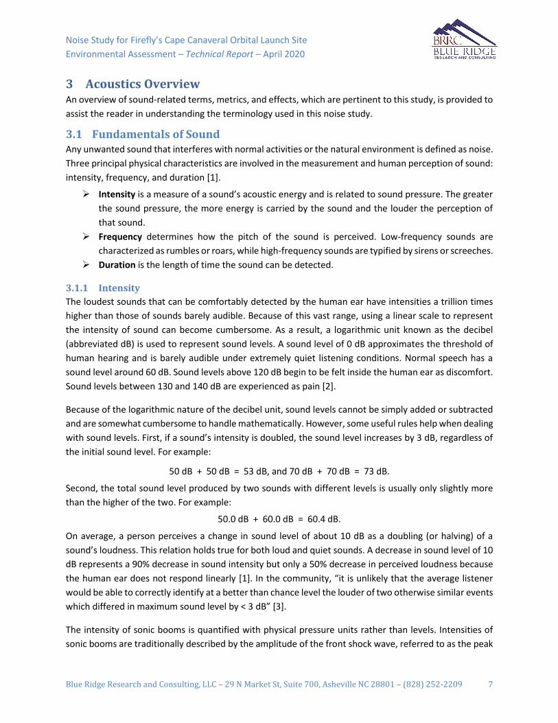
Noise Study for Firefly’s Cape Canaveral Orbital Launch Site
Environmental Assessment – Technical Report – April 2020
Blue Ridge Research and Consulting, LLC – 29 N Market St, Suite 700, Asheville NC 28801 – (828) 252-2209 7
3 Acoustics Overview An overview of sound-related terms, metrics, and effects, which are pertinent to this study, is provided to
assist the reader in understanding the terminology used in this noise study.
3.1 Fundamentals of Sound Any unwanted sound that interferes with normal activities or the natural environment is defined as noise.
Three principal physical characteristics are involved in the measurement and human perception of sound:
intensity, frequency, and duration [1].
➢ Intensity is a measure of a sound’s acoustic energy and is related to sound pressure. The greater
the sound pressure, the more energy is carried by the sound and the louder the perception of
that sound.
➢ Frequency determines how the pitch of the sound is perceived. Low-frequency sounds are
characterized as rumbles or roars, while high-frequency sounds are typified by sirens or screeches.
➢ Duration is the length of time the sound can be detected.
3.1.1 Intensity
The loudest sounds that can be comfortably detected by the human ear have intensities a trillion times
higher than those of sounds barely audible. Because of this vast range, using a linear scale to represent
the intensity of sound can become cumbersome. As a result, a logarithmic unit known as the decibel
(abbreviated dB) is used to represent sound levels. A sound level of 0 dB approximates the threshold of
human hearing and is barely audible under extremely quiet listening conditions. Normal speech has a
sound level around 60 dB. Sound levels above 120 dB begin to be felt inside the human ear as discomfort.
Sound levels between 130 and 140 dB are experienced as pain [2].
Because of the logarithmic nature of the decibel unit, sound levels cannot be simply added or subtracted
and are somewhat cumbersome to handle mathematically. However, some useful rules help when dealing
with sound levels. First, if a sound’s intensity is doubled, the sound level increases by 3 dB, regardless of
the initial sound level. For example:
50 dB + 50 dB = 53 dB, and 70 dB + 70 dB = 73 dB.
Second, the total sound level produced by two sounds with different levels is usually only slightly more
than the higher of the two. For example:
50.0 dB + 60.0 dB = 60.4 dB.
On average, a person perceives a change in sound level of about 10 dB as a doubling (or halving) of a
sound’s loudness. This relation holds true for both loud and quiet sounds. A decrease in sound level of 10
dB represents a 90% decrease in sound intensity but only a 50% decrease in perceived loudness because
the human ear does not respond linearly [1]. In the community, “it is unlikely that the average listener
would be able to correctly identify at a better than chance level the louder of two otherwise similar events
which differed in maximum sound level by < 3 dB” [3].
The intensity of sonic booms is quantified with physical pressure units rather than levels. Intensities of
sonic booms are traditionally described by the amplitude of the front shock wave, referred to as the peak

Noise Study for Firefly’s Cape Canaveral Orbital Launch Site
Environmental Assessment – Technical Report – April 2020
Blue Ridge Research and Consulting, LLC – 29 N Market St, Suite 700, Asheville NC 28801 – (828) 252-2209 8
overpressure. The peak overpressure is normally described in units of pounds per square foot (psf), where
1 psf = 47.88 Pascals (Pa). The amplitude is particularly relevant when assessing structural effects as
opposed to loudness or cumulative community response. In this study, sonic booms are quantified by
either dB or psf, as appropriate for the particular impact being assessed [4].
3.1.2 Frequency
Sound frequency is measured in terms of cycles per second or hertz (Hz). Human hearing ranges in
frequency from 20 Hz to 20,000 Hz, although perception of these frequencies is not equivalent across this
range. Human hearing is most sensitive to frequencies in the 1,000 to 4,000 Hz range. Most sounds are
not simple pure tones, but contain a mix, or spectrum, of many frequencies. Sounds with different spectra
are perceived differently by humans even if the sound levels are the same. Weighting curves have been
developed to correspond to the sensitivity and perception of different types of sound.
A-weighting and C-weighting are the two most common weightings. These two curves, shown in Figure
3-1, are adequate to quantify most environmental noises. A-weighting puts emphasis on the 1,000 to
4,000 Hz range to match the reduced sensitivity of human hearing for moderate sound levels. For this
reason, the A-weighted decibel level (dBA) is commonly used to assess community sound. Very loud or
impulsive sounds, such as explosions or sonic booms, can sometimes be felt, and they can cause secondary
effects, such as shaking of a structure or rattling of windows. These types of sounds can add to annoyance
and are best measured by C-weighted sound levels, denoted dBC. C-weighting is nearly flat throughout
the audible frequency range and includes low frequencies that may not be heard but cause shaking or
rattling. C-weighting approximates the human ear’s sensitivity to higher intensity sounds.
Note, “unweighted” sound levels refer to levels in which no weighting curve has been applied to the
spectra. Unweighted levels are appropriate for use in examining the potential for noise impacts on
structures.
Figure 3-1. Frequency adjustments for A-weighting and C-weighting [5]

Noise Study for Firefly’s Cape Canaveral Orbital Launch Site
Environmental Assessment – Technical Report – April 2020
Blue Ridge Research and Consulting, LLC – 29 N Market St, Suite 700, Asheville NC 28801 – (828) 252-2209 9
3.1.3 Duration
Sound sources can contain a wide range of frequency (pitch) content as well as variations in extent from
short durations to continuous, such as back-up alarms and ventilation systems, respectively. Some sound
sources (air conditioners, generators, lawn mowers) are continuous with levels that are constant for a
given duration; others (vehicles passing by) are the maximum sound during an event, and some (urban
day and nighttime) are averages over extended periods [6]. Sonic booms are considered low-frequency
impulsive noise events with durations lasting a fraction of a second.
3.1.4 Common Sounds
Common sources of noise and their associated levels are provided for comparison to the noise levels from
the proposed action.
A chart of A-weighted sound levels from everyday sounds [7] is shown in Figure 3-2. Per the US
Environmental Protection Agency, “Ambient noise in urban areas typically varies from 60 to 70 dB but can
be as high as 80 dB in the center of a large city. Quiet suburban neighborhoods experience ambient noise
levels around 45-50 dB” [8].
Figure 3-2. Typical A-weighted sound levels of common sounds [9]

Noise Study for Firefly’s Cape Canaveral Orbital Launch Site
Environmental Assessment – Technical Report – April 2020
Blue Ridge Research and Consulting, LLC – 29 N Market St, Suite 700, Asheville NC 28801 – (828) 252-2209 10
A chart of typical impulsive events along with their corresponding peak overpressures in terms of psf and
peak dB values are shown in Figure 3-3.
Figure 3-3. Typical impulsive event levels [10]
3.2 Noise Metrics A variety of acoustical metrics have been developed to describe sound events and to identify any potential
impacts to receptors within the environment. These metrics are based on the nature of the event and
who or what is affected by the sound. A brief description of the noise metrics used in this noise study are
provided below.
Maximum Sound Level (Lmax)
The highest unweighted sound level measured during a single event, in which the sound changes with
time, is called the Maximum Sound Level (abbreviated as Lmax). The highest A-weighted sound level
measured during a single event is called the Maximum A-weighted Sound Level (abbreviated as LA,max).
Although it provides some measure of the event, Lmax (or LA,max) does not fully describe the sound because
it does not account for how long the sound is heard.
Peak Sound Level (Lpk)
For impulsive sounds, the true instantaneous peak sound pressure level, which lasts for only a fraction of
a second, is important in determining impacts. The peak pressure of the front shock wave is used to
describe sonic booms, and it is usually presented in psf. Peak sound levels are not frequency weighted.
Day-Night Average Sound Level (DNL) and Community Noise Equivalent Level (CNEL)
Day-Night Average Sound Level is a cumulative metric that accounts for all noise events in a 24-hour
period. To account for increased sensitivity to noise at night, DNL applies an additional 10 dB adjustment
to events during the acoustical nighttime period, defined as 10:00 PM to 7:00 AM. DNL represents the
average sound level exposure for annual average daily events. DNL does not represent a level heard at
any given time but represent long-term exposure to noise.
3.3 Noise Effects Noise criteria have been developed to protect the public health and welfare of the surrounding
communities. The impacts of launch vehicle noise and sonic booms are evaluated on a cumulative basis
in terms of human annoyance. In addition, the launch vehicle noise and sonic boom impacts are evaluated
on a single-event basis in relation to hearing conservation and potential structural damage. Although FAA
Order 1050.1F does not have guidance on hearing conservation or structural damage criteria, it recognizes
the use of supplemental noise analysis to describe the noise impact and assist the public’s understanding
of the potential noise impact.

Noise Study for Firefly’s Cape Canaveral Orbital Launch Site
Environmental Assessment – Technical Report – April 2020
Blue Ridge Research and Consulting, LLC – 29 N Market St, Suite 700, Asheville NC 28801 – (828) 252-2209 11
3.3.1 Human Annoyance
A significant noise impact would occur if the “action would increase noise by DNL 1.5 dB[A] or more for a
noise sensitive area that is exposed to noise at or above the DNL 65 dB[A] noise exposure level, or that
will be exposed at or above this level due to the increase, when compared to the No Action Alternative
for the same timeframe” [11].
DNL is based on long-term cumulative noise exposure and has been found to correlate well with long-
term community annoyance for regularly occurring events including aircraft, rail, and road noise [12, 13].
Noise studies used in the development of the DNL metric did not include rocket noise, which are
historically irregularly occurring events. Thus, it is acknowledged that the suitability of DNL for infrequent
rocket noise events is uncertain. Additionally, it has been noted that the DNL “threshold does not
adequately address the effects of noise on visitors to areas within a national park or national wildlife
refuge where other noise is very low and a quiet setting is a generally recognized purpose and attribute”
[11]. However, DNL is the most widely accepted metric to estimate the potential changes in long-term
community annoyance.
For impulsive noise sources with significant low-frequency content such as sonic booms, C-weighted DNL
(CDNL) is preferred over A-weighted DNL [14]. In terms of percent highly annoyed, DNL 65 dBA is
equivalent to CDNL 60 dBC [15].
3.3.2 Hearing Conservation
Launch Vehicle Noise
U.S. government agencies have provided guidelines on permissible noise exposure limits. These
documented guidelines are in place to protect human hearing from long-term continuous daily exposures
to high noise levels and aid in the prevention of noise-induced hearing loss (NIHL). A number of federal
agencies have set exposure limits on non-impulsive noise levels, including the Occupational Safety and
Health Administration (OSHA) [16], National Institute for Occupational Safety and Health (NIOSH) [17],
and the Department of Defense (DoD) Occupational Hearing Conservation Program [18]. The most
conservative of these upper noise level limits has been set by OSHA at 115 dBA. At 115 dBA, the allowable
exposure duration is 15 minutes for OSHA and 28 seconds for NIOSH and DoD. LA,max contours are used to
identify potential locations where hearing protection should be considered for rocket operations.
Sonic Booms
Multiple federal government agencies have provided guidelines on permissible noise exposure limits on
impulsive noise such as sonic booms. In terms of upper limits on impulsive or impact noise levels,
NIOSH [17] and OSHA [19] have stated that levels should not exceed 140 dB peak sound pressure level,
which equates to a sonic boom level of approximately 4 psf.
3.3.3 Structural Damage
Launch Vehicle Noise
Typically, the most sensitive components of a structure to launch vehicle noise are windows, and
infrequently, the plastered walls and ceilings. The potential for damage to a structure is unique interaction

Noise Study for Firefly’s Cape Canaveral Orbital Launch Site
Environmental Assessment – Technical Report – April 2020
Blue Ridge Research and Consulting, LLC – 29 N Market St, Suite 700, Asheville NC 28801 – (828) 252-2209 12
among the incident sound, the condition of the structure, and the material of each element and its
respective boundary conditions. A report from the National Research Council on the “Guidelines for
Preparing Environmental Impact Statements on Noise” [20] states that one may conservatively consider
all sound lasting more than one second with levels exceeding 130 dB (unweighted) as potentially
damaging to structures.
A NASA technical memo examined the relationship between structural damage claims and overall
sound pressure level and concluded “the probability of structural damage [was] proportional to the
intensity of the low frequency sound” [21]. This relationship estimated that one damage claim in 100
households exposed is expected at an average continuous sound level of 120 dB (unweighted), and one
in 1,000 households at 111 dB (unweighted). The study was based on community responses to 45 ground
tests of the first and second stages of the Saturn V rocket system conducted in Southern Mississippi over
a period of five years. The sound levels used to develop the criteria were modeled mean sound levels.
It is important to highlight the difference between the static ground tests on which the rate of structural
damage claims is based and the dynamic events modeled in this noise study. During ground tests, the
engine/motor remains in one position, which results in a longer-duration exposure to continuous levels
as opposed to the transient noise occurring from the moving vehicle during a launch event. Regardless of
this difference, Guest and Slone’s [21] damage claim criteria represents the best available dataset
regarding the potential for structural damage resulting from rocket noise. Thus, Lmax values of 120 dB
(unweighted) and 111 dB (unweighted) are used in this report as conservative thresholds for potential risk
of structural damage claims.
Sonic Booms
High-level sonic booms are also associated with structural damage. Most damage claims are for brittle
objects, such as glass and plaster. Table 3-1 summarizes the threshold of damage that may be expected
at various overpressures [22]. Additionally, Table 3-1 describes example impulsive events for each level
range. A large degree of variability exists in damage experience, and much of the damage depends on the
pre-existing condition of a structure. Breakage data for glass, for example, spans a range of two to three
orders of magnitude at a given overpressure. The probability of a window breaking at 1 psf ranges from
one in a billion [23] to one in a million [24]. These damage rates are associated with a combination of
boom load and glass condition. At 10 psf, the probability of breakage is between one in 100 and one in
1,000. Laboratory tests involving glass [25] have shown that properly installed window glass will not break
at overpressures below 10 psf, even when subjected to repeated booms. However, in the real world, glass
is not always in pristine condition.
Damage to plaster occurs at similar ranges to glass damage. Plaster has a compounding issue in that it will
often crack due to shrinkage while curing or from stresses as a structure settles, even in the absence of
outside loads. Sonic boom damage to plaster often occurs when internal stresses are high as a result of
these factors. In general, for well-maintained structures, the threshold for damage from sonic booms is
2 psf [22], below which damage is unlikely.

Noise Study for Firefly’s Cape Canaveral Orbital Launch Site
Environmental Assessment – Technical Report – April 2020
Blue Ridge Research and Consulting, LLC – 29 N Market St, Suite 700, Asheville NC 28801 – (828) 252-2209 13
Table 3-1. Possible damage to structures from sonic booms [22]
Nominal level Damage Type Item Affected
0.5 – 2 psf piledriver at construction site
Plaster Fine cracks; extension of existing cracks; more in ceilings; over doorframes; between some plasterboards.
Glass Rarely shattered; either partial or extension of existing.
Roof Slippage of existing loose tiles/slates; sometimes new cracking of old slates at nail hole.
Damage to outside walls
Existing cracks in stucco extended.
Bric-a-brac Those carefully balanced or on edges can fall; fine glass, such as large goblets, can fall and break.
Other Dust falls in chimneys.
2 – 4 psf cap gun/firecracker near ear
Glass, plaster, roofs, ceilings
Failures show that would have been difficult to forecast in terms of their existing localized condition. Nominally in good condition.
4 – 10 psf handgun at shooter’s ear
Glass Regular failures within a population of well-installed glass; industrial as well as domestic greenhouses.
Plaster Partial ceiling collapse of good plaster; complete collapse of very new, incompletely cured, or very old plaster.
Roofs High probability rate of failure in nominally good state, slurry-wash; some chance of failures in tiles on modern roofs; light roofs (bungalow) or large area can move bodily.
Walls (out) Old, free standing, in fairly good condition can collapse.
Walls (in) Inside (“party”) walls known to move at 10 psf.
> 10 psf fireworks display from viewing stand
Glass Some good glass will fail regularly to sonic booms from the same direction. Glass with existing faults could shatter and fly. Large window frames move.
Plaster Most plaster affected.
Ceilings Plasterboards displaced by nail popping.
Roofs Most slate/slurry roofs affected, some badly; large roofs having good tile can be affected; some roofs bodily displaced causing gale-end and will-plate cracks; domestic chimneys dislodged if not in good condition.
Walls Internal party walls can move even if carrying fittings such as hand basins or taps; secondary damage due to water leakage.
Bric-a-brac Some nominally secure items can fall; e.g., large pictures, especially if fixed to party walls.

Noise Study for Firefly’s Cape Canaveral Orbital Launch Site
Environmental Assessment – Technical Report – April 2020
Blue Ridge Research and Consulting, LLC – 29 N Market St, Suite 700, Asheville NC 28801 – (828) 252-2209 14
4 Noise Modeling An overview of the propulsion noise and sonic boom modeling methodologies used in this noise study are
presented in Section 4.1 and 4.2, respectively.
4.1 Propulsion Noise Modeling Launch vehicle propulsion systems, such as solid rocket motors and liquid-propellant rocket engines,
generate high-amplitude broadband noise. Most of the noise is created by the rocket plume interacting
with the atmosphere and the combustion noise of the propellants. Although rocket noise radiates in all
directions, it is highly directive, meaning that a significant portion of the source’s acoustic power is
concentrated in specific directions.
The Launch Vehicle Acoustic Simulation Model (RUMBLE), developed by Blue Ridge Research and
Consulting, LLC (BRRC), is the noise model used to predict the noise associated with the proposed
operations. The core components of the model are visualized in Figure 4-1 and are described in the
following subsections.
Figure 4-1. Conceptual overview of rocket noise prediction model methodology
4.1.1 Source
The rocket noise source definition considers the acoustic power of the rocket, forward flight effects,
directivity, and the Doppler effect.
Acoustic Power
Eldred’s Distributed Source Method 1 (DSM-1) [26] is utilized for the source characterization. The DSM-1
model determines the launch vehicle’s total sound power based on its total thrust, exhaust velocity, and
the engine/motor’s acoustic efficiency. BRRC’s recent validation of the DSM-1 model showed very good
agreement between full-scale rocket noise measurements and the empirical source curves [27]. The

Noise Study for Firefly’s Cape Canaveral Orbital Launch Site
Environmental Assessment – Technical Report – April 2020
Blue Ridge Research and Consulting, LLC – 29 N Market St, Suite 700, Asheville NC 28801 – (828) 252-2209 15
acoustic efficiency of the rocket engine/motor specifies the percentage of the mechanical power
converted into acoustic power. The acoustic efficiency of the rocket engine/motor was modeled using
Guest’s variable acoustic efficiency [28]. Typical acoustic efficiency values range from 0.2% to 1.0% [26].
In the far-field, distributed sound sources are modeled as a single compact source located at the nozzle
exit with an equivalent total sound power. Therefore, launch vehicle propulsion systems with multiple
tightly clustered equivalent engines can be modeled as a single engine with an effective exit diameter and
total thrust [26]. Additional boosters or cores (that are not considered to be tightly clustered) are handled
by summing the noise contribution from each booster/core.
Forward Flight Effect
A rocket in forward flight radiates less noise than the same rocket in a static environment. A standard
method to quantify this effect reduces overall sound levels as a function of the relative velocity between
the jet plume and the outside airflow [29, 30, 31, 32]. This outside airflow travels in the same direction as
the rocket exhaust. At the onset of a launch, the rocket exhaust travels at far greater speeds than the
ambient airflow. Conversely, for a vertical landing, the rocket exhaust and ambient airflow travel in
opposing directions, yielding an increased relative velocity differential. As the differential between the
forward flight velocity and exhaust velocity decreases, jet plume mixing is reduced, which reduces the
corresponding noise emission. Notably, the maximum sound levels are normally generated before the
vehicle reaches the speed of sound. Thus, the modeled noise reduction is capped at a forward flight
velocity of Mach 1.
Directivity
Rocket noise is highly directive, meaning the acoustic power is concentrated in specific directions, and the
observed sound pressure will depend on the angle from the source to the receiver. NASA’s Constellation
Program has made significant improvements in determining launch vehicle directivity of the reusable solid
rocket motor (RSRM) [33]. The RSRM directivity indices (DI) incorporate a larger range of frequencies and
angles then previously available data. Subsequently, improvements were made to the formulation of the
RSRM DI [34] accounting for the spatial extent and downstream origin of the rocket noise source. These
updated DI are used for this analysis.
Doppler Effect
The Doppler effect is the change in frequency of an emitted wave from a source moving relative to a
receiver. The frequency at the receiver is related to the frequency generated by the moving sound source
and by the speed of the source relative to the receiver. The received frequency is higher (compared to the
emitted frequency) if the source is moving towards the receiver, it is identical at the instant of passing by,
and it is lower if the source is moving away from the receiver. During a rocket launch, an observer on the
ground will hear a downward shift in the frequency of the sound as the distance from the source to
receiver increases. The relative changes in frequency can be explained as follows: when the source of the
waves is moving toward the observer, each successive wave crest is emitted from a position closer to the
observer than the previous wave. Therefore, each wave takes slightly less time to reach the observer than
the previous wave, and the time between the arrivals of successive wave crests at the observer is reduced,
causing an increase in the frequency. While they are traveling, the distance between successive wave

Noise Study for Firefly’s Cape Canaveral Orbital Launch Site
Environmental Assessment – Technical Report – April 2020
Blue Ridge Research and Consulting, LLC – 29 N Market St, Suite 700, Asheville NC 28801 – (828) 252-2209 16
fronts is reduced such that the waves "bunch together." Conversely, if the source of waves is moving away
from the observer, then each wave is emitted from a position farther from the observer than the previous
wave; the arrival time between successive waves is increased, reducing the frequency. Likewise, the
distance between successive wave fronts increases, so the waves "spread out." Figure 4-2 illustrates this
spreading effect for an observer in a series of images, where a) the source is stationary, b) the source is
moving less than the speed of sound, c) the source is moving at the speed of sound, and d) the source is
moving faster than the speed of sound. As the frequency is shifted lower, the A-weighting filtering on the
spectrum results in a decreased A-weighted sound level. For unweighted overall sound levels, the Doppler
effect does not change the levels since all frequencies are accounted for equally.
Figure 4-2. Effect of expanding wavefronts (decrease in frequency) that an observer would notice for higher relative speeds of the rocket relative to the observer for: a) stationary source b) source velocity < speed of sound c) source velocity = speed of sound d) source velocity > speed of sound
4.1.2 Propagation
The sound propagation from the source to receiver considers the ray path, atmospheric absorption, and
ground interference.
Ray Path
The model assumes straight line propagation between the source and receiver to determine propagation
effects. For straight rays, sound levels decrease as the sound wave propagates away from a source
uniformly in all directions. The launch vehicle noise model components are calculated based on the
specific geometry between source (launch vehicle trajectory point) to receiver (grid point). The position
of the launch vehicle, described by the trajectory, is provided in latitude and longitude, defined relative
to a reference system (e.g. World Geodetic System 1984) that approximates the Earth’s surface by an
ellipsoid. The receiver grid is also described in geodetic latitude and longitude, referenced to the same
reference system as the trajectory data, ensuring greater accuracy than traditional flat earth models.

Noise Study for Firefly’s Cape Canaveral Orbital Launch Site
Environmental Assessment – Technical Report – April 2020
Blue Ridge Research and Consulting, LLC – 29 N Market St, Suite 700, Asheville NC 28801 – (828) 252-2209 17
Atmospheric Absorption
Atmospheric absorption is a measure of the sound attenuation from the excitation of vibration modes of
air molecules. Atmospheric absorption is a function of temperature, pressure, and relative humidity of
the air. The propulsion noise model utilizes an atmospheric profile, which describes the variation of
temperature, pressure, and relative humidity with respect to the altitude. Standard atmospheric data
sources [35, 36, 37, 38] were used to create a composite atmospheric profile for altitudes up to 66 miles.
The atmospheric absorption is calculated using formulas found in ANSI Standard S1.26-1995 (R2004). The
result is a sound-attenuation coefficient, which is a function of frequency, atmospheric conditions, and
distance from the source. The amount of absorption depends on the parameters of the atmospheric layer
and the distance that the sound travels through the layer. The total sound attenuation is the sum of the
absorption experienced from each atmospheric layer.
Nonlinear propagation effects can result in distortions of high-amplitude sound waves [39] as they travel
through the medium. These nonlinear effects are counter to the effect of atmospheric absorption [40,
41]. However, recent research shows that nonlinear propagation effects change the perception of the
received sound [42, 43], but the standard acoustical metrics are not strongly influenced by nonlinear
effects [44, 45]. The overall effects of nonlinear propagation on high-amplitude sound signatures and their
perception is an ongoing area of research, and it is not currently included in the propagation model.
Ground Interference
The calculated results of the sound propagation using DSM-1 provide a free-field sound level (i.e. no
reflecting surface) at the receiver. However, sound propagation near the ground is most accurately
modeled as the combination of a direct wave (source to receiver) and a reflected wave (source to ground
to receiver) as shown in Figure 4-1. The ground will reflect sound energy back toward the receiver and
interfere both constructively and destructively with the direct wave. Additionally, the ground may
attenuate the sound energy, causing the reflected wave to propagate a smaller portion of energy to the
receiver. RUMBLE accounts for the attenuation of sound by the ground [46, 47] when estimating the
received noise. The model assumes a five-foot receiver height and a homogeneous grass ground surface.
However, it should be noted that noise levels may be 3 dB louder over water surfaces compared to the
predicted levels over the homogeneous grass ground surfaces assumed in the modeling. To account for
the random fluctuations of wind and temperature on the direct and reflected wave, the effect of
atmospheric turbulence is also included [46, 48].
4.1.3 Receiver
The received noise is estimated by combining the source and propagation components. The basic received
noise is modeled as overall and spectral level time histories. This approach enables a range of noise
metrics relevant to environmental noise analysis to be calculated and prepared as output.

Noise Study for Firefly’s Cape Canaveral Orbital Launch Site
Environmental Assessment – Technical Report – April 2020
Blue Ridge Research and Consulting, LLC – 29 N Market St, Suite 700, Asheville NC 28801 – (828) 252-2209 18
4.2 Sonic Boom Modeling A vehicle creates sonic booms during supersonic flight. The potential for the boom to intercept the ground
depends on the trajectory and speed of the vehicle as well as the atmospheric profile. The sonic boom is
shaped by the physical characteristics of the vehicle and the atmospheric conditions through which it
propagates. These factors affect the perception of a sonic boom. The noise is perceived as a deep boom,
with most of its energy concentrated in the low frequency range. Although sonic booms generally last less
than one second, their potential for impact may be considerable.
A brief sonic boom generation and propagation modeling primer is provided in Section 4.2.1 to describe
relevant technical details that inform the sonic boom modeling. The primer also provides visualizations of
the boom generation, propagation, and ground intercept geometry. An overview of the sonic boom
modeling software used in the study, PCBoom, and a description of inputs are found in Section 4.2.2.
4.2.1 Primer
When a vehicle moves through the air, it pushes the air out of its way. At subsonic speeds, the displaced
air forms a pressure wave that disperses rapidly. At supersonic speeds, the vehicle is moving too quickly
for the wave to disperse, so it remains as a coherent wave. This wave is a sonic boom. When heard at
ground level, a sonic boom consists of two shock waves (one associated with the forward part of the
vehicle, the other with the rear part) of approximately equal strength. When plotted, this pair of shock
waves and the expanding flow between them has the appearance of a capital letter “N,” so a sonic boom
pressure wave is usually called an “N-wave.” An N-wave has a characteristic "bang-bang" sound that can
be startling. Figure 4-3 shows the generation and evolution of a sonic boom N-wave under the vehicle.
Figure 4-3. Sonic boom generation and evolution to N-wave [49]

Noise Study for Firefly’s Cape Canaveral Orbital Launch Site
Environmental Assessment – Technical Report – April 2020
Blue Ridge Research and Consulting, LLC – 29 N Market St, Suite 700, Asheville NC 28801 – (828) 252-2209 19
For aircraft, the front and rear shock are generally the same magnitude. However, for rockets, in addition
to the two shock waves generated from the vehicle body, the plume itself acts as a large supersonic body,
and it generates two additional shock waves (one associated with the forward part of the plume, the other
with the rear part) and extends the waveform duration to as large as one second. If the plume volume is
significantly larger than the vehicle, its shocks will be stronger than the shocks generated by the vehicle.
Figure 4-4 shows the sonic boom wave cone generated by a vehicle in steady (non-accelerating) level
supersonic flight. The wave cone extends toward the ground and is said to sweep out a “carpet” under
the flight track. The boom levels vary along the lateral extent of the “carpet” with the highest levels
directly underneath the flight track and decreasing levels as the lateral distance increases to the cut-off
edge of the “carpet.”
Figure 4-4. Sonic boom carpet for a vehicle in steady flight [50]
Although the wave cone can be calculated from an aircraft-fixed reference frame, the ray perspective is
more convenient when computing sonic boom metrics in a ground-fixed observer’s reference frame [51].
Both perspectives are shown in Figure 4-5. The difference in wave versus ray perspectives is described for
level, climbing, and diving flight, in the PCBoom Sonic Boom Model User Guide [51]:
Sonic boom wave cones are not generated fully formed at a single point in time, instead
resulting from the accumulation of all previous disturbance events that occurred during
the vehicle’s time history. […] Unlike wave cones, ray cones are fully determined at a
single point in time and are independent of future maneuvers. They are orthogonal to
wave cones and represent all paths that sonic boom energy will take from the point they
are generated until a later point in time when they hit the ground. The ray perspective is
particularly useful when considering refraction due to atmospheric gradients or the effect
of aircraft maneuvers, where rays can coalesce into high amplitude focal zones.

Noise Study for Firefly’s Cape Canaveral Orbital Launch Site
Environmental Assessment – Technical Report – April 2020
Blue Ridge Research and Consulting, LLC – 29 N Market St, Suite 700, Asheville NC 28801 – (828) 252-2209 20
When the ray cone hits the ground, the resulting intersection is called an “isopemp.” The
isopemp is forward-facing [as shown in Figure 4-5] and falls a distance ahead of the
vehicle called the “forward throw.” At each new point in the trajectory, a new ray cone is
generated, resulting in a new isopemp that strikes the ground. These isopemps are
generated throughout the trajectory, sweeping out an area called the “boom footprint.”
Figure 4-5. Mach cone vs ray cone viewpoints
Figure 4-4 and Figure 4-5 may give the impression that the boom footprint is generally
associated with rays generated from the bottom of a vehicle. This is the case for vehicles
at moderate climb and dive angles, or in level flight as shown in Figure 4-5. For a vehicle
climbing at an angle steeper than the ray cone half angle, such as in the left image of
Figure 4-6, rays from that part of its trajectory will not reach the ground. This is important
for vertical launches, where the ascent stage of a launch vehicle typically begins at a steep
angle. In these cases, sonic booms are not expected to reach the ground unless refracted
back downwards by gradients in the atmosphere. Conversely, if a vehicle is in a sufficiently
steep dive, such as in the right image of Figure 4-6, the entire ray cone may intersect the
ground, resulting in an elliptical or even circular isopemp. This is of importance for space
flight reentry analysis, where descent may be nearly vertical.
Figure 4-6. Ray cone in climbing (left) and diving (right) flight

Noise Study for Firefly’s Cape Canaveral Orbital Launch Site
Environmental Assessment – Technical Report – April 2020
Blue Ridge Research and Consulting, LLC – 29 N Market St, Suite 700, Asheville NC 28801 – (828) 252-2209 21
4.2.2 PCBoom
The single-event prediction model, PCBoom [52, 53, 54], is a full ray trace sonic boom program that is
used to calculate the magnitude, waveform, and location of sonic boom overpressures on the ground
from supersonic flight operations. Additionally, PCBoom accounts for the effect of rocket exhaust plumes
on the boom [55].
Several inputs are required to calculate the sonic boom impact, including the geometry of the vehicle, the
trajectory path, and the atmospheric conditions. These parameters along with time-varying thrust, drag,
and weight are used to define the PCBoom starting signatures used in the modeling. The starting
signatures are propagated through the US Standard atmospheric profile.

Noise Study for Firefly’s Cape Canaveral Orbital Launch Site
Environmental Assessment – Technical Report – April 2020
Blue Ridge Research and Consulting, LLC – 29 N Market St, Suite 700, Asheville NC 28801 – (828) 252-2209 22
5 Results The following sections present the results of the environmental propulsion noise and sonic boom impacts
associated with the proposed Firefly operations. Note, noise levels over water may be higher because of
the acoustical hardness of the water surface. Single event and cumulative launch vehicle noise results are
presented in Section 5.1 and Section 5.2, respectively.
5.1 Single Event Noise Single event propulsion noise and sonic boom modeling results are presented in Sections 5.1.1 and 5.1.2,
respectively.
5.1.1 Propulsion Noise
Individual launch site and static operations are evaluated using maximum A-weighted and unweighted
sound levels for propulsion noise. The composite noise contour maps are provided representing the
maximum sound levels over the range of launch azimuths proposed (between 44° and 110°).
Maximum A-weighted Sound Level (LA,max)
The modeled LA,max contours associated with the launch and static fire operations at Firefly’s CCAFS SLC-20
facility for each vehicle are presented in Figure 5-1 through Figure 5-4. An upper limit noise level of
115 dBA is used as a guideline to protect human hearing from long-term continuous daily exposures to
high noise levels and to aid in the prevention of NIHL. The 115 dBA contours associated with the launch
and static fire events are entirely within the boundaries of CCAFS. Thus, the potential for impacts to people
in the community with regards to hearing conservation is negligible.
Launch Operations
The Alpha launch event generates modeled levels at or above an LA,max of 115 dBA within 0.3 miles of the
launch site. The Beta launch event generates modeled levels at or above an LA,max of 115 dBA within
0.5 miles of the launch site. The 115 dBA contours for the Alpha and Beta launch events are shown in
Figure 5-1 and Figure 5-2, respectively.
Static Fire Operations
The Alpha and Beta static fire event noise contours are more directive than the launch event noise
contours because the plume is redirected in-line with the deflector heading. A receptor located along the
peak directivity angle may experience an LA,max of 115 dBA at approximately 0.2 miles away from the Alpha
and approximately 0.4 miles away from the Beta during a static fire event. The 115 dBA contours for the
Alpha and Beta static fire events are shown in Figure 5-3 and Figure 5-4, respectively. Note, the levels
produced by static fire events will remain constant over the duration of the event, whereas the levels
produced by launch events will decrease as the rocket moves further away from the receptor.

Noise Study for Firefly’s Cape Canaveral Orbital Launch Site
Environmental Assessment – Technical Report – April 2020
Blue Ridge Research and Consulting, LLC – 29 N Market St, Suite 700, Asheville NC 28801 – (828) 252-2209 23
Figure 5-1. LA,max contours for the Alpha launch from Firefly’s CCAFS SLC-20A
Figure 5-2. LA,max contours for the Beta launch from Firefly’s CCAFS SLC-20B

Noise Study for Firefly’s Cape Canaveral Orbital Launch Site
Environmental Assessment – Technical Report – April 2020
Blue Ridge Research and Consulting, LLC – 29 N Market St, Suite 700, Asheville NC 28801 – (828) 252-2209 24
Figure 5-3. LA,max contours for all Alpha static fire operations at Firefly’s CCAFS SLC-20A
Figure 5-4. LA,max contours for all Beta static fire operations at Firefly’s CCAFS SLC-20B

Noise Study for Firefly’s Cape Canaveral Orbital Launch Site
Environmental Assessment – Technical Report – April 2020
Blue Ridge Research and Consulting, LLC – 29 N Market St, Suite 700, Asheville NC 28801 – (828) 252-2209 25
Maximum Unweighted Sound Level (Lmax)
The modeled Lmax contours associated with the Alpha and Beta launch and static fire operations from
Firefly’s CCAFS SLC-20 facility are presented in Figure 5-5 through Figure 5-8. For reference, the potential
for structural damage claims is approximately one damage claim per 100 households exposed at 120 dB
and one in 1,000 households at 111 dB [21]. The entire land area encompassed by the 111 dB noise
contours resulting from the Alpha and Beta launch or static fire events lies within the CCAFS and National
Aeronautics and Space Administration (NASA) John F. Kennedy Space Center (KSC) boundaries.
Launch Site Operations
For the Alpha launch event, the modeled 120 dB and 111 dB Lmax contours are limited to radii of 0.6 miles
and 1.6 miles from the launch site, respectively, as shown in Figure 5-5. For the Beta launch event, the
modeled 120 dB and 111 dB Lmax contours are limited to radii of 1.5 miles and 4.0 miles from the launch
site, respectively, as shown in Figure 5-6.
Static Fire Operations
For the Alpha static fire, a receptor located along the peak directivity angle may experience Lmax values of
120 dB and 111 dB at approximately 0.6 miles and 1.5 miles from the launch site, respectively, as shown
in Figure 5-7. For the Beta static fire, a receptor located along the peak directivity angle may experience
Lmax values of 120 dB and 111 dB at approximately 1.5 miles and 3.5 miles from the launch site,
respectively, as shown in Figure 5-8.

Noise Study for Firefly’s Cape Canaveral Orbital Launch Site
Environmental Assessment – Technical Report – April 2020
Blue Ridge Research and Consulting, LLC – 29 N Market St, Suite 700, Asheville NC 28801 – (828) 252-2209 26
Figure 5-5. Lmax contours for the Alpha launch from Firefly’s CCAFS SLC-20A
Figure 5-6. Lmax contours for the Beta launch from Firefly’s CCAFS SLC-20B

Noise Study for Firefly’s Cape Canaveral Orbital Launch Site
Environmental Assessment – Technical Report – April 2020
Blue Ridge Research and Consulting, LLC – 29 N Market St, Suite 700, Asheville NC 28801 – (828) 252-2209 27
Figure 5-7. Lmax contours for all Alpha static fire operations at Firefly’s CCAFS SLC-20A
Figure 5-8. Lmax contours for all Beta static fire operations at Firefly’s CCAFS SLC-20A

Noise Study for Firefly’s Cape Canaveral Orbital Launch Site
Environmental Assessment – Technical Report – April 2020
Blue Ridge Research and Consulting, LLC – 29 N Market St, Suite 700, Asheville NC 28801 – (828) 252-2209 28
5.1.2 Sonic Booms
Individual launch site operations are evaluated using maximum peak overpressure for sonic booms.
Maximum Peak Overpressure (psf)
The modeled sonic boom peak overpressure contours for typical Alpha and Beta launch operations are
presented in Figure 5-9 and Figure 5-10, respectively. The sonic booms were modeled based on Alpha and
Beta launch trajectories at a nominal azimuth of 85° relative to true north. The sonic booms produced by
the Alpha and Beta launch vehicles have long, narrow, forward-facing, crescent-shaped focus boom
regions 37 and 44 miles downrange of the launch site, respectively. These focus boom regions are
generated because the rocket continuously accelerates and pitches downward as it ascends. The
maximum peak overpressures along the focus boom regions for the Alpha and Beta launch vehicles are
predicted to be approximately 6.1 psf and 7.4 psf, respectively. However, these levels would only occur in
extremely small areas along the focus boom regions. As the rocket gains altitude, the sonic boom peak
overpressure gradually decreases, and the crescent-shaped contours become slightly wider.
To determine the sonic boom peak overpressure contours over the range of proposed launch azimuths,
the 85° nominal trajectory was rotated to create composite contours. To facilitate visualization of the
effect of rotation, an intermediate illustration of the 44°, 85°, and 110° trajectories is shown for Alpha and
Beta launches in Figure 5-11 and Figure 5-12, respectively. A bounding line is shown in gray to demonstrate
the overall extents of the contours obtained from the rotated trajectories.
The composite contours shown in Figure 5-13 and Figure 5-14 for the Alpha and Beta launch operations,
respectively, represent the maximum peak overpressure that may occur due to Alpha and Beta launch
operations at any azimuth between 44° and 110°. The banding of contour levels shown in Figure 5-13 is a
result of the narrow focal zones. Note, sonic booms produced by a single launch event will not be audible
over the entire contour areas shown in Figure 5-13 and Figure 5-14, but they will impact somewhere
within these contour areas, with the specific locations determined by the launch azimuth. As discussed
previously, the potential remains for elevated levels within small focal regions.
The locations of the sonic boom footprints produced by Alpha and Beta launch operations will be highly
dependent on the vehicle configuration, trajectory, and atmospheric conditions at the time of flight.
However, the sonic booms resulting from Alpha and Beta launch operations are predicted to occur over
the Atlantic Ocean for all proposed launch azimuths between 44° and 110°. Thus, no noise impacts with
respect to human annoyance, health and safety, or structural damage are expected due to the sonic
booms produced by Alpha and Beta launch operations.

Noise Study for Firefly’s Cape Canaveral Orbital Launch Site
Environmental Assessment – Technical Report – April 2020
Blue Ridge Research and Consulting, LLC – 29 N Market St, Suite 700, Asheville NC 28801 – (828) 252-2209 29
Figure 5-9. Sonic boom peak overpressure contours for a nominal Alpha launch from SLC-20A
Figure 5-10. Sonic boom peak overpressure contours for a nominal Beta launch from SLC-20B
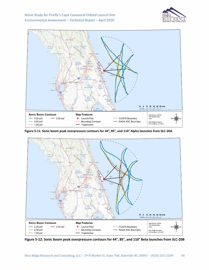
Noise Study for Firefly’s Cape Canaveral Orbital Launch Site
Environmental Assessment – Technical Report – April 2020
Blue Ridge Research and Consulting, LLC – 29 N Market St, Suite 700, Asheville NC 28801 – (828) 252-2209 30
Figure 5-11. Sonic boom peak overpressure contours for 44°, 85°, and 110° Alpha launches from SLC-20A
Figure 5-12. Sonic boom peak overpressure contours for 44°, 85°, and 110° Beta launches from SLC-20B

Noise Study for Firefly’s Cape Canaveral Orbital Launch Site
Environmental Assessment – Technical Report – April 2020
Blue Ridge Research and Consulting, LLC – 29 N Market St, Suite 700, Asheville NC 28801 – (828) 252-2209 31
Figure 5-13. Maximum sonic boom peak overpressure contours for Alpha launches from SLC-20A
Figure 5-14. Maximum sonic boom peak overpressure contours for Beta launches from SLC-20B

Noise Study for Firefly’s Cape Canaveral Orbital Launch Site
Environmental Assessment – Technical Report – April 2020
Blue Ridge Research and Consulting, LLC – 29 N Market St, Suite 700, Asheville NC 28801 – (828) 252-2209 32
5.2 Cumulative Noise The potential for long-term community annoyance is assessed using A-weighted DNL for launch vehicle
noise and C-weighted DNL for sonic booms. Alpha and Beta launch operations are considered over a range
of launch azimuths between 44° and 110°.
Launch Site Operations
The DNL 60 dBA contour is used to conservatively identify the potential for significant noise impacts, as
60 dBA is the smallest level that could “increase noise by DNL 1.5 dB[A] or more for a noise sensitive area
that is exposed to noise at or above the DNL 65 dB[A] noise exposure level, or that will be exposed at or
above this level due to the increase” [11]. The DNL contours from 60 dBA to 75 dBA are presented in
Figure 5-15. The DNL 65 and 60 dBA contours extend approximately 1.2 and 1.8 miles from the launch
pad, respectively. This area does not encompass land outside of the boundaries of CCAFS and NASA KSC,
and, thus, no residences are impacted.
Figure 5-15. DNL contours for launch and static fire operations for both Alpha and Beta vehicles at Firefly’s CCAFS SLC-20
The presence and/or location of sonic booms from Firefly launches will be highly dependent on the vehicle
configuration, trajectory, and atmospheric conditions at the time of flight. However, the sonic booms
resulting from the range of proposed launch trajectories would be directed easterly out over the Atlantic
Ocean in the direction of the launch azimuth, making them inaudible on the mainland. Therefore, with
respect to human annoyance, health and safety, or structural damage; noise impacts due to sonic booms
for the launch trajectory are not expected. Thus, a quantitative analysis was not performed.

Noise Study for Firefly’s Cape Canaveral Orbital Launch Site
Environmental Assessment – Technical Report – April 2020
Blue Ridge Research and Consulting, LLC – 29 N Market St, Suite 700, Asheville NC 28801 – (828) 252-2209 33
6 Summary This report documents the noise study performed as part of the EA for Firefly’s CCAFS SLC-20 Facility.
Firefly plans to conduct Alpha operations for up to 10 pre-launch static fire engine tests, 24 acceptance
static fire engine tests, and 10 vertical launches per year. Beta operations are planned for up to 18 pre-
launch static fire engine tests, 24 acceptance static fire engine tests, and 18 vertical launches per year.
Both the static fire and launch events will occur at Firefly’s CCAFS SLC-20 Facility. The potential impacts
from propulsion noise and sonic boom are evaluated on a single-event and cumulative basis in relation to
hearing conservation, structural damage, and human annoyance.
Single Event Noise Results with respect to Hearing Conservation
An upper limit noise level of LA,max 115 dBA is used as a guideline to protect human hearing from long-term
continuous daily exposures to high noise levels and to aid in the prevention of NIHL. The 115 dBA contours
associated with the launch and static fire events are entirely within the boundaries of CCAFS.
For impulsive noise events such as sonic booms, noise impacts to human annoyance and health and safety
are not expected. Thus, the potential for impacts to people in the community with regards to hearing
conservation is negligible
Single Event Noise Results with respect to Structural Damage
The potential for structural damage claims is approximately one damage claim per 100 households
exposed at 120 dB and one in 1,000 households at 111 dB [21]. The entire land area encompassed by the
111 dB noise contours resulting from the Alpha and Beta launch or static fire events lies within CCAFS/KSC
boundaries.
For impulsive events such as sonic booms, there is potential for structural damage (to glass, plaster, roofs,
and ceilings) for well-maintained structures for overpressure levels greater than 2 psf. Modeled sonic
boom overpressure levels between 2 and 4 psf are directed easterly out over the Atlantic Ocean in the
direction of the launch azimuth, making them inaudible on the mainland. Thus, the potential for impacts
with regards to structural damage is negligible
Cumulative Noise Results
The DNL 60 dBA contour is used to conservatively identify the potential for significant noise impacts. The
area identified within the 60 dBA contour for cumulative noise does not encompass land outside of the
boundaries of CCAFS and NASA KSC, and, thus, no residences are impacted.

Noise Study for Firefly’s Cape Canaveral Orbital Launch Site
Environmental Assessment – Technical Report – April 2020
Blue Ridge Research and Consulting, LLC – 29 N Market St, Suite 700, Asheville NC 28801 – (828) 252-2209 34
7 References
[1] US Navy, "Discussion of Noise and Its Effect on the Environment, Appendix H2," December 2016.
[2] B. Berglund and T. Lindvall, "Community Noise," Editors, Stockholm, Sweden, 1995.
[3] F. Fahy and D. Thomspon, Fundamentals of Sound and Vibration, 2nd ed., CRC Press, 2015.
[4] "F-22A Beddown Environmental Assessment," Appendix D Aircraft Noise Analysis and Airspace
Operations, June 2006.
[5] ANSI S1.4A-1985, "Specification of Sound Level Meters," 1985.
[6] US Air Force, "Supplemental Environmental Impact Statement for F-35 Beddown at Eglin Air Force
Base, Florida, Draft Appendix E: Noise," September 2010.
[7] C. M. Harris, Handbook of Acoustical Measurements and Noise Control, 1998.
[8] US Environmental Protection Agency (USEPA), "Protective Noise Levels," Office of Noise Abatement
and Control, Washington, D.C. USEPA Report 550/9-79-100, November 1978.
[9] Department of the Navy, "Aircraft Noise Assessment," NAS Oceana Strike Fighter Transition: Final
EA. Appendix A-53, October 2017.
[10] FAA, "Environmental Assessment for the Site, Launch, Reentry and Recovery Operations at the
Kistler Launch Facility, Nevada Test Site (NTS)," April 2002.
[11] FAA, Environmental Impacts: Policies and Procedures, Order 1050.1F, 2015.
[12] T. Schultz, "Synthesis of Social Surveys on Noise Annoyance," J. Acoust. Soc. Am., vol. 64, no. 2, pp.
377-405, August 1978.
[13] L. Finegold, C. Harris and H. v. Gierke, "Community Annoyance and Sleep Disturbance: Updated
Criteria for Assessing the Impacts of General Transportation Noise on People," Noise Control
Engineering Journal, vol. 42, pp. 25-30, 1994.
[14] FAA, "Order 1050.1 Desk Reference DRAFT," May 2018.
[15] Committee on Hearing, Bioacoustics, and Biomechanics (CHBB), "Assessment of community
response to high-energy impulsive sounds," National Academy Press, National Research Council,
Washington, D.C., 1981.
[16] OSHA, "Federal Regulation Title 29 - Labor, Subtitle B, Capter XVII, Part 1910 - Occupational Saftey
and Health Standards, Subpart G - Occupational Health and Environmental Control, 1910.95 -
Occupational noise exposure," [Online]. Available: http://www.ecfr.gov/. [Accessed February 2019].
[17] NIOSH, Criteria for a Recommended Standard-Occupational Exposure to Noise – Revised Criteria
1998, DHHS (NIOSH) Pub. No. 98-126, 1998.
[18] Department of Defense, Instruction: Hearing Conservation Program (HCP), DoDI 6055.12, 2010.

Noise Study for Firefly’s Cape Canaveral Orbital Launch Site
Environmental Assessment – Technical Report – April 2020
Blue Ridge Research and Consulting, LLC – 29 N Market St, Suite 700, Asheville NC 28801 – (828) 252-2209 35
[19] OSHA, "Federal Regulation Title 29 - Labor, Subtitle B, Capter XVII, Part 1910 - Occupational Saftey
and Health Standards, Subpart G - Occupational Health and Environmental Control, 1910.95 -
Occupational noise exposure," [Online]. Available: http://www.ecfr.gov/. [Accessed April 2017].
[20] B. a. B. Committee on Hearing, "Guidelines for Preparing Environmental Impact Statements on
Noise," National Academy of Sciences, Washington DC, 1977.
[21] S. Guest and R. M. Slone Jr., Structural Damage Claims Resulting from Acoustic Environments
Developed During Static Firing of Rocket Engines, San Antonio, Texas, April 1972.
[22] J. Haber and D. Nakaki, "Sonic Boom Damage to Conventional Structures. HSD-TR-89," 1989.
[23] L. Sutherland, Effects of Sonic Boom on Structures, Lecture 3 of Sonic Boom: Prediction and Effects,
AIAA Short Course, 1990.
[24] R. L. Hershey and T. H. Higgins, Statistical Model of Sonic Boom Structural Damage. FAA RD-76-87,
1976.
[25] R. White, Effects of Repetitive Sonic Booms on Glass Breakage, 1972.
[26] K. M. Eldred, NASA SP-8072: Acoustic Loads Generated By the Propulsion Systems, NASA, 1971.
[27] M. M. James, A. R. Salton, K. L. Gee, T. B. Neilsen and S. A. McInerny, Full-scale rocket motor acoustic
tests and comparisons with empirical source models, vol. 18, J. Acoust. Soc. Am., 2014.
[28] S. H. Guest, NASA TN D-1999: Acoustic Efficiency Trends for High Thrust Boosters, NASA Marshall
Space Flight Center: NASA, 1964.
[29] K. Viswanathan and M. J. Czech, Measurements and Modeling of Effect of Forward Flight on Jet
Noise, vol. 49, AIAA, 2011.
[30] S. Saxena and P. Morris, Noise Predictions for High Subsonic Single and Dual-Stream Jets in Flight,
Colorado Springs, CO, 2012.
[31] R. Buckley and C. L. Morfey, Flight Effects on Jet Mixing Noise: Scaling Laws Predicted for Single Jets
from Flight Simulation Data, Atlanta, GA: AIAA, 1983.
[32] R. Buckley and C. L. Morfey, Scaling Laws for Jet Mixing Noise in Simulated Flight and the Prediction
Scheme Associated, Williamsburg, VA: AIAA, 1984.
[33] J. Haynes and J. R. Kenny, Modifications to the NASA SP-8072 Distributed Source Method II, Miami,
Florida: AIAA, 2009.
[34] M. M. James, A. R. Salton, K. L. Gee, T. B. Neilsen, S. A. McInerny and R. J. Kenny, Modification of
directivity curves for a rocket noise model, vol. 18, J. Acoust. Soc. Am., 2014.
[35] NASA, "Terrestrial Envrionment (Climatic) Criteria Gudelines for use in Aerospace Vehicle
Devlopment," NASA TM-4511, 1993.
[36] Handbook of Astronautical Engineering, McGraw-Hill, 1961.
[37] NOAA, NASA, USAF, "U.S. Standard Atmosphere, 1976," U.S. Government Priting Office,
Washington, D.C..

Noise Study for Firefly’s Cape Canaveral Orbital Launch Site
Environmental Assessment – Technical Report – April 2020
Blue Ridge Research and Consulting, LLC – 29 N Market St, Suite 700, Asheville NC 28801 – (828) 252-2209 36
[38] National Climatic Data Center, "Global gridded upper air statistics, 1980-1995," National Climatic
Data Center, Asheville, NC, 1996.
[39] S. A. McInerny, K. L. Gee, J. M. Downing and M. M. James, Acoustical Nonlinearities in Aircraft Flyover
Data, Rome, Italy: AIAA, 2007.
[40] S. A. McInerny and S. M. Ölçmen, High-Intensity Rocket Noise: Nonlinear Propagation, Atmospheric
Absorption, and Characterization, vol. 117, J. Acoust. Soc. Am., 2005, pp. 578-591.
[41] D. F. Pernet and R. C. Payne, Non-linear propagation of signals in airs, vol. 17, Journal of Sound and
Vibration, 1971, pp. 383-396.
[42] K. L. Gee, V. W. Sparrow, A. A. Atchley and T. B. Gabrielson, On the Perception of Crackle in High
Amplitude Jet Noise, vol. 45, AIAA, 2007, pp. 593-598.
[43] J. E. Ffowcs, J. Simson and V. J. Virchis, Crackle: an annoying component of jet noise, vol. 71, Journal
of Fluid Mechanics, 1975, pp. 251-271.
[44] K. L. Gee, V. W. Sparrow, M. M. James, J. M. Downing, C. M. Hobbs, T. B. Gabrielson and A. A. Atchley,
The role of nonlinear effects in the propagation of noise from high-power jet aircraft, vol. 123, J.
Acoust. Soc. Am., 2008, pp. 4082-4093.
[45] K. L. Gee, V. W. Sparrow, M. M. James, J. M. Downing, C. M. Hobbs, T. B. Gabrielson and A. A. Atchley,
Measurement and Prediction of Noise Propagation from a High-Power Jet Aircraft, Cambridge,
Massachusetts: AIAA, 2006.
[46] C. Chessel, Propagation of noise along a finite impedance boundary, vol. 62, J. Acoust. Soc. Am.,
1977, pp. 825-834.
[47] T. Embleton, J. Piercy and G. Daigie, Effective flow resistivity of ground surfaces determined by
acoustical measurements, vol. 74, J. Acoust. Soc. Am., 1983, pp. 1239-1244.
[48] G. A. Daigle, Effects of atmospheric turbulence on the interference sound waves above a finite
impedance boundary, vol. 65, J. Acoust. Soc. Am., 1979.
[49] H. W. Carlson, NASA SP-147: Experimental and Analytical Research on Sonic Boom Generation at
NASA, NASA Langley Research Center: NASA, 1967, p. 10.
[50] K. J. Plotkin and L. C. Sutherland, Sonic Boom: Prediction and Effects, Tallahassee, FL, Florida: AIAA,
1990, pp. 1-7.
[51] K. A. Bradley, C. Wilmer and V. S. Miguel, "PCBoom: Sonic Boom Model for Space Operations,
Version 4.99 User Guide," Wyle Laboratories, Inc., Arlington, VA, 2018.
[52] K. J. Plotkin, "PCBoom3 Sonic Boom Prediction Model: Version 1.0c, Wyle Research Report WR 95-
22C," 1996.
[53] K. Plotkin, "Review of Sonic Boom Theory," AIAA, pp. 89-1105, 1989.
[54] J. A. Page, K. J. Plotkin and C. Wilmer, "PCBoom Version 6.6 Technical Reference and User Manual,"
December 2010.

Noise Study for Firefly’s Cape Canaveral Orbital Launch Site
Environmental Assessment – Technical Report – April 2020
Blue Ridge Research and Consulting, LLC – 29 N Market St, Suite 700, Asheville NC 28801 – (828) 252-2209 37
[55] K. J. Plotkin and F. Grandi, "Computer Models for Sonic Boom Analysis: PCBoom4, CABoom,
BooMap, CORBoom, Wyle Research Report WR 02-11," 2002.
[56] J. Panda, R. N. Mosher and B. J. Porter, Identification of noise sources during rocket engine test firings
and a rocket launch using a microphone phased-array, TM 216625, NASA, 2013.
[57] NASA, "Kennedy NASA Procedural Requirements," 2013.
[58] H. W. Carlson, "NASA Technical Paper 1122: Simplified Sonic-Boom Prediction," NASA, 1978.


Environmental Assessment Reconstitution and Enhancement of Launch Complex 20 Multi-user Launch Operations
APPENDIX C 1
USFWS Biological Opinion 2
3


United States Department of the Interior FISH AND WILDLIFE SERVICE North Florida Ecological Services
7915 BAYMEADOWS WAY, SUITE 200 JACKSONVILLE, FLORIDA 32256-7517
FWS Log No. 04EF1000-2020-F-0288 April 23, 2020 Mr. Michael Blaylock, Chief, Environmental Conservation Department of the Air Force, 45th Space Wing 45 CES/CEIE 1224 Jupiter Street Patrick AFB, Florida 32925 (Attn: Angy Chambers) Subject: Space Florida LC-20 Dear Mr. Blaylock: This letter acknowledges the U.S. Fish and Wildlife Service (Service) has reviewed the consultation request and the supporting Biological Assessment (EA) for Space Florida’s Launch Complex-20 (SLC-20) Construction and Operations at Cape Canaveral Air Force Station (CCAFS), Brevard County, FL. The 45th Space Wing (SW) has prepared a BA pursuant to section 7 of the Endangered Species Act of 1973 (Act) (16 U.S.C. 1531 et seq.) and is requesting our concurrence and formal consultation for the proposed modifications at SLC-20. Some of the information needed to initiate consultation was included with your request received on October 18, 2019, or was supplied in a supplemental BA provided on March 5, 2020. The 45th SW has revised the effects determination for eastern indigo snake (Drymarchon corais couperi) and Florida Scrub-Jay (Aphelocoma coerulescens). Section 7 allows the Service up to 90 calendar days to conclude formal consultation with your agency and an additional 45 days to prepare our biological opinion (unless we mutually agree to an extension). Under the revised regulations 50 CFR §402.16, reinitiating criteria is clarified to include informal consultations. The 45th SW has determined that the Action may affect, and is likely to adversely affect southeastern beach mice (Peromyscus polionotus niveiventris). The Service has received the information for the formal consultation request in the amended BA. In the amended BA, the Service was provided an updated map for the proposed southeastern beach mouse habitat enhancement area for the pending biological opinion and an updated effects analysis for the following species.

CCAFS– Space Florida Launch Complex 20 FWS Log No. 04EF1000-2020-F-0288 Informal Concurrence and Formal Consultation Initiation 2
Florida Scrub-Jay The 45th SW is revising its approach with current and future users to ensure burn windows occur annually to prioritize prescribed fire management goals. The 45th SW is working with senior CCAFS environmental staff to develop operational controls. These operational controls will block out a set number of days annually within which launches or other activities affected by prescribed burns cannot occur. Designated burn windows will allow SW to meet its habitat management goals agreed to with the resource agencies. Space Florida will incorporate language into their tenant lease agreements that reference the prescribed burn goal, listed species management responsibilities, and resulting annual restrictions (1-2 weeks) during a 45th SW predefined period. As part of the lease agreement with Space Florida, the tenants will have a contractual obligation to comply with the specified prescribed burn days schedule by providing adequate protection for their equipment (via containment or filtration systems) or moving sensitive equipment to another location while the prescribed burn days are in force. In summary, the Service concurs with the revised determination based on the following revisions in the BA:
1) Schedule operational controls that will provide assurances that 45th SW can meet the land management responsibilities;
2) Space Florida’s lease agreements that the proposed processing facility shall accommodate smoke or move sensitive equipment to another location; and
3) the loss of 0.3 acres marginal coastal scrub habitat will have a discountable impact overall to the species management.
Eastern Indigo Snake The 45th SW has agreed to implement the Standard Protection Measures for Eastern Indigo Snakes (SPM) to minimize any potential effects on the species. The eastern indigo snake has been observed on Cape Canaveral but has not been documented in the LC-20 project area. Scoping of burrows before collapsing will ensure that the species is not entombed during the collapse of refugia. Although eastern indigo snakes are vulnerable during construction activities, the SPM will educate construction personnel. If any indigo snakes are encountered during clearing activities, they will be allowed to move out of the project area safely and the 45th SW will contact the Service per the SPM. Thank you for the request for formal consultation and revised BA, we expect to provide you with our biological opinion not later than July 16, 2020. For any questions about our concurrence letter, please contact Ms. Tera Baird by phone at 904-731-3196 or by email at [email protected].
Sincerely, Jay B. Herrington Field Supervisor

United States Department of the Interior
FISH AND WILDLIFE SERVICE North Florida Ecological Services
7915 BAYMEADOWS WAY, SUITE 200 JACKSONVILLE, FLORIDA 32256-7517
FWS Log No. 04EF1000-2020-F-0288 July 13, 2020 Mr. Michael Blaylock Chief, Environmental Conservation 45 CES/CEIE-Cape Subject: Space Florida Launch Complex 20 Dear Mr. Blaylock: This letter transmits the U.S. Fish and Wildlife Service’s (Service) biological opinion (BO) for Space Florida’s Construction and Operations at Space Launch Complex-20 (SLC-20 or Action) at Cape Canaveral Air Force Station (CCAFS), Brevard County, FL. The 45th Space Wing (SW) prepared a Biological Assessment pursuant to section 7 of the Endangered Species Act of 1973 (Act) (16 U.S.C. 1531 et seq.) and requested formal consultation for the proposed modifications at SLC-20 and the anticipated effects of the Action on southeastern beach mice (Peromyscus polionotus niveiventris). The transmitted BO considers the effects of the Action on southeastern beach mice. The Action does not affect designated critical habitat; therefore, this BO does not address critical habitat. The Service has determined that the proposed action will not jeopardize the continued existence of the southeastern beach mouse. The SW determined that the Action may affect, but is not likely to adversely affect the West Indian manatee (Trichechus manatus latirostris), Wood stork (Myteria americana), Piping plover (Charadrius melodus ), Red knot (Calidris canutus), eastern indigo snake (Drymarchon corais couperi) and Florida Scrub-Jay (Aphelocoma coerulescens). The Service concurred with the determinations for the first four species in a letter dated February 10, 2020 and concurred on the remaining two species in a letter dated April 23, 2020. The SW has determined that the Action may affect, and is likely to adversely affect the following nesting marine turtles: leatherback (Dermocheuls coriacea), green (Chelona mydas), loggerhead (Caretta caretta), Kemp’s ridley (Lepidochelys kempii), and hawksbill (Eretmochelys imbricata). The Service has analyzed programmatically the effects of facility lighting adjacent to nesting marine turtle habitat and has exempted incidental take under the BO, FWS Log. 2009-F-0087.

CCAFS– Space Florida Launch Complex 20 FWS Log No. 04EF1000-2020-F-0288 Formal Consultation Transmittal
2
The applicant and the SW have agreed to implement the measures outlined in the BO and the Service has determined programmatically that such actions that implement all the terms and conditions of the BO will not jeopardize the continued existence of nesting marine turtles. Thank you for requesting consultation with the Service. If you have any questions about the BO, please contact Ms. Tera Baird by email at [email protected] or by phone at 904-731-3196.
Sincerely, Acting for: Jay B. Herrington Field Supervisor

Biological Opinion
For Space Launch Complex -20 At Cape Canaveral Air Force Station
FWS Log #: 04EF1000-2020-F-0288
Prepared by:
U.S. Fish and Wildlife Service North Florida Ecological Services 7915 Baymeadows Way, Suite 200
Jacksonville, FL 32256
Jay B. Herrington - Field Supervisor Date Acting For

Space Florida Complex - 20 FWS Log #: 04EF1000-2020-F-0288 Cape Canaveral Air Force Station
ii
TABLE OF CONTENTS 1. INTRODUCTION .............................................................................................................................................. 1 2. PROPOSED ACTION ....................................................................................................................................... 3
2.1. Construction ............................................................................................................................................... 3 2.2. Southeastern Beach Mouse Habitat Enhancement ..................................................................................... 4 2.3. Operations .................................................................................................................................................. 4 2.4. Other Activities Caused by the Action ........................................................................................................ 5 2.5. Action Area ................................................................................................................................................. 5 2.6. Tables and Figures ..................................................................................................................................... 6
3. SOURCES OF CUMULATIVE EFFECTS ..................................................................................................... 8 4. Status of Southeastern Beach Mouse ................................................................................................................ 8
4.1. Species Description .................................................................................................................................... 8 4.2. Life History ................................................................................................................................................. 8 4.3. Numbers, Reproduction, and Distribution ................................................................................................ 12 4.4. Conservation Needs and Threats .............................................................................................................. 14
5. Environmental Baseline for Southeastern Beach Mice ................................................................................. 15 5.1. Action Area Numbers, Reproduction, and Distribution ............................................................................ 15 5.2. Action Area Conservation Needs .............................................................................................................. 16 5.3. Tables and Figures ................................................................................................................................... 17
6. Effects of the Action on Southeastern Beach Mice ........................................................................................ 18 6.1. Facility Construction and Refurbishment ................................................................................................. 18 6.2. Southeastern Beach Mouse Habitat Enhancement ................................................................................... 20 6.3. Operations ................................................................................................................................................ 20
7. Conclusion ........................................................................................................................................................ 21 8. INCIDENTAL TAKE STATEMENT ............................................................................................................ 21
8.1. Amount or Extent of Take ......................................................................................................................... 22 8.2. Reasonable and Prudent Measures .......................................................................................................... 24 8.3. Terms and Conditions ............................................................................................................................... 24 8.4. Monitoring and Reporting Requirements ................................................................................................. 24
9. CONSERVATION RECOMMENDATIONS ............................................................................................... 25 10. REINITIATION NOTICE .............................................................................................................................. 25 11. LITERATURE CITED .................................................................................................................................... 26
-

Space Florida Complex - 20 FWS Log #: 04EF1000-2020-F-0288 Cape Canaveral Air Force Station
iii
CONSULTATION HISTORY This section lists key events and correspondence during this consultation. A complete administrative record of this consultation is on file in the U.S. Fish and Wildlife North Florida Ecological Services’ Office (Service). 2019-09-27 - 45th Space Wing (SW) sent a biological assessment (BA) requesting formal consultation for southeastern beach mouse (Peromyscus polionotus niveiventris), eastern indigo snake (Drymarchon corais couperi) and Florida Scrub-Jay (Aphelocoma coerulescens). 2020-12-06 - Air Force liaison and Service biologist had a call with the SW to discuss two projects, Space Florida Launch Complex-20, Space Florida Launch Complex-16, and the proposed compensation. AF Liaison discussed swapping the proposed compensation to support southeastern beach mice habitat restoration near the launch pads and an opportunity to collaborate with Florida Fish and Wildlife Commission to monitor the beach mice near the launch facilities. 2020-01-15 - SW sent a revised BA with changes to the project description and requested consultation on the following species: marine turtles: leatherback (Dermocheuls coriacea), green (Chelona mydas), loggerhead (Caretta caretta), Kemp’s ridley (Lepidochelys kempii), and hawksbill (Eretmochelys imbricata), southeastern beach mouse (Peromyscus polionotus niveiventris), Florida Scrub-Jay (Aphelocoma coerulescens), eastern indigo snake (Drymarchon corais couperi), West Indian manatee (Trichechus manatus latirostris), Wood stork (Mycteria americana), Piping plover (Charadrius melodus), and Red knot (Calidris canutus). The BA also addressed the candidate species, gopher tortoise (Gopherus polyphemus). 2020-02-05 – SW sent an email with the proposed area for southeastern beach mouse habitat enhancement at land management unit 27. 2020-02-11- SW sent an email with the revised map for southeastern beach mouse habitat enhancement/restoration compensation. Habitat enhancement area is between Space Launch Complex-16 and Space Launch Complex-19. 2020-02-18 - The Service sent a concurrence letter dated February 10, 2020, for the following species: marine turtles (leatherback, green, Kemp’s ridley, and hawksbill), West Indian manatee, Wood stork, Piping plover, and Red knot. The letter requested more information to support the effect determination for the Florida Scrub-Jay and eastern indigo snake. 2020-02-24- AF Liaison and Florida Scrub-Jay recovery biologists met with the SW and members of the space industry, including Space Florida, to discuss future compatibility of prescribed fire habitat management and operations of the launch facilities.

Space Florida Complex - 20 FWS Log #: 04EF1000-2020-F-0288 Cape Canaveral Air Force Station
iv
2020-03-05 – SW revised BA with an updated determination for Florida Scrub-Jay and eastern indigo snake. The BA has described that SW will establish an operational window for prescribed fire in the launch schedule to assist in prioritizing the habitat management. 2020-04-21 - The Service sent a letter dated April 6, 2020 to the SW stating that the consultation package is complete and expects formal consultation to be concluded on July 17, 2020. The Service concurred with the may affect, but is not likely to adversely affect determination for Florida Scrub-Jay and eastern indigo snake. 2020-04-24 - The Service sent a revised concurrence letter dated April 23, 2020, correcting the project proponent name in the subject line, header, and paragraph one. No changes to the consultation conclusion date of July 17, 2020. 2020-06-10 – The Service provided SW the complete draft to review. 2020-06-25 – The Service received preliminary track tube data from the Fish and Wildlife Commission and clarified the project description with the SW on the types of management that will occur outside the area of construction.

Space Florida Complex - 20 FWS Log #: 04EF1000-2020-F-0288 Cape Canaveral Air Force Station
1
BIOLOGICAL OPINION 1. INTRODUCTION A biological opinion (BO) is the document that states the opinion of the U.S. Fish and Wildlife Service (Service) under the Endangered Species Act of 1973, as amended (ESA), as to whether a Federal action is likely to:
• jeopardize the continued existence of species listed as endangered or threatened; or • result in the destruction or adverse modification of designated critical habitat.
The Federal action addressed in this BO is the refurbishment of the Launch Complex 20, for Space Florida at Cape Canaveral Air Force Station (the Action). This BO considers the effects of the Action on the southeastern beach mice (Peromyscus polionotus niveiventris). The Action does not affect designated critical habitat; therefore, this BO does not address critical habitat. The 45th Space Wing (SW) has determined that the Action may affect, but is not likely to adversely affect the West Indian manatee (Trichechus manatus latirostris), Wood stork (Myteria americana), Piping plover (Charadrius melodus), and Red knot (Calidris canutus). The Service concurs with the determinations for these species in a letter dated February 10, 2020. The Service asked for more information to support the determination for the eastern indigo snake (Drymarchon corais couperi) and Florida Scrub-Jay ( in the concurrence letter sent on February 10, 2020. SW revised BA and the effect determination to may affect, but is not likely to adversely affect the Florida Scrub-Jay and eastern indigo snake on March 05, 2020, and the Service concurred in a letter dated April 06, 2020. The Service sent a revised concurrence letter dated April 23, 2020. The SW has determined that the Action may affect, and is likely to adversely affect nesting marine turtles: leatherback (Dermocheuls coriacea), green (Chelona mydas), loggerhead (Caretta caretta), Kemp’s ridley (Lepidochelys kempii), and hawksbill (Eretmochelys imbricata). The Service has analyzed programmatically the effects of facility lighting adjacent to nesting marine turtle habitat and has exempted incidental take under the BO, FWS Log. 2009-F-0087. The applicant and the SW have agreed to implement the measures outlined in the opinion and the Service has determined programmatically that such actions that implement all the terms and conditions of the BO will not jeopardize the continued existence of nesting marine turtles. This BO uses hierarchical numeric section headings. Primary (level-1) sections are labeled sequentially with a single digit (e.g., 1. PROPOSED ACTION). Secondary (level-2) sections within each primary section are labeled with two digits (e.g., 1.1. Action Area), and so on for level-3 sections.

Space Florida Complex - 20 FWS Log #: 04EF1000-2020-F-0288 Cape Canaveral Air Force Station
2
BO Analytical Framework A BO that concludes a proposed Federal action is not likely to jeopardize the continued existence of listed species and is not likely to result in the destruction or adverse modification of critical habitat fulfills the Federal agency’s responsibilities under §7(a)(2) of the ESA.
“Jeopardize the continued existence means to engage in an action that reasonably would be expected, directly or indirectly, to reduce appreciably the likelihood of both the survival and recovery of a listed species in the wild by reducing the reproduction, numbers, or distribution of that species” (50 CFR §402.02). “Destruction or adverse modification means a direct or indirect alteration that appreciably diminishes the value of critical habitat as a whole for the conservation of a listed species” (50 CFR §402.02).
The Service determines in a BO whether we expect an action to satisfy these definitions using the best available relevant data in the following analytical framework (see 50 CFR §402.02 for the regulatory definitions of action, action area, environmental baseline, effects of the action, and cumulative effects).
a. Proposed Action. Review the proposed Federal action and describe the environmental changes its implementation would cause, which defines the action area.
b. Status. Review and describe the current range-wide status of the species or critical habitat.
c. Environmental Baseline. Describe the condition of the species or critical habitat in the action area, without the consequences to the listed species caused by the proposed action. The environmental baseline includes the past and present impacts of all Federal, State, or private actions and other human activities in the action area, the anticipated impacts of all proposed Federal projects in the action area that have already undergone formal or early consultation, and the impacts of State or private actions which are contemporaneous with the consultation.
d. Effects of the Action. Predict all consequences to species or critical habitat caused by the proposed action, including the consequences of other activities caused by the proposed action, which are reasonably certain to occur. Activities caused by the proposed action would not occur but for the proposed action. Effects of the action may occur later in time and may include consequences that occur outside the action area.
e. Cumulative Effects. Predict all consequences to listed species or critical habitat caused by future non-Federal activities that are reasonably certain to occur within the action area.
f. Conclusion. Add the effects of the action and cumulative effects to the environmental baseline, and in light of the status of the species, formulate the Service's opinion as to whether the action is likely to jeopardize species or adversely modify critical habitat.

Space Florida Complex - 20 FWS Log #: 04EF1000-2020-F-0288 Cape Canaveral Air Force Station
3
2. PROPOSED ACTION The Proposed Action is the repurposing and operation of a commercial launch site at Space Launch Complex 20 (SLC-20) at CCAFS, Florida. Space Florida intends to refurbish, enhance, and use the existing SLC-20 support shop, Horizontal Integration Facility (HIF), and blockhouse. The proposed real property license area, 220-acres, includes SLC-20 facility area that will be rehabilitated and adjacent undeveloped lands. The facility would contain infrastructure to test rocket engines, integrate launch vehicles, and conduct launches of liquid fueled, small and medium-lift class launch vehicles. The action includes construction of a Concept A and Concept B launch pads, horizontal integration facility, fuel storage tanks, lighting, stormwater retention ponds throughout the complex, and customer and operations support buildings. SLC-20 is located centrally within the Air Force Station and south of Space Launch Complex 34 to the north, 19 to the south, and the Atlantic Ocean to the east within Sections 5-8, Township 23 South, Range 38 East, Brevard County, Florida (Figure 2-1). The following sections deconstruct the Action in three parts: Construction, Habitat Enhancement, and Operations. 2.1. Construction The SLC-20 real property license area is 220 acres, but most of the area proposed for construction, 33 acres, is previously disturbed and developed in areas. The Action will reuse much of the existing impervious concrete for planned roads and structures. Construction activities, such as scraping, facility demolition, or refurbishment will be required to make the existing structures viable for launch activities. Site development will take place over three phases of construction. The BA has a list of phases with the new construction mapped within the bounds of the Proposed Action Boundary, (pg. 4-2, 4-3). The new HIF/hazardous payload processing facility along the southwest region of the Proposed Action Boundary is the only new construction that requires clearing outside the legacy SLC-20 footprint. The new HIF will result in clearing of 0.3 acre of undisturbed live oak and saw palmetto upland habitat (Figure 2-1). Remaining areas are impervious or previously disturbed and now dominated some native and exotic plant species. Within the area of construction there will be heavy machinery and staging areas for construction equipment. The limits within the area of construction will be cleared using heavy machinery. Cleared material will be placed in wheeled dump trucks for removal from that area. Once vegetation is removed from this area, much of the site will be graded using large, heavy tracked bulldozers. Material will either be transferred to a suitable off-site area or burned on location in accordance with SW regulations as schedule and burn conditions permit. It is anticipated that all excavated soil will remain onsite within the area of construction. Existing roadways will be reused but may require resurfacing and potentially slight widening to support small and medium launch vehicle transporters and equipment.

Space Florida Complex - 20 FWS Log #: 04EF1000-2020-F-0288 Cape Canaveral Air Force Station
4
2.2. Southeastern Beach Mouse Habitat Enhancement The habitat enhancement for southeastern beach mouse (SEBM) will be done within a 9.5 acre plot (Figure 2-2). The exact acreage and methodology will be outlined in the scope of work. Relativity Space has agreed to habitat enhancement within the same area. The SW, the Service, Relativity Space, and Space Florida will be collaborating on a scope of work for the proposed area that will focus on the following: 1. Improve the condition of the ecotone between the primary and secondary habitat, thus improving the condition of the seaward edge of the secondary habitat. 2. Provide corridors from the primary habitat into good and fair condition scrub and other landward habitats. The scope of work may include track mechanical thinning or hand clearing of coastal scrub habitat and clearing to create corridors to landward scrub habitat. Vegetation will either be removed to a suitable off-site area or incinerated on location in accordance with SW regulations as schedule and conditions permit. 2.3. Operations Space Florida expects up to 24 total Concept A/B launches. Seventy percent of the launches are expected to occur during daylight hours and 30 percent of the launches are expected to occur during night hours (after 10 p.m. and before 7 a.m.). To prepare for launches, payload preparation activities would be conducted in parallel with most launch vehicle preparations. Payload activities include payload checkout, spacecraft propellant loading (if required), and payload encapsulation in the fairings. The encapsulated payload would then be transported to SLC-20. Non-hazardous and hazardous payload processing and encapsulation would take place in the existing HIF for the Concept A launch vehicle. Following construction of the new HIF, hazardous payload processing would transition to the new facility. SLC-20 will have maintained roads and grassed areas within the complex. The areas are expected to be maintained by mowing on a periodic basis using standard large-scale grass mowing equipment. Maintained roads outside the area of construction at the complex and the security fence will be maintained on a periodic basis. The mowing right-of-way near the fence line and roads will not exceed 30 feet.

Space Florida Complex - 20 FWS Log #: 04EF1000-2020-F-0288 Cape Canaveral Air Force Station
5
2.4. Other Activities Caused by the Action A BO evaluates all consequences to species or critical habitat caused by the proposed Federal action, including the consequences of other activities caused by the proposed action, that are reasonably certain to occur (see definition of “effects of the action” at 50 CFR §402.02). Additional regulations at 50 CFR §402.17(a) identify factors to consider when determining whether activities caused by the proposed action (but not part of the proposed action) are reasonably certain to occur. These factors include, but are not limited to:
(1) past experiences with activities that have resulted from actions that are similar in scope, nature, and magnitude to the proposed action;
(2) existing plans for the activity; and (3) any remaining economic, administrative, and legal requirements necessary for the
activity to go forward. In its request for consultation, the SW did not describe, and the Service is not aware of, any additional activities caused by the Action that are not included in the previous description of the proposed Action. Therefore, this BO does not address further the topic of “other activities” caused by the Action. 2.5. Action Area The action area is defined as “all areas to be affected directly or indirectly by the Federal action and not merely the immediate area involved in the action” (50 CFR §402.02). Delineating the action area is necessary for the Federal action agency to obtain a list of species and critical habitats that may occur in that area, which necessarily precedes any subsequent analyses of the effects of the action to the species or critical habitats. It is practical to treat the action area for a proposed Federal action as the spatial extent of its direct and indirect “modifications to the land, water, or air” (a key phrase from the definition of “action” at 50 CFR §402.02). Indirect modifications include those caused by other activities that would not occur but for the action under consultation. The action area determines any overlap with critical habitat and the physical and biological features therein that we defined as essential to the species’ conservation in the designation final rule. For species, the action area establishes the bounds for an analysis of individuals’ exposure to action-caused changes, but the subsequent consequences of such exposure to those individuals are not necessarily limited to the action area. Figures 2-1 and 2-2 shows the locations of all activities that the proposed Action that would cause changes to land, water, or air caused by these activities. The action area for this BO is the SLC- 20 real property lease area boundary, 220 acres, of which 33 acres is the proposed area of construction and re-development, and the proposed 9.5 acre habitat enhancement area for SEBM near SLC-19.
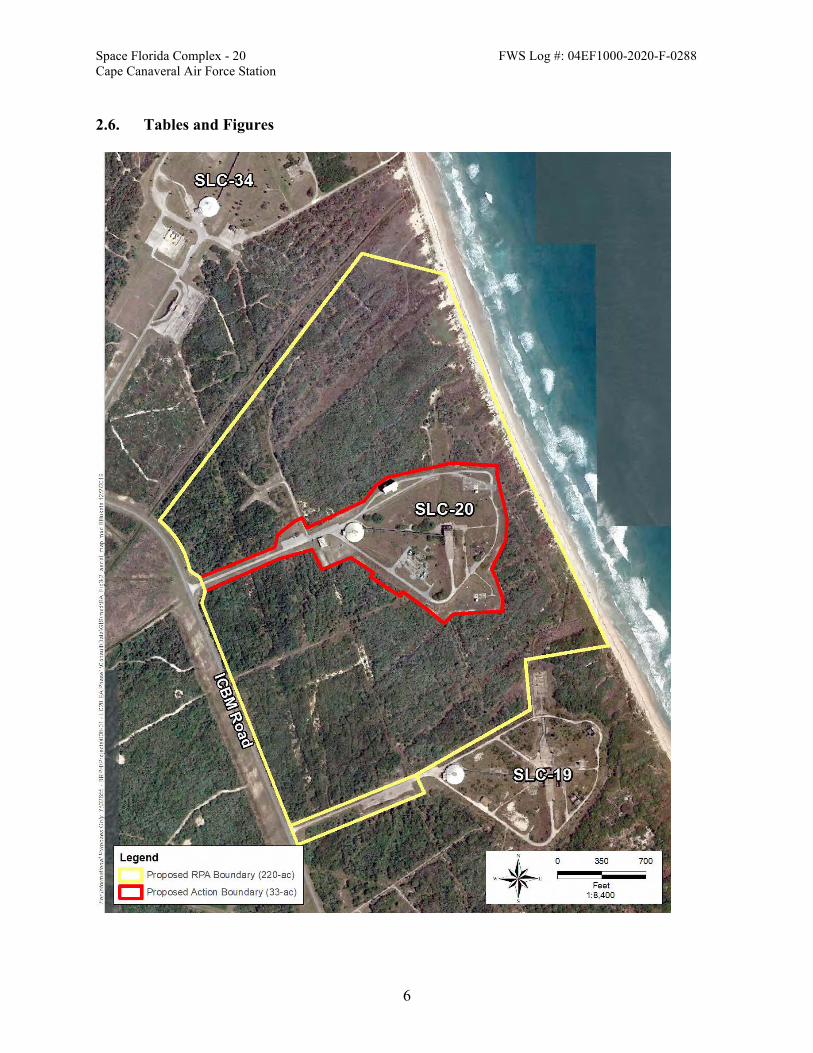
Space Florida Complex - 20 FWS Log #: 04EF1000-2020-F-0288 Cape Canaveral Air Force Station
6
2.6. Tables and Figures

Space Florida Complex - 20 FWS Log #: 04EF1000-2020-F-0288 Cape Canaveral Air Force Station
7
Figure 2-1. Real Property Lease Boundary of SLC-20 and Proposed Action Boundary. All construction activities will occur within the Proposed Action Boundary.
Figure 2-2. The proposed SEBM habitat enhancement area outlined yellow

Space Florida Complex - 20 FWS Log #: 04EF1000-2020-F-0288 Cape Canaveral Air Force Station
8
3. SOURCES OF CUMULATIVE EFFECTS A BO must predict the consequences to species caused by future non-Federal activities within the action area, i.e., cumulative effects. “Cumulative effects are those effects of future State or private activities, not involving Federal activities, that are reasonably certain to occur within the action area of the Federal action subject to consultation” (50 CFR §402.02). Additional regulations at 50 CFR §402.17(a) identify factors to consider when determining whether activities are reasonably certain to occur. These factors include, but are not limited to: existing plans for the activity; and any remaining economic, administrative, and legal requirements necessary for the activity to go forward. In its request for consultation, the SW did not describe, and the Service is not aware of, any future non-Federal activities that are reasonably certain to occur within the action area. Therefore, we anticipate no cumulative effects that we must consider in formulating our opinion for the Action. 4. STATUS OF SOUTHEASTERN BEACH MOUSE This section summarizes best available data about the biology and current condition of the throughout its range that are relevant to formulating an opinion about the Action. Most of this text is taken directly from the draft Status Species Assessment (SSA) that is currently under peer-review. The Service published its decision to list the SEBM as threatened species under the Act in 1989 (54 FR 20598). Critical habitat is not designated for this subspecies, and therefore will not be analyzed in this opinion. 4.1. Species Description The SEBM is one of 16 recognized subspecies of old field mice Peromyscus polionotus (Hall 1981); it is one of the eight of those subspecies that are called beach mice. The SEBM is a small mouse that reaches an average length of 136 mm with an average body mass of 14.5 g (Stout 1992). Southeastern beach mice have pale, buffy coloration from the back of their head to their tail, and their underparts are white. 4.2. Life History SEBM are generally nocturnal, semifossorial, and monogamous. The subspecies occupies foredunes (i.e., frontal, primary, and secondary), transitional (i.e., coastal grasslands and coastal strand) dunes, coastal scrub dunes. SEBM also occur in interior scrub and other landward habitats, though the extent to which these areas utilized is unclear. Below is a summary of the

Space Florida Complex - 20 FWS Log #: 04EF1000-2020-F-0288 Cape Canaveral Air Force Station
9
various elements of the SEBM life history, including reproduction, survival and mortality, foraging, home range, burrowing behavior, and habitat. 4.2.1. Survival and Mortality The average life span of beach mice in the wild is 9 months to one year (Bird et al. 2016, Oddy 2000, Swilling 2000), although a few individuals have been known to live longer than two years. Studies at CCAFS found the mean longevity of SEBM on across study grids was 113 days with no significant differences between sexes (Oddy 2000). Maximum longevity in this study was 596 days. Swilling and Wooten (2002) found longer persistence times associated with mice dispersing further away from their natal home range, perhaps a result of reduced predation rates. 4.2.2. Foraging Beach mice are food generalists and feed on a variety of seeds of dune and scrub plants and insects (Moyers 1996, Sneckenberger 2001, Keserauskis 2007). Studies show that the diet of the SEBM varies seasonally and among and within habitats, and fruits, seeds and arthropods that feed on them comprise most of their diet (Keserauskis 2007). In most cases, fruits and seeds that are consumed by beach mice are produced by low growing, prostrate plants, on supple stems easily manipulated by mice, or as the fruits and seeds become available as fallen seeds (Moyers 1996). Beach mice also consume invertebrates, especially during late winter or early spring when seeds are scarce (Ehrhart 1978). 4.2.3. Home Range Beach mouse home range size varies among subspecies (USFWS 2010) and may vary seasonally and in relation to density as well as habitat and food resources. Beach mouse home ranges average approximately 1.2 acres (Bird 2016). Swilling and Wooten (2002) found the mean home range for Anastasia beach mice (ABM) (both sexes) was approximately 0.89 acres, whereas using radio telemetry data, Lynn (2000) found home ranges of 1.68 acres and 1.73 acres for males and females respectively; neither study noted significant differences in home range size between males and females. Blair (1951) found home ranges of beach mice living in the comparatively dense cover of the beach dunes averaged significantly larger in the spring than in the fall. Beach mice tend to inhabit a single home range throughout their lifetime and will often maintain several burrows within their home range (Blair 1951). Extine and Stout (1987, USFWS 1999) reported movements of the SEBM between the primary dunes and interior scrub on Kennedy Space Center (KSC) and Merritt Island National Wildlife Refuge (MINWR) and concluded that home ranges can overlap and reach high densities within preferred habitats.

Space Florida Complex - 20 FWS Log #: 04EF1000-2020-F-0288 Cape Canaveral Air Force Station
10
4.2.4. Burrows While multiple species of Peromyscus will excavate burrows, P. polionotus is the only member of the genus that excavates its own burrow, which is extensive (Ehrhart 1978, USFWS 1999). Beach mice are semifossorial, and may utilize as many as 20 burrows within their home range (USFWS 1999). Beach mice will use burrows as a place to rest during the day and between nightly foraging bouts. Burrows are also used for escape from predators, birthing and caring for young. Burrows generally consist of an entrance tunnel, nest chamber, and escape tunnel (Weber et al. 2013). High predation risk and the harsh coastal environment make selection of quality burrow sites critical for survival of beach mice (Swilling and Wooten 2002). Beach mice have been found to select burrow sites based on a suite of biotic and abiotic features. (Lynn 2000; Sneckenberger 2001). Bird et al. (2004) in a study exploring the effects of artificial illumination on the behaviors of beach mice found that patch use was affected by the presence of illumination, light type, and distance from light source. In this study, foraging frequency was significantly higher in dark arrays and that more seeds were removed from resource patches as distance from illumination increased. This is consistent with the observation that beach mice activity decreases in response to increased levels of moonlight due to elevated risk perceptions (Stoddard et al. 2018).
4.2.5. Habitat Beach mouse habitat includes a heterogeneous mix of interconnected coastal communities on barrier islands. Holler (1992) described beach mouse habitat at the time as including primary and secondary dunes vegetated by sea oats, beach grass (Panicum amarum), and blue stem (Andropogon maritimus). Contemporary understandings of the geographic distribution of beach mouse habitat is that beach mice inhabit coastal dune, strand, and scrub habitats (where available) that range from being comprised mostly of grasses to mostly shrubs (Sneckenberger 2001, Suazo et al. 2009, Stout et al 2012, Wilkinson et al. 2012, Breininger et al. 2018). Additionally, the coastal strand and scrub plant communities (e.g. Cape Canaveral area) likely serve as refugia for and sources of individuals that disperse into dune systems after storm events (Stout et al. 2012). Coastal communities of Florida can be classified into three general zones. These zones, as described by Johnson and Barbour (1990) and used in the draft Species Status Assessment include foredunes (frontal, primary, and secondary), transitional dunes (coastal grasslands and strands), and coastal scrub dunes. Additionally, beach mice are known to utilize adjacent or connected landward habitats including interior scrub (particularly within the Cape Canaveral), ruderal or old-field environments, and mowed roadside edges and rights-of-way. Foredunes occur in the zone nearest the shoreline, but beyond the limits of the forces of annual wave action (Johnson and Barbour 1990) and include dunes frequently referred to as frontal, primary, and secondary. There is considerable uncertainty regarding optimal ranges of habitat conditions for SEBM in foredune areas. Given the differences in beach mouse habitats between

Space Florida Complex - 20 FWS Log #: 04EF1000-2020-F-0288 Cape Canaveral Air Force Station
11
the Gulf and Atlantic coasts, additional research is needed to accurately define optimal habitat conditions within foredune areas specific to SEBM. Transitional dunes are in the zone situated between the foredunes and more distinct natural communities such as coastal scrub or maritime hammock (FNAI 2010). Transitional dunes may include herbaceous natural communities such as coastal grasslands as well as areas with a higher prevalence of woody plants such as coastal strand. Coastal scrub dunes are typically located behind the foredunes. In addition to the shrubbier form of live oak, plant assemblages in this community include myrtle oak (Q. myrtifolia), saw palmetto, and yaupon holly (Ilex vomitoria) (Kurz 1942, Johnson and Barbour 1990) within a matrix of open sand areas. The low stature of coastal scrub is maintained via the effects of salt spray to terminal buds of plants (Johnson and Barbour 1990). Similarly, to inland scrub habitats (described below), periodic fires are integral to the maintenance of coastal scrub systems. In the absence of fire or in combination with fire, mechanical treatments may be used to manipulate the structure of vegetation within scrub communities. While the predominance of SEBM occurrence within scrub type habitats is in the coastal scrub dunes, SEBM are known to occur in more interior scrub environments within the Cape Canaveral Complex. The cape feature at Cape Canaveral is unique among SEBM habitats as it includes a broad expanse of upland habitats between the Atlantic coast and the Banana and Indian Rivers. Beyond the Cape Canaveral, SEBM habitat generally occurs in narrow stretches along the shoreline. While seasonally abundant, the availability of food resources in the foredunes fluctuates (Sneckenberger 2001). In contrast, the scrub habitat provides a more stable level of food resources, which becomes crucial when food is scarce or nonexistent in the primary and secondary dunes. Furthermore, the coastal scrub dunes appear to serve as refugia for beach mice during and after tropical storm events (Holliman 1983, Swilling et al. 1998), from which recolonization of the foredunes takes place (Swilling et al. 1998, Sneckenberger 2001). This suggests that access to primary, secondary, and coastal scrub habitat is essential to beach mice at the individual and population levels and to some extent at the range wide level. Additionally, studies have found no detectable differences between scrub and frontal dunes in beach mouse body mass, home range size, dispersal, reproduction, survival, food quality, and burrow site availability (Swilling et al. 1998, Swilling 2000, Sneckenberger 2001). It should be noted that the presence of “scrub” habitat with or without storm events as a driving factor for SEBM is known only for the Cape Canaveral area and portions of the panhandle; the entire dune system of the CNS and other areas of SEBM habitat mostly lack this feature. Beyond the foredunes, transitional areas and coastal scrub, barrier islands often grade into stabilized dunes where shrubby plant communities give way to canopied forests. Stable dune areas may include maritime hammocks and forests that are not considered suitable beach mouse habitat. SEBM rarely, if ever, occur in areas where woody vegetation >2m is dominant (Stout 1992). Additionally, while Toombs’ (2001) captured SEBM in the primary dunes and none were captured in dense areas of saw palmetto where it may be more difficult to burrow, this does not

Space Florida Complex - 20 FWS Log #: 04EF1000-2020-F-0288 Cape Canaveral Air Force Station
12
appear to be representative of occupancy of SEBM within the Cape Canaveral Complex in more dense and unmanaged coastal habitats (Oddy personal communication, 2019). There is research that provides evidence of long-term occupancy of interior scrub habitats by SEBM within the CCAFS (Stout 1979, Suazo et al. 2009, Simmons 2008). The three general zones can be classified into two habitat classes for SEMB. Primary habitat identifies the characteristic dune habitats typically occupied by SEBM (foredunes, transitional dunes, and coastal scrub dunes). Secondary habitats include interior scrub and other natural and human-altered landscapes landward of the dunes that provide critical refugia habitat and may support SEBM resource needs, may provide movement corridors, or may support an extension of a population. 4.3. Numbers, Reproduction, and Distribution 4.3.1. Numbers and Distribution
SEBM are found in coastal habitats of Florida’s east coast. The 1989 Final Listing Rule states that the subspecies was known to occur on Canaveral National Seashore (CNS), MINWR, CCAFS, the north and south ends of Orchid Island at Sebastian Inlet area and Fort Pierce Inlet State Park (also known as north Hutchinson Island) on the north side of Ft. Pierce Inlet.
The Recovery Plan for the Anastasia Island Beach Mouse and the Southeastern Beach Mouse (USFWS 1993) described the limits of occurrence of SEBM from Volusia County at Canaveral National Seashore south to 7 miles north of the Brevard County line and including scattered localities in Indian River County, and St. Lucie County. At the time of listing, in areas south of St. Lucie Inlet, nearly all dune habitat was developed and unsuitable for beach mice (USFWS 1988). Some potentially suitable habitat remains within public conservation lands on Jupiter Island, St. Lucie Inlet Preserve State Park, Hobe Sound National Wildlife Refuge and in Palm Beach County at John D. MacArthur Beach State Park. In the draft SSA, the Service reviewed the extant and historic distribution of the species range wide and grouped the populations into geographic segments: Canaveral North, Canaveral South, Orchid Island/ Hutchinson Island North, Hutchinson Island, Jupiter Island, Jupiter South, Palm Beach, Boynton, and Hillsboro. The geographic segments are illustrated in Figure 4-1. and includes inlet locations associated with limits of historic range (light grey box), limits of range at the time of federal listing (1989; medium grey box), current range where two extant populations are known to occur (dark grey box), and areas of uncertain occupancy (red dashed lines).

Space Florida Complex - 20 FWS Log #: 04EF1000-2020-F-0288 Cape Canaveral Air Force Station
13
FIGURE 4.1 SEBM RANGE MAP – Extant and Likely Extirpated.

Space Florida Complex - 20 FWS Log #: 04EF1000-2020-F-0288 Cape Canaveral Air Force Station
14
To assess current condition of the species, the draft SSA characterizes the amount of primary and secondary habitat within the geographic segments across the range of species. The geographic segments are parsed in eight different resilience units. The Canaveral Complex resilience unit is the most important for the recovery of the species. The Canaveral Complex Unit is a metapopulation and has the most habitat to support the species. The Canaveral Complex has 89% of the total protected habitat, with the most acres of primary habitat, 3,377 acres, and 11,897 secondary habitats. Within the secondary habitat, the natural communities within occur at a fine-scale mosaic of conditions that may or may not be suitable for SEBM. 4.3.2. Reproduction Beach mice have a monogamous mating system (Blair, 1951, Smith 1966, Lynn 2000). Mated pairs tend to remain associated in acquiring food and sharing burrows (Blair 1951). Beach mice reach sexual maturity at 55 days of age; however, some mice are capable of breeding earlier (Ehrhart 1978). Peak breeding season for beach mice appears to occur between November and early January (Blair 1951) and appears to coincide with increased availability of food from the previous growing season (Rave and Holler 1992); although pregnant and lactating SEBM have been observed in all seasons (Stout 1979, Oddy et al. 1999, Oddy 2000, Bard personal communication, 2019). While the reproductive potential of beach mice is generally high, Blair (1951) reported only 19.5 percent of beach mice within his study survived from January to May in the same year indicating that mortality of adult beach mice is also quite high. 4.4. Conservation Needs and Threats 4.4.1. Conservation Needs There is considerable uncertainty regarding beach mouse use of the scrub and more stable, interior habitats, particularly within the CCAFS. Future research is needed to better define optimal habitat conditions for SEBM in coastal scrub and interior scrub habitats. Habitat conditions within the interior scrub areas that benefit the threatened Florida Scrub-jay (Aphelocoma coerulescens) may also benefit SEBM (Suazo et al. 2009). While ranges of habitat conditions occur as a result of management regimes and techniques, optimal habitat conditions for Florida Scrub-Jays within the interior scrub within the Canaveral Complex includes a more open habitat structure (Breininger 1992, Breininger et al. 2003, USFWS 2007) that is ideally maintained with use of periodic prescribed fire. Optimal fire-return intervals may be shorter in coastal scrub habitats than in more interior locations (Schmalzer and Hinkle 1992), which may result in less desirable SEBM conditions in the more interior areas. Depending on the matrix of vegetation within the coastal scrub and adjacent habitats, fire return frequencies vary from 3 to

Space Florida Complex - 20 FWS Log #: 04EF1000-2020-F-0288 Cape Canaveral Air Force Station
15
10 years (USFWS 2007). In the absence of fire, the cover and stature of woody vegetation increases, often resulting in the loss of open areas. 4.4.2. Threats
Habitat loss and fragmentation due to destruction associated with residential and commercial development has created disjunct and isolated populations of SEBM along the east coast of Florida. South of the Port Canaveral Entrance Chanel, five inlets between Indian River and Broward Counties create additional barriers to dispersal. Most remaining SEBM habitat occurs on public conservation lands, though some private lands also support areas of natural dune vegetation that could be occupied by beach mice (e.g. St. Lucie Nuclear Power Plant, undeveloped lots, and undeveloped portions of residential and commercial lots). As a result, extant populations of SEBM are geographically and thus genetically, isolated. Within the current landscape configuration, natural dispersal between existing populations is highly unlikely. Other threats to the species include shoreline armoring to protect coastal to protect coastal properties from erosion, coastal lighting at facilities or residential development, vehicular or foot traffic near developments, and climate change. 5. ENVIRONMENTAL BASELINE FOR SOUTHEASTERN BEACH MICE This section is an analysis of the effects of past and ongoing human and natural factors leading to the current status of the southeastern beach mice its habitat, and ecosystem within the action area. The environmental baseline is a “snapshot” of the species’ health in the action area at the time of the consultation and does not include the effects of the Action under review. 5.1. Action Area Numbers, Reproduction, and Distribution The SEBM is found along the entire reach of immediate coastline and within coastal strand on CCAFS in addition to the KSC and Cape Canaveral National Seashore. The known distribution is a result of cursory surveys, intermittent trapping involving different construction projects, two demography studies conducted in 2007, 2011-2012, and annual occupancy studies conducted 2010-2015, and 2018. In addition, several captures of have occurred in the existing blockhouse in 2001. In 2020, Florida Fish and Wildlife Conservation Commission (FWC), set up tube tracking cameras to monitor SEBM use near the SLC pads that are proposed for rehabilitation or construction and the near the pad proposed for the habitat enhancement. Track tubes at SLC 16 and 19 have been deployed since late January 2020 and have been checked a total of 9 times. Track tubes at SLC 20 have been in place since late April 2020 and have been checked 3 times. Track tubes at LMU 18 and 22 have been out since late April and have been checked 4 times. All track tubes are checked every 2 weeks. Figure 5-1, is a map of the preliminary data sent to the Service on June 25, 2020, and the map has the detection rates displayed as percentage of total surveys at a site with positive beach mouse detections.

Space Florida Complex - 20 FWS Log #: 04EF1000-2020-F-0288 Cape Canaveral Air Force Station
16
Using the GIS layer created for the draft SSA, we reviewed distribution the primary and secondary habitat within the real property lease area (Figure 5.2). The lease area is 220 acres with 25 acres of primary habitat (landward foredunes), and 90 acres secondary habitat (human altered habitat of the dune). The area of construction within the lease area has about 4 acres of primary habitat and 5 acres of secondary habitat. To estimate the number of individuals that the lease area may support, we reviewed home range data and compared it to the acres of primary habitat within the action area. Beach mouse home ranges average approximately 1.2 acres (Bird 2016), .89 acres for both male and female (Swilling and Wooten 2000), and 1.68 acres and 1.73 acres for males and females respectively (Lynn 2000). Using the 25 acres of primary habitat, we estimate the lease area has enough primary habitat to support between 15 – 28 individuals. However, the habitat within the action area has not been managed to support the species, and the transitional dune systems is degraded from previous development. The maintained grasses in the lease area portion of the action area have a mixture of native and exotic species, making the foraging habitat less than ideal. Based on the habitat condition there is likely a small fraction of the estimated individuals within the lease area portion of the action area. We expect a smaller number of those individuals are utilizing the primary (4 ac) and secondary habitat (5 ac) within the proposed construction area (33 ac) for foraging, burrows, and travel corridors. 5.2. Action Area Conservation Needs The proposed construction area for SLC-20 is situated west of the beach dune area. Figure 5-1 shows the habitat types within the construction portion of the action area and the entire lease portion of the action area. To support SEBM, the coastal scrub and grasses should be managed, particularly areas that connect to the seaward edge of the secondary habitat. Restoration and management of the primary and secondary habitat may provide increased connectivity, allow for storm refugia, and diverse forage. SEBM are at increased risk to predation and modify their foraging behavior when exposed to artificial lighting. Lighting should be managed to protect coastal species, including SEBM which are vulnerable to excessive coastal lighting.

Space Florida Complex - 20 FWS Log #: 04EF1000-2020-F-0288 Cape Canaveral Air Force Station
17
5.3. Tables and Figures
Figure 5-1. CCAFS Track Tube SEBM Detections through June 17, 2020. Preliminary data provided by FWC.

Space Florida Complex - 20 FWS Log #: 04EF1000-2020-F-0288 Cape Canaveral Air Force Station
18
Figure 5-2. Habitat types (primary and secondary) within the Real Property Lease Area of SLC- 20. 6. EFFECTS OF THE ACTION ON SOUTHEASTERN BEACH MICE In a BO for a listed species, the effects of the proposed action are all reasonably certain consequences to the species caused by the action, including the consequences of other activities caused by the action. Activities caused by the action would not occur but for the action. Consequences to species may occur later in time and may occur outside the action area. We identified and described the activities included in the proposed Action in sections 2.1–2.3. Our analyses of the consequences caused by each of these activities follows. 6.1. Facility Construction and Refurbishment Construction activities will include heavy equipment to remove live oak and saw palmetto in inland areas and refurbishment of the launch complex. The refurbishment will consist of heavy equipment for the demolition and new construction of a customer support building, operation support building, and development of generators at the historical site near facility 18800 and the Blockhouse. The habitat is degraded but has habitat for SEMB. The species has been recorded in

Space Florida Complex - 20 FWS Log #: 04EF1000-2020-F-0288 Cape Canaveral Air Force Station
19
the Blockhouse and recorded via track tubes this year. Preliminary data indicates that the species is utilizing the area, however density cannot be derived from these data. There will be several facilities constructed within the existing launch pad, including a non-hazardous payload processing facility and Concept A within SEBM habitat. The consequences of the action, construction activities and modifying areas where the species is known to be present, will result in the loss of habitat that supports resource needs such as foraging and a movement corridor. Based on plans for construction, the Service expects harm to any individuals via the destruction of burrows during clearing activity or during the refurbishment of facilities or new construction in primary habitat, secondary habitat or possibly in the construction area of the launch facility. Individuals may also be harmed if they are utilizing the primary or secondary habitat for burrows or within the construction area. Using action area baseline estimates outlined in section 5.1, we expect several SEBM and/or nestlings will be exposed to the consequences of habitat destruction and new construction associated with re-development of the launch facility. There is also some risk that construction activities within the 33 acres of the project area may adversely affect the SEBM that may be using the area as a movement corridor or foraging area. Preliminary track tube data (Figure 5-1) indicates that during the period tubes were monitored, that SEBM are frequently utilizing the area for foraging. Track tube detections were outside the primary and secondary habitat within the pad area. However, most, if not all, of the construction will occur within the daytime periods when mice are typically inside burrowing habitat and not out moving within the habitat. Most of the soils within the construction area are compacted from past use and development, but some of the soils could still support burrows. Construction activities could collapse undetected burrows within the 33 acres of the construction area, and we anticipate there is a risk that SEBM may not be able to excavate or escape from a collapsed burrow. The scale of the action area is a small fraction of the geographic segment of the Canaveral Complex Unit. The loss of a several individuals will not result is adverse population effects or reduce appreciably the species’ likelihood of survival and recovery. Additionally, the refurbishment of the launch facility will not place barriers for species movement, a threat to the species described in section 4.4. After construction activities, we expect the species will have access and can use the primary and secondary habitat within the lease area as a corridor for movement, refugia, or forage opportunities. To set a standard for determining when the level of anticipated take has been exceeded, the Service can establish a causal link to construction activities within primary and secondary habitats, see Figure 5.1 showing habitat types within the construction area, to the harm or “taking” of the species. The linking habitat within the construction boundary of the action area will allow the Service to have a clear standard for determining when the level of anticipated take has been exceeded.

Space Florida Complex - 20 FWS Log #: 04EF1000-2020-F-0288 Cape Canaveral Air Force Station
20
6.2. Southeastern Beach Mouse Habitat Enhancement The purpose of the SEBM habitat enhancement plan is to address the conservation needs of the species within the action area. The habitat enhancement plan and monitoring shall be developed with the Service, FWC, and SW with support of Space Florida. The plan will include an FWC monitoring component to monitor how the species is using the coastal scrub habitat between the space launch facilities. The removal dense woody vegetation and coastal scrub management will allow for species movement and increase forage quality in the secondary habitat. If project timing allows, the Service is recommending that the habitat enhancement area serve as a recipient site for mice found within the construction area (described in Section 8, Conservation Recommendations). The recommendation includes saturation trapping of SEBM in areas that are slated for construction, roadways or anywhere habitat modification shall occur. To minimize adverse effects to the species, saturation trapping should be completed by a qualified biologist and follow the 2020 Beach Mouse Protocol for trapping, thus reducing the likelihood that the species is harmed via trapping or relocating activities. Because we anticipate that individuals would be harmed during construction, the salvaging of all individuals via trapping and moving the newly restored area would be a net benefit to the species. If salvage activities cannot occur due to project timelines or the timeline of the habitat restoration component, the restoration and enhancement of coastal scrub will still provide a net benefit to the species and addresses the conservation needs of the species range-wide and within the action area. 6.3. Operations SEBM have been documented inside facilities throughout CCAFS, the SW has a Programmatic BO that covers pest management activities within and around such facilities. Per the Programmatic BO, Space Florida will be required to live trap and release mice within and around its facilities on SLC-20. During facility operations, rocket launches may startle SEBM, and noise associated with landing, though not as loud, may do the same. Noise impact to wildlife is expected to be minimal and discountable. Current and past launch programs at CCAFS, the Atlas, Titan, and Delta launches did not document any animal mortality associated with noise. Operational lighting at the facility may have adverse effects to the species by disrupting foraging behavior. Nighttime launches and the lighting needed to support these events will have some adverse effects, but it is anticipated not to last more than a few days to support the launch activity. We expect that the lighting will be managed to standards outlined in the Programmatic Sea Turtle Biological Opinion, 2009-F-0087, and conform to the SW Instruction 32-7001. This will minimize lighting and restrict lighting visible to the beaches during sea turtle nesting season (1 May through 31 October). Beach mice will likely benefit from these restrictions, but the period does not cover the wintertime, a peak period for SEBM.

Space Florida Complex - 20 FWS Log #: 04EF1000-2020-F-0288 Cape Canaveral Air Force Station
21
SLC-20 will have maintained roads and grassed areas within the complex. The maintained roads and grass areas within the complex are expected to be maintained by mowing on a periodic basis using standard large-scale grass mowing equipment. Mowing or habitat modification within the real property lease area is not proposed except for the 30 feet right-of-way around the perimeter of the fence line and adjacent to the roads that lead to the launch complex. The Service expects minimal disturbance to the species via noise, vibration, and temporal loss of forage associated with periodic maintenance. 7. CONCLUSION “Jeopardize the continued existence” means to engage in an action that reasonably would be expected, directly or indirectly, to reduce appreciably the likelihood of both the survival and recovery of a listed species in the wild by reducing the reproduction, numbers, or distribution of that species (50 CFR §402.02). After reviewing the current status of the species, the environmental baseline for the Action Area, the effects of the Action and the cumulative effects, it is the Service’s BO that the Action is not likely to jeopardize the continued existence of the southeastern beach mouse. The Service has come to this conclusion based on the following:
• The loss of several individuals within the action area will not result in adverse population effects or reduce appreciably the species’ likelihood of survival and recovery.
• The refurbishment of the launch facility will not place a barrier for species movement that will preclude or delay recovery goals.
• After construction activities, we expect the species will access and use the primary and secondary habitat within the lease area as a corridor for movement, refugia, or forage opportunities.
• Restoration of coastal scrub at SLC-19 addresses conservation needs of the species within the action area and recovery needs for the species range-wide.
8. INCIDENTAL TAKE STATEMENT ESA §9(a)(1) and regulations issued under §4(d) prohibit the take of endangered and threatened fish and wildlife species without a special exemption. The term “take” in the ESA means “to harass, harm, pursue, hunt, shoot, wound, kill, trap, capture, or collect, or to attempt to engage in any such conduct” (ESA §3(19)). In regulations, the Service further defines:
• “harm” as “an act which actually kills or injures wildlife. Such act may include significant habitat modification or degradation where it actually kills or injures wildlife by significantly impairing essential behavioral patterns, including breeding, feeding or sheltering;” (50 CFR §17.3) and
• “incidental take” as “takings that result from, but are not the purpose of, carrying out an otherwise lawful activity conducted by the Federal agency or applicant” (50 CFR §402.02).

Space Florida Complex - 20 FWS Log #: 04EF1000-2020-F-0288 Cape Canaveral Air Force Station
22
Under the terms of ESA §7(b)(4) and §7(o)(2), taking that is incidental to a Federal agency action that would not violate ESA §7(a)(2) is not considered prohibited, provided that such taking is in compliance with the terms and conditions of an incidental take statement (ITS). The Action considered in this BO includes the refurbishment of the SLC-20, Space Florida Launch Complex at Cape Canaveral and the SEBM habitat enhancement area. This BO considers the effects of the Action on southeastern beach mice (Peromyscus polionotus niveiventris). The Action does not affect designated critical habitat; therefore, this BO does not address critical habitat. For the exemption in ESA §7(o)(2) to apply to the Action considered in this BO, the SW and the Space Florida must undertake the non-discretionary measures described in this ITS, and these measures must become binding conditions of any permit, contract, or grant issued for implementing the Action. Consistent with ESA section 7(b)(4)(C)(iv), the SW has a continuing duty to regulate the Action activities covered by this ITS that are under its jurisdiction. The Space Florida is responsible for the Action activities covered by this ITS that are under its control and are not under SW jurisdiction. The protective coverage of §7(o)(2) may lapse if the SW or Space Florida fails to:
• assume and implement the terms and conditions; or • require a permittee, contractor, or grantee to adhere to the terms and conditions of the ITS
through enforceable terms that are added to the permit, contract, or grant document. In order to monitor the impact of incidental take, the SW and Space Florida must report the progress of the Action and its impact on the species to the Service as specified in this ITS. 8.1. Amount or Extent of Take This section specifies the amount or extent of take of listed wildlife species that the Action is reasonably certain to cause, which we estimated in the “Effects of the Action” section of this BO. Table 8-1 identifies the species, life stage(s), estimated number of individuals, the form of take anticipated, and the section of the BO that contains the supporting analysis. Table 8-1. Estimates of the amount of take (# of individuals) caused by the Action, by species,
life stage, and form of take, collated from the cited BO effects analyses.
Common Name Life Stage # of Individuals Form of Take BO Effects
Analysis Section Southeastern Beach Mice
ALL Several Harm 6.1
Southeastern Beach Mice
Adult or Juvenile
ALL* Capture 6.2

Space Florida Complex - 20 FWS Log #: 04EF1000-2020-F-0288 Cape Canaveral Air Force Station
23
* Capture is exempted if the Conservation Recommendations are undertaken by the SW, SW authorized agents, FWS personnel or SEBM recovery permit holders. Salvage activities via capture of SEBM within the action area under this BO must follow the Service’s South Eastern Beach Mouse Trapping Protocols 2020 or most recent version. Please contact the Service for these protocols. It is difficult to estimate number of species within the action area, section 5.1 estimates use home ranges, but the actual number of individuals is likely a fraction of this estimate because the habitat quality. Additionally, salvage success will likely to be less within the areas where the construction actions are slated to occur. Surrogate Measures for Monitoring For the SEBM, detecting take that occurs incidental to the Action is not practical. SEBM are semi-fossorial during the day so locating all individuals within the area slated for construction is impractical. However, we do know that 4 acres of primary habitat and 5 acres of secondary habitat is within the 33 acres of construction area. The Service will monitor take using the temporary modification of the habitat as the surrogate. When it is not practical to monitor take in terms of individuals of the listed species, the regulations at 50 CFR §402.14(i)(1)(i) indicate that an ITS may express the amount or extent of take using a surrogate (e.g., a similarly affected species, habitat, or ecological conditions), provided that the Service also:
• describes the causal link between the surrogate and take of the listed species; and • sets a clear standard for determining when the level of anticipated take has been
exceeded. We have identified surrogate measures in our analyses of effects that satisfy these criteria for monitoring take of the species named above during Action implementation. Table 8-2 lists the species, life stage, surrogate measure, and the section of the BO that explains the causal link between the surrogate and the anticipated taking. We describe procedures for this monitoring in section 8.4. Table 8-2. Surrogate measures for monitoring take of listed wildlife species caused by the
Action, based on the cited BO effects analyses.
Common Name Life Stage Surrogate (units) Quantity
BO Effects Analysis Section
Southeastern Beach Mice
All Primary/secondary habitat
acres within the proposed
construction limits
9 6.1

Space Florida Complex - 20 FWS Log #: 04EF1000-2020-F-0288 Cape Canaveral Air Force Station
24
8.2. Reasonable and Prudent Measures The Service believes that no reasonable and prudent measures are necessary or appropriate to minimize the impact, i.e., the amount or extent, of incidental take of southeastern beach mice caused by the Action. Minor changes that do not alter the basic design, location, scope, duration, or timing of the Action would not reduce incidental take below the amount or extent anticipated for the Action as proposed. Therefore, this ITS does not provide RPMs for these species. 8.3. Terms and Conditions No reasonable and prudent measures to minimize the impacts of incidental take caused by the Action are provided in this ITS; therefore, no terms and conditions for carrying out such measures are necessary. 8.4. Monitoring and Reporting Requirements In order to monitor the impacts of incidental take, the SW must report the progress of the Action and its impact on the species to the Service as specified in the incidental take statement (50 CFR §402.14(i)(3)). This section provides the specific instructions for such monitoring and reporting. As necessary and appropriate to fulfill this responsibility, the SW must require any permittee, contractor, or grantee to accomplish the monitoring and reporting through enforceable terms that are added to the permit, contract, or grant document. Such enforceable terms must include a requirement to immediately notify the SW and the Service if the amount or extent of incidental take specified in this ITS is exceeded during Action implementation. M&R 1. Reporting After construction is completed, report to the Service the sum (in acres) that was modified or cleared within the area of construction. The sum shall not exceed 33 acres which includes 4 acres of Primary habitat within the area of construction. M&R 2. Disposition of Dead or Injured Upon locating a dead, injured, or sick threatened or endangered species, notification must be made to the North Florida Ecological Services Field Office at 904-731-3336 and by email to [email protected] within 24 hours. If an injured or sick specimen is found and North Florida Ecological Services Field Office staff is unable to be reached, contact the Florida Fish and Wildlife Conservation Commission Wildlife Alert Hotline at 1-888-404-3922. Care should be taken in handling dead specimens to ensure biological material is preserved in the best possible state for later analysis as to the cause of death. If a dead specimen is found in the project area, the specimen should be thoroughly soaked in water and frozen for later analysis of cause of death. In conjunction with the preservation of biological materials from a dead animal, the finder has the responsibility to carry out instructions provided by Law Enforcement to ensure that evidence intrinsic to the specimen is not unnecessarily disturbed.

Space Florida Complex - 20 FWS Log #: 04EF1000-2020-F-0288 Cape Canaveral Air Force Station
25
9. CONSERVATION RECOMMENDATIONS §7(a)(1) of the ESA directs Federal agencies to use their authorities to further the purposes of the ESA by conducting conservation programs for the benefit of endangered and threatened species. Conservation recommendations are discretionary activities that an action agency may undertake to avoid or minimize the adverse effects of a proposed action, implement recovery plans, or develop information that is useful for the conservation of listed species.
1. Salvage any SEBM that would otherwise be harmed by the action. If project timing allows, complete the habitat enhancement before the construction activities at SLC-20. The habitat enhancement area could serve as a recipient site for SEBM residing within the construction area of the launch complex. Saturation trapping of SEBM (conducted by a qualified biologist) should be completed within the area of construction before construction activities commence. Mice found within the area of construction may be relocated to the habitat enhancement areas between SLC-16 and SLC-19. If the habitat enhancement area/restoration activities are not completed, SEBM may be moved to nearby low to non-occupied suitable habitat.
2. Collaborate with FWC to monitor SEBM within the habitat enhancement area between SLC-16 and SLC-19 and other areas of interest at Cape Canaveral Complex.
10. REINITIATION NOTICE Formal consultation for the Action considered in this BO is concluded. Reinitiating consultation is required if the SW retains discretionary involvement or control over the Action (or is authorized by law) when:
a. the amount or extent of incidental take is exceeded; b. new information reveals that the Action may affect listed species or designated critical
habitat in a manner or to an extent not considered in this BO; c. the Action is modified in a manner that causes effects to listed species or designated
critical habitat not considered in this BO; or d. a new species is listed or critical habitat designated that the Action may affect.
In instances where the amount or extent of incidental take is exceeded, SW is required to immediately request a reinitiation of formal consultation.

Space Florida Complex - 20 FWS Log #: 04EF1000-2020-F-0288 Cape Canaveral Air Force Station
26
11. LITERATURE CITED Bard, A. 2019. Personal communication between Jo Ann Emanuel (U.S. Fish and Wildlife
Service) and Alice Bard (Biologist, Florida Park Service) on June 21, 2015. Subject: [Southeastern Beach Mouse Species Status Assessment Expert Review Edits/Comments].
Bird, B.L., L.C. Branch, M.E. Hostetler. 2016. Beach Mice. University of Florida IFAS. WEC 165. Gainesville, Florida.
Bird, B.L., L.C. Branch, D.L. Miller, 2004. Effects of Coastal Lighting on Foraging Behavior of Beach Mice. Conservation Biology. 18(5):1435-1439.
Blair, W.F. 1951. Population structure, social behavior, and environmental relations in a natural population of the beach mouse (Peromyscus polionotus leucocephalus). Contributions from the Laboratories of Vertebrate Biology 48:1-47.
Breininger, D.R., Oddy, D.M., Stolen, E.D., and Hunt, D.K. 2018. Influence of Sex and Transients on Survival and Detection Probabilities of the Southeastern Beach Mouse. Journal of Mammalogy. 99(4)-946-951.
Ehrhart, L.M. 1978. Choctawhatchee beach mouse. Pages 18-19. In: J.N. Layne, (ed.) Rare and endangered biota of Florida. Vol. 1, Mammals. University Presses of Florida, Gainesville.
Extine, D. D., I.J. Stout. 1987. Dispersion and Habitat Occupancy of the Beach Mouse Peromyscus polionotus niveiventris. Journal of Mammalogy 68(2):297-304.
Hall, E.R. The Mammals of North America. 1981. 2nd ed. John Wiley and Sons, New York. Volume 2:601-1181.
Holliman, D.C. 1983. Status and habitat of Alabama gulf coast beach mice Peromyscus polionotus ammobates and P. p. allophrys. Northeast Gulf Science 6:121-129.
Johnson, A.F. and M.G. Barbour. 1990. Dunes and maritime forests. Pages 429-480 In: R.L. Myers and J.J. Ewel (editors). Ecosystems of Florida. University of Central Florida Press, Orlando, Florida.
Keserauskis, M.M. 2007. Trophic states of a small mammal assemblage on Cape Canaveral Air Force Station with an emphasis on Peromyscus polionotus niveiventris (southeastern beach mouse). Master’s Thesis. University of Central Florida, Orlando, Florida. 46 pages.
Kurz, H. 1942. Florida dunes and scrub vegetation and geology. Florida Geology Survey
Bulletin 23:15-154.

Space Florida Complex - 20 FWS Log #: 04EF1000-2020-F-0288 Cape Canaveral Air Force Station
27
Lynn, W.J. 2000. Social organization and burrow-site selection of the Alabama beach mouse (Peromyscus polionotus ammobates). Unpublished Master’s Thesis, Auburn University, Auburn, Alabama. 51 pages.
Moyers, J. E. 1996. Food habits of the Gulf Coast subspecies of beach mice (Peromyscus
polionotus spp.). Master’s Thesis. Auburn University. Auburn, Alabama. Oddy, D. M. 2000. Population estimate and demography of the southeastern beach mouse
(Peromyscus polionotus niveiventris) on Cape Canaveral Air Force Station, Florida. Unpublished Master’s Thesis, University of Central Florida, Orlando, Florida. 94 pp.
Oddy, D. M., M.A. Hensley, J.A. Provancha and R.B. Smith. 1999. Long- distance Dispersal of a Southeastern Beach Mouse (Peromyscus polionotus niveiventris) at Cape Canaveral, FL. Florida Field Naturalist 24:124-125.
Oddy, D.M. 2019. Personal communication between Jo Anna Emanuel (U.S. Fish and Wildlife
Service) and Donna Oddy (NASA Ecological Program, Integrated Mission Support Service) on August 1, 2019. Subject: Southeastern Beach Mouse Species Status Assessment Draft Chapters 1-3 edits.
Rave, E.H. and N.R. Holler. 1992. Population Dynamics of Beach Mice (Peromyscus polionotus
ammobates) in Southern Alabama. Journal of Mammalogy 73:347-355. Smith, M. H. 1966. The evolutionary significance of certain behavioral, physiological, and
morphological adaptations of the old-field mouse, Peromyscus polionotus. Ph.D. Dissertation, University of Florida, Gainesville. 187 pages.
Sneckenberger, S. I. 2001. Factors Influencing Habitat Use by the Alabama Beach Mouse (Peromyscus polionotus ammobates). Master’s Thesis. Auburn University, Auburn, Alabama. 101 pages.
Stoddard M.A., D.L. Miller, M. Thetford, L.C. Branch. 2018. If you build it, will they come?
Use of restored dunes by beach mice. Restoration Ecology. 27(3):531-537. DOI:10.1111/rec.12892
Stout, I. J. 1992. Southeastern beach mouse. Pages 242-249 In: S.R. Humphrey, ed., Rare and
endangered biota of Florida. Vol. I: Mammals. 392 pages. Stout, I. J. 1979. Terrestrial community analysis. Vol. 1 of IV: a continuation of baseline studies
for environmentally monitoring space transportation systems (STS) at John F. Kennedy Space Center. NASA Contract Report #10-8986. 628 pages.
Toombs, A. K. 2001. Summary Report of Live Trapping Survey of the Southeastern Beach
Mouse (Peromyscus polionotus niveiventris), along Canaveral National Seashore, Merritt

Space Florida Complex - 20 FWS Log #: 04EF1000-2020-F-0288 Cape Canaveral Air Force Station
28
Island National Wildlife Refuge, Cape Canaveral Air Force Station, Florida. On file at the U.S. Fish and Wildlife Service, Jacksonville Field Office, Jacksonville, Florida.
Stout, I. J., J.D. Roth, C.L. Parkinson, J.L. Van Zant, H.M. Kalkvik. 2012. A Range Wide
Evaluation of the Impact of Hurricane Activity in 2004 on the Status of the Southeastern Beach Mouse. Final Report 2006-2008 for U.S. Fish and Wildlife Service. Jacksonville, Florida. 182 pages.
Swilling, W.R. Jr., M.C. Wooten, N.R. Holler, W.J. Lynn. 1998. Population Dynamics of
Alabama Beach Mice (Peromyscus polionotus ammobates) Following Hurricane Opal. The American Midland Naturalist. 140(2):287-298.
Swilling, W.R. Jr. 2000. Ecological Dynamics Of The Endangered Alabama Beach Mouse
(Peromyscus polonotus ammobates) Master’s Thesis. Auburn University, Auburn, Alabama. 102 pages.
Swilling, W.R. Jr. and M.C. Wooten. 2002. Subadult Dispersal in a Monogamous Species: The Alabama Beach Mouse (Peromyscus polionotus ammobates). Journal of Mammalogy 83(1):252-259.
Suazo, A. A., J.E. Fauth, J.D. Roth, C.L. Parkinson, I.J. Stout. 2009. Responses of Small
Rodents to Habitat Restoration and Management for the Imperiled Florida Scrub-Jay. Biological Conservation. 142:2322-2328.
Weber, J. N., Peterson, B. K., and Hoekstra, H.E. 2013. Discrete Genetic Modules Are
Responsible for Complex Burrow Evolution in Peromyscus Mice. Nature. 493:402-405. Wilkinson, E.B., L.C. Branch, D.L. Miller, and J.A. Gore. 2012. Use of trach tubes to detect
changes in abundance of beach mice. Journal of Mammalogy 93:791-798.
U.S. Fish and Wildlife Service (USFWS). 1993. Recovery Plan Anastasia Island Beach Mouse and Southeastern Beach Mouse. https://ecos.fws.gov/docs/recovery_plan/930923b.pdf
U.S. Fish and Wildlife Service (USFWS). 1998. Endangered and Threatened Wildlife and Plants;
Determination of Endangered Status for St. Andrew Beach Mouse. Federal Register 60(243):70053-70062.
U.S. Fish and Wildlife Service (USFWS). 1999. Multi-Species Recovery Plan for South Florida
(Southeastern Beach Mouse). Atlanta, Georgia. 20 pages. U. S. Fish and Wildlife Service (USFWS). 2007. Florida Scrub-jay (Aphelocoma coerulescens)
5-Year Review: Summary and Evaluation. Jacksonville, Florida. U.S. Fish and Wildlife Service (USFWS). 2010. St. Andrews Beach Mouse Recovery Plan
(Peromyscus polionotus peninsularis). Atlanta, Georgia. 67 pp.

Space Florida Complex - 20 FWS Log #: 04EF1000-2020-F-0288 Cape Canaveral Air Force Station
29


Environmental Assessment Reconstitution and Enhancement of Launch Complex 20 Multi-user Launch Operations
APPENDIX D 1
Biological Assessment 2
3


BIOLOGICAL ASSESSMENT FOR THE
RECONSTITUTION AND ENHANCEMENT OF SPACE LAUNCH COMPLEX 20
MULTI-USER LAUNCH OPERATIONS AT
CAPE CANAVERAL AIR FORCE STATION, FLORIDA
REVISION A
Prepared for:
Space Florida
In Cooperation With:
45th Space Wing, Patrick Air Force Base, Florida
Prepared by:
Jones Edmunds, BRPH, and LG2 Environmental Solutions Inc.
Jones Edmunds Project No.: 02655-008-01
May 2020


02655-008-01 i May 2020 Table of Contents
TABLE OF CONTENTS 1 SUMMARY ..................................................................................................... 1-1
2 PURPOSE AND NEED ..................................................................................... 2-1
3 INTRODUCTION AND DESCRIPTION OF THE PROPOSED ACTION .................. 3-1
3.1 Project Location .......................................................................................... 3-1
3.2 Launch Vehicles .......................................................................................... 3-6
3.2.1 Concept A Launch Vehicle ...................................................................... 3-6
3.2.2 Concept B Launch Vehicle ...................................................................... 3-7
4 SITE DEVELOPMENT ...................................................................................... 4-1
4.1 Launch-Related Operations .......................................................................... 4-1
4.2 Launch Events ............................................................................................ 4-1
5 DESCRIPTION OF the AREA IMPACTED BY THE PROPOSED ACTION .............. 5-1
5.1 Land Cover ................................................................................................ 5-1
5.1.1 Uplands ............................................................................................... 5-1
5.1.2 Wetlands ............................................................................................. 5-4
5.1.3 Surface Waters ..................................................................................... 5-4
6 LISTED WILDLIFE SPECIES ........................................................................... 6-1
6.1 Florida Scrub-Jay ........................................................................................ 6-1
6.2 Gopher Tortoise .......................................................................................... 6-6
6.3 Eastern Indigo Snake .................................................................................. 6-9
6.4 Southeastern Beach Mouse .......................................................................... 6-9
6.5 Marine Turtles .......................................................................................... 6-12
6.6 West Indian Manatee ................................................................................ 6-13
6.7 American Alligator .................................................................................... 6-13
6.8 American Wood Stork ................................................................................ 6-13
6.9 Piping Plover ............................................................................................ 6-14
6.10 Red Knot ................................................................................................. 6-14
7 EFFECTS OF ACTION ON LISTED SPECIES ..................................................... 7-1
7.1 Florida Scrub-Jay ........................................................................................ 7-1
7.1.1 Direct Impacts ...................................................................................... 7-1
7.1.2 Indirect Impacts ................................................................................... 7-1
7.2 Gopher Tortoise .......................................................................................... 7-2
7.3 Eastern Indigo Snake .................................................................................. 7-3
7.4 Southeastern Beach Mouse .......................................................................... 7-3

02655-008-01 ii May 2020 Table of Contents
7.5 Marine Turtles ............................................................................................ 7-4
7.6 West Indian Manatee .................................................................................. 7-4
7.7 American Alligator ...................................................................................... 7-5
7.8 American Wood Stork .................................................................................. 7-5
7.9 Piping Plover .............................................................................................. 7-5
7.10 Red Knot ................................................................................................... 7-6
8 COMPENSATION FOR AFFECTED SPECIES ..................................................... 8-1
8.1 Florida Scrub-Jay ........................................................................................ 8-1
8.2 Gopher Tortoise .......................................................................................... 8-1
8.3 Eastern Indigo Snake .................................................................................. 8-3
8.4 Southeastern Beach Mouse .......................................................................... 8-3
8.5 Marine Turtles ............................................................................................ 8-3
8.6 West Indian Manatee .................................................................................. 8-3
8.7 American Alligator ...................................................................................... 8-3
8.8 American Wood Stork .................................................................................. 8-4
8.9 Piping Plover .............................................................................................. 8-4
8.10 Red Knot ................................................................................................... 8-4
9 CUMULATIVE IMPACTS .................................................................................. 9-1
10 LIST OF PREPARERS.................................................................................... 10-1
11 LITERATURE CITED ..................................................................................... 11-1
LIST OF TABLES Table 3-1 Existing SLC-20 Facilities ..................................................................... 3-4 Table 3-2 Launch Vehicle Specifications ................................................................ 3-6 Table 4-1 Proposed New Construction .................................................................. 4-2 Table 5-1 Summary of Land Cover Types ............................................................. 5-3 Table 6-1 Potential Impacts, Section 7 Finding, and Compensation to Federal and
State Protected Wildlife Species that Occur or Have Potential to Occur within the Proposed Action Area ............................................................ 6-2
LIST OF FIGURES Figure 3-1 Location Map ...................................................................................... 3-2 Figure 3-2 Aerial Map .......................................................................................... 3-3 Figure 3-3 Existing Facilities Map .......................................................................... 3-5 Figure 4-1 Proposed Facilities Map ........................................................................ 4-3 Figure 5-1 Existing Land Cover ............................................................................. 5-2 Figure 5-2 Topographic Map ................................................................................. 5-5 Figure 6-1 2018 Florida Scrub-Jay Census Map ....................................................... 6-3

02655-008-01 iii May 2020 Table of Contents
Figure 6-2 CCAFS Florida Scrub-Jay Annual Census Totals (45th Space Wing, 2019) ................................................................................................ 6-4
Figure 6-3 Proposed Florida Scrub-Jay Habitat Impacts and Census Data................... 6-5 Figure 6-4 Proposed Action Boundary PO Gopher Tortoise Burrow Location Map ......... 6-7 Figure 6-5 Proposed RPA Boundary Area PO Gopher Tortoise Burrow Location Map ..... 6-8 Figure 6-6 Locations at which Southeastern Beach Mice were Detected During the
Occupancy Survey on CCAFS, February to March 2018 .......................... 6-10 Figure 6-7 Land Management Units (Blue), Long-Term Grids (Green), and
Random Coastal Points (Red) on CCAFS Where Small Mammal Trapping Occurred in Fall 2011 and Spring 2012 ................................... 6-11
Figure 6-8 All Sea Turtle Nests Deposited at CCAFS and PAFB ................................ 6-12 Figure 8-1 Habitat Enhancement Location Map……………………………………………………………..8-2
LIST OF PHOTOGRAPHS Photograph 5-2 North Portion of SLC-20 Looking North Toward Existing HIF................. 5-3 Photograph 5-1 South Side of SLC-20...................................................................... 5-3 Photograph 5-3 Coastal scrub Facing South from Launch Pad Access Road ................... 5-4 Photograph 6-1 Hatchling Gopher Tortoise Burrow Adjacent to Road to Launch Pad ...... 6-6 Photograph 6-2 Adult Gopher Tortoise Burrow .......................................................... 6-6


02655-008-01 1-1 May 2020 Summary
1 SUMMARY Space Florida was created pursuant to Chapter 331, Part II, Florida Statutes as an independent special district and subdivision of the State of Florida. The purpose of Space Florida is to foster the growth and development of a sustainable and world-leading aerospace industry in Florida. Space Florida leverages Florida’s highly skilled workforce and existing infrastructure to attract and expand the next generation of space industry businesses. The Cape Canaveral Spaceport (CCS), where Space Florida has an operational spaceport authority role, is the premiere transportation hub for global space commerce. Space Florida oversees management and operation of key elements of Florida’s existing space transportation capability.
Space Florida is pursuing a Real Property Agreement (RPA) with the US Air Force (USAF) 45th Space Wing of approximately 220 acres (88 hectares [ha]) of land, to include Space Launch Complex 20 (SLC-20) and all facilities contained within, at Cape Canaveral Air Force Station (CCAFS). Space Florida will develop and sublicense the approximately 220 acres to meet current and future commercial, national, and state space transportation requirements through the expansion and modernization of space transportation facilities.
Space Florida, in cooperation with USAF as the Lead Agency, and the Federal Aviation Administration (FAA) and National Aeronautics and Space Administration (NASA) as Cooperating Agencies, is preparing an Environmental Assessment (EA) to comply with National Environmental Policy Act (NEPA) requirements to support obtaining the Real Property transfer. This EA will evaluate the potential environmental impacts resulting from the refurbishment and enhancement of SLC-20 facilities, operation of small- and medium-lift launch vehicles on 33 acres (13.2 ha) of the 220 acres, activities associated with redeveloping SLC-20 into a vehicle processing area, an engine test area, and a space vehicle launch facility for Firefly Aerospace, Inc. The EA process has identified certain actions associated with the Proposed Action that may affect federally listed threatened and/or endangered species. In accordance with the Endangered Species Act, Formal Section 7 Consultation is required for any action that may affect listed species. This Biological Assessment (BA) provides the necessary information required to initiate Formal Section 7 Consultation.


02655-008-01 2-1 May 2020 Purpose and Need
2 PURPOSE AND NEED The purpose of the Proposed Action is to provide multiple launch pads for commercial users to support Space Florida’s CCS Master Plan in accordance with Florida Statutes Section 331 (Space Florida, 2017). Specifically, Space Florida must meet current and future commercial, national, and state space transportation requirements through expansion and modernization of space transportation facilities within its Spaceport territories. The territory includes, but is not limited to, areas within CCAFS. The Proposed Action would allow commercial launch providers such as Firefly to assemble, process, test, and launch vehicles to meet the demand for lower-cost access to space in the legacy SLC-20 disturbed area. The Proposed Action would provide the continued capability of space exploration by commercial users and improve the return on taxpayer investment of CCAFS facilities through expanded use and improved utilization. The Proposed Action would also continue to provide economic and technical benefits to the government and the private sector following the retirement of the Space Shuttle Program in 2011. On November 27, 2018, the Space Florida Board of Directors approved the request to proceed with negotiations and agreements for the redevelopment of SLC-20 to meet Florida’s commercial space transportation industry needs.
The Proposed Action is needed to test and launch vehicles efficiently in the United States for use by commercial space launch enterprises. The Proposed Action would contribute to meeting the goals of the CCS Master Plan consistent with the National Space Transportation Policy, NASA’s Space Act Agreement, and the Department of Defense (DoD) policy pursuant to DoD Directive 3230.3.


02655-008-01 3-1 May 2020 Introduction and Description of the Proposed Action
3 INTRODUCTION AND DESCRIPTION OF THE PROPOSED ACTION
The Proposed Action is to twofold: (1) to transfer by RPA approximately 220 acres of land to include SLC-20 and all facilities contained within at CCAFS by the USAF to Space Florida and (2) to sub-license 33 acres of the 220 acres to include the existing launch site infrastructure to Firefly on a dedicated basis. Following execution of a sub-license, Firefly will refurbish and enhance existing SLC-20 facilities, test and operate small- and medium-lift launch vehicles, and transport vehicle stages from Exploration Park to SLC-20.
3.1 PROJECT LOCATION
The project location consists of 220 acres, referred to as the RPA Boundary, that contain the SLC-20 within CCAFS in Sections 5-8 Township 23 South, Range 38 East, Brevard County, Florida (Figures 3-1 and 3-2). The SLC-20 developed launch site consists of 14 facilities (Table 3-1 and Figure 3-3) and is within the northeast portion of CCAFS off ICBM Road between SLC-19 and SLC-34. The remainder of the RPA Boundary area is primarily oak/palmetto.

02655-008-01 3-2 May 2020 Introduction and Description of the Proposed Action
Figure 3-1 Location Map

02655-008-01 3-3 May 2020 Introduction and Description of the Proposed Action
Figure 3-2 Aerial Map

02655-008-01 3-4 May 2020 Introduction and Description of the Proposed Action
Table 3-1 Existing SLC-20 Facilities Original Site Facility Name Current Name Year
Built Status
15500, Control Cableway
15500, Control Cableway 1959 The structure’s setting and design remains
intact.
15500AD, Fuel Holding Area
15500AD, Liquid Hydrogen Holding Area
1963 All that remains today is the earthen berm, concrete walls, above-ground storage tank holding area, and truck parking area.
15500AF, Oxidizer Holding Area
15531, Retaining Wall 1962 All that remains of the original facility is the
earthen berms and concrete retaining walls.
15500B, Launch Stand and Ramp
15500B, Launch Stand and Ramp
1959 Very little of the original components remain.
15540, Launch Pad A – Ballistic Missile Development Office
15540, Launch Pad A – Ballistic Missile Development Office
1989
The facility is now abandoned in-place and essentially unchanged. The launch rail has been removed and only the mounting ring remains.
15541, Equipment Building Pad
15541, Equipment Building
1989 The facility remains abandoned in-place and essentially unchanged.
15608, Power Center
15603, Power Center 2003
The facility served as an instrumentation facility until it was abandoned in-place in 2010.
15609, Control Center
15609, Control Center 2003
The facility served as an instrumentation facility until it was abandoned in-place in 2010.
15640, Launch Pad B – Ballistic Missile Development Office
15640, Launch Pad B – Ballistic Missile Development Office
1989
The facility remains abandoned in-place and essentially unchanged. The launch rail has been removed and only the mounting ring remains.
15641, Equipment Building Pad A
15641, Equipment Building
1989 The facility remains intact.
18705, Warehouse
18705, Warehouse 1999 The building remains intact.
15500A, Blockhouse
18800, Blockhouse 1959 Although abandoned in-place in 2012, the
building remains intact. 18803, Guard House
18803, Guard House 1999 This structure is in a ruinous state of
condition. 15500C, Ready Building
18806, Payload Assembly Building
1959 The building is abandoned and in a state of disrepair.

02655-008-01 3-5 May 2020 Introduction and Description of the Proposed Action
Figure 3-3 Existing Facilities Map

02655-008-01 3-6 May 2020 Introduction and Description of the Proposed Action
3.2 LAUNCH VEHICLES
Space Florida proposes to establish a multi-user launch capability at SLC-20. Firefly, one of the potential launch providers, proposes to launch Alpha, a small-lift class launch vehicle, and future Beta, a small- to medium-lift class launch vehicle from SLC-20. Firefly’s Alpha and Beta launch vehicles will be used as representative vehicles for the Proposed Action and will be subsequently referred to as Concept A and Concept B, respectively. Both representative launch vehicles are expendable and provide satellite delivery services with the future opportunity for lunar surface delivery services. The following describes each vehicle. Table 3-2 summarizes general specifications for both launch vehicles.
Table 3-2 Launch Vehicle Specifications Specification Concept A Concept B (Future) Length 95 ft (29 m) 140 ft (43 m) Diameter 6 ft (2 m) 10 ft (3.1 m) Stages 2 2 Recoverable First Stage No No Parachute Required? No No First Stage Propellant LOX/RP-1 LOX/RP-1/LCH4 Total Wet Mass 120,000 lb (54,000 kg) 470,000 lb (214,000 kg) First Stage Thrust 730 kN (163,888 lbf) 2,760 kN (620,000 lbf)
Notes: ft = feet; kg = kilogram; kN = kilonewtons; lbf = pound-force; lb = pounds; LCH4 = liquid methane; LOX = liquid oxygen; m = meter; RP-1 = Rocket propellant -1.
3.2.1 CONCEPT A LAUNCH VEHICLE
The Concept A launch vehicle is a small, unmanned, light-lift, two-stage, liquid-fueled launch vehicle with a gross lift-off weight of approximately 120,000 lb (81,647 kg) that can carry payloads between 1,323 lb (600 kg) and 2,205 lb (1,000 kg), depending on the orbit. The first and second stages use only liquid oxygen (LOX) and rocket propellant-1 (RP-1), which is highly refined kerosene.
The first stage consists of a cylindrical structure containing LOX and RP-1 tanks separated by an intertank. This first stage is powered by four 182-kN (40,972-lbf) thrust LOX/RP-1 engines. Roll control and thrust vector control use hydraulic actuators and the on-board RP-1 for its fuel. The engine is a 70-kN (15,714-lbf) thrust engine with hot helium attitude control and hydraulic actuators for thrust vector control.
Concept A may carry small payloads of up to 2,205 lb (1,000 kg) consisting mostly of non-hazardous materials. Some payloads may use small amounts of hazardous propellants for on-orbit maneuvering. These propellants for payloads may include hypergolic fuels such as hydrazine, pressurized gases including helium and nitrogen, and some solid propellants. Hazardous material quantities would vary. In addition, a small amount of ordnance such as small explosive bolts and on-board batteries are typical. Payload propellants will be stored before use in a certified facility near the payload processing facility where the loading will occur. Residual propellants for payloads will be returned to the storage facilities.

02655-008-01 3-7 May 2020 Introduction and Description of the Proposed Action
Two potential paths for flight termination exist. If the Concept A launch vehicle varies from its planned trajectory, the launch vehicle will be equipped with a destructive flight termination system. Preliminary flight safety analysis will determine the flight termination system type. The expected destructive termination system includes two linear-shaped charges that are intended to rupture the vehicle tanks when commanded to destruct, thereby dispersing propellants and breaking up the vehicle to minimize the impact to ground assets.
A second option if approved would be thrust termination. A thrust termination system commands the shutdown of the vehicle engines. Upon activation of the thrust termination system, the Concept A launch vehicle would fall to the ocean possibly intact and, depending on the circumstances and time in the flight of the termination, may explode upon impact. If later in flight, the Concept A launch vehicle would likely break up from aerodynamic loading of the airframe dispersing propellants similar to a destruct termination system.
The Proposed Action includes a non-destructive software and telemetry testing of the flight termination systems. No ascent abort testing of the launch vehicle is proposed nor is the destructive testing of the ordnance flight termination system or thrust termination system.
3.2.2 CONCEPT B LAUNCH VEHICLE
The Concept B launch vehicle shares the same basic design as the Concept A launch vehicle with higher thrust, providing a higher payload capacity that can carry between 7,275 lb (3,300 kg) and 12,787 lb (5,800 kg) depending on orbit. Concept B will also use liquid propellants LOx and RP-1.


02655-008-01 4-1 May 2020 Site Development
4 SITE DEVELOPMENT Site development will occur on 33 acres (13.2 ha) of the approximately 220-acre (88-ha) RPA Boundary, and the majority of site development/refurbishment will occur within the existing disturbed legacy SLC-20 footprint (Figure 3-2).
The Proposed Action’s Launch Vehicle Program is designed for minimal vehicle assembly or processing on the launch pad, and most of the vehicle assembly will occur at Exploration Park. Launch vehicle stages and payloads will arrive at SLC-20 from Exploration Park via heavy truck (tractor-trailer). Development of Exploration Park was previously addressed by an Environmental Assessment (NASA, 2008).
Space Florida intends to refurbish, enhance, and use the existing SLC-20 support shop, Horizontal Integration Facility (HIF), and blockhouse. The Proposed Action will reuse and likely resurface and/or improve existing impervious surface areas for planned roads and structures. Proposed new facilities and supporting infrastructure are summarized in Table 4-1 and are depicted on Figure 4-1. Site development will take place over three phases of construction.
The new HIF/hazardous payload processing facility along the southwest region of the Proposed Action Boundary is the only new construction that requires clearing outside the legacy SLC-20 footprint. The new HIF will result in clearing of 0.3 acre of undisturbed upland habitat (Figure 4-1). Remaining areas are impervious or previously disturbed and now dominated by ruderal and exotic plant species. These areas are expected to be maintained by mowing on a periodic basis using standard large-scale grass mowing equipment.
4.1 LAUNCH-RELATED OPERATIONS
Payload preparation activities would be conducted in parallel with most launch vehicle preparations. Payload activities include payload checkout, spacecraft propellant loading (if required), and payload encapsulation in the fairings. The encapsulated payload would then be transported to SLC-20. Non-hazardous and hazardous payload processing and encapsulation would take place in the existing HIF for the Concept A launch vehicle. However, following construction of the new HIF, hazardous payload processing would transition to the new facility.
4.2 LAUNCH EVENTS
Space Florida expects up to 24 total Concept A/B launches. To be conservative in determining noise-related impacts, all 24 annual launches are assumed to be from Concept B launch vehicles. Seventy percent of the launches are expected to occur during daylight hours and 30 percent of the launches are expected to occur during night hours. Night is defined as any event occurring after 10 p.m. and before 7 a.m.

02655-008-01 4-2 May 2020 Site Development
Table 4-1 Proposed New Construction Phase New Facility Historical Site
Phase 1
Concept A Pad Fac 15540, Launch Pad A Concept A Launch Equipment Fac 15541, Equipment Building Pad A
Deluge Containment New Construction Near Former Facilities 15540 and 15541
Concept A ECS New Construction Rocket Propellant 1 and Gaseous Nitrogen Storage
Facility 15500AD, Fuel Holding Area
Ordnance Storage New Construction Near Former Facility 15640, Launch Pad B
Liquid Oxygen, Liquid Nitrogen, and Gaseous Helium
Facilities 15608, Power Center; 15609, Control Center; and 15531, Retaining Wall (Former Oxidizer Holding Area)
Generators New Construction Near Facility 18800, Blockhouse
Launch Communication Equipment and Pad Office
New Construction Near Facility 18800, Blockhouse
Support Shop Facility 18806, Payload Assembly Building
Pad Security Facility 18803, Guard House Non-hazardous Payload Process Facility Facility 18705, Warehouse Horizontal Integration Facility
Phase 2
Complex Support Building/Office New Construction Deluge Containment
Facility 15500B, Launch Stand and Ramp
Concept A/B Pad Concept B ECS Concept B Launch Equipment New Horizontal Integration Facility/Hazardous Payload Processing Facility
New Construction
Water Pump House New Construction
Phase 3 Customer Support Building/Office New Construction

02655-008-01 4-3 May 2020 Site Development
Figure 4-1 Proposed Facilities Map

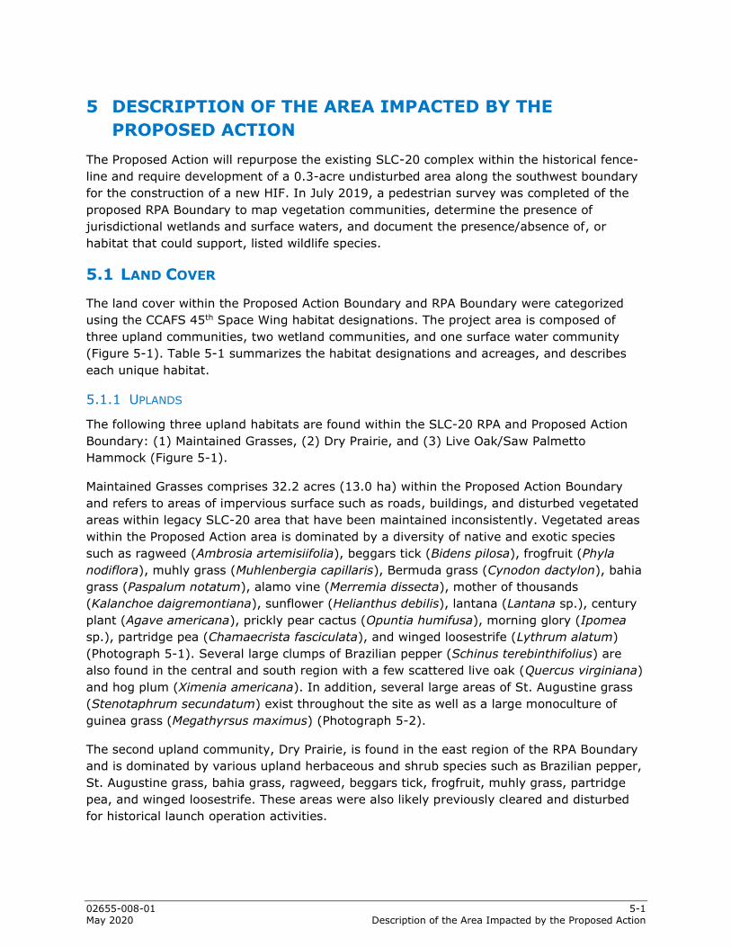
02655-008-01 5-1 May 2020 Description of the Area Impacted by the Proposed Action
5 DESCRIPTION OF THE AREA IMPACTED BY THE PROPOSED ACTION
The Proposed Action will repurpose the existing SLC-20 complex within the historical fence-line and require development of a 0.3-acre undisturbed area along the southwest boundary for the construction of a new HIF. In July 2019, a pedestrian survey was completed of the proposed RPA Boundary to map vegetation communities, determine the presence of jurisdictional wetlands and surface waters, and document the presence/absence of, or habitat that could support, listed wildlife species.
5.1 LAND COVER
The land cover within the Proposed Action Boundary and RPA Boundary were categorized using the CCAFS 45th Space Wing habitat designations. The project area is composed of three upland communities, two wetland communities, and one surface water community (Figure 5-1). Table 5-1 summarizes the habitat designations and acreages, and describes each unique habitat.
5.1.1 UPLANDS
The following three upland habitats are found within the SLC-20 RPA and Proposed Action Boundary: (1) Maintained Grasses, (2) Dry Prairie, and (3) Live Oak/Saw Palmetto Hammock (Figure 5-1).
Maintained Grasses comprises 32.2 acres (13.0 ha) within the Proposed Action Boundary and refers to areas of impervious surface such as roads, buildings, and disturbed vegetated areas within legacy SLC-20 area that have been maintained inconsistently. Vegetated areas within the Proposed Action area is dominated by a diversity of native and exotic species such as ragweed (Ambrosia artemisiifolia), beggars tick (Bidens pilosa), frogfruit (Phyla nodiflora), muhly grass (Muhlenbergia capillaris), Bermuda grass (Cynodon dactylon), bahia grass (Paspalum notatum), alamo vine (Merremia dissecta), mother of thousands (Kalanchoe daigremontiana), sunflower (Helianthus debilis), lantana (Lantana sp.), century plant (Agave americana), prickly pear cactus (Opuntia humifusa), morning glory (Ipomea sp.), partridge pea (Chamaecrista fasciculata), and winged loosestrife (Lythrum alatum) (Photograph 5-1). Several large clumps of Brazilian pepper (Schinus terebinthifolius) are also found in the central and south region with a few scattered live oak (Quercus virginiana) and hog plum (Ximenia americana). In addition, several large areas of St. Augustine grass (Stenotaphrum secundatum) exist throughout the site as well as a large monoculture of guinea grass (Megathyrsus maximus) (Photograph 5-2).
The second upland community, Dry Prairie, is found in the east region of the RPA Boundary and is dominated by various upland herbaceous and shrub species such as Brazilian pepper, St. Augustine grass, bahia grass, ragweed, beggars tick, frogfruit, muhly grass, partridge pea, and winged loosestrife. These areas were also likely previously cleared and disturbed for historical launch operation activities.

02655-008-01 5-2 May 2020 Description of the Area Impacted by the Proposed Action
Figure 5-1 Existing Land Cover

02655-008-01 5-3 May 2020 Description of the Area Impacted by the Proposed Action
Table 5-1 Summary of Land Cover Types Site Land Cover Description Acreage*
Proposed Action Maintained Grasses 32.2 (13.0) Oak/Palmetto 0.3 (0.1) Wet Prairie 0.19 (0.08) 33.0 (13.2)
RPA Boundary Maintained Grasses 2.2 (0.9) Dry Prairie 4.2 (1.7) Oak/Palmetto 155.1 (62.0) Marsh - Freshwater 2.5 (1.0) Wet Prairie 23.0 (9.2) 187.0 (74.8)
Total= 220.0 (88) *Hectares in parenthesis.
The third upland community, Oak/Palmetto, is found in the southwest region of the Proposed Action area and comprises approximately 0.3 acre (Figure 5-1) (Photograph 5-3). This community is dominated by live oak (Quercus virginiana), sabal palm (Sabal palmetto), saw palmetto (Serenoa repens), grape vine (Vitis sp.), and greenbriar (Smilax sp.).
Photograph 5-1 South Side of SLC-20
Photograph 5-2 North Portion of SLC-20 Looking North Toward
Existing HIF

02655-008-01 5-4 May 2020 Description of the Area Impacted by the Proposed Action
5.1.2 WETLANDS
The two wetland communities found within the RPA are Wet Prairie and Marsh – Freshwater (Figure 5-1). The Wet Prairie community found throughout the RPA Boundary is dominated by Brazilian pepper, sand cordgrass (Spartina bakerii), lateflowering thoroughwort (Eupatorium serotinum), winged loosestrife, broomsedge (Andropogon glomeratus), sawgrass (Cladium jaimacense), frogfruit, and foxtail (Seteria sp.). Surface water was not present, soils were extremely dry, and hydric soil indicators consisted of sandy redox (S5). Due to the lack of an organic horizon at the surface, these wetlands are not expected to experience prolonged inundation during the wet seasons; rather, the water table is found at or below grade. The second wetland community, Marsh – Freshwater, is in the northeast and southeast corners of the RPA Boundary (Figure 5-1). This community is dominated by dense cattail.
5.1.3 SURFACE WATERS
This community comprises 0.2 acre and is in the southwest region of the Proposed Action Boundary. It is an upland cut roadside drainage swale that is dominated by frog-fruit, St. Augustine grass, pennywort (Hydrocotyle umbellata), and sedges (Cyperus sp.).
Figure 5-2 presents a light detecting and ranging-derived digital elevation model (DEM) topographic map for the Proposed Action.
Photograph 5-3 Coastal scrub Facing South from Launch Pad Access Road

02655-008-01 5-5 May 2020 Description of the Area Impacted by the Proposed Action
Figure 5-2 Topographic Map


02655-008-01 6-1 May 2020 Listed Wildlife Species
6 LISTED WILDLIFE SPECIES Table 6-1 summarizes the listed wildlife species that may be potentially impacted as a result of the Proposed Action based on field investigations, existing data, and habitats found within the Proposed Action or RPA Boundary area.
6.1 FLORIDA SCRUB-JAY
The Florida scrub-jay is a federally threatened bird endemic to open, oak-dominated scrub habitats of Florida. Widespread loss and degradation of scrub habitat over the last century have resulted in dramatic declines in the distribution and abundance of this species. Populations of this species that remain are small, demographically isolated, and likely to decline. One of three core populations that contains over half of the State’s remaining scrub-jays is found at Kennedy Space Center (KSC)/CCAFS (USAF, 2018a). The 45th Civil Engineering Squadron, Environmental Conservation Element (45 CES/CEIE-C) is the organization within the 45th Space Wing with primary responsibility for overseeing Florida scrub-jay management and handling Section 7 consultations with the US Fish and Wildlife Service (USFWS) as required under the Endangered Species Act.
The SLC-20 RPA Boundary is in Land Management Units (LMU) 15 and 18. The Proposed Action site contains 0.3 acre (0.1 ha) of coastal scrub habitat that is considered poor quality (Figure 6-1) (USAF, 2018a). However, in the future the 45th Space Wing may conduct controlled burns and mechanical vegetation management to improve the coastal scrub habitat within the RPA Boundary up to the Proposed Action Boundary.
USAF conducts a yearly census of the Cape Canaveral population of scrub-jays in all suitable accessible jay habitat. In 2018, 136 Florida scrub-jay groups were identified, which has varied from 104 groups in 2000 to 157 groups in 1996 and 1997 (Figures 6-1 and 6-2). Data from the 2018 census indicate the presence of a single group within the RPA Boundary area just east of ICBM Road but over 1,100 feet west of the Proposed Action Boundary (Figure 6-3).
As previously stated, the Proposed Action will impact 0.3 acre (0.1 ha) of low-quality Florida scrub-jay habitat dominated by sand live oak and saw palmetto (Figure 6-3). The remaining disturbed areas do not support the Florida scrub-jay.


02655-008-01 6-2 May 2020 Listed Wildlife Species
Table 6-1 Potential Impacts, Section 7 Finding, and Compensation to Federal and State Protected Wildlife Species that Occur or Have Potential to Occur within the Proposed Action Area (Area defined as direct or indirect impact by construction or operations)
Common Name Scientific Name
Status1 Occurrence Potential Impacts Section 7 Finding Compensation
USFWS FFWCC
Florida Scrub-Jay Aphelocoma coerulescens
T T Potential Reduced restoration of suitable habitat.
May Affect, But Not Likely To Adversely Affect
Habitat restoration near SLC-19, change in 45 SW operational controls to ensure burn days, and continued habitat restoration on CCFAS.
Gopher Tortoise Gopherus polyphemus
C T Documented Crushing by equipment. Loss of habitat. NA Affected individuals to be relocated.
Eastern Indigo Snake Drymarchon corais couperi
T T Potential Crushing by equipment. May Affect, But Not Likely To Adversely Affect Continued habitat restoration on CCAFS.
Southeastern Beach Mouse Peromyscus polionotus niveiventris
T T Documented Crushing by equipment. Disruption due to noise.
May Affect and Is Likely To Adversely Affect Continued habitat restoration on CCAFS.
Marine Turtle: Leatherback (Dermocheyls coriacea) Green (Chelona mydas) Loggerhead (Caretta caretta) Kemps Ridley (Lepidochelys kempii) Hawksbill (Eretmochelys imbricata)
E T T E E
E T T E E
Documented Disruption and disorientation due to light.
May Affect and Is Likely To Adversely Affect
Implement exterior lighting compliant management plans.
West Indian Manatee Trichechus mantus
T T No habitat No impacts No Affect NA
American Alligator Alligator mississippiensis
S/A No habitat No impacts No Affect NA
American Wood Stork Mycteria americana
T T Potential Disruption of foraging habitat. Disruption due to noise. May Affect But Not Adversely Affect
Impacts to wetlands will be mitigated in accordance with state and federal wetland regulations.
Piping Plover Charadrius melodus
T T Potential Disruption due to noise. May Affect But Not Adversely Affect None provided.
Red Knot Calidris canutus
T Potential Disruption due to noise. May Affect But Not Adversely Affect None provided.
Note 1: Legend: (C) Candidate; (T) Threatened; (E) Endangered; (S/A) Similarity of Appearance. FFWCC = Florida Fish and Wildlife Conservation Commission.


02655-008-01 6-3 May 2020 Listed Wildlife Species
Figure 6-1 2018 Florida Scrub-Jay Census Map

02655-008-01 6-4 May 2020 Listed Wildlife Species
Figure 6-2 CCAFS Florida Scrub-Jay Annual Census Totals (USAF, 2019)

02655-008-01 6-5 May 2020 Listed Wildlife Species
Figure 6-3 Proposed Florida Scrub-Jay Habitat Impacts and Census Data

02655-008-01 6-6 May 2020 Listed Wildlife Species
6.2 GOPHER TORTOISE
The gopher tortoise is a State-Listed Threatened species by FFWCC and is protected by State law, Chapter 68A-27, Florida Administrative Code (FAC). The gopher tortoise is also currently classified as a Category 2 Candidate Species by USFWS under the Endangered Species Act. The basis of the Threatened classification by FFWCC for the gopher tortoise is due to habitat loss and destruction of burrows. The gopher tortoise can live up to 80 years in the wild and occurs in upland habitats such as sandhills, pine flatwoods, scrub, scrubby flatwoods, dry prairies, xeric hammock, pine-mixed hardwoods, and coastal dunes. Gopher tortoises will dig and use several burrows during the warm months and burrows can range from 3 to 52 feet long. These burrows provide refuge for more than 350 other commensal species such as small mammals, frogs, mice, snakes, and insects.
In July 2019, a pedestrian gopher tortoise survey was completed for approximately 90 percent of the Proposed Action area and approximately 60 percent of high probability habitat in the RPA Boundary. Within the Proposed Action area, a diversity of burrow sizes was observed, from juveniles to large adults (Photographs 6-1 and 6-2), with over 160 potentially occupied (PO) burrows observed within the boundary and 35 observed outside the boundary (Figures 6-4 and 6-5).
Photograph 6-1 Hatchling Gopher Tortoise Burrow Adjacent to Road to
Launch Pad
Photograph 6-2 Adult Gopher Tortoise Burrow

02655-008-01 6-7 May 2020 Listed Wildlife Species
Figure 6-4 Proposed Action Boundary PO Gopher Tortoise Burrow Location Map

02655-008-01 6-8 May 2020 Listed Wildlife Species
Figure 6-5 Proposed RPA Boundary Area PO Gopher Tortoise Burrow Location Map

02655-008-01 6-9 May 2020 Listed Wildlife Species
6.3 EASTERN INDIGO SNAKE
The eastern indigo snake is a federally Threatened species that may attain a length of up to 8 feet. It is found in a diversity of habitats and is closely associated with gopher tortoise burrows, which it uses for shelter during cold weather and extremely dry periods. The eastern indigo snake feeds on other snakes, frogs, salamanders, toads, small mammals, and birds and can have a home range of over 200 acres (USAF, 2018a). The eastern indigo snake has been observed on CCAFS and likely occurs throughout the installation; however, exact numbers are not known. The breeding season occurs between November and April with egg-laying occurring May through June with hatchlings emerging in late July through October. Major threats to the indigo snake on CCAFS are habitat loss and vehicle traffic. An installation-wide census for the eastern indigo snake has not been completed. This species is likely to occur within the Proposed Action Boundary based on the abundance of gopher tortoise burrows. This species is also likely to occur within the RPA Boundary area due to the habitat type and presence of gopher tortoise burrows.
6.4 SOUTHEASTERN BEACH MOUSE
The southeastern beach mouse is a federally Threatened subspecies that historically existed on coastal dunes and coastal strand communities from Ponce Inlet south (Volusia County) to Hollywood, Florida (Broward County) (Humphrey et al., 1987). Currently, the southeastern beach mouse is restricted to predominantly federal lands encompassing and adjacent to CCAFS, KSC, Canaveral National Seashore (CNS), the Merritt Island National Wildlife Refuge (MINWR), and a few locations on Pelican Island National Wildlife Refuge and Sebastian Inlet State Park (Oddy et al., 2012). This species is a high priority for management on federal lands encompassing the Cape Canaveral Barrier Island Complex (CCBIC), which includes KSC/MINWR, CCAFS, and CNS.
Reasons for decline in southeastern beach mouse populations include habitat loss due to development and erosion, habitat fragmentation, isolation, competition from the house mouse, and predation from domesticated cats (Stout, 1992). The beach mouse is a monogamous species for which breeding typically occurs November through January with females producing two or more litters per year with an average of three to four offspring per litter.
Biologists have been studying the demographics of this species since the late 1970s with a baseline study of KSC and CCAFS conducted by Stout (1979). Since 2008, biologists have monitored habitat occupancy of the southeastern beach mouse on the CCBIC, with the goal of sampling habitat occupancy annually each fall/winter throughout the entire area of suitable coastal habitat.
A long-term sampling grid (BG3) is north of the Proposed Action area but within the RPA Boundary as well as a 2011 to 2012 random coastal point referred to as 18 (Figure 6-6). Southeastern beach mice were captured at these locations during the 2011 to 2012 sampling period (Oddy et al., 2012). Sampling conducted in 2018 did not detect the presence of this species (Oddy and Stolen, 2018) (Figure 6-7), and results of the sampling determined a habitat occupancy rate of 0.72 percent of CCBIC coastal habitat was occupied. More importantly, several southeastern beach mice were captured inside the SLC-20

02655-008-01 6-10 May 2020 Listed Wildlife Species
Figure 6-6 Locations at which Southeastern Beach Mice were Detected During the Occupancy Survey on CCAFS, February to March 2018
(Green circles indicate that beach mice were detected at a site, and red circles indicate no detection at a site. Numbers indicate site locations.) (Oddy and Stolen, 2018)

02655-008-01 6-11 May 2020 Listed Wildlife Species
blockhouse (Facility 18800) in 2001 (ESC, 2002). As a result, the presence of this species has been confirmed within the Proposed Action Boundary as well as within the RPA Boundary area.
Figure 6-7 Land Management Units (Blue), Long-Term Grids (Green), and Random Coastal Points (Red) on CCAFS Where Small Mammal Trapping Occurred in Fall 2011 and Spring 2012

02655-008-01 6-12 May 2020 Listed Wildlife Species
6.5 MARINE TURTLES
The loggerhead, green, leatherback, and Kemp’s ridley sea turtles nest on the beaches of CCAFS and Patrick Air Force Base (PAFB). In 1986, the 45th Space Wing began sea turtle monitoring at CCAFS and PAFB. Nests are deposited on CCAFS and PAFB each year between April and September. Each year, between 1,400 to 3,600 sea turtle nests are deposited on the 13 miles of beach at CCAFS based on nest surveys at CCAFS from 1986 through 2018 (Figure 6-8) (USAF, 2018b).
Figure 6-8 All Sea Turtle Nests Deposited at CCAFS and PAFB
Although sea turtles spend much of their lives in the ocean, females come ashore each year to nest. Preliminary research indicates that lights adjacent to sea turtle nesting beaches may hinder the beach nest site selection of nesting females. Regarding sea turtle hatchlings, extensive research has demonstrated that the principal component of the emergent sea turtle hatchlings’ orientation behavior is visual (Carr and Ogren, 1960; Dickerson and Nelson, 1989; Witherington and Bjorndal, 1991). Artificial beachfront lighting has been documented to cause disorientation (loss of bearings) and misorientation (incorrect bearing) of hatchling turtles. As hatchlings head toward artificial lights, their exposure to predators and the likelihood of dehydration are greatly increased. Misoriented hatchlings can become entrapped in vegetation or debris, and some hatchlings have been found dead on nearby roadways and in parking lots after being struck by vehicles. Intense artificial lighting can even draw hatchlings back out of the surf (USAF, 2018b).
In 1988, in compliance with Section 7 of the Endangered Species Act, USAF developed Light Management Plans (LMPs) for various areas and facilities on CCAFS to protect sea turtles. A Biological Opinion (BO) issued by USFWS in April 1991, with several subsequent revisions, requires LMPs for any new facilities that are close to the beach, are not constructed in accordance with 45th Space Wing Instruction (SWI) 32-7001, have lighting directly visible from the beach, and/or may cause significant sky glow. The BO was modified again in 2008 and authorized a 3-percent take of nesting females and up to 3 percent of all hatchlings
0
500
1000
1500
2000
2500
3000
3500
4000
1986 1988 1990 1992 1994 1996 1998 2000 2002 2004 2006 2008 2010 2012 2014 2016 2018
CCAFS
PAFB

02655-008-01 6-13 May 2020 Listed Wildlife Species
disoriented/misoriented from a representative sample of all surveyed marked nests. The BO also requires at least five night light surveys at CCAFS and PAFB during the peak of nesting season (May 1 through October 31). Currently, no exterior lighting operates at SLC-20 and no disorientation has been documented on the beach in this area for several years.
6.6 WEST INDIAN MANATEE
The West Indian manatee is listed as Endangered by USFWS. Manatees are protected under the Marine Mammal Protection Act, which prohibits the take (i.e., harass, hunt, capture, or kill) of all marine mammals. Manatees are found in marine, estuarine, and freshwater water bodies. The West Indian manatee includes two distinct subspecies; the Florida manatee (Trichechus manatus latirostris) and the Antillean manatee (Trichechus manatus manatus). Although morphologically distinctive, both subspecies have many common features such as large, seal-shaped bodies with paired flippers and a round, paddle-shaped tail. They are typically grey (color can range from black to light brown) and occasionally spotted with barnacles or colored by patches of green or red algae. The muzzle is heavily whiskered and coarse, single hairs are sparsely distributed throughout the body. On average, adult manatees are approximately 9 feet long (3 meters) and on average weigh 1,000 lb (200 kg). At birth, calves are between 3 and 4 feet long (1 meter) and weigh between 40 and 60 lb (30 kg).
No surface waters exist for the West Indian manatee within the Proposed Action or RPA Boundary areas. However, this species could use coastal waters of the Atlantic Ocean to the east.
6.7 AMERICAN ALLIGATOR
The American alligator is federally listed as Threatened due to its similarity in appearance to other endangered species such as the American crocodile (Crocodylus acutus). The American alligator has made a strong recovery in Florida and inhabits and reproduces in nearly all CCAFS waters. Alligators are apex predators and consume fish, amphibians, reptiles, birds, and mammals. They play an important role as ecosystem engineers in wetlands through the creation of alligator holes, which provide wet and dry habitats for numerous other organisms.
The Proposed Action area does not contain wetland or surface water habitat that could support this species. However, the RPA Boundary area does contain two cattail-dominated ponds that could support the American alligator (Figure 5-1).
6.8 AMERICAN WOOD STORK
The American wood stork is a federally listed Threatened species and is the only stork species found in North America. It is a large, white and black wading bird, with a long ‘ibis-shaped’ beak. Wood storks forage in small pools and wetland areas that support small fish. The species breeds in late winter once fish populations in small vernal pools have dried up sufficiently to support the raising of young.
The Proposed Action area does not contain wetland or surface waters that would be used by the American wood stork. However, the proposed RPA Boundary area does contain two

02655-008-01 6-14 May 2020 Listed Wildlife Species
cattail-dominated ponds and several depressional wetlands that could provide marginal foraging habitat for use by the American wood stork.
6.9 PIPING PLOVER
The piping plover, a federally listed Threatened species, is a small sand-colored, sparrow-sized shorebird that nests and feeds along coastal sand and gravel beaches in North America. The adult has yellow-orange legs, a black band across the forehead from eye to eye, and a black ring around the neck. Their breeding habitat includes beaches or sand flats on the Atlantic coast, Great Lakes, and the mid-west. They forage for food on beaches moving across in short bursts around the high-tide wrack zone eating insects, marine worms, and crustaceans.
The piping plover is not known to breed in Brevard County; however, it does have the potential to occur on Brevard beaches during the non-breeding season (July to March) and has been previously observed on CCAFS beaches in small numbers.
6.10 RED KNOT
The red knot is a federally listed Threatened species and is a medium-sized shorebird that breeds in tundra and the Arctic Cordillera in the far north of Canada, Europe, and Russia. The red knot has one of the longest migrations of any bird. The red knot is an occasional visitor along the Florida seashore during its annual migration. This species is not known to breed or nest in Brevard County; however, it has been previously observed on CCAFS beaches in small numbers.

02655-008-01 7-1 May 2020 Effects of Action on Listed Species
7 EFFECTS OF ACTION ON LISTED SPECIES The following sections discuss specific effects from the Proposed Action. Effects are caused by construction and operations activities. Envisioned impacts include construction and operation activities associated with the launch of the Concept A and B launch vehicles. Potential impacts to listed species have been significantly minimized by siting facilities/structures in cleared and disturbed areas associated with the legacy SLC-20. The only proposed impacts to undisturbed areas are in association with the new HIF in Phase 2, which will require the clearing of 0.3 acre (0.1 ha) of coastal scrub. Construction in this area is unavoidable due to HIF orientation requirements to move the assembled launch vehicle to the launch pad.
7.1 FLORIDA SCRUB-JAY
7.1.1 DIRECT IMPACTS
The clearing for the new HIF of the Proposed Action will result in the loss of approximately 0.3 acre (0.1 ha) of poor-quality unoccupied scrub-jay habitat. Figure 6-3 shows that the 2018 Florida Scrub-Jay census did not reveal the presence of any scrub-jay groups or individuals within the Proposed Action area. However, the 2018 census did observe this species within the proposed RPA Boundary area (just west of ICBM Road) but not within areas where the proposed construction would occur. As a result, direct impacts to this species are not expected. The proposed operations at SLC-20 would increase traffic in the vicinity of the scrub-jay habitat and thus create the opportunity for a take due to road-kill mortality.
7.1.2 INDIRECT IMPACTS
Potential effects to the Florida scrub-jay, if present, during construction activities would include disruption of normal activities due to noise and ground disturbances. These impacts would be short-term and would elicit a startle response to avoid the noise. This would help the birds to avoid the threat and therefore would not cause a negative impact to populations near the Proposed Action and RPA Boundary areas. Launch-related noise may startle many species within the CCAFS area. However, actual noise impact to wildlife, including the Florida scrub-jay is expected to be minimal. Current and past launch programs on CCAFS, i.e., Atlas, Titan, and Delta launches, have been documented as not causing any animal mortality or significant impact to wildlife on CCAFS (USAF, 1998).
The 45th Space Wing has a CCAFS habitat management goal of burning 500-acres annually to manage habitat for the Florida scrub-jay and other threatened and endangered species. This goal has been established through consultation with federal resource agencies pursuant to Section 7 of the Endangered Species Act. In order to achieve this goal, the 45th Space Wing typically needs 6-8 days of prescribed burning per year. Burn window opportunities for the 45th Space Wing have been periodically reduced due to numerous factors such as weather, payload transport, payload processing, payload storage at a launch pad, launches, wet dress, and static test fires, among others. Historically, the 45th Space Wing has been relatively successful at meeting this objective. However, due to the current military project needs and increasing number of commercial aerospace customers, prescribed burning has and will become more difficult.

02655-008-01 7-2 May 2020 Effects of Action on Listed Species
As a result, the presence of new launch operations at SLC-20 has the potential to reduce burn windows for LMUs 15 and 18 and other LMUs due to launches, payload processing, and other operation activities. As a result, this could have negative indirect impacts on the Florida scrub-jay because of the reduced restoration of suitable habitat for this species.
Historically, the 45th Space Wing has maintained a launch table from which burn windows are identified. The increase in aerospace activities has reduced the availability of these windows due to reasons listed above as well as secondary impacts such as launch delays or improper weather conditions when a prescribed burn window arises. As a result, the 45th Space Wing plans to revise its approach with current and future users and Space Florida to ensure adequate burn windows occur annually in an effort to prioritize this listed species management activity rather than it being secondary to launch operations. The SW is currently working with senior CCAFS staff to develop operational controls that will block out a set number of days annually within which launches or other activities affected by prescribed burns cannot occur in order to allow SW to meet its habitat management goals agreed to with the resource agencies. Operational controls will be implemented that will provide more assurance that CCAFS will meet its burning goals as part of its land management unit responsibilities. In addition, Space Florida will incorporate language into their tenant lease agreements that references the 45th Space Wing prescribed burn goal, listed species management responsibilities, and resulting annual restrictions (1-2 weeks) during a 45th Space Wing predefined period. As part of the lease agreement with Space Florida, the tenants will have a contractual obligation to comply with the specified prescribed burn days schedule by providing adequate protection for their equipment (via containment or filtration systems) or moving sensitive equipment to another location while the prescribed burn days are in force. In addition, Space Florida will work closely with 45th Space Wing and attend the CCAFS Controlled Burn Working Group meetings to stay abreast of prescribed fire schedules.
Because of the potential for an indirect take of scrub-jays as noted above, the 45th Space Wing has determined that the proposed project may affect, but not likely to adversely affect the Florida scrub-jay.
7.2 GOPHER TORTOISE
PO gopher tortoise burrows are throughout the Proposed Action area, adjacent to proposed facilities, and very dense along the shoulders of the road that serves the SLC-20 launch pads (Figure 6-4). As such, the Proposed Action will result in the loss of occupied gopher tortoise habitat and require the relocation of numerous tortoises. Relocation activities on military bases are exempt from FFWCC permitting and fees in accordance with the FFWCC Gopher Tortoise Management Plan. Additionally, USAF is required to provide an annual report that includes relocation activities taking place on its property in accordance with the Gopher Tortoise Candidate Conservation Agreement.
All tortoises that may be impacted will be safely excavated by FFWCC-authorized gopher tortoise agents and relocated to an approved gopher tortoise recipient site on CCAFS property in accordance with FFWCC rules. The Proposed Action could result in a direct take due to mortality or injuries sustained by heavy equipment.

02655-008-01 7-3 May 2020 Effects of Action on Listed Species
Reptiles and amphibians are sensitive to vibrations, which provide information about approaching predators and prey. Vibration and noise associated with construction activities would potentially cause short-term disturbance to gopher tortoises. These impacts would be considered short-term and would not cause a significant impact to populations within the vicinity of the project area. Noise associated with rocket launches may startle many species within the CCAFS area. However, actual noise impact to wildlife is expected to be minimal. As previously stated, studies on current and past launch programs on CCAFS have not been documented to cause animal mortality or significant impact to wildlife on CCAFS (USAF, 1998).
7.3 EASTERN INDIGO SNAKE
The Proposed Action will result in the loss of approximately 0.3 acre (0.1 ha) of potential eastern indigo snake habitat (undisturbed coastal scrub) and approximately 32 acres (13 ha) of disturbed habitat having a high density of gopher tortoise burrows that could be used by this species as refugia. As a result, it is unlikely a take may occur as the result of habitat loss and vast acreages of adjacent suitable habitat are present. A direct take would also not occur for this species that may be utilizing gopher tortoise burrows as all burrows will be excavated and any eastern indigo snakes will be safely moved or allowed to move outside the Proposed Action boundary. Eastern indigo snakes could be vulnerable to mortality as a result of injuries sustained during construction activities.
Reptiles and amphibians are sensitive to vibrations, which provide information about approaching predators and prey. Vibration and noise associated with construction activities would elicit a startle response to avoid the noise. These impacts would be considered short-term and would not cause a negative impact to the eastern indigo snake within the vicinity of the project area (USAF, Environ). Noise associated with rocket launches may startle this species within the CCAFS area. However, actual noise impact to this species is expected to be minimal. As previously stated, studies on current and past launch programs on CCAFS have not been documented to cause animal mortality or significant impact to wildlife on CCAFS (USAF, 1998).
Due to the potential for indirect take of the eastern indigo snake as noted above, the 45th Space Wing has determined that the proposed project may affect, but not likely to adversely affect the eastern indigo snake.
7.4 SOUTHEASTERN BEACH MOUSE
Construction and operations will occur approximately 100 feet west of the beach dune area, typical habitat of the beach mouse. However, the Proposed Action will not result in the clearing of beach dune habitat and is limited to clearing 0.3 acre (0.1 ha) of coastal scrub approximately 850 feet west of the toe-of-slope of coastal dune habitat. All other impacts will be to previously disturbed and maintained low-quality ruderal habitat associated with the legacy SLC-20 area.
This species has been documented in the blockhouse, which will be renovated under the Proposed Action. As such, a take of beach mice is not expected to occur due to a loss of potential habitat. Rather, a take may occur as a result of the renovation of abandoned facilities that this species is known to use as refugia. However, the SLC-20 tenant will

02655-008-01 7-4 May 2020 Effects of Action on Listed Species
request and perform live trapping in accordance with the USFWS August 2002 BO on rodent trapping.
Potential noise-related effects to the southeastern beach mouse during construction activities would include disruption of normal activities due to noise and ground disturbances. These impacts would be short-term and would elicit a startle response to avoid the noise. This would help the mice avoid the threat and therefore would not cause an impact to this species within the vicinity of the project area. Noise associated with rocket launches may startle this species within the CCAFS area. However, actual noise impact to this species is expected to be minimal. As previously stated, studies on current and past launch programs on CCAFS have not documented animal mortality or significant impact to wildlife on CCAFS (USAF, 1998).
The proposed operations at SLC-20 would increase traffic in the vicinity of the southeastern beach mouse habitat and thus create the opportunity for a take due to road-kill mortality.
Due to the potential for direct and indirect take of the southeastern beach mouse as noted above, the 45th Space Wing has determined that the proposed project may affect and is likely to adversely affect the southeastern beach mouse.
7.5 MARINE TURTLES
The proposed clearing and construction of new facilities would not directly impact the nesting beach. Exterior lighting proposed for the new facilities and lighting required for night launches has the potential to be visible from the beach and could result in adult and/or hatchling disorientation adjacent to SLC-20. However, proposed lighting and its use will be outlined in a CCAFS-approved LMP.
Sea turtles are not expected to be affected by vibration and noise associated with construction activities since the project area will be beyond the beach and dune area. However, noise associated with rocket launches may startle many species within the CCAFS area, but the noise impact to wildlife is expected to be minimal. Sonic boom noise in the area is minimal, and large sonic boom may only occur offshore and would also have no effect.
Due to the potential that night launches may result in the disorientation of hatchlings, the 45th Space Wing has determined that the proposed project may affect and is likely to adversely affect the five species of marine turtles occurring at CCAS.
7.6 WEST INDIAN MANATEE
The Proposed Action contains no habitat for this species and their presence is limited to Atlantic Ocean coastal waters to the east. Manatees are not expected to be affected by vibration and noise associated with construction activities since they are not in the area.
Noise associated with rocket launches may startle many species within the CCAFS area; however, its impact to wildlife is expected to be minimal. Sonic boom noise impacts to this species is expected to be negligible since it will occur many miles offshore.
Due to the lack of habitat, the 45th Space Wing has determined that the proposed project will have no effect on the West Indian manatee.

02655-008-01 7-5 May 2020 Effects of Action on Listed Species
7.7 AMERICAN ALLIGATOR
The Proposed Action will not impact the American alligator or its habitat as the small man-made swale totaling 0.19 acre (0.08 ha) would not be considered alligator habitat. Therefore, the Proposed Action is not likely to impact alligators. The RPA Boundary area does contain two cattail ponds that could provide habitat for this species. However, the Proposed Action proposes no impacts to this habitat.
Reptiles and amphibians are sensitive to vibrations, which provide information about approaching predators and prey. Vibration and noise associated with construction activities could cause short-term disturbance to an alligator. These impacts would be considered short-term and would not affect alligators within the vicinity of the project area. Noise associated with rocket launches may startle the American alligator and other species within the CCAFS area. However, actual noise impact to wildlife is expected to be minimal. As previously stated, studies on current and past launch programs on CCAFS have not been documented to cause animal mortality or significant impact to wildlife on CCAFS (USAF, 1998).
Because of the lack of potential impact to this species, the 45th Space Wing has determined that the proposed project will have no effect on the American alligator.
7.8 AMERICAN WOOD STORK
The Proposed Action area does not contain wetland or surface waters that would be used by the American wood stork. However, the proposed RPA Boundary area does contain two cattail dominated ponds comprising 2.5 acres (1.0 ha) that could provide marginal foraging habitat. The dense vegetation limits the value of this habitat for the wood stork. Approximately 15.5 acres (6.3 ha) of shallow depressional wetlands exist characterized as wet prairies throughout the RPA Boundary area. However, as previously mentioned, these wetlands do not experience prolonged inundation and they are not connected to other wetlands or surface waters to support fish species that wood storks rely on. As such, these wetlands likely provide little to no foraging habitat for use by the American wood stork.
Noise associated with rocket launches may startle many species within the CCAFS area. Actual noise impact to wildlife is expected to be minimal. As previously stated, studies on current and past launch programs on CCAFS have not been documented to cause animal mortality or significant impact to wildlife on CCAFS (USAF, 1998). Sonic boom noise may only occur well offshore and its impact on this species is expected to be minimal.
Due to the lack of potential impact to this species, the 45th Space Wing has determined that the proposed project may affect but is not likely to adversely affect the American wood stork.
7.9 PIPING PLOVER
The piping plover forages along the shoreline and nesting has been documented in Brevard County. As a result, the Proposed Action and future activities within the RPA Boundary area will not impact Piping Plover habitat.

02655-008-01 7-6 May 2020 Effects of Action on Listed Species
Potential noise-related effects from construction or launches is not expected to impact the piping plover.
Due to the lack of potential impact to this species, the 45th Space Wing has determined that the proposed project may affect but is not likely to adversely affect the piping plover.
7.10 RED KNOT
The red knot is recognized as an occasional visitor that forages along the shoreline during its migration. The Proposed Action or future activities within the RPA Boundary area will not impact shoreline habitat used by the red knot.
Potential noise-related effects from construction or launches is not expected to impact the red knot.
Due to the lack of potential impact to this species, the 45th Space Wing has determined that the proposed project may affect but is not likely to adversely affect the red knot.

02655-008-01 8-1 May 2020 Compensation for Affected Species
8 COMPENSATION FOR AFFECTED SPECIES
8.1 FLORIDA SCRUB-JAY
USFWS and USAF have agreed to a mitigation formula for scrub-jay habitat impacts that mitigate loss of scrub or potential scrub habitat acreage by restoring degraded scrub habitat at a 2:1 ratio. The objective of CCAFS scrub habitat restoration is to restore, using fire and mechanical methods, the over-mature scrub to a condition suitable to support the Florida scrub-jay. The 45th Space Wing proposes to enhance coastal scrub habitat on the southeast corner of SLC-19 as compensation for effects on the southeastern beach mouse (Figure 8-1). This habitat enhancement will provide suitable habitat for the Florida scrub-jay to mitigate the proposed 0.3 acre of habitat impacts. Space Florida will be the agency responsible for the completion and subsequent monitoring of the habitat enhancement mitigation area.
Although the Proposed Action area is not suitable habitat nor currently occupied, scrub-jay surveying would be conducted before clearing to ensure that no jays are nesting within 300 feet of clearing activities. All suitable scrub-jay habitat would be surveyed for nesting jays. Any nests encountered would be flagged and no clearing would be allowed within 300 feet until all birds have fledged.
8.2 GOPHER TORTOISE
Substantial impacts to gopher tortoises could occur due to the high density of this species within the Proposed Action area. A high density of gopher tortoise burrows occurs on the shoulders of the launch pad access roads as well as the north/south road spur that ends at the launch pad (Figure 6-4). These roads are very old and need repairing and at a minimum resurfacing. Currently, the extent of road renovations or expansion under the Proposed Action have not been determined; therefore, the resulting impacts to the gopher tortoise is not known.
To minimize impacts to gopher tortoises, gopher tortoise burrows will not be disturbed if a minimum of a 25-foot (7.6-m) buffer can remain as well as maintaining connectivity of this buffer to foraging areas in accordance with FFWCC guidelines. No more than 90 days before and no fewer than 72 hours before any clearing or construction, a 100-percent pedestrian survey in accordance with FFWCC guidelines will be conducted to locate and flag/stake all burrows. Gopher tortoise burrows that occur within areas to be cleared, areas for new construction, or burrows found on the shoulder of roads to be rebuilt will be excavated, and captured tortoises will be relocated by an FFWCC-authorized agent in accordance with FFWCC guidelines to the 45th Space Wing-approved recipient site on CCAFS. A map showing the locations of the burrow and their occupancy status if a tortoise was captured will be provided to the construction contractor by the commercial space entity under lease agreement with Space Florida for SLC-20. Educational posters will be provided to construction personnel and future tenant personnel so that they are observant for any tortoises that may enter the construction site or during site operations. Any live or dead tortoises observed will be reported to the 45th Space Wing immediately.

02655-008-01 8-2 May 2020 Compensation for Affected Species
Figure 8-1 Proposed Habitat Enhancement Location Map

02655-008-01 8-3 May 2020 Compensation for Affected Species
8.3 EASTERN INDIGO SNAKE
The 45th Space Wing Indigo Snake Protection/Education Plan will be presented to the commercial space user project manager, their construction manager, and construction personnel. Educational signs will be displayed at the site to inform personnel of the snake’s appearance, its protected status, and who to contact if any are spotted in the area. If any indigo snakes are encountered during clearing activities, they will be allowed to safely move out of the project area. Any observations of live or dead indigo snakes will be reported to the 45th Space Wing immediately, who will then report it to USFWS if appropriate.
8.4 SOUTHEASTERN BEACH MOUSE
The Proposed Action would not significantly impact the southeastern beach mouse population at CCAFS since no clearing or construction of suitable habitat will occur. However, there could be a take of a southeastern beach mouse due to their use of the block house and disturbed habitats between this structure and the coast dunes. USAF has an USFWS Programmatic Biological Opinion that addresses impacts to beach mice associated with certain activities including launch site restoration actions (USFWS, 2002). Based on past studies completed for CCAFS, beach mice are benefitting from the same land management activities being conducted for scrub-jays, and the population is expanding into inland locations. However, as compensation for the potential take of this species as a result of the Proposed Action, Space Florida is proposing to enhance dune and coastal scrub habitat within an area on the southeast corner of SLC-19 (Figure 8-1). This habitat enhancement will help to provide high quality habitat and a corridor to additional suitable interior habitat. Space Florida will be the agency responsible for the completion and subsequent monitoring of the habitat enhancement mitigation area.
8.5 MARINE TURTLES
To minimize potential impacts to sea turtles from new or temporary facility lighting, the majority of exterior lighting proposed for this project would be in accordance with the 2018 45th SWI 32-7001, Exterior Lighting Management. Some non-turtle friendly lighting may be required during the day of launch and if any launches were occurring at night. An LMP will be completed by the SLC-20 tenant and submitted to the 45th Space Wing and USFWS for approval before new or temporary lighting construction. Clearing of vegetation at the SLC-20 area will not have an impact to nesting or hatchling sea turtles; therefore, no mitigation is required for those activities.
8.6 WEST INDIAN MANATEE
Since the area where the West Indian manatee may be present is offshore well to the east of the Proposed Action area, negligible impacts are expected; therefore, mitigation measures are not proposed or needed.
8.7 AMERICAN ALLIGATOR
Since the only potential water bodies where alligators may reside are not part of the Proposed Action construction area, impacts to this species are not expected; therefore, no mitigation measures are needed. However, construction and operations personnel will be advised of the potential presence of alligators in the off-site cattail ponds and disturbance

02655-008-01 8-4 May 2020 Compensation for Affected Species
to nests is not authorized. Additionally, Space Florida and its lessee will be responsible for ensuring all personnel understand the laws regarding the feeding of alligators. Any personnel observed feeding alligators will be reported to the appropriate authorities.
8.8 AMERICAN WOOD STORK
This species or its nests have not been observed on-site. In addition, no suitable foraging habitat exists within the Proposed Action Boundary. Therefore, no mitigation measures are required or proposed. During launch operations, wood storks in surrounding areas could be startled but this is expected to be a short-term impact.
8.9 PIPING PLOVER
Since no clearing or disturbance to the beach is proposed, impacts to piping plover habitat will not occur. However, during launch operations, any plovers on the beach adjacent to SLC-20 could be startled; this would be expected to be a short-term impact.
8.10 RED KNOT
Since no clearing or disturbance to the beach is proposed, impacts to red knot habitat will not occur. However, during launch operations, red knots on the beach adjacent to SLC-20 could be startled; this would be expected to be a short-term impact.

02655-008-01 9-1 May 2020 Cumulative Impacts
9 CUMULATIVE IMPACTS Potential cumulative adverse impacts would occur for the Florida scrub-jay and eastern indigo snake when evaluated with other projects occurring or proposed on CCAFS and the potential for additional coastal scrub impacts in the future within the RPA Boundary area. These potential cumulative impacts arise due to the removal of coastal scrub habitat that could support the eastern indigo snake and coastal scrub habitat that could be restored in the future to support additional Florida scrub-jays. Potential cumulative impacts could also occur as a result of additional launches by future tenants, which could negatively affect the CCAFS controlled burn program, thereby slowing Florida scrub-jay habitat restoration efforts.
Cumulative impacts on the gopher tortoise are not expected within the Proposed Action area or the RPA Boundary area. Gopher tortoises observed within any area to be impacted by ground disturbance would be excavated and relocated by an FFWCC-Authorized Agent to an onsite recipient area approved and managed by USAF.
Cumulative impacts on sea turtles have the potential to occur. The new facilities will result in more exterior lighting than is currently present at LC-20. Adherence to the LMP and USAF lighting policies will minimize these impacts. CCAFS- and FFWCC-compliant lighting will be used to minimize potential adverse impacts on nesting turtles and/or their young.
Cumulative impacts on the West Indian manatee, American alligator, American wood stork, piping plover, and red knot are not expected to occur with the Proposed Action as there is no habitat that supports these species in the Proposed Action Boundary area. In addition, cumulative impacts on these species is not expected in the RPA Boundary area due to the lack of habitat to support these species.


02655-008-01 10-1 May 2020 List of Preparers
10 LIST OF PREPARERS
▪ B.J. Bukata, MS, PWS, AA, Senior Scientist and Authorized Gopher Tortoise Agent, Jones Edmunds.
▪ Laura Coveney Craig, AA, Project Scientist and Authorized Gopher Tortoise Agent, Jones Edmunds.
▪ Nicola Staton, Senior Technical Communications Coordinator, Jones Edmunds. ▪ Nancy Vaseen, Senior Technical Communications Coordinator, Jones Edmunds. ▪ Stephen Berry, Vice President of Operations, LG2 Environmental Solutions, Inc. ▪ Priyanka Valletta, PE, Civil Engineer, BRPH Architects-Engineers, Inc.


02655-008-01 11-1 May 2020 References and Documents Cited
11 LITERATURE CITED Carr, A., and L. Ogren. 1960. The Ecology and Migrations of Sea Turtles. 4. The Green
Turtle in the Caribbean Sea. Bulletin of the American Museum of Natural History. 121: 1-48 p.
Dickerson, D.D., and D.A. Nelson. 1989. Recent Results on Hatchling Orientation Responses to Light Wavelengths and Intensities. In: Eckert, S.A., K.L. Eckert, and T.H. Richardson (compilers). Proceedings on the Ninth Annual Workshop on Sea Turtle Conservation and Biology. NOAA Technical Memorandum NMFS-SEFC-232. 41-43 p.
Environmental Support Contract (ESC), 2002. Final Exit Environmental Baseline Survey, Launch Complex 20, Cape Canaveral Air Force Station, Florida. Prepared for USAF 45th Space Wing, Patrick Air Force Base, Florida.
Humphrey, S.R., W.H. Kern, Jr., and M.S. Ludlow. 1987. Status survey of seven Florida mammals. Florida Cooperative Fish and Wildlife Research Unit Tech. Rept. # 25. Gainesville, Florida. 39 p. National Wetlands Inventory Map: www.fws.gov/wetlands/.
NASA, 2008. Final Environmental Assessment for Exploration Park – Phase I, Kennedy Space Center. Prepared by Dynamac Corporation for Space Florida and Kennedy Space Center. December 2018.
Oddy, D.M., E.D. Stolen, S.L. Gann, K.G. Holloway-Adkins, S.A. Legare, S.K. Weiss, and D.R. Breninger. 2012. Final Report, Demography, Occupancy, and Homerange of the Southeastern Beach Mouse (Peromyscus polionotus niveiventris) on the Cape Canaveral Air Force Station 2011-2012. Prepared for 45 CES/CEAN Cape Canaveral Air Force Station, FL. Delivery Order FA 2521-11-F-0245.
Oddy, D.M. and E.D. Stolen 2018. Report on southeastern beach mouse (Peromyscus polionotus niveiventris) habitat occupancy survey on Kennedy Space Center, Merritt Island National Wildlife Refuge, Cape Canaveral Air Force Station and Canaveral National Seashore. Integrated Mission Support Services.
Space Florida. 2017. Space Florida’s Cape Canaveral Spaceport Master Plan. Prepared for Space Florida and Florida Department of Transportation. January 2017. (https://www.spaceflorida.gov/wp-content/uploads/2018/12/sf-bod-approved-ccs-master-plan-02-01-17.pdf)
Stout, I.J. 1979. Terrestrial community analysis. Vol. 1 of IV: a continuation of baseline studies for environmentally monitoring space transportation systems (STS) at John F. Kennedy Space Center. NASA Contract Report No. 10-8986.
Stout, I.J. 1992. Southeastern beach mouse. Pages 242-249. In: S.R. Humphrey (ed.). Rare and endangered biota of Florida. Vol. I. Mammals. University Presses of Florida, Gainesville.
US Air Force (USAF), 1998. Final Environmental Impact Statement Evolved Expendable Launch Vehicle.

02655-008-01 11-2 May 2020 References and Documents Cited
US Air Force (USAF), 2018a. Integrated Natural Resources Management Plan for the 45th Space Wing Report. Attachment D-3 Scrub Habitat Restoration Plan, Appendix D: Threatened and Endangered Species.
US Air Force (USAF), 2018b. Integrated Natural Resources Management Plan for the 45th Space Wing Report. Attachment D-1 Sea Turtle Management Plan.
US Air Force (USAF), 2019. Personal communication with Angie Chambers CES/CEIE, Environmental Resources who provided digital dataset of 2018 Florida scrub jay survey counts.
US Fish and Wildlife Service (USFWS), 2002. Letter to 45th Space Wing Regarding Cape Canaveral Air Force Station Rodent Control Program. August 22, 2002.
Witherington, B.E., and K.A. Bjorndal. 1991. Influences of Artificial Lighting on the Seaward Orientation of Hatchling Loggerhead Turtles (Caretta caretta). Biological Conservation. 55:139-149 p.

Environmental Assessment Reconstitution and Enhancement of Launch Complex 20 Multi-user Launch Operations
APPENDIX E 1
NMFS Consultation 2
3


OF
4 4
. g
4rES 0c
Donald DankertEnvironmental Management BranchNational Aeronautics and Space AdministrationJohn F. Kennedy Space CenterMail Code: SI-E3Kennedy Space Center, Florida 32899
UNITED STATES DEPARTMENT OF COMMERCENational Oceanic and Atmospheric AdministrationNATIONAL MARINE FISHERIES SERVICESoutheast Regional Office263 13th Avenue SouthSt. Petersburg, Florida 33701-5505http://seronmfs.noaa.gov
AUG 082016
F/SER3 1: NMB
Daniel CzelusniakEnvironmental SpecialistFederal Aviation Administration800 Independence Avenue SouthwestSuite 325Washington, DC 20591
Dear Mr. Dankert and Mr. Czelusniak:
This letter responds to your request for consultation with us, the National Marine FisheriesService (NMFS), pursuant to Section 7 of the Endangered Species Act (ESA) for the followingaction.
Applicant(s) SER Number Project Type(s)
National Aeronautics and Space SER-2016-17894 Waterborne landingsAdministration (NASA) and Federal Aviation of spacecraftAdministration
Consultation HistoryWe received your letter requesting consultation on April 11, 2016. We discussed the projectwith the applicant on May 3, 2016, and requested additional information. During this call, wedetermined that the project would be expanded from the request to analyze 2 launches withNASA as the lead federal agency to now analyzing all launches occurring from the KennedySpace Center (KSC), Cape Canaveral Air Force Station (CCAFS), and SpaceX Texas LaunchComplex, with the lead federal agency being assigned as NASA, Federal AviationAdministration, or the U.S. Air Force. After exchanging 3 drafts of the project description, wereceived a final response on July 14, 2016, and initiated consultation that day.

Project LocationAddress Latitude/Longitude Water bodyKennedy Space Center and 28.608402°N, 80.604201°W (North Atlantic Ocean off ofCanaveral Air Force Station, American Datum 1983) Cape Canaveral andBrevard County, Florida Coordinates provided are for launch Gulf of Mexico
pad 39A. Other launch pads at theKSC and CCAFS may be used.
Texas SpaceX Launch Site, 2 25.99684°N, 97.15523°W (World Gulf of Mexicomiles east of l3oca Chica Geodetic System 1984)Village, Cameron County,Texas
Representative image of spacecraft and launch vehicle Atlantic Ocean landing site (Image provided by NASA)
2

Existing Site ConditionsThe KSC and CCAFS are located on Merritt Island on the northeast coast of Florida. The TexasSpaceX launch site is located on a private site along the east coast of Texas away from thenearby beach. All launch areas are located in upland areas and landing areas are located in open-water within the Atlantic Ocean or Gulf of Mexico, as shown in the images above. The open-water areas for planned landings start a minimum of 5 nautical miles offshore and exclude NorthAtlantic right whale critical habitat in the Atlantic Ocean.
Proj ect DescriptionFor the purposes of this consultation, the term “spacecraft” will be used to describe modules sentinto orbit on the launch vehicle carrying payloads, supplies, or crew. The term “launch vehicle”will be used to describe the rocket and all of its components.
The launch complexes on KSC and CCAFS provide the capability for a variety of vertical andhorizontal launch vehicles including, but not limited to, Atlas V, Delta IV, Delta IV Heavy,Liberty, Falcon 9 and 9 vl.l, Falcon Heavy, Antares, RSLV-S, Athena lic, Xaero, and the SpaceLaunch System to be processed and launched. These launch vehicles and their commercial orgovernment operators are responsible for transporting various spacecraft and payloads into orbit,including reusable manned and unmanned spacecraft such as Orion, Dream Chaser, Boeing CST100, Liberty Composite Crew Module, and the SpaceX Crew and Cargo Dragon.
The SpaceX Texas launch site provides the capability for operating the Falcon 9 and FalconHeavy launch vehicles. All Falcon 9 and Falcon Heavy launches would be expected to havepayloads including satellites or experimental payloads. Additionally, the Falcon 9 and FalconHeavy may also carry the SpaceX Dragon spacecraft. Most payloads would be commercial;however, some could be government sponsored launches.
Commercial and government spacecraft launched from KSC, CCAFS and the SpaceX Texaslaunch complex may result in portions of the spacecraft and/or launch vehicle returning to earthand landing in the Atlantic Ocean or Gulf of Mexico. The launch trajectories are specific to eachparticular launch vehicle’s mission. However, all launches are conducted to the east over the
Representative image of spacecraft and launch vehicle Gulf of Mexico landing site (Image provided by NASA)
3

Atlantic Ocean, similar to past and current launches from KSC and CCAFS. All launchtrajectories from the SpaceX Texas launch facility would be to the east over the Gulf of Mexico.
The following is a representative example of a nominal launch, waterborne landing and recoverybased on the SpaceX Falcon 9 launch vehicle and the Crew Dragon spacecraft launched fromKSC. This scenario is also generally applicable to other launch vehicles and spacecraft launchand recovery operations. It should be noted that currently not all of the above mentioned launchvehicles have a recoverable first or second stage. For example, launch vehicles in the Atlas andDelta family are classified as evolved expendable launch vehicles. These types of launchvehicles destruct upon reentry into the atmosphere and are not recovered. In the unlikely eventof a launch failure, pad abort, or assent abort, efforts would be made to attempt to recover anyremaining portions of the launch vehicle or spacecraft. Any debris that could not be recoveredfrom the surface would sink to the ocean bottom.
There are several scenarios that could occur due to a launch failure:• The entire launch vehicle and spacecraft, with onboard propellants, fails on the launch
pad and an explosion occurs. The spacecraft may be jettisoned into the nearshore waters.• The entire launch vehicle and spacecraft, with onboard propellants, is consumed in a
destruction action during assent. The launch vehicle is largely consumed in thedestruction action and the spacecraft is jettisoned, but residual propellant escapes andvaporizes into an airborne cloud.
• The launch vehicle and spacecraft survive to strike the water intact or partially intactpotentially releasing propellants into the surface waters.
The probability of any of these launch failure scenarios is unknown and highly unlikely butcould potentially have a short term localized adverse effect on marine life and habitat. To date,NASA has had a 98-99% success rate with launches.
Following the nominal launch of the launch vehicle and following first stage separation thelaunch vehicle would make a powered decent returning to either a designated landing pad locatedonshore or a drone ship located approximately 500 miles down range on the Atlantic Ocean eastof Cape Canaveral or in the Gulf of Mexico. The manned or unmanned spacecraft, aftercompletion of its mission, would descend into the Atlantic Ocean or Gulf of Mexico either underparachute canopy or propulsive landing. These capsules are relatively small in size, averagingless than 200 square feet (ft2) in size. The main parachutes may be up to 150 feet (ft) indiameter.
A propulsive landing scenario and parachute landing scenario generally follow the same landingsequence with the main difference being that under a propulsive landing scenario the spacecraftwould fire its engines to slow its decent. The spacecraft performs a deorbit burn in orbit and reenters the atmosphere on a lifting guided trajectory. At high altitudes, the vehicle may performan “engine burp” in order to test engine health before the propulsive landing. For a propulsivelanding, the drogue chutes may be used but the main parachutes will not be deployed. Instead, atan altitude of between approximately 500 and 1,000 meters, the vehicle will light its engines andstart to decelerate until ultimately it makes a waterborne landing. In a non-propulsive
4

waterborne landing scenario the main parachutes are deployed at a predesignated altitude andslow the spacecraft to a safe speed prior to entering the water.
Following a successful landing, a contracted vessel will retrieve the parachutes and spacecraftfrom the water surface. Since the contracted vessel will be in the water to observe the test,recovery of the capsule and parachutes is expected to begin within an hour of the landing. Thevessel will either use an overhead crane to load the capsule onto the vessel or tow the capsuleback to shore at Port Canaveral or other nearby commercial wharf where it will be offloaded andtransported to an inland facility.
A spacecraft reentering the atmosphere for either a propulsive or non-propulsive waterbornelanding may contain residual amounts of propellant used to support on-orbit operations, thedeorbit bum, entry and attitude control and propulsive landings. Spacecraft are designed tocontain residual propellant and it is not expected that there would be a release of any propellantsinto the water. Once the spacecraft is safely transported back to land the remaining propellantswould be offloaded.
In the unlikely event that any propellants are released into the water during a failed launch or awater landing, they would be quickly dispersed and diluted and would not be expected to createany long term effects on habitat or species within proximity to the landing area. According toNASA, spacecraft may carry hypergolic propellants, which are toxic to marine organisms.Specifically, the spacecraft may carry nominal values of monomethylhydrazine fuel and nitrogentetroxide oxidizer. Propellant storage is designed to retain residual propellant, so any propellantremaining in is not expected to be released into the ocean. Nitrogen tetroxide almostimmediately forms nitric and nitrous acid on contact with water, and would be very quicklydiluted and buffered by seawater; hence, it would offer negligible potential for harm to marinelife. With regard to hydrazine fuels, these highly reactive species quickly oxidize formingamines and amino acids. Prior to oxidation, there is some potential for exposure of marine life totoxic levels, but for a very limited area and time. A half-life of 14 days for hydrazine in water issuggested based on the unacclimated aqueous biodegradation half-life.
Within the overall missions that could potentially have waterbome landings there may be alimited number of pad abort and assent abort testing operations that would involve launchingspacecraft on a low altitude non-orbit trajectory resulting in a waterborne landing within 1-20miles east of the launch site in the coastal waters of the Atlantic Ocean. This type of testingoperation would typically involve a non-propulsive landing using both drogue and mainparachutes. Recovery operations would be consistent with the description above.
As the space program advances, there is currently a general progression in the development oftechnology and mission operations to enable both launch vehicles and spacecraft to land onbarges at sea and ultimately on land. To that end, the need for open-water landings of routinemissions may be phased out in the future. However, it is likely that waterborne landings in theAtlantic Ocean or Gulf of Mexico will be utilized as back-up landing locations to land basedlanding sites. NASA estimates that approximately 60 open-water landings could occur in thenext 10 years including test launches associated with pad abort and ascent abort operations.Open-water landings may occur day or night at any time of year. This consultation address all
5

open-water landings occuffing from KSC, CCAFS and the SpaceX Texas Launch Complexresult in portions that follow the protective measures defined below.
Construction ConditionsNASA will follow the protective measures listed below:1) Education and Observation: All personnel associated with the project shall be instructed
about the presence of species protected under the Endangered Species Act (ESA) and theMarine Mammal Protection Act (MMPA).a) A dedicated observer shall be responsible for monitoring for ESA-species during all in-
water activities including transiting marine waters to retrieve space launch equipment.Observers shall survey the area where space equipment landed in the water to determineif any ESA-listed species were injured or killed.
b) All personnel shall be advised that there are civil and criminal penalties for harming,harassing, or killing ESA listed species or marine mammals.
c) More information about ESA-listed species is available on our website at:http ://sero .nmfs. noaa. gov/protected_resources/section 7/threatened_endangered/index. html
2) Reporting of interactions with protected species:a) Any collision(s) with and/or injury to any sea turtle, sawfish, or whale, shall be reported
immediately to NMFS’s Protected Resources Division (PRD) at (1-727-824-5312) or byemail to takereport.nmfsser(),noaa.gov.
b) Smalltooth sawfish: Report sightings to 1-941-255-7403 or email SawfishMyFWC.cornc) Sea turtles and marine mammals: Report stranded, injured, or dead animals to 1-877-
WHALE HELP (1-877-942-5343).d) North Atlantic right whale: Report injured, dead, or entangled right whales to the U.S.
Coast Guard via VHF Channel 16.
3) Vessel Traffic and Construction Equipment: All vessel operators must watch for andavoid collision with ESA-protected species. Vessel Operators must maintain a safe distanceby following these protective measures:a) Sea turtles: Maintain a minimum distance of 150 ft.b) North Atlantic right whale: Maintain a minimum 1,500 ft (500 yard) distance.c) Vessels 65-ft long or more must comply with the Right Whale Ship Strike Reduction
Rule (50 CFR 224.105) including reducing speeds to 10 knots or less in SeasonalManagement Areas (http ://www. fisheries .noaa. gov/pr/shipstrike/).
d) Mariners shall check various communication media for general information regardingavoiding ship strikes and specific information regarding right whale sightings in the area.These include NOAA weather radio, U.S. Coast Guard NAVTEX broadcasts, andNotices to Mariners.
e) Marine mammals (i.e., dolphins, whales, and porpoises): Maintain a minimum distance of300 ft.
f) When these animals are sighted while the vessel is underway (e.g., bow-riding), attemptto remain parallel to the animal’s course. Avoid excessive speed or abrupt changes indirection until they have left the area.
6

g) Reduce speed to 10 knots or less when mother/calf pairs or groups of marine mammalsare observed, when safety permits.
4) Hazardous Materials Emergency Response: In the unlikely event of a failed launch orlanding, SpaceX would follow the emergency response and cleanup procedures outlined intheir Hazardous Material Emergency Response Plan. These procedures may includecontaining the spill using disposable containment materials and cleaning the area withabsorbents or other materials to reduce the magnitude and duration of any impacts. In mostlaunch failure scenarios at least a portion of the fuels will be consumed by the launch, andany remaining fuels will be diluted by seawater and biodegrade over time (timeframes arevariable based on environmental conditions).
Effects Determination(s) for Species the Action Agency or NMFS Believes May Be Affectedby the Proposed Action
ESA Action AgencyNMFS EffectSpecies Listing Effect
DeterminationStatus Determination
Sea TurtlesGreen (North Atlantic and South Atlantic
T NLAA NLAAdistinct population segment [DPS])Kemp’s ridley E NLAA NLAALeatherback E NLAA NLAALoggerhead (Northwest Atlantic Ocean DPS) T NLAA NLAA
Hawksbill E NLAA NLAA
Smalltooth sawfish (U.S. DPS) E NLAA NLAAGulf sturgeon
T NLAA NLAA(Atlantic sturgeon, Gulf subspecies)Shortnose sturgeon E NLAA NLAAAtlantic sturgeon (Carolina DPS) E NLAA NLAAAtlantic sturgeon (South Atlantic DPS) E NLAA NLAA
Marine Mammals
North Atlantic right whale E NLAA NLAA
Blue whale E ND NLAA
Fin whale E ND NLAA
Humpback whale E ND NLAA
Sei whale E ND NLAA
Sperm whale E ND NLAAE endangered; T = threatened; NLAA = may affect, not likely to adversely affect; ND = nodetermination
7

Critical HabitatNorth Atlantic right whale critical habitatNASA planned landings are proposed to occur outside of North Atlantic right whale criticalhabitat. In the unlikely event that a launch failure occurred in nearshore waters near CapeCanaveral, it could occur in North Atlantic right whale critical habitat. The following essentialfeatures are present in Unit 2:
• Sea surface conditions associated with Force 4 or less on the Beaufort Scale• Sea surface temperatures of 7°C to 17°C• Water depths of 6 to 28 m, where these features simultaneously co-occur over contiguous
areas of at least 231 square nautical miles of ocean waters during the months ofNovember through April. When these features are available, they are selected by rightwhale cows and calves in dynamic combinations that are suitable for calving, nursing,and rearing, and which vary, within the ranges specified, depending on factors such asweather and age of the calves.
We do not believe any of the essential features may be affected by the proposed action.
Loggerhead sea turtle critical habitatThe in-water landing sites are located within the boundary of loggerhead sea turtle criticalhabitat. The following primary constituent elements (PCEs) are present in the Atlantic Oceanand Gulf of Mexico landing areas that include Units Logg-N-l to Logg-N-19 plus Logg-S-1 andLogg-S-2. Since the open-water landing areas begin 5 nautical miles offshore, nearshorereproductive habitat is not considered within the planned landing areas. In the unlikely eventthat a launch failure occurred in nearshore waters near Cape Canaveral, it could occur inloggerhead nearshore reproductive critical habitat.
Nearshore reproductive habitat: The physical or biological features of nearshore reproductivehabitat as a portion of the nearshore waters adjacent to nesting beaches that are used byhatchlings to egress to the open-water environment as well as by nesting females to transitbetween beach and open water during the nesting season. The following primary constituentelements support this habitat: (i) Nearshore waters directly off the highest density nestingbeaches and their adjacent beaches, as identified in 50 CFR 17.95(c), to 1.6 kilometersoffshore; (ii) Waters sufficiently free of obstructions or artificial lighting to allow transitthrough the surf zone and outward toward open water; and (iii) Waters with minimalmanmade structures that could promote predators (i.e., nearshore predator concentrationcaused by submerged and emergent offshore structures), disrupt wave patterns necessary fororientation, and/or create excessive longshore currents.
• Breeding areas: the physical or biological features of concentrated breeding habitat as thosesites with high densities of both male and female adult individuals during the breedingseason. Primary constituent elements that support this habitat are the following: (i) Highdensities of reproductive male and female loggerheads; (ii) Proximity to primary Floridamigratory corridor; and (iii) Proximity to Florida nesting grounds.
• Constricted migratory habitat: the physical or biological features of constricted migratoryhabitat as high use migratory corridors that are constricted (limited in width) by land on oneside and the edge of the continental shelf and Gulf Stream on the other side. Primary
8

constituent elements that support this habitat are the following: (i) Constricted continentalshelf area relative to nearby continental shelf waters that concentrate migratory pathways;and (ii) Passage conditions to allow for migration to and from nesting, breeding, and/orforaging areas.
• Sargassum habitat: the physical or biological features of loggerhead Sargassum habitat asdevelopmental and foraging habitat for young loggerheads where surface waters formaccumulations of floating material, especially Sargassum. Primary constituent elements thatsupport this habitat are the following: (i) Convergence zones, surface-water downwellingareas, the margins of maj or boundary currents (Gulf Stream), and other locations where thereare concentrated components of the Sargassum community in water temperatures suitable forthe optimal growth of Sargassum and inhabitance of loggerheads; (ii) Sargassum inconcentrations that support adequate prey abundance and cover; (iii) Available prey andother material associated with Sargassum habitat including, but not limited to, plants andcyanobacteria and animals native to the Sargassum community such as hydroids andcopepods; and (iv) Sufficient water depth and proximity to available currents to ensureoffshore transport (out of the surf zone), and foraging and cover requirements by Sargassumfor post-hatchling loggerheads, i.e., >10 m depth.
• Winter habitat: the physical or biological features of loggerhead winter habitat are warmwater habitat south of Cape Hatteras near the western edge of the Gulf Stream used by a highconcentration ofjuveniles and adults during the winter months. Primary constituent elementsthat support this habitat are the following: (i) Water temperatures above 100 C fromNovember through April; (ii) Continental shelf waters in proximity to the western boundaryof the Gulf Stream; and (iii) Water depths between 20 and 100 m.
We do not believe any of the PCEs may be affected by the proposed action.
Analysis of Potential Routes of Effects to SpeciesSea turtles, smalltooth sawfish, sturgeon, whales may be affected by open-water landings if theywere to be struck by falling materials, spacecraft, or controlled burn water landings. Due to therelative small size of capsules (less than 200 ft2), NMFS believes that is highly unlikely thatprotected species will be struck and that the effects are discountable. Smalltooth sawfish andsturgeon are bottom dwelling and unlikely to interact with these items at the surface. Sea turtlesand whales spend time at the surface to breath and are thus are at a higher risk of interacting withspacecraft. However, turtles and whales spend the majority of their time submerged as opposedto on the surface, thus lowering the risk of interactions. These launches have been occurring fordecades with no known interactions with sea turtles or whales. Also, launches occurintermittently (occurring approximately every few months) and the goal is to ultimately reduceand eliminate the need for open-water landings.
Sea turtles and whales could also become entangled in the parachutes that will transport thecapsule to the water surface. However, we believe that these species will avoid the areaimmediately following a landing and that all materials will be retrieved quickly (approximately 1hour). Therefore, we believe the risk of entanglement is discountable.
Sea turtles, smalltooth sawfish, sturgeon, and whales could be affected by any hazardousmaterials spilled into the Atlantic Ocean or Gulf of Mexico during the proposed action.
9

However, such an effect is highly unlikely (98-99% success rate), failed missions do notnecessarily occur over marine waters, and most if not all fuel would be consumed or contained.For planned marine landings, all fuel valves will shut automatically prior to landing to retain anyresidual fuels. Therefore, although a small fuel spill is possible, it is highly unlikely and any riskto protected species is discountable.
ConclusionBecause all potential project effects to listed species and critical habitat were found to bediscountable, insignificant, or beneficial, we conclude that the proposed action is not likely toadversely affect listed species and critical habitat under NMFS’s purview. This concludes yourconsultation responsibilities under the ESA for species under NMFS’ s purview. Consultationmust be reinitiated if a take occurs or new information reveals effects of the action not previouslyconsidered, or if the identified action is subsequently modified in a manner that causes an effectto the listed species or critical habitat in a manner or to an extent not previously considered, or ifa new species is listed or critical habitat designated that may be affected by the identified action.NMFS’s findings on the project’s potential effects are based on the project description in thisresponse. Any changes to the proposed action may negate the findings of this consultation andmay require reinitiation of consultation with NMFS.
We have enclosed additional relevant information for your review. We look forward to furthercooperation with you on other projects to ensure the conservation of our threatened andendangered marine species and designated critical habitat. If you have any questions on thisconsultation, please contact Nicole Bonine, Consultation Biologist, at (727) 824-5336, or byemail at Nicole.Boninenoaa.gov.
Sincerely,
‘& Roy E. Crabtree, Ph.D.Regional Administrator
Enc.: 1. Sea Turtle and Smalltooth SawjIsh Construction Conditions (Revised March 23, 2006)2. FCTS Access and Additional Considerationsfor ESA Section 7 Consultations
(Revised March 10, 2015)
File: 15l4-22.V
10

SEA TURTLE AND SMALLTOOTH SAWFISH CONSTRUCTION CONDITIONS
The permittee shall comply with the following protected species construction conditions:
a. The permittee shall instruct all personnel associated with the project of the potential presence of these species and the need to avoid collisions with sea turtles and smalltooth sawfish. All construction personnel are responsible for observing water-related activities for the presence of these species.
b. The permittee shall advise all construction personnel that there are civil and criminal penalties for harming, harassing, or killing sea turtles or smalltooth sawfish, which are protected under the Endangered Species Act of 1973.
c. Siltation barriers shall be made of material in which a sea turtle or smalltooth sawfish cannot become entangled, be properly secured, and be regularly monitored to avoid protected species entrapment. Barriers may not block sea turtle or smalltooth sawfish entry to or exit from designated critical habitat without prior agreement from the National Marine Fisheries Service’s Protected Resources Division, St. Petersburg, Florida.
d. All vessels associated with the construction project shall operate at “no wake/idle” speeds at all times while in the construction area and while in water depths where the draft of the vessel provides less than a four-foot clearance from the bottom. All vessels will preferentially follow deep-water routes (e.g., marked channels) whenever possible.
e. If a sea turtle or smalltooth sawfish is seen within 100 yards of the active daily construction/dredging operation or vessel movement, all appropriate precautions shall be implemented to ensure its protection. These precautions shall include cessation of operation of any moving equipment closer than 50 feet of a sea turtle or smalltooth sawfish. Operation of any mechanical construction equipment shall cease immediately if a sea turtle or smalltooth sawfish is seen within a 50-ft radius of the equipment. Activities may not resume until the protected species has departed the project area of its own volition.
f. Any collision with and/or injury to a sea turtle or smalltooth sawfish shall be reported
immediately to the National Marine Fisheries Service’s Protected Resources Division (727-824- 5312) and the local authorized sea turtle stranding/rescue organization.
g. Any special construction conditions, required of your specific project, outside these general conditions, if applicable, will be addressed in the primary consultation.
Revised: March 23, 2006

PCTS Access and Additional Considerations for ESA Section 7 Consultations (Revised 03-10-2015)
Public Consultation Tracking System (PCTS) Guidance: PCTS is a Web-based query system at https://pcts.nmfs.noaa.gov/ that allows all federal agencies (e.g., U.S. Army Corps of Engineers - USACE), project managers, permit applicants, consultants, and the general public to find the current status of NMFS’s Endangered Species Act (ESA) and Essential Fish Habitat (EFH) consultations which are being conducted (or have been completed) pursuant to ESA Section 7 and the Magnuson-Stevens Fishery Conservation and Management Act’s (MSA) Sections 305(b)2 and 305(b)(4). Basic information including access to documents is available to all.
The PCTS Home Page is shown below. For USACE-permitted projects, the easiest and quickest way to look up a project’s status, or review completed ESA/EFH consultations, is to click on either the “Corps Permit Query” link (top left); or, below it, click the “Find the status of a consultation based on the Corps Permit number” link in the golden “I Want To…” window.
Then, from the “Corps District Office” list pick the appropriate USACE district. In the “Corps Permit #” box, type in the 9-digit USACE permit number identifier, with no hyphens or letters. Simply enter the year and the permit number, joined together, using preceding zeros if necessary after the year to obtain the necessary 9-digit (no more, no less) number. For example, the USACE Jacksonville District’s issued permit number SAJ-2013-0235 (LP-CMW) must be typed in as 201300235 for PCTS to run a proper search and provide complete and accurate results. For querying permit applications submitted for ESA/EFH consultation by other USACE districts, the procedure is the same. For example, an inquiry on Mobile District’s permit MVN201301412 is entered as 201301412 after selecting the Mobile District from the “Corps District Office” list. PCTS questions should be directed to Kelly Shotts at [email protected] or (727) 551-5603.

EFH Recommendations: In addition to its protected species/critical habitat consultation requirements with NMFS’ Protected Resources Division pursuant to Section 7 of the ESA, prior to proceeding with the proposed action the action agency must also consult with NMFS’ Habitat Conservation Division (HCD) pursuant to the MSA requirements for EFH consultation (16 U.S.C. 1855 (b)(2) and 50 CFR 600.905-.930, subpart K). The action agency should also ensure that the applicant understands the ESA and EFH processes; that ESA and EFH consultations are separate, distinct, and guided by different statutes, goals, and time lines for responding to the action agency; and that the action agency will (and the applicant may) receive separate consultation correspondence on NMFS letterhead from HCD regarding their concerns and/or finalizing EFH consultation.
Marine Mammal Protection Act (MMPA) Recommendations: The ESA Section 7 process does not authorize incidental takes of listed or non-listed marine mammals. If such takes may occur an incidental take authorization under MMPA Section 101 (a)(5) is necessary. Please contact NMFS’ Permits, Conservation, and Education Division at (301) 713-2322 for more information regarding MMPA permitting procedures.


F/SER31:DMB SER-2018-19649
Daniel Czelusniak Environmental Specialist Federal Aviation Administration 800 Independence Avenue Southwest Suite 325 Washington, DC 20591
Dear Mr. Czelusniak:
This letter responds to your request for re-initiation of consultation with us, the National Marine Fisheries Service (NMFS), pursuant to Section 7 of the Endangered Species Act (ESA) for the following action.
Applicant(s) SER Number Project Type(s) Federal Aviation Administration (FAA), National Aeronautics and space Administration (NASA), and the U.S. Air Force (USAF)
SER-2018-19649 Waterborne landings of spacecraft
Consultation History We completed consultation on the proposed action on August 8, 2016 (Public Consultation Tracking System [PCTS] identifier number SER-2016-17894). In that consultation, we determined the proposed action was not likely to adversely affect (NLAA) green sea turtle (North Atlantic and South Atlantic distinct population segments [DPSs]), Kemp’s ridley sea turtle, leatherback sea turtle, loggerhead sea turtle (Northwest Atlantic DPS), loggerhead sea turtle designated critical habitat (Units LOGG-N-1 through LOGG-N-19, LOGG-S-1, and LOGG-S-2), hawksbill sea turtle, smalltooth sawfish (U.S. DPS), Gulf sturgeon, shortnose sturgeon, Atlantic sturgeon (Carolina and South Atlantic DPSs), North Atlantic right whale, North Atlantic right whale designated critical habitat (Unit 2), blue whale, fin whale, humpback whale, sei whale, and sperm whale.
On October 19, 2018, we received your letter requesting re-initiation of consultation due to our recent listing of the giant manta ray and the oceanic whitetip shark as threatened under the ESA (83 FR 2916 and 83 FR 4153, respectively). We re-initiated consultation on October 19, 2018.
Nov, 21, 2018

2
Project Location Address Latitude/Longitude* Water body Kennedy Space Center (KSC) and Cape Canaveral Air Force Station (CCAFS) , Brevard County, Florida
28.608402ºN, 80.604201ºW (North American Datum 1983) Coordinates provided are for launch pad 39A. Other launch pads at the KSC and CCAFS may be used.
Atlantic Ocean
Texas SpaceX Launch Site, 2 miles east of Boca Chica Village, Cameron County, Texas
25.99684°N, 97.15523°W (World Geodetic System 1984)
Gulf of Mexico
All launch areas are located in upland areas and landing areas are located in open-water within the Atlantic Ocean or Gulf of Mexico, as shown in Figures 1 and 2 below. The open-water areas for planned landings start a minimum of 5 nautical miles offshore and exclude North Atlantic right whale critical habitat in the Atlantic Ocean.
Figure 1. Representative image of action area in the Atlantic Ocean (Image provided by NASA)

3
Figure 2. Representative image of action area in the Gulf of Mexico (Image provided by NASA)
Existing Site Conditions Please refer to PCTS identifier number SER-2016-17894 for existing site conditions. The applicants have not identified any changes to the existing site conditions.
Project Description Please refer to PCTS identifier number SER-2016-17894 for the existing project description. The applicants are not proposing any changes to the existing project description.
Construction Conditions Please refer to PCTS identifier number SER-2016-17894 for construction conditions, including Education and Observation, Reporting, Vessel Traffic and Construction Equipment, and Hazardous Materials Emergency Response. The applicants are not proposing any changes to the existing construction conditions.
Effects Determination(s) for Species the Action Agency or NMFS Believes May Be Affected by the Proposed Action
Species ESA Listing Status
Action Agency Effect
Determination
NMFS Effect Determination
Fish Scalloped hammerhead shark (Central Atlantic [CA] and Southwest Atlantic [SWA] DPS)
T -- NLAA
Giant manta ray T NLAA NLAA Oceanic whitetip shark T NLAA NLAA
Marine Mammals Bryde’s whale E (Proposed) -- NLAA E = endangered; T = threatened; NLAA = may affect, not likely to adversely affect

4
Please refer to PCTS identifier number SER-2016-17894 for the previous effect determinations for species occurring within the action areas. There are no changes to these determinations. Critical Habitat The action area is located in North Atlantic right whale critical habitat (Unit 2) and loggerhead sea turtle critical habitat (Units Logg-N-1 through Logg-N-19, Logg-S-1, and Logg-S-2). Please refer to the PCTS identifier number SER-2016-17894 for the previous effect determinations for these critical habitat units. Because the action area in the Gulf of Mexico starts a minimum of 5 nautical miles offshore, the project is also located within the boundary of Gulf sturgeon critical habitat (Unit 14 – Suwannee Sound). The following primary constituent elements (PCEs) are present in Unit 14: (1) Abundant prey items within estuarine and marine habitats and substrates for juvenile,
subadult, and adult life stages; (2) Water quality, including temperature, salinity, pH, hardness, turbidity, oxygen content, and
other chemical characteristics, necessary for normal behavior, growth, and viability of all life stages;
(3) Sediment quality, including texture and other chemical characteristics, necessary for normal behavior, growth, and viability of all life stages; and
(4) Safe and unobstructed migratory pathways necessary for passage within and between riverine, estuarine, and marine habitats (e.g., a river unobstructed by any permanent structure, or a dammed river that still allows for passage).
We believe only the water quality PCE of Gulf sturgeon critical habitat (Unit 14 – Suwannee Sound) may be affected by the proposed action. Analysis of Potential Routes of Effects to Species Scalloped hammerhead shark, giant manta ray, oceanic whitetip shark, and Bryde’s whale may be affected by open-water landings if they were to be struck by falling materials, spacecraft, or controlled burn water landings. We believe that it is highly unlikely that these species will be struck and that the effects are discountable given the relatively small size of capsules (less than 200 ft²) compared to the open ocean. These launches have been occurring for decades with no known interactions with these species. Further, launches will occur intermittently (approximately every few months) and the goal is to ultimately reduce and eliminate the need for open-water landings. Scalloped hammerhead shark, giant manta ray, oceanic whitetip shark, and Bryde’s whale may become entangled in the parachutes that will transport the capsule to the water surface. However, we believe the risk of entanglement is discountable. Due to their high mobility, these species will likely avoid the area immediately following a landing. Additionally, all materials will be retrieved quickly (approximately 1 hour). As stated previously, the ultimate goal is to reduce the need for open-water landings, thus reducing the need for parachutes. Scalloped hammerhead shark, giant manta ray, oceanic whitetip shark, and Bryde’s whale may be affected by any hazardous materials spilled into the Atlantic Ocean or Gulf of Mexico during the proposed action. For planned marine landings, all fuel valves will shut automatically prior to

5
landing to retain any residual fuels. We believe any effect to these species from a hazardous materials spill is discountable. While a small fuel spill is possible, hazardous material spills are highly unlikely due to the NASA’s 98-99% success rate. Further, failed missions do not necessarily occur over marine waters, and most, if not all, fuel would be consumed (e.g., during an explosion) or contained (according to the applicant’s Hazardous Material Emergency Response Plan) during a failed mission.
Analysis of Potential Routes of Effect to Critical Habitat Water quality, including temperature, salinity, pH, hardness, turbidity, oxygen content, and other chemical characteristics, necessary for normal behavior, growth, and viability of all life stages (PCE 2) of Gulf sturgeon critical habitat (Unit 14 – Suwannee Sound) may be affected by any hazardous materials spilled into Gulf of Mexico during the proposed action. We believe the effect to PCE 2 from a hazardous materials spill is discountable. While a small fuel spill is possible, hazardous material spills are highly unlikely due to the NASA’s 98-99% success rate. Further, failed missions do not necessarily occur over marine waters, and most, if not all, fuel would be consumed (e.g., during an explosion) or contained (according to the applicant’s Hazardous Material Emergency Response Plan) during a failed mission.
Conclusion Because all potential project effects to listed species and critical habitat were found to be discountable, insignificant, or beneficial, we conclude that the proposed action is not likely to adversely affect listed species and critical habitat under NMFS’s purview. This concludes your consultation responsibilities under the ESA for species under NMFS’s purview. Consultation must be reinitiated if a take occurs or new information reveals effects of the action not previously considered, or if the identified action is subsequently modified in a manner that causes an effect to the listed species or critical habitat in a manner or to an extent not previously considered, or if a new species is listed or critical habitat designated that may be affected by the identified action. NMFS’s findings on the project’s potential effects are based on the project description in this response. Any changes to the proposed action may negate the findings of this consultation and may require reinitiation of consultation with NMFS.
We look forward to further cooperation with you on other projects to ensure the conservation of our threatened and endangered marine species and designated critical habitat. If you have any questions on this consultation, please contact Dana Bethea, Consultation Biologist, at (727) 209-5974, or by email at [email protected].
Sincerely,
David Bernhart Assistant Regional Administrator
for Protected Resources
File: 1514-22.v


Environmental Assessment Reconstitution and Enhancement of Launch Complex 20 Multi-user Launch Operations
APPENDIX F 1
Cultural Resource Documents 2
3


TECHNICAL MEMO
Phase I Cultural Resources Assessment Survey Near Launch Complex 20, Cape Canaveral Air Force Station, Brevard County, Florida
Prepared for:
45th Space Wing
Cape Canaveral Air Force Station
1224 Jupiter Street
Patrick Air Force Base, FL 32925
Prepared by:
University of South Florida Libraries
Digital Heritage and Humanities Center
4202 East Fowler Avenue LIB 122
Tampa, FL 33620
www.lib.usf.edu/dhhc/
Jaime A. Rogers, M.A. Project Archaeologist
Lori D. Collins, Ph.D. Co-Principal Investigator
Travis F. Doering, Ph.D. Co-Principal Investigator
June 2019

2
INTRODUCTION The University of South Florida’s Digital Heritage and Humanities Center (DHHC) is conducting ongoing cultural resource assessment surveys (CRAS) of multiple land management units (LMUs) along ICBM road on Cape Canaveral Air Force Station (CCAFS). These projects were performed to comply with Section 110(a)(2)(D) of the National Historic Preservation Act (NHPA). The current technical memo describes our methods and results within LMUs 15 and 18, north and south of Launch Complex 20 (LC-20), respectively (Figure 1). LMUs 15 and 18 are part of different ongoing DHHC projects. LMU 15 is under the LMU 13-17 project, which fieldwork is completed for and report writing is underway. LMU 18 is under the ICBM project, which fieldwork is currently underway. Shovel testing is complete in both LMUs.
METHODS Because this was a Section 110 project, our survey method focused on testing a site probability model created in ArcGIS Pro, rather than overlying an arbitrary shovel test grid on an Area of Potential Effect (APE) as is more common with Section 106 projects. The suitability model generated zones of high, medium, and low site probability, which were tested at 25m, 50m, and 100m intervals, respectively. Several Basic Information Guides (BIGs) from the 50s, 60s, 70s, 90s, and 00s were georeferenced and compared with field findings. Additionally, 2019 FMSF GIS data and previous surveys were reviewed.
RESULTS A total of 119 shovel tests were excavated within LMU 15. All were negative for cultural material (Figure 2). Of the 119 shovel tests, 47 were noted as being disturbed or possibly disturbed. Soil drainage was also recorded, 76 were noted as being well-drained, 30 were medium, and 13 were poorly drained. The poorly drained shovel tests were concentrated in the northeast portion of the LMU.
Generally speaking, the majority of profiles in the south and central areas showed evidence of disturbance. Fill was often observed on the surface in these areas. The shovel tests along the dune ridges, while elevated, showed no evidence of cultural material. Those to the west were not disturbed but were also sterile and within very dense vegetation. The central portion of this LMU had very dense vegetation, but given the low elevation and disturbed surroundings, we do not think there is much probability of encountering sites within the untested area. Clay inclusions or sandy clay strata were noted in a few shovel tests, but there is no spatial pattern between them. Minimal shell inclusions were relatively common throughout most of the LMU. The majority of the tests noted as being disturbed also had small rock inclusions as well. The location of the disturbed tests often aligns with clearings in the historic aerials, although some tests are outside of the apparent disturbance zones.
A total of four Air Force facilities were encountered within LMU 15 (Figure 3). Two are identified as a Weather Tower 006 (F. 22101) and associated equipment building (F. 22100) (Figure 4). These were constructed in 1990 in the same location as historic structures that served the same function (F. 15523A and F. 15523B). The remnants of the historic facilities were not encountered. Given the year the new weather tower was constructed, the two facilities will not be recorded.
The other two structures are currently unidentified. The first is a small fenced-in area with metal and wood remains (Figure 5). When BIGs are georeferenced, the remnants are within 20m of F. 15530, but this facility number designates a contaminated liquids pond. The next closest facility is 90m away and is

3
a Theodolite Building (15521A); however, the structural information provided on the BIGs do not align with the structural remains encountered. It is likely that this facility was short lived during the 80s, given our gap of BIGs during this time. However, there is also a possibility that this structure is pre-Air Force. Regardless, this structure remains unidentified. However, given its small size and deteriorating condition, the DHHC would more than likely recommend the structure ineligible for listing on NRHP.
Lastly, another unidentified structure is present 75m east of Weather Tower 006 (Figures 6 and 7). This facility remains unlabeled on BIGs, except for the general area being described as Thrust Block and Valve Pit on the 1966 BIG. Additional maps and documents are currently being reviewed to try and confirm the identity of this structure.
A total of 96 shovel tests were excavated within LMU 18. All were negative for cultural material (see Figure 2). Only eight were described as being disturbed. The majority of the disturbed tests are in the southern portion of the LMU boundary. The vast majority of soil was described as being well-drained, some medium-drained, and none were described as being poorly drained. Stratigraphy described in LMU 18 is very similar to those outlined in LMU 15 above.
A total of three Air Force structures were encountered in LMU 18 (see Figure 3). In the southern portion of LMU 18, the DHHC encountered a small vented structure with a tunnel attached (Figure 8). After a review of an Engineering report done by AMRO (Eley et al. 1962), we have preliminarily identified the structure as an escape tunnel (Figure 9). Eley et al. (1962:51) depict a typical launch complex layout. Although their example uses LC-15 and LC-16, the layout for LC-19 should be the same or very similar. Figure 9 indicates an Air Vent and Escape Tunnel leading northwest from the Blockhouse in the same location as the structure observed by the DHHC. Therefore, the DHHC likely encountered the terminus of the escape tunnel for LC-19 and will be recorded as a structure within the Resource Group associated with LC-19 (8BR216).
The second structure is currently unidentified. It consists of a metal hatched door overlying a few pumps that are currently inundated (Figure 10). When georeferenced with BIGs, the closest facilities are storage buildings and an electric substation. We do not currently have a preliminary identification for this structure but considering its size and presumed limited function, we would likely not recommend this eligible for NRHP.
The third structure encountered in LMU 18 is the same type of structure encountered in LMU 15 and has the same location in relation to the respective launch complex (LC-19) (Figure 11). Therefore, the structure has been temporarily called a Thrust Block and Valve Pit until a positive identification can be confirmed.
CONCLUSIONS Fieldwork around LC-20 has been completed, but the identification of Air Force structures within LMUs 15 and 18 is ongoing. In total, five historic structures were encountered. Two are preliminarily identified as Thrust Block and Valve Pit structures associated with LC-19 and LC-20. One is preliminarily identified as an Air Vent and Escape Tunnel associated with LC-19. The remaining two are currently unidentified. The DHHC will continue to review historic maps and documents to try and determine the temporality and function of all of the structures mentioned in this memo. No evidence of prehistoric habitation was encountered in either LMU.

4
APPENDIX A: FIGURES
Figure 1. Project area (red) discussed in this memo (LMUs 15 and 18 on CCAFS).

5
Figure 2. STP results for LMUs 15 and 18.

6
Figure 3. Structures located within LMUs 15 and 18.

7
Figure 4. Weather Tower 006 (F. 22101) in the southeast portion of LMU 15 - view facing W.

8
Figure 5. Unidentified structure (wood and metal remains) in LMU 15 - view facing E.

9
Figure 6. Backside of structure preliminarily identified as a Thrust Block and Valve Pit – view facing W.

10
Figure 7. View of water pump on structure preliminarily identified as a Thrust Block and Valve Pit - view facing S.

11
Figure 8. Vented structure attached to a tunnel located in LMU 18 - view facing S.

12
Figure 9. AMRO Engineering Staff (1962:51) LC 15/16 Plan View. Escape tunnel highlighted in red (Figure II.26).

13
Figure 10. Unidentified structure in LMU 18.

14
Figure 11. Similar structure to the one found in LMU 15. Preliminarily identified as a Thrust Block and Valve Pit - view facing N.
WORK CITED Eley, H. E., T. J. Bryan, Jack L. Gregory, R. L. Thibault, and J. W. Tolbert 1962 The AMRO Handbook Volume VI: Atlantic Missile Range Launch Facilities. Prepared by the AMRO
Engineering Staff. Aerospace Corporation. Report No. ATM-63. On File with Pan American World Airways Inc. Master Planning.

RON DESANTIS
Governor
LAUREL M. LEE
Secretary of State
Division of Historical Resources
R.A. Gray Building • 500 South Bronough Street• Tallahassee, Florida 32399
850.245.6300 • 850.245.6436 (Fax) • FLHeritage.com
Mr. Michael A. Blaylock September 12, 2019 Chief, Environmental Conservation 45 CES/CEIE 1224 Jupiter Street, MS-9125 Patrick AFB, FL 32925-3343 RE: DHR Project File No.: 2019-5045
Proposed Reuse of Launch Complex 20 (LC-20) Cape Canaveral Air Force Station, Brevard County, Florida
Mr. Blaylock: Our office received and reviewed the above referenced project in accordance with Section 106 and Section 110 of the National Historic Preservation Act of 1966, for possible impact to historic properties listed, or eligible for listing, in the National Register of Historic Places. A review of our files indicates that this office has previously determined that Facility 18800 - LC-20 Blockhouse (8BR3155 appears to meet the criteria for listing on the National Register. However, based on the information provided, this office concurs with your determination that the proposed undertaking will have no adverse effect on the historic character of the blockhouse or other historic resources. If you have any questions, please contact Scott Edwards, Historic Preservationist, by electronic mail [email protected], or at 850.245.6333 or 800.847.7278. Sincerely, Timothy A. Parsons, Ph.D. Director, Division of Historical Resources and State Historic Preservation Officer


RON DESANTIS Governor
LAUREL M. LEE Secretary of State
Division of Historical Resources
R.A. Gray Building • 500 South Bronough Street• Tallahassee, Florida 32399 850.245.6300 • 850.245.6436 (Fax) • FLHeritage.com
Chris Stahl June 9, 2020 Florida State Clearinghouse Florida Department of Environmental Protection 2600 Blair Stone Road, M.S. 47 Tallahassee, FL 32399-2400 RE: DHR Project File No.: 2020-3034
Project: SAI# FL202005128941C Department of Defense – Department of the Air Force Environmental Assessment for the Reconstitution and Enhancement of Space Launch Complex 20 Multi-User Launch Operations Cape Canaveral Air Force Station, Brevard County
Mr. Stahl: The Florida State Historic Preservation Officer reviewed the referenced project for possible effects on historic properties listed, or eligible for listing, on the National Register of Historic Places. The review was conducted in accordance with Section 106 of the National Historic Preservation Act of 1966, as amended, and its implementing regulations in 36 CFR Part 800: Protection of Historic Properties. We have reviewed Sections 3.4, 4.4 and 5.3.4 of the referenced document which deal with Cultural Resources. The 45th Space Wing Cultural Resources Manager evaluated the areas that would be affected by the Proposed Action, and no historical or cultural resource issues were found within the Proposed Action boundaries or surrounding areas with the exception of Facility 18800 - LC-20 Blockhouse (8BR3155). The Blockhouse was previously determined by this office to appear to meet the criteria for listing in the National Register. The Proposed Action proposes to use the facility as it was originally intended and to maintain the exterior similar to its original construction. Therefore, based on the information provided, it is the opinion of this office that the document has adequately addressed cultural resources and it is our opinion that proposed undertakings will have no adverse effect on the historic character of the blockhouse or other historic resources.

Mr. Stahl June 9, 2020 DHR No.: 2020-3034 Page 2 of 2
If you have any questions, please contact Scott Edwards, Historic Preservationist, by electronic mail [email protected], or at 850.245.6333 or 800.847.7278. Sincerely, Timothy A. Parsons, Ph.D. Director, Division of Historical Resources and State Historic Preservation Officer


DDEETTEERRMMIINNAATTIIOONN OOFF EELLIIGGIIBBIILLIITTYY FFOORR LLAAUUNNCCHH CCOOMMPPLLEEXX 2200 ((88BBRR33227722)),,
CCAAPPEE CCAANNAAVVEERRAALL AAIIRR FFOORRCCEE SSTTAATTIIOONN,, BBRREEVVAARRDD CCOOUUNNTTYY,, FFLLOORRIIDDAA
4455tthh SSppaaccee WWiinngg,, UU.. SS.. AAiirr FFoorrccee CCiivviill EEnnggiinneeeerriinngg SSqquuaaddrroonn//
IInnssttaallllaattiioonn MMaannaaggeemmeenntt aanndd EEnnvviirroonnmmeennttaall EElleemmeenntt ((4455CCEESS//CCEEIIEE))
11222244 JJuuppiitteerr SSttrreeeett PPaattrriicckk AAiirr FFoorrccee BBaassee,, FFlloorriiddaa 3322992255

DETERMINATION OF ELIGIBILITY FOR LAUNCH COMPLEX 20 (8BR3272),
CAPE CANAVERAL AIR FORCE STATION, BREVARD COUNTY, FLORIDA
Prepared For:
Florida State Historic Preservation Office R.A. Gray Building, 4th Floor 500 South Bronough Street Tallahassee, Florida 32399
Prepared By:
45th Space Wing, U. S. Air Force Civil Engineering Squadron/
Installation Management and Environmental Element (45CES/CEIE)
1224 Jupiter Street Patrick Air Force Base, Florida 32925
____________________________________
Thomas E. Penders
Archaeologist/Cultural Resources Manager
January 2015

TABLE OF CONTENTS
Title Page
TABLE OF CONTENTS ....................................................................................................................... iii
LIST OF FIGURES .............................................................................................................................. viii
LIST OF TABLES ................................................................................................................................. xii
ACRONYMS AND ABBREVIATIONS ........................................................................................... xiii
EXECUTIVE SUMMARY .................................................................................................................. xvii
1.0 INTRODUCTION .......................................................................................................................... 1
1.1 Background .......................................................................................................................... 1
1.2 Cape Canaveral Air Force Station Location and Description ..................................... 1
1.3 Launch Complex 20 Location and Description ............................................................... 2
2.0 METHODOLOGY ......................................................................................................................... 4
2.1 Historical Research ............................................................................................................... 4
2.2 Determination of Eligibility ................................................................................................. 5
2.2.1 National Register of Historic Places Eligibility ..................................................... 5
2.2.2 Cold War Resources Ranking.................................................................................. 7
2.2.3 Man in Space National Historic Landmark Theme Study Criteria .................... 8
2.3 Definition of Facility ............................................................................................................. 8
3.0 HISTORICAL CONTEXT.............................................................................................................. 9
3.1 The Cold War (1946-1991) .............................................................................................. 9
3.2 History of CCAFS and PAFB ............................................................................................. 12
4.0 MISSILE SYSTEMS AT LAUNCH COMPLEX 20 ................................................................... 16
4.1 Titan Missile Program ......................................................................................................... 16
4.1.1 Titan-I ICBM .............................................................................................................. 17
4.1.2 Dyna-Soar Program ................................................................................................ 19
4.1.3 Titan-III ICBM............................................................................................................ 20
4.1.3.1 Titan IIIA ICBM .......................................................................................... 20
4.2 Starlab/Starbird Missile Program ................................................................................... 21
Table of Contents iii

TABLE OF CONTENTS
Title Page
4.3 Prospector-I/Joust-I Missile Program .............................................................................. 24
4.4 Red Tigress Missile Program ............................................................................................. 25
4.5 Loki/Super Loki Missile Program ..................................................................................... 26
5.0 LAUNCH COMPLEX 20 (8BR3272) DETERMINATION OF ELIGIBILITY ....................... 28
5.1 Previous Investigations at Launch Complex 20 ............................................................. 28
5.2 History of Use and Development ...................................................................................... 29
5.3 Integrity ................................................................................................................................. 34
5.4 NRHP Eligibility .................................................................................................................... 35
5.5 Facilities ................................................................................................................................. 35
5.5.1 Facility 15500-Control Cableway (8BR3151) ................................................... 35
5.5.1.1 Location ........................................................................................................ 35
5.5.1.2 History .......................................................................................................... 36
5.5.1.3 Description ................................................................................................... 36
5.5.1.4 Integrity ....................................................................................................... 39
5.5.1.5 NRHP Eligibility .......................................................................................... 39
5.5.2 Facility 15500AD-Lquid Hydrogen Holding Area (8BR3152) ........................ 39
5.5.2.1 Location ........................................................................................................ 39
5.5.2.2 History .......................................................................................................... 40
5.5.2.3 Description ................................................................................................... 40
5.5.2.4 Integrity ....................................................................................................... 42
5.5.2.5 NRHP Eligibility .......................................................................................... 43
5.5.3 Facility 15531-Retaining Wall (8BR3153) ......................................................... 43
5.5.3.1 Location ........................................................................................................ 43
5.5.3.2 History .......................................................................................................... 43
5.5.3.3 Description ................................................................................................... 47
5.5.3.4 Integrity ....................................................................................................... 47
5.5.3.5 NRHP Eligibility .......................................................................................... 47
5.5.4 Facility 15500B-Launch Stand and Ramp (8BR3154)....................................... 49
5.5.4.1 Location ........................................................................................................ 49
5.5.4.2 History .......................................................................................................... 49
Table of Contents iv

TABLE OF CONTENTS
Title Page
5.5.4.3 Description ................................................................................................... 54
5.5.4.4 Integrity ....................................................................................................... 54
5.5.4.5 NRHP Eligibility .......................................................................................... 54
5.5.5 Facility 15540-Launch Pad A-BMDO ................................................................... 57
5.5.5.1 Location ........................................................................................................ 57
5.5.5.2 History .......................................................................................................... 57
5.5.5.3 Description ................................................................................................... 59
5.5.5.4 Integrity ....................................................................................................... 59
5.5.5.5 NRHP Eligibility .......................................................................................... 60
5.5.6 Facility 15541-Equipment Building ....................................................................... 60
5.5.6.1 Location ........................................................................................................ 60
5.5.6.2 History .......................................................................................................... 60
5.5.6.3 Description ................................................................................................... 62
5.5.6.4 Integrity ....................................................................................................... 62
5.5.6.5 NRHP Eligibility .......................................................................................... 62
5.5.7 Facility 15608-Power Center and Facility 15609-Control Center ............... 62
5.5.7.1 Location ........................................................................................................ 62
5.5.7.2 History .......................................................................................................... 64
5.5.7.3 Description ................................................................................................... 63
5.5.7.4 Integrity ....................................................................................................... 64
5.5.7.5 NRHP Eligibility .......................................................................................... 64
5.5.8 Facility 15640-Launch Pad B-BMDO ..................................................................... 64
5.5.8.1 Location ......................................................................................................... 64
5.5.8.2 History ........................................................................................................... 64
5.5.8.3 Description .................................................................................................... 66
5.5.8.4 Integrity ......................................................................................................... 66
5.5.8.5 NRHP Eligibility ............................................................................................ 66
5.5.9 Facility 15611-Equipment Building ........................................................................ 67
5.5.9.1 Location ........................................................................................................ 67
5.5.9.2 History .......................................................................................................... 67
5.5.9.3 Description ................................................................................................... 69
Table of Contents v

TABLE OF CONTENTS
Title Page
5.5.9.4 Integrity ...................................................................................................... 69
5.5. 9.5 NRHP Eligibility ........................................................................................ 69
5.5.10 Facility 18705-Warehouse ................................................................................... 69
5.5.10.1 Location .................................................................................................... 69
5.5.10.2 History ...................................................................................................... 69
5.5.10.3 Description ............................................................................................... 71
5.5.10.4 Integrity .................................................................................................... 71
5.5.10.5 NRHP Eligibility ....................................................................................... 71
5.5.11 Facility 18800-Launch Complex 20 Blockhouse (8BR3155) ............................ 71
5.5.11.1 Location .................................................................................................... 71
5.5.11.2 History ...................................................................................................... 71
5.5.11.3 Description ............................................................................................... 78
5.5.11.4 Integrity .................................................................................................... 78
5.5.11.5 NRHP Eligibility ....................................................................................... 78
5.5.12 Facility 18803-Guard House ............................................................................. 80
5.5.12.1 Location .................................................................................................... 80
5.5.12.2 History ...................................................................................................... 82
5.5.12.3 Description ............................................................................................... 82
5.5.12.4 Integrity .................................................................................................... 82
5.5.12.5 NRHP Eligibility ....................................................................................... 82
5.5.13 Facility 18806-Payload Assembly Building (8BR3156) ................................. 82
5.5.13.1 Location .................................................................................................... 82
5.5.13.2 History ...................................................................................................... 82
5.5.15.3 Description ............................................................................................... 85
5.5.15.4 Integrity .................................................................................................... 85
5.5.15.5 NRHP Eligibility ....................................................................................... 86
6.0 SUMMARY AND CONCLUSIONS .......................................................................................... 87
6.1 Summary .............................................................................................................................. 87
6.2 Conclusions ........................................................................................................................... 87
Table of Contents vi

TABLE OF CONTENTS
Title Page
7.0 REFERENCES CITED .................................................................................................................. 88
APPENDICES
Appendix A. Photographs ................................................................................................................ A
Appendix B. As-Built Drawings ......................................................................................................... B
Appendix C. Florida Master Site File Forms ................................................................................. C
Table of Contents vii

LIST OF FIGURES
Figure Page
Figure 1. Location of the project area in Brevard County, Florida………………………..2
Figure 2. Excerpt from a current USGS map indicating the location of LC-20 ....................... 3
Figure 3. Current aerial photograph indicating the project area and current conditions...... 4
Figure 4. Map of Cold War Europe ............................................................................................. 10
Figure 5. Eastern Test Range ca. 1957......................................................................................... 13
Figure 6. Launch of Bumper 8, July 24, 1950 ............................................................................. 14
Figure 7. Launch complexes on CCAFS ......................................................................................... 15
Figure 8. Titan I J-5 missile launch from LC-20 on August 30, 1960 ...................................... 17
Figure 9. An artist’s conception from 1961 of a Dyna-Soar launch ......................................... 19
Figure 10. Titan IIIA launch from LC-20 in 1964 ........................................................................ 21
Figure 11. Drawing of the Spacelab module ............................................................................... 22
Figure 12. Planned monitoring of the Starbird missile from Spacelab on the shuttle ............ 22
Figure 13. First Starbird to be launched from LC-20 ................................................................. 23
Figure 14. Prospector-1 being assembled on launcher at LC-20 ............................................. 24
Figure 15. Joust-I launch scenario .................................................................................................. 25
Figure 16. Red Tigress II on launcher at Launch Complex 20 ................................................... 26
Figure 17. Loki launch from Launch Complex 20 ........................................................................ 27
Figure 18. As-built drawing from 1959 showing LCs 15, 16, 19 and 20 ............................. 29
Figure 19. Drawing from the 1960 real property manual for CCAFS showing a
a “typical” Titan launch complex ............................................................................... 30
Figure 20. Aerial photograph from 1960 of Launch Complex 20 .......................................... 31
Figure 21. As-built drawing for modification to LC-20 for the Titan II Dyna-Soar
program .......................................................................................................................... 32
Figure 22. Photograph from 1963 of modifications to Launch Stand and Ramp ................. 32
Figure 23. Aerial photograph from 1993 showing conditions at Launch Complex 20 ....... 33
Figure 24. Aerial photograph showing LC-20 and its facilities ............................................... 35
Figure 25. USGS map showing the location of Facility 15000-Control
Cableway (8BR3151) .................................................................................................. 37
Figure 26. Aerial photograph from 1965 looking southeast at Launch Complex 20 ......... 37
Figure 27. View to the northwest of Facility 15500-Control Cableway (8BR3151) ........... 38
List of Figures viii

LIST OF FIGURES
Figure Page
Figure 28. Photograph from the top of the Launch Stand and Ramp of Facility
15500-Control Cableway (8BR3151), looking west .............................................. 38
Figure 29. USGS map showing the location of Facility 15500AD-Liquid Hydrogen
Holding Area (8BR3152) .............................................................................................. 40
Figure 30. Photograph from 1963 showing LC-20 undergoing renovations with
Facility15500AD-Liquid Hydrogen Holding Area (8BR3152) in the
foreground ...................................................................................................................... 41
Figure 31. View to the northwest at Facility 15500AD-Liquid Hydrogen Holding
Area (8BR3152). ............................................................................................................ 41
Figure 32. View to the east at Facility 15500AD-Liquid Hydrogen Holding Area
(8BR3152) ...................................................................................................................... 42
Figure 33. USGS map showing the location of Facility 15531-Retaining Wall
(8BR3153) ...................................................................................................................... 44
Figure 34. Photograph from 1963 of Facility 15531 ............................................................... 44
Figure 35. Aerial photograph from February 1990 of the LC-20 configuration for the
Starbird program .......................................................................................................... 46
Figure 36. View to the east of LC-20 from 2005 ....................................................................... 46
Figure 37. View to the west of the Facility 15531 area. .......................................................... 48
Figure 38. View to the northwest of the Facility 15531 area .................................................. 48
Figure 39. USGS map showing the location of Facility 15500B-Launch Stand and
Ramp (8BR3154) ............................................................................................................ 50
Figure 40. Photograph from 1957 of LC-20 under construction with Facility
15500B-Launch Stand and Ramp (8BR3154) in the foreground ......................... 50
Figure 41. Diagram of the launch gantry at Launch Complex 20 ........................................... 51
Figure 42. First and second Titan stages being erected at LC-20 ........................................... 53
Figure 43. Wide view to the southwest of Facility 15500B ..................................................... 55
Figure 44. View to the southwest of the main section of Facility 15500B ............................. 55
Figure 45. Interior photograph of Facility 15500B showing current conditions. ................... 56
Figure 46. Interior photograph of Facility 15500B showing current conditions and
Electrical components from the Red Tigress program .............................................. 56
List of Figures ix

LIST OF FIGURES
Figure Page
Figure 47. USGS map showing the location of Facility 15540-Launch Pad A-BMDO ........ 57
Figure 48. Photograph from 1989 showing Facility 15540-Launch Pad A-BMDO
under construction ........................................................................................................... 58
Figure 49. Photograph from 1993 showing Facility 15540-Launch Pad A-BMDO ............. 58
Figure 50. View to the east of Facility 15540-Launch Pad A-BMDO .................................... 59
Figure 51. USGS map showing the location of Facility 15541-Equipment Building ............ 60
Figure 52. View to the northeast of Facility 15541-Equipment Building ............................... 61
Figure 53. View to the west of Facility 15541-Equipment Building ........................................ 61
Figure 54. USGS map showing the location of Facilities 15608-Power Center and
15609-Control Center .................................................................................................. 63
Figure 55. View to the west of Facilities 155608 and 15609 ................................................ 63
Figure 56. USGS map showing the location of Facility 15640- Launch Pad B-BMDO ....... 65
Figure 57. Photograph from 1989 showing Facility 15640-Launch Pad B-BMDO
under construction ........................................................................................................... 65
Figure 58. View to the southwest of Facility 15640-Launch Pad B-BMDO ........................... 66
Figure 59. USGS map showing the location of Facility 15641-Equipment Building ............ 67
Figure 60. View to the northeast of Facility 15641-Equipment Building ............................... 68
Figure 61. View to the west of Facility 15641-Equipment Building. ....................................... 68
Figure 62. USGS map showing the location of Facility 18705-Warehouse ......................... 70
Figure 63. View to the northeast at Facility 18705 ................................................................... 70
Figure 64. USGS map showing the location of Facility 18800-Blockhouse (8BR3155) ...... 72
Figure 65. Photograph showing Facility 18800-Blockhouse (8BR3155) under
construction ..................................................................................................................... 72
Figure 66. As-built drawing showing the blockhouse at LC-20 ................................................ 73
Figure 67. Photograph from 1961 of the LC-20 Blockhouse .................................................... 73
Figure 68. View to the west of the LC-20 Blockhouse during the Starbird program ........... 75
Figure 69. Photograph of the launch control center during the Titan III program ................ 76
Figure 70. Photograph of the launch control center during the Titan III program ................ 76
Figure 71. Photograph of the launch control center during its use in 1993 ........................... 77
Figure 72. Photograph of the first floor office area during its use in 1993 ......................... 77
List of Figures x

LIST OF FIGURES
Figure Page
Figure 73. View to the east of the LC-20 Blockhouse. ............................................................... 79
Figure 74. View to the northwest of the LC-20 Blockhouse ....................................................... 79
Figure 75. USGS map showing the location of Facility 18003-Guard House ...................... 80
Figure 76. View to the southwest of Facility 18803 .................................................................. 81
Figure 77. View to the southeast of Facility 18803. .................................................................. 81
Figure 78. USGS map showing the location of Facility 18806- Payload Assembly
Building (8BR3156) ...................................................................................................... 83
Figure 79. Aerial photograph from 1965 of Facility 18806 ................................................... 84
Figure 80. As-built drawing of the LC-20 Ready Building ........................................................ 84
Figure 81. View to the southeast of Facility 18806 ................................................................... 86
Figure 82. View to the northwest of Facility 18806. ................................................................. 86
List of Figures xi

LIST OF TABLES
Tables Page
Table 1. Launches from Launch Complex 20 ............................................................................... 18
Table 2. Facilities and NHRP Eligibility ........................................................................................ 36
List of Tables xii

ACRONYMS AND ABBREVIATIONS
Acronym/Abbreviation Definition
AC Acre
AFB Air Force Base
AFETR Air Force Eastern Test Range
AFMTC Air Force Missile Test Center
AFSC Air Force Systems Command
AFS&MM Air Force Space and Missile Museum
AMOS Air Force Maui Optical Station
AST Above Ground Storage Tank
ASTM American Society of Testing and Materials
BAR Bureau of Archaeological Research
BIG Basic Information Guide
BMCO Ballistic Missile Construction Office
BMDO Ballistic Missile Development Office
BR Brevard County
BRNAS Banana River Naval Air Station
CA Circa
CCAFS Cape Canaveral Air Force Station
CE Contributing Element
CERL Construction Engineering Research Laboratory
CES/CEIE Civil Engineering Squadron/Installation
Management and Environmental Element
CFR Code of Federal Regulations
CIA Central Intelligence Agency
CM Centimeter(s)
CRM Cultural Resources Manager
CX Complex
E East, Eligible
ENG Engineering
ETR Eastern Test Range
FAC Facility
Acronyms and Abbreviations xiii

ACRONYMS AND ABBREVIATIONS
Acronym/Abbreviation Definition
FDEP Florida Department of Environmental Protection
FDHR Florida Division of Historical Resources
FDOT Florida Department of Transportation
FMSF Florida Master Site File
FS Florida Statute, Field Specimen
FT Foot, Feet
FY Fiscal Year
HA Hectare
HABS Historic American Buildings Survey
HAER Historic American Engineering Record
ICBM Intercontinental Ballistic Missile
ICRMP Integrated Cultural Resource Management Plan
IN Inch(es)
INF Intermediate Nuclear Force
IOMS Infrastructure Operations and Maintenance Services
IRBM Intermediate Range Ballistic Missile
JCWS Johnson Controls World Services
JDMTA Jonathan Dickinson Missile Tracking Annex
JLRPG Joint Long Range Proving Ground
KG Kilograms
KM Kilometer(s)
KSC Kennedy Space Center
KT Kiloton
LBS Pounds
LC Launch Complex
LH2 Liquid Hydrogen
LOX Liquid Oxygen
LRPG Long Range Proving Ground
LV Launch Vehicle
M Meter(s)
Acronyms and Abbreviations xiv

ACRONYMS AND ABBREVIATIONS
Acronym/Abbreviation Definition
MAD Mutual Assured Destruction
MCC Mission Control Center
MI Mile(s)
MM Millimeters
MOB Manned Orbiting Laboratory
MSL Missile
MST Mobile Service Tower
MT Megaton
MTA Malabar Tracking Annex
N North
NAS Naval Air Station
NASA National Aeronautics and Space Administration
NATO North Atlantic Treaty Organization
NCE Non-contributing Element
NE Northeast
NHL National Historic Landmark
NM Nautical Mile
NPS National Park Service
NRHP National Register of Historic Places
NW Northwest
OSC Orbital Sciences Corporation
PAB Payload Assembly Building
PAFB Patrick Air Force Base
PANAM Pan American Airways
R&D Research and Development
RAI Resource Analysts, Inc.
RD Road
RSCH Research
SDC Space Data Corporation
SDIO Strategic Defense Initiative Office
Acronyms and Abbreviations xv

ACRONYMS AND ABBREVIATIONS
Acronym/Abbreviation Definition
SE Southeast
SGS Space Gateway Support
SR State Road
SSP Strategic Systems Program
START Strategic Arms Reduction Treaty
SW Southwest
SWAT Short Wave Adaptive Technology
T Ton
TFE Tracking Field Experiments
TNT Trinitrotoluene
USACE United States Army Corp of Engineers
USAF United States Air Force
USASDC United States Army Strategic Defense Command
USDA United States Department of Agriculture
USDI United States Department
USGS United States Geological Survey
USSR Union of Soviet Socialist Republics
UVPI Ultraviolet Plume Instrument
VLF Vertical Launch Facility
Acronyms and Abbreviations xvi

EXECUTIVE SUMMARY
Launch Complex 20 (LC-20) has never been adequately assessed to determine if the
complex and the individual facilities within are eligible for listing in the National Register of
Historic Places (NRHP). The Cultural Resources manager (CRM) of the Civil Engineering
Squadron/Installation Management and Environmental Element (CES/CEIE), 45th Space Wing
(45 SW) conducted a historic properties survey in October and November 2014 to determine
if the complex and its individual buildings and structures were eligible for listing in the NRHP.
Launch Complex 20 (LC-20) consists of 14 facilities, of these a total of four date to its
original construction in 1959, two date to the period of use for Titan-III launches and the
remainder of the date to 1989s or later. The original function of LC-20 was as a R&D facility
of the Cold War-era Titan ICBM which was a vital component of our nation’s missile defense.
However, its contribution to the Titan I and III missile programs was negligible. Most of the
Titan I testing was conducted at LC-19 and only four Titan III missiles were launched from the
complex before the program was moved to LCs 40 and 41. It later played a minor R&D role
in short-lived missile programs R&D in the 1990s. Based on the criteria established by Lewis et
al. (1995), LC-20 has a minor Cold War relationship as well as a low rating for identifying the
base’s role within the national Cold War context. It also has minor importance with respect to
science, theories or ideas.
Using the NRHP criteria, the Launch Complex 20 Historic District and its components are
not eligible due to the lack of integrity and the fact that it played only a minor role in our
nation’s defense and missile development history. Also, its eligibility is questionable due to its
redundant design and characteristics.
Executive Summary xvii

DETERMINATION OF ELIGIBILITY FOR LAUNCH COMPLEX 20,
CAPE CANAVERAL AIR FORCE STATION, BREVARD COUNTY, FLORIDA
1.0 INTRODUCTION
1.1 Background
Launch Complex 20 (LC-20) has never been adequately assessed to determine if the
complex and the individual facilities within are eligible for listing in the National Register of
Historic Places (NRHP). The Cultural Resources manager (CRM) of the Civil Engineering
Squadron/Installation Management and Environmental Element (CES/CEIE), 45th Space Wing (45
SW) conducted a historic properties survey in October and November 2014 to determine if the
complex and its individual buildings and structures were eligible for listing in the NRHP.
This study utilized methodology that complied with Section 106 of the National Historic
Preservation Act of 1966, as amended by Public Law 89-665; the Archaeological and Historic
Preservation Act, as amended by Public Law 93-291; Executive Order 11593; and Chapters 267
and 337, Florida Statutes. All work was carried out in conformity with the standards contained in
The Historic Preservation Compliance Review Program of the Florida Department of State, Division
of Historical Resources Manual (Tesar 1990) and Cultural Resources Management Standards and
Operations Manual (FDHR 2002). The Principal Investigator for this project meets the Secretary
of the Interior's Standards and Guidelines for Archaeology and Historic Preservation (36 CFR, Part
66, Appendix C).
1.2 Cape Canaveral Air Force Station Location and Description
Cape Canaveral Air Force Station (CCAFS) is located north of the city of Cape Canaveral
on the east coast of Florida in Brevard County (Figure 1). Geographically, it is located on the
Canaveral Peninsula which is a barrier island approximately 249 kilometers (km) or 155 miles
(mi) (south of Jacksonville, 338 km (210 mi) north of Miami, and approximately 96 km (60 mi)
east of Orlando.
The northern boundary of CCAFS abuts the Kennedy Space Center (KSC) boundary on the
barrier island. The southern boundary abuts Port Canaveral. Cape Canaveral Air Force Station is
separated from KSC by the Banana River. The Atlantic Ocean borders CCAFS along its eastern
margin. In total the base occupies approximately or 6,394 ha (15,800 ac). It is 7.2 km (4.5 mi)
A Determination of Eligibility for the Launch Complex 20 (8BR3272), 1 Cape Canaveral Air Force Station, Brevard County, Florida

45 Space Wing, Patrick Air Force Base, Florida
Figure 1. Location of the project area in Brevard County, Florida.
wide at its widest point. Cape Canaveral Air Force Station is accessible primarily from State
Road 528 (SR 528) to the south and from KSC which is to the west and north.
There are currently four active and 12 inactive launch pads at 12 launch complexes (LCs)
and the 3.05 km (10,000 ft) east to west Skid Strip. Along with the various launch and support
facilities, CCAFS maintains a centralized industrial complex to support the technical, mechanical,
and administrative needs of each launch program. The industrial complex contains structures that
support the LCs and includes warehouse and hangar space used to store critical spares and
package payloads, and serves as a base of operations for Civil Engineering, base operations,
and command personnel.
1.3 Launch Complex 20 Location and Description
Launch Complex 20 is located within the northeastern portion of CCAFS, off of ICBM Rd
A Determination of Eligibility for Launch Complex 20 (8BR3272), 2 Cape Canaveral Air Force Station, Brevard County, Florida

45 Space Wing, Patrick Air Force Base, Florida
Figure 2. Excerpt from a current USGS map indicating the location of LC-20 (USGS 1984). (Figure 2). The legal description of the complex is the SW¼ of Section 5 and SE¼ of Section 6 in,
Township 23 South, Range 38 East of the United States Geological Survey False Cape
Quadrangle Map (USGS 1984) (Figure 2).
Launch Complex 20 is surrounded by dense coastal scrub consisting of vegetative cover
consisting of dense hardwood and palmetto brush, with cacti common. The project area itself is a
complex of several original structures, semi-permanent structures from the 1990s, an old missile on
mounting pedestals, and a guard shack surrounded by a double chain link fence. It can be
accessed by way of ICBM Rd (Figure 3).
Launch Complex 20
A Determination of Eligibility for Launch Complex 20 (8BR3272), 3 Cape Canaveral Air Force Station, Brevard County, Florida

45 Space Wing, Patrick Air Force Base, Florida
Figure 3. Current aerial photograph indicating the project area and current conditions.
2.0 METHODOLOGY
2.1 Historical Research
A review of the literature was performed as the first step in preparation of the
archaeological and historical study. Copies of historical survey reports for Brevard County and
the project area were obtained from the Florida Master Site File (FMSF) of the Bureau of
Archaeological Research (BAR) in Tallahassee. The reports were reviewed to become familiar with
the current state of research for the site area and Brevard County. Archaeological publications
for the area were reviewed and literature searches were also conducted at the Tebeau Field
Library of Florida History and University of Central Florida for documents and references that
may have relevance to the project area. The files of the Brevard County Historical Society,
Brevard County Planning Office, Brevard County Property Appraiser’s Office, and Tebeau
Library of Florida History were reviewed for the parcels and adjoining parcels. This research
included land records, maps, genealogical records, historic documents, and aerial photographs of
the area. A search was conducted of the Title and Records Section, Florida Department of
Environmental Protection (FDEP) for historic records and information from previous surveys
conducted in the project area. Additional research included research of the Historic American
Building Survey (HABS) and Historic American Engineering Record (HAER) database for historic
A Determination of Eligibility for Launch Complex 20 (8BR3272), 4 Cape Canaveral Air Force Station, Brevard County, Florida

45 Space Wing, Patrick Air Force Base, Florida properties. Other databases used include historical Florida Department of Transportation (FDOT)
aerials, historical structures, and topographic maps. The standards set forth in the American
Society of Testing and Materials (ASTM) Standard Practice for Phase I Environmental Site
Assessments (E-1527-00) were also utilized for this project. This includes a conducting reviewing at
least one aerial photograph dating back at least 50 years and in intervals of 10 to 15 years,
review of floodplain maps, wetland maps, construction documents, Soil Conservation Service
county soil books, interviews, and general public records.
A review was conducted of historical installation maps, photographs, and the Basic
Information Guides (BIGs)1 from 1957 to present on file at the Air Force Space and Missile
Museum (AFS&MM). As-built drawings (construction plans) and Real Property cards archived at
the base operations contractor’s office were reviewed for information on the original use and
configuration of the buildings.
2.2 Determination of Eligibility
2.2.1 National Register of Historic Places Eligibility
Following the background research and field survey historic resources within the subject
property were evaluated for eligibility to be listed in the NRHP. The application of NRHP criteria
was guided by United States Department of Interior (USDI), National Park Service (NPS)
publications on the subject (Andrus et al. 1992; Derry et al. 1985; O’Donnell 1998; Potter and
Boland 1992; Seifert et al. 1997; Sherfy and Luce 1996; Townsend et al. 1993; USDI 1997). The
basic criteria are:
Criterion A: Associated with events that have made a significant contribution to the
broad patterns of our history.
Criterion B: Associated with the lives of significant persons in or past.
Criterion C: Embody the distinctive characteristics of a type, period, or method of
construction, or that represent the work of a master, or that possess high
artistic values, or that represent a significant and distinguishable entity whose
components may lack individual distinction.
1. BIGs are manuals that document the construction date, square footage, location, ownership, occupants, and basic use of CCAFS facilities.
A Determination of Eligibility for Launch Complex 20 (8BR3272), 5 Cape Canaveral Air Force Station, Brevard County, Florida

45 Space Wing, Patrick Air Force Base, Florida
Criterion D: Have yielded or may be likely to yield, information important in history or
prehistory.
As a rule, resources that have achieved significance within the last 50 years are not
eligible for inclusion in the National Register. Fifty years is a general estimate of the time
required for some historic perspective on a resource to have developed, and for its significance to
be evaluated. This helps to safeguard against listing of resources of fleeting contemporary
interest. However, under Criteria Consideration G, resources that have achieved significance
within the past 50 years may be listed in the NRHP if they are of “exceptional importance”
(Andrus et al. 1992; Derry et al. 1985; O’Donnell 1998; Seifert et al. 1997; Sherfy and Luce
1996; Townsend et al. 1993; USDI 1997, 1998).
Typically resources such as cemeteries, birthplaces, or graves of historical figures,
properties used for religious purposes, structures that have been moved from their original
locations, reconstructed historic buildings, properties primarily commemorative in nature, and
properties that have achieved significance within the past 50 years shall not be considered NRHP
eligible. However, these properties can qualify if they are integral parts of districts that do meet
the criteria or if they fall within the following categories (Andrus et al. 1992; Derry et al. 1985;
O’Donnell 1998; Seifert et al. 1997; Sherfy and Luce 1996; Townsend et al. 1993; USDI 1997):
1. A religious property deriving primary significance from architectural or artistic
distinction or historical importance.
2. A building or structure removed from its original location but which is significant
primarily for architectural value, or which is the surviving structure most importantly
associated with a historic person or event. 3. A birthplace or grave of a historical figure of outstanding importance if there is no
appropriate site or building directly associated with his productive life.
4. A cemetery which derives its primary significance from graves or persons of
transcendent importance, from age, from distinctive design features, or from association
with historic events. 5. A reconstructed building when accurately executed in a suitable environment and
A Determination of Eligibility for Launch Complex 20 (8BR3272), 6 Cape Canaveral Air Force Station, Brevard County, Florida

45 Space Wing, Patrick Air Force Base, Florida
presented in a dignified manner as part of a restoration master plan, and when no
other building or structure with the same association has survived.
6. A property primarily commemorative in intent if design, age, tradition, or symbolic
value has invested it with its own exceptional significance.
7. A property achieving significance within the past 50 years if it is of exceptional
importance.
2.2.2 Cold War Resources Ranking
The 45 SW CRM adapted the methodology developed in 1995 for the assessment of
Cold War resources for Air Force Combat Command (Lewis et al. 1995). The priority ranking
matrix is an equation developed to determine if a property is NRHP eligible. The equation used
by Lewis et al. (1995) was adapted as follows:
1. Relationship of a particular resource to the role the base played in the Cold War.
Resources were ranked from highest to lowest based on:
a. Direct Cold War relationship: through being part of the technological advance
important to the base, or through a significant association with an event or
important figure.
b. Indirect Cold War relationship: includes resources that are part of the period that
may relay information about local history, construction technology, or local persons
of importance.
c. No direct relationship to the Cold War but are of the period.
d. Resources that may be important in their own right but are not of the period.
2. Level of importance of a particular property:
a. Premier: is a property that has major importance in identifying the base’s role
within the national Cold War context or has a major importance with respect to
science.
A Determination of Eligibility for Launch Complex 20 (8BR3272), 7 Cape Canaveral Air Force Station, Brevard County, Florida
45 Space Wing, Patrick Air Force Base, Florida
theories or ideas.
b. High: is a property that has importance to the base’s role although not necessarily
at the national level.
c. Medium: properties that have limited importance in the individual base Cold War
context.
d. Low: does not reflect Cold War or the period.
2.2.3 Man in Space National Historic Landmark Theme Study Criteria
In 1983, RAI conducted an architectural and engineering evaluation of facilities at CCAFS
(Barton and Levy 1984). This study became the basis for the joint 1984 USAF and NPS
nomination of six launch complexes (LCs 5/6, 13 MST, 14, 19, 26, and 34) and Mission Control
Center (MCC) as a NHL district. The study, which became known as the Man in Space National
Historic Landmark Theme Study, categorized historic resources based on the following themes
(Butowsky 1984):
1. Technical Foundations before 1958.
2. The Effort to Land a Man on the Moon.
3. The Exploration of Planets and the Solar System.
4. The Role of Scientific and Communications Satellites.
2.3 Definition of Facility
At CCAFS and PAFB, the term “facility” has historically referred to any area, facility, or
structure designated with a number and used for a specific purpose or activity. In order to avoid
potential future confusion among USAF personnel who may be reviewing this document and
implementing further assessment based on its recommendations, it was decided to continue using
the term “facility” in its historical CCAFS/PAFB context, rather than employing a more generic
term. For consistency, the term “facility” will be used throughout this document when officially
referring to the numbered designation for a structure. Historically, facilities on CCAFS may have
been assigned multiple facility numbers over the years. To avoid confusion, duplicate facility
numbers were eliminated during the screening process and the most recent facility number was A Determination of Eligibility for Launch Complex 20 (8BR3272), 8 Cape Canaveral Air Force Station, Brevard County, Florida

45 Space Wing, Patrick Air Force Base, Florida used for reference.
3.0 HISTORICAL CONTEXT
3.1 The Cold War (1946-1991)
The start and end of the Cold War has been debated by historians. Some suggest it
began in the 1945-1948 timeframe, and ended in 1989, having been a dispute over the division
of Europe. For others, Cold War began in 1917 with the Bolshevik Revolution in Russia, and
ended in 1991 with the collapse of the Union of Soviet Socialist Republics (USSR or Soviet Union),
having been a conflict between Bolshevism and Democracy. The most widely accepted date for
the start of the Cold War was at the end of World War II (1945). For the purposes of this paper
it ended with the fall of the USSR in 1991. The term "Cold War" was first used in 1947 by
Bernard Baruch, senior advisor to US President Harry Truman, in reference to the frequently
occurring crises between the United States and the USSR (Bair 2003; Global Security 2012;
Mannino 1999; Mark 2005; Park 1986).
The beginning of the Cold War was marked when much of Europe was devastated by
years of warfare during World War II. By the end of World War II approximately 36.5 million
Europeans had died in the conflict and millions were homeless. Refugee camps and rationing
dominated much Europe. The United States wanting to realize free elections and free trade were
committed to helping Europe recover from the war. Communists aided by the USSR were
threatening elected governments across Europe. The first few years of the early Cold War
(between 1945 and 1948), the conflict was more political than military. This changed in February
1948 when the Communist Party of Czechoslovakia, with covert backing from the USSR,
overthrew the government in that country. Then, in reaction to the democratic consolidation of
West Germany, the USSR blockaded Allied-controlled West Berlin in a bid to consolidate their
hold on the German capital (Bair 2003; Global Security 2012; Mannino 1999; Mark 2005; Park
1986).
During the Cold War, the Soviet leaders’ doctrine was to prepare the way for the final
triumph of Communism, to assure the military security of the USSR by keeping down the defeated
Germany, and by creating in Eastern Europe governments they considered friendly. These
countries would also form a buffer between USSR and the west in the event of a war (NATO
2011; Park 1986). The “Iron Curtain”, a phrase coined by Winston Churchill in 1946 discussing
Soviet domination in Eastern Europe, became a reality in the form of border defenses between A Determination of Eligibility for Launch Complex 20 (8BR3272), 9 Cape Canaveral Air Force Station, Brevard County, Florida

45 Space Wing, Patrick Air Force Base, Florida
Figure 4. Map of Cold War Europe (from Penders 2012).
the countries of western and eastern Europe. The wall that divided East and West Berlin became
the most well-known section of this dividing line. To prevent the consolidation of Europe under the
USSR, Washington opposed any spread of Soviet influence into Western Europe, the Middle East,
or the Far East. It was during this time that the US joined Canada and the western European
countries in the North Atlantic Treaty Organization (NATO) which was founded to deter Soviet
expansionism, forbid the revival of nationalist militarism in Europe such as was seen in Germany
and Italy during World War II, and encourage European political integration (NATO 2011; Park
1986). By 1952, the Cold War map of east versus west in Europe had been drawn (Figure 4).
In the early years, the forces of the USSR stationed in East Germany could have easily
overrun Western Europe by sheer numbers of troops. But as the western allies’ strength grew,
Soviet offensive action would have required considerable augmentation of their forces stationed
in East Germany with reserve formations from within the USSR. It was thought if those forces could
be prevented from reaching the front line of any offensive action the odds for stopping a Soviet
attack would be less formidable. So the US doctrine during the early years of the Cold War was
to use missile and air warfare systems to attack both frontline and rear troops and to destroy A Determination of Eligibility for Launch Complex 20 (8BR3272), 10 Cape Canaveral Air Force Station, Brevard County, Florida

45 Space Wing, Patrick Air Force Base, Florida rear area (USSR) logistical assets (Bair 2003; Mark 2005; Park 1986). The official nuclear policy
became of the United States was one of "massive retaliation", as coined by President Dwight D.
Eisenhower's Secretary of State John Foster Dulles, which called for massive attack against the
Soviet Union if they were to invade Europe, regardless of whether it was a conventional or a
nuclear attack. This later developed into the doctrine of Mutual Assured Destruction (MAD) which
assumes that each side has enough nuclear weaponry to destroy the other side; and that either
side, if attacked for any reason by the other, would retaliate without fail with equal or greater
force resulting in mutual, total and assured destruction. The payoff of the MAD doctrine was
expected to be a tense but stable global peace. Except for direct confrontations with the USSR
during the Cold War with the Cuban Missile Crisis (1962) and the closest we came to a real war
with the USSR during the Able Archer Exercise in 1983. The US and USSR typically opposed each
other in a series of proxy wars such as the Korean War (1950-1953), Vietnam War (1957-
1975), and the civil wars in Angola, El Salvador, and Nicaragua (1970s-1980s).
Within this escalating tension between the US and USSR, that the Soviet Union
demonstrated its military and space technological advantage in 1957 with the launch of the first
intercontinental ballistic missile (ICBM) and their satellites Sputnik 1 and 2. The Sputnik launches
greatly increased the attention of Congress and the general public on the issues of technology
and space capabilities. This led to a generalized fear that we were lagging behind the Soviets
and funding to military and space programs were increased to catch up. This gap, known as the
“missile gap” was the perception that deployed Soviet missiles was significantly greater than the
number deployed by the United States. Throughout the late 1950s and 1960, the missile gap
became a US presidential campaign platform and to pump funding into our military and space
programs (Bair 2003; Mark 2005).
A recently declassified document best illustrates the tension and paranoia exhibited
during this time. The US space program, from the Soviet point of view, described Project Mercury
as a means to place human occupied armed satellites into space and the manned lunar program
as a means to establish a base on the moon to attack the USSR (Korenevskiy 1961). Meanwhile,
Central Intelligence Agency (CIA) declassified documents from 1959 and 1965 show the missile
gap was not as large as previously believed and that their missile and space programs were
having series difficulties (CIA 1959, 1965). In fact, recent estimates indicated the US had more
nuclear ICBM’s than the USSR until 1978 (Norris and Kristensen 2006). However, one must not lose
sight of the fact that during the 1950s and 1960s there was a real fear of communist domination A Determination of Eligibility for Launch Complex 20 (8BR3272), 11 Cape Canaveral Air Force Station, Brevard County, Florida

45 Space Wing, Patrick Air Force Base, Florida of the world which led to our missile and space programs.
The development of these missile and space programs required a huge investment of
resources and money by the US government on a scale never seen in the history of this country to
promote technology and science to counter the perceived advancements by the USSR. As the
launching site for a majority of the U.S. missile and space programs, both military and civilian,
CCAFS played a critical role during the Cold War. This era in history, spanning roughly from
1946 to 1989, pitted the ideologies, economies, technologies, and military power of the United
States and the Soviet Union against each other. This struggle originated in Europe but eventually
spread around the globe. The defining feature of the Cold War was the massive arms race that
developed between the Soviet Union and the United States. This arms race relied heavily on
constantly advancing technology. The Soviet Union and the United States both developed massive
missile and space programs after World War II. Although military and political goals fueled the
early missile and space efforts of the United States, one important offshoot of these efforts was
the emergence of a separate civilian space program. The civilian space program, which included
both manned and unmanned missions, grew alongside and benefited from the military missile and
space programs. The military programs, in turn, also benefited from the successes of the civilian
space program.
3.2 History of CCAFS and PAFB
With the exception of the Cape Canaveral Lighthouse, all extant buildings and structures
are related to the military period (after 1940 for Patrick Air Force Base [PAFB] and after 1950
for CCAFS). The few earlier buildings left standing after the military arrived were eventually
demolished. Neither installation was a static entity; facilities are periodically changed, reused, or
demolished. As technical operations are updated, parts of facilities have been adapted, sold for
scrap, or salvaged for use on other structures. PAFB was initially developed in 1940 as the
Banana River Naval Air Station (BRNAS).
Banana River NAS faced closure in 1947, but in 1948 the Navy transferred it to the
jurisdiction of the Air Force as a base for the Joint Long-Range Proving Ground (JLRPG) to be
used by the Army, Navy, and Air Force. The gradual advancement of the U.S. missile research
program made a testing range necessary, and the National Security Act of 1947 gave the
newly-created Department of the Air Force the responsibility of implementing the
recommendations of the Joint Research and Development Board. The Florida site was A Determination of Eligibility for Launch Complex 20 (8BR3272), 12 Cape Canaveral Air Force Station, Brevard County, Florida

45 Space Wing, Patrick Air Force Base, Florida recommended for missile testing because off-shore bases were available for downrange
observation stations, and the length of the range could be extended as the distances increased.
Other factors included a suitable launching site at Cape Canaveral with good climate, as well as
undeveloped sparsely-settled land which was isolated enough to minimize harm to nearby
communities (Barton and Levy 1984; Cleary 1991; McCarthy et al. 1993; Penders 2014).
Figure 5. Eastern Test Range ca. 1957 (45 SW, USAF).
In 1950, the joint operation was discontinued and the installation was designated the
LRPG with the status of major Air Command. Agreements with the British government in 1950
permitted a 1,609-km (1,000-mi) range (Figure 5), and later extensions brought the range 7,081
km (4,400 mi) to Ascension Island and eventually to the Indian Ocean. Construction of the first
missile launch pads and support facilities at the Cape, along with new roads and downrange
tracking stations, was begun in 1950. These early structures proved limited in keeping up with the
technical demands of rapidly changing missile technology, and by the 1960s launch facilities were
developed with a greater degree of flexibility to support operational changes. The tremendous
amount of construction activity in the 1950s also resulted in new administrative and technical
facilities at PAFB. In 1951 a draft LRPG Master Plan was released, and major base improvements
were begun at PAFB. During this early Cold War period, operational and support buildings were
related to the active programs of research and testing new missile systems. Facility 312, PAFB's
A Determination of Eligibility for Launch Complex 20 (8BR3272), 13 Cape Canaveral Air Force Station, Brevard County, Florida

45 Space Wing, Patrick Air Force Base, Florida assembly site for the Matador missile, was secured as the first restricted area on the base (Barton
and Levy 1984; Cleary 1991; McCarthy et al. 1993; Penders 2014).
Figure 6. Launch of Bumper 8, July 24, 1950 (45 SW History Office).
The first missile, a German V-2 rocket with an Army WAC Corporal second stage, was
launched from the Cape on July 24, 1950 (Figure 6). During the next three years various cruise-
type missiles were tested, including the Matador in 1951 and later the Snark and Bomarc.
Conditions were primitive for these early launches with gantries constructed from painters' steel
scaffolding and plywood platforms, and blockhouse facilities of slit trenches surrounded by
sandbags. After 1953, facility construction supported the Intermediate Range Ballistic Missile
(IRBM) and ICBM programs with increasingly sophisticated support structures. Due to their
proximity to the launch pads, launch control centers (blockhouses) were highly reinforced buildings
designed to withstand the shock if a missile should go awry. Depending on the type of launch
complex, other structures might include service towers, umbilical towers, launch stands, fuel
facilities, camera stations, liquid oxygen systems, deflectors, skimming basins, and other facilities
(Barton and Levy1984; Cleary 1991; McCarthy et al. 1993; Penders 2014).
A Determination of Eligibility for Launch Complex 20 (8BR3272), 14 Cape Canaveral Air Force Station, Brevard County, Florida

45 Space Wing, Patrick Air Force Base, Florida
Figure 7. Launch complexes on CCAFS.
By the 1960s, numerous launch complexes (some with dual pads) had been constructed on
the Cape (Figure 7). The early satellite launches and all manned Mercury and Gemini flights
originated from CCAFS. When the Manned Lunar Landing Program was initiated in 1961, a large
section of Merritt Island across the Banana River from CCAFS was selected as the launch center
for the Apollo Program. Those complexes directly related to manned space flight were LCs 5/6,
14, 19, 26 and 34. Other facilities included the original MCC and the MST at LC-13. Activities at
CCAFS had reached their peak in 1966, and the years following saw a gradual decline in many
phases of operations. Launch complexes and support buildings which had served their purposes
were adapted to other uses, deactivated, or put on standby. Many facilities which had been
A Determination of Eligibility for Launch Complex 20 (8BR3272), 15 Cape Canaveral Air Force Station, Brevard County, Florida

45 Space Wing, Patrick Air Force Base, Florida transferred to the National Aeronautic and Space Administration (NASA) during the early 1960s
gradually returned to USAF control. Current Air Force launch programs include ballistic missile
operations and commercial launch vehicles. Operation and maintenance of the missile test range
has been the responsibility of a civilian contractor since 1953. PAFB continues as the center of
administrative activities of Headquarters 45th Space Wing, including CCAFS, Antigua Air Station,
Ascension Auxiliary Air Field, Malabar Transmitter Annex (MTA), and Jonathan Dickinson Missile
Tracking Annex (JDMTA) (Barton and Levy 1984; Cleary 1991; McCarthy et al. 1993; Penders
2014).
The development of the space industry also dramatically transformed the surrounding
communities, including Eau Gallie, Melbourne, Cocoa, and Titusville. Their population expanded
greatly, and all had to cope with the demands of a suddenly enlarged workforce for social and
educational services. Support industries appeared on the periphery of both installations. State
and local governments strained to install the physical infrastructure to accommodate the new
population and activity, while at the same time tourism was also increasing along what came to
be known as the "Space Coast" (Penders 2014).
4.0 MISSILE SYSTEMS AT LAUNCH COMPLEX 20
Launch Complex 20 was originally constructed in 1958 and 1959 for the Titan missile
program. It was used from 1960 through 1961 for the Titan I missile program and in 1964 for
the Titan III program. There was almost a 30 year break and additional launch programs were
conducted at the complex between 1993 and 2000. The various programs are summarized
below and in Table 1.
4.1 Titan Missile Program
A development contract for what would become the Titan ICBM was issued to the Martin
Company in October 1955; subsequently, the missile was named after the Greek mythological
father of Zeus. Titan was intended to be a backup to the Atlas and not intended for full-scale
development and production unless Atlas would be significantly delayed. In October 1957 this
changed in after the USSR launched Sputnik. It was decided to deploy both Atlas and Titan by
1962. The Titan was developed under the management of the Air Force Systems Command
(AFSC), Space Division. The program objective was to design a multi-purpose launch vehicle to
serve many different roles. The Titan has the distinctions of being the second ICBM of the USAF,
the USAF's first multistage design launch vehicle, and the largest ICBM ever deployed by the US A Determination of Eligibility for Launch Complex 20 (8BR3272), 16 Cape Canaveral Air Force Station, Brevard County, Florida

45 Space Wing, Patrick Air Force Base, Florida
Figure 8. Titan I J-5 missile launch from LC-20 on August 30, 1960 (USAF 1960a).
(Cleary 1991, 1994, 1995a; Garcia 1988; Hundley 2008a, 2008b; Lanius 2002; Lonnquest and
Winkler 1996; Neufeld 1990; Parsch 2014; Wade 2014).
4.1.1 Titan I ICBM
The USAF accepted delivery of the first Titan I in June 1958, followed by a test program
that culminated in the successful inaugural launch of the missile from CCAFS on February 6, 1959.
In December 1961 it was declared operational Titan I used two stages, both equipped with
Aerojet engines that burned liquid oxygen and missile quality kerosene known as RP-1, and could
deliver a four-megaton (4-MT) warhead over a distance of 12,900 km (8015.7 mi). Inertial
guidance incorporated groundbreaking digital computer technology (Cleary 1991, 1994, 1995;
Hundley 2008a, 2008b; Lanius 2002; Lonnquest and Winkler 1996; Neufeld 1990; Parsch
2014; Piper 1964; Wade 2014). An example of a Titan I can be seen in Figure 8.
Three months later the USACE Ballistic Missile Construction Office (BMCO) started
construction of the first Titan I underground silos at Lowry AFB, Colorado. The missiles were stored
in underground silos. After fueling, the Titan I had to be lifted out of the silo for launch. As with the
A Determination of Eligibility for Launch Complex 20 (8BR3272), 17 Cape Canaveral Air Force Station, Brevard County, Florida

45 Space Wing, Patrick Air Force Base, Florida
Table 1. Launches from Launch Complex 20
Date Launch Vehicle
Vehicle No. Notes
July 1, 1960
Titan I
J-2 Mk 4 re-entry vehicle test. Destroyed 90 m above pad
July 28, 1960 J-4 Mk 4 re-entry vehicle test. Failed 130 km from pad
August 30, 1960 J-5 Mk 4 re-entry vehicle test.
October 7, 1960 J-3
December 20, 1960 J-9 Mk 4 re-entry vehicle test. Failure.
February 10, 1961 J-11 Mk 4 re-entry vehicle test.
March 3, 1961 J-12 Mk 4 re-entry vehicle test. Failure.
March 31, 1961 J-15 Mk 4 re-entry vehicle test. Failure.
May 23, 1961 J-16
Mk 4 re-entry vehicle test.
July 20, 1961 J-18
August 3, 1961 J-19
September 6, 1961 J-17
September 28, 1961 J-20
October 24, 1961 J-21
November 21, 1961 J-22 First launch by all USAF personnel, Mk 4 re-entry vehicle test
December 13, 1961 J-23 NTMP TV Test
September 1, 1964
Titan IIIA
65-210 Titan IIIA Transtage I. Transtage pressurization failure caused premature shutdown
December 10, 1964 65-209 Titan IIIA Transtage 2. Launch vehicle test.
February 11, 1964 65-211 LES-1. Lincoln Experimental Satellite.
May 6 ,1964 65-214 LCS-1. Aluminum sphere used for radar calibration. LES-2. Lincoln Experimental Satellite.
December 18, 1990 Starbird LACE UVPI Target mission.
June 18, 1991 Joust-1 VEH-1 Prospector I. Microgravity mission. Material and biological experiments. Failure.
August 20, 1991 Red Tigress
1A
SDIO Experiment October 14, 1991 1B May 23, 1993
Red Tigress II
May 28, 1993
January 21, 2000 Super Loki LiteStar. Education mission
December 12, 2000 Loki Test Mission.
December 13, 2000 Super Loki LiteStar. Test Mission.
Atlas, the non-storable liquid fuels were a safety hazard and also lead to a reaction time from
order to launch of about 20 minutes. The first Titan I squadron at Lowry AFB and its complement
of nine Titan I's was placed on operational alert in 1962. When the Minuteman and Titan II
became operational in 1963, it was decided to phase out the Titan I (together with the Atlas) as
quickly as possible. Between January and April 1965, all deployed Titan I’s were retired from
service. A total of 47 Titan I launches were conducted at CCAFS from LCs 15, 16, 19 and 20. It
should be noted, unlike the Titan II, the Titan I was modified for spaceflight (Cleary 1991, 1994,
A Determination of Eligibility for Launch Complex 20 (8BR3272), 18 Cape Canaveral Air Force Station, Brevard County, Florida

45 Space Wing, Patrick Air Force Base, Florida 1995; Hundley 2008a, 2008b; Lanius 2002; Lonnquest and Winkler 1996; Neufeld 1990;
Parsch 2014; Piper 1964; Wade 2014).
Figure 9. An artist’s conception from 1961 of a Dyna-Soar launch (USAF 1961a).
4.1.2 Dyna-Soar Program
The Dyna-Soar (Figure 9) was America's first spacecraft which actually reached the
hardware stage. It was conceived in 1957 by the USAF to use a Titan II missile and the Dyna-Soar
as their first step into the military use of outer space. They planned numerous versions of the ship,
including satellite inspection and electronic and photographic intelligence gathering. Later versions
were also planned as mini-space stations which could carry "stand-off" nuclear weapons into
orbit. The project was cancelled in 1963 with only one non- flying mock-up completed. The USAF’s
astronaut corps shifted into training for the MOL or NASA's manned space program (Cleary
A Determination of Eligibility for Launch Complex 20 (8BR3272), 19 Cape Canaveral Air Force Station, Brevard County, Florida

45 Space Wing, Patrick Air Force Base, Florida 1991, 1994, 1995a; Hundley 2008a, 2008b; Lanius 2002; Lonnquest and Winkler 1996;
Neufeld 1990; Parsch 2014; Wade 2014; Willis and Bamford 2008).
4.1.3 Titan III ICBM
The Titan III was the second type of Titan missile tested and launched from LC-20. The
launch vehicle was the result of an effort by military planners to increase low orbit payload
weight to 11340 kilograms (kg) or 25,000 pounds (lbs), establish a high degree of
standardization, and provide significantly greater economies of operation, using a vehicle
assembled from standard building blocks and possessing high reliability and mission flexibility.
The choice for the core was Titan II, most powerful American ICBM. The concept grew to include a
new pressure fed third stage topped by a control module and a standard payload fairing. This
basic "core," designated Titan IIIA, would be capable of lofting significant payload weights. The
technically unique element of the system was the addition of solid propellant motors to vastly
augment an otherwise nominal payload capacity. The Titan III family of launch vehicles was born
out of a need for rockets capable of carrying payloads heavier than those that could be handled
by the Atlas-Centaur. It was originally conceived as a carrier of manned military spacecraft:
Dyna-Soar, Gemini B and Manned Orbital Laboratory (MOL), and launching space planes in
support of the MOL follow-on space stations. All of these projects were cancelled in turn (Cleary
1991, 1994, 1995; Hundley 2008a, 2008b; Lanius 2002; Neufeld 1990; Parsch 2014; Piper
1964; Wade 2014).
4.1.3.1 Titan IIIA ICBM
Development of a third generation Titan began in 1961 when the need for a larger
payload capability became evident. In 1962, the Titan IIIA was selected by the USAF as its
standard launch vehicle for military payloads. It differed from the Titan II by more powerful first
and second stages as well as the addition of the “Transtage” as a third stage. Introduced in
1964, the Titan IIIA (Figure 10) was a two-stage liquid-propellant vehicle that employed two
solid-propellant motors to augment the thrust capability of the basic vehicle during lift-off. Titan
IIIA flew four development missions between September 1964 and May 1965, then was
integrated into the Titan IIIC configuration which was launched from LCs 40 and 41 (Cleary 1991,
1994, 1995a; Garcia 1988; Hundley 2008a, 2008b; Lanius 2002; Neufeld 1990; Parsch 2014;
Piper 1964; Wade 2014).
A Determination of Eligibility for Launch Complex 20 (8BR3272), 20 Cape Canaveral Air Force Station, Brevard County, Florida

45 Space Wing, Patrick Air Force Base, Florida
Figure 10. Titan IIIA launch from LC-20 in 1964 (USAF 1964a).
4.2 Starlab/Starbird Missile Program
The Starbird missile was linked to the Starlab program. The Starlab mission was a module
placed within the cargo bay of the Space Shuttle orbiter to be used to conduct acquisition,
tracking and pointing experiments (Figure 11). The purpose of these experiments is to resolve
critical technology issues associated with the development of space based defenses against
strategic ballistic missiles (Cleary 1994, 1995a; Herrick et al. 1990).
Starlab program activities included (1) passive experiments for collecting and analyzing
ultraviolet and infrared; (2) experiments using small space test objects deployed from the orbiter
to sight the lasers and to demonstrate the capability of rapidly changing from tracking one object
to acquiring and tracking a second; (3) ground calibration engagements that locate and actively
A Determination of Eligibility for Launch Complex 20 (8BR3272), 21 Cape Canaveral Air Force Station, Brevard County, Florida

45 Space Wing, Patrick Air Force Base, Florida
Figure 11. Drawing of the Spacelab module (from Herrick et al. 1990).
Figure 12. Planned monitoring of the Starbird missile from Spacelab on the shuttle (from Herrick et al. 1990).
A Determination of Eligibility for Launch Complex 20 (8BR3272), 22 Cape Canaveral Air Force Station, Brevard County, Florida

45 Space Wing, Patrick Air Force Base, Florida
Figure 13. First Starbird to be launched from LC-20 (Bionetics 1993a).
scan sites on Antigua and Ascension Island with lasers, which are then reflected back to the shuttle;
(4) engagements with ground launched rockets (i.e., Starbird vehicles) that actively identify and
track Starbird vehicles launched from Cape Canaveral and Wake Island and their plumes; and
(5) a Short Wave Adaptive Technology (SWAT) experiment that actively links the obiter with the
Air Force Maui Optical Station (AMOS) in Hawaii using blue and green lasers from AMOS and
red lasers from the Starlab (Figure 12) (Cleary 1994, 1995a; Herrick et al. 1990).
As mission partners NASA was the mission manager for the proposed action and was
responsible for overall operation and coordination of the Space Shuttle. The USAF Space Systems
Division was responsible for the Starlab payload in the obiter and the SWAT experiment. The
Space Systems Division was responsible for the construction of the launch sites and the launch of
the Starbird vehicles (Cleary 1994, 1995a; Herrick et al. 1990).
The first four-stage Starbird vehicle was launched from LC-20 on December 18, 1990
(Figure 13). The primary objective of the first flight was to provide a booster and target vehicle
A Determination of Eligibility for Launch Complex 20 (8BR3272), 23 Cape Canaveral Air Force Station, Brevard County, Florida

45 Space Wing, Patrick Air Force Base, Florida for the US Army's Ultraviolet Plume Instrument to demonstrate its ability to acquire, point cameras
and track the Starbird's third and fourth stages. The Innovative Science and Technology Facility on
Merritt Island was tasked to cover the Starbird's first stage separation and impact, and the
Atlantic Laser Ground Station at MTA directed a laser on the vehicle in a demonstration of
passive and active tracking abilities. The launch and mission took only 228 seconds to complete,
and the vehicle's fourth stage splashed down approximately 421.6 km (262 mi) downrange. In
that brief space of time, the flight validated the Starbird's performance and allowed the US Army
to characterize the vehicle's rocket plumes (Cleary 1994, 1995a; Herrick et al. 1990).
Figure 14. Prospector-1 being assembled on launcher at LC-20 (Bionetics 1990a).
4.3 Prospector-1/Joust-1Missile Program
Prospector was part of Orbital Sciences Corporation (OSC) Starbird family of suborbital
vehicles. Prospector was a 14 m (46 ft) tall, single-stage suborbital rocket, using the Castor IV-A
solid propellant rocket motor (Figure 14). The Litton Guidance and Control Systems inertial
navigation system generated the steering commands for the vehicle control system to keep the
rocket on course. Attached to the payload was a nose cone containing the parachute recovery
system. The rocket has jet vanes and movable air vanes for thrust control. After parachute
deployment, the payload descends to the ocean, about 50 km (31 mi) down range, where it is
recovered (Ferguson 1991; Wessling and Lundquist 1990).
A Determination of Eligibility for Launch Complex 20 (8BR3272), 24 Cape Canaveral Air Force Station, Brevard County, Florida

45 Space Wing, Patrick Air Force Base, Florida
Figure 15. Joust-I launch scenario (from Ferguson 1991).
The launch of Joust-1, a commercial suborbital payload carrying 10 materials and
biotechnology experiments, launched on March 29, 1990 from LC-20. The Joust-1 mission was
sponsored by the University of Alabama in Huntsville's Consortium for Materials Development in
Space (UAH CMDS), a NASA Center for Commercial Development of Space. Orbital Sciences
Corp., Space Data Division, Chandler, Ariz., under a contract with UAH CMDS, provided the
rocket and launch services. The vehicle was to launch vehicle to lift the Joust-1 payload
approximately 643.7 km (400 mi) into space. The one-stage rocket was to provide about 13
minutes of microgravity for the experiments. Following reentry, the payload was to splash down in
the Atlantic Ocean about 322 km (200 mi) downrange (Figure 15). There was a failure and the
vehicle was lost (Cleary 1994, 1995a; Ferguson 1991; Wessling and Lundquist 1990).
4.4 Red Tigress Missile Program
Aries Red Tigress I was a solid-fueled rocket built by OSC. The rocket was launched twice
in support of Strategic Defense Initiative Office (SDIO) research efforts. The launches were
conducted under the Red Tigress program, an effort to identify and track enemy missiles. Red
Tigress I was launched on August 20, 1991. The mission was a failure as the rocket developed
severe guidance difficulties and was destroyed by the Range Safety Officer. Launch of Red
Tigress II (Figure 16) was delayed as a result, but was successfully conducted on October 14,
A Determination of Eligibility for Launch Complex 20 (8BR3272), 25 Cape Canaveral Air Force Station, Brevard County, Florida

45 Space Wing, Patrick Air Force Base, Florida
Figure 16. Red Tigress II on launcher at Launch Complex 20 (Bionetics Corporation 1993).
1991. Tracking Field Experiments (TFE) were successfully completed during Red Tigress II. In
addition to tracking multiple small payloads and decoys, the TFE experiments established a
stabilized track of the rocket’s plume using lasers and cameras (Associated Press 1991; Cleary
1994, 1995a; Dillow 1991).
4.5 Loki/Super Loki Missile Program
Loki (Figure 17) was an American unguided anti-aircraft rocket based on the German A Determination of Eligibility for Launch Complex 20 (8BR3272), 26 Cape Canaveral Air Force Station, Brevard County, Florida

45 Space Wing, Patrick Air Force Base, Florida
Figure 17. Loki launch from Launch Complex 20 (USAF n.d.).
Taifun developed during World War II. Like the Taifun, Loki never saw service in its original role,
but later found widespread use as a sounding rocket. It was so successful in this role that several
advanced versions were developed on the basic Loki layout, including the final Super Loki. The US
Army had initially studied the Taifun in 1946, and the German engineers now working for the
Army were convinced the concept deserved more development. When similar concerns about the
development time of their own guided missile projects were raised, the Taifun was reconsidered
and a development program started at Bendix in 1948. One major change was to replace the
warhead area with a dart-like version, which was separated from the main rocket body at engine
burnout to continue on without the drag of the airframe and thereby reach higher altitudes. The A Determination of Eligibility for Launch Complex 20 (8BR3272), 27 Cape Canaveral Air Force Station, Brevard County, Florida

45 Space Wing, Patrick Air Force Base, Florida US Army, Navy and Air Force attempted to use the Loki as an anti-missile missile. Many other
Lokis were sold into the civilian market, where they were used for meteorological work. These
were named the Loki-Dart. A larger-diameter motor with 50 percent more fuel was developed in
1957, creating the Loki II, the original retroactively becoming Loki I. Other companies developed
additional versions (Bollermann and Walker 1972; Parsch 2014; Wade 2014; Walker 1965).
In 1963, Space Data Corporation (SDC) formed to provide small sounding rockets to the
various defense agencies. They used the meteorological rockets and created an instrument
payload for the Loki. The SDC version was slightly heavier than the original Loki in order to
improve stability during "cruise", which lowered maximum altitude by about 3048 m (10,000 ft).
This heavier version was known as the Loki Datasonde and was produced from 1966 to 1985. The
USAF requested a version that would not require radar tracking, and SDC responded by placing
a transponder in the payload. This increased payload weight further increasing launch weight. To
reach the required altitudes, SDC developed a much larger booster, which also increased overall
weight and further improved stability. The resulting Super Loki first flew in 1968, and since then
9,000 have been delivered. Orbital Sciences Corporation bought SDC in 1990. The production of
the Super Loki and continued until 2001 when the product line was abandoned (Bollermann and
Walker 1972; Parsch 2014; Wade 2014; Walker 1965).
5.0 LAUNCH COMPLEX 20 (8BR3272) DETERMINATION OF ELIGIBILITY
5.1 Previous Investigations at Launch Complex 20
In 1983 RAI conducted an architectural and engineering evaluation of facilities at CCAFS
(Barton and Levy 1984) which resulted in the determination of NRHP eligibility of 21 launch
complexes, the lighthouse, Hangar S, and the original Mission Control Center (MCC). This study
became the basis for the joint 1984 USAF and NPS nomination of six launch complexes (LCs 5/6,
13 MST, 14, 19, 26, and 34) and MCC as a NHL district. This discontinuous district contains the
only NRHP properties currently listed on 45 SW bases. They never did determine if the complex
was eligible for listing in the NRHP (Barton and Levy 1984).
In 1993, CERL evaluated 16 of the facilities from the previous RAI study for possible NRHP
eligibility (McCarthy et al. 1993). Their study recommended six additional launch complexes (LCs
1/2, 3/4, 17, 21/22, 25, and 31/32) for nomination to the NRHP. It was suggested that the
remaining facilities (LCs 10, 11, 12, 15, 16, 18, 30, 37, and Hangar S) should be documented in
lieu of being preserved. It is unknown why LC-20 was never assessed during their survey. A Determination of Eligibility for Launch Complex 20 (8BR3272), 28 Cape Canaveral Air Force Station, Brevard County, Florida

45 Space Wing, Patrick Air Force Base, Florida
Figure 18. As-built drawing from 1959 showing LCs 15, 16, 19 and 20 (Rader and Associates 1959).
5.2 History of Use and Development
Complex 20 is located along the northern section of Cape Canaveral Air Station, one
of four similar and adjacent complexes known as part of lCBM Row, each with a single-pad,
single blockhouse design. These four sites were used for launching Titan missiles, and were
originally configured for the requirements of the Titan I. This can be seen in the 1959 as-built
drawing (Figure 18) and the description of a “typical” Titan launch complex (Figure 19).
Site preparation work on the four Titan complexes began in October 1956, and LC-20
was activated in June 1959. The USAF had the Martin Company prepare the launch complex
design, which the Jacksonville District USACE constructed through subcontracts. Martin's Denver
office supplied the drawings and plans, and the USACE hired Rader and Associates of Miami,
Florida to modify them to suit local conditions. Construction was originally contracted to the
MacDonald Construction Company, who defaulted on the contracts after four months. The
Diversified Construction Company of California completed the work. Contracts for the launch
complex components unique to the Titan missile (i.e. umbilical tower and erector) were overseen
by the missile's developer and builder, the Martin Company (Cleary 1991).
Launch Complex 20 in its Titan I launch configuration, consisted of a blockhouse connected A Determination of Eligibility for Launch Complex 20 (8BR3272), 29 Cape Canaveral Air Force Station, Brevard County, Florida

45 Space Wing, Patrick Air Force Base, Florida
Figure 19. Drawing from the 1960 real property manual for CCAFS showing a
“typical” Titan launch complex (DCS 1960).
to the launch stand and ramp by a cableway. There was a fuel farm southwest of the stand and
ramp as well as a Liquid Oxygen (LOX) facility adjacent to the stand. Separate holding ponds
were north of the launch stand and ramp. A deluge system ran from the stand and ramp north to
a skimming pond. On the launch stand and ramp was a steel I-beam erector. In addition there
was a mobile service tower (MST) and umbilical tower (UST). These were used for missile access
and various connector points to the Titan I. East of the launch stand and ramp was a theodolite
building used to insure the missile was properly aligned for launch. The entire complex was
surrounded by a perimeter road which also contained camera pads. At the entrance to the
complex was a structure known as the Ready Building (Figure 20). Launch Complex 20 remained
in this configuration from the first Titan I launch on July, 1, 1960 until the last launch on
December13, 1961. In total, 16 launches occurred here during this time period. As with most of
the early launch attempts there were numerous mishaps. Of the 16 Titan I’s launched from LC-20,
only five were successful (Cleary 1991, 1994, 1995a, 1995b; PanAm 1960, 1963, 1965; 45
SW Real Property 2014).
Launch Complex 20 was shut down after the Titan I program ended. However, plans were
already being developed to modify the launch site for the Titan II Dyna-Soar program. In these
A Determination of Eligibility for Launch Complex 20 (8BR3272), 30 Cape Canaveral Air Force Station, Brevard County, Florida

45 Space Wing, Patrick Air Force Base, Florida
Figure 20. Aerial photograph from 1960 of Launch Complex 20 (USAF 1960b).
drawings the plan was to add hydrazine and oxidizer farms and eliminate the existing fuel farm
(Figure 21). From 1963 until 1964, LC-20 underwent significant modifications to handle the larger
Titan III launch vehicle. In addition to the change in propellant farms, etc there was a major
modification to the launch stand and ramp including a larger erector/gantry (Figure 22). The
complex was used to support four Titan IIIA flights which took place between September 1, 1964
and May 7, 1965. The site was deactivated in April 1967. By July 1967 major components of the
complex were being demolished and removed from the complex including all the components of
the propellant farms as well as the erector and UT (Cleary 1991, 1994, 1995a, 1995b; PanAm
1960, 1963, 1965, 1967; 45 SW Real Property 2014).
The complex reportedly served as a drum crushing operation and a waste liquid storage
area for an approximate 10-year period from the late 1970’s to the late 1980’s. This was
located within the area occupied by Facility 15531 which is within the southern portion of the
complex (Parsons Engineering 1999; 2014 45 SW Real Property).
A Determination of Eligibility for Launch Complex 20 (8BR3272), 31 Cape Canaveral Air Force Station, Brevard County, Florida

45 Space Wing, Patrick Air Force Base, Florida
Figure 21. As-built drawing for modification to LC-20 for the Titan II Dyna-Soar program (PanAm 1961).
Figure 22. Photograph from 1963 of modifications to Launch Stand and Ramp (USAF 1963).
A Determination of Eligibility for Launch Complex 20 (8BR3272), 32 Cape Canaveral Air Force Station, Brevard County, Florida

45 Space Wing, Patrick Air Force Base, Florida
Figure 23. Aerial photograph from 1993 showing conditions at Launch Complex 20 (FDOT 1993).
Launch Complex 20 remained abandoned in in place until 1987. In 1987, LC-20 was
selected to be used for the Starbird/Starlab program. The design package for Starbird launch
facilities (LC-20) was sent to the Army in October 1987 for approval. The contract for Starbird
modifications to the launch site was awarded to Butler Construction Company in November 1988.
Butler went to work in early January 1989 under the supervision of the USACE. The new Starbird
facility consisted of two launch pads with 17.7-m (58-ft) tall rail launchers, two Launch Equipment
Buildings, a Launch Support Center, additions to the fuel farm, and a Payload Assembly Building.
It also had a Payload Support Center, Vehicle Support Center at the blockhouse and a Missile
Assembly Building off-site. Facility construction was virtually complete by the fall of 1990, and the
only Starbird was launched on December 18, 1990 (Cleary 1991, 1994, 1995a, 1995b;
Ferguson 1990; 45 SW Real Property 2014).
The pad was used for between June 1991 and May 1993, the complex supported the
A Determination of Eligibility for Launch Complex 20 (8BR3272), 33 Cape Canaveral Air Force Station, Brevard County, Florida

45 Space Wing, Patrick Air Force Base, Florida commercial Prospector-I/Joust-I launch and four Red Tigress and Red Tigress II missions sponsored
by the SDIO. By June 1993, the complex was again abandoned in place (Figure 23). Two years
later most of LC-20’s electronic equipment and both of its rail launchers were removed rendering
the site inactive. As part of a contamination cleanup the flume and skimming basin was removed
and the actuator pit within the launch stand and ramp was drained and filled (Cleary 1994,
1995a, 1995b; JCWS 1993, 45 SW Real Property 2014).
In 1999, the LC-20 was re-activated to support new launch facilities under the direction of
Space Florida for commercial launches. The re-activation included the construction of a new
building along the perimeter road, northeast of the blockhouse. Other than the construction of a
warehouse it appears the complex was never used by Space Florida. From 2000 to 2012, LC-20
was occupied by NASA’s Advanced Technology Development Center, a research and
development project to provide infrastructure to test, demonstrate and qualify new spaceport
technologies. At that time the site is shared with the Florida Air National Guard. LC-20 is now
being considered for use again as a launch complex as part of the Blue Origin Program (Clements
2000; InDyne Inc. 2010; Parsons Engineering 1999; SGS 2000, 2003, 2005, 2008; 45 SW Real
Property 2014).
5.3 Integrity
Launch Complex 20 (8BR2272) has never been moved and still sits at the same location
where it was constructed. Most of the original components have been removed from the complex
and a series of modifications and new construction occurred at the complex in the 1990s. Due to
then extensive modifications he complex’s integrity of association between the buildings and the
events associated with its historic context (Titan missile program) no longer exists.
5.4 NRHP Eligibility
The original function of LC-20 was as a R&D facility of the Cold War-era Titan ICBM
which was a vital component of our nation’s missile defense. It later played a minor role in missile
R&D in the 1990s. Based on the criteria established by Lewis et al. (1995), LC-20 has a minor
Cold War relationship as well as a low rating for identifying the base’s role within the national
Cold War context. It also has minor importance with respect to science, theories or ideas.
Using the NRHP criteria, the Launch Complex 20 Historic District not is recommended
eligible as a historic district due to the lack of integrity and the fact that it played only a minor
A Determination of Eligibility for Launch Complex 20 (8BR3272), 34 Cape Canaveral Air Force Station, Brevard County, Florida

45 Space Wing, Patrick Air Force Base, Florida role in our nation’s defense and missile development history Again, its eligibility is also
questionable due to its redundant design and characteristics.
Figure 24. Aerial photograph showing LC-20 and its facilities.
5.5 Facilities
Launch Complex 20 consists of 14 facilities, of these a total of four date to its original
construction in 1959, two date to the period of use for Titan-III launches and the remainder of the
date to 1989s or later (Table 1). The descriptions provided below of the facilities will not include
septic tanks, lift stations, drainfield, etc. It will focus on those facilities associated with the use of
LC-20 as a missile R&D site. The extant facilities at the complex are discussed in narrative form
below, shown in Figure 24, and summarized in Table 2. Additional photographs are located in
Appendix A, as-builts are in Appendix B, and FMSF forms are located in Appendix C.
5.5.1 Facility 15000-Control Cableway (8BR3151)
5.5.1.1 Location
Facility 15000-Control Cableway (8BR3151) is located within the central portion of the
complex. It is in the SW¼ of Section 5 and SE¼ of Section 6 in Township 23 South and Range 38
East of the False Cape, (USGS 1984) Quadrangle Map (Figure 25).
Fac 15500
Fac 18806
Fac 18803
Fac 18705
Fac 18800
Fac 15640
Fac 15641
Fac 15608 Fac 15609 Fac 15531
Fac 15540
Fac 15541
Fac 15500B
Fac 15500AD
A Determination of Eligibility for Launch Complex 20 (8BR3272), 35 Cape Canaveral Air Force Station, Brevard County, Florida

45 Space Wing, Patrick Air Force Base, Florida
Table 2. Facilities and NHRP Eligibility
Site # Original Name
Current Name
Year Built
Contributing or Non-Contributing
Element
Individual NRHP
Eligibility
8BR3151 Fac.15500-Control Cableway
Fac.15500-Control Cableway 1959 CE NE
8BR3152 Fac. 15500AD- Fuel Holding Area
Fac. 15500AD-Liquid Hydrogen Holding area 1963 NCE NE
8BR3153 Fac. 15500AF- Oxidizer Holding Area
Fac. 15531-Retaining Wall 1964 NCE NE
8BR3154 Fac. 15500B- Launch Stand & Ramp
Fac. 15500B-Launch Stand & Ramp 1959 CE NE
Fac. 15540-Launch Pad A-BMDO
Fac. 15540-Launch Pad A-BMDO 1989 NCE NE
Fac. 15541-Equipment Bldg-Pad A
Fac. 15541-Equipment Bldg.. 1989 NCE NE
Fac 15608-Power Center Fac 15608-Power Center 2003 NCE NE
Fac 15609-Control Center Fac 15609-Control Center 2003 NCE NE
Fac. 15640-Launch Pad B- BMDO
Fac. 15640-Launch Pad B-BMDO 1989 NCE NE
Fac. 15641-Equipment Bldg-Pad A
Fac. 15641-Equipment Bldg.. 1989 NCE NE
Fac. 18705-Warehouse Fac. 18705-Warehouse 1999 NCE NE
8BR3155 Fac.15500A-Blockhouse Fac.18800-Blockhouse 1959 CE NE
Fac. 18803-Guard House Fac. 18803-Guard House 1999 NCE NE
8BR3156 Fac 15500C-Ready Building
Fac. 18806-Payload Assembly Bldg. 1959 NCE NE
5.5.1.2 History
Facility 15000-Control Cableway (8BR3151) was built in 1959 as part of the original
Titan-I missile complex. The above ground, walk through cableway, provided environmental
protection, blast protection, and ease of maintenance for the thousands of feet of cabling
connecting the Blockhouse to the Launch Stand and Ramp. It was abandoned in place after the
end of the Titan-III program at LC-20. A 1965 aerial photograph (Figure 26) shows
Facility15000 as it appeared during the Titan-III program (PanAm 1960, 1963, 1965, 45 SW
Real Property 2014).
5.5.1.3 Description
The concrete cableway extends toward Facility 15500B-Launch Stand and Ramp
(8BR3154) from the east side of Facility 18800-Blockhouse (8BR3156). It was built above ground
for the protection, and ease of maintenance for the thousands of feet of cabling
connecting the two facilities. Interior dimensions of the cableway are 2.4 x 2.1 m (8 x 7 ft). Both
A Determination of Eligibility for Launch Complex 20 (8BR3272), 36 Cape Canaveral Air Force Station, Brevard County, Florida

45 Space Wing, Patrick Air Force Base, Florida
Figure 25. USGS map showing the location of Facility 15000-Control Cableway
(8BR3151) (USGS 1984).
Figure 26. Aerial photograph from 1965 looking southeast at Launch Complex 20 (AFMTC 1965)
8BR3151
A Determination of Eligibility for Launch Complex 20 (8BR3272), 37 Cape Canaveral Air Force Station, Brevard County, Florida

45 Space Wing, Patrick Air Force Base, Florida
Figure 27. View to the northwest of Facility 15500-Control Cableway (8BR3151).
Figure 28. Photograph from the top of the Launch Stand and Ramp of Facility 15500- Control Cableway (8BR3151), looking west.
A Determination of Eligibility for Launch Complex 20 (8BR3272), 38 Cape Canaveral Air Force Station, Brevard County, Florida

45 Space Wing, Patrick Air Force Base, Florida sides of the cableway were lined with 51 cm (20 in) wide cable baskets. The baskets, spaced
20.3 to 22.9 cm (8 to 9 in) apart vertically, spanned the entire length of the cableway. Steel
doors on either side of the cableway allowed personnel to enter or exit the passage as needed.
The cableway is covered with a built-up asphalt and pea gravel roof (Figures 27 and 28).
5.5.1.4 Integrity
Facility 15000-Control Cableway (8BR3151) has never been moved and still sits at the
same location where it was constructed LC-20. The structure’s setting and design remains intact
and illustrates the military industrial character of CCAFS and its launch complexes. The original
concrete block and poured concrete materials that make up the building are still intact. The
standardized military workmanship is intact. The building retains its integrity of feeling or its
ability to evoke the sense of its historic past and period of significance. All of the above
characteristics convey the building’s integrity of association between the building and the events
associated with its historic context.
5.5.1.5 NRHP Eligibility
Looking at the three methods of determining significance and NRHP eligibility, Facility
15500-Control Cableway (8BR3151) has no association with the Man in Space thematic study.
Using the criteria established by Lewis et al. (1995), Facility 15500-Control Cableway
(8BR3151) has an indirect/minor relationship in the Cold War through an association with the
development of the Titan I and III ICBMs. Only a handful of Titan missiles were launched from LC-
20 and it was quickly abandoned after the end of the program.
Looking at the NRHP criteria, Facility 15500-Control Cableway (8BR3151) does not meet
the criteria for listing in the NRHP. While an important component for launch operations at LC-20
the entire complex itself only played a minor role in Titan ICBM research and development. There
are better examples of the cableway found at the NHL listed LCs 14, 19 and 34. Other similar
examples can be found at several other launch complexes at CCAFS.
5.5.2 Facility 15500AD-Liquid Hydrogen Holding Area (8BR3152)
5.5.2.1 Location
Facility 15500AD-Liquid Hydrogen Holding Area (8BR3152) is located within the eastern
portion of the complex along the perimeter road. It is the SW¼ of the NE¼ of Section 36, A Determination of Eligibility for Launch Complex 20 (8BR3272), 39 Cape Canaveral Air Force Station, Brevard County, Florida

45 Space Wing, Patrick Air Force Base, Florida
Figure 29. USGS map showing the location of Facility 15500AD-Liquid Hydrogen Holding Area (8BR3152) (USGS 1984).
Township 23 South and Range 38 East of the False Cape, United States Geological Survey (USGS
1984) Quadrangle Map (Figure 29).
5.5.2.2 History
Facility 15500AD-Liquid Hydrogen Holding Area (8BR3152) was not an original
component of LC-20. It was constructed in 1963 as part of the conversion of the complex from the
Titan-I to Titan-III configuration. As-built drawings for the conversion of the complex for the Titan-
II Dyna-Soar Program do not show a liquid hydrogen farm. However, this commodity was used in
the Titan III. So it can be assumed the farm was constructed for use in the Titan-III tests conducted
at LC-20 during 1964 (PanAm 1963, 1965; 45 SW Real Property 2014).
5.5.2.3 Description
Facility 15500AD-Liquid Hydrogen Holding Area (8BR3152) is located 100 m (328 ft)
east of the Launch Stand and Ramp. When constructed in 1963 it consisted of the tank area,
transfer/control room, and truck access area (Figure 30). The tank area is a 5.5 x 16.7 m (18 x
55 ft) concrete trough enclosed by 4.0 m (13 ft) high concrete walls. The trough surrounded the
tank and protected the surrounding site from potential fuel spills. Earth berms were constructed on
8BR3152
A Determination of Eligibility for Launch Complex 20 (8BR3272), 40 Cape Canaveral Air Force Station, Brevard County, Florida

45 Space Wing, Patrick Air Force Base, Florida
Figure 30. Photograph from 1963 showing LC-20 undergoing renovations with Facility 15500AD-Liquid Hydrogen Holding Area (8BR3152) in the foreground (Photograph
courtesy of the AFS&MM).
Figure 31. View to the northwest at Facility 15500AD-Liquid Hydrogen Holding Area (8BR3152).
8BR3152
A Determination of Eligibility for Launch Complex 20 (8BR3272), 41 Cape Canaveral Air Force Station, Brevard County, Florida

45 Space Wing, Patrick Air Force Base, Florida
Figure 32. View to the east at Facility 15500AD-Liquid Hydrogen Holding Area (8BR3152).
the west, north and south sides of the tank area to increase the blast protection of the tank. A
concrete and steel stairway and walkway was located on the south side of the trough for access
to the fuel tank by launch personnel. The truck access area was covered with a metal gabled roof
set on a steel I-beam frame. Liquid hydrogen was pumped through above ground pipes to a
second fuel holding area located next to the test stand on the east side of the Launch Stand and
Ramp. Today none of the original equipment remains at the facility. All that remains is the
earthern berm, concrete walls, AST holding area, and the truck parking area (Figures 31 and 32).
5.5.2.4 Integrity
Facility 15500AD-Liquid Hydrogen Holding Area (8BR3152) has never been moved and
still sits at the same location where it was constructed at LC-20 in 1963. The structure’s setting and
design illustrates the military industrial character of CCAFS and its launch complexes. The original
concrete block and poured concrete materials that make up the building are still intact. The
standardized military workmanship is intact. However, all the equipment associated with its use as
a liquid hydrogen fueling facility has been removed. The building no longer retains its integrity of
feeling or its ability to evoke the sense of its historic past and period of significance. All that
remains is the general structure of the facility. A Determination of Eligibility for Launch Complex 20 (8BR3272), 42 Cape Canaveral Air Force Station, Brevard County, Florida

45 Space Wing, Patrick Air Force Base, Florida 5.5.2.5 NRHP Eligibility
Looking at the three methods of determining significance and NRHP eligibility, Facility
15500AD-Liquid Hydrogen Holding Area (8BR3152) has no association with the Man in Space
thematic study.
Using the criteria established by Lewis et al. (1995), Facility 15500AD-Liquid Hydrogen
Holding Area (8BR3152) played a minor role in the Cold War through a very limited association
with the development of the Titan III ICBMs. Only four Titan III missiles were launched from LC-20
and it was quickly abandoned after the end of the program.
Looking at the NRHP criteria, Facility 15500AD-Liquid Hydrogen Holding Area (8BR3152)
does not meet the criteria for listing in the NRHP. It played a very minor role in the Cold War
through a very limited association with the development of the Titan III ICBMs. Only four Titan III
missiles were launched from LC-20 and it was quickly abandoned after the end of the program.
This style of construction was used for oxidizer, hyrdrazine, RP-1, RP-4, liquid nitrogen, and a host
of similar fuel farms within the launch complexes at CCAFS and is considered typical of those
facilities. In addition, better examples remain at LCs 14, 19 and 34 which are components of the
Man in Space NHL district.
5.5.3 Facility 15531-Retaining Wall (8BR3153)
5.5.3.1 Location
Facility 15531-Retaining Wall (8BR3153) is located within the south central portion of the
complex. It is the SW¼ of Section 5 and SE ¼ of Section 6 in Township 23 South and Range 38
East of the False Cape (USGS 1984) Quadrangle Map (Figure 33).
5.5.3.2 History
The facility was built in 1962 and was originally identified as Facility 15500AF-Oxidizer
Holding Area. A new fueling system (hypergols) was installed during the conversion of the LC-20
to the Titan II and Titan III Programs. Hypergolic fuel is a combination of an oxidizer (nitrogen
tetroxide), and a fuel (Aerozine-50). Liquid nitrogen tetroxide is toxic, will not burn by itself, will
support combustion and is more stable than Aerozine-50. Aerozine-50 is a mixture of hydrazines,
water and other soluble chemicals. Oxidizers and hydrazines are combined to create a controlled
explosion for liftoff and thus require the two “fuel farms” to be at opposite ends of the launch
complex. Typically these chemicals are stored at Fuel Storage Area 1 on CCAFS where they are A Determination of Eligibility for Launch Complex 20 (8BR3272), 43 Cape Canaveral Air Force Station, Brevard County, Florida

45 Space Wing, Patrick Air Force Base, Florida
Figure 33. USGS map showing the location of Facility 15531-Retaining Wall (8BR3153) (USGS 1984).
Figure 34. Photograph from 1963 of Facility 15531 (Photograph courtesy of the AFS&MM).
8BR3153
8BR3153
A Determination of Eligibility for Launch Complex 20 (8BR3272), 44 Cape Canaveral Air Force Station, Brevard County, Florida
45 Space Wing, Patrick Air Force Base, Florida scrubbed and then conveyed to the launch complex where they are offloaded into ASTs. From
here they are conveyed to the launch stand and ramp via an above ground cross country pipeline
(PanAm 1960, 1963, 1965, 1967, 1969, 1971, 1973, 1975, 1977; SGS 1998, 2000, 2003,
2005, 2008; 45 SW Real Property 2014).
When originally built it looked almost identical to Facility 15500AD-Liquid Hydrogen
Holding Area. The fuel holding area is located 30.5 m (100 ft) southwest of the test stand. The
fuel holding area consisted of the fuel tank area, transfer/control room, and truck access area
(Figure 34). The tank area is a 5.5 x 16.7 m (18 x 55 ft) concrete trough enclosed by 4.0 m (13
ft) walls. The "trough" surrounded the AST and protected the surrounding site from potential fuel
spills Earth berms were constructed on the north, east, and west sides of the AST area to increase
the blast protection of the tank. For launch personnel to reach the tank, a concrete and steel
stairway, constructed on the south side, accessed a steel ladder and walkway. A concrete and
steel stairway and walkway was located on the south side of the trough for access to the fuel
tank by launch personnel. An open concrete drive, located next to the transfer/control room,
became the transfer location of the oxidizer from the truck to the tank. A steel-grate area drain
spanned the length of the drive to collect spills that may occur. The spills were then drained to a
contaminated fuel holding area. From my experience of working ten years in launch support there
should be a vapor “stack” (tall metal pipe chimney) to vent vapors as needed. No vapor stack
was observed in the historic photographs nor is one shown in the BIGs.
From 1963 to 1970 the facility was identified in the BIGs and 45 SW Real Property
Holding Area (Former Facility 15500AF). From 1973 to 1976 the designation was changed to
Facility 15531-Contaminated Liquids Tank. The facility reportedly served as a drum crushing
operation and a waste liquid storage area for an approximate 10-year period from the late
1970’s to the late 1980’s. In 1977 and until 1992 Facility 15531 was identified as the
Contaminated Liquids Storage-CX 20 (PanAm 1963, 1965, 1967, 1969, 1971, 1973, 1975,
1977; Parsons Engineering 1999; 45 SW Real Property 2014).
Then in 1993 it was changed again to just Contaminated Liquids Storage. It retained that
name until 2003. As can be seen in Figure 35 the facility remained abandoned in place without
its AST through the 1990s. In 1997 the facility, along with the entire launch complex was under
NASA ownership (JCWS 1993, 1995, 1997; 45 SW Real Property 2014).
A Determination of Eligibility for Launch Complex 20 (8BR3272), 45 Cape Canaveral Air Force Station, Brevard County, Florida

45 Space Wing, Patrick Air Force Base, Florida
Figure 35. Aerial photograph from February 1990 of the LC-20 configuration for the Starbird program (USAF 1990b).
Figure 36. View to the east of LC-20 from 2005 (SGS 2005).
A Determination of Eligibility for Launch Complex 20 (8BR3272), 46 Cape Canaveral Air Force Station, Brevard County, Florida

45 Space Wing, Patrick Air Force Base, Florida Beginning in 2003 there were significant changes to the facility. At that time the name was
changed to Facility 15531-Liquids Storage. It was partially demolished so only the berms and
three retaining walls remained, a large AST was added, and a large paved area was created
along with the addition of three facilities: Facility 15614-Equipment Building, Facility 15615-
Substation, and Facility 15616-Substation. In 2005 the area became a large chemical processing
area primarily associated with liquid oxygen (LOX). The facility was renamed to Facility 15531-
Retaining Wall. Nine new facilities were added including a nitrogen storage tank area (Fac.
15603), two storage buildings (Facs 15610 and 15611), two LOX ASTs (fac. 15605 and 15607),
Facility 15608-Power Storage, Facility 15609-Control Center, and an elevated cableway
(Facility 15620) from the blockhouse to this location (Figure 36). However, by 2010 the complex
was abandoned in place and by 2012 was back in USAF ownership (InDyne Inc. 2010; SGS
2003, 2005, 2008; 45 SW Real Property 2014).
5.5.3.3 Description
Today little remains of Facility 15531. Most of the components of the original Oxidizer
Holding Area are gone. All that remains of the original facility is the earthen berms and concrete
retaining walls. Also most of the ca. 2003-2005 structures have been removed as well (Figures 37
and 38).
5.5.3.4 Integrity
Facility 15531-Retaining Wall (8BR3153) has never been moved and still sits at the same
location where it was constructed at LC-20 in 1962. The structure’s setting and design illustrates
the military industrial character of CCAFS and its launch complexes. The original concrete block
and poured concrete materials that make up part of the structure are still intact. The standardized
military workmanship is no longer intact. All the equipment associated with its use as an oxidizer
storage facility have been removed. The building no longer retains its integrity of feeling or its
ability to evoke the sense of its historic past and period of significance. All that remains is the part
of the general structure and remnants of the 2003-2005 use of the facility.
5.5.3.5 NRHP Eligibility
Looking at the three methods of determining significance and NRHP eligibility,
Facility15531-Retaining Wall (8BR3153) has no association with the Man in Space thematic
study.
A Determination of Eligibility for Launch Complex 20 (8BR3272), 47 Cape Canaveral Air Force Station, Brevard County, Florida

45 Space Wing, Patrick Air Force Base, Florida
Figure 37. View to the west of the Facility 15531 area.
Figure 38. View to the northwest of the Facility 15531 area.
A Determination of Eligibility for Launch Complex 20 (8BR3272), 48 Cape Canaveral Air Force Station, Brevard County, Florida

45 Space Wing, Patrick Air Force Base, Florida
Using the criteria established by Lewis et al. (1995), 15531-Retaining Wall (8BR3153)
played a minor role in the Cold War through a very limited association with the development of
the Titan III ICBMs. Only four Titan III missiles were launched from LC-20 and it was quickly
abandoned after the end of the program.
Looking at the NRHP criteria, Facility 15531-Retaining Wall (8BR3153) does not meet the
criteria for listing in the NRHP. It played a very minor role in the Cold War through a very limited
association with the development of the Titan III ICBMs. Only four Titan III missiles were launched
from LC-20 and it was quickly abandoned after the end of the program. This style of construction
was used for oxidizer, hyrdrazine, RP-1, RP-4, liquid nitrogen, and a host of similar fuel farms
within the launch complexes at CCAFS and is considered typical of those facilities. Better
examples remain at LCs 14, 19 and 34 which are components of the Man in Space NHL district.
Finally, there is very little of the facility left intact.
5.5.4 Facility 15500B-Launch Stand and Ramp (8BR3154)
5.5.4.1 Location
Facility 15500B-Launch Stand and Ramp (8BR3154) is located at the center of the
complex. It is the SW¼ of Section 5 in Township 23 South and Range 38 East of the False Cape
United States Geological Survey (USGS 1984) Quadrangle Map (Figure 39).
5.5.4.2 History
Facility 15500B-Launch Stand and Ramp (8BR3154) was constructed between 1957 and
1959 for the Titan-I program (Figure 40). The pivotal point of the launch pad is the launch stand
and ramp (also known as the launch support building or LSB in some documents). Extending off the
south side of the launch stand and ramp is the 91.4 m (300 ft) paved approach ramp. Extending
to the north was the test stand, flume, and deluge basin. Directly on top, was the launch deck that
supported the erector/service towers (erectors) and vehicle transporters. The launch stand was a
multipurpose structure used to support the launch vehicle. The main function was to conduct the
prelaunch checkout of the launch vehicle. Several mechanical systems within the building supplied
the launch vehicle with power, instrumentation, communication and propellant Iines, as well as
hydraulic and pneumatic pressure (InDyne Inc. 2010; JCWS 1993, 1995, 1997; PanAm 1960,
1963, 1965, 1967, 1969, 1971, 1973, 1975, 1977; SGS 1998, 2000, 2003, 2005, 2008; 45
SW Real Property 2014).
A Determination of Eligibility for Launch Complex 20 (8BR3272), 49 Cape Canaveral Air Force Station, Brevard County, Florida

45 Space Wing, Patrick Air Force Base, Florida
Figure 39. USGS map showing the location of Facility 15500B-Launch Stand and Ramp (8BR3154) (USGS 1984).
Figure 40. Photograph from 1957 of LC-20 under construction with Facility 15500B- Launch Stand and Ramp (8BR3154) in the foreground (USAF 1957).
8BR3153
8BR3153
A Determination of Eligibility for Launch Complex 20 (8BR3272), 50 Cape Canaveral Air Force Station, Brevard County, Florida

45 Space Wing, Patrick Air Force Base, Florida
The two-story Launch Stand and Ramp is constructed of steel framing and reinforced
concrete. When it was originally constructed it was 20.4 m (67 ft) wide and 137.1 m (450 ft)
long. Housed on the first floor were the Terminal Room, Hydraulic Checkout Room, and a
combination Equipment and Shop area. Located in the second floor was the
Instrumentation/Shop area. The roof functioned as the launch deck. The reinforced concrete and
steel surface allowed launch vehicle transporters to deliver the Titan-I missile stages to the two
staging areas as well as provide a horizontal surface for the erectors (Figure 40).
Figure 41. Diagram of the launch gantry at Launch Complex 20 (Aerospace Corporation 1964).
The actuator pit, located in the north end of the Launch Stand and Ramp, contained
hydraulic and pneumatic pressure units used to raise and lower the erectors. The pit was a four-
story room with of the levels below ground. The equipment, connected to a winch cableway and
winch pit, was located in the south end of the Launch Stand and Ramp. The winch activated the
hydraulic equipment. Each erector contained two steel "arms ". The arms extended through the
actuator slots on the launch deck to push the erector into position. The erector pivoted around the
load strut and came to rest over the test stand (Figure 41).
A Determination of Eligibility for Launch Complex 20 (8BR3272), 51 Cape Canaveral Air Force Station, Brevard County, Florida

45 Space Wing, Patrick Air Force Base, Florida
Now gone, there were two staging areas on the Launch Stand. Each staging area
consisted of a launch mount, thrust mount, and flame bucket). The uppermost part of each staging
area was the launch mount. The west mount consisted of a fixed-in-place, steel-frame mount
containing four steel arms that locked the missile in place. Each arm contained an explosive bolt
that when sufficient thrust was attained during launch, each bolt exploded and the missile lifted
from the pad. The east mount consisted of two smaller steels rings with four wedge-shape
supports that vertically cradled the stage during testing. Located directly below each thrust
mount was a "wet" flame bucket. The deluge, or "wet" system, was a series of pipes and nozzles
constructed as an integral part of each bucket that sent thousands of gallons of water onto the
launch deck, UT, erector, flame bucket, roadway and pad. The purpose of the flame buckets
was to direct the blast, away from the missile, launch stand and ramp and sensitive launch
equipment. It was also used to cool surrounding equipment, dilute spewed propellants, and
provide sound attenuation (Figure 41).
The two side-by-side erectors installed at LC-20 were steel-frame, multi-level towers used
to position the first and second stages of the Titan I missiles into a vertical position. The purpose of
the 33.5 m (110-ft) west erector, the larger of the two, was twofold. First, the erector raised the
first stage of the Titan I missile into place to conduct static firing. Second, the erector was used to
mate the first and second stages of the Titan I missile. The smaller east erector, approximately
15.2 m (50-ft) tall, raised the second stage of the Titan I missile into a vertical position for static
firing. Once testing was completed on both stages, both erectors returned to a horizontal position.
While the first stage remained in the vertical position the second stage was lowered and placed
into the lowered west erector. Then, the second stage was again raised to a vertical position and
mated to the first stage as can be seen in Figure 42.
While remaining in the vertical position, both erectors acted as service towers for launch
personnel. Numerous platforms on each erector wrapped around their respective vehicle to allow
personnel to conduct final mating procedures and prelaunch checkout. The west erector contained
seven work platforms connected by a steel-rung ladder and elevator. The east erector contained
a single steel stairway. Prior to static firing the stages and during missile launch the erectors
returned to their horizontal position on the launch deck. Although the erectors remained on the
launch deck during testing or launch, they sustained very little damage from the blast.
A Determination of Eligibility for Launch Complex 20 (8BR3272), 52 Cape Canaveral Air Force Station, Brevard County, Florida

45 Space Wing, Patrick Air Force Base, Florida
Figure 42. First and second Titan stages being erected at LC-20 (USAF 1964b).
During the conversion of LC-20 to the Titan III program, the physical structure of the launch
stand and ramp was not modified. The introduction of new propellant, communication and
monitoring systems, however, required extensive modification to the original mechanical systems
within the launch stand and ramp Also, the launch stand and ramp was outlined with additional air
conditioning, communication and power systems to specifically support the missile. Propellant lines
were replaced to support the new fueling requirements of the missile. Propellant piping from both
the oxidizer and fuel area was routed through the launch stand and ramp via a new oxidizer and
fuel distribution shelter.
In the 1990s most of the components of the Launch Stand and Ramp were demolished or
removed. The rooms within the facility were converted for use as part of the Red Tigress program.
In 1990, it was renamed Facility 15507-Electric Gear/Transformer Building, BMDO and retains
that name to this day (InDyne Inc. 2010; JCWS 1993, 1995, 1997; SGS 1998, 2000, 2003,
2005, 2008; 45 SW Real Property 2014). In 2011, the actuator pit was opened and drained of
groundwater as part of a contamination cleanup. It was then sealed.
A Determination of Eligibility for Launch Complex 20 (8BR3272), 53 Cape Canaveral Air Force Station, Brevard County, Florida

45 Space Wing, Patrick Air Force Base, Florida 5.5.4.3 Description
Today the facility is in a ruinous state. Very little of the original components remain. It is
essentially the outer concrete walls that remain. All the exterior doors have been removed and
some of the entrances are sealed. The exterior metal stairways are on the verge of collapse.
There is spalling concrete on all the exterior walls. The railings on the launch deck are severely
corroded. The actuator pits were cleaned in 2011 and access to them have been covered with
plywood panels. Interior rooms contain spalling concrete and are deteriorating. Some of the
rooms contain their original electrical system components. Areas of the floor have metal panels
that allow access to cableways in the floor (Figures 43 through 46).
5.5.4.4 Integrity
Facility 1500B-Launch Stand and Ramp (8BR3154) has never been moved and still sits at
the same location where it was constructed at LC-20 in 1962. The structure’s setting and design
illustrates the military industrial character of CCAFS and its launch complexes. The original
concrete block and poured concrete materials that make up part of the structure are still intact.
The standardized military workmanship is no longer intact. All the equipment associated with its
use have been removed. The building no longer retains its integrity of feeling or its ability to
evoke the sense of its historic past and period of significance.
5.5.4.5 NRHP Eligibility
Looking at the three methods of determining significance and NRHP eligibility, Facility
1500B-Launch Stand and Ramp (8BR3154) has no association with the Man in Space thematic
study.
Using the criteria established by Lewis et al. (1995), Facility 1500B-Launch Stand and
Ramp (8BR3154) played a minor role in the Cold War through a very limited association with the
development of the Titan I and III ICBMs. Only 20 Titan missiles were launched from LC-20 over a
four year period and it was quickly abandoned after the end of the program.
Looking at the NRHP criteria, Facility 1500B-Launch Stand and Ramp (8BR3154) does not
meet the criteria for listing in the NRHP. It played a very minor role in the Cold War through a
very limited association with the development of the Titan ICBMs and it was quickly abandoned
after the end of the program. This style of construction is considered typical of those launch
complexes along ICBM Road. Better examples remain at LCs 14, 19 and 34 which are A Determination of Eligibility for Launch Complex 20 (8BR3272), 54 Cape Canaveral Air Force Station, Brevard County, Florida

45 Space Wing, Patrick Air Force Base, Florida
Figure 43. Wide view to the southwest of Facility 15500B.
Figure 44. View to the southwest of the main section of Facility 15500B.
A Determination of Eligibility for Launch Complex 20 (8BR3272), 55 Cape Canaveral Air Force Station, Brevard County, Florida

45 Space Wing, Patrick Air Force Base, Florida
Figure 45. Interior photograph of Facility 15500B showing current conditions.
Figure 46. Interior photograph of Facility 15500B showing current conditions and electrical components from the Red Tigress program.
A Determination of Eligibility for Launch Complex 20 (8BR3272), 56 Cape Canaveral Air Force Station, Brevard County, Florida

45 Space Wing, Patrick Air Force Base, Florida components of the Man in Space NHL district. Finally, there is very little of the facility left intact.
Figure 47. USGS map showing the location of Facility 15540- Launch Pad A-BMDO (USGS 1984).
5.5.5 Facility 15540-Launch Pad A-BMDO
5.5.5.1 Location
Facility 15540-Launch Pad A-BMDO is located at the northeast corner of the complex. It is
the SW¼ of Section 5 in Township 23 South and Range 38 East of the False Cape United States
Geological Survey (USGS 1976) Quadrangle Map (Figure 47).
5.5.5.2 History
Considering the recent nature of the construction of this facility it was assumed there would
be a wealth of information. However, this was not the case. Facility 15540 was constructed in
1989 for the Starbird rocket program on top of the Titan program LOX Holding Pond (Figure 47).
When constructed it consisted of a rectangular shaped poured concrete launch pad measuring 2.3
x 2.3 m ( 25 x 25 ft) with a 15 x 24-m (50 x 80 ft) work apron, four lightning protection masts,
metal launch rail, and a launch equipment building (Facility 15541) (Figures 48 and 49). The
FAC. 15540
A Determination of Eligibility for Launch Complex 20 (8BR3272), 57 Cape Canaveral Air Force Station, Brevard County, Florida

45 Space Wing, Patrick Air Force Base, Florida
Figure 48. Photograph from 1989 showing Facility 15540-Launch Pad A-BMDO under construction (Bionetics Corp. 1989a).
Figure 49. Photograph from 1993 showing Facility 15540-Launch Pad A-BMDO (Bionetics Corp. 1993a). A Determination of Eligibility for Launch Complex 20 (8BR3272), 58 Cape Canaveral Air Force Station, Brevard County, Florida

45 Space Wing, Patrick Air Force Base, Florida rocket was launched by raising the rocket via rail to the selected trajectory.
According to the 45 SW Real Property records and BIGs Facility 15540 was originally
identified as Facility 15540-Launch Pad A: Starbird and two years later the name was changed
to its current designation. The facility was also used for the Prospector-I/Joust-I mission and the
Red Tigress program. It was abandoned in place by 1995 (InDyne Inc. 2010; JCWS 1993, 1995,
1997; PanAm 1960, 1963, 1965, 1967, 1969, 1971, 1973, 1975, 1977; SGS 1998, 2000,
2003, 2005, 2008; 45 SW Real Property 2014).
Figure 50. View to the east of Facility 15540-Launch Pad A-BMDO
5.5.5.3 Description
Today the facility remains abandoned in place and essentially unchanged. The launch rail
has been removed and only the mounting ring remains (Figure 50).
5.5.5.4 Integrity
The facility’s setting remains and retains its original design. The original materials that
make up the facility are still intact except the most important component, the launch rail has been
removed.. The standardized military workmanship is intact.
A Determination of Eligibility for Launch Complex 20 (8BR3272), 59 Cape Canaveral Air Force Station, Brevard County, Florida

45 Space Wing, Patrick Air Force Base, Florida 75.5.5.5 NRHP Eligibility
Facility 15540-Launch Pad A-BMDO was constructed in 1989. It is less than 50 years old
and served as a launch complex to a series of very short lived rocket programs in 1993. It does
not meet any of the criteria for listing in the NRHP.
Figure 51. USGS map showing the location of Facility 15541-Equipment Building (USGS 1984).
5.5.6 Facility 15541-Equipment Building
5.5.6.1 Location
Facility 15541-Equipment Building is located at the northeast corner of the complex within
Facility 15540-Launch Pad A-BMDO. It is the SW¼ of Section 5 in Township 23 South and Range
38 East of the False Cape United States Geological Survey (USGS 1984) Quadrangle Map
(Figure 51).
5.5.6.2 History
Facility 15541 was part of the Starbird rocket program built on top of the Titan program
LOX Holding Pond in 1989. It was used to house electrical equipment associated with launch
operations at the pad. According to the 45 SW Real Property records and BIGs it was originally
FAC. 15541
A Determination of Eligibility for Launch Complex 20 (8BR3272), 60 Cape Canaveral Air Force Station, Brevard County, Florida

45 Space Wing, Patrick Air Force Base, Florida
Figure 52. View to the northeast of Facility 15541-Equipment Building.
Figure 53. View to the west of Facility 15541-Equipment Building.
A Determination of Eligibility for Launch Complex 20 (8BR3272), 61 Cape Canaveral Air Force Station, Brevard County, Florida

45 Space Wing, Patrick Air Force Base, Florida identified as Facility 15541-Equipment Building: Pad A and two years later the name was
changed to its current designation. The facility was also used for the Prospector-I/Joust-I mission
and the Red Tigress program. It was abandoned in place by 1995 (InDyne Inc. 2010; JCWS
1993, 1995, 1997; SGS 1998, 2000, 2003, 2005, 2008; 45 SW Real Property 2014).
5.5.6.3 Description
Today the facility remains abandoned in place and essentially unchanged. Facility 15541
is a rectangular-shaped building totaling 103.9 sq m (341 sq ft). The building sits on top of the
launch pad slab which serves as the floor and foundation. The walls and roof are constructed of
poured concrete slabs. On the east side are two curved metal vents. On the south side are two
metal doors which open into two separate rooms. Over the doors is a cantilevered metal shed-
style roof (Figures 52 and 53).
5.5.6.4 Integrity
The facility’s setting remains and retains its original design. The original materials that
make up the facility are still intact. The standardized military workmanship is intact.
5.5.6.5 NRHP Eligibility
This facility was constructed in 1989. It is less than 50 years old and served as a launch
complex to a series of very short lived rocket programs in the 1990s. It does not meet any of the
criteria for listing in the NRHP.
5.5.7 Facilities 15608-Power Center and 15609-Control Center
5.5.7.1 Location
The two facilities are located within the south central portion of the complex at the site of
Facility 15531. They are found in the SW¼ of Section 5 and SE ¼ of Section 6 in Township 23
South and Range 38 East of the False Cape (USGS 1984) Quadrangle Map (Figure 54).
5.5.7.2 History
Both facilities were constructed in 2003 when the Facility 15531 was used to process
chemicals and have always been identified by the current nomenclature. They have always
served as instrumentation facilities from 2003 until 2010 when abandoned in place (InDyne Inc.
2010; SGS 2003, 2005, 2008; 45 SW Real Property 2014).
A Determination of Eligibility for Launch Complex 20 (8BR3272), 62 Cape Canaveral Air Force Station, Brevard County, Florida

45 Space Wing, Patrick Air Force Base, Florida
Figure 54. USGS map showing the location of Facilities 15608-Power Center and 15609- Control Center(USGS 1984).
Figure 55. View to the west of Facilities 155608 and 15609.
FACILITIES 15608 AND 15609
FACILITY 15608
FACILITY 15609
A Determination of Eligibility for Launch Complex 20 (8BR3272), 63 Cape Canaveral Air Force Station, Brevard County, Florida

45 Space Wing, Patrick Air Force Base, Florida 5.5.7.3 Description
The two structures are identical. They are rectangular modular structures with all four walls
and roof constructed of steel frames covered with metal panels. Each measures 36.6 sq m (120 sq
ft) in size. They set on poured concrete piers. Access is via poured concrete steps leading to metal
panel doors. At one end of each is an air conditioning unit and both structures appear to once
have contained a single rectangular-shaped window that have been sealed with a metal panel
(Figure 55).
5.5.7.4 Integrity
The facilities settings remain and retain their original design. The original materials that
make up the facility are still intact.
5.5.7.5 NRHP Eligibility
These structures were moved to the site in 2003 and served as instrumentation facilities for
approximately seven years. They do not meet any of the criteria for listing in the NRHP.
5.5.8 Facility 15640-Launch Pad B-BMDO
5.5.8.1 Location
Facility 15640-Launch Pad B-BMDO is located at the southeast corner of the complex. It is
the SW¼ of Section 5 in Township 23 South and Range 38 East of the False Cape United States
Geological Survey (USGS 1984) Quadrangle Map (Figure 56).
5.5.8.2 History
Facility 15640 was constructed in 1989 for the Starbird rocket program at the same time
as facility 15540 (Figure 57). When constructed it consisted of a rectangular shaped poured
concrete launch pad measuring 2.3 x 2.3 m (25 x 25 ft) with a 15 x 24-m (50 x 80 ft) work
apron, four lightning protection masts, metal launch rail, and a launch equipment building (Facility
15641). The rocket was launched by raising the rocket via rail to the selected trajectory. However
it does not appear that it was actually used to launch rockets.
According to the 45 SW Real Property records and BIGs, Facility 15640 was originally
identified as Facility 15640-Launch Pad B: Starbird and two years later the name was changed
to its current designation. The facility was also used for the Prospector-I/Joust-I mission and the
A Determination of Eligibility for Launch Complex 20 (8BR3272), 64 Cape Canaveral Air Force Station, Brevard County, Florida
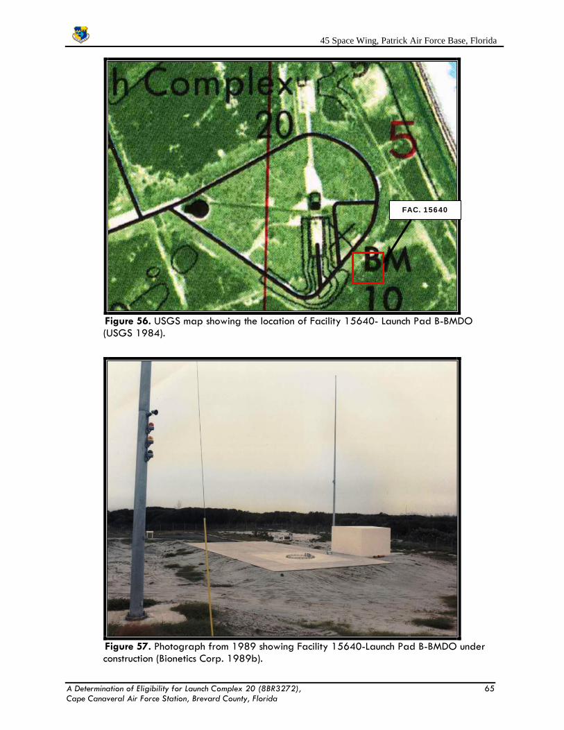
45 Space Wing, Patrick Air Force Base, Florida
Figure 56. USGS map showing the location of Facility 15640- Launch Pad B-BMDO (USGS 1984).
Figure 57. Photograph from 1989 showing Facility 15640-Launch Pad B-BMDO under construction (Bionetics Corp. 1989b).
FAC. 15640
A Determination of Eligibility for Launch Complex 20 (8BR3272), 65 Cape Canaveral Air Force Station, Brevard County, Florida

45 Space Wing, Patrick Air Force Base, Florida
Figure 58. View to the southwest of Facility 15640-Launch Pad B-BMDO.
Red Tigress program. It was abandoned in place by 1995 (InDyne Inc. 2010; JCWS 1993, 1995,
1997; SGS 1998, 2000, 2003, 2005, 2008; 45 SW Real Property 2014).
5.5.8.3 Description
Today the facility remains abandoned in place and essentially unchanged. The launch rail
has been removed and only the mounting ring remains. Metal parts and a square-shaped metal
structure of unknown function were observed on the pad (Figure 58).
5.5.8.4 Integrity
The facility’s setting remains and retains its original design. The original materials that
make up the facility are still intact except the most important component, the launch rail has been
removed.. The standardized military workmanship is intact.
5.5.8.5 NRHP Eligibility
Facility 15640-Launch Pad B-BMDO was constructed in 1989. It is less than 50 years old
and served as a launch complex to a series of very short lived rocket programs in 1993. It does
not meet any of the criteria for listing in the NRHP.
A Determination of Eligibility for Launch Complex 20 (8BR3272), 66 Cape Canaveral Air Force Station, Brevard County, Florida

45 Space Wing, Patrick Air Force Base, Florida
Figure 59. USGS map showing the location of Facility 15641-Equipment Building (USGS 1984).
5.5.9 Facility 15641-Equipment Building
5.5.9.1 Location
Facility 15641-Equipment Building is located at the southeast corner of the complex within
Facility 15640-Launch Pad B-BMDO. It is the SW¼ of Section 5 in Township 23 South and Range
38 East of the False Cape United States Geological Survey (USGS 1984) Quadrangle Map
(Figure 59).
5.5.9.2 History
Facility 15641 was constructed in 1989 to house electrical equipment associated with
launch operations at the pad. According to the 45 SW Real Property records and BIGs the
structure was originally identified as Facility 15641-Equipment Building: Pad B and two years
later the name was changed to its current designation. The facility was also used for the
Prospector-I/Joust-I mission and the Red Tigress program. It was abandoned in place by
1995(InDyne Inc. 2010; JCWS 1993, 1995, 1997; SGS 1998, 2000, 2003, 2005, 2008; 45
SW Real Property 2014).
FAC. 15641
A Determination of Eligibility for Launch Complex 20 (8BR3272), 67 Cape Canaveral Air Force Station, Brevard County, Florida

45 Space Wing, Patrick Air Force Base, Florida
Figure 60. View to the northeast of Facility 15641-Equipment Building.
Figure 61. View to the west of Facility 15641-Equipment Building.
A Determination of Eligibility for Launch Complex 20 (8BR3272), 68 Cape Canaveral Air Force Station, Brevard County, Florida

45 Space Wing, Patrick Air Force Base, Florida 5.5.9.3 Description
Today the facility remains abandoned in place and essentially unchanged. Facility 15541
is a rectangular-shaped building totaling 103.9 sq m (341 sq ft). The building sits on top of the
launch pad slab which serves as the floor and foundation. The walls and roof are constructed of
poured concrete slabs. On the east side are two curved metal vents. On the south side are two
metal doors which open into two separate rooms. Over the doors is a cantilevered metal shed-
style roof (Figures 60 and 61).
5.5.9.4 Integrity
The facility’s setting remains and retains its original design. The original materials that
make up the facility are still intact. The standardized military workmanship is intact.
5.5.9.5 NRHP Eligibility
This facility was constructed in 1989. It is less than 50 years old and served as a launch
complex to a series of very short lived rocket programs in the 1990s. It does not meet any of the
criteria for listing in the NRHP.
5.5.10 Facility 18705-Warehouse
5.5.10.1 Location
Facility 18705-Warehouse is located within the north-central portion of the complex. It is
the SW¼ of Section 5 in Township 23 South, Range 38 East of the False Cape, United States
Geological Survey (USGS 1976) Quadrangle Map (Figure 62).
5.5.10.2 History
Facility 18705 was constructed in 1999 by Space Florida when they were leased the
launch complex. According to the records the facility was identified as the Quick Reaction
Program Horizontal Processing Facility and was under NASA ownership. In 2003, it was identified
as the Horizontal Processing Facility, and from 2005 to present it has been known as Facility
18705-Warehouse. It has been under USAF ownership since 2012 (InDyne Inc. 2010; SGS 2000,
2003, 2005, 2008; 45 SW Real Property 2014).
Based on its original name it appears to have been used as a highbay facility to process
some type of aerospace component. However, if this was a rocket, missile or some other launch
vehicle is unknown. Attempts to identify the ca. 2000 Quick Reaction Program were unsuccessful. A Determination of Eligibility for Launch Complex 20 (8BR3272), 69 Cape Canaveral Air Force Station, Brevard County, Florida
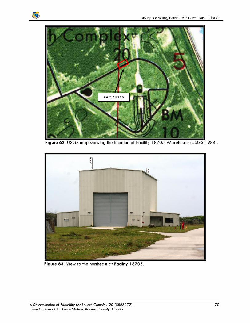
45 Space Wing, Patrick Air Force Base, Florida
Figure 62. USGS map showing the location of Facility 18705-Warehouse (USGS 1984).
Figure 63. View to the northeast at Facility 18705.
FAC. 18705
A Determination of Eligibility for Launch Complex 20 (8BR3272), 70 Cape Canaveral Air Force Station, Brevard County, Florida
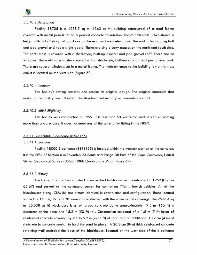
45 Space Wing, Patrick Air Force Base, Florida 5.5.10.3 Description
Facility 18705 is a 1938.5 sq m (6360 sq ft) building constructed of a steel frame
covered with metal panels set on a poured concrete foundation. The central mass is two-stories in
height with 1-1/2 story roll up doors on the east and west elevations. The roof is built-up asphalt
and pea gravel and has a slight gable. There are single story masses on the north and south side.
The north mass is covered with a shed-style, built-up asphalt and pea gravel roof. There are no
windows. The south mass is also covered with a shed-style, built-up asphalt and pea gravel roof.
There are several windows set in a metal frame. The main entrance to the building is via this mass
and it is located on the west side (Figure 63).
5.5.10.4 Integrity
The facility’s setting remains and retains its original design. The original materials that
make up the facility are still intact. The standardized military workmanship is intact.
5.5.10.5 NRHP Eligibility
This facility was constructed in 1999. It is less than 50 years old and served as nothing
more than a warehouse. It does not meet any of the criteria for listing in the NRHP.
5.5.11 Fac.18000-Blockhouse (8BR3155)
5.5.11.1 Location
Facility 18000-Blockhouse (8BR3155) is located within the western portion of the complex.
It is the SE¼ of Section 6 in Township 23 South and Range 38 East of the Cape Canaveral, United
States Geological Survey (USGS 1984) Quadrangle Map (Figure 64).
5.5.11.2 History
The Launch Control Center, also known as the blockhouse, was constructed in 1959 (Figures
65-67) and served as the command center for controlling Titan I launch vehicles. All of the
blockhouses along ICBM Rd are almost identical in construction and configuration. Those located
within LCs 15, 16, 19 and 20 were all constructed with the same set of drawings. The 7936.4 sq
m (26,038 sq ft) blockhouse is a reinforced concrete dome approximately 47.5 m (156 ft) in
diameter at the base and 15.2 m (50 ft) tall. Construction consisted of a 1.5 m (5 ft) layer of
reinforced concrete covered by 2.1 to 5.2 m (7-17 ft) of sand and an additional 10.2 cm (4 in) of
shotcrete (a concrete mortar to hold the sand in place). A 20.3-cm (8-in) thick reinforced concrete
retaining wall encircled the base of the blockhouse. Located on the west side of the blockhouse A Determination of Eligibility for Launch Complex 20 (8BR3272), 71 Cape Canaveral Air Force Station, Brevard County, Florida

45 Space Wing, Patrick Air Force Base, Florida
Figure 64. USGS map showing the location of Facility 18800-Blockhouse (8BR3155) (USGS 1984).
Figure 65. Photograph showing Facility 18800-Blockhouse (8BR3155) under construction (USAF 1959).
FAC. 18800
A Determination of Eligibility for Launch Complex 20 (8BR3272), 72 Cape Canaveral Air Force Station, Brevard County, Florida

45 Space Wing, Patrick Air Force Base, Florida
Figure 66. As-built drawing showing the blockhouse at LC-20 (Rader and Associates 1956).
Figure 67. Photograph from 1961 of the LC-20 Blockhouse (USAF 1961b). A Determination of Eligibility for Launch Complex 20 (8BR3272), 73 Cape Canaveral Air Force Station, Brevard County, Florida

45 Space Wing, Patrick Air Force Base, Florida was the entrance into the building. A reinforced concrete U-shaped passage, formed by the
junction of the blockhouse and the west side utility room, protects the entrance from the launch
blast and gases. The equipment room, a flat-roof non-reinforced building, contained a diesel
generator and a cooling tower to support the numerous systems in the blockhouse. An octagonal
steel-grate viewing stand, located on the roof of the blockhouse, was used by launch personnel to
monitor launch proceedings before each launch. At approximately T-20 minutes, terminal count,
excess personnel evacuated the complex and a drive mechanism closed and locked the steel
security doors. Terminal count was the time at which the potential for an explosion or detonation
existed (Figures 65 through 67).
From 1959 to 1965 it was identified as Facility 15500A-Blockhouse from 1959 to 1963
the name was annotated with LC 20. In 1965, the annotation was changed to Launching Test Fac.,
Complex 20. From 1966 to 1970 the blockhouse was identified as Facility 15500A-Launch
Control Bldg. In 1967 and 1969 it was annotated as being deactivated. This suggests that the
blockhouse stayed in use through the conversion to the Titan III program and launches of the
missile. In 1971 the facility had its name and number changed to facility 18800-Data Storage
and annotated with the nomenclature MSL/Space RSCH Bldg. It appears to have retained the
name and function until 1975 when the name was changed a again to Facility 18800-Blockhouse.
The name has not changed from that time (InDyne Inc. 2010; JCWS 1993, 1995, 1997; Maurice
H. Connell and Associates 1958; PanAm 1960, 1963, 1965, 1967, 1969, 1971, 1973, 1975,
1977; SGS 1998, 2000, 2003, 2005, 2008; 45 SW Real Property 2014).
While not shown in all the records we do know that the function of the blockhouse never
changed after 1975 when it appears to have returned to use as a launch control center. However,
it remained unoccupied until 1987-1989 when the pad was modified for the Starbird Program
(Figure 68), again in 1991-1993, and again in 2003 with various follow-on launch programs
(InDyne Inc. 2010; JCWS 1993, 1995, 1997; PanAm 1965, 1967, 1969, 1971, 1973, 1975,
1977; SGS 1998, 2000, 2003, 2005, 2008; 45 SW Real Property 2014).
The 24.4 m (80 ft) interior diameter of the igloo-shaped blockhouse contained two floors.
The first floor was used for general operations, repair, and communications while the second floor
contained the actual launch control systems. A protected vestibule gave access to the general
work area, a ready room, operations room, instrumentation repair room, communication pit, two
escape pits and access to the cableway are also located on the first floor. Equipment A Determination of Eligibility for Launch Complex 20 (8BR3272), 74 Cape Canaveral Air Force Station, Brevard County, Florida

45 Space Wing, Patrick Air Force Base, Florida
Figure 68. View to the west of the LC-20 Blockhouse during the Starbird program
(Bionetics Corp. 1990).
supporting first floor operations included range sequencing and control area instrumentation,
power systems, and control racks for cables extending out to the launch area. Two reinforced
concrete escape pits, one on the north and south sides of the building, provided emergency egress
for blockhouse personnel in case of explosion.
The second floor of the Blockhouse contained the actual operations center. Equipment and
operations included safety systems, countdown indicators, the flight control and propulsion system,
the facilities console, instrumentation racks, test conductor consoles and TV monitors. To permit
viewing of the launch stand and pad by personnel within the launch control room, four periscopes,
similar to submarine periscopes, extended through the roof of the blockhouse. In addition to the
launch support equipment located on the second floor, a glass observation room was included for
visiting VIPS. The launch crew consisted of the lead engineer, assistant engineers and the Test
Conductor.
The exterior structure of the blockhouse did not require modification to support the follow-
A Determination of Eligibility for Launch Complex 20 (8BR3272), 75 Cape Canaveral Air Force Station, Brevard County, Florida

45 Space Wing, Patrick Air Force Base, Florida
Figure 69. Photograph of the launch control center during the Titan III program (USAF 1964c).
Figure 70. Photograph of the launch control center during the Titan III program (USAF 1964d).
A Determination of Eligibility for Launch Complex 20 (8BR3272), 76 Cape Canaveral Air Force Station, Brevard County, Florida

45 Space Wing, Patrick Air Force Base, Florida
Figure 71. Photograph of the launch control center during its use in 1993 (Bionetics
Corp. 1993b).
Figure 72. Photograph of the first floor office area during its use in 1993 (Bionetics
Corp. 1993c).
A Determination of Eligibility for Launch Complex 20 (8BR3272), 77 Cape Canaveral Air Force Station, Brevard County, Florida

45 Space Wing, Patrick Air Force Base, Florida on launch programs. Numerous instrumentation, communications, power and range sequencing
racks and consoles, however, were removed and updated to support the programs. New
equipment and operations included the Launch Vehicle (LV) safety system, countdown indicators, a
LV test conductor console, the LV flight control and propulsion console, LV facilities console, LV
instrumentation racks, spacecraft auxiliary racks, numerous spacecraft test conductor consoles and
TV monitors. Additional tracking equipment needed to support the missile programs included pulse
radar as well as assorted optical instruments. The changes to the interior between 1964 and
1993 can be seen in Figures 69 through 72
5.5.11.3 Description
Facility 18800-Blockhouse (8BR3155) looks much the same as it did when constructed in
1959. Except for changes in cables access ports and updating the viewing platform on the roof
very little has changed. The condition is slowly degrading but the years of use have resulted in
maintaining basic upkeep. Since being abandoned in place in 2012 vegetation is beginning to
grow out of the surfaces of the dome and corrosion is becoming an issue on the exterior metal
(Figures 73 and 74). The interior is empty. All the previous launch related equipment was
removed on 2010-2012.
5.5.11.4 Integrity
Facility 18000-Launch Complex 20 Blockhouse (8BR3155) retains its integrity. It has
never been moved and still sits at the same location where it was constructed LC-20. The
building’s setting remains intact and illustrates the military industrial character of CCAFS and its
launch complexes. The blockhouse retains its original design. The original concrete block and
poured materials that make up the building are still intact. The standardized military
workmanship is intact. The building retains its integrity of feeling or its ability to evoke the sense
of its historic past and period of significance. All of the above characteristics convey the
building’s integrity of association between the building and the events associated with its historic
context.
5.5.11.5 NRHP Eligibility
Looking at the three methods of determining significance and NRHP eligibility, the LC-20
Blockhouse has no association with the Man in Space thematic study.
A Determination of Eligibility for Launch Complex 20 (8BR3272), 78 Cape Canaveral Air Force Station, Brevard County, Florida

45 Space Wing, Patrick Air Force Base, Florida
Figure 73. View to the east of the LC-20 Blockhouse.
Figure 74. View to the northwest of the LC-20 Blockhouse.
A Determination of Eligibility for Launch Complex 20 (8BR3272), 79 Cape Canaveral Air Force Station, Brevard County, Florida

45 Space Wing, Patrick Air Force Base, Florida
Using the criteria established by Lewis et al. (1995), the blockhouse had a minor
relationship in the Cold War through a brief association with the development of the Titan I and
III missiles. Only a few missiles were launched over a five year period. While the complex was
modified for the Titan III missile only 4 were launched from here in 1964. All Titan III operations
moved to LCs 40 and 41 in 1965 and the complex was abandoned.
Looking at the NRHP criteria, Facility 18800-Launch Complex 20 Blockhouse (8BR3155)
could meet Criterion C the blockhouse for its construction. However, it is almost identical in
configuration to LCs 11-16, 19 and 34 with some variations. It is identical to those at LCs 15, 16,
and 19. The blockhouse never played a major role in any of the missile programs tested at
CCAFS and has sat largely vacant over its 55 year history.
Figure 75. USGS map showing the location of Facility 18003-Guard House (USGS 1984).
5.5.12 Fac.18003-Guard House
5.5.12.1 Location
Facility 18003-Guard House is located within the western portion of the complex. It is the
SE¼ of Section 6 in Township 23 South and Range 38 East of the False Cape, United States
Geological Survey (USGS 1984) Quadrangle Map (Figure 75).
FAC. 18803
A Determination of Eligibility for Launch Complex 20 (8BR3272), 80 Cape Canaveral Air Force Station, Brevard County, Florida

45 Space Wing, Patrick Air Force Base, Florida
Figure 76. View to the southwest of Facility 18803 (note incorrect facility number on bldg).
Figure 77. View to the southeast of Facility 18803.
A Determination of Eligibility for Launch Complex 20 (8BR3272), 81 Cape Canaveral Air Force Station, Brevard County, Florida

45 Space Wing, Patrick Air Force Base, Florida 5.5.12.2 History
The small wooden building, at the entrance of the complex, was used to monitor all
personnel and deliveries entering the complex. However, it is not the original guard shack at LC-
20. According to the 45 SW Real Property records (2014) it was moved to its present location in
1990 after the original structure was demolished. The original location is unknown.
5.5.12.3 Description
The 12.2 sq m (40 sq ft) building was built on a 3.6 sq m (12 sq ft) poured concrete slab
foundation. Three of the four walls contained double-hung wood windows while the fourth wall
contained the wood and glass entrance door. The built-up shed roof extended three feet over the
entrance door. It is in very poor condition and on the verge of collapse (Figures 76 and 77). It is
designated for demolition in FY 2016.
5.5.12.4 Integrity
Facility 18003-Guard House does not have its integrity. It was moved to the site from
another unknown location. While the BIGs and Real Property records indicate it was built in 1990
that may not necessarily be accurate. It has been found at other areas of CCAFS that temporary
buildings such as guard shacks may have been built earlier but shown at their new location as
being built the day they were moved. The building is in a ruinous state.
5.5.12.5 NRHP Eligibility
Facility 18003-Guard House does not meet any of the criteria for listing in the NRHP. It
was been moved to its present location in 1990, the date of construction cannot be determined,
and it is typical of guard shacks or sentry houses found in military and industrial settings.
5.5.13 Facility 18806-Payload Assembly Building (8BR3156)
5.5.13.1 Location
Facility 18806-Payload Assembly Building (8BR3156) is located within the western
portion of the complex. It is the SE¼ of Section 6 in Township 23 South and Range 38 East of the
Cape Canaveral, United States Geological Survey (USGS 1984) Quadrangle Map (Figure 78).
5.5.13.2 History
Facility 18806-Payload Assembly Building, originally known as the Ready Building was
constructed in 1959 and was used by facility engineers and contractors for prelaunch A Determination of Eligibility for Launch Complex 20 (8BR3272), 82 Cape Canaveral Air Force Station, Brevard County, Florida

45 Space Wing, Patrick Air Force Base, Florida
Figure 78. USGS map showing the location of Facility 18806- Payload Assembly Building (8BR3156) (USGS 1984).
administration and briefings. In the 1959 BIG the facility was identified by the map key number
241 and as Ready Building. Annotations indicated it was under construction. The following year it
was identified as Facility 15500C-Ready Building and retained that designation until 1971. From
1971 to 1974 it was known as Facility 18806-Data Storage Building with an annotation of
MSL/Space RSCH ENG. Suggesting it was used for storage of files and hard copies of documents.
In 1975 The name was changed again to Storage Bldg-CX 20 and maintained both the facility
number and annotation. From 1979 to 1987, it was known as Security Police Training Building
and used by the security contractor for administrative functions. It appears with the introduction of
missile programs in the 1990s the building returned to being used for launch related activities.
From 1991 through 1999, it was renamed the Payload Assembly Building and used for
processing missiles. Three years later it still retained the name but was annotated as Traffic Check
HSE. In 2005 the building was identified as being owned by NASA and it retained the same
name. In 2012, the building was returned to the USAF from NASA (InDyne Inc. 2010; JCWS
1993, 1995, 1997; Maurice H. Connell and Associates 1958; PanAm 1960, 1963, 1965, 1967,
1969, 1971, 1973, 1975, 1977; SGS 1998, 2000, 2003, 2005, 2008; 45 SW Real Property
2014).
FAC. 18806
A Determination of Eligibility for Launch Complex 20 (8BR3272), 83 Cape Canaveral Air Force Station, Brevard County, Florida

45 Space Wing, Patrick Air Force Base, Florida
Figure 79. Aerial photograph from 1965 of Facility 18806 (USAF 1965).
Figure 80. As-built drawing of the LC-20 Ready Building (PanAm 1959).
A Determination of Eligibility for Launch Complex 20 (8BR3272), 84 Cape Canaveral Air Force Station, Brevard County, Florida
45 Space Wing, Patrick Air Force Base, Florida The original function of the building was to provide office space for the test conductor, lead
engineers, and complex manager. Daily test conductor and contractor meetings were also held i n
the Ready Room. Before each launch "ready-to-launch" meetings were held. In the 1990s the
function of the building changed to processing rockets and their payloads.
Set on a concrete foundation, the 878 sq m (2880 sq ft), rectangular-shaped Ready
Building was constructed in 1959 of wood frame clad with corrugated asbestos cement siding and
topped by a flat roof. The floor plan for the building incorporated a Briefing Room, Workshop,
Test Conductor’s office, Office, Conference Room, Heater Room, Storage, and a Men’s and
Women’s Restroom. The public rooms had an asphalt tile floor, walls clad with wood and gypsum
board, and an acoustic board ceiling. Windows were four and eight light windows (Figures 79
and 80). In 1990 the building was modified with the installation of a roll-up garage door within
the north elevation. The interior was reconfigured to create a large room for processing the
smaller rockets launched from the site.
5.5.13.3 Description
Facility 18806 is abandoned in place and in a state of disrepair. It has remained
essentially unchanged from its original construction. As previously stated the windows were
replaced and a roll up garage door was installed in the north elevation. Entry to the building is
via one of several metal slab doors with fixed pane windows set in a metal frame. Over the
doors are cantilevered overhangs. The original windows remain in place. The roof contains metal
ventilators (Figures 81 and 82).
5.5.13.4 Integrity Facility 18806-Payload Assembly Building (8BR3156) retains its integrity. It has never
been moved and still sits at the same location where it was constructed LC-20. The building’s
setting remains intact and illustrates the military industrial character of CCAFS and its launch
complexes. Facility 18806 retains its original design and materials used for its construction. The
standardized military workmanship is intact. Facility 18806 retains its integrity of feeling or its
ability to evoke the sense of its historic past and period of significance. All of the above
characteristics convey the building’s integrity of association between the building and the events
associated with its historic context.
A Determination of Eligibility for Launch Complex 20 (8BR3272), 85 Cape Canaveral Air Force Station, Brevard County, Florida

45 Space Wing, Patrick Air Force Base, Florida
Figure 81. View to the southeast of Facility 18806.
Figure 82. View to the northwest of Facility 18806.
A Determination of Eligibility for Launch Complex 20 (8BR3272), 86 Cape Canaveral Air Force Station, Brevard County, Florida

45 Space Wing, Patrick Air Force Base, Florida 5.5.13.5 NRHP Eligibility
Looking at the three methods of determining significance and NRHP eligibility, the Facility
18806 Blockhouse has no association with the Man in Space thematic study.
Using the criteria established by Lewis et al. (1995), Facility 18806-Payload Assembly
Building had a minor relationship in the Cold War through a brief association with the
development of the Titan I and III missiles. Only a few missiles were launched from this complex
over a five year period. While the complex was modified for the Titan III missile only 4 were
launched from here in 1964. All Titan III operations moved to LCs 40 and 41 in 1965 and the
complex was abandoned. During this period, Facility 18806 served as an administrative center
for the complex
Looking at the NRHP criteria, Facility 18806-Payload Assembly Building (8BR3156) does
not meet any of the criteria for listing in the NRHP. It is almost identical in configuration to LCs 11-
16, 17, 19, 34, 36, 37, 40 and 41 with some variations. It is identical to those at LCs 15, 16, and
19. It is not unique in construction or design and never served a significant function at the complex.
Facility 18806 never played a major role in any of the missile programs tested at CCAFS and
has sat largely vacant over its 55 year history.
6.0 SUMMARY AND CONCLUSIONS 6.1 Summary
Launch Complex 20 (LC-20) has never been adequately assessed to determine if the
complex and the individual facilities within are eligible for listing in the NRHP. The 45 SW CRM
conducted a historic properties survey in October and November 2014 to determine if the
complex and its individual buildings and structures were eligible for listing in the NRHP.
6.2 Conclusions
Launch Complex 20 (LC-20) consists of 14 facilities, of these a total of four date to its
original construction in 1959, two date to the period of use for Titan-III launches and the
remainder of the date to 1989s or later. The original function of LC-20 was as a R&D facility of
the Cold War-era Titan ICBM which was a vital component of our nation’s missile defense.
However, its contribution to the Titan I and III missile programs was negligible. Most of the Titan I
testing was conducted at LC-19 and only four Titan III missiles were launched from the complex
before the program was moved to LCs 40 and 41. It later played a minor R&D role in short-lived
A Determination of Eligibility for Launch Complex 20 (8BR3272), 87 Cape Canaveral Air Force Station, Brevard County, Florida

45 Space Wing, Patrick Air Force Base, Florida missile programs R&D in the 1990s. Based on the criteria established by Lewis et al. (1995), LC-
20 has a minor Cold War relationship as well as a low rating for identifying the base’s role
within the national Cold War context. It also has minor importance with respect to science, theories
or ideas.
Using the NRHP criteria, the Launch Complex 20 Historic District and its components are
not eligible due to the lack of integrity and the fact that it played only a minor role in our nation’s
defense and missile development history. Also, its eligibility is questionable due to its redundant
design and characteristics.
7.0 REFERENCES
Aerospace Corporation
1964 Erector and Umbilical Tower, Titan III, Complex 20. Drawing on file 45 SW, USAF, CCAFS,
Fl.
Air Force Missile Test Center (AFMTC)
1965 CX 20. Photograph on file, AFS&MM, CCAFS, Fl.
Andrus, Patrick W., Michael J. Auer, Caroline R. Bedinger, Susan L. Henry, Stephen A. Morris, and
John W. Renaud
1992 Manual for State Historic Preservation Review Boards. National Register Bulletin. NRHP,
NPS, Department of Interior, Washington, D.C.
American Society of Testing and Materials
2005 Standard Practice for Environmental Site Assessments: Phase 1 Environmental Site
Assessment Process (E1527-00). Electronic document, http://www.astm.org/Standards/
E1527.htm, accessed November 15, 2014.
Bair, Jeffrey A.
2003 An Examination of Intercontinental Ballistic Missile Development within the United States
from 1952 to 1965. Unpublished masters thesis on file U.S. Army Command and
General Staff College, Ft. Leavenworth, Ks.
Barton, David F., and Richard S. Levy
A Determination of Eligibility for Launch Complex 20 (8BR3272), 88 Cape Canaveral Air Force Station, Brevard County, Florida

45 Space Wing, Patrick Air Force Base, Florida 1983 An Architectural and Engineering Survey and Evaluation of Facilities at Cape Canaveral Air
Force Station, Brevard County, Florida. Report on file, FDHR, Tallahassee, Fl.
Bionetics Corporation
1989a Construction Activity, Complex 20, Launch Pad A. Photograph No. PL89C-11580.11.
Photograph on file, AFS&MM, CCAFS, Fl.
1989b Construction Activity, Complex 20, Launch Pad B. Photograph No. PL89C-11580.14.
Photograph on file, AFS&MM, CCAFS, Fl.
1990a View of Complex 20 Site. Photograph No. PL90C-11826.12. Photograph on file,
AFS&MM, CCAFS, Fl.
1990b Aerial of CX 20 for the Starbird Program. Photograph on file, AFS&MM, CCAFS, Fl.
1993a Space Launch Complex 20-Pad A. Photograph No. PL93C-11300.11. Photograph on
file, AFS&MM, CCAFS, Fl.
1993b Space Launch Complex 20 Blockhouse-Launch Control Center. Photograph No. PL93C-
11300.03. Photograph on file, AFS&MM, CCAFS, Fl.
1993c Space Launch Complex 20 Blockhouse-Office Room. Photograph No. PL93C-11300.10.
Photograph on file, AFS&MM, CCAFS, Fl.
Bollerman, Bruce and Robert L. Walker
1972 Design, Development and Flight test of the Super Loki Dart Meteorological Rocket
Systems. Document on file, Air Force Cambridge Research Laboratories, Bedford, Ma.
Electronic document, http://www.dtic.mil/dtic/index.html, accessed December 14, 2014.
Bowman, Norman J.
1963 The Handbook of Rockets and Guided Missiles. Perastadion Press, Newtown Square, Pa.
Butowsky, Harry A.
1984 Man in Space: A National Historic Landmark Theme Study, Phase I and II. United States A Determination of Eligibility for Launch Complex 20 (8BR3272), 89 Cape Canaveral Air Force Station, Brevard County, Florida

45 Space Wing, Patrick Air Force Base, Florida
Department of Interior, Washington, D.C.
Cantley, Charles, Joe Joseph, and Leslie Raymer
1993 Historic Properties Survey, Cape Canaveral Air Force Station, Brevard County, Florida.
Report on file, FDHR, Tallahassee, Fl.
Central Intelligence Agency
1959 Soviet Capabilities in Guided Missiles and Space Vehicles. Advance Portion of National
Intelligence Estimate Number 11-5-59. Central Intelligence Agency, Washington, D.C.
Electronic document, http://www.foia.cia.gov/, accessed November 21, 2014.
1965 The Soviet Space Program. National Intelligence Estimate Number 11-1-65. Central
Intelligence Agency, Washington, D.C. Electronic document, http://www.foia.cia.gov/,
accessed November 21, 2014.
Cleary, M. C.
1991 The 6555th, Missile and Space Launches Through 1970. 45 SW History Office, PAFB,
Fl.
1994 The Cape, Military Space Operations, 1971-1992. 45 SW History Office, PAFB, Fl.
1995a 45th Space Wing: Its Heritage, History & Honors, 1950-1994. 45 SW History Office,
PAFB, Fl.
1995b Eastern Range Launch Site Summary. Facilities & Launches 1950 through 1994. 45 SW
History Office, PAFB, Fl.
Clements, Gregory R.
2000 The Advanced Technology Development Center (ATDC). Document on file, NASA Library,
Kennedy Space Center, Fl.
DCS
1960 Air Force Missile Test Center Real Property. Docuent on file, 45 SW, USAF, CCAFS, Fl.
Derry, Anne, W. Ward Jandl, Carol D. Shull, Jan Thorman, Patricia L. Parker A Determination of Eligibility for Launch Complex 20 (8BR3272), 90 Cape Canaveral Air Force Station, Brevard County, Florida

45 Space Wing, Patrick Air Force Base, Florida 1984 Guidelines for Local Surveys: A Basis for Preservation Planning. National Register Bulletin
24. NRHP, NPS, Department of Interior, Washington, D.C.
Dillow, Michael
1991 Red Tigress Mission Report. Applied Technology Associates, Inc., Albuquerque, N.M.
Ferguson, Bruce
1991 JOUST Spaceborne Materials Processing Missions on the Prospector Suborbital Vehicle.
Paper presented at the Second Annual Symposium on the Industrial Involvement and
Success in Commercial Space, Washington, D.C.
Florida Department of Transportation
1993 Aerial Photograph. Photograph No. PD2930-12-38. May 6, 1993. Electronic document,
http://www.dot.state.fl.us/surveyingandmapping/apac.shtm, accessed October 1,
2014.
Florida Division of Historical Resources
2002 Cultural Resources Management Standards and Operations Manual. Document on file,
FDHR, Tallahassee, Fl.
Geiger, Clarence J.
1963 History of the X-20A Dyna-Soar. Vol. 1: AFSC Historical Publications Series 63-50-I.
Aeronautical Systems Division Information Office, Wright-Patterson AFB, Oh.
Global Security
2014 The Cold War. Electronic document, http://www.globalsecurity.org/military/ops/cold_
war.htm, accessed December 20, 2014.
Hacker, Barton C., and James M. Grimwood, James M.
1977 On the Shoulders of Titans: A History of Project Gemini, NASA SP-4203. National
Aeronautics and Space Administration, Washington, DC.
Herrick, Dan, Jack Rodden, and Paul Shirley
1990 End-to-End Control System Verification of the Starlab Experiment. Paper presented at the A Determination of Eligibility for Launch Complex 20 (8BR3272), 91 Cape Canaveral Air Force Station, Brevard County, Florida

45 Space Wing, Patrick Air Force Base, Florida annual Rocky Mountain Guidance and Control Conference, Keystone, Co. Electronic
document, http://www.dtic.mil/dtic/index.html, accessed December 2014.
Hundley, J.D.
2008a Prelude to U.S. Space Launch-Vehicle Technology: Goddard Rockets to Minuteman
III. University Press of Florida, Gainesville, Fl.
2008b U.S. Space Launch-Vehicle Technology: Viking to Space Shuttle. University Press of Florida,
Gainesville, Fl.
InDyne, Inc.
2010 Basic Information Guide Cape Canaveral Air Force Station. Document on file, 45 SW,
CCAFS, Fl.
Johnson Controls World Services
1991 Eastern Test Range, Basic Information Guide, Cape Canaveral Air Force Station.
Document on file, 45 SW, USAF, CCAFS, Fl.
1992 Eastern Test Range, Basic Information Guide, Cape Canaveral Air Force Station. Document
on file, 45 SW, USAF, CCAFS, Fl.
1993 Basic Information Guide, Cape Canaveral Air Force Station. Document on file, 45 SW,
USAF, CCAFS, Fl.
1994 Basic Information Guide, Cape Canaveral Air Force Station. Document on file, 45 SW,
USAF, CCAFS, Fl.
1995 Basic Information Guide, Cape Canaveral Air Force Station. Document on file, 45 SW,
USAF, CCAFS, Fl.
1996 Basic Information Guide, Cape Canaveral Air Force Station. Document on file, 45 SW,
USAF, CCAFS, Fl.
1997 Basic Information Guide, Cape Canaveral Air Force Station. Document on file, 45 SW,
USAF, CCAFS, Fl. A Determination of Eligibility for Launch Complex 20 (8BR3272), 92 Cape Canaveral Air Force Station, Brevard County, Florida

45 Space Wing, Patrick Air Force Base, Florida
Korenevskiy, N.
1961 Роль космических оружий в будущем войне (The Role of Space Weapons in
Future War). Воинская мысль (Military Thought). Translated by the Central Intelligence
Agency, Washington, DC. Electronic document, http://www.foia.cia.gov/, accessed
October 21, 2014.
Launius, Roger D.
2002 Titan: Some Heavy Lifting Required. In: To Reach the High Frontier: A History of U.S.
Launch Vehicles, edited by Roger D. Launius and Dennis R. Jenkins, pp: 147-187.
University Press of Kentucky, Lexington, Ky.
Launius, Roger D., and Dennis R. Jenkins. Editors.
2002 To Reach the High Frontier: A History of U.S. Launch Vehicles. University Press of Kentucky,
Lexington, Ky.
Lewis, Karen, Katherine J. Roxlau, Lori E. Rhodes, Paul Boyer, and Joseph S. Murphey
1995 A Systematic Study of Air Combat Command Cold War Material Culture. Volume 1: Historic
Context and Methodology for Assessment. Report on file Air Combat Command, USAF,
Langley, Va.
Lonnquest, John C., and David F. Winkler
1996 To Defend and Deter: The Legacy of the United States Cold War Missile Program. U.S.
Army Construction Engineering Research Laboratories, Champaign, Il.
Mannino, Vito V.
1999 Cold War. When Did it Start? Why Did it Start? Research report on file, Air Command
and Staff College, Maxwell Air Force Base, Al.
Mark, Eduard
2005 Defending the West: The United States Air Force and European Security 1946-1998. Air
Force History and Museums Program, Washington, D.C.
McCarthy, Sheila, Patrick Nowlan, Chad Randl, Virge Jenkins and Ring-Ru Lin
A Determination of Eligibility for Launch Complex 20 (8BR3272), 93 Cape Canaveral Air Force Station, Brevard County, Florida

45 Space Wing, Patrick Air Force Base, Florida 1993 Determination of Eligibility of Launch Complexes and Related Facilities for Listing on the
National Register of Historic Places at Cape Canaveral Air Force Station, Cape Canaveral,
Florida. Report on file, FDHR, Tallahassee, Fl.
National Park Service
1981 Reconnaissance Survey: Man in Space. National Park Service, Denver Service Center,
Denver, Co.
1984 Cape Canaveral Air Force Station. National Historic Landmark Nomination. Revised
Federal Agency Nomination prepared by History Division, National Park Service,
Washington, DC, and United States Air Force. Washington, D.C.
1987 Man in Space: A Study of Alternatives. U.S. Department of Interior, NPS, Washington,
D.C.
Neufeld, Jacob
1990 The Development of Ballistic Missiles in the United States Air Force 1945-1960. Office of
Air Force History, United States Air Force, Washington, D.C.
Norris, Robert S. and Hans M. Kristensen
2006 Global Nuclear Stockpiles, 1945-2006. Bulletin of the Atomic Scientists 2006: 64-66.
North Atlantic Treaty Organization
2011 A Short History of NATO. Electronic document, http://www.nato.int/history/nato-
history.html, accessed September 27, 2014.
O’Donnell, Eleanor
1998 Researching a Historic Property. National Register Bulletin. NRHP, NPS, Department of
Interior, Washington, D.C.
Pan American World Airways
1959a Air Force Eastern Test Range Basic Information Guide Cape Kennedy. Document on file,
45 SW, Cape Canaveral Air Force Station, Fl.
1959b Complex 20 Ready Building. Drawing No. CAN-3677. Drawing on file, 45 SW, USAF, A Determination of Eligibility for Launch Complex 20 (8BR3272), 94 Cape Canaveral Air Force Station, Brevard County, Florida

45 Space Wing, Patrick Air Force Base, Florida PAFB, Fl.
1960 Cape Canaveral Missile Test Annex, Atlantic Missile Range Master Plan. Document on file,
45 SW, USAF, CCAFS, Fl.
1961 Dynasoar-Titan II Facilities at Complex 20. Location Map and Site Plan. Drawing No. CAN-
4987-1. Drawing on file, 45 SW, USAF, PAFB, Fl.
1963 Cape Canaveral Missile Test Annex, Atlantic Missile Range Master Plan. Document on file,
45 SW, USAF, CCAFS, Fl.
1964 Cape Kennedy Air Force Station Building Schedules and Locations (Master Plan-Tab C-1).
Document on file, 45 SW, USAF, CCAFS, Fl.
1965 Cape Kennedy Air Force Station Building Schedules and Locations (Master Plan-Tab C-1).
Document on file, 45 SW, USAF, CCAFS, Fl.
1968 Air Force Eastern Test Range, Basic Information Guide, Cape Kennedy. Document on file,
45 SW, USAF, CCAFS, Fl.
1969 Air Force Eastern Test Range, Basic Information Guide, Cape Kennedy. Document on file,
45 SW, USAF, CCAFS, Fl.
1971 Air Force Eastern Test Range, Basic Information Guide, Cape Kennedy. Document on file,
45 SW, USAF, CCAFS, Fl.
1973 Air Force Eastern Test Range, Basic Information Guide, Cape Kennedy. Document on file,
45 SW, USAF, CCAFS, Fl.
1975 Air Force Eastern Test Range, Basic Information Guide, Cape Canaveral. Document on file,
45 SW, USAF, CCAFS, Fl.
1977 Air Force Eastern Test Range, Basic Information Guide, Cape Canaveral. Document on file,
45 SW, USAF, CCAFS, Fl.
A Determination of Eligibility for Launch Complex 20 (8BR3272), 95 Cape Canaveral Air Force Station, Brevard County, Florida

45 Space Wing, Patrick Air Force Base, Florida 1979 Eastern Test Range, Basic Information Guide, Cape Canaveral Air Force Station. Document
on file, 45 SW, USAF, CCAFS, Fl.
1980 Cape Canaveral Air Force Station Facilities Location Map. Drawing #RFP-E-4020D.
Drawing on file, 45 SW, USAF, CCAFS, Fl.
1981 Eastern Test Range, Basic Information Guide, Cape Canaveral Air Force Station. Document
on file, 45 SW, USAF, CCAFS, Fl.
1983 Eastern Test Range, Basic Information Guide, Cape Canaveral Air Force Station. Document
on file, 45 SW, USAF, CCAFS, Fl.
1985 Eastern Test Range, Basic Information Guide, Cape Canaveral Air Force Station. Document
on file, 45 SW, USAF, CCAFS, Fl.
1987 Eastern Test Range, Basic Information Guide, Cape Canaveral Air Force Station. Document
on file, 45 SW, USAF, CCAFS, Fl.
Park, William H.
1986 Defending the West: A History of NATO. Westview Press, Boulder, Co.
Parsch, Andreas
2014 Directory of U.S. Military Rockets and Missiles. Electronic document, http://www.
designation_systems.net, accessed November 6, 2014.
Parsons Engineering Science, Inc.
1999 RCRA Facility Investigation Report, Space launch Complex 20, SWMU No. 43, Cape
Canaveral Air Force Station, Florida. Document on file, 45 SW, PAFB, Fl.
Penders, Thomas E.
2014 45th Space Wing Integrated Cultural Resource Management Plan: Cape Canaveral Air
Force Station, Patrick Air Force Base, Malabar Transmitter Annex, and Jonathan
Dickinson Missile Tracking Annex, Florida. Document on file, 45 SW Civil Engineering
Office, Patrick Air Force Base, Fl. A Determination of Eligibility for Launch Complex 20 (8BR3272), 96 Cape Canaveral Air Force Station, Brevard County, Florida

45 Space Wing, Patrick Air Force Base, Florida Piper, Robert F.
1964 History of Titan III: 1961-1963. Air Force Space Systems Division Historical Division, Los
Angeles Air Force Base, Ca.
Rader and Associates
1956 Martin Flight Test Facility. Drawing No. 60-08-74. Drawing on file, 45 SW, PAFB, Fl.
Seifert, Donna J, Barbara J. Little, Beth L. Savage, and John H. Sprinkle, Jr.
1997 Defining Boundaries for National Register Properties. National Register Bulletin. NRHP,
NPS, Department of Interior, Washington, D.C.
Sherfy, Marcella, and W. Ray Luce
1996 Guidelines for Evaluating and Nominating Properties that Have Achieved Significance within
the Past Fifty Years. National Register Bulletin. NRHP, NPS, Department of Interior,
Washington, D.C.
Space Gateway Support
1999 Facilities at CCAS & KSC, CCAS BIG/KSC GP-14-2. Document on file, 45 SW, CCAFS, Fl.
2003 Cape Canaveral Spaceport Facilities CCAFS/KSC Basic Information Guide. Document on
file, 54 SW, CCAFS, Fl.
2005 Cape Canaveral Spaceport Facilities CCAFS/KSC Basic Information Guide. Document on
file, 54 SW, CCAFS, Fl.
2008 Cape Canaveral Spaceport Facilities CCAFS/KSC Basic Information Guide. Document on
file, 54 SW, CCAFS, Fl.
Townsend, Jan, John H. Sprinkle, Jr., and John Knoerl
1993 Guideline for Evaluating and Registering Historical Archeological Sites and Districts.
National Register Bulletin 36. NRHP, NPS, Department of Interior, Washington, D.C.
United States Air Force
n.d. Loki launch from Launch Complex 20. Photograph on file, AFS&MM, CCAFS, Fl.
A Determination of Eligibility for Launch Complex 20 (8BR3272), 97 Cape Canaveral Air Force Station, Brevard County, Florida

45 Space Wing, Patrick Air Force Base, Florida 1957 Pad 20 from E, CCMTA. Photograph on file, AFS&MM, CCAFS, Fl.
1959 CX 20 Blockhouse Under Construction. Photograph on file, AFS&MM, CCAFS, Fl.
1960a Titan I J-5 missile launch from LC-20 on August 30, 1960. Photograph on file, AFS&MM,
CCAFS, Fl.
1960b Aerial 1960-CCAFS, Aerial No. 2-20. Photograph on file, 45 SW History Office, PAFB,
Fl.
1961a Dyna-Soar on Titan Booster. Image No. M-MS-G-94-1-61. Drawing on file, AFS&MM,
CCAFS, Fl.
1961b Complex 20 Blockhouse. Photograph on file, AFS&MM, CCAFS, Fl.
1964a Launch of Titan IIIA from Pad 20. Photograph No. PL64C-83216. Photograph on file,
AFS&MM, CCAFS, Fl.
1964b Erection of Titan IIIA Second Stage on Pad 20. Photograph No. PL64C-81748.
Photograph on file, AFS&MM, CCAFS, Fl.
1964c Titan III Pretest Alert, CX 20 Blockhouse, August 1964. Photograph on file, AFS&MM,
CCAFS, Fl.
1964d Prelaunch Activity in CX 20, August 1964. Photograph on file, AFS&MM, CCAFS, Fl.
United States Department of the Interior
1997 How to Apply the National Register Criteria for Evaluation. NRHP, NPS, Department of
Interior, Washington, D.C.
United States Geological Survey (USGS)
1989 False Cape Quadrangle Map, 7.5’ series, US Geological Survey, Washington, D.C.
Wade, Mark A Determination of Eligibility for Launch Complex 20 (8BR3272), 98 Cape Canaveral Air Force Station, Brevard County, Florida
45 Space Wing, Patrick Air Force Base, Florida 2014 Encyclopedia Astronautica. Electronic document, http://www.astronautix.com/, accessed
May 10, 2014.
Wessling, Francis C., and Charles A. Lunquist
1991 Low Gravity Investigations on Suborbital Rockets. Document on file, NASA, KSC, Fl.
Willis, C. Scott and James Bamford
2008 Astrospies. Nova documentary. Original air date February 12, 2008. Electronic media,
http://www.pbs.org/wgbh/nova/military/astrospies.html, accessed October 16, 2014.
A Determination of Eligibility for Launch Complex 20 (8BR3272), 99 Cape Canaveral Air Force Station, Brevard County, Florida

APPENDIX A
PHOTOGRAPHS

Figure A-1. View to the south of the former flume and basin.
Figure A-2. View of the Launch Stand and Ramp and Facility and Warehouse.

Figure A-3. View to the northeast of the Cableway.
Figure A-4. View to the west of Facility 15500AD.

Figure A-5. View to the southeast of Facility 15531.
Figure A-6. View to the southwest of Facility 15531.

Figure A-7. Top of the Launch Stand and Ramp looking north.


APPENDIX B
AS-BUILT DRAWINGS
APPENDIX C
FMSF FORMS


Environmental Assessment Reconstitution and Enhancement of Launch Complex 20 Multi-user Launch Operations
APPENDIX G 1
Transportation Concurrence Correspondence 2
3


Re: Re-Issue of permit #072919-1 with correct route
Gaddis, Gregory (KSC-SII10) <[email protected]>Wed 7/31/2019 6:56 PM
To: Priyanka Valletta <[email protected]>; Huff, Patrick D. (KSC-BOSS-4240)[PAE - SGT Partners LCC] <[email protected]>
Good Evening Pri...!
The permit isn’t a requirement for the EA... and it was me that questioned the use of that specific bridge.
Given the answer Patrick worked up for us, I’m confident there will be no issues with the route...
The specific permit can be worked when the customer is actually within a few weeks of the actual transport...
Hope that helps...!
THANKS!
Greg “Tremendously Awesome” Gaddis *** It’s an attitude... not a self-assessment ***KSC Master Integrator Customer Service & Integration Branch321-861-9556 (Office)
Sent from my iPhone
On: 31 July 2019 18:31, "Priyanka Valletta" <[email protected]> wrote:
Hi Greg, hi Patrick,
I promise to quit bugging you guys on this one soon. 🙂Can we get a revised permit with the updated vehicle dimensions (12' wide, 14' high)?
So no issues with using the Roy Bridges bridge from a weight limit perspective?
Just wanted to make sure so we're covered for the EA.
Thanks!Pri
Priyanka Valletta PE
Civil Engineer
EMAIL [email protected]
DIRECT 321-751-3095
CELL 321-243-2584
FAX 321-259-4703
BRPH | 5700 North Harbor City Boulevard, Suite 400 | Melbourne, Florida 32940 | BRPH.com
Engineering News-Record Top 500 Design Firms - 2018
From: Priyanka Valle� a <[email protected]>Sent: Tuesday, July 30, 2019 9:41 AMTo: Gaddis, Gregory (KSC-SII10) <[email protected]>Subject: Re: Re-Issue of permit #072919-1 with correct route Most likely not until after Jan 2021. Initial launches are targeted for the start of 2021, but the manufacturing may not begin in Floridauntil later in the year 2021.
Priyanka Valletta PE
Civil Engineer
EMAIL [email protected]
DIRECT 321-751-3095
CELL 321-243-2584
FAX 321-259-4703
BRPH | 5700 North Harbor City Boulevard, Suite 400 | Melbourne, Florida 32940 | BRPH.com

Engineering News-Record Top 500 Design Firms - 2018
From: Gaddis, Gregory (KSC-SII10) <[email protected]>Sent: Tuesday, July 30, 2019 8:26 AMTo: Priyanka Valle� a <[email protected]>Subject: RE: Re-Issue of permit #072919-1 with correct route You bet… even more of a requirement for the escort…! When might the customer start moving hardware…??? THANKS! Greg “Tremendously Awesome” Gaddis*** It's an attitude...not a self-assessment ***KSC Master IntegratorCustomer Service & Integration Branch (SI-I1)321-861-9556 (Office) cid:[email protected]
From: Priyanka Valle� a <[email protected]> Sent: Tuesday, July 30, 2019 8:24 AMTo: Gaddis, Gregory (KSC-SII10) <[email protected]>Subject: [EXTERNAL] Re: Re-Issue of permit #072919-1 with correct route Hi Greg! Thanks for following up on this one. Yes, I think when we get closer to operations, the customer would prefer to have an escort. One note on the updated permit--can we modify the height and width to the 12' wide and 14' height?
Thanks!Pri Priyanka Valletta PE
Civil Engineer
EMAIL [email protected]
DIRECT 321-751-3095
CELL 321-243-2584
FAX 321-259-4703
BRPH | 5700 North Harbor City Boulevard, Suite 400 | Melbourne, Florida 32940 | BRPH.com
Engineering News-Record Top 500 Design Firms - 2018

���������������� �������������������� ���� ��
������� �!"#$!% &'()*(++,-. /#!"#$!%0#�����*,12���0#$3456" 789-8:-,; 7<== >?
@� A!�%�2B� C�DD"EE� /FF!�B��G1H!FG0I$J4
, �EE�IGJ"2E� &=7 'K.
-7:;,;*,0F�LM
NOOPQROSTUTVQWSUXYQZ[Q\]QPU[_[[]PQ]SaU]SXQQbc]TQ\]QV]dQaO[]QdOQPOUTVQdc][]QOe]SfOT[gQhQi]aU]j]QkO_laaQmTPQdcdQnnZopQp]_SUdk\UaaQi]Q][OSfTVQkO_QSO[[QqpnQdOQprnstuXQdcU[QU[QpvwxyNrzQS]O{{]TP]PX][e]UaakQ\UdcQ|UVcdQcSP\S]}Qr]dQ{]Q~TO\QcO\QhQ{kQ�UaUdd]QkO_SQ[_ ][[QUTQdc]Q�_d_S]XYQ�������
�
����������������������������������
���������� ����¡�¢£¤¥¥¥ ¦�����¤§©���¤��ª¤ �����
��«�¬�����®�������
«�����������°��±�®���������²���°³��®µ®¶·
¹¶µº»¶µ¼½½»�¾¿¿�°�·
�
QQQQ
ÀÁÂÃÄQÅ_ÆgQWdSU~QÇ}QÈqpnsÉxppsÊtÊuËÌWZÍQsQpNvQWSdT]S[QrnnÎQÏedSU~}P}c_ÆÐT[}VOjÑQÒÓÔÕÄQv_][PkgQÖ_akQ×ugQtuØÙQÚÛÜtQZRÝÂÄQWSUQÞaa]ßQÈqpnËÌÉwWÅQZwnÅhvÍnvpQÍyNhyÍÍwpQhynÎQÏeeS~[cÐiSec}O{ÑàQqpnsÉO[[sÇávzxoohnÍQÏqpnsÉxppsÇávzxoohnÍÐ{ Ua}T[}VOjÑâãÄQqpnsÇrsÉxppsRhpphxysnxxwÇhyZvxwpQÏqpnsÇrsÉxppsRhpphxysnxxwÇhyZvxwpÐ{ Ua}T[}VOjÑàQNPPU[gNS]VOSkQÈqpnsphhØuËQÏVS]VOSk}VPPU[sØÐT[}VOjÑàQR_aa]TgQÉSUTQÖ}QÈqpnsÉxppsÊtÊuËÌWZÍQsQpNvQWSdT]S[QrnnÎÏiSUT}ä}{_aa]TÐT[}VOjÑÒåæçÓãÕÄQw]sh[[_]QO�Qe]S{UdQèuÚtÙØÙsØQ\UdcQOSS]dQSO_d]QvcU[QU[QQp]a�sÍ[OSdQe]S{Ud}Qh�QqpnQÍ[OSd[QS]QP][US]PgQOTddQÉxppQÇ_dkQxé]}Qêëìíîïðñòóñôõöö÷ñêóøóñññ�����ù����«����±����°�����ú������û�����������������
²����¾ü��������±��ü�°�ü�������°���²¾��·
²���ý��»µ¶þ¼»�ÿ������¹þµ�¹
���������ü�°��«��������������¹º¼¼
���¹¶µº»¶µ�»»�
��� ü���°�ý�ý³�¿¿�����ý��

1ENG-F-BP02 Rev 3
PERMIT FOR OVERWEIGHT/OVERSIZE ROADWAY VEHICLE AT KSCPERMIT MUST BE IN VEHICLE AT ALL TIMES
DATE OF ISSUE: 7/29/2019 EXPIRATION DATE: 9/29/2019 ROUTE: Space Commerce Way/NASA Parkway/Gate 3/BananaRiver Bridge/CCAFS
PERMIT #: 072919-1 OPERATOR / POINT OF CONTACT: Priyanka Valletta PHONE #: 321-243-2584
VEHICLE: Truck Semi-Trailer hauling FlightHardware
HEIGHT: 13’-6” WIDTH: 8’-0” LENGTH: 80’-0”
NO. OF AXLES: 4
AXLE WEIGHTS: Legal (80K GVWR)
ATTACHMENT A: ROUTE
ATTACHMENT B: AXLES AND DIMENSIONS
ATTACHMENT C: LOAD PLATES
Prior permits Void- Route is limited to: same as above Transit under Kennedy Parkway overpass prohibited.
Load distribution plates are required per Attachment C for Pad A/B BypassRoad culverts. All hardware is to be provided by Permittee.
Movement against oncoming traffic requires traffic be blocked.
Maximum Speed on bridges is 5 mph.
Convoy commander will review speed requirements with permit vehicleoperator. Lead escort vehicle will maintain maximum speed andremain in front of escorted vehicle at all times.
Requester must submit a request for route approval and or escort supportfrom Support Operations Center (853-5211) and contact BOSS Duty Office @321-861-5050 on KSC. If using CCAFS, contact the Air Force watchcommander (853-2159) prior to movement. Verify bridges & facilities are in-service prior to scheduled move.
Vehicle centered on all bridge spans.
No stopping, no accelerating. Convoy commander will use the leadescort vehicle as a point of reference for permit vehicle driver andmaintain the escort vehicle in the center of the bridge spans.
KSC Security Escort, operations, route preparation, and flagging requiredper OMI-Q-3745.
Permittee self-escort, operations, route preparation, and flagging requiredper OMI-Q-3745.
Wind speed shall be 25 mph or less on bridge.
The requestor is responsible for ensuring that all operations comply with the requirements in the current KNPR 6000.1. This authorization / permit prescribes equipmentconfiguration for the movement of overweight / oversize equipment on KSC & CCAFS. For further information, contact BOSS Design Engineering at 861-4664. Thisauthorization permits the movement of the equipment in the configuration as described above in accordance with the noted restrictions / requirements. If theconfiguration changes at any time this permit becomes invalid.NOTE: This is a multiple vehicle configuration permit. The operator is to perform route survey to verify no obstructions prior to transit.
Approvals:
7/30/2019
X
Signed by: Patrick Huff (affiliate)
Name/Title: Patrick Huff, P.E.
7/30/2019
X Brian Mullen
Signed by: Brian Mullen (affiliate)
Name/Title: Brian Mullen, Engineer 2
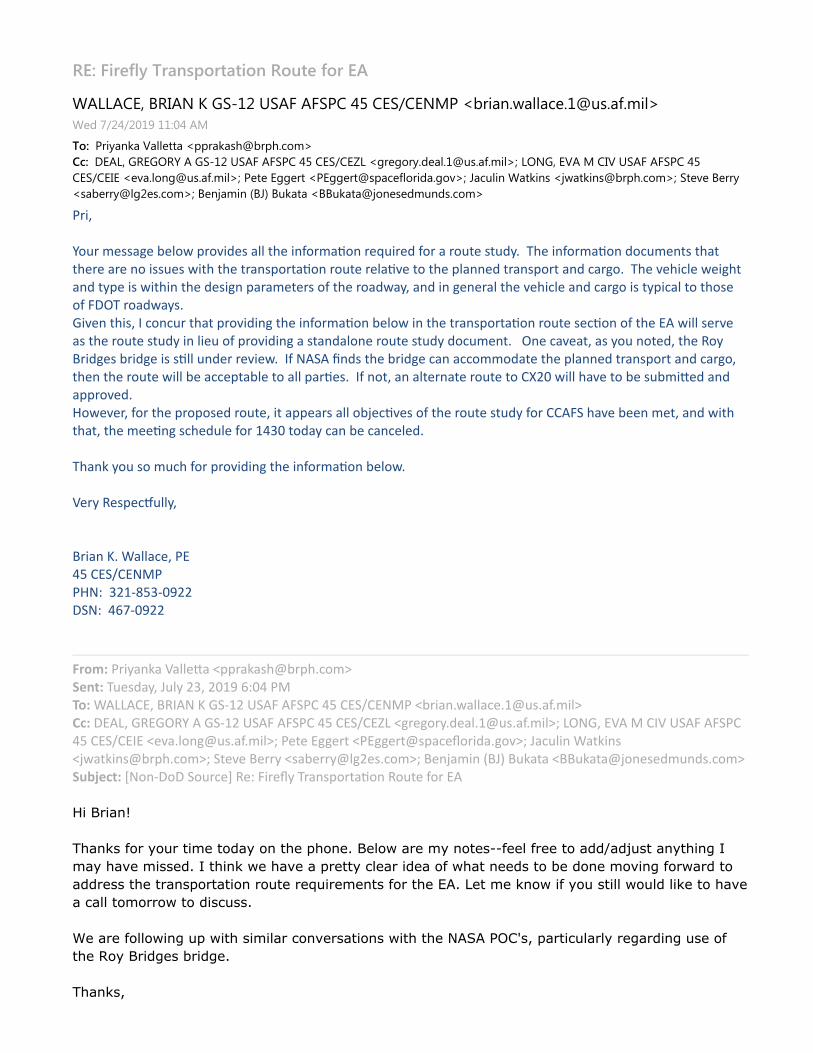
������������� ��������� �������������
����������������� !"#$�%!�&��&!'��()���!*���+'�,-./01230440562#78920:2;/4<�6=�>*$(*$?#@�##A?(��+
����'./B01C0�D0446EE0�,FF.0C09G7-.FG25H;<
IJ��K����� �� L�M��� !"#$�%!�&��&!'��()���!*��N��,O.6OH.B2=6042#78920:2;/4<P��L� ���D��+���D�%!�&��&!'��()
��!*�����,6Q024H1O78920:2;/4<P�'6E6��OO6.E�,'�OO6.E79F056:4H./=02OHQ<P�R0584/1��0EC/19�,S30EC/197-.FG25H;<P�!E6Q6��6..B
,90-6..B74O$6925H;<P��61S0;/1�T�RU��8C0E0�,��8C0E07SH1696=;81=925H;<
VWXYZ[\]WZ_ ab_Zc_d\eZfW\gXh_ZaddZij_ZXkl\Wam\kZW_n]XW_hZl\WZaZW\]i_Zi]hopZZqj_ZXkl\Wam\kZh\r] _kiZijaiij_W_ZaW_Zk\ZX]_ZeXijZij_ZiWakf\Wiam\kZW\]i_ZW_damg_Zi\Zij_Zfdakk_hZiWakf\WiZakhZraWb\pZZqj_Zg_jXrd_Ze_XbjiakhZiof_ZXZeXijXkZij_Zh_XbkZfaWa _i_WZ\lZij_ZW\aheaoYZakhZXkZb_k_WadZij_Zg_jXrd_ZakhZraWb\ZXZiofXradZi\Zij\_\lZstuqZW\aheaopvXg_kZijXYZwZr\kr]WZijaiZfW\gXhXkbZij_ZXkl\Wam\kZc_d\eZXkZij_ZiWakf\Wiam\kZW\]i_Z_rm\kZ\lZij_ZxyZeXddZ_Wg_aZij_ZW\]i_Zi]hoZXkZdX_]Z\lZfW\gXhXkbZaZiakhad\k_ZW\]i_Zi]hoZh\r] _kipZZZuk_Zrag_aiYZaZo\]Zk\i_hYZij_Zz\o{WXhb_ZcWXhb_ZXZmddZ]kh_WZW_gX_epZZwlZ|y}yZ~khZij_ZcWXhb_ZrakZarr\ \hai_Zij_Zfdakk_hZiWakf\WiZakhZraWb\Yij_kZij_ZW\]i_ZeXddZc_Zarr_fiacd_Zi\ZaddZfaWm_pZZwlZk\iYZakZadi_Wkai_ZW\]i_Zi\Z����ZeXddZjag_Zi\Zc_Z]c X�_hZakhaffW\g_hp�\e_g_WYZl\WZij_ZfW\f\_hZW\]i_YZXiZaff_aWZaddZ\c�_rmg_Z\lZij_ZW\]i_Zi]hoZl\WZ��ys}Zjag_Zc__kZ_iYZakhZeXijijaiYZij_Z__mkbZrj_h]d_Zl\WZ����Zi\haoZrakZc_Zrakr_d_hpZqjak�Zo\]Z\Z]rjZl\WZfW\gXhXkbZij_ZXkl\Wam\kZc_d\epZ�_WoZz_f_r�]ddoYZZ{WXakZ�pZ�addar_YZVx��Z�x}��x|�VV�|�ZZ������������t}|�ZZ��������ZZ
�����ZVWXoak�aZ�add_�aZ�ffWa�aj�cWfjpr\ �Z� ¡¢�Zq]_haoYZ£]doZ��YZ����Z����ZV�¤��Z�y¥¥y�xYZ{zwy|Z�Zv}���Z¦}ysZys}V�Z��Z�x}��x|�VZ�cWXakpeaddar_p��]palpXd�§�Ztxy¥YZvzxvuz[ZyZv}���Z¦}ysZys}V�Z��Z�x}��x©¥Z�bW_b\Woph_adp��]palpXd�ªZ¥u|vYZx�yZ�Z�w�Z¦}ysZys}V���Z�x}��xwxZ�_gapd\kb�]palpXd�ªZV_i_Zxbb_WiZ�Vxbb_Wi� far_«\WXhapb\g�ªZ£ar]dXkZ�ai�Xk��eai�Xk�cWfjpr\ �ªZ}i_g_Z{_WWoZ�ac_WWo�db�_pr\ �ªZ{_k�a XkZ¬{£Z{]�aiaZ�{{]�aia��\k__h ]khpr\ ��®° ¢�Z±|\k�t\tZ}\]Wr_²Zz_�ZsXW_«oZqWakf\Wiam\kZz\]i_Zl\WZxy³µ¶·µ¹º»
¶
¼½¹º¾¿¶ÀÁ¶ÂÁöĵÅƶÄÁǹ¶Áº¶Ä½Æ¶È½ÁºÆɶ·ÆÊÁ˶¹Æ¶Å¶ºÁÄÆ¿ÌÌÀÆÆʶÀÆƶÄÁ¶¹ÇÇ͹ÇÎÿĶ¹ºÂĽµºÏ¶Ð
Ź¶½¹Ñƶŵ¿¿ÆÇɶжĽµº¾¶Ëƶ½¹Ñƶ¹¶ÈÆÄĶÒÊƹ¶µÇƹ¶ÁÀ¶Ë½¹Ä¶ºÆÆÇ¿¶ÄÁ¶ÓƶÇÁºÆ¶ÅÁѵºÏ¶ÀÁ˹ǶÄÁ
¹ÇÇÆ¿¿¶Ä½Æ¶Ä¹º¿ÈÁĹĵÁº¶ÁÃÄƶÆÔõÆÅƺĿ¶ÀÁ¶Ä½Æ¶ÕÖɶ×ÆĶÅƶ¾ºÁ˶µÀ¶ÂÁö¿ÄµÊʶËÁÃÊǶʵ¾Æ¶ÄÁ¶½¹ÑÆ
¹¶Ò¹ÊʶÄÁÅÁ Á˶ÄÁ¶Çµ¿Òÿ¿É¶
¶
Øƶ¹Æ¶ÀÁÊÊÁ˵ºÏ¶Ãȶ˵Ľ¶¿µÅµÊ¹¶ÒÁºÑÆ¿¹ÄµÁº¿¶ËµÄ½¶Ä½Æ¶ÙÖÚÖ¶ÛÜÝ޿߶ȹĵÒÃʹʶÆϹǵºÏ¶Ã¿Æ¶ÁÀ
ĽƶàÁ¶·µÇÏÆ¿¶ÓµÇÏÆÉ
¶
¼½¹º¾¿ß

���
������������� ����������������������� ������ ������ ���������������� ����
�� � ������������� ���� �������������
�������!������ ������ ��"
#$%&'($)(*+,-./$&0%12
3�����!��� �������������� �!4 3����������� ��� ���� �� ������5�678
��������� ������
!��������������������������������� ����������������������������!4 3���9����
�������� ����5�678�������� �����:;�<���� ��� ���9�=�>7�<����� �������9��?=
� ������9�������� ����������� ��;8=888������
@ABCDEBFEGHDCABFGIIBJEBFGCDGKBLMNOBACPKQPRQBFEGHDCBIGSGCATBKUBPQQGCGUKPI
GSVRUWESEKCABCUBCDEBRUXCEBPREBPKCGYGVPCEQBCUBPYYUSSUQPCEBCDEBWEDGYIE
FEGHDCZB
#$%&'($),&[$\-&*\-)+\,)[+\$] $_&\02
!��������������������������������� ����������������9��� �� ������9����
����� ��;8��3�������� ��������� �:����������������������?���� ����������
�������53 �a�6bc� ��a�6dde��������3�����������f������������� �
7d=����dg���������������������������� �������������=����h8����c8
���������������������� ����� ��������������������
3��� �������������� �� ����!���������������������������� ����
��"�
ijkj)l+_m/+n.k+[]$()op)l%&((&q-)l+_m/+np�3�������������� ����
�������������� �����������e8��3����������� ��������� ���������
������ ����������������� �����r43�!��� s����3��� ������������ �
����� ��������������7e=�� �������� ������� �� ��������f����� �����
�������������������������
k+[]$()o)l%&((&q-)l+_m/+n)+\,)t$+ n)u+]\'%)v*+,p�3���������
� �� ���f����������������:���� 9��78������������������?���
���������� ��������������9������������������������:d88���?�
t$+ n)u+]\'%)v*+,)+\,)woxy)v*+,p�3�������������� ����������
�������� �����������c8�
woxy)v*+,)+\,)kuoz{|p)3�������������� ������������������� ��
��������b8��
3��������������������������������������f����������������� ����
� �����������53 ���������
}PAEQBUKBCDEBUJAERWPCGUKABPJUWETBKUBPQQGCGUKPIBGSVRUWESEKCABCUBCDE
RUXCEBPREBPKCGYGVPCEQBCUBPYYUSSUQPCEBCDEBWEDGYIEBQGSEKAGUKABPKQBCXRKGKH
SPKEXWERAZB
5�~��� ����������"
!����������� ��������� ����� ������� ������� � ���� ����
����"
3���� ����� ��� ����������������~������������ ����� �� ������� � �
���r�������� ���� �������������� �� ���������� ������
a�������������� �������r������� ����~��� ���������~��������� ���������
� �������������������� ������ ��� ������������������

����������������� ����������������������������������������������������
������������ �������������� ���� ����������� ��������� ����������� �������
������ ����������������������������������� ���������������������������������
����������������������������� ����� ������ ����������������������
�
� !"#$%#&'#(()**#��+,
-!.!(&/$0!$))
&
/1234���������� ����� 5�������
637/-8������9:;<=>;<9?@>
-/44�����������9:;<:A9<:>BA
C2D������������9:;<:>@<A=?9
�
E7�F�G�>=??�H�����I �����J����K����� ����L�����A??�G�M��������������� �9:@A?��G��E7�FNOPQ
�
RSTUSVVWUSTXYVZ[\]V_WXa_bXcddXeV[UTSXfUWg[X\Xhdij
�
�
klmnopqrstuvwupxuyyz{u|}~�op��v�ut�p��ytp���p����p����pq��mop��������p�����p�p�����p����p���q�p��p��������qp��rsuv ¡uyyu¢z �£�¤ u¥ ¦sy§©opª����p����«�¬p�p�����p����p���q�p��p�������p�®rz®�rt �zuy �£�¤ u¥ ¦sy§p�«���p�x�p�p��xp����p���q���p��������p�z°u y�v®£�¤ u¥ ¦sy§pqz±zp�®®zr±p�q�®®zr±£¤²u¢z³�rs�u ®�°§p�u¢�ysvp�u±wsv¤�¡u±wsv¤£�r²µ ¢�¦§|¶·}©�op�srz³tp¹ruv¤²�r±uº�vp���±zp¥�rp��»I��K�� �
�
,� ��������������� ��������������������������������������������������������¼������������
������ ���½�� ������������� �� ��� ���������������� �����������������L¾J<:?�,½�¼������
�� �����������
�
¿���¼���������������������������¼���������������������� ��� � ����� ������� ���������� ��������
¼��� ���� ������������������ �B?À�� ���� �������� ���������� �������������������������������
ÁB?�???����� ���IL<:?� ������ ����Â�������� �������������� ��������¼���,����� ����+ �Ã�������
L¾J<:?�¼ �������¼��� ������������� �����:�������¼���� ���½��� ��������� ��:<9�������¼���� ���K��
���������Ä������ �������� ����� � ����� ������������ ��������� �� ������������������������ ��Å��¼
����������������������������������������� ����¼�����,½������ ������������������������������������
¼�����������Å
�
��À�������������������������������� ���������������Æ����������,½��J������������ ����������
� ������������������������������ ��� ��Å
�
�� Ã����Ç
+��
�
�
� !"#$%#&'#(()**#��+,
-!.!(&/$0!$))
&
/1234���������� ����� 5�������

����������������� ��
������������������������
���������������������� �
�
��������� ���������� ���!"�#�$�%&'(��)*�+%"�'�� ���,'& �%�-'*�.&��")������ ���������/012
�
345647786459:7;<=>7?@8A9B@C9DEE9F7<6549G68H<9=9IEJK
�

Environmental Assessment Reconstitution and Enhancement of Launch Complex 20 Multi-user Launch Operations
APPENDIX H 1
Florida State Clearinghouse Correspondence 2


1
LONG, EVA M CIV USSF SPOC 45 CES/CEIE
From: Stahl, Chris <[email protected]>Sent: Wednesday, July 1, 2020 4:14 PMTo: LONG, EVA M CIV USSF SPOC 45 CES/CEIECc: State_ClearinghouseSubject: [Non-DoD Source] State Clearance Letter for FL202005128941C- Environmental
Assessment For The Reconstitution And Enhancement Of Space Launch Complex 20 Multi-User Launch Operations At Cape Canaveral Air Force Station, Brevard County, Florida
Attachments: 2020 3034 - Clearinghouse - SCH 106 USAF CCAFS.pdf
July 1, 2020 Eva Long U.S. Air Force 45 CES/CEI Samuel C Phillips Pkwy, Cape Canaveral Air Force Station, Florida 32925 RE: Department of Defense, Department of the Air Force, U.S. Air Force, Environmental Assessment For The Reconstitution And Enhancement Of Space Launch Complex 20 Multi‐User Launch Operations At Cape Canaveral Air Force Station, Brevard County, Florida SAI # FL202005128941C Dear Eva: Florida State Clearinghouse staff has reviewed the proposal under the following authorities: Presidential Executive Order 12372; § 403.061(42), Florida Statutes; the Coastal Zone Management Act, 16 U.S.C. §§ 1451‐1464, as amended; and the National Environmental Policy Act, 42 U.S.C. §§ 4321‐4347, as amended. The proposed project has been reviewed by the Department of Environmental Protection’s Central District and it has determined that it may require a DEP Drinking Water Main Extension Permit, NPDES Stormwater Permit, a Dewatering permit, an Industrial Wastewater Permit and a possibly an Environmental Resource Permit (ERP): • The activities may require a Conceptual ERP Permit and/or an Individual ERP Permit pursuant to 373, F.S. for wetland impacts and stormwater control requirements. If required, the project will be reviewed under the Environmental Resource Permit Applicant’s Handbook I and II (Chapter 62‐330, F.A.C.). • If wetlands and other surface waters are proposed to be impacted by the project, a demonstration of the elimination and reduction of wetland and surface water impacts will be required and any unavoidable impacts will require mitigation pursuant to Chapter 10.3 A.H. Vol I. • Any portion of the project that crosses sovereign, submerged lands will require a public easement through the Department’s Division of State Lands (Chapter 18‐21.005, F.A.C.). The Florida Department of State has reviewed the proposed action and submitted comments. As a courtesy, these have been attached to this letter and are incorporated hereto. Based on the information submitted and minimal project impacts, the state has no objections to allocation of federal funds for the subject project and, therefore, the funding award is consistent with the Florida Coastal Management

2
Program (FCMP). The state’s final concurrence of the project’s consistency with the FCMP will be determined during any environmental permitting processes, in accordance with Section 373.428, Florida Statutes, if applicable. Thank you for the opportunity to review the proposed plan. If you have any questions or need further assistance, please don’t hesitate to contact me at (850) 717‐9076. Sincerely,
Chris Stahl
Chris Stahl, Coordinator Florida State Clearinghouse Florida Department of Environmental Protection 3800 Commonwealth Blvd., M.S. 47 Tallahassee, FL 32399-2400 ph. (850) 717-9076 [email protected]