Energy-water analysis of the 10-year WECC transmission planning study cases
Upload
khangminh22Category
view
0download
0
European Network of Transmission System Operators
for Electricity
ENTSO-E 10-YEAR NETWORK DEVELOPEMENT PLAN 2012
PROJECT FOR CONSULTATION
DRAFT
VERSION FOR PUBLIC CONSULTATION 1 MARCH – 26 APRIL

Page 2 of 148
TYNDP 2012 DRAFT PROJECT REPORT IN CONSULTATION European Network of
Transmission System Operators for Electricity
CONTENTS�
1� Executive Summary��������������������������������������������������������������������������������������������������������
1.1� ENTSO-E delivers the TYNDP 2012 package��������������������������������������������������������������������
1.2� What is new compared to TYNDP 2010?����������������������������������������������������������������������������
1.3� What are the scenarios for the coming decade?������������������������������������������������������������������
1.4� Where are the major investment needs?�����������������������������������������������������������������������������
1.5� What are the grid investments for the coming decade?�����������������������������������������������������
1.6 What is the resilience of the proposed investments? ������������������������������������������������������
1.7� What are the next steps?����������������������������������������������������������������������������������������������������
2� Introduction��������������������������������������������������������������������������������������������������������������������
2.1� ENTSO-E supplies a vision for grid development in the coming 10 years in Europe: the TYNDP package 2012�������������������������������������������������������������������������������������������������������������������
2.1.1� Complying with European regulations�������������������������������������������������������������������������������������������������2.1.2� A structured, both synthetic and comprehensive, material�������������������������������������������������������������������
2.2� A top-down, open and constantly improving process��������������������������������������������������������What’s new with the TYNDP 2012 package? ������������������������������������������������������������������������������������������������
2.3� How to read the TYNDP 2012 report?�������������������������������������������������������������������������������
3� Assessment of TYNDP 2010��������������������������������������������������������������������������������������������
3.1� Robustness of the TYNDP 2010 investment portfolio�������������������������������������������������������
3.2� Monitoring of projects of TYNDP������������������������������������������������������������������������������������
4� Methodology for TYNDP 2012����������������������������������������������������������������������������������������
4.1� Market and network integrated modeling�������������������������������������������������������������������������4.1.1� Scenarios to encompass possible futures����������������������������������������������������������������������������������������������4.1.2� Market studies to derive economic balances����������������������������������������������������������������������������������������4.1.3� Network studies to assess grid transfer capability�������������������������������������������������������������������������������4.1.4� An explicit and practical valuation of projects������������������������������������������������������������������������������������
4.2� A specific, top-down, Europe-wide coordination���������������������������������������������������������������
5� Scenarios�����������������������������������������������������������������������������������������������������������������������
5.1� Long-term visions and Scenarios���������������������������������������������������������������������������������������
5.2� Renewable energy boom by 2020���������������������������������������������������������������������������������������
5.3� European power exchanges by 2020���������������������������������������������������������������������������������
6� Investment needs����������������������������������������������������������������������������������������������������������
6.1� Present Situation�������������������������������������������������������������������������������������������������������������� �
Page 3 of 148
TYNDP 2012 DRAFT PROJECT REPORT IN CONSULTATION European Network of
Transmission System Operators for Electricity
6.2� Drivers of power system evolution�������������������������������������������������������������������������������������
6.3� Main bottlenecks possibly developing in the coming decade��������������������������������������������
6.4� Expected bulk power flows by 2020����������������������������������������������������������������������������������6.4.1� Generation connection�������������������������������������������������������������������������������������������������������������������������6.4.2� market integration��������������������������������������������������������������������������������������������������������������������������������6.4.3� Security of supply of large areas���������������������������������������������������������������������������������������������������������
6.5� RES integration as the major concern������������������������������������������������������������������������������
7� Projects of pan-European Significance���������������������������������������������������������������������������
7.1� Grid development projects of pan-European significance are needed all over Europe���
7.2� Over 50000 km for grid to build or refurbish in the coming 10 years������������������������������
7.3� Grid transfer capability increase by 2020������������������������������������������������������������������������
7.4� Projects benefits�������������������������������������������������������������������������������������������������������������� �7.4.1� A direct support to the EU energy policy������������������������������������������������������������������������������������������� �7.4.2� High technical performance standards��������������������������������������������������������������������������������������������������7.4.3� A difficult social acceptance of projects����������������������������������������������������������������������������������������������7.4.4� 5% of savings in generation operating costs����������������������������������������������������������������������������������������
7.5� About €100 billion investments in the coming 10 years�������������������������������������������������� ��
8� Transmission adequacy��������������������������������������������������������������������������������������������������
9� High environmental standards���������������������������������������������������������������������������������������
9.1� A relatively limited network growth despite a major shift in generation mix���������������� �
9.2� A strong support to EU energy policies, with efficient resources commitment��������������� �
10� Resilience assessment������������������������������������������������������������������������������������������������
10.1� A plan robust to all reasonably likely situations������������������������������������������������������������� �
10.2� A profitable investment plan for Europe������������������������������������������������������������������������ ��
10.3� Implementation of edge technologies������������������������������������������������������������������������������ ��
10.4� A milestone toward Electricity Highways 2050������������������������������������������������������������������
11� Conclusion������������������������������������������������������������������������������������������������������������������
11.1� RES integration is the major challenge for grid development in the coming decade��������
11.2� Requirement to build or refurbish over 50000 km of network, for around €100 billion� ��
11.3� ENTSO-E provides strong support for EU energy policies���������������������������������������������� �
12 Appendix 1: table of projects of pan European Significance �������������������������������������
13� Appendix 2: Key concepts and definitions���������������������������������������������������������������� �

Page 4 of 148
TYNDP 2012 DRAFT PROJECT REPORT IN CONSULTATION European Network of
Transmission System Operators for Electricity
13.1� ENTSO-E������������������������������������������������������������������������������������������������������������������������ �
13.2� Legal requirements for TYNDP (EC 714/2009)����������������������������������������������������������������
13.3� Scenarios and Cases����������������������������������������������������������������������������������������������������������
13.4� Investment needs typology������������������������������������������������������������������������������������������������
13.5� Investment items, projects, projects of pan-European Significance���������������������������������
13.6� Boundaries, bulk power flows, grid transfer capability����������������������������������������������������
13.7� Abbreviations��������������������������������������������������������������������������������������������������������������������
14� Appendix 3: Guidelines for Grid Development������������������������������������������������������������
14.1� Introduction and scope�����������������������������������������������������������������������������������������������������14.1.1� Transmission system planning�������������������������������������������������������������������������������������������������������14.1.2� Scope of the document��������������������������������������������������������������������������������������������������������������������14.1.3� Content of the document�����������������������������������������������������������������������������������������������������������������
14.2� Planning scenarios������������������������������������������������������������������������������������������������������������14.2.1� Definitions���������������������������������������������������������������������������������������������������������������������������������������14.2.2� Common criteria����������������������������������������������������������������������������������������������������������������������������14.2.3� Best practice�����������������������������������������������������������������������������������������������������������������������������������
14.3� Technical criteria for planning�����������������������������������������������������������������������������������������14.3.1� Definitions���������������������������������������������������������������������������������������������������������������������������������������14.3.2� Common criteria�����������������������������������������������������������������������������������������������������������������������������14.3.3� Best practice�����������������������������������������������������������������������������������������������������������������������������������
14.4� Project assessment������������������������������������������������������������������������������������������������������������14.4.1� Assessment framework�������������������������������������������������������������������������������������������������������������������14.4.2� Cost and environmental liability assessment�����������������������������������������������������������������������������������14.4.3� Benefit assessment�������������������������������������������������������������������������������������������������������������������������
15 Appendix 4: social acceptance of projects ��������������������������������������������������������������
15.1� Better streamlined authorization processes for power lines would secure EU energy policy goals��������������������������������������������������������������������������������������������������������������������������������� �
15.2� The TYNDP 2010 summed up the key concerns regarding social acceptance of transmission projects������������������������������������������������������������������������������������������������������������������ �
15.3� The draft Energy Infrastructure Package sets promising leads for improving social acceptance of transmission projects���������������������������������������������������������������������������������������������
16� Appendix 5: Technologies – outlook, perspectives������������������������������������������������������
16.1� Introduction����������������������������������������������������������������������������������������������������������������������
16.2� Overview of available or promising technologies today���������������������������������������������������16.2.1� Transmission lines (overhead lines and cables)�����������������������������������������������������������������������������16.2.2� Substations������������������������������������������������������������������������������������������������������������������������������������

Page 5 of 148
TYNDP 2012 DRAFT PROJECT REPORT IN CONSULTATION European Network of
Transmission System Operators for Electricity
16.2.3� Operating strategies������������������������������������������������������������������������������������������������������������������������
16.3 Conclusion������������������������������������������������������������������������������������������������������������������� �
17� Appendix 6: import capacity compared to net generating capacity������������������������������
LIST of FIGURES
Figure 1: overview of the general methodology ....................................................................... 8
Figure 2: power exchanges patterns in 2020 between ENTSO-E countries .......................... 10
Figure 3: 100 main concerns in Europe in 2020 .................................................................... 11
Figure 4: projects of pan-European significance - volumes ................................................... 12
Figure 5: Grid Transfer Capability increases .......................................................................... 13
Figure 6: projects of pan-European significance – contribution to EU energy policies .......... 14
Figure 7: projects of pan-European significance – technical assessment ............................. 15
Figure 8: TYNDP 2012 elaboration schedule ......................................................................... 20
Figure 9: ENTSO-E System Development Regions ............................................................... 21
Figure 10: building-up process of the TYNDP ........................................................................ 22
Figure 11: evolution of projects from TYNDP 2010 to TYNDP 2012 ..................................... 24
Figure 12: monitoring of projects of TYNDP 2010 ................................................................. 25
Figure 13: overview of the general methodology ................................................................... 27
Figure 14: principles of multi-criteria assessment of projects of pan-European significance . 30
Figure 15: evolution of the generation mix (EU 2020 scenario, in GW) ................................. 34
Figure 16: power exchanges patterns in 2020 among ENTSO-E countries .......................... 35
Figure 17: illustration of Net Transfer Capacities in Europe (winter 2010/11) ........................ 37
Figure 18: grid development drivers ....................................................................................... 39
Figure 19: 100 main concerns in Europe in 2020 .................................................................. 41
Figure 20: Bulk Power Flows related to generation connection ............................................. 43
Figure 21: Bulk Power Flows related to market integration .................................................... 44
Figure 22: Bulk Power Flows related to security of supply ..................................................... 46

Page 6 of 148
TYNDP 2012 DRAFT PROJECT REPORT IN CONSULTATION European Network of
Transmission System Operators for Electricity
Figure 23: RES Integration is the major concern for grid development ................................. 48
Figure 24: projects of pan-European significance mid-term (until 2016) ................................ 51
Figure 25: projects of pan-European significance long-term (as of 2017) ............................. 52
Figure 26: projects of pan-European significance - volumes ................................................. 53
Figure 28: Grid Transfer Capability increases breakdown ..................................................... 54
Figure 27: Grid Transfer Capability increases ........................................................................ 55
Figure 29: projects of pan-European significance – contribution to EU energy policies ........ 56
Figure 30: projects of pan-European significance – technical assessment ........................... 57
Figure 31: projects of pan-European significance – social and environmental impact .......... 59
Figure 32: “electric peninsulas” in Europe by 2020 ................................................................ 60
Figure 33: investment costs breakdown ................................................................................. 61
Figure 34: projects of pan-European significance – volume breakdown per EU Energy policy pillar........................................................................................................................................ 65
Figure 35: reduction of energy curtailment without/with storage ............................................ 70
Figure 36: towards 2050 ........................................................................................................ 72
Figure 37: RES development by 2050 (Source: DG Energy) ................................................. 72
Figure 38: challenges of a fully renewable energy sources based electricity system in 2050 73
Figure 39: projects-Boundaries correspondence ................................................................... 79
Figure 40: table of projects of pan-European significance ..................................................... 83
Figure 41: ENTSO-E countries and member TSOs ............................................................. 107
Figure 42: main categories of the project assessment ......................................................... 126
Figure 43: example of assessment summary table .............................................................. 128
Figure 44: methodology to compute indicators .................................................................... 130
Figure 45: import capacity/Net generation capacity in 2011 ............................................... 147
Figure 46: import capacity/Net generation capacity in 2020 ................................................ 148

TYNDP 2012 DRAFT PROJECT REPORT IN CONSULTATION
V6, 08.02.2012
European Network of Transmission System Operators
for Electricity
1 EXECUTIVE SUMMARY
1.1 ENTSO-E DELIVERS THE TYNDP 2012 PACKAGE
The European Network of Transmission System Operators for Electricity1 (ENTSO-E) provides herewith the 2012 release of the Community-wide Ten-Year Network Development Plan (TYNDP).
The present report is part of an 8-document suite also comprising the Scenario Outlook and Adequacy Forecast and 6 Regional Investment Plans. Together these form the TYNDP 2012 Package. Complying with present regulations (especially EC 2009/714) and anticipating the implementation of a future Energy Infrastructure package, these 8 reports jointly deliver a structured, both systematic and comprehensive vision for grid development in the coming 10 years in Europe. They describe significant investments in the European power, which are required to achieve European energy policy goals.
1.2 WHAT IS NEW COMPARED TO TYNDP 2010? In a volatile environment, the TYNDP and its methodology are bound to evolve. ENTSO-E targets a delivery every two years of an enhanced product, introducing methodology improvements so as to ensure timely and consistent results, achieving efficiency rather than awaiting perfection.
The first Ten-Year Network Development Plan was published by ENTSO-E on a voluntary basis in Spring 2010, in anticipation of the Directive and the Regulation. The 2012 release builds on this experience and the feedback received from stakeholders. In the last two years, ENTSO-E especially organized two consultations, nine workshops and stakeholders’ meetings in order i/ to discuss scenarios, methodologies, study process, project valuation, and initial results; ii/ to jointly develop more harmonized methodologies; and iii/ to agree on the expected outcomes of a transparent process.
New common top-down-defined and run processes have thus been developed:
• 20-year, Europe-wide scenarios, each displaying a valid generation adequacy assessment, encompassing jointly all foreseeable futures and matching EU 202020 targets (see SOAF 2012);
• Generic planning standards (see “Guidelines for Grid Development”, in Appendix 3); and
1 See www.entsoe.eu.

Page 8 of 148
TYNDP 2012 DRAFT PROJECT REPORT IN CONSULTATION European Network of
Transmission System Operators for Electricity
• An integrated market and network modeling combining market and network studies in an iterative process.
FIGURE 1: OVERVIEW OF THE GENERAL METHODOLOGY
In order to streamline efforts and ensure consistency, regional and pan-European perspectives are built together in an integrated process.
Projects of pan-European significance – i.e. candidate Projects of Common interest – have been defined (see Appendix 2) and 3rd parties, i.e. non-ENTSO-E members, had the possibility to submit candidate projects by complying with a public procedure advertised at the beginning of the process.
Finally, the presentation of projects in the TYNDP 2012 has been reshuffled to display both a synthetic technical description of every investment item; and the cost benefit analysis of every project, through a multi-criteria assessment scale (see Appendix 3).
1.3 WHAT ARE THE SCENARIOS FOR THE COMING DECADE? Grid development requires the anticipation and consideration of the long term. Notwithstanding the Electricity Highways 2050 works ongoing, ENTSO-E developed 4 visions up to 2030 to examine the challenges and opportunities for TSOs development of longer-term scenarios. Within these visions, 2 scenarios2 have been used as a basis for the TYNDP 2012:
• The scenario EU2020 has been built top-down, based on the European 20-20-20 objectives and the NREAPs3 (it is the reference scenario);
• The scenario SAF-B extrapolates information from market players’ present investments perspectives in a bottom-up approach.
2 Visions and scenarios for this TYNDP 2012 are depicted in SOAF 2012.
3 National Renewable Energy Action Plans: each EU Member State published their roadmap towards the EU202020 targets.

Page 9 of 148
TYNDP 2012 DRAFT PROJECT REPORT IN CONSULTATION European Network of
Transmission System Operators for Electricity
Both scenarios however match the EU and Members States 202020 goals:
• Power demand evolution results from contradicting effects of, downward, the present economic crisis, strong energy efficiency measures, and, upwards, the switch by end-uses from fossil fuel to electricity (heat pumps, electric vehicles...) and development of electronic devices. At the perimeter of the ENTSO-E system, the peak load in January continues growing by 8% in scenario EU2020 over the coming decade.
• Renewable energies boom, mostly wind and photovoltaic, providing by 2020 as much as 38% of the electricity demand in scenario EU2020.
• Depending on the share of gas and coal-fired units in the mix in the coming ten years, CO2 emissions of the power sector also sink from 26% to 57% in scenario EU2020.
Scenarios have been validated in a public consultation early 2011. The re-stated decisions of German government regarding nuclear phase-out plans led ENTSO-E to test a sensitivity with respect to the presence/absence of nuclear units in this country in order to ensure robustness of the results.
1.4 WHERE ARE THE MAJOR INVESTMENT NEEDS? In the coming decade, the net generating capacity will increase by about 250 GW, i.e. 25% of the present total. Almost all the increase can be explained by RES development (about 220 GW). The figure however hides the important decommissioning by 2016 of obsolete fossil-fuel-fired units not compliant with the emissions thresholds set by the Large Combustion Plant Directive, partly substituted by the commissioning of new conventional power plants (mostly gas, but also coal and nuclear).
All in all, about a third of the present net generating capacity will be built in the coming decade. New generating capacity is almost fully located farther from load centers, RES including: wind generation develops mostly as large wind farms, also offshore. The major shift in the generation mix will therefore induce a massive relocation of generation means and, with large wind and solar capacities, more volatile flows, requiring the grid to adapt.
Market studies can appraise the resulting gross commercial exchange patterns by 2020. As shown in Figure 2 below, Italy, the UK, Poland and Baltic states remain major importing countries; France and Scandinavia are the larger exporters, as is the case today, however, exchanged volumes are higher. Germany, Spain and Portugal experience high exchange volumes but for both imports and exports, which results in an overall balance. Rather logically, the highest volumes are exchanged in the heart of Europe.

Page 10 of 148
TYNDP 2012 DRAFT PROJECT REPORT IN CONSULTATION European Network of
Transmission System Operators for Electricity
e Exchanges < 1 TWh < 5 TWh < 10 TWh > 10 TWh
Country balancesimporterrather balancedexporter
FIGURE 2: POWER EXCHANGES PATTERNS4 IN 2020 BETWEEN ENTSO-E COUNTRIES
Market studies basically show larger, more volatile power flows, over larger distance across Europe, mostly North South from Scandinavia to Italy, between mainland Europe and the Iberian Peninsula, Ireland and UK; or East to South and West in the Balkan Peninsula. Investment on grid is needed to avoid present congestion worsening and new congestion appearing.
About 100 bottlenecks can be identified on the European network by the end of the decade, as displayed in Figure 3 below. About 60% of the concerns are primarily related to market integration (either between price zones, or intra-price zones), about 30% primarily related to generation connection and 10% primarily related to security of supply. However 80% of the bottlenecks are related to RES integration, either because direct connection of RES is at stake, or because the network section or corridor is a keyhole between RES and load centers. The north-south internal corridors in Germany are typical examples of the latter.
4 The annual power flows shown on the map do not reflect actual physical power flow on the grid but simplified expected commercial exchanges.

Page 11 of 148
TYNDP 2012 DRAFT PROJECT REPORT IN CONSULTATION European Network of
Transmission System Operators for Electricity
FIGURE 3: 100 MAIN CONCERNS IN EUROPE IN 2020

Page 12 of 148
TYNDP 2012 DRAFT PROJECT REPORT IN CONSULTATION European Network of
Transmission System Operators for Electricity
1.5 WHAT ARE THE GRID INVESTMENTS FOR THE COMING DECADE? Over 100 transmission projects of pan-European significance have been identified to address and solve the abovementioned concerns in the coming decade (among them, 40% are interconnectors).
About 79% of the investment items in the TYNDP 2012 package were previously included in the TYNDP 20105 and are hence confirmed. 21% are new ones, which is a bit more than what the regular turnover of the TYNDP process could be expected to be. These figures show both the robustness of the TYNDP 2010, and that the TYNDP is a living process. Overall, there has been material delay to the delivery of one third of the investments, mostly because of social resistance and longer than initially anticipated permitting procedures, possibly leading to project reengineering.
As displayed in the figure below, projects of pan-European significance total about 51500 km of new or refurbished Extra High Voltage routes, split rather equally between the two 5-year sub-periods. It represents a 23% increase compared to TYNDP 2010, especially with individually long-stretching new investments: +3000 km of subsea routes are envisaged, developing in total 10000 km of offshore grid key-assets; +7000 km of routes are considered inland, mostly to bring to load centers the power generated on the outskirts of the European territory.
FIGURE 4: PROJECTS OF PAN-EUROPEAN SIGNIFICANCE - VOLUMES
5 52 of the 495 investments items contained in the TYNDP 2010 have been commissioned, to date. (12 have been partly commissioned, 26 are expected to be commissioned in 2012.)

Page 13 of 148
TYNDP 2012 DRAFT PROJECT REPORT IN CONSULTATION European Network of
Transmission System Operators for Electricity
Projects of pan-European significance are very diverse, adapting to the very specific geography they are inserted in. They develop grid transfer capability (GTC) ranging from a few hundreds of MW to more than 4 GW. Globally, increases to GTC are basically developed where higher power exchanges are expected, as displayed in the figure below:
FIGURE 5: GRID TRANSFER CAPABILITY INCREASES

Page 14 of 148
TYNDP 2012 DRAFT PROJECT REPORT IN CONSULTATION European Network of
Transmission System Operators for Electricity
The planned projects directly support the EU energy policy (see Figure 6):
�����������������������������������
��������������������������������� ���!����������������"���#�$���!�����%���& '������
���& '�������������������������������� ���!����������������"���#�$���!�����%('������
���������������
����!��
��!����)*+�������������,����-
��!����)*+������������(,����-
.���/���������"�����!&�!���"��# ��!�$$�!���0��)*+
������� ������!!�
/���!���� 1���"�������%
/����/� ��2����'�����! %
3�$3�� ��2��('�����! %
"#$�����������
����!��
/���$������,���4���/���$�����(,���4���
FIGURE 6: PROJECTS OF PAN-EUROPEAN SIGNIFICANCE – CONTRIBUTION TO EU ENERGY POLICIES
80% of the projects contribute to RES integration (either for direct connection or serving RES energy movements across Europe): transmission grid development at the European level is required for about 125 GW of new RES, i.e. half of the expected RES development
in Europe.
47%6 contribute significantly to market integration, enabling each generation costs savings of at least 30 M€/yr, which equates to greater than 100 M€/yr including the benefit of the integration of the four regions currently with the weakest integration to the European system namely: Italy, the Iberian Peninsula, Ireland and the UK and Baltic states.
Globally, comparing the situation before and after grid reinforcement, the analyses show that transmission projects of pan-European significance will help alleviate total generation
6 Not accounting projects that directly connects new generation (another 40%).

Page 15 of 148
TYNDP 2012 DRAFT PROJECT REPORT IN CONSULTATION European Network of
Transmission System Operators for Electricity
operational costs by about 5%. Most savings are expected in the abovementioned countries.
33%7 of the projects are required to integrate isolated systems such as the Baltic States, secure large load centers (in particular capital cities), or even countries with negative generation adequacy forecast in the coming years.
All projects contribute to significantly mitigating CO2 emissions in Europe (with the exception of the few direct connections of fossil-fuel-fired power plants).
All the projects also display high technical performances (see Figure 7). A project’s technical resilience and flexibility can be substantially influenced by TSOs and consequently projects of pan-European significance typically show robust design. On the other hand, other characteristics such as losses are influenced greatly by other exogenous factors, and there the project’s benefit in such areas are diverse: positive effect on losses for those merely improving grid meshing/interconnection; negative when connection of new remote generation is at stake; and undetermined when the appraisal is more complex.
�����������������
������
�����
��
�� ������
������
�����
��
���������������
������� �
��������������
�������� �
FIGURE 7: PROJECTS OF PAN-EUROPEAN SIGNIFICANCE – TECHNICAL ASSESSMENT
Total investments costs for projects of pan-European significance amount to € 104 billion, of which € 23 billion is for subsea cables. The figures are is in line with the previous analysis of the TYNDP 2010 and the overall € 100 billion envisaged by the European Commission in their communication on the Energy Infrastructure Package on 17th Nov 2011.
This effort is significant for TSOs financial means. It equates however to about 1.5-2 €/MWh of power consumption in Europe over the 10-year period, i.e. only around 2% of the bulk power prices or less than 1% of the total end-users’ electricity bill.
1.6 WHAT IS THE RESILIENCE OF THE PROPOSED INVESTMENTS? Thousands of market situations, which consider all hazards that may affect the power system have been simulated and processed for this TYNDP 2012. Frequent situations, or rare ones but resulting in particularly extreme flow patterns, have then been identified for further
7 Other projects enhance grid meshing and thus the overall security of supply, but are discarded from the analysis; in their regard, the initial situation locally shows acceptable risk.

Page 16 of 148
TYNDP 2012 DRAFT PROJECT REPORT IN CONSULTATION European Network of
Transmission System Operators for Electricity
analysis, in order to test the grid’s ability to withstand them; and to define if necessary the required measures. Such typical situations are at peak load in winter or summer, with extreme but probable low or high wind/solar generation. Thus, TSOs can ensure the proposed investments are adaptable, valuable and robust.
Are all investment needs identified in the coming decade appropriately solved by the proposed transmission projects? It is highly likely that the proposed investments solve the transmission issues for all of the generation connection or security of supply projects: these are rather well limited and easier to address. Projects also fully meet requirements of market integration in the foreseen scenarios, except for rare situations that are still feasible for certain rather open and interacting concerns. Sizing investments to match these rare situations would however not prove profitable for European countries. .
Resilience is also ensured by the fact that TYNDP 2012 project designs use cutting edge technologies. Some of them are new technology demonstrators and world premieres: largest DC VSC equipment, longest AC cable route, DC and AC parallel operation... Aside from the proposed extra high voltage investments, TSOs also contribute to the development of smartgrids8: latest electronic tools and IT systems help optimizing the operation of existing assets, and especially monitor, forecast and control distributed RES and load management.
Visions for 2030 are a step toward 2050, where the EU advocates 100% RES power generation. 2050 scenarios and analyses are still ongoing, in the framework of the Electricity Highways 2050 consortium led by ENTSO-E. Even before this work is complete, it emphasizes that the trends depicted in the present TYNDP report will continue developing in the coming decades: generation moving to the periphery of the European area, mostly with offshore RES and coastal large conventional units; hence, larger, more volatile power flows over larger distances in Europe; as a result, grid development is primarily triggered by generation development.
ENTSO-E thus believes that the pan-European TYNDP constitutes a solid and robust synthesis of the required development of the European grid.
A major challenge is that the grid development may not be in time if the RES targets are met as planned by 2020. Permit-granting procedures are lengthy, and often cause commissioning delays. If energy and climate objectives have to be achieved, it is of upmost importance to smooth the authorization processes. In this respect, ENTSO-E welcomes the proposals made by the European Commission with the draft Energy Infrastructure Package, as there are many positive elements in the permitting section that will facilitate the fast tracking of transmission infrastructure projects including the proposal of a one-stop shop and defined time lines. More thorough analyses are, however, required so as to ensure the measure can be successfully implemented, particularly in relation to whether the timelines proposed are achievable, and particularly in the context of the public participation process and the potential for legal delays. One must also notice that the supporting schemes are limited to the so-called Project of Common Interest (PCIs) whereas there are many significant national
8 See the ENTSO-E R&D Plan (in https://www.entsoe.eu/resources/key-documents/).

Page 17 of 148
TYNDP 2012 DRAFT PROJECT REPORT IN CONSULTATION European Network of
Transmission System Operators for Electricity
transmission projects that are crucial to the achievement of Europe’s targets for climate change, renewable and market integration.
1.7 WHAT ARE THE NEXT STEPS? The quality of the integrated market and network modeling relies on the knowledge of all specific parameters of each local power system in Europe; as well as the resulting ability to master and cut aptly through numerous uncertain parameters. The aim is to properly model every grid concern in a limited timeframe, and therefore correctly valuate just over 100 projects from right across Europe.
ENTSO-E hence devised a specific top-down coordination, both relying on common standards and subsidiarity to take advantage of TSOs’ local expertise and workforce. This organization will be improved to address new challenges but must continue to rely on this combination of top-down lead and decentralized expertise.
The TYNDP 2012 enabled ENTSO-E to implement for the first time a cost benefit analysis, articulating market and network studies. ENTSO-E believes that the developed methodology is a good basis in the perspective of the future Energy Infrastructure Package. The valuation of projects and the integrated realization of both the pan-European and regional reports are intended to efficiently support the selection of Projects of Common Interest in the Regional Groups. Scenarios in the SOAF are released every year to accommodate every required update. ENTSO-E now expects stakeholders’ feedback to further develop the methodologies to deliver the TYNDP. The preparation of the TYNDP 2014 has already started!
Beyond the coming decade, ENTSO-E also anticipates longer-run needs: ENTSO-E Regional Group North Sea directly contributes to the North Seas offshore grid concept for 2020/2030 following the Memorandum of Understanding for the North Seas Countries’ Offshore Grid Initiative (NSCOGI). Also, ENTSO-E leads a consortium in charge of the “e-Highway2050” study, which seeks to develop a strategic plan that will provide a vision for a pan-European power system, built around the Electricity Highways concept developed in sequence over the time horizon to 2050.

Page 18 of 148
TYNDP 2012 DRAFT PROJECT REPORT IN CONSULTATION European Network of
Transmission System Operators for Electricity
2 INTRODUCTION
2.1 ENTSO-E SUPPLIES A VISION FOR GRID DEVELOPMENT IN THE
COMING 10 YEARS IN EUROPE: THE TYNDP PACKAGE 2012 The European Network of Transmission System Operators for Electricity9 (ENTSO-E) provides herewith the 2012 release of the Community-wide Ten-Year Network Development Plan (TYNDP).
The objectives of the TYNDP are to ensure transparency regarding the electricity transmission network and to support decision-making processes at regional and European level. This pan-European report and the appended Regional Investment Plans are the most comprehensive and up-to-date European-wide reference for the transmission network. They point to significant investments in the European power grid in order to help achieve European energy policy goals.
2.1.1 COMPLYING WITH EUROPEAN REGULATIONS The present publication complies with the requirements of Regulation EC 714/2009, in force since March 2011 whereby (According to Art. 8.3-b) “ENTSO-E shall adopt a non-binding Community-wide 10 year network development plan, including a European generation adequacy outlook, every two years”10.
The Regulation set forth that the TYNDP must “build upon national investment plans” (the consistency to which is monitored by the Agency for the Cooperation of Energy Regulators, ACER), “and if appropriate the guidelines for trans-European energy networks”. Also, it must “build on the reasonable needs of different system users”. Finally, the TYNDP must “identify investment gaps, notably with respect to cross-border capacities”.
2.1.2 A STRUCTURED, BOTH SYNTHETIC AND COMPREHENSIVE, MATERIAL Stakeholders require for grid development synthetic and detailed perspectives at the same time. ENTSO-E faces the challenge by supplying the “TYNDP package 2012”, a suite of documents consisting of 9 See in Appendix § A2.1 and for more information www.entsoe.eu.
10 Legal requirements set for the TYNDP by Regulation 714/2009 are summed up in Appendix § A2.1.

Page 19 of 148
TYNDP 2012 DRAFT PROJECT REPORT IN CONSULTATION European Network of
Transmission System Operators for Electricity
• the present Community-wide TYNDP report 2012;
• the 6 Regional Investment Plans 2012; and
• the Scenario Outlook and Adequacy Forecast 2012.
All these documents present information of European importance. They complete each other, with limited repetition of information from one document to another only when necessary to make everyone of them sufficiently self-supported:
• Scenarios are comprehensively depicted in the SOAF;
• Investments needs and projects of European importance are comprehensively depicted in the Regional Investment Plans;
• The present Community-wide TYNDP report hence only sums up synthetic information for concerns and projects of pan-European significance.
Every document is designed to be between 50 and 100 pages long, not accounting for appendices. Generic information presented in the TYNDP 2010, especially section 2 and 3 regarding the organization of the European power system and the challenges for grid development is not recalled in the present edition.
The TYNDP 2012 package is consulted in Spring 2012 in order to be finalized in June 2012.
2.2 A TOP-DOWN, OPEN AND CONSTANTLY IMPROVING PROCESS The first Ten-Year Network Development Plan was published by ENTSO-E on a voluntary basis in Spring 2010, in anticipation of the Directive and the Regulation. The 2012 release builds on this experience and the feedback received from stakeholders.
In the last two years, ENTSO-E organized in this respect two consultations, regarding the TYNDP 2010 in Spring 2010, and the scenarios for the TYNDP 2012 in Winter 2011; as well as nine workshops, in Brussels or regionally, about scenarios, methodologies, study process, projects valuation, and first results11. The Florence forums, conferences, dedicated meetings with DG Energy, ACER and market players also contributed to sharing concerns, jointly developing more and more harmonized methodologies and agreeing on the expected outcomes of the process.
11 See workshop and consultation material on www.entsoe.eu.
Page 20 of 148
TYNDP 2012 DRAFT PROJECT REPORT IN CONSULTATION European Network of
Transmission System Operators for Electricity
�������
�������
���� ���� ����
�������
�������
TYNDP 2010
NREAPs
New 202020 scenario
6 RgIPs + TYNDP reports
SOAF 2012 reportWorkshop
Methodologies& assessment
criteria
SAF 2011
Final reports
�������
Scenarios
Consultation
� ����
Regionalworkshops
RgIP & TYNDP results
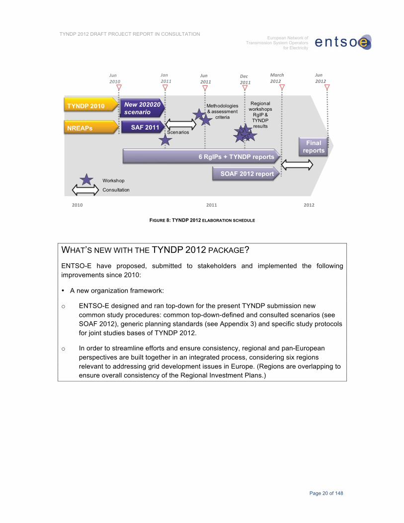
FIGURE 8: TYNDP 2012 ELABORATION SCHEDULE
WHAT’S NEW WITH THE TYNDP 2012 PACKAGE? ENTSO-E have proposed, submitted to stakeholders and implemented the following improvements since 2010:
• A new organization framework:
o ENTSO-E designed and ran top-down for the present TYNDP submission new common study procedures: common top-down-defined and consulted scenarios (see SOAF 2012), generic planning standards (see Appendix 3) and specific study protocols for joint studies bases of TYNDP 2012.
o In order to streamline efforts and ensure consistency, regional and pan-European perspectives are built together in an integrated process, considering six regions relevant to addressing grid development issues in Europe. (Regions are overlapping to ensure overall consistency of the Regional Investment Plans.)

Page 21 of 148
TYNDP 2012 DRAFT PROJECT REPORT IN CONSULTATION European Network of
Transmission System Operators for Electricity
FIGURE 9: ENTSO-E SYSTEM DEVELOPMENT REGIONS
o The possibility for 3rd parties (non-ENTSO-E members) to submit candidate projects by complying with a public procedure12.
• Improved outcomes, directly answering stakeholders request when consulted about TYNDP 2010:
o Identification of main future congestions issues on the grid and assessment of bulk power flows across these;
o Explicit definition of projects of pan-European significance (see §A2.5 in appendix);
o Higher-level presentation of projects, showing connections between investments to develop additional grid transfer capability;
o Valuation of every project benefits assessment to enable cost benefit analysis;
o Synthetic assessment of the transmission adequacy expected with the planned investments.
12https://www.entsoe.eu/fileadmin/user_upload/_library/SDC/TYNDP/2012/3rd_parties_projects_guidance.pdf

Page 22 of 148
TYNDP 2012 DRAFT PROJECT REPORT IN CONSULTATION European Network of
Transmission System Operators for Electricity
In a volatile environment, the TYNDP and its methodology are bound to evolve. ENTSO-E targets a regular delivery every two years of an enhanced product, introducing methodology improvements so as to ensure timely and consistent results, thus achieving efficiency rather than aiming at perfection.
The following chart sums up the overall process: basically open to stakeholders; constantly improving; integrating efficiently both pan-European and regional exercises (see Chapter 4 for more details).
Regional Investment
Plans
Draft 10yNDP consultation
Grid adequacy analyses
Background scenarios validation
First ββ-TYNDPconsultation
Inputs/data for background scenarios
First draft β-TYNDP
Investment gapsGrid projects
3rd package + stakeholders’ expectations
Next issues of TYNDP
Background scenarios
State of the art
Network data
Background scenarios development
FIGURE 10: BUILDING-UP PROCESS OF THE TYNDP
2.3 HOW TO READ THE TYNDP 2012 REPORT? The document is structured in the following way:
• Chapter 3, Assessment of TYNDP 2010 points out the main changes that have occurred with respect to the investments presented in the TYNDP 2010 submission.
• Chapter 4, Methodology describes the overall process and specific methods used to elaborate the TYNDP 2012 package. (Regional parameters used to apply the methodology, as the case may be, or specific regional outlooks are presented in the Regional Investment Plans.)
• Chapter 5, Scenarios gives only a synthetic overview of the basic scenarios underlying the present TYNDP. (The detailed description of the scenarios and the generation adequacy forecast are in the SOAF 2012 report.)

Page 23 of 148
TYNDP 2012 DRAFT PROJECT REPORT IN CONSULTATION European Network of
Transmission System Operators for Electricity
• Chapter 6, Investment needs exposes the evolution of the European grid capacity from the present situation, highlighting the drivers of grid development, location of grid bottlenecks in ten-year time and bulk power flows across these bottlenecks.
• Chapter 7, Projects presents a synthetic overview of all planned projects of pan-European significance. (The technical details of the projects are in Appendix 1; see also the Regional Investment Plans.)
• Chapter 8, Transmission adequacy sums up the improved situation in ten-years time with all projects of pan-European significance implemented.
• Chapter 9, Environmental concerns sums up the environmental impact of the planned projects13.
• Chapter 10, Assessment of resilience resets the planned projects in larger and farther-looking perspective.
• Chapter 11, Conclusion.
• Appendix 1 displays the Table of Projects, summing up all the information regarding projects of pan-European significance.
• Appendix 2 supplies the definition of key-concepts and a glossary.
• Appendix 3 describes the planning standards.
• Appendix 4 focuses on measures to improve social acceptance of grid investments.
• Appendix 5 sums up the state of the art regarding transmissions technologies.
• Appendix 6 supplies additional results.
13 The Strategic Environmental Assessment of projects is available at national level and is not recalled here.

Page 24 of 148
TYNDP 2012 DRAFT PROJECT REPORT IN CONSULTATION European Network of
Transmission System Operators for Electricity
3 ASSESSMENT OF TYNDP 2010 This chapter deals with the evolution of projects planned in TYNDP 2010. It compares the evolution of the table of project in Appendix 1 of the TYNDP 2010 and TYNDP 2012 reports.
3.1 ROBUSTNESS OF THE TYNDP 2010 INVESTMENT PORTFOLIO
The structure of the table of projects has evolved compared to the TYNDP 2010, especially based on stakeholders’ feedback:
o The investments items are now clustered into larger projects to display both a synthetic technical description of every investment item and the cost benefit analysis of every project;
o The labeling build on the investment items’ references supplied in the TYNDP 2010 report. Additional investment items are labeled “Axxx”;
o A specific column monitors the evolution of every investment item from TYNDP 2010 to 2012.
The diagram below illustrates the evolution of the TYNDP Project table between the 2010 and 2012 publications:
Com
mis
sion
ned
Reg. Inv. Plans 2012
TYNDP 2012# 100 projects
TYNDP 2010
FIGURE 11: EVOLUTION OF PROJECTS FROM TYNDP 2010 TO TYNDP 2012
Out of 495 investments items presented in the TYNDP 2010,

Page 25 of 148
TYNDP 2012 DRAFT PROJECT REPORT IN CONSULTATION European Network of
Transmission System Operators for Electricity
• About 75% are present in the pan-European TYNDP 2012 report;
• 52 have been commissioned, to date (12 have been partly commissioned, 26 are expected to be commissioned in 2012);
• 106, expected to be commissioned after 2012 are now presented in the Regional Investment Plans 201214;
• 12 have evolved in their design or have been entirely substituted (the correspondence can be monitored in the table of project “status evolution from 2010 to 2012”)
24% of the investments in the pan-European TYNDP report 2012 have been newly introduced. This figure compares to the 17% of the investment planned in the TYNDP 2010 that are now completed or about to be completed. This is a relatively normal turn-over although a bit high, but matching the evolutions of investment needs in Chapter 6. These figures show both the robustness of the TYNDP 2010 which is here confirmed; and that the TYNDP is a living process.
In total, 486 investment items are now clustered into a few more than 100 projects of pan-European significance (see Chapter 7 and Appendix 1 for more details)
3.2 MONITORING OF PROJECTS OF TYNDP 52 investment items have been completed. The following chart shows the progression of all the projects detailed in the TYNDP2010 that are still to be commissioned, in order to illustrate whether the stated delivery timescales for the investments have been met. The projects have been classified as either “delayed”, “on track” or “ahead of schedule” depending on whether the expected commissioning date for each has changed.
��������� ����������� �� �� ���
������������������ ���
������
FIGURE 12: MONITORING OF PROJECTS OF TYNDP 2010
14 18 new investment items have been introduced in addition in the Regional Investment Plans 2012.

Page 26 of 148
TYNDP 2012 DRAFT PROJECT REPORT IN CONSULTATION European Network of
Transmission System Operators for Electricity
5% of the investments are ahead of schedule. This is mostly the case of investments where consensus among stakeholders has been reached earlier than expected: the business plan has hence been validated earlier enabling to entering the permitting phase.
More than 55% remain on track. It can be generally concluded that good progress has been made as the delivery timescales for the projects move from the long-term to the mid-term.
That withstanding, there has been material delay to the delivery of one third of the investments, mostly because of social resistance and longer than initially expected permitting procedures, possibly leading to project reengineering. For example, some sections of new proposed overhead power line routes have had to be substituted with the use of underground cables. The phenomenon is not specific to certain countries or regions. On average, delayed investments are delayed a bit longer than 2 years.

Page 27 of 148
TYNDP 2012 DRAFT PROJECT REPORT IN CONSULTATION European Network of
Transmission System Operators for Electricity
4 METHODOLOGY FOR TYNDP 2012
4.1 MARKET AND NETWORK INTEGRATED MODELING ENTSO-E developed for the present TYNDP 2012 the target-methodology introduced in Chapter 8 of the TYNDP 2010.
As summed up in the figure below, the top-down target methodology breaks down into 4 steps, detailed hereafter:
FIGURE 13: OVERVIEW OF THE GENERAL METHODOLOGY
The present chapter deals with the specific methodological features developed for the TYNDP 2012. Generic planning standards are presented in Appendix 3.
4.1.1 SCENARIOS TO ENCOMPASS POSSIBLE FUTURES The first step is the construction of scenarios (see definition in Appendix, § A2.3). Each scenario must show intrinsic logic and consistency, especially a valid generation adequacy15 and all scenarios must encompass all foreseeable futures. Scenarios are built for the entire Europe to ensure global consistency. They comply with visions until 2030 in order to provide longer-run perspective. They have been publicly consulted.
The reference scenario for the TYNDP 2012 is the ‘EU2020’ scenario, and all results are presented by default for this scenario. It is a top-down scenario, deriving from the policy goals the EC and Member States16 set themselves for 2020. The other basic scenario “B” derive from a bottom-up approach, based especially from presently known intentions of
15 .����������������5��6���5�6����7���������5������� 8is ���������������������5����������6� ������� 5�5��������9���������!���:;<�������""6�������"����� ����������5���
16 ����������7������ �6�.�������������

Page 28 of 148
TYNDP 2012 DRAFT PROJECT REPORT IN CONSULTATION European Network of
Transmission System Operators for Electricity
market players. The scenarios eventually rather converge, showing shared consensus regarding the achievement of the EU 202020 targets.
Variants of these scenarios may have been analyzed additionally, to accommodate specific local options whenever needed. Especially, sensitivity to the shut-down nuclear power plants have been considered.
Scenarios are synthetically presented in Chapter 5 and detailed in the SOAF 2012.
4.1.2 MARKET STUDIES TO DERIVE ECONOMIC BALANCES For every scenario, a market study answers the question “which generation (location/type) is going to serve which demand (location) in any future instant?”. Their outcome is market balances in every country/price zone and especially generation, and exchange patterns (“bulk power flows”).
To perform a market study, the demand must be modeled, and usually as dependent on weather conditions. Additionally, generation connected to the distribution level, and thus seen as negative demand from TSOs, or smart grids may lead to the need to enrich this model. At the same time, the generation features (especially a cost function) must be modeled, and these depend on several parameters such as raw material prices, financial situation, geopolitical evolutions, meteorological conditions, etc. Systems experiencing energy constraints, as for example those with significant part of hydro storage capacities, need to adopt annual or pluri-annual scopes in order to take into account time of production optimization.
The modeling of all market components’ behavior is thus huge. Most market study tools rely on probabilistic modeling. Conversely, the modeling of the transmission grid itself must rely in most cases on a 1-node-per-country (or price zone) principle with simplified transmission capacity limitation modeling between the nodes. Because of computation limitations, available tools show different trade-off with more or less detailed modeling of every market item versus network feature. They have been developed to match specific characteristics of hydro-systems here or delicate thermal unit commitment there.
ENTSO-E thus organized for the elaboration of the TYNDP 2012 the possibility to run in parallel several market study tools at regional levels, in order to better adapt to specifics of every region on the one hand, and mutually challenge the models to derive more robust results. The variety of outcomes of market studies are presented in Regional Investment Plans. All the simulations however are derived from a single database depicting the scenarios to ensure consistency between all six European regions.

Page 29 of 148
TYNDP 2012 DRAFT PROJECT REPORT IN CONSULTATION European Network of
Transmission System Operators for Electricity
4.1.3 NETWORK STUDIES TO ASSESS GRID TRANSFER CAPABILITY Network studies answer the question “will the dispatch of generation and load given in every case generated by the market study result in power flows that endanger the safe operation of the system (accounting especially for the well-known N-1 rule)?” If yes, then transmission projects are designed, tested and evaluated for all relevant cases. Studied cases explore a variety of dispatch situations: frequent ones, or rare ones but resulting in particularly extreme flow patterns. A limited set is chosen to map the whole range of situations identified in the market studies.
Inputs to common network studies are default pan-European Power Systems Models (PSMs), where the specific generation and load dispatch stemming from the market studies is blended. PSMs are datasets, depicting transmission assets, with default topology and an “example case”. ENTSO-E regularly organizes data collection to update and make available to all TSOs these basic datasets.
The methodology for network studies is depicted in Appendix 3, Guidelines for Grid Development. Basically, network studies help assessing the grid transfer capability, and its increase enabled by transmission projects. This output of the network studies can be retro-fitted in market studies to assess improvement brought by the enhanced grid to the market.
Market studies (assessment of all cases with simplified grid description) and network studies (extensive grid description for one particular case) are thus duals. They are wisely articulated in a two-step, iterative process in order to ensure consistency and efficiency (every concern being properly addressed with the appropriate modeling) and to avoid too complex all-in-one black-box models either too complex to run or lacking detailed enough modeling of some aspects.
4.1.4 AN EXPLICIT AND PRACTICAL VALUATION OF PROJECTS The network value develops from the combined action of all grid assets interacting with each other. Stakeholders wished to get a better idea of how the proposed investments interact. Isolating objectively the specific impact of every investment is, however, very complex because of the network effect17.
The presentation of projects in the TYNDP 2012 has hence been reshuffled to display both a synthetic technical description of every project item and the cost benefit analysis of every project.
Transmission projects are valuated against the following multi-criteria scale developed by ENTSO-E (see Appendix 3 for the definitions):
17 Schematically, the added value of all assets is greater than the sum of their individual values,ceteris paribus.

Page 30 of 148
TYNDP 2012 DRAFT PROJECT REPORT IN CONSULTATION European Network of
Transmission System Operators for Electricity
����������������������������� �
������������������������� �*�����������
��������� ���������� ����
�� � ���������
������� �� ���������
����������� ������ ��� ������
�������!������������
������ �� �
"�###�$%
FIGURE 14: PRINCIPLES OF MULTI-CRITERIA ASSESSMENT OF PROJECTS OF PAN-EUROPEAN SIGNIFICANCE
Projects basically improve the grid transfer capability and an assessment of the grid transfer capability increase is provided for every project. All other dimensions are assessed via 3-level indicators:
• The social and economic welfare indicator, the RES integration indicator and improved security of supply values the benefits of the projects in the 3 dimensions of the EU Energy policy: market integration, RES development and security of supply;
• The RES integration, losses variations and CO2 emissions variation indicators value the benefits with respect to the three pillars of the 202020 policy;
• The technical resilience and flexibility indicators refer to the technical performance of the assets in the grid;
• The social & environmental impact completes the costs, date of commissioning and the status of the project as well as show risks attached to the project completion.
The assessment of the benefits compares the situation with and without the projects, ceteris paribus.
�
4.2 A SPECIFIC, TOP-DOWN, EUROPE-WIDE COORDINATION This new top-down methodology represents a great improvement compared to the previous release of the TYNDP. The whole process has been implemented for the first time, by ENTSO-E and all 41 TSOs members to deliver the TYNDP 2012 package, involving huge amounts of data and new models.
ENTSO-E is already building on the gathered feedback to strengthen all the involved procedures and further improve the methodology implementation. The goal is threefold: to

Page 31 of 148
TYNDP 2012 DRAFT PROJECT REPORT IN CONSULTATION European Network of
Transmission System Operators for Electricity
accelerate and strengthen data collection, consistency checks and processing; to facilitate common model calibration; to coordinate regional groups, articulate pan-European and regional assessment and merge all results consistently.
The quality of the integrated market and network modeling described supra relies on the knowledge of all specific features of every local power system in Europe as well as the resulting ability to master and cut aptly through numerous uncertain parameters. The aim is to model properly every grid concern in a limited timeframe of 2 years, and hence valuate correctly more than 100 projects all over Europe.
ENTSO-E hence devised specific top-down coordination, both relying on common standards and subsidiarity to take advantage of TSOs’ local expertise and workforce:
• 1 working group coordinating the TYNDP 2012 delivery and 3 working groups of key-experts to set up methodologies and organize data framework, for planning standards; scenarios and market studies; power system models.
• 6 regional groups, gathering TSOs experts, jointly performing regional analyses, sharing views, mutually challenging and jointly building solutions, each group able to focus on the specific concerns of their area.
As a result, about 200 people in Europe contributed to the TYNDP 2012 package. Be they all thanked for their commitment.

Page 32 of 148
TYNDP 2012 DRAFT PROJECT REPORT IN CONSULTATION European Network of
Transmission System Operators for Electricity
5 SCENARIOS This chapter deals with the assumptions used to develop the results presented in the TYNDP 2012 package. The presented material gives the main conclusions of the SOAF 2012 report and the market studies that have been carried out in the Regional Investment Plans.
5.1 LONG-TERM VISIONS AND SCENARIOS The development of the transmission grid requires a long-term vision that is robust for relevant developments that determine the future use of the grid. In the SOAF 2012 report the pan-European ENTSO-E energy visions for 2030 are presented. In these four visions, four credible, coherent and consistent energy projections until the year 2030 are described. Although 2030 is beyond the scope of this TYNDP, these visions are the background against which the ENTSO-E scenarios will look at in the future.
The SOAF 2012 report presents an update of the scenarios that were developed in SOAF 2011, have been publicly consulted and commented on in the first semester of 2011, and used as bases of the analyses. The re-stated decision of German government regarding nuclear phase-out plans led ENTSO-E to test a sensitivity to the presence/absence of nuclear units in this country in order to ensure robustness of the results.
Two pan-European scenarios were established to assess the system adequacy in this TYNDP. The two scenarios, being EU2020 and SAF-B, describe different paths of relevant parameters until the year 2020.
• In the scenario EU2020, the European 20-20-20 objectives and the NREAPs18 were the starting point and the necessary evolution towards this target has been filled in (top-down). The EU2020 scenario is used as the reference scenario and reported by default.
• For scenario B the present situation is taken as a starting point and the future developments are extrapolated until 2020 based on the best estimate (bottom-up).
The evolution of new generation in the top-down scenario is interpolated between the current situation and the end vision: therefore information about the location of new generation must be also assumed top-down, whereas in the bottom-up scenario the evolution of the system derives from market players’ known intentions, and the location of new generation match them.
18 National Renewable Energy Action Plans, each EU member state published the roadmap towards the EU202020 targets.

Page 33 of 148
TYNDP 2012 DRAFT PROJECT REPORT IN CONSULTATION European Network of
Transmission System Operators for Electricity
Toward a sustainable future As the European Commission is preparing a directive to make a further step in improving energy efficiency in a context where energy represents around 80% of the greenhouse gas emissions, TSOs are enlarging their approach to better contribute to energy efficiency. TSOs cannot directly control the use of energy by end-users: however, they can contribute by enabling the use of new technologies or concepts such as efficient generation, demand side management, smart grids and energy storage.
TSOs support energy efficiency, considering the following criteria to qualify the efficiency of energy: • Environmental footprint (CO2, renewability) • Affordability • Reliability and availability • Losses Thus, with their efforts to develop their transmission network in order to enable renewable energy sources to evacuate their power, TSOs play an active and positive role in realizing environmental neutral generation. The market-focused tools developed by TSOs make it possible to lower the use of expensive electricity generation when the consumption decreases, which participates in the economic aspect of energy efficiency. By developing their network, TSOs enable the use of new power plants, which in major cases generate electricity with a better efficiency than older ones. By this, more efficient and affordable generation becomes available to a larger market.
Of course, TSOs have been fighting to control their energy losses for long, for these weigh directly on TSOs’ energy efficiency as well. It seems useful to remember at this stage, that with constant levels of transit (generation and consumption remaining equal), network development (new lines) implies less losses (though a low effect), thus a higher energy efficiency� However, the current main driver for new corridors is usually the need for more transit, with connected losses. The transmission of electrical energy introduces losses that increase with the magnitude of the flow and the distance of the transport. TSOs have been spending much effort to reduce the losses as much as possible by using extra high voltage.
As the TYNDP includes numerous projects either dedicated to connecting new renewable energy sources, or more energy-efficient power plants, or bound to transporting this efficient energy towards consumption areas, grid development projects play a major role on the way to the 20% energy-saving target.
5.2 RENEWABLE ENERGY BOOM BY 2020 In the SOAF 2012 report, a projection of the evolution of load and generation are presented. In Figure 15 the generation mix for 2012 and 2020 is displayed.

Page 34 of 148
TYNDP 2012 DRAFT PROJECT REPORT IN CONSULTATION European Network of
Transmission System Operators for Electricity
���
�,&
���
,�
�����
���������
�
�,�,��
�
�����
���������#��
������������
�������*����������
����*����������#��
����������������� ��!���*���"���������
�������
FIGURE 15: EVOLUTION OF THE GENERATION MIX (EU 2020 SCENARIO, IN GW)
The total of installed capacity will increase by 250 GW, i.e. by 26%, to reach 1214 GW. This increase is mainly due to wind and solar generation which will be developped by 220 GW by 2020. These generation technologies are by nature not controlled and the power system will have to adapt to greater RES outputs. Scenario B also shows a significant RES development, but about 22 GW lower than scenario EU 2020. The installed capacity of fossil fuel units increases by 14 GW in scenario B, while in scenario EU 2020, it slightly decreases (2 GW).
In parallel, the total system peak load will continue to increase, between 2012 and 2020, by about 30 GW and will reach 567 GW in the reference scenario. New conventional generation develops in pace with the load growth. The overall generation adequacy is threfore assumed to be ensured by the end of the coming decade. (More details are available in the SOAF 2012 report.)
5.3 EUROPEAN POWER EXCHANGES BY 2020 Market studies have been conducted to simulate the behavior of the power system by 2020 (see Chapter 4). All situations likely to occur during the 8760h of the year have been analyzed. The following map synthesizes the results, displaying for every border the magnitude of the energy exchanged in every direction; and for every country the magnitude of the net yearly energy balance.
France and Scandinavia are the biggest exporters and the United Kingdom, Italy, Poland, Belgium and the Baltic States have a clear import position. Other countries such as Spain or Germany show a rather balanced position on average, but can experience significant bidirectional flows to neighboring countries due to the intermittency of RES.

Page 35 of 148
TYNDP 2012 DRAFT PROJECT REPORT IN CONSULTATION European Network of
Transmission System Operators for Electricity
e Exchanges < 1 TWh < 5 TWh < 10 TWh > 10 TWh
Country balancesimporterrather balancedexporter
FIGURE 16: POWER EXCHANGES PATTERNS19 IN 2020 AMONG ENTSO-E COUNTRIES
19 The annual power flows shown on the map do not reflect actual physical power flow on the grid but simplified expected commercial exchanges.

Page 36 of 148
TYNDP 2012 DRAFT PROJECT REPORT IN CONSULTATION European Network of
Transmission System Operators for Electricity
6 INVESTMENT NEEDS Once scenarios have been defined, the next phase in network planning consists of characterizing the Investment needs, i.e. every concern ahead on the regional grid and of European significance, and which are likely to trigger extra-high voltage grid investment in order to restore the grid ability to fulfill the duties and services expected from this infrastructure.
Investment needs are described in the present Chapter 6, before solutions to accommodate them are summed up in the next Chapter 7.
6.1 PRESENT SITUATION The map Figure 17 depicts cross-border transfer capacities nowadays20:
The map shows diverse level of Net Transfer Capacities (NTC) in Europe. These discrepancies basically match the geography and demography of Europe: highest NTC levels (and highest grid density generally) are met in the central part of the continent where there is also the highest population density (and hence higher consumption, and installed generation), from London to Milan. South East Europe also shows a consistent pattern with similar interconnection capabilities all across the area, but at a globally lower level than in more densely populated areas.
20 Source : www.entsoe.net

Page 37 of 148
TYNDP 2012 DRAFT PROJECT REPORT IN CONSULTATION European Network of
Transmission System Operators for Electricity
FIGURE 17: ILLUSTRATION OF NET TRANSFER CAPACITIES IN EUROPE (WINTER 2010/11)

Page 38 of 148
TYNDP 2012 DRAFT PROJECT REPORT IN CONSULTATION European Network of
Transmission System Operators for Electricity
6.2 DRIVERS OF POWER SYSTEM EVOLUTION Drivers for grid development directly derives from the three pillars of EU energy policy goals: Security of Supply; Renewable energy integration; Internal Market integration.
The map Figure 18 (next page) shows the main primary drivers21 for grid development in Europe in the coming decade (see definition in Appendix 2, §A2.4):
• Large amount of RES spread all over Europe, with concentration in Iberian Peninsula, in the South of Italy, and North Seas neighboring countries. About 220 GW of new RES generation are foreseen (see SOAF 2012 report).
• Power plant decommissioning22: about 25 GW of nuclear capacity is scheduled to be shut down from 2010 to 2020, especially in Germany (16 GW) and the UK (7 GW). Obsolete coal-fired power plants are also scheduled to be shut down in order to meet environmental standards, especially in the UK (9 GW). The decommissioned power plants were mostly located relatively close to the most populated areas in Europe, possibly resulting in security of supply issues.
• In total, about twenty large areas (shown by amber dots) with specific supply are at risk unless transmission capabilities are improved or local generation develops.
• The relatively low interconnection of Baltic States regarding neighboring EU states.
• Cyprus and Iceland are island systems. No interconnectors with other ENTSO-E countries have been considered in the TYNDP package 2012.
21 As the case may be, any other investment needs (ageing of equipment, reliable grid operation, decommissioning of smaller units, etc.) are shown in Regional Investment Plans.
22 To clarify the picture, only decommissioning of power plants larger than1 GW that are not replaced on site by new generation – and changing hence the power flow patterns – are described.

Page 39 of 148
TYNDP 2012 DRAFT PROJECT REPORT IN CONSULTATION European Network of
Transmission System Operators for Electricity
FIGURE 18: GRID DEVELOPMENT DRIVERS

Page 40 of 148
TYNDP 2012 DRAFT PROJECT REPORT IN CONSULTATION European Network of
Transmission System Operators for Electricity
6.3 MAIN BOTTLENECKS POSSIBLY DEVELOPING IN THE COMING DECADE As a result of the market and network study process, almost 100 possible bottlenecks have been identified in Europe in the coming decade (unless new transmission assets are developed).
The map Figure 19 (next page) shows their location, i.e. the grid sections (the “boundaries”), the transfer capability of which may not be large enough to accommodate the likely power flows that will need to cross them unless new transmission assets are developed.
In order to ease the understanding, the likely bottlenecks have been sorted according to three types of concerns:
• Security of supply when some specific area may not be supplied according to expected quality standards and no other issue is at stake;
• Generation direct connection;
• Market integration, if inter-area balancing is at stake, distinguishing what is internal to a price zone and what is between price zones (cross-border).
NB: when a boundary can be flagged with more than one concern, then, somewhat arbitrarily, Market integration prevails over Generation connection and Security of Supply.
• About 60 % the boundaries are primarily related to market integration issues, 40% cross-border and 20% internal. Most present cross-border congestions can be recognized on the map, as they would just develop unless new grid assets are implemented.
• About 30% are primarily related to generation direct connection;
• About 10% are primarily related to security of supply issues.
As shown infra, the above sorting hides that boundaries flagged “market integration” are almost all contributing to RES integration (see § 6.4.1). Some of them are also related to security of supply issues (see § 6.4.3).

Page 41 of 148
TYNDP 2012 DRAFT PROJECT REPORT IN CONSULTATION European Network of
Transmission System Operators for Electricity
FIGURE 19: 100 MAIN CONCERNS IN EUROPE IN 2020

Page 42 of 148
TYNDP 2012 DRAFT PROJECT REPORT IN CONSULTATION European Network of
Transmission System Operators for Electricity
6.4 EXPECTED BULK POWER FLOWS BY 2020 A Bulk power flow is the typical power flow triggering grid development across a boundary. They are quantified in the following sections for every concern. Bulk power flows range from about 500 MW to more than 10000 MW.
6.4.1 GENERATION CONNECTION The map of generation integration (Figure 20 next page) shows the boundaries that are related to direct connection of renewable or conventional facilities to the grid. It highlights:
• Higher bulk power flows (amber and red) where there are big concentration of new generation
o developing in a limited area, especially offshore wind in the North Sea;
o adding up to already large concentration of generation (Scotland, Wales, Alps, Rhone Valley)
• Lower bulk power flows (blue and green) where large amounts of RES develop where relatively little generation was installed: in Ireland, Portugal, Spain, Southern Italy, Greece, Bulgaria and Romania, Poland, and Nordic countries.
• Lower bulk power flows (blue) where large power plants are planned in Germany, Poland, Lithuania, and Finland.

Page 43 of 148
TYNDP 2012 DRAFT PROJECT REPORT IN CONSULTATION European Network of
Transmission System Operators for Electricity
FIGURE 20: BULK POWER FLOWS RELATED TO GENERATION CONNECTION
6.4.2 MARKET INTEGRATION The map Figure 21 (next page) displays market integration concerns:

Page 44 of 148
TYNDP 2012 DRAFT PROJECT REPORT IN CONSULTATION European Network of
Transmission System Operators for Electricity
FIGURE 21: BULK POWER FLOWS RELATED TO MARKET INTEGRATION
The map shows:

Page 45 of 148
TYNDP 2012 DRAFT PROJECT REPORT IN CONSULTATION European Network of
Transmission System Operators for Electricity
• Relatively larger bulk power flows in the heart of Europe than on the periphery of the continent. This is a rather mechanical result: the area spreading from Benelux to the Alp region is denser, and geographically located at the crossroad of the European power system compared to other countries.
• Compared to other peripheral areas, Ireland and the UK show remarkably higher bulk power flows (amber rather than green or blue). The generating fleet will experience a deep renewal, and obsolete nuclear and coal-fired power plants will be substituted especially by wind generation. As all wind turbines in the area show very correlated output profiles, large surpluses or deficits are likely and hence more variable exchange patterns with mainland Europe.
• The largest bulk power flows related to market integration are located in the central part of Europe, and are oriented North South between:
o generation concentration along and off the North Seas shores and high RES development in Southern Italy; and
o large consumption areas (Benelux, Paris area, South of Germany, North and Central Italy, Mediterranean Sea shores from Spain to Italy) with relatively low installed generation (and even lower with unit decommissioning);
o hydro storage in Scandinavia and the Alps, with pumping capacity.
From North to South, the power system alternatively shows generation and consumptions areas. As a result, the power flows are large, but also more volatile than today: for instance, in summer the Southern part of Germany will show surpluses every day and deficits every night.
• On a parallel corridor, there are much larger North-South flows in Baltic States, Poland and Central-East Europe than the present transfer capability of the grid allows for.
• There are much larger East to West and South flows in South-Eastern Europe than the present transfer capability of the grid allows for.
6.4.3 SECURITY OF SUPPLY OF LARGE AREAS The map Figure 22 (next page) locates and quantifies all security of supply concerns:

Page 46 of 148
TYNDP 2012 DRAFT PROJECT REPORT IN CONSULTATION European Network of
Transmission System Operators for Electricity
FIGURE 22: BULK POWER FLOWS RELATED TO SECURITY OF SUPPLY
The analysis shows very different issues:

Page 47 of 148
TYNDP 2012 DRAFT PROJECT REPORT IN CONSULTATION European Network of
Transmission System Operators for Electricity
• Supply of large cities or urbanized areas (Lisbon, Catalonia, French Riviera...);
• Countries with a negative generation adequacy forecast (Belgium, Luxembourg) requiring additional cross-border transmission capacity23;
• Regions within countries with a negative generation adequacy forecast (South of Germany, Brittany, North West Hungary, Northern Norway) requiring additional transmission capacity;
• Baltic States requiring a higher interconnection with EU countries to ensure their supplies.
6.5 RES INTEGRATION AS THE MAJOR CONCERN The breakdown into security of supply, generation connection and market integration in § 6.4 is useful for better understanding and comparisons of every single concern.
However 80% of the bottlenecks are directly related to RES integration (see Figure 23), either because direct connection of RES is at stake; or because the network section or corridor is a key-hole between RES and load centers. The north-south internal corridors in Germany are typical example of the latter. The following map displays the overall picture, with, in lighter green the boundaries related to the accommodation of inter-area transits triggered by RES; and in darker green the boundaries related to direct connection of RES generation (or to both concerns as the case may be).
The massive development of RES is the main driver for larger, more volatile power flows, over larger distance across Europe, mostly North-South from Scandinavia to Italy, between mainland Europe and the Iberian Peninsula, Ireland and the UK; or East to South and West in the Balkan Peninsula.
The next Chapter 7 deals with grid investments that are hence needed to avoid present congestion to worsen and new congestion to appear.
23 See SOAF 2012. Conversely, when the generation adequacy forecast of a country is acceptable without accounting for import capacity, no security of supply issue is marked on the map. The countrymay however require imports to mitigate electricity prices. Italy is an example of such situation.

Page 48 of 148
TYNDP 2012 DRAFT PROJECT REPORT IN CONSULTATION European Network of
Transmission System Operators for Electricity
FIGURE 23: RES INTEGRATION IS THE MAJOR CONCERN FOR GRID DEVELOPMENT

Page 49 of 148
TYNDP 2012 DRAFT PROJECT REPORT IN CONSULTATION European Network of
Transmission System Operators for Electricity
7 PROJECTS OF PAN-EUROPEAN SIGNIFICANCE To solve all investment needs identified for the coming decade in Europe, the European TSOs evaluated in collaboration numerous grid reinforcements.
The pan-European TYNDP report focuses on projects of pan-European significance (see definition in Appendix 2, § A2.5). Projects with more regional (resp. national) focus are presented in the ENTSO-E Regional Investment Plans (resp. National Development Plans).
Every project of pan-European significance is listed, described and valuated in Appendix 1. The present Chapter provides an overall view about the projects, their costs and benefits.
Projects promoted by 3rd parties
In order to deliver the most comprehensive and up-to-date outlook of the electricity grid by 2020 and beyond, ENTSO-E, based on the stakeholders’ feedback to the TYDNP 2010, elaborated and made publicly available in February 2011 as part of the TYNDP development process, a procedure for the inclusion of the third party projects in the 2012 release of the TYNDP: https://www.entsoe.eu/system-development/tyndp/tyndp-2012/.
ENTSO-E- received five submissions, analyzed in every relevant Regional Group. The candidate projects however did not demonstrate evidence of a transmission license or an exemption for such license granted by the relevant national regulatory authorities and the EC, in accordance with the TYNDP procedure. The non-discrimination principle (especially with regard to similar projects that may not have applied for inclusion for this reason), makes it inappropriate for these five projects to be incorporated in the table of projects of the TYNDP 2012 package.
7.1 GRID DEVELOPMENT PROJECTS OF PAN-EUROPEAN SIGNIFICANCE
ARE NEEDED ALL OVER EUROPE The following two maps geographically display all investments item composing the projects of Pan-European Significance. The first map (Figure 24) shows all projects commissioned mid-term, i.e. in the first five-year period of the TYNDP, from 2012 to 2016; the second map (Figure 25) shows all projects commissioned in the longer run, i.e. from 2017. The maps show basic information regarding location, routes and technology (AC or DC, voltage level). When the precise location of an investment is not yet known, the area where the investment

Page 50 of 148
TYNDP 2012 DRAFT PROJECT REPORT IN CONSULTATION European Network of
Transmission System Operators for Electricity
is likely to occur is colored. The investment labels ease the correspondence with the table of projects in Appendix 1.
The maps show projects of pan-European significance basically planned all over Europe, with a relative balance between long-term or mid-term. Projects are rather well defined for the coming five years. Longer-run projects may still be in planning or design & permitting phases: they may not be precisely designed and located yet, and several options might still be envisaged for some of them.

Page 51 of 148
TYNDP 2012 DRAFT PROJECT REPORT IN CONSULTATION
European Network of Transmission System Operators
for Electricity
FIGURE 24: PROJECTS OF PAN-EUROPEAN SIGNIFICANCE MID-TERM (UNTIL 2016)

Page 52 of 148
European Network ofTransmission System Operators
for Electricity TYNDP 2012 DRAFT PROJECT REPORT IN CONSULTATION
FIGURE 25: PROJECTS OF PAN-EUROPEAN SIGNIFICANCE LONG-TERM (AS OF 2017)

Page 53 of 148
TYNDP 2012 DRAFT PROJECT REPORT IN CONSULTATION
V6, 08.02.2012
European Network of Transmission System Operators
for Electricity
7.2 OVER 50000 KM FOR GRID TO BUILD OR REFURBISH IN THE COMING
10 YEARS Over 100 transmission projects of pan-European significance have been identified to address and solve the abovementioned concerns in the coming decade. (Among them, 40% interconnectors).
As displayed on Figure 26 below, projects of pan-European significance total about 51500 km of new or refurbished Extra High Voltage routes24. The expected commissioning dates are split rather equally between the two 5-year sub-periods.
FIGURE 26: PROJECTS OF PAN-EUROPEAN SIGNIFICANCE - VOLUMES
The TYNDP 2012 figures represent a 21% increase compared to TYNDP 2010, with especially individually long-stretching new investments. +3000 km of subsea routes are envisaged, developing in total 10000 km of offshore grid key-assets; +7000 km of routes are considered inland, mostly to bring to load centers the power generated on the outskirts of the European territory.
The vast majority of project (around 39000 km) use the common HVAC technique. This is the common technical standard in Europe for electricity transmission and is a well-established
24 Compared to the existing grid length of about 305000 km.

Page 54 of 148
TYNDP 2012 DRAFT PROJECT REPORT IN CONSULTATION European Network of
Transmission System Operators for Electricity
technology. In addition, about 12600 km of HVDC links are planned. Most relate to subsea investments where AC technology is no option. Several HVDC interconnection projects are however considered inland with parallel operation with HVAC lines. 1080 km of HVAC subsea cables, at 150 kV or 220 kV are also planned, mostly for offshore wind connection.
Over 80% of the investments correspond to new equipment/routes and 20% to refurbishment or upgrade of existing assets.
7.3 GRID TRANSFER CAPABILITY INCREASE BY 2020 As developed in Chapter 6, the challenge of the coming decade is to face larger and more volatile power flows across larger distance in Europe. The proposed grid reinforcements hence focus on Grid Transfer Capability (GTC) increase.
The GTC increase enabled by every project is presented in Appendix 1. The following map (Figure 28, next page) synthesizes the outcome across all boundaries in Europe. The values of gained GTC are oriented by needs and cover a huge range of transmission capacity increase efforts: projects of pan-European significance are very diverse, adapting to the very specific geography they are inserted in. They develop GTC ranging from a few hundreds of MW to more than 4 GW. Globally, greater GTC increases are developed basically where higher power exchanges are expected.
#��
$��
���
���
������
�������
�� �������
�������������
FIGURE 27: GRID TRANSFER CAPABILITY INCREASES BREAKDOWN
Larger GTC increases correspond to situations where parallel investments combine their effort across a large boundary where large bulk power flows are expected (for instance, between Ireland and the UK and mainland Europe). Lower amounts correspond to more specific situations (new power plant connection for instance).

Page 55 of 148
TYNDP 2012 DRAFT PROJECT REPORT IN CONSULTATION European Network of
Transmission System Operators for Electricity
FIGURE 28: GRID TRANSFER CAPABILITY INCREASES

Page 56 of 148
TYNDP 2012 DRAFT PROJECT REPORT IN CONSULTATION European Network of
Transmission System Operators for Electricity
7.4 PROJECTS BENEFITS The projects’ impacts were assessed by the multi-criteria assessment developed by ENTSO-E (see Appendix 3) to show the benefits of each project.
7.4.1 A DIRECT SUPPORT TO THE EU ENERGY POLICY The charts shown below (see Figure 29) illustrate the magnitude of support given by the projects to the EU energy policy. The corresponding benefit is considered in terms of four criteria: Social and Economic Welfare, RES Integration, Security of Supply and CO2 Emissions Mitigation.
�����������������������������������
��������������������������������� ���!����������������"���#�$���!�����%���& '������
���& '�������������������������������� ���!����������������"���#�$���!�����%('������
���������������
����!��
��!����)*+�������������,����-
��!����)*+������������(,����-
.���/���������"�����!&�!���"��# ��!�$$�!���0��)*+
������� ������!!�
/���!���� 1���"�������%
/����/� ��2����'�����! %
3�$3�� ��2��('�����! %
"#$�����������
����!��
/���$������,���4���/���$�����(,���4���
FIGURE 29: PROJECTS OF PAN-EUROPEAN SIGNIFICANCE – CONTRIBUTION TO EU ENERGY POLICIES
As a result of the strict criteria applied25, the Socio-Economic Welfare (SEW) indicator has a very strong correlation with market integration. High-marked projects correspond mostly to
25 Warning: low-rated projects regarding the social and economic welfare indicator also merge here key-projects for generation connection, thus triggering the social and economic welfare of the generation project itself.

Page 57 of 148
TYNDP 2012 DRAFT PROJECT REPORT IN CONSULTATION European Network of
Transmission System Operators for Electricity
additional interconnectors with four network peninsulas: Ireland and Great Britain, Spain and Portugal, the Baltic States, and Italy.
80% of the projects show high benefits for RES integration, half by directly connecting RES, and half by accommodating inter-area unbalances triggered by RES. Projects still marked low with respect to RES integration either contribute specifically to connecting nuclear or conventional generation or for securing the supply of load areas at risk.
With respect to the Security of Supply, 13% of projects are classified as High, meaning the project will secure an area for at least ten years after commissioning. 24% are classified as Medium, meaning the project will contribute to securing a specific area but for less than ten years after commissioning. (If more than one project is required to secure an area for more than ten years, then none can be individually classified as High. This is the case for projects securing Belgium and the Baltic States.)
All projects reduce the CO2 emissions with the exception of a small number of projects that are solely for the integration of new fossil-fuel-fired power plants.
7.4.2 HIGH TECHNICAL PERFORMANCE STANDARDS All the projects also display high technical performances (see Figure 30):
��������������������
� �!��
�'" �
# �#
��������� �
� �!��
�'" �
# �#
������������ ���
# �#'��$!��'�
�!�#$'%����'�"
$!�'��$!��'�
FIGURE 30: PROJECTS OF PAN-EUROPEAN SIGNIFICANCE – TECHNICAL ASSESSMENT
The charts for Flexibility and Technical Resilience illustrate that for such technical factors, for which a TSO has a wide degree of freedom to influence, very high performance can be achieved. This is in contrast to other objectives which are strongly affected by factors which cannot be significantly controlled by a TSO such as the location of generation.
In this latter respect, losses for instance depend on exogenous factors, and projects benefits in this respect are diverse (as explained in the insert below): positive for those merely improving the grid meshing; negative when connection of new remote generation is at stake; and undetermined when the appraisal is more complex.

Page 58 of 148
TYNDP 2012 DRAFT PROJECT REPORT IN CONSULTATION European Network of
Transmission System Operators for Electricity
Grid losses variation
Transmitting electrical energy causes electrical losses, the more distance and the higher the energy, the higher the losses.
An efficient way to reduce losses is to operate the grid at higher voltage and thus reducing the electrical current. However, equipment for higher voltage is more costly and therefore an economic equilibrium between (investment) costs and benefit (reduction of losses) is chosen at the design of the extra-high voltage grid. Typically in Europe voltages of 400 kV and 220 kV are used to transport electrical energy over large distances. In itself the extra-high voltage grid is already designed to be as efficient as possible to minimize the overall costs.
The effect on overall losses of a single transmission line is fairly small; it should not be expected that the losses indicator in the TYNDP will reveal a major step in efficiency of the grid, the big step has already been made with the introduction of the extra high voltages. Some projects however can have a substantial positive effect on electrical losses.
The Assessment Alternatives
The assessment of the losses of a single project is not straightforward. There are various perspectives and ways to assess the losses in the grid, all with other outcomes.
1. The project can be assessed by itself. This means that the amount of loss on the lines in the project can be evaluated. The effect on the other parts of the interconnected grid is neglected which would give a very narrow view on the effect of losses. The outcome of this indicator using this method for assessing would be that new projects will have losses, more or less depending on the project design; voltage upgrades of existing lines could reduce the losses.
2. The project can be assessed as a part of the European Transmission Grid. A comparison between the European grid with and without the project can be made without modifying the load and generation profile. In general this would mean that for a grid extension project the overall impedance would decrease and the losses would reduce; in case of decommissioning the losses would also generally increase.
3. The project can be assessed, taking into account its effect on GTC. In case a project increases the GTC on a specific corridor, more energy can potentially be transmitted along that corridor. This would potentially mean a different running arrangement for generators; an increase of generation in the congested area, and a decrease of generation in the non-congested area. A different GTC results in a different running arrangement of generators over the hours in the whole year. The two configurations are not easily comparable anymore. Therefore a planning case by planning case assessment of efficiency is not meaningful and year-round comparisons should be made. For instance, connecting offshore wind farms that would substitute fossil-fuel-fired units closer to load centers would result in higher losses on the total grid – in general only a marginal drawback compared to the total increase of social and economic welfare.

Page 59 of 148
TYNDP 2012 DRAFT PROJECT REPORT IN CONSULTATION European Network of
Transmission System Operators for Electricity
The assessment of the grid losses variation derives for every project from the most suitable approach considering its specific features.
7.4.3 A DIFFICULT SOCIAL ACCEPTANCE OF PROJECTS The social & environmental index measures the risk that a project might not be completed at the expected commissioning date. Results are displayed in Figure 31:
� ���������������� ������ ����
��������
��������
�� ������
FIGURE 31: PROJECTS OF PAN-EUROPEAN SIGNIFICANCE – SOCIAL AND ENVIRONMENTAL IMPACT
This indicator reflects the perception of risk, which may vary depending on every national context. Project promoters of course indicate low risk when the target date is still to be more accurately defined, in the long run; or when projects are under construction, and close to being completed. Conversely, projects in the permitting phase are almost all classified as Medium or High-risk.
(See Appendix 4 for more details about social acceptance issues)
7.4.4 5% OF SAVINGS IN GENERATION OPERATING COSTS Comparing the power system costs to, on the one hand, present, limited, NTCs26, and on the other hand future NTCs once projects of pan-European significance are implemented, shows that long-term cross-border transmission projects of pan-European significance will help alleviate total annual generation operational costs by about 5%. For higher generation costs that can be expected by 2020, this represents about €5 billion.
Most of the savings are expected from the integration of the four regions showing presently the weakest integration to the European system: Italy, the Iberian Peninsula, Ireland and the UK, and the Baltic states.
26 Only benefits of increased NTCs are measured here. Investment costs for the corresponding long-term cross-border projects amount to about €20 billion.

Page 60 of 148
TYNDP 2012 DRAFT PROJECT REPORT IN CONSULTATION European Network of
Transmission System Operators for Electricity
FIGURE 32: “ELECTRIC PENINSULAS” IN EUROPE BY 2020
7.5 ABOUT €100 BILLION INVESTMENTS IN THE COMING 10 YEARS Project costs show a very wide range, corresponding to the diversity of the projects’ designs (see Appendix 1), from less than €50 million to more than €1 billion: 40% of the projects display costs lower than €300 million and 23% greater than €1 billion.
The following table (Figure 33) figures out the total expected investments cost per country27 for all projects of pan-European significance28,29:
27 This is the best available information to date. Figures however keep adjusting for every project and the information is subject to changes for every country.
28 TSOs invest beyond projects of pan-European significance at regional or national level.
29 Figures for countries indicated with a * in the table correspond to the investments solely born by the TSO(s) of the country; in other words, investments possibly made by others investors are then not reported for that country.

Page 61 of 148
TYNDP 2012 DRAFT PROJECT REPORT IN CONSULTATION European Network of
Transmission System Operators for Electricity
��������� ���������.������ =�= ������� >���� �� => ���� � ������ �?���@���� �� �� � ����� � �A������ � �B ���������� ������ � �B ���������� ���@���������� � =A ���������� �!���� �� ��"�! CD#�����$ =� %����� B>&���� � � %������� =D' ����� �E ����� � �A'����� EE (��� � �B')�*� �= (����$ � �+�����! �= (����� � �+����� � (�� � �E������! �= ("���� B�������� �� (" �@������ =A����!, A= -� ����. ����� =>�
/�����& /(*&���� ����� =��
FIGURE 33: INVESTMENT COSTS BREAKDOWN
Total investments costs amount to € 104 billion, of which € 23 billion is for subsea cables. The figures are is in line with the previous analysis of the TYNDP 2010 and of the overall € 100 billion envisaged by the European Commission in their communication on Energy Infrastructure Package on 17th Nov 2011.
Total investment costs per country correlate relatively with land size and population. Still there are noticeable deviations. Ireland thus foresees as much as €4 billion (due mostly to HVDC long-distance cables), an important effort compared to the population size. With big evolutions with respect to generation location on the German ground, Germany considers by far the highest investments, with €30.1 billion.
The investment efforts are significant for TSOs financial means. It represents however about 1.5-2 €/MWh of power consumption in Europe over the 10-year period, i.e. about 2% of the bulk power prices or less than 1% of the total electricity bill.

Page 62 of 148
TYNDP 2012 DRAFT PROJECT REPORT IN CONSULTATION European Network of
Transmission System Operators for Electricity
8 TRANSMISSION ADEQUACY Are all investment needs identified in the coming decade appropriately solved by the proposed transmission projects?
It is most likely for every generation connection or security of supply issue: these are rather well limited and easier to address.
Projects also match requirements of market integration in the foreseen scenarios, except for rare situations that are still possible for these rather open and interacting concerns. Sizing investments to match these rare situations would not prove profitable for European countries.
The TYNDP 2010 recognized some seven main clusters of investment needs related to renewable integration, East-West and North-South flows in the South-East and Central South regions, Baltic States integration, connection of new conventional power plants and supply of some European cities and regions, and market integration.
Checking against those needs one can state that the direct renewable connection needs are solved almost in all the cases except in the parts of Northern Spain. However, a lot of transmission needs stem from the fact that the RES are located away from the consumption centers, which shows on the North-South transmission needs.
There are more uncertainties linked in the transmission adequacy for North-South flows in Northern, Central and Southern Europe. German nuclear phase-out has created some uncertainty for the transmission adequacy of the proposed projects inside Germany. The TYNDP package reflects results as far as available in January 2012.
France-Spain interconnection stands out. With all projects included in this TYNDP 2012, it is still expected that the interconnection will have congestions more than 50% of the time. However, from the TSO’s point of view, the projects have to be implemented step by step, and they are complex enough so that it is not possible to commission more than one project in a timeframe of 6 years.
In South-East Europe there are uncertainties for the East-West transmission adequacy linked with the possible new undersea DC tie lines between Balkan and Italy, the connection of Ukraine and Turkey to the rest of the Europe and a huge potential of RES in the overall region that could, with new transits from Ukraine, Turkey, Romania and Bulgaria, make congestions on the above mentioned directions.
Baltic States will surely be integrated more tightly to the rest of the European electricity system but according to the studies there will be some situations where the transmission capacity might not be enough for the market needs.

Page 63 of 148
TYNDP 2012 DRAFT PROJECT REPORT IN CONSULTATION European Network of
Transmission System Operators for Electricity
To summarise, there are only a few cases where additional measures are certain to be needed on top of the proposed projects in the plan. However, there is a level of uncertainty for residual congestion in some rare conditions or a need for further investigations in some areas. This can of course change if the assumptions behind the analysis change, for example, with more ambitious renewable targets or other sudden large changes in the system, like the decision on nuclear phase-out in Germany has shown.

Page 64 of 148
TYNDP 2012 DRAFT PROJECT REPORT IN CONSULTATION European Network of
Transmission System Operators for Electricity
9 HIGH ENVIRONMENTAL STANDARDS Presently, the European transmission network consists of ca. 305000 km of routes. Completing the projects of pan-European significance will lead to refurbishing about 10000 km of existing assets and building 42000 km of new assets, increasing the total length of the network by 14% over the coming ten years (of which 70% are overhead, and 30% underground or subsea).
9.1 A RELATIVELY LIMITED NETWORK GROWTH DESPITE A MAJOR SHIFT
IN GENERATION MIX
An equivalent of about one third of the present net generating capacity will be built in the coming decade. New generating capacities are almost all located farther to load centers, RES especially (wind generation develops mostly as large wind farms, also offshore). The major shift in the generation mix will hence induce a massive relocation of generation means and, with large wind and solar capacities, more volatile flows, requiring the grid to adapt. This represents for the adaptation of the generation fleet a rate of 3%/yr.
On the other hand climate change mitigation will require energy-efficiency measures (including in the power sector) but also transfer from fossil-fuel based end-uses to CO2-free energy sources. European power peak load is thus expected to grow slightly in all scenarios by 7 to 8% over the next ten years (see SOAF 2012). This represents 0.7%/yr for the load growth.
The major driver for grid development is therefore generation. In comparison to the 3%/yr for the generation adaptation rate, the grid’s growth rate looks relatively modest, with 1.3%/yr. This illustrates once more the “network effect”, where the output developed by all elements together is greater than the summated output of every individual element.
9.2 A STRONG SUPPORT TO EU ENERGY POLICIES, WITH EFFICIENT
RESOURCES COMMITMENT By nature, projects of pan-European significance aim at supporting EU energy policies. The diagram below shows how many out of the 51500 km of either upgraded or new assets contribute to all of the three pillars of the EU Energy policy:

Page 65 of 148
TYNDP 2012 DRAFT PROJECT REPORT IN CONSULTATION European Network of
Transmission System Operators for Electricity
�������������� ���������
���������
������� ���������������
���������
������� ������������� �
������������!!�"�����
FIGURE 34: PROJECTS OF PAN-EUROPEAN SIGNIFICANCE – VOLUME BREAKDOWN PER EU ENERGY POLICY PILLAR
It should be noted that, if summated, the total volumes of circuit kilometers for each pillar (84800 km) would be greater than the total physically constructed (51500 km) as it is possible for a single project to fulfill several requirements at the same time. This again illustrates that network development proves to be a productive and efficient way to invest and reach several high-level goals at once, while reducing environmental impacts greatly by sparing resources.
The commissioning of projects of pan-European significance will result in CO2 savings of 170 MtCO2, of which 150 MtCO2 results from the connection of renewable generation technology and 20 MtCO2 which stem from saving following further market integration (mostly “electric peninsulas”).
The projects of pan-European significance allow around 125 GW of renewable generation to be integrated in the power system and are thus required for about half of the expected RES development in Europe (about 220 GW).

Page 66 of 148
TYNDP 2012 DRAFT PROJECT REPORT IN CONSULTATION European Network of
Transmission System Operators for Electricity
10 RESILIENCE ASSESSMENTThe main objective of transmission system planning is to ensure, with respect to the mid- and long-term horizon, the development of an adequate transmission system which contributes to
• Security of Supply, Transmission grid ensures safe system operation and provides a high level of security of supply.
• Sustainability, Transmission grid allows for the integration of renewable energy sources.
• Competitiveness, Transmission grid facilitates grid access to all market participants and contributes to social welfare through internal market integration and harmonization.
This chapter will firstly describe how the plan answers to the technical and economical assessment and then describes the technological development and long-run issues.
The more detailed description of the Planning standards can be found in Appendix 3.
10.1 A PLAN ROBUST TO ALL REASONABLY LIKELY SITUATIONS The transmission grid is designed for future needs. It needs to cope with the situation that will be there, not just fix problems encountered today. For this aim several future scenarios or sensitivity cases are needed for the basis of the plan. The new infrastructure should fit in with the existing infrastructure, and also should not hinder any long-term future development.
TSOs perform complex system and grid studies to check the system behavior under extreme conditions.
There are two commonly agreed main background scenarios: EU2020, B-scenario. Sensitivity to the shut-down nuclear power plants has been considered. Regional analyses have been done for these in an all-year-round analysis. Thousands of market situations, considering all hazards that may affect the power system have been simulated and processed for this TYNDP 2012.
Regionally most restrictive cases based on the possible future situations have been studied in grid studies in order to check the secure functioning of the grid after the projects are commissioned. High-load cases, low-load cases, high/low renewable production cases, different hydro years in the Nordic system and other regionally constrained cases have been studied.
The detailed results of the studies can be found in the Regional Investment Plans .

Page 67 of 148
TYNDP 2012 DRAFT PROJECT REPORT IN CONSULTATION European Network of
Transmission System Operators for Electricity
The system has been verified both for the capacity that the proposed projects will give and for the technical functioning against the common ENTSO-E planning standards, see Appendix 3.
10.2 A PROFITABLE INVESTMENT PLAN FOR EUROPE Investments should positively address social welfare.
Socio-economic assessment of a project is carried out in order to evaluate its economic viability and overall impact. TSOs systematically undertake such studies. In general, the assessment takes into account the foreseen investment costs and benefits of the new projects. The investment costs are subject to uncertainties concerning the permitting processes or other supply chain considerations, and include capital/operational cost, etc. On the other hand, benefit evaluation is a more demanding exercise since for example some technical improvements (for Security of Supply) or pursuing policy objectives (integration of renewable sources) are difficult to quantify.
Grid investments help so that bottlenecks are removed and so renewable generation is not bottled somewhere in the grid. This also includes how the benefits should be looked at on a wider pan-European level.
The total benefit in generation savings for the long-term projects regarding the market integration in this Plan (in total about €20 billion investment) has been analyzed to be €5 billion/year; therefore, there is definitely a positive economical value of the projects notwithstanding the other benefits that have not been changed into monetary value.
10.3 IMPLEMENTATION OF EDGE TECHNOLOGIES The challenge of grid development must be met by use of cost effective solutions and without any disturbance for the whole reliability of the European transmission. The technologies employed to date in the transmission grids are efficient, reliable, well engineered and are widely available techniques for transferring energy in high-voltage grids. The ongoing technology progression, predominantly driven by special applications, has led to new techniques that may have the potential to be employed in the future transmission grid. Of course, it is not possible to give a comprehensive description of all the research done about grid operation and development in the present report. Appendix 5 supplies a more detailed perspective. For further information, the reader is invited to refer to the ENTSO-E R&D Plan30.
New 400 kV AC OHL projects are in technical, economic, and ecological terms the most efficient solution for long-distance electricity transmission. Indeed, such reinforcements 30 See the ENTSO-E R&D Plan (in https://www.entsoe.eu/resources/key-documents/).

Page 68 of 148
TYNDP 2012 DRAFT PROJECT REPORT IN CONSULTATION European Network of
Transmission System Operators for Electricity
integrate straightforwardly into the existing grid since this technology has been the standard for a long time. In addition, other solutions are implemented to accommodate specific situations when necessary.
This chapter deals with novel techniques as well as unconventional techniques, i.e. known technologies that have not been widely used for various reasons. Basically technologies can be sorted into four categories depending on their maturity: mature (PST), in large-scale testing phase (real-time thermal rating, low sag conductors), in the development phase (FACTS) and in the research phase (superconductors, nanotechnology).
Some illustrations on the more novel and unconventional technologies that have been selected for the projects in this plan:
Underground Cables. There are examples in the plan where an AC cable has been deemed as an appropriate technology selection. These are mostly short connections in the order of some tens of kilometers.
High Temperature Conductors (HTCs). This technical choice has been made for several projects of the TYNDP: the 260 km long 400 kV overhead line between France and Italy, 275 km in the French Rhône Valley, an ongoing upgrade of a 220 kV line in Poland...
The High Voltage Direct Current (HVDC). More than 40 HVDC links representing some 13000 km of routes, mostly undersea and located in north, west, central and south Europe, are described in the TYNDP 2012. Nevertheless, some cables are to be installed onshore, e.g. between France and Spain or Belgium and Germany.
Underground and submarine XLPE (Cross-Linked Poly-Ethylene) cables, some above mentioned HVDC projects consider the use or will use XLPE cables.
HVDC combined with AC. Some projects combine HVDC and HVAC solutions, like the South-West link in Sweden and Norway.
Combined Grid Solution. Krieger’s’ Flak could be mentioned as a project combining offshore Wind integration with interconnectors between Denmark and Germany.
Gas Insulated Line (GIL) pilot project in the Brenner Tunnel being currently under consideration between Italy and Austria, constituted of a 65 km long double circuit 400 kV Gas Insulated Line.
Phase Shifting Transformers (PSTs), which help better controlled active power through preventive or curative strategies. There are several projects including PST devices, for example a dozen of Phase Shifting Transformers are to be installed in Europe in the coming ten years, like in Zandvliet (4th PST on the Belgian north border).
Flexible Alternating Current Transmission System (FACTS). Several projects in the Plan includes FACTs devices, such as SVC's.
Several novel technologies can be mentioned that can be considered as a possible help in operations, but do not appear as a full part of the TYNDP list of investments.

Page 69 of 148
TYNDP 2012 DRAFT PROJECT REPORT IN CONSULTATION European Network of
Transmission System Operators for Electricity
Real-Time Thermal Rating (RTTR)-monitored cables/lines, or Dynamic Line Rating, are on their way to becomine a mature technology based on the real-time control of the thermal rating of a line or a cable.
Fault Current Limiters (FCLs) comprise technologies with different degrees of maturity.
Wide Area Monitoring System (WAMS) is an information platform with monitoring purposes. Based on Phasor Measurement Units (PMUs), WAMS allow monitoring transmission system conditions over large areas in view of detecting and further counteracting grid instabilities. This early warning system contributes to increasing system reliability by avoiding the spreading of large area disturbances, and optimizing the use of assets.
Electric Storage: as for now, there are around 15 projects in Europe, which are limited to the connection of hydro pump power plants, mainly in Switzerland, Austria, Romania, Spain and Portugal. As for storage demonstration projects, the TWENTIES project involving several ENTSO-E members, responding to the ENERGY 2009.7.1.1 call (optimization of the electricity grid with large-scale RES and storage) can be quoted, as well as the Almacena project in Spain.
Storage capacity development in Europe
Recent evolution of the renewable energy source in most of the European countries, supported by favorable incentive schemes, by quick permitting procedures and by network reinforcement, suggests the TSOs to bring up a few additional issues for the forthcoming years. In order to comply with the third energy package the further development of the electricity systems should be carried out in the most efficient way, reducing the bottlenecks on the transmission grid and developing new technologies for the management of the intermittent production. Beyond grid reinforcements, which aim to increase the transmission capacity by avoiding the wind curtailment, storage systems might prove efficient and profitable facilities to cope with the future increase of the wind and photovoltaic sources, see Figure 35 below:
�� �� �# �� �� �� �� �� �� �� �� �� �# �� �� �� �� �� �� �� �� �� �# ��
���������������� ���� �������� ���������������� ������� ������ ����������������� ����
�� �� �� �� �� �� �� �� � �� �� �� �� �� �� �� �� �� � �� �� �� �� ��
������������������������������ ��������������������������������������������������������� ������������������������������ ��������������������� ������������������

Page 70 of 148
TYNDP 2012 DRAFT PROJECT REPORT IN CONSULTATION European Network of
Transmission System Operators for Electricity
FIGURE 35: REDUCTION OF ENERGY CURTAILMENT WITHOUT/WITH STORAGE
The boom of RES installations has been sustained thanks to the TSO effort to follow the investment needs; therefore most of the new capacity has been connected either to the new transmission grid or to an upgraded portion. Moreover, the intermittent generation, having a priority access to the network, put out of the market the thermal generation decreasing the availability of reserve. Therefore, electricity systems with high penetration of RES are exposed to the risk of a difficult management of the margin reserve, in particular during the off-peak load period.
In order to reduce constraints to full access of RES generation, new power capacity is first required. Meanwhile, a more flexible management of the energy produced by RES is strongly required taking into account the capacity to be installed within 2020 in compliance with the national action plans. Such a process needs the involvement of all the users to develop the electricity system, starting with the TSOs to develop the grid; quick permitting procedures of new lines/substations/transformation, are therefore very important to speed up the authorization process. System needs are in the meanwhile development of other facilities, characterized by an easy construction.
As a conclusion, storage facilities might be a complement, and not an alternative way, to the grid development in order to allow:
• resolution of grid congestions,
• peak shaving ,
• reserve for the electricity system,
• primary frequency regulation.
Depending on their location, storage systems might need coordination of TSOs and DSOs to supply connection to the grid and take full advantage of the solution.
Smartgrids The term „Smart Grids“ usually refers to distribution rather than transmission systems. From the technical point of view, many “smart” features which the Distribution System Operator (DSO) of the future will be able to employ are already available to and implemented by the Transmission System Operators (TSOs) nowadays. Among these features are
• massive communication in real time between virtually all nodes in the system
• active and reactive power flow control based on real-time measurements
• loss optimization via optimal power flow algorithms

Page 71 of 148
TYNDP 2012 DRAFT PROJECT REPORT IN CONSULTATION European Network of
Transmission System Operators for Electricity
• legal provisions for redispatch, countertrading, market interruptions, cross-border remedial actions, etc.
Network development as tackled in the TYNDP is indirectly concerned with the ongoing development of the distribution systems. The more active role of the networks themselves as well as the expected more active participation of loads and generation embedded in the distribution systems will impact on the forecast of the load as well as, in the long run, the design of the market models used to simulate the behavior of the system participants. ENTSO-E is actively involved in the design of the network codes necessary to accommodate smart distribution grids and will continue to tune the tools used in the elaboration of the TYNDP accordingly.
TSOs strive to make the best use of existing assets implementing technologies such as PST, HTLS, and FACTS, in order to achieve an efficient grid development or as an interim measure where grid extension cannot be realized in a timely manner. When grid extension is needed, proven new technologies are widely resorted to fulfilling transmission tasks. TSOs also anticipate future challenges with live-texting of promising new technologies through pilot projects.
Some of the technologies are still in a premature state and a large-scale integration of these technologies in the transmission grid is not possible due to reliability constraints. As the TSO’s have the responsibility for the whole electrical system in their control zone, precaution is needed with respect to the introduction of new technologies.
As a matter of fact, none of the examined technology is a universal solution. Each project has to be considered in a dedicated study assessing the best fitting technologies.
For that reason, some technologies will play a real role in the European TSOs’ transmission projects in the next ten years, and some other technologies do not appear yet, for their level of maturity and reliability are not satisfying yet within this timeframe.
10.4 A MILESTONE TOWARD ELECTRICITY HIGHWAYS 2050 First step toward Electricity Highways 2050
Most of the grid we have today, will still be there for a long time. In addition the grid that we build today will be there for at least the next 40-60 years. The existing grid and the future grid should be compatible with each other.
TYNDP and the projects in the plan are the first step toward the Electricity Highways 2050.

Page 72 of 148
TYNDP 2012 DRAFT PROJECT REPORT IN CONSULTATION European Network of
Transmission System Operators for Electricity
2010 205020302020
TYNDPNSCOGI
E-Highways
Planned projects Envisaged projects
Possible projects
2050 Energy Pathways (National analysis)FP7 Projects (Susplan, Realisegrid, Twenties, Optimate,�..)�.
TSOs PlanEU Policies
Time
Possibilities
FIGURE 36: TOWARDS 2050
In the 2050-perspective the EU energy system is expected to undergo a fundamental transformation. This is brought about by the production of large and intermittent wind volumes predominantly in the Northern Seas and large-scale solar in Southern Europe and possibly in Northern Africa and the Middle East along with the developments in storing and consuming electricity and in decentralized models of electricity generation (see Figure 37 below).
Wind energy
Solar energy
Wave energy
Bioenergy
Simplified Map
FIGURE 37: RES DEVELOPMENT BY 2050 (SOURCE: DG ENERGY)

Page 73 of 148
TYNDP 2012 DRAFT PROJECT REPORT IN CONSULTATION European Network of
Transmission System Operators for Electricity
The consistency of the EU’s and ENTSO-E’s strategic visions and needs is extremely important in order to address the necessities arising according to all projections for the penetration of carbon-neutral technologies in the future energy mix, with production often located in very distant areas from consumption and storage areas.
In a context of a full decarbonized energy future, the question will be raised on how to solve the RES generation fluctuation (see Figure 38 below), and how to transform yesterday’s “generation follows load” into a tomorrow’s “load follows generation” principle.
FIGURE 38: CHALLENGES OF A FULLY RENEWABLE ENERGY SOURCES BASED ELECTRICITY SYSTEM IN 2050
Acknowledging this, ENTSO-E has stressed the importance of consistent long-term transmission planning, supported by novel planning approaches based on dedicated R&D efforts. In line with the proposal for an Energy Infrastructure Package (comprising of two Regulations, namely the “Guidelines for the Implementation of European Energy Infrastructure Priorities” and the “Connecting Europe Facilities”), as published in October 2011, ENTSO-E tries to assess how a pan-European Electricity Highways System should be built over a time horizon to 2050. A study roadmap was provided in 2011, in order to frame a Modular Development Plan on a pan-European Electricity Highways System (MoDPEHS) for 2050.
Based on this study, the modular development plan shall now be developed by a study consortium consisting of ENTSO-E and its members, relevant professional associations, Research Institutes, Universities, etc. within the “e-Highway2050” study project, which should start in the course of 2012.
The “e-Highway2050” study seeks to develop a strategic plan that will provide a vision for a pan-European power system, built around the Electricity Highways concept developed sequentially over a time horizon to 2050.

Page 74 of 148
TYNDP 2012 DRAFT PROJECT REPORT IN CONSULTATION European Network of
Transmission System Operators for Electricity
The approach will start from the pan-European transmission network by 2020, which is assumed to be known and in line with the 2020 EU energy targets. Thus, the project aims at covering the time period beyond ENTSO-E’s Ten-Year Network Development Plan. It will consider two important first steps: The TYNDP as a basis, and also the North Seas offshore grid concept for 2020/30, following the Memorandum of Understanding for North Seas Countries’ Offshore Grid Initiative (NSCOGI). The “e-Highway2050” study project aims at:
• developing future-oriented novel planning approaches, allowing a comprehensive but efficient Electricity Highways discussion,
• analyzing and justifying bulk power transmission needs, taking into account future generation and its spread throughout the whole transcontinental region,
• proposing concrete implementation, operation and governance principles for needed grid investments throughout Europe and to neighboring areas,
• in the interest of security, efficiency, feasibility and sustainability, considering the whole energy supply chain including relevant technical/technological, economical/financial, ecological political/sociopolitical and geopolitical/security issues,
• following a modular approach: 2030, 2035, 2040, 2045 and 2050, • and finally, proposing general strategic Electricity Highways architectures including
technology options. The modular long-term planning roadmap will be provided by using two parallel approaches, based on the same macro-scale scenarios:
• a scenario approach using linear power flow approximations for the network modeling and semi-quantitative cost benefit analysis techniques to propose an expansion plan for 2020-2050,
• improvements for the above expansion plan, taking into account critical issues using novel planning techniques (correlated uncertainties in energy and power scenarios, voltage problems and stability considerations, black-out risks) in order to make the above expansion plan more robust.
Both planning approaches will consider the whole energy supply chain, including all the relevant technical/technological, economical/financial and regulatory/socio-political dimensions needed to develop efficient, yet sustainable, grid architecture options meeting future energy supply requirements. Scenarios on generation, storage capacities and consumption patterns will be detailed based on stakeholder consultations and in-depth work with professional associations. As part of the “e-Highway2050” dissemination process, respective progress reports along the three-year study project will support the TYNDP 2014 process, as the starting point for sketching intermediary steps reflecting the increase of decarbonization of the electricity systems.

Page 75 of 148
TYNDP 2012 DRAFT PROJECT REPORT IN CONSULTATION European Network of
Transmission System Operators for Electricity
11 CONCLUSION
11.1 RES INTEGRATION IS THE MAJOR CHALLENGE FOR GRID
DEVELOPMENT IN THE COMING DECADE The TYNDP 2012 studies show basically larger, more volatile power flows, over greater distances across Europe. About 100 bottlenecks can be identified on the European network by the end of the decade. About half of the concerns are primarily related to market integration (either between price zones, or intra-price zones), one third primarily to generation connection and 20% primarily to security of supply. However 80% of the bottlenecks are related to RES integration, either because the direct connection of RES is at stake, or because the network section or corridor is a keyhole between RES and load centers. The north-south internal corridors in Germany are typical example of the latter.
11.2 REQUIREMENT TO BUILD OR REFURBISH OVER 50000 KM OF
NETWORK, FOR AROUND €100 BILLION A bit more than 100 transmission projects of pan-European significance have been identified to address the abovementioned concerns in the coming decade. About 79% of the investment items of the TYNDP 2012 package were already present in the TYNDP 201031 and are hence confirmed. 21% are new ones, which is a little greater than what could be anticipated from the inherent, regular turnover of the TYNDP process. These figures show both the robustness of the TYNDP 2010; and that the TYNDP is a living process.
Projects of pan-European significance total about 51500 km of new or refurbished Extra High Voltage routes, split rather equally between the two 5-year sub-periods. This figure represents a 23% increase compared to TYNDP 2010, which in the main stems from new investments of very long circuits: +3000 km of subsea routes are envisaged, developing in total 10000 km of offshore grid key-assets; +7000 km of onshore routes are being considered, mostly to bring to load centers the power generated on the outskirts of the European territory.
It should be noted that the planned projects are in direct support of the EU energy policy:
31 52 investments items have been commissioned, to date. (12 have been partly commissioned, 26are expected to be commissioned in 2012.)

Page 76 of 148
TYNDP 2012 DRAFT PROJECT REPORT IN CONSULTATION European Network of
Transmission System Operators for Electricity
• 80% of the projects contribute to RES integration (either for direct connection or serving RES energy movements across Europe): transmission grid development at European level is required for about 125 GW of new RES, i.e. half of the expected RES development in Europe.
• 47%32 contribute significantly to market integration, enabling each generation costs savings of at least 30 M€/yr, which increases to more than 100 M€/yr when the integration of the 4 regions with the weakest current integration with the European system are considered: Italy, Iberian Peninsula, Ireland, the UK and Baltic states. Globally comparing the situation before and after grid reinforcement, the analyses show that long-term cross-border transmission projects of pan-European significance will help alleviate total generation operational costs by about 5%. Most savings are expected from the abovementioned countries.
• 33%33 of the projects are required to integrate isolated systems such as the Baltic States, secure large load centers (in particular capital cities), or even countries with negative generation adequacy forecast in the coming years (ex: Belgium).
• All projects contribute to significantly mitigating CO2 emissions in Europe (but the few directly connecting fossil-fuel-fired power plants).
Total investment costs sum up to € 104 billion, of which € 23 billion is for subsea cables. The figures are in line with the previous analysis of the TYNDP 2010 and the overall € 100 billion envisaged by the European Commission in their communication on the Energy Infrastructure Package on 17th Nov 2011. This effort is significant for TSOs financial means. It represents however about 1.5-2 €/MWh of power consumption in Europe over the 10-year period, i.e. only around 2% of the bulk power prices or less than 1% of the total electricity bill.
11.3 ENTSO-E PROVIDES STRONG SUPPORT FOR EU ENERGY POLICIES The quality of the integrated market and network modeling relies on the knowledge of all specific features of every local power system in Europe; as well as the resulting ability to master and cut aptly through numerous uncertain parameters. The aim is to model properly every grid concern in a limited timeframe, and hence valuate correctly slightly more than 100 projects all over Europe. ENTSO-E hence devised a specific top-down coordination, both relying on common standards and subsidiarity to take advantage of TSOs’ local expertise and workforce. This organization will be improved to address new challenges but must continue to rely on this combination of top-down lead and decentralized expertise.
32 Not accounting projects that directly connects new generation (another 40%).
33 Other projects enhance grid meshing and thus the overall security of supply, but are discarded from the analysis as in their regard, the initial situation locally shows acceptable risk.

Page 77 of 148
TYNDP 2012 DRAFT PROJECT REPORT IN CONSULTATION European Network of
Transmission System Operators for Electricity
The TYNDP 2012 enabled ENTSO-E to implement for the first time a cost benefit analysis, articulating market and network studies. ENTSO-E believes that the developed methodology is a good basis in the perspective of the future Energy Infrastructure Package. The valuation of projects and the integrated realization of both the pan-European and regional reports are intended to efficiently support the selection of Projects of Common Interest in the Regional Groups. Visions to 2030 give the framework for the future definition of scenarios and cases bases for ENTSOE datasets and studies. Scenarios in the SOAF are released every year to accommodate every required updates. ENTSO-E now expects stakeholders’ feedback to further develop the methodologies to deliver the TYNDP. The preparation of the TYNDP 2014 has already started!
A major challenge is that the grid development may not be in time if the RES targets are met as planned by 2020. Permit granting procedures are lengthy, and often cause commissioning delays. If energy and climate objectives have to be achieved, it is of upmost importance to smooth the authorization processes. In this respect, ENTSO-E welcomes the proposals made by the European Commission with the draft Energy Infrastructure Package, as there are many positive elements in the permitting section that will facilitate the fast tracking of transmission infrastructure projects including the proposal of a one-stop shop and defined time lines. More thorough analyses are however required so as to ensure the measure can be successfully implemented, particularly in relation to whether the timelines proposed are achievable, and particularly in the context of the public participation process and the potential for legal delays. One must also notice that the supporting schemes are limited to the Project of Common Interest whereas there are many significant national transmission projects that are crucial to the achievement of Europe’s targets for climate change, renewable and market integration.

Page 78 of 148
TYNDP 2012 DRAFT PROJECT REPORT IN CONSULTATION European Network of
Transmission System Operators for Electricity
12 APPENDIX 1: TABLE OF PROJECTS OF PAN EUROPEAN
SIGNIFICANCE The following table shows some synthetic information about the projects mentioned in Chapter 7 of the main document. It gives a synthetic description of each project with some factual information as well as the expected projects impacts and commissioning information.
Project & investment items
A project in the TYNDP package 2012 can cluster several investment items. Every row of the table in appendix 1 to the TYNDP or Regional Investment Plan report corresponds to one investment item. The basic rule for the clustering is that an investment item belongs to a project if this item is required to develop the grid transfer capability increase associated with the project. A project can be limited to one investment item only. An investment item can contribute to two projects; in this case it is depicted only once in the table of projects, in one of the projects (and only referred to in the other project: no technical description, status, etc. are repeated).
Labeling
Projects of pan-European significance are numbered from 1 to 112. Investment items’ labels have the following structure: project_index.investment_index. They are displayed on the projects maps in chapter 7 and in the table of projects below.
Investment items which were present in the TYNDP 2010 have the same index in the TYNDP 2012 package. Indices of investments items which were not present in the TYNDP 2010 start with “Axxx”.
Examples:
• 79.459 designates an investment item, already present in TYNDP 2010 (under the label 459) and contributing to project 79;
• 42.A86 designates a new investment item, not present in TYNDP 2010, contributing to project 42.
Projects develop grid transfer capability across the boundaries as displayed on the following map (see Figure 39). The numbers attached to every boundary on the following map correspond to the projects’ indices relieving the constraints across that boundary:

Page 79 of 148
TYNDP 2012 DRAFT PROJECT REPORT IN CONSULTATION European Network of
Transmission System Operators for Electricity
FIGURE 39: PROJECTS-BOUNDARIES CORRESPONDENCE
For each project, the following information is displayed:

Page 80 of 149
TYNDP 2012 DRAFT PROJECT REPORT IN CONSULTATION
• Column 1 of the table, “Project nr”
• Column 2 of the table, “Investment nr”, shows the label under which the investment item is referred to in the TYNDP 2012 package, especially the projects maps shown in Chapter 7.
• Columns 3 &4 “Substation 1” & “Substation 2” show both ends of the investment
item; when only one substation is concerned (e.g. refurbishment or installation of some device like a new PST or compensation devices), the two columns are merged. The code of the country concerned is given between brackets.
• Column 5 “Brief technical description” gives a summary of the technical features
(e.g. new line/upgrading of existing circuit, underground cable/OHL, double circuit/single circuit, voltage, route length...).
Columns 6 to 15 sums up the project assessment made for the projects of pan-European significance (see Appendix 3).
• Column 6 “Grid transfer capability increase” shows in MW the order of magnitude, or a range, for the additional grid transfer capability brought by the project.
• Column 7 “Social and economic welfare” can show 5 different displays distinguishing i/ the SEW gained via better accommodation of inter-area transits (background color) and ii/ the SEW gained if the project supplies access to the grid for new generation:
• Column 9 “Improved security of supply” shows 3 levels of concern, and specifies
the area at risk as the case may be: Minor (no specific need)
< 30 M€/y < 30 M€/y and additionally gives direct grid access for new generation 30 to 100 M€/y 30 to 100 M€/y and additionally gives direct grid access for new generation > 100 M€/y
• Column 8 “RES integration” can show 5 different displays distinguishing the direct
connection of RES (< or > 500 MW) and the accommodation of inter-area flows triggered by large amount of RES (> 500 MW):
Neutral Direct access to the grid for less than 500 MW of new RES (medium,
connection) Direct access to the grid for more than 500 MW of new RES (high,
connection) Increasing the capacity between an area with excess of RES generation to
share this with other areas1 (in order to facilitate at least 500 MW of RES penetration)

Page 81 of 149
TYNDP 2012 DRAFT PROJECT REPORT IN CONSULTATION
Medium (supply risk solved for less than 10 years after commissioning) High (supply risk solved for more than 10 years after commissioning)
• Column 10 “Losses variation” shows 3 levels: Higher losses No clear trend Lower losses
• Column 11 “CO2 emissions mitigation” shows 3 levels:
Neutral Medium (savings < 500 ktCO2/y) High (savings > 500 ktCO2/y)
• Column 12 “Technical resilience” shows 3 levels:
Minor Medium High
• Column 13 “Flexibility” shows 3 levels of concerns:
Minor Medium High
• Column 14 “Social and environmental impact” shows 3 levels of concerns:
Low risk Medium risk High risk
• Column 15 “Project investment costs” shows 3 levels of concerns:
> 1000 M€ 300 to 1000 M€ < 300 M€
• Column 16 “present status” describes the progress of the project, with respect to
the main typical phases of grid projects: under consideration / planned / design & permitting / under construction / completed;
• Column 17 “expected commissioning date” gives the year by which the
investment should be commissioned35. 35 This date highly depends of the duration of the permitting process, which TSOs do not master. The date given here is the most likely one, according to present status and to TSO’s experience in conducting projects. The date proposed for reinforcements at a very early stage, the consistency of which is still uncertain, is likely to be further refined by the next TYNDP.

Page 82 of 149
TYNDP 2012 DRAFT PROJECT REPORT IN CONSULTATION
• Column 18 “Evolution compared to the TYNDP 2010 situation” explains the
reasons for any adaptation of the technical consistency, evolution of the commissioning date and status of the investment.
• Column 19&20 “comments” displays any additional information that could be of
interest for every investment and for every project.

Ten
Year
Net
wor
k De
velo
pmen
t Pla
n 20
12 p
acka
geTa
ble o
f pro
jects
of p
an-E
urop
ean
relev
ance
Proj
ect n
umbe
rIn
vest
men
t nu
mbe
rSu
bsta
tion
1Su
bsta
tion
2Br
ief te
chni
cal d
escr
iptio
n
Grid Transfer Capability Increase
[MW]
Socio-economic Welfare
RES integration
Improved Security of Supply
Losses variation
CO2 mitigation
Technical resilience
Flexibility
Social and environmental
Impact
Project costs
1. 1
Frad
es B
(PT)
Pedr
alva 1
&2 (P
T)
Crea
tion o
f a ne
w 40
0kV
statio
n in F
rade
s B co
nnec
ted to
Ped
ralva
by m
eans
of tw
o new
40
0kV,
40km
lines
. The
reali
satio
n of th
is tw
o con
necti
ons c
an ta
ke ad
vanta
ge of
some
alr
eady
exist
ing 15
0kV
single
lines
, whic
h will
be re
cons
tructe
d as d
ouble
circu
it line
s 40
0+15
0kV
line a
nd pa
rtially
shar
ing to
wers
with
those
400k
V cir
cuits
.
desig
n & pe
rmitti
ng20
14
Adjus
tmen
t res
ulting
from
the n
ew da
te of
the hy
dro p
ower
pla
nt.
1. 2
Pedr
alva (
PT)
Alfen
a (PT
)Ne
w 50
km do
uble
circu
it Ped
ralva
(PT)
- Al
fena (
PT) 4
00kV
OHL
, (on
ly on
e circ
uit
instal
led in
a firs
t step
). Th
is lin
e is g
oing t
o use
partia
lly a
corri
dor o
f a ex
isting
sing
le 15
0 OH
L.
pla
nned
2017
Adjus
tmen
t res
ulting
from
the n
ew da
te of
the hy
dro p
ower
pla
nt.
1. 3
Pedr
alva (
PT)
Vila
Fria
(PT)
New
55km
doub
le cir
cuit P
edra
lva -
Vila
Fria
400k
V OH
L (on
e circ
uit in
stalle
d), w
ith
need
ed ex
tensio
n of e
xistin
g Vila
Fria
subs
tation
to in
clude
400k
V fac
ilities
.
de
sign &
perm
itting
2014
/2015
Delay
s due
to au
thoriz
ation
proc
ess.
1. 4
Frad
es B
- Ri
beira
de
Pena
- Fe
ira (P
T)0
New
160k
m do
uble-
circu
it 400
kV O
HL F
rade
s B (P
T) -R
ibeira
de P
ena (
PT) -
Feir
a (PT
) (o
ne ci
rcuit o
pera
ted at
220k
V be
twee
n R. P
ena a
nd F
eira)
with
a ne
w 40
0/60k
V su
bstat
ion in
Rib.
Pen
a. In
a firs
t step
, only
the 1
30km
secti
on R
ib. de
Pen
a (PT
) - F
eira
(PT)
will
be co
nstru
cted a
nd op
erate
d at 2
20kV
as V
ila P
ouca
Agu
iar (P
T) -
Carra
patel
o (P
T) -
Estar
reja
(PT)
(see
proje
ct 6)
. In a
seco
nd st
ep, o
ne ci
rcuit o
f this
line w
ill be
op
erate
d at 4
00kV
.
desig
n & pe
rmitti
ng20
15/20
16
Prog
ress
es as
plan
ned
1. 5
Mac
edo d
e Ca
valei
ros (
PT)
Vila
Pouc
a de A
guiar
(P
T)Ne
w 75
km do
uble
circu
it 400
+220
kV O
HL M
aced
o de C
avale
iros (
PT) -
Valpa
ços (
PT) -
Vi
la Po
uca d
e Agu
iar (P
T).
partly
unde
r con
struc
tion,
desig
n & pe
rmitti
ng20
11/20
12
Delay
s due
to au
thoriz
ation
proc
ess.
A se
ction
of th
e line
Mac
edo d
e Cav
aleiro
-Vila
Pou
ca de
Ag
uiar b
etwee
n Mac
edo d
e Cav
aleiro
s and
Valp
aços
(53 k
m)
was c
ommi
ssion
ed at
the e
nd of
2011
.Th
is pr
oject
allow
s the
conn
ectio
n of R
ES (m
ainly
wind
) an
d inc
reas
es th
e tra
snmi
ssion
capa
city i
n the
Dou
ro
area
.
1. 6
V. P
. Agu
iar -
Carra
patel
o -
Estar
reja
(PT)
0Ne
w 40
0+22
0kV
doub
le cir
cuit O
HL (in
itially
only
used
at 22
0kV)
Vila
Pou
ca A
guiar
- (R
ib. P
ena)
- Ca
rrapa
telo -
Esta
rreja
. Tota
l leng
th of
line:
2x(9
0+49
)km.
desig
n & pe
rmitti
ng20
13
Delay
s due
to au
thoriz
ation
proc
ess.
This
proje
ct all
ows t
he co
nnec
tion o
f the R
ES (m
ainly
wind
) and
new
load
in th
e are
a.
1. A1
Ribe
ira de
Pen
a -
Guar
da (P
T)0
New
192k
m do
uble/
single
-circu
it 400
kV O
HL R
ibeira
de P
ena (
PT) -
Gua
rda (
PT).
In a f
irst s
tep, o
nly th
e 75 k
m se
ction
Ribe
ira de
Pen
a - G
uard
a will
be co
nstru
cted a
nd
oper
ated a
t 220
kV be
twee
n Vila
Pou
ca de
Agu
iar an
d Mac
edo d
e Cav
aleiro
s (se
e pr
oject
5), in
a se
cond
step
one c
ircuit
of th
is lin
e will
be op
erate
d at 4
00 kV
. Betw
een
Mac
edo d
e Cav
aleiro
s zon
e and
Poc
inho z
one a
sing
le lin
e will
be co
nstru
cted,
betw
een
Pocin
ho zo
ne an
d Cha
fariz
zone
a do
uble
circu
it 400
kV O
HL w
ill be
cons
tructe
d (on
ly on
e circ
uit in
stalle
d in a
first
step)
, this
last li
ne w
ill us
e one
circu
it of th
e line
V. C
hã B
- Gu
arda
(see
proje
ct Ne
w PT
1) to
estab
lish t
he lin
e Ribe
ira de
Pen
a (PT
) - G
uard
a (PT
).
plann
ed20
22
New
inves
tmen
t in T
YNDP
. This
inve
stmen
t the
supp
orts
the
integ
ratio
n of n
ew hy
dro a
nd w
ind po
wer p
lant in
Nor
thern
Po
rtuga
l
2. 8
V. C
hã B
- Ar
g./Gó
is -
Pene
la - P
araim
o /
Batal
ha (P
T)0
New
single
circu
it 400
kV O
HL V
ila C
hã B
-Arg
anil/G
ois-P
enela
(90k
m) pl
us ne
w do
uble
circu
it 400
kV O
HL (1
5km)
to co
nnec
t Pen
ela su
bstat
ion to
Par
aimo -
Bata
lha lin
e. Tw
o ne
w 40
0/60k
V su
bstat
ions a
t Vila
Chã
B an
d Arg
./Góis
are n
eede
d, as
well
as th
e ex
pans
ion of
the e
xistin
g Pen
ela su
bstat
ion to
inclu
de 40
0kV
facilit
ies.
desig
n & pe
rmitti
ng20
15/20
16
Prog
ress
es as
plan
ned
2. 9
Guar
da -
Ferro
B -
(C. B
ranc
o) -
Falag
ueira
(PT)
0
New
doub
le cir
cuit 4
00+2
20kV
OHL
Gua
rda (
PT) -
Ferro
B (P
T) -'C
astel
o Bra
nco z
one'
(PT)
(betw
een G
uard
a and
Fer
ro B
only
the 40
0kV
circu
it will
be in
stalle
d) pl
us ne
w do
uble
circu
it 400
+150
kV O
HL 'C
astel
o Bra
nco z
one'
(PT)
-Fala
gueir
a (PT
). Ne
w 40
0/60k
V su
bstat
ions i
n Gua
rda a
nd F
erro
B. T
otal le
ngth
of lin
e: 13
5km.
desig
n & pe
rmitti
ng20
15/20
16
Adjus
tmen
t res
ulting
from
the n
ew da
te of
the re
newa
bles
proje
ct.
2. 10
Falag
ueira
(PT)
Peg
o (PT
)Ne
w 40
km do
uble
circu
it 400
+150
kV O
HL su
bstitu
ting f
or an
exist
ing 15
0kV
line.
desig
n & pe
rmitti
ng20
14Pr
ogre
sses
as pl
anne
d
2. A2
V. C
hã B
- Gu
arda
(P
T)0
New
doub
le cir
cuit 4
00kV
OHL
Vila
Chã
B-G
uard
a (55
km)
plann
ed20
20Ne
w inv
estm
ent in
TYN
DPTh
is inv
estm
ent s
uppo
rts th
e inte
grati
on of
new
hydr
o and
wi
nd po
wer p
lant in
Nor
thern
Por
tuga
3. 12
Rio M
aior -
Alm
. Bi
spo -
Fan
hões
(PT)
0Ne
w 71
km do
uble
circu
it 400
kV O
HL fe
eding
Lisb
on ar
ea fr
om no
rth w
ith cr
eatio
n of a
400/2
20/60
kV su
bstat
ion in
Alm
arge
m do
Bisp
o. A
secti
on of
this
reinf
orce
ment
(betw
een
Rio M
aior a
nd C
arvo
eira z
one)
will
be fin
ished
earlie
r inclu
ded o
n a 40
0/220
kV do
ubl
plann
ed20
16/20
19Pr
ogre
sses
as pl
anne
d
3. 13
Palm
ela -
F. F
erro
-Ri
batej
o (PT
)0
Expa
nsion
of F
ernã
o Fer
ro su
bstat
ion to
inclu
de 40
0kV
facilit
ies an
d con
necti
on to
the
exist
ent P
almela
(PT)
- Ri
batej
o (PT
) sing
le cir
cuit l
ine by
a ne
w 25
km do
uble-
circu
it 40
0kV
OHL.
unde
r con
struc
tion
2012
Prog
ress
es as
plan
ned
Line P
almela
-F.F
erro
-Riba
tejo w
as co
mmisi
ned a
t the e
nd of
20
11.
The e
xpan
sion o
f Fer
não F
erro
subs
tation
to in
clude
the 4
00
kV w
ill be
conc
luded
only
in 20
12
3. 14
Mar
ateca
- Pe
gões
- Fa
nhõe
s (PT
)0
New
400/6
0kV
subs
tation
s in P
egoe
s. Ne
w 90
km do
uble-
circu
it 400
kV O
HL . T
his ne
w lin
e will
be co
nnec
ted to
alre
ady e
xistin
g line
Palm
ela (P
T) -
Sine
s 2 (P
T) , s
o mak
ing a
direc
t link
Sine
s-Peg
ões (
PT) -
Fanh
ões (
PT) s
ubsta
tions
.
un
der c
onstr
uctio
n20
12
Prog
ress
es as
plan
ned
2
1800
low
(indi
cato
r do
es n
ot a
ccou
nt f
or t
he d
irect
con
nect
ion
and
with
draw
al o
f ne
w ge
nera
tion)
high
dire
ct
ambe
r
This
proje
ct int
egra
tes ne
w hy
dro p
ower
plan
ts (5
90 M
W w
ith
pump
ing) a
nd ev
acua
tes th
e exis
tent a
nd ne
w wi
nd ge
nera
tion i
n the
inn
er ce
ntral
regio
n of P
ortug
al (it
is ex
pecte
d to c
onne
ct mo
re 80
0 M
W of
new
wind
, but
the w
ind ta
rget
in thi
s reg
ion ov
erco
mes
surm
ounts
of m
ore t
han 2
000 M
W).
The e
xistin
g netw
ork o
f 220
kV
and 1
50kV
is no
mor
e ade
quate
to in
tegra
te the
se ne
w am
ounts
of
powe
r, an
d a ne
w 40
0kV
axis
shou
ld be
laun
ched
in th
is re
gion i
n a
two m
ajor r
outes
: one
to th
e litto
ral s
trip (P
enela
/Par
aimo/B
atalha
) an
d ano
ther b
y the
inter
ior, e
stabli
shing
a co
nnec
tion t
o Fala
gueir
a su
bstat
ion, w
here
ther
e is a
n inte
rconn
ectio
n with
Spa
in (F
alagu
eira-
Cedil
lo).
3
1880
low
low
Lisboa and Setúbal Peninsula
gold
This
proje
ct re
infor
ceS
the se
curity
of su
pply
of Lis
bon a
nd S
etuba
l re
gion (
north
and s
outh
Tagu
s rive
r) by
crea
ting a
stro
ng se
mi-ri
ng of
40
0 kV,
with
two n
ew 40
0kV
subs
tation
s tha
t can
guar
antee
the l
oad
grow
th in
the re
gion i
n a sa
fe, se
cure
and q
uality
way
.Cu
rrentl
y the
re ar
e only
3 40
0/VHV
subs
tation
s (Al
to de
Mira
, Fa
nhõe
s and
Palm
ela),
and t
wo of
them
are q
uite f
ar fr
om th
e main
loa
d. Th
is ne
w pr
oject
will c
reate
two n
ew 40
0 kV
subs
tation
s nea
r the
main
load
s.
Proj
ect i
dent
ificat
ion
Proj
ect a
sses
smen
t
Pres
ent s
tatu
s Ex
pect
ed d
ate o
f co
mm
issio
ning
Evol
utio
n co
mpa
red
to th
e TYN
DP 20
10 si
tuat
ion
Inve
stm
ent c
omm
ent
Proj
ect c
omm
ent
1
3800
low
(indi
cato
r do
es n
ot a
ccou
nt f
or t
he d
irect
con
nect
ion
and
with
draw
al o
f ne
w ge
nera
tion)
high
dire
ct
Tras -os Montes and the Alto Duore area
ambe
r
This
proje
ct int
egra
tes ne
w am
ounts
of H
ydro
Pow
er P
lants
in the
No
rther
n reg
ion of
Por
tugal
(320
0 MW
of w
hich 2
700 M
W w
ith
pump
ing) a
nd to
crea
te be
tter c
ondit
ions t
o eva
cuate
Wind
Pow
er
alrea
dy ex
isten
t and
new
with
autho
rizati
on fo
r con
necti
on. T
hese
ne
w am
ounts
of po
wer w
ill inc
reas
e the
flows
in th
e reg
ion, a
nd it
is es
timate
d tha
t the f
lows c
ould
reac
h 380
0 MW
, whic
h mus
t be
evac
uated
to th
e litto
ral s
trip an
d sou
th Po
rtuga
l thro
ugh t
hree
new
indep
ende
nt ro
utes.
Part
of the
se flo
ws w
ill int
erfer
e and
accu
mulat
e wi
th the
alre
ady e
xisten
t flow
s ente
ring i
n Por
tugal
throu
gh th
e int
erna
tiona
l inter
conn
ectio
ns w
ith S
pain
on th
e Nor
th, th
e Alto
Lin
doso
-Riba
de A
ve-R
ecar
ei an
d Lag
oaça
-Alde
adáv
ila ax
is, w
hich
induc
es ad
dition
al ne
eds f
or re
infor
ceme
nt of
this a
xis in
a co
ordin
ated w
ay.

Ten
Year
Net
wor
k De
velo
pmen
t Pla
n 20
12 p
acka
geTa
ble o
f pro
jects
of p
an-E
urop
ean
relev
ance
Proj
ect n
umbe
rIn
vest
men
t nu
mbe
rSu
bsta
tion
1Su
bsta
tion
2Br
ief te
chni
cal d
escr
iptio
n
Grid Transfer Capability Increase
[MW]
Socio-economic Welfare
RES integration
Improved Security of Supply
Losses variation
CO2 mitigation
Technical resilience
Flexibility
Social and environmental
Impact
Project costs
Proj
ect i
dent
ificat
ion
Proj
ect a
sses
smen
t
Pres
ent s
tatu
s Ex
pect
ed d
ate o
f co
mm
issio
ning
Evol
utio
n co
mpa
red
to th
e TYN
DP 20
10 si
tuat
ion
Inve
stm
ent c
omm
ent
Proj
ect c
omm
ent
4. 16
Alde
adáv
ila (E
S) La
goaç
a (PT
) -
Arma
mar (
PT) -
Re
care
i (PT)
New
Duer
o Inte
rconn
ectio
n 400
kVNe
w 40
0kV
OHL i
nterco
nnec
tion l
ine A
ldead
ávila
(ES)
- La
goaç
a (PT
) , in
cludin
g new
La
goaç
a sub
statio
n (PT
). Al
so as
socia
ted, th
e line
s Lag
oaça
-Arm
amar
-Rec
arei
400k
V in
PT an
d the
Arm
amar
(PT)
400/2
20kV
subs
tation
.On
a firs
t pha
se (2
009)
a ne
w 40
0/220
kV su
bstat
ion (L
agoa
ça -
PT) w
ill be
crea
ted w
ith
only
220k
V lev
el ins
talled
, and
ther
e will
be so
me re
arra
ngem
ents
and r
einfor
ceme
nts on
the
loca
l 220
kV ne
twor
k stru
cture
. On r
iver c
ross
ing a
new
220k
V do
uble
line w
ith
sepa
rated
circu
its, fi
rstly
Alde
adav
ila (E
S) -
Lago
aça (
PT) 1
& 2
and c
hang
ing la
ter to
Al
dead
avila
(ES)
- Po
cinho
(PT)
1 &
2, wi
ll sub
stitut
e the
exist
ing tw
o 220
kV lin
es
Alde
adav
ila (E
S) –
Bemp
osta
(PT)
and A
ldead
avila
(ES)
-Poc
inho (
PT).
Total
leng
th: 1k
m(E
S)+1
05km
(PT)
.
partly
comp
leted
, des
ign &
pe
rmitti
ng
Alde
adav
ila-L
agoa
ça
400k
V (cr
os bo
rder
),
Alde
adav
ila (E
S) -
Pocin
ho (P
T) 1
& 2
220 k
V, La
goaç
a 40
0/220
kV
Subs
tation
, Arm
amar
(P
T)-L
agoa
ça (P
T)
400 k
V co
mmiss
ioned
in
2010
.Ar
mama
r (PT
)-Re
care
i (PT)
expe
cted
in 20
12.
Alde
adav
ila-L
agoa
ça 40
0kV
(cros
s-bor
der),
Alde
adav
ila (E
S)
Pocin
ho (P
T) 1
& 2 2
20 kV
, Lag
oaça
400/2
20 kV
Sub
statio
n, Ar
mama
r (PT
)-Lag
oaça
(PT)
400 k
V co
mplet
ed.
Portu
gues
e sec
tion A
rmam
ar (P
T)-R
ecar
ei (P
T) de
layed
in
autor
izatio
n pro
cess
.
4. 17
Guille
na (E
S)-P
uebla
de
Guz
man (
ES)
Tavir
a (PT
)-Por
timao
(P
T)
New
South
ern I
nterco
nnec
tion
New
400k
V OH
L dou
ble-ci
rcuit l
ine be
twee
n Guil
lena (
ES)-P
uebla
de G
uzma
n (ES
) -
Tavir
a (PT
) - P
ortim
ão (P
T), in
cludin
g new
Tav
ira (P
T) an
d P.G
uzma
n (ES
) 400
kV
subs
tation
s. On
the i
nterco
nnec
tion s
ectio
n P.G
uzmá
n (ES
) –Tav
ira (P
T), in
itially
only
one c
ircuit
will
be pl
aced
. Tota
l leng
th: 25
km (E
S)+1
10km
(PT)
.
partly
unde
r con
struc
tion,
desig
n & pe
rmitti
ng20
12-2
013
Por
tugue
se se
ction
comm
ission
ed.P
. Guz
man -
Guille
na (E
S)bu
ilt an
d ope
ratin
g at 2
20kV
. Diffi
cultie
s in t
he au
thoriz
ation
pr
oces
s in t
he S
panis
h sec
tion P
. Guz
man -
bord
er an
d co
nnec
tion t
o Guil
lena 4
00 K
v.
4. 18
Bobo
ras (
ES)-O
Co
velo
(ES)
Vila
Fría
(PT)
- V
ila C
onde
(PT)
- Re
care
i (PT)
New
north
ern i
nterco
nnec
tion.
New
doub
le cir
cuit 4
00kV
OHL
betw
een O
Bob
oras
(ES)
-O
Cove
lo (E
S) -
Vila
Fria
(PT)
- Vi
la do
Con
de (P
T) -
Reca
rei (P
T), in
cludin
g new
400k
V su
bstat
ions O
Cov
elo (E
S), B
obor
as (E
S), V
ila F
ria (P
T) an
d Vila
do C
onde
(PT)
.On
the s
ectio
n O C
ovelo
(ES)
– Vi
la do
Con
de (P
T), o
nly on
e circ
uit w
ill be
plac
ed.
Total
leng
th: 50
km (E
S)+1
12km
(PT)
.
desig
n & pe
rmitti
ng20
14
Prog
ress
es as
plan
ned.
Chan
ges i
n rou
te an
d con
necti
ng po
int in
Spa
in du
e to
envir
onme
ntal c
onstr
aints
4. 21
Alde
adav
ila (E
S)
JM O
riol (E
S)
Villa
rino (
ES)
Cace
res (
ES)
Upra
ting t
he ex
isting
Alde
adáv
ila-V
illarin
o 400
kV O
HL in
orde
r to i
ncre
ase i
ts ca
pacit
from
1350
MVA
to 16
90M
VA.
Upra
ting t
he ex
isting
line J
M O
riol-C
acer
es 22
0 kV
unde
r con
struc
tion
2013
Prog
ress
ans p
lanne
d, alt
ough
ther
e are
diffic
ulties
to fin
d a
suita
ble pe
riod f
or a
plan
ned o
utage
to ca
rry on
the p
rojec
t.
4. 21
JM O
riol (E
S)Ar
enale
s -Ca
cere
s (E
S)
New
220k
V JM
Orio
l-Are
nales
, and
new
Aren
ales s
ubsta
tion.
desig
n & pe
rmitti
ng20
14De
lays d
ue to
autho
rizati
on pr
oces
s.
5. 19
Vic (
ES)
Pier
ola (E
S)Up
grad
ing (u
prati
ng) t
he ex
isting
75km
sing
le cir
cuit V
ic-Pi
erola
400k
V lin
e in o
rder
to
incre
ase i
ts ca
pacit
y fro
m 13
60 M
VA to
1710
MVA
. un
der c
onstr
uctio
n20
12De
lays d
ue to
autho
rizati
on pr
oces
s.
5. 20
Arka
le (E
S)He
rnan
i (ES)
Upgr
ading
the e
xistin
g sing
le cir
cuit A
rkale-
Hern
ani n
°2 22
0kV
OHL i
n ord
er to
incre
ase
its ca
pacit
y up t
o 640
MVA
. de
sign &
perm
itting
2014
Delay
s due
to au
thoriz
ation
proc
ess.
5. 36
Sta.L
logaia
(ES)
Baixa
s (FR
)Ne
w HV
DC (V
SC) b
ipolar
inter
conn
ectio
n in t
he E
aster
n par
t of th
e bor
der,
via 32
0kV
DC un
derg
roun
d cab
le us
ing ex
isting
infra
struc
tures
corri
dors
and c
onve
rters
in bo
th en
ding p
oints.
partly
unde
r con
struc
tion,
desig
n & pe
rmitti
ng20
14
Prog
ress
es as
plan
ned.
5. 37
Santa
Llog
aia (E
S)Be
scan
ó (ES
)
New
doub
le cir
cuit S
ta.Llo
gaia-
Rami
s-Bes
cano
-Vic/
Sen
mena
t 400
kV O
HL (s
ingle
circu
it in
some
secti
ons)
New
400k
V su
bstat
ions i
n Bes
cano
, Ram
is an
d Sta.
Lloga
ia, w
ith 40
0/220
kV tr
ansfo
rmer
in Ra
mis a
nd B
esca
no.
unde
r con
struc
tion
2011
-201
3
Besc
ano-
Vic/S
enme
nat 4
00 K
V co
mmiss
ioned
. Diffi
cultie
s in
the au
thoriz
ation
proc
ess o
f the s
ectio
n Bes
cano
-Sta
Lloga
ia 40
0kV
5. 46
Baixa
s (FR
)Ga
udièr
e (FR
)Re
cond
uctor
ing of
exist
ing 70
km do
uble
circu
it 400
kV O
HL to
incre
ase i
ts ca
pacit
y.
desig
n & pe
rmitti
ngen
d 201
3
Prog
ress
es as
plan
ned
6. 22
Boim
ente
(ES)
Grad
o (ES
)pa
rtly co
mplet
ed, d
esign
&
perm
itting
2012
-201
4
Secti
on P
esoz
-Sala
s com
miss
ioned
. El P
alo co
nnec
tion i
s in
prog
ress
. Diffi
cultie
s in t
he au
thoriz
ation
proc
ess o
f the s
ectio
nBo
imen
te-Pe
soz a
nd S
alas-G
rado
6. 22
Soto
-Gra
do- G
ozon
-Re
boria
(ES)
Costa
verd
e-Sa
ma
(ES)
desig
n & pe
rmitti
ng20
15
Chan
ges i
n the
defin
ition o
f the i
nves
tmen
t: Sub
estat
ion V
alle
del N
alón 4
00kV
is no
t req
uired
as th
e link
can n
ot tak
e ad
vanta
ge of
exist
ing 13
2kV
due t
o tec
hnica
l and
en
viron
menta
l pro
blems
, con
ectio
n Goz
ón-C
arrio
400k
V ca
n no
t use
exist
ing co
rrido
r of lo
wer v
oltag
e line
s and
requ
ires
there
fore a
new
sube
statio
n Reb
oria
400k
V.
6. 22
Soto
(ES)
Pena
gos (
ES)
comp
leted
comm
ission
edCo
mmiss
ioned
6. 22
Sama
(ES)
Velill
a (ES
)de
sign &
perm
itting
2015
Delay
s due
to au
thoriz
ation
proc
ess.
6. 22
Lada
(ES)
Robla
(ES
comp
leted
comm
ission
edCo
mmiss
ioned
6. 22
Pena
gos/A
guay
o (E
S)Ab
anto
(ES)
partly
comp
leted
, des
ign &
pe
rmitti
ng20
12Fr
om P
enag
os/A
guay
o to u
dalla
comm
ission
ed. T
he
conn
ectio
n fro
m ud
alla t
o Aba
nto ha
s dela
ys in
autho
risati
on
proc
ess
6. 22
Zierb
ena (
ES)
Aban
to (E
S)co
mplet
edco
mmiss
ioned
Comm
ission
ed
6. 22
Aban
to/Gu
eñes
(ES)
Ichas
o (ES
)de
sign &
perm
itting
2016
Delay
s due
to au
thoriz
ation
proc
ess.
7. 23
Ichas
o (ES
)Ca
stejón
(ES)
North
ern p
art o
f the n
ew C
antab
ric-M
edite
rrane
an ax
is. N
ew do
uble
circu
it Cas
tejón
-M
urua
rte-D
icasti
llo-Ic
haso
400k
V OH
L, wi
th ne
w 40
0kV
subs
tation
s in M
urua
rte an
d Di
casti
llo w
ith 40
0/220
kV tr
ansfo
rmer
s.Sec
tion C
astej
ón-M
urua
rte 40
0kV
alrea
dy in
se
rvice
partly
comp
leted
, des
ign &
pe
rmitti
ng20
17
Caste
jón-M
urua
rte se
ction
have
been
comm
ision
ed. M
urua
rteDi
casti
llo-Ic
haso
has d
ifficu
lties i
n the
autho
risati
on pr
oces
s wh
ich le
d to c
hang
e the
route
and c
onne
ction
(Icha
so
subs
titutes
Vito
ria)
7. 23
La S
erna
(ES)
Mag
allón
(ES)
New
doub
le cir
cuit L
a Ser
na-M
agall
ón 40
0kV
OHL.
de
sign &
perm
itting
2014
Delay
s due
to au
thoriz
ation
proc
ess.
7. A4
Tude
la (E
S)M
agall
ón (E
S)Ne
w CC
RS (C
ombin
ation
of R
eacto
rs ste
p by s
tep) in
Mag
alló 2
20 kV
de
sign &
perm
itting
2013
New
inves
tmen
t in th
e TYN
DP, a
s it is
requ
ired t
o ens
ure t
he
GTC
incre
ase f
or th
e enti
re pr
oject
North
axis
Proje
ct be
twee
n Gali
cia an
d the
Bas
que C
ountr
y.Pa
rt of
the pr
oject
is co
nside
red a
s the
Astu
rias R
ing.
New
doub
le cir
cuit B
oimen
te-Pe
soz-E
l Palo
-Sala
s Gra
do 40
0kV
OHL.
Chan
ge of
volta
ge le
vel o
f the e
xistin
g Soto
-Tab
iella
single
circu
it fro
m 22
0kV
to 40
0kV,
an
d con
necti
on as
inpu
t/outp
ut in
Grad
o. Ne
w sin
gle ci
rcuit S
oto-P
enag
os 40
0kV
OHL.
New
doub
le cir
cuit A
guay
o/Pen
agos
-Uda
lla-A
banto
400k
V OH
LNe
w do
uble
circu
it Zier
bena
-Aba
nto-G
ueñe
s 400
kV O
HL.
New
doub
le cir
cuit G
ueñe
s-Ich
aso O
HL.
New
doub
le cir
cuit G
ozón
-Reb
oria-
-Sam
a-La
da 40
0kV
OHL.
New
doub
le cir
cuit S
ama-
Velill
a 400
kV O
HL.
Uupr
ating
the s
ingle
circu
it Lad
a-Ro
bla 40
0kV
OHL i
n ord
er to
incre
ase i
ts ca
pacit
y by
arou
nd 30
0 MVA
. It i
nclud
es ne
w 40
0kV
subs
tation
s Pes
oz, E
l Palo
,Sala
s, Gr
ado,
Gozó
n, Sa
ma, R
ebor
ia ,
Costa
Ver
de, P
enag
os, S
olorza
no, U
dalla
, Aba
nto an
d sev
eral
trans
forme
rs to
220k
V.
6
2000- 4200
med
ium
(in
dica
tor
does
not
acc
ount
for
the
dire
ct c
onne
ctio
n an
d wi
thdr
awal
of
new
gene
ratio
n)hi
gh in
ter-
area
ambe
r
Larg
er an
d mor
e vola
tile W
est E
ast p
ower
flows
from
Gali
cia to
the
Basq
ue C
ountr
y, trig
gere
d esp
ecial
ly by
the d
evelo
peme
nt of
new
gene
ratio
n sou
rces i
n the
Nor
th an
d Nor
th W
ester
n par
t of th
e co
untry
(main
ly wi
nd, a
new
pump
ing hy
dro p
ower
plan
t, and
some
CC
GT th
at wi
ll rep
lace f
orme
r coa
l pow
er pl
ants)
and t
he ne
ed to
fee
d the
high
indu
strial
and d
eman
ding r
egion
s of th
e Nor
th an
d No
rthEa
stern
part
of Sp
ain.
4
P>E 1700 - E>P 1400
med
ium
high
inte
r-ar
ea
ambe
r
This
proje
ct inc
reas
es th
e cap
acity
betw
een P
T an
d ES.
Larg
er an
d mo
re vo
latile
flows
are e
xpec
ted be
twee
n both
coun
tries d
ue to
the
huge
incre
ase o
f vola
tible
sour
ces a
nd th
e mar
ket in
terch
ange
s.Th
e pro
ject in
clude
s two
inter
conn
ectio
n rou
tes, b
eside
s the
inter
nal
reinf
orce
ments
requ
ired,
one i
n the
Nor
th an
d othe
r in th
e Sou
th, du
e to
the im
porta
nt loo
p flow
s betw
een t
he tw
o cou
ntries
and,
cons
eque
ntly,
only
both
inter
conn
ectio
ns al
low to
reac
h a re
ason
able
impo
rt/ex
port
capa
cities
that
will r
each
the "
3.2 G
W" .
5
1200-1400 in both directions
high
high
inte
r-ar
ea
Perpignan, Gerona
ambe
r
Mid-
term
inter
conn
ectio
n pro
ject b
etwee
n Fra
nce a
nd S
pain
("2.8
GW")
. It in
clude
s cro
ss bo
rder
lines
and i
ntern
al lin
es re
quire
d to
assu
re N
TC.

Ten
Year
Net
wor
k De
velo
pmen
t Pla
n 20
12 p
acka
geTa
ble o
f pro
jects
of p
an-E
urop
ean
relev
ance
Proj
ect n
umbe
rIn
vest
men
t nu
mbe
rSu
bsta
tion
1Su
bsta
tion
2Br
ief te
chni
cal d
escr
iptio
n
Grid Transfer Capability Increase
[MW]
Socio-economic Welfare
RES integration
Improved Security of Supply
Losses variation
CO2 mitigation
Technical resilience
Flexibility
Social and environmental
Impact
Project costs
Proj
ect i
dent
ificat
ion
Proj
ect a
sses
smen
t
Pres
ent s
tatu
s Ex
pect
ed d
ate o
f co
mm
issio
ning
Evol
utio
n co
mpa
red
to th
e TYN
DP 20
10 si
tuat
ion
Inve
stm
ent c
omm
ent
Proj
ect c
omm
ent
7. A5
Dica
stillo
(ES)
Mon
cayo
(ES)
New
doub
le cir
cuit D
icasti
llo-E
l Seq
uero
-San
ta En
grac
ia-M
agañ
a-M
onca
yo 22
0kV
OHL.
desig
n & pe
rmitti
ng20
13-2
017
New
inves
tmen
t in th
e TYN
DP. E
nsur
es th
e GTC
incre
ase o
f the
proje
ct wh
ile he
lping
to ev
acua
te the
gene
ratio
n in S
oria
and A
ragó
n.
7. 23
Arag
ón (E
S)
Tude
la (E
S)La
Ser
na (E
S)
Peña
flor (
ES)
Mag
allón
(ES)
Ichas
o (ES
)
Upra
ting t
he ex
isting
Ara
gón-
Peña
flor 4
00kV
OHL
, Tu
dela-
Mag
allón
220k
V an
d La
Sern
a-Ich
aso 2
20 kV
. de
sign &
perm
itting
2013
-201
4
New
inves
tmen
t in th
e TYN
DP. D
ifficu
lties i
n the
autho
rizati
onpr
oces
s
7. 24
Fuen
detod
os
/Mud
ejar (
ES)
Elian
a/Go
delle
ta(ES
)
South
ern p
art o
f the n
ew C
antab
ric-M
edite
rrane
an ax
is.Ne
w do
uble
circu
it Fue
ndeto
dos-M
unies
a-M
ezqu
ita-P
latea
-God
elleta
400k
V OH
L. Ne
w do
uble
circu
it Ter
uel-M
udeja
r-Mor
ella-
la Pl
ana/G
odell
eta 40
0kV-
OHL.
the ne
w TG
odell
eta su
bstat
ion w
ill be
equip
ped w
ith a
400/2
20kV
tran
sform
er an
d co
nnec
ted to
the e
xistin
g 400
kV lin
es C
ofren
tes-L
a Elia
na, a
nd C
atada
u-Re
quen
a 400
kV
lines
.Ne
w 40
0kV
subs
tation
s Mez
quita
, Plat
ea, M
unies
a, M
udeja
r and
God
elleta
with
40
0/220
kV tr
ansfo
rmer
units
desig
n & pe
rmitti
ng20
12-2
015
Turis
sube
statio
n is s
ubsti
tuted
by G
odell
eta du
e to
envir
onme
ntal re
ason
s. Up
rate
Elian
a-La
Plan
a and
new
circu
it is r
ejecte
d due
to
envir
onme
ntal re
ason
. As a
ltern
ative
a do
uble
circu
it co
nnec
tion m
orell
a-Go
delle
ta/La
plan
a.Th
ese i
ssue
s dela
y the
proje
ct up
to 20
15
8. 25
Arag
ón (E
S)
Isona
(ES)
New
doub
le cir
cuit A
ragó
n/Peñ
alba-
Arne
ro-Is
ona 4
00kV
OHL
with
new
400k
V su
bstat
ions A
rner
o and
Ison
a, an
d a 40
0/220
kV tr
ansfo
rmer
in A
rner
o.de
sign &
perm
itting
2014
Delay
s due
to au
thoriz
ation
proc
ess..
In ad
dition
, Mon
zón
sube
statio
n is s
ubsti
tuted
by A
rner
o
8. 25
Esca
tron (
ES)
La S
ecuit
a (ES
)Ne
w sin
gle ci
rcuit E
scatr
ón-E
ls Au
bals-
La S
ecuit
a 400
kV O
HL w
ith ne
w 40
0kV
subs
tation
in E
ls Au
bals
and L
a Sec
uita w
ith 40
0/220
kV tr
ansfo
rmer
desig
n & pe
rmitti
ng20
15De
lays d
ue to
autho
rizati
on pr
oces
s.
8. A6
Torre
s del
Segr
e(ES
)Meq
uinen
za (E
S)Ne
w SS
SC (S
tatic
Sync
hron
ous S
eries
Com
pens
ator)
in To
rres d
el Se
gre-
Meq
uinen
za
220k
V.de
sign &
perm
itting
2013
New
inves
tmen
t in th
e TYN
DP. E
nsur
es th
e GTC
incre
ase o
f the
proje
ct wh
ile al
leviat
ing pr
esen
t and
the f
uture
cong
estio
n in
the pa
ralle
l 220
kV ax
is
8. A7
Man
gran
ers (
ES)
Begu
es (E
S)Ne
w Do
uble
circu
it Man
gran
ers-E
splug
a-Be
gues
and M
angr
aner
s-Jun
eda-
Secu
ita-
Pera
fort-B
egue
s 220
kVde
sign &
perm
itting
2013
New
inves
tmen
t in th
e TYN
DP. E
nsur
es th
e GTC
incre
ase o
f the
proje
ct wh
ile al
leviat
ing pr
esen
t and
the f
uture
cong
estio
n in
the pa
ralle
l 220
kV ax
is
8. A8
Esplu
ga (E
S)Pe
nede
s (ES
)Up
rate
116k
m sin
gle ci
rcuit 2
20kV
OHL
desig
n & pe
rmitti
ng20
11-2
013
New
inves
tmen
t in th
e TYN
DP. E
nsur
es th
e GTC
incre
ase o
f the
proje
ct wh
ile al
leviat
ing pr
esen
t and
the f
uture
cong
estio
n in
the pa
ralle
l 220
kV ax
is
8. A9
Garra
f (ES
)Va
ndell
os (E
S)Up
rate
108k
m sin
gle ci
rcuit 4
00kV
OHL
desig
n & pe
rmitti
ng20
15Ne
w inv
estm
ent in
the T
YNDP
. Ens
ures
the G
TC in
creas
e of
the pr
oject
while
allev
iating
pres
ent a
nd th
e futu
re co
nges
tion
in the
para
llel 2
20kV
axis
8. A1
0Iso
na (E
S)Ca
lders
(ES)
upra
te 79
km si
ngle
circu
it 400
kV O
HLde
sign &
perm
itting
2015
New
inves
tmen
t in th
e TYN
DP. E
nsur
es th
e GTC
incre
ase o
f the
proje
ct wh
ile al
leviat
ing pr
esen
t and
the f
uture
cong
estio
n in
the pa
ralle
l 220
kV ax
is 9.
26Ca
tadau
(ES)
Bena
jama (
ES)
New
doub
le-cir
cuit C
atada
u-Jij
ona-
Bene
jama 4
00kV
OHL
.A ne
w 40
0kV
subs
tation
will
be cr
eated
at Ji
jona a
nd tr
ansfo
rmer
s ins
talled
in Ji
jona a
nd C
atada
u.
de
sign &
perm
itting
2017
Delay
s due
to au
thoriz
ation
proc
ess.
9. 26
Catad
au (E
S)Jij
ona (
ES)
220 k
V lin
es fr
om C
atada
u to J
ijona
in th
e coa
st of
Costa
blanc
a usin
g par
tially
the 1
32KV
lin
esde
sign &
perm
itting
2016
-201
9
New
inves
tmen
t in th
e TYN
DP co
mplem
entin
g the
prev
ious
one t
o alle
viate
cong
estio
n in t
he 13
2kV
lines
that
supp
lies
Casa
banc
a are
a. 13
2 kV
lines
will
be up
grad
ed to
220K
V.
10. 2
8Co
frente
s (ES
)Ay
ora (
ES)
New
single
circu
it Cofr
entes
-Ayo
ra 40
0kV
OHL.
desig
n & pe
rmitti
ng20
15De
lays d
ue to
autho
rizati
on pr
oces
s. for
cing t
o res
ched
ule th
e inv
estm
ent
10. 2
8Ay
ora (
ES)
Pinil
la (E
S)Ne
w sin
gle ci
rcuit C
ofren
tes-A
yora
-Cam
pana
rio-P
inilla
400k
V OH
L. Th
is pr
oject
also
includ
es a
new
400k
V su
bstat
ion in
Cam
pana
riode
sign &
perm
itting
2012
-201
3Pr
ogre
sses
glob
ally a
s plan
ned
10. 3
3Ro
mica
(ES)
Man
zana
res (
ES)
Tran
sman
cheg
a pro
ject
New
doub
le cir
cuit l
ine R
omica
-Man
zana
res 4
00kV
OHL
. New
su
bstat
ion M
anza
nare
s with
a 40
0/220
kV tr
ansfo
rmer
unit.
de
sign &
perm
itting
2016
Postp
oned
in ne
w na
tiona
l Mas
ter P
lan as
need
is no
t im
mine
nt
10. 3
3M
anza
nare
s (ES
)Br
azato
rtas (
ES)
Tran
sman
cheg
a pro
ject
New
doub
le cir
cuit l
ine M
anza
nare
s-Bra
zator
tas 40
0kV
OHL
The n
ew 40
0kV
subs
tation
Bra
zator
tas w
ill be
conn
ected
to th
e exis
ting l
ine G
uada
me-
Valde
caba
llero
sde
sign &
perm
itting
2013
Prog
ress
es as
plan
ned
11. 2
9Ca
rtuja
(ES)
Guad
ame (
ES)
New
doub
le cir
cuit C
artuj
a-Ar
cos d
e la F
ronte
ra-L
a Rod
a-Ca
bra-
Cord
oba-
Guad
ame
400k
V OH
L (pa
rtly al
read
y com
miss
ioned
) . It
includ
es ne
w 40
0kV
subs
tation
s Car
tuja
and C
ordo
ba, w
ith 40
0/220
kV tr
ansfo
rmer
s.
partly
comp
leted
, des
ign &
pe
rmitti
ng20
11/20
14
Arco
s-Cab
ra-G
uada
me se
ction
comm
ission
ed. C
ordo
ba
conn
ectio
n pos
tpone
d in n
ew N
ation
al M
aster
Plan
as ne
ed
for d
eman
d is n
ot im
mine
nt. C
artuj
a-Ar
cos f
aces
diffic
ulties
in
the au
thoriz
ation
proc
ess.
11. A
11Ca
rtuja-
Pto S
ta M
aria
(ES)
Facin
as (E
S)Ne
w 52
km si
ngle
circu
it 220
kV O
HL P
uerto
Sta
Mar
ia-Pt
o.Rea
l-Par
ralej
o-Fa
cinas
desig
n & pe
rmitti
ng20
12/20
13Ne
w inv
estm
ent in
the T
YNDP
, con
tributi
ng al
so to
evac
uate
the ge
nera
tion i
n the
coas
t of C
adiz
12. 3
0Do
n Rod
rigo (
ES)
Azna
lcolla
r (ES
)
New
doub
le cir
cuit 4
00kV
OHL
: Azn
alcoll
ar-G
uada
ira-D
on R
odrig
o. Az
nalco
llar
subs
tation
will
also h
ave a
new
input/
outpu
t in G
uillen
a-Pa
los 40
0kV.
This
proje
ct als
o inc
ludes
new
400k
V su
bstat
ions i
n Az
nalco
llar a
nd G
uada
ira w
ith
400/2
20kV
tran
sform
erss
.
desig
n & pe
rmitti
ng20
17
Delay
s due
to au
thoriz
ation
proc
ess.
which
led t
hat G
uillen
a-Gu
adair
a con
necti
on is
subs
tituted
by A
znalc
ollar
-Gua
daira
wi
th a n
ew to
polog
y.
12. 3
0Gu
illena
(ES)
Al
mara
z (ES
)Ne
w do
uble
circu
it 400
kV O
HL G
uillen
a-Br
ovale
s-Arro
yo S
.Ser
van-
Carm
onita
- Alm
araz
. Th
is pr
oject
also i
nclud
es ne
w 40
0kV
subs
tation
s in A
rroyo
S.S
erva
n, Ca
rmon
ita w
ith
400/2
20kV
tran
sform
erss
. de
sign &
perm
itting
2012
Alcu
esca
r sub
estat
ion su
bstite
d by C
armo
nita.
Prog
ress
es as
plan
ned o
therw
ise
13. 3
1Ca
para
cena
(ES)
La R
ibina
(ES)
New
doub
le cir
cuit C
apar
acen
a-Ba
za-L
a Ribi
na 40
0kV
OHL,
with
two n
ew 40
0kV
subs
tation
s in B
aza a
nd La
Ribi
na (t
hese
subs
tation
s will
be al
so co
nnec
ted to
Car
ril-Lit
oral
400k
V lin
e ).
desig
n & pe
rmitti
ng20
16
Delay
s due
to au
thoriz
ation
proc
ess.
13. 3
1Ca
para
cena
(ES)
Litor
al (E
S)Th
e exis
ting s
ingle
circu
it Lito
ral-T
aber
nas-H
uene
ja-Ca
para
cena
400k
V lin
e will
be
upra
ted in
orde
r to i
ncre
ase i
ts ca
pacit
y .
unde
r con
struc
tion
2012
Final
phas
e of p
ermi
tting..
Pro
gres
s as p
lanne
d alth
ough
ther
ear
e diffi
cultie
s to f
ind a
suita
ble pe
riod f
or a
plann
ed ou
tages
toca
rry ou
t the w
ork
14. 3
4Tr
ives (
ES)
Tord
esilla
s (ES
)Ne
w lin
e Triv
es-A
pare
cida-
Arbil
lera-
Tord
esilla
s 400
kV O
HL an
d Triv
es-C
onso
-Valp
arais
oTo
rdes
illas 2
20kV
OHL
. New
400k
V su
bstat
ions i
n Apa
recid
a, un
der c
onstr
uctio
n20
11-2
012
Prog
ress
as pl
anne
d. Tr
ives-T
orde
sillas
400k
V ax
is sh
ares
tow
ers w
ith th
e Triv
es-T
orde
silla
220k
V lin
e. Fin
al ph
ase o
f pe
rmitti
ng.
14. 3
4To
rdes
illas (
ES)
La C
erea
l /Mor
aleja
(ES)
New
doub
le cir
cuit T
orde
sillas
-Seg
ovia-
Gala
paga
r 400
kV O
HL.
unde
r con
struc
tion
2012
-201
3Pa
rtly co
mmiss
ioned
. Pro
gres
ses a
s plan
ned
12
2150-1600
med
ium
med
ium
ambe
r
Larg
er an
d mor
e vola
tile S
outhw
ester
n-No
rthwe
stern
powe
r flow
s, trig
gere
d esp
ecial
ly by
the d
evelo
peme
nt of
new
gene
ratio
n sou
rces
in Se
villa
and H
uelva
(main
ly wi
nd an
d sola
r), b
ut als
o in
Extre
madu
ra, th
at joi
ned t
o the
exist
ing ge
nera
tion s
ource
s in t
he
area
caus
es hi
gher
flows
, tha
t wou
ld na
turall
y flow
to th
e lar
ge
cons
umpti
on ar
eas i
n the
Sou
th (S
evilla
) or in
the N
orth
(towa
rds
Mad
rid),
depe
nding
on th
e dem
and/g
ener
ation
situa
tion.
13
1950-3400
low
(indi
cato
r do
es n
ot a
ccou
nt f
or t
he d
irect
con
nect
ion
and
with
draw
al o
f ne
w ge
nera
tion)
high
dire
ct
gold
The p
rojec
t aim
s at e
nsur
ing th
e con
necti
on to
the t
rans
miss
ion
netw
ork o
f new
RES
(wind
, sola
r and
pump
ing hy
dro)
and e
nsur
ing
the po
ssibi
lity of
mor
e vola
tile po
wer f
lows b
etwee
n the
Alm
eria
and
Gran
ada.
10
3380-4270
low
(indi
cato
r do
es n
ot a
ccou
nt f
or t
he d
irect
con
nect
ion
and
with
draw
al o
f ne
w ge
nera
tion)
high
dire
ct
gold
Larg
er an
d mor
e vola
tile E
ast-W
est fl
ows t
rigge
red m
ainly
due t
o ne
w RE
S ge
nera
tion d
evelo
pmen
t in V
alenc
ia, A
lbace
te an
d Ci
udad
Rea
l .
11
1270
low
(indi
cato
r do
es n
ot a
ccou
nt f
or t
he d
irect
con
nect
ion
and
with
draw
al o
f ne
w ge
nera
tion)
high
dire
ct
gold
Larg
er an
d mor
e vola
tile S
outh-
North
powe
r flow
s, trig
gere
d es
pecia
lly by
the d
evelo
peme
nt of
new
RES
in Ca
diz, th
at joi
ned t
o the
exist
ing ge
nera
tion s
ource
s (RE
S an
d con
venti
onal)
in th
e are
a ca
uses
high
er flo
ws, t
hat w
ould
natur
ally f
low to
the l
arge
co
nsum
ption
area
s in
the N
orth.
8
3870
HIG
Hhi
gh+h
igh
gold
Larg
er an
d mor
e vola
tile S
outh-
Nor
thEas
tern p
ower
flows
from
Ar
agón
to C
atalun
ya, tr
igger
ed es
pecia
lly by
the d
evelo
peme
nt of
new
RES
in the
south
of C
atalun
ya an
d Ara
gón,
that jo
ined t
o the
ex
isting
gene
ratio
n sou
rces (
RES
and c
onve
ntion
al) in
this
area
an
dfurth
er in
the s
outh
caus
es hi
gher
flows
, that
would
natur
ally f
low
to the
larg
e con
sump
tion a
reas
in C
atalun
ya.
9
1840
low
low
Costablanca area
gold
Secu
rity of
supp
ly of
the C
ostab
lanca
area
in Le
vante
med
iterra
nean
co
ast
7
1320--4280
high
high
dire
ct
ambe
r
Larg
er an
d mor
e vola
tile C
antab
ric-M
edite
rrane
an po
wer f
lows i
n Sp
ain, tr
igger
ed by
the d
evelo
pmen
t of lo
cal R
ES bu
t also
influ
ence
d by
tran
sits f
lows c
ause
d by t
he ge
nera
tion/d
eman
d situ
ation
s in t
he
North
and L
evan
te ar
eas.

Ten
Year
Net
wor
k De
velo
pmen
t Pla
n 20
12 p
acka
geTa
ble o
f pro
jects
of p
an-E
urop
ean
relev
ance
Proj
ect n
umbe
rIn
vest
men
t nu
mbe
rSu
bsta
tion
1Su
bsta
tion
2Br
ief te
chni
cal d
escr
iptio
n
Grid Transfer Capability Increase
[MW]
Socio-economic Welfare
RES integration
Improved Security of Supply
Losses variation
CO2 mitigation
Technical resilience
Flexibility
Social and environmental
Impact
Project costs
Proj
ect i
dent
ificat
ion
Proj
ect a
sses
smen
t
Pres
ent s
tatu
s Ex
pect
ed d
ate o
f co
mm
issio
ning
Evol
utio
n co
mpa
red
to th
e TYN
DP 20
10 si
tuat
ion
Inve
stm
ent c
omm
ent
Proj
ect c
omm
ent
14. 3
4Se
govia
(ES
)-PST
Ga
lapag
arM
orale
ja (E
S)Ne
w inp
ut/ou
tput o
f Mor
aleja
in Se
govia
-Gala
paga
r 400
kV O
HL an
d new
PST
in th
e 40
0kV
line G
alapa
gar-M
orale
ja.de
sign &
perm
itting
2013
-201
5
Delay
s due
to au
thoriz
ation
proc
ess.
14. 3
4Lo
eche
s (ES
)SS
Reye
s (ES
)Up
grad
e of th
e exis
ting 2
1km
single
circu
it Loe
ches
-SS
Reye
s 220
kV O
HL to
400k
V in
orde
r to i
ncre
ase i
ts ca
pacit
y.de
sign &
perm
itting
2015
Delay
s due
to au
thoriz
ation
proc
ess.
14. 3
4Fu
enca
rral (E
S)Ga
lapag
ar (E
S)Up
rate
Galap
agar
-Fue
ncar
ral 4
00kV
desig
n & pe
rmitti
ng20
14Ne
w inv
estm
ent in
TYN
DP
14. 3
4M
udar
ra (E
S)
Tord
esilla
s (ES
)Ne
w do
uble
circu
it 400
kV M
udar
ra-T
orde
sillas
OHL
and u
pgra
de of
the e
xistin
g sin
gle-
circu
it Mud
arra
-Tor
desil
las 40
0kV
line i
n ord
er to
incre
ase i
ts ca
pacit
y. pa
rtly un
der c
onstr
uctio
n, de
sign &
perm
itting
2018
Upra
te fos
tered
beca
use o
f nec
cesit
y. Ne
w lin
e pos
tpone
d in
new
Mas
ter P
lan.
15. A
12Ol
medil
la (E
S)Va
ldemi
ngom
ez (E
S)Ne
w do
uble
circu
it Olm
edilla
-Villa
res-M
orata
-Vald
eming
omez
400
kV O
HL, a
nd N
ewsu
bstat
ion V
illare
s and
Vald
eming
omez
400k
V, w
ith 40
0/220
kV tr
ansfo
rmer
s in
T.Ve
lasco
de
sign &
perm
itting
2016
/2017
New
inves
tmen
t in T
YNDP
15. 3
2(C
astill
a) (E
S)(M
adrid
) (ES
)
Upra
te Co
frente
s-Ming
lanilla
-Beli
ncho
n-M
orata
400k
V,do
uble
circu
it Trill
o-Vi
llanu
eva
Escu
dero
s-Olm
edilla
-Beli
ncho
n 400
kV, d
ouble
circu
it Vald
ecab
aller
os-A
rañu
elo 40
0 kV,
do
uble
circu
it Mor
ata-V
illami
el-Al
mara
z 400
kV, d
ouble
circu
it Villa
vicios
a- A
lmar
az 40
0 kV
, dou
ble ci
rcuit A
ldead
avila
-Ara
ñuelo
and A
ldead
avila
- Hino
josa-
Alma
raz 4
00kV
, Pi
con-
Acec
a-Lo
s Pra
dillos
-Tor
rejon
de V
elasc
o and
Año
ver-T
orre
jón de
Vela
sco-
Pinto
Ay
uden
-El H
ornil
lo-Vi
llave
rde 2
20 kV
partly
unde
r con
struc
tion,
desig
n & pe
rmitti
ng20
11/20
18
Some
of th
e inv
estm
ents
prog
ress
ed as
plan
ned.
Othe
r hav
e pr
oblem
s eith
er in
perm
ittign
proc
ess o
r find
ing a
suita
ble
perio
d for
a pla
nned
outag
e to c
arry
out th
e wor
ks.
16. 3
8Ga
tica (
ES)
Aquit
aine (
FR)
New
HVDC
(VSC
) bipo
lar in
terco
nnec
tion i
n the
Wes
tern p
art o
f the b
orde
r, via
320k
V DC
subm
arine
cable
in th
e Bisc
ay G
ulfun
der c
onsid
erati
onca
. 202
0
New
inves
tmen
t in T
YNDP
, defi
ned s
ince l
ast r
eleas
e, aim
ing
4 GW
capa
city b
etwee
n Fra
nce a
nd S
pain.
16. A
14
Amor
ebiet
a (ES
)Ga
rraf (
ES)
Adra
ll (ES
)Or
coye
n (ES
)
Gueñ
es (E
S)Se
cuita
(ES)
La P
obla
(ES)
Elge
a (ES
)
Upra
tes re
quire
d in b
asqu
e cou
ntry a
nd C
atalon
ia in
orde
r to u
se fu
lly th
e ben
efit o
f the
longte
rm E
S-FR
inter
conn
ectio
n. un
der c
onsid
erati
on20
16
New
inves
tmen
t in T
YNDP
mea
nt to
solve
cong
estio
n in t
his
area
.
16. A
17Ar
kale
(ES)
0Ne
w PS
T on
Arka
le-Ar
gia 22
0 kV
inter
conn
ectio
n line
desig
n & pe
rmitti
ng20
16Ne
w inv
estm
ent e
nabli
ng to
take
full a
dvan
tage o
f the t
rans
feca
pacit
y of th
e new
subs
ea in
terco
nnec
tion.
17. 4
2Lo
nny (
FR)
Vesle
(FR)
Reco
nstru
ction
of th
e exis
ting 7
0km
single
circu
it 400
kV O
HL as
doub
le cir
cuit O
HL.
desig
n & pe
rmitti
ng>2
019
Prog
ress
es as
plan
ned
17. 4
4Ha
vre (F
R)Ro
ugem
ontie
r (FR
)Re
cond
uctor
ing of
exist
ing 54
km do
uble
circu
it 400
kV O
HL to
incre
ase i
ts ca
pacit
y.
desig
n & pe
rmitti
ng20
18
As th
e pac
e of g
ener
ation
insta
llatio
n is l
ower
than
expe
cted,
the in
vestm
ent h
as be
en po
stpon
ed.
This
inves
tmen
t is ne
eded
for in
tegra
ting n
ew ge
nera
tion
in Le
Hav
re ar
ea. A
s the
pace
of ge
nera
tion i
nstal
lation
is
lower
than
assu
med e
arlie
r, the
inve
stmen
t has
been
po
stpon
ed fr
om 20
15 to
2018
17. A
18tbd
(FR)
tbd (F
R)Ne
w ne
twor
k rein
force
ment
betw
een H
aute
Norm
andie
and t
he so
uth of
Par
is ar
ea.
Leng
th ab
out 1
60 km
.un
der c
onsid
erati
onca
. 202
0
New
inves
tmen
t in T
YNDP
, defi
ned s
ince l
ast r
eleas
e
Eithe
r exis
ting a
ssets
upra
te or
new
HVDC
, actu
al ne
eds
still b
eing e
valua
ted, d
epen
ding o
n unc
ertai
nties
on
gene
ratio
n loc
ation
17. 4
5Ta
ute (F
R)Ou
don (
FR)
"Cote
ntin-
Main
e "Pr
oject
: new
163k
m do
uble
circu
it 400
kV O
HL co
nnec
ted to
exist
ing
netw
ork v
ia tw
o new
subs
tation
s in C
otenti
n and
Main
e reg
ions.
unde
r con
struc
tion
end 2
012-
begin
ning
2013
Delay
s due
to au
thoriz
ation
proc
ess.
17. A
144
Cerg
y (FR
)Te
rrier
(FR)
MOR
P pr
oject
: new
sing
le cir
cuit 4
00-kV
unde
rgro
und l
ine be
twee
n exis
ting 4
00-kV
su
bstat
ions
plann
ed20
18
New
inves
tmen
t in T
YNDP
, defi
ned s
ince l
ast r
eleas
e, trig
gere
d by l
arge
r and
mor
e vola
tile po
wer f
lows b
etwee
n ge
nera
tion d
evelo
pping
Nor
th to
Paris
and P
aris
area
.
18. 4
8Ga
udièr
e (FR
)Ru
eyre
s (FR
)Re
cond
uctor
ing w
ith A
CCS
limitin
g sec
tion (
10km
) of e
xistin
g sing
le ci
rcuit 4
00kV
OHL
.un
der c
onstr
uctio
nen
d 201
2Pr
ogre
sses
as pl
anne
d
18. A
19tbd
(FR)
tbd (F
R)Re
ctruc
turati
on of
who
le EH
V gr
id in
Mas
sif C
entra
l are
aun
der c
onsid
erati
onlon
g ter
mNe
w inv
estm
ent in
TYN
DP, d
efine
d sinc
e las
t rele
ase,
trigge
red b
y lar
ger a
nd m
ore v
olatile
powe
r flow
s in S
outh
Wes
t Fra
nce.
18. A
20(P
rove
nce)
(FR)
(Midi
) (FR
)Ne
w su
bsea
HVD
C lin
k bee
twee
n Mar
seille
area
and L
angu
edoc
plann
ed20
19Ne
w inv
estm
ent in
TYN
DP, d
efine
d sinc
e las
t rele
ase,
trigge
red b
y lar
ger a
nd m
ore v
olatile
powe
r flow
s in S
outh
Wes
t Fra
nce.
1919
. 51
Boutr
e (FR
)La
Boc
ca (F
R)
PACA
"File
t de s
écur
ité" p
rojec
t: con
struc
tion o
f 3 ne
w 22
0kV
unde
rgro
und c
ables
(B
outre
- Tr
ans [
72 km
], Bian
çon -
Fré
jus [2
6 km]
& B
ianço
n - La
Boc
ca [1
6 km]
) and
ins
tallat
ion of
reac
tive p
ower
comp
ensa
tion d
evice
s in 2
20 kV
Bou
tre an
d Tra
ns
subs
tation
s
500
low
low
French riviera
gold
desig
n & pe
rmitti
ng20
15
Prog
ress
es as
plan
ned
Secu
rity of
supp
ly of
the F
renc
h rivi
era
20. 5
3Co
ulang
e (FR
)Le
Cha
ffard
(FR)
Reco
nduc
toring
(with
ACC
S / A
CCR)
of tw
o exis
ting d
ouble
circu
it 400
kV O
HL
(Cou
lange
- Pi
voz-C
ordie
r - Le
Cha
ffard
and C
oulan
ge -
Beau
mont-
Mon
teux -
Le
Chaff
ard)
. Tota
l leng
th of
both
lines
: 275
kmun
der c
onstr
uctio
n20
16
Prog
ress
es as
plan
ned
Cons
tructi
on ov
er 4
year
s bec
ause
the w
orks
are o
nly
poss
ible d
uring
limite
d per
iods e
very
year
s on t
his
strate
gic co
rrido
r
20. 1
8, A2
00
00
00
0Th
e inv
estm
ent c
ontrib
utes b
oth to
proje
ct 18
and p
rojec
t 20
. For
the t
echn
ical d
escri
ption
see p
rojec
t 18
21. 5
4Co
rnier
(FR)
Pios
sasc
o (IT
)
Repla
ceme
nt of
cond
uctor
s (by
ACC
S) on
Albe
rtville
(FR)
- M
ontag
ny (F
R) -
Corn
ier
(FR)
and A
lbertv
ille (F
R) -
La C
oche
(FR)
- La
Pra
z (FR
) - V
illaro
din (F
R) -
Vena
us (I
T) -
Pios
sasc
o (IT
) sing
le cir
cuit 4
00kV
OHL
s. In
addit
ion, c
hang
e of c
ondu
ctors
and o
pera
tion
at 40
0kV
of an
exist
ing si
ngle
circu
it OHL
betw
een G
rand
e Ile
and A
lbertv
ille (F
R)
curre
ntly o
pera
ted at
lowe
r volt
age,
and a
ssoc
iated
wor
ks in
Albe
rtville
(FR)
400k
V su
bstat
ion. (
Total
leng
th of
lines
: 257
km)
unde
r con
struc
tion
2012
Prog
ress
es as
plan
ned
18
>1000
med
ium
low
Provence area
red
Larg
er an
d mor
e vola
tile N
orth
South
powe
r flow
s in S
outh-
Wes
tern
Fran
ce, tr
igger
ed by
the d
evelo
pmen
t of lo
cal R
ES ge
nera
tion b
ut als
o infl
uenc
ed by
tran
sits f
lows w
ith ne
ighbo
uring
coun
tries.
20
2400
high
low
South East France
ambe
r
The p
rojec
t aim
s at e
nsur
ing th
e reli
able
grid
oper
ation
to co
pe w
ith
new
gene
ratio
n dev
elope
ment
along
the R
hone
Vall
ey an
d mor
e vo
latile
powe
r flow
s betw
een t
he A
lps an
d Sou
th W
ester
n Fra
nce.
16
Fr->Es 1200 ; Es ->Fr 2000
high
high
inte
r-ar
ea
Biarritz, Basque country
red
Long
-term
inter
conn
ectio
n pro
ject b
etwee
n Fra
nce a
nd S
pain
("4
GW")
. It in
clude
s cro
ss bo
rder
lines
and i
ntern
al lin
es re
quire
d to
assu
re N
TC.
17
9000
high
high
inte
r-ar
ea
Reims, Paris area
red
Larg
er an
d mor
e vola
tile N
orth
South
powe
r flow
s fro
m No
rman
dy to
Ch
ampa
gne,
trigge
red e
spec
ially
by th
e dev
elope
ment
of ne
w ge
nera
tion s
ource
s (alo
ng th
e Cha
nnel
coas
ts, fr
om P
icard
ie to
Cham
pagn
e and
furth
er N
orth
abro
ad) t
hat w
ould
natur
ally f
low to
lar
ge co
nsum
ption
area
s: Pa
ris ar
ea, b
ut als
o mor
e bro
adly
from
Brita
nny t
o Reim
s.
14
600+3000
high
high
inte
r-ar
eaam
ber
Larg
er an
d mor
e vola
tile N
orthw
ester
n- C
entre
powe
r flow
s ,
trigge
red e
spec
ially
by th
e dev
elope
ment
of ne
w RE
S in
Galic
ia an
d Ca
stilla
-Leó
n, th
at joi
ned t
o the
exist
ing ge
nera
tion s
ource
s (RE
S an
d con
venti
onal)
in th
e are
a and
furth
er in
the n
orth
caus
es hi
gher
flo
ws, t
hat w
ould
natur
ally
flow
to the
larg
e con
sump
tion a
reas
in
the ce
ntre o
f Spa
in, m
ainly
Mad
rid.
15
8700
med
ium
(in
dica
tor
does
not
acc
ount
for
the
dire
ct c
onne
ctio
n an
d wi
thdr
awal
of
new
gene
ratio
n)hi
gh d
irect
gold
Larg
er an
d mor
e vola
tile S
outh-
Cen
tre po
wer f
lows ,
trigg
ered
es
pecia
lly by
the d
evelo
peme
nt of
new
RES
in Cu
enca
, tha
t wou
ld na
turall
y flow
to th
e lar
ge co
nsum
ption
area
of M
adrid
but a
lso
influe
nced
by tr
ansit
s flow
s cau
sed b
y high
er flo
ws co
ming
from
the
south
of S
pain.

Ten
Year
Net
wor
k De
velo
pmen
t Pla
n 20
12 p
acka
geTa
ble o
f pro
jects
of p
an-E
urop
ean
relev
ance
Proj
ect n
umbe
rIn
vest
men
t nu
mbe
rSu
bsta
tion
1Su
bsta
tion
2Br
ief te
chni
cal d
escr
iptio
n
Grid Transfer Capability Increase
[MW]
Socio-economic Welfare
RES integration
Improved Security of Supply
Losses variation
CO2 mitigation
Technical resilience
Flexibility
Social and environmental
Impact
Project costs
Proj
ect i
dent
ificat
ion
Proj
ect a
sses
smen
t
Pres
ent s
tatu
s Ex
pect
ed d
ate o
f co
mm
issio
ning
Evol
utio
n co
mpa
red
to th
e TYN
DP 20
10 si
tuat
ion
Inve
stm
ent c
omm
ent
Proj
ect c
omm
ent
21. 5
5Gr
ande
Ile (F
R)Pi
ossa
sco (
IT)
"Sav
oie -
Piém
ont"
Proje
ct :
New
190k
m HV
DC (V
SC) in
terco
nnec
tion F
R-IT
via u
nder
grou
nd ca
ble an
d con
verte
r sta
tions
at bo
th en
ds (t
wo po
les, e
ach o
f them
with
500M
W ca
pacit
y). T
he ca
bles w
ill be
lai
d in t
he se
curity
galle
ry of
the F
rejus
moto
rway
tunn
el an
d pos
sibly
also a
long t
he
exist
ing m
otorw
ays'
right-
of-wa
y.
desig
n & pe
rmitti
ng20
17
Prog
ress
es as
plan
ned
21. 8
1Tr
ino (I
T)La
cchia
rella
(IT)
A ne
w 38
0kV
doub
le cir
cuit O
HL be
twee
n the
exist
ing 38
0kV
subs
tation
s of T
rino a
nd
Lacc
hiare
lla in
Nor
th W
est It
aly ar
ea. T
otal li
ne le
ngth:
95km
, Volt
age u
pgra
de of
the
exist
ing M
agen
ta 22
0/132
kV su
bstat
ion up
to 38
0kV.
un
der c
onstr
uctio
n20
13
Autho
rizati
on pr
oces
s end
ed, c
onstr
uctio
n pha
se on
going
21. 8
4Ca
sano
va (IT
)Vi
gnole
(IT)
Volta
ge up
grad
e of th
e exis
ting 1
00km
Cas
anov
a-Vi
gnole
220k
V OH
L to 4
00kV
and n
ew
400/2
20/15
0kV
subs
tation
in A
sti ar
ea.
desig
n & pe
rmitti
nglon
g ter
mDe
lays d
ue to
autho
rizati
on pr
oces
s.
21. 1
01Tu
rin (IT
)0
Restr
uctur
ing of
the 2
20kV
netw
ork i
n the
urba
n are
a of T
urin.
Som
e new
220k
V ca
bles,
some
new
220/1
32kV
subs
tation
s and
some
reinf
orce
ments
of ex
isting
asse
ts ar
e pla
nned
. Tota
l leng
th: 63
km.
desig
n & pe
rmitti
nglon
g ter
m
Prog
ress
es as
plan
ned
2222
. 57
unde
r con
sider
ation
(F
R)
unde
r con
sider
ation
(C
H)
Reinf
orce
ment
of the
inter
conn
ectio
n in t
he ar
ea of
Gen
eva's
lake
.
< 1000 from FR to CH and < 1500 from CH to
FR
med
ium
high
inte
r-ar
ea
gold
unde
r con
sider
ation
long t
erm
Prog
ress
es as
plan
ned.
Seve
ral te
chnic
al op
tions
(rou
te,
techn
ologie
s) ha
ve be
en de
signe
d and
are b
eing i
nves
tigate
d The v
ery u
ncer
tain e
nviro
nmen
t, reg
ardin
g co
mmiss
ioning
and d
ecom
miss
ioning
of ge
nera
tion i
n pa
rticula
r mak
es th
e ass
essm
ent c
omple
x.
Fran
ce-S
witze
rland
inter
conn
ectio
n dev
elopm
ent u
nder
co
nside
ratio
n.
23. 6
0un
der c
onsid
erati
on
(FR)
unde
r con
sider
ation
(B
E)to
be de
termi
ned
unde
r con
sider
ation
20
18-2
020
Proje
ct en
tered
a fea
sibilit
y stud
y pha
se. E
xpec
ted da
te of
comi
ssion
ning i
s now
2018
.
23. A
21Av
elin (
FR)
Mas
taing
(FR)
Oper
ation
at 40
0 kV
of ex
isting
line c
urre
ntly o
pera
ted at
220 k
Vde
sign &
perm
itting
2017
New
inves
tmen
t in th
e TYN
DP
23. A
22Av
elin (
FR)
Gavre
lle (F
R)Su
bstitu
tion o
f a ne
w do
uble-
circu
it 400
kV O
HL to
an ex
isting
400-
kV si
ngle
circu
it OHL
desig
n & pe
rmitti
ng20
20Ne
w inv
estm
ent in
the T
YNDP
24. 6
0aLil
lo (B
E)M
erca
tor (B
E)Br
abo P
rojec
t : Do
ublin
g of th
e axis
Zan
dvlie
t-Mer
cator
via L
illo. F
irst p
art :
erec
ting a
new
22km
doub
le cir
cuit 3
80kV
OHL
with
1500
MVA
capa
city L
illo an
d Mer
cator
.de
sign &
perm
itting
2017
New
date
of op
erati
on ad
vanc
ed to
2017
due t
o new
ge
nera
tion p
rojec
ts.Br
abo P
rojec
t
24. 4
45Za
ndvli
et (B
E)Lil
lo (B
E)Br
abo P
rojec
t : Do
ublin
g of th
e axis
Zan
dvlie
t-Mer
cator
via L
illo. S
econ
d par
t : er
ectin
g ane
w 22
km do
uble
circu
it 380
kV O
HL w
ith 15
00 M
VA ca
pacit
y Lillo
and Z
andv
liet a
nd a
new
400 k
V su
bstat
ion in
Lillo
desig
n & pe
rmitti
ng20
17Pe
rmits
canc
elled
by na
tiona
l auth
ority
. New
perm
itting
pr
oced
ure h
as st
arted
Brab
o Pro
ject
24. 4
45a
Gram
me (B
E)Va
n Eyc
k (BE
)Do
ublin
g of 1
08km
380k
V ax
is Gr
amme
-Van
Eyc
k + hi
gh pe
rform
ance
cond
uctor
s + ne
w 38
0 kV
subs
tation
(Van
Eyc
k)de
sign &
perm
itting
2014
Perm
itting
phas
e has
star
ted
24. A
26Ho
rta (B
E)Do
el/M
erca
tor (B
E)Up
grad
e with
high
perfo
rman
ce co
nduc
tors.
desig
n & pe
rmitti
ng20
16-2
020
New
inves
tmen
t in th
e TYN
DP (T
he gr
id sim
ulatio
ns
perfo
rmed
by R
egion
al Gr
oup N
orth
Sea s
howe
d high
er N
orth
South
phys
ical fl
ows o
n noth
ern B
elgian
boun
dary.
This
pr
oject
avoid
a N
TC re
ducti
on d
ue to
high
er lo
op flo
ws.)
24. A
27Za
ndvli
et (B
E)0
New
PST
in Za
ndvli
et su
bstat
ion
plann
ed20
16-2
020
New
inves
tmen
t in th
e TYN
DP (T
he gr
id sim
ulatio
ns
perfo
rmed
by R
egion
al Gr
oup N
orth
Sea s
howe
d high
er N
orth
South
phys
ical fl
ows o
n noth
ern B
elgian
boun
dary.
This
pr
oject
avoid
a N
TC re
ducti
on d
ue to
high
er lo
op flo
ws)
4th P
ST on
the B
elgian
north
bord
er.
2525
. 62
Unde
r Con
sider
ation
(F
R)Un
der C
onsid
erati
on
(GB)
New
subs
ea H
VDC
Link b
etwee
n the
UK
and F
ranc
e. Ca
pacit
y is s
till to
be de
termi
ned.
(Pos
sibly
1000
MW
)
1000
high
low
ambe
r
unde
r con
sider
ation
20
19
Furth
er in
vesti
gatio
ns du
ring t
he fe
asibi
lity ph
ase h
ave l
ed to
re
asse
ss th
e exp
ected
comm
ission
ing da
te for
"IFA
2"Fr
ance
-UK
inter
conn
ectio
n dev
elopm
ent u
nder
cons
idera
tion
26. 6
3Lie
nz (A
T)Ve
neto
regio
n (IT
)Th
e pro
ject fo
rese
es th
e rec
onstr
uctio
n of th
e exis
ting 2
20kV
-inter
conn
ectio
n line
as
380k
V-lin
e on a
n opti
mize
d rou
te to
minim
ize th
e env
ironm
ental
impa
ct. T
otal le
ngth
plan
ned
long t
erm
Prog
ress
es as
plan
ned
26. 2
20Lie
nz (A
T)0
Erec
tion o
f a ne
w 22
0/220
kV- P
ST in
the s
ubsta
tion L
ienz (
AT).
unde
r con
struc
tion
2012
Proje
ct is
in er
recio
n and
expe
cted t
o be c
ommi
ssion
ed 20
12
acco
rding
to th
e sch
edule
The i
nves
tmen
t con
tribute
s also
to pr
oject
47.
26. 4
7. 21
60
00
00
0Th
e inv
estm
ent c
ontrib
utes b
oth to
proje
ct 26
and p
rojec
t 47
. For
the t
echn
ical d
escri
ption
see p
rojec
t 47.
26. 6
4Br
essa
none
(IT)
New
subs
tation
near
Inn
sbru
ck (A
T)Ne
w do
uble
circu
it 400
kV in
terco
nnec
tion t
hrou
gh th
e pilo
t tunn
el of
the pl
anne
d Bre
nner
Ba
se T
unne
l. Tota
l line
leng
th: 65
km.
unde
r con
sider
ation
>202
2Pr
ogre
sses
as pl
anne
d
26. 6
6Pr
ati di
Vizz
e (IT
)St
einac
h (AT
) U
pgra
de of
the e
xistin
g 44k
m Pr
ati di
Vizz
e (IT
) – St
einac
h (AT
) sing
le cir
cuit 1
10/13
2kV
OHL,
curre
ntly o
pera
ted at
med
ium vo
ltage
and i
nstal
ling a
110k
V/13
2kV
PST.
desig
n & pe
rmitti
ngmi
d ter
mInv
estm
ent d
elaye
d with
2 ye
ars
due t
o the
perm
itting
proc
ess
26. 8
3Vo
lpago
(IT)
North
Ven
ezia
(IT)
Reali
zatio
n of a
new
380k
V lin
e betw
een t
he ex
isting
subs
tation
of N
orth
Vene
zia an
d the
fut
ure 3
80kV
subs
tation
of V
olpag
o, co
nnec
ted in
and o
ut to
the 38
0kV
"San
drigo
- Co
rdign
ano”
. Tota
l line
leng
th: 31
km.
desig
n & pe
rmitti
ng20
15
Delay
s due
to au
thoriz
ation
proc
ess.
26. 9
3Do
lo (IT
)Ca
min (
IT)
New
15km
doub
le cir
cuit 4
00kV
OHL
betw
een e
xistin
g Dolo
and C
amin
400k
V su
bstat
ions,
to be
built
in pa
ralle
l with
the e
xistin
g line
.un
der c
onstr
uctio
n20
14
Autho
rizati
on pr
oces
s end
ed, c
onstr
uctio
n pha
se on
going
26. 9
7Po
lpet (
IT)
0Vo
ltage
upgr
ade o
f the e
xistin
g Polp
et 15
0kV/
mediu
m vo
ltage
subs
tation
up to
220k
Vco
mplyi
ng w
ith 40
0kV
stand
ards
. The
subs
tation
will
be co
nnec
ted by
two s
horts
links
to
the ex
isting
Sov
erze
ne-L
ienz 2
20kV
line.
desig
n & pe
rmitti
ng20
15Au
thoriz
ation
proc
ess s
tarted
, pro
ject p
hase
on go
ing
26. 2
18Ob
ersie
lach (
AT)
Lienz
(AT)
New
190k
m 38
0kV
OHL
conn
ectin
g the
subs
tation
s Lien
z (AT
) and
Obe
rsiela
ch (A
T) to
clo
se th
e Aus
trian 3
80kV
-Ring
in th
e sou
thern
grid
area
. Line
leng
th: 19
0km
unde
r con
sider
ation
long t
erm
Prog
ress
es as
plan
ned
The i
nves
tmen
t con
tribute
s also
to pr
oject
47.
26. A
102
New
inter
conn
ectio
n be
twee
n Ital
y and
Au
stria
0Ne
w po
ssibl
e inte
rconn
ectio
n line
betw
een I
taly a
nd A
ustria
unde
r con
sider
ation
long t
erm
This
inves
tmen
t rep
laces
inve
stmen
t n°6
5 men
tione
d on
TYND
P 20
10. T
he pr
eviou
s inv
estm
ent e
volve
d so m
uch t
hat
it is s
ubsti
tued b
y a ne
w pr
oject.
Fea
sibilit
y stud
ies on
going
inc
luding
inter
nal re
infor
ceme
nts27
. 68
Okro
glo (S
I)Ud
ine (IT
)Ne
w 12
0km
doub
le cir
cuit 4
00kV
OHL
with
insta
llatio
n of a
PST
in O
kroglo
. The
ther
mal
ratin
g will
be 18
70 M
VA pe
r circ
uitpla
nned
long t
erm
Prog
ress
es as
plan
ned
27. 9
2W
est U
dine (
IT)
Redip
uglia
(IT)
New
40km
doub
le cir
cuit 4
00kV
OHL
betw
een t
he ex
isting
subs
tation
s of W
est U
dine a
nd
Redip
uglia
, pro
viding
in an
d out
conn
ectio
n to t
he fu
ture 4
00kV
subs
tation
of S
outh
Udine
. de
sign &
perm
itting
2015
The i
nves
tmen
t is de
layed
due t
o lon
ger t
han e
xpec
ted
autho
rizati
on pr
oced
ures
.
27. A
96Ne
w int
erco
nnec
tion
betw
een I
taly a
nd
Slov
enia
0Ne
w int
erco
nnec
tion b
etwee
n Ital
y and
Slov
enia
unde
r con
sider
ation
long t
erm
Feas
ibility
stud
ies on
going
inclu
ding t
he in
terna
l re
infoc
emen
ts.Ne
ed fo
r stre
ngthe
ning t
he co
nnec
tion b
etwee
n Slov
enia
and I
taly a
nd in
creas
ing of
powe
r exc
hang
e cap
abilit
y
This
proje
ct inc
reas
es th
e cap
acity
betw
een S
loven
ia - It
aly an
d Sl
oven
ia -
Hung
ary.
Proje
ct wi
ll re
move
cong
estio
n and
stre
nghte
n co
nnec
tion o
n Nor
th-So
uth an
d Eas
t-Wes
t axis
.
24
1500
low
high
inte
r-ar
ea
Antwerp areaam
ber
The p
rojec
t aim
s at e
nsur
ing th
e reli
able
grid
oper
ation
to co
pe w
ith
new
gene
ratio
n dev
elope
ment
in the
nothe
rn pa
rt of
Belgi
um an
d mo
re vo
latile
north
south
flows
. It al
so en
hanc
es th
e sec
urity
of
supp
ly in
Antw
erp h
arbo
ur.
26
750
med
ium
high
inte
r-ar
ea
red
Reinf
orce
ment
of the
inter
conn
ectio
n betw
een I
taly a
nd A
ustria
. Also
the
supp
ort th
e inte
rracti
on be
twee
n the
RES
in m
ainly
Italy
with
the
pump
stor
age i
n the
Aus
trian A
lps.
21
1600 from FR to IT, (600 in the MT)
high
low
red
Plan
ned F
ranc
e-Ita
ly int
erco
nnec
tion d
evelo
pmen
t
23
1800-3000
med
ium
high
inte
r-ar
ea
Lille, Ruien area
ambe
r
Fran
ce-B
elgium
inter
conn
ectio
n dev
elopm
ent: i
ntern
al Fr
ench
grid
reinf
orce
ments
, that
are p
rere
quisi
te to
maint
ain th
e pre
sent
NTC
and f
urthe
r inter
conn
ectio
n dev
elopm
ent u
nder
cons
idera
tion.
This
proje
ct en
hanc
e sec
urity
of su
pply
in Be
lgium
and a
llows
intra
and
inter
coun
tries R
ES in
tegra
tion.
Upgr
ade o
f all g
rid as
sets
in No
rther
n Fra
nce a
t the s
ame
stand
ard

Ten
Year
Net
wor
k De
velo
pmen
t Pla
n 20
12 p
acka
geTa
ble o
f pro
jects
of p
an-E
urop
ean
relev
ance
Proj
ect n
umbe
rIn
vest
men
t nu
mbe
rSu
bsta
tion
1Su
bsta
tion
2Br
ief te
chni
cal d
escr
iptio
n
Grid Transfer Capability Increase
[MW]
Socio-economic Welfare
RES integration
Improved Security of Supply
Losses variation
CO2 mitigation
Technical resilience
Flexibility
Social and environmental
Impact
Project costs
Proj
ect i
dent
ificat
ion
Proj
ect a
sses
smen
t
Pres
ent s
tatu
s Ex
pect
ed d
ate o
f co
mm
issio
ning
Evol
utio
n co
mpa
red
to th
e TYN
DP 20
10 si
tuat
ion
Inve
stm
ent c
omm
ent
Proj
ect c
omm
ent
27. 2
23Ci
rkovc
e (SI
)He
viz (H
U)
Zerja
vene
c (HR
)
The e
xistin
g sub
statio
n of C
irkov
ce (S
I) wi
ll be c
onne
cted t
o one
circu
it of th
e exis
tinHe
viz (H
U) -Z
erjav
inec (
HR) d
ouble
circu
it 400
kV O
HL by
erec
ting a
new
80km
doub
le cir
cuit 4
00kV
OHL
in S
loven
ia. T
he pr
oject
will r
esult
in tw
o new
cros
s-bor
der c
ircuit
sde
sign &
perm
itting
2016
Pres
ently
in th
e auth
oriza
tion p
roce
ss. T
his in
vestm
ent w
as
delay
ed du
e to p
ermi
tting p
roce
ss.
27. 2
24Kr
sko (
SI)
Beric
evo (
SI)
New
400k
V do
uble
circu
it OHL
. This
proje
ct wi
ll stre
ngthe
n con
necti
on be
twee
n Eas
t and
Ce
ntral
part
of Sl
oven
ia an
d con
nect
an in
terna
l loop
. Line
leng
th: 80
km.
unde
r con
struc
tion
2015
Autho
rizati
on pr
oces
s end
ed, c
onstr
uctio
n pha
se is
on go
ing.
This
inves
tmen
t was
delay
ed du
e to p
ermi
tting p
roce
ss.
27. 2
25Di
vaca
(SI)
Cirko
vce (
SI)
Upgr
ading
220k
V lin
es to
400k
V in
corri
dor D
ivaca
-Klec
e-Be
ricev
o-Po
dlog-
Cirko
vce.
Line
length
: 193
km.
plann
edlon
g ter
mPr
ogre
sses
as pl
anne
d
27. A
105
Lika(
HR)
Brinj
e(HR
)Ne
w 55
km si
ngle
circu
it 400
kV O
HL re
placin
g agin
g 220
kV ov
erhe
ad lin
epla
nned
2020
Stre
ngthe
ning o
f the 4
00 kV
corri
dor a
cross
the A
driat
ic co
ast
in Cr
oatia
in LT
perio
d and
remo
val o
f reg
ional
cong
estio
n at
north
-south
axis
, also
to ac
comm
odate
powe
r tra
nsfer
s fro
m Cr
oatia
and B
osnia
&Her
zego
vina t
o Ital
y thr
ough
new
IT-M
E DC
link (
Inves
tmen
t 70)
.
27. A
106
Lika(
HR)
Veleb
it(HR)
New
60km
sing
le cir
cuit 4
00 kV
OHL
repla
cing a
ging 2
20 kV
over
head
line
plann
ed20
20
Stre
ngthe
ning o
f the 4
00 kV
corri
dor a
cross
the A
driat
ic co
ast
in Cr
oatia
in LT
perio
d and
remo
val o
f reg
ional
cong
estio
n at
north
-south
axis
, also
to ac
comm
odate
powe
r tra
nsfer
s fro
m Cr
oatia
and B
osnia
&Her
zego
vina t
o Ital
y thr
ough
new
IT-M
E DC
link (
Inves
tmen
t 70)
.
27. A
107
Lika (
HR)
0Ne
w 40
0/110
kV su
bstat
ion, 2
x300
MVA
plann
ed20
17
Stre
ngthe
ning o
f the 4
00 kV
corri
dor a
cross
the A
driat
ic co
ast
in Cr
oatia
in LT
perio
d and
remo
val o
f reg
ional
cong
estio
n at
north
-south
axis
, also
to ac
comm
odate
powe
r tra
nsfer
s fro
m Cr
oatia
and B
osnia
&Her
zego
vina t
o Ital
y thr
ough
new
IT-M
E DC
link (
Inves
tmen
t 70)
.
27. A
108
Brinj
e (HR
)0
New
400/2
20 kV
subs
tation
, 1x4
00 M
VApla
nned
2020
Stre
ngthe
ning o
f the 4
00 kV
corri
dor a
cross
the A
driat
ic co
ast
in Cr
oatia
in LT
perio
d and
remo
val o
f reg
ional
cong
estio
n at
north
-south
axis
, also
to ac
comm
odate
powe
r tra
nsfer
s fro
m Cr
oatia
and B
osnia
&Her
zego
vina t
o Ital
y thr
ough
new
IT-M
E DC
link (
Inves
tmen
t 70)
.
27. 2
29Pl
omin
(HR)
Meli
na(H
R)Ne
w 90
km do
uble
circu
it OHL
, with
two c
onne
cting
subs
tation
s and
tran
sform
er 40
0/220
kV
, 400
MVA
desig
n & pe
rmitti
ng>2
016
Proje
ct mo
ved t
o lon
g ter
m, du
e to p
ostpo
ned c
ommi
ssion
ing
date
of the
rmal
powe
r plan
t Plom
in27
. 227
Banja
Luka
(BA
)Lik
a (HR
)Ne
w 40
0kV
inter
conn
ectio
n line
betw
een B
A an
d HR
unde
r con
sider
ation
2020
End p
oints
of OH
L and
comm
ission
ing da
te de
fined
after
bil
atera
l HR-
BA ag
reem
ent
28. 7
0Vi
llano
va (I
T)La
stva (
ME)
New
1000
MW
HVD
C int
erco
nnec
tion l
ine be
twee
n Ital
y and
Mon
teneg
ro vi
a 375
km
500k
V DC
subs
ea ca
ble an
d con
verte
r stat
ions a
t both
endin
g poin
ts.un
der c
onstr
uctio
n20
15
Autho
rizati
on pr
oces
s end
ed, c
onstr
uctio
n pha
se on
going
. Th
e sub
statio
ns on
the M
E sid
e has
been
chan
ged.
28. 8
6Fo
ggia
(IT)
Villa
nova
(IT)
New
178k
m do
uble
circu
it 400
kV O
HL be
twee
n exis
ting F
oggia
and V
illano
va 40
0kV
subs
tation
s, als
o con
necte
d in a
nd ou
t to th
e Lar
ino an
d Giss
i sub
statio
ns. A
PST
will
bede
sign &
perm
itting
2015
Prog
ress
es as
plan
ned
28. 8
9Fa
no (I
T)Te
ramo
(IT)
New
200k
m sin
gle ci
rcuit 4
00kV
OHL
betw
een t
he ex
isting
400k
V su
bstat
ions o
f Fan
oan
d Ter
amo,
prov
iding
the c
onne
ction
in an
d out
to the
futur
e sub
statio
n to b
e buil
t in
Mac
erata
area
. de
sign &
perm
itting
long t
erm
The i
nves
tmen
t is de
layed
due t
o lon
ger t
han e
xpec
ted
autho
rizati
on pr
oced
ures
.
28. 2
32Vi
segr
ad (B
A)Pl
jevlja
(ME)
New
70km
sing
le cir
cuit 4
00kV
OHL
betw
een V
isegr
ad an
d Plje
vlja
plann
ed20
15Fe
asibi
lity st
udy f
or 40
0kV
inter
conn
ectio
ns R
S-M
E-BA
pr
opos
ed un
der I
nfras
tructu
re P
rojec
ts Fa
cility
for W
ester
n Ba
lkans
28. 2
33a
Lastv
a (M
E)0
A ne
w su
bstat
ion w
ill be
conn
ected
to th
e exis
ting l
ine 40
0kV
Podg
orica
2(M
E)-
Treb
inje(
BA),
with
two t
rans
forme
rs 2X
300M
VA 40
0/110
kV, a
nd co
nver
tor st
ation
for t
he
DC ca
ble La
stva(
Tivat)
-Villa
nova
(see
70).
desig
n & pe
rmitti
ng20
15
Feas
ibility
stud
y cov
ering
the a
spec
ts of
route
plan
ning,
subs
tation
loca
tion,
envir
onme
ntal a
nd so
cial is
sues
and
equip
ment
selec
tion i
s due
to en
d in s
econ
d half
of 20
11
28. 2
33b
Lastv
a (M
E)Pl
jevlja
(ME)
New
160 k
m do
uble
circu
it 400
kV O
HL ex
isting
subs
tation
Plje
vlja a
nd ne
w su
bstat
ion
Tivat.
desig
n & pe
rmitti
ng20
16
Feas
ibility
stud
y cov
ering
the a
spec
ts of
route
plan
ning,
subs
tation
loca
tion,
envir
onme
ntal a
nd so
cial is
sues
and
equip
ment
selec
tion i
s due
to en
d in s
econ
d half
of 20
11
28. A
109
Bajin
a Bas
ta (R
S)Vi
segr
ad (B
A)Ne
w 40
0kV
inter
conn
ectio
n OHL
betw
een S
erbia
and B
iH, a
nd re
cons
tructi
on of
exist
ing
two O
HL 22
0 kV
betw
een B
iH an
d Ser
bia.
plann
ed>2
016
New
inves
tmen
t in T
YNDP
New
400 k
V ov
erhe
ad lin
e betw
een S
erbia
and B
IH. It
wi
ll elim
inate
cons
traint
s in t
he re
gion f
or el
ectric
ener
gy
trans
its an
d exc
hang
e.
28. A
110
Bajin
a Bas
ta (R
S)TP
P Ob
reno
vac (
RS)Ne
w do
uble
circu
it 400
kV O
HL be
twee
n new
subs
tation
Baji
na B
asta
(see i
nfra)
, and
su
bstat
ion O
bren
ovac
desig
n & pe
rmitti
ng>2
016
New
inves
tmen
t in T
YNDP
Obre
nova
c is t
he "s
trong
est"
400 k
V no
de in
Ser
bia, th
us
prov
iding
sign
ifican
t upg
rade
for e
vacu
ation
and e
nerg
y tra
nsfer
from
north
to so
uth, a
nd fu
rther
down
in
Mon
teneg
ro, th
roug
h the
new
line b
etwee
n Baji
na B
asta
and P
ljevlj
a (M
E)
28. A
111
Bajin
a Bas
ta (R
S)Pl
jevlja
(ME)
New
86 km
sing
le cir
cuit 4
00kV
OHL
conn
ectin
g exis
ting s
ubsta
tion P
ljevlj
a (M
E) an
d su
bstat
ion B
ajina
Bas
ta (R
S).
plann
ed>2
016
New
inves
tmen
t in T
YNDP
28. A
112
Bajin
a Bas
ta (R
S)0
New
400/1
10 kV
subs
tation
in B
ajina
Bas
ta, up
grad
ing an
exist
ing 22
0/110
kV su
bstat
ion.
plann
ed>2
016
New
inves
tmen
t in T
YNDP
28. A
113
Bistr
ica (R
S)0
New
220/1
10 kV
subs
tation
desig
n & pe
rmitti
ng20
15
New
inves
tmen
t in T
YNDP
After
a top
ology
chan
ge in
the a
rea,
the in
vestm
ent w
ill eli
mina
te firm
conn
ectio
n in "
Vard
iste"
(sec
ure a
nd st
able
oper
ation
in S
erbia
n netw
ork a
nd sy
stems
of B
osnia
and
Herze
govin
a and
Mon
teneg
ro),
to eli
mina
te co
nstra
ints i
n the
regio
n for
elec
tric en
ergy
tran
sits a
nd ex
chan
ge.
28. A
114
Konjs
ko(H
R)Ve
lebit(H
R)Ne
w 10
0km
single
circu
it 400
kV O
HL re
placin
g age
ing 22
0 kV
over
head
line
plann
ed20
20
Stre
ngthe
ning o
f the 4
00 kV
corri
dor a
cross
the A
driat
ic co
ast
in Cr
oatia
in LT
perio
d and
remo
val o
f reg
ional
cong
estio
n at
north
-south
axis
, also
to ac
comm
odate
powe
r tra
nsfer
s fro
m Cr
oatia
and B
osnia
&Her
zego
vina t
o Ital
y thr
ough
new
IT-M
E DC
link (
Inves
tmen
t 70)
.
28. 2
31Ko
njsko
(HR)
0Ins
tallat
ion of
a 15
0MVA
r rea
ctive
powe
r dev
icede
sign &
perm
itting
2014
Inves
tmen
t pos
tpone
d 1 ye
ar du
e to p
ermi
tting p
roce
ss
28. A
115
Plat
(HR)
0Ne
w 22
0/110
kV su
bstat
ionun
der c
onstr
uctio
n20
13Ne
w inv
estm
ent in
TYN
DP, c
ontrib
uting
to m
esh t
he ne
twor
k su
rroun
ding H
VDC
link I
T-M
E an
d to i
ncre
ase t
he re
liabil
ity of
the
EHV
syste
m28
. 228
Treb
inhe(
BA)
Plat(
HR)
Re-e
stabli
shme
nt of
two p
revio
usly
exist
ing 22
0kV
single
circu
it inte
rconn
ectio
n Tr
ebinj
e(BA
)-Plat
(HR)
; Tota
l leng
th 10
km.
plann
ed20
14Pr
ogre
sses
as pl
anne
d
27
>1800
high
high
+hig
h
ambe
r
28
1000
high
high
inte
r-ar
ea
red
It con
tribute
s sign
ifican
tly to
the i
ncre
ase o
f GTC
betw
een t
he W
est
Balka
ns an
d IT
such
contr
ibutin
g to m
arke
t integ
ratio
n; co
mplem
ents
the M
E - IT
cable

Ten
Year
Net
wor
k De
velo
pmen
t Pla
n 20
12 p
acka
geTa
ble o
f pro
jects
of p
an-E
urop
ean
relev
ance
Proj
ect n
umbe
rIn
vest
men
t nu
mbe
rSu
bsta
tion
1Su
bsta
tion
2Br
ief te
chni
cal d
escr
iptio
n
Grid Transfer Capability Increase
[MW]
Socio-economic Welfare
RES integration
Improved Security of Supply
Losses variation
CO2 mitigation
Technical resilience
Flexibility
Social and environmental
Impact
Project costs
Proj
ect i
dent
ificat
ion
Proj
ect a
sses
smen
t
Pres
ent s
tatu
s Ex
pect
ed d
ate o
f co
mm
issio
ning
Evol
utio
n co
mpa
red
to th
e TYN
DP 20
10 si
tuat
ion
Inve
stm
ent c
omm
ent
Proj
ect c
omm
ent
29. 7
3El
Aou
aria
(TU)
Parta
nna (
IT)
New
350k
m 10
00 M
W H
VDC
line b
etwee
n Tun
isia a
nd Ita
ly via
Sici
ly wi
th 40
0kV
DC
subs
ea ca
ble an
d con
verte
rs sta
tions
at bo
th en
ds.
desig
n & pe
rmitti
nglon
g ter
m
The i
nves
tmen
t is de
layed
due t
o lon
ger t
han e
xpec
ted
autho
rizati
on pr
oced
ures
.Th
is pr
oject
will b
e rea
lized
in 2
steps
. In th
e pre
vious
TY
NDP
just th
e firs
t par
t of th
e inv
estm
ent w
as
menti
oned
(500
MW
).
29. 7
6Pa
rtann
a (IT
)Ci
minn
a (IT
) N
ew 65
km si
ngle
circu
it 400
kV O
HL in
Sici
ly be
twee
n exis
ting P
artan
na an
d Cim
inna
subs
tation
s.pla
nned
long t
erm
Prog
ress
es as
plan
ned
29. A
97un
know
n (IT
)un
know
n (AL
)Ne
w int
erco
nnec
tion b
etwee
n Ital
y and
Alge
ria -n
ew D
C su
bmar
ine ca
bleun
der c
onsid
erati
onlon
g ter
m
New
inves
tmen
t in T
YNDP
Need
for a
new
inter
conn
ectio
n betw
een A
lgeria
and I
taly
and i
ncre
asing
of po
wer e
xcha
nge c
apab
ility w
ith N
orth
Afric
a fro
ntier
. feas
ibility
stud
y on g
oing
30. 7
4Ch
iaram
onte
Gulfi
(IT)
Sorg
ente
(IT)
Reali
zatio
n of 3
80kV
ring g
rid, tr
ough
the c
onstr
uctio
n of 3
new
380k
V lin
e: "C
hiara
monte
Gulfi
- Cim
inna"
, "So
rgen
te - C
iminn
a" an
d "Pa
ternò
- Pr
iolo"
. It w
ill be
reali
zed a
new
380/1
50kV
subs
tation
in C
altan
issett
a are
a and
the v
oltag
e upg
rade
of th
e exis
ting
Cimi
nna s
ubsta
tion u
p to 3
80kV
. Tota
l line
leng
th: 36
5km.
New
380/1
50 kV
subs
tation
in
Sorg
ente
area
will
be te
mpor
aly co
nnec
ted in
and o
ut to
the ex
isting
400 l
ine kV
"Pate
rno
plann
ed20
16/lo
ng te
rm
Feas
ibility
stud
ies ca
rried
out h
ave l
ed to
adap
t the s
ched
ule.
30. 7
5So
rgen
te (IT
)Ri
zzico
ni (IT
)Ne
w 90
km do
uble
circu
it 400
kV lin
e, pa
rtly vi
a sub
sea c
able
and p
artly
via O
HL. T
his lin
e is
part
of a l
arge
r pro
ject th
at for
esee
s the
crea
tion o
f the f
uture
400k
V rin
g grid
of S
icily.
unde
r con
struc
tion
2014
Delay
s on c
onstr
uctio
n pha
se
30. 7
7Pa
rtinico
(IT)
Fulga
tore (
IT)
New
45km
sing
le cir
cuit 4
00kV
OHL
betw
een P
artin
ico an
d Fulg
atore
in W
ester
n Sici
ly.pla
nned
2016
Feas
ibility
stud
ies ca
rried
out h
ave l
ed to
adap
t the s
ched
ule.
30. 8
7Fe
rolet
o (IT
)M
aida (
IT)
New
400k
V OH
L acro
ss C
alabr
ia be
twee
n the
exist
ing su
bstat
ion of
Fer
oleto
and t
he
futur
e sub
statio
n of M
aida,
while
restr
uctur
ing th
e exis
ting g
rid in
Nor
th Ca
labria
. de
sign &
perm
itting
mid t
erm
Delay
s due
to au
thoriz
ation
proc
ess.
30. A
98M
ineo (
IT)
0Ne
w 38
0/150
kV su
bstat
ion in
Mine
o are
a con
necte
d in a
nd ou
t to th
e exis
ting 4
00 lin
e kV
"Chia
ramo
nte G
ulfi -
Pater
no" a
nd to
the l
ocal
HV ne
twor
k.pla
nned
long t
erm
New
inves
tmen
t in T
YNDP
need
ed to
over
come
the e
xpec
ted co
nges
tions
on th
e ce
ntral-
east
HV ne
twor
k of S
icily
affec
ted by
the f
lows o
f co
nsist
ent p
rodu
ction
from
rene
wable
plan
ts
31. 8
5Pa
via ar
ea (IT
)Pi
acen
za ar
ea (IT
)Ne
w 45
km do
uble
circu
it 400
kV O
HL be
twee
n 2 su
bstat
ions i
n the
Pav
ia ar
ea an
d Pi
acen
za.
plann
edlon
g ter
m
Initia
l des
ign pa
rtially
chan
ged,
with
new
reinf
orce
ments
and
rear
rang
emen
ts ac
tivitie
s on t
he ne
ighbo
uring
area
as re
sultin
g fro
m fur
ther s
tudies
31. 9
5M
ese (
IT)
0Vo
ltage
upgr
ade o
f the e
xistin
g 220
/132k
V M
ese s
ubsta
tion u
p to 4
00kV
. de
sign &
perm
itting
2014
Delay
s due
to au
thoriz
ation
proc
ess.
31. 9
9Av
ise (I
T)Ch
atillo
n (IT
)Vo
ltage
upgr
ade o
f the e
xistin
g 40k
m Av
ise-V
illene
uve-
Chati
llon s
ingle
circu
it 220
kV O
HL
up to
400k
V.de
sign &
perm
itting
2014
Delay
s due
to au
thoriz
ation
proc
ess.
31. 1
00M
ilan (
IT)
0Re
struc
turing
of th
e 220
kV ne
twor
k in t
he ur
ban a
rea o
f Mila
n. So
me ne
w 22
0kV
cable
s(3
3km)
, a ne
w 22
0kV
subs
tation
(Mus
occo
) and
some
reinf
orce
ments
of ex
isting
asse
ts (3
5km)
are p
lanne
d. de
sign &
perm
itting
mid t
erm
The c
ables
in th
e mIla
n are
a are
in op
erati
on, th
e app
ropr
iate
subs
tation
s are
unde
r con
struc
tion a
nd th
e rein
force
ments
are
unde
r des
ign an
d per
mittin
g
31. 1
03Br
escia
(IT)
0Ne
w 40
0/132
kV su
bstat
ion in
Sou
th Ea
st ar
ea of
Bre
scia,
conn
ected
in an
d out
to the
ex
isting
Fler
o-Na
ve 40
0kVO
HL, w
hile r
estru
cturin
g the
132k
V ne
twor
k. pla
nned
mid t
erm
Prog
ress
es as
plan
ned
31. 1
12Tir
ano (
IT)
Verd
erio(
IT)
New
140k
m sin
gle ci
rcuit 4
00kV
OHL
betw
een T
irano
and V
erde
rio su
bstat
ions
conn
ectin
g also
the n
ew 40
0kV
subs
tation
Gro
sio/P
iated
a.pla
nned
long t
erm
Prog
ress
es as
plan
ned
31. 1
24M
ettlen
(CH)
Airo
lo (C
H)Up
grad
e of e
xistin
g 225
kV O
HL in
to 40
0kV.
Line
leng
th: 90
km.
unde
r con
sider
ation
2020
Prog
ress
es as
plan
ned
31. A
101
New
inter
conn
ectio
ns
betw
een I
taly a
nd
Switz
erlan
d0
Up to
4 int
erco
nnec
tion p
rojec
ts ar
e und
er di
scus
sion,
one o
r two
prob
ably
will b
e im
pleme
nted
unde
r con
sider
ation
long t
erm
This
inves
tmen
t rep
laces
inve
stmen
t n° 1
20 m
entio
ned o
n TY
NDP
2010
. The
prev
ious i
nves
tmen
t evo
lved s
o muc
h tha
t it i
s sub
stitue
d by a
new
proje
ct. F
easib
ility s
tudies
ongo
ing
includ
ing th
e inte
rnal
reinf
orce
ments
.
32. 8
8M
ontec
orvin
o (IT
)Be
neve
nto (IT
)
New
70km
doub
le cir
cuit 4
00kV
OHL
betw
een t
he ex
isting
400k
V su
bstat
ions o
f M
ontec
orvin
o and
Ben
even
to II,
prov
iding
in an
d out
conn
ectio
n to t
he fu
ture s
ubsta
tion t
o be
build
in A
vellin
o Nor
th ar
ea, w
hich w
ill be
also
conn
ected
to th
e exis
ting "
Mate
ra-S
. So
fia" 4
00kV
line.
desig
n & pe
rmitti
ngmi
d ter
m
The A
velin
o sub
statio
n is u
nder
con
struc
tion,
the l
ine is
in
delay
due t
o auth
oriza
tion p
roce
ss.
32. 9
1Fo
ggia
(IT)
Bene
vento
II (IT
)Up
grad
e of th
e exis
ting 8
5km
Fogg
ia-Be
neve
nto II
400k
V OH
L and
insta
llatio
n of a
PST
on
this
line.
unde
r con
struc
tion
2013
-201
4Au
thoriz
ation
proc
ess e
nded
, con
struc
tion p
hase
on go
ing
32. 9
6De
liceto
(IT)
Bisa
ccia
(IT)
New
30km
sing
le cir
cuit 4
00kV
OHL
betw
een t
he fu
ture s
ubsta
tions
of D
elice
to an
d Bi
sacc
ia, in
the C
ande
la ar
ea.
desig
n & pe
rmitti
ngmi
d ter
m T
he 2
subs
tation
s are
in op
erati
on fr
om 20
11. T
he co
nnec
ting
line i
s still
in de
sign a
nd pe
rmitti
ng.T
his de
lay is
due t
o au
thoriz
ation
proc
ess
32. 9
6a
Seve
ral n
ew 38
0 kV
subs
tation
s in C
entra
l / S
outh
of Ita
ly for
RE
S (IT
)
0It w
ill be
reali
zed f
ew ne
w 38
0/150
kV su
bstat
ions.
The n
ew su
bstat
ions w
ill be
conn
ected
to
the w
ind po
wer p
lants
in or
der t
o avo
id the
cong
estio
ns on
the 1
50kV
netw
ork a
nd to
dis
patch
the r
enwa
ble en
ergy
prod
uced
.un
der c
onstr
uctio
nmi
d ter
m
The r
ealis
ation
of th
e sub
statio
ns is
delay
ed. T
hese
inv
estm
ents
are h
igly s
ensit
ive to
the c
onstr
uctio
n fo t
he
wind
/solar
plan
ts tha
t are
mea
nt to
conn
ect.
32. 1
02Na
ples (
IT)
0Re
struc
turing
of th
e 220
kV ne
twor
k in t
he ur
ban a
rea o
f Nap
les. S
ome n
ew 22
0kV
cable
s an
d som
e rein
force
ments
of ex
isting
asse
ts ar
e plan
ned.
Total
leng
th: 36
kmde
sign &
perm
itting
long t
erm
Prog
ress
es as
plan
ned
32. 1
10a
Alian
o (IT
)M
ontec
orvin
o (IT
)Ne
w co
nnec
tion O
HL 40
0 kV
betw
een n
orth
Basil
icata
and C
ampa
nia re
gion.
plann
edlon
g ter
mPr
ogre
sses
as pl
anne
d
32. A
99Re
struc
turing
of
North
Cala
bria
(IT)
0
New
400k
V OH
L betw
een t
he ex
isting
subs
tation
s of L
aino a
nd A
ltomo
nte in
Cala
bria
and a
new
380/1
50 kV
subs
tation
in A
liano
conn
ected
in an
d out
to the
exist
ing 40
0 line
kV
"Mate
ra -
Laino
" and
to th
e loc
al HV
netw
ork.
Relat
ed to
this
proje
ct wi
ll be a
cted a
gr
eat r
estru
cturin
g of th
e loc
al HV
netw
ork,
down
grad
ing th
e exis
ting 2
20 kV
lines
to 15
0 kV
leve
l and
the d
emoli
tion o
f gre
at pa
rt of
exist
ing 15
0 kV
lines
insid
e the
Poll
ino P
ark.
partly
unde
r con
struc
tion,
desig
n & pe
rmitti
ng20
12/m
id ter
m
New
inves
tmen
t in T
YNDP
(initia
l des
ign pa
rtially
chan
ged,
evolu
tion i
nclud
ing ne
w re
infor
ceme
nts an
d rea
rrang
emen
ts ac
tivitie
s on t
he ne
ighbo
uring
area
s res
ulting
from
furth
er
studie
s)
33. 9
0Ca
lenza
no (IT
)Co
lunga
(IT)
Volta
ge up
grad
e of th
e exis
ting 8
0km
Calen
zano
-Colu
nga 2
20kV
OHL
to 40
0kV,
pr
ovidi
ng in
and o
ut co
nnec
tion t
o the
exist
ing 22
0/150
kV su
bstat
ion of
S. B
ened
etto d
el Qu
erce
to (w
hich a
lread
y com
plies
with
400k
V sta
ndar
ds).
desig
n & pe
rmitti
ngmi
d ter
m
Delay
s due
to au
thoriz
ation
proc
ess.
33. 9
4M
antov
a are
a (IT
)M
oden
a are
a (IT
)Ne
w 35
km 40
0kV
OHL b
etwee
n the
2 su
bstat
ions i
n Mod
ena a
nd M
antov
a are
a.pla
nned
long t
erm
Durin
g the
preli
mina
ry co
nsult
ation
proc
ess t
he su
bstat
ions
have
beca
me un
certa
in.
Reinf
orce
ment
betw
een N
orthe
rn an
d Cen
tral p
art o
f Ital
y to
acco
mmod
ate in
creas
ing m
arke
t flow
s.
31
>1000
med
ium
ambe
r
Incre
ase i
nterco
nnec
tion c
apab
ility b
etwee
n IT
and C
H.
32
1900
low
(indi
cato
r do
es n
ot a
ccou
nt f
or t
he d
irect
con
nect
ion
and
with
draw
al o
f ne
w ge
nera
tion)
high
dire
ct
Naple urban area, Sorrento Penninsul, minor Campania islands and Tirrenic South coast Italy
red
Reinf
orce
ment
betw
een S
outh
and C
entra
l-Sou
th of
Italy
to ac
comm
odate
incre
asing
mar
ket fl
ows.
29
1500
med
ium
low
ambe
r
Inter
conn
ectio
n betw
een I
taly a
nd N
orth
Afric
a.
30
1000
low
(indi
cato
r do
es n
ot a
ccou
nt f
or t
he d
irect
con
nect
ion
and
with
draw
al o
f ne
w ge
nera
tion)
high
dire
ct
Palermo, Catania, Agrigento and Messina area
red
Sicil
ian 40
0kV
trans
miss
ion rin
g.

Ten
Year
Net
wor
k De
velo
pmen
t Pla
n 20
12 p
acka
geTa
ble o
f pro
jects
of p
an-E
urop
ean
relev
ance
Proj
ect n
umbe
rIn
vest
men
t nu
mbe
rSu
bsta
tion
1Su
bsta
tion
2Br
ief te
chni
cal d
escr
iptio
n
Grid Transfer Capability Increase
[MW]
Socio-economic Welfare
RES integration
Improved Security of Supply
Losses variation
CO2 mitigation
Technical resilience
Flexibility
Social and environmental
Impact
Project costs
Proj
ect i
dent
ificat
ion
Proj
ect a
sses
smen
t
Pres
ent s
tatu
s Ex
pect
ed d
ate o
f co
mm
issio
ning
Evol
utio
n co
mpa
red
to th
e TYN
DP 20
10 si
tuat
ion
Inve
stm
ent c
omm
ent
Proj
ect c
omm
ent
33. 1
04Ro
me (IT
)0
Restr
uctur
ing of
the n
etwor
k in t
he R
ome a
rea.
The w
ork c
onsis
ts of
: a ne
w 38
0/150
kV
subs
tation
in so
uth-W
est a
rea o
f Rom
e, co
nnec
ted in
and o
ut to
the ex
isting
380k
V lin
e "R
ome W
est-R
ome S
outh"
, a vo
ltage
upgr
ade o
f the e
xistin
g Flam
inia s
ubsta
tion u
p to
380k
V to
be co
nnec
ted in
and o
ut to
the fo
rese
en 38
0kV
line "
Rome
Wes
t - R
ome N
orth"
an
d a re
struc
turing
of th
e 150
kV ne
twor
k.
desig
n & pe
rmitti
ng20
13/lo
ng te
rm
Prog
ress
es as
plan
ned
33. 1
09No
rth B
ologn
a (IT
)0
New
400/1
32kV
subs
tation
in N
orth
Bolog
na ar
ea co
nnec
ted in
and o
ut to
the ex
isting
Se
rmide
–Mar
tigno
ne 40
0kV
line.
desig
n & pe
rmitti
ngmi
d ter
mDe
lays d
ue to
autho
rizati
on pr
oces
s.
33. 1
11Lu
cca (
IT)
0Ne
w 38
0/132
kV su
bstat
ion in
Lucc
a are
a con
necte
d in a
nd ou
t to th
e exis
ting 3
80kV
line
“La S
pezia
-Acc
iaiolo
”. pla
nned
long t
erm
Prog
ress
es as
plan
ned
33. 1
13M
onte
S. S
avino
(IT)
0Ne
w 40
0/220
/132k
V su
bstat
ion in
Mon
te S.
Sav
ino ar
ea co
nnec
ted to
the e
xistin
g S.
Barb
ara 4
00kV
subs
tation
by up
grad
ing an
exist
ing 22
0kV
line.
desig
n & pe
rmitti
ng20
15/lo
ng te
rmDe
lays d
ue to
autho
rizati
on pr
oces
s.
3434
. A10
0Co
dron
giano
s (IT
)Su
vere
to (IT
)Re
powe
ring o
f exis
ting H
VDC
inter
conn
ectio
n betw
een S
ardin
ia, C
orse
and m
ainlan
d Ita
ly via
220k
V DC
subs
ea ca
ble (3
58km
). Th
e firs
t con
necti
on is
in op
erati
on si
nce 1
970.
Total
capa
city o
f the b
ipolar
link:
500M
W.
500
low
(indi
cato
r do
es n
ot a
ccou
nt f
or t
he d
irect
con
nect
ion
and
with
draw
al o
f ne
w ge
nera
tion)
high
dire
ct
ambe
r
plann
edlon
g ter
m
New
inves
tmen
t in T
YNDP
.Re
infor
ceme
nt be
twee
n Sar
dinia
Corso
and m
ainlan
d Ital
y.
35. 1
37Vi
tkov (
CZ)
Mec
hlenr
euth
(DE)
New
400k
V sin
gle ci
rcuit t
ie-lin
e betw
een n
ew (C
Z) su
bstat
ion an
d exis
ting (
DE)
subs
tation
. Len
gth: 7
0km.
unde
r con
sider
ation
long t
erm
Prog
ress
es as
plan
ned
35. 1
38tbd
(CZ)
tbd (D
E) -
South
-Ea
stern
part
of 50
Hertz
Tr
ansm
ission
contr
ol ar
ea (R
öhrsd
orf)
Poss
ible i
ncre
ase o
f inter
conn
ectio
n cap
acity
betw
een C
EPS
and 5
0Her
tz Tr
ansm
ission
is
unde
r con
sider
ation
: eith
er a
new
400k
V tie
-line (
OHL o
n new
route
) or a
reinf
orce
ment
of the
exist
ing 40
0kV
tie-lin
e Hra
dec (
CEPS
) – Rö
hrsd
orf (
50He
rtz T
rans
miss
ion).
unde
r con
sider
ation
long t
erm
Prog
ress
es as
plan
ned
35. 3
06Vi
tkov (
CZ)
0 N
ew 40
0/110
kV su
bstat
ion eq
uippe
d with
tran
sform
ers 2
x350
MVA
. pla
nned
2017
/2018
It is c
losely
depe
nden
t on c
onstr
uctio
n of li
ne in
vestm
ent
n°30
8
35. 3
07Ve
rner
ov (C
Z)0
New
400/1
10kV
subs
tation
equip
ped w
ith tr
ansfo
rmer
s 2x3
50M
VA.
plann
ed20
13/20
16Co
mmiss
ionnin
g date
has b
een d
ivide
d into
two p
hase
s (1.
phas
e - te
mpor
ary c
onne
ction
of w
ind pl
ant 1
80M
W, 2
. pha
se
finali
zatio
n of s
ubsta
tion c
onstr
actio
n inc
luding
conn
ectio
n to
thedis
tributi
ongr
id(co
nsum
ption
)35
. 308
Vern
erov
(CZ)
Vitko
v (CZ
)Ne
w 40
0kV
doub
le cir
cuit O
HL, 1
385 M
VA.
plann
edlon
g ter
mPe
rmitti
ng pr
oced
ure c
ompli
catio
ns ar
e for
esee
n (lin
e cro
sses
pr
otecte
d are
a)
35. 3
09Vi
tkov (
CZ)
Pres
tice (
CZ)
New
400k
V do
uble
circu
it OHL
, 138
5 MVA
.un
der c
onsid
erati
onlon
g ter
mPe
rmitti
ng pr
oced
ure c
ompli
catio
ns ar
e for
esee
n (lin
e cos
ses
prote
cted a
rea)
35. 3
11Ko
cin (C
Z)0
Upgr
ade o
f the e
xistin
g sub
statio
n 400
/110k
V; up
grad
e tra
nsfor
mers
2x35
0MVA
.de
sign &
perm
itting
long t
erm
Sche
dule
harm
oniza
tion w
ith m
arke
t par
ticipa
nts
35. 3
12M
irovk
a (CZ
)0
Upgr
ade o
f the e
xistin
g sub
statio
n 400
/110k
V wi
th tw
o tra
nsfor
mers
2x25
0MVA
.pla
nned
long t
erm
Sche
dule
harm
oniza
tion d
ecide
d with
mar
ket p
artic
ipants
35. 3
13Ko
cin (C
Z)M
irovk
a (CZ
)Co
nnec
tion o
f 2 ex
isting
400k
V su
bstat
ions w
ith do
uble
circu
it OHL
havin
g 120
.5km
length
: and
a ca
pacit
y of 2
X138
5 MVA
.pla
nned
long t
erm
Sche
dule
harm
oniza
tion d
ecide
d with
mar
ket p
artic
ipants
35. 3
14M
irovk
a (CZ
)V4
13 (C
Z)Ne
w do
uble
circu
it OHL
with
a ca
pacit
y of 2
x138
5 MVA
and 2
6.5km
leng
th.
plann
edlon
g ter
mSc
hedu
le ha
rmon
izatio
n dec
ided w
ith m
arke
t par
ticipa
nts
35. 3
15Ko
cin (C
Z)Pr
estic
e (CZ
)Ad
ding s
econ
d circ
uit to
exist
ing si
ngle
circu
it line
OHL
upgr
ade i
n len
gth of
115.8
km.
Targ
et ca
pacit
y 2x1
385 M
VA.
plann
edlon
g ter
mSc
hedu
le ha
rmon
izatio
n dec
ided w
ith m
arke
t par
ticipa
nts
35. 3
16M
irovk
a (CZ
)Ce
bin (C
Z)Ad
ding s
econ
d circ
uit to
exist
ing si
ngle
circu
it line
(88.5
km, 2
x138
5 MVA
).un
der c
onsid
erati
onlon
g ter
mSc
hedu
le ha
rmon
izatio
n dec
ided w
ith m
arke
t par
ticipa
nts
35. 3
17Hr
adec
(CZ)
Repo
ryje (
CZ)
Upgr
ade o
f exis
ting 4
00kV
sing
le cir
cuit O
HL w
ith le
ngth
of 11
6.9km
. Tar
get c
apac
ity
1385
MVA
.co
mplet
edco
mmiss
ioned
Comm
ission
ed
3636
. 141
Ishøj/
Bjæ
versk
ov
(DK)
Bentw
isch/G
üstro
w (D
E)
The K
riege
rs Fla
k Com
bined
Grid
Solu
tion i
s the
new
offsh
ore m
ultite
rmina
l con
necti
on
betw
een D
enma
rk an
d Ger
many
used
for b
oth gr
id co
nnec
tion o
f offs
hore
wind
farm
s Kr
ieger
s Flak
and i
nterco
nnec
tion.
Tech
nical
featur
es st
ill ha
ve to
be de
termi
ned.
600
med
ium
(in
dica
tor
does
not
acc
ount
for
the
dire
ct c
onne
ctio
n an
d wi
thdr
awal
of
new
gene
ratio
n)hi
gh+h
igh
gold
plann
edlon
g ter
m
Perm
ission
for D
anish
Wind
Far
m KF
3 is
in pe
nding
. Co
nnec
tion t
o Swe
den i
s with
draw
n at p
rese
nt, bu
t can
come
on
a lat
er st
age.
The K
riege
rs Fla
k Com
bined
Grid
Solu
tion i
s the
new
offsh
ore
multit
ermi
nal c
onne
ction
betw
een D
enma
rk an
d Ger
many
used
for
both
grid
conn
ectio
n of o
ffsho
re w
ind fa
rms K
riege
rs Fla
k and
int
erco
nnec
tion.
37. 1
42To
nstad
(NO)
tbd (D
E)No
rd.Li
nk/N
orGe
r: a n
ew H
VDC
conn
ectio
n betw
een S
outhe
rn N
orwa
y and
Nor
thern
Ge
rman
y. Es
timate
d sub
sea c
able
length
: 520
- 60
0km.
Cap
acity
: 100
0 MW
.de
sign &
perm
itting
2018
/2021
Revis
ed ca
pacit
y and
pro
gres
s pos
tpone
d, du
e to m
ore
dema
nding
syste
m op
erati
ons a
nd tim
e nee
ded t
o obta
in ne
cess
ary g
over
nmen
t per
mits
for re
infor
cing
the na
tiona
l gr
id.
37. 4
08Kr
istian
sand
, Fed
a (N
O)0
Reac
tive c
ompe
nsati
on du
e to H
VDC
links
Nor
Ned a
nd S
kage
rak 4
. Rea
ctive
powe
r de
vices
in 40
0kV
subs
tation
s.de
sign &
perm
itting
2012
/2014
Feda
is in
the p
lannin
g and
perm
itting
stag
e. Kr
istian
sand
is
unde
r con
struc
tion(
comm
ission
ed ex
pecte
d as p
lanne
d 201
2)
37. 4
06(S
outhe
rn pa
rt of
Norw
ay) (
NO)
0
Volta
ge up
ratin
g of e
xistin
g 300
kV lin
e Sau
da/S
aurd
al - L
yse -
Ton
stad
- Fed
a - 1&
2, Fe
da -
Krist
iansa
nd; S
auda
-Sam
nang
er in
long
term
.Volt
age u
pgra
ding o
f exis
ting s
ingle
circu
it 400
kV O
HL T
onsta
d-So
lhom-
Aren
dal. R
eacti
ve po
wer d
evice
s in 4
00kV
su
bstat
ions.
desig
n & pe
rmitti
ng20
16 (2
013-
2018
)
Revis
ed pr
ogre
ss. D
ue to
mor
e dem
andin
g sys
tem op
erati
ons
and t
ime n
eede
d to o
btain
nece
ssar
y gov
ernm
ent p
ermi
ts for
re
infor
cing t
he na
tiona
l grid
. The
inve
stmen
t now
embe
d for
mer T
YNDP
2010
's inv
estm
ents
407 a
nd 40
9 and
the
techn
ical d
escri
ption
has b
een u
pdate
d acc
ordin
gly.
3838
. 425
Feda
(NO)
tbd (N
L)No
rNed
2: a
seco
nd H
VDC
conn
ectio
n betw
een N
orwa
y and
The
Neth
erlan
ds vi
a 570
km
450k
V DC
subs
ea ca
ble w
ith 70
0 - 14
00M
W ca
pacit
y.
700
med
ium
(in
dica
tor
does
not
acc
ount
for
the
dire
ct c
onne
ctio
n an
d wi
thdr
awal
of
new
gene
ratio
n)hi
gh in
ter-
area
ambe
r
unde
r con
sider
ation
Long
term
NorN
ed 2
is no
w no
t like
ly be
reali
sed d
uring
this
plann
ing
perio
d but
is inc
luded
in th
e TYN
DP ca
lculat
ions a
nd th
erefo
reon
the p
rojec
t list.
Nor
Ned 2
is no
t inclu
ded i
n the
curre
nt No
rweg
ian na
tiona
l grid
deve
lopme
nt pla
n.
Addit
ional
inter
conn
ectio
n betw
een N
O an
d NL u
nder
cons
idera
tion
39. 4
28Ka
ssø
(DK)
Tjele
(DK)
Rebu
ilding
of a
400k
V OH
L of 1
73km
from
a sin
gle-ci
rcuit t
o a do
uble-
circu
it . T
his
incre
ases
the t
rans
fer ca
pacit
y with
appr
ox 10
00 M
W.
desig
n & pe
rmitti
ng20
12/20
14Pr
ogre
sses
as pl
anne
d
39. 1
44Au
dorf
(DE)
Kass
ö (DK
)
Step
3 in
the D
anish
-Ger
man a
gree
ment
to up
grad
e the
Jutla
nd-D
E tra
nsfer
capa
city.
cons
ists o
f par
tially
an up
grad
e of e
xistin
g 400
kV lin
e and
partia
lly a
new
400k
V ro
ute in
De
nmar
k. In
Germ
any n
ew 40
0kV
line m
ainly
in the
trac
e of a
exist
ing 22
0kV
line.
The
total
length
of th
is OH
L is 1
14km
unde
r con
sider
ation
2017
Prog
ress
es as
plan
ned
37
1000-1400
high
med
ium
red
The p
urpo
se is
: Mar
ket in
tegra
tion w
ith th
e con
tinen
t and
facil
itatin
g RE
S int
egra
tion i
n sou
thern
and w
ester
n Nor
way.
Will
also i
mpro
ve
secu
rity of
supp
ly in
south
ern N
orwa
y.
39
1000-1550
high
high
inte
r-ar
ea
ambe
r
Step
3 in
the D
anish
-Ger
man a
gree
ment
to up
grad
e the
Jutla
nd-D
E tra
nsfer
capa
city.
33
500
low
low
central part of Italy
ambe
r
35
500
med
ium
(in
dica
tor
does
not
acc
ount
for
the
dire
ct c
onne
ctio
n an
d wi
thdr
awal
of
new
gene
ratio
n)m
ediu
m
red
This
proje
ct is
requ
ered
to en
able
powe
r flow
s betw
een W
est a
nd
East,
enha
nce t
he tr
ansfe
r cap
abilit
y betw
een C
Z an
d DE
and
supp
orts
the fu
ture g
ener
ation
evac
uatio
n.

Ten
Year
Net
wor
k De
velo
pmen
t Pla
n 20
12 p
acka
geTa
ble o
f pro
jects
of p
an-E
urop
ean
relev
ance
Proj
ect n
umbe
rIn
vest
men
t nu
mbe
rSu
bsta
tion
1Su
bsta
tion
2Br
ief te
chni
cal d
escr
iptio
n
Grid Transfer Capability Increase
[MW]
Socio-economic Welfare
RES integration
Improved Security of Supply
Losses variation
CO2 mitigation
Technical resilience
Flexibility
Social and environmental
Impact
Project costs
Proj
ect i
dent
ificat
ion
Proj
ect a
sses
smen
t
Pres
ent s
tatu
s Ex
pect
ed d
ate o
f co
mm
issio
ning
Evol
utio
n co
mpa
red
to th
e TYN
DP 20
10 si
tuat
ion
Inve
stm
ent c
omm
ent
Proj
ect c
omm
ent
40. 4
46Ba
scha
rage
(LU)
Auba
nge (
BE)
As a
first s
tep(2
016)
a PS
T co
uld be
plac
ed in
the e
xistin
g 225
kV lin
e betw
een L
U an
d BE
. In a
seco
nd st
age,
two s
olutio
ns ar
e cur
rentl
y inv
estig
ated (
4 TSO
s - E
lia, A
mprio
n, CR
EOS,
RTE
are i
nvolv
ed).
Solut
ions 1
wou
ld be
a ne
w int
erco
nnec
tion b
etwee
n Cre
os
grid
in LU
and E
LIA gr
id in
BE vi
a a 16
km do
uble
circu
it 225
kV un
derg
roun
d cab
le wi
th a
capa
city o
f 100
0 MVA
. Solu
tion 2
wou
ld be
the i
nterco
nnex
tion b
etwee
n CRE
OS gr
id in
LU an
d ELIA
grid
in BE
via a
new
380 k
V do
uble
circu
it. Th
e cur
rent
study
will
inves
tigate
the
impa
ct of
this n
ew in
terco
nnec
tion o
n othe
r bou
ndar
ies (im
pact
of loo
p flow
) and
on
inter
nal g
rids .
The
poten
tial re
infor
ceme
nts of
the o
ther b
ound
aries
and t
he in
terna
l gr
ids w
ill als
o be t
aken
into
acco
unt in
the e
valua
tion.
unde
r con
sider
ation
2016
/2020
The c
omiss
ionnin
g date
and s
tatus
chan
ged a
s the
stud
y to
deter
mine
the b
est in
vestm
ent is
still
ongo
ing.
40. A
29Ba
scha
rage
(LU)
tbd (B
E, D
E, &
/o FR
)New
inter
conn
ectio
n with
neigh
bour
(s) ei
ther 2
20kV
or 40
0kV
unde
r con
sider
ation
2020
New
inves
tmen
t in T
YNDP
An on
going
netw
ork s
tudy (
4 TSO
s inv
olved
) inve
stiga
testhe
robu
stnes
s of th
e plan
ned 2
20kV
conn
ectio
n betw
een
LU an
d BE
and t
he po
tentia
lly ne
ed fo
r an
upgr
ading
to a
400k
V int
erco
nnec
tor in
the S
outh.
40. 4
47He
isdor
f (LU
)Be
rchem
(LU)
New
20km
doub
le-cir
cuit m
ixed (
unde
rgro
und c
able+
OHL)
225k
V pr
oject
with
1000
MVA
ca
pacit
y inc
luding
subs
tation
s for
infee
d in l
ower
volta
ge le
vels.
desig
n & pe
rmitti
ng20
12/20
17Pr
ogre
sses
as pl
anne
d
40. A
30Ba
scha
rage
(LU)
Nied
erste
dem
(DE)
or
tbd (
DE)
Upgr
ading
and n
ew co
nstru
ction
of an
inter
conn
ector
to D
E, in
conju
nctio
n with
the
inter
conn
ector
in the
south
of LU
; Par
tial u
pgra
ding o
f exis
ting 2
20kV
lines
and p
artia
l new
co
nstru
ction
of lin
es; W
ith po
wer t
rans
forme
r stat
ion in
LU
unde
r con
sider
ation
2020
New
inves
tmen
t in T
YNDP
41. 1
49Do
llern
(DE)
Stad
e (DE
)Ne
w 40
0kV
doub
le cir
cuit O
HL D
oller
n - S
tade i
nclud
ing ne
w 40
0kV
switc
hgea
r in S
tade.
Leng
th:14
km.
desig
n & pe
rmitti
ngmi
d ter
m
This
inves
tmen
t dep
ends
on th
e com
miss
ioning
of a
co
nven
tiona
l pow
er pl
ant i
n the
area
. The
addit
ional
reas
on
for de
lay is
the l
ong p
ermi
tting p
roce
dure
asso
ciated
with
this
inves
tmen
t.
41. 1
50Co
nnefo
rde (
DE)
Maa
de (D
E)Ne
w 40
0kV
doub
le cir
cuit (
unde
rgro
und c
able+
OHL)
Con
nefor
de -
Maa
de in
cludin
g new
40
0kV
switc
hgea
r Maa
de. L
ength
: 37k
m.de
sign &
perm
itting
long t
erm
Prog
ress
es as
plan
ned
41. A
74No
rth of
Con
trol A
rea
50Hz
T (D
E)0
Cons
tructi
on of
new
subs
tation
s/line
s for
integ
ratio
n of n
ewly
build
powe
r plan
ts in
north
ern p
art o
f 50H
zT co
ntrol
area
.pla
nned
long t
erm
New
inves
tmen
t in T
YNDP
, bec
ause
of ad
dition
nal n
eed f
or
gene
ratio
n eva
cuati
on. S
ome
of the
inve
stmen
ts ar
e to b
e co
mmiss
ioned
by th
e mid
term
and t
he so
me by
long
term
.Su
ppor
t of c
onve
ntion
al ge
nera
tion i
ntegr
ation
in N
orth-
Easte
rn G
erma
ny, m
aintai
ning o
f sec
urity
of su
pply
and
supp
ort o
f mar
ket d
evelo
pmen
t.
42. 1
52Dö
rpen
/Wes
t (DE
)0
New
subs
tation
for c
onne
ction
of of
fshor
e wind
farm
s. un
der c
onstr
uctio
nmi
d ter
m
Prog
ress
es as
plan
ned
Comm
ercia
lly se
nsitiv
e info
rmati
on ab
out th
is ne
w wi
nd-
farm
conn
ectio
n can
not b
e disp
layed
in th
e TYN
DP
repo
rt
42. 1
59Cl
uster
Bor
Win1
(D
E)Di
ele (D
E) N
ew H
VDC
trans
miss
ion sy
stm co
nsist
ing of
offsh
ore p
lattfo
rm, c
able
and c
onve
rters
with
a tota
l leng
th of
205k
m. Li
ne ca
pacit
y: 40
0MW
.un
der c
onstr
uctio
nmi
d ter
mTh
e com
miss
ion da
te of
this w
ind fa
rms c
onne
ction
shou
ld be
in
2012
. Ene
rgy t
rans
porta
tion i
s how
ever
alre
ady e
nable
Due t
o non
disclo
sure
aggr
eeme
nts it
is no
t pos
sible
to giv
e fur
ther in
forma
tion a
bout
this w
ind fa
rm co
nnec
tion
in TY
NDP
42. 1
60Of
fshor
e- W
ind pa
rk No
rder
grün
de (D
E)Inh
ause
n (DE
) N
ew A
C-ca
ble co
nnec
tion w
ith a
total
length
of 35
km.
desig
n & pe
rmitti
ngmi
d ter
mPr
ogre
sses
depe
nd on
deve
lopme
nt of
the of
f sho
re w
ind fa
rm
42. 1
61Of
fshor
e- W
ind pa
rk GE
OFre
E (D
E)Gö
hl (D
E) N
ew A
C-ca
ble co
nnec
tion w
ith a
total
length
of 32
km.
desig
n & pe
rmitti
ngmi
d ter
mPr
ogre
sses
depe
nd on
deve
lopme
nt of
the of
f sho
re w
ind fa
rm
42. 1
63Cl
uster
HelW
in1 (D
E)Bü
ttel (D
E)
New
HVDC
tran
smiss
ion sy
stm co
nsist
ing of
offsh
ore p
lattfo
rm, c
able
and c
onve
rters
with
a tota
l leng
th of
145k
m. Li
ne ca
pacit
y: ap
rox.
690M
W. T
his P
rojec
t inclu
des a
lso a
new
subs
tation
Bütt
el an
d con
necti
on of
this
new
subs
tation
with
the e
xistin
g OHL
Br
ünsb
üttel
- Wils
ter.
unde
r con
struc
tion
mid t
erm
Prog
ress
es w
ith de
lay.
Due t
o non
disclo
sure
aggr
eeme
nts it
is no
t pos
sible
to giv
e fur
ther in
forma
tion a
bout
this w
ind fa
rm co
nnec
tion
in TY
NDP
42. 1
64Cl
uster
SylW
in1 (D
E)Bü
ttel (D
E) N
ew lin
e con
sistin
g of u
nder
grou
nd +
subs
ea ca
ble w
ith a
total
length
of 21
0km.
Line
ca
pacit
y: ap
rox.8
64M
W.
unde
r con
struc
tion
mid t
erm
Prog
ress
es as
plan
ned
Due t
o non
disclo
sure
aggr
eeme
nts it
is no
t pos
sible
to giv
e fur
ther in
forma
tion a
bout
this w
ind fa
rm co
nnec
tion
in TY
NDP
42. 1
65Cl
uster
DolW
in1 (D
E)Dö
rpen
/Wes
t (DE
) N
ew lin
e con
sistin
g of u
nder
grou
nd +
subs
ea ca
ble w
ith a
total
length
of 15
5km.
Line
ca
pacit
y: 80
0MW
.un
der c
onstr
uctio
nmi
d ter
mPr
ogre
sses
as pl
anne
dDu
e to n
ondis
closu
re ag
gree
ments
it is
not p
ossib
le to
give f
urthe
r infor
matio
n abo
ut thi
s wind
farm
conn
ectio
n in
TYND
P
42. 1
66Of
fshor
e Wind
park
Riffg
at (D
E)Em
den /
Borß
um(D
E) N
ew A
C-ca
ble co
nnec
tion w
ith a
total
length
of 80
km.
unde
r con
struc
tion
mid t
erm
Prog
ress
es as
plan
ned
Due t
o non
disclo
sure
aggr
eeme
nts it
is no
t pos
sible
to giv
e fur
ther in
forma
tion a
bout
this w
ind fa
rm co
nnec
tion
in TY
NDP
42. 1
67Cl
uster
Bor
Win2
(D
E)Di
ele (D
E)Ne
w HV
DC tr
ansm
ission
systm
cons
isting
of of
fshor
e plat
tform
, cab
le an
d con
verte
rs
with
a tota
l leng
th of
205k
m. Li
ne ca
pacit
y: 80
0MW
.un
der c
onstr
uctio
nmi
d ter
mPr
ogre
sses
as pl
anne
dDu
e to n
ondis
closu
re ag
gree
ments
it is
not p
ossib
le to
give f
urthe
r infor
matio
n abo
ut thi
s wind
farm
conn
ectio
n in
TYND
P
42. A
82Cl
uster
DolW
in2 (D
E)Dö
rpen
/Wes
t (DE
)Ne
w HV
DC tr
ansm
ission
systm
cons
isting
of of
fshor
e plat
tform
, cab
le an
d con
verte
rs wi
th a t
otal le
ngth
of 16
0 km.
Line
capa
city:
900 M
Wun
der c
onstr
uctio
nmi
d ter
mNe
w inv
estm
ent in
TYN
DP, fo
r con
necti
on of
new
off-sh
ore
wind
-farm
s
Due t
o non
disclo
sure
aggr
eeme
nts it
is no
t pos
sible
to giv
e fur
ther in
forma
tion a
bout
this w
ind fa
rm co
nnec
tion
in TY
NDP
42
>8000
Integ
ratio
n of th
e offs
hore
wind
parks
and t
he on
shor
e grid
re
infor
ceme
tns in
the N
orthe
rn D
E.
40
380-900
low
low
Luxemburg area
ambe
r
Incre
ase t
he tr
ansfe
r cap
abilit
y betw
een L
U,DE
, BE
and F
R.
41
>3000
low
(indi
cato
r do
es n
ot a
ccou
nt f
or t
he d
irect
con
nect
ion
and
with
draw
al o
f ne
w ge
nera
tion)
low
gold
Evac
uatio
n of th
e new
conv
entio
nal g
ener
ation
in th
e 50H
z and
Te
nneT
area
.

Ten
Year
Net
wor
k De
velo
pmen
t Pla
n 20
12 p
acka
geTa
ble o
f pro
jects
of p
an-E
urop
ean
relev
ance
Proj
ect n
umbe
rIn
vest
men
t nu
mbe
rSu
bsta
tion
1Su
bsta
tion
2Br
ief te
chni
cal d
escr
iptio
n
Grid Transfer Capability Increase
[MW]
Socio-economic Welfare
RES integration
Improved Security of Supply
Losses variation
CO2 mitigation
Technical resilience
Flexibility
Social and environmental
Impact
Project costs
Proj
ect i
dent
ificat
ion
Proj
ect a
sses
smen
t
Pres
ent s
tatu
s Ex
pect
ed d
ate o
f co
mm
issio
ning
Evol
utio
n co
mpa
red
to th
e TYN
DP 20
10 si
tuat
ion
Inve
stm
ent c
omm
ent
Proj
ect c
omm
ent
42. A
83Cl
uster
DolW
in3 (D
E)Dö
rpen
/Wes
t (DE
)Ne
w HV
DC tr
ansm
ission
systm
cons
isting
of of
fshor
e plat
tform
, cab
le an
d con
verte
rs wi
th a t
otal le
ngth
of 16
0 km.
Line
capa
city:
900 M
Wde
sign &
perm
itting
mid t
erm
New
inves
tmen
t in T
YNDP
, for c
onne
ction
of ne
w off
-shor
e wi
nd-fa
rms
42. A
84Cl
uster
Bor
Win3
Dörp
en/W
est (
DE)
New
HVDC
tran
smiss
ion sy
stm co
nsist
ing of
offsh
ore p
lattfo
rm, c
able
and c
onve
rters
with
a tota
l leng
th of
180 k
m. Li
ne ca
pacit
y: 90
0 MW
desig
n & pe
rmitti
ngmi
d ter
mNe
w inv
estm
ent in
TYN
DP, fo
r con
necti
on of
new
off-sh
ore
wind
-farm
s
42. A
85Cl
uster
HelW
in2Bü
ttel (D
E)Ne
w HV
DC tr
ansm
ission
systm
cons
isting
of of
fshor
e plat
tform
, cab
le an
d con
verte
rs wi
th a t
otal le
ngth
of 14
5km.
Line
capa
city:
690 M
Wun
der c
onstr
uctio
nmi
d ter
mNe
w inv
estm
ent in
TYN
DP, fo
r con
necti
on of
new
off-sh
ore
wind
-farm
s
Due t
o non
disclo
sure
aggr
eeme
nts it
is no
t pos
sible
to giv
e fur
ther in
forma
tion a
bout
this w
ind fa
rm co
nnec
tion
in TY
NDP
42. A
86Cl
uster
Bor
Win4
(D
E)Em
den/O
st (D
E)Ne
w HV
DC tr
ansm
ission
systm
cons
isting
of of
fshor
e plat
tform
, cab
le an
d con
verte
rs wi
th a t
otal le
ngth
of 18
5 km.
Line
capa
city:
900 M
Wun
der c
onsid
erati
onlon
g ter
mNe
w inv
estm
ent in
TYN
DP, fo
r con
necti
on of
new
off-sh
ore
wind
-farm
s
42. A
87Cl
uster
SylW
in2 (D
E)Bü
ttel (D
E)Ne
w HV
DC tr
ansm
ission
systm
cons
isting
of of
fshor
e plat
tform
, cab
le an
d con
verte
rs wi
th a t
otal le
ngth
of 21
0km.
Line
capa
city:
800 M
Wun
der c
onsid
erati
onlon
g ter
mNe
w inv
estm
ent in
TYN
DP, fo
r con
necti
on of
new
off-sh
ore
wind
-farm
s
42. 2
11Fu
rther
conn
ectio
ns
of mo
re of
fshor
e wind
far
ms (D
E)0
Furth
er co
nnec
tions
in th
e clus
ters B
orW
in, D
olWin,
SylW
in an
d HelW
in.
unde
r con
sider
ation
long t
erm
Prog
ress
es de
pend
on de
velop
ment
of the
off s
hore
wind
farm
43. A
81Rh
ine R
uher
area
(D
E)Ar
ea of
Stut
tgart
(DE)
New
DC-lin
es to
integ
rate
new
wind
gene
ratio
n esp
ecial
ly fro
m No
rth/ B
altis
Sea t
owar
ds
Centr
al-So
uth E
urop
e for
cons
umpti
on an
d stor
age.
unde
r con
sider
ation
long t
erm
New
inves
tmen
t in T
YNDP
, due
to lo
ng di
stanc
e RES
int
egra
tion;
volta
ge st
abilit
y of th
e grid
; SOS
in th
e Sou
th of
Germ
any
43. A
88Ar
ea of
Sch
leswi
g-Ho
lstein
(DE)
Grafe
nrhe
infeld
(DE)
, Isa
r (DE
) and
Ob
erba
cher
n (DE
)
New
DC-lin
es to
integ
rate
new
wind
gene
ratio
n fro
m No
rther
n Ger
many
towa
rds
South
ern G
erma
ny an
d Sou
thern
Eur
ope f
or co
nsum
ption
and s
torag
eun
der c
onsid
erati
onlon
g ter
m
New
inves
tmen
t in T
YNDP
, due
to lo
ng di
stanc
e RES
int
egra
tion;
volta
ge st
abilit
y of th
e grid
; SOS
in th
e Sou
th of
Germ
any
43. A
75Ar
ea of
Man
nheim
(D
E)Ar
ea of
Mag
debu
rg
(DE)
NewD
C- lin
es to
integ
rate
new
wind
gene
ratio
n fro
m Ba
ltic S
ea to
ward
s Cen
tral/s
outh
Euro
pe fo
r con
sump
tion a
nd st
orag
eun
der c
onsid
erati
onlon
g ter
mNe
w inv
estm
ent in
TYN
DP, d
ue to
long
dista
nce R
ES
integ
ratio
n; vo
ltage
stab
ility o
f the g
rid; S
OS in
the S
outh
of Ge
rman
y
43. A
89Ar
ea of
Nor
thern
Lo
wer S
axon
y (DE
)0
New
lines
for in
tegra
ttion o
f on-
and o
ffsho
re W
indge
nera
tion
unde
r con
sider
ation
long t
erm
New
inves
tmen
t in T
YNDP
, due
to ne
w wi
nd ge
nera
tion
proje
cts
43. A
90Ar
ea of
Sch
leswi
g-Ho
lstein
(DE)
0Ab
out 3
00 km
new
380-
kV-lin
es an
d aro
und 2
4 new
tran
sform
ers f
or in
tegra
tion o
f on
shor
e Wind
in S
chles
wig-
Holst
einun
der c
onsid
erati
onlon
g ter
mNe
w inv
estm
ent in
TYN
DP, d
ue to
new
wind
gene
ratio
n pr
ojects
44. 1
47Do
llern
(DE)
Hamb
urg/N
ord (
DE)
New
400k
V do
uble
circu
it OHL
Doll
ern -
Ham
burg
/Nor
d inc
luding
one n
ew 40
0/230
kV
trans
forme
r in su
bstat
ion H
ambu
rg/N
ord a
nd ne
w 40
0kV
switc
hgea
r Kum
merfe
ld.
Leng
th:43
km.
desig
n & pe
rmitti
ngmi
d ter
m De
lays d
ue to
autho
rizati
on pr
oces
s.
44. 1
48Au
dorf
(DE)
Hamb
urg/N
ord (
DE)
New
400k
V do
uble
circu
it OHL
Aud
orf -
Ham
burg
/Nor
d inc
luding
two n
ew 40
0/230
kV
trans
forme
rs in
subs
tation
Aud
orf. L
ength
: 65k
m.
desig
n & pe
rmitti
ngmi
d ter
mTh
is inv
estm
ent w
as sc
hedu
lted f
or 20
15. P
rese
ntly i
t is
fores
een a
delay
of ar
ound
1 ye
ar du
e to p
ermi
tting p
roce
ss.
44. 1
51W
ehre
ndor
f (DE
)Ga
nder
kese
e (DE
)Ne
w lin
e (len
gth: c
a. 95
km),
exten
sion o
f exis
ting a
nd er
ectio
n of s
ubsta
tions
, ere
ction
of
380/1
10kV
-tran
sform
ers.
desig
n & pe
rmitti
ngmi
d ter
mDe
lays d
ue to
autho
rizati
on pr
oces
s.
44. 1
56Ni
eder
rhein
(DE)
Dörp
en/W
est (
DE)
New
400k
V do
uble
circu
it OHL
Dör
pen -
Nied
errh
ein in
cludin
g exte
nsion
of ex
isting
su
bstat
ions.
Leng
th: 16
7km.
de
sign &
perm
itting
mid t
erm
Delay
s due
to au
thoriz
ation
proc
ess.
44. 1
57W
ahle
(DE)
Mec
klar (
DE)
New
400k
V do
uble
circu
it OHL
Wah
le - M
eckla
r inclu
ding t
wo ne
w su
bstat
ions.
Leng
th:
210k
m.de
sign &
perm
itting
mid t
erm
Delay
s due
to au
thoriz
ation
proc
ess.
44. 1
70Gr
oßga
rtach
(DE)
Hüffe
nhar
dt (D
E)Ne
w 38
0kV
OHL.
Leng
th: 23
km. In
clude
d with
the p
rojec
t : 1 n
ew 38
0kV
subs
tation
, 2
trans
forme
rs.
unde
r con
struc
tion
2012
Prog
ress
es as
plan
ned
44. 1
71Hü
ffenh
ardt
(DE)
Neur
ott (D
E)Up
grad
e of th
e line
from
220k
V to
380k
V. Le
ngth:
11km
. Inclu
ded w
ith th
e pro
ject :
1 new
38
0kV
subs
tation
. pla
nned
2020
Prog
ress
es as
plan
ned
44. 1
72M
ühlha
usen
(DE)
Groß
garta
ch (D
E)Up
grad
ing lin
e fro
m 22
0kV
to 38
0kV.
Leng
th:-4
5km.
desig
n & pe
rmitti
ng20
14Pr
ogre
sses
as pl
anne
d
44. 1
73Ho
hene
ck (D
E)En
dersb
ach (
DE)
Upgr
ading
line f
rom
220k
V to
380k
V. Le
ngth:
20km
. de
sign &
perm
itting
2014
Prog
ress
es as
plan
ned
44. 1
74Br
uchs
al Kä
ndelw
eg
(DE)
Ubsta
dt (D
E)A
new
380k
V OH
L. Le
ngth:
6km.
de
sign &
perm
itting
2014
Postp
oned
from
one y
ear d
ue to
perm
itting
proc
edur
es
44. 1
76Vi
llinge
n (DE
)W
eier (
DE)
A ne
w 38
0kV
OHL.
Leng
th:75
km.
unde
r con
sider
ation
2020
Prog
ress
es as
plan
ned
44. 1
78Ba
den-
Wür
ttemb
erg,
Süde
n & N
ordo
sten
(DE)
0Ins
tallat
ion of
2x25
0 MVA
r 380
kV ca
pacit
ance
bank
s. un
der c
onstr
uctio
n 20
14On
e mor
e ban
k in a
dditio
n. Tw
o hav
e alre
ady b
een i
nstal
led.
Proje
cts re
alise
d ear
lier b
ecau
se th
e nee
d for
reac
tive p
ower
co
mpen
satio
n bec
ame u
rgen
t.
44. 1
79Ro
mmer
skirc
hen
(DE)
Weiß
enthu
rm (D
E)Ne
w lin
e, ex
tensio
n of e
xistin
g and
erec
tion o
f sub
statio
ns, e
recti
on of
380/1
10kV
-tra
nsfor
mers.
Tota
l line
leng
th: 10
0km.
un
der c
onstr
uctio
n/des
ign &
pe
rmitti
ngmi
d ter
mSo
me pa
rts ar
e com
miss
ioned
but th
e main
elem
ents
of the
inv
estm
ent a
re st
ill in
desig
n and
perm
itting
due t
o dela
ys in
pe
rmitti
gn pr
oces
s.
44. 1
81Da
uersb
erg (
DE)
Limbu
rg (D
E)Ne
w 38
0kV
doub
le cir
cuit O
HL, e
xtens
ion of
exist
ing of
subs
tation
s, To
tal lin
e len
gth:
20km
. un
der c
onstr
uctio
n/des
ign &
pe
rmitti
ngmi
d ter
m
Some
parts
are c
ommi
ssion
ed bu
t the m
ain el
emen
ts of
the
inves
tmen
t are
still
in de
sign a
nd pe
rmitti
ng du
e to d
elays
in
perm
ittign
proc
ess.
44. 1
82Kr
iftel (D
E)Es
chbo
rn (D
E)On
the m
ain di
stanc
e upg
radin
g line
: total
lenth
: 10 k
mun
der c
onstr
uctio
n/des
ign &
pe
rmitti
ngmi
d ter
m
Some
parts
are c
ommi
ssion
ed bu
t the m
ain el
emen
ts of
the
inves
tmen
t are
still
in de
sign a
nd pe
rmitti
ng du
e to d
elays
in
perm
ittign
proc
ess.
44. A
80Ar
ea of
Wes
t Ge
rman
y (DE
)0
Instal
lation
of sv
eral
300 M
VAr 3
80kV
capa
citan
ce ba
nks,
exten
sion o
f exis
ting
subs
tation
s. un
der c
onsid
erati
onlon
g ter
mNe
w inv
estm
ent in
TYN
DP, b
ecau
se of
addit
ional
need
s for
RE
S int
egra
tion (
comb
ined w
ith S
oS)
44. A
79Cl
oppe
nbur
g (DE
)No
rth B
aden
-W
uertt
embe
rg (D
E)Ne
w lin
es an
d ins
tallat
ion of
addit
ional
circu
its, e
xtens
ion of
exist
ing an
d ere
ction
of
seve
ral E
HV-su
bstat
ions.
unde
r con
sider
ation
long t
erm
RES
integ
ratio
n com
bined
with
pump
stor
age i
n the
alp r
egion
(mar
ket)
/ incre
asing
of th
e NTC
44. 1
83W
ehre
ndor
f (DE
)0
Instal
lation
of 30
0 MVA
r 380
kV ca
pacit
ance
bank
s, ex
tensio
n of e
xistin
g sub
statio
ns.
desig
n & pe
rmitti
ngmi
d ter
mDe
lays d
ue to
autho
rizati
on pr
oces
s.
44
>4000
Bavaria and Baden-Wurtenbergh area
This
proje
ct he
lps ac
como
datin
g the
incre
asing
flows
comi
ng m
ainly
form
RES
in NW
DE
to SW
DE
and C
H.
low
(indi
cato
r do
es n
ot a
ccou
nt f
or t
he d
irect
con
nect
ion
and
with
draw
al o
f ne
w ge
nera
tion)
high
dire
ctre
d
43
9000
high
high
inte
r-ar
ea
Bavaria and Baden-Wurtenbergh area
red
Comb
ined D
C an
d AC
new
infra
struc
ture t
o acc
ommo
date
the ne
w RE
S ge
nera
tion,
the as
socia
ted flo
ws fr
om N
orth
to So
uth an
d also
se
cure
the S
OS in
Sou
th Ge
rman
y.

Ten
Year
Net
wor
k De
velo
pmen
t Pla
n 20
12 p
acka
geTa
ble o
f pro
jects
of p
an-E
urop
ean
relev
ance
Proj
ect n
umbe
rIn
vest
men
t nu
mbe
rSu
bsta
tion
1Su
bsta
tion
2Br
ief te
chni
cal d
escr
iptio
n
Grid Transfer Capability Increase
[MW]
Socio-economic Welfare
RES integration
Improved Security of Supply
Losses variation
CO2 mitigation
Technical resilience
Flexibility
Social and environmental
Impact
Project costs
Proj
ect i
dent
ificat
ion
Proj
ect a
sses
smen
t
Pres
ent s
tatu
s Ex
pect
ed d
ate o
f co
mm
issio
ning
Evol
utio
n co
mpa
red
to th
e TYN
DP 20
10 si
tuat
ion
Inve
stm
ent c
omm
ent
Proj
ect c
omm
ent
44. 1
84Bü
rstad
t (DE
)0
Instal
lation
of 2
x 300
MVA
r 380
kV ca
pacit
ance
bank
s, ex
tensio
n of e
xistin
g sub
statio
ns.
desig
n & pe
rmitti
ngmi
d ter
mDe
lays d
ue to
autho
rizati
on pr
oces
s.
44. 1
85Ar
ea of
Mue
nster
land
and W
estfa
lia (D
E)0
New
lines
and i
nstal
lation
of ad
dition
al cir
cuits
, exte
nsion
of ex
isting
and e
recti
on of
se
vera
l 380
/110k
V-su
bstat
ions.
Total
leng
th: ca
. 110
km.
desig
n & pe
rmitti
nglon
g ter
mDe
lays d
ue to
autho
rizati
on pr
oces
s.
44. 1
86Gü
terslo
h (DE
)Be
chter
disse
n (DE
)Ne
w lin
es an
d ins
tallat
ion of
addit
ional
circu
its, e
xtens
ion of
exist
ing an
d ere
ction
of
380/1
10kV
-subs
tation
. Tota
l line
leng
th:27
km.
unde
r con
struc
tion
mid t
erm
Delay
s due
to au
thoriz
ation
proc
ess.
44. 1
87Ar
ea of
Wes
t-Rh
inelan
d (DE
)0
New
lines
and i
nstal
lation
of ad
dition
al cir
cuits
, exte
nsion
of ex
isting
and e
recti
on of
se
vera
l 380
/110k
V-su
bstat
ions.
unde
r con
struc
tion
2013
Prog
ress
es as
plan
ned
44. 1
88Kr
ucke
l (DE)
Daue
rsber
g (DE
)Ne
w lin
es, e
xtens
ion of
exist
ing an
d ere
ction
of se
vera
l 380
/110k
V-su
bstat
ions.
Total
line
length
: 130
km.
plann
edlon
g ter
mPr
ogre
sses
as pl
anne
d
44. A
78W
eisse
nthur
m (D
E)Ni
eder
stede
m (D
E)Co
nstru
ction
of ne
w 38
0kV
doub
le-cir
cuit O
HLs,
deco
mmiss
ioning
of ex
isting
old 2
20kV
do
uble-
circu
it OHL
s, ex
tensio
n of e
xistin
g and
erec
tion o
f sev
eral
380/1
10kV
-subs
tation
s. Le
ngth:
105k
m.
plann
edlon
g ter
m
New
inves
tmen
t in T
YNDP
RES
integ
ratio
n/ M
arke
t integ
ratio
n esp
ecial
ly ea
st-we
st-dir
ectio
n
44. A
77Ar
ea of
Sou
th-W
uertt
embe
rg (D
E)0
Cons
tructi
on of
new
380k
V do
uble-
circu
it OHL
s, de
comm
ission
ing of
exist
ing do
uble-
circu
it OHL
s, ex
tensio
n of e
xistin
g 380
-kV-su
bstat
ions.
Leng
th: ca
. 60k
m.
plann
edlon
g ter
m
New
inves
tmen
t in T
YNDP
RES
integ
ratio
n com
bined
with
pump
stor
age i
n the
alp
regio
n (ma
rket)
/ incre
asing
of th
e NTC
DE-
CH/A
T
44. 1
90Sa
ar-P
falz-R
egion
(D
E)0
New
lines
, exte
nsion
of ex
isting
and e
recti
on of
seve
ral 3
80/11
0kV-
subs
tation
s. Up
grad
e of
an ex
isting
line f
rom
220 t
o 380
kVpla
nned
long t
erm
Delay
s due
to au
thoriz
ation
proc
ess.
SoS
(Neu
b. Fr
ltg F
raula
ut-Sa
arwe
llinge
n) co
mbine
d with
RE
S int
egra
tion
44. 1
75Bi
rkenfe
ld (D
E)Öt
isheim
(DE)
A ne
w 38
0kV
OHL.
Leng
th:11
km.
plann
ed20
20Ne
w inv
estm
ent in
TYN
DP
44. 1
89Ni
eder
rhein
(DE)
Utfor
t (DE
) N
ew 38
0kV
doub
le-cir
cuit O
HL in
Sou
th-Ea
stern
part
of 50
Hertz
Tra
nsmi
ssion
contr
ol ar
ea. T
otal le
ngth:
105k
m.un
der c
onsid
erati
onlon
g ter
mNe
w inv
estm
ent in
TYN
DP
45. 9
0. 17
70
0
0Th
e inv
estm
ent c
ontrib
utes b
oth to
proje
ct 45
and p
rojec
t 90
. For
the t
echn
ical d
escri
ption
see p
rojec
t 90.
45. 1
91Ne
uenh
agen
(DE)
Vier
rade
n (DE
)Pr
oject
of ne
w 38
0kV
doub
le-cir
cuit O
HL N
euen
hage
n-Vi
erra
den-
Bertik
ow w
ith 12
5km
length
as pr
ereq
uisite
for t
he pl
anne
d upg
radin
g of th
e exis
ting 2
20kV
doub
le-cir
cuit
inter
conn
ectio
n Kra
jnik (
PL) –
Vier
rade
n (DE
Her
tz Tr
ansm
ission
). de
sign &
perm
itting
2013
/2015
Proje
ct in
perm
itting
phas
e, str
ong l
ocal
resis
tance
45. 1
93Ha
lle/S
aale
(DE)
Schw
einfur
t (DE
)
New
380k
V do
uble-
circu
it OHL
betw
een t
he su
bstat
ions V
ieselb
ach-
Alten
feld-
Redw
itz
with
215k
m len
gth co
mbine
d with
upgr
ade b
etwee
n Red
witz
and G
rafen
rhein
feld (
see
proje
ct 15
3). T
he S
ectio
n Lau
chste
dt-Vi
eselb
ach h
as al
read
y bee
n com
ission
ed.
Supp
ort o
f RES
integ
ratio
n in G
erma
ny, a
nnua
l redis
patch
ing co
st re
ducti
on, m
aintai
ning
of se
curity
of su
pply
and s
uppo
rt of
the m
arke
t dev
elopm
ent. T
he lin
e cro
sses
the f
orme
r bo
rder
betw
een E
aster
n and
Wes
tern G
erma
ny an
d is r
igt do
wnstr
eam
in the
main
load
flo
w dir
ectio
n. Th
e pro
ject w
ill he
lp to
avoid
loop
flows
thro
ugh n
eighb
ourin
g grid
s.
desig
n & pe
rmitti
ngmi
d ter
m
proje
ct pa
rtly co
mplet
ed, s
trong
loca
l pub
lic re
sistan
ce- d
elay
due t
o per
mittin
g pro
cess
45. 1
97Ne
uenh
agen
(DE)
Wus
terma
rk (D
E)Co
nstru
ction
of ne
w 38
0kV
doub
le-cir
cuit O
HL be
twee
n the
subs
tation
s Wus
terma
rk-Ne
uenh
agen
with
70km
leng
th. S
uppo
rt of
RES
and c
onve
ntion
al ge
nera
tion i
ntegr
ation
, ma
intain
ing of
secu
rity of
supp
ly an
d sup
port
of ma
rket d
evelo
pmen
t.un
der c
onstr
uctio
nmi
d ter
m
Proje
ct pa
rtly un
der c
onstr
uctio
n and
partly
in pe
rmitti
ng
phas
e. Ex
pecte
d date
of co
mmiss
ioning
was
adjus
ted du
e to
long p
ermi
tting p
roce
ss an
d stro
ng lo
cal p
ublic
resis
tance
.
45. 1
99W
ester
n Pom
eran
ia (D
E)Uc
kerm
ark N
orth
(DE)
Cons
tructi
on of
new
380k
V do
uble-
circu
it OHL
s in N
orth-
Easte
rn pa
rt of
50Hz
T co
ntrol
area
and d
ecom
miss
ioning
of ex
isting
old 2
20kV
doub
le-cir
cuit O
HLs.
Leng
th:
135k
m.Su
ppor
t of R
ES an
d con
venti
onal
gene
ratio
n inte
grati
on in
Nor
th Ge
rman
y, ma
intain
ing of
secu
rity of
supp
ly an
d sup
port
of ma
rket d
evelo
pmen
t.
plann
ed20
15
Prog
ress
es as
plan
ned
45. 2
00Lu
bmin
(DE)
Erfur
t are
a (DE
)38
0-kV
-grid
enha
ncem
ent a
nd st
ructu
ral c
hang
e are
a Lub
min-
Stra
lsund
and a
rea
Mag
debu
rg/W
olmirs
tedt
plann
edlon
g ter
mPr
ogre
sses
as pl
anne
d
45. 2
02Ar
ea up
per
Laus
itz(D
E)Ar
ea G
era(
DE)
Upgr
ading
of se
vera
l exis
ting d
ouble
-circu
it 380
kV O
HL in
the S
outh-
Easte
rn pa
rt of
the
contr
ol ar
ea of
50He
rtz T
rans
miss
ion. T
otal le
ngth:
190k
m.Su
ppor
t of R
ES an
d con
venti
onal
gene
ratio
n inte
grati
on in
Nor
th-Ea
stern
Ger
many
, ma
intain
ing of
secu
rity of
supp
ly an
d sup
port
of ma
rket d
evelo
pmen
t.
desig
n & pe
rmitti
ng20
17
Prog
ress
es as
plan
ned
45. 2
04Ar
ea so
uth of
M
agde
burg
(DE)
Förd
erste
dt (D
E)Co
nstru
ction
of ne
w 38
0kV
doub
le-cir
cuit O
HL be
twee
n sub
statio
ns so
uth of
Mag
debu
rg
with
80 km
leng
th an
d dou
ble co
nnec
tion/l
oop i
n for
För
derst
edt
plann
edmi
d ter
m / lo
ng te
rmInv
estm
ent d
elaye
d due
to lo
nger
than
expe
cted p
ermi
tting
proc
ess.
The d
ate m
entio
ned i
n the
TYN
DP 20
10 w
as a
typing
mist
ake.
45. 2
05Fö
rder
tsedt
Area
Mag
debu
rg(D
E)
Cons
tructi
on of
new
380k
V do
uble-
circu
it OHL
betw
een t
he su
bstat
ions F
örde
rsted
Klos
terma
nsfel
d-La
uchs
tädt w
ith 80
km le
ngth
and d
ouble
conn
ectio
n/loo
p in f
or
Förd
erste
dt; R
einfor
ceme
nt of
exist
ing sw
itchg
ear,
Supp
ort o
f RES
and c
onve
ntion
al ge
nera
tion i
ntegr
ation
, main
tainin
g of s
ecur
ity of
supp
ly an
d sup
port
of ma
rket
deve
lopme
nt.
plann
ed20
15/20
20
Prog
ress
es as
plan
ned
45. 2
06Ar
ea Le
ipzig(
DE)
Area
Che
mnitz
(DE)
Upgr
ade o
f exis
ting d
ouble
-circu
it 380
-kV-o
verh
ead l
ines (
length
: 50k
m) an
d als
cons
tructi
on of
70km
of ne
w 38
0 kV-
doub
le-cir
cuits
OHL
in S
axon
y and
doub
le-co
nnec
tion/l
oop i
n Weid
aun
der c
onsid
erati
on20
20Pr
ogre
sses
as pl
anne
d
45. 2
07
Subs
tation
s in S
outh-
Wes
tern p
art o
f 50
Hertz
Tr
ansm
ission
contr
ol ar
ea (D
E)
0Co
nstru
ction
of ne
w 38
0kV
subs
tation
in S
outhe
rn M
agde
burg
area
and d
ecom
miss
ionin
of ex
isting
old 2
20kV
equip
ment.
Upg
radin
g of th
e exis
ting d
ouble
-circu
it 380
kV O
HL. 5
0 km
plann
edlon
g ter
m
Some
of th
e inv
estm
ents
are t
o be c
ommi
ssion
ed by
the m
id ter
m an
d the
some
by lo
ng te
rm.
45. 2
08
Lines
and
Subs
tation
s in S
outh-
Wes
tern p
art o
f 50
Hertz
Tr
ansm
ission
contr
ol ar
ea (D
E)
0
Cons
tructi
on of
new
380k
V do
uble-
circu
it OHL
with
abou
t 260
kmUp
grad
ing of
the e
xistin
g dou
ble-ci
rcuit 3
80kV
OHL
. Len
gth: 1
90km
.Su
ppor
t of R
ES an
d con
venti
onal
gene
ratio
n inte
grati
on, m
aintai
ning o
f sec
urity
of su
pply
and s
uppo
rt of
marke
t dev
elopm
ent.
plann
ed20
15/20
20
Prog
ress
es as
plan
ned
45. 2
09
Subs
tation
s in
50He
rtz
Tran
smiss
ion co
ntrol
area
0ex
tensio
n of e
xistin
g and
erec
tion o
f new
380 k
V-su
bstat
ions a
nd se
vera
l 380
/110k
V-su
bstat
ions.
desig
n & pe
rmitti
ngmi
d ter
m
This
inves
tmen
t inclu
des s
ever
al su
bstat
ions i
n the
contr
ol ar
ea of
50He
rtz T
rans
miss
ion co
ntrol
area
. Pre
sent
status
va
ries f
orm
desig
n & pe
rmitti
ng, p
lannin
g to u
nder
co
nside
ratio
n and
the d
ate of
comm
ission
ing va
ries f
rom
shor
t/mid
to lon
g ter
m.
high
high
inte
r-ar
eare
d
45
>2000
Bavaria and Baden-Wurtenbergh area
This
proje
ct he
lps ac
como
datin
g the
incre
asing
flows
comi
ng m
ainly
form
RES
in NE
DE
to So
uth D
E an
d to t
he A
lps.

Ten
Year
Net
wor
k De
velo
pmen
t Pla
n 20
12 p
acka
geTa
ble o
f pro
jects
of p
an-E
urop
ean
relev
ance
Proj
ect n
umbe
rIn
vest
men
t nu
mbe
rSu
bsta
tion
1Su
bsta
tion
2Br
ief te
chni
cal d
escr
iptio
n
Grid Transfer Capability Increase
[MW]
Socio-economic Welfare
RES integration
Improved Security of Supply
Losses variation
CO2 mitigation
Technical resilience
Flexibility
Social and environmental
Impact
Project costs
Proj
ect i
dent
ificat
ion
Proj
ect a
sses
smen
t
Pres
ent s
tatu
s Ex
pect
ed d
ate o
f co
mm
issio
ning
Evol
utio
n co
mpa
red
to th
e TYN
DP 20
10 si
tuat
ion
Inve
stm
ent c
omm
ent
Proj
ect c
omm
ent
45. 1
53Re
dwitz
(DE)
Grafe
nrhe
infeld
(DE)
Upgr
ade o
f 230
kV co
nnec
tion R
edwi
tz - G
rafen
rhein
feld t
o 400
kV, in
cludin
g new
400k
V sw
itchg
ear E
ltman
n. Lin
e len
gth: 9
7km.
de
sign &
perm
itting
mid t
erm
Inves
tmetn
delay
due t
o dela
y in t
he im
pleme
ntaito
n fo t
he
line H
alle-
Schw
einfur
t(inve
stmen
t 45.
193)
45. 1
54Re
dwitz
(DE)
0Ne
w 50
0 MVA
r SVC
in su
bstat
ion R
edwi
tz.
plann
edmi
d ter
mPr
ogre
sses
as pl
anne
d
45. 1
55Ra
itersa
ich (D
E)0
New
500 M
VAr S
VC in
subs
tation
Rait
ersa
ich.
plann
edmi
d ter
mPr
ogre
sses
as pl
anne
d
45. 4
7. 15
80
00
00
0Th
e inv
estm
ent c
ontrib
utes b
oth to
proje
ct 45
and p
rojec
t 47
. For
the t
echn
ical d
escri
ption
see p
rojec
t 47.
46. 1
94wi
nd fa
rm cl
uster
Ba
ltic S
ea E
ast (
DE)
Lüde
rshag
en/
Lubm
in (D
E)
Offsh
ore w
ind fa
rm co
nnec
tion p
rojec
t (by
AC-
cable
s on t
rans
miss
ion vo
ltage
leve
l or b
y clu
sterin
g with
DC
conn
ectio
ns) h
as to
be co
nstru
cted a
nd af
terwa
rds a
lso to
be op
erate
d by
the T
SO (in
this
proje
ct: 50
Hertz
Tra
nsmi
ssion
) acc
ordin
g to G
erma
n law
.de
sign &
perm
itting
2012
-202
0
This
inves
tmen
t inclu
des s
ever
al co
nnec
tions
of of
fshor
e wind
far
ms in
the e
aster
n par
t of th
e Balt
ic Se
a. Th
e pre
sent
expe
cted d
ate of
comm
ission
ing va
ries f
rom
2012
to 20
20.
46. 1
95wi
nd fa
rm cl
uster
Ba
ltic S
ea W
est (
DE)Be
ntwisc
h (DE
)Of
fshor
e wind
farm
conn
ectio
n pro
ject (
by A
C-ca
bles o
n tra
nsmi
ssion
volta
ge le
vel o
r by
cluste
ring w
ith D
C co
nnec
tions
) has
to be
cons
tructe
d and
after
ward
s also
to be
oper
ated
by th
e TSO
(in th
is pr
oject:
50He
rtz T
rans
miss
ion) a
ccor
ding t
o Ger
man l
aw.
desig
n & pe
rmitti
ng20
13-2
020
This
inves
tmen
t inclu
des s
ever
al co
nnec
tions
of of
fshor
e wind
far
ms in
the w
ester
n par
t of th
e Balt
ic Se
a. Th
e pre
sent
expe
cted d
ate of
comm
ission
ing va
ries f
rom
2013
to 20
20.
47. A
76Vö
hring
en / L
eupo
lz (D
E)W
esttir
ol (A
T)Up
grad
e of a
n exis
ting O
HL to
380 k
V, ex
tensio
n of e
xistin
g and
erre
ction
of ne
w 38
0-kV
-su
bstat
ions i
nclud
ing 38
0/110
-kV-tr
ansfo
rmer
spla
nned
long t
erm
New
inves
tmen
t in T
YNDP
47. 1
58Irs
ching
(DE)
Otten
hofen
(DE)
Upgr
ade o
f 230
kV co
nnec
tion I
rschin
g - O
ttenh
ofen t
o 400
kV, in
cludin
g new
400k
V sw
itchg
ear Z
olling
. Len
gth 76
km.
plann
edmi
d ter
mPr
ogre
sses
as pl
anne
dTh
e inv
estm
ent c
ontrib
utes a
lso to
proje
ct 45
.
47. 2
12Isa
r / O
ttenh
ofen
(DE)
St. P
eter (
AT)
New
400k
V do
uble
circu
it OHL
Isar
- St
. Pete
r inclu
ding n
ew 40
0kV
switc
hgea
rs Al
theim
, Si
mbac
h and
St. P
eter,
and o
ne ne
w 40
0/230
kV tr
ansfo
rmer
in su
bstat
ion A
ltheim
and
fourth
circu
it on l
ine Is
ar -
Otten
hofen
. Line
leng
th: 90
km.
desig
n & pe
rmitti
ng20
17
Prog
ress
es as
plan
ned
47. 2
16St
. Pete
r (AT
)Ta
uern
(AT)
Comp
letion
of th
e 380
kV-lin
e St. P
eter -
Tau
ern.
This
conta
ins an
upgr
ade o
f the e
xistin
g 38
0kV-
line S
t. Pete
r - S
alzbu
rg fr
om 22
0kV-
oper
ation
to 38
0kV-
oper
ation
and t
he er
ectio
of a n
ew in
terna
l dou
ble ci
rcuit 3
80kV
-line c
onne
cting
the s
ubsta
tions
Salz
burg
and
Taue
rn (r
eplac
emen
t of e
xistin
g 220
kV-lin
es on
optim
ized r
outes
). M
oreo
ver t
he er
ectio
n of
the ne
w su
bstat
ions W
agen
ham
and P
onga
u and
the i
ntegr
ation
of th
e sub
statio
ns
Salzb
urg a
nd K
apru
n is p
lanne
d. Lin
e len
gth: 1
30km
.
desig
n & pe
rmitti
ng20
17/20
19
Prep
arati
on fo
r the
perm
itting
proc
edur
e is o
ngoin
g. AP
G is
makin
g effo
rts to
set th
e 380
-kV-S
alzbu
rg-lin
e 201
7 into
se
rvice
. Dep
endin
g on p
ossib
le de
lays d
uring
the p
ermi
tting
proc
edur
e the
comm
ission
ing is
expe
cted b
etwee
n 201
7 and
20
19Th
e inv
estm
ent c
ontrib
utes a
lso to
proje
ct 26
.
47. 2
6. 21
80
00
00
0Th
e inv
estm
ent c
ontrib
utes b
oth to
proje
ct 26
and p
rojec
t 47
. For
the t
echn
ical d
escri
ption
see p
rojec
t 47.
47. 2
19W
esttir
ol (A
T)Ze
ll-Zille
r (AT
)Up
grad
e of th
e exis
ting 2
20kV
-line W
esttir
ol - Z
ell-Z
iller a
nd er
ectio
n of a
dditio
nal
220/3
80kV
-Tra
nsfor
mers.
Line
leng
th: 10
5km
partly
unde
r con
struc
tion
2013
-202
0Pr
oject
cons
ists o
f sev
eral
meas
ures
and i
s on s
hedu
le
47. 2
6. 22
00
00
00
0Th
e inv
estm
ent c
ontrib
utes b
oth to
proje
ct 26
and p
rojec
t 47
. For
the t
echn
ical d
escri
ption
see p
rojec
t 47.
47. 2
21St
. Pete
r (AT
)Er
nstho
fen (A
T)Up
grad
e fro
m 22
0kV-
oper
ation
to 38
0kV
and e
recti
on of
a 38
0kV-
Subs
tation
in
Erns
thofen
and S
t. Pete
r.un
der c
onstr
uctio
n20
13Th
e pro
ject is
on sc
hedu
le. P
ermi
ssion
s are
obtai
ned.
Comm
ission
ing is
expe
cted f
or 20
13
48. 2
14Ga
bciko
vo (S
K)Gő
nyü a
rea (
HU)
New
inter
conn
ectio
n (ne
w 2x
400 k
V tie
-line)
betw
een S
K an
d HU
startin
g fro
m Ga
bčíko
vo su
bstat
ion (S
K) to
the G
őnyü
subs
tation
on H
unga
rian s
ide (
preli
mina
ry de
cision
). Pr
oject
also i
nclud
es th
e ere
ction
of ne
w sw
itchin
g stat
ion G
abčíko
vo ne
xt to
the ex
isting
one.
unde
r con
sider
ation
2016
The
comm
ission
ing da
te ha
s bee
n mov
ed to
earlie
r ter
m du
e to
earlie
r ere
ction
of n
ew 4
00 kV
line V
eľký Ď
ur -
Gabč
íkovo
tha
t help
to ev
acua
te po
wer f
rom
new
NPP.
Nego
tiatio
ns st
ill in
prog
ress
. This
proje
ct is
close
ly co
nnec
ted w
ih the
proje
ct of
erec
tion o
f new
line b
etwee
n Ri
mavs
ka S
obota
subs
tation
(SK)
and S
ajoiva
nka
subs
tation
(HU)
; see
below
.
48. 2
98Ve
ľký Ď
ur (S
K)Ga
bčíko
vo (S
K)Er
ectio
n of n
ew 2x
400k
V lin
e betw
een t
wo im
porta
nt su
bstat
ions a
nd ex
tensio
n of th
e su
bstat
ion V
eľký Ď
ur (S
K) Li
ne le
ngth:
93km
.pla
nned
2016
The
comm
ission
ing da
te ha
s bee
n mov
ed to
earlie
r ter
m du
e to
ensu
re se
curity
of p
ower
evac
uatio
n fro
m ne
w NP
P in
V.ĎU
R ar
ea.
48. A
125
Veľký
Ďur
(SK)
Levic
e (SK
)Th
e ere
ction
of ne
w 1x
400 k
V lin
e betw
een t
wo im
porta
nt Veľ
ký Ď
ur an
d Lev
ice
subs
tation
s, inc
luding
exten
sion o
f the V
.Ďur a
nd Le
vice s
ubsta
tion.
The d
river
for t
his
proje
ct is
expe
cted c
onne
ction
of to
new
gene
ratio
n unit
s in V
eľký Ď
ur ar
ea.
unde
r con
sider
ation
2018
New
inves
tmen
t in T
YNDP
, whic
h will
signif
icantl
y inc
reas
e of
the se
curity
and r
eliab
ility
of the
powe
r eva
cuati
on fr
om
new
NPP.
48. A
126
Rima
vská
Sob
ota
(SK)
Sajói
vánk
a (HU
)Co
nnec
tion o
f the t
wo ex
isting
subs
tation
s (R.
Sobo
ta (S
K) -
Sajoó
ivánk
a (HU
)) by
the
new
2x40
0 kV
line (
preli
mina
ry ar
med o
nly w
ith on
e circ
uit).
unde
r con
sider
ation
2016
New
inves
tmen
t in T
YNDP
Nego
tiatio
ns/bi
later
al stu
dies i
n pro
gres
s. Th
is pr
oject
is clo
sely
conn
ected
with
the p
rojec
t 2x4
00kV
line
Gabč
íkovo
(SK)
- Hu
ngar
y (se
e abo
ve).
48. A
127
Sajói
vánk
a (HU
)0
Seco
nd 40
0/120
kV tr
ansfo
rmer
and 2
x70 M
var s
hunt
reac
tors i
n stat
ion S
ajóivá
nka
unde
r con
sider
ation
2016
New
inves
tmen
t in T
YNDP
48. A
128
Győr
(HU)
0Th
ird 40
0/120
kV tr
ansfo
rmer
and 7
0 Mva
r shu
nt re
actor
in st
ation
Győr
unde
r con
sider
ation
2016
New
inves
tmen
t in T
YNDP
49. 2
35Tir
ana(
AL)
Prist
ina (R
S)Ne
w 23
8km
400k
V OH
L; on
78km
the c
ircuit
will
be in
stalle
d on t
he sa
me to
wers
as th
e Tir
ana-
Podg
orica
OHL
curre
ntly i
n con
struc
tion (
see p
rojec
t 233
); the
rest
will b
e buil
t as
single
circu
it line
.de
sign &
perm
itting
2013
Line i
n Alba
nia is
alre
ady c
onstr
ucted
. The
rest
fo the
lines
de
velop
s acc
ordin
g to t
he sc
hedu
le.
49. 2
36Le
skov
ac(R
S)St
ip (M
K)Ne
w 22
0km
400k
V sin
gle ci
rcuit o
verh
ead i
nterco
nnec
tion b
etwee
n Ser
bia an
d FYR
of
Mac
edon
ia. A
new
400/1
10 su
bstat
ion w
ill be
built
in Se
rbia
betw
een c
onne
ction
node
s.un
der c
onstr
uctio
n
Serb
ian pa
rt co
mmiss
ioned
, M
aced
onian
part
: 20
13
Serb
ian pa
rt is
comp
leted
. Reg
ardin
g the
Mac
edon
ian pa
rt,
the de
sign i
s fini
shed
; the l
and a
quisi
tion i
s ong
oing a
nd th
e co
nstru
ction
tend
er is
in pr
epar
ation
.
49. 2
37TP
P Ko
sovo
(RS)
Skop
je (M
K)A
new
400k
V OH
L rele
vant
to pla
nning
inve
stmen
t of 2
000M
W of
TPP
in th
e are
a of
Koso
vo an
d Meto
hija.
Line l
ength
: 85k
m.un
der c
onsid
erati
on20
20
Prog
ress
es as
plan
ned
48
1100 SK -> HU; HU -> SK 400
med
ium
high
inte
r-ar
ea
(North-West Hungary)
gold
This
cluste
r will
incre
ase t
he tr
ansfe
r cap
acity
betw
een S
lovak
and
Hung
arian
netw
ork s
ystem
s and
incre
ase s
ecur
ity of
supp
ly. T
he
inter
nal in
terco
necti
ons i
n Slov
akia
are n
eces
sary
for th
e sam
e ob
jectiv
e. Al
so th
is clu
ster is
impo
rtant
for su
ppor
t of N
orth
- Sou
th flo
w fro
m RE
S in
North
of E
U.
49
600
It inc
reas
es si
gnific
antly
the N
orth
to So
uth G
TC th
us
acco
mmod
ating
bulk
trans
ports
to G
R, F
YROM
and A
L
46
>2000
low
(indi
cato
r do
es n
ot a
ccou
nt f
or t
he d
irect
con
nect
ion
and
with
draw
al o
f ne
w ge
nera
tion)
high
dire
ct
gold
The i
ntegr
ation
of of
fshor
e wind
geen
ratio
n in t
he B
altic
Sea.
47
>2000
high
high
inte
r-ar
ea
red
The r
einfor
ceme
nt of
the in
terco
nnec
tion b
etwee
n Aus
tria an
d Ge
rman
y. Al
so th
e sup
port
the in
terra
ction
betw
een t
he R
ES in
No
rther
n Eur
ope(
mainl
y DE)
with
the p
ump s
torag
e in t
he A
ustria
n Al
ps.
high
high
inte
r-ar
eare
d

Ten
Year
Net
wor
k De
velo
pmen
t Pla
n 20
12 p
acka
geTa
ble o
f pro
jects
of p
an-E
urop
ean
relev
ance
Proj
ect n
umbe
rIn
vest
men
t nu
mbe
rSu
bsta
tion
1Su
bsta
tion
2Br
ief te
chni
cal d
escr
iptio
n
Grid Transfer Capability Increase
[MW]
Socio-economic Welfare
RES integration
Improved Security of Supply
Losses variation
CO2 mitigation
Technical resilience
Flexibility
Social and environmental
Impact
Project costs
Proj
ect i
dent
ificat
ion
Proj
ect a
sses
smen
t
Pres
ent s
tatu
s Ex
pect
ed d
ate o
f co
mm
issio
ning
Evol
utio
n co
mpa
red
to th
e TYN
DP 20
10 si
tuat
ion
Inve
stm
ent c
omm
ent
Proj
ect c
omm
ent
49. 2
52M
elliti
(GR)
Kard
ia (G
R) N
ew 40
0kV
doub
le cir
cuit O
HL. L
ength
:40km
.de
sign &
perm
itting
long t
erm
Due t
o new
ther
mal g
ener
ation
in S
outh
Gree
ce th
e inv
estm
ent is
no m
ore n
eede
d urg
ently
and p
ostpo
ned t
o the
lon
ger t
erm.
(This
inve
stmen
t main
ly wa
s init
ially
desig
ned t
o so
lve vo
ltage
prob
lems i
n Sou
th Gr
eece
.)
49. 2
53Ka
rdia
(GR)
Trika
la (G
R) N
ew 40
0kV
doub
le cir
cuit O
HL. L
ength
:80km
.de
sign &
perm
itting
long t
erm
Prog
ress
es as
plan
ned
49. 2
54La
rissa
(GR)
Trika
la (G
R) N
ew 40
0kV
doub
le cir
cuit O
HL. L
ength
:57km
.un
der c
onsid
erati
onlon
g ter
mPr
ogre
sses
as pl
anne
d
50. 2
38Pa
ncev
o (RS
)Re
sita (
RO)
New
131 k
m do
uble
circu
it 400
kV O
HL be
twee
n exis
ting s
ubsta
tions
in R
oman
ia an
d Se
rbia
(63 k
m on
Rom
anian
side
and 6
8 km
on S
erbia
n side
).de
sign &
perm
itting
2015
(201
9?)
Due t
o fina
ncing
gap,
the co
mmiss
ioning
dead
line w
as
postp
oned
to 20
19. R
O int
ends
to ap
ply fo
r fun
ding
throu
gh
the O
pera
tiona
l Pro
gram
me 'In
creas
e of E
cono
mic
Comp
etitiv
enes
s' - P
riority
Axis
4. T
his w
ould
ensu
re
reali
zatio
n of th
e pro
ject a
nd al
low fo
r fas
ter fin
aliza
tion (
2015
ins
tead o
f esti
mated
2019
). Co
nstru
ctive
char
acter
istics
wer
e up
dated
asar
esult
ofpr
ogre
ssof
feasib
ilitya
ndde
sign
50. 2
69Po
rtile d
e Fier
(RO)
Resit
a (RO
)Ne
w 40
0kV
OHL b
etwee
n exis
ting s
ubsta
tion 4
00 kV
Por
tile de
Fier
and n
ew 40
0 kV
subs
tation
Res
ita. L
ine le
ngth:
116k
m. N
ew 40
0 kV
subs
tation
Res
ita, w
ith 40
0/220
kV
and 4
00/11
0 kV
trans
forme
rs, as
deve
lopme
nt of
the ex
isting
220/1
10 kV
subs
tation
.de
sign &
perm
itting
2016
Cons
tructi
ve ch
arac
terist
ics w
ere u
pdate
d as a
resu
lt of
prog
ress
of fe
asibi
lity an
d des
ign st
udies
. Com
miss
ioning
date
has b
een s
lightl
y shif
ted.
50. A
116
Beog
rad 2
0 (RS
)0
New
400/1
10 kV
subs
tation
on th
e Belg
rade
terri
tory
unde
r con
struc
tion
2012
New
inves
tmen
t in T
YNDP
By ta
king l
arge
amou
nt of
load f
rom
other
Belg
rade
su
bstat
ions,
the in
vestm
ent w
ill bo
th i/ i
mpro
ve th
e loc
al So
S sig
nifica
ntly,
and i
i/ reli
eve t
he co
nstra
ints o
n the
EH
V loc
al ne
twor
k and
enab
le gr
eater
inter
-are
a tra
nsits
.
50. A
117
Kralj
evo 3
(RS)
0Up
grad
e of th
e exis
ting 2
20/11
0kV
subs
tation
Kra
ljevo
3 by
cons
tructi
ng th
e 400
kV le
vel.
desig
n & pe
rmitti
ng20
15Ne
w inv
estm
ent in
TYN
DP
50. A
118
Kralj
evo 3
(RS)
Bajin
a Bas
ta (R
S)Ne
w 14
0km
doub
le cir
cuit 4
00kV
OHL
betw
een s
ubsta
tion K
ralje
vo 3
and s
ubsta
tion
Bajin
a Bas
ta. K
ralje
vo 3
(400
kV) w
ill be
conn
ected
to K
ragu
jevac
2 (4
00 kV
) sub
statio
n, wh
ich is
conn
ected
to a
Sofia
(Bulg
aria)
thro
ugh a
400 k
V lin
e.pla
nned
>2
015
New
inves
tmen
t in T
YNDP
New
axis
for tr
ansit
s fro
m Ea
st to
the W
est, t
ypica
lly fr
omBu
lgaria
to B
osnia
and M
onten
egro
, and
furth
er to
the
west.
50. 2
70Re
sita(
RO)
Timiso
ara-
Saca
laz-
Arad
(RO)
Upgr
ade o
f an e
xistin
g 220
kV do
uble
circu
it line
to 40
0kV
doub
le cir
cuit l
ine an
d re
place
mnet
of 22
0 kV
subs
tation
s Tim
isoar
a and
Sac
alaz w
ith 40
0 kV
subs
tation
s. Lin
e len
gth: 1
56km
.de
sign &
perm
itting
2022
Due t
o fina
ncing
gap,
the co
mmiss
ioning
dead
line w
as
postp
oned
to 20
22. C
onstr
uctiv
e cha
racte
ristic
s wer
e upd
ated
as a
resu
lt of p
rogr
ess o
f feas
ibility
and d
esign
stud
ies.
51. 2
39Bi
tola (
MK)
Elba
san (
AL)
New
200k
m cro
ss-b
orde
r sing
le cir
cuit 4
00kV
OHL
betw
een e
xistin
g sub
statio
ns. N
ew
400/1
10 kV
subs
tation
in O
hrid
area
conn
ected
in/ou
t to th
e new
400 k
V lin
e Bito
la-El
basa
n. pla
nned
2015
Chan
ge of
date
of co
mmiss
ioning
due t
o : re
solvi
ng th
e pr
oblem
s in t
he 11
0KV
in S-
W M
aced
onia;
facil
itate
the
marke
t integ
ratio
n; inc
reas
ed in
teres
t of p
otenti
al inv
estor
s.Se
lectio
n of c
onsu
ltant
for pr
epar
ation
of fe
asibi
lity st
udy
51. 2
44Fil
ippi(G
R)La
gada
s (GR
)Ne
w 40
0kV
subs
tation
in La
gada
s in T
hess
alonik
i are
a and
conn
ectio
n to t
he ex
isting
su
bstat
ion of
Filip
pi via
a ne
w 11
0km
doub
le cir
cuit 4
00kV
OHL
. un
der c
onstr
uctio
n20
13
Initia
l dela
ys du
e to a
uthor
izatio
n pro
cess
.The
proje
ct is
now
unde
r con
struc
tion
51. 2
56M
arits
a Eas
t 1 (B
G)N.
Santa
(GR)
New
inter
conn
ectio
n line
BG-
GR by
a 13
0km
single
circu
it 400
kV O
HL.
desig
n & pe
rmitti
nglon
g ter
m
After
the i
nterco
nnec
tion w
ith T
urke
y, the
proje
ct ca
n be
delay
ed to
LT as
it is
mainl
y con
necte
d to f
urthe
r RES
de
velop
ment.
The
final
comm
ission
ing da
te is
subje
ct to
chan
ge de
pend
ing of
the e
volut
ion in
the a
rea.
51. 2
57M
arits
a Eas
t 1 (B
G)Pl
ovdiv
(BG)
New
100k
m sin
gle ci
rcuit 4
00kV
OHL
in pa
ralle
l to th
e exis
ting o
ne.
desig
n & pe
rmitti
ng20
14
51. 2
58M
arits
a Eas
t 1 (B
G)M
arits
a Eas
t 3 (B
G)Ne
w 13
km si
ngle
circu
it 400
kV O
HL in
para
llel to
the e
xistin
g one
.de
sign &
perm
itting
2014
51. 2
62M
arits
a Eas
t 1 (B
G)Bu
rgas
(BG)
New
400k
V OH
L. Lin
e len
gth: 1
50km
.de
sign &
perm
itting
2014
52. 2
40Pa
tras (
GR)
400k
V Co
ntine
ntal
Syste
m (G
R)
New
400k
V su
bstat
ion in
Patr
as (G
IS T
echn
ology
) and
in&o
ut co
nnec
tion t
o the
exist
ing
Axelo
os -
Disto
mo 40
0kV
OHL v
ia a n
ew 15
km do
uble
circu
it line
, par
t of w
hich w
ill co
nsist
of su
bsea
cable
. The
proje
ct sh
all co
nstitu
te the
first
400k
V co
rrido
r to
Pelop
onne
se.
desig
n & pe
rmitti
ng20
13
52. 2
41Pa
tras (
GR)
Meg
alopo
lis (G
R)Ne
w 40
0kV
subs
tation
in M
egalo
polis
and c
onne
ction
to P
atras
400k
V su
bstat
ion vi
a a
110k
m do
uble
circu
it OHL
. 2nd
corri
dor t
o Pelo
ponn
ese.
desig
n & pe
rmitti
ng20
13
52. 2
42M
egalo
polis
(GR)
Korin
thos (
GR)
Cons
tructi
on of
a ne
w 40
0kV
subs
tation
in K
orint
hos (
GIS
Tech
nolog
y) an
d con
necti
on to
the
Meg
alopo
lis su
bstat
ion vi
a a 11
0km
doub
le cir
cuit 4
00kV
OHL
. de
sign &
perm
itting
2014
52. 2
43Ko
rintho
s (GR
)Ko
ymoy
ndoy
ros (
GR)Re
place
ment
of the
exist
ing 15
0kV
doub
le cir
cuit l
ine by
a 87
km do
uble
circu
it 400
kV
OHL.
desig
n & pe
rmitti
ng20
14
53. 2
76Su
ceav
a(RO
)Ga
dalin
(RO)
New
400k
V OH
L betw
een e
xistin
g stat
ions.
Line l
ength
: 260
km.
plann
ed20
21Co
nstru
ctive
desig
n cha
racte
ristic
s and
time s
ched
ule w
ere
upda
ted as
a re
sult o
f pro
gres
s of fe
asibi
lity an
d des
ign
studie
s.
53. A
131
Steja
ru(R
O)Gh
eorg
hieni(
RO)
Reco
nduc
toring
(with
HTL
S) of
exist
ing si
mple
circu
it 220
kV lin
e.un
der c
onsid
erati
on20
15Ne
w inv
estm
ent in
the T
YNDP
, req
uired
to in
tegra
te ne
w RE
S ge
nera
tion a
nd m
aintai
n the
GTC
for t
he en
tire pr
oject.
53. 2
73Ce
rnav
oda (
RO)
Stalp
u Ne
w 40
0kV
doub
le cir
cuit O
HL be
twee
n exis
ting s
tation
s. Lin
e len
gth:14
5km.
plann
ed20
17Co
nstru
ctive
char
acter
istics
wer
e upd
ated a
s a re
sult o
f pr
ogre
ss of
feas
ibility
and d
esign
stud
ies
53. 2
74Co
nstan
ta (R
O)M
edgid
ia(RO
)Ne
w 40
0kV
doub
le cir
cuit (
one c
ircuit
wire
d) O
HL be
twee
n exis
ting s
tation
s. Lin
e len
gth:75
km.
plann
ed20
20
As fo
r othe
r inve
stmen
ts, th
e com
miss
ioning
date
was
postp
oned
due t
o fina
ncing
gap.
Cons
tructi
ve ch
arac
terist
ics
were
upda
ted as
a re
sult o
f pro
gres
s of fe
asibi
lity an
d des
ign
studie
s.
53. 2
75Sm
arda
n(RO
)Gu
tinas
(RO)
New
400k
V do
uble
circu
it OHL
betw
een e
xistin
g stat
ions.
Line l
ength
:140k
m.pla
nned
2020
As fo
r othe
r inve
stmen
ts, th
e com
miss
ioning
date
was
postp
oned
due t
o fina
ncing
gap.
Cons
tructi
ve ch
arac
terist
ics
were
upda
ted as
a re
sult o
f pro
gres
s of fe
asibi
lity an
d des
ign
studie
s.
52
600-700
low
(indi
cato
r do
es n
ot a
ccou
nt f
or t
he d
irect
con
nect
ion
and
with
draw
al o
f ne
w ge
nera
tion)
high
dire
ct
Peloponnese area
gold
The p
rojec
t is lik
ely to
be de
layed
main
ly du
e to t
he
envir
onem
ental
conc
erns
; stro
ng op
posit
ion by
the l
ocal
comm
unitie
s res
ulted
in th
e dela
y in p
ermi
tting p
roce
dure
s an
d sub
sequ
ent d
elay i
n the
expe
cted d
ate of
comm
ission
ing
It inc
reas
es si
gnific
antly
the G
TC to
/from
the p
eninu
la of
Pelop
onne
se, th
us al
lowing
the a
ccom
odati
on of
larg
e amo
unt o
f RE
S in
the pe
ninsu
la an
d also
contr
ibutes
to m
arke
t integ
ratio
n
The p
rojec
t will
help
evac
uate
impo
rtant
amou
nt of
new
gene
ratio
n (w
ind +
nucle
ar ge
nera
tion)
in E
aster
n par
t of R
oman
ia
50
1000hi
ghhi
gh+h
igh
Area BeLgrade and south Banat region
gold
This
proje
ct inc
reas
es th
e tra
nsfer
capa
bility
betw
een S
erbia
, Ro
mania
and a
ccom
moda
tes ne
w RE
S ge
nera
tion o
n the
W
est/E
ast p
art o
f Rom
anian
, res
pecti
vely
Serb
ia. It
also i
ncre
ases
the
tran
sfer c
apab
ility o
n the
inter
face b
etwee
n RO
+BG/
RS+B
A+M
E.
51
1255 MW BG - AL ,>1000 BG-TR
med
ium
high
inte
r-ar
ea
gold
East-
Wes
t cor
ridor
from
Bulg
aria
to Ita
ly.
Inves
tmen
ts 25
7, 25
8 and
262 c
an bu
ild up
an in
depe
ndan
t sub
-pr
oject,
as th
ey w
ill bo
th i/ d
evelo
p allto
gethe
r, sp
ecific
ally,
grid
trans
fer ca
pabil
ity w
ith T
urke
y; ii/
contr
ibutes
with
all o
ther
inves
tmen
ts clu
stere
d in t
he pr
oject
to de
velop
ping G
TC E
ast-W
est
from
Bulga
ria to
BiH
and M
onten
egro
.
Inves
tmen
ts 25
7,258
and 2
62 ar
e pos
tpone
d bec
ause
the
perm
itting
proc
edur
es (e
nviro
nmen
tal re
quire
ments
) with
the
land o
wner
s ind
uced
delay
s .
low
low
gold

Ten
Year
Net
wor
k De
velo
pmen
t Pla
n 20
12 p
acka
geTa
ble o
f pro
jects
of p
an-E
urop
ean
relev
ance
Proj
ect n
umbe
rIn
vest
men
t nu
mbe
rSu
bsta
tion
1Su
bsta
tion
2Br
ief te
chni
cal d
escr
iptio
n
Grid Transfer Capability Increase
[MW]
Socio-economic Welfare
RES integration
Improved Security of Supply
Losses variation
CO2 mitigation
Technical resilience
Flexibility
Social and environmental
Impact
Project costs
Proj
ect i
dent
ificat
ion
Proj
ect a
sses
smen
t
Pres
ent s
tatu
s Ex
pect
ed d
ate o
f co
mm
issio
ning
Evol
utio
n co
mpa
red
to th
e TYN
DP 20
10 si
tuat
ion
Inve
stm
ent c
omm
ent
Proj
ect c
omm
ent
53. 2
71
conn
ectio
n IN-
OUT
in M
edgid
ia(RO
) of
actua
l 400
kV O
HL
Isacc
ea(R
O)-V
arna
(B
G)
0
The 4
00kV
Isac
cea (
RO) -
Var
na (B
G) is
pass
ing ne
ar 40
0 kV
subs
tation
Med
gidia
S.
The l
ine sh
all be
conn
ected
in M
edgid
ia S,
thro
ugh a
doub
le cir
cuit O
HL. N
ew w
ind fa
rms
shall
be co
nnec
ted to
the 4
00 kV
OHL
Isac
cea -
Med
gidia
S se
ction
. Sub
statio
n M
edgid
ia S,
400 k
V, sh
all be
refur
bishe
d with
GIS
tech
nolog
y in o
rder
to pr
ovide
ne
cess
ary s
pace
for n
ew co
nnec
tions
.
desig
n & pe
rmitti
ng20
15
As fo
r othe
r inve
stmen
ts, th
e com
miss
ioning
date
was
postp
oned
due t
o fina
ncing
gap.
Cons
tructi
ve ch
arac
terist
ics
were
upda
ted as
a re
sult o
f pro
gres
s of fe
asibi
lity an
d des
ign
studie
s.
53. A
132
Stalp
u (RO
)Te
leajen
(RO)
- Br
azi
(RO)
Upgr
ade o
f an e
xistin
g 220
kV si
ngle
circu
it line
to 40
0kV.
New
400 k
V su
bstat
ions:
Stalp
u (40
0/110
kV, 1
x250
MVA
), Te
leajen
(400
/110k
V, 1x
400 M
VA)
plann
ed20
18
New
inves
tmen
t in T
YNDP
This
inves
tmen
t was
mer
ged w
ith in
vestm
ent 2
73 in
TY
NDP
2010
. The
y are
now
pres
ented
as se
para
te inv
estm
ents
in TY
NDP
2012
, acc
ordin
g to i
ntern
al pr
oject
orga
nizati
on. T
he ne
twor
k dev
elopm
ent is
still
the
same
.
53. A
133
Fanta
nele
(RO)
Ungh
eni (R
O)Re
cond
uctor
ing (w
ith H
TLS)
of ex
isting
simp
le cir
cuit 2
20kV
line.
unde
r con
sider
ation
long t
erm
New
inve
stmen
t in th
e TYN
DP, r
equir
ed to
acco
moda
te ne
w RE
S ge
nera
tion n
ot for
esee
n in t
he T
YNDP
2010
, by
incre
asing
the G
TC fo
r the
entire
proje
ct.
53. 2
72M
edgid
ia (R
O)0
Conn
ectio
n IN-
OUT
in M
edgid
ia (R
O) of
exist
ing 40
0kV
OHL I
sacc
ea (R
O)-D
obru
dja
(BG)
, pas
sing n
earb
y. Th
e line
shall
be co
nnec
ted in
Med
gidia
S, th
roug
h a do
uble
circu
it OH
L. Su
bstat
ion M
edgid
ia S,
400 k
V, sh
all be
refur
bishe
d with
GIS
tech
nolog
y in o
rder
to
prov
ide ne
cess
ary s
pace
for n
ew co
nnec
tions
.
desig
n & pe
rmitti
ng20
15
As fo
r othe
r inve
stmen
ts, th
e com
miss
ioning
date
was
postp
oned
due t
o fina
ncing
gap.
Cons
tructi
ve ch
arac
terist
ics
were
upda
ted as
a re
sult o
f pro
gres
s of fe
asibi
lity an
d des
ign
studie
s.
New
wind
farm
s sha
ll be c
onne
cted t
o the
400 k
V OH
L Isa
ccea
- M
edgid
ia S
secti
on.
53. A
134
Gheo
rghie
ni(RO
)Fa
ntane
le (R
O)Re
cond
uctor
ing (w
ith H
TLS)
of ex
isting
simp
le cir
cuit 2
20kV
line.
unde
r con
sider
ation
2015
New
inve
stmen
t in th
e TYN
DP, r
equir
ed to
acco
moda
te ne
w RE
S ge
nera
tion n
ot for
esee
n in t
he T
YNDP
2010
, by
incre
asing
the G
TC fo
r the
entire
proje
ct.
54. 2
93Vo
ľa (S
K)po
int of
splitt
ing (S
K)Sp
litting
of th
e exis
ting s
ingle
400k
V lin
e betw
een L
emeša
ny an
d Veľk
é Kap
ušan
y su
bstat
ions t
o con
nect
the ne
w 40
0kV
subs
tation
Voľa
with
trans
forma
tion 4
00/11
0kV
(repla
cing e
xistin
g 220
kV su
bstat
ion).
New
400
kV do
uble
circu
it OHL
. Len
gth: 2
3km
desig
n & pe
rmitti
ng20
13
Prog
ress
es as
plan
ned
54. 2
94Le
meša
ny (S
K)Ve
ľké K
apuš
any (
SK)Er
ectio
n of n
ew 4
00 kV
line b
etwee
n Lem
ešany
and V
eľké K
apuš
any s
ubsta
tions
. The
pr
oject
includ
es th
e exte
nsion
both
subs
tation
s Lem
ešany
and V
.Kap
ušan
y. Li
ne
length
:100 7
4km.
plann
ed20
18
Prog
ress
es as
plan
ned
54. A
127
Veľké
Kap
ušan
y (SK
)tbd (H
U)Er
ectio
n of n
ew 2x
400 l
ine be
twee
n SK
and H
unga
ry (su
bstat
ion on
Hun
garia
n side
still
tbe
defin
ed)
unde
r con
sider
ation
2021
New
inves
tmen
t in T
YNDP
55. 3
02Vy
skov
(CZ)
Cech
y stre
d (CZ
)Ne
w se
cond
circu
it 400
kV O
HL; 1
385 M
VA.
desig
n & pe
rmitti
ng20
15Pr
ogre
sses
as pl
anne
d
55. 3
03Ba
bylon
(CZ)
Bezd
ecin
(CZ)
New
seco
nd ci
rcuit 4
00kV
OHL
; 138
5 MVA
.pla
nned
2016
Prog
ress
es as
plan
ned
55. 3
04Ba
bylon
(CZ)
Vysk
ov (C
Z)Ne
w se
cond
circu
it 400
kV O
HL; 1
385 M
VA.
plann
ed20
18Pr
ogre
sses
as pl
anne
d
55. A
91Pr
aha S
ever
(CZ)
0Ne
w 40
0/110
kV su
bstat
ion eq
uippe
d with
tran
sform
ers 2
x350
MVA
.pla
nned
long t
erm
New
inves
tmen
t in T
YNDP
55. 3
10Vy
skov
(CZ)
Repo
ryje (
CZ)
New
conn
ectio
n betw
een 2
exist
ing su
bstat
ions l
ine si
ngle
circu
it OHL
1385
MVA
.un
der c
onsid
erati
onlon
g ter
mSc
hedu
le ha
rmon
izatio
n with
othe
r prio
rity in
vestm
ents:
this
inves
tmen
t has
been
delay
ed be
caus
e of p
riority
give
n to o
theinv
estm
ents
56. A
92Ch
odov
(CZ)
Cech
y stre
d (CZ
)Ad
ding s
econ
d circ
uit to
exist
ing si
ngle
circu
it line
OHL
upgr
ade i
n len
gth of
35.1k
m.
Targ
et ca
pacit
y 2x1
385 M
VA.
plann
ed20
21Ne
w inv
estm
ent in
TYN
DP
56. A
93Ty
nec (
CZ)
Kras
ikov (
CZ)
Addin
g sec
ond c
ircuit
to ex
isting
sing
le cir
cuit l
ine O
HL up
grad
e in l
ength
of 10
3.8km
. Ta
rget
capa
city 2
x138
5 MVA
.pla
nned
2025
New
inves
tmen
t in T
YNDP
57. 3
20Da
rgole
za (P
L)0
A ne
w AC
400/1
10kV
(450
MVA
) sub
statio
n betw
een e
xistin
g sub
statio
ns Słu
psk a
nd
Żarn
owiec
in N
orthe
rn P
oland
. New
subs
tation
Dar
golez
a is c
onne
cted b
y spli
tting a
nd
exten
ding o
f exis
ting 4
00kV
line S
łupsk
- Da
rgole
za.
plann
ed20
20
The n
ew su
bstat
ion D
argo
leza i
s req
uired
for t
he co
nnec
tion
new
wind
gene
ratio
n in N
orthe
rn P
oland
. The
time h
orizo
n for
co
miss
ioning
of th
is inv
estm
ent h
as be
en ch
ange
d due
to
chan
ge in
wind
farm
s con
necti
on sc
hedu
le in
the re
gion.
57. 3
28Pi
ła Kr
zewi
na (P
L)By
dgos
zcz Z
achó
d (P
L)Ne
w 84
km 40
0kV
doub
le cir
cuit 2
x187
0 MVA
OHL
inter
conn
ectio
n line
Piła
Krze
wina
- By
dgos
zcz Z
achó
d tem
pora
rily on
220k
V.
desig
n & pe
rmitti
ng20
16
The t
ime s
ched
ule of
the p
rojec
t was
shifte
d to m
eet th
e sc
hedu
le of
the R
ES (w
ind) g
ener
ation
conn
ectio
n. Th
is on
e ye
ar de
lay in
the p
lans a
ppea
red a
fter u
pdati
ng of
the N
DP.
The c
hang
e in t
he N
DP in
trodu
ced a
doub
le cir
cuit.
57. 3
29Ży
dowo
(PL)
Słup
sk (P
L)
A ne
w AC
400/1
10kV
subs
tation
next
to ex
isting
220/1
10kV
subs
tation
in N
orthe
rn
Polan
d with
tran
sform
ation
400/1
10kV
450 M
VA. N
ew su
bstat
ion Ży
dowo
is co
nnec
ted
by ne
w 70
km 40
0kV
2x18
70 M
VA O
HL do
uble
circu
it line
s Żyd
owo -
Słup
sk an
d Żyd
owo
- Gda
ńsk P
rzyjaź
ń. Di
sman
tling o
f exis
ting 2
20/11
0kV
trans
forme
rs +
Upgr
ade o
f su
bstat
ion SŁ
upsk
plann
ed20
20
The d
ate of
comm
ission
ing ev
olved
due t
o reg
ulator
y, so
cial
and e
nviro
nmen
tal is
sues
. The
inve
stmen
t also
fore
see
upgr
ade w
orks
in su
bstat
ion Sł
upsk
.
57. 3
30Ży
dowo
(PL)
Gdań
sk P
rzyjaź
ń (P
L)
A ne
w AC
subs
tation
in G
dańs
k Agg
lomer
ation
Are
a. Ne
w su
bstat
ion G
dańsk
Przy
jaźń i
s co
nnec
ted by
splitt
ing an
d exte
nding
of on
e circ
uit of
exist
ing lin
e Żarn
owiec
- Gd
ańsk
Bł
onia
and n
ew 15
0km
400k
V 2x
1870
MVA
doub
le cir
cuit O
HL lin
e Żyd
owo -
Gda
ńsk
Przy
jaźń w
ith on
e circ
uit fr
om Ży
dowo
to G
dańs
k tem
pora
rily on
220k
V aft
er di
sman
tling
of 22
0kV
line Ż
ydow
o - G
dańs
k.
plann
ed20
20
The d
ate of
comm
ission
ing ev
olved
due t
o reg
ulator
y, so
cial
and e
nviro
nmen
tal is
sues
.
57. 3
52Du
nowo
(PL)
Plew
iska (
PL)
Cons
tructi
on of
a ne
w do
uble
circu
it 400
kV O
HL D
unow
o - Ży
dowo
(2x1
870 M
VA) p
artly
us
ing ex
isting
220k
V lin
e + C
onstr
uctio
n of a
new
400k
V OH
L Plew
iska -
Piła
Krze
wina
- Ży
dowo
(2x1
870 M
VA);
single
circu
it tem
pora
rily w
orkin
g as a
220k
V +
A ne
w AC
400k
V sw
itchg
ear in
exist
ing su
bstat
ion P
ila K
rzewi
na +
upgr
ade o
f sub
statio
n Dun
owo
desig
n & pe
rmitti
ng20
20
Prog
ress
ed as
plan
ned.
The i
nves
tmen
t also
fore
see u
pgra
de
works
in su
bstat
ion D
unow
o.
56
1000
med
ium
(in
dica
tor
does
not
acc
ount
for
the
dire
ct c
onne
ctio
n an
d wi
thdr
awal
of
new
gene
ratio
n)lo
w
gold
This
proje
ct is
requ
ired b
oth to
ease
powe
r flow
s Wes
t to E
ast a
nd
for fu
ture g
ener
ation
evac
uatio
n.
57
3000
low
(indi
cato
r do
es n
ot a
ccou
nt f
or t
he d
irect
con
nect
ion
and
with
draw
al o
f ne
w ge
nera
tion)
high
dire
ct
ambe
r
Wind
– the
infra
struc
ture i
n this
proje
ct as
sure
s reli
able
conn
ectio
n of
3000
MW
of w
ind ge
nera
tion i
n nor
thern
Pola
nd. It
also
allow
s the
ev
acua
tion o
f pow
er in
the s
outhe
rn di
recti
on.
54
500
low
high
inte
r-ar
ea
gold
This
cluste
r will
incre
ase t
he tr
ansfe
r cap
acity
betw
een S
lovak
and
Hung
arian
netw
ork s
ystem
s and
incre
ase s
ecur
ity of
supp
ly. T
he
inter
nal in
terco
necti
ons i
n Slov
akia
are n
eces
sary
for th
e sam
e ob
jectiv
e. Al
so th
is clu
ster is
impo
rtant
for su
ppor
t of N
orth
- Sou
th flo
w fro
m RE
S in
North
of E
U.
55
3000
med
ium
(in
dica
tor
does
not
acc
ount
for
the
dire
ct c
onne
ctio
n an
d wi
thdr
awal
of
new
gene
ratio
n)lo
w
Prague area
gold
This
proje
ct is
requ
ired b
oth to
ease
powe
r flow
s Wes
t to E
ast a
nd to
en
hanc
e sec
urity
of su
pply
of Pr
ague
.
53
2000-2500
low
(indi
cato
r do
es n
ot a
ccou
nt f
or t
he d
irect
con
nect
ion
and
with
draw
al o
f ne
w ge
nera
tion)
high
dire
ct
ambe
r

Ten
Year
Net
wor
k De
velo
pmen
t Pla
n 20
12 p
acka
geTa
ble o
f pro
jects
of p
an-E
urop
ean
relev
ance
Proj
ect n
umbe
rIn
vest
men
t nu
mbe
rSu
bsta
tion
1Su
bsta
tion
2Br
ief te
chni
cal d
escr
iptio
n
Grid Transfer Capability Increase
[MW]
Socio-economic Welfare
RES integration
Improved Security of Supply
Losses variation
CO2 mitigation
Technical resilience
Flexibility
Social and environmental
Impact
Project costs
Proj
ect i
dent
ificat
ion
Proj
ect a
sses
smen
t
Pres
ent s
tatu
s Ex
pect
ed d
ate o
f co
mm
issio
ning
Evol
utio
n co
mpa
red
to th
e TYN
DP 20
10 si
tuat
ion
Inve
stm
ent c
omm
ent
Proj
ect c
omm
ent
58. 3
53Kr
ajnik
(PL)
Bacz
yna (
PL)
Cons
tructi
on of
a ne
w do
uble
circu
it 400
kV O
HL K
rajni
k - B
aczy
na (2
x187
0 MVA
, 91k
m);
single
circu
it tem
pora
rily w
orkin
g at 2
20kV
on K
rajni
k - G
orzó
w pa
rt +
New
subs
tation
40
0kV
Bacz
yna w
ill be
conn
ected
by sp
litting
and e
xtend
ing ex
isting
line K
rajni
k-Plew
iska
+ Up
grad
ing of
limita
tions
line K
rajni
k - P
lewisk
a.
plann
ed20
20
Prog
ress
es as
plan
ned
58. 3
55M
ikułow
a (PL
)Św
iebod
zice (
PL)
Doub
le cir
cuit l
ine 22
0kV
Miku
łowa-Ś
wieb
odzic
e will
be up
grad
ed to
400k
V - s
ingle
circu
it tem
pora
rily w
orkin
g at 2
20kV
.pla
nned
2020
Prog
ress
es as
plan
ned
58. A
67Gu
bin (P
L)0
New
400 k
V su
bstat
ion pl
anne
d nea
r the
PL-
DE bo
rder
. The
subs
tation
will
be co
nnec
ted
to pla
nned
line E
isenh
ütten
stadt
(DE)
- Pl
ewisk
a (PL
) cre
ating
new
lines
Eise
nhütt
ensta
dt (D
E) -
Gubin
(PL)
and G
ubin
(PL)
- Pl
ewisk
a (PL
).pla
nned
2020
New
inves
tmen
t in T
YNDP
This
new
subs
tation
on th
e thir
d DE-
PL co
nnec
tion i
s ne
cess
ary f
or fu
ture g
ener
ation
conn
ectio
n whil
e ens
uring
inter
conn
ectio
n cap
abilit
y.
58. 1
40Ei
senh
ütten
stadt
(DE)
Plew
iska (
PL)
New
400k
V do
uble
circu
it OHL
Eise
nhütt
ensta
dt (D
E) -
Plew
iska (
PL) in
cludin
g the
co
nstru
ction
of ne
w su
bstat
ion P
lewisk
a Bis
(PL)
plann
ed20
20
Prog
ress
es as
plan
ned
59. 3
68Eł
k (PL
)PL
-LT
bord
er (L
T)Co
nstru
ction
of a
new
400k
V OH
L Ełk
to PL
-LT
bord
er. (
2x18
70 M
VA, 1
08km
).de
sign &
perm
itting
2015
Prog
ress
es as
plan
ned
59. 3
69Si
edlce
Ujrz
anów
(P
L)M
iłosn
a (PL
)Co
nstru
ction
of a
new
400k
V OH
L Sied
lce U
jrzan
ów -
Miłos
na (1
870 M
VA, 8
4km)
+ A
ne
w AC
400k
V sw
itchg
ear in
exist
ing su
bstat
ion S
iedlce
Ujrz
anow
with
tran
sform
ation
40
0/110
kV 40
0 MVA
.de
sign &
perm
itting
2015
Prog
ress
es as
plan
ned
59. 3
70Eł
k (PL
)Ło
mża (
PL)
Cons
tructi
on of
a ne
w 40
0kV
doub
le cir
cuit O
HL Ełk
- Łom
ża (2
x187
0 MVA
, 95k
m) +
A
new
AC 40
0kV
switc
hgea
r in ex
isting
subs
tation
Elk
+ A
new
400 k
V AC
subs
tation
Ło
mża
desig
n & pe
rmitti
ng20
15
Łomż
a has
been
elec
ted as
end s
ubsta
tion f
or th
e pro
ject a
nd
the te
chnic
al de
scrip
tion i
s ada
pted a
ccor
dingly
. Pro
gres
ses
as pl
anne
d othe
rwise
.
59. 3
71Os
trołęk
a (PL
)Na
rew
(PL)
Cons
tructi
on of
a ne
w 40
0kV
OHL O
strołę
ka-Ło
mża-
Nare
w (1
870 M
VA, 1
20km
) + A
ne
w AC
400k
V sw
itchg
ear in
exist
ing su
bstat
ion O
strole
ka (in
two s
tages
) with
tra
nsfor
matio
n 400
/220k
V 50
0 MVA
and w
ith tr
ansfo
rmati
on 40
0/110
kV 40
0 MVA
+
exten
sion o
f 400
switc
hgea
r in su
bstat
ion N
arew
.
desig
n & pe
rmitti
ng20
15
Prog
ress
ed as
plan
ned.
The i
nves
tmen
t also
fore
see
exten
sion w
orks
in su
bstat
ion N
arew
.
59. 3
72Ol
tarze
w (P
L)0
A ne
w AC
subs
tation
with
two t
rans
forme
rs 40
0/220
kV 2x
500 M
VA an
d one
400/1
10kV
33
0 MVA
will
be co
nnec
ted by
splitt
ing 40
0kV
line R
ogow
iec-M
iłosna
and M
iłosn
a-Pło
ck
and 2
20kV
line M
ory-S
ocha
czew
and M
ory-J
anów
. un
der c
onstr
uctio
n20
15
Prog
ress
es as
plan
ned
59. 3
73Os
trołęk
a (PL
)St
anisł
awów
(PL)
Sing
le cir
cuit l
ine 22
0kV
Ostro
łęka-
Miło
sna w
ill be
partly
upgr
aded
to do
uble
circu
it line
40
0kV
(2x1
870 M
VA, 1
06km
) with
deve
lopme
nt of
Ostroł
ęka 4
00kV
subs
tation
+ N
ew
subs
tation
400k
V St
anisła
wów
will b
e con
necte
d by s
plittin
g and
exten
ding e
xistin
g line
M
iłosn
a-Na
rew
and M
iłosn
a-Si
edlce
.
desig
n & pe
rmitti
ng20
20
Prog
ress
es as
plan
ned
59. 3
74Ko
zienic
e (PL
)Si
edlce
Ujrz
anów
(P
L)Ex
isting
sing
le cir
cuit l
ine w
ill be
upgr
aded
to 40
0kV
line i
n the
same
dire
ction
(187
0 M
VA, 9
0km)
+ up
grad
e of K
ozien
ice su
bstat
ion to
conn
ect th
e new
line
desig
n & pe
rmitti
ng20
20
Prog
ress
ed as
plan
ned.
The i
nves
tmen
t also
fore
see
exten
sion w
orks
in su
bstat
ion K
ozien
ice
59. 3
75Pł
ock (
PL)
Olsz
tyn M
ątki (P
L)Ne
w sin
gle ci
rcuit l
ine 40
0kV
(187
0 MVA
, 180
km) w
ith de
velop
ment
of Ol
sztyn
Mątki
40
0kV
subs
tation
.de
sign &
perm
itting
2020
Prog
ress
es as
plan
ned
59. 3
76Al
ytus (
LT)
PL-L
T bo
rder
(PL)
Cons
tructi
on of
Bac
k-to-
Back
conv
ertor
stati
on ne
ar A
lytus
330k
V su
bstat
ion.
Cons
tructi
on of
doub
le cir
cuit 4
00kV
OHL
betw
een A
lytus
and P
L-LT
bord
er. C
onstr
uctio
of 33
0kV
AC lin
e Alyt
us-K
ruon
is. Le
ngth
of lin
e: 46
km.
desig
n & pe
rmitti
ng20
15
Prog
ress
es as
plan
ned
59. 3
79Kr
uonis
(LT)
Alytu
s (LT
)Ne
w do
uble
circu
it 330
kV O
HL (2
x108
0 MVA
, 53k
m).
plann
ed20
15Pr
ogre
sses
faste
r tha
n inti
ally p
lanne
d to s
uppo
rt the
LitP
ol pr
oject
60. 3
77Kl
aiped
a (LT
)Te
lsiai
(LT)
New
single
circu
it 330
kV O
HL (9
43 M
VA, 8
5km)
.un
der c
onstr
uctio
n20
14
Proje
ct de
layed
beca
use o
f land
renti
ng is
sues
.
60. 3
78Pa
neve
zys (
LT)
Mus
a (LT
)Ne
w sin
gle ci
rcuit 3
30kV
OHL
(108
0 MVA
, 80k
m).
plann
ed20
18
Proje
ct po
stpon
ed af
ter in
vestm
ent p
ortfo
lio op
timisa
tion
60. 3
83Kl
aiped
a (LT
)Ny
bro (
SE)
(Nor
dBalt
) A ne
w 30
0kV
HVDC
VSC
partly
subs
ea an
d par
tly un
derg
roun
d cab
le be
twee
n Lith
uania
and S
wede
n. (4
40km
).de
sign &
perm
itting
2015
Prog
ress
es as
plan
ned
60. 3
84Ri
gaCH
P1 (L
V)Im
anta
(LV)
A ne
w 12
.5km
AC 33
0kV
cable
will
be bu
ilt fro
m Ri
gaCH
P1 su
bstat
ion to
Iman
ta su
bstat
ion. B
oth su
bstat
ions w
ill be
reco
nstru
cted,
acco
rding
new
line c
onne
cting
. New
ca
ble w
ill be
unde
rgro
und a
nd on
e par
t will
be un
derw
ater (
unde
r Dau
gava
river
). Ex
pecte
d cap
acity
: 880
MW
.
unde
r con
struc
tion
2012
Prog
ress
es as
plan
ned
The i
nves
tmen
t con
tribute
s also
to pr
oject
62
60. A
52Ek
hydd
an (S
E)Ny
bro/H
emsjö
(SE)
New
single
circu
it 400
kV O
HLun
der c
onsid
erati
on20
19Ne
w inv
estm
ent in
TYN
DP
60
700
West LV region
“Nor
dbalt
“ pro
ject. P
lanne
d DC
conn
ectio
n betw
een L
ithua
nia an
d Sw
eden
. The
proje
ct wi
ll con
nect
the B
altic
grid
to the
Nor
dic an
d int
egra
te the
Balt
ic co
untrie
s with
the N
ordic
elec
tricity
mar
ket,
incre
ases
secu
rity of
supp
ly. P
ossib
ility t
o con
nect
offsh
ore w
ind
farms
as w
ell.
58
>1000
high
high
inte
r-ar
ea
ambe
r
Bridg
e – th
ird in
terco
nnec
tion b
etwee
n Pola
nd an
d Ger
many
.
59
1000
high
low
South LT and NE/central PL
red
“LitP
ol Lin
k” pr
oject.
Inter
conn
ectio
n of L
ithua
nian p
ower
syste
m wi
th Po
lish p
ower
syste
m via
Bac
k to B
ack s
tation
. This
proje
ct all
ows
integ
ratio
n of B
altics
to th
e inte
rnal
Euro
pean
powe
r mar
ket,

Ten
Year
Net
wor
k De
velo
pmen
t Pla
n 20
12 p
acka
geTa
ble o
f pro
jects
of p
an-E
urop
ean
relev
ance
Proj
ect n
umbe
rIn
vest
men
t nu
mbe
rSu
bsta
tion
1Su
bsta
tion
2Br
ief te
chni
cal d
escr
iptio
n
Grid Transfer Capability Increase
[MW]
Socio-economic Welfare
RES integration
Improved Security of Supply
Losses variation
CO2 mitigation
Technical resilience
Flexibility
Social and environmental
Impact
Project costs
Proj
ect i
dent
ificat
ion
Proj
ect a
sses
smen
t
Pres
ent s
tatu
s Ex
pect
ed d
ate o
f co
mm
issio
ning
Evol
utio
n co
mpa
red
to th
e TYN
DP 20
10 si
tuat
ion
Inve
stm
ent c
omm
ent
Proj
ect c
omm
ent
60. 3
85Gr
obina
(LV)
Iman
ta (L
V)
Kurze
me ro
ject a
Latvi
an gr
id re
infor
ceme
nt ro
ject w
ith ne
w 33
0kV
OHL c
onstr
uctio
n and
co
nnec
tion t
o the
Riga
node
. New
330k
V OH
L con
struc
tion m
ainly
instea
d of th
e exis
ting
110k
V do
uble
circu
it line
route
, 110
kV lin
e will
be re
nova
ted at
the s
ame t
ime a
nd bo
th wi
ll be a
ssem
bled o
n the
same
towe
rs. Le
ngth
380k
m, C
apac
ity 80
0MW
desig
n & pe
rmitti
ng20
18
Inves
etmen
t dela
ys du
e to a
uthor
izatio
n pro
cess
and t
he
exten
sive w
orks
.
The i
nves
tmen
t con
tribute
s also
to pr
oject
62
61. 3
80Vi
sagin
as (L
T)Kr
uonis
(LT)
New
sing
le cir
cuit 3
30kV
OHL
(108
0 MVA
, 200
km).
plann
ed20
20Pr
ogre
sses
as pl
anne
d
61. 3
81Vi
sagin
as (L
T)Lik
sna (
LV)
Upgr
ade s
ingle
circu
it OHL
(943
MVA
, 50k
m).
unde
r con
sider
ation
2020
Prog
ress
es as
plan
ned
61. 3
82Vi
lnius
(LT)
Neris
(LT)
New
sing
le cir
cuit 3
30kV
OHL
(943
MVA
, 50k
m).
plann
ed20
20Pr
ogre
sses
as pl
anne
d
62. 6
0. 38
40
00
00
0
The i
nves
tmen
t con
tribute
s both
to pr
oject
62 an
d pro
ject
64. F
or th
e tec
hnica
l des
cripti
on se
e pro
ject 6
2
62. 6
0. 38
50
00
00
0Th
e inv
estm
ent c
ontrib
utes b
oth to
proje
ct 62
and p
rojec
t 64
. For
the t
echn
ical d
escri
ption
see p
rojec
t 62
62. 3
86Ki
lingi-
Nomm
e(EE
) Ri
gaCH
P2(L
V)
Eston
ia-La
tvia t
hird i
nterco
nnec
tion w
ill co
nsist
of 33
0 kV
AC O
HL H
arku
-Lihu
la-Si
ndi in
Es
tonian
part
and O
HL be
twee
n Kilin
gi-Nõ
mme s
ubsta
tion i
n Esto
nia an
d TEC
2 su
bstat
ion in
Latvi
a. Th
e thir
d inte
rconn
ectio
n allo
ws to
incre
ase t
he N
TC be
twee
n Es
tonia
and L
atvia
addit
ionall
y in t
he ra
nge o
f 450
to 60
0 MW
.
plann
ed20
20
Prog
ress
es as
plan
ned
62. 3
87Ta
rtu (E
E)Si
ndi (E
E)A
new
162k
m int
erna
l con
necti
on w
ill be
estab
lishe
d on e
xistin
g rou
te re
sultin
g in d
ouble
cir
cuit l
ine w
ith 2
differ
ent v
oltag
es (3
30kV
/ 110
kV).
unde
r con
struc
tion
2014
Prog
ress
es as
plan
ned
62. 3
88Ha
rku (E
E)Si
ndi (E
E)Ne
w do
uble
circu
it OHL
with
2 dif
feren
t volt
ages
330 k
V an
d 110
kV an
d with
capa
city
1200
MVA
/240 M
VA an
d a le
ngth
140 k
m. M
ajor p
art o
f new
inter
nal c
onne
ction
will
be
estab
lishe
d on e
xistin
g righ
t of w
ay on
the W
ester
n par
t of E
stonia
n main
land.
desig
n & pe
rmitti
ng20
18
Prog
ress
es as
plan
ned
63. 3
89Ee
sti (E
E)Pü
ssi (E
E)Re
infor
ceme
nt of
exist
ing 57
km si
ngle
circu
it 330
kV O
HL. E
xpec
ted ca
pacit
y:120
0 MVA
.co
mplet
edco
mmiss
ioned
Comm
ission
ed
63. 3
90Ba
lti (E
E)Pü
ssi (E
E)Re
cons
tructi
on of
68km
sing
le cir
cuit 3
30kV
OHL
.co
mplet
edco
mmiss
ioned
Comm
ission
ed
63. 3
91Pü
ssi (E
E)An
ttila (
FI)
A ne
w HV
DC (4
50kV
) con
necti
on w
ill be
built
betw
een E
stonia
and F
inlan
d. On
the
Finnis
h side
, a 14
km D
C ov
erhe
ad lin
e will
be bu
ilt to
a new
subs
tation
Antt
ila w
here
the
conv
erter
stati
on w
ill be
plac
ed. O
n the
Esto
nian s
ide, a
11km
DC
cable
line w
ill be
built
to a e
xistin
g sub
statio
n Püs
si wh
ere t
he co
nver
ter st
ation
will
be pl
aced
. leng
th of
marin
e ca
ble is
140k
m. E
xpec
ted ca
pacit
y: 65
0MW
.
unde
r con
struc
tion
2014
The e
xpec
ted da
te of
comm
ission
ing is
begin
ning o
f 201
4, po
stpon
ed a
few m
onths
comp
ared
to th
e pre
limina
ry es
timate
end o
f 201
3.
64. 3
92Yl
likkä
lä (F
I)Hu
utoko
ski (F
I)Ne
w 15
5km
single
circu
it 400
kV O
HL an
d ren
ovati
on of
400k
V su
bstat
ions i
n Yllik
kälä
and H
uutok
oski.
Exp
ected
capa
city:
1850
MVA
.un
der c
onstr
uctio
n20
13
Prog
ress
es as
plan
ned.
Expe
cted d
ate of
comm
ission
is
begin
ning o
f 201
3.
64. 3
93Se
inäjok
i Ulvi
la Ve
ntusn
eva (
FI)
Tuov
ila (F
I) Kr
istine
stad (
FI)
Pyhä
nselk
ä (FI
)
Four
new
single
circu
it 400
kV O
HL ar
e par
t of p
rojec
t in up
grad
ing O
strob
othnia
n 220
kV
syste
m int
o 400
kV, a
nd st
reng
thenin
g the
400 k
V gr
id in
North
ern F
inlan
d. Co
mmiss
ioning
of fir
st se
ction
in ye
ar 20
11, s
econ
d in 2
014 t
hird i
n ca.
2018
and f
ourth
ca
2020
. total
leng
th of
lines
: 520
km. E
xpec
ted ca
pacit
y: 18
50 M
VA.
unde
r con
struc
tion
2011
/2020
Proje
ct ha
s pro
gres
sed a
s plan
ned.
Sinc
e TYN
DP 20
10
Seinä
joki-T
uovil
a has
been
cons
tucted
and U
lvila-
Krist
inesta
d ha
s pro
gres
sed t
o des
ign an
d per
mittin
g pha
se. K
eminm
aa-
Pyhä
nselk
ä is n
ow pr
esen
ted as
a se
para
te inv
estm
ent it
em.
64. A
62Py
häns
elkä (
FI)
Petäj
äves
i or
Vihta
vuor
i (FI)
New
single
circu
it 400
kV O
HLs w
ill be
built
from
midd
le Fin
land t
o Oulu
joki A
rea t
o inc
reas
e the
capa
city b
etwee
n Nor
th an
d Sou
th Fin
land.
desig
n & pe
rmitti
ng20
20
New
inves
tmen
t in T
YNDP
65. 3
94Hi
kiä (F
I)Fo
rssa (
FI)
New
80km
sing
le cir
cuit 4
00kV
OHL
and b
uildin
g of 4
00 kV
subs
tation
in F
orss
a.de
sign &
perm
itting
2015
Prog
ress
es as
plan
ned
65. A
63Fo
rssa (
FI)
Lieto
(FI)
New
67km
sing
le cir
cuit 4
00 kV
OHL
.un
der c
onsid
erati
on20
17Ne
w inv
estm
ent in
TYN
DP
66. 4
00Ek
hydd
an (S
E)Ba
rkeryd
(SE)
New
single
circu
it 400
kV O
HL.
desig
n & pe
rmitti
ng20
17Pr
ogre
sses
as pl
anne
d
66. 4
01Vä
stervi
k (SE
)Go
tland
(SE)
New
DC su
bsea
cable
inter
conn
ectio
n 400
kV (1
000 M
W).
desig
n & pe
rmitti
ng20
17 -2
020
The f
irst c
able
is pr
ogre
ssing
as pl
anne
d but
the se
cond
cable
is
plann
ed to
be in
comm
ission
after
2017
due t
o adju
stmen
ts to
RES.
Th
e new
subs
ea co
nnec
tion t
o the
islan
d of G
otlan
d will
be tw
o con
necti
ons w
ith a
capa
city o
f 500
MW
for e
ach
cable
. The
first
cable
is pl
anne
d to b
e in c
ommi
ssion
20
17 an
d the
seco
nd is
plan
ned t
o be i
n com
miss
ion
betw
een 2
018 a
nd 20
20.
Seve
ral 4
00 kV
AC
lines
are p
lanne
d in F
inlan
d to b
e buil
t to
incre
ase t
he N
orth-
South
tran
smiss
ion cp
acity
thus
enab
ling t
he
integ
ratio
n of n
ew re
newa
ble an
d con
venti
onal
gene
ratio
n in n
orthe
rfin
land a
nd to
comp
ensa
te the
dism
antlin
g of th
e obs
olesc
ent
exixt
ing 22
0 kV
lines
. The
comm
ission
ing of
the l
ines i
s sch
edule
d to
take p
lace i
n seg
ments
both
in mi
d and
long
term
.
Estlin
k2 ; T
he m
ain dr
iver f
or th
is clu
ster is
integ
ratio
n nee
d of
Elec
tricity
Mar
ket.
This
proje
ct wi
ll inc
reas
e the
tran
sfer c
apab
ility
betw
een E
stonia
and
Finlan
d and
will
acco
mmod
ate R
ES ge
nera
tion i
n the
Nor
th of
Eston
ia an
d will
incre
ase t
he S
OS in
the B
altics
.
Reinf
orce
ments
due t
o cha
nged
exch
ange
patte
rns a
nd re
liable
grid
oper
ation
of S
outh-
Wes
t Finl
and.
66
1250
low
(indi
cato
r do
es n
ot a
ccou
nt f
or t
he d
irect
con
nect
ion
and
with
draw
al o
f ne
w ge
nera
tion)
high
dire
ct
65
ambe
r
The n
ew su
bsea
conn
ectio
n to t
he is
land o
f Gotl
and w
ill be
two
conn
ectio
ns w
ith a
capa
city o
f 500
MW
for e
ach c
able.
64
700-1400
med
ium
high
inte
r-ar
ea
West coast Finland
gold
ambe
r
800
low
med
ium
SW Finland
gold
62
450-600
high
high
dire
ct
Riga reagion
gold
This
proje
ct wi
ll inc
reas
e the
tran
sfer c
apab
ility
betw
een E
stonia
and
Latvi
a and
will
acco
mmod
ate R
ES ge
nera
tion i
n the
Balt
ic Se
a. Th
is wi
ll be t
he 3r
d cor
ridor
betw
een t
hese
coun
tries.
63
650
med
ium
high
inte
r-ar
ea
NW Estonia
med
ium
high
+hig
ham
ber
61
1400
low
(indi
cato
r do
es n
ot a
ccou
nt f
or t
he d
irect
con
nect
ion
and
with
draw
al o
f ne
w ge
nera
tion)
low
gold
“New
NPP
” pro
ject. G
rid de
velop
ment
for co
nnec
tion o
f new
Lit
huan
ian nu
clear
powe
r plan
t plan
ned i
n Visa
ginas
to th
e pow
er
syste
m. T
his pr
oject
allow
s safe
and r
eliab
le int
egra
tion o
f new
NPP
to
the po
wer s
ystem
.

Ten
Year
Net
wor
k De
velo
pmen
t Pla
n 20
12 p
acka
geTa
ble o
f pro
jects
of p
an-E
urop
ean
relev
ance
Proj
ect n
umbe
rIn
vest
men
t nu
mbe
rSu
bsta
tion
1Su
bsta
tion
2Br
ief te
chni
cal d
escr
iptio
n
Grid Transfer Capability Increase
[MW]
Socio-economic Welfare
RES integration
Improved Security of Supply
Losses variation
CO2 mitigation
Technical resilience
Flexibility
Social and environmental
Impact
Project costs
Proj
ect i
dent
ificat
ion
Proj
ect a
sses
smen
t
Pres
ent s
tatu
s Ex
pect
ed d
ate o
f co
mm
issio
ning
Evol
utio
n co
mpa
red
to th
e TYN
DP 20
10 si
tuat
ion
Inve
stm
ent c
omm
ent
Proj
ect c
omm
ent
67. 4
02Ba
rkeryd
(SE)
Halls
berg
(SE)
Tveit
en (N
O)
Hurva
(SE)
"Sou
th W
est li
nk"
cons
isting
of th
ree m
ain pa
rts:
1) N
ew 40
0kV
line b
etwee
n Hall
sber
g and
Bar
keryd
(SE)
2) N
ew do
uble
HVDC
VSC
unde
rgro
und c
able
and O
HL b
etwee
n Bar
keryd
and H
urva
(S
E)3)
New
doub
le HV
DC V
SC lin
e betw
een B
arke
ryd (S
E) an
d Tve
iten (
NO).
The p
rojec
t also
inclu
de ne
w su
bstat
ions a
nd co
nver
ter st
ation
s in t
he co
nnec
tion p
oints
line
doub
le cir
cuit n
ew O
HL H
allsb
erg -
Bar
keryd
170k
m, un
derg
roun
d VSC
Bar
keryd
- Hu
rva
250k
m an
d VSC
Bar
keryd
- Tv
eiten
with
103k
m on
the N
orwe
gian s
ide. E
xpec
ted
capa
city:
1200
MW
.
desig
n & pe
rmitti
ng20
14-2
019
Comm
ission
ing da
te up
dated
after
bilat
eral
nego
ciatio
ns
betw
een t
he tw
o cou
ntries
. Hall
sber
g-Ba
rkeryd
-Hur
va
expe
cted i
n 201
4; Ba
rkeryd
-Tve
iten i
n 201
9
67. 4
11Rø
d (NO
)Sy
lling (
NO)
Volta
ge up
grad
ing of
exist
ing si
ngle
circu
it 300
kV O
HL R
ød-T
veite
n-Fle
sake
r-Syll
ing in
co
nnec
tion w
ith th
e new
HVD
C lin
e to S
wede
n, the
Syd
Ves
t link
.de
sign &
perm
itting
2018
/2020
Inves
tmen
t pos
tpone
d, es
pecia
lly be
caus
e of lo
ng pe
rmitti
ng
proc
esse
s.
67. 4
12 R
ød (N
O) -
Syllin
g (NO
) -
Flesa
ker (
NO) -
Hasle
(NO)
Tegn
eby (
NO)
Tegn
eby (
NO)
Reinv
estm
ent a
nd ca
pacit
y inc
reas
e Oslo
fjord
400k
V su
bsea
cable
s. Th
ree c
ables
: Fil
tvedt
- Bre
nntan
gen,
Solbe
rg -
Bren
ntang
en, a
nd T
eigen
- Ev
je.de
sign &
perm
itting
2015
Inves
tmen
t dela
yed,
espe
cially
beca
use o
f long
perm
itting
pr
oces
ses.
One c
able
is un
der c
onstr
uctio
n.
68. 4
21Of
oten (
NO)
Balsf
jord (
NO)
New
160k
m sin
gle ci
rcuit 4
00kV
OHL
.de
sign &
perm
itting
2016
Inves
tmen
t dela
yed,
espe
cially
beca
use o
f long
perm
itting
pr
oces
ses.
68. 4
22Ba
lsfjor
d (NO
)Ha
mmer
fest (
NO)
New
360 k
m sin
gle ci
rcuit 4
00kV
OHL
.de
sign &
perm
itting
2018
Inves
tmen
t dela
yed,
espe
cially
beca
use o
f long
perm
itting
pr
oces
ses.
68. 4
23Sk
aidi (N
O)Va
rang
erbo
tn (N
O)Ne
w 23
0 km
single
circu
it 400
kV O
HL.
plann
ed20
22
Inves
tmen
t pos
tpone
d, es
pecia
lly be
caus
e of lo
ng pe
rmitti
ng
proc
esse
s.
69. 4
24j
Bram
ford (
GB)
Twins
tead (
GB)
New
400k
V do
uble
circu
it
2600
Desig
n & P
ermi
tting
2018
/2019
Delay
ed by
one y
ear t
o 201
8/19 d
ue to
an an
ticipa
ted sl
ower
gr
owth
in the
uptak
e of w
ind.
69. A
39Si
zewe
ll C (G
B)Br
amfor
d (GB
)Re
cond
uctor
Size
well C
-Bra
mfor
d-Si
zewe
llPl
anne
d20
15/16
New
inves
tmen
t in T
YNDP
, ans
werin
g an e
xpec
ted gr
owth
in off
shor
e wind
and n
uclea
r gen
erati
on in
and a
roun
d Nor
folk
and E
ast A
nglia
, abo
ve w
hat w
as an
ticipa
ted fo
r the
TYN
DP
2010
.
69. A
40No
rwich
Main
(GB)
Bram
ford (
GB)
Norfo
lk Of
fshor
e Wind
: NOR
W-B
RFO
Tee-
in to
Lowe
stoft
Plan
ned
2015
/16
New
inves
tmen
t in T
YNDP
, ans
werin
g an e
xpec
ted gr
owth
in off
shor
e wind
and n
uclea
r gen
erati
on in
and a
roun
d Nor
folk
and E
ast A
nglia
, abo
ve w
hat w
as an
ticipa
ted fo
r the
TYN
DP
2010
.
69. A
41W
alpole
(GB)
Bram
ford (
GB)
Reco
nduc
toring
Nor
wich
Main
-Walp
ole an
d Bra
mfor
d-No
rwich
Main
Unde
r Con
struc
tion
2015
/2016
New
inves
tmen
t in T
YNDP
, ans
werin
g an e
xpec
ted gr
owth
in off
shor
e wind
and n
uclea
r gen
erati
on in
and a
roun
d Nor
folk
and E
ast A
nglia
, abo
ve w
hat w
as an
ticipa
ted fo
r the
TYN
DP
2010
.
70. 4
05Kr
istian
sand
(NO)
Rød (
NO)
Volta
ge up
grad
ing of
an ex
isting
sing
le cir
cuit 3
00kV
OHL
and a
new
secti
on of
OHL
be
twee
n Rød
and B
amle.
Tota
l leng
th: 17
5km.
de
sign &
perm
itting
2014
Prog
ress
es as
plan
ned
70. 4
26Kr
istian
sand
(NO)
Tjele
(DK)
Skag
erak
4: 4t
h HVD
C co
nnec
tion b
etwee
n Sou
thern
Nor
way a
nd W
ester
n Den
mark,
bu
ilt in
para
llel w
ith th
e exis
ting 3
HVD
C ca
bles;
new
700M
W in
cludin
g 230
km 50
0kV
DC
subs
ea ca
ble.
Unde
r con
struc
tion
2014
Prog
ress
es as
plan
ned
7171
. 427
Endr
up (D
K)Ee
msha
ven (
NL)
COBR
A: N
ew si
ngle
circu
it HVD
C co
nnec
tion b
etwee
n Jutl
and a
nd th
e Neth
erlan
ds vi
a 35
0km
subs
ea ca
ble; th
e DC
volta
ge w
ill be
up to
320k
Vand
the c
apac
ity 60
0-70
0MW
.
700 MW
med
ium
(in
dica
tor
does
not
acc
ount
for
the
dire
ct c
onne
ctio
n an
d wi
thdr
awal
of
new
gene
ratio
n)hi
gh in
ter-
area
ambe
r
desig
n & pe
rmitti
ng20
16
Prog
ress
es as
plan
ned
Cobr
a
72. 4
30Re
vsing
(DK)
Land
erup
gård
(DK)
New
18km
sing
le cir
cuit 4
00kV
line v
ia ca
ble w
ith ca
pacit
y of a
ppro
x. 12
00 M
W.
Plan
ned
2017
Prog
ress
es as
plan
ned
72. 4
35En
drup
(DK)
Revs
ing(D
K)Up
grad
e of 5
0km
doub
le-cir
cuit 4
00kV
OHL
to re
ach a
capa
city o
f app
rox.
2000
MW
.de
sign &
perm
itting
2015
Earlie
r date
of co
mmiss
ioning
than
initia
lly ex
pecte
d cau
sed
by re
prior
itizati
on of
proje
ct. A
lso on
e of th
e sub
statio
ns ha
s be
en ch
ange
d: En
drup
was
repla
ced b
y Tjel
e.
72. 4
36Ido
mlun
d (DK
)En
drup
(DK)
New
74km
sing
le cir
cuit 4
00kV
line v
ia ca
ble w
ith ca
pacit
y of a
ppro
x. 12
00M
W.
unde
r con
sider
ation
2018
/2020
Envis
aged
route
chan
ged f
rom
Idoml
und-
Tjele
to Ido
mlun
d-En
drup
73. 4
32As
væsv
ærke
t (DK
)Ky
ndby
værke
t (DK
)Ne
w 60
km si
ngle
circu
it 400
kV lin
e via
cable
with
capa
city o
f app
rox.
1200
MW
.de
sign &
perm
itting
2014
Prog
ress
es as
plan
ned
73. 4
33Gl
enteg
ård (
DK)
Amag
ervæ
rket &
H.
C. Ø
rsted
værke
t (D
K)Ne
w 22
km si
ngle
circu
it 400
kV lin
e via
cable
with
capa
city o
f app
rox.
1200
MW
.pla
nned
2016
Prog
ress
es as
plan
ned
74. 4
43Ri
chbo
roug
h (GB
)Ze
ebru
gge (
BE)
Nemo
Pro
ject: N
ew D
C se
a link
inclu
ding 1
35km
of 25
0kV
DC su
bsea
cable
with
10
00M
W ca
pacit
yPl
anne
d20
18Inv
estm
ent d
elaye
d to 2
018 d
ue to
autho
rizati
on de
lays r
elate
to ne
eded
inter
nal g
rid re
infor
ceme
ntsNe
mo pr
oject
74. 4
49Ri
chbo
roug
h (GB
)Ca
nterb
ury (
GB)
New
400k
V do
uble
circu
it OHL
and n
ew 40
0kV
subs
tation
in R
ichbo
roug
hPl
anne
d20
19/20
20
Prog
ress
es as
plan
ned
The r
einfor
ceme
nts sh
own h
ere r
eflec
t initia
l opti
ons b
ut ar
e sub
ject to
cons
ultati
on an
d rev
iew of
othe
r fea
sible
optio
ns.
74. 4
50Se
llindg
e (GB
)Du
ngen
ess (
GB)
Reco
nduc
tor S
ellind
ge-D
unge
ness
Plan
ned
2014
/2015
The r
econ
ducto
ring o
f the S
ellind
ge to
Dun
gene
ss ci
rcuits
(P
rojec
t 450
) rem
ain as
origi
nally
plan
ned i
n the
TYN
DP
2010
.
73
>1000
low
(indi
cato
r do
es n
ot a
ccou
nt f
or t
he d
irect
con
nect
ion
and
with
draw
al o
f ne
w ge
nera
tion)
med
ium
gold
The p
rojec
t will
incre
ase t
he st
abilit
y of th
e DK
easte
rn po
wer s
ystem
and a
llow
for la
rger
tran
smiss
ion an
d tra
nsit.
74
>1000
high
high
inte
r-ar
ea
Thames estuar
ambe
r
Inter
conn
ectio
n betw
een U
K an
d the
main
land E
urop
e(BE
).
70
700
med
ium
(in
dica
tor
does
not
acc
ount
for
the
dire
ct c
onne
ctio
n an
d wi
thdr
awal
of
new
gene
ratio
n)hi
gh in
ter-
area
ambe
r
Mar
ket in
tegra
tion a
nd R
ES in
tegra
tion.
72
950
low
(indi
cato
r do
es n
ot a
ccou
nt f
or t
he d
irect
con
nect
ion
and
with
draw
al o
f ne
w ge
nera
tion)
high
dire
ct
DK west and north DE
ambe
r
The m
ain pu
rpos
e of th
e pro
ject is
to in
tegra
te an
d tra
nsmi
t larg
e sc
ale w
ind po
wer in
DK
west.
68
350-1500
low
high
dire
ct
Northern Norway
ambe
r
The m
ain pu
rpos
e of th
is pr
oject
is to
secu
re th
e nor
ther p
art o
f NO.
69
low
(indi
cato
r do
es n
ot a
ccou
nt f
or t
he d
irect
con
nect
ion
and
with
draw
al o
f ne
w ge
nera
tion)
high
dire
ct
ambe
r
This
proje
ct su
ppor
ts the
evca
ution
of en
ergy
from
a ne
w nu
clear
po
wer p
lant a
nd fr
om th
e offs
hore
wind
parks
of th
e Eas
tern c
oast
of GB
.
1800
67
1400 (E-W), 1200 (N-S)
med
ium
high
inte
r-ar
ea
red
5 inv
estm
ents
of HV
DC an
d AC
lines
in S
wede
n and
Nor
way a
s we
ll as b
etwee
n the
coun
tries,
resu
lting i
n inc
reas
ed G
TC an
d ma
rket in
tegra
tion

Ten
Year
Net
wor
k De
velo
pmen
t Pla
n 20
12 p
acka
geTa
ble o
f pro
jects
of p
an-E
urop
ean
relev
ance
Proj
ect n
umbe
rIn
vest
men
t nu
mbe
rSu
bsta
tion
1Su
bsta
tion
2Br
ief te
chni
cal d
escr
iptio
n
Grid Transfer Capability Increase
[MW]
Socio-economic Welfare
RES integration
Improved Security of Supply
Losses variation
CO2 mitigation
Technical resilience
Flexibility
Social and environmental
Impact
Project costs
Proj
ect i
dent
ificat
ion
Proj
ect a
sses
smen
t
Pres
ent s
tatu
s Ex
pect
ed d
ate o
f co
mm
issio
ning
Evol
utio
n co
mpa
red
to th
e TYN
DP 20
10 si
tuat
ion
Inve
stm
ent c
omm
ent
Proj
ect c
omm
ent
75. 4
44Zo
merg
em (B
E)Ze
ebru
gge (
BE)
New
appr
ox 50
km do
uble-
circu
it 380
kV (
3000
MVA
for e
ach c
ircuit
) be
twee
n Zom
erge
m an
d Zee
brug
ge to
evac
uate
the lo
cally
(offs
hore
) pro
duce
d pow
er lin
e and
allow
co
nnec
tion o
f NEM
O to
380 k
V gr
id.
desig
n & pe
rmitti
ng20
14
Prog
ress
es as
plan
ned
Stev
in pr
oject
75. A
28Ze
ebru
gge (
BE)
offsh
ore p
latfor
m (B
E)2 o
ffsho
re pl
atfor
ms co
nnec
ted to
AC
grid
with
unde
rgro
und c
ables
inclu
ding
comp
ensa
tion
plann
ed20
16
New
inves
tmen
t in T
YNDP
, res
ulting
from
rece
nt stu
dies
demo
nstra
ting s
uch a
platf
orm
would
be op
timal
for B
elgian
off
shor
e wind
offta
ke. P
lannin
g and
imple
menta
tion o
f the
proje
ct de
pend
s on t
he ev
olutio
n of B
elgian
legis
lation
.Be
lgian
offsh
ore p
latfor
m
76. A
42Pe
lham
(GB)
Walt
ham
Cros
s (GB
)Re
cond
uctor
Pelh
am-R
ye H
ouse
-Walt
ham
Cros
sDe
sign &
Per
mittin
g20
15/20
16Ne
w inv
estm
ent in
TYN
DP
76. A
43Ha
ckne
y (GB
)W
altha
m Cr
oss (
GB)
Upra
te to
400k
V Ha
ckne
y-Tott
enha
m-W
altha
m Cr
oss
Desig
n & P
ermi
tting
2015
/2016
New
inves
tmen
t in T
YNDP
76. A
44Ha
ckne
y (GB
)St
. Joh
n's W
ood
(GB)
New
400k
V St
. Joh
n's W
ood-
Hack
ney d
ouble
circu
itDe
sign &
Per
mittin
g20
17/20
18Ne
w inv
estm
ent in
TYN
DP
76. A
45Til
bury
(GB)
Elstr
ee (G
B)Up
rate
to 40
0kV
Tilbu
ry-W
arley
-Elst
ree
Plan
ned
2021
/22Ne
w inv
estm
ent in
TYN
DP
76. A
46St
. Joh
n's W
ood
(GB)
Wim
bledo
n (GB
)Ne
w 40
0kV
St. J
ohn's
Woo
d-W
imble
don c
ables
Desig
n & P
ermi
tting
2017
/2018
New
inves
tmen
t in T
YNDP
76. A
47W
est W
eybr
idge
(GB)
Bedd
ington
(GB)
Upra
te to
400k
V W
est W
eybr
idge-
Ches
singto
n-Be
dding
tonPl
anne
d20
17/20
18Ne
w inv
estm
ent in
TYN
DP
77. 4
52De
eside
(GB)
Hunte
rston
(GB)
New
2000
MW
HVD
C Lin
k via
360k
m 50
0kV
DC su
bsea
cable
on th
e Wes
t Coa
st of
the
UK an
d new
400k
V su
bstat
ion in
Dee
side
Desig
n & P
ermi
tting
2015
/2016
Prog
ress
es as
plan
ned (
still t
arge
tting t
he fin
ancia
l yea
r 20
15/20
16)
77. 4
53Pe
terhe
ad (G
B)Ha
wtho
rn P
it (GB
)Ne
w 20
00M
W H
VDC
Link v
ia 36
5km
500k
V DC
subs
ea ca
ble on
the E
ast C
oast
of the
UK
and n
ew 40
0kV
subs
tation
in H
awtho
rn P
itPl
anne
d20
18/20
19Pr
ogre
sses
as pl
anne
d (sti
ll tar
gettin
g the
finan
cial y
ear
2018
/2019
)
77. 4
54Ha
wtho
rn P
it (GB
)No
rton (
GB)
Upra
te to
400k
V Ha
wtho
rn P
it-Nor
tonPl
anne
d20
18/20
19Pr
ogre
sses
as pl
anne
d (sti
ll tar
gettin
g the
finan
cial y
ear
2018
/2019
)
77. 4
56Ha
rker (
GB)
Quer
nmor
e (GB
)Re
cond
uctor
Har
ker-H
utton
-Que
rnmo
reDe
sign &
Per
mittin
g20
14/20
15Pr
ogre
sses
as pl
anne
d (sti
ll tar
gettin
g the
finan
cial y
ear
2014
/2015
)
77. 4
49a
Grav
ir (GB
)Be
auly
(GB)
Wes
tern I
sles l
ink. N
ew 45
0MW
HVD
C lin
k, +/
- 150
kV. R
oute
length
156k
m (8
0km
subs
ea, 7
6km
onsh
ore u
nder
grou
nd ca
ble).
desig
n & pe
rmitti
ng20
15
The 2
010 T
YNDP
show
ed co
mmiss
ioning
sche
duled
for
2013
. How
ever
the d
evelo
pers
of the
larg
e Wes
tern I
sles
wind
farm
proje
cts w
hich d
rive t
he ne
ed fo
r the
link,
have
ex
perie
nced
comm
ercia
l dela
ys. C
ommi
ssion
ing of
the l
ink is
the
refor
e now
proje
cted f
or 20
15.
77. 4
50a
Kerg
ord a
nd
Caith
ness
(GB)
Blac
khillo
ck (G
B)Th
e Mor
ay F
irth H
VDC
deve
lopme
nt - S
hetla
nd an
d Cait
hnes
s link
s with
offsh
ore H
VDC
hub.
Thre
e end
ed H
VDC
link,
2 x 60
0MW
legs
and c
ommo
n 120
0MW
leg.
Total
route
len
gth 39
5km.
desig
n & pe
rmitti
ng20
16
Proje
cted c
ommi
ssion
ing is
now
2016
. The
2010
TYN
DP
show
ed co
mmiss
ioning
sche
duled
for 2
014.
At th
at tim
e the
co
ncep
t was
to in
clude
an of
fshor
e nod
e in a
subs
ea H
VDC
link t
hat w
as pl
anne
d fro
m Sh
etlan
d to t
he S
cottis
h main
land.
77. 4
51a
Doun
reay
(GB)
Beau
ly (G
B)St
ring a
seco
nd 27
5kV
OHL c
ircuit
on ex
isting
towe
rs.un
der c
onstr
uctio
n20
12Pr
ogre
sses
as pl
anne
d
77. 4
52a
Beau
ly (G
B)Ki
ntore
(GB)
Reco
nduc
tor ex
isting
275k
V ov
erhe
ad lin
e rou
te.de
sign &
perm
itting
2014
Prog
ress
es as
plan
ned (
still t
arge
tting t
he fin
ancia
l yea
r 20
14/20
15)
77. 4
53a
Blac
khillo
ck (G
B)Ki
ncar
dine (
GB)
Reins
ulate
exist
ing 27
5kV
route
for 4
00kV
oper
ation
and e
stabli
sh th
ree n
ew 40
0kV
subs
tation
s en-
route
.de
sign &
perm
itting
2016
Sche
duled
comp
letion
in 20
16 is
one y
ear la
ter th
an fo
rese
en
in the
2010
TYN
DP. T
he no
rth of
Sco
tland
tran
smiss
ion
syste
m is
signif
icantl
y dep
leted
by co
nstru
ction
outag
es to
ac
comm
odate
the m
ain B
eauly
-Den
ny re
build
by 20
14. T
he
syste
m ac
cess
that
is av
ailab
le for
this
inves
tmen
t (45
3a) t
o
77. 4
55Be
auly
(GB)
Denn
y (GB
)Ne
w do
uble
circu
it 400
kV O
HL (2
20km
) with
new
termi
nal s
ubsta
tions
and s
ubsta
tion
exten
sions
en ro
ute.
unde
r con
struc
tion
2014
Prog
ress
es as
plan
ned
77. 4
57Ha
rker (
GB)
Stell
a W
est (
GB)
New
400k
V se
ries a
nd sh
unt c
ompe
nsati
on at
a nu
mber
of lo
catio
ns ac
ross
the A
nglo-
Scott
ish bo
rder
.de
sign &
perm
itting
2014
/2015
Prog
ress
es as
plan
ned
7878
. 458
Hink
ley (G
B)Se
aban
k (GB
)Ne
w 60
km do
uble
circu
it 400
kV O
HL
3200
low
(indi
cato
r do
es n
ot a
ccou
nt f
or t
he d
irect
con
nect
ion
and
with
draw
al o
f ne
w ge
nera
tion)
high
dire
ct
ambe
r
desig
n & pe
rmitti
ng20
19/20
Seab
ank h
as be
en de
layed
by th
ree y
ears
due t
o co
rresp
ondin
g dela
ys to
the a
ssoc
iated
new
nucle
ar pr
oject.
Proje
ct ne
eded
for r
enew
ables
off o
f the S
outh
Wes
t pen
insula
, the
repla
nting
of H
inkley
Poin
t nuc
lear p
ower
stati
on an
d fur
ther C
CGT
at Se
aban
k
79. A
48Tr
awsfy
nydd
(GB)
Treu
dyyn
(GB)
Reco
nduc
tor T
raws
fynyd
d-Tr
eudd
yn
1700
Plan
ned
2017
/2018
New
inves
tmen
t in th
e TYN
DP, a
s it w
as m
istak
enly
omitte
d fro
m the
TYN
DP 20
10 su
bmiss
ion. It
is ne
cess
ary d
ue to
RE
S Int
egra
tion i
n Nor
th W
ales.
79. 4
59Ne
w Su
bstat
ion (G
B)Le
gacy
-Shr
ewsb
ury
Tee (
GB)
New
400k
V do
uble
circu
it OHL
and n
ew 40
0kV
subs
tation
in M
id-W
ales
880
Desig
n & P
ermi
tting
2016
/2017
Prog
ress
es as
plan
ned (
still t
arge
tting t
he fin
ancia
l yea
r 20
16/20
17)
Inves
tmen
t nee
ded t
o con
nect
Mid-
Wale
s wind
farm
s
79. 4
59b
Wylf
a (GB
)Pe
mbro
ke (G
B)Ne
w HV
DC bi
polar
inter
conn
ectio
n with
poss
ible o
ffsho
re co
nnec
tion p
oints
at the
Irish
Se
a offs
hore
wind
farm
.
2000
Plan
ned
2020
/21
Desig
n Cha
nge –
The
desig
n of th
e HVD
C re
infor
ceme
nt cir
cuit f
rom
Wylf
a has
chan
ged f
rom
that in
the T
YNDP
2010
to
now
termi
nate
at Pe
mbro
ke in
stead
of M
id-W
ales.
This
has
the po
tentia
l to sa
ve so
me on
shor
e con
senti
ng ch
allen
ges.
Addit
ional
bene
fits m
ay be
reali
sed b
y co-
ordin
ating
the
deve
lopme
nt of
the of
fshor
e tra
nsmi
ssion
asse
ts wi
th tha
t of
the on
shor
e sys
tem. T
he lo
catio
n of th
e Wylf
a HVD
C ter
mina
tion m
ay ye
t mov
e offs
hore
to be
loca
ted cl
oser
to th
e wi
nd tu
rbine
s. Th
e exp
ected
comm
ission
ing da
te ha
s re
maine
d at 2
020.
79. 4
60Pe
ntir (
GB)
Traw
sfyny
dd (G
B)Up
grag
e Pen
tir-Tr
awsfy
nydd
to do
uble
circu
it
3800
plann
ed20
16/20
17
Sligh
t dela
y in e
xpec
ted co
mmiss
ioning
date
Inves
tmen
t nee
ded t
o acc
ommo
date
new
wind
ge
nera
tion o
ff Ang
lesey
and n
uclea
r rep
lantin
g at W
ylfa
79. 4
60b
Wylf
a (GB
)Pe
ntir (
GB)
New
400k
V W
ylfa-
Penti
r dou
ble ci
rcuit
3600
plann
ed20
17/20
18Pr
ogre
sses
as pl
anne
d (sti
ll tar
gettin
g the
finan
cial y
ear
2017
/2018
)Inv
estm
ent n
eede
d to c
onne
ct off
shor
e wind
and n
uclea
r
77
4000
low
(indi
cato
r do
es n
ot a
ccou
nt f
or t
he d
irect
con
nect
ion
and
with
draw
al o
f ne
w ge
nera
tion)
high
dire
ct
red
This
proje
ct fac
ilitate
s the
conn
ectio
n of R
ES an
d the
conn
ectio
n of
the re
mote
Scott
ish Is
lands
.
79
low
(indi
cato
r do
es n
ot a
ccou
nt f
or t
he d
irect
con
nect
ion
and
with
draw
al o
f ne
w ge
nera
tion)
high
dire
ct
red
Reinf
orce
ment
of the
inter
nal g
rid to
integ
rate
the ad
dition
a flow
s fro
m the
RES
gene
ratio
n.
75
1500
low
(indi
cato
r do
es n
ot a
ccou
nt f
or t
he d
irect
con
nect
ion
and
with
draw
al o
f ne
w ge
nera
tion)
high
dire
ct
ambe
r
The p
rojec
t allo
ws th
e con
necti
on of
2,3 G
W of
offsh
ore w
ind
prod
uctio
n. It a
lso al
lows o
nsho
re R
ES co
nnec
tion.
This
proje
ct en
hanc
es se
curity
of su
pply
of Be
lgian
coas
tal ar
ea an
d allo
ws th
e NE
MO
conn
ectio
n.
76
7600
low
(indi
cato
r do
es n
ot a
ccou
nt f
or t
he d
irect
con
nect
ion
and
with
draw
al o
f ne
w ge
nera
tion)
high
dire
ct
London area
red
All o
f thes
e inv
estm
ents
are r
equir
ed du
e to a
comb
inatio
n of a
ge
relat
ed as
set r
eplac
emen
t, inc
reas
ing po
wer f
lows a
nd ch
angin
g cu
stome
r dem
and c
onne
ction
requ
ireme
nts. A
furth
er dr
iver f
or al
l of
these
proje
cts is
that
powe
r flow
s thr
ough
Lond
on in
creas
e dur
ing
inter
conn
ector
expo
rt to
mainl
and E
urop
e (Po
wer f
lows f
rom
the
north
thro
ugh L
ondo
n to t
he in
terco
nnec
tors w
ithin
the T
hame
s Es
tuary)
.
New
proje
cts in
the L
ondo
n are
a, no
t pre
vious
ly re
porte
d in
the T
YNDP
2010
. All o
f thes
e inv
estm
ents
are
requ
ired d
ue to
a co
mbina
tion o
f age
relat
ed as
set
repla
ceme
nt, in
creas
ing po
wer f
lows a
nd ch
angin
g cu
stome
r dem
and c
onne
ction
requ
ireme
nts. A
furth
er
drive
r for
all o
f thes
e pro
jects
is tha
t pow
er flo
ws th
roug
h Lo
ndon
incre
ase d
uring
inter
conn
ector
expo
rt to
mainl
and
Euro
pe (P
ower
flows
from
the n
orth
throu
gh Lo
ndon
to
the in
terco
nnec
tors w
ithin
the T
hame
s Estu
ary).

Ten
Year
Net
wor
k De
velo
pmen
t Pla
n 20
12 p
acka
geTa
ble o
f pro
jects
of p
an-E
urop
ean
relev
ance
Proj
ect n
umbe
rIn
vest
men
t nu
mbe
rSu
bsta
tion
1Su
bsta
tion
2Br
ief te
chni
cal d
escr
iptio
n
Grid Transfer Capability Increase
[MW]
Socio-economic Welfare
RES integration
Improved Security of Supply
Losses variation
CO2 mitigation
Technical resilience
Flexibility
Social and environmental
Impact
Project costs
Proj
ect i
dent
ificat
ion
Proj
ect a
sses
smen
t
Pres
ent s
tatu
s Ex
pect
ed d
ate o
f co
mm
issio
ning
Evol
utio
n co
mpa
red
to th
e TYN
DP 20
10 si
tuat
ion
Inve
stm
ent c
omm
ent
Proj
ect c
omm
ent
8080
. 461
Woo
dland
(IE)
Dees
ide (G
B)
A ne
w 26
0 km
HVDC
(200
kV D
C) un
derg
roun
d and
subs
ea co
nnec
tion b
etwee
n Ire
land
and B
ritain
with
500M
W ca
pacit
y. On
the I
rish s
ide, a
45km
dire
ct cu
rrent
unde
rgro
und
cable
will
be bu
ilt to
the W
oodla
nd su
bstat
ion w
here
the V
SC co
nver
ter st
ation
will
be
place
d.
500
med
ium
high
inte
r-ar
ea
Island of Ireland?
ambe
r
unde
r con
struc
tion
2012
Inves
tmen
t still
on sc
hedu
le for
2012
, with
less
than
1-ye
ar
delay
This
mediu
m ter
m pr
oject
will e
stabli
sh 50
0MW
inter
conn
ectio
n ca
pacit
y betw
een I
relan
d and
GB
8181
. 462
Woo
dland
(IE)
Turle
enan
(NI)
A ne
w 14
0 km
single
circu
it 400
kV 15
00 M
VA O
HL fr
om T
urlee
nan 4
00/27
5 kV
in No
rther
n Ire
land t
o Woo
dland
400/2
20 kV
in Ir
eland
. This
is a
new
inter
conn
ector
proje
ct be
twee
n Ire
land a
nd N
orthe
rn Ir
eland
.
600
med
ium
high
inte
r-ar
ea
NE Ireland
gold
desig
n & pe
rmitti
ng20
16
Proje
ct de
layed
due t
o per
mittin
g pro
cess
in bo
th jur
isdict
ions.
The i
nterm
ediat
e stat
ion M
oyhil
l is de
ffere
d pe
nding
outco
me
of fut
ure l
oad g
rowt
h.
This
mediu
m ter
m pr
oject
will i
ncre
ase t
rans
fer ca
pacit
y betw
een
Irelan
d and
N Ir
eland
to im
prov
e sec
urity
of su
pply
and f
acilit
ate
Sing
le M
arke
t dev
elopm
ent
82. 4
70Be
llaco
rick (
IE)
Cash
la or
Flag
ford
(IE)
New
130k
m sin
gle ci
rcuit 4
00 kV
OHL
from
north
Wes
t May
o to t
he E
HV sy
stem.
650
desig
n & pe
rmitti
ng20
19
Inves
tmen
t tech
nical
desc
riptio
n and
comm
ision
ing da
te ar
e no
w de
fined
, and
statu
s cha
nged
to "d
esign
and p
ermi
tting"
.
82. A
37tbd
(NI)
Tune
s Wind
(NI
)No
rth co
ast o
ff-sh
ore w
ind fa
rm. M
ultipl
e con
necti
on op
tions
are u
nder
cons
idera
tion.
300
unde
r con
sider
ation
2020
New
inves
tmen
t in T
YNDP
82. 4
63tbd
(IE)
tbd (N
I)St
reng
thenin
g of E
HV ne
twor
ks (p
artia
l upr
ate an
d new
) into
Done
gal a
nd N
orth
and
Wes
t of N
orthe
rn Ir
eland
and e
nhan
ced l
inks b
etwee
n the
two c
ountr
ies. V
ariou
s tec
hnolo
gies a
re be
ing co
nside
red.
1500-2000
unde
r con
sider
ation
2020
New
inves
tmen
t in T
YNDP
83. 4
67M
oney
point
(IE)
Kilpa
ddog
e (IE
)
A ne
w 10
km si
ngle
circu
it 220
kV 50
0MVA
(und
ergr
ound
+sub
sea)
cable
cons
tructe
d ac
ross
the R
iver S
hann
on E
stuar
y fro
m M
oney
point
in C
o. Cl
are t
o Tar
bert
or a
new
Kilpa
ddog
e stat
ion in
Co.
Kerry
. A ne
w 40
0/220
kV tr
ansfo
rmer
at M
oney
point
stati
on is
inc
luded
in th
is pr
oject.
desig
n & pe
rmitti
ng20
14
Proje
ct de
layed
by 2
year
s bec
ause
await
ing th
e com
pletio
n othe
Mon
eypo
int 40
0 kV
statio
n red
evelo
pmen
t wor
ks to
fac
ilitate
the n
ew co
nnec
tion,
and a
delay
due t
o for
esho
re
perm
itting
arisi
ng fr
om a
chan
ge in
one o
f the c
onne
ction
po
ints (
from
Tarb
ert to
Kilp
addo
ge)
83. 4
68M
oney
point
(IE)
North
Ker
ry (IE
)A
new
27km
sing
le 40
0 kV
circu
it, co
nsist
ing of
a su
bmar
ine ca
ble fr
om M
oney
point
ac
ross
the S
hann
on E
stuar
y and
an ov
erhe
ad lin
e to a
new
400 k
V sta
tion i
n nor
th Ke
rryde
sign &
perm
itting
2019
Inves
tmen
t tech
nical
desc
riptio
n and
comm
ision
ing da
te ar
e no
w de
fined
, and
statu
s cha
nged
to "d
esign
and p
ermi
tting"
.Inc
reas
ed ca
pacit
y betw
een t
he S
outh-
Wes
t and
the M
id-W
est r
egion
s.
83. 4
69Kn
ockra
ha (IE
)Du
nstow
n (IE
)A
new
250k
m sin
gle ci
rcuit 4
00kV
OHL
from
Cor
k to t
he ea
st, w
ith on
e inte
rmed
iary
statio
n in t
he S
outh-
East.
desig
n & pe
rmitti
ng20
20
Inves
tmen
t tech
nical
desc
riptio
n and
comm
ision
ing da
te ar
e no
w de
fined
, and
statu
s cha
nged
to "d
esign
and p
ermi
tting"
.Inc
reas
ed ca
pacit
y betw
een K
nock
raha
in th
e Sou
th-W
est a
nd D
unsto
wn in
the M
id-Ea
st re
gions
. The
proje
ct wi
ll also
facil
ate fu
ture i
nterco
nnec
tion.
84. 4
71M
ayno
oth (IE
)W
oodla
nd (IE
)A
new
25km
sing
le cir
cuit 4
00kv
OHL
from
Woo
dland
400 k
V sta
tion t
o a ne
w 40
0 kV
statio
n nea
r or a
t May
nooth
220 k
V sta
tion.
The p
rojec
t may
invo
lve up
grad
ing ex
isting
22
0 kV
circu
its to
400 k
V or
utilis
ing th
e rou
te.un
der c
onsid
erati
on>2
020
TYND
P 20
10 in
vestm
ent 4
71 no
w pr
esen
ted in
two p
arts
(471
and I
E2)
84. A
31Fin
glas /
Hun
tstow
n (IE
)W
oodla
nd (IE
)A
new
25km
sing
le cir
cuit 4
00 kV
from
Woo
dland
400 k
V sta
tion t
o a ne
w 40
0 kV
statio
n in
the vi
cinity
of H
untst
own a
nd F
inglas
220 k
V sta
tions
. un
der c
onsid
erati
on>2
020
New
inves
tmen
t in T
YNDP
to av
oid ov
erloa
ds in
Dub
lin C
ity
netw
ork a
nd to
ensu
re su
pply
to no
rth D
ublin
City
load
84. A
32Du
nstow
n (IE
)M
ayno
oth (IE
)A
new
40km
sing
le cir
cuit 4
00kV
OHL
circu
it fro
m Du
nstow
n 400
kV st
ation
to a
new
400
kV st
ation
in th
e vici
nity o
f May
nooth
220 k
V sta
tion.
unde
r con
sider
ation
>202
0Ne
w inv
estm
ent in
TYN
DP to
avoid
over
loads
in D
ublin
City
ne
twor
k, sp
lit ou
t from
TYN
DP20
10 in
vestm
ent 4
71
84. A
33Ca
rrick
mine
s (IE
)Du
nstow
n (IE
)A
new
45km
sing
le cir
cuit 4
00kV
OHL
from
Dun
stown
400 k
V sta
tion t
o a ne
w 40
0 kV
statio
n in t
he vi
cinity
of C
arric
kmine
s 220
kV st
ation
. un
der c
onsid
erati
on>2
020
New
inves
tmen
t in T
YNDP
to av
oid ov
erloa
ds in
Dub
lin C
ity
netw
ork
8585
. A3
F. A
lentej
o - O
uriqu
e -Ta
vira (
PT)
0
New
122k
m do
uble-
circu
it 400
+150
kV O
HL F
. Alen
tejo-
Ouriq
ue-T
avira
. The
reali
satio
n of
this c
onne
ction
can t
ake a
dvan
tage o
f som
e alre
ady e
xistin
g 150
kV si
ngle
lines
, whic
h ca
n be r
econ
struc
ted as
doub
le cir
cuit l
ine 40
0+15
0kV,
with
need
ed ex
tensio
n of e
xistin
g Ou
rique
subs
tation
to in
clude
400 k
V fac
ilities
.
1390
low
(indi
cato
r do
es n
ot a
ccou
nt f
or t
he d
irect
con
nect
ion
and
with
draw
al o
f ne
w ge
nera
tion)
high
dire
ct
gold
plann
ed20
18/20
19
New
inves
tmen
t in T
YNDP
This
proje
ct he
lps in
tegra
te ne
w so
lar an
d wind
powe
r plan
s in
Alen
tejo a
nd A
lgarve
area
This
proje
ct int
egra
tes ne
w am
ounts
of so
lar (a
nd al
so so
me w
ind)
gene
ratio
n in t
he so
uth of
Por
tugal.
The
exist
ing ne
twor
k of 1
50 kV
is
not s
uffici
ent to
integ
rate
these
amou
nts of
powe
r and
a ne
w 40
0 kV
axis
shou
ld be
laun
ched
in th
is re
gion,
estab
lishin
g a co
nnec
tion
betw
een t
he tw
o Sou
thern
inter
conn
ectio
ns be
twee
n Por
tugal
and
Spain
, the F
erre
ira do
Alen
tejo-
Alqu
eva-
Brov
ales a
nd T
avira
-Pue
bla
de G
usma
n. Th
is ax
is wi
ll also
clos
e a rin
g of 4
00 kV
in th
e Sou
thern
pa
rt of
Portu
gal th
at wi
ll gua
rante
e the
load
grow
th in
the re
gion
(Alga
rve is
one o
f the r
egion
s tha
t pre
sents
the b
igges
t gro
wth r
ate in
Po
rtuga
l) in a
safe,
secu
re an
d qua
lity w
ay.
86. A
49Ke
adby
(GB)
Grim
sby W
est (
GB)
KEAD
-KILL
KILL
-SHB
A KE
AD-G
RIW
circu
it upr
ateun
der c
onsid
erati
onlon
g ter
mNe
w inv
estm
ent in
TYN
DPTh
ese i
nves
tmen
ts ar
e req
uired
due t
o unp
rece
dente
d vo
lumes
of of
fshor
e wind
gene
ratio
n con
necti
on re
ques
ts.
86. A
50Un
der C
onsid
erati
on
(GB
East
Coas
t)Un
der C
onsid
erati
on
(GB
East
Coas
t)Co
nnec
tion o
f Trito
n Kno
ll, Do
gger
bank
& H
orns
ea G
B W
ind F
arms
and a
ll ass
ociat
ed
works
unde
r con
sider
ation
long t
erm
This
inves
tmen
t gro
ups f
orme
r 424
b, 42
4c, 4
24d,
424e
, 424
f, 42
4g, 4
24h a
nd 42
4i inv
estm
ents
of TY
NDP
2010
. The
grou
p of
proje
cts on
the e
ast c
oast
of Gr
eat B
ritain
has b
een
remo
ved a
s wor
k is i
n pro
gres
s to o
ptimi
se th
e on
shor
e/offs
hore
coor
dinati
onan
dred
ucep
otenti
alco
nsen
ting
87. A
53Fo
rsmar
k (SE
)Rå
sten (
SE)
New
50km
sing
le cir
cuit 4
00kV
OHL
desig
n & pe
rmitti
ng20
19Ne
w inv
estm
ent in
TYN
DP
87. A
54Rå
sten (
SE)
Hamr
a (SE
)Ne
w 85
km si
ngle
circu
it 400
kV O
HLde
sign &
perm
itting
2019
New
inves
tmen
t in T
YNDP
87. A
55Fo
rsmar
k (SE
)St
ackb
o (SE
)Ne
w 70
km si
ngle
circu
it 400
kV O
HLde
sign &
perm
itting
2018
New
inves
tmen
t in T
YNDP
87. A
56Än
gsbe
rg (S
E)Ho
rnda
l (SE)
New
55km
sing
le cir
cuit 4
00kV
OHL
unde
r con
sider
ation
2020
New
inves
tmen
t in T
YNDP
87. A
57Ho
rnda
l (SE)
Lindb
acka
(SE)
New
145k
m sin
gle ci
rcuit 4
00kV
OHL
unde
r con
sider
ation
2020
New
inves
tmen
t in T
YNDP
87. A
58Ha
mra (
SE)
Väste
rås (
SE)
New
50km
sing
le cir
cuit 4
00kV
OHL
plann
ed20
21Ne
w inv
estm
ent in
TYN
DP
87. 3
99Va
stera
s (SE
)Lin
dbak
a (SE
)Up
grad
e/Rep
lacem
ent o
f exis
ting s
ingle
circu
it 220
kV lin
es to
400k
V.un
der c
onsid
erati
on20
21Al
l inve
stmen
ts in
proje
ct 87
has b
een p
rioriti
zed a
nd re
sult i
n ne
w co
mmiss
ioning
dates
87
1215
low
med
ium
ambe
r
Seve
ral 4
00 kV
AC
lines
and s
tation
s due
to in
creas
e of n
uclea
r po
wer a
nd R
ES, r
esult
in in
creas
ed G
TC
84
1500-2000
low
(indi
cato
r do
es n
ot a
ccou
nt f
or t
he d
irect
con
nect
ion
and
with
draw
al o
f ne
w ge
nera
tion)
high
dire
ct
Dublin area
ambe
r
This
proje
ct wi
ll pro
vide a
high
capa
city p
ath ar
ound
Dub
lin
impr
oving
secu
rity of
supp
ly to
the ci
ty an
d ope
rabil
ity of
the D
ublin
ne
twor
k
86
5200
low
(indi
cato
r do
es n
ot a
ccou
nt f
or t
he d
irect
con
nect
ion
and
with
draw
al o
f ne
w ge
nera
tion)
high
dire
ct
ambe
r
This
proje
cts he
lps ac
comm
odate
new
offsh
ore R
ES ge
nera
tion i
n the
Nor
th Se
a .
82
low
(indi
cato
r do
es n
ot a
ccou
nt f
or t
he d
irect
con
nect
ion
and
with
draw
al o
f ne
w ge
nera
tion)
high
dire
ct
red
The i
nfras
tructu
re de
velop
ment
is re
quire
d to f
acilit
ate co
nnec
tion o
f re
newa
bles i
n the
Nor
th an
d Wes
t of th
e Isla
nd; It
will
furthe
r int
egra
te the
Irela
nd an
d N Ir
eland
tran
smiss
ion sy
stems
and p
rovid
e ca
pacit
y for
subs
tantia
l dem
and g
rowt
h in t
he ar
ea.
83
1500-2000
low
(indi
cato
r do
es n
ot a
ccou
nt f
or t
he d
irect
con
nect
ion
and
with
draw
al o
f ne
w ge
nera
tion)
high
dire
ct
ambe
r
The i
nfras
tructu
re de
velop
ment
is re
quire
d to f
acilit
ate co
nnec
tion o
f re
newa
bles i
n the
Sou
th of
the Is
land;
the pr
oject
will a
lso fa
cilita
te ne
w int
erco
nnec
tion c
onne
cting
to th
e grid
in th
e sou
th.

Ten
Year
Net
wor
k De
velo
pmen
t Pla
n 20
12 p
acka
geTa
ble o
f pro
jects
of p
an-E
urop
ean
relev
ance
Proj
ect n
umbe
rIn
vest
men
t nu
mbe
rSu
bsta
tion
1Su
bsta
tion
2Br
ief te
chni
cal d
escr
iptio
n
Grid Transfer Capability Increase
[MW]
Socio-economic Welfare
RES integration
Improved Security of Supply
Losses variation
CO2 mitigation
Technical resilience
Flexibility
Social and environmental
Impact
Project costs
Proj
ect i
dent
ificat
ion
Proj
ect a
sses
smen
t
Pres
ent s
tatu
s Ex
pect
ed d
ate o
f co
mm
issio
ning
Evol
utio
n co
mpa
red
to th
e TYN
DP 20
10 si
tuat
ion
Inve
stm
ent c
omm
ent
Proj
ect c
omm
ent
8888
. A23
offsh
ore w
ind fa
rms
(FR)
seve
ral F
renc
h su
bstat
ions (
FR)
Subs
ea ca
bles a
nd su
bstat
ions w
orks
3000(MT) 6000 (LT) lo
w (in
dica
tor
does
not
acc
ount
for
the
dire
ct c
onne
ctio
n an
d wi
thdr
awal
of
new
gene
ratio
n)hi
gh d
irect
red
desig
n & pe
rmitti
ng20
15-2
020
New
inves
tmen
t in T
YNDP
, req
uired
to co
nnec
t offs
hore
wind
far
ms as
decid
ed by
the F
renc
h gov
ernm
ent in
2010
Conn
ectio
n of 6
GW
offsh
ore w
ind fa
rms i
n 2 ph
ases
. Firs
t 3 G
W
phas
e in p
rogr
ess (
tende
r).
8989
. A24
Calan
(FR)
Plain
e-Ha
ute (F
R)Ne
w 10
0km
doub
le cir
cuit 2
20kV
unde
rgro
und c
able
with
2 pha
se sh
ifters
and T
-co
nnec
tion o
f an e
xistin
g HV
subs
tation
; 115
0 MVA
Rs of
capa
citor
s and
SVC
; new
tra
nsfor
mer 4
00/22
0kV
500 MW
low
med
ium
Brittany area
gold
desig
n & pe
rmitti
ng20
17
New
inves
tmen
t in T
YNDP
, req
uired
to se
cure
Britt
any's
su
pply,
alon
g with
DSM
man
agem
ent p
lan an
d a ne
w CC
GT
in Fin
istèr
e are
a.Se
curity
of su
pply
of the
Britt
any
90. 1
31Bi
ckige
n (CH
)0
Addit
ion of
a se
cond
400/2
20kV
tran
sform
er in
an ex
isting
subs
tation
. de
sign &
perm
itting
2012
Prog
ress
es as
plan
ned
90. 1
32M
ühleb
erg (
CH)
0Co
nstru
ction
of a
new
400/2
20kV
subs
tation
. de
sign &
perm
itting
2015
Delay
s due
to au
thoriz
ation
proc
ess.
90. 1
34Ba
ssec
ourt
(CH)
Roma
nel (C
H)Co
nstru
ction
of di
ffere
nt ne
w 40
0kV
line s
ectio
ns an
d volt
age u
pgra
de of
exist
ing 22
5kV
lines
into
400k
V lin
es. T
otal le
ngth:
140k
m.de
sign &
perm
itting
2015
Delay
s due
to au
thoriz
ation
proc
ess.
90. 1
36Ar
ea of
Bod
ense
e (D
E, A
T, C
H)0
Cons
tructi
on of
new
lines
, exte
nsion
of ex
isting
ones
ande
recti
on of
400/2
20/11
0kV-
subs
tation
.Th
is pr
oject
will i
ncre
ase t
he cu
rrent
powe
r exc
hang
e cap
acity
betw
een t
he D
E, A
T an
d CH
.Th
e pro
ject is
expe
cted t
o inc
reas
eNTC
and I
mpro
ved t
he se
curity
of su
pply.
plann
edlon
g ter
m
Prog
ress
as pl
anne
d
90. 1
29Be
znau
(CH)
Mett
len (C
H)Up
grad
e of th
e exis
ting 6
5km
doub
le cir
cuit 2
20kV
OHL
to 40
0kV.
desig
n & pe
rmitti
ng20
15Pr
ogre
sses
as pl
anne
d
90. 1
30La
Pun
t (CH
)Pr
adell
a / O
va S
pin
(CH)
Instal
lation
of th
e sec
ond c
ircuit
on ex
isting
towe
rs of
a dou
ble-ci
rcuit 4
00kV
OHL
(50k
m).
plann
ed20
17
Delay
s due
to au
thoriz
ation
proc
ess.
90. 1
33Bo
nadu
z (CH
)M
ettlen
(CH)
Upgr
ade o
f the e
xistin
g 180
km do
uble
circu
it 220
kV O
HL in
to 40
0kV.
un
der c
onsid
erati
on20
20Pr
ogre
sses
as pl
anne
d
90. 4
4. 17
00
00
00
0Th
e inv
estm
ent c
ontrib
utes b
oth to
proje
ct 44
and p
rojec
t 90
. For
the t
echn
ical d
escri
ption
see p
rojec
t 44.
90. 4
4. 17
20
00
00
0Th
e inv
estm
ent c
ontrib
utes b
oth to
proje
ct 44
and p
rojec
t 90
. For
the t
echn
ical d
escri
ption
see p
rojec
t 44.
90. 4
4. 17
30
00
00
0Th
e inv
estm
ent c
ontrib
utes b
oth to
proje
ct 44
and p
rojec
t 90
. For
the t
echn
ical d
escri
ption
see p
rojec
t 44.
90. 4
4. 17
60
00
00
0Th
e inv
estm
ent c
ontrib
utes b
oth to
proje
ct 44
and p
rojec
t 90
. For
the t
echn
ical d
escri
ption
see p
rojec
t 44.
90. 1
77Go
ldshö
fe (D
E)Bü
nzwa
ngen
(DE)
A ne
w 38
0kV
OHL.
Leng
th: 45
km.
unde
r con
sider
ation
2020
Prog
ress
es as
plan
ned
The i
nves
tmen
t con
tribute
s also
to pr
oject
45.
91. 1
21Bi
ckige
n (CH
)Ro
mane
l (CH)
Cons
tructi
on of
diffe
rent
new
400k
V OH
L sec
tions
and v
oltag
e upg
rade
of ex
isting
225k
V lin
es in
to 40
0kV
lines
. Tota
l leng
th: 25
0km.
desig
n & pe
rmitti
ng20
15
Delay
s due
to au
thoriz
ation
proc
ess.
91. 1
22Ch
ippis
(CH)
Lavo
rgo (
CH)
Cons
tructi
on of
diffe
rent
new
400k
V lin
e sec
tions
and v
oltag
e upg
rade
of ex
isting
225k
V lin
es in
to 40
0kV.
Tota
l leng
th: 12
0km.
desig
n & pe
rmitti
ng20
17
Delay
s due
to au
thoriz
ation
proc
ess.
91. 1
23M
ettlen
(CH)
Ulric
hen (
CH)
Cons
tructi
on of
diffe
rent
new
400k
V lin
e sec
tions
and v
oltag
e upg
rade
of ex
isting
225k
V lin
es in
to 40
0kV
lines
. Tota
l leng
th: 90
km.
plann
ed20
19
Delay
s due
to au
thoriz
ation
proc
ess.
91. 1
25Sc
hwan
den (
CH)
Limme
rn (C
H)Ne
w 40
0kV
doub
le cir
cuit (
OHL a
nd un
derg
roun
d cab
le) be
twee
n Sch
wand
en an
d Lim
mern
. de
sign &
perm
itting
2015
Prog
ress
es as
plan
ned
91. 1
26Go
lbia (
CH)
Robb
ia (C
H)Ne
w 2x
400k
V ca
ble co
nnec
tion b
etwee
n Golb
ia an
d the
Ber
nina l
ine do
uble
circu
it.un
der c
onsid
erati
on20
19
Prog
ress
es as
plan
ned
91. 1
27M
agad
ino (C
H)Ve
rzasc
a (CH
)Up
grad
e of e
xistin
g 150
kV lin
e into
220k
V lin
e.un
der c
onsid
erati
on20
20
Prog
ress
es as
plan
ned
91. 1
28Bâ
tiaz (
CH)
Nant
de D
ranc
e (CH
)New
400k
V do
uble
circu
it OHL
betw
een B
âtiaz
and C
hâtel
ard.
New
2x 40
0kV
cable
co
nnec
tion b
etwee
n Châ
telar
d and
Nan
t de D
ranc
e. To
tal le
ngth:
22km
. de
sign &
perm
itting
2016
Delay
s due
to au
thoriz
ation
proc
ess.
91
>4000
low
(indi
cato
r do
es n
ot a
ccou
nt f
or t
he d
irect
con
nect
ion
and
with
draw
al o
f ne
w ge
nera
tion)
high
dire
ct
ambe
r
The i
nves
tmen
ts he
lp ac
como
datin
g new
pump
ing st
orag
e unit
s wh
ich su
ppor
t main
ly the
incre
asing
RES
gene
ratio
n in N
orth
Sea
area
.
904000
high
high
inte
r-ar
ea
red
This
proje
ct inc
reas
e the
tran
sfer c
apab
ility b
etwee
n FR,
DE
, AT
towar
ds p
ump s
torag
e in C
H.

Ten
Year
Net
wor
k De
velo
pmen
t Pla
n 20
12 p
acka
geTa
ble o
f pro
jects
of p
an-E
urop
ean
relev
ance
Proj
ect n
umbe
rIn
vest
men
t nu
mbe
rSu
bsta
tion
1Su
bsta
tion
2Br
ief te
chni
cal d
escr
iptio
n
Grid Transfer Capability Increase
[MW]
Socio-economic Welfare
RES integration
Improved Security of Supply
Losses variation
CO2 mitigation
Technical resilience
Flexibility
Social and environmental
Impact
Project costs
Proj
ect i
dent
ificat
ion
Proj
ect a
sses
smen
t
Pres
ent s
tatu
s Ex
pect
ed d
ate o
f co
mm
issio
ning
Evol
utio
n co
mpa
red
to th
e TYN
DP 20
10 si
tuat
ion
Inve
stm
ent c
omm
ent
Proj
ect c
omm
ent
9292
. 146
Aach
en/D
üren
regio
n (D
E)Lix
he (B
E)
Conn
ectio
n betw
een G
erma
ny an
d Belg
ium in
cludin
g new
100k
m HV
DC un
derg
roun
d ca
ble an
d exte
nsion
of ex
isting
380k
V-su
bstat
ions.
On B
elgian
side
, new
380 k
V cir
cuit
betw
een L
ixhe a
nd H
erde
ren a
nd se
cond
380 k
V ov
erhe
adlin
e in/o
ut fro
m He
rder
en to
Lix
he. In
Belg
ium, a
dditio
n of 2
tran
sform
ers 3
80/15
0 kV
in Lix
he an
d in L
imbu
rg pa
rt;
1000
med
ium
high
inte
r-ar
ea
Northern Belgium
ambe
r
desig
n & pe
rmitti
ng20
17
Proje
ct en
tered
desig
n and
perm
itting
phas
e in 2
011,
techn
icade
scrip
tion h
as be
en co
mplet
ed an
d exp
ected
date
of co
miss
ioning
is 20
17Al
egro
Pro
ject
First
Belgi
um-G
erma
ny in
terco
nnec
tion.
This
proje
ct en
hanc
es
secu
rity of
supp
ly of
both
BE an
d DE.
This
HVD
C lin
k in a
n AC
grid
bring
s flex
ibility
and b
idire
ction
al po
wer c
ontro
l allo
wing
integ
ratio
n of
RES
in bo
th co
untrie
s. Th
is pr
oject
aims t
o be a
demo
nstra
tion f
or
HVDC
link
integ
ratio
n in t
he A
C me
shed
grid.
93. 4
13Ør
skog
(NO)
Fard
al (N
O)Ne
w 28
5 km
single
circu
it 400
kV O
HL.
unde
r con
struc
tion
2015
Inves
tmen
t dela
yed d
ue to
due t
o lon
g per
mittin
g pro
cedu
re.
The p
rojec
t is ke
y to i
mpro
ve S
oS in
Mid-
Norw
ay:
pres
ently
, for s
ever
al N-
1 con
tinge
ncies
, load
migh
t be
disco
nnec
ted. T
he pr
oject
is als
o the
pre-
requ
isite
to lift
the
ban o
n RES
deve
lopem
ent in
the w
hole
area
cove
red
by th
e new
line Ø
rskog
- Fa
rdal.
93. 3
98A
Unde
r con
sider
ation
(S
E)0
New
shun
t com
pens
ation
of O
HL.
unde
r con
sider
ation
2015
New
part
of inv
estm
ent 3
98 in
TYN
DP 20
10
Inves
tmen
t 398
in T
YNDP
2010
have
been
divid
ed in
to 39
8A an
d 398
B. 39
8B is
desc
ribed
in pr
oject
104.
93. 4
03Sc
andin
avia
north
(S
E)Sc
andin
avia
South
(S
E)A
joint
Statt
nett &
Sve
nska
Kra
ftnat
study
north
- so
uth re
infor
ceme
nt (A
C or
VSC
), ex
pecte
d len
gth: 4
00 -
500k
m un
der s
tudy.
unde
r con
sider
ation
2025
Postp
oned
after
repr
ioritiz
ation
of th
e pro
ject p
ortfo
lio
93. 4
14Fa
rdal
(NO)
Aurla
nd (N
O)Vo
ltage
upgr
ading
of ex
isting
sing
le cir
cuit 3
00kV
OHL
Far
dal-A
urlan
d Exte
nsion
of 41
3 -
Ørsk
og -
Fard
al.pla
nned
2020
Inves
tmen
t pos
tpone
d, es
pecia
lly be
caus
e of lo
ng pe
rmitti
ng
proc
esse
s.
93. 4
17Au
ra/V
iklan
det (
NO)
Fåbe
rg (N
O)Vo
ltage
upgr
ading
of ex
isting
sing
le cir
cuit 3
00kV
OHL
Aur
a/Vikl
ande
t-Fåb
erg.
unde
r con
sider
ation
long t
erm
Inves
tmen
t pos
tpone
d, es
pecia
lly be
caus
e of lo
ng pe
rmitti
ng
proc
esse
s.
93. 4
16Kl
æbu
(NO)
Aura
/ Vikl
ande
t (NO
)Vo
ltage
upgr
ading
of ex
isting
sing
le cir
cuit 3
00kV
OHL
Klæ
bu-A
ura.
desig
n & pe
rmitti
ng20
18 (2
016-
2020
)Inv
estm
ent p
ostpo
ned,
espe
cially
beca
use o
f long
perm
itting
pr
oces
ses.
94. 1
39Vi
erra
den (
DE)
Krajn
ik (P
L)Up
grad
e of e
xistin
g 220
kV lin
e Vier
rade
n-Kr
ajnik
to do
uble
circu
it 400
kV O
HL.
desig
n & pe
rmitti
nglon
g ter
m
Expe
cted d
ate of
comm
ission
ing w
as ad
justed
due t
o lon
g pe
rmitti
ng pr
oces
s and
stro
ng lo
cal p
ublic
resis
tance
.
94. A
68Kr
ajnik
(PL)
0Up
grad
e 400
kVde
sign &
perm
itting
2014
New
inves
tmen
t in th
e TYN
DP, s
plit o
ut fro
m inv
estm
ent 1
39
94. A
69M
ikułow
a (PL
)0
Upgr
ade 4
00 kV
desig
n & pe
rmitti
ng20
14Ne
w inv
estm
ent in
the T
YNDP
, spli
t out
from
inves
tmen
t 139
94. A
70Kr
ajnik
(PL)
0Ne
w PS
Tde
sign &
perm
itting
2014
New
inves
tmen
t in th
e TYN
DP, s
plit o
ut fro
m inv
estm
ent 1
39
94. A
71M
ikułow
a (PL
)0
New
PST
desig
n & pe
rmitti
ng20
14Ne
w inv
estm
ent in
the T
YNDP
, spli
t out
from
inves
tmen
t 139
95. A
119
Dobr
udja(
BG)
Burg
as (B
G)Ne
w 14
0km
single
circu
it 400
kV O
HL in
para
llel to
the e
xistin
g one
.pla
nned
2016
New
inves
tmen
t in T
YNDP
, req
uired
to ac
comm
odate
20
00M
W R
ES in
Dob
rudja
regio
n
95. 2
65Vi
dno (
BG)
Svob
oda (
BG)
New
400k
V do
uble
circu
it OHL
to ac
comm
odate
2000
MW
RES
gene
ratio
n in
N-E
Bulga
ria (D
obru
ja re
gion)
. Line
leng
th: 2x
70km
.pla
nned
2015
95. 2
63SS
400/1
10kV
Sv
obod
a(Kr
usar
i)0
New
400/1
10kV
subs
tation
to ac
comm
odate
the e
xpec
ted R
ES ge
nera
tion(
2000
MW
) in
N-
E Bu
lgaria
(Dob
ruja
regio
n)pla
nned
2015
95. 2
64SS
400/1
10kV
Vidn
o0
New
400/1
10kV
subs
tation
to a
ccom
moda
te the
expe
cted R
ES ge
nera
tion(
2000
MW
) in
N-E
Bulga
ria (D
obru
ja re
gion)
plann
ed20
15
95. 2
66
IN-O
UT in
Svo
boda
on
actua
l 400
kV O
HL
Isacc
ea(R
O)-V
arna
(B
G)
0Ne
w 40
0kV
doub
le cir
cuit O
HL to
acc
ommo
date
the ex
pecte
d RES
ge
nera
tion(
2000
MW
) in
N-E
Bulg
aria
(Dob
ruja
regio
n). L
ine le
ngth:
2x10
km.
plann
ed20
15
9696
. A64
Kemi
nmaa
(FI)
Pyhä
nselk
ä (FI
)Int
egra
tion o
f new
gene
ratio
n + in
creas
ed tr
ansm
ission
capa
city d
eman
d.
1000
low
(indi
cato
r do
es n
ot a
ccou
nt f
or t
he d
irect
con
nect
ion
and
with
draw
al o
f ne
w ge
nera
tion)
high
dire
ct
gold
unde
r con
sider
ation
2019
New
inves
tmen
t in T
YNDP
, spli
t out
from
inves
tmen
t 393
, an
d now
been
mov
ed as
a sta
nd-a
lone p
rojec
t clus
ter
beca
use o
f his
spec
ific be
nefits
.
Integ
ratio
n of n
ew ge
nera
tion a
nd in
creas
ed tr
ansm
ission
capa
city
dema
nd.
9797
. A65
Uusn
ivala
(FI)
Pyhä
joki (F
I)Ne
w do
uble
circu
it 400
kV O
HLs
1600
low
(indi
cato
r do
es n
ot a
ccou
nt f
or t
he d
irect
con
nect
ion
and
with
draw
al o
f ne
w ge
nera
tion)
low
gold
unde
r con
sider
ation
2020
New
inves
tmen
t in T
YNDP
, req
uired
to co
nnec
t Fen
novo
imas
new
1 250
-1 70
0 MW
nucle
ar po
wer p
lant th
at wi
ll be b
uilt in
Py
häjok
i
New
inves
tmen
t in T
YNDP
, req
uired
to co
nnec
t Fen
novo
imas
new
125
0-1 7
00 M
W nu
clear
powe
r plan
t that
will b
e buil
t in P
yhäjo
ki
9898
. A66
Raum
a (FI
)Fo
rssa (
FI)
Lieto
(FI)
Ulvil
a (FI
)Ne
w sin
gle ci
rcuit 4
00 kV
OHL
s
1600
low
(indi
cato
r do
es n
ot a
ccou
nt f
or t
he d
irect
con
nect
ion
and
with
draw
al o
f ne
w ge
nera
tion)
low
gold
unde
r con
sider
ation
2020
New
inves
tmen
t in T
YNDP
, req
uired
to co
nnec
t TVO
's ne
w 1
000-
1 800
MW
nucle
ar po
wer p
lant th
at wi
ll be b
uilt in
Ol
kiluo
to.
New
inves
tmen
t in T
YNDP
, req
uired
to co
nnec
t TVO
's ne
w 1 0
00-1
80
0 MW
nucle
ar po
wer p
lant th
at wi
ll be b
uilt in
Olki
luoto
9999
. 324
Dobr
zeń (
PL)
Wro
cław/
Pa
sikur
owice
(PL)
New
76 km
400k
V 2x
1870
MVA
OHL
doub
le cir
cuit l
ine fr
om D
obrze
ń to s
plitte
d Pa
sikur
owice
- W
rocła
w lin
e + up
grad
e and
exten
sion o
f 400
kV sw
itchg
ear in
subs
tation
Do
brze
ń.
1800
low
(indi
cato
r do
es n
ot a
ccou
nt f
or t
he d
irect
con
nect
ion
and
with
draw
al o
f ne
w ge
nera
tion)
low
Warsaw and lower Silesia
area
gold
desig
n & pe
rmitti
ng20
17
Prog
ress
es gl
oball
y as p
lanne
d. Te
chnic
al de
scrip
tion a
nd
comm
ission
ing da
te ha
ve be
en up
dated
so as
to de
liver
full
bene
fit as
from
2017
Dobr
zeń -
the p
rojec
t intro
duce
s new
infra
struc
ture (
2x40
0 kV
line)
to
allow
powe
r eva
cuati
on fr
om tw
o (2x
9000
MW
) con
venti
onal
units
to
be in
stalle
d in e
xistin
g pow
er pl
ant O
pole.
The
new
line p
rovid
es
powe
r sup
ply fo
r agg
lomer
ation
Wro
claw,
it inc
reas
es th
e SoS
for
this a
rea.
94
>1000
high
high
inte
r-ar
ea
go
ld
PSTs
– Co
ntrol
of the
tran
sits o
f pow
er on
the p
olish
sync
hron
ous
profi
le (in
creas
e of im
port
capa
city,
incre
ase o
f grid
oper
ation
safet
y).
95
1500
low
(indi
cato
r do
es n
ot a
ccou
nt f
or t
he d
irect
con
nect
ion
and
with
draw
al o
f ne
w ge
nera
tion)
high
+hig
h
gold
It con
tribute
s to t
he ac
como
datio
n of la
rge a
moun
t of R
ES in
Do
brud
ja re
gion (
2000
MW
). It a
lso co
ntribu
tes to
Nor
th-So
uth
trans
fers a
nd in
creas
es th
e SoS
in B
urga
s reg
ion.
Mov
ed fr
om LT
(TYN
DP 20
10)
to M
T du
e to h
igh in
teres
t for
very
fast im
pleme
ntatio
n of a
bout
2000
MW
RES
gene
ratio
n in
Dobr
udja
regio
n
93
2250
med
ium
high
+hig
h
South west of Trondheim (county Møre and Romsdal)
red
Secu
rity of
supp
ly for
mid-
Norw
ay (M
øre a
nd R
omsd
al ma
inly)
and
RES
integ
ratio
n in w
ester
n Nor
way.

Ten
Year
Net
wor
k De
velo
pmen
t Pla
n 20
12 p
acka
geTa
ble o
f pro
jects
of p
an-E
urop
ean
relev
ance
Proj
ect n
umbe
rIn
vest
men
t nu
mbe
rSu
bsta
tion
1Su
bsta
tion
2Br
ief te
chni
cal d
escr
iptio
n
Grid Transfer Capability Increase
[MW]
Socio-economic Welfare
RES integration
Improved Security of Supply
Losses variation
CO2 mitigation
Technical resilience
Flexibility
Social and environmental
Impact
Project costs
Proj
ect i
dent
ificat
ion
Proj
ect a
sses
smen
t
Pres
ent s
tatu
s Ex
pect
ed d
ate o
f co
mm
issio
ning
Evol
utio
n co
mpa
red
to th
e TYN
DP 20
10 si
tuat
ion
Inve
stm
ent c
omm
ent
Proj
ect c
omm
ent
100
100.
335
Ostro
łęka (
PL)
Olsz
tyn M
ątki (P
L)Ne
w 13
8km
400k
V 2x
1870
MVA
doub
le cir
cuit O
HL lin
e Ostr
ołęka
- Ol
sztyn
Mątk
i afte
r dis
mantl
ing of
220k
V lin
e Ostr
ołęka
- Ol
sztyn
with
one c
ircuit
from
Ostr
ołęka
to O
lsztyn
tem
pora
rily on
220k
V.
1000
low
(indi
cato
r do
es n
ot a
ccou
nt f
or t
he d
irect
con
nect
ion
and
with
draw
al o
f ne
w ge
nera
tion)
low
gold
desig
n & pe
rmitti
ng20
17Th
e tim
e sch
edule
of th
e pro
ject w
as sh
ifted t
o mee
t the
sche
dule
of the
gene
ratio
n con
necti
on.
Ostro
łęka -
the n
ew 40
0 kV
line a
llows
powe
r eva
cuati
on fr
om ne
w 10
00 M
W co
nven
tiona
l unit
to be
insta
lled i
n exis
ting p
ower
plan
t Os
trolek
a.
101.
327
Kozie
nice (
PL)
Ołtar
zew
(PL)
New
130k
m 40
0kV
2x18
70 M
VA O
HL do
uble
circu
it line
Koz
ienice
- Ołta
rzew
+ up
grad
e an
d exte
nsion
of 40
0 kV
switc
hgea
r in s
ubsta
tion K
ozien
ice fo
r the
conn
etion
of ne
w lin
ede
sign &
perm
itting
2017
The t
ime s
ched
ule of
the p
rojec
t was
shifte
d to m
eet th
e sc
hedu
le of
the ge
nera
tion c
onne
ction
.
101.
338
Kozie
nice (
PL)
Mor
y/ Pi
asec
zno (
PL)R
eplac
emen
t of c
ondu
ctors
(high
temp
eratu
re co
nduc
tors).
unde
r con
struc
tion
2014
Prog
ress
es as
plan
ned,
with
comm
ission
ing no
w ex
pecte
d in
2014
102.
A72
Gdań
sk B
łonia
(PL)
0Ex
tensio
n and
upgr
ade o
f an e
xistin
g 400
/110 k
V su
sbsta
tion G
dańsk
Błon
ia for
co
nnec
tion o
f plan
ned 9
00 M
W po
wer p
lant.
plann
ed20
20
New
inves
tmen
t in T
YNDP
Powe
r Eva
cuati
on N
orth.
The
upgr
aded
subs
tation
will
conn
ect a
plan
ned 9
00 M
W C
CPP.
102.
334
Pątnó
w (P
L)Gr
udzią
dz (P
L)Ne
w 17
4km
400k
V 2x
1870
MVA
doub
le cir
cuit O
HL lin
e Pątn
ów -
Grud
ziądz
after
dis
mantl
ing of
220k
V lin
e Pątn
ów -
Jasin
iec (t
wo pa
ralle
l line
s) an
d Jas
iniec
- Gr
udziąd
z. On
e circ
uit fr
om Pą
tnów
to Gr
udzią
dz vi
a Jas
iniec
temp
orar
ily on
220k
V.
desig
n & pe
rmitti
ng20
20
The t
ime s
ched
ule of
the p
rojec
t was
shifte
d to m
eet th
e sc
hedu
le of
the ge
nera
tion c
onne
ction
.Po
wer E
vacu
ation
Nor
th
102.
326
Grud
ziądz
(PL)
Gdań
sk P
rzyjaź
ń (P
L)
A ne
w AC
400/1
10kV
subs
tation
betw
een e
xistin
g sub
statio
n Gru
dziąd
z and
plan
ned
subs
tation
Gda
ńsk P
rzyjaź
ń. Ne
w su
bstat
ion P
elplin
is co
nnec
ted by
new
110k
m 40
0kV
2x18
70 M
VA O
HL do
uble
circu
it line
s Gru
dziąd
z - P
elplin
and P
elplin
- Gd
ańsk P
rzyjaź
ń aft
er di
sman
tling o
f 220
kV lin
e Jas
iniec
- Gd
ańsk.
plann
ed20
20
The t
ime s
ched
ule of
the p
rojec
t was
shifte
d to m
eet th
e sc
hedu
le of
the ge
nera
tion c
onne
ction
.Po
wer E
vacu
ation
Nor
th
103.
145
Nied
errh
ein (D
E)Do
etinc
hem
(NL)
New
400k
V lin
e dou
ble ci
rcuit D
E-NL
inter
conn
ectio
n line
. Len
gth:60
km.
desig
n & pe
rmitti
ng>=
2013
Delay
s due
to au
thoriz
ation
proc
ess.
103.
438
Eems
have
n (NL
)Di
emen
(NL)
New
175-
200k
m AC
over
head
line w
ith ca
pacit
y of 2
x265
0 MVA
of 38
0kV.
desig
n & pe
rmitti
ng20
18
Delay
s due
to au
thoriz
ation
proc
ess.
103.
439
Borss
ele (N
L)Ge
ertru
idenb
erg (
NL)
New
100-
130k
m do
uble-
circu
it 380
kV O
HL w
ith 2x
2650
MVA
capa
city.
desig
n & pe
rmitti
ng20
16
Delay
s due
to au
thoriz
ation
proc
ess.
103.
440
Maa
svlak
te (N
L)Be
verw
ijk (N
L)Ne
w 38
0 kV
doub
le-cir
cuit m
ixed p
rojec
t (OH
L+ un
derg
roun
d cab
le) in
cludin
g ap
prox
imate
ly 20
km of
unde
rgro
und c
able
for 26
50 M
VA. T
he ca
ble se
ction
s are
a pil
ot pr
oject.
The
total
leng
th of
cable
at 38
0kV
is fro
zen u
ntil m
ore e
xper
ience
is ga
ined.
unde
r con
struc
tion
2016
Delay
s due
to au
thoriz
ation
proc
ess.
103.
441
Zwoll
e (NL
)He
ngelo
(NL)
Upgr
ade o
f the c
apac
ity of
the e
xistin
g 60k
m do
uble
circu
it 380
kV O
HL to
reac
h a
capa
city o
f 2x2
650 M
VA.
unde
r con
sider
ation
long t
erm
Prog
ress
es as
plan
ned
103.
442
Krim
pen a
an de
Ijsse
l (N
L)M
aasb
rach
t (NL
)Up
grad
e of th
e cap
acity
of th
e exis
ting 1
50km
doub
le cir
cuit 3
80kV
OHL
to re
ach a
ca
pacit
y of 2
x265
0 MVA
.un
der c
onsid
erati
onlon
g ter
m
Prog
ress
es as
plan
ned
104.
398B
Unde
r con
sider
ation
(S
E)0
New
serie
s com
pens
ation
of O
HL.
unde
r con
sider
ation
2015
In the
2010
TYN
DP on
ly se
ries c
ompe
nsati
on w
as a
part
of the
inve
stmen
t. The
serie
s com
pens
ation
contr
ibutes
to
proje
ct 10
4 and
the s
hunt
comp
ensa
tion t
o pro
ject 9
3. Th
erefo
r I do
n’t th
ink th
at the
row
in the
table
for 9
3.104
.398
shou
ldbe
blank
Inves
tmen
t 398
in T
YNDP
2010
have
been
divid
ed in
to 39
8A an
d 398
B. 39
8A is
desc
ribed
in pr
oject
93.
104.
415
Nams
os (N
O)Kl
æbu
and S
toreh
eia
(NO)
New
line a
nd vo
ltage
upgr
ade o
f 286
km si
ngle
circu
it 400
kV O
HLde
sign &
perm
itting
2015
Delay
s due
to au
thoriz
ation
proc
ess.
New
line a
nd vo
ltage
upgr
ade t
o fac
ilitate
new
wind
po
wer g
ener
ation
104.
418
Nedr
e Røs
såga
(NO)
Nams
os (N
O)Up
grad
e of 7
0km
single
circu
it 400
kV O
HLde
sign &
perm
itting
2019
Inves
tmen
t pos
tpone
d, es
pecia
lly be
caus
e of lo
ng pe
rmitti
ng
proc
esse
s.Inc
reas
ed ca
pasit
y betw
een n
orth
and m
id No
rway
. Fa
cilita
tes R
ES in
tegra
tion
104.
420
Stor
heia
(NO)
Orkd
al / T
rollh
eim
(NO)
New
130k
m sin
gle ci
rcuit 4
00kV
OHL
desig
n & pe
rmitti
ng20
17-2
020
Inves
tmen
t pos
tpone
d due
to lo
ng pe
rmitti
ng pr
oced
ure.
New
line t
o fac
ilitate
wind
powe
r gen
erati
on
104.
A59
Råbä
cken
(SE)
Letsi
- Be
tåsen
(SE)
New
55km
sing
le cir
cuit 4
00kV
OHL
unde
r con
sider
ation
2017
New
inves
tmen
t in T
YNDP
. Will
prob
ably
be po
stpon
ed af
ter
2020
due t
o late
r dev
elopm
ent o
f wind
powe
r in th
e are
a
104.
A51
Svar
tisen
(NO)
Nedr
e Røs
såga
(NO)
New
116k
m 40
0kV
OHL
plann
ed20
20Ne
w inv
estm
ent in
TYN
DPNe
w lin
e to f
acilit
ate w
ind po
wer g
ener
ation
105
105.
A60
Skog
ssäte
r (SE
)St
enun
gsun
d/Sten
kull
en (S
E)Ne
w 80
km si
ngle
circu
it 400
kV O
HL
600
low
high
dire
ct
gold
unde
r con
sider
ation
2019
New
inves
tmen
t in T
YNDP
This
proj
ect f
acili
tate
s the
con
nect
ion
of w
ind
pow
er a
long
the
Swed
ish
wes
t coa
st
106
106.
A34
tbd (IE
)tbd
(GB)
A ne
w HV
DC su
bsea
conn
ectio
n betw
een I
relan
d and
Gre
at Br
itain
700
med
ium
high
inte
r-ar
ea
ambe
r
unde
r con
sider
ation
long t
erm
New
inves
tmen
t in T
YNDP
, con
ceptu
al, co
st be
nefit
analy
sis
to be
confi
rmed
This
proje
ct wi
ll inc
reas
e inte
rconn
ectio
n cap
acity
betw
een I
relan
d an
d Gre
at Br
itain
107
107.
A25
tbd (IE
)tbd
(FR)
A ne
w HV
DC su
bsea
conn
ectio
n betw
een I
relan
d and
Fra
nce
700
med
ium
high
inte
r-ar
ea
red
unde
r con
sider
ation
long t
erm
New
inves
tmen
t in T
YNDP
, con
ceptu
al, co
st be
nefit
analy
sis
to be
confi
rmed
This
proje
ct wi
ll esta
blish
inter
conn
ectio
n cap
acity
betw
een I
relan
d an
d Fra
nce
108.
A134
Tarn
ita (R
O)M
intia
(RO)
New
145k
m do
uble
circu
it 400
kV O
HLpla
nned
2018
New
inves
tmen
t in T
YNDP
Conn
ectio
n of p
umpe
d stor
age h
ydro
plan
t Tar
nita
Lapu
stesti
to th
e grid
. The
plan
t has
an in
stalle
d cap
acity
of
1000
MW
and w
ill su
ppor
t sys
tem ba
lancin
g, es
pecia
lly in
orde
r to f
ace t
he in
termi
ttent
RES
outpu
t.
108.
A135
Tarn
ita (R
O)Cl
uj E
- Gad
alin (
RO)N
ew 40
km do
uble
circu
it 400
kV O
HLpla
nned
2018
New
inves
tmen
t in T
YNDP
108.
A136
Tarn
ita (R
O)0
New
400k
V su
bstat
ionpla
nned
2018
New
inves
tmen
t in T
YNDP
109.
A35
Oriel
(IE)
Oriel
Wind
Far
m (IE
)Or
iel of
f-sho
re w
ind fa
rm co
nnec
ting t
o a ne
w Or
iel 22
0 kV
statio
n loc
ated o
n the
Louth
- W
oodla
nd 22
0 kV
circu
it
330
unde
r con
sider
ation
2016
New
inves
tmen
t in T
YNDP
, req
uired
to co
nnec
t Offs
hore
W
indTh
is pr
oject
will f
acilit
ate th
e con
necti
on of
offsh
ore w
ind
gold
The p
rojec
t will
conn
ect to
the g
rid 10
00M
W hy
dro p
ump s
torag
e.
108
1000
low
(indi
cato
r do
es n
ot a
ccou
nt f
or t
he d
irect
con
nect
ion
and
with
draw
al o
f ne
w ge
nera
tion)
high
dire
ct
103
13900
med
ium
high
dire
ct
NW part of Netherlandsre
d
The p
rojec
t rein
force
s the
Dutc
h grid
to ac
comm
odate
new
conv
entio
nal a
nd re
newa
ble ge
nera
tion,
to ha
ndle
new
flow
patte
rns
and t
o inc
reas
e the
inter
conn
ectio
n cap
acity
betw
een D
E an
d NL"
104
1200
low
high
dire
ct
ambe
r
RES
integ
ratio
n in m
id-No
rway
(Tr
ønde
lag an
d Nor
dland
) and
re
infor
ceme
nt of
Swed
ish in
terna
l inter
conn
ectio
ns in
orde
r to
facilit
ate w
ind po
wer in
tegra
tion i
n nor
thern
Swe
den
101
1000
low
(indi
cato
r do
es n
ot a
ccou
nt f
or t
he d
irect
con
nect
ion
and
with
draw
al o
f ne
w ge
nera
tion)
low
Warsaw area
gold
Kozie
nice -
the n
ew 2x
400 k
V lin
e allo
ws po
wer e
vacu
ation
from
ne
w 10
00 M
W co
nven
tiona
l unit
to be
insta
lled i
n exis
ting p
ower
pla
nt Ko
zienic
e. Th
e new
unit i
s for
esee
n to s
upply
War
saw
agglo
mera
tion a
rea.
The p
rojec
t also
allow
s to c
lose t
he 40
0 kV
ring
arou
nd W
arsa
w ag
glome
ratio
n are
incre
asing
the S
oS si
gnific
antly
.
102
2900
low
(indi
cato
r do
es n
ot a
ccou
nt f
or t
he d
irect
con
nect
ion
and
with
draw
al o
f ne
w ge
nera
tion)
low
ambe
r
North
- the
Nor
th-So
uth co
rrido
r pro
vides
nece
ssar
y cap
acity
to
evac
uate
the po
wer f
rom
new
2900
MW
of co
nven
tiona
l gen
erati
on
plann
ed to
be in
stalle
d in n
orthe
rn P
oland
.

Ten
Year
Net
wor
k De
velo
pmen
t Pla
n 20
12 p
acka
geTa
ble o
f pro
jects
of p
an-E
urop
ean
relev
ance
Proj
ect n
umbe
rIn
vest
men
t nu
mbe
rSu
bsta
tion
1Su
bsta
tion
2Br
ief te
chni
cal d
escr
iptio
n
Grid Transfer Capability Increase
[MW]
Socio-economic Welfare
RES integration
Improved Security of Supply
Losses variation
CO2 mitigation
Technical resilience
Flexibility
Social and environmental
Impact
Project costs
Proj
ect i
dent
ificat
ion
Proj
ect a
sses
smen
t
Pres
ent s
tatu
s Ex
pect
ed d
ate o
f co
mm
issio
ning
Evol
utio
n co
mpa
red
to th
e TYN
DP 20
10 si
tuat
ion
Inve
stm
ent c
omm
ent
Proj
ect c
omm
ent
109.
A36
Carri
ckmi
nes (
IE)
Kish
Ban
k Wind
Fa
rm (I
E)Ki
sh B
ank o
ff-sh
ore w
ind fa
rm co
nnec
ting t
o the
exist
ing C
arric
kmine
s 220
kV st
ation
364
unde
r con
sider
ation
2015
New
inves
tmen
t in T
YNDP
, req
uired
to co
nnec
t Offs
hore
W
ind
109.
A38
North
ern I
relan
d (NI
)Ea
st Co
ast O
ffsho
re
(IE)
'Eas
t Coa
st Of
f-sho
re' w
ind fa
rm co
nnec
ting t
o a 27
5 kV
statio
n to b
e dete
rmine
d. M
ultipl
e con
necti
on op
tions
are u
nder
cons
idera
tion.
300-600
unde
r con
sider
ation
2018
New
inves
tmen
t in T
YNDP
, req
uired
to co
nnec
t Offs
hore
W
ind
110
110.
424
Kvilld
al (N
O)tbd
(GB)
A ne
w 10
00M
W H
VDC
bipola
r insta
llatio
n con
necti
ng W
ester
n Nor
way a
nd G
reat
Brita
in via
800k
m su
bsea
cable
; DC
volta
ge is
to be
deter
mine
d.
1000-1400
high
high
inte
r-ar
ea
red
desig
n & pe
rmitti
ng20
18/20
21
Capa
city r
evise
d. Inv
estm
ent p
ostpo
ned,
espe
cially
beca
use
of lon
g per
mittin
g pro
cess
es.
Mar
ket in
tegra
tion.
Facil
itate
RES
integ
ratio
n in s
outhe
rn an
d we
stern
Nor
way a
nd im
prov
e sec
urity
of su
pply.
111
111.
396
Finlan
d Nor
th (F
I)Sw
eden
Nor
th (S
E)Th
ird si
ngle
circu
it 400
kV A
C OH
L betw
een S
wede
n and
Finl
and.
Expe
cted c
apac
ity:
1850
MVA
.
700
med
ium
high
inte
r-ar
ea
gold
unde
r con
sider
ation
2021
The p
rojec
ts re
infor
cing t
he N
orth-
South
tran
smiss
ion in
the
Scan
dinav
ia ha
ve be
en pr
ioritis
ed ah
ead o
f this
proje
ct. B
ased
on co
mmon
estim
ation
proje
ct ca
n be d
elaye
d to 2
021.
SvK
wi
ll eva
luate
the pr
oject
and t
he tim
etable
in on
going
stud
ies
Third
AC
400 k
V cro
ssbo
rder
line b
etwee
n Nor
th-Sw
eden
and N
orth-
Finlan
d is u
nder
cons
idera
tion.
Stre
nghte
ning t
he A
C co
nnec
tion
betw
een F
inlan
d and
Swe
den i
s nec
essa
ry du
e to n
ew w
ind po
wer
gene
ratio
n, lar
ger c
onve
ntion
al un
its an
d dec
ommi
ssion
ing of
the
exist
ing 22
0 kV
inter
conn
ector
.
112.
98Po
rden
one (
IT)
0Vo
ltage
upgr
ade o
f the e
xistin
g Por
deno
ne 22
0kV
subs
tation
up to
400k
V. T
he su
bstat
ion
will b
e con
necte
d in a
nd ou
t to th
e exis
ting U
dine O
. – Cor
digna
no 40
0kV
line.
plann
edlon
g ter
m
Prog
ress
es as
plan
ned
112.
105
Trev
iso (IT
)0
New
380/1
32kV
subs
tation
in T
revis
o are
a, co
nnec
ted in
and o
ut to
the ex
isting
380k
V lin
e “Sa
ndrig
o - C
ordig
nano
". de
sign &
perm
itting
mid t
erm
Proje
ct de
layed
by 2
year
s due
to lo
nger
than
expe
cted
perm
itting
proc
edur
e.
112.
106
Schio
(IT)
0 N
ew 22
0/132
kV su
bstat
ion in
Sch
io ar
ea, p
rovid
ing th
e con
necti
on in
and o
ut to
the
exist
ing 22
0kV
line "
Ala-
Vice
nza M
onte
Viale
”. pla
nned
mid t
erm
Proje
ct de
layed
by 2
year
s due
to lo
nger
than
expe
cted
perm
itting
proc
edur
e.
112.
107
Vice
nza I
ndus
trial (I
T)0
New
380/1
32kV
subs
tation
in th
e ind
ustria
l are
a of V
icenz
a, co
nnec
ted in
and o
ut to
the
exist
ing S
andr
igo-D
ugale
400k
V lin
e.pla
nned
long t
erm
Prog
ress
es as
plan
ned
112.
108
North
Wes
t Pad
ova
(IT)
0Ne
w 22
0/132
kV su
bstat
ion in
Nor
th W
est P
adov
a are
a, co
mplyi
ng w
ith 40
0kV
stand
ards
, pr
ovidi
ng th
e con
necti
on in
and o
ut to
the ex
isting
Dug
ale-M
argh
era S
ubsta
tion1
220k
V lin
e. pla
nned
long t
erm
Prog
ress
es as
plan
ned
112
2150
LOW
LOW
Triveneto area
This
proje
cts he
pls to
incre
ase t
he se
curity
of su
pply
in the
N-E
part
of Ita
ly.
109
gold
ambe
rlo
w (in
dica
tor
does
not
acc
ount
for
the
dire
ct c
onne
ctio
n an
d wi
thdr
awal
of
new
gene
ratio
n)hi
gh d
irect

Page 106 of 148
TYNDP 2012 DRAFT PROJECT REPORT IN CONSULTAT European Network of Transmission System Operators
for Electricity
13 APPENDIX 2: KEY CONCEPTS AND DEFINITIONS
13.1 ENTSO-E The European Network of Transmission System Operators for Electricity (ENTSO-E) was established on a voluntary basis on 19 December 2008 and became fully operational on 1 July 20009, in anticipation of the entry in to force of the 3rd Package on 3 March 2011.
Today, 41 TSOs from 34 European countries are members of ENTSO-E. The working structure of the association consists of Working and Regional Groups, coordinated by three Committees (System Development, System Operations and Markets), supervised by a management Board and the Assembly of ENTSO-E, and supported by the Secretariat, the Legal and Regulatory Group, and Expert Groups.
The main purposes of ENTSO-E are: • to pursue the co-operation of the European TSOs both on the pan-European and
regional level; and • to have an active and important role in the European rule setting process in
compliance with EU legislation.
Country Company
Nor
th
Sea
Bal
tic
Sea
CC
E
CSE
CC
S
CSW
Austria APG-Austrian Power Grid AG VKW-Netz AG
Belgium Elia System Operator SA Bosnia and
Herzegovina Nezavisni operator sustava u Bosni i
Hercegovini
Bulgaria Electroenergien Sistemen Operator EAD Croatia HEP-Operator prijenosnog sustava d.o.o. Cyprus Cyprus Transmission System Operator Czech Republic CEPS a.s. Denmark Energinet.dk Estonia Elering OÜFinland Fingrid OyJ France Réseau de Transport d'Electricité
FYR of Macedonia Macedonian Transmission System Operator AD
Germany
50Hertz Transmission GmbH Amprion GmbH EnBW Transportnetze AG TenneT TSO GmbH

Page 107 of 148
TYNDP 2012 DRAFT PROJECT REPORT IN CONSULTATION European Network of
Transmission System Operators for Electricity
Greece Hellenic Transmission System Operator S.A.
Country Company
Nor
th
Sea
Bal
tic
Sea
CC
E
CSE
CC
S
CSW
Hungary MAVIR Iceland Landsnet hf Ireland EirGrid plc Italy Terna - Rete Elettrica Nazionale SpA Latvia AS Augstsprieguma tÏkls Lithuania LITGRID AB Luxembourg Creos Luxembourg S.A. Montenegro Crnogorski elektroprenosni sistem ADNetherlands TenneT TSO B.V. Norway Statnett SF Poland PSE Operator S.A. Portugal Rede Eléctrica Nacional, S.A. Romania C.N. Transelectrica S.A. Serbia JP Elektromreža Srbije
Slovak Republic Slovenska elektrizacna prenosova sustava, a.s.
Slovenia Elektro Slovenija d.o.o. Spain Red Eléctrica de España: S.A. Sweden Affärsverket Svenska Kraftnät Switzerland swissgrid ag
United Kingdom
National Grid Electricity Transmission plc Scottish and Southern Energy plc Scottish Power Transmission plc System Operation Northern Ireland Ltd
FIGURE 41: ENTSO-E COUNTRIES AND MEMBER TSOS
For more information, please refer to www.entsoe.eu.
13.2 LEGAL REQUIREMENTS FOR TYNDP (EC 714/2009) The key requirements of the 3rd Package, especially Regulation EC 714/2009, that forms the legislative driver for the “2012 Ten Year Network Development Plan” suite of documents (the “TYNDP 2012 package”) are under:
• Art 8.3 (b) of Regulation
ENTSO-E shall adopt a non-binding Community-wide 10 year network development plan, including a European generation adequacy outlook, every two years.

Page 108 of 148
TYNDP 2012 DRAFT PROJECT REPORT IN CONSULTATION European Network of
Transmission System Operators for Electricity
• Art 8.4
The European generation adequacy outlook shall cover the overall adequacy of the electricity system to supply current and projected demands for electricity for the next five-year period as well as for the period between five and 15 years from the date of the outlook. The European generation adequacy outlook shall build on national generation adequacy outlooks prepared by each individual transmission operator.
• Art 8.10
ENTSO-E shall adopt and publish a network development plan every two years.
The network development plan shall include the modelling of the integrated network, scenario development, a European generation adequacy outlook and an assessment of the resilience of the system.
The network development plan shall:
• Build on national investment plans, taking into account regional plans, and if appropriate Community aspects of network planning, including the guidelines for trans-European energy networks;
• Build on the reasonable needs of different system users and integrate long-term commitments from investors referred to in Article 8 (tendering procedures), article 13 (ISO) and article 22 (network development) of the Directive;
• Identify investment gaps, notably with respect to cross-border capacities. A review of barriers to the increase of cross-border capacities arising from different approval procedures or practices may be annexed to the network development plan.
13.3 SCENARIOS AND CASES As introduced in TYNDP 2010, § 4.1.2, network planning makes use of two different levels of details to describe the hypotheses, both of which are often referred to as “scenarios” (and thus become sources of confusion):
• A scenario: general economic conditions (economic growth, prices of primary fuels and CO2); general level of load (with underlying uses of electricity, resulting for example in typical shape of load curve and sensitivity to temperature); generation fleet (number of units of every type, and respective size), network consistency;
• A case: i.e. a particular situation that may occur within the framework of a scenario, featuring:
o one specific point-in-time (e.g. winter / summer, peak hours / low load conditions),

Page 109 of 148
TYNDP 2012 DRAFT PROJECT REPORT IN CONSULTATION European Network of
Transmission System Operators for Electricity
o a particular realisation of random phenomena, generally linked to climatic conditions (such as wind conditions, hydro inflows, temperature, etc.) oravailability of plants (forced and planned);
o the corresponding merit-order dispatch of all generating units resulting from all above assumptions.
A scenario can thus be described quite synthetically, and debated. Cases correspond however to the relevant situations that network planers study to assess likely investments needs and the efficiency of any measure to solve them.
13.4 INVESTMENT NEEDS TYPOLOGY As introduced in TYNDP 2010, § 5, Investment needs are every concern ahead on the regional grid and of European significance, and which are likely to trigger extra-high voltage grid investment in order to restore the grid ability to fulfil the duties and services expected from this infrastructure.
The investment needs are sorted in the following categories:
• Demand growth: large cities or regions, where the security of supply can be at risk despite a sufficient generation capacity overall, i.e.: at risk specifically because of lacking transmission means.
• Future generation evacuation: places where new generation facilities asked (or are likely to ask) for connection, be they large power plants and/or distributed generation, RES or not, and the existing network does not assure an adequate evacuation and integration into the system. In the present TYNDP 2012 package, RES and conventional generation have been distinguished to provide a clearer picture.
• Existing generation evacuation: places where existing generation cannot be evacuated reliably in all situations because of a change in surrounding power flow patterns.
• Generation decommissioning: places where large power plants are decommissioned, modifying the surrounding power flow patterns, or causing local voltage level concerns.
• Insufficient cross-border capacity, i.e. structural market congestion between price zones 29. Two subset of structural congestion are specifically identified:
o Change in exchange patterns: grid section, the transfer capability of which may appear no more appropriate to accommodate power exchanges, that is new (or recent) congestion.

Page 110 of 148
TYNDP 2012 DRAFT PROJECT REPORT IN CONSULTATION European Network of
Transmission System Operators for Electricity
o Isolated systems to be connected: typically islands to be connected to the mainland.
• Reliable grid operation: substations, where risks of current and voltage limits violation require upgrade of HV equipment to withstand now likely high short circuit currents, to manage reactive power issues, transient stability issues, etc. in steady state and fault situations.
• Ageing/obsolescence of existing network equipment: asset requiring replacement or heavy refurbishment in order to maintain the grid transfer capability at its present standards, but possibly address new environmental concerns (e.g. higher standards against climatic conditions).
Isolation of systems, demand growth, commissioning and decommissioning of generation, ageing/obsolescence of existing network equipment are primary drivers, i.e. exogenous causes for grid development. Other needs (change in exchange patterns, existing generation evacuation, insufficient cross-border capacity, reliable grid operation) are assessed only once the primary drivers are set.
13.5 INVESTMENT ITEMS, PROJECTS, PROJECTS OF PAN-EUROPEAN
SIGNIFICANCE A Project in the TYNDP package 2012 can cluster several Investment items. Every row of the table in appendix 1 to the TYNDP or Regional Investment Plan report corresponds to one investment item. The basic rule for the clustering is that an investment item belongs to a project if this item is required to develop the grid transfer capability increase associated to the project.
A project can be limited to one investment item only.
An investment item can contribute to two projects. In this case it is depicted only once, in one of the projects; and only referred to in the other project (no technical description, status, etc. are repeated).
A Project of Pan-European Significance is a set of Extra High Voltage assets, matching the following criteria:
• The main equipment is at least 220 kV if it is an overhead line AC or at least 150 kV otherwise and is, at least partially, located in one of the 32 countries represented in TYNDP.
• Altogether, these assets contribute to a grid transfer capability increase across a network boundary within the ENTSO-E interconnected network (e.g. additional NTC

Page 111 of 148
TYNDP 2012 DRAFT PROJECT REPORT IN CONSULTATION European Network of
Transmission System Operators for Electricity
between two market areas) or at its borders (i.e. increasing the import and/or export capability of ENTSO-E countries vis-à-vis others).
• An estimate of the abovementioned grid transfer capability increase is explicitly provided in MW in the application.
• The grid transfer capability increase meets least one of the following minimums: o At least 500 MW of additional NTC; or o Connecting or securing output of at least 1 GW/1000 km² of generation; or o Securing load growth for at least 10 years for an area representing
consumption greater than 3 TWh/yr. NB:
• Regional Investment Plans and National Development Plans can complement the development perspective with respect to other projects than Projects of Pan-European Significance.
• Projects of pan-European significance are candidate projects for the Project of Common Interest foreseen by the future EIP.
13.6 BOUNDARIES, BULK POWER FLOWS, GRID TRANSFER CAPABILITY According to the “Guideline for the assessment of impacts of projects” (see Appendix 3) a Boundary is one section of the grid between one area and another (price zone, area within a country or a TSO), or several sections of the grid sharing the same concern, across which it appears relevant for TSOs to assess grid transfer capability values (in order to auction capacity, to advertise the possibility of new generation connection upstream, or to communicate on securing load growth for several years downstream). A boundary, across which a grid transfer capability assessed, is hence oriented, i.e. relates to a specific direction of power flows (for an international border A-B, one boundary A>B and another boundary B>A can be defined. The PL>DE+CZ+SK is a boundary; CZ>PL is another).
A boundary may remain stable (border between states or price zones), or vary from one horizon or scenario to another. It may be internal to a country or a price zone.
A Bulk power flow is the typical power flow triggering grid development across a boundary.
The Grid Transfer Capability (GTC) is the ability of the grid to transport electricity across a boundary, i.e from one area (price zone, area within a country or a TSO) to another. It depends on the considered state of consumption, generation and exchange, as well as the topology and availability of the grid, and account for safety rules (such as the N-1 rule). It is expressed in MW, and represents maximum transfer capabilities between two areas calculated under certain conditions.

Page 112 of 148
TYNDP 2012 DRAFT PROJECT REPORT IN CONSULTATION European Network of
Transmission System Operators for Electricity
The Grid Transfer Capability is oriented, which means that across a boundary, there may be two different values.
The Grid Transfer Capability compares rather directly with the NTC when the boundary separates prices zones if the transmission reliability margin is neglected; or, roughly again, with the amount of generation or load that can be accommodated.
13.7 ABBREVIATIONS AC Alternating Current ACER Agency for the Cooperation of Energy Regulators CCS Carbon Capture and Storage CHP Combined Heat and Power Generation DC Direct Current EIP Energy Infrastructure Package ELF Extremely Low Frequency EMF Electromagnetic Field ETS Emission Trading System ENTSO-E European Network of Transmission System Operators for Electricity (see § A2.1) FACTS Flexible AC Transmission System FLM Flexible Line Management GTC Grid Transfer Capability (see § A2.6) HTLS High Temperature Low Sag Conductors HV High Voltage HVAC High Voltage AC HVDC High Voltage DC KPI Key Performance Indicator IEM Internal Energy Market LCC Line Commutated Converter LOLE Loss of Load Expectation NGC Net Generation Capacity NRA National Regulatory Authority NREAP National Renewable Energy Action Plan NTC Net Transfer Capacity OHL Overhead LinePCI Project of Common Interest (see EIP) PST Phase Shifting Transformer RAC Reliable Available Capacity RC Remaining Capacity RES Renewable Energy Sources RG BS Regional Group Baltic Sea RG CCE Regional Group Continental Central East RG CCS Regional Group Continental Central South RG CSE Regional Group Continental South EastRG CSW Regional Group Continental South West RG NS Regional Group North Sea SEW Social and Economic Welfare SOAF Scenario Outlook & Adequacy Forecast

Page 113 of 148
TYNDP 2012 DRAFT PROJECT REPORT IN CONSULTATION European Network of
Transmission System Operators for Electricity
SoS Security of Supply TEN-E Trans-European Energy Networks TSO Transmission System Operator VOLL Value of Lost Load VSC Voltage Source Converter

Page 114 of 148
TYNDP 2012 DRAFT PROJECT REPORT IN CONSULTATION European Network of
Transmission System Operators for Electricity
14 APPENDIX 3: GUIDELINES FOR GRID DEVELOPMENT NB: the Guidelines for Grid Development are general guidelines that apply in particular but not only for TYNDP underlying studies. It is published by ENTSO-E and as independent document. It is recalled here in appendix to the TYNDP 2012.
14.1 INTRODUCTION AND SCOPE
14.1.1 TRANSMISSION SYSTEM PLANNING The move to a more diverse power generation portfolio due to the rapid development of renewable energy sources and the liberalization of the European market have resulted in more and more interdependent power flows across Europe, with large and correlated variations. Therefore, transmission systems need to be designed looking beyond the traditional TSO boundaries, towards regional and European solutions. Thus, close co-operation of member companies responsible for the future development of the European transmission system is required to achieve a coherent and coordinated planning The main objective of transmission system planning is to ensure, with respect to mid and long term horizons, the development of an adequate transmission system which:
• &��5�!��� "!��6� !!�"#!� $"�K�
• !�"9$#!�� �$$%$�%!9!%�""��!&5�$ 6�""��5##%6K�
• �"� �$�5 !�� "� ��5� $� �%!�#!9!%"#!!� K�• ' &$%$ !��%�$#� &&!��� "� %%�! �&! �# � $&$# � �K�
• �"� �$�5 !�� "�$� !�� %�! �&! �$� !%� $"�<�" &$%$ !��&"!#! $ $"�<� �#�$ �!"�$� $"�K�
• �"� �$�5 !�� "�!""$&$!�&6�""� $!��6� !!��In this process certain key rules have to be kept in mind, in particular:
• "!'5$�!!!� �� �#� %!�!� %� �!%5% $"��� ""� $!� %$�!� %$�!#� &5�"#! �� #"7!�� �#� !%!& �$&$ 6�! �&! ��! ��6��!%!9 � �&#�%!%$�% $"�K
• &#�#"%$&$!�� �#� �%! �K�
• � $"� %�%!%$�% $"�� �#��!%5% "�6�"� !!7"�&K�
• $!&5�$ 6�""�#!"#%!� �#�$�"� � �5& 5�!K�
• &�9$�"�!!� %�#"%$&$!�� �#�&"�� � $� �K�
• %� ��# �!�&6�$��#�"&!#5�!�� ##%$!#K�
• &&"�"!$&�!""$&$!�&6�

Page 115 of 148
TYNDP 2012 DRAFT PROJECT REPORT IN CONSULTATION European Network of
Transmission System Operators for Electricity
The planning criteria to which transmission systems are designed are generally specified in transmission planning documents. Such criteria have been developed for application by individual TSOs taking into account the above factors and specific conditions to the network to which they relate. The planning standards inherited from individual TSOs are technically very similar, but clarity and common assessment criteria for reinforcements at a pan-european level are required. In order to optimize the efforts of each TSO involved and comply with a coherent pan-european Ten Year Network Development Plan, suitable methodologies have been adopted on future development projects, and common investment assessments have been developed. This document gives an overview of the common methodologies adopted by ENTSO-E.
14.1.2 SCOPE OF THE DOCUMENT This document describes the common principles and procedures to be used by TSOs within ENTSO-E when elaborating Regional Investment Plans and the Community-wide Ten Year Network Development Plan (TYNDP), as ratified by EC Regulation 714/2009 of the 3rd Legislative Package. Typically, development transmission projects fall into three categories as follows:
• Those that only affect transfer capabilities between individual TSOs. These projects will be developed according to the criteria in this document.
• Those that influence both transfer capabilities between TSOs and the internal capability of a TSO’s network. These projects will meet the criteria of this document and of the affected TSO’s internal standard.
• Those that impact only on an internal national network and neither influence interconnection capability or are of European interest. These are not in the scope of this code, and are developed according to the TSO’s internal standard.
14.1.3 CONTENT OF THE DOCUMENT Transmission system development focuses on the long-term preparation and scheduling of reinforcements and extensions to the existing transmission grid. This document describes each phase of the development planning process and the planning criteria adopted by ENTSO-E.
The first phase of the planning process consists of the definition of scenarios, which represent a coherent, comprehensive and internally consistent description of a plausible future. The aim of scenario analysis is to depict uncertainties on future system developments on both the production and demand sides. In order to incorporate these uncertainties in the planning process, a number of planning cases are built, taking into account forecasted future demand level and location, dispatch and location of generating units, power exchange patterns, as well as planned transmission assets. This phase is detailed in Chapter 2.

Page 116 of 148
TYNDP 2012 DRAFT PROJECT REPORT IN CONSULTATION European Network of
Transmission System Operators for Electricity
The analyses and “network stress tests” performed on each planning case in order to identify reinforcement needs follow specific technical planning criteria developed by ENTSO-E on the basis of long term engineering practice. The criteria cover both the kind of contingencies36 chosen as “proxies” for hundreds of other events that could happen to the grid, and the adequacy criteria relevant for assessing overall behavior of the transmission system. The behavior of the grid when simulating the contingencies indicates the “health” and robustness of the system. A power system that fails one of these tests is considered “unhealthy” and steps must be taken so that the system will respond successfully under the tested conditions. Several planning cases are thus assessed in order to identify how robust reinforcement is. This process is developed in Chapter 3.
Finally, the last step of planning process is the identification of projects necessary to restore the “health” of the system and their assessment. Chapter 4 thus describes the procedure and multi-criteria framework adopted for project assessment.
36 A contingency is the loss of one or several elements of the power transmission system

Page 117 of 148
TYNDP 2012 DRAFT PROJECT REPORT IN CONSULTATION European Network of
Transmission System Operators for Electricity
The impact assessment criteria adopted in this document reflect each transmission project’s added value for society, in terms of increased capacity for trading of energy and balancing services between price zones, RES integration and security of supply. The indicators also reflect the effects of the project in terms of costs and environmental impact.
The whole process is continuingly evolving, and it is the intention that this document will be reviewed periodically in line with prudent planning practice and further editions of the TYNDP.

Page 118 of 148
TYNDP 2012 DRAFT PROJECT REPORT IN CONSULTATION European Network of
Transmission System Operators for Electricity
14.2 PLANNING SCENARIOS Planning scenarios are defined to represent future environments. The essence of scenario analysis is to come up with plausible pictures of the future. Scenarios are means to approach the uncertainties and the interaction between these uncertainties.
Planning studies require a set of assumptions as inputs. In order to provide planning studies with the required data, scenarios are defined to represent technical and economic conditions by considering a demand forecast, a generation mix and a set of exchange patterns with systems outside the studied region.
The following are the more important issues that have to be taken into account when building detailed cases for planning studies:
• #!! �#<�%!�!� $"�� �#�#"7!��!(&$ �%!�""�!& � ��$��#$""!�!� � $!!�$"�$)"��<� �#��#!&$"$&��! ��""��! 7"�&�" &$%$ $!�� �!� "��!�&"��$#!�!#���
• #!! �#� �#�%!�!� $"��"%5& 5 !�� $�"5%$� �# 6� �#� $�"5%$� $!�6! ����
• &! $!��$�� �" & "�� $ ��" �"�%6�$�"%5!�&!��#!! �#� �#<�$�&�! �$�%%6<�%!�!� $"���5 � %�"� $!� !&$�$& %�& # �$%$ $!��""� $!� � ��!$��$"���! 7"�&���
14.2.1 DEFINITIONS D.1. Planning scenario: It is a coherent, comprehensive and internally consistent
description of a plausible future (in general composed of several time horizons) built on the imagined interaction of economic key parameters (including economic growth, fuel prices, CO2 prices, etc.). A planning scenario is characterized by a generation portfolio (power installation forecast, type of generation, etc.), a demand forecast (impact of efficiency measures, rate of growth, shape of demand curve, etc.), and exchange patterns with the systems outside the studied region. A scenario may be based on trends (bottom-up scenarios) or energy policy targets (top-down scenarios). A scenario is represented by several cases.
D.2. Planning case: A planning case represents a particular situation that may occur within the framework of a planning scenario, featuring:
� one specific point-in-time (e.g. winter / summer, peak hours / low demand conditions, year), with its corresponding demand and environmental conditions;
� a particular realisation of random phenomena, generally linked to climatic conditions (such as wind conditions, hydro inflows, temperature, etc.) or availability of plants (forced and planned);
� the corresponding dispatch (coming from a market simulator or a merit order) of all generating units (and international flows);
� detailed location of generation and demand; � power exchange forecasts with regions neighbour to the studied region;

Page 119 of 148
TYNDP 2012 DRAFT PROJECT REPORT IN CONSULTATION European Network of
Transmission System Operators for Electricity
� and assumption on grid development. D.3. Representative planning scenarios: Scenarios defined from EU objectives
and/or from trends by ENTSO-E and TSOs, taking into account regional and national particularities.
D.4. Representative planning case: Representative planning cases are those that are considered relevant to represent a planning scenario in order to assess the need of grid reinforcement and/or grid optimization. They are defined based on criticality and/or frequency of occurrence.
D.5. Merit order: In cases where multiple generation sources are available, generating facilities and individual generating units within those facilities are ranked according to their availability and their variable cost of generation (supposing a perfect market). This ranking is referred to as merit order rank. Non dispatchable units (such as wind and PV), then generation facilities with the lowest prices, are used first to balance the demand.
14.2.2 COMMON CRITERIA C.1. Representative planning scenarios are to be used
C.2. Each scenario is assessed through its representative planning cases: Each selected scenario is assessed by analyzing the cases that represent it. These cases are defined (considering the issues mentioned in C.4) by the TSOs involved in each study, taking into account regional and national particularities.
C.3. Time horizons: At least two time horizons, with a 5 years span, will be considered when building representative cases:
� Mid term horizon (typically 5 years). � Long term horizon (typically 10 years).
C.4. When building representative planning cases the following issues should be considered: � Estimated main power exchanges with external systems. � Seasonal variation (e.g. winter/summer). � Demand variation (e.g. peak/valley). � Weather variation (e.g. wind, temperature, precipitations, sun, tides�).
C.5. Planned transmission system: All the transmission assets that are included in existing plans will be dealt with in the corresponding case taking into account the forecasted commissioning and decommission dates (other cases may be used, see R2).
14.2.3 BEST PRACTICE R.1. Representative cases may be established using results of market studies. R.2. Other cases different from representative cases can be investigated if
needed. These other cases might be defined in a multi-case or probabilistic analysis. This approach aims to assess risks of grid operation throughout the year or several years and to determine the uncertainties that characterise it. The objective is to cover many transmission system states in order to:
� Detect ‘critical system states’ that are not detected by other means.

Page 120 of 148
TYNDP 2012 DRAFT PROJECT REPORT IN CONSULTATION European Network of
Transmission System Operators for Electricity
� Estimate the probability of occurrence of each case assessed, facilitating the priority evaluation of the needed new assets.
For more information about multi-case analysis, see R.8.
R.3. Planned transmission system expansion projects. The uncertainty in the commissioning date of some future assets could require a conservative approach when building the cases, taking into account:
� State of permitting procedure (permits already obtained and permits that are pending).
� Existence of local objection to the construction of the infrastructure.
� Manufacturing and constructing deadlines.
A case without one or some reinforcements foreseen, as well as cases including less conservative approaches, could be analysed.
R.4 Obsolete or old assets. To check the actual role of a grid element, and thus compare different strategies (e.g. refurbishment of the asset vs. dismantling and building a new asset), it may be considered as absent in the planning case.
14.3 TECHNICAL CRITERIA FOR PLANNING Technical methods and criteria are defined to be used when assessing the planning scenarios, in order to identify future problems and determine the required development of the transmission grid.
The general methodology implies:
• +�$#� � %6�$����
� Investigation of base case topology (all network elements available).
� Different type of events (failures of network elements, loss of generation, �) are considered depending on their probability of occurrence.
• &9 %5 $"��""��!�5% ���
� Evaluation of consequences by checking the main technical indicators:
- Cascade tripping.
- Thermal limits.
- Voltages.
- Loss of demand
- Loss of generation
- Short circuit levels
- Stability conditions.
- Angular difference.

Page 121 of 148
TYNDP 2012 DRAFT PROJECT REPORT IN CONSULTATION European Network of
Transmission System Operators for Electricity
� Acceptable consequences can depend on the probability of occurrence of the event.
Currently deterministic criteria are used in the planning of the grid.
14.3.1 DEFINITIONS
#� � Base Case for network analysis. Data used for analysis are mainly determined by the planning cases. For any relevant point in time, the expected state of the whole system, “with all network equipment available”, forms the basis for the analysis (“Base case analysis”).
#��� Contingencies. A contingency is the loss of one or several elements of the power transmission system. A differentiation is made between normal, rare and out-of-range contingencies. The wide range of climatic conditions and the size and strength of different networks within ENTSO-E mean that the frequency and consequences of contingencies vary among TSOs. As a result, the definitions of normal and rare contingencies can differ between TSOs. The standard allows for some variation in the categorisation of contingencies, based on their likelihood and impact within a specific TSO network.
� A normal contingency is the (not unusual) loss of one of the following elements:
- Generator.
- Transmission circuit (overhead, underground or mixed).
- A single transmission transformer or two transformers connected to the same bay.
- Shunt device (i.e. capacitors, reactors, ...).
- Single DC circuit.
- Network equipment for load flow control (phase shifter, FACTS, �).
- A line with two or more circuits on the same towers if a TSO considers this appropriate and includes this contingency in its normal system planning
� A rare contingency is the (unusual) loss of one of the following elements:
- A line with two or more circuits on the same towers if a TSO considers this appropriate and does not include this contingency in its normal system planning
- A single busbar.
- A common mode failure with the loss of more than one generating unit or plant.
- A common mode failure with the loss of more than one DC link.
� An out-of-range contingency includes the (very unusual) loss of one of the following:
- Two lines independently and simultaneously.
- A total substation with more than one busbar.
- Loss of more than one generation unit independently.

Page 122 of 148
TYNDP 2012 DRAFT PROJECT REPORT IN CONSULTATION European Network of
Transmission System Operators for Electricity
#��� N-1 criterion for grid planning. The N-1 security criterion is satisfied if the network is within acceptable limits for expected transmission and supply situations as defined by the planning cases, following a temporary (or permanent) outage of one of the elements of the normal contingency list (see D7 and chapter 3.2.2 ).
14.3.2 COMMON CRITERIA 3.2.1 Studies to be performed
�� � Load flow analysis
• Examination of normal contingencies. N-1 criterion is systematically assessed taking into account each single normal contingency of one of the elements mentioned above.
Examination of rare contingencies. Rare contingencies are assessed in order to prevent serious interruption of supply within a wide-spread area. This kind of assessment is done for specific cases based on the probability of occurrence and/or based on the severity of the consequences.
Examination of out-of-range contingencies. Out-of-range contingencies are very rarely assessed. Their consequences are minimised through Defence Plans.
���� Short circuit analysis. Maximum and minimum symmetrical and single-phase short-circuit currents are evaluated according to the IEC 60 909, in every bus of the transmission network
���� Voltage collapse. Analysis of cases with a further demand increase by a certain percentage above the peak demand value is undertaken. The resulting voltage profile, reactive power reserves, and transformer tap positions are calculated.
��� Stability analysis. Transient simulations and other detailed analysis oriented to identifying possible instability shall be performed only in cases where problems with stability can be expected, based on TSO knowledge.
3.2.2 Criteria for assessing consequences
����� Steady state criteria
• Cascade tripping. A single contingency must not result in any cascade tripping that may lead to a serious interruption of supply within a wide-spread area (e.g. further tripping due to system protection schemes after the tripping of the primarily failed element).
• Maximum permissible thermal load. The base case and the case of failure must not result in an excess of the permitted rating of the network equipment. Taking into account duration, short term overload capability can be considered, but only assuming that the overloads can be eliminated by operational countermeasures within the defined time interval, and do not cause a threat to safe operation.
• Maximum and minimum voltage levels. The base case and the case of

Page 123 of 148
TYNDP 2012 DRAFT PROJECT REPORT IN CONSULTATION European Network of
Transmission System Operators for Electricity
failure shall not result in a voltage collapse, nor in a permanent shortfall of the minimum voltage level of the transmission grid, which are needed to ensure acceptable voltage levels in the sub-transmission grid. The base case and the case of failure shall not result in an excess of the maximum admissible voltage level of the transmission grids defined by equipment ratings and national regulation, taking into account duration.
����� Maximum loss of load or generation should not exceed the power available in primary regulation reserve for each synchronous region.
����� Short circuit criteria. The rating of equipment shall not be exceeded to be able to withstand both the initial symmetrical and single-phase short-circuit current (e.g. the make rating) when energising on to a fault and the short circuit current at the point of arc extinction (e.g. the break rating). Minimum short-circuit currents must be assessed in particular in busbars where a HVDC installation is connected in order to check that it works properly.
����� Voltage collapse criteria. The reactive power output of generators and compensation equipment in the area should not exceed their continuous rating, taking into account transformer tap ranges...
���� Stability criteria. Taking into account the definitions and classifications of stability phenomena37, the objective of stability analysis is the rotor angle stability, frequency stability and voltage stability in case of normal contingencies (see section 3.1), i.e. incidents which are specifically foreseen in the planning and operation of the system. For the assessment of normal contingencies a successful fault clearing by the primary protection system is implied.
• Transient stability. Any 3-phase short circuits successfully cleared by the primary protection system in service (or forecasted) shall not result in the loss of the rotor angle and the disconnection of the generation unit (unless the protection scheme requires the disconnection of a generation unit from the grid).�
• �
• �%�&&��'()*+��,-.��,/&.� �)��'&')0�� !"��$�%!� #$ �!� �7$�%$�%� �#� #"7!�� "�&$%% $"���*!�%�� �$%%!�!#� �6� �7$ &$$�%� "#!� $"�+� $�� $!� � ��!$��$"�� %�$#� �$ %%� �" � �!�5% � $��#""�%6�# !#!#�"��!9!��5�# !#!#�#"7!��"�&$%% $"����
• �1&)�/.�(.-*+')0���"�! %�&"� $�%!�&$!��*$�&%5#$�%�%"���""��! & $9!�#"7!��$�"!!#+�!5� ��" � %! #� "� 9$"% $"�� ""� $!� #!$��$�%!� 9"% %!� � �%!� $ � $�� �#!&$"$!#� �6� $!��!�#!& $9!�%$���������6������5����������5���
3.2.3 Solution proposal
���� �� ���� ���������� ���������� ��9��5�6� ���� ���� ���<� ����� �������������� ��� ���� ����� �������������������������������5�����������5����5���������������������������7���L
• Reinforcement of overhead circuits to increase their capacity (e.g. increased distance to ground, replacing of circuits).
• Duplication of cables to increase rating.
• Replacing of network equipment or reinforcement of substations (e.g. based on short-circuit rating).
37 Definition and Classification of Power System Stability, IEEE/CIGRE Joint Task Force, June 2003

Page 124 of 148
TYNDP 2012 DRAFT PROJECT REPORT IN CONSULTATION European Network of
Transmission System Operators for Electricity
• Extension of substations and construction of new ones.
• Installation of reactive-power compensation equipment (e.g. capacitor banks).
• Addition of network equipment to control the active power flow (e.g. phase shifter, series compensation devices).
• Additional transformer capacities.
• Construction of new circuits (overhead and cable).
14.3.3 BEST PRACTICE R5. Load flow analysis. Failures combined with maintenance. Certain
combinations of possible failures and non-availabilities of transmission elements may be considered in some occasions. Maintenance related non-availability of one element combined with a failure of another one may be assessed. Such investigations are done by the TSO based on the probability of occurrence and/or based on the severity of the consequences, and are of particular relevance for network equipment that may be unavailable for a considerable period of time due to a failure, maintenance, overhaul (for instance cables or transformers) or during major constructions.
R6. Steady state analysis. Acceptable consequences depend on the type of event that is assessed. In the case of rare contingencies, acceptable consequences can be defined regarding the scale of the incident, and include loss of demand. Angular differences should be assessed to ensure that circuit breakers can re-close without imposing unacceptable step changes on local generators.
R7. Voltage Collapse analysis: The aim of voltage collapse analysis is to give some confidence that there is sufficient margin to the point of system collapse in the analysed case to allow for some uncertainty in future levels of demand and generation.
R8. Multi-case analysis. The decisions in ENTSO-E system planning studies are generally based on deterministic analysis, in which several representative planning cases are taken into account. Additionally, studies based on a probabilistic approach may be carried out. This approach aims to assess the likelihood of risks of grid operation throughout the year, and to determine the uncertainties that characterise it. The objective is to cover many transmission system states across the entire year taking into account many cases. Thus it is possible to:
• Detect 'critical system states' that are not detected by other means.
• Estimate the probability of occurrence of each case assessed, facilitating the priority evaluation of the needed new assets.
The basic idea of probabilistic methods is based on creating multiple cases depending on the variation of certain variables (that are uncertain). Many uncertainties can lead to building multiple cases: demand, generation availability, renewable production, exchange patterns, network components availability, etc. The general method consists of the following steps:

Page 125 of 148
TYNDP 2012 DRAFT PROJECT REPORT IN CONSULTATION European Network of
Transmission System Operators for Electricity
• Definition of variables to be considered (for example: demand).
• Definition of values to be considered for each of the variables and estimation of the probability of occurrence. In the case where a variable with many possible values is considered (for example: network unavailability), the amount of different possible combinations could recommend the use of a random approach method.
• Building of all the planning cases needed. The amount of cases will depend on the amount of variables and the amount of different values of each of them.
• Each case is analysed separately.
• Assessment of the results. Depending on the amount of cases, a probabilistic approach could be needed to assess the results. A priority list of actions could result from this assessment.
If the variables used to build multiple cases are estimated in a pure probabilistic way a statistical tool is needed for the assessment. In this case, besides helping to make a priority list of the actions needed in a development plan and identifying critical cases not known to be critical in advance, the probabilistic approach allows forecasting the Energy Not Supplied (ENS) and Loss Of Load Expectation (LOLE) and congestion costs. The probabilistic assessment of other variables, like short-circuit current, could also be very useful for planning decisions.
14.4 PROJECT ASSESSMENT The goal of project assessment is to characterise the impact of transmission projects, both in terms of added value for society (increase of capacity for trading of energy and balancing services between price zones, RES integration, increased security of supply, �) as well as in terms of costs.
���� ������� ������� ����������� ����������� �5�������� ��� ������������� ���� ������ ��� ����9��5����9������������8�������;���5����������������������9��������������
It is important to note that ranking of projects is out of the scope of this document.
14.4.1 ASSESSMENT FRAMEWORK The assessment framework is a multi-criteria one. The criteria set out in this document have been selected on the following basis:
- They will enable an appreciation of project benefits in terms of EU network objectives:
• ensure the development of a single European grid to permit the 20-20-20 objectives;
• guarantee security of supply; ��
� .�������� ����� �5�������� ��9����������� �������9�� ������ �������� ��� ����� ��������9�������������������� .�� �������������������������6�����������������������6���������������������<����7������������������������������������6���������9���������������������6���

Page 126 of 148
TYNDP 2012 DRAFT PROJECT REPORT IN CONSULTATION European Network of
Transmission System Operators for Electricity
• complete the internal energy market, especially through a contribution to increased social welfare ;
• ensure technical resilience of the system, as expressed in the Green paper on infrastructure networks39, the European Regulation 2009-714, the European Infrastructure Package40 and further detailed during the consultation on the TYNDP 201041 and the Stakeholder Workshop on the assessment of projects of European interest.
- They will give a measure of project costs and feasibility (especially environmental and social impact).
- The indicators used will be as simple and robust as possible. This will lead to simplified methodologies for some indicators.
The figure below shows the main categories that group the indicators used to assess the impact of projects.
FIGURE 42: MAIN CATEGORIES OF THE PROJECT ASSESSMENT
Some investments or projects will provide all the benefit categories, whereas other projects will only contribute significantly to one or two of them.
Other impacts, such as benefits for competition, more flexible operation etc� also exist. These are more difficult to model, and will not be explicitely taken into account at this stage.
This assessment has to be done independently for each evaluated scenario.
The Benefit Categories42 are defined as follows:
��� %2+13.4� (.-*+')0�15� (*22&0�� ������ ��� ���������6�������7��� �6����� �����9�����������5�������� ���5����56�������������6�����������������������
39 Green Paper on Infrastructure Networks, November 2008 40 Proposal for a REGULATION OF THE EUROPEAN PARLIAMENT AND OF THE COUNCIL on guidelines for trans-European energy infrastructure, * COM/2011/0658, October 2011 41 Ten Yers Network Development Plan, 2010 42 Some definitions of a market benefit include an aspect of facilitating competition in the generation of electricity. These Guidelines are unable to well-define any metric solely relating to facilitation of competition. If transmission reinforcement has minimised congestion, that has facilitated competition in generation to the greatest extent possible. 43 Adequacy measures the ability of a power system to supply demand in full, at the current state of network availability; the power system can be said to be in an N-0 state. Security measures the ability of a power system to meet demand in full, and to continue to do so under all credible contingencies of single transmission faults; such a system is said to be N-1 secure.

Page 127 of 148
TYNDP 2012 DRAFT PROJECT REPORT IN CONSULTATION European Network of
Transmission System Operators for Electricity
����1-'�&��,4�.-1,1%'-�6.&5�+.�������������6��������� ��� ���������������6� ���������6�������7��� �6����� ������5���������������������5����9�������������5�������������������������6���
�������',)./+�)'1,���5����������������������������������������������6���������6����������7���������������������7��������������5������ �������8�����;�����������<�7����������������5������������
B4. Variation in losses in the transmission grid is the characterisation of the evolution of thermal losses in the power system. It is an indicator of energy efficiency.
����+'�)'1,�',�� ��.%'(('1,(���������������������������������9�5��������!���������������������7����6������ � �� �����5���� "���5�������������������7�����7�����������������������"��9��������������������
���.-7,'-�&� +.('&'.,-.8(0().%�(�5.)0 ��� ���������6���� ���� �6����� ��� 7��������� ����������6�� ������ �6��������������������������������������
��� �&.9'�'&')0� ��� ���� �����6� ��� ���� ������� �������������� ��� ��� ����5���� ��� ���������� ������� �5�5�����9������������������������<����5����������������������������9������
The Project costs are defined as follows:
�����1)�&� 2+1:.-)� .92.,4')*+.(�������������������� 5���� 7������������������� ��5����������������������� ����������6� ������ ������ ����<�#��� $���� �����<� �����������������������������<�������������9��6����7�����������������������������5����������������6����������
The Project impact on society is defined as follows:
S.1. Social and Environmental impact characterises the project impact as perceived by the local population, and as such, gives a measure of probability that the project will be built at the planned commissioning date.
������������������������
The collated assessments findings are shown diagrammatically in the form of an assessment table. This table displays the assessment results mainly in terms of a simple color code for each of the benefits, as well as costs and social and environmental impact. The calculated increase of Grid Transfer Capability (GTC) is also provided.
44 The reduction of congestions is an indicator of social and economic welfare assuming equitable distribution of benefits under the goal of the European Union to develop an integrated market (perfect market assumption).

Page 128 of 148
TYNDP 2012 DRAFT PROJECT REPORT IN CONSULTATION European Network of
Transmission System Operators for Electricity
FIGURE 43: EXAMPLE OF ASSESSMENT SUMMARY TABLE
14.4.2 COST AND ENVIRONMENTAL LIABILITY ASSESSMENT
14.4.2.1 C.1. TOTAL PROJECT EXPENDITURE
For each project costs have to be estimated. Within ENTSO-E, project expenditures are strongly dependent on local conditions and therefore differing. Consequently, project costs may be calculated by using local standard-cost.
Indicative colors are assigned as follows: Light green: Higher than 1000 M€
Green: Between 300 M€ and 1000 M€
Dark green: Lower than 300 M€
14.4.2.2 S.1. SOCIAL AND ENVIRONMENTAL IMPACT
Social and Environmental impact characterises the project impact as perceived by the local population, and as such, gives a measure of probability that the project will be built at the planned commissioning date. Impact on nature (biodiversity�), on human activity and social compatibility (visual impact �) are analysed in order to identify the impact on the planned commissioning date. Early assessment of social and environmental impact will help increasing social compatibility and successful licensing. The indication is found through an expert assessment, if possible supported by preliminary environmental studies. Indicative colors are assigned as follows:
Light green: the probability of carrying out a project at the planned commissioning date is considered as high (no protected or dense urban area is affected, there are no known former infrastructure conflicts in the area, the visual impact is perceived as low).
Amber: the probability of carrying out a project at the planned commissioning date is considered as realistic but exposed to uncertainty (protected or urban area may be affected in a limited way, visual impact is perceived as moderate).
1. Red: the probability of carrying out a project at the planned commissioning date is considered as low (visual impact is perceived as high, protected or urban area may

Page 129 of 148
TYNDP 2012 DRAFT PROJECT REPORT IN CONSULTATION European Network of
Transmission System Operators for Electricity
be affected, there have been former conflicts in the area).
14.4.3 BENEFIT ASSESSMENT
14.4.3.1 GEOGRAPHICAL SCOPE OF THE ANALYSIS
The geographical scope of the analysis is an ENTSO-E Region as a minimum. If necessary, it can be extended to surrounding countries.
14.4.3.2 BENEFIT ANALYSIS
The evaluation of the effects may be performed using both market studies and network analysis, including expert assessment.
Market based assessment gives a detailed assessment of generation and consumption profile, using a simplified representation of the grid. Market studies performing hourly analysis throughout the year have the advantage of clearly highlighting the structural rather than incidental bottlenecks.
%��7���� ����������� ��� �������� �5�� ��� �� ����� ��� ������� �����<� �������� ��� ���� ������ �����������������6������������<�����5���6�������9��6�������������������9����6��������������5�6��� ��������������������������������������������������������������<������������������������������������������%��7������5�������9��������9��������������������������5���������������������������������7��������5����������7����.��������������������������������������������
14.4.3.3 GRID TRANSFER CAPABILITY
�����+'4� �+�,(5.+� ��2��'&')0� ;���<�� ����&�!� �������� ���� �����6� ��� ���� ����� ��� ��������� ���������6� ������� ����5����6<� ����� ����� ���� ����� ������ '���<� ����� 7������ �� ��5���6� ��� �� ����� ��� ��������� �� ������� ��� ����������������������������5�����<����������������� ������<����7��������������6������9�������6������������������ &���� ��������� !������6� ��� ��������<� 7����� ������ ����� ������� �� ��5����6<� ������ ��6� ��� �7�� ����������9�5���� �(������5�������)*��
�����1*,4�+0��.���5����6���6������ ��������������7�������������������'�����<����9��6��������������'��������������������������
D.11 Cross-boundary impact. A project with a grid transfer capability increase by at least 500 MW compared to the situation without commissioning of the project is deemed to have a significant cross-border impact.
45 See Chapter 2.

Page 130 of 148
TYNDP 2012 DRAFT PROJECT REPORT IN CONSULTATION European Network of
Transmission System Operators for Electricity
14.4.3.4 METHODOLOGY FOR EACH BENEFIT INDICATOR
B1. SECURITY OF SUPPLY
Security of Supply is the ability of a power system to provide an adequate and secure supply of electricity in normal conditions, in a specific area. The improvement of security of supply is assessed under contingencies defined in Chapter 3. The assessment shall be focused on a delimited geographical area. The boundary of the area may consist of the nodes of a quasi-radial sub-system or semi-isolated area (e.g. with a single 400 kV injection). The system is at risk if the given contingency criteria are not fulfilled during 10 years following its commissioning.
As an example, a simple indicator is shown in the figure below.
FIGURE 44: METHODOLOGY TO COMPUTE INDICATORS
������������� ����������������������� ����� ������ ��� ���������� ����������������������������������������������������������������������������
� ��� ��������������������������������� !"#$%� !�#$������������ !"#�$%� !�#�$������������������������
Indicative colors are assigned as follows :
• Light green: the project will not improve security of supply, i.e. for supplying electricity for normal contingencies, during the ten years following its commissioning
• Green: the project improves the security of supply under normal contingencies as defined in chapter 2 during the ten years following its commissioning.
••
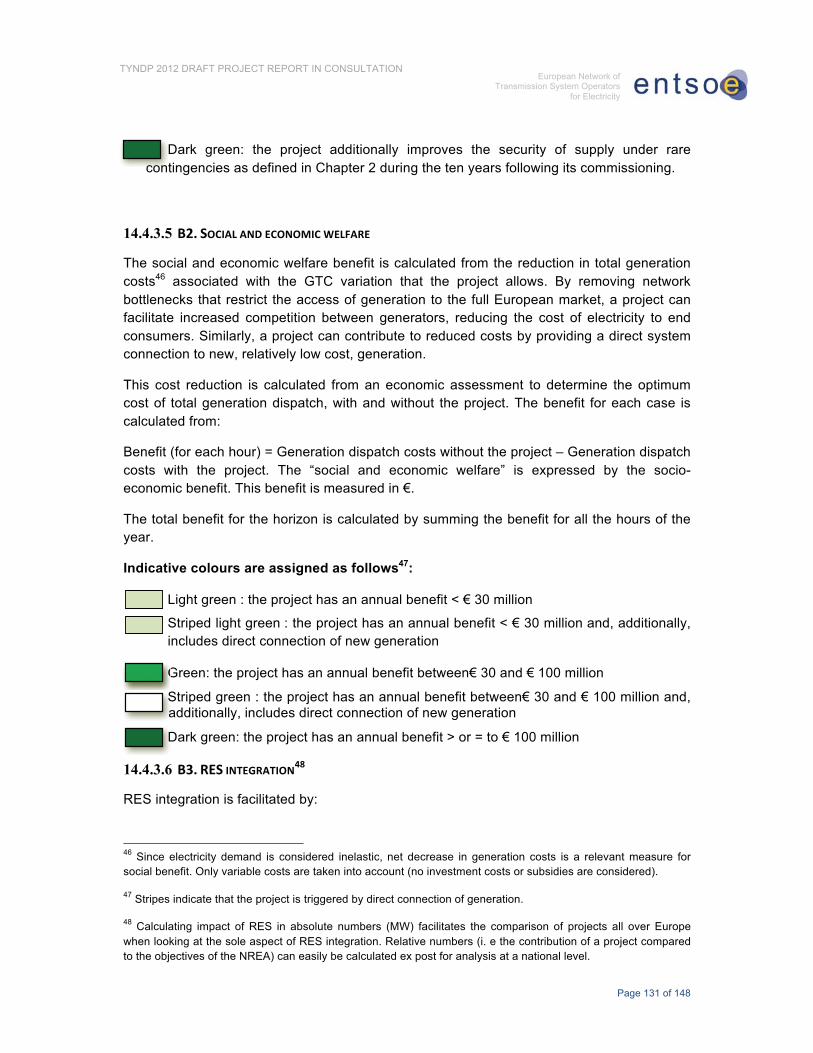
Page 131 of 148
TYNDP 2012 DRAFT PROJECT REPORT IN CONSULTATION European Network of
Transmission System Operators for Electricity
Dark green: the project additionally improves the security of supply under rare contingencies as defined in Chapter 2 during the ten years following its commissioning.
14.4.3.5 ���� ���������� � �����������
The social and economic welfare benefit is calculated from the reduction in total generation costs46 associated with the GTC variation that the project allows. By removing network bottlenecks that restrict the access of generation to the full European market, a project can facilitate increased competition between generators, reducing the cost of electricity to end consumers. Similarly, a project can contribute to reduced costs by providing a direct system connection to new, relatively low cost, generation.
This cost reduction is calculated from an economic assessment to determine the optimum cost of total generation dispatch, with and without the project. The benefit for each case is calculated from:
Benefit (for each hour) = Generation dispatch costs without the project – Generation dispatch costs with the project. The “social and economic welfare” is expressed by the socio-economic benefit. This benefit is measured in €.
The total benefit for the horizon is calculated by summing the benefit for all the hours of the year.
Indicative colours are assigned as follows47:
• Light green : the project has an annual benefit < € 30 million
Striped light green : the project has an annual benefit < € 30 million and, additionally, includes direct connection of new generation
• Green: the project has an annual benefit between€ 30 and € 100 million
• Striped green : the project has an annual benefit between€ 30 and € 100 million and, additionally, includes direct connection of new generation
• Dark green: the project has an annual benefit > or = to € 100 million
14.4.3.6 �������������� �����
RES integration is facilitated by:
46 Since electricity demand is considered inelastic, net decrease in generation costs is a relevant measure for social benefit. Only variable costs are taken into account (no investment costs or subsidies are considered).
47 Stripes indicate that the project is triggered by direct connection of generation.
48 Calculating impact of RES in absolute numbers (MW) facilitates the comparison of projects all over Europe when looking at the sole aspect of RES integration. Relative numbers (i. e the contribution of a project compared to the objectives of the NREA) can easily be calculated ex post for analysis at a national level.
conn
G•
••••• SSa
•••• D

Page 132 of 148
TYNDP 2012 DRAFT PROJECT REPORT IN CONSULTATION European Network of
Transmission System Operators for Electricity
1. Connection to the main system
2. Increasing the GTC between an area with excess of RES generation to share this with other areas in order to facilitate higher level of RES penetration
For point 1, RES integration is measured by amount of MW connected in a given area. For point 2, the border for calculating the GTC is to be placed in a way that divides an area with an excess of RES from an area where that RES generation can be consumed. The RES integration benefit is then calculated in MW through the calculation of the increase in GTC provided by a project.
The analysis process consists of taking two cases, one with and one without the project, and for each case increasing the renewable production in the excess generation area until the criteria of chapter 2 is not fulfilled. The RES benefit is calculated by the difference between the values of GTC obtained for both cases.
Market studies may also be used to calculate RES energy that is integrated in the model in the area with excess of RES, taking into account RES production time profiles.
Indicative colours are assigned as follows49:
• White: the project has a neutral effect on the capability of integrating RES
• Striped green: the project allows direct connection of less than 500 MW RES production
• Striped dark green: the project allows direct connection of more than 500 MW RES production
• Dark green: This project allows an increase of capacity between an area with excess of RES generation to share this with other areas50 (in order to facilitate at least 500 MW of RES penetration)
������� ����� �����;���������������<�
The energy efficiency benefit of a project is measured through the reduction of thermal losses (MW) in the system51. The losses in the system are quantified for each case, with and without the project. The total benefit is then calculated as the difference between both values. 49 Stripes indicate that the project is triggered by direct connection of generation.
50 Direct access can be also achieved incidentally.
51 It should be noted that an increase in losses means a higher utilisation of the grid, e.g due to additional cross border exchanges or RES infeed.
•• Spp
••• Spp
•• Doo

Page 133 of 148
TYNDP 2012 DRAFT PROJECT REPORT IN CONSULTATION European Network of
Transmission System Operators for Electricity
Indicative colors are assigned as follows:
• Red: the project contributes to increase the volume of losses on the grid
• White: the project may help decreasing losses in some situations and increasing them in others
• Light green: the project the project contributes to decrease the volume of losses on the grid
������� ����� ������ ���
"6� ����9���� ����������<� ��������������� ��6� ������ �7�������� �7��� ����� ��� ��������� ��������������6������7����5�������������������<������������9�������������7����������������������������
Furthermore, reinforcements may reduce losses in the grid, and thus reduce the amount of generation needed to cover demand. Calculation of CO2 variations is therefore a two-step approach, taking into account both the substitution effect and the effect on losses.
Indicative colors are assigned as follows:
• White: the project has no positive effect on CO2 emissions
• Green: the total of projects reduces CO2 emissions by < 500 kt/year
• Dark green: the total of projects reduces CO2 emissions by > 500 kt/year
�������������������8��������������������
.��5��������9�� �5����������� ���� ��������� �������������� �6����� �����6�������������������� �������������6������������5����������6������������������������+, �����������������������������9�����������������������������������
�
%���L� ����� ��� ���� +, (�� ��9��� ���7� ��6� ��� 5���� ��� ���� ��� ���� ����������� ��������� ��� ���������� ��������������6������������������9�������5���������������7����������� ���������������6�7�����������������������5�����5�����" ��
�
+, �������
��������MM-M-���
.��� ��� ����� ���� ��������������� ���� ����5���� ��������� 7����������������������5��������������������������
�
•
••• G
••••
D•

Page 134 of 148
TYNDP 2012 DRAFT PROJECT REPORT IN CONSULTATION European Network of
Transmission System Operators for Electricity
.��� �������� ���� ����������������� � ������6� ������ ���������� ���� �5�� �������������������������
�
.�����������������������������������9���������������������������5��������������������������
�
�
�
Indicative colors are assigned as follows:
• White: the score of KPI’s is 0
• Green: the score of KPI’s is < or = 3+
• Dark green: the score of KPI’s is > 3 +
���� �������8��������
.��5��������9���5����������������� �����6��������5��������������������������������6������������5����������6��������������������������������������������������9���������������������������������
� � � � � � � � � � �
+, �������
��������MM-M-���
.��� ��� ���6� 7���� �� ������� ���������� ��������������� �������9��������������������5��������5���������������5�����������5��������������������������
�
.��� ��� ���6� 7���� �� ������� ���������� ��������������� �������9��������������������5�����������������������5���������������������5�������������������
�
.��� ��� ���6� 7���� �� ������� ���������� ���������������� �������9�������������� ������ ��������5�� �������� ���� ��������� ���������������������5��������������������������
�
.����6���������6������������ �
.����6� ��� ���������� �������� ��� ��������� ���9����� ��� 7����� ����������������<�����5��������7�����6�������5��������
�
�
••

Page 135 of 148
TYNDP 2012 DRAFT PROJECT REPORT IN CONSULTATION European Network of
Transmission System Operators for Electricity
Indicative colors are assigned as follows:
• White: the score of KPI’s is 0
• Green: the score of KPI’s is < or = 5+
• Dark green: the score of KPI’s is > 5+
End note.
System development tools are continuingly evolving, and it is the intention that this document will be reviewed periodically in line with prudent planning practice and further editions of the TYNDP.
•

Page 136 of 148
TYNDP 2012 DRAFT PROJECT REPORT IN CONSULTATION European Network of
Transmission System Operators for Electricity
15 APPENDIX 4: SOCIAL ACCEPTANCE OF PROJECTS
15.1 BETTER STREAMLINED AUTHORIZATION PROCESSES FOR POWER
LINES WOULD SECURE EU ENERGY POLICY GOALS Effective electricity infrastructure is fundamental for guaranteeing EU security of energy supply. Ensuring the development of the grid is necessary to permit the achievement of the EU’s renewable energy and climate change objectives and for completing the internal energy market. These are challenges for the governments of all member states. As detailed in the TYNDP 2010 report, the development of electricity infrastructure is thus of crucial national and European importance to make Europe meet these challenges.
Yet, many electricity infrastructure projects face long and complex procedures in the authorization phase, across the different European countries. For the most part, these concerns arise irrespective of whether the developments are domestic or cross-border lines. The procedures for Extra High Voltage assets prove often longer and more complex than for any other infrastructure (roads, railways, gas-pipes).
Authorization processes for power lines must be streamlined so as to ensure both fulfillment of legal obligations as for other infrastructure and industrial facilities, and the timely commissioning of the transmissions assets which would help the EU meet their energy policy goals.
15.2 THE TYNDP 2010 SUMMED UP THE KEY CONCERNS REGARDING
SOCIAL ACCEPTANCE OF TRANSMISSION PROJECTS The TYNDP 2010 report explains all concerns with respect to long and complex, possibly redundant, and long authorization procedures for power lines, summed up hereafter:
• Unharmonised legislation between countries and even between regions within the same country;
• Lack of reasonable and concrete time limits for issuing the approvals;
• High number of approval agencies that share different interests;
• Balance between the necessity for grid development and environmental interests;
• Different permitting procedures for different technologies (e.g. line/ substations, OHL/Cable) esp. with respect to EIA;

Page 137 of 148
TYNDP 2012 DRAFT PROJECT REPORT IN CONSULTATION European Network of
Transmission System Operators for Electricity
• Lack of stakeholder (including political) support for projects;
• Lack of social acceptance of projects:
o Lack of public understanding with respect to the requirement for the project –consideration proposals are mere transit/commercial lines without public benefit;
o doubts about the project necessity, environmental impact, EMF, property devaluation;
o existence of alternative solutions even if are more expensive and technical complicated.
15.3 THE DRAFT ENERGY INFRASTRUCTURE PACKAGE SETS PROMISING
LEADS FOR IMPROVING SOCIAL ACCEPTANCE OF TRANSMISSION
PROJECTS ENTSO-E released the TYNDP 2010 early 2010 so as to raise concerns about the urgency to solve structural problems with respect to power grid development. In late 2010, the EC launched the drafting of new legislation to foster the development of key energy network assets. The so-called Energy Infrastructure Package, proposes in particular a whole range of measures to improve social acceptance of projects:
• Priority status for permit granting Projects of Common Interest at national level
• One competent national authority taking the final decision
• Clear time limits for decisions by competent Authority:
o pre application (max 2 years)
o statutory granting procedure (max 1 year)
• In the case of Substantive delays – a European Coordinator to be appointed
• Increase of transparency, efficiency and reduction of complexity.
• Member States within 9 months after decision to take measures to streamline decision-making process. Appointment CA within 6 months.
• Member States to provide joint procedures with respect to the environmental assessment.

Page 138 of 148
TYNDP 2012 DRAFT PROJECT REPORT IN CONSULTATION European Network of
Transmission System Operators for Electricity
ENTSO-E welcomes these proposals, as there are many positive elements in the permitting section which will facilitate the fast tracking of transmission infrastructure projects including the proposal on one stop shop and defined time lines.
More thorough analyses are however required so as to ensure the measure can be successfully implemented, in particular in relation to whether the timelines proposed are achievable particularly in the context of the public participation process and the potential for legal delays.
One must also notice that the supporting schemes are limited to the so-called Project of Common Interest (PCIs) whereas there are many significant national transmission projects which are crucial to the achievement of Europe’s targets for climate change, renewable and market integration.

Page 139 of 148
TYNDP 2012 DRAFT PROJECT REPORT IN CONSULTATION European Network of
Transmission System Operators for Electricity
16 APPENDIX 5: TECHNOLOGIES – OUTLOOK, PERSPECTIVES
16.1 INTRODUCTION As we can observe changes in electricity markets requirements, power demand shape, power sources distribution or other external constraints, Transmission System Operators need to anticipate their future needs and participate in an active way in the research and development of new technologies. For the same reasons, TSOs consider permanently the panel of available technologies and strive to make the best use of them, including technologies considered as unconventional rather than new, for their little use does not offer the very large experience shared on conventional technologies.
The technologies employed to date in the transmission grids are efficient, reliable, well engineered and are widely available techniques for transferring energy in high-voltage grids.
The evolution of technologies depends on several factors. As a matter of fact, documents such as the European “SmartGrids Vision” formulate a demand pull on technology, which is fully experienced by TSOs through their deep involvement in R&D projects. Liberalization of the European electricity market, massive integration of renewable generation in the system, as well as environmental, social and economic constraints, constitute the major drivers of this demand pull.
On the other hand, power industry offers a variety of new, emerging technologies for the evolution of power systems, as observed in many available studies and recently compiled by the “Realisegrid” European co-funded project.
Of course, the present appendix is not bound to give a comprehensive description of all the research done about grid operation and development. Moreover, as some projects are considered as demonstration projects rather than network development projects, they do not appear at the TYNDP level.
Therefore, the reader is invited to refer to the ENTSO-E R&D Plan, which describes a plan of around €560 million over ten years, split into €270 million for research and €290 million for demonstrations.
Priority research fields, which are included in the R&D plan and subsequently in R&D projects managed by ENTSO-E members – and therefore monitored by ENTSO-E – include the following:
• architecture and planning tools for the pan-European network,
• tools to prove the efficiency of technology aimed at increasing both the flexibility and the security of the operation of transmission systems,

Page 140 of 148
TYNDP 2012 DRAFT PROJECT REPORT IN CONSULTATION European Network of
Transmission System Operators for Electricity
• new tools based on simulation techniques that will give rise to new market design options.
In this respect, this appendix only presents a brief illustration of the researched fields, to illustrate how transmission projects presented in Chapter “Foreseen Investments on the European Grid” indeed take advantage of the best available technologies to meet present and future grid development challenges.
In the present selection of innovative and unconventional technologies, each technology has its own advantages and drawbacks, which have to be considered and assessed in the context of a given project. As ENTSO-E considers it very difficult and delicate to assess a technology in a global way and apart from given local needs and constraints, the current document does not provide any quantitative assessment or any comparison between examined technologies.
Indeed, each project is different and therefore inherits different levels of benefits from new technologies. Although some new technologies have been granted a lot of publicity, there is no universal solution for transmission networks so far.
Each project has to be studied with its own characteristics and assessment of the best fitted technologies.
16.2 OVERVIEW OF AVAILABLE OR PROMISING TECHNOLOGIES TODAY This section deals with novel techniques as well as with unconventional techniques, i.e. known technologies that have not been widely used for various reasons. Basically technologies can be sorted into four categories depending on their maturity:
• Some are mature, even though they might not be largely implemented, i.e. they have already proved their general applicability, have been fully developed, tested, their operation within the existing meshed grid proved reliable and introducing new items is not a technological challenge. DC connections between synchronous and asynchronous areas, Phase Shifting Transformers (PSTs) are examples of such mature technologies.
• Some are in large scale testing phase, i.e. they have been fully developed (laboratory devices work) but their insertion into the existing meshed grid is still being, or to be, tested, in order to check they can be reliably operated along with other equipments in all likely situations. For instance Real Time Thermal Rating (RTTR), low sag conductors reached this level of maturity.
• Some are in development phase, i.e. no feasibility questions remain, but some resources are needed to engineer some still missing brick (e.g. some operating IT, some kind of Flexible AC Transmission System – FACTS).

Page 141 of 148
TYNDP 2012 DRAFT PROJECT REPORT IN CONSULTATION European Network of
Transmission System Operators for Electricity
• Some are in research phase, i.e. some key-issue is not yet solved and hence feasibility is not demonstrated. Typically, distributed storage solutions are today no alternative solution to transmission grid development as their capability, regarding power as energy issues, is about 100 or 1000 times too small compared to transmission grid requirements. Implementation of superconductors and nanotechnologies is also still researched with no practical application yet.
This section presents an overview of selected new transmission technologies that have the potential for large scale integration in the transmission grid in Europe in the future.
16.2.1 TRANSMISSION LINES (OVERHEAD LINES AND CABLES) High Temperature Conductors (HTCs) are able to withstand higher operating temperatures, thus carrying higher amount of power compared to conventional conductors. However, as the losses depend on the square of transmitted current, operating at higher rates generates significantly more losses.
HTCs can enhance transmission capacity without impacting the negotiated right-of-way, ideally without modifications of transmission towers, but this is not always the case. Although existing lines are used, in some countries such projects have to go through the impact assessment procedure again, especially when expected currents are higher due to the increase of magnetic field level.
HTCs encompass a broad family of very different technologies in terms of potential for transmission capacity and investment costs level. This explains the diverging viewpoints observed between equipment manufacturers and TSOs: the appropriate selection of a conductor will follow an in-depth analysis of the power system including operational and climatic conditions, fatigue and safety issues as well as the overall investment costs. Gains in capacity can reach 30% for the most used HT Conductors, while transfer capacity could be more than doubled with some technical solutions such as composite type conductors.
HTC costs are generally higher (in some cases much higher) than conventional ACSR (Aluminium Conductor, Steel Reinforced) conductors. Investment cost figures need to be tuned by considering electrical losses, potential structure reinforcement, installation and maintenance costs. The assessment of performances over the whole life-time through a better understanding of reconductored lines (models, endurance testing and level of electrical losses) is essential to further extend HTC uses.
Among the studied technologies, High Temperature Superconducting (HTS) cables are the ones which are the farthest away from commercial applications. Some optimistic experts consider first applications of HTS by 2020 thanks to a second generation of materials (Yttrium Barium Copper Oxide, YBCO) and advanced deposition techniques, starting at distribution system level. However, the majority of manufacturers are much more prudent with regards to their use in transmission systems and do not consider any significant application at least before 2030. Costs and size of the cryogenic refrigeration units will
Page 142 of 148
TYNDP 2012 DRAFT PROJECT REPORT IN CONSULTATION European Network of
Transmission System Operators for Electricity
remain a major obstacle. Field tests experimentations within very specific situations (short distance, dense urban area, DC applications) will contribute to the further development of the HTS technology blocks.
Illustration: illustrating the above mentioned difficulties, the choice of HTC has been made for only two projects of the TYNDP: the 260 km long 400 kV overhead line between France and Italy, and the ongoing upgrade of a 220 kV line in Poland.
The High Voltage Direct Current (HVDC) technology has proven its reliability and attractiveness for long distance power transmission, long submarine cable links and interconnection of asynchronous systems. Converters to convert current from AC to DC and DC to AC are critical.
The most recent technology, self-commutated Voltage Source Converter (VSC), is more flexible than the more conventional line-commutated Current Source Converter (CSC) since it allows controlling active and reactive power independently.
HVDC key benefits are in terms of increased transmission capacity compared to conventional HVAC for the same asset size, and power flow controllability, which in turn can enhance the stability of the link and of its surrounding environment.
Although the investment costs of a VSC-HVDC converter station are higher than those of an AC substation, the overall investment costs of a DC transmission link can be lower than those ones of a corresponding AC interconnection if a certain transmission distance is reached (i.e. “break-even” distance). This break-even distance strongly depends on the specific project parameters: it is typically between 80 and 120 km for offshore submarine cable connections; while for onshore applications, the break-even distance between an AC and DC OHL is usually in the order of 700 km. Nevertheless, other constraints have then to be taken into account.
Typical applications of VSC-HVDC include the active control of flows, interconnection of offshore wind farms, black start functionalities and multi-terminal DC applications. This technology is a key component of future European grid architectures, as we already can observe in the TYNDP.
Meshed DC systems could appear with the advent of commercial DC breakers.
Illustration: around 45 HVDC projects representing some 10 000 km of lines (up to 800 km for the UK –NO interconnector), mostly undersea and located in north, west, central and south Europe, are described in the TYNDP 2012. Nevertheless, some cables are to be installed onshore, e.g. in France between Haute Normandie and the south of Paris.
Real-Time Thermal Rating (RTTR) – monitored cables/overhead lines, or Dynamic Line Rating –, are on their way to become a mature technology based on the real time control of

Page 143 of 148
TYNDP 2012 DRAFT PROJECT REPORT IN CONSULTATION European Network of
Transmission System Operators for Electricity
thermal rating of an overhead line or a cable. It aims at maximizing the capability of a transmission line/cable while respecting design margins, thus reducing potential congestion problems. Its further development will be facilitated by solving some practical integration challenges: integration with other tools, interoperability with protection equipment settings, coordination of RTTR monitored links, communication with SCADA and use of RTTR output values at a dispatch level.
Combined uses of RTTR measurements with weather forecast might significantly increase the value of RTTR for network operations: it could become an interesting option for TSOs to achieve higher transmission capacity ratings safely and reliably for existing systems, at relatively low investment costs (when compared to the investment needed for new transmission links). The challenge here consists in developing more reliable and precise wind forecasts.
Illustration: Real-Time Thermal Rating Projects do not explicitly appear as such in the TYNDP list, for they are not considered by TSOs as necessarily directly related to the development of the European transmission grid.
Underground and submarine XLPE (Cross-Linked Poly-Ethene) cables present a good potential for transmission. Such cables for HVDC applications are more and more used. For HVAC XLPE cables, however, notwithstanding the recent technological progress, the further deployment and consequent cost reduction, the cost barrier (when compared to conventional solutions) is still high and expected to remain so due to the intrinsic higher complexity and installation constraints of this technology.
Yet, the cost barrier might be reduced when all types of benefits stemming from this technology are considered, such as the consideration of losses during the whole life-time, authorization procedures duration in some countries, visual impacts, etc.
Nevertheless, these underground assets represent a specific risk for operation that has to be carefully analysed: on the one hand this technology is less exposed to external events, but on the other hand causes long outages when damaged.
Illustration: some above mentioned HVDC projects consider the use or will use XLPE cables.
Gas Insulated Line (GIL) is a proven, yet not widespread, technology mostly used in short length installations (exploiting tunnels, bridges, or other existing infrastructures). It allows carrying a much higher amount of power through a single line than conventional solutions and XLPE cables. Yet, it faces strong environmental concerns in terms of SF6 emissions, which are more than 20 000 times more harmful than CO2 emissions, with a cost ratio over conventional solutions that remains high. GIL deployment is likely to continue within niche applications valorizing existing nonelectrical infrastructures: much will also depend on the successful implementation of GILs in planned projects at European level (like it is discussed for the Brenner tunnel).

Page 144 of 148
TYNDP 2012 DRAFT PROJECT REPORT IN CONSULTATION European Network of
Transmission System Operators for Electricity
Illustration: pilot project in the Brenner Tunnel between Italy and Austria being currently under consideration, constituted of a 65 km long double circuit 400 kV Gas Insulated Line.
16.2.2 SUBSTATIONS Phase Shifting Transformers (PSTs) are a mature technology, implemented by TSOs in Europe to control active power through preventive or curative strategies. PSTs do not increase the capacity of the line themselves; but in case some lines are overloaded while capacity is still available on others parallel to them, then optimizing the transits with PSTs can increase the overall grid capacity. In the future, the focus will be on enabling issues: the development of shared PST models by TSOs and standards should facilitate PST integration in transmission systems. In parallel, the development of cross-border power trade and the integration of renewable generation will increase the need for such a technology, possibly operated by power electronics and enhanced by coordinated control protocols implemented within inter-TSO coordination centers.
Illustration: a dozen of Phase Shifting Transformers are to be installed in Europe in the coming ten years, like in Zandvliet (4th PST on the Belgian north border).
Fault Current Limiters (FCLs) comprise technologies with different degrees of maturity. When addressing novel concepts (High Temperature Superconducting FCL, solid-state FCL, hybrid FCL), technology challenges still remain to be faced before a commercial exploitation (especially for High Temperature Superconducting FCL). The implementation of joint testing facilities by TSOs at EU level would help converging on design types and materials, cost reduction and standards and might speed-up the technology take-up in some niche applications in Europe.
Illustration: such a technology is considered as a possible help in operations, but does not appear as full part of the TYNDP list of investments.
Flexible Alternating Current Transmission System (FACTS) equipment is a family of power electronics-based devices able to enhance AC system controllability and stability and to increase power transfer capability. FACTS are naturally compared by TSOs with mechanical driven equipment providing controllability features, such as Phase Shifting Transformers (a simpler, more robust, reliable and generally less costly solution, but with limited dynamic capabilities).
FACTS devices can be classified according to their shunt, series or combined types of connection. Shunt type devices present relevant features for reactive power compensation and voltage control, while series devices offer key advantages for active power flow control and transient stability enhancement.

Page 145 of 148
TYNDP 2012 DRAFT PROJECT REPORT IN CONSULTATION European Network of
Transmission System Operators for Electricity
Costs, complexity and reliability issues represent nowadays the main barriers to the integration of these promising technologies from the TSOs’ perspective. Up to present, shunt devices (like the SVC, Static VAR Compensator) have been the most widespread and mature FACTS technologies. Further FACTS penetration will depend on the technology providers’ ability to overcome these barriers, thanks to more standardization, interoperability and economies of scale.
Key technology challenges are in terms of power electronic topologies and exploration of new types of semiconductors replacing silicon. More user-friendly interfaces and proof of performance through field testing will contribute to improve TSOs’ confidence in these new technologies. Like other active equipments (HVDC (VSC) and PST), FACTS will be crucial for the future integration of RES into the European system, while delivering full benefits when subject to a coordinated control, in combination with Wide Area Measurement Systems (WAMS).
Illustration: such a technology is considered as a possible help in operations, but does not appear specifically under this name in the TYNDP list of investments. Nevertheless, some TYNDP projects involving banks of capacitors include SVC.
16.2.3 OPERATING STRATEGIES Wide Area Monitoring System (WAMS) is an information platform with monitoring purposes. Based on Phasor Measurements Units (PMUs), WAMS allow monitoring transmission system conditions over large areas in view of detecting and further counteracting grid instabilities. This early warning system contributes to increase system reliability by avoiding the spreading of large area disturbances, and optimizing the use of assets. Yet, some critical R&D challenges lie in signal accuracy and reliability, communication architectures and data processing.
Standards for data processing, large scale demonstrations, possibly in combination with other active equipment, will be needed to estimate benefits brought by WAMS.
Illustration: such a technology is considered as a possible help in operations, but does not appear as full part of the TYNDP list of investments.
Electric Storage: although not generally operated by TSOs, electricity storage solutions could have a significant impact on transmission planning and operations. Storage solutions (centralized ones like hydro pumping e.g. or decentralized ones like batteries in cars, if and when electric cars will be deployed massively) can provide TSOs with new options to cope with variable power flows.
Storage could help maximizing electricity system stability in case of any sudden drop/surge due to the variability of most RES generation plants. It could also support CO2 emissions

Page 146 of 148
TYNDP 2012 DRAFT PROJECT REPORT IN CONSULTATION European Network of
Transmission System Operators for Electricity
abatement targets either during off-peak periods, by avoiding electricity spillage, or during peak periods in the case of a generation mix that is highly fossil fuel dependent.
Historically, storage is related to technologies like Pumped Hydro and Compressed Air Energy Storage, whereas other storage technologies are not clearly addressing large scale system issues. Yet, there are still technical and mostly regulatory issues to be faced. In terms of regulatory issues, open questions are related to which players (private market operators contributing to system optimization or regulated operators) shall own and manage storage facilities. Implementing large scale demonstrations of storage solutions at European level appears to be a necessary step to validate both storage benefits based on full scale studies and the potential asset ownership options for storage regulations.
Illustration: as for now, there are around 15 projects among Europe, which are limited to the connection of hydro pump power plants, mainly in Switzerland, Austria, Romania, Spain and Portugal. As for storage demonstration projects, the TWENTIES project involving several ENTSO-E members, responding to the ENERGY 2009.7.1.1 call (optimization of the electricity grid with large-scale renewables and storage) can be quoted, as well as the Almacena project in Spain.
16.3 CONCLUSION As already mentioned, European TSO’s are supporting the development of the above mentioned new technologies by testing new products supplied by manufacturers, testing new technologies, influencing thus the improvement of the most relevant technologies. In fact TSOs are frontrunners in all these advances in new technologies, while carefully choosing the most promising ones.
Some of the technologies are still in a premature state and a large scale integration of these technologies in the transmission grid is not possible due to reliability constraints. As the TSO’s have the responsibility for the whole electrical system in their control zone, precaution is needed with respect to the introduction of new technologies.
As a matter of fact, none of the examined technology is a universal solution. Each project has to be considered in a dedicated study assessing the best fitting technologies.
For that reason, some technologies play a real role in the European TSOs’ transmission projects in the next ten years, and some other technologies do not appear yet, for their level of maturity and reliability are not satisfying yet within this timeframe.
Moreover, as some projects are considered as demonstrations rather than network development projects, they do not appear at the TYNDP level. The ENTSO-E R&D Plan is providing a larger and exhaustive approach of projects involving new technologies, and for that reason, the reader is invited to refer to this document in order to get more detailed information regarding new technologies.

Page 147 of 148
TYNDP 2012 DRAFT PROJECT REPORT IN CONSULTATION European Network of
Transmission System Operators for Electricity
17 APPENDIX 6: IMPORT CAPACITY COMPARED TO NET
GENERATING CAPACITY The European Council52 has proposed a very simple criterion for interconnection development, asking from every Member States a minimum import capacity level equivalent to 10% of its installed production. The result is depicted below.
10% to 15%
5% to 10%
> 15%
<5%
FIGURE 45: IMPORT CAPACITY/NET GENERATION CAPACITY IN 2011
The above map shows that Island systems or electricity quasi-Island systems (Ireland and UK, Iberian peninsula) but also Poland show the lowest import -generation ratios. France and Italy are slightly under the 10% threshold and Germany, Romania, Bulgaria and Greece slightly above. All other countries display index levels greater than 15%. This shows both the power and the limits of the indicator: every Baltic state for instance display a high index level. As they are mutually interconnected, assessing the indicator for all three of them, and towards EU countries, would lead to a mere 4%. 52 ,��������6�!���5�����<�"���������5������!�5���<��������� �)����������

Page 148 of 148
TYNDP 2012 DRAFT PROJECT REPORT IN CONSULTATION European Network of
Transmission System Operators for Electricity
The criterion computed for the present situation can be reassessed after a projection in 2020, assuming all projects of pan-E significance implemented. The result is depicted below:
10% to 15%
5% to 10%
> 15%
<5%
FIGURE 46: IMPORT CAPACITY/NET GENERATION CAPACITY IN 2020
Poland, Great-Britain, Italy, Portugal and France reach the 10% target threshold by 2020 once projects of pan-European significance are implemented. Despite its interconnection capacity is multiplied by about 4, Spain still show a 4%, below the target threshold.
Copyright © 2022 FDOKUMEN