EntraPass Installer Guide - Kantech
454
DN1420-1003 / Version 4.03 Reference Manual
-
Upload
khangminh22 -
Category
Documents
-
view
6 -
download
0
Transcript of EntraPass Installer Guide - Kantech

Reference Manual
DN1420-1003 / Version 4.03

Copyright © 2010 Tyco International Ltd. and its Respective Companies. All Rights Reserved. All specifications were current as of publication date and are subject to change without notice. EntraPass, Kantech and the Kantech logo are trademarks of Tyco International Ltd. and its Respective Companies.

Reference Manual
TYCO INTERNATIONAL LTDEND-USER LICENSE AGREEMENT
FOR KANTECH Software Provided With or Without Products or Components
IMPORTANT - READ CAREFULLYKANTECH Software purchased with or without Products and Components is copyrighted and is purchasedunder the following license terms:
• This End-User License Agreement (“EULA”) is a legal agreement between You (the company, individual or entity who acquired the Software and any related Hardware) and KANTECH, the manufacturer of the integrated secu-rity systems and the developer of the software and any related products or components (“HARDWARE”) which You acquired.
• If the KANTECH software product (“SOFTWARE PRODUCT” or “SOFTWARE”) is intended to be accompanied by HARDWARE, and is NOT accompanied by new HARDWARE, You may not use, copy or install the SOFT-WARE PRODUCT. The SOFTWARE PRODUCT includes computer software, and may include associated media, printed materials, and “online” or electronic documentation.
• Any software provided along with the SOFTWARE PRODUCT that is associated with a separate end-user license agreement is licensed to You under the terms of that license agreement.
• By installing, copying, downloading, storing, accessing or otherwise using the SOFTWARE PRODUCT, You agree unconditionally to be bound by the terms of this EULA, even if this EULA is deemed to be a modification of any previous arrangement or contract. If You do not agree to the terms of this EULA, KANTECH is unwilling to license the SOFTWARE PRODUCT to You, and You have no right to use it.
SOFTWARE PRODUCT LICENSEThe SOFTWARE PRODUCT is protected by copyright laws and international copyright treaties, as well asother intellectual property laws and treaties. The SOFTWARE PRODUCT is licensed, not sold.
1 GRANT OF LICENSE - This EULA grants You the following rights:a Software Installation and Use - For each license You acquire, You may have only one copy of the SOFT-
WARE PRODUCT installed. b Storage/Network Use - The SOFTWARE PRODUCT may not be installed, accessed, displayed, run,
shared or used concurrently on or from different computers, including a workstation, terminal or other digital electronic device (“Device”). In other words, if You have several workstations, You will have to acquire a license for each workstation where the SOFTWARE will be used.
c Backup Copy - You may make back-up copies of the SOFTWARE PRODUCT, but You may only have one copy per license installed at any given time. You may use the back-up copy solely for archival purposes. Except as expressly provided in this EULA, You may not otherwise make copies of the SOFTWARE PRODUCT, including the printed materials accompanying the SOFTWARE.
2 DESCRIPTION OF OTHER RIGHTS AND LIMITATIONSa Limitations on Reverse Engineering, Decompilation and Disassembly - You may not reverse engineer,
decompile, or disassemble the SOFTWARE PRODUCT, except and only to the extent that such activity is expressly permitted by applicable law notwithstanding this limitation. You may not make any changes or modifications to the Software, without the written permission of an officer of KANTECH. You may not remove any proprietary notices, marks or labels from the Software Product. You shall institute reasonable measures to ensure compliance with the terms and conditions of this EULA.
iii

Reference Manual
b Separation of Components - The SOFTWARE PRODUCT is licensed as a single product. Its component parts may not be separated for use on more than one HARDWARE unit.
c Single INTEGRATED PRODUCT - If You acquired this SOFTWARE with HARDWARE, then the SOFT-WARE PRODUCT is licensed with the HARDWARE as a single integrated product. In this case, the SOFT-WARE PRODUCT may only be used with the HARDWARE as set forth in this EULA.
d Rental - You may not rent, lease or lend the SOFTWARE PRODUCT. You may not make it available to oth-ers or post it on a server or web site.
e Software Product Transfer - You may transfer all of Your rights under this EULA only as part of a permanent sale or transfer of the HARDWARE, provided You retain no copies, You transfer all of the SOFTWARE PRODUCT (including all component parts, the media and printed materials, any upgrades and this EULA), and provided the recipient agrees to the terms of this EULA. If the SOFTWARE PRODUCT is an upgrade, any transfer must also include all prior versions of the SOFTWARE PRODUCT
f Termination - Without prejudice to any other rights, KANTECH may terminate this EULA if You fail to com-ply with the terms and conditions of this EULA. In such event, You must destroy all copies of the SOFT-WARE PRODUCT and all of its component parts.
g Trademarks - This EULA does not grant You any rights in connection with any trademarks or service marks of KANTECH or its suppliers.
3 COPYRIGHT
All title and intellectual property rights in and to the SOFTWARE PRODUCT (including but not limited to anyimages, photographs, and text incorporated into the SOFTWARE PRODUCT), the accompanying printedmaterials, and any copies of the SOFTWARE PRODUCT, are owned by KANTECH or its suppliers. You maynot copy the printed materials accompanying the SOFTWARE PRODUCT. All title and intellectual propertyrights in and to the content, which may be accessed through use of the SOFTWARE PRODUCT, are the prop-erty of the respective content owner and may be protected by applicable copyright or other intellectual prop-erty laws and treaties. This EULA grants You no rights to use such content. All rights not expressly grantedunder this EULA are reserved by KANTECH and its suppliers.
4 EXPORT RESTRICTIONS
You agree that You will not export or re-export the SOFTWARE PRODUCT to any country, person, or entitysubject to US export restrictions.
5 CHOICE OF LAW
This Software License Agreement is governed by the laws of the State of New York.
6 LIMITED WARRANTYa NO WARRANTY
KANTECH PROVIDES THE SOFTWARE “AS IS” WITHOUT WARRANTY. KANTECH DOES NOT WAR-RANT THAT THE SOFTWARE WILL MEET YOUR REQUIREMENTS OR THAT OPERATION OF THESOFTWARE WILL BE UNINTERRUPTED OR ERROR-FREE.
b CHANGES IN OPERATING ENVIRONMENTKANTECH shall not be responsible for problems caused by changes in the operating characteristics of theHARDWARE, or for problems in the interaction of the SOFTWARE PRODUCT with non-KANTECH SOFT-WARE or HARDWARE PRODUCTS.
c LIMITATION OF LIABILITY; WARRANTY REFLECTS ALLOCATION OF RISK IN ANY EVENT, IF ANY STATUTE IMPLIES WARRANTIES OR CONDITIONS NOT D IN THIS LICENSEAGREEMENT, KANTECH'S ENTIRE LIABILITY UNDER ANY PROVISION OF THIS LICENSE AGREE-MENT SHALL BE LIMITED TO THE GREATER OF THE AMOUNT ACTUALLY PAID BY YOU TOLICENSE THE SOFTWARE PRODUCT AND FIVE US DOLLARS (USD$5.00). BECAUSE SOME JURIS-DICTIONS DO NOT ALLOW THE EXCLUSION OR LIMITATION OF LIABILITY FOR CONSEQUENTIAL
iv

Reference Manual
OR INCIDENTAL DAMAGES, THE ABOVE LIMITATION MAY NOT APPLY TO YOU.d DISCLAIMER OF WARRANTIES
THIS WARRANTY CONTAINS THE ENTIRE WARRANTY AND SHALL BE IN LIEU OF ANY AND ALLOTHER WARRANTIES, WHETHER EXPRESSED OR IMPLIED (INCLUDING ALL IMPLIED WARRAN-TIES OF MERCHANTABILITY OR FITNESS FOR A PARTICULAR PURPOSE) AND OF ALL OTHEROBLIGATIONS OR LIABILITIES ON THE PART OF KANTECH. KANTECH MAKES NO OTHER WAR-RANTIES. KANTECH NEITHER ASSUMES NOR AUTHORIZES ANY OTHER PERSON PURPORTINGTO ACT ON ITS BEHALF TO MODIFY OR TO CHANGE THIS WARRANTY, NOR TO ASSUME FOR ITANY OTHER WARRANTY OR LIABILITY CONCERNING THIS SOFTWARE PRODUCT.
e EXCLUSIVE REMEDY AND LIMITATION OF WARRANTYUNDER NO CIRCUMSTANCES SHALL KANTECH BE LIABLE FOR ANY SPECIAL, INCIDENTAL, CON-SEQUENTIAL OR INDIRECT DAMAGES BASED UPON BREACH OF WARRANTY, BREACH OF CON-TRACT, NEGLIGENCE, STRICT LIABILITY, OR ANY OTHER LEGAL THEORY. SUCH DAMAGESINCLUDE, BUT ARE NOT LIMITED TO, LOSS OF PROFITS, LOSS OF THE SOFTWARE PRODUCT ORANY ASSOCIATED EQUIPMENT, COST OF CAPITAL, COST OF SUBSTITUTE OR REPLACEMENTEQUIPMENT, FACILITIES OR SERVICES, DOWN TIME, PURCHASERS TIME, THE CLAIMS OF THIRDPARTIES, INCLUDING CUSTOMERS, AND INJURY TO PROPERTY.
WARNING: KANTECH recommends that the entire system be completely tested on a regular basis. However,despite frequent testing, and due to, but not limited to, criminal tampering or electrical disruption, it is possi-ble for this SOFTWARE PRODUCT to fail to perform as expected.
v

Reference Manual
vi

Reference Manual
Table of ContentsChapter 1 •Introduction .................................................................... 1EntraPass Main Features ........................................................................ 2EntraPass Manual and Help .................................................................... 4
Using the Reference Manual .............................................................................. 4Getting Help ...................................................................................................... 4Technical Support ............................................................................................. 5
System Architecture ................................................................................ 6
Chapter 2 •Software Installation ...................................................... 7Recommended System Requirements ..................................................... 8
Additional Requirements .................................................................................... 8Installation Kit ......................................................................................... 9InstallShield Wizard .............................................................................. 10
Installing EntraPass (New Installation) ............................................................. 10System Installation ............................................................................... 11
Adding System Components ............................................................................ 19Upgrading EntraPass ....................................................................................... 21
Updating EntraPass .............................................................................. 23Before Updating EntraPass .............................................................................. 23Updating EntraPass ......................................................................................... 23
Removing EntraPass ............................................................................. 27
Chapter 3 •Getting Started ............................................................. 29Session Start and End ........................................................................... 30
Starting the EntraPass Workstation .................................................................. 30Accessing Information on the Server Workstation Connection Status ................. 32Modifying your Work Area Properties ............................................................... 32
Express Setup ....................................................................................... 33System Stand-Alone Utilities ................................................................ 34EntraPass Toolbars ............................................................................... 35Basic Functions .................................................................................... 38
Finding Components ........................................................................................ 38Using the Extended Selection Box .................................................................... 40Selecting Components ..................................................................................... 41
Selecting a Specific Folder ........................................................................... 42Selecting a Specific Site .............................................................................. 43
Printing a List or a Report ................................................................................ 43Displaying Components Links .......................................................................... 44Floating Windows ............................................................................................ 45
Chapter 4 •System Devices ............................................................ 47The Devices Toolbar ........................................................................................ 47
EntraPass Applications Configuration .................................................. 48Configuring an EntraPass Application ............................................................... 48
Defining General Parameters ....................................................................... 48Defining Security Parameters ....................................................................... 49Defining Workspaces ................................................................................... 50Defining Message Controls ........................................................................... 51Defining Alarm Controls ............................................................................... 52
vii

Reference Manual
Defining Email Report Options ...................................................................... 53Defining Host Modem and Keypad Delays ..................................................... 54
Sites Configuration .............................................................................. 56Setting up Communication Timing .....................................................................57Configuring a Direct RS-232 Connection Type ..................................................58Configuring an IP Device Connection Type .......................................................59Configuring an Ethernet Polling Connection Type ..............................................61Configuring a Dial-Up (RS-232) Modem Connection Type ..................................62
Controllers Configuration ..................................................................... 65KT-400 Ethernet Four-Door Controller ..............................................................65
Main Features .............................................................................................. 65Configuring General Parameters for Kantech Controllers ...................................66Configuring the KT-100 Controller ....................................................................70Configuring the KT-200 Controller ....................................................................71
Defining KT-200 Expansion Devices .............................................................. 71Defining KT-200 Auxiliary Devices ................................................................ 72
Programming KT-2252 Elevator Controllers .......................................................72Programming REB-8 Elevator Controllers ..........................................................74
Defining REB-8 Relays ................................................................................. 75Configuring the KT-300 Controller ....................................................................76Configuring the KT-300 Combus Modules .........................................................77Configuring the KT-400 Ethernet Four-Door Controller ......................................79
Configuring the KT-400 Expansion Modules .................................................. 81Configuring the Status Relay Activations ....................................................... 86
Defining Controller Options ..............................................................................87Defining the KT-400 Controller Local Areas .......................................................88Defining the KT-400 Elevator Floor Associations ...............................................89
Associating Pattern with Door and Floor Numbers ......................................... 89Controller Event Buffer Overflow Message ........................................................90
Kantech Telephone Entry System (KTES) Configuration ...................... 91Defining General Parameters for the KTES .......................................................91Defining the Kantech Telephone Entry System parameters ................................93Defining the Language and Welcome Message Parameters ...............................95
Special Characters ....................................................................................... 95Defining the Options Parameters ......................................................................97Defining the Status Relay Parameters ...............................................................98Defining the Pager Options ..............................................................................99Configuring Tenant Administration Level Parameters ....................................... 101
Doors Configuration ............................................................................ 102Defining General Parameters for a Door ......................................................... 102Defining Door Keypad Options ........................................................................ 104
For KT-100 and KT-300 Controllers ............................................................. 104For KT-400 Controllers ............................................................................... 104
Defining Door Contact Options ....................................................................... 106Defining REX (Request to Exit) Options .......................................................... 107Defining Interlock Options (Mantrap) ............................................................... 108Defining Elevator Doors ................................................................................. 109Configuring Door Events ................................................................................ 110Defining Door Options for Controllers and the KTES ........................................ 113Configuring External Alarm System Interfaces ................................................. 114
Relay Configuration ............................................................................ 118Defining Relays ............................................................................................. 118
Input Configuration ............................................................................. 119Defining Input ................................................................................................ 119Defining Relays and Inputs ............................................................................. 121Defining Tamper and Trouble ......................................................................... 122
viii

Reference Manual
Defining an Input for an Elevator Door ............................................................ 123Enabling Remote Event Reporting .................................................................. 124
Output Device Configuration ...............................................................125Defining General Options for an Output .......................................................... 125Associating Events with Auxiliary Outputs ...................................................... 126
Integrated Panel Configuration ............................................................128Minimum Requirements to View and Use the Integration Buttons ................. 128The Integration process is divided in three sections: ................................... 128
Integrated Component Configuration ...................................................132
Chapter 5 •Definitions .................................................................. 133The Definition Toolbar ................................................................................... 133
Schedules Definition ............................................................................134Defining a Schedule ...................................................................................... 134
To Create a 2-day Continuous Interval ........................................................ 135Floors Definition ..................................................................................137Graphics Definition ..............................................................................138
Defining Components of a Graphic ................................................................. 138Designing the Background for the Graphic Window ......................................... 140Assigning System Components to Graphic Icons ............................................ 142Printing System Components and Graphics .................................................... 143
Holiday Definition ................................................................................146
Chapter 6 •Operations .................................................................. 149The Operation Toolbar ................................................................................... 149The Operation Dialogs ................................................................................... 149The Operations Contextual Menu ................................................................... 150The Component Status Dialog ........................................................................ 150
Manual Data Reload .............................................................................152Manual Operations on Sites .................................................................153
Performing Manual Operations on a Site ........................................................ 154Manual Operations on Controllers .......................................................155
Selecting a Controller .................................................................................... 156Performing a Controller Soft Reset ................................................................. 156Performing a Controller Hard Reset ................................................................ 156Reloading a Controller Manually ..................................................................... 157
Resetting Cards In Counters or all Controller local areas ............................. 157Calculating Number of Cards In ...................................................................... 157
Resetting Cards In Counters or all Controller local areas ............................. 157Manual Operations on Doors ...............................................................158
Selecting a Door or a Door Group .................................................................. 159Locking a Door Manually ................................................................................ 159Unlocking a Door Manually ............................................................................ 159Unlocking a Door Temporarily ........................................................................ 160Resetting a Door Schedule ............................................................................ 160Enabling a Door Reader ................................................................................. 160Disabling a Door Reader ................................................................................ 160
Manual Operations on Elevator Doors .................................................161Selecting an Elevator Door ............................................................................ 162Locking Floors from Elevator Doors ................................................................ 162Unlocking Floors from Elevator Doors ............................................................ 162Unlocking Floors from Elevator Doors Temporarily .......................................... 163Resetting an Elevator Door Schedule ............................................................. 163
ix

Reference Manual
Enabling an Elevator Floor ............................................................................. 163Disabling an Elevator Floor ............................................................................ 163
Manual Operations on Relays ............................................................. 164Selecting Relays ............................................................................................ 164Deactivating a Relay Manually ........................................................................ 165 Activating a Relay Manually .......................................................................... 165Activating a Relay Temporarily ....................................................................... 165Resetting a Relay Schedule ........................................................................... 165
Manual Operations on Inputs .............................................................. 167Performing Manual Operations on Inputs ........................................................ 167Returning an Input to Its Normal State Manually .............................................. 168Stopping Monitoring an Input .......................................................................... 168Stopping Input Supervision (Shunt) Temporarily .............................................. 168
Manual Operations on View Roll Call .................................................. 169Manual Operations on Integrated Panels ............................................ 170
Chapter 7 •Users........................................................................... 173The Users Toolbar ......................................................................................... 173
Cards Definition .................................................................................. 174Issuing a New Card ........................................................................................ 174Issuing a New Card in Enhanced User Management Environment .................... 175Creating New Cards Using the “Save As” Feature ........................................... 176Issuing Cards Using the “Batch Load” Feature ................................................ 177Viewing and Verifying PINs ............................................................................ 177
Viewing Cards Assigned the Same PIN ....................................................... 177Card Handling ..................................................................................... 178
Editing a Card ................................................................................................ 178Finding a Card ............................................................................................... 178Deleting a Card .............................................................................................. 178Customizing Card Information Fields .............................................................. 178
Cardholder Access Levels Assignation .............................................. 180Assigning an Access Level to a Cardholder ..................................................... 180
Card Options Definition ....................................................................... 181Adding Comments to a Card ........................................................................... 182Assigning Pictures and Signatures .................................................................. 182
Assigning a Picture from a File ................................................................... 183Assigning a Picture Using a Video Camera .................................................. 183
Importing a signature from a file ..................................................................... 185Adding a Signature from a Signature Capture Device ...................................... 186Working with Photos and Signatures ............................................................... 187
Extracting Part of an Image ........................................................................ 187Editing a Picture/Signature ......................................................................... 189
Printing Badges ............................................................................................. 190Selecting a Badge Printer ........................................................................... 190Previewing and Printing Badges .................................................................. 191
Badges Designing ............................................................................... 193Creating a Badge Template ............................................................................ 193
To Specify Properties for a Badge Layout .................................................... 193To Edit a Badge Layout .............................................................................. 194To Modify the Number of Card Sides ........................................................... 195To Modify the Background Color ................................................................. 196To Add Objects to a Badge Layout .............................................................. 197To Incorporate Card Information Fields ....................................................... 197To Align Objects in the Template Layout ..................................................... 199
x

Reference Manual
To Modify Card Fields Properties ................................................................ 199To Modify Picture Properties ...................................................................... 201To Add Static Text Objects ......................................................................... 202To Add Bar Codes ..................................................................................... 203To Set Up Barcode Properties .................................................................... 204To Add the Current Date ............................................................................ 204To Add an Image ....................................................................................... 206To Place Other Design Objects ................................................................... 208To Place a Rectangle ................................................................................. 208
Validating Card Access .................................................................................. 209Cards Printing ......................................................................................211
Printing Cards ............................................................................................... 211Last Transactions Display ....................................................................214
Viewing the Last Transaction ......................................................................... 214Card Access Groups Definition ............................................................216Access Levels Definition ......................................................................217CSV Files Import and Export ................................................................218
Using a Predefined Pattern ............................................................................ 218Creating a New Import/Export Pattern ............................................................ 219Exporting Cards ............................................................................................ 221Importing Cards ............................................................................................. 223Correcting Import/Export Errors ...................................................................... 224
Tenants List .........................................................................................227Creating a New Tenants List .......................................................................... 227Adding New Tenants to the List ...................................................................... 227Importing a Tenant List .................................................................................. 229Exporting a Tenant List .................................................................................. 231
Chapter 8 •Groups ........................................................................ 233Controller Group Creation ....................................................................234Door Group Creation ............................................................................235Relay Group Creation ...........................................................................236Input Group Creation ...........................................................................237Access Level Groups Grouping ...........................................................238Floor Group Creation ...........................................................................239
Chapter 9 •System Status............................................................. 241Text Status ...........................................................................................242
Displaying a Component Status ..................................................................... 242Numerical Status ..................................................................................244Graphic Status .....................................................................................245
Viewing a Controller Status ............................................................................ 245Database Status ...................................................................................247
Chapter 10 •System ...................................................................... 249The System Toolbar ...................................................................................... 249
Operators Definition .............................................................................250Creating or Editing an Operator ...................................................................... 250
Security Level Definition ......................................................................254Creating/Modifying an Operator Security Level ............................................... 254Defining Login Options for an Operator .......................................................... 255
xi

Reference Manual
Hiding Card Information ................................................................................. 257Workspace Definition .......................................................................... 258
Workspace Filtering ....................................................................................... 258Defining Gateways and Sites .......................................................................... 259Defining Controllers ....................................................................................... 260Defining Doors ............................................................................................... 261Defining Relays ............................................................................................. 262Defining Inputs .............................................................................................. 263Defining Access Levels .................................................................................. 263Defining Reports ............................................................................................ 264Defining Graphics .......................................................................................... 266Defining Workspaces ..................................................................................... 266Specifying Security Level ............................................................................... 267Defining Panels ............................................................................................. 268Defining Panel Components ........................................................................... 269Defining Events ............................................................................................. 270
Event Parameters Definition ................................................................ 272Defining Events Parameters ........................................................................... 272Viewing Default Parameters ........................................................................... 274Printing Event Parameters .............................................................................. 275
Instructions Definition ........................................................................ 276Defining an Instruction ................................................................................... 276
Message Filters Definition ................................................................... 277Defining Event for a Message Filter ................................................................ 277
Database Structure Definition ............................................................. 281Viewing the Database Components ................................................................. 281
Chapter 11 •EntraPass Desktops ................................................. 283The Desktops Toolbar .................................................................................... 283
Work Area Customizing ....................................................................... 284Changing the Display Properties ..................................................................... 284
Specific Desktop Customizing ............................................................ 285Customizing a Desktop for a “Full Access” Operator ........................................ 285Customizing a Desktop for a “Read-Only” Operator ......................................... 286Transferring a Customized Desktop ................................................................ 287
Message List Desktop ......................................................................... 288Viewing and Sorting System Events ................................................................ 288Customizing Event Display in the Message Desktops ...................................... 289Performing Tasks on System Messages .......................................................... 291
Picture Desktop ................................................................................... 293Modifying Pictures Display Options ................................................................. 293
Filtered Messages Desktop ................................................................. 295Configuring a Filtered Messages Desktop ....................................................... 295
Historical Report Desktop ................................................................... 296Configuring a Historical Reports Desktop ........................................................ 296
To Create and Edit Historical Reports from a Desktop ................................. 297To Display Historical Report State in Real-time ........................................... 297
Alarms Desktop ................................................................................... 299Defining an Alarms Desktop ........................................................................... 299Viewing System Alarm Messages ................................................................... 300Displaying Alarm Desktops Automatically ........................................................ 302Acknowledging Alarms/Events ........................................................................ 303
Automatic Acknowledgement ...................................................................... 303
xii

Reference Manual
To Acknowledge an Alarm Message ........................................................... 304To Acknowledge Alarms from the Alarms Desktop ....................................... 304
Instruction Desktop ..............................................................................305Viewing an Instruction About an Alarm Message ............................................. 305
Graphic Desktop ..................................................................................306Viewing Graphics in the Graphic Desktop ....................................................... 306
Chapter 12 •Reports ..................................................................... 309The Report Toolbar ....................................................................................... 309
Quick Report Definition ........................................................................310Defining a Quick Report ................................................................................. 310
Historical Reports Definition ................................................................313Defining a Default “All Events” Report ............................................................ 313Defining a Custom Historical Report ............................................................... 314
Defining Components for a Custom Historical Report .................................. 314Defining Card Options for a Custom Historical Report ................................. 316
Defining a Card Use Report ........................................................................... 316Defining Automatic Report Schedules ............................................................. 318
Specifying Additional Options for an Automatic Report ................................ 320Defining a Report Output Format .................................................................... 321Requesting Historical Reports ........................................................................ 323Requesting an Event Report .......................................................................... 325
Emailed Reports ...................................................................................326Defining a Report to Email ............................................................................. 326
Time and Attendance Reports Definition .............................................328Defining Time and Attendance Reports ........................................................... 328
Time and Attendance Reports Request ................................................331Requesting a Time and Attendance Report Manually ...................................... 331
Operations on Time and Attendance ....................................................332Adding a Transaction in the Time and Attendance Database ........................... 332
Roll Call Reports ..................................................................................335Functionalities ............................................................................................... 335Roll Call Report generation ............................................................................ 336
Example of a Roll Call Report ..................................................................... 337Report State .........................................................................................338Reports Viewing ...................................................................................339
Displaying a Report ....................................................................................... 339Previewing Historical Reports ........................................................................ 340Previewing Time and Attendance Reports ....................................................... 341
Chapter 13 •EntraPass Options .................................................... 343The Options Toolbar ...................................................................................... 343
Default Card Format Selection .............................................................344Defining a Card Display Format ...................................................................... 344
System Language Selection .................................................................346Changing the System Language ..................................................................... 346
Printers Selection and Configuration ...................................................347Selecting and Setting Up a Log Printer ........................................................... 347Selecting and Setting Up a Report Printer ...................................................... 348Selecting and Setting Up a Badge Printer ....................................................... 348
System Date & Time Modification ........................................................349Multimedia Devices Configuration .......................................................350
xiii

Reference Manual
Selecting an Alarm Sound .............................................................................. 350Defining Video Options ................................................................................... 351Setting Up the Signature Capture Device ........................................................ 352
System Parameters Configuration ...................................................... 354Server Parameters ......................................................................................... 354
Disk Space ................................................................................................ 354Icon Status ................................................................................................ 354
Firmware Parameters ..................................................................................... 355KT-100 ...................................................................................................... 355KT-300 ...................................................................................................... 356KT-400 ...................................................................................................... 356KTES ......................................................................................................... 357Kantech IP Link .......................................................................................... 357
Image Parameters .......................................................................................... 358Picture and Badging ................................................................................... 358Graphic ...................................................................................................... 359
Report Parameters ......................................................................................... 360CSV ........................................................................................................... 360Disk Space ................................................................................................ 360User Name Format ..................................................................................... 361
Credentials Parameters .................................................................................. 362Card .......................................................................................................... 362
Workstation ................................................................................................... 363Toolbar Buttons .......................................................................................... 363Integration ................................................................................................. 363
Backup Scheduler ............................................................................... 365Scheduling Automatic Backups of the System Database .................................. 365
Custom Messages ............................................................................... 368Setting up Custom Messages ......................................................................... 368
System Registration ............................................................................ 369Checking Server and Workstation Databases ..................................... 370
Server Database ............................................................................................ 370Workstation Database .................................................................................... 370
Chapter 14 •Backups .................................................................... 371The Backup Toolbar ....................................................................................... 371Creating Backups of Type D, A, and T ............................................................ 371Restoring Data (D, A and T) ........................................................................... 373
Viewing the System Logs .................................................................... 374Viewing System Error Logs ............................................................................ 375
Chapter 15 •System Utilities......................................................... 377Database Utility ................................................................................... 378
Running the Database Utility .......................................................................... 378Verifying Database Integrity ........................................................................ 379Updating Database Fields ........................................................................... 379Verifying Database Index ............................................................................ 380Verifying Database Links ............................................................................ 380Verifying Database Hierarchy ..................................................................... 380verifying Database Archive Files ................................................................. 380Verifying Time & Attendance Files .............................................................. 380Swapping Descriptions ............................................................................... 381Cleaning the Database ............................................................................... 381Rebuilding Card Last Transaction Files ....................................................... 381
Vocabulary Editor ................................................................................ 382
xiv

Reference Manual
Installing the Vocabulary Editor ...................................................................... 382Translating the System Language .................................................................. 382Integrating the Custom Language in EntraPass ............................................... 385Distributing the New System Vocabulary ........................................................ 387Updating the System Vocabulary .................................................................... 387Upgrading the System Vocabulary .................................................................. 389
Express Setup Program .......................................................................390Configuring a Controller Using Express Setup ................................................ 394Configuring a KTES Using Express Setup ....................................................... 396
Defining Relays ......................................................................................... 398Defining Inputs .......................................................................................... 398Defining Auxiliary Outputs (LED and Buzzer) .............................................. 399
Quick Report Viewer ............................................................................401EntraPass Online Help .........................................................................403
Getting the Online Help ................................................................................. 403
Chapter 16 •Animated Icons ......................................................... 405Controllers ...........................................................................................406Doors ....................................................................................................408Relays ..................................................................................................412Inputs ...................................................................................................414Sites and Gateways ..............................................................................417
Controller Site: .......................................................................................... 417Gateway: ................................................................................................... 417Gateway (Gateway Software Interface): ...................................................... 419
EntraPass Application ..........................................................................420Others ....................................................................................................... 420
Index 423
xv

Reference Manual
xvi

Reference Manual
Chapter 1 • Introduction
Welcome to EntraPass, a powerful multi-user access control system that provides all the featuresrequired in the most demanding applications.
What is EntraPass? EntraPass is a comprehensive, menu-driven access control softwarepackage. Among the many features EntraPass offers, you will find:• Connection to the Kantech IP Link• KT-100, KT-200, KT-300 and KT-400 compatibility (Note)
NOTE: You can connect a loop of KT-200 controllers on the RS-485 of the KT-400 if not mixed with other controllers (Kantech KT-100, KT-300 and KT-400).
• Kantech Telephone Entry System (KTES)• Express setup• Local anti-passback, and DayPass for temporary visitors• Elevator control• Integrated badging capability• Interactive floor plans• Configurable desktops by operator• Multiple reader technology• External alarm system interfacing• Time and Attendance reporting• Email reports capability• Visual diagnostics• Vocabulary editor• Intrusion Integration• Windows 7 Pro 32-bit supported
What is Access Control? Access control consists of a set of components (door readers,exit detectors, motion detectors, etc.) that are professionally installed and electronically controlled.System workstations are used to receive event messages, acknowledge alarms, modify the systemdatabase, etc. A supporting advantage of access control is that all system events are carefullyarchived and can be easily retrieved for inspection purposes.
1

Reference Manual
EntraPass Main Features
Kantech Advantage Program (KAP): New optional KAP provides 12 months of freeupgrades and online training for end users. For further details, refer to the Application Note, NewOptional Kantech Advantage Program, DN1874.
Kantech IP Link. EntraPass is compatible with the Kantech IP Link that provides a secureethernet connection that serves as a polling device that will control the excess bandwidth bycommunicating to the system only when necessary. The Kantech IP Link’s main function is to relayinformation between the controllers and the gateway.
KT-100, KT-200, KT-300 and KT-400 Controllers. EntraPass is compatible withKantech’s KT-100, KT-200, KT-300 and KT-400 controllers. This has an added benefit whenupgrading existing sites that require more flexibility and improved user interfaces. It also allowsinstallers to select the controller that best suits their customers’ needs and budget.
KT-400. The KT-400 controller is a four-door ethernet encrypted controller that is used as a doorcontroller and as a IP communication device for a remote site loop.
Expansion Modules for the KT-400. The KT-400 controller allows connection ofexpansion modules in order to add outputs, like relays and open drain outputs, and inputs. Mixingup input and output expansion modules gives the ability to connect up to 256 inputs and 256outputs per KT-400 Controller.• KT-MOD-REL8: This expansion module is an 8-relay expansion module used as general relays
or elevator control outputs. The module supports daisy chaining which can add up to 32 KT-MOD-REL8 modules for a total of 256 external relays per KT-400 controller.
• KT-MOD-INP16: This expansion module is an input module that adds up to 16 zones to the KT-400 controller. The module supports daisy chaining; you can interconnect up to 15 KT-MOD-INP16 modules for a total of 240 external inputs per KT-400. Adding the 16 onboard inputs of the KT-400 gives a total of 256 inputs per KT-400.
• KT-MOD-OUT16: This expansion module is an open drain to 12 VDC 16 output module. It can be used for elevator access control (may require additional hardware). The module supports daisy chaining; you can interconnect up to 16 KT-MOD-OUT16 modules for a total of 256 external outputs per KT-400.
Kantech Telephone Entry System. The Kantech Telephone Entry System enables usersto grant access to the building, to their visitors, via their own land telephone or cellular telephone.This telephone line can also serve, via an integrated modem, as a programming link or a monitoringlink. The KTES is designed to be a stand-alone unit as well as a part of a complete access controlsystem such as EntraPass from Kantech or any access control system. It can communicate withEntraPass through a Corporate gateway for programming and monitoring. The KTES installationcan also include Kantech controllers (KT-100, KT-300 and KT-400) as well as any controller thatsupports a Wiegand interface port. Also, in order to ease the process of importing and exportingtenant lists, an automated procedure has been implemented to guide you through the various steps.For details concerning the installation and the local programming of the KTES, refer to the KTESInstallation Manual, DN1769 and KTES Programming Manual, DN1770.
Express Setup. The Express Setup program enables installers to automatically define andconfigure the most standard system components. This saves installation time and prevents setuperrors. With Express Setup, the system is fully functional and ready to test the hardware and wiringbefore the installer makes the customized changes necessary for a particular site.
1 • Introduction2

Reference Manual
Elevator Control Capability. EntraPass allows installers to program up to 64 floors perelevator cab using expansion devices such as KT-PC4216, KT-PC4204 (16 floors maximum) withthe KT-300 or such as KT-MOD-OUT16, KT-MOD-INP16 or KT-MOD-REL8 with the KT-400. Thisindispensable feature in a multi-tenant building allows facility managers to restrict specific flooraccess to authorized cardholders.
Integrated Badging. The Integrated Badging feature was added to EntraPass to allow usersto design and print badges. Pictures and signatures can be imported or, with the necessary devices,captured and incorporated into cards for printing badges.
Interactive Floor Plans. EntraPass can import and display high-resolution graphicscreated on CAD-type systems (converted to .jpg or .bmp), allowing you to design a graphic-basedsystem that operators can use with minimal training. Interactive icons can be added to floor plans todisplay component status and offer full manual operation of the component in real-time.
Configurable Desktops by Operator. With EntraPass, each Operator can be assignedup to 4 configurable desktops. These desktops display selected windows featuring message events,user photos, filtered events, and alarm instructions. Desktops can contain any combination ofwindows.
Interfacing with External Alarm Panels. KT-100, KT-300 and KT-400 controllersallow users to arm, disarm, and postpone the arming of an external alarm panel through. This allowsEntraPass to easily integrate with an external alarm system.
Time and Attendance Feature. The Time and Attendance feature is a low-costalternative to high-priced dedicated Time and Attendance systems. It enables operators to print ordownload time sheets in a CSV format to a payroll system.
Visual Diagnostics. EntraPass offers on-screen real-time visual representation of the systemdevices, with conditions updated in real-time, including high resolution floor plans that can beimported and displayed on screen. Interactive system icons can be added to the graphic to displaycomponent status in real-time. Manual operations may be performed from the real-time systemgraphic.
Vocabulary Editor. Simple and easy program used to translate the software in the languageof your choice. By default, Entrapass is available in English, French, Spanish, German and Italian. Itcan also be translated in up to 99 languages, by using this feature.
3EntraPass Main Features

Reference Manual
EntraPass Manual and Help
Using the Reference ManualThe Reference Manual is designed for EntraPass system installers, administrators and users. Youmay refer to the hard copy of the manual or to the on-line version in pdf format.
Getting HelpOur window-level Help will provide you with immediate and context-related Help. Press [F1] on yourkeyboard to display the Help related to the active window or select Help > Contents from theEntraPass menu bar. For immediate help, use the Help button, found in all the system windows. Youmay also use the right-click option; it may either display a shortcut menu or the help file of the activewindow.
1 • Introduction4

Reference Manual
Technical SupportIf you cannot find the answer to your question in this manual or in the Help files, we recommend youcontact your system installer. Your installer is familiar with your system configuration and should beable to answer any of your questions. Should you need additional information, refer to the followingtable for the Technical Support Help Desk in your area.
Country/Region Phone NumbersSupport Hours
North America Toll Free +888 222 1560 (GMT -05:00)
US and CanadaDirect: +450 444 2030Fax: +450 444 2029
8:00 to 20:00 [email protected]
Latin America (GMT -03:00)
Argentina
Direct: +5411 4717 2929Direct: +5411 4717 1320Direct: +5411 4717 5525Fax: +5411 4717 1060
9:00 to 18:00 [email protected]
Asia (GMT +08:00)
Singapore
Direct: +65 6319 9820Fax: +65 6319 9821
Direct: +65 6389 8297Fax: +65 6389 8292
8:30 to 18:[email protected]@tycoint.com
Europe Toll Free +800 CALL TYCO / +800 2255 8926 (GMT +01:00)
Bahrain +800 04127
8:00 to 18:00 [email protected]
France +33 04 72 79 14 83
Greece +00 800 31 22 94 53
Russia +8 10 800 2052 1031
Spain +900 10 19 45
Turkey +00 800 31 92 30 37
United Arab Emirates +800 0 31 0 7123
United Kingdom+44 08701 ADT SUP / 44 08701 238 787
Direct: +31 475 352 722Fax: +31 475 352 725
5EntraPass Manual and Help

Reference Manual
System Architecture
1 • Introduction6

Reference Manual
Chapter 2 • Software Installation
Before any installation takes place, make sure that the computers on which the software will beinstalled meet the necessary requirements.For information concerning hardware equipment installed with the software, refer to thedocumentation supplied with the hardware.This chapter contains information related to the EntraPass software. You will find:• System requirements• Software installation and upgradingDepending on the system configuration, there are different system hardware requirements for theinstallation of the EntraPass software.
7

Reference Manual
Recommended System RequirementsThe following system requirements apply to the EntraPass system. Make sure that the computer onwhich you are installing the software meets the following requirements:• Operating systems: Windows 2000, XP Pro, Server 2003, Server 2008, Vista and Windows 7
Pro 32-bit with their latest Service Packs (Note).
NOTE: Only 32-Bit Windows operating systems are supported.
• Processor: Pentium IV at 1.8 GHz• 512 MB RAM• Minimum free hard disk space: 10 GB• Screen resolution: 1024 x 768• Graphic adapter card: 32 MB• 48X CD-ROM drive• Network Interface card: 10/100 Base-T network adaptor
NOTE: For Vista operating systems and video integration, we highly recommend a dual coreor higher processor and, at minimum 2 GB of RAM. Actual requirements may vary based onyour operating system and configuration.
Additional RequirementsFor several applications, you can use the following devices:• A video capture card—to capture user images for card identification• A sound card—to use warning sounds when an alarm is reported• A badge printer— to print badges (Badging)• A signature capture device— to capture signatures (Badging)• A log printer—(dot-matrix or laser) to print events (messages and alarms)• A Report printer—(laser) to print reports
2 • Software Installation8

Reference Manual
Installation KitThe EntraPass installation package contains EntraPass software CD-ROM as well as the ReferenceManual DN1420. It also contains the CBLK-10 kit which includes 30 m (100 ft) RS-232 cable withRJ-12 connectors, the DB9F to RJ-12 (740-1023) adaptor and the DB9M to DB25F (740-1041) adaptor.Your installation CD-ROM allows you to install the basic components of your EntraPass:• 1 Single workstation application• Report Viewer• Vocabulary Editor• KT-Finder program
9Installation Kit

Reference Manual
InstallShield WizardThe InstallShield Wizard will guide you through the various installation scenarios. Table 2-1 lists thevarious installation scenarios.
Installing EntraPass (New Installation)The system will be up and running in three steps. Installers need to:1 Install the software using the System Installation Code located in the CD-ROM pocket.2 Install the workstation.
Table 2-1: Procedures list for EntraPass
Procedure Page
1- Installing EntraPass (New Installation) 10
2- Adding System Components 19
3- Upgrading EntraPass 21
4- Updating EntraPass 23
5- Removing EntraPass 27
2 • Software Installation10

Reference Manual
System Installation1 Before you begin the installation, make sure that no EntraPass application is running.2 Insert the software CD-ROM into the CD-ROM drive. The installation program should start
automatically if your computer is configured to autorun. If the installation program does not startautomatically, click Start > Run, then enter D:\Setup.exe (where D: is the CD-ROM drive) in thedisplayed field.
3 Before you go any further, you will be prompted to Choosesetup language. English is selected by default.
NOTE: The setup (InstallShield) language cannot bechanged later on if you need to perform an EntraPassupdate or install system components with a differentlanguage. If you must change the setup language, you haveto remove and re-install the software.
NOTE: The system and database language depends on thelanguage you select when installing the software. For example, if you select “English”, it willbe the system default language at start up. The system and database language can bechanged from the EntraPass Workstation.
4 Click OK. The Welcome screen will be displayed.
• All the installation windows look the same as the Welcome window. • You will notice the software version you are about to install is located at the top left. • The middle section of the window contains the instructions you will follow throughout the
installation process. The instructions will be updated automatically when you click Next.
11System Installation

Reference Manual
• Back and Next buttons are available at the bottom of the screen to allow navigating backand forth within the installation screens if you wish to verify or modify a parameter youpreviously setup.
• You can Cancel the installation at any time.5 Click Next to continue the installation. The Setup Start window will be displayed.
6 Select the operation(s) you wish to perform. The first set of options are for new installs and the lastoption is for updates. During the first installation, you will only be able to select one of the installoptions. We suggest that you install the first option in the list.• Install Server, Database and Workstation: This option will install the EntraPass Special
Edition system. It will be grayed out if the application is already installed on the machine.• Update Installed Applications: This option will be grayed out if the system has not been
installed previously. To update your EntraPass system, see "Updating EntraPass" on page23.
2 • Software Installation12

Reference Manual
7 Click Next. The Serial Number window will be displayed.
8 Enter the serial number for the EntraPass Special Server or Software. The information is locatedin the CD-ROM pocket. Make sure to enter the correct digits. The Next button is only enabled if theserial number is valid.
9 Click Next. The system displays the software End-User License Agreement.
13System Installation

Reference Manual
10 Select I accept... if you understand and agree with the conditions described in the end-user licenseagreement or click I do not accept... to cancel the installation.
NOTE: You will not be able to complete the installation if you refuse the terms of the licenseagreement. The Next button will remain grayed out until you select I accept...
11 Click Next. The Customer Information screen will be displayed.
12 Enter the User Name and the Company Name.13 Select the user type: Anyone who will use this computer or Only the person currently logged in and
registered in the system.
2 • Software Installation14

Reference Manual
14 Click Next. The Choose Destination window will be displayed.
15 You can keep the selected directory and click Next, or selectanother one. • If you want to change the directory where to install the
application, click Change. The Choose Folder dialog willpop up where you can select the new installation directory.
• Type in the destination directory where you want to installEntraPass or double-click the directory structure all the waydown to the destination directory. Then, click Ok. The pathwill be indicated in the Choose Destination Location window.
15System Installation

Reference Manual
16 Click Next. The Ready to Install the Program window will be displayed.
17 If you need to review the parameters you’ve setup, click Back. If everything is ready for theinstallation, click Next. The installation will begin.
18 During the installation process, you will beprompted to Select the primary andsecondary languages. This will define thelanguage used to build the database and thelanguages used to run EntraPass.
19 Click OK. The installation will continue.
2 • Software Installation16

Reference Manual
20 Once the options are completed, the system will prompt you to consult the Read Me file.
21 Click Next. The system will verify if there are any other applications or utilities you can install. If thisis the case, the following message will popup on screen:
• If you want to install other applications, click Yesand start over at number 4.
17System Installation

Reference Manual
• If the installation is completed and you do not wish to install other applications, click No.The InstallShield Wizard Completed window will popup:
22 You can select to restart your computer at this time or do it later.23 Remove the CD-ROM from the CD-ROM drive.24 Click Finish to complete the installation.
NOTE: You must restart the computer after the installation.
2 • Software Installation18

Reference Manual
Adding System Components1 From the Options toolbar, click on System registration. The System registration window appears.
EntraPass Special Edition
EntraPass KTES Edition
19System Installation

Reference Manual
2 From the System registration window, select the component you want to install. Then select theClick here to install component button (left-hand pane). The component Registration (Name ofcomponent) window appears.
3 Enter the Option Serial Number (located on the Option Certificate).
NOTE: There are two ways of registered a new component; register online atwww.kantech.com or contact your local Kantech technical support to get the registrationconfirmation code.
4 Go to www.kantech.com and click on the Member Center.
NOTE: If you are not a member yet, submit your request and your membership confirmationshould be received by email within 1-2 business days.
2 • Software Installation20

Reference Manual
5 Click on Kantech Registration.
6 Enter the System Serial Number and follow the instructions online.7 Return to the EntraPass Component Registration screen and enter the Registration
Confirmation Code, then click OK. The OK button is only enabled when both codes are valid.
Upgrading EntraPass1 Before you begin the installation, make sure that no EntraPass application is running.2 Insert the software CD-ROM into the CD-ROM drive. The installation program should start
automatically if your computer is configured to autorun. If the installation program does not startautomatically, click Start > Run, then enter D:\Setup.exe (where D: is the CD-ROM drive) in thedisplayed field.
NOTE: A database backup will be automatically performed during the upgrade process.
3 Enter the Upgrade Serial Number (located on the Upgrade Certificate).
NOTE: There are two ways of upgrading the system; register online at www.kantech.com orcontact your local Kantech technical support to get the Registration confirmation code.
21System Installation

Reference Manual
4 Go to www.kantech.com and click on the Member Center.
NOTE: If you are not a member yet, submit your request and your membership confirmationshould be received by email within 1-2 business days.
5 Click on Kantech Registration.
6 Enter the System Serial Number and follow the instructions online.7 Return to the System Upgrade screen and enter the Registration Confirmation Code, then click
OK. The OK button is only enabled when both codes are valid.8 The next steps are the same as updating EntraPass. Go to “Updating EntraPass” on page 23.
2 • Software Installation22

Reference Manual
Updating EntraPassWhen you update your software, the system automatically detects the components that are installedand updates them. It is highly recommended to update your system when the system is at itsminimum use (Friday night, for example.)
Before Updating EntraPass1 Perform a complete backup of your system database. For more information on how to perform
a backup, see "Backup Scheduler" on page 365.2 Verify the system database (see "Database Utility" on page 378) to make sure that no errors are
detected.3 Once all applications have been updated, we strongly recommend that you reload the gateways to
ensure that all data will be refreshed and sent to controllers (Operations > Gateway reload).
Updating EntraPass1 Insert the software installation CD-ROM into the CD-ROM drive. The installation program should
start automatically if your computer is configured to autorun. If the installation program does notstart automatically, click Start > Run, then enter d:\Setup.exe (where d: is the CD-ROM drive) in thedisplayed field. The system displays the installation setup window.
2 Click Next. The Welcome window will be displayed.
23Updating EntraPass

Reference Manual
3 Click Next. The Setup Start window will be displayed.
4 Select Update Installed Applications and click Next. The Previous Software window will bedisplayed, listing all the software that are currently installed on your machine.
2 • Software Installation24

Reference Manual
5 Click Next to continue. The update will start and all programs currently installed on your machinewill be updated.
6 Click the View button to read the Read-Me File that contains information on the updates that weredone to the different applications. When you are done with this file, close it. You will automaticallyreturn to the Setup End window.
7 Click Next. The system will verify if there are any otherapplications or utilities you can install. If this is the case, amessage will popup on screen:• If you want to install other applications, click Yes
and start over at number 2.
25Updating EntraPass

Reference Manual
• If the installation is completed, click No. The Maintenance Completed window will popup:
8 You can select to restart your computer at this time or do it later.9 Remove the CD-ROM from the CD-ROM drive.10 Click Finish to complete the installation.
NOTE: After the update, you must restart the computer in the order prescribed at thebeginning of this chapter, see "Before Updating EntraPass" on page 23.
2 • Software Installation26

Reference Manual
Removing EntraPassIf you need to remove the EntraPass software from the computer, you will use the Add/RemovePrograms option in the Control Panel.1 Click Start > Settings > Control Panel. 2 When the Control Panel is opened, click Add/Remove Programs to open the dialog.3 Select the program you want to delete from the list and click Remove. The EntraPass Uninstall
program dialog will display on the screen.
4 Select the application you want to uninstall. If you want to uninstall EntraPass completely, check theUninstall all applications box.
5 Click Next. 6 Before you go any further, the system will prompt you
to confirm. • Click Yes if you want to continue the uninstall
process.• Click No if you want to cancel the uninstall
process.
27Removing EntraPass

Reference Manual
7 When the uninstall process is completed, the Maintenance completed dialog will display on thescreen.
8 Click Finish to exit the wizard.9 Restart your computer.
2 • Software Installation28

Reference Manual
Chapter 3 • Getting Started
This chapter introduces operators to the EntraPass system graphical user interface and basicfunctions.To start an EntraPass session, you only have to start the Entrapass Workstation
NOTE: All authorized system operators must have a unique and confidential login name andpassword that should be assigned by the system installer/administrator. It is very important torestrict access to the EntraPass workstations to authorized personnel only.
29

Reference Manual
Session Start and End
Starting the EntraPass WorkstationAn EntraPass workstation is a computer where the EntraPass monitoring application has beeninstalled. It enables operators to access and program the system database and components. 1 Start EntraPass workstation (from Windows® Start menu or from the EntraPass desktop icon).
2 The EntraPass Workstation main window will display on screen.
3 • Getting Started30

Reference Manual
3 Click the Login/logout button on the toolbar to access the Operator login dialog.
4 Enter your User name and Password. The password is case sensitive. The default User nameis kantech. It is not case sensitive. The default Password is kantech, in lower case; it is casesensitive.
NOTE: If you cannot login properly, check if the Caps Lock key on your keyboard is activated.When proper login data have been entered, the system menu, toolbar and status bar areenabled. Also, the server must be running if you want to be able to log in the system.
31Session Start and End

Reference Manual
Accessing Information on the Server Workstation Connection Status1 Click any tab to access the system toolbar or select a menu item to access the system menu. In
the lower part of the window, color-coded flags indicate the communication status: Green,communication is OK; Red: communication problems; Blue: a report is pending.
2 Move the cursor over the colored rectangles to show details about the network status, thenetwork database status and the workstation application report status.
3 Move the cursor over the displayed numeric values to show details. It will indicate, in order, thesystem date and time, the operator’s name, items in the Alarms desktop, alarms to beacknowledged, etc.
4 Double-click (or single click, depending on yoursystem settings) any number in the status bar todisplay the Status information window.
NOTE: It is recommended to use the Login/logoutbutton when you exit EntraPass programs. Thisensures that the system databases are shutdownproperly.
Modifying your Work Area Properties1 Right click anywhere in the main window to display the Properties window. It allows you to
customize the window buttons as well as the background color.
2 To modify the size of the toolbar buttons,select one of the following:• Small buttons: small buttons are
displayed below menu items• Large buttons with images:
components icons are displayed onlarge buttons
• Large buttons without images: noicons are displayed
3 In the Miscellaneous section, make the appropriate choice:• Display menu: only the menu bar appears. No icons are displayed. Right-click the work
area to modify the properties.• Display toolbar: the menu bar and the toolbar are displayed.
4 Select a background color for the work space.
3 • Getting Started32

Reference Manual
Express SetupExpress Setup allows you to configure system components such as sites and controllers, as well asdevices associated with these components such as doors and inputs. This utility reducesprogramming to a minimum, allowing the installer to test the installation and system components.You may use it to configure a site or to define controllers associated with a site. When used toconfigure a site, it allows installers to associate this site to a gateway. It also allows installers toconfigure the site rapidly, giving minimum configuration information about the controllers connectedto it. You may launch Express Setup from Windows® menu: Start > All Programs > EntraPass SpecialEdition > Express Setup or by clicking the Express Setup icon from a number of EntraPassworkstations’ windows. When used to configure a controller, it allows operators to assign defaultvalues to a controller and to its associated devices (input, relays and output). In this case, it islaunched from a system message box or from a controller definition menu.
NOTE: You have to login to the workstation when you launch Express Setup. In fact, as theprogram allows you to modify the system devices configuration, it is essential to authenticateyourself before proceeding with any modification.
For details on Express Setup, see "Express Setup Program" on page 390.
33Express Setup

Reference Manual
System Stand-Alone UtilitiesEntraPass includes a number of stand-alone utilities that allow operators to perform a variety oftasks including verifying the system database or changing the system language. The following is alist of EntraPass stand-alone utilities:• Database Utility: This program is intended to re-index archived files, update database fields,
verify archived files, verify the database integrity, verify the database index, verify the databaselinks and verify the database hierarchy.
• Express Setup: Program used to configure all the components related to a gateway includingthe type of readers used, type of connection, number of sites, number of controllers in a site,etc.
• KT-Finder: Program used to configure locally or remotely Kantech IP devices such as theKantech IP Link, the KT-400 Ethernet Four-Door Controller and the KT-NCC NetworkCommunications Controller (Note).
NOTE: The KT-NCC Network Communications Controller is only available with EntraPassGlobal Edition.
• System Report Viewer: Program used by the operator to view reports without having to start aWorkstation. When this utility is installed, operators can view reports sent by other workstationsusing the EntraPass email feature.
• Vocabulary Editor: Simple and easy program used to translate the software in the language ofyour choice.
These utilities may be launched from the Windows® Start menu of any computer where Entrapass isinstalled. For details on EntraPass stand-alone utilities, see "System Utilities" on page 377.
3 • Getting Started34

Reference Manual
EntraPass ToolbarsEntraPass dialogs display most of the following buttons. They are an easy way to access the systemfunctions. Generally, a “hint” is displayed when you move the cursor over an icon.
Each toolbar corresponds to a specific chapter as shown in the following figure.
You may access the toolbar from any EntraPass dialog window. Icons vary according to the windowthat is open. Most of the icons are similar to icons you are familiar with and that are used in thecomputer industry.
Icon Description
The New icon is used to insert new information in the system database. This may be adding a site, a schedule, a controller, etc.
The Save icon saves all the information you have entered since the last save. Information is saved directly in the system.
The Save As icon allows operators to save all of the information of an existing component under a new name without affecting the original component. When using this option while issuing a card, it allows you to create a new card or save under a new card number without having to modify the information of the original card.
The Delete icon is used to delete the currently selected record. As a security against accidental deletion, a warning is displayed prompting you for confirmation. When a component is erased, all links with other items are erased as well. However, the records (archives) are kept in the database after an item is erased.
The Print icon: depending on which menu you are working in, the Print button can be used to print reports, card lists, event parameters, etc.
35EntraPass Toolbars

Reference Manual
The Parent icon allows operators to display their search in a hierarchy or to divide searches by gateways, site and controller (according to the menu). This button becomes useful when the system database increases in size; you can find a specific item by selecting its parent items.
The Link icon enables operators to see all instances of an item in other menus. For more information, see "Displaying Components Links" on page 44.
The Find icon allows operators to find a specific item or component in the system database by using a specific character string. For more information, see "Finding Components" on page 38.
The Express Setup icon allows installers and system administrators to configure system devices by assigning default settings.
The System Tree View icon displays the components list in a hierarchy format. The components displayed in this window can be selected or unselected.
The Close icon is used to close a menu or a sub-menu. If you forget to save your information before closing a menu, the system displays a window prompting you to confirm the “save” operation before closing the menu.
The Cancel icon is used to cancel all modifications that were made since the last time a valid save was performed. The system will prompt you to confirm the operation.
Use the Help icon to view the help content on a specific subject.
The OK icon is used to save and accept the modifications, additions or deletions made to a record in the database of the system.
The Select all icon is used to select all the items or components displayed in a list.
The Unselect all icon is used to unselect all the items or components that were previously selected in a list of choices.
In several system windows, operators have access to graphic and animation buttons. These buttons are particularly useful when you want to display the status of a component before performing an operation on that component.The Enable graphic icon is used for example in the Status menu and in the Operations menu. When enabled, this button displays the image related to the selected component (i.e.: door) and displays also the associated components (i.e.: reader). To display components in real-time, this button must be used with the Enable animation button.
Icon Description
3 • Getting Started36

Reference Manual
The Enable animation icon: when enabled, this icon automatically enables the Enable graphic icon. This activates the current component (i.e.: door) and displays its status in real-time. For example, if you wish to lock a door which was previously unlocked, the reader's image (also visible) will be modified; the green dot will change to red.
Right-click Right-click allows operators to enable a shortcut menu from which they can choose a specific command depending on the active menu.
Icon Description
37EntraPass Toolbars

Reference Manual
Basic FunctionsFollowing are the basic system operations:• Find components• Use the extended selection box• Select components, a specific folder, a site or a gateway• Print lists or reports• View links between components• Calling the system tree view
Finding ComponentsThe Find Components function allows operators to find a specific item or component in the systemdatabase by using a specific character string.There are two types of Find Components dialogs: One that can be accessed from any EntraPasswindow toolbar; One that will be accessed through all the dialogs that pertain to users (Cards,Visitor Cards and Daypasses). 1 In both cases, you must click the binoculars button in the toolbar to open the Find component
dialog.
3 • Getting Started38

Reference Manual
• The window on the left is used to find components and the window on the right is used tofind cards.
2 To start a search, enter a keyword and click the binoculars on the right. To reduce the searchresults, check one of the boxes:• Start with: Results will list all components that start with the one you have just entered, in
alphabetical order, and will include the rest of the list of components available in thedatabase.
• Begins with: Results will list only components with name that start with the text youspecified.
• Contains: Results will list all components that contain the text you specify.
Icons Description
Will search the database for components or cards.
Will search the database for the picture that corresponds to the card you selected in the list.
Will open a menu where you can select which card index you want to search on (card number, cardholder name, card information fields, etc.).
39Basic Functions

Reference Manual
3 If you want to view the picture that corresponds to the card selected in the list, click thebinocular with a plus sign button.
4 To cancel a search in progress, click the Cancel button. 5 Click OK. The selected component in the list will be displayed in the dialog where you initiated
the search.
Using the Extended Selection BoxAn extended selection box allows you to view all components of a drop-down list by right-clicking onthe list. This option is available where a drop-down list exists for components such as applications,
3 • Getting Started40

Reference Manual
controllers, and doors. If the option is available, a hint box is displayed when the cursor is placedover the drop-down list.
• Available Filters types in the extended selection box are:• Contains• Starts with• Ends with• Exact words• Selected
• You can also enter specific words in the Text filter field to locate a specific item. • You can choose to Suppress the address in the search results.• You can also set the number of Columns for search result display.
Selecting ComponentsThe Component selection function allows operators to select one or more system components.The method employed may be context sensitive.1 From the active window, click the Select Components button. It opens a secondary window
from which you may select appropriate options.2 You may need to check options that are displayed or use the Select All button (left) to select all
the displayed options. You may also select Single to view components that are not grouped orselect Group to view the existing groups.
3 From the displayed list, select the component/group you want to display. You may check theView option to display the components associated with the selected components.
41Basic Functions

Reference Manual
4 Where available, use the Select all button to select all the components, or use the Clear allbutton to remove the check marks from the selected components. Click Cancel to return to theprevious window without any selections or changes.
5 Another selection method may be used as displayed in the following Controller Status window.Right click inside the window to display an Extended Selection Box with a complete listing ofcomponents.
6 Set the required number of columns in the Extended Selection box window to display allcomponents as required. A Text Filter may be employed to limit the listing.
7 Click OK to apply selections and return to previous window.
Selecting a Specific FolderYou may need to browse through the hard drive to locate a specific folder for backups, for example.
3 • Getting Started42

Reference Manual
1 From the active window, click the Select button (it is identified by “...”). It opens a secondarywindow from which you may select a specific folder.
2 To change the destination folder, browse the Drives drop-down list (lower part of the window).You may click the Refresh drive list to make sure that the displayed list is up-to-date.
3 Once you locate the folder you are searching, click OK to go back to the active window.
Selecting a Specific SiteEntraPass offers you the ability to associate a specific component with a specific site. For example,you can define a specific holiday for a specific site.1 From an active window, click the New icon. The system displays the Select Site window. 2 Double-click a Site from the displayed list, then click OK. 3 Assign a meaningful name to the component being defined. 4 Follow the steps to complete the task.
Printing a List or a ReportOperators may need the Print function to:• Print a list of cards• Print event parameters• Print event-relay association• Setup a report for printing1 From any EntraPass window, click the Print icon. 2 Select the components you wish to include in your list. You can use the Select all button (if
available) to include all the displayed components in the list.3 When you select the Print empty fields and/or the Print component reference option (if
available), the list will include the titles of the fields even if they are empty.4 When you have finished selecting the fields, you can preview your list before you actually print
it. When you preview the list, you can:• Define the printer setup • Print a hardcopy of your report or list • Save the report or list for later use with the Quick Viewer program or load an existing
report. For more information on this program, see "Quick Report Viewer" on page 401.5 If you want to modify the settings, close, modify and print your list.6 You can use the Font button to select a specific font and font size for your list. 7 To select or modify a font selection:
• Select the font type from the Font menu. A preview of your selection will be displayed in theSample box.
• Choose the formatting attribute from the Font Style menu (regular, italic, bold or bolditalic).
• Enter the font size from the Size menu (10 or 11 is a default). The smaller the font, themore items appear on your list.
43Basic Functions

Reference Manual
8 You can also select a color from the Color menu (black is a default). The changes appearautomatically in the sample box. Click on OK when you are done. Use the Preview button fromthe Print window to preview your output before printing.
NOTE: If there is no printer configured for the computer, an error message appears.
Displaying Components LinksThe View links function allows you to view all instances of an item within other menus. Therefore, itis possible to see all links an item has with other items.
NOTE: You can use the View links button before you delete a component from the database inorder to see which menus will be affected by the deletion. You can also print the links of aselected component.
1 From any menu window, select a component and click the Link button. All the components thatare associated with the selected component are displayed.
2 The icons that are located on the left side of the components indicate the component type. Forexample, if you select the Always valid schedule (in the Schedule definition menu) and clickthe Link button, the system will display a list of all the menus in which this schedule is used.
NOTE: In the highlighted example, the Always valid schedule is used as the REX (Request toEXit) schedule in the Door definition menu.You can right-click an item to select a category.For example, if you right-click and select Access levels, only the access levels in which thisschedule is defined are displayed.
3 • Getting Started44

Reference Manual
3 To view the links of the selected door with other components of the system, select the door,then click the Link button again:
4 All system components that are associated with the selected door appear. In this example, the“door” is used in the Administrator access level; users granted this access level are allowedaccess to the selected door.
5 Click the Print button to print the information displayed on the screen.
Floating WindowsThe floating window button can be used to move the window outside the workstation screen. Thisbutton is located at the left of the Minimize button for windows that support the floating windowfunction.
It is not possible to go back when the window is floating. It should be closed and then reopened. Noinformation on the window’s position is kept by the system.
45Basic Functions

Reference Manual
3 • Getting Started46

Reference Manual
Chapter 4 • System Devices
The Devices ToolbarAfter the installation of the system hardware and software, you have to configure the systemdevices. The Devices toolbar, located at the top of the Workstation window will allow you to accessall the devices dialogs (EntraPass applications) and physical components (controllers, KTES,relays, doors, third party hardware, etc.).
NOTE: It is recommended to use the Express Setup program to save configuration time and toprevent setup errors. In addition, using Express Setup allows you to test the hardwareand wiring immediately after the installation.
You run the Express Setup program when you are configuring sites or controllers for the first time.You may run the Express set up utility by clicking its icon in EntraPass windows. For detailedinformation about using the Express Setup program, see "Express Setup Program" on page 390.
47

Reference Manual
EntraPass Applications ConfigurationEntraPass Special Edition application is a single-workstation software.
Configuring an EntraPass Application1 From the EntraPass main window, select the Devices tab, then click the EntraPass
applications icon. The EntraPass applications main window appears.
2 From the EntraPass application drop-down list, select the application you want to configure.This list displays all EntraPass applications that have been installed. The Application typedrop-down list displays the type of the selected item. Assign a name to the selected EntraPassapplication. If you are running the software in two languages, for example in English andFrench, you may assign a name in English and in French.
3 Click the Save button to activate the new application.
Defining General ParametersThe General tab allows you to specify the system behavior when the operator is inactive, that iswhen there is no action on the keyboard (idle time).
1 For added security, specify the system behavior when the operator is inactive. This featureprovides additional security to prevent access to the system by an unauthorized person. Thedefault delay is 20 min. You may keep the default delay or change it.• Select the Send to tray on idle if you want the EntraPass applications to be minimized
when there is no action on the keyboard. If you do this, you have to specify the period afterwhich the application will be minimized if there is no action on the keyboard: in the Send totray on idle, enter the delay after which the EntraPass applications will be minimized andsent to the task bar.
• Select the Automatic Logout on idle option if you want the EntraPass applications tologout when there is no action on the keyboard. If you do this, you have to specify the
4 • System Devices48

Reference Manual
period after which the application will be minimized: in the Automatic logout on idle enterthe delay after which the Operator will be automatically logged out, (the option has to bechecked).
2 From the Graphic list, you may select the graphic to which the EntraPass applications isassigned, if applicable. For details on defining graphics, see "Graphics Definition" on page 138.
Defining Security ParametersThis section applies to all EntraPass applications: EntraPass Workstations
1 From the EntraPass application window, select a workstation and move to the Parameterstab.
2 Make the appropriate choices:• Display Login List: if checked, this option tells the system to save the five last login
names to make them available for selection when opening new sessions. This option offersa fast way to open a session since an operator has only to select a user name and enter apassword. You may however leave this field to its default setting (unchecked) for increasedsecurity; this will oblige operators to enter both a valid user name and password beforeaccessing EntraPass.
• Must be login to close application: checking this option will oblige operators to loginbefore they exit an EntraPass program.
• Suspend messages: if this option is selected, all incoming messages for this EntraPassapplications will be suspended. Use this option for an EntraPass workstation that is usedonly to configure components or when messages are not required.
• Operator must login to view events: checking this option will oblige the operator to loginat least once with a valid username and password before system event messages can beviewed.
• Display description in title bar: check this box to display EntraPass applicationsdescription in the window titlebar (top).
49EntraPass Applications Configuration

Reference Manual
• Display description in taskbar: check this box to display EntraPass applicationsdescription in the window taskbar (bottom).
• Notify when remote sites must be updated: check this option to tell the system to send anotification before updating remote sites. When this option is enabled, operators willreceive a notification before updating site communicating via a modem. If this option isselected, operators will receive a notification each time data related to sites (such asschedules, controllers, etc.) are modified. They will have the choice of updating remotesites (Yes), refusing the change (No) or clicking Details so that they can select specificsites to be updated.
Defining WorkspacesThe Workspace tab allows you to select which workspace configuration and event parameters willbe applied on a specific workstation therefore making EntraPass geographically relevant. Thisfeature provides the ability to define workstation behavior.
• Apply workstation workspace and event parameters: When checked this will enable theworkstation workspace definition for event messages display.• When logged out: will apply the selected workspace rules when the no one is logged on
the workstation.• When logged in: will apply the selected workspace rules when an operator is logged in,
overriding the operator’s workspace definition. • When shutdown: will apply the selected workspace rules when the workstation is
shutdown. • Apply operator workspace to filter messages: when operator logs on, the workstation will
apply the operator workspace rules.• The Process when both workspaces are selected section lists the options available when
both Apply workstation workspace and event parameters and Apply operator workspaceto filter messages boxes are checked.
4 • System Devices50

Reference Manual
• Workstation workspace AND Operator workspace: events will be filtered according tothe EntraPass workstation workspace configuration, and filtered again according to theworkspace configuration of the operator who is currently logged on the EntraPassworkstation.
• Workstation workspace OR Operator workspace: will select the workspace that has ahigher level in the hierarchy.
• Operator workspace ONLY: Operator workspace will have priority over the workstationworkspace.
Defining Message Controls 1 Click the Messages tab to define how messages should be processed in the module.
NOTE: Messages desktops are configured in the Desktop definition menu. For details, seeEntraPass Desktops on page 283.
2 In the Message control section:• Specify the number of messages that will be kept on the server when the EntraPass
workstation is off-line, that is, when it is not connected to the module. The module buffers amaximum of 10,000 messages per EntraPass workstation (default: 500).
• Specify the number of messages that will be kept on the workstation. There is amaximum of 100,000 messages per EntraPass workstation. By default, it keeps 5,000messages.
NOTE: The EntraPass workstation will always keep newer events. To view older events, youhave to request a historical report. For details on requesting reports, see Reports onpage 309.
3 Specify if the Server should keep newest or oldest messages when its buffer reaches thedefined maximum number:
51EntraPass Applications Configuration

Reference Manual
• Keep older messages: The module will keep the oldest messages and archive the newestmessages when the EntraPass workstation is off-line and when the Server buffer is full.
• Keep newer messages: The module will keep the newest messages and archive theoldest messages when the EntraPass workstation is off-line and when its buffer is full.Messages are processed on a first in - first out basis.
4 In the Clear Message Desktops section, specify when messages should be cleared:• On logout (on a regular logout by an operator)• On workstation shutdown (when the EntraPass workstation is completely shutdown)
5 In the Picture information section, select the field content that will be displayed below thecardholder picture. The Show cardholder information with picture drop-down list contains 10definable fields (User information 1, User information 2, etc.).
NOTE: By default, the field displays “User information #1” to “User information #10”. Theselabels may be customized. For more information on renaming card information labels,see "Customizing Card Information Fields" on page 178.
6 In the Status icon refresh delay section, specify the time interval at which the EntraPassapplications refreshes the condition reported by the status icon visible in the status bar. Refreshdelays range from 0.01 to 5.00 min. in increments of 0.01 sec.
7 You can define the Maximum number of records that can be retrieved from archived files anddisplayed on screen for the Historical Report Desktop. The maximum is 200,000.
Defining Alarm Controls1 Click the Alarms tab to define how alarms should be processed.
NOTE: Alarms desktops are configured in the Desktop definition menu. For details, seeEntraPass Desktops on page 283.
2 In the Alarm control section:
4 • System Devices52

Reference Manual
• Specify the number of alarms that will be kept on server when the EntraPass workstationis off-line, that is, when it is not connected to the EntraPass module. The EntraPassmodule buffers a maximum of 100,000 alarms per EntraPass workstation (default: 500).
• Specify the number of alarms that will be kept on workstation. There is a maximum of100,000 alarms per EntraPass workstation. By default, it keeps 5,000 alarms.
NOTE: The EntraPass workstation will always keep newer events. To view older events, youhave to request a historical report. For details on requesting reports, see Reports onpage 309.
3 Specify if the server should keep newest or oldest alarms when its buffer reaches the definedmaximum number: • Keep older alarms: The EntraPass module will keep the oldest alarms and archive the
newest alarms when the EntraPass workstation is off-line and when the Server buffer isfull.
• Keep newer alarms: The EntraPass module will keep the newest alarms and archive theoldest alarms when the EntraPass workstation is off-line and when its buffer is full. Alarmsare processed on a first in - first out basis.
4 In the Clear Alarms Desktops section, specify when alarms should be cleared:• On logout (on a regular logout by an operator)• On workstation shutdown (when the EntraPass workstation is completely shutdown)
5 You may define the acknowledgement parameters. Checking Display alarm message box willsend an acknowledgement message box even if the operator is working in another application.When this option is enabled, you have to enter the delay during which the acknowledgementmessage box will be suspended. At the end of the delay, an alarm message box will bedisplayed again requiring an acknowledgement from the operator.
6 You may check the option Send message on acknowledge time-out to generate an“acknowledge time-out” event when the operator fails to acknowledge an event during the time-out delay specified in the Acknowledge time-out delay field. The message will be sent to theMessage desktop and the Alarms desktop. For more information on EntraPass desktops, seeEntraPass Desktops on page 283.
Defining Email Report OptionsEntraPass and the EntraPass WebStation offer users the ability to send reports using emailcapabilities.
53EntraPass Applications Configuration

Reference Manual
1 From the EntraPass Application main window, select the Email reports tab.
2 In the Email server (SMTP or Exchange server) field, enter the IP address of the Email serverthat will be used for sending emails.
3 In the Email Port field, enter the number of the port that will be used for sending emails (usually25).
4 Enter a valid Email address in the Email sender field. This email address will be used forauthenticating the email server.
Defining Host Modem and Keypad DelaysThe host modem and the keypad delays are defined in the Configuration tab.
4 • System Devices54

Reference Manual
1 In the Keypad delays section, enter the Inter-Digit Delay time (m:ss). It represents themaximum delay permitted between each selection of a keypad key by a user. The maximumdelay is 4:15 minutes.
2 Enter the Time-out on keypad delay time (m:ss). It is set in seconds. It represents themaximum time allowed for users to begin entering their personal identification number at akeypad. The maximum delay is 4:15 minutes.
NOTE: The maximum time allowed for both the inter-digit and time-out on keypad delays is4 minutes and 15 seconds.
3 In the Delays (Not applicable to KT-200), use the up/down arrows, determine the number ofInvalid attempts before keypad is disabled. Users have a maximum of 255 invalid attemptsbefore the keypad is disabled.
4 Enter the Keypad disabled duration delay (h:mm). The maximum duration allowed is4 hours:15 minutes. When the counter reaches the maximum attempts counter, the keypad willbe disabled for all cards. It is disabled for the delay specified in the Keypad disabled durationfield.
5 Enter the Reset attempt counter delay (m:ss). When the delay specified in the Reset attemptcounter field is expired, the system will set the attempt counter to zero. The maximum delay is4:15 minutes. If the value entered is greater than the maximum allowed, then the system willuse the previous correct value.
6 Click the Host Modem Definition button to configure the modem communication options if yourgateway connects to the first controller of a remote site via modem.
• Click on the New button to add a modem to the modem selection list.• Configure the modem as per the example entries shown in the previous window and
click OK to return to the Device definition window.
NOTE: For reliability and configuration consistency, Kantech currently supports the USRobotics Sportster external modem only. Moreover, the Modem connection typeshould be set to Receive and transmit while the Modem settings should not bechanged. If you are uncertain about modem setup parameters, consult your networkadministrator for the settings which apply to your particular hardware configuration.
55EntraPass Applications Configuration

Reference Manual
Sites ConfigurationA site is composed of 32 controllers attached to the same serial port. EntraPass Special Editionsupports 2 sites composed of KT-100, KT-200, KT-300 and KT-400 controllers. Items displayed inthe EntraPass Site window vary depending on the selected connection type. For example, if theselected connection type is an RS-232, an RS-232 tab will be displayed to configure thecorresponding serial port and baud rate. If the connection type is dial-up, three extra tabs will bedisplayed for modem configuration.
Six types of connections are available: Direct (RS-232 and USB), Secure IP (KT-400),Secure IP (KTES), Secure IP (IP Link), Ethernet (polling) and Dial-Up (RS-232) modem. Check thefollowing table for the connection type versus the gateway.
NOTE 1: The Corporate Gateway is available in all EntraPass Editions. Even though, it is notreferred as a Corporate Gateway, the EntraPass Special Edition includes animbedded Corporate Gateway.
NOTE 2: The KT-NCC and the Global Gateway are only available with EntraPass GlobalEdition.
Connection TypeCorporate Gateway (Note 1)
Global Gateway (Note 2)
KT-NCC(Note 2)
Direct (RS-232 or USB) Yes Yes Yes
Ethernet (polling) Yes Yes Yes
Secure IP (KT-400) Yes
NoSecure IP (KTES) Yes
Secure IP (IP Link) Yes
Dial-up (RS-232) modem Yes
4 • System Devices56

Reference Manual
1 From the Devices window, click the Site icon.
2 Select the Gateway where the site will be configured. 3 If you are defining a new Site, assign a name to the new site and click the Save icon. The bullet
next to the Site name will turn green.4 Under the General tab:
• In the Hardware definition and KTES section, specify the number of controllers for thesite. There may be up to 32 controllers per site. If the number specified is greater than themaximum allowed, the system will set the value to 32.
NOTE: When the connection type is Secure IP (KTES), the number of KTES is automaticallylimited to a single KTES per site.
• In the Daylight saving time options section, check the Use Windows daylight savingtime setting box to automatically switch to daylight saving time according to Windowsstandard settings. Leave unchecked if you want to do it manually.
• If you are communicating with a remote site by modem, enter the time difference betweenthe remote site and the EntraPass location in the Time adjustment based on Gatewaytimezone (h) field. This setting will allow events from the remote site to be displayed atlocal gateway time on EntraPass workstations located in different timezones.
• Select a Graphic view to which the gateway is assigned, if applicable.• Use the scroll list to select the Connection type between the systems. This will determine
which tabs will be displayed for configuration.
Setting up Communication TimingCaution: Do not use the Communication timing option. If you need to set up the communicationdelay and polling frequency, call Kantech Technical Support Help Desk. Inappropriate use of this
57Sites Configuration

Reference Manual
option may cause serious problems to the system. The Communication timings window shows theactual default settings. They must be preserved unless advised otherwise by Kantech.
Configuring a Direct RS-232 Connection TypeThis type of connection can be configured in EntraPass Special Edition to communicate via a RS-232 gateway.
1 When selecting the Direct RS-232 connection type option in the General tab, a RS-232 tabwill become available.
• Select the Communication Port COM.• Select the Controller’s loop baud rate. The default rate is 19200 baud.
4 • System Devices58

Reference Manual
Configuring an IP Device Connection TypeThis type of connection can be configured in the EntraPass Workstation to communicate via aKantech IP Link, a KT-400 Ethernet Four-Door Controller or a KTES.
NOTE 1: For additional information on configuring the Kantech IP Link, please refer to theKantech IP Link Installation Manual, DN1670.
NOTE 2: For hardware information on the KT-400 Ethernet Four-Door Controller, please refer tothe KT-400 Ethernet Four-Door Controller Installation Manual, DN1726.
NOTE 3: If you choose Secure (IP KT-400) as a connection type, the master controller must bea KT-400.
NOTE 4: For the KTES, the only controller in the loop must be a KTES. For hardwareinformation on the KTES, please refer to the KTES Installation Manual, DN1769.
1 When you specify Secure IP (IP Link), Secure IP (KT-400) or Secure IP (KTES) from theConnection type drop-down list in the General tab, you will be able to access three extra tabs:IP Device IP configuration, IP Device Automated Connection and IP Device Parameters.
• MAC address: Complete the device MAC address. The first 6 characters in the MAC address(00-50-F9) cannot be modified.
• Check the Online box.• Obtain IP address automatically: Check this option when configuring the device with a
Reserved DHCP IP address.• Use the following IP Address: Check this option when you want to assign a static IP
address to the device. When selected the next three parameters will become available.• IP Address: The static IP address should be provided by the System Administrator.• Subnet Mask: This address should be provided by the System Administrator.• Gateway (Router): This address should be provided by the System Administrator. • DNS server address: This address should be provided by the System Administrator
(for Kantech IP Link and KT-400 only).
59Sites Configuration

Reference Manual
• Protocol: Used to specify the communication protocol, UDP or TCP.• Port 18810 is automatically assigned to the device by default. It should not be modified
unless the IP device is at a remote location, like in a WAN.
NOTE: Port 18802 should be used for use with KT-400 and IPLink.
• The EntraPass Special Edition / Corporate Gateway IP address will be used.• IP address: You will enter the gateway computer IP address.• Domain name: If you don’t have the gateway IP address, you can enter the domain name
provided by the System Administrator (for Kantech IP Link and KT-400 only).
NOTE: You must select to either enter the IP address or the domain name. You cannot enterboth at the same time (for Kantech IP Link and KT-400 only).
• Test DNS: Once you have entered the domain name, click on the Test DNS button. Thisshould display the corresponding IP address (for Kantech IP Link and KT-400 only).
2 Move to the IP Device Automated Connection tab if you are in a WAN environment.
• The Broadcast configuration box must be checked at all times.• Private IP Address (LAN): Will assign the IP address automatically.• Public IP Address (WAN): This IP address should have been provided by your
internet provider. This corresponds to the IP of the remote site.• Domain Name (WAN): This information should be provided by the System
Administrator. This corresponds to the IP of the remote site.• Enable KT-Finder diagnostic for IP device: Check this box if you want to use the KT-
Finder as a configuration and troubleshooting tool.
4 • System Devices60

Reference Manual
3 Move to the IP Device Parameters tab to configure security and communication parameters.
• Encryption key: You will enter a 16-Digit hexadecimal code to secure your site.• Controller’s loop baud rate: Enter the controller’s loop baud rate.
NOTE: For a KT-200, the maximum baud rate is 19200.
• In the Delays section:• Heartbeat frequency (mm:ss): Enter the frequency to which you want the IP device to
send a signal to the gateway to indicate it is online (00:15 to 10:00).• Fail to report after (mm:ss): Enter the delay before acknowledging communication
failure (01:30 to 59:59).• Fail-soft delay on gateway communication failure (mm:ss): Enter the delay before the
IP device will consider communication with a controller has been lost and the controller isin fail-soft mode.
• Retry Count: Enter the number of times the IP device will try to communicate with acontroller within the delay setup in the previous parameter before acknowledgingcommunication failure (1 to 15).
• Maximum wait on send command (s.cc): When applicable, enter the maximum delayperiod that the gateway will allow for the IP device to acknowledge reception of a commandfrom an EntraPass workstation (1.00 to 9.99).
Configuring an Ethernet Polling Connection TypeThis type of connection can be configured in EntraPass Special Edition to communicate via thenetwork (Lantronix).
61Sites Configuration

Reference Manual
1 When selecting the Ethernet (Polling) option in the General tab, an IP device tab will becomeavailable.
• Enter the terminal server IP address and Port number. • Select the communication protocol:
• TCP if the site communicates with the gateway through a terminal server using TCPprotocol. In this case, you have to configure the terminal server. To do this, follow themanufacturer’s instructions or refer to the Terminal server documentation.
• UDP (User Datagram Protocol), uses the IP protocol to send datagrams from oneInternet application to another. It is called “connectionless” because the sender andthe receiver are not required to connect before the transmission of data. Check thisoption if the site you are configuring uses this protocol.
Configuring a Dial-Up (RS-232) Modem Connection TypeIf you specified Dial-up (RS-232) modem from the Connection type drop-down list in the Generaltab, you will be able to access three extra tabs: Modem options, Modem schedule parameters andMiscellaneous.
1 Select the Modem Options tab to set outgoing call behavior to site modem.
4 • System Devices62

Reference Manual
NOTE: The Remote Baud rate should not be changed. If you are uncertain about modem setupparameters, consult your network administrator for the settings which apply to yourparticular hardware configuration.
• Enter the Code to access an outside line (if applicable). • Enter the Remote phone number.
NOTE: For reliability and configuration consistency, Kantech currently supports the USRobotics Sportster external modem only.
NOTE: The Modem init settings can not be changed.
• Select the Phone line type: Tone or Pulse.• Set the Number of rings before answer that will define the number of rings before the
modem picks up the call. This option is valid whenever ring schedules are not in effect.• Set the Answer on first ring schedule option to configure the time interval during which
site modem will be allowed to answer on one ring.• Set the Number of retries. This will set the number of calls the modem will attempt to
make before giving up.2 Move to the Modem Schedule parameters tab to set time intervals during which the gateway
or site connects to remote sites or gateways (through modem calls) in order to perform specifictasks.
• Click on the Retrieve site events browse button to bring up the schedule selection window.Select the schedule that best corresponds to the time requirements set out for this task. Formore information on defining schedules, see "Schedules Definition" on page 134
• Repeat this step for If data is modified since last, Report events under priority calltype and Report events automatically.
• Define the delay before the system will Fail to report after (mm:ss).
63Sites Configuration

Reference Manual
NOTE: To schedule the reporting of events under priority call types, first define Priority calltypes for items such as doors, inputs and controllers.
3 Click the Miscellaneous tab to configure how modems handle site incoming and outgoing calls.
• Check the Use a callback connection option to force the gateway modem to hang up afterinitial connection to the remote site modem and to stand by for an acknowledgement callfrom the remote modem. You may also want to customize the Fail to callback delay.Default is set to 1:30 (1 min 30 secs.).
• This option only applies to the KTES. Check the Enable multiple KTES line sharingoption to change the Identification delay (ss) between each KTES. The time range valueis between 00 and 20 seconds.
• Select the Primary host modem in the drop down list. If available, select a backup modemin the Secondary host modem. This setting is useful when the primary modem is busy orfails to take the call.
• Check After reception stay online for if you wish to limit in-call time to a predeterminedamount of time which can be set to anywhere between 00.03.00 and 23.59.59.
• Check the Call immediately when slave controller communication failure to be alertedin the event that a slave controller fails to send data to the master controller (the onecarrying the modem).
• Check the Call immediately when buffer 70% full to force download of a site controller’sevent buffer as soon as it reaches 70% capacity.
NOTE: Do not click the Remote modem delays button. All values are factory-set for optimumperformances with the supported US Robotics modems. Settings SHOULD NOT beedited unless recommended by Kantech.
4 • System Devices64

Reference Manual
Controllers ConfigurationControllers provide audiovisual feedback on the access decision. Typically, a red/green light (LED)indicator on the reader informs the cardholder that the door is unlocked or that access has beendenied. A local door alarm can be installed to provide an audible warning if the door is forced openor remains open after an access.
The controller definition tells the system how a controller is being used and what devices areassociated with it: (doors, input zones, relays and output devices). Controllers may be definedduring a system or site configuration; or in the controller definition menu, by selecting either thecontroller icon (Devices > Controller) or by using Express Setup program. EntraPass supports fourtypes of controllers: KT-100, KT-200, KT-300 and KT-400. These provide the ability to activate localfunctions associated with a controller. The number of devices associated with a controller variesaccording to the controller type. The following table summarizes the basic components associated
with each type of Kantech controller:
KT-400 Ethernet Four-Door ControllerThe KT-400 is a Four-Door Ethernet-ready encrypted controller providing a secure solution for anycompany looking for the highest security available. It integrates into existing EntraPass v4.01 andhigher systems and with other Kantech controllers or can be the basis of new security installations.
Main Features• Up to 256 inputs (16 onboard with high security double end-of-line resistor configuration) • Up to 256 outputs • Four Onboard form C relays• 16 reader output on board• Onboard 128-bit AES encryption ensures a high degree of network security • Removable terminal blocks• On Board Ethernet port ensures quick network connectivity, no external Ethernet device
required• Automatic Port Detection
Type Door(s) RelaysInput Zones
Auxiliary Outputs
KT-100 1 4 4 2
KT-200 2 2 16 4
KT-300 2 2 8 4
KT-400 4 4 16 16
65Controllers Configuration

Reference Manual
• For readers, locks and other devices, built-in battery backed power supply ensures continuousoperation and saves installation time and money by eliminating the need for an external powersource
• Can act as an IP Master controller on a RS-485 network• Compatible with Kantech controllers KT-100, KT-300 & (KT-200 on a separate loop)• Dedicated Tamper Input• External lock device power option• Four configurable output per reader• Built-in WEB page configuration• Multiple Configuration Options (IP, RS-485 & RS-232)• Low network bandwidth consumption • Visual Status Indicators (LEDs)• More supervision and monitoring• Controller local area with anti-passback• 100,000 Card per controller and 20,000 stored events in stand-alone mode• Activation time on temporary action & events
Configuring General Parameters for Kantech Controllers1 From the Controller definition window, select the gateway associated with the controller site.2 From the Site drop-down list, select the site where the controller is located.3 From the Controller drop-down list, select the controller you want to define. Once selected, the
language section is enabled. You may rename the selected controller.4 In the General tab drop-down list, select the KT Controller type.
• Assign a meaningful name to the controller in the language section (English and French inour example), then click the Save icon. Once you save, the Controller type drop-down listbecomes disabled.
4 • System Devices66

Reference Manual
NOTE: If you selected a KT-200, move your cursor exactly abovethat number, a hint will popup to indicate the dip switchsettings for that specific KT-200 controller.
• The system prompts you to use the Express Setup program.Click Yes to continue. If you select No you will have tomanually configure these devices in their respectivedefinition menus (doors, relays, inputs and auxiliary outputs).
NOTE: EntraPass offers you the ability to install two types of readers on the same controller(primary and secondary The two readers must be of the same technology (Wiegand orABA). This feature is only available with KT-100, KT-300 and KT-400.
• After configuring components associated with the controller, select the reader and keypadinstalled on your controller from the Reader and Keypad type drop-down lists. CheckTable 4-1 for the reader types and Table 4-2 the keypad types versus the controller type.
Table 4-1: Reader Types
Reader Types KT-100 KT-200 KT-300 KT-400
ABA with Type CNPID Cards Yes Yes Yes
BC-201 - CF100 Yes Yes Yes
BC-201 Barcode with Polaris Cards Yes Yes Yes Yes
CARDKEY Yes Yes Yes
CASI-RUSCO 26/28-Bit Wiegand Yes Yes Yes
CHECKPOINT Sielox Format Yes Yes Yes
CHUBB Yes Yes Yes
DORADO ABA clock and data Yes Yes Yes
DORADO ABA Wiegand Yes Yes Yes
DORADO EMPI 26-Bit Yes Yes Yes
DORADO EMPI 34-Bit Yes Yes Yes
FIPS 201 75-bit no expiry date Yes
FIPS 201 75-bit with expiry date Yes
H10302, 37-Bit Yes Yes Yes Yes
HID CORPORATE 1000 Generic Yes Yes Yes Yes
HID iClass 37-Bit No Party Yes
67Controllers Configuration

Reference Manual
HID KSF (Kantech Secure Format) Yes Yes Yes Yes
HUGHES 36-Bit - CF104 Yes Yes Yes
INDALA old 27-Bit Format Yes Yes Yes
INTERCON Yes Yes Yes
ioProx Dual Driver (26-Bit and XSF) Yes Yes Yes Yes
ioProx Kantech 26-Bit Wiegand Yes Yes Yes Yes
ioProx Kantech XSF Format Yes Yes Yes Yes
ioProx UK 31-Bit Wiegand Yes
KRONOS Card with Bar Code Reader Yes Yes Yes
Mifare 32-Bit CSN Yes Yes Yes Yes
Mifare 34-Bit AID 517A Yes Yes Yes
Mirage 135 Yes Yes Yes
NCS Yes Yes Yes
Northern 32-Bit with NR1 Reader Yes Yes Yes
Northern 34-Bit with Hughes Reader Yes Yes Yes
Paramount Farm 32-Bit Wiegand Yes Yes Yes Yes
Polaris 1 - CF101 Yes Yes Yes
Polaris 1 with 10-Digit Cards Yes Yes Yes
Polaris 1 with 16-Digit Cards Yes Yes Yes
Polaris 1 with Polaris Cards Yes Yes Yes Yes
Polaris 2 ABA with 10-Digit Cards Yes Yes Yes
Polaris 2 ABA with 16-Digit Cards Yes Yes Yes
Polaris 2 ABA with Polaris Cards Yes Yes Yes Yes
Polaris 2KP ABA with 10-Digit Cards Yes Yes Yes
Polaris 2KP ABA with 16-Digit Cards Yes Yes Yes
Polaris 2KP ABA with Polaris Cards Yes Yes Yes Yes
Reader Types KT-100 KT-200 KT-300 KT-400
4 • System Devices68

Reference Manual
Table 4-2: Keypad Types
NOTE: The New reader driver icon allows you to install a custom driver for a specificcontroller. Moreover, using this button allows you to add the driver in the Reader+Driver table, making it available the next time you want to configure a new controller.
• Use the Disable controller polling when you need to put the controller in disable mode. Indisable mode, the controller will never be polled and all status requests from this specificcontroller will send a message that this controller is disabled.
NOTE: This option can be used when a controller is removed temporarily but must not bedeleted (when under repair, for example). It also allows Operators to easily setup thesoftware before the physical installation is completed.
• Select a Graphic view to which the gateway is assigned, if applicable.
Polaris 32/35/37 CHRS - CF103 Yes Yes Yes
RBH 50-Bit Card Driver Yes
SCHLAGE 1030 and 1040 Card Format Yes Yes Yes
Sensor 26-Bit Wiegand Standard Yes Yes Yes Yes
Sensor 34-Bit Wiegand Yes Yes Yes Yes
SFT-R50 26-Bit Yes Yes Yes
Shadow PROX Yes Yes Yes Yes
Siteguard Format Yes Yes Yes
Wiegand 26/28-Bit - CF102 Yes Yes Yes
WLS Wireless 26-Bit Yes Yes Yes
WLS Wireless Shadow Prox and HID Yes Yes Yes
Reader Types KT-100 KT-200 KT-300 KT-400
Keypad Types KT-100 KT-200 KT-300 KT-400
KP-1003H Yes Yes Yes
KP-500, KP-2000, KP-2500, KP-3000 Yes Yes Yes
ioProx with Integrated Keypad (8-Bit Burst) Yes Yes Yes Yes
POL-2KP - 5-Digit Integrated Keypad Yes Yes Yes Yes
69Controllers Configuration

Reference Manual
5 To define the schedules applicable to the new controller, you must move to theSupervision Schedule tab.
• Select the applicable Schedules for the new controller:• When a KT-100 or KT-300 is selected: only the Power supervision schedule list is
displayed.• When a KT-200 or KT-400 is selected, the Power supervision schedule and the
Tamper switch supervision schedule lists are available.6 Click the Save icon.
Configuring the KT-100 ControllerOnce the general parameters are defined, the Controller type tab is displayed.
1 Select the KT-100 tab from the Controller window.
2 Enter the controller serial number in the Serial number field. Usually, the number is found onthe controller label. The field is defined to accept only numeric characters, except for the first
4 • System Devices70

Reference Manual
character which may be an a or A. If a lower case character is entered, the system converts it toa capital letter.
3 Enter the Wait for second access card delay. The maximum time allowed is 2 minutes and7 seconds. This feature is useful for secured areas where two cards are required to access asecured door. If the value entered is greater than the maximum allowed, the system will use theexisting value.
4 In the Keypad escape key drop-down list, choose a keypad escape key if applicable. Thisfeature is associated with PIN numbers. When a user enters a wrong number, he/she maypress the escape key and re-enter the PIN, without incrementing the number of attempts.
5 In the EOL resistor (5.6K) drop-down list, select the resistor type used with your system. Bydefault, this choice is set to None. This feature is used as a supervision device for all inputs. Infact, if this feature is enabled and if an input is disconnected, an alarm message is generatedand sent to the Alarm message desktop (or other desktop configured to receive such events).
NOTE: For details on defining controller options for KT-100 controllers, see "DefiningController Options" on page 87.
Configuring the KT-200 ControllerEach KT-200 can monitor, in real-time, the state of 16 input points such as magnetic contacts,motion detectors, temperature sensors, etc. The door contact (supervising door state) and the REX(warning the system that a user is exiting) are connected to such inputs.
The KT-200 is equipped with two relays. These relays can be activated according to schedules,reported events or a combination of different logical conditions. The system is expandable to 16relays using REB-8 relay expansion board modules. REB-8 may be used as relays or as elevatorcontrollers. KT-2252 are only used as elevator controllers.
NOTE: Please note that the KT-2252 elevator controllers are no longer available.
Defining KT-200 Expansion DevicesKT-2252 elevators offer a low voltage interface for up to 32 floors. Up to 4 KT-2252 can beconnected to one KT-200 controller for a maximum of 64 floors per cab. One KT-2252 can be sharedbetween 2 cabs, serving a maximum of 16 floors each (one common service switch for both cabs).When users present their cards to the elevator cab reader, the KT-200 verifies which floors can beaccessed by this cardholder and sends a list of floors to be enabled to the KT-2252 interface. TheKT-2252 closes the electronic interrupters corresponding to the related floors.
71Controllers Configuration

Reference Manual
Defining KT-200 Auxiliary Devices1 From the Controller definition window, select the KT-200 tab.
2 In the Auxiliary devices section, select the type of devices used with KT-200 controller. • Check the REB-8 relay option if REB-8 expansion boards are used as relays. Only 16
relays can be defined. If two REB-8 are added, the last two relays (the 17th and 18threlays) can be used to perform different actions. You have to specify the additional actionsfor the two relays in the Extra relay drop-down list.
• Check the KT-2252 elevator controller and REB-8 relay option if KT-2252 are used aselevator controllers and REB-8 are used as relays on the same door controller. A maximumof four KT-2252 can be connected to the controller.
• Check the REB-8 Elevator Controller option if REB-8 are used for elevator control. Up tofour REB-8 can be used for elevator control.
NOTE: When an elevator controller option is checked, an Elevator tab appears beside the KT-200 tab.
The following section explains how to program elevator controls using REB-8 and KT-2252 elevatorcontrollers.
Programming KT-2252 Elevator ControllersThe Elevator tab allows you to specify which auxiliary devices are used with the KT-200 for elevatorcontrol and how they are used. Depending on the expansion board installed and on the optionchecked, the Elevator window displays the REB-8 Installed or KT-2252 Installed section.
1 From the Controller definition window, select the KT-200 tab.2 In the Auxiliary devices section, select KT-2252 elevator controller, or KT-2252 elevator
controller and REB-8 relay. The Elevator tab appears.
4 • System Devices72

Reference Manual
3 To configure elevator controllers, select the Elevator tab. When KT-2252 elevator controllersare used, the Elevator mode section is enabled.
4 In the Elevator mode section, check the appropriate number of floors. This indicates how thefloors are controlled with the KT-2252. • Select 16 Floors if there is one KT-2252 for two cabs sharing the same floors.• Select 32 Floors if there is one KT-2252 per cab.
NOTE: The Inputs column refers to the KT-2252 terminals. When floors have been defined (inthe Floor menu), the Floors column contains the floors that are associated with theinputs.
5 In the KT-2252 installed section, specify the number of KT-2252 installed. The options arecumulative. If for example the KT-2252 #3 option is checked, KT-2252 #1 & 2 have to bechecked as well. The following table summarizes how KT-2252 elevator controllers are used:
Number of Cabs Number of Floors Number of KT-2252
1 8 1
1 16 1
1 32 1
1 64 2
2 8 1
2 16 1
2 32 2
2 64 4
73Controllers Configuration

Reference Manual
6 In the Floors column, select the floors associated with KT-2252 controller terminals.
NOTE: The Inputs column refers to the KT-2252 terminals. When floors have been defined (inthe Floor menu), the Floors column contains the floors associated with the inputs.
Programming REB-8 Elevator ControllersREB-8 relay expansion boards may be used as a cost-efficient alternative for elevator control. Witha REB-8 expansion board added to a KT-200, the software may control up to two elevator cabs percontroller.
1 In the KT-200 definition window, select the REB-8 elevator controller option. When the optionis selected, an Elevator tab appears beside the KT-200 tab. The REB-8 definition section isonly active when REB-8 are used as relays.
2 Select the Elevator tab to configure the REB-8 elevator controllers. Up to four REB-8 elevatorcontrollers are supported.
4 • System Devices74

Reference Manual
3 Specify the number of REB-8 that are installed on the controller. The selection is cumulative.For example, if four REB-8 are installed, the first three checkboxes have to be checked also.The following table summarizes how REB-8 are assigned to floors and to elevator cabs.
NOTE: The Inputs column refers to the REB-8 terminals. When floors have been defined (inthe Floor menu), the Floors column contains the floors that are associated with theinputs.
4 In the Floors column, select the floors associated with REB-8 controller terminals. For detailson floor definition and door group definition, see "Doors Configuration" on page 102.
NOTE: There is no floor confirmation when an REB-8 is used as an elevator controller.
Defining REB-8 RelaysWhen REB-8 are used as relays, you need to specify how many relays are installed on the KT-200.The controller can handle a maximum of 16 accessible relays and already provides 2 on-boardrelays.
1 Under the KT-200 tab, select the REB-8 relay option if REB-8 are used as relays.
2 If they are used with the KT-2252 elevator controller, select the KT-2252 elevator controllerand REB-8 relay option. In either case, the REB-8 definition section is enabled.
Number of REB-8 Number of Floors Number of Cabs
1 1 to 8 Cab 1
2 9 to 16 Cab 1
3 1 to 8 Cab 2
4 9 to 16 Cab 2
75Controllers Configuration

Reference Manual
3 In the REB-8 Definition section, select the appropriate option: No REB-8, One REB-8 or TwoREB-8.
4 If two REB-8 are added (for a total of 18 relays), the last two relays can be used to performdifferent actions: select the use for the extra relays from the Extra relay drop-down list.
5 Select the Status relay tab to program a relay or group of relays that will be activated when anevent occurs.
NOTE: For details on defining controller options for KT-200 controllers, see "DefiningController Options" on page 87.
Configuring the KT-300 ControllerThe KT-300 constantly supervises battery condition and reports “Low battery / No battery condition”status to the system. It also supervises locking devices for short and open circuits to detect lockfailures.
KT-300 controllers support Combus modules. The Combus is a 4-conductor cable bus to whichseveral expansion modules are connected in parallel to add inputs, outputs, relays and an LCD timeand date display.
1 From the Site menu, click the Controller icon, then select the KT-300 tab.
2 Enter the controller serial number in the Serial number field. Usually, the number is found onthe controller label. The field is defined to accept only numeric characters, except for the firstcharacter. It may be an a or A. If a lower case character is entered, the system converts it toupper case.
3 Enter the Wait for second access card delay. The maximum time allowed is two minutes andseven seconds. If the value entered is greater than the maximum allowed, the system will usethe existing value. This feature is useful when access to a place is controlled by two cards.
4 • System Devices76

Reference Manual
4 In the Keypad escape key drop down list, choose a keypad escape key if applicable. Thisfeature is associated with PINs. When a user enters a wrong number, he/she may press theescape key and re-enter the PIN, without incrementing the number of attempts.
5 In the EOL resistor (5.6K) drop-down list, select the resistor type. By default, the Singleresistor option is selected. If you hear a long buzz, verify the number of resistors installed onyour system.
Configuring the KT-300 Combus Modules Five combus modules can be connected to a KT-300:
• KT-PC4108 (8-zone input expansion module). This module has a tamper contact input.• KT-PC4116 (16-zone input expansion module). This module has a tamper contact input.• KT-PC4204 (4-relay/power supply expansion module). It has a tamper contact input and
also includes a built-in 12VDC, 1A power supply for field devices.• KT-PC4216 (16-zone output expansion module). It can be used for elevator control,
although additional hardware may be required.• KT-LCD3 (Kantech 32-character liquid crystal display). The LCD is green (normal status),
red (power failure) and yellow (trouble).1 If a Combus module is installed to the KT-300 controller, click the Combus module
configuration button. Undefined Combus terminals are identified by red flags/bullets. Once amodule has been defined, it is identified by a green flag.
2 To define a module, select one, then click the Define button (lower part of the window). TheEnter Combus module serial number message box appears.
3 Enter the module’s serial number, then click OK.
NOTE: To obtain this number, you have to activate the Tamper switch or to press any key onthe keyboard. The Combus serial number is displayed in the Desktop Message.
4 Assign names to the modules in the language fields.5 Check the options related to the module you want to configure (if these are displayed in the
window).
77Controllers Configuration

Reference Manual
NOTE: Usage options of a module vary according to the selected Combus module. Forexample, installing the KT3-LCD and checking the options Combus low power andDisplay date and time will allow the KT-300 to report Combus low power conditionsand to display the date and time.
The following table summarizes the options associated with each module:
6 Check the Combus low power option so that the KT-300 will report any Combus low powercondition
7 Check Display date and time option so that LCD can display the date and time.8 When you have finished configuring the Combus module, click the OK button to go back to the
Status relay tab.
9 Associate a Local activation relay for Power failure, Combus failure and Combus lowpower. If you want to assign a specific relay, you may click the three-dot button and select aspecific relay or group of relays.
Combus type
Options Additional options
KT3-LCDCombus low power, display date and time
No additional options
KT-PC4108 Tamper alarm, Combus low power 8-input module
KT-PC4116 Tamper alarm, Combus low power 16-input module
KT-PC4204Tamper alarm, Combus low power, Low battery, Power failure, lower auxiliary power
Used as relays (1-4)
KT-PC4216 Tamper alarm, Combus low power Used as outputs
4 • System Devices78

Reference Manual
NOTE: To configure local activation relay, you must configure relays (Devices > Relays), andthen select specific relays for local activation.
10 Under Priority call type, assign the call type option that best suits failure event reporting. Toaccess the Priority call type feature, the site connection type must be set to Modem.
NOTE: For details on defining controller options for KT-300 controllers, see "DefiningController Options" on page 87.
Configuring the KT-400 Ethernet Four-Door ControllerThe KT-400 constantly supervises ac power and battery condition and reports “AC Power Failure”,“Normal Battery”, “Low Battery”, “Battery Critical”, “No Battery”, or “Battery Brown Out”, status to theEntraPass system. Power outputs are supervised and electronically protected against short-circuitsand surges. Locking devices are also supervised for short and open circuits.
NOTE: For hardware information on the KT-400 Ethernet Four-Door Controller, please refer tothe KT-400 Ethernet Four-Door Controller Installation Manual, DN1726.
1 From the Devices > Controller menu, click on the General tab and select the Reader type(s).
79Controllers Configuration

Reference Manual
2 Select the Keypad type (if applicable).
3 Click on the KT-400 tab. Enter the controller serial number in the Serial number field. Thenumber is found on the controller label next to the reset button. The field is defined to acceptonly numeric characters, except for the first character. It may be an a or A. If a lower casecharacter is entered, the system converts it to upper case.
4 Enter the Wait for second access card delay. The maximum time allowed is 4 minutes and15 seconds. If the value entered is greater than the maximum allowed, the system will use theexisting value. This feature is useful when access to a place is controlled by two cards.
5 In the Keypad escape key drop down list, choose a keypad escape key if applicable. Thisfeature is associated with PINs. When a user enters a wrong number, he/she may press theescape key and re-enter the PIN, without incrementing the number of attempts.
6 In the EOL Resistor (5.6 K) drop-down list, select the resistor type. By default, the Singleresistor option is selected. If you hear a long buzz from the installed reader/keypad, verify thenumber of resistors installed on your system.
4 • System Devices80

Reference Manual
Configuring the KT-400 Expansion ModulesThe KT-400 Ethernet Four-Door Controller support expansion modules through its SPI expansionport. The SPI port is a 6-conductor cable bus to which several expansion modules are daisy-chained to add inputs, outputs and relays.
Warning: The KT-400 SPI port maximum current draw is 500 mA, when the 12V AUX terminalsare not used. External power supply (12 VDC, 2 Amps) for the expansion module is requiredwhen the total current draw exceeds 500mA on the SPI Port. For additional hardware details,please refer to the KT-400 Ethernet Four-Door Controller Installation Manual, DN1726.
Three expansion module types are available:
• KT-MOD-INP16: The KT-MOD-INP16 is an input module that adds 240 zones to the KT-400controller. Up to 15 input modules (16 input modules if used for elevator configuration) can beconnected to a KT-400 for a total of 240 external inputs. Adding the 16 onboard inputs of theKT-400 gives a total of 256 inputs per KT-400. For further details, check the KT-MOD-INP16 KT-400 Expansion Module 16-Zone Input with SPI Cable, Install Sheet, DN1776.
• KT-MOD-OUT16: The KT-MOD-OUT16 is a 16-output module. It can be used for elevatoraccess control with additional hardware. Up to 16 output modules can be connected to a KT-400 for a total of 256 outputs. For further details, check the KT-MOD-OUT16 KT-400 ExpansionModule 16-Output with SPI Cable, Install Sheet, DN1781.
• KT-MOD-REL8: The KT-MOD-REL8 is an 8-relay outputs expansion module used as generalrelays or elevator control outputs. Up to 32 relay modules can be connected to a KT-400 for atotal of 256 relays. For further details, check the KT-MOD-REL8 KT-400 Expansion Module 8-Relay Output with SPI Cable, Install Sheet, DN1786.
The following table summarizes the options associated with each module:
NOTE: There are already 4 relays available on the KT-400. Make sure to check the relaynumber assignments to prevent redundancy unless it has been planned on purpose.
NOTE: The 9-16 relay configuration is set by default.
Expansion Module Options
KT-MOD-INP16Controller inputs (up to 256) and/or elevator inputs (up to 64 per elevator door)
KT-MOD-OUT16Outputs relays (up to 256) and/or elevator outputs (up to 64 per elevator door)
KT-MOD-REL8 (Note)Relays (up to 256) and/or elevator outputs (up to 64 per elevator door)
81Controllers Configuration

Reference Manual
1 If an expansion module(s) is(are) connected to a KT-400, click the Expansion module
configuration button. The Expansion modules setup appears.
2 To add a KT-MOD-INP16, select the Input Module tab and then click on Add. If there is morethan one input modules listed, make sure that you select the correct one before changing theinput assignments. Assign names to the modules in the language fields and choose the options.
3 Select the DEOL: Double end-of-line resistor JP4 On checkbox to define a KT-MOD-INP16module in DEOL.
NOTE: The entire expansion board is used to provide 8 inputs with DEOL. These 8 inputs areadded of the next group of 8 inputs. For example, if inputs #33-40 are linked to aDEOL module, inputs #33-40 and #41-48 will not be available for other modules.
NOTE: Controller inputs 1-16 are reserved to the inputs on the KT-400.
Example with Inputs 1-8 Configured as Controller Inputs
If you want to then go to
configure an input module KT-MOD-INP16 Step 2.
configure an output module KT-MOD-OUT16 Step 5.
configure an output module KT-MOD-REL8 Step 6.
modify an existing expansion module configuration Step 7.
4 • System Devices82

Reference Manual
4 Selection of the inputs numbers can be done in two ways: using the drop-down menu or theExtended selection box. Right-click on the inputs menu selection to view the Extendedselection box, See "Using the Extended Selection Box" on page 40.
Example with Inputs 9-16 Configured as Elevator Inputs
NOTE: This is an exclusive condition. You cannot select the same item in the Inputs drop-down menu and in the Elevator inputs drop-down menu because it will be a duplicate,and the system does not accept any duplicate. For example, Inputs # 17-24 cannot beselected twice. Another way to let you understand this concept, is that in the Elevatorinputs menu the same item will not be available for the same door. The same conceptapplies for the Elevator outputs menu.
5 To add a KT-MOD-OUT16, select the Output Module tab and then click on Add. When youclick on the Add button, a menu appears and lets you select which output module you want toadd. Assign names to the modules in the language fields and choose the options.
83Controllers Configuration

Reference Manual
Example with Outputs 1-8 Configured as Output Relays
Example with Outputs 9-16 Configured as Elevator Outputs
6 To add a KT-MOD-REL8, select the Output Module tab and then click on Add. When you clickon the Add button, a menu appears and lets you select which output module you want to add.Assign names to the modules in the language fields and choose the options.
4 • System Devices84

Reference Manual
Example with Relays 1-8 Configured as Elevator Outputs
Example with Relays 1-8 Configured as Relays
Warning: There are already 4 relays available on the KT-400. Make sure to check the relaynumber assignments to prevent redundancy unless it has been planned on purpose.
85Controllers Configuration

Reference Manual
7 From the Summary tab, you can modify all the modules. Make sure to highlight the module youwant to modify in the left column before doing any modifications on the right side.
Example of Modifications for an Existing Expansion Module
8 When you have finished configuring the expansion modules, click the OK button to go back tothe KT-400 configuration window.
Configuring the Status Relay Activations1 Select the Status relay tab to program a relay or group of relays that will be activated when an
event occurs.
4 • System Devices86

Reference Manual
Defining Controller OptionsThe Option tab enables operators to configure such features as:
• Anti-passback (for synchronizing entry/exit readers)• Duress function (for defining a panic button)• Card count options (for specifying cards in an area), etc.
NOTE: The anti-passback option works with entry/exit readers. It allows securityadministrators to keep track of the number of monitored cardholders in an area. It islocal to each controller defined by corresponding entry/exit readers. A relay can beactivated when the counter reaches the number of cards defined to be inside the area;the relay is disabled when the number of cards in the area goes below the specifiednumber.
1 In the Controller window, click the Option tab to define anti-passback options, duress optionsand card count options.
2 Determine the Duress options. When a duress option is selected, you have to assign a duresskey, that is a silent panic key.• Duress on access granted: this option enables the duress key when access is granted.• Duress on access denied: this option enables the duress key, even when access is
denied.3 Select a duress key from the Keypad duress key drop-down list.
NOTE: For added security, you may select the two options.
4 From the Anti-passback options, select the anti-passback option from the Type drop-downlist: when an anti-passback option is enabled, a card cannot be used on an exit door unless ithas been used on a corresponding entry door.• None: the anti-passback option is disabled.
87Controllers Configuration

Reference Manual
• Soft anti-passback: this option allows a cardholder to use an entry (or exit) reader morethan once without using the corresponding exit (or entry) reader. Only an “Access granted- Passback bad location” event is sent to the Message desktop.
• Hard anti-passback: a card used at an entry reader will not be able to access the sameentry reader again until it has used the corresponding exit reader. Only an “Access denied- Passback bad location” event is sent to the Message desktop.
• Controller local area: this selection enables the Controller local area tab. This option isonly functional with the KT-400; the Controller Local Area tab will only appear with a KT-400.
5 In the Forgive schedule section, click the three-dot button to set a schedule for resetting theanti-passback option on all other cards.
NOTE: The Forgive Schedule section is enabled only when Soft anti-passback or Hard anti-passback item is selected.
6 In the Miscellaneous section, indicate options for Enable fail-soft delay (10-255 s). During afail-soft mode, the controller operates in stand-alone mode, following a communication failure.
7 Enter the 32-bit card family code (optional). You can locate this hexadecimal code on theaccess card.
8 In the Card count options, use the up or down controls to set the maximum card number. Themaximum card number allowed is 2,147,483,647. The system keeps track of the number ofmonitored cards that are in the monitored area and activates a relay when the count is reached.When users exit the area, the counter decrements and the relay will eventually reset when thecount is smaller than the value defined.
9 You may configure the system to Activate a single relay or a group of relays when themaximum count is reached. Click the three-dot button to select the relay or relay group that willbe activated when the number is reached.
NOTE: The Activate relay section is enabled only when Soft anti-passback or Hard anti-passback item is selected.
Defining the KT-400 Controller Local Areas
NOTE: The controller local area option is only available with a KT-400 controller (seeprevious section for the procedure to enable the Controller local area tab).
1 In the Controller window, click the Controller local area tab to define up to 4 local areas.
4 • System Devices88

Reference Manual
2 Assign a name for both languages for the 1st controller local area.3 Select the Forgive schedule from the drop-down menu.4 Enter the maximum number of cards allowed in the Cards threshold field.5 Check the Deny access on area full box to prevent more users to enter the area after the
cards threshold has been reached.6 Click on the three-dot to select the relay or the relay group to activate when the cards threshold
has been reached.7 Repeat steps 2 to 6 for each controller local area.
Defining the KT-400 Elevator Floor Associations
NOTE: The Elevator tab displays only when expansion modules have been defined as inputsor outputs for elevators under the KT-400 tab, see Configuring the KT-400 ExpansionModules on page 81.
Associating Pattern with Door and Floor NumbersFor KT-400 controller only, it is possible to choose up to four patterns to define door and floornumbers that will be associated with each pattern. By default, pattern 1 specifies all door numbers.
1 In the Controller window, click the elevator tab to define the floor associations.
2 In the Elevator tab, click Pattern #2, and then select the appropriate Door number checkbox(es).
3 From the Floors drop-down menu, select the appropriate item or floor number to associate withthe door number and the pattern number.
4 Repeat Steps 2 and 3 for each pattern.5 Click Save.
89Controllers Configuration

Reference Manual
Controller Event Buffer Overflow MessageWhen a controller is disconnected from the server, the controller buffer starts collecting thecontroller’s events. When the buffer is full, it transfers the oldest events in a secondary buffer (50 to100 bytes) that always contain 50 events. When the communication is restored, the system thenstarts sending messages to the Desktop Message List (shown below) to indicate that the buffer isfull and that events are being deleted from the buffer.
• The controller will delete messages in FIFO order (First In, First Out). The oldest message willtherefore be deleted first.
• When the controller is reconnected to the server, the controller events will be sent to theMessage list all at once, in the following order: events in the controller’s secondary event buffer;a single Event Buffer Overflow will display, followed by the list of events generated while thecontroller was disconnected from the server.
• In the Message List above, the highlighted error message “Event buffer overflow” is the 50th
oldest controller event sent to the Message List.
4 • System Devices90

Reference Manual
Kantech Telephone Entry System (KTES) ConfigurationThe Kantech™ Telephone Entry System (KTES) is a telephone entry system that is suited for smalland large applications with a separate access control system, or in applications that requiretelephone entry access only. This system provides visitor access control for a variety ofapplications: apartment buildings, gated communities, condominiums, office buildings, factories,and industrial sites. Visitors use the KTES to communicate directly with a tenant and are easilyidentified by voice communication. The tenant can grant or deny the visitor access directly from atelephone land line or a cellular phone.
Designed as a stand-alone unit, the system controls one door, auxiliary relay, and supports postallock access. For larger commercial installations, the KTES integrates with EntraPass SpecialEdition and KT-controllers to provide a complete access control solution. All programming of thesystem can be done directly on the keypad or remotely from a PC via a modem, Ethernetconnection, or RS-485 interface.
The system reports all events directly to EntraPass where you can obtain a detailed event log.Additionally, programmed alarms can be reported to a pager and/or to the EntraPass system via anintegrated modem. For more information on the KTES, refer to the KTES Installation Manual,DN1769 and the KTES Programming Manual, DN1770.
Defining General Parameters for the KTES1 In the Devices toolbar, select the KTES icon.
NOTE: You must select a Corporate Gateway when configuring a KTES.
91Kantech Telephone Entry System (KTES) Configuration

Reference Manual
NOTE: As shown in the above picture, using the KTES Setup Wizard will help you setup theKantech Telephone Entry System (KTES) in a few quick easy steps. See "SystemUtilities" on page 377 for more details.
2 In the KTES window, select a site (from the Site drop-down list) and the KTES you want todefine. New items are identified with a red button. The button turns green once the item hasbeen defined and saved.
NOTE: see "Sites Configuration" on page 56 for more information on site configuration.
3 From the General tab, specify the visitor call settings:• Talk time: This is the maximum talk duration in seconds for a normal call between a visitor
and a tenant (10 secs to 59 min:59 secs). Default value is 40 secs.• Extended talk time: This is the maximum talk duration in seconds for a extended call
between a visitor and a tenant (10 secs to 59 min:59 secs). Default value is 60 secs.• Talk time remaining warning: The system sends a warning ring (a beep sound), a certain
number of seconds (depending on the value entered) to indicate the end of the allowedtalking period (1 sec to 59 min:59 secs). Default value is 10 secs.
• Number of rings before answer: This is the maximum number of rings allowed for a tenantto answer (4 to 16). Default value is 5.
• Extended number of rings before answer: This is the maximum number of rings allowed,for a tenant with the extended option, to answer (4 to 16). Default value is 10.
4 Specify the Postal Lock options:• Postal lock contact: This is the input corresponding to the door postal lock (0 to 4). Select
an input and click OK:
NOTE: see "Input Configuration" on page 119 for more information.
• Postal lock Schedule: This is the schedule inside which the input, corresponding to thepostal lock, generates a valid postal lock request when that input is in alarm.
NOTE: See Schedules Definition on page 134 for more information about schedule definition.
5 Disable KTES polling option: Select this checkbox when you need to put the KTES in disablemode. In disable mode, the KTES will never be polled and all status requests from this specific.Default value is selected.
6 Specify the Tenants list options:• Tenants list capacity: By default, the capacity is 125 tenants unless you have registered
for 500, 1000 or 3000 tenants total.
NOTE: Remember that you are limited by the options purchased with the software. If you haveregistered many KTES options for additional capacity, make sure to assign it to thecorrect KTES site.
• Tenants list: Select a tenants list. Default value is empty.
NOTE: See Tenants List on page 227 for more information about Tenants list definition.
• Use all tenants from list: Check this box to include all the tenants from the list. Otherwise,leave the check box empty and click the Customize button. Select the check boxes fortenants to be included and/or displayed on the LCD. Default value is selected.
4 • System Devices92

Reference Manual
• Use the Print button to send a printout of the tenants list to a printer of your choice. Sort byname or by code and preview before printing.
• Select a Graphic view to which the gateway is assigned, if applicable.
Defining the Kantech Telephone Entry System parameters1 From the KTES window, select the Kantech Telephone Entry System tab.2 Specify the General options:
• Serial number: The serial number is unique to each KTES. It is used for communicationbetween the KTES and the EntraPass software. Default value is 00000000.
• Enable fail-soft delay: Enter the delay before EntraPass enters fail-soft mode and considercommunication with the KTES lost. Values range from 10 secs to 4 min:15 secs. Default valueis 45 secs.
• EOL resistor: This parameter defines the input termination as: None for no end-of-lineresistor (dry contact), Single for single end-of-line resistor (5.6K) or Double for double end-of-line resistor (2 * 5.6K). Default value is None.
3 Specify the Regional configuration parameters:• Line Type: Set this parameter to select the telephone line type used by the system. Possible
values are Tone or Pulse. Default value is Tone.
NOTE: For New Zealand, pulse dialing cannot be used.
93Kantech Telephone Entry System (KTES) Configuration

Reference Manual
• Telephone line regional setting: The Telephone line regional settingmust be set to specify which telephone line country code should be usedby the KTES. Default value is USA/Canada (0). Click the drop down listto display the available countries:
• Time base: Main time base comes from the AC power input (50 Hz or60 Hz) for best accuracies over large operating temperatures. Time basewill be automatically switched to internal Xtal in case of AC powerfailure. Time base can be forced to internal Xtal when DC power only orunstable AC source is used. Default value is 60Hz.
• Line monitoring: The telephone line is monitored when busy ordisconnected, when this option is selected. Default value is selected.
NOTE: In order to comply with New Zealand Telepermit requirements, linesensing must be turned on.
4 Specify the Tenant response setting:• Keypad key for access granted by tenant: This telephone key can be
used by a tenant to grant access to a visitor. Default value is 9.• Keypad key for access denied by tenant: This telephone key can be
used by a tenant to deny access to a visitor. Default value is *.• Keypad key for auxiliary relay activated by tenant: This telephone
key can be used to grant access to a visitor that is using a secondaryentrance. Default value is empty.
5 Specify the Wiegand interface options:• Reader type: This is the Wiegand Interface output format to be sent to the access controller,
four modes are possible: Kantech XSF, Kantech KSF, Wiegand 26-bit and Wiegand 34-bit.Default value is Kantech XSF.
• Wiegand integration with an access controller: Selecting this option indicates that theKTES is connected to an access controller. Otherwise it is operating in Standalone mode(not available in EntraPass KTES Edition).
• Card holder used for postal activated: This is the card number used by the KTES togenerate a Wiegand code when the postal lock is activated. Default value is empty.
4 • System Devices94

Reference Manual
Defining the Language and Welcome Message Parameters1 From the KTES window, select the Languages and Welcome messages tab.
2 Specify the Enabled languages: Select the languages available in the KTES LCD Display.Default values are unselected.
3 Specify the Custom language: Select the custom language available in the KTES LCD Display,chosen by the customer (in addition to the enabled languages). Use the + button to add otherlanguages. Default value is None.
NOTE: See Vocabulary Editor on page 382 for more information about Custom languagedefinition.
4 Specify the Default KTES language: Select the default language used by the KTES. Defaultvalue is None.
5 Define the Welcome Messages:• Enter the message to be displayed on the KTES LCD for each enabled language. Default
value is empty. Use the button next to the Display delay text box to center the messagetext.
• Enter the displaying delay in seconds (0 sec to 4 min:15 secs). Default value is 2 secs.• Repeat both steps for the second message.
6 Click the Save button.
Special CharactersBy combining the commands listed in the following table, you can display the KTES current hourand date according to different formats. For example:
• The complete current date in the international format: &yyy/&o/&d = 2007/01/18• The complete current date in the american format: &o/&d/&y = 01/18/07
95Kantech Telephone Entry System (KTES) Configuration

Reference Manual
• The complete current hour in 24 hours format: &h:&m:&s = 14:50:55• The complete current hour in am/pm format: &h:&m:&s&a = 02:50:55pm• The current day in 3 letters format: &ww = mon• The current day in 10 letters format: &wwwwwwwww = wednesday• The current month in 3 letters format: &oo = jan• The current month in 9 letters format: &Oooooooo = January• The complete current date in letters and digits format: &ww &oo &d &yyy = thu jan 18 2007
Display Format
Hour displayed in 24 hours format &h
Hour displayed in 12 hours format &h&a
Minutes &m
Seconds &s
Ten of years &y
Year &yyy
Month &o
Date &d
Day of the week &ww to &wwwwwwwww
Current month in text format &oo to &ooooooooo
4 • System Devices96

Reference Manual
Defining the Options Parameters1 From the KTES window, select the Options tab.
2 Specify the LCD setting:• Hide PIN number: Select this check box to hide the tenant’s PIN numbers on the LCD.
Default value is unselected.• Backlight delay: The Backlight Delay is the maximum delay of inactivity before the LCD
backlight turns low (0 sec to 4 min:15 secs). Default value is 20 secs.• Next character delay: The Next Character Delay is the maximum delay allowed between
each key press before considering a next character entrance when entering a text string atthe keypad (0 sec to 4 min:15 secs). Default value is 2 secs.
• Find user timeout delay: After pressing the Find option key, the Find user timeout delayis the maximum delay allowed between each key press before cancelling a find sequence (5sec to 4 min:15 secs) Default value is 15 secs.
• Programming PIN timeout delay: The Programming PIN timeout delay is the maximumdelay allowed to enter a complete valid PIN number before entering in system programmingmode (5 sec to 4 min:15 secs). Default value is 20 secs.
• Programming mode timeout delay: The Programming mode timeout delay is themaximum delay allowed between each key press before exiting from the programming modeand returning to the welcome messages (5 secs to 9h:59 min). Default value is 60 secs.
3 Specify the Duress options. A Duress alarm is used by employees or tenants to signal for help:• Duress on access granted: Allows a tenant to trigger a duress alarm after a valid PIN
entry. Default value is unselected.• Duress on access denied: Allows a tenant to trigger a duress alarm after an invalid PIN
entry. Default value is unselected.• Keypad duress key: Set this parameter to configure the symbol that will activate the duress
functions. A Duress alarm is used by employees or tenants to signal for help(0 to 9, # and *).Default value is 9.
4 Specify the Supervision Schedule options:
97Kantech Telephone Entry System (KTES) Configuration

Reference Manual
• Power supervision schedule: To define the schedule applicable to KTES powermonitoring. Select a schedule from the list and click OK. Default value is empty.
• Tamper switch supervision schedule: To define the schedule applicable to KTES tamperswitch monitoring. Select a schedule from the list and click OK. Default value is empty.
5 Click the Save button.
NOTE: See Schedules Definition on page 134 for more information about schedule definition.
Defining the Status Relay Parameters1 From the KTES window, select the Status relay tab.
NOTE: See Relay Configuration on page 118 for more information about relay configuration.
2 Specify the Relay activation parameters:• Power failure: This is the relay that can be activated when a KTES AC power failure occurs.
Default value is none.• Battery trouble: Relay that will be activated if the 12 volts standby battery is disconnected or
comes low (under 11.5 volts DC). Default value is none.• Tamper in alarm: This is the relay that can be activated when a KTES tamper switch event
occurs. Default value is none.• Buffer 70% full: Relay that will be activated if the event buffer for the Entrapass software
has reach a 70% capacity. Default value is none.• Lock power trouble: This parameter defines the relay to be activated in the event of a door
lock problem, locking device disconnected or shorted to ground. Default value is none.• Other troubles: Relay that will be activated when any other trouble on the KTES occurs.
Default value is none.
4 • System Devices98

Reference Manual
• Heater kit activated: Relay that will be activated when cabinet inside temperature falls
below +5oC. Default value is none.• Postal lock: Relay that will be activated with an entry request from the front door postal lock.
Default value is none.3 Specify the Pager call type:
For each event you can configure a pager call type. You can select No call (the relay activation for that event will not be sent to the pager), Immediate call (the relay activation for that event will be sent immediately to the pager) or Schedule call (the relay activation for that event will be sent to the pager according to the pager call schedule). Default value is No call. See "Defining a Schedule" on page 134.
NOTE: To specify pager call types for each events, the Pager reporting function must beenabled. See "Defining the Pager Options" on page 99
Defining the Pager Options1 From the KTES window, select the Pager tab.
NOTE: For New Zealand: This equipment shall not be set up to make automatic calls to theTelecom “111” Emergency Service.
2 Specify the Pager Reporting options:• Pager phone number: The pager phone number to which events will be reported
(24 characters maximum). Default value is empty.• Pager call schedule: The schedule number from which the KTES can communicate
programmed events, alarms and troubles to the pager. Select a schedule from the list andclick OK.
99Kantech Telephone Entry System (KTES) Configuration

Reference Manual
NOTE: See Schedules Definition on page 134 for more information about schedule definition.
• Unit ID: The Unit ID identifies the KTES that sent the pager code(0001 to 9999). Defaultvalue is 0001.
• Restore code: The Restore code is the pager code corresponding to the general event thattriggered a zone restore condition (0 to 999). Default value is 0.
• Alarm code: The Alarm code is the pager code corresponding to the general event thattriggered a zone alarm condition (0 to 999). Default value is 1.
• Tamper code: The pager code corresponding to the general event that triggered a zonetamper condition (0 to 999). Default value is 2.
• Trouble code: The pager code corresponding to the general event that triggered a zonetrouble condition (0 to 999). Default value is 3.
• Field separator: The Field separator is the character to be used as a field separator ordelimiter (*, # or ,). Default value is *.
• Field ending: The Field ending is used to indicate that the call is completed. Rememberthat you can enter any signs for the ending parameter (*, # or ,). Default value is #.
3 Specify the General event pager codes:• Tamper in alarm: The pager code that corresponds to a tamper switch problem (0 to 999).
Default value is 100.• Power failure: The pager code that indicates an AC power failure on the KTES (0 to 999).
Default value is 101.• Battery trouble: The pager code that indicates a low battery problem on the KTES (0 to
999). Default value is 102.• Buffer 70% full: The pager code sent to indicate that the event buffer for the Entrapass
software has reach a 70% capacity (0 to 999). Default value is 103.• Other troubles: The pager code that corresponds to any other system event that can
occur (0 to 999). Default value is 104.• Door forced open: The pager code that corresponds to a forced open door (0 to 999).
Default value is 120.• Door open too long: The pager code that corresponds to a door opened for too long (0 to
999). Default value is 121.• Door alarm on relock: The pager code that corresponds to a door left opened (0 to 999).
Default value is 122.• Lock trouble: The pager code that corresponds to a problem with the door locking device
supervision (0 to 999). Default value is 123.• Keypad disabled: The pager code that corresponds to a keypad disabled condition (when
the option is enabled (0 to 999). Default value is 124.• Duress alarm: The pager code that corresponds to a duress alarm. A Duress alarm is used
by employees or tenants to signal for help (0 to 999). Default value is 125.• Access granted: The pager code that corresponds to a granted access. An access
granted code is sent when the tenant was granted access using his PIN (0 to 999). Defaultvalue is 140.
• Invalid access schedule: The pager code that corresponds to a denied access. An accessdenied code is sent when the tenant was denied access using his PIN (0 to 999). Defaultvalue is 141.
4 • System Devices100

Reference Manual
• Access granted by tenant: The pager code that corresponds to an allowed access by atenant to a visitor (0 to 999). Default value is 142.
• Auxiliary relay activated by tenant: The pager code that corresponds to an allowedaccess by a tenant to a visitor at an alternate entrance, different from the main entranceusually used by the tenants or visitors, for example (0 to 999). Default value is 143.
• Access denied by tenant: The pager code that corresponds to a denied access by atenant to a visitor (0 to 999). Default value is 144.
• Tenant traced: The pager code that corresponds to a granted access for a traced tenant(0 to 999). Default value is 145.
• Disabled tenant: The pager code that corresponds to an access attempt from a tenantwith an invalid status (0 to 999). Default value is 146.
• Other access denied: The pager code that corresponds to an access attempt from atenant outside of his assigned schedule (0 to 999). Default value is 147.
Configuring Tenant Administration Level Parameters1 From the KTES window, select the Tenant administration level tab.
2 Specify the access parameters rights: Use the scroll boxes to set the administration level for thefour different tenant types (Full access, Read only or No access).
101Kantech Telephone Entry System (KTES) Configuration

Reference Manual
Doors ConfigurationThis menu is used to define the door parameters on which readers and/or keypads are installed. Adoor can be an elevator door, a Time & Attendance door, an entry door for anti-passback, an exitdoor for anti-passback or an access door. It depends on how the settings are programmed. Thecontrolled door may be secured at all times or only during defined schedules. The common lockingdevices used are electric door strikes and electromagnetic locks. A door may be equipped with oneor two readers; one reader on each side. For doors equipped with two readers, the outer reader hasto be defined as an entry reader and the inner reader as an exit reader.
Defining General Parameters for a Door
NOTE: When you are using the KT-300 system, you are working with h:mm:ss and the rangevalue can be from 00:00:01 to 9:06:07. Each time you are using a KT-400 system, youare working with hh:mm:ss and the range value can be from 00:00:01 to 04:15 (255sec.) for a KT-100, KT-200 and KT-300; or to 18:12:15 (65535 seconds) for a KT-400. So,please take this difference into consideration.
1 In the Devices toolbar, select the Door icon.
NOTE: The Local areas options are only available for a KT-400 controller with the Controllerlocal area property enabled (See "Defining the KT-400 Controller Local Areas" onpage 88 for more information).
NOTE: The Miscellaneous, Time and Attendance, and Door Anti-Passback options are notavailable for a KTES door.
2 In the Door window, select a site (from the Site drop-down list) and the controller associatedwith the door you want to define.
4 • System Devices102

Reference Manual
3 From the Door drop-down list, select the door you want to modify or define. New items areidentified with a red button. The button turns green once the item has been defined and saved.
4 From the General tab, specify the Door lock mode: Depending on the lock device used, thelocked state will energized or de-energized to lock. Default value is Fail-secure.• Fail-secure: The strike is locked when power is removed (door locks, door strikes).• Fail-safe: The lock output is energized to lock the door (electro magnetic locks).
5 If the door is for a KTES then go to Step 13.6 Check the Elevator cab option if the door is to be used for elevator control. When this option is
checked, the Elevator tab is displayed to define the unlocking schedules. Default value isunchecked.
7 Specify the Time and Attendance type from the drop-down list (default is None):• None: The reader is considered as an access reader. An access reader generates only
“Access granted/Access denied” events.• Entry: An entry door is an entry point. In order for the system to record an entry, the door
must be opened after a valid access (if a door contact is installed).• Exit: An exit door is an exit point. In order for the system to record an exit, the door must be
opened after a valid access (if a door contact is installed).8 If the Controller Local Areas are enabled then go to Step 11.9 Specify the Door Anti-Passback type (default is Access):
• Access: The reader is considered as an access reader. Anti-Passback options are notused with access doors. An access reader generates only “Access granted/Access denied”events.
• Entry: An entry door is an entry point. In order for the system to record an entry, the doormust be opened after a valid access (if a door contact is installed).
• Exit: An exit door is an exit point. In order for the system to record an exit, the door must beopened after a valid access (if a door contact is installed).
10 Go to Step 13.
NOTE: None, Soft anti-passback and Hard anti-passback are used only with the KT-400and Controller Local Areas.
11 Specify the Door Anti-Passback type (default is Access):• None: the anti-passback option is disabled.• Soft anti-passback: If the destination area is under Deny Access on Local Area Full,
access is denied. When a user is passing his access card to a local area, for example, thesystem will allow him to access another local area even if the user was not in the Localarea before. The system will generate the event: “Access granted - Passback badlocation“.
• Hard anti-passback: If the destination area is under Deny Access on Local Area Full,access is denied. A card used at an entry reader will not be able to access the same entryreader again until it has used the corresponding exit reader. The system will generate theevent: “Access denied - Passback bad location“.
12 Specify the Local area before and Local area after. These items are enabled and can bespecified only for Controller Local Area.
13 Specify the Door access delay:
103Doors Configuration

Reference Manual
• Unlock time (hh:mm:ss): The time during which the door is unlocked on a valid card reador a valid request to exit event (when the REX is defined to unlock the door). The timerange value can be from 00:00:01 to 04:15 (255 sec.) for a KT-100, KT-200 and KT-300; orto 18:12:15 (65535 seconds) for a KT-400. If this is an elevator door and a push button(input) is used to enable floor selection, this is the time during which a floor selection will beallowed. Usually, a longer period should be defined to allow the user to select floors.Default value is 10s. For more information, see "Defining an Input for an Elevator Door" onpage 123.
• Open time (hh:mm:ss): The time during which a door can remain opened following apermitted access or a valid request to exit request. This applies only to a door defined witha door contact input. The time range value can be from 00:00:01 to 04:15 (255 sec.) for aKT-100, KT-200 and KT-300; or to 18:12:15 (65535 seconds) for a KT-400. After this delayhas expired, the system will generate the event “door open too long” and the door piezo willsound to warn the cardholder. You can use the Pre-alarm on door open too long (Doorwindow, Contact tab) to sound the door piezo when half of this delay has expired. It willcontinue to sound until the door is closed. Default value is 30s.
14 The Extended door access delay (hh:mm:ss) feature allows to keep the door open for anextended period in order to allow people with disabilities to pass through without triggering analarm. If you want to use this option, specify the delays in the Unlock time (default is 40s) andOpen time (default is 2 min) fields. The time range value, for both delays, can be from 00:00:01to 04:15 (255 sec.) for a KT-100, KT-200 and KT-300; or to 18:12:15 (65535 seconds) for a KT-400.
15 Unlock Schedule will allow the system to unlock the door for a predetermine period of time thatyou will select.
16 Select a Graphic view to which the gateway is assigned, if applicable.
Defining Door Keypad Options
For KT-100 and KT-300 Controllers
Doors can be defined with relay activation when the * or # keys are pressed on the keypad. Thisoption is only available for KT-100 (with firmware version 1.04 and higher) and KT-300 (withfirmware version 1.16 and higher) controllers.
For KT-400 ControllersDoors can be defined with relay or relay group activation by pressing any specified key on thekeypad.
NOTE: The Keypad tab is enabled only if you have selected a Keypad type while defining thecontroller associated with the door being defined, see "Select the Keypad type (ifapplicable)." on page 80. There are 4 keys. The first 2 keys: # and * are fixed keys andthey are similar and play the same role as in the KT-300 system. The 2 other keys: Key3 and key 4 are variable according to the client’s needs.
4 • System Devices104

Reference Manual
1 From the Door window, select the Keypad tab.
2 Specify how access to the door is controlled (default is Reader only):• Reader only: Select this option if access is granted using a reader. A reader only
installation is the most common application.• Reader or keypad: Select this option if access is granted using a reader or a keypad only.
A keypad only installation is generally considered less secure than a reader onlyinstallation, because a user may “lend” its PIN to another person but cannot prevent furtheruse (in comparison to getting a card back).
NOTE: This option can be enabled on a reader with an integrated keypad if you want, forinstance, to use the keypad only.
• Reader and keypad: Select this option if both a reader and a keypad are used to permitaccess to this door. The keypad will only be used when the “keypad schedule” is valid.Adding a keypad to a reader significantly increases the level of security. PIN coderequirement can be limited by a schedule for use only outside business hours, for example,rather than during high traffic hours.
3 From the Card and PIN schedule menu, select a schedule during which cardholders will haveto enter their PIN after a valid card read. The time allowed between a valid card read andentering the PIN at the keypad is set in the Gateway definition menu (Time-out on keypadoption).
4 Check the Enable duress function on keypad option, if desired. Default value is unselected. 5 Select the Keypad relay activation key(s):
• For KT-100 and KT-300 Controllers: For doors defined with keypad or reader and keypad,you can program the star key (*) or pound key (#) to activate a relay. When this feature isenabled, users can activate a relay simply by pressing the appropriate key.
105Doors Configuration

Reference Manual
• For KT-400 Controllers: For doors defined with keypad or reader and keypad, you canprogram *, # or any key to activate a relay or a relay group. When this feature is enabled,users can activate a relay or a relay group simply by pressing the appropriate key.
Defining Door Contact OptionsIn most applications, the low cost door contact is the only supervisory element that protects theinvestment made to control access to the door. The door lock and card reader (or keypad) providesecurity and prevent unauthorized entry only when the door is closed and locked. A simple doorcontact allows the ability to monitor several door conditions such as: door forced open, door opentoo long, interlock options (mantrap), etc.
1 In the Door window, select the Contact tab.
2 Select the door contact from the Door contact list.
NOTE: For KT-200 Controllers, Input 1 (door contact) and 2 (request to exit device) areideally reserved for Door 1 of the controller whereas Input 9 (door contact) and 10(request to exit device) are ideally reserved for Door 2 of the same controller. Theinput that is used for the door contact or REX contact SHOULD NOT have a“monitoring” schedule defined in the “Input Definition” menu.
3 Check the door reading options:• Door open reading—If selected, this option allows the system to read cards while the door
is open. However the system will not unlock the door if it was locked. If selected, the event“Access granted” is generated. Otherwise, the event “Access granted - Door open” isgenerated. Default is checked.
• Door unlocked reading—If selected, this option allows the system to read cards while thedoor is unlocked manually by the operator or by a valid unlock schedule. If selected, theevent “Access granted - Door unlocked” will be generated on access. To ignore all accessevents while the door is unlocked, leave this option unselected. Default is checked.
4 • System Devices106

Reference Manual
• Pre-alarm door opened too long—If selected, this option allows the system to generatethe event “pre-alarm door open too long” and sound the door piezo when half of the delaydefined in the Open time field is expired. It will continue to sound until the door is closed.Default is unchecked.
• Unlock on access door opened— If selected, this option allows the system to unlockaccess on door opened at any time. Default is unchecked.
4 Select the appropriate Relock on access option. You may choose to relock an access On dooropening or On door closing. Default value is On door opening.
Defining REX (Request to Exit) OptionsA signal from the REX indicates that someone wants to exit through a controlled door. Devices suchas motion detectors, push buttons can provide the REX signal. EntraPass enables users toconfigure doors with unlock time reset each time the primary or secondary REX is triggered. Thisoption is only available for KT-100 (with firmware version 1.04) and KT-300 (with firmware version1.16) controllers.
1 From the door window, select the REX tab, then check the appropriate Relock on Rex options(default is On door closing): • On door opening, if you want the door device to re-lock following a valid access• On door closing, if you want the door device to re-lock when it closes.
2 For the Primary and Secondary REX options (the Secondary REX options does not apply toKTES), make the appropriate choices:• Assign the REX contact: the input to which a “request to exit” detector can be connected.
This input must be local; it has to be one of the inputs on the controller operating the door.• Select a Rex schedule: when this schedule becomes valid, the controller will detect
request to exit signals originating for the exit contact. This option applies only to a doordefined with a REX contact.
107Doors Configuration

Reference Manual
• Unlock on REX: the door will be unlocked if a valid request to exit is permitted by thecontroller. This option may be useful on exit doors such as interior doors, shipping doors orother push doors through which people carrying packages may pass. The system willpermit the exit and generates the “request to exit granted” event rather than “door forcedopen” event.
• Resettable REX function: the unlock time is restarted on a valid request to exit. Open andunlock times are defined in the door definition (Devices > Door > General). Select thisoption for high traffic area doors such as manufacturing doors where many users may needto exit at short intervals (for example after a work shift) to prevent unwanted door open toolong or door forced open events.
NOTE: It is recommended to choose either Unlock on REX or Resettable Rex function, not thetwo options at the same time. If you choose these two options, the door may remainunlocked for long periods of time. Moreover, these features should not be used if adoor contact has not been defined.
Defining Interlock Options (Mantrap)You may define interlock options (mantrap) between two doors to synchronize the time when thesetwo doors are open/closed. The interlock options are also called the mantrap. This ensures thatonce the cardholder has accessed the first door, that door is closed and locked before thecardholder is granted access to the second door. The two doors have to be controlled by the samecontroller.
NOTE: The Interlock options do not apply to a KTES door.
1 In the Door window, select the Miscellaneous tab.
2 From the Door drop-down list, select the first door for which you want to define interlock options(mantrap).
4 • System Devices108

Reference Manual
3 From the Interlock contact list, select the first input for the interlock options (mantrap). Theselected input has to be the door contact of the second door.
4 Return to the Door drop-down list to select the second door for which the interlock options(mantrap) are being defined; then select the interlock contact for this second door. It has to bethe door contact of the first door.
5 Select the Interlock schedule: the two doors must have the same interlock schedule. This isthe schedule according to which the interlock is checked by the controller before access isgranted to users.
NOTE: The interlock options (mantrap) are not available on doors controlled by a KT-100.
6 Check the Unlock door by schedule after first man in option to unlock the door automaticallywhen a first access card is granted. Default is unchecked.
7 The Suspend report delay on door relock (hh:mm:ss) indicates the time during which theselected inputs will not be monitored when the door unlocks. It is not possible to shunt a doorcontact since the system will automatically shunt it. Values range from 00:00:01 to 18:12:15.Default is 15 secs.
8 In the Shunt inputs scrolling pane, select inputs that will not be monitored when the doorunlocks. Selected inputs or input group will remain unmonitored for the delay defined in theShunt delay field.
NOTE: The Shunt input items vary depending on the KT-300 or KT-400 system used.
Defining Elevator DoorsDuring a door definition, it is possible to specify whether it is a “regular door” or an Elevator cab(Door window, General tab). When a door is defined as an Elevator cab, an Elevator tab isdisplayed in the Door definition window. This tab is used to define the automatic unlock schedulesfor specific floor groups.
1 From the Door definition window, select the Elevator tab.
109Doors Configuration

Reference Manual
2 From the Unlock schedule #1 list, select the applicable unlock schedule. By default, you mayselect the Always valid schedule. You may also create a new schedule (Definition menu,Schedules).
3 From the Floor group #1 list, select the appropriate floor group associated with the Unlockschedule #1. Only floors that have a valid schedule in the Floor group definition will beunlocked or available for selection when the Unlock schedule #1 becomes valid.
4 From the Unlock schedule #2 list, select the schedule applicable to the second group of floors. 5 From the Floor group #2 list, select the appropriate floor group. Only floors that have a valid
schedule in the Floor group definition will be “unlocked” or available for selection when theUnlock schedule #2 becomes valid.
Important Notes: • The Unlock schedule defined during a door definition (Door menu, General tab) will
OVERRIDE these schedules even if they are valid.• Only one Unlock schedule can be valid at a time. For example if the first schedule (Unlock
schedule #1) is valid from 6h00 to 9h00 and the second schedule (Unlock Schedule #2) isvalid from 7h00 to 9h00, then Unlock schedule #2 will NEVER be valid since Unlockschedule #1 is already valid.
• Do not overlap schedules. For example, if the first schedule is valid from 8h00 am to 17h00and the second schedule is valid from 16h00 to 21h00, the gap (between 16h00 and17h00) can result in erratic operation of the elevator control system.
• Only floors that have a valid schedule in the Floor Group definition will be “unlocked” oravailable for selection when the unlock schedules become valid.
NOTE: For more information on how to program elevator control using REB-8 relays, see"Defining KT-200 Expansion Devices" on page 71.
Configuring Door Events1 In the Door window, select the Door events tab. This is to define the relays (or relay groups)
that are to be activated on specified events. However, when you are using a controller otherthan KT-400, this tab is used to define relays only.
4 • System Devices110

Reference Manual
Door Events Configuration for a KTES
2 Select the relay that will be activated locally for each event.3 Pager call type (applies to KTES only): You can select Do not call (the relay activation for that
event will not be sent to the pager), Call immediately (the relay activation for that event will besent immediately to the pager) or Call when scheduled (the relay activation for that event willbe sent to the pager according to the pager call schedule). See "Defining a Schedule" on page134. Default value is Do not call.
NOTE: To specify pager call types for each events, the Pager reporting function must beenabled. See "Defining the Pager Options" on page 99.
111Doors Configuration

Reference Manual
4 Once all door event features have been set, select the Access events tab to define relays (orrelay groups if you are using KT-400) that are to be activated on miscellaneous events.
Access Events Configuration for a KTES
NOTE: EntraPass offers you the ability to define a relay that will be activated if the Extendeddelay feature is used. The card used must be defined with this feature. Only KT-100,KT-300, KT-400 and KTES can be configured with the Extended door access delayfeature.
5 Select the relay that will be activated locally or the relay group (if you are using KT-400) foreach event.
4 • System Devices112

Reference Manual
6 Pager call type (applies to KTES only): You can select Do not call (the relay activation for thatevent will not be sent to the pager), Call immediately (the relay activation for that event will besent immediately to the pager) or Call when scheduled (the relay activation for that event willbe sent to the pager according to the pager call schedule). See "Defining a Schedule" on page134. Default value is Do not call.
NOTE: To specify pager call types for each events, the Pager reporting function must beenabled. See "Defining the Pager Options" on page 99
Defining Door Options for Controllers and the KTES1 Select the Options and alarm system tab (or Options for a KTES).
• Supervised door lock device: This feature is used in specific applications such as bankvaults to compensate for the slow motor locks. Adding this delay avoids false door forcedopen alarms if a user is opening the door before it has been completely secured at the endof unlocking delay. Check this option if you want to enable it in EntraPass. Default isunchecked.
• Motor lock delay (does not apply to KTES): Enter the time period (hh:mm:ss) after whichthe door will be considered locked. Values range from 0s to 18 h:12 min:15 secs. Thedefault value is 0:00 for inactive. For example, if this delay is set to 5 seconds andunlocking delay is 20 seconds after access granted; the lock output will d deactivate after15 seconds and no door forced open alarm will be generated if the door is opened duringthe last 5 seconds.
• If a second card read is required, select a schedule from the Second card schedulerequired (two-man rule) list (does not apply to KTES).
• Relay to follow lock output (Only available for KT-400 and KTES): The relay follows thelock output status.
113Doors Configuration

Reference Manual
• Enable duress function on keypad (KTES only): Set this parameter to enable the duressfunction on the door controller keypad. A duress alarm is used by employees or tenants tosignal for help. Duress function must be previously enabled to operate. Default isunchecked. See "Defining the Options Parameters" on page 97 for more information.
Configuring External Alarm System InterfacesKT-100, KT-300 and KT-400 controllers offer the ability to interface with any external alarm system.When you add these Kantech controllers to an existing alarm system, cardholders can arm/disarman existing system, simply by presenting a valid card on an entry/exit door. Adding a keypad willincrease the system security since cardholders will be required to enter a PIN in addition topresenting a card (does not apply to a KTES door). There are two ways of arming/disarming orpostponing an external alarm system:
• On a valid card read and with the trigger of an arming input• On a valid arming code entered and with the trigger of an arming input
There may be a combination of the options. For example, an alarm system will be disarmed with acorrect access code during a valid predefined schedule and after a valid card read.
1 Click the External alarm system options button located under the Options and AlarmSystem tab in the Door dialog. The Alarm system options dialog will display on screen.
2 Under the Arming request tab, select the Arming request input. This is the input that isactivated on an external alarm arming request.
3 Once you have selected an arming request input, you have to Enable arming requestschedule during which the request will be valid.
4 If applicable, select an Arming access level. • The Group option allows you to select all access levels. • The Single option allows you to select a specific level. • If the level you want does not appear in the list, you may right-click in the Arming access
level field to create a specific level to arm the external alarm system.5 To increase the security of your alarm system:
4 • System Devices114

Reference Manual
• Wait for access granted to arm will force the user to present a valid card before pressingthe selected Keypad button option.
• Relock door on request to arm will be used in conjunction with the Wait for accessgranted to arm to override the schedule.
• Relock door on arming after exit delay will relock the door and arm the system after thepre-configure exit delay is over.
• Prevent arming request on input status will prevent arming the system if an input is inalarm.
6 Specify the Exit delay and Entry delay (hh:mm:ss). The Entry delay is the time during whichthe alarm system is bypassed after an access granted event. The Exit delay is the periodbefore which the system is armed. The maximum values are 18:12:15 for both the exit andentry delays. When the KT-300 system is used, the maximum values are 9:06:07. Usually theentry delay is shorter than the exit delay.
7 Select the input that will indicate the External alarm system panel status. When the selectedinput status is “normal”, this indicates that the external alarm panel is armed.
115Doors Configuration

Reference Manual
8 Select the Input tab to define input devices that will be supervised or shunted (no supervision)when the alarm system is armed. The input description column contains all the inputs that aredefined in the system.
For KT-100/KT-300 controllers
For KT-400 controllers
• Using the checkboxes, select the appropriate input where you want an external alarmsystem to supervise them. Also select the appropriate item for which you want to suspendsupervision (on entry, on exit, or when the alarm system is disarmed).
4 • System Devices116

Reference Manual
9 Select the Disarming request tab to select the Input to postpone arming.
10 Select the applicable schedule from the Enable postpone arming schedule. 11 You may check the Wait for access granted to postpone box. If this option is checked, the
alarm system will be postponed only after a valid card read and the cardholder will then pressthe selected Keypad button to postpone the external alarm system.
12 Select the Postpone or disarm access level from the list. 13 Select the Relay tab to define a relay (Partition and Relays for the KT-400 to define a group of
relays) and input status for the external alarm relays.
NOTE: When you select an Alarm relay, you may specify its Activation type. It may beactivated permanently or temporarily.
117Doors Configuration

Reference Manual
Relay ConfigurationThe output control relays provided on each KT-100, KT-200, KT-300, KT-400 and KTES can be usedto activate alarms or other devices such as lighting control, ventilation, and air conditioning. Theserelays can be activated according to schedules, events reported by the system. They can also beactivated to indicate the status of an alarm system or a combination of different logic conditions.
Defining Relays1 From the Devices definition tab, select the Relay icon.
2 Select the Site and the Controller from the displayed drop-down lists, then select the relay forwhich you want to define settings.
3 Specify the Operating mode for the relay:• Normal: the relay is normally de-energized (deactivated) until it is energized (activated) by
an operator, an event or any other system schedule.• Reverse: the relay is normally energized (activated or resting) until it is de-energized
(deactivated) by an operator, an event or any other system function.4 Specify the Automatic activation schedule: when this schedule is valid, the relay will be
triggered (activated or deactivated) according to the specified activation mode.5 Specify the Disable relay action: when this schedule is valid, the relay will be deactivated (or
activated) according to the predefined operating mode. 6 Set the Temporary activation timer to indicate the delay during which the relay will be
temporarily triggered following a temporary activation.
NOTE: When the timer is set to zero, the default activation delay is set to five seconds.Maximum time allowed: 9:06:07 (9 hours, 6 minutes and 7 seconds). When you areusing the KT-400, the maximum time allowed is 18:12:15 (18 hours, 12 minutes and 15seconds).
7 Select a Graphic view associated with the relay, if applicable.
4 • System Devices118

Reference Manual
Input ConfigurationDoor controllers can monitor the state of input points such as: door contacts, interlocks, alarmpoints, motion detectors, temperature sensors, any REX and other devices with dry contacts. KT-100 monitors the state of 4 input points, KT-200 monitors the state of 16 input points, and KT-300monitors the state of 8 on-board input points, with a maximum capacity of 16.
• For KT-200 only. Inputs are normally closed or normally open dry contacts connected in serieswith one resistor. If the dry contact is connected in series with the green resistor, the inputnumber will be odd. If the dry contact is connected in series with the red resistor, the inputnumber will be even.
• Inputs 1 (door contact) and 2 (request to exit device) are ideally reserved for Door 1 of thecontroller whereas Input 9 (door contact) and 10 (request to exit device) are ideally reserved forDoor 2 of the same controller. The input that is used for the door contact or REX contactSHOULD NOT have a “monitoring” schedule defined in the “Input Definition” menu.
• For KT-100 Controllers. Input 1 is reserved for door contact while input 2 is reserved for arequest to exit device.
• For KT-300 Controllers. Input 1 should be reserved for contact on door 1 while input 2 shouldbe used for request to exit device for door 1 of the controller. Input 3 should be reserved forcontact on door 2 while input 4 should be used for request to exit device for door 2 of thecontroller.
• For KT-400 Controllers. Input 1 should be reserved for contact on door 1 while input 2 shouldbe used for request to exit device for door 1 (REX Door #1) of the controller. Input 5 should bereserved for contact on door 2 while input 6 should be used for request to exit device for door 2of the controller. Input 9 should be reserved for contact on door 3 while input 10 should be usedfor request to exit device for door 3 of the controller. Input 13 should be reserved for contact ondoor 4 while input 6 should be used for request to exit device for door 4 of the controller.
Defining InputYou may define inputs from the Input button of the Devices toolbar. You can also define inputsusing the Express Setup when defining a controller (see "Express Setup Program" on page 390).
119Input Configuration

Reference Manual
1 From the Devices toolbar, select the Input icon.
2 Select a specific site (from the Site drop-down list), a controller (from the Controller drop-downlist).
3 From the Input drop-down list, select the input you want to define. 4 Assign a Monitoring schedule to the selected input: this is the schedule during which the
system will supervise the condition of the input. When the schedule is valid, a change in inputcondition generates either an “Input in alarm” or “Input restore” event.
NOTE: The input that is used for the door contact, REX contact or interlock contact SHOULDNOT have a monitoring schedule.
5 Specify the Normal condition for the input: it may be Closed or Opened.
NOTE: When using single or double EOL resistors, set input Normal Condition to Closed.
6 Specify the Notify abnormal condition for the input: it may be Alarm or Activate.
NOTE: When configuring event parameters with Input in alarm or Input activated as theselected event, only the inputs corresponding to these criteria are displayed. See"Event Parameters Definition" on page 272 for more information.
7 By default, EntraPass will not select the Suspend status update when not monitored. This isto keep data traffic at a minimum. However, this option can be enabled if necessary.
8 Specify the Input response time. This delay corresponds to a period within which an inputmust remain in the same state before a transition is recognized. This delay is expressed inminutes (mm:ss:cc). Values range from 10 secs to 10 min:55 secs:35 cc for both the alarmresponse and alarm restore times. • Alarm response time (mm:ss:cc): The delay before the system generates the input and
alarm event. Default is 50 cc.• Restore response time (mm:ss:cc): The delay before the system generates the input
restore events Default is 50 cc.
4 • System Devices120

Reference Manual
NOTE: Specifying the input response time allows bouncing time when the contact changesstate, and helps to generate only one event for each transition if this time is longerthan the bouncing time. For example, a 01:00:00 delay requires that a conditionremains stable for at least one minute before it is reported.
9 Specify the Kantech Telephone Entry System options (applies to KTES only).
NOTE: To access the modem call type feature, the site connection type must be set toModem. For more information, see "Sites Configuration" on page 56. The modem calltype feature is supported by Corporate Gateways only.
• Pager call type: You can select Do not call (the relay activation for that event will not besent to the pager), Call immediately (the relay activation for that event will be sentimmediately to the pager) or Call when scheduled (the relay activation for that event willbe sent to the pager according to the pager call schedule). See "Defining a Schedule" onpage 134. Default value is Do not call.
• Under modem call type, assign the call type option that best suits event reporting. Defaultvalue is Do not call
• Input pager ID: Enter the pager code corresponding to the selected input. Possible valuesare 201, 202, 203 and 204.
NOTE: To specify pager call types for each events, the Pager reporting function must beenabled. See "Defining the Pager Options" on page 99
10 For KT-400 and KTES only, check Override default EOL (56K), and then, in the drop-downmenu, select the appropriate item. Default is unchecked.
11 Select a Graphic view associated with the input, if applicable.
Defining Relays and Inputs1 Select the Relay and input tab to define which relay(s) or input(s) will be activated or shunted
when this input is enabled.
121Input Configuration

Reference Manual
2 From the Activate relay list, select a relay or a relay group that will be triggered when this inputis enabled.
3 Activate relay temporarily will activate the relay according to the Temporary activationparameters defined in the Relay dialog. Default is unchecked.
4 In the Temporary Shunt Timer (h:mm:ss) field, specify the period during which an input is notmonitored. Setting the timer to 0:00:00 will instruct the relay to follow the input state. Themaximum value for the Shunt delay (hh:mm:ss) is 18:12:15 when you are using the KT-400 orthe KTES. Default is 0s.
NOTE: For the system to process properly the reset delay on a temporary shunt, theTemporary Shunt Timer option must be set in the definition of the input that will resetthe delay. For example, if Input 1 will temporary shunt Input 2, the Temporary ShuntTimer must be specified also in the definition of Input 2.
5 From the Shunt input list, select the input that will not be monitored when the input beingdefined is enabled.
6 If applicable check Shunt input temporarily and Reset delay for shunt temporarily options.Default is unchecked for both.
7 Delay before unshunt: Values range from 1 sec to 18 h:12min:15 secs.
NOTE: When the input is restored or returns to normal condition, the shunted input will alsoreturn to normal condition. The event “Input shunted by input” will be generated by thesystem. When the input returns to normal condition, the event “Input unshunted byinput” will be generated.
Defining Tamper and Trouble1 Select the Tamper and trouble tab to associate a relay or a group of relays to activate in case
of an input in trouble or in tamper. This tab is visible for a zone in DEOL (double end-of-line)only.
2 From the Activate relay list (Tamper alarm), select a relay or a relay group that will be triggeredwhen this input is in tamper.
4 • System Devices122

Reference Manual
3 Activate relay temporarily will activate the relay according to the Temporary activationparameters defined in the Relay dialog. Default is unchecked.
4 From the Activate relay list (Input in trouble), select a relay or a relay group that will betriggered when this input is in trouble.
5 Activate relay temporarily will activate the relay according to the Temporary activationparameters defined in the Relay dialog. Default is unchecked.
Defining an Input for an Elevator DoorWhen the input being defined or edited is used for elevator control, an Elevator tab is displayed inthe Input definition window. You may associate an input to a push button. It can then be used by aguard or by a receptionist to temporarily enable the floors defined in the Floor group activationsection.
1 In the Input definition window, select the Elevator tab.
NOTE: Only the floors marked with an “X” in the state column in the Floor group menu will beavailable for selection. The system will temporarily enable floor selection according tothe delay defined in the Unlock time of the Door menu. A valid schedule has to beselected (Enable schedule list) for this feature to be activated. It may be necessary todefine a door as an elevator cab to access this tab.
2 In the Select cab for floor group activation section, select the cab associated with the input. 3 Select the Floor group associated with the selected cab, that will be enabled when the input is
triggered.4 Select a schedule according to which the defined input will carry out this command.
123Input Configuration

Reference Manual
Enabling Remote Event Reporting1 Select the Input event tab.
2 From the Local activation relay list, select a relay or a relay group that will be triggered whenthis input is in alarm (activated).
NOTE: The relay group is only available when you are using KT-400.
3 Under modem call type, assign the call type option that best suits event reporting. Defaultvalue is Do not call.
NOTE: To access the modem call type feature, the site connection type must be set toModem. For more information, see "Sites Configuration" on page 56. The modem calltype feature is supported by Corporate Gateways only.
4 • System Devices124

Reference Manual
Output Device ConfigurationOutputs usually control the reader LED and buzzer. There are four outputs available per KT-200,KT-300 (2 per door), but there are 16 outputs for KT-400 controllers (4 per door). A KT-100supervises the state of two outputs. Electrical outputs are configured as open-collector. Theyprovide an open circuit when deactivated (not connected to ground) and are switched to groundwhen activated. You may configure Output devices from a controller definition menu or from agateway window.
Defining General Options for an Output1 From the Devices configuration window, select the Output icon.
NOTE: The Miscellaneous section is hidden in the case of using the KT-400 system becausethe items are already defined in the Gateway/KT-400 events.
2 Select the physical components related to the output: gateway, site, controller for the output. 3 From the Output drop-down list, select the output you are modifying. 4 Specify the Operating mode for the output device (default is Normal):
• Normal—The output is switched to ground when it is activated.• Inverse—The output is an open circuit (not grounded) when it is activated.
5 In the Selected doors section, select which door will affect the output you are configuring:• First door—Only the first door port will follow the state programmed for these events. • Second door—Only the second door port will follow the state programmed for these
events.
NOTE: This option is not available with KT-100 and KTES.
6 Set the Activation period (m:ss) delay. It defines the activation time in seconds during whichthe output remains active when it is programmed for a temporary activation. An e will leave theoutput activated indefinitely, regardless of the activation type. Values range from 1 sec to 4min:15 secs. Default is 5 secs.
NOTE: This option is not available when you are using the KT-400 or the KTES.
125Output Device Configuration

Reference Manual
Associating Events with Auxiliary OutputsSystem events can trigger auxiliary outputs. You can define how each event will trigger the output.
1 Select the Definition tab to associate a door event with an auxiliary output.
Outputs Definition for a KTES
2 In the Options column, associate an event with an output state. Default is None.
4 • System Devices126

Reference Manual
• Steady timed—The output given this option will not flash, it will remain activated for thespecified activation period and will return to normal state when the activation period is over.
• Flash timed—The output will flash and remain activated for the specified activation periodand will return to its normal state when the activation period is over.
• Steady—The output given this option will not flash, it will remain activated until it returns tonormal condition.
• Flash—The output will flash and remain activated until its condition returns to normal.
127Output Device Configuration

Reference Manual
Integrated Panel Configuration
Minimum Requirements to View and Use the Integration Buttons• The Integration DLL must have been loaded at the EntraPass Server. If the toolbar doesn’t
display the two buttons, see Integration on page 363.• The third party hardware must be connected on the serial port of the Corporate Gateway or the
serial port of a pass-through KT-400 controller.• The third party hardware must be powered up.
The Integration process is divided in three sections:• From the Devices toolbar > Integrated Panel — The connection type, the panel model, the
communication port, the virtual keypad(s) and the partition(s) are defined.• From the Devices toolbar > Integrated Component — The component type(s) are defined.• From the Operations toolbar > Integrated Panel — see Manual Operations on Integrated
Panels on page 170.• The device is configured through its Virtual Keypad.• The partition can be:
• Arm away• Arm stay• Arm no entry delay• Arm with code• Disarm partition
1 From the Devices toolbar, select the Integrated Panel icon.
2 Click on the New icon and assign a name for both languages.3 By default, the Gateway is a workstation. Select a Panel from the drop-down list.
4 • System Devices128

Reference Manual
4 Select a Connection type: Gateway or KT-400. 5 Select a Panel model.6 If you have previously selected DSC PowerSeries, KT-400 serial selection for the
connection type, you must now select the controller for pass-through.7 If you have previously selected DSC PowerSeries, KT-400 serial selection for the
connection type, you must now select the access management.
NOTE: When selecting the Access managed by user, a tab named Intrusion will becomeavailable in the Users toolbar > Card.
8 From the Graphic list, you may select the graphic to which the EntraPass applications isassigned, if applicable. For details on defining graphics, see "Graphics Definition" on page 138.
9 Select the Panel Component tab.
• Auto-detection: The partition and zone labels are automatically detected from the panel.
NOTE: This feature depends on the type of intrusion panel. The device has to be first createdin EntraPass for the DLL to be downloaded into the corresponding gateway or KT-400.Once downloaded, the auto-detection becomes active.
10 Define the Zone, Partition and User parameters.• These parameters have the following maximum values:
Parameter PC1616 PC1832 PC1864
Zones 32 32 64
Partitions 2 4 8
Users 48 72 95
129Integrated Panel Configuration

Reference Manual
11 Select the RS-232 tab.
12 Select the Communication port COM and the Baud rate from the drop-down lists.13 Select the Information tab.
14 Select a user for the Default user access code. This code is used by any Kantech Operator toarm or disarm a partition panel from the Operation screen. It provides full access to allfunctions.
NOTE: This cannot be done when creating a new system. It must be saved once so the userscan be downloaded.
15 Enter the Master access code. The master code is used to upload the information from thealarm panel into EntraPass.
16 Select Use 6 digits pins to use 6 digits pins for the Master access code.
4 • System Devices130

Reference Manual
17 Click Save.
131Integrated Panel Configuration

Reference Manual
Integrated Component ConfigurationThe Integrated Component dialog can handle any type of panel components (partition, zone...etc)under any type of panel (intrusion, temperature control,...etc).
1 From the Devices toolbar, select the Integrated Component icon.
2 Select the Panel from the drop-down list, then select the Component.
NOTE: You can use the dropdown list in the toolbar to sort the displayed components by type.
3 Select the Component type.4 Enter the User access code (used for user component types). This code is a PIN number used
for arming or disarming a partition.5 From the Graphic list, you may select the graphic to which the EntraPass applications is
assigned, if applicable. For details on defining graphics, see "Graphics Definition" on page 138.6 Click Save.7 See "Manual Operations on Integrated Panels" on page 170 to complete the configuration.
4 • System Devices132

Reference Manual
Chapter 5 • Definitions
The Definition ToolbarUnder the Definition toolbar, operators will be able to define the system logical componentssuch as:
• Schedules• Floors• Graphics• Holidays
133

Reference Manual
Schedules DefinitionA schedule indicates when the system will execute certain operations such as automaticallyunlocking doors, permitting access to employees, running automatic reports, monitoring inputs,etc. It also determines when events are to be acknowledged or when to activate relayscontrolling different functions (lighting, heat, etc.). You can use the same schedule in differentmenus, but it is recommended to create a different schedule for each application, because it ismuch easier to modify a particular schedule without affecting other applications.
Each schedule is composed of four intervals. Each interval has a starting and ending time. Eachof these intervals can be individually selected for the seven days of the week, and for 4holidays. EntraPass gives you the possibility of programming 99 schedules per site.
Defining a Schedule1 From the EntraPass main window, click the Definition tab. Then click the Schedules icon from
the Definition toolbar.
2 From the Schedule drop down list, select the schedule you want to modify or click the New iconto create a new one.
3 Assign a name (or modify an existing one) to the schedule. It is recommended to choose ameaningful name.
4 You can click the Holiday icon in the toolbar to view the list of holiday that are defined in thesystem.
NOTE: EntraPass supports four types of holidays.
5 Specify the Start time: this is the scheduled time when the interval becomes valid. It willbecome invalid when the end time has been reached.
6 Specify the End time: this is the scheduled time when the interval is no longer valid.
NOTE: Start and end times are in 24-hour time format; this gives a range from 00:00 to 24:00.For any interval, the end time must be greater than the start time.
5 • Definitions134

Reference Manual
7 Check the Days of the week during which this schedule interval will be valid. To do this, click inthe checkbox below each day.
8 Check the holiday type (Hol1, Hol2, etc.) column checkbox if you have defined four holidays inthe Holiday definition menu and you want this interval to be valid during a holiday. You can alsoclick on the + sign to display a calendar for the next 12 months showing holidays in one of thethree colors identified in the legend.
NOTE: The legend is different from the one used to define holidays. See "Holiday Definition" onpage 146 for more information.
To Create a 2-day Continuous IntervalTo create an interval from Monday 20:00 (8:00 PM) to Tuesday 08:00 AM, the schedule must bedivided into two intervals:
135Schedules Definition

Reference Manual
1 First define an interval for Monday from 20:00 to 24:00;
2 Define a second interval for Tuesday from 00:00 to 08:00. The system considers these twointervals as one continuous interval.
5 • Definitions136

Reference Manual
Floors DefinitionThe Floor dialog is used to create or edit elevator floors. Once the floors are created, they aregrouped and associated with a schedule that will define when access is permitted.1 In the Definition toolbar, click the Floor icon.
2 In the Site drop-down list, select the site for which you are defining floors. This allows you tominimize the list of components defined in the system.
3 Select a floor or click the New icon to create a new floor group. 4 Assign a meaningful name to the floor, then click the Close button. The system prompts you to
save.
137Floors Definition

Reference Manual
Graphics DefinitionA graphic corresponds to the secured area of the system where components (EntraPassapplications, controllers, inputs, relays, etc.) are located on a site. With graphics, operators caneasily view the exact location of a component installed on a site, or the status of componentsand devices such as doors, contacts, motion detectors, controllers assigned to the graphic.Operators can perform manual operations directly from the displayed component (for example,locking/unlocking a door). Each graphic can display up to 250 components You may also importgraphics or maps from other programs in the following formats (BMP, EMF, WMF, JPEG, GIF,PCX, PNG, TIF or PCD).
NOTE: Entrapass offers users four sample floor plans. You can customize them to suit yoursystem needs. The sample floor plans are located at: C:\Program Files\Kantech\Server_SE\Generaldata\Demobmp folder.
Defining Components of a Graphic1 In the Definition toolbar, click the Graphics icon.
2 From the Graphic drop-down list, select the graphic you want to modify, or click the New icon tocreate a new one.
3 Assign a name to the graphic (or modify the existing name).
NOTE: When you select an existing graphic, or when you create a new one, all the componentsthat are assigned in your graphic are displayed in the left-hand pane. The right-hand part ofthe window displays the graphic itself.
5 • Definitions138

Reference Manual
4 From the Graphic Definition window, Click here to create, edit or modify a graphic to bringup the Assign Components window.
5 Click on the Options menu to display a pull down menu ofdrawing options. A check mark appears next to an option that isactivated.• Show hints provides the component’s name (component's
address and name) when you point your mouse cursor overthat graphic.
• Draw transparently will place a transparent icon on top ofa background picture for a blended effect.
• Draw frame draws a frame around the component. Framecolor indicates the current frame color and allows you tochange the color.
• Select Edit background picture to edit the background ofthe selected graphic. From this window you can modify thegraphic's frame and background color and add annotations.
• Select Add Web page as background to have a Web page as background. Enter the URLaddress of the site and press Enter on the keyboard, or click Test. The Login and
139Graphics Definition

Reference Manual
Password are not required unless the Web page you want to access requires it. Click Testto see that the page is loading properly. Then, click Save.‘
• Select Clear background in order to clear the background picture of the graphic onlyleaving the assigned components. You can use this option when you want to insert a newgraphic and leave the same components.
Designing the Background for the Graphic Window1 Double-click anywhere in the background of the Assign components window to bring up the
Design background picture dialog.
2 Use this window to import a graphic that was created with another application or create yourown background using the drawing toolbar buttons.
5 • Definitions140

Reference Manual
•To import an existing graphic, click the diskette icon, then drag and drop the diskettein the work area. Once you have positioned the component, and released the mousebutton, the Image properties dialog will pop up on the screen. The system displays
the Open window. Locate the graphic you want to import and click Open. The graphic willbe placed in the graphic area of the dialog.
•To import a custom icon into the background graphic, click the Custom imagesbutton in the toolbar. The Select an image window pops up on the screen. Select anicon, then click OK to close the window and import the image in your design.
• To insert shapes and text in the background image,select a rectangle, a circle, an ellipse, etc. in thetoolbar, and drag and drop it in your background.
• To modify a shape you’ve just placed in theburgeoned window, right-click it to open theProperties dialog. and make the appropriatemodifications (color, position, etc.).
• You can setup the system to display theProperties dialog as you drop the shape intothe design window. To do so, select the Showproperties on Drop from the Options menu.
• To retrieve shapes that were previously savedto a disk, select the Load annotations option in the Image menu. When you add shapes toa graphic, you have the option of saving them as annotation on a separate file in order toretrieve them later.
• To save annotations on a separate file from your graphic, select the Save annotationsoption in the Image menu. You will be able to retrieve them for later use.
• To clear the shapes, select Clear annotation in the Image menu. If you save the graphicwith the shapes, the shape become permanent.
• Use the View menu to define how the graphic will be displayed.
NOTE: Sizing handles (square handles that are displayed along the sides of the object thatsurrounds the selected object) indicate the object is selected.
141Graphics Definition

Reference Manual
Assigning System Components to Graphic Icons1 From the Assign Components window toolbar, click and drag the selected component to the
desired position. To drag an object across a window, select the object with your mouse anddrag, while keeping the button pressed down, to the desired location in the graphic.
2 Once you have positioned the component, and released the mouse button, the Assign Fromdialog will pop up on the screen.
3 Select the system component you want to assign to the icon on the screen.4 Click OK to go back to the previous window.
NOTE: If you do not assign the icon to a component, the icon will not be saved in the graphic.Only components that were not selected in the graphic will be available for selection.
5 • Definitions142

Reference Manual
Printing System Components and Graphics1 From the Definition toolbar, click on the Graphic button and select a graphic from the drop-
down list.2 Click on the Print icon from the Graphic dialog toolbar.
• Select the graphics to be printed using the checkboxes. You can also use the Select all orthe Clear all buttons.
• Select Print empty fields to include the titles of the fields even if they are empty.• Select Print component references to print the component reference numbers.• Use the Font button to display the standard Windows Font dialog and modify the font
attributes accordingly.
143Graphics Definition

Reference Manual
• Click on the Preview button to display a general view of the printing layout.
5 • Definitions144

Reference Manual
3 Click on Print to send the graphic to the printer.
145Graphics Definition

Reference Manual
Holiday Definition1 A holiday is treated differently than other days. It is recommended to program holidays at
the beginning of the year; this helps to modify floating holidays for the current year (Easter,Thanksgiving, etc.). A holiday may be identified by a specific type (Hol 1, 2, 3, 4). The sameday may be defined as a holiday at one site, but as a regular day in another site. From theDefinition window, select the Holiday icon. The Holiday window appears.
2 To create a new holiday, select the New icon. 3 To create a global holiday, proceed with the holiday definition. If you want to define a holiday for
a specific gateway/site, select the gateway/site from the drop-down list. 4 Assign a name to the holiday.5 From the Date pull-down menu, select a the holiday date from the calender.6 Check the Recurring option if this is the case for the holiday you are defining.
NOTE: If the holiday is not a recurring holiday, you will have to reprogram it for the followingyear. You can program holidays years in advance; but it is recommended to review holidayson a yearly basis.
7 In the Holiday type section, select the type of the holiday you are defining. This gives youflexibility when defining a holiday. For example, you may decide that a given day is a holiday fora certain group of users, but it is a regular day for another group.
5 • Definitions146

Reference Manual
8 Click on the + Holiday list button to display a calendar for the next 12 months showingholidays in one of the three colors identified in the legend.
NOTE: The legend is different from the one used to define schedules. See "SchedulesDefinition" on page 134 for more information.
147Holiday Definition

Reference Manual
5 • Definitions148

Reference Manual
Chapter 6 • Operations
The Operation ToolbarUnder the Operation toolbar, operators will be able to perform manual operations on varioussystem components (gateway, site, controllers, etc.) such as manually resetting or monitoringdevices, disabling readers, etc. Manual operations are used to override schedules or processspecial requests, when necessary. When you launch a manual operation on a component, it ispossible to view the status of the selected components in real-time. You can also edit componentsby accessing the component directly from the operation window.
The Operation DialogsAll operation dialogs have a series of icons in their window. Series of icons will only appear inspecific operation dialogs. The five buttons described below appear in all operation dialogs.
NOTE: A hint is displayed when you move your cursor over a button. It gives details about theoperation to be performed.
Icon Description
Select All is used to select all the items or components displayed in the list.
Unselect All is used to unselect all the items or components that were previously selected in the list.
Enable Graphic displays the image related to the selected component (i.e.: door) and will also display the associated components (i.e.: reader). To display in real-time, this button must be used with the Enable anima-tion button.
Enable Animation will automatically enable the Enable graphic button. This will activate the current component (i.e.: door) and will display its sta-tus in real-time.
Help will open the On line help corresponding to the window you are cur-rently navigating.
149

Reference Manual
The Operations Contextual MenuYou will be able to access a contextual menu by right clicking within the list in any operation window.The items in the popup menu correspond to the icons in the operation window toolbar. Threeadditional options can be found in the popup menu, when you access it from the Gateway or the Siteoperation window.• Full status: Opens a status window that contains the current information corresponding to the
component you selected in the list. For more details, see "The Component Status Dialog" onpage 150.
• Edit: Opens the window corresponding to the selected component to allow editing.• Extended selection box: Opens the Extended selection box dialog that allows you to search
for a specific component.
The Component Status DialogA message window that contains the site messages can be accessed by right-clicking within thecorresponding operations window under the Operation tab, and selecting Status in the contextualmenu.
6 • Operations150

Reference Manual
In the example above, the information is listed for a site status in EntraPass Special Edition. Wehave listed some of the information that can appear in that window.
Parameter Description
Number of sites Indicates the number of sites for this gateway.
Number of cards Indicates the number of cards processed by this controller
Number of processes Indicates the number of processes
Version Indicates the software and hardware version number.
Local Time Indicates the controller’s current local time.
Last startup Date the last system startup was performed.
151

Reference Manual
Manual Data ReloadThe Reload data command allows operators to refresh system parameters with new data from thesystem database. After a reload operation, the database reorganizes the data received andcommunicates the new data to all the sites and controllers. Communication with controllers will besuspended during a reload operation.When to reload the data?• After major changes in the system database such as new cards, new devices, modification of
component definition, definition of new schedules;• When one or more controller(s) is malfunctioning (when it does not receive data for instance).
Icon Definition
Reload data: to refresh system parameter with new data from the system database.
Icon Definition
Broadcast: will send a signal to the selected component manually.
Forced reload firmware: will force a reload of the selected firmware.
6 • Operations152

Reference Manual
Manual Operations on SitesThe manual operations on site feature is used to poll unassigned controllers. For example, when acontroller has been added in the system without a serial number, you can use this command to getthe controller serial number.
NOTE: A hint is displayed when you move your cursor over a button. It gives details about theoperation to be performed.
Icon Description
Connect to remote site: Click to connect to a remote site using a pre-configured dial-up connection.
Disconnect remote site: Click to close the connection between this EntraPass workstation and the remote site.
Disable remaining time: Click to stay connected until clicked again. This action disables preset connection remaining time. This action bypasses any idle time.
Update remote site: After selecting site, click to connect and update parameters.
Update all remote sites: Click to connect and update parameters on all sites starting with the first site on the list.
Remove site from connect and wait list: Select a site then click to sus-pend connection after all sites had been set for update.
Reload IP Link firmware: will force a reload of the selected Kantech IP Link firmware.
NOTE: For security reasons, the System Administrator may disable this icon.
Broadcast IP Device: will send a signal to the selected Kantech IP Link and also the KT-400 IP Secure.
153Manual Operations on Sites

Reference Manual
Performing Manual Operations on a Site1 From the Operation window, click on the Site icon to open the Site window, then select the
gateway to which the site is connected.
2 To poll a controller that is not assigned, click the Controller icon. A message is sent to anunassigned controller, asking it to identify itself. When the controller receives the call from thesite, it sends an acknowledgement message in the Message desktop.
3 You may select the Message desktop to view the controller serial number.
NOTE: The % column shows the communication performance of a selected site. If thepercentage is too low (below 75% for instance), it may indicate that the site is notcommunicating efficiently. Communication problems may stem from various reasons such asinterferences, damaged cables, etc.
6 • Operations154

Reference Manual
Manual Operations on ControllersThis dialog is used to reset or reload a controller: soft reset, hard reset, reload and reload controllerfirmware.
NOTE: A hint is displayed when you move your cursor over a button. It gives details about theoperation to be performed.
Icon Definition
Soft reset: will not affect the controller database. This command sends new information to a controller to update its physical components (relays, inputs, doors and outputs)
Hard reset: will erase the existing controller database and reload it with new information in the controller databaseReset commands should be executed with caution. Before you carry out a controller reset operation, we recommend you contact our Technical Sup-port. For more information, see "Technical Support" on page 5.
Reload: will reload the controller database; if for example a controller database is not reloaded correctly due to an erratic operation
Reload controller firmware: will reload the firmware of the controller (KT-100, KT-300).
Unlock reader keypad: will unlock the reader keypad for KT-100 control-lers.
Reset reader power: will reset the controller reader power. This opera-tion can only be performed on KT-300.
Forgive: will reset to zero the cards-in and cards-out counters or card counters from controller local area
Anti-passback cards list: displays the number of cards per local area, obtain a card list in local area controllers, move cards (when you have a KT-400 system) and allows you to get position a a card. This feature is used only for Corporate Gateway.
155Manual Operations on Controllers

Reference Manual
Selecting a Controller1 From the Operations window, select the Controller icon to open the Controller window where
you will be able to reset the controller.
2 From the Site pane, select a site. Controllers attached to this site appear in the right-hand pane.• From the Controller list, select the controller where the operations will take place. It has to
be highlighted. To perform the operation on a group of controllers, select Controller Group(lower right-hand pane).
NOTE: If only one site is defined in the system, the Site Controller list pane will not appear onthe Controller window.
Performing a Controller Soft ResetA soft reset will refresh the data in the controller. 1 In the Controller dialog, select desired controller or controller group.2 Click the Soft reset icon in the toolbar. This command will sends new information to the
controller to update its physical components (relays, inputs, doors and outputs, etc.)
Performing a Controller Hard ResetA hard reset will delete the existing controller database and reload it with new information in thecontroller database.
NOTE: Reset commands should be executed with caution. Before you carry out a controllerreset operation, we recommend you contact our Technical Support. For more information, see"Technical Support" on page 5.
1 In the Controller dialog, select desired controller or controller group.2 Click the Hard reset icon in the toolbar. This command will sends new information to the
controller to update its physical components (relays, inputs, doors and outputs, etc.)
6 • Operations156

Reference Manual
Reloading a Controller ManuallyEntraPass allows you to reload a controller database when, for example, a controller database isnot reloaded correctly due to an erratic operation.1 In the Controller dialog, select desired controller or controller group.2 Click the Reload icon in the toolbar. The controller’s database will be reloaded.
Resetting Cards In Counters or all Controller local areasThis option allows to reset to zero for the cards in counter.1 In the Controller dialog, select desired controller or controller group.2 Click the Forgive icon in the toolbar. Card holders will not be considered inside or outside until
the next use of their card at an entry or exit reader.
Calculating Number of Cards InIf you have one or more controllers configured with anti-passback, this function allows you to view alist of cards that are considered inside (Cards in) an area. To do so, the passback option (either softor hard synchronization) has to be enabled on the reader and the door has to be defined as an entrydoor.1 In the Controller dialog, in the Gateway/Site section, select KT-400-IP. Then in the Controller
section, the list of appropriate controllers relative to the selection display.2 Select desired controller or controller group.3 Click the Get Card List icon in the toolbar. The system will display the number of cards in for
the selected controller or controller group.
NOTE: This operation is performed only on one controller at a time as it may be a lengthyoperation.The option is only available on a Corporate Gateway.
4 Right-click the appropriate local area number, and then click Find card position.In the Get card position dialog, click Start with, Begin with or Contains to filter the searchcriterion.5 In the list, select the wanted card position, and then click Get position.
Resetting Cards In Counters or all Controller local areasThis option allows to reset to zero for the cards in counter.1 In the Controller dialog, select desired controller or controller group.2 Click the Forgive icon in the toolbar. Card holders will not be considered inside or outside until
the next use of their card at an entry or exit reader.
157Manual Operations on Controllers

Reference Manual
Manual Operations on DoorsThis dialog allows an authorized operator to manually modify the state of a door or group of doors. Operators can manually lock/unlock a door, temporary lock/unlock a door or group of doors, andenable/disable readers on selected doors.
NOTE: A hint is displayed when you move your cursor over a button. It gives details about theoperation to be performed.
There are various reasons why you would want to perform one of these operations; for example youmay need to “disable a reader” for a short period in order to deny access to the door, etc. Thisoperation allows an operator to lock a door that was previously unlocked by an operator or aschedule. When a door is manually locked through the Operation menu, it remains locked until:• The presentation of a valid card (will re-lock after access), or• The next valid change of the automatic unlocking schedule (for a door defined with an unlocking
schedule), or• An operator manually unlocks the door.
Icon Definition
Lock door or group of doors: will manually lock the selected door or group of doors.
Unlock door or group of doors: The selected door or group of doors will be manually unlocked and will remain unlock until the next valid change of the unlocking schedule or an operator manually locks the door or group of doors
Temporarily lock/unlock door or group of doors: Temporarily unlocks a door or group of doors for a preset delay. Once the delay expires, the door or group of doors re-lock automatically.
Return to schedule: Will re-apply the locking schedule for a door or a group of doors.
Enable card reader: Will enable a previously disabled door reader.
Disable card reader: Will disable a door reader and user will not be able to access that door, even if they have access rights.
6 • Operations158

Reference Manual
Selecting a Door or a Door Group1 From the Operations window, select the Door icon. The Door window appears.
2 Click the Enable animation icon to view a real-time display of the door status.• The left-hand pane displays the list of all Sites. You may select all or select one site.• The individual doors associated with the site selected on the left are displayed in the top
right side of the pane. If you select All on the left, all doors in the system will be listed onthe right. You can select one, several or all doors.
NOTE: If only one site is defined in the system, the site list window will not appear on theController window.
• Door groups associated to the site selected on the left are displayed at the bottom rightside of the pane. If you select All on the left, all door groups in the system will be listed atthe bottom right. You can select one or several or all groups.
Locking a Door Manually1 In the Door dialog, select desired door(s) or door group. 2 Click the Lock-door icon in the toolbar.
Unlocking a Door Manually1 In the Door dialog, select desired door(s) or door group.2 Click the Unlock-door icon in the tool bar. The selected door(s) will be manually unlocked. The
system will prompt for operator confirmation. A door defined with an automatic unlockingschedule will remain unlocked until:• The next valid change of the unlocking schedule, or• An operator manually locks the door.
159Manual Operations on Doors

Reference Manual
Unlocking a Door TemporarilyEntraPass allows you to temporarily unlock a door for a preset delay. Once the delay expires, thedoor re-locks automatically. You can use this option in cases where you need to grant access to auser who does not have a card or has forgotten his/her card.
NOTE: The maximum unlock time: 4:15 (255 seconds).
1 Click the Temporarily unlock icon. The Change delay on actiondialog will popup.
2 Enter the New time delay (m:ss) and click OK. The selected doorwill be temporarily unlocked by an operator.
NOTE: If a door contact is installed, the door will re-lock as soon the system sees a “door open-door closed” transition. There is no “Animation” for this type of operation.
Resetting a Door ScheduleEntraPass allows you to reset a door schedule after a manual operation has been performed on acomponent.1 In the Door dialog, select desired door(s) or door group.2 Click the Return to Schedule button. This option will reset the schedule for the selected
components.
Enabling a Door Reader1 In the Door dialog, select desired door(s) or door group.2 Click the Reader-enable button. This option enables a previously disabled door reader.
Disabling a Door Reader1 In the Door dialog, select desired door(s) or door group.2 Click the Reader-disabled button. This option disables a previously enabled reader. Disabling
a reader prohibits users from accessing the door, even if access rights have been granted.
6 • Operations160

Reference Manual
Manual Operations on Elevator DoorsThis dialog allows an authorized operator to manually lock, unlock or temporarily unlock elevatorfloors. The window will also display, in real-time, the status of the selected elevator door(s).
How Elevator Access Is authorized
• The cardholder pushes an “up/down” button, the elevator door opens, • The cardholder presents its card at the reader (usually inside the cab), • The system checks if the schedule assigned to this door is valid. If yes, the system checks
which floor group is associated to this door, • Then the system verifies each floor of the floor group (in the floor group menu) and checks if the
schedule associated to each floor of the group is valid or not valid. • Only floors that have a valid schedule will be available for selection by the user (the elevator
panel will enable the buttons corresponding to the floors).
NOTE: A hint is displayed when you move your cursor over a button. It gives details about theoperation to be performed.
Icon Definition
Lock elevator floor or group of elevator floors: will manually lock the selected eleva-tor floor or group of elevator floors.
Unlock elevator floor or group of elevator floors: The selected elevator floor or group of elevator floors will be manually unlocked and will remain unlock until the next valid change of the unlocking schedule or an operator manually locks the elevator floor or group of elevator floors.
Temporarily lock/unlock elevator floor or group of elevator floors: Temporarily unlocks an elevator floor or group of elevator floors for a preset delay. Once the delay expires, the elevator floor or group of elevator floors re-lock automatically.
Return to schedule: Will re-apply the locking schedule for a door or a group of doors.
Enable card reader: will enable a previously disabled reader.
Disable card reader: will disable a reader and users will not be able to access any eleva-tor floor, even if they have access rights.
Enable elevator floor: will enable a previously disabled elevator floor or floor group.
Disable elevator floor: will disable an elevator floor or floor group and users will not be able to access that elevator floor or floor group, even if they have access rights.
161Manual Operations on Elevator Doors

Reference Manual
Selecting an Elevator Door1 From the Operations menu, select the Elevator door icon.
2 Click the Enable animation icon to view a real-time display of the elevator door status.• The left-hand pane displays the list of all Sites. You may select all or select one site.• The individual elevator doors associated with the site selected on the left are displayed in
the top right side of the pane. If you select All on the left, all elevator doors in the systemwill be listed on the right. You can select one, several or all elevator doors.
• Elevator door groups associated to the site selected on the left are displayed at thebottom right of the pane. If you select All on the left, all elevator door groups will be listedat the bottom right. You can select one or several or all elevator door groups.
Locking Floors from Elevator Doors1 Select an elevator door or a group of elevator doors. 2 Click the Lock icon in the toolbar. This command will manually lock the floor group that was
previously unlocked by an operator or a schedule.
NOTE: A door defined without an unlocking schedule will only be locked by a manual command.To lock all floors that were previously unlocked, use the Unlock option in the Manualoperation on doors menu.
Unlocking Floors from Elevator Doors1 Select an elevator door or a group of elevator doors. 2 Click the Unlock elevator floors icon in the toolbar to unlock a previously locked floor. This
command will only enable the elevator floors that are defined with an “X” in the “” column of theFloor group Definition menu. If you do this, the system will prompt the you to select a floorgroup that should be unlocked (available). Once the group is selected, the system will promptthe operator to confirm the operation.
6 • Operations162

Reference Manual
NOTE: For a door defined with an “automatic unlocking schedule”, floors will remain availableuntil the next valid change of the unlocking schedule, or an operator manually locks the door.
NOTE: A door defined without an unlocking schedule will only be locked by a manual command.To lock all floors that were previously unlocked, use the Unlock option in the Manual operationon doors menu.
NOTE: When a manual unlocking operation is completed, only floors that are defined with an“X” in the “” field of the Floor Group Definition menu will be available for selection. Also, whencommunication is lost and the controllers are working in stand-alone mode, only the floorsmarked with an “X” will be available for selection and the access schedule will be ignored.
Unlocking Floors from Elevator Doors TemporarilyEntraPass allows you to temporarily unlock a floor from an elevatordoor for a preset delay. Once the delay expires, the elevator door re-locks automatically. The maximum unlock time: 4:15 (255 seconds). 1 Click the Temporarily unlock icon. The Change delay on action
dialog will popup.2 Enter the New time delay (m:ss) and click OK. The selected
elevator floor will be temporarily unlocked by an operator.
NOTE: This command will only temporarily enable the elevator floors that are defined with an“X” in the “” column of the “Floor group Definition menu” (available for selection).
NOTE: There is no “Animation” for this type of operation. To temporarily unlock all floors, usethe “temporarily unlock door” option in the “manual operation on doors” menu.
Resetting an Elevator Door ScheduleEntraPass allows you to reset an elevator door schedule after a manual operation has beenperformed on a component.1 In the Elevator door dialog, select desired elevator door(s) or door group.2 Click the Return to Schedule button. This option will reset the schedule for the selected
components.
Enabling an Elevator Floor1 In the Elevator floor dialog, select desired floor(s) or floor group.2 Click the Enable elevator floor button. This option enables previously disabled elevator floors
or floor group.
Disabling an Elevator Floor1 In the Elevator door dialog, select desired floor(s) or floor group.2 Click the Disabled elevator floor button. This option disables a previously enabled elevator
floor. Disabling a floor prohibits users from accessing the floor, even if access rights have beengranted.
163Manual Operations on Elevator Doors

Reference Manual
Manual Operations on RelaysUse this menu to manually change the state of a relay or group of relays. You can activate/deactivate and temporarily activate relays or group of relays manually. The window will also display,in real-time, the status of the selected relay(s). This feature allows to manually turn off a relay; for example, when an input programmed to activatea relay goes in alarm in unknown conditions.
NOTE: A hint is displayed when you move your cursor over a button. It gives details about theoperation to be performed.
Selecting Relays1 From the Operation window, select the Relay icon.
2 Click the Enable animation icon to view a real-time display of the relay status.
Icon Definition
Deactivate relay: allows an operator to deactivate a relay which was pre-viously activated by an operator, event, schedule or input in alarm.
Activate relay: activate a relay which was previously deactivated by an operator, event, schedule or input in alarm.
Temporarily activated relay: Temporarily activate a relay or group of relays for a preset delay.
Return to schedule: Will re-apply a schedule after a manual operation was performed on a component.
6 • Operations164

Reference Manual
• The left-hand pane displays the list of all Sites. You may select All or select one site/gateway.
• The individual relays associated with the site selected on the left are displayed in the topright side of the pane. If you select All on the left, all relays in the system will be listed onthe right. You can select one, several or all relays.
• Relay groups associated to the site selected on the left are displayed at the bottom rightside of the pane. If you select All on the left, all relay groups in the system will be listed atthe bottom right. You can select one or several or all groups.
Deactivating a Relay Manually1 Select a relay or a group of relays.2 Click the Deactivate Relay icon.
NOTE: If you manually deactivate a relay that is usually activated according to a schedule, itwill remain deactivated until its reactivation schedule becomes valid. This means that if arelay needs to be activated according to a schedule and you deactivate it, remember toreactivate it again for the remaining scheduled time, because one relay can be defined forvarious components of the system; its activation or deactivation will relate to its configurationwithin these components.
Activating a Relay Manually1 Select a relay or a group of relays. 2 Click the Activate Relay icon. The selected relay(s) will be activated. This operation allows an
operator to activate a relay which was previously deactivated by an operator, event, schedule orinput in alarm.
Activating a Relay Temporarily1 In the right-hand pane, you may select a relay in the upper part of the window, All Relays in the
lower part of the window.2 Click the Activate relay temporarily icon. The Change delay on
action window will popup on screen. 3 Enter the New time delay (m:ss) and click OK. The selected relay will
be temporarily activated by an operator.
NOTE: The selected relay(s) will be temporarily activated. This isuseful for an operator who would like to activate temporarily a relay which was previouslydeactivated by an operator, event, schedule or input in alarm. The system displays a messagebox requesting that a temporary activation delay, is entered. When this delay is over, the relaywill be deactivated automatically.
Resetting a Relay ScheduleEntraPass allows you to reset a relay schedule after a manual operation has been performed on acomponent.
165Manual Operations on Relays

Reference Manual
1 In the Relay door dialog, select desired relay(s) or relay group.2 Click the Return to Schedule button. This option will reset the schedule for the selected
components.
6 • Operations166

Reference Manual
Manual Operations on InputsThis dialog allows you to bring an input back to its normal state, or to stop monitoring an input, ormonitor a specific input at all times, or to perform a temporary shunt on a selected input, if it hadbeen previously modified from its original state as setup in the Device menu.
NOTE: A hint is displayed when you move your cursor over a button. It gives details about theoperation to be performed.
Performing Manual Operations on Inputs1 From the Operation window, select the Input icon.
2 Click the Enable animation icon to view a real-time display of the relay status.• The left-hand pane displays the list of all Sites. You may select All or select one site.
Icon Definition
Input normal: returns an input to its normal state as setup in the Device menu.
Input continuous supervision: will monitor the selected input at all times.
Input with no supervision will terminate the input monitoring, regard-less of its schedule, and will start monitoring with the next pre-defined schedule.
Input no supervision temporarily (Shunt): will stop input monitoring for a pre-set period of time.
167Manual Operations on Inputs

Reference Manual
• The individual input associated with the site selected on the left are displayed in the topright side of the pane. If you select All on the left, all inputs in the system will be listed onthe right. You can select one, several or all inputs.
• Input groups associated to the site selected on the left are displayed at the bottom rightside of the pane. If you select All on the left, all input groups in the system will be listed atthe bottom right. You can select one or several or all input groups.
Returning an Input to Its Normal State ManuallyThis option is used in cases where an input status has been modified by an operator and you wantto return the input to its normal state. For example, if an input is assigned a monitoring schedule inits definition and an operator has reversed the state of the input making it “not supervised”, it can bereturned to its normal state using this button.1 Select an input or a group of inputs.2 Click the Input normal icon. The selected input returns to its normal state as defined in the
Device menu.
Stopping Monitoring an InputYou will use this option to terminate the input supervision, regardless of its schedule (if defined).1 Select an input or a group of inputs.2 Click the Input no supervision. The selected input will not be monitored.
Stopping Input Supervision (Shunt) TemporarilyYou will use this option when you want the system to bypass a specific input, for a specific period oftime. 1 To temporarily shunt an input, select the input, then click the Temporarily shunt icon. The input
will not be monitored temporarily. 2 Click the Input no supervision temporarily. The Change delay
on action dialog will popup.3 Enter the New time delay (m:ss) and click OK. An icon next to
the input will indicate that it is temporarily shunt. If an alarmoccurs, or if the input is disconnected, no message will be sent tothe desktop Message list.
6 • Operations168

Reference Manual
Manual Operations on View Roll CallThis feature is used to visualize the users entering a pre-defined perimeter. When a user enters thisarea, the corresponding data is displayed in the following dialog:
169Manual Operations on View Roll Call

Reference Manual
Manual Operations on Integrated Panels1 From the Operations toolbar, select the Integrated Panel icon.
2 If required, select a specific component from the All components drop-down menu.3 Select a panel from the left column and then right-click to view its contextual menu.
6 • Operations170

Reference Manual
4 Select Full status to view the panel status details.
5 Select Virtual Keypad to view the virtual keypad.
171Manual Operations on Integrated Panels

Reference Manual
6 Select a partition and right-click to view its contextual menu.
7 Select Arm partition or Disarm partition as required.
NOTE: For the Integrated Panel button to be available, a Panel has to be created first in Device> Integrated Panel. Simply perform a Logout/Login operation to enable the button. SeeChapter 4 "Integrated Panel Configuration" on page 128 for more information about panelcreation.
6 • Operations172

Reference Manual
Chapter 7 • Users
The Users ToolbarThe Users toolbar allows you to easily manage the EntraPass cardholder database. The Userstoolbar icons start the following tasks:
• Define and issue cards as well as perform card-related tasks (find, modify or delete existingcards),
• Design and print badges using the integrated badging feature. Pictures and signatures can beimported or, with the necessary devices, captured and incorporated into cards for printingbadges,
• Define and manage card access groups,• Define access levels,• Import or export CSV files,The integrated badging function in EntraPass allows users to create and print badges. It is alsopossible to import or, with the appropriate utilities, to capture and integrate images and signatureson the card in order to print badges.• Define and modify the Kantech Telephone Entry System (KTES) tenants list.
173

Reference Manual
Cards DefinitionCards are defined by the following properties: card number, card user name, access level andstatus (valid, invalid, pending, lost/stolen or expired). If you have enabled the Enhanced usermanagement feature in the System parameters dialog (see "Credentials Parameters" on page 362). Cards records can be searched, sorted and deleted.
Issuing a New Card1 From the Users toolbar, select the Card icon. The displayed Card window is used to enter/verify
general information on the cardholder.
2 Click the New icon (first icon) in the toolbar. The Card number field is enabled. 3 Enter the number printed on the card (Card number field), then press Enter. If it is a new card, the
Card user name field is initialized with “New user”. If the card already exists, the system displaysinformation about the card.
4 Enter the cardholder’s name in the Card user name field. You can enter up to 50 characters.
NOTE: The system automatically displays the Creation date, the Modification date and theModification count information on the upper right-hand side of the Card dialog.
5 Fill out the Card Information 1 to 10 fields. These are user definable fields. They are used to storeadditional information regarding the cardholder. For example, you could use Card Information 1 tostore the employee number; Card Information 2, Department where the employee works; CardInformation 3, employee address, etc. Later, card information fields will be used to index reports,customize cardholder lists, etc.
NOTE: These information fields are editable labels. To rename an information field label,double-click it, then enter the appropriate name in the displayed fields. You can enter up to 50characters.
6 Click the Save icon.
7 • Users174

Reference Manual
Issuing a New Card in Enhanced User Management Environment
NOTE: see "Credentials Parameters" on page 362 for more details on how to enable theEnhanced User Management environment.
1 From the Users toolbar, select the Card icon. The displayed Card window is used to enter/verifygeneral information on the cardholder.
2 Click the New icon (first icon) in the toolbar. The Card user name field is enabled to enter thecardholder’s name. You can enter up to 50 characters.
3 Click Save.4 Click on the Card number tab, double-click on Card #1 if you want to change the label.
5 Enter the Card number.• If EntraPass was previously configured for Multiple Card Format, you can modify the card
format by right-clicking the Card number field, see "Defining a Card Display Format" onpage 344 to enable the multiple card formats. The default card format is HH:DDDDD(Hexadecimal and decimal 24 bits).
• When the Multiple Card Format is enabled: A list of all card formats will be displayedwhen you right-click in the card number field.
175Cards Definition

Reference Manual
• When a card format has been defined by the system administrator, the card format has acheck mark next to its description.
6 If your access rights allow it, you can decide to Display card number or not, then the user cardnumber in reports and message lists in the EntraPass workstation.
NOTE: The system automatically displays the Creation date, the Modification date and theModification count information on the upper right-hand side of the Card dialog.
7 Check the Use expiration date option and select the corresponding date.8 Check the Trace option if you want to monitor the use of a particular card. Selecting this option will
cause the “Card traced” event to be generated each time this card is presented to a card reader. Forexample, you can request and generate a report containing the “card traced” event in order to verifyuser actions.
9 Check the Stolen/Lost option, if the card has been stolen or lost. The card will not be functionalanymore.
Creating New Cards Using the “Save As” FeatureThe Save as feature allows you to create a new card based on an existing card, only makingchanges to specific information. For example: changing only the user name and keeping all othercard information.
1 Type required changes into specific fields in the Cardwindow and click the Save as icon. This feature allowsyou to create a new card under a new card number.
2 Enter the new card number in the New card numberfield.
7 • Users176

Reference Manual
3 Select the Keep/Delete original card options to specify if the original card should be kept ordeleted (usually kept), then click OK to save the new information. The Card window is displayed.
Issuing Cards Using the “Batch Load” FeatureThe Batch Load feature allows operators to issue cards by presenting cards to a door reader. Thecard number is displayed on an “unknown card” or “access denied” event messages. During a BatchLoad operation, the operator can create new cards or modify existing ones.1 From the Card window, click the Batch Load button.2 From the Door drop-down list, select the door that will be used to read the cards.3 Check the following options:
• Refresh an access granted: if this option is checked, each time an access is granted theinformation displayed will be refreshed with data relative to the card.
• Save on new card: if this option is checked, new cards will be saved in the card databaseon an “unknown card” event message. If this box is not checked, the operator will have tosave the card manually each time a card is read.
NOTE: When this option is selected, the first card presented to the door reader will be savedonly when presenting a second card or by pressing the save icon.
• Find: allows operators to search for an existing card in order to create a new card based onthe existing card data.
NOTE: If an operator clicks the Close button without saving (when the Save button is stillenabled), a system prompt will ask to save the last information.
Viewing and Verifying PINsEntraPass enables you to view and validate each configured cardholders’ PINs in the Card window.
Viewing Cards Assigned the Same PIN1 From the Card window, click the List of PIN
owners button.2 Enter the PIN number you wish to validate
and click OK. A list containing all operatorsthat have a PIN number will be displayed onthe screen.
NOTE: If the system is set to PIN duplication (Options > System Parameters), and if the PIN isused by more than one cardholders, the system displays a list of cardholders who are usingthe PIN. This feature is useful when for example you want to display the list of cardholderswho are using a given PIN or if you are issuing new cards and you want to verify which PINsare already being used.
177Cards Definition

Reference Manual
Card Handling
Editing a Card• Enter the card number in the Card number field and press Enter. The system displays the
card; you may then modify the card as required.• Browse the Card number field using the Up/down arrows and then select the card to be
modified.• Browse the Card user name field, using the Up/down arrows.
Finding a CardYou can perform two types of card searches from the Card dialog toolbar:
Find the card information
Find archived card information
NOTE: For more information on how to search information in EntraPass, see "FindingComponents" on page 38.
Deleting a CardThe Delete feature allows an operator who has the proper access rights to remove a card from thecardholder database. A card that has been deleted from the cardholder database must be re-issuedagain in order to use it again.1 Locate the card you want to delete.2 Click the Delete icon, then click Yes in the Warning message box.
NOTE: Although a deleted card is removed from the card database, it remains in the cardhistory; all events involving that card remain in the event messages database. An event reportlocating past events that involved any deleted card can be performed.
Customizing Card Information FieldsYou may rename Card information fields under the General tab according to your organizationrequirements. These fields can contain any information. They can be used as edit boxes or drop-down lists.
7 • Users178

Reference Manual
1 In the Card definition dialog, select any card, then double-click the Card information label underthe General tab. The system displays the Change labels window:
2 Select the field you want to modify on the left, and enter the name in the field on the right. If yoursystem operates in two languages, two fields will be available to enter the field name in bothlanguages. For example, if you want to rename Card Information 1 to Employee number, double-click the Card Information 1 label and enter the new name in the field(s) on the right.
3 Select the Edit field option if the information appears as an Edit field (one-line information) orDrop-down list (as applicable); then click OK to save your modifications.
4 You need to repeat these steps for all the fields you want to modify.
NOTE: Check Mandatory field to ensure that this field is not left empty.
NOTE: An operator must have full access privileges to edit card information fields. Anoperator with read only access may only view information in these fields.
179Card Handling

Reference Manual
Cardholder Access Levels AssignationAn access level must be assigned to each card. Access levels determine where and when the cardwill be valid. The access level allows the cardholder entry to selected locations during specifiedschedules. For information on defining access levels, see "Access Levels Definition" on page 217.
NOTE: When you modify the access level assigned to a card, you also modify the user’saccess permission to the doors and schedules associated to that access level.
In order to assign an access level to a card, you have to:• Create schedules that will correspond to the time the user has access to the desired doors,• Assign the created schedule to the desired doors (in the Access level definition menu),• Assign the access level to cards.
Assigning an Access Level to a Cardholder1 From the Card definition window, select the Access level tab. The Access level window appears, it
displays the Site column and Access level drop down list.
2 Click the Card access group button (displayed on the left of the Site or Gateway list) to copyinformation from a Card access group to a card. The Site column displays the sites and gateways towhich an access level will be associated.
3 From the Access level drop-down list, select the access level that will determine the cardholder’saccess to the doors of the selected site. If you do not want this cardholder to have access to thedoor of this site, leave this field to None.
NOTE: You have to create Access levels (Users > Access Level) to have them displayed inthe Access Level drop-down list.
7 • Users180

Reference Manual
Card Options DefinitionUse the Miscellaneous tab to specify and view card options.1 Select a card number using the Up/down arrows. The Start date field indicates the card creation
date. You can change this information by selecting another date in the displayed calender. The startdate must be the same day or earlier than the current date; else, the Card state field(Miscellaneous section) will be set to “Pending”.
2 Check the Use end date box if applicable. When this box is checked, the system displays acalender allowing you to select the end date. When the end date is reached, the Card state field isset to “Expired”.
3 Check the Delete when expired option (if applicable). This option can only be used with the Useend date option. When selected, the card information will automatically be deleted on the expirydate (using the end date specified), otherwise the Card state field will be modified to “Expired”.
NOTE: A deleted card is a card that is not active in the system database. Even if a card wasdeleted, previous events generated by this card are still stored in the archive file.
4 Check the Wait for keypad option to force users to enter a PIN on keypad to access all doors, thenin the Editable PIN field enter the PIN that users will be required to enter.
NOTE: Selecting the Wait for keypad will delay access to a door for this card until the correctPIN has been entered on a keypad. This only affects doors defined with both reader andkeypad in the Door Definition menu (Devices > Doors). The keypad schedule must also bevalid for this door. For more information on defining a door, see "Doors Configuration" on page102.
5 From the Card state drop-down list, assign a state to the selected card. By default, a card is valid.The following s are available:• Valid: the card is functional,• Invalid: the card is NOT functional,
181Card Options Definition

Reference Manual
• Lost/Stolen: the card is NOT functional,• Pending: the card is not yet functional.• Expired: the card has reached its expiry date,
NOTE: You cannot force a card state to Pending by selecting this state from the Card statedrop-down list. To do so, you have to change the Start date.
6 Check the Disable passback option if you want the card to override the passback option whendefined.
NOTE: If your are issuing a card for a cardholder with disabilities, check the Extended dooraccess delay option. To enable this option in the system, you have to define appropriatedelays in the Door definition.
Adding Comments to a Card1 From the Card window, select the Comment tab.
2 Enter a comment (if necessary) relative to this cardholder. The displayed field can be used to storeadditional information in the database. Maximum allowed: up to 241 characters.
3 Click the Save button, then the Close button to exit.
Assigning Pictures and Signatures EntraPass offers the ability to associate photos and signatures with cardholders and to associatebadge templates with cards as well as to print badges. Photos and signatures can be retrieved fromfiles, pasted from the clipboard, or captured using an appropriate device. To capture video images,use any MCI and TWAIN compliant device. For capturing signatures, signature pads such as Topaz,Penware TTI500 and Penware TT3100 are recommended.
7 • Users182

Reference Manual
Assigning a Picture from a File1 From the Card window, select the Picture tab.
NOTE: The Video capture option is enabled only when a video capturing device is installed.
2 Right-click the picture area. A shortcut menu appears; choose the appropriate action:• Get picture from file: This option allows you to select a previously saved picture:
1 From the Files of type drop-down list, select the file type you are looking for or leave thisfield to All to display all image files. Make sure that the Auto displayer option is selected toenable preview.
2 Select the directory where the image is stored. Select the image you are looking for, thenclick Open to import it into the Card window.
NOTE: Files with the following extensions are supported: BMP, EMF, WMF, JPG, GIF, PNG,PCD, and TIF.
• Paste picture: this option allows you to paste a picture from the clipboard. To use thisoption, you have to copy the picture, then paste it into the picture window.
NOTE: To delete the imported picture, right-click the picture, then choose Clear picture fromthe shortcut menu.
Assigning a Picture Using a Video CameraThe Video capture option is enabled only when the option Enable video capture is checked:Options > Multimedia devices > Video capture tab.
NOTE: Before you can capture images using a video camera, all equipment needs to beproperly configured. For more information, consult your manufacturer’s device manual. If youhave more than one video driver, you will need to specify the video driver to be used (Options> Multimedia devices > Video tab).
183Card Options Definition

Reference Manual
1 Right-click the picture area.
2 From the shortcut menu, select Video capture. This option is enabled only when the Video capturecapability has been enabled in the Options menu (Options > Multimedia devices > Video).
NOTE: Options may vary depending on the video capture program. If you have more than onevideo driver, you will need to specify the video driver you are using. For more information onconfiguring your video drivers, see "Multimedia Devices Configuration" on page 350.
7 • Users184

Reference Manual
3 Click the Freeze button when you are satisfied with the displayed image, then click the Capturebutton to paste and save the displayed image.
4 To associate a badge layout with the defined card, select one from the Badge layout list. Forinformation on how to define a badge layout, see "Badges Designing" on page 193.
NOTE: The Print badge and Preview badge buttons are enabled only when a badge printerand badge layout has been selected and the option Use badge printer checked: Options >Printer options > Badge printer. If these buttons are enabled, you can preview and print thecardholder’s badge.
Importing a signature from a fileYou can import a signature, just as you import other images such as logos or pictures into the card.1 From the Card window, right-click the signature area. A shortcut menu appears.
2 From the shortcut menu, make the appropriate choice:
185Card Options Definition

Reference Manual
• Get signature from file: allows you to select a previously saved signature,• Paste signature: allows you to paste a signature that was previously copied to the
clipboard. The option is enabled when there is content in the clipboard.
NOTE: The Signature pad option is enabled only when the appropriate device is enabled inthe Options menu (Options > Multimedia devices > Signature).
3 Select the signature file, then click Open.
Adding a Signature from a Signature Capture DeviceUse this option if a Signature Capture Device is installed and configured. The Signature pad optionis enabled only when the appropriate device is enabled in the Options menu (Options > Multimediadevices > Signature).1 From the Card window, right-click the signature area. A shortcut menu appears.
7 • Users186

Reference Manual
2 From the shortcut menu, select Signaturepad. The Signature window appears,allowing you to preview the signature.
3 Click OK to paste the signature in the cardwindow.
Working with Photos and SignaturesThe EntraPass Integrated Badging feature allows users to extract part of an image or enhanceimages that are incorporated into cards.
Extracting Part of an ImageIf you have incorporated a large image but you need only part of it, you can select and extract thepart that you want to assign to the card (picture, signature). 1 Right-click the image you have just imported.
NOTE: The Extract option is enabled after you have started the selection mode. Similarly, theUndo option is enabled only when an image has been pasted.
187Card Options Definition

Reference Manual
2 Select Start selection mode from the shortcut menu.
NOTE: You can increase the size of the selection rectangle by dragging its sides and cornersto adjust to the part of the image you want to extract. You can also move it by dragging it tothe desired area of the image.
3 Once you have selected the part you want to incorporate into the card, right-click the image again. Ashortcut menu appears.
NOTE: To disable the current selection, right-click the picture, then select Cancel selectionmode. Select Undo to discard the changes. The Undo option is enabled only when you havepasted an image.
4 From the shortcut menu, select Extract.
7 • Users188

Reference Manual
Editing a Picture/Signature1 Right click the image you want to edit.
NOTE: The Barcode area allows you to assign a barcode to a badge for identification purposes. Selectany item from the drop-down list to be used as the value of the barcode. Select Custom to enable theValue field and type a specific barcode value. If you do not enter a custom barcode value, the Cardnumber is used as the default value.
2 From the shortcut menu, select Edit (picture or signature).
3 Adjust the features of the image using the displayed options. The Reset all option enables you togo back to the original image:
189Card Options Definition

Reference Manual
• Auto contrast: this feature gives better contrast by intensifying lights and shadows: itmakes the darks darker and the lights lighter. In general, this auto contrast feature gives agood result when a simple contrast adjustment is needed to improve an image’s contrast.
• Sharpen: this feature provides more definition to blurry images by applying sharpeningonly when an edge is found.
• Brightness: this feature allows you to add light to the image by sliding towards the positivevalues.
• Reset all: this feature allows you to undo all the changes and to restore the original image.4 Click OK to close the Picture editing window.5 From the Badge layout pull-down menu, select a layout to associate with the card you have defined
To define a badge layout, see "Badges Designing" on page 193.
Printing BadgesYou may print badges from a Card or from all Badge preview windows. The software is set up to letyou print one single or double-sided badges.Before you print, you have to select a badge printer. It may be any network printer, or a specificbadge printer.
Selecting a Badge Printer1 From the EntraPass Workstation window, select the Options toolbar, then click the Printer
Options button.2 From the Printer options window, select the Badge printer tab.
NOTE: You can print badges to any network printer. However, to print badges on appropriatecards, you have to select a badge printer.
3 Check the Badge printer option to indicate to the system that a badge printer is selected. If theBadge printer option is checked, the Print badge and Preview badge are displayed in windowswhere you can print badges (Card windows).
4 From the Select badge printer drop-down list, select the printer dedicated to badging.5 Adjust the margins:
• Origin offset, X axis: indicates the left margin.• Y axis indicates the upper margin.
7 • Users190

Reference Manual
Previewing and Printing BadgesThe Badge - Preview and Print window allows you to preview a badge layout with card information(if the badge layout is associated with a card) or with default values (if the template is not yetassociated with a particular card). The program permits you to print single or double sided badges. 1 From the Card window, click the Preview badge button.
NOTE: From the Badge design window, the preview option allows you to view a badge withdefault values since there is no card associated with it.
2 From the Badge - Preview and Print window, choose a printing option:
191Card Options Definition

Reference Manual
• Print front side: only the front side (preview in the left-hand pane) is printed.• Print back side: only the back side (preview in the right-hand pane) is printed. This button
is enabled only when the badge is defined with two sides.• Print both sides: the front and back side are printed. This button is enabled only when the
badge is defined with two sides.
NOTE: Important! In Order to print badges with barcodes, your printer has to be properly set.You have to select the “black resin” option, otherwise, barcode readers may not detect thebarcode. If you have problems with barcode printing or reading, refer to your printermanufacturer’s manual.
7 • Users192

Reference Manual
Badges DesigningEntraPass contains a badge layout editor which enables users to create, save, edit or delete badgetemplates that are later selected and associated with cards for badge printing. You can create andedit badge templates, add colored or graphic backgrounds, logos, text, barcodes, and place photoor signature holders.
Creating a Badge Template1 From the Users menu, select the Badge icon. The Badge window appears.
NOTE: The Badge window contains all the tools available in other EntraPass windows: new,save, copy, delete, print, links, search (the Hierarchy button is disabled). However, it containsan additional 1-2 button which allows to modify the number of sides assigned to a badgelayout.
2 Click the New icon in the toolbar. The Badge properties window appears.
To Specify Properties for a Badge Layout1 In the Badge properties window, indicate the number of sides for the badge, then select the desired
size for the badge layout, then click OK.
193Badges Designing

Reference Manual
2 Indicate the number of sides for the badge, then select the desired size for the badge layout, thenclick OK.
NOTE: Measures are expressed either in inches or millimeters (a hundredth of an inch or atenth of a millimeter). To change the unit of measure, check the appropriate radio button in theUnits section.
3 Enter the name for the badge template in the language fields. You can enter up to 40 characters. 4 You may check Set as default card layout if you want this new design to be automatically used
for all new badges.
NOTE: Only one default layout is available. When you select one layout and check the optionSelect as default card layout, the current default layout is replaced.
5 Click the Save icon to save the badge template.
To Edit a Badge LayoutThe Badge design utility allows users to edit the badge layout, to add background color or graphics,to modify the font, etc.
NOTE: Once a card layout is created, you cannot modify its size; you have to create a newlayout. However, you can modify the number of sides by clicking on the Sides icon in theBadge window toolbar.
7 • Users194

Reference Manual
To Modify the Number of Card Sides1 From the badge window, select the badge you want to edit.
2 From the Badge window toolbar, click the 1-2 button.
3 Click the Save icon to save the new badge information.
195Badges Designing

Reference Manual
To Modify the Background Color1 From the Badge window, select the badge you want to modify.2 Click the Click here to modify the card layout button (located in the lower part of the window) to
open the Badge design window.
NOTE: When you move the cursor over the Badge design objects, a hint explaining eachobject appears.
3 To modify the template background color, right-click anywhere in the work area. The Propertiesshortcut menu appears.
Working area
7 • Users196

Reference Manual
4 Select Properties. The Backgroundproperties window appears.
5 Select the appropriate options for thetemplate:• No background (default setting)• Use color as background: this
option will allow you to apply abackground color to all the designs.
• Use image as background. Thisoption allows you to incorporate animage that will be displayed as awatermark in all the badges.
• Orientation: allows you to select a landscape (horizontal) or portrait (vertical) display.
To Add Objects to a Badge LayoutBy a simple click and drop feature, the Badging utility permits you to incorporate objects into thebadge template:• Card fields information,• Barcodes,• Text boxes,• Current date,• Previously saved images and logos (BMP, JPG, GIF, etc.),• Border,• Rectangle (including rounded rectangle, ellipse),• Line, pointer,
NOTE: Objects are incorporated with their default settings. To modify an object’s properties,right-click the object, then select appropriate settings from the shortcut menu.
To Incorporate Card Information Fields1 To add card information fields to the badge template, click the Card fields icon. The Card fields
submenu appears.
2 To modify an object property before you drop it, go to Options in the Badge design window, thenchoose Show properties on drop. If you do this, the Properties window will open every time youdrop an item in the template work area.
197Badges Designing

Reference Manual
NOTE: To enable last and first name selection in the Card fields menu ofthe Badge design window, go to the Options menu, then choose Systemparameters, select the User name format tab, check Parse user namecheckbox, then select the name (first or last name) that will be used forsorting cardholders’ names. For more information see "User Name Format"on page 361.
3 From the shortcut menu, select the card information field you want to add to thetemplate layout, then click in the template work area to incorporate that fieldyou have selected.
NOTE: When you add a photo to a badge design template, the photo that appears is only aplaceholder. It indicates where the cardholder’s photo will be displayed. When a badge isassigned to a card, the appropriate cardholder’s photo is displayed.
7 • Users198

Reference Manual
To Align Objects in the Template LayoutGrids assist you in aligning items in the badge layout template. It can be used as a visual aid toplace items on gridlines.
Three options are available to help you align your objects in the badge template: • Show gridlines: displays grid points to aid with object alignment.• Align to grid: must be activated before you start building your template. As you “click and
drop” design objects in the template work area, they will be “snapped” to the nearest gridmark.
• Grid settings: allows you to specify the horizontal (Height) and vertical (Width) gridspacing (in pixels).
NOTE: To disable the grid unselect Show gridline in the Align menu.
To Modify Card Fields Properties Objects are incorporated in the template with their default settings (font, color, etc.). You can modifythe settings later. For example, you can modify the appearance of any text object, such as cardfield, static text, date, etc.
199Badges Designing

Reference Manual
1 From the Badge design template, right-click the object you have inserted (in this example, Cardinformation fields).
2 From the shortcut menu, select Card fields properties.
NOTE: The Properties menu item depends on the selected item. For example, it will change toImage properties or Current date properties, depending on the selected object.
7 • Users200

Reference Manual
3 From the Card fields properties window, you can modify all the text properties:• Font (name, color, style (bold, italic, underline)),• Background (transparent or solid with a color),• Justification (horizontal, vertical),• Orientation,• Parameters (word wrap, for example).
NOTE: The Set as default checkbox allows you to apply all the characteristic to all text objectsthat will be incorporated in the template.
NOTE: When Text Orientation is set to “Other” it is not possible to resize the field.
To Modify Picture PropertiesThis applies to any picture object such as photos, logos, and signatures.1 From the Badge design work area, right-click the image (picture, logo) or signature that you want to
modify.
2 From the shortcut menu, select Images properties.
201Badges Designing

Reference Manual
3 You may select another image from file ormodify the image properties:• Stretch ratio: select this option if you
want the image to be centered in theimage holder space, while keeping theproportion of the original image.
• Transparent mode: if you choose thisoption, there is no background color,
• Draw frame: select this option if youwant a frame around the pictureobject,
• Frame color (enabled when a Frame option is selected): select this option if you want toapply a specific color to the image frame. The Frame color drop-down list enables you toselect a custom color from the frame.
4 You may check the Set as default option if you want these properties to apply to all image objectsyou add in the badge template.
To Add Static Text ObjectsTo add text objects to a badge, first click and drop a text box, then enter the text in the Textproperties window. It is also in the Text properties window that you modify the text appearance.1 From the Badge design tool bar, click the text icon. To resize the text box, select it and use the two-
headed arrow to drag the sizing handles to the desired position. This also allows you to change theheight and width of the text box.
2 To align the text box, see "To Align Objects in the Template Layout" on page 199.
7 • Users202

Reference Manual
3 To add text to the text box, right-click the text box, then select Static text properties from theshortcut menu.
4 Enter text in the Enter text field; then modify the text properties as desired. The Preview sectionshows the result of the changes you apply to the text.
To Add Bar CodesThe Badging feature allows users to add bar codes to badges. By default, the barcode value is thecard number, if no other value is specified.1 From the Badge design window, click the Barcode icon, then click in the Badge design work area.
203Badges Designing

Reference Manual
2 To align the barcode, see "To Align Objects in the Template Layout" on page 199.
To Set Up Barcode Properties1 From the Badge design window, right click the barcode to open the Barcode Properties window.
2 From the Properties window, you can define settings for the barcode that you want to incorporate inthe Badge design.
NOTE: If it is necessary to set Barcode encoding option to Code 39-Modulo 43, set FieldChecksum to true.
To Add the Current DateYou add the current date just as you add any other design item by selecting the item in the tool bar,then by clicking in the Badge design work area.
Supported Encoding Options:Code 39 or Code 39-Modulo 43POSTNETCodabarEAN 8 & EAN 13UPC AUPC ECode 2 of 5Interleaved 2 of 5Code 128
7 • Users204

Reference Manual
1 From the Badge Design template, select the Current date icon, then click in the Badge designwork area.
2 Right-click the current date to display the shortcut menu.
3 To align the current date, see "To Align Objects in the Template Layout" on page 199.
205Badges Designing

Reference Manual
4 Select Current date properties from the shortcut menu.
5 From the Current date properties window, you can:• Select the date format (top of the window)• Change the text properties: font, color, justification, orientation etc.
To Add an ImageBackground images can be imported from any directory. Scanned images, photos taken with adigital camera and artwork created in any illustration design program can be incorporated into thebadge design.1 From the Badge design window, select the Picture icon.
7 • Users206

Reference Manual
NOTE: The Badging feature supports most available image formats: BMP, JPG, EMF, WMF,GIF, PNG, PCD, and TIF.
2 Drop the Picture icon in the template work area. The Image properties window appears. 3 Click the Select image from file button. The Open window appears, allowing you to select an
image.
4 Browse to the desired image, then click Open. The picture appears in the template area.
NOTE: When you import an image, you have to resize it to its original size as illustrated on thefollowing image.
5 Using the sizing handles, adjust the image to the desired size, then move it to the right-handposition; you can use the grid to align it properly. For more information, see "To Align Objects in theTemplate Layout" on page 199.
Click the zoombutton toincrease thesize of theimage in thepreview pane
207Badges Designing

Reference Manual
6 Right click the image to modify its properties. For details, see "To Modify Picture Properties" onpage 201.
To Place Other Design ObjectsThe Badging feature lets you add borders, rectangles (regular, rounded, ellipse), lines and pointers,just as you add any other design object, by a click in the toolbar, then a drop in the design workarea.
1 From the Badge design window,select the object you want to add(next to the Diskette icon), thenclick in the Badge design workarea” The Border propertieswindow opens.
2 To modify the border properties,select the border color, the borderstyle, and the border width. Youmay check the Set as defaultoption, then click OK to exit.
To Place a Rectangle1 From the Badge design window, select the rectangle tool (next to the Border tool), then click in the
work area.
7 • Users208

Reference Manual
NOTE: This applies also to rectangles, rounded rectangles and ellipses.
2 From the Rectangle properties window, you may define the rectangle properties before importing it: • Line color,• Line style,• Line width,• Background (brush style and brush color).
Validating Card AccessThe Validate card access feature lets you view access levels that are assigned to a particularcardholder. 1 From the Card window, select a card.
2 From the Card window toolbar, click the View and Validate Access button (the key icon in thetoolbar).
3 Select a site from the Gateway and site list.
209Badges Designing

Reference Manual
4 From the Select specific value section, select the date, time and the door on which the validationis required. The system displays the access levels for the selected door as well as the schedulesassigned to the displayed access levels. The Access Level column displays the access levelsassociated with the selected door. The Schedule column displays the schedule associated with theaccess level.• Red—Indicates that access to the selected door on the selected date and time is not
allowed (not authorized).• Green—Indicates that access to the selected door on the selected date and time is allowed
(authorized).
7 • Users210

Reference Manual
Cards PrintingUse the Print feature to print a specific range of all the cards that are stored in the database. Youcan select various filters to customize the card list. You can preview your list so that you can modifyor verify the settings (fields) before printing. You can also use the Font button to set a different fontand font size for your report.
NOTE: Whatever your selections, the card user name and card number will always bedisplayed. By default, only fields containing information will be printed. If no fields areselected, only cards containing information will be printed. If you want to print empty fields,check the Print empty fields option. If you want to print component references, check thePrint component references option. If you want to simply preview card reports there must beat least one printer installed on the computer.
Printing Cards1 From the Card dialog, click the Printer icon.
211Cards Printing

Reference Manual
NOTE: By default, empty fields are not printed. To print empty fields, check the Print emptyfields option.
2 Select a sorting criteria from the Card Index drop-down list. These are card information fields.3 If you are printing a specific range, check the Specific range option. Select the field that will be
used to sort the card list. For example, if you select Card number, the cards in the list will be sortedaccording to the card numbers in ascending order. This field can also be used to target a specificrange of cards when using the Lower/Upper boundaries fields.• If you want to print a specific range, you have to specify a starting number in the Lower
boundary field. It has to be used with the Upper boundary field. You must use the “cardindex field”.
• If you have decided to print a specific range and if you have entered a Lower boundaryvalue, enter the last number or letter in the Upper boundary field. This field is used withthe Lower boundary and the Card Index field.
NOTE: Only cards that match ALL the selected filters will be printed. For example, if youspecify six filters, all the six criteria must be met. Cards that do not match all the six criteriawill not be included in the range.
4 Select the Filter option if you do not want the system to search through all the cards of the system.Filters will restrict the search and facilitate the production of the desired card list.• Start date between—The system will include cards with a “Start date” field which is within
the specified range (Miscellaneous tab).• End date between—The system will include cards with a “Use end date” field which is
within the specified range (Miscellaneous tab).• Card —Check the option and then select the desired state. The system will include cards
that have this card state selected in the Card window (Miscellaneous tab).• Select the Exist trace for the system to include cards that have the “Card Trace” option in
their definition (Card window, Miscellaneous tab).• Select the Exist comment option for the system to include cards that have information in
the Comment field in their definition (Card window, Comment tab).• Select Exist PIN—The system will include cards that have a PIN.• Select Exist delete when expired—The system will include cards that have information in
the Delete when expired field (Card window, Miscellaneous tab).• Select Exist wait for keypad for the system to include cards that have information in the
Wait for keypad field (Card window, Miscellaneous tab).5 You may also check the Print selected fields to include specific data. If you select this field, no
other fields below, the system will print the cards that match the filters you specified above with thecard number and user name only.
7 • Users212

Reference Manual
6 Click the Select door access filter button if you want to include cards associated to a door.
7 Select the Based on time option if you want to select cards according to the time or select Basedon schedule if you want to select cards according to a defined schedule.
NOTE: To extend the selection, right click within Select door for access filter window.
8 Check the appropriate field you want to print. The system will include the field content as it appearsin the card definition.
9 You may save the list as a.QRP file (Quick Report) to view later using the Quick Viewer option. 10 You can also use the “Font” button to use a different font and font size for your list. The changes will
appear automatically in the sample box. Use the Preview button from the print window to previewyour report.
213Cards Printing

Reference Manual
Last Transactions DisplayThe View last transactions feature lets you view the most recent transactions for the selectedcardholder. For example, the window will display “Access denied” as the type of event, and willdisplay the date and time as well as the event message that was displayed in the Message desktop. The system displays the 15 most recent transactions for each category: • Access denied events (bad location, bad access level, bad card status, etc.),• Access granted events,• Database events (that have affected the database, such as: card definition modified, relay
definition modified, etc.),• Other/Miscellaneous events (these include events that were generated by cardholders),• Time and Attendance events (entry, exit).
NOTE: To view more transactions for a specific category, see the “Card use report” option inthe Historical Report definition menu.
Viewing the Last Transaction1 From the card definition window, select the View last transaction icon.
• Type: Displays the event category. • Date and time: Displays the date and the time stamp of the event message.• Event message: Displays the event message that was sent when this event occurred. This
is the same message as in the Message desktop (Desktop menu).• Details: Displays additional details directly related to the type of transaction. For example,
for a “card definition modified” event message, the Details column lists the EntraPassapplications from which the card was modified as well as the operator name.
• Refresh: This button can be used to refresh the window with new transactions as theyhappen. As cardholders generate events, new information is available.
• Parent: To view the parent component of a selected component. For more information, see"Basic Functions" on page 38.
• Print: Use this button to print an exact copy of the window. For more information, see"Basic Functions" on page 38.
7 • Users214

Reference Manual
• Preview: The Preview button request the selection of a printer and then displays theReport Preview dialog.
215Last Transactions Display

Reference Manual
Card Access Groups DefinitionPre-programmed card access groups allow quick selection of access levels for various sites of thesystem. This card access group can be recalled during card programming instead of re-entering theaccess levels for each site. It is only the card access group information that is associated with thecard. Therefore, you can modify the card access group information without modifying the cardaccess information.
NOTE: When importing cards, the Card access group may be used to assign an access levelto the cards.
1 From the Users toolbar, click the Card access group icon.
2 To modify an existing card access group, select it from the Card access group drop-down list. Tocreate a new group, click on the New button and enter the group name in the language section. TheSite column displays the site associated with a card access group.
3 From the Access level drop-down list, select the access level that will determine the access to thedoors of the selected site.
7 • Users216

Reference Manual
Access Levels DefinitionAccess levels determine where and when the card will be valid. Pre-programmed card accessgroups allow quick selection of access levels for various sites. A total of 248 access levels can beprogrammed per site. In order to assign an access level to a card, you have to:
• Create schedules that will correspond to the time the user has access to the desired doors• Assign the created schedule to the desired doors (in the Access level definition menu)• Assign the access level to a card.
NOTE: The default access level is Always valid, all doors: cardholders assigned this defaultaccess level have access to all doors at any time. To restrict access to certain doors and at acertain time, you have to create a specific access level.
1 From the Users toolbar, select the Access level icon. The Access level window appears.
2 From the Access level drop-down list, click on New, then assign a meaningful name to the accesslevel you are creating.
NOTE: Components that are displayed in the Doors and Schedule columns have to be pre-defined for selection. To define Doors: Devices > Door. To define Schedules: Definition >Schedule.
3 From the Doors list, select the doors to which the cardholder has access.4 From the Schedule column, select the schedule during which the cardholder will have access to
the corresponding door.
217Access Levels Definition

Reference Manual
CSV Files Import and ExportThe CSV Import/Export feature allows the ability to import or export card files that are saved in aCSV (Comma Separated Value) format. Importing/exporting data between two applications allowsthe ability for the two application to share data. CSV files can be edited in most applications (Excel,NotePad, etc.). You will use the CSV Import/Export feature if:
• You are upgrading from EntraPass DOS or WinPass 64 and you want to retrieve the cardscreated in these previous versions.
• Your company desires to import the card database information into the payroll system. Usingthe Import/Export feature will save a considerable amount of time in setting up the card holderdatabase.
• Your company has a new database: instead of having to reprogram all the information alreadyavailable in the card database, the system administrator could export the data contained in thecard database (names, departments, card numbers, etc.) into a CSV file that can be importedinto the target database.
NOTE: The CSV Import/Export feature imposes a number of rules: each field contains aspecific value format that has to be respected. For example, the card state field will onlyaccept the following values (0=valid, 1=invalid, 2=stolen/lost).
To Import/Export card information, you may use Kantech pre-defined patterns or you may createyour custom patterns.
Using a Predefined PatternTwo patterns are available: the EntraPass (1,2,3) and the WinPass64 model. You may use thetemplate “as is” or you may edit it.1 From the Users toolbar, select the Import/Export CSV file button.
2 From the Select operation drop-down list, select either Import or Export.3 In the Available Patterns pane, select the pattern you wish to use. This depends on the software
you are upgrading from.4 Use the Edit pattern button if you want to edit the pattern.
7 • Users218

Reference Manual
Creating a New Import/Export PatternThis menu lets you create your own import/export mask that will be used to import or export CSVfiles.1 From the Users toolbar, select Import/Export CSV File icon. The system displays the Import /
Export CSV file window.
2 From the Import/Export CSV file window, click on New Pattern. The New pattern window displaysa list of all the fields that are available in the EntraPass card databases. They contain specific valueformats that have to be respected. For example, the card state field will only accept the followingvalues (0=valid, 1=invalid, 2=stolen/lost).
219CSV Files Import and Export

Reference Manual
3 Double-clicking on the available fields or using the left and right hand buttons moves the fieldback and forth. Once the fields are selected, you can use the red Up / down arrows to organizeinformation (this will indicate how information will be arranged in the CSV file).
NOTE: The card number must always be selected for every pattern including a specific card.For example, if you select the field Card #1 - Stolen/Lost, you must also select the field Card#1 - Card Number.
4 Specify the Add code and Modification code. These codes are used by the system to identify,when importing a file, which card has to be modified or added to the card database. Default addcode is “+” and default modification code is “+”.
5 Select the Delete code. This code is used by the system to identify, when importing a file, whichcard has to be removed from the card database. Default delete code is “-”. Field separators can be:tab, space, comma, semicolon (;) and other.
6 Select the Field separator. This code will be used to separate the selected fields when importing orexporting data. Usually a comma (,) is selected. Keep this in mind when adding users’ last namesand first names separated by a commas.
7 Select the Date format. The date will be exported or imported according to the specified format.The most commonly used format is YYYY/MM/DD. Other date formats are:• MM/DD/YYYY• DD/MM/YYYY• YY/MM/DD• MM/DD/YY• DD/MM/YY
NOTE: The Use DLL feature allows you to enable a program that will convert specific cardnumbers. You may use the Remove DLL when you do not wish to enable the program thatconverts card numbers.
8 Click OK to exist the pattern window and to specify the new pattern name.
7 • Users220

Reference Manual
9 Enter the pattern name, then click OK. The system automatically returns to the Export/Import CSVfile window. The pattern you have just created is displayed in the Available patterns list.
10 If you want to add or remove fields from your pattern, double-click the new pattern to edit and makethe necessary modifications. Now you can import or export your information using the new patternyou have just created.
Exporting CardsYour organization may need to export the card database data into another application. You may usea predefined template or create a custom template.1 From the Users toolbar, select the Import/Export CSV File button. The system displays the
Import / Export CSV file window.
2 From the Select operation drop-down list, select Export. 3 From the Available patterns list (left-hand pane), select the pattern you want to use when
exporting cards. If necessary, you may edit the pattern so that it matches the target applicationpattern, else, you may create a new one. (For more information on how to create a pattern, see"Creating a New Import/Export Pattern" on page 219).
4 For the Transaction file, click on the three-dot, then select the folder in which EntraPass will savethe card database content. You can open the CSV file in Excel, NotePad, etc.
221CSV Files Import and Export

Reference Manual
5 Once you have selected/created an export folder, click OK to return to the Import / Export CSV filewindow.
6 Click the Export button; it is enabled once the transaction file is selected. The system displays awindow allowing you to filter the cards you want to export.
NOTE: For cards to be included in your file, they must match all the selected filters, if one ormore filters are not matched, the card will not be included.
7 • Users222

Reference Manual
7 In the Export Card’s filter window, specify the cards you want to export. Once you have made allyour selections, click the Export button. The Import / Export CSV file window appears.
NOTE: The Transaction file field shows the target file name and location. By default, theexport file is saved in the specified folder (Exportdata, in this example). The status bar (lowerpart of the window), shows the number of imported cards (1, in this example). The defaultname is YYYYMMDD.csv. You can open the target file with NotePad for instance.
Importing Cards1 From the Users toolbar, select the Import/Export CSV File icon. The Import / Export CSV file
dialog will display on screen.
2 In the Select Operation drop-down list, select Import.3 Click the Available patterns button to select the pattern that will be used to import the cards
information (for more information on how to create a pattern, see "Creating a New Import/ExportPattern" on page 219).
223CSV Files Import and Export

Reference Manual
4 For the Transaction file, click on the three-dot, browse your hard drive to the CSV file thatcontains the data to import into the card database.
5 Once the file has been selected, click Open. You will return to the Import / export CSV file window.
6 If no errors are present (or once you have corrected errors), click Import to complete the operation.
NOTE: The system scans the file to be imported; then it displays the results using a colorcode. Each entry is identified by a color flag. A yellow or red flag identifies an entry in error.Errors are frequently caused by the patterns. You have to select another pattern or edit thepattern you are using so that the pattern entries have to match the source file entries. Theremay be errors also even if the transaction code is identified by a green flag.
Correcting Import/Export ErrorsThe CSV Import/Export feature imposes a number of rules: each field contains a specific valueformat that has to be respected. For example, the card state field will only accept the followingvalues (0=valid, 1=invalid, 2=stolen/lost). The pattern used has to match the pattern used by thesource file. The present section will assist you in correcting import/export errors.
7 • Users224

Reference Manual
1 Click the Import or Export button to start the transaction (the following example illustrates a caseof importing CSV data). The lower part of the window displays the number of cards in the list.
NOTE: Although entries in the Transaction code column are identified with a green flag, theCard number column is empty. This indicates problems in the pattern conversion.
2 Click the Import button.
NOTE: The Error button is enabled because the system encountered problems during theimport transaction.
3 You may click the Error button to display information about the error. The Process error windowshows that the pattern used is invalid.
4 Click the Close button to go back to the Import Export window.
225CSV Files Import and Export

Reference Manual
5 In the Import/Export CSV window, double-click the pattern you have used for the Import transaction(Custom, in the example above).
6 From the Field separator drop-down list, select Comma as the field separator, then click OK. Datain the Card number field indicates that the import transaction will be successful.
7 • Users226

Reference Manual
Tenants ListThe tenant is a resident in an apartment building or an employee in a company. The tenant cangrant access to a visitor. Tenants list can be created in EntraPass to be used by the KTES.
Creating a New Tenants List1 From the Users toolbar, select the Tenants list button.2 Edit the Tenants list name. Default value is New tenant list.3 Select the Tenant ID length (1 to 5). Default value is 4.4 Select the Tenant PIN length (4 to 6). Default value is 4.5 Select the Wiegand display format on LCD. Possible values are:
• Hexadecimal 24 bits• Hexadecimal and decimal 24 bits• Hexadecimal 32 bits• Hexadecimal and decimal 32 bits• Decimal ABA 8 digits• Decimal ABA 10 digitsDefault value is Hexadecimal 32 bits
Adding New Tenants to the List1 Select the General tab.2 Click the Add (+)button. You can use the Legend button to display the actual status of each tenant.3 Configure the tenant parameters:
• Tenant name: Enter the tenant’s name (20 characters maximum). Default value is Newtenant.
227Tenants List

Reference Manual
• Tenant ID: Enter the tenant’s ID. The tenant’s ID is an identification code consisting in a 1 to5-digits number a visitor can use to call a tenant. The number of digits available for an ID hasalready been configured when the list was created. Default value is 0000.
• First phone number: Enter the first phone number. The first phone number is used when avisitor select the tenant from the KTES directory. If no phone number is entered, the tenantcannot be called by the KTES system and will not be displayed in the KTES directory either(15 digits maximum). Default value is empty.
• Second phone number: Enter a second phone number. The second phone number is usedby the KTES to contact the tenant when there is no answer to the first number (15 digitsmaximum). Default value is empty.
• PIN: A Personal Identification Number (PIN) consists of a 4 to 6-digits number configured foreach tenant. The number of digits available for a PIN has already been configured when thelist was created. Default value is 0000.
• Access schedule: Enter the access schedule. For security reasons, an Access Scheduleshould be configured in order to link a schedule with the tenant access rights. A tenant canaccess the building according to specific time, days and holidays defined in the system.Default value is Always valid. Refer to see "Schedules Definition" on page 134 for moreinformation on schedules definition.
• Tenant admin level: Select the administration level for the tenant (Installer, Owner,Maintenance or Tenant). Default value is Tenant.
• Tenant language: Select the default language used by the KTES for the tenant (System,English, French, Spanish, Custom). Default value is Default (for more information on thesystem language, see "Kantech Telephone Entry System (KTES) Configuration" on page91.
• Disabled Tenant: A Disabled Tenant status allows the activation of a relay and/or thegeneration of an alarm. Default value is unselected (enabled).
• Trace: The trace option allows the activation of a relay and/or the generation of a traceabilityevent. Default value is unselected (not traced).
• Hide tenant: This option is used if you want the current tenant’s name to be displayed orhidden. Default value is unselected (displayed).
• Extended door access delay: The extended delays correspond to the additional time lapsea door should stay unlocked and could be kept opened (for instance, a handicapped personcould need more time to access to a building). Default value is unselected (no extendeddelay).
• Extended ring: The system can allow an extended number of rings in order to give moretime for the tenant to answer. Default value is unselected (no extended ring).
7 • Users228

Reference Manual
4 Select the Miscellaneous tab.
5 Set the Tenant validation date:• Start date: The Start date is the date from which the tenant can access the system. Enter
the date in the field (mm/dd/yyyy) or click on the calendar button to select a date. Defaultvalue is empty.
• Use end date: The end date is the date at which the tenant cannot access the systemanymore and its status is no more valid. Select the checkbox to enable the end date. Defaultvalue is unselected (no end date used). Enter the date in the field (mm/dd/yyyy) or click onthe calendar button to select a date. Default value is empty.
6 Set the Wiegand interface for access granted:• Tenant card number: A 64-bit number associated to each tenant. This number is used by
the tenant to get access from the KTES.• Card holder for access granted (not available in EntraPass KTES Edition): This card
holder’s number will be the first card number to be used by the tenant to get access fromthe KTES.
7 Wiegand integration with an access controller (not available in EntraPass KTES Edition): • Card holder for access granted by tenant: This is the card number generated by the
Wiegand output when the access is granted for a visitor by a tenant. This option is availableonly when the Wiegand integration with an access controller option has been selected forthe KTES (see "Defining the Kantech Telephone Entry System parameters" on page 93 formore details).
Importing a Tenant ListIn order to ease the process of importing tenant lists, an automated procedure has beenimplemented to guide you through the various steps.
229Tenants List

Reference Manual
Step 1: Click the Import button to run the Tenant Export/Import Wizard.
Step 2: Click the Next button and select a CSV format source file.Step 3: Click the Next button and choose the field to be imported from the list at right. Use the leftand right “hand” buttons to add or remove data fields. A different field separator can also beselected (default is Comma).
Step 4: Click the Next button and select the tenants to be imported.Step 5: Click the Next button and then the Import button to complete the operation.
7 • Users230

Reference Manual
Step 6: Click the Next button to see a summary of the imported data.
Exporting a Tenant ListAs for the importation, an automated procedure has been implemented to guide you through thevarious steps of exporting a tenant list.
Step 1: Click the Export button to run the Tenant Export/Import Wizard.
231Tenants List

Reference Manual
Step 2: Click the Next button and choose the field to be exported from the list at left. Use the leftand right “hand” buttons to add or remove data fields. A different field separator can also beselected (default is Comma).
Step 3: Click the Next button and select the tenants to be exported.Step 4: Click the Next button and select a CSV format destination file. Click the Export button.Step 5: Click the Next button to see a summary of the exported data.
7 • Users232

Reference Manual
Chapter 8 • Groups
The Groups ToolbarThe groups toolbar is useful to create groups so that operators can perform modifications on agroup of components or other system functions.
NOTE: Each system component has to be defined before it can be included in a group.
You can create:• Controller groups• Door groups• Relay groups• Input groups,• Access level groups • Floor groups
233

Reference Manual
Controller Group CreationThe Controller group menu is used to group a number of controllers of the same site. The controllergroup can later be used to perform manual operations on controllers, for instance (i.e.: reload).1 From the Groups window, select the Controller icon.
2 Select the View hierarchy button to display all the sites defined in the system.3 From the Gateway/Site drop-down list, select the site or gateway from which you want to group
controllers.4 To create a new group of controllers, click the New icon. To modify an existing group, select one
from the Controller group drop-down list, then enter the necessary information in the languagesection.
5 From the list of controllers connected to the selected site, check the controllers that are to beassigned to the group.
NOTE: For more information on controllers, see "Controllers Configuration" on page 65
8 • Groups234

Reference Manual
Door Group CreationThe Door group menu is used to group doors of a specific site. The door group can later be used tocarry out manual operations such as unlocking a group of doors. 1 From the Groups window, select the Door icon.
2 Select the View hierarchy button to display all the sites defined in the system. 3 From the Gateway/Site drop-down list, select the site or gateway from which you want to group
doors.4 From the Door Group drop-down list, select a door group you want to modify or click the New icon
to create a new group, then enter the necessary information.5 From the Door list, select the doors that must be assigned to the group.
NOTE: For more information on doors, see "Doors Configuration" on page 102.
235Door Group Creation

Reference Manual
Relay Group CreationThe Relay group menu is used to group relays of a specific site. This relay group can later be usedto carry out manual operations such as temporarily activating relays. 1 From the Groups window, select the Relay icon.
2 Select the View hierarchy button to display all the sites defined in the system.3 From the Gateway/Site drop-down list, select the site or gateway from which you want to group
relays.4 From the Relay group drop-down list, select a relay group or click the New icon to create a new
group; then enter the necessary information in the language section.5 From the Relay list, select the relays that must be assigned to the group.
NOTE: For more information on relays, see "Relay Configuration" on page 118.
8 • Groups236

Reference Manual
Input Group CreationThe Input group menu is used to group inputs of a controller site. This input group can later be usedto carry out manual operations such as shunt on inputs. 1 From the Groups window, select the Input icon.
2 Select the View hierarchy button to display all the sites defined in the system.3 From the Gateway/Site drop-down list, select the site for which you want to group inputs.4 From the Inputs group drop-down list, select an existing group to modify it, or click the New icon
to create a new group; then enter the necessary information in the language section.5 From the Inputs list, select the inputs that must be assigned to the group.
NOTE: For more information on inputs, see "Input Configuration" on page 119.
237Input Group Creation

Reference Manual
Access Level Groups GroupingThe Access level group dialog is used to group access levels of the same site. 1 From the Group window, select the Access level group icon.
2 Select the View hierarchy button to display all the sites defined in the system.3 From the Gateway/Site drop-down list, select the site or gateway from which you want to group
access levels.4 Click the New button to create a new group access level, and assign a name in the English field.5 Check the boxes that correspond to the access level group.
8 • Groups238

Reference Manual
Floor Group CreationThis menu is used to group the floors that were created in the floor definition menu. Floor groupsare also used for various operations in the system such as: manual operations (unlockingschedules), access levels, etc.1 From the Groups tab, select the Floor/Elevator door icon.
2 Select the View hierarchy button to display all the sites defined in the system; then from theGateway/Site drop-down list, select the site or gateway from which you want to group the floors.
3 From the Floor group drop-down list, select an existing group if you want to modify it; or click theNew icon to create a new group. Then enter the name of the group in the language section.
4 From the list of defined floors that is displayed by the system, check the state column for theFloors you want to include in the group. Only floors that have the state field selected will beenabled when: • A manual unlock operation is done, or • An “input” is programmed, for example, as a push button to enable floors for visitors
(Devices > Input definition menu > Elevator tab), • Cardholders present their card to the card reader to enable floor selection when the
controller is operating in stand-alone mode (due to communication failure). Only the floorsmarked with an “X” are available for selection.
5 Only floors that have state selected will be enabled when: • A manual unlocking operation is done, or • An “input” is programmed, for example as a push button to enable floors for visitors (input
definition menu - elevator tab), • Cardholders present their card at the card reader to enable floor selection and the
controller is operating in “stand-alone” (due to communication failure). Only the floorsmarked with an “X” will be available for selection
239Floor Group Creation

Reference Manual
8 • Groups240

Reference Manual
Chapter 9 • System Status
The Status ToolbarThe Status toolbar allows system operators to view the status of various devices and componentsof the access system:
• The Text button allows operators to view, in text, the status of EntraPass applications, sites,controllers (KT-100, KT-200, or KT-300), doors, relays, inputs. The status displayed depends onthe controller installed.
• The Numerical button allows operators to view the statistical status of all components, bygateway. For example, you can view the number of inputs in an alarm.
• The Graphic button allows operators to display the graphic status of a controller.• The Database button provides information on the database structure. In addition, an operator
can perform configuration operations or manual commands from the database window.
241

Reference Manual
Text StatusThe Text status allows an operator to display the status of a selected component (and sub-components) as well as all the characteristics associated with this component in a text form. Thismenu option applies to all the system devices: applications, sites, controllers, doors, relays andinputs. The text window contains additional buttons/icons that assist operators in their tasks:• The first seven buttons represent system devices (Workstation, Gateway, Site, Controller, Door,
Input and Output). • Summary / Detailed list—The magnifying glass icon is used to display components that are not in
normal condition. It displays a summary list or a detailed list. • Summary: shows the components that are not in normal condition• Detail: shows all the components in any condition.
• Stop display—This button is used to stop the display when the information is taking too muchtime. It cancels or interrupts the process.
• Refresh—Refreshes the status of the selected components.• Print—Use this button to print the displayed status. You can preview your report before printing
it.
Displaying a Component Status1 From the Status tab, select the Text Status button. The Text window appears.
9 • System Status242

Reference Manual
2 In the Text window, select the icon of the component for which you want to view the status. Ifyou select the Workstation icon, the system displays the list of the EntraPass Applicationsdefined in the system.
3 You can check the EntraPass application you want to display the status or enter a fewcharacters of the component name (field at the top) for the system to searched in the database.For example, you can enter “Sec” for Security Office. The system will highlight the first namecontaining the entered characters. You may also click the Select all button to select all theEntraPass applications; or select specific components by clicking in the checkboxes next toeach component name. The Clear all button removes the check marks from the selectedcomponents. Click Cancel to return to the previous window without any selections or changes.
4 You may check the View sub-components option (lower part of the window) to display detailedinformation on the sub-components linked to the selected component. For example, if youselected a controller, all its components (doors, relays, inputs) with appropriate status will bedisplayed on the window if this option was checked. For more focus in one window, filter doors,relays or inputs by site.
5 Click OK to return to the previous window and apply your selections.
NOTE: The Magnifying glass button is used to display components that are not in normalcondition. When it is in a “summary” position, only components that are not in normalcondition will be displayed; the “detailed” position, displays a full status of all components.
243Text Status

Reference Manual
Numerical StatusThis menu allows an operator to view the number of components in a “not normal” state for aselected gateway. 1 In the Status tab, select the Numerical status button. The Numerical window appears.
2 The window displays the number of cards for that gateway, the number of inputs in alarm, thenumber of relays manually activated, the number of doors forced open, etc. This can be veryuseful if you need to find out how many cards are defined.
9 • System Status244

Reference Manual
Graphic StatusThis feature is used to display a graphical status of a door controller, including the status of all itscomponents (outputs, inputs, power supply status, communication status, etc.) represented bycolored shapes (circle, square, etc.).• An ellipse shape represents the controller• A circle represents a door• A square represents a relay• A rectangle represents an input. Rectangles may be horizontal (KT-200 and KT-300) or vertical
(KT-100).
Viewing a Controller Status 1 From the Gateway drop-down list, select the gateway on which the controller to display is
located. You may select “All gateways” to display all the controllers in the list. 2 From the Controller drop-down list, select the controller for which you want to display the
status.Example with a KT-200 Controller
245Graphic Status

Reference Manual
Example with a KT-400 Controller
NOTE: The displayed graphic depends on the type of the controller selected.
3 To find out which items are represented by a colored shape, move the mouse over a coloredshape. The item highlighted on the right-hand (in the list) identifies the component.
4 Select a controller from the Controller list drop-down list (right side of the window), double-click the item on which status is required.• Red—The component is “Supervised” and “in a trouble state”.• Green—The component is “Supervised” and “in normal condition”.• Yellow—The component is “Not Supervised” and “in a trouble state”.• Gray—The component is “Not Supervised” and “in normal condition”.• Blue—The relay is activated (by an event or an operator).
NOTE: If there’s more than one controller site per gateway, the numbers between parentheses(xx) indicates the controller number and the following numbers (xx) indicate the componentnumber.
9 • System Status246

Reference Manual
Database StatusThis window displays the status of the components within the database while browsing the databasestructure. The system displays all applications (connected or not), the gateway, controller sites, etc. You can also perform manual operations directly from the window and edit components in order tomodify their configuration. 1 From the Status window, select the Database icon. The Database window appears.
NOTE: The icon identifies the type of component.
2 In the Database window, select the application you want to view the database. The lower part ofthe window displays the actual status of the selected component as well as its full name.
3 Select a component to modify its definition directly from the Database window. For example, ifyou have selected a door, right-click the door to display a shortcut menu.
4 Select a command in the cascading sub-menu; select a menu option.
NOTE: The command list varies according to the selected component.
5 Make your modifications to return to the Database status window. The Right-click shortcutmenu offers the following options:• Full expand—This feature allows you to fully expand the tree status and view all
components. Only applications that are connected to the server will display a “+” sign.• Full collapse—This feature allows you to fully collapse the tree status and hide all
components of the root component.
247Database Status

Reference Manual
• Edit—When you select an assigned component (i.e.: input) and click edit, the system willedit the definition window so you can modify its definition and when finished, return to thewindow you edited the component from.
• Limited display / No limited display—When you click on a physical component, thebottom part of the window displays its status.
• By selecting Limited display, the system will erase the previous status and display thestatus of the next selected component.
NOTE: The icons on the left side components indicate the component type.
9 • System Status248

Reference Manual
Chapter 10 • System
The System ToolbarUse the System toolbar to define parameters for systems operators, security levels, eventparameters, instructions, and message filters. This menu allows you also to view the EntraPassdatabase structure.
You will define system parameters as follows:
• Operator: user name, login name, mandatory card type, password settings for EntraPassoperators.
NOTE: Mandatory card type is an optional field. If that option is not selected, the operator will becreated regardless.
• Security level: use this menu to grant or deny access permission on system logicalcomponents (desktop display, card fields, etc.) for an operator’s day to day operations.
• Workspace: use this menu to grant or deny operators access to view and configure the systemphysical components (gateways, sites, relays, etc.).
• Event parameters: use this menu to define priority, color, schedule (display, printing schedule,acknowledgement) as well as tasks for system events.
• Instruction: use this menu to create instructions for alarm messages.• Message filter: Use this menu to direct event messages from a specific EntraPass application
to another EntraPass application and to define sort criteria for messages that are sent to theFiltered Message desktop.
• Database structure: Use this menu to display EntraPass physical and logical components andto edit or sort system components.
249

Reference Manual
Operators DefinitionUse the Operator menu to define system operators and to determine their security level andprivileges. An operator is responsible for issuing cards, carrying out manual operations on systemcomponents, requesting reports, arming the system, etc. For security reasons, each operatoraccessing the system database should have his/her profile defined to ensure that all the actionsperformed in the system will be traceable. You need to create at least one operator account ormodify the pre-created accounts in order for the operator to use and operate EntraPass and toreceive event messages.
There are three default operators created in the system. These are associated with three levels ofaccess rights:
• Installer (login name and password are kantech): Full access to view, modify, delete, printcomponents.
• Administrator (the login Kantech1 and the password kantech): Medium access with limitedaccess to system menus.
• Guard (login Kantech2 and password are kantech): Limited access to system menus.
NOTE: You can define operators using the default operators or you can create new operators. Fordetails about operators’ security levels, see "Security Level Definition" on page 254.
Creating or Editing an Operator1 From the System tab, select the Operator icon to open the Operator window.
NOTE: The upper right-hand corner shows the last time the operator logged on.
2 Enter the operator Name. The operator name is composed of a maximum of 40 alphanumericcharacters (including spaces). This is the name that will be displayed in the desktop messagelists and the reports.
10 • System250

Reference Manual
3 Enter the operator’s email (optional).4 Enter the operator Login name. This is a descriptive name composed of 6 to 20 alphanumeric
characters (including spaces).
NOTE: On login, operators must enter their login name followed by their password in order for thesystem to validate their access. The login name is displayed in the events’ details when operatorevents are generated (i.e. manual operation, login, logout, etc.).
5 In the Password field, enter the password that will be used to login with the login name. Thepassword is alphanumeric and consists of a maximum of twenty characters (minimum sevencharacters). The password is not displayed nor printed, the system displays the password asasterisks.
NOTE: The password is case-sensitive - make sure that all operators are aware of this.
6 In the Password Confirmation field, enter the operator password again for confirmation usingthe proper case. If this password is not identical to the one entered in the password field, anerror message will appear.
7 In the Language section, check the appropriate option for the display language for thisoperator. If you change the display language, it will be effective only when the operator logs outand logs in again. When an operator logs out and exits an application, the next operator whologs on the application will see the startup window in the language of the last operator.
8 In the Privileges section:• Select the Auto acknowledge option. If this option is selected, the Manual button is added
to the Alarms desktop (See "EntraPass Desktops" on page 283). The operator can decideto manually or automatically acknowledge events. This is an operator privilege.
9 Click on the Security tab to set operator access parameters.
10 From the Login Schedule pull-down menu, select the schedule during which the operator willbe allowed to login into the system. You may want to create a specific schedule for an operator(Definition > Schedule), and then assign the schedule to the operator.
251Operators Definition

Reference Manual
11 From the Security Level pull-down menu, select a security level that will determine whichcomponents an operator has access to. A security level consists of menus through which anoperator can modify the database, create components, view system components and events,etc.
NOTE: It is possible to define up to 250 custom security levels; EntraPass offers 3 built-in securitylevels (Installer, Administrator and Guard) on configuration. The default configuration for Installerpermits access to all system components. The Installer must program other security levels to limitoperator access to menu commands and/or options.
12 From the Workspace pull-down menu, select a workspace that will determine which physicalcomponents (desktop display, card fields, etc.) the operator will be able to access for day to dayoperations.
NOTE: EntraPass offers 1 built-in Installer workspace when you install EntraPass for the first time.
13 Access the Security section to edit the security features of the currently displayed operatorprofile:• Operator disabled: use this feature if you want to temporarily suspend or limit an operator
access to the system without using an expiry date. If you select an operator and then checkthis option, the selected operator will not be able to run the application.
• Change password at next login: use this feature if you want an operator to change his/her password at next login.
• Disable operator on bad password: use this feature to limit the number of retries on badpassword. For example, if you set this number to three (3), the operator will be disable afterthree errors when entering his/her password.
• Days before password is reset: this feature allows to manage operators’ passwords. Atthe end of the number of the days specified in this field, the operator will be prompted tochange his/her password.
• Use expiration date: this feature allows you also to manage operators’ password. Whenthis feature is checked, you have to select an expiration date (Operator expiration date).
• Operator expiration date: used with the Use expiration date feature, the Operatorexpiration date allows you to disable an operator’s access at a specified date.
NOTE: Changes to the currently displayed profile will take effect at the next login attempt.
10 • System252

Reference Manual
14 Click on the Default value tab to select a mandatory card type (optional).
15 Check the Mandatory field option to enable it.16 Click on three-dot to select the card type.
253Operators Definition

Reference Manual
Security Level DefinitionSecurity level refers to the permissions granted to an operator to access EntraPass logicalcomponents (desktops, card information, etc.), as well as to perform some actions on thosecomponents.
NOTE: You have to program the appropriate security levels if you want to limit operator access tocommands and/or options of the system menu.
It is possible to customize an operator security level; the system allows you to create up to 250security levels. Each operator has a separate login name, password and a corresponding securitylevel. The password is case-sensitive. There are three operators and security levels alreadyconfigured in EntraPass. These are: Installer, Administrator and Guard.
• Installer: • Login name and password: kantech• Security level: By default, a user defined as Installer has full access to all the system
menus. He/she can read and edit system components and has unrestricted access to thesystem.
• Administrator: • Login name: kantech1; password: kantech• Security level: Administrator. By default, a user defined as Administrator has limited
access to a number of the system menus. • Guard:
• Login name: kantech2; password: kantech• Security level: Guard. By default, a user defined as Guard has limited access to the
system menu.
Creating/Modifying an Operator Security LevelAssigning security levels is critical to the system. In fact, if a security level is given full access to asystem menu, operators who are assigned this security level will be able to modify systemparameters. Make sure that each operator is given the security level corresponding to his/her tasks.
Items in the Security Level window are presented in a root tree with all components available forselection. This structure makes it possible to target specific components when granting securitylevel for manual operations. Each security level is identified by a color: full access (green), read-only (yellow) and no access (red). The security manager or an operator with appropriatepermissions can easily change or assign a component to a lower level security level by doubleclicking an item until it changes to the desired color code.
NOTE: Operators will not be able to see items for which they have not been given access.
10 • System254

Reference Manual
1 Under the System tab, select the Security level icon. The Security level window appears withthe Menu tab enabled.
2 From the drop-down list, select the Security level you want to modify. • To create a new security level, click the New button and enter the necessary information in
the language section. 3 Under the Menu tab, double-click an item until it reaches the desired status: No access (red),
Read-only (yellow) or Full access (green). You can also check the appropriate items on theleft to be more specific about the allowed rights.
NOTE: A user with Read-only rights will not be able to print components in EntraPass.
Defining Login Options for an OperatorThe Miscellaneous tab allows you to define operator login and system display options:
• Operator login options: you can allow or restrict an operator to login an EntraPass workstation.• Active windows that can be kept on the desktop: EntraPass allows operators to keep two active
windows on the desktop.• Component display options: components can be displayed with our without their physical
address. The physical address can appear on the left or right of the component name.
255Security Level Definition

Reference Manual
1 Select the Miscellaneous tab to define parameters for the security level being defined.
2 In the Login restrictions section, select the appropriate login options:• Select Allow login on workstation to allow the operator to login to the system.
3 The Keep on application desktop section allows users to increase the number of activewindows on the desktop. In fact, operators can open two windows at the same time. EntraPasswindows are classified in two categories:• Configuration screen: this group includes all the menus that allow an operator to program
the system. This group includes such menu items as: User menu (card, Badging, cardaccess group, access level, Definition menu; Group menu; Devices menu; Systemmenu; Historical and Time and attendance reports.
• Operation screen: this group includes all the Operation menu items.
NOTE: These options allow operators to keep more than one window active on the desktop. Theycan bring to front or send to back the window they want to display, simply by pressing [ALT-F6].
4 In the Components physical address section, specify how the component's physical addresswill be displayed. This will also affect how components will be sorted.• Display on left—If selected, components will be sorted by their address (i.e. 01.01.01
Controller xyz).• Display on right—If selected, components will be sorted by their component name (i.e.
Controller xyz 01.01.01).• No display—If selected, the address will not be displayed (i.e. Controller xyz) and
components will be sorted by name.5 In the Miscellaneous section:
• Hide card holder pin content: If selected, it offers you the ability to hide the card holderpin content from the view.
10 • System256

Reference Manual
Hiding Card InformationEntraPass offers you the ability to hide card information fields from view. For example, you candecide that a certain security level (Guard for example) can view or modify card information field. Todo so, select the security level, then under the Card database fields tab, check the box thatcorresponds to the fields you want to hide.
1 Select the Card database fields tab to limit the number of card fields which are visible to theoperator who is assigned this security level.
2 Select the fields (either individually or in groups) that will be hidden to the selected securitylevel. Click on a field box repeatedly to scroll through the different status (Normal, Hide or Readonly).
257Security Level Definition

Reference Manual
Workspace DefinitionWorkspaces allow System Administrators to grant or deny operators access to system physicalcomponents such as gateways, sites, relays, etc. Workspaces are defined according to the type oftasks the operators will be allowed to perform in EntraPass; creating and editing items, viewingcomponents, printing lists or reports, etc. Operators who are assigned a given workspace will not beable to see nor modify EntraPass components that are not selected in that workspace definition.Workspaces can also be used by operators to discriminate the information they want to view onscreen. For example, a System Administrator who has access to all components of the EntraPasssystem may want to view only specific components. In that case, the System Administrator candefine a specific workspace for that environment and work within those parameters.
NOTE: There is only one default Installer workspace created when you install EntraPass for the firsttime.
Workspace Filtering• Hierarchical filter: items in a list will be displayed according to the item selected in the level
above. For example, when selecting a specific site (parent), the system will automaticallyadjusts itself to display only the corresponding controllers (children). And if you select a specificcontroller (parent), the system will adjust itself to display only the corresponding doors(children), and so on.
NOTE: If a tab is empty, verify that you have selected components from it’s parent.
• Once you have selected the Hierarchical filtering mode, it will remain activated under all tabs.
10 • System258

Reference Manual
Defining Gateways and Sites1 Move to the Gateway and Site tab to select the list of gateways and sites that will be available
to an operator who is assigned the workspace.
• Select All gateways and sites if you want all the displayed gateways and sites to beavailable to the operator assigned to this workspace.
• You can also select individual gateways and sites from the displayed list.2 Save your modifications.
259Workspace Definition

Reference Manual
Defining Controllers1 Move to the Controller tab to select the list of controllers that will be available to an operator
who is assigned the workspace.
• Select All controllers if you want all the displayed controllers to be available to theoperator who is assigned this workspace.
• You can also select individual controllers from the displayed list.2 Save your modifications.
NOTE: When you select a controller, you also select all the components defined “under” or relatedto the controller (i.e. doors, relays, inputs, outputs). Make sure that you have also selected thegateway (Gateway and Site tab) for which the selected controller is defined. If the gateway is notselected, the controller will not be available even if it is selected in the list.
10 • System260

Reference Manual
Defining Doors1 Move to the Door tab to select the list of doors that will be available to an operator who is
assigned this workspace.
• Select All doors if you want all the displayed doors to be available to the operator who isassigned this workspace.
• You can also select individual doors from the displayed list.2 Save your modifications.
261Workspace Definition

Reference Manual
Defining Relays1 Move to the Relay tab to select the list of relays that will be available to an operator who is
assigned the workspace.
• Select All relays if you want all the displayed doors to be available to the operatorassigned this workspace.
• You can also select individual relays from the displayed list.2 Save your modifications.
10 • System262

Reference Manual
Defining Inputs1 Move to the Input tab to select the list of inputs that will be available to an operator who is
assigned the selected workspace.
• Select All inputs if you want all the displayed inputs to be available to the operatorassigned this workspace.
• You can also select individual inputs from the displayed list.2 Save your modifications.
Defining Access LevelsAssociating specific access levels to a workspace allows you to control the access levels that anoperator can define or modify. For example, a security guard may have the right to issue cards thatare valid for a given door or access level only.
263Workspace Definition

Reference Manual
1 Move to the Access level tab to select the list of access levels that will be available to anoperator who is assigned this workspace.
• Select All access levels if you want all the displayed access levels to be available to anoperator who is assigned this workspace.
• You can also select individual access levels from the displayed list.2 Save your modifications.
NOTE: Make sure that you have also selected the gateway for which the selected access level isdefined. If the gateway is not selected, the access level will not be available even if it is selected inthe list.
Defining ReportsThis feature gives operators access to specific reports according to their workspace. For example, aSystem Administrator may have access to all the reports that can be generated whereas theGuards’ Supervisor may only have access to all Guard Tour related reports. The reports will begenerated from the Archived Message list on the workstation desktop. Once the reports have beenassigned to workspaces, operators will only have access to reports that correspond to theirworkspace.
10 • System264

Reference Manual
1 Move to the Report tab to select the list of reports that will be available to an operator who isassigned this workspace.
• Select All reports if you want all the displayed reports to be available to the operator whois assigned this workspace.
• You can also select individual reports from the displayed list.2 Save your modifications.
265Workspace Definition

Reference Manual
Defining Graphics1 Move to the Graphic tab to select the list of graphics that will be available to an operator who is
assigned the workspace.
• Select All graphics if you want all the displayed graphics to be available to the operatorassigned this workspace.
• You can also select individual graphics from the displayed list.2 Save your modifications.
Defining WorkspacesThis feature gives operators access to information that pertains to specific workspaces according toother operators workspaces. For example, Guards in the system may have a workspace assigned tothem according to the area they are patrolling and the type of information they can view and edit inEntraPass. The Guard’s Supervisor, however, must have access the information available to all theGuards working in his department. In that case the list of workspaces for the Supervisor will containall the Guards’ workspaces defined in EntraPass.
10 • System266

Reference Manual
1 Move to the Workspace tab to select the list of workspaces that will be available to an operatorwho is assigned the selected workspace.
• Select All workspaces if you want all of them to be available to the operator who isassigned this workspace.
• You can also select individual workspaces from the displayed list.2 Save your modifications.
Specifying Security LevelThe Security level tab in the workspace only limits the operators to select which security levels theycan assign when creating/modifying operators.
267Workspace Definition

Reference Manual
1 Move to the Security level tab to select the security level(s) that you want to assign thatworkspace. If you must create a new security level, See "Security Level Definition" on page254.
• Select All security levels if you want to assign them all to that workspace.• You can also select individual security level from the displayed list.
2 Save your modifications.
Defining PanelsAssociating panels to a workspace allows you to control the panels that an operator can define ormodify.
10 • System268

Reference Manual
1 Move to the Panel tab to select the list of panels that will be available to an operator who isassigned this workspace.
• Select All panels if you want all the panels to be available to the operator assigned thisworkspace.
• You can also select individual panels from the displayed list.2 Save your modifications.
Defining Panel ComponentsAssociating panel components to a workspace allows you to control the panel components that anoperator can define or modify.
269Workspace Definition

Reference Manual
1 Move to the Panel Component tab to select the list of panel components that will be availableto an operator who is assigned this workspace.
• Select All panel components if you want all the panel components to be available to theoperator assigned this workspace.
• You can also select individual panel components from the displayed list.2 Save your modifications.
Defining EventsThis feature is used to define the event messages that can be displayed to operators who areassigned the selected workspace.
10 • System270

Reference Manual
1 Move to the Events tab to select the list of events that will be displayed on an operatorworkstation.
• Select the events you want to display for the operator who is assigned this workspace.2 Save your modifications.
271Workspace Definition

Reference Manual
Event Parameters DefinitionDefining event parameters is one of the most powerful features of the system. For each event, youcan determine how it will be processed by the system. For example, you can:
• Direct events to output devices (such as Messages desktop and log printer), • Define schedules that will allow, for example, to send alarms only at night,
There are more than 400 system events. The most common among them are:
• Access granted• Input in alarm• Card modified by operator, etc.Events are associated with system components, such as doors, controllers, etc. Every eventmessage is associated with a system component and output devices or group of devices. Forexample, an Access granted event can be defined for each individual door or by default it can bedefined for all doors. This flexibility allows for different actions or responses on a door-by-doorbasis.
Defining Events ParametersThe Event parameters dialog allows you to customize your system events. In fact, you can specifyevents that will be printed automatically or acknowledged during a specific schedule. You can alsosend instructions to inform an operator of an alarm through other media (i.e.: email, pager, etc.)when alarms are generated. By default, all events are defined to be displayed on all the Messagedesktops. You can customize your system events by manually associating events and components.There are two types of associations: manual and default association.
10 • System272

Reference Manual
• Default associations: Default associations are preset in the system. By default all eventsmessages occur on all components associated with them and are displayed in Messagesdesktops. You may keep the default settings.
NOTE: Manual associations: Manual associations are setup by administrator and allow to sendmessages to Message desktops for specific events. Manual associations take priority over defaultassociations. When you define a manual association between an event message and a component,the default association is ignored. It can be restored by deleting the manual association. Manualassociations should be used with caution.
1 From the System tab, click the Event parameters icon.
Default associationsComments
Component Workstation
Default Default All events originating from all components are sent to all workstations
Default (Specific) Workstation 2
All events originating from all components are sent to only Workstation 2
Specific (Door 1) Default Only events originating from Door 1 are sent to all workstations
273Event Parameters Definition

Reference Manual
2 From the Event drop-down list, select an event for which you want to define settings.
NOTE: By default, all events are defined to be sent to the Messages desktop with an always validschedule. It is recommended to keep default settings especially when these settings apply to allevents. However, you may decide to create manual associations if you want a specific event togenerate a specific message or alarm.
3 In the Display settings section, specify the display options: by default, all events areprogrammed to be displayed in the Messages desktop window, and are assigned an Alwaysvalid schedule.
4 From the Print popup menu, select a schedule to determine when the event will be printed.When this schedule is valid, the selected event will be printed
5 From the Color drop-down list, select the color that will be used to display the event in theMessage desktop. The default colors are set according to the following convention:• Red for alarm events;• Green for elements returning to a normal condition;• Yellow for warnings and errors;• Blue for other events.
6 In the Alarm Settings section, specify:• Alarm (schedule)—When this schedule is valid, the event will be sent to the Alarms
Desktop and will require an acknowledgement from the operator.• Instructions—Select the instruction that will be sent to the Instruction desktop with the
event to be acknowledged. Instructions will only be sent when the alarm schedule is valid.7 Assign the Priority level to the event using the slider. This determines the sequence in which
alarm messages will be displayed to the operator in the alarm queue. The priorities are presetto the most common values (0 = higher, 9 = lower).
Viewing Default Parameters1 From the component pane select a component.
2 Click on the View default parameters icon in the toolbar to view the default parametersmessage box. It will show if the event parameters were set by default or manually.
10 • System274

Reference Manual
3 Click again on the View default parameters icon to close the message box.
Printing Event ParametersEntraPass allows you to print events parameters (alarm and display settings) for the selectedevents.
1 From the Event parameters window, select the Printer icon.
2 In the Select events pane, select the events to be included in your printout or click on theSelect all button to select all the events from the displayed list.
3 In the Select workstations pane select the EntraPass workstation to be included in yourprintout or click on the Select all button to select all the EntraPass workstations from thedisplayed list.• Print empty fields: If selected, the system will print the fields that do not contain any
information. Only the field title will be printed.• Print with default values: If selected, the system will print the default associations as well
as manual associations.
NOTE: If you do not select this field, only manual associations (not involving defaults) will bedisplayed in the report. If you do not have manual associations (component x with event y), thereport will be empty.
• Print components reference: If selected, the system will print the component physicaladdress next to the component identification.
• Use the Font button to choose a different font (and font size) for your report.• Select the Preview button before printing, if desired.
275Event Parameters Definition

Reference Manual
Instructions DefinitionThis menu is used to define instructions that must be assigned to events. When an alarm isgenerated, the instruction will display in the Instruction window (Desktop menu) foracknowledgement. Usually, each line will contain a single directive; the response instructions will becomposed of several directives (lines). This allows for greater flexibility when modifications arerequired.
Defining an Instruction1 From the System main window, select the Instruction icon.
2 To create a new instruction, click the New icon. To modify an existing instruction, select onefrom the Instruction drop-down list.
3 Enter the instruction name/identification in the language section. 4 Select an appropriate language tab to enter the instruction. Instructions are entered in one
selected language.
NOTE: You may enter up to 511 characters (including spaces) per instruction.
5 To assign instructions to events, see "Event Parameters Definition" on page 272.
10 • System276

Reference Manual
Message Filters DefinitionThe Message filter feature allows you to define filters for the Filtered Messages desktop. Thesefilters are used to view a specific selection of events. There are many pre-defined filters such as:access events, controller events, etc. These filters can be accessed by all operators. You can selector create filters directly from the “Filtered Messages” desktop or from the Message Filters menu.
NOTE: For more information, see "Filtered Messages Desktop" on page 295.
Defining Event for a Message Filter1 In the System main window, select the Message Filter icon.The Message filter window
appears.
2 From the Message filter drop-down list, select an event message type (for example: Doorevents or Relay events) for which you want to define a filter. You may also click the New icon tocreate your own filter.
3 From the Event list, select the events that must appear in the selected filter. You may check theSelect all events option, if you do not want to select specific events. For example, for a Doorevents type filter, you may decide to include all events or select the Access-denied events.
4 Select the Door filters tab to filter doors that will send messages to the Filtered messagesdesktop. Additionally, when “Access events” are filtered, the cardholder’s picture can be
277Message Filters Definition

Reference Manual
displayed with the event (if pictures are assigned to cardholders). You can select which doorswill display the cardholder picture when the event for this door is generated.
5 Check the All doors option or choose specific doors for which the cardholders’s picture will bedisplayed an door event.
6 From the Door filter type, select the filter that will be used for filtering Door events:• Door filter: Only events related to the selected doors will be sent to the Filtered Message
desktop• Pictures filter: Cardholders’ pictures related to cards presented to the selected doors will
be sent to the Filtered Message desktop • Filters for doors and pictures: Door events related to the selected doors as well as
cardholders’ pictures that triggered door events on the selected doors will be sent to theFiltered Message desktop.
10 • System278

Reference Manual
7 Select the Gateway and site tab to filter gateways and sites events sent to the FilteredMessages desktop.
8 Check the All events option to receive events originating from the components of the sites. Youmay select the site that will send events to be displayed.
NOTE: When you use filters, the system retrieves events that are already displayed in yourMessage desktop and sorts these events according to the settings of the selected filter.
9 Select the Special filter tab to filter events according to their type.
• Picture: all events associated with a cardholder’s picture will be displayed in the FilteredMessage desktop.
279Message Filters Definition

Reference Manual
• Fail-soft: all events generated by a controller in stand-alone mode following acommunication failure will be sent to the Filtered Message desktop. Fail-soft messages areidentified with a + sign in the Filtered Message desktop (and Message Desktop) when thisoption is select when defining the Messages list properties (Desktop > Message Desktop> right-click an event > Properties).
NOTE: When you use filters, the system retrieves events that are already displayed in yourMessage desktop and filters these events according to the settings of the selected filter.
10 • System280

Reference Manual
Database Structure DefinitionUse the Database structure menu to browse the system database. It will display the entire structureof the database including:
• The physical components (EntraPass applications, sites, controllers, doors, relays, inputs andauxiliary outputs), and
• The logical components (cards, schedules, reports, instructions, groups, etc.). Operators can edit or sort the system components from the Database structure window.
Viewing the Database Components1 From the System toolbar, click on the Database structure icon.
2 To display only the Physical components, select the physical components icon. Whenselected, only the physical components of the database will be displayed.
NOTE: By default, physical components are always displayed.
3 To display Logical components, select the logical components icon. When selected, logicalcomponents of the database will be displayed along with the physical components.
4 You may use the Refresh button to refresh the display in order to obtain the most recentinformation saved in the server database.
5 You may select the Full Expand button to fully expand the tree structure and view all sub-components of a selected component. For example, if you use this button on a controller, thesystem will display the controller components (doors, inputs, relays) on the right-hand side ofthe window.
6 You may select the Full Collapse button to fully collapse the tree structure and hide all sub-components of a selected component.
281Database Structure Definition

Reference Manual
7 To edit a component, right-click it and select Edit from the contextual menu. The system willdisplay the corresponding definition window so you can modify its parameters.
8 To sort the component, right click the component, then select Sorted by from the contextualmenu. Sort the components listed in the right-hand pane of the window for an easier find. Youcan sort by component or name.
NOTE: You can define how the component's physical address will be displayed. This will also affecthow components will be sorted. For more on this, see "Security Level Definition" on page 254.
10 • System282

Reference Manual
Chapter 11 • EntraPass Desktops
The Desktops Toolbar
Use the Desktops toolbar to define Desktops. Desktops can receive and display system events(current or historical), alarms, cardholders’s picture, system graphics, etc. A desktop can also be usedto acknowledge alarms, display instructions, etc. There are four (4) pre-defined desktops. These canbe configured as follows:
• Desktop 1: All system events• Desktop 2: System events and pictures• Desktop 3: Alarms screen• Desktop 4: Graphic screen
The following windows can be combined with other desktops:• Instructions• Pictures• Historical Reports
It is possible to display more than one window at a time. Depending on their security level, operatorscan modify the settings of each of these windows (background color, size, toolbar, etc.). However, anoperator whose access level is ‘read-only’ on a given desktop cannot modify, move, maximize orminimize a desktop.
Note: Only operators with the required security level can customize their desktops (System tab >Security Level). They also have the ability to allow “Read-only operators” to modify theirdesktop settings. In this case, the changes apply only to the current session.
283

Reference Manual
Work Area CustomizingEntraPass enables operators, with appropriate permissions, to customize their work area and tomodify the desktop properties. To define an operator’s security level: System tab > Security Level.
Changing the Display Properties
1 From the Desktop window, right-click anywhere in the window.
2 Select Properties from the shortcut menu.
3 From the Properties window that appears,select the display options: you may changethe default size of buttons, the defaultbackground color, etc. • Small buttons: If this option is
selected, small components’ icons aredisplayed with no descriptive text. Thisoption can be appropriate foroperators who are familiar with EntraPass icons and do not need an additional description.
• Large buttons with images: Icons are displayed with their description. • Large buttons without images: Large buttons are displayed with no description. • Display menu: check this option to view the system menu.• Display toolbar: check this option to view the toolbar for system menus.• Background color: select a background color for the whole work area. • Change system font: click this button to change the font for all the user interface.
11 • EntraPass Desktops284

Reference Manual
Specific Desktop Customizing
EntraPass enables operators with appropriate permission to customize their desktop. Moreover,operators with full access permissions can permit operators with read-only permission to customizetheir desktop. They can also customize a specific desktop and transfer this customized desktop toother operators using the Assign desktop feature. The following sections explain how to customize adesktop:
• Customizing a desktop by a full access operator• Customizing a desktop for a read-only operator• Transferring a customized desktop
Customizing a Desktop for a “Full Access” Operator
Operators with full access permission have the ability to customize their desktops. To grant full accessto an operator: (System > Security Level).1 Select the desktop you want to customize, right-click and select Properties in the menu to open
the Desktop properties dialog.
2 From the Desktop name field, assign a meaningful name to the desktop you are configuring.3 Select the window type:
• Floating window—a floating window can be resized and positioned anywhere in the workarea screen. For example, you can choose to send it to the back or to bring it to the front. If
285Specific Desktop Customizing

Reference Manual
a floating window was sent to the back, you may bring it to the front by right-clicking thedesktop button, then selecting the Bring to front menu item.
• Desktop window—a desktop window is trapped within the work area. It is not possible tosend the window in the background. It always remains within the main work area.
4 To save your changes:• Click OK—If selected, you just save your the changes, the window is not displayed. • Click OK & GO—If selected, this function saves your changes and displays the window you
have just configured.
Note: When opening a desktop window for the first time, you may need to re-size it in order to view theinformation correctly. To do so, point to the frame border you want to change; when the pointerturns into a double-headed arrow, drag the border to exact size. You may then position thewindow in the work area to the desired position.
Customizing a Desktop for a “Read-Only” Operator
The security manager or an operator with the appropriate security level can give permission tooperators who do not have the appropriate permission to customize their desktop during a session. 1 Login, using the user name and password of the operator with ‘full access’ security level.2 Select the desktop you want to customize, right-click and select Properties in the menu to open
the Desktop properties dialog.
Note: A Permit button appears when the operator who is logged on has ‘read-only’ accesspermission. The permission acquired during this session will be valid until the operator logs out.
11 • EntraPass Desktops286

Reference Manual
Click the Permit button. The operator login window appears. Enter your user name andpassword, and click, OK. The temporary permission will be granted.
Transferring a Customized Desktop
Another possibility available to the Security Manager (or to the operator with the appropriate securitylevel) is to customize a desktop, and then to assign the settings to other operators who may not havethe appropriate security level to modify their desktop settings.1 Right-click the desktop you want to assign the settings.
2 Select the Assign (desktop) option from the shortcut menu.
3 From the displayed window, select the operators to whom you wish to assign the desktopproperties (you must check the appropriate checkbox). You may select operators one by one, oryou may use the Select all button.
287Specific Desktop Customizing

Reference Manual
Message List DesktopBy default, the first desktop is defined as the Messages List Desktop. It displays all system events.Events are displayed with their icon, date and time, description, system components involved in theevent such as controllers, cardholder pictures (if defined), etc. When a new event is displayed, thewindow scrolls up. The newest events are added at the bottom of the window.
Viewing and Sorting System Events
By default, the first desktop is dedicated to displaying system events.When you select an event fromthe list, you interrupt the incoming sequence (the green status indicator located at the bottom left partof the desktop turns red when scrolling is interrupted). By default, the scrolling will restartautomatically after a pre-set period of time, unless the auto-scroll parameter was disabled, In thatcase, to restore the normal scrolling, click the Restart Scroll button.
Note: If you configure a Desktop as a message screen and a picture screen, two windows aredisplayed simultaneously when you select the desktop.
1 Select the first desktop. By default, all system events are displayed in ascending order with anarea at the bottom of the screen that displays the selected event in the list.
Note: You may change the message color: System > Events parameters. You may also change theevents display order; see "Customizing Event Display in the Message Desktops" on page 289.
2 From the Message list screen, you may change the sorting criterion by clicking on theSequence drop-down list. You may choose to sort by:• Sequence: Events are sorted according to the normal sequence (default). New events are
added at the bottom of the window. (This option is not available for Archived MessagesLists.)
• Date and time: This sort order interrupts the normal scrolling of events. This feature isuseful when you want to know when an event was generated. This time may be differentfrom the “normal sequence” for dial-up sites for instance or after a power failure.
• Event: When selected, the system sorts the Event message column in alphabetical order,grouping identical events. For example, all Input in alarm events are grouped together inalphabetical order.
11 • EntraPass Desktops288

Reference Manual
• Message type: When selected, the system sorts the Event message column inalphabetical order, grouping similar events. For example, all Site events are groupedtogether in alphabetical order.
Note: To go back to the default display, Select Sequence from the Sequence drop-down list.
3 Clicking the Text filter button (top leftof the window) will open the Text filterdialog that allows to enter a key wordto display all the events that containthat keyword in the Message list. Toclose the Text filter dialog box, clickCancel or the Windows closing button (X).
4 To return to the normal display of events in the Messages list screen, click the Text filter button.
Customizing Event Display in the Message Desktops
1 From the displayed shortcut menu (Message desktop > Right-click a message), selectProperties.
2 From the Properties window, select the appropriate display options.• Multi-line—Usually, events are displayed on a single line. You can increase the line
spacing between events by checking the appropriate option (1, 2, 3 or 4 lines). • Show icons —You can choose to display different types of icons beside each event.
• Message type—When you select this option, the system inserts an icon next toevents indicating the type of event. For example, if the event is a “door forced open”an icon representing a door is displayed (a hand represents a manual operation, adiskette represents the operation that modified the database, etc.). Access eventsare represented by the login/logout icons.
• Picture—When you select this option, the system inserts a card icon next to eventscontaining cardholder pictures.
• Fail-soft messages—When you select this option, the system displays a plus (+)sign next to the events that occurred when controllers were off-line.
• The Miscellaneous section allows you to enable additional options:
289Message List Desktop

Reference Manual
• Keep card picture—When selected, the system keeps the latest card picture (if thePicture window option is selected) until another event containing a card occurs.
• Display toolbar—Displays/hides the toolbar on the top of the Message Desktop.
• Manual properties save only—When you select this option, you have to click theSave button (once selected, the button is disabled). The system saves all thesettings defined in the Properties window as well as the position of the windowwithin the Messages Desktop.
• Display selected messages (full)—When you select this option, a smaller windowis added at the bottom portion of the Message window. It displays the selectedevent with its full description. This feature is very useful when your Message windowis too small to display the entire description of an event.
• Display events in bold: select this option to increase the legibility of text eventmessages displayed in EntraPass desktops (Message list, Filtered messages andAlarm desktops). Moreover, if the color selected for an event message is the samecolor as the background color, the event message will be displayed in black bold sothat it can always stand out. (This option is not available for Archived MessagesLists.)
• Last Message on Top: By default, event messages are displayed in ascendingorder of occurrence, with the area at the bottom of the screen reserved for thehighlighted event. You can select to display the events in descending order, with thehighlighted event showing above the list of event messages.
11 • EntraPass Desktops290

Reference Manual
• Auto-scroll delay (mm:ss): Will automatically start scrolling the message list after apre-set delay when the operator selects an item in the list. By default, this option isturned on with a preset delay. You can select to turn this option off which means thatthe operator will have to click the Restart Scroll button in the Messages List. (Thisoption is not available for Archived Messages Lists.)
• Message background color—Allows the operator to modify the background color of themessage window.
Note: To change the font color of system messages: System > Event parameters.
Performing Tasks on System Messages
EntraPass enables you to perform various tasks on system events. These include:• Deleting messages• Viewing card information• Validating card status and card transaction• Modifying the desktop properties (such as display options), etc.
Note: Some tasks are related to the selected desktop. For example, if you right-click an alarm event,the shortcut menu displays tasks that are related to alarm events. For details, see "AlarmsDesktop" on page 299.
291Message List Desktop

Reference Manual
1 From the Message desktop, right-click an event to enable a shortcut menu:
2 Do one of the following:• Delete all: This option allows an operator to delete all the events displayed. • Card: This menu items offers two choices: View card transactions and Search card.
Select View card transactions to display all access information related to the cardholderwho has triggered the access event. The Search card shortcut allows you to browse thecard database and to display information about all the card numbers associated with thisspecific card user name from the View card information window. From this window,operators can perform a variety of tasks including viewing and validating informationcontained on a card, such as the card number, cardholder name, card state (valid orinvalid), etc. They can also select a card and view its transactions or view and validate acard access. For details about validating cardholders’ access and last transactions, seeChapter 7 ‘Cards Definition’ on page 174.
• View parent: Displays the parent of each component related to the selected event.
• Edit: This feature offers you the ability to edit each component associated with the selectedevent. If Edit is selected, a shortcut menu displays components associated with theselected event. In this example, the Site definition modified event involves the EntraPassapplication, the operator who was on duty when the event was generated and the siterelated to the event. It is now possible to edit any of the three components by selecting itfrom the shortcut menu. If the selected event is an access event and if the card thattriggered the event has already been registered in the system, it will be possible to edit thecard. However, if the card is associated with an Access denied - card unknown event, thecard will be created and registered in the system.
• Send to back: This option only works when the window type is set to floating. It sends theactive window behind the main application window. To bring back to front, right click thedesktop button, then select Bring to front.
• Help: Displays the EntraPass Online Help.• Properties: This menu item enables users to modify the display properties for the selected
desktop.
11 • EntraPass Desktops292

Reference Manual
Picture DesktopIf you selected Picture screen when defining the Message desktop, it will be displayed with thePicture window. Access events are displayed with the cardholder’s picture if you have set theappropriate display option in the Message filter definition (System > Message filters). For details, see"Message Filters Definition" on page 277.
Modifying Pictures Display Options
1 From the Message list and Picture, select an access event, then right-click the cardholder’spicture.
Note: Send to back—This option only works when the window type is set to floating. It sends theactive window (Picture window) behind the Message desktop main window. To bring it back tofront, right click the Message desktop button, then select Bring to front from the shortcut menu.From the shortcut menu, select Properties.
2 From the Aspect drop-down list, select the display size for the picture:
293Picture Desktop

Reference Manual
• Design size: the cardholder’s picture will be displayed with its original size.• Stretch —This option stretches the picture to the window size without maintaining
proportions. The picture may appear distorted.• Stretch ratio—This option stretches the picture to the window size while maintaining
proportions.3 The Display multiple pictures option allows you to show up to four photos, depending on your
needs. When selected, you can keep the default value “Message” or choose a specific door foreach of the four photos.
4 Check Apply all the following items for all cells to assign the parameters to all cells.5 Select the information you want to see displayed with the cardholder’s picture:
• Door: The door where the card was presented will be displayed above of the cardholder’spicture
• Event: The event message will be displayed• User information: The User information field will be displayed above the picture.• Comment: If this option is selected, a comment field appears below the cardholder’s
picture. The comment entered when defining the card appears in this field.
Note: If a door is associated to a cell (photo) and the option Door is selected (Display selectedfields), the name of that door will be displayed in blue instead of the usual black color.
11 • EntraPass Desktops294

Reference Manual
Filtered Messages DesktopThe Filtered Messages desktop allows operators to display specific events. For example, you cancreate filters to display events that are related to a specific controller and from a particular gateway ofthe system. If this is the case, those events will be displayed in the Filtered Message desktop. Filteredmessages are defined in the Message filters menu: System > Message filters.
Note: When you use filters, the system retrieves events that are already displayed in the Messagesdesktop and filters these events according to the selected filters.
Configuring a Filtered Messages Desktop
1 From the Desktop main window, select the desktop you want to configure as a Filteredmessages desktop.
2 Assign a meaningful name to the Filtered message desktop; then define the desktop type(Message window, Picture window or both).
3 You can change the Text filter, to display specific events. For details on the Filtered messagesdesktop, see "Message List Desktop" on page 288.
295Filtered Messages Desktop

Reference Manual
Historical Report DesktopThe Historical Report desktop allows operators to display events that come from pre-defined,historical reports, view the report generation state. Security levels will determine which historicalreports are available to each operator. The Historical Report message list operates the same wayas all message lists in EntraPass except that it has an extra combo box that allows operators to selecta pre-defined historical report.
Historical reports are defined under Report > Historical Report.Security levels for reports are defined under System > Security Level > under the Report tab.
Configuring a Historical Reports Desktop
1 From the Desktop main window, click the desktop button you want to configure as a HistoricalReports Desktop.
2 Assign a meaningful name to the Historical Reports Desktop, then define the desktop type(Message window, Picture window or both).
3 Select the sort criteria you want to use to display historical data from the drop-down list (Dateand Time, Event, or Message Type).
4 You can enter a text string that will be used for searching specific archived messages (whenapplicable).
5 In the combo-box, select the historical Report you want to generate. The list of availablereports corresponds to your security level.
6 After selecting the report, a Date and Time window will popup requesting a reporting date andtime period.
11 • EntraPass Desktops296

Reference Manual
7 Enter Start and End date and time or click thecalendar icon to open the calendar and select thestart and end dates, and then type in the startand end times.
8 Check the Clear Screen Before ProcessRequest box in order to clear the HistoricalReport message list of the previous searchresults.
9 Click OK. The status indicator light located at thebottom left of the screen will change from green to blue to indicate a historical report is beinggenerated. It will turn green again when the data transfer will be completed and the historicaldata will be displayed according to the criteria you have selected.
To Create and Edit Historical Reports from a Desktop• When your security level allows you to create new reports, you can access the Historical Report
dialog from the New Report command in the Historical Report Desktop pop up menu. For moreinformation on Historical Reports, see see "Historical Reports Definition" on page 313.
• When your security level allows you to edit existing reports, you can access the HistoricalReport dialog from the Edit Report command in the Historical Report Desktop popup menu.For more information on Historical Reports, see "Historical Reports Definition" on page 313.
To Display Historical Report State in Real-timeThis feature allows you to view the progress of report generation for a specific report in the HistoricalReport Desktop List.1 Right-click an entry in the Historical Report Desktop window. A contextual menu will pop up.
297Historical Report Desktop

Reference Manual
2 Select Report State. The Report State dialog will open displaying Report generationinformation.
3 When the report is finally generated in the Desktop window, the information in the Report Statedialog will disappear. Click Close.
11 • EntraPass Desktops298

Reference Manual
Alarms DesktopThe Alarms desktop is used to view and to acknowledge alarm events. Alarm events are defined in theEvent Parameter menu (System > Event Parameters). Any event can be defined as an alarm event.Alarm events require operator acknowledgment and are displayed in the Alarms desktop. A schedulemust be defined for all alarms (System > Event parameters, Alarm settings).When an alarm isgenerated during a valid schedule, operators have to acknowledge the alarm. Alarms are displayedwith date and time, alarm description, details, instructions (if defined) and associated graphic (ifdefined). New events are added at the bottom of the Alarm desktop unless you have setup the list todisplay in descending order (in the Alarm Desktop Properties dialog).
Defining an Alarms Desktop
1 From the Desktop main window, select the desktop in which you want to display alarmmessages, then define the window type: Floating or Desktop type.
2 Specify the secondary windows that will be associated with the Alarms desktop: • Display on new alarm: Will open the Alarms desktop automatically when an alarm occurs. • Message screen: This window allows operators to view and acknowledge alarms that
have an “acknowledgement schedule” selected in the Event Parameters definition menu(System > Event Parameters > Alarm settings) or to display the auto-acknowledgebutton configured in the Operator dialog (System > Operator > Privileges).
299Alarms Desktop

Reference Manual
• Instructions screen: This window displays the instruction that is linked to the event to beacknowledged (i.e. call the police, send a message to a client application, etc.).Instructions are defined in the System > Instructions. Then after, they may be associatedwith events.
• Graphic screen: This window will display the location of the alarm being reported (ifgraphics are defined in the system). For more information on assigning graphic, see"Graphics Definition" on page 138.
Note: An Alarm desktop may be defined as a Message window, a graphic window and an Instructionwindow. These features may apply to a single desktop. When you select a desktop defined withthese three features, three windows are displayed simultaneously. For a better display, you mayneed to resize and to position the windows.
Viewing System Alarm Messages
1 Select the Alarm desktop. Alarm events are displayed according to the criteria selected in theSorted by field.
2 You can double-click the log area (middle of the window) to add a comment. The Add acomment window opens and enables you to enter text data. Once you have finished and clickedthe OK button to close the window, the alarm event will be preceded by a + sign, indicating thatan annotation has been added to the alarm event.
3 You may change/define the sorting order (Sorted by drop-down list):• Sequence—alarms are sorted by their order of arrival. This the default sequence. The
window scrolls to the end each time a new alarm is displayed.• State—alarms are sorted according to their status (acknowledged, to be acknowledged or
flagged). When you use this option, you interrupt the normal scrolling of events. Select“sequence” to go back to the default display.
• Date and time—alarms are sorted according to the date and time of their arrival.
11 • EntraPass Desktops300

Reference Manual
• Event—The Event messages column is sorted in alphabetical order, grouping identicalevents For example, all Input in alarm events are grouped.
• Priority—Events are sorted by priority (as defined in Event parameter). 4 You may right-click anywhere in the window to enable the Properties window from which you
can enable alarm status icons:• Red—To be acknowledged or suspended. If suspended, the suspension delay is displayed.
When the delay expires, the operator is required to acknowledge again. If the delay is notexpired but the operator wishes to acknowledge a suspended alarm, he/she has to click onthe delay. The delay will be reset to zero.
• Green—Acknowledged.• Yellow—Flagged.• Black—Deleted. To view alarms that have been manually deleted, select the View deleted
logs from the Properties.• Blue—Manual log.
5 Select the Manual / Automatic buttons to toggle the acknowledgement method (automatic ormanual). Only operators who are assigned this feature in the Operator Definition menu can usethis option. For more information, see "Operators Definition" on page 250.
Note: The Manual / Automatic acknowledgement option is only available through the AlarmsDesktop. When the operator logs out, it will return to “manual” by default.
6 Right click an alarm message to perform additional tasks on alarm events:
• Manual log—When selected, the system displays the Manual log window to allow anoperator to add log comments, and hence to generate a customized event (with priority,event details, color etc.).When a manual log is added, a hand and a blue circle are addedbeside an alarm message. These are visible when icons are enabled (right-click an alarmevent > Properties > Show icons).
• Acknowledge—When selected, a green point is inserted beside an alarm message toindicate that the event was acknowledged.
301Alarms Desktop

Reference Manual
• Flag—When selected, the system flags the selected event. A yellow indicator is insertedbeside flagged events.
• Add comment—Allows operators to enter comments concerning the selected event. Theadded comments are displayed in the bottom part of the alarm window. A blue + signbeside an alarm message indicates that a comment was added to the alarm message(visible when icons are enabled: right-click an alarm event > Properties > Show icons).
• Print log—When selected, the system prints the alarm message.• Delete log—When selected, the selected alarm message is marked for deletion (the
indicator becomes “black” to indicate that the log has been marked for deletion). To viewthe logs marked for deletion, before you actually purge them, right click anywhere in thewindow and select Properties then select View deleted logs.
• Purge deleted log—Select this option to permanently remove logs that were marked fordeletion.
Displaying Alarm Desktops Automatically
EntraPass enables users to display graphics automatically - from any desktop - as soon as an alarmoccurs.This feature enables operators on duty to automatically view new alarms without having toopen the alarm desktop and secondary windows associated with it. If Display on new alarm ischecked the alarm desktop (and its secondary windows) will be displayed as soon as an alarm occursregardless of the active window.1 Define a desktop and customize it as an alarm desktop: for this, you have to check the items of
the Alarms desktop section.
11 • EntraPass Desktops302

Reference Manual
2 Check the Display on new alarm option so that operators can automatically view new alarmswithout having to open the alarm desktop and secondary windows associated with it.
Note: If this option is selected when defining a Filtered message desktop for instance and if thedesktop icon is selected, the filtered message desktop will be displayed (the background color ofits icon turns blue), but the windows below the Display on new alarm section will not bedisplayed; they are only displayed when a new alarm occurs. If those windows are displayed (onnew alarm), clicking the “X” in the top right hand corner of one of them will close all the openwindows. If Display on new alarm is not checked, the alarm desktop and all its secondarywindows will be displayed on call (that is, when the alarm desktop is selected).
3 Click OK and Go for your configuration to take effect immediately.
Note: When you define a desktop as an alarm desktop to be displayed on new alarm, it isrecommended to reopen the Automatic Alarm Display desktop, to position its windows the wayyou want them to appear, then to click OK and GO again. This way, it will appear exactly as youhave defined it.
Acknowledging Alarms/Events
Usually, operators have to acknowledge receipt of an alarm condition (event—such as intrusion, inputin alarm, etc.) by responding in ways such as depressing an acknowledgment button. In EntraPass,operators acknowledge alarm messages from an alarm warning box or from the Alarms desktopwindow.
Note: A sound can be added to alarm events. For more details about setting options for an alarmsound, see "Multimedia Devices Configuration" on page 350.
Acknowledgement options are setup in the EntraPass application definition (Devices > EntraPassapplication > Alarm tab, Acknowledgement parameters). Events that require operatoracknowledgment are defined in the System > Event Parameters.
Automatic AcknowledgementAlarms can be automatically acknowledged without operator intervention. This option is enabled in theOperator definition menu (System > Operators > Privileges, Auto acknowledge).
Note: In order for the Manual button to display on the Alarm Desktop window, it is important to closethe EntraPass session and reopen it after you have selected the Auto acknowledge option.
Note: Only operators granted the appropriate access privilege should be using this option. If theAutomatic acknowledge feature is used, the alarm message box is not displayed; therefore, itwill not be possible to suspend alarms. If this option is enabled in the Operator definition menu,the Manual button is added to the Alarms desktop. This button toggles between Manual andAutomatic acknowledgement.
303Alarms Desktop

Reference Manual
To Acknowledge an Alarm Message1 When the Acknowledgement required message box appears, take one of the following
actions:
• Click the Acknowledge button to acknowledge the displayed alarm event. The red statusbutton turns green once an alarm is acknowledged.
• Click the Suspend button to suspend alarms while doing other operations in the system.The alarm will be suspended for the delay time specified in the EntraPass applicationdefinition menu. Once the suspended alarm delay time expires, the system prompts theoperator to acknowledge the alarm.
• Click the Flag button if you want to acknowledge an alarm message, and if you want toidentify it for future reference. A flagged alarm is identified by a yellow button.
• Click the Mute button if you want to stop the alarm sound.
Note: The Acknowledgement required message box will be presented in a format without theInstructions window if there are no instructions associated with the alarm message.
To Acknowledge Alarms from the Alarms Desktop1 Select the alarm event you want to acknowledge (one that has been flagged, for instance),
Right-click to enable a shortcut menu.2 Select Acknowledge from the sub-menu. The status indicator becomes green.
Note: To tag an alarm message for specific purposes, select the alarm event you want to identify; right-click and select Flag from the sub-menu. You can also click an alarm message until the color ofits status indicator changes to the desired color.
11 • EntraPass Desktops304

Reference Manual
Instruction DesktopThe Instruction window displays the instructions to follow when an alarm is reported. Instructions willonly be displayed if this option is enabled during the Event Parameters settings (System > Eventparameters, Alarm settings).
Viewing an Instruction About an Alarm Message
1 You may view instructions about an alarm by selecting the Alarms desktop defined as amessage and an instruction window, or defined as an instruction window. When a desktop isdefined as being both a message window and an instruction window, the two windows aredisplayed at the same time:
2 You may also view an instruction about an alarm by selecting an alarm message and right-clicking it.
Note: This feature is very useful when the Alarms desktop is too small to display the entire descriptionof an event.
305Instruction Desktop

Reference Manual
Graphic DesktopThe Graphic desktop displays the graphical location of the alarm being reported (if graphics aredefined in the system). A graphic corresponds to the secured area of the system where components(EntraPass application, controllers, inputs, relays, etc.) are located on a site. With graphics, operatorscan easily view the exact location of a component installed on a site, or the status of components anddevices such as area groups, areas, doors, contacts, motion detectors, controllers, assigned to thegraphic. In an emergency situation where muster reporting has been defined, icons will indicate whenall employees have vacated the area. Operators can perform manual operations directly from thedisplayed component (for example lock/unlock a door). To define interactive floor plans, see "GraphicsDefinition" on page 138.
Viewing Graphics in the Graphic Desktop
1 Right click the desktop icon you want to assign to graphic, name the desktop (Graphics, forexample), then define the window type (Floating or Desktop).
2 Click OK and Go to display the Graphics desktop.3 Right click anywhere in the Graphic desktop, then, from the shortcut menu, select the graphic
you want to display.
Note: If the window is smaller than the graphic size, you can click-hold-and-drag the graphic to move itaround within the Graphic window.
4 You may right click anywhere in the graphic to enable a shortcut menu in order to:• Adjust the display size of the selected graphic (Fit to screen, Design size or Picture size.• Select Auto result for the system to display a message indicating the cause of the
communication loss in case of communication failure. If Auto result is not selected,operators will have to manually request the results for the component by using the Showresult.
5 Right-click a component in abnormal condition to enable a sub menu.
11 • EntraPass Desktops306

Reference Manual
Note: Components in alarms are represented by their animated icons. Selecting an animated icon andviewing its parent components allows operators to learn more about the “alarm condition”.
6 Select Full status from the shortcut menu to display the error list related to one or all thecomponents in alarm.
7 Select the Double click menu item to allow operators to modify the status of a component inalarm from the Graphic desktop. For example, if the displayed component is a door and if theDouble click menu item was set to Unlock, an operator can manually open the door from theGraphic desktop.
Note: When you modify the Double-click feature via the Graphic desktop, the system does not savethe modifications. Modify the default Double-click feature via the graphic definition(Definition > Graphics, Design window, right click a component > Default dblclick menuitem). For more information on how to create graphics and on how to assign components tographics, see "Graphics Definition" on page 138.
307Graphic Desktop

Reference Manual
11 • EntraPass Desktops308

Reference Manual
Chapter 12 • Reports
The Report ToolbarUse the Report toolbar to define and generate reports. These reports may be generatedautomatically or requested manually. Reports can be sent by email.
There are five types of reports:• Quick reports: these are based on selected group of events (i.e.: door, controller, etc.) and
event types (normal, abnormal, etc.) • Historical reports: these are historical and card use reports. The historical report type contains
archived and filtered events, whereas card use reports contain events related to card use. • T & A reports (Time and attendance): these are defined according to selected doors and
cards defined as time and attendance.• Roll Call Reports—this report is a snapshot of who has swiped a card at a reader or a group of
readers, within a certain reset period.Under the Report toolbar, EntraPass users may also:• View reports— this feature allows an operator to select pre-defined reports to view on screen
or to print.• View Reports—this features allows an operator to view the status of all reports that have been
previously generated. • Perform Manual operations on Time and Attendance reports to add, insert, and delete Time
and Attendance entries.
309

Reference Manual
Quick Report DefinitionThe Quick report feature offers a rapid method of creating reports for certain types of events. Forexample, it is possible to create a report regarding all abnormal or normal access events in just afew seconds. Quick report files may be viewed using the EntraPass Quick Viewer, a utility thatallows users to display Quick report files and all .QRP files. These include report files that are savedfrom a report preview. The Quick Viewer is launched from Windows® Start menu, without the needto launch the software.
Defining a Quick Report1 Under the Report toolbar, click the Quick report request icon.
2 From the Event drop-down list, select the event type for the current report (access, controller,door, relay, input, operator, manual operation events, etc.). If you have selected “accessevents”, the Card tab appears in the window.
3 Among the Event type options, select the event type to be included in the report. • Normal—Quick report can create reports based on normal events. In an access report,
normal events would be such events as “access granted” for instance.• Abnormal—Such events as access denied (bad access level, supervisor level required),
workstation server abnormal disconnection, gateway communication failure, or all eventsrelated to a process that is not complete (a controller reload failure, for example), areconsidered abnormal.
• Normal & abnormal—Select this option to include normal and abnormal events in thereport.
• Custom events—Select this option to include your own events. The Custom tab appearswhen the Custom events option is selected. This option allows the operator to selects the
12 • Reports310

Reference Manual
components that have generated the selected events according to the setting in the “event”field.
NOTE: When you use the Event field, you have to specify which component(s) should be usedor not used. Once you select an event (i.e. access), the system displays all the doors. If youselect Controllers, the system displays all the controllers. Once you have selected an event(i.e. controller events), select the controllers (i.e. list of controllers) to be included in thereport.
4 Select the Card tab to specify filter details about the report. The Card tab appears only if acard-related event is selected.
5 In the Card index drop-down list, specify the information that will be used as the filter. Forexample, if you select “card number”, only access events in which the defined card numbersappear will be selected.
NOTE: If you select Card number, the Lower and Upper boundary editable fields display thedefault numerical values to be replaced by card numbers. If you select Card user name, thesefields are enabled to receive text data. For example, you can enter A in the Lower boundaryfield and F in the Upper boundary fields for the system to include events in which the selecteddoor is defined and events in which the defined card numbers appear but only for card userswhose names begin with A to F. If you select All, the editable fields are disabled.
6 In the Report name tab, enter a name for the report (this name will be displayed on yourreport).
7 In the Start/end date tab, enter the date and time on which the system will start to collect theevents. For example, if you enter 7:00 and an event occurred at 6:00, this event will not beincluded. To target events that occurred during a specific time frame, use the Time period tab.
8 In the Time period tab, check the Specific time frame option to include events that match thespecified time frame. Enter the target time for the report.
311Quick Report Definition

Reference Manual
9 If you want to overwrite the previous file, select the Miscellaneous tab then check Overwriteexisting output file. If you do this, the existing default output file will be replaced by this newone.
10 Define the output parameters:• Database output type: Select the database output format (Paradox, DBase IV, or CSV). • Directory—Indicates where the report is saved and stored. The default folder is:
C:\ProgramFiles\Kantech\Server_SE\Report\your file.xx. • Output filename—Indicates the output file name. By default, reports are saved on disk in
C:\ProgramFiles\Kantech\Server_SE \Report\your file.xx. The report filename is composedof the date and time on which the report was created. You can modify the filename ifnecessary, but do not modify the extension.
• Database output process—Select the appropriate output processes. A report template isassociated with each output.
• Database only: The report will be saved in the system database.• Display (historical, detailed, summary or statistics) report: The report will appear
on-screen.• Report printed by (sequence, date & time or event): The report will be printed
according to the specified sort order.• Email (historical, detailed, summary or statistics) report: The report will be sent by
email to a specified valid email address.11 Click on the Execute button to launch the report.12 Click on the Preview button to view the report.
12 • Reports312

Reference Manual
Historical Reports DefinitionThe Historical report definition feature allows users to define customized historical reports and carduse reports with their own automatic execution parameters. Reports that are defined with automaticsettings are automatically generated at the specified time. However, they may be requestedmanually when needed. The “Historical Report Request” menu enables operators to trigger reportsby overriding automatic settings. When requested manually, automatic settings are ignored.
Defining a Default “All Events” ReportYou may generate a default report that will include all events. The default report is an Historicalreport type. EntraPass enables you to send an automatic report by email.1 Under the Report toolbar, click the Historical report icon. The Historical report window
appears.
2 Only the language section can be modified for the all events historical report.
313Historical Reports Definition

Reference Manual
Defining a Custom Historical Report1 Under the Report toolbar, click the Historical report icon. The Historical report window
appears.
2 To create a new report, click the New icon (in the toolbar) and enter the necessary informationin the language section. To modify an existing report, select it from the Report drop-down list.
3 You may check the Select all events option. All the 307 possible events will be checked andincluded in the report. You may choose to check specific events that you want to include in thereport. Move left or right to view the other events.
NOTE: When you select the Historical report type with a filter mode (Filter mode drop-downlist), the system will display additional tabs: Components and Cards when events areselected.
4 Historical Reports Only. If you selected Historical report, check the Specific time frameoption. If selected, the time frame specified will be used by the system. Only events (event time)that are within this specific time frame will be included in your report. For example, if you define8:00 to 8:30, only events which occurred during this time frame will be included in the report.
5 Select the Automatic report schedule tab to specify details about the report. For details aboutdefining an automatic report, see "Defining Automatic Report Schedules" on page 318.
Defining Components for a Custom Historical ReportIf the selected report is a Historical report type and if you have selected a Filter mode, theComponents and Cards tabs will appear only when the corresponding events are checked. Youhave to specify the components and cards that may affect the report.
12 • Reports314

Reference Manual
1 Historical Reports Only. Select one of the 3 Filter modes. These filters are used to targetspecific events that were generated from selected components. You can select various filteringmethods. When you use this field, you have to specify which component(s) and card(s) to use.
2 Select the event(s) or check Select all events.
3 Move to the Components tab. The Components window lists all the component typesthat have a direct link with the selected events.
4 Select an event type to display its items in the right-hand pane. If you select Doors, all theaccess system doors are displayed in the right-hand pane.
NOTE: If an item in the left-hand pane (Selected components) is selected, its color changes(turns red). When it is deselected, it resumes to the default color.
315Historical Reports Definition

Reference Manual
Defining Card Options for a Custom Historical Report1 In the Historical report window, move to the Cards tab. It is displayed only when access events
are selected. It is used to add more filters to your report in order to target specific events.
2 Select the All Cards option to include all cards. 3 Specify the information that will be used as a filter (Filter index drop-down list). For example, if
you select “Card number”, as the filter index, only access events in which the defined cardnumbers appear will be selected.
4 From the Filter mode drop-down list (None, Include, Exclude), specify if the system shouldexclude or include the value range that you specify in the Upper/Lower boundary fields. When afilter mode is selected (Exclude or Include), the “Boundary” fields are enabled.
5 Enter the value range in the Lower/Upper boundary fields according to the selection in theFilter mode field. These may be, for example, alphabet letters (if the filter index is by names; ornumeric, if the filter index is by card number). You could, for instance, use the card user nameand specify A to F in the Lower/Upper boundary as the lower and upper boundaries. As aresult the system will include events in which the selected door is defined and events in whichthe defined card numbers appear but only for card holders whose names begin with A to F.
NOTE: Users may select more than one filter for the same report using the filter index. Eventswill be filtered n times depending on how many filter indexes are defined for the report.
Defining a Card Use ReportThe card use report feature is used to create reports that will list cardholders who did/did notgenerate events since a specific number of days or a specific date. For example, operators couldrequest a report including “access granted” events that were generated since a specific date.
NOTE: When you select a card use report option, the Use definition tab appears in theHistorical report window. It allows you to define the card use parameters, such as: used sincea specific date, not used since 30 days before today, etc.
12 • Reports316

Reference Manual
The system displays five event types:• Access denied (bad location, bad access level, bad card status, etc.)• Access granted• Database (events that have affected the database, such as card definition modified)• Other events• Time and Attendance events (entry, exit)
1 In the Historical report window, select a report from the Report drop-down list. If you arecreating a new report, click the New icon in the toolbar, then enter the necessary information inthe language section.
2 From the Report type drop-down list, select Card use report. When you select the Card usereport type, only events related to card usage are displayed in the left-hand pane.
3 You may check the Select all events option (when it is checked the display pane is disabled),or you may select only the events you want to include in the report.
4 You may also check the Process separately option if you want the events to be processedindividually for each card. For example, if you want a report for “Access denied events” and“Access granted events”, if you do not check the Process separately option, the report willcontain all these events. When the Process separately option is checked the report will displayAccess granted events and Access denied events separately.
NOTE: The Process separately option appears only when the report type is a Card use report.
5 Move to the Use definition tab to specify the card use options (Not used since or Used since)and defined periods.
317Historical Reports Definition

Reference Manual
NOTE: The Use definition tab appears only when the selected report type is a Card usereport.
6 To define the target period, check the From checkbox and enter a date in the From field. Youmay select a date in the calender when you click the Calender button. Alternatively, you mayuse the up/down controls or enter the Number of days back, starting from today’s date.
7 When you have finished defining the report, save it. You may request it using the Reportrequest button in the Report toolbar.
8 Select the Automatic report schedule tab to specify details about the report. For details aboutdefining an automatic report, see "Defining Automatic Report Schedules" on page 318.
Defining Automatic Report SchedulesFor both Historical and Card use reports
Use the Automatic report schedule tab to define automatic settings for your reports so they can beautomatically generated when needed. These settings indicate:• The frequency: when the report should be generated (none, weekly, monthly, once) • The time period covered• The output process (display, print, etc.) • The output type (dBase, Paradox, CSV) • The language and the filename
NOTE: Make sure that EntraPass is running at the time you have defined for the automaticreport generation. For example, if you have set the report schedule to daily, at 00:30,EntraPass must be running at that time to generate the report.
12 • Reports318

Reference Manual
1 In the Historical report window, move to the Automatic report schedule tab.
2 From the Schedule mode drop-down list, select the frequency at which the report should beexecuted:• Select None if you want the report to be manually requested (see Historical Report
Request).• Select Weekly if you want a report every week. You have to check the day on which the
report should be executed automatically.• Select Monthly if the report is needed once a month. You have to specify the day (ex. the
second Friday of the month or the 15th day of the month) when the report will be executedautomatically.
• Select Once if you want the report to be executed automatically on a specified date.3 In the Start at this time field, enter the time at which the system will start executing the report.4 Specify the Scheduling parameters.
NOTE: These settings are ignored when the report is requested manually by an operator.
• Start this many days back—The report will start collecting events according to thenumber of days specified in this field. It is based on the present date.
• Start at this time—Once you specify the amount of days, specify the starting time (i.e.:7:00am). For example, if you enter 7:00, events that occurred at 6:00 will not be included inthe report.
• Stop this many days back—The report will include the specified number of days enteredin this field. It is based on the present date.
• Stop at this time—Once you specify the number of days, specify the ending time (i.e.:5:00pm), that is, the day on which the system will stop collecting data; you may also specify thetime at which it will stop. For example, if you enter 7:00 and an event occurred at 8:00, then
319Historical Reports Definition

Reference Manual
this event will not be included. To target events that occurred during a specific time frame,you have to use the Specific time frame option.
NOTE: The start and end time are only used for the first day and last day, for example if youstart collecting events on Monday at 8:00 and end on Friday at 17:00 all events between 8:00Monday and 17:00 Friday will be included. The system does not use the start and end time foreach day but for the whole period.
Specifying Additional Options for an Automatic Report1 Select the More button to add more settings to the automatic scheduled report. When you click
the More button, the Automatic report output definition window appears.
2 From the Output type drop-down list, select the output format of the report. You may chooseParadox, Dbase IV, or CSV formats.
NOTE: From the Database output process, you can select Email historical report if you wantthis report to be automatically sent to specified recipients. If you choose this option, select theEmail tab to enter the recipients’ email address in the Send Email to field. EntraPass enablesyou to protect the report by a password before emailing it.
3 You may check the Automatic filename (...) option. The default file name is YYY_MM_DD-HH_MM_SS.X, indicating the year_ month_ day-hours, minutes_second.file extension.
NOTE: For details on the output type and the output process, refer to the table below. It givesa comparison of the different report formats.
The following table shows the difference between these database formats and their output fileformats:
Database Description .db .rdf .csv
Paradox In addition to the traditional.db,.rdf output formats, the Para-dox database generates the.px,.xg0,.xg1,.yg0,.yg1 files. These contain the indexes and are useful when using a “Paradox” database. They can also be used by the database administrator.
X X X
12 • Reports320

Reference Manual
4 Refer to the following table for information on the editing tools compatible with the output files.Only.db file formats can be edited.
5 From the Output process drop-down list, select the report template. It will be used with therequested report. For details on the output format, see "Defining a Report Output Format" onpage 321.
Defining a Report Output FormatHistorical and Card use reports
1 If you select Database only (CSV, Paradox and Dbase): The report will include the followinginformation: event sequence, date and time, event message, description types (displays aspecific number that identifies a component in the system), description names (displays thename of the component as defined in the system—name of description type number) as well asthe card number (for card-related events).
NOTE: A database only report is saved in the reports folder in the specified format. It will notbe printed nor displayed.
2 If you select Display Historical report - Display card last transaction report (Paradox Only):The report will automatically be displayed on your desktop when completed. You can customizethe report before you print it manually. For more information on how to customize the report,see "Previewing Historical Reports" on page 340. The report will include the following
Dbase IV A popular database management system format for storing data that is supported by nearly all database management and spreadsheet systems. Even systems that do not use the DBase format internally are able to import and export data in Dbase format.
X X -
CSV Will save the report in a comma separated values format (yourfile.csv). A data format in which each piece of data is separated by a comma. This is a popular format for transfer-ring data from one application to another; because most database systems are able to import and export comma-delimited data.
- X
Output file Paradox Dbase IV CSV
.db, Editing tool dBase IV, dBFast, MultiEdit, DbVista, Paradox, SmartWare and XtreeGold.
dBase III, IV, FoxPro, dBFast, DataBoss and Excel.
-
.csv, Editing tool - - Excel, NotePad, WordPad, etc.
.rdf, Viewing tool EntraPass tool (Borland Database Engine)
EntraPass tool (Borland Database Engine)
NotePad
Database Description .db .rdf .csv
321Historical Reports Definition

Reference Manual
information: event sequence, date and time, event message, card number (for card-relatedevents) and descriptions 1 to 4 which contain details on the event.
3 Report printed by sequence (Paradox Only): This report is sorted by event sequence number(order in which they were generated by the system) and printed automatically at the printer.
4 Report printed by date and time (Paradox Only): This report is sorted by date and time andprinted automatically at the printer of the destination workstation.
NOTE: The printed reports (option three and four) will be saved in the reports folder in thespecified format. They will also be printed but not displayed.
5 Report printed by event (Paradox Only): This report is sorted by event message(alphabetically) and printed automatically at the printer. The report is saved in the reports folderin the specified format, but not displayed.
Time and Attendance Reports
Time and attendance reports will be saved in the reports folder, they are not printed nor displayed.User have to manually retrieve the report to view it, they can also use the “View Report” menu.1 Single file with all data (CSV only): The report is generated in one file containing the data and
the descriptions (date & time, transaction ID, card number, card user name and doordescription).
2 Database with transactions (CSV, Paradox & DBase IV): The report is generated with all thedata and transactions in one single file. It includes the date & time, the transaction ID, the cardnumber and the card user name.
3 Display time and attendance report (Paradox only): The report will automatically be displayedon the desktop when completed. You can customize the report before you print it manually. Itcontains: the card number, card user name, entry time, exit time, contents of the cardinformation field as selected in report definition and total hours per cardholder. For moreinformation on how to customize the report, see "Previewing Time and Attendance Reports" onpage 341.
4 Two (2) databases with all data (Paradox & DbaseIV): the report will be generated in twoseparate files: • One file containing: date, time, event message (transaction type), pkcard, pkdoor,
pkdoorgroup.• One file containing: pk description (explaining pkcard, pkdoor and pkdoorgroup), card
number, object and contents of card information field selected in the report definition menu.
NOTE: PK refers to a component unique number within the system
5 Single database with all data (Paradox & DbaseIV): The report will be generated in one filecontaining the data and the descriptions (date and time, transaction ID, card number, card username, door description and sequence).
6 CSV compilation time and attendance (CSV Only): The report will be generated in two files.One file containing a total, of hours for instance, by department, and the other file containingdetailed information. Depending on the number of days covered by the report, a “day” columnwill be reserved for each day.• Automatic filename—Select this feature if you want the system to automatically use the
date and time as the filename. You cannot use the “overwrite existing output file” when youuse this option.
12 • Reports322

Reference Manual
• Filename—If you wish to overwrite the same report (for example—every week), you canenter a filename here and when the report will be executed according to specifications, thenew report will replace the oldest report.
• Destination: this is where the report should be sent/printed automatically.You can also usethe Overwrite existing output option to specify a different destination file.
• Report language—This field is used to include additional information in your report. Selectfrom the displayed list.
Requesting Historical Reports With this feature operators can request pre-defined Historical reports or Card use reports thatwere created using the Historical Report menu. Operators can also email the report to one ormultiple recipients.
NOTE: If your report contain automatic settings, these will be ignored. You must indicate newsettings.
1 Under the Report toolbar, click the Report Request icon. The Report request window appears.
2 In the Report list display pane, select the report that you want to execute.3 You may define output parameters, including the database output type format (Paradox,
DBase IV, CSV, PDF, Excel, RTF or Text), the target folder, the output filename, etc. For moreinformation on how to select an output format, see "Defining a Report Output Format" on page321.
NOTE: If a Card use report is selected, the “Date and time” section is disabled.
4 Click Execute. A system message informs you that the report is being processed. The Reportoptions window appears and is then minimized to the task bar.
323Historical Reports Definition

Reference Manual
5 Select the Preview button to define the report and filter options. This will increase thereadability of the report by adding, for instance, alternating band colors, framing events, iconsin the reports, etc., or by sorting events in the report (by event ID number, alphabetical order ordate and time).
6 Enter the description in the Search description field. The report is updated in real-time whenyou enter a filter option.
7 You may use Preview to preview the report or the Properties button to view details about thereport. When you click the Preview button, the system will display the result of the report. Fromthat window, you can save the report in various formats or print the report.
12 • Reports324

Reference Manual
Requesting an Event Report1 Under the Report toolbar, click the Report request icon. The Historical report request window
appears.
2 Specify the Start and End time. By default, the end date and time are set to the system time.
3 You may specify the output parameters or leave these to default.
NOTE: It is important to know the differences among the output type and processes. Fordetails, see "Defining a Report Output Format" on page 321.
4 You may select the Report state icon from the toolbar to view the report status.5 Select the View report icon from the toolbar to view the report. The default report name is
YYYY_MM_DD_-HH_MM_SS.db.
325Historical Reports Definition

Reference Manual
Emailed ReportsEntraPass allows you to email any report to one or more recipients. The email feature is enabledwhen defining an EntraPass workstation and when specifying the report database output format. Historical, time and attendance and quick reports can be sent by email to any valid email address.
Defining a Report to Email1 Under the Report toolbar, select Quick report request, Report request or T and A request.
2 In the Report List, select the report you want to email.3 Define the report’s parameters.4 In the Database Output Process drop down menu, select the email (detailed, summary or
statistics) report you want to send.5 Click the Define Email parameters button to open the Automatic report output definition
window.
6 In the Send Email to enter the recipient’s email address. For multiple recipients, addresses areseparated by a semi-colon.
12 • Reports326

Reference Manual
7 Click OK to close this window.
NOTE: Sending reports does not compromise the security of your data. In fact, EntraPassallows you to protect rpf files with a password. Only recipients with the correct password willbe able to access the file. You cannot set a password to CSV files.
8 Click the Execute button to send the report to the specified recipient. The report will be sent tothe workstation selected in the Send to workstation drop-down list and to the specifiedrecipients.
327Emailed Reports

Reference Manual
Time and Attendance Reports DefinitionThis feature is used to define customized time and attendance reports with automatic executionparameters.
NOTE: Reports can be defined with automatic settings so they are generated when you needthem or can be requested manually using the “Time and attendance report request” icon.When requested manually, automatic settings are ignored.
Defining Time and Attendance Reports1 Under the Report toolbar, click the T & A Report icon.
2 If you select the Doors option, only the doors defined as “Time and attendance” doors (in theDoor definition menu) are displayed. Check the View deleted doors to add deleted doors to thelist. When you select the Door group option, the View deleted doors option is disabled. Thesystem displays the door groups of your system; then you may select one.
3 Check the Overwrite existing output file option if you want the system to replace the existingfile. If you leave this option unchecked, the system will create another output file.
12 • Reports328

Reference Manual
4 Select the Card tab to add other filters for the report.
5 Select a filter index, then select a filter mode (None, Include, Exclude). If you have selected afilter index, select the filter mode and enter the value range in the Upper/Lower boundaryfields. To include all the fields, leave the filter mode to None. For example, if you select Cardnumber as the Filter index, leave the filter mode to None so that all events triggered by cardswill appear in the report.
6 To add information in the sort criteria, select an item from the Additional information drop-down list.
NOTE: Repeat these steps for all the card information fields that are listed in the filter indexfield. You could use the card user name and specify A to F in the Upper/Lower boundaryfields for the system to include events in which the defined card numbers appear but only forcard users whose names begin with A to F (G and up will not be included even if the cardnumber is included in the range).
7 Select the Automatic report schedule tab to specify information for automatic reports. Fordetails, see "Defining Automatic Report Schedules" on page 318.
329Time and Attendance Reports Definition

Reference Manual
8 Select the Rules tab to define the rules of time and attendance in employee time reports. Rulescan be created to define periods of time as specific values. For example, all employee entriesbetween 7:50 AM and 8:15 AM can be defined as the value of 8:00 AM on reports.
• Select the Keep only the first entry (first IN) and the last exit (last OUT) option to getthe time lapsed between the first reading of the card on an entry reader and the lastreading of the card on an exit reader.
12 • Reports330

Reference Manual
Time and Attendance Reports RequestThe Request Time and attendance reports feature is used to request the pre-defined Time andattendance reports that were created using the Time and Attendance Report Definition menu. Thisfeature is useful when you want to override automatic settings.
NOTE: If the report contains automatic settings, these will be ignored.
Requesting a Time and Attendance Report Manually1 Under the Report toolbar, click the T and A Request icon. The T and A Request report window
appears.
2 From the Report list display pane, select the Time and Attendance report that you want toexecute.
3 Specify Date and time as well as the Output parameters.4 Click Execute to trigger the report.
NOTE: For the Paradox output type, the system displays a report preview window. For otheroutput formats, you will have to retrieve the report manually since it is not printed ordisplayed. To view all the reports that have been generated, use the View report button in theReport toolbar. For details on reports output formats, see "Defining a Report Output Format"on page 321.
331Time and Attendance Reports Request

Reference Manual
Operations on Time and Attendance Use the Operation on Time and Attendance feature to manually insert, add or delete Time andAttendance transactions in the database. This feature is useful for an organization using the Timeand Attendance feature for the payroll system, for instance.
Adding a Transaction in the Time and Attendance Database1 Under the Report toolbar, click the Operations on T and A icon.
2 Enter the Card number for which you want to modify the Time and Attendance transactions,then click the Load button. If you do not know the number, use the Find button.
NOTE: The card number field is mandatory to start loading.
3 Select the View deleted transactions option if you want to view the transactions that werepreviously deleted. Deleted transactions are marked with an “X” in the Delete column.
4 Check the Find deleted cards option if you want to find the deleted cards. This does not applyto entries that were added manually.
5 Specify the Start date, the day on which the system will start to collect the events, by clickingthe Calender icon and selecting a specific date. Only events that occurred on this date andafter are displayed.
NOTE: The Start date is mandatory to start loading.
6 Specify the End date, that is the day and time on which the system will stop collecting events.Only events that occurred on the specified date and before are displayed. If you do not specifyan end date, the system will include all the data up to the present day time.
7 In the Site drop-down list, select the appropriate site to view the Time and Attendance doors.
NOTE: The gateway is mandatory to start loading.
12 • Reports332

Reference Manual
8 You may check the All Doors option, then all the doors displayed under this field will beselected. You may also select specific doors. All the Time and Attendance events that weregenerated for the selected doors will be displayed.
9 Check the View deleted doors option so that even doors that are no longer defined as time andattendance doors (but that have been defined as time and attendance) will be displayed.
NOTE: Doors are mandatory to start loading.
10 Enter the necessary information in the transaction table. The transaction table displays thetransactions for the selected cardholder:• The Delete column indicates transactions that have been deleted (if the View deleted
transactions option is checked). These are identified by an X.• The Date column indicates the date on which the transaction occurred. Use this field to
specify the date when you manually insert a new transaction. • The Time column indicates the time at which the cardholder entered or exited an area. Use
this field to specify the time (entry or exit) when manually inserting a new transaction.• The Transaction column indicates the transaction type. For every entry transaction, there
should be an exit transaction. • Entry—indicates that this is an entry transaction generated when a cardholder
presented his/her card at a door defined as entry.• Exit—Indicates that this is an exit transaction generated when a cardholder presented
his/her card at a door defined as “Exit”.• Manual entry—Indicates that this is an entry transaction that was manually inserted or
added in the system. When you manually insert a transaction, you have to specify ifthis transaction is an “Entry” transaction or an exit transaction. For every entry, thereshould be an exit.
• Manual exit—Indicates that this is an “exit” transaction that was manually inserted oradded in the system. When you manually insert a transaction, you have to specify ifthis transaction is an entry transaction or an exit transaction. For every entry, thereshould be an exit.
• The Door column indicates which door was accessed by this user. When you manuallyinsert a transaction, you have to specify the door according to the transaction type (Entry orExit).
NOTE: If you are inserting an entry transaction, only doors defined as “Entry doors” will bedisplayed in the list. If your are inserting an exit transaction, only doors defined as “Exitdoors” will be displayed in the list.
11 Click the Load button to load the transactions from the server for this cardholder. You have toenter the card number, select the site and door(s), then click the Load button. The button isdisabled once you have loaded the transactions.
12 Click the Add button to add a transaction to the existing transaction list. The new transactionwill be added at the end of the list.
13 Use the Insert button to insert a transaction between existing transactions or above anytransaction.
333Operations on Time and Attendance

Reference Manual
14 Click Cancel to cancel any insertion or modification that was made BEFORE saving.
NOTE: When you delete a transaction that was added manually, it is permanently deleted fromthe list; as opposed to transactions that were generated by controllers. When they aredeleted, they are identified by an X in the Deleted column.
12 • Reports334

Reference Manual
Roll Call ReportsThe Roll call report is used to take a snapshot of who has swiped a card at a reader or a group ofreaders within a certain reset period. With the Roll call, one or many doors in EntraPass may beconfigured as entry points for a certain perimeter and upon criteria later defined in this document.Based on the last location a card holder has passed, operators will receive reports on who hasentered this perimeter.
Since EntraPass Special Edition does not function in services mode, the application must be activeon the PC at all times for the roll call report to be executed and produce accurate results.
Functionalities• A maximum of 8 roll call reports can be configured through EntraPass.• Doors must be assigned to a report number (1-8) in order to be considered for the roll call report
(see "Doors Configuration" on page 102 for more information).• At runtime, the Roll call report will list all individuals that have swiped a card at a pre-defined
reader. No other card holder will be shown in the report than the ones who have entered aperimeter after the last perimeter reset.
• To create an “in-out” functionality, the operator must make sure that doors considered “out” of abuilding or site have a different roll call number. Any door that doesn’t have a number assignedto it will have no effect on the location of the card holder for the roll call report.
• A configurable reset of the report is available and the default value is 12:00PM (midnight) everyday. This function cleans the report. Reset can be performed for all reports in the roll call reportwindow.
• Upon manual request in Report –> Roll Call Report or on trigger of a pre-configured input, areport can be generated up to 3 times to a pre-defined printer, workstation or email address.
335Roll Call Reports

Reference Manual
Roll Call Report generation1 Under the Report toolbar, click the Roll call report icon:
2 Select the roll call sector. If the roll call sector you wish to select is not listed, click on the buttonnext to drop-down arrow:
12 • Reports336

Reference Manual
3 Specify the report destinations:
• Report Destination: Select a destination using the three-dots button.• Output printer: Select the printer(s) from the list.• E-mail recipient: Enter the name(s) of the recipient(s) to email the report to.
Example of a Roll Call Report
337Roll Call Reports

Reference Manual
Report StateUse the Report state feature to display a list as well as the status of all requested reports that arestill pending.
1 To delete/stop a pending report, select it, then click Abort.
12 • Reports338

Reference Manual
Reports ViewingThe View Report feature enables users to view the reports that were defined and saved in thesystem. Operators can use it to view reports in any format, or to customize a report before printingit.
NOTE: When you create a report (csv, db or dbf), the system automatically creates anassociated rdf file. This rdf file is the one that is listed in the View report window. When youclick “Preview”, the system automatically launches the appropriate program to view the report.
Displaying a Report1 Under the Report toolbar, click the View report icon. The system displays the default
destination folder. If the report was saved in a different folder, browse the disk, using the scroll-down arrow (bottom of the window) to the report you want to display.
2 Select the report you want to view. If there is a printer installed, the Preview button is enabled.It is used to preview the report before printing it.
NOTE: You must have a printer installed on your computer in order to preview or print reports.To setup a printer, click on Start > Settings > Printers > Add Printer. For more information,consult your system administrator.
3 Click the Details button to display information about the report. If you click the Details button,the Report details window appears, displaying information related to the selected report filesuch as the report filename, title, type, date, etc. To close the Report details window, click theDetails button again.
4 Click the Preview button to view the report in the system displays the Report preview window.
339Reports Viewing

Reference Manual
Previewing Historical Reports1 From the View report window, select the report you want to view in the right-hand pane. If you
select an historical report generated by Paradox, the Report Options window will displayallowing you to customize your report before printing it.
NOTE: If you select a CSV type of report, the report will be generated in a WordPad window,in text format.
2 Define the filter options: enter a text string in the Search description field. The report will besorted leaving only events containing the specified text string. You may refine your filter:• Contains: All events which contain the specified text will be included in the report.• Starts with: All events which start with the specified text will be included in the report.• Ends with: All events which end with the specified text will be included in the report.• Exact words: All events containing the exact specified text will be included in the report.
3 Click on the Preview button, select a printer from the drop-down list and click OK. The systemdisplays the result of the report. From that window, you can:• Search text within the report• Print a report• Save a report in various formats such as PDF, RTF, HTML and TXT• Load a report (in a.QRP format)
4 Click Properties to access the Reports details window where detailed information is displayed:• Report filename: Displays the whole path where the report was saved as well as its name.• Report title: Displays the title of the report.
12 • Reports340

Reference Manual
• Start date: Reports are created for a selected time frame. This option specifies the startingdate of this time frame.
• End date: Reports are created for a selected time frame. This option specifies the endingdate of this time frame as well as the time.
• Requested: Displays the date and time at which the report was requested.• Delivered: Displays the date and time at which the report was produced and printed. • Requested by: Displays the name of the operator that requested the report.• Count: Displays the number of transactions (lines) in the report. • Output process: Displays a list of the possible templates used for this report.
Previewing Time and Attendance Reports1 In the View report window, select the report you want to view. If the selected report was defined
as a “Display Time and Attendance Report” and “Paradox Database” as the output format, thefollowing window appears.
2 Select the display options: • Group by— Select this option for easier management. The report data may be grouped by
card user names or by card numbers. • Sort by—You may choose a sort order, by user names, or by card numbers. • Report type—Select this option for easier management. You may choose to include details
with or without total. 3 Click Preview to display the result of the report. From that window, you can save the report
(in.QRP format) or print the report.
341Reports Viewing

Reference Manual
12 • Reports342

Reference Manual
Chapter 13 • EntraPass Options
The Options ToolbarThe Options toolbar offers users the ability to change a number of system parameters. Theseinclude changing the card format, the date and time, or changing server parameters.
• Select a default card format• Select a language• Setup printer options• Change the system date and time• Setup the multimedia devices• Modify the system parameters• Configure custom messages• Configure printer options (log and badge printers) • Configure multimedia devices (alarm, video and signature capture settings)• Configure custom Messages• System registration• Server full database check• Workstation full database check
343
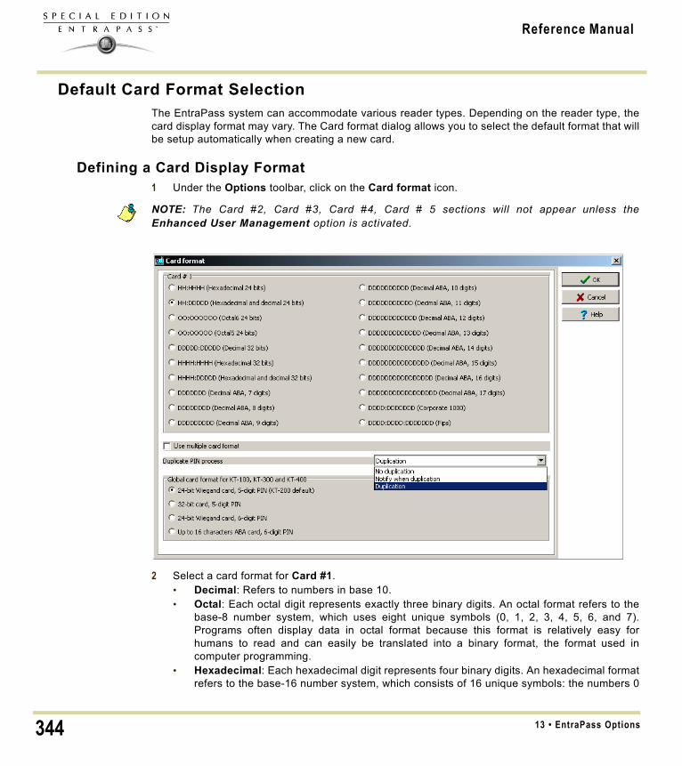
Reference Manual
Default Card Format SelectionThe EntraPass system can accommodate various reader types. Depending on the reader type, thecard display format may vary. The Card format dialog allows you to select the default format that willbe setup automatically when creating a new card.
Defining a Card Display Format1 Under the Options toolbar, click on the Card format icon.
NOTE: The Card #2, Card #3, Card #4, Card # 5 sections will not appear unless theEnhanced User Management option is activated.
2 Select a card format for Card #1.• Decimal: Refers to numbers in base 10.• Octal: Each octal digit represents exactly three binary digits. An octal format refers to the
base-8 number system, which uses eight unique symbols (0, 1, 2, 3, 4, 5, 6, and 7).Programs often display data in octal format because this format is relatively easy forhumans to read and can easily be translated into a binary format, the format used incomputer programming.
• Hexadecimal: Each hexadecimal digit represents four binary digits. An hexadecimal formatrefers to the base-16 number system, which consists of 16 unique symbols: the numbers 0
13 • EntraPass Options344

Reference Manual
to 9 and the letters A to F. For example, the decimal number 15 is represented as F in thehexadecimal numbering system. The hexadecimal system is useful because it canrepresent every byte (8 bits) as two consecutive hexadecimal digits. It is easier for humansto read hexadecimal numbers than binary numbers.
• FIPS (Federal Information Processing Standard): This card format can use more than 32bits of data.
3 Check the Use multiple card format box if your environment contains multiple reader typesand you would like to have the capability to select a different reader, that is not the defaultreader, when creating a new card.
4 Select one of the Duplicate PIN process in the scrolling box. This feature can be used forexample while loading cards in a batch. An operator may decide to set the PIN option to allowduplication. Later, if desired, the duplicate PINs can be changed to prevent confusion. • No duplication: An error appears on the workstation; the PIN field will be reset to the
default value (00000) and will be highlighted, inviting you to enter a new and valid PIN.Only PIN 00000 will be duplicated regardless of the PIN setting option.
• Notify when duplication: the server verifies if this PIN already exists. If the PIN exists, amessage box appears, indicating that the PIN exists. A Details button will allow operatorsto view a list of cardholders who were issued this PIN.
• Duplication: no test will be processed, the PIN will be accepted even if it is a duplicate.5 Under the Global card format for KT-100, KT-300 and KT-400, select the appropriate option to
coordinate with the selection in the upper section of the dialog.• 24-bit Wiegand card, 5-digit PIN (KT-200 default): for up to 24-bit for KT-100, KT-200,
KT-300 and KT-400.• 32-bit card, 5-digit PIN: for up to 32-bit for KT-100, KT-300 and KT-400.• 24-bit Wiegand card, 6-digit PIN: for up to 24-bit for KT-100, KT-300 and KT-400.• Up to 16 characters ABA card, 6-digit PIN: for up to 16 for KT-100, KT-300 and KT-400.
NOTE: KT-100, KT-300 and KT-400 controllers will do a hard reset on card format change.Avoid alternating between different card formats because this may result in lost cardinformation.
345Default Card Format Selection

Reference Manual
System Language SelectionEntraPass allows you to run the software in the language of your choice. The basic languages areEnglish, French, Spanish, German and Italian. The Vocabulary Editor utility enable users to addother custom languages.
Changing the System Language1 From the EntraPass main window, select the Options toolbar, then click the Select language
icon.
NOTE: When you modify the primary language, the database operation will be suspendedduring the operation and the changes will be effective only when you shutdown and thenrestart the system. The database language will be modified according the ascii values of thecharacters in the primary language. Accents and special characters of different languagesmay have an impact on your database.
2 From the Select primary language drop-down list, select the language you want to use as aprimary language. From the Select Secondary language drop-down list, select the languageyou want to use as a secondary language.
3 Log out of EntraPass and login again.
13 • EntraPass Options346

Reference Manual
Printers Selection and ConfigurationThe Printer options dialog that can be accessed under the Options toolbar allows users to select alog printer that will be used when printing events and to select a report or a badge printer.
Selecting and Setting Up a Log PrinterWhen you define events (in the Events parameters definition menu), it is possible to determine howand when events will be printed. For example, you can decide to dispatch events to an EntraPassapplication, a printer, or to activate a relay. Your decision may be based on, for instance, schedulesthat will send alarms to a remote terminal at a specific moment.
NOTE: You need to assign a “print” schedule to certain events to print them at a specifiedtime.
1 From Printer options dialog select the Log printer tab.
2 Select a printing option in the Printer type section:• No log printer—If you select this option, no event will be printed, even if a print schedule is
defined for the events.• Use Network/Local Windows® printer (page printer)—If you select this option, all events
sent to the printer will be buffered and printed when a full page is ready to be printed.Events will be printed on the network/local printer - not on a specific log printer.
• Use local dot matrix printer—If you select this option, all events sent to the printer will beprinted one-by-one and one under the other, or it will print one event per page, dependingon your printer type. Select the printer port that will be used in the “printer” field. Specify ifmessages and alarms will be printed on this printer.
3 In the Printer selection section, specify whether you want to print message or alarms.• Print messages log—If you select this option, all events that are assigned a “display”
schedule in the events parameters menu will be printed.• Print alarms logs—If you select this option, all events that are assigned an “alarm”
schedule (and need to be acknowledged) in the events parameters menu will be printed.4 From the Printer drop-down list, select the specific printer that will be used as a log printer.
347Printers Selection and Configuration

Reference Manual
• If you have selected a dot matrix printer, select the Port on which the printer is connectedto communicate with the computer. The Port field appears when a dot matrix printer isselected.
• If you are using a network/local printer, select the Font and the Font size. The font andfont size influence the number of events that will be printed on one page. Using a smallerfont increases the number of events printed on a page.
Selecting and Setting Up a Report PrinterThe Report printer will be defined to print reports.
1 From the Printer options window, select the Report printer tab.
Selecting and Setting Up a Badge PrinterThe Badge printer will be defined to print badges that are created in EntraPass.
1 From the Printer option window, select the Badge printer tab.
2 Check the Badge printer option if a badge printer will be used; as a result, the Print badge andPreview badge button will be displayed in the Card window.
3 From the Select badge printer drop-down list, select the appropriate badge printer.4 If you want the picture on the reverse side of the badge to be inverted, click the Invert Reverse
Side box.5 Check the Use barcode 39 as font when appropriate, and select the corresponding Font.
13 • EntraPass Options348

Reference Manual
System Date & Time ModificationThe Change system option should be used with caution and only when necessary; this functionsmay affect logical components of the access system (i.e. schedules, etc.).
1 From the Option main window, select the Change System date and time icon.
2 Enter the date in the Date field, or select a date from the calender. Connected components ofthis application will also receive the date change notification.
3 Enter the time in the Time field. Connected components of this application will also receive thetime change notification.
4 Click OK to exit.IMPORTANT NOTE: You should not change the time using Windows® settings. It is stronglyrecommended to change the system time through the server parameter settings.
349System Date & Time Modification

Reference Manual
Multimedia Devices ConfigurationThe Multimedia devices utility allows you to set up your system multimedia objects:• Alarm sound• Video capture devices • Signature capture devices
Selecting an Alarm Sound1 From the Options main window, select the Multimedia devices icon.
2 Check the Assign alarm sound option if you want an alarm sound notification.3 Select a sound from the displayed list. 4 Select a Priority level for the selected sound so that it is played when an alarm defined with
this priority is sounded.
NOTE: The Priority level refers to the order in which alarm messages are displayed in theAlarm desktop. In EntraPass, O is associated with the highest priority, and 9 to the lowest.Formore information, see "Event Parameters Definition" on page 272.
5 Click the Play button to listen to the selected sound. The system will play the selected sound.6 Click the Add button to add a new sound from your personal files. Clicking on this button
displays a new window allowing you to add new alarm sounds.
NOTE: The Current selection section displays the sound currently selected (in use). You canadjust the delay of the alarm sound in the Delay field.
13 • EntraPass Options350

Reference Manual
Defining Video Options1 From the Multimedia devices window, select the Video capture tab.
2 Check the Enable video capture box to enable the video capture options in your system. • MCI device: Standard Windows® capture drivers.• Twain device: Twain capture drivers. (Recommended).• Use overlay: Option activated for image capture devices.• Enable controls menu: Activates options (such as zoom, pan and tilt) on image capture
devices, if applicable.• MCI device number: Select identification number of MCI device.• Portrait: Enables portrait orientation of captured images.• Landscape: Enables landscape orientation of captured images. (Default value).
3 Click the Test button to verify if the video camera is functional.
351Multimedia Devices Configuration

Reference Manual
Setting Up the Signature Capture Device1 From the Multimedia devices window, select the Signature tab.
2 Check the Enable Signature pad option to enable the use of a signature pad device. 3 From the displayed list of supported Signature pad devices, select the driver for the signature
pad you want to use.4 Check the Remote application box if the signature device is setup as such.5 Select a Pen width.6 Use the Test button to check if the driver selected is functional. When you click the Test button,
the Signature Pad Test window appears. This window appears whenever you choose theSignature pad option (Card definition windows).
13 • EntraPass Options352

Reference Manual
7 Select the Video tab to set video options for use with the Video Integration feature. This optionallows you to choose between the windows or video format for Video playback.
• Disable DirectX option: DirectX is a Windows® technology that enables higherperformance in graphics and multimedia, including video and sound. By default, DirectX isenabled with the Video feature. However, you may want to disable it; if for example Videoimages are not correctly displayed or are not displayed at all, disabling DirectX can beuseful. However, when DirectX is disabled, the system will use more system resources.
• The Video bandwidth control option allows you to reduce or increase the bandwidthrequired to stream live video without compromising video storage quality and computerperformance. The range value is between 64 KB/s and 8192 KB/s.
NOTE: The video bandwidth control value cannot exceed the EntraPass Server value (seepage 476).
353Multimedia Devices Configuration

Reference Manual
System Parameters ConfigurationThe System parameters dialog allows the System Administrator to modify parameters that definethe EntraPass system. Parameters have been grouped together under different labels such asFirmware, Image, etc.
Server ParametersUnder the Server tab, you will define disk free space threshold and icon status.
Disk SpaceThe Disk Space feature has been developed as a protection against system failures that may becaused by the lack of disk space. This feature allows you to monitor the amount of free disk spacefor optimal system operation or for generating reports. In fact, EntraPass offers the ability to havethe system abort the execution of a report if the free disk space has reached a specified threshold.
• Disk free space threshold (MB) scroll-down list: specify a disk free space threshold thatindicates when you want the system to send a message when the amount of free space fallsbelow the value indicated. This value is in mega bytes. The range value is 2000 up to 99999MB.
• Time between notifications (hh:mm): enter the amount of time between notifications whenthe disk free space has reached the quota specified in the Disk free space threshold field. Forexample, if you enter 00:30 in the field, a system warning will be displayed every half an hour.The time range value is 00:10 to 24:00.
• Quick backup: When this option is checked, the main server do not close the tables during thesynchronization with the mirror database. Messages can still be received and the databaseviewed. A yellow icon is then displayed on the left to indicate that the system is in read onlymode.
Icon StatusThe Status time out delay (m:ss) parameter allows you to define a period of time before theworkstation queries the server for the latest icon statuses. The higher the delay, the lower the icon
13 • EntraPass Options354

Reference Manual
refresh rate will be therefore creating less traffic on the network. The maximum time out delay is 1min. 30 seconds.
Firmware ParametersThis section contains all the information pertaining to controllers, gateways and IP communicationmodule, as well as the section to update you firmware.
NOTE: The KTES tab will be available only if a KTES controller have been previously definedin the system. See ‘Kantech Telephone Entry System (KTES) Configuration’ on page 91 formore information.
KT-100The KT-100 tab specifies the location of the folder containing the firmware for KT-100 controllers.The system will use this data to update the installed controllers (not available in EntraPass KTESEdition).
355System Parameters Configuration

Reference Manual
KT-300The KT-300 tab specifies the location of the folder containing the firmware for KT-300 controllers.The system will use this data to update the installed controllers (not available in EntraPass KTESEdition).
KT-400The KT-400 tab specifies the location of the folder containing the firmware for KT-400 controllers.The system will use this data to update the installed controllers (not available in EntraPass KTESEdition).
• When checked, the Enable TFTP KT-400 updater option will allow operators to upgrade theKT-400 firmware from the Update firmware button from the Operation > Site dialog inEntraPass.
13 • EntraPass Options356

Reference Manual
• Enable automatic firmware update: Select to make an update of each KT-400 with a differentfirmware version.
NOTE: The automatic firmware update function applies only to KT-400s that support it.
NOTE: The Corporate Gateway must be restarted in order to enable the TFTP KT-400 updater.
• For security reasons, you may decide, as a System Administrator to disable this option and notallow operators to update the firmware.
KTESThe KTES tab specifies the location of the folder containing the firmware for the KTES. The systemwill use this data to update the installed KTES.
Kantech IP LinkThe IP Link tab specifies the location of the folder containing the firmware for the Kantech IP Linkmodule. The system will use this data to update the installed firmware (not available in EntraPassKTES Edition).
357System Parameters Configuration

Reference Manual
• When checked, the Enable TFTP IP Link updater option will allow operators to upgrade the IPLink firmware from the Update firmware button from the Operation > Site dialog in EntraPass.
NOTE: The Corporate Gateway must be restarted in order to enable the TFTP IP Link updater.
• For security reasons, you may decide, as a System Administrator to disable this option and notallow operators to update the firmware.
Image ParametersThe Image section is where you will define parameters for the badging features. You will defineimage quality for picture, signature and background images.• If you are using the badging feature, it is recommended to leave the jpeg quality to default.
Reducing the image quality may affect the quality of the pictures imported from badges.• If you are not using the badging feature, you may reduce the jpeg quality of your images so that
they will not occupy a large space in the database. You must take in consideration, however,that reducing the quality of the saved images may affect the quality of the photos imported intobadges.
A parameter allows you to save cards and visitor card pictures, signatures and background graphicsto a file instead of directly to the database. We are offering this option for sites that have large banksof pictures and graphics. The picture, signature and graphic database can currently contain up to 2Gb of data each. The parameter will be used in instances where a site may need more space tosave pictures, signatures and graphics.
Picture and BadgingThe picture and badging feature allows you to adjust the image and signature quality for use withthe Badging feature (not available in EntraPass KTES Edition).
13 • EntraPass Options358

Reference Manual
• Unchecking Use JPEG format for pictures, signatures and badges tells the system to savepictures (or signatures) in a tiff format.
NOTE: Remember that this may affect the image quality. If you are not an advanced user,leave these values to default.
• The User picture, Signature, Badge background and Badge picture indicate the quality ofthe image that will be saved. If you choose 10, the saved image quality will be poor; 100indicates an excellent quality.
• Select the location of the Picture (Signature) transparent color position for pictures andsignature. Four choices are available (top-right, top-left, bottom-right and bottom-left). Bydefault, the system chooses the bottom left-hand corner for the transparent background color.EntraPass allows operators to choose a more suitable color.
• When checking the Save card pictures and signatures in a file box, the system will createPicture and Signature directories under C:\Program Files\Kantech\Server_SE\Data whereall pictures and signatures will be saved instead of directly in the database.
• When checking the Save visitor pictures and signatures in a file box, the system will createPicture and Signature directories under C:\Program Files\Kantech\Server_SE\Data whereall visitor pictures and signatures will be saved instead of directly in the database.
NOTE: When modifying an existing picture or signature, EntraPass will save it to theappropriate file and delete the corresponding entry in the database.
GraphicThe graphic feature allows you to adjust the graphic quality for use with the EntraPass software.
• Unchecking Use JPEG format for graphics tells the system to save graphics in a tiff format.
NOTE: Remember that this may affect the image quality. If you are not an advanced user,leave these values to default.
• The JPEG quality value for Graphic background (picture) indicates the quality of the imagethat will be saved. If you choose 10, the saved image quality will be poor; 100 indicates anexcellent quality.
359System Parameters Configuration

Reference Manual
• When checking the Save graphics in a file box, the system will create a Graphic directoryunder C:\Program Files\Kantech\Server_SE\Data where all graphics will be saved instead ofdirectly in the database.
NOTE: When modifying an existing graphics, EntraPass will save it to the appropriate file anddelete the corresponding entry in the database.
Report ParametersThe Report tab enables users to define the field separator for reports, disk free space threshold anduser name format.
CSVUnder the CSV tab, you can define the field separator for your reports.• By default, the system uses a comma (,) as the Field separator. You can modify the comma for
another character. Other options are: Period, Equal, Semicolon, Colon, Space and tab.• It is recommended to check the Date and time on separate fields option. When selected, CSV
(comma separated values) as the output process for your reports, by default, the systemincludes the date and the time in a single field. When you select this option, the system willseparate the date and the time fields.
Disk SpaceThis feature is a protection when for instance a huge report has been requested. In this case, thesystem will abort the execution of the report and displays an alert message indicating the reason ofthe cancellation.• Abort report if free space lower than (MB) scroll-down list allows you to specify the minimum
amount of free disk space required for the execution of reports. The range value is 2000 to999,999 MB.
• Maximum event for email report scroll-down list allows you to specify the maximum numberof events that can be sent via an email report. The range value is 100 to 100,000 events.
13 • EntraPass Options360

Reference Manual
• Maximum event for standard report scroll-down list allows you to specify the maximumnumber of events that can be sent in a report. The range value is 1000 to 500,000 events.
User Name FormatSpecifying the user name format will tell the system how cardholder’s names will be displayed inEntraPass (not available in EntraPass KTES Edition).
• Parse user name should be checked if you want to select a method of parsing the user’s namein the system.
• User name format lets you select the parsing method. Options are: Begin with last name,Begin with first name.
• Parse user name with lets you select the character that will be used to parse the user namefields.Options are: Comma, Period, Equal, Semicolon, Colon, Space.
• Strict search on card field should be left empty unless you wish to keep the previous method(EntraPass Version 3.17 and lower) of strict searching a card field for reports.
NOTE: Prior to version 3.18 of EntraPass, the system used a strict search method thatrequired Administrators to enter specific upper and lower boundaries to attain specific results.For example, for generating a report that included all users whose last name started with A,the lower boundary had to be A and the upper boundary had to be AZZZZZ. Now, the systemwill display all user names that start with an A just by entering A as a lower and upperboundary.
361System Parameters Configuration

Reference Manual
Credentials Parameters
CardUnder the Card tab, System Administrators will be able to migrate their EntraPass system toenhanced user management where users are managed by their user name as well as their cardnumber. Each card holder will be handled by user name. This will allow for creating cards withoutassigning card number to the new cards, see "Issuing a New Card in Enhanced UserManagement Environment" on page 175 (not available in EntraPass KTES Edition).
NOTE: Enabling the migrate to enhanced user management is NOT REVERSIBLE through thesoftware. However, when the system is migrating data, a backup is performed in EntraPass,so this can be restored to return to its previous action.
• Migrate to enhanced user management: when checked, EntraPass will migrate to theenhanced user management (See ‘Issuing a New Card in Enhanced User ManagementEnvironment’ on page 175 for more details).
• After checking the box and clicking OK, a warning will popup on screen indicating that theaction is irreversible before EntraPass performs a backup of your data.
• Once the process has been completed, you will notice that the option is greyed out underthe Card tab.
13 • EntraPass Options362

Reference Manual
Workstation
Toolbar Buttons
The toolbar buttons size can be increased up to 2.5 times the original size, in order to improvevisibility of the text below the button. Logout and log back in to apply the change to the toolbar.
Here is an example at minimum size (1.0) compared to maximum size (2.5).
IntegrationThe Integration tab allows the user to select third party hardware that has been integrated toEntraPass by Kantech.
DLL registration: The available DLL in this menu will be used to specify which type of hardware thecustomer will connect to EntraPass.
363System Parameters Configuration

Reference Manual
• Click on Add to integrate another DLL. For additional details, see "Integrated PanelConfiguration" on page 128.
Virtual keypad: The Virtual keypad tab allows the user to customize the virtual keypad screendisplay. Three different display modes can be selected: Floating, Modal or Stay on top.
13 • EntraPass Options364

Reference Manual
Backup SchedulerA backup is a copy of the systems database which serves as a substitute or alternative in case thecomputer fails. If your system computer fails, you may restore a backup copy onto anothercomputer.• Back up your files regularly, at least once a week or more if many modifications were made to
the database.• We recommend that you make two backups of all your database files. To be especially safe,
keep them in separate locations. • To backup your files, you can use:
• the menus of the Backup Tab, or • the Backup Scheduler to apply automatic schedules, or • other third party software and hardware (the third party software is not recommended).
NOTE: By default, when you backup or restore files, the databases will temporarily bedisabled (not available). The Workstation will not be able to modify the databases.
The Backup Scheduler program is used to schedule automatic backups of your data, archives, andTime and attendance databases. Define the default settings and the system will do the rest.
Scheduling Automatic Backups of the System Database1 From the Backup toolbar, select the Backup icon.
365Backup Scheduler

Reference Manual
2 Select the tab corresponding to the information you want to backup: Data, Archive, Time &Attendance (Time & Attendance is not available in EntraPass KTES Edition).
NOTE: By default, the system will automatically backup your files every Sunday at 4:00 AM forall new installations. Setting this feature at 4:00AM has an added benefit of not interferingwith the system processing time or other tasks scheduled around midnight.
3 Select the Automatic backup option to enable the options displayed in the window. Theoptions displayed depend on the tab that is enabled.
4 Select the Backup folder: • Default folder—will backup your files in a system default backup folder. By default, the
name of the backup sub-directory is generated automatically according to the followingconvention: X_YYYY_MM_DD_HH_MM_SS (Where 'X' = Data or Archives or Time andAttendance (D, A or T), year, month, day, hour, minutes, and seconds.
NOTE: By default, the system backs up all the information originating from the followingdirectories: C:\Program files\Kantech\Server\Data or Archive or Time on video or V. Theinformation is sent to:
C:\Program files\Kantech\Server\Backup\X_YYYY_MM_DD_HH_MM_SS.
• Specific folder—will backup your files in a sub-folder labeled according to the defaultconvention in the XXX folder.
5 Select the Backup type: The options that are displayed depend on the type of the data to besaved. • Under the Data tab only:
• Separate files: will backup the databases one by one.• Self-extracting compressed file: will create an executable file (*.exe) that will
compress the information1 so as to reduce the amount of disk space taken by thebackup.
• Under the Archive and Time and Attendance tabs only:• Separate files (full backup): will backup all databases.• Self-extracting compressed file (full backup): will create an executable file (*.exe)
that will compress the information so as to reduce the amount of disk space taken bythe backup.
• Separate files (incremental): will backup all databases. Only the information that wasmodified since the last backup will be saved.
• Self-extracting compressed file (incremental): will create an executable file (*.exe)that will compress the information so as to reduce the amount of disk space taken bythe backup. Only the information that was modified since the last backup will be saved.
NOTE: Restoring a self-extracting backup after an EntraPass upgrade can only be done fromthe workstation where the original self-extracting backup was done.
NOTE: When you have selected “full backup”, each time a backup is done a new sub-foldercontaining the data or the self-extracting file will be created. If you are using the incrementalbackup type, only the information that was modified since the last backup will be saved. If youwant to restore information, you will have to restore all the sub-folders one-by-one (startingfrom the oldest).
13 • EntraPass Options366

Reference Manual
6 Select the frequency of the backup, • Weekly: the backup will be carried out once a week. Specify which day (example, the
backup will be executed every Thursday). • Monthly: the backup will be carried out monthly, specify the day of the month (example,
the backup will be carried out every first day of the month).• Daily: the backup will be carried out every day.• Now: this option allows you to request a backup when you need it.
7 Enter the time at which the backup will start (24:00 format).8 Click on OK to save.
367Backup Scheduler

Reference Manual
Custom MessagesThe Custom Messages option (not available for EntraPass KTES Edition) allows operators withproper security rights to define custom messages that can generate an event based on a schedule.Up to 10 custom messages can be programmed to trigger an event at a preset time. And eachcustom message can be triggered when the schedule becomes valid, invalid, or both. In otherwords, you can trigger up to 20 custom events if you take into account the start and/or end of aschedule interval.
Each custom events will be displayed in the Messages List on the Desktops.
Setting up Custom Messages1 From the Options toolbar, click Custom Messages.
2 In the first tab, enter the first custom message you want to see display in the Messages List.Two fields are available for primary and secondary languages.
3 Select a preset schedule that will determine when the custom event will be triggered.4 Select if you want the custom event to be triggered when the schedule becomes Valid or
Invalid, or both.5 Move to the second tab to enter a second custom message, and so on.
13 • EntraPass Options368

Reference Manual
System RegistrationThis menu is used to register new system components such as the KTES.
NOTE: For more information on how to install and register new applications, see "SoftwareInstallation" on page 7. Before you install new applications, make sure that you have theproper serial numbers for the installation.
369System Registration

Reference Manual
Checking Server and Workstation Databases
Server Database
1 From the Options toolbar, click the Server fulldatabase check icon. The system displays a warning.
2 Select Yes to continue.
NOTE: This is a surface operation. If your system isexperiencing problems, you must run the DatabaseUtility program from the Windows® Start menu. For moreinformation, See ‘Verifying Database Integrity’ on page379.
Workstation Database
1 From the Options toolbar, click the Workstation fulldatabase check icon. The system displays a warning.
2 Select Yes to continue.
NOTE: This is a surface operation. If your system isexperiencing problems, you must run the DatabaseUtility program from the Windows® Start menu. For moreinformation, See ‘Verifying Database Integrity’ on page379.
13 • EntraPass Options370

Reference Manual
Chapter 14 • Backups
The Backup Toolbar
A backup is a copy of your system database which serves as a substitute or alternative in case thecomputer fails. Backing up your files safeguards them against accidental loss when for example thehard disk fails or when you accidentally overwrite or delete data. If your computer system fails, youmay restore a backup copy onto another computer, on which the EntraPass application has beeninstalled.
The EntraPass Backup tab allows operators to perform manual backups of the system data (D),archive (A) and time and attendance (T) databases. It is also used to restore backup data.Safeguard tips:• Back up your files regularly, at least once a week or more if many modifications were made to
the database.• We recommend that you make two backups of all your database files. To be safe, keep them in
different locations. • To backup your files, you can use:
• The menu of the EntraPass Backup utility, or • Other third party software and hardware.
NOTE: By default when you backup or restore files, the EntraPass database will temporarilybe disabled.On the EntraPass application main window, you will notice that the secondcolored square at the bottom left of the screen turns red when the database is unavailable.Modifications done on the workstations will not be applied to the database until the databaseis available again.
All the system data can be found under the following path: C:\Program Files\Kantech\Server_SE\XXXX. If you are using a third party program to perform backups, it is recommended tobackup the whole Kantech directory and sub-directories. Each time a backup is done (even if it isdone automatically), a new sub-folder containing the data or the self-extracting file is created. If youare using the “incremental” backup type and you want to restore information, you will have to restoreall the sub-folders one-by-one (starting with the oldest).
Creating Backups of Type D, A, and TBy default, the name of the sub-directory in which the data/archive/time and attendance databaseswill be saved is generated automatically according to the following convention:X_YYYY_MM_DD-h_mm_ss, where X is the data type (D for Data, A for archive and T for Time and Attendance). The
371

Reference Manual
following steps explain how to backup data. The same steps apply also when you backup archivesor time and attendance data.1 Select the item you want to backup: data, archive, time and attendance databases. The system
displays the backup sub-directory in which the information will be saved. You may keep thedefault folder, or you may browse your disk to specify a new destination folder for the backup.
NOTE: By default, the system/workstation will backup all the information originating from thefollowing directory: C:\Program Files\Kantech\Server_SE\Data or Archive or Time andattendance toC:\ProgramFiles\Kantech\Server_SE\Backup\ X_YYYY_MM_DD-h_mm_ss,where X is the data type. The data type is followed by the year, month and dayinformation as well as the time of the backup.
2 Select the Backup type:• Separate file: the system will back up the databases one by one (standard). This backup
type includes the Regdata.ini file containing the following identification data: software usedto create the backup, backup type (data, archive, time and attendance), operator whorequested the backup, date and time of the backup as well as the software version.
• Self-extracting compressed file: the system will create an executable file (.exe) that willcompress the information so as to reduce the amount of disk space taken by the backup.The system displays information identifying the backup: software used to create thebackup, backup type (data, archive, time and attendance), operator who requested thebackup, date and time of the backup as well as the software version.
14 • Backups372

Reference Manual
NOTE: If you want to use the .exe file on its own to restore a self-extracting backup, makesure that the EntraPass system code is the same as the one stored in the .exe backup file orelse the extraction will not work. In cases where your system has failed and EntraPass dataand applications are no longer available, we strongly suggest that you reinstall EntraPass anduse the backup functionality to restore your backup instead of using the .exe file on its own.
3 From the Drives drop-down list, select the drive on which the backup will be performed. A list ofchoices is available according to your computer settings. To save as default, leave as is.
4 You may click the New folder button if you want to specify a new destination folder.5 Click OK to launch the backup procedure. The backup process can be viewed on the bottom
part of the window.
Restoring Data (D, A and T)If you are restoring data, it is strongly recommended to perform a backup before you do so. If youare using a third party program to restore the data, it is recommend to restore the whole Kantechdirectory and sub-directories.1 From the Backup tab, select the desired Restore button (Data, Archive, Time and
attendance). The system displays the Restore data window. It displays the path of the backupfolder.
2 To change the destination folder, browse the Drives drop-down list. Click OK to launch therestore process.
NOTE: By default, the system restores all the information originating from the followingdirectory: C:\ProgramFiles\Kantech\Server_SE\Backup\ X_YYYY_MM_DD-h_mm_ss toC:\Program Files\Kantech\Server_SE\Data or Archive or Time and Attendance.
NOTE: It is recommended to reload the Gateway after restoring the data (Operation > Reloaddata).
373

Reference Manual
Viewing the System LogsThe System Log window contains all the login and logout events for all workstations defined in thesystem. The logs are displayed with date and time, the workstation name, the operator name usingthe workstation as well as the log type. The System Log window contains all the login and logoutevents for all workstations defined in the system.1 Select the Backup toolbar and click on the System log icon.
2 From the Sorted by drop-down list, select the sorting criterion: the system events will bedisplayed according to your specifications.• Date and time— This is the normal incoming sequence, if you select another sorting mode,
you interrupt the normal sequence. Select date and time to restore the normal sequence.To do this, you have also to use the “restart scroll” button.
• Operator—When selected, all columns will be sorted according to the Operator column inalphabetical order.
• Workstation—When selected, all columns will be sorted according to the Workstationcolumn in alphabetical order.
• Text filter—When selected, a new window will be displayed. From that window, enter thetext string (i.e.: kantech), and the system will only display logs containing the specifiedstring text. To return to normal display, click on text filter.
3 You may change the background color. To do this, right-click on the window and select a colorfrom the displayed shortcut list.
4 You may also clear the window. To do this, right-click in the window, then select Clear from theshortcut menu.
14 • Backups374

Reference Manual
Viewing System Error LogsThe system errors are displayed with the date and time, the workstation name where the errororiginated from, the code number and its description.1 Select the Backup toolbar and click on the System error log icon.
2 You may also use the right-click menu to change the window background or to clear all the datadisplayed.
NOTE: For information on system registration, see "System Installation" on page 11.
System RegistrationThis menu is used to register new system components such as the KTES, see Chapter 13 ‘SystemRegistration’.
375Viewing the System Logs

Reference Manual
14 • Backups376

Reference Manual
Chapter 15 • System Utilities
This section groups the utility programs of the EntraPass Software. These programs are accessiblefrom the Windows® Start menu.• Database Utility — Program intended to re-index archived files, update database fields, verify
archived files, verify the database integrity, verify the database index, verify the database links and to verify the database hierarchy while the server is shutdown.
• Express Setup — Program used to configure all the components related to a gateway including the type of readers used, type of connection, number of controller sites, number of controllers in a site, etc.
• KT-Finder: Program used to configure locally or remotely Kantech IP devices such as the Kantech IP Link, the KT-400 Ethernet Four-Door Controller and the KT-NCC Network Communications Controller (Note).
NOTE: The KT-NCC Network Communications Controller is only available with EntraPassGlobal Edition.
• Quick Report Viewer — Program used by the operator to view reports without having to start EntraPass.
• System Report Viewer — Program used by the operator to view reports without having to start EntraPass. This utility is installed from the Setup window.
• Vocabulary Editor — Program used to translate, in the language of your choice, the display text of the software.
• EntraPass Online Help — This is the same content as the reference manual but without the screen captures. Simply click on the (? Help) button and the corresponding topic displays on screen. The online help language follows the primary language selection, if the EntraPass primary language is english, the online help will be in english as well. The online help is available in five languages; english, french, spanish, german and italian.
377

Reference Manual
Database UtilityThe Database utility program verifies the integrity of the database tables that are used to storeevents, alarms, network alarms, and graphics. Basically, the system scans all the system databasetables and corrects errors (when they are found). Usually, the system verifies the database integrityautomatically at start-up (a system message is displayed). If an operator decides not to perform adatabase check at startup, he/she may trigger the operation later, using the Database Utilityprogram. It may also be necessary to launch the database utility program when for instance thesystem experiences problems frequently. This operation should be executed when the system is notused since the system database is not available during operations on the databases. Someverifications such as re-indexing the archive files, updating database fields, verifying archive files,or swapping database languages require that the EntraPass applications be shutdown. Once all theEntraPass applications that are running on the EntraPass Server computer are closed, you can startthe Database utility. When an operation that requires the application to be shutdown is launched,the operator is warned that the database access will be suspended during the operation.
NOTE: The EntraPass workstation must be shutdown before you run the database utility.
Running the Database Utility1 You can launch the Database Utility from the Windows® Start > All Programs > EntraPass
Special Edition > Database Utility.
15 • System Utilities378

Reference Manual
NOTE: When you select the File > Workstation menu, the system displays only two icons, theVerify database integrity and the Update database fields icons. The File > Server menu offersmore choices.
Verifying Database Integrity1 Click the Verify database integrity icon in the toolbar. You have the choice to perform a quick
or a complete check.• Quick check: The system scans through the database tables, but does not display a
detailed report afterwards.• Complete check: The system scans through the database tables and a detailed report is
displayed.
Updating Database FieldsThis function is automatically executed when you perform a software is updated. If an operatorperforms a database restore (Server, Options toolbar, Restore), the database fields areautomatically updated when the information is restored. Even when an operator performs adatabase restore outside the Server (copies the databases from a third party backup program), thisfunction is automatically carried out when the Server is started up again. 1 From the EntraPass Database utility window, select the Update database field icon.
NOTE: Use this function when, for instance, you experience problems when starting theworkstation. When the system does not start, this may imply that there are problems in thedatabase; that the source and the structure do not match.
379Database Utility

Reference Manual
Verifying Database IndexThe Verify database Index program allows to entirely rebuild the database index by using theinformation that was copied in the primary databases and grouping it to rebuild the Registry.DBdatabase. The latter is used to increase the system performance.
NOTE: This program can be used when a database is corrupted because it has not beenbacked up.
Verifying Database LinksThe Verify Database Links utility is used to rebuild all the links of the database. Moreover, thisprogram cleans the databases by deleting links that are no longer valid. For example, if a schedulewas assigned to a functionality and this schedule was deleted, the system will initialize the fieldwhere it was assigned in the primary database. It will also remove the records that point to deletedcomponents. For example, if an access level is assigned to a gateway and this access level wasdeleted, it will delete the record in the database. The Verify Database Links utility enables completemanagement of the links between each component and ensures that the correct information isdisplayed when:• Viewing the structure of a component's links to all other components of the system,• Removing all the traces of a component within the database when this component has been
deleted. For example, if a schedule is deleted, the system will use the link list to initialize all the database fields that contains this schedule.
NOTE: It may be necessary to use this function when it is obvious that the database links areincorrect. This features is useful when for example the system experiences abnormalterminations.
Verifying Database Hierarchy In EntraPass, the database is set up in a hierarchical way, which means that all components have aparent and can have children components. The Verify database hierarchy utility is used to rebuildthe parent-child links within the database. The results of this program are limited if the damages ofthe database are severe.
NOTE: When a user tries to access a controller by selecting a gateway and a site and whenthe result does not correspond to the reality, this means that the database hierarchy isprobably corrupted. In this case, the Verify database hierarchy feature can be used to correctthe problem. If the problem cannot be fixed, this could mean that the database is too damagedto be fixed. It will be necessary to restore the database.
verifying Database Archive FilesThis function is used to verify archive files. It assigns a new unique sequential value to all primaryindexes of archive files.
Verifying Time & Attendance FilesThis function is used to verify time and attendance database files. It assigns a new uniquesequential value to all primary indexes of time and attendances database files.
15 • System Utilities380

Reference Manual
Swapping DescriptionsThis function is used to interchange or to swap the database descriptions.
Cleaning the Database This option is used to physically remove database records which have been identified by the systemas erased. Most of these records relate to cards and are kept in the Deleted Components section ofthe database. Using this option will considerably reduce the space required by your database. It willalso improve system performance relating to searches for card information. It will not affect the tableRegistry, nor will it have an impact on historical reports.
NOTE: It is strongly suggested to back-up the database before performing this operation.Clean database will suspend operation of the database while cleaning is in effect.
Rebuilding Card Last Transaction FilesThis function is used to rebuild the card last transaction files.
381Database Utility

Reference Manual
Vocabulary EditorThe Vocabulary Editor allows users to translate the display text of the software in the language oftheir choice. EntraPass offers you the possibility of adding up to 99 languages for the purpose ofchanging the text language in the graphic user interface. However, you can only run the software intwo languages at a time, a primary and a secondary language. If you want to use the software in alanguage other than English, French, German, Italian or Spanish, you can have the databasedictionary translated in the language of your choice. You will then have to integrate the translateddictionary in the software. The creation of a new display language is carried out in three stages: • Translating the source text,• Integrating the newly created language to the EntraPass dictionary in the Server,• Distributing the new custom language to all EntraPass application.
NOTE: In order to be able to run a new language, your operating system (Windows®) mustsupport the desired language. For example, your keyboard (characters) and window (display)must support the specific characters of the desired language. The computers whereEntraPass applications are running must also support the language. For more information onlanguage support, refer to your system administrator.
Installing the Vocabulary EditorEntraPass Vocabulary Editor is a stand-alone program. You can install it and run it independently. Ifyou want to translate the system language, you just have to install the Vocabulary editor and then totranslate the vocabulary database.
NOTE: You do not need an additional license to install the Vocabulary Editor. You just have toselect it in the Setup window. For more information, see "System Installation" on page 11.
Translating the System LanguageEntraPass Vocabulary Editor is a stand-alone program. You can run it independently, you do notneed to launch EntraPass software to run the Vocabulary editor. The Vocabulary Editor program willassist you if you want to translate the software in a language, other than English, French, SpanishItalian or German.
15 • System Utilities382

Reference Manual
1 Start the Vocabulary editor from the Windows® Start menu: click Start > All Programs >EntraPass Special Edition > Vocabulary Editor > Vocabulary Editor.
2 Select one of the available languages and click on New. The system displays the Selectlanguage window.
383Vocabulary Editor

Reference Manual
3 Select the source language for the translation, then click OK. The newly selected language istransferred to the right in the Custom Languages display list.
4 Click on the new Custom Language and then on the Edit custom language button to starttranslating the software vocabulary. The system displays the dictionary database.
NOTE: You must make sure that the Customdictionnary directories are regularly backed up(C:\ProgramFiles\Kantech\Vocabulary Editor\CustomDictionary\files.xxx.ath) orC:\ProgramFiles\Kantech\”Application type”\CustomDictionary\files.xxx.0
15 • System Utilities384

Reference Manual
The table below shows the value of the Vocabulary Editor color codes.
• The “Source language” column contains text based on the basic language that was selected during the creation of the vocabulary. This column will serve as a “source” for the translation. Software language columns cannot be modified by the user.
• Use the right-click to enable a contextual sub-menu or use the Language editor toolbar. A hint appears when you position the mouse over a button.
Integrating the Custom Language in EntraPassOnce the translation is finished, you have to integrate the new dictionary into the system dictionaryso that system operators can use it. The table below describes the icons action in the vocabularyeditor dialog. These options can also be selected from the Actions menu.
1 Start the Vocabulary Editor. The Vocabulary Editor window toolbar displays five buttons.
NOTE: The Graphic User Interface will only appear in one of five languages: English, French,German, Italian or Spanish.
VOCABULARY EDITOR COLOR
CODESVALUE
Green Valid text string.
Blue/Green New text string.
Red Obsolete text string.
Icon Description
Apply changes to operational dictionary: this option is useful when you want totest your changes before you update the whole system.
Restore operational vocabulary: this option allows the user to easily restore thedefault languages. It creates a self-extracting file which restores the originaldictionary.
Scan dictionary for new entries: this option is useful when the software wasupdated.
Create self-extracting file for update: If you decide to implement the newvocabulary. The system creates an Updatedictionary.exe file, and prompts you toselect a destination folder for the file.
385Vocabulary Editor

Reference Manual
2 Select a newly translated vocabulary.
• You may choose to Apply changes to the Operational dictionary: this option is useful when you want to test your changes before you update the whole system.
• Restore the operational vocabulary: this option allows the user to easily restore the default languages. It creates a self-extracting file which restores the original dictionary.
• Scan dictionary for new entries: this option is useful when the software was updated for example.
3 If you decide to implement the new vocabulary, select the Actions menu, then choose Createself-extracting file for update option. The system creates the Updatedictionary.exe file, andprompts you to select a destination folder for the file:
15 • System Utilities386

Reference Manual
4 Select the destination folder for Updatedictionary.exe. By default, the Self-extracting file isstored in C:\Program Files\Kantech (application).
NOTE: It is recommended to copy the Updatedictionary.exe file on a network folder if you wantoperators to access the file to update their software application.
Distributing the New System VocabularyBefore you run the file, make sure to exit the EntraPass software; otherwise the operation will notwork.
Updating the System Vocabulary1 Exit all Entrapass programs.2 Start Windows Explorer® > Kantech > (EntraPass application), then copy the
Updatedictionary.exe on the server.
387Vocabulary Editor

Reference Manual
3 Double-click Updatedictionary.exe. The system displays the Entrapass applications that areinstalled on the computer.
4 Select each application, then click the Update dictionary button.5 You have to copy Updatedictionary.exe on every computer where EntraPass is installed, and
then double-click it in order to launch the language update. To do so, you have first to exit allEntraPass applications before you run the self-extracting file.
6 Select the application you want to update (one at a time) and click Update dictionary button.The system will automatically copy the vocabulary to the Custom Dictionary directory thenmerge the custom directory with the application dictionary.
NOTE: You MUST update all the applications in the system.
NOTE: To restore the dictionary back to original default values, follow the same procedures asfor updating the dictionary.
7 Select the Options toolbar, then select the Select language icon.
15 • System Utilities388

Reference Manual
8 In the Select the language window, select the primary language and the secondary language.The newly integrated language is displayed in the list. It is important to select the language atthis stage, otherwise the operators of the system will not be able to use it.
NOTE: For example, if your primary language is “English” and your secondary language is“French”: if you select your new language (i.e. Russian) as primary, all operators who have“English” as their display language in the Operator menu will be modified to “Russian”. On theother hand, if you change the secondary language to “Russian” and operators are using“English”, you will have to manually select “Russian” in the Operator definition menu”. Toassign the desired language to an operator, use the System definition menu, then select theOperator definition menu.
NOTE: For every language you are installing, be sure to select the correct keyboard (Start >Settings > Control panel > Keyboard). The selected keyboard is displayed in the system tray.
Upgrading the System VocabularyWhen you upgrade your system, the new or modified strings are automatically inserted in thesystem vocabulary and also in the custom dictionary. If you have added a custom language to yoursystem, you have to translate the new/modified strings following a system upgrade. Therefore, youhave to re-edit the vocabulary and create a new self-extracting file. When you re-open thevocabulary table, new strings are indicated by a green point. Obsolete strings (no longer used) aretagged red.
NOTE: For easier management, we recommend that you always edit your vocabulary from thesame computer and integrate it to the system using a self-extracting file.
389Vocabulary Editor

Reference Manual
Express Setup ProgramThe Express Setup program offers a quick and simple way to configure all the components of asystem: type of readers used, number of sites, site name, number of controllers on a site, etc. Forexample, it enables users to modify a door’s name by automatically applying default settings to allrelays and inputs of controllers connected to the selected door.
1 From Windows® Start menu: Start > All Programs > EntraPass Special Edition > ExpressSetup.You may also launch the Express Setup by clicking the Express Setup icon (rabbit) fromthe various dialogs in the Devices toolbar.
2 Click the New site icon to create a new site.
3 Enter the Site name in the Site description field, then select the reader type.
15 • System Utilities390

Reference Manual
4 Select the Controller type for this site.
NOTE: The KTES option is available for a Corporate Gateway only.
NOTE: There is no reader type or number of controllers to select when the controller type isa KTES.
5 Select the Reader type.6 Set the Number of controllers.7 Specify the Connection type. This indicates how the site communicates with the computer.
The connection types available will follow the controller type selection.• Select Direct (RS-232 or USB), if the site is integrated to the gateway computer and
connected to it by an RS-232 serial port. If the connection type is direct, then you have to specify the serial port (com:) as well as the controller site baud rate (usually set at either 9600 or 19200). The default value is 19200.
• Select Ethernet (polling) if the site communicates with the gateway through a terminal server device (Lantronix) using a port number. Then you have to specify the terminal server’s IP Address and Port number. To configure the terminal server, follow the manufacturer’s instructions or refer to the terminal server documentation.
• Select Dial-up (RS-232) modem if applicable.• Select Secure IP (KT-400) if applicable. Complete the associated tabs.• Select Secure IP (KTES) if applicable. Complete the associated tabs.• Select Secure IP (IP Link) if applicable. Complete the associated tabs.
8 Click OK. 9 Specify the minimum configuration for the controllers or KTES defined in the site. This includes
assigning a name to the controller/KTES, specifying the passback option, and entering theserial number.
Example for a KT-400 Controller
NOTE: The serial number column appears only for the KT-100, KT-300, KT-400 controllersand the KTES. The passback type column only appears for the KT-300 and the KT-400. Thepassback feature will not allow any card to re-enter unless it has been used to exit. Thisrequires that readers be used for both entry and exit.
10 For a new site with a KTES, go to Step 14.11 Check the Same door 1 and 2 and Same door 3 and 4 option if a reader is installed on each
side of the door. The Same door 3 and 4 boxes are available only when you are using KT-400.12 Select the appropriate Passback type (none, soft or hard). If a door is defined as an access
door, there is no anti-passback defined for this door. An entry or an exit door can be assigned apassback option.
13 Go to Step 16.14 Check the Door contact option.
391Express Setup Program

Reference Manual
Example for a KTES
15 Check the Postal lock option, if applicable, for a KTES only.16 Enter the Serial number, if this column is displayed. The serial number (S/N) is on a sticker
and generally starts with Axxxxxxx. 17 Click OK. The components associated with the controller and to the site are created in the
server database. By default, the KT-200 and KT-300 are assigned two doors except for the KT-400 which is assigned four doors, if the Same door option is not checked. The following tablesummarizes default values that are assigned to controllers.
NOTE: When the system is updating the database, the second status flag turns red, indicatingthat the system database is locked. When you try to access another system menu while thedatabase is locked, an error message appears. Simply wait until the system databasebecomes available.
The following are default values assigned to controllers by the Express Setup program.
The following tables summarize how input zones are used by the system for controllers.
Controller or KTES
Door Relay Input zoneAuxiliary
output
KT-100 1 4 4 2
KT-200 2 2 16 4
KT-300 2 2 8 4
KT-400 4 4 16 16
KTES 1 3 4 2
Input zone
System use Controllers
1 Door 1 contactKT-100, KT-200, KT-300 and KT400
2 Door 1 Rex
3 Door 2 contactKT-300
4 Door 2 Rex
5 Door 2 contactKT-400
6 Door 2 Rex
15 • System Utilities392

Reference Manual
The following tables summarize how input zones are used by the system for the KTES.
The following table summarizes how output zones are used by the system.
9 Door 2 contactKT-200
10 Door 2 Rex
9 Door 3 contact
KT-40010 Door 3 Rex
13 Door 4 contact
14 Door 4 Rex
Input zone
System use Kantech Telephone Entry System
1 Door Contact
KTES2 Postal Lock
3 Door Rex
4 Future
Auxiliary output
Use Controllers
1 LED (Door 1)KT-100, KT-200, KT-300 and KTES
2 Buzzer (Door 1)
3 LED (Door 2)KT-200 and KT-300
4 Buzzer (Door 2)
Input zone
System use Controllers
393Express Setup Program

Reference Manual
NOTE: The remaining components (relays and input zones) are undefined, that is, they havebeen created but not yet defined. Components that are defined are grayed out. You cannotselect them or change their description. You can change their description in their respectivedefinition menu (Devices > Relays/Input zones).
By default, the system assumes that:• The reader is ioProx Kantech XSF Format,• The power supervision schedule is always valid,• The failsoft delay is enabled for 45 seconds,• The resistor type is none (KT-100, KT-300, KT-400 and KTES),• The wait for second card delay is 30 seconds.
Configuring a Controller Using Express SetupWhen you select a connection type to a new site and immediately save, the system prompts you touse the Express Setup tool to define the device. You may also launch this tool by selecting a
controller and clicking the Express Setup ( ) in the Controller dialog.1 From the Controller window, select an undefined controller.2 Under the General tab, select the Controller type.
1 OUT1 (Door 1)
KT-400
2 OUT2 (Door 1)
3 LED (Door 1)
4 Buzzer (Door 1)
5 OUT1 (Door 2)
6 OUT2 (Door 2)
7 LED (Door 2)
8 Buzzer (Door 2)
9 OUT1 (Door 3)
10 OUT2 (Door 3)
11 LED (Door 3)
12 Buzzer (Door 3)
13 OUT1 (Door 4)
14 OUT2 (Door 4)
15 LED (Door 4)
16 Buzzer (Door 4)
Auxiliary output
Use Controllers
15 • System Utilities394

Reference Manual
3 Click on Save, a message box should display: Do you want to use the Express Setup programto configure the associated devices. Click Yes to continue with the Express Setup. • If you click on No, you can always return to the Express Setup by clicking on the icon.
Example for a new KT-400
NOTE: Please note that the KT-300 is a 2-door system while a KT-400 is a four-door system.
4 Specify if Both readers are installed on the same door, if applicable (not for a KTES). Whentwo readers are installed on the same door, the REX contact option is disabled.
5 Click the Advanced button to de02fine the other devices, such as doors, inputs, relays andoutputs.
395Express Setup Program

Reference Manual
NOTE: Components are listed in the left-hand pane. The related tabs are displayed in themiddle of the window. When you select a component, its default name, number and defaultsettings are displayed in the language section. Select a component to enable its tab.Components that are assigned are gray and cannot be modified at this stage. However, youmay later modify any component description in its definition menu (Devices > Controller/Door/Relay/Input/Output).
Configuring a KTES Using Express SetupWhen you select a connection type to a new site and immediately save, the system prompts you touse the Express Setup tool to define the device. You may also launch this tool by selecting a KTESand clicking the Express Setup (rabbit icon) in the KTES dialog.1 From the Site window, click on New to define a new site. Assign it a name for both languages.2 Under the General tab, select the Controller type: Secure IP (KTES).3 Click on Save, a message box should display: Do you want to use the Express Setup program
to configure the associated devices. Click Yes to continue with the Express Setup.
15 • System Utilities396

Reference Manual
• If you click on No, you can always return to the Express Setup by clicking on the icon.
4 Check the Door contact and the REX contact options.5 Check the Postal lock option, if applicable.6 Click the Advanced button to define the other devices, such as doors, inputs, relays and
outputs.
NOTE: Components are listed in the left-hand pane. The related tabs are displayed in themiddle of the window. When you select a component, its default name, number and defaultsettings are displayed in the language section. Select a component to enable its tab.Components that are assigned are gray and cannot be modified at this stage. However, youmay later modify any component description in KTES dialog menu (Devices > KantechTelephone Entry System).
397Express Setup Program

Reference Manual
Defining RelaysYou may configure relays to define their operation mode, activation and deactivation schedules. Ifyou want to assign a name to the relay, you have to select it. When you use the Select All button,the default names are kept.1 Select the first relay if you want to modify its description. The relay tab is enabled. You have to
check the box beside the relay name in order to enable the language section.
2 Check the appropriate options for the Operating mode. 3 In the Automatic activation schedule drop-down list, choose the appropriate activation
schedule.4 In the Disable relay action drop-down list, choose the appropriate action.
Defining InputsBy default, the response time for a REX is 250 ms; it is 500 ms for other input zones. The alarmrestore time is 500 ms by default. The Express Setup program allows you to define the InputNormal State and Monitoring Schedule.
15 • System Utilities398

Reference Manual
1 Select the first undefined input (its checkbox is not gray). Check its box to enable the languagefields, then assign names to it.
2 Choose the Input normal state option.3 Select the Monitoring schedule from the drop-down list. If you want to assign a custom
schedule to the selected input, you have to define it in the Definition > Schedule.
Defining Auxiliary Outputs (LED and Buzzer)If you want to change their assignment, you may do so while defining a controller or a KTES and inthe Devices > Output.1 Select the first undefined output (its checkbox is not gray). Check its box to enable the
language fields, then assign names to it.
2 Choose the Operating mode option.3 Assign a door to the output from the Selected doors drop-down lists.
399Express Setup Program

Reference Manual
The following table summarizes how output zones are used by the system.
Auxiliary output
Use Controllers
1 LED (Door 1)KT-100, KT-200, KT-300 and KTES
2 Buzzer (Door 1)
3 LED (Door 2)KT-200 & KT-300
4 Buzzer (Door 2)
3 LED (Door 1)
KT-400
4 Buzzer (Door 1)
7 LED (Door 2)
8 Buzzer (Door 2)
11 LED (Door 3)
12 Buzzer (Door 3)
15 LED (Door 4)
16 Buzzer (Door 4)
15 • System Utilities400

Reference Manual
Quick Report ViewerThe Quick Report Viewer program allows operators to view previously saved reports withouthaving to start EntraPass. It is used to view / display / load reports that were previously saved (ina.QRP format) during a print preview or Quick reports. For details on requesting and generatingreports, see "Reports" on page 309. This program is useful when EntraPass is off-line and when areport must be displayed for specific purposes.1 From the Windows® task bar, click Start > All Programs > EntraPass > Quick Report Viewer.
2 Click the Open button to open a report. The system displays the Open window:
3 By default, when a report is saved in a QRP format, the system automatically saves it in “MyDocuments” folder. If you have saved the report in another folder you have to browse to thefolder to select the report.
4 Click Open to preview the report. Once you have selected the requested report, the system willdisplay your report:
401Quick Report Viewer

Reference Manual
5 Use the toolbar buttons to preview the report:
Icon Description
Use the Zoom out button to zoom out the report view.
Use the Zoom In button to display details (view closer).
Use Previous Page and Next Page buttons to change pages.
Use the Open button to open a report located in any folder on yourcomputer.
Use the Print button to print the report. There will be no printersetup dialog box, the report will automatically print, to cancel theprinting, click Cancel.
Use the Quit button to quit the application.
15 • System Utilities402

Reference Manual
EntraPass Online Help
Getting the Online Help1 There are two ways of calling the EntraPass Online Help:
• By clicking on the (? Help) button.
• From the Windows® task bar, click Start > All Programs > EntraPass Special Edition > English Help.
403EntraPass Online Help

Reference Manual
15 • System Utilities404

Reference Manual
Chapter 16 • Animated Icons
Animated icons indicate the status of physical or logical components in the windows of EntraPasssoftware. They represent the component status in real time and simulate a movement by displayinga series of pictures associated with the component.
If a particular component status is difficult to identify, use this section to identify it.
405

Reference Manual
ControllersController animated icons indicate the status of a door controller in the graphic window (Desktop >Graphic desktop) or in the “Operation” window.
Status unknown
Appears when the EntraPass application has not received the component' status after four (4)attempts. It is displayed in: • the Operation window (alarms, door, elevator door, relay, input, reload data) • or the Desktop > Graphic desktop.
Controller AC failure
Appears when the controller is in AC failure. It is displayed in: • the Graphic desktop (Desktop > Graphic desktop window)• the Operation > Controller Reset Controller AC failure and Tamper Switch in “alarm”
Appears when the controller is in AC failure and the tamper switch is in alarm. It is displayed in: • the Graphic desktop (Desktop > Graphic desktop window)• the Operation > Controller Reset
Controller is not communicating
Appears when the controller is not communicating. It is displayed in: • the “Operation” — “Controller Reset” windows.• the Desktop > Graphic desktop.
Controller communication is regular (no problem)
Appears when the controller is communicating and the communication is regular. It is displayed in: • the Graphic desktop (Desktop > Graphic desktop window)• the Operation > Controller Reset.
Controller status is not yet known
Appears when the status of the controller is not yet known. It is displayed in:
16 • Animated Icons406

Reference Manual
• the Graphic desktop (Desktop > Graphic desktop window)
Controller is in “Reset” and AC failure
Appears when the controller is in “reset mode” and in “AC failure”. It is displayed in: • the Graphic desktop (Desktop > Graphic desktop window)• the Operation > Controller Reset.
Controller is in “Reset”, “AC failure” and “Tamper in alarm”
Appears when the controller is in “reset mode”, in “AC failure” and the tamper is in alarm. It isdisplayed in:• the Graphic desktop (Desktop > Graphic desktop window)• the Operation > Controller Reset
Controller is in reset and tamper in alarm
Appears when the controller is in “reset mode” and the tamper is in alarm. It is displayed in: • the Graphic desktop (Desktop > Graphic desktop window)• the Operation > Controller Reset.
Controller tamper in alarm
Appears when the controller tamper is in alarm. It is displayed in: • the Graphic desktop (Desktop > Graphic desktop window)• the Operation > Controller Reset when the controller tamper is in alarm.
Controller reloading firmware
Appears when the controller is reloading firmware. It is displayed in: • the Graphic desktop (Desktop > Graphic desktop window)• the Operation > Controller Reset.
KT-400 controller trouble
Appears when there is a KT-400 controller trouble. It is displayed in:• the Desktop > Graphic desktop• the Operation > Controller.
407Controllers

Reference Manual
DoorsIcons representing a door state indicate the status of door within the graphic window (from thedesktop) or within the “Operation” window.
Door forced open
This animated icon appears when the door is opened and that no access granted nor request to exitwas permitted. It is displayed in: • the Graphic desktop (Desktop > Graphic desktop window)• the Operation > Door, Elevator Door
Door forced open (reader disabled)
This animated icon appears when the door is opened and that no access granted nor request to exitwas permitted and the reader is disabled. it is displayed in: • the “Graphic” window (desktop—graphic) • the Operation > Door, Elevator Door
Door closed and locked
This animated icon appears when the door is closed and locked. It is displayed in: • the Graphic desktop (Desktop > Graphic desktop window)• the Operation > Door
Door closed and locked (reader disabled)
This animated icon appears when the door closed and locked and that the reader is disabled. It isdisplayed in: • the Graphic desktop (Desktop > Graphic desktop window)• the Operation > Door.
Door status unknown
This animated icon appears in: • the “Graphic” window (desktop—graphic) when the status of the door is not yet known.
16 • Animated Icons408

Reference Manual
Door open too long
This animated icon appears when the door is opened more than the permitted delay set in “opentime”. It is displayed in: • the Graphic desktop (Desktop > Graphic desktop window)• the Operation > Door, Elevator door.
Door open too long (reader disabled)
This animated icon appears when the door is opened more than the permitted delay set in “opentime” and that the reader is disabled. It is displayed in: • the Graphic desktop (Desktop > Graphic desktop window)• the Operation > Door, Elevator door.
Door open and unlocked manually
This animated icon appears when the door is opened and it was unlocked by an operator. it isdisplayed in: • the Graphic desktop (Desktop > Graphic desktop window)• the Operation > Door > Elevator door.
Door open and unlocked manually (reader disabled)
This animated icon appears when the door is opened and it was unlocked by an operator and thereader is disabled. It is displayed in: • the Graphic desktop (Desktop > Graphic desktop window)• the Operation > Door > Elevator door.
Door is opened and unlocked by schedule
This animated icon appears when the door is opened and it was unlocked by a schedule. It isdisplayed in: • the Graphic desktop (Desktop > Graphic desktop window)• the Operation > Door > Elevator door.
Door is opened and unlocked by schedule (reader disabled)
409Doors

Reference Manual
This animated icon appears when the door is opened, and it was unlocked by a schedule and thereader is disable. It is displayed in: • the Graphic desktop (Desktop > Graphic desktop window)• the Operation > Door > Elevator door.
Door pre-alarm on open too long
This animated icon appears when the door is opened more than half the time permitted delay set in“open time”. It is displayed in: • the Graphic desktop (Desktop > Graphic desktop window)• the Operation > Door > Elevator door.
Door pre-alarm on open too long (reader disabled)
This animated icon appears when the door is opened more than half the time permitted delay set in“open time” and the reader is disabled. It is displayed in: • the Graphic desktop (Desktop > Graphic desktop window)• the Operation > Door > Elevator door.
Door still opened schedule invalid
This animated icon appears when the door is opened and the unlock schedule is invalid. It isdisplayed in: • the Graphic desktop (Desktop > Graphic desktop window)• the Operation > Door/Elevator door.
Door still opened schedule invalid (reader disabled)
This animated icon appears when the door is opened and the unlock schedule is invalid and thereader is disabled. It is displayed in: • the Graphic desktop (Desktop > Graphic desktop window)• the Operation > Door/ Elevator door.
Door unlocked by an operator
This animated icon appears when the door is unlocked by an operator (manually). It is displayed in: • the Graphic desktop (Desktop > Graphic desktop window)• the Operation > Door > Elevator door.
16 • Animated Icons410

Reference Manual
Door unlocked by an operator (reader disabled)
This animated icon appears when the door is unlocked by an operator (manually) and the reader isdisabled. It is displayed in: • the Graphic desktop (Desktop > Graphic desktop window)• the Operation > Door/Elevator door.
Door unlocked by a schedule
This animated icon appears when the door is unlocked by a schedule. It is displayed in: • the Graphic desktop (Desktop > Graphic desktop window)• the Operation > Door/Elevator door.
Door unlocked by a schedule (reader disabled)
This animated icon appears when the door is unlocked by a schedule and the reader is disabled. It is displayed in: • the Graphic desktop (Desktop > Graphic desktop window)• the Operation > Door/Elevator door.
Elevator door unlocked and closed
This animated icon appears when the elevator door is closed and unlocked. It is displayed in: • the Graphic desktop (Desktop > Graphic desktop window)• the Operation > Door/Elevator door.
411Doors

Reference Manual
RelaysRelays icons indicate the status of a relay within the graphic window (from the desktop) or within the“Operation” window.
Relay activated by an event
This animated icon appears in: • the “Graphic” window (desktop—graphic) when the relay is triggered by an event.• the Operation > Relay when the relay is triggered by an event.
Relay temporarily activated by an event
This animated icon appears in: • the “Graphic” window (desktop—graphic) when the relay is temporarily activated by an event.• the Operation > Relay when the relay is temporarily activated by an event.
Relay activated by an input
This animated icon appears in: • the “Graphic” window (desktop—graphic) when the relay is triggered by an input.• the Operation > Relay when the relay is triggered by an input.
Relay temporarily activated by an input
This animated icon appears in: • the “Graphic” window (desktop—graphic) when the relay is temporarily activated by an input.• the Operation > Relay when the relay is temporarily activated by an input.
Relay activated by an operator
This animated icon appears in: • the “Graphic” window (desktop—graphic) when the relay is activated by an operator.• the Operation > Relay when the relay is activated by an operator.
Relay temporarily activated by an operator
16 • Animated Icons412

Reference Manual
This animated icon appears in: • the “Graphic” window (desktop—graphic) for a relay temporarily activated by an operator.• the Operation > Relay when the relay is temporarily activated by an operator.
Relay activated by a schedule
This animated icon appears in: • the “Graphic” window (desktop—graphic) when the relay is activated by a schedule.• the Operation > Relay when the relay is activated by a schedule.
Relay deactivated
This animated icon appears in: • the “Graphic” window (desktop—graphic) when the relay is not activated.• the Operation > Relay when the relay is not activated.
Relay status unknown
This animated icon appears in: • the “Graphic” window (desktop—graphic) when the status of the relay is not yet known.
413Relays

Reference Manual
InputsThis section is used to indicate the status of an input within the graphic window (from the desktop)or within the “Operation” window.
Input activated—Not supervised
This animated icon appears in: • the “Graphic” window (desktop—graphic) when the input is activated and the monitoring
schedule is invalid.• the Operation > Input when the input is activated and the monitoring schedule is invalid.
Input activated—Supervised
This animated icon appears in: • the “Graphic” window (desktop—graphic) when the input is activated and the monitoring
schedule is valid.• the Operation > Input when the input is activated and the monitoring schedule is valid.
Input activated—Not supervised manual operation
This animated icon appears in: • the “Graphic” window (desktop—graphic) when the input is activated, manually operated and
the monitoring schedule is invalid.• the Operation > Input when the input is activated, manually operated and the monitoring
schedule is invalid.
Input activated—Supervised manual operation
This animated icon appears in: • the “Graphic” window (desktop—graphic) when the input is activated, manually operated and
the monitoring schedule is valid.• the Operation > Input when the input is activated, manually operated and the monitoring
schedule is valid.
Input activated—Supervised temporarily manual operation
This animated icon appears in:
16 • Animated Icons414

Reference Manual
• the “Graphic” window (desktop—graphic) when the input is activated, manually operated andthe monitoring schedule is temporarily valid.
• the Operation > Input when the input is activated, manually operated and the monitoringschedule is temporarily valid.
Input in alarm—Not supervised
This animated icon appears in: • the “Graphic” window (desktop—graphic) when the input is in alarm and the monitoring
schedule is invalid.• the Operation > Input when the input is in alarm and the monitoring schedule is invalid.
Input in alarm—Shunted by operator
This animated icon appears in: • the “Graphic” window (desktop—graphic) when the input is in alarm and it is shunted by an
operator.• the Operation > Input when the input is in alarm and it is shunted by an operator.
Input in alarm—Supervised
This animated icon appears in: • the “Graphic” window (desktop—graphic) when the input is in alarm and the monitoring
schedule is valid.• the Operation > Input when the input is in alarm and the monitoring schedule is valid.
Input in alarm—Supervised by operator
This animated icon appears in: • the “Graphic” window (desktop—graphic) when the input is in alarm and it is supervised by an
operator (continuous supervision).• the Operation > Input when the input is in alarm and it is supervised by an operator (continuous
supervision).
Input OK—Not supervised
This animated icon appears in: • the “Graphic” window (desktop—graphic) when the input is in normal condition and the
monitoring schedule is invalid.
415Inputs

Reference Manual
• the Operation > Input when the input is in normal condition and the monitoring schedule isinvalid.
Input OK—Shunted by operator
This animated icon appears in: • the “Graphic” window (desktop—graphic) when the input is in normal condition and it is shunted
by an operator.• the Operation > Input when the input is in normal condition and it is shunted by an operator.
Input OK—Supervised
This animated icon appears in: • the “Graphic” window (desktop—graphic) when the input is in normal condition and the
monitoring schedule is valid.• the Operation > Input when the input is in normal condition and the monitoring schedule is valid.
Input OK—Supervised by operator
This animated icon appears in: • the “Graphic” window (desktop—graphic) when the input is in normal condition and it is
supervised by an operator (continuous supervision).• the Operation > Input when the input is in normal condition and it is supervised by an operator
(continuous supervision).
Input status unknown
This animated icon appears in the “Graphic” desktop when the status of the input is not yet known.
16 • Animated Icons416

Reference Manual
Sites and GatewaysThese icons indicate the status of a site, or gateway within the graphic window (from the desktop) orwithin the “Operation” window.
Controller Site:
Site status is not yet known
This animated icon appears in: • the “Graphic” window (desktop—graphic) when the status of the controller site is not yet known.
Controller site connected
This animated icon appears in: • the “Graphic” window (desktop—graphic) when the site is connected and communication is OK.• the Operation > Reload data when the site is connected and communication is OK.
Controller site connected and in “Reload Data”
This animated icon appears in: • the “Graphic” window (desktop—graphic) when the site is connected and is in “reload data”
state.• the Operation > Reload data when the site is connected and is in “reload data” state.
Controller site—Communication Failure
This animated icon appears in: • the “Graphic” window (Desktop—graphic) when the site is disconnected and there is a
communication failure.• the Operation > Reload data when the site is disconnected and there is a communication
failure.
Gateway:
Gateway—Communication Failure
This animated icon appears in:
417Sites and Gateways

Reference Manual
• the “Operation” (door, elevator door, relay, input, reload gateway) window when the gateway isin communication failure.
• the “Graphic” window (desktop—graphic) when the gateway is in communication failure.
Gateway in “Reload Data”
This animated icon appears in: • the “Graphic” window (Desktop—graphic) when the gateway is being reloaded.• the Operation > (door, elevator door, relay, input, reload gateway) when the gateway is being
reloaded.
Gateway—Communication Failure during Reload Data
This animated icon appears in: • the “Operation” (reload data gateway) window when the gateway loses communication during a
reload data operation.• the “Graphic” window (desktop—graphic) when the gateway loses communication during a
reload data operation.
Gateway communication is regular (no problem)
This animated icon appears in: • the “Graphic” window (desktop—graphic) when the gateway is communicating and the
communication is regular.• the Operation > Reload data gateway, communication is regular.
Gateway Trouble
This animated icon appears in: • the “Graphic” window (desktop—graphic) when the gateway is not communicating.• the Operation > Reload data gateway, the gateway is not communicating.
Gateway Trouble when Reloading
This animated icon appears in: • the “Graphic” window (desktop—graphic) when the gateway is not communicating. • the Operation > Reload data gateway is not communicating with the gateway during a reload
data operation.
16 • Animated Icons418

Reference Manual
Gateway (Gateway Software Interface):
Gateway OK—communicating
This animated icon appears in: • the “Graphic” window (desktop—graphic) when the gateway is communicating.• the Operation > Reload data when the gateway is communicating.
Gateway in “Reload Data”
This animated icon appears in: • the “Graphic” window (desktop—graphic) when the gateway is being reloaded.• the Operation > Reload data when the gateway is being reloaded.
Gateway—Communication Failure
This animated icon appears in: • the “Graphic” window (desktop—graphic) when gateway is not communicating.• the Operation > Reload data when the gateway is not communicating.
419Sites and Gateways

Reference Manual
EntraPass Application
Application status is not yet known
This animated icon appears in: • the “Graphic” window (desktop—graphic) when the status of the application is not yet known.
Application attempts communication
This animated icon appears in: • the startup window when the workstation attempts to communicate with the server.
Application—Communication Failure
This animated icon appears in: • the “Graphic” window (desktop—graphic) when the workstation is in communication failure.• the “Operation” window (alarm, door, elevator door, relay, input, reload gateway) when the
workstation is in communication failure.
Others
Database Initialization
This animated icon appears in: • the startup window when the workstation initializes the database.
Data not available
This animated icon is used to indicate a transient stage. This could indicate that the requestedinformation is not currently available.
No state available
This animated icon is used to indicate a transient stage. This could indicate that the requestedcomponent status is not currently available.
16 • Animated Icons420

Reference Manual
Output status is not yet known
This animated icon appears in: • the “Graphic” window (desktop—graphic) when the status of the output is not yet known.
Status unknown
This animated icon appears in: • the “Operation” (alarms, door, elevator door, relay, input, reload) window when the workstation
has not received the component' status after four (4) attempts.• the “Graphic” window (desktop—graphic) when the workstation has not received the
component' status after four (4) attempts.
Error in process
This animated icon appears in: • the “Operation” (alarms, door, elevator door, relay, input, reload data) window when a specific
error is detected.• the “Graphic” window (desktop—graphic) when a specific error is detected.
Undefined Component
This animated icon appears in: • the “Operation” window (alarm, door, elevator door, relay, input, reload data gateway) when the
component does not exist.• the “Graphic” window (desktop—graphic) when the component does not exist.
421EntraPass Application

Reference Manual
16 • Animated Icons422

Reference Manual
Index
Numerics1st IN last OUT
Time & Attendance reports 3303rd party hardware
Configuration 128, 132DLL integration 363Operations 170
AAbort report if free space lower than (MB) 360Access
Control 1Events 112Levels
Administrator 45Arming 114Bad 112Create groups 238Definitions 217Primary access level 180
Managed by user 129Schedule
Tenants 228Acknowledging alarms
Acknowledge schedule 274Automatic 251Definition and purpose 303Set priority 274Using the alarm message box 53
Activate relay temporarily 122Adding 19Adding system components 19Advanced schedule capability 354Alarm
ControlsDefinition 52
Message box 53
Response time 120Sound 350
Animated iconsControllers 406Doors 408Inputs 414Others 420Relays 412Site and gateway 417
Anti-passbackHard anti-passback 87Soft anti-passback 87
Assign alarm sound 350Assigning an Access Level to a Cardholder 180Automatic
Activation schedule 118Backup 366
Backup scheduler 365
BBackground
Web page 139Backlight delay (KTES) 97Backup 371
Folder 366Scheduler 365Separate files 366Type 366
Badging 3Creating a badge 193Edit a badge layout 194Get picture from file 183MCI 182Paste picture 183Video images 182
BandwidthVideo 353
Battery trouble (KTES) 98Buffer (KTES) 98Buttons
Resize 363
423

Reference Manual
CCard
Access groupAccess levels 216Definitions 216
Access levels to cardholders 180Adding a signature from a signature capture device
186Assign a picture 182Assign picture from file 183Assigning a Picture from a File 183Assigning a Picture Using a Video Camera 183Card access group 180Card format 344
Hard reset 345Multiple card format 345
Card holder for access granted by tenant 229Card number 175
Trace 176Change card format 344
Decimal 344Hexadecimal 344Octal 344
Creation date 176Database fields
Security level 257Default card format 344Definition 174Delete when expired 181Display Format
Defining 344Enhanced user management 362Expired 182FIPS 345Format Selection 344Hiding card information 257Importing a signature from a file 185Information fields 174Keep picture on desktop 290Last transaction files
Rebuild 381Last transactions 214
Lost 176Modification date 174, 176Modifications count 174, 176New 174Number 174Passback option 182Pending 182Print a list of cards 211Printing 211Printing badges 190Show cardholder information with picture 52Start date 181State 181Stolen 176Trace 176Use reports
Schedule mode 319User name 174, 175Validate card access 209Wait for keypad 181
CardholdersAccess Levels 180
Changing the System Language 346Checking Server and Workstation Databases 370Clean Database 381Clear alarm messages 52, 53Clear annotation 141Clear background 140Communication protocol 60Communication timing 57Component links
Display 44Components physical address 256Configuration
3rd party hardware 128Controllers 65Doors 102EntraPass workstations 48Inputs 119Integrated component 132Relays 118Sites/Loops 56System devices 47
424

Reference Manual
ContactInterlock 109Options
Doors 106Controllers
Animated icons 406Configuration 65controller local area
KT-400 88Create groups 234Definition 65Express setup 394, 396Hard reset 156Local area 103Loop baud rate 58, 391Reloading firmware 157Reset 155Soft reset 156Status (graphic view) 245
CredentialsEnhanced user management 362
CSV Import/Export 218Create patterns 219Exporting procedure 221Importing procedure 223
Custom images 141Custom language
KTES 382Custom Messages 368
DDatabase
Checking 370Logical components (view) 281Output Type 312Status 247Structure 281Utility program
Rebuild card last transaction files 381Swap descriptions 381Verify Database hierarchy 380Verify Database links 380
Verify Time & Attendance files 380Verify integrity 378
Date and time on separate fields 360Daylight saving time 57Decimal 344Definition
Access Levels 217E-mail parameters 326Graphic 138Schedule 134
DelaysBefore unshunt 122Exit and Entry 115Reset delay for shunt temporarily 122
DEOLDouble end-of-line 122
Design background picture 140Desktops
Alarms 299Alarms desktop
Acknowledge 301Delete log 302Display graphic screen 306Display instruction screen 305Flag 302Print log 302Purge deleted log 302
Filtered messages 295Floating 45Historical reports 296Messages desktop
Auto-rescroll delay 291Background color 291Delete all 292Display events in bold 290Display last message on top 290Display message (in full) 290Display toolbar 290Keep card picture 290Manual properties 290Message type 289Multi-line 289Send to back 292
425

Reference Manual
Show icons 289View parent 292
Dial-up modem 62Directory 312Disabling
Card readers 161DirectX 353Door reader 160Relay action 118
Disarming request 117Disk free space threshold 354
Reports 360Workstation 354
Disk space 354Display
Multiple pictures 294Displaying component links 44DLL integration
3rd party hardware 363Doors
Animated icons 408Contact options 106Create groups 235Defining general parameters 102Elevators 109Events 110Group 235Interlock options 108Keypad options 104Open reading 106Options and alarm system 114Options for controllers and the KTES 113Return to schedule 158, 161REX options 107Selecting a door 159Unlock reading 106
Draw frame 139Draw transparently 139Duress
Duress on access denied 97Duress on access granted 97Keypad duress key 97Options 87
EEdit background picture 139Elevators
CabDoors 103
ControlUnlock schedules (elevator floors) 110
Controllers 71Create floor groups 239Create floors 137Door
Input definition 123Selecting 162
Doors 109Locking floors 162
Floor disabling 163Floor enabling 163REB-8s 72Select cab for floor group activation 123
EmailOptions 53Reports 53
EnablingArming request schedule 114Card readers 161Door reader 160Duress function on KTES keypad 114Fail-soft delay (KTES) 93Postpone arming schedule 117Signature pad 352TFTP IP Link updater 358TFTP KT-400 updater 356Video capture 351
End-of-lineDouble 122KT-400 65KTES 93KT-MOD-INP16 module 82Override default 121
Enhanced user managementCredentials 362New card 175
426

Reference Manual
EntraPassConfiguring 48Starting the workstation 30
Ethernet polling 391Configuration 61
EventsAcknowledge schedule 274Buffer
Controller 64Color 274Display (schedule) 274Doors 110Instructions (assign to events) 274Pager codes (KTES) 100Parameter definition 272Print parameters 275Print schedule 274Set priority 274
Expansion ModulesConfiguring 81
Express Setup 33, 390Controllers 394KTES 396
Extended door access delay 104, 112Tenant 228
Extended number of ring before answer (KTES) 92Extended ring
Tenant 228Extended selection box 40Extended talk time (KTES) 92External Alarm
System interfaces 114System options 114System panel status 115
FFail-safe
Doors 103Fail-secure
Doors 103Fail-Soft 280, 289Filtered Message list and Picture 293
Find user timeout delay (KTES) 97FIPS 345First entry last exit
Time & Attendance reports 330First IN last OUT
Time & Attendance reports 330Floating
Desktops 45Windows 45
FloorConfirmation 75Definition 137Group 110, 123, 239
Frame color 139
GGateway
Animated icons 417Data reload 152
General parameters 48Graphic
Definition 138, 139Designing the background 140Icons
Assigning system components 142, 143Printing system components and graphics 143Status (controller view) 245
GroupsAccess levels 238Controllers 234Doors 235Floors 239Inputs 237Relays 236
HHard anti-passback 88, 103Hard reset
Card format 345Hardware
427

Reference Manual
Definition 57Heater kit activated (KTES) 99Hide PIN number (KTES) 97Historical Reports 313
Automatic filename 322Automatic report schedule screen 318Desktop 296Destination 323Filter mode 315Output process 321Output type 320Preview 340Report language 323Schedule mode 319Selected components 315State 297
HolidayDefinition 146
Host modemDefinition 54
IIcons, see Animated icons 405Immediate call 99, 113, 121Import/Export 218Input module
End-of-line 82Inputs
Abnormal condition 120Alarm system options 116Animated icons 414Arming request 114Configuration 119Continuous supervision 167Create groups 237Elevator door 123Group 237Input to postpone arming 117KTES 121Monitoring schedule 120Normal 167Normal condition 120
Performing manual operations 167Remote event reporting 124Response time 120Shunt 109, 122Tamper and Trouble 122
InstructionsAssign to events 274Definition 276
Integrated componentConfiguration 132
Integrated panelConfiguration 128Manual operations 170
Integration3rd party panel 47
Interlock optionsDoors 108Mantrap 108
Interval 135Intrusion
Access managed by user 129Master access code 130PowerSeries 129User access code 132
IP Device Parameters 61IP Link 357
KKantech controllers
Configuration 66Kantech IP Link 2, 59Kantech Telephone Entry System 2
Configuration 91Options 93
KeypadDelays
Definition 54Enable duress function 105Escape key 71Options
Doors 104Relay activation 105
428

Reference Manual
KT-100Configuration 70
KT-200Auxiliary devices 72Configuration 71Expansion devices 71
KT-2252Elevator controllers 71, 72
Program 72KT-300
Combus modulesConfiguration 77
ControllerConfiguration 76
KT-400Configuring 79Controller local area 88Defining controller local areas 88Elevator floor associations
Definition 89End-of-line 65Ethernet Four-Door Controller 59Ethernet four-door controller
Configuration 79Expansion modules 81
Configuration 81KTES
Custom language 382Duress options 97End-of-line 93Event pager codes 100Express Setup 396Fail-soft delay 93General parameters 91Language and Welcome messages 95LCD settings 97Options 97Pager reporting 99Phone line configuration 93Postal lock 92Relays parameters 98Serial number 93Setup Wizard 92, 396
Supervision schedules 97Tenant administration levels 101Tenant response settings 94Tenants list 92Visitor call settings 92Welcome Message 95Wiegand integration 94
KT-MOD-INP16 81End-of-line 82
KT-MOD-OUT16 81KT-MOD-REL8 81
LLanguage
Custom 382KTES 95Operator 251
LCD setting (KTES) 97Line monitoring (KTES) 94Line Type (KTES) 93Load annotations 141Local activation relay 124Local area after 103Local area before 103Lock
Door temporarily 158Elevator door 161Elevator door temporarily 161Group of doors 158Mode
Doors 103Power trouble (KTES) 98
Locking a Door Manually 159Log Printer 347Login
Name 251Schedule 251
Logout on idle 49Lost Card 176
429

Reference Manual
MMAC address 59Mantrap 108
Interlock options 108Manual Operations
Disable card readers 158Disable reader 161Enable card readers 158Enable readers 161Integrated panel 170Lock door or group of doors 158Lock elevator door 161Temporarily lock door 161Temporarily lock/unlock door or group of doors 158Temporarily unlock door 161Unlock door or group of doors 158Unlock doors 161
Master access code 130Maximum event for email report 360, 361Messages
Controls 51Definition (Filters) 277Desktop 288
Migrate to enhanced user management 362Modem
Call type 121, 124Dial-up 62
Modifying Pictures Display Options 293Motor lock delay 113Multimedia Devices 343, 350
Alarm sound 350Signature capture 352Video options 351
MultiplePictures 294
NNext character delay (KTES) 97No call 99, 113, 121Number of rings before answer (KTES) 92
OOnline help 4Open time 104Operators
Definition 250Language selection 251Login name 251Login Restrictions 256Login schedule 251Password 251
Options and alarm system 113Output
Activation period 125Associating door events to auxiliary outputs 126Device configuration 125Filename 312Flash 127Flash timed 127General options 125Operating mode 125Selected doors 125Steady 127Steady timed 127
OverrideEnd-of-line 121
PPager
Call type 111, 121Call type (KTES) 99Options (KTES)
KTESPager options 99
Reporting (KTES) 99Panel
3rd party hardware 1703rd party panel 47DLL integration 363
ParametersCredentials 362Doors 102
430

Reference Manual
Firmware 355Image 358Integration 363Reports 360Workstation 363
Parse user name 361Password
Operator 251Photos
Multiple 294Pictures
Desktop 293Multiple 294Transparent color position 359
PINDuplicate PIN process 345Number 71, 181
Polling (KTES) 92Port number 391Postal lock
Card holder used for postal activated 94KTES 92
Postpone or disarm access level 117Power failure (KTES) 98Power supervision schedule 70
KTES 98Pre-alarm on door opened too long 107Prevent arming request on input status 115Print a log 302Print cards 211Print event parameters 275Printer, see Log printer 347Printers Selection and Configuration 347Priority level 350Programming mode timeout delay (KTES) 97Programming PIN timeout delay (KTES) 97
QQuick backup 354Quick report
Definition 310Emailing 326
Request 310Viewer 401
RREB-8
Elevator controllerProgramming 74
Relay expansion board modules 71Relays
Definition 75Regional configuration (KTES) 93Registration
see Workstation registration 375Server 369, 375System 369
RelaysActivated 164Activation (KTES) 98Alarm system options 117Animated icons 412Configuration 118Create groups 236Deactivated 164Group 236Operation mode 118Parameters (KTES) 98Resetting schedule 165Return to schedule 164Selecting 164Temporarily activated 164Temporary activation 122To follow lock output 113
RelockDoor on arming after exit delay 115Door on request to arm 115On access 107On door closing 107On door opening 107On Rex 107
RemoteApplication 352Event reporting
431

Reference Manual
Enabling 124Modem delay 64
Removing EntraPass 27Reports
Disk free space threshold 360Historical report 313Quick report 310Quick report request 310Report request 323Report state 338Roll Call report 335Time & Attendance report 328View report 339
ResetDelay for shunt temporarily 122See Controllers 155
Resettable REX function 108Resetting a Door Schedule 160Resize
Toolbar buttons 363REX 71
Contact 107Options
Doors 107Primary and Secondary 107
Roll CallReports 309, 335
RS-232Connection
Configuration 58Serial port 391
SSaving
Annotations 141Card pictures and signatures in a file 359Graphics in a file 360Visitor pictures and signatures in a file 359
Schedules 3542-day continuous interval 135Acknowledge schedule 274Call 99, 113, 121
Card and PIN 105Days 135Definition 134End time 134Interlock 109Login schedule (operators) 251Postal Lock 92Printing events 274REX 107Start time 134Supervision 97Unlock 104, 110Unlock schedule # 1 (elevator doors) 110
Second card schedule required (two-man rule) 113Security level
Administrator 250Assign to operator 252Card database fields 257Definition 254Installer 250Read only - (View components) 256Restricted 250Workspace 252, 267
Security parameters 49Selecting
Controller 156Primary language 346Secondary language 346
Self-extracting compressed file 366Serial
Number (KTES) 93Server
Database Utility Program, see Database 378IP Address 391Parameters 354Registration 369, 375
Setting Up a Badge Printer 348Setting Up a Report Printer 348Show properties on Drop 141Shunt delay 109Shunt input temporarily 122Signature capture 352Site
432

Reference Manual
Configuration 56Retrieving site events 63
Soft anti-passback 88, 103Software installation 7Special Characters
Welcome messages 95SPI Port
KT-400 81Start a session 30Starting the EntraPass workstation 30State (cards), see Cards 181Status
IconRefresh delay 52
Relay activationConfiguration 86
Time out delay 354Stolen Card 176Strict search on card field 361Supervised door lock device 113Suspend messages 49Suspend report delay on door relock 109Suspend status update when not monitored 120Swap descriptions 381System
Data 371Date & Time 349
Modification 349Installation 11Language selection 346Parameters 354Requirements 8
TTalk time (KTES) 92Talk time remaining warning (KTES) 92Tamper and trouble
Definition 122Inputs 122
Tamper in alarm (KTES) 98Tamper switch supervision schedule (KTES) 98Taskbar
Description 50TCP/IP 62Technical Support 5Temporary activation timer 118Temporary Shunt Timer 122Tenant
Admin level 228Administration level (KTES) 101End date 229Extended door access delay 228Extended ring 228First phone number 228Hide 228ID length 227Language 228List
Options 92Name 227PIN 228PIN access schedule 228PIN length 227Response setting (KTES) 94Second phone number 228Start date 229Tenants list 227
Adding new tenant 227Creating new 227
Trace 228Validation date 229Wiegand display format on LCD 227Wiegand integration with an access controller 229Wiegand interface for access granted 229
Tenants listExport/Import Wizard 230Exporting 231Importing 229
Terminal server 62Time & Attendance Reports 256, 309, 322, 328
Add transactions 333Doors 103First IN last OUT 330Operations 332Preview 341
433

Reference Manual
Request 331Select doors 328Use specific card range 329
Time base (KTES) 94Time between notifications 354Toolbar buttons
Resize 363Trace
Card 176Card number 176
UUDP 62Unlock
Door by schedule after first man in 109Door temporarily 158Elevator door 161Elevator door temporarily 161Group of doors 158On access door opened 107On REX 108Schedules (elevator floors) 110Time 104
Unlocking a Door Manually 159Unlocking a Door Temporarily 160Updating the system 23Use JPEG format for graphics 359Use JPEG format for pictures, signatures and badges359User access code 132User Datagram Protocol (UDP) 62User name format 361Users 173
VValidate Card Access 209Video
Bandwidth 353Bandwidth control 353
View
Last transactions 214Roll Call 169
VisitorCall settings (KTES) 92
Visual feedbacksee Reader 65
WWait for access granted to arm 115Wait for access granted to postpone 117Web page
Background 139WebStation
Email reports 53WebViews
Add Web page as background 139Graphic definition 138
What is access control? 1Wiegand
Display format on LCD 94Integration (KTES) 94Reader type 94
WindowsFloating 45
Work areaModify 32
WorkspaceDefining access levels 263Defining applications 260Defining doors 261Defining events 270Defining gateways and sites 259Defining graphics 266Defining inputs 263Defining panel components 269Defining panels 268Defining relays 262Defining reports 264Defining workspace 266Definition 50Security Levels 267Security levels 252
434

Reference Manual
WorkstationAutomatic logout on idle 49Disk free space threshold 354Suspend messages 49
435

Reference Manual
436

© 2010 Tyco International Ltd. and its Respective Companies. All Rights Reserved.www.kantech.com
DN1420-1003