Auspicious start as new dinars enter circulation - Kuwait Times
Upload
khangminh22Category
view
1download
0
www.aramax.com.au
ARAMAX FREESPAN APPLICATIONS
The Hangar is a gallery, public museum and operation facility for a collection of World War II aircraft. The incorporation of ARAMAX FreeSpan as the cantilevered roofing and walling profile allows the design to be technically sophisticated yet a romantic enclosure with sufficient volume to provide for the movement of aircraft.
THE HANGAR | LOCATION Cessnock, NSW | ARCHITECT Peter Stutchbury Architecture
Enter the
manual
Digital Edition 1.3.0

Introduction
Company Profile & Scope of Manual
Guarantees & Warranties
Disclaimer
Trade Marks & Natspec Product Partnership
Product Selection
Roofing and Walling Profiles Non Cyclonic
Profile Selection Guide
KingKlip 700®
HiKlip® 630
HiRib™ 680
TL-5™
Spanform™
Lo-Rib™
Panelform™
S-Rib™ Corrugated
Mini-Flute
Heritage Products
Finesse® Range
Shadowline™ 305
Shadowline™ WA
Neo Roman™
Prominence™
Boulevard™
Grandeur™
Aramax
Freeform
Roofing and Walling Profiles Cyclonic
KingKlip 700®
HiKlip® 630
HiRib™ 680
TL-5™
Spanform™
Shadowline™ WA
Boulevard™
Prominence™
S-Rib™ Corrugated
Rainwater Goods and Accessories
Guttering and Fascias
WaterGate®
Rainheads and Vents
Vent Ridge
Cappings
Design Data
Long Length Roofing Solutions
Rainfall Intensity
Water Carrying Capacity and Rainwater Run-off
Comparative Analysis: Concealed Fix vs. Screw Fix
Curving of Steel Decks
Typical Roofing Details
Flashing Order Guide
Typical Pierce Fix Installation Guide
Flashing, Cappings and Ends of Sheets
Thermal Expansion and Contraction of Steel Sheeting
Oil Canning
The Caterpillar Effect
Direct Contact Between Metals
Roofing Acoustics
Environmental Sustainability
Reflectivity
Material Selection Guide for Severe Environmental Conditions
Sample Specwriter™ Template
Gutter Capacity Tool Example
Maintenance and Care
At the Site Handling and Storage
Care and Storage
Inert Catchment
Fasteners and Accessories
COLORBOND® Steel
Swarf
Corstrip
Lead
Sealants
Upkeep
Touch Up
Painting ZINCALUME® Steel
Handling Steel Roofing and Walling Products On Site
Technical Bulletins
Walking on Roofs
Appendices
A: Concealed Fix Steel Roofing Guarantee
B: Screw Fix Steel Roofing Guarantee
C: Warranty/Guarantee Comparisons
D: Warranty Sample
E: Standards
Glossary of Terms
Case Studies
Evanston Gardens Community Centre, SA
Guide Dogs Discovery Centre, Adelaide, SA
Home HQ, Gepps Cross, SA
North Lakes Health Precinct, QLD
Prestige Development, North Shore, Sydney, NSW
Tamworth Equine Centre, NSW
Gleeson college Science and Home Economics Block, Golden Grove, SA
Lords, Millennium
Contact Fielders®
Index

Introduction Company Profile
Scope of Manual
Guarantees & Warranties
Disclaimer
Trade Marks
Fielders® & Natspec Product Partnership
Product Selection
Return to index

Quick Links: home index non-cyclonic profiles finesse profiles aramax profiles freeform profiles cyclonic profiles rainwater goods & acc. design data maintenance & care warranty glossary
Introduction
Company ProfileFielders® have been synonymous with quality and strength for over 100 years in an industry where success is reliant on performance. Initially providing roofing materials, the company has now extended its product range and reach across Australia to include purlins, doorframes, carports & verandahs, fencing, flooring, garages and sheds. This ensures comprehensive product offerings and support for many aspects of building construction. Utilising our progressive culture, specialised resources and market leadership position, Fielders® is famous for an avant-garde approach to manufacturing and installation. We are the only company to have introduced nine mobile roofing mills, four new concealed fix roofing profiles and five KingFlor® formwork systems in the past ten years.
Being at the forefront of international building standards, we have won the loyalty of many architects, engineers, roofers and builders who have experienced the practical and economic benefits of our products. With these and many other new developments, Fielders® will continuously strive for growth through superior products, convenience, quality and service.
Scope of ManualThis manual is intended as a guide in the design and installation of Fielders® roofing and wall cladding products as well as the associated fasteners and accessories. The manual serves as a reference document and assists in the easy specification of Fielders® products for all personnel involved in cladding projects from architects and engineers to contractors and builders on site. By following the guidelines in this manual, a cost effective, efficient and aesthetically pleasing roof or wall can be achieved.
The data and information presented in this document deals specifically with the broad range of products available from Fielders® and must not be used on competitors’ products.
Guarantees & WarrantiesFielders® support their products with guarantees that are amongst the most comprehensive in the industry, to ensure the highest standards in quality and service for production and installation. Moreover, Fielders® guarantees provide building owners with assurance of the longevity of their roofs.
At Fielders® sole discretion, and subject to conditions, Fielders® may offer the following guarantees for our roof cladding:
• The flagship 20 Year Watertight Installation Guarantee (terms & conditions apply) on KingKlip 700®, and HiKlip® 630 concealed-fix roof sheeting on the complete installation (refer to Appendix A)
• A 5 Year Watertight Installation Guarantee on pierced-fix roofing product on the completed installation (refer to Appendix B)
To qualify for either the 5 Year Watertight Installation
this section start next section start
View a Case Study

Quick Links: home index non-cyclonic profiles finesse profiles aramax profiles freeform profiles cyclonic profiles rainwater goods & acc. design data maintenance & care warranty glossary
Guarantee or the 20 Year Watertight Installation Guarantee just follow these three easy steps:
1. Specify and use Fielders® roofing, walling and accessories
2. Specify and use Fielders® Approved Contractors
3. Specify and use Fielders® Watertight Installation Guarantee
For more information regarding these guarantees, please see Appendices A and B.
Also available are corrosion and paint performance warranties on the steel sheeting:
• Up to 30 years for BlueScope Steel ZINCALUME® based products
• Up to 15 years for Z600 Heritage Galvanised - the only galvanised guarantee in Australia
For more information regarding warranty and guarantees, please see Appendices C and D.
DisclaimerAny person who proposes to use the Specifying Fielders® - Roofing & Walling manual acknowledges that use of the manual is only permitted by Fielders® on the basis that the provisions of this disclaimer apply.
Care has been taken to ensure the information in the Specifying Fielders® – Roofing & Walling manual is accurate, however Fielders® does not accept responsibility for its use, or for errors due to misinterpretation by the user. The manual, associated programs, data files and documentation are the property of Fielders®. Reproduction of any kind, in whole or in part in any form, without prior written consent is
strictly prohibited.
To the maximum extent permissible by law, all conditions, warranties, guarantees and representations on the part of Fielders® are expressly excluded. Fielders® liability for any claim arising out of the use of the manual is limited to the re-supply of material. Under no circumstances shall Fielders® be liable for any consequential or indirect losses.
If the user is not a qualified expert, it is recommended that the user obtain qualified expert advice when seeking confirmation on product application. The Specifying Fielders® – Roofing & Walling manual has been produced for use by practising architects and engineers as a design aid. Responsibility for the interpretation and application of the data lies entirely with the architect or engineer, contractor or builder.
Data and information are only applicable to products manufactured or supplied by Fielders® and are not applicable for other manufacturers’ and suppliers’ products which may differ in grade, size, gauge, chemical composition, tolerances, conformance to relevant standards and mechanical properties.
The product range manufactured and supplied by Fielders® may change without notice. Contact Fielders® to confirm this data is current.
Any other queries relating to the information contained in this manual should be directed to Fielders®.
View a Case Study
Introduction
this section start next section start

Quick Links: home index non-cyclonic profiles finesse profiles aramax profiles freeform profiles cyclonic profiles rainwater goods & acc. design data maintenance & care warranty glossary
Trade MarksBluescope®, COLORBOND® and ZINCALUME® are registered trade marks of BlueScope Steel Limited. Permastop®, Vapa-Chek®, Sisalation® and Deckmate® are registered trademarks of Fletchers Insulation Pty Ltd. Teks® and RoofZIPS® are registered trademarks of ITW Buildex. All other trade marks are properties of their respective owners.
Fielders® & Natspec Product PartnershipFielders® Steel Roofing are proud to announce their product partnership with NATSPEC, one of Australia’s most sourced and trustworthy specification systems for building structures.
NATSPEC, founded in 1975, is a not-for-profit organis-ation that is owned by the design, building, construction and property industries through various professional associations and government property groups.
NATSPEC’s major service is the comprehensive national specification system endorsed by government and professional bodies. The specification is for all building structures with specialist packages for architects, interior designers, landscape architects, structural, mechanical, hydraulic and electrical engineers and domestic owners.
In the majority of Australian States and Territories, NATSPEC specifications are required for building projects. Government Departments and clients prefer NATSPEC specifications so that they are assured of a baseline level of project quality. FIELDERS® is the perfect choice as product partner for NATSPEC as they offer one of Australia’s largest ranges of quality steel products from roll formed sheet metal, rainheads, facades, copper and much more. FIELDERS® also have the resources to tender to specific projects and have the ability to provide different materials for the various different aspects of any development.
It is a competitive world and as the industry continues to consolidate, greater emphasis is being placed on the cost of a project. Contractors want to compete on an even footing and a NATSPEC specification means that the job will not be lost to someone who will cut the quality of construction. The partnership between FIELDERS® and NATSPEC will help improve the quality of construction in Australia via the provision of quality information, tools, products and services. Which includes but extends beyond the selection of materials by providing the baseline for acceptable quality of construction. Further information regarding Fielders® or NATSPEC can be obtained from visiting www.fielders.com.au or www.natspec.com.au.
View a Case Study
Introduction
this section start next section start

Quick Links: home index non-cyclonic profiles finesse profiles aramax profiles freeform profiles cyclonic profiles rainwater goods & acc. design data maintenance & care warranty glossary
Roofing & Walling Profiles Product Selection
Fielders® provide a wide range of cladding profiles for you to select from. When choosing a profile or product, the designer or specifier needs to consider the following design factors:
Roof Cladding
Roof Length and PitchThe length of your roof from ridge to gutter and the pitch of your roof have a direct effect on its capacity to effectively shed rainwater. Steeply pitched roofs shed water more quickly and hence longer lengths can be used. The length of the roof also affects the sizing of gutters and downpipes. Care must be taken in the design of the supporting structure if using very low pitched roofs to prevent possible ponding of rainwater. Use a minimum roof slope of 1° (or 1 in 60). On very long roofs, thermal expansion and contraction can cause a problem if the incorrect sheeting profile and fastening system are specified and thus, step joints may be required (see section “Thermal Expansion and Contraction of Steel Sheeting” for more details). Fielders® recommend the use of long length concealed fix sheets rolled on site to avoid step joints (refer to section “Long Length Roofing Solutions”).
LoadsLoads that need to be considered when designing cladding include dead, live, wind and snow loads. Dead loads allow for the self weight of the cladding, whereas live loads allow for stacked materials or maintenance equipment that may be used on the roof (in accordance with AS 1170.1:2002). Wind loading is often the most critical load case for cladding design, particularly for uplift on the cladding. In snow
regions, the effect of snow loading on the cladding can be very severe. Refer to the product specific load capacity tables presented in this manual for more information.
Shape of RoofCurved or wave-form roofs can be formed by either pre- curving the cladding for smaller radius curves or by spring fixing/curving for large radius curves. Pre-curved corrugated sheeting can be curved to radius as tight as 450mm whereas spring curved roofing generally starts at a radius of 9m depending upon the profile and thickness of the cladding. Refer to section “Curving of Steel Decks” for more information on the design of curved roofs.
Wall Cladding
GeneralWind loading is the major design loading on wall cladding and, in terms of the roof design, affects the spacing of supports. Similarly, thermal expansion and contraction can cause problems on very long lengths of walls, meaning step joints may be required. Other main design considerations relate to the aesthetics of the building, including fastening details, flashing details, trimming and surface texture.
View a Case Study
this section start next section start

Quick Links: home index non-cyclonic profiles finesse profiles aramax profiles freeform profiles cyclonic profiles rainwater goods & acc. design data maintenance & care warranty glossary
Product Selection
Materials and FinishesMaterials and Finishes Fielders® metal roof and wall cladding products are generally manufactured from G550 (550MPa tensile strength) steel sheeting and are available in both ZINCALUME® and COLORBOND® finishes.
For pre-curved sheeting, grade G300 (300MPa tensile strength) steel sheeting is used. ZINCALUME® cladding products comply with the requirements of AS 1397:2011 and AS 2728:2013. The base steel comes with a standard AM100 ZINCALUME® base for COLORBOND® or AM150 ZINCALUME® base for COLORBOND® Ultra pre-painted finish in compliance with AS 2728:2013.
COLORBOND® is suitable for general exterior roofing and walling applications and is the most widely used pre- painted finish. COLORBOND® Ultra pre-painted finish is suitable for use in coastal and industrial settings, while COLORBOND® Stainless should be used in severe marine environments.
Galvanised finishes are available for S-Rib Corrugated and Spanform® cladding with a choice of either a Z450 coating (450g/m2 of zinc) or the heavier duty Heritage Galvanised finish of Z600 (600g/m2 of zinc). All materials comply with the requirements of AS 1397:2011.
Roof and wall cladding is generally available in 3 gauges, specified as the Base Metal Thickness (BMT) and measured in millimetres (mm). 0.42mm BMT is the most economical and is generally applied in domestic situations, while the 0.48mm BMT is a slightly heavier gauge that is more suited to commercial construction. The third most common gauge is 0.60mm BMT and is used for pre-curved sheeting and for particular applications where longer spans or greater strength is required.
The following product selection guide includes details of BMT for each of the Fielders® cladding profiles.
Testing has been carried out on Fielders® roof and wall cladding in accordance with AS 1562.1:1992. “Design and Installation of Sheet Roof and Wall Cladding: Metal” and AS 4040.1:1992 “Methods of Testing Sheet Roof and Wall Cladding: Resistance to Concentrated Loads”. Loads were determined in accordance with the following: AS 1170.1:2002 “Dead and Live Loads and Load Combinations”; AS 1170.2:2011 “Wind Loads”.
View a Case Study
Roofing & Walling Profiles
this section start next section start

Quick Links: home index non-cyclonic profiles finesse profiles aramax profiles freeform profiles cyclonic profiles rainwater goods & acc. design data maintenance & care warranty glossary
Roofing & Walling Profiles Product Selection
Your Problems – Fielders® Solutions
Custom Design AssistanceArchitectural imagination has long been constrained by manufacturing capabilities. Steel as a building material can be rigid and restrict the creative boundaries of Australia’s best Building Designers. Fielders® are prepared to go the extra mile and work with you to achieve solutions that ‘push the limits’ and extend the manufacturing capability of steel roll formers and fabricators.
Fielders® have historically provided solutions to complex problems using state of the art manufacturing methods and machinery through customising products and finishes to suit your particular requirements. Their fleet of mobile mills bears testament in that nationally Fielders® were the first manufacturer to ‘go to any lengths’ and roll roofing sheets in excess of 100m thus avoiding step joints on buildings of any size.
Specific ChallengesWhen it comes to innovating a specific solution such as involving the use of smooth curving or crank curving technology Fielders® are at the cutting edge of these processes and will assist during the design process. The Esplanade Station in Perth is a prime example of a stylish concealed fix smooth curved roof that Fielders® uniquely was able to manufacture.
Different materials, some of which are exclusive to Fielders® provide opportunity to offer unique solutions in locations that present challenges namely marine and chemically corrosive environments.
The Tamworth Equine Centre presented a number of challenges. A domed roof required the unconventional development and testing of a tapered high ribbed flat pan deck that would curve in two planes. The main stadium whilst only curving in one plane required a concealed fix profile that could be rolled directly on the roof in continuous lengths of over 70m. Fielders® came to the party. Both problems were solved utilising considerable resources and yet with a minimum of fuss.
View a Case Study
this section start next section start

Roofing & Walling Profiles (Non-Cyclonic)
Profile Selection Guide
KingKlip 700®
HiKlip® 630
HiRib™ 680
TL-5™
Spanform™
Lo-Rib™
Panelform™
S-Rib™ Corrugated
Mini-Flute
Heritage Products
Finesse® Range
Shadowline™ 305
Shadowline™ WA
Neo Roman™
Prominence™
Boulevard™
Grandeur™
Aramax
Freeform
Return to index

Quick Links: home index non-cyclonic profiles finesse profiles aramax profiles freeform profiles cyclonic profiles rainwater goods & acc. design data maintenance & care warranty glossary
Roofing & Walling Profiles Product Selection
The Way ForwardContact Fielders® design team through your local Commercial Roofing Representative in each state to discuss the wide range of opportunities open to you. The backing of a team of experienced quality engineers ensures that the solutions offered can be fully tested to the relevant Australian standards and meet the design criteria of your specific project need.
Your problem – our solution. Finish on top with Fielders®.
Notes: 1. The above span information is to be used as a guide
only. Spans have been based on a Region A location with a Terrain Category of 3 as per AS1170.2. All capacities shall be confirmed for each project by referring to Specifying Fielders® – Roofing & Walling manual or your local Fielders® representative.
2. 1 Spans are based on KingKlip 700® Mk2 with Mk2 Zenith clips.
3. 2 Spans are based on button punched fixings.
4. * Spans in excess of 3000mm may be available subject to enquiry. Long spans require particular attention to installation practice.
5. ** Subject to Condition.
Roofing Profile Selection Guide
Profile BMT (mm)
Lineal Metre Mass (Kg/m)
Width of Coverage
(mm)
Depth of Rib (mm)
Minimum Recommended Roof Pitch (mm)
Max. Recommended Spacing of Supports for Roof Spans for Normal
Conditions (mm)Guarantee Availability
Single End Internal
KingKlip 700®
0.42 3.26 700 42 1° (1 in 60)
- 2000 250020 yrs** National
0.48 3.70 700 42 - 2600 3000*
HiKlip® 630
0.42 3.26 630 66 1° (1 in 60)
2000 2200 260020 yrs** National
0.48 3.70 630 66 2400 2700 3000*
HiRib™ 680
0.42 3.26 680 48 1° (1 in 60)
2350 3000* 3000*5 yrs National
0.48 3.70 680 48 3000* 3000* 3000*
TL-5™
0.42 3.26 762 28 2° (1 in 30)
1300 1400 19005 yrs National
0.48 3.70 762 28 1900 2200 2900
Spanform™
0.42 3.26 700 24 3° (1 in 20)
1300 1800 24005 yrs National
0.48 3.70 700 24 2000 2200 3000
305mm
48m
mShadowline™ 305
0.70 2.85 305 48 1° (1 in 60) 1800 2000 2500 5 yrsNSW,
Vic, SA
305mm
48m
mShadowline™ WA2
0.70 2.85 305 48 1° (1 in 60) 1800 2000 2500 5yrs WA
S-Rib™ Corrugated
0.42 3.26 762 165°
(1 in 12)
700 900 1200
5 yrs National0.48 3.70 762 16 800 1300 1700
0.65 4.70 762 17 1600 1600 1800
Neo Roman
0.55 1.83 275 30 7.5° (1 in 8)
Refer to design data for spans
5 yrs National0.55 2.75 475 30
Prominence™
0.55 1.81 265 30 7.5° (1 in 8)
Refer to design data for spans
20 yrs* National0.55 3.41 465 38
View a Case Study
this section start next section start

Quick Links: home index non-cyclonic profiles finesse profiles aramax profiles freeform profiles cyclonic profiles rainwater goods & acc. design data maintenance & care warranty glossary
Roofing & Walling Profiles Product Selection
Walling Profile Selection Guide
Profile BMT (mm)
Lineal Metre Mass (Kg/m,
zinc)
Width of coverage
(mm)
Depth of Rib(mm)
Maximum Recommended Spacing of Wall Supports for
Normal Conditions (mm) Availability
Single End Internal
KingKlip 700®
0.42 3.26 700 42 - 2850 3000*National
0.48 3.70 700 42 - 3000* 3000*
HiKlip® 630
0.42 3.26 630 66 3000* 3000* 3000*National
0.48 3.70 630 66 3000* 3000* 3000*
HiRib
0.42 3.26 680 48 2350 3000* 3000*National
0.48 3.70 680 48 3000* 3000* 3000*
TL-5™
0.35 2.75 762 28 1750 2200 2500
National0.42 3.26 762 28 1900 2500 2500
0.48 3.70 762 28 2100 2500 2500
Spanform™
0.42 3.26 700 24 1900 2600 3000* NSW, Vic, SA0.48 3.70 700 24 2200 2850 3000*
Lo-Rib™
0.35 2.75 817 12 - 900 1300National
0.42 3.26 817 12 - 1350 1800
Panelform™
0.42 3.26 865 4 600 600 600 National
S-Rib™ Corrugated
0.42 3.26 810 16 1550 1900 3000
National0.48 3.70 810 16 1600 2150 3000*
0.60 4.70 810 17 1750 2300 3000*
Mini-Flute
0.42 3.26 810 6 950 1200 1500National
0.48 3.70 810 6 1150 1250 1700
View a Case Study
this section start next section start

Quick Links: home index non-cyclonic profiles finesse profiles aramax profiles freeform profiles cyclonic profiles rainwater goods & acc. design data maintenance & care warranty glossary
Roofing & Walling Profiles Product Selection
View a Case Study
Walling Profile Selection Guide
Profile BMT (mm)
Lineal Metre Mass (Kg/m,
zinc)
Width of coverage
(mm)
Depth of Rib(mm)
Maximum Recommended Spacing of Wall Supports for
Normal Conditions (mm) Availability
Single End Internal
305mm
48m
m
Shadowline™ 305
0.70 2.85 305 48 2500 2700 2700NSW,
Vic, SA
305mm
48m
m
Shadowline™ WA2
0.70 2.85 305 48 2500 2700 2700 WA
Notes: 1. The provided span information is to be used as a guide only. Spans have been based on a Region A location with a
Terrain Category of 3 as per AS1170.2. All capacities shall be confirmed for each project by referring to Specifying Fielders® – Roofing & Walling manual or your local Fielders® representative.
2. 1 Spans are based on KingKlip 700® Mk2 with Mk2 Zenith clips
3. * Spans in excess of 3000mm may be available subject to enquiry. Long spans require particular attention to installation practice.
4. ** Subject to Condition.
this section start next section start

Quick Links: home index non-cyclonic profiles finesse profiles aramax profiles freeform profiles cyclonic profiles rainwater goods & acc. design data maintenance & care warranty glossary
Material Specifications KingKlip 700® Non-Cyclonic
Property Notes
Base Metal Thickness (mm) 0.42 0.48 BMTTotal Coated Thickness (mm) 0.47* 0.53* TCT
Mass / Unit LengthZINCALUME® 3.26 3.70
kg/mCOLORBOND® 3.32* 3.76*
Mass / Unit AreaZINCALUME® 4.66 5.28
kg/m2
COLORBOND® 4.74* 5.37*
2nd moment of area about principal axis (103 mm4)
Ix 77 88Iy 18460 21100
Section modulus about principal axis (103 mm3)
Zx 2 3Zy 50 57
Warping Constant (109 mm6)
Iw 4 5
Torsion Constant (mm4) J 23 35Minimum Yield Strength G550 Base Steel Designation
Coating Class
Z600 (Heritage Galvanised), AM100 (COLORBOND®),
AM125 (ZINCALUME®), AM150 (COLORBOND® Ultra) and Z450
(Galvanised)
Minimum Coating g/m2
Coverage (mm) 700
ToleranceSheet Length ±7mm Cover Width
±4mm
Thermal Expansion2.9mm average per 5m at
50°C change
Table KK MS NC 001 Note:
1. KingKlip 700® is manufactured from materials in accordance to AS 1397 and AS 2728. It is to be installed in accordance with AS 1562 and HB 39.
2. The sectional properties are theoretical values per sheet width. These properties are gross values only.
3. *is based on Standard COLORBOND® single-sided material. For other painted steel options please contact a Fielders® representative.
View a Case Study
700mm
42mm
yx
Non-Cyclonic Clip FixedKingKlip 700®
this section start next section start

Quick Links: home index non-cyclonic profiles finesse profiles aramax profiles freeform profiles cyclonic profiles rainwater goods & acc. design data maintenance & care warranty glossary Figure KK RC NC 001
Maximum Roof Length (m) KingKlip 700® Non-Cyclonic
Roof Slope (degrees)
Rainfall Capacity (mm/hr)
100 150 200 250 300 350 400
1 208 138 104 83 69 59 522 294 196 147 118 98 84 733 360 240 180 144 120 103 904 416 277 208 166 139 119 1045 465 310 232 186 155 133 116
Table KK RL NC 002
View a Case Study
Non-Cyclonic Clip FixedKingKlip 700®
Rainfall CapacityFor further information, please refer to sections "Rainfall Intensity" and "Water Carrying Capacity and Rainwater Run-Off".
0
100
200
300
400
500 100mm/hr
150mm/hr
200mm/hr
250mm/hr
300mm/hr
350mm/hr
400mm/hr
Max
imum
She
et L
eng
th (m
)
Roof Slope (degrees)
1 2 3 4 5
this section start next section start

Quick Links: home index non-cyclonic profiles finesse profiles aramax profiles freeform profiles cyclonic profiles rainwater goods & acc. design data maintenance & care warranty glossary
Non-Cyclonic Clip Fixed
Figure KK NC End Spans, Internal Spans and Overhangs 002
Overhang
Overhang
Overhang
Overhang(End span)
End span
End span
End span
Internal spans
Internal spans
Non-Cyclonic Load Span TablesThe design pressures and allowable spans have been determined from tests carried out in accordance with the following Australian Standards: AS 1562.1:1992, “Design and installation of sheet roof and wall cladding – Metal” and AS 4040:1992, “Methods of testing sheet roof and wall cladding”.
All values are applicable for fixing into a minimum steel support thickness of 1.5mm.
KingKlip 700®
View a Case Study
Wind Pressure Capacities (kPa)KingKlip 700® Mk2 with Mk2 Zenith Clips Non-Cyclonic
Span (mm)
0.42 mm BMT 0.48 mm BMT
End Span Internal Span End Span Internal Span
Serv. Strength Serv. Strength Serv. Strength Serv. Strength
900 3.33 5.34 3.51 6.05 4.27 5.24 4.94 6.23
1200 2.83 3.98 3.24 4.80 3.70 4.16 4.06 4.94
1500 2.37 3.17 2.97 4.01 3.16 3.48 3.49 4.12
1800 1.96 2.63 2.70 3.47 2.66 3.01 3.09 3.56
2100 1.59 2.25 2.42 3.06 2.19 2.66 2.78 3.14
2400 1.27 1.97 2.14 2.75 1.77 2.39 2.54 2.82
2700 0.99 1.74 1.86 2.50 1.38 2.18 2.34 2.56
3000 0.76 1.57 1.58 2.30 1.03 2.00 2.18 2.35
3300 0.58 1.42 1.29 2.13 0.71 1.86 2.05 2.18
3600 0.44 1.30 1.01 1.99 0.44 1.73 1.93 2.03
Table KK WC NC 001Note: 1. Values are based on fixing into steel supports with a minimum thickness of 1.5mm.
2. Values in italics are estimates based on trend lines fitted to the test data.
3. Values are based on no insulation under the sheeting.
this section start next section start

Quick Links: home index non-cyclonic profiles finesse profiles aramax profiles freeform profiles cyclonic profiles rainwater goods & acc. design data maintenance & care warranty glossary
View a Case Study
Note: 1. Maximum roofing spans comply with both strength and serviceability
wind pressure requirements.
2. Spans shown in italics are limited by foot traffic requirements.
3. * Spans in excess of 3000mm may be available subject to enquiry. Long spans require particular attention to installation practice.
Maximum Recommended Roof Cladding Span (mm)KingKlip 700® Mk2 with Mk2 Zenith Clips Non-Cyclonic
WindRegion
Base Metal
Thickness
Terrain Category 2 Terrain Category 3
End Internal End Internal
A0.42 1950 2500 2000 2500
0.48 2350 3000* 2600 3000*
B0.42 1200 2500 1750 2500
0.48 1300 3000* 2100 3000*
Table KK RS NC 002
Non-Cyclonic Clip FixedKingKlip 700®
Maximum Recommended Wall Cladding Span (mm)KingKlip 700® Mk2 with Mk2 Zenith Clips Non-Cyclonic
WindRegion
Base Metal
Thickness
Terrain Category 2 Terrain Category 3
End Internal End Internal
A0.42 2400 3000* 2850 3000*
0.48 2800 3000* 3000* 3000*
B0.42 1650 3000* 2350 3000*
0.48 1900 3000* 3000 3000*
Table KK RS NC 001Note: 1. Maximum walling spans comply with both strength and serviceability
wind pressure requirements.
2. * Spans in excess of 3000mm may be available subject to enquiry. Long spans require particular attention to installation practice.
*Wind Loading Design Parameters
Design Life 50 years
Importance Level 2
Max. Roof Height H = 10m
External Pressure Coefficient Cpe = -0.65 (walling)
External Pressure Coefficient Cpe = -0.9 (roofing)
Internal Pressure Coefficient Cpi = 0.2
Local Pressure Factor, KL = 2.0 (end & single spans)
Local Pressure Factor, KL = 1.0 (internal spans)
this section start next section start

Quick Links: home index non-cyclonic profiles finesse profiles aramax profiles freeform profiles cyclonic profiles rainwater goods & acc. design data maintenance & care warranty glossary
Wind Pressure Capacities (kPa) KingKlip 700® Mk2 with Superklip Non-Cyclonic
Span (mm)
0.42 mm BMT 0.48 mm BMT
End Span Internal Span End Span Internal Span
Serv. Strength Serv. Strength Serv. Strength Serv. Strength
900 5.12 8.20 5.42 8.83 6.52 9.48 7.12 10.09
1200 3.97 6.60 4.16 7.41 4.97 7.76 5.17 7.93
1500 3.08 5.35 3.38 6.21 3.78 6.35 4.03 6.58
1800 2.38 4.34 2.86 5.21 2.88 5.19 3.29 5.65
2100 1.85 3.48 2.48 4.37 2.20 4.25 2.77 4.96
2400 1.43 2.73 2.19 3.67 1.67 3.48 2.39 4.44
2700 1.11 2.08 1.97 3.07 1.27 2.85 2.09 4.02
3000 0.86 1.49 1.78 2.58 0.97 2.33 1.86 3.68
3300 0.67 0.96 1.63 2.16 0.74 1.90 1.67 3.40
3600 0.52 0.47 1.51 1.81 0.56 1.56 1.52 3.16
Table KK WC NC 002Note: 1. Values are based on fixing into steel supports with a minimum thickness of 1.5mm.
2. Values in italics are estimates based on trend lines fitted to the test data.
3. Values are based on no insulation under the sheeting.
View a Case Study
SuperKlipFielders® have developed a new roofing clip that provides higher wind capacities than Mark II clips. SuperKlip is easy to install and therefore not only strengthens the roof system, but is also more economical than other roofing clips.
Non-Cyclonic Clip FixedKingKlip 700®
Facsimile: (08) 8292 3626
REV DESCRIPTIONAPPROVED BY :REV LETTER
---APPROVED
MATERIAL:
0
TOLERANCES
FINISH:
0.0
0.00
ANGLES
DATE
E
ALL DIM'S IN MM UNLESS STATED
D
6
FIELDERS AUSTRALIA PTY LTD
F
1 2
E
D
15 Railway Terrace Mile End South SA 5031
Telephone: (08) 8292 3611
3
THIS DRAWING IS THE PROPERTY OFFIELDERS AUSTRALIA PTY LTD
IT IS A CONFIDENTIAL DOCUMENT AND MUST NOTBE COPIED, REPRODUCED, USED OR ITS CONTENTSDIVULGED WITHOUT PRIOR WRITTEN CONSENT
COPYRIGHT
7
4 5
8
C
B
A
1 2 3 4 5
C
DRAWING NUMBER READ WITH
SHEET OF SHEETS
B
A
F
CAD FILE No:
FILE No:
OFFM/M INCH
QTY:
REF. FILE No:
IMAGE No:
6
PATH:
APPROVED
CHECKED
DRAWN
DESIGNED
NAME TITLE:
Cadsys: Inventor 11
7
SIGNED
SCALE
DATE
8
AT A3
RELEASE
RWCPS 110708
KINGKLIPMK3 CLIP
1 : 2 1 2
IF IN DOUBT - ASK! NOTED
xxā1.0ā0.5ā0.1
ā2Ā
A-A
Y Z X B-B
A A
B
B
Y
Z
X
699,9
202,0 233,3 233,3
728,00
31,0
28,3
22,1
17,25
30,543
,1
43,0
30,5
17,25
39,2
37,2
15,3
10,9
17,2
31,515,615,4
10,3
R10
R10
R3,0R3,0
R3,0
7,1 7,1
this section start next section start

Quick Links: home index non-cyclonic profiles finesse profiles aramax profiles freeform profiles cyclonic profiles rainwater goods & acc. design data maintenance & care warranty glossary
Maximum Recommended Roof Cladding Span (mm)KingKlip 700® Mk2 with Superklip Non-Cyclonic
WindRegion
Base Metal
Thickness
Terrain Category 2 Terrain Category 3
End Internal End Internal
A0.42 2000 2500 2000 2500
0.48 2600 3000* 2600 3000*
B0.42 1900 2500 2000 2500
0.48 2200 3000* 2600 3000*
Table KK RS NC 004
Note: 1. Maximum roofing spans comply with
both strength and serviceability wind pressure requirements.
2. Spans shown in italics are limited by foot traffic requirements.
3. * Spans in excess of 3000mm may be available subject to enquiry. Long spans require particular attention to installation practice.
Maximum Recommended Roof Cladding Spans Based on Foot Traffic (mm)
KingKlip 700® Non-Cyclonic
Base Metal Thickness (mm) End Internal
0.42 2000 2500
0.48 2600 3000*
Table KK FT 001
View a Case Study
Non-Cyclonic Clip FixedKingKlip 700®
Maximum Recommended Wall Cladding Span (mm)KingKlip 700® Mk2 with Superklip Non-Cyclonic
WindRegion
Base Metal
Thickness
Terrain Category 2 Terrain Category 3
End Internal End Internal
A0.42 2500 3000* 2900 3000*
0.48 2700 3000* 3000* 3000*
B0.42 2300 3000* 2700 3000*
0.48 2600 3000* 3000 3000*
Table KK RS NC 003
Note: 1. Maximum walling spans comply with both
strength and serviceability wind pressure requirements.
2. * Spans in excess of 3000mm may be available subject to enquiry. Wall applications or long spans require particular attention to installation practice.
Note: 1. * Spans in excess of 3000mm may be
available subject to enquiry. Long spans require particular attention to installation practice.
this section start next section start
*Wind Loading Design Parameters
Design Life 50 years
Importance Level 2
Max. Roof Height H = 10m
External Pressure Coefficient Cpe = -0.65 (walling)
External Pressure Coefficient Cpe = -0.9 (roofing)
Internal Pressure Coefficient Cpi = 0.2
Local Pressure Factor, KL = 2.0 (end & single spans)
Local Pressure Factor, KL = 1.0 (internal spans)

Quick Links: home index non-cyclonic profiles finesse profiles aramax profiles freeform profiles cyclonic profiles rainwater goods & acc. design data maintenance & care warranty glossary
Concealed Fastening
Fasteners - Clip FixingFasteners must be selected to match the life expectancy of the cladding material. Recommendations from fastener manufacturers should be sought.
Only fasteners complying with AS 3566:2002 and those that are compatible with the roofing material should be used for its fastening.
Crest or Pan Fixing KingKlip 700® can be crest fixed to timber or steel supports. Fasteners should not be located less than 30mm from the ends of the sheets. Contact your local Fielders® Representative for capacity information.
Insulation Care needs to be taken when installing insulation with roof sheeting. When insulation thickness up to 50mm are installed the screws detailed in Table KK RF NC 001 may need to be increased depending on the thickness and density of the insulation. When the screw is properly tightened into metal there should be a minimum of three (3) threads protruding past the support being fixed in to. For timber the screw must penetrate the timber as much as the screws detailed in Table KK RF NC 001 do without insulation. For insulation thicknesses greater than 50mm Fielders® recommend the use of a thermal spacer to help maintain Rw values as well as minimising any bulging in the profile caused by the insulation.
Notes:1. Use three (3) fasteners per clip
2. Recommended fasteners shown in Table KK RF NC 001 are for construction without insulation
Figure KK MKII KingKlip® NY 001 - Concealed Fix Clipping System
Clip specifications may vary from state to state, refer to your local Fielders® representative for clarification.
Recommended FastenersKingKlip 700® Concealed-Fixed
Supports Recommended Fastener (Without Insulation)
Steel 1.5mm No. 10 x 16mmHexagon head self-drilling screws for metal
Timber Hardwood No.12 x 25mmHexagon head Type 17 self-drilling screws
Timber Softwood No.12 x 45mmHexagon head Type 17 self-drilling screws
Table KK RF NC 001
View a Case Study
Non-Cyclonic Clip FixedKingKlip 700®
this section start next section start

Quick Links: home index non-cyclonic profiles finesse profiles aramax profiles freeform profiles cyclonic profiles rainwater goods & acc. design data maintenance & care warranty glossary
KingKlip 700® Installation ProcedureRefer to "Maintenance and Care" for general handling instructions.
Step 1Fix the first clip, with the arrow on the clip pointing towards the area to be laid, perpendicular to the gutter in a straight line using the correct fasteners. Use a string line or the edge of the first sheet to ensure straightness. Care should be taken so that the overlap is facing away from the prevailing wind.
Fix down each clip in this order
Ì
Ì
Ì
First run of clipsStart
String line
Step 2Locate the first sheet above the clips ensuring that the overhang into the gutter is correct. Push downwards on the sheet until the decking is secured at every clip. Do not use excessive force.
Push down evenly on crests
Female Rib
Prevailing weather
StartLaying direction
Gutter over-hang
Male rib
1st Sheet
Step 3Lap the next clip over the top of the male rib. The holes on the existing and new clip will align, and hook into place on self locating tabs. Fasten this first and then fix the remaining two holes as previously. Fasten all clips in this manner.
Fix down each clip in this order
➌
➊
➋
Tab hole
2nd run of clips
1st Sheet
View a Case Study
Non-Cyclonic Clip FixedKingKlip 700®
this section start next section start

Quick Links: home index non-cyclonic profiles finesse profiles aramax profiles freeform profiles cyclonic profiles rainwater goods & acc. design data maintenance & care warranty glossary
Step 4Lay the next sheet of KingKlip 700® as previously. Checks should be made periodically to ensure the decking is installed squarely. This can be done by comparing the coverage at the ridge and gutter line. At the end of the purlins, cut the deck and the clip to suit.
Step 5Turn up KingKlip 700® pans at the ridge line. On lower pitches, pans should be turned down at gutter line.
Step 6Flash the roof with compatible products using F10 bracket and sliding brackets, to allow for thermal expansion and contraction.
Step 7Clean the roof daily during construction as per Fielders® maintenance guide, removing all swarf, pop rivets and fasteners.
Note: Foot traffic should be restricted to the pans of the decking.
Turning of Roof Sheeting EndsRefer to section “Flashings, Cappings & Ends of Sheets”.
Designing Without Step JointsRefer to section "Long Length Roofing Solutions".
Maximum Sheet LengthSee section “Thermal Expansion and Contraction of Steel Sheeting”.
Curving KingKlip 700®
For details regarding spring, crank and smooth curving of KingKlip 700® sheets, please see section “Curving of Steel Decks”.
Fielders® Expa-Tread™
For details of a non piercing walkway system refer to “Fielders® Expa-Tread™”
View a Case Study
Sliding brackets F10 bracket
At end of purlin run cut deck and the clip
to suit
1st sheet
2 nd sheet
Non-Cyclonic Clip FixedKingKlip 700®
this section start next section start

Quick Links: home index non-cyclonic profiles finesse profiles aramax profiles freeform profiles cyclonic profiles rainwater goods & acc. design data maintenance & care warranty glossary
KingKlip 700® Flashings & Details
Masonry ParapetSide Wall (Low)
Masonry ParapetSide Wall (High) Apron Flashings Overflashing Headwall Apron Flashing Soaker Gutter
100 87°93°
10 10 S.B.
100 10087°
93°
10 10
130
50100°150 10 S.B.
25
10
70130
Angle to suit roof pitch
50100°
150
13020
Angle to suit roof pitch
200
Product Code: KF1 Product Code: KF2 Product Code: KF3 GIRTH 330 Product Code: KF4 Girth 112 Product Code: KF5 Girth 350 Product Code: KF6 Girth 350
Soffit Corner Flashing Shoe Flashing Valley Gutter Under OverFlashing
Mansard RoofFlashing
Industrial DoorJamb Flashing
40
95°
10
30
50
3051
95° 95°50
30 30
50
150 150
20 20
130130
Angle to suit roof pitch
50
20
100°
130
130
Angle to suit roof pitch
50
20
100°
10 S.B.
70
52
50
Product Code: KF7 Girth 211 Product Code: KF8 Product Code: KF11 Girth 340 Product Code: KF12 Girth 330 Product Code: KF13 Girth 330 Product Code: KF14 Girth 182
Apex Capping Type 1 Apex Capping Type 2 Back Channel Barge Capping Steel Construction Barge Capping Framed Parapet Capping
95
130
100°25
Angle to suit roof pitch
5095
130
100°
10
50
Angle to suit roof pitch
52
48
30
130
95
50
25135°
100° 95
130
100°
7
50
18
100 10087° 93°
30 30
135°
Product Code: KF17 Girth 300 Product Code: KF18 Girth 285 Product Code: KF19 Girth 130 Product Code: KF20 Girth 300 Product Code: KF22 Girth 300 Product Code: KF23
Two Piece StepFlashing Sliding Bracket
10 S.B.
150
130
100°
20
Angle to suit roof pitch
45
25110°
15
30 32
53
Product Code: KF24 Product Code: KF25
Table KK FD NC 001
View a Case Study
Notes:1. denotes size to be determined by application. All sizes are in mm and should be
used as a guide only. They should be measured on-site to determine actual size.
2. S.B. denotes ‘Slight Break’.
3. Also refer to “Typical Roofing Details”.
Non-Cyclonic Clip FixedKingKlip 700®
this section start next section start

Quick Links: home index non-cyclonic profiles finesse profiles aramax profiles freeform profiles cyclonic profiles rainwater goods & acc. design data maintenance & care warranty glossary
Material Specifications HiKlip® 630 Non-Cyclonic
Property NotesBase Metal Thickness (mm) 0.42 0.48 BMT
Total Coated Thickness (mm) 0.47* 0.53* TCT
Mass / Unit LengthZINCALUME® 3.26 3.70
kg/mCOLORBOND® 3.32* 3.76*
Mass / Unit AreaZINCALUME® 5.17 5.87
kg/m2
COLORBOND® 5.49* 6.23*2nd moment of area about
principal axis (103 mm4)Ix 212 242Iy 16650 19030
Section modulus about principal axis (103 mm3)
Zx 5 5Zy 49 55
Warping Constant (109 mm6)
Iw 10 11
Torsion Constant (mm4) J 23 35Minimum Yield Strength G550 Base Steel Designation
Coating Class
Z600 (Heritage Galvanised), AM100(COLORBOND®), AM125 (ZINCALUME®),
AM150 (COLORBOND® Ultra) andZ450 (Galvanised)
Minimum Coating g/m2 of Zinc - Aluminium
Coverage (mm) 630Tolerance Sheet Length ±7mm Cover Width ±4mm
Thermal Expansion 2.9mm average per 5m at 50°C change
630mm
66mm
HiKlip® 630 Non-Cyclonic
Table HK MS NC 0011. HiKlip® 630 is manufactured from materials in accordance to AS 1397 and AS 2728. It is to be installed in accordance
with AS 1562 and HB 39.
2. The sectional properties are theoretical values per sheet width. These properties are gross values only.
3. *is based on Standard COLORBOND® single-sided material. For other painted steel options please contact a Fielders® representative.
yx
this section start next section start

Quick Links: home index non-cyclonic profiles finesse profiles aramax profiles freeform profiles cyclonic profiles rainwater goods & acc. design data maintenance & care warranty glossary
Rainfall CapacityFor further information, please refer to “Rainfall Intensity” and “Water Carrying Capacity and Rainwater Run-Off”.
HiKlip® 630 Non-Cyclonic
Table HK RL NC 001
Maximum Roof Length (m) HiKlip® 630 Non-Cyclonic
Roof Slope (degrees)
Rainfall Capacity (mm/hr)
100 150 200 250 300 350 400
1 331 221 166 132 110 95 832 468 312 234 187 156 134 1173 574 383 287 230 191 164 1434 663 442 331 265 221 189 1665 741 494 371 297 247 212 185
Figure HK RC NC 001
0
100
200
300
400
500
600
700
800 100mm/hr
150mm/hr
200mm/hr
250mm/hr
300mm/hr
350mm/hr
400mm/hr
Max
imum
She
et L
eng
th (m
)
Roof Slope (degrees)
1 2 3 4 5
this section start next section start

Quick Links: home index non-cyclonic profiles finesse profiles aramax profiles freeform profiles cyclonic profiles rainwater goods & acc. design data maintenance & care warranty glossary
Non-CyclonicHiKlip® 630
Table HK WC NC 001Note: 1. Values are based on fixing into steel supports with a minimum thickness of 1.5mm.
2. Values in italics are estimates based on trend lines fitted to the test data.
3. Values are based on no insulation under the sheeting.
Wind Pressure Capacities (kPa) HiKlip® 630 Non-Cyclonic
Span (mm)
0.42 BMT 0.48 BMT
Single Span End Span Internal Span Single Span End Span Internal Span
Serv. Strength Serv. Strength Serv. Strength Serv. Strength Serv. Strength Serv. Strength
1200 4.50 8.40 5.00 8.60 6.00 11.50 5.05 10.75 5.55 11.50 7.25 14.25
1500 3.70 5.50 4.10 6.75 5.00 8.60 4.15 7.70 4.50 8.25 5.95 11.20
1800 3.00 4.00 3.35 5.30 4.00 6.75 3.35 5.60 3.70 6.10 4.95 8.60
2100 2.40 3.10 2.75 4.15 3.20 5.30 2.70 4.10 3.05 4.75 4.10 6.70
2400 1.90 2.45 2.25 3.40 2.55 4.15 2.15 3.05 2.50 3.85 3.50 5.25
2700 1.50 2.00 1.85 2.80 2.05 3.40 1.70 2.35 2.05 3.25 3.00 4.20
3000 1.15 1.60 1.55 2.40 1.75 2.80 1.35 1.90 1.65 2.80 2.60 3.50
3300 0.85 1.35 1.35 2.10 1.55 2.40 1.05 1.60 1.40 2.40 2.25 3.05
3600 0.65 1.15 1.15 1.80 1.35 2.10 0.84 1.45 1.15 2.10 1.95 2.85
Figure HK NC Concealed Fix Clipping System 008
Non-Cyclonic Load Span TablesThe design pressures and allowable spans have been determined from tests carried out in accordance with the following Australian Standards: AS 1562.1:1992, “Design and installation of sheet roof and wall cladding – Metal” and AS 4040:1992, “Methods of testing sheet roof and wall cladding”. All values are applicable for fixing into a minimum steel support thickness of 1.5mm.
this section start next section start

Quick Links: home index non-cyclonic profiles finesse profiles aramax profiles freeform profiles cyclonic profiles rainwater goods & acc. design data maintenance & care warranty glossary
Table HK RS NC 002Note: 1. Maximum roofing spans
comply with both strength and serviceability wind pressure requirements.
2. Spans shown in italics are limited by foot traffic requirements.
3. * Spans in excess of 3000mm available subject to enquiry. Long spans require particular attention to installation practice.
HiKlip® 630 Non-Cyclonic
Maximum Recommended Roof Cladding Span (mm)HiKlip® 630 Non-Cyclonic
Wind Region Base Metal Thickness
Terrain Category 2 Terrain Category 3
Single End Internal Single End Internal
A0.42 2000 2200 2600 2000 2200 2600
0.48 2400 2700 3000* 2400 2700 3000*
B0.42 2000 2200 2600 2000 2200 2600
0.48 2100 2400 3000* 2400 2700 3000*
Non-Cyclonic Load SpansMaximum Recommended Wall Cladding Span (mm)
HiKlip® 630 Non-Cyclonic
Wind Region Base Metal Thickness
Terrain Category 2 Terrain Category 3
Single End Internal Single End Internal
A0.42 2800 3000* 3000* 3000* 3000* 3000*
0.48 3000 2450 3000* 3000* 3000* 3000*
B0.42 2150 2600 3000* 2650 3000* 3000*
0.48 2450 2900 3000* 2950 3000* 3000*
Table HK RS NC 001Note: 1. Maximum walling spans
comply with both strength and serviceability wind pressure requirements.
2. * Spans in excess of 3000mm available subject to enquiry. Wall applications or long spans require particular attention to installation practice.
*Design Parameters Region A, Terrain Category 2: Max. Roof Height 10m Cp,e = -0.65
Pu = 2.25kPa
vu = 50m/s
Cp,i = 0.2
Ps = 1.93kPa
KL = 2.0
Note: 1. Recommended roof spans are based on
foot traffic only.
Overhang
Overhang
Overhang
Overhang(End span)
End spanEnd span
End span
Internal spans
Internal spans
Figure HK NC End Spans, Internal Spans and Overhangs 002
Maximum Recommended Roof Cladding Spans Based on Foot Traffic (mm)
HiKlip® 630 Non-Cyclonic
Base Metal Thickness
(mm)Single End Internal
0.42 2000 2200 2600
0.48 2400 2700 3000*
Table HK FT 001Notes:1. * Spans in excess of
3000mm may be available subject to enquiry. Long spans require particular attention to installation practice.
this section start next section start

Quick Links: home index non-cyclonic profiles finesse profiles aramax profiles freeform profiles cyclonic profiles rainwater goods & acc. design data maintenance & care warranty glossary
Fasteners - Clip FixingFasteners must be selected to match the life expectancy of the cladding material. Recommendations from fastener manufacturers should be sought.
Only fasteners complying with AS 3566:2002 and those that are compatible with the roofing material should be used for its fastening.
For Non-Cyclonic regions, 3 screws shall be used per clip.
Insulation Care needs to be taken when installing insulation with roof sheeting. When insulation thickness up to 50mm are installed the screws detailed in Table HK CF NC 001 may need to be increased depending on the thickness and density of the insulation. When the screw is properly tightened into metal there should be a minimum of three (3) threads protruding past the support being fixed in to. For timber the screw must penetrate the timber as much as the screws detailed in Table HK CF NC 001 do without insulation. For insulation thicknesses greater than 50mm Fielders® recommend the use of a thermal spacer to help maintain Rw values as well as minimising any bulging in the profile caused by the insulation.
Table HK CF NC 001Notes:1. Use three (3) fasteners per clip
2. Recommended fasteners shown in Table HK RF NC 001 are for construction without insulation
HiKlip® 630 Non-Cyclonic
Recommended Fasteners - Concealed-FixedHiKlip® 630 Non-Cyclonic
Supports Recommended Fasteners
Steel 1.5 mm No. 10 x 25 mm Hexagon head self-drilling screws for metal
Timber Hardwood No.12 x 25 mm Hexagon head Type 17 self-drilling screws
Timber Softwood No.12 x 45 mm Hexagon head Type 17 self-drilling screws
this section start next section start

Quick Links: home index non-cyclonic profiles finesse profiles aramax profiles freeform profiles cyclonic profiles rainwater goods & acc. design data maintenance & care warranty glossary
Laying HiKlip® 630
Step 1
Fix the first of the HiKlip® 630 clips perpendicular to the gutter in a straight line using the correct fasteners. Use a string line or the edge of the first sheet to ensure straightness. Care should be taken so that the overlap is facing away from the prevailing weather.
Step 2Locate the first sheet above the clips ensuring that the overhang into the gutter is correct. Push downwards on the sheet until the decking is secured at every clip. Do not use excessive force.
Step 3 Lap the next HiKlip® 630 clip over the top of the male rib, ensuring that the sheet being laid is parallel to the previous sheet and perpendicular to the gutter line. Fasten this first and fix the remaining two holes as previously done. Fasten all clips in this manner.
Step 4 Lay the next sheet of HiKlip® 630 as previously described. Checks should be carried out periodically to ensure the decking is installed squarely. This can be done by comparing the coverage at the ridge to that at the gutter line or by using a string line. At the end of the purlins, cut the deck and clip to suit.
Step 5 Turn up the HiKlip® 630 pans at the ridge line. On lower pitches the pans should be turned down at the gutter line.
HiKlip® 630
Figure HK NC Clips Located By Fixing Centre Screw First 004
Installation procedure
Figure HK NC Clips Over The Top Of The Male Rib 005
this section start next section start

Quick Links: home index non-cyclonic profiles finesse profiles aramax profiles freeform profiles cyclonic profiles rainwater goods & acc. design data maintenance & care warranty glossary
Step 6Flash the roof with compatible products using F10 brackets and sliding brackets as necessary to allow for thermal expansion and contraction.
Step 7Clean the roof daily during construction as per Fielders® maintenance guide, ensuring the removal of all swarf, pop rivets and fasteners.
Figure HK NC Clips Located Over HiKlip® 630 Male Rib 006
Concealed Fastening
Unique double-clip actionOnly HiKlip® 630 features an over-and-under double clipping action on the side lap for added strength to withstand the strongest winds. And therefore, because the clips and brackets allow the sheet to move with temperature changes, you do not need step/expansion joints.
Further details are available in “Comparative Analysis: Concealed Fix vs. Screw Fix”.
Installation procedureHiKlip® 630
Sliding bracketsF10 bracket
Figure HK NC Double-clip action ensures maximum strength 007
Figure HK NC Concealed Fix Clipping System 008
this section start next section start

Quick Links: home index non-cyclonic profiles finesse profiles aramax profiles freeform profiles cyclonic profiles rainwater goods & acc. design data maintenance & care warranty glossary
Turning of Roof Sheeting EndsRefer to section “Flashings, Cappings & Ends of Sheets”.
Designing Without Step JointsFor further information regarding the design of HiKlip® 630 roofs without step joints, please see section "Long Length Roofing Solutions".
Maximum Sheet LengthSee section “Thermal Expansion and Contraction of Steel Sheeting”.
Curving HiKlip® 630For details regarding spring curving of HiKlip® 630 sheets, please see section “Curving of Steel Decks”.
Fielders® Expa-Tread™For details of a non piercing walkway system refer to “Fielders® Expa-Tread™”
Installation procedureHiKlip® 630
this section start next section start

Quick Links: home index non-cyclonic profiles finesse profiles aramax profiles freeform profiles cyclonic profiles rainwater goods & acc. design data maintenance & care warranty glossary
HiKlip® 630 Flashings & Details
Masonry ParapetSide Wall (Low)
Masonry ParapetSide Wall (High) Apron Flashings Overflashing Headwall Apron Flashing Soaker Gutter
100 87°93°
10 10 S.B.
100 10087°
93°
10 10
130
70100°150 10 S.B.
25
10
70130
Angle to suit roof pitch
70100°
150
13020
Angle to suit roof pitch
200
Product Code: HK1 Product Code: HK2 Product Code: HK3 GIRTH 330 Product Code: HK4 Girth 112 Product Code: HK5 Girth 350 Product Code: HK6 Girth 350
Soffit Corner Flashing Shoe Flashing Bracket Valley Gutter Under OverFlashing
Mansard RoofFlashing
40
95°
10
30
50
3051
95° 95°50
30 30
50
Product Code: HK7 Girth 211 Product Code: HK8 Product Code: HK10 Product Code: HK11 Girth 340 Product Code: HK12 Girth 330 Product Code: HK13 Girth 330
Industrial DoorJamb Flashing Apex Capping Type 1 Apex Capping Type 2 Back Channel Barge Capping
Steel Construction Barge Capping
95
130
100°25
Angle to suit roof pitch
70
Product Code: HK14 Girth 182 Product Code: HK17 Girth 300 Product Code: HK18 Girth 285 Product Code: HK19 Girth 130 Product Code: HK20 Girth 300 Product Code: WK22 Girth 300
Framed Parapet Capping Two Piece StepFlashing Sliding Bracket
10S.B.
150
130
100°
20
Angle to suit roof pitch
* 70
Product Code:HK23 Product Code: HK24 Product Code: HK25
45
25110°
15
30 32
53
100 10087° 93°
30 30
135°
95
130
100°
7
70
18
130
95
50
25135°
100°52
48
30
10 S.B.
70
52
50
130
130
Angle to suit roof pitch
70
20
100°130
130
Angle to suit roof pitch
70
20
100°150 150
20 20
95
130
100°
10
70
Angle to suit roof pitch
1. denotes size to be determined by application. All sizes are in mm and should be used as a guide only. They should be measured on-site to determine actual size.
2. S.B. denotes ‘ Slight Break’.
3. Also refer to “Typical Roofing Details”.
Flashings & DetailsHiKlip® 630
Table HK FD NC 001
this section start next section start

Quick Links: home index non-cyclonic profiles finesse profiles aramax profiles freeform profiles cyclonic profiles rainwater goods & acc. design data maintenance & care warranty glossary
Material Specifications HiRib™ 680 Non-Cyclonic
Property NotesBase Metal Thickness (mm) 0.42 0.48 0.60 BMT
Total Coated Thickness (mm) 0.47* 0.53* 0.65* TCT
Mass / Unit LengthZINCALUME® 3.30 3.77 4.70
kg/mCOLORBOND® 3.36* 3.84* 4.78*
Mass / Unit AreaZINCALUME® 4.34 4.96 6.18
kg/m2
COLORBOND® 4.42* 5.05* 6.29*2nd moment of area about
principal axis (103 mm4)Ix 124 142 163Iy 20090 22960 26300
Section modulus about principal axis (103 mm3)
Zx 4 4 5Zy 52 60 68
Warping Constant (109 mm6)
Iw 7 8 9
Torsion Constant (mm4) J 23 35 52Minimum Yield Strength G550 Base Steel Designation
Coating Class
Z600 (Heritage Galvanised), AM100 (COLORBOND®), AM125 (ZINCALUME®), AM150 (COLORBOND® Ultra) and Z450
(Galvanised)
Minimum Coating g/m2 of Zinc - Aluminium
Coverage (mm) 680Tolerance Sheet Length ±7mm Cover Width ±4mm
Thermal Expansion 2.9mm average per 5m at 50° C change
HiRib™ 680
yx
680mm
48mm
Non-Cyclonic
Table HR MS NC 001Note:1. HiRib™ 680 is manufactured from materials in accordance to AS 1397 and AS 2728. It is to be installed in accordance
with AS 1562 and HB 39.
2. The sectional properties are theoretical values per sheet width. These properties are gross values only.
3. *is based on Standard COLORBOND® single-sided material. For other painted steel options please contact a Fielders® representative.
this section start next section start

Quick Links: home index non-cyclonic profiles finesse profiles aramax profiles freeform profiles cyclonic profiles rainwater goods & acc. design data maintenance & care warranty glossary
Rainfall CapacityFor further information, please refer to sections "Rainfall Intensity" and "Water Carrying Capacity and Rainwater Run-Off".
HiRib™ 680
Maximum Roof Length (m) HiRib™ 680 Non-Cyclonic
Roof Slope (degrees)
Rainfall Capacity (mm/hr)
100 150 200 250 300 350 400
1 439 293 219 176 146 125 1102 621 414 310 248 207 177 1553 760 507 380 304 253 217 1904 878 585 439 351 293 251 2195 981 654 491 393 327 280 245
Non-Cyclonic
Table HR RL NC 001Note: 1. Minimum recommended slope is 1°. Sheet lengths
greater than 24m are not recommended due to thermal expansion and contraction.
Figure HR RC NC 001
0
200
400
600
800
1000 100mm/hr
150mm/hr
200mm/hr
250mm/hr
300mm/hr
350mm/hr
400mm/hr
Max
imum
She
et L
eng
th (m
)
Roof Slope (degrees)
1 2 3 4 5
this section start next section start

Quick Links: home index non-cyclonic profiles finesse profiles aramax profiles freeform profiles cyclonic profiles rainwater goods & acc. design data maintenance & care warranty glossary
Non-Cyclonic Load Capacity TablesHiRib™ 680
Table HR LC NC 001Note:1. Values in the table above have been generated based on testing into steel supports with at thickness of 1.5 mm.
2. Values in italics are estimates based on trend lines fitted to the test data.
3. Values are based on no insulation under the sheeting.
Wind Load Capacity Crest Fixed (kPa) – Limit State DesignHiRib™ 680 Non-Cyclonic
Span (mm)
0.42 mm BMT 0.48 mm BMT
Single Span End Span Internal Span Single Span End Span Internal Span
Serv. Strength Serv. Strength Serv. Strength Serv. Strength Serv. Strength Serv. Strength
900 - - 3.40 5.67 - - - - 4.60 8.18 - -
1200 - - 2.76 4.19 3.31 5.30 - - 3.60 5.89 4.49 7.60
1500 4.05 4.28 2.23 3.32 2.83 4.19 4.79 6.15 2.77 4.57 3.75 5.89
1800 3.10 3.55 1.80 2.74 2.41 3.46 3.67 4.85 2.10 3.71 3.11 4.79
2100 2.30 2.94 - - 2.07 2.94 2.71 3.97 - - 2.58 4.02
2400 1.64 2.43 - - 1.80 2.56 1.91 3.33 - - 2.16 3.45
2700 1.12 2.02 - - - - 1.28 2.86 - - - -
3000 0.75 1.73 - - - - 0.81 2.49 - - - -
3300 0.52 1.54 - - - - 0.50 2.20 - - - -
3600 0.44 1.47 - - - - 0.35 1.97 - - - -
3900 - - - - - - 0.37 1.77 - - - - this section start next section start

Quick Links: home index non-cyclonic profiles finesse profiles aramax profiles freeform profiles cyclonic profiles rainwater goods & acc. design data maintenance & care warranty glossary
Non-Cyclonic Load Capacity TablesHiRib™ 680
Non-Cyclonic Load Spans
Table HR RS NC 001Note: 1. Maximum roofing spans comply with both strength and serviceability wind pressure requirements.
2. Values in italics are conservative estimates based on extrapolated trend lines fitted to the test data.
3. Roof data is based on crest fixed installation, wall data is based on valley fixed data.
Table HR RS NC 002Note: 1. Maximum roofing spans comply with both strength and serviceability wind pressure requirements.
2. Values in italics are conservative estimates based on extrapolated trend lines fitted to the test data.
3. Roof data is based on crest fixed installation, wall data is based on valley fixed data.
Overhang
Overhang
Overhang
Overhang(End span)
End spanEnd span
End span
Internal spans
Internal spans
Figure HR NC End Spans, Internal Spans and Overhangs 002
*Design Parameters
Design Life 50 years
Importance Level 2
Terrain Category 3
Maximum Roof Height H = 10m
Cp,e = -0.65
for walling
Cp,e = -0.9
for roofing
Cp,i = 0.2 KL = 2.0
Maximum Recommended Wall Cladding Span (mm) HiRib™ 680 Non-Cyclonic
Wind Region Base Metal Thickness Single End Internal
A0.42 2350 3000* 3000*
0.48 3000* 3000* 3000*
B0.42 2250 2500 2800
0.48 2950 3000* 3000*
Maximum Recommended Roof Cladding Span (mm) HiRib™ 680 Non-Cyclonic
Wind Region Base Metal Thickness Single End Internal
A0.42 2650 2500 3000*
0.48 3000* 2850 3000*
B0.42 2250 1850 2300
0.48 2700 2400 3000*
this section start next section start

Quick Links: home index non-cyclonic profiles finesse profiles aramax profiles freeform profiles cyclonic profiles rainwater goods & acc. design data maintenance & care warranty glossary
Non-Cyclonic Load Capacity TablesHiRib™ 680
Wind Load Capacity Valley Fixed - Limit State Design (kPa)HiRib™ 680 Non-Cyclonic
Span (mm)
0.42 BMT 0.48 BMT
Single Span End Span Internal Span Single Span End Span Internal Span
Serv. Strength Serv. Strength Serv. Strength Serv. Strength Serv. Strength Serv. Strength
600 - - 11.5 15.75 - - - - - - - -
900 - - 6.61 8.87 7.27 10.96 - - 6.99 9.63 - -
1200 - - 4.46 5.90 5.00 7.18 - - 4.84 6.66 5.99 9.62
1500 2.62 4.13 3.29 4.30 3.74 5.17 5.41 5.57 3.78 4.59 4.57 6.65
1800 1.70 3.36 2.56 3.32 2.95 3.95 3.40 4.27 3.03 3.42 3.66 4.58
2100 1.17 2.83 2.08 2.67 2.42 3.15 2.29 3.42 2.52 3.15 3.04 3.41
2400 0.85 2.43 - - 2.03 2.59 1.63 2.82 2.14 3.78 2.58 3.14
2700 0.64 2.13 - - - - 1.21 2.38 - - - -
3000 0.50 1.89 - - - - 0.92 2.04 - - - -
3300 0.40 1.70 - - - - 0.72 1.78 - - - -
3600 0.32 1.54 - - - - 0.58 1.57 - - - -
3900 0.27 1.41 - - - - 0.47 1.40 - - - -
Table HR WC NC 002Note: 1. Values in the table above have been generated based on testing into steel supports with at thickness of 1.5 mm.
2. Values are based on no insulation under the sheeting.
Maximum Recommended Roof Cladding Spans Based on Foot Traffic (mm)
HiRib™ 680 Non-Cyclonic
Base Metal Thickness (mm) Single End Internal
0.42 2700 2800 3400
0.48 3300 3300 4000
Table HR FT NC 001
this section start next section start

Quick Links: home index non-cyclonic profiles finesse profiles aramax profiles freeform profiles cyclonic profiles rainwater goods & acc. design data maintenance & care warranty glossary
Pierce Fixing HiRib™ 680 Non-Cyclonic
Fixing Supports Crest Fixing Valley Fixing Side Lap Fixing
Steel1.0 to 3.5mm
12-14x75mmMetal Teks hexagon head
with seal
10-16x16mmMetal Teks hexagon head with seal
10-16x16mmhexagon head Teks screws
with seal
TimberHardwood
14-10x90mmType 17 hexagon head with
seal
12-11x25mmType 17 hexagon head with seal
TimberSoftwood
14-10x100mmType 17 hexagon head with
seal
12-11x40mmType 17 hexagon head with seal
Metal Battens(0.55 to 1.0mm)
14-10x75mmType 17 hexagon head with
seal
15-15x25mmMetal Batten Teks hexagon head
with seal
Pierce Fastening Fasteners must be selected to match the life expectancy of the cladding material. Recommendations from fastener manufacturers should be sought.
Only fasteners complying with AS 3566:2002 and those that are compatible with the roofing material should be used for its fastening.
Insulation Care needs to be taken when installing insulation with roof sheeting. When insulation thickness up to 50mm are installed the screws detailed in Table HR PF NC 001 may need to be increased depending on the thickness and density of the insulation. When the screw is properly tightened into metal there should be a minimum of three (3) threads protruding past the support being fixed in to. For timber the screw must penetrate the timber as much as the screws detailed in Table HR PF NC 001 do without insulation. For insulation thicknesses greater than 50mm Fielders® recommend the use of a thermal spacer to help maintain Rw values as well as minimising any bulging in the profile caused by the insulation.
Table HR PF NC 001
Non-Cyclonic Load Capacity TablesHiRib™ 680
this section start next section start

Quick Links: home index non-cyclonic profiles finesse profiles aramax profiles freeform profiles cyclonic profiles rainwater goods & acc. design data maintenance & care warranty glossary
HiRib™ 680 Installation ProcedureFor installation procedures see section “Typical Pierce Fix Installation Guide”. For general handling instructions refer to section “Maintenance and Care”.
Crest and Valley Fasteners locationsEither four Crest or four Valley Fixings.
Side Lap FasteningIt may be necessary to use side lap fasteners to maintain a weatherproof side lap. One or more fasteners are recommended when using HiRib at maximum spans, for walling cladding. Lap fasteners are also required alongside each valley fastener.
Notes: 1. All fasteners used externally should be fitted with an EPDM seal (washer).
2. Do not use punches to form fastener holes.
Turning of Roof Sheeting EndsRefer to section “Flashings, Cappings & Ends of Sheets”.
Non-Cyclonic InstallationHiRib™ 680
Fastener Spacings - Non Cyclonic
Crest Fastener Location
3 Fasteners per sheet – Internal and end supportsRoofing should be lapped away from the prevailing weather.
Valley Fastener Location (Wall Only)side lap fasteners
3 Fasteners per sheet – Internal and end supports
Table HR FS NC 001
this section start next section start

Quick Links: home index non-cyclonic profiles finesse profiles aramax profiles freeform profiles cyclonic profiles rainwater goods & acc. design data maintenance & care warranty glossary
28mm
762mm
TL-5™ Non-Cyclonic
Table TL MS NC 001Note:1. TL-5 is manufactured from materials in accordance to AS 1397 and AS 2728. It is to be installed in accordance
with AS 1562 and HB 39.
2. The sectional properties are theoretical values per sheet width. These properties are gross values only.
3. *is based on Standard COLORBOND® single-sided material. For other painted steel options please contact a Fielders® representative.
yx
Material Specifications TL-5™ Non-Cyclonic
Property NotesBase Metal Thickness (mm) 0.35 0.42 0.48 BMT
Total Coated Thickness (mm) 0.40* 0.47* 0.53* TCT
Mass / Unit LengthZINCALUME® 2.75 3.30 3.70
kg/mCOLORBOND® 2.80* 3.36* 3.77*
Mass / Unit AreaZINCALUME® 3.60 4.34 4.87
kg/m2
COLORBOND® 3.68* 4.42* 4.96*2nd moment of area about
principal axis (103 mm4)Ix 32 39 45Iy 19150 22980 26270
Section modulus about principal axis (103 mm3)
Zx 2 2 2Zy 47 56 64
Warping Constant (109 mm6)
Iw 2 2 3
Torsion Constant (mm4) J 14 23 35Minimum Yield Strength G550 Base Steel Designation
Coating Class
Z600 (Heritage Galvanised), AM100 (COLORBOND®), AM125
(ZINCALUME®), AM150 (COLORBOND® Ultra) and Z450 (Galvanised)
Minimum Coating g/m2 of Zinc - Aluminium
Coverage (mm) 762
ToleranceSheet Length ±7mm Cover Width
±4mmThermal Expansion 2.9mm average per 5m at 50°C change
this section start next section start

Quick Links: home index non-cyclonic profiles finesse profiles aramax profiles freeform profiles cyclonic profiles rainwater goods & acc. design data maintenance & care warranty glossary
Non-CyclonicTL-5™
Rainfall Capacity For further information, please refer to sections “Rainfall Intensity” and “Water Carrying Capacity and Rainwater Run-Off”.
Maximum Roof Length (m) TL-5™ Non-Cyclonic
Roof
Slope (degrees)
Rainfall Capacity (mm/hr)
100 150 200 250 300 350 400
2 172 114 86 69 57 49 433 210 140 105 84 70 60 534 243 162 121 97 81 69 615 272 181 136 109 91 78 68
Figure TL RC NC 001
Table TL RL NC 001Note: 1. Minimum recommended slope is 2°. Sheet lengths greater
than 24m are not recommended due to thermal expansion and contraction.
0
50
100
150
200
250
300 100mm/hr
150mm/hr
200mm/hr
250mm/hr
300mm/hr
350mm/hr
400mm/hr
Max
imum
She
et L
eng
th (m
)
Roof Slope (degrees)
2 3 4 5
this section start next section start

Quick Links: home index non-cyclonic profiles finesse profiles aramax profiles freeform profiles cyclonic profiles rainwater goods & acc. design data maintenance & care warranty glossary
Non-CyclonicTL-5™
Wind Load Capacity Crest Fixed - Limit State Design (kPa)TL-5™ Non-Cyclonic
Span (mm)
0.42 mm BMT 0.48 mm BMT
Single Span End Span Internal Span Single Span End Span Internal Span
Serv. Strength Serv. Strength Serv. Strength Serv. Strength Serv. Strength Serv. Strength
900 4.33 6.22 5.38 7.58
1200 3.21 5.29 3.89 6.01 3.98 6.37 4.41 7.37
1500 1.94 4.53 2.37 4.46 2.83 4.95 2.27 5.23 2.95 5.33 3.33 6.20
1800 1.13 3.74 1.76 3.74 2.17 4.06 1.37 4.24 2.19 4.44 2.43 5.19
2100 0.71 3.18 1.30 3.13 1.74 3.35 0.89 3.56 1.62 3.72 1.71 4.33
2400 0.48 2.76 0.97 2.62 1.44 2.82 0.61 3.05 1.20 3.16 1.17 3.63
2700 0.34 2.44 0.72 2.22 0.44 2.66 0.89 2.76
3000 0.25 2.18 0.53 1.93 0.33 2.36 0.66 2.52
Table TL WC NC 001Note:1. Values are based on fixing into steel supports with a minimum thickness of 1.5mm.
2. Values are based on no insulation under the sheeting.
this section start next section start

Quick Links: home index non-cyclonic profiles finesse profiles aramax profiles freeform profiles cyclonic profiles rainwater goods & acc. design data maintenance & care warranty glossary
Non-CyclonicTL-5™
Wind Load Capacity Valley Fixed - Limit State Design (kPa)TL-5™ Non-Cyclonic
Span (mm)
0.35 mm BMT 0.42 mm BMT 0.48 mm BMT
Single Span End Span Internal Span Single Span End Span Internal Span Single Span End Span Internal Span
Serv. Strength Serv. Strength Serv. Strength Serv. Strength Serv. Strength Serv. Strength Serv. Strength Serv. Strength Serv. Strength
900 5.73 7.06 8.39 9.66 4.64 10.13
1200 4.20 4.46 5.46 7.09 4.59 5.91 6.86 8.74 3.90 6.55 4.46 9.36
1500 1.40 4.52 2.92 3.12 4.18 4.93 1.74 6.75 2.88 4.05 5.13 5.76 2.21 8.31 3.22 4.67 3.97 6.54
1800 0.86 3.93 1.90 2.33 3.09 3.31 1.05 5.01 1.96 2.97 3.72 4.09 1.33 6.82 2.60 3.54 3.45 4.87
2100 0.57 3.48 1.13 1.82 2.19 2.23 0.69 3.77 1.42 2.28 2.65 3.07 0.87 5.78 2.04 2.80 2.91 3.80
2400 0.40 3.14 0.61 1.47 1.48 1.67 0.48 3.03 1.07 1.82 1.91 2.39 0.60 5.01 1.55 2.29 2.35 3.07
2700 0.29 2.87 0.35 1.22 0.34 2.78 0.84 1.49 0.43 4.41 1.11 1.92
3000 0.22 2.64 0.34 1.03 0.26 3.03 0.67 1.25 0.32 3.94 0.73 1.63
Table TL WC NC 002Note:1. Values are based on fixing into steel supports with a minimum thickness of 1.5mm.
2. Values are based on no insulation under the sheeting.
Wind Loading Design Parameters:Design Life 50 yearsImportance Level 2Terrain Category 3Maximum Roof Height H = 10mExternal Pressure Coefficient Cpe = -0.65 for walling External Pressure Coefficient Cpe = -0.9 for roofing Internal Pressure Coefficient Cpi = 0.2Local Pressure Factor kL = 2.0 (end & single span) Local Pressure Factor KL = 1.0 (internal span)
Load Span TablesThe allowable spans have been determined from tests carried out in accordance with the following Australian Standards (wind load available by region): AS 1562.1 :1992, “Design and installation of sheet roof and wall cladding - Metal” and AS 4040:1992, “Methods of testing sheet roof and wall cladding”.
Figure TL NC End Spans, Internal Spans and Overhangs 002
Overhang
Overhang
Overhang
Overhang(End span)
End spanEnd span
End span
Internal spans
Internal spans
this section start next section start

Quick Links: home index non-cyclonic profiles finesse profiles aramax profiles freeform profiles cyclonic profiles rainwater goods & acc. design data maintenance & care warranty glossary
TL-5™
Crest Fixed - Maximum Recommended Roof Cladding Span (mm) TL-5™ Non-Cyclonic
Wind Region Base Metal Thickness
Terrain Category 2 Terrain Category 3
Single End Internal Single End Internal
A0.42 1300 1400 1900 1300 1400 1900
0.48 1900 2200 2900 1900 2200 2900
B0.42 1300 1400 1900 1300 1400 1900
0.48 1600 2050 2900 1900 2200 2900
Table TL RS NC 002Note: 1. Note: Maximum roofing spans comply with both strength and serviceability wind pressure requirements.
2. Spans shown in italics are limited by foot traffic requirements.
Roof Fixing Details1. Crest Fixed - 12-14x68 Hex Heads one per crest
Valley Fixed - Maximum Recommended Wall Cladding Span (mm) TL-5™ Non-Cyclonic
Wind Region Base Metal Thickness
Terrain Category 2 Terrain Category 3
Single End Internal Single End Internal
A
0.35 1550 2000 2500 1750 2200 2500
0.42 1650 2200 2500 1900 2500 2500
0.48 1800 2500 2550 2100 2500 2500
B
0.35 1500 1575 2500 1700 1950 2500
0.42 1600 1800 2500 1850 2250 2500
0.48 1750 2050 2500 2000 2500 2500
Table TL RS NC 001Note: 1. Maximum walling spans comply with both strength and serviceability wind pressure requirements.
Walling Fixing Details 1. Valley Fixed - 10-16x16 Hex Heads one per valley
side lap fasteners
Maximum Recommended Roof Cladding Spans Based on Foot Traffic (mm)TL-5™ Non-Cyclonic
Base Metal Thickness (mm) Single End Internal
0.42 1300 1400 1900
0.48 1900 2200 2900
Table TL FT 001
Non-Cyclonic
this section start next section start

Quick Links: home index non-cyclonic profiles finesse profiles aramax profiles freeform profiles cyclonic profiles rainwater goods & acc. design data maintenance & care warranty glossary
Pierce FixingFasteners must be selected to match the life expectancy of the cladding material. Recommendations from fastener manufacturers should be sought.
Only fasteners complying with AS 3566:2002 and those that are compatible with the roofing material should be used for its fastening.
Notes: All fasteners used externally should be fitted with an EPDM seal (washer). Do not use punches to form fastener holes.
Insulation Care needs to be taken when installing insulation with roof sheeting. When insulation thickness up to 50mm are installed the screws detailed in Table TL PF NC 001 may need to be increased depending on the thickness and density of the insulation. When the screw is properly tightened into metal there should be a minimum of three (3) threads protruding past the support being fixed in to. For timber the screw must penetrate the timber as much as the screws detailed in Table TL PF NC 001 do without insulation. For insulation thicknesses greater than 50mm Fielders® recommend the use of a thermal spacer to help maintain Rw values as well as minimising any bulging in the profile caused by the insulation.
Non-Cyclonic
Pierce Fixing - Non-Cyclonic TL-5™ Non-Cyclonic
Fixing Supports Crest Fixing Valley Fixing (Wall only) Side Lap Fixing
Steel1.0 to 3.5mm
M5.5 x 50mm Auto Teks hexagon head with
HiGrip and seal
10-16x16mmMetal Teks hexagon head with seal
10-16x16mmhexagon head Teks screws
with seal
TimberHardwood
M6-11x65mmRoofZips hexagon head with HiGrip
& seal
M6-11x25mmRoofZips hexagon head with seal
TimberSoftwood
M6-11x65mmRoofZips hexagon head with HiGrip
& seal
M6-11x25mmRoofZips hexagon head with seal
Metal Battens(0.55 to 1.0mm)
M6-11x50mm RoofZips hexagon head
with HiGrip & seal
15-15x25mmMetal Batten Teks hexagon
head with seal
TL-5™
Table TL PF NC 001
this section start next section start

Quick Links: home index non-cyclonic profiles finesse profiles aramax profiles freeform profiles cyclonic profiles rainwater goods & acc. design data maintenance & care warranty glossary
Side Lap FixingIt may be necessary to use side lap fasteners at mid spans when using TL-5 at maximum spans. These will help to hold the sheet laps firmly in place and maintain a weather-proof joint.
AQUABLOK™ System The AQUABLOK system utilises an anti-capillary gap that prevents water from seeping into roofing joints.
TL-5™ Installation Procedure For installation procedures see section “Typical Pierce Fix Installation Guide”. For general handling instructions refer to section “Maintenance and Care”.
Turning of Roof Sheeting EndsRefer to section “Flashings, Cappings & Ends of sheets”.
Curving For details regarding spring fixing and crank curving of TL-5 sheets, please see section “Curving of Steel Decks”.
Capillary air gap
Buildex Climaseal screw
Underlap Support
Figure TL NC AQUABLOK™ System 003
Fastener Spacings - Non-Cyclonic
Crest Fastener Location
4 Fasteners per sheet – Internal and end supportsRoofing should be lapped away from the prevailing
weather.
Valley Fastener Location (Wall Only)side lap fasteners
4 Fasteners per sheet – Internal and end supports
Non-CyclonicTL-5™
Table TL FS NC 001Note: 1. Do not use punches to form fastener holes. AQUABLOK™ System
this section start next section start

Quick Links: home index non-cyclonic profiles finesse profiles aramax profiles freeform profiles cyclonic profiles rainwater goods & acc. design data maintenance & care warranty glossary
TL-5™ 406 Flashings & Details
Masonry ParapetSide Wall (Low)
Masonry ParapetSide Wall (High) Apron Flashings Overflashing Headwall Apron Flashing Soaker Gutter
100 87°93°
10 10 S.B.
*
*
100 10087°
93°
10 10
*
120
30135°150 10 S.B.
25
10
70120
Angle to suit roof pitch
30135°
150
13020
Angle to suit roof pitch
200
Product Code: TF1 Product Code: TF2 Product Code: TF3 GIRTH 330 Product Code: TF4 Girth 112 Product Code: TF5 Girth 350 Product Code: TF6 Girth 350
Soffit Corner Flashing Shoe Flashing Offset Wall FlashingType 1
Offset Wall FlashingType 2 Valley Gutter Under Over
Flashing
40
95°
10
30
35
3036
95° 95°50
30 30
5036° 36°
Product Code: TF7 Girth 211 Product Code: TF8 Product Code: TF9 GIRTH 150 Product Code: TF10 Product Code: TF11 Girth 340 Product Code: TF12 Girth 330
Mansard RoofFlashing
Industrial DoorJamb Flashing
Opening Jamb Flashing Door Head Flashing Apex Capping Type 1 Apex Capping Type 2
100
130
135°30
Angle to suit roof pitch
30
Product Code: TF13 Girth 330 Product Code: TF14 Girth 182 Product Code: TF15 Product Code: TF16 Girth 100 Product Code: TF17 Girth 290 Product Code: TF18 Girth 270
Back Channel External Corner & Barge Capping
Internal CornerCapping Barge Capping Fragmented Parapet
CappingTwo Piece Step
Flashing
100 10087° 93°
30 30
135°
150
130
135°
20
Angle to suit roof pitch
* 30
Product Code:TF19 Girth 110 Product Code: TF20 Girth 330 Product Code: TF21 Girth 330 Product Code: TF22 Girth 230 Product Code: TF23 Product Code: TF24
36
35
39 95°
3010
50
130
135°
7
50
18
30
135
135°
135
135°30
135
135
30
30135°
135°30
50
30
100
130
135°
10
30
Angle to suit roof pitch
50
95°
S.B.
50
30
50135°
10 S.B.
10 S.B.
60
35
45120
130
Angle to suit roof pitch
30
20
135°
130130
Angle to suit roof pitch
70
20
100°150 150
12 1214036
50
10 S.B.
95°
30
Notes:1. denotes size to be determined by application. All sizes are in mm and should be used as a guide only. They should be measured on-site to determine actual size.
2. S.B. denotes ‘Slight Break’.
3. Also refer to “Typical Roofing Details”.
Flashing & DetailsTL-5™
Table TL FD NC 001
this section start next section start

Quick Links: home index non-cyclonic profiles finesse profiles aramax profiles freeform profiles cyclonic profiles rainwater goods & acc. design data maintenance & care warranty glossary
Material Specifications Spanform™ Non-Cyclonic
Property NotesBase Metal Thickness (mm) 0.42 0.48 BMT
Total Coated Thickness (mm) 0.47* 0.53* TCT
Mass / Unit LengthZINCALUME® 3.30 3.70
kg/mCOLORBOND® 3.36* 3.77*
Mass / Unit AreaZINCALUME® 4.71 5.29
kg/m2
COLORBOND® 4.48* 5.38*2nd moment of area about
principal axis (103 mm4)Ix 35 40Iy 19840 22670
Section modulus about principal axis (103 mm3)
Zx 3 3Zy 52 59
Warping Constant (109 mm6)
Iw 2 2
Torsion Constant (mm4) J 24 35Minimum Yield Strength G550 Base Steel Designation
Coating Class
Z600 (Heritage Galvanised), AM100 (COLORBOND®), AM125 (ZINCALUME®), AM150 (COLORBOND® Ultra) and Z450
(Galvanised)
Minimum Coating g/m2 of Zinc - Aluminium
Coverage (mm) 700Tolerance Sheet Length ±7mm Cover Width ±4mm
Thermal Expansion 2.9mm average per 5m at 50°C change
Spanform™ Non-Cyclonic
Table SF MS NC 001Notes:1. Spanform® is manufactured from materials in accordance to AS 1397 and AS 2728. It is to be installed
in accordance with AS 1562 and HB 39.
2. The sectional properties are theoretical values per sheet width. These properties are gross values only.
3. *is based on Standard COLORBOND® single-sided material. For other painted steel options please contact a Fielders® representative.
View a Case Study
yx
700mm
24mm
this section start next section start

Quick Links: home index non-cyclonic profiles finesse profiles aramax profiles freeform profiles cyclonic profiles rainwater goods & acc. design data maintenance & care warranty glossary
Rainfall Capacity For further information, please refer to sections “Rainfall Intensity” and “Water Carrying Capacity and Rainwater Run-Off”.
Spanform™ Non-Cyclonic
Maximum Roof Length (m) Spanform™ Non-Cyclonic
Roof Slope
(degrees)
Rainfall Capacity (mm/hr)
100 150 200 250 300 350 400
3 83 55 41 33 28 24 214 95 64 48 38 32 27 245 107 71 53 43 36 31 27
Figure SF RC NC 001
Table SF RL NC 001Note: 1. Minimum recommended slope is 3°. Sheet lengths greater
than 24m are not recommended due to thermal expansion and contraction.
View a Case Study
20
40
60
80
100
120 100mm/hr
150mm/hr
200mm/hr
250mm/hr
300mm/hr
350mm/hr
400mm/hr
Max
imum
She
et L
eng
th (m
)
Roof Slope (degrees)
3 4 5
this section start next section start

Quick Links: home index non-cyclonic profiles finesse profiles aramax profiles freeform profiles cyclonic profiles rainwater goods & acc. design data maintenance & care warranty glossary
Spanform™ Non-Cyclonic
View a Case Study
Wind Load Capacity Crest Fixed - Limit State Design (kPa)Spanform™ Non-Cyclonic
Span (mm)
0.42 mm BMT 0.48 mm BMT
Single Span End Span Internal Span Single Span End Span Internal Span
Serv. Strength Serv. Strength Serv. Strength Serv. Strength Serv. Strength Serv. Strength
900 2.04 8.35 2.05 5.85 1.96 6.90 2.50 9.00 3.05 7.55 2.72 9.00
1200 1.64 6.85 1.82 4.40 1.81 5.80 2.08 7.55 2.58 5.65 2.40 7.05
1500 1.27 5.45 1.61 3.20 1.66 4.70 1.69 6.25 2.15 4.05 2.09 5.50
1800 0.96 4.30 1.40 2.35 1.52 3.70 1.34 5.10 1.78 3.35 1.79 4.30
2100 0.72 3.50 1.20 1.85 1.37 2.85 1.04 4.25 1.47 2.85 1.53 3.40
2400 0.54 2.95 1.02 1.55 1.23 2.25 0.79 3.60 1.20 2.50 1.30 2.75
2700 0.41 2.60 0.83 1.45 1.08 1.80 0.58 3.10 0.96 2.25 1.10 2.35
3000 0.30 2.30 0.65 1.40 0.93 1.60 0.38 2.70 0.75 2.10 0.95 2.10
3300 0.79 1.50 0.82 2.00
Table SF WC NC 001 Note: 1. Values in the table above have been generated based on testing into steel supports with at thickness of 1.0 mm.
2. Values are based on no insulation under the sheeting.
Wind Loading Design Parameters:Design Life 50 yearsImportance Level 2Maximum Roof Height H = 10mExternal Pressure Coefficient Cpe = -0.65 for walling External Pressure Coefficient Cpe = -0.9 for roofing Internal Pressure Coefficient Cpi = 0.2Local Pressure Factor kL = 2.0 (end & single spans)Local Pressure Factor kL = 1.0 (internal spans)
Overhang
Overhang
Overhang
Overhang(End span)
End span
End span
Internal spans
Internal spans
Figure SF NC End Spans, Internal Spans and Overhangs 002
this section start next section start

Quick Links: home index non-cyclonic profiles finesse profiles aramax profiles freeform profiles cyclonic profiles rainwater goods & acc. design data maintenance & care warranty glossary
Spanform™ Non-Cyclonic
View a Case Study
Maximum Recommended Wall Cladding Span (mm) Spanform™ Non-Cyclonic
Wind Region Base Metal Thickness
Terrain Category 2 Terrain Category 3
Single End Internal Single End Internal
A0.42 1500 1900 3500 1900 2600 3000*
0.48 1800 2300 3550 2200 2850 3000*
B0.42 1400 1700 2950 1800 2200 3000*
0.48 1650 2100 3350 2100 2700 3000*
Maximum Recommended Roof Cladding Span (mm) Spanform™ Non-Cyclonic
Wind Region Base Metal Thickness
Terrain Category 2 Terrain Category 3
Single End Internal Single End Internal
A0.42 1200 1350 2400 1300 1800 2400
0.48 1600 1850 3000 2000 2200 3000
B0.42 1050 1800 1150 1300 1800 2400
0.48 1450 1700 2850 1900 2200 3000
Table SF RS 001Note: 1. Maximum walling spans comply with both strength and serviceability wind pressure requirements.
2. * Spans in excess of 3000mm may be available subject to enquiry. Wall applications or long spans require particular attention to installation practice.
Table SF RS 002Note: 1. Maximum roofing spans comply with both strength and serviceability wind pressure requirements.
2. Spans shown in italics are limited by foot traffic requirements.
side lap fasteners
Maximum Recommended Roof Cladding Spans Based on Foot Traffic (mm)Spanform™ Non-Cyclonic
Base Metal Thickness (mm) Single End Internal
0.42 1300 1800 2400
0.48 2000 2200 3000
Table SF FT 001
Walling Fixing Details1. Valley Fixed - 10-16x16 Hex Heads one per valley
Roof Fixing Details1. Valley Fixed - 10-16x16 Hex Heads one per valley
this section start next section start

Quick Links: home index non-cyclonic profiles finesse profiles aramax profiles freeform profiles cyclonic profiles rainwater goods & acc. design data maintenance & care warranty glossary
Spanform™ Non-Cyclonic
View a Case Study
Pierce Fixing Spanform™ Non-Cyclonic
Fixing Supports Crest Fixing Valley Fixing (Wall only) Side Lap Fixing
Steel1.0 to 3.5mm
M5.5 x 50mm Auto Teks hexagon head with HiGrip
& seal
10-16x16mm Metal Teks hexagon head with
seal
10-16x16mmhexagon head Teks
screws with seal
TimberHardwood
M6-11x65mm RoofZips hexagon head with HiGrip
& seal
M6-11x25mm RoofZips hexagon head with seal
TimberSoftwood
M6-11x65mm RoofZips hexagon head with HiGrip
& seal
M6-11x25mm RoofZips hexagon head with seal
Metal Battens(0.55 to 1.0mm)
M6-11x50mm RoofZips hexagon head with HiGrip
& seal
15-15x25mm Metal Batten Teks hexagon head
with seal
Table SF PF NC 001
Pierce FixingFasteners must be selected to match the life expectancy of the cladding material. Recommendations from fastener manufacturers should be sought.
Only fasteners complying with AS 3566:2002 and those that are compatible with the roofing material should be used for its fastening.
Notes: 1. All fasteners used externally should be fitted with an
EPDM seal (washer). Do not use punches to form fastener holes.
Insulation Care needs to be taken when installing insulation with roof sheeting. When insulation thickness up to 50mm are installed the screws detailed in Table SF PF NC 001 may need to be increased depending on the thickness and density of the insulation. When the screw is properly tightened into metal there should be a minimum of three (3) threads protruding past the support being fixed in to. For timber the screw must penetrate the timber as much as the screws detailed in Table SF PF NC 001 do without insulation. For insulation thicknesses greater than 50mm Fielders® recommend the use of a thermal spacer to help maintain Rw values as well as minimising any bulging in the profile caused by the insulation.
this section start next section start

Quick Links: home index non-cyclonic profiles finesse profiles aramax profiles freeform profiles cyclonic profiles rainwater goods & acc. design data maintenance & care warranty glossary
AQUABLOK™ SystemThe AQUABLOK system utilises an anti-capillary gap that prevents water from seeping into roofing joints.
Figure SF NC AQUABLOK™ System 003
Side Lap FixingSide lap fasteners may be necessary at mid spans for purlin spacings over 900mm and girt spacings over 1200mm to hold the sheet laps firmly in place and maintain a weather-proof joint. Use 10-12 x 20mm Needle point hexagon head self-drilling stitching screws.
Table SF FS NC 001
Spanform™ Installation ProcedureFor installation procedures see section “Typical Pierce Fix Installation Guide”. For general handling instructions refer to section “Maintenance and Care”.
Turning of Roof Sheeting Ends Refer to section “Flashings, Cappings & Ends of Sheets”.
Curving For details regarding spring and crank curving of Spanform® sheets, please see section “Curving of Steel Decks”.
Capillary air gap
Buildex Climaseal screw
Underlap support
Fastener Spacings - Non-Cyclonic
Crest Fastener Location
3 Fasteners per sheet – Internal supportsRoofing should be lapped away from the prevailing
weather.
Valley Fastener Location (Wall Only)side lap fasteners
3 Fasteners per sheet – Internal supports
Non-CyclonicSpanform™
View a Case Study
this section start next section start

Quick Links: home index non-cyclonic profiles finesse profiles aramax profiles freeform profiles cyclonic profiles rainwater goods & acc. design data maintenance & care warranty glossary
Spanform™ Flashings & Details
Masonry ParapetSide Wall (Low)
Masonry ParapetSide Wall (High) Apron Flashings Overflashing Headwall Apron Flashing Soaker Gutter
100 87°93°
10 10 S.B.
100 10087°
93°
10 10
120
30135°150 10 S.B.
25
10
70
120Angle to suit roof
pitch
30135°
150
13020
Angle to suit roof pitch
200
Product Code: SF1 Product Code: SF2 Product Code: SF3 GIRTH 330 Product Code: SF4 Girth 112 Product Code: SF5 Girth 350 Product Code: SF6 Girth 350
Soffit Corner Flashing Shoe Flashing Offset Wall FlashingType 1
Offset Wall FlashingType 2 Valley Gutter Under Over
Flashing
40
95°
10
20
35
3036
95° 95°50
30 30
5030° 36° 36
35
39 95°
3010
3650
10 S.B.
95°
30 150 150
12 12140°
120130
Angle to suit roof pitch
30
20
135°
Product Code: SF7 Girth 149 Product Code: SF8 Product Code: SF9 GIRTH 150 Product Code: SF10 Product Code: SF11 Girth 324 Product Code: SF12 Girth 300
Mansard RoofFlashing
Industrial DoorJamb Flashing
Opening Jamb Flashing Door Head Flashing Apex Capping Type 1 Apex Capping Type 2
120
130
Angle to suit roof pitch
30
20
135°
10 S.B.
60
35
4530
50135°
10 S.B.
100
130
135°30
Angle to suit roof pitch
30100
130
135°
10
30
Angle to suit roof pitch
Product Code: SF13 Girth 330 Product Code: SF14 Girth 150 Product Code: SF15 Product Code: SF16 Girth 100 Product Code: SF17 Girth 290 Product Code: SF18 Girth 270
Back Channel External Corner & Barge Capping
Internal CornerCapping Barge Capping Fragmented Parapet
CappingTwo Piece Step
Flashing
30
50
30
135
135
30
30135°
135°
30
135
135°
135
135°30
50
130
140°
7
30
18
100 10087° 93°
30 30
135°
150
130
135°
20
Angle to suit roof pitch
* 30
Product Code:SF19 Girth 110 Product Code: SF20 Girth 330 Product Code: SF21 Girth 330 Product Code: SF22 Girth 255 Product Code: SF23 Product Code: SF24
50
95°
S.B.
50
Notes:1. denotes size to be determined by application. All sizes are in mm and should be used as a guide only. They should be measured on-site to determine actual size.
2. S.B. denotes ‘Slight Break’.
3. Also refer to “Typical Roofing Details”.
Flashing & DetailsSpanform™
Table SP FD NC 001
View a Case Study
this section start next section start

Quick Links: home index non-cyclonic profiles finesse profiles aramax profiles freeform profiles cyclonic profiles rainwater goods & acc. design data maintenance & care warranty glossary
Maximum Recommended Span* (mm)Lo-Rib™ Non-Cyclonic
Span Type0.35 BMT 0.42 BMT
Wall Wall
End Span 900 1350
Internal Span 1300 1800
817mm12mm
Material Specifications Lo-Rib™ Non-Cyclonic
Property NotesBase Metal Thickness (mm) 0.35 0.42 BMT
Total Coated Thickness (mm) 0.40* 0.47* TCT
Mass / Unit LengthZINCALUME® 2.75 3.30
kg/mCOLORBOND® 2.80* 3.36*
Mass / Unit AreaZINCALUME® 3.37 4.04
kg/m2
COLORBOND® 3.43* 4.11*Minimum Yield Strength G550 Base Steel Designation
Coating Class
Z600 (Heritage Galvanised), AM100 (COLORBOND®), AM125 (ZINCALUME®), AM150 (COLORBOND® Ultra) and Z450
(Galvanised)
Minimum Coating g/m2 of Zinc - Aluminium
Coverage (mm) 817
ToleranceSheet Length ±10mm Cover Width
±4mmThermal Expansion 2.9mm average per 5m at 50°C change
Overhang
Overhang
Overhang
Overhang(End span)
End spanEnd span
End span
Internal spans
Internal spans
Figure LR NC End Spans, Internal Spans and Overhangs 001
Lo-Rib™ Non-Cyclonic
Table LR MS NC 001Note:1. Lo-Rib is manufactured from materials in accordance to AS 1397 and AS 2728. It is to be installed in
accordance with AS 1562 and HB 39.
2. The sectional properties are theoretical values per sheet width. These properties are gross values only.
3. *is based on Standard COLORBOND® single-sided material. For other painted steel options please contact a Fielders® representative.
Table LR RS NC 001
yx
this section start next section start
Quick Links: home index non-cyclonic profiles finesse profiles aramax profiles freeform profiles cyclonic profiles rainwater goods & acc. design data maintenance & care warranty glossary
Pierce FixingFasteners must be selected to match the life expectancy of the cladding material. Recommendations from fastener manufacturers should be sought.
Only fasteners complying with AS 3566:2002 and those that are compatible with the roofing material should be used for its fastening.
Insulation Care needs to be taken when installing insulation with roof sheeting. When insulation thickness up to 50mm are installed the screws detailed in Table LR PF NC 001 may need to be increased depending on the thickness and density of the insulation. When the screw is properly tightened into metal there should be a minimum of three (3) threads protruding past the support being fixed in to. For timber the screw must penetrate the timber as much as the
screws detailed in Table LR PF NC 001 do without insulation. For insulation thicknesses greater than 50mm Fielders® recommend the use of a thermal spacer to help maintain Rw values as well as minimising any bulging in the profile caused by the insulation.
Side Lap Fastener Side lap fasteners are required at mid span when girt centres are 1800mm or greater. These are essential to hold the sheet laps firmly in place and maintain a weather-proof joint. Use aluminium 4-2 rivets.
Fastener Spacings - Non-Cyclonic
Valley Fastener Locationside lap fasteners
Externally, panels should be lapped away from the prevailing weather.
Lo-Rib™ Installation ProcedureFor installation procedures see section "Typical Pierce Fix Installation Guide". For general handling instructions refer to section “Maintenance and Care”.
Non-CyclonicLo-Rib™
Table LR PF NC 001Notes: 1. All fasteners used externally should be fitted with an EPDM seal (washer).
Do not use punches to form fastener holes.
Table LR FS NC 001
Pierce Fixing Lo-Rib™ Non-Cyclonic
Fixing Supports Valley Fixing (Wall Only) Side Lap Fixing
Steel1.0 to 3.0mm
10-16x16mmMetal Teks hexagon head
with sealABMG4-1/3
Buildex Multigrip Aluminium/Steel RivetsTimber Hardwood and
Softwood
M6-11x25mmRoofZips hexagon head
with seal this section start next section start

Quick Links: home index non-cyclonic profiles finesse profiles aramax profiles freeform profiles cyclonic profiles rainwater goods & acc. design data maintenance & care warranty glossary
Material Specifications Panelform™ Non-Cyclonic
Property NotesBase Metal Thickness (mm) 0.42 BMT
Total Coated Thickness (mm) 0.47 TCT
Mass / Unit LengthZINCALUME® 3.30
kg/mCOLORBOND® 3.36
Mass / Unit AreaZINCALUME® 3.82
kg/m2
COLORBOND® 3.88Minimum Yield Strength G550 Base Steel Designation
Coating Class
Z600 (Heritage Galvanised), AM100 (COLORBOND®),
AM125 (ZINCALUME®), AM150 (COLORBOND® Ultra) and Z450
(Galvanised)
Minimum Coating g/m2 of Zinc - Aluminium
Coverage (mm) 865
ToleranceSheet Length ±10mm Cover Width
±4mm
Thermal Expansion2.9mm average per 5 metre
at 50°C change
Panelform™
865mm cover
4mm
Overhang
Overhang
Overhang
Overhang(End span)
End span
End span
End span
Internal spans
Internal spans
Figure PF NC End Spans, Internal Spans and Overhangs 001
Maximum Recommended Span (mm)Panelform™ Non-Cyclonic
Span Type0.42 BMT
Ceiling Wall
Single Span 450 600
End Span 450 600
Internal Span 450 600
Non-Cyclonic
Table PF MS NC 001Notes:1. Panelform is manufactured from materials in accordance to AS 1397 and AS 2728. It is to be installed
in accordance with AS 1562 and HB 39.
2. The sectional properties are theoretical values per sheet width. These properties are gross values only.
3. *is based on Standard COLORBOND® single-sided material. For other painted steel options please contact a Fielders® representative.
Table PF RS NC 001
yx
this section start next section start

Quick Links: home index non-cyclonic profiles finesse profiles aramax profiles freeform profiles cyclonic profiles rainwater goods & acc. design data maintenance & care warranty glossary
Non-CyclonicPanelform™
Table PF PF NC 001Notes: 1. All fasteners used externally should be fitted with an EPDM seal (washer).
Do not use punches to form fastener holes.
Table PF FS NC 001
Pierce Fixing Panelform™ Non-Cyclonic
Fixing Supports Valley Fixing (Wall Only) Side Lap Fixing
Steel1.0 to 3.5mm
10-16x16mmMetal Teks hexagon head
with sealAS 4.2
Aluminium/Steel RivetsTimber
Hardwood and Softwood
M6-11x25mmRoofZips hexagon head
with seal
Fastener Spacings - Non-Cyclonic
Valley Fastener Location (Walling Only)side lap fasteners
Externally, panels should be lapped away from the prevailing weather.
Panelform™ Installation ProcedureFor installation procedures see section "Typical Pierce Fix Installation Guide". For general handling instructions refer to section “Maintenance and Care”.
Pierce FixingFasteners must be selected to match the life expectancy of the cladding material. Recommendations from fastener manufacturers should be sought.
Only fasteners complying with AS 3566:2002 and those that are compatible with the roofing material should be used for its fastening.
Insulation Care needs to be taken when installing insulation with roof sheeting. When insulation thickness up to 50mm are installed the screws detailed in Table PF PF NC 001 may need to be increased depending on the thickness and density of the insulation. When the screw is properly tightened into metal there should be a minimum of three (3) threads protruding past the support being fixed in to. For timber the screw must penetrate the timber as much as the screws detailed in Table PF PF NC 001 do without insulation. For insulation thicknesses greater than 50mm Fielders® recommend the use of a thermal spacer to help maintain Rw values as well as minimising any bulging in the profile caused by the insulation.
this section start next section start
Quick Links: home index non-cyclonic profiles finesse profiles aramax profiles freeform profiles cyclonic profiles rainwater goods & acc. design data maintenance & care warranty glossary
yx
762mm cover
16mm
Material Specifications S-Rib™ Corrugated Non-Cyclonic
Property NotesBase Metal Thickness (mm) 0.35 0.42 0.48 0.60 BMT
Total Coated Thickness (mm) 0.40* 0.47* 0.53* 0.65* TCT
Mass / Unit LengthZINCALUME® 2.75 3.30 3.70 4.70
kg/mCOLORBOND® 2.80* 3.36* 3.77* 4.78*
Mass / Unit AreaZINCALUME® 3.60 4.34 4.87 6.18
kg/m2
COLORBOND® 3.68* 4.42* 4.96* 6.29*
2nd moment of area about principal axis (103 mm4)
Ix 11 14 15 19
Iy 19510 23420 26760 33450Section modulus about principal axis (103 mm3)
Zx 1 2 2 2Zy 47 56 64 80
Warping Constant (109 mm6)
Iw 1 1 1 1
Torsion Constant (mm4) J 13 23 35 68
Minimum Yield Strength G550 G550 G550 G300Base Steel
Designation
Coating ClassZ600 (Heritage Galvanised), AM100 (COLORBOND®), AM125 (ZINCALUME®), AM150 (COLORBOND® Ultra)
and Z450 (Galvanised)
Minimum Coating g/m2 of
Zinc - Aluminium
Coverage (mm) 762Tolerance Sheet Length ±7mm Cover Width ±4mm
Thermal Expansion 2.9mm average per 5m at 50°C change
S-Rib™ Corrugated Non-Cyclonic
Table SR MS NC 001Notes:1. S-Rib Corrugated is manufactured in accordance to AS 1445 and from materials in accordance to AS
1397 and AS 2728. It is to be installed in accordance with AS 1562 and HB 39.
2. The sectional properties are theoretical values per sheet width. These properties are gross values only.
3. *is based on Standard COLORBOND® single-sided material. For other painted steel options please contact a Fielders® representative.
View a Case Study
this section start next section start

Quick Links: home index non-cyclonic profiles finesse profiles aramax profiles freeform profiles cyclonic profiles rainwater goods & acc. design data maintenance & care warranty glossary
S-Rib™ Corrugated Non-Cyclonic
Rainfall Capacity For further information, please refer to sections “Rainfall Intensity” and “Water Carrying Capacity and Rainwater Run-Off”.
Figure SR RC NC 001
Table SR RL NC 001Notes: 1. Minimum recommended slope is 5°. Sheet lengths greater
than 24m are not recommended due to thermal expansion and contraction.
View a Case Study
5
10
15
20
25
30
35
40 100mm/hr
150mm/hr
200mm/hr
250mm/hr
300mm/hr
350mm/hr
400mm/hr
Max
imum
She
et L
eng
th (m
)
Roof Slope (degrees)
5
this section start next section start Maximum Roof Length (m)
S-Rib™ Corrugated Non-Cyclonic
Roof
Slope
(degrees)
Rainfall Capacity (mm/hr)
100 150 200 250 300 350 400
5 37 25 18 15 12 11 9

Quick Links: home index non-cyclonic profiles finesse profiles aramax profiles freeform profiles cyclonic profiles rainwater goods & acc. design data maintenance & care warranty glossary
S-Rib™ Corrugated Non-Cyclonic
View a Case Study
Wind Load Capacity - Limit State Design (kPa) S-Rib™ Corrugated Non-Cyclonic
Span (mm)
0.42 mm BMT 0.48 mm BMT 0.60 mm BMT
Single Span End Span Internal Span Single Span End Span Internal Span Single Span End Span Internal Span
Serv. Strength Serv. Strength Serv. Strength Serv. Strength Serv. Strength Serv. Strength Serv. Strength Serv. Strength Serv. Strength
600 5.39 12.00 6.08 12.00 1.91 11.35 7.48 12.00 8.00 12.00 1.98 12.00 10.50 12.00 11.00 12.00 3.05 12.00
900 3.20 12.00 4.27 12.00 1.67 9.25 3.74 12.00 4.75 12.00 1.96 10.15 6.03 12.00 7.72 12.00 2.55 12.00
1200 1.75 10.15 2.79 9.90 1.45 7.45 2.23 10.75 2.86 12.00 1.84 8.50 2.62 12.00 4.80 12.00 2.11 9.15
1500 0.94 8.10 1.59 7.55 1.23 6.00 1.26 8.65 1.97 10.60 1.62 7.10 1.30 10.00 2.62 9.05 1.75 6.80
1800 0.45 7.40 1.02 5.75 1.03 4.85 0.57 8.10 1.39 8.00 1.36 5.70 0.62 8.35 1.40 7.35 1.48 5.65
2100 0.65 4.50 0.85 3.90 0.97 6.20 1.07 4.55 0.36 7.25 0.89 6.55 1.25 5.15
2400 0.42 3.60 0.69 3.20 0.66 5.00 0.82 3.60 0.32 6.35 0.73 6.20 1.05 4.95
2700 0.30 3.05 0.56 2.70 0.44 4.25 0.62 2.90 0.58 5.70 0.84 4.55
Table SR WC NC 001 Note: 1. Values in the table above have been generated based on testing into steel supports with at thickness of 1.0mm.
2. Values are based on no insulation under the sheeting.
Wind Loading Design Parameters:Design Life 50 yearsImportance Level 2Maximum Roof Height H = 10mExternal Pressure Coefficient Cpe = -0.65 for walling External Pressure Coefficient Cpe = -0.9 for roofing Internal Pressure Coefficient Cpi = 0.2Local Pressure Factor kL = 2.0 (end & single spans)Local Pressure Factor kL = 1.0 (internal spans)Figure SR NC End Spans, Internal Spans and
Overhangs 002
Overhang
Overhang
Overhang
Overhang(End span)
End spanEnd span
End span
Internal spans
Internal spans
this section start next section start

Quick Links: home index non-cyclonic profiles finesse profiles aramax profiles freeform profiles cyclonic profiles rainwater goods & acc. design data maintenance & care warranty glossary
S-Rib™ Corrugated Non-Cyclonic
View a Case Study
Crest Fixed Maximum Recommended Wall Cladding Span (mm) S-Rib™ Corrugated Non-Cyclonic
Wind Region Base Metal Thickness
Terrain Category 2 Terrain Category 3
Single End Internal Single End Internal
A
0.42 1350 1650 2350 1550 1900 3000
0.48 1450 1900 2700 1600 2150 3000*
0.60 1550 2050 2600 1750 2300 3000*
B
0.42 1300 1600 2150 1600 2150 3000*
0.48 1400 1800 2500 1550 2050 3000*
0.60 1500 2000 2500 3200 2250 2950
Crest Fixed Maximum Recommended Roof Cladding Span (mm) S-Rib™ Corrugated Non-Cyclonic
Wind Region Base Metal Thickness
Terrain Category 2 Terrain Category 3
Single End Internal Single End Internal
A
0.42 700 900 1200 700 900 1200
0.48 800 1300 1700 800 1300 1700
0.60 1400 1600 1800 1600 1600 1800
B
0.42 700 900 1200 700 900 1200
0.48 800 1300 1700 800 1300 1700
0.60 1350 1600 1800 1550 1600 1800
Table SR RS NC 001Note: 1. Maximum walling spans comply with both strength and serviceability wind pressure requirements.
2. *Spans in excess of 3000mm may be available subject to enquiry. Wall applications or long spans require particular attention to installation practice.
Table SR RS NC 002Note: 1. Maximum roofing spans comply with both strength and serviceability wind pressure requirements.
2. Spans shown in italics are limited by foot traffic requirements.
5 Fasteners per sheet – end supports and end laps
3 Fasteners per sheet – Internal supportsRoofing should be lapped away from the prevailing weather.
side lap fasteners (optional)
side lap fasteners
5 Fasteners per sheet – end supports and end laps
3 Fasteners per sheet – Internal supports
this section start next section start

Quick Links: home index non-cyclonic profiles finesse profiles aramax profiles freeform profiles cyclonic profiles rainwater goods & acc. design data maintenance & care warranty glossary
Pierce Fixing S-Rib™ Corrugated Non-Cyclonic
Fixing Supports Crest Fixing Valley Fixing (Wall only) Side Lap Fixing
Steel1.0 to 3.5mm
12-14x35mmMetal Teks hexagon head with seal
10-16x16mmMetal Teks hexagon head with seal
10-16x16mmhexagon head Teks
screws with seal
TimberHardwood
M6-11x50mmRoofZips hexagon head
with HiGrip & seal
M6-11x25mmRoofZips hexagon head with seal
TimberSoftwood
M6-11x50mmRoofZips hexagon head
with HiGrip & seal
M6-11x25mmRoofZips hexagon head with seal
Metal Battens(0.55 to 1.0mm)
M6-11x50mmRoofZips hexagon head
with HiGrip & seal
15-15x25mmMetal Batten Teks hexagon
head with seal
Non-CyclonicS-Rib™ Corrugated
Table SR PF NC 001
View a Case Study
Maximum Recommended Roof Cladding Spans Based on Foot Traffic (mm)
S-Rib™ Corrugated Non-Cyclonic
Base Metal Thickness (mm) Single End Internal
0.42 700 900 1200
0.48 800 1300 1700
0.60 1600 1600 1800
Table SR FT 001
Insulation Care needs to be taken when installing insulation with roof sheeting. When insulation thickness up to 50mm are installed the screws detailed in Table SR PF NC 001 may need to be increased depending on the thickness and density of the insulation. When the screw is properly tightened into metal there should be a minimum of three (3) threads protruding past the support being fixed in to. For timber the screw must penetrate the timber as much as the screws detailed in Table SR PF NC 001 do without insulation. For insulation thicknesses greater than 50mm Fielders® recommend the use of a thermal spacer to help maintain Rw values as well as minimising any bulging in the profile caused by the insulation.
this section start next section start

Quick Links: home index non-cyclonic profiles finesse profiles aramax profiles freeform profiles cyclonic profiles rainwater goods & acc. design data maintenance & care warranty glossary
Pierce FixingFasteners must be selected to match the life expectancy of the cladding material. Recommendations from fastener manufacturers should be sought.
Only fasteners complying with AS 3566:2002 and those that are compatible with the roofing material should be used for its fastening.
Fastener Spacings - Non-Cyclonic
Crest Fastener Location
5 Fasteners per sheet – end supports and end laps
3 Fasteners per sheet – Internal supportsRoofing should be lapped away from the prevailing weather.
Valley Fastener Location (Walling Only)side lap fasteners (optional)
5 Fasteners per sheet – end supports and end lapsside lap fasteners
3 Fasteners per sheet – Internal supports
AQUABLOK™ SystemThe AQUABLOK system utilises an anti-capillary gap that prevents water from seeping into roofing joints.
S-Rib™ Corrugated Installation ProcedureFor installation procedures see section “Typical Pierce Fix Installation Guide”. For general handling instructions refer to section “Maintenance and Care”.
Side Lap FixingIt may be necessary to use side lap fasteners at mid spans when using S-Rib at maximum spans. These will help to hold the sheet laps firmly in place and maintain a weather-proof joint.
Figure SR NC Corrugation Laps 003
Non-Cyclonic
Figure SR NC AQUABLOK™ System 003
S-Rib™ Corrugated
Table SR FS NC 001Notes: 1. All fasteners used externally should be fitted with an EPDM seal (washer).
2. Do not use punches to form fastener holes.
View a Case Study
Capillary air gap
Buildex Climaseal screw
Underlap support
1.5 Corrugations per lap
this section start next section start

Quick Links: home index non-cyclonic profiles finesse profiles aramax profiles freeform profiles cyclonic profiles rainwater goods & acc. design data maintenance & care warranty glossary
Turning of Roof Sheeting EndsRefer to section “Flashings, Cappings & Ends of Sheets”.
Curving S-Rib™ CorrugatedFor details regarding spring, crank and smooth curving of S-Rib sheets, please see section “Curving of Steel Decks”.
Curving quality corrugated is manufactured from G300 sub-strate (0.60 BMT). It is consequently more ductile, enabling specialist tradesmen using precision curving machines to form sheets to traditional heritage shapes and challenging architectural details down to radii as tight as 450mm. Fielders® have a dedicated roll forming machine for G300 thus avoiding any inconsistency arising out of changing over from G550 Hi-tensile coil.
Non-CyclonicS-Rib™ Corrugated
View a Case Study
this section start next section start

Quick Links: home index non-cyclonic profiles finesse profiles aramax profiles freeform profiles cyclonic profiles rainwater goods & acc. design data maintenance & care warranty glossary
Curving OrdersWhen ordering curved sheets, please state the following:
ZINCALUME Sheets
COLORBOND Sheets
Color Sheets
Direction of laying (facing roof)
Left to right Sheets
Right to Left Sheets
Overall Length of Sheet (Allow 50mm into Gutters) mm
Bullnosed
A Radius (minimum 500mm) mm
B Pitch or fall mm
D Wall to outside fascia mm
E Straight length mm
H Height mm
Concave
D Wall to outside fascia mm
H Height mm
X Dip from Straight Line mm
A
E
B
H
D
D
X
Bull Nosing
Curving to Underslung or Overslung
Non-Cyclonic
Figure SR NC Bullnosed Dimensions 004
Figure SR NC Concave Dimensi 005
S-Rib™ Corrugated
View a Case Study
this section start next section start

Quick Links: home index non-cyclonic profiles finesse profiles aramax profiles freeform profiles cyclonic profiles rainwater goods & acc. design data maintenance & care warranty glossary
Radius Curve (Deep Curve)
‘S’ Curve
Ridge Curve and Bullnoosing with extended straight section
Curved Flashings COLORBOND® and ZINCALUME® steel roofing gives the designer or architect greater flexibility than other roofing materials. Fielders® curved flashings offer an attractive, watertight method of finishing off barges. Fielders® sheet-metal workshop uses either Pittsburgh or Snap-Lock seams to achieve a curved profile flashing. Acrylead and flexible Dektite flashings may also be used.
Pittsburgh Lock - Seam
Snap - Lock
Figure SR NC Pittsburgh Lock-Seam and Snap-Lock 007
Non-Cyclonic
Figure SR NC Typical Curves 006
S-Rib™ Corrugated
View a Case Study
this section start next section start

Quick Links: home index non-cyclonic profiles finesse profiles aramax profiles freeform profiles cyclonic profiles rainwater goods & acc. design data maintenance & care warranty glossary
Non-CyclonicS-Rib™ Corrugated
Table SR CF NC 001
Table SR HB NC 001
View a Case Study
Curved Flashing Available Materials
Finish Conforming to Standard BMT Colour
ZINCALUME® AS 1397 G300-AZ150
0.50 N/A
COLORBOND® XRW
AS 1397 G300-AZ150 and AS 2728
0.50As
selected
COLORBOND® Ultra
AS 1397 G300-AZ200 and AS 2728
0.55As
selected
COLORBOND® Stainless Grade 430 base 300 0.45
As selected
Z600 Heritage Galvanised
AS 1397 G300-Z600
0.50 N/A
Hip Bracing
C/Bond Cover Strip
100mm
Figure SR NC Type A Hip Bracing 008
100mm
Figure SR NC Type B Hip Bracing 009
Hip Bracing Materials
Finish Conforming to Standard BMT Colour
GalvanisedAS 1397:2002
G300-Z4500.95 N/A
CappingsRefer to section “Cappings”.
Perforated Metal S-Rib corrugated is also available ex stock in 0.48 BMT ZINCALUME® steel , conforming to AS 1397:2001 G550- AZ150, or in COLORBOND® steel (Surfmist only) to AS 1397:2001 G550-AZ150 with 2.38mm diameter holes at 6.74 pitch providing 11% open area. Other materials and gauges with different hole sizes and pitches are available upon request.
this section start next section start

Quick Links: home index non-cyclonic profiles finesse profiles aramax profiles freeform profiles cyclonic profiles rainwater goods & acc. design data maintenance & care warranty glossary
S-RibTM Corrugated Flashings & Details
Masonry ParapetSide Wall (Low)
Masonry ParapetSide Wall (High) Apron Flashings Overflashing Headwall Apron Flashing Soaker Gutter
100 87°93°
10 10 S.B.
100 10087°
93°
10 10
120
20135°150 10 S.B.
25
10
70130
Angle to suit roof pitch
20135°
150
13020
Angle to suit roof pitch
200
Product Code: CF1 Product Code: CF2 Product Code: CF3 GIRTH 300 Product Code: CF4 Girth 112 Product Code: CF5 Girth 300 Product Code: CF6 Girth 350
Soffit Corner Flashing Shoe Flashing Offset Wall FlashingType 1
Offset Wall FlashingType 2 Valley Gutter Under Over
Flashing
37
95°
10
30
21
3022
95° 95°50
30 30
5022° 22°
Product Code: CF7 Girth 150 Product Code: CF8 Product Code: CF9 GIRTH 150 Product Code: CF10 Product Code: CF11 Girth 324 Product Code: CF12 Girth 300
Mansard RoofFlashing
Industrial DoorJamb Flashing
Opening Jamb Flashing Door Head Flashing Apex Capping Type 1 Apex Capping Type 2
100
130
135°30
Angle to suit roof pitch
30
Product Code: CF13 Girth 330 Product Code: CF14 Girth 150 Product Code: CF15 Product Code: CF16 Girth 100 Product Code: CF17 Girth 270 Product Code: CF18 Girth 260
Back Channel External Corner & Barge Capping
Internal CornerCapping Barge Capping Fragmented Parapet
CappingTwo Piece Step
Flashing
100 10087° 93°
20 20
135°
150
130
135°
20
Angle to suit roof pitch
* 20
Product Code :CF19 Girth 100 Product Code: CF20 Girth 330 Product Code: CF21 Girth 330 Product Code: CF22 Girth 230 Product Code: CF23 Product Code: CF24
22
25
50 95°
3010
50
130
140°
7
25
18
20
130
135°
130
135°30
130
130
20
20135°
135°25
45
30
100
130
135°
10
20
Angle to suit roof pitch
50
95°
S.B.
50
20
50135°
10 S.B.
10 S.B.
70
25
45130
130
Angle to suit roof pitch
20
20
135°
130130
Angle to suit roof pitch
20
20
135°
2250
10 S.B.
95°
30
Notes:1. denotes size to be determined by application. All sizes are in mm and should be used as a guide only. They should be measured on-site to determine actual size.
2. S.B. denotes ‘Slight Break’.
3. Also refer to “Typical Roofing Details”.
150 150
12 12140°
Flashings & DetailsS-Rib™ Corrugated
Table SR FD NC 001
View a Case Study
this section start next section start

Quick Links: home index non-cyclonic profiles finesse profiles aramax profiles freeform profiles cyclonic profiles rainwater goods & acc. design data maintenance & care warranty glossary
Material Specifications Mini-Flute Non-Cyclonic
Property NotesBase Metal Thickness (mm) 0.42 0.48 BMT
Total Coated Thickness (mm) 0.47* 0.53* TCT
Mass / Unit LengthZINCALUME® 3.30 3.70
kg/mCOLORBOND® 3.36* 3.77*
Mass / Unit AreaZINCALUME® 4.07 4.57
kg/m2
COLORBOND® 4.15* 4.65*2nd moment of area about
principal axis (103 mm4)Ix 2 2Iy 22930 26200
Section modulus about principal axis (103 mm3)
Zx 1 1Zy 55 63
Warping Constant (109 mm6)
Iw 0 0
Torsion Constant (mm4) J 23 35Minimum Yield Strength G550 Base Steel Designation
Coating Class
AZ150 (150g/m2)
AZ200 (Ultra)Z450 (Galvanised)
Z600 (Heritage Galvanised)
Minimum Coating g/m2 of Zinc - Aluminium
Coverage (mm) 810
ToleranceSheet Length ±7mm Cover Width ±4mm
Thermal Expansion2.9mm average per 5m at
50° C change
Mini-Flute
6mm810mm
yx
Non-Cyclonic
Table MF MS NC 001Notes:1. Mini-Flute is manufactured from materials in accordance to AS 1397 and AS 2728. It is to be installed
in accordance with AS 1562 and HB 39.
2. The sectional properties are theoretical values per sheet width. These properties are gross values only.
3. *is based on Standard COLORBOND® single-sided material. For other painted steel options please contact a Fielders® representative.
View a Case Study
this section start next section start

Quick Links: home index non-cyclonic profiles finesse profiles aramax profiles freeform profiles cyclonic profiles rainwater goods & acc. design data maintenance & care warranty glossary
Mini-Flute Non-Cyclonic
View a Case Study
Wind Load Capacity - Limit State Design (kPa) Mini-Flute Non-Cyclonic
Span (mm)
0.42 mm BMT 0.48 mm BMT
Single Span End Span Internal Span Single Span End Span Internal Span
Serv. Strength Serv. Strength Serv. Strength Serv. Strength Serv. Strength Serv. Strength
450 6.20 11.70 6.50 8.80 7.00 11.70 7.00 12.00 7.50 10.95 8.00 12.00
600 3.99 10.15 4.69 7.30 5.23 9.25 4.71 12.00 5.35 8.95 5.89 10.90
900 1.17 7.65 2.17 5.10 2.67 5.85 1.72 8.25 2.38 6.10 2.94 6.80
1200 0.35 5.70 1.00 3.95 1.33 4.30 0.69 6.10 1.07 4.75 1.57 5.10
1500 0.00 0.00 0.34 3.15 0.46 3.50 0.40 4.85 0.39 3.95 0.80 4.20
Table MF WC NC 001 Note: 1. Values in the table above have been generated based on testing into steel supports with at thickness of 1.0 mm.
2. Values are based on no insulation under the sheeting.
Maximum Recommended Wall Cladding Span (mm) Mini-Flute Non-Cyclonic
Wind Region Base Metal Thickness
Terrain Category 2 Terrain Category 3
Single End Internal Single End Internal
A0.42 850 1050 1350 950 1200 1500
0.48 1050 1100 1550 1150 1250 1700
B0.42 800 1000 1350 900 1150 1500
0.48 1000 1050 1500 1100 1200 1650
Table MF RS NC 001
Walling Fixing Details - Valley Fixed6 fasteners per sheet
Overhang
Overhang
Overhang
Overhang(End span)
End span
End span
End span
Internal spans
Internal spans
Figure MF NC End Spans, Internal Spans and Overhangs 001
Wind Loading Design Parameters:Design Life 50 yearsImportance Level 2Maximum Roof Height H = 10mExternal Pressure Coefficient Cpe = -0.65 for walling External Pressure Coefficient Cpe = -0.9 for roofing Internal Pressure Coefficient Cpi = 0.2Local Pressure Factor kL = 2.0 (end & single spans)Local Pressure Factor kL = 1.0 (internal spans)
this section start next section start

Quick Links: home index non-cyclonic profiles finesse profiles aramax profiles freeform profiles cyclonic profiles rainwater goods & acc. design data maintenance & care warranty glossary
Pierce Fixing Mini-Flute Non-Cyclonic
Fixing Supports
Interior - Valley Fixed (Walling Only)
Exterior - Valley Fixed
(Walling Only)Side Lap Fixing*
Steel1.0 to 3.0mm
10-16x20mmRipple Teks self drilling
screwsABMG4-1/3
Buildex Multigrip Aluminium/Steel
Rivets
ABMG4-1/3Buildex Multigrip Aluminium/Steel
Rivets
TimberHardwood
and Softwood
10-16x30mmRipple Teks (Type 17) self
drilling screws
See the Difference
Fielders®
• Fully formed ‘S’ curve of 6mm radius.
• Allowance for 1.5 flute lapping edge - cleaner joints, NO shadows.
The Others
• More pointed curve, not fully formed.
6mm
Pierce FixingFasteners must be selected to match the life expectancy of the cladding material. Recommendations from fastener manufacturers should be sought.
Only fasteners complying with AS 3566:2002 and those that are compatible with the roofing material should be used for its fastening.
Notes: All fasteners used externally should be fitted with an EPDM seal (washer). Do not use punches to form fastener holes.
Cappings
MF2
MF1
Figure MF NC Extruded Aluminium Channels 002
Non-Cyclonic
4-6mm
Extruded Aluminium Channels Mini-Flute Non-Cyclonic
Fielders® MF1 Mini-Flute Extruded Aluminium
Fielders® MF2 Mini-Flute Extruded Aluminium
10mm
15mm
60mm
10mm
15mm
60mm
Material: Aluminium Material: Aluminium
Finish: Raw Finish: Raw
Mini-Flute
Table MF PF NC 001
Table MF EA NC 001
View a Case Study
Note:It may be necessary to fasten the side laps midspan to improve the aesthetic performance of miniflute.
this section start next section start

Quick Links: home index non-cyclonic profiles finesse profiles aramax profiles freeform profiles cyclonic profiles rainwater goods & acc. design data maintenance & care warranty glossary
Mini-Flute Installation ProcedureFor installation procedures see section "Typical Pierce Fix Installation Guide". For general handling instructions refer to section “Maintenance and Care”.
Perforated MetalMini-Flute is also available in 0.48 BMT ZINCALUME® steel (conforming to AS 1397:2001 G550-AZ150) or in COLORBOND® steel (conforming to AS 1397:2001 G300-AZ150) with 2.38mm diameter holes at 6.74 pitch, providing 11% open area. Other materials and gauges with different hole sizes and pitches are also available.
Mini-Flute is also available in 0.42 BMT G550 and 0.60 BMT subject to minimum order quantity and appropriate lead time.
Curving Mini-FluteMini-Flute can be curved by hart curving down to a radius of 500mm in either 0.42 BMT, 0.48 BMT or 0.60 BMT to form sheets to traditional heritage shapes and challenging architectural details.
For details regarding spring and smooth curving of Mini-Flute sheets, please see section “Curving of Steel Decks”.
Non-CyclonicMini-Flute
View a Case Study
this section start next section start

Quick Links: home index non-cyclonic profiles finesse profiles aramax profiles freeform profiles cyclonic profiles rainwater goods & acc. design data maintenance & care warranty glossary
Barrel Rolling, Re-creating history Our beautifully restored 75 year old barrel press rolls the steel to create authentic deep corrugations (19mm - 3/4”), compared with 16mm for modern roll formers, and a cover of 705mm. This authentic profile product is called ’3/4” corrugated’ and is available in short sheets up to 10 feet (3.05m) in length to perfectly match those on century-old buildings.
An Extra Ounce of ProtectionBack in 1900 when Fielders® was first established, galvanised roofing came in two weights:
• light Z275 (one ounce per square foot)
• heavy Z600 (two ounces per square foot).
In the main, the roof sheeting and gutters of quality buildings (the ones that have probably survived the century) were given the heavier, longer lasting two ounce coating which was double-smelted and often imported.
As time went by, companies stopped making this double-coated roofing as builders economised with the more rust-prone light coating or they compromised with the Z450 one and a half ounce product. Needless to say, neither gave a satisfactory result, nor one that lasted as long. This, you could say, galvanised us into action.
Brand New, Good Old-fashioned RoofsToday this means that the 100% Australian-owned Fielders® is back in the business of making heritage roofing and guttering. Fielders® is the only Australian company that makes roofing and guttering from 100% genuine double thickness Z600 galvanised BlueScope steel.
Heritage Products Non-Cyclonic
View a Case Study705mm
19mm
Figure H NC Barrel Rolling 001
this section start next section start

Quick Links: home index non-cyclonic profiles finesse profiles aramax profiles freeform profiles cyclonic profiles rainwater goods & acc. design data maintenance & care warranty glossary
Additional Heritage Products• Mini-Flute
• Ridge, valleys, barge rolls
• Full range of gutter profiles and downpipes (see “Guttering and Fascias”)
• Rainheads, vents, dormers & cupolas (see “Rainheads and Vents”)
An Old-fashioned Guarantee as WellFielders® is the only company in this country making galvanised roofing backed with a guarantee of up to 15 years against corrosion. On top of that, when installed by a Fielders® Approved Contractor, your whole roof is guaranteed by Fielders® to be sound and watertight for up to 15 years. So if you want your restoration to last another hundred years, you’d better specify Fielders® double-thickness Heritage Z600 galvanised roofing.
Heritage Products Non-Cyclonic
this section start next section start

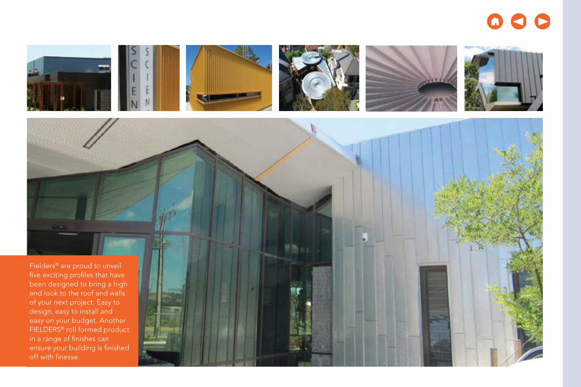
Fielders® are proud to unveil five exciting profiles that have been designed to bring a high end look to the roof and walls of your next project. Easy to design, easy to install and easy on your budget. Another FIELDERS® roll formed product in a range of finishes can ensure your building is finished off with finesse.

Quick Links: home index non-cyclonic profiles finesse profiles aramax profiles freeform profiles cyclonic profiles rainwater goods & acc. design data maintenance & care warranty glossary
Shadowline™ 305
View a Case Study
Material SpecificationsShadowline™ 305
Property 0.70 BMT NotesBase Metal Thickness (mm) 0.70 BMT
Total Coated Thickness (mm) 0.75* TCT
Mass / Unit LengthZINCALUME® 2.96
kg/mCOLORBOND® 2.99*
Mass / Unit AreaZINCALUME® 9.70
kg/m2
COLORBOND® 9.81*Minimum Yield Strength G300 Base Steel Designation
Coating ClassAM100 - COLORBOND®
AM125 - ZINCALUME®
AM150 - COLORBOND® Ultra
Minimum Coating g/m2 of Zinc - Aluminium
Coverage 305 mmTolerance Sheet Length ±10mm Cover Width ±5mm
Thermal Expansion 2.9mm average per 5m at 50° C change
Table SL MS NC 001Notes:1. Shadowline™ 305 is manufactured from materials in accordance to AS 1397 and AS 2728. It is to be
installed in accordance with AS 1562 and HB 39.
2. The sectional properties are theoretical values per sheet width. These properties are gross values only.
3. *is based on Standard COLORBOND® single-sided material. For other painted steel options please contact a Fielders® representative.
Finesse® Profiles
For WA projects please click here to view the Shadowline™ WA data.
305mm cover
48mm
305mm cover
48mm
275/475
25
this section start next section start
48mm
305mm

Quick Links: home index non-cyclonic profiles finesse profiles aramax profiles freeform profiles cyclonic profiles rainwater goods & acc. design data maintenance & care warranty glossary
About ShadowlineTM 305Fielders® Shadowline™ 305 is a two pan, low-pitched roof deck that can be used down to a minimum of one degree pitch as a concealed fix button punched deck (see Figure SL IG NC 001) or as a pierced fix wall cladding. Fielders® Shadowline™ 305 is available in all states of Australia except WA - see Shadowline™ WA for details.
When used as a wall cladding Fielders® Shadowline™ 305 can be fixed both horizontally and vertically through each pan to each girt with a hexagon head self-drilling and tapping screw. The exact specification is subject to project requirements.
Fielders® Shadowline™ 305 can be rolled to any transportable length in ZINCALUME® with the full range of COLORBOND® colours in 0.70 BMT gauge.
Lead time for the Shadowline™ 305 profile is subject to the material finish and the colour availability. Smaller quantities are available as a stock item, subject to normal rolling schedules. For substantial quantities the lead time generally does not exceed two to three weeks. Contact your local Fielders® office for further information.
Finesse® Profiles
For WA projects please click here to view the Shadowline™ WA data.
Shadowline™ 305
this section start next section start

Quick Links: home index non-cyclonic profiles finesse profiles aramax profiles freeform profiles cyclonic profiles rainwater goods & acc. design data maintenance & care warranty glossary
Shadowline™ 305
Rainfall Capacity For further information, please refer to sections “Rainfall Intensity” and “Water Carrying Capacity and Rainwater Run-Off”.
Maximum Roof Length (m) Shadowline™ 305 Non-Cyclonic
Roof Slope (degrees)
Rainfall Capacity (mm/hr)
100 150 200 250 300 350 4001 219 146 110 88 73 64 55
2 273 182 136 109 91 80 68
3 320 213 160 128 107 94 80
4 359 239 180 144 120 106 905 398 265 199 159 133 117 100
Figure SL RC NC 001
Table SL RL NC 001Note: 1. Minimum recommended slope is 1°. Sheet lengths greater
than 24m are not recommended due to thermal expansion and contraction.
50
100
150
200
250
300
350
400100mm/hr
150mm/hr
200mm/hr
250mm/hr
300mm/hr
350mm/hr
400mm/hr
Max
imum
She
et L
eng
th (m
)
Roof Slope (degrees)
1 2 3 4 5
this section start next section start
Finesse® Profiles

Quick Links: home index non-cyclonic profiles finesse profiles aramax profiles freeform profiles cyclonic profiles rainwater goods & acc. design data maintenance & care warranty glossary
Wind Load Capacity - Limit State Design (kPa)ShadowlineTM 305 Button Punched
Span (mm)
0.70 BMT
Single Span End Span Internal Span
Serv. Strength Serv. Strength Serv. Strength
900 2.60 3.60 1.45 4.20 2.05 5.20
1200 2.10 3.25 1.45 3.80 1.90 4.90
1500 1.70 2.85 1.40 3.45 1.80 4.55
1800 1.35 2.70 1.35 3.15 1.65 4.15
2100 1.10 2.40 1.30 2.75 1.55 3.65
2400 0.95 2.20 1.25 2.45 1.45 3.05
2700 0.80 1.95 1.15 2.25 1.30 2.50
Turning of Roof Sheeting EndsRefer to section “Flashings, Cappings & Ends of Sheets”.
Overhang
Overhang
Overhang
Overhang(End span)
End spanEnd span
End span
Internal spans
Internal spans
Figure SL NC 001 End Spans, Internal Spans and Overhangs
Table SL WC NC 001Note: 1. Values in the table above have been generated based on testing into steel supports with at thickness of 1.0 mm.
2. Values are based on no insulation under the sheeting.
View a Case Study
ShadowlineTM 305 Button Punched
Finesse® Profiles
button punched
screw fixed
Shadowline™ 305
this section start next section start

Quick Links: home index non-cyclonic profiles finesse profiles aramax profiles freeform profiles cyclonic profiles rainwater goods & acc. design data maintenance & care warranty glossary
View a Case Study
Maximum Recommended Roof Cladding Span (mm)ShadowlineTM 305 Button Punched
WindRegion
Base Metal
Thickness
Terrain Category 2 Terrain Category 3
Single End Internal Single End Internal
A 0.70 1500 - 2500 1800 2000 2500
B 0.70 - - 2500 1800 2000 2500
Table SL RS NC 002Notes:1. Maximum roofing spans comply with both strength and serviceability wind
pressure requirements.
2. Spans shown in italics are limited by foot traffic requirements.
Maximum Recommended Wall Cladding Span (mm)ShadowlineTM 305 Button Punched
WindRegion
Base Metal
Thickness
Terrain Category 2 Terrain Category 3
Single End Internal Single End Internal
A 0.70 1900 2200 2700 2500 2700 2700
B 0.70 1500 1400 2700 2300 2700 2700
Table SL RS NC 001Notes:1. Maximum walling spans comply with both strength and serviceability wind
pressure requirements.
Finesse® Profiles
Maximum Recommended Roof Cladding Spans Based on Foot Traffic (mm)
ShadowlineTM 305 Button Punched
Base Metal Thickness (mm) Single End Internal
0.70 1800 2000 2500
Table SL FT NC 001
Shadowline™ 305
Wind Loading Design Parameters:Design Life 50 yearsImportance Level 2Maximum Roof Height H = 10mExternal Pressure Coefficients: Cp,e = -0.65 (walling) Cp,e = -0.9 (roofing)Internal Pressure Coefficient: Cp,i = 0.2Local Pressure Factors: K l = 2.0 (end & single spans) K l = 1.0 (internal spans)
this section start next section start

Quick Links: home index non-cyclonic profiles finesse profiles aramax profiles freeform profiles cyclonic profiles rainwater goods & acc. design data maintenance & care warranty glossary
Shadowline™ 305 - Limit State Design (kPa)ShadowlineTM 305 Pierced Fixed
Span (mm)
0.70mm BMT
End Span Internal Span
Serv. Strength Serv. Strength
900 4.09 12.09
1200 3.63 9.34 4.24 12.09
1500 3.48 7.16 3.50 9.34
1800 3.21 5.09 3.27 7.16
2100 2.74 3.67 3.09 5.09
2400 2.46 3.63 2.74 3.67
2700 1.98 3.09
3000 1.78 2.88
3300 1.49 2.38
Table SL WC NC 002
Maximum Recommended Wall Cladding Span (mm)ShadowlineTM 305 Pierced Fixed
WindRegion
Base Metal
Thickness
Terrain Category 2 Terrain Category 3
End Internal End Internal
A 0.70 3000* 3000* 3000* 3000*
B 0.70 3000* 3000* 3000* 3000*
Table SL RS NC 003Notes:1. Maximum walling spans comply with both strength and serviceability wind
pressure requirements.
2. * Spans in excess of 3000mm may be available subject to enquiry. Wall applications or long spans require particular attention to installation practice.
ShadowlineTM 305 Pierced Fixed
View a Case Study
button punched
screw fixed
Shadowline™ 305
Insulation Care needs to be taken when installing insulation with Shadowline™ roof sheeting. When insulation thicknesses up to 50mm are installed the screws may need to be increased depending on the thickness and density of the insulation. When the screw is properly tightened into metal there should be a minimum of three (3) threads protruding past the support being fixed in to. For timber, the screw must have a minimum embedment of 25mm into timber.
When insulation is required in conjunction with Finesse® profiles, Fielders® recommend the use of a thermal spacer to help maintain Rw values as well as minimising any bulging in the profile caused by the insulation.
this section start next section start
Finesse® Profiles
SL INS NC 001

Quick Links: home index non-cyclonic profiles finesse profiles aramax profiles freeform profiles cyclonic profiles rainwater goods & acc. design data maintenance & care warranty glossary
Installation Guidelines: Button Punched (Concealed Fixed)1. Place first sheet down with the correct length into the gutter.
Using the rib closing tool squash the female rib and place a top fixing clip over and fix to the purlin.
2. Using the rib closing tool squeeze the male rib of the first sheet. Place top fixing clip over each squashed male rib and fix to purlin. This needs to be done to prevent the sheet from lifting in the wind before the barges are fitted. The use of string lines will assist in ensuring sheets are installed straight.
3. Make a small non-permanent mark in the pan to enable you to locate the clips in the latter locking operation with the button punch.
4. Position the female rib of the next sheet over the male rib and clips ensuring that it is fully engaged. Fully engage the sheet with the clips using foot pressure on the ribs over each clip. You can do this by walking along the full length of the sheet with one foot in the tray next to the overlapping rib and the other foot applying pressure to the top of the interlocking ribs at regular intervals.
5. Repeat steps 3 to 5.
6. All lapped ribs must be locked along their length, by button punching at the clips, and if necessary between the clips (typically at 900mm centre to centre). Punching to a string line guide stretched across the sheeting is recommended as random punching marks the appearance of the finished work.
Figure SL IG NC 002
Figure SL IG NC 003
Figure SL IG NC 001
Shadowline™ 305
this section start next section start
Finesse® Profiles

Quick Links: home index non-cyclonic profiles finesse profiles aramax profiles freeform profiles cyclonic profiles rainwater goods & acc. design data maintenance & care warranty glossary
7. You must button punch through the hole in each top fixing clip, you can locate the clip with the non-permanent mark made previously. When operating the punching tool, stand on the pan of the overlapping sheet to ensure that the sheets are fully engaged.
Ends of SheetsWind can drive water uphill under the flashings or cappings. Also, at the low end of a roof, wind or capillary action can cause water to run back up the underside of the sheeting. To minimise these problems, turn the pans up at the top of sheets, and turn them down at the bottom. A tool is available for these jobs (ref. Figure SL IG NC 005).
Rib must touch
Fold ‘ears’ against toolfor a flush turn-up
Part of ribremoved
90˚
50mm
50mm
Figure SL IG NC 005
Figure SL IG NC 004
Shadowline™ 305
this section start next section start
Finesse® Profiles

Quick Links: home index non-cyclonic profiles finesse profiles aramax profiles freeform profiles cyclonic profiles rainwater goods & acc. design data maintenance & care warranty glossary
Turning-upFlush turn-ups are usually used on Shadowline™ 305. Cut off a portion of the female rib for at least 50mm. For a flush turn-up, you also need to cut the crown of the centre rib for at least 50mm.
Holding the end of the tool against the end of the sheet, pull the handle up 90°. If turning-up flush, fold the protruding ears flush against the turn-up tool with a rubber mallet (ref. Figure SL IG NC 005).
Turning-downAll roofing on slopes below 1 in 5 (10°) must be turned-down. Turning-down is usually done after the sheeting is fixed on the roof, provided there is no obstruction to the operation of the turn-down tool.
Push the turn-down tool over the end of the tray, as far as it will go.
Hold the tool hard against the end of the tray and push the handle to form a turn-down of about 20° (Figure SL IG NC 006).
20°
Figure SL IG NC 006
12 - 15mm
FIELDERS SHADOWLINE PAN FIXING ARRANGEMENT
SCREW SIZE: - 14 - 10x25 HH TEKS
Shadowline™ 305
Table SL RF NC 002
Recommended FastenersShadowlineTM 305 Pierced Fixed
Supports Recommended Fastener (Without Insulation)
Steel 1.0 to 3.5mm 14g-10x25mm Hex Head Tek Screw
Timber Hardwood 14g-10x25mm Hex Head Type 17 Screw
Timber Softwood 14g-10x25mm Hex Head Type 17 Screw
Steel Battens (0.55 to 1.0mm) 14g-10x25mm Hex Head Tek Screw
this section start next section start
Finesse® Profiles
Recommended FastenersShadowlineTM 305 Button Punched
Supports Recommended Fastener (Without Insulation)
Steel 1.0 to 3.5mm 10g-16x16mm Wafer Head Tek Screw
Timber Hardwood 10g-12x25mm Wafer Head Type 17 Screw
Timber Softwood 10g-12x25mm Wafer Head Type 17 Scre
Steel Battens (0.55 to 1.0mm) 10g-16x16mm Wafer Head Tek Screw
Table SL RF NC 001
Figure SL IG NC 007

Quick Links: home index non-cyclonic profiles finesse profiles aramax profiles freeform profiles cyclonic profiles rainwater goods & acc. design data maintenance & care warranty glossary
Roof to Wall Connection Detail 1
CUTKINK LINES
CUT
BENDLINES
SLOPE HEIGHTOF RIB
WIDTH-TOPOF RIB
ROOF PITCH ANGLE
Apply recommended sealant inside ends and along bottom of cap.
Place in position over opened rib andfasten with four 4mm blind rivets.
Continuous sheeting.Mansard roof with trays bentand the cut ribs waterproofedwith sealed rib caps.
Figure SL IG NC 008
Shadowline™ 305
this section start next section start
Finesse® Profiles
Step 1 - Rib Caps Cut and Folded from Flat Sheet
Development of Cap on Flat Sheet
CUTKINK LINES
CUT
BENDLINES
SLOPE HEIGHTOF RIB
WIDTH-TOPOF RIB
ROOF PITCH ANGLE
Apply recommended sealant inside ends and along bottom of cap.
Place in position over opened rib andfasten with four 4mm blind rivets.
Continuous sheeting.Mansard roof with trays bentand the cut ribs waterproofedwith sealed rib caps.
Figure SL IG NC 009
Step 2
CUTKINK LINES
CUT
BENDLINES
SLOPE HEIGHTOF RIB
WIDTH-TOPOF RIB
ROOF PITCH ANGLE
Apply recommended sealant inside ends and along bottom of cap.
Place in position over opened rib andfasten with four 4mm blind rivets.
Continuous sheeting.Mansard roof with trays bentand the cut ribs waterproofedwith sealed rib caps.
Figure SL IG NC 010
Step 3

Quick Links: home index non-cyclonic profiles finesse profiles aramax profiles freeform profiles cyclonic profiles rainwater goods & acc. design data maintenance & care warranty glossary
Roof to Wall Connection Detail 2
ROOF SHEET TO SLIDE OVER WALL SHEETS
RIVET
CUT BACK TO PAN
CUT BACK TO SUIT ROOF PITCH
50mm
X°
ROOF PITCH “X”
CUT BACK SO PANS MEETAND RIBS ARE FLUSH
Figure SL IG NC 011
Shadowline™ 305
this section start next section start
Finesse® Profiles
Step 1
SILICON INTERNALPLUS RIVET BOTH SIDES
WALL RIB TO SITINSIDE ROOF RIB
BUTYL TAPE
SILICONE BEAD
A
A
SECTION A-A
Figure SL IG NC 012
Step 2 Step 3
SILICON INTERNALPLUS RIVET BOTH SIDES
WALL RIB TO SITINSIDE ROOF RIB
BUTYL TAPE
SILICONE BEAD
A
A
SECTION A-A
Figure SL IG NC 013
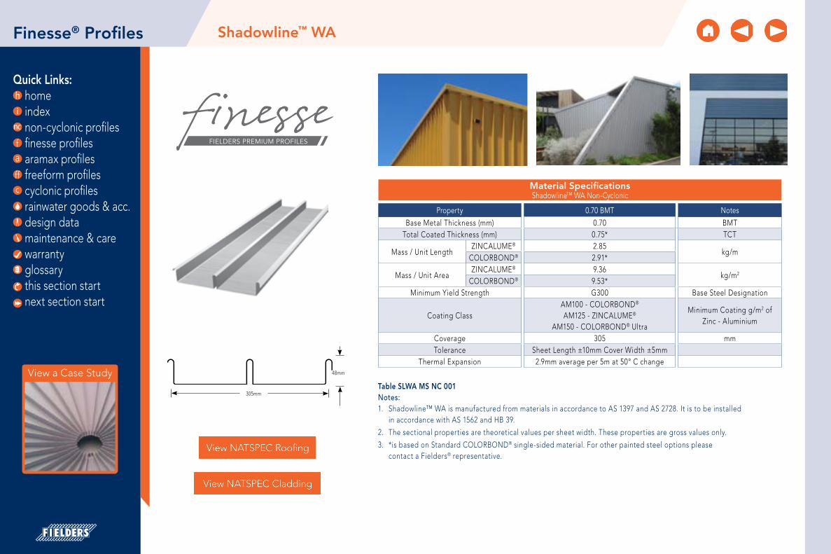
Quick Links: home index non-cyclonic profiles finesse profiles aramax profiles freeform profiles cyclonic profiles rainwater goods & acc. design data maintenance & care warranty glossary
Material Specifications ShadowlineTM WA Non-Cyclonic
Property 0.70 BMT NotesBase Metal Thickness (mm) 0.70 BMT
Total Coated Thickness (mm) 0.75* TCT
Mass / Unit LengthZINCALUME® 2.85
kg/mCOLORBOND® 2.91*
Mass / Unit AreaZINCALUME® 9.36
kg/m2
COLORBOND® 9.53*Minimum Yield Strength G300 Base Steel Designation
Coating ClassAM100 - COLORBOND®
AM125 - ZINCALUME®
AM150 - COLORBOND® Ultra
Minimum Coating g/m2 of Zinc - Aluminium
Coverage 305 mmTolerance Sheet Length ±10mm Cover Width ±5mm
Thermal Expansion 2.9mm average per 5m at 50° C change48mm
305mmTable SLWA MS NC 001Notes:1. Shadowline™ WA is manufactured from materials in accordance to AS 1397 and AS 2728. It is to be installed
in accordance with AS 1562 and HB 39.
2. The sectional properties are theoretical values per sheet width. These properties are gross values only.
3. *is based on Standard COLORBOND® single-sided material. For other painted steel options please contact a Fielders® representative.
View a Case Study
Shadowline™ WAFinesse® Profiles
this section start next section start

Quick Links: home index non-cyclonic profiles finesse profiles aramax profiles freeform profiles cyclonic profiles rainwater goods & acc. design data maintenance & care warranty glossary
View a Case Study
About Shadowline™ WAFielders® Shadowline™ WA is a two pan, low-pitched roof deck that can be used down to a minimum of one degree pitch as a concealed fix button punched deck (see Figure SLWA IG NC 001) or as a pierced fix wall cladding. Fielders® Shadowline™ WA is only available in Western Australia.
When used as a wall cladding Fielders® Shadowline™ WA can be fixed both horizontally and vertically through each pan to each girt with a hexagon head self-drilling and tapping screw. The exact specification is subject to project requirements. An unobtrusive fixing option is the ‘Irius’ screw from Power Fasteners.
Fielders® Shadowline™ WA can be rolled to any transportable length in ZINCALUME® with the full range of COLORBOND® colours in 0.70 BMT gauge.
Lead time for the Shadowline™ WA profile is subject to the material finish and the colour availability. Smaller quantities are available as a stock item, subject to normal rolling schedules. For substantial quantities the lead time generally does not exceed two to three weeks. Contact your local Fielders® office for further information.
Finesse® Profiles Shadowline™ WA
this section start next section start

Quick Links: home index non-cyclonic profiles finesse profiles aramax profiles freeform profiles cyclonic profiles rainwater goods & acc. design data maintenance & care warranty glossary
View a Case Study
Shadowline™ WA
Rainfall Capacity For further information, please refer to sections “Rainfall Intensity” and “Water Carrying Capacity and Rainwater Run-Off”.
Maximum Roof Length (m) Shadowline™ WA Non-Cyclonic
Roof Slope (degrees)
Rainfall Capacity (mm/hr)
100 150 200 250 300 350 4001 292 194 146 117 97 83 73
2 414 276 207 166 138 118 104
3 508 338 254 203 169 145 127
4 587 391 293 235 196 168 1475 655 437 328 262 218 187 164
10 925 617 463 370 308 264 231
Figure SLWA RC NC 001
Table SLWA RL NC 001Note: 1. Minimum recommended slope is 1°. Sheet lengths greater
than 24m are not recommended due to thermal expansion and contraction.
0
200
400
600
800
1000100mm/hr
150mm/hr
200mm/hr
250mm/hr
300mm/hr
350mm/hr
400mm/hr
Max
imum
She
et L
eng
th (m
)
Roof Slope (degrees)
1 2 3 4 5
this section start next section start
Finesse® Profiles

Quick Links: home index non-cyclonic profiles finesse profiles aramax profiles freeform profiles cyclonic profiles rainwater goods & acc. design data maintenance & care warranty glossary
Limit State Design (kPa)ShadowlineTM WA Non-Cyclonic Button Punched
Span (mm)
0.70mm BMT
Single Span End Span Internal Span
Serv. Strength Serv. Strength Serv. Strength
900 2.60 3.60 1.45 4.20 2.05 5.20
1200 2.10 3.25 1.45 3.80 1.90 4.90
1500 1.70 2.85 1.40 3.45 1.80 4.55
1800 1.35 2.70 1.35 3.15 1.65 4.15
2100 1.10 2.40 1.30 2.75 1.55 3.65
2400 0.95 2.20 1.25 2.45 1.45 3.05
2700 0.80 1.95 1.15 2.25 1.30 2.50
Table SLWA WC NC 002Note: 1. Values in the table above have been generated based on testing into steel supports with at thickness of 1.0 mm.
2. Values are based on no insulation under the sheeting.
View a Case Study
Shadowline™ WA
ShadowlineTM WA Button Punched button punched
screw fixed
Overhang
Overhang
Overhang
Overhang(End span)
End spanEnd span
End span
Internal spans
Internal spans
Figure SLWA NC 001 End Spans, Internal Spans and Overhangs
this section start next section start
Finesse® Profiles

Quick Links: home index non-cyclonic profiles finesse profiles aramax profiles freeform profiles cyclonic profiles rainwater goods & acc. design data maintenance & care warranty glossary
Shadowline™ WA
Maximum Recommended Wall Cladding Span (mm)ShadowlineTM WA Button Punched
WindRegion
Base Metal
Thickness
Terrain Category 2 Terrain Category 3
Single End Internal Single End Internal
A 0.70 1900 2200 2700 2500 2700 2700
B 0.70 1500 1400 2700 2300 2700 2700
Maximum Recommended Roof Cladding Span (mm)ShadowlineTM WA Button Punched
WindRegion
Base Metal
Thickness
Terrain Category 2 Terrain Category 3
Single End Internal Single End Internal
A 0.70 1500 - 2500 1800 2000 2500
B 0.70 - - 2500 1800 2000 2500
Table SLWA RS NC 003Notes:1. Maximum walling spans comply with both strength and serviceability wind pressure requirements.
Table SLWA RS NC 004Notes:1. Maximum roofing spans comply with both strength and serviceability wind pressure requirements.
2. Spans shown in italics are limited by foot traffic requirements.
this section start next section start
Finesse® Profiles
Wind Loading Design Parameters:Design Life 50 yearsImportance Level 2Maximum Roof Height H = 10mExternal Pressure Coefficients: Cp,e = -0.65 (walling) Cp,e = -0.9 (roofing)Internal Pressure Coefficient: Cp,i = 0.2Local Pressure Factors: K l = 2.0 (end & single spans) K l = 1.0 (internal spans)

Quick Links: home index non-cyclonic profiles finesse profiles aramax profiles freeform profiles cyclonic profiles rainwater goods & acc. design data maintenance & care warranty glossary
View a Case Study
Maximum Recommended Roof Cladding Span (mm)ShadowlineTM WA Pierced Fixed
WindRegion
Base Metal
Thickness
Terrain Category 2 Terrain Category 3
Single End Internal Single End Internal
A 0.70 3000* 3000* 3000* 3000* 2000 2500
B 0.70 3000* 3000* 3000* 3000* 2000 2500
Table SLWA RS NC 002Notes:1. Maximum roofing spans comply with both strength and serviceability wind pressure
requirements.
2. Spans shown in italics are limited by foot traffic requirements.
3. * Spans in excess of 3000mm may be available subject to enquiry. Long spans require particular attention to installation practice.
Maximum Recommended Wall Cladding Span (mm)ShadowlineTM WA Pierced Fixed
WindRegion
Base Metal
Thickness
Terrain Category 2 Terrain Category 3
End Internal End Internal
A 0.70 3000* 3000* 3000* 3000*
B 0.70 3000* 3000* 3000* 3000*
Table SLWA RS NC 001
Notes:1. Maximum walling spans comply with both strength and serviceability wind pressure
requirements.
2. *Spans in excess of 3000mm may be available subject to enquiry. Wall applications or long spans require particular attention to installation practice.
Finesse® Profiles
Limit State Design (kPa)ShadowlineTM WA Pierced Fixed
Span (mm)
0.70mm BMT
End Span Internal Span
Serv. Strength Serv. Strength
900 4.09 12.09
1200 3.63 9.34 4.24 12.09
1500 3.48 7.16 3.50 9.34
1800 3.21 5.09 3.27 7.16
2100 2.74 3.67 3.09 5.09
2400 2.46 3.63 2.74 3.67
2700 1.98 3.09
3000 1.78 2.88
3300 1.49 2.38
Table SLWA WC NC 001
Shadowline™ WA
Maximum Recommended Roof Cladding Spans Based on Foot Traffic (mm)
ShadowlineTM WA Button Punched
Base Metal Thickness (mm) Single End Internal
0.70 1800 2000 2500
Table SLWA FT NC 001
this section start next section start
ShadowlineTM WA Pierced Fixed
button punched
screw fixed

Quick Links: home index non-cyclonic profiles finesse profiles aramax profiles freeform profiles cyclonic profiles rainwater goods & acc. design data maintenance & care warranty glossary
Setting Your Button Punch1. First set the depth that the button punch will punch.
2. Place the button punch on its handles and lean it against a support with the button lining up with the face of the cup.
3. Measure between the two punch holders (in photo about 24mm).
4. Close the handles until the gap decreases by 2.0mm.
5. Adjust the stop adjustment until it is set at that distance.
6. Setting the distance down from the top of the rib of the roof sheet that the button punch is located.
7. The distance from the centre of the button punch to the support guides is 17mm as shown.
8. If this needs to be adjusted, loosen the set screws, adjust the stop and retightened.
9. After you do the first button punch check that it is in fact punching to that dimension.
10. Some minor adjustment may be required as it should punch in the centre of the hole in the clip.
17mm
Shadowline™ WA
this section start next section start
Finesse® Profiles

Quick Links: home index non-cyclonic profiles finesse profiles aramax profiles freeform profiles cyclonic profiles rainwater goods & acc. design data maintenance & care warranty glossary
Figure SLWA NC 001
Installation Guide: Button Punched (Concealed Fixed)
1. Fix a clip to the first and last purlin.
2. Attached a string line to the first and last clip as a guide to fix the remainder of the clips to the purlins in between.
3. Place the first sheet over the clips with the correct length into the gutter.
4. Using the rib closing tool squeeze the male rib of the first sheet. Place top clip over each squashed male rib and fix to purlin. This needs to be done to prevent the sheet from lifting in the wind before the barges are fitted. The use of string lines will assist in ensuring sheets are installed straight.
Finesse® Profiles
Figure SLWA IG NC 001
Figure SLWA IG NC 002
Shadowline™ WA
this section start next section start

Quick Links: home index non-cyclonic profiles finesse profiles aramax profiles freeform profiles cyclonic profiles rainwater goods & acc. design data maintenance & care warranty glossary
5. Make a small non-permanent mark in the pan to enable you to locate the clips in the latter locking operation with the button punch.
6. Position the female rib of the next sheet over the male rib and clips ensuring that it is fully engaged. Fully engage the sheet with the clips using foot pressure on the ribs over each clip. You can do this by walking along the full length of the sheet with one foot in the tray next to the overlapping rib and the other foot applying pressure to the top of the interlocking ribs at regular intervals.
7. Repeat steps 3 to 5.
8. All lapped ribs must be locked along their length, by button punching at the clips, and if necessary between the clips (typically at 900mm centre to centre). Punching to a string line guide stretched across the sheeting is recommended as random punching marks the appearance of the finished work.
You must button punch through the hole in each top fixing clip, you can locate the clip with the non-permanent mark made previously. When operating the punching tool, stand on the pan of the overlapping sheet to ensure that the sheets are fully engaged.
Figure SLWA IG NC 004
Rib must touch
Shadowline™ WA
Figure SLWA IG NC 003
this section start next section start
Finesse® Profiles

Quick Links: home index non-cyclonic profiles finesse profiles aramax profiles freeform profiles cyclonic profiles rainwater goods & acc. design data maintenance & care warranty glossary
Ends of SheetsWind can drive water uphill under the flashings or cappings. Also, at the low end of a roof, wind or capillary action can cause water to run back up the underside of the sheeting. To minimise these problems, turn the pans up at the top of sheets, and turn them down at the bottom. A tool is available for these jobs (ref. Figure SLWA IG NC 005)
Turning-upFlush turn-ups are usually used on Shadowline™ WA. Cut off a portion of the female rib for at least 50mm. For a flush turn-up, you also need to cut the crown of the centre rib for at least 50mm.
Holding the end of the tool against the end of the sheet, pull the handle up 90°. If turning-up flush, fold the protruding ears flush against the turn-up tool with a rubber mallet (ref. Figure SLWA IG NC 005).
Fold ‘ears’ against toolfor a flush turn-up
Part of ribremoved
90˚
50mm
50mm
Figure SLWA IG NC 005
20°
Figure SLWA IG NC 006
Shadowline™ WA
this section start next section start
Finesse® Profiles

Quick Links: home index non-cyclonic profiles finesse profiles aramax profiles freeform profiles cyclonic profiles rainwater goods & acc. design data maintenance & care warranty glossary
Shadowline™ WA
Turning-downAll roofing on slopes below 1 in 5 (10°) must be turned-down.
Turning-down is usually done after the sheeting is fixed on the roof, provided there is no obstruction to the operation of the turn-down tool.
Push the turn-down tool over the end of the tray, as far as it will go.
Hold the tool hard against the end of the tray and push the handle to form a turn-down of about 20° (ref. Figure SLWA IG NC 006).
Recommended FastenersShadowlineTM WA Pierced Fixed
Supports Recommended Fastener (Without Insulation)
Steel 1.0 to 3.5mm 14g-10x25mm Hex Head Tek Screw
Timber Hardwood 14g-10x25mm Hex Head Type 17 Screw
Timber Softwood 14g-10x25mm Hex Head Type 17 Screw
Steel Battens (0.55 to 1.0mm) 14g-10x25mm Hex Head Tek Screw
Table SLWA RF NC 001
Insulation Care needs to be taken when installing insulation with Shadowline™ WA roof sheeting. When insulation thicknesses up to 50mm are installed the screws may need to be increased depending on the thickness and density of the insulation. When the screw is properly tightened into metal there should be a minimum of three (3) threads protruding past the support being fixed in to. For timber, the screw must have a minimum embedment of 25mm into timber.
When insulation is required in conjunction with Finesse® profiles, Fielders® recommend the use of a thermal spacer to help maintain Rw values as well as minimising any bulging in the profile caused by the insulation.
Table SLWA RF NC 002
Recommended FastenersShadowlineTM WA Button Punched
Supports Recommended Fastener (Without Insulation)
Steel 1.0 to 3.5mm 10g-16x16mm Wafer Head Tek Screw
Timber Hardwood 10g-12x25mm Wafer Head Type 17 Screw
Timber Softwood 10g-12x25mm Wafer Head Type 17 Screw
Steel Battens (0.55 to 1.0mm) 10g-16x16mm Wafer Head Tek Screw
this section start next section start
Finesse® Profiles
SLWA INS NC 001
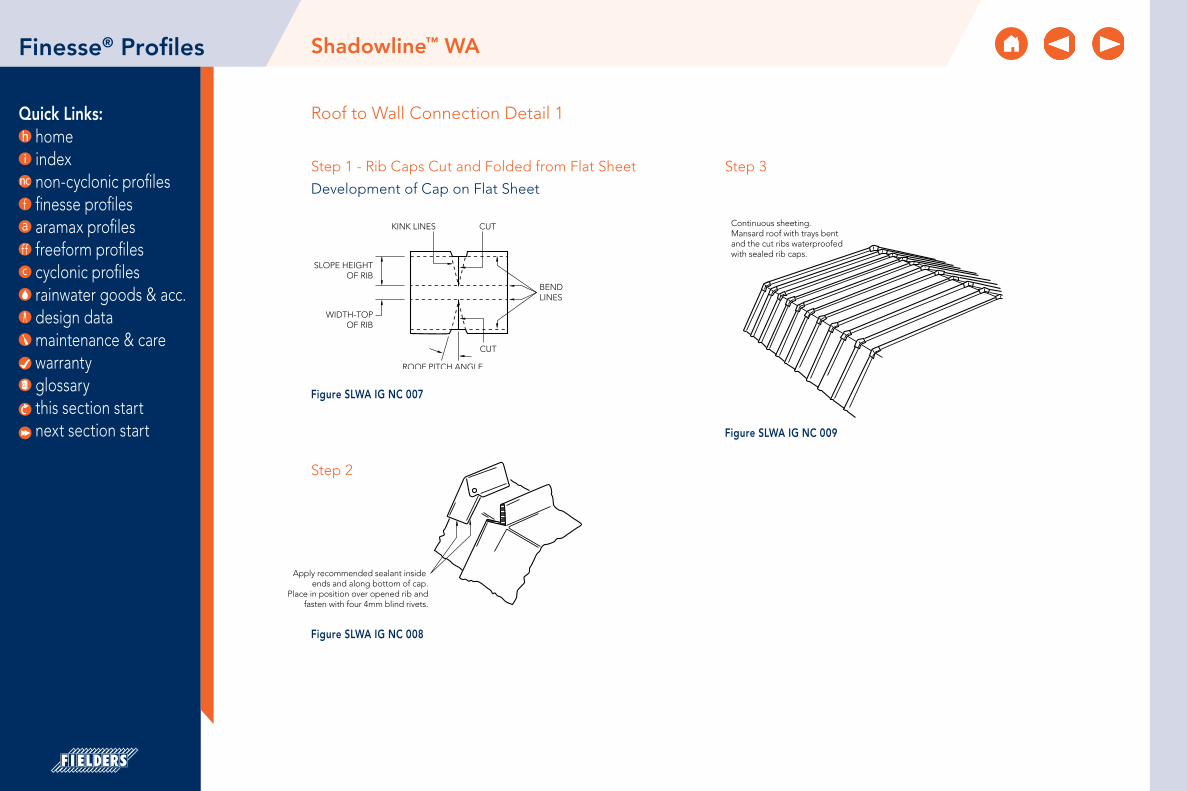
Quick Links: home index non-cyclonic profiles finesse profiles aramax profiles freeform profiles cyclonic profiles rainwater goods & acc. design data maintenance & care warranty glossary
Roof to Wall Connection Detail 1
CUTKINK LINES
CUT
BENDLINES
SLOPE HEIGHTOF RIB
WIDTH-TOPOF RIB
ROOF PITCH ANGLE
Apply recommended sealant inside ends and along bottom of cap.
Place in position over opened rib andfasten with four 4mm blind rivets.
Continuous sheeting.Mansard roof with trays bentand the cut ribs waterproofedwith sealed rib caps.
Figure SLWA IG NC 007 this section start next section start
Finesse® Profiles
Step 1 - Rib Caps Cut and Folded from Flat Sheet
Development of Cap on Flat Sheet
CUTKINK LINES
CUT
BENDLINES
SLOPE HEIGHTOF RIB
WIDTH-TOPOF RIB
ROOF PITCH ANGLE
Apply recommended sealant inside ends and along bottom of cap.
Place in position over opened rib andfasten with four 4mm blind rivets.
Continuous sheeting.Mansard roof with trays bentand the cut ribs waterproofedwith sealed rib caps.
Figure SLWA IG NC 008
Step 2
CUTKINK LINES
CUT
BENDLINES
SLOPE HEIGHTOF RIB
WIDTH-TOPOF RIB
ROOF PITCH ANGLE
Apply recommended sealant inside ends and along bottom of cap.
Place in position over opened rib andfasten with four 4mm blind rivets.
Continuous sheeting.Mansard roof with trays bentand the cut ribs waterproofedwith sealed rib caps.
Figure SLWA IG NC 009
Step 3
Shadowline™ WA

Quick Links: home index non-cyclonic profiles finesse profiles aramax profiles freeform profiles cyclonic profiles rainwater goods & acc. design data maintenance & care warranty glossary
Shadowline™ WA
Roof to Wall Connection Detail 2
ROOF SHEET TO SLIDE OVER WALL SHEETS
RIVET
CUT BACK TO PAN
CUT BACK TO SUIT ROOF PITCH
50mm
X°
ROOF PITCH “X”
CUT BACK SO PANS MEETAND RIBS ARE FLUSH
Figure SLWA IG NC 010
this section start next section start
Finesse® Profiles
Step 1
SILICON INTERNALPLUS RIVET BOTH SIDES
WALL RIB TO SITINSIDE ROOF RIB
BUTYL TAPE
SILICONE BEAD
A
A
SECTION A-A
Figure SLWA IG NC 011
Step 2 Step 3
SILICON INTERNALPLUS RIVET BOTH SIDES
WALL RIB TO SITINSIDE ROOF RIB
BUTYL TAPE
SILICONE BEAD
A
A
SECTION A-A
Figure SLWA IG NC 012

Quick Links: home index non-cyclonic profiles finesse profiles aramax profiles freeform profiles cyclonic profiles rainwater goods & acc. design data maintenance & care warranty glossary
Material SpecificationsNeo RomanTM
Property 275mm Pan Width 475mm Pan Width Notes
Base Metal Thickness (mm) 0.55 0.75 0.55 0.75 BMTTotal Coated Thickness (mm) 0.60* 0.80* 0.60* 0.80* TCT
Mass / Unit LengthZINCALUME® 1.83 2.41 2.75 3.61
kg/mCOLORBOND® 1.86* 2.44* 2.80* 3.66*
Mass / Unit AreaZINCALUME® 6.65 8.76 5.79 7.61
kg/m2
COLORBOND® 6.76* 8.87* 5.90* 7.71*
Coverage 275 275 475 475 mm
Minimum Yield Strength G300 MPa
Coating ClassAM100 - COLORBOND®
AM125 - ZINCALUME®
AM150 - COLORBOND® Ultra
Minimum Coating g/m2 of Zinc - Aluminium
ToleranceSheet length ±7mmCover width ± 4mm
Thermal Expansion2.9mm average per 5.0 metre
@ 50˚C change
Table NR MS NC 001Notes:1. The COLORBOND® and ZINCALUME® material is in accordance to AS 1397, AS 1365 and AS 2728.
The installation of the cladding should be in accordance to AS 1562.1 and HB39.
2. *is based on Standard COLORBOND® single-sided material. For other painted steel options please contact a Fielders® representative.
Neo RomanTM
AA
JJ
CD GRADEPLYWOOD 19mm
BREATHABLEANTI-ABRASIVE
MEMBRANE
CD GRADEPLYWOOD 19mm
* WHEN ROOF PITCH IS UNDER 7.5° OR TOTAL COMBINED SHEET LENGTH IS OVER 5 METRES
MIN 20mm VENTILATION GAP
MIN 20mm VENTILATION GAP
STRUCTURE
STRUCTURE
RIVETS. BOTH SIDES @ 600mm c/c*
RIB BRACKETNEO-ROMAN SINGLE RIB
SILICONE FASTENERS #14 – 10x35mm HEXAGON HEAD TYPE 17 SCREW @ 600mm c/c*
BREATHABLEANTI-ABRASIVE
MEMBRANE
* SCREW SPACING MAY VARY IN HIGH WIND ZONES. CONSULT FIELDERS FOR FURTHER ADVICE.
* SCREW SPACING MAY VARY IN HIGH WIND ZONES. CONSULT FIELDERS FOR FURTHER ADVICE.
FASTENERS #14 – 10x35MM HEXAGON HEAD TYPE 17 SCREW @ 600mm c/c*
NEO-ROMAN DOUBLE RIBAVAILABLE ON REQUEST:
MINIMUM QUANTITIES APPLY
275/475mm
275/475mm
25m
m
13m
m
25m
m
this section start next section start
Finesse® Profiles
Double Rib
Single Rib

Quick Links: home index non-cyclonic profiles finesse profiles aramax profiles freeform profiles cyclonic profiles rainwater goods & acc. design data maintenance & care warranty glossary
About Neo RomanTM
Neo Roman™ is manufactured exclusively by Fielders® and is available in a wide range of material including ZINCALUME®, COLORBOND®, COLORBOND® Ultra, COLORBOND® Metallic, copper and stainless steel. Neo Roman™ is installed on a ply substrate and in most cases can be installed to a minimum pitch of 5°.
Fielders® Neo Roman™ utilises the ancient Roman roofing profile to create aesthetically pleasing and functional roofing solutions. Neo Roman™ is available in standard 275mm and 475mm cover widths. The rib height of the Neo Roman™ profile is 25mm.
Neo Roman™ offers many creative possibilities with the profile being able to be used as either a roof or wall cladding. It can also be made with both ribs and pan (Figure NR ID NC 001) in the one piece or alternatively with only one rib (Figure NR ID NC 003). Both the single and double rib profiles come in a maximum sheet length of 4000mm with the double rib profile fixed through the crest of the rib.
Neo RomanTM
this section start next section start
Finesse® Profiles

Quick Links: home index non-cyclonic profiles finesse profiles aramax profiles freeform profiles cyclonic profiles rainwater goods & acc. design data maintenance & care warranty glossary
Neo RomanTM
Rainfall Capacity For further information, please refer to sections “Rainfall Intensity” and “Water Carrying Capacity and Rainwater Run-Off”.
Maximum Roof Length (m) Neo RomanTM Single Rib 275 Non-Cyclonic
Roof Slope (degrees)
Rainfall Capacity (mm/hr)
100 150 200 250 300 350 4005 108 72 54 43 36 31 27
7.5 133 89 67 53 44 38 3310 151 101 76 60 50 43 3815 187 125 94 75 62 53 47
Maximum Roof Length (m) Neo RomanTM Single Rib 475 Non-Cyclonic
Roof Slope (degrees)
Rainfall Capacity (mm/hr)
100 150 200 250 300 350 4005 115 77 58 46 38 33 29
7.5 140 94 70 56 47 40 3510 162 108 81 65 54 46 4115 198 132 99 79 66 57 50
Figure NR (275) RC NC 001 Figure NR (475) RC NC 002
Table NR (275) RL NC 001Note: 1. Minimum recommended slope is 5°. Sheet lengths greater
than 24m are not recommended due to thermal expansion and contraction.
Table NR (475) RL NC 002Note: 1. Minimum recommended slope is 5°. Sheet lengths greater
than 24m are not recommended due to thermal expansion and contraction.
Max
imum
She
et L
eng
th (m
)
Roof Slope (degrees)
5 7.5 10 15
700
600
500
400
300
200
100
0
100mm/hr
150mm/hr
200mm/hr
250mm/hr
300mm/hr
350mm/hr
400mm/hr
this section start next section start
Finesse® Profiles
Max
imum
She
et L
eng
th (m
)
Roof Slope (degrees)
5 7.5 10 15
700
600
500
400
300
200
100
0
100mm/hr
150mm/hr
200mm/hr
250mm/hr
300mm/hr
350mm/hr
400mm/hr
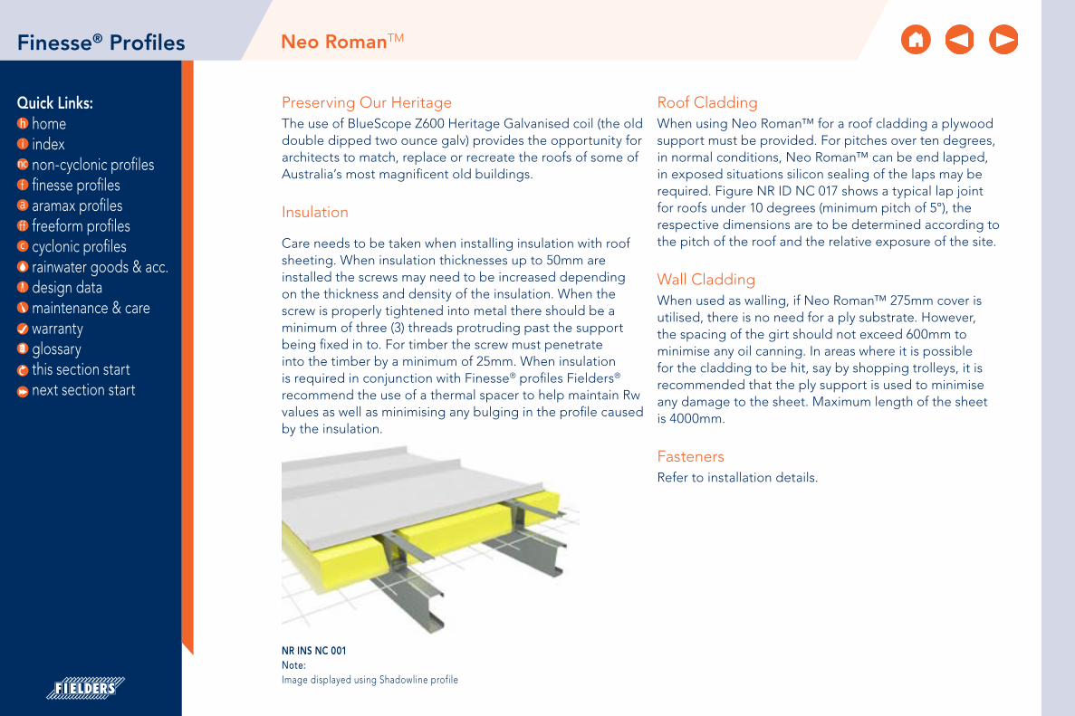
Quick Links: home index non-cyclonic profiles finesse profiles aramax profiles freeform profiles cyclonic profiles rainwater goods & acc. design data maintenance & care warranty glossary
Neo RomanTM
Preserving Our HeritageThe use of BlueScope Z600 Heritage Galvanised coil (the old double dipped two ounce galv) provides the opportunity for architects to match, replace or recreate the roofs of some of Australia’s most magnificent old buildings.
Insulation
Care needs to be taken when installing insulation with roof sheeting. When insulation thicknesses up to 50mm are installed the screws may need to be increased depending on the thickness and density of the insulation. When the screw is properly tightened into metal there should be a minimum of three (3) threads protruding past the support being fixed in to. For timber the screw must penetrate into the timber by a minimum of 25mm. When insulation is required in conjunction with Finesse® profiles Fielders® recommend the use of a thermal spacer to help maintain Rw values as well as minimising any bulging in the profile caused by the insulation.
Roof CladdingWhen using Neo Roman™ for a roof cladding a plywood support must be provided. For pitches over ten degrees, in normal conditions, Neo Roman™ can be end lapped, in exposed situations silicon sealing of the laps may be required. Figure NR ID NC 017 shows a typical lap joint for roofs under 10 degrees (minimum pitch of 5°), the respective dimensions are to be determined according to the pitch of the roof and the relative exposure of the site.
Wall CladdingWhen used as walling, if Neo Roman™ 275mm cover is utilised, there is no need for a ply substrate. However, the spacing of the girt should not exceed 600mm to minimise any oil canning. In areas where it is possible for the cladding to be hit, say by shopping trolleys, it is recommended that the ply support is used to minimise any damage to the sheet. Maximum length of the sheet is 4000mm.
FastenersRefer to installation details.
this section start next section start
Finesse® Profiles
NR INS NC 001Note: Image displayed using Shadowline profile

Quick Links: home index non-cyclonic profiles finesse profiles aramax profiles freeform profiles cyclonic profiles rainwater goods & acc. design data maintenance & care warranty glossary
275/475mm
25m
m
275/475mm
25m
m
13m
m
HEAVY DUTY ROOF SARKING ANTI ABRASIVE MEMBRANE
CD GRADEPLYWOOD 19mm
* WHEN ROOF PITCH IS UNDER 7.5° OR TOTAL COMBINED SHEET LENGTH IS OVER 5 METRES
min 20mm VENTILATION GAP STRUCTURE
SILICONE FASTENERS 14g-10x35mm HEX HEAD TYPE 17 SCREW @ 600mm c/c*
* SCREW SPACING MAY VARY IN HIGH WIND ZONES. CONSULT FIELDERS FOR FURTHER ADVICE.
CD GRADEPLYWOOD 19mm
min 20mm VENTILATION GAP STRUCTURE
4.8mm RIVETS. BOTH SIDES @ 600mm c/c*
RIB BRACKET
HEAVY DUTY ROOF SARKING ANTI ABRASIVE MEMBRANE
* SCREW SPACING MAY VARY IN HIGH WIND ZONES. CONSULT FIELDERS FOR FURTHER ADVICE.
FASTENERS 14g-10x35mm HEX HEAD TYPE 17 SCREW @ 600mm c/c*
24mm
7mm HOLE
15mm
NEO ROMAN™ BRACKET TO BE
SAME LENGTH AS SHEET
Installation Details: Double Rib Note: Available on request, minimum quantities apply.
Figure NR ID NC 003
Figure NR ID NC 004
Figure NR ID NC 002
Figure NR ID NC 001
Installation Details: Single Rib
Neo RomanTM
this section start next section start
Finesse® Profiles
Figure NR ID NC 005Note: The bracket is 1.0mm BMT Galvanised.
Neo Roman Bracket
275/475mm
25m
m
275/475mm
25m
m
13m
m
HEAVY DUTY ROOF SARKING ANTI ABRASIVE MEMBRANE
CD GRADEPLYWOOD 19mm
* WHEN ROOF PITCH IS UNDER 7.5° OR TOTAL COMBINED SHEET LENGTH IS OVER 5 METRES
min 20mm VENTILATION GAP STRUCTURE
SILICONE FASTENERS 14g-10x35mm HEX HEAD TYPE 17 SCREW @ 600mm c/c*
* SCREW SPACING MAY VARY IN HIGH WIND ZONES. CONSULT FIELDERS FOR FURTHER ADVICE.
CD GRADEPLYWOOD 19mm
min 20mm VENTILATION GAP STRUCTURE
4.8mm RIVETS. BOTH SIDES @ 600mm c/c*
RIB BRACKET
HEAVY DUTY ROOF SARKING ANTI ABRASIVE MEMBRANE
* SCREW SPACING MAY VARY IN HIGH WIND ZONES. CONSULT FIELDERS FOR FURTHER ADVICE.
FASTENERS 14g-10x35mm HEX HEAD TYPE 17 SCREW @ 600mm c/c*
24mm
7mm HOLE
15mm
NEO ROMAN™ BRACKET TO BE
SAME LENGTH AS SHEET

Quick Links: home index non-cyclonic profiles finesse profiles aramax profiles freeform profiles cyclonic profiles rainwater goods & acc. design data maintenance & care warranty glossary
Installation Details: Layout Drawing Walling
Neo RomanTM
STRUCTURE
VerticalHorizontal
STEEL BATTEN
NEO ROMAN™ PANEL
NEO ROMAN™PANEL
STEEL BATTENSTRUCTURE
600m
m m
ax
Figure NR ID NC 006
this section start next section start
Finesse® Profiles

Quick Links: home index non-cyclonic profiles finesse profiles aramax profiles freeform profiles cyclonic profiles rainwater goods & acc. design data maintenance & care warranty glossary
Installation Details: Ventilation
HEAVY DUTY ROOF SARKING ANTI ABRASIVE MEMBRANE
STEELWORK BY OTHERS PURLINS BY OTHERS
VENTILATION
CD GRADE PLYWOOD 19mm
NEO ROMAN™PANEL
Figure NR ID NC 007
Neo RomanTM
this section start next section start
Finesse® Profiles

Quick Links: home index non-cyclonic profiles finesse profiles aramax profiles freeform profiles cyclonic profiles rainwater goods & acc. design data maintenance & care warranty glossary
Installation Details: Eave Gutter
CD GRADE PLYWOOD 19mmWITH ROUTED REBATE
EXT GUTTER BRACKET
EAVES GUTTER min 20mm
VENTILATION GAP
HEAVY DUTY ROOF SARKING ANTI ABRASIVE MEMBRANE
HEAVY DUTY ROOF SARKING ANTI ABRASIVE MEMBRANE
SHEET TURN DOWN
NEO ROMAN™PANEL
Figure NR ID NC 008
Neo RomanTM
this section start next section start
Finesse® Profiles

Quick Links: home index non-cyclonic profiles finesse profiles aramax profiles freeform profiles cyclonic profiles rainwater goods & acc. design data maintenance & care warranty glossary
Installation Details: Low Eave
CD GRADE PLYWOOD 19mm WITH ROUTED REBATE
10g-12x25mm WAFER HEADSTAINLESS STEEL WOOD SCREW W/#2 PHILLIPS SLOT @ 100mm c/c.
min 20mm VENTILATION GAP
SHEET TURN DOWN
POLE PLATE FLASHING
HEAVY DUTY ROOF SARKING ANTI ABRASIVE MEMBRANE
BOX GUTTER
Figure NR ID NC 009
Neo RomanTM
this section start next section start
Finesse® Profiles
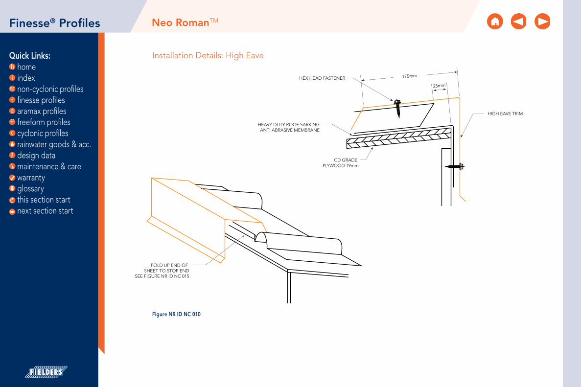
Quick Links: home index non-cyclonic profiles finesse profiles aramax profiles freeform profiles cyclonic profiles rainwater goods & acc. design data maintenance & care warranty glossary
Installation Details: High Eave
HIGH EAVE TRIM
CD GRADE PLYWOOD 19mm
HEAVY DUTY ROOF SARKING ANTI ABRASIVE MEMBRANE
HEX HEAD FASTENER
25mm
175mm
FOLD UP END OF SHEET TO STOP END
SEE FIGURE NR ID NC 015
Figure NR ID NC 010
Neo RomanTM
this section start next section start
Finesse® Profiles

Quick Links: home index non-cyclonic profiles finesse profiles aramax profiles freeform profiles cyclonic profiles rainwater goods & acc. design data maintenance & care warranty glossary
Installation Details: Hip/Ridge
RIDGE TRIMFIX THROUGH TO SUBSTRATE AT min 900mm c/c TYP.
VENTILATION GAP
STOP END
INTERMEDIATEHEX HEAD FIXING
CD GRADEPLYWOOD 19mm
HEAVY DUTY ROOF SARKING ANTI ABRASIVE MEMBRANE
150mm
25mm
Figure NR ID NC 011
Neo RomanTM
this section start next section start
Finesse® Profiles

Quick Links: home index non-cyclonic profiles finesse profiles aramax profiles freeform profiles cyclonic profiles rainwater goods & acc. design data maintenance & care warranty glossary
Installation Details: Rake Barge
OPTION A
OPTION B
FLASHING
min 20mmVENTILATION
min 20mmVENTILATION
HEX HEAD FASTENER
CD GRADE PLYWOOD 19mm
Figure NR ID NC 012
Neo RomanTM
this section start next section start
Finesse® Profiles

Quick Links: home index non-cyclonic profiles finesse profiles aramax profiles freeform profiles cyclonic profiles rainwater goods & acc. design data maintenance & care warranty glossary
Installation Details: Rake Wall Flashing
10 mm min
10m
m m
in 1
00m
m
75m
m
CHASE INTO WALL
WALL STRUCTURE
NEUTRAL SEALANT
COVER FLASHING
APRON FLASHING
CD GRADE PLYWOOD 19mm
HEAVY DUTY ROOF SARKING ANTI ABRASIVE MEMBRANE
Figure NR ID NC 013
Neo RomanTM
this section start next section start
Finesse® Profiles

Quick Links: home index non-cyclonic profiles finesse profiles aramax profiles freeform profiles cyclonic profiles rainwater goods & acc. design data maintenance & care warranty glossary
Installation Details: ValleyFor roof pitches greater than 7.5°
Note:For roof pitches less than 7.5° insert gutter in valley.
HEAVY DUTY ROOF SARKING ANTI ABRASIVE MEMBRANE
NEO ROMAN™PANEL
VALLEY TRIM
min 20mmVENTILATION GAP
12mm CD GRADE PLYWOOD WITH SUPPORTS AT max 300mm c/c TO VALLEY AREA
Figure NR ID NC 014
Neo RomanTM
this section start next section start
Finesse® Profiles

Quick Links: home index non-cyclonic profiles finesse profiles aramax profiles freeform profiles cyclonic profiles rainwater goods & acc. design data maintenance & care warranty glossary
Installation Details: Sheet Turn Down1. Place pan into the panel hemming tool. The front edge of the tool must rest against the panel edge on both sides.
2. While maintaining pressure against the panel joints, rotate the hemming tool 45°.
PANEL HEMMING TOOL
45°
15mm
Figure NR ID NC 015
Neo RomanTM
this section start next section start
Finesse® Profiles

Quick Links: home index non-cyclonic profiles finesse profiles aramax profiles freeform profiles cyclonic profiles rainwater goods & acc. design data maintenance & care warranty glossary
PANEL WITH STOP END
STOP END DETAIL
25m
m
90°
PANEL STOP END TOOL
PLY SUBSTRATE
TILE BRACKET
Installation Details: Stop End1. Place pan into the panel stop end tool. The front edge of the tool must rest between the ribs.
2. While maintaining pressure against the panel, rotate the stop end tool as close to 90 degrees as possible.
3. Inspect completed bend.
Installation Details: Lap Joint
Figure NR ID NC 016
Neo RomanTM
this section start next section start
Figure NR ID NC 017
Finesse® Profiles

Quick Links: home index non-cyclonic profiles finesse profiles aramax profiles freeform profiles cyclonic profiles rainwater goods & acc. design data maintenance & care warranty glossary
Material SpecificationsProminence™
Property 265mm Pan Width with 38mm rib
465mm Pan Width with 38mm rib Notes
Base Metal Thickness (mm) 0.55 0.75 0.55 0.75 BMTTotal Coated Thickness (mm) 0.60* 0.80* 0.60* 0.80* TCT
Mass / Unit Length (kg/m)
ZINCALUME® 1.83 2.41 2.75 3.61kg/m
COLORBOND® 1.86* 2.44* 2.80* 3.70*
Mass / Unit Area (kg/m2)
ZINCALUME® 6.91 9.09 5.92 6.88kg/m2
COLORBOND® 7.02* 9.21* 6.02* 6.97*
Coverage (mm) 265 265 465 465 mm
Minimum Yield Strength (MPa) G300
Coating Class
AM100 - COLORBOND®
AM100 - COLORBOND® Metallic
AM125 - ZINCALUME®
AM150 - COLORBOND® Ultra
Minimum Coatingg/m2 of Zinc -
Aluminium
ToleranceSheet length ±7mmCover width ± 4mm
Thermal Expansion2.9mm average per 5.0 metre
@ 50˚ C change
Table PR MS NC 001Notes:1. The COLORBOND® and ZINCALUME® material is in accordance to AS 1397, AS 1365 and AS 2728.
2. Installation of the cladding should also be in accordance to AS 1562.1 and HB 39.
3. *is based on Standard COLORBOND® single-sided material. For other painted steel options please contact a Fielders® representative.
Prominence™
465mm
265mm
38mm
38mm
this section start next section start
Finesse® Profiles

Quick Links: home index non-cyclonic profiles finesse profiles aramax profiles freeform profiles cyclonic profiles rainwater goods & acc. design data maintenance & care warranty glossary
Prominence™
About Prominence™With its elegant flat pans and ease of installation the profile is a rare mix that both the specifier and the builder can appreciate. Available in a 265mm and a 465mm wide panel. As with all the profiles in the Fielders® Finesse® range, Fielders® Prominence™ is available in any colour you choose and looks particularly striking in a Metallic COLORBOND®. Prominence™ is also available in 0.75mm steel and 1.00mm aluminium (subject to minimum order quantities). Contact your local Fielders® representative for availability and further information.
Prominence™ is offered on traditional supporting substrates, plywood and fibre cement panels, and now with comprehensive testing can be offered on cost effective steel battens.
Finesse® Profiles
this section start next section start

Quick Links: home index non-cyclonic profiles finesse profiles aramax profiles freeform profiles cyclonic profiles rainwater goods & acc. design data maintenance & care warranty glossary
Prominence™
Rainfall Capacity For further information, please refer to sections “Rainfall Intensity” and “Water Carrying Capacity and Rainwater Run-Off”.
Maximum Roof Length (m) Prominence™ 265 Non-Cyclonic
Roof Slope (degrees)
Rainfall Capacity (mm/hr)
100 150 200 250 300 400 5003 160 107 80 64 53 40 324 180 120 90 72 60 45 365 199 133 100 80 66 50 40
7.5 238 158 199 95 79 59 4810 273 182 137 109 91 68 55
Figure PR RC NC (265) 001
Table PR RL NC (265) 001Note: 1. Minimum recommended slope is 3°. Sheet lengths greater than 24m are not
recommended due to thermal expansion and contraction.
Max
imum
She
et L
eng
th (m
)
Roof Slope (degrees)
3 4 5 7.5 10
300
250
200
150
100
50
0
100mm/hr
150mm/hr
200mm/hr
250mm/hr
300mm/hr
400mm/hr
500mm/hr
Finesse® Profiles
this section start next section start

Quick Links: home index non-cyclonic profiles finesse profiles aramax profiles freeform profiles cyclonic profiles rainwater goods & acc. design data maintenance & care warranty glossary
Prominence™Finesse® Profiles
Wind Loading Design Parameters
Figure PR NC 001 End Spans, Internal Spans and Overhangs
Overhang
Overhang
Overhang
Overhang(End span)
End span
End span
End span
Internal spans
Internal spans
Table PR WC NC 001Note:*465mm wide Prominence™ only recommended for walling applications.
Wind Pressure CapacitiesProminenceTM 0.55mm BMT Non-Cyclonic
Plywood Steel Batten
Cover Width (mm)
Serviceability (kPa)
Strength (kPa)
Spacing (mm)
Serviceability (kPa)
Strength (kPa)
265 1.07 4.23 600 1.07 4.23
465* 0.40 3.35 450 0.40 3.35
40mm x 0.55mm STEEL BATTEN
1x10g-16x16 WAFER HEAD SCREW PER SUPPORT THROUGH SLOTS/SHEET
(SARKING IS OMITTED FOR CLARITY)
STEEL BATTEN SPACING
450mm max
600mm max
600mm max15mm CD GRADE PLYWOOD
10g-12x25 WAFER HEAD TYPE 17 SCREW WITH min CLASS 3 COATING THROUGH SLOTS
Figure PR ID NC 001 Figure PR ID NC 002
this section start next section start

Quick Links: home index non-cyclonic profiles finesse profiles aramax profiles freeform profiles cyclonic profiles rainwater goods & acc. design data maintenance & care warranty glossary
Prominence™Finesse® Profiles
Table PR RS NC 001Notes:1. 465mm wide Prominence is available for roofing applications when used in
conjunction with plywood fixed at 450mm c/c max.
Maximum Recommended Roof Cladding Span (mm)Prominence™ Non-Cyclonic
Cover (mm)
BMT Single End Internal
2650.55 600 600 600
0.75 700 700 700
Installation
Prominence™ is concealed pierce-fixed to either plywood or batten supports. This means the fastener screws pass through the sheeting at the concealed underlap edge. Screws can be placed either through the slotted holes or directly through the sheet. See PR NC ID 003-007.
Non-Cyclonic Load Span Tables
The design pressures and allowable spans have been determined from tests carried out in accordance with the following Australian Standards: AS 1562.1:1992, "Design and installation of sheet roof and wall cladding - Metal" and AS 4040:1992, "Methods of testing sheet roof and wall cladding".
Wind Loading Design Parameters:Design Life 50 yearsImportance Level 2Maximum Roof Height H = 10mExternal Pressure Coefficients: Cp,e = -0.65 (walling) Cp,e = -0.9 (roofing)Internal Pressure Coefficient: Cp,i = 0.2Local Pressure Factors: K l = 2.0 (end & single spans) K l = 1.0 (internal spans)
this section start next section start
Table PR RS NC 002Notes:1. Maximum walling spans comply with both strength and serviceability wind
requirements.
2. Minimum steel support 0.75mm BMT G550.
Maximum Recommended Wall Cladding Span (mm)Prominence™ Non-Cyclonic
Cover (mm)
BMT Single End Internal
2650.55 900 900 1200
0.75 1000 1000 1300
4650.55 450 450 450
0.75 550 550 550
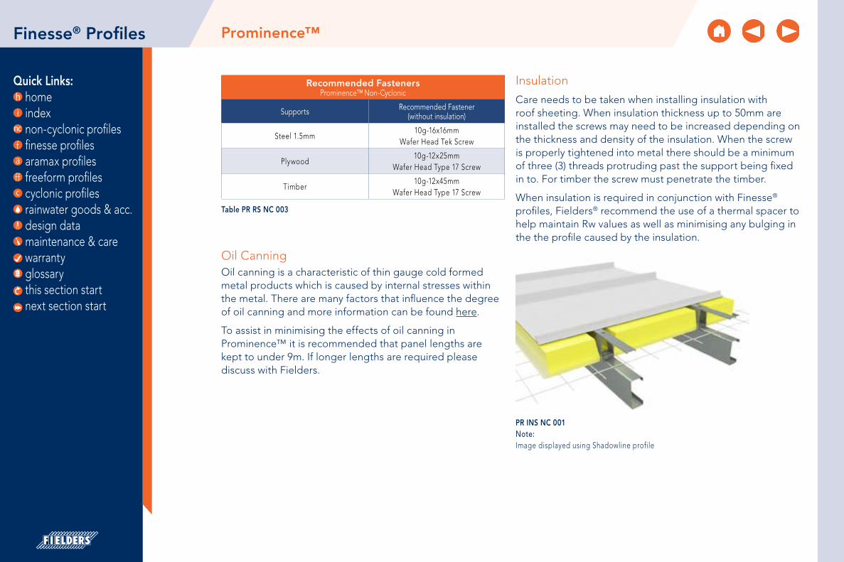
Quick Links: home index non-cyclonic profiles finesse profiles aramax profiles freeform profiles cyclonic profiles rainwater goods & acc. design data maintenance & care warranty glossary
Insulation
Care needs to be taken when installing insulation with roof sheeting. When insulation thickness up to 50mm are installed the screws may need to be increased depending on the thickness and density of the insulation. When the screw is properly tightened into metal there should be a minimum of three (3) threads protruding past the support being fixed in to. For timber the screw must penetrate the timber.
When insulation is required in conjunction with Finesse® profiles, Fielders® recommend the use of a thermal spacer to help maintain Rw values as well as minimising any bulging in the the profile caused by the insulation.
Prominence™Finesse® Profiles
Table PR RS NC 003
Recommended FastenersProminence™ Non-Cyclonic
Supports Recommended Fastener (without insulation)
Steel 1.5mm10g-16x16mm
Wafer Head Tek Screw
Plywood10g-12x25mm
Wafer Head Type 17 Screw
Timber10g-12x45mm
Wafer Head Type 17 Screw
Oil CanningOil canning is a characteristic of thin gauge cold formed metal products which is caused by internal stresses within the metal. There are many factors that influence the degree of oil canning and more information can be found here.
To assist in minimising the effects of oil canning in Prominence™ it is recommended that panel lengths are kept to under 9m. If longer lengths are required please discuss with Fielders.
PR INS NC 001Note: Image displayed using Shadowline profile
this section start next section start

Quick Links: home index non-cyclonic profiles finesse profiles aramax profiles freeform profiles cyclonic profiles rainwater goods & acc. design data maintenance & care warranty glossary
Prominence™Finesse® Profiles
A
A
B
B
C C
STEEL BATTEN
WINDOW HEAD FLASHING
WAFER HEAD SCREW
PROMINENCE™ PANEL
STEEL BATTEN
WINDOW HEAD FLASHING
WAFER HEAD SCREW
PROMINENCE™ PANEL
PROMINENCE™ PANEL
STEEL BATTEN
WINDOW JAMB FLASHING
Installation Details: Window Details - Horizontal Panels
HORIZONTAL PANEL AROUND OPENING
SECTION A-A HEAD SECTION B-B SILL SECTION C-C JAMB
Figure PR ID NC 003
Figure PR ID NC 004Note:Head and sill flashings to be turned up and down behind jamb flashing
this section start next section start

Quick Links: home index non-cyclonic profiles finesse profiles aramax profiles freeform profiles cyclonic profiles rainwater goods & acc. design data maintenance & care warranty glossary
Prominence™Finesse® Profiles
A
A
B
B
C C
WINDOW HEAD FLASHING
WAFER HEAD SCREW
PROMINENCE™ PANEL
WINDOW SILL FLASHING
PROMINENCE™ PANEL
RIVET
PROMINENC™ PANEL
WINDOW JAMB FLASHING
PROMINENCE™ PANEL TURNED OUT
Installation Details: Window Details - Vertical Panels
VERTICAL PANEL AROUND OPENING
SECTION A-A HEAD SECTION B-B SILL SECTION C-C JAMB
Figure PR ID NC 005
Figure PR ID NC 006Note:Head and sill flashings to be turned up and down behind jamb flashing
this section start next section start
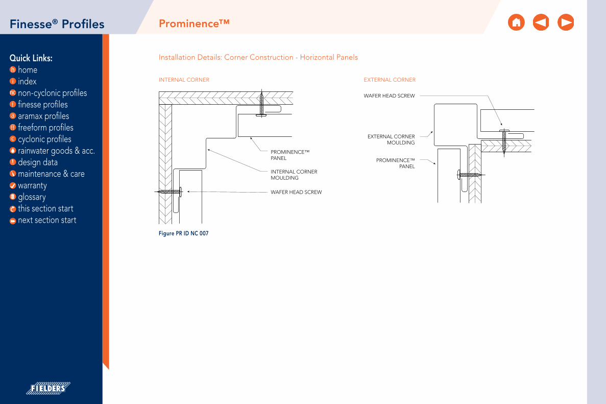
Quick Links: home index non-cyclonic profiles finesse profiles aramax profiles freeform profiles cyclonic profiles rainwater goods & acc. design data maintenance & care warranty glossary
Prominence™Finesse® Profiles
PROMINENCE™ PANEL PROMINENCE™
PANEL
EXTERNAL CORNER MOULDING
WAFER HEAD SCREW
INTERNAL CORNER MOULDING
WAFER HEAD SCREW
Installation Details: Corner Construction - Horizontal Panels
INTERNAL CORNER
Figure PR ID NC 007
EXTERNAL CORNER
this section start next section start

Quick Links: home index non-cyclonic profiles finesse profiles aramax profiles freeform profiles cyclonic profiles rainwater goods & acc. design data maintenance & care warranty glossary
Prominence™Finesse® Profiles
PROMINENCE™ PANEL
INTERNAL CORNER MOULDING
WAFER HEAD SCREW
PROMINENCE™ PANEL
EXTERNALCORNER MOULDING
WAFER HEAD SCREW
Installation Details: Corner Construction - Vertical Panels
INTERNAL CORNER
Figure PR ID NC 008
EXTERNAL CORNER
this section start next section start

Quick Links: home index non-cyclonic profiles finesse profiles aramax profiles freeform profiles cyclonic profiles rainwater goods & acc. design data maintenance & care warranty glossary
Prominence™Finesse® Profiles
PROMINENCE™ PANEL
WAFER HEAD SCREW
FOOT MOULD
DRAIN HOLES
STEEL BATTEN
PROMINENCE™ PANEL
WAFER HEAD SCREW
FOOT MOULD FLASHING A
FOOT MOULD FLASHING B
RIVET
PROMINENCE™ PANEL
WAFER HEAD SCREW
FOOT MOULD
DRAIN HOLES
GROUND LEVEL GROUND LEVEL GROUND LEVEL
Installation Details: Foot Mould and Bottom of Facade
FOOT MOULD HORIZONTAL PANELS
Figure PR ID NC 009
FOOT MOULD VERTICAL PANELS
BOTTOM OF FACADE HORIZONTAL PANELS
this section start next section start

Quick Links: home index non-cyclonic profiles finesse profiles aramax profiles freeform profiles cyclonic profiles rainwater goods & acc. design data maintenance & care warranty glossary
WAFER HEAD SCREW
STEEL BATTEN
15mm CD GRADE PLYWOOD*
STRUCTURE
PROMINENCE™
Installation Details: Wall Layout — Horizontal
Figure PR ID NC 010Notes:*For walling configurations plywood is optional. Prominence™ can be fixed directly to the framing system provided fixings do not exceed those specified in Table PR RS NC 001 (closer spacings may be required in high wind zones, confirm with Fielders). In areas where impact of the material is possible, plywood is recommended to minimise damage to the profile.
Prominence™Finesse® Profiles
this section start next section start

Quick Links: home index non-cyclonic profiles finesse profiles aramax profiles freeform profiles cyclonic profiles rainwater goods & acc. design data maintenance & care warranty glossary
PROMINENCE™
ANTI-ABRASIVEMEMBRANE
CD GRADE PLYWOOD 19mm
STEELWORK BY OTHERS PURLINS BY
OTHERS
VENTILATION
CUT BACK RIB ON ANGLE.EDGE FOLDED TO CLOSE.
Installation Details: Roofing Layout
Figure PR ID NC 011
Prominence™Finesse® Profiles
this section start next section start
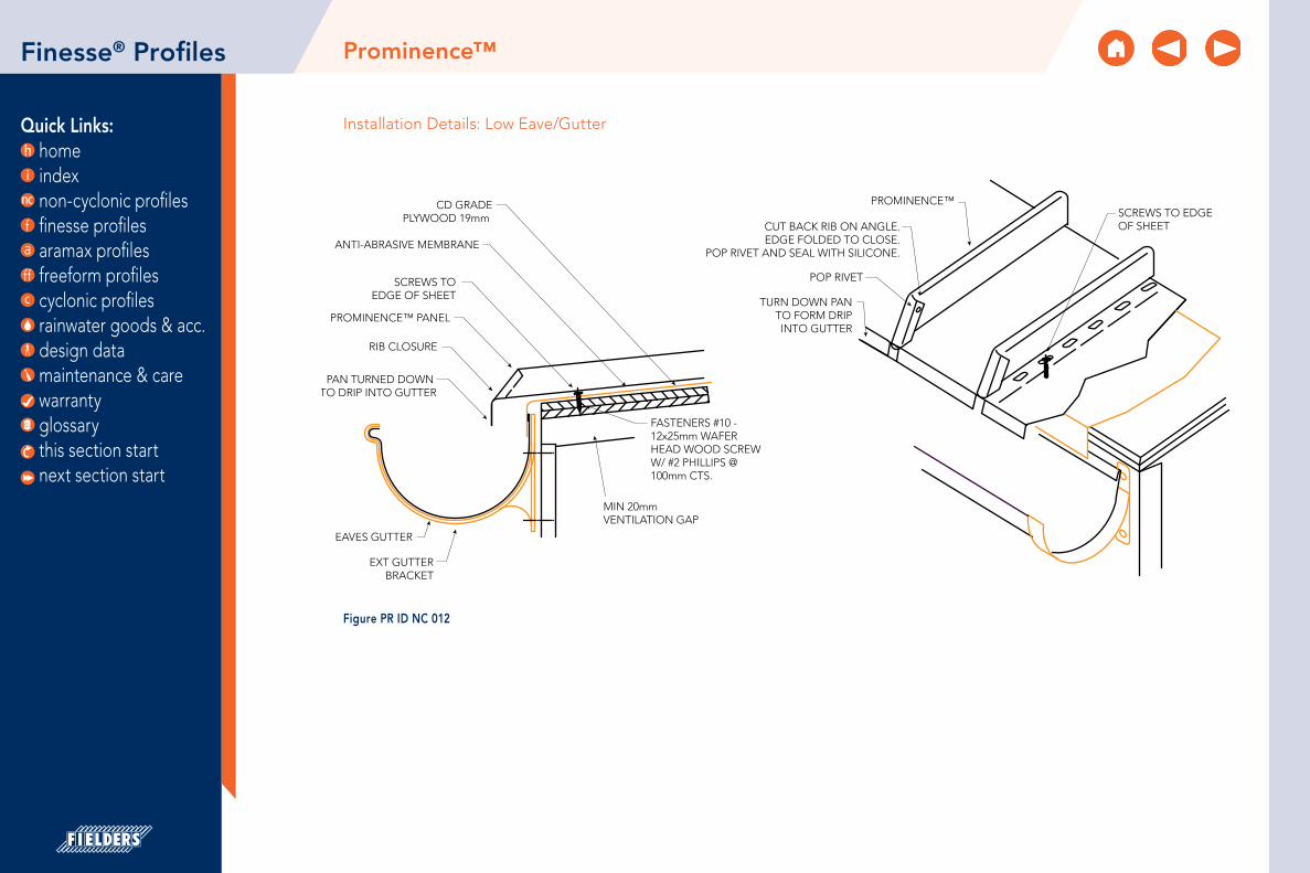
Quick Links: home index non-cyclonic profiles finesse profiles aramax profiles freeform profiles cyclonic profiles rainwater goods & acc. design data maintenance & care warranty glossary
Installation Details: Low Eave/Gutter
CD GRADEPLYWOOD 19mm
SCREWS TOEDGE OF SHEET
PAN TURNED DOWN TO DRIP INTO GUTTER
EXT GUTTERBRACKET
EAVES GUTTER
RIB CLOSURE
PROMINENCE™ PANEL
FASTENERS #10 - 12x25mm WAFER HEAD WOOD SCREWW/ #2 PHILLIPS @ 100mm CTS.
MIN 20mm VENTILATION GAP
CUT BACK RIB ON ANGLE.EDGE FOLDED TO CLOSE.
POP RIVET AND SEAL WITH SILICONE.
TURN DOWN PANTO FORM DRIPINTO GUTTER
ANTI-ABRASIVE MEMBRANE
PROMINENCE™SCREWS TO EDGEOF SHEET
POP RIVET
Figure PR ID NC 012
Prominence™Finesse® Profiles
this section start next section start

Quick Links: home index non-cyclonic profiles finesse profiles aramax profiles freeform profiles cyclonic profiles rainwater goods & acc. design data maintenance & care warranty glossary
BARGE CAPPING
LOW PROFILE FASTENER(BY INSTALLER)
ANTI-ABRASIVE MEMBRANE
FASTENER FIX THROUGH TO PLY SUBSTRATE AT MIN 900 c/c
FOLD UP END OF SHEETSEE SHEET - TYPICAL
STOP END
NOTCHED OVER RIBS
CD GRADEPLYWOOD 19mm
25mm
175mm
ANTI-ABRASIVE MEMBRANE
CD GRADE PLYWOOD19mm WITH ROUTED REBATE
MIN 20mm VENTILATION GAP
PAN TURNED DOWN - 25mm
POLE PLATEFLASHING
CUT BACK RIB ON ANGLE.EDGE FOLDED TO CLOSE.POP RIVET AND SILICONE SEAL
PROMINENCE™#10-12x25mm WAFER HEADWOOD SCREW W/ #2 PHILLIPS SLOT @ 100mm c/c
PROMINENCE™
Figure PR ID NC 013
Prominence™
Installation Details: Typical Capping Without Gutter
Figure PR ID NC 014Note:Consider profiled close cell foam infill for high wind areas.
Finesse® Profiles
this section start next section start

Quick Links: home index non-cyclonic profiles finesse profiles aramax profiles freeform profiles cyclonic profiles rainwater goods & acc. design data maintenance & care warranty glossary
5mm Ø RIVET THROUGH FLUSHING TO TOP OF EACH PROMINENCE™ LAPPED RIBS AT BOTH SIDES
- ONE PIECE RIDGE CAPPING- PROMINENCE™- HEAVY DUTY ROOF SARKING- 19mm CD GRADE PLYWOOD WITH ROUTED REBTE
VENTILATION GAP
25mm
FOLD UP END SHEET, SEE TYP. STOP END DETAIL
FOLD UP END SHEET, SEE TYP. STOP END DETAIL
- ONE PIECE RIDGE CAPPING- 5mm Ø RIVET THROUGH FLUSHING TO TOP OF EACH PROMINENCE™ LAPPED RIBS AT BOTH SIDES- EDGE DISTANCE: 25mm25mm
200mm 200mm
40mm 40mm
200mm 200mm
40mm 40mm
SUBSTRUCTURE: PLYWOOD
Figure PR ID NC 015Note:Consider profiled close cell foam infill for high wind areas.
Prominence™Finesse® Profiles
SUBSTRUCTURE: METAL BATTENS
Figure PR ID NC 016Note:Consider profiled close cell foam infill for high wind areas.
5mm Ø RIVET THROUGH FLUSHING TO TOP OF EACH PROMINENCE™ LAPPED RIBS AT BOTH SIDES
- ONE PIECE RIDGE CAPPING- PROMINENCE™- HEAVY DUTY ROOF SARKING- 19mm CD GRADE PLYWOOD WITH ROUTED REBTE
VENTILATION GAP
25mm
FOLD UP END SHEET, SEE TYP. STOP END DETAIL
FOLD UP END SHEET, SEE TYP. STOP END DETAIL
- ONE PIECE RIDGE CAPPING- 5mm Ø RIVET THROUGH FLUSHING TO TOP OF EACH PROMINENCE™ LAPPED RIBS AT BOTH SIDES- EDGE DISTANCE: 25mm25mm
200mm 200mm
40mm 40mm
200mm 200mm
40mm 40mm
this section start next section start

Quick Links: home index non-cyclonic profiles finesse profiles aramax profiles freeform profiles cyclonic profiles rainwater goods & acc. design data maintenance & care warranty glossary
Installation Details: Typical Barge
BARGE
BARGE
BARGEFLASHING
40mm BATTEN
CD GRADE PLYWOOD 19mm
ANTI-ABRASIVEMEMBRANE
BARGE
BARGEFLASHING
MINIMUM 20mmVENTILATION
BARGE
CD GRADE PLYWOOD 19mm WITH ROUTED REBATE
ANTI-ABRASIVEMEMBRANE
MINIMUM 20mmVENTILATION
IF OVER 240mm, PROVIDE 40mm STEEL BATTEN SUPPORT, FIX THROUGH PROMINENCE™ TO SUPPORT AT EACH LEG USING 10g-16x16mm METAL TEK.
IF OVER 240mm, PROVIDE 40mm STEEL BATTEN SUPPORT, FIX THROUGH PROMINENCE™ TO SUPPORT AT EACH LEG USING 10g-16x16mm METAL TEK.
COLORBOND® BARGE CAPPING
Figure PR ID NC 017
Figure PR ID NC 018
Prominence™Finesse® Profiles
SUBSTRUCTURE - PLYWOOD
SUBSTRUCTURE - PLYWOOD BATTENS SUBSTRUCTURE - METAL BATTENS
Figure PR ID NC 019
this section start next section start

Quick Links: home index non-cyclonic profiles finesse profiles aramax profiles freeform profiles cyclonic profiles rainwater goods & acc. design data maintenance & care warranty glossary
PROMINENCE™
FOLD UP END SHEET, SEE TYP.
STOP END DETAIL
12g-14 HEX HEAD T17 SCREW FIX THROUGH TO SUBSTRATE SUPPORT AT min 900mm SPACING25mm
LOW PROFILE FASTENER (BY
INSTALLER)
- BARGE CAPPING, NOTCH OVER RIBS, TURN LEG DOWN 80°- PROMINENCE™- HEAVY DUTY ROOF SARKING- 19mm CD GRADE PLYWOOD WITH ROUTED REBATE, TURN LEG DOWN 80°
TYP. BARGE CAPPING DIMENSIONS
DEPTH TO FIT DESIGN
175mm
40mm100°
PROMINENCE™
FOLD UP END SHEET, SEE TYP.
STOP END DETAIL
LOW PROFILE FASTENER(BY INSTALLER)
25mm
LOW PROFILE FASTENER (BY
INSTALLER)TYP. BARGE CAPPING DIMENSIONS
DEPTH TO FIT DESIGN
175mm
40mm100° BARGE CAPPING,
NOTCH OVER RIBS, TURN LEG DOWN 80°
Prominence™Finesse® Profiles
SUBSTRUCTURE - PLYWOOD
SUBSTRUCTURE - METAL BATTENS
Figure PR ID NC 020Note:Consider profiled close cell foam infill for high wind areas.
PROMINENCE™
FOLD UP END SHEET, SEE TYP.
STOP END DETAIL
12g-14 HEX HEAD T17 SCREW FIX THROUGH TO SUBSTRATE SUPPORT AT min 900mm SPACING25mm
LOW PROFILE FASTENER (BY
INSTALLER)
- BARGE CAPPING, NOTCH OVER RIBS, TURN LEG DOWN 80°- PROMINENCE™- HEAVY DUTY ROOF SARKING- 19mm CD GRADE PLYWOOD WITH ROUTED REBATE, TURN LEG DOWN 80°
TYP. BARGE CAPPING DIMENSIONS
DEPTH TO FIT DESIGN
175mm
40mm100°
PROMINENCE™
FOLD UP END SHEET, SEE TYP.
STOP END DETAIL
LOW PROFILE FASTENER(BY INSTALLER)
25mm
LOW PROFILE FASTENER (BY
INSTALLER)TYP. BARGE CAPPING DIMENSIONS
DEPTH TO FIT DESIGN
175mm
40mm100° BARGE CAPPING,
NOTCH OVER RIBS, TURN LEG DOWN 80°
Figure PR ID NC 021Note:1. Consider profiled close cell foam infill for high wind areas.
2. 12mm CD Grade Plywood with supports at 300mm c/c max to valley area.
this section start next section start

Quick Links: home index non-cyclonic profiles finesse profiles aramax profiles freeform profiles cyclonic profiles rainwater goods & acc. design data maintenance & care warranty glossary
10mm min
10m
m m
in15
0mm
min
CHASE INTO WALL
WALL STRUCTURE
CD GRADE PLYWOOD 19mm
ANTI-ABRASIVE MEMBRANE
NEUTRAL SEALANT
FOLDED FLASHING
FOLDED APRON FLASHING
10g HEX HEAD SCREW WITH EPDM WASHER
40mm STEEL BATTEN IF OVER 240mm, FIX TO SUPPORT WITH 10g SCREW AT 1.2m INTERVAL
STARTER RIB
WALL
CHASE INTO WALL NEUTRAL SEALANT
COLORBOND® FOLDED OVER FLASHING
COLORBOND® FOLDED APRON FLASHING
40mm STEEL BATTEN IF OVER 240mm, FIX TO
SUPPORT WITH 10g SCREW AT 1.2m INTERVAL
10g HEX HEAD SCREW WITH EPDM WASKER
STEEL BATTEN SUPPORT
10mm min
10m
m m
in
150m
m m
in
Installation Details: Typical Apron Flashing to Wall
Prominence™Finesse® Profiles
SUBSTRATE - PLYWOOD
SUBSTRATE - METAL BATTENS
Figure PR ID NC 022
Figure PR ID NC 023
this section start next section start

Quick Links: home index non-cyclonic profiles finesse profiles aramax profiles freeform profiles cyclonic profiles rainwater goods & acc. design data maintenance & care warranty glossary
TURN DOWN PAN, CUT BACK RIB ON ANGLE. EDGE FOLDED TO CLOSE. POP RIVET AND SILICONE SEAL.
PROMINENCE™ PANEL
10g-12x25mm WAFER HEAD T17 SCREW AT 100mm c/c THRU PROMINENCE™ SLOTTED LEG TO SUPPORTmin 20mm
VENTILATION GAP
COLORBOND® VALLEY GUTTER, WITH 25mm RETURNED EDGEHEAVY DUTY ROOF SARKING
19mm CD GRADE PLYWOOD WITH ROUTED REBATE
min 20mm VENTILATION GAP
TURN DOWN PAN, CUT BACK RIB ON ANGLE. EDGE FOLDED TO CLOSE. POP RIVET AND SILICONE SEAL.
PROMINENCE™ PANEL
25mm BYCELL COMPRESSED STRIP
COLORBOND® VALLEY GUTTERHEAVY DUTY ROOF SARKING
19mm CD GRADE PLYWOOD WITH ROUTED REBATE
12MM CD GRADE PLYWOOD WITH SUPPORTS AT 300MM C/C MAX TO VALLEY AREA.
Prominence™Finesse® Profiles
Installation Details: Typical Valley
PLAN VIEW
PROMINENCE™ PANEL
CUT BACK RIB ON ANGLE.EDGE FOLDED TO CLOSE.POP RIVET AND SILICONE SEAL.
10mm CLOSED CELL FOAM TAPE
40mm STEEL BATTEN
3x22mm STEEL BATTENS
ROOF RAFTER/TRUSS
COLORBOND® VALLEY GUTTER
TURN DOWN PAN
CENTRE OF VALLEY
VALLEY
GUTTER
RIBS
TURNDOWN
Figure PR ID NC 025
Figure PR ID NC 024 this section start next section start

Quick Links: home index non-cyclonic profiles finesse profiles aramax profiles freeform profiles cyclonic profiles rainwater goods & acc. design data maintenance & care warranty glossary
Prominence™Finesse® Profiles
Figure PR ID NC 026 this section start next section start

Quick Links: home index non-cyclonic profiles finesse profiles aramax profiles freeform profiles cyclonic profiles rainwater goods & acc. design data maintenance & care warranty glossary
Prominence™Finesse® Profiles
Installation Details: Typical Valley Over 7.5° SUBSTRATE - PLYWOOD
TURN DOWN PAN, CUT BACK RIB ON ANGLE. EDGE FOLDED TO CLOSE. POP RIVET AND SILICONE SEAL.
PROMINENCE™ PANEL
10g-12x25mm WAFER HEAD T17 SCREW AT 100mm c/c THRU PROMINENCE™ SLOTTED LEG TO SUPPORTmin 20mm
VENTILATION GAP
COLORBOND® VALLEY GUTTER, WITH 25mm RETURNED EDGEHEAVY DUTY ROOF SARKING
19mm CD GRADE PLYWOOD WITH ROUTED REBATE
min 20mm VENTILATION GAP
TURN DOWN PAN, CUT BACK RIB ON ANGLE. EDGE FOLDED TO CLOSE. POP RIVET AND SILICONE SEAL.
PROMINENCE™ PANEL
25mm BYCELL COMPRESSED STRIP
COLORBOND® VALLEY GUTTERHEAVY DUTY ROOF SARKING
19mm CD GRADE PLYWOOD WITH ROUTED REBATE
12MM CD GRADE PLYWOOD WITH SUPPORTS AT 300MM C/C MAX TO VALLEY AREA.
Figure PR ID NC 027 this section start next section start
SUBSTRATE - METAL BATTENS
PROMINENCE™ PANEL
CUT BACK RIB ON ANGLE.EDGE FOLDED TO CLOSE.POP RIVET AND SILICONE SEAL.
10mm CLOSED CELL FOAM TAPE
40mm STEEL BATTEN
3x22mm STEEL BATTENS
ROOF RAFTER/TRUSS
COLORBOND® VALLEY GUTTER
TURN DOWN PAN
CENTRE OF VALLEY
VALLEY
GUTTER
RIBS
TURNDOWN
Figure PR ID NC 028

Quick Links: home index non-cyclonic profiles finesse profiles aramax profiles freeform profiles cyclonic profiles rainwater goods & acc. design data maintenance & care warranty glossary
Roof to Wall Connection Detail 1
CUTKINK LINES
CUT
BENDLINES
SLOPE HEIGHTOF RIB
WIDTH-TOPOF RIB
ROOF PITCH ANGLE
Apply recommended sealant inside ends and along bottom of cap.
Place in position over opened rib andfasten with four 4mm blind rivets.
Continuous sheeting.Mansard roof with trays bentand the cut ribs waterproofedwith sealed rib caps.
Figure PR ID NC 029
Finesse® Profiles
Step 1 - Rib Caps Cut and Folded from Flat Sheet
Development of Cap on Flat Sheet
CUTKINK LINES
CUT
BENDLINES
SLOPE HEIGHTOF RIB
WIDTH-TOPOF RIB
ROOF PITCH ANGLE
Apply recommended sealant inside ends and along bottom of cap.
Place in position over opened rib andfasten with four 4mm blind rivets.
Continuous sheeting.Mansard roof with trays bentand the cut ribs waterproofedwith sealed rib caps.
Figure PR ID NC 030
Step 2
CUTKINK LINES
CUT
BENDLINES
SLOPE HEIGHTOF RIB
WIDTH-TOPOF RIB
ROOF PITCH ANGLE
Apply recommended sealant inside ends and along bottom of cap.
Place in position over opened rib andfasten with four 4mm blind rivets.
Continuous sheeting.Mansard roof with trays bentand the cut ribs waterproofedwith sealed rib caps.
Figure PR ID NC 031
Step 3
Prominence™
this section start next section start

Quick Links: home index non-cyclonic profiles finesse profiles aramax profiles freeform profiles cyclonic profiles rainwater goods & acc. design data maintenance & care warranty glossary
Prominence™
Roof to Wall Connection Detail 2
ROOF SHEET TO SLIDE OVER WALL SHEETS
RIVET
CUT BACK TO PAN
CUT BACK TO SUIT ROOF PITCH
50mm
X°
ROOF PITCH “X”
CUT BACK SO PANS MEETAND RIBS ARE FLUSH
Figure PR ID NC 032
Finesse® Profiles
Step 1
SILICON INTERNALPLUS RIVET BOTH SIDES
WALL RIB TO SITINSIDE ROOF RIB
BUTYL TAPE
SILICONE BEAD
A
A
SECTION A-A
Figure PR ID NC 033
Step 2 Step 3
SILICON INTERNALPLUS RIVET BOTH SIDES
WALL RIB TO SITINSIDE ROOF RIB
BUTYL TAPE
SILICONE BEAD
A
A
SECTION A-A
Figure PR ID NC 034
this section start next section start

Quick Links: home index non-cyclonic profiles finesse profiles aramax profiles freeform profiles cyclonic profiles rainwater goods & acc. design data maintenance & care warranty glossary
Installation Details: Typical Panel Turndown
1. Panels requiring field hemmed ends should be fabricated 25mm longer than the finished panel length. Valley conditions must be field cut to the appropriate angle.
2. Cut back panel joints 25mm.
3. Place protruding pan into the panel hemming tool. The front edge of the tool must rest against the notched joint legs on both sides.
4. While maintaining pressure against the panel joints, rotate the hemming tool as close to 90° as possible.
PANEL HEMMING TOOL
CUT RIBSBACK 25mm
25m
m
Figure PR ID NC 035
Prominence™Finesse® Profiles
this section start next section start

Quick Links: home index non-cyclonic profiles finesse profiles aramax profiles freeform profiles cyclonic profiles rainwater goods & acc. design data maintenance & care warranty glossary
Installation Details: Typical Stop End
1. Place pan into the panel stop end tool. The front edge of the tool must rest between the ribs.
2. While maintaining pressure against the panel, rotate the stop end tool as close to 90° as possible.
3. Inspect completed bend.
PANEL WITH STOP END
STOP END DETAIL
PANEL STOP END TOOL
25m
m90°
Figure PR ID NC 036
Prominence™Finesse® Profiles
this section start next section start

Quick Links: home index non-cyclonic profiles finesse profiles aramax profiles freeform profiles cyclonic profiles rainwater goods & acc. design data maintenance & care warranty glossary
Table BL MS NC 001Notes:1. The total panel width (which includes the 20mm width for the recessed groove joint) detailed in Table BL MS NC 001 is
300mm. For availability on other panel width options, please contact your local Fielders® Representative.
2. 0.70mm is available subject to minimum order quantities.
3. The COLORBOND® and ZINCALUME® material is in accordance to AS 1397, AS 1365 and AS 2728. The installation of the cladding should be in accordance to AS 1562.1 and HB39.
4. *is based on Standard COLORBOND® single-sided material. For other painted steel options please contact a Fielders® representative.
BoulevardTM
485mm*
*OTHER WIDTHS AVAILABLE
15mm VARIABLE TO SUIT EXPRESS JOINT
285mm*
15mm VARIABLE TO SUIT EXPRESS JOINT
SUBJECT TO M.O.Q.
Material SpecificationsBoulevardTM Non-Cyclonic
Property 285mm Pan Width 485mm Pan Width Notes
Base Metal Thickness (mm) 0.55 0.75 0.55 0.75 BMTTotal Coated Thickness (mm) 0.60* 0.80* 0.60* 0.80* TCT
Mass / Unit Length (kg/m)
ZINCALUME® 1.76 2.23 2.65 3.36kg/m
COLORBOND® 1.78* 2.24* 2.67* 3.37*
Mass / Unit Area (kg/m2)
ZINCALUME® 5.88 7.43 5.31 6.71kg/m2
COLORBOND® 5.92* 7.47* 5.35* 6.75*
Nominal Panel Width (mm) 280 mm
Maximum Purlin / Girt Spacing (mm) 600Minimum Yield Strength (MPa) G300
Coating Class
AM100 - COLORBOND®
AM125 - ZINCALUME®
AM100 - COLORBOND® MetallicAM150 - COLORBOND® Ultra
Minimum Coating g/m2 of Zinc -
Aluminium
ToleranceSheet length ±7mmCover width ± 4mm
Thermal Expansion2.9mm average per 5.0 metre
@ 50˚C change
this section start next section start
Finesse® Profiles

Quick Links: home index non-cyclonic profiles finesse profiles aramax profiles freeform profiles cyclonic profiles rainwater goods & acc. design data maintenance & care warranty glossary
About BoulevardTM
Where a flat recessed joint look is wanted without compromising the quality of the materials, Fielders® BoulevardTM is the solution. A contemporary wall cladding, BoulevardTM, is available in a wide array of colours and finishes and is the most versatile in the Finesse® range. It offers sophisticated European technologies combined with Fielders® local know-how to deliver a high end look to any project.
BoulevardTM is a pierced-fixed wall cladding system installed with a ventilated air space. It involves laying interlocking panels on a metal framework fixed to the supporting structure. The panels are simply connected by the use of an interlocking groove giving the elegant appearance of a recessed joint.
BoulevardTM can be laid vertically or horizontally. The choice of direction implies different aesthetics and technical solutions for the main flashings. Panels are fixed directly on plywood or steel battens.
BoulevardTM is available in two standard widths 285mm and 485mm, all with a side depth of 22mm. The panel comes in lengths from 0.5m to 8.0m, with a width of longitudinal joint of 5mm to 18mm, with 15mm being the standard.
BoulevardTMFinesse® Profiles
this section start next section start

Quick Links: home index non-cyclonic profiles finesse profiles aramax profiles freeform profiles cyclonic profiles rainwater goods & acc. design data maintenance & care warranty glossary
BoulevardTMFinesse® Profiles
Non-Cyclonic Load Span Tables
The design pressures and allowable spans have been determined by tests carried out in accordance with the following Australian Standards: AS1562.1:1992, "Design and Installation of Sheet Roof and Wall Cladding Metal" and AS4040.1992 "Methods of Testing Sheet Roof and Wall Cladding".
Table BL WC NC 001Notes:* Steel batten, 40x0.75mm** Steel batten, 61x0.75mm
Wind Pressure CapacitiesBoulevardTM 0.55mm BMT Non-Cyclonic
Plywood Steel Batten
Cover Width (mm)
Serviceability (kPa)
Strength (kPa)
Spacing (mm)
Serviceability (kPa)
Strength (kPa)
2851.50 4.03 450* 1.50 4.03
- - 600** 1.58 4.33
485 0.66 3.73 450* 0.66 3.73
Table BL RS NC 001Notes:1. Minimum Steel support 0.75mm BMT G550.
Maximum Recommended Wall Cladding Span (mm)BoulevardTM 0.55mm BMT Non-Cyclonic
Cover Width (mm)
Gauge Single End Internal
2850.55 1200 1200 1500
0.75 1300 1200 1500
4850.55 900 900 1200
0.75 1000 1000 1300
COVER WIDTH
STEEL BATTEN SPACING
Wind Loading Design Parameters
Figure BL NC 001 End Spans, Internal Spans and Overhangs
Overhang
Overhang
Overhang
Overhang(End span)
End span
End span
End span
Internal spans
Internal spans
*Design Parameters:Design Life 50 yearsImportance Level 2Maximum Roof Height H = 10mExternal Pressure Coefficients: Cp,e = -0.65 Internal Pressure Coefficient: Cp,i = 0.2Local Pressure Factors: K l = 2.0 (end & single spans) K l = 1.0 (internal spans)
this section start next section start

Quick Links: home index non-cyclonic profiles finesse profiles aramax profiles freeform profiles cyclonic profiles rainwater goods & acc. design data maintenance & care warranty glossary
Installation Guide
BoulevardTM provides a water screen only and needs to be fitted on a water tight barrier. This may consist of a precast wall or steel sheeting backing, such as PanelformTM, or another waterproof membrane like heavy duty roof sarking.
Prior to commencement ensure the surface that the system is being fixed to is free of sharp edges and in the correct plane.
If the membrane is to be fixed before the 40mm batten use the following procedures. It is recommended that the membrane be PanelformTM as this will allow the membrane to be made watertight without the chance of movement and vibration.
BoulevardTM
EXPRESSJOINT 40mm x 0.75mm BMT
G550 STEEL BATTEN@450mm c/c
TEK SCREW
STRUCTURE
EXPRESSJOINT
Figure BL ID NC 001
Finesse® Profiles
HORIZONTAL PANELS VERTICAL PANELS
this section start next section start

Quick Links: home index non-cyclonic profiles finesse profiles aramax profiles freeform profiles cyclonic profiles rainwater goods & acc. design data maintenance & care warranty glossary
Fixing of the Membrane (Sisalation with insulation sarking attached)*1. Check that the steel work or concrete is free of any sharp
edges or protrusions that may puncture the membrane.
2. The sarking must be a minimum of 453 Sisalation or equivalent with the Sisalation to the outside face.
3. The sarking must be hung and sealed at the top. It must be free of ripples and puckers with holding battens between the 40mm vertical battens securing it to the supporting member. See BL ID NC 008.
4. All laps in the sarking must be made with 150mm lap sealed with double sided tape between the faces of the foil and taped with sisal tape on the outside face.
5. The perimeter of the membrane (sarking) must be sealed also with premium quality Sisal tape with holding or 40mm battens to secure it. See BL ID NC 011.
6. Note: - It is essential that attention is paid to ensuring that sarking is air tight, fixed in a way that it won’t flap or tear away at the laps or edges.
7. At the bottom of the façade a flashing is required to direct any water from the blanket membrane external of the façade. This will be done in a way as to allow any water to pass between the flashing and the foot mould. See BL ID NC 009.
8. If any of the membrane is to be fixed horizontally a different fixing procedure is to be followed; please contact your local Fielders® Representative.
Fixing of the Backing Plates1. The backing plates should be full length where possible and
fixed with Teks with a Neo washer or a 3mm pop rivet at a maximum of 1200mm centers.
2. If pop rivets are used they should be sealed rivets or sealed with silicone.
3. Any laps should be a minimum of 100mm.
4. The top of all backing plates should have a return 10mm fold to prevent water from being blown over the end of the plate. See BL ID NC 012.
5. Backing plates for Express joints should be 100mm wide overall with 10mm return fold on both sides if the Express joint is 15mm wide. See BL ID NC 004.
BoulevardTMFinesse® Profiles
this section start next section start

Quick Links: home index non-cyclonic profiles finesse profiles aramax profiles freeform profiles cyclonic profiles rainwater goods & acc. design data maintenance & care warranty glossary
BoulevardTMFinesse® Profiles
Fixing of the 40mm Battens
1. The battens should be fixed on both sides with 10g-16x16mm Hex Head Tek Screws to the girts through the membrane. See BL ID NC 004 and 005. If an insulation blanket is fitted the screws should be 10g-16x25mm Hex Head Tek Screws.
2. If fixed to a concrete wall the fixing centers of the battens should be a maximum of 450mm apart.
3. All vertical 40mm battens should be fixed at a maximum of 450mm apart.
4. All battens fixed to support vertical joints, external and internal corners should be positioned so that the return edge of the backing plate is center of the face of the batten. See BL ID 004 and 005. This allows the fastener fixing the panel to be fixed in a location that doesn’t penetrate the backing plate.
Note: Care should be taken not to puncture the membrane while fixing the 40mm battens. If it is punctured it should be taped on both sides of the puncture.
Fixing of the Panels (Horizontal)
1. The top mould of parapet cap should be fixed first with the female edge downward. See BL ID NC 008.
2. The panels should have a foam block both ends fixed 25mm inside the stop end of the panel with the center of the foam block center to the 10mm return fold on the side of the backing plate. See BL ID NC 004, 005, 012.
3. A small corner should be removed off the bottom of the foam block to allow water or condensation to drain out freely. See BL ID NC 012.
4. This is required on straight panels and internal corners but not on external corners.
5. Measure out a matrix and mark the steel battens for the full length with the width of the panel plus gap so that when the panels are placed in position the bottom edge of the female rib can be lined up to the marks. This will ensure that the panels are fixed parallel with the same gap along the complete face. See BL ID NC 014.
6. Before installing a panel, a silicone bead must be applied to the back of the male and female edges from the center of the foam block to the edge of the panel. See BL ID NC 012.
7. The male edge of the panel is then inserted into the female edge leaving a gap that is predetermined, lining up the bottom edge of the panel with the mark on the hat section. See BL ID NC 012 and 013.
8. Screw the trailing female edge to the hat section with 10g-16x16mm Wafer Head Tek Screws.
9. Continue to fix all the panels until the bottom of the façade is reached.
10. When all sections of the façade are complete the foot mould is then fitted with the top vertical edge engaging the female recess on the panel. The predetermined gap between the panels should be maintained between the foot mould and the bottom panel.
11. The foot mould must be fitted in a way to allow water to drain between the foot mould and the flashing at the bottom of the membrane.
12. If the top of the façade has a fall (not horizontal), cut and fold the panels as in BL ID NC 006.
13. When the side of a façade finishes against a brick or concrete wall it should be done as per BL ID NC 011.
this section start next section start

Quick Links: home index non-cyclonic profiles finesse profiles aramax profiles freeform profiles cyclonic profiles rainwater goods & acc. design data maintenance & care warranty glossary
BoulevardTM
Oil CanningOil canning is a characteristic of thin gauge cold formed metal products which is caused by the internal stresses with the metal. There are many factors that influence the degree of oil canning and more information can be found here.
Finesse® Profiles
Insulation
Care needs to be taken when installing insulation with Boulevard™ roof sheeting. When insulation thicknesses up to 50mm are installed the screws may need to be increased depending on the thickness and density of the insulation. When the screw is properly tightened into metal there should be a minimum of three (3) threads protruding past the support being fixed in to. For timber, the screw must have a minimum embedment of 25mm into timber.
When insulation is required in conjunction with Finesse® profiles, Fielders® recommend the use of a thermal spacer to help maintain Rw values as well as minimising any bulging in the profile caused by the insulation.
Table BL RS NC 002
Recommended FastenersBoulevardTM Non-Cyclonic
Supports Recommended Fastener (without insulation)
Steel 1.5mm10g-16x16mm
Wafer Head Tek Screw
Plywood10g-16x25mm
Wafer Head Type 17 Screw
Fixing of Windows and Doorways1. When fixing the windows & doorways (penetrations)
remember that the panels are the waterproof seal and the membrane is the air seal and backup water seal.
2. The membrane must be sealed to the penetrations in a way that it can’t over time break away. This may require the fitting of a holding batten. It also must be draining to the outside of the building.
3. The panels over the penetrations must be flashed to the penetration allowing any water that drains from the membrane to escape between the flashing and the top of the penetration.
4. BL ID NC 008-013 show some typical details to the top, bottom and sides of window penetrations.
Note:BoulevardTM creates a water screen and not a watertight barrier. If a watertight barrier is required it is recommended that an additional cladding layer is included behind the BoulevardTM such as PanelformTM. For further information contact Fielders®.
BL INS NC 001Note: Image displayed using Shadowline profile
this section start next section start

Quick Links: home index non-cyclonic profiles finesse profiles aramax profiles freeform profiles cyclonic profiles rainwater goods & acc. design data maintenance & care warranty glossary
BoulevardTMFinesse® Profiles
Installation Details: Standard Fixing Detail
Figure BL ID NC 002
Installation Details: Express Joint Detail
Figure BL ID NC 003
ENDBATTEN
BACKING PLATE FLASHING 4.8mm RIVET TO BATTEN AT 300mm c/c
EXPRESS JOINT
HORIZONTALBOULEVARD™
PROVIDE HEAVY DUTY SARKING BEHIND PANEL, DETAIL OMITTED IN DRAWING FOR CLARITY.
PROVIDE HEAVY DUTY SARKING BEHIND PANEL, DETAIL OMITTED IN DRAWING FOR CLARITY.
VERTICALBOULEVARD™
ENDBATTEN
BACKING PLATE FLASHING 4.8mm RIVET TO BATTEN AT 300mm c/c
EXPRESS JOINT
this section start next section start

Quick Links: home index non-cyclonic profiles finesse profiles aramax profiles freeform profiles cyclonic profiles rainwater goods & acc. design data maintenance & care warranty glossary
75m
m m
in
FALL 3° min
PARAPET LINING
PARAPET CAP FLASHING
HORIZONTALBOULEVARD™
BACKING PLATE FLASHING
12g-14 METAL TEK SCREW WITH EPDM WASHER AT 500mm SPACING
75m
m m
in
FALL 3° min
PARAPET LINING
PARAPET CAP
12g-14 METAL TEK SCREW WITH EPDM WASHER AT 500mm SPACING
STEEL BATTEN
VERTICALBOULEVARD™
75m
m m
in
FALL 3° min
PARAPET LINING
PARAPET CAPFLASHING
12g-14 METAL TEK SCREW WITH EPDM WASHER AT 500mm SPACING
VERTICALBOULEVARD™
Installation Details: Top of Facade/ Parapet — Horizontal Panels
Installation Details: Top of Facade/ Parapet — Vertical Panels
BoulevardTM
Figure BL ID NC 004
Figure BL ID NC 005
Finesse® Profiles
this section start next section start

Quick Links: home index non-cyclonic profiles finesse profiles aramax profiles freeform profiles cyclonic profiles rainwater goods & acc. design data maintenance & care warranty glossary
BoulevardTM
Installation Details: Pitched Roof
CAPPING
SCREW FIXING
BOULEVARD™
STEEL BATTEN
CUT EDGES OFPANEL FOLDED IN
PANELFORM™
A
A
Finesse® Profiles
Figure BL ID NC 006
this section start next section start

Quick Links: home index non-cyclonic profiles finesse profiles aramax profiles freeform profiles cyclonic profiles rainwater goods & acc. design data maintenance & care warranty glossary
D
D
E
E
FF
HORIZONTAL BOULEVARD™
12g-14 METAL TEK SCREW AT 500mm SPACING
WINDOW HEAD FLASHING
STEEL BATTEN
PANELFORM™
SCREW FIXING
STEEL BATTEN
BOULEVARD™
FOOT MOULDING
FLASHING PANELFORM™
WINDOW
STRUCTURE OR GIRT
D
D
E
E
FF
HORIZONTAL BOULEVARD™
12g-14 METAL TEK SCREW AT 500mm SPACING
WINDOW HEAD FLASHING
STEEL BATTEN
PANELFORM™
SCREW FIXING
STEEL BATTEN
BOULEVARD™
FOOT MOULDING
FLASHING PANELFORM™
WINDOW
STRUCTURE OR GIRT
BoulevardTM
Figure BL ID NC 007
Installation Details: Window Details - Horizontal Panels
Finesse® Profiles
HORIZONTAL PANEL AROUND OPENING
Section D-D HeadOPTION A OPTION B
Figure BL ID NC 008
this section start next section start

Quick Links: home index non-cyclonic profiles finesse profiles aramax profiles freeform profiles cyclonic profiles rainwater goods & acc. design data maintenance & care warranty glossary
WINDOW SILL FLASHING
STEEL BATTEN
PANELFORM™
12g-14 METAL TEK SCREW AT 500mm SPACING
PANELFORM™
SCREW FIXING
BOULEVARD™
STEEL BATTEN
SUPPORT STRUCTURE
SEAL BETWEEN WINDOW LIP AND PANEL
WINDOW
STRUCTURE OR GIRT
STRUCTURE OR GIRT
RIBFORM
SCREW FIXING
STEEL BATTEN
FOAM SEAL
BOULEVARD™
TAPE AND BATTEN MEMBRANE TO
WINDOW FRAME
WINDOW
BACKING FLASHING
FLASHING WINDOW
BACKING ROD AND SEALANT
CLOSURE FLASHING
12g-14 METAL TEK SCREW AT 500mm SPACING
BOULEVARD™
WINDOW JAMB FLASHING
RIVET AT 300mm c/c
WINDOW JAMB FLASHING
ANGLE FLASHING
Figure BL ID NC 010
Section E-E Sill
OPTION A OPTION B
Figure BL ID NC 009
Section F-F Jamb
OPTION A OPTION B
BoulevardTMFinesse® Profiles
this section start next section start

Quick Links: home index non-cyclonic profiles finesse profiles aramax profiles freeform profiles cyclonic profiles rainwater goods & acc. design data maintenance & care warranty glossary
A
A
B
B
CC
JAMB
WINDOW JAMB FLASHING
FLASHING
STEEL BATTEN
12g-14 METAL TEK SCREW
SILL
WINDOW SILL FLASHING
STEEL BATTEN
STEEL BATTEN
12g-14 METAL TEK SCREW
HEAD
STEEL BATTEN
BOULEVARD™
TEK SCREW
WINDOW HEAD FLASHING
BoulevardTM
Installation Details: Window Details - Vertical Panels
Figure BL ID NC 011
Finesse® Profiles
VERTICAL PANEL AROUND OPENING
A
A
B
B
CC
JAMB
WINDOW JAMB FLASHING
FLASHING
STEEL BATTEN
12g-14 METAL TEK SCREW
SILL
WINDOW SILL FLASHING
STEEL BATTEN
STEEL BATTEN
12g-14 METAL TEK SCREW
HEAD
STEEL BATTEN
BOULEVARD™
TEK SCREW
WINDOW HEAD FLASHING
SECTION A-A SECTION B-B SECTION C-C
this section start next section start

Quick Links: home index non-cyclonic profiles finesse profiles aramax profiles freeform profiles cyclonic profiles rainwater goods & acc. design data maintenance & care warranty glossary
BoulevardTM
Installation Details: Express Joints
EXPRESS JOINTS15mm STANDARD JOINT WIDTH - IF VARIABLE CONTACT FIELDERS
VERTICAL PANEL HORIZONTAL EXPRESS JOINT SECTION
STEEL BATTEN
POSITIONED TO ACCOMODATEPANEL JUNCTION POSITION
BOULEVARD
RIVET
BACKING PLATE FLASHING
HORIZONTAL PANEL VERTICALEXPRESS JOINT SECTION VIEW
TOPHAT SECTION RIVET
BACKING PLATE FLASHING
INTERLOCKING PANELEXPRESS JOINTS
15mm STANDARD JOINT WIDTH - IF VARIABLE CONTACT FIELDERS
VERTICAL PANEL HORIZONTAL EXPRESS JOINT SECTION
STEEL BATTEN
POSITIONED TO ACCOMODATEPANEL JUNCTION POSITION
BOULEVARD
RIVET
BACKING PLATE FLASHING
HORIZONTAL PANEL VERTICALEXPRESS JOINT SECTION VIEW
TOPHAT SECTION RIVET
BACKING PLATE FLASHING
INTERLOCKING PANEL
Figure BL ID NC 012
STEEL BATTEN
BOULEVARD™
RIVET
BACKING PLATE FLASHING
BACKING PLATE FLASHING
STEEL BATTEN RIVET
BOULEVARD™
BOULEVARD™
FOAM SEAL
EXPRESS JOINT BACKING PLATE
STEEL BATTEN
PANELFORM™
STRUCTURE OR GIRT
Finesse® Profiles
OPTION A OPTION B
STEEL BATTEN
BOULEVARD™
RIVET
BACKING PLATE FLASHING
BACKING PLATE FLASHING
STEEL BATTEN RIVET
BOULEVARD™
BOULEVARD™
FOAM SEAL
EXPRESS JOINT BACKING PLATE
STEEL BATTEN
PANELFORM™
STRUCTURE OR GIRT
this section start next section start

Quick Links: home index non-cyclonic profiles finesse profiles aramax profiles freeform profiles cyclonic profiles rainwater goods & acc. design data maintenance & care warranty glossary
BoulevardTM
Installation Details: Express Joint Vertical Panel
MALE PANEL
FEMALEPANEL
STRUCTURESTRUCTURE
STEEL BATTENTEK SCREW
BOULEVARD™BOULEVARD™
STEEL BATTEN
TEK SCREW
FLASHING
STEEL BATTEN
PANELFORM™ PANELFORM™
Figure BL ID NC 013
Finesse® Profiles
OPTION A OPTION B
this section start next section start

Quick Links: home index non-cyclonic profiles finesse profiles aramax profiles freeform profiles cyclonic profiles rainwater goods & acc. design data maintenance & care warranty glossary
BoulevardTM
STRUCTURE STRUCTURE
STEEL BATTEN
BOULEVARD™
BACKING PLATE
RIVET AT 300mm c/c
BOULEVARD™
BOULEVARD™
FLASHING
RIVET AT 300mm c/c
STEEL BATTEN
BOULEVARD™
PANELFORM™ PANELFORM™
FOAM SEAL
Figure BL ID NC 014
Installation Details: Internal Corner - Horizontal Panels
Finesse® Profiles
OPTION A OPTION B
this section start next section start

Quick Links: home index non-cyclonic profiles finesse profiles aramax profiles freeform profiles cyclonic profiles rainwater goods & acc. design data maintenance & care warranty glossary
BoulevardTM
INTERIOR CORNERPANEL FORMED TO SUIT
BOULEVARD™
STEEL BATTEN
BOULEVARD™
FLASHING
TEK SCREW
STEEL BATTEN
BOULEVARD™
BOULEVARD™
TEK SCREW
STEEL BATTEN
PANELFORM™ PANELFORM™
STRUCTURE
BOULEVARD™
STEEL BATTEN
TEK SCREW
BOULEVARD™
FLASHING
RIVET BOULEVARD™
STEEL BATTENBOULEVARD™
TEK SCREW
STEEL BATTEN
STRUCTURE
PANELFORM™PANELFORM™
Figure BL ID NC 015
Installation Details: Interior Corner - Vertical Panels
Installation Details: Exterior Corner - Horizontal Panels
Figure BL ID NC 016
Finesse® Profiles
OPTION A OPTION B
INTERIOR CORNERPANEL FORMED TO SUIT
BOULEVARD™
STEEL BATTEN
BOULEVARD™
FLASHING
TEK SCREW
STEEL BATTEN
BOULEVARD™
BOULEVARD™
TEK SCREW
STEEL BATTEN
PANELFORM™ PANELFORM™
STRUCTURE
BOULEVARD™
STEEL BATTEN
TEK SCREW
BOULEVARD™
FLASHING
RIVET BOULEVARD™
STEEL BATTENBOULEVARD™
TEK SCREW
STEEL BATTEN
STRUCTURE
PANELFORM™PANELFORM™
OPTION A OPTION B
this section start next section start

Quick Links: home index non-cyclonic profiles finesse profiles aramax profiles freeform profiles cyclonic profiles rainwater goods & acc. design data maintenance & care warranty glossary
BOULEVARD™
40mm STEEL BATTEN
SCREW FIXING
SEAL INSIDE PANEL AT MITRE
PANELFORM™
STRUCTURE OR GIRT
MALE PANEL
FEMALEPANEL
STRUCTURESTRUCTURE
STEEL BATTENTEK SCREW
BOULEVARD™BOULEVARD™
STEEL BATTEN
TEK SCREW
FLASHING
STEEL BATTEN
PANELFORM™ PANELFORM™
BOULEVARD™
40mm STEEL BATTEN
SCREW FIXING
SEAL INSIDE PANEL AT MITRE
PANELFORM™
STRUCTURE OR GIRT
MALE PANEL
FEMALEPANEL
STRUCTURESTRUCTURE
STEEL BATTENTEK SCREW
BOULEVARD™BOULEVARD™
STEEL BATTEN
TEK SCREW
FLASHING
STEEL BATTEN
PANELFORM™ PANELFORM™
Installation Details: External Corner
Figure BL ID NC 017
BoulevardTM
Figure BL ID NC 018
Installation Details: Exterior Corner - Vertical Panels
Finesse® Profiles
OPTION A OPTION B
this section start next section start

Quick Links: home index non-cyclonic profiles finesse profiles aramax profiles freeform profiles cyclonic profiles rainwater goods & acc. design data maintenance & care warranty glossary
Figure BL ID NC 019
Installation Details: Foot Mould - Horizontal Panels
BoulevardTM
BOULEVARD™
STEEL BATTEN
SCREW FIXING
FOOT MOULDING
STRUCTURE OR GIRT
DRAIN HOLES GL
BOULEVARD™
STEEL BATTEN
SCREW FIXING
FOOT MOULDING
PANELFORM™
STRUCTURE OR GIRT
BOULEVARD™
TEK SCREW
FOOT MOULDING
STRUCTURE OR GIRT
DRAIN HOLES GL
STEEL BATTEN
PANELFORM™ PANELFORM™
Finesse® Profiles
OPTION A OPTION B
Figure BL ID NC 020
Installation Details: Foot Mould - Vertical Panels
BOULEVARD™
STEEL BATTEN
SCREW FIXING
FOOT MOULDING
STRUCTURE OR GIRT
DRAIN HOLES GL
BOULEVARD™
STEEL BATTEN
SCREW FIXING
FOOT MOULDING
PANELFORM™
STRUCTURE OR GIRT
BOULEVARD™
TEK SCREW
FOOT MOULDING
STRUCTURE OR GIRT
DRAIN HOLES GL
STEEL BATTEN
PANELFORM™ PANELFORM™
this section start next section start

Quick Links: home index non-cyclonic profiles finesse profiles aramax profiles freeform profiles cyclonic profiles rainwater goods & acc. design data maintenance & care warranty glossary STRUCTURE OR GIRT
CONCRETE/MASONARY WALL
PANELFORM™
SCREW FIXING
STEEL BATTEN
BOULEVARD™CONCRETE FLASHING
CLOSURE FLASHINGFLASHING
BACKING ROD AND SEALANTBACKING FLASHING
Figure BL ID NC 021
Installation Details: Side of Facade
BoulevardTMFinesse® Profiles
this section start next section start

Quick Links: home index non-cyclonic profiles finesse profiles aramax profiles freeform profiles cyclonic profiles rainwater goods & acc. design data maintenance & care warranty glossary
BoulevardTM
EDGE DETAIL: HORIZONTAL PANELS
OPTION A
FOAM FILLER ROD
EDGE DETAIL: VERTICAL PANELS
OPTION A
TEK SCREW
BOULEVARD™
EXPRESS JOINT
EDGE FLASHING
CAULKED SEAL
FOAM FILLER ROD
TEK SCREW
BOULEVARD™
CLOSED JOINT
EDGE FLASHING
CAULKED SEAL
FOAM FILLER ROD
TEK SCREW
BOULEVARD™
EXPRESS JOINT
EDGE FLASHING
FOAM FILLER ROD
TEK SCREW
BOULEVARD™
EDGE FLASHING
OPTION B
OPTION B
Figure BL ID NC 022
Installation Details: Edge Detail
Finesse® Profiles
this section start next section start

Quick Links: home index non-cyclonic profiles finesse profiles aramax profiles freeform profiles cyclonic profiles rainwater goods & acc. design data maintenance & care warranty glossary
LOWER LIP OF PANEL
NO
MIN
ATE
D
FAC
E
15m
m15
mm
285m
m28
5mm
MALE SIDE LAP
FEMALE SIDE LAP
MEASURE/MARK LOWER EDGE OF PANEL ON BATTEN
LOWER LIP OF NEXT PANEL
A
A
Figure BL ID NC 023 Figure BL ID NC 024
Installation Details: Typical Panel Section Installation Details: Panel Marking Matrix
BoulevardTMFinesse® Profiles
this section start next section start

Quick Links: home index non-cyclonic profiles finesse profiles aramax profiles freeform profiles cyclonic profiles rainwater goods & acc. design data maintenance & care warranty glossary
10mm
FOLD 10mm RETURN AT TOP OF ALL BACKING PLATES
CLOSED CELL FOAM SEAL TO HAVE 6mm X 45° CHAMFERED LOWER EDGE TO ALLOW MOISTURE DRAIN
SEALANT TO BE APPLIED BETWEEN FOAM SEAL
AND PANEL
SEALANT TO BE APPLIED BEHIND PANELAT MALE/FEMALE EDGE
Figure BL ID NC 025 Figure BL ID NC 026
Note:
1. Foam is required for horizontal panels to stop water egress behind the panels.
2. Foam to be 30x30mm Biycell foam strip.
Installation Details: Backing Plates Installation Details: Foam Seal
BoulevardTMFinesse® Profiles
this section start next section start

Quick Links: home index non-cyclonic profiles finesse profiles aramax profiles freeform profiles cyclonic profiles rainwater goods & acc. design data maintenance & care warranty glossary
Grandeur™
Material SpecificationsGrandeur™
Property Notes
Material Steel Aluminium
Base Metal Thickness (mm) 0.55 0.75 0.90 1.00 BMT
Total Coated Thickness (mm) 0.60* 0.80* 0.96 1.06 TCT
Coverage (mm) 325/525 325/525 mm
Minimum Yield Strength (MPa) G300 180 MPa
Coating Class
Z600 - Heritage GalvanisedAM100 - COLORBOND®
AM125 - ZINCALUME®
AM150 - COLORBOND® UltraAM100 - COLORBOND® Metallic
Z450 - Galvanised
5251/5052 H32Minimum
Coating g/m2
Tolerance Sheet Length ±7mm Cover Width ±4 mm
Thermal Expansion2.9mm average per 5m at 50°C
change5.9mm average per 5m at
50°C change
Table GR MS NC 001Notes:1. The COLORBOND® and ZINCALUME® material is in accordance to AS 1397, AS 1365 and AS 2728.
2. *is based on Standard COLORBOND® single-sided material. For other painted steel options please contact a Fielders® representative.
Single Seam
Double SeamNote: applicable for use with aluminium only.
this section start next section start
Finesse® Profiles
27mm
27mm

Quick Links: home index non-cyclonic profiles finesse profiles aramax profiles freeform profiles cyclonic profiles rainwater goods & acc. design data maintenance & care warranty glossary
About Grandeur™ The Grandeur™ profile is a classic, versatile solution for both stylish and elegant design. Grandeur™ has a curving capacity, not easily achieved with all cladding profiles, allowing for exceptional results. Clean lines for a striking finish, Grandeur™ is available in a wide range of colours and finishes to separate your next project from the rest.
Grandeur™ can be smooth curved to a radius of 3m in steel and to 1.5m in aluminium.
Grandeur™ is offered on traditional supporting substrates, plywood and fibre cement panels, and now with comprehensive testing, can be offered on cost effective steel battens.
Grandeur™
this section start next section start
Finesse® Profiles

Quick Links: home index non-cyclonic profiles finesse profiles aramax profiles freeform profiles cyclonic profiles rainwater goods & acc. design data maintenance & care warranty glossary
Grandeur™
Rainfall Capacity For further information, please refer to sections “Rainfall Intensity” and “Water Carrying Capacity and Rainwater Run-Off”.
Maximum Roof Length (m) Grandeur™ 325 & 525 Non-Cyclonic
Roof Slope(degrees)
Rainfall Capacity (mm/hr)
100 150 200 250 300 4003 348 232 174 139 116 87
4 392 261 196 157 131 98
5 433 288 216 173 144 1087.5 516 344 258 206 172 12910 593 395 296 237 198 148
Figure GR (325 & 525) RC NC 001
Table GR (325 & 525) RL NC 001Note: 1. Minimum recommended slope is 3˚.
2. Sheet lengths greater than 24m are not recommended due to thermal expansion and contraction.
3. For slopes under 7.5 degrees the use of box gutters is recommended.
0
100
200
300
400
500
600 100mm/hr
150mm/hr
200mm/hr
250mm/hr
300mm/hr
400mm/hr
500mm/hr
Max
imum
She
et L
eng
th (m
)
Roof Slope (degrees)
3 4 5 7.5 10 this section start next section start
Finesse® Profiles

Quick Links: home index non-cyclonic profiles finesse profiles aramax profiles freeform profiles cyclonic profiles rainwater goods & acc. design data maintenance & care warranty glossary
Grandeur™Finesse® Profiles
this section start next section start
Non-Cyclonic Load Span TablesThe design pressures and allowable spans have been determined from tests carried out in accordance with the following Australian Standards: AS 1562.1:1992 “Design and installation of sheet roof and wall cladding – Metal”, and AS 4040:1992 “Methods of testing sheet roof and wall cladding”.
Wind Pressure Capacities (kPa) Grandeur™ Non-Cyclonic
Width of pan (mm)
Clip Spacing (mm)
Plywood Steel Batten
Serviceability (kPa)
Strength (kPa)
Serviceability (kPa)
Strength (kPa)
325350 0.87 S/F 5.50 S/F 0.87 F 5.12 F700 1.29 S 4.63 S 1.29 F 2.88 F
525350 0.36 F/S 2.65 F/S 0.36 F 2.70 F700 0.50 S 1.62 S 0.50 F 1.62 F
Table GR WC NC 001
Legend: S = Sliding Clip F = Fixed Clip
Note: 1. 525mm wide pan only suited for walling applications.
2. Plywood options: 15mm CD grade plywood to be supported at 540mm centres maximum. 17mm CD grade plywood to be supported at 600mm centres maximum.
3. Steel Battens to be 40mm x 0.55mm BMT G550 minimum, supported at 1200mm centres maximum fixed to 0.75mm BMT G550 steel supports (minimum).

Quick Links: home index non-cyclonic profiles finesse profiles aramax profiles freeform profiles cyclonic profiles rainwater goods & acc. design data maintenance & care warranty glossary
Grandeur™
InstallationFielders® Grandeur™ profile is a concealed fixed cladding system that is sound for both direct installation onto steel battens, or conventional plywood backing. For ply substrate installations, a minimum of 15mm thick plywood must be used and fixed with 10g-16x40mm wing-teks with countersunk rib heads at 150 centres. Screws located at the end of the plywood panel need to be a minimum of 50mm from the edge. Alternatively, Grandeur™ can be installed directly onto 40mm x 0.55 BMT G550 steel battens with a maximum span of 1200mm.
Stainless Steel ClipsTo allow for expansion and contraction, a combination of fixed and sliding clips should be used to install the profile, as detailed in Figure GR CL NC 001 & 002. this section start
next section start
Finesse® Profiles
MILLENIUM PANEL
BREATHABLE MEMBRANE
M4.8-15x16 SMOOTH TOP SCREWS - CLASS 3
SEPERATION TAPE
SLIDING CLIP
CD GRADE PLY (15mm FOR WALL& 19mm FOR ROOF)
Seamed Detail Vertical Lay Horizontal Lay
Typical Wall & Roof Sheet Layout
a
a
Hard fix clips for middle5 rows @165mm crs
Sliding clips @350mm crs
Sliding clips @350mm crs
a
a
a
a
Sliding clips for 5 rows @ 165mm crs (Aluminium) 350mm crs (Colorbond)
Fixed clips for top5 rows @ 165mm crs
Sliding clips for 5rows @ 165mm crs
Fixed clips for top5 rows @ 165mm crs
Sliding clips @350mm crs (Aluminium)700mm crs (Colorbond)
Sliding clips @350mm crs
aDenotes perimeter edge - this area is dictated by the height of building as per AS1170.2 & AS4055.
300-25 Standingseam fixed clip
300-25 Standingseam sliding clip
9 13
102726
500mm MAX
Sliding clip
Fixed clip
MILLENIUM PANEL
MILLENIUM PANEL
BREATHABLE MEMBRANE
M4.8-15x16 SMOOTH TOP SCREWS - CLASS 3
SEPERATION TAPE
SLIDING CLIP
CD GRADE PLY (15mm FOR WALL& 19mm FOR ROOF)
Seamed Detail Vertical Lay Horizontal Lay
Typical Wall & Roof Sheet Layout
a
a
Hard fix clips for middle5 rows @165mm crs
Sliding clips @350mm crs
Sliding clips @350mm crs
a
a
a
a
Sliding clips for 5 rows @ 165mm crs (Aluminium) 350mm crs (Colorbond)
Fixed clips for top5 rows @ 165mm crs
Sliding clips for 5rows @ 165mm crs
Fixed clips for top5 rows @ 165mm crs
Sliding clips @350mm crs (Aluminium)700mm crs (Colorbond)
Sliding clips @350mm crs
aDenotes perimeter edge - this area is dictated by the height of building as per AS1170.2 & AS4055.
300-25 Standingseam fixed clip
300-25 Standingseam sliding clip
9 13
102726
500mm MAX
Sliding clip
Fixed clip
MILLENIUM PANEL
Figure GR CL NC 001 Grandeur™ Fixed Clip
Figure GR CL NC 002 Grandeur™ Sliding Clip

Quick Links: home index non-cyclonic profiles finesse profiles aramax profiles freeform profiles cyclonic profiles rainwater goods & acc. design data maintenance & care warranty glossary
Grandeur™
this section start next section start
Finesse® Profiles
Vertical Lay Horizontal Lay
a
a
a
a
a
a
Sliding clips for 5 rows @ 165mm c/c (Aluminium)
350mm c/c (Colorbond)
Sliding clips @350mm c/c (Aluminium)700mm c/c (Colorbond)
a
Denotes perimeter edge - this area is dictated by the height of building as per AS1170.2 & AS4055.
Fixed clips for top 5 rows @ 165mm c/c (Aluminium)350mm c/c (Colorbond)
Sliding clips @ 350mm c/c (Aluminium) 700mm c/c (Colorbond)
Sliding clips for 5 rows @ 165mm c/c (Aluminium) 350mm c/c (Colorbond)
Fixed clips for 5 rows @ 165mm c/c (Aluminium) 350mm c/c (Colorbond)
Sliding clips @ 350mm c/c (Aluminium) 700mm c/c (Colorbond)
Sliding clips @ 350mm c/c (Aluminium) 700mm c/c (Colorbond)
Fixed clips for middle 5 rows @ 165mm c/c (Aluminium) 350mm c/c (Colorbond)
Figure GR ID NC 001
Typical Wall & Roof Sheet LayoutFor typical clip, wall and roof sheet layouts on plywood see Figure GR ID NC 001.
When GrandeurTM is supported on steel battens, fixed clips are to be used through out with a maximum sheet length of 6m.

Quick Links: home index non-cyclonic profiles finesse profiles aramax profiles freeform profiles cyclonic profiles rainwater goods & acc. design data maintenance & care warranty glossary
Grandeur™
this section start next section start
Finesse® Profiles
Seaming ToolThe cladding is to be installed with the seam running perpendicular with the battens or purlins. The seam is then formed using a specifically designed seaming tool that bends the lip of the female rib 90 degrees, locking it onto the male rib. This process can also be repeated with aluminium material to form a double seam.
Installation GuidelinesTypical Roofing Installation
Step 1
Starting from the lowest part of the roof, lay across the roof plywood an anti-abrasive membrane. Proceed to lay further runs up the roof pitch until the whole of the plywood is covered. Make sure that all the laps are from the top run over the lower run so any moisture will run into the gutters.
Recommended Fasteners
Recommended Fasteners Grandeur™ 325 & 525 (Concealed Fixed)
Supports Recommended Fastener (Without Insulation)Steel battens M4.8-16x16mm
Smooth top flat head metal screws. 2 per fixed clip.Plywood 8g-15x25mm Type 17
Countersunk head metal screws. 2 per fixed clip and 3 per sliding clip.
Table GR RF NC 001
Step 2
Install a starter edge trim before attempting to fix the first panel. See Figure GR ID NC 002.
Step 3
Place the first panels female rib over the lip of the edge trim and when engaged, lay the panel flat on the covered plywood.
Step 4
Fit the clips to the male rib as per the details mentioned above, making sure they are square with no sharp edges protruding and screws fully tightened.
Step 5
Remove any protective strippable film before fixing the next panel.
Step 6
Place the next panel’s female rib over the male rib and repeat step 4.
Step 7
Continue to repeat Step 4,5 & 6 until the roof is fully covered.
Step 8
Seam the ribs with one pass for the single seam and two passes for the double seam (aluminium only).
Step 9
Flash the roof with products of the same material as the roof panels as per architect’s details.

Quick Links: home index non-cyclonic profiles finesse profiles aramax profiles freeform profiles cyclonic profiles rainwater goods & acc. design data maintenance & care warranty glossary
Grandeur™
this section start next section start
Finesse® Profiles
Oil CanningOil canning is a characteristic of thin gauge cold formed metal. There are many factors that influence the degree of oil canning and more information can be found here.
InsulationCare needs to be taken when installing insulation with Grandeur™ roof sheeting. When insulation thicknesses up to 50mm are installed the screws may need to be increased depending on the thickness and density of the insulation. When the screw is properly tightened into metal there should be a minimum of three (3) threads protruding past the support being fixed in to. For timber, the screw must have a minimum embedment of 25mm into timber.
When insulation is required in conjunction with Finesse® profiles, Fielders® recommend the use of a thermal spacer to help maintain Rw values as well as minimising any bulging in the profile caused by the insulation.
GR INS NC 001Note: Image displayed using Shadowline profile

Quick Links: home index non-cyclonic profiles finesse profiles aramax profiles freeform profiles cyclonic profiles rainwater goods & acc. design data maintenance & care warranty glossary
Grandeur™
Installation Details: Starter Edge Trim with Double Seam (Type 1) Plywood
Figure GR ID NC 001
this section start next section start
FINISHING EDGE TRIM GRANDEUR™ RIBHEAVY DUTY ROOF SARKING ANTI ABRASIVE MEMBRANE
PLYWOODMIN 40mm GAPGRANDEUR™ROOF SHEET
FEMALE RIB WITH LIP FLATTENED
ON ROOF SHEET
Finesse® Profiles

Quick Links: home index non-cyclonic profiles finesse profiles aramax profiles freeform profiles cyclonic profiles rainwater goods & acc. design data maintenance & care warranty glossary
Grandeur™
Installation Details: Starting or Finishing Edge Trim Steel Battens
Figure GR ID NC 002
this section start next section start
Finesse® Profiles
STARTER OR FINISHING EDGE TRIM GRANDEUR™ RIB
HEAVY DUTY ROOF SARKING ANTI ABRASIVE MEMBRANE
40mm STEEL BATTEN
GRANDEUR™ROOF SHEET
TURNED UP CUT EDGE ON
ROOF SHEET

Quick Links: home index non-cyclonic profiles finesse profiles aramax profiles freeform profiles cyclonic profiles rainwater goods & acc. design data maintenance & care warranty glossary
Installation Details: Apron Flashing Abuting Side Wall Plywood
Figure GR ID NC 003
Grandeur™
PLYWOOD
20mm AIR GAP
NEUTRAL SEALANT
6mm Diam. ANCHOR IN OVER FLASHING
50mm OVERLAP
MIN 100mm UPSTAND
Z SUPPORT FLASHING
TURNDOWN OVER RIB
20x10 RECESS IN WALL
HEAVY DUTY ROOF SARKING ANTI ABRASIVE MEMBRANE
SILICONE BEAD UNDER Z - FLASHING
ROOF SHEETGRANDEUR™
this section start next section start
Finesse® Profiles

Quick Links: home index non-cyclonic profiles finesse profiles aramax profiles freeform profiles cyclonic profiles rainwater goods & acc. design data maintenance & care warranty glossary
Installation Details: Apron Flashing Abuting Side Wall Steel Batten
Figure GR ID NC 004
Grandeur™
ROOF SHEET
NEUTRAL SEALANT
6mm Diam. ANCHOR IN OVER FLASHING
50mm OVERLAP
Min 100mm UPSTAND
Z SUPPORT FLASHING
TURNDOWN OVER GRANDEURTM RIB
20x10 RECESS IN WALL
GRANDEUR™
HEAVY DUTY ROOF SARKING ANTI ABRASIVE MEMBRANE
SILICONE BEAD UNDER Z - FLASHING
40mm STEEL BATTEN
this section start next section start
Finesse® Profiles

Quick Links: home index non-cyclonic profiles finesse profiles aramax profiles freeform profiles cyclonic profiles rainwater goods & acc. design data maintenance & care warranty glossary
Installation Details: Apron Flashing Abuting Headwall Plywood
Figure GR ID NC 005
Grandeur™
this section start next section start
Finesse® Profiles
PLYWOOD
Min. 20mm AIR GAP
NEUTRAL SEALANT
6mm Diam. ANCHOR IN OVER FLASHING
50mm OVERLAP
Min 100mm UPSTAND
ANGLE BRACKET
APRON FLASHING NOTCHED OVER GRANDEUR™ RIBS
20x10 RECESS IN WALL
HEAVY DUTY ROOF SARKING ANTI ABRASIVE MEMBRANE
APRON FLASHING
TURNED UP STOP END
ROOF SHEETGRANDEUR™

Quick Links: home index non-cyclonic profiles finesse profiles aramax profiles freeform profiles cyclonic profiles rainwater goods & acc. design data maintenance & care warranty glossary
Installation Details: Apron Flashing Abuting Headwall Steel Battens
Figure GR ID NC 005
Grandeur™
this section start next section start
Finesse® Profiles
Min 40mm AIR GAP
STEEL BATTEN
40mm STEEL BATTEN
NEUTRAL SEALANT
6mm Diam. ANCHOR IN OVER FLASHING
50mm OVERLAP
Min 100mm UPSTAND
ANGLE BRACKET
APRON FLASHING NOTCHED OVER GRANDEURTM RIBS
20x10 RECESS IN WALL
HEAVY DUTY ROOF SARKING ANTI ABRASIVE MEMBRANE
APRON FLASHING
TURNED UP STOP END
ROOF SHEETGRANDEUR™

Quick Links: home index non-cyclonic profiles finesse profiles aramax profiles freeform profiles cyclonic profiles rainwater goods & acc. design data maintenance & care warranty glossary
Installation Details: Barge Cap (Cut Sheet) Plywood
Figure GR ID NC 006
Grandeur™
PLYWOOD
GRANDEUR™ RIB
Z SUPPORT FLASHING
BARGE CAPPING
TURNED UP CUT EDGE OF ROOF SHEET
GRANDEUR™ROOF SHEET
Min 40mm AIR GAP
HEAVY DUTY ROOF SARKING ANTI ABRASIVE MEMBRANE
this section start next section start
Finesse® Profiles

Quick Links: home index non-cyclonic profiles finesse profiles aramax profiles freeform profiles cyclonic profiles rainwater goods & acc. design data maintenance & care warranty glossary
Installation Details: Barge Cap (Uncut Sheet) Plywood
Figure GR ID NC 007
Grandeur™
this section start next section start
Finesse® Profiles
PLYWOOD
GRANDEUR™ RIB
BARGE CAPPING
Z SUPPORT FLASHING
GRANDEUR™ROOF SHEET
Min 40mm AIR GAP
HEAVY DUTY ROOF SARKING ANTI ABRASIVE MEMBRANE

Quick Links: home index non-cyclonic profiles finesse profiles aramax profiles freeform profiles cyclonic profiles rainwater goods & acc. design data maintenance & care warranty glossary
Grandeur™
min 100mm LAP FIXING CLEAT 1.00mm
FIXING CLEAT 1.00mm
Min 40mm AIR GAP
SILICONE
HEAVY DUTY ROOF SARKING ANTI ABRASIVE MEMBRANE
PLYWOODVALLEY GUTTER
WAFER HEAD FIXING SCREWS
25mm PAN OF SHEETRETURNED UNDER
GRANDEUR™ROOF SHEET
ADEQUATE STRUCTURAL SUPPORT TO SUPPORT FOOT TRAFFIC ON REBATED SECTION.
Installation Details: Valley Gutter Plywood — for roof pitch over 7.5°
Figure GR ID NC 008
this section start next section start
Finesse® Profiles

Quick Links: home index non-cyclonic profiles finesse profiles aramax profiles freeform profiles cyclonic profiles rainwater goods & acc. design data maintenance & care warranty glossary
Grandeur™
BOX GUTTERWAFER HEAD FIXING SCREWS
GRANDEUR™ROOF SHEET
HEAVY DUTY ROOF SARKING ANTI ABRASIVE MEMBRANE
PLYWOOD
FIXING CLEAT 1.00mm
Min 40mm AIR GAP
FIXING CLEAT 1.00mm
HEAVY DUTY ROOF SARKING ANTI ABRASIVE MEMBRANE
GRANDEUR™ROOF SHEET
25mm PAN OF SHEETRETURNED UNDER
Installation Details: Box Gutter Plywood
Figure GR ID NC 009
this section start next section start
Finesse® Profiles

Quick Links: home index non-cyclonic profiles finesse profiles aramax profiles freeform profiles cyclonic profiles rainwater goods & acc. design data maintenance & care warranty glossary
Grandeur™
SEAL EDGES TO RIBSWITH SILICONE BEAD
RIDGE CAP
TURNED UP STOP END
Z FLASHING
RIDGE CAP WITHFLATENED FOLD
Min 40mm AIR GAP
SILICONE BETWEENPAN & Z FLASHING
STICHING SCREW
HEAVY DUTY ROOF SARKING ANTI ABRASIVE MEMBRANE
GRANDEUR™ROOF SHEET
PLYWOOD
Installation Details: Alternative Ridge and Hip Cap Plywood
Figure GR ID NC 010
this section start next section start
Finesse® Profiles


Quick Links: home index non-cyclonic profiles finesse profiles aramax profiles freeform profiles cyclonic profiles rainwater goods & acc. design data maintenance & care warranty glossary
ARAMAXInnovation is all about new ideas – ideas that work. The ARAMAX FreeSpan structural cladding system meets this criterion perfectly because it is unlike any other. ARAMAX FreeSpan is bigger, bolder and deeper than conventional steel cladding profiles.
Due to its unique profile shape ARAMAX FreeSpan roof sheeting allows for huge roofing spans of up to 20 metres with no purlins or girts. This enables the designer to eliminate the cost and complexity of the buildings secondary structure, whilst also providing substantialincreased speed of construction. The ARAMAX FreeSpan serves as a visually stunning and structural component of the structure, reducing cost without compromising on performance.
ARAMAX is manufactured in a cover widths varying from 700mm to 900mm (800mm being the most common).
ARAMAX Free Span is rollformed from prepainted steel and aluminium which is available in a wide range of long lasting colours (both single and double sided). Prepainted steel utilises a Zinc/Aluminium/alloy-coated steel G550 AZ150 (550MPa minimum yield strength, 150g/m2 minimum coating mass). Aluminium is available in many different grades and tempers (commonly aluminium grade 5052-H38 temper) however, this may vary depending on application. Minimum order quantities may apply for ARAMAX FreeSpan however our team will be pleased to speak with you regarding your specific project requirements.
ARAMAX FreeSpan
314mm
800mm cover
this section start next section start

Quick Links: home index non-cyclonic profiles finesse profiles aramax profiles freeform profiles cyclonic profiles rainwater goods & acc. design data maintenance & care warranty glossary
ARAMAX FreeSpan is rollformed to any transportable length. For large volume projects or those with long continuous spans, rollforming may be achieved on site.
The profile can accommodate individual project requirements by tapering the sheeting along its length to produce spectacular curves and designs. Specialist engineering assistance is available for design of ARAMAX structures.
Advantages • Clear spans up to 20 metres
• Can reduce structural steel & cladding cost up to 30%
• Significantly reduces construction time
• Aesthetically appealing
• Accommodates irregular geometry
• Waterproof & vermin free
• Accommodates cantilever overhangs up to 5 metres
Applications • Warehousing & bulk storage
• Workshops
• Factories
• Sports stadia
• Aircraft hangars
• Reservoir service basin roofs
• Commercial car park roofs
• Shade structures (e.g. schools, bowls clubs, sale yard pavilions & livestock feed lots)
• Shelters
FreeSpanARAMAX
this section start next section start

Quick Links: home index non-cyclonic profiles finesse profiles aramax profiles freeform profiles cyclonic profiles rainwater goods & acc. design data maintenance & care warranty glossary
DesignFielders® offers a free in house design service for its ARAMAX profile. Provide Fielders® with the details of your project and they will work with you to achieve an economical design.
InstallationDue to its unique shape and size ARAMAX is to be installed by a Fielders® approved contractor. There are a number of contractors available throughout Australia. Contact your local Fielders® representative for the Fielders® ARAMAX Installation procedure.
FreeSpanARAMAX
Download the Aramax
brochure
View an Aramax case
study
View File
this section start next section start


Quick Links: home index non-cyclonic profiles finesse profiles aramax profiles freeform profiles cyclonic profiles rainwater goods & acc. design data maintenance & care warranty glossary
Freeform
FreeForm
Profile 3D extrusion and dimensioned section drawings, similar to the other profiles.
400 Profile (3 swage)
220 - 400 Profile (2 swage*)
*Curved and tapered.
this section start next section start

Quick Links: home index non-cyclonic profiles finesse profiles aramax profiles freeform profiles cyclonic profiles rainwater goods & acc. design data maintenance & care warranty glossary
FreeFormFreeForm™ is engineered for the design flexibility architects require for varying construction types including standard purlin construction (single skin roof applications i.e. sheeting to purlin with no ceiling), vertical wall, conical tapered roof profiles, structural deck and cassette type roof applications, re-roof framing and plywood substrate roofing systems.
FreeForm™ panels accommodate the most complex roof configurations including curved surfaces allowing smooth transitions between roof planes and between the roof and other building elements. A variety of end panels and ridge covers cap off the most complex roof design.
The unique tapering can be done from our standard 400mm profile and reduce to 220mm. on special designs we can make a 600mm cover width sheet that will taper down to 220mm. This allows curved buildings like sports stadia to be accommodated with ease.
Profile Cover= 400mm (note: this is the standard cover width, however there are tapered options of 220mm to 400mm profile widths)
Rib Height= 66.5mm.
Capillary groove on the male rib prevents siphoning action and with the addition of the mechanical zipper this provides an impenetrable weather barrier against rain, wind, snow and ice.
Fielders® unique and extensive 20 Year Concealed Watertight Installation guarantee (WIG) is available for the FreeForm™ profile.
Freeform
this section start next section start

Quick Links: home index non-cyclonic profiles finesse profiles aramax profiles freeform profiles cyclonic profiles rainwater goods & acc. design data maintenance & care warranty glossary
Freeform
Wind Load Capacity - Limit State Design (kPa)Freeform™ - Non-Cyclonic
Span (mm)
0.55 mm BMT 0.75 mm BMT
Single Span End Span Internal Span Single Span End Span Internal Span
Serv. Strength Serv. Strength Serv. Strength Serv. Strength Serv. Strength Serv. Strength
900 0.56 3.89 0.43 2.41 1.14 6.25 1.71 6.65 1.16 5.13 1.71 8.37
1200 0.60 3.16 0.44 1.81 0.90 3.90 1.50 5.40 1.18 4.30 1.50 5.68
1500 0.62 2.56 0.45 1.45 0.75 2.71 1.36 4.42 1.19 3.61 1.36 4.21
1800 0.65 2.08 0.46 1.21 0.65 2.01 1.25 3.63 1.20 3.03 1.25 3.29
2100 0.67 1.69 0.47 1.04 0.57 1.56 1.16 2.96 1.21 2.54 1.16 2.68
2400 0.48 0.91 0.51 1.25 1.22 2.13 1.09 2.24
2700 0.49 0.81 0.47 1.03 1.23 1.79 1.04 1.91
Note:1. Values in the table above have been generated based on testing into steel supports with at
thickness of 1.5 mm.
this section start next section start

Quick Links: home index non-cyclonic profiles finesse profiles aramax profiles freeform profiles cyclonic profiles rainwater goods & acc. design data maintenance & care warranty glossary
Freeform
Note:1. Maximum walling spans comply with strength wind requirements only.
Note:1. Maximum roofing spans comply with strength wind requirements and point loading only.
Maximum Recommended Wall Cladding Span (mm)Freeform™ Non-Cyclonic
Wind RegionBase Metal Thickness
Terrain Category 2 Terrain Category 3
Single End Internal Single End Internal
A0.55 2000 1200 2700 2100 1750 2700
0.75 2100 2650 2700 2100 2700 2700
B0.55 1300 750 2000 1850 1100 2550
0.75 2100 1850 2700 2100 2500 2700
Maximum Recommended Roof Cladding Span (mm)Freeform™ Non-Cyclonic
Wind RegionBase Metal Thickness
Terrain Category 2 Terrain Category 3
Single End Internal Single End Internal
A0.55 1300 900 2000 1300 1600 2100
0.75 1600 1800 2250 1600 1800 2250
B0.55 920 550 1750 1300 800 2000
0.75 1600 1400 2250 1600 1800 2250
Point Load Spans (mm)Freeform™ Non-Cyclonic
Base Metal Thickness
Single End Internal
0.55 1300 1600 2000
0.75 1600 1800 2250
Wind Loading Design Parameters:Design Life 50 yearsImportance Level 2Terrain Category 3Maximum Roof Height H = 10mExternal Pressure Coefficient Cpe = -0.65 for walling External Pressure Coefficient Cpe = -0.9 for roofing Internal Pressure Coefficient Cpi = 0.2Local Pressure Factor kL = 2.0
this section start next section start

Quick Links: home index non-cyclonic profiles finesse profiles aramax profiles freeform profiles cyclonic profiles rainwater goods & acc. design data maintenance & care warranty glossary
Materials / Finishes Available in both pre-painted COLORBOND® steel (G300) and Aluminium finishes (various types of Aluminium grades and tempers available).
COLORBOND® available in 0.55mm to 0.75mm bmt, Aluminium available in 0.7mm, 0.9mm & 1.2mm bmt.
FreeForm™ is also available in stainless steel, consult your local Fielders® Representative for further information.
ManufactureFreeForm™ can be roll-formed on site (mobile roll former) with a maximum length of 150m depending on site conditions, and in most cases this entails a full-length ridge-to-eave panel which in turn eliminates the need for end laps. The onsite roll-former can be set at ground or roof levels. FreeForm™ can be factory rolled to standard lengths of up to 30m (Subject to transportation limitations).
Curving Capabilities FreeForm™ can be sprung curved (naturally curved) to a maximum limit of 88m radii. FreeForm™ can be mechanically curved via a smooth curve machine to radii of 20m(*). FreeForm™ can also be mechanically curved via a crimped/ cranked curved machine to radii of 2m. (Please note this is limited to a “bullnose” type roof)*
*Mechanical Curving is only available upon request, lead times also apply - please speak to your local Fielders® Representative for further information.
Tapering FreeForm™ has the capability of being tapered for conical or other roof surfaces.
Freeform
this section start next section start

Quick Links: home index non-cyclonic profiles finesse profiles aramax profiles freeform profiles cyclonic profiles rainwater goods & acc. design data maintenance & care warranty glossary
Roof Pitch Capabilities 1.5 degrees for roof sheets without end-lap.
3 degrees for roof length with end-lap.
InstallationFreeForm™ Clip Concealed floating clip attachments, available in a variety of configurations to meet any substrate conditions, allow faster penetration at structural supports and side laps. The clips allow panels to expand and contract freely in response to temperature variations whilst also remaining resistant to wind uplift forces. The clips must be fixed to a steel, aluminium or timber structure. The clips are attached to the substructure with building authority-approved connecting elements. The composite clips can be combined with spacer caps in order to compensate for height tolerance.
Fasteners10-12x25mm wafer head Type 17 self drilling screw
Freeform
this section start next section start

Roofing & Walling Profiles Cyclonic
KingKlip 700®
HiKlip® 630
HiRib™ 680
TL-5™
Spanform™
Shadowline™ WA
Boulevard™
Prominence™
S-Rib™ Corrugated
Return to index

Quick Links: home index non-cyclonic profiles finesse profiles aramax profiles freeform profiles cyclonic profiles rainwater goods & acc. design data maintenance & care warranty glossary
Cyclonic
700mm
42mm
KingKlip 700®
Table KK MS CY 001Notes:1. KingKlip 700® is manufactured from materials in accordance to AS 1397 and AS 2728. It is to be installed in
accordance with AS 1562 and HB 39.
2. The sectional properties are theoretical values per sheet width. These properties are gross values only.
3. *is based on Standard COLORBOND® single-sided material. For other painted steel options please contact a Fielders® representative.
yx
View a Case Study
this section start next section start
Material Specifications KingKlip 700® Cyclonic
Property Notes
Base Metal Thickness (mm) 0.42 0.48 BMTTotal Coated Thickness (mm) 0.47* 0.53* TCT
Mass / Unit LengthZINCALUME® 3.26 3.70
kg/mCOLORBOND® 3.32* 3.76*
Mass / Unit AreaZINCALUME® 4.66 5.28
kg/m2
COLORBOND® 4.74* 5.37*
2nd moment of area about principal axis (103 mm4)
Ix 77 88Iy 18460 21100
Section modulus about principal axis (103 mm3)
Zx 2 3Zy 50 57
Warping Constant (109 mm6)
Iw 4 5
Torsion Constant (mm4) J 23 35Minimum Yield Strength G550 Base Steel Designation
Coating Class
Z600 (Heritage Galvanised), AM100 (COLORBOND®),
AM125 (ZINCALUME®), AM150 (COLORBOND® Ultra) and Z450
(Galvanised)
Minimum Coating g/m2
Coverage (mm) 700
ToleranceSheet Length ±7mm Cover Width
±4mm
Thermal Expansion2.9mm average per 5m at 50° C
change

Quick Links: home index non-cyclonic profiles finesse profiles aramax profiles freeform profiles cyclonic profiles rainwater goods & acc. design data maintenance & care warranty glossary
Cyclonic
Figure KK RC CY 001
Maximum Roof Length (m) KingKlip 700® Cyclonic
Roof Slope (degrees)
Rainfall Capacity (mm/hr)
100 150 200 250 300 350 400
1 208 138 104 83 69 59 522 294 196 147 118 98 84 733 360 240 180 144 120 103 904 416 277 208 166 139 119 1045 465 310 232 186 155 133 116
KingKlip 700®
Table KK RL CY 001
View a Case Study
Rainfall CapacityFor further information, please refer to sections "Rainfall Intensity" and "Water Carrying Capacity and Rainwater Run-Off".
0
100
200
300
400
500 100mm/hr
150mm/hr
200mm/hr
250mm/hr
300mm/hr
350mm/hr
400mm/hr
Max
imum
She
et L
eng
th (m
)
Roof Slope (degrees)
1 2 3 4 5
this section start next section start

Quick Links: home index non-cyclonic profiles finesse profiles aramax profiles freeform profiles cyclonic profiles rainwater goods & acc. design data maintenance & care warranty glossary
Cyclonic Clip FixedKingKlip 700®
Wind Load Capacity - Strength Limit State Design (kPa)KingKlip 700® Cyclonic Clip Fixed
Span(mm)
0.42 mm BMT 0.48 mm BMT
Single Span
Double Span
Multiple Spans Single Span
Double Span
Multiple Spans
End Internal End Internal
900 9.28 7.43 5.52 5.52 6.29 6.29
1200 5.78 5.42 4.38 5.35 6.71 5.93 4.94 6.07
1500 3.91 3.98 3.42 4.39 4.58 4.57 3.83 4.95
1800 3.07 3.11 2.64 3.59 3.22 3.5 2.93 4.01
2100 2.95 2.61 2.71 3.27
Table KK WC CY 001Notes:1. Serviceability pressures can be found in the non-cylonic section.
2. Values are based on no insulation under the sheeting.
View a Case Study
Cyclonic TestingFielders® have undertaken cyclonic testing of the KingKlip 700® profile in accordance with the Low-High-Low (LHL) cyclonic testing method in the BCA. The cyclonic wind load capacities for KingKlip 700® roofing profile is shown in the table below.
KingKlip Clip Fixed
this section start next section start

Quick Links: home index non-cyclonic profiles finesse profiles aramax profiles freeform profiles cyclonic profiles rainwater goods & acc. design data maintenance & care warranty glossary
Cyclonic Clip FixedKingKlip 700®
Table KK RS CY 001Notes:1. Values are based on fixing into steel supports with a minimum thickness of 1.5mm.
2. Values in italics are estimates based on trend lines fitted to the test data.
3. Values are based on no insulation under the sheeting.
View a Case Study
*Design Parameters Max. Roof Pitch <10o
Pa,r = 1:500 Vr = 66 m/s for Region C Vr = 88 m/s for Region DMd = 1.00 FC = 1.05 Ms = 1.00Cp,i = 0.70 Cp,e = - 0.90 KL = 2 for Area G and 1.5 for Area F local pressure factors * Pressure is total ultimate value in accordance with AS1170.2-2002
Table KK RS CY 002
Maximum Allowable Roof Spans* (mm) in Region CKingKlip 700® Cyclonic Clip Fixed - for building heights between 5.0 m – 10.0 m
Terrain Category
Roof Area Notation & Uplift (kPa)*
0.42 BMT 0.48 BMT
Single Span
Double Span
Multiple Spans Single Span
Double Span
Multiple Spans
End Internal End Internal
1 & 2
D - 4.63 1360 1350 1150 1450 1490 1480 1280 1590
F - 5.93 1180 1110 830 1070 1300 1200 980 1240
G - 7.23 1050 930 - 750 1140 960 - 940
2.5
D - 4.13 1450 1460 1290 1610 1580 1610 1410 1760
F - 5.30 1260 1220 980 1240 1390 1330 1120 1400
G - 6.46 1230 1030 - 940 1230 1100 870 1110
Maximum Allowable Roof Spans* (mm) in Region CKingKlip 700® Cyclonic Clip Fixed - for building heights ≤ 5.0m
Terrain Category
Roof Area Notation & Uplift (kPa)*
0.42 BMT 0.48 BMT
Single Span
Double Span
Multiple Spans Single Span
Double Span
Multiple Spans
End Internal End Internal
1 & 2
D - 4.18 1440 1450 1280 1600 1570 1600 1400 1740
F - 5.35 1250 1210 970 1230 1380 1320 1100 1390
G - 6.53 1120 1020 - 920 1220 1080 850 1090
2.5
D - 3.54 1600 1630 1470 1840 1710 1790 1590 1980
F - 4.54 1370 1370 1180 1480 1510 1510 1300 1620
G - 5.54 1230 1180 920 1180 1350 1280 1050 1340
a
a/2
a
a
≤ 25 metres
G
F
Area D
a/2
Figure KK CY Local Pressure Factors 003Note: 1. The value of ‘a’ is the minimum of 0.2 breadth, 0.2
width or 0.2 height.
2. Local pressure factors are not applicable at the ridge where the roof pitch is less than 10°.
Cyclonic Load Span Tables - Region C
this section start next section start

Quick Links: home index non-cyclonic profiles finesse profiles aramax profiles freeform profiles cyclonic profiles rainwater goods & acc. design data maintenance & care warranty glossary
Maximum Allowable Roof Spans* (mm) in Region DKingKlip 700® Cyclonic Clip Fixed - for building heights ≤ 5.0m
Terrain Category
Roof Area Notation & Uplift (kPa)*
0.42 mm BMT 0.48 mm BMT
Single Span
Double Span
Multiple Spans Single Span
Double Span
Multiple Spans
End Internal End Internal
1 & 2
D - 6.66 1125 1015 600 790 1205 1040 820 1040
F - 8.54 965 735 105 205 940 625 400 540
G - 10.41 805 455 - - 680 210 - -
2.5
D - 5.65 1220 1180 865 1105 1350 1260 1040 1315
F - 7.24 1075 930 445 610 1125 910 690 885
G - 8.83 940 690 - 115 900 560 335 460
Maximum Allowable Roof Spans* (mm) in Region DKingKlip 700® Cyclonic Clip Fixed - for building heights between 5.0 m – 10.0 m
Terrain Category
Roof Area Notation & Uplift (kPa)*
0.42 mm BMT 0.48 mm BMT
Single Span
Double Span
Multiple Spans Single Span
Double Span
Multiple Spans
End Internal End Internal
1 & 2
D - 7.38 1065 905 410 560 1105 880 660 850
F - 9.46 885 595 - - 815 420 195 290
G - 11.54 705 285 - - 520 - - -
2.5
D - 6.59 1130 1025 620 815 1215 1055 835 1060
F - 8.45 970 750 130 230 955 645 420 565
G - 10.30 815 470 - - 695 235 - -
Cyclonic Clip FixedKingKlip 700®
Overhang
Overhang
Overhang
Overhang(End span)
End span
End span
End span
Internal spans
Internal spans
Figure KK CY End Spans, Internal Spans and Overhangs 004
Table KK RS CY 003
View a Case Study
Cyclonic Load Span Tables - Region D
Table KK RS CY 004
this section start next section start

Quick Links: home index non-cyclonic profiles finesse profiles aramax profiles freeform profiles cyclonic profiles rainwater goods & acc. design data maintenance & care warranty glossary
KingKlip 700®
Wind Load Capacity - Strength Limit State Design (kPa)KingKlip 700® Cyclonic Screw Fixed
Span(mm)
0.42 mm BMT 0.48 mm BMT
Single Span
Double Span
Multiple Spans Single Span
Double Span
Multiple Spans
End Internal End Internal
900 9.35 6.18 5.05 5.37
1200 5.83 4.58 4.01 4.89 6.66 4.94 4.49 5.24
1500 4.04 3.45 3.51 4.02 4.98 4.03 3.51 4.49
1800 2.99 2.81 2.44 3.24 3.75 3.21 2.44 3.71
2100 2.57 2.98 2.50 2.89
Table KK WC CY 002Notes:1. Serviceability pressures can be found in the non-cylonic section.
2. Values in italics are estimates based on trend lines fitted to the test data.
3. Values are based on no insulation under the sheeting.
View a Case Study
Cyclonic TestingFielders® have undertaken cyclonic testing of the KingKlip 700® profile in accordance with the Low-High-Low (LHL) cyclonic testing method in the BCA. The cyclonic wind load capacities for KingKlip 700® roofing profile is shown in the table below.
Cyclonic Screw Fixed
KingKlip Screw Fixed14-10x75mm Hex head metal teks with high rib cyclone washer assembly
Gasket
this section start next section start

Quick Links: home index non-cyclonic profiles finesse profiles aramax profiles freeform profiles cyclonic profiles rainwater goods & acc. design data maintenance & care warranty glossary
KingKlip 700®
Table KK RS CY 005Notes:1. Values are based on fixing into steel supports with a minimum thickness of 1.5mm.
2. Values in italics are estimates based on trend lines fitted to the test data.
3. Values are based on no insulation under the sheeting.
View a Case Study
Wind Loading Design Parameters:Design Life 50 yearsImportance Level 2Maximum Roof Height H = 5, 10mExternal Pressure Coefficient Cpe = -0.90 for roofing, -0.65 for walling Internal Pressure Coefficient Cpi = 0.7Local Pressure Factor kL = 2.0, 1.5, 1.0Ms = Mt = Md = 1.0
Table KK RS CY 006 Notes:1. Values are based on fixing into steel supports with a minimum thickness of 1.5mm.
2. Values in italics are estimates based on trend lines fitted to the test data.
3. Values are based on no insulation under the sheeting.
Maximum Allowable Roof Spans* (mm) in Region CKingKlip 700® Cyclonic Screw Fixed - for building heights between 5.0 m – 10.0 m
Terrain Category
Roof Area Notation & Uplift (kPa)*
0.42 BMT 0.48 BMT
Single Span
Double Span
Multiple Spans Single Span
Double Span
Multiple Spans
End Internal End Internal
1 & 2
D - 4.63 1350 1150 1050 1700 1550 1300 1100 1400
F - 5.93 1150 900 700 1500 1300 950 800 1000
G - 7.23 1050 650 500 1300 1100 700 600 750
2.5
D - 4.13 1450 1250 1200 1800 1650 1450 1250 1600
F - 5.30 1250 1000 850 1650 1400 1100 950 1200
G - 6.46 1100 850 600 1450 1200 850 700 900
Maximum Allowable Roof Spans* (mm) in Region CKingKlip 700® Cyclonic Screw Fixed- for building heights ≤ 5.0m
Terrain Category
Roof Area Notation & Uplift (kPa)*
0.42 BMT 0.48 BMT
Single Span
Double Span
Multiple Spans Single Span
Double Span
Multiple Spans
End Internal End Internal
1 & 2
D - 4.18 1450 1250 1150 1400 1650 1400 1200 1550
F - 5.35 1250 1000 850 1050 1400 1100 900 1150
G - 6.53 1100 850 600 800 1200 850 700 900
2.5
D - 3.54 1600 1450 1400 1650 1850 1650 1400 1800
F - 4.54 1350 1150 1050 1300 1550 1300 1100 1450
G - 5.54 1200 1000 800 800 1350 1050 900 1100
a
a/2
a
a
≤ 25 metres
G
F
Area D
a/2
Figure KK CY Local Pressure Factors 003Note: 1. The value of ‘a’ is the minimum of 0.2 breadth, 0.2
width or 0.2 height.
2. Local pressure factors are not applicable at the ridge where the roof pitch is less than 10°.
Cyclonic Screw Fixed
Cyclonic Load Span Tables - Region C14-10x75mm Hex head metal teks with high rib cyclone washer assembly
Gasket
14-10x75mm Hex head metal teks with high rib cyclone washer assembly
Gasket
this section start next section start

Quick Links: home index non-cyclonic profiles finesse profiles aramax profiles freeform profiles cyclonic profiles rainwater goods & acc. design data maintenance & care warranty glossary
Maximum Allowable Roof Spans* (mm) in Region DKingKlip 700® Cyclonic Screw Fixed - for building heights ≤ 5.0m
Terrain Category
Roof Area Notation & Uplift (kPa)*
0.42 mm BMT 0.48 mm BMT
Single Span
Double Span
Multiple Spans Single Span
Double Span
Multiple Spans
End Internal End Internal
1 & 2
D - 6.66 1100 850 600 750 1200 800 650 850
F - 8.54 950 650 350 500 1000 450 400 550
G - 10.41 800 550 - 300 850 - - 350
2.5
D - 5.65 1200 950 750 1000 1350 1000 850 1100
F - 7.24 1050 750 500 650 1100 700 600 750
G - 8.83 900 650 300 450 1000 450 400 500
Maximum Allowable Roof Spans* (mm) in Region DKingKlip 700® Cyclonic Screw Fixed - for building heights between 5.0 m – 10.0 m
Terrain Category
Roof Area Notation & Uplift (kPa)*
0.42 mm BMT 0.48 mm BMT
Single Span
Double Span
Multiple Spans Single Span
Double Span
Multiple Spans
End Internal End Internal
1 & 2
D - 7.38 1000 750 450 1250 1100 650 550 700
F - 9.46 900 600 - 900 950 350 350 400
G - 11.54 750 500 - 650 800 - - -
2.5
D - 6.59 1100 850 600 1450 1200 800 700 850
F - 8.45 950 650 350 1050 1000 500 450 550
G - 10.30 850 550 - 800 900 - - 350
KingKlip 700®
Overhang
Overhang
Overhang
Overhang(End span)
End span
End span
End span
Internal spans
Internal spans
Figure KK CY End Spans, Internal Spans and Overhangs 004
Table KK RS CY 007Notes:1. Values are based on fixing into steel supports with a minimum thickness of 1.5mm.
2. Values in italics are estimates based on trend lines fitted to the test data.
3. Values are based on no insulation under the sheeting.
View a Case Study
Cyclonic Load Span Tables - Region D
Table KK RS CY 008Notes:1. Values are based on fixing into steel supports with a minimum thickness of 1.5mm.
2. Values in italics are estimates based on trend lines fitted to the test data.
3. Values are based on no insulation under the sheeting.
Cyclonic Screw Fixed
14-10x75mm Hex head metal teks with high rib cyclone washer assembly
Gasket
14-10x75mm Hex head metal teks with high rib cyclone washer assembly
Gasket
this section start next section start

Quick Links: home index non-cyclonic profiles finesse profiles aramax profiles freeform profiles cyclonic profiles rainwater goods & acc. design data maintenance & care warranty glossary
KingKlip 700®
Table KK WS CY 005Notes:1. Values are based on fixing into steel supports with a minimum thickness of 1.5mm.
2. Values in italics are estimates based on trend lines fitted to the test data.
3. Values are based on no insulation under the sheeting.
View a Case Study
Wind Loading Design Parameters:Design Life 50 yearsImportance Level 2Maximum Roof Height H = 5, 10mExternal Pressure Coefficient Cpe = -0.90 for roofing, -0.65 for walling Internal Pressure Coefficient Cpi = 0.7Local Pressure Factor kL = 2.0, 1.5, 1.0Ms = Mt = Md = 1.0
Table KK WS CY 006 Notes:1. Values are based on fixing into steel supports with a minimum thickness of 1.5mm.
2. Values in italics are estimates based on trend lines fitted to the test data.
3. Values are based on no insulation under the sheeting.
Maximum Allowable Wall Spans* (mm) in Region CKingKlip 700® Cyclonic Screw Fixed - for building heights between 5.0 m – 10.0 m
Terrain Category
Roof Area Notation & Uplift (kPa)*
0.42 BMT 0.48 BMT
Single Span
Double Span
Multiple Spans Single Span
Double Span
Multiple Spans
End Internal End Internal
1 & 2
D - 4.63 1500 1350 1250 1500 1750 1500 1300 1650
F - 5.93 1300 1100 950 1200 1500 1200 1050 1300
G - 7.23 1200 950 750 950 1300 1000 800 1050
2.5
D - 4.13 1600 1500 1400 1650 1850 1650 1450 1850
F - 5.30 1400 1200 1100 1350 1600 1350 1150 1500
G - 6.46 1250 1050 900 1100 1400 1150 950 1250
Maximum Allowable Wall Spans* (mm) in Region CKingKlip 700® Cyclonic Screw Fixed - for building heights ≤ 5.0m
Terrain Category
Roof Area Notation & Uplift (kPa)*
0.42 BMT 0.48 BMT
Single Span
Double Span
Multiple Spans Single Span
Double Span
Multiple Spans
End Internal End Internal
1 & 2
D - 4.18 1600 1400 1400 1650 1850 1600 1450 1850
F - 5.35 1400 1200 1100 1350 1600 1350 1150 1500
G - 6.53 1250 1000 850 1100 1400 1100 950 1200
2.5
D - 3.54 1800 1550 1650 1900 2100 1850 1650 2050
F - 4.54 1550 1300 1350 1600 1800 1600 1350 1750
G - 5.54 1400 1150 1100 1350 1600 1350 1150 1450
a
a/2
a
a
≤ 25 metres
G
F
Area D
a/2
Figure KK CY Local Pressure Factors 003
Cyclonic Screw Fixed
Cyclonic Load Span Tables - Region C14-10x75mm Hex head metal teks with high rib cyclone washer assembly
Gasket
14-10x75mm Hex head metal teks with high rib cyclone washer assembly
Gasket
this section start next section start
Note: 1. The value of ‘a’ is the minimum of 0.2 breadth,
0.2 width or 0.2 height.
2. Local pressure factors are not applicable at the ridge where the roof pitch is less than 10°.

Quick Links: home index non-cyclonic profiles finesse profiles aramax profiles freeform profiles cyclonic profiles rainwater goods & acc. design data maintenance & care warranty glossary
Maximum Allowable Wall Spans* (mm) in Region DKingKlip 700® Cyclonic Screw Fixed - for building heights ≤ 5.0m
Terrain Category
Roof Area Notation & Uplift (kPa)*
0.42 mm BMT 0.48 mm BMT
Single Span
Double Span
Multiple Spans Single Span
Double Span
Multiple Spans
End Internal End Internal
1 & 2
D - 6.66 1200 950 800 1000 1350 1050 850 1100
F - 8.54 1050 800 550 700 1150 750 600 800
G - 10.41 950 700 350 500 1000 500 450 550
2.5
D - 5.65 1350 1100 1000 1200 1500 1250 1050 1300
F - 7.24 1150 900 700 900 1300 950 800 1050
G - 8.83 1050 800 500 700 1150 750 600 750
Maximum Allowable Wall Spans* (mm) in Region DKingKlip 700® Cyclonic Screw Fixed - for building heights between 5.0 m – 10.0 m
Terrain Category
Roof Area Notation & Uplift (kPa)*
0.42 mm BMT 0.48 mm BMT
Single Span
Double Span
Multiple Spans Single Span
Double Span
Multiple Spans
End Internal End Internal
1 & 2
D - 7.38 1150 900 650 850 1250 900 750 950
F - 9.46 1000 750 400 600 1050 600 500 650
G - 11.54 900 600 - 400 950 350 350 450
2.5
D - 6.59 1200 1000 800 1000 1350 1050 850 1100
F - 8.45 1050 800 550 700 1150 750 600 800
G - 10.30 950 700 350 500 1000 500 450 600
KingKlip 700®
Overhang
Overhang
Overhang
Overhang(End span)
End span
End span
End span
Internal spans
Internal spans
Figure KK CY End Spans, Internal Spans and Overhangs 004
Table KK WS CY 007Notes:1. Values are based on fixing into steel supports with a minimum thickness of 1.5mm.
2. Values in italics are estimates based on trend lines fitted to the test data.
3. Values are based on no insulation under the sheeting.
View a Case Study
Cyclonic Load Span Tables - Region D
Table KK WS CY 008Notes:1. Values are based on fixing into steel supports with a minimum thickness of 1.5mm.
2. Values in italics are estimates based on trend lines fitted to the test data.
3. Values are based on no insulation under the sheeting.
Cyclonic Screw Fixed
14-10x75mm Hex head metal teks with high rib cyclone washer assembly
Gasket
14-10x75mm Hex head metal teks with high rib cyclone washer assembly
Gasket
this section start next section start

Quick Links: home index non-cyclonic profiles finesse profiles aramax profiles freeform profiles cyclonic profiles rainwater goods & acc. design data maintenance & care warranty glossary
Cyclonic Clip FixedKingKlip 700®
Recommended FastenersKingKlip 700® Cyclonic
Fixing Supports Clip Fixing Screw Fixing Edge Restraint
Steel 1.5mm 12-14 x 20mm Self drilling hex head
14-10 x 75mm Hex head metal Teks with galvanised profiled washer with seal 250 x
1.0mm
14-10 x 75mm Hex head metal
Teks with high rib cyclone washer
assembly
Table KK RF CY 001
View a Case Study
Figure KK CY Clip Fixing Detail 006Notes:1. Use six (6) fasteners per clip.
Figure KK CY Screw Fixing Detail 007Notes:1. Provide screw at every rib.
Figure KK CY Superclip KingKlip® Clip Fix Clipping System 005
FasteningClip specifications may vary from state to state, refer to your local Fielders’ representative for clarification.
Clip FixingFasteners must be selected to match the life expectancy of the cladding material. Recommendations from fastener manufacturers should be sought. Only fasteners complying with AS 3566:2002 and those that are compatible with the roofing material should be used for its fastening.
Screw Fixing KingKlip 700® can be crest fixed to steel supports. Fasteners should not be located less than 30mm from the ends of the sheets.
Insulation Care needs to be taken when installing insulation with roof sheeting. When insulation thickness up to 50mm are installed the screws detailed in Table KK RF CY 001 may need to be increased depending on the thickness and density of the insulation. When the screw is properly tightened into metal there should be a minimum of three (3) threads protruding past the support being fixed in to. For timber the screw must penetrate the timber as much as the screws detailed in Table KK RF CY 001 do without insulation. For insulation thicknesses greater than 50mm Fielders® recommend the use of a thermal spacer to help maintain Rw values as well as minimising any bulging in the profile caused by the insulation.
14-10x75mm Hex head metal teks with high rib cyclone washer assembly
Gasket
this section start next section start

Quick Links: home index non-cyclonic profiles finesse profiles aramax profiles freeform profiles cyclonic profiles rainwater goods & acc. design data maintenance & care warranty glossary
Cyclonic Clip Fix Installation
KingKlip 700® Installation Procedure with SuperclipRefer to "Maintenance and Care" for general handling instructions.
Step 1
Fix the first two clips, with the arrow on the clip pointing towards the area to be laid, perpendicular to the gutter in a straight line using the correct fasteners. Use a string line or the edge of the first sheet to ensure straightness. Care should be taken so that the overlap is facing away from the prevailing wind.
Step 2
Locate the first sheet above the clips ensuring that the overhang into the gutter is correct. Push downwards on the sheet until the deking is secured at every clip. Do not use excessive force.
Step 3
Locate the next clip. Align the holes on the two clips and fasten with screw. Insert all screws for the clip. Fasten all clips in this manner.
Step 4
Lay the next sheet of KingKlip 700® as previously. Checks should be made periodically to ensure the decking is installed squarely. This can be done by comparing the coverage at the ridge and gutter line. At the end of the purlins, cut the deck and the clip to suit.
Step 5
Turn up KingKlip 700® pans at the ridge line. On lower pitches, pans should be turned down at gutter line.
KingKlip 700®
View a Case Study
this section start next section start

Quick Links: home index non-cyclonic profiles finesse profiles aramax profiles freeform profiles cyclonic profiles rainwater goods & acc. design data maintenance & care warranty glossary
Cyclonic Clip Fix Installation
Step 6
Flash the roof with compatible products using F10 bracket and sliding brackets, to allow for thermal expansion and contraction.
Step 7
Clean the roof daily during construction as per Fielders® maintenance guide, removing all swarf, pop rivets and fasteners.
Note: 1. Foot traffic should be restricted to the pans of the decking.
Turning of Roof Sheeting EndsRefer to section “Flashings, Cappings & Ends of Sheets”.
Designing Without Step JointsRefer to section "Long Length Roofing Solutions".
Maximum Sheet LengthSee section “Thermal Expansion and Contraction of Steel Sheeting”.
Curving KingKlip 700®
For details regarding spring, crank and smooth curving of KingKlip 700® sheets, please see section “Curving of Steel Decks”.
KingKlip 700®
View a Case Study
Sliding brackets F10 bracket
this section start next section start

Quick Links: home index non-cyclonic profiles finesse profiles aramax profiles freeform profiles cyclonic profiles rainwater goods & acc. design data maintenance & care warranty glossary
KingKlip 700® Flashings & Details
Masonry ParapetSide Wall (Low)
Masonry ParapetSide Wall (High) Apron Flashings Overflashing Headwall Apron Flashing Soaker Gutter
100 87°93°
10 10 S.B.
100 10087°
93°
10 10
130
50100°150 10 S.B.
25
10
70130
Angle to suit roof pitch
50100°
150
13020
Angle to suit roof pitch
200
Product Code: KF1 Product Code: KF2 Product Code: KF3 GIRTH 330 Product Code: KF4 Girth 112 Product Code: KF5 Girth 350 Product Code: KF6 Girth 350
Soffit Corner Flashing Shoe Flashing Valley Gutter Under OverFlashing
Mansard RoofFlashing
Industrial DoorJamb Flashing
40
95°
10
30
50
3051
95° 95°50
30 30
50
150 150
20 20
130130
Angle to suit roof pitch
50
20
100°
130
130
Angle to suit roof pitch
50
20
100°
10 S.B.
70
52
50
Product Code: KF7 Girth 211 Product Code: KF8 Product Code: KF11 Girth 340 Product Code: KF12 Girth 330 Product Code: KF13 Girth 330 Product Code: KF14 Girth 182
Apex Capping Type 1 Apex Capping Type 2 Back Channel Barge Capping Steel Construction Barge Capping Framed Parapet Capping
95
130
100°25
Angle to suit roof pitch
5095
130
100°
10
50
Angle to suit roof pitch
52
48
30
130
95
50
25135°
100° 95
130
100°
7
50
18
100 10087° 93°
30 30
135°
Product Code: KF17 Girth 300 Product Code: KF18 Girth 285 Product Code: KF19 Girth 130 Product Code: KF20 Girth 300 Product Code: KF22 Girth 300 Product Code: KF23
Two Piece StepFlashing Sliding Bracket
10 S.B.
150
130
100°
20
Angle to suit roof pitch
Product Code: KF24 Product Code: KF25
KingKlip 700® Flashing & Details
Notes:1. denotes size to be determined by application. All sizes are in mm and should be used as a guide only. They should be measured on-site to determine actual size.
2. S.B. denotes ‘Slight Break’.
3. Also refer to “Typical Roofing Details”.
45
25110°
15
30 32
53
Table KK FD CY 001
View a Case Study
this section start next section start
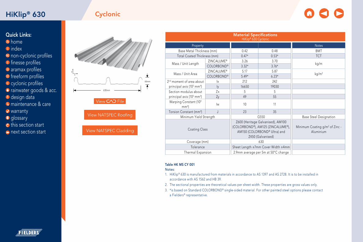
Quick Links: home index non-cyclonic profiles finesse profiles aramax profiles freeform profiles cyclonic profiles rainwater goods & acc. design data maintenance & care warranty glossary
630mm
66mm
yx
CyclonicHiKlip® 630
Table HK MS CY 001Notes:1. HiKlip® 630 is manufactured from materials in accordance to AS 1397 and AS 2728. It is to be installed in
accordance with AS 1562 and HB 39.
2. The sectional properties are theoretical values per sheet width. These properties are gross values only.
3. *is based on Standard COLORBOND® single-sided material. For other painted steel options please contact a Fielders® representative.
this section start next section start
Material Specifications HiKlip® 630 Cyclonic
Property NotesBase Metal Thickness (mm) 0.42 0.48 BMT
Total Coated Thickness (mm) 0.47* 0.53* TCT
Mass / Unit LengthZINCALUME® 3.26 3.70
kg/mCOLORBOND® 3.32* 3.76*
Mass / Unit AreaZINCALUME® 5.17 5.87
kg/m2
COLORBOND® 5.49* 6.23*2nd moment of area about
principal axis (103 mm4)Ix 212 242Iy 16650 19030
Section modulus about principal axis (103 mm3)
Zx 5 5Zy 49 55
Warping Constant (109 mm6)
Iw 10 11
Torsion Constant (mm4) J 23 35Minimum Yield Strength G550 Base Steel Designation
Coating Class
Z600 (Heritage Galvanised), AM100(COLORBOND®), AM125 (ZINCALUME®),
AM150 (COLORBOND® Ultra) andZ450 (Galvanised)
Minimum Coating g/m2 of Zinc - Aluminium
Coverage (mm) 630Tolerance Sheet Length ±7mm Cover Width ±4mm
Thermal Expansion 2.9mm average per 5m at 50°C change

Quick Links: home index non-cyclonic profiles finesse profiles aramax profiles freeform profiles cyclonic profiles rainwater goods & acc. design data maintenance & care warranty glossary
Rainfall CapacityFor further information, please refer to sections “Rainfall Intensity” and “Water Carrying Capacity and Rainwater Run-Off”.
CyclonicHiKlip® 630
Table HK RL CY 001
Figure HK RC CY 001
Maximum Roof Length (m) HiKlip® 630 Cyclonic
Roof Slope (degrees)
Rainfall Capacity (mm/hr)
100 150 200 250 300 350 400
1 331 221 166 132 110 95 832 468 312 234 187 156 134 1173 574 383 287 230 191 164 1434 663 442 331 265 221 189 1665 741 494 371 297 247 212 185
0
100
200
300
400
500
600
700
800 100mm/hr
150mm/hr
200mm/hr
250mm/hr
300mm/hr
350mm/hr
400mm/hr
Max
imum
She
et L
eng
th (m
)
Roof Slope (degrees)
1 2 3 4 5
this section start next section start

Quick Links: home index non-cyclonic profiles finesse profiles aramax profiles freeform profiles cyclonic profiles rainwater goods & acc. design data maintenance & care warranty glossary
Cyclonic Load SpansHiKlip® 630
Allowable SpansThe allowable roof spans for the HiKlip® 630 roofing profile in Regions C and D are shown in Tables “HK RS CY 001” and “HK RS CY 002”.
The allowable spans have been determined from tests carried out in accordance with Building Code of Australia (BCA) 2008 Specification B1.2 for the LHL cyclonic testing method, AS 1170.2-2002 and AS 4040.0-1992.
The local pressure factors (KL) are shown in Figure 2.7.B. Local pressure factors are not applicable at the ridge where the roof pitch is less than 10°. The value of ‘a’ is the minimum of 0.2 breadth, 0.2 width or the height.
Overhang
Overhang
Overhang
Overhang(End span)
End span
End span
End span
Internal spans
Internal spans
Figure HK CY End Spans, Internal Spans and Overhangs 001
Table HK WC CY 001Notes:1. Values are based on fixing into steel supports with a minimum thickness of 1.5mm.
2. Values in italics are estimates based on trend lines fitted to the test data.
3. Values are based on no insulation under the sheeting.
Cyclonic TestingFielders® have undertaken cyclonic testing of the HiKlip® 630 profile in accordance with the Low-High-Low (LHL) cyclonic testing method in the BCA.
The cyclonic wind load capacities for HiKlip® 630 roofing profile is shown in the table below.
Wind Load Capacity (kPa) Strength Limit StateHiKlip® 630 Cyclonic
Span (mm) 0.42 mm BMT 0.48 mm BMT
End Span Internal Span End Span Internal Span
450 11.61 13.07
600 9.51 11.18 11.09 12.59
900 6.22 8.05 7.79 9.86
1200 4.13 5.72 5.36 7.47
1500 3.26 4.21 3.81 5.42
1800 3.51 3.70 this section start next section start

Quick Links: home index non-cyclonic profiles finesse profiles aramax profiles freeform profiles cyclonic profiles rainwater goods & acc. design data maintenance & care warranty glossary
Cyclonic Load SpansHiKlip® 630
Maximum Allowable Roof Spans (mm)HiKlip® 630 Cyclonic – for building heights ≤ 5.0 metres
Terrain Category
Region C Region D
Roof Area Notation & Uplift (kPa)*
0.42 BMT 0.48 BMT Roof Area Notation & Uplift (kPa)
0.42 BMT 0.48 BMT
End Span Internal Span End Span Internal
Span End Span Internal Span End Span Internal
Span
1 & 2
D - 4.18 1190 1510 1410 1710 D - 6.66 850 1060 1020 1310
F - 5.35 1000 1260 1200 1510 F - 8.54 670 840 820 1060
G - 6.53 860 1080 1040 1330 G - 10.41 530 660 650 830
2.5
D - 3.54 1350 1770 1580 1830 D - 5.65 960 1210 1150 1460
F - 4.54 1120 1410 1330 1640 F - 7.24 790 990 950 1230
G - 5.54 980 1230 1170 1480 G - 8.83 650 820 790 1020
Table HK RS CY 001Notes:1. Values are based on fixing into steel supports with a minimum thickness of 1.5mm.
2. Values in italics are estimates based on trend lines fitted to the test data.
3. Values are based on no insulation under the sheeting.
Table HK RS CY 002Notes:1. Values are based on fixing into steel supports with a minimum thickness of 1.5mm.
2. Values in italics are estimates based on trend lines fitted to the test data.
3. Values are based on no insulation under the sheeting.
aa/2
a
a
≤ 25 metres
F
G
Area D
a/2
Figure HK CY Local Pressure Factors 002Note: 1. The local pressure factors (KL) are shown in Figure 2.
Local pressure factors are not applicable at the ridge where the roof pitch is less than 10°. The value of ‘a’ is the minimum of 0.2 breadth, 0.2 width or the height.
Maximum Allowable Roof Spans (mm) HiKlip® 630 Cyclonic – for building heights between 5.0 m – 10.0 m
Terrain Category
Region C Region D
Roof Area Notation & Uplift (kPa)*
0.42 BMT 0.48 BMT Roof Area Notation & Uplift (kPa)
0.42 BMT 0.48 BMT
End Span Internal Span End Span Internal
Span End Span Internal Span End Span Internal
Span
1 & 2
D - 4.63 1110 1400 1320 1630 D - 7.38 780 970 940 1210
F - 5.93 930 1160 1110 1420 F - 9.46 600 750 730 940
G - 7.23 790 990 960 1230 G - 11.54 450 570 560 710
2.5
D - 4.13 1200 1520 1420 1710 D - 6.59 860 1070 1030 1320
F - 5.30 1010 1270 1200 1510 F - 8.45 680 850 830 1070
G - 6.46 870 1090 1050 1340 G - 10.30 540 670 660 840
*Design Parameters Design Life 50 yearsImportance Level 2Maximum Roof Height H = 5, 10mExternal Pressure Coefficient Cpe = -0.90 for roofing, -0.65 for walling Internal Pressure Coefficient Cpi = 0.7Local Pressure Factor kL = 2.0, 1.5, 1.0Ms = Mt = Md = 1.0
this section start next section start

Quick Links: home index non-cyclonic profiles finesse profiles aramax profiles freeform profiles cyclonic profiles rainwater goods & acc. design data maintenance & care warranty glossary
Cyclonic Load SpansHiKlip® 630
Maximum Allowable Wall Spans (mm)HiKlip® 630 Cyclonic – for building heights ≤ 5.0 metres
Terrain Category
Region C Region D
Roof Area Notation & Uplift (kPa)*
0.42 BMT 0.48 BMT Roof Area Notation & Uplift (kPa)
0.42 BMT 0.48 BMT
End Span Internal Span End Span Internal
Span End Span Internal Span End Span Internal
Span
1 & 2
D - 4.18 1350 1780 1580 1830 D 970 1210 1160 1460
F - 5.35 1150 1450 1370 1670 F 820 1020 980 1260
G - 6.53 1020 1280 1220 1530 G 690 860 840 1080
2.5
D - 3.54 1600 1750 1600 1940 D 1080 1370 1290 1600
F - 4.54 1290 1670 1520 1790 F 930 1160 1120 1420
G - 5.54 1140 1440 1350 1660 G 810 1010 970 1250
Table HK WS CY 001Notes:1. Values are based on fixing into steel supports with a minimum thickness of 1.5mm.
2. Values in italics are estimates based on trend lines fitted to the test data.
3. Values are based on no insulation under the sheeting.
Table HK WS CY 002Notes:1. Values are based on fixing into steel supports with a minimum thickness of 1.5mm.
2. Values in italics are estimates based on trend lines fitted to the test data.
3. Values are based on no insulation under the sheeting.
aa/2
a
a
≤ 25 metres
F
G
Area D
a/2
Figure HK CY Local Pressure Factors 002Note: 1. The local pressure factors (KL) are shown in Figure 2.
Local pressure factors are not applicable at the ridge where the roof pitch is less than 10°. The value of ‘a’ is the minimum of 0.2 breadth, 0.2 width or the height.
Maximum Allowable Wall Spans (mm) HiKlip® 630 Cyclonic – for building heights between 5.0 m – 10.0 m
Terrain Category
Region C Region D
Roof Area Notation & Uplift (kPa)*
0.42 BMT 0.48 BMT Roof Area Notation & Uplift (kPa)
0.42 BMT 0.48 BMT
End Span Internal Span End Span Internal
Span End Span Internal Span End Span Internal
Span
1 & 2
D - 4.63 1250 1590 1470 1760 D 880 1120 1070 1370
F - 5.93 1070 1350 1280 1590 F 740 930 900 1160
G - 7.23 950 1190 1130 1440 G 620 770 750 970
2.5
D - 4.13 1370 1820 1590 1840 D 970 1220 1170 1470
F - 5.30 1160 1470 1380 1680 F 820 1030 990 1270
G - 6.46 1030 1290 1220 1540 G 700 870 850 1090
*Design Parameters Design Life 50 yearsImportance Level 2Maximum Roof Height H = 5, 10mExternal Pressure Coefficient Cpe = -0.90 for roofing, -0.65 for walling Internal Pressure Coefficient Cpi = 0.7Local Pressure Factor kL = 2.0, 1.5, 1.0Ms = Mt = Md = 1.0
this section start next section start

Quick Links: home index non-cyclonic profiles finesse profiles aramax profiles freeform profiles cyclonic profiles rainwater goods & acc. design data maintenance & care warranty glossary
Fixing of CladdingFasteners must be selected to match the life expectancy of the cladding material. Recommendations from fastener manufacturers should be sought. Only fasteners complying with AS 3566:2002 and those that are compatible with the roofing material should be used for its fastening.
All fasteners used externally should be fitted with an EPDM seal. Do not use punches to form fastener holes. For a concealed-fixed cladding, the clips are fastened to the support at the base of each rib, as shown in Figure 2.7.C. Fasteners used in the clip fixing is shown in Table “HK CF CY 001”.
Insulation Care needs to be taken when installing insulation with roof sheeting. When insulation thickness up to 50mm are installed the screws detailed in Table HR PF NC 001 may need to be increased depending on the thickness and density of the insulation. When the screw is properly tightened into metal there should be a minimum of three (3) threads protruding past the support being fixed in to. For timber the screw must penetrate the timber as much as the screws detailed in Table HR PF NC 001 do without insulation. For insulation thicknesses greater than 50mm Fielders® recommend the use of a thermal spacer to help maintain Rw values as well as minimising any bulging in the profile caused by the insulation.
Clip Fixing HiKlip® 630 Cyclonic
Fixing Supports Clip-Fixing Edge Restraint
Steel 1.5 mm 12 – 14 x 20mm Self-drilling hex head Teks screw
14 – 10 x 95mm Self-drilling hex head Teks screw
For further information on the HiKlip® 630 roofing profile, including installation procedures, refer to the “installation procedure”.
Cyclonic Load SpansHiKlip® 630
Table HK CF CY 001
Figure HK CY HiKlip® 630 clip fastener locations 003
this section start next section start

Quick Links: home index non-cyclonic profiles finesse profiles aramax profiles freeform profiles cyclonic profiles rainwater goods & acc. design data maintenance & care warranty glossary
Installation procedureHiKlip® 630
Concealed Fastening
Unique double-clip action
Only HiKlip® 630 features an over-and-under double clipping action on the side lap for added strength to withstand the strongest winds. And therefore, because the clips and brackets allow the sheet to move with temperature changes, you do not need step/expansion joints.
Further details are available in section “Comparative Analysis: Concealed Fix vs. Screw Fix”.
Figure HK CY Double-clip action ensures maximum strength 007
Figure HK CY HiKlip® Concealed Fix Clipping System 008
this section start next section start

Quick Links: home index non-cyclonic profiles finesse profiles aramax profiles freeform profiles cyclonic profiles rainwater goods & acc. design data maintenance & care warranty glossary
Figure HK CY Clips Located By Fixing Centre Screw First 004
Installation procedureHiKlip® 630
Laying HiKlip® 630
Step 1
Fix the first of the HiKlip® 630 clips perpendicular to the gutter in a straight line using the correct fasteners. Use a string line or the edge of the first sheet to ensure straightness. Care should be taken so that the overlap is facing away from the prevailing weather.
Step 2
Locate the first sheet above the clips ensuring that the overhang into the gutter is correct. Push downwards on the sheet until the decking is secured at every clip. Do not use excessive force.
Step 3
Lap the next HiKlip® 630 clip over the top of the male rib, ensuring that the sheet being laid is parallel to the previous sheet and perpendicular to the gutter line. Fasten this first and fix the remaining two holes as previously done. Fasten all clips in this manner.
Step 4
Lay the next sheet of HiKlip® 630 as previously described. Checks should be carried out periodically to ensure the deck-ing is installed squarely. This can be done by comparing the coverage at the ridge to that at the gutter line or by using a string line. At the end of the purlins, cut the deck and clip to suit.
Step 5
Turn up the HiKlip® 630 pans at the ridge line. On lower pitches the pans should be turned down at the gutter line.
Figure HK CY HiKlip® Clips Over The Top Of The Male Rib 005
this section start next section start

Quick Links: home index non-cyclonic profiles finesse profiles aramax profiles freeform profiles cyclonic profiles rainwater goods & acc. design data maintenance & care warranty glossary
Step 6
Flash the roof with compatible products using F10 brackets and sliding brackets as necessary to allow for thermal expansion and contraction.
Step 7
Clean the roof daily during construction as per Fielders® maintenance guide, ensuring the removal of all swarf, pop rivets and fasteners.
Turning of Roof Sheeting EndsRefer to section “Flashings, Cappings & Ends of Sheets”.
Designing Without Step JointsFor further information regarding the design of HiKlip® 630 roofs without step joints, please see section "Long Length Roofing Solutions".
Maximum Roof LengthSee section “Thermal Expansion and Contraction of Steel Sheeting”.
Curving HiKlip® 630For details regarding spring curving of HiKlip® 630 sheets, please see section “Curving of Steel Decks”.
Installation procedure
Sliding bracketsF10 bracket
HiKlip® 630
Figure HK CY Clips Located Over HiKlip® 630 Male Rib 006
this section start next section start

Quick Links: home index non-cyclonic profiles finesse profiles aramax profiles freeform profiles cyclonic profiles rainwater goods & acc. design data maintenance & care warranty glossary
HiKlip® 630 Flashings & Details
Masonry ParapetSide Wall (Low)
Masonry ParapetSide Wall (High) Apron Flashings Overflashing Headwall Apron Flashing Soaker Gutter
100 87°93°
10 10 S.B.
100 10087°
93°
10 10
130
70100°150 10 S.B.
25
10
70
130Angle to suit roof
pitch
70100°
150
13020
Angle to suit roof pitch
200
Product Code: HK1 Product Code: HK2 Product Code: HK3 GIRTH 330 Product Code: HK4 Girth 112 Product Code: HK5 Girth 350 Product Code: HK6 Girth 350
Soffit Corner Flashing Shoe Flashing Bracket Valley Gutter Under OverFlashing
Mansard RoofFlashing
40
95°
10
30
50
3051
95° 95°50
30 30
50
150 150
20 20
130130
Angle to suit roof pitch
70
20
100°
130
130
Angle to suit roof pitch
70
20
100°
Product Code: HK7 Girth 211 Product Code: HK8 Product Code: HK10 Product Code: HK11 Girth 340 Product Code: HK12 Girth 330 Product Code: HK13 Girth 330
Industrial DoorJamb Flashing Apex Capping Type 1 Apex Capping Type 2 Back Channel Barge Capping
Steel Construction Barge Capping
10 S.B.
70
52
50
95
130
100°25
Angle to suit roof pitch
7095
130
100°
10
70
Angle to suit roof pitch
52
48
30
130
95
50
25135°
100°95
130
100°
7
70
18
Product Code: HK14 Girth 182 Product Code: HK17 Girth 300 Product Code: HK18 Girth 285 Product Code: HK19 Girth 130 Product Code: HK20 Girth 300 Product Code: WK22 Girth 300
Framed Parapet Capping Two Piece StepFlashing Sliding Bracket
100 10087° 93°
30 30
135°
10S.B.
150
130
100°
20
Angle to suit roof pitch
* 70
45
25110°
15
30 32
53
Product Code:HK23 Product Code: HK24 Product Code: HK25
Notes: 1. denotes size to be determined by application. All sizes are in mm and should be used as a guide only. They should be
measured on-site to determine actual size.
2. S.B. denotes ‘ Slight Break’.
3. Also refer to “Typical Roofing Details”.
Flashings & DetailsHiKlip® 630
Table HK FD CY 001
this section start next section start

Quick Links: home index non-cyclonic profiles finesse profiles aramax profiles freeform profiles cyclonic profiles rainwater goods & acc. design data maintenance & care warranty glossary
HiRib™ 680 CyclonicHiRib™ 680
Table HR MS CY 001Notes:1. HiRib 680 is manufactured from materials in accordance to AS 1397 and AS 2728. It is to be installed in
accordance with AS 1562 and HB 39.
2. The sectional properties are theoretical values per sheet width. These properties are gross values only.
3. *is based on Standard COLORBOND® single-sided material. For other painted steel options please contact a Fielders® representative.
yx
680mm
48mm
this section start next section start
Material Specifications HiRib™ 680 Cyclonic
Property NotesBase Metal Thickness (mm) 0.42 0.48 0.60 BMT
Total Coated Thickness (mm) 0.47* 0.53* 0.65* TCT
Mass / Unit LengthZINCALUME® 3.30 3.77 4.70
kg/mCOLORBOND® 3.36* 3.84* 4.78*
Mass / Unit AreaZINCALUME® 4.34 4.96 6.18
kg/m2
COLORBOND® 4.42* 5.05* 6.29*2nd moment of area about
principal axis (103 mm4)Ix 124 142 163Iy 20090 22960 26300
Section modulus about principal axis (103 mm3)
Zx 4 4 5Zy 52 60 68
Warping Constant (109 mm6)
Iw 7 8 9
Torsion Constant (mm4) J 23 35 52Minimum Yield Strength G550 Base Steel Designation
Coating Class
Z600 (Heritage Galvanised), AM100 (COLORBOND®), AM125 (ZINCALUME), AM150 (COLORBOND® Ultra) and Z450
(Galvanised)
Minimum Coating g/m2 of Zinc - Aluminium
Coverage (mm) 680Tolerance Sheet Length ±7mm Cover Width ±4mm
Thermal Expansion 2.9mm average per 5m at 50° C change

Quick Links: home index non-cyclonic profiles finesse profiles aramax profiles freeform profiles cyclonic profiles rainwater goods & acc. design data maintenance & care warranty glossary
Rainfall CapacityFor further information, please refer to sections "Rainfall Intensity" and "Water Carrying Capacity and Rainwater Run-Off".
HiRib™ 680
Maximum Roof Length (m)HiRib™ 680 Cyclonic
Roof Slope (degrees)
Rainfall Capacity (mm/hr)
100 150 200 250 300 350 400
1 439 293 219 176 146 125 1102 621 414 310 248 207 177 1553 760 507 380 304 253 217 1904 878 585 439 351 293 251 2195 981 654 491 393 327 280 245
CyclonicHiRib™ 680
Table HR RL CY 001Note: 1. Minimum recommended slope is 1°.
2. Sheet lengths greater than 24m are not recommended due to thermal expansion and contraction.
Figure HR RC CY 001
0
200
400
600
800
1000 100mm/hr
150mm/hr
200mm/hr
250mm/hr
300mm/hr
350mm/hr
400mm/hr
Max
imum
She
et L
eng
th (m
)
Roof Slope (degrees)
1 2 3 4 5
this section start next section start

Quick Links: home index non-cyclonic profiles finesse profiles aramax profiles freeform profiles cyclonic profiles rainwater goods & acc. design data maintenance & care warranty glossary
Cyclonic Testing Fielders® have undertaken cyclonic testing of Hi-Rib in accordance with AS4040.0-1992.
The cyclonic wind load capacities for Hi-Rib roofing profile are shown in Table “HR WC CY 001” below.
Wind Load Capacity - Limit State Design (kPa) HiRib™ 680 Cyclonic
Span (mm)
0.42 BMT 0.48 BMT 0.55 BMT
SingleSpan
DoubleSpan
Multi SpansSingleSpan
DoubleSpan
Multi SpansSingleSpan
DoubleSpan
Multi Spans
EndSpan
Internal Span
EndSpan
Internal Span
EndSpan
Internal Span
900 11.83 6.81 5.71 5.71 - - 6.30 6.30 14.63 6.84 5.98 5.98
1200 8.22 5.09 4.78 5.57 9.46 5.30 4.81 6.30 8.95 5.63 4.84 5.82
1500 5.37 3.95 3.44 4.77 6.47 4.40 3.56 4.85 5.31 4.56 3.58 4.85
1800 3.29 3.47 1.70 3.72 4.43 3.60 2.22 3.77 3.71 3.63 2.19 3.84
2100 - - - 2.44 3.32 2.89 - 2.84 - - - 2.78
HiRib™ 680 Cyclonic
Overhang
Overhang
Overhang
Overhang(End span)
End span
End span
End span
Internal spans
Internal spans
Figure HR CY End Spans, Internal Spans and Overhangs 001
Table HR WC CY 001Note: 1. 0.42 & 0.48mm BMT is G550 and 0.55mm BMT is G300.
2. Values are based on no insulation under the sheeting.
Allowable Spans
The allowable roof spans for the HiRib™ roofing profile in Regions C and D are shown in Tables “HR RS CY 001” and “HR RS CY 002”.
The allowable spans have been determined from tests carried out in accordance with AS4040.0-1992, AS 1170.2-2002 and the Building Code of Australia (BCA) 2008 Specification B1.2 for the design of buildings in cyclonic areas.
this section start next section start

Quick Links: home index non-cyclonic profiles finesse profiles aramax profiles freeform profiles cyclonic profiles rainwater goods & acc. design data maintenance & care warranty glossary
Maximum Allowable Roof Spans (mm) in Region CHiRib™ 680 Cyclonic – for building heights ≤ 5.0 m
Terrain Category
Roof Area Notation & Uplift (kPa)*
0.42 BMT 0.48 BMT 0.55 BMT
SingleSpan
DoubleSpan
Multi SpansSingleSpan
DoubleSpan
Multi SpansSingleSpan
DoubleSpan
Multi SpansEndSpan
Internal Span
EndSpan
Internal Span
EndSpan
Internal Span
1 & 2
D - 4.18 1660 1430 1350 1680 1850 1580 1350 1680 1660 1620 1360 1700
F - 5.35 1500 1150 1330 1290 1650 1180 1090 1370 1490 1270 1070 1350
G - 6.53 1370 940 - - 1490 830 860 1100 1380 970 740 970
2.5
D - 3.54 1760 1720 1480 1850 2010 1820 1500 1870 1890 1830 1510 1880
F - 4.54 161 0 1330 1260 1570 1780 1450 1270 1580 1600 1510 1280 1590
G - 5.54 1480 1110 960 1210 1520 1130 1050 1330 1470 1220 1020 1290
HiRib™ 680 CyclonicHiRib™ 680
Table HR RS CY 001
Table HR RS CY 002
Cyclonic Load Span Tables - Region C
aa/2
a
a
≤ 25 metres
F
G
Area D
a/2
Figure HR CY Local Pressure Factors 002Note: The local pressure factors (KL) are shown in Figure 2. Local pressure factors are not applicable at the ridge where the roof pitch is less than 10°. The value of ‘a’ is the minimum of 0.2 breadth, 0.2 width or the height.
Maximum Allowable Roof Spans (mm) in Region CHiRib™ 680 Cyclonic – for building heights between 5.0 m – 10.0 m
Terrain Category
Roof Area Notation & Uplift (kPa)*
0.42 BMT 0.48 BMT 0.55 BMT
SingleSpan
DoubleSpan
Multi SpansSingleSpan
DoubleSpan
Multi SpansSingleSpan
DoubleSpan
Multi SpansEndSpan
Internal Span
EndSpan
Internal Span
EndSpan
Internal Span
1 & 2
D - 4.63 1660 1310 1240 1540 1760 1420 1250 1560 1590 1480 1250 1570
F - 5.93 1430 1040 800 1030 1570 1010 970 1230 1430 1120 910 1160
G - 7.23 1300 840 - - 1410 - - 950 1320 810 - -
2.5
D - 4.13 1670 1450 1360 1690 1860 1600 1360 1700 1670 1630 1370 1710
F - 5.30 1510 1160 1050 1310 1650 1200 1100 1390 1500 1290 1080 1360
G - 6.46 1380 950 - - 1500 850 870 1110 1380 990 760 990
*Design Parameters
Region C
Pa,r = 1:500
Vr = 66 m/s for Region C
Vr = 88 m/s for Region D
Md = 1.00
FC = 1.05
FD = 1.1
Ms = 1.00
Mt = 1.00
Cp,i = 0.70
Cp,e = - 0.90
KL = 1.5 for Area F
KL = 2.0 for Area G
in accordance with AS1170.2-2002
this section start next section start

Quick Links: home index non-cyclonic profiles finesse profiles aramax profiles freeform profiles cyclonic profiles rainwater goods & acc. design data maintenance & care warranty glossary
Maximum Allowable Roof Spans (mm) in Region DHiRib™ 680 Cyclonic – for building heights between 5.0 m – 10.0 m
Terrain Category
Roof Area Notation & Uplift (kPa)*
0.42 BMT 0.48 BMT 0.55 BMT
SingleSpan
DoubleSpan
Multi SpansSingleSpan
DoubleSpan
Multi SpansSingleSpan
DoubleSpan
Multi SpansEndSpan
Internal Span
EndSpan
Internal Span
EndSpan
Internal Span
1 & 2
D - 7.38 1270 800 360 520 1410 505 685 975 1330 765 530 720
F - 9.46 1095 440 - - 1200 - 265 545 1175 250 - -
G - 11.54 925 - - - 990 - - 115 1065 - - -
2.5
D - 6.59 1370 940 615 820 1490 770 840 1140 1395 960 740 960
F -8.45 1180 615 - - 1300 150 465 755 1240 500 250 385
G - 10.30 1025 290 - - 115 - - 370 1130 - - -
Maximum Allowable Roof Spans (mm) in Region DHiRib™ 680 Cyclonic – for building heights ≤ 5.0 m
Terrain Category
Roof Area Notation & Uplift (kPa)*
0.42 BMT 0.48 BMT 0.55 BMT
SingleSpan
DoubleSpan
Multi SpansSingleSpan
DoubleSpan
Multi SpansSingleSpan
DoubleSpan
Multi SpansEndSpan
Internal Span
EndSpan
Internal Span
EndSpan
Internal Span
1 & 2
D - 6.66 1365 925 595 790 1480 745 830 640 1390 945 720 940
F - 8.54 1175 600 - - 1290 120 450 - 1235 480 225 360
G - 10.41 1020 1270 - - 1105 - - - 1125 - - -
2.5
D - 5.65 1470 1100 920 1170 1620 1805 1030 1335 1470 1195 985 1225
F - 7.24 1305 825 405 575 1425 555 710 460 1340 800 565 760
G - 8.83 1150 550 - - 1265 - 390 - 1210 405 150 270
HiRib™ 680 CyclonicHiRib™ 680
Table HR RS CY 003
Table HR RS CY 004Note: * Pressure is total ultimate value
Cyclonic Load Span Tables - Region D
this section start next section start

Quick Links: home index non-cyclonic profiles finesse profiles aramax profiles freeform profiles cyclonic profiles rainwater goods & acc. design data maintenance & care warranty glossary
Fixing of CladdingFasteners must be selected to match the life expectancy of the cladding material. Recommendations from fastener manufacturers should be sought. Only fasteners complying with AS 3566:2002 and those that are compatible with the roofing material should be used for its fastening.
All fasteners used externally should be fitted with an EPDM seal. Do not use punches to form fastener holes. Fasteners are to be fixed at each crest of the Hi-Rib™ roof sheeting.
For further information on the Hi-Rib™ roofing profile,including installation procedures, refer to Specifying Fielders® – Roofing & Walling manual.
HiRib™ 680 Installation ProcedureFor installation procedures see section “Typical Pierce Fix Installation Guide”. For general handling instructions refer to section “Maintenance and Care”.
Insulation Care needs to be taken when installing insulation with roof sheeting. When insulation thickness up to 50mm are installed the screws detailed in Table HR PF NC 001 may need to be increased depending on the thickness and density of the insulation. When the screw is properly tightened into metal there should be a minimum of three (3) threads protruding past the support being fixed in to. For timber the screw must penetrate the timber as much as the screws detailed in Table HR PF NC 001 do without insulation. For insulation thicknesses greater than 50mm Fielders® recommend the use of a thermal spacer to help maintain Rw values as well as minimising any bulging in the profile caused by the insulation.
HiRib™ 680 Cyclonic
this section start next section start

Quick Links: home index non-cyclonic profiles finesse profiles aramax profiles freeform profiles cyclonic profiles rainwater goods & acc. design data maintenance & care warranty glossary
Crest and Valley Fasteners locations
Either four Crest or four Valley Fixings.
Side Lap FasteningIt may be necessary to use side lap fasteners to maintain a weatherproof side lap. One or more fasteners are recommended when using HiRib at maximum spans, for walling cladding. Lap fasteners are also required alongside each valley fastener.
Notes:1. All fasteners used externally should be fitted with an EPDM seal (washer).
2. Do not use punches to form fastener holes.
3. HiRib Cyclonic uses 14-10x75 hex screws with a cyclonic plate seal.
Turning of Roof Sheeting EndsRefer to section “Flashings, Cappings & Ends of Sheets”.
Hi-Rib™ Pierce Fixing – Cyclonic
Fixing Supports Crest Fixing Side Lap Fixing
Steel 1.5 mm 14-10 x 75mm Metal Teks head 10 x 16mm Neo Teks hex head
10 x 16mm Neo Teks hex head
HiRib™ 680 Cyclonic
Table HR PF CY 001
this section start next section start

Quick Links: home index non-cyclonic profiles finesse profiles aramax profiles freeform profiles cyclonic profiles rainwater goods & acc. design data maintenance & care warranty glossary
HiRib™ 680 Flashings & Details
Masonry ParapetSide Wall (Low)
Masonry ParapetSide Wall (High) Apron Flashings Overflashing Headwall Apron Flashing Soaker Gutter
100 87°93°
10 10 S.B.
100 10087°
93°
10 10
130
70100°150 10 S.B.
25
10
70
130Angle to suit roof
pitch
70100°
150
13020
Angle to suit roof pitch
200
Product Code: HR1 Product Code: HR2 Product Code: HR3 GIRTH 330 Product Code: HR4 Girth 112 Product Code: HR5 Girth 350 Product Code: HR6 Girth 350
Soffit Corner Flashing Shoe Flashing Bracket Valley Gutter Under OverFlashing
Mansard RoofFlashing
40
95°
10
30
50
3051
95° 95°50
30 30
50
150 150
20 20
130130
Angle to suit roof pitch
70
20
100°
130
130
Angle to suit roof pitch
70
20
100°
Product Code: HR7 Girth 211 Product Code: HR8 Product Code: HR10 Product Code: HR11 Girth 340 Product Code: HR12 Girth 330 Product Code: HR13 Girth 330
Industrial DoorJamb Flashing Apex Capping Type 1 Apex Capping Type 2 Back Channel Barge Capping
Steel Construction Barge Capping
10 S.B.
70
52
50
95
130
100°25
Angle to suit roof pitch
7095
130
100°
10
70
Angle to suit roof pitch
52
48
30
130
95
50
25135°
100°95
130
100°
7
70
18
Product Code: HR14 Girth 182 Product Code: HR17 Girth 300 Product Code: HR18 Girth 285 Product Code: HR19 Girth 130 Product Code: HR20 Girth 300 Product Code: HR22 Girth 300
Framed Parapet Capping Two Piece StepFlashing Sliding Bracket
100 10087° 93°
30 30
135°
10S.B.
150
130
100°
20
Angle to suit roof pitch
* 70
45
25110°
15
30 32
53
Product Code:HR23 Product Code: HR24 Product Code: HR25
Notes: 1. denotes size to be determined by application. All sizes are in mm and should be used as a guide only. They should be
measured on-site to determine actual size.
2. S.B. denotes ‘ Slight Break’.
3. Also refer to “Typical Roofing Details”.
Flashings & Details
Table HR FD CY 001
HiRib™ 680
this section start next section start

Quick Links: home index non-cyclonic profiles finesse profiles aramax profiles freeform profiles cyclonic profiles rainwater goods & acc. design data maintenance & care warranty glossary
28mm
762mm
yx
CyclonicTL-5™
Table TL MS CY 001Notes:1. TL-5 is manufactured from materials in accordance to AS 1397 and AS 2728. It is to be installed in
accordance with AS 1562 and HB 39.
2. The sectional properties are theoretical values per sheet width. These properties are gross values only.
3. *is based on Standard COLORBOND® single-sided material. For other painted steel options please contact a Fielders® representative.
this section start next section start
Material Specifications TL-5™ Cyclonic
Property NotesBase Metal Thickness (mm) 0.35 0.42 0.48 BMT
Total Coated Thickness (mm) 0.40* 0.47* 0.53* TCT
Mass / Unit LengthZINCALUME® 2.75 3.30 3.70
kg/mCOLORBOND® 2.80* 3.36* 3.77*
Mass / Unit AreaZINCALUME® 3.60 4.34 4.87
kg/m2
COLORBOND® 3.68* 4.42* 4.96*2nd moment of area about
principal axis (103 mm4)Ix 32 39 45Iy 19150 22980 26270
Section modulus about principal axis (103 mm3)
Zx 2 2 2Zy 47 56 64
Warping Constant (109 mm6)
Iw 2 2 3
Torsion Constant (mm4) J 14 23 35Minimum Yield Strength G550 Base Steel Designation
Coating Class
Z600 (Heritage Galvanised), AM100 (COLORBOND®), AM125
(ZINCALUME®), AM150 (COLORBOND® Ultra) and Z450 (Galvanised)
Minimum Coating g/m2 of Zinc - Aluminium
Coverage (mm) 762
ToleranceSheet Length ±7mm Cover Width
±4mmThermal Expansion 2.9mm average per 5m at 50°C change

Quick Links: home index non-cyclonic profiles finesse profiles aramax profiles freeform profiles cyclonic profiles rainwater goods & acc. design data maintenance & care warranty glossary
Rainfall Capacity For further information, please refer to sections “Rainfall Intensity” and “Water Carrying Capacity and Rainwater Run-Off”.
TL-5™ Maximum Roof Length (m)TL-5™ Cyclonic
Roof
Slope
(degrees)
Rainfall Capacity (mm/hr)
100 150 200 250 300 350 400
2 172 114 86 69 57 49 433 210 140 105 84 70 60 534 243 162 121 97 81 69 615 272 181 136 109 91 78 68
Figure TL RC CY 001
CyclonicTL-5™
Table TL RL CY 001Notes:1. Minimum recommended slope is 2°.
2. Sheet lengths greater than 24m are not recommended due to thermal expansion and contraction.
0
50
100
150
200
250
300 100mm/hr
150mm/hr
200mm/hr
250mm/hr
300mm/hr
350mm/hr
400mm/hr
Max
imum
She
et L
eng
th (m
)
Roof Slope (degrees)
2 3 4 5
this section start next section start

Quick Links: home index non-cyclonic profiles finesse profiles aramax profiles freeform profiles cyclonic profiles rainwater goods & acc. design data maintenance & care warranty glossary
CyclonicTL-5™
Cyclonic TestingFielders® have undertaken cyclonic testing of TL-5 in accordance with the Low-High-Low cyclonic testing method in the BCA.
The cyclonic wind load capacities for TL-5 roofing profile are shown in Table TL WC CY 001 below.
Wind Load Capacity –Strength Limit State Design (kPa)TL-5™ Cyclonic
Span(mm)
0.42 mm BMT 0.48 mm BMTEnd Internal End Internal
900 6.50 - 7.21 -
1200 3.95 5.96 4.85 6.81
1500 2.66 3.99 3.29 4.86
1800 1.94 2.87 2.52 3.51
2100 - 2.17 - 2.76
Allowable Roof SpansThe allowable roof spans for the TL-5 roofing profile in Region C are shown in Tables “TL RS CY 001” and “TL RS CY 002”.
The allowable spans have been determined from tests carried out in accordance with AS4040.0-1992, AS 1170.2-2002 and the Building Code of Australia (BCA) 2008 Specification B1.2 for the design of buildings in cyclonic areas.
Overhang
Overhang
Overhang
Overhang(End span)
End span
End span
End span
Internal spans
Internal spans
Figure TL CY End Spans, Internal Spans and Overhangs 001
Table TL WC CY 001
this section start next section start

Quick Links: home index non-cyclonic profiles finesse profiles aramax profiles freeform profiles cyclonic profiles rainwater goods & acc. design data maintenance & care warranty glossary
Maximum Allowable Roof Spans* (mm)TL-5™ Cyclonic – for building heights between 5.0 m – 10.0 m
Terrain Category
Region C Region D
Roof Area Notation & Uplift (kPa)*
0.42 BMT 0.48 BMT Roof Area Notation & Uplift (kPa)*
0.42 BMT 0.48 BMT
End Internal End Internal End Internal End Internal
1 & 2
D - 4.18 1100 1380 1230 1540 D-7.38 795 880 985 1110
F - 5.35 960 1200 1050 1320 F-9.46 550 615 665 790
G - 6.53 830 1070 900 1140 G-11.54 305 350 350 470
2.5
D - 3.54 1170 1460 1320 1640 D-6.59 890 890 1105 1235
F - 4.54 1020 1280 1130 1420 F-8.45 670 670 820 950
G - 5.54 900 1150 980 1250 G-10.30 455 455 7540 665
Maximum Allowable Roof Spans* (mm)TL-5™ Cyclonic – for building heights ≤ 5.0 m
Terrain Category
Region C Region D
Roof Area Notation & Uplift (kPa)*
0.42 BMT 0.48 BMT Roof Area Notation & Uplift (kPa)*
0.42 BMT 0.48 BMT
End Internal End Internal End Internal End Internal
1 & 2
D - 4.18 1170 1460 1310 1630 D-6.66 880 970 1095 1225
F - 5.35 1020 1270 1130 1410 F-8.54 660 730 805 935
G - 6.53 900 1150 980 1240 G-10.41 440 495 520 645
2.5
D - 3.54 1270 1600 1440 1790 D-5.65 1000 1100 1245 1280
F - 4.54 1120 1400 1250 1560 F-7.24 815 895 1005 1135
G - 5.54 1000 1250 1100 1380 G-8.83 625 695 765 890
CyclonicTL-5™
Table TL RS CY 001
Table TL RS CY 002Notes:* Pressure is total ultimate value
aa/2
a
a
≤ 25 metres
F
G
Area D
a/2
Figure TL CY Local Pressure Factors 002Note: The local pressure factors (KL) are shown in Figure 2. Local pressure factors are not applicable at the ridge where the roof pitch is less than 10°. The value of ‘a’ is the minimum of 0.2 breadth, 0.2 width or the height.
*Design Parameters Max. Roof Pitch <10o
Pa,r = 1:500 Vr = 66 m/s for Region C Vr = 88 m/s for Region D
Md = 1.00 FC = 1.05
FD = 1.1
Ms = 1.00 Mt = 1.00
Cp,i = 0.70
Cp,e = - 0.90
KL = 1.5 for Area F
KL = 2.0 for Area G in accordance with AS1170.2-2002
this section start next section start

Quick Links: home index non-cyclonic profiles finesse profiles aramax profiles freeform profiles cyclonic profiles rainwater goods & acc. design data maintenance & care warranty glossary
Fixing of CladdingFasteners must be selected to match the life expectancy of the cladding material. Recommendations from fastener manufacturers should be sought. Only fasteners complying with AS 3566:2002 and those that are compatible with the roofing material should be used for its fastening.
All fasteners used externally should be fitted with an EPDM seal. Do not use punches to form fastener holes. Fasteners are to be fixed at each crest of the TL-5™ roof sheeting.
TL-5™ Pierce Fixing - Cyclonic
Fixing Supports Crest Fixing Valley Fixing (Wall Only) Side Lap Fixing
Steel1.0 to 3.5mm
114-10x50mmMetal Teks hex head
Square-Lok cyclone assembly
14-10x25mmMetal Teks hexagon
head Ext Pt/Seal
10x16mm14-10x75mm
Neo Teks hex head
TimberHardwood
14-10x65mmType 17 hex head
Square-Lok cyclone assembly
14-10x25mmType 17 hex head & seal
TimberSoftwood
14-10x75mm Neo Teks hex head
Type 17 hex head Square-Lok cyclone assembly
14-10x25mmType 17 hex head & seal
Metal Battens(0.55 to 1.0mm)
15-15x55mmMetal Batten Teks hex head
Square-Lok cyclone assembly
15-15x25mmMetal Batten Teks hex
head & seal
For further information on the TL-5 roofing profile, including installation procedures, refer to Specifying Fielders® – Roofing & Walling manual.
Insulation Care needs to be taken when installing insulation with roof sheeting. When insulation thickness up to 50mm are installed the screws detailed in Table HR PF NC 001 may need to be increased depending on the thickness and density of the insulation. When the screw is properly tightened into metal there should be a minimum of three (3) threads protruding past the support being fixed in to. For timber the screw must penetrate the timber as much as the screws detailed in Table HR PF NC 001 do without insulation. For insulation thicknesses greater than 50mm Fielders® recommend the use of a thermal spacer to help maintain Rw values as well as minimising any bulging in the profile caused by the insulation.
CyclonicTL-5™
Table TL PF CY 001
this section start next section start

Quick Links: home index non-cyclonic profiles finesse profiles aramax profiles freeform profiles cyclonic profiles rainwater goods & acc. design data maintenance & care warranty glossary
Side Lap FixingIt may be necessary to use side lap fasteners at mid spans when using TL-5 at maximum spans. These will help to hold the sheet laps firmly in place and maintain a weather-proof joint.
Note:Do not use punches to form fastener holes. AQUABLOK™ System
AQUABLOK™ System The AQUABLOK system utilises an anti-capillary gap that prevents water from seeping into roofing joints.
TL-5™ Installation Procedure For installation procedures see section “Typical Pierce Fix Installation Guide”. For general handling instructions refer to section “Maintenance and Care”
Turning of Roof Sheeting EndsRefer to section “Flashings, Cappings & Ends of sheets”.
Curving For details regarding spring fixing and crank curving of TL-5 sheets, please see section “Curving of Steel Decks”.
Capillary air gap
Buildex Climaseal screw
Underlap Support
Figure TL CY AQUABLOK™ System 003
CyclonicTL-5™
this section start next section start

Quick Links: home index non-cyclonic profiles finesse profiles aramax profiles freeform profiles cyclonic profiles rainwater goods & acc. design data maintenance & care warranty glossary
TL-5™ 406 Flashings & Details
Masonry ParapetSide Wall (Low)
Masonry ParapetSide Wall (High) Apron Flashings Overflashing Headwall Apron Flashing Soaker Gutter
100 87°93°
10 10 S.B.
*
*
100 10087°
93°
10 10
*
120
30135°150 10 S.B.
25
10
70120
Angle to suit roof pitch
30135°
150
13020
Angle to suit roof pitch
200
Product Code: TF1 Product Code: TF2 Product Code: TF3 GIRTH 330 Product Code: TF4 Girth 112 Product Code: TF5 Girth 350 Product Code: TF6 Girth 350
Soffit Corner Flashing Shoe Flashing Offset Wall FlashingType 1
Offset Wall FlashingType 2 Valley Gutter Under Over
Flashing
40
95°
10
30
35
3036
95° 95°50
30 30
5036° 36° 36
35
39 95°
3010
36
50
10 S.B.
95°
30150 150
12 12140
130130
Angle to suit roof pitch
70
20
100°
Product Code: TF7 Girth 211 Product Code: TF8 Product Code: TF9 GIRTH 150 Product Code: TF10 Product Code: TF11 Girth 340 Product Code: TF12 Girth 330
Mansard RoofFlashing
Industrial DoorJamb Flashing
Opening Jamb Flashing Door Head Flashing Apex Capping Type 1 Apex Capping Type 2
120
130
Angle to suit roof pitch
30
20
135°
10 S.B.
60
35
4530
50135°
10 S.B. 50
95°
S.B.
50100
130
135°30
Angle to suit roof pitch
30100
130
135°
10
30
Angle to suit roof pitch
Product Code: TF13 Girth 330 Product Code: TF14 Girth 182 Product Code: TF15 Product Code: TF16 Girth 100 Product Code: TF17 Girth 290 Product Code: TF18 Girth 270
Back Channel External Corner & Barge Capping
Internal CornerCapping Barge Capping Fragmented Parapet
CappingTwo Piece Step
Flashing
30
50
30
135
135
30
30135°
135°
30
135
135°
135
135°30
50
130
135°
7
50
18
100 10087° 93°
30 30
135°
150
130
135°
20
Angle to suit roof pitch
* 30
Product Code:TF19 Girth 110 Product Code: TF20 Girth 330 Product Code: TF21 Girth 330 Product Code: TF22 Girth 230 Product Code: TF23 Product Code: TF24
Flashing & DetailsTL-5™
Table TL FD CY 001 Notes1. denotes size to be determined by application. All sizes are in mm and should be used as a guide only. They should be measured on-site to determine actual size.
2. S.B. denotes ‘Slight Break’.
3. Also refer to “Typical Roofing Details”.
this section start next section start

Quick Links: home index non-cyclonic profiles finesse profiles aramax profiles freeform profiles cyclonic profiles rainwater goods & acc. design data maintenance & care warranty glossary
700mm
24mm
CyclonicSpanform™
yx
Table SF MS CY 001Notes:1. Spanform® is manufactured from materials in accordance to AS 1397 and AS 2728. It is to be installed
in accordance with AS 1562 and HB 39.
2. The sectional properties are theoretical values per sheet width. These properties are gross values only.
3. *is based on Standard COLORBOND® single-sided material. For other painted steel options please contact a Fielders® representative.
View a Case Study
this section start next section start
Material Specifications Spanform™ Cyclonic
Property NotesBase Metal Thickness (mm) 0.42 0.48 BMT
Total Coated Thickness (mm) 0.47* 0.53* TCT
Mass / Unit LengthZINCALUME® 3.30 3.70
kg/mCOLORBOND® 3.36* 3.77*
Mass / Unit AreaZINCALUME® 4.71 5.29
kg/m2
COLORBOND® 4.48* 5.38*2nd moment of area about
principal axis (103 mm4)Ix 35 40Iy 19840 22670
Section modulus about principal axis (103 mm3)
Zx 3 3Zy 52 59
Warping Constant (109 mm6)
Iw 2 2
Torsion Constant (mm4) J 24 35Minimum Yield Strength G550 Base Steel Designation
Coating Class
Z600 (Heritage Galvanised), AM100 (COLORBOND®), AM125 (ZINCALUME), AM150 (COLORBOND® Ultra) and Z450
(Galvanised)
Minimum Coating g/m2 of Zinc - Aluminium
Coverage (mm) 700Tolerance Sheet Length ±7mm Cover Width ±4mm
Thermal Expansion 2.9mm average per 5m at 50°C change

Quick Links: home index non-cyclonic profiles finesse profiles aramax profiles freeform profiles cyclonic profiles rainwater goods & acc. design data maintenance & care warranty glossary
Rainfall Capacity For further information, please refer to sections “Rainfall Intensity” and “Water Carrying Capacity and Rainwater Run-Off”.
Cyclonic
Figure SF RC CY 001
Spanform™
Table SF RL CY 001Note: Minimum recommended slope is 3°. Sheet lengths greater than 24m are not recommended due to thermal expansion and contraction.
View a Case Study
Maximum Roof Length (m)Spanform™ Cyclonic
Roof Slope
(degrees)
Rainfall Capacity (mm/hr)
100 150 200 250 300 350 400
3 83 55 41 33 28 24 214 95 64 48 38 32 27 245 107 71 53 43 36 31 27
20
40
60
80
100
120 100mm/hr
150mm/hr
200mm/hr
250mm/hr
300mm/hr
350mm/hr
400mm/hr
Max
imum
She
et L
eng
th (m
)
Roof Slope (degrees)
3 4 5
this section start next section start

Quick Links: home index non-cyclonic profiles finesse profiles aramax profiles freeform profiles cyclonic profiles rainwater goods & acc. design data maintenance & care warranty glossary
CyclonicSpanform™
Cyclonic TestingFielders® have undertaken extensive and comprehensive testing on our roofing profiles for cyclonic regions. The following tables provide wind capacities and span values for the Spanform® roofing profile in cyclonic region.
The cyclonic wind load capacities for Spanform® roofing profile is shown in Table “SF WC CY 001” below.
Wind Load Capacity – Strength Limit State Design (kPa)Spanform™ Cyclonic
Span (mm)
0.42 BMT 0.48 BMT
Single Span
Double Span
Multipule SpanSingle Span
Double Span
Multipule Span
End Span
Internal Span
End Span
Internal Span
900 12.45 7.59 6.14 - 14.31 8.60 7.60 -
1200 7.20 4.74 4.15 5.91 8.25 5.41 4.95 7.09
1500 4.70 3.30 3.07 4.31 5.39 3.78 3.55 5.02
1800 3.32 2.45 2.39 3.33 3.80 2.82 2.70 3.78
2100 - - - 2.68 - - - 2.98
Allowable Roof SpansThe allowable roof spans for the Spanform® roofing profile in Regions C and D are shown in Tables “SF RS CY 001” and “SF RS CY 002”.
The allowable spans have been determined from tests carried out in accordance with AS4040.0-1992, AS 1170.2-2002 and the Building Code of Australia (BCA) 2008 Specification B1.2 for the design of buildings in cyclonic areas.
Overhang
Overhang
Overhang
Overhang(End span)
End span
End span
End span
Internal spans
Internal spans
Figure SF CY End Spans, Internal Spans and Overhangs 001
Table SF WC CY 001
View a Case Study
this section start next section start

Quick Links: home index non-cyclonic profiles finesse profiles aramax profiles freeform profiles cyclonic profiles rainwater goods & acc. design data maintenance & care warranty glossary
CyclonicSpanform™
Maxium Allowable Roof Spans (mm) in Region C Spanform™ Cyclonic - for building heights ≤ 5.0m
Terrain Category
Roof Area Notation & Uplift (kPa)*
0.42 BMT 0.48 BMT
Single Span
Double Span
Multipule SpanSingle Span
Double Span
Multipule Span
End Span
Internal Span
End Span Internal Span
1 & 2
D - 4.18 1590 1300 1190 1530 1710 1410 1340 1690
F - 5.35 1400 1110 990 1290 1500 1210 1140 1440
G - 6.53 1260 990 860 1120 1350 1070 1000 1260
2.5
D - 3.54 1740 1430 1350 1720 1870 1560 1500 1880
F - 4.54 1530 1230 1120 1440 1640 1340 1270 1600
G - 5.54 1380 1090 970 1250 1480 1180 1110 1410
Table SF RS CY 001
Table SF RS CY 002
View a Case Study
Cyclonic Load Span Tables - Region C
*Design Parameters Max. Roof Pitch <10o
Pa,r = 1:500 Vr = 66 m/s for Region C Vr = 88 m/s for Region DMd = 1.00 FC = 1.05 FD = 1.1Ms = 1.00 Mt = 1.00 Cp,i = 0.70Cp,e = - 0.90 KL = 1.5 for Area F KL = 2.0 for Area G in accordance with AS1170.2-2002
Maximum Allowable Roof Spans (mm) in Region CSpanform™ Cyclonic – for building heights between 5.0 m – 10.0 m
Terrain Category
Roof Area Notation & Uplift (kPa)*
0.42 BMT 0.48 BMT
Single Span
Double Span
Multiple SpanSingle Span
Double Span
Multiple Span
End Span Internal Span End Span Internal
Span
1 & 2
D - 4.63 1510 1220 1110 1420 1620 1320 1250 1580
F - 5.93 1330 1050 920 1200 1430 1130 1060 1350
G - 7.23 1200 930 800 1040 1290 1000 930 1180
2.5
D - 4.13 1600 1300 1200 1540 1720 1420 1350 1700
F - 5.30 1410 1120 1000 1290 1510 1210 1140 1450
G - 6.46 1270 990 870 1120 1360 1070 1000 1270
aa/2
a
a
≤ 25 metres
F
G
Area D
a/2
Figure SF CY Local Pressure Factors 002Note: The local pressure factors (KL) are shown in Figure 2. Local pressure factors are not applicable at the ridge where the roof pitch is less than 10°. The value of ‘a’ is the minimum of 0.2 breadth, 0.2 width or the height.
this section start next section start

Quick Links: home index non-cyclonic profiles finesse profiles aramax profiles freeform profiles cyclonic profiles rainwater goods & acc. design data maintenance & care warranty glossary
CyclonicSpanform™
Maxium Allowable Roof Spans (mm) in Region D Spanform™ Cyclonic - for building heights ≤ 5.0m
Terrain Category
Roof Area Notation & Uplift (kPa)*
0.42 BMT 0.48 BMT
Single Span
Double Span
Multipule SpanSingle Span
Double Span
Multipule Span
End Span
Internal Span
End Span Internal Span
1 & 2
D - 6.66 1265 1000 820 1060 1365 1080 1005 1260
F - 8.54 1125 800 540 705 1185 905 795 990
G - 10.41 1015 605 255 355 1095 730 580 720
2.5
D - 5.65 1385 1105 975 1260 1475 1175 1120 1410
F - 7.24 1200 935 735 950 1305 1030 940 1180
G - 8.83 1105 770 494 655 1170 880 760 950
Table SF RS CY 003
Table SF RS CY 004Note:* Pressure is total ultimate value
View a Case Study
Cyclonic Load Span Tables - Region D
Maximum Allowable Roof Spans (mm) in Region DSpanform™ Cyclonic – for building heights between 5.0 m – 10.0 m
Terrain Category
Roof Area Notation & Uplift (kPa)*
0.42 BMT 0.48 BMT
Single Span
Double Span
Multiple SpanSingle Span
Double Span
Multiple Span
End Span Internal Span End Span Internal
Span
1 & 2
D - 7.38 1190 920 715 925 1290 1015 925 1160
F - 9.46 1070 705 400 535 1140 820 690 855
G - 11.54 950 485 - 145 1035 625 455 555
2.5
D - 6.59 1275 1005 830 1075 1375 1090 1015 1270
F - 8.45 1130 810 550 725 1190 915 805 1005
G - 10.30 1025 615 275 375 1100 740 595 735
this section start next section start

Quick Links: home index non-cyclonic profiles finesse profiles aramax profiles freeform profiles cyclonic profiles rainwater goods & acc. design data maintenance & care warranty glossary
CyclonicSpanform™
Fixing of CladdingFasteners must be selected to match the life expectancy of the cladding material. Recommendations from fastener manufacturers should be sought. Only fasteners complying with AS 3566:2002 and those that are compatible with the roofing material should be used for its fastening.
All fasteners used externally should be fitted with an EPDM seal. Do not use punches to form fastener holes. Fasteners are fixed at alternate crests of the Spanform® roof sheeting.
Spanform™ Pierce Fixing - Cyclonic
Fixing Supports Crest Fixing Side Lap Fixing
Steel1.5 mm
14-10 x 50mm Metal Teks head Square-Lok cyclone assembly
10 x 16mm Neo Teks hex head
For further information on the Spanform® roofing profile, including installation procedures, refer to Specifying Fielders® – Roofing & Walling manual.
Pierce FixingFasteners must be selected to match the life expectancy of the cladding material. Recommendations from fastener manufacturers should be sought.
Only fasteners complying with AS 3566:2002 and those that are compatible with the roofing material should be used for its fastening.
Notes: All fasteners used externally should be fitted with an EPDM seal (washer). Do not use punches form fastener holes.
AQUABLOK™ SystemThe AQUABLOK system utilises an anti-capillary gap that prevents water from seeping into roofing joints.
Side Lap FixingSide lap fasteners may be necessary at mid spans for purlin spacings over 900mm and girt spacings over 1200mm to hold the sheet laps firmly in place and maintain a weather-proof joint. Use 10-12 x 20mm Needle point hexagon head self-drilling stitching screws.
Note: Do not use punches to form fastener holes.
Table SF PF CY 001
View a Case Study
this section start next section start
Capillary air gap
Buildex Climaseal screw
Underlap support
Figure SF CY AQUABLOK™ System 003

Quick Links: home index non-cyclonic profiles finesse profiles aramax profiles freeform profiles cyclonic profiles rainwater goods & acc. design data maintenance & care warranty glossary
Insulation Care needs to be taken when installing insulation with roof sheeting. When insulation thickness up to 50mm are installed the screws detailed in Table HR PF NC 001 may need to be increased depending on the thickness and density of the insulation. When the screw is properly tightened into metal there should be a minimum of three (3) threads protruding past the support being fixed in to. For timber the screw must penetrate the timber as much as the screws detailed in Table HR PF NC 001 do without insulation. For insulation thicknesses greater than 50mm Fielders® recommend the use of a thermal spacer to help maintain Rw values as well as minimising any bulging in the profile caused by the insulation.
Spanform™ Installation ProcedureFor installation procedures see section “Typical Pierce Fix Installation Guide”. For general handling instructions refer to section “Maintenance and Care”.
Turning of Roof Sheeting Ends Refer to section “Flashings, Cappings & Ends of sheets”.
Curving For details regarding spring and crank curving of Spanform® sheets, please see section “Curving of Steel Decks”.
CyclonicSpanform™
View a Case Study
this section start next section start
SP INS CY 001Note: Image displayed using Shadowline profile

Quick Links: home index non-cyclonic profiles finesse profiles aramax profiles freeform profiles cyclonic profiles rainwater goods & acc. design data maintenance & care warranty glossary
Spanform™ Flashings & Details
Masonry ParapetSide Wall (Low)
Masonry ParapetSide Wall (High) Apron Flashings Overflashing Headwall Apron Flashing Soaker Gutter
100 87°93°
10 10 S.B.
100 10087°
93°
10 10
120
30135°150 10 S.B.
25
10
70120
Angle to suit roof pitch
30135°
150
13020
Angle to suit roof pitch
200
Product Code: SF1 Product Code: SF2 Product Code: SF3 GIRTH 330 Product Code: SF4 Girth 112 Product Code: SF5 Girth 350 Product Code: SF6 Girth 350
Soffit Corner Flashing Shoe Flashing Offset Wall FlashingType 1
Offset Wall FlashingType 2 Valley Gutter Under Over
Flashing
40
95°
10
20
35
3036
95° 95°50
30 30
5030° 36° 36
35
39 95°
3010
3650
10 S.B.
95°
30 150 150
12 12140° Angle to suit roof pitch
120130
30
20
135°
Product Code: SF7 Girth 149 Product Code: SF8 Product Code: SF9 GIRTH 150 Product Code: SF10 Product Code: SF11 Girth 324 Product Code: SF12 Girth 300
Mansard RoofFlashing
Industrial DoorJamb Flashing
Opening Jamb Flashing Door Head Flashing Apex Capping Type 1 Apex Capping Type 2
120
130
30
20
135°Angle to suit roof pitch
10 S.B.
60
35
4530
50135°
10 S.B.
50
95°
S.B.
50
100
130
135°30
Angle to suit roof pitch
30
Angle to suit roof pitch
100
130
135°
10
30
Product Code: SF13 Girth 330 Product Code: SF14 Girth 150 Product Code: SF15 Product Code: SF16 Girth 100 Product Code: SF17 Girth 290 Product Code: SF18 Girth 270
Back Channel External Corner & Barge Capping
Internal CornerCapping Barge Capping Fragmented Parapet
CappingTwo Piece Step
Flashing
30
50
30
135
135
30
30135°
135°
30
135
135°
135
135°30
50
130
140°
7
30
18
100 10087° 93°
30 30
135°
150
130
135°
20
Angle to suit roof pitch
* 30
Product Code:SF19 Girth 110 Product Code: SF20 Girth 330 Product Code: SF21 Girth 330 Product Code: SF22 Girth 255 Product Code: SF23 Product Code: SF24
Table SP FD CY 001
View a Case Study
Flashings and DetailsSpanform™
Notes:1. denotes size to be determined by application. All sizes are in mm and should be used as a guide only. They should be measured on-site to determine actual size.
2. S.B. denotes ‘Slight Break’.
3. Also refer to “Typical Roofing Details”.
this section start next section start

Quick Links: home index non-cyclonic profiles finesse profiles aramax profiles freeform profiles cyclonic profiles rainwater goods & acc. design data maintenance & care warranty glossary
CyclonicShadowline™ WA
Cyclonic TestingFielders® have undertaken extensive and comprehensive testing on our roofing profiles for cyclonic regions. The following tables provide wind capacities and span values for the Shadowline™ WA roofing profile in cyclonic regions for both button punched and pan screw fixing types.
The cyclonic wind load capacities for Shadowline™ WA roofing profiles is shown in Table “SLWA WC CY 001” and “SLWA WC CY 002” in this section.
305mm48
mm
Material Specifications Shadowline™ WA Cyclonic
Property 0.70 BMT NotesBase Metal Thickness (mm) 0.70 BMT
Total Coated Thickness (mm) 0.75* TCT
Mass / Unit LengthZINCALUME® 2.85
kg/mCOLORBOND® 2.91*
Mass / Unit AreaZINCALUME® 9.36
kg/m2
COLORBOND® 9.53*Minimum Yield Strength G300 Base Steel Designation
Coating ClassAM100 - COLORBOND®
AM125 - ZINCALUME®
AM150 - COLORBOND® Ultra
Minimum Coating g/m2 of Zinc - Aluminium
Coverage 305 mmTolerance Sheet Length ±10mm Cover Width ±5mm
Thermal Expansion 2.9mm average per 5m at 50° C change
Table SLWA MS CY 001Notes:1. Shadowline™ WA is manufactured from materials in accordance to AS 1397 and AS 2728. It is to be
installed in accordance with AS 1562 and HB 39.
2. The sectional properties are theoretical values per sheet width. These properties are gross values only.
3. *is based on Standard COLORBOND® single-sided material. For other painted steel options please contact a Fielders® representative.
View a Case Study
this section start next section start

Quick Links: home index non-cyclonic profiles finesse profiles aramax profiles freeform profiles cyclonic profiles rainwater goods & acc. design data maintenance & care warranty glossary
About ShadowlineTM WAFielders® Shadowline™ WA is a two pan low-pitched roof deck available in Western Australia, which can be used down to a minimum of one degree pitch as a concealed fix button punched deck (see Figure SLWA IG CY 002) or as a pierced fix wall cladding. For availabilities in other regions please contact your local Fielder® representative.
When used as a wall cladding Fielders® Shadowline™ WA can be fixed both horizontally and vertically through each pan to each girt with a hexagon head self-drilling and tapping screw. The exact specification is subject to project requirements.
Fielders® Shadowline™ WA can be rolled to any transportable length in ZINCALUME® with the full range of COLORBOND® colours in 0.70 BMT gauge.
Lead time for the Shadowline™ WA profile is subject to the material finish and the colour availability. Smaller quantities are available as a stock item, subject to normal rolling schedules. For substantial quantities, the lead time generally does not exceed two to three weeks. Contact your local Fielders® office for further information.
CyclonicShadowline™ WA
View a Case Study
this section start next section start

Quick Links: home index non-cyclonic profiles finesse profiles aramax profiles freeform profiles cyclonic profiles rainwater goods & acc. design data maintenance & care warranty glossary
Rainfall Capacity For further information, please refer to sections “Rainfall Intensity” and “Water Carrying Capacity and Rainwater Run-Off”.
Maximum Roof Length (m) Shadowline™ WA Cyclonic
Roof Slope (degrees)
Rainfall Capacity (mm/hr)
100 150 200 250 300 350 4001 292 194 146 117 97 83 73
2 414 276 207 166 138 118 104
3 508 338 254 203 169 145 127
4 587 391 293 235 196 168 1475 655 437 328 262 218 187 164
10 925 617 463 370 308 264 231
Figure SLWA RC CY 001
Table SLWA RL CY 001Note: 1. Minimum recommended slope is 1°. Sheet lengths greater
than 24m are not recommended due to thermal expansion and contraction.
0
200
400
600
800
1000100mm/hr
150mm/hr
200mm/hr
250mm/hr
300mm/hr
350mm/hr
400mm/hr
Max
imum
She
et L
eng
th (m
)
Roof Slope (degrees)
1 2 3 4 5
View a Case Study
this section start next section start
CyclonicShadowline™ WA

Quick Links: home index non-cyclonic profiles finesse profiles aramax profiles freeform profiles cyclonic profiles rainwater goods & acc. design data maintenance & care warranty glossary
Allowable Roof & Wall SpansThe allowable roof spans for the Shadowline™ WA roofing profiles in Regions C and D are shown in Tables “SLWA RS CY 001” to “SLWA RS CY 008”.
The allowable spans have been determined from tests carried out in accordance with AS 4040.0-1992, AS1170.2-2002 and the Building Code of Australia (BCA) 2008 Specification B1.2 for the design of buildings in cyclonic areas.
The values in the maximum recommended span tables are based on strength. serviceability and foot traffic for the roof sheeting.
Cyclonic
View a Case Study
Shadowline™ WA
Table SLWA WC CY 001Note:1. Capacities are only valid for fixing to steel supports of minimum 1.5mm or thicker.
2. Values are based on no insulation under the sheeting.
Strength Limit State Design (kPa)Shadowline™ WA Cyclonic Button Punched
Span (mm)
0.70mm BMT
Single Span End Span Internal Span
Serv. Strength Serv. Strength Serv. Strength
450 7.48 9.74 6.58 8.84 7.23 9.75
600 7.10 9.75 5.69 7.59 6.43 8.63
900 6.34 9.48 4.15 5.50 5.01 6.66
1200 5.59 8.83 2.96 3.95 3.82 5.07
1500 4.83 7.79 2.12 2.94 2.88 3.85
1800 4.07 6.37 1.62 2.48 2.17 3.01
Shadowline™ WA Button Punched button punched
screw fixed
this section start next section start
Overhang
Overhang
Overhang
Overhang(End span)
End spanEnd span
End span
Internal spans
Internal spans
Figure SLWA CY 001 End Spans, Internal Spans and Overhangs

Quick Links: home index non-cyclonic profiles finesse profiles aramax profiles freeform profiles cyclonic profiles rainwater goods & acc. design data maintenance & care warranty glossary
Cyclonic
View a Case Study
Shadowline™ WA
Maximum Recommended Roof Cladding Span (mm) in Region CShadowline™ WA Cyclonic - for building heights ≤ 5 metres
Terrain Category
Roof Area Notation &Uplift (kPa)
0.70 mm BMT
Single End Internal
1 & 2
D - 4.18 1800 1140 1400
F - 5.35 1800 920 1140
G - 6.53 1770 740 920
2.5
D - 3.54 1800 1300 1590
F - 4.54 1800 1070 1310
G - 5.54 1800 890 1100
Maximum Recommended Roof Cladding Span (mm) in Region C Shadowline™ WA Cyclonic - for building heights between 5m < h ≤ 10m
Terrain Category
Roof Area Notation &Uplift (kPa)
0.70 mm BMT
Single End Internal
1 & 2
D - 4.63 1800 1050 1290
F - 5.93 1800 830 1020
G - 7.23 1620 640 800
2.5
D - 4.13 1800 1150 1420
F - 5.30 1800 930 1150
G - 6.46 1780 750 930
Table SLWA RS CY 001
Table SLWA RS CY 002
Cyclonic Load Span Tables - Region C
aa/2
a
a
≤ 25 metres
F
G
Area D
a/2
Figure SLWA CY 002 Local Pressure Factors Note: The local pressure factors (K l) are shown in the figure above. Local pressure factors are not applicable at the ridge where the roof pitch is less than 10°. The value of ‘a’ is the minimum of 0.2 breadth, 0.2 width or the height.
Wind Loading Design Parameters:Design Life 50 yearsImportance Level 2Maximum Roof Height H = 5m, 10mExternal Pressure Coefficients: Cp,e = -0.65 (walling) Cp,e = -0.9 (roofing)Internal Pressure Coefficient: Cp,i = 0.7Local Pressure Factors: K l = 2.0 (end & single spans) K l = 1.0 (internal spans)
this section start next section start
button punched
screw fixed
button punched
screw fixed

Quick Links: home index non-cyclonic profiles finesse profiles aramax profiles freeform profiles cyclonic profiles rainwater goods & acc. design data maintenance & care warranty glossary
Cyclonic
View a Case Study
Shadowline™ WA
Table SLWA WC CY 002Note:1. Capacities are only valid for fixing to steel supports of minimum 1.5mm or thicker.
2. Values are based on no insulation under the sheeting.
Maximum Recommended Walling — Shadowline Pan-Fixed
Pierced Fixed Walling Wind Load Capacity Limit State Design (kPa)
Shadowline™ WA Cyclonic
Span (mm)
0.70mm BMT
Single Span End Span Internal Span
Serv. Strength Serv. Strength Serv. Strength
450 6.23 8.09 5.44 7.59 6.00 8.10
600 6.05 8.03 4.66 6.86 5.30 7.46
900 5.69 7.83 3.37 5.56 4.08 6.30
1200 5.33 7.54 2.42 4.45 3.10 5.26
1500 4.97 7.15 1.81 3.55 2.36 4.37
1800 4.62 6.65 1.54 2.84 1.85 3.61
Maximum Recommended Roof Cladding Span (mm) in Region D Shadowline™ WA Cyclonic - for building heights ≤ 5 metres
Terrain Category
Roof Area Notation & Uplift (kPa)
0.70 mm BMT
Single End Internal
1 & 2
D – 6.66 1740 720 890
F – 8.54 1290 480 610
G – 10.41 - - -
2.5
D – 5.65 1800 870 1080
F – 7.24 1620 640 800
G – 8.83 1190 450 570
Maximum Recommended Roof Cladding Span (mm) in Region DShadowline™ WA Cyclonic - for building heights between 5m < h ≤ 10m
Terrain Category
Roof Area Notation & Uplift (kPa)
0.70 mm BMT
Single End Internal
1 & 2
D – 7.38 1590 620 780
F – 9.46 910 380 480
G – 11.54 - - -
2.5
D – 6.59 1750 730 910
F – 8.45 1320 490 620
G – 10.30 - - -
Table SLWA RS CY 003 Table SLWA RS CY 004
Cyclonic Load Span Tables - Region D
Maximum Recommended Wall Cladding Span (mm) in Region CShadowline™ WA Cyclonic - for building heights ≤ 5 metres
Terrain Category
Roof Area Notation & Uplift (kPa)
0.70 mm BMT
Single End Internal
1 & 2
D – 3.52 1900 1500 1830
F – 4.37 1900 1220 1490
G – 5.22 1900 980 1210
2.5
D – 2.99 1900 1720 2090
F – 3.71 1900 1440 1750
G – 4.43 1900 1200 1470
Table SLWA WS CY 005
this section start next section start
button punched
screw fixed
button punched
screw fixed
button punched
screw fixed

Quick Links: home index non-cyclonic profiles finesse profiles aramax profiles freeform profiles cyclonic profiles rainwater goods & acc. design data maintenance & care warranty glossary
Cyclonic
View a Case Study
Shadowline™ WA
Maximum Recommended Wall Cladding Span (mm) in Region CShadowline™ WA Cyclonic - for building heights between 5m < h ≤ 10m
Terrain Category
Wall Area Notation &Applied Pressure (kPa)
0.70 mm BMT
Single End Internal
1 & 2
D – 3.91 1900 1370 1670
F – 4.85 1900 1080 1330
G – 5.79 1900 840 1040
2.5
D – 3.49 1900 1520 1850
F – 4.33 1900 1230 1510
G – 5.17 1900 1000 1230
Table SLWA WS CY 007
Maximum Recommended Wall Cladding Span (mm) in Region DShadowline™ WA Cyclonic - for building heights between 5m < h ≤ 10m
Terrain Category
Wall Area Notation &Applied Pressure (kPa)
0.70 mm BMT
Single End Internal
1 & 2
D – 6.23 1900 730 910
F – 7.73 1020 420 530
G – 9.23 - - -
2.5
D – 5.56 1900 890 1100
F – 6.90 1650 590 740
G – 8.24 - - -
Table SLWA WS CY 008
Maximum Recommended Wall Cladding Span (mm) in Region DShadowline™ WA Cyclonic - for building heights ≤ 5 metres
Terrain Category
Wall Area Notation &Applied Pressure (kPa)
0.70 mm BMT
Single End Internal
1 & 2
D – 5.62 1900 880 1090
F – 6.98 1610 570 720
G – 8.33 - - -
2.5
D – 4.77 1900 1,100 1360
F – 5.92 1900 810 1000
G – 7.07 1550 550 690
Table SLWA WS CY 006
Maximum Recommended Roof Cladding Spans Based on Foot Traffic (mm)
Shadowline™ WA Cyclonic Button Punched
Base Metal Thickness (mm) Single End Internal
0.70 1800 2600 2600
Table SLWA FT CY 001
this section start next section start
button punched
screw fixed
button punched
screw fixed
button punched
screw fixed button punched
screw fixed
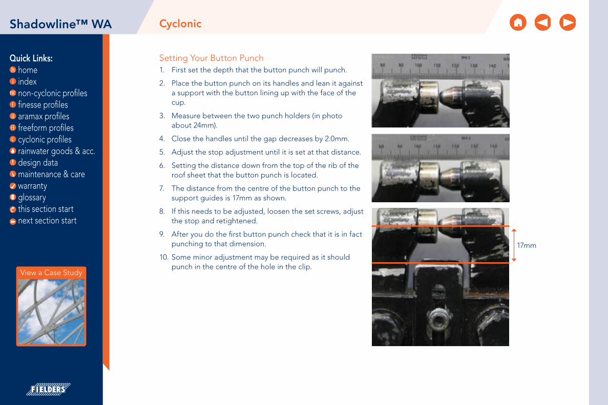
Quick Links: home index non-cyclonic profiles finesse profiles aramax profiles freeform profiles cyclonic profiles rainwater goods & acc. design data maintenance & care warranty glossary
CyclonicShadowline™ WA
Setting Your Button Punch1. First set the depth that the button punch will punch.
2. Place the button punch on its handles and lean it against a support with the button lining up with the face of the cup.
3. Measure between the two punch holders (in photo about 24mm).
4. Close the handles until the gap decreases by 2.0mm.
5. Adjust the stop adjustment until it is set at that distance.
6. Setting the distance down from the top of the rib of the roof sheet that the button punch is located.
7. The distance from the centre of the button punch to the support guides is 17mm as shown.
8. If this needs to be adjusted, loosen the set screws, adjust the stop and retightened.
9. After you do the first button punch check that it is in fact punching to that dimension.
10. Some minor adjustment may be required as it should punch in the centre of the hole in the clip.
17mm
View a Case Study
this section start next section start

Quick Links: home index non-cyclonic profiles finesse profiles aramax profiles freeform profiles cyclonic profiles rainwater goods & acc. design data maintenance & care warranty glossary
CyclonicShadowline™ WA
View a Case Study
this section start next section start
Figure SLWA IG CY 001
Installation Guide: Button Punched (Concealed Fixed)
1. Fix a clip to the first and last purlin.
2. Attached a string line to the first and last clip as a guide to fix the remainder of the clips to the purlins in between.
3. Place the first sheet over the clips with the correct length into the gutter.
4. Using the rib closing tool squeeze the male rib of the first sheet. Place top clip over each squashed male rib and fix to purlin. This needs to be done to prevent the sheet from lifting in the wind before the barges are fitted. The use of string lines will assist in ensuring sheets are installed straight.
Figure SLWA IG CY 002
Figure SLWA IG CY 003

Quick Links: home index non-cyclonic profiles finesse profiles aramax profiles freeform profiles cyclonic profiles rainwater goods & acc. design data maintenance & care warranty glossary
CyclonicShadowline™ WA
View a Case Study
this section start next section start
5. Make a small non-permanent mark in the pan to enable you to locate the clips in the latter locking operation with the button punch.
6. Position the female rib of the next sheet over the male rib and clips ensuring that it is fully engaged. Fully engage the sheet with the clips using foot pressure on the ribs over each clip. You can do this by walking along the full length of the sheet with one foot in the tray next to the overlapping rib and the other foot applying pressure to the top of the interlocking ribs at regular intervals.
7. Repeat steps 3 to 5.
8. All lapped ribs must be locked along their length, by button punching at the clips, and if necessary between the clips (typically at 900mm centre to centre). Punching to a string line guide stretched across the sheeting is recommended as random punching marks the appearance of the finished work.
You must button punch through the hole in each top fixing clip, you can locate the clip with the non-permanent mark made previously. When operating the punching tool, stand on the pan of the overlapping sheet to ensure that the sheets are fully engaged.
Figure SLWA IG CY 005
Rib must touch
Figure SLWA IG CY 004

Quick Links: home index non-cyclonic profiles finesse profiles aramax profiles freeform profiles cyclonic profiles rainwater goods & acc. design data maintenance & care warranty glossary
CyclonicShadowline™ WA
View a Case Study
this section start next section start
Ends of SheetsWind can drive water uphill under the flashings or cappings. Also, at the low end of a roof, wind or capillary action can cause water to run back up the underside of the sheeting. To minimise these problems, turn the pans up at the top of sheets, and turn them down at the bottom. A tool is available for these jobs (ref. Figure SLWA IG CY 006)
Turning-upFlush turn-ups are usually used on Shadowline™ WA. Cut off a portion of the female rib for at least 50mm. For a flush turn-up, you also need to cut the crown of the centre rib for at least 50mm.
Holding the end of the tool against the end of the sheet, pull the handle up 90°. If turning-up flush, fold the protruding ears flush against the turn-up tool with a rubber mallet (ref. Figure SLWA IG CY 006).
Fold ‘ears’ against toolfor a flush turn-up
Part of ribremoved
90˚
50mm
50mm
Figure SLWA IG CY 006
20°
Figure SLWA IG CY 007

Quick Links: home index non-cyclonic profiles finesse profiles aramax profiles freeform profiles cyclonic profiles rainwater goods & acc. design data maintenance & care warranty glossary
CyclonicShadowline™ WA
View a Case Study
this section start next section start
Turning-downAll roofing on slopes below 1 in 5 (10°) must be turned-down.
Turning-down is usually done after the sheeting is fixed on the roof, provided there is no obstruction to the operation of the turn-down tool.
Push the turn-down tool over the end of the tray, as far as it will go.
Hold the tool hard against the end of the tray and push the handle to form a turn-down of about 20° (ref. Figure SLWA IG CY 007).
Table SLWA RF CY 001
Insulation Care needs to be taken when installing insulation with Shadowline™ WA roof sheeting. When insulation thicknesses up to 50mm are installed the screws may need to be increased depending on the thickness and density of the insulation. When the screw is properly tightened into metal there should be a minimum of three (3) threads protruding past the support being fixed in to. For timber, the screw must have a minimum embedment of 25mm into timber.
When insulation is required in conjunction with Finesse® profiles, Fielders® recommend the use of a thermal spacer to help maintain Rw values as well as minimising any bulging in the profile caused by the insulation.
Table SLWA RF CY 002
Recommended FastenersShadowlineTM WA Pierced Fixed
Supports Recommended Fastener (Without Insulation)
Steel 1.0 to 3.5mm 14g-10x25mm Hex Head Tek Screw
Timber Hardwood 14g-10x25mm Hex Head Type 17 Screw
Timber Softwood 14g-10x25mm Hex Head Type 17 Screw
Steel Battens (0.55 to 1.0mm) 14g-10x25mm Hex Head Tek Screw
Recommended FastenersShadowlineTM WA Button Punched
Supports Recommended Fastener (Without Insulation)
Steel 1.0 to 3.5mm 10g-16x16mm Wafer Head Tek Screw
Timber Hardwood 10g-12x25mm Wafer Head Type 17 Screw
Timber Softwood 10g-12x25mm Wafer Head Type 17 Screw
Steel Battens (0.55 to 1.0mm) 10g-16x16mm Wafer Head Tek Screw
SLWA INS CY 001Note: Image displayed using Shadowline profile

Quick Links: home index non-cyclonic profiles finesse profiles aramax profiles freeform profiles cyclonic profiles rainwater goods & acc. design data maintenance & care warranty glossary
Table BL MS CY 001Notes:1. 0.70mm is available subject to minimum order quantities.
2. The COLORBOND® and ZINCALUME® material is in accordance to AS 1397, AS 1365 and AS 2728. The installation of the cladding should be in accordance to AS 1562.1 and HB39.
3. *is based on standard COLORBOND® single-sided material. For other painted steel options please contact a Fielders® representative.
485mm*
*OTHER WIDTHS AVAILABLE
15mm VARIABLE TO SUIT EXPRESS JOINT
285mm*
15mm VARIABLE TO SUIT EXPRESS JOINT
SUBJECT TO M.O.Q.
Material SpecificationsBoulevardTM Cyclonic
Property 285mm Pan Width 485mm Pan Width Notes
Base Metal Thickness (mm) 0.55 0.75 0.55 0.75 BMTTotal Coated Thickness (mm) 0.60* 0.80* 0.60* 0.80* TCT
Mass / UnitZINCALUME® 1.76 2.23 2.65 3.36
kg/mCOLORBOND® 1.78* 2.24* 2.67* 3.37*
Mass / Unit AreaZINCALUME® 5.88 7.43 5.31 6.71
kg/m2
COLORBOND® 5.92* 7.47* 5.35* 6.75*Minimum Yield Strength (MPa) G300
Coating Class
AM100 - COLORBOND®
AM125 - ZINCALUME®
AM100 - COLORBOND® MetallicAM150 - COLORBOND® Ultra
Minimum Coating g/m2 of Zinc - Aluminium
ToleranceSheet length ±7mmCover width ± 4mm
Thermal Expansion2.9mm average per 5.0 metre
@ 50˚C change
CyclonicBoulevard™
this section start next section start

Quick Links: home index non-cyclonic profiles finesse profiles aramax profiles freeform profiles cyclonic profiles rainwater goods & acc. design data maintenance & care warranty glossary
About BoulevardTM
Where a flat recessed joint look is wanted without compromising the quality of the materials, Fielders® BoulevardTM is the solution. A contemporary wall cladding, BoulevardTM, is available in a wide array of colours and finishes and is the most versatile in the Finesse® range. It offers sophisticated European technologies combined with Fielders® local know-how to deliver a high end look to any project.
BoulevardTM is a pierced-fixed wall cladding system installed with a ventilated air space. It involves laying interlocking panels on a metal framework fixed to the supporting structure. The panels are simply connected by the use of an interlocking groove giving the elegant appearance of a recessed joint.
BoulevardTM can be laid vertically or horizontally. The choice of direction implies different aesthetics and technical solutions for the main flashings. Panels are fixed directly on plywood or steel battens.
BoulevardTM is available in two standard widths 285mm and 485mm, all with a side depth of 22mm. The panel comes in lengths from 0.5m to 8.0m, with a width of longitudinal joint of 5mm to 18mm, with 15mm being the standard.
CyclonicBoulevard™
this section start next section start

Quick Links: home index non-cyclonic profiles finesse profiles aramax profiles freeform profiles cyclonic profiles rainwater goods & acc. design data maintenance & care warranty glossary
CyclonicBoulevard™
Cyclonic TestingFielders® have undertaken cyclonic testing of the Boulevard profile in a 285mm panel width in accordance with the Low-High-Low (LHL) cyclonic testing method in the National Construction Code (NCC) 2016.
Boulevard™ can be supported on one of three supporting structures; plywood, steel battens or Fielders® Kingflor® KF40®. The cyclonic wind load capacities are shown in Table BL WC CY 001.
Table BL WC CY 001Note:Support and fastener spacings as detailed in figures BL ID CY 001-003.
Wind Pressure Capacities (kPa)BoulevardTM Cyclonic
Cover Width (mm) Plywood Steel Batten KF40®
285 9.45 4.05 12.6
Installation Layout: Plywood
600mm max
PURLIN TO BE MINIMUM 1.0mm BMT G550
600mm max
250mm
VERTICAL PANELSHORIZONTAL PANELS Figure BL ID CY 001
this section start next section start

Quick Links: home index non-cyclonic profiles finesse profiles aramax profiles freeform profiles cyclonic profiles rainwater goods & acc. design data maintenance & care warranty glossary
CyclonicBoulevard™
Installation Layout: Steel Batten
450mm max
40mm X 0.75mm BMT G550
STEEL BATTEN
1500mm max
PURLIN TO BE MINIMUM 1.0mm BMT G550
1500mm max
450mm max
250mm
VERTICAL PANELSHORIZONTAL PANELS Figure BL ID CY 002
this section start next section start

Quick Links: home index non-cyclonic profiles finesse profiles aramax profiles freeform profiles cyclonic profiles rainwater goods & acc. design data maintenance & care warranty glossary
CyclonicBoulevard™
Installation Layout: Kingflor® KF40®
PROVIDE HEAVY DUTY SARKING BEHIND PANEL, DETAIL OMITTED IN DRAWING FOR CLARITY.
FIX HORIZONTALLY MOUNTED BOULEVARD PANELS TO KINGFLOR® KF40® SUBSTRATE AT EVERY RIB (250mm SPACING) WITH 10g-16x16mm WAFER HEAD TEK SCREWS THROUGH BOTH OVER AND UNDER LAP LEGS.
KF40® BACKING
Max1200mm
WALL GIRT
WALL GIRT
WALL GIRT
WALL GIRT
KF40® BACKING
Max 1200mm
VERTICAL BATTENS
PROVIDE HEAVY DUTY SARKING BEHIND PANEL, DETAIL OMITTED IN DRAWING FOR CLARITY.
FIX VERTICALLY MOUNTED BOULEVARD PANELS TO KINGFLOR® KF40® SUBSTRATE AT EVERY RIB (250mm SPACING) WITH 10g-16x16mm WAFER HEAD TEK SCREWS THROUGH BOTH OVER AND UNDER LAP LEGS.
250mm
VERTICAL PANELSHORIZONTAL PANELS
Figure BL ID CY 003
PROVIDE HEAVY DUTY SARKING BEHIND PANEL, DETAIL OMITTED IN DRAWING FOR CLARITY.
FIX HORIZONTALLY MOUNTED BOULEVARD PANELS TO KINGFLOR® KF40® SUBSTRATE AT EVERY RIB (250mm SPACING) WITH 10g-16x16mm WAFER HEAD TEK SCREWS THROUGH BOTH OVER AND UNDER LAP LEGS.
KF40® BACKING
Max1200mm
WALL GIRT
WALL GIRT
WALL GIRT
WALL GIRT
KF40® BACKING
Max 1200mm
VERTICAL BATTENS
PROVIDE HEAVY DUTY SARKING BEHIND PANEL, DETAIL OMITTED IN DRAWING FOR CLARITY.
FIX VERTICALLY MOUNTED BOULEVARD PANELS TO KINGFLOR® KF40® SUBSTRATE AT EVERY RIB (250mm SPACING) WITH 10g-16x16mm WAFER HEAD TEK SCREWS THROUGH BOTH OVER AND UNDER LAP LEGS.
250mm
this section start next section start

Quick Links: home index non-cyclonic profiles finesse profiles aramax profiles freeform profiles cyclonic profiles rainwater goods & acc. design data maintenance & care warranty glossary
CyclonicBoulevard™
Installation Guide
BoulevardTM provides a water screen only and needs to be fitted on a water tight barrier. This may consist of a precast wall or steel sheeting backing, such as PanelformTM, or another waterproof membrane like heavy duty roof sarking. Prior to commencement ensure the surface that the system is being fixed to is free of sharp edges and in the correct plane.
If the membrane is to be fixed before the 40mm batten use the following procedures. It is recommended that the membrane be Panelform™ as this will allow the membrane to be made watertight without the chance of movement and vibration.
this section start next section start
EXPRESSJOINT 40mm x 0.75mm BMT
G550 STEEL BATTEN@450mm c/c
TEK SCREW
STRUCTURE
EXPRESSJOINT
Figure BL ID CY 004
HORIZONTAL PANELS VERTICAL PANELS

Quick Links: home index non-cyclonic profiles finesse profiles aramax profiles freeform profiles cyclonic profiles rainwater goods & acc. design data maintenance & care warranty glossary
CyclonicBoulevard™
Fixing of the Membrane (Sisalation with insulation sarking attached)*1. Check that the steel work or concrete is free of any sharp
edges or protrusions that may puncture the membrane.
2. The sarking must be a minimum of 453 Sisalation or equivalent with the Sisalation to the outside face.
3. The sarking must be hung and sealed at the top. It must be free of ripples and puckers with holding battens between the 40mm vertical battens securing it to the supporting member. See BL ID CY 011.
4. All laps in the sarking must be made with 150mm lap sealed with double sided tape between the faces of the foil and taped with sisal tape on the outside face.
5. The perimeter of the membrane (blanket) must be sealed also with premium quality Sisal tape with holding or 40mm battens to secure it. See BL ID CY 014.
6. Note: - It is essential that attention is paid to ensuring that sarking is air tight, fixed in a way that it won’t flap or tear away at the laps or edges.
7. At the bottom of the façade a flashing is required to direct any water from the blanket membrane external of the façade. This will be done in a way as to allow any water to pass between the flashing and the foot mould. See BL ID CY 012.
8. If any of the membrane is to be fixed horizontally a different fixing procedure is to be followed; please contact your local Fielders® Representative.
Fixing of the Backing Plates1. The backing plates should be full length where possible
and fixed with Teks with a Neo washer or a 3mm pop rivet at a maximum of 1200mm centers.
2. If pop rivets are used they should be sealed rivets or sealed with silicone.
3. Any laps should be a minimum of 100mm.
4. The top of all backing plates should have a return 10mm fold to prevent water from being blown over the end of the plate. See BL ID CY 015.
5. Backing plates for Express joints should be 100mm wide overall with 10mm return fold on both sides if the Express joint is 15mm wide. See BL ID CY 007.
this section start next section start

Quick Links: home index non-cyclonic profiles finesse profiles aramax profiles freeform profiles cyclonic profiles rainwater goods & acc. design data maintenance & care warranty glossary
CyclonicBoulevard™
this section start next section start
Fixing of the 40mm Battens
1. The battens should be fixed on both sides with 10g-16x16mm Hex Head Tek Screws to the girts through the membrane. See BL ID CY 007 and 008. If an insulation blanket is fitted the screws should be 10g-16x25mm Hex Head Tek Screws.
2. If fixed to a concrete wall the fixing centers of the battens should be a maximum of 450mm apart.
3. All vertical 40mm battens should be fixed at a maximum of 450mm apart.
4. All battens fixed to support vertical joints, external and internal corners should be positioned so that the return edge of the backing plate is center of the face of the batten. See BL ID CY 007 and 008. This allows the fastener fixing the panel to be fixed in a location that doesn’t penetrate the backing plate.
Note: Care should be taken not to puncture the membrane while fixing the 40mm battens. If it is punctured it should be taped on both sides of the puncture.
Fixing of the Panels (Horizontal)
1. The top mould of parapet cap should be fixed first with the female edge downward. See BL ID CY 011.
2. The panels should have a foam block both ends fixed 25mm inside the stop end of the panel with the center of the foam block center to the 10mm return fold on the side of the backing plate. See BL ID CY 007, 008, 015.
3. A small corner should be removed off the bottom of the foam block to allow water or condensation to drain out freely. See BL ID CY 015.
4. This is required on straight panels and internal corners but not on external corners.
5. Measure out a matrix and mark the steel battens for the full length with the width of the panel plus gap so that when the panels are placed in position the bottom edge of the female rib can be lined up to the marks. This will ensure that the panels are fixed parallel with the same gap along the complete face. See BL ID CY 017.
6. Before installing a panel, a silicone bead must be applied to the back of the male and female edges from the center of the foam block to the edge of the panel. See BL ID CY 015.
7. The male edge of the panel is then inserted into the female edge leaving a gap that is predetermined, lining up the bottom edge of the panel with the mark on the hat section. See BL ID CY 012 and 016.
8. Screw the trailing female edge to the hat section with 10g-16x16mm Wafer Head Tek Screws.
9. Continue to fix all the panels until the bottom of the façade is reached.
10. When all sections of the façade are complete the foot mould is then fitted with the top vertical edge engaging the female recess on the panel. The predetermined gap between the panels should be maintained between the foot mould and the bottom panel.
11. The foot mould must be fitted in a way to allow water to drain between the foot mould and the flashing at the bottom of the membrane.
12. If the top of the façade has a fall (not horizontal), cut and fold the panels as in BL ID CY 009.
13. When the side of a façade finishes against a brick or concrete wall it should be done as per BL ID CY 014.

Quick Links: home index non-cyclonic profiles finesse profiles aramax profiles freeform profiles cyclonic profiles rainwater goods & acc. design data maintenance & care warranty glossary
CyclonicBoulevard™
this section start next section start
Oil CanningOil canning is a characteristic of thin gauge cold formed metal products which is caused by the internal stresses with the metal. There are many factors that influence the degree of oil canning and more information can be found here.
Insulation
Care needs to be taken when installing insulation with Boulevard™ roof sheeting. When insulation thicknesses up to 50mm are installed the screws may need to be increased depending on the thickness and density of the insulation. When the screw is properly tightened into metal there should be a minimum of three (3) threads protruding past the support being fixed in to. For timber, the screw must have a minimum embedment of 25mm into timber.
When insulation is required in conjunction with Finesse® profiles, Fielders® recommend the use of a thermal spacer to help maintain Rw values as well as minimising any bulging in the profile caused by the insulation.
Table BL RF CY 001
Recommended FastenersBoulevardTM Cyclonic
Supports Recommended Fastener (without insulation)
Steel 1.5mm10g-16x16mm
Wafer Head Tek Screw
Plywood10g-16x25mm
Wafer Head Type 17 Screw
Fixing of Windows and Doorways1. When fixing the windows & doorways (penetrations)
remember that the panels are the waterproof seal and the membrane is the air seal and backup water seal.
2. The membrane must be sealed to the penetrations in a way that it can’t over time break away. This may require the fitting of a holding batten. It also must be draining to the outside of the building.
3. The panels over the penetrations must be flashed to the penetration allowing any water that drains from the membrane to escape between the flashing and the top of the penetration.
4. BL ID CY 010-016 show some typical details to the top, bottom and sides of window penetrations.
Note:BoulevardTM creates a water screen and not a watertight barrier. If a watertight barrier is required it is recommended that an additional cladding layer is included behind the BoulevardTM such as PanelformTM. For further information contact Fielders®.
BL INS CY 001Note: Image displayed using Shadowline profile

Quick Links: home index non-cyclonic profiles finesse profiles aramax profiles freeform profiles cyclonic profiles rainwater goods & acc. design data maintenance & care warranty glossary
ENDBATTEN
BACKING PLATE FLASHING 4.8mm RIVET TO BATTEN AT 300mm c/c
EXPRESS JOINT
HORIZONTALBOULEVARD™
PROVIDE HEAVY DUTY SARKING BEHIND PANEL, DETAIL OMITTED IN DRAWING FOR CLARITY.
PROVIDE HEAVY DUTY SARKING BEHIND PANEL, DETAIL OMITTED IN DRAWING FOR CLARITY.
VERTICALBOULEVARD™
ENDBATTEN
BACKING PLATE FLASHING 4.8mm RIVET TO BATTEN AT 300mm c/c
EXPRESS JOINT
CyclonicBoulevard™
this section start next section start
Installation Details: Standard Fixing Detail
Figure BL ID CY 005
Installation Details: Express Joint Detail
Figure BL ID CY 006

Quick Links: home index non-cyclonic profiles finesse profiles aramax profiles freeform profiles cyclonic profiles rainwater goods & acc. design data maintenance & care warranty glossary
75m
m m
in
FALL 3° min
PARAPET LINING
PARAPET CAP FLASHING
HORIZONTALBOULEVARD™
BACKING PLATE FLASHING
12g-14 METAL TEK SCREW WITH EPDM WASHER AT 500mm SPACING
75m
m m
in
FALL 3° min
PARAPET LINING
PARAPET CAP
12g-14 METAL TEK SCREW WITH EPDM WASHER AT 500mm SPACING
STEEL BATTEN
VERTICALBOULEVARD™
75m
m m
in
FALL 3° min
PARAPET LINING
PARAPET CAPFLASHING
12g-14 METAL TEK SCREW WITH EPDM WASHER AT 500mm SPACING
VERTICALBOULEVARD™
CyclonicBoulevard™
this section start next section start
Installation Details: Top of Facade/ Parapet — Horizontal Panels
Installation Details: Top of Facade/ Parapet — Vertical Panels
Figure BL ID CY 007
Figure BL ID CY 008

Quick Links: home index non-cyclonic profiles finesse profiles aramax profiles freeform profiles cyclonic profiles rainwater goods & acc. design data maintenance & care warranty glossary
CyclonicBoulevard™
this section start next section start
Installation Details: Pitched Roof
CAPPING
SCREW FIXING
BOULEVARD™
STEEL BATTEN
CUT EDGES OFPANEL FOLDED IN
PANELFORM™
A
A
Figure BL ID CY 009

Quick Links: home index non-cyclonic profiles finesse profiles aramax profiles freeform profiles cyclonic profiles rainwater goods & acc. design data maintenance & care warranty glossary
D
D
E
E
FF
HORIZONTAL BOULEVARD™
12g-14 METAL TEK SCREW AT 500mm SPACING
WINDOW HEAD FLASHING
STEEL BATTEN
PANELFORM™
SCREW FIXING
STEEL BATTEN
BOULEVARD™
FOOT MOULDING
FLASHING PANELFORM™
WINDOW
STRUCTURE OR GIRT
D
D
E
E
FF
HORIZONTAL BOULEVARD™
12g-14 METAL TEK SCREW AT 500mm SPACING
WINDOW HEAD FLASHING
STEEL BATTEN
PANELFORM™
SCREW FIXING
STEEL BATTEN
BOULEVARD™
FOOT MOULDING
FLASHING PANELFORM™
WINDOW
STRUCTURE OR GIRT
Installation Details: Window Details - Horizontal Panels
Section D-D HeadOPTION A OPTION B
CyclonicBoulevard™
this section start next section start
Figure BL ID CY 010
HORIZONTAL PANEL AROUND OPENING
Figure BL ID CY 011

Quick Links: home index non-cyclonic profiles finesse profiles aramax profiles freeform profiles cyclonic profiles rainwater goods & acc. design data maintenance & care warranty glossary
CyclonicBoulevard™
this section start next section start
WINDOW SILL FLASHING
STEEL BATTEN
PANELFORM™
12g-14 METAL TEK SCREW AT 500mm SPACING
PANELFORM™
SCREW FIXING
BOULEVARD™
STEEL BATTEN
SUPPORT STRUCTURE
SEAL BETWEEN WINDOW LIP AND PANEL
WINDOW
STRUCTURE OR GIRT
STRUCTURE OR GIRT
RIBFORM
SCREW FIXING
STEEL BATTEN
FOAM SEAL
BOULEVARD™
TAPE AND BATTEN MEMBRANE TO
WINDOW FRAME
WINDOW
BACKING FLASHING
FLASHING WINDOW
BACKING ROD AND SEALANT
CLOSURE FLASHING
12g-14 METAL TEK SCREW AT 500mm SPACING
BOULEVARD™
WINDOW JAMB FLASHING
RIVET AT 300mm c/c
WINDOW JAMB FLASHING
ANGLE FLASHING
Figure BL ID CY 013
Section E-E Sill
Figure BL ID CY 012
Section F-F Jamb
OPTION A OPTION B
OPTION A OPTION B
WINDOW SILL FLASHING
STEEL BATTEN
PANELFORM™
12g-14 METAL TEK SCREW AT 500mm SPACING
PANELFORM™
SCREW FIXING
BOULEVARD™
STEEL BATTEN
SUPPORT STRUCTURE
SEAL BETWEEN WINDOW LIP AND PANEL
WINDOW
STRUCTURE OR GIRT
STRUCTURE OR GIRT
RIBFORM
SCREW FIXING
STEEL BATTEN
FOAM SEAL
BOULEVARD™
TAPE AND BATTEN MEMBRANE TO
WINDOW FRAME
WINDOW
BACKING FLASHING
FLASHING WINDOW
BACKING ROD AND SEALANT
CLOSURE FLASHING
12g-14 METAL TEK SCREW AT 500mm SPACING
BOULEVARD™
WINDOW JAMB FLASHING
RIVET AT 300mm c/c
WINDOW JAMB FLASHING
ANGLE FLASHING

Quick Links: home index non-cyclonic profiles finesse profiles aramax profiles freeform profiles cyclonic profiles rainwater goods & acc. design data maintenance & care warranty glossary
CyclonicBoulevard™
this section start next section start
Figure BL ID CY 014
A
A
B
B
CC
JAMB
WINDOW JAMB FLASHING
FLASHING
STEEL BATTEN
12g-14 METAL TEK SCREW
SILL
WINDOW SILL FLASHING
STEEL BATTEN
STEEL BATTEN
12g-14 METAL TEK SCREW
HEAD
STEEL BATTEN
BOULEVARD™
TEK SCREW
WINDOW HEAD FLASHING
Installation Details: Window Details - Vertical Panels
VERTICAL PANEL AROUND OPENING
A
A
B
B
CC
JAMB
WINDOW JAMB FLASHING
FLASHING
STEEL BATTEN
12g-14 METAL TEK SCREW
SILL
WINDOW SILL FLASHING
STEEL BATTEN
STEEL BATTEN
12g-14 METAL TEK SCREW
HEAD
STEEL BATTEN
BOULEVARD™
TEK SCREW
WINDOW HEAD FLASHING
SECTION A-A SECTION B-B SECTION C-C

Quick Links: home index non-cyclonic profiles finesse profiles aramax profiles freeform profiles cyclonic profiles rainwater goods & acc. design data maintenance & care warranty glossary
CyclonicBoulevard™
this section start next section start
Installation Details: Express Joints
EXPRESS JOINTS15mm STANDARD JOINT WIDTH - IF VARIABLE CONTACT FIELDERS
VERTICAL PANEL HORIZONTAL EXPRESS JOINT SECTION
STEEL BATTEN
POSITIONED TO ACCOMODATEPANEL JUNCTION POSITION
BOULEVARD
RIVET
BACKING PLATE FLASHING
HORIZONTAL PANEL VERTICALEXPRESS JOINT SECTION VIEW
TOPHAT SECTION RIVET
BACKING PLATE FLASHING
INTERLOCKING PANELEXPRESS JOINTS
15mm STANDARD JOINT WIDTH - IF VARIABLE CONTACT FIELDERS
VERTICAL PANEL HORIZONTAL EXPRESS JOINT SECTION
STEEL BATTEN
POSITIONED TO ACCOMODATEPANEL JUNCTION POSITION
BOULEVARD
RIVET
BACKING PLATE FLASHING
HORIZONTAL PANEL VERTICALEXPRESS JOINT SECTION VIEW
TOPHAT SECTION RIVET
BACKING PLATE FLASHING
INTERLOCKING PANEL
Figure BL ID CY 015
STEEL BATTEN
BOULEVARD™
RIVET
BACKING PLATE FLASHING
BACKING PLATE FLASHING
STEEL BATTEN RIVET
BOULEVARD™
BOULEVARD™
FOAM SEAL
EXPRESS JOINT BACKING PLATE
STEEL BATTEN
PANELFORM™
STRUCTURE OR GIRT
OPTION A OPTION B
STEEL BATTEN
BOULEVARD™
RIVET
BACKING PLATE FLASHING
BACKING PLATE FLASHING
STEEL BATTEN RIVET
BOULEVARD™
BOULEVARD™
FOAM SEAL
EXPRESS JOINT BACKING PLATE
STEEL BATTEN
PANELFORM™
STRUCTURE OR GIRT

Quick Links: home index non-cyclonic profiles finesse profiles aramax profiles freeform profiles cyclonic profiles rainwater goods & acc. design data maintenance & care warranty glossary
CyclonicBoulevard™
this section start next section start
Figure BL ID CY 016
Installation Details: Express Joint Vertical Panel
MALE PANEL
FEMALEPANEL
STRUCTURESTRUCTURE
STEEL BATTENTEK SCREW
BOULEVARD™BOULEVARD™
STEEL BATTEN
TEK SCREW
FLASHING
STEEL BATTEN
PANELFORM™ PANELFORM™
OPTION A OPTION B

Quick Links: home index non-cyclonic profiles finesse profiles aramax profiles freeform profiles cyclonic profiles rainwater goods & acc. design data maintenance & care warranty glossary
CyclonicBoulevard™
this section start next section start
STRUCTURE STRUCTURE
STEEL BATTEN
BOULEVARD™
BACKING PLATE
RIVET AT 300mm c/c
BOULEVARD™
BOULEVARD™
FLASHING
RIVET AT 300mm c/c
STEEL BATTEN
BOULEVARD™
PANELFORM™ PANELFORM™
FOAM SEAL
Figure BL ID CY 017
Installation Details: Internal Corner - Horizontal Panels
OPTION A OPTION B

Quick Links: home index non-cyclonic profiles finesse profiles aramax profiles freeform profiles cyclonic profiles rainwater goods & acc. design data maintenance & care warranty glossary
CyclonicBoulevard™
this section start next section start
INTERIOR CORNERPANEL FORMED TO SUIT
BOULEVARD™
STEEL BATTEN
BOULEVARD™
FLASHING
TEK SCREW
STEEL BATTEN
BOULEVARD™
BOULEVARD™
TEK SCREW
STEEL BATTEN
PANELFORM™ PANELFORM™
STRUCTURE
BOULEVARD™
STEEL BATTEN
TEK SCREW
BOULEVARD™
FLASHING
RIVET BOULEVARD™
STEEL BATTENBOULEVARD™
TEK SCREW
STEEL BATTEN
STRUCTURE
PANELFORM™PANELFORM™
Figure BL ID CY 018
Installation Details: Interior Corner - Vertical Panels
Installation Details: Exterior Corner - Horizontal Panels
Figure BL ID CY 019
OPTION A OPTION B
INTERIOR CORNERPANEL FORMED TO SUIT
BOULEVARD™
STEEL BATTEN
BOULEVARD™
FLASHING
TEK SCREW
STEEL BATTEN
BOULEVARD™
BOULEVARD™
TEK SCREW
STEEL BATTEN
PANELFORM™ PANELFORM™
STRUCTURE
BOULEVARD™
STEEL BATTEN
TEK SCREW
BOULEVARD™
FLASHING
RIVET BOULEVARD™
STEEL BATTENBOULEVARD™
TEK SCREW
STEEL BATTEN
STRUCTURE
PANELFORM™PANELFORM™
OPTION A OPTION B

Quick Links: home index non-cyclonic profiles finesse profiles aramax profiles freeform profiles cyclonic profiles rainwater goods & acc. design data maintenance & care warranty glossary
CyclonicBoulevard™
this section start next section start
BOULEVARD™
40mm STEEL BATTEN
SCREW FIXING
SEAL INSIDE PANEL AT MITRE
PANELFORM™
STRUCTURE OR GIRT
MALE PANEL
FEMALEPANEL
STRUCTURESTRUCTURE
STEEL BATTENTEK SCREW
BOULEVARD™BOULEVARD™
STEEL BATTEN
TEK SCREW
FLASHING
STEEL BATTEN
PANELFORM™ PANELFORM™
Installation Details: External Corner
Figure BL ID CY 020
Figure BL ID CY 021
Installation Details: Exterior Corner - Vertical Panels
OPTION A OPTION B
BOULEVARD™
40mm STEEL BATTEN
SCREW FIXING
SEAL INSIDE PANEL AT MITRE
PANELFORM™
STRUCTURE OR GIRT
MALE PANEL
FEMALEPANEL
STRUCTURESTRUCTURE
STEEL BATTENTEK SCREW
BOULEVARD™BOULEVARD™
STEEL BATTEN
TEK SCREW
FLASHING
STEEL BATTEN
PANELFORM™ PANELFORM™

Quick Links: home index non-cyclonic profiles finesse profiles aramax profiles freeform profiles cyclonic profiles rainwater goods & acc. design data maintenance & care warranty glossary
CyclonicBoulevard™
this section start next section start
Figure BL ID CY 022
Installation Details: Foot Mould - Horizontal Panels
BOULEVARD™
STEEL BATTEN
SCREW FIXING
FOOT MOULDING
STRUCTURE OR GIRT
DRAIN HOLES GL
BOULEVARD™
STEEL BATTEN
SCREW FIXING
FOOT MOULDING
PANELFORM™
STRUCTURE OR GIRT
BOULEVARD™
TEK SCREW
FOOT MOULDING
STRUCTURE OR GIRT
DRAIN HOLES GL
STEEL BATTEN
PANELFORM™ PANELFORM™
OPTION A OPTION B
Figure BL ID CY 023
Installation Details: Foot Mould - Vertical Panels
BOULEVARD™
STEEL BATTEN
SCREW FIXING
FOOT MOULDING
STRUCTURE OR GIRT
DRAIN HOLES GL
BOULEVARD™
STEEL BATTEN
SCREW FIXING
FOOT MOULDING
PANELFORM™
STRUCTURE OR GIRT
BOULEVARD™
TEK SCREW
FOOT MOULDING
STRUCTURE OR GIRT
DRAIN HOLES GL
STEEL BATTEN
PANELFORM™ PANELFORM™

Quick Links: home index non-cyclonic profiles finesse profiles aramax profiles freeform profiles cyclonic profiles rainwater goods & acc. design data maintenance & care warranty glossary
CyclonicBoulevard™
this section start next section start
STRUCTURE OR GIRT
CONCRETE/MASONARY WALL
PANELFORM™
SCREW FIXING
STEEL BATTEN
BOULEVARD™CONCRETE FLASHING
CLOSURE FLASHINGFLASHING
BACKING ROD AND SEALANTBACKING FLASHING
Figure BL ID CY 024
Installation Details: Side of Facade

Quick Links: home index non-cyclonic profiles finesse profiles aramax profiles freeform profiles cyclonic profiles rainwater goods & acc. design data maintenance & care warranty glossary
CyclonicBoulevard™
this section start next section start
EDGE DETAIL: HORIZONTAL PANELS
OPTION A
FOAM FILLER ROD
EDGE DETAIL: VERTICAL PANELS
OPTION A
TEK SCREW
BOULEVARD™
EXPRESS JOINT
EDGE FLASHING
CAULKED SEAL
FOAM FILLER ROD
TEK SCREW
BOULEVARD™
CLOSED JOINT
EDGE FLASHING
CAULKED SEAL
FOAM FILLER ROD
TEK SCREW
BOULEVARD™
EXPRESS JOINT
EDGE FLASHING
FOAM FILLER ROD
TEK SCREW
BOULEVARD™
EDGE FLASHING
OPTION B
OPTION B
Figure BL ID CY 025
Installation Details: Edge Detail

Quick Links: home index non-cyclonic profiles finesse profiles aramax profiles freeform profiles cyclonic profiles rainwater goods & acc. design data maintenance & care warranty glossary
CyclonicBoulevard™
this section start next section start
LOWER LIP OF PANEL
NO
MIN
ATE
D
FAC
E
15m
m15
mm
285m
m28
5mm
MALE SIDE LAP
FEMALE SIDE LAP
MEASURE/MARK LOWER EDGE OF PANEL ON BATTEN
LOWER LIP OF NEXT PANEL
A
A
Figure BL ID CY 026 Figure BL ID CY 027
Installation Details: Typical Panel Section Installation Details: Panel Marking Matrix

Quick Links: home index non-cyclonic profiles finesse profiles aramax profiles freeform profiles cyclonic profiles rainwater goods & acc. design data maintenance & care warranty glossary
CyclonicBoulevard™
this section start next section start
10mm
FOLD 10mm RETURN AT TOP OF ALL BACKING PLATES
CLOSED CELL FOAM SEAL TO HAVE 6mm X 45° CHAMFERED LOWER EDGE TO ALLOW MOISTURE DRAIN
SEALANT TO BE APPLIED BETWEEN FOAM SEAL
AND PANEL
SEALANT TO BE APPLIED BEHIND PANELAT MALE/FEMALE EDGE
Figure BL ID CY 028 Figure BL ID CY 029
Note:
1. Foam is required for horizontal panels to stop water egress behind the panels.
2. Foam to be 30x30mm Biycell foam strip.
Installation Details: Backing Plates Installation Details: Foam Seal

Quick Links: home index non-cyclonic profiles finesse profiles aramax profiles freeform profiles cyclonic profiles rainwater goods & acc. design data maintenance & care warranty glossary
CyclonicProminence™
this section start next section start
Material SpecificationsProminence™
Property 265mm Pan Width with 38mm rib Notes
Base Metal Thickness (mm) 0.55 BMTTotal Coated Thickness (mm) 0.60* TCT
Mass / Unit Length (kg/m)
ZINCALUME® 1.83kg/m
COLORBOND® 1.86*
Mass / Unit Area (kg/m2)
ZINCALUME® 6.91kg/m2
COLORBOND® 7.02*
Coverage (mm) 265 mm
Minimum Yield Strength (MPa) G300
Coating Class
AM100 - COLORBOND®
AM100 - COLORBOND® Metallic
AM125 - ZINCALUME®
AM150 - COLORBOND® Ultra
Minimum Coatingg/m2 of Zinc -
Aluminium
ToleranceSheet length ±7mmCover width ± 4mm
Thermal Expansion2.9mm average per 5.0 metre
@ 50˚ C change
Table PR MS CY 001Notes:1. The COLORBOND® and ZINCALUME® material is in accordance to AS 1397, AS 1365 and AS 2728.
2. Installation of the cladding should also be in accordance to AS 1562.1 and HB 39.
3. *is based on Standard COLORBOND® single-sided material. For other painted steel options please contact a Fielders® representative.
465mm
265mm
38mm
38mm

Quick Links: home index non-cyclonic profiles finesse profiles aramax profiles freeform profiles cyclonic profiles rainwater goods & acc. design data maintenance & care warranty glossary
CyclonicProminence™
this section start next section start
About Prominence™With its elegant flat pans and ease of installation the profile is a rare mix that both the specifier and the builder can appreciate. Available in a 265mm wide panel. As with all the profiles in the Fielders® Finesse® range, Fielders® Prominence™ is available in any colour you choose and looks particularly striking in a Metallic COLORBOND®. Prominence™ is also available in 0.75mm steel and 1.00mm aluminium (subject to minimum order quantities). Contact your local Fielders® representative for availability and further information.
Prominence™ is offered on traditional supporting substrates, plywood and fibre cement panels, and now with comprehensive testing can be offered on cost effective steel battens.

Quick Links: home index non-cyclonic profiles finesse profiles aramax profiles freeform profiles cyclonic profiles rainwater goods & acc. design data maintenance & care warranty glossary
CyclonicProminence™
this section start next section start
Rainfall Capacity For further information, please refer to sections “Rainfall Intensity” and “Water Carrying Capacity and Rainwater Run-Off”.
Maximum Roof Length (m) Prominence™ 265 Non-Cyclonic
Roof Slope (degrees)
Rainfall Capacity (mm/hr)
100 150 200 250 300 400 5003 160 107 80 64 53 40 324 180 120 90 72 60 45 365 199 133 100 80 66 50 40
7.5 238 158 199 95 79 59 4810 273 182 137 109 91 68 55
Figure PR RC CY (265) 001
Table PR RL CY (265) 001Note: 1. Minimum recommended slope is 3°. Sheet lengths greater than 24m are not
recommended due to thermal expansion and contraction.
Max
imum
She
et L
eng
th (m
)
Roof Slope (degrees)
3 4 5 7.5 10
300
250
200
150
100
50
0
100mm/hr
150mm/hr
200mm/hr
250mm/hr
300mm/hr
400mm/hr
500mm/hr

Quick Links: home index non-cyclonic profiles finesse profiles aramax profiles freeform profiles cyclonic profiles rainwater goods & acc. design data maintenance & care warranty glossary
CyclonicProminence™
this section start next section start
Cyclonic Testing
Fielders® have undertaken cyclonic testing of the Prominence™ profile in a 265mm panel width for walling applications in accordance with the Low-High Low (LHL) cyclonic testing method in the National Construction Code (NCC) 2016. Prominence™ can be supported on one of three supporting structures; plywood, steel battens or Fielders® KingFlor® KF40. The cyclonic wind load capacities are shown in Table PR WC CY 001.
Table PR WC CY 001Note: Support and fastener spacings as detailed in Figures PR ID CY 001-004.
Wind Pressure CapacitiesProminence™ Cyclonic – Walling Only
Cover Width (mm) Plywood Steel Batten KF40®
265 4.05 4.05 5.18
Wind Loading Design Parameters
Figure PR CY 001 End Spans, Internal Spans and Overhangs
Overhang
Overhang
Overhang
Overhang(End span)
End span
End span
End span
Internal spans
Internal spans
Wind Loading Design Parameters:Design Life 50 yearsImportance Level 2Maximum Roof Height H = 10mExternal Pressure Coefficient: Cp,e = -0.65 (walling)Internal Pressure Coefficient: Cp,i = 0.2Local Pressure Factors: K l = 2.0 (end & single spans) K l = 1.0 (internal spans)

Quick Links: home index non-cyclonic profiles finesse profiles aramax profiles freeform profiles cyclonic profiles rainwater goods & acc. design data maintenance & care warranty glossary
Figure PR ID CY 001
Installation Layout: Plywood
HORIZONTAL PANEL VERTICAL PANEL
PURLIN TO BE MINIMUM 1.0mm BMT G550
PURLIN TO BE MINIMUM1.0mm BMT G550
15mm CD GRADE PLY15mm CD GRADE PLY
450mmmax
450mmmax
600mmmax
600mmmax
600mmmax
CyclonicProminence™
this section start next section start

Quick Links: home index non-cyclonic profiles finesse profiles aramax profiles freeform profiles cyclonic profiles rainwater goods & acc. design data maintenance & care warranty glossary
Installation Layout: Steel Batten
HORIZONTAL PANEL VERTICAL PANEL
PURLIN TO BE MINIMUM1.0mm BMT G550
1200mmmax
40mm x 0.75mmBMT G550STEEL BATTEN
450mm max
450mmmax
1200mm max
CyclonicProminence™
this section start next section start
Figure PR ID CY 002

Quick Links: home index non-cyclonic profiles finesse profiles aramax profiles freeform profiles cyclonic profiles rainwater goods & acc. design data maintenance & care warranty glossary
Rib End Stitching Detail for Cyclonic Areas
VERTICAL BATTEN
KF40® BACKING
FIX PROMINENCE™ TO KF40® SUBSTRATE AT EVERY RIB (250mm SPACING) WITH 10g-16x16mm WAFER HEAD SCREW AND M5-15x1.2mm ROUNDED WASHER.
VERTICAL PROMINENCE™ PANELSWALL GIRT
Max SUPPORT SPACING: 1200mm
OVER-LAP RIB
UNDER-LAP RIB
5mm x 15mm BLIND RIVET THROUGH LAP
25mm FROM EDGE
10mm FROM PAN
Figure PR ID CY 004
Figure PR ID CY 003
Cyclonic Fixing to KF40® Substrate - Vertical Panels
CyclonicProminence™
this section start next section start

Quick Links: home index non-cyclonic profiles finesse profiles aramax profiles freeform profiles cyclonic profiles rainwater goods & acc. design data maintenance & care warranty glossary
Figure PR ID CY 005
Cyclonic Fixing to KF40® Substrate - Horizontal Panels
MaxSUPPORT SPACING:
1200mm
KF40® BACKING
FIX PROMINENCE™ TO KF40® SUBSTRATE AT EVERY RIB (250mm) WITH 10g-16x16mm WAFER HEAD SCREW AND M5-15x1.2mm ROUNDED WASHER.
HORIZONTAL PROMINENCE™ PANELSWALL GIRT
CyclonicProminence™
this section start next section start

Quick Links: home index non-cyclonic profiles finesse profiles aramax profiles freeform profiles cyclonic profiles rainwater goods & acc. design data maintenance & care warranty glossary
CyclonicProminence™
this section start next section start
Installation
Prominence™ is concealed pierce-fixed to either plywood or batten supports. This means the fastener screws pass through the sheeting at the concealed underlap edge. Screws can be placed either through the slotted holes or directly through the sheet. See PR ID NC 003-007.
Table PR RS CY 001
Recommended FastenersProminence™ Cyclonic
Supports Recommended Fastener (without insulation)
Steel 1.5mm
10g-16x16mm Wafer Head Tek Screw + M5-15x1.2 galvanised steel washer
At Rib Edge:Multigrip rivets or equivalent to
stitch ribs at end of sheet.
Plywood
10g-12x25mm Wafer Head Type 17 Screw+ M5-15x1.2 galvanised steel washer
At Rib Edge:Multigrip rivets or equivalent to
stitch ribs at end of sheet.
Timber
10g-12x45mm Wafer Heady Type 17 Screw+ M5-15x1.2 galvanised steel washer
At Rib Edge:Multigrip rivets or equivalent to
stitch ribs at end of sheet.

Quick Links: home index non-cyclonic profiles finesse profiles aramax profiles freeform profiles cyclonic profiles rainwater goods & acc. design data maintenance & care warranty glossary
Insulation
Care needs to be taken when installing insulation with roof sheeting. When insulation thickness up to 50mm are installed the screws may need to be increased depending on the thickness and density of the insulation. When the screw is properly tightened into metal there should be a minimum of three (3) threads protruding past the support being fixed in to. For timber the screw must penetrate the timber. When insulation is required in conjunction with Finesse® profiles, Fielders® recommend using a thermal spacer to help maintain Rw values and minimise any bulging in the profile caused by the insulation.
Oil CanningOil canning is a characteristic of thin gauge cold formed metal products which is caused by the internal stresses with the metal. There are many factors that influence the degree of oil canning and more information can be found here.
To assist in minimising the effects of oil canning in Prominence™ it is recommended that panel lengths are kept to under 9m. If longer lengths are required please discuss with Fielders®.
PR INS CY 001Note: Image displayed using Shadowline profile
CyclonicProminence™
this section start next section start

Quick Links: home index non-cyclonic profiles finesse profiles aramax profiles freeform profiles cyclonic profiles rainwater goods & acc. design data maintenance & care warranty glossary
CyclonicProminence™
this section start next section start
A
A
B
B
C C
STEEL BATTEN
WINDOW HEAD FLASHING
WAFER HEAD SCREW
PROMINENCE™ PANEL
STEEL BATTEN
WINDOW HEAD FLASHING
WAFER HEAD SCREW
PROMINENCE™ PANEL
PROMINENCE™ PANEL
STEEL BATTEN
WINDOW JAMB FLASHING
Installation Details: Window Details - Horizontal Panels
HORIZONTAL PANEL AROUND OPENING
SECTION A-A HEAD SECTION B-B SILL SECTION C-C JAMB
Figure PR ID CY 006
Figure PR ID CY 007Note:Head and sill flashings to be turned up and down behind jamb flashing

Quick Links: home index non-cyclonic profiles finesse profiles aramax profiles freeform profiles cyclonic profiles rainwater goods & acc. design data maintenance & care warranty glossary
CyclonicProminence™
this section start next section start
A
A
B
B
C C
WINDOW HEAD FLASHING
WAFER HEAD SCREW
PROMINENCE™ PANEL
WINDOW SILL FLASHING
PROMINENCE™ PANEL
RIVET
PROMINENC™ PANEL
WINDOW JAMB FLASHING
PROMINENCE™ PANEL TURNED OUT
Installation Details: Window Details - Vertical Panels
VERTICAL PANEL AROUND OPENING
SECTION A-A HEAD SECTION B-B SILL SECTION C-C JAMB
Figure PR ID CY 008
Figure PR ID CY 009Note:Head and sill flashings to be turned up and down behind jamb flashing

Quick Links: home index non-cyclonic profiles finesse profiles aramax profiles freeform profiles cyclonic profiles rainwater goods & acc. design data maintenance & care warranty glossary
CyclonicProminence™
this section start next section start
PROMINENCE™ PANEL PROMINENCE™
PANEL
EXTERNAL CORNER MOULDING
WAFER HEAD SCREW
INTERNAL CORNER MOULDING
WAFER HEAD SCREW
Installation Details: Corner Construction - Horizontal Panels
INTERNAL CORNER
Figure PR ID CY 010
EXTERNAL CORNER

Quick Links: home index non-cyclonic profiles finesse profiles aramax profiles freeform profiles cyclonic profiles rainwater goods & acc. design data maintenance & care warranty glossary
CyclonicProminence™
this section start next section start
PROMINENCE™ PANEL
INTERNAL CORNER MOULDING
WAFER HEAD SCREW
PROMINENCE™ PANEL
EXTERNALCORNER MOULDING
WAFER HEAD SCREW
Installation Details: Corner Construction - Vertical Panels
INTERNAL CORNER
Figure PR ID CY 011
EXTERNAL CORNER

Quick Links: home index non-cyclonic profiles finesse profiles aramax profiles freeform profiles cyclonic profiles rainwater goods & acc. design data maintenance & care warranty glossary
CyclonicProminence™
this section start next section start
PROMINENCE™ PANEL
WAFER HEAD SCREW
FOOT MOULD
DRAIN HOLES
STEEL BATTEN
PROMINENCE™ PANEL
WAFER HEAD SCREW
FOOT MOULD FLASHING A
FOOT MOULD FLASHING B
RIVET
PROMINENCE™ PANEL
WAFER HEAD SCREW
FOOT MOULD
DRAIN HOLES
GROUND LEVEL GROUND LEVEL GROUND LEVEL
Installation Details: Foot Mould and Bottom of Facade
FOOT MOULD HORIZONTAL PANELS
Figure PR ID CY 012
FOOT MOULD VERTICAL PANELS
BOTTOM OF FACADE HORIZONTAL PANELS

Quick Links: home index non-cyclonic profiles finesse profiles aramax profiles freeform profiles cyclonic profiles rainwater goods & acc. design data maintenance & care warranty glossary
yx
762mm cover
16mm
CyclonicS-Rib™ Corrugated
Table SR MS CY 001Notes:1. S-Rib Corrugated is manufactured in accordance to AS 1445 and from materials in accordance to AS 1397 and AS 2728.
It is to be installed in accordance with AS 1562 and HB 39.
2. The sectional properties are theoretical values per sheet width. These properties are gross values only.
View a Case Study
this section start next section start
Material Specifications S-Rib™ Corrugated Cyclonic
Property NotesBase Metal Thickness (mm) 0.35 0.42 0.48 0.60 BMT
Total Coated Thickness (mm) 0.40* 0.47* 0.53* 0.65* TCT
Mass / Unit LengthZINCALUME® 2.75 3.30 3.70 4.70
kg/mCOLORBOND® 2.80* 3.36* 3.77* 4.78*
Mass / Unit AreaZINCALUME® 3.60 4.34 4.87 6.18
kg/m2
COLORBOND® 3.68* 4.42* 4.96* 6.29*
2nd moment of area about principal axis (103 mm4)
Ix 11 14 15 19
Iy 19510 23420 26760 33450Section modulus about principal axis (103 mm3)
Zx 1 2 2 2Zy 47 56 64 80
Warping Constant (109 mm6)
Iw 1 1 1 1
Torsion Constant (mm4) J 13 23 35 68
Minimum Yield Strength G550 G550 G550 G300Base Steel
Designation
Coating ClassZ600 (Heritage Galvanised), AM100 (COLORBOND®), AM125 (ZINCALUME), AM150 (COLORBOND® Ultra)
and Z450 (Galvanised)
Minimum Coating g/m2 of
Zinc - Aluminium
Coverage (mm) 762Tolerance Sheet Length ±7mm Cover Width ±4mm
Thermal Expansion 2.9mm average per 5m at 50° C change

Quick Links: home index non-cyclonic profiles finesse profiles aramax profiles freeform profiles cyclonic profiles rainwater goods & acc. design data maintenance & care warranty glossary
Cyclonic
Rainfall Capacity For further information, please refer to sections “Rainfall Intensity” and “Water Carrying Capacity and Rainwater Run-Off”.
Figure SR RC CY 001
Max Roof Length (m)S-Rib™ Corrugated Cyclonic
Roof
Slope
(degrees)
Rainfall Capacity (mm/hr)
100 150 200 250 300 350 400
5 37 25 18 15 12 11 9
S-Rib™ Corrugated
Table SR RL CY 001Note: 1. Minimum recommended slope is 5°.
2. Sheet lengths greater than 24m are not recommended due to thermal expansion and contraction.
View a Case Study
5
10
15
20
25
30
35
40 100mm/hr
150mm/hr
200mm/hr
250mm/hr
300mm/hr
350mm/hr
400mm/hr
Max
imum
She
et L
eng
th (m
)
Roof Slope (degrees)
5
this section start next section start

Quick Links: home index non-cyclonic profiles finesse profiles aramax profiles freeform profiles cyclonic profiles rainwater goods & acc. design data maintenance & care warranty glossary
CyclonicS-Rib™ Corrugated
Cyclonic TestingFielders® have undertaken cyclonic testing of S-Rib in accordance with the Low-High-Low cyclonic testing method in the BCA.
The cyclonic wind load capacities for S-Rib roofing profile is shown in Table “SR WC CY 001” below.
Roofing Wind Load Capacity – Strength Limit State (kPa)S-Rib™ Corrugated Cyclonic
Span (mm)
0.42 BMT 0.48 BMT 0.60 BMT
SingleSpan
DoubleSpan
Multi SpansSingleSpan
DoubleSpan
Multi SpansSingleSpan
DoubleSpan
Multi Spans
EndSpan
Internal Span
EndSpan
Internal Span
EndSpan
Internal Span
600 16.12 11.01 8.92 - 17.30 11.92 9.71 - 18.89 12.51 - -
900 10.62 5.50 5.68 7.53 11.27 6.16 6.29 8.25 12.26 6.78 8.91 -
1200 7.18 3.47 3.61 5.23 7.52 3.83 4.07 5.81 8.25 4.17 3.67 8.28
1500 5.80 2.35 2.30 3.63 6.04 2.58 2.64 4.09 6.24 2.76 3.99 5.75
1800 - - - 2.52 - - - 2.88 - - 3.00 4.26
2100 - - - - - - - - - - - 3.31
Allowable Roof SpansThe allowable roof spans for the S-Rib Corrugated roofing profile in Regions C and D are shown in Tables “SR RS CY 001” and “SR RS CY 002”.
The allowable spans have been determined from tests carried out in accordance with AS4040.0-1992, AS 1170.2-2002 and the Building Code of Australia (BCA) 2008 Specification B1.2 for the design of buildings in cyclonic areas.
Overhang
Overhang
Overhang
Overhang(End span)
End span
End span
End span
Internal spans
Internal spans
Figure SR ES CY 002
Table SR WC CY 001
View a Case Study
*Design Parameters Max. Roof Pitch <10o
Pa,r = 1:500
Vr = 66 m/s for Region C
Vr = 88 m/s for Region D
Md = 1.00
FC = 1.05
FD = 1.1
Ms = 1.00
Mt = 1.00
Cp,i = 0.70
Cp,e = - 0.90
KL = 1.5 for Area F
KL = 2.0 for Area G
in accordance with AS1170.2-2002
this section start next section start

Quick Links: home index non-cyclonic profiles finesse profiles aramax profiles freeform profiles cyclonic profiles rainwater goods & acc. design data maintenance & care warranty glossary
CyclonicS-Rib™ Corrugated
Allowable Roof Spans (mm) in Region CS-Rib™ Corrugated Cyclonic – for building heights ≤ 5.0 m
Terrain Category
Roof Area Notation & Uplift (kPa)*
0.42 BMT 0.48 BMT 0.60 BMT
SingleSpan
DoubleSpan
Multi SpansSingleSpan
DoubleSpan
Multi SpansSingleSpan
DoubleSpan
Multi SpansEndSpan
Internal Span
EndSpan
Internal Span
EndSpan
Internal Span
1 & 2
D - 4.18 1930 1060 1100 1380 2040 1130 1180 1480 2010 1200 1460 1820
F - 5.35 1560 920 940 1180 1650 970 1010 1270 1670 1030 1240 1570
G - 6.53 1310 830 810 1020 1340 870 870 1100 1440 920 1100 1390
2.5
D - 3.54 2230 1180 1210 1520 2350 1300 1300 1620 2280 1320 1620 2020
F - 4.54 1800 1010 1050 1320 1900 1120 1120 1410 1890 1140 1380 1730
G - 5.54 1510 910 910 1150 1600 990 990 1240 1630 1010 1220 1530
Table SR RS CY 001
Table SR RS CY 002
View a Case Study
Cyclonic Load Span Tables - Region C
aa/2
a
a
≤ 25 metres
F
G
Area D
a/2
Figure SR LPF CY 003Note: The local pressure factors (KL) are shown in Figure 2. Local pressure factors are not applicable at the ridge where the roof pitch is less than 10°. The value of ‘a’ is the minimum of 0.2 breadth, 0.2 width or the height.
Maximum Allowable Roof Spans (mm) in Region CS-Rib™ Corrugated Cyclonic – for building heights between 5.0 m – 10.0 m
Terrain Category
Roof Area Notation & Uplift (kPa)*
0.42 BMT 0.48 BMT 0.60 BMT
SingleSpan
DoubleSpan
Multi SpansSingleSpan
DoubleSpan
Multi SpansSingleSpan
DoubleSpan
Multi SpansEndSpan
Internal Span
EndSpan
Internal Span
EndSpan
Internal Span
1 & 2
D - 4.18 1770 1000 1030 1300 1870 1060 1110 1390 1860 1130 1360 1710
F - 5.35 1430 870 870 1100 1510 920 940 970 1550 970 1160 1470
G - 6.53 1200 780 740 930 1280 820 800 870 1330 870 1030 1300
2.5
D - 3.54 1950 1070 1110 1390 2060 1140 1190 1210 2030 1210 1470 1830
F - 4.54 1570 930 940 1190 1660 980 1020 1040 1680 1040 1250 1570
G - 5.54 1330 830 810 1020 1410 880 1110 930 1450 930 1100 1400
this section start next section start

Quick Links: home index non-cyclonic profiles finesse profiles aramax profiles freeform profiles cyclonic profiles rainwater goods & acc. design data maintenance & care warranty glossary
CyclonicS-Rib™ Corrugated
Allowable Roof Spans (mm) in Region DS-Rib™ Corrugated Cyclonic – for building heights ≤ 5.0 m
Terrain Category
Roof Area Notation & Uplift (kPa)*
0.42 BMT 0.48 BMT 0.60 BMT
SingleSpan
DoubleSpan
Multi SpansSingleSpan
DoubleSpan
Multi SpansSingleSpan
DoubleSpan
Multi SpansEndSpan
Internal Span
EndSpan
Internal Span
EndSpan
Internal Span
1 & 2
D - 6.66 1315 840 810 1015 1375 875 870 1095 1435 915 1110 1390
F - 8.54 1080 735 635 770 1120 775 705 865 1180 810 935 1170
G - 10.41 910 635 460 525 970 680 540 635 1040 710 760 945
2.5
D - 5.65 1535 895 905 1145 1535 925 985 1230 1590 1030 1205 1520
F - 7.24 1195 810 755 940 1255 845 815 1025 1350 875 1055 1325
G - 8.83 1055 720 619 730 1095 760 675 830 1155 795 905 1135
Table SR RS CY 003
Table SR RS CY 004Note:* Pressure is total ultimate value
View a Case Study
Cyclonic Load Span Tables - Region D
Maximum Allowable Roof Spans (mm) in Region DS-Rib™ Corrugated Cyclonic – for building heights between 5.0 m – 10.0 m
Terrain Category
Roof Area Notation & Uplift (kPa)*
0.42 BMT 0.48 BMT 0.60 BMT
SingleSpan
DoubleSpan
Multi SpansSingleSpan
DoubleSpan
Multi SpansSingleSpan
DoubleSpan
Multi SpansEndSpan
Internal Span
EndSpan
Internal Span
EndSpan
Internal Span
1 & 2
D - 7.38 1155 800 745 920 1230 835 805 1005 1330 870 1040 1305
F - 9.46 1000 685 550 650 1045 730 620 750 1110 760 850 1060
G - 11.54 850 570 355 375 885 620 440 495 955 650 660 815
2.5
D - 6.59 1330 845 815 1025 1340 880 875 1105 1450 920 1115 1400
F - 8.45 1090 740 645 780 1125 780 710 875 1185 815 945 1180
G - 10.30 930 640 470 540 980 685 550 650 1045 715 770 950
this section start next section start

Quick Links: home index non-cyclonic profiles finesse profiles aramax profiles freeform profiles cyclonic profiles rainwater goods & acc. design data maintenance & care warranty glossary
CyclonicS-Rib™ Corrugated
Cyclonic TestingFielders® have undertaken cyclonic testing of S-Rib in accordance with the Low-High-Low cyclonic testing method in the BCA.
The cyclonic wind load capacities for S-Rib roofing profile is shown in Table “SR WC CY 001” below.
Walling Wind Load Capacity – Strength Limit State (kPa)S-Rib™ Corrugated Cyclonic
Span (mm)
0.42 BMT 0.48 BMT
SingleSpan
DoubleSpan
Multi SpansSingleSpan
DoubleSpan
Multi Spans
EndSpan
Internal Span
EndSpan
Internal Span
600 13.03 7.85 9.37 - 15.15 8.09 9.37 -
900 10.28 5.35 6.81 7.53 11.15 5.66 6.81 8.25
1200 7.53 3.64 4.95 5.23 7.54 3.85 4.95 5.81
1500 4.77 2.48 3.60 3.63 4.31 2.64 3.60 4.09
1800 2.02 1.69 2.62 2.52 1.48 2.05 2.62 2.88
2100 - - - - - - - -
Allowable Wall SpansThe allowable roof spans for the S-Rib Corrugated roofing profile in Regions C and D are shown in Tables “SR RS CY 001” and “SR RS CY 002”.
The allowable spans have been determined from tests carried out in accordance with AS4040.0-1992, AS 1170.2-2002 and the Building Code of Australia (BCA) 2008 Specification B1.2 for the design of buildings in cyclonic areas.
Overhang
Overhang
Overhang
Overhang(End span)
End span
End span
End span
Internal spans
Internal spans
Figure SR ES CY 002
Table SR WC CY 002Note:1. 1. Serviceability pressures can be found in the non-cylonic section.
2. 2. Values are based on no insulation under the sheeting.View a Case Study
Wind Loading Design Parameters:Design Life 50 yearsImportance Level 2Maximum Roof Height H = 5, 10mExternal Pressure Coefficient Cpe = -0.65 for walling Internal Pressure Coefficient Cpi = 0.7Local Pressure Factor kL = 2.0, 1.5, 1.0Ms = Mt = Md = 1.0
this section start next section start

Quick Links: home index non-cyclonic profiles finesse profiles aramax profiles freeform profiles cyclonic profiles rainwater goods & acc. design data maintenance & care warranty glossary
CyclonicS-Rib™ Corrugated
Allowable Wall Cladding Span* (mm) in Region CS-Rib™ Corrugated Cyclonic – for building heights ≤ 5.0 m
Terrain Category
Roof Area Notation & Uplift (kPa)*
0.42 BMT 0.48 BMTSingleSpan
EndSpan
Internal Span
SingleSpan
EndSpan
Internal Span
1 & 2
D - 4.18 1600 1200 1550 1650 1250 1500
F - 5.35 1500 1050 1300 1550 1100 1300
G - 6.53 1450 900 1100 1450 950 1150
2.5
D - 3.54 1650 1350 1750 1700 1400 1650
F - 4.54 1600 1150 1500 1600 1200 1450
G - 5.54 1500 1000 1300 1550 1050 1300
Table SR WS CY 001
Table SR WS CY 002
View a Case Study
Cyclonic Load Span Tables - Region C
aa/2
a
a
≤ 25 metres
F
G
Area D
a/2
Figure SR LPF CY 003Note: The local pressure factors (KL) are shown in Figure 2. Local pressure factors are not applicable at the ridge where the roof pitch is less than 10°. The value of ‘a’ is the minimum of 0.2 breadth, 0.2 width or the height.
Maximum Allowable Wall Cladding Span (mm) in Region CS-Rib™ Corrugated Cyclonic – for building heights between 5.0 m – 10.0 m
Terrain Category
Roof Area Notation & Uplift (kPa)*
0.42 BMT 0.48 BMTSingleSpan
EndSpan
Internal Span
SingleSpan
EndSpan
Internal Span
1 & 2
D - 4.18 1550 1100 1450 1600 1150 1400
F - 5.35 1450 950 1200 1500 1000 1200
G - 6.53 1350 800 1000 1400 850 1050
2.5
D - 3.54 1600 1200 1550 1650 1250 1500
F - 4.54 1500 1050 1300 1550 1100 1300
G - 5.54 1450 900 1100 1450 950 1150
this section start next section start

Quick Links: home index non-cyclonic profiles finesse profiles aramax profiles freeform profiles cyclonic profiles rainwater goods & acc. design data maintenance & care warranty glossary
CyclonicS-Rib™ Corrugated
Allowable Wall Cladding Span* (mm) in Region DS-Rib™ Corrugated Cyclonic – for building heights ≤ 5.0 m
Terrain Category
Roof Area Notation & Uplift (kPa)*
0.42 BMT 0.48 BMTSingleSpan
EndSpan
Internal Span
SingleSpan
EndSpan
Internal Span
1 & 2
D - 6.66 1400 850 1000 1400 850 1050
F - 8.54 1260 650 800 1300 700 850
G - 10.41 1100 550 600 1150 550 700
2.5
D - 5.65 1500 950 1200 1500 1000 1200
F - 7.24 1350 800 950 1400 800 1000
G - 8.83 1250 650 750 1300 650 850
Table SR WS CY 003
Table SR WS CY 004Note:* Pressure is total ultimate value
View a Case Study
Cyclonic Load Span Tables - Region D
Maximum Allowable Wall Spans (mm) in Region DS-Rib™ Corrugated Cyclonic – for building heights between 5.0 m – 10.0 m
Terrain Category
Roof Area Notation & Uplift (kPa)*
0.42 BMT 0.48 BMTSingleSpan
EndSpan
Internal Span
SingleSpan
EndSpan
Internal Span
1 & 2
D - 7.38 1300 750 900 1350 800 950
F - 9.46 1150 600 650 1200 600 750
G - 11.54 1000 450 450 1050 450 600
2.5
D - 6.59 1400 850 1050 1400 850 1050
F - 8.45 1250 700 800 1300 700 850
G - 10.30 1100 550 600 1150 550 700
this section start next section start

Quick Links: home index non-cyclonic profiles finesse profiles aramax profiles freeform profiles cyclonic profiles rainwater goods & acc. design data maintenance & care warranty glossary
Fixing of CladdingFasteners must be selected to match the life expectancy of the cladding material. Recommendations from fastener manufacturers should be sought. Only fasteners complying with AS 3566:2002 and those that are compatible with the roofing material should be used for its fastening.
All fasteners used externally should be fitted with an EPDM seal. Do not use punches to form fastener holes. Fasteners are fixed at alternate crests of the S-Rib Corrugated roof sheeting.
S-Rib™ Pierce Fixing - Cyclonic
Fixing Supports Crest Fixing Side Lap FixingSteel
1.5 mm14-10x42mm Metal Teks head Corri-Lok cyclone assembly
10 x 16mm Neo Teks hex head
Table SR PF CY 001
For further information on the S-Rib Corrugated roofing profile, including installation procedures, refer to Specifying Fielders® – Roofing & Walling manual.
Pierce FixingFasteners must be selected to match the life expectancy of the cladding material. Recommendations from fastener manufacturers should be sought.
Only fasteners complying with AS 3566:2002 and those that are compatible with the roofing material should be used for its fastening.
Notes: All fasteners used externally should be fitted with an EPDM seal (washer). Do not use punches to form fastener holes.
AQUABLOK™ SystemThe AQUABLOK system utilises an anti-capillary gap that prevents water from seeping into roofing joints.
CyclonicS-Rib™ Corrugated
Capillary air gapBuildex Climaseal
screw
Underlap support
Figure SR CY AQUABLOK System 004
1.5 Corrugations per lap
Figure SR CY AQUABLOK System 005
View a Case Study
this section start next section start

Quick Links: home index non-cyclonic profiles finesse profiles aramax profiles freeform profiles cyclonic profiles rainwater goods & acc. design data maintenance & care warranty glossary
S-Rib™ Corrugated Installation ProcedureFor installation procedures see section "Typical Pierce Fix Installation Guide". For general handling instructions refer to section “Maintenance and Care”.
Side Lap FixingIt may be necessary to use side lap fasteners at mid spans when using S-Rib at maximum spans. These will help to hold the sheet laps firmly in place and maintain a weather-proof joint.
Turning of Roof Sheeting EndsRefer to section “Flashings, Cappings & Ends of Sheets”.
Curving S-Rib™ CorrugatedFor details regarding spring, crank and smooth curving of S-Rib sheets, please see section “Curving of Steel Decks”.
Curving quality corrugated is manufactured from G300 sub-strate (0.60 BMT). It is consequently more ductile, enabling specialist tradesmen using precision curving machines to form sheets to traditional heritage shapes and challenging architectural details down to radii as tight as 450mm. Fielders® have a dedicated roll forming machine for G300 thus avoiding any inconsistency arising out of changing over from G550 Hi-tensile coil.
CyclonicS-Rib™ Corrugated
View a Case Study
this section start next section start

Quick Links: home index non-cyclonic profiles finesse profiles aramax profiles freeform profiles cyclonic profiles rainwater goods & acc. design data maintenance & care warranty glossary
S-Rib Corrugated Flashings & Details
Masonry ParapetSide Wall (Low)
Masonry ParapetSide Wall (High) Apron Flashings Overflashing Headwall Apron Flashing Soaker Gutter
100 87°93°
10 10 S.B.
100 10087°
93°
10 10
120
20135°150 10 S.B.
25
10
70
130Angle to suit roof
pitch
20135°
150
13020
Angle to suit roof pitch
200
Product Code: CF1 Product Code: CF2 Product Code: CF3 GIRTH 300 Product Code: CF4 Girth 112 Product Code: CF5 Girth 300 Product Code: CF6 Girth 350
Soffit Corner Flashing Shoe Flashing Offset Wall FlashingType 1
Offset Wall FlashingType 2 Valley Gutter Under Over
Flashing
37
95°
10
30
21
3022
95° 95°50
30 30
5022° 22° 22
25
50 95°
3010
Product Code: CF7 Girth 150 Product Code: CF8 Product Code: CF9 GIRTH 150 Product Code: CF10 Product Code: CF11 Girth 324 Product Code: CF12 Girth 300
Mansard RoofFlashing
Industrial DoorJamb Flashing
Opening Jamb Flashing Door Head Flashing Apex Capping Type 1 Apex Capping Type 2
130
130
Angle to suit roof pitch
20
20
135°
10 S.B.
70
25
4520
50135°
10 S.B. 50
95°
S.B.
50100
130
135°30
Angle to suit roof pitch
30100
130
135°
10
20
Angle to suit roof pitch
Product Code: CF13 Girth 330 Product Code: CF14 Girth 150 Product Code: CF15 Product Code: CF16 Girth 100 Product Code: CF17 Girth 270 Product Code: CF18 Girth 260
Back Channel External Corner & Barge Capping
Internal CornerCapping Barge Capping Fragmented Parapet
CappingTwo Piece Step
Flashing
25
45
30
130
130
20
20135°
135°
20
130
135°
130
135°30
50
130
140°
7
25
18
100 10087° 93°
20 20
135°
150
130
135°
20
Angle to suit roof pitch
* 20
Product Code :CF19 Girth 100 Product Code: CF20 Girth 330 Product Code: CF21 Girth 330 Product Code: CF22 Girth 230 Product Code: CF23 Product Code: CF24
130130
Angle to suit roof pitch
20
20
135°
2250
10 S.B.
95°
30
Table SR FD CY 001 Notes:1. denotes size to be determined by application. All sizes are in mm and should be used as a guide only. They should be measured on-site to determine actual size.
2. S.B. denotes ‘Slight Break’.
3. Also refer to “Typical Roofing Details”.
150 150
12 12140°
Flashings & DetailsS-Rib™ Corrugated
View a Case Study
this section start next section start

Rainwater Goods and Accessories
Guttering and Fascias
WaterGate®
Rainheads and Vents
Vent Ridge
Cappings
Return to index

Quick Links: home index non-cyclonic profiles finesse profiles aramax profiles freeform profiles cyclonic profiles rainwater goods & acc. design data maintenance & care warranty glossary
Guttering and FasciasRainwater Goods & Accessories
Fielders® steel guttering and Fascias conforms to AS 1397, AS 2179 and AS 2728, unless noted otherwise.
Available Materials
Material / Finish Conforming to BMT (mm)
ZINCALUME® SteelAS 1397 G300 - AM125
(Steel Fascia G550)0.50
COLORBOND® Steel AS 1397 G300 - AM100 and AS 2728 0.55*COLORBOND® Ultra Steel AS 1397 G300 - AM150 and AS 2728 0.55
COLORBOND® Stainless Steel Grade 430 base 300 0.45Galvanised Z275 0.55
Heritage Galvanised AS 1397:2001 G300 - Z600 0.50
Table RGA GF AM 001Notes:1. * OG115 and 115 Quad is available in 0.42mm BMT.
View a Case Study
this section start next section start

Quick Links: home index non-cyclonic profiles finesse profiles aramax profiles freeform profiles cyclonic profiles rainwater goods & acc. design data maintenance & care warranty glossary
Guttering and Fascia Availability
Gutter Type SA WA NSW VIC115 Hi Ten O.G. Y - Y Y
115 Quad Y - - Y115 Quad (WA) - Y - -125 D Gutter Y - Y Y
125 Quarter Round - Y - -150 Half Round Y - Y Y
150 Halfline® Y - Y Y150 Hi Front Quad Y - Y Y
Ainsworth OG Y - - YFascia Cover Y - Y YFascia Gutter Y - Y -
Flat Fascia Y - Y YLongline - Y - -
Wide Bases Ovolo - Y - -Rebated Fascia - Y - -
Urbis Y - Y Y
Guttering and FasciasRainwater Goods & Accessories
Table RGA GF AV 001
View a Case Study
this section start next section start

Quick Links: home index non-cyclonic profiles finesse profiles aramax profiles freeform profiles cyclonic profiles rainwater goods & acc. design data maintenance & care warranty glossary
Gutters and Accessories - SA / VIC / NSW
Fascia Gutter
118
144
Cross sectional area 8,024mm2
Hook-lock™
Brackets:GP Universal Bracket‘J’ Strap
125 D Gutter
Cross Sectional Area
8,250mm2
131
90
Brackets:External ‘D’ Bracket‘OB’ Strap‘UB’ Strap
Ainsworth O.G.
Cross Sectional Area
7,420mm2
137
96
Hook-lock™
Brackets:‘OG’ External Bracket‘OG’ Internal Strap
150mm Half Round
150
98Cross
Sectional Area 8,600mm2
Brackets:External Half Round Bracket
Table RGA GF GA 001Notes: 1. Not all guttering and fascia profiles are available in all states.
Please check with your local Fielders® staff for state specific availability.
2. All gutters should have a slight fall to the downpipe outlet
3. (1 in 500). Brackets/straps should be spaced at 1.2 m centres
Guttering and FasciasRainwater Goods & Accessories
View a Case Study
this section start next section start

Quick Links: home index non-cyclonic profiles finesse profiles aramax profiles freeform profiles cyclonic profiles rainwater goods & acc. design data maintenance & care warranty glossary
Gutters and Accessories - SA / VIC / NSW
150 Halfline® Gutter
136
98Cross
Sectional Area 8,121mm2
Brackets:Halfline® Universal Bracket‘UB’ StrapSuspension Clips
115 Quad Gutter
Cross Sectional Area
6,850mm2
115
90
Brackets:Hi-Front GP BracketSuspension ClipsJ Strap
Accessories:Internal and External Cast Corners.
115 Hi-Ten O.G.
Cross Sectional Area 7,420mm2
126
91
Brackets:OG External BracketOG Internal Strap
Accessories:Internal and External Cast Corners
Hi Front Quad Gutter
Cross Sectional Area
8,322mm2
140
116
Brackets:Hi Front Universal BracketJ Strap
Accessories:Internal and External Cast Corners
Guttering and FasciasRainwater Goods & Accessories
View a Case Study
Notes:1. All gutters should have a slight fall to the downpipe outlet
(1 in 500).
2. Brackets/straps should be spaced at 1.2 m centres.
this section start next section start

Quick Links: home index non-cyclonic profiles finesse profiles aramax profiles freeform profiles cyclonic profiles rainwater goods & acc. design data maintenance & care warranty glossary
Gutters and Accessories - WA
125mm Quarter Round
139
96 Cross Sectional Area
8211mm2
Brackets:Strap (Quarter Round Quad)
115mm Quad
Cross Sectional Area
7,378mm2
115
100
Brackets:Strap (Quarter Round Quad)
Longline
125
104 Cross Sectional Area
6,319mm2
Brackets:F StrapStandard Strap
Guttering and FasciasRainwater Goods & Accessories
View a Case Study
Notes:1. All gutters should have a slight fall to
the downpipe outlet (1 in 500).
2. Brackets/straps should be spaced at 1.2 m centres.
this section start next section start

Quick Links: home index non-cyclonic profiles finesse profiles aramax profiles freeform profiles cyclonic profiles rainwater goods & acc. design data maintenance & care warranty glossary
Gutters and Accessories - WA
Fascia Gutter
Cross Sectional Area
7,436mm2
125
120
Brackets:Concealed BracketSpring ClipOverstrap
Ovolo Gutter
130
94 Cross Sectional Area
6,906mm2
Rainwater Goods & Accessories Guttering and Fascias
View a Case Study
Notes:1. All gutters should have a slight fall to
the downpipe outlet (1 in 500).
2. Brackets/straps should be spaced at 1.2 m centres.
this section start next section start

Quick Links: home index non-cyclonic profiles finesse profiles aramax profiles freeform profiles cyclonic profiles rainwater goods & acc. design data maintenance & care warranty glossary
Sizing Eaves GuttersThe following tables are intended to assist designers in determining the size of eaves gutters required in accordance with AS/NZS 3500.3:2003.
Effective Cross Sectional Area (mm2) of Eaves GutterRequired to Drain Roof Catchment Area into One Downpipe for Gradients of 1:500
and Steeper
Rainfall Intensity (mm/hr)
Roof Catchment Area10m2 20m2 50m2 100m2
80 3600 780090 4450 8500
100 4900 9250120 3000 5300 10700140 3300 6150 12100160 1750 7000 13500180 4100 7800 14800200 4450 8500 16050225 4900 10300 17700250 3100 5300 11050300 3500 6150 12800350 4000 7000 14500400 4450 7800 16100450 4900 8500 17600500 5300 9400
Rainwater Goods & Accessories
Effective Cross Sectional Area (mm2) of Eaves GutterRequired to Drain Roof Catchment Area into One Downpipe for Gradients Flatter
than 1:500
Rainfall Intensity (mm/hr)
Roof Catchment Area10m2 20m2 50m2 100m2
80 5900 1045090 6500 11400
100 7100 12300120 8200 14250140 9300 16100160 4450 10450 18000180 5000 11450 19700200 5500 12450 21500225 5950 13600 23600250 6500 14800300 4000 7100 17100350 4700 8200 19450400 5300 9400 21500450 6450 10400 23550500 7000 11400
Guttering and Fascias
Table RGA GF ECSA 001 Table RGA GF ECSA 002Note: Values for tables “RGA GF ECSA 001” and “RGA GF ECSA 002”were determined from Figure 3.5(B) AS /NZS 3500.3:2003
View a Case Study
this section start next section start

Quick Links: home index non-cyclonic profiles finesse profiles aramax profiles freeform profiles cyclonic profiles rainwater goods & acc. design data maintenance & care warranty glossary
Steel Fascia System and AccessoriesFielders® ZINCALUME® and COLORBOND® Steel Fascia system offers the new home builder an
easily installed maintenance free fascia at a fraction of the cost of timber.
Joining sleeve
Rafter bracket
External corner
Internal corner
Gutter suspension
clip
FASCIA COVERING fits easily over old timber or asbestos fascia, lasts for years • No maintenance • No painting • Full COLORBOND® range• Screw or nail into place. Install guttering with straps as shown.• Rollform Ribs For Greater Strength
Rainwater Goods & Accessories Guttering and Fascias
Table RGA GF FSA 001
View a Case Study
this section start next section start

Quick Links: home index non-cyclonic profiles finesse profiles aramax profiles freeform profiles cyclonic profiles rainwater goods & acc. design data maintenance & care warranty glossary
Table RGA GF GFA 001
Guttering and Fascia Accessories
Pre-made COLORBOND®, Galvanised or
ZINCALUME® Mitres
Easyfix Pre-moulded Mitres (Plain or Pre-painted)
Gutter Stop Ends (ZINCALUME®, Galvanised or
COLORBOND® Finish)Downpipe Standard Sizes
Available to suit: Fascia, D, O.G., 150mm Half Round
and Halfline® Gutter.
Available to suit: O.G., 150mm Half Round and
Halfline® Gutter.
Available to suit: Fascia, D, O.G., 150mm Half Round and Halfline® Gutter.
Square (1800 lengths)
Round (1800
lengths)
External
Internal Internal
External
RightLeft
50mm x 50mm 75mm x 50mm 75mm x 75mm
100mm x 50mm 100mm x 75mm
100mm x 100mm 125mm x 100mm 150mm x 100mm
50mm 65mm 75mm 90mm
100mm 125mm 150mm
Downpipe Accessories
OUTLETS STRAPS ELBOWS SHOES
SQUARE ROUND
Rainwater Goods & Accessories Guttering and Fascias
View a Case StudyTable RGA GF DA 001
this section start next section start

Quick Links: home index non-cyclonic profiles finesse profiles aramax profiles freeform profiles cyclonic profiles rainwater goods & acc. design data maintenance & care warranty glossary
Before you buy WaterGate leaf guard check that:
• Your house has standard 125mm wide guttering.
• The roof overhang is about 5cm into the gutter.
How to Install Your WaterGate®
You will need a pair of tin snips for trimming and a thick pair of gloves for protection before installing your WaterGate.
Before a New Roof is Installed
1. Insert the small ‘v’ shaped end of WaterGate into the gutter’s outer edge bead.
2. Lower WaterGate until it sits on the internal gutter straps.
3. Insert further lengths as per Step 1, allowing a 25mm overlap.
4. At gutter corners, cut to 45 degrees with tin snips and butt together.
On an Existing Tiled Roof
Rainwater Goods & Accessories
WaterGate
Internal gutter strap
Gutter
Gutter bread
WaterGate
Internal gutter strap
Gutter
Gutter bead
1. For a tiled roof, simply slide back one row of tiles to expose the entire gutter and proceed as above for new roofing, sliding tiles back into place when finished
WaterGate®
View a Case Study
this section start next section start

Quick Links: home index non-cyclonic profiles finesse profiles aramax profiles freeform profiles cyclonic profiles rainwater goods & acc. design data maintenance & care warranty glossary
On an Existing Steel Roof
1. Position WaterGate as shown so the flat edge slips up under the roof’s edge and is supported beneath by the internal gutter straps.
2. Wearing heavy gloves, compress the WaterGate by hand, by pushing it against the back of the gutter.
3. This will allow you to insert the outer ‘v’ shaped edge into the gutter’s outer edge bead, clipping the WaterGate securely in place.
Guttering with external brackets.
Support blocks are available from WaterGate stockists. Position support blocks one metre apart and follow as above for new or existing guttering.
Note:REMEMBER You will need tin snips and gloves to install WaterGate®.
WaterGate
Internal gutter strap
Gutter
Roof sheeting
Gutter bead
Internal gutter strap
Gutter
Gutter bead
Roof sheeting
WaterGate
Internal gutter strap
Gutter
Gutter bead
Roof sheeting
Rainwater Goods & Accessories WaterGate®
WaterGate
External gutter strap
Gutter
Gutter beadRoof sheeting
Support block
View a Case Study
this section start next section start

Quick Links: home index non-cyclonic profiles finesse profiles aramax profiles freeform profiles cyclonic profiles rainwater goods & acc. design data maintenance & care warranty glossary
Adding Style & SophisticationFielders® offers Australia’s largest range of rainheads and vents, with each being meticulously hand made to suit the unique needs of individual projects. This ensures that you receive the perfect product each time. All these rainhead and vent designs are available in a variety of finishes, creating hundreds of creative architectural possibilities.
Fielders® rainheads can be ordered in a matching COLORBOND® range to create a neat finish with no rivets. Alternative finishes such as Stainless Steel, Galvanised, ZINCALUME® or Z600 Double Thickness Heritage Galvanised are also available.
Rainwater Goods & Accessories Rainheads and Vents
D
W
D1
L
Figure RGA RV RD 001Note: The dimensions in the above tables relate to the dimensions shown in figure 3.3.A. These dimensions are approximate only. Contact your local Fielders® representative for exact measurements as required.
Modern Rainheads
Ned Kelly Type 1 Product Code: R1 Ned Kelly Type 2 Product Code: R2
Available Sizes (mm) Available Sizes (mm)Length Width Depth Length Width Depth
260360
240260
350450
260360
240260
450450
Half Cylinder Type 1 Product Code: R3 Half Cylinder Type 2 Product Code: R4Available Sizes (mm) Available Sizes (mm)
Length Width Depth Length Width Depth260360
240260
350450
450650
200300
450650
Conical Type 1 Product Code: R5 Conical Type 2 Product Code: R6Available Sizes (mm) Available Sizes (mm)
Length Width Depth Length Width Depth400600
200250
400600
400600
200250
400600
View a Case Study
this section start next section start

Quick Links: home index non-cyclonic profiles finesse profiles aramax profiles freeform profiles cyclonic profiles rainwater goods & acc. design data maintenance & care warranty glossary
Modern Rainheads
Conical (Single Overflow) Product Code: R7 Conical (Large Overflow) Product Code: R8Available Sizes (mm) Available Sizes (mm)
Length Width Depth Length Width Depth
300360
350410
450550
380500700
380500700
500700
1000
Conical (Three Overflows) Product Code: R9 Tapered Type 1 Product Code: R10
Available Sizes (mm) Available Sizes (mm)
Length Width Depth Length Width Depth
400550
250300
600750
400550
300350
500600
Rainwater Goods & Accessories
Tapered Type 2 Product Code: R11 Tapered Type 3 Product Code: R12Available Sizes (mm) Available Sizes (mm)
Length Width Depth Length Width Depth400550
200250
500650
400550
200250
500650
U-shape Type 1 Product Code: R13 U-shape Type 2 Product Code: R14
Available Sizes (mm) Available Sizes (mm)
Length Width Depth Length Width Depth
400600
300400
600800
600400
300400
600800
1/4 Round Product Code: R15 1/2 Round Type 1 Product Code: R16Available Sizes (mm) Available Sizes (mm)
Diameter Diameter
300500600
400550800
Rainheads and Vents
View a Case Study
this section start next section start
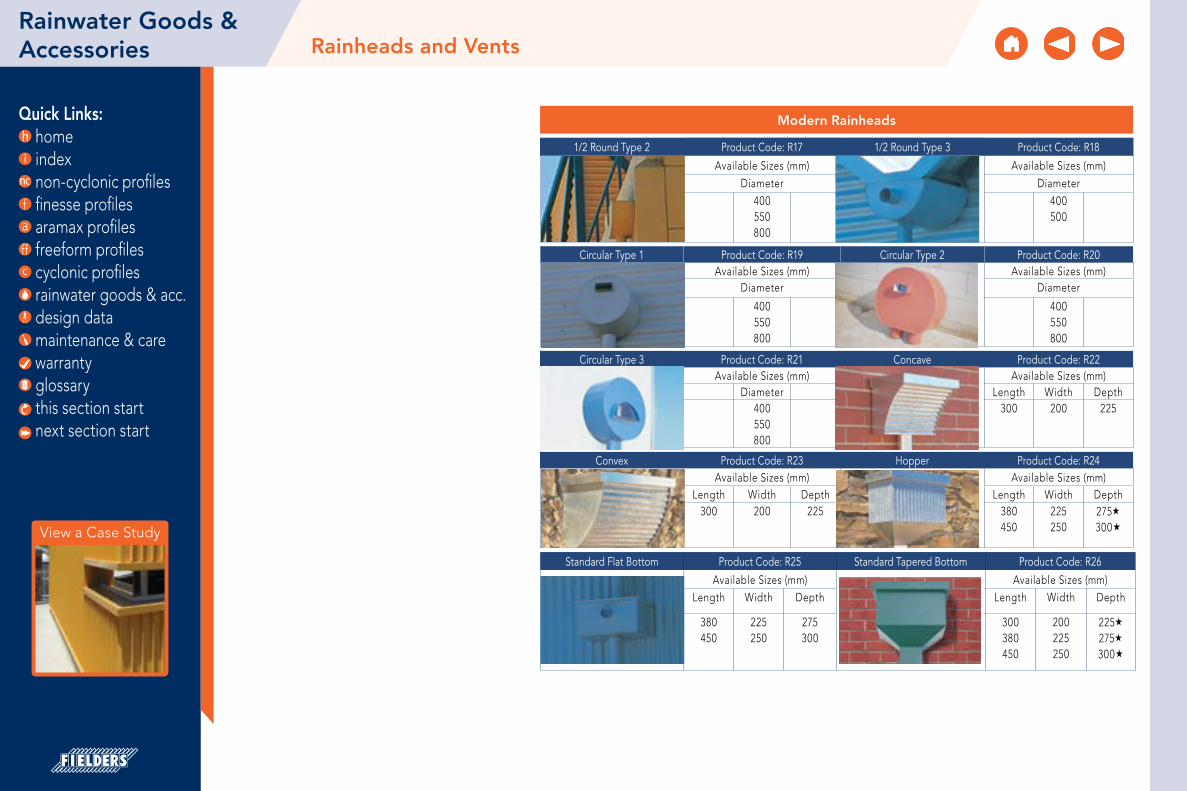
Quick Links: home index non-cyclonic profiles finesse profiles aramax profiles freeform profiles cyclonic profiles rainwater goods & acc. design data maintenance & care warranty glossary
Rainwater Goods & Accessories
Standard Flat Bottom Product Code: R25 Standard Tapered Bottom Product Code: R26
Available Sizes (mm) Available Sizes (mm)Length Width Depth Length Width Depth
380450
225250
275300
300380450
200225250
225275300
Modern Rainheads
1/2 Round Type 2 Product Code: R17 1/2 Round Type 3 Product Code: R18
Available Sizes (mm) Available Sizes (mm)
Diameter Diameter
400550800
400500
Circular Type 1 Product Code: R19 Circular Type 2 Product Code: R20Available Sizes (mm) Available Sizes (mm)
Diameter Diameter
400550800
400550800
Circular Type 3 Product Code: R21 Concave Product Code: R22Available Sizes (mm) Available Sizes (mm)
Diameter Length Width Depth400550800
300 200 225
Convex Product Code: R23 Hopper Product Code: R24Available Sizes (mm) Available Sizes (mm)
Length Width Depth Length Width Depth300 200 225 380
450225250
275300
Rainheads and Vents
View a Case Study
this section start next section start
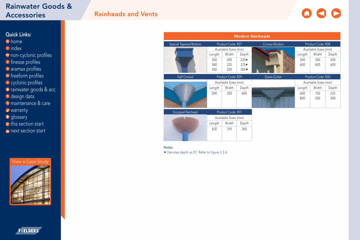
Quick Links: home index non-cyclonic profiles finesse profiles aramax profiles freeform profiles cyclonic profiles rainwater goods & acc. design data maintenance & care warranty glossary
Modern Rainheads
Special Tapered Bottom Product Code: R27 Convex Modern Product Code: R28Available Sizes (mm) Available Sizes (mm)
Length Width Depth Length Width Depth
300380450
200225250
225275300
500600
300400
500600
Half Conical Product Code: R29 Eaves Gutter Product Code: R30
Available Sizes (mm) Available Sizes (mm)
Length Width Depth Length Width Depth
500 250 400 600800
150200
225300
Scooped Rainhead Product Code: R31
Available Sizes (mm)
Length Width Depth
620 310 260
Notes: Denotes depth as D1. Refer to figure 3.3.A.
Rainwater Goods & Accessories Rainheads and Vents
View a Case Study
this section start next section start

Quick Links: home index non-cyclonic profiles finesse profiles aramax profiles freeform profiles cyclonic profiles rainwater goods & acc. design data maintenance & care warranty glossary
Ornate Rainheads
Fan-top Type 1 Product Code: RO1 Fan-top Type 2 Product Code: RO2Available Sizes (mm) Available Sizes (mm)
Length Width Depth Length Width Depth300380
200225
225275
275300
220220
300400
Classic O.G Product Code: RO3 The Kent MKI Product Code: RO4Available Sizes (mm) Available Sizes (mm)
Length Width Depth Length Width Depth500700
300500
470670
300380450
200225250
225«275«300«
The Kent MKII Product Code: RO5 WoolStore Product Code: RO6Available Sizes (mm) Available Sizes (mm)
Length Width Depth Length Width Depth500600
275330
400500
380500
250340
380500
Colonial Product Code: RO7 Edwardian Product Code: RO8Available Sizes (mm) Available Sizes (mm)
Length Width Depth Length Width Depth
300380450
200225225
150200250
300380450
200225250
225275300
Edwardian Corner Product Code: RO9 Norfolk Product Code: RO10Available Sizes (mm) Available Sizes (mm)
Length Width Depth Length Width Depth150190225
200225250
225275300
330420
250300
340440
Notes: Denotes depth as D1. Refer to figure 3.3.A.
Rainwater Goods & Accessories Rainheads and Vents
View a Case Study
this section start next section start

Quick Links: home index non-cyclonic profiles finesse profiles aramax profiles freeform profiles cyclonic profiles rainwater goods & acc. design data maintenance & care warranty glossary
Notes: Denotes depth as D1. Refer to figure 3.3.A.
Ornate Rainheads
Victorian Style Product Code: RO11 Low Profile Traditional Product Code: RO12Available Sizes (mm) Available Sizes (mm)
Length Width Depth Length Width Depth290330
210240
300340
550700
200225
250300
Traditional Product Code: RO13Available Sizes (mm)
Length Width Depth250330
180225
400500
Rainwater Goods & Accessories Rainheads and Vents
View a Case Study
this section start next section start

Quick Links: home index non-cyclonic profiles finesse profiles aramax profiles freeform profiles cyclonic profiles rainwater goods & acc. design data maintenance & care warranty glossary
Rainwater Goods & Accessories
Vent Your CreativityTake a look through our dormer vents, gable vents and other variety vents and see how they can enhance your designs. Fielders® have been making vents for the last century and as such, a large range of classic and modern styles to suit existing structures or nouveau specifications are available. Just see what effect our 1912 Prince Alfred dormer can have when it crowns a roof line.
Vent your creative urges with Fielders® Vents.
Dormer Vents
1/2 Round Corrugated Top Product Code: DV1 1/2 Round Flat Top Product Code: DV2Available Sizes (mm) Available Sizes (mm)
Width Height Width Height600900
300450
600900
300450
Saddle Style Product Code: DV3 Contemporary Type 1 Product Code: DV4Available Sizes (mm) Available Sizes (mm)
Width Height Width Height600900
300450
600900
300450
Contemporary Type 2 Product Code: DV5 Decorative Type 1 Product Code: DV6Available Sizes (mm) Available Sizes (mm)
Width Height Width Height500800
6001100
500800
8001100
Decorative Type 2 Product Code: DV7 Decorative Type 3 Product Code: DV8Available Sizes (mm) Available Sizes (mm)
Width Height Width Height500800
8001100
500800
8001100
Decorative Type 4 Product Code: DV9 Decorative Type 5 Product Code: DV10Available Sizes (mm) Available Sizes (mm)
Width Height Width Height500800
8001100
500800
8001100
Rainheads and Vents
View a Case Study
this section start next section start

Quick Links: home index non-cyclonic profiles finesse profiles aramax profiles freeform profiles cyclonic profiles rainwater goods & acc. design data maintenance & care warranty glossary
Decorative Type 8 Product Code: DV13 Decorative Type 9 Product Code: DV14
Available Sizes (mm) Available Sizes (mm)
Width Height Width Height600900
300450
500800
8001100
Prince Alfred Product Code: DV15 Box Style Type 1 Product Code: DV16Available Sizes (mm) Available Sizes (mm)
Width Height Width Height500800
8001100
500700
500700
Box Style Type 2 Product Code: DV17 Porthole Product Code: DV18Available Sizes (mm) Available Sizes (mm)
Width Height Width Height500800
250400
7001000
400600
Rainwater Goods & Accessories Rainheads and Vents
Dormer Vents
Decorative Type 6 Product Code: DV11 Decorative Type 7 Product Code: DV12Available Sizes (mm) Available Sizes (mm)
Width Height Width Height500800
250400
500800
8001100
View a Case Study
this section start next section start

Quick Links: home index non-cyclonic profiles finesse profiles aramax profiles freeform profiles cyclonic profiles rainwater goods & acc. design data maintenance & care warranty glossary
Cupola and Other Vents
Cupola Type 1 Product Code: OV1 Cupola Type 2 Product Code: OV2Available Sizes (mm) Available Sizes (mm)
Width Height Width Height450600750
450600750
450600750
450600750
Cupola Type 3 Product Code: OV3 Western Rotary Product Code: OV4Available Sizes (mm) Available Sizes (mm)
Width Height Diameter450600750
450600750
300
Revolving Cowl Product Code: OV5 Standard Flue Cap Product Code: OV6Available Sizes (mm) Available Sizes (mm)
Diameter Diameter150200250
75100125150200300
Product Code: OV7 Canopy Vent Pipe Product Code: OV8Available Sizes (mm) Available Sizes (mm)
Width Height Width HeightCustom made Custom made
Industrial Roof Product Code: OV9Available Sizes (mm)
Width Height450600750
450600750
Rainwater Goods & Accessories Rainheads and Vents
View a Case Study
this section start next section start

Quick Links: home index non-cyclonic profiles finesse profiles aramax profiles freeform profiles cyclonic profiles rainwater goods & acc. design data maintenance & care warranty glossary
Gable Vents
Circular Product Code: GV1 Circular Louvred Product Code: GV2Available Sizes (mm) Available Sizes (mm)
Width Height Width Height300380430530600
300380430530600
90012001500
90012001500
1/2 Round Product Code: GV3 1/4 Round Product Code: GV4Available Sizes (mm) Available Sizes (mm)
Width Height Width Height500750
1200
250375600
100015001800
500750900
Rectangular (Landscape) Product Code: GV5 Rectangular (Portrait) Product Code: GV6Available Sizes (mm) Available Sizes (mm)
Width Height Width Height450600900
300450600
450450
600900
Triangular Product Code: GV7 Ornate Type 1 Product Code: GV8Available Sizes (mm) Available Sizes (mm)
Width Height Width HeightCustom made 900
12001500
90012001500
Rainwater Goods & Accessories Rainheads and Vents
View a Case Study
this section start next section start

Quick Links: home index non-cyclonic profiles finesse profiles aramax profiles freeform profiles cyclonic profiles rainwater goods & acc. design data maintenance & care warranty glossary
Gable Vents
Ornate Type 2 Product Code: GV9 Round Top Product Code: GV10Available Sizes (mm) Available Sizes (mm)
Width Height Width HeightCustom made 450
450600900
Multi-panel Louvre Product Code: GV11 Louvre Product Code: GV12Available Sizes (mm) Available Sizes (mm)
Width Height Width HeightCustom made Custom made
Rainwater Goods & Accessories Rainheads and Vents
View a Case Study
this section start next section start

Quick Links: home index non-cyclonic profiles finesse profiles aramax profiles freeform profiles cyclonic profiles rainwater goods & acc. design data maintenance & care warranty glossary
Rainwater Goods & Accessories Vent Ridge
The size of the vent ridge should be determined in accordance with the Building Code of Australia, and any relevant state building requirements. In general the minimum ventilation required of a building is 5% of its floor area (section F4, Vol.1, Building Code of Australia 2006).
Figure RGA VR 001 Vent Ridge for Less Than 450mm Throat Size
Figure RGA VR 002 Vent Ridge for 450mm Throat Size and Above
Figure RGA VR 003 Cappings for Throat Sizes 450mm and Above
30mm
90mm
Available Sizes for Vent Ridge (mm)
Vent Ridge Dimensions Throat A B C D E Suit Contemporary Ridge125 125 80 85 70 154 x = 190
x x
150 150 80 95 90 175 x = 229200 200 80 125 80 235 x = 305250 250 130 140 100 276 x = 380300 300 130 180 125 344 x = 455350 250 155 175 130 363 x = 425400 300 150 200 140 417 x = 505450 300 200 225 190 375 x = 530500 320 200 250 195 430 x = 570600 300 207 265 150 500 x = 600
Optional Baffle Flashing
The installation of a baffle flashing is recommended where roofing is subject to strong winds or severe weather conditions.
Vent Ridge
Baffle flashing
Roof sheeting
Figure RGA VR 004 Optional Baffle Flashings
Table RGA VR AM 001
Table RGA VR AS 001Note: The brackets for throat sizes 125, 150 and 200mm are made in 2mm gauge material. Throat sizes 300mm and above are made in 3mm gauge material.
View a Case Study
AB
CD
E
Available Materials
Material / Finish Conforming to BMT (mm) ColourZINCALUME® Steel AS 1397 G300 - AM125 0.50 -
COLORBOND® Steel AS 1397 G300 - AM100 and AS 2728 0.50 As SelectedCOLORBOND® Ultra Steel AS 1397 G300 - AM150 and AS 2728 0.55 As Selected
COLORBOND® Stainless Steel Grade 430 base 300 0.45 As SelectedHeritage Galvanised AS 1397 G300 - Z600 0.50 -
this section start next section start

Quick Links: home index non-cyclonic profiles finesse profiles aramax profiles freeform profiles cyclonic profiles rainwater goods & acc. design data maintenance & care warranty glossary
350mm Roll Top Ridge Cap Low Profile Ridge
Rainwater Goods & Accessories Cappings
Available Materials
Material / Finish Conforming to BMT (mm) ColourZINCALUME® Steel AS 1397 G300 - AM125 0.50
COLORBOND® Steel AS 1397 G300 - AM100 and AS 2728 0.50 As SelectedCOLORBOND® Ultra Steel AS 1397 G300 - AM150 and AS 2728 0.55 As Selected
COLORBOND® Stainless Steel Grade 430 base 300 0.45 As SelectedHeritage Galvanised AS 1397 G300 - Z600 0.50
100mm approx..
260mm approx..
135°
30° 26mm radius
Figure RGA CA RTR 001Notes:* Also available in ZINCALUME® and COLORBOND® 0.42 BMT G550
to suit
to suit
140°
220°
160°120°
Figure RGA CA LPR 002
Note: Dimensions on the following diagrams apply to SA only. Please check with your local Fielders® representative for state specific dimensions.
Table RGA C AM 001
View a Case Study
this section start next section start

Quick Links: home index non-cyclonic profiles finesse profiles aramax profiles freeform profiles cyclonic profiles rainwater goods & acc. design data maintenance & care warranty glossary
Barge Capping
Figure RGA CA B 001
Barge Roll
Figure RGA CA BR 002
Rainwater Goods & Accessories
20
130mm
50mm
135°
20mm
10mm
Cappings
View a Case Study
1
1
2
2
3
3
4
4
5
5
6
6
A A
B B
C C
D D
1 OF 1 DRAWN
CHECKED
APPROVED M.F
T.W
M.F
17/08/2015
17/08/2015 DWG NO
BARGE ROLL
SCALE @
SHEET
ROF15003DESCRIPTION
NAME DATE
FINISHCOLOURMATERIAL 1:1
213 RAILWAY TCEKESWICK TERMINAL SA 5035
Ph: 08 8292 3611Fax: 08 8292 3626
FINISH ON TOP
TOLERANCESUNLES OTHERWISE STATED
0 DEC ±1 DEC ±2 DEC ±HOLES + -
ISSUE REVISION DESCRIPTION DRAWN DATE
0.55 BMT COLORBOND
AS REQUIRED
DO NOT SCALE - DIMENSIONS IN MILLIMETRES UNLESS STATED OTHERWISE
1.00.50.10.5 0.0
A3
19
130
n52
28
12
10
0,55
R1,5 this section start next section start

Quick Links: home index non-cyclonic profiles finesse profiles aramax profiles freeform profiles cyclonic profiles rainwater goods & acc. design data maintenance & care warranty glossary
Edge Roll
Figure RGA CA ER 003
Barge Roll Caps
Figure RGA CA BR 004 Madonna Cap
Knob Plug
Flat Plug
40mm
45mm
Rainwater Goods & Accessories Cappings
View a Case Study
this section start next section start

Design Data Long Length Roofing Solutions
Rainfall Intensity
Water Carrying Capacity and Rainwater Run-off
Comparative Analysis: Concealed Fix vs. Screw Fix
Curving of Steel Decks
Typical Roofing Details
Flashing Order Guide
Typical Pierce Fix Installation Guide
Flashing, Cappings and Ends of Sheets
Thermal Expansion and Contraction of Steel Sheeting
Oil Canning
The Caterpillar Effect
Direct Contact Between Metals
Roofing Acoustics
Environmental Sustainability
Reflectivity
Material Selection Guide for Severe Environmental Conditions
Sample Specwriter™ Template
Gutter Capacity Tool Example
Return to index

Quick Links: home index non-cyclonic profiles finesse profiles aramax profiles freeform profiles cyclonic profiles rainwater goods & acc. design data maintenance & care warranty glossary
Step joints serve no function in a concealed fix roof and are a legacy of manufacturers’ inability to transport sheets longer than 30 metres. Step joints can be the weakest link in an otherwise sound roof. They allow for the build up of debris and constitute an unwashed area that is not covered by the BlueScope Steel Warranty.
Fielders® Long Length Roofing Solutions
The superior performance of Fielders® long length roofing solutions has been well documented since we first introduced on-site mobile roll forming to Australia. Fielders® have successfully supplied sheet lengths of up to 102 metres in Australia, eliminating the need for unsightly step joints.
Developers, builders and roofers have now experienced the economical and functional benefits of long length sheeting which has led to its rising popularity. As such, the number of Fielders® Mobile Mills has increased to 9; rolling products like HiKlip® 630, KingKlip 700® and Shadowline 305 at sites all over Australia.
Fielders® range of concealed fix, long length roofing solutions is designed to accommodate thermal expansion and contraction as well as provide superior resistance to high wind loads.
What Do You Get With a Fielders® Long Length Roofing Solution?
• No leaking screw holes
• Fielders® unique 20 Year Watertight Guarantee (conditions apply)
• No unsightly and costly step joints. Long length roof sheeting saves on unnecessary material and labour
• A roof warranty without exclusions
Getting It Right...the Second Time
The demand for long length roofing solutions has led to Fielders® pioneering re-roofing applications without step joints.
An approved Fielders® contractor can successfully re-roof your commercial building and eliminate step joints with a long length solution without the need to change the existing structure.
Long Length Roofing SolutionsDesign Data
Sheeting turned down.
Baffle flashing. Notch over ribs & fasten to underlapping
sheetsTrays turned up
250mmminimum overlap
300mm
x x. Dimension varies to allow for expansion and
contraction of roof sheets No tophat sections required for remaining purlins
Tophat sections to accommodate difference in purlin height
Original step joint eliminated New Fielders® concealed fix roof
Figure DD LRS SJ 002 Original EliminatedNote: Purlins remain unchanged either side of the original step joint
Figure DD LRS SJ 001
View a Case Study
this section start next section start

Quick Links: home index non-cyclonic profiles finesse profiles aramax profiles freeform profiles cyclonic profiles rainwater goods & acc. design data maintenance & care warranty glossary
Rainfall Intensity by Locality (mm/hr)
Locality
Average recurrence internal, once in:
Locality
Average recurrence internal, once in:
Locality
Average recurrence internal, once in:
20 years
100 years
20 years
100 years
20 years
100 years
ACT Mt Morgan 225 300 Roy Hill 160 216Canberra 137 194 Noosa 253 320 Tom Price 164 222
SA Posperpine 272 356 Wittenoom 182 245Adelaide 123 186 Rockhampton 248 336 NTArkaroola 134 194 Roma 192 358 Alice Springs 139 204Ceduna 125 200 Southport 246 308 Darwin 285 366
Mt. Barker 120 184 Toowoomba 189 251 Katherine 230 304Mt. Gambier 108 168 Townsville 260 346 NSW
Murray Bridge 117 181 Warwick 178 240 Albury 135 191Nuriootpa 111 164 Weipa 293 370 Armidale 154 219
Port Augusta 124 189 TAS Batesmans Bay 211 279Port Pirie 125 201 Bridgewater 101 156 Bathurst 143 197
Yorketown 118 197 Burnie 118 191 Bowral 170 225VIC Deloraine 108 165 Broken Hill 130 181
Bacchus Marsh 126 189 Dover 97 165 Casino 198 256Ballarat 127 184 Flinders Island 128 184 Coffs Harbour 232 293Benalla 133 187 Hobart 99 155 Cooma 129 183
Geelong 118 172 Kingston 98 154 Coonabarabran 178 247Hamilton 120 184 Launceston 101 150 Cowra 144 203
Healesville 129 192 Mt Wellington 122 191 Dorrigo 214 273Horsham 120 174 New Norfolk 100 166 Dubbo 159 221
Korumburra 116 168 Queenstown 118 183 Forbes 151 209Lakes Entrance 124 179 Scottsdale 119 190 Glen Innes 159 219
Melbourne 127 186 Sorell 101 152 Gosford 189 240Mildura 125 174 St. Helens 131 185 Goulburn 145 197Morwell 129 196 St. Marys 205 266 Inverell 179 251Orbost 130 188 WA Kempsey 220 283Stawell 127 185 Abydos 199 275 Kiama 224 283
Wonthaggi 114 165 Albany 142 217 Lismore 219 278QLD Broome 252 343 Lithgow 141 191
Biloela 220 298 Bunbury 148 215 Maitland 169 224Brisbane 251 333 Carnarvon 142 196 Merimbula 207 278
Bundaberg 241 318 Collie 145 217 Mittagong 172 277Cairns 282 368 Dampier 231 337 Mullumbimby 250 315
Cape York 301 388 Derby 254 343 Murwillumbah 244 302Charleville 170 236 Geraldton 132 173 Muswellbrook 141 195
Charters Towers 218 285 Halls Creek 181 237 Newcastle 181 233Cloncurry 172 228 Hamersley 180 244 Nowra 219 280Emerald 220 289 Hillside 192 265 Orange 152 214
Goondiwindi 182 246 Kalgoorlie 116 180 Penrith 166 220Gympie 228 299 Katanning 125 203 Port Macquarie 223 290
Hughenden 199 266 Kununurra 256 347 Robertson 228 297Innisfail 254 323 Marble Bar 205 287 Singleton 148 199Kingaroy 208 279 Meekatharra 111 155 Sydney 214 273
Longreach 189 251 Mundaring 139 204 Taree 190 241Mackay 273 363 Newman 143 195 Tweed Heads 245 303
Mareeba 219 290 Perth 146 214 Wollongong 233 294Mt Isa 169 223 Port Hedland 233 332 Wyong 186 240
Design Data Rainfall Intensity
The data relates to a storm of five minutes duration and an average recurrence interval of one in 20 years for eaves gutters and one in 100 years for valley and internal box gutters, based on Australian Rainfall and Runoff (1987) published by Engineers Australia.
Minimum for eaves gutters.
Minimum for internal box and valley gutters.
Notes:1. Data for other locations may be obtained from
local drainage authorities. Data for any locality in Australia (to a resolution of 1/40th of a degree of latitude or longitude) may be obtained from the Bureau of Meteorology.
2. Data shown for large cities are the maxima within the greater city area. Data for specific locations within these areas may be obtained from the Bureau of Meteorology.
3. More stringent requirements should be considered for buildings where the avoidance of gutter overflow is of paramount importance.
4. All gutters and outlets, particularly box gutters served by internal sumps, need to be regularly inspected and maintained to avoid breakages.
Table DD RI LO 001
View a Case Study
this section start next section start

Quick Links: home index non-cyclonic profiles finesse profiles aramax profiles freeform profiles cyclonic profiles rainwater goods & acc. design data maintenance & care warranty glossary
The Right Profile For the Right Job
In Australia, we experience vast differences in regional conditions as well as variations in the functional and performance requirements of buildings, yet most roofing manufacturers offer the same profiles for all applications.
Fielders® provide the largest range of long length concealed fix decking on the Australian market. Each profile has been developed to give maximum performance in a variety of applications, giving you the right roofing profile for any conditions.
Figure DD WCC RD 001Note: Figures based on exposure conditions as follows:
1. Rainfall intensity - 370 mm / hr (Cairns 100 year).
2. Roof Slope - 5.0 degrees.
3. Flow condition - Steady state & uniform.
4. Flow (L/s/m) - Per metre width of sheet.
Fielders® three concealed fix roofing profiles have all your requirements covered. KingKlip 700® is a premium wide deck with a clip design allowing faster installation. And finally, HiKlip® 630 has the greatest water carrying capacity on the market.
All concealed fix decks are backed by Fielders® unique 20 Year Watertight Installation Guarantee - and more importantly, they have no more holes!
Design Data Water Carrying Capacity and Rainwater Run-off
View a Case Study
25
Disc
harg
e L/
s/m
20
15
10
5
0HiKlip® KingKlip® TL-5 Spanform S-Rib
Profile
this section start next section start

Quick Links: home index non-cyclonic profiles finesse profiles aramax profiles freeform profiles cyclonic profiles rainwater goods & acc. design data maintenance & care warranty glossary
Figure DD WCC CFR 001
Fielders® HiKlip® 630
Fielders® recognised the demand for a concealed fix deck that provided total protection for buildings located in areas prone to flash deluges, high wind and rainfall. The result was that Fielders® designed HiKlip® 630. HiKlip® 630 is a revolutionary deep rib deck with two important performance features. Firstly, HiKlip® 630 is the strongest concealed-fixed roofing product, and secondly, it has the greatest water carrying capacity of any deck on the market.
Both the HiKlip® 630 deck and clip mechanism exhibit great strength and are able to resist very high wind pressures whilst allowing the brackets and decking to slide independently of each other to accommodate temperature variations without unsightly step joints.
Design Data Water Carrying Capacity and Rainwater Run-off
KingKlip 700®
HiKlip® 630
Shadowline™305
View a Case Study
this section start next section start

Quick Links: home index non-cyclonic profiles finesse profiles aramax profiles freeform profiles cyclonic profiles rainwater goods & acc. design data maintenance & care warranty glossary
The question: ‘Which system is better to use, concealed fix or screw fix?’ has concerned the industry for quite some time, particularly in the light of claims that screw fixing is more cost effective and “does the same job” as a concealed fix roof. This comparative analysis serves to remove this confusion by investigating the benefits of concealed fix over screw fix profiles.
Over tightening of screws is one of the most common install-ation flaws. Even when the most skilled roofers are involved, with an average of 36,000 screws per 6,000m2, the probability that over tightening will occur is extremely high. This installation flaw causes denting and washer damage, both of which lead to corrosion.
Dents are caused when screws are over tightened thus deforming the rib of the deck. Despite the drainage capabilities of the best of roofs, dents allow water to pond and remain around the screw. Corrosion will eventually occur as the screw has exposed the base metal to the “ponding” water.
Figure DD CA 001 - Corrosion Caused by Ponding of Water
Meanwhile, damage to the neoprene washer can occur in a similar fashion to denting, as the over tightening action of the screw squeezes the washer to one side, breaking the watertight seal between the screw and the hole.
Figure DD CA 002 - Neoprene Washer Damage Caused by Over Tightening
Concealed fix decks have greater rib heights than screw fix decks. This increases their strength and water drainage capacity. Higher ribs enable water to drain from the roof at a faster rate. Some Australian manufacturers recommend the use of screw fix decks down to a 2° pitch, whereas the world standard is a minimum of 5°. Any deflection in the steel work could reduce the effective pitch to 1° or less, allowing water to pond.
Design Data Comparative Analysis: Concealed Fix vs. Screw Fix
View a Case Study
this section start next section start

Quick Links: home index non-cyclonic profiles finesse profiles aramax profiles freeform profiles cyclonic profiles rainwater goods & acc. design data maintenance & care warranty glossary
Concealed fix decks are more robust and as such give better resistance to foot traffic and damage by trade and maintenance personnel. Some screw fix decks, due to the nature of their profile, cannot withstand the same force exerted on a single pan or rib and are thus highly susceptible to foot traffic damage.
The availability of the Fielders® Mobile Roofing Mill for concealed fix decks enables long lengths to be rolled on site, thus eliminating the need for costly step joints and the inevitable consequences of their eventual failure (see “Long Length Roofing Solutions”). This is further backed with Fielders® unique 20 Year Watertight Installation Guarantee (terms & conditions apply).
Concealed fix profiles are suited to a diverse range of applications. Fielders® range of concealed fix decks provide many options for different requirements, whether these be budgetary, durability or environmental issues. KingKlip® is a premium grade, robust deck with a unique “Over and Under” clipping system. HiKlip® is designed specifically for extreme cyclonic conditions and has the greatest water drainage capacity of the three profiles.
The final benefit of our concealed-fixed roofing over screw-fixed roofing is the Fielders® 20 Year Watertight Installation Guarantee (terms and conditions apply). Fielders® is confident in the strength and longevity of our concealed-fixed roof cladding and is able to offer eligible customers this unique guarantee.
Design Data Comparative Analysis: Concealed Fix vs. Screw Fix
View a Case Study
this section start next section start

Quick Links: home index non-cyclonic profiles finesse profiles aramax profiles freeform profiles cyclonic profiles rainwater goods & acc. design data maintenance & care warranty glossary
Figure DD CA CFR 005
Design Data
HiKlip® 630
KingKlip 700®
Shadowline™ 305
Comparative Analysis: Concealed Fix vs. Screw Fix
View a Case Study
WATERTIGHT
20
YEAR CONCEALED FIX
GUARANTEE* Terms and Conditions Apply
this section start next section start

Quick Links: home index non-cyclonic profiles finesse profiles aramax profiles freeform profiles cyclonic profiles rainwater goods & acc. design data maintenance & care warranty glossary
Calculations To calculate rise when radius, r and arc length are known, first determine the central angle as below:
r =width2 + 4(d2)
8d
Design Data Curving of Steel Decks
widthd
O
r
q
arc length
Note: The online Circle Calculator can be helpful in finding various values relating to circles and arcs. Find it at http://www.1728.com/circsect.htm.
View a Case Study
Formula is as follows:
180 arc length= q
pr
where q = central angle p = 3.142 r = radius
Figure DD CDS Convex 002
Figure DD CSD Concave 001
this section start next section start

Quick Links: home index non-cyclonic profiles finesse profiles aramax profiles freeform profiles cyclonic profiles rainwater goods & acc. design data maintenance & care warranty glossary
Design Data Curving of Steel Decks
View a Case Study
Spring Curving of Concealed Fix DeckFielders’ HiKlip® 630, KingKlip 700® can successfully be sprung curved within certain parameters. The performance of spring curved KingKlip® for resistance to wind loads is shown in tables “DD CSD CSC 001 and DD CSD CSC 002”. However there are factors to take into account other than the ‘unzipping’ of the deck from the clip. Aesthetics often determine the suitability of the use of a roofing deck and consequently there are limiting considerations, given the propensity of a wide pan concealed fix deck to ‘oil can’ or facet.
Wide pan concealed fix decks will not spring curve down to the radii that corrugated and close pitch trapezoidal screw fix decks will achieve.
Furthermore, it is impractical to table the ability of Fielders’ concealed fix profiles to spring curve given there are numerous variables that affect their performance, for instance gauge, purlin spacings, wind pressure and the
degree of acceptability for oil canning. In general terms, the higher the rib, the more difficult it will be to spring curve successfully. Conversely, a heavier gauge material will improve the roof’s aesthetic performance in this regard.
Fielders’ experienced sales staff will be able to provide feedback in relation to your specific project.
Figure “DD CDS 003” gives indicative performance of Fielders® concealed fix profiles when spring fixed. The data provided is typical only and varies subject to limit state wind pressure, building height, purlin spacings and other factors. Typically the tighter the radius, the greater propensity for oil canning or faceting to occur (although the deck will not ‘unzip’).
this section start next section start

Quick Links: home index non-cyclonic profiles finesse profiles aramax profiles freeform profiles cyclonic profiles rainwater goods & acc. design data maintenance & care warranty glossary
Convex Spring Curving Guide
Profile BMTRadius of Curve (m)
110 100 90 80 70 60 50 40 30
KingKlip®0.42
0.48
HiKlip®0.42
0.48
Figure DD CDS 003 Convex Spring Curving Guide
Convex Spring Curved KingKlip 700® Wind Load CapacityLimit State Design (kPa) Non - Cyclonic. Fixed with Mark II Clips
Span (mm)
0.42 BMT 0.48 BMT
Radius of curvature (m) Radius of curvature (m)Flat 90 80 70 60 50 Flat 90 80 70 60 50
1200 2.19 1.96 1.93 1.88 1.81 1.73 3.04 2.75 2.71 2.64 2.57 2.47
1500 1.92 1.78 1.75 1.73 1.69 1.63 2.85 2.68 2.66 2.61 2.58 2.50
1800 1.72 1.65 1.63 1.61 1.58 1.54 2.62 2.53 2.51 2.48 2.45 2.40
2100 1.57 1.54 1.52 1.50 1.48 1.46 2.39 2.34 2.32 2.31 2.28 2.25
2400 1.46 1.44 1.44 1.42 1.41 1.38 2.05 2.02 2.02 2.00 1.98 1.95
2700 1.28 1.28 1.26 1.25 1.23 1.22 1.73 1.73 1.72 1.71 1.69 1.67
Concave Spring Curved KingKlip 700® Wind Load CapacityLimit State Design (kPa) Non - Cyclonic. Fixed with Mark II Clips
Span (mm)
0.42 BMT 0.48 BMT
Radius of curvature (m) Radius of curvature (m)Flat 90 80 70 60 50 Flat 90 80 70 60 50
1200 2.19 1.96 1.94 1.90 1.86 1.79 3.04 2.68 2.64 2.58 2.50 2.39
1500 1.92 1.82 1.80 1.77 1.73 1.68 2.85 2.66 2.62 2.58 2.51 2.43
1800 1.72 1.66 1.65 1.63 1.61 1.57 2.62 2.50 2.48 2.45 2.41 2.36
2100 1.57 1.54 1.53 1.51 1.50 1.47 2.39 2.32 2.30 2.28 2.26 2.22
2400 1.46 1.45 1.44 1.43 1.42 1.40 2.05 2.01 2.00 1.98 1.96 1.93
2700 1.28 1.28 1.28 1.27 1.26 1.24 1.73 1.71 1.70 1.68 1.66 1.64
Design Data
Notes:1. These capacity figures relate to the penultimate clip
of a continuous sheet to guard against an ‘unzipping’ failure.
2. Capacities in bold show max load capacity / purlin spacing for each radius.
3. Faceting will be most significant with small radii, thin sheeting & large purlin spacing.
4. Oil canning will be more significant with thin sheet & small radius curving.
5. It is assumed that all purlins are sufficiently rigid to maintain a curved ‘profile’ along the span.
6. Contact Fielders® for project specific advice on aesthetic performance in sprung curve applications.
7. Tables DD CSD CSC 001 and DD CSD CSC 002 are calculated from analytical performance based upon:
a. Sheet stiffness determined from single span load & deflection tests.
b. Sheets are continuous over five equal spans.
c. Purlin reactions are computed to achieve a circular profile.
d. Uplift capacity at clips is reduced by the tension force to form then curved profile.
Curving of Steel Decks
Table DD CSD CSC 001
Table DD CSD CSC 002
View a Case Study
this section start next section start

Quick Links: home index non-cyclonic profiles finesse profiles aramax profiles freeform profiles cyclonic profiles rainwater goods & acc. design data maintenance & care warranty glossary
Convex Spring Curving
Spanform™ S-Rib™ Corrugated
0.42 BMT 0.48 BMT 0.42 BMT 0.48 BMT 0.60 BMT
Minimum Radius (m) 20 20 12 10 9
Purlin Spacing at Minimum Radius (mm)
1400 1200 800 1000 900
Maximum Radius (m) 60 60 35 35 35
Design Data
Spring Curving of Pierce Fix Decks
Convex Spring CurvingCOLORBOND® & ZINCALUME® steel’s versatile properties allow the roofer to curve straight sheeting on-site to the radii shown in the tables to the right.
Side laps should be sealed with recommended sealants over the crest of the arch where the slope is less than recommended minimum for that sheet profile. If end laps are necessary, they should not be located at or near the crest of the arch and each sheet length should span at least three purlin spacings. The top face of all purlins should accurately follow, and be tangential to, the arch curvature. Each alternate sheet should be laid from opposite sides of the roof. It should be noted that very slight crease marks may appear in the trays or valleys over the supports when curved sheeting is subjected to foot traffic. These crease marks do not affect the integrity of the sheets.
Concave Spring CurvingRoof slope at the lower end of the sheeting must not be less than the minimum pitch for the selected roofing profile.
Curving of Steel Decks
Table DD CSD CSC 003
Table DD CSD CSC 004Note: Maximum recommended radius to provide sufficient drainage near crest of curvature.
View a Case Study
Concave Spring Curving
Spanform™ TL-5™ S-Rib™ Corrugated
0.42 BMT 0.48 BMT 0.42 BMT 0.48 BMT 0.42 BMT 0.48 BMT 0.60 BMT
Minimum Radius (m) 18 20 20 22 10 10 8
Purlin Spacing at Minimum Radius (mm)
1200 1400 1200 1000 800 1000 800
this section start next section start

Quick Links: home index non-cyclonic profiles finesse profiles aramax profiles freeform profiles cyclonic profiles rainwater goods & acc. design data maintenance & care warranty glossary
Crank CurvingFielders® brings a new dimension to commercial and industrial roofing with versatile crank curved decking available in TL-5, Spanform® and KingKlip 700® profiles.
The Advantages of Crank Curving
• Smoother flow of wind over eaves, meaning less chance of sheet ends lifting
• Continuous pieces reduce cost
• Curved edges can eliminate debris collecting in gutters and fascia purlins because rain can simply run straight downwards and be collected in spoon drains
• It is easier to clean a spoon drain than to clear the corrosion causing debris collected in eaves guttering
• The ability to curve from roofing straight down into vertical sheets can eliminate the need for bird or vermin-proofing of regular eaves
• Minimum radius for crank curving is 750mm for TL-5 and 900mm for KingKlip® and Spanform
Notes:There are a number of essential prerequisites for ordering a crank curved project:
1. Either the exact radius or an accurate full size template must be supplied by the customer
2. A set of detailed, fully dimensioned drawings also need to be submitted
3. The customer must allow for two additional sheets over and above the estimated amount to be used as test sheets
Design Data Curving of Steel Decks
View a Case Study
this section start next section start

Quick Links: home index non-cyclonic profiles finesse profiles aramax profiles freeform profiles cyclonic profiles rainwater goods & acc. design data maintenance & care warranty glossary
Crank Curving
S Curve Radius Curve Monitor Crank Centre Crank
Half Circle Extended Bullnose Double Crank Offset Crank
Reverse Bullnose Up Slope Offset Double Typical Crank
Design Data Curving of Steel Decks
View a Case Study
Table DD CSD CC 005
this section start next section start

Quick Links: home index non-cyclonic profiles finesse profiles aramax profiles freeform profiles cyclonic profiles rainwater goods & acc. design data maintenance & care warranty glossary
Smooth Curving of Concealed Fix Decks - KingKlip®
Smooth curving is an option unique to Fielders®. All profiles have limitations as to the minimum radius to which they can be spring fixed. Crank curving is available in a number of profiles however it is not aesthetically acceptable on some projects. Profiles such as Corrugated and others may be spring curved or fixed to relatively tight radii but they are all pierce fixed decks and SAA HB 39 – 1997 section 7.17.3 states that all side laps should be sealed with a recommended sealant where the pitch of the roof is less than the recommended pitch for the given profile. Whilst this does provide a ‘method’ of fixing, it is not deemed to be the most desirable solution in that the watertightness of the roof is largely dependent on the silicone seal.
KingKlip 700® is able to be smooth curved by Fielders® state of the art purpose built machinery achieving smooth curves to much tighter radii than can be achieved by spring curving. KingKlip®, being a concealed fix product, provides a far more secure barrier to the ingress of water for a curved roof than a screw fixed product. The minimum achievable pitches are determined by the gauge and grade of steel used, refer to table “DD CSD MR 001” to the left.
Ordering Smooth Curved Roofs
Fielders® need to view detailed drawings to determine the following:
1. The suitability of the roof for smooth curving and what material would achieve the best result
2. Whether the curving needs to take place on site or in the factory
3. Calculation of costs in order to prepare a detailed quotation
4. Ascertain whether it is necessary to visit the site to ensure that there is sufficient area available on site if an on-site curve is required. This will be particularly relevant to when long length sheets are required
Design Data Curving of Steel Decks
Table DD CSD MR 001Notes: 1. This table does not provide definitive values and
should not be used as a basis for design without consulting Fielders® technical staff
2. After which faceting occurs. These limits do not reflect wind load capacity limits.
3. ▲Subject to availability and special pricing.
View a Case Study
Minimum Radiifor Smooth Curving KingKlip 700®
BMT (mm) Grade Minimum
Radius (m)
Maximum Purlin Spacing
(mm)0.42 G550 20.00 1500
0.48 G550 20.00 1800
0.50 G550 ▲■ 18.00 1800
0.55 G300 ▲■ 15.00 1800
0.70 G220 ▲■ 12.00 1800
this section start next section start

Quick Links: home index non-cyclonic profiles finesse profiles aramax profiles freeform profiles cyclonic profiles rainwater goods & acc. design data maintenance & care warranty glossary
Design Data
Spacing between ridge purlins
Figure DD CDS SCR 004
Minimum Spacing of Ridge Purlins for Spring Curving (mm)
Roof PitchKingKlip 700® Spanform™ TL-5™ S-Rib Corrugated
0.42 BMT 0.48 BMT 0.42 BMT 0.48 BMT 0.42 BMT 0.48 BMT 0.42 BMT 0.48 BMT 0.60 BMT
2 ° (1 in 30) 1900 2700 N/A N/A 1500 1600 N/A N/A N/A
3 ° (1 in 20) 2000 2800 1500 1600 1600 1700 N/A N/A N/A
4 ° (1 in 15) - - 1600 1700 - 1800 N/A N/A N/A
5 ° (1 in 12) - - - 1800 - - 1200 1300 1200
6 ° (1 in 10) - - - - - - - 1400 1300
7 ° (1 in 8) - - - - - - - - 1400
Spring Curving of RidgesOn lower pitch roofing the process of spring-curved ridges eliminates the need for ridge capping. Full length sheeting can be laid from eave to eave and spring curved between the ridge purlins. This process eliminates the possibilities of leakage caused by a break in the sheeting at the ridge, providing a neat and cheap alternative to ridge capping.
• As a result of this process some oil canning, purlin lines, or puckering of laps can occur in the ridge curve
• Side laps should be sealed for the length of the curvature
• Each sheet should be first fastened to one side of the roof and then pulled down to the other side of the gable
Curving of Steel Decks
Table DD CSD SRP 001Notes:1. All other purlins spacings as per product specifications.
2. N/A - not applicable
View a Case Study
this section start next section start

Quick Links: home index non-cyclonic profiles finesse profiles aramax profiles freeform profiles cyclonic profiles rainwater goods & acc. design data maintenance & care warranty glossary
Design Data Typical Roofing Details
Typical Roofing Details
Masonry Parapet Sidewall, Low Parapet Masonry Parapet Sidewall, High Parapet
Parapet capping Type 1
Apron flashing Type 3
Fielders® sheeting
3°min. Fall
Packing to suit
7mm/slight break
10mm return fold
Parapet capping Type 2
Overflashing Type 4
Apron flashing Type 3
Fielders® sheeting
3° min. FallPacking to suit
10mm return fold
25mm
Masonry Parapet, Headwall Masonry Chimney Flashings
Packing to suit
Parapet capping Type 1
Apron flashing Type 5
Scribed in
Fielders® sheeting
10mm return fold
7mm/slight break
3° min. Fall
Overflashing Type 4
Soaker gutter Type 6Overflashing Type 4
Apron flashing Type 5
Scribed in
Fielders® sheeting
25mmView a Case Study
Table DD RD 001
this section start next section start

Quick Links: home index non-cyclonic profiles finesse profiles aramax profiles freeform profiles cyclonic profiles rainwater goods & acc. design data maintenance & care warranty glossary
Typical Roofing Details
Framed Parapet Wall Cladding / Masonry Junction
Packing to suit
3° min. Fall
Capping Type 23 scribed in for profiled
cladding
7mm/slight break
Cladding
Cladding
Cladding
Fielders®
sheeting
Apron flashing Type 5
Scribed in
Cladding
Soffit
Soffit
Soffit corner flashing Type 7
Cladding
Shoe flashing Type 8
Cladding
Framing
Offset wall flashing Type 10
Offset wall flashing Type 9
Wall
Valley Gutter
Fielders® sheeting
Fielders® sheeting
Valley gutter Type 11
Wall
Design Data Typical Roofing Details
View a Case Study Table DD RD 002
this section start next section start

Quick Links: home index non-cyclonic profiles finesse profiles aramax profiles freeform profiles cyclonic profiles rainwater goods & acc. design data maintenance & care warranty glossary
Typical Roofing Details
Pitched / Flat Roof Mansard Roof
Under-over flashing Type 12 Scribed in
Framing
Fielders® sheeting
Mansard roof flashing Type 13
Scribed in
Fielders® sheeting
Fielders® sheeting
Framing
Step-in Roof Industrial Door Jamb
Two piece step flashing Type 24
Fielders® sheeting
Scribed
Fielders® sheeting
7mm/slight break
Framing
CappingFielders® sheeting
Jamb
Framing
Industrial Door Head Opening Jamb
Framing
Fielders® wall cladding
Door head flashing Type 16
Head
Can suit roller door application
FramingFielders® Sheeting
Opening jamb flashing Type 15
Design Data Typical Roofing Details
View a Case Study
Table DD RD 003
this section start next section start

Quick Links: home index non-cyclonic profiles finesse profiles aramax profiles freeform profiles cyclonic profiles rainwater goods & acc. design data maintenance & care warranty glossary
Typical Roofing Details
Opening Head Apex Capping
Framing
Door head flashing Type 16
Fielders® wall cladding
Apex capping Type 18
Framing
7mm/slight breakFraming
Apex capping Type 17 Scribed in
Fielders®
sheeting
Extra with Barge
Back Channel Barge Capping
Fielders® sheeting
Wall, fascia etc.Back channel Type 19 fixed
to wall. Sealant between back channel and wall face
Fielders®
sheeting
Framing
Wall
Barge capping Type 22
3° min. Fall
Design Data Typical Roofing Details
View a Case Study
Table DD RD 004
this section start next section start

Quick Links: home index non-cyclonic profiles finesse profiles aramax profiles freeform profiles cyclonic profiles rainwater goods & acc. design data maintenance & care warranty glossary
Typical Roofing Details
Barge Capping, Steel Construction Ridge Capping
Barge capping Type 20 Fielders® sheeting
Cladding
Scribed in
Ridge capping
Capping
Fielders® sheeting
Alternative profiles
Steel Sheet Edge Capping Industrial Corner Capping
Fielders® sheeting
Framing
Flashing Type 14 Fielders® sheeting
External corner capping Type 20
Girt
Internal corner capping Type 21
Fielders® sheeting
Box Gutter, Parapet Box Gutter, Internal
Overflashing Type 4
Flashing
Fielders® box gutter
Fielders® sheeting
Optional anti-splash flashing
Gutter board suspended using straps and saddles or angles and
drop-down bolts
10mm return fold
10mm/45
25mm
Fielders® sheeting
Optional anti-splash flashing
Fielders® Spanform®
gutter board
Optional anti-splash flashing
Fielders® gutter box
Design Data Typical Roofing Details
View a Case Study
Table DD RD 005
this section start next section start

Quick Links: home index non-cyclonic profiles finesse profiles aramax profiles freeform profiles cyclonic profiles rainwater goods & acc. design data maintenance & care warranty glossary
Fielders® produce a full range of custom folded gutters, flashings & cappings in continuous lengths of up to 10m. Ideally these are ordered by the customer providing a detailed, fully dimensioned drawing with all the relevant angles clearly marked. A range of typical details follow. However on occasion, it may be necessary to order a flashing over the telephone, in this instance the ‘clock’ method may be utilised, a step by step guide is given below.
Figure DD FOG 001 - The ‘Clock’ Method
1. Place pencil on paper
2. Draw a line to a point of the clock equivalent to angle required to a designated length
3. Mark the dimension to the side of the line at mid point
4. Place the pencil at the point where the line finished and assuming that the point is the centre of the clock, draw the next line using the same method
5. When ordering COLORBOND® flashings, specify on which side of the flashing the colour is required
Design Data Flashing Order Guide
60°
90°
120°
150°150°
120°
90°
60°
30°
121
2
3
4
56
7
8
9
10
11
30°
0°
0°
4 o’clock
6 o’clock
11 o’clock
6 o’clock
30°
120°
Figure DD FOG 002 - TYPE 41
Handy Hints
When ordering a flashing that has an obtuse angle reflecting the pitch of the roof, ensure that the angle includes the pitch plus 90° as illustrated in the example below.
When ordering flashings such as Type A and B below that require both Left and Right hand options, clearly state either by drawing both flashings completely or indicating clearly under one drawing that both left hand and right hand is required.
Angel = roof pitch + 90°
Roof pitch
GF
B
C
DE
HI
J
A
Figure DD FOG 003 - Type A Figure DD FOG 004 - Type B F
View a Case Study
this section start next section start

Quick Links: home index non-cyclonic profiles finesse profiles aramax profiles freeform profiles cyclonic profiles rainwater goods & acc. design data maintenance & care warranty glossary
Typical Flashings & Capping Details
Gutters
Type 1 Type 2 Type 3 Type 4 Type 5 Type 6
A C
BC
B
A
D
C
B
A
D E
C
B
A
D E
A
D
B
C
B
A
D E
C
Type 7 Type 8 Type 9 Type 10 Type 11 Type 12
A
B
CD E
A
B
CAngle
A
B
CAngle
A
B
CAngle
A
B
C
E ED
A
B
CF Angle
Type 13 Type 14 Type 15 Type 16 Type 17 Type 18
A
DF
B
C
EA
BCD
EF
G H
IA
BCD
E
FA
C D
B
C DA
B
C D
BA
Type 19 Type 20
C DA
B
C DA
B
Cappings
Type 21 Type 22 Type 23 Type 24 Type 25 Type 26
A
B
C
D
135°C
B
A
D
A
BC
DE
A
B
C
DE
A
BC
D
A
B
DE
C
Type 27 Type 28 Type 29 Type 30 Type 31 Type 32
A
B
DE
C A
B
D
E
C
F
A
B
C
D
A
B
C
D EAngle
A
B
C
EDAngle
CB
ED AngleA
Type 33 Type 34 Type 35
A
B
C D
EF
AB
CD
E
AngleA
B
C DEF
Design Data Flashing Order Guide
View a Case Study
Table DD FOG FCA 001
this section start next section start

Quick Links: home index non-cyclonic profiles finesse profiles aramax profiles freeform profiles cyclonic profiles rainwater goods & acc. design data maintenance & care warranty glossary
Design Data Flashing Order Guide
Typical Flashings & Capping Details
Flashing
Type 36 Type 37 Type 38 Type 39 Type 40 Type 41
AB
CD E
A
B
C
AB
C
D
A B C
AngleA
BC
D AB
C
D
Angle
Type 42 Type 43 Type 44 Type 45 Type 46 Type 47
A
BC
D AB
CD
Angle
Angle
A
B
AB C
D AB
CD
A
B
C
D
Angle
Type 48 Type 49 Type 50
AB
C
DA
B
C
D
A
B
C
Other
Type 51 Type 52 Type 53 Type 54 Type 55 Type 56
A B
C
250
2070°
150 AB
C
D
E
Angle
A
B C D
E
AngleA
BC
D Angle A BC
D
Type 57 Type 58 Type 59 Type 60
AB C
DAngle
A B
C DAngle A
C D
A
B
C DE
FView a Case Study
Table DD FOG FCA 002
this section start next section start

Quick Links: home index non-cyclonic profiles finesse profiles aramax profiles freeform profiles cyclonic profiles rainwater goods & acc. design data maintenance & care warranty glossary
1. Ensure supporting roof members are in the same plane.
2. Check that roof pitch is adequate for the profile being used. Refer to section “Product Selection”.
Figure DD PFI RP 001Note: Fielders® recommend that the above should be pierce fixed through the crest of the profile.
3. Compare the actual purlin spacings with Fielders® recommended maximum spacings and ensure that these parameters are not exceeded. Refer to the relevant profile sub-section in section 2.
4. Sheets should be laid with overlaps facing away from the prevailing weather.
5. Sheets should be fixed parallel to the end wall or barge and at 90° to the fascia/gutter line.
6. The roof sheets should overhang the gutter by at least 50mm.
7. Sheets should be properly side lapped to ensure the optimum performance of the anti-capillary function of Fielders® AQUABLOK™ system.
Capillary air gap
Buildex Climaseal screw
Underlap support
8. It is important that the recommended self-drilling screws are not over tightened so that the roof sheet is not dented thus allowing water to pond around the screw holes. Over tightening also damages the neoprene washer causing the ponding water to ingress through the screw hole and the corrosion of the exposed sub-strate of the roof sheet.
Design Data Typical Pierce Fix Installation Guide
Figure DD PFI 002 - AQUABLOK™ System
Figure DD PFI 003 - Neoprene Washer Damage From Over Screwing
View a Case Study
S-Rib™ Corrugated
Spanform™
TL-5™
HiRib™ 680
this section start next section start

Quick Links: home index non-cyclonic profiles finesse profiles aramax profiles freeform profiles cyclonic profiles rainwater goods & acc. design data maintenance & care warranty glossary
9. Care should be taken to ensure that the self-drilling screws are fixed at 90° to the roof sheeting and at the high point centrally on the rib.
Figure DD PFI CVF 001 - Fastners and Locations
Figure DD PFI CVF 002 - Fixing to Timber
Figure DD PFI CVF 003 - Fixing to Steel
Wall CladdingWall cladding may be pierce fixed to the valleys of the sheets to improve the aesthetic performance of the product. However the side laps may need to be fixed when the supports are close to the maximum span either with a side lap fastener or crest fixed in the same way as roofing.
Flashings, Cappings and Ends of SheetsFor more information on refer to “flashings, cappings and ends of sheets”.
Editor’s Note: International Building StandardsAlthough it is common practice in Australia to pierce fix roofs at pitches down to as low as 2 degrees, the British Code BS5427.1:1996 Section 3.2.1 states (in part) “for low pitches of 4 degrees or less, only secret-fixed (concealed fix) profiles with raised side laps and properly engineered end laps should be used. Through-fixed (pierced fix) profiles are not suitable for such low pitches”. Fielders® believe the industry would be best served if Australia moved toward that standard.
Side LapScrew
No. 12 x 25mmType 17 Screw
No. 14 x 75mmType 17 Screw
Normal fixing of crest for roofing applications
Normal fixing in valleys for walling applications showing side lap fastener
Side lap fastner
Design Data Typical Pierce Fix Installation Guide
View a Case Study
this section start next section start

Quick Links: home index non-cyclonic profiles finesse profiles aramax profiles freeform profiles cyclonic profiles rainwater goods & acc. design data maintenance & care warranty glossary
Aesthetically, flashing and capping creates sharp lines and enhances the visual edge to a building. Practically, flashings and cappings ensure that the building is watertight at ridges, valleys, changes in pitch, corners, penetrations, windows and doors.
Flashings and cappings are either transverse or longitudinal, running across or parallel to the valleys of the sheeting. Transverse flashing requires notching to fit snugly with the sheeting profile, while longitudinal flashing is simply turned down to suit the depth of the sheeting. Applications for flashing and capping include parapet flashing, flashing at changes in pitch, ridge capping and fascia capping.
MaterialsExisting lead flashings must not come in contact with COLORBOND® or ZINCALUME® sheeting. Refer to section “Direct Contact Between Metals” for appropriate flashing materials.
Flashing for Roof PenetrationsThere are many different ways of approaching the flashing of large roof penetrations, therefore each penetration should be assessed individually. Most commonly, large roof penetrations utilize a flat tray and sleeve or an apron flashing with a head gutter. Both methods produce the same result; redirecting the water to prevent damming in valleys of sheeting. Large penetrations may require additional supports for the roof sheeting depending on the sheeting profile. Foot traffic on apron flashings should always be avoided.
Figure DD FCS DEKTITE® Flashing 001
Pipe penetrations of up to 300mm in diameter can be flashed using a flexible Ethylene Propylene Diene Monomer (EPDM) flanged sleeve or a flanged cylindrical sleeve covered by a tapered skirt. If the penetration blocks any valley resulting in the damming of water on the high side, it is important that it be treated as a large penetration with a tray ramp or head gutter across the high side. EPDM flanged sleeves should be installed to manufactures specifications.
Design Data Flashing, Cappings and Ends of Sheets
View a Case Study
this section start next section start
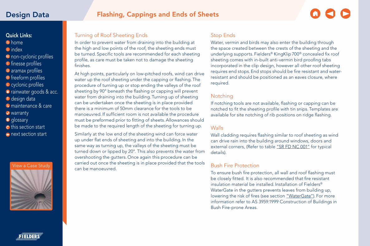
Quick Links: home index non-cyclonic profiles finesse profiles aramax profiles freeform profiles cyclonic profiles rainwater goods & acc. design data maintenance & care warranty glossary
Design Data
Turning of Roof Sheeting EndsIn order to prevent water from draining into the building at the high and low points of the roof, the sheeting ends must be turned. Specific tools are recommended for each sheeting profile, as care must be taken not to damage the sheeting finishes.
At high points, particularly on low-pitched roofs, wind can drive water up the roof sheeting under the capping or flashing. The procedure of turning up or stop ending the valleys of the roof sheeting by 90° beneath the flashing or capping will prevent water from draining into the building. Turning up of sheeting can be undertaken once the sheeting is in place provided there is a minimum of 50mm clearance for the tools to be manoeuvred. If sufficient room is not available the procedure must be preformed prior to fitting of sheets. Allowances should be made to the required length of the sheeting for turning up.
Similarly at the low end of the sheeting wind can force water up under flat ends of sheeting and into the building. In the same way as turning up, the valleys of the sheeting must be turned down or lipped by 20°. This also prevents the water from overshooting the gutters. Once again this procedure can be carried out once the sheeting is in place provided that the tools can be manoeuvred.
Stop EndsWater, vermin and birds may also enter the building through the space created between the crests of the sheeting and the underlying supports. Fielders® KingKlip 700® concealed fix roof sheeting comes with in-built anti-vermin bird proofing tabs incorporated in the clip design, however all other roof sheeting requires end stops. End stops should be fire resistant and water-resistant and should be positioned as an eaves closure, where required.
NotchingIf notching tools are not available, flashing or capping can be notched to fit the sheeting profile with tin snips. Templates are available for site notching of rib positions on ridge flashing.
WallsWall cladding requires flashing similar to roof sheeting as wind can drive rain into the building around windows, doors and external corners, (Refer to table “SR FD NC 001” for typical details).
Bush Fire ProtectionTo ensure bush fire protection, all wall and roof flashing must be closely fitted. It is also recommended that fire resistant insulation material be installed. Installation of Fielders® WaterGate in the gutters prevents leaves from building up, lowering the risk of fires (see section “WaterGate”). For more information refer to AS 3959:1999 Construction of Buildings in Bush Fire-prone Areas.
Flashing, Cappings and Ends of Sheets
View a Case Study
this section start next section start

Quick Links: home index non-cyclonic profiles finesse profiles aramax profiles freeform profiles cyclonic profiles rainwater goods & acc. design data maintenance & care warranty glossary
Expansion and contraction theoretically takes place longitudinally from the centre of the sheet outwards. Therefore, the degree of expansion and contraction is greater at the ends of the sheet, where it is approximately half of the total amount. Lateral expansion is negligible due to the general design of profiles.
The maximum distance between the top and bottom rows for screw fix decks should only be 24m for roofs and 15m for walling. In excess of these rec-ommended maximum lengths, the expansion and contraction elongates screw holes (see “Figure DD TEC 001”), rendering the neoprene washers ineffective and possibly causing the screws to shear. Thus, for pierce fix roofs, step joints are required where lengths exceed 24m (see “Long Length Roofing Solutions”). For lengths of roofs greater than 24m, concealed decks are recommended as they will remove the need for step joints, which can be a cause of leaks in the roof.
Table “DD TEC SS 001” and “DD TEC SS 002” show the degree of expansion and contraction of steel and stainless steel sheeting through various temperature changes.
Design Data Thermal Expansion and Contraction of Steel Sheeting
Insufficient cover of neoprene washer allows water ingress
Screw fix sheet over 24m long
Steel sub-strate exposed to water
ingress
Zinc alloy coating
PurlinExpansion/contraction of sheet against solidly fixed tek-screw
elongates the screw hole
Figure DD TEC 001 - Elongated Screw Hole Note: Diagram not to scale.
Lighter colours expand and contract at a less significant rate than darker colours, so on occasions longer sheet lengths for pierce fix roofs may be possible. Please contact your local Fielders® representative for clarification.
Steel
Sheet Length (m)Temperature Change
10° C 30° C 50° C10 1.20 mm 3.60 mm 6.00 mm
20 2.40 mm 7.20 mm 12.00 mm
30 3.60 mm 10.80 mm 18.00 mm
50 6.00 mm 18.00 mm 30.00 mm
75 9.00 mm 24.00 mm 45.00 mm
100 12.00 mm 36.00 mm 80.00 mm
Stainless Steel
Sheet Length (m)Temperature Change
10° C 30° C 50° C10 1.70 mm 5.10 mm 8.50 mm
20 3.40 mm 10.20 mm 17.00 mm
30 5.10 mm 15.30 mm 25.50 mm
50 8.50 mm 25.50 mm 42.50 mm
75 12.75 mm 38.25 mm 63.75 mm
100 17.00 mm 51.00 mm 85.00 mm
Note: Fielders® HiKlip® 630 and KingKlip 700® allow for expansion and contraction as the decks slide over the clip, enabling sheets of any length to be used.
Table DD TEC SS 001 Table DD TEC SS 002
View a Case Study
this section start next section start

Quick Links: home index non-cyclonic profiles finesse profiles aramax profiles freeform profiles cyclonic profiles rainwater goods & acc. design data maintenance & care warranty glossary
Design Data
For the changes in length due to expansion and contraction for other roofing material, simply use the following formula:
∆L =a Li ∆T
105
where ∆L = change in length due to thermal expansion/contraction (mm)
∆ = linear expansion coefficient for other materials
Li = initial length of the sheeting (mm)
∆T = change in temperature (°C)
Table “DD TEC LEC 001” shows the values of the linear expansion coefficient (a) for various other roofing materials.
Linear Expansion Coefficient (a)
Material aCopper 1.76
Aluminium 2.34
Zinc 2.20
Lead 2.90
Concrete 1.20
Glass 0.09
Steel 1.24
Following are some examples of changes in length due to expansion/contraction for other materials.
Aluminium
Sheet Length (m)Temperature Change
10° C 30° C 50° C5 1.20 mm 3.50 mm 5.90 mm
10 2.30 mm 7.00 mm 11.70 mm
15 3.50 mm 10.50 mm 17.60 mm
Zinc
Sheet Length (m)Temperature Change
10° C 30° C 50° C5 1.10 mm 3.30 mm 5.50 mm
10 2.20 mm 6.60 mm 11.00 mm
15 3.30 mm 9.90 mm 16.50 mm
Copper
Sheet Length (m)Temperature Change
10° C 30° C 50° C5 0.90 mm 2.60 mm 4.40 mm
10 1.80 mm 5.30 mm 8.80 mm
15 2.60 mm 7.90 mm 13.20 mm
Thermal Expansion and Contraction of Steel Sheeting
Table DD TEC LEC 001
Table DD TEC SS 003
Table DD TEC SS 004
Table DD TEC SS 005
View a Case Study
this section start next section start

Quick Links: home index non-cyclonic profiles finesse profiles aramax profiles freeform profiles cyclonic profiles rainwater goods & acc. design data maintenance & care warranty glossary
Design Data Oil Canning
Oil CanningOil canning is a characteristic of thin gauge cold formed metal products defined as ‘moderate deformation or buckling of sheet material, particularly common with flat sheet metal surfaces. Typically caused by uneven stresses at the fastening points. This terminology also refers to the popping sound made when pressure is applied to the deformed sheet forcing the deformation in the opposite direction.’* Internal stresses within the metal can cause a waviness in the surface of the profile. There are many ways that the effects of oil canning can be minimised however due to the inherent nature of metal it can not necessarily be removed completely.
Some of the common causes of oil canning are;
Profile dimensions
The thinner the gauge of metal used and the wider the flat pan section of the profile the more evident oil canning will be. Inclusion of ribs or embossments will assist in reduce oil canning.
Manufacturing
The very nature of the manufacturing process of the profile can lead to oil canning. Any additional stresses put in the metal by way of shaping the metal or by slitting the coil can cause oil canning.
Substructure
Any unevenness in the supporting substructure or any movement in the substructure will increase the effects of oil canning.
Connection detailing
Taking care with the connection details of the profile will assist in the effects of the oil canning. By allowing for expansion and contraction of the material the effects of oil canning will be minimised. This can be done by utilising by slotted holes and thermal breaks. It is important that if you are not familiar with detailing products that are prone to oil canning that you discuss with your local Fielders® representative ways to minimise the effects.
Material finish
The colour and finish of the material chosen will also effect the oil canning in the profile. Profiles of a dark colour make oil canning more obvious to the eye, as well as increasing
this section start next section start

Quick Links: home index non-cyclonic profiles finesse profiles aramax profiles freeform profiles cyclonic profiles rainwater goods & acc. design data maintenance & care warranty glossary
Design Data Oil Canning
the solar absorption of the material the thermal expansion and contraction of the material will also increase. The surface finish, i.e. a gloss or matt finish, will also affect the appearance of the oil canning. The higher the gloss finish the more the obvious the oil canning will be to the eye.
Weather
The weather plays a major role in the appearance of oil canning. The change in temperature on the surface of the profile will impact on the thermal expansion of the profile. Even though there may not a large temperature difference in the ambient temperature there can be significant differences in temperature on the surface of the metal. A profile may be subjected to early morning frost, but by being positioned in full sun the surface temperatures can easily reach over 50°C during the day. There are many factors that can adjust the temperature experienced by the profile from the colour of the profile to location, orientation and shielding.
Light
Light will impact on how noticeable oil canning is. Some days and times of day the oil canning may be more noticeable than others. The orientation that the light is reflecting off the waviness of the oil canning effects the way it is perceived by the eye.
Handling & storage
Due care needs to be taken with all profiles especially those with large flat pans. Any additional stress put on the material will increase the likeness of oil canning appearing in the pans.
Oil canning is generally an aesthetic issue and structural integrity is typically not affected. In the absence of specific contract requirements oil canning should not be the sole grounds for panel rejection.
*Note: Definition of oil canning adopted from SA HB39 2015.
this section start next section start

Quick Links: home index non-cyclonic profiles finesse profiles aramax profiles freeform profiles cyclonic profiles rainwater goods & acc. design data maintenance & care warranty glossary
The caterpillar effect is a theoretical phenomenon that describes the process whereby expansion takes place mono-directionally i.e. the material does not resort to its original position when contraction takes place but rather moves in one direction after each expansion/contraction cycle. Therefore it has the potential to ‘work its way’ off the clip and subsequently off the roof. It is relevant only to concealed fix decks where the roof sheet is held in place by a clip and the expansion and contraction process is managed by the profile sliding over the fixing clip.
Fielders® have installed many long length roofs up to 102m and have never encountered the problem of the caterpillar effect. However if a building designer has concerns the following method can be used:
Fixed-point screws should be installed at the ridge and hip. At pitches of less than 5°, a shallow head screw is installed through the male rib into the clip and covered by the female rib. At pitches over 5°, a hexagonal-headed screw with a bonded washer is installed into the ridge spacer in the centre of each pan. It should be hidden by a ridge flashing where possible.
The end of a sheet must be turned down by 20° at eaves/valleys, using the correct end of the tool supplied, even on a 1° pitch roof this permits good water run-off, prevents run-back under the sheet and laterally stiffens the pan. Turn-down must be carried out to all sheets, irrespective of pitch.
For additional security, the interlocking ribs can be riveted together through the rib head, 5mm from the sheet end at the eaves/valleys position.
Design Data
Figure DD CA RR 001
The Caterpillar Effect
View a Case Study
this section start next section start

Quick Links: home index non-cyclonic profiles finesse profiles aramax profiles freeform profiles cyclonic profiles rainwater goods & acc. design data maintenance & care warranty glossary
Acceptability Of Direct Contact Between Metals
Accessory or fastener material
Zinc coated steel & zinc (Galvanised)
Stainless Steel (300 Series)
Aluminium / zinc alloy
coated steel (ZINCALUME)
LeadCopper
& copper alloys
Aluminium alloys
SL & VS MILD SL &
VS MILD SL & VS MILD SL &
VS MILD SL & VS MILD SL &
VS MILD
Zinc-coated steel & zinc (Galvanised)
ü ü û ü ü ü û ü û û ü ü
Stainless Steel (300 Series) û û ü ü û û û ü û û û û
Aluminium / zinc alloy-coated steel
(ZINCALUME)Þ Þ û ü ü ü û û û û ü ü
Lead û ü ü ü û û ü ü ü ü û û
Copper & copper alloys û û û ü û û û ü ü ü û û
Aluminium alloys Þ Þ Ì ü ü ü û û û û ü ü
Acceptability Of Drainage Between Metals
Lower cladding or rainwater goods
material
Upper cladding or rainwater goods material
Zinc coated steel & zinc (Galvanised)
Stainless Steel (300
Series)
Aluminium / zinc alloy
coated steel (ZINCALUME)
Pre-painted metal Lead
Copper & copper alloys
Aluminium alloys
Zinc-coated steel & zinc (Galvanised)
ü û û û p û û
Stainless Steel (300 Series)
p ü p p ü p p
Aluminium / zinc alloy-coated steel
(ZINCALUME)ü p ü ü û û ü
Lead p p p p ü p p
Copper & copper alloys
p p p p ü ü p
Aluminium alloys ü p ü ü p û ü
Legend
Mild, SI, VS, = mild, severe industrial, and very severe classifications (see AS 2312:2002 & AS 2311:2000).
ü acceptable - as a result of bimetallic contact, either no additional corrosion of rainwater goods will take place, or at the worst, only very slight additional corrosion. It also implies that the degree of corrosion would not significantly shorten the service life.
û not acceptable - moderate to severe corrosion of rainwater goods will occur, a condition which may result in a significant reduction in the service life.
Includes monel metal rivets.
Ì Grade 316 accordance with ASTM A240 is suitable.
Þ Unpainted zinc-coated steel and zinc are suitable for direct contact but should not receive drainage from an inert catchment.
p Whilst drainage between the materials shown would be acceptable, direct contact should be avoided.
Notes:1. Due to its toxicity, lead is not recommended for rainwater
goods.
2. Unless adequate separation can be assured, pre-painted rainwater goods should be considered in terms of the base metal or coated steel.
Design Data Direct Contact Between Metals
Table DD DCM A 001
Table DD DCM AD 001
View a Case Study
this section start next section start

Quick Links: home index non-cyclonic profiles finesse profiles aramax profiles freeform profiles cyclonic profiles rainwater goods & acc. design data maintenance & care warranty glossary
Acoustics and noise transfer in buildings are becoming an important issue in the construction industry. There are several issues that must be understood to fully appreciate the transfer of noise. Noise is an airborne vibration, which has an effect on the eardrum. Noise has two characteristics, its level and its frequency.
There are two types of noise: airborne and impact. Airborne sounds are those that are transferred in the air. These noises include traffic, conversations, and music. Impact sounds are those that are propagated in the walls and floors of a building and include noise such as footsteps and drills. Most noises encountered in a building consist of both airborne and impact sounds.
The two major influences in the transfer of noise are absorption and reflection. There are three main areas in a room that influence the transfer of the noise: ceiling, walls and floor (for a suspended floor).
• The ceiling is the major sound surface in many rooms. As the room size increases so does the importance of the ceiling for sound transference. Ceilings in a commercial application are often constructed from, or covered by, some form of sound absorbing mineral tile. However, ceiling tiles do not provide a uniform surface due to joints between tiles and light fittings whether recessed or suspended. Flat lucite/perspex lenses over fluorescent tubes are the worst fittings for sound reflection. Parabolic, deep cell diffusers are the best for sound absorption.
• Walls – These are usually the next most influential surface. Their importance increases as room size decreases. Typically walls have very poor sound absorbing qualities and this is often made worse by putting sound reflectors against the walls such as filing cabinets.
• Floor – carpeting the floor will only slightly increase the NRC (Noise Reduction Coefficient). Moving to thicker carpeting is often not a cost-effective solution because much of the floor area is covered with furniture with a worse NRC. Carpeting will however reduce impact noise.
Design Data Roofing Acoustics
Decibel Ratings
Sound Pressure Level (dB) Description of Activity Typical Subjective
Description0 Threshold of hearing Absolute silence
20 Whispering at 1 metre Very quiet
40 Quiet residential neighbourhood Quiet
60 Conversation at 1 metre Moderately noisy
80 Shouting Noisy
100 Heavy industry Very Noisy
120 Heavy gun-fire Intolerable
140 Rocket launch at 100 metres away Intolerable
It must be understood that the decibel rating is a logarithmic scale. The mass law equation predicts that each time the frequency of measurement or the mass per unit area of a single layer wall is doubled, the transmission loss increases by about 6dB.
Table DD RA DR 001
View a Case Study
this section start next section start

Quick Links: home index non-cyclonic profiles finesse profiles aramax profiles freeform profiles cyclonic profiles rainwater goods & acc. design data maintenance & care warranty glossary
Effects of Materials
The acoustic behaviour of materials is influenced by several parameters: its mass, reactivity, and vibration absorption. The increased weight per unit area of panel decreases sound transmission. The increased frequency of incident sound decreases sound transmission.
Other factors that affect sound transmission are:
• Panel stiffness – at very low frequencies the stiffness (i.e. resistance to deformation) may have more effect than its weight. In this part of the frequency range insulation is termed stiffness controlled.
• Rigid panels – if a rigid panel is struck it will continue to vibrate at frequencies determined by its size, shape, and thickness – this is its “natural frequency” (natural mode of vibration).
A good rule of thumb is the stiffer the panel, the more sound it will transmit. A profiled steel sheet of a given thickness can produce the same structural strength as a flat panel of substantially greater weight and thickness. That is because a profiled panel will have a higher bending stiffness than a flat one.
Acoustic data is usually quoted in terms of either sound absorption or sound transmission loss. Sound transmission loss is the more relevant value and is expressed as a function of frequency. This is Rw (alternatively know as Sound Transmission Coefficient). It is a constant for any particular material and is measured in decibels.
The density and spacing of fixing elements and their separation from the interior support can also impact on the Rw values of a system. Insulation can play the biggest factor in increasing the Rw values of the system.
Concrete
A single layer of poured concrete 150mm thick gives an Rw of about 55.
Construction Material Rw
Single skin construction using 0.35mm COLORBOND® steel 17Db
Single skin construction using 0.42mm COLORBOND® steel 19Db
Single skin construction using 0.48mm COLORBOND® steel 21Db
Single skin construction using 0.80mm COLORBOND® steel 26Db
Single skin construction using 1.25mm steel 27Db
A twin skinned system with 50mm of insulation 37Db
Design Data Roofing Acoustics
Table DD DCM VM 001Notes: BlueScope Steel data is from testing of panels without sealing between sheets.
Corus data is theoretical only.
View a Case Study
this section start next section start

Quick Links: home index non-cyclonic profiles finesse profiles aramax profiles freeform profiles cyclonic profiles rainwater goods & acc. design data maintenance & care warranty glossary
Design Data Roofing Acoustics
Effects of Systems
If a higher Rw value is necessary, and it often is in high quality construction, it is not economical to continually double the wall or floor thickness to achieve it. Double layer assemblies are a more practical way of getting high Rw values without excessive weight.
A built-up steel cladding system comprises an external profiled sheet, a perforated or non-perforated internal liner sheet and an in-fill between the two sheets, such as mineral fibre.
The transmission loss of such a system can be modified in a number of ways:
• The total mass can be increased by using a denser or thicker layer of in-fill
• Better performance is possible through using dense, soft rolls of mineral fibre in-fills, rather than rigid ones
• Transmission loss is also improved via an air-gap inside the outer face of the cladding as it minimises transmission of reverberations from the external sheets to the insulation
If sound absorption in a room is important, then the internal sheet of the cladding system should be perforated to allow deadening by the insulation. However this can also have a reverse effect on the transmission loss characteristics of a structure.
The ideal double layer assembly has no rigid mechanical connection between its two surfaces. Rigid mechanical connections are the acoustic equivalent of an electrical short circuit or a thermal bridge in an insulated wall and should be avoided.
The mechanical connection between layers of wallboard can be reduced by the use of staggered wooden studs, separate rows of wooden studs, or a single row of wooden studs with resilient metal furring strips to support the wallboard layers independently of each other. Non-load-bearing steel studs are usually resilient enough to provide adequate mechanical de-coupling between the layers. Good results have also been obtained using 150mm load-bearing steel studs in conjunction with resilient channels.
Connection between a floor system and a ceiling should be via acoustic resilient mounts.
Small openings, such as fixing points and penetrations, allow airborne sound to pass through the element. Therefore to increase the insulation properties of the element it is important for that element to be airtight. To seal perimeters and penetrations for services, dense, flexible material such as a mastic should be used. For areas where large movement is expected, a polyurethane fire and acoustic rated sealant should be used.
View a Case Study
this section start next section start

Quick Links: home index non-cyclonic profiles finesse profiles aramax profiles freeform profiles cyclonic profiles rainwater goods & acc. design data maintenance & care warranty glossary
Design Data
Insulation
The use of Permastop or Vapa-Chek under a metal roof provides acoustic benefits to a building in two different ways:
1. Impact. Installing Permastop or Vapa-Chek against the underside of a metal deck roof greatly dampens the impact noise from rain and hail, providing superior sound absorption and sound transmission control at minimal cost
2. Airborne Reverberation. Installing Permastop or Vapa-Chek under the roof and against the walls will also help to control the reverberation from noise created within the building. Table 4.12.C shows the noise reduction performance of standard 75mm Permastop or Vapa-Chek with light duty Sisalation foil. The use of a perforated Sisalation foil will further enhance the acoustic performance. This is not recommended where condensation may be an issue.
Noise Reduction Performance
ProductFrequency (Hz) Noise Reduction
Coefficient125 250 500 1000 2000 4000
75mm Permastop or Vapa-Chek with light duty Sisalation
0.41 0.92 1.18 0.6 0.39 0.24 0.75
Further InformationThe following websites are a good reference for acoustic information:
www.insulation.com.au
www.csr.com.au
www.rondo.com.au
For further information contact your local Fielders® representative.
Roofing Acoustics
Table DD DCM NR 001
View a Case Study
this section start next section start

Quick Links: home index non-cyclonic profiles finesse profiles aramax profiles freeform profiles cyclonic profiles rainwater goods & acc. design data maintenance & care warranty glossary
Design Data Environmental Sustainability
Environmental sustainability is becoming one of the most important issues in construction. This is reflected by the introduction of Greenstar ratings and the upgrade of the BCA to include more environmental requirements. The 2006 BCA is only the start of the environmental requirements with continued upgrades of the BCA expected to make requirements more stringent.
There are many issues to be considered when improving the sustainability of a building such as:
• Choice of construction material
• Minimisation of environmental impact in use, such as design for low-energy
• Flexibility of design to allow for future adaptation with minimal extra cost or disruption
When designing for environmental sustainability it is important to consider all aspects of the design and construction of a building not just the materials used. When comparing materials, the environmental performance of the material should be compared rather than the properties per weight. For example, when comparing the performance of KingFlor® to plywood formwork, the reduction of steel reinforcement in the slab, as well as the overall reduction of materials required should be considered.
Fielders® are continually looking at ways to reduce steel waste and to keep all steel scrap on the factory floor where it is directly transported to recycling rather than going to land fill. This is evident in Fielders® products being rolled to measure, and new products like AngleCut for which S-Rib Corrugated sheets are cut prior to delivery, reducing on site waste.
BCA
Changes to the BCA that came into effect in 2006 include the following environmental requirements that must be addressed in a building design:
• Thermal performance
• Building sealing
• Air-conditioning
• Artificial lighting
• Hot water supply
• Access for maintenance
• Material properties
• Ductwork insulation and sealing
• Lighting and power control devices
Life Span of the Building
The life span of the building is an important aspect to consider when determining the environmental impact of material selection. Steel products require minimal on-going maintenance when used and treated in an appropriate manner at the time of original installation. In most instances, KingFlor® can easily exceed a life span of 50 years before first maintenance is required. Pre-finished steels such as COLORBOND® require minimal on-going maintenance. When maintenance is required there are refurbishment solutions available which will extend the functional lifetime of the building.
View a Case Study
this section start next section start

Quick Links: home index non-cyclonic profiles finesse profiles aramax profiles freeform profiles cyclonic profiles rainwater goods & acc. design data maintenance & care warranty glossary
R-R-R (Refurbish Re-use Recycle)
Steel is a 100% recyclable material and therefore it is an ideal material for environmental sustainability. The inclusion of steel scrap does not compromise the quality of new steel and has become a normal part to the steel production process. Due to steel’s magnetic properties it is the easiest material to recover for recycling, and requires 70% less energy than virgin steel to produce.
Globally, the demand for steel exceeds that which can be derived from scrap alone. This means that, for the time being, virgin steel production is essential for contributing to the developing global infrastructure.
Presently BlueScope roll formed steel contains a minimum of 15% recycled steel.
Thermal Performance
The most important factor to consider when designing an environmentally sustainable building is to reduce the energy required to heat and cool it. A considerable amount of energy used to heat or cool a building is lost due to air leakage. By ensuring that the building is air-tight heating and cooling losses from the building, and therefore energy costs, are reduced.
When designing a building to minimise the heating and cooling requirements the following factors should be considered:
• Adequate insulation within the building envelope
• The glazed area and its orientation
• Shading
• Natural ventilation or passive cooling measures
• The colour of the cladding
BlueScope Steel offers guidance for the solar absorption of its COLORBOND® and ZINCALUME® material range in accordance with both the BCA and New South Wales BAS IX “DD SEC MS 001”. Check www.fielders.steeltalk.com.au for updates to the colour range.
Steel sheeting is inherently an airtight material, however caution needs to be taken when treating the ends to ensure that there is no leakage at the interface with other materials. Appendix E of AS 2627.1:1993 states that metal roofing provides negligible thermal resistance on its own and insulation should be used to increase the thermal performance of the system. Insulation is the single most effective way of improving a building’s energy efficiency. Typically insulation products installed during construction will last for the life of the building with very little or no maintenance.
The easiest and lowest cost method is to include insulation at the construction stage of a project such as Permastop or Vapa-Chek roofing blankets, incorporating bulk insulation with a reflective Sisalation foil. These products provide significant levels of thermal insulation and also help to reduce noise and control condensation. Where higher levels of insulation are required, Insulco Fat Batts can also be installed into the roof and wall cavities during construction.
Additionally, Permastop, Vapa-Chek and Fat Batts all contain approximately 70% recycled glass, helping to conserve our natural resources.
To minimise deck bulge with thicker insulations and to reduce the thermal bridging effect at purlins we recommend the use of Deckmate thermal spacer.
For more information on Fielders® products and environ-mental sustainability contact your local Fielders® representative.
Design Data Environmental Sustainability
View a Case Study
this section start next section start

Quick Links: home index non-cyclonic profiles finesse profiles aramax profiles freeform profiles cyclonic profiles rainwater goods & acc. design data maintenance & care warranty glossary
Design Data Environmental Sustainability
View a Case Study
Colour Classification
Product Complying Colours
BCA Classification Solar Absorptance Basix Classification Swatch CMYK RGB HEX
COLORBOND® Steel Classic Cream L 0.32 L 6 12 32 2 233 220 184 E9DCB8
Surfmist L 0.32 L 2 2 11 12 228 226 213 E4E2D5
Paperbark M 0.42 L 6 13 30 19 202 191 164 CABFA4
Evening Haze M 0.43 L 1 2 22 28 197 194 170 C5C2AA
Shale Grey M 0.43 L 10 4 11 26 189 191 186 BDBFBA
Dune M 0.47 L 30 25 32 8 177 173 163 B1ADA3
Cove M 0.54 M 30 27 41 16 165 159 138 A59F8A
Windspray M 0.58 M 25 15 19 43 136 139 138 888B8A
Pale Eucalypt M 0.60 M 55 35 60 14 124 132 106 7C846A
Gully D 0.63 M 40 38 44 26 133 126 115 857E73
Mangrove D 0.64 M 48 36 54 32 115 117 98 737562
Wallaby D 0.64 M 43 37 39 28 127 124 120 7F7C78
Jasper D 0.68 M 50 50 60 33 108 97 83 6C6153
Basalt D 0.69 M 51 43 40 32 109 108 110 6D6C6E
Manor Red D 0.69 M 32 97 100 51 94 29 14 5E1D0E
Terrain D 0.69 M 30 66 76 51 103 67 46 67432E
Woodland Grey D 0.71 D 45 35 42 67 75 76 70 4B4C46
Monument D 0.73 M 24 18 14 90 50 50 51 323233
Ironstone D 0.74 D 37 20 5 80 62 67 76 3E434C
Cottage Green D 0.75 D 77 22 64 64 48 76 60 304C3C
Deep Ocean D 0.75 D 64 39 15 69 54 65 82 364152
Night Sky D 0.96 D 75 65 40 100 0 0 0 000000
Table DD ES CC 001Notes:1. Colours are indicative only and may vary depending on your screen settings.
this section start next section start
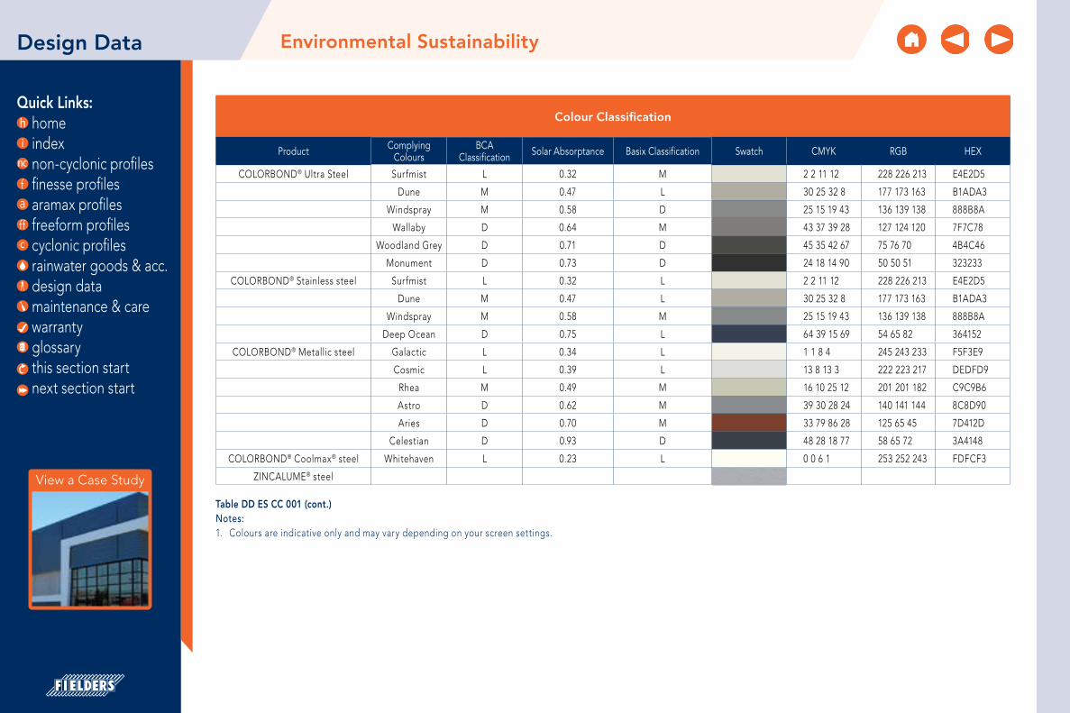
Quick Links: home index non-cyclonic profiles finesse profiles aramax profiles freeform profiles cyclonic profiles rainwater goods & acc. design data maintenance & care warranty glossary
Design Data Environmental Sustainability
Table DD ES CC 001 (cont.)Notes:1. Colours are indicative only and may vary depending on your screen settings.
View a Case Study
Colour Classification
Product Complying Colours
BCA Classification Solar Absorptance Basix Classification Swatch CMYK RGB HEX
COLORBOND® Ultra Steel Surfmist L 0.32 M 2 2 11 12 228 226 213 E4E2D5
Dune M 0.47 L 30 25 32 8 177 173 163 B1ADA3
Windspray M 0.58 D 25 15 19 43 136 139 138 888B8A
Wallaby D 0.64 M 43 37 39 28 127 124 120 7F7C78
Woodland Grey D 0.71 D 45 35 42 67 75 76 70 4B4C46
Monument D 0.73 D 24 18 14 90 50 50 51 323233
COLORBOND® Stainless steel Surfmist L 0.32 L 2 2 11 12 228 226 213 E4E2D5
Dune M 0.47 L 30 25 32 8 177 173 163 B1ADA3
Windspray M 0.58 M 25 15 19 43 136 139 138 888B8A
Deep Ocean D 0.75 L 64 39 15 69 54 65 82 364152
COLORBOND® Metallic steel Galactic L 0.34 L 1 1 8 4 245 243 233 F5F3E9
Cosmic L 0.39 L 13 8 13 3 222 223 217 DEDFD9
Rhea M 0.49 M 16 10 25 12 201 201 182 C9C9B6
Astro D 0.62 M 39 30 28 24 140 141 144 8C8D90
Aries D 0.70 M 33 79 86 28 125 65 45 7D412D
Celestian D 0.93 D 48 28 18 77 58 65 72 3A4148
COLORBOND® Coolmax® steel Whitehaven L 0.23 L 0 0 6 1 253 252 243 FDFCF3
ZINCALUME® steel
this section start next section start

Quick Links: home index non-cyclonic profiles finesse profiles aramax profiles freeform profiles cyclonic profiles rainwater goods & acc. design data maintenance & care warranty glossary
Design Data Reflectivity
When selecting materials the building designer will often have to determine the reflectivity of their product of choice. There are a number of issues with which they have to contend. Firstly, all materials reflect sunlight to a degree, however some colours reflect light more than others. Materials and/or colours with a high degree of reflectivity will give better thermal performance than those with lower reflectivity. Therefore colour choice will affect heating and ventilating costs.
It is difficult to quantify the reflectivity of a material in isolation The following considerations will affect the degree of reflectivity or colour selection:
• When sunlight scatters and reflects colour from adjoining surfaces, the colour of the building in question will be compromised, in that it is tinted by the reflected colour. Therefore the observable colour in practice is not the colour necessarily selected.
• The orientation of a building will determine the amount of light reflected, for example if a roof is viewed from the north, it is unlikely that any glare will be experienced.
• The pitch of the roof and the topography of the ground will affect the angle at which the light will strike a building and hence how it is reflected.
• Seasonal variations such as the height of the sun in the sky will affect the amount of glare, with summer conditions obviously being the worst.
• As pre-painted steel roofs age, they naturally weather and the effect of glare is reduced proportionately.
Giving consideration to the above points, it is necessary to assess each building on its merits rather than applying a ‘rule of thumb’ judgement based on numerical criteria such as a Tristimulus value.
The correlation between thermal absorption and reflectivity whilst not being exactly inversely proportional, generally does follow this pattern. Therefore table “DD ES CC 001” can be of assistance in assessing the relative degree of reflectivity of various colours. In general terms, the colours that have a solar absorption of >0.70 will have a low degree of reflectivity in comparison to the colours having a value of <0.35.
The Building Code of Australia (BCA) and the New South Wales Building and Sustainability Index (BASIX) both have a classification system which groups colours into light, medium and dark to assist designers in determining their colour classification. Table DD ES CC001 classifies the Bluescope Steel COLORBOND® range to the BCA and BASIX systems, as well as the Solar Absorption ratio.
For further information please refer to the following resources:
http://www.steelselect.com
Technical Bulletin TB28.
View a Case Study
this section start next section start

Quick Links: home index non-cyclonic profiles finesse profiles aramax profiles freeform profiles cyclonic profiles rainwater goods & acc. design data maintenance & care warranty glossary
Design Data Material Selection Guide for Severe Environmental Conditions
The environment can impact the performance and durability of steel roofing significantly. Selection of appropriate materials can mitigate any negative effects from a variety of environmental situations.
Environmental factors can be effectively categorised into two sections:
1. Atmospheric Conditions
2. Intensive Farming and Industrial Conditions
Atmospheric ConditionsAustralia has a wide range of climatic conditions ranging from hot, arid, desert regions to the monsoonal areas in the north as well as alpine conditions in the southern interior regions. Australia’s huge coastline also merits special consideration when determining material selection.
In Industrialised zones, the emissions from concentrated burning of fossil fuels and other sources of dangerous airborne pollutants have to be taken into consideration. Local wind and weather patterns play a large part in how these will effect surrounding areas.
Locality, unwashed areas, geographical outlook, prevailing winds and the geographic formations around marine influence are a few of the essential factors that are required to determine the corrosive impact on a building.
The following information is presented as a guide only. BlueScope Steel classifies atmospheric conditions under four major categories: very severe, severe, moderate and benign, as shown in table “DD SEC MS 001”. This table should be used as a guide for selecting BlueScope products in regard to their performance in marine areas.
BlueScope Steel issues a material warranty that varies according to individual circumstances. Fielders® also adds its own five year screw fix warranty or a concealed fix warranty for up to 20 years on top of these material warranties for your peace of mind on properly registered projects (see Appendices A and B for details).
For a more detailed analysis of your project’s material selection requirements, please free to contact your local Fielders® representative. Fielders® offer specialist advice on the most suitable choice from our huge range of materials and profiles to suit all your needs.
View a Case Study
this section start next section start

Quick Links: home index non-cyclonic profiles finesse profiles aramax profiles freeform profiles cyclonic profiles rainwater goods & acc. design data maintenance & care warranty glossary
Material Selection for Severe Environmental Conditions
Exposure Severity Approximate Distance from Marine Influence Recommended Products
Very Severe Marine <100m from breaking surf COLORBOND® Stainless steel
Severe Marine100-200m from breaking
surf or <100m from calm still water (eg. harbour)
COLORBOND® Ultra steel
Marine200-400m from breaking surf or 100-200m from calm still
water (eg. harbour)
COLORBOND® steel COLORBOND® Coolmax® steel
ZINCALUME® steel
Moderate>400m from breaking surf or >200m from calm still water
(eg. harbour)
COLORBOND® steel COLORBOND® Metallic steel
COLORBOND® Coolmax® steel ZINCALUME® steel
Benign>1000m from breaking surf or >1000m from calm still water
(eg. harbour)
COLORBOND® steel COLORBOND® Metallic steel
COLORBOND® Coolmax® steel ZINCALUME® steel
Design Data Material Selection Guide for Severe Environmental Conditions
Table DD SEC MS 001 Notes:1. Absolute performance is subject to local conditions (eg. prevailing winds) and
unwashed areas (to regions of the roof not naturally washed by rain).
2. The above table applies to roofing products only.
3. The above table applies to salt marine influences only. For installations subject to severe, heavy industrial conditions, it is essential to consult a BlueScope Steel sales office for advice on the appropriate product.
View a Case Study
Intensive Farming and Industrial Conditions
Industrial activities and processes constitute a major factor when considering the impact of the environment on a project. Industrial use of chemicals, acids, heat, moisture and combustion affect any area adjacent to the site. Intensive animal farming will also increase the severity of corrosive conditions. Consult Fielders® or BlueScope Steel before undertaking projects subject to these environmental factors.
For optimum performance and durability under these severe conditions, Fielders® recommends profiles that are roll formed from a heavy coating mass, zinc coated with a Z600 coating class, in G300 or G550 steel (depending on profile).
this section start next section start

Quick Links: home index non-cyclonic profiles finesse profiles aramax profiles freeform profiles cyclonic profiles rainwater goods & acc. design data maintenance & care warranty glossary
Design Data Sample Specwriter™ Template
Visit The SpecWriterTM Web Page to write a Fielders® specification on any given product in our range. A Specwriter specification will produce a reference to Fielders® unique Watertight Installation Guarantee for up to 20 years when installed by a Fielders® approved contractor (subject to terms and conditions). Refer to Appendices A and B for further information.
The generated specification can be cut and pasted into your specification template. The following screen shots from the website demonstrate the step-by-step, easy to follow process to write your Fielders® specification using Specwriter.
Step 1
In the Fielders® home page, select Specwriter from the Design Tools drop-down menu. You will then be directed to the Specwriter website.
Fielders® are a branded partner of NatSpec, Australia’s most sourced and trustworthy project specification system for building structures. You can access NatSpec by visiting www.fielders.com.au and clicking on the NatSpec product partner icon. This will then direct you to the NatSpec website. Various examples of Fielders® specifications can be found there. If you are already a NatSpec subscriber you can write a building specification using Fielders® quality steel products with an updated version of NatSpec.
View a Case Study
this section start next section start

Quick Links: home index non-cyclonic profiles finesse profiles aramax profiles freeform profiles cyclonic profiles rainwater goods & acc. design data maintenance & care warranty glossary
Design Data Sample Specwriter™ Template
Step 2
Select the product of interest.
Step 3
Select the product gauge, home state in Australia, material and colour, as shown below. Then, create the specification for the product.
Step 4
After successfully creating a specification, select the “Copy to clipboard” button to copy the specification into your documentation.
Step 5
Specwriter also provides an option for you to submit your specification to Fielders®, which is strongly recommended to ensure availability and other relevant information relating to the product(s). After selecting the “Submit to Supplier” button, as shown in the screen shot in step 4, you will be prompted to fill in relevant details. Your details and specification will then be sent to Fielders® for assessment.
View a Case Study
this section start next section start

Quick Links: home index non-cyclonic profiles finesse profiles aramax profiles freeform profiles cyclonic profiles rainwater goods & acc. design data maintenance & care warranty glossary
Design Data Gutter Capacity Tool Example
The Steel Select Gutter Capacity Tool is an online calculator designed to calculate eaves gutter capacity and determine both the number of downpipes required and downpipe size. Visit the Gutter Capacity Tool Web Page to start using the calculator.
View a Case Study
this section start next section start

Quick Links: home index non-cyclonic profiles finesse profiles aramax profiles freeform profiles cyclonic profiles rainwater goods & acc. design data maintenance & care warranty glossary
Design Data Gutter Capacity Tool Example
Step 1
Get started by selecting the gutter capacity tool.
Step 2 and 3
Select start and then select the gutter slope profile for the project and wind conditions in your region.
View a Case Study
this section start next section start

Quick Links: home index non-cyclonic profiles finesse profiles aramax profiles freeform profiles cyclonic profiles rainwater goods & acc. design data maintenance & care warranty glossary
Design Data Gutter Capacity Tool Example
Step 4
Specify the slope and wind conditions.
Step 5
If the catchment area is known, enter the value and click ‘proceed’. Otherwise the catchment area can be worked out online by specifying the plan area and roof pitch.
View a Case Study
this section start next section start

Quick Links: home index non-cyclonic profiles finesse profiles aramax profiles freeform profiles cyclonic profiles rainwater goods & acc. design data maintenance & care warranty glossary
Design Data Gutter Capacity Tool Example
Step 6
Enter the rainfall intensity if known. If not, select the state and city the project is based in and the rainfall intensity will be shown.
Step 7
Specify the downpipe style.
View a Case Study
this section start next section start

Quick Links: home index non-cyclonic profiles finesse profiles aramax profiles freeform profiles cyclonic profiles rainwater goods & acc. design data maintenance & care warranty glossary
Design Data Gutter Capacity Tool Example
Calculate results
Specifications and frequently asked questions for the gutter chosen are now displayed. Please note that details of the five steps will be displayed in the calculation summary on the right hand side of the screen for easy viewing.
View a Case Study
this section start next section start

Maintenance and Care At the Site Handling and Storage
Care and Storage
Inert Catchment
Fasteners and Accessories
COLORBOND® Steel
Swarf
Corstrip
Lead
Sealants
Upkeep
Touch Up
Painting ZINCALUME® Steel
Handling Steel Roofing And Walling Products On Site
Technical Bulletins
Walking on Roofs
Return to index

Quick Links: home index non-cyclonic profiles finesse profiles aramax profiles freeform profiles cyclonic profiles rainwater goods & acc. design data maintenance & care warranty glossary
Maintenance & Care
At the Site Handling and Storage
To preserve the zinc/aluminium surface, handling should only be carried out using clean, dry gloves. Careless handling or excessive traffic on formed panels must be avoided as it causes unsightly scuffing and marking. Do not slide sheets over rough surfaces or over each other. As with zinc coated steel, packs of ZINCALUME® steel (in all finishes) must be kept dry in transit, stored clear of the ground and kept under cover to prevent water and/or condensation being trapped between adjacent surfaces.
To ensure the maximum protection against unsightly and damaging stains developing (if sheets become wet during storage), ZINCALUME® steel is chemically treated during processing to pacify the surface. If packs do become wet, sheets should be separated, wiped with a clean cloth without delay and placed so that air circulation completes the drying process. These procedures are recommended to avoid possible deterioration of the coating, leading to a reduced life expectancy or poor appearance.
Care and Storage
Care and storage of COLORBOND® steel prior to installation is vital to the life of the product when installed. If not required for immediate use, stack the sheets neatly and clear of the ground and provide cover to protect the sheeting from getting wet. A process called capillary action can cause corrosion which may lead to reduced life expectancy or a wet storage stain. Moisture on sheets or coil wraps of COLORBOND® steel can penetrate between surfaces causing temporary softening of the paint film and possibly even minor colour changes on some paint finishes. After drying, the coating will revert to its original state. Take extreme care with the surface until it has been dried and the coating hardness returns to normal.
View a Case Study
this section start next section start

Quick Links: home index non-cyclonic profiles finesse profiles aramax profiles freeform profiles cyclonic profiles rainwater goods & acc. design data maintenance & care warranty glossary
Inert Catchment
Inert catchment has caused the demise of many a gutter. Roofing which does not change the quality or nature of rainwater as it flows across the roof is referred to as an inert catchment. Such roofing includes COLORBOND® steel, terracotta tiles, sealed concrete tiles, acrylic sheeting, glass, ZINCALUME® or aluminium.
This means that virtually pure water (plus any chlorides or acids dissolved in the rainwater from the atmosphere) flows into the gutter.
While galvanised steel gutters serve well for old fashioned roofs with unglazed tiles or galvanised steel sheeting, they are not serviceable for modern, inert roofing products.
Select COLORBOND® or ZINCALUME® steel for your gutters, as these will provide equal service to that of the roofing material. BlueScope Steel no longer recommends the use of galvanised rainwater products.
Fasteners and Accessories
The selection of the correct fasteners and accessories is crucial in ensuring the entire project enjoys maximum life. Fasteners used to fix roof sheeting must be chosen to last as long as the life of the ZINCALUME®/ COLORBOND® steel. In all cases they should comply with AS 3566:2002.
COLORBOND® Steel
Rainwater goods and roof flashings should always be made from a material which is at least as durable as the roof sheeting. For example, a galvanised gutters with a COLORBOND® roof. See Section “Direct Contact Between Metals” for more
information. Ask for ZINCALUME® or COLORBOND® steel by name.
COLORBOND® Ultra is ideal for severe marine and industrial environments. Both sides are treated with a high build corrosion resistant primer.
COLORBOND® is intended for a wide range of applications, and provides superb performance in moderate urban and rural environments.
There are certain adverse conditions in which ZINCALUME® and COLORBOND® steel are not suitable. They should not be used as walling buried in or touching soil or concrete, or as cladding for intensive animal shelters, concrete formwork or culverts.
Following this advice will give an installation which will avoid an early failure of one or more components.
Swarf
Don’t forget to clean up each day. Swarf particles and other metal scraps, such as pop rivet stems and fasteners, if left on a ZINCALUME®/COLORBOND® steel surface, will cause rust stains which will detract from the finished appearance. Swarf should be swept or hosed from the job at the end of each day. Caution is needed when attempting to detach swarf which has become stuck. No action which is likely to remove the paint or metal coatings should be attempted. For critical applications, inspection of the job should be made after two weeks when rain or condensation will have caused any remaining swarf to rust, and will highlight affected areas.
Maintenance & Care
View a Case Study
this section start next section start

Quick Links: home index non-cyclonic profiles finesse profiles aramax profiles freeform profiles cyclonic profiles rainwater goods & acc. design data maintenance & care warranty glossary
Maintenance & Care
Corstrip
Many COLORBOND® steel products are supplied with a specially designed polyethylene strippable film. This film protects the sheet during storage and handling and should be stripped off immediately on installation. Sunlight can increase the adhesion so it is vital that sheets are not left uncovered while outside. Corstrip on coil should be removed within 12 months.
Lead
Lead flashings should not be used with ZINCALUME® steel. Soft zinc or aluminium should be used instead. See Section “Direct Contact Between Metals” for more information.
Sealants
Neutral cure silicone rubber sealants are the only sealants recommended for use with COLORBOND® or ZINCALUME® steel. The advantages of neutral cure sealants are:
• They provide good adhesion and do not require a primer except in extreme service conditions
• They resist extremes of both heat and cold while retaining good flexibility
• They provide high resistance to the damaging effects of ultra-violet rays
• They do not have acidic additives which may adversely affect steel. This gives long life compatible with ZINCALUME® and COLORBOND® steel
Sealants should be applied to avoid exposure to UV rays (i.e. sandwiched in the lap), so they don’t create water run-off and dirt tracks down a roof or facade.
Upkeep
To get the best possible performance from a ZINCALUME® or COLORBOND® steel product it is vital you treat it with care.
Areas not normally washed by rain need regular cleaning with water. These areas include the underside of carports and verandahs, soffits, wall cladding under eaves and the underside of eaves gutters. Washing should be done with clean water at least every six months or more frequently in coastal environments and areas with high levels of industrial fallout.
View a Case Study
this section start next section start

Quick Links: home index non-cyclonic profiles finesse profiles aramax profiles freeform profiles cyclonic profiles rainwater goods & acc. design data maintenance & care warranty glossary
Maintenance must be frequent enough to ensure that accumulation of pollutants, salts, dust and other materials is minimised.
It is essential that special care is taken in cleaning bends, joints and formed parts of all products in unwashed areas. Night-time condensation combined with dust, salts and pollutants can accelerate corrosion.
In cases where salts and dirts are not removed with regular washing down, a mild solution of detergent should be applied with a soft bristle brush, and then washed down with clean water. At no stage should solvent cleaners or hard bristle scrubbing brushes be used.
In general ZINCALUME® and COLORBOND® products from Fielders® are not recommended to be used over or in close proximity to spa or swimming pool areas.
By undertaking preventative maintenance, the life span and performance of your Fielders® product will be significantly increased. For further information on correct maintenance techniques contact your local Fielders® representative.
Touch Up
Have you ever noticed how an otherwise professional job can be ruined by clumsy attempts to touch up minor damages such as scratches?
The use of spray cans result in not only coverage of the scratch but also of a considerable area surrounding it. The problem is not immediately obvious but the overspray paint weathers at a different rate to the oven dried paint on COLORBOND® steel and, eventually, you will be left with an unsightly blemish on the sheet. Our recommendation is not to touch up. Minor scratching will not affect the life of the sheet and is rarely obvious to a casual observer. Should damage be substantial the sheet should be replaced. Where touch up is required for pop rivets or fastener heads, touch up lacquer is available in 250ml tins and carries clear instructions for application.
Painting ZINCALUME® Steel
The smooth finish of ZINCALUME® steel provides excellent adhesive qualities for painting. It can be readily painted with a water-based acrylic top-coat (without priming) for a high quality finish.
Any specific details on paints or paint systems should be discussed with your paint supplier.
Maintenance & Care
View a Case Study
this section start next section start

Quick Links: home index non-cyclonic profiles finesse profiles aramax profiles freeform profiles cyclonic profiles rainwater goods & acc. design data maintenance & care warranty glossary
Maintenance & Care
Handling Steel Roofing And Walling Products On Site
Appropriate safety precautions must always be taken when handling steel roofing and walling products on site.
Given the outdoor nature of roofing and walling erection it is recommended that suitable precautions be taken to prevent personal sun damage. It has been found that sunscreens containing semi-conducting metal oxides such as titanium dioxide (TiO2) and zinc oxide (ZnO) can accelerate the degradation of organic materials, including paint systems.
For personal safety, and to protect the surface of COLORBOND® steel prepainted steel, it is recommended to:
• Wear clean, dry, cut-resistant gloves that are suitable for the task.
• Take suitable protection against personal sun damage, and
• Prevent contact of the painted surface with titanium dioxide (TiO2) and zinc oxide (ZnO) containing sunscreens.
Refer Bluescope Steel Technical Bulletin TB-13 Rev 7 2013, section 4.
View a Case Study
this section start next section start

Quick Links: home index non-cyclonic profiles finesse profiles aramax profiles freeform profiles cyclonic profiles rainwater goods & acc. design data maintenance & care warranty glossary
Maintenance & Care
Technical Bulletins
COLORBOND® Coolmax® steel - “Thermal Performance Study”
COLORBOND® Coolmax® steel brochure overview
COLORBOND® steel Commercial Colour Chart
COLORBOND® steel for Fencing Colour Chart
COLORBOND® steel Residential Colour Chart
Corrosion Technical Bulletin CTB 1 - General Introduction
Corrosion Technical Bulletin CTB 2 - Galvanic Protection
Corrosion Technical Bulletin CTB 3 - Zinc Coatings on Steel
Corrosion Technical Bulletin CTB 4 - Coating Thickness
Corrosion Technical Bulletin CTB 5 - Corrosion Resistance of Zinc in Water
Corrosion Technical Bulletin CTB 6 - Aluminium Zinc coating on Steel
View a Case Study
this section start next section start

Quick Links: home index non-cyclonic profiles finesse profiles aramax profiles freeform profiles cyclonic profiles rainwater goods & acc. design data maintenance & care warranty glossary
Maintenance & Care
Technical Bulletins
Corrosion Technical Bulletin CTB 7 - Barrier Coatings
Corrosion Technical Bulletin CTB 8 - Building Applications
Corrosion Technical Bulletin CTB 9 - Contact with Unprotected Steel Supports
Corrosion Technical Bulletin CTB 10 - Roof Penetrations
Corrosion Technical Bulletin CTB 11 - Condensation and Insulation
Corrosion Technical Bulletin CTB 12 - Dissimilar Metals
Corrosion Technical Bulletin CTB 13 - Contact with Timber
Corrosion Technical Bulletin CTB 14 - Exhaust from Wood and Oil Fired Burners
Corrosion Technical Bulletin CTB 15 - Acid Cleaning Brickwork
Corrosion Technical Bulletin CTB 16 - Immersion
Corrosion Technical Bulletin CTB 17 - Following Trades
Corrosion Technical Bulletin CTB 18 - Painting Lead Flashing
View a Case Study
this section start next section start

Quick Links: home index non-cyclonic profiles finesse profiles aramax profiles freeform profiles cyclonic profiles rainwater goods & acc. design data maintenance & care warranty glossary
Maintenance & Care
Technical Bulletins
Corrosion Technical Bulletin CTB 19 - Roof Profile Closures
Corrosion Technical Bulletin CTB 20 - Perforated Coated Steel
Corrosion Technical Bulletin CTB 21 - Special Service Environments: Enclosed Swimming Pool Buildings
Corrosion Technical Bulletin CTB 22 - Special Service Environments: Intensive Animal Farming
Corrosion Technical Bulletin CTB 23 - Concrete Decking
Corrosion Technical Bulletin CTB 24 - Fertiliser Manufacturing and Storage Buildings
Corrosion Technical Bulletin CTB 25 - Rainwater Catchment
Get the facts
NATSPEC BlueScope Steel branded worksheets
New South Wales Building and Sustainability Index (BASIX)
Steel Inspired - Issue 18
Steel Inspired - Issue 19
Steel Inspired - Issue 20
View a Case Study
this section start next section start

Quick Links: home index non-cyclonic profiles finesse profiles aramax profiles freeform profiles cyclonic profiles rainwater goods & acc. design data maintenance & care warranty glossary
Maintenance & Care
Technical Bulletins
Steel Inspired - Issue 21
Sustainability Technical Bulletin - Urban Heat Islands
Sustainability Technical Bulletin STB1 - Zero-Carbon and Carbon Neutral Developments
Sustainability Technical Bulletin STB2 - Urban Heat Islands
Sustainability Technical Bulletin STB3 - Voluntary Green Building Ratings Tools in Australia
Sustainability Technical Bulletin STB4 - Recycling
Sustainability Technical Bulletin STB5 - Mandatory Sustainability Requirements for Residential Buildings in Australia
Sustainability Technical Bulletin STB7 - Sustainable Building Solutions: Thermal Mass
Sustainability Technical Bulletin STB8 - Steel in Sustainable Buildings
Sustainability Technical Bulletin STB9 - Extreme Weather Events
Technical Bulletin TB 1a - Steel Roofing Products - Selection Guide
Technical Bulletin TB 1b - Steel Walling Products - Selection Guide
View a Case Study
this section start next section start

Quick Links: home index non-cyclonic profiles finesse profiles aramax profiles freeform profiles cyclonic profiles rainwater goods & acc. design data maintenance & care warranty glossary
Maintenance & Care
Technical Bulletins
Technical Bulletin TB 2 - Overpainting and Restoration of COLORBOND® prepainted steel sheet
Technical Bulletin TB 3 - AQUAPLATE® steel for Water Tanks
Technical Bulletin TB 4 - Maintenance of COLORBOND® steel and ZINCALUME® steel
Technical Bulletin TB 5 - Swarf Staining of Steel Roofing and Walling Profiles
Technical Bulletin TB 6 - Curving of Corrugated Steel Sheeting
Technical Bulletin TB 7 - Care and Storage of Exterior BlueScope Steel Products Prior to Installation
Technical Bulletin TB 8 - Flashing Materials for ZINCALUME® steel and COLORBOND® steel sheet
Technical Bulletin TB 9 - Sealants for Exterior Finishes
Technical Bulletin TB 10 - Cut Edge Protection of zinc-coated and zinc-aluminium alloy-coated steel
Technical Bulletin TB 13 - General Guide to Good Practices in the use of Steel Roofing and Walling Products
Technical Bulletin TB 14 - Builders Guide to Australian Steel Sheet and Strip Standards
Technical Bulletin TB 15 - Recommended Steel Gutter Systems
View a Case Study
this section start next section start

Quick Links: home index non-cyclonic profiles finesse profiles aramax profiles freeform profiles cyclonic profiles rainwater goods & acc. design data maintenance & care warranty glossary
Maintenance & Care
Technical Bulletins
Technical Bulletin TB 16 - Fasteners for Roofing and Walling Products - Selection Guide
Technical Bulletin TB 17 - Selection Guide for Galvanized Steel Purlin Products
Technical Bulletin TB 18 - Guide to Good Practice - Processing and Application of ZINCALUME® steel
Technical Bulletin TB 19 - COLORBOND® Metallic prepainted steel
Technical Bulletin TB 21 - Resistance Spot Welding of BlueScope Steel Metallic-Coated Steel Sheet
Technical Bulletin TB 22 - COLORBOND® prepainted steel - Colour Selection
Technical Bulletin TB 23 - Possible Problems Relating to the Mixing of Different Prepainted Products
Technical Bulletin TB 24 - COLORBOND® prepainted steel and Graffiti
Technical Bulletin TB 26 - Weathering Resistant Steels
Technical Bulletin TB 27 - Identification of Fungus in the field and Recommendations for its Removal
Technical Bulletin TB 28 - Building Materials and Reflectivity
Technical Bulletin TB 29 - DECKFORM® Zinc-coated Structural Steel
Technical Bulletin TB 30 - Sheds and Garages
View a Case Study
this section start next section start

Quick Links: home index non-cyclonic profiles finesse profiles aramax profiles freeform profiles cyclonic profiles rainwater goods & acc. design data maintenance & care warranty glossary
Maintenance & Care
Technical Bulletins
Technical Bulletin TB 31 - COLORBOND® Insulated Panel Prepainted Steel for Coolroom Panels
Technical Bulletin TB 32 - Impact of Hail Damage To COLORBOND® steel
Technical Bulletin TB 33 - Guidelines for ZINCALUME® steel and Zinc Coated Steels in High Temperature Applications and Food Contact
Technical Bulletin TB 34 - Steel House Frames
Technical Bulletin TB 35 - Australian Salt Marine Classifications
Thermatech® Commercial & Industrial Facts Sheet
Thermatech® Homeowners Facts Sheet
Thermatech® Residential Buildings Facts Sheet
View a Case Study
this section start next section start

Quick Links: home index non-cyclonic profiles finesse profiles aramax profiles freeform profiles cyclonic profiles rainwater goods & acc. design data maintenance & care warranty glossary
Maintenance & Care
Walking on RoofsWhen walking on a roof, particular attention should be paid to the following:
1. Always wear soft soled shoes but avoid the ribbed types that pick up and hold small stones and metal waste
2. On metal decking, walk in the trays or on at least two ribs, as close as possible to the roofing support. Distribute body weight evenly over the soles of the feet, trying not to concentrate weight on heel or toe
3. On pitched roofs over 25°, protection against falling should be provided by way of safety mesh, harness or perimeter protection
4. The surfaces of zinc or aluminium coated steel and aluminium are prone to ‘scuffing’ if footwear or heavy equipment is dragged across their surface. As this affects the appearance, and possibly the performance, preventive measures should be taken
As sheets freshly taken from packs may have an oily surface, care should be taken when walking over newly laid sheets before the oil has evaporated.
Wide spaced trapezoidal roof profile
Figure MC WR 001
View a Case Study
this section start next section start

Quick Links: home index non-cyclonic profiles finesse profiles aramax profiles freeform profiles cyclonic profiles rainwater goods & acc. design data maintenance & care warranty glossary
Maintenance & Care
Option 2 - Fielders® Expa-Tread™
No Drilling Means No Leaks
In a “world first” application, Fielders® Expa-Tread utilizes leading edge industrial adhesive technology that delivers secure, rigid fixing with no drilling at all. The fixing method also allows for expansion and contraction through a wide temperature range without flexing or fitment damage. Fielders® Expa-Tread is the only walkway system that upholds Fielders® Watertight 20 year no-leaks Guarantee for concealed fix roofing.*
Less Weight, No Corrosion
Fielders® Expa-Tread components are manufactured from aluminium; strong, much lighter than steel, and no corrosion problems.
Stable Footing in the Wet
Fielders® Expa-Tread grate texture means sure foot grip even when the surface is wet. Safer walking in all conditions speeds maintenance work and cuts out WorkCover claims.
Components that Comply
Fielders® Expa-Tread uses proprietary components that are fully compliant with AS1657, so meeting relevant standards is a given.
Fielders® Expa-Tread is available in kit form, comprising six metre lengths and nonslip walkway grating panels 600mm wide. Recommended spacing for supports is 700mm. Fitting is fast, simple and flexible to your requirements across large or small applications. A full specification and fitting information pack is supplied with every order.
View a Case Study
this section start next section start

Quick Links: home index non-cyclonic profiles finesse profiles aramax profiles freeform profiles cyclonic profiles rainwater goods & acc. design data maintenance & care warranty glossary
Maintenance & Care
Expa-Tread™ Installation Procedure
View a Case Study
this section start next section start

Appendices A: Concealed Fix Steel Roofing Guarantee
B: Screw Fix Steel Roofing Guarantee
C: Warranty/Guarantee Comparisons
D: Warranty Sample
E: Standards
Return to index

Quick Links: home index non-cyclonic profiles finesse profiles aramax profiles freeform profiles cyclonic profiles rainwater goods & acc. design data maintenance & care warranty glossary
Appendices Concealed Fix Steel Roofing Guarantee
View a Case Study
Appendix AThe Fielders® Concealed-Fixed Watertight Installation Guarantee (up to 20 years) is available for eligible projects using the Fielders® concealed-fixed roof cladding, namely KingKlip
700® and HiKlip® 630.
The following example shows the specification requirements for eligibility for the Watertight Installation Guarantee for a project using KingKlip 700® in a non-cyclonic roofing application.
Specifications for Fielders® Concealed Fix Steel Roofing Guarantee(Example Specification Using KingKlip 700® Profiled Sheeting and Accessories in Non-Cyclonic Roofing Applications)
1. Fielders® KingKlip 700® Concealed-Fixed GuaranteeA written guarantee against leakage due solely to poor workmanship by Fielders® Approved Contractors or Product defects or failure, of up to twenty (20) years duration, will be issued after final inspection of the installed roof by Fielders® Steel Roofing. The precise duration of the guarantee will be determined by Fielders® in its sole and absolute discretion, after consideration of all relevant factors relevant to Product use (including but not limited to installation location), and specified in the Fielders® Watertight Installation Guarantee Inspection report.
Application for this guarantee must be made prior to commencement of the project involving installation of the Product, and all criteria and specifications set out below must be met. For the avoidance of doubt, Fielders® will not provide any guarantee unless an application is made, and this guarantee
covers only the workmanship and watertightness associated with Product installation and use. Fielders® responsibility in the event of any leakage or other defect is limited to the re-supply of the Product, including erection.
Any guarantee provided by Fielders® shall be in addition to and shall not extend the period retention monies (if any) that are held by the owner and/or builder pursuant to the terms of the Construction Contract, or any other agreement between those parties.
If a customer makes a claim pursuant to this guarantee and the claim was not caused by poor workmanship of the Fielders® Approved Contractor or faulty Products of Fielders®, then the customer will pay on demand any reasonable costs incurred by Fielders® or its Approved Contractor in undertaking or investigation of the claim and any repairs undertaken by Fielders® or its Approved Contractor (in their sole and absolute discretion).
A separate guarantee for the raw material roll-formed to profile by Fielders® to form the Product may be obtained by application to the manufacturer, BlueScope Steel at bluescopesteel.com.au/warranties. In the event that the manufacturer of the raw material is not BlueScope Steel, application shall be made direct to Fielders® Steel Roofing, acting on behalf of the relevant manufacturer. Such applications must be made prior to commencement of the relevant project.
this section start next section start

Quick Links: home index non-cyclonic profiles finesse profiles aramax profiles freeform profiles cyclonic profiles rainwater goods & acc. design data maintenance & care warranty glossary
Appendices Concealed Fix Steel Roofing Guarantee
View a Case Study
2. SheetingThe roof sheeting shall be concealed-fix “KingKlip 700®” profile rollformed in continuous lengths by Fielders® Steel Roofing. The profile shall be rollformed with four ribs at centres not exceeding 233 mm and a cover width not exceeding 700 mm. The sheets will include a male and female rib with capillary action breaks. The minimum sheet depth will be 42 mm. Each trough incorporates two stiffener ribs.
3. Fixing KingKlip 700®
The KingKlip 700® sheets shall be fixed to every purlin by means of KingKlip 700® “Mk II” clips having spurs which will securely hold the sheets in position and will lock-in both the side lap and centre ribs. The clips shall be fixed to the purlin with three self-drilling screws with a hexagonal or wafer head.
Support Material Without Insulation
STEEL (1.5 mm thick)10 x 16 mm
Hex head self-drilling screws for metal
TIMBER - HARDWOOD12 x 25 mm
Hex head Type 17 self-drilling screws
TIMBER - SOFTWOOD12 x 45 mm
Hex head Type 17 self-drilling screws
Recommended Fasteners for Non-Cyclonic Roofing ApplicationsNote: The recommended fasteners in Table 1 is for construction without insulation
4. Flashingsa) Must be of compatible materials approved by Fielders® and
fixed with approved screws and sealants.
Compatible Materials: ZINCALUME® with ZINCALUME®
ZINCALUME® with COLORBOND®
COLORBOND® with COLORBOND®
Approved Sealants: Neutral Cure Silicone
b) Prior to flashings being fixed, all troughs at the apex shall be stop ended to the full depth of the sheet to prevent any penetration of wind driven water.
c) The troughs of each sheet shall be lipped down at the eaves end to prevent capillary action.
d) To prevent wind driven water either notch flashing flanges to the sheet profile or use serrated closures.
e) All flashings are to be manufactured to the longest length capable of being handled on site to reduce the number of joints. Sliding brackets to cater for expansion and f10 brackets may be used at necessary intervals (Fielders® manufacture lengths up to 10000mm).
f) Care shall be taken to ensure that no sheeting or flashing will be cut with an ABRASIVE DISC ON THE ROOF surface in order to prevent burning steel spatter from penetrating colour coated areas or damaging the Galvanised or ZINCALUME® surface. Abrasive discs also burn coating from the cut edges, voiding corrosion warranties. Use of abrasive discs automatically voids this guarantee.
Figure 1 KingKlip 700® “Mk II” Clips
this section start next section start

Quick Links: home index non-cyclonic profiles finesse profiles aramax profiles freeform profiles cyclonic profiles rainwater goods & acc. design data maintenance & care warranty glossary
Appendices Concealed Fix Steel Roofing Guarantee
View a Case Study
g) Where a protective plastic, Corstrip® is applied to pre-painted flashings and cappings it must be removed just prior to installation and must not be left in direct sunlight for long periods of time as this will cause the Corstrip® to adhere more strongly to the product and it will, therefore, become very difficult to remove.
5. Inspection Prior To Installation or ErectionBefore commencing installation, the Fielders® Approved Contractor shall verify that the following items have been checked and accepted:
a) The entire structure (or the portion thereof to be sheeted with the Product) has been correctly aligned, levelled and accepted.
b) Purlins and sheeting rails are at the correct spacing and are within the specified tolerances.
c) The roof pitch is correct, minimum roof pitch 1º for steel purlins and 2º for timber purlins.
d) The corners of the roof are constructed square and that the wall framework is perpendicular or as otherwise specified.
e) No protrusions such as bolt heads, splice plates, cleats, etc. appear on the face of any supporting framework.
f) All members to which sheeting is to be fixed in aesthetically sensitive areas are constructed true and square.
g) Paint types and any other materials that may be incompatible with the sheeting have been properly painted over with compatible material or so dealt with that their direct contact with the sheeting is avoided.
h) The contact faces of the purlins or girts and the claddings are all in the same plane. Should the alignment not be true the Fielders® Approved Contractor shall, through
appropriate channels, request a remedial instruction from the engineer before proceeding with the fixing of any cladding.
6. ErectionAll necessary precautions shall be taken in order to prevent any damage to roof sheets and flashings, and the Product components generally, during all stages of the construction and installation process. Duckboards shall be used whenever necessary to protect the sheeting from damage. Roof sheets or flashings which have in any way become damaged or deformed shall be replaced at the Fielders® Approved Contractor’s expense.
7. SafetyThe Fielders® Approved Contractor shall provide sufficient manpower and exercise special care during the handling of long lengths of sheeting, particularly during windy conditions. If work is interrupted, for any reason whatsoever, loose sheeting and incomplete sections must all be adequately secured against any possible movement due to gravity or wind forces.
8. Handling and StorageThe Fielders® Approved Contractor shall ensure that all materials used on site for cladding, etc. are transported, handled and stored in accordance with the manufacturer’s recommendations, and all damaged material shall be rejected and replaced with undamaged material at the Fielders® Approved Contractor’s expense. Repair of damaged material will not generally be permitted. Fielders® Approved Contractor’s rates are to include for the protection of sheets and flashings and the prevention of damage during all stages of construction.
this section start next section start

Quick Links: home index non-cyclonic profiles finesse profiles aramax profiles freeform profiles cyclonic profiles rainwater goods & acc. design data maintenance & care warranty glossary
Appendices Concealed Fix Steel Roofing Guarantee
View a Case Study
9. Cleaning of Roof, etcAny debris, which may arise from the operation of fixing the sheeting, shall be removed from the surface of the roof as the fixing progresses. All off-cut/surplus pieces of sheeting, flashings, fasteners, sealants, pins from blind rivets, food packaging, cartons, bottles, cans, etc. shall not be left on the roof or in the gutters.
10. Protrusions Through Sheeted SurfacesAll protrusions such as pipes, ducts and similar items, shall be properly flashed where they pass through the surface of the sheeting. Where ribs have had to be cut away to permit penetration of such items, additional framing must be installed, as necessary, to support the sheeting. Depending on the position of any penetrations through the roof, special attention shall be given to back flashing the sheeting to the ridge or other point of potential water ingress. In all cases, all cutting and flashings shall be arranged that provision is made for the adequate drainage of all troughs and corrugations.
Fielders® guarantee does not include any penetrations to Products made by other trades for other services either during or after construction, unless approved by Fielders® in writing.
Perforations which are partly or wholly due to the following causes will not be covered by this guarantee:
a) Mechanical, chemical or other damage sustained during handling, storage, erection or subsequent to erection.
b) Attack from chemical agents, fumes, liquids or solids, other than direct rain falling onto the product under warranty (excluding activities carried out within the building as specified to Fielders® at the time when the application for this guarantee was made, or the Fielders® Watertight Installation Guarantee Inspection report issued).
c) Contact with soils, ashes, fertilizers or other moisture retaining substances.
d) Areas in metallic contact with lead or copper or subject to the run off from copper flashings and pipes.
e) Failure to remove debris and/or failure to provide free drainage of water including internal condensation from all surfaces of the product.
f) Deterioration of the sheet caused by contact with green or wet timber or treated pine.
g) Installations subject to unusually corrosive environments at any time in the future.
h) Storm and tempest or other acts of God.
this section start next section start

Quick Links: home index non-cyclonic profiles finesse profiles aramax profiles freeform profiles cyclonic profiles rainwater goods & acc. design data maintenance & care warranty glossary
Appendices Screw Fix Steel Roofing Guarantee
View a Case Study
Appendix BThe Fielders® Screw-Fixed Watertight Installation Guarantee (up to 5 years) is available for eligible projects using the Fielders®
screw-fixed roof cladding.
The following example shows the specification requirements for eligibility for the Watertight Installation Guarantee for a project using Fielders’ screw-fixed cladding in a non-cyclonic roofing application.
Specifications for Fielders® Screw Fix Steel Roofing Guarantee(Example Specification Using Screw-Fixed Cladding and Accessories in Non-Cyclonic Roofing Applications)
1. Fielders® Screw Fix Guarantee
A written guarantee against leakage due solely to poor work-manship by Fielders® Approved Contractors or Product defects or failure, of up to five (5) years duration, will be issued after final inspection of the installed roof by Fielders® Steel Roofing. The precise duration of the guarantee will be determined by Fielders® in its sole and absolute discretion, after consideration of all relevant factors relevant to Product use (including but not limited to installation location), and specified in the Fielders® Watertight Installation Guarantee Inspection report.
Application for this guarantee must be made prior to the commencement of the project involving installation of the Product, and all criteria and specifications set out below must be met. For the avoidance of doubt, Fielders® will not provide any guarantee unless an application is made, and this guarantee covers only the workmanship and watertightness associated with Product installation and use. Fielders’® responsibility in the event of any leakage or other defect is limited to the re-supply of the Product, including erection.
Any guarantee provided by Fielders® shall be in addition to and shall not extend the period retention monies (if any) are held by the owner and/or builder pursuant to the terms of the Construction Contract, or any other agreement between those parties.
If a customer makes a claim pursuant to this guarantee and the claim was not caused by poor workmanship of the Fielders® Approved Contractor or faulty Products of Fielders, then the customer will pay on demand any reasonable costs incurred by Fielders® or its Approved Contractor in undertaking or investigation of the claim and any repairs undertaken by Fielders® or its Approved Contractor (in their sole and absolute discretion).
A separate guarantee for the raw material roll-formed to profile by Fielders® Steel Roofing to form the Product may be obtained by application to the manufacturer, Bluescope Steel at www.bluescopesteel.com.au/warranties. In the event that the manufacturer of the raw material is not Bluescope Steel, application shall be made direct to Fielders® Steel Roofing, acting on behalf of the relevant manufacturer. Such applications must be made prior to commencement of the relevant project.
2. Products Covered by the Guarantee(a) Fielders® S-Rib Corrugated
(b) Fielders® Spanform
(c) Fielders® TL-5
Fielders® will only guarantee roof areas covered with the above Products.
this section start next section start

Quick Links: home index non-cyclonic profiles finesse profiles aramax profiles freeform profiles cyclonic profiles rainwater goods & acc. design data maintenance & care warranty glossary
The Products will be manufactured either from first grade Galvanised, ZINCALUME® or COLORBOND®, in the gauge and finish specified for the project or materials otherwise specified and approved e.g. stainless steel.
3. Fixings(a) Screws
Buildex® self drilling AS3566 Class 3 Climaseal with Neoprene washers fitted or other as specified or recommended for specific projects.
Pre-painted screws are recommended to be used on coloured roofing products to maximise aesthetics.
Recommended Fixings
Cladding Profile Support Material Roofing(Crest-Fixed)
Walling(Pan-Fixed)
S-Rib CorrugatedSteel 12 x 35 mm 10 x 16 mm
Timber 12 x 50 mm 12 x 25 mm
SpanformSteel 12 x 45 mm 10 x 16 mm
Timber 12 x 65 mm 12 x 25 mm
TL-5Steel 12 x 45 mm 10 x 16 mm
Timber 12 x 65 mm 12 x 25 mm
(c) Fixing Methods
Sheets of all profiles shall be fixed to roofing and walling areas at spacings and frequency as shown in the Corrugated, TL-5 and Spanform® product information sheets. Side lap fasteners are to be placed at recommended spacings, where applicable.
4. Flashings(a) Must be of compatible materials approved by Fielders® and fixed with approved screws and sealants.
Compatible Materials ZINCALUME® with ZINCALUME®
ZINCALUME® with COLORBOND®
COLORBOND® with COLORBOND®
Galvanised with Galvanised
Approved Sealants Neutral Cure Silicone
(b) Screws must be fixed with an appropriate pre-tensioned drill (tek-gun) set at the correct depth which allows the neoprene washer to seal correctly.
(c) Prior to flashings being fixed, all troughs at the apex shall be stop ended to the full depth of the sheet to prevent any penetration of wind driven water.
(d) The troughs of each sheet shall be lipped down at the eaves end and sufficiently flashed to prevent wind driven water penetration.
(e) All flashings are to be manufactured to the longest length capable of being handled on site to reduce the number of joints (Fielders® manufacture lengths up to 10000mm in length).
(f) Care shall be taken to ensure that no sheeting or flashing will be cut with an ABRASIVE DISC ON THE ROOF surface in order to prevent burning steel spatter from penetrating colour coated areas or damaging the Galvanised or ZINCALUME® surface. Abrasive discs also burn coating from the cut edges, voiding corrosion warranties. Use of abrasive discs automatically voids this guarantee.
Appendices Screw Fix Steel Roofing Guarantee
View a Case Study
this section start next section start

Quick Links: home index non-cyclonic profiles finesse profiles aramax profiles freeform profiles cyclonic profiles rainwater goods & acc. design data maintenance & care warranty glossary
Appendices Screw Fix Steel Roofing Guarantee
View a Case Study
(g) Where a protective plastic, Corstrip®, is applied to pre-painted flashings and cappings it must be removed just prior to installation and must not be left in direct sunlight for long periods of time as this will cause the Corstrip® to adhere more strongly to the product and it will, therefore, become very difficult to remove.
5. Inspection Prior To Installation or ErectionBefore commencing installation, the Fielders® Approved Contractor shall verify that the following items have been checked and accepted:
(a) The entire structure (or the portion thereof to be sheeted) has been correctly aligned, leveled and accepted.
(b) Purlins and sheeting rails are at the correct spacing and are within the specified tolerances.
(c) The roof pitch is correct - refer Fielders® product sheet for the correct minimum pitch of each product.
(d) The corners of the roof are constructed square and that the wall framework is perpendicular or as otherwise specified.
(e) No protrusions such as bolt heads, splice plates, cleats, etc. appear on the face of any supporting framework.
(f) All members to which sheeting is to be fixed in aesthetically sensitive areas are constructed true and square.
(g) Paint types and any other materials that may be incompatible with the sheeting have been properly painted over with a compatible material or so dealt with that their direct contact with the sheeting is avoided.
(h) The contact faces of the purlins or girts and the cladding are all in the same plane. Should the alignment not be true, the Fielders® Approved Contractor shall, through
appropriate channels, request a remedial instruction from the engineer before proceeding with the fixing of any cladding.
6. ErectionAll necessary precautions shall be taken in order to prevent any damage to roof sheets and flashings, and the Product components generally, during all stages of the construction process. Duckboards shall be used whenever necessary to protect the sheeting from damage. Roof sheets or flashings which have in any way become damaged or deformed shall be replaced at the Fielders® Approved Contractor’s expense.
7. SafetyThe Fielders® Approved Contractor shall provide sufficient manpower and exercise special care during the handling of long lengths of sheeting, particularly during windy conditions. If work is interrupted, for any reason whatsoever, loose sheeting and incomplete sections must all be adequately secured against any possible movement due to gravity or wind forces.
8. Handling and StorageThe Fielders® Approved Contractor shall ensure that all materials used on site for cladding, etc. are transported, handled and stored in accordance with the manufacturer’s recommendations, and all damaged material shall be rejected and replaced with undamaged material at the Fielders® Approved Contractor’s expense. Repair of damaged material will not generally be permitted. Fielders® Approved Contractor’s rates are to include for the protection of sheets and flashings and the prevention of damage during all stages of construction.
this section start next section start

Quick Links: home index non-cyclonic profiles finesse profiles aramax profiles freeform profiles cyclonic profiles rainwater goods & acc. design data maintenance & care warranty glossary
Appendices Screw Fix Steel Roofing Guarantee
View a Case Study
9. Cleaning of Roof, etcAny debris, which may arise from the operation of fixing the sheeting shall be removed from the surface of the roof as the fixing progresses. All off-cut/surplus pieces of sheeting, flashings, fasteners, sealants, pins from blind rivets, food packaging, cartons, bottles, cans, etc. shall not be left on the roof or in the gutters.
10. Protrusions Through Sheeted SurfacesAll protrusions such as pipes, ducts and similar items, shall be properly flashed where they pass through the surface of the sheeting. Where ribs have had to be cut away to permit penetration of such items, additional framing must be installed as necessary to support the sheeting. Depending on the position of any penetrations through the roof, special attention shall be given to back flashing the sheeting to the ridge or other point of potential water ingress. In all cases, all cutting and flashings shall be arranged that provision is made for the adequate drainage of all troughs and corrugations.
Fielders’ guarantee does not include any penetrations to Products made by other trades for other services either during or after construction, unless approved by Fielders® in writing.
Perforations which are partly or wholly due to the following causes will not be covered by this guarantee:
(a) Mechanical, chemical or other damage sustained during handling, storage, erection or subsequent to erection.
(b) Attack from chemical agents, fumes, liquids or solids, other than direct rain falling onto the product under warranty (excluding activities carried out within the building as specified to Fielders® at the time when the warranty was issued).
(c) Contact with soils, ashes, fertilisers or other moisture retaining substances.
(d) Areas in metallic contact with lead or copper or subject to the run off from copper flashings and pipes.
(e) Failure to remove debris and/or failure to provide free drainage of water including internal condensation from all surfaces of the product.
(f) Deterioration of the sheet caused by contact with green or wet timber or treated pine.
(g) Installations subject to unusually corrosive environments at any time in the future.
(h) Storm and tempest or other acts of God.
this section start next section start

Quick Links: home index non-cyclonic profiles finesse profiles aramax profiles freeform profiles cyclonic profiles rainwater goods & acc. design data maintenance & care warranty glossary
Warranty Guarantee Comparisons
The purpose of this section is to outline the types of warranties available. The main warranties and guarantees are as follows:
1. Warranty on ZINCALUME® and COLORBOND® which covers the performance of the base metal and the finish of the steel. This warranty is for a maximum of 30 years, but is more likely to be between 15-20 years and is assessed by BlueScope Steel on a job by job basis. Once approved, this warranty is then issued by the manufacturer of the roofing profile. The BlueScope Steel Warranty conditions include:
• The paint finish must not be scratched, abraded or damaged in any way.
• Sheltered or areas unwashed by rain exposure must be washed down on a regular 6 monthly basis in accordance with the BlueScope recommendations.
• There are a number of exclusions such as damage caused by installation or subsequent to installation.
• If the perforation occurs due to natural weathering then liability is limited to the replacement on a pro-rata basis.
• The warranty only covers the replacement or repaired cost of material, not labour.
2. The warranty provided by the manufacturer of the roofing profile which covers the performance and general specifications of the profile as per the published data.
3. The warranty given by the roof fixer on his workmanship, usually between 1-8 years and varies from state to state.
4. The Fielders® 20 Year Watertight Installation Guarantee which covers the workmanship of the roof fixer guarantees that the roofing has been installed correctly and will not leak. The guarantee period is up to 20 years. Fielders® are the only manufacturers to offer this type of guarantee, which is in line with overseas practice where manufacturers are directly involved with the installation of the product and oversee the workmanship of the subcontractor to ensure that it is up to standard.
Warranty
View a Case Study
this section start next section start

Quick Links: home index non-cyclonic profiles finesse profiles aramax profiles freeform profiles cyclonic profiles rainwater goods & acc. design data maintenance & care warranty glossary
WarrantyWarranty
All warranty information is available at http://warranties.bluescopesteel.com.au/
View a Case Study
this section start next section start

Quick Links: home index non-cyclonic profiles finesse profiles aramax profiles freeform profiles cyclonic profiles rainwater goods & acc. design data maintenance & care warranty glossary
Appendices Standards
AS 1397:2001
This Standard specifies requirements for hot-dip zinc-coated or aluminium/zinc-coated steel sheet and strip, supplied in thicknesses up to and including 5.0 mm.
This Standard specifies requirements for steel grades, coating classes and surface finish, as follows:
a. Formability grades of steel
b. Structural grades of steel
c. Classes of zinc coating, including differential coatings
d. Classes of zinc coating converted to zinc/iron alloy
e. Classes of aluminium/zinc alloy coating
f. Surface finish
AS 2728:1997
This Standard specifies performance requirements for prepainted and organic film/metal laminate products in sheet and strip form that are coated on one or both sides with an organic film, and that are intended for fabrication into products for use in the construction or finishing of buildings.
The Standard classifies pre-finished/prepainted metal products into six types according to their performance, in respect to durability and aesthetics, in environments of varying severity. It specifies three levels of coating finish.
AS 1562.1:1992
Specifies requirements for the design and installation of all classes of self-supporting sheet metal roof and wall cladding for both cyclone and non-cyclone regions.
AS 4040:1992
Specifies a series of test methods which can be applied to sheet roof and wall cladding of various forms and base materials.
AS 1170.1:2002
Provides design values of permanent, imposed and other actions to be used in the limit state design of structures and members. It is intended to be used in conjunction with AS/NZS 1170.0. Other actions covered include liquid pressure, ground water, rain water ponding and earth pressure.
AS 1170.2: 2002
Provides design values of wind actions for use in structural design. It is intended to be used in conjunction with AS/NZS 1170.0, which gives the procedure for structural design. Wind speeds and direction factors are provided for a range of probabilities of exceedance. Other factors cover the environment around the structure, the geometry of the structure and the dynamic interaction of the structure with the wind.
AS 1445:1986
Specifies requirements for 76mm pitch corrugated steel sheet manufactured from hot-dipped zinc-coated or aluminium/zinc-coated steel sheet in accordance with AS 1397. Three classes of product are specified and these represent materials in common use - for roofing (Class R), tank making (Class T) and walling (Class W).
View a Case Study
this section start next section start

Quick Links: home index non-cyclonic profiles finesse profiles aramax profiles freeform profiles cyclonic profiles rainwater goods & acc. design data maintenance & care warranty glossary
Appendices Standards
HB39:1997
Provides additional information in the form of pictures, sound and text, to help in the understanding of Sections 3, 5, 7 and 8 of SAA HB39-1997. Published in conjunction with the Metal Building Products Manufacturers Association and the Victorian Plumbing Industry Board.
AS 3566:2002
Specifies the dimensions, thread forms, lead types, mechanical properties and performance and working requirements for self-drilling screws intended for drilling and tapping into steel and fixing to timber
AS 3959:1999
Sets out requirements for the design and construction of buildings in bushfire-prone areas in order to improve their performance when they are subjected to burning debris, radiant heat or flame contact generated from a bushfire. Also includes a methodology for assessing categories of bushfire attack in respect of a site situated in an area that has been designated by a relevant authority as bushfire-prone.
AS 2312:2002
Provides guidelines for the selection and specification of coating systems for the short, medium and long term protection of structural steel work against interior and exterior atmospheric, and non-atmospheric corrosive environments. The following aspects are covered in detail: Atmospheric environments, planning and design, surface preparation treatments, metallic and paint coatings, maintenance of coating systems, inspection and testing, and preparation of coating specifications. Contains comprehensive details of modern paint systems, including properties and typical applications.
AS 2311:2000
Provides guidelines on products and procedures for the painting of buildings for domestic, commercial and industrial use. Discusses different material surfaces, paint products, the preparation of unpainted and prepainted surfaces and gives recommendations for painting systems for new and maintenance work. Includes recommendations for some specialized service applications, guidelines on the preparation of a paint system specification and discusses inspection and testing protocols.
BS EN 10327:2004
BS EN 10327:2004 supersedes BS EN 10214. It specifies requirements for continuously hot-dip coated products made of low carbon steels for cold forming coated with zinc (Z), zinc-iron alloy (ZF), zinc-aluminium alloy (ZA), aluminium-zinc alloy (AZ) and aluminium-silicon alloy (AS ) with a thickness of 0.35mm to 3.0mm unless otherwise agreed.
This document applies to strips of all widths and to sheets cut from it (≥ 600 mm width) and cut lengths (< 600mm width). If agreed at the time of enquiry and order, this document may also be applied to continuously hot-dip coated flat products in thicknesses > 3.0mm. In this case the mechanical property, adhesion of coating and surface condition requirements shall also be agreed at the time of enquiry and order.
BS EN 10327:2004 is not applicable to continuously hot-dip coated structural steel flat products; electrolytically zinc coated cold rolled steel flat products; continuously organic coated (coil coated) steel flat products; or continuously hot-dip coated strip and sheet of steels with higher yield strength for cold forming.
View a Case Study
this section start next section start

Quick Links: home index non-cyclonic profiles finesse profiles aramax profiles freeform profiles cyclonic profiles rainwater goods & acc. design data maintenance & care warranty glossary
BS 5427
Code of practice for the use of profiled sheet for roof and wall cladding on buildings; apples to:
Cladding (buildings), Sheet cladding, Exterior cladding, Sheet materials, Corrugated, Construction materials, Sheet roof coverings, Sheet wall coverings, Profile, Design, Steels, Aluminium, Plastics, Cements, Finishes
ASTM A240
Standard Specification for Chromium and Chromium-Nickel Stainless Steel Plate, Sheet, and Strip for Pressure Vessels and for General Applications
BCA
Australian Building Codes Board 2006, Building Code of Australia, Australian Building Codes Board
Australian Rainfall and Runoff
Australian Rainfall and Runoff, 1987, Engineers Australia, Australia
Appendices Standards
View a Case Study
this section start next section start

Quick Links: home index non-cyclonic profiles finesse profiles aramax profiles freeform profiles cyclonic profiles rainwater goods & acc. design data maintenance & care warranty glossary
Glossary
Access opening
An opening in a building element, fitted with a removable cover, to allow maintenance of a concealed pipe, fixture or other apparatus.
Access point
A place where access may be made to a drain for inspection, cleaning or maintenance; may include an inspection point, rodding point, inspection chamber or access chamber.
Accessible
Capable of being reached for the purposes of inspection, maintenance, repair or replacement, but may first require removal of an access panel, cover, door or similar obstruction.
Acoustics
The qualities or characteristics of a room, auditorium, stadium, etc., that determine the audibility or fidelity of sounds in it.
Air venting
Allowing air to enter into or escape from a confined space.
Base metal thickness
The thickness of metal sheeting prior to coating or painting.
Back siphonage
Backflow that occurs when the water supply pressure falls below atmospheric pressure.
Barge cap
Capping for the overhanging end of a gable sheet.
Blanket
Insulating material such as fibreglass, usually bonded to a reflective foil.
Box gutter
Internal gutter either rectangular or a trough between two sloping roof surfaces or a roof slope and a parapet.
Capillary joint
A joint in which the parts are united by the flow of filler metal by capillary action along the annular space between the outside and inside of a pipe socket or capillary filling.
Capping
Metal caps used as a waterproof device where the roof sheeting ends.
Coating class
The degree of corrosion protection. This is directly proportion to the coating mass.
Concealed-fixed deck
A type of decking/roofing. Rather than being fixed onto the roof by screws, the roof decking is locked onto fixing clips that were fastened onto the roof supports.
Coupling
A fitting used for connecting together other fittings or fixtures.
Corstrip
A polyethylene strippable film which protects the roof and wall sheeting during storage.
Crank (Crimp) curving
Mechanically curving a roof sheet to a tight radii with a series of transverse segments.
Crimp joint
A joint using an internally inserted fitting and an external crimp ring, which is compressed with a calibrated crimp tool or other suitable tool.
De-indexing
Lifting and separating of interlocking roofing sheets.
View a Case Study
this section start next section start

Quick Links: home index non-cyclonic profiles finesse profiles aramax profiles freeform profiles cyclonic profiles rainwater goods & acc. design data maintenance & care warranty glossary
Downpipe
A pipe to carry roof water from gutters and roof catchments to drains or storage tanks.
Eaves
Overhang at the lower edge of a roof.
EPDM
Ethylene Proylene Diene Monomer. A rubber commonly used for washers of fasteners.
Fall
The difference in height between two points in the direction of flow.
Fascia
The member usually fixed vertically to timber or steel around the building covering the joint between the top of a wall and the projecting eaves upon which the rainwater guttering is usually connected.
Fastener
A fixing arrangement designed to bolt, screw, fasten or otherwise fix or mount products or related items.
Flange
A projecting flat rim or disc, with or without bolt holes, for attaching to, or assembling on the end of a fitting.
Flashing
Sheet metal used to reinforce and weatherproof the joints and angles of a roof.
Gable roof
Duo or two pitched roof with vertical ends.
Gauge
The thickness or diameter of various, usually thin, objects, such as the thickness of sheet metal or the diameter of a wire or screw.
Girt
Horizontal wall member to which the wall cladding is fixed.
Gutter
A trough fixed under or along the eaves for draining rainwater from a roof.
Hip
Inclined projecting angle formed by the junction of the sloping end and the side of a roof.
Hip bracing
A flashing connecting two pieces of curved sheeting.
Hipped roof
Roof with sloping ends and sides.
Inert catchment
Areas where water is trapped due to dents on the roof sheeting. These can cause corrosion and discolouration of the roof.
Joint
The result of the joining together of two or more parts of a construction.
Lineal metre mass
Mass per linear metre (kg/m).
Load span tables
A table of maximum spans that the roof sheeting can have without failure occurring considering assumptions or parameters as detailed in AS 1170:2002.
Minimum yield strength
Minimum force/pressure asserted before breaking occurs.
Glossary
View a Case Study
this section start next section start

Quick Links: home index non-cyclonic profiles finesse profiles aramax profiles freeform profiles cyclonic profiles rainwater goods & acc. design data maintenance & care warranty glossary
Glossary
Mobile mill
A system for roll forming concealed roofing profiles on site rather than in a factory to lengths in excess of 100m.
Oil canning
Undulations or waviness on the surface of otherwise flat metal sheets. Prevented by use of stiffening ribs as per HB39:1997.
Overhang
The part of the roof structure which extends horizontally beyond the vertical plane of the exterior walls of a building.
Parapet
Any low protective wall or barrier at the edge of a roof or balcony.
Penetration
Protrusions such as pipes, ducts etc. that pass through the surface of roof sheeting that require flashings.
Pierce (screw) fixed deck
Decking fixed onto the roof by fastening it with screws.
Pitch
Upward or downward inclination or slope.
Ponding
Water remaining on roof due to deflection of roof sheeting and/or guttering, a potential source of corrosion.
Purlin
A horizontal roof member to which the roof sheeting is fixed longitudinally.
Rainfall capacity
See ‘Water carrying capacity’.
Rainhead
An external gutter pit used to connect downpipes to roof gutters and to provide an external overflow point.
Ridge
The peak of a pitched roof.
Sarking
See ‘Sisalation’.
Sisalation
A water resistant vapour barrier fixed beneath roof sheeting, commonly as a reflective foil.
Skillion Roof
Mono/single pitched roof.
Sleeve
Conduit built into a structure of a building to allow another profile to pass through, giving protection and allowing for relative movement.
Smooth curving
Mechanically pre-curving roof sheet prior to fixing, achieving a smooth unbroken curve.
Span
The distance between supports of the roof sheeting.
Spouting
See ‘Gutter’.
Spring curving
Fixing of a roof sheet to a radius without mechanically curving the material.
Step joint
To cover a long roof area, the roof sheeting is joined by overlapping the end of one sheet with the start of another. These overlaps are called step joints. Step joints are undesirable as they collect debris and dust and water may seep through.
View a Case Study
this section start next section start

Quick Links: home index non-cyclonic profiles finesse profiles aramax profiles freeform profiles cyclonic profiles rainwater goods & acc. design data maintenance & care warranty glossary
Storm water
The run-off due to rainfall from roofed areas, termed roof water, from paved and unpaved areas, termed surface water and from water bearing ground, termed subsoil water.
Storm water system
Comprised of all storm water mains and drainage works vested in the regulatory authority.
Swarf
Fine metallic filings or shavings made by a cutting tool or drill.
Substrate
A material underlying a surface coating.
Sump
A pit made in a floor, or a sunk below the general base of an excavation, to collect unwanted water for the purpose of facilitating its removal.
Run-off
The discharge of water from a surface.
Tensile strength
Maximum amount of pressure a material can be subjected to before breaking.
Thermal expansion/contraction
The expansion and contraction of a material due to changes in its temperature.
Tolerance
The permissible limit of variation in a dimension or parameter of a manufactured object. Dimensions and parameters may vary within certain limits without significantly affecting function. Tolerances are specified to allow leeway for imperfections in manufacturing without compromising performance.
Total coated thickness
The thickness of metal sheeting including the thickness of the coating.
Trimming (trim)
The finish materials in a building, such as mouldings, applied around openings (windows trim, door trim) or at the floor and ceiling of rooms (baseboard, cornice, and other mouldings).
Turn down
Mechanically turning down the pan of a roof sheet into the gutter.
Turn up
Mechanically turning up the pan of a roof sheet under the ridge.
Valley
Internal intersection of two roof slopes.
Vent
An opening, usually on the roof, which allows the escape of air.
Vent ridge
A vent ridge runs the entire length of the roof peak, blending into the roof line for a more attractive home.
Water carrying capacity
The maximum amount of water that the roof sheeting can carry.
Wind load capacity
The maximum limit a structure can withstand from wind speeds and associated pressures without failure.
Glossary
View a Case Study
this section start next section start

Case Studies Evanston Gardens Community Centre, SA
Guide Dogs Discovery Centre, Adelaide, SA
Home HQ, Gepps Cross, SA
North Lakes Health Precinct, QLD
Prestige Development, North Shore, Sydney, NSW
Tamworth Equine Centre, NSW
Gleeson College Science and Home Economics Block, Golden Grove, SA
Lords Millennium
Return to index

Return to index
Architect Habitable Places Engineer John Bowlty
Consultant Engineer
Builder BMD Constructions
Roofer S & LJ Roofing
Products: Spanform® 0.42 Z/A 1100m2 | Neo Roman® 0.55 Z/A | Perforated Miniflute® 0.48 Z/A 500m2 | Interlocking Panel Z275 Glav & Z600 Heritage Galv 300m2 Miniflute® 0.42 Z/A 170m2 | Corrugated 0.42 Z/A 200m2
The architect expertly fused heritage materials with state of the art, contemporary, interlocking panels, to provide a striking finish to this Community Project. Fielders® are unique in being able to offer this blend of old and new, by utilising sophisticated European technology to roll 100% Australian Bluescope and Z275 Galvanised steel into a cutting edge wall cladding panel.
Case Study: Evanston Gardens Community Centre, SA

Architect Sands Architects Builder Badge
Constructions Contractor S& LJ Roofing
Products: Interlocking Panels | Rheinzink Pre Weathered Pro
Return to index
Fielders’ flexibility in the use of materials for Interlocking Panels was demonstrated when Titanium Zinc was the material of choice for the new “Guide Dogs Discovery Centre”. Fielders’ state of the art, European roll forming machine has the flexibility to manufacture materials ranging from COLORBOND® Steel, Aluminium, Titanium Zinc through to Stainless Steel.
The result, whatever option is selected, is a stunning reflection of Fielders’ leading industry position in providing exciting wall cladding solutions.
Case Study: Guide Dogs Discovery Centre, Adelaide, SA

Architect Hames Sharley Builder Built Environs Roofer Cladding & Roofing
Products KingKlip® 0.48 Z/A 65000m2 | Shadowline 0.7 Portico Grey 3000m2
Return to index
Case Study: Home HQ, Gepps Cross, SA
Concealed fix long length roofing of up to 70m in length provided the security that modern large scale Retail Outlets demand. Fielders® met that requirement for the latest Homemaker Centre north of Adelaide with their KingKlip® profile. Hi-tech solutions were also required to meet the burgeoning stringent statutory obligations designed to protect our public buildings. Fielders® met the BCA stipulations for the insulation of large commercial developments, with a unique bespoke spacer clip,
another fielders’ first. Shadowline, part of the distincitve Fielders’ “Finesse®” range, provided the fascia backdrop for some of the nation’s iconic brand names populating this new vibrant commercial centre.

Architect Jackson Architecture
Engineer Ascon Builder Hutchinson Builders
Roofer Roofmaster
Products Interlocking Panel 0.7 | Metallic Colourguard - Silver Coin & Portico Grey (2700m2 total) | KingKlip® (0.48) 3000m2
Return to index
Case Study: North Lakes Health Precinct, QLD
Achieving the vibrancy and warmth of softer metallic products within a reasonable budget, presents a challange to the architect. Fielders® solution: 70mm Colourguard Metallic on this Health Facility north of Brisbane, satisfied all the criteria, allowing the architect to deliver a building that makes a powerful statement in the ‘today’ environment that is North Lakes.

Roofer Academy Roofing
Products Tapered Shadowline COLORBOND®
Return to index
Case Study: Prestige Development, North Shore, Sydney, NSW
You could be forgiven for thinking that Captain Kirk or the “Klingons” had landed on the North Shore at Sydney when it was merely Fielders® crafting an ingenious solution for the roof of an imaginative, futuristic private residence. The swirling shape of the roof discharging into a central sump was made possible by the use of Fielders® Tapered Shadowline.
This product is usually only available for large commercial developments but clever use of standard materials enabled Fielders® to meet the challenge of manufacturing to the client’s wishes in the domestic market.

Architect Timothy Court & Co.
Engineer Murray Ellen Builder Buildplan Group
Roofer Maintek
Products 2600m2 Tapered Shadowline | 12,000m2 - 48 KingKlip® Colorguard | 20,000m2 - 48 Spanform
Return to index
Case Study: Tamworth Equine Centre, NSW
Meeting the challenge of cladding a 2,600m2 domed roof arena and a 12,000m2 multi-leveled stadium would be a concern for any steel roll farmer. At Tamworth Equine Centre Fielders® met both these challenges and dared to be different. Tapered Shadowline was the product of choice for the dome, custom designed and manufactured to precise requirements, it also met the aesthetic design criteria. The multi-leveled stadium was clad with Fielders®
‘flagship’ concealed fix profile, KingKlip® Colorguard in continuous lengths of up to 76m with no step joints, every sheet rolled on site straight onto the roof. Fielders® dare to be different.

Architect Tridente Architects Engineer Dare Sutton Clarke Roofer McMahon Roofing
Owner Gleeson College
Products Custom Colour - Saffron Buff | Shadowline 305 1200m2 | Power Fastoners - Irus Head Screws
Return to index
Case Study: Gleeson College Science and Home Economics Block, Golden Grove, SA
Shadowline was chosen for this distinctive Science and Home Economics Block at Gleeson College, Golden Grove SA. Its modern design reflected the contemporary nature of the college’s approach to education. The buildings unique form was further enchanced by the choice of custom colour “Saffron Buff” ensuring that this facility is a stand alone architectural statement.
Shadowline, as part of the ‘Finesse®’ range of specialist cladding products, can be offered in a substantial range of ‘bespoke’ colour subject to MOQ.

Architect DC Architecture Contractor James Henry
Roofing
Products ZINCALUME® Millennium
Return to index
Case Study: Lords Millennium
Millennium is not a significant product in the Fielders® Finesse® portfolio but when you are asked to recreate the facade of the Press Box at Lords; the Home of Cricket England, in the Hills of South Australia then you dig deep into the bag. ZINCALUME® Millennium , fixed expertly by a specialist European contractor, mirrored the image and gave Fielders® what they want, another satisfied customer. What can Fielders® fashion for you?

Head Office213 Railway Tce, Keswick Terminal SA 5035PO Box 281, Marleston SA 5033Phone 1800 182 255 Phone (08) 8292 2600Email [email protected]
Fielders® free call Phone 1800 182 255
For your local branch Phone 1800 182 255
Centenary® Patios, Carports and Verandahs Phone 1800 882 672
Endurance® Sheds & Structures Phone 1800 182 255
SA — Sales CentresFree call 1800 182 255 Mile End 213 Railway Terrace, Keswick Terminal SA 5035Phone (08) 8292 3611Fax (08) 8292 3678Despatch (08) 8292 3677 Gawler Lot 14 Bernard Court, Gawler Belt SA 5118Phone (08) 8522 8888Fax (08) 8522 1011 Marion 844 Marion Road, Marion SA 5043Phone (08) 8377 0155Fax (08) 8377 1929
Noarlunga 59 Dyson Road, Port Noarlunga SA 5167Phone (08) 8326 5499Fax (08) 8326 8613
VIC — Sales CentresFree call 1800 182 255 Campbellfield 1827 Sydney Road Campbellfield VIC 3061Phone (03) 9300 7700Fax (03) 9300 7799
NSW — Sales CentresFree call 1800 182 255 Minchinbury 27 Sterling Road, Minchinbury NSW 2770Phone (02) 9426 5000Fax (02) 9603 1666
WA — Sales CentresFree call 1800 182 255 Wangara 35 Prestige Parade, Wangara WA 6065Phone (08) 9303 1400Fax (08) 9303 1496Email [email protected]
Wangara Door Frames19 Integrity Way, Wangara WA 6065Phone (08) 9303 1400Commercial Door Frames Fax (08) 9303 1466Domestic Door Frames Fax (08) 9303 1466Email [email protected]
Osborne Park 40 Drake Street, Osborne Park WA 6017Phone (08) 9725 4932Fax (08) 9725 4946 Bunbury 44 Halifax Drive, Bunbury WA 6230Phone (08) 9725 4932Fax (08) 9725 4946 O’Connor 1/73 Forsyth Street, O’Connor WA 6163Phone (08) 9337 5111Fax (08) 9337 5444
Geraldton 110 Anderson Street, Geraldton WAPhone (08) 9964 9691Fax (08) 9964 8066
Return to index
Copyright © 2022 FDOKUMEN