Engström Carestation - Meditegic
282
Engström Carestation Technical Reference Manual
-
Upload
khangminh22 -
Category
Documents
-
view
1 -
download
0
Transcript of Engström Carestation - Meditegic

Engström Carestation
Technical Reference Manual
Engström Carestation
08/07 1505-1018-000
Datex-Ohmeda products have unit serial numbers with coded logic which indicates a product group code, the year of manufacture, and a sequential unit number for identification. The serial number can be in one of two formats.
Engström Carestation, ComWheel, D-fend
,,,, SSSSppppiiiirrrrooooDDDDyyyynnnnaaaammmmiiiiccccssss,,,, IIIInnnnvvvviiiieeeewwww
and
EVair 03
are registered trademarks of Datex-Ohmeda Inc.
Other brand names or product names used in this manual are trademarks or registered trademarks of their respective holders.
A A A
X
11111 A A A
X X
111111 A A
The
X
represents an alpha character indicating the year the product was manufactured;
H
= 2004,
J
= 2005, etc.
IIII
and
O
are not used.
The
X X
represents a number indicating the year the product was manufactured;
04
= 2004,
05
= 2005, etc.

Technical Reference Manual
1505-1018-000 08/07
i
This document is not to be reproduced in any manner, nor are the contents to be disclosed to anyone, without the express authorization of the product service department, Datex-Ohmeda, Ohmeda Drive, PO Box 7550, Madison, Wisconsin, 53707.
© 2007 Datex-Ohmeda Inc.
Engström Carestation

Engström Carestation
ii
08/07 1505-1018-000
Important
The information contained in this Technical Reference manual pertains only to those models of products which are marketed by Datex-Ohmeda as of the effective date of this manual or the latest revision thereof. This Technical Reference manual was prepared for exclusive use by Datex-Ohmeda service personnel in light of their training and experience as well as the availability to them of parts, proper tools and test equipment. Consequently, Datex-Ohmeda provides this Technical Reference manual to its customers purely as a business convenience and for the customer's general information only without warranty of the results with respect to any application of such information. Furthermore, because of the wide variety of circumstances under which maintenance and repair activities may be performed and the unique nature of each individual's own experience, capacity, and qualifications, the fact that customer has received such information from Datex-Ohmeda does not imply in anyway that Datex-Ohmeda deems said individual to be qualified to perform any such maintenance or repair service. Moreover, it should not be assumed that every acceptable test and safety procedure or method, precaution, tool, equipment or device is referred to within, or that abnormal or unusual circumstances, may not warrant or suggest different or additional procedures or requirements.
This manual is subject to periodic review, update and revision. Customers are cautioned to obtain and consult the latest revision before undertaking any service of the equipment. Comments and suggestions on this manual are invited from our customers. Send your comments and suggestions to the Manager of Technical Communications, Datex-Ohmeda, Ohmeda Drive, PO Box 7550, Madison, Wisconsin 53707.
wwww
CAUTION
Servicing of this product in accordance with this
Technical Reference
manual should never be undertaken in the absence of proper tools, test equipment and the most recent revision to this service manual which is clearly and thoroughly understood.
Technical Competence
The procedures described in this Technical Reference manual should be performed by trained and authorized personnel only. Maintenance should only be undertaken by competent individuals who have a general knowledge of and experience with devices of this nature. No repairs should ever be undertaken or attempted by anyone not having such qualifications.
Datex-Ohmeda strongly recommends using only genuine replacement parts, manufactured or sold by Datex-Ohmeda for all repair parts replacements.
Read completely through each step in every procedure before starting the procedure; any exceptions may result in a failure to properly and safely complete the attempted procedure.

1505-1018-000 08/07 iii
Table of Contents
Important . . . . . . . . . . . . . . . . . . . . . . . . . . . . . . . . . . . . . . . . . . . . . . . . . . . . . . . . . . . . . . . . . . . . . . ii
Technical Competence . . . . . . . . . . . . . . . . . . . . . . . . . . . . . . . . . . . . . . . . . . . . . . . . . . . . . . . . . . . ii
Table of Contents
1 Introduction
1.1 What this manual includes . . . . . . . . . . . . . . . . . . . . . . . . . . . . . . . . . . . . . . . . . . . . . . . . . .1-2
1.2 User’s Reference manuals . . . . . . . . . . . . . . . . . . . . . . . . . . . . . . . . . . . . . . . . . . . . . . . . . . .1-2
1.3 Conventions used . . . . . . . . . . . . . . . . . . . . . . . . . . . . . . . . . . . . . . . . . . . . . . . . . . . . . . . . . .1-2
1.4 What is an Engström Carestation? . . . . . . . . . . . . . . . . . . . . . . . . . . . . . . . . . . . . . . . . . . . . .1-3
1.5 Ventilator overview . . . . . . . . . . . . . . . . . . . . . . . . . . . . . . . . . . . . . . . . . . . . . . . . . . . . . . . . .1-5
1.6 Display controls and indicators . . . . . . . . . . . . . . . . . . . . . . . . . . . . . . . . . . . . . . . . . . . . . . .1-7
1.7 Ventilator display . . . . . . . . . . . . . . . . . . . . . . . . . . . . . . . . . . . . . . . . . . . . . . . . . . . . . . . . . . .1-8
1.7.1 Using menus . . . . . . . . . . . . . . . . . . . . . . . . . . . . . . . . . . . . . . . . . . . . . . . . . . . . . . 1-10
1.8 Symbols used in the manual or on the equipment . . . . . . . . . . . . . . . . . . . . . . . . . . . . . 1-11

Engström Carestation
iv 08/07 1505-1018-000
2 Theory of Operation
2.1 Pneumatic Operation . . . . . . . . . . . . . . . . . . . . . . . . . . . . . . . . . . . . . . . . . . . . . . . . . . . . . . .2-2
2.1.1 Primary Gas Inlet . . . . . . . . . . . . . . . . . . . . . . . . . . . . . . . . . . . . . . . . . . . . . . . . . . . .2-3
2.1.2 Expiratory circuit . . . . . . . . . . . . . . . . . . . . . . . . . . . . . . . . . . . . . . . . . . . . . . . . . . . . .2-9
2.1.3 Associated circuits . . . . . . . . . . . . . . . . . . . . . . . . . . . . . . . . . . . . . . . . . . . . . . . . . 2-11
2.1.4 Electronic micropump nebulizer . . . . . . . . . . . . . . . . . . . . . . . . . . . . . . . . . . . . . . 2-11
2.2 Electrical Operation . . . . . . . . . . . . . . . . . . . . . . . . . . . . . . . . . . . . . . . . . . . . . . . . . . . . . . . 2-12
2.2.1 Display Unit overview . . . . . . . . . . . . . . . . . . . . . . . . . . . . . . . . . . . . . . . . . . . . . . 2-12
2.2.2 Software requirements . . . . . . . . . . . . . . . . . . . . . . . . . . . . . . . . . . . . . . . . . . . . . 2-13
2.2.3 DU system connections . . . . . . . . . . . . . . . . . . . . . . . . . . . . . . . . . . . . . . . . . . . . . 2-13
2.3 System Connections . . . . . . . . . . . . . . . . . . . . . . . . . . . . . . . . . . . . . . . . . . . . . . . . . . . . . 2-14
2.3.1 Display Unit . . . . . . . . . . . . . . . . . . . . . . . . . . . . . . . . . . . . . . . . . . . . . . . . . . . . . . . 2-14
2.3.2 High Performance Display Unit . . . . . . . . . . . . . . . . . . . . . . . . . . . . . . . . . . . . . . . 2-15
2.3.3 Communication channels . . . . . . . . . . . . . . . . . . . . . . . . . . . . . . . . . . . . . . . . . . . 2-16
2.3.4 Ventilator Control Board - VCB . . . . . . . . . . . . . . . . . . . . . . . . . . . . . . . . . . . . . . . 2-18
2.3.5 Ventilator Monitoring Board - VMB . . . . . . . . . . . . . . . . . . . . . . . . . . . . . . . . . . . . 2-20
2.3.6 Power Management Board – PMB . . . . . . . . . . . . . . . . . . . . . . . . . . . . . . . . . . . . 2-23
2.3.7 Other Electronic Items . . . . . . . . . . . . . . . . . . . . . . . . . . . . . . . . . . . . . . . . . . . . . . 2-23
2.3.8 Motherboard (backplane) . . . . . . . . . . . . . . . . . . . . . . . . . . . . . . . . . . . . . . . . . . . 2-24
2.3.9 Monitoring Interface Board – Monitoring Module Bays . . . . . . . . . . . . . . . . . . . . 2-25
3 Checkout Procedure
3.1 Inspect the system . . . . . . . . . . . . . . . . . . . . . . . . . . . . . . . . . . . . . . . . . . . . . . . . . . . . . . . . .3-2
3.2 Automated Checkout . . . . . . . . . . . . . . . . . . . . . . . . . . . . . . . . . . . . . . . . . . . . . . . . . . . . . . .3-2
3.3 Backlight test . . . . . . . . . . . . . . . . . . . . . . . . . . . . . . . . . . . . . . . . . . . . . . . . . . . . . . . . . . . . . .3-3
3.4 Power failure test . . . . . . . . . . . . . . . . . . . . . . . . . . . . . . . . . . . . . . . . . . . . . . . . . . . . . . . . . . .3-3
3.5 Electrical safety tests . . . . . . . . . . . . . . . . . . . . . . . . . . . . . . . . . . . . . . . . . . . . . . . . . . . . . . .3-4

Table of Contents
1505-1018-000 08/07 v
4 Installation and Service Menus
4.1 Service and Installation menu structure . . . . . . . . . . . . . . . . . . . . . . . . . . . . . . . . . . . . . . . .4-2
4.2 Install/Service Menu (Super User) . . . . . . . . . . . . . . . . . . . . . . . . . . . . . . . . . . . . . . . . . . . . .4-3
4.2.1 Trends Setup . . . . . . . . . . . . . . . . . . . . . . . . . . . . . . . . . . . . . . . . . . . . . . . . . . . . . . . .4-4
4.2.2 Display Settings . . . . . . . . . . . . . . . . . . . . . . . . . . . . . . . . . . . . . . . . . . . . . . . . . . . . .4-5
4.2.3 Ventilator Settings . . . . . . . . . . . . . . . . . . . . . . . . . . . . . . . . . . . . . . . . . . . . . . . . . . .4-7
4.2.4 Parameter Settings . . . . . . . . . . . . . . . . . . . . . . . . . . . . . . . . . . . . . . . . . . . . . . . . . . .4-7
4.2.5 Defaults . . . . . . . . . . . . . . . . . . . . . . . . . . . . . . . . . . . . . . . . . . . . . . . . . . . . . . . . . . . .4-8
4.2.6 Factory Defaults . . . . . . . . . . . . . . . . . . . . . . . . . . . . . . . . . . . . . . . . . . . . . . . . . . . 4-10
4.3 Calibration menu . . . . . . . . . . . . . . . . . . . . . . . . . . . . . . . . . . . . . . . . . . . . . . . . . . . . . . . . . 4-11
4.4 Service menu . . . . . . . . . . . . . . . . . . . . . . . . . . . . . . . . . . . . . . . . . . . . . . . . . . . . . . . . . . . . 4-12
4.4.1 Configuration . . . . . . . . . . . . . . . . . . . . . . . . . . . . . . . . . . . . . . . . . . . . . . . . . . . . . 4-13
4.4.2 Options Key . . . . . . . . . . . . . . . . . . . . . . . . . . . . . . . . . . . . . . . . . . . . . . . . . . . . . . . 4-14
4.4.3 Options List . . . . . . . . . . . . . . . . . . . . . . . . . . . . . . . . . . . . . . . . . . . . . . . . . . . . . . . 4-14
4.4.4 Options Card . . . . . . . . . . . . . . . . . . . . . . . . . . . . . . . . . . . . . . . . . . . . . . . . . . . . . . 4-14
4.4.5 Copy Configuration . . . . . . . . . . . . . . . . . . . . . . . . . . . . . . . . . . . . . . . . . . . . . . . . . 4-15
4.4.6 Service Log menu . . . . . . . . . . . . . . . . . . . . . . . . . . . . . . . . . . . . . . . . . . . . . . . . . . 4-16
4.4.7 Software/Hardware version menu . . . . . . . . . . . . . . . . . . . . . . . . . . . . . . . . . . . . 4-17
4.4.8 Resetting feature option key codes . . . . . . . . . . . . . . . . . . . . . . . . . . . . . . . . . . . 4-18
5 Service Tests and Calibration
5.1 Calibration (super-user) . . . . . . . . . . . . . . . . . . . . . . . . . . . . . . . . . . . . . . . . . . . . . . . . . . . . .5-2
5.1.1 Calibration procedure . . . . . . . . . . . . . . . . . . . . . . . . . . . . . . . . . . . . . . . . . . . . . . . .5-3
5.2 Service level tests and calibration . . . . . . . . . . . . . . . . . . . . . . . . . . . . . . . . . . . . . . . . . . . . .5-4
5.2.1 Service application setup . . . . . . . . . . . . . . . . . . . . . . . . . . . . . . . . . . . . . . . . . . . . .5-4
5.2.2 Test setup . . . . . . . . . . . . . . . . . . . . . . . . . . . . . . . . . . . . . . . . . . . . . . . . . . . . . . . . . .5-4
5.2.3 Vent engine debris clean-out . . . . . . . . . . . . . . . . . . . . . . . . . . . . . . . . . . . . . . . . . . .5-5
5.2.4 Regulator output pressure test . . . . . . . . . . . . . . . . . . . . . . . . . . . . . . . . . . . . . . . . . 5-6
5.2.5 Vent engine leak test (low pressure) . . . . . . . . . . . . . . . . . . . . . . . . . . . . . . . . . . . . .5-8
5.2.6 Vent engine leak test (high O
2
pressure) . . . . . . . . . . . . . . . . . . . . . . . . . . . . . . . 5-12
5.2.7 Vent engine leak test (high Air pressure) . . . . . . . . . . . . . . . . . . . . . . . . . . . . . . . . 5-14
5.2.8 Calibrate airway pressure transducer Zero and Span . . . . . . . . . . . . . . . . . . . . . 5-16
5.2.9 Verify operation of free-breathing valve . . . . . . . . . . . . . . . . . . . . . . . . . . . . . . . . 5-18
5.2.10 Verify operation of inspiratory effort valve . . . . . . . . . . . . . . . . . . . . . . . . . . . . . 5-20
5.2.11 Verify operation of auxiliary pressure relief valve . . . . . . . . . . . . . . . . . . . . . . . . 5-22
5.2.12 Mechanical over-pressure valve test . . . . . . . . . . . . . . . . . . . . . . . . . . . . . . . . . 5-24

Engström Carestation
vi 08/07 1505-1018-000
6 Installation and Maintenance
6.1 Engström Carestation Installation Checklist . . . . . . . . . . . . . . . . . . . . . . . . . . . . . . . . . . . . .6-2
6.2 Engström Carestation Planned Maintenance . . . . . . . . . . . . . . . . . . . . . . . . . . . . . . . . . . . .6-4
6.2.1 Every twelve (12) months . . . . . . . . . . . . . . . . . . . . . . . . . . . . . . . . . . . . . . . . . . . . . .6-4
6.2.2 Every forty-eight (48) months . . . . . . . . . . . . . . . . . . . . . . . . . . . . . . . . . . . . . . . . . .6-4
6.2.3 Every sixty (60) months . . . . . . . . . . . . . . . . . . . . . . . . . . . . . . . . . . . . . . . . . . . . . . . 6-4
6.3 JunAir EVair03 Compressor Maintenance (Model OF302-1.5DSA) . . . . . . . . . . . . . . . . . .6-5
6.3.1 Every twelve (12) months . . . . . . . . . . . . . . . . . . . . . . . . . . . . . . . . . . . . . . . . . . . . . .6-5
6.3.2 Every 10, 000 hours . . . . . . . . . . . . . . . . . . . . . . . . . . . . . . . . . . . . . . . . . . . . . . . . . .6-6
6.4 Cleaning and sterilizing agents . . . . . . . . . . . . . . . . . . . . . . . . . . . . . . . . . . . . . . . . . . . . . . . .6-7
6.5 Battery capacity test . . . . . . . . . . . . . . . . . . . . . . . . . . . . . . . . . . . . . . . . . . . . . . . . . . . . . . . .6-8
7 Troubleshooting
7.1 Troubleshooting Checkout Failures . . . . . . . . . . . . . . . . . . . . . . . . . . . . . . . . . . . . . . . . . . . .7-2
7.1.1 Paw transducer check . . . . . . . . . . . . . . . . . . . . . . . . . . . . . . . . . . . . . . . . . . . . . . . .7-2
7.1.2 Barometric pressure test . . . . . . . . . . . . . . . . . . . . . . . . . . . . . . . . . . . . . . . . . . . . . .7-3
7.1.3 Low pressure leak and compliance check . . . . . . . . . . . . . . . . . . . . . . . . . . . . . . . .7-3
7.1.4 Safety valve relief and back pressure . . . . . . . . . . . . . . . . . . . . . . . . . . . . . . . . . . . .7-4
7.1.5 Exhalation valve calibration check . . . . . . . . . . . . . . . . . . . . . . . . . . . . . . . . . . . . . .7-5
7.1.6 Exhalation flow sensor calibration test . . . . . . . . . . . . . . . . . . . . . . . . . . . . . . . . . . .7-5
7.1.7 Measure breathing circuit resistance . . . . . . . . . . . . . . . . . . . . . . . . . . . . . . . . . . . .7-6
7.1.8 Air inspiratory flow sensor calibration check . . . . . . . . . . . . . . . . . . . . . . . . . . . . . .7-6
7.1.9 O
2
inspiratory flow sensor calibration check . . . . . . . . . . . . . . . . . . . . . . . . . . . . . .7-6
7.1.10 O
2
sensor test and calibration . . . . . . . . . . . . . . . . . . . . . . . . . . . . . . . . . . . . . . . .7-6
7.1.11 Neonatal flow sensor calibration check . . . . . . . . . . . . . . . . . . . . . . . . . . . . . . . .7-7
7.2 Troubleshooting Vent Engine Leaks . . . . . . . . . . . . . . . . . . . . . . . . . . . . . . . . . . . . . . . . . . . .7-8
7.2.1 Vent engine leak test . . . . . . . . . . . . . . . . . . . . . . . . . . . . . . . . . . . . . . . . . . . . . . . . .7-8
7.2.2 Auxiliary and expiratory pressure circuit leaks . . . . . . . . . . . . . . . . . . . . . . . . . . . 7-12
7.3 Troubleshooting Startup Screen (POST) messages . . . . . . . . . . . . . . . . . . . . . . . . . . . . . 7-14
7.4 Troubleshooting Startup Screen (POST) messages - for HPDU . . . . . . . . . . . . . . . . . . . . 7-15
7.5 Troubleshooting the Display - HPDU . . . . . . . . . . . . . . . . . . . . . . . . . . . . . . . . . . . . . . . . . 7-17
7.6 Alarm message troubleshooting chart . . . . . . . . . . . . . . . . . . . . . . . . . . . . . . . . . . . . . . . . 7-18
7.7 Troubleshooting Service App messages . . . . . . . . . . . . . . . . . . . . . . . . . . . . . . . . . . . . . . 7-39

Engström Carestation
1505-1018-000 08/07 vii
8 Service Diagnostics and Software Download
8.1 EC Service Application . . . . . . . . . . . . . . . . . . . . . . . . . . . . . . . . . . . . . . . . . . . . . . . . . . . . . .8-2
8.1.1 Main menu and system information . . . . . . . . . . . . . . . . . . . . . . . . . . . . . . . . . . . . .8-2
8.1.2 Power diagnostics . . . . . . . . . . . . . . . . . . . . . . . . . . . . . . . . . . . . . . . . . . . . . . . . . . .8-3
8.1.3 Power controller power diagnostics . . . . . . . . . . . . . . . . . . . . . . . . . . . . . . . . . . . . .8-4
8.1.4 Display Unit Power Diagnostics . . . . . . . . . . . . . . . . . . . . . . . . . . . . . . . . . . . . . . . . .8-6
8.2 Display Diagnostics . . . . . . . . . . . . . . . . . . . . . . . . . . . . . . . . . . . . . . . . . . . . . . . . . . . . . . . .8-7
8.3 Special Functions . . . . . . . . . . . . . . . . . . . . . . . . . . . . . . . . . . . . . . . . . . . . . . . . . . . . . . . . . .8-8
8.3.1 View revision log . . . . . . . . . . . . . . . . . . . . . . . . . . . . . . . . . . . . . . . . . . . . . . . . . . . . .8-9
8.3.2 View PC Card install log . . . . . . . . . . . . . . . . . . . . . . . . . . . . . . . . . . . . . . . . . . . . . . .8-9
8.4 Software Download . . . . . . . . . . . . . . . . . . . . . . . . . . . . . . . . . . . . . . . . . . . . . . . . . . . . . . 8-10
8.5 EC Service Application (PC based) . . . . . . . . . . . . . . . . . . . . . . . . . . . . . . . . . . . . . . . . . . 8-12
8.5.1 Port setup . . . . . . . . . . . . . . . . . . . . . . . . . . . . . . . . . . . . . . . . . . . . . . . . . . . . . . . . 8-12
8.5.2 Main menu and system information . . . . . . . . . . . . . . . . . . . . . . . . . . . . . . . . . . . 8-12
8.6 VCB Diagnostics and Calibration . . . . . . . . . . . . . . . . . . . . . . . . . . . . . . . . . . . . . . . . . . . 8-13
8.6.1 Sensirion sensors . . . . . . . . . . . . . . . . . . . . . . . . . . . . . . . . . . . . . . . . . . . . . . . . . . 8-13
8.6.2 VCB input signal latch . . . . . . . . . . . . . . . . . . . . . . . . . . . . . . . . . . . . . . . . . . . . . . 8-14
8.6.3 VCB channel configurations . . . . . . . . . . . . . . . . . . . . . . . . . . . . . . . . . . . . . . . . . . 8-15
8.6.4 VCB outputs . . . . . . . . . . . . . . . . . . . . . . . . . . . . . . . . . . . . . . . . . . . . . . . . . . . . . . 8-16
8.6.5 Calibrations and tests . . . . . . . . . . . . . . . . . . . . . . . . . . . . . . . . . . . . . . . . . . . . . . 8-17
8.6.6 Neon tools . . . . . . . . . . . . . . . . . . . . . . . . . . . . . . . . . . . . . . . . . . . . . . . . . . . . . . . 8-18
8.6.7 Peep stability . . . . . . . . . . . . . . . . . . . . . . . . . . . . . . . . . . . . . . . . . . . . . . . . . . . . . 8-19
8.6.8 Logging checkout results . . . . . . . . . . . . . . . . . . . . . . . . . . . . . . . . . . . . . . . . . . . . 8-20
8.6.9 Logging Calibration Results . . . . . . . . . . . . . . . . . . . . . . . . . . . . . . . . . . . . . . . . . . 8-21
8.7 VMB Diagnostics . . . . . . . . . . . . . . . . . . . . . . . . . . . . . . . . . . . . . . . . . . . . . . . . . . . . . . . . 8-22
8.7.1 VMB Channel Configurations . . . . . . . . . . . . . . . . . . . . . . . . . . . . . . . . . . . . . . . . . 8-23
8.7.2 VMB outputs . . . . . . . . . . . . . . . . . . . . . . . . . . . . . . . . . . . . . . . . . . . . . . . . . . . . . . 8-24
8.7.3 VMB data . . . . . . . . . . . . . . . . . . . . . . . . . . . . . . . . . . . . . . . . . . . . . . . . . . . . . . . . 8-24
8.7.4 Baro P cal . . . . . . . . . . . . . . . . . . . . . . . . . . . . . . . . . . . . . . . . . . . . . . . . . . . . . . . . 8-25
8.7.5 Acutronic . . . . . . . . . . . . . . . . . . . . . . . . . . . . . . . . . . . . . . . . . . . . . . . . . . . . . . . . 8-25
8.7.6 EEProm . . . . . . . . . . . . . . . . . . . . . . . . . . . . . . . . . . . . . . . . . . . . . . . . . . . . . . . . . . 8-25

Engström Carestation
viii 08/07 1505-1018-000
9 Repair Procedures
9.1 Circuit Board Replacement precautions . . . . . . . . . . . . . . . . . . . . . . . . . . . . . . . . . . . . . . . .9-3
9.1.1 Software download . . . . . . . . . . . . . . . . . . . . . . . . . . . . . . . . . . . . . . . . . . . . . . . . . . .9-3
9.1.2 Required calibrations . . . . . . . . . . . . . . . . . . . . . . . . . . . . . . . . . . . . . . . . . . . . . . . . .9-3
9.2 How to bleed gas pressure from the machine . . . . . . . . . . . . . . . . . . . . . . . . . . . . . . . . . . . .9-4
9.3 Accessing chassis components . . . . . . . . . . . . . . . . . . . . . . . . . . . . . . . . . . . . . . . . . . . . . . .9-4
9.3.1 To remove the chassis from the housing . . . . . . . . . . . . . . . . . . . . . . . . . . . . . . . . . .9-5
9.3.2 To remove the Vent Engine from the chassis . . . . . . . . . . . . . . . . . . . . . . . . . . . . . .9-5
9.3.3 To replace chassis mounted components . . . . . . . . . . . . . . . . . . . . . . . . . . . . . . . .9-6
9.3.4 To replace vent engine components . . . . . . . . . . . . . . . . . . . . . . . . . . . . . . . . . . . . .9-6
9.3.5 To replace inspiratory valve assembly (1505-8502-000) . . . . . . . . . . . . . . . . . . .9-9
9.3.6 To replace free breathing valve (0211-1454-100) . . . . . . . . . . . . . . . . . . . . . . . 9-10
9.3.7 To replace Vent Engine assembly, complete . . . . . . . . . . . . . . . . . . . . . . . . . . . . 9-11
9.3.8 To replace Vent Engine, sub-assembly . . . . . . . . . . . . . . . . . . . . . . . . . . . . . . . . . 9-11
9.4 Servicing the Display Unit (DU) . . . . . . . . . . . . . . . . . . . . . . . . . . . . . . . . . . . . . . . . . . . . . 9-12
9.4.1 Remove the Display Unit . . . . . . . . . . . . . . . . . . . . . . . . . . . . . . . . . . . . . . . . . . . . 9-12
9.4.2 Disassemble the Display Unit . . . . . . . . . . . . . . . . . . . . . . . . . . . . . . . . . . . . . . . . 9-13
9.4.3 To replace the CPU board . . . . . . . . . . . . . . . . . . . . . . . . . . . . . . . . . . . . . . . . . . . 9-14
9.4.4 To replace the LCD display . . . . . . . . . . . . . . . . . . . . . . . . . . . . . . . . . . . . . . . . . . . 9-15
9.4.5 To replace the backlights . . . . . . . . . . . . . . . . . . . . . . . . . . . . . . . . . . . . . . . . . . . . 9-16
9.4.6 To replace the Inverters . . . . . . . . . . . . . . . . . . . . . . . . . . . . . . . . . . . . . . . . . . . . . 9-17
9.4.7 To replace the front enclosure or components . . . . . . . . . . . . . . . . . . . . . . . . . . . 9-18
9.5 Servicing the High Performance Display Unit (HPDU) . . . . . . . . . . . . . . . . . . . . . . . . . . . . 9-20
9.5.1 Remove the Display Unit . . . . . . . . . . . . . . . . . . . . . . . . . . . . . . . . . . . . . . . . . . . . 9-20
9.5.2 Disassemble the Display Unit . . . . . . . . . . . . . . . . . . . . . . . . . . . . . . . . . . . . . . . . 9-21
9.5.3 CPU Fan . . . . . . . . . . . . . . . . . . . . . . . . . . . . . . . . . . . . . . . . . . . . . . . . . . . . . . . . . . 9-21
9.5.4 To replace the CPU board . . . . . . . . . . . . . . . . . . . . . . . . . . . . . . . . . . . . . . . . . . . 9-22
9.5.5 To replace the LCD display . . . . . . . . . . . . . . . . . . . . . . . . . . . . . . . . . . . . . . . . . . . 9-23
9.5.6 To replace the backlights . . . . . . . . . . . . . . . . . . . . . . . . . . . . . . . . . . . . . . . . . . . . 9-25
9.5.7 To replace the Inverters . . . . . . . . . . . . . . . . . . . . . . . . . . . . . . . . . . . . . . . . . . . . . 9-26
9.5.8 To replace the front enclosure or components . . . . . . . . . . . . . . . . . . . . . . . . . . . 9-27
9.6 Adjusting the display arm . . . . . . . . . . . . . . . . . . . . . . . . . . . . . . . . . . . . . . . . . . . . . . . . . . 9-29
9.6.1 Adjust upper pivot . . . . . . . . . . . . . . . . . . . . . . . . . . . . . . . . . . . . . . . . . . . . . . . . . 9-29
9.6.2 Adjust lower pivot . . . . . . . . . . . . . . . . . . . . . . . . . . . . . . . . . . . . . . . . . . . . . . . . . . 9-30
9.6.3 Adjust arm bearing . . . . . . . . . . . . . . . . . . . . . . . . . . . . . . . . . . . . . . . . . . . . . . . . . 9-30
9.7 Removing a compressor from the cart . . . . . . . . . . . . . . . . . . . . . . . . . . . . . . . . . . . . . . . . 9-31
9.8 Attaching Labels . . . . . . . . . . . . . . . . . . . . . . . . . . . . . . . . . . . . . . . . . . . . . . . . . . . . . . . . . 9-32
9.8.1 Key/BID label . . . . . . . . . . . . . . . . . . . . . . . . . . . . . . . . . . . . . . . . . . . . . . . . . . . . . 9-32
9.8.2 Feature label . . . . . . . . . . . . . . . . . . . . . . . . . . . . . . . . . . . . . . . . . . . . . . . . . . . . . . 9-32

Table of Contents
1505-1018-000 08/07 ix
10 Illustrated Parts
10.1 Service tools . . . . . . . . . . . . . . . . . . . . . . . . . . . . . . . . . . . . . . . . . . . . . . . . . . . . . . . . . . . 10-2
10.1.1 Software tools . . . . . . . . . . . . . . . . . . . . . . . . . . . . . . . . . . . . . . . . . . . . . . . . . . . . 10-2
10.1.2 Manual shut-off valves . . . . . . . . . . . . . . . . . . . . . . . . . . . . . . . . . . . . . . . . . . . . . 10-3
10.1.3 Special tools . . . . . . . . . . . . . . . . . . . . . . . . . . . . . . . . . . . . . . . . . . . . . . . . . . . . . 10-3
10.1.4 Leak test devices. . . . . . . . . . . . . . . . . . . . . . . . . . . . . . . . . . . . . . . . . . . . . . . . . . 10-4
10.1.5 Lubricants and Adhesives . . . . . . . . . . . . . . . . . . . . . . . . . . . . . . . . . . . . . . . . . . 10-5
10.2 Exhalation valve assembly . . . . . . . . . . . . . . . . . . . . . . . . . . . . . . . . . . . . . . . . . . . . . . . . 10-6
10.3 Neonatal Flow Sensor . . . . . . . . . . . . . . . . . . . . . . . . . . . . . . . . . . . . . . . . . . . . . . . . . . . . 10-7
10.4 External components - front view . . . . . . . . . . . . . . . . . . . . . . . . . . . . . . . . . . . . . . . . . . . 10-8
10.5 External components - rear view . . . . . . . . . . . . . . . . . . . . . . . . . . . . . . . . . . . . . . . . . . . 10-9
10.6 Display arm mounting hardware . . . . . . . . . . . . . . . . . . . . . . . . . . . . . . . . . . . . . . . . . . 10-10
10.7 Display arm assembly . . . . . . . . . . . . . . . . . . . . . . . . . . . . . . . . . . . . . . . . . . . . . . . . . . 10-12
10.8 High Performance Display Unit (HPDU) . . . . . . . . . . . . . . . . . . . . . . . . . . . . . . . . . . . . . 10-14
10.9 Display Unit (DU) . . . . . . . . . . . . . . . . . . . . . . . . . . . . . . . . . . . . . . . . . . . . . . . . . . . . . . . 10-16
10.10 Main enclosure (external) . . . . . . . . . . . . . . . . . . . . . . . . . . . . . . . . . . . . . . . . . . . . . . 10-18
10.11 Main enclosure (internal) . . . . . . . . . . . . . . . . . . . . . . . . . . . . . . . . . . . . . . . . . . . . . . . 10-20
10.12 Vent Engine . . . . . . . . . . . . . . . . . . . . . . . . . . . . . . . . . . . . . . . . . . . . . . . . . . . . . . . . . . 10-22
10.13 Outlet manifold . . . . . . . . . . . . . . . . . . . . . . . . . . . . . . . . . . . . . . . . . . . . . . . . . . . . . . . 10-24
10.14 Inlet manifold . . . . . . . . . . . . . . . . . . . . . . . . . . . . . . . . . . . . . . . . . . . . . . . . . . . . . . . . 10-26
10.15 AC power cords . . . . . . . . . . . . . . . . . . . . . . . . . . . . . . . . . . . . . . . . . . . . . . . . . . . . . . . 10-28
10.16 AC Inlet/Outlet Components . . . . . . . . . . . . . . . . . . . . . . . . . . . . . . . . . . . . . . . . . . . . 10-30
10.17 Cart . . . . . . . . . . . . . . . . . . . . . . . . . . . . . . . . . . . . . . . . . . . . . . . . . . . . . . . . . . . . . . . . 10-32
10.18 Module rack . . . . . . . . . . . . . . . . . . . . . . . . . . . . . . . . . . . . . . . . . . . . . . . . . . . . . . . . . 10-34
10.19 Compressor . . . . . . . . . . . . . . . . . . . . . . . . . . . . . . . . . . . . . . . . . . . . . . . . . . . . . . . . . . 10-35
10.20 Feature Options . . . . . . . . . . . . . . . . . . . . . . . . . . . . . . . . . . . . . . . . . . . . . . . . . . . . . . 10-36
10.21 Key/BID label . . . . . . . . . . . . . . . . . . . . . . . . . . . . . . . . . . . . . . . . . . . . . . . . . . . . . . . . 10-37
11 Schematics and Diagrams
Appendix A 1

Engström Carestation
x 08/07 1505-1018-000

1505-1018-000 08/07 1-1
1 Introduction
In this section
This section provides a general overview of the Engström Ventilator.
1.1 What this manual includes . . . . . . . . . . . . . . . . . . . . . . . . . . . . . . . . . . . . . . . . . . . . . . . . . . .1-2
1.2 User’s Reference manuals . . . . . . . . . . . . . . . . . . . . . . . . . . . . . . . . . . . . . . . . . . . . . . . . . . .1-2
1.3 Conventions used . . . . . . . . . . . . . . . . . . . . . . . . . . . . . . . . . . . . . . . . . . . . . . . . . . . . . . . . . .1-2
1.4 What is an Engström Carestation? . . . . . . . . . . . . . . . . . . . . . . . . . . . . . . . . . . . . . . . . . . . . .1-3
1.5 Ventilator overview . . . . . . . . . . . . . . . . . . . . . . . . . . . . . . . . . . . . . . . . . . . . . . . . . . . . . . . . .1-5
1.6 Display controls and indicators . . . . . . . . . . . . . . . . . . . . . . . . . . . . . . . . . . . . . . . . . . . . . . .1-7
1.7 Ventilator display . . . . . . . . . . . . . . . . . . . . . . . . . . . . . . . . . . . . . . . . . . . . . . . . . . . . . . . . . . .1-8
1.7.1 Using menus . . . . . . . . . . . . . . . . . . . . . . . . . . . . . . . . . . . . . . . . . . . . . . . . . . . . . . 1-10
1.8 Symbols used in the manual or on the equipment . . . . . . . . . . . . . . . . . . . . . . . . . . . . . . 1-11

Engström Carestation
1-2 08/07 1505-1018-000
1.1 What this manual includes
This manual covers the service information for the Engström Carestation.
It covers the following components:
• Display Unit (DU/HPDU)• Integral electronics• Gas delivery components• Frame component
Other equipment
Other equipment may be attached to the system. Consult separate documentation relative to these items for details.
1.2 User’s Reference manuals
Some sections of this manual refer you to the User’s Reference manual for the Engström Carestation. To expedite repairs, you must have, and be familiar with, the User’s Reference manual for this product.
Refer to the Engström Carestation User’s Reference manual if you need further information about the operation of the system.
1.3 Conventions used
Hard keys
Names of the hard keys on the display and modules are written in bold typeface; for example,
Normal Screen
.
Menu selections
Menu selections are written in bold italic typeface; for example,
Patient Setup
.
Messages
Messages that are displayed on the screen are enclosed in single quotes; for example, ‘Check sample gas out.’
Sections and headings
When referring to different sections or headings in the User’s Technical Reference manual, the name is written in italic typeface and is enclosed in double quotes; for example,
“System Controls and Menus.”

1 Introduction
1505-1018-000 08/07 1-3
1.4 What is an Engström Carestation?
The Engström Carestation (EC) is a critical care ventilator that is flexible and physically adaptable to a variety of work environments. It has an intuitive user interface that is common to many Datex-Ohmeda products. A wide selection of performance options gives the user full control of the system configuration. The Engström Carestation is a complete system featuring patient monitoring, patient ventilation, and the capability of interfacing with central monitoring.
Note
Photos and drawings shown in this manual may not be identical to all variants of the product. Some photos and drawings show accessories and options that may not be present or available on all variants. This manual does not cover the operation of every accessory; refer to the accessory documentation for further information.
The EC must only be operated by authorized medical personnel well trained in the use of this product, for patient ventilation in the intensive care environment. It must be operated according to the instructions in the User’s Reference manual. The ventilator is designed to be used with infant through adult patients with a body weight of 5 kg or greater. If the neonatal option is installed on the ventilator, patients weighing down to 0.5 kg may be ventilated by the EC. The EC is designed to maintain lung ventilation in the absence of spontaneous breathing effort as well as in support of the patient’s existing spontaneous breathing effort.
Figure 1-1 • Engström Carestation (EC)

Engström Carestation
1-4 08/07 1505-1018-000
The system is designed for facility use, including within-facility transport, and should only be used under the orders of a clinician. It is designed to be operated on medical-grade gases only and should never be connected to gasses that do not meet the medical-grade requirements listed in Appendix A.
The Engström Carestation consists of three main components: a display, a ventilator unit, and an optional module bay. The display allows the user to interface with the system and control settings. The ventilator unit controls electrical power, nebulization, and pneumatic gas flow to and from the patient. The module bay allows the integration of various patient monitoring modules with the ventilator.
Optional accessories include an air compressor, airway modules, module bay, support arm, humidifier and water trap mounting brackets, auxiliary electrical outlets, and a neonatal flow sensor.

1 Introduction
1505-1018-000 08/07 1-5
1.5 Ventilator overview
Figure 1-2 • Front view of the EC
1. Module bay (optional) 10. Expiratory inlet2. Ventilator lock [locks Ventilator unit (item 6) to Cart (item 3)] 11. Expiratory flow sensor3. Cart 12. Gas exhaust port4. Caster 13. Leak test plug5. Dovetail rails 14. Exhalation valve housing latch6. Ventilator unit 15. Water trap7. Display 16. Auxiliary pressure port8. Nebulizer connection 17. Inspiratory outlet9. Exhalation valve housing
1
2
3
4
5
6
AB.9
8.01
1
8 9 10 11
13
1415
12
1617
7
AB.9
8.12
7

Engström Carestation
1-6 08/07 1505-1018-000
1. Display fan filter2. Display connection3. Module bay connection4. AC mains inlet5. System switch6. Equipotential connector7. Oxygen supply connection (pipeline)8. Air supply connection (pipeline or compressor)9. Module bay mounting thumbscrews10. Ventilator unit fan filter11. Serial communication port (Nurse call - Port 4)12. Arm holder13. Port 1 (Neonatal Flow Sensor)14. Port 2 (Not currently supported)15. Port 3 (Used to communicate with PC based Service Application — Refer to Section 8.5)16. Communication port (Refer to Section 2.3) 17. Communication port (Refer to Section 2.3) 18. Communication port (Refer to Section 2.3) 19. Communication port (Refer to Section 2.3)
Figure 1-3 • Back view of the E V
23
4
5
6
8
10
11
3
AB.9
8.15
5
97
1
12
131415
18
1617
2
AB.9
8.15
4
19

1 Introduction
1505-1018-000 08/07 1-7
1.6 Display controls and indicators
Figure 1-4 • Controls and indicators
2
4
3 5
3
3
7
1
6
8
AB.9
8.13
9
1 Alarm LEDs The red and yellow LEDs indicate the priority of active alarms.2 Silence Alarm key Push to silence any active, silenceable high and medium priority alarms or
to suspend any non-active high or medium priority alarms. Alarm audio is silenced or suspended for 120 seconds for Adult and Pediatric patient types, and for 30 seconds for Neonatal patient types. Push to clear resolved alarms.
3 Menu keys Push to show corresponding menu.4 ComWheel Push to select a menu item or confirm a setting. Turn clockwise or
counterclockwise to scroll menu items or change settings.5 Normal Screen key Push to remove all menus from the screen.6 AC mains indicator The green LED lights continuously when the EC is connected to an AC mains
source. The internal batteries are charging when the LED is lit.7 Quick keys Push to change corresponding ventilator setting. Turn the ComWheel to
make a change. Push the Quick key or ComWheel to activate the change.8
↑
O2 key Push to deliver 100% O
2
(Adult or Ped) or 25% above current setting (Neo) for 2 minutes.

Engström Carestation
1-8 08/07 1505-1018-000
1.7 Ventilator display
Figure 1-5 • Normal Screen view
1 2 3 4
7
89
5
•
6
AB.9
8.01
3
1 Alarm silence symbol and countdown
Displays the time remaining during an alarm silence or alarm suspend period.
2 Alarm message fields Alarms will appear in order of priority. Refer to
“Alarms and Troubleshooting”
for more information on alarm behavior.
3 Waveform fields The top two waveforms are permanently set to Paw and Flow. The third waveform may be selected as CO
2
, O
2
, Vol, Paux, or Off.
4 General message field Displays informational messages.5 Clock The time may be set in 12 or 24 hour format in the Time and Date menu.6 Patient type icon Displays Neonatal, Pediatric, or Adult patient type mode.7 Measured value fields Displays current measured values corresponding to the waveforms.8 Digit field Displays information related to Volume, CO
2
, O
2
, Compliance, Metabolics, Spirometry, or Volume per weight.
9 Ventilator settings Displays several of the settings for the current mode of ventilation.

1 Introduction
1505-1018-000 08/07 1-9
When a menu key is selected the waveform fields start at the right edge of the menu. The entire waveform is always displayed.
1. Menu2. Waveform fields
Figure 1-6 • Menu view
1
2
AB.9
8.01
4

Engström Carestation
1-10 08/07 1505-1018-000
1.7.1 Using menus
Push a menu key to display the corresponding menu. Use the ComWheel to navigate through the menu.
1. Menu title2. Present selection3. Adjustment window4. Indicates submenu5. Short instructions6. Menu selections
Figure 1-7 • Example menu
1. Push the menu key to display the corresponding menu.
2. Turn the ComWheel counterclockwise to highlight the next menu item. (Turn the ComWheel clockwise to highlight the previous menu item.)
3. Push the ComWheel to enter the adjustment window or a submenu.
4. Turn the ComWheel clockwise or counterclockwise to highlight the desired selection.
5. Push the ComWheel to confirm the selection.
6. Select
Normal Screen
or push the
Normal Screen
key to exit the menu and return to the normal monitoring display. (Select
Previous Menu
to return to the last displayed menu, if available.)
Xxxxxx Xxxxxx
12
3
4
6
5
AB.9
1.00
7

1 Introduction
1505-1018-000 08/07 1-11
1.8 Symbols used in the manual or on the equipment
Symbols replace words on the equipment, on the display, or in Datex-Ohmeda manuals.
Warnings and Cautions tell about the dangerous conditions that can occur if the instructions in the manual are not followed.
Warnings tell about a condition that can cause injury to the operator or the patient.
Cautions tell about a condition that can cause damage to the equipment. Read and follow all warnings and cautions.
l
On (power) O
Off (power)
p
On for part of the equipment œ
Off for part of the equipment
o Standby m Type B protection against electrical shock
wW Attention, refer to product instructionsIEC 60601-1 w Caution, ISO 7000-0434
REF Stock number SN Serial number
† Direct current ∏ Alternating current
y Earth ground x Protective earth ground
Y Equipotential connector Fuse
z Lock Z Unlock
t Variability T Variability in steps
+ Plus, positive polarity - Minus, negative polarity
N Movement in one direction ˆ Movement in both directions
This way up Warning, dangerous voltage
N N

Engström Carestation
1-12 08/07 1505-1018-000
Pneumatic inlet Pneumatic outlet
Electrical input Electrical output
Inspiratory port Expiratory port
Electrical testing certification Inspiratory breath identifier
Serial port Module data indicator
Module bay port Electronic micropump nebulizer
Auxiliary pressure port Display signal input/output
No battery/battery failure Battery in use. Bar indicates amount of battery power remaining.
Silence alarms Submenu
Hourmeter Drain outlet

1 Introduction
1505-1018-000 08/07 1-13
Air Pump
Heavy object USB port
Ethernet connection Network ID connection(Datex-Ohmeda proprietary port)
134°C Autoclavable
ÍNot autoclavable
Authorized representative in the European Community
Systems with this mark agree with the European Council Directive (93/42/EEC) for Medical Devices when they are used as specified in their User’s Reference Manuals. The xxxx is the certification number of the Notified Body used by Datex-Ohmeda’s Quality Systems.
Date of Manufacture Maximum
Neonatal option in installed Functional Residual Capacity option is installed
SpiroDynamics option is installed Neonatal patient type
Pediatric patient type Adult patient type
Manufacturer GOST R Russian certification
IDX1
XXXX

Engström Carestation
1-14 08/07 1505-1018-000
Indicates that the waste of electrical and electronic equipment must not be disposed as unsorted municipal waste and must be collected separately. Please contact an authorized representative of the manufacturer for information concerning the decommissioning of equipment.

1505-1018-000 08/07 2-1
2 Theory of Operation
In this section 2.1 Pneumatic Operation . . . . . . . . . . . . . . . . . . . . . . . . . . . . . . . . . . . . . . . . . . . . . . . . . . . . . . .2-2
2.1.1 Primary Gas Inlet . . . . . . . . . . . . . . . . . . . . . . . . . . . . . . . . . . . . . . . . . . . . . . . . . . . .2-3
2.1.2 Expiratory circuit . . . . . . . . . . . . . . . . . . . . . . . . . . . . . . . . . . . . . . . . . . . . . . . . . . . . .2-9
2.1.3 Associated circuits . . . . . . . . . . . . . . . . . . . . . . . . . . . . . . . . . . . . . . . . . . . . . . . . . 2-11
2.1.4 Electronic micropump nebulizer . . . . . . . . . . . . . . . . . . . . . . . . . . . . . . . . . . . . . . 2-11
2.2 Electrical Operation . . . . . . . . . . . . . . . . . . . . . . . . . . . . . . . . . . . . . . . . . . . . . . . . . . . . . . . 2-12
2.2.1 Display Unit overview . . . . . . . . . . . . . . . . . . . . . . . . . . . . . . . . . . . . . . . . . . . . . . 2-12
2.2.2 Software requirements . . . . . . . . . . . . . . . . . . . . . . . . . . . . . . . . . . . . . . . . . . . . . . 2-13
2.2.3 DU system connections . . . . . . . . . . . . . . . . . . . . . . . . . . . . . . . . . . . . . . . . . . . . . 2-13
2.3 System Connections . . . . . . . . . . . . . . . . . . . . . . . . . . . . . . . . . . . . . . . . . . . . . . . . . . . . . . 2-14
2.3.1 Display Unit . . . . . . . . . . . . . . . . . . . . . . . . . . . . . . . . . . . . . . . . . . . . . . . . . . . . . . . 2-14
2.3.2 High Performance Display Unit . . . . . . . . . . . . . . . . . . . . . . . . . . . . . . . . . . . . . . . 2-15
2.3.3 Communication channels . . . . . . . . . . . . . . . . . . . . . . . . . . . . . . . . . . . . . . . . . . . 2-16
2.3.4 Ventilator Control Board - VCB . . . . . . . . . . . . . . . . . . . . . . . . . . . . . . . . . . . . . . . 2-18
2.3.5 Ventilator Monitoring Board - VMB . . . . . . . . . . . . . . . . . . . . . . . . . . . . . . . . . . . . 2-20
2.3.6 Power Management Board – PMB . . . . . . . . . . . . . . . . . . . . . . . . . . . . . . . . . . . . 2-23
2.3.7 Other Electronic Items . . . . . . . . . . . . . . . . . . . . . . . . . . . . . . . . . . . . . . . . . . . . . . 2-23
2.3.8 Motherboard (backplane) . . . . . . . . . . . . . . . . . . . . . . . . . . . . . . . . . . . . . . . . . . . 2-24
2.3.9 Monitoring Interface Board – Monitoring Module Bays . . . . . . . . . . . . . . . . . . . . 2-25

Engström Carestation
2-2 08/07 1505-1018-000
2.1 Pneumatic Operation
For a complete diagram of the pneumatic system, refer to Figure 11-3, "Vent Engine manifold flow diagram" in Section11.
The EC requires medical-grade oxygen (O2) and medical-grade Air sources ranging from 2.4 to 6.5 bar (35 to 94 psi). Refer to Appendix For additional information regarding medical-grade gasses. Additional filtering will not be necessary if supplied gasses are medical grade. If gas supply does not meet specifications refer to Appendix A for information regarding risks and recommendations on filters.
The system includes two separate channels (O2 and Air) to provide dynamic mixture control of the delivered O2 percentage.
The Air supply may include an optional compressor unit 1 for applications where pipeline Air is not available or to provide a continued Air supply if the pipeline supply goes down.
O2Air
AirAB
.98.
022
1
AB.9
8.05
5

2 Theory of Operation
1505-1018-000 08/07 2-3
2.1.1 Primary Gas Inlet Compressed gas enters the EC through an inlet fitting 2 that is particular to the institution’s supply system. The gas is filtered through a 2-micron particulate filter 3 and then a 0.5-micron coalescing particulate filter 3a as it enters the ventilator’s “pneumatic engine” manifold. The Air Pipeline Inlet filter assembly 3a is standard on all configurations. The O2 Pipeline Inlet Filter assembly does not come standard, but is an orderable option. The 0.5-micron filter protects the EC from pipeline particle and liquid aerosol contamination.
A high-pressure transducer 4 having a dynamic range of 0 to 8.3 bar (0 to 120 psi) is tapped at the outlet of the filter. This transducer monitors the adequacy of the supply pressure. Failures of supply gas, coupling hoses or an occluded filter are identified by the supply pressure transducer.
Next in the downstream path of flow is a check valve 5. The check valve prevents backflow from the EC that would possibly contaminate the supply pressure lines. For example; if the O2 supply were to be lost, the check valve in the O2 channel will prevent Air from moving back into the O2 supply lines.
Air
25 psi172 kPa
25 psi172 kPa
FlowSensor
FlowSensor
O2
HT
HT
PR
High PressureTransducer
PrimaryInlet
CheckValve
Regulator
FlowValve
Regulator
FlowValve
CheckValve
High PressureTransducer
PrimaryInlet
TestPort
TestPortP
P
InletFilter Optional
InletFilter Standard
2
2
3
3
4
3a
3a
5
Air
25 psi172 kPa
25 psi172 kPa
FlowSensor
FlowSensor
O2
HT
HT
PR
High PressureTransducer
PrimaryInlet
CheckValve
Regulator
FlowValve
Regulator
FlowValve
CheckValve
High PressureTransducer
PrimaryInlet
TestPort
TestPortP
P
InletFilter Optional
InletFilter Standard
5
5
4

Engström Carestation
2-4 08/07 1505-1018-000
Downstream from the check valve is a 172 kPa (25 psi) pressure regulator 6. (The regulator is a non-relieving type that does not bleed gas into the ventilator’s enclosure.) The regulator ensures a constant pressure supply to the flow valve 8. The regulated supply is flow rate dependant, which is compensated for in the flow valve’s on-site calibration.
Between the regulator and the flow valves is the inspiratory flow sensor 7. The sensor is a thermal mass-flow type that injects heat into the flow stream and monitors the associated temperature rise at a downstream location. The temperature change is dependent on the mass flow of the flow stream and the specific heat of the gas moving through the sensor. Since the composition of gas in the sensor is known, a conversion of mass-flow rate to volumetric flow at ambient conditions can be made using the ambient density of the gas. The sensor uses a laminar (two channel) flow element to split a portion of the flow through the sensor past the heat injection and temperature sensing elements. The sensor is pre-calibrated and includes an electronic PCB that produces direct digital output of mass flow through an RS-232 interface.
Individual flow sensors measure the volume of gas dispensed from the O2 and Air channels during inspiration and expiration. The relative proportion of gas dispensed from each channel is continuously adjusted to precisely control the percentage of O2 delivered to the patient.
Air
25 psi172 kPa
25 psi172 kPa
FlowSensor
FlowSensor
O2
HT
HT
High PressureTransducer
PrimaryInlet
CheckValve
Regulator
FlowValve
Regulator
FlowValve
CheckValve
High PressureTransducer
PrimaryInlet
TestPort
TestPortP
P
InletFilter Optional
InletFilter Standard
876
876

2 Theory of Operation
1505-1018-000 08/07 2-5
Downstream of the flow sensor is a flow valve 8 that meters flows from approximately 0.05 l/min (leakage level) to a full flow value of 160 l/min. The valve is a normally- closed proportional solenoid that is powered by a current feedback loop. When calibrated on-site, the flow valve uses both sensors during calibration. Data comes from the Total Flow Sensor and is verified again by the Air or O2 Flow Sensors. Using data from the inspiratory flow sensor, a precise volumetric flow versus input current profile is developed that includes both the valve and regulator characteristics.
A Bleed Resistor 29 is located in parallel with the O2 Flow Control Valve to prevent pressure build-up between the O2 regulator and the Flow Control Valve. This Bleed Resistor has a 35 ml/min nominal flow.
Air
25 psi172 kPa
25 psi172 kPa
FlowSensor
FlowSensor
O2
HT
HT
High PressureTransducer
PrimaryInlet
CheckValve
Regulator
FlowValve
Regulator
FlowValve
CheckValve
High PressureTransducer
PrimaryInlet
TestPort
TestPortP
P
InletFilter Optional
InletFilter Standard
8
29
8

Engström Carestation
2-6 08/07 1505-1018-000
Following the two individual flow valves is the total flow sensor 10. This sensor is the same type as the individual flow sensors and is used to measure the combined inspiratory flow being dispensed from the system. Using the known mixture composition along with atmospheric pressure and gas temperature information, mass-flow data from the sensor is converted to delivered volumetric flow towards the patient. During calibration, the sensor is checked against the output of the O2 and Air flow sensors to ensure proper operation.
FlowSensor
FlowSensor
Total Flow
InspiratoryEffortValve
Free Breathi Check Valv
HT
HT
Auxilia
PneumaticResistor
FlowValve
HT
10Air
O2

2 Theory of Operation
1505-1018-000 08/07 2-7
Following the total flow sensor are the free-breathing check valve 11 and the inspiratory effort valve 12.
During normal operation, the inspiratory effort valve is open, allowing the free-breathing check valve to admit flow if the patient draws a significant amount of inspiratory pressure, causing the airway pressure to become more negative than -0.5 cm H2O. The free-breathing check valve allows the patient to spontaneously breathe in case of a ventilation delivery failure.
On occasion, to assess the patient’s tolerance to be weaned from the ventilator, clinicians can determine the amplitude of inspiratory effort that the patient can create. During this “procedure”, the inspiratory effort valve is closed, effectively locking out the free breathing valve from the patient circuit.
Next in the flow path is the O2 sensor 13. The sensor is used to monitor the O2 concentration produced by the combined O2 and Air flows.
The O2 sensor uses the paramagnetic principle (oxygen molecules are attracted in magnetic fields) to measure the oxygen concentration. The sensor includes two nitrogen-filled glass spheres mounted on a suspension containing a conductive coil that is located in a non-uniform magnetic field. When the system is disturbed by an impulse of current, the suspension begins to oscillate, inducing an EMF into the coil. The oscillation period of the induced EMF is dependent on the partial pressure of oxygen surrounding the suspension.
As sample gas fills the sensor, oxygen that is present in the sample is attracted into the strongest part of the magnetic field. This congregation of O2 molecules alters the natural oscillation frequency of the suspension. Calculations based on the difference between the oscillation period for an oxygen sample and that for nitrogen, and readings from the absolute pressure transducer, determine the measured O2 percentage.
O2
FlowSensor
FlowSensor
Total Flow
InspiratoryEffortValve
Free Breathing Check Valve
HT
HT
PneumaticResistor
O2 Sensor
AuxiT
FlowValve
FlowValve
Expiratory Press
P
HT
13
O2
Air
11
12
Engström Carestation
2-8 08/07 1505-1018-000
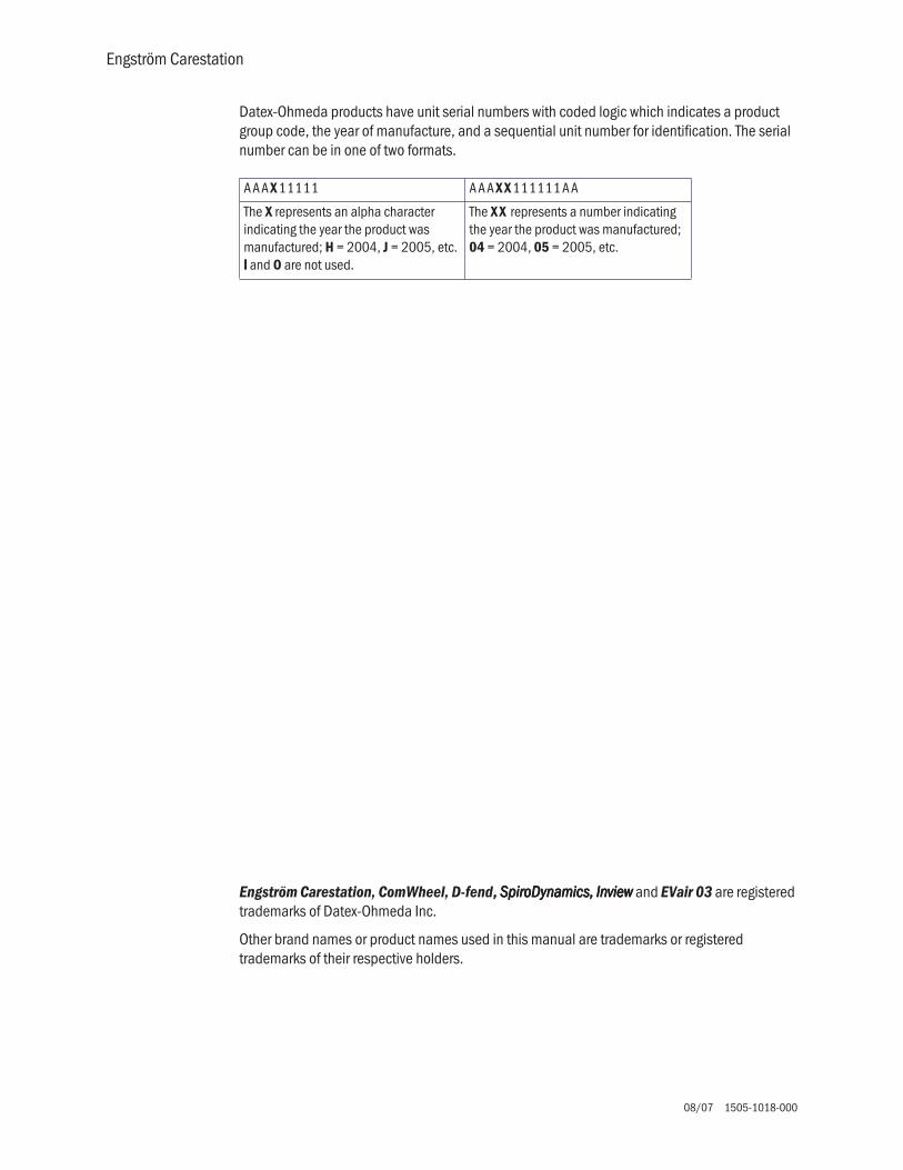
As a safety measure, a relief valve 14, located downstream from the O2 sensor, can be energized to vent the full flow rate of the inspiratory delivery side of the system. If an overpressure condition is detected, the valve can be opened by either of the EC’s two control processors. To provide redundant safety (independent of the electronic circuits), the valve begins to mechanically relieve pressure at a nominal 115 cm H2O.
The inspiratory airway pressure transducer 15, along with its associated zeroing valve, is located just prior to the inspiratory outlet port. This transducer has a range of –20 to 120 cm H2O and serves as one of three airway pressure measuring devices in the EC.
O2
SafetyRelief Valve
FlowSensor
FlowSensor
Total Flow
InspiratoryEffortValve
Free Breathing Check Valve
HT
HT
P
PneumaticResistor
O2 SensorInspiratory Zero
Valve
Auxiliary PressureTransducer
Inspiratory Pressure
FlowValve
FlowValve
ReliefValve
ExhalationValve
Valve
Expiratory Pressure
P
HT
O2
Air
14
15

2 Theory of Operation
1505-1018-000 08/07 2-9
2.1.2 Expiratory circuit At the expiratory side of the ventilator, a solenoid powered exhalation valve 16 controls exhaust from the breathing circuit. The valve contains an elastomer diaphragm that is held against a rigid seat by a solenoid (voice coil) driven piston. The valve achieves a balance between the pressure generated within its 21-mm diameter seat area and the force applied by the piston, releasing exhalation flow as necessary to maintain balance. The proportional solenoid controls the exhalation sealing pressure within a range of 0 to 100 cm H2O. Software control provides continuous oscillatory movement (dithering) of the exhalation valve to minimize static friction effects.
Immediately upstream of the exhalation valve is a tap for the expiratory pressure transducer 17 and its associated zeroing valve. The expiratory pressure tap is continuously purged with 35 ml/min of air to ensure that exhaled condensate does not occlude the tap. The air flow is established from the regulated Air supply using a fixed orifice (pneumatic resistor) 18.
Downstream of the exhalation valve is the expiratory flow transducer 19. In principle, the transducer is similar to a hot-wire anemometer. A wire having a large “temperature to electrical resistance” relationship is placed in the flowstream. The wire is kept at a constant temperature using a Wheatstone bridge circuit. The current necessary to maintain the resistance of the sensor portion of the bridge is a function of the flow through the sensor.
At the output of the flow sensor is a flapper type check valve 20 that prevents gas from being drawn in through the expiratory valve and minimizes patient rebreathing in the event of a ventilator failure.
Located downstream on the patient wye is an optional Neonatal Flow Sensor 28. The sensing elements for the Neonatal Flow Sensor Subsystem consist of two hot wires each with its own drive circuitry and Wheatstone bridge. The hot wires reside off-board in a flow tube situated at the patient wye and
O2
SafetyRelief Valve
FlowSensor
FlowSensor
Total Flow
InspiratoryEffortValve
Free Breathing Check Valve
HT
HT
P
22 / 15 mmMale / Female
PneumaticResistor
O2 SensorInspiratory Zero
Valve
Auxiliary Pressure
Inspiratory Pressure
FlowValve
FlowValve
MicropumpNebulizer
Patient
H
30 mm Male Cone
22 / 15 mmMale / Female
ExhalationValve
ExhalationFlow Sensor
Pneumatic Resistor
Expiratory ZeroValve
Expiratory Pressure
EXP
INSP
P
HT
H
Neonatal Flow Sensor - Optional
16
Air
17
18 19
20
Patient
From
To
28

Engström Carestation
2-10 08/07 1505-1018-000
electrically act as variable resistors in each of the bridges. The sensors hold a constant temperature at all times as they contain a linear resistance change with temperature. The Neonatal Flow sensor is connected to the Ventilator Monitoring Board (VMB) through the Motherboard via Port 1 and a 2+ meter long shielded cable, detachable at both ends. The other Wheatstone bridge resistors and all associated drive circuitry reside on the VMB. As gas (Air and Oxygen) flows, current through the hot wire elements increases. These currents are converted to a voltage, amplified, offset with a voltage reference and converted to a digital value by the 12-bit ADC. Because of the bidirectional nature of gas flow at the patient wye, a post that is situated between the elements serves to shadow the downstream element and reduce the downstream signal. By comparison of the individual signal levels of the two hot wire elements, flow direction can be ascertained.

2 Theory of Operation
1505-1018-000 08/07 2-11
2.1.3 Associated circuits Associated with the inspiratory and expiratory pressure transducers are two “zeroing” solenoid valves 21 and 22. These valves are used to disconnect the pressure transducers from circuit pressure and vent them to atmosphere during zero bias calibration. This zeroing procedure is conducted routinely (every 12 hours) under the control of the Vent Engine software.
A third (auxiliary) pressure channel 23 is used to measure additional patient “airway” pressures at the discretion of the clinician. This port could be used to measure circuit pressure directly at the airway, laryngeal cuff pressures or pressures lower in the airway tract. The transducer circuit includes a valve 24 to provide a 35 ml/min purge flow as required by the particular clinical application. For example, in measuring airway pressure at the endotracheal tube the purge would most likely be turned on, but for measuring laryngeal cuff pressures (closed system) the purge would be turned off. The purge flow is established from the regulated Air supply using a fixed orifice (pneumatic resistor) 25. The relief valve 26 limits pressure in the auxiliary channel to less than 230 cm H2O.
2.1.4 Electronicmicropump nebulizer
The Aeroneb Professional Nebulizer System (Aeroneb Pro) by Aerogen, Inc. 27 is integrated into the EC. This nebulizer is electrically connected to the EC and uses proprietary technology to produce a fine-droplet, low-velocity aerosolized drug delivered into the breathing circuit.
The Aeroneb Pro is designed to operate in-line with standard ventilator circuits and mechanical ventilators. It operates without changing the patient ventilator parameters.
Air
O2
25 psi172 kPa
25 psi172 kPa
SafetyRelief Valve
FlowSensor
FlowSensor
O2
Total Flow
InspiratoryEffortValve
Free Breathing Check Valve
HT
HT
P
22 / 15 mmMale / Female
Auxiliary PressurePurge Valve
PneumaticResistor
O2 SensorInspiratory Zero
Valve
Auxiliary PressureTransducer
High PressureTransducer
PrimaryInlet
CheckValve
Regulator
Inspiratory Pressure
FlowValve
Regulator
FlowValve
CheckValve
High PressureTransducer
PrimaryInlet
ReliefValve
TestPort
TestPort
MicropumpNebulizer
Patient
H
30 mm Male Cone
22 / 15 mmMale / Female
ExhalationValve
ExhalationFlow Sensor
Pneumatic Resistor
Expiratory ZeroValve
Expiratory Pressure
EXP
INSP
1/8, 3/16,1/4 inch Stepped Hose Barb
P
P
P
P
HT
Paux
InletFilter Optional
InletFilter Standard
H
Neonatal Flow Sensor - Optional
21
22
2324
26
25
27

Engström Carestation
2-12 08/07 1505-1018-000
2.2 Electrical Operation
For a complete diagram of the electrical system, refer to Figure 11-5, "Electrical architecture" in Section11.
The EC includes 5 major processor control boards:
• Display Unit: DU (1009-8289-000) or HPDU (1009-5933-000)• Ventilator Control Board (1505-5500-000)• Ventilation Monitoring Board: Original VMB (1505-5501-000) or
Current VMB (M1052980)• Expiratory Flow Sensor Board (1505-5507-000)• Power Management Board (1505-5502-000)
The EC includes 5 analog boards:
• Motherboard/backplane: Original Motherboard (1505-5504-000) or Current Motherboard (M1053184)
• Monitoring Module Power Supply Board (M1052831)• 3 Airway Pressure Transducer boards (1505-5506-000)
2.2.1 Display Unitoverview
The Engström Carestation can use one of two display units:
• the original Display Unit (DU)• or the High Performance Display Unit (HPDU)
The display unit handles most of the machine’s user interface functions through the front panel controls and the LCD screen. It is the primary interface to external peripherals
The main components of the display include:
• An active matrix thin film transistor liquid crystal display ((((AAAA))))• The CPU board ((((BBBB))))• The System Interconnect assembly ((((CCCC))))
The CPU board includes a host processor and three coprocessors to handle display, front panel, and monitoring interfaces.
B
C
A

2 Theory of Operation
1505-1018-000 08/07 2-13
2.2.2 Softwarerequirements
The DU uses a PCMCIA interface to handle software upgrades and to load the diagnostics Service Application. The DU is compatible with system software versions 3.X and lower.
The HPDU uses a Compact Flash interface to handle software upgrades and to load the diagnostics Service Application. The HPDU requires system software version 4.X or greater.
2.2.3 DU systemconnections
The display unit is physically separate from the ventilator chassis (connected through a single cable running through the display arm). The display unit contains a CPU board based on the Elan SC520 processor. A small daughter board (DU Interface board), provides a communications interface between the DU’s CPU and the remainder of the EC system. A second daughter board (DU Connector board), provides hardware connector interfaces for the USB, Network ID, Ethernet, and Display Unit connector ports.
The CPU board includes a PCMCIA (PC Card) interface.
The DU’s CPU board provides power and signals for operating the main audio speaker and a 12 inch (30 cm) backlit color LCD display, providing an interactive video interface. Membrane keys from three front-panel keypads and a rotary encoder (ComWheel) complete the loop for acquiring user inputs.
The DU housing contains a continuously operating fan for temperature reduction.
PC Card
Speaker
CPU ElanSC520
Display Unit
UARTs
Display UnitCPU Board
DU Conn Bd
DU Infc Bd
DU
LCD DisplayKeypadKnob
NetID
Ethernet USB
AB.9
8.07
3

Engström Carestation
2-14 08/07 1505-1018-000
2.3 System Connections
2.3.1 Display Unit The DU accommodates the following connections:
• Display connection (1111).• DIS connector - supports D-O Device Interface Solution (DIS) (2222).• Network connection - Standard Ethernet port for network connectivity (3333).• Network ID - accepts D-O proprietary network identification plug (4444).• USB port - standard USB interface for external communication (5555).
DIS
1
2 3 4 5
AB.9
8.18
2

2 Theory of Operation
1505-1018-000 08/07 2-15
2.3.2 High PerformanceDisplay Unit
The HPDU accommodates the following connections:
• Display connection (1111).• Future expansion(2222).• Future expansion (3333).• Future expansion (4444).• Future expansion (5555).
1
2 3 4 5
AB.9
8.18
1

Engström Carestation
2-16 08/07 1505-1018-000
2.3.3 Communicationchannels
The DU communicates to the remainder of the EC system through the Motherboard using 5 digital channels.
[1] A 500 Kbaud, RS-485 interface (Mod Bus: Datex-Ohmeda proprietary module communication protocol), to external monitoring modules. This link runs through the Monitoring Module Power supply board which forms the physical interface to the M-Gas (and ultimately other) monitoring modules.
Additionally, the Mod Bus interfaces with the PSM (Patient Side Module) support circuitry (future expansion).
[2] A 38.4 Kbaud, RS-422 interface relays setting and alarm annunciation information from the VMB, and receives alarm commands and data.
[3] A 38.4 Kbaud, RS-422 interface relays setting and alarm annunciation information from the VCB, and receives sensor data for presentation to the user as well as alarm commands. As described later, the VMB also communicates directly to the VCB, thus there exists a triangle of bi-directional communication paths between the DU, VCB and VMB.
An RS-232 Serial port that routes to an external connector directly on the motherboard. This link ports data from the DU to other compatible equipment via the Ohmeda Com 1.X protocol.
[4] A 38.4 Kbaud, RS-232 link to the PMB. Provides display signal input/output, battery and power information to the DU. This link is located internally on the Motherboard and is used to confirm a “hard” power down of the EC with user inputs to the DU being relayed to the PMB for power down action.

2 Theory of Operation
1505-1018-000 08/07 2-17
Processor
Display Unit CPU
DU Controls
DU
Color LCD
Memory Card
Vent ControlBoard
MotorolaColdfire V4
PowerManagement
BoardAtmel ATmega128 Processor
RS-42238.4 Kbaud
19.2 Kbaud
Vent MonitorBoard
Atmel ATmega128 Processor
PSM (Future Expansion)Neo Flow Sensor - Optional
PCMCIA (2)
RS-42238.4 Kbaud
RS-422921.6 Kbaud19.2 Kbaud
Future ExpansionService App
External I/O SerialNurse Call
E & M-GasIntel 196Processor
Module Bay
ISA
Bus
RS-23238.4 Kbaud
VMBVCB
PMB
Display Unit
9.6
Kbau
dSe
rial
EV Chassis
RS-232 SerialExternal I/O
Mod Bus,
Future Expansion
RS-42238.4 Kbaud
RS-23238.4 Kbaud
RS-42238.4 Kbaud
RS-485500 Kbaud
Mod Bus, RS-485500 Kbaud
RS-422
RS-422
[1]
[2]
[3]
[4]
[5]
AB.9
8.19
8

Notes
2-18 08/07 1505-1018-000
2.3.4 VentilatorControl Board -
VCB
The VCB is a Motorola Coldfire V4 CPU powered assembly that: •collects information from all EC system sensors (some indirectly from the VMB), •and controls all actuators necessary to effect ventilation delivery.
The VCB computes and supplies all ventilation sensor monitoring data for display on the DU. If there are alarms to be generated based on this monitoring data, the VCB notifies the DU to post the appropriate alarm message and audio sequence. The VCB observes the DU’s response to ensure that the alarm is adequately presented.
To control ventilation, the VCB accepts ventilation parameters from the DU. Measured data (waveform and numeric) is also sent to the DU from the VCB. This data flow occurs on the 38.4 Kbaud, RS-422 communications link (VCB - DU Data I/O).
The VCB also communicates directly with the VMB every 1 ms, receiving expiratory flow, expiratory pressure and O2 sensor data on the 921.6 Kbaud, RS-422 interface (VMB Sensor Data I/O). Barometric pressure data is also received from the VMB, but at a lower data rate.
The following sensor information is acquired directly by the VCB:• Air Flow/Temp sensor through the RS-232 cable interface @ 200 Hz,• O2 Flow/Temp sensor through the RS-232 cable interface @ 200 Hz,• Total Flow/Temp sensor through the RS-232 cable interface @ 200 Hz,• Inspiratory Pressure sensor via a differential analog signal – 12 bits @ 1000 Hz.• Auxiliary Pressure sensor via a differential analog signal – 12 bits @ 1000 Hz.
The VCB contains actuator drive circuits for the following:• the Air and O2 Flow Valves,• the Exhalation Valve,• the Inspiratory Pressure Sensor zeroing valve• and the Auxiliary Pressure Sensor purge flow valve.
The Flow Valve and Exhalation valve actuators are driven using current drive circuits and feedback controlled using current sense resistors. The VCB contains digital control signals for activating the inspiratory effort and safety relief valves (through the VMB) and the Piezo-Electric Nebulizer.
The VCB receives 12.5 Vdc from the PMB, which it regulates down to various voltages for use by the board’s digital circuits and analog drivers. These voltage lECels are self-tested on the VCB.
An additional 12.5 Vdc power line is separately connected to an auxiliary buzzer on the VCB that provides a backup audio alarm source. The buzzer is normally on and must be kept silent by both the VCB and through a dedicated digital line coming from the VMB. A reset or failure of either the VCB or VMB is regarded as a system fault and the buzzer is activated.
The VCB includes 1 MB of SRAM and 8 MB of Flash memory. The CPU is connected to a digital watchdog circuit to monitor continuous and properly sequenced execution of software code.
As the core processor unit for the EC, the VCB includes two external serial I/O channels: one 19.2 Kbaud RS-422 channel (Expansion Port I/O #1 to External Connector 3) and one 19.2 Kbaud RS-422 channel (Expansion Port I/O #2 to External Connector 2).

2 Theory of Operation
1505-1018-000 08/07 2-19
For further details, refer to Figure 11-13, "VCB block diagram" in Section11.
ColdfireV4 CPU
Total Flow/Temp
Air Flow/Temp
O2 Flow/Temp
Vent Control Board
Air Valve Drivew/ I Sense
O2 Valve Drivew/ I Sense
Power for Buzzer
BackupBuzzer
Circuit Power
Expansion Port I/O #1Expansion Port I/O #2
AirFlow Valve
Piezo-ElectricNeb Board
O2Flow Valve
Exhal Valve
Aux P PurgeValve
8 MBFlash
1 MBSRAM
Exhal ValveDrive w/ V & I
Sense
RS-232
16 CHMUX
12 BitADC
8 UARTS
Watchdog
V Checks
Buzzer Control
Safety Valve On/OffExh Valve On/Off
VMB SensorData I/O
VCB - DU Data I/O
Exh Valve Closed
Current Lmt Control
Insp Effort Valve
Aux P
Insp P
Expansion Signals
Buzzer Sense
PowerRegs
SerialXCVRs
RS-232
RS-232
Insp P ZeroValve
Nebulizer
VCB
RS-42238.4Kb
AB.9
8.07
6

Engström Carestation
2-20 08/07 1505-1018-000
2.3.5 VentilatorMonitoring Board -
VMB
The Engström Carestation can use one of two Ventilator Monitoring Boards:
• Original VMB, PN 1505-5501-000 (Original VMB units do not support the Neonatal option) oooorrrr
• Current VMB, PN M1052980 (Current VMB units support Neonatal hardware and expansion capability; Port 2 (RS-422) via the Motherboard.)
NNNNooootttteeee:::: If replacement of the original VMB with a current VMB is required, it is necessary to replace the original Motherboard (1505-5504-000) with the current Motherboard (M1053184).
The VMB is based on an Atmel Atmega 128 CPU. The VMB performs as an independent monitoring system that provides computational and oversight redundancy to the DU and VCB.
The VMB independently acquires sensor data relating to the ventilator’s three safety parameters:
• airway pressure (expiratory), • delivered O2 percentage, • and exhaled minute/tidal volume.
In addition, the VMB monitors the air and oxygen supply pressures:
• Air High Pressure Supply via analog cable –10 bits @ 11 Hz,• O2 High Pressure Supply via analog cable – 10 bits @ 11 Hz,• Expiratory flow sensor data via an I2C cable interface @ 200 Hz,• O2 Concentration via a serial cable @ 5 Hz,• Expiratory Airway Pressure via analog signal – 12 bits @ 1000 Hz,• Barometric Pressure onboard VMB – 10 bits @ 11 Hz.
The VMB controls a safety valve actuator that enables it to unilaterally relieve pressure in the breathing circuit. This allows the barotrauma hazard with its 50 ms reaction time to be independently controlled by either action of the VCB or VMB. The hazards associated with O2 concentration (improper mixture) and low exhaled minute volume (hypoventilation) have much slower reaction times (on the order of minutes) and are controlled under fault conditions by the VMB’s ability to unilaterally activate the backup buzzer.
The VMB receives 12.5 Vdc from the PMB, which it regulates down to various voltages for use by the board’s digital circuits and analog drivers. These voltage levels are self-tested on the VMB.
The VMB communicates directly to the DU via the bi-directional 38.4 Kbaud RS-422 channel (VCD - DU Data I/O). A separate 921.6 Kb RS-422 link (VMB Sensor Data I/O) is used to transmit the VMB’s sensor data to the VCB.
Neonatal Option For Neonatal patients, the VMB provides circuitry designed to interface with the VCB and VMB and a remote bidirectional gas flow sensor. The analog sensor signals are routed from outside of the Engström housing to the VMB via an electrical harness to the back of the machine and are filtered on the Motherboard before entering the VMB through the Motherboard internal connector. This circuitry is provided 12.5V power via the Motherboard and regulates this down to 5V and 3.3V, independent of other VMB circuitry.

2 Theory of Operation
1505-1018-000 08/07 2-21
Nurse Call Nurse Call functionality is supported on units with Serial Numbers greater than CBK00356 and units updated with Motherboard M1053184 and VMB M1052980.
Port 4 (15 pin) may be used to output alarm signals to a nurse call system. The ventilator will signal an alarm with a normally open or normally closed signal. The nurse call will be triggered by all medium and high priority alarms. When alarms are suspended, the nurse call will not be signalled. If an alarm is silenced, the nurse call signal will turn off.
NNNNooootttteeee:::: Motherboard M1053184 and VMB 1052980 are included in the following kits:
The 15-pin female D connector configuration:
• Pin 3 - relay common• Pin 10 - normally open• Pin 11 - normally closed
Load current:
• Minimum: 100 uA at 100 mVdc• Maximum: 1 A at 30 Vdc• Relay isolated
Item Description Stock Number
Neonatal Upgrade kit (with hardware components) M1061589
FRC and Neonatal Upgrade kit (with hardware components) M10792676
SpiroDynamics and Neonatal
Upgrade kit (with hardware components) M1079272
FRC, SpiroDynamics, and Neonatal
Upgrade kit (with hardware components) M1079274
10
3
11
AB.9
8.18
0

Engström Carestation
2-22 08/07 1505-1018-000
Exp FlowSensor Bd
AtmelATmega128
CPU
Baro P
Air Pipeline P
O2 Pipeline P
Vent Monitor Board
VMB Sensor Data I/O
Circuit PowerInsp Effort
Valve
SafetyRelief Valve
Safety ValveDrive
Insp ManeuverValve Drive
ADC /MUX
Exh Valve Closed
UARTS
Watchdog
V ChecksBuzzer Control
Exh Valve On/OffSafety Valve On/Off
VMB - DU Data I/O
O2 Sensor
Insp Effort Valve Control
Exp P
Expansion Signals
Circuit Power
Buzzer Sense
Exp P ZeroValve
I2C
RS-232
Exp FlowSensor
Exp FlowInfc Bd
VMB
RS-42238.4 Kb
RS-422921.6 Kb
Original VMB Current VMB 505-5501-000 M1052980
AB.9
8.07
7

2 Theory of Operation
1505-1018-000 08/07 2-23
2.3.6 PowerManagementBoard – PMB
The PMB is based on an Atmel Atmega 128 CPU. The PMB performs power selection between power sources in the following order:
• AC power mains,• Internal battery.
The PMB regulates the 24 Vdc power supply output down to raw 16 V and 12.5 V power rails that are used throughout the system (all boards locally regulate from these power rails).
The PMB controls the charging operation of the internal battery, selecting trickle, bulk, or float charge status.
The PMB communicates with the DU through the 9.6 Kbaud, RS-232 link (PMB Data I/O). It sends status commands to the DU concerning the charge status of the internal 24 V battery.
The PMB uses this link as a communication interlock to handle the unit shutdown sequence. Once a signal is received by the PMB from the mechanical On/Standby switch, the PMB prompts the DU for a confirmation signal that shutdown is appropriate (unit is not in a ventilation therapy state). Once the DU relays this confirmation to the PMB, the power-off sequence is initiated.
The PMB supports the operation of the EC chassis fan and the fan on the PMB heatsink.
2.3.7 OtherElectronic Items
The EC employs a separate AC to DC switching power supply for providing a nominal 24v voltage level to the PMB. The power supply is capable of regulating 150 W of power output. A power entry module contains fuses and filters for Mains AC input cables. Finally, two internal 12v batteries are connected in series to provide an internal backup 24v power source for the system.
For further details, refer to Figure 11-9, "PMB block diagram" in Section11.
2 - 12 V4AHr
Batteries
PMBFan
150W MainsPower Supply
Power EntryModule
Mains/BatSelect
Power Management Board
Bat ChargeCntlr
On/Standbyand
Safety Switch
Power PanelConnectors
Battery I &V Monitor
AtmelATmega128 CPU
Fan Cntlrs
16VReg
PMB Data I/O
12.5VReg
BackupAudio Power
Chassis Gnd
VentEngineFan
V Checks
UARTS
PMB
AB.9
8.19
7

Engström Carestation
2-24 08/07 1505-1018-000
2.3.8 Motherboard(backplane)
The Engström Carestation can use one of two Motherboards:
• Original Motherboard - 1505-5504 (Port 2 - 15 pin) oooorrrr• Current Motherboard - M1053184 (Port 2 - 9 pin)
NNNNooootttteeee:::: If replacement of the original Motherboard with a current Motherboard is required, it is necessary to replace the original VMB (1505-5501-000) with the current VMB (M1052980).
The EC motherboard provides backplane connectivity for the VCB, VMB and PMB assemblies in the EC chassis.
Analog circuits on the board provide current limiting for external peripheral connections to ensure that the EC’s primary ventilation and monitoring functions are not compromised by excessive power draw. In addition, 10VA energy limit circuitry is provided for power connections within 20 cm of O2 exhaust outlets, in order to mitigate the risk of an oxygen enriched fire.
The board features 6 external connectors that exit through a rear sheet metal interface. Refer to section 2.3.3.
• Patient Side Module (PSM) support connector, Neonatal Flow Sensor, (future expansion)
• Serial (future expansion) connector
• Service Application, Serial (future expansion) connector
• External Serial I/O connector, Nurse call
• Main DU connector (communication channel between DU and EC)
• Monitoring Module, Mod Bus connector
CCCCuuuurrrrrrrreeeennnntttt MMMMooootttthhhheeeerrrrbbbbooooaaaarrrrddddOOOOrrrriiiiggggiiiinnnnaaaallll MMMMooootttthhhheeeerrrrbbbbooooaaaarrrrdddd
11115555 PPPPiiiinnnn 11115555 PPPPiiiinnnn11115555 PPPPiiiinnnn
11115555 PPPPiiiinnnn
9999 PPPPiiiinnnn9999 PPPPiiiinnnn11115555 PPPPiiiinnnn9999 PPPPiiiinnnn11115555 PPPPiiiinnnn
11115555 PPPPiiiinnnn

2 Theory of Operation
1505-1018-000 08/07 2-25
2.3.9 MonitoringInterface Board –
MonitoringModule Bays
The EC accommodates an optional four-bay module assembly that supports compatible Datex-Ohmeda M-series modules.
The assembly includes a Monitoring Interface Board (MIB) that communicates with the DU through the Mod Bus connector. The MIB includes circuitry that regulates the raw16 V power down to +15 V (unregulated), ±15 V (regulated), and +5 V levels required by the M series monitoring modules.
RS-422
I/O Panel Connectors
RS-422#1
12.5V
12.5VExpansion Port I/O #2
Expansion Port I/O #1
Mod Bus
E & M SeriesModule
Bay 1
Bay 2
Bay 3
Bay 4
MonitorInterface
Board
PSM
16V
16V
16V
Filtering
Filtering
Filtering
Filtering
Filtering
+15VD-15V+15V+5V
E & M SeriesModule
PSM (Future Expansion)Neo Flow Sensor - Optional
Future ExpansionService App
External I/O SerialNurse Call
Future Expansion
#1
AB.9
8.19
9

Engström Carestation
2-26 08/07 1505-1018-000

1505-1018-000 08/07 3-1
3 Checkout Procedure
In this section 3.1 Inspect the system . . . . . . . . . . . . . . . . . . . . . . . . . . . . . . . . . . . . . . . . . . . . . . . . . . . . . . . . .3-2
3.2 Automated Checkout . . . . . . . . . . . . . . . . . . . . . . . . . . . . . . . . . . . . . . . . . . . . . . . . . . . . . . .3-2
3.3 Backlight test . . . . . . . . . . . . . . . . . . . . . . . . . . . . . . . . . . . . . . . . . . . . . . . . . . . . . . . . . . . . . .3-3
3.4 Power failure test . . . . . . . . . . . . . . . . . . . . . . . . . . . . . . . . . . . . . . . . . . . . . . . . . . . . . . . . . . .3-3
3.5 Electrical safety tests . . . . . . . . . . . . . . . . . . . . . . . . . . . . . . . . . . . . . . . . . . . . . . . . . . . . . . .3-4
wwww WARNINGS After any repair or service of the Engström Ventilator, complete all tests in this section.
Before you do the tests in this section:
• Complete all necessary calibrations and subassembly tests. Refer to the individual procedures for a list of necessary calibrations.
• Completely reassemble the system.
If a test failure occurs, make appropriate repairs and test for correct operation.

Engström Carestation
3-2 08/07 1505-1018-000
3.1 Inspect the system
Before testing the system, ensure that:
• The equipment is not damaged.
• Components are correctly attached.
• Pipeline gas supplies are connected.
• The casters are not loose and the brakes are set and prevent movement.
• The power cord is connected to a wall outlet. The mains indicator comes on when AC Power is connected.
3.2 Automated Checkout
The EC is equipped with an automated checkout.
Note If any of the Checks fail, refer to Section 7.1, “Troubleshooting Checkout Failures”, to troubleshoot a specific failure.
To file a quality report or request technical assistance regarding a checkout failure, create and include a Checkout log using the EC Service application (Section 8.6.8).
Run the Checkout while the EC Service Application is running and select LLLLoooogggg CCCCaaaalllliiiibbbbrrrraaaattttiiiioooonnnn RRRReeeessssuuuullllttttssss.
When in Standby, the Patient Setup menu is displayed on the normal screen.
1. Select Checkout.
2. Attach the patient circuit.
3. Occlude the patient wye.
4. Select Start Check.
• The results appear next to each check as they are completed. When the entire checkout is finished ‘Checkout complete’ will appear and the highlight will move to Delete Trends.
• If one or more checks fail, select Check Help for troubleshooting tips.

3 Checkout Procedure
1505-1018-000 08/07 3-3
5. Select Previous Menu.
Checkout includes the following checks:
• Paw Transducer Check
• Barometric Pressure Check
• Relief Valve Check
• Exhalation Valve Check
• Expiratory Flow Sensor Check
• Air Flow Sensor Check
• O2 Flow Sensor Check
• O2 Concentration Sensor Check
• Neonatal Flow Sensor Check (if applicable)
• Circuit Leak, Compliance, and Resistance
3.3 Backlight test
1. Access the Calibration menu.
• In the standby mode, push the System Setup key.
• On the System Setup menu, select Install/Service (23-17-21).
• On the Install/Service menu, select Calibration.
2. On the Calibration menu, select Backlight Test.
3. Select Start Test.
4. The display will show the test running on light 1 and then on light 2. If the display goes completely blank or flickers during the test, one of the lights has failed.
3.4 Power failure test
1. Connect the power cord to a wall outlet. The mains indicator on the front panel of the Display Unit comes on when AC Power is connected.
2. Set the system switch to On and Start a case.
3. Unplug the power cord with the system turned on.
4. Make sure the following message is displayed:
• ‘On battery’
5. Connect the power cable again.
6. Make sure the alarm cancels.

3-4 08/07 1505-1018-000
3.5 Electrical safety tests
wwww WARNING Make sure the system is completely assembled and that the power cords are connected as illustrated in Section 10.15. Make sure all accessory devices are connected to electrical outlets.
1. Connect an approved test device (for example: UL, CSA, or AAMI) and verify that the leakage current is less than:
2. Make sure that the resistance to ground is less than 0.2Ω between the equipotential stud and the ground pin on the power cord.
Voltage Max. Leakage Current
120/100 Vac 300 µAmps
220/240 Vac 500 µAmps

1505-1018-000 08/07 4-1
4 Installation and Service Menus
In this section 4.1 Service and Installation menu structure . . . . . . . . . . . . . . . . . . . . . . . . . . . . . . . . . . . . . . . .4-2
4.2 Install/Service Menu (Super User) . . . . . . . . . . . . . . . . . . . . . . . . . . . . . . . . . . . . . . . . . . . . .4-3
4.2.1 Trends Setup . . . . . . . . . . . . . . . . . . . . . . . . . . . . . . . . . . . . . . . . . . . . . . . . . . . . . . . .4-4
4.2.2 Display Settings . . . . . . . . . . . . . . . . . . . . . . . . . . . . . . . . . . . . . . . . . . . . . . . . . . . . .4-5
4.2.3 Ventilator Settings . . . . . . . . . . . . . . . . . . . . . . . . . . . . . . . . . . . . . . . . . . . . . . . . . . .4-7
4.2.4 Parameter Settings . . . . . . . . . . . . . . . . . . . . . . . . . . . . . . . . . . . . . . . . . . . . . . . . . . .4-7
4.2.5 Defaults . . . . . . . . . . . . . . . . . . . . . . . . . . . . . . . . . . . . . . . . . . . . . . . . . . . . . . . . . . . .4-8
4.2.6 Factory Defaults . . . . . . . . . . . . . . . . . . . . . . . . . . . . . . . . . . . . . . . . . . . . . . . . . . . 4-10
4.3 Calibration menu . . . . . . . . . . . . . . . . . . . . . . . . . . . . . . . . . . . . . . . . . . . . . . . . . . . . . . . . . 4-11
4.4 Service menu . . . . . . . . . . . . . . . . . . . . . . . . . . . . . . . . . . . . . . . . . . . . . . . . . . . . . . . . . . . . 4-12
4.4.1 Configuration . . . . . . . . . . . . . . . . . . . . . . . . . . . . . . . . . . . . . . . . . . . . . . . . . . . . . 4-13
4.4.2 Options Key . . . . . . . . . . . . . . . . . . . . . . . . . . . . . . . . . . . . . . . . . . . . . . . . . . . . . . . 4-14
4.4.3 Options List . . . . . . . . . . . . . . . . . . . . . . . . . . . . . . . . . . . . . . . . . . . . . . . . . . . . . . . 4-14
4.4.4 Options Card . . . . . . . . . . . . . . . . . . . . . . . . . . . . . . . . . . . . . . . . . . . . . . . . . . . . . . 4-14
4.4.5 Copy Configuration . . . . . . . . . . . . . . . . . . . . . . . . . . . . . . . . . . . . . . . . . . . . . . . . . 4-15
4.4.6 Service Log menu . . . . . . . . . . . . . . . . . . . . . . . . . . . . . . . . . . . . . . . . . . . . . . . . . . 4-16
4.4.7 Software/Hardware version menu . . . . . . . . . . . . . . . . . . . . . . . . . . . . . . . . . . . . 4-17
4.4.8 Resetting feature option key codes . . . . . . . . . . . . . . . . . . . . . . . . . . . . . . . . . . . . 4-18

Engström Carestation
4-2 08/07 1505-1018-000
4.1 Service and Installation menu structure
This section describes the Service level functions that are part of the main software installed in the ventilator.
Section 8, “Service Diagnostics and Software Download,” covers a separate service application that loads from a PCMCIA card and is used to download system software and run service diagnostics and other service tests.
Menu structure The Service menu structure has two levels which are password protected:
• Install/Service (super-user)• Service
The Install/Service level (with super-user password) supports standard hospital preferences such as colors, units, ventilator settings and alarm defaults, and access to the Calibration and Service menus.
The Service level (with service password) supports system configuration and provides access to the Service Log menu.
Follow the menu structure to access the various service screens:
• On the front panel of the Display Unit, press the System Setup key to access the System Setup menu.
• On the System Setup menu, select Install/Service to access (with super-user password) the Install/Service menu;- select Calibration to access the Calibration menu.- select Service to access (with service password) the Service menus.
System Setup Install/Service Calibration Service Service Log
Patient SetupScreen SetupNeo Flow Sensor Setup Parameters SetupSystem StatusInstall/ServiceNormal Screen
Trends SetupDisplay SettingsVentilator SettingsParameter SettingsDefaults
Calibration
ServiceExit
O2 FCVAir FCVExhalation ValveBacklight TestGas CalibrationCal. Flag
Previous Menu
Configuration
Copy ConfigService LogExit
Scroll Recent
Error LogEvent Log
Alarm LogSW HW versionsCopy LogsReset LogsPrevious Menu

4 Installation and Service Menus
1505-1018-000 08/07 4-3
4.2 Install/Service Menu (Super User)
Use the super-user password to access the Install/Service menu: “23-17-21”.
Menu Item Message text Comments
Trends Setup Configure graphical trend pages. Refer to section 4.2.1
Display Settings Set colors, units of parameter, and time and date. Show alarm limits in digit fields.
Refer to section 4.2.2
Ventilator Settings Configure ventilator settings: breath timing, flow, and modes using backup ventilation.
Default is Yes
Parameter Settings Set volume conditions and CO2 humidity compensation.
Refer to section 4.2.4
Defaults Set or change default settings. Refer to section 4.2.5
Calibration Calibrate airway gas, calibrate gas valves, and test backlights.
Refer to section 4.3
Service Set and copy configuration and show technical data. Note: The system will have to be turned off to exit this menu.
Refer to section 4.4
Exit Turn power off to exit menu.

Engström Carestation
4-4 08/07 1505-1018-000
4.2.1 Trends Setup
Graphical Trends
Page Menus Use the Pull Aside list to select options for each menu item and page. Options are shown below:
Menu Item Message text Values
Default Trend Change default trend type:graphical, numerical, or settings.
Num (default), Graph, or Set
Graphical Trends Configure graphical trend pages Pages 1-5
Previous Menu Return to previous menu.
Menu Item Message text
Page 1(Page 2 to Page 5)
Configure first graphical trend page(Second, third, fourth, fifth)
Previous Menu Return to previous menu.
Menu Item OptionsPage 1Default
Page 2Default
Page 3Default
Page 4Default
Page 5Default
Field 1 Off—Select Off to clear trend fieldrr+co2—respiration rate and CO2Pres—Ppeak, PplatPmean—PmeanPEEP—Peepe and PeepiMVexp—expired minute volumeSpont—spontaneous MVexp and respiration rateCompl—compliance and RawSSSSppppiiiirrrroooo—static compliancePaux—auxiliary pressureVO2—VO2 and VCO2VO2/m2—VO2 and VCO2 weighted by body surface areaVO2/kg—VO2 and VCO2 weighted by body kgEE/RQ—energy expenditure and respiratory quotient
Field 2
Field 3
PreviousMenu
Return to previous menu.

4 Installation and Service Menus
1505-1018-000 08/07 4-5
4.2.2 Display Settings The Display Settings menu can be accessed here in the super-user level to change individual preferences, or if required during installation, in the service level Installation menu.
Colors Menu
Menu Item Message text Values
Colors Set colors of parameters.
Units Set units of Paw, Flow, CO2, height, weight, and EE.
Show Alarm Limits Select yes/No to show alarm limits in digit fields.
Yes/No
Time and Date Change clock and calendar functions.
Previous Menu Return to previous menu.
Menu Item Message text Values
Paw Change color of Paw waveform, digits and trend.
Yellow, White, Green, Red, or Blue
Flow Change color of Flow waveform, Flow and Volume digits and trend.
Yellow, White, Green, Red, or Blue
O2 Change color of O2 waveform, digits and trend.
Yellow, White, Green, Red, or Blue
CO2 Change color of CO2 waveform, digits and trend.
Yellow, White, Green, Red, or Blue
Volume Change color of Volume waveform, digits and trend.
Yellow, White, Green, Red, or Blue
Paux Change color of Paux waveform, digits and trend.
Yellow, White, Green, Red, or Blue
Previous Menu Return to previous menu.

Engström Carestation
4-6 08/07 1505-1018-000
Units Menu
Show Alarm Limits
Time and Date
Menu Item Message text Values
Paw Change Paw unit kPa, cmH2O
Flow Change Flow unit l/min or l/s
CO2 Change CO2 unit %, kPa, or mmHg
Height Change height unit cm or in
Weight Change weight unit kg or lb
Energy Expenditure Change EE unit kcal/d or kJ/d
Altitude Change altitude unit m or ft
Gas Supply Pressure Change gas supply pressure unit psi, kPa, or bar
Exit Turn power off to exit menu and save settings.
Menu Item Message text Values
Show Alarm Limits Select Yes to show alarm limits in digit fields.
Yes or No
Menu Item Message text Values
Hour Set Hour. a (am) p (pm)
Minutes Set Minutes. 0-59
Zero seconds Set seconds to zero.
Day Set Day. 1-31
Month Set Month. Month
Year Set Year. XXXX
Clock Format Set Clock Format: 12 or 24 hours. 12 or 24
Previous Menu Return to previous menu.

4 Installation and Service Menus
1505-1018-000 08/07 4-7
4.2.3 Ventilator Settings
4.2.4 Parameter Settings
Menu Item Message text Values
Timing Change timing setting: I:E, Tinsp, or Tpause. Tpause is only available when Flow is set to On.
I:E, Tinsp, Tpause
Flow Select to use Flow settings or Insp Pause. Tpause Timing is available when Flow is set to On.
On, Off
Modes with Backup
Select Modes that will allow backup ventilation.
SIMV-VC (Yes, No)SIMV-PC (Yes, No)Bi-Level (Yes, No)CPAP/PSV (Yes, No)SIMV/PCVG (Yes, No)
Previous Menu
Menu Item Message text Values
TV Based on Change value calculations: ATPD (no humidifier) or BTPS (heated humidifier).
ATPD, BTPS
CO2 Numbers Change humidity compensation type in CO2 partial pressure values.
Dry, Wet
Previous Menu Return to previous menu.

Engström Carestation
4-8 08/07 1505-1018-000
4.2.5 Defaults
Menu Item Message text Comments
Scroll Settings Push ComWheel to scroll default settings.
Default Type Select default patient type. The selected type (Adult, Pediatric, or Neonatal) determines the Patient Type in the Select Patient Menu on power up. The corresponding Adult, Pediatric, Neonatal, or facility defaults are displayed for the settings on power up. If the setting is changed within a power cycle, those settings remain for a specific Patient Type until they are changed by the user or the ventilator is turned off.
View Not selectable: Heading for the following mutually exclusive lists — Adult, Pediatric, Neonatal, or Factory.
Adult Show Adult facility defaults and settings.
The “Adult Settings” page contains a list of parameters or settings and the corresponding “Saved” and “Current” values for the Adult patient type. The “Current” values reflect the settings in the Vent Setup and Alarms Setup menus. Any setting that does not have a value shows three dashes.
Pediatric Show Pediatric facility defaults and settings.
The “Pediatric Settings” page contains a list of parameters or settings and the corresponding “Saved” and “Current” values for the Pediatric patient type. The “Current” values reflect the settings in the Vent Setup and Alarms Setup menus. Any setting that does not have a value shows three dashes.
Factory Show adult and pediatric Factory defaults.
Refer to section 4.2.6
Neonatal Show Neonatal defaults and settings.
The "Neonatal Settings" page contains a list of parameters or settings and the corresponding "Saved" and "Current" values for the Neonatal patient type. The "Current" values reflect the setting in the Vent Setup and Alarms Setup menus. Any setting that does not have a value shows three dashes.
Neo Factory Show neonatal factory defaults. Refer to section 4.2.6
Backup Set defaults for backup ventilation.

4 Installation and Service Menus
1505-1018-000 08/07 4-9
Menu Item Message text Comments
Save Current Save current settings as facility defaults.
The default selection is No. Common values in the saved defaults are overridden if another ventilation mode is set up and saved.
Factory Reset Save factory settings as facility defaults.
The default selection is No. If Yes is selected, “Reset machine for defaults to take effect.”
Previous Menu Return to previous menu.

Engström Carestation
4-10 08/07 1505-1018-000
4.2.6 Factory Defaults The following table lists the factory defaults for parameters and alarm limits:
Setting Adult Pediatric Neonatal Backup Defaults
Vent Mode BiLevel BiLevel PCV PCV
FiO2 50 50 50 Current FiO2 setting
TV 500 100 10
Pinsp 10 cmH2O (10 mbar, 1.0 kPa, 10 hPa, 8 mmHg)
7 cmH2O (7 mbar, 0.7 kPa, 7 hPa, 5 mmHg)
5 cm H2O (5 mbar, 0.5 kPa, 5 hPa, 3 mmHg)
10 cmH2O (10 mbar, 1.0 kPa, 10 hPa, 8 mmHg)
Rate 10 15 25 12
I:E 1:2 1:2 1:2 1:2
Tinsp 1.70 1.0 0.4
PEEP Off Off Off Off
Psupp 5 cmH2O (5 mbar, 0.5 kPa, 5 hPa, 4 mmHg)
3 cmH2O (3 mbar, 0.3 kPa, 3 hPa, 2 mmHg)
0
Pmax 30 cmH2O (30 mbar, 3 kPa, 30 hPa, 23 mmHg)
30 cmH2O (30 mbar, 3 kPa, 30 hPa, 23 mmHg)
12 cmH2O (12 mbar, 1.2 kPa, 12 hPa, 50
40 cmH2O (40 mbar, 4 kPa, 40 hPa, 29 mmHg)
Plimit 100 cmH20 (20 mbar, 2 kPa, 20 hPa, 15 mmHg)
100 cmH20 (20 mbar, 2 kPa, 20 hPa, 15 mmHg)
100 cmH20 (20 mbar, 2 kPa, 20 hPa, 15 mmHg)
Insp Pause 0 0 0
Rise Time 100 ms 100 ms 100 ms 100 ms
Trig Window 25 25 25
Trigger 2 l/min (0.03 l/s) 1 l/min (0.02 l/s) 0.5 l/min (0.008l/s) 2 l/min (0.03 l/s)
Bias Flow 3 l/min (0.05 l/s) 2 l/min (0.04 l/s) 2 l/min (o.04 l/s) 3 l/min (0.05 l/s)
End Flow 25 25 25
Low FiO2 44 44 44
High FiO2 56 56 56
Low MVexp 2 l/min (0.03 l/s) 1 l/min (0.02 l/s) 0.2 l/min (0.003 l/s)
High MVexp 10 l/min (0.16 l/s) 5 l/min (0.08 l/s) 0.4 l/min (0.007 l/s)
Low TVexp Off Off Off
High TVexp Off Off Off
Low RR Off Off Off
High RR Off Off Off
Low EtO2 Off Off NA
High EtO2 Off (8kPa, 60 mmHg) Off (8 kPa, 60 mmHg) NA
Low EtCO2 3% (3 kPa, 23 mmHg) 3% (3 kPa, 23 mmHg) NA
High EtCO2 8% (8 kPa, 60 mmHg) 8% (8 kPa, 60 mmHg) NA
Wave Field 3 Vol (Volume) Vol (Volume) Vol (Volume)
Digit Field Compl (Pulmonary Mechanics)
Compl (Pulmonary Mechanics)
Compl (Pulmonary Mechanics)
Split Screen None None None
Alarm Volume 3 3 3

4 Installation and Service Menus
1505-1018-000 08/07 4-11
4.3 Calibration menu
Note The Cal. Flag menu item is used by the factory to activate the “Calibration required” alarm. It is set as a reminder that calibrations must be performed when the machine is set up for operation at its permanent location.
After completing the O2 FCV, Air FCV, and the Exhalation Valve calibrations, set the Cal. Flag to Off.
If EC Service Application is connected, ensure DAC is set to 0 and the checkbox is marked.
Refer to Section 5.1.1 for further information.
Menu Item Message text Comments
O2 FCV Start O2 Flow Control Valve calibration and leak test.
Select Start Calibration. Open inspiratory port to atmosphere. Start 02 Flow Control Valve calibration.
Air FCV Start Air Flow Control Valve calibration and leak test.
Select Start Calibration.Open inspiratory port to atmosphere.Start Air Flow Control Valve.
Exhalation Valve Patient must not be connected to circuit during calibration. Start Exhalation Valve calibration.
Connect to the patient circuit.Occlude the patient wye.Start Exhalation Valve calibration.
Backlight Test Start display backlight test. This test turns off one backlight to test the other light. Screen brightness may change during the test.
Gas Calibration Start gas calibration. Calibrate CO2 and O2 measurements.
Gas Calibration is enabled whenever an MGAS module is installed. Gas Calibration is disabled if the MGAS module is warming up.
Cal. Flag Turn the Calibration required message On/Off.
When Cal. Flag is set to On, the “Calibration required” message is displayed in the general message area.
Previous Menu Return to previous menu.

Notes
4-12 08/07 1505-1018-000
4.4 Service menu
Use the service-level password to access the Service menu: “34-22-14.”
Whenever service menu is entered, “Enter Service dd-mmm-yyyy hh:mm:ss” is recorded in the Event log.
Menu Item Message text
Configuration Set language, altitude and units.
Options Key Enable software options.
Options List Display software options.
Options Card Install card to enable software options.
Copy Config Save or install configuration and default settings using memory card.
Service Log Show error, event, and alarm histories and system information.
Exit Turn power off to exit menu.

4 Installation and Service Menus
1505-1018-000 08/07 4-13
4.4.1 Configuration
Menu Item Message text Values Comments
Decimal Marker Select decimal delineator.
0.01, 0 01 or 0,01 Default: 0.01
Language Select language for screen.
Chinese (simplified) CzechDanishDutchEnglish FinnishFrenchGermanGreekHungarianItalianJapaneseNorwegianPolishPortugueseRussianSpanishSwedishTurkish
Default: English
Paw Change Paw units: kPa, cmH2O, mbar.
kPa, cmH2O, or mbar Default: cmH2O
Flow Change flow units: l/min or l/s.
l/min or l/s Default: l/min
CO2 Change CO2 units: %, kPa, or mmHg.
%, kPa, or mmHg Default: %
Height Change height units: cm or in.
cm or in Default: cm
Weight Change weight units: kg or lb.
kg or lb Default: kg
Energy Expenditure Change energy expenditure
kcal/d or kJ/d kcal/d
Altitude Change altitude used for gas calculations.
–400 to 3000 m in 100-m increments
Default: 300 m

Engström Carestation
4-14 08/07 1505-1018-000
4.4.2 Options Key
4.4.3 Options List
4.4.4 Options Card
Menu Item Message text
Current Key Enter key code to enable options.
Entry 1 Enter first value of key-code.
Entry 2 Enter second value of key-code.
Entry 3 Enter third value of key-code.
Entry 4 Enter fourth value of key-code.
Entry 5 Enter fifth value of key-code.
Entry 6 Enter sixth value of key-code.
Entry 7 Enter seventh value of key-code.
Save New Key Confirm values for key-code
Control Board ID Control number used by key-code.
Menu Item Message text
Available Options FRC, SpiroDynamics, Neonatal, SIMV-PCVG, BiLevel-VG
Menu Item Message text
Upgrade Yes, No
Options Availableon Card
Install card to enable software options.

4 Installation and Service Menus
1505-1018-000 08/07 4-15
4.4.5 CopyConfiguration
Systems cannot accept configuration files from a different product model.
The software version is stored with the saved configuration. A system will reject any configurations from other than the current version of software.
Selecting Save to Card overwrites any configuration on the card.
Menu Item Message text Values Comments
Save to Card Save Configuration and defaults to card.
<blank>, Fail, or OK.
The field is blank until the data has either been written to the card (OK) or the system determines it cannot write to the card (Fail).
Saves all settings that are not hardware dependent, including facility defaults, screen configuration, trend settings, colors, units, decimal marker, altitude, patient type, backup settings, and the Show Alarm Limits selection.
Copy from Card Copy Configuration and defaults from card.
When completed:Copy from card complete. Please reboot system.
<blank>, Fail, or OK.
The field is blank until the data has either been read from the card (OK) or the system determines it cannot read the card or the card does not have the required data (Fail).

Engström Carestation
4-16 08/07 1505-1018-000
4.4.6 Service Logmenu
The Service log menu is a organized listing of stored events.
Each history log shows at the top of the screen total Running Hours, the date when the logs were last reset, and the Ventilator Serial Number.
Whenever logs are reset, “Reset Logs dd-MMM-yyy hh:mm:ss” is recorded in the Event log.
If the logs are saved to a memory card, the ventilator’s serial number, date, and time are saved along with the current contents of the logs.
Error Log The Error Log lists the last 200 errors logged since the last log reset, starting with the most recent. The system stores the last 1,000 errors logged since the last log reset.
Event Log The Event Log records the service history of the device. This includes: service calibrations, entry into the service mode, options enabled, and software installation. In the event of a board replacement, it is understood that this log like all others could be lost.
The Event History menu lists the last 200 events logged starting with the most recent. The Event History log stores the last 1000 events.
The Event History log cannot be reset.
Alarm Log The Alarm Log lists the last 200 alarms since the last log reset starting with the most recent. The Alarm History log store the last 1000 entries.
Copy Logs The Copy Logs function copies Error, Event, and Alarm logs along with the software/hardware configuration to a text file on a PCMCIA card.
Menu Item Message text
Scroll Recent Scroll through newest entries.
Error Log Show error history.
Event Log Show event history.
Alarm Log Show alarm history.
SW HW versions Show system information.
Copy Logs Save HW/SW info, all logs and trend information to memory card.
Reset Logs Erase Error and Alarm log entries
Previous Menu Return to previous menu.
4 Installation and Service Menus
1505-1018-000 08/07 4-17
4.4.7 Software/Hardware
version menu
Turn the ComWheel to scroll through the list box.
Push the ComWheel to return to the Service menu.
System Informationmenu
X=Number, A, B, C = letter
The MGAS information is only displayed when an Airway module is present.
SW HW versionSystem Information:
Running Hours: XXXXX
Software Release: XX.XX
Model Code: XXX
Serial Number: ABCDXXXXX
Option Package: XXX
Options Code: XXXXXXXXXXXXXXXX
VCB Software Version: XX.XX
VCB Hardware Version: XXXX-XXXX-XXX REV A
VCB Hardware Serial Number: ABCXXXXX
DU Software Version: XX.XX
DU Hardware Version: XXXX-XXXX-XXX REV A
DU Hardware Serial Number: ABCXXXXX
VMB Software Version: XX.XX
VMB Hardware Version: XXXX-XXXX-XXX REV A
VMB Hardware Serial Number: ABCXXXXX
PMB Software Version: XX.XX
PMB Hardware Version: XXXX-XXXX-XXX REV A
PMB Hardware Serial Number: ABCXXXXX
BIOS Software Version
MGAS Software Version: X.X
MGAS Hardware Version: GAS SW Pr. XXXXXXX-X
MGAS Hardware Serial Number: ABCXXXXX

Engström Carestation
4-18 08/07 1505-1018-000
4.4.8 Resettingfeature option key
codes
1. Power up the Engström Carestation and select Service Menu -Options List.
2. Record the available options that are "On".
3. Power down the ventilator.
4. Perform the software download per TRM Section 8.4, "Download New".
5. After software download is complete, power up the ventilator and select Service Menu-Options List.
6. Verify the options "On" match the options recorded in step 2. (IMPORTANT)
• If the "On" options match the options recorded in step 2, proceed to step 11.
• If the options "On" do not match the options recorded in step 2, go to the Datex Ohmeda "Key Code Generator" Web site: www.docodes.com, and follow the instructions to request a new "Key Code".
• After you receive the new Key Code, select Service Menu-Options Key. Enter the new key code, select Save New Key and proceed to step 7.
7. Select Service Menu- Options key. Record the new three digit Control Board ID and new seven digit Key Code on the new Key/BID label. (1504-3521-000)
8. Remove the existing Key/BID label from the back of the machine.
9. Clean the area with Isopropyl alcohol.
10.Affix the new Key/BID label to the machine. (1504-3521-000)
11.Perform Super User Calibrations per TRM Section 5.1.1.
12.Perform Checkout procedure (Section 3).

1505-1018-000 08/07 DRAFT ONLY 5-1
5 Service Tests and Calibration
w WARNING After adjustments and calibration are completed, always perform the checkout procedure. Refer to Section 3 of this manual.
In this section 5.1 Calibration (super-user) . . . . . . . . . . . . . . . . . . . . . . . . . . . . . . . . . . . . . . . . . . . . . . . . . . . . .5-2
5.1.1 Calibration procedure . . . . . . . . . . . . . . . . . . . . . . . . . . . . . . . . . . . . . . . . . . . . . . . .5-3
5.2 Service level tests and calibration . . . . . . . . . . . . . . . . . . . . . . . . . . . . . . . . . . . . . . . . . . . . .5-4
5.2.1 Service application setup . . . . . . . . . . . . . . . . . . . . . . . . . . . . . . . . . . . . . . . . . . . . .5-4
5.2.2 Test setup . . . . . . . . . . . . . . . . . . . . . . . . . . . . . . . . . . . . . . . . . . . . . . . . . . . . . . . . . .5-4
5.2.3 Vent engine debris clean-out . . . . . . . . . . . . . . . . . . . . . . . . . . . . . . . . . . . . . . . . . . .5-5
5.2.4 Regulator output pressure test . . . . . . . . . . . . . . . . . . . . . . . . . . . . . . . . . . . . . . . . . 5-6
5.2.5 Vent engine leak test (low pressure) . . . . . . . . . . . . . . . . . . . . . . . . . . . . . . . . . . . . .5-8
5.2.6 Vent engine leak test (high O2 pressure) . . . . . . . . . . . . . . . . . . . . . . . . . . . . . . . 5-12
5.2.7 Vent engine leak test (high Air pressure) . . . . . . . . . . . . . . . . . . . . . . . . . . . . . . . . 5-14
5.2.8 Calibrate airway pressure transducer Zero and Span . . . . . . . . . . . . . . . . . . . . . 5-16
5.2.9 Verify operation of free-breathing valve . . . . . . . . . . . . . . . . . . . . . . . . . . . . . . . . 5-18
5.2.10 Verify operation of inspiratory effort valve . . . . . . . . . . . . . . . . . . . . . . . . . . . . . 5-20
5.2.11 Verify operation of auxiliary pressure relief valve . . . . . . . . . . . . . . . . . . . . . . . . 5-22
5.2.12 Mechanical over-pressure valve test . . . . . . . . . . . . . . . . . . . . . . . . . . . . . . . . . 5-24

Engström Carestation
5-2 08/07 1505-1018-000
5.1 Calibration (super-user)
The EC ventilator includes integrated software that allows a qualified user to periodically calibrate the O2 flow valve, the Air flow valves, and the Exhalation valve.
At a minimum, these calibrations should be completed every 6 months, whenever performance is questioned, or when associated components are serviced or replaced. These calibrations can be performed more frequently, as needed, for optimal performance.
The menu structure for accessing the calibration software is described in Section 4, “Installation and Service Menus” .
Note The Valve calibrations (Section 5.1.1) can be performed without performing the Service level test and calibrations (Section 5.2). However, if the Service level test and calibrations are performed, the Valve calibrations should be performed again after the Service level test are completed (passed).
Note To file a quality report or request technical assistance regarding a calibration failure, create and include a Calibration log while using the EC Service application .
Run the Calibration while the EC Service Application is running and select Log Calibration Results .

5 Service Tests and Calibration
1505-1018-000 08/07 5-3
5.1.1 Calibrationprocedure
1. If present, disconnect the patient circuit from the inspiratory port (open to atmosphere).
2. Access the Calibration menu.
• In the standby mode, push the System Setup key.
• On the System Setup menu, select Install/Service (23-17-21).
• On the Install/Service menu, select Calibration.
3. On the Calibration menu, select O2 FCV.
• On the O2 FCV menu, select Start Calibration and allow the system to perform the calibration procedure.
• When O2 FCV calibration is complete (passed), select Previous Menu.
4. On the Calibration menu, select Air FCV.
• On the Air FCV menu, select Start Calibration and allow the system to perform the calibration procedure.
• When Air FCV calibration is complete (passed), select Previous Menu.
5. On the Calibration menu, select Exhalation Valve.
• Connect a patient circuit and block the patient port.
• On the Exhalation Valve menu, select Start Calibration and allow the system to perform the calibration procedure.
• When Exhalation Valve calibration is complete (passed), select Previous Menu.
Backlight Test 6. On the Calibration menu, select Backlight Test.
7. Select Start Test.
8. The display will show the test running on light 1 and then on light 2. If the display goes completely blank or flickers during the test, one of the lights has failed. Note: Screen brightness may change during test.
9. Turn power off to exit the Install/Service menu.

Engström Carestation
5-4 08/07 1505-1018-000
5.2 Service level tests and calibration
The service level tests require the Windows based service application as described in Section 8.5, “EC Service Application (PC based)” .
Note After completing the Service level test and calibrations, perform the Valve calibrations in Section 5.1.1.
5.2.1 Service applicationsetup
1. Connect a Windows based PC to the serial port (Port 3) of the EC using a USB to RS-422 converter (Refer to section 10.1.1).
2. Start the Service Application on the PC.
• Open the VCB and VMB windows.
3. To establish communication between the PC Service Application and the EC, the EC must be powered On.
a. Read only access is available in normal operation mode.
b. Controlled access is available in Super User or Service modes.
5.2.2 Test setup 1. Connect a manual shut-off valve to each gas supply inlet.
• Remove the inlet fittings from the EC and ensure o-ring remains on the adapter).
• Connect the shut-off valve to the respective EC pipeline adapter.
• Connect the removed inlet fitting to the respective shut-off valve.
2. Close both shut-off valves.
3. Connect pipeline supplies to each shut-off valve.

5 Service Tests and Calibration
1505-1018-000 08/07 5-5
5.2.3 Vent engine debrisclean-out
This procedure is needed only if:
• The pneumatic system within the vent engine was serviced; that is, components were replaced or removed for evaluation.
• A gas inlet filter was replaced.
Clean-out procedure
1. Open both shut-off valves.
2. Verify that the inspiratory outlet is open to atmosphere (not plugged).
3. On the VCB screen:
• Verify that the Air and O2 Flow Valves are energized ( ).
• Set the Air DAC counts to 60,000 (fully open).
• Set the O2 DAC counts to 60,000 (fully open).
4. After 20 seconds:
• Close both shut-off valves. Pulse the Air and O2 flow valves 5 times for 5 seconds.
• Set the Air DAC counts to zero (closed).
• Set the O2 DAC counts to zero (closed).
Note Closing the shut-off valves before setting the flow DAC counts to zero, bleeds pressure from the system.

Engström Carestation
5-6 08/07 1505-1018-000
5.2.4 Regulator output pressure test
Important The regulator output pressure should be checked during battery replacement intervals or whenever the unit is already opened for other reasons.
Air regulator 1. Remove the plug from the Air regulator outlet test port.
2. Connect a test pressure gauge to the Air regulator outlet test port.
3. Open the manual Air shut-off valve.
4. On the VCB screen:
• Verify that the Air Flow Valve is energized ( ).• Adjust the Air DAC reading (start at approximately 9,500)
until the Air flow reading is 15 l/min.
5. Verify that the test gauge indicates 172 ± 0.69 kPa (25 ± 0.10 psi).
6. If required, adjust the regulator.
• Be sure to tighten the locking nut after adjustment.
7. Close the manual Air shut-off valve.
8. Remove the test gauge and plug the test port.
O2 regulator 1. Remove the plug from the O2 regulator outlet test port.
2. Connect a test pressure gauge to the O2 regulator outlet test port.
3. Open the manual O2 shut-off valve.
4. On the VCB screen:
• Verify that the O2 Flow Valve is energized ( ).• Adjust the O2 DAC reading (start at approximately 9,500)
until the O2 flow reading is 15 l/min.
5. Verify that the test gauge indicates 172 ± 0.69 kPa (25 ± 0.10 psi).
6. If required, adjust the regulator.
• Be sure to tighten the locking nut after adjustment.
7. Close the manual O2 shut-off valve.
Remove the test gauge and plug the test port.
Air RegulatorTest Port
Air AdjustO2 Adjust
O2 RegulatorTest Port

5 Service Tests and Calibration
1505-1018-000 08/07 5-7
O2
25 psi172 kPa
25 psi172 kPa
SafetyRelief Valve
FlowSensor
FlowSensor
Total Flow
InspiratoryEffortValve
Free Breathing Check Valve
HT
HT
P
Auxiliary PressurePurge Valve
PneumaticResistor
O2 SensorInspiratory Zero
Valve
Auxiliary PressureTransducer
Regulator
Inspiratory Pressure
FlowValve
Regulator
FlowValve
ReliefValve
TestPort
TestPort
H
30 mm Male Cone
ExhalationValve
ExhalationFlow Sensor
Pneumatic Resistor
Expiratory ZeroValve
Expiratory Pressure
Inlet Manifold Vent Engine Manifold Outlet Manifold
EXP
INSP
P
P
HT
Paux
Air
O2
High PressureTransducer
PrimaryInlet
CheckValv
e
CheckValv
e
High PressureTransducer
PrimaryInlet
P
P
InletFilter Optional
InletFilter Standard
AB.9
8.19
6
Paux
H
Atmosphere
EXP
INSP
Pexp
O2Regulator
O2TestPort
O2FlowValve
O2FlowSensor
TotalFlowSensor
AirFlowSensor
O2 SensorPaux
Relief
Paux
AirFlowValve
AirTest Port
AirRegulator
Pinsp
O2
P P
Air
Standard
InletFilter
Optional
InletFilter
AB.9
8.11
9

Engström Carestation
5-8 08/07 1505-1018-000
5.2.5 Vent engine leaktest (low pressure)
There are two low pressure leak tests to perform: P1 and P2.
Low P1 Test 1. Verify that both shut-off valves are closed.
2. On the VCB screen:
• Energize ( ) the Auxiliary Pressure Purge valve.
• Verify that the Air Flow Valve, O2 Flow Valve and the Exhalation Flow Valve are energized ( ).
• Set the Air DAC, O2 DAC, and the Exhalation DAC counts to 60,000 (this will release all pressurized gas from the system).
3. Attach the “low-pressure test tool” to the INSPiratory outlet.
4. Plug the following ports:
• Expiratory inlet (EXP).
• Auxiliary pressure port (Paux).
5. Using the low pressure test tool, increase the pressure in the low pressure side of the system until the measured Expiratory Pressure (VMB), Auxiliary Pressure (VCB), and Inspiratory Pressure (VCB) readings indicate 70 cmH2O.
Note: Ensure that the three pressures are stable and approximately equal (within 5 cmH2O). If not, refer to Section 7.2.2.
6. Once 70 cmH2O is reached, clamp the tube on the low pressure test tool to prevent gas flow from the INSPiratory outlet.
7. On the VCB screen, select Low P Leak 1111 to start the low pressure P1leak test.
8. After the test is complete (15 seconds):
• If the leak result does not exceed 10 ml/min, proceed to to step 9.(Note: The Low P2 test is not required if Leak result ≤ 10 ml/min.)
• If Leak result is >10 ml/min and ≤ 35 ml/min, perform the Low P2 test.
• If the Leak rate exceeds 35 ml/min, refer to Section 7.2 to help identify the cause of the leak.
9. Remove the plugs from the EXPiratory inlet and the Paux port.
10.De-energize ( ) the Auxiliary Pressure Purge valve.
AB.9
8.08
8

5 Service Tests and Calibration
1505-1018-000 08/07 5-9
O2
25 psi172 kPa
25 psi172 kPa
SafetyRelief Valve
FlowSensor
FlowSensor
Total Flow
InspiratoryEffortValve
Free Breathing Check Valve
HT
HT
P
PneumaticResistor
O2 SensorInspiratory Zero
Valve
Auxiliary PressureTransducer
Regulator
Inspiratory Pressure
FlowValve
Regulator
FlowValve
ReliefValve
Auxiliary PressurePurge Valve
TestPort
TestPort
H
30 mm Male Cone
ExhalationValve
ExhalationFlow Sensor
Pneumatic Resistor
Expiratory ZeroValve
Expiratory Pressure
Inlet Manifold Vent Engine Manifold Outlet Manifold
EXP
INSP
P
P
HT
Paux
Air
O2
High PressureTransducer
PrimaryInlet
CheckValve
CheckValve
High PressureTransducer
PrimaryInlet
P
P
InletFilter Optional
InletFilter Standard
AB.9
8.18
8AB
.98.
101
Paux
H
Atmosphere
EXP
INSP
Air
Standard
InletFilter
Optional
InletFilter
Pexp
P P
O2Regulator
O2TestPort
O2FlowValve
O2FlowSensor
TotalFlowSensor
AirFlowSensor
O2 SensorPaux
Relief
Paux
AirFlowValve
AirTest Port
AirRegulator
Pinsp
O2

Engström Carestation
5-10 08/07 1505-1018-000
Low P2 Test 1. Verify that both shut-off valves are closed.
2. On the VCB screen:
• Energize ( ) the Effort Valve Energized valve.
• Energize ( ) the Auxiliary Pressure Purge valve.
• Verify that the Air Flow Valve, O2 Flow Valve and the Exhalation Flow Valve are energized ( ).
• Set the Air DAC, O2 DAC, and the Exhalation DAC counts to 60,000 (this will release all pressurized gas from the system).
3. Attach the “low-pressure test tool” to the INSPiratory outlet.
4. Plug the following ports:
• Expiratory inlet (EXP).
• Auxiliary pressure port (Paux).
5. Using the low pressure test tool, increase the pressure in the low pressure side of the system until the measured Expiratory Pressure (VMB), Auxiliary Pressure (VCB), and Inspiratory Pressure (VCB) readings indicate 70 cmH2O.
Note: Ensure that the three pressures are stable and approximately equal (within 5 cmH2O). If not, refer to Section 7.2.2.
6. Once 70 cmH2O is reached, clamp the tube on the low pressure test tool to prevent gas flow from the INSPiratory outlet.
7. On the VCB screen, select Low P Leak 2222 to start the low pressure P2 leak test.
8. After the test is complete (15 seconds):
• IVerify that the displayed Leak result does not exceed 10 ml/min.
• If the Leak rate exceeds 10 ml/min, refer to Section 7.2 to help identify the cause of the leak.
9. Remove the plugs from the EXPiratory inlet and the Paux port.
10.De-energize ( ) the Auxiliary Pressure Purge valve.
AB.9
8.08
8

5 Service Tests and Calibration
1505-1018-000 08/07 5-11
O2
25 psi172 kPa
25 psi172 kPa
SafetyRelief Valve
FlowSensor
FlowSensor
Total Flow
InspiratoryEffortValve
Free Breathing Check Valve
HT
HT
P
PneumaticResistor
O2 SensorInspiratory Zero
Valve
Auxiliary PressureTransducer
Regulator
Inspiratory Pressure
FlowValve
Regulator
FlowValve
ReliefValve
Auxiliary PressurePurge Valve
TestPort
TestPort
H
30 mm Male Cone
ExhalationValve
ExhalationFlow Sensor
Pneumatic Resistor
Expiratory ZeroValve
Expiratory Pressure
Inlet Manifold Vent Engine Manifold Outlet Manifold
EXP
INSP
P
P
HT
Paux
Air
O2
High PressureTransducer
PrimaryInlet
CheckValve
CheckValve
High PressureTransducer
PrimaryInlet
P
P
InletFilter Optional
InletFilter Standard
AB.9
8.20
9
Paux
H
Atmosphere
EXP
INSP
Air
Standard
InletFilter
Optional
InletFilter
Pexp
P P
O2Regulator
O2TestPort
O2FlowValve
O2FlowSensor
TotalFlowSensor
AirFlowSensor
O2 SensorPaux
Relief
Paux
AirFlowValve
AirTest Port
AirRegulator
Pinsp
O2
AB.9
8.21
0

Engström Carestation
5-12 08/07 1505-1018-000
5.2.6 Vent engineleak test (high O2
pressure)
Note: The high O2 pressure leak test will not start if the O2 supply pressure is 35 psig or below.
1. Verify that the inspiratory outlet is open to atmosphere (not plugged).
2. Open the manual O2 shut-off valve.
3. On the VMB screen:
• Verify that the measured O2 Supply Pressure = pipeline pressure.
• Verify that the measured Air Supply Pressure = 0.0 psig.
4. On the VCB screen:
• Energize ( ) the Effort Valve Energized valve.
• Energize ( ) the Auxiliary Pressure Purge valve.
• Verify that the Exhalation Flow Valve is energized ( ).
• Set the Exhalation DAC counts to 60,000.
• Verify that the Air Flow Valve is energized ( ).
• Set the Air DAC counts to 60,000(this will release any air pressure in the system).
• De-energize ( ) the O2 Flow Valve.
5. Plug the following ports:
• INSPiratory outlet.
• EXPiratory inlet.
• Auxiliary pressure port (Paux).
6. Close the manual O2 shut-off valve.
7. On the VCB screen, select High O2 Leak to start the test.
8. After the test is complete (Max 15 seconds):
• Verify that the displayed Leak rate does not exceed 26 ml/min.
• if not, troubleshoot for leaks in the shaded area.
9. Remove the plugs from the INSPiratory, EXPiratory, and Paux ports.
10.On the VCB screen:
• De-energize ( ) the Effort Valve Energized valve.
• De-energize ( ) the Auxiliary Pressure Purge valve.
AB.9
8.08
6

5 Service Tests and Calibration
1505-1018-000 08/07 5-13
O2
25 psi172 kPa
25 psi172 kPa
SafetyRelief Valve
FlowSensor
FlowSensor
Total Flow
InspiratoryEffortValve
Free Breathing Check Valve
HT
HT
P
PneumaticResistor
O2 SensorInspiratory Zero
Valve
Auxiliary PressureTransducer
Regulator
Inspiratory Pressure
FlowValve
Regulator
FlowValve
ReliefValve
Auxiliary PressurePurge Valve
TestPort
TestPort
H
30 mm Male Cone
ExhalationValve
ExhalationFlow Sensor
Pneumatic Resistor
Expiratory ZeroValve
Expiratory Pressure
Inlet Manifold Vent Engine Manifold Outlet Manifold
EXP
INSP
P
P
HT
Paux
Air
High PressureTransducer
PrimaryInlet
CheckValve
P
O2
CheckValve
High PressureTransducer
PrimaryInlet
P
InletFilter Optional
InletFilter Standard
AB.9
8.18
9
Paux
H
Atmosphere
EXP
INSP
Air
Pexp
O2Regulator
O2TestPort
O2FlowValve
O2FlowSensor
TotalFlowSensor
AirFlowSensor
O2 SensorPaux
Relief
Paux
AirFlowValve
AirTest Port
AirRegulator
Pinsp
O2
P P
Standard
InletFilter
Optional
InletFilter
AB.9
8.11
2

Engström Carestation
5-14 08/07 1505-1018-000
5.2.7 Vent engine leaktest (high Air pressure)
Note: The high Air pressure leak test will not start if the Air supply pressure is 35 psig or below.
1. Verify that the INSPiratory outlet is open to atmosphere (not plugged).
2. Open the manual Air shut-off valve.
3. On the VMB screen:
• Verify that the measured Air Supply Pressure = pipeline pressure.
• Verify that the measured O2 Supply Pressure = 0.0 psig.
4. On the VCB screen:
• Energize ( ) the Effort Valve Energized Valve.
• Energize ( ) the O2 Flow Valve.
• Set the O2 DAC counts to 60,000 (this will release any O2 pressure in the system).
• De-energize ( ) the Air Flow Valve.
5. Plug the INSPiratory outlet.
6. Close the manual Air shut-off valve.
7. On the VCB screen, select High Air Leak to start the test.
8. After the test is complete (Max 6 seconds):
• Verify that the displayed Leak rate does not exceed 50 ml/min.
• if not, troubleshoot for leaks in the shaded area.
9. Remove the plug from the INSPiratory outlet.
10.On the VCB screen:
• De-energize ( ) the Effort Valve Energized Valve.
AB.9
8.09
3

5 Service Tests and Calibration
1505-1018-000 08/07 5-15
O2
25 psi172 kPa
25 psi172 kPa
SafetyRelief Valve
FlowSensor
FlowSensor
Total Flow
InspiratoryEffortValve
Free Breathing Check Valve
HT
HT
P
PneumaticResistor
O2 SensorInspiratory Zero
Valve
Auxiliary PressureTransducer
Regulator
Inspiratory Pressure
FlowValve
Regulator
FlowValve
ReliefValve
Auxiliary PressurePurge Valve
TestPort
TestPort
H
30 mm Male Cone
ExhalationValve
ExhalationFlow Sensor
Pneumatic Resistor
Expiratory ZeroValve
Expiratory Pressure
Inlet Manifold Vent Engine Manifold Outlet Manifold
EXP
INSP
P
P
HT
Paux
O2
CheckValv
e
High PressureTransducer
PrimaryInlet
P
InletFilter Optional
Air
High PressureTransducer
PrimaryInlet
CheckValv
e
P
InletFilter Standard
AB.9
8.19
0
Paux
H
Atmosphere
EXP
INSP
Air
Standard
InletFilter
Optional
InletFilter
Pexp
O2Regulator
O2TestPort
O2FlowValve
O2FlowSensor
TotalFlowSensor
AirFlowSensor
O2 SensorPaux
Relief
Paux
AirFlowValve
AirTest Port
AirRegulator
Pinsp
O2
P P
AB.9
8.11
3

Engström Carestation
5-16 08/07 1505-1018-000
5.2.8 Calibrateairway pressure
transducerZero and Span
This procedure calibrates the Inspiratory, Expiratory, and Auxiliary pressure transducers.
Note: If Air is not available, the O2 supply can be used to calibrate the pressure transducers. The Service Application senses which supply is available and, in step 5, activates the corresponding flow valve.
1. Start up the system and enter the Install/Service mode.
2. Verify that the ventilator passes the low pressure leak test (Section 5.2.5).
3. Attach the test setup to the EC as shown in the illustration below.
• Connect a tee adapter to the INSPiratory outlet.
• Connect a short patient circuit tube from the tee adapter to the EXPiratory inlet.
• Connect a pressure sensing tube from the Inspiratory tee to a manometer and to the Auxiliary pressure port (Paux).
4. Open the manual Air (O2) shut-off valve.
5. On the VCB screen:
• Verify that the Exhalation Flow Valve is energized ( ).
• Verify that the Air Flow Valve is energized ( ).
• Select Start Paw Span (~2 L/min established through Air (O2) flow valve).
• Adjust the Span DAC Value (Exhalation valve) reading (start at approximately 40,000) until the manometer reading equals 100 ±0.2 cmH2O.
6. At 100 cmH2O, select End Paw Span.
7. Close the manual Air (O2) shut-off valve.
8. Remove the test setup.
Note If the span calibration is aborted or failed, the last known good calibration will be used.
To Manometer
AB.9
8.08
9

5 Service Tests and Calibration
1505-1018-000 08/07 5-17
O2
25 psi172 kPa
25 psi172 kPa
SafetyRelief Valve
FlowSensor
FlowSensor
Total Flow
InspiratoryEffortValve
Free Breathing Check Valve
HT
HT
P
PneumaticResistor
O2 SensorInspiratory Zero
Valve
Auxiliary PressureTransducer
Regulator
Inspiratory Pressure
FlowValve
Regulator
FlowValve
ReliefValve
Auxiliary PressurePurge Valve
TestPort
TestPort
H
30 mm Male Cone
ExhalationValve
ExhalationFlow Sensor
Pneumatic Resistor
Expiratory ZeroValve
Expiratory Pressure
Inlet Manifold Vent Engine Manifold Outlet Manifold
EXP
INSP
P
P
HT
Paux
Air
O2
High PressureTransducer
PrimaryInlet
CheckValv
e
CheckValv
e
High PressureTransducer
PrimaryInlet
P
P
InletFilter Optional
InletFilter Standard
AB.9
8.19
2
To Manometer
Paux
H
Atmosphere
EXP
INSP
Pexp
O2Regulator
O2TestPort
O2FlowValve
O2FlowSensor
TotalFlowSensor
AirFlowSensor
O2 SensorPaux
Relief
Paux
AirFlowValve
AirTest Port
AirRegulator
Pinsp
O2
P P
Air
Standard
InletFilter
Optional
InletFilter
AB.9
8.11
5
To Manometer

Engström Carestation
5-18 08/07 1505-1018-000
5.2.9 Verifyoperation of free-
breathing valve
1. Ensure both manual shut-off valves are closed.
2. Connect a negative pressure squeeze bulb to the INSPiratory outlet.
3. Fully depress the bulb a minimum of 10 times.
4. On the VCB screen:
• Verify that the measured Inspiratory Pressure is more positive than - 3 cmH2O at all times.
• if not, troubleshoot the free-breathing check valve and the inspiratory effort valve.
5. Disconnect the squeeze bulb from the INSPiratory outlet.
AB.9
8.09
1

5 Service Tests and Calibration
1505-1018-000 08/07 5-19
O2
25 psi172 kPa
25 psi172 kPa
SafetyRelief Valve
FlowSensor
FlowSensor
Total Flow
InspiratoryEffortValve
Free Breathing Check Valve
HT
HT
P
PneumaticResistor
O2 SensorInspiratory Zero
Valve
Auxiliary PressureTransducer
Regulator
Inspiratory Pressure
FlowValve
Regulator
FlowValve
ReliefValve
Auxiliary PressurePurge Valve
TestPort
TestPort
H
30 mm Male Cone
ExhalationValve
ExhalationFlow Sensor
Pneumatic Resistor
Expiratory ZeroValve
Expiratory Pressure
Inlet Manifold Vent Engine Manifold Outlet Manifold
EXP
INSP
P
P
HT
Paux
Air
O2
High PressureTransducer
PrimaryInlet
CheckValv
e
CheckValv
e
High PressureTransducer
PrimaryInlet
P
P
InletFilter Optional
InletFilter Standard
AB.9
8.19
3
Paux
H
Atmosphere
EXP
INSP
Pexp
O2Regulator
O2TestPort
O2FlowValve
O2FlowSensor
TotalFlowSensor
AirFlowSensor
O2 SensorPaux
Relief
Paux
AirFlowValve
AirTest Port
AirRegulator
Pinsp
O2
P P
Air
Standard
InletFilter
Optional
InletFilter
AB.9
8.11
6

Engström Carestation
5-20 08/07 1505-1018-000
5.2.10 Verifyoperation of
inspiratory effortvalve
1. Ensure both manual shut-off valves are closed.
2. On the VCB screen:
• Energize ( ) the Auxiliary Pressure Purge valve.
• Energize (close) the inspiratory effort valve ( Effort Valve Energized).
• Verify that the Air Flow Valve, O2 Flow Valve and the Exhalation Flow Valve are energized ( ).
• Set the Air DAC, O2 DAC, and the Exhalation DAC counts to 60,000.
3. Connect a negative pressure squeeze bulb to the INSPiratory outlet.
4. Plug the EXPiratory inlet and the Auxiliary pressure port (Paux).
5. Fully depress the squeeze bulb.
• The bulb should not fully inflate in less than 5 seconds.
• if not, troubleshoot the inspiratory effort valve.
6. Disconnect the squeeze bulb from the INSPiratory outlet.
7. De-energize (open) the inspiratory effort valve( Effort Valve Energized).
8. Set the Air DAC, O2 DAC, and Exhalation DAC counts to zero.
AB.9
8.08
7

5 Service Tests and Calibration
1505-1018-000 08/07 5-21
O2
25 psi172 kPa
25 psi172 kPa
SafetyRelief Valve
FlowSensor
FlowSensor
Total Flow
HT
HTInspiratoryEffortValve
Free Breathing Check Valve
P
PneumaticResistor
O2 SensorInspiratory Zero
Valve
Auxiliary PressureTransducer
Regulator
Inspiratory Pressure
FlowValve
Regulator
FlowValve
ReliefValve
Auxiliary PressurePurge Valve
TestPort
TestPort
H
30 mm Male Cone
ExhalationValve
ExhalationFlow Sensor
Pneumatic Resistor
Expiratory ZeroValve
Expiratory Pressure
Inlet Manifold Vent Engine Manifold Outlet Manifold
EXP
INSP
P
P
HT
Paux
Air
O2
High PressureTransducer
PrimaryInlet
CheckValv
e
CheckValv
e
High PressureTransducer
PrimaryInlet
P
P
InletFilter Optional
InletFilter Standard
AB.9
8.19
4
Paux
H
Atmosphere
EXP
INSP
Pexp
O2Regulator
O2TestPort
O2FlowValve
O2FlowSensor
TotalFlowSensor
AirFlowSensor
O2 SensorPaux
Relief
Paux
AirFlowValve
AirTest Port
AirRegulator
Pinsp
Paux
EXP
O2
P P
Air
Standard
InletFilter
Optional
InletFilter
AB.9
8.11
7

Engström Carestation
5-22 08/07 1505-1018-000
5.2.11 Verifyoperation of
auxiliary pressurerelief valve
1. Connect a manometer to the auxiliary pressure port (Paux) using a tee fitting and a short piece of 3-mm (1/8 inch) tubing.
2. Open the manual Air shut-off valve.
3. On the VCB screen:
• Energize ( ) the Auxiliary Pressure Purge valve.
4. Block the outlet of the tee.
5. Verify that the pressure indicated by the manometer (not the PC based application) is greater than 90 cmH2O but less than 230 cmH2O.
Caution: Do not allow the pressure to build up over 250 cmH2O.
• if not, troubleshoot the umbrella relief valve (1505-3267-000).
6. Close the manual Air shut-off valve.
7. Remove the test setup.
To Manometer
AB.9
8.09
2

5 Service Tests and Calibration
1505-1018-000 08/07 5-23
O2
25 psi172 kPa
25 psi172 kPa
SafetyRelief Valve
FlowSensor
FlowSensor
Total Flow
HT
HTInspiratoryEffortValve
Free Breathing Check Valve
P
PneumaticResistor
O2 SensorInspiratory Zero
Valve
Auxiliary PressureTransducer
Regulator
Inspiratory Pressure
FlowValve
Regulator
FlowValve
ReliefValve
Auxiliary PressurePurge Valve
TestPort
TestPort
H
30 mm Male Cone
ExhalationValve
ExhalationFlow Sensor
Pneumatic Resistor
Expiratory ZeroValve
Expiratory Pressure
Inlet Manifold Vent Engine Manifold Outlet Manifold
EXP
INSP
P
P
HT
Paux
Air
O2
High PressureTransducer
PrimaryInlet
CheckValv
e
CheckValv
e
High PressureTransducer
PrimaryInlet
P
P
InletFilter Optional
InletFilter Standard
AB.9
8.19
5
To Manometer
Paux
H
Atmosphere
EXP
INSP
Pexp
O2Regulator
O2TestPort
O2FlowValve
O2FlowSensor
TotalFlowSensor
AirFlowSensor
O2 SensorPaux
Relief
AirFlowValve
AirTest Port
AirRegulator
Pinsp
O2
P P
Air
Standard
InletFilter
Optional
InletFilter
AB.9
8.11
8
To Manometer
UUUUmmmmbbbbrrrreeeellllllllaaaa RRRReeeelllliiiieeeeffff VVVVaaaallllvvvveeee

Notes
5-24 DRAFT ONLY 08/07 1505-1018-000
5.2.12 Mechanicalover-pressure
valve test
1. Verify that the ventilator passes the low pressure leak test (Section 5.2.5).
2. Turn the ventilator off.
3. Using a syringe, inject 60 ml of air into the ventilator through the INSPiratory port.
4. After the entire volume is delivered, verify that the pressure reading on the manometer is greater than 100 and less than 130 cmH2O.
• if not, troubleshoot the safety relief valve.
Note: Pressure may spike higher than 130 cmH2O during 60 ml volume delivery if delivered at a rate greater than 4 l/min.
To Manometer
AB.9
8.09
0

5 Service Tests and Calibration
1505-1018-000 08/07 5-25
O2
25 psi172 kPa
25 psi172 kPa
SafetyRelief Valve
FlowSensor
FlowSensor
Total Flow
InspiratoryEffortValve
Free Breathing Check Valve
HT
HT
P
PneumaticResistor
O2 SensorInspiratory Zero
Valve
Auxiliary PressureTransducer
Regulator
Inspiratory Pressure
FlowValve
Regulator
FlowValve
ReliefValve
Auxiliary PressurePurge Valve
TestPort
TestPort
H
30 mm Male Cone
ExhalationValve
ExhalationFlow Sensor
Pneumatic Resistor
Expiratory ZeroValve
Expiratory Pressure
Inlet Manifold Vent Engine Manifold Outlet Manifold
EXP
INSP
P
P
HT
Paux
Air
O2
High PressureTransducer
PrimaryInlet
CheckValv
e
CheckValv
e
High PressureTransducer
PrimaryInlet
P
P
InletFilter Optional
InletFilter Standard
AB.9
8.19
1 To Manometer
Paux
H
Atmosphere
Air
EXP
INSP
Standard
InletFilter
Optional
InletFilter
Pexp
O2
P P
O2Regulator
O2TestPort
O2FlowValve
O2FlowSensor
TotalFlowSensor
AirFlowSensor
O2 SensorPaux
Relief
Paux
AirFlowValve
AirTest Port
AirRegulator
Pinsp
AB.9
8.11
4
To Manometer

Engström Carestation
5-26 08/07 1505-1018-000

1505-1018-000 08/07 6-1
6 Installation and Maintenance
In this section This section covers the regular maintenance procedures (minimum requirements) needed to make sure that the Engström Carestation operates to specifications.
6.1 Engström Carestation Installation Checklist . . . . . . . . . . . . . . . . . . . . . . . . . . . . . . . . . . . . .6-2
6.2 Engström Carestation Planned Maintenance . . . . . . . . . . . . . . . . . . . . . . . . . . . . . . . . . . . .6-4
6.2.1 Every twelve (12) months . . . . . . . . . . . . . . . . . . . . . . . . . . . . . . . . . . . . . . . . . . . . . .6-4
6.2.2 Every forty-eight (48) months . . . . . . . . . . . . . . . . . . . . . . . . . . . . . . . . . . . . . . . . . .6-4
6.2.3 Every sixty (60) months . . . . . . . . . . . . . . . . . . . . . . . . . . . . . . . . . . . . . . . . . . . . . . . .6-4
6.3 JunAir EVair03 Compressor Maintenance (Model OF302-1.5DSA) . . . . . . . . . . . . . . . . . .6-5
6.3.1 Every twelve (12) months . . . . . . . . . . . . . . . . . . . . . . . . . . . . . . . . . . . . . . . . . . . . . .6-5
6.3.2 Every 10, 000 hours . . . . . . . . . . . . . . . . . . . . . . . . . . . . . . . . . . . . . . . . . . . . . . . . . .6-6
6.4 Cleaning and sterilizing agents . . . . . . . . . . . . . . . . . . . . . . . . . . . . . . . . . . . . . . . . . . . . . . . .6-7
6.5 Battery capacity test . . . . . . . . . . . . . . . . . . . . . . . . . . . . . . . . . . . . . . . . . . . . . . . . . . . . . . . .6-8
wwww WARNINGS Do not perform testing or maintenance on the Engström Ventilator while it is being used on a patient. Possible injury can result.
Items can be contaminated due to infectious patients. Wear sterile rubber gloves. Contamination can spread to you and others.
Obey infection control and safety procedures. Used equipment may contain blood and body fluids.

Engström Carestation
6-2 08/07 1505-1018-000
6.1 Engström Carestation Installation Checklist
Note: Check for shipping damage, if any is noted, take photos and notify the shipping carrer.
1. Unpack and assemble the Engström Carestation. Refer to Section 3.
2. Remove protective tape from casters if applicable (Cart only).Make sure the power cord is fully seated in the power inlet connector(s) and the power cord clamp(s) is secure.
3. Power system On and access the Install/Service menu (TRM - Section 4.2).Change the following as required:
a. Trends Setup (TRM - Section 4.2.1)
• Default Trend
• Graphical Trends
b. Display Settings (TRM - Section 4.2.2)
• Color
• Units
• Show Alarm Limits
• Time and Date
c. Ventilator Settings (TRM - Section 4.2.3)
• Timing and Flow
• Modes with Backup
d. Parameter Settings (TRM - Section 4.2.4)
• TV Based on
• CO2 Numbers
4. Access the Service Menu and change the following as required (TRM Section 4.4):
a. Configuration (TRM - Section 4.4.1)
• Decimal marker
• Language
• Paw
• Flow
• CO2
• Height
• Weight
• Altitude
Serial Number: Date: (YY/MM/DD) / /
Hospital: Performed by:

6 Maintenance
1505-1018-000 08/07 6-3
b. Options List (TRM - Section 4.4.3)
• Verify that the factory installed ventilation options match the configuration purchased with the machine.
c. Copy Configuration menu (TRM - Section 4.4.5)
• Can be used to copy a configuration to a Compact Flash card and then copy the configuration to additional machines.
d. From the Service menu select the Service Log menu (TRM - Section 4.4.6)
• Review and reset the error and alarm log entries.
5. Access the Install/Service menus and perform the following as required (TRM Section 5.1.1):
a. Calibration (TRM - Section 4.3)
• O2 FCV
• Air FCV
• Exhalation Valve
• Backlight test
b. Cal Flag
• Set to Off
c. Power system Off.
6. System Checkout (TRM - Section 3):
a. Power system On and verify the "Calibration Required" message is not displayed (upper right portion of the display).
b. Perform Checkout Procedure (TRM - Section 3)
• Inspect system (TRM Section 3.1)
• Automated Checkout (TRM Section 3.2)
• Power Failure test (TRM Section 3.4)
• Electrical Safety tests (TRM Section 3.5)
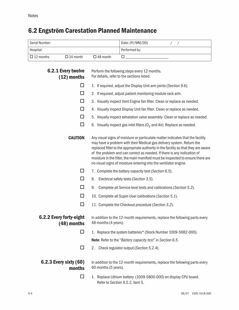
Notes
6-4 08/07 1505-1018-000
6.2 Engström Carestation Planned Maintenance
6.2.1 Every twelve(12) months
Perform the following steps every 12 months.For details, refer to the sections listed.
1. If required, adjust the Display Unit arm joints (Section 9.6).
2. If required, adjust patient monitoring module rack arm.
3. Visually inspect Vent Engine fan filter. Clean or replace as needed.
4. Visually inspect Display Unit fan filter. Clean or replace as needed.
5. Visually inspect exhalation valve assembly. Clean or replace as needed.
6. Visually inspect gas inlet filters (O2 and Air). Replace as needed.
CAUTION Any visual signs of moisture or particulate matter indicates that the facility may have a problem with their Medical gas delivery system. Return the replaced filter to the appropriate authority in the facility so that they are aware of the problem and can correct as needed. If there is any indication of moisture in the filter, the main manifold must be inspected to ensure there are no visual signs of moisture entering into the ventilator engine.
7. Complete the battery capacity test (Section 6.5).
8. Electrical safety tests (Section 3.5).
9. Complete all Service level tests and calibrations (Section 5.2).
10. Complete all Super-User calibrations (Section 5.1).
11. Complete the Checkout procedure (Section 3.2).
6.2.2 Every forty-eight(48) months
In addition to the 12-month requirements, replace the following parts every 48 months (4 years).
1. Replace the system batteries* (Stock Number 1009-5682-000).
Note: Refer to the “Battery capacity test” in Section 6.5.
2. Check regulator output (Section 5.2.4).
6.2.3 Every sixty (60)months
In addition to the 12-month requirements, replace the following parts every 60 months (5 years).
1. Replace Lithium battery (1009-5800-000) on display CPU board. Refer to Section 9.5.2, item 5.
Serial Number: Date: (YY/MM/DD) / /
Hospital: Performed by:
12 months 24 month 48 month ______________________
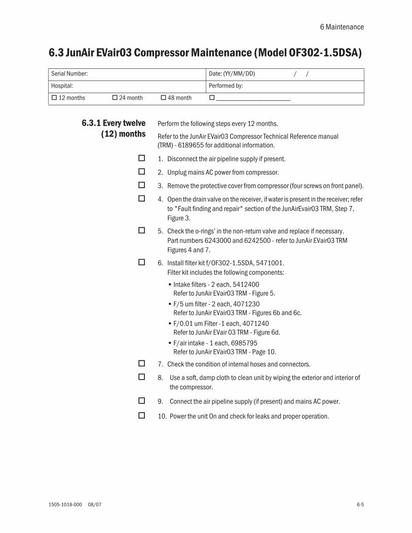
6 Maintenance
1505-1018-000 08/07 6-5
6.3 JunAir EVair03 Compressor Maintenance (Model OF302-1.5DSA)
6.3.1 Every twelve(12) months
Perform the following steps every 12 months.
Refer to the JunAir EVair03 Compressor Technical Reference manual (TRM) - 6189655 for additional information.
1. Disconnect the air pipeline supply if present.
2. Unplug mains AC power from compressor.
3. Remove the protective cover from compressor (four screws on front panel).
4. Open the drain valve on the receiver, if water is present in the receiver; refer to "Fault finding and repair" section of the JunAirEvair03 TRM, Step 7, Figure 3.
5. Check the o-rings’ in the non-return valve and replace if necessary. Part numbers 6243000 and 6242500 - refer to JunAir EVair03 TRM Figures 4 and 7.
6. Install filter kit f/OF302-1.5SDA, 5471001. Filter kit includes the following components:
• Intake filters - 2 each, 5412400 Refer to JunAir EVair03 TRM - Figure 5.
• F/5 um filter - 2 each, 4071230 Refer to JunAir EVair03 TRM - Figures 6b and 6c.
• F/0.01 um Filter -1 each, 4071240Refer to JunAir EVair 03 TRM - Figure 6d.
• F/air intake - 1 each, 6985795Refer to JunAir EVair03 TRM - Page 10.
7. Check the condition of internal hoses and connectors.
8. Use a soft, damp cloth to clean unit by wiping the exterior and interior of the compressor.
9. Connect the air pipeline supply (if present) and mains AC power.
10. Power the unit On and check for leaks and proper operation.
Serial Number: Date: (YY/MM/DD) / /
Hospital: Performed by:
12 months 24 month 48 month ______________________
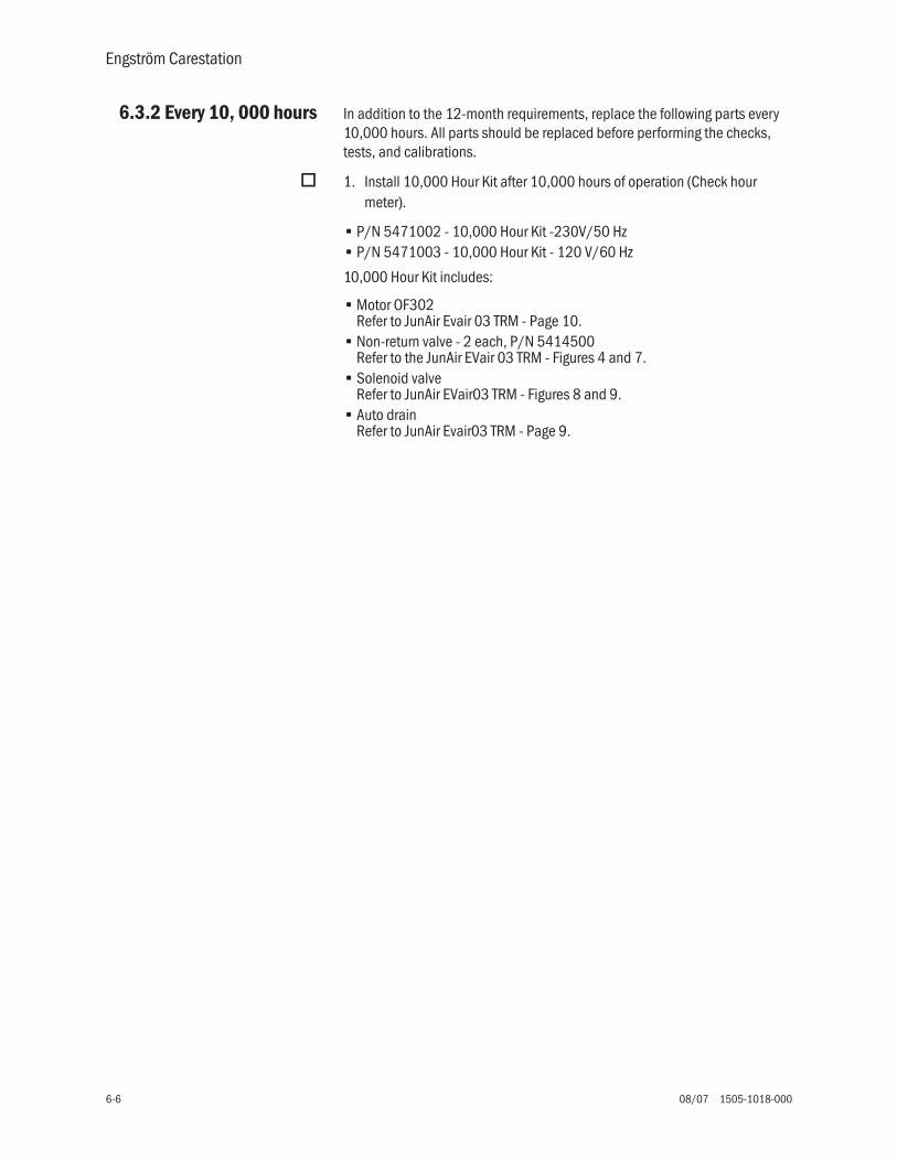
Engström Carestation
6-6 08/07 1505-1018-000
6.3.2 Every 10, 000 hours In addition to the 12-month requirements, replace the following parts every 10,000 hours. All parts should be replaced before performing the checks, tests, and calibrations.
1. Install 10,000 Hour Kit after 10,000 hours of operation (Check hour meter).
• P/N 5471002 - 10,000 Hour Kit -230V/50 Hz• P/N 5471003 - 10,000 Hour Kit - 120 V/60 Hz
10,000 Hour Kit includes:
• Motor OF302Refer to JunAir Evair 03 TRM - Page 10.
• Non-return valve - 2 each, P/N 5414500Refer to the JunAir EVair 03 TRM - Figures 4 and 7.
• Solenoid valveRefer to JunAir EVair03 TRM - Figures 8 and 9.
• Auto drainRefer to JunAir Evair03 TRM - Page 9.

6 Maintenance
1505-1018-000 08/07 6-7
6.4 Cleaning and sterilizing agents
WARNING The following cleaning/disinfection agents have been validated for material compatibility only. The effectiveness of sterilization with these agents has not been validated.
EthylAlcohol
Sporox II Cidex NU-CIDEX CIDEX OPAAutoclave at
134° C
Mild detergent and warm
water
Expiratory flow sensor
yes yes no no no yes yes
Exhalation valve housing and parts
yes yes no no no yes yes
Fan filters no no no no no no yes
Aeroneb Pro Nebulizer
no no yes yes yes yes yes
Water trap(cart mounted)
yes yes no no no yes yes
Cables yes no no no no no yes
External surfaces no no no no no no yes
Neo Flow Sensor yes yes no no no yes yes

Engström Carestation
6-8 08/07 1505-1018-000
6.5 Battery capacity testAlthough replacement of the backup batteries is recommended at the end of 4 years, batteries that pass the capacity test can be considered viable for battery backup of the system for up to 6 years at the discretion of the hospital.
Before testing the batteries, ensure that the PMB Diagnostics screen shows that the battery is fully charged. Battery status will show "Float Charge" which indicates that the battery is fully charged. Refer to section 8.1.3 .
Test procedure
1. Turn the system on and start a case (simulated).
2. Disconnect the power cord from the mains outlet.
3. Allow the system to run on battery until it does an orderly shutdown.
4. Reconnect the power cord to a mains outlet.
5. Boot the system with the PCMCIA Service Application for the DU and Compact Flash for HPDU, then access the Power Diagnostics function as detailed in Section 8.
• On the Main Menu of the Service Application, select Power Diagnostics.
• On the Power Diagnostic menu, select Power Control.
6. Page 1 of the Power Controller Power Diagnostics screen shows the ‘Date battery Tested’ (the last full battery discharge until shutdown) and the ‘Discharge Time’.
• If Discharge Time information is not displayed on the screen, the test has not been run. Repeat the test procedure.
• If the ‘Discharge Time’ is greater than 60 minutes, the batteries can be left in service for one more year.
• If the ‘Discharge Time’ is less than 60 minutes, both batteries should be replaced.
NNNNooootttteeee:::: Charge battery for at least 8 hours before next use.

1505-1018-000 08/07 7-1
7 Troubleshooting
In this section 7.1 Troubleshooting Checkout Failures . . . . . . . . . . . . . . . . . . . . . . . . . . . . . . . . . . . . . . . . . . . .7-2
7.1.1 Paw transducer check . . . . . . . . . . . . . . . . . . . . . . . . . . . . . . . . . . . . . . . . . . . . . . . .7-2
7.1.2 Barometric pressure test . . . . . . . . . . . . . . . . . . . . . . . . . . . . . . . . . . . . . . . . . . . . . .7-3
7.1.3 Low pressure leak and compliance check . . . . . . . . . . . . . . . . . . . . . . . . . . . . . . . .7-3
7.1.4 Safety valve relief and back pressure . . . . . . . . . . . . . . . . . . . . . . . . . . . . . . . . . . . .7-4
7.1.5 Exhalation valve calibration check . . . . . . . . . . . . . . . . . . . . . . . . . . . . . . . . . . . . . .7-5
7.1.6 Exhalation flow sensor calibration test . . . . . . . . . . . . . . . . . . . . . . . . . . . . . . . . . . .7-5
7.1.7 Measure breathing circuit resistance . . . . . . . . . . . . . . . . . . . . . . . . . . . . . . . . . . . .7-6
7.1.8 Air inspiratory flow sensor calibration check . . . . . . . . . . . . . . . . . . . . . . . . . . . . . .7-6
7.1.9 O2 inspiratory flow sensor calibration check . . . . . . . . . . . . . . . . . . . . . . . . . . . . . .7-6
7.1.10 O2 sensor test and calibration . . . . . . . . . . . . . . . . . . . . . . . . . . . . . . . . . . . . . . . .7-6
7.1.11 Neonatal flow sensor calibration check . . . . . . . . . . . . . . . . . . . . . . . . . . . . . . . .7-7
7.2 Troubleshooting Vent Engine Leaks . . . . . . . . . . . . . . . . . . . . . . . . . . . . . . . . . . . . . . . . . . . .7-8
7.2.1 Vent engine leak test . . . . . . . . . . . . . . . . . . . . . . . . . . . . . . . . . . . . . . . . . . . . . . . . .7-8
7.2.2 Auxiliary and expiratory pressure circuit leaks . . . . . . . . . . . . . . . . . . . . . . . . . . . 7-12
7.3 Troubleshooting Startup Screen (POST) messages . . . . . . . . . . . . . . . . . . . . . . . . . . . . . 7-14
7.4 Troubleshooting Startup Screen (POST) messages - for HPDU . . . . . . . . . . . . . . . . . . . . 7-15
7.5 Troubleshooting the Display (HPDU) . . . . . . . . . . . . . . . . . . . . . . . . . . . . . . . . . . . . . . . . . 7-16
7.6 Alarm message troubleshooting chart . . . . . . . . . . . . . . . . . . . . . . . . . . . . . . . . . . . . . . . . 7-17
7.7 Troubleshooting Service App messages . . . . . . . . . . . . . . . . . . . . . . . . . . . . . . . . . . . . . . 7-39

Engström Carestation
7-2 08/07 1505-1018-000
7.1 Troubleshooting Checkout Failures
Note: If the Automated Checkout (Section 3.2) results in failures, refer to the following sections to troubleshoot a specific failure. Use EC Service Application PC based (Section 8.5) while running all tests .
To file a quality report or request technical assistance regarding a checkout failure, create and include a Checkout log using the EC Service Application.
7.1.1 Paw transducercheck
The Paw Transducer Check can indicate a failure from four conditions:
1. Inspiratory Pressure Sensor Zero Failure:
With the Inspiratory Pressure Zero Valve actuated, raw counts from the Inspiratory Pressure Sensor must be between 631 and 968; if not, test results indicate Fail and the Pinsp sensor out of range message is displayed.
• Use EC Service Application PC based (Section 8.5) to facilitate problem isolation.
• Ensure proper connections.• Remove the Inspiratory Pressure Zero valve. If the Inspiratory Pressure
Sensor values are between 631 and 968 counts, replace the Zero Valve.• Replace the Inspiratory Pressure Sensor Board.• Replace the Vent Control board (VCB).
2. Expiratory Pressure Sensor Zero Failure:
With the Expiratory Pressure Zero Valve actuated, raw counts from the Expiratory Pressure Sensor must be between 631 and 968; if not, test results indicate Fail and Pexp sensor out of range message is displayed.
• Use EC Service Application PC based (Section 8.5) to facilitate problem isolation.
• Ensure proper connections.• Remove the Expiratory Pressure Zero valve. If the Inspiratory Pressure
Sensor values are between 631 and 968 counts, replace the Zero Valve.• Replace the Expiratory Pressure Sensor board.• Replace the Vent Monitor board (VMB).
3. Cannot achieve 34 cmH2O pressure:
The Air (O2) flow valve is set to approximately 10 lpm and the test is initiated if 34 cmH2O pressure is not achieved; test results indicate Fail but no alarm message is displayed.
• Use EC Service Application PC based (Section 8.5) to facilitate problem isolation.
• Ensure supply gas is connected.• Continue with other tests. If a significant leak is indicated during the Low
Pressure Leak test, repair the leak then repeat this check.• Check respective Flow Control Valve for proper operation.

7 Troubleshooting
1505-1018-000 08/07 7-3
4. Paw insp and Paw exp are not within 4 cmH2O when pressurized to 34 cm H2O.
Test results indicate Fail but no alarm message is displayed.
• Use EC Service Application PC based (Section 8.5) to facilitate problem isolation.
• Use the Service Application to calibrate sensors (Section 5.2.8).• Replace the affected Sensor board(s) or Zero valves, if calibration fails.
If this check fails, all ventilation modes will still be available.
7.1.2 Barometric pressure test
A failure indicates that the difference between calculated barometric pressure based on the input altitude, and the measured barometric pressure is greater than 20%.
• Verify correct altitude setting.• If setting is correct, calibrate the barometric sensor (Section 8.7.4).• Replace the Vent Monitor board (VMB) - recalibrate barometric sensor.
If this check fails, all ventilator modes will still be available and the calculations will use the input altitude as basis for absolute pressure.
7.1.3 Low pressure leak and compliance check
If there are errors in the calculation (negative values, divide by zero) the results will be dashed. The results of this calculation will be displayed after the Safety Relief Valve test is completed.
1. The first calculation is compliance and is based on the amount of time it takes for a 3 lpm flow to create 34 cmH2O of pressure at the Pexp sensor. If this pressure cannot be achieved, a "Failed" message will appear and no compliance information will be available.
2. The second calculation is the low pressure leak rate. It is based on the amount of pressure decay from 25 cmH2O pressure in approximately 3 seconds.
• If the leak rate is greater than 1 lpm (@ 25 cmH2O), the compliance value will be dashed and the leak value will show "> 1000 ml/min." This value can be useful in diagnosing other failures during checkout.
• If the Leak is greater than or equal to 500 ml/min or Compliance cannot be measured or Resistance cannot be measured, the "Failed" message will apear across from Circuit Check.
• If the the Leak is less than 500 ml/min and Compliance and Resistance can be measured, a message will be displayed.
3. Finally, a correction based on the leak rate is applied to the compliance calculation and the information will be displayed.

Engström Carestation
7-4 08/07 1505-1018-000
7.1.4 Safety valve relief and back pressure
The Safety Valve Relief test checks the ability of the Safety Relief Valve to relieve all patient pressure on demand. Failures include:
1. Set the Air (O2) flow valve to 3 lpm. If at least 30 cmH2O cannot be achieved, the test will indicate Fail but no alarm message is displayed.
• Ensure supply gas is connected.
• A leak is indicated; use the EC Service Application PC based (Section 8.5) and the Low Pressure Leak test (Section 7.2) to isolate and repair the leak.
• Repeat check.
2. Once pressure stabilizes, the Safety Relief Valve is opened. If Pexp does not go to less than 2 cmH2O within 250 msec, the test will indicate Fail and Relief Valve Failure message will be displayed.
Use the Service Application to simulate this test.
a. If pressure remains significantly above 2 cmH2O:
• Listen for the valve actuator to "click"when actuating. Check the connections to the safety relief valve.
• Ensure seat/seal interface is clean.• Replace the Manifold Assembly.
b. If pressure is only slightly above 2 cmH2O:
• Re-zero pressure sensors.• Ensure seat/seal interface is clean.• If Exhalation Valve Calibration Check also fails, replace the Pexp
sensor.• Repeat check.
3. If a flow of 75 l/min creates more than 15 cmH2O pressure at Pexp sensor with the safety relief valve open, the test will indicate Fail and Relief Valve Failure message will be displayed. If 75 l/min cannot be achieved, the test will indicate Fail but no message will be displayed.
Use the Service Application to simulate this test.
• Check the connections to the safety relief valve.
• Replace the Manifold, Insp Valve Assembly.
If this test fails, no mechanical ventilation is allowed.

7 Troubleshooting
1505-1018-000 08/07 7-5
7.1.5 Exhalation valve calibration check
The Exhalation Valve Calibration check sets flow at 4 l/min as measured by the total flow sensor and the expiratory valve to 34 cmH2O. Once stable, it opens the Expiratory Valve and verifies that the exp Paw is less than 2 cmH2O within 250 ms.
1. Cannot achieve 34 cmH2O (+/- 10 cmH2O pressure.
The test will indicate Fail but no alarm message is displayed.
• Ensure supply gas is connected and device can achieve at least 4 lpm at the 10 lpm calibration point (see step 3a).
• Calibrate the Exhlation Valve.
• A leak is indicated; use the EC Service Application PC based (Section 8.5) and the Low Pressure Leak test (Section 5.2.4) to isolate and repair the leak.
• Repeat check.
2. If both the Relief Valve and Exhalation Valve tests fail and the leak rate is less than 2000 counts, the most likely problem is with the Pexp Sensor not returning to zero:
• Use the Service Application to apply 34 cmH2O of pressure until stable, then release the pressure using either the Exhalation Valve or the Safety Relief Valve. The Pexp value must return to less than 2 within 250 msec. If not, re-zero and repeat or replace the Pexp sensor.
3. If only this check is failing:
a. Use the Service Application to verify at least 4 l/min is generated by the FCV. If not:
• Recalibrate the FCV.
• Replace the FCV.
b. Remove the Exhalation Valve Assembly and ensure the Voice coil shaft is clean and dry and moves freely without binding.
c. Replace the Exhalation Valve Assembly.
d. Replace the Voice coil assembly.
If this check fails, all ventilator modes will still be available.
7.1.6 Exhalation flowsensor calibration test
The Exhalation Flow Sensor Calibration test compares the Exhalation Flow Sensor output to the Total Flow Sensor output at 10 l/min. If the Expiratory Flow Sensor is within 20% of the Total Flow Sensor, the test passes and an Expiratory Flow normalization table is created to compensate for up to 10% of this discrepancy.
1. If only this test fails, replace the Exhalation Flow Sensor.
2. If the Air and/or O2 Inspiratory Flow Sensor calibration checks also fail, use the Service Application to determine the accuracy of the Total Flow Sensor.
If this test fails, all ventilator functions will still be available. The message Flow Sensor Error will be displayed.

Engström Carestation
7-6 08/07 1505-1018-000
7.1.7 Measure breathing circuit resistance
The breathing circuit resistance is calculated from the amount of resistance created when 60 l/min is flowing through the circuit. It is calculated and displayed on the bottom of the screen. It represents the resistance of 1/2 of the breathing circuit.
7.1.8 Air inspiratory flow sensor
calibration check
This check verifies that the Air Flow Sensor is functioning and compares the flow and temperature measurements with the total flow sensor at 30 l/min. Total flow and Air flow must be within 15% and temperature must be within 9° C.
Failure can be due to lack of flow as well as flow or temperature differences. Use the EC Service Application (Section 8.5) to simulate the test and isolate the problem.
If this check fails, all ventilator functions will still be available. The message FlAir Control Error will be displayed.
7.1.9 O2 inspiratoryflow sensor
calibration check
This check verifies that the O2 Flow Sensor is functioning and compares the flow and temperature measurements with the total flow sensor at 30 l/min. Total flow and O2 flow must be within 15% and temperature must be within 9°C.
Failure can be due to lack of flow as well as flow or temperature differences. Use the EC Service Application (Section 8.5) to simulate the test and isolate the problem.
If this check fails, all ventilator functions will still be available. The message FlO2 Control Error will be displayed.
7.1.10 O2 sensor testand calibration
This test/calibration will only be performed if both Air and O2 are connected. The O2 offset is calibrated while flowing 30 l/min of Air, and the O2 gain is calibrated with 30 l/min of O2. The test will FFFFaaaaiiiillll if either Air or O2 fail to achieve 30 l/min flow.
Calibration is verified by flowing 15 l/min Air and 15 l/min O2 and comparing the sensor output to the calculated valve (approximately 60.5%). The test will FFFFaaaaiiiillll if O2 sensor is not within 5% of the calculated value.
If this check fails, all ventilator functions will still be available.
Note: This test is performed before the O2 inspiratory flow sensor calibration check.

7 Troubleshooting
1505-1018-000 08/07 7-7
7.1.11 Neonatal flowsensor calibration
check
This test verifies the accuracy of both the inspiratory and expiratory flow sensor circuits in the Neonatal Flow Sensor at 20 l/min.
1. During this stage the circuit is occluded. The flow is set to 4 l/min and the flow sensor should indicate 0 l/min. If not, the test will indicate Fail and the next step will be skipped (no message box will appear).
2. A message box is displayed requesting removal of the circuit occlusion. After detecting that Paw drops below 3 cmH2O, flow will be set at 20 l/min. The exhalation valve is closed.
a. The Total Flow Sensor must be within 25% of the expiratory neonatal flow (absolute value) +4.59 l/min.
b. The Total Flow Sensor must be within 15% of the inspiratory neonatal flow (absolute value).
Use the EC Service Application to simulate the test and isolate the problem.
If this check fails, all ventilator functions will still be available.
Important Volume control and monitoring will be more accurate if the neonatal flow sensor is calibrated in the following situations:
• Before use, during the Checkout procedure.
• After replacing the flow sensor.
• After a power cycle.

Engström Carestation
7-8 08/07 1505-1018-000
7.2 Troubleshooting Vent Engine Leaks
Note: Use the EC Service Application PC based (Section 8.5) while running all tests.
• Refer to Section 7.2.1 if the vent engine leak test fails (Section 5.2.5) by either being unable to build 70 cmH2O pressure or if the leak rate exceeds 10 ml/min.
• Refer to Section 7.2.2 if able to build inspiratory pressure to 70 cmH2O inspiratory pressure, but unable to build 70 cmH2O of either expiratory pressure or auxiliary pressure.
To file a quality report or request technical assistance regarding a checkout failure, create and include a Checkout log using the EC Service Application.
7.2.1 Vent engineleak test
While retaining the leak test setup:
1. Close the Air and O2 flow valves to limit the components tested (remove the checkmarks from the boxes next to the DAC counts).
2. Repeat the Vent Engine Leak Test.
• If the test passes, proceed to step 5.
• If the leak remains, toggle the Effort Valve closed.
3. Repeat the Vent Engine Leak Test.
• If the system passes, check the Free Breathing Valve diaphram and o-ring seal.
• If the leak remains, toggle the safety valve open/closed.
4. Repeat the Vent Engine Leak Test.
• If the system passes, check the safety valve seal.
• If the leak remains, check the individual components in the Total Flow path.
AB.9
8.08
8
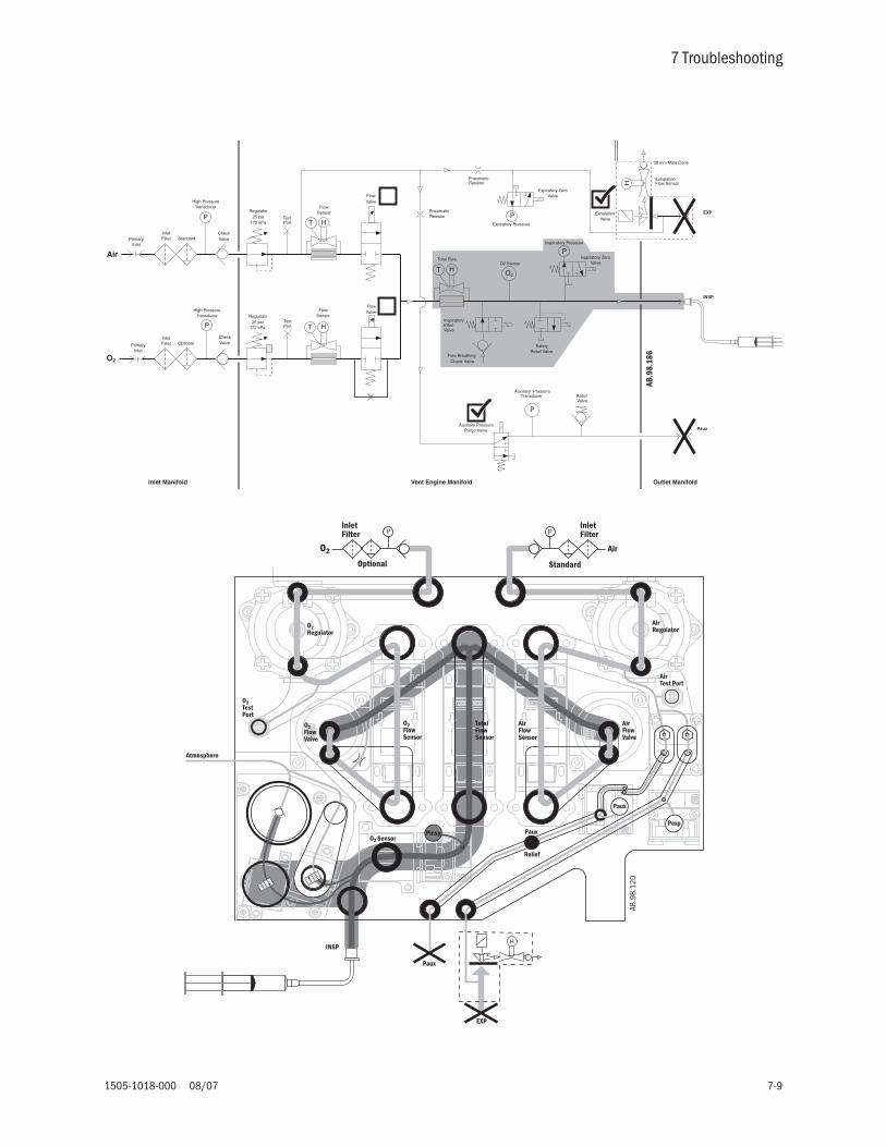
7 Troubleshooting
1505-1018-000 08/07 7-9
AB.9
8.10
0
O2
25 psi172 kPa
25 psi172 kPa
SafetyRelief Valve
FlowSensor
FlowSensor
Total Flow
InspiratoryEffortValve
Free Breathing Check Valve
HT
HT
P
PneumaticResistor
O2 SensorInspiratory Zero
Valve
Auxiliary PressureTransducer
Regulator
Inspiratory Pressure
FlowValve
Regulator
FlowValve
ReliefValve
Auxiliary PressurePurge Valve
TestPort
TestPort
H
30 mm Male Cone
ExhalationValve
ExhalationFlow Sensor
Pneumatic Resistor
Expiratory ZeroValve
Expiratory Pressure
Inlet Manifold Vent Engine Manifold Outlet Manifold
EXP
INSP
P
P
HT
Paux
Air
O2
High PressureTransducer
PrimaryInlet
CheckValve
CheckValve
High PressureTransducer
PrimaryInlet
P
P
InletFilter Optional
InletFilter Standard
AB.9
8.18
6
AB.9
8.10
1
Paux
H
Atmosphere
EXP
INSP
Pexp
P P
O2Regulator
O2TestPort
O2FlowValve
O2FlowSensor
TotalFlowSensor
AirFlowSensor
O2 SensorPaux
Relief
Paux
AirFlowValve
AirTest Port
AirRegulator
Pinsp
O2 Air
Standard
InletFilter
Optional
InletFilter
AB.9
8.12
0

Engström Carestation
7-10 08/07 1505-1018-000
5. Open only the O2 flow valve by checking the O2 Flow Valve box (verify that 60000 DAC counts are set).
6. Repeat the Vent Engine Leak Test.
• If the test fails, check the individual components in the O2 Flow path.
• If the test passes, check the individual components in the Air Flow path.
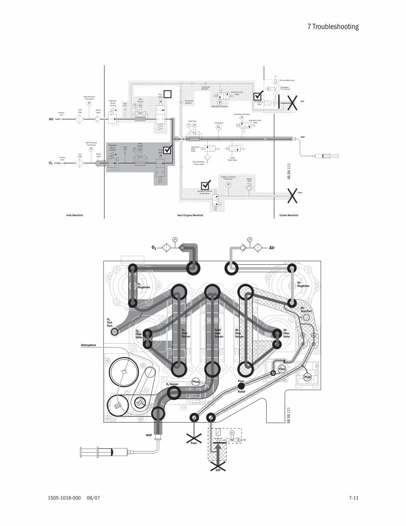
7 Troubleshooting
1505-1018-000 08/07 7-11
AB.9
8.10
0
Air
O2
25 psi172 kPa
25 psi172 kPa
SafetyRelief Valve
FlowSensor
FlowSensor
O2
Total Flow
InspiratoryEffortValve
Free Breathing Check Valve
HT
HT
P
PneumaticResistor
O2 SensorInspiratory Zero
Valve
Auxiliary PressureTransducer
InletFilter
High PressureTransducer
PrimaryInlet
CheckValve
Regulator
Inspiratory Pressure
FlowValve
Regulator
FlowValve
CheckValve
High PressureTransducer
InletFilterPrimary
Inlet
ReliefValve
Auxiliary PressurePurge Valve
TestPort
TestPort
H
30 mm Male Cone
ExhalationValve
ExhalationFlow Sensor
Pneumatic Resistor
Expiratory ZeroValve
Expiratory Pressure
Inlet Manifold Vent Engine Manifold Outlet Manifold
EXP
INSP
P
P
P
P
HT
Paux
AB.9
8.11
1
Paux
H
Atmosphere
Air
EXP
INSP
Pexp
O2
P P
O2Regulator
O2TestPort
O2FlowValve
O2FlowSensor
TotalFlowSensor
AirFlowSensor
O2 SensorPaux
Relief
Paux
AirFlowValve
AirTest Port
AirRegulator
Pinsp
AB.9
8.12
1

Engström Carestation
7-12 08/07 1505-1018-000
7.2.2 Auxiliary andexpiratory pressure
circuit leaks
If the vent engine leak test (Section 5.2.5) fails at step 5, the following steps will help to locate the possible leak locations. Flow in the Auxiliary and Expiratory pressure circuits is restricted, therefore failure to build pressure may not cause the leak test to fail, and may not affect checkout, or system while in use.
Note: If both the Auxiliary and Expiratory pressure is low, it is possible that both restrictors are partially plugged, or both circuits have leaks. Therefore, it is best to troubleshoot each pressure circuit as an individual problem.
If the Expiratory pressure is lower than the Inspiratory pressure:
1. Remove the Exhalation valve and plug the Exhalation Pressure opening on the front panel. Repeat the test:
a. If pressures equal, the problem is from the Exhalation valve housing, or the seal located between the Exhalation valve and the front panel.
b. If not, continue.
Warning Before removing restrictors: shut off supply valves and open flow valves to bleed system pressure build-up.
1. Remove the restrictor and reinstall the restrictor access cover. Repeat the test.
a. If pressures equal, install a new restrictor and repeat the test.
b. If not, or if the test fails with the new restrictor, continue.
2. Check the following seals on the individual components in the order listed, replace components as needed, and repeat the test.
a. Restrictor cover gasket
b. Expiratory pressure zero valve gasket.
c. Expiratory pressure sensor o-ring.
d. Outlet manifold o-ring.
3. If the test fails, replace the following components in the order listed.
a. Expiratory pressure sensor assembly.
b. Outlet panel assembly.
c. Main manifold assembly.

7 Troubleshooting
1505-1018-000 08/07 7-13
If the Auxiliary pressure is lower than the Inspiratory pressure:
1. Remove the restrictor and re-install the restrictor access cover. Repeat the test.
a. If pressures equal, install a new restrictor and repeat the test.
b. If not, or if failure occurs with new restrictor, continue.
2. Check seals on the following individual components in the order listed, replace components as needed, and repeat the test:
a. Restrictor cover gasket.
b. Auxiliary pressure relief valve.
c. Auxiliary pressure zero valve gasket.
d. Auxiliary pressure sensor o-ring.
e. Outlet manifold o-ring.
3. If failure occurs, replace the following components in the order listed:
a. Auxiliary pressure sensor assembly.
b. Auxiliary zero valve.
c. Outlet panel assembly.
d. Main manifold assembly.

Engström Carestation
7-14 08/07 1505-1018-000
7.3 Troubleshooting Startup Screen (POST) messages
If the EC system encounters a problem at startup to where it cannot initiate system software, a BIOS error message indicating the failure will be displayed.
Some system failures can result in a High Priority alarm displayed.
Message What it indicates Troubleshooting Action Required
***NOTE: RTC failed. xx
This indicates an illegal value in the CPU's Real Time Clock date or time registers.
Set the system date and time manually to the correct values.
***NOTE: CMOS defaults reloaded.
This is an informational message. No action needed.
***NOTE: CMOS battery failed. Replace soon.
Service is required to replace the CPU battery.
Replace the battery on the DU CPU board. Reload software and check out the system.
***NOTE: Alarm tone detection failed.
Service is required to correct a faulty connection to the speaker.
Reconnect the speaker if possible. Replace DU CPU board if speaker connection can not be corrected.
***NOTE: ECC failed. xx
The RAM memory ECC circuitry is faulty.
Replace the DU CPU board.
***NOTE: System reset. EC xx
This usually indicates a software (BIOS) failure.
Report this error, along with the machine logs, to Technical Support.Reload software. If problem persists, replace the DU CPU board.
***NOTE: Critical hardware failure. xx
Some of the DU hardware could not be initialized.
Replace the DU CPU board.
***NOTE: OS/App ROM CRC failed.
The software must be reloaded. Reload software and check out the system.
***NOTE: System reset.
The software must be reloaded. Reload Software and check out the system.
Message What it indicates Troubleshooting Action Required
VCB/VMB Fail This usually indicates a software failure.
Report this error, along with the machine logs, to Technical Support.Reload software. If problem persists, replace the DU CPU board.

7 Troubleshooting
1505-1018-000 08/07 7-15
7.4 Troubleshooting Startup Screen (POST) messages - for HPDU
If the EC system encounters a problem at startup to where it cannot initiate system software, a BIOS error message indicating the failure will be displayed.
Some system failures can result in a High Priority alarm displayed.
Message What it indicates Troubleshooting Action Required
***ERROR: CPU data cache fault.
This indicates a hardware failure. Replace the HPDU CPU board.
***ERROR: No bootable device available.
This indicates a problem with the internal CF card.
Check or replace the internal compact flash card.
***ERROR: Program load failed - CRC.
This usually indicates a software file corruption.
Reload the software and check out the system.
***ERROR: RAM memory error.
This indicates a hardware failure. Replace the HPDU CPU board.
***ERROR: System reset: ECxx xx xx . . .
This usually indicates a software failure.
Report this error, along with the machine logs, to Technical Support.Reload software. If problem persists, replace the internal flash card and reload software. If problem persists, replace the HPDU CPU board.
***ERROR: System reset: FFFF FF FF
Indicates the HPDU lithium battery has lost contact with the holder or the battery is below voltage.
Replace the lithium battery if below rated voltage.Install the software downloader card to restore system setups.
***ERROR: watchdog circuit failed.
This indicates a hardware failure. Replace the HPDU CPU board.
***NOTE: Alarm speaker not detected. Check connection.
Service is required to correct a faulty connection to the speaker.
Reconnect the speaker if possible. Replace the HPDU CPU board if speaker connection can not be corrected.
***NOTE: CMOS battery is weak. Please replace.
Service is required to replace the CPU battery.
Replace the battery on the HPDU CPU board. Reload software and check out the system.
***NOTE: RTC date/time error. Battery may be weak.
Service is required to replace the CPU battery.
Replace the battery on the HPDU CPU board. Reload software and check out the system.
Message What it indicates Troubleshooting Action Required
VCB/VMB Fail This usually indicates a software failure.
Report this error, along with the machine logs, to Technical Support.Reload software. If problem persists, replace the HPDU CPU board.

Engström Carestation
7-16 08/07 1505-1018-000

7 Troubleshooting
1505-1018-000 08/07 7-17
7.5 Troubleshooting the Display - HPDU
Symptom Resolution
System will not boot from external Compact Flash card during software installation process
1. Verify that the Compact Flash card is properly inserted. 2. Insert a backup Compact Flash card.3. Open the HPDU and verify that the external Compact Flash card carrier
socket (1009-5961-000) is properly seated.4. Replace external Compact Flash card carrier socket (1009-5961-000).5. Replace HPDU main PCB.
Display appears mostly white and the green LED is on
1. Verify that the cable connecting the HPDU to the system’s rear panel is properly seated.2. Open the HPDU and verify that the cable connecting the main PCB to the display at J28 is properly seated within the mating housing and check for damage and/or wear.3. Replace the HPDU.
Rotary encoder fails to work 1. Open the HPDU and verify that the cable connecting the main PCB to the rotary encoder at J38 is properly seated within the mating connector.2. Verify that the revision of the flex cables connecting the main PCB to the keypads at J23 and J26 are at revision 101 or greater by inspecting the labels directly adhered to the flex cables.3. Replace the rotary encoder,4. Replace the HPDU main PCB.
Unit fails to boot and the green LED is on 1. Open the HPDU and ensure that the lithium coin cell at J17 on the main PCB is properly installed.2. Replace the lithium coin cell at J17 on the main PCB.3. Verify that the internal Flash card at J10 on the main PCB is properly seated.4. Attempt to boot the system using a spare compact flash card and replace the card if necessary.5. Attempt to boot the system from the external Compact Flash card.6. Replace the HPDU main PCB.
Excessive fan noise 1. Clean the HPDU fan inlet filter.2. Check for obstructions within the external fan and verify source of fan noise.3. Open the HPDU and verify internal CPU fan noise.4. Replace internal or external fan assembly if causing excessive noise.

Engström Carestation
7-18 08/07 1505-1018-000
7.6 Alarm message troubleshooting chart
Note: Whenever “Check/replace harness” is indicated, ensure that all terminals are fully inserted into the connector body window and that all wires are properly crimped.
Troubleshooting guidelines are listed in order of probability. The entire list does not need to be carried out if the problem is resolved. The list may not include all possible solutions.
• Alarm message = display message
• Alarm ID = message in Error log or Event log
Alarm message Alarm ID Priority Alarm Condition Special Behavior/Comments
• Action/Troubleshooting
-none- DU RAM Error Failed
Self test failure or multi bit error detected.
Run Backup Ventilation if in Therapy.
• Cycle power.• Replace display unit CPU board.
-none- Neo Flow Sensor Comparison
High (Neo TVexp - Neo TVinsp)>(0.3* Neo TVinsp) or 5 mL whichever is greater for 6 consecutive breaths.
Freeze vent engine volume compensation on first breath detection.
• Calibrate neo flow sensor.• Check neo flow sensor and cable connections.• Replace neo flow sensor.• Replace neo flow sensor cable.• Replace VMB.• Repace motherboard.• Replace VCB
-none- Neo Total Flow Sensor Comparison
High (Neo TVexp - Neo TVinsp)>(0.3* Neo TVinsp) or 30 mL whichever is greater for 6 consecutive breaths.
Freeze vent engine volume compensation on first breath detection.
• Calibrate neo flow sensor.• Check neo flow sensor and cable connections.• Calibrate expiratory flow sensor.• Replace neo flow sensor.• Replace neo flow sensor cable.• Replace expiratory flow sensor.• Replace total flow sensor.• Replace VMB.• Repace motherboard.• Replace VCB.

7 Troubleshooting
1505-1018-000 08/07 7-19
-none- Neo Exh Flow Sensor Comparison
High (Exh TVexp - Neo TVexp) > (0.3* Neo TVexp) or 30 mL whichever is greater for 6 consecutive breaths.
• Calibrate neo flow sensor.• Check neo flow sensor and cable connections.• Calibrate expiratory flow sensor.• Replace neo flow sensor.• Replace neo flow sensor cable.• Replace expiratory flow sensor.• Replace VMB.• Repace motherboard.• Replace VCB.
-none- Therapy Power Off High
Power switch is set to Off. Non-silenceable.
• Normal operation if On/Standby switch is moved to standby while in therapy.• Verify vent is in standby state prior to turning power On/Standby switch to standby.• Verify display unit encoder accepts other inputs reliably. If not, replace encoder.• Check/replace harness to On/Standby switch.• Check/replace On/Standby switch.• Check/replace PMB.
Air supply pressure high
Air Supply Pres High Low Air supply pressure > 95 psig for more than 0.5 seconds
May result in FiO2 low alarm.
• Check air supply.• Disconnect sensor and verify output is zero gauge pressure.• Interchange harness connections on both supply pressure sensors.• If alarm follows the sensor, replace supply pressure sensor.• If not, check/replace VMB.
Air supply pressure low
Flow Wave:O2 only
Air Supply Pres Low Medium
Air supply pressure < 24.3 psig for more than 0.5 seconds
Unit shuts down Air supply and delivers 100% Oxygen
• Check air supply.• Disconnect sensor and verify output is zero gauge pressure.• Interchange harness connections on both supply pressure sensors.• If alarm follows the sensor, check sensor connector terminals. Replace supply pressure sensor if necessary.• If not, check/replace harness.• If not harness, check/replace VMB.
Alarm message Alarm ID Priority Alarm Condition Special Behavior/Comments
• Action/Troubleshooting

Engström Carestation
7-20 08/07 1505-1018-000
Air temp high
Flow Wave:O2 only
Temp High High
Total flow sensor temperature > 48°C Switch to 100% O2.Air is turned off regardless of other alarm conditions (for example, O2 Supply Low).When the condition clears, the vent changes back to previous known good set O2 mixture.
• Check inlet air temperature. • Use Service App to check temperatures of air and total flow sensors.• If inlet air temp is NOT high, and if temp from total flow sensor reports more than 9°C higher than the air
sensor, replace Total Flow Sensor.• With a air flow of approximately 10 l/min, verify air and total flows are within 10% of each other.
Air temp sensor error
Air Temperature Sensor Failure
Low
Out of range air temperature sensor data (range is 0-60 degrees C).
Use total flow temperature for all air flow sensor calculations, including alarms.If total flow sensor temperature not available, use 50°C.
• Check inlet air temperature. • If comm. Failure alarm is also active, check harness connections.• With gas supplies disconnected and system temperature stabilized, use Service App to check temperatures
of air and total flow sensors. Air flow sensor and total flow sensor shall not differ by more than 9°C.• Replace sensors.
Backup audio failure
Backup Buzzer POST Medium Current to buzzer indicates audio is not sounding.
This alarm is logged at start-up and can be de-escalated but cannot be cleared from the screen. The primary and backup alarm audio sounds upon every power-up of the EC system.
• Check harness connection between PMB/On-Standby switch.• Verify buzzer current with voltage measurement at TP15 on VCB. If voltage IS NOT present, replace PMB. If
voltage IS present, replace VCB.
Backup mode active
Backup Mode Active Medium Spontaneous breathing is insufficient or Display Unit failure.System goes into Backup Ventilation mode.
Uses PCV mode and preset settings (customer configurable).
• Ensure the patient’s spontaneous breathing and ventilatory support is adequate. This alarm could be triggered by user errors regarding patient ventilation requirements. See URM for details.
• Check error log for communication errors or DU errors.
Alarm message Alarm ID Priority Alarm Condition Special Behavior/Comments
• Action/Troubleshooting

7 Troubleshooting
1505-1018-000 08/07 7-21
Cannot calculate FRC
FRC invalid Low An FRC measurement was started for FRC or PEEP Inview, but unable to be completed within the last 5 seconds.
• Check end tital CO2 reading.• Ensure airway module is available and active.• Stop any active procedures.• Start a new FRC measurement.• Ventilation changes will stop an FRC measurement.• With gas module plugged in, check power supply status LEDs on MIB from bottom of sheetmetal enclosure.
If any LEDs are lit, then unplug module. If LEDs remain lit, replace MIB.• Replace gas module.
Check D-fend
CO2 or O2 wave instruction:Check D-fend. Wait 30 sec and press Normal Screen to continue.
MGAS D-fend Not Connected >40 Sec
MGAS D-fend Not Connected >60 Sec
Low
Medium
MGAS communicates that the D-fend module is not installed.
The pump turns Off.If Normal Screen is selected the DU commands the MGAS to start sampling again.
• Check that the sample tube is connected.• Check that the water trap is connected.• Check that the gas outlet is not blocked.• Replace Module.
Check sample gas out
CO2 or O2 waveform instruction:Check sample gas out. Wait 30 sec and press Normal Screen to continue.
MGAS Check Sample Gas Out > 40 Sec
MGAS Check Sample Gas Out > 60 Sec
Low
Medium
MGAS communicates continuous occlusion for 40 seconds.
MGAS communicates continuous occlusion for 60 seconds.
The pump turns Off.If Normal Screen is selected, the DU commands the MGAS to start sampling again.
• Check the gas outlet.• Replace module.
Clean neo flow sensor
Neo Flow Sensor Contaminated
Medium Neo flow sensor reporting flow > 32 l/min for 4 continuous seconds as measured by the VCB or VMB.
• Calibrate neo flow sensor.• Clean neonatal flow sensor• Replace neo flow sensor.• Replace neo flow sensor cable.• Replace VMB.• Repace motherboard.• Replace VCB.
Alarm message Alarm ID Priority Alarm Condition Special Behavior/Comments
• Action/Troubleshooting

Engström Carestation
7-22 08/07 1505-1018-000
Connect nebulizer
Nebulizer not Connected
Low
Nebulizer disconnected while nebulization procedure is running.
• Re-connect Nebulizer.• Replace Nebulizer cable.• Replace Nebulizer head.• Replace Nebulizer board.
Controls frozen. Need service
Front Panel Com Fail High
Display CPU board fails to send life tick for greater than 10 seconds
DU to allow power off confirmation, even in Therapy. (The Power lock popup will not appear.)
• Look for physical damage to the keypad. If damaged, disconnect the internal keypad cable.• If the unit powers up with no failures indicated, replace the membrane switch assembly.• If failure still exists, disconnect each of the the remaining keypad connections (one-by-one) until the failed
component is located. Replace the failed component.• If failure still exists with all keypads disconnected, replace the CPU board.
Display fans failed
CPU Fan Speed Fail
CPU Overheat
Medium
Medium
CPU fan speed less than 2500 RPM (50% of nominal speed).
Temperature reading of either DU thermistor >60°C.
• Verify fan connection.• Verify fan is not spinning while powered. If not, then replace fan.• Replace DU CPU board.
Exp flow sensor failure
Exhalation Flow Sensor Communications Failure
High
Failed communications with exhalation flow sensor.
Use open loop pressure control.
• Check harness connection between VMB and exhalation flow sensor PCB.• Replace exhalation flow sensor PCB.• Replace VMB.
Exp Flow sensor error
Exhalation Flow Sensor Comparison
Medium
( TVexp – TVinsp) > (0.3* TVinsp) or 100 mL whichever is greater for 6 consecutive breaths.
Freeze vent engine volume compensation on first breath detected.
• Using Service App, verify Inspiratory flows match Expiratory flow within tolerance stated above.• Replace expiratory sensor as necessary.• Replace exhalation flow sensor board (EFSB).
Fans require service
Fan Fail Medium
Fan Power Status Bits for main fan or vicor fan is low.
• Check connections to fans.• Replace broken fan(s).
Alarm message Alarm ID Priority Alarm Condition Special Behavior/Comments
• Action/Troubleshooting

7 Troubleshooting
1505-1018-000 08/07 7-23
FiO2 control error Air Flow Sensor Communications Failure
Medium
Loss of communication with Air Flow Sensor.
Use Open Loop valve mixture control.Return to closed loop volume delivery control when cleared.
• Check Error Log for Air/O2 Insp Flow Sensor Supply Voltage. • If yes:
-Disconnect vent engine harness at air flow sensor. If voltage error stops, replace air flow sensor.-Disconnect vent engine harness at O2 flow sensor. If voltage error stops, replace O2 flow sensor.-Disconnect vent engine harness at VCB. If voltage error stops, replace harness.
• If no:-Check connection to Air Flow Sensor.-Interchange harness connection between air and total flow sensor.-If problem stays with sensor, replace sensor. If alarm follows harness, check/replace harness. If harness is
OK, replace VCB.
FiO2 control error O2 Flow Sensor Communications Failure
Medium
Loss of communication with O2 Flow Sensor.
Use Open Loop valve mixture control.Return to closed loop volume delivery control when cleared.
• Check Error Log for Air/O2 Insp Flow Sensor Supply Voltage. • If yes:
-Disconnect vent engine harness at air flow sensor. If voltage error stops, replace air flow sensor.-Disconnect vent engine harness at O2 flow sensor. If voltage error stops, replace O2 flow sensor.-Disconnect vent engine harness at VCB. If voltage error stops, replace harness.
• If no:-Check connection to O2 Flow Sensor.-Interchange harness connection between O2 and total flow sensor.-If problem stays with sensor, replace sensor. If alarm follows harness, check/replace harness. If harness is
OK, replace VCB.
FRC series stopped
FRC series terminated Low Set O2 is >set FRC O2 and user decreases the set O2 during a series interval with the last 5 seconds OrSet O2 is <set FRC and user increases the set O2 so that FRC O2 would be > 100% within the last 5 seconds.
Alarm is removed upon state change or when new series is initiated.
• Verify correct settings.• Restart series.
Internal power failureOn battery
PMB DC-DC Fail Medium
AC supply is OK but batteries are being discharged.
• Check screw terminal connections and harness between AC-DC power supply and PMB• Check fuse F1. If not OK, replace PMB.• Replace AC-DC power supply.
Alarm message Alarm ID Priority Alarm Condition Special Behavior/Comments
• Action/Troubleshooting

Engström Carestation
7-24 08/07 1505-1018-000
Mixed gas temp sensor error
Total Flow Temperature Sensor Failure
Low
Out of range total temperature sensor data or loss of communication.
Use air flow temperature for total flow sensor calculations, including alarms.If air flow sensor temperature not available use 50°C.
• Check inlet air temperature. • If comm. Failure alarm is also active, check harness connections.• With gas supplies disconnected and system temperature stabilized, use Service App to check temperatures
of air and total flow sensors. If either reports temperature out of range (0 to 60°C), replace that sensor.
Missed scheduled FRC
FRC missed Low Another procedure or condition prevented the FRC series measurement from starting within the last 5 seconds.
Series continues (only one measurement was missed).
• Ensure airway module is available and active.• Stop any active procedures.• Start a new FRC measurement.• Ventilation setting changes will stop an FRC measurement.
Module fail. No CO2, O2 data
MGAS Sensor Inop > XX Medium
MGAS communicates hardware failure (RAM failure, ROM checksum error, Error in CPU EEPROM, Error O2 preamp EEPROM, Error in SSSboard EEPROM, Voltage error, or Lamp control failure.)
• Replace Module
Module not compatible
Module Not Compatible Low
The monitoring module detected is not compatible with system software. Refer to Airway Modules - Section 5 in the User’s Reference manual.
• Remove and reseat Module.• Check software revision in the Service Log.• Replace Module.
Negative airway pressure
Negative Pressure High
Paw insp < -10 cmH20 for greater than 50 continuous ms.
Latched alarm.PEEP numeric changes to flashing red background.
• Compare Insp and Exp sensor values using the Service App at zero and 100 cm/H2O. The Insp and Exp pressure sensors should match within ±5 cmH20 (while at 0 cmH2O true pressure) and ±10 cmH2O (while at 100 cmH20 true pressure)
• Calibrate pressure sensors.• Refer to pneumatic troubleshooting section for testing zeroing valve.• Check harness connection on VCB and VMB.• Replace sensor as needed.
Neo flow sensor error
Neonatal Flow Comparison - System
High Neo flow sensor comparison alarm active or neo-total flow sensor comparison alarm active or neo-exh flow sensor comparison alarm active.
• See Neo flow sensor comparison alarm, neo-flow sensor comparison alarm, or neo-exh flow sensor comparison alarm troubleshooting
Alarm message Alarm ID Priority Alarm Condition Special Behavior/Comments
• Action/Troubleshooting

7 Troubleshooting
1505-1018-000 08/07 7-25
Neo flow sensor off
Neo Flow Sensor Off Medium Neo flow sensor turned off in neo flow sensor setup menu.
• Turn on neo flow sensor.
Remove airway module
Neo module not compatible
Low Any MGAS module is installed in the module bay during neo patient type.
• Remove module or change patient type to adult or pediatric.
No neo flow sensor
No Neonatal Flow Sensor - Standby
Low Both neonatal flow sensor hot wires reporting less than 20 ADC as measured by the VCB or VMB.
• Calibrate neo flow sensor.• Check neo flow sensor and cable connections.• Replace neo flow sensor.• Replace neo flow sensor cable.• Replace VMB.• Repace motherboard.• Replace VCB.
Neo flow sensor reversed
Neo Flow Sensor Reversed
High Neo TVinsp more negative than -3 mL for 6 consecutive mechanical breaths.
• Verify FMI 34014 has been completed on unit.
• Calibrate neo flow sensor.• Check neo flow sensor and cable connections.• Replace neo flow sensor.• Replace neo flow sensor cable.• Replace VMB.• Repace motherboard.• Replace VCB.
No neo flow sensor
No Neonatal Flow Sensor - Therapy
High Both neonatal flow sensor hot wires reporting less than 20 ADC as measured by the VCB or VMB.
• Calibrate neo flow sensor.• Check neo flow sensor and cable connections.• Replace neo flow sensor. Neonatal flow sensor is warranteed for 90 days.• Replace neo flow sensor cable.• Replace VMB.• Repace motherboard.• Replace VCB.
No battery backup
Degraded Battery Medium
The total battery voltage is <20VDC -or-Each battery voltage is <10VDC
• Verify unit has been connected to mains for more than 24 hours.• Check error log for related messages.• Use Service App to determine charge state. If in trickle charge, replace batteries.• Check/replace harness.• Check/replace PMB.
Alarm message Alarm ID Priority Alarm Condition Special Behavior/Comments
• Action/Troubleshooting

Engström Carestation
7-26 08/07 1505-1018-000
No battery backup?
(Note "?" in alarm message)
DU to PMB Com Error-or-PMB to DU Com Error
Medium
Communications from the DU to the power controller cannot be established for 10 seconds. -or-Communications from the power controller to the DC cannot be established for 10 seconds.
PMB assumes failed state and allows system to shutdown without confirmation from DU.(This alarm allows vent to be shut down if DU communications is lost.)
Note question mark at end of message and no battery status indicator on display.
• Check error logs for related messages.• Check communication (no software information indicates no communication).• If multiple failures, replace DU CPU board.• Check / replace display cable.• Check (reseat) all connections on all PC boards.• Check/replace DU interface board.• Replace motherboard.• Replace PMB.
No battery backup?
(Note "?"in alarm message)
PMB POST Failure Medium
Power controller failed CPU self tests Note question mark at end of message and no battery status indicator on display
• Cycle power.• Replace PMB.
No battery backup
Battery Charge Fail-or-Standby Current High
Medium
The system is powered on with a battery current >1.3 amps.-or-System is in Standby andthe charge current is >1.7 Amps.
Refer to Section 8.1.3 for more information.
• Cycle power.• Check/replace harness.• Replace Power Supply.• Replace PMB.
No battery backup
Battery Fail Medium
While bulk, over, or float charging any battery is <10.5VDC (short) -or-Battery has been charging for >24h while powered on (sulfated)-or-Voltage >16.5V during bulk or over charging and normal current >0.25 amps (sulfated).
Battery status indicator appears under clock.
Refer to Section 8.1.3 for more information.
• Cycle power.• Check/replace harness.• Replace batteries.
Alarm message Alarm ID Priority Alarm Condition Special Behavior/Comments
• Action/Troubleshooting

7 Troubleshooting
1505-1018-000 08/07 7-27
No battery backup
Battery Missing Medium
Any battery voltage is between -1.0 and +1.0VDC.
Battery status indicator appears under clock.
Refer to Section 8.1.3 for more information.
• Cycle power.• Check connections/replace harness.• Check/replace fuse. • Replace batteries.
No battery backup
Battery Reversed Connection
Medium
Any battery voltage is less than -1.0VDC
Battery status indicator appears under clock.
Refer to Section 8.1.3 for more information.
• Cycle power.• Check connections to battery.• Replace batteries.• Replace PMB.
No battery backup
PMB Self Test Fail Medium
Power controller failed self tests (memory, voltages, or CPU).
Battery status indicator appears under clock.
Refer to Section 8.1.3 for more information.
• Cycle power.• Replace PMB
No battery backup
Standby Bulk Charge > 12Hrs
Medium
System is in Standby and the charge mode is bulk charging and the duration has exceeded 12 hours.
Refer to Section 8.1.3 for more information.
• Check connections• Replace batteries.• Replace PMB.
No D-lite sensor? MGAS source D-lite off High MGAS Ppeak< 3 cmH2O and (MGAS Ppeak +5 cmH2O < Vent Ppeak) for 3 consecutive breaths.
• Verify tube connections at D-lite sensor.• Replace D-lite sensor and tubing.• See Module TRM for additional troubleshooting information.
No exp flow sensor
No Exhal Flow Sensor High
No Exhalation Flow Sensor connected Use Open Loop pressure control.This alarm can be suspended.
• Check Exhalation flow sensor connection.• Replace Exhalation Flow Sensor. Waranteed for 90 days.• Verify low pressure leak test passes.• Check/replace interface PCB and flex circuit.• Check/replace exhalation flow sensor PCB.
Alarm message Alarm ID Priority Alarm Condition Special Behavior/Comments
• Action/Troubleshooting

Engström Carestation
7-28 08/07 1505-1018-000
No gas supply pressure
No Supply Pressure High
O2 supply pressure and air supply pressure < 24.3 psi for more than 0.5 seconds
Continue 100% gas flow of whichever gas has the higher pressure value at the onset of the alarm; if both are equal, use 100% O2.
• Check O2 and Air supply pressures.• Check/replace harness between sensor and VMB.• Check error log for reference voltage errors.• Check/replace VMB.
O2 sensor failure O2 Sensor Fail Medium
Out of range O2 sensor (Paracube) data greater than 103% or communication error
• Calibrate O2 sensor with Checkout (ensure both Air and O2 gas supply are connected).• Calibrate O2 sensor with Service App (ensure both Air and O2 gas supply are connected).• Verify O2 Concentration sensor voltage error is not present in error log.• Check/replace harness.• Check/replace O2 sensor.• Check/replace VMB.
O2 supply pressure high
O2 Supply Pres High Low
O2 supply pressure > 95 psi for more than 0.5 seconds
• Check O2 supply.• Disconnect sensor and verify output is zero gage pressure.• Interchange harness connections on both supply pressure sensors.• If alarm follows the sensor, replace supply pressure sensor.• If not, check/replace harness.• If not harness, check/replace VMB.
O2 supply pressure low
Flow Wave:Air only
O2 Supply Pres Low Medium
O2 supply pressure < 24.3 psi for more than 0.5 seconds
LatchedDe-escalatableGo to 100% Air.
• Check O2 supply.• Disconnect sensor and verify output is zero gauge pressure.• Interchange harness connections on both supply pressure sensors.• If alarm follows the sensor, check sensor connector terminals. Replace supply pressure sensor if necessary.• If not, check/replace harness. • If not harness, replace VMB.
O2 temp sensor error
O2 Temperature Sensor Failure
Low
Out of range O2 temperature sensor data. (range is 0-60 degrees C)
• Check inlet O2 temperature. • If comm. Failure alarm is also active, check harness connections.• With gas supplies disconnected and system temperature stabilized, use Service App to check temperatures
of O2 and total flow sensors. O2 flow sensor and total flow sensor shall not differ by more than 9°C.• Replace sensors.
Alarm message Alarm ID Priority Alarm Condition Special Behavior/Comments
• Action/Troubleshooting

7 Troubleshooting
1505-1018-000 08/07 7-29
On battery Low InternalBattery – 30 Min
Medium
Mains power not available.Internal battery supply < 30 minutes calculated via battery discharge algorithm.
On battery OnBattery
Medium
Mains power not available. System powered by internal battery for more than 300 ms.
• Normal alarm if system is operating on battery.• Check connection to AC supply (verify green LED on DU is lit).• If LED is not lit, check AC mains source, check rear power cord clamp, check fuses.• If LED is lit, check output of DC power supply at screw terminals. Range is 20-32 V. If out of range, disconnect
DC power supply input harness and verify output is still out of range. Check/replace DC power supply input harness. If out of range and harness is OK, replace DC power supply.
• Measure voltage at F1 (both sides) on PMB. Range is 20-32V.• Check/replace fuse F1 on PMB.• Replace PMB.
Pair sensor out of range
Air Supply Pressure Sensor Out of Range
Low
Out of range Air supply pressure sensor data. Range is 195 to 4760 mV
• Check Air supply• Disconnect sensor and verify output is zero gage pressure.• Interchange harness connections on both supply pressure sensors.• If alarm follows the sensor, check sensor connector terminals. Replace supply pressure sensor if necessary.• If not, check/replace harness.• If harness OK, replace VMB.
Alarm message Alarm ID Priority Alarm Condition Special Behavior/Comments
• Action/Troubleshooting

Engström Carestation
7-30 08/07 1505-1018-000
Patient connected?
Standby Patient Detection
Suction patient detection
High
Paw insp or Paw exp > 3 cmH2O when bias flow set to 3 l/min air or O2 (if Air not available) and exhalation valve set to 6 cmH2O for 3 seconds.
Paw exp> 3 cmH2O for approx. 1 secondOrPaw exp< -0.5 cm H2O for approx. 1 secondOrOr Exp Flow< -1 l/min for 1 second
Non-silencableAudible in Standby and Monitoring states.When placed in Standby state either by the user or after power up, the ventilator will maintain a bias flow so as to detect if a patient has been attached to the circuit. This functionality alerts for an inadvertent attachment of the patient without the user actuating ventilation. The Standby menu shall be displayed with the highlight on Start Ventilation when alarm is initially activated.
• Was patient connected during standby state? If yes, this is a user error. If no:• Remove all tube connections from vent. If alarm persists, check exhalation pressure port and exhalation
valve housing.• Calibrate Flow control valves.• Calibrate airway pressure transducers.• Using the Service App and occluded circuit, set 3 l/min flow, and set 6 cmH20 on exh. Valve. Ensure both
Insp and Exp pressure sensors read 6 ±3 cmH20. Open circuit and verify pressure is < 2 cmH20.• Check/replace zero valves.• Replace appropriate pressure sensor board.• Replace appropriate flow control valve.
Paux high Paux High Low
Paux > 100 cmH2O De-energize Paux purge valve (if purge valve is energized) until alarm condition clears.
• Verify Paux port (and any tubing that is connected to Paux port) is not occluded when purge valve is energized (purge is turned ON).
• Zero Paux pressure sensor.• Use the Service App to calibrate the Paux pressure sensor (Section 5.2.8).• Interchange Paux and Pexp connections. If Paux high alarm stops, replace Paux sensor.• If Paux High alarm continues, replace VCB.
Paux sensor out of range
Paux Sensor out of range
Low
Paux sensor data out of range. Range: 10-4095 mV
• Check/replace harness.• Interchange Paux and Pexp connections. If Paux alarm stops, replace Paux sensor.• If Paux alarm continues, replace VCB
Paux sensor out of range
Paux Zeroing Error Low
Range for zero pressure: 631-968 mV (counts)
If failed, use previous known good offset value for Paux.
• Verify Paux port (and any tubing that is connected to Paux port) is not occluded when purge valve is energized (Purge is turned ON).
• Zero Paux pressure sensor.• Check/replace harness.• Interchange Paux and Pexp connections. If Paux alarm stops, replace Paux sensor.• If Paux alarm continues, replace VCB
Alarm message Alarm ID Priority Alarm Condition Special Behavior/Comments
• Action/Troubleshooting

7 Troubleshooting
1505-1018-000 08/07 7-31
Pbaro sensor out of range
Barometric Pressure Sensor Out of Range
Low
Out of range barometric pressure data. Range: 2163-4340 mV or 732-1196 cmH2O
The EC will use the entered altitude setting to determine the calculated barometric pressure value.
• Calibrate the barometric sensor (refer to Section 8.7.4).• Replace VMB (recalibrate barometric sensor).
Pexp sensor out of range
Paw exp Sensor Out of Range
High
Out of range Paw exp sensor data.Range: 10-4095 mV
• Check/replace harness.• Interchange Paux and Pexp connections. If Pexp alarm stops, replace Pexp sensor.• If Pexp alarm continues, replace VMB.
Pexp sensor out of range
Paw exp Zeroing Error Low
Range for zero pressure: 631-968 mV (counts)
If failed, vent uses previous known good offset value for Paw exp
• Verify Pexp port is not occluded.• Zero Pexp pressure sensor.• Check/replace zeroing valve.• Check/replace harness.• Interchange Paux and Pexp connections. If Pexp alarm stops, replace Pexp sensor.• If Pexp alarm continues, replace VMB.
Pinsp sensor out of range
Paw insp Sensor Out of Range
High
Out of range Paw insp sensor data >= 50 ms or Inspiratory Pressure Zero Valve energized for >=1 second.Range: 10-4095 mV
• Check/replace harness.• Interchange Paux and Pinsp connections. If Pinsp alarm stops, replace Pinsp sensor.• If Pinsp alarm continues, replace VCB
Pinsp sensor out of range
Paw insp Zeroing Error Low
Range for zero pressure: 631-968 mV (counts)
If failed, vent uses previous known good offset value for Paw insp.
• Zero Pinsp pressure sensor.• Check/replace zeroing valve.• Check/replace harness.• Interchange Paux and Pinsp connections. If Pinsp alarm stops, replace Pinsp sensor.• If Pinsp alarm continues, replace VCB.
PO2 sensor out of range
O2 Supply Pressure Sensor Out of Range
Low
Out of range O2 supply pressure sensor data. Range is 195 to 4760 mV
• Check O2 supply.• Disconnect sensor and verify output is zero gage pressure.• Interchange harness connections on both supply pressure sensors.• If alarm follows the sensor, check sensor connector terminals. Replace supply pressure sensor if necessary.• If not, then check/replace harness. • If not harness, then replace VMB
Alarm message Alarm ID Priority Alarm Condition Special Behavior/Comments
• Action/Troubleshooting

Engström Carestation
7-32 08/07 1505-1018-000
Pressure sensor failure
Paw Cross- Check High
Paw exp – Paw insp > 10 cmH2O for more than 100 ms
• Verify Pexp port is not occluded.• Check airway pressure transducer calibration(s) at 0, 50, and 100cmH2O. Calibrate if necessary.• Check/replace zeroing valve(s).• Check/replace harness.• Check/replace pressure transducer(s).• Check/replace VCB or VMB.
Primary audio failure
Alarm Confirm Error High
If the DU detects a speaker current sense bit false when attempting to sound the speaker.
Audible in Standby and Monitoring.De-escalates to Low priority.VCB/VMB will receive data from DU indicating: 1) High priority alarm successfully sounded.2) High priority alarm not successfully sounded.3) No High priority alarm currently active. The VMB or VCB will activate the backup buzzer when condition 2 in the special behavior column is active or if condition 1 in the special behavior column is not detected within 15 seconds of the VCB or VMB issuing A high priority alarm. (All high priority alarms that have the VCB or VMB as the source will activate this alarm.)
• Adjust speaker volume to its highest volume. If alarm stops, replace DU speaker.• Check DU speaker connection.• Replace speaker.• Replace DU CPU board.
Relief valve failure
Paw and Flow Wave:Ventilation not available
Safety Valve Checkout Failure
High
Failed Safety Relief Valve Checkout. Paw reaches 30 cmH2O within 4 seconds of the start of the check.
User cannot enter Therapy state after a powerup until removal criteria is met.
• Check for pneumatic leaks.• Verify seat/seal interface is clean.• Verify safety valve relief port (bottom of ventilator) is not blocked.• Perform the Mechanical over-pressure valve test (Section 5.2.12). Removal requires successful
checkout.
Alarm message Alarm ID Priority Alarm Condition Special Behavior/Comments
• Action/Troubleshooting

7 Troubleshooting
1505-1018-000 08/07 7-33
Replace D-fend
CO2 or O2 wave:Replace D-fend
MGAS Inlet Filter Residue >40 Sec
Low
MGAS communicates: Residue buildup on the water trap membrane. This decreases airflow.
De-escalatable.The pump turns Off.If a Normal Screen push is detected, the DU commands the MGAS to start sampling again.
• Replace D-fend.
Replace neo flow sensor
Neo Flow Sensor Failure High Neo flow sensor with 1 hot wire reporting less than 20 ADC and other hot wire reporting normal as measured by VCB or VMB.
• Calibrate neo flow sensor.• Check neo flow sensor and cable connections.• Replace neo flow sensor.• Replace neo flow sensor cable.• Replace VMB.• Repace motherboard.• Replace VCB
Sample line blocked
CO2 or O2 waveform instruction:Continuous blockage. Check sample line and D–fend. Wait 30 seconds and press Normal Screen to continue.
MGAS Line Blocked >40 Sec
MGAS Line Blocked >60 Sec
Low
Medium
MGAS communicates: The sample tubing inside or outside the monitor blocked, or the water trap is occluded.
De-escalatable.The pump turns Off.If a Normal Screen push is detected, the DU commands the MGAS to start sampling again.
• Replace the sample line.• Replace D-fend.
SBT ends < 2 minutes
SBT<2 minutes Low SBT countdown time reaches 2 minutes
•
Alarm message Alarm ID Priority Alarm Condition Special Behavior/Comments
• Action/Troubleshooting

Notes
7-34 08/07 1505-1018-000
Failed State message:System failure. Service required
DU to VCB Com Error Failed
Proper communications from the DU to the VCB is not successfully completed within 90 seconds after startup or within a 10 second window after communications have been established with the DU.
Run Backup Ventilation if in Therapy.
• Cycle power.• Check error log for underlying causes such as voltage range errors.• Using service card, check DU communication to VMB.• If multiple subsystem communication failures:
-Check/replace DU cable.-Verify DU system interface PCB is fully inserted into DU CPU PCB.-Check/replace DU system interface PCB (connector panel assembly).-Check/replace DU CPU board.
• If not multiple subsystem communication failures:-Check/replace DU cable-Verify VCB is fully inserted into mother board.-Verify yellow VCB communications activity indicator CR16 (RX DU) is lit and blinking. If not blinking:-Replace VCB.-Check/replace motherboard.-Check/replace DU system interface PCB (connector panel assembly).-Check/replace DU CPU board.
Failed State message:System failure. Service required
DU to VMB Com Error Failed
Proper communications from the DU to the VMB is not successfully completed within 90 seconds after startup or within a 10 second window after communications have been established with the DU.
Run Backup Ventilation if in Therapy.
• Cycle power.• Check error log for underlying causes such as voltage range errors.• Using service card, check DU communication to VCB.• If multiple subsystem communication failures:
-Check/replace DU cable.-Verify DU system interface PCB is fully inserted into DU CPU PCB.-Check/replace DU system interface PCB (connector panel assembly).-Check/replace DU CPU board.
• If not multiple subsystem communication failures:-Check/replace DU cable-Verify VMB is fully inserted into motherboard.-Replace VMB.-Check/replace motherboard.-Check/replace DU system interface PCB (connector panel assembly).-Check/replace DU CPU board.
Alarm message Alarm ID Priority Alarm Condition Special Behavior/Comments
• Action/Troubleshooting

7 Troubleshooting
1505-1018-000 08/07 7-35
Failed State message:System failure. Service required
Processor Reset Failed
Sequential watchdogs cause a processor reset on either VCB or VMB.
Vent Safe Operation.This requirement is intended to ensure that a SW or watchdog reset (indicating loss of processor control) of either the VCB or VMB will activate the backup audio alarm.
• Cycle power.• Using service card, check error log for underlying causes such as voltage range errors.• Using service card, check DU communication to VCB and VMB. • If no VCB comm., check VCB CR10 red reset indicators. If lit, replace VCB.• If no VMB comm., check VMB CR10 red reset indicators. If lit, replace VMB.
Failed State message: System failure. Service required
VCB to DU Com Error Failed
Proper communications from the VCB to the DU is not successfully completed within a 10 second window. Note: Timing does not start for 90 seconds after power up.
Run Backup Ventilation if in Therapy.
• Cycle power.• Check error log for underlying causes such as voltage range errors.• Using service card, check DU communication to VMB.• If multiple subsystem communication failures:
-Check/replace DU cable.-Verify DU system interface PCB is fully inserted into DU CPU PCB.-Check/replace DU system interface PCB (connector panel assembly).-Check/replace DU CPU board.
• If not multiple subsystem communication failures:-Check/replace DU cable-Verify VCB is fully inserted into mother board.-Verify yellow VCB communications activity indicator CR15 (TX DU) is lit and blinking. If not blinking:-Replace VCB.-Check/replace motherboard.-Check/replace DU CPU board.
Alarm message Alarm ID Priority Alarm Condition Special Behavior/Comments
• Action/Troubleshooting

Engström Carestation
7-36 08/07 1505-1018-000
Failed State message: System failure. Service required
VMB to DU Com Error Failed
Proper communications from the VMB to the DU is not successfully completed within a 10 second window. Note: Timing does not start for 90 seconds after power up.
Run Backup Ventilation if in Therapy.
• Cycle power.• Check error log for underlying causes such as voltage range errors.• Using service card, check DU communication to VCB. • If multiple subsystem communication failures:
-Check/replace DU cable.-Verify DU system interface PCB is fully inserted into DU CPU PCB.-Check/replace DU system interface PCB (connector panel assembly).-Check/replace DU CPU board.
• If not multiple subsystem communication failures:-Check/replace DU cable-Verify VMB is fully inserted into mother board.-Replace VMB.-Check/replace motherboard.-Check/replace DU system interface PCB (connector panel assembly).-Check/replace DU CPU board.
Failed State message: System failure. Service required
VMB to VCB Com Error Failed
Proper communication of the high speed sensor data from the VMB to the VCB is not successfully completed within a 50 ms window.
• Cycle power.• Check error log for underlying causes such as voltage range errors.• Check DU/VMB and DU/VCB communication using Service Card.• Verify VMB and VCB are fully inserted into motherboard.• Check/replace VMB.• Check/replace VCB.• Check/replace motherboard.
Alarm message Alarm ID Priority Alarm Condition Special Behavior/Comments
• Action/Troubleshooting

7 Troubleshooting
1505-1018-000 08/07 7-37
System shutdown in <20 min.
Low Internal Battery – 20 Min
High
Mains power not available. Internal battery supply < 20 minutes calculated via battery discharge algorithm.
System shutdown in <10 min
Low Internal Battery – 10 Min
High
Mains power not available.Internal battery supply < 10 minutes calculated via battery discharge algorithm
System shutdown in <5 min
Low Internal Battery – 5 Min
High
Mains power not available Internal battery supply < 5 minutes calculated via battery discharge algorithm
System shutdown in <1 min
Low Internal Battery – 1 Min
High
Mains power not available.Internal battery supply < 1 minute calculated via battery discharge algorithm
• Normal alarm if system is operating on battery.• Check connection to AC supply (verify green LED on DU is lit).• If LED is not lit, check AC mains source, check rear power cord clamp, check fuses.• If LED is lit, check output of DC power supply at screw terminals. Range is 20-32 V. If out of range, disconnect
DC power supply input harness and verify output is still out of range. Check/replace DC power supply input harness. If out of range and harness is OK, replace DC power supply.
• Measure voltage at F1 (both sides) on PMB. Range is 20-32V.• Check/replace fuse F1 on PMB.• Replace PMB • Use EC Service Application -PC based (Section 8.5) to verify charge discharge rate.
Temp high. Shutdown possible
Paw Wave Instruction:Check fan filter.
Power Supply Temp High
High
Vicor power supply temperature exceeds 75°C
• Check main fan filter.• Check/replace fans.• Check error log/power diagnostics for underlying causes such as fan failure indicators or voltage range
errors.• Verify ambient is < 40 degrees C.• Replace PMB
Alarm message Alarm ID Priority Alarm Condition Special Behavior/Comments
• Action/Troubleshooting

Engström Carestation
7-38 08/07 1505-1018-000
Volume delivery error
Total Flow Sensor Communications Failure
High
Out of range total flow sensor data-or-Loss of communication.
Return to closed loop volume delivery control when cleared.
• Check Error Log for Total Flow Sensor Supply Voltage.-If yes:- Disconnect harness at flow sensor. If voltage error stops, replace flow sensor.-Disconnect vent engine harness at VCB. If voltage error stops, replace harness.
• If no:-Check connection to Total Flow Sensor.-Interchange harness connection between air and total flow sensor.-If this alarm stops, replace total flow sensor. If this alarm persists, check/replace harness. If harness is OK,
replace VCB.
Alarm message Alarm ID Priority Alarm Condition Special Behavior/Comments
• Action/Troubleshooting

7 Troubleshooting
1505-1018-000 08/07 7-39
7.7 Troubleshooting Service App messages
The VCB Service App screen includes a Calibrations and Tests section (Section 8.6.5). This section includes a field “Calibration Running” that displays messages while a test is in progress. Some messages indicate that the test encountered a problem. Use the following table to help troubleshoot messages that result in a failed test or calibration.
Message in “Calibration running” field
Reason Troubleshooting
120 Lpm flow test Prior to calibration flow valve, make sure system can flow 120 Lpm for at least 1 second.
None
125 Cal Point Too High: Value
Exhalation valve calibration point at 1.25 cmH2O was above 1.30 cmH2O.Value = pressure (cmH2O x 100) recorded at the 1.25 cm H2O cal point.
Verify exhalation housing and assembly are seated properly.
300 point too high Flow valve calibration point targeting 300 mLpm was measured above 290 mLpm and could not be extrapolated down.
1. Verify breathing circuit is connected and not leaking.
2. Verify low pressure vent engine system is not leaking.
3. Verify exhalation valve is properly connected and all seals are in place.
4. Verify gas flow from flow control valves. Recal if necessary.
Aborted Calibration or test in progress has been aborted.
None
Air Flow Sensor Chk Air Flow Sensor Chk is in progress. None
Air Flow Sensor Chk Complete
Air Flow Sensor Check passed. None
Air Flow Sensor Chk Fail Air Flow Sensor Check failed. See previous message in status log for cause of failure.
Air Flow Sensor Fail: No Air Air Flow Sensor step of Checkout has failed because no low/no air supply pressure was detected.
Verify proper supply pressure.
Air Flush Time: Value sec Value = time (sec) needed to flush system with Air until stability of 0.1% O2 is reached.
None
Air Valve Cal Air Valve Cal in progress. None
Air Valve Cal Complete Air Valve Cal passed. None
Air Valve Cal Fail Air Valve Cal failed. See previous message in status log for cause of failure.

Engström Carestation
7-40 08/07 1505-1018-000
Aux Span Counts: Value Auxiliary pressure sensor DAC counts that correspond to 100 cmH2O. (range: 3026 to 3589)
None
Aux Zero Aux Zero Cal is in progress. None
Aux Zero Complete Auz Zero Cal passed. None
Aux Zero Fail: value Auxiliary pressure sensor zero DAC is out of range. Value = measured zero DAC (normal range = 631 to 968)
1. Verify Paux port is open to atmosphere (either directly or via open tube).2. Replace zero valve.3. Replace pressure transducer.
Bad Air Flow Not able to achieve proper flow during exhalation valve calibration. Set at 4 L/min.
1. Verify FCV is opening to give flow. Should be at least 2 L/min. If no flow, replace FCV.
Bad Low Pressure: value Lowest pressure achieved during exhalation valve cal > 2.5 cmH2O. Value = lowest pressure achieved in cmH2Ox100
1. Verify exhalation valve assembly is properly assembled and latched to outlet manifold.2. Verify tube connecting Insp port to Exp port is not occluded/kinked.
Bad O2 Flow Not able to achieve proper flow during exhalation valve calibration. Set at 4 L/min.
1. Verify FCV is opening to give flow. Should be at least 2 L/min. If no flow, replace FCV.
Barometric Chk Barometric pressure sensor check in progress. None
Barometric Chk Complete Barometric Chk passed. None
Barometric Chk Fail During Barometric pressure check, barometric pressure sensor and calculated baro pressure from set altitude differ by more than 20% of calculated baro pressure.
Refer to Section 7.1.2.
Calibrating Flow Valve Calibrating Flow Valve. None
Can’t Achieve 80cmH2O Exhalation valve calibration can not generate 80 cmH2O pressure in the breathing circuit.
1. Verify flow > 1 L/min from FCV. Recal if necessary.
2. Verify breathing circuit is connected and not leaking.
3. Verify low pressure vent engine system is not leaking.
4. Verify clean exhalation housing seat/seal. Replace parts as necessary.
5. Verify power to exhalation valve actuator.6. Check/replace harness.7. Replace VCB.
Message in “Calibration running” field
Reason Troubleshooting

7 Troubleshooting
1505-1018-000 08/07 7-41
Can’t Establish Pressure: Flow
During Checkout step, unable to achieve 8 Lpm with which to attempt to reach 34 cmH2O.
1. Verify breathing circuit is connected and not leaking.
2. Verify low pressure vent engine system is not leaking.
3. Verify exhalation valve is properly connected and all seals are in place.
4. Verify gas flow from flow control valves. Recal if necessary.
Can’t Extrapolate Table During flow valve calibration, if a weak or restricted gas supply pressure requires the 140 or 160 L/min points to be extrapolated and the calculated value is > 65,000 DAC counts, this message comes up. This results in maximum flow limited to whatever is the highest flow point in the calibration table.
Check for a weak or restricted gas supply pressure.
Can’t Pressurize: Value During Paw transducer check, the breathing circuit could not reach 33 cmH2O.
During Relief Valve check, the breathing circuit could not reach 30 cmH2O.
During Exh Valve Cal Check, the exp pressure does not stabilize within 0.1 cmH2O within 12 seconds.
Value = max exp pressure achieved.
1. Verify breathing circuit is connected and not leaking.
2. Verify low pressure vent engine system is not leaking.
3. Verify exhalation valve is properly connected and all seals are in place.
4. Verify gas flow from flow control valves. Recal if necessary.
Can’t Pressurize1: Value During 1st half of Low Pressure leak check, the breathing circuit could not reach 34 cmH2O.
Value = max exp pressure achieved.
1. Verify breathing circuit is connected and not leaking.
2. Verify low pressure vent engine system is not leaking.
3. Verify exhalation valve is properly connected and all seals are in place.
4. Verify gas flow from flow control valves. Recal if necessary.
Can’t Pressurize2: Value During 2nd half of Low Pressure leak check, the breathing circuit could not reach 25 cmH2O.
Value = max exp pressure achieved.
1. Verify breathing circuit is connected and not leaking.
2. Verify low pressure vent engine system is not leaking.
3. Verify exhalation valve is properly connected and all seals are in place.
4. Verify gas flow from flow control valves. Recal if necessary.
Checking Supply Press1 During FCV calibration, the source and integrity of the gas supply (compressor or wall supply) is being tested.
None; normal operation.
Message in “Calibration running” field
Reason Troubleshooting

Engström Carestation
7-42 08/07 1505-1018-000
Checking Supply Press2 During FCV calibration, the source and integrity of the gas supply (compressor or wall supply) is being tested.
None; normal operation.
Checking Supply Press3: Value
During FCV calibration, the source and integrity of the gas supply (compressor or wall supply) is being tested.Value = measured supply pressure (psi)
None; normal operation.
Checkout Aborted Checkout Aborted None
Checkout Done Checkout Done None
Ci=Value Intermediate value in low pressure leak check compliance calculation.
None; for information only.
Disabling normalization - invalid leak
Leak value measured by checkout is greater than 0.5 Lpm; expiratory flow sensor normalization is being disabled.
1.Verify breathing circuit is connected and not leaking.
2. Verify low pressure vent engine is not leaking.3. Verify exhalation valve is properly connected
and all seals are in place.4. Verify gas flow from flow control valves. Recal
if necessary.
Disagree Temp: Value During Air (or O2) flow sensor check, air flow sensor temp is more than 9˚C different than total flow sensor temp. Value = temperature difference (˚C)
1. If only one flow check fails, replace that flow sensor.
2. If both Air and O2 flow check fails, replace total flow sensor.
Disagree Tot: Value1 Air: Value2
During air flow sensor check, air flow sensor is more than 15% different than total flow sensor at a nominal flow of 30 L/min. Value1 = measured total flow. Value2 = measured air flow.
Check regulator for oscillation. Replace if necessary.
Downstream Flow Diff: Value
Difference between flow measured by total flow sensor and expiratory wire of neonatal flow sensor during Checkout (mLpm).
None; for information only.
End Pressure: Value Exhalation valve check: Value = time required to relieve pressure in system from 34 cmH2O to less than 2 cmH2O. Must be less than 250 msec to pass.
Refer to Section 7.1.5.
Exh Flow Sensor Chk Exhalation flow sensor check in progress. None
Exh Flow Sensor Chk Complete
Exhalation flow sensor check passed. None
Exh Flow Sensor Chk Fail Exhalation flow sensor check failed. See previous message in status log for cause of failure.
Message in “Calibration running” field
Reason Troubleshooting

7 Troubleshooting
1505-1018-000 08/07 7-43
Exh Valve Cal Exhalation valve calibration in progress. None
Exh Valve Cal Chk Exhalation valve check in progress. None
Exh Valve Cal Chk Complete Exhalation valve calibration passed. None
Exh Valve Cal Chk Fail Exhalation valve cal check failed. See previous message in status log for cause of failure.
Exh Valve Cal Complete Exhalation valve cal check passed. None
Exh Valve Cal Fail Exhalation valve calibration failed. See previous message in status log for cause of failure.
Exp Flow Cal Expiratory flow sensor calibration in progress. None
Exp Valve Step Sweep Done Exp valve sweep complete. None
Exp Valve Sweep Exp valve step sweep in progress. None
FAIL No 120 Min: Value Flow valve cal timeout: never made it to 120 L/min of flow during flow valve cal.
Check for weak or restricted gas pressure supply.If EC Service Application is connected, insure flow valves and exhalation valve DAC counts are set to "0" and checked "on".
Failed 120lpm flow: Value During FCV calibration - could not hold 120 L/min flow for 1 second before supply pressure drops below 30 psi.
Check for weak or restricted gas pressure supply.
Failed Supply Press: Value During FCV calibration - inadequate supply pressure.
Check gas supply source to see if it is too weak or restricted.
Failed Supply Press2: Value During FCV calibration - inadequate supply pressure.
Check gas supply source to see if it is too weak or restricted.
Failed Supply Press3: Value During FCV calibration - inadequate supply pressure.
Check gas supply source to see if it is too weak or restricted.
Failed Supply Press4: Value During FCV calibration - inadequate supply pressure.
Check gas supply source to see if it is too weak or restricted.
Failed Supply Press5: Value During FCV calibration - inadequate supply pressure.
Check gas supply source to see if it is too weak or restricted.
Failed Supply Press6: Value During FCV calibration - inadequate supply pressure.
Check gas supply source to see if it is too weak or restricted.
Failed Supply Press7: Value During FCV calibration - inadequate supply pressure.
Check gas supply source to see if it is too weak or restricted.
Failed Supply Press8: Value During FCV calibration - inadequate supply pressure.
Check gas supply source to see if it is too weak or restricted.
Message in “Calibration running” field
Reason Troubleshooting

Engström Carestation
7-44 08/07 1505-1018-000
Failed Supply Press9: Value During FCV calibration - inadequate supply pressure.
Check gas supply source to see if it is too weak or restricted.
fCompliance = Value Intermediate value in low pressure leak check compliance calculation.
None; for information only.
fCorrectedLeak = Value Intermediate value in low pressure leak check compliance calculation.
None; for information only.
Final Flow Achieved: Value Flow value (mLpm) achieved during current Checkout step.
None; for information only.
Final Rising Flow Achieved: Value
Flow value (mLpm) achieved during current Checkout step.
None; for information only.
fLeak = Value Intermediate value in low pressure leak check compliance calculation.
None; for information only.
Flow Cal - Waiting for Sensiron
Total flow sensor is being set up to read the proper gas for the current valve calibration.
None
Flow Diff: Value Exhalation flow sensor check: Value = flow difference between insp (total) flow sensor and exh flow sensor (mL/min). Must be less than 20% difference. |Exp flow - tot flow| < 0.20 * tot flow.
Refer to Section 7.1.6.
Flow Too High: Value During FCV calibration, the FCV is leaking more than 1150 mL/min. Value = leak in smL/min.
1. Run approximately 160 L/min flow through the FCV to dislodge any debris that might be present on the valve seat/seal.
2. Recal/Replace FCV.
Flow Valve Cal Complete Flow valve cal passed. None
Flow Valve Cal Fail Flow valve cal failed. See previous message in status log for cause of failure.
Flow Valve DAC Too Low FCV- DAC counts went too low without a corresponding decrease in flow.
1. Check flow sensor. 2. Check for sticking valve.
Message in “Calibration running” field
Reason Troubleshooting
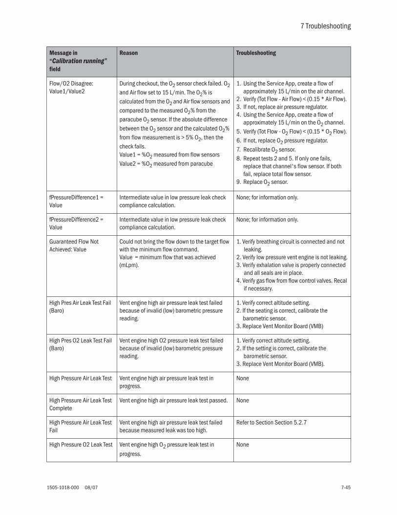
7 Troubleshooting
1505-1018-000 08/07 7-45
Flow/O2 Disagree: Value1/Value2
During checkout, the O2 sensor check failed. O2 and Air flow set to 15 L/min. The O2% is calculated from the O2 and Air flow sensors and compared to the measured O2% from the paracube O2 sensor. If the absolute difference between the O2 sensor and the calculated O2% from flow measurement is > 5% O2, then the check fails.Value1 = %O2 measured from flow sensorsValue2 = %O2 measured from paracube
1. Using the Service App, create a flow of approximately 15 L/min on the air channel.
2. Verify (Tot Flow - Air Flow) < (0.15 * Air Flow).3. If not, replace air pressure regulator.4. Using the Service App, create a flow of
approximately 15 L/min on the O2 channel. 5. Verify (Tot Flow - O2 Flow) < (0.15 * O2 Flow).6. If not, replace O2 pressure regulator.7. Recalibrate O2 sensor.8. Repeat tests 2 and 5. If only one fails,
replace that channel's flow sensor. If both fail, replace total flow sensor.
9. Replace O2 sensor.
fPressureDifference1 = Value
Intermediate value in low pressure leak check compliance calculation.
None; for information only.
fPressureDifference2 = Value
Intermediate value in low pressure leak check compliance calculation.
None; for information only.
Guaranteed Flow Not Achieved: Value
Could not bring the flow down to the target flow with the minimum flow command.Value = minimum flow that was achieved (mLpm).
1. Verify breathing circuit is connected and not leaking.
2. Verify low pressure vent engine is not leaking.3. Verify exhalation valve is properly connected
and all seals are in place.4. Verify gas flow from flow control valves. Recal
if necessary.
High Pres Air Leak Test Fail (Baro)
Vent engine high air pressure leak test failed because of invalid (low) barometric pressure reading.
1. Verify correct altitude setting.2. If the seating is correct, calibrate the
barometric sensor.3. Replace Vent Monitor Board (VMB)
High Pres O2 Leak Test Fail (Baro)
Vent engine high O2 pressure leak test failed because of invalid (low) barometric pressure reading.
1. Verify correct altitude setting.2. If the setting is correct, calibrate the
barometric sensor.3. Replace Vent Monitor Board (VMB).
High Pressure Air Leak Test Vent engine high air pressure leak test in progress.
None
High Pressure Air Leak Test Complete
Vent engine high air pressure leak test passed. None
High Pressure Air Leak Test Fail
Vent engine high air pressure leak test failed because measured leak was too high.
Refer to Section Section 5.2.7
High Pressure O2 Leak Test Vent engine high O2 pressure leak test in
progress.
None
Message in “Calibration running” field
Reason Troubleshooting

Engström Carestation
7-46 08/07 1505-1018-000
High Pressure O2 Leak Test Complete
Vent engine high O2 pressure leak test passed. None
High Pressure O2 Leak Test Fail
Vent engine high O2 pressure leak test failed because measured leak was too high.
Refer to Section Section 5.2.6
High Pressure: Aborted The Checkout step in progress was aborted due to high pressure.
1. Verify breathing circuit is properly connected for checkout.
2. Verify proper flow and exhalation valve calibration; recal if necessary.
Insp flow below target: >Target = Value1>Insp = Value2
Flow cannot be controlled down to the target flow because the measured flow is already lower than the target flow.
1. Check for disconnected breathing circuit during Checkout.
2. Verify proper flow valve calibration; recal if necessary.
Insp Span Counts: Value Inspiratory pressure sensor DAC counts that correspond to 100 cmH2O. (range: 3026 to 3589)
None
lInspFlowAccumulator=Value1, _jj=Value2
Intermediate values in low pressure leak check compliance calculation.
None; for information only.
Low Air Pressure: value Air supply pressure < 30 psig Verify proper gas supply.
Low Exp Pressure: Value1, Value 2
During exh valve cal, the pressure dropped more than 1.25 cmH2O in 4 msec. Value1 = Current measured pressure (cmH2Ox100).Value2 = Current calibration point
Check for disconnected breathing circuit during calibration.
Low Max Flow: Value FCV - Indicator that system will use the degraded wall supply routine for FCV calibration.
Check gas supply source to see if it is too weak or restricted if this causes problems.
Low O2 Pressure: Value O2 supply pressure < 30 psig Verify proper gas supply.
Low Pres Leak Test Fail (Baro)
Vent engine low pressure leak test failed because of invalid (low) barometric pressure reading.
1. Verify correct altitude setting.2. If the setting is correct, calibrate the
barometric sensor.3. Replace Vent Monitor Board (VMB)
Low Pressure Leak Chk Breathing circuit leak check in progress. None
Low Pressure Leak Chk Complete
Breathing circuit leak check passed. None
Low Pressure Leak Chk Fail Breathing circuit leak check failed. See previous message in status log cause of failure.
Low Pressure Leak Test Vent engine low pressure leak test in progress. None
Message in “Calibration running” field
Reason Troubleshooting
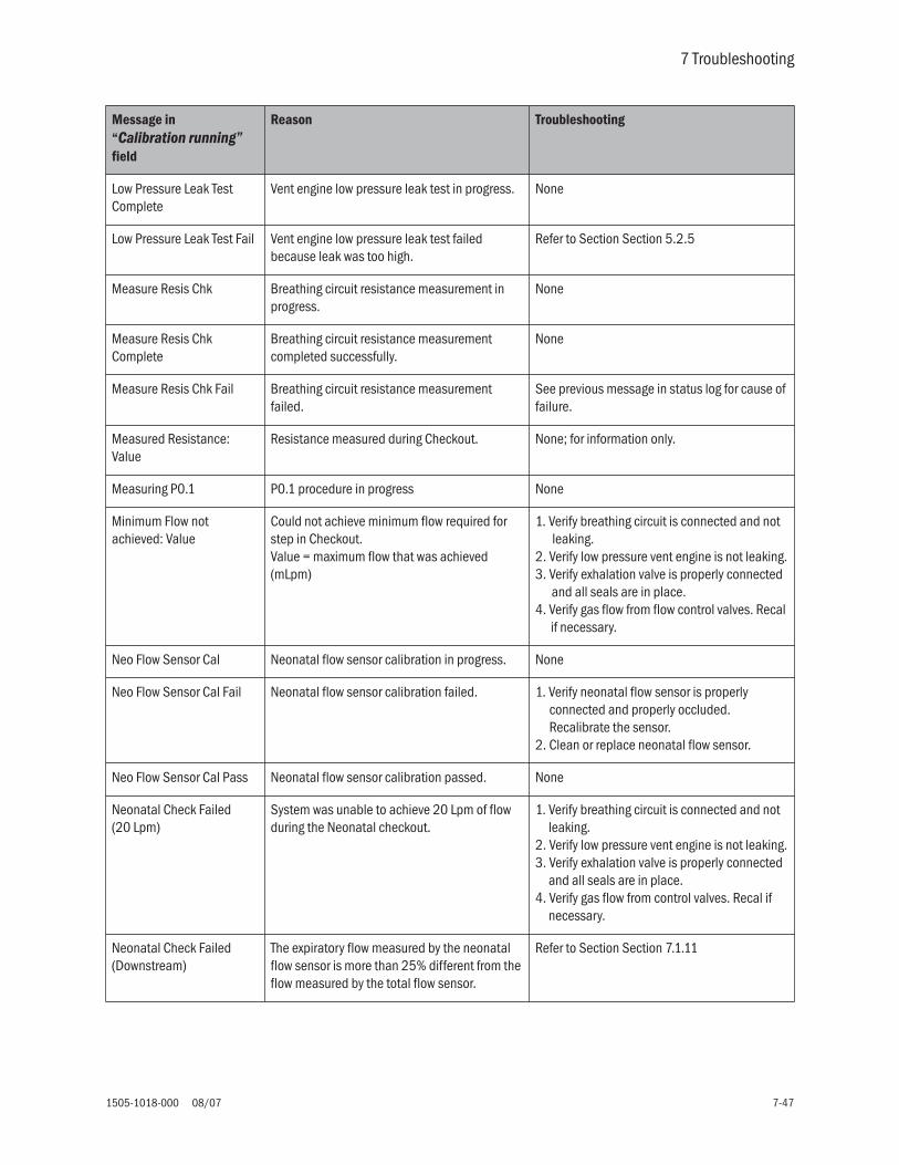
7 Troubleshooting
1505-1018-000 08/07 7-47
Low Pressure Leak Test Complete
Vent engine low pressure leak test in progress. None
Low Pressure Leak Test Fail Vent engine low pressure leak test failed because leak was too high.
Refer to Section Section 5.2.5
Measure Resis Chk Breathing circuit resistance measurement in progress.
None
Measure Resis Chk Complete
Breathing circuit resistance measurement completed successfully.
None
Measure Resis Chk Fail Breathing circuit resistance measurement failed.
See previous message in status log for cause of failure.
Measured Resistance: Value
Resistance measured during Checkout. None; for information only.
Measuring P0.1 P0.1 procedure in progress None
Minimum Flow not achieved: Value
Could not achieve minimum flow required for step in Checkout. Value = maximum flow that was achieved (mLpm)
1. Verify breathing circuit is connected and not leaking.
2. Verify low pressure vent engine is not leaking.3. Verify exhalation valve is properly connected
and all seals are in place.4. Verify gas flow from flow control valves. Recal
if necessary.
Neo Flow Sensor Cal Neonatal flow sensor calibration in progress. None
Neo Flow Sensor Cal Fail Neonatal flow sensor calibration failed. 1. Verify neonatal flow sensor is properly connected and properly occluded. Recalibrate the sensor.
2. Clean or replace neonatal flow sensor.
Neo Flow Sensor Cal Pass Neonatal flow sensor calibration passed. None
Neonatal Check Failed (20 Lpm)
System was unable to achieve 20 Lpm of flow during the Neonatal checkout.
1. Verify breathing circuit is connected and not leaking.
2. Verify low pressure vent engine is not leaking.3. Verify exhalation valve is properly connected
and all seals are in place.4. Verify gas flow from control valves. Recal if
necessary.
Neonatal Check Failed (Downstream)
The expiratory flow measured by the neonatal flow sensor is more than 25% different from the flow measured by the total flow sensor.
Refer to Section Section 7.1.11
Message in “Calibration running” field
Reason Troubleshooting

Engström Carestation
7-48 08/07 1505-1018-000
Neonatal Check Failed (Reaching 30)
System was unable to achieve 30 Lpm of flow during the Neonatal Checkout.
1. Verify breathing circuit is connected and not leaking.
2. Verify low pressure vent engine is not leaking.3. Verify exhalation valve is properly connected
and all seals are in place.4. Verify gas flow from flow control valves. Recal
if necessary.
Neonatal Check Failed (Reversed @20)
The neonatal flow sensor indicated reversed flow during the 20 Lpm check during Checkout.
Clean or replace neonatal flow sensor.
Neonatal Check Failed (Reversed @ 30)
The neonatal flow sensor indicated reversed flow during the 30 Lpm check during Checkout.
Clean or replace the neonatal flow sensor.
Neonatal Failed Neonatal flow sensor check failed because no gas supply was detected.
Verify proper gas supply.
Neonatal Flow Check Neonatal flow sensor flow check is in progress. None
Neonatal Zero Neonatal flow sensor zero check is in progress. None
Neonatal Zero Failed Neonatal flow sensor zero check failed because no gas supply was detected.
Verify proper gas supply.
Neonatal Zero Failed (4 Lpm)
Neonatal flow sensor zero check failed because the system was unable to achieve 4 Lpm.
1, Verify breathing circuit is connected and not leaking.
2. Verify low pressure vent engine is not leaking.3. Verify exhalation valve is properly connected
and all seals are in place.4. Verify gas flow from flow control valves.
Recal if necessary.
Neonatal Zero Failed (Expected 0 Flow)
Neonatal flow sensor zero check failed because the neonatal flow sensor measured non-zero flow while occluded.
1. Recalibrate neonatal flow sensor and rerun the Checkout.
2. Clean or replace the flow sensor.
NFS Check (10 Lpm) Neonatal flow sensor zero check failed because system was unable to reach 10 Lpm prior to the zero.
1. Verify breathing circuit is connected and not leaking.
2. Verify low pressure vent engine is not leaking.3. Verify exhalation valve is properly connected
and all seals are in place.4. Verify gas flow from flow control valves. Recal
if necessary.
NFS Check (30 Lpm) Neonatal flow sensor zero check failed because system was unable to reach 30 Lpm prior to the zero.
1. Verify breathing circuit is connected and not leaking.
2. Verify low pressure vent engine is not leaking.3. Verify exhalation valve is properly connected
and all seals are in place.4. Verify gas flow from flow control valves. Recal
if necessary.
Message in “Calibration running” field
Reason Troubleshooting

7 Troubleshooting
1505-1018-000 08/07 7-49
NFS Checkout Complete Neonatal flow sensor flow check completed, None
No Air Supply pressure for Air is below 30 psi. Verify proper gas supply.
No Exp Flow Sensor Expiratory flow sensor is not detected by system.
Verify proper installation of expiratory flow sensor and exhalation housing. Replace expiratory flow sensor if necessary.
No Gas Supply Supply pressure for both Air and O2 is below 30 psi.
Verify proper gas supply.
No Oxygen Supply pressure for O2 is below 30 psi. Verify proper gas supply.
No Supply Pressure Supply pressure for both Air and O2 is below 30 psi.
Verify proper gas supply.
None No calibrations, zero measurements, or checkout tests are running
None
Normalized Flow Comparison Failed:>Target = Value1>I = Value2>E = Value3
Normalized expiratory flow and total flow are more than 10% (or 200 mL, whichever is greater) apart.Value1 = Normalization Table flow point being tested (mLpm)Value2 = Inspiratory Flow measured by total flow sensor (mLpm)Value3 = Expiratory flow measured by expiratory flow sensor (mLpm)
1. Verify breathing circuit is connected and not leaking.
2. Verify low pressure vent engine is not leaking.3. Verify exhalation valve is properly connected
and all seals are in place.4. Verify gas flow from flow control valves. Recal
if necessary.
O2 Flush Time: Value sec Value = time (sec) needed to flush system with O2 until stability of 0.1% O2 is reached.
None
O2 Sensor Fail Failed Paracube communications during O2 sensor check
Replace Paracube.
O2 Sensor: Failed 100% Cal
Paracube Cal never competed, timed out during 100% O2 cal
Check paracube sensor.
O2 Sensor: Failed 21% Cal Paracube Cal never competed, timed out during 21% O2 cal
Check paracube sensor.
O2 Too Low for 100% Cal Measured O2% < 41% during the 100% span calibration of the O2 sensor.
1. Verify proper connection of gases to ventilator.
2. Use the Service App’s O2 Sensor cal to override limits on O2 sensor calibration.
3. Replace Paracube.
Message in “Calibration running” field
Reason Troubleshooting

Engström Carestation
7-50 08/07 1505-1018-000
O2 Too Low for 21% Cal Measured O2% < 8% during 21% calibration of O2 sensor.
1. Verify proper connection of gases to ventilator.
2. Use the Service App’s O2 Sensor cal to override limits on O2 sensor calibration.
3. Replace Paracube.
O2 Valve Cal O2 Valve Cal in progress None
O2 Valve Cal Complete O2 Valve Cal Passed. None
O2 Valve Cal Fail O2 Valve Cal failed. See previous message in status log for cause of failure.
Oxygen Flow Sensor Chk Oxygen Flow Sensor Check. None
Oxygen Sensor Chk Complete
O2 flow sensor check passed. None
Oxygen Flow Sensor Chk Fail
Oxygen Flow Sensor Check failed. See previous message in status log for cause of failure.
Oxygen Flow Sensor Chk Fail: No O2
Oxygen Flow Sensor Check failed because oxygen supply not detected.
Verify proper gas supply.
Oxygen Flow Sensor Fail Oxygen Flow Sensor Check failed because system was unable to achieve 30 Lpm during check.
1. Verify breathing circuit is connected and not leaking.
2. Verify low pressure vent engine is not leaking.3. Verify exhalation valve is properly connected
and all seals are in place.4. Verify gas flow from flow control valves. Recal
if necessary.
Paracube Cal O2 Sensor calibration in progress. None
Paracube Cal Complete O2 sensor check passed. None
Paracube Cal Fail O2 sensor check failed. See previous message in status log for cause of failure.
Paracube Chk Paracube (O2 sensor) check in progress. None
Paracube Chk Complete Paracube (O2 sensor) check passed.
Paracube Chk Fail Paracube (O2 sensor) check failed. See previous message in status log for cause of failure.
Message in “Calibration running” field
Reason Troubleshooting

7 Troubleshooting
1505-1018-000 08/07 7-51
Paracube Chk Fail (50/50 Air)
Paracube (O2 sensor) check failed to reach 15 Lpm air flow for 50/50 cal.
1. Verify breathing circuit is connected and not leaking.
2. Verify low pressure vent engine is not leaking.3. Verify exhalation valve is properly connected
and all seals are in place.4. Verify gas flow from flow control valves. Recal
if necessary.
Paracube Chk Fail (Air) Paracube (O2 sensor) check failed 21% cal. Paracube never completed 21% calibration. Check Paracube.
Paracube Chk Fail (O2) Paracube (O2 sensor) check failed to reach 30 Lpm O2 flow for O2 cal.
1. Verify breathing circuit is connected and not leaking.
2. Verify low pressure vent engine is not leaking.3. Verify exhalation valve is properly connected
and all seals are in place.4. Verify gas flow from flow control valves. Recal
if necessary.
Paracube Fail Paracube (O2 sensor) check failed to reach 30 Lpm air flow.
1. Verify breathing circuit is connected and not leaking.
2. Verify low pressure vent engine is not leaking.3. Verify exhalation valve is properly connected
and all seals are in place.4. Verify gas flow from flow control valves. Recal
if necessary.
Paracube Sensor Fail (50/50 O2)
Paracube (O2 sensor) check failed to reach 15 Lpm O2 flow for 50/50 cal.
1. Verify breathing circuit is connected and not leaking.
2. Verify low pressure vent engine is not leaking.3. Verify exhalation valve is properly connected
and all seals are in place.4. Verify gas flow from flow control valves. Recal
if necessary.
Paux Zeroing... Auxiliary pressure sensor is being zeroed at start of Span Cal.
None
Paw Xducer Check Airway pressure sensor check in progress. None
Paw Xducer Check Complete
Airway pressure sensor check passed. None
Paw Xducer Check Fail Airway pressure sensor check failed. See previous message in status log for cause of failure.
Paw Xducer Check Fail (PressureZeroCal)
Pressure sensors were not successfully zeroed. Refer to Section 7.1.1 and Section 5.2.8.
Paw Xducer OK Airway pressure sensor check passed. None
Message in “Calibration running” field
Reason Troubleshooting

Engström Carestation
7-52 08/07 1505-1018-000
Pressure not maintained: value
System was unable to maintain at least 25 cmH2O of pressure during relief valve check.
1. Verify breathing circuit is connected and not leaking.
2. Verify low pressure vent engine is not leaking.3. Verify exhalation valve is properly connected
and all seals are in place.4. Verify gas flow from flow control valves. Recal
if necessary.
Q1 = Value Intermediate value in low pressure leak check compliance calculation.
None, for information only.
Relief Pressure: Value Safety Valve check: Value = back pressure generated from 75 L/min flow thru open relief valve. Must be less than 10 cmH2O to pass.
Refer to Section 7.1.4.
Relief Time: Value Safety Valve check: Value = time required to relieve pressure in system from 34 to less than 2 cmH2O. Must be less than 250 msec to pass.
Refer to Section 7.1.4.
Relief Valve Chk Relief valve check in progress. None
Relief Valve Chk Complete Relief valve check passed. None
Relief Valve Chk Fail Relief valve check failed. See previous message in status log for cause of failure.
Rising Flow Not Achieved: Value
Could not achieve minimum flow required fro step in Checkout. Value = maximum flow that was achieved (mLpm)
1. Verify breathing circuit is connected and not leaking.
2. Verify low pressure vent engine is not leaking.3. Verify exhalation valve is properly connected
and all seals are in place.4. Verify gas flow from flow control valves. Recal
if necessary.
Sensor Disagree: Value During FCV calibration, if the Air (or O2) flow sensor disagree by more than: 20% of total flow or 1500 mL/min, whichever is greater, the calibration will fail. Value = flow difference between Air (or O2) flow sensor and total flow sensor.
1. Check regulator for oscillation.2. If only one FCV cal fails, replace that flow
sensor.3. If both FCV cal fail, replace total flow sensor.
Sensor Removed Exhalation flow sensor removed prior or during checkout.
Install exh flow sensor and rerun checkout.
Skipping CHECKOUT - not in checkout state
A Checkout command was received by the Vent Control Board (VCB) while it was not in the Checkout sate. This is most often caused by a series of rapidly requested Checkout starts and aborts without allowing Checkout to run in between.
Restart Checkout and allow it to allow it to complete.
Message in “Calibration running” field
Reason Troubleshooting

7 Troubleshooting
1505-1018-000 08/07 7-53
Span Pressure transducer span calibration is in progress.
None
Start Normalization... Expiratory flow sensor normalization is in progress.
None
T1 = Intermediate value in low pressure leak check compliance calculation.
None; for information only.
T2 = Intermediate value in low pressure leak check compliance calculation.
None; for information only.
Target flow not reached @ 300
Flow remains greater than the target flow with the minimum flow command during Checkout.
1. Verify breathing circuit is connected and not leaking.
2. Verify low pressure vent engine is not leaking.3. Verify exhalation valve is properly connected
and all seals are in place.4. Verify gas flow from flow control valves. Recal
if necessary.
Total: Value1 O2: Value2 During O2 flow sensor check, O2 flow sensor is more than 15% different than total flow sensor at a nominal flow of 30 L/min. Value1 = measured total flow. Value2 = measured O2 flow.
1. Check regulator for oscillation. Replace if necessary.
2. If only O2 flow sensor check fails, replace O2 flow sensor. If both Air and O2 flow sensor checks fail, replace total flow sensor.
unbounded Qin = Value Intermediate value in low pressure leak check compliance calculation.
None; for information only.
Upstream Flow Diff: Value Difference between flow measured by total flow sensor and inspiratory wire of neonatal flow sensor during Checkout (mLpm).
None; for information only.
Upstream Flow Failed (Upstream)
The inspiratory flow measured by the neonatal flow sensor is more than 15% different from the flow measured by the total flow sensor.
Refer to Section 7.1.11
Valve Step Sweep Valve step sweep in progress. None
Valve Step Sweep Aborted Valve step sweep aborted because maximum flow was reached.
None; normal operation.
Valve Step Sweep Done Valve step sweep completed. None
Valve Sweep Valve sweep in progress. None
Valve Sweep Done Valve sweep completed. None
VMB Exp Flow Sensor Cal Fail
Expiratory flow sensor calibration has failed. Verify expiratory flow sensor and exhalation housing are properly installed.
Message in “Calibration running” field
Reason Troubleshooting

Engström Carestation
7-54 08/07 1505-1018-000
VMB Exp Flow Sensor Cal Pass
Expiratory flow sensor calibration has passed. None
Waiting for supply pressure FCV calibration - if a weak supply pressure is used, system will occasionally pause and wait for supply pressure to come back up before resuming FCV cal.
None; normal operation.
Weak Supply Detected1: Value
FCV calibration - Indicator that system will use the degraded wall supply routine for FCV calibration.
None; normal operation. A weak supply pressure was detected when trying to ramp the flow up to 165 L/min.
Weak Supply Detected2: Value
FCV calibration - Indicator that system will use the degraded wall supply routine for FCV calibration.
None; normal operation. A weak supply pressure was detected during the 120 L/min flow test.
Weak Supply Detected3: Value
FCV calibration - Indicator that system will use the degraded wall supply routine for FCV calibration.
None; normal operation. A weak supply was detected during final flow ramp-up before first cal points are taken.
Weak Supply Detected4: Value
FCV calibration - Indicator that system will use the degraded wall supply routine for FCV calibration.
None; normal operation. A weak supply was detected during final flow ramp-up before first cal points are taken if DAC output reached 65,000 counts before flow reached 170 L/min.
Xducer Error: Value During Paw Xducer check, the insp and exp pressure difference > 4 cmH2O.
Value = pressure difference.
Refer to Section 5.2.8.
Zero flow samp Error in FCV calibration cal point projection. Check for weak or restricted gas pressure supply
Zero for flow sampl2 Error in FCV calibration cal point projection. Check for weak or restricted gas pressure supply
Zero out of range ADC counts are out of the acceptable zero pressure range for the inspiratory and/or expiratory pressure sensor. The acceptable range for each sensor is 631 to 968 ADC counts.
Refer to Section 5.2.8
Zero Pressure Sensors Airway pressure sensors are currently being zeroed.
None
Zero Pressure Sensors Complete
Airway pressure sensor zeros are complete. None
Message in “Calibration running” field
Reason Troubleshooting

1505-1018-000 08/07 8-1
8 Service Diagnostics and Software Download
In this section 8.1 EC Service Application . . . . . . . . . . . . . . . . . . . . . . . . . . . . . . . . . . . . . . . . . . . . . . . . . . . . . .8-2
8.1.1 Main menu and system information . . . . . . . . . . . . . . . . . . . . . . . . . . . . . . . . . . . . .8-2
8.1.2 Power diagnostics . . . . . . . . . . . . . . . . . . . . . . . . . . . . . . . . . . . . . . . . . . . . . . . . . . .8-3
8.1.3 Power controller power diagnostics . . . . . . . . . . . . . . . . . . . . . . . . . . . . . . . . . . . . .8-4
8.1.4 Display Unit Power Diagnostics . . . . . . . . . . . . . . . . . . . . . . . . . . . . . . . . . . . . . . . . .8-6
8.2 Display Diagnostics . . . . . . . . . . . . . . . . . . . . . . . . . . . . . . . . . . . . . . . . . . . . . . . . . . . . . . . .8-7
8.3 Special Functions . . . . . . . . . . . . . . . . . . . . . . . . . . . . . . . . . . . . . . . . . . . . . . . . . . . . . . . . . .8-8
8.3.1 View revision log . . . . . . . . . . . . . . . . . . . . . . . . . . . . . . . . . . . . . . . . . . . . . . . . . . . . .8-9
8.3.2 View PC Card install log . . . . . . . . . . . . . . . . . . . . . . . . . . . . . . . . . . . . . . . . . . . . . . .8-9
8.4 Software Download . . . . . . . . . . . . . . . . . . . . . . . . . . . . . . . . . . . . . . . . . . . . . . . . . . . . . . 8-10
8.5 EC Service Application (PC based) . . . . . . . . . . . . . . . . . . . . . . . . . . . . . . . . . . . . . . . . . . 8-12
8.5.1 Port setup . . . . . . . . . . . . . . . . . . . . . . . . . . . . . . . . . . . . . . . . . . . . . . . . . . . . . . . . 8-12
8.5.2 Main menu and system information . . . . . . . . . . . . . . . . . . . . . . . . . . . . . . . . . . . 8-12
8.6 VCB Diagnostics and Calibration . . . . . . . . . . . . . . . . . . . . . . . . . . . . . . . . . . . . . . . . . . . 8-13
8.6.1 Sensirion sensors . . . . . . . . . . . . . . . . . . . . . . . . . . . . . . . . . . . . . . . . . . . . . . . . . . 8-13
8.6.2 VCB input signal latch . . . . . . . . . . . . . . . . . . . . . . . . . . . . . . . . . . . . . . . . . . . . . . 8-14
8.6.3 VCB channel configurations . . . . . . . . . . . . . . . . . . . . . . . . . . . . . . . . . . . . . . . . . . 8-15
8.6.4 VCB outputs . . . . . . . . . . . . . . . . . . . . . . . . . . . . . . . . . . . . . . . . . . . . . . . . . . . . . . 8-16
8.6.5 Calibrations and tests . . . . . . . . . . . . . . . . . . . . . . . . . . . . . . . . . . . . . . . . . . . . . . 8-17
8.6.6 Neon tools . . . . . . . . . . . . . . . . . . . . . . . . . . . . . . . . . . . . . . . . . . . . . . . . . . . . . . . 8-18
8.6.7 Peep stability . . . . . . . . . . . . . . . . . . . . . . . . . . . . . . . . . . . . . . . . . . . . . . . . . . . . . 8-19
8.6.8 Logging checkout results . . . . . . . . . . . . . . . . . . . . . . . . . . . . . . . . . . . . . . . . . . . . 8-20
8.6.9 Logging Calibration Results . . . . . . . . . . . . . . . . . . . . . . . . . . . . . . . . . . . . . . . . . . 8-21
8.7 VMB Diagnostics . . . . . . . . . . . . . . . . . . . . . . . . . . . . . . . . . . . . . . . . . . . . . . . . . . . . . . . . 8-22
8.7.1 VMB Channel Configurations . . . . . . . . . . . . . . . . . . . . . . . . . . . . . . . . . . . . . . . . . 8-23
8.7.2 VMB outputs . . . . . . . . . . . . . . . . . . . . . . . . . . . . . . . . . . . . . . . . . . . . . . . . . . . . . . 8-24
8.7.3 VMB data . . . . . . . . . . . . . . . . . . . . . . . . . . . . . . . . . . . . . . . . . . . . . . . . . . . . . . . . 8-24
8.7.4 Baro P cal . . . . . . . . . . . . . . . . . . . . . . . . . . . . . . . . . . . . . . . . . . . . . . . . . . . . . . . . 8-25
8.7.5 Acutronic . . . . . . . . . . . . . . . . . . . . . . . . . . . . . . . . . . . . . . . . . . . . . . . . . . . . . . . . 8-25
8.7.6 EEProm . . . . . . . . . . . . . . . . . . . . . . . . . . . . . . . . . . . . . . . . . . . . . . . . . . . . . . . . . . 8-25

Engström Carestation
8-2 08/07 1505-1018-000
8.1 EC Service Application
This section documents the EC Service Application that loads from a PCMCIA card (DU) or Flash Card (HPDU) and is used to download software or to run various diagnostic functions.
To run the application, first set the system power switch to Off. Insert the card carrier (with card and slots facing to the rear) into the rear PCMCIA interface slot of the display unit (behind left side door), then set the system power switch On. The service application will load and display the Main Menu along with the System Information page.
8.1.1 Main menu andsystem information
The Main Menu appears on the left-hand side of the screen and includes the following selections:
Note You can not return to the Diagnostic section of the service application after entering the software download section. You must reboot the system to exit Software Download.
The System Information page appears on the right-hand side of the screen and displays the following system information:
S y s t e m I n f o r m a t i o n
Main Menu Remarks
Power Diagnostics Access to the Power Supply Diagnostics functions
Display Diagnostics Access to the Front Panel Controls
Special Functions Access to logs and compatibility tables
--------------------------
Software Download Access to the Software Download function.
Subsystem HW Rev Serial # SW Ver # Boot
Front Panel Cntl - - - - - - XX.XX XX.XX
Power Monitor Bd XXXX/A/XX ABCXXXXX XX.XX XX.XX
Vent Monitor Bd XXXX/A/XX ABCXXXXX XX.XX XX.XX
Vent Control Bd XXXX/A/XX ABCXXXXX XX.XX XX.XX
Dsply Unit BIOS XXXX/A/XX ABCXXXXX XX.XX
Dsply Unit App XXX/A/XX ABCXXXXX XX.XX
Machine Serial Number: ABCDXXXXX
PC Card ID: XXXXXX

8 Software Download and Diagnostics
1505-1018-000 08/07 8-3
8.1.2 Power diagnostics The service application provides power supply diagnostics for the various circuit boards in the EC ventilator.
Selecting Power Diagnostics on the Main Menu brings up the following menu selections in the left-hand frame and the instructions in the right-hand frame:
Main Menu
Power Diagnostics
Display Diagnostics
Special Functions
-------------------------------------------
Software Download
Power Diagnostics Power Diagnostics Instructions
Power ControlSelect a menu item
to see the power statusand measured voltages.
To troubleshoot a power problem,start with the power controller and work forward.
Problem voltages are in red.
Display Unit
-> Main Menu

Engström Carestation
8-4 08/07 1505-1018-000
8.1.3 Power controllerpower diagnostics
There are two pages of diagnostics for the Power Controller.
Selecting Power Control brings up the first page of the Power Controller Diagnostics.
( P a g e 1 o f 2 )P o w e r C o n t r o l P o w e r D i a g n o s t i c s
Turn the ComWheel to select the second page.
Push the ComWheel to return focus to the Power Diagnostics selection menu.
Power Diagnostics
Power Control
Display Unit
->Main Menu
Label Value Format Units Normal range
AC Status OK, Fail
12Vdc Supply XX.XX Vdc 11.70 to 12.30
3.3Vdc Supply X.XXX Vdc 3.201 to 3.399
1.5 Vdc Supply X.XXX Vdc 1.45 to 1.55
Battery Connected Yes, No
Battery Status Fail, Bulk Chg, Over Chg,Float Chg, Trickle Chg, Discharge
Battery Current X.XXX A
Battery 1 Volts XX.X< 6.0 FAIL (red)<10 T Chg (yellow)10-15.5 (Green)
Vdc 10.0 to 15.5
Battery 2 Volts XX.X< 6.0 FAIL (red)<10 T Chg (yellow)10-15.5 (Green)
Vdc 10.0 to 15.5
Calc Battery Time XX Min 0 to 30
Date Battery Tested XX-ABC-XXXX
Last Full Discharge Time XXX Min
Ext’l Battery Current X.XX A

8 Software Download and Diagnostics
1505-1018-000 08/07 8-5
( P a g e 2 o f 2 )P o w e r C o n t r o l P o w e r D i a g n o s t i c s
Note: Fan 1 is located on the rear cage, Fan 2 is located on the PMB.
Turn the ComWheel to return to the first page.
Push the ComWheel to return focus to the Power Diagnostics selection menu.
Battery Status
Power Diagnostics
Power Control
Display Unit
->Main Menu
Label Value Format Units Normal range
Board Temperature <65C OK (green)>65C <75C Warn (Yellow)>75C Fail (red)
Deg C Upper Limit 64
Fan Speed Slow, Fast
Fan 1 Voltage XX.XX(high fan speed = 23.7V typical)(low fan speed = 20.7V typical)
Vdc 17.5 to 25.0
Fan 1 Status Fail, OK
Fan 2 Status Fail, OK
Battery Status Description
Fail Battery is disconnected from Power Control Power Diagnostics and is in Trickle mode for > 12 hours.
Bulk Chg Initial phase of battery charging. Battery is at 600 mA when system is running and 1.2 Amps when system is in standby.
Over Chg Topping off remaining 5-10% of battery capacity and approaching full charge.
Float Chg Battery is being maintained at full charge.
Trickle Chg Independent of battery charger. Severely degraded batteries are charged at 25 mA constant current when either battery is 6-10 Vdc and batteries are not connected to Power Control Power Diagnostics.
Discharge System is running on battery power.

Engström Carestation
8-6 08/07 1505-1018-000
8.1.4 Display Unit PowerDiagnostics
Selecting Display Unit brings up the Display Unit Power Diagnostics page.
D i s p l a y U n i t P o w e r D i a g n o s t i c s
Power Diagnostics
Power Control
Display Unit
->Main Menu
Label Value Format Units Normal range
5.0Vdc (PCMCIA) X.XX Vdc 4.50 to 5.50
3.3Vdc (PCMCIA) X.XX Vdc 2.97 to 3.63
5.0Vdc (Fan) X.XX Vdc 4.50 to 5.50
5.0Vdc (USB) X.XX Vdc 4.50 to 5.50
8.0Vdc (DIS) X.XX Vdc 7.20 to 8.80
11Vdc (LCD) XX.XX Vdc 10.35 to 13.62

8 Software Download and Diagnostics
1505-1018-000 08/07 8-7
8.2 Display Diagnostics
The service application provides several pages for display diagnostics.
Selecting Display Diagnostics on the Main Menu brings up the following menu selections in the left-hand frame:
Main Menu
Power Diagnostics
Display Diagnostics
Special Functions
-------------------------------------------
Software Download
Display Diagnostics Display Diagnostics Instructions
Test LEDs
Select a menu item
To troubleshoot a display problem, start with Test LEDs and work forward
Test Speaker
Test Backlight 1
Test Backlight 2
Test Keys
-> Main Menu
Display Diagnostics Action when selected
Test LEDs Selecting Test LEDs causes the red and yellow LEDS next to the Silence Alarms key to flash for 10 seconds.
Test Speaker Selecting Test Speaker causes the speaker to sound for 5 seconds.
Test Backlight 1 Selecting Test Backlight 1 turns backlight 2 off for 10 seconds. “If screen goes black during test, a backlight is out”
Test Backlight 2 Selecting Test Backlight 2 turns backlight 1 off for 10 seconds. “If screen goes black during test, a backlight is out”
Test Keys Selecting Test Keys brings up a representative display of the front panel controls. Pressing a softkey will cause the corresponding key text to be highlighted.
Main Menu Selecting Main Menu returns to the Main Menu.

Engström Carestation
8-8 08/07 1505-1018-000
8.3 Special Functions
Selecting Special Functions on the Main Menu brings up the following menu selections in the left-hand frame:
Error, Alarm, Event Logs In a functioning system, the Error, Alarm, and Event Logs are accessible on the system’s Service Log menu (refer to Section 4.4.6). If a system comes up in a “Failed State”, you can download the logs to the Service Application PC Card and view them on the Special Functions screen.
1. With the system still in the “Failed State”, insert the Service Application PC Card into the Display Unit and press the “Help” softkey.
2. Wait approximately 60 seconds while the logs are downloaded to the card (no apparent activity).
3. Restart the system with the Service Application to view the logs.
Revision and PC Card InstallLogs
Whenever a Software Download is completed, the specific software download is recorded in the Revision Log that resides on the system (Display Unit) and in the PC Card Install Log that resides on the PC Card.
Compatibility Table The Compatibility Table lists the current software components that last downloaded on to the system. In essence, it is the latest listing that appears in the Revision Log, which allows you to view the current log directly without having to scroll to it.
Main Menu
Power Diagnostics
Display Diagnostics
Special Functions
-------------------------------------------
Software Download
Special Functions System Information
View Error Log
View Alarm Log
View Event Log
View Revision Log
Compatibility Table
PC Card Install Log
View Install Errors
-> Main Menu
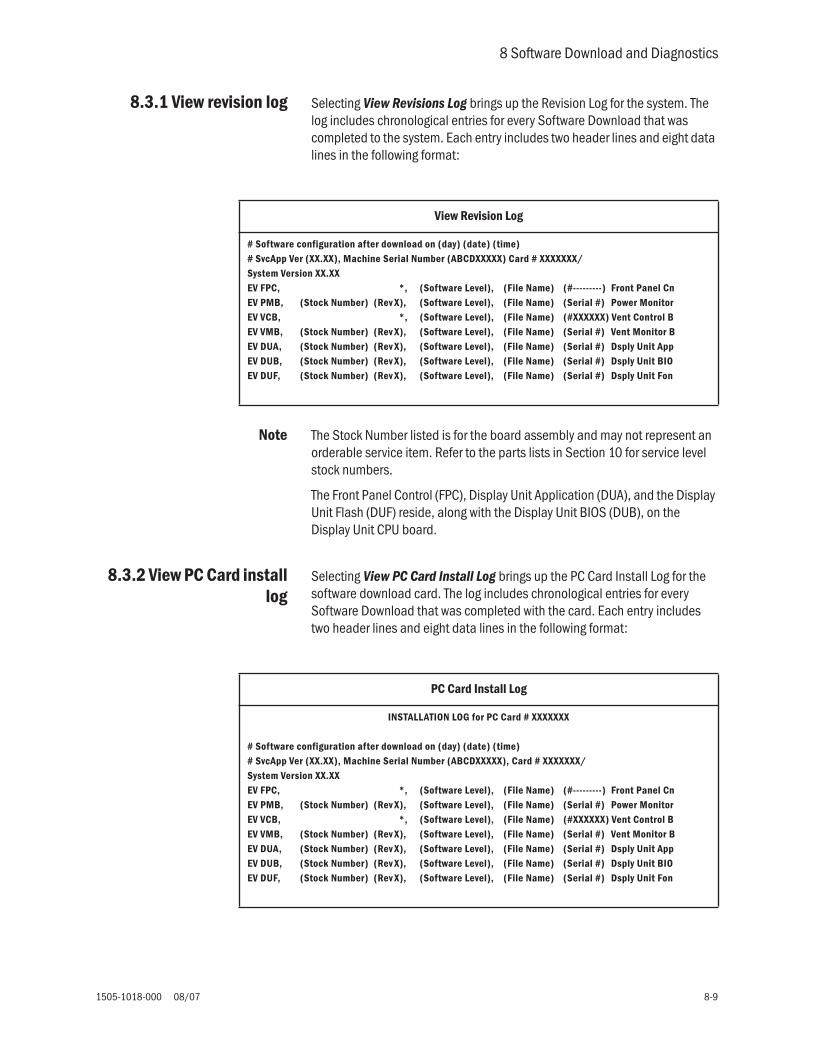
8 Software Download and Diagnostics
1505-1018-000 08/07 8-9
8.3.1 View revision log Selecting View Revisions Log brings up the Revision Log for the system. The log includes chronological entries for every Software Download that was completed to the system. Each entry includes two header lines and eight data lines in the following format:
Note The Stock Number listed is for the board assembly and may not represent an orderable service item. Refer to the parts lists in Section 10 for service level stock numbers.
The Front Panel Control (FPC), Display Unit Application (DUA), and the Display Unit Flash (DUF) reside, along with the Display Unit BIOS (DUB), on the Display Unit CPU board.
8.3.2 View PC Card installlog
Selecting View PC Card Install Log brings up the PC Card Install Log for the software download card. The log includes chronological entries for every Software Download that was completed with the card. Each entry includes two header lines and eight data lines in the following format:
View Revision Log
# Software configuration after download on (day) (date) (time)# SvcApp Ver (XX.XX), Machine Serial Number (ABCDXXXXX) Card # XXXXXXX/System Version XX.XXEV FPC, *, (Software Level), (File Name) (#---------) Front Panel CnEV PMB, (Stock Number) (Rev X), (Software Level), (File Name) (Serial #) Power MonitorEV VCB, *, (Software Level), (File Name) (#XXXXXX) Vent Control BEV VMB, (Stock Number) (Rev X), (Software Level), (File Name) (Serial #) Vent Monitor BEV DUA, (Stock Number) (Rev X), (Software Level), (File Name) (Serial #) Dsply Unit AppEV DUB, (Stock Number) (Rev X), (Software Level), (File Name) (Serial #) Dsply Unit BIOEV DUF, (Stock Number) (Rev X), (Software Level), (File Name) (Serial #) Dsply Unit Fon
PC Card Install Log
INSTALLATION LOG for PC Card # XXXXXXX
# Software configuration after download on (day) (date) (time)# SvcApp Ver (XX.XX), Machine Serial Number (ABCDXXXXX), Card # XXXXXXX/System Version XX.XXEV FPC, *, (Software Level), (File Name) (#---------) Front Panel CnEV PMB, (Stock Number) (Rev X), (Software Level), (File Name) (Serial #) Power MonitorEV VCB, *, (Software Level), (File Name) (#XXXXXX) Vent Control BEV VMB, (Stock Number) (Rev X), (Software Level), (File Name) (Serial #) Vent Monitor BEV DUA, (Stock Number) (Rev X), (Software Level), (File Name) (Serial #) Dsply Unit AppEV DUB, (Stock Number) (Rev X), (Software Level), (File Name) (Serial #) Dsply Unit BIOEV DUF, (Stock Number) (Rev X), (Software Level), (File Name) (Serial #) Dsply Unit Fon

Engström Carestation
8-10 08/07 1505-1018-000
8.4 Software Download
Selecting Software Download bring up the following information page:
Note You can not return to the Diagnostic section of the service application after entering the software download section. You must reboot the system to exit Software Download.
Entering software download brings up the Software Download menu.
Since downloading all the subsystem software can take an hour or more, you should normally choose “Download New” to install only the updated subsystem software or software required for newly installed subsystems.
S o f t w a r e D o w n l o a d S t a t u s
Main Menu
Power Diagnostics
Display Diagnostics
Special Functions
-------------------------------------------
Software Download
ENTERING SOFTWARE DOWNLOAD MODE!
To return to Diagnostics: turn On/Standby switch to Standby, and turn off AC mains switch in rear.Wait 20 seconds, then turn on power with the AC
mains switch and the On/Standby switch.
(Press ComWheel to continue with Download.)
Software Download Remarks
Download New Downloads only new software versions not found on the system and compatible with installed subsystem hardware.
Download All Downloads all software subsystems.
Software Download
Download New
Download All
Subsystem HW RevCurrentSW Rev
NewSW Rev Status
Front Panel Cntl - - - XX.XX XX.XX Xxxxxxx
Power Monitor Bd XXXX/A/XX XX.XX XX.XX Xxxxxxx
Vent Monitor Bd XXXX/A/XX XX.XX XX.XX Xxxxxxx
Vent Control Bd XXXX/A/XX XX.XX XX.XX Xxxxxxx
Dsply Unit BIOS XXXX/A/XX XX.XX XX.XX Xxxxxxx
Dsply Unit App XXXX/A/XX - - - XX.XX Xxxxxxx
Dsply Unit Fonts XXXX/A/XX XX.XX XX.XX Xxxxxxx
Loading Xxxx Xxxxxxxxx Xxxxx:
********************

8 Software Download and Diagnostics
1505-1018-000 08/07 8-11
Notes about downloading software
Download process The PCMCIA card includes only the latest software for each subsystem along with the diagnostic application.
As each subsystem software segment is being downloaded, the following status messages note the state of each subsystem and the result of the download:
• Busy - System is running its application code; not ready for download.• Ready - System is in its boot code; ready for download.• CRCtest - System is analyzing the download CRC.• Loading - System is accepting download data.• Done - Software download has completed successfully.• Fail - Software download did not complete successfully. A “Fail” message will require
reloading of the software; or repair of the system may be necessary.• Skipped - Software download was bypassed.• Linked - System is communicating, but status is not yet known.• Not Compatible - The software version on the PCMCIA card is not compatible with the
subsystem.
If the subsystem is communicating but the HW Rev or current SW Rev are not known, the message Unknown will appear under the columns for those values. If the HW Rev or current SW Rev are not known, the download function will still be available.
As the software loads, an activity bar at the bottom of the screen shows the download progress for each subsystem.
Note If a Communication Failure occurs during software download, power down the system, wait for 20 seconds, and restart system.
Download complete When all the required subsystem software is downloaded, the following message appears on the screen. You must shut down the system to exit the download function.
Note After powering down the system, be sure to wait at least 20 seconds before restarting the system.
If there is no Front Panel Control software installed in the system (as would be the case when the display units control board is replaced), the Service Application automatically downloads the Front Panel Controls software at startup. During the download the two display unit LEDs will flash and the display speaker will sound an alarm tone to indicate that Software Download is proceeding.
To ensure that all software versions on the system are compatible, the end result of “Download All” or “Download New” will be the same. The software loaded on the machine will exactly match what is on the card. Be sure to have the latest/correct version of software before attempting a download to avoid inadvertent overwrites of newer software with an older version.
If, during the “Download New” process, the compatibility checker detects a newer version of software component on the system, a “Notice” appears on the screen that asks you to confirm the downgrade.
“Download All” will download all compatible software from the card to the system without issuing a notice that newer version of software component may be on the system.
DOWNLOAD IS COMPLETE.
Remove PCMCIA card. Turn OFF AC mains switch in rear.Disconnect power cord.

Engström Carestation
8-12 08/07 1505-1018-000
8.5 EC Service Application (PC based)
This section documents the EC Service Application that run on a Windows based computer and communicates with the EC ventilator through the serial port ( Port 3).
To enable communication between the EC and the PC Service Application, the EC must be in the Service mode.
8.5.1 Port setup When the EC serial port is enabled, the PC application presents a port setup menu that allows you to select a COM port for your PC. Select the appropriate COM port and click OK to continue.
Note: Ensure that no other application (such as PDA hot-sync) is using this port while the Service Application is running.
8.5.2 Main menu andsystem information
The Main Menu appears on the screen and includes the following selections as shown in the table below:
The main menu includes a Connection Status message area that shows whether or not the program is communicating with the EC.
The VCB and VMB Diagnostics pages can both be displayed at the same time.
Closing the main menu, closes the application.
Select Gas Supply units for gas units for display on the VMB screen or select PAW Units to display pressure units for display on the VCB and VMB screens.
Menu Item Selections Default
Port COM1, COM2, COM3, COM4, COM5, COM6, COM7, COM8, COM9, COM10
COM1
Main Menu Selections
VCB Opens the VCB Diagnostics page.
VMB Opens the VMB Diagnostics page.
Menu Item Selections Default
Gas Supply Units (VMB) psig, kPa, bar psig
PAW Units (VCB/VMB) cmH2O, kPa, mbar cmH2O

8 Software Download and Diagnostics
1505-1018-000 08/07 8-13
8.6 VCB Diagnostics and Calibration
Selecting VCB Diagnostics and Calibration on the Main Menu brings up the following page that contains five grouped area.
8.6.1 Sensirion sensors The Sensirion (Inspiratory Flow) Sensors group shows the temperature and the flow through each flow sensor: Total flow, Oxygen, and Air.
Item Total Oxygen Air
Temperature XXX.X C XXX.X C XXX.X C
Flow ml/min XXXXXX XXXXXX XXXXXX

Engström Carestation
8-14 08/07 1505-1018-000
8.6.2 VCB inputsignal latch
The VCB Input Signal Latch group shows the status of the displayed item.
Item Description
Module Power FAIL = Power to the monitor module has failed.OK = Module Power has not failed or module power has been manually shut off.
PSM Power FAIL = Power to the Patient Side Module has failed.OK = PSM Pwr has not failed or PSM power has been manually shut off.
Insp Press Zero Valve ON = Inspiratory pressure zero valve on.OFF = Inspiratory pressure zero valve off.
Aux Press Purge Valve ON = Auxiliary pressure purge valve on.OFF = Auxiliary pressure purge valve off.
Exhalation Vlv Open YES = VMB is commanding the exhalation valve open.NO = The valve is not opened.
VMB Buzzer On? YES = VMB is activating the buzzer.NO = Buzzer is not active or is activated by the VCB.
Nebulizer Detected? YES = Nebulizer is connected.NO = Nebulizer is not connected.
Buzzer Detected? NO = Buzzer current is too low. Valid when buzzer should be on.YES = Buzzer is sensed.NA = Buzzer not being activated.
Over Pressure DETECTED = Expiratory over-pressure detected.NOT DETECTED = Over pressure was not detected.
Vcb Pld Rev Displays the revsion number of the Programmable Logic Device software.

8 Software Download and Diagnostics
1505-1018-000 08/07 8-15
8.6.3 VCB channelconfigurations
The VCB Channel Configurations group includes items that are measured from the VCB. If the item is within the acceptable range, “OK” is displayed next to the value. If the item is out of the acceptable range, “FAIL” is displayed instead.
Item Description Format Units Range
Auxiliary Press Auxiliary pressure sensor measurement
XXX.XX cmH2O -20 to 120
Inspiratory Press Inspiratory pressure sensor measurement
XXX.XX cmH2O -20 to 120
Exhalation Volt Exhalation valve voltage XXXXX mV 0 to 12500
Exhalation Current Exhalation valve current XXX.X mA 0 to 815
O2 Flow Current O2 Flow Valve drive current XXX.X mA 0 to 198
Air Flow Current Air Flow Valve drive current XXX.X mA 0 to 198
Nebulizer Power Nebulizer power (when on)Nebulizer power (when off)
XXXXXXXX
mVmV
On:11500 to 12710Off: 0 to 500
Ambient Temp Ambient temperature near the valve drive circuits
XXX.X C 0 to 55
Module Power 16 V Circuit breaker for module power XXXXX mV 15200 to 16800
12.5V Supply 12.5 V Supply Voltage XXXXX mV 12040 to 13330
5V Analog 5V analog supply voltage XXXXX mV 4800 to 5200
6V Analog 6V analog supply voltage XXXXX mV 5760 to 6240
-6V Analog -6V analog supply voltage XXXXX mV -6240 to -5760
5.5V Analog 5.5V analog supply voltage XXXXX mV 5280 to 5720
Insp Flow Power 9V power supply for the O2 and Air inspiratory flow sensors
XXXXX mV 8530 to 9240
Total Insp Flow Pwr 9V power supply for the total inspiratory flow sensor
XXXXX mV 8530 to 9240
4.096V Ref Analog measurement of the independent 4.096V voltage reference
XXXXX mV 4055 to 4137
Ground Measurement of the analog ground at the A to D converter
XXXXX mV 0 to 10
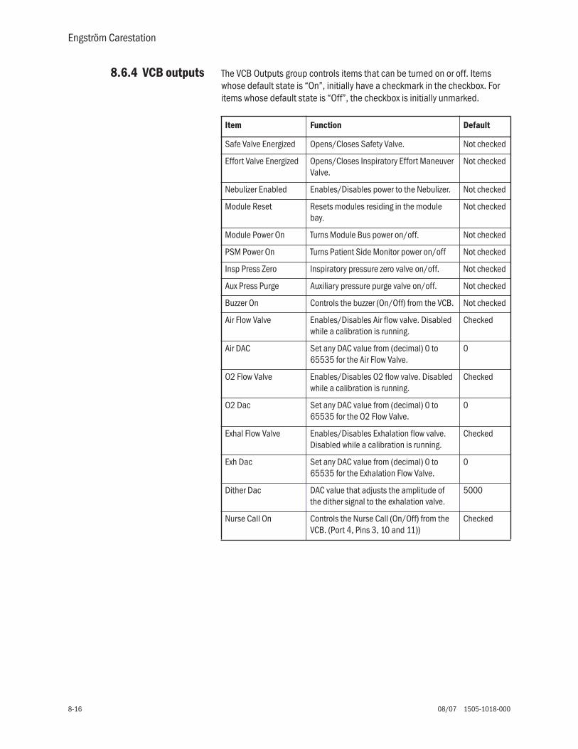
Engström Carestation
8-16 08/07 1505-1018-000
8.6.4 VCB outputs The VCB Outputs group controls items that can be turned on or off. Items whose default state is “On”, initially have a checkmark in the checkbox. For items whose default state is “Off”, the checkbox is initially unmarked.
Item Function Default
Safe Valve Energized Opens/Closes Safety Valve. Not checked
Effort Valve Energized Opens/Closes Inspiratory Effort Maneuver Valve.
Not checked
Nebulizer Enabled Enables/Disables power to the Nebulizer. Not checked
Module Reset Resets modules residing in the module bay.
Not checked
Module Power On Turns Module Bus power on/off. Not checked
PSM Power On Turns Patient Side Monitor power on/off Not checked
Insp Press Zero Inspiratory pressure zero valve on/off. Not checked
Aux Press Purge Auxiliary pressure purge valve on/off. Not checked
Buzzer On Controls the buzzer (On/Off) from the VCB. Not checked
Air Flow Valve Enables/Disables Air flow valve. Disabled while a calibration is running.
Checked
Air DAC Set any DAC value from (decimal) 0 to 65535 for the Air Flow Valve.
0
O2 Flow Valve Enables/Disables O2 flow valve. Disabled while a calibration is running.
Checked
O2 Dac Set any DAC value from (decimal) 0 to 65535 for the O2 Flow Valve.
0
Exhal Flow Valve Enables/Disables Exhalation flow valve. Disabled while a calibration is running.
Checked
Exh Dac Set any DAC value from (decimal) 0 to 65535 for the Exhalation Flow Valve.
0
Dither Dac DAC value that adjusts the amplitude of the dither signal to the exhalation valve.
5000
Nurse Call On Controls the Nurse Call (On/Off) from the VCB. (Port 4, Pins 3, 10 and 11))
Checked

8 Software Download and Diagnostics
1505-1018-000 08/07 8-17
8.6.5 Calibrations andtests
The O2 Flow Valve DAC, Air Flow Valve DAC, and the Exhalation Flow Valve DAC return to their default values when a calibration completes.
Item Description
Calibration Running Shows the current calibration that is running.% Done The percentage of the calibration that is completed.Start Paw Span Starts airway pressure transducer zero and span for all
three pressure transducers (Insp, Exp, and Aux).End Paw Span Ends airway pressure transducer zero and span for all
three pressure transducers (Insp, Exp, and Aux).Span DAC Value Exhalation valve DAC counts for the Paw Span Test.
Default = 0Reset DAC Sets DAC value to zero.O2 Flow Valve Runs O2 Flow Valve Test.Air Flow Valve Runs Air Flow Valve Test.Exhal Valve Runs Exhalation Flow Valve Test.Cal Tables Displays a new window showing the calibration tables of
the Air Flow Valve, O2 Flow Valve, and Exhal Valve tests.Zero Pressures Zeros the Inspiratory and Expiratory pressure sensors.Exh Flow Exhalation flow sensor zero.O2 Sensor Runs the Paracube O2 sensor test.Valve Sweep Runs the Valve Sweep calibration.Low P Leak Runs Low Pressure Leak Test.High O2 Leak Runs High O2 Pressure Leak Test.O2 Leak w/o filter Displays the calculated vent engine high pressure O2 leak
without a filter.O2 leak w/ filter Displays the calculated vent engine high pressure O2 leak
with a filter.O2 Flow Valve Leak Displays calculated vent engine high pressure O2 Flow
Valve leak.High Air Leak Runs High Air Pressure Leak Test.Air Leak w/o Filter Displays the calculated vent engine high pressure Air leak
without a filter.Air Leak w/ Filter Displays the calculated vent engine high pressure Air leak
with a filter.Air Flow Valve Leak Displays calculated vent engine high pressure Air Flow
Valve leak.Leak Result: The measured leak from the last Low Pressure, High O2,
and High Air leak tests.Log Calibration results to file:
Enter file name (example D:\testlog1.log).
Find Log File Searches for a log file that already exists.Start Logging Updates selected log as calibrations are completed.
Note: The current log overwrites previous entries. Stop Logging Turns off the calibration log.

Engström Carestation
8-18 08/07 1505-1018-000
8.6.6 Neon tools The Neon Toolbox group contains lists of counts, flows, and zero offsets related to the Neonatal Flow Sensor (NFS).
VCB flows
VMB flows
Item Function Unit
Insp Flow Displays the Inspiratory Flow counts reported by the Neonatal Flow Sensor
Counts
Exp Flow Displays the Expiratory Flow counts reported by the Neonatal Flow Sensor.
Counts
Net Flow Net Flow is calculated from the counts reported by the Neonatal Flow Sensor and the current zero point. Inspiratory flow is displayed as positive net flow and expiratory flow is displayed as negative net flow.
mL/min

8 Software Download and Diagnostics
1505-1018-000 08/07 8-19
Static zeroing
Offsets
8.6.7 Peep stabilityThe Peep Stability menu is used by manufacturing only.
Item Function Unit
Insp Offset The inspiratory point of the DAC, recorded from the last static zero.
Counts
Exp Offset The expiratory point of the DAC, recorded from the last static zero.
Counts
Zero NFS When selected, the system performs a static zero of the Neonatal Flow Sensor.
Item Function Unit
Insp Offset (DAC Counts)
Displays the inspiratory DAC zero offset movement from the last recorded static zero. Updated by the dynamic zeroing.
Counts
Exp Offset (DAC Counts)
Displays the expiratory DAC zero offset movement from the last recorded static zero. Updated by the dynamic zeroing.
Counts
Insp Offset (ADC Counts)
Displays the calculated inspiratory zero offset since the last DAC zero movement. Updated by the dynamic zeroing.
Counts
Exp Offset (ADC Counts)
Displays the calculated expiratory zero offset since the last DAC zero movement. Updated by the dynamic zeroing.
Counts
Engström Carestation
8-20 08/07 1505-1018-000
8.6.8 Logging checkoutresults
The ventilator does not have to be in the Service Mode to log the checkout results.
• Power on the system and wait for the Patient Setup menu to display.
Note: For systems with 4.2X software, wait for the Select Patient menu to display, then select Patient Setup menu .
• Connect a PC to the system and start the PC Application software (Revision 1.58 or higher).
1. Access the Log Calibration result to file area of the PC Service Application and select Find Log File.
2. Select the desired folder from your PC hard drive to store Log Files.
• Rename the file and select OPEN. Suggested file naming convention: Serial Number +date+"ck.log"
• If a Log File does not exist a message window displays. "Select Yes to create a Log File."
3. Verify the file address location displayed in the Log Calibration results to file area and select Start Logging.
• The Status Log window displays and indicates that the log has been initialized.
4. From the EC Ventilator, access the Patient Setup menu and select Checkout.
• Follow the screen instructions and select Start Checkout. Information from the ventilator will begin loading into the log after a few seconds.
5. From the PC, select Stop Log from the Status Log window after checks are complete.
6. Select Save Log from Status Log window
As each system checkout occurs the Status Log will display Pass or Fail. If a checkout fails the log will record and display information about the exact parameter that failed. This information is essential in determining the cause for checkout failure(s). Always include the Log file when iTrak quality reports are submitted.

8 Software Download and Diagnostics
1505-1018-000 08/07 8-21
8.6.9 Logging CalibrationResults
The ventilator must be in the Service Mode to log the calibration results.
• Power on the system and wait for the Patient Setup menu to display.
Note: For systems with 4.2X software, wait for the Select Patient menu to display, then select Patient Setup menu .
1. Access the Service Calibration menu.
2. Connect a PC to the system and start the PC Application software (Revision 1.58 or higher).
3. Access the Log Calibration result to file area of the PC Service Application and select Find Log File.
4. Select the desired folder from the PC hard drive to store Log Files.
• Rename the file and select OPEN. Suggested file naming convention: Serial Number +date+"cal.log"
• If a Log File does not exist a message window displays. "Select Yes to create a Log File."
5. Verify the file address location displayed in the Log Calibration results to file area and select Start Logging.
• The Status Log window displays and indicates that the log has been initialized.
6. From the EC Ventilator, access the Calibrations menu from the Install/Service menu.
• Select each calibration and follow the screen instructions to complete the calibrations.
• From the PC, select Save Log from the Status Log window after calibrations are complete. Select Ignore if "Debug Assertion Failed" message appears.
As each system calibration occurs the Status Log will display Pass or Fail. If a calibration fails the log will record and display information about the exact parameter that failed. This information is essential in determining the cause for calibration failure(s). Always include the Log file when iTrak quality reports are submitted.

Engström Carestation
8-22 08/07 1505-1018-000
8.7 VMB Diagnostics
Selecting VMB Diagnostics on the Main menu brings up the following page that contains five grouped areas.

8 Software Download and Diagnostics
1505-1018-000 08/07 8-23
8.7.1 VMB ChannelConfigurations
The VMB Channel Configurations group includes items that are measured from the VMB. If the item is within the acceptable range, “OK” is displayed next to the value. If the item is out of the acceptable range, “FAIL” is displayed instead.
Item Description Format Units Range
Expiratory Press Expiratory Pressure sensor measurement
XXX.XX cmH2O -26.8 to 131.8
Barometric Press Barometric pressure sensor measurement
XXX.XX cmH2O 643.7 to 1182.0
O2 Supp Press O2 supply pressure sensor measurement
XXX.XX psig -9.1 to 127.8
Air Supp Press Air supply pressure sensor measurement
XXX.X psig -9.1 to 127.8
Reference 1.22V Reference XXXXX mV 1104 to 1338
12.5V Supply 12.5V Power supply to the VMB XXXXX mV 10900 to 13320
6.1V Expiratory 6.1V power supply to the expiratory flow sensor
XXXXX mV 5770 to 6370
5V O2 Supply 5V power supply to the O2 sensor XXXXX mV 4720 to 5380
5V O2 Press 5V power supply to the O2 pressure sensor
XXXXX mV 4680 to 5340
5V Air Press 5V power supply to the Air pressure sensor
XXXXX mV 4680 to 5340
5.5V Analog 5.5V analog supply XXXXX mV 5140 to 5880
-5.5V Analog -5.5V analog supply XXXXX mV -6220 to -4440
Ground Ground XXXXX mV

Engström Carestation
8-24 08/07 1505-1018-000
8.7.2 VMB outputs The VMB Outputs group controls items that can be turned on or off. Items whose default state is “On”, initially have a checkmark in the checkbox. For items whose default state is “Off”, the checkbox is initially unmarked.
8.7.3 VMB data The VMB Data group shows the reported values for Expiratory Flow and O2 concentration.
Item Function Default
Exh Valve Pwr Opens/closes the exhalation valve (opens when checked). Not checked
Safe Valve Energized
Opens/closes the safety valve from the VMB (energized when checked).
Not checked
O2 Sensor Off Turn oxygen sensor On (not checked) or Off (checked) Not checked
Exh Flow Sensor Pwr
Turn exhalation sensor On (checked) or Off (not checked) Checked
VMB Buzzer On The VMB turns the buzzer On/Off. Not checked
VMB Reset Resets the VMB (disables the watchdog) when checked. Not checked
Exp Press Zero Open
Opens/Closes the expiratory pressure zero valve. The valve will be opened when checked.
Not checked
Item Description Format Units
Exp Flow Expiratory flow sensor measurement. XXX.XX mL/min
O2 % Measured oxygen concentration from the oxygen sensor.
XXX %

8 Software Download and Diagnostics
1505-1018-000 08/07 8-25
8.7.4 Baro P cal
8.7.5 Acutronic
8.7.6 EEProm EEProm is used by manufacturing only.
Item Description
Enter Pressure Enter the local barometric pressure in mmHg. The Baro P Calibration will use this value to calibrate the barometric pressure transducer.
Baro P Cal Starts the barometric pressure transducer calibration. The calibration will Fail if nothing is entered in the Enter Pressure box.
Status Displays the results of the barometric calibration (Passed or Failed).
Item Description
SW Ver Software version of the acutronic Sensor software.Exp Zero ADC Displays the Analog to Digital Counter zero value fro the
expiratory flow sensor.Exp Zero DAC Displays the Digital to Analog Counter used to zero the
expiratory flow sensor.

Engström Carestation
8-26 08/07 1505-1018-000

1505-1018-000 08/07 9-1
9 Repair Procedures
In this section 9.1 Circuit Board Replacement precautions . . . . . . . . . . . . . . . . . . . . . . . . . . . . . . . . . . . . . . . .9-3
9.1.1 Software download . . . . . . . . . . . . . . . . . . . . . . . . . . . . . . . . . . . . . . . . . . . . . . . . . . .9-3
9.1.2 Required calibrations . . . . . . . . . . . . . . . . . . . . . . . . . . . . . . . . . . . . . . . . . . . . . . . . .9-3
9.2 How to bleed gas pressure from the machine . . . . . . . . . . . . . . . . . . . . . . . . . . . . . . . . . . . .9-4
9.3 Accessing chassis components . . . . . . . . . . . . . . . . . . . . . . . . . . . . . . . . . . . . . . . . . . . . . . .9-4
9.3.1 To remove the chassis from the housing . . . . . . . . . . . . . . . . . . . . . . . . . . . . . . . . . .9-5
9.3.2 To remove the Vent Engine from the chassis . . . . . . . . . . . . . . . . . . . . . . . . . . . . . .9-5
9.3.3 To replace chassis mounted components . . . . . . . . . . . . . . . . . . . . . . . . . . . . . . . .9-6
9.3.4 To replace vent engine components . . . . . . . . . . . . . . . . . . . . . . . . . . . . . . . . . . . . .9-6
9.3.5 To replace inspiratory valve assembly (1505-8502-000) . . . . . . . . . . . . . . . . . . .9-9
9.3.6 To replace free breathing valve (0211-1454-100) . . . . . . . . . . . . . . . . . . . . . . . 9-10
9.3.7 To replace Vent Engine assembly, complete . . . . . . . . . . . . . . . . . . . . . . . . . . . . 9-11
9.3.8 To replace Vent Engine, sub-assembly . . . . . . . . . . . . . . . . . . . . . . . . . . . . . . . . . 9-11
9.4 Servicing the Display Unit (DU) . . . . . . . . . . . . . . . . . . . . . . . . . . . . . . . . . . . . . . . . . . . . . 9-12
9.4.1 Remove the Display Unit . . . . . . . . . . . . . . . . . . . . . . . . . . . . . . . . . . . . . . . . . . . . 9-12
9.4.2 Disassemble the Display Unit . . . . . . . . . . . . . . . . . . . . . . . . . . . . . . . . . . . . . . . . 9-13
9.4.3 To replace the CPU board . . . . . . . . . . . . . . . . . . . . . . . . . . . . . . . . . . . . . . . . . . . 9-14
9.4.4 To replace the LCD display . . . . . . . . . . . . . . . . . . . . . . . . . . . . . . . . . . . . . . . . . . . 9-15
9.4.5 To replace the backlights . . . . . . . . . . . . . . . . . . . . . . . . . . . . . . . . . . . . . . . . . . . . 9-16
9.4.6 To replace the Inverters . . . . . . . . . . . . . . . . . . . . . . . . . . . . . . . . . . . . . . . . . . . . . 9-17
9.4.7 To replace the front enclosure or components . . . . . . . . . . . . . . . . . . . . . . . . . . . 9-18
9.5 Servicing the High Performance Display Unit (HPDU) . . . . . . . . . . . . . . . . . . . . . . . . . . . . 9-20
9.5.1 Remove the Display Unit. . . . . . . . . . . . . . . . . . . . . . . . . . . . . . . . . . . . . . . . . . . . . 9-20
9.5.2 Disassemble the Display Unit . . . . . . . . . . . . . . . . . . . . . . . . . . . . . . . . . . . . . . . . 9-21
9.5.3 CPU Fan . . . . . . . . . . . . . . . . . . . . . . . . . . . . . . . . . . . . . . . . . . . . . . . . . . . . . . . . . . 9-21
9.5.4 To replace the CPU board . . . . . . . . . . . . . . . . . . . . . . . . . . . . . . . . . . . . . . . . . . . 9-22
9.5.5 To replace the LCD display . . . . . . . . . . . . . . . . . . . . . . . . . . . . . . . . . . . . . . . . . . . 9-23
9.5.6 To replace the backlights . . . . . . . . . . . . . . . . . . . . . . . . . . . . . . . . . . . . . . . . . . . . 9-25
9.5.7 To replace the Inverters . . . . . . . . . . . . . . . . . . . . . . . . . . . . . . . . . . . . . . . . . . . . . 9-26
9.5.8 To replace the front enclosure or components . . . . . . . . . . . . . . . . . . . . . . . . . . . 9-27
9.6 Adjusting the display arm . . . . . . . . . . . . . . . . . . . . . . . . . . . . . . . . . . . . . . . . . . . . . . . . . . 9-29
9.6.1 Adjust upper pivot . . . . . . . . . . . . . . . . . . . . . . . . . . . . . . . . . . . . . . . . . . . . . . . . . 9-29
9.6.2 Adjust lower pivot . . . . . . . . . . . . . . . . . . . . . . . . . . . . . . . . . . . . . . . . . . . . . . . . . . 9-30
9.6.3 Adjust arm bearing . . . . . . . . . . . . . . . . . . . . . . . . . . . . . . . . . . . . . . . . . . . . . . . . . 9-30
9.7 Removing a compressor from the cart . . . . . . . . . . . . . . . . . . . . . . . . . . . . . . . . . . . . . . . . 9-31
9.8 Attaching Labels . . . . . . . . . . . . . . . . . . . . . . . . . . . . . . . . . . . . . . . . . . . . . . . . . . . . . . . . . 9-32
9.8.1 Key/BID label . . . . . . . . . . . . . . . . . . . . . . . . . . . . . . . . . . . . . . . . . . . . . . . . . . . . . 9-32
9.8.2 Feature label . . . . . . . . . . . . . . . . . . . . . . . . . . . . . . . . . . . . . . . . . . . . . . . . . . . . . . 9-32
Engström Carestation
9-2 08/07 1505-1018-000
w WARNING To prevent fires:
• Use lubricants approved for O2 environments, such as Krytox. Other lubricants may burn or explode in high O2 concentrations.
• All covers used on the system must be made from antistatic materials. Static electricity can cause fires in high O2 concentrations.
w Obey infection control and safety procedures. Used equipment may contain blood and body fluids.
w A movable part or a removable component may present a pinch or a crush hazard. Use care when moving or replacing system parts and components.
w Some internal parts have sharp edges and can cause cuts or abrasions. Use care when servicing internal components.
w When servicing the EC, extreme care must be taken to avoid introducing foreign debris into the pneumatic flow passages of the ventilator. This includes dust and contaminants on the vent engine and particularly metal chips generated by screw threads. Before removing components on the vent engine, secure a clean work area and thoroughly clean the vent engine to remove any contaminants. Failure to do so may result in damage to the internal components.
w After repairs are completed, always perform the checkout procedure. Refer to Section 3 of this manual.
w CAUTION Electrostatic discharge through circuit boards may damage the components on them. Wear a static control wrist strap before touching the circuit boards. Handle all circuit boards by their non-conductive edges. Use anti-static containers when transporting them.

9 Repair Procedures
1505-1018-000 08/07 9-3
9.1 Circuit Board Replacement precautions
The EC stores the system serial number and installed optional features (if any) in three locations:
• Display Unit CPU board• Vent Control board (VCB)• Power Monitor board (PMB)
Each time the system is powered up, the software checks to ensure that the information stored in these locations is the same.
If, on power up, only two of the three boards have matching information (such as would be if one of these boards is replaced), the software loads the information from the two matching boards to the third board. This scheme allows for replacement of these boards while retaining machine specific parameters.
NNNNooootttteeee:::: No checking or replication occurs when the Service App is loaded. The unit must be powered up with system software.
Caution Do not replace more than one of these boards at a time without first powering up the unit. Wait until the initial checkout menu appears to insure that the machine specific information has been replicated.
9.1.1 Softwaredownload
After replacing any of the following boards, download the current software for the newly installed subsystem (refer to Section 8.4):
• Display Unit CPU board (or a replacement HPDU)• Power Monitor board (PMB)• Vent Monitor board (VMB)• Vent Control board (VCB)
9.1.2 Requiredcalibrations
When repairs are complete, if either the VMB or the VCB were replaced, the following calibrations must be performed before completing the checkout procedure.
If the VMB is replaced,• calibrate the airway pressure transducers (refer to Section 5.2.8).• calibrate the barometric pressure transducer (refer to Section 8.7.4).
If the VCB is replaced,• calibrate the airway pressure transducers (refer to Section 5.2.8).• calibrate the flow control valves — O2 FCV, Air FCV, and Exhalation Valve
(refer to Section 4.3).

Engström Carestation
9-4 08/07 1505-1018-000
9.2 How to bleed gas pressure from the machine
Before disconnecting pneumatic fittings, bleed all gas pressure from the ventilator.
1. Disconnect all gas supplies from the source.
2. Set the system switch to On.
3. Ensure that all pressures read zero.
4. Establish a flow for the affected gas to bleed down the pressure.
5. Set the system switch to Standby.
9.3 Accessing chassis components
Most of the EC components are mounted to a two-tier chassis that slides out of the housing for access to the internal components.
The pneumatic (and related Vent Engine) components are mounted on a manifold that occupies the lower tier of the chassis. To access the pneumatic components, the entire manifold assembly can be removed from the chassis.
The electrical (and related circuit board) components occupy the upper tier.
Electrical components on the Vent Engine connect to the Ventilator Control Board (VCB) and the Ventilator Monitor Board (VMB) through a single, two-connector harness.
To diagnose the operation of the EC while still disassembled, the components (Vent Engine, circuit boards, Display Unit) can be arranged and reconnected with existing harnesses. A separate Display Unit Cable can be used as a service tool to make the connection between the Chassis and the Display Unit less restricted.
Vent Engine
Chassis
Housing

9 Repair Procedures
1505-1018-000 08/07 9-5
9.3.1 To removethe chassis from
the housing
1. To prevent the housing from tipping over when the chassis is removed, position the Display Unit (as shown) centered over the housing.
2. If applicable, remove any patient circuit components.
3. Remove the Exhalation Valve. The chassis can not be removed with the Exhalation Valve in place.
4. Disconnect the Display Cable from the chassis connector.
5. Loosen the four captured mounting screws at each corner of the back panel.
6. Slide the chassis out of the housing.
9.3.2 To removethe Vent Engine
from the chassis
1. Remove the circuit board retainer.
2. Disconnect the engine harness connectors from the circuit boards.
3. Remove the four screws (two on each side) that hold the Vent Engine manifold to the chassis.
4. Slide the Vent Engine out of the chassis.
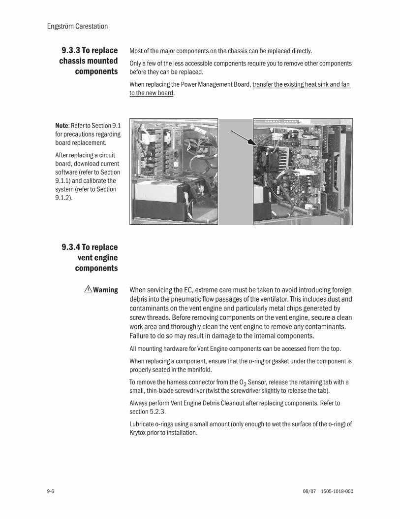
Engström Carestation
9-6 08/07 1505-1018-000
9.3.3 To replacechassis mounted
components
Most of the major components on the chassis can be replaced directly.
Only a few of the less accessible components require you to remove other components before they can be replaced.
When replacing the Power Management Board, transfer the existing heat sink and fan to the new board.
9.3.4 To replacevent engine
components
wWarning When servicing the EC, extreme care must be taken to avoid introducing foreign debris into the pneumatic flow passages of the ventilator. This includes dust and contaminants on the vent engine and particularly metal chips generated by screw threads. Before removing components on the vent engine, secure a clean work area and thoroughly clean the vent engine to remove any contaminants. Failure to do so may result in damage to the internal components.
All mounting hardware for Vent Engine components can be accessed from the top.
When replacing a component, ensure that the o-ring or gasket under the component is properly seated in the manifold.
To remove the harness connector from the O2 Sensor, release the retaining tab with a small, thin-blade screwdriver (twist the screwdriver slightly to release the tab).
Always perform Vent Engine Debris Cleanout after replacing components. Refer to section 5.2.3.
Lubricate o-rings using a small amount (only enough to wet the surface of the o-ring) of Krytox prior to installation.
Note: Refer to Section 9.1 for precautions regarding board replacement.
After replacing a circuit board, download current software (refer to Section 9.1.1) and calibrate the system (refer to Section 9.1.2).

9 Repair Procedures
1505-1018-000 08/07 9-7
Vent engine cleanrepair procedure
1. Use compressed air to blow any loose particulates and dust from the manifold and components prior to loosening fasteners. Use caution around small parts and elastomers such as o-rings and diaphragms.
2. Obtain alcohol prep pads or similar damp cleaning wipes before removing components. Do not use materials that will lose fibers or leave a residue on components.
3. Completely remove all fasteners and place in a temporary container before moving the component.
4. Carefully lift the component straight up and away from the manifold. Check to make sure all necessary o-rings and gaskets are present. Store components in a temporary container and not on the workspace tabletop.
5. If the component is going to be re-installed, place it on the side or back on a clean surface to protect the mating surface.
6. Using an alcohol prep pad, damp wipe clean the manifold surface by starting at the opening and wiping away from it. This will reduce the risk of loose material dropping into the manifold.
7. Carefully inspect the opening in the manifold. If there is any visual sign of contamination or discoloration, the manifold and any upstream components must be replaced.
8. If the component removed is to be reinstalled, clean it in a similar manner by wiping from any gas stream access points toward the outside edge.
9. Carefully inspect the component and seal. If there is any sign of contamination, knicks, small tears, or discoloration, the component and or seal must be replaced.
10.Carefully set the component back on the manifold directly over and aligned with the attachments and avoid sliding the component once it is in contact with the manifold.
11.Reinstall the fasteners and torque it to the required specification as listed.
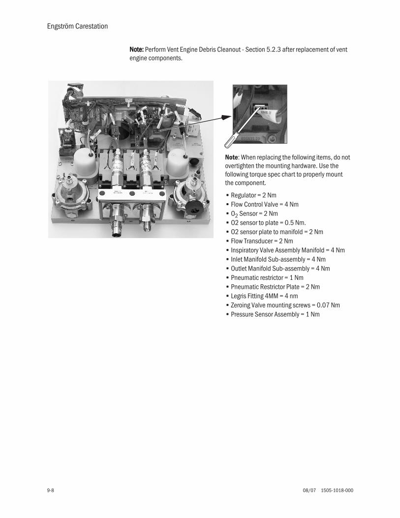
Engström Carestation
9-8 08/07 1505-1018-000
NNNNooootttteeee:::: Perform Vent Engine Debris Cleanout - Section 5.2.3 after replacement of vent engine components.
Note: When replacing the following items, do not overtighten the mounting hardware. Use the following torque spec chart to properly mount the component.
• Regulator = 2 Nm• Flow Control Valve = 4 Nm• O2 Sensor = 2 Nm• O2 sensor to plate = 0.5 Nm.• O2 sensor plate to manifold = 2 Nm• Flow Transducer = 2 Nm• Inspiratory Valve Assembly Manifold = 4 Nm• Inlet Manifold Sub-assembly = 4 Nm• Outlet Manifold Sub-assembly = 4 Nm• Pneumatic restrictor = 1 Nm• Pneumatic Restrictor Plate = 2 Nm• Legris Fitting 4MM = 4 nm• Zeroing Valve mounting screws = 0.07 Nm• Pressure Sensor Assembly = 1 Nm

9 Repair Procedures
1505-1018-000 08/07 9-9
9.3.5 To replaceinspiratory valve
assembly(1505-8502-000)
1. Remove the chassis from the housing per Section 9.3.1.
2. Remove the Vent Engine from the chassis per Section 9.3.2.
3. Disconnect the wiring harness from the inspiratory valve and safety valve actuators.
4. Remove the four M4 X 12 socket head screw that secure the assembly to the main manifold and remove the Inspiratory Valve assembly.
5. Install the new Inspiratory Valve assembly to the main manifold using four M4 X 12 socket head screws. Torque = 2.0 NmNote: On original main manifold without guide pins use “Safety Valve Alignment tool” (1505-8598-000) to align the inspiratory Valve Assembly to the main manifold.)
6. Transfer or install the new Safety Valve Actuator (M1114504 and Seal (1505-8600-000) to the new Inspiratory Valve Assembly. Apply a small amount (only enough to wet the surface) of Loctite 271 to screw. Torque = 2.0 Nm
7. Perform Service level tests and calibrations. Refer to section 5.2.3, 5.2.5, 5.2.9, 5.2.10, and 5.2.12.
8. Install Vent Engine assembly into chassis. Refer to section 9.3.2.
9. Install chassis into housing. Refer to section 9.3.1.
10.Perform Super User calibrations per Section 5.1.1.
11.Perform Automated Checkout per Section 3.2.
Safety valve alignment tool

Engström Carestation
9-10 08/07 1505-1018-000
9.3.6 To replacefree breathing
valve(0211-1454-100)
1. Remove the chassis from the housing per Section 9.3.1.
2. Remove the Vent Engine from the chassis per Section 9.3.2.
3. Remove the Free Breathing Valve seat (1503-3204-000) from the main manifold.
4. Remove and discard Valve Flapper (0211-1454-100) and o-ring (1503-3208-000).
5. Clean the Free Breathing Valve seal and Valve Flapper using an alcohol prep pad.
6. Pull the Valve Flapper through the hole in the Free Breathing Valve seat and cut off tip of flapper to approximately 7mm.
7. Apply a thin film of Krytox to o-ring (only enough to wet the surface of the o-ring) and fit o-ring into the groove located on the Free Breathing Valve seat.
8. Install the Free Breathing Valve seat into the main manifold and tighten valve until it is flush with the manifold.
9. Perform Service level tests and calibration per Section 5.2.9.
10.Install Vent Engine Assembly into chassis. Refer to Section 9.3.7.
11.Install chassis into housing. Refer to Section 9.3.1
12.Perform Super-User calibrations per Section 5.1.1.
13.Perform an Automated Checkout per Section 3.2
9 Repair Procedures
1505-1018-000 08/07 9-11
9.3.7 To replaceVent Engine
assembly,complete
1. Remove the chassis from the housing. Refer to Section 9.3.1.
2. Remove the Vent Engine from the chassis. Refer to Section 9.3.2
3. Replace the Vent Engine with new Vent Engine assembly and connect harness to the VCB and VMB.
NNNNooootttteeee:::: Do not install Vent Engine assembly into chassis until all tests and calibration in Step 4 have been completed.
4. Perform Service level tests and calibration. Refer to Section 5.2.
5. Install Vent Engine assembly into chassis. Refer to Section 9.3.2.
6. Install chassis into housing. Refer to Section 9.3.1.
7. Perform Super-User calibrations. Refer to Section 5.1.1.
8. Perform Automated Checkout. Refer to Section 3.2.
9.3.8 To replaceVent Engine,
sub-assembly
1. Remove the chassis from the housing per Section 9.3.1.
2. Remove the Vent Engine assembly from the chassis. Refer to Section 9.3.2.
3. Remove the following components from the Vent Engine assembly:
a. Harness (vent engine to VCB/VMB) - (1505-5706-000).
b. Inspiratory Manifold Panel Assembly with safety valve (1505-8502-000).
c. Outlet Manifold Panel Assembly (including all mounted components) -(1505-8505-000).
d. O2 Pipeline Adapter (from inlet manifold) - (1505-3206-000).
e. AIR Pipeline adapter (from inlet manifold) - (1505-3207-000).
4. Clean and install the above removed parts on the new Vent Engine sub assembly. Refer to Section 9.3.4.
5. Connect the new Vent Engine assembly harness to the VCB and VMB.
NNNNooootttteeee:::: Do not install Vent Engine assembly into chassis until all tests and calibration in Step 6 have been completed.
6. Perform Service level tests and calibration. Refer to Section 5.2.
7. Install Vent Engine Assembly into the chassis. Refer to Section 9.3.2
8. Install chassis into housing. Refer to Section 9.3.1.
9. Perform Super-User calibrations. Refer to Section 5.1.1.
10.Perform Automated Checkout. Refer to Section 3.2.

Engström Carestation
9-12 08/07 1505-1018-000
9.4 Servicing the Display Unit (DU)
Note The item numbers appearing in parenthesis in this section refer to items in the parts list in Section 10.9.
The fan filter (26) and the access door (27) to the PCMCIA interface can be replaced with the Display Unit in place.
To replace the filter, slide the filter capsule (27) downward to remove it from the Display Unit.
To service other components of the Display Unit, you must first remove the Display Unit from the machine.
9.4.1 Remove theDisplay Unit
The Display Unit attaches to the pivot arm with screws that are accessible under the pivot covers.
1. Remove the pivot arm covers on each side of the upper pivot.
• The pivot covers are held in place by three tabs in the locations shown by the arrows.
• Slide a thin blade between the cover and the pivot housing to release each tab.
2. Raise the DU so that it faces backwards.
3. Disconnect the display cable (A).
4. Remove the four screws that hold the DU to the upper pivot (B).
(27)
(28)
(27)
(29)
A
B

9 Repair Procedures
1505-1018-000 08/07 9-13
9.4.2 Disassemblethe Display Unit
Place the Display Unit face down on an anti-static pad. Before removing the rear enclosure, ensure that the release tabs on the PCMCIA frame are fully depressed.
1. Loosen (L) the four captive screws at each corner of the rear enclosure.
2. Lift the rear enclosure slightly and pivot it away from the lower enclosure at the bottom side of the Display Unit.
At this point, you can replace the following items (The item numbers refer to the parts list in Section 10.9):
• the fan (26)
• the connector panel assembly (21)
• the encoder assembly (12)
• the battery (5)
• the speaker (20) — To access the mounting screws for the speaker, you must first remove the ten screws that hold the mounting plate to the front enclosure so that you can raise the bottom edge of the assembly slightly — Refer to section 9.4.4.)
• the rear enclosure (1) — You can transfer the captive screws to the new enclosure. However, the gasket (28) is held in place with adhesive. When replacing the rear enclosure, also include a new gasket.
To replace the remaining items requires further disassembly.
20
12
L
L
L
L
(26)
(21) (28) (1)
(5)

Engström Carestation
9-14 08/07 1505-1018-000
9.4.3 To replacethe CPU board
1. Remove the connector panel assembly (21) — two screws.
2. Disconnect the following cables:
• Inverter harnesses (A)
• Membrane switch flex-cable at ZIF (zero insertion force) connector (B)
• Speaker cable (C)
• Encoder assembly cable (D)
• Membrane switch flex-cable at ZIF (zero insertion force) connector (E)
• Fan cable (F)
• LCD cable (G)
3. Remove the remaining four screws (H) that hold the CPU board to the mounting plate.
4. Remove the CPU board from the mounting plate.
5. If you are replacing the PCMCIA frame (3) on an existing CPU board (remove four screws on back of CPU board), you must also apply new gaskets (4) to the frame. Align the ends of the gaskets with the top edge of the frame.
6. Transfer the battery (5) to the new CPU board.
7. Reassemble in reverse order.
8. Download latest software (Section 8.4).
H
H
HA
B
C
D F
G
(21)
H
(5)
Verify
3-4
J17 Jumpers
5-67-89-10
open
E
(4)
(3)

9 Repair Procedures
1505-1018-000 08/07 9-15
9.4.4 To replacethe LCD display
1. Disconnect the following cables:
• Membrane switch flex-cable at ZIF (zero insertion force) connector (A)
• Encoder assembly cable (B)
• Membrane switch flex-cable at ZIF (zero insertion force) connector (C)
• Fan cable (D)
• LCD cable (E)
2. Remove the ten screws (circled) that hold the mounting plate to the front enclosure.
3. Remove the mounting plate assembly from the front enclosure.
4. Disconnect the backlight harnesses (F) from the inverter boards.
5. Slide the grommet (G) out of the mounting plate slot (transfer to new LCD).
6. Remove the four screws (circled) that hold the LCD to the mounting plate.
A
B D
E
C
F
G

Engström Carestation
9-16 08/07 1505-1018-000
7. Lift the left side of the LCD display slightly away from the mounting plate to pull some of the display ribbon cable (H) to the top side of the plate. Flip the LCD over to the left of the assembly.
8. Disconnect the display ribbon cable (I).
9. Reassemble in reverse order.
Note: When replacing the LCD, pull the excess ribbon cable to the bottom side of the plate as you lower the LCD on to the plate. For the backlight harness grommet (G), ensure that the slit in the grommet faces toward the inside of the keyhole.
9.4.5 To replacethe backlights
The backlight replacement kit includes a backlight assembly (with two backlights) and two inverters with mounting hardware. To replace the backlight assembly follow the procedure in Section 9.3 to gain access to the assembly. To replace the inverters, follow the procedure in the next section.
1. Remove the one screw (J) that holds the backlight assembly to the LCD.
2. Slide the backlight assembly to the left to free it from the retaining tabs and then lift it out of the holder.
3. Transfer the grommet (G) to the new backlight assembly.
4. Reassemble in reverse order.
I
LCDDisplay
H
J
Slit
G
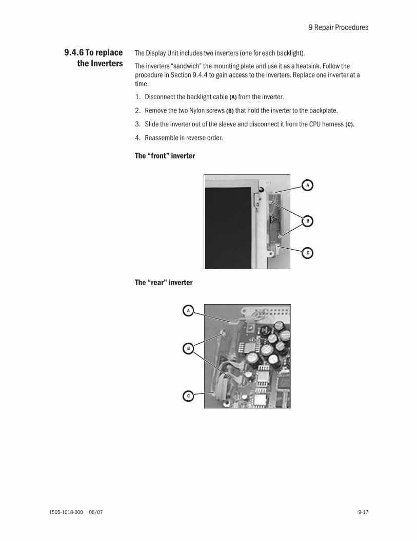
9 Repair Procedures
1505-1018-000 08/07 9-17
9.4.6 To replacethe Inverters
The Display Unit includes two inverters (one for each backlight).
The inverters “sandwich” the mounting plate and use it as a heatsink. Follow the procedure in Section 9.4.4 to gain access to the inverters. Replace one inverter at a time.
1. Disconnect the backlight cable (A) from the inverter.
2. Remove the two Nylon screws (B) that hold the inverter to the backplate.
3. Slide the inverter out of the sleeve and disconnect it from the CPU harness (C).
4. Reassemble in reverse order.
The “front” inverter
The “rear” inverter
A
B
C
A
B
C

Notes
9-18 08/07 1505-1018-000
9.4.7 To replacethe front
enclosure orcomponents
Disassemble the Display Unit following procedures in the previous sections to the point where you have removed the mounting plate assembly from the front enclosure.
If you are replacing the front enclosure, you can transfer the encoder (12) assembly to the new enclosure; but, you must build up the replacement enclosure with:
• a new window (11)
• new membrane switches — right-side (14), lower (15), left-side (16) • new keypads - right-side (17), lower (18), left-side (19)
• new EMC gasket (10)
If you are replacing a keypad or a membrane switch, you must replace both items.
To replace the window 1. Place the front enclosure face up on a flat surface.
2. Press down on one corner of the window to free it from the enclosure.
3. Work your way around the window until you can get a hold of it from the back.
4. Slowly pry the window from the enclosure.
5. Place the front enclosure face down on a flat surface, taking care not to damage the encoder.
6. Remove any remaining residue from the mounting area; clean with isopropyl alcohol.
7. Remove the inside protective material from the front of the window.
8. Peel the front outside frame of the release liner.
9. Lower the window straight down in the enclose, noting the notch in the window and the matching nub on the enclosure.
10.Before seating the window, position it in contact with the bottom and right sides of the frame (see arrows) so that the larger gap between the window and the enclosure is at the top and left edges (as viewed from behind).
11.Remove the protective film from the back side of the window.
(11)
(14, 17)
(12)
(15, 18)
(16, 19)
Nub
(10)

9 Repair Procedures
1505-1018-000 08/07 9-19
To replace a membraneswitch and keypad
1. Remove the screw that attaches the grounding strap to the enclosure.
2. Pry the membrane switch and keypad from the enclosure.
3. Remove any remaining residue from the mounting area; clean with isopropyl alcohol.
4. Remove the backing from the membrane. Be sure to remove the small backing below the flex cable. For the lower membrane, remove the protective film from the IRDA window.
5. Insert the flex cable and ground strap through the slot in the enclosure. Ensure that all of the ground strap passes through the slot and does not remain folded over under the membrane.
6. Carefully lower the membrane straight down to the enclosure. Seat the membrane in place.
7. Remove the backing from the keypad and install it over the membrane switches.
8. Attach the ground strap to the enclosure.
To install the EMIgasket
To fully seal the Display Unit enclosure, you will need approximately 2.3 meters of EMC gasket (10). Cut the gasket into five strips shown below.
Ground Strapfully inserted
286 mm
286 mm
222 mm 222 mm
Insert a continuous length of gasket in the outside grove of the enclosure (sparingly apply “Super Glue Gel” to the channels near the corners before installing the gasket).
Insert individual lengths of gasket in the inside grove around the window (sparingly apply “Super Glue Gel” to the channels near the corners before installing the gasket).
1206 mm
(10)
totalfour sides

Engström Carestation
9-20 08/07 1505-1018-000
9.5 Servicing the High Performance Display Unit (HPDU)
Note To service the DU, refer to Section 9.4.
The item numbers appearing in parenthesis in this section refer to items in the parts list in Section 10.8.
The fan filter (26) and the access door (3) to the PCMCIA interface can be replaced with the Display Unit in place.
To replace the filter, slide the filter capsule (25) downward to remove it from the Display Unit.
To service other components of the Display Unit, you must first remove the Display Unit from the machine.
9.5.1 Remove theDisplay Unit
The Display Unit attaches to the pivot arm with screws that are accessible under the pivot covers.
1. Remove the pivot arm covers on each side of the upper pivot.
• The pivot covers are held in place by three tabs in the locations shown by the arrows.
• Slide a thin blade between the cover and the pivot housing to release each tab.
2. Raise the DU so that it faces backwards.
3. Disconnect the display cable ((((AAAA)))).
4. Remove the four screws that hold the DU to the upper pivot ((((BBBB)))).
(3)
(26)
(25)
A
B

9 Repair Procedures
1505-1018-000 08/07 9-21
9.5.2Disassemble the
Display Unit
Place the Display Unit face down on an anti-static pad.
1. Loosen (L) the four captive screws at each corner of the rear enclosure.
2. Lift the rear enclosure slightly and pivot it away from the lower enclosure at the bottom side of the Display Unit.
At this point, you can replace the following items (The item numbers refer to the parts list in Section 10.8):
• the internal Compact Flash card (27)• the external Compact Flash Kit (28)• the fan (24) — for the HPDU this is a 12-volt fan• the connector panel assembly (21)• the encoder assembly (12)• the battery (5)• the speaker (20) — (To access the mounting screws for the speaker, you must first
remove the ten screws that hold the mounting plate to the front enclosure so that you can raise the bottom edge of the assembly slightly — Refer to section 9.5.5.)
• the rear enclosure (1) — You can transfer the captive screws to the new enclosure. However, the gasket (2) is held in place with adhesive. When replacing the rear enclosure, also include a new gasket.
To replace the remaining items requires further disassembly.
9.5.3 CPU Fan w CAUTION: Do not remove the heatsink from the CPU board.
1. Note the orientation of the fan harness. Disconnect the fan harness from the CPU board.
2. Remove the fan (29) from the CPU heatsink, leaving the heatsink in place.
3. Remove the heatsink (discard) from the replacement fan assembly.
4. Noting the orientation of the fan harness, secure the fan to the CPU heatsink.
5. Connect the fan harness to the CPU board.
20
12
L
L
L
L
(24)
(21) (2) (1)(5)(27)
(29)(28)

Engström Carestation
9-22 08/07 1505-1018-000
9.5.4 To replacethe CPU board
1. Remove the connector panel assembly (21) — two screws.
2. Disconnect the following cables:
• Inverter harnesses (A)
• Right membrane switch flex-cable at ZIF (zero insertion force) connector (B)
• Speaker cable (C)
• Encoder assembly cable (D)
• Lower membrane switch flex-cable at ZIF (zero insertion force) connector (E)
• Fan cable (F)
• LCD cable (G) Make sure cable is plugged in securely, if not screen may display incorrectly (white).
• Left membrane switch flex-cable at ZIF (zero insertion force) connector (H)
3. Remove the remaining four screws (I) that hold the CPU board to the mounting plate.
4. Remove the CPU board from the mounting plate.
5. Transfer the battery (5) to the new CPU board.
6. Reassemble in reverse order.
7. Download the latest software (Section 8.4).
B
I
C
D F
G
(21)
I
(5)
I
I
A
E
H

9 Repair Procedures
1505-1018-000 08/07 9-23
9.5.5 To replacethe LCD display
1. Disconnect the following cables:
• Right membrane switch flex-cable at ZIF (zero insertion force) connector (A)
• Encoder assembly cable (B)
• Lower membrane switch flex-cable at ZIF (zero insertion force) connector (C)
• Fan cable (D)
• LCD cable (E)
• Left membrane switch flex-cable at ZIF (zero insertion force) connector (F)
2. Remove the ten screws (circled) that hold the mounting plate to the front enclosure.
3. Remove the mounting plate assembly from the front enclosure.
4. Disconnect the backlight harnesses (G) from the inverter boards.
5. Slide the grommet (H) out of the mounting plate slot (transfer to new LCD).
A
B D
E
C
F

Engström Carestation
9-24 08/07 1505-1018-000
6. Remove the four screws (circled) that hold the LCD to the mounting plate.
7. Lift the left side of the LCD display slightly away from the mounting plate to pull some of the display ribbon cable (I) to the top side of the plate. Flip the LCD over to the left of the assembly.
8. Disconnect the display ribbon cable (J).
9. Reassemble in reverse order.
Note: When replacing the LCD, pull the excess ribbon cable to the bottom side of the plate as you lower the LCD on to the plate. For the backlight harness grommet (H), ensure that the slit in the grommet faces toward the inside of the keyhole.
G
H
J
LCDDisplay
I

9 Repair Procedures
1505-1018-000 08/07 9-25
9.5.6 To replacethe backlights
The backlight replacement kit includes a backlight assembly (with two backlights) and two inverters with mounting hardware. To replace the backlight assembly follow the procedure in Section 9.4.4 to gain access to the assembly. To replace the inverters, follow the procedure in the next section.
1. Remove the one screw (K) that holds the backlight assembly to the LCD.
2. Slide the backlight assembly to the left to free it from the retaining tabs and then lift it out of the holder.
3. Transfer the grommet (H) to the new backlight assembly.
4. Reassemble in reverse order.
Note: When replacing a backlight or a backlight inverter, you must replace both inverters and the backlight assembly found in the Backlight Kit.
K
Slit
H

Engström Carestation
9-26 08/07 1505-1018-000
9.5.7 To replacethe Inverters
The Display Unit includes two inverters (one for each backlight).
The inverters “sandwich” the mounting plate and use it as a heatsink. Follow the procedure in Section 9.5.5 to gain access to the inverters. Replace one inverter at a time.
1. Disconnect the backlight cable (A) from the inverter.
2. Remove the two Nylon screws (B) that hold the inverter to the backplate.
3. Slide the inverter out of the sleeve and disconnect it from the CPU harness (C).
4. Reassemble in reverse order.
The “front” inverter
The “rear” inverter
Note: When replacing a backlight or a backlight inverter, you must replace both inverters and the backlight assembly found in the Backlight Kit.
A
B
C
A
B
C

9 Repair Procedures
1505-1018-000 08/07 9-27
9.5.8 To replacethe front
enclosure orcomponents
Disassemble the Display Unit following procedures in the previous sections to the point where you have removed the mounting plate assembly from the front enclosure.
If you are replacing the front enclosure, you can transfer the encoder (12) assembly to the new enclosure; but, you must build up the replacement enclosure with:
• a new window (11)• new membrane switches — right-side (14), lower (15), left-side spacer (16) • new keypads - right-side (17), lower (18), left-side blank (19)• new EMC gasket (10)
If you are replacing a keypad or a membrane switch, you must replace both items.
To replace the window 1. Place the front enclosure face up on a flat surface.
2. Press down on one corner of the window to free it from the enclosure.
3. Work your way around the window until you can get a hold of it from the back.
4. Slowly pry the window from the enclosure.
5. Place the front enclosure face down on a flat surface, taking care not to damage the encoder.
6. Remove any remaining residue from the mounting area; clean with isopropyl alcohol.
7. Remove the inside protective material from the front of the window.
8. Peel the front outside frame of the release liner.
9. Lower the window straight down in the enclose, noting the notch in the window and the matching nub on the enclosure.
10.Before seating the window, position it in contact with the bottom and right sides of the frame (see arrows) so that the larger gap between the window and the enclosure is at the top and left edges (as viewed from behind).
11.Remove the protective film from the back side of the window.
(11)
(14, 17)
(12)
(15, 18)
(16, 19)
Nub
(10)

Engström Carestation
9-28 08/07 1505-1018-000
To replace a membraneswitch and keypad
1. Remove the screw that attaches the grounding strap to the enclosure.
2. Pry the membrane switch and keypad from the enclosure.
3. Remove any remaining residue from the mounting area; clean with isopropyl alcohol.
4. Remove the backing from the membrane. Be sure to remove the small backing below the flex cable. Be careful not to allow the ribbon cable to adhere to the backing.
5. Insert the flex cable and ground strap through the slot in the enclosure. Ensure that all of the ground strap passes through the slot an does not remain folded over under the membrane.
6. Carefully lower the membrane straight down to the enclosure. Seat the membrane in place.
7. Remove the backing from the keypad and install it over the membrane switches.
8. Attach the ground strap to the enclosure.
To install the EMIgasket
To fully seal the Display Unit enclosure, you will need approximately 2.3 meters of EMC gasket (10). Cut the gasket into five strips shown below.
Ground Strapfully inserted
286 mm
286 mm
222 mm 222 mm
Insert a continuous length of gasket in the outside grove of the enclosure (sparingly apply “Super Glue Gel” to the channels near the corners before installing the gasket).
Insert individual lengths of gasket in the inside grove around the window (sparingly apply “Super Glue Gel” to the channels near the corners before installing the gasket).
1206 mm
(10)
totalfour sides
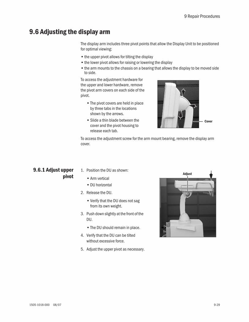
9 Repair Procedures
1505-1018-000 08/07 9-29
9.6 Adjusting the display arm
The display arm includes three pivot points that allow the Display Unit to be positioned for optimal viewing:
• the upper pivot allows for tilting the display• the lower pivot allows for raising or lowering the display• the arm mounts to the chassis on a bearing that allows the display to be moved side
to side.
To access the adjustment hardware for the upper and lower hardware, remove the pivot arm covers on each side of the pivot.
• The pivot covers are held in place by three tabs in the locations shown by the arrows.
• Slide a thin blade between the cover and the pivot housing to release each tab.
To access the adjustment screw for the arm mount bearing, remove the display arm cover.
9.6.1 Adjust upperpivot
1. Position the DU as shown:
• Arm vertical
• DU horizontal
2. Release the DU.
• Verify that the DU does not sag from its own weight.
3. Push down slightly at the front of the DU.
• The DU should remain in place.
4. Verify that the DU can be tilted without excessive force.
5. Adjust the upper pivot as necessary.
Cover
Adjust

Engström Carestation
9-30 08/07 1505-1018-000
9.6.2 Adjust lowerpivot
1. Position the DU as shown:
• Arm forward
• Upper and lower pivots in line horizontally
• DU vertical
2. Release the DU.
• Verify that the DU does not sag from its own weight.
3. Push down slightly at the top of the DU.
• The DU should remain in place.
4. Verify that the DU can be raised and lowered without excessive force.
5. Adjust the lower pivot as necessary.
9.6.3 Adjust armbearing
1. Position the DU as shown above:
• Arm forward
• Upper and lower pivots in line horizontally
• DU vertical
2. Move the DU side to side.
• Verify that the DU can be moved without excessive force and that it remains in place with slight sideways pressure.
3. Adjust the bearing as necessary.
Adjust
Adjust

9 Repair Procedures
1505-1018-000 08/07 9-31
9.7 Removing a compressor from the cart
In routine cases, the compressor can be serviced without removing it from the cart. Refer to the EVair03 Air Compressor Technical Reference manual (6189655).
In situations where greater access to components is required, the compressor can be removed from the cart for service.
w WARNING To avoid personal injury, two people are required to remove and install the compressor.
1. Remove the trim pieces from the side extrusions.
2. Remove the compressor mounting hardware from each side of the cart.
3. Screw in a lifting handle (service tool #5370055) into each side of the compressor.
4. With a person on each side of the cart, lift the compressor slightly and slide it forward out of the cart.
w CAUTION To avoid tipping, use care when moving the ventilator with the compressor removed from the cart.
Tap inscrewdriverblade at base
Pry toloosen
Service Tool5370055

Engström Carestation
9-32 08/07 1505-1018-000
9.8 Attaching Labels
9.8.1 Key/BIDlabel
1. If present, remove the existing Key/BID label from the back of the machine.
2. Clean the area with Isopropyl alcohol.
3. Affix the new Key/BID label to the machine
9.8.2 Featurelabel
Use the feature label to attach FRC, SpiroDynamics, or Neonatal
1. Affix the Feature Label holder to the front of the machine as shown.
• Align the right edge of the label approximately 6 mm from the right edge of the outlet manifold.
• Align the bottom edge of the label approximately 15 mm from the top edge of the outlet manifold.
2. Affix the Feature Specific label in the square recesses in the label holder.
• install the labels starting with the right-most available recess.

1505-1018-000 08/07 10-1
10 Illustrated Parts
In this section 10.1 Service tools . . . . . . . . . . . . . . . . . . . . . . . . . . . . . . . . . . . . . . . . . . . . . . . . . . . . . . . . . . . 10-2
10.1.1 Software tools . . . . . . . . . . . . . . . . . . . . . . . . . . . . . . . . . . . . . . . . . . . . . . . . . . . . 10-2
10.1.2 Manual shut-off valves . . . . . . . . . . . . . . . . . . . . . . . . . . . . . . . . . . . . . . . . . . . . . 10-3
10.1.3 Special tools . . . . . . . . . . . . . . . . . . . . . . . . . . . . . . . . . . . . . . . . . . . . . . . . . . . . . 10-3
10.1.4 Leak test devices. . . . . . . . . . . . . . . . . . . . . . . . . . . . . . . . . . . . . . . . . . . . . . . . . . 10-4
10.1.5 Lubricants and Adhesives . . . . . . . . . . . . . . . . . . . . . . . . . . . . . . . . . . . . . . . . . . 10-5
10.2 Exhalation valve assembly . . . . . . . . . . . . . . . . . . . . . . . . . . . . . . . . . . . . . . . . . . . . . . . . 10-6
10.3 Neonatal Flow Sensor . . . . . . . . . . . . . . . . . . . . . . . . . . . . . . . . . . . . . . . . . . . . . . . . . . . . 10-7
10.4 External components - front view . . . . . . . . . . . . . . . . . . . . . . . . . . . . . . . . . . . . . . . . . . . 10-8
10.5 External components - rear view . . . . . . . . . . . . . . . . . . . . . . . . . . . . . . . . . . . . . . . . . . . 10-9
10.6 Display arm mounting hardware . . . . . . . . . . . . . . . . . . . . . . . . . . . . . . . . . . . . . . . . . . 10-10
10.7 Display arm assembly . . . . . . . . . . . . . . . . . . . . . . . . . . . . . . . . . . . . . . . . . . . . . . . . . . 10-12
10.8 High Performance Display Unit (HPDU) . . . . . . . . . . . . . . . . . . . . . . . . . . . . . . . . . . . . . 10-14
10.9 Display Unit (DU) . . . . . . . . . . . . . . . . . . . . . . . . . . . . . . . . . . . . . . . . . . . . . . . . . . . . . . . 10-16
10.10 Main enclosure (external) . . . . . . . . . . . . . . . . . . . . . . . . . . . . . . . . . . . . . . . . . . . . . . 10-18
10.11 Main enclosure (internal) . . . . . . . . . . . . . . . . . . . . . . . . . . . . . . . . . . . . . . . . . . . . . . . 10-20
10.12 Vent Engine . . . . . . . . . . . . . . . . . . . . . . . . . . . . . . . . . . . . . . . . . . . . . . . . . . . . . . . . . . 10-22
10.13 Outlet manifold . . . . . . . . . . . . . . . . . . . . . . . . . . . . . . . . . . . . . . . . . . . . . . . . . . . . . . . 10-24
10.14 Inlet manifold . . . . . . . . . . . . . . . . . . . . . . . . . . . . . . . . . . . . . . . . . . . . . . . . . . . . . . . . 10-26
10.15 AC power cords . . . . . . . . . . . . . . . . . . . . . . . . . . . . . . . . . . . . . . . . . . . . . . . . . . . . . . . 10-28
10.16 AC Inlet/Outlet Components . . . . . . . . . . . . . . . . . . . . . . . . . . . . . . . . . . . . . . . . . . . . 10-30
10.17 Cart . . . . . . . . . . . . . . . . . . . . . . . . . . . . . . . . . . . . . . . . . . . . . . . . . . . . . . . . . . . . . . . . 10-32
10.18 Module rack . . . . . . . . . . . . . . . . . . . . . . . . . . . . . . . . . . . . . . . . . . . . . . . . . . . . . . . . . 10-34
10.19 Compressor . . . . . . . . . . . . . . . . . . . . . . . . . . . . . . . . . . . . . . . . . . . . . . . . . . . . . . . . . . 10-35
10.20 Feature Options . . . . . . . . . . . . . . . . . . . . . . . . . . . . . . . . . . . . . . . . . . . . . . . . . . . . . . 10-36
10.21 Key/BID label . . . . . . . . . . . . . . . . . . . . . . . . . . . . . . . . . . . . . . . . . . . . . . . . . . . . . . . . 10-37

Engström Carestation
10-2 08/07 1505-1018-000
10.1 Service tools
10.1.1 Softwaretools
Item Description Stock Number
1 Service Application/System Software 2.X(on Compact Flash card - DU) Note: For Standard Display Unit (DU)
1505-8000-000
2 Service Application/System Software 4.X(on Compact Flash card - HPDU)Note: For High Performance Display Unit - HPDU
M1079267
3 Compact Flash Adapter, PCMCIA carrier Note: For Standard Display Unit only (DU)
1009-5874-000
4 Windows based EC Service Application 1505-8001-000
5 Cable, USB Converter to EC 1505-8587-000
6 Converter, USB to RS-422/RS-485 (includes USB cable) 1505-8586-000
Male pin end(9-pin DSUB)
Female pin end(9-pin DSUB)
Port 3(9-pin)
7 1 TX+8 2 TX+9 3 RX+6 4 RX-3 5 GND
5
6
USB type B
1, 2 3
RS-422/RS-485

10 Illustrated Parts
1505-1018-000 08/07 10-3
10.1.2 Manual shut-off valves
10.1.3 Special tools
Item Tool Stock Number
1 Manual shut-off valve — O2Manual shut-off valve — Air
1505-8578-0001505-8579-000
1a — O-ring, 1006-3614-000
1b — Adapter, O2 M181b — Adapter, Air M16
1505-8576-0001505-8577-000
1c — Valve, two-way 0207-6023-300
1d — Nipple, 1/8 NPTM 1 L — O21d — Nipple, 1/8 NPTM 1.5 L — Air
0213-5025-3350213-5026-500
1e — Filter body, M18 — O21e — Filter body, M16 — Air
1001-5921-0001001-5923-000
1a 1b 1c 1d 1e
1
Item Description Stock Number
1 Cable, Remote Display Unit (2 meters) For connect DU to EC chassis when disassembled for repair and evaluation - Refer to section 9.3
M1063496
2 Tool, Nebulizer connector - Refer to section 10.13 1505-8506-000
3 Safety Valve alignment tool (For early manifolds only)Refer to Section 9.3.5 :
1505-8598-000
Handle, Service EC Air Compressor – two requiredRefer to section 9.7
5370055
1 2
3

Engström Carestation
10-4 08/07 1505-1018-000
10.1.4 Leak test devices
Item Tool Stock Number
Leak test device kit (includes items 1 through 10) 1505-8590-000
1 Syringe, 60 cc 1505-3061-000
2 Clamp, tubing 7000-0000-097
3 Tee, 1/8 inch barb 7000-0000-186
4 Negative low-pressure leak test device 0309-1319-800
5 Tee, sensing 22-mm to 15-mm 0212-0763-100
6 Connector, Endo tube 0219-5060-530
7 Plug, 4-mm 1006-3530-000
8 Plug, stopper (2) 2900-0001-000
9 Silicone tubing 3/16 ID 1006-3666-000
10 Tubing, clear 0.125 ID 1605-1001-000
4
6
5
9
7
10
8
2
1
3
1010
10

10 Illustrated Parts
1505-1018-000 08/07 10-5
10.1.5 Lubricants and Adhesives
Item Description Stock Number
1 Lubricant, Krytox GPL 205, 2 oz 1001-3854-000
2 Thread Lock, Loctite No 24221 (medium strength), 10 ml 0220-5017-300
3 Thread Lock, Loctite No 277 (high strength), 50 ml 0220-5026-300
4 Thread Lock, Loctite No 222 (medium strength), 10 ml 7000-0000-183
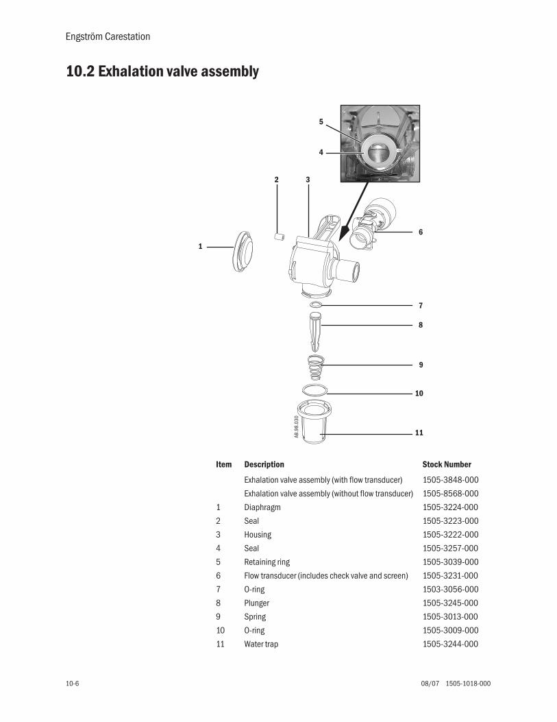
Engström Carestation
10-6 08/07 1505-1018-000
10.2 Exhalation valve assembly
1
2 3
6
7
8
9
10
AB.9
8.03
0
11
4
5
Item Description Stock Number
Exhalation valve assembly (with flow transducer) 1505-3848-000
Exhalation valve assembly (without flow transducer) 1505-8568-000
1 Diaphragm 1505-3224-000
2 Seal 1505-3223-000
3 Housing 1505-3222-000
4 Seal 1505-3257-000
5 Retaining ring 1505-3039-000
6 Flow transducer (includes check valve and screen) 1505-3231-000
7 O-ring 1503-3056-000
8 Plunger 1505-3245-000
9 Spring 1505-3013-000
10 O-ring 1505-3009-000
11 Water trap 1505-3244-000

10 Illustrated Parts
1505-1018-000 08/07 10-7
10.3 Neonatal Flow Sensor
1
2
Item Description Stock Number
1 Neonatal Flow Sensor 1505-3272-000
2 Neonatal Flow Sensor Cable 1505-5604-000

Engström Carestation
10-8 08/07 1505-1018-000
10.4 External components - front view
11(13, 14)
12(13, 14)
2
1
3
4 (5)
9
10
6 (7, 8)
Item Description Stock Number
1 Display Unit Refer to section 10.9
2 Module rack Refer to section 10.18
3 Cart Refer to section 10.17
4 Foot, Vent Housing 1505-3430-000
5 Screw, M5x20 SKT HD 0144-2131-919
6 Latch Plate, Vent Housing 1505-3432-000
7 Belleville Washer, 1505-3051-000
8 Screw, M5x14 Shoulder 1505-3052-000
9 Cage, air transfer 1505-3250-000
10 Screw, M4x8 Pan HD 9211-0440-083
11 Handle Left Vent Housing 1505-3429-000
12 Handle Right Vent Housing 1505-3428-000
13 Screw M4x10 Pan Hd Pozidriv 0144-2117-722
14 Washer M4 external 9213-0540-003

10 Illustrated Parts
1505-1018-000 08/07 10-9
10.5 External components - rear view
1 7
8(22 cm)
8(22 cm)
8(13 cm)
2
3
4
5(6)9
Item Description Stock Number
1 Main enclosure (external)Main enclosure (internal)
Refer to section 10.10Refer to section 10.11
2 Display arm mounting hardwareDisplay arm assembly
Refer to section 10.6Refer to section 10.7
3 Guard, DU connector 1505-3419-000
4 Screw, M4x12 0140-6226-111
5 Spacer, connector guard 1505-3434-000
6 Screw, M4x25 0140-6226-125
7 Housing, Vent 1505-3403-000
8 Tape, Wear UHMW Polyethylene 1505-3030-000
9 Guard, connector for HPDU M1057949

Engström Carestation
10-10 08/07 1505-1018-000
10.6 Display arm mounting hardware
Item Description Stock Number
1 Cable, Display Unit 1505-5600-000
Cable, Remote Display unit (2 meter) M1063496
2 Base Display Arm Mount 1505-3415-000
3 Screw M4-0.7 x 8 SHCS 9211-0640-083
4 Washer, M4 Flat 0144-1025-165
5 Bearing Rotate Display Arm 1505-3418-000
6 Plate Rotate Display Unit 1505-3414-000
7 Screw M6x20 SHCS w/Nylon Strip 1505-3038-000
8 WASHER BELLEVILLE SMALL 1505-3017-000
9 Washer Thrust Steel 6.35ID 17.45OD 1.56THK 1505-3021-000
10 Bearing Thrust 1505-3020-000
11 Mount Pivot Display Unit 1505-3412-000

10 Illustrated Parts
1505-1018-000 08/07 10-11
7
8
9109
1
3(4)
6
11
3(4)
2
Display
Coil CableConnect Cable
5

Engström Carestation
10-12 08/07 1505-1018-000
10.7 Display arm assembly
Item Description Stock Number
1 Mandrel Display Arm Spring 1505-3417-000
2 Sleeve Display Arm Spring Mandrel 1505-3431-000
3 Spring Torsion Display Arm 1505-3016-000
4 Arm Display 1505-3410-000
5 Bearing Tilt Display Arm 1505-3416-000
6 Screw M8x60 SHCS 1505-3018-000
7 WASHER BELLEVILLE BIG 1505-3040-000
8 Nut M8 Keps 0144-3717-348
9 Screw M4x12 SHCS 1102-3006-000
10 Cover Display Arm 1505-3411-000
11 Screw M3-0.5 x 6 Pan Hd Pozidriv Sems s/s 0140-6219-128
12 Cover Display Unit Pivot Mount 1505-3413-000

10 Illustrated Parts
1505-1018-000 08/07 10-13
68
7
2
1
3
4
55
68
10(11)
12
9

Engström Carestation
10-14 08/07 1505-1018-000
10.8 High Performance Display Unit (HPDU)Item Description Stock Number
HPDU Assembly, complete - without keypads and guards M1056959-S1 Enclosure, rear (HPDU) 1009-6089-0002 Gasket, cover plate 1009-5678-0003 Door 1009-5679-0004 CPU Board, HPDU 1009-5933-0005 Battery, Lithium 3V (positive side up) 1009-5800-0006 Display (DG 41), LCD 12-inch color (includes backlights) 1009-5938-0007* Backlight Kit for DG 41 display
(backlight assembly, 2 inverters, 2 insulators, and hardware)1009-8422-000
7a Harness, inverter 1009-5527-0007b Spacer, 8mm Nylon 1009-5695-0007c Insulator, tube 1009-3149-000
8 Grommet, diagonal cut (backlight cable) 1009-3151-0009 Enclosure, front 1505-3424-00010 Gasket, EMC 1.8mm OD hollow RND (2.3 m per enclosure) 1009-5802-00011 Window 1009-5676-00012 Encoder assembly 1503-3012-00013 Knob, soft touch GEMS steel blue 1609-3090-00014** Membrane switches, right 1009-5505-00015** Membrane switches, lower 1009-5507-00016** Membrane switches, left 1009-5506-00017 Keypad, right-side (part of keypad set) Refer to Table 118 Keypad, lower (part of keypad set) Refer to Table 119 Keypad, left (part of keypad set) Refer to Table 120 Speaker assembly, 8-ohm 1605-3263-00021 Connector Panel Assembly (with interface boards) - HPDU M105795322 Cable, ribbon CPU to Display 1009-5520-00023 Grommet 1009-3152-00024 Fan, 12Vdc (HPDU) 1009-6096-00025 Capsule, fan filter 89608926 Filter, fan 89701027 Compact Flash Card, formatted M105500828 External Compact Flash Interface Replacement Kit M105624029*** Fan, CPU - with heatsink 12V 1009-6095-00030 Guard M105794931 Screw, M4x12 PAN 0140-6226-11132 Guard 1505-3419-00033 Screw, M4x25 PAN 0140-6226-12534 Spacer 1505-3434-000
Where Used (Not Shown)Speaker (2) Door (2) — 35 Screw, M3x6 Sems 0140-6219-128
Rear enclosure (4) — 36 Screw, M4x12 relieved body 1504-3001-000Rear enclosure (4) — 37 Lockwasher, M4 external 9213-0540-003
Fan (4) — 38 Screw, M3x16 1504-3003-000Fan (4) — 39 Lockwasher, M3 external 9213-0530-003
Inverters (4) — 40 Screw, M3x6 Nylon 9211-1730-065CPU to plate (4) —
Connector panel (2) —Ground straps, keypads (2) —
Mounting plate (10) —
41 Screw, M4x8 Sems 0140-6226-113
* When replacing a backlight or a backlight inverter, you must replace both inverters and the backlight assembly found in the Backlight Kit (Item 7).** Keypads will likely be damaged during membrane switch replacement, order parts accordingly.*** Remove (discard) the heatsink from the replacement fan before installing it onto the CPU heatsink on the HPDU CPU board.

10 Illustrated Parts
1505-1018-000 08/07 10-15
1
4 6 7
14
9 (10)
17
13
1815
12
19
20
21
2
24
26
25
3
8
11
2223
16
Table 1: Language Keypad SetChinese M1056555Czech M1056543Danish M1056553Dutch M1056536English M1056532Finnish M1056541French M1056534German M1056535Greek M1056547Hungarian M1056548Italian M1056537Japanese M1056549Norwegian M1056545Polish M1056544Portuguese M1056540Russian M1056551Spanish M1056539Swedish M1056550Turkish M1056546
5
4
21
28
29
33 (34)
30
32
31
27
31

Engström Carestation
10-16 08/07 1505-1018-000
10.9 Display Unit (DU)
Item Description Stock Number1 Enclosure, rear 1009-5673-0002 CPU Board, display unit (with PCMCIA frame) 1009-8289-0003 Frame, PCMCIA 1009-5761-0004 Gasket, knife edge (2 each) 1009-5804-0005 Battery, Lithium 3V (positive side up) 1009-5800-0006 Display, DG41, LCD 12-inch color (includes backlights) 1009-5938-0007 Backlight Kit, DG41
(backlight assembly, 2 inverters, and hardware)1009-8422-000
7a Inverter, backlight 1009-5694-0007b Harness, inverter 1009-5527-0007C Spacer, 8mm Nylon 1009-5695-000
8 Grommet, diagonal cut (backlight cable) 1009-3151-0009 Enclosure, front 1505-3424-00010 Gasket, EMC 1.8mm OD hollow RND (2.3 m per enclosure) 1009-5802-00011 Window 1009-5676-00012 Encoder assembly 1503-3012-00013 Knob, soft touch GEMS steel blue 1609-3090-00014 Membrane switches, right 1009-5505-00015 Membrane switches, lower 1009-5507-00016 Membrane switches, left 1009-5506-00017 Keypad, right-side (part of keypad set) Refer to Table 118 Keypad, lower (part of keypad set) Refer to Table 119 Keypad, left (part of keypad set) Refer to Table 120 Speaker assembly, 8-ohm 1605-3263-00021 Rear Connector Panel Assembly (with interface boards) 1505-8507-00022 Cable, ribbon CPU to Display 1009-5520-00023 Grommet 1009-3152-00024 Fan, 5Vdc 1504-3516-00025 Capsule, fan filter 89608926 Filter, fan 89701027 Door, PCMCIA 1009-5679-00028 Gasket, cover plate 1009-5678-00029* Screw, M3x6 Sems 0140-6219-12830* Screw, M4x8 Sems 0140-6226-11331* Screw, M4x12 relieved body 1504-3001-00032* Lockwasher, M4 external 9213-0540-00333* Screw, M3x16 1504-3003-00034* Lockwasher, M3 external 9213-0530-00335* Screw, M3x6 Nylon 9211-1730-06536* Screw, M2x16 0140-6216-100* Refer to Table 2 for where used.

10 Illustrated Parts
1505-1018-000 08/07 10-17
1
2 6 7
14
9 (10)
17
13
1815
12
19
20
21
5
3
4
24
26
25
2827
8
11
2223
16
Table 1: Language Keypad SetChinese 1505-3453-000Czech 1505-3443-000Danish 1505-3452-000Dutch 1505-3438-000English 1505-3435-000Finnish 1505-3442-000French 1505-3436-000German 1505-3437-000Greek 1505-3447-000Hungarian 1505-3448-000Italian 1505-3439-000Japanese 1505-3449-000Norwegian 1505-3445-000Polish 1505-3444-000Portuguese 1505-3441-000Russian 1505-3451-000Spanish 1505-3440-000Swedish 1505-3450-000Turkish 1505-3446-000
Table 2:
Hardware Item where used (Qty)
Speaker: 29(2)
Door: 29(2)
CPU to plate: 30(4)
Rear connector panel assembly: 30(2)
Ground straps for keypads: 30(2)
Mounting plate to Front enclosure: 30(10)
Rear enclosure: 31(4), 32(4)
Fan: 33(4), 34(4)
Inverters: 35(4)
PCMCIA frame: 36(4)

Engström Carestation
10-18 08/07 1505-1018-000
10.10 Main enclosure (external)
Item Description Stock Number
1 Mount Arm/PM Module Rack 1505-3409-000
2 Screw, M4x8 0144-2436-108
3 Screw Thumb M6x16 1505-3005-000
4 Ring, Retaining External 4.8 SFT SST 1505-3035-000
*5 STDF Screwlock, #4-40 Female 1504-3007-000
6 Jacksocket, M2.5/M2 SST 1505-3023-000
77a
Filter Guard (includes media), Fan 80MMFilter media
1505-3027-0001505-3029-000
8*** Screw M3x20 CTSK SKT HD 1505-3056-000
9 Screw M3x40 CTSK SKT HD 1505-3057-000
10 AC Inlet, Filter with fuseholder 1505-5001-000
11 Screw M3-0.5x8 Flat Head Pozidriv 9211-0530-083
12 Fuse Drawer, AC Inlet 1505-5002-000
13 Fuse, 2A 250V 5X20 mm Delayed Time 1503-3073-000
14 Switch, On/Standby DPST 1605-3043-000
15 Retainer, Power Cord 1505-3033-000
16 Screw, M3x8 POSI PAN HD SEMS SST 0140-6219-130
18 Stud Equal Potential 0208-0070-300
**19 Gasket EMI 3x4 with pressure sensitive adhesive 1505-3002-000
20 M4-0.7x12 Pozidriv Pan Hd Relieved SST 1504-3001-000
21 Lockwasher, M4 Internal 0144-1118-128
22 Cable, Display Unit 1505-5600-000
23 Cable, Patient Module Rack 1505-5601-000
24 Cable, AC Power Cord Refer to section 10.15
25 Plug 1505-3015-000
26 O2 Pipeline Inlet Filter Adapter (See Section 10.14 for Filter Part Numbers)
1505-3268-000
27 Air Pipeline Inlet Filter Adapter (See Section 10.14 for Filter Part Numbers)
1505-3269-000
* Apply Loctite 277.** Total length = 1230 mm (300 mm top/bottom — 315 mm sides).*** Item 8 retained with nut on inside of chassis (Refer to section 10.11).
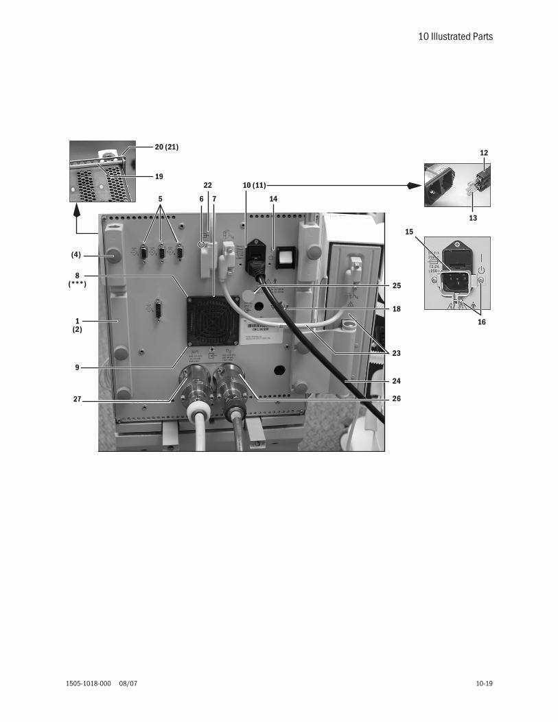
10 Illustrated Parts
1505-1018-000 08/07 10-19
24
23
26
8
1
(4)
(2)
75 6
10 (11)
14
12
13
16
15
25
18
19
20 (21)
22
9
(***)
22227777

Engström Carestation
10-20 08/07 1505-1018-000
10.11 Main enclosure (internal)
Item Description Stock Number
1 Power Supply Module M1052831
2 Screw 4-40x3/16 Pozidriv Pan Sems 1505-3004-000
3 Harness (Power Supply to PMB) 1505-5700-000
4 Harness (AC Inlet to Power Supply) 1605-3261-000
5 Wire, chassis safety ground 1605-3060-000
6 Harness, Jumper AC Inlet 1505-5718-000
8 Lockwasher, M4 external 9213-0540-003
9 Harness (On/Standby) 1605-3059-000
10 Motherboard - current (Requires VMB M1052980)Refer to Motherboard (backplane) block diagram - Current 11-9
M1053184
10 Motherboard - originalRefer to Motherboard (backplane) block diagram - Original 11-8
1505-5504-000
11 Screw, M4X6 PAN HD SEMS 1505-3000-000
12 Power Management Board (PMB) 1505-5502-000
13 Heat Sink 1505-5004-000
14 Screw, M3-0.5x20 Pan HD Pozidriv 0140-6719-103
15 Lockwasher, M3 external 9213-0530-003
16 Fan, 24Vdc 14CFM with harness 1505-3025-000
17 Screw, M3x50 Pan Hd Pozidriv SST 1505-3037-000
18 Lockwasher, M3 Split Lock SST 1505-3036-000
19 Washer, 3.18ID 8.64OD 0.76T SST 1006-5234-000
20 Vent Monitor Board (VMB) - Current (Requires Motherboard M1053184)Refer to VMB block diagram - Current (sheet 1 of 2) 11-12
M1052980
20 Vent Monitor Board (VMB) - OriginalRefer to VMB block diagram - Original 11-11
1505-5501-000
21 Vent Control Board (VCB) 1505-5500-000
22 Retainer, PCA/CARD CAGE 1505-3401-000
23 Foam, 3.18 THK 12.7W X 90L EPDM 1505-3402-000
24 Guide, Card 1505-3001-000
26 Harness (battery to PMB) 1505-5702-000
27 Tie Wrap 0203-5915-300
28 Fan, 24VDC 39.6CFM with harness 1505-3024-000
29 Nut, M3 Keps 0144-3717-302
30 Battery (Internal) 1009-5682-000
31 Battery Tray 1009-3133-000

10 Illustrated Parts
1505-1018-000 08/07 10-21
32 Strap, Battery Restraint 1504-3509-000
33 Label, Battery Service Instruction 1009-5530-000
34 M4-0.7x12 Pozidriv Pan Hd Relieved SST 1504-3001-000
35 Star Washer 9213-0540-003
Item Description Stock Number
1(2)
3
45
67 (8)
9
10 (11)
22
(14, 15)13
(17, 18, 19)16
12 20 21
23
242627
Battery 1Battery 2
J1
Wire ColorBlackRed
30 2831 32
33
34 (35)
29

Engström Carestation
10-22 08/07 1505-1018-000
10.12 Vent EngineItem Description Stock Number
Vent Engine Assembly Complete M1081816Vent Engine Sub-assemblyMounting screws (Not shown) 4 M4x8, Pozidriv
M11159970140-6226-107
A Manifold, Main Assembly (does not include mounted components) 1505-8504-000B Pressure Sensor Assembly, expiratory - inspiratory
(includes Items 13 through 19)1505-8503-000
C Manifold, Insp Valve Assembly (includes effort valve ) (does not include safety valve actuator or safety valve seal)
1505-8502-000
***1 Regulator w/screws O-ring, EPR, 2-012
1505-3256-0001503-3056-000
*2 Port, Regulator 1505-3260-0003 Gasket, Port 1505-3261-0004 Inlet manifold
O-ring, EPR, 2-016Screw M5-0.8x30 SHCS
Refer to section 10.141006-3616-0001102-3049-000
5 Transducer Flow 0-160 LPMO-ring, EPR, 2-018
1505-3208-0000210-0684-300
6 Fitting 4mm G1/8 Self Sealing Legris 1505-3266-0007 Plug 4mm dia Legris 1006-3530-0008 Valve Flow Control 160 LPM
O-ring, EPR, 2-0121505-3209-0001503-3056-000
9 Restrictor, Pneumatic 1505-3218-00010 Gasket, Pneumatic restrictor 1505-3220-00011 Plate, Pneumatic restrictor 1505-3219-00012 Screw M4x8 Pan Hd Pozidriv 9211-0440-08313 Manifold Zeroing Valve 1505-3248-00014 Valve Zeroing 3/2 1505-3249-00015 O-ring, EPR, 2-007 1006-3213-00016 PCA Airway Press Sens Board
(see Note on following page)1505-5506-000
17 Screw M3-0.5x16 Pan Hd Pozidriv 1504-3003-00018 O-ring, Buna-N, 2-005 1009-3306-00019 Gasket Zeroing Valve 1505-3211-00020 Screw M3-0.5 x 6 Pan Hd Pozidriv Sems s/s 0140-6219-12821 Outlet manifold
O-ring, EPR, 2-016O-ring, EPR, 2-012Screw M5-0.8x20 SHCS
Refer to section 10.131006-3616-0001503-3056-0000144-2131-919
22 Transducer O2 CONC 1505-3215-00023 Plate, O2 Sensor 1505-3247-00024 Screw M2 x 6 Pan Hd Pozidriv SST 0140-6712-10225 O-ring, VITON, BS 4518 0171-16 1505-3059-00026 Screw M4-0.7x12 SHCS 1102-3006-00027 Gasket Inspiratory Manifold 1505-3262-00028 Valve Seat Free Breathing 1503-3204-000
**29 Valve Flapper (Free Breathing) 0211-1454-10030 O-ring, EPR, 2-126 1503-3208-00031 Harness (vent engine to VCB/VMB) 1505-5706-00032 Tie Wrap 0203-5915-30033 Valve Umbrella Check 1505-3267-00034 Seal, safety valve w/disc 1505-8600-000

10 Illustrated Parts
1505-1018-000 08/07 10-23
35 Safety valve actuator (includes safety valve support) M111450436 Subplate, O2 Flow Control Valve (FCV) assembly M107914537 Screw M4x25 SHCS, O2 FCV Subplate N12201738 O-ring - 2, O2 FCV Subplate 1503-3056-000
* Apply Teflon tape to threads.** Install the flapper valve from the threaded side of the valve seat. Trim the tail piece close to the outside surface of the seat (refer to removed flapper).*** Do not use old regulator. Order revision 100 or greater.
Item Description Stock Number
1***
76
8
11
12
1416 3221 33
(15, 20)
2
3
1
C
9
10
31
22
23
24
25
4
76
26
27
29**
30
28
5
12
34
A
37
38
36
26
35
14
17
1819
1313 B
16
15
Note: When replacing the Airway Pressure Sensing board (Item 16), ensure that the o-ring (Item 15) is properly seated in the manifold before mounting the board in place.
8

Engström Carestation
10-24 08/07 1505-1018-000
10.13 Outlet manifold
Item Description Stock Number
A Outlet Manifold Panel Assembly; includes EMI gasket(does not include mounted components)
1505-8505-000
1 Port, Insp 1505-3216-000
2 O-ring, 2-016, EPR 1006-3616-000
3 Port , auxiliary pressure 1505-3217-000
4 O-ring, 2-011, EPR 017-923
5 Seal, Rolling Shaft 1505-3225-000
6 Ring, Retaining 1406-3540-000
7 Port, Occlusion Outlet Manifold (Adult and Neo.) 1505-3259-000
8 Pull, Exhalation Housing Latch 1505-3236-000
9 Screw M4-0.7x12 SHCS 1102-3006-000
10* PCA Ultrasonic Neb Control 1505-3251-000
11 Screw M3-0.5x6 Pan Head Pozidriv Sems SST 0140-6219-128
12 Spring, Exhalation Housing Latch 1505-3237-000
13 Rod, Exhalation Housing Latch 1505-3238-000
14 Housing, Exhalation Housing Latch 1505-3239-000
15 Screw Shoulder M3x0.5-12.7 SS 1011-3147-000
16 Spring, Compression 6.1 OD 12.7L 1006-3735-000
17 PCA, Exh Flow Interface Board 1505-5508-000
18 Cable Exh Flow Sensor (Lubed cable) 1505-5603-000
*19 PCA Exh Flow Sensor Board (For Rev 101 or higher.) 1505-5507-000
20 Screw 6-32 x 1/4 PH Pan Hd SST 0140-6524-102
21 Actuator, Voice Coil 1505-3227-000
22 Bracket, Voice Coil Connector 1505-3228-000
23 Adapter, Voice Coil Magnet 1505-3230-000
* Use special tool (Refer to section 10.1.3) to remove collar from Nebulizer connector. Apply Loctite 271 to treads of connector when replacing collar.

10 Illustrated Parts
1505-1018-000 08/07 10-25
1, 2
3, 4 5, 6
7
8 (9)
10
11 13129 14 17
15, 16
18
19
112011
2122
23
25
A
10*
Note: When installing the voice coil, be sure to route the wires around the coil. Ensure the wire are below the thread engagement of item 23. Do not pinch the wires.

Engström Carestation
10-26 08/07 1505-1018-000
10.14 Inlet manifold
Item Description Stock Number1 Air Pipeline Inlet Assembly (includes Filter Bowl, O-ring, and
Filter Element) Standard1505-8595-000
2 O2 Pipeline Inlet Assembly (includes Filter Bowl, O-ring, and Filter Elelment) Optional
1505-8594-000
3 Filter Bowl with O-ring 1505-3062-0004 O-ring, Filter Bowl 1503-3034-0005 Filter Element 1505-3060-0006 Transducer, Pressure 827 kPa (120 psi) 1011-3413-0007 Adapter, O2 Pipeline 1505-3206-0008 Adapter, Air Pipeline 1505-3207-0009 Screw, M4-0.7x12 Pozidriv Pan Hd Relieved SST 1504-3001-000
10 O-ring, OD23.9 ID20.35 EPDM DURO70 -019 1006-3614-00011 Manifold (includes EMI gasket) 1505-8501-00012 O-ring, EPR 2-122 70 DURO 1504-3612-00013 Filter Disc, Wire Mesh 2 Micron 1504-3708-00014 Check Valve 1505-3273-00015 Inlet fitting, Air Refer to Table 116 Inlet fitting, O2 Refer to Table 1
Table 1: Inlet Fitting
Stock Number
1 - O2 2 - Air
DISS 9913-6489-400 9913-6557-800
DISS Female 1505-3851-000 1505-3830-000
NIST 1001-5967-000 1001-5826-000
SIS 1505-3852-000 1505-3831-000
S90-116 1505-3274-000 1505-3275-000

10 Illustrated Parts
1505-1018-000 08/07 10-27
10
1(2)
11
6
8 (9)
AIR O2
7 (9)
Adapter 13
12Course side shown(downstream)
14
10
15 16
5
3
4
1111 ((((2222))))

Engström Carestation
10-28 08/07 1505-1018-000
10.15 AC power cords
Item Description Stock Number
1 Power Cord
Australia, AS3112, 220-240V~, 50-60Hz 1500-3561-000
China, 220-240V~, 50-60 Hz M1062785
Danish, Hospital Grade SB107-2-D1, 220-240V~, 50-60 Hz
1505-3878-000
Europe, CEE 7/7, 220-240V~, 50-60Hz 1500-3291-000
India and South Africa, BS 546, 220- 240V~, 50-60Hz
1505-3817-000
Japan, JIS8303, 100-120V~, 50-60Hz M1098772
North America (NA), NEMA 5-15, 100-120V~, 50-60Hz
1505-3816-000
Swiss, SEV 1011, 220-240V~, 50-60Hz 1500-3292-000
United Kingdom, BS1363, 220-240V~, 50-60 Hz
1500-3283-000
2 Power Cord Jumper, 1.0 meters 1505-3844-000
3 Power Cord Jumper, 0.5 meters 1505-3843-000
4 Retainer, Outlet Power Cord Jumper 1505-3041-000
5 Retainer, Inlet Power Cord 1505-3033-000
6 Screw, M3x8 Pozidrive HD Sems 0140-6219-130
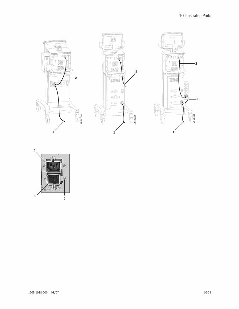
10 Illustrated Parts
1505-1018-000 08/07 10-29
1
3
2
AB.9
8.04
9
1
1AB
.98.
052
1
2AB
.98.
008
4
56
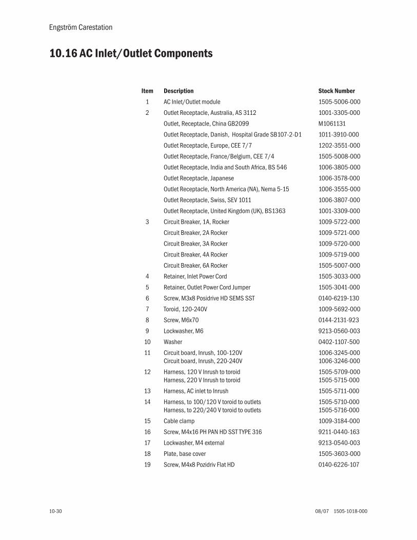
Engström Carestation
10-30 08/07 1505-1018-000
10.16 AC Inlet/Outlet Components
Item Description Stock Number
1 AC Inlet/Outlet module 1505-5006-000
2 Outlet Receptacle, Australia, AS 3112 1001-3305-000
Outlet, Receptacle, China GB2099 M1061131
Outlet Receptacle, Danish, Hospital Grade SB107-2-D1 1011-3910-000
Outlet Receptacle, Europe, CEE 7/7 1202-3551-000
Outlet Receptacle, France/Belgium, CEE 7/4 1505-5008-000
Outlet Receptacle, India and South Africa, BS 546 1006-3805-000
Outlet Receptacle, Japanese 1006-3578-000
Outlet Receptacle, North America (NA), Nema 5-15 1006-3555-000
Outlet Receptacle, Swiss, SEV 1011 1006-3807-000
Outlet Receptacle, United Kingdom (UK), BS1363 1001-3309-000
3 Circuit Breaker, 1A, Rocker 1009-5722-000
Circuit Breaker, 2A Rocker 1009-5721-000
Circuit Breaker, 3A Rocker 1009-5720-000
Circuit Breaker, 4A Rocker 1009-5719-000
Circuit Breaker, 6A Rocker 1505-5007-000
4 Retainer, Inlet Power Cord 1505-3033-000
5 Retainer, Outlet Power Cord Jumper 1505-3041-000
6 Screw, M3x8 Posidrive HD SEMS SST 0140-6219-130
7 Toroid, 120-240V 1009-5692-000
8 Screw, M6x70 0144-2131-923
9 Lockwasher, M6 9213-0560-003
10 Washer 0402-1107-500
11 Circuit board, Inrush, 100-120VCircuit board, Inrush, 220-240V
1006-3245-0001006-3246-000
12 Harness, 120 V Inrush to toroidHarness, 220 V Inrush to toroid
1505-5709-0001505-5715-000
13 Harness, AC inlet to Inrush 1505-5711-000
14 Harness, to 100/120 V toroid to outletsHarness, to 220/240 V toroid to outlets
1505-5710-0001505-5716-000
15 Cable clamp 1009-3184-000
16 Screw, M4x16 PH PAN HD SST TYPE 316 9211-0440-163
17 Lockwasher, M4 external 9213-0540-003
18 Plate, base cover 1505-3603-000
19 Screw, M4x8 Pozidriv Flat HD 0140-6226-107
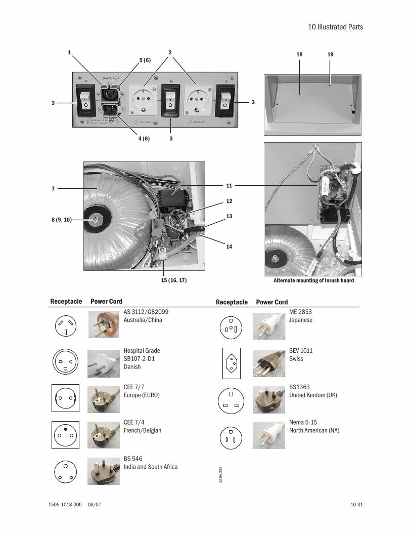
10 Illustrated Parts
1505-1018-000 08/07 10-31
1
3
3
3
4 (6)
7
8 (9, 10)
12
13
14
11
15 (16, 17)
25 (6)
18 19
Alternate mounting of Inrush board
AS 3112/GB2099Australia/China
ME 2853Japanese
Hospital Grade SB107-2-D1Danish
SEV 1011Swiss
CEE 7/7Europe (EURO)
BS1363United Kindom (UK)
CEE 7/4French/Belgian
Nema 5-15North American (NA)
BS 546India and South Africa
AA.9
6.22
8
Receptacle Power Cord Receptacle Power Cord

Engström Carestation
10-32 08/07 1505-1018-000
10.17 Cart
Item Description Stock Number1 Cart Assembly 1505-3600-0002 Back Handle, Cart 02-08-045(J)3 Lock Plate Kit 03-11-0484 Extrusion, left
Extrusion, right03-11-04903-11-050
5 Caster Kit, non-locking 03-11-0466 Caster Kit, locking 03-11-0457 Bottom Casting, Cart 02-08-045 (G)8 Front Cover, Cart 21947-0019 Front Handle, Cart 02-08-045(K)
10 Back Handle Block Support, Cart 02-08-045(I)11 Receiver Assembly (hardware included) Kit includes 1 assembly 1505-3850-000
Kit includes 2 assemblies 1505-3847-00012 Panel Assembly, rear 1505-3601-00013 Bracket, mounting rear panel assembly 1505-3602-00014 Screw, M6x12 SKT HD CAP 1102-3052-00015 Panel, outlet blank 1505-3845-00016 Nut, M4 Keps 0144-3717-31417 Box, outlet (for carts with compressor) 1505-3833-00018 Screw, M6x12 Sems 0144-2436-106
19* WeightScrew, M6x70Lockwasher, M6Washer
1009-3337-0000144-2131-9239213-0560-0030402-1107-500
Not ShownHardware Kit (includes hardware used to assemble base cart)M4 lock nut (6)M4 unthreaded spacer (4)Screw, #10x1/2 Hi-Lo (6)Screw, M4x8 Nylock (8)Screw, M4x16 (8)Screw, M6x16 (10)Screw, M6x12 (4)Screw, M6x25 (12)Screw, M8x35 (2)Washer, shoulder (4)Washer, M4 flat fender (4)Screw, M8x35 (2)
03-11-047
* CAUTION: Carts, which do not include AC Outlets, have a weight installed in the base (in place of the toroid). To reduce the risk of tipping the cart, do not remove the weight.

10 Illustrated Parts
1505-1018-000 08/07 10-33
5
4
3
6
9
2
10
8
7
1314
14
18
19
1211
17
15
1
B
B
A
Note: For new installation of receiver assemblies (6), use the hardware provided in the kit to open mounting holes in the rear panel assembly (7). Thread the hardware from inside the cart at the locations that apply.
* Use location A for single receiver.
* Use location B for dual receivers.
(16)

Engström Carestation
10-34 08/07 1505-1018-000
10.18 Module rack
2
3 (4)
5
6
6
7
8
9
10
1
11
Item Description Stock Number
Module Rack, complete assembly 1505-3849-000
1 Enclosure, Rear Module Rack (includes Module Interface Board) 1505-3803-000
2 Housing, Module Rack 1505-3802-000
3 Screw, M3x0.5-12 Pan Hd 1102-3078-000
4 Washer, Flat M3 0144-1003-132
5 Shaft, Pivot 1505-3832-000
6 Bearing 1505-3806-000
7 Arm, Module Rack 1505-3805-000
8 Screw, M6x16 Button Hd Skt drive 0144-2436-103
9 Washer, M6 Split Lock N145402
10 Washer, Thrust 1505-3021-000
11 Cable, Patient Module Rack 1505-5601-000

10 Illustrated Parts
1505-1018-000 08/07 10-35
10.19 Compressor
1
6
2
3(5)
4(5)
7 (8)
7 (8)
9
Item Description Stock Number1 EVair03 Compressor, only
for service information and partsrefer to Jun-Air Compressor Technical Reference Manual — 6189655
230V 50Hz120V 60Hz
16090001609002
2 Drain Bottle Kit 56123163 Inlet fitting, pipeline Air:
DISS 9913-6557-800DISS Female 1505-3830-000NIST 1001-5826-000S90-116 Fitting 1010-7048-000
Seal 1010-3220-000SIS 1505-3831-000
4 Outlet hose, AirDISS 1505-3810-000DISS Female 1505-3812-000NIST 1505-3811-000S90-116 1505-3815-000SIS 1505-3813-000
5 O-Ring -019 70 EPDM 1006-3614-0006 Foam, Vibration Damper 1505-3829-0007 Screw, M6x20 SHCS Shoulder 1505-3031-0008 Washer, 6.35x11x2.4 Nylon Fender 1505-3034-0009 Filter, air inlet 6985795
Not ShownFilter Kit , f/OF302-1.5SDA 547100110, 000 Hour Kit 230V/50 Hz 547100210, 000 Hour Kit 120V/60 5471003Trim, compressor Long 1505-3604-000Trim, compressor Short 1505-3605-000

Engström Carestation
10-36 08/07 1505-1018-000
10.20 Feature Options
Item Description Stock Number1 Feature label Holder M10577022 Neonatal Label M10577133 SpiroDynamics Label M10577074 FRC Label M1057705
1
2 3 4

10 Illustrated Parts
1505-1018-000 08/07 10-37
10.21 Key/BID label
Item Description Stock Number1 Key/BID label 1504-3521-000

Engström Carestation
10-38 08/07 1505-1018-000

1505-1018-000 08/07
11-1
11 Schematics and Diagrams
In this section
Schematics are subject to change without notice.
Circuit boards are available only as complete assemblies.
Figure 11-1
Pneumatic system - Original . . . . . . . . . . . . . . . . . . . . . . . . . . . . . . . . . . . . . . . . . . . . . . . . . . . 11-2
Figure 11-2
Pneumatic System - Current . . . . . . . . . . . . . . . . . . . . . . . . . . . . . . . . . . . . . . . . . . . . . . . . . . . 11-3
Figure 11-3
Vent Engine manifold flow diagram . . . . . . . . . . . . . . . . . . . . . . . . . . . . . . . . . . . . . . . . . . . . . . 11-4
Figure 11-4
System cable/harness interconnections . . . . . . . . . . . . . . . . . . . . . . . . . . . . . . . . . . . . . . . . . 11-5
Figure 11-5
Electrical architecture. . . . . . . . . . . . . . . . . . . . . . . . . . . . . . . . . . . . . . . . . . . . . . . . . . . . . . . . . 11-6
Figure 11-6
Power distribution . . . . . . . . . . . . . . . . . . . . . . . . . . . . . . . . . . . . . . . . . . . . . . . . . . . . . . . . . . . . 11-7
Figure 11-7
Motherboard (backplane) block diagram - Original . . . . . . . . . . . . . . . . . . . . . . . . . . . . . . . . . 11-8
Figure 11-8
Motherboard (backplane) block diagram - Current . . . . . . . . . . . . . . . . . . . . . . . . . . . . . . . . . 11-9
Figure 11-9
PMB block diagram. . . . . . . . . . . . . . . . . . . . . . . . . . . . . . . . . . . . . . . . . . . . . . . . . . . . . . . . . . 11-10
Figure 11-10
VMB block diagram - Original. . . . . . . . . . . . . . . . . . . . . . . . . . . . . . . . . . . . . . . . . . . . . . . . . . 11-11
Figure 11-11
VMB block diagram - Current (sheet 1 of 2) . . . . . . . . . . . . . . . . . . . . . . . . . . . . . . . . . . . . . . 11-12
Figure 11-12
VMB block diagram - Current (sheet 2 of 2) . . . . . . . . . . . . . . . . . . . . . . . . . . . . . . . . . . . . . . 11-13
Figure 11-13
VCB block diagram . . . . . . . . . . . . . . . . . . . . . . . . . . . . . . . . . . . . . . . . . . . . . . . . . . . . . . . . . . 11-14
Figure 11-14
Monitoring Module Rack block diagram . . . . . . . . . . . . . . . . . . . . . . . . . . . . . . . . . . . . . . . . . 11-15
Figure 11-15
Schematic, AC outlet module; 100–120 V (with isolated outlets) . . . . . . . . . . . . . . . . . . . . 11-16
Figure 11-16
Schematic, AC outlet module; 220–240 V (with isolated outlets) . . . . . . . . . . . . . . . . . . . . 11-17

Engström Carestation
11-2
08/07 1505-1018-000
Figure 11-1 • Pneumatic system - Original
Air
O2
25 psi172 kPa
25 psi172 kPa
SafetyRelief Valve
FlowSensor
FlowSensor
O2
Total Flow
InspiratoryEffortValve
Free Breathing Check Valve
HT
HT
P
22 / 15 mmMale / Female
Auxiliary PressurePurge Valve
PneumaticResistor
O2 SensorInspiratory Zero
Valve
Auxiliary PressureTransducer
InletFilter
High PressureTransducer
PrimaryInlet
CheckValve
Regulator
Inspiratory Pressure
FlowValve
Regulator
FlowValve
CheckValve
High PressureTransducer
InletFilterPrimary
Inlet
ReliefValve
TestPort
TestPort
MicropumpNebulizer
Patient
H
30 mm Male Cone
22 / 15 mmMale / Female
ExhalationValve
ExhalationFlow Sensor
Pneumatic Resistor
Expiratory ZeroValve
Expiratory Pressure
Inlet Manifold Vent Engine Manifold Outlet Manifold
EXP
INSP
1/8, 3/16,1/4 inch Stepped Hose Barb
P
P
P
P
HT
Paux
AB.9
8.06
5

11 Schematics and Diagrams
1505-1018-000 08/07
11-3
Figure 11-2 • Pneumatic System - Current
AB.9
8.07
2
Air
O2
25 psi172 kPa
25 psi172 kPa
SafetyRelief Valve
FlowSensor
FlowSensor
O2
Total Flow
InspiratoryEffortValve
Free Breathing Check Valve
HT
HT
P
22 / 15 mmMale / Female
Auxiliary PressurePurge Valve
PneumaticResistor
O2 SensorInspiratory Zero
Valve
Auxiliary PressureTransducer
High PressureTransducer
PrimaryInlet
CheckValve
Regulator
Inspiratory Pressure
FlowValve
Regulator
FlowValve
CheckValve
High PressureTransducer
PrimaryInlet
ReliefValve
TestPort
TestPort
MicropumpNebulizer
Patient
H
30 mm Male Cone
22 / 15 mmMale / Female
ExhalationValve
ExhalationFlow Sensor
Pneumatic Resistor
Expiratory ZeroValve
Expiratory Pressure
Inlet Manifold Vent Engine Manifold Outlet Manifold
EXP
INSP
1/8, 3/16,1/4 inch Stepped Hose Barb
P
P
P
P
HT
Paux
InletFilter Optional
InletFilter Standard
H
Neonatal Flow Sensor - Optional

Engström Carestation
11-4
08/07 1505-1018-000
Figure 11-3 • Vent Engine manifold flow diagram
Paux
H
Atmosphere
EXP
INSP
Pexp
O2Regulator
O2TestPort
O2FlowValve
O2FlowSensor
TotalFlowSensor
AirFlowSensor
O2 SensorPaux
Relief
Paux
AirFlowValve
AirTest Port
AirRegulator
Pinsp
O2
P P
Air
Standard
InletFilter
Optional
InletFilter
AB.9
8.07
2

11 Schematics and Diagrams
1505-1018-000 08/07
11-5
Figure 11-4 • System cable/harness interconnections
RS-232
RS-232
RS-232
Motherboard(backplane)
Vent ControlBoard
PowerManagement
Board
FutureExpansion
Port 1
Vent MonitorBoard
Display Unit
DU serial Port
Nurse Call
DU Port
PSM Port
Ethernet
USB
DIS
Total Flow/Temp
Air Flow/Temp
O2 Flow/Temp
AirFlow Valve
Piezo-ElectricNeb Board
O2Flow Valve
Exhal Valve
Aux P PurgeValve
Aux P
Insp P
Insp P ZeroValve
Nebulizer
Exp FlowSensor Bd
Insp EffortValve
SafetyRelief Valve
O2 Sensor
Exp P
Exp P ZeroValve
I2C
RS-232
Exp FlowSensor
Exp FlowInfc Bd
O2 Pipeline P
2 - 12 V4AHr
Batteries
PMBFan
150W MainsPower Supply
Power EntryModule
On/Standbyand
Safety SwitchExt BatConnector
Back PanelConnectors
VentEngine
Fan
MonitoringModule
PortMonitoring Module
J4
J2
J12
J11
J3
J1
J8
J10
J7
PMB
VCB
VMB
FutureExpansion
Port 2
USB
RS 485
RS 422
RS 422
RS 232
Ext Bat24V
NEO Sensor
Air Pipeline P
A: Display Unit cable
B: Monitoring module cable
C: Vent Engine harness
D: Battery to PMB harness
E: Power Supply to PMB harness
F: On/Standby Switch harness
G: External battery to PMB harness
H: AC Inlet to Power Supply harness
I: Flex cable
J: Nebulizer cable
A
B
C
D
EFG
H
J
I
AB.9
8.06
0

Engström Carestation
11-6
08/07 1505-1018-000
Figure 11-5 • Electrical architecture
Exp FlowSensor Bd
2 - 12 V4AHr
Batteries
Fan 1
150W MainsPower Supply
Power EntryModule
PC Card
RS-422 #1
AtmelATmega128
CPU
Speaker
I/O Panel Connectors
ColdfireV4 CPU
CPU &Chipset
Baro P
Total Flow/Temp
Air Flow/Temp
O2 Flow/Temp
RS-422 #2
Motherboard
Display Compartment
Ventilator Chassis
Vent Control Board
Air Pipeline P
O2 Pipeline P
Air Valve Drivew/ I Sense
O2 Valve Drivew/ I Sense
Mains/BatSelect
Power ManagementBoard
Bat ChargeCntlr
Vent Monitor Board
UARTs
Display UnitCPU Board
12.5V
PMB Data I/O
VMB - DU Data I/OVCB - DU Data I/O
12.5V
12.5V
Monitor Module Data I/O
Expansion Port I/O #2
Expansion Port I/O #1
12.5V
VMB SensorData I/O
Power for Buzzer
USB
DU Conn Bd
BackupBuzzer
MonitoringModule
Compartment
On/Standby &
SafetySwitch
Power PanelConnectors
I LMT25W
Circuit Power
Circuit Power
Expansion Port I/O #1
Mod Bus
NetID
M-CAiOVXModule
Bay 1
Bay 2
Bay 3
Bay 4
I LMT32W
AirFlow Valve
Neb ControlBoard
O2Flow Valve
Insp EffortValve
Exhal Valve
Safety Valve
Aux P ZeroValve
8 MBFlash
1 MBSRAM
Safety ValveDrive
Insp EffortValve Drive
Exhal ValveDrive w/ V & I
Sense
RS-232
MUX
ADC /MUX
ADC
8 UARTS
Exh Valve Closed
Watchdog
V Checks
UARTS
Watchdog
MonitorInterface
Board
V Checks
Battery I &V Monitor
AtmelATmega128 CPU
Fan Cntlrs
PSMI LMT
16W
Buzzer Control
Buzzer Control
Safety Valve On/Off
Exh Valve On/Off
Ethernet
External Serial I/O
PSM/NeoFlow
16V
Safety Valve On/Off
Exh Valve On/Off
VMB SensorData I/O
Nurse CallDU RS-232RS-422 #3
16V
16V
VCB - DU Data I/O
VMB - DU Data I/O
DU Infc Bd
O2 Sensor
Insp Effort Valve Control
Exh Valve Closed
Current Lmt Control
Insp Effort Valve
Aux P
Exp P
Circuit Power
Insp P
16VReg
PMB Data I/O
12.5VReg
BackupAudio Power
Expansion Signals
Chassis Gnd
Buzzer Sense
Buzzer Sense
PowerRegs
SerialXCVRs
RS-232
RS-232
Filtering
Filtering
Filtering
Filtering
Filtering
USB
Insp P ZeroValve
Exp P ZeroValve
Nebulizer
I2C
RS-232
Fan 2
LCD DisplayKeypadKnob
V Checks
+15VD-15V+15V+5V
UARTS
Exp FlowSensor
Exp FlowInfc Bd
Neo FlowSensor
SPI for Neo Flow sensor
SPI for Neo flow sensor
Neo FlowSensor Circuit
Expansion Port I/O #2
VCB Expansion Signals
VCB Expansion Signals
Analog Neo Flow
Analog Neo Flow
2 UARTS
PLD
Nurse Call EnableRelay
1
2
3
4
Port
Expansion Port I/O #3
Expansion Port I/O #3
Controlled byVCB
AB.9
8.05
6

11 Schematics and Diagrams
1505-1018-000 08/07
11-7
Figure 11-6 • Power distribution
CPU 3.3V
USB 5V
PCMCIA 3.3V
LCD 12V
DIS 8V (not used)
CPU 5V
LCD 3.3V
PCMCIA 5V
CPU 2.5V+4.1V Step Dwn
FAN 5V+6.0V Step Dwn
Display Unit CPU Board
+1
2.5
V(s
witc
he
db
us
vo
ltag
e)
+20Vto
+31V(batteryvoltage)
Power Management Board+12.5V
(switched bus voltage)
ACMains
Motherboard(backplane)
+6VA
+5VA
-6V
3.2 W
15W
43W
2W
4W
+3.3V
+3.3V stdby
Vent Monitor Board
+3.3V
Ventilator Control Board
4W
MGAS
-15V LDO
+5V Step Dwn
+15V LDO
+15.1VDD LDO
+/-17V Flyback
14.5W
+12V fan1
24VBattery
7.8W
150WAC-DCPowerSupply
External24V
Battery
+12.5V (10VA Internal Expansion) up to 20W
+12.5V (10VA Ext Expansion Port 1)
NESTPR
26W
+1.8V
Valve Drive (12V)
+6V
+5VA
+5V Vdd
-6V
Charger
12.5VReg
9W
16VReg
Exp Flw Snsr
Valves (12V)
8W
Monitoring Module Power Supply Board
16W
PSM16W
+12.5V (10VA Ext Expansion Port 2)
I-LMT
I-LMT
I-LMT
20W
up to 20W
up to 20W
F
F
F
FPowerEntry
ModuleF
PMB
VCB
VMB
+9VA
+9V
+5.5VA
Neb 12V1W
AB.9
8.05
9

Engström Carestation
11-8
08/07 1505-1018-000
Figure 11-7 • Motherboard (backplane) block diagram - Original
MOD_PWR_FAIL
PSM_PWR_FAIL
EXP_PWR_FAIL
BUZZER_SNSE
VM_EXHAL_OPEN
MNVR_OPEN
SAFE_CLSE
OK_TO_ZERO
RESET
VM_BUZZER_ON
AUX_AUDIO_PWR
16V
ILIM_EN(3)
DU/PMB COMM RS232
MAINS LED
MONITOR ON/STANDBY
DU/MN COMM RS232
MO
D_B
US
_16
V
DU/MOD BUS & PSM COMM RS485
DU/MOD BUS & PSM RESET
DU/VMB COMM RS422
DU/VCB COMM RS422
12.5VBUS
ILIM_MOD_EN
ILIM_PSM_EN
ILIM_EXP_EN
PS
M/R
S48
5_16
V
PS
M/R
S48
5_16
V
RS
422_
12V
12.5VBUS
EXP1_COMM
EXP_MBUS_RESET
EXP_MBUS_COMM
PWR_FAIL(3)
16V
12.5VBUS
VCB/VMB COMM RS422
IRQ6 CNTL
CF_TXD/RXD
12.5VBUS
12.5VBUS
12.5VBUS
AUX_AUDIO_PWR
(PO
WE
RM
AN
AG
EM
EN
TB
OA
RD
CO
NN
EC
TOR
)
DISPLAY INTERFACE CONNECTOR
EMI Filters
MONITOR SERIAL CONNECTOR
EMI FiltersESD Protection
MOD BUS I/O CONNECTOR
EMI FiltersESD Protection
PSM I/O (RS-485) CONNECTOR
EMI FiltersESD Protection
EXPANSION PORT #2 (RS-485)CONNECTOR
EXPANSION PORT #1 (RS-422)CONNECTOR
EMI FiltersESD Protection
EMI FiltersESD Protection
16V Current LimiterEMI Filter
16V Current LimiterEMI Filter
12.5V Current LimiterEMI Filter
(VE
NT
ILA
TO
RM
ON
ITO
RB
OA
RD
CO
NN
EC
TOR
)
TEST HEADER
(VE
NT
ILA
TO
RC
ON
TR
OL
BO
AR
DC
ON
NE
CTO
R)
EXP BUS CONTROL
BA[2:0]
EXPD[7:0]
SPI BUS
I2C BUS
VC
B
VM
B
PM
B
RS 485 RS 485 RS 422RS 232
AB.9
8.06
8

11 Schematics and Diagrams
1505-1018-000 08/07
11-9
Figure 11-8 • Motherboard (backplane) block diagram - Current
AB.9
8.05
7
MOD_& PSM PWR_FAIL
THERAPYMODULE_PWR_FAIL 1
THERAPYMODULE_PWR_FAIL 2
BUZZER_SNSE
VM_EXHAL_OPEN
MNVR_OPEN
SAFE_CLSE
OK_TO_ZERO
RESET
VM_BUZZER_ON
AUX_AUDIO_PWR
ILIM_EN(3)
DU/PMBCOMMRS232
MAINS LED
MONITOR ON/STANDBY
DU/MN COMM RS232
MO
D_
BU
S_
16V
DU/MOD BUS & PSM COMM RS485
DU/MOD BUS & PSM RESET
DU/VMB COMM RS422
DU/VCB COMM RS422
ILIM_MOD_EN
ILIM_TMP_EN_1
ILIM_TMP_EN_1
PS
M/R
S4
85_
16
V
R
S4
22_
12
.5V
12.5VBUS
Service RS422Application /Therapy DeviceCommunication
THERAPY COMMUNICATIONS (RS422)
PWR_FAIL(3)
16V
12.5VBUS
VCB/VMB COMM RS422
IRQ6 CNTL
12.5VBUS
AUX_AUDIO_PWR
PO
WE
R M
AN
AG
EM
EN
T B
OA
RD
CO
NN
EC
TO
R
DISPLAY INTERFACE CONNECTOR
EMI Filters
MONITOR SERIAL / NURSE CALLCONNECTOR
EMI FiltersESD Protection
MODULE BUS CONNECTOR
EMI FiltersESD Protection
NEON Flow SensorPORT #1 J4
EMI FiltersESD Protection
EXPANSION (RS-422)PORT #3 J6
EMI FiltersESD Protection
EMI FiltersESD Protection
12.5V Current LimiterEMI Filter
16V Current LimiterEMI Filter
12.5V Current LimiterEMI Filter
VE
NT
ILA
TO
R M
ON
ITO
R B
OA
RD
CO
NN
EC
TO
R
VE
NT
ILA
TO
R C
ON
TR
OL
BO
AR
D C
ON
NE
CT
OR
EXP BUS CONTROL
BA[2:0]
EXPD[7:0]
SPI BUS
RS
42
2_1
2.5
V
EXPANSION (RS-422)PORT #2 J5
12.5VBUS
Neonatol Analog Flow Signals
12.5VBUS
VMB 3rd RS422
Craig TolmieFebruary24, 2006Version 2
Nurse Call Enable
CO
M
NC
NO
12.5VBUS

Engström Carestation
11-10
08/07 1505-1018-000
Figure 11-9 • PMB block diagram
Battery ConnectTimer
Step-DownSMPS
Step-DownSMPS
VBUS
+12V
Fuse
IsolatedDC_DCConvert
VBUS
Switch
FF
ENABLE
OR
+12.5V
VoltageSense
VoltageSense
VBAT
uC
TEMP
BATT1_VBATT2_V
FAN_GOOD
BATT_I
BATT_STAT_1
BATT_STAT_2
AC_GOOD
SYS_ON
12V
BATT_STROBEFAN_HIGH
WATCHD0G
VREF
ON/STBY_UP
WDOG
RESET
SET_SYS_ONCLR_SYS_ON
ON/STBY_UP
SET_SYS_ON
CLR_SYS_ON
CurrentSense
Voltage/Current
Converter
BATT_I
BatteryCharger/
DischargeDetector
BATT_DISCHARGE
CURRENT_SENSE
BatteryCharge
Controller
DRIVERLevel Shifter
PS_V_ADJ
CURRENT_SENSE
CHARGER_ONAND
AC_GOOD
BATT_CONNECT
Logic
BATT_STAT_1
BATT_STAT_2OVER_CHARGE
/FLOAT_CHARGE
BATT_DISCHARGE
PS_V_ADJ
AC_GOODISO
BATT_CONNECT
+3.3V(VDD)
LDO
VBUS
VBATVSTBY
VBAT GND
VSTBY
VSTBY
TEMPSENSOR
TX
RXOPTO
ISORS-232
LDO
+12.5V
VBAT
VBAT_SENSE
VBUSFuse Linear Reg
SpeedDetect
FAN1_GOOD
FAN1_HIGH
BATT2_V
BATT1_V
+12V
+3.3V(VDD)
+12V
+3.3V(VDD)
SYS_ONQ
BATT_IBATT_STROBE
IsolatedDC_DCConvert
+16VENABLEDiode
+3.3V(VDD)
Switch
EXT_BAT_SEL
EXT_BAT_SEL
EXT_BAT_V
VoltageSense
CurrentSense
EXT_BAT_I
GND
EXT_BAT_V
+3.3V(VDD)
EXT_BAT_V
EXT_VBAT
EXT_BAT_I
Fan1Connector
MB
Co
nn
ec
tor
Int BatteryConnector
Int BatteryConnector
On/StandbySwitch
Connector
Po
we
rS
up
ply
Co
nn
ec
tor
Ext BatteryConnector
MB
Co
nn
ec
tor
SYS_ON OPTOISO
PM_P
+12.5V
MB
Co
nn
ec
tor
Fuse
IsolatedDriveCircuit
AC_GOODMAINS_LED_A
MAINS_LED_C
MB
Co
nn
ec
tor
Debug/ProgrammingConnector
OR
MAINS_PWR
MAINS_PWR
VBAT
EXT_VBAT
SAFETY_SW
MB
Co
nn
ec
tor
AUX_AUDIO_PWR
A_GND
V_GND_1.5V
VFAN1
ISP Connector
InternalBatteryTrickle
Charger
MAINS_PWR
TRKLE_CHRG_CTRLVBAT
MUX
VFANVDD
MODE
FAN_ON
LOW_CHG_RATEBATT_STROBE
EXT_BAT_ON_FULLEXT_BAT_I_LMT
EXT_BATT_CLKINT_BAT_DISABLE
ISOLATEDPS
FAN_FAIL_DET_EN
FAN1_ON
Linear RegSpeedDetect
FAN2_GOOD
Fan2Connector
VFAN2
FAN2_ON
FAN2_HIGH
AB.9
8.05
7

11 Schematics and Diagrams
1505-1018-000 08/07
11-11
Figure 11-10 • VMB block diagram - Original
VBUS
+5VA
EX_5V
10-BIT ADC INPUTS
O2_P
MUX_OUT
Watchdog
VD
DC
OM
P
VDDHV_RESET
NRZ_O2RX
NRZ_O2TX
Div
ide
r
Am
p
Div
ide
r
Am
p
Div
ide
r
Am
p
SPI/O2_CS
AUXGND
Div
ide
r
Am
p
TO
MO
TH
ER
BO
AR
D(4
0x
2)
VC_MNVR_OPEN
Div
ide
r
Am
p
# STROBE
VDD
12.5VBUS
VMTX_VCRX
VMRX_VCTX
Drvr
Drv
r
VMTX_DURX
VMRX_DUTX
SPIUART
DURX DIFF DATA
14.7456MHz
Buffer/Drvr
Diff.
Driv
er
Dif
f.
Re
ceiv
er
DUTX DIFF DATA
VCRX DIFF DATA
Diff.
Driv
er
Dif
f.R
ece
ive
r
VCTX DIFF DATA
Div
ide
r
Am
p
AIR_P
SwitchingRegulator
Fuse
6V1_SW
LinearRegulator
VoltageRef
Fuse
VDD LinearRegulator
Filter
Filter
Filter
VoltageRef
4096VBARO
4096VINSP
O2_5V LinearRegulator
LinearRegulator
ChargePump
+5.5VA
VoltageRef
-5.5VA
4096VADC
VoltageRef
VoltageRef
O2HP_5VAIRHP_5V
8:1Analog
Mux
#BUZZER_ON
#VC_SAFE_CLSE
#OK_TO_ZERO
EMI Filter
ExpiratoryPressureSensor Board
Ins
p
IA
SK
Filte
r
SK
Filte
r
ESD/EMISuppression
Air Supply PressureTransducer
BEI Edcliff
BEI Edcliff
O2 Supply PressureTransducer
Acutronics
Exhal Flow Sensor
Paracube
O2 Sensor
BicronNC
Safety ReliefValve
Insp EffortValve
BicronNO
TO
VE
NT
EN
GIN
E(1
1x
2)
Off Board
AIRHP_5V
O2HP_5V
EX_5V
O2_5V
SK
Filte
r
MUX[2:0]
BARO_P
Div
ide
r
Am
p
N5P5_TEST
5P5_TEST
AIRP5V_TEST
O2P5V_TEST
O25V_TEST
EX5V_TEST
12P5_TEST
-5.5VA
+5.5VA
AIRHP_5V
O2HP_5V
O2_5V
EX_5V
12.5VBUS
Fuse
Fuse 12.5VBUS
12.5VBUS
N-CHFET
N-CHFET
N-CHFET
#VC_SAFE_CLSE
#SAFE_CLSE
VCB_MNVR_OPEN
#OVER_PRESS
Co
mp
EX_SDA
EX_SCL
ATmega128Microcontroller
10
-Bit
AD
C
AVCC VCC
AREF
UA
RT
1U
AR
T0
RESET
EX_SDAEX_SCL
uC JTAG
5X
2
DU
RX
I2C
_S
DA
O2
TX
O2
RX
VC
BR
X
VC
BT
X
DU
TX
#UC_RESET
#EXHAL_OPEN
VDD
VDD
JTAG_5V
SPI/EXCOM_CS
SPI/EXCOM_CS
Barometric PressureTransducer
SDX15A4 EMI Filter
Ba
ro
IA
SK
Filte
r
4096VBARO
#BUZZER_SNSE
SPI/ADC_CS
SPI/ADC_CS
SPI12-BitADC
Filter
SPIUART
Drv
r
RS
23
2
Rcv
rR
S2
32
5X
2
VDD
8x
1
+5.5VA
ZERO_12V
ZERO_RTN
N-CHFET
LogicFET
#ZERO_INSP
#ZERO_INSP
EXHAL_OPEN
#SAFE_CLSE
#EXCOM_RDY
Buffer/Drvr
1.8432MHz
1.8432MHz
1.8432MHz
#O2_RDY
#O2_RDY
EXHAL_OPEN
SAFE_OPEN
SAFE_OPEN
WD_RESET
WD_RESET
#OVER_PRESSLogic
#SAFE_CLSE
#ZERO_INSP
VDDVDD
VDD
uC
_A
CT
MPX2010
AB.9
8.06
1

Engström Carestation
11-12
08/07 1505-1018-000
Figure 11-11 • VMB block diagram - Current (sheet 1 of 2)
AB.9
8.06
1

11 Schematics and Diagrams
1505-1018-000 08/07
11-13
Figure 11-12 • VMB block diagram - Current (sheet 2 of 2)
AB.9
8.06
1
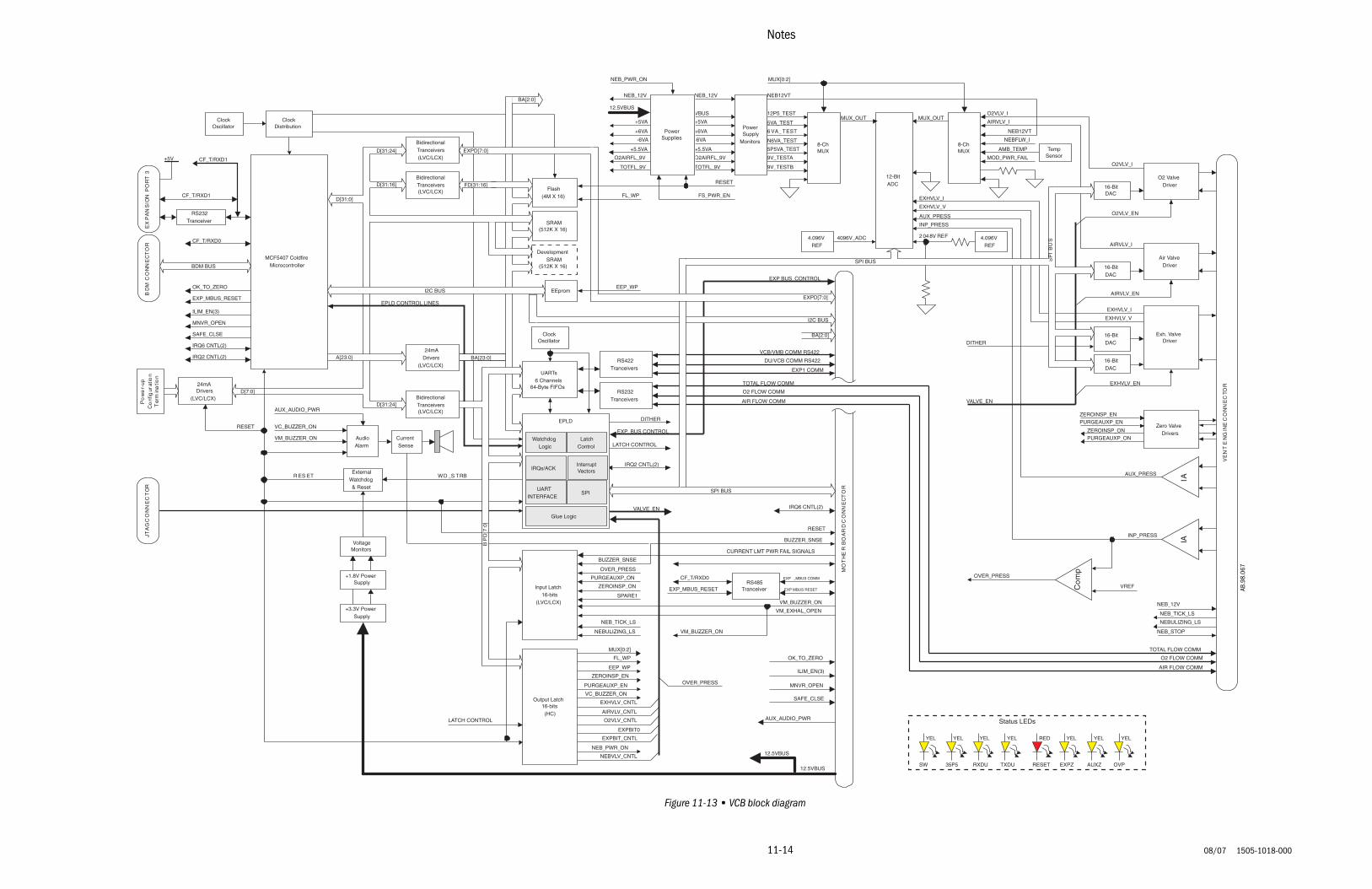
11-14
08/07 1505-1018-000
Notes
Figure 11-13 • VCB block diagram
AMB_TEMP
EXP_BUS CONTROL
O2 FLOW COMM
AIR FLOW COMM
TOTAL FLOW COMM
ILIM_EN(3)
+6VA
-6VA
+5VA
+5.5VA
O2AIRFL_9V
TOTFL_9V
NEB_12V
12.5VBUS
+6VA
-6VA
+5VA
+5.5VA
O2AIRFL_9V
TOTFL_9V
NEB_12V
VBUS
6 VA_ TEST
N6VA_TEST
5VA_TEST
5P5VA_TEST
9V_TESTA
9V_TESTB
12P5_TEST
DITHER
VALVE_EN
VALVE_EN
EEP_WP
FL_WP
CF_T/RXD0
RESET
WD _S TRB
IRQ2 CNTL(2)
AUX_AUDIO_PWR
CURRENT LMT PWR FAIL SIGNALS
NEBVLV_CNTL
NEB_PWR_ON
EXPBIT_CNTL
EXPBIT0
O2VLV_CNTL
MUX[0:2]
FL_WP
EEP_WP
ZEROINSP_EN
PURGEAUXP_EN
VC_BUZZER_ON
EXHVLV_CNTL
AIRVLV_CNTL
LATCH CONTROL
4096V_ADC
EXHVLV_V
EXHVLV_IEPLD CONTROL LINES
12.5VBUS
D[31:24]
D[31:16]
A[23:0]
D[31:0]
BP
D[7
:0]
FD[31:16]
BA[23:0]
MCF5407 ColdfireMicrocontroller
RS232Tranceiver
EX
PA
NS
ION
PO
RT
3
CF_T/RXD1
+5V
BidirectionalTranceivers(LVC/LCX)
SRAM(512K X 16)
Flash(4M X 16)
DevelopmentSRAM
(512K X 16)
EEpromBD
MC
ON
NE
CT
OR
BDM BUS
ClockDistribution
ClockOscillator
12-BitADC
BidirectionalTranceivers(LVC/LCX)
D[31:24]
24mADrivers
(LVC/LCX)
BidirectionalTranceivers(LVC/LCX)
UARTs6 Channels
64-Byte FIFOs
ClockOscillator
AudioAlarm
ExternalWatchdog& Reset
+1.8V PowerSupply
+3.3V PowerSupply
VoltageMonitors
Input Latch16-bits
(LVC/LCX)
Output Latch16-bits(HC)
MO
TH
ER
BO
AR
DC
ON
NE
CT
OR
VCB/VMB COMM RS422
DU/VCB COMM RS422
EXP _MBUS COMM
EXP1 COMM
RS422Tranceivers
RS232Tranceivers
CF_T/RXD1
CF_T/RXD0RS485
Tranceiver
VE
NT
EN
GIN
EC
ON
NE
CTO
R
O2 ValveDriver
Air ValveDriver
Exh. ValveDriver
Zero ValveDrivers
16-BitDAC
16-BitDAC
16-BitDAC
16-BitDAC
AIRVLV_I
O2VLV_I
PowerSupplies
12.5VBUS
PowerSupply
Monitors 8-ChMUX
SP
IB
US
8-ChMUX
NEB12VT
NEB12VT
NEBFLW_I
TempSensorMOD_PWR_FAIL
MUX_OUT MUX_OUT
EXHVLV_I
EXHVLV_V
AUX_PRESS
AUX_PRESS
INP_PRESS
INP_PRESS
Co
mp
VREF
OVER_PRESSOVER_PRESS
BUZZER_SNSE
PURGEAUXP_ON
ZEROINSP_ON
SPARE1VM_BUZZER_ON
VM_EXHAL_OPEN
NEB_TICK_LS
NEBULIZING_LS
CurrentSense
AIRVLV_I
O2VLV_I
4.096VREF
4.096VREF
2 04 8V REF
IAIA
MUX[0:2]
NEB_12V
EXP BUS_CONTROL
PURGEAUXP_ONZEROINSP_ON
ZEROINSP_ENPURGEAUXP_ENDITHER
NEB_TICK_LS
NEBULIZING_LS
VM_BUZZER_ON
VM_BUZZER_ON
VC_BUZZER_ON
NEB_PWR_ON
NEB_STOP
R ES ET
AUX_AUDIO_PWR
24mADrivers
(LVC/LCX)D[7:0]
Po
we
r-up
Co
nfig
urat
ion
Ter
min
atio
n
RESET
O2VLV_EN
AIRVLV_EN
EXHVLV_EN
FS_PWR_EN
RESET
SAFE_CLSE
SAFE_CLSE
TOTAL FLOW COMM
O2 FLOW COMM
AIR FLOW COMM
OVER_PRESS
YEL
SW
YEL
35P5
YEL
RXDU
YEL
TXDU
RED
RESET
YEL
EXPZ
YEL
AUXZ
YEL
OVP
Status LEDs
I2C BUS
I2C BUS
SPI BUS
SPI BUS
IRQ6 CNTL(2)
LATCH CONTROL
EPLD
WatchdogLogic
LatchControl
IRQs/ACKInterruptVectors
UARTINTERFACE
SPI
Glue Logic
JTA
GC
ON
NE
CT
OR
IRQ2 CNTL(2)
EXP_MBUS_RESET
OK_TO_ZERO
BA[2:0]
EXPD[7:0]
EXPD[7:0]
BA[2:0]
IRQ6 CNTL(2)
BUZZER_SNSE
EXP_MBUS_RESET EXP MBUS RESET
ILIM_EN(3)
MNVR_OPEN
OK_TO_ZERO
MNVR_OPEN
AB.9
8.06
7

11 Schematics and Diagrams
1505-1018-000 08/07
11-15
Figure 11-14 • Monitoring Module Rack block diagram
MO
DB
US
I/O
MBUS_P_RESET
MBUS_M_RESET
MBUS_P_DATA_485
MBUS_M_DATA_485
16V_PWR_10VA_LIMIT
EM
IF
ilte
rs
ES
DP
rote
ctio
n
LDO
LDOmax
Vdropout0.5V
+15VD
LPF
LDO
Fly-BackSMPS
BuckSMPS
Mon
itorin
gM
odu
leR
ece
ptic
le#
1M
onito
ring
Mo
dule
Re
cept
icle
#2M
on
itorin
gM
odu
leR
ecep
ticle
#3
Mon
itori
ng
Mod
ule
Rec
epti
cle
#4
+15V
-15V
+5V
ES
DP
rote
ctio
n
MO
NIT
OR
ING
MO
DU
LEP
OW
ER
Voltage Monitors
RED
+15VFAIL
RED
-15VFAIL
RED
+5VFAIL
RED
+15VDFAIL
AB.9
8.06
6

Engström Carestation
11-16
08/07 1505-1018-000
Figure 11-15 • Schematic, AC outlet module; 100–120 V (with isolated outlets)
LOAD
FUSIBLE
FUSE2AG250VAC1AF1
20%2W
R110
140V
RV1D6521ZOV141RA20
15%250V
G2U-5B
15%250V
G1U-5B
150VD6521ZOV151RA20
RV2
120VKH111T1
10%5W
1.8R2
K1
JH1A-W-AC120V-Q10%1500W250V1.5KE250CCR1
140V
RV3D6521ZOV141RA20
1
2
1
2
TIMERDELAYSTATESOLID 3
4
1
2
14
56
DifferentialMode
LINE OUT
NEUTRAL OUT
CHASSIS GROUND
LINE IN
NEUTRAL IN
CommonMode
INRUSH PCA 100-120V
(BLU)
(BRN)
GND (GRN/YEL)
IN
OUT130C
BRN
BLU
BRN
BLK
THERMAL FUSE130C
THERMAL FUSE
ISOLATION TRANSFORMER
RED
ORN
RED
VIO
CONNECTOR
BLK
WHITE
CONNECTOR
NC
NC
SYSTEM BREAKER
COUNTRY SPECIFICOUTLETS
OUTLETBREAKERS
CHASSISGROUND
IEC 320
AC INLET
OUTLET PANEL
TOVENTILATOR
AC INLET/OUTLET MODULE
EQUIPOTENTIAL STUD
AB.9
8.06
2

11 Schematics and Diagrams
1505-1018-000 08/07
11-17
Figure 11-16 • Schematic, AC outlet module; 220–240 V (with isolated outlets)
1AF1
250VACFUSE2AG
CERAMIC
2W10R1
20%
1.5KE440CACR1
440V
1500W5%
RV1D65ZOV271RA140275V
JH1A-W-AC240V-Q
K1
KH115T1
240V
R2
10%
6.8
7WFUSIBLE
G1
470V15%
U-9B
RV3D65ZOV271RA140275V
D65ZOV271RA140RV2
275V
G2
470V15%
U-9B
14
56
TIMERDELAYSTATESOLID
4
1
2
3
2
1
2
1
Mode
LINE OUT
NEUTRAL OUT
ModeCommon
LINE IN
NEUTRAL IN
CHASSIS GROUND
Differential
(BLU)
(BRN)
GND (GRN/Y)
SYSTEM BREAKER
INRUSH PCA 220-240V
COUNTRY SPECIFICOUTLETS
CONNECTOR130C
BRN
BLU
BRN
BLK
THERMAL FUSE130C
THERMAL FUSE
ISOLATION TRANSFORMER
RED
ORN
RED
VIO
CONNECTOR
BLK
WHITE
OUTLETBREAKERS
NC
NC
CHASSISGROUND
IEC 320
AC INLET/OUTLET MODULE
OUTLET PANEL
AC INLET
TOVENTILATOR
EQUIPOTENTIAL STUD
AB.9
8.06
3

Engström Carestation
11-18
08/07 1505-1018-000

1505-1018-000 08/07 Appendix-1
Appendix A
In this section This section provides
Appendix A.1.1 Medical-Grade Air Recommended Specifications . . . . . . . . . . . . . . . . . . . . . .1-2
Appendix A.1 Medical-Grade Air Auxiliary Filter Recommendations . . . . . . . . . . . . . . . . . . . . .1-2
Appendix A.1 Medical-Grade Oxygen Recommendations. . . . . . . . . . . . . . . . . . . . . . . . . . . . . .1-2

Engström Carestation
Appendix-2 08/07 1505-1018-000
Appendix A.1
A.1.1 Medical-Grade AirRecommendedSpecifications
The following information has been obtained from the Compressed Gas Association, "Compressed Gas For Human Respiration" Pamphlet G-7 unless otherwise noted.
NNNNooootttteeee 1111: The term "atm" (atmospheric) denotes the oxygen content normally present in atmospheric air; the numerical values denote the oxygen limits for synthesized air.
NNNNooootttteeee 2222: From NFPA 99 Health Care Facilities 2002 Edition
NNNNooootttteeee 3333: From GE recommendation on filtering pipeline Air
A.1.2 Medical-GradeAir Auxiliary
Filter Recommendations
The Engström ventilator was designed to be operated using Medical-Grade Air. The generally accepted standards for medical air are ISO 8573-1:2002 (E) specifications quality class 1.2.1, Breathing Air. The key elements that relate to equipment reliability are liquid hydrocarbons, moisture, and particulates. In general the standards for medical air from an air compressor system calls for no particulates larger then 1.0 micron, a maximum pressure dew point of 39°F (4°C) at 50 psig, and a maximum oil content of 0.01 ppm.
The Engström ventilator has inter inlet filters, and optional inlet filters are available if the integrity of the customer’s ventilator pipeline is questionable. The intent of the internal filter is to block any large particles that may be introduced when the ventilator is not connected to a wall source or during the connection process, it does not filter particulates finer than 5 micron, oil, or moisture. The optional inlet filter is provided to give a visual indication of contaminate problems. It has a clear bowl so that the filter material is visible to the user. If there is any indication of contamination from particulates or moisture, the ventilator should be removed from the source and the source must be cleaned. This inlet filter will not protect the ventilator from damage if a continuous source of particulate or moisture is present in the supply lines.
limiting Characteristic Gaseous
% O2 (v/v) Balance predominantly N2 (Note 1)
Atm/19.5% to 23.5%
Hydrocarbons (condensed) in Mg/M3 of gat at NTTP
5 ppm
Carbon Monoxide 10 ppm
Odor None
Carbon Dioxide 500 ppm
Halogenated Hydrocarbons(Note 2)
2 ppm
Dewpoint (Note 2) 39° F (4° C) at 50 psig
Particulate (Note 3) 2 micron

Appendix A
1505-1018-000 08/07 Appendix-3
Damage to the ventilator due to medical gas contamination is not a waranteed condition. The ventilator should only be operated using medical- grade gas.
GE Healthcare LSS Research and Development Engineering conducted tests to determine if a filter, or a combination of filters would effectively remove contamination from an unfiltered source.
Listed below is the filter combination that provides the best results when used under ventilation conditions. None of the filters tested, including the filters listed were 100% effective. GE Healthcare does not warranty these filters or make any specific claims of their efficacy or reliability. Use of these filters does not change the ventilator product warranty. GE Healthcare is not responsible for the maintenance or support of these filters.
The Coalescing filter can capture particles down to 0.01 micron, so the Particulate filter must be installed up stream of the Coalescing filter, otherwise premature failure can occur. The filters must be properly maintained as recommended by the filter manufacturer. Only genuine replacement parts from the filter manufacturer must be used. GE Healthcare will not supply these filters or mounting hardware. All components must be sourced and assembled locally. The filters must be mounted to the cart or wall and a hose connection between these filters and the ventilator inlet is required to minimize stress on the inlet manifold. Adding filters to the pipeline source can cause a pressure drop to the ventilator. This pressure drop will increase as the filters degrade, replace filters frequently.
• Wilkerson Particulate filter F28 Type A with automatic drain• Wilkerson Coalescing filter M18 Type B with automatic drain
Other manufacturers filters may be substituted if they meet or exceed all of the performance specifications of these filters.
To locate a local distributor or get performance specifications:http://www.wilkersoncorp.com

Engström Carestation
Appendix-4 08/07 1505-1018-000
A.1.3 Medical-Grade OxygenRecommendedSpecifications
The following information has been obtained from the Compressed Gas Association, "Compressed Gas For Human Respiration" Pamphlet G-7 unless otherwise noted.
limiting Characteristic Gaseous Liquefied
Oxygen Min. % (v/v) 99.5% 99.5%
Inerts Balance Balance
Odor None None
Water 6.6 6.6
Dewpoint °F -82°F -82°F
Methane 50 ppm 25 ppm
Ethane and Other Hydrocarbons (such as Ethane)
6 ppm 3 ppm
Ethylene 0.4 0.2
Acetylene 0.1 0.05
Carbon Dioxide 10 ppm 5 ppm
Nitrous Oxide 4 ppm 2 ppm
Halogenated Refrigerants 2 1
Solvents 0.2 0.1
Other by Infrared 0.2 0.1
Permanent Particulates 1.0 mg/l 1 mm
Fibers (40 g diameter) 6mm


1505 1018 00008 07 14 14 04Printed in USA
Technical Reference Manual, EnglishEngström Carestation