Engineering Standard - eBizGlow
128
Previous Issue: 28 January 2004 Next Planned Update: 1 November 2010 Revised paragraphs are indicated in the right margin Page 1 of 128 Primary contact: Richard L. Britton on 874-6162 Engineering Standard SAES-Y-103 12 October 2005 Royalty/Custody Metering of Hydrocarbon Liquids Document Responsibility: Custody Measurement Al-Fadhl, K.A., Chairman Britton, R.L., Vice Chairman Al-Far, H.S. Al-Hijji, A.S. Al-Maatoug, M.A. Al-Marri, S.M. Al-Morohen, F.H. Al-Roumi, S.H. Al-Sannaa, Z.A. Al-Shaikh, A.M. Baines, J.S. Bakhsh, A.H. Buerkel, D.W. Grainger, J.F. Lajami, A.A. Rockwell, W.A. Trembley, R.J. Saudi Aramco DeskTop Standards Table of Contents 1 Scope............................................................. 2 2 Conflicts and Deviations................................. 2 3 References..................................................... 2 4 Definitions...................................................... 6 5 General Requirements................................... 8 6 Application Requirements............................ 16 7 Equipment Requirements............................. 21 8 Testing and Inspection................................. 37 9 Shipping Requirements................................ 38 10 Documentation............................................. 40 Appendix A: Pipeline and Marine Metering Control Systems............................ 41 Appendix B: Automation Requirements for Truck,Rail Car & Refueler Loading Meters....... 124 Appendix C: Automation Requirements for Truck, Rail Car & Refueler Unloading and Aircraft Refueling, Defueling & Dispensing Meters....... 128
-
Upload
khangminh22 -
Category
Documents
-
view
0 -
download
0
Transcript of Engineering Standard - eBizGlow
Previous Issue: 28 January 2004 Next Planned Update: 1 November 2010 Revised paragraphs are indicated in the right margin Page 1 of 128 Primary contact: Richard L. Britton on 874-6162
Engineering Standard
SAES-Y-103 12 October 2005 Royalty/Custody Metering of Hydrocarbon Liquids
Document Responsibility: Custody Measurement Al-Fadhl, K.A., Chairman Britton, R.L., Vice Chairman Al-Far, H.S. Al-Hijji, A.S. Al-Maatoug, M.A. Al-Marri, S.M. Al-Morohen, F.H. Al-Roumi, S.H. Al-Sannaa, Z.A. Al-Shaikh, A.M. Baines, J.S. Bakhsh, A.H. Buerkel, D.W. Grainger, J.F. Lajami, A.A. Rockwell, W.A. Trembley, R.J.
Saudi Aramco DeskTop Standards Table of Contents 1 Scope............................................................. 2 2 Conflicts and Deviations................................. 2 3 References..................................................... 2 4 Definitions...................................................... 6 5 General Requirements................................... 8 6 Application Requirements............................ 16 7 Equipment Requirements............................. 21 8 Testing and Inspection................................. 37 9 Shipping Requirements................................ 38 10 Documentation............................................. 40 Appendix A: Pipeline and Marine Metering Control Systems............................ 41 Appendix B: Automation Requirements for Truck,Rail Car & Refueler Loading Meters....... 124 Appendix C: Automation Requirements for Truck, Rail Car & Refueler Unloading and Aircraft Refueling, Defueling & Dispensing Meters....... 128
Document Responsibility: Custody Measurement SAES-Y-103 Issue Date: 12 October 2005 Next Planned Update: 1 November 2010 Royalty/Custody Metering of Hydrocarbon Liquids
Page 2 of 128
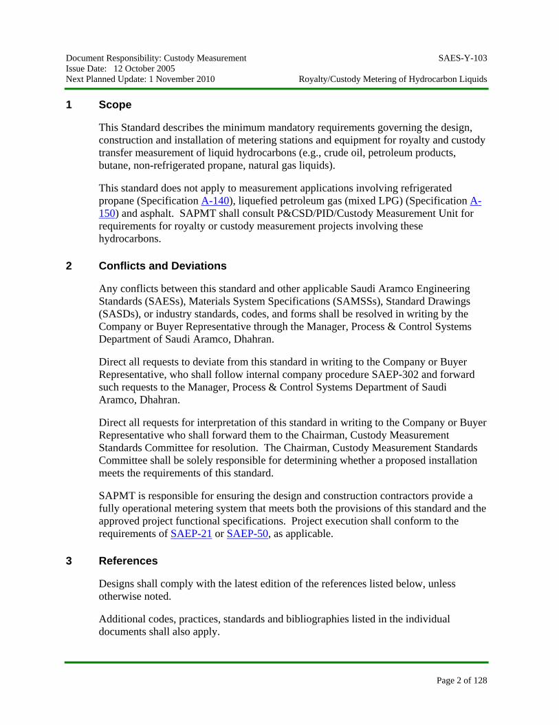
1 Scope
This Standard describes the minimum mandatory requirements governing the design, construction and installation of metering stations and equipment for royalty and custody transfer measurement of liquid hydrocarbons (e.g., crude oil, petroleum products, butane, non-refrigerated propane, natural gas liquids).
This standard does not apply to measurement applications involving refrigerated propane (Specification A-140), liquefied petroleum gas (mixed LPG) (Specification A-150) and asphalt. SAPMT shall consult P&CSD/PID/Custody Measurement Unit for requirements for royalty or custody measurement projects involving these hydrocarbons.
2 Conflicts and Deviations
Any conflicts between this standard and other applicable Saudi Aramco Engineering Standards (SAESs), Materials System Specifications (SAMSSs), Standard Drawings (SASDs), or industry standards, codes, and forms shall be resolved in writing by the Company or Buyer Representative through the Manager, Process & Control Systems Department of Saudi Aramco, Dhahran.
Direct all requests to deviate from this standard in writing to the Company or Buyer Representative, who shall follow internal company procedure SAEP-302 and forward such requests to the Manager, Process & Control Systems Department of Saudi Aramco, Dhahran.
Direct all requests for interpretation of this standard in writing to the Company or Buyer Representative who shall forward them to the Chairman, Custody Measurement Standards Committee for resolution. The Chairman, Custody Measurement Standards Committee shall be solely responsible for determining whether a proposed installation meets the requirements of this standard.
SAPMT is responsible for ensuring the design and construction contractors provide a fully operational metering system that meets both the provisions of this standard and the approved project functional specifications. Project execution shall conform to the requirements of SAEP-21 or SAEP-50, as applicable.
3 References
Designs shall comply with the latest edition of the references listed below, unless otherwise noted.
Additional codes, practices, standards and bibliographies listed in the individual documents shall also apply.

Document Responsibility: Custody Measurement SAES-Y-103 Issue Date: 12 October 2005 Next Planned Update: 1 November 2010 Royalty/Custody Metering of Hydrocarbon Liquids
Page 3 of 128
3.1 Saudi Aramco Documents
Saudi Aramco Engineering Procedures
SAEP-21 Project Execution Requirements for Saudi Aramco Royalty/Custody Metering Systems
SAEP-50 Project Execution Requirements for Third Party Royalty/Custody Metering Systems
Saudi Aramco Engineering Standards
SAES-A-112 Meteorological and Seismic Design Data
SAES-B-054 Access, Egress, and Materials Handling for Plant Facilities
SAES-B-068 Electrical Area Classification
SAES H-001 Selection Requirements for Industrial Coatings
SAES-J-002 Regulated Vendors List for Instruments
SAES-J-003 Instrumentation Basic Design Criteria
SAES-J-004 Instrument Symbols and Identification
SAES-J-005 Instrument Drawings and Forms
SAES-J-100 Process Flow Metering
SAES-J-200 Pressure
SAES-J-400 Temperature
SAES-J-600 Pressure Relief Devices
SAES-J-700 Control Valves
SAES-J-902 Electrical Systems for Instrumentation
SAES-L-102 Regulated Vendors List for Valves
SAES-L-108 Selection of Valves
SAES-L-105 Piping Material Specifications
SAES-L-140 Thermal Expansion Relief in Piping
SAES-N-001 Basic Criteria, Industrial Insulation
SAES-P-101 Regulated Vendor List for Electrical Equipment
SAES-P-103 Direct Current and UPS Systems
SAES-P-104 Wiring Methods and Materials
SAES-P-111 Grounding
Document Responsibility: Custody Measurement SAES-Y-103 Issue Date: 12 October 2005 Next Planned Update: 1 November 2010 Royalty/Custody Metering of Hydrocarbon Liquids
Page 4 of 128
SAES-P-116 Switchgear and Control Equipment
Saudi Aramco Materials System Specifications
01-SAMSS-010 Fabricated Carbon Steel Piping
04-SAMSS-001 Gate Valves
04-SAMSS-041 Expanding Plug Valve
04-SAMSS-051 Ball Valves, API 6D
09-SAMSS-080 Shop Applied Baked Internal Coatings
17-SAMSS-515 Auxiliary Electrical Systems for Skid Mounted Equipment
34-SAMSS-117 Turbine Flow Meters in Liquid Service
34-SAMSS-118 Positive Displacement Meters
34-SAMSS-119 Bi-Directional Meter Prover
34-SAMSS-120 Uni-Directional Meter Prover
34-SAMSS-511 Chromatographs
34-SAMSS-517 Density Meters
34-SAMSS-525 Automatic Sampling Systems for Crude Oil & Refined Products
34-SAMSS-711 Control Valves – General Services
34-SAMSS-718 Electric Motor Operated Valve Actuators
34-SAMSS-820 Instrument Control Cabinets - Indoor
34-SAMSS-821 Instrument Control Cabinets - Outdoor
34-SAMSS-830 Programmable Logic Controller
34-SAMSS-831 Instrumentation for Packaged Units
34-SAMSS-913 Instrumentation and Thermocouple Cable
Saudi Aramco Standard Drawings
AB-036019 Thermowell Assembly and Detail
AA-036513 Custody Transfer Metering and Proving Station (Liquid)
Saudi Aramco Library Drawings
DC-950040 Pressure Indicators and Switches, Locally Mounted Instrument Piping Details
Document Responsibility: Custody Measurement SAES-Y-103 Issue Date: 12 October 2005 Next Planned Update: 1 November 2010 Royalty/Custody Metering of Hydrocarbon Liquids
Page 5 of 128
DC-950042 Pressure Instruments, Blind and Indicating Type
DC-950043 Electrical Connections for Field Mounted Instruments
Saudi Aramco Product Specifications
A-140 Refrigerated Propane LPG (a)
A-150 Liquefied Petroleum Gas (LPG)
3.2 Industry Codes and Standards
API Manual of Petroleum Measurements Standards (MPMS)
Chapter 1 Vocabulary
Chapter 4 Proving Systems
Chapter 5 Metering
Chapter 6 Metering Assemblies
Chapter 7 Temperature Determination
Chapter 8 Sampling
Chapter 9 Density Determination
Chapter 10 Sediment and Water
Chapter 11 Physical Properties Data
Chapter 12 Calculation of Petroleum Quantities
Chapter 14 Natural Gas Fluids Measurement
Chapter 21 Flow Measurement Using Electronic Metering Systems
Other Documents
ANSI B-40-1M-79 Gauges, Pressure Indicating Dial Type
ANSI/NFPA 70 National Electrical Code (NEC)
ASME/ANSI B31.3 Chemical Plant and Petroleum Refinery Piping
API RP 1004 Bottom Loading and Vapor Recovery for MC-306, Tank Motor Vehicles
API RP 2003 Protection Against Ignitions Arising Out of Static, Lightning and Stray Currents
API STD 594 Wafer and Wafer-Lug Check Valves
ASME SEC VIII Boiler and Pressure Vessel Code
Document Responsibility: Custody Measurement SAES-Y-103 Issue Date: 12 October 2005 Next Planned Update: 1 November 2010 Royalty/Custody Metering of Hydrocarbon Liquids
Page 6 of 128
ASTM D1250-52 Petroleum Measurement Tables
ASTM D1250-80 Standard Guide for Petroleum Measurement Tables
ASTM D1250-04 Standard Guide for Use of Petroleum Measurement Tables
ASTM D3700 Obtaining LPG Samples Using a Floating Piston Cylinder
ASTM E1 ASTM Liquid-in-Glass Thermometers
IEC 60751 Industrial Platinum Thermometer Sensors
IEC 61000-4-3 Electromagnetic Compatibility (EMC) - Testing and Measurement Techniques - Radiated, Radio Frequency Electromagnetic Field Immunity Test
IEC 61000-6-2 Electromagnetic Compatibility (EMC) - General Standards - Immunity for Industrial Environments
NEMA ICS 6-1983 Enclosures for Industrial Controls and Systems
4 Definitions
Air Fueling Operation (AFO): A Distribution Operations plant that stores aircraft fuel and distributes it to aircraft. For the purpose of this standard, the associated pipeline receiving metering system(s), truck unloading meters, refueler loading meters, refueler meters, defueler meters, and dispensing meters are considered a part of the air fueling unit.
Bulk Plant: A Distribution Operations plant that stores refined product and distributes it to domestic customers, contract haulers, and/or other plants. For the purpose of this standard, the pipeline receiving and shipping metering system(s), marine unloading metering system(s), truck and rail car loading and unloading meters are considered a part of the bulk plant.
Commentary Note: A sub-paragraph that contains comments that are explanatory or advisory in nature. These comments are not mandatory, except to the extent that they explain mandatory requirements contained in this standard.
Custody Transfer Measurement: A specialized form of measurement that provides quantity and quality information used for the physical and fiscal documentation of a change in ownership and/or responsibility of commodities. The following measurements are custody transfer measurements:
Document Responsibility: Custody Measurement SAES-Y-103 Issue Date: 12 October 2005 Next Planned Update: 1 November 2010 Royalty/Custody Metering of Hydrocarbon Liquids
Page 7 of 128
• Measurement of hydrocarbon liquid or gas movements (deliveries or receipts) between Saudi Aramco and its customers, suppliers, or transport contractors.
• Measurement of hydrocarbon liquid or gas transfers within, or between, Saudi Aramco business entities (e.g., refineries, bulk plants, terminals, VELA, etc.) where the measurement is used for accounting or loss control.
Delivery: A custody transfer from a bulk plant, fractionating center, gas plant, refinery or terminal to a customer, marine vessel, pipeline or contract hauler.
Dual Devices: Two identical devices that perform the same function independent of each other.
Flow Computer: A dedicated off-the-shelf electronic device specifically designed for calculating and totaling metered volumes, and/or calculating meter factors during meter proving for one or more meters.
Fractionating Center: Juaymah Gas Plant or Yanbu Gas Plant. For the purpose of this standard, the associated marine loading and unloading metering systems are considered a part of the fractionating center
Gas Plant: Berri Gas Plant, Haradh Gas Plant, Hawiyah Gas Plant, Khursaniyah Gas Plant, Shedgum Gas Plant, Uthmaniyah Gas Plant.
Graphical User Interface (GUI): An operator interface to the metering system that is a part of the Metering Supervisory Computer (MSC).
Meter Run: A single pipeline meter and its associated inlet block valve, check valve, strainer, flow conditioning sections, control valve, outlet block valve, prover inlet valve and instrumentation.
Meter Skid: The field portion of a metering system consisting of the meters, strainers, density meter, flow-conditioning sections, block valves, control valves, piping, instruments, electrical equipment, and associated structural steel.
Meter Station: A facility that is primarily dedicated to the measurement of the quantity and quality of a liquid or gas hydrocarbon.
Metering Supervisory Computer (MSC): Computer that performs supervisory functions (data archiving, report generation, system integrity checks, alarm logging and operator interface) for a metering system.
Metering System: A complete assembly of equipment that is designed to measure the quantity and quality of a liquid or gas hydrocarbon. The metering system includes, but is not limited to, the meter skid (meters, strainers, density meter, flow conditioning sections, valves), prover skid, samplers, and control system (flow computers,
Document Responsibility: Custody Measurement SAES-Y-103 Issue Date: 12 October 2005 Next Planned Update: 1 November 2010 Royalty/Custody Metering of Hydrocarbon Liquids
Page 8 of 128
programmable logic controllers, metering supervisory computers, etc.).
Non-Transfer Activity: Any activity that results in an indicated volume for a meter that is not associated with an actual transfer of hydrocarbon. Activities that are considered non-transfer activities include, but are not limited to: 1) Generation of volume by using a frequency generator as part of meter maintenance, 2) Flushing of a liquid hydrocarbon from a loading line in preparation for the delivery of another hydrocarbon, 3) Recirculation of a hydrocarbon through the metering system back to tankage.
Prover Skid: The field portion of a metering system consisting of the meter prover, outlet block valve, control valve, piping, instruments, electrical equipment and associated structural steel.
Receipt: A custody transfer to a bulk plant, fractionating center, gas plant, refinery or terminal from a supplier, marine vessel, pipeline or contract hauler.
Redundant Devices: Two identical devices that operate in an interchangeable primary/secondary arrangement in which the functions of the primary device are duplicated in the secondary and are automatically transferred to the secondary if the primary fails without the intervention of a third device.
Refinery: Jeddah Refinery, Rabigh Refinery, Ras Tanura Refinery, Riyadh Refinery, Yanbu Refinery. For the purpose of this standard, the associated pipeline receiving and shipping metering system(s), and marine loading and unloading metering system(s) are considered a part of the refinery.
Royalty Measurement: A specialized form of measurement that is used as the basis for paying royalty to the Saudi Arabian Government.
Terminal: Juaymah Terminal, Juaymah Gas Plant Sea Island, Ras Tanura Terminal or Yanbu Crude Oil Terminal. For the purpose of this standard, the associated pipeline receiving and shipping metering system(s) and marine unloading and loading metering system(s) are considered a part of the terminal.
Terminal Management System: A supervisory computer system that manages the operation of a bulk plant or air fueling unit.
5 General Requirements
The following general requirements apply to all categories of royalty and custody transfer measurement.
Commentary Note:
Specific requirements for each measurement application and measurement equipment

Document Responsibility: Custody Measurement SAES-Y-103 Issue Date: 12 October 2005 Next Planned Update: 1 November 2010 Royalty/Custody Metering of Hydrocarbon Liquids
Page 9 of 128
are provided in Sections 6 and 7, respectively.
5.1 Units of Measurement
Depending upon the facility and the application, either the U.S. Customary (USC) or metric (SI) system of units shall be used:
Item Metric (SI) U.S. Customary (USC)
Mass Kilograms, Metric Tons Long Tons
Volume Cubic Meters, Liters Barrels, U.S. Gallons
Temperature Degrees Celsius (°C) Degrees Fahrenheit (°F)
Pressure Kilopascals Gauge [kPa (ga)] Pounds per Square Inch Gauge (psig)
Density Kilograms per Liter, Kilograms per Cubic Meter
Degrees API, Relative Density (Specific Gravity)
5.1.1 Pipelines Originating at Gas Plants
All liquid hydrocarbons shall be measured using equipment registering in U.S. Customary (USC) units.
All volumes shall be expressed in barrels.
5.1.2 Refineries, Terminals & Fractionating Centers
All liquid hydrocarbons shall be measured using equipment registering in U.S. Customary (USC) units.
All volumes except that of bunker fuel shall be expressed in barrels. Bunker fuel volumes shall be expressed in barrels or gallons. Volumes shall also be expressed in cubic meters when transfers are to be made to Distribution Operations.
5.1.3 Distribution Bulk Plants & Air Fueling Units
Crude oil volumes shall be measured using equipment registering in the U.S. Customary (USC) units and shall be expressed in barrels.
All refined products (e.g., gasoline, diesel, kerosene, Jet A1, JP4, JP5, JP8, and fuel oil) shall be measured using equipment registering in metric (SI) units.
Refined product volumes shall be expressed in liters, dekaliters or cubic meters. Jet A1 and JP4 sales volumes may also be expressed in kilograms.
Document Responsibility: Custody Measurement SAES-Y-103 Issue Date: 12 October 2005 Next Planned Update: 1 November 2010 Royalty/Custody Metering of Hydrocarbon Liquids
Page 10 of 128
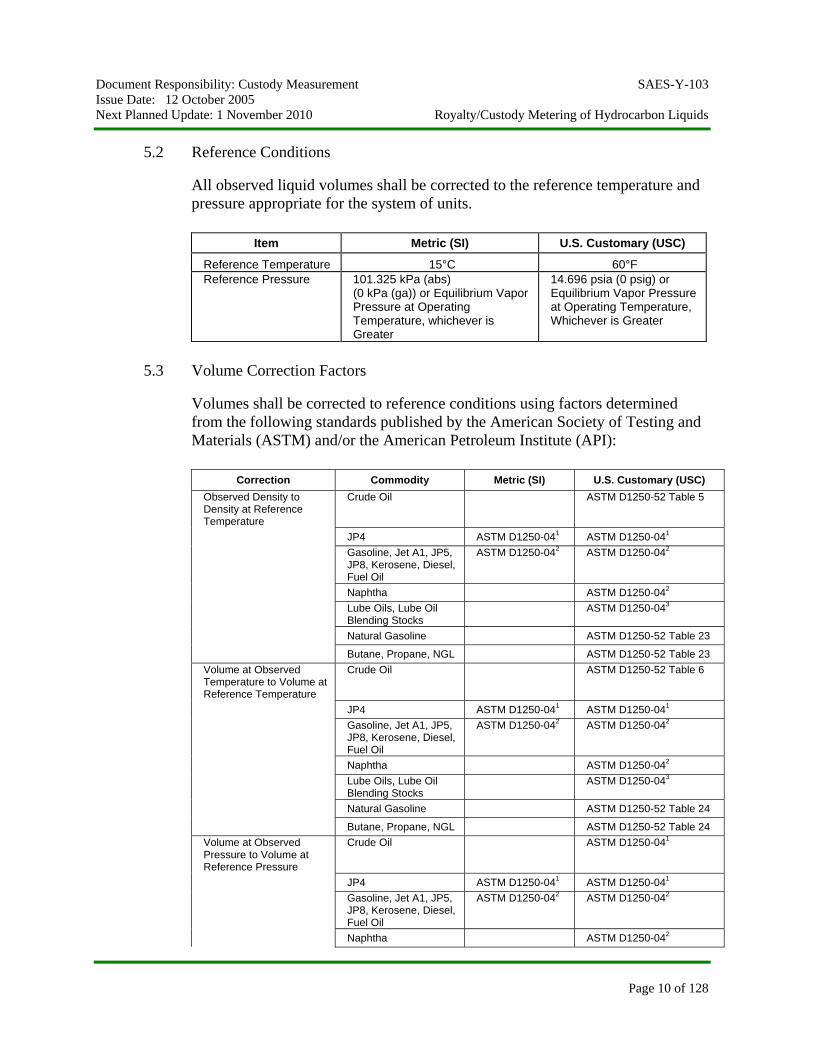
5.2 Reference Conditions
All observed liquid volumes shall be corrected to the reference temperature and pressure appropriate for the system of units.
Item Metric (SI) U.S. Customary (USC)
Reference Temperature 15°C 60°F Reference Pressure 101.325 kPa (abs)
(0 kPa (ga)) or Equilibrium Vapor Pressure at Operating Temperature, whichever is Greater
14.696 psia (0 psig) or Equilibrium Vapor Pressure at Operating Temperature, Whichever is Greater
5.3 Volume Correction Factors
Volumes shall be corrected to reference conditions using factors determined from the following standards published by the American Society of Testing and Materials (ASTM) and/or the American Petroleum Institute (API):
Correction Commodity Metric (SI) U.S. Customary (USC)
Observed Density to Density at Reference Temperature
Crude Oil ASTM D1250-52 Table 5
JP4 ASTM D1250-041 ASTM D1250-041 Gasoline, Jet A1, JP5,
JP8, Kerosene, Diesel, Fuel Oil
ASTM D1250-042 ASTM D1250-042
Naphtha ASTM D1250-042 Lube Oils, Lube Oil
Blending Stocks ASTM D1250-043
Natural Gasoline ASTM D1250-52 Table 23
Butane, Propane, NGL ASTM D1250-52 Table 23 Volume at Observed Temperature to Volume at Reference Temperature
Crude Oil ASTM D1250-52 Table 6
JP4 ASTM D1250-041 ASTM D1250-041 Gasoline, Jet A1, JP5,
JP8, Kerosene, Diesel, Fuel Oil
ASTM D1250-042 ASTM D1250-042
Naphtha ASTM D1250-042 Lube Oils, Lube Oil
Blending Stocks ASTM D1250-043
Natural Gasoline ASTM D1250-52 Table 24
Butane, Propane, NGL ASTM D1250-52 Table 24 Volume at Observed Pressure to Volume at Reference Pressure
Crude Oil ASTM D1250-041
JP4 ASTM D1250-041 ASTM D1250-041 Gasoline, Jet A1, JP5,
JP8, Kerosene, Diesel, Fuel Oil
ASTM D1250-042 ASTM D1250-042
Naphtha ASTM D1250-042

Document Responsibility: Custody Measurement SAES-Y-103 Issue Date: 12 October 2005 Next Planned Update: 1 November 2010 Royalty/Custody Metering of Hydrocarbon Liquids
Page 11 of 128
Lube Oils & Lube Oil Blending Stocks
ASTM D1250-043
Natural Gasoline ASTM D1250-041 Butane, Propane, NGL API MPMS 11.2.2 &
Addendum
1Generalized Crude Oils Commodity Group 2Generalized Refined Products Commodity Group 3Generalized Lubricating Oils Commodity Group
Commentary Note:
The product commonly referred to as "Naphtha" at Yanbu Gas Plant is considered to be "Natural Gasoline" for measurement purposes.
A look-up table shall be used whenever ASTM D1250-52 is specified. A computer algorithm and its implementation procedures shall be used whenever ASTM D1250-04 is specified. A mathematical model shall be used when API Manual of Petroleum Measurement Standards, Chapter 11.2.2 is specified.
5.4 Environmental Conditions
Equipment shall be suitable for installation in the applicable environment specified in SAES A-112 and shall meet the environmental conditions specified in SAES J-003.
5.5 General Design
The Chairman, Custody Measurement Standards Committee, shall approve all metering system vendors and sub-vendors prior to placing the purchase order for the metering system.
Commentary Note:
Approval of vendors by the Chairman, Custody Measurement Standards Committee, is required to ensure that only qualified vendors are used, and adequate technical support and spare parts are available for all Saudi Aramco metering systems.
Instruments, valves and electrical equipment shall be furnished from approved vendors as specified in SAES J-002, SAES L-102 and SAES P-101, respectively.
Meters, meter provers and control equipment shall be purchased as integrated systems. The metering system shall be designed from off-the-shelf components which require a minimum of customization and which are field proven in the intended application.
At a minimum, the following data shall be provided and used to design the measurement system:

Document Responsibility: Custody Measurement SAES-Y-103 Issue Date: 12 October 2005 Next Planned Update: 1 November 2010 Royalty/Custody Metering of Hydrocarbon Liquids
Page 12 of 128
• Type of meter operation (pipeline; marine loading or unloading; truck loading or unloading; aircraft refueling, defueling or dispensing)
• Fluid properties (e.g., specific gravity, viscosity, vapor pressure from the Saudi Aramco product specification or other source)
• Operating temperature and pressure
• System maximum and minimum flow rate
• Maximum and minimum batch size (for crude oil systems)
• Available utilities (e.g., electrical power, instrument air)
• Pipe I.D. and line pressure at sample point (for crude oil systems)
• Meter proving method
Provisions for meter proving shall be considered as part of the design of each meter station. Metering system design shall permit proving of meters and associated equipment in-situ with permanent or portable provers. Pumps and prover inlet and outlet piping shall be sized to permit proving of each meter at its maximum linear or continuous flow rate (capacity).
Unless specified otherwise for a particular application, temperature and pressure measurement devices (temperature transmitter, RTD and/or glass thermometer, test thermowell, and pressure transmitter and/or gauge) shall be provided for each meter and for each prover.
Installation of primary temperature measurement devices and test thermowells shall conform to Detail 1 or 3, as applicable, of Standard Drawing AB-036019.
Pressure transmitters shall be installed in accordance with Library Drawing DC-950042 and DC-950043. Pressure gauges shall be installed in accordance with Detail 1 or 2, as applicable, of Library Drawing DC-950040.
A manual sampling probe shall be provided for each meter or group of parallel meters. See Section 7.3.5 for design requirements.
Walkways, stairways, platforms, and material handling equipment shall be provided in accordance with SAES B-054.
5.6 Layout
The layout of equipment shall provide for unencumbered access for operations and maintenance, and shall permit easy removal of equipment.
Distances between meters and meters provers shall be kept as short as possible. Where a fixed meter proving station is provided to service multiple meters (e.g.,
Document Responsibility: Custody Measurement SAES-Y-103 Issue Date: 12 October 2005 Next Planned Update: 1 November 2010 Royalty/Custody Metering of Hydrocarbon Liquids
Page 13 of 128
truck loading) or meter skids, it shall be centrally located to minimize the distance between the meters and the prover.
Space shall be provided adjacent to each fixed prover for positioning of prover calibration equipment.
Where a portable prover is to be used, space shall be provided adjacent to the meter skid for the prover and associated equipment (e.g., generators, tank trucks, etc.).
For a positive displacement meter, temperature and pressure measurement devices shall be located within a 1-m long piping segment adjacent to, and preferably downstream of, the meter. For a turbine meter, these devices shall be located within a 0.5-m long pipe segment beginning at a distance of 5 pipe diameters downstream from the meter.
The temperature and pressure measurement devices shall be located in the specified piping segment in the following order: 1) Primary temperature measurement device (temperature transmitter, RTD or thermometer); 2) Test thermowell at a distance of no more than 0.3 m from the primary temperature measurement device; 3) Pressure transmitter and/or pressure gauge.
No connections, instruments or other devices shall be located within the upstream (10 pipe diameters) and downstream (5 pipe diameters) flow conditioning sections of a turbine meter.
Density meters, automatic samplers and manual sample probes shall be located in accordance with instructions provided in Sections 7.3.4, 7.3.5 and 7.3.6, respectively.
5.7 Piping
All skid-mounted piping and pressure containing components shall be designed and constructed in accordance with ANSI B31.3, SAES-L-105 and 01-SAMSS-010.
A double block-and-bleed valve shall be provided whenever leakage through a valve could result in fluid bypass around a meter or prover, or fluid could be introduced into a prover at a point after the meter.
If a bypass line is provided around the meter skid, the bypass shall include a double block-and-bleed valve or a spectacle blind flange to prevent leakage during normal operation.
If the metering skid will be used for both deliveries and receipts, cross-over piping with double block-and-bleed valves and check valves shall be installed
Document Responsibility: Custody Measurement SAES-Y-103 Issue Date: 12 October 2005 Next Planned Update: 1 November 2010 Royalty/Custody Metering of Hydrocarbon Liquids
Page 14 of 128
between the upstream and downstream piping to ensure the flow through the meters and prover is always in the same direction.
The cavity bleed on each double block-and-bleed valve in butane or propane service shall be equipped with a pressure gauge and vent to a flare or other safe location. The cavity bleed on each double block-and-bleed valve in any other service shall discharge to an open funnel.
Provision shall be made to isolate and drain each individual meter, without affecting the operation of adjacent meters.
Valve selection shall conform to the requirements of SAES-L-108. A gate valve or ball valve may be specified for any block valve except where a double block-and-bleed valve is required (e.g., inlet header valve, strainer isolation valve).
High point vents shall be provided in all systems to facilitate the venting of trapped air or vapor.
Thermal relief valves shall be provided in accordance with the requirements of SAES-L-140, and shall discharge into an oily water sewer or blow down system.
The number of vents, drains and thermal relief valves on the piping between a meter(s) and a prover (connections) and between a meter(s) and the point of custody transfer shall be kept to a minimum. Each vent, drain or thermal relief shall be provided with a means to permit examination for, or prevention of, leakage. Each vent shall discharge to an open funnel or be plugged. Each thermal relief shall discharge to an open funnel. Each drain connection shall be furnished with a skillet blind on the discharge side of the drain valve.
Threaded connections on meter bodies, prover interchanges and 4-way valves, and double block-and-bleed valves shall not be seal welded.
Piping shall be fabricated and installed, and pipe supports provided to prevent external stresses on and distortion of the meter body.
5.8 Stream Conditioning
A strainer shall be provided directly upstream of each individual meter or group of parallel meters. For strainers in continuous operation on common supply headers, provision shall be made for on-line cleaning, or a back-up strainer shall be provided.
An air eliminator shall be provided upstream of each meter or group of meters whenever air can be introduced or vapor can be released in the metering system.
The system design shall include provisions to ensure that pressure pulsation and
Document Responsibility: Custody Measurement SAES-Y-103 Issue Date: 12 October 2005 Next Planned Update: 1 November 2010 Royalty/Custody Metering of Hydrocarbon Liquids
Page 15 of 128
surges are minimized. Installation of a pressure surge tank, expansion chamber and/or surge relief system may be used to meet this requirement.
5.9 Instrumentation/Electrical
Field instruments and electrical equipment shall be designed for the electrical area classification as determined by SAES B-068.
Design and installation of instruments and electrical equipment shall conform to the requirements of ANSI/NFPA 70, SAES J-902, SAES P-104, and SAES-P-111. Instruments and electrical equipment furnished as part of vendor supplied metering systems shall also conform to 34-SAMSS-831 and 17-SAMSS-515, respectively.
All flow computers, programmable logic controllers, system communications equipment and metering supervisory computers shall be powered by a UPS system which conforms to the requirements of SAES J-902.
Instrument cabling shall conform to 34-SAMSS-913. Shielded, twisted-pair wire shall be used for all meter pulse signals.
Field junction boxes shall conform to the requirements specified in SAES J-902 and shall be installed in accessible locations at the edge of the meter or prover skid. Conduit and cable connections shall enter each junction box from the bottom. Each conduit to or from a location other than on the meter or prover skid (e.g., control room, PIB, etc.) shall be sealed with a weather-tight seal at the entrance to a field junction box.
Commentary Note:
Installation of weather-tight seals as described above is required to prevent or minimize the introduction of moisture from long conduits into field junction boxes and is not required for safety.
The original physical structure of each cable shall extend at least 50 cm above the entry point of a junction box or marshaling cabinet. The cable shall be centered at the entry point.
Electrical and electronic equipment supplied as part of the metering systems shall carry the EC conformity mark ("CE") designating compliance with European EMC Directive 89/336/EEC. An authorized agency shall also have tested and certified the equipment is immune to electromagnetic interference, electrostatic discharge, radio frequency interference, surge and fast transients, voltage dips and interruptions at Performance Level A in accordance with IEC 61000-6-2. Tests shall have been performed to confirm the equipment is immune to radiated, radio frequency and electromagnetic emissions in accordance with IEC 61000-4-3 using Test Level 3.

Document Responsibility: Custody Measurement SAES-Y-103 Issue Date: 12 October 2005 Next Planned Update: 1 November 2010 Royalty/Custody Metering of Hydrocarbon Liquids
Page 16 of 128
6 Application Requirements
This section outlines specific requirements for particular categories of royalty and custody transfer measurement.
6.1 Pipeline Shipping/Receiving & Marine Loading/Unloading
6.1.1 General
See Drawing AA-036513 for arrangement and installation details for pipeline and marine metering systems
Blind flange connections shall be provided on the inlet and outlet header of each meter skid to permit the future addition of at least one meter.
To balance the flow between the various meters and reduce the number of pipe fittings, it is recommended that the inlet and outlet be positioned on opposite corners of the meter skid.
6.1.2 Meters
Turbine meters shall be used for all pipeline and marine applications unless the viscosity or proving frequency dictates otherwise. See Section 7.1 for meter selection and sizing requirements.
A minimum of two operational meters shall be provided as part of each pipeline and marine loading metering system.
A minimum of three operational meters shall be provided as part of each marine unloading metering system.
In addition to the operational meters, a fully operational installed spare meter shall be furnished as part of each pipeline, or marine loading or unloading metering system.
6.1.3 Meter Proving
See Section 7.2 for prover selection and design requirements.
6.1.4 Auxiliary Equipment
An on-line density meter shall be provided for each pipeline, and marine loading and unloading metering system. See Section 7.3.3 for on-line density meter requirements.
Document Responsibility: Custody Measurement SAES-Y-103 Issue Date: 12 October 2005 Next Planned Update: 1 November 2010 Royalty/Custody Metering of Hydrocarbon Liquids
Page 17 of 128
An automatic sampling system shall be provided for each crude oil metering system. An automatic sampling system shall also be provided when requested by the operating organization. See Section 7.3.4 for automatic sampling system requirements.
Commentary Note:
An automatic sampling system is required to collect representative samples that are analyzed to determine both sediment and water content, and density for crude oil deliveries and receipts. This data is used in the calculation of net crude oil volumes delivered or received. An automatic sampling system is sometimes required to collect samples that are analyzed to ensure product deliveries or receipts meet quality specifications.
An automatic sampling system or gas chromatograph shall be provided as part of each metering system in natural gas liquids (NGL) service. See Section 7.3.4 and Section 7.3.16 for requirements associated with automatic sampling systems and gas chromatographs, respectively.
In marine unloading applications, an air eliminator shall be provided upstream of each meter or the entire meter skid. The air eliminator shall be located on-shore as close to the marine vessel as possible.
A check valve shall be installed upstream of each meter or group of parallel meters.
If product or crude oil can be received during a power outage at the location (e.g., from pipelines or marine vessels), an emergency power source shall be provided in addition to an UPS.
For metering systems in refrigerated butane service, the meter runs and piping to the prover shall be insulated in accordance with SAES N-001.
6.1.5 Metering Automation & Control Systems
See Appendix A for automation and control requirements for pipeline and marine metering systems.
A flow-activated alarm shall be supplied on the primary piping discharging from each relief system that bypasses a meter skid.
6.2 Truck, Rail Car & Refueler Loading (Distribution Operations)
6.2.1 General
For typical installation details, consult P&CSD/PID/Custody

Document Responsibility: Custody Measurement SAES-Y-103 Issue Date: 12 October 2005 Next Planned Update: 1 November 2010 Royalty/Custody Metering of Hydrocarbon Liquids
Page 18 of 128
Measurement Unit.
The loading system shall be designed to ensure that the maximum velocity at any point in the system (loading arms, truck inlet nozzle, etc.) does not exceed the limits set forth in API Recommended Practice 2003.
6.2.2 Meters
Positive displacement meters equipped with direct drive pulse generators shall be used for all truck, rail car and refueler loading applications.
Commentary Note:
Direct drive pulse generators are required to permit proving with a small volume prover.
Meter size shall not exceed four inches.
Meters shall be double-case design when the design pressure is greater than 1000 kPa (ga) (150 psig).
6.2.3 Meter Proving
See Section 7.2 for prover selection and design requirements.
6.2.4 Auxiliary Equipment
A digital set-stop valve shall be provided downstream of each meter to control flow during initial low flow start, normal flow and ramped or stepped shutdown, and to maintain back pressure on the meter.
If the potential exists for back flow of product during pump shutdown, a check valve shall be installed upstream of each meter or group of parallel meters.
Commentary Note:
This may be the case where loading racks are at higher elevations than the storage tanks.
An air eliminator shall be provided immediately upstream of each meter or group of parallel meters whenever the introduction of air or the formation of vapor is possible prior to the meter(s). A combination strainer/air eliminator may be used.
Document Responsibility: Custody Measurement SAES-Y-103 Issue Date: 12 October 2005 Next Planned Update: 1 November 2010 Royalty/Custody Metering of Hydrocarbon Liquids
Page 19 of 128
Installation of a pressure transmitter for pressure compensation is not required where the total fluctuation of the supply pressure is less than ± 100 kPa (± 15 psi) from the average pressure, or where a single dedicated supply pump and connecting piping is provided for each loading position.
NOTE: Correction for the effects of pressure may be accomplished by the preset controller using a constant pressure (preferable) or by use of a composite meter factor which includes such a correction.
6.2.5 Metering Automation & Control Systems
The functions of an electronic preset controller shall be provided for each operational meter. These functions shall include, but not be limited to, totaling volumes, correcting volumes to reference conditions, and controlling the loading operation at the rack (batch loading).
PLC's (programmable logic controllers) and electro-mechanical relays may also be utilized for connection to pump control logic and other local interlocks to the preset controller.
See Appendix B for automation requirements for truck, rail car and refueler loading meters.
6.3 Truck, Rail Car & Refueler Unloading (Distribution Operations)
6.3.1 General
For typical installation details, consult P&CSD/PID/Custody Measurement Unit.
6.3.2 Meters
Positive displacement meters equipped with direct drive pulse generators shall be used for all truck, rail car and refueler unloading applications.
Commentary Note:
Direct drive pulse generators are required to permit proving with a small volume prover.
Meter size shall not exceed four inches.
The use of single case meters is permitted.
Document Responsibility: Custody Measurement SAES-Y-103 Issue Date: 12 October 2005 Next Planned Update: 1 November 2010 Royalty/Custody Metering of Hydrocarbon Liquids
Page 20 of 128
6.3.3 Meter Proving
See Section 7.2 for prover selection and design requirements.
Meter proving connections shall be provided downstream of each meter, for connection to a pipe prover, master meter, or tank prover, as applicable.
6.3.4 Auxiliary Equipment
A control valve shall be provided downstream of each meter to maintain back pressure on the meter, and to control the flow rate.
An air eliminator shall be furnished immediately upstream of the meter (normally downstream of the unloading pump).
A check valve shall be installed on the downstream of each meter to prevent back-flow of product through the meter.
Installation of a pressure transmitter for automatic pressure compensation is not required.
NOTE: Correction for the effect of pressure shall be accomplished by the flow computer using a constant pressure (preferable) or by use of a composite meter factor which includes such a correction.
All truck and rail car unloading systems shall include a sliding vane, positive displacement pump and motor to facilitate unloading of the product.
6.3.5 Metering Automation & Control Systems
See Appendix C for automation requirements for truck, rail car and refueler unloading meters.
A low voltage adjustable frequency drive (AFD) shall be provided to control the pump/motor speed (flow rate). See Section 7.3.17 for adjustable frequency drive (AFD) requirements.
6.4 Aircraft Refueling, Defueling and Dispensing (Distribution Operations)
6.4.1 Meters
Positive displacement meters shall be utilized for all aircraft refueling, defueling and dispensing applications.

Document Responsibility: Custody Measurement SAES-Y-103 Issue Date: 12 October 2005 Next Planned Update: 1 November 2010 Royalty/Custody Metering of Hydrocarbon Liquids
Page 21 of 128
Meters in these applications may be furnished with a single pulse generator.
The use of single case meters is permitted.
Meters shall be provided with cases that are constructed of aluminum or epoxy coated steel. Meter internals shall be constructed of non-ferrous materials. All metal parts in contact with the fuel shall contain no more than 5% zinc or cadmium. Copper and copper bearing alloy material shall not make-up more than 10% of the total wetted surface.
6.4.2 Meter Proving
See Section 7.2 for prover selection and design requirements.
6.4.3 Auxiliary Equipment
An air eliminator shall be furnished upstream of each meter.
If a filter is provided upstream of the meter, a separate strainer is not required.
Installation of a pressure transmitter for automatic pressure compensation is not required.
NOTE: Correction for the effects of pressure shall be accomplished by the flow computer using a constant pressure (preferable) or by use of a composite meter factor which includes such a correction.
6.4.4 Metering Automation & Control Systems
See Appendix C for automation requirements for aircraft dispensing and refueling meters.
7 Equipment Requirements
7.1 Meter Selection and Design Requirements
The number and size of meters shall be determined based on the process and operational data outlined in Section 5 and the requirements of the specific application as specified in Section 6.
7.1.1 Meter Selection
Turbine or positive displacement meters shall be used for all applications.

Document Responsibility: Custody Measurement SAES-Y-103 Issue Date: 12 October 2005 Next Planned Update: 1 November 2010 Royalty/Custody Metering of Hydrocarbon Liquids
Page 22 of 128
A turbine meter or positive displacement meter shall be selected based on the viscosity of the fluid to be measured and the criteria provided in API Manual of Petroleum Measurement Standards, Chapter 5.1, Figure 1.
In applications where both turbine meters and positive meters are acceptable for the viscosity of the fluid, meter selection shall be governed by the following guidelines:
• Turbine meters are recommended for applications where the metering operation is essentially continuous and where the meters will be proved routinely at intervals one month or less (e.g., pipeline deliveries and receipts; marine cargo loading and unloading).
• Positive displacement meters are recommended for applications where the measurement operation is intermittent or where the meters will be proved at intervals greater than one month (e.g., rail car and truck loading and unloading; aircraft refueling, defueling and dispensing; bunker fuel deliveries).
7.1.2 Turbine Meters
Turbine meters shall conform to 34-SAMSS-117 and API Manual of Petroleum Measurement Standards, Chapter 5.3.
A turbine meter shall be sized to operate between 40 and 100% of its maximum normal linear flow rate (capacity) after all relevant process data (e.g., viscosity, and specific gravity) has been considered.
Turbine meters with rim-type designs shall be selected if available in the required size.
Turbine meters shall be furnished with two pulse generators with integral pre-amplifiers. The two pulse generators shall produce signals that are 90 degrees out of phase.
A flow conditioning assembly (flow straightener) shall be provided for each turbine meter. See Section 7.3.8 for details.
7.1.3 Positive Displacement Meters
Positive displacement meters shall conform to 34-SAMSS-118 and API Manual of Petroleum Measurement Standards, Chapter 5.2.
Document Responsibility: Custody Measurement SAES-Y-103 Issue Date: 12 October 2005 Next Planned Update: 1 November 2010 Royalty/Custody Metering of Hydrocarbon Liquids
Page 23 of 128
Positive displacement meters with a nominal size of 6 inches or less shall be selected to operate between 20 and 85% of the manufacturer's maximum continuous flow rate (capacity). Positive displacement meters with a nominal size greater than 6 inches shall be selected to operate between 20 and 75% of the manufacturer's maximum continuous flow rate (capacity).
Unless otherwise specified for an application, each positive displacement meter shall be equipped to furnish dual channel pulse signals which are 90 degrees out of phase (dual pulse quadrature). Meter pulse signals shall be derived directly from the meter's main shaft without intervening gearing whenever a small volume prover will be used to prove the meter.
Commentary Note:
Direct drive pulse generators are preferred for all positive displacement meters.
7.2 Meter Prover Selection and Design Requirements
Base prover volumes shall be sufficient to allow the metered (and proving) volumes to be read to a resolution of 1 in 10,000.
Base prover volumes shall be expressed in the appropriate units at the reference conditions (temperature and pressure) in accordance with Section 5.1.
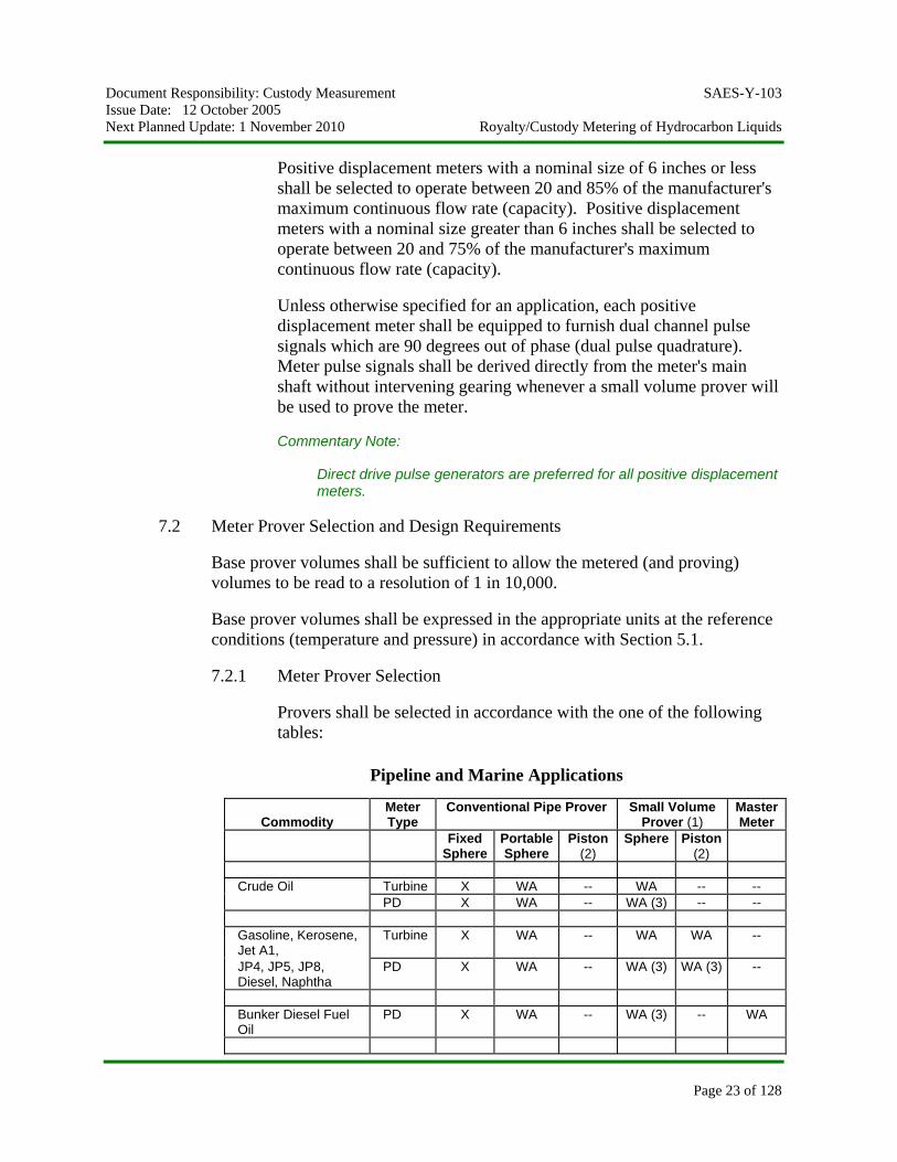
7.2.1 Meter Prover Selection
Provers shall be selected in accordance with the one of the following tables:
Pipeline and Marine Applications
Commodity Meter Type
Conventional Pipe Prover Small Volume Prover (1)
MasterMeter
Fixed Sphere
PortableSphere
Piston (2)
Sphere Piston(2)
Crude Oil Turbine X WA -- WA -- -- PD X WA -- WA (3) -- -- Gasoline, Kerosene, Jet A1,
Turbine X WA -- WA WA --
JP4, JP5, JP8, Diesel, Naphtha
PD X WA -- WA (3) WA (3) --
Bunker Diesel Fuel Oil
PD X WA -- WA (3) -- WA
Document Responsibility: Custody Measurement SAES-Y-103 Issue Date: 12 October 2005 Next Planned Update: 1 November 2010 Royalty/Custody Metering of Hydrocarbon Liquids
Page 24 of 128
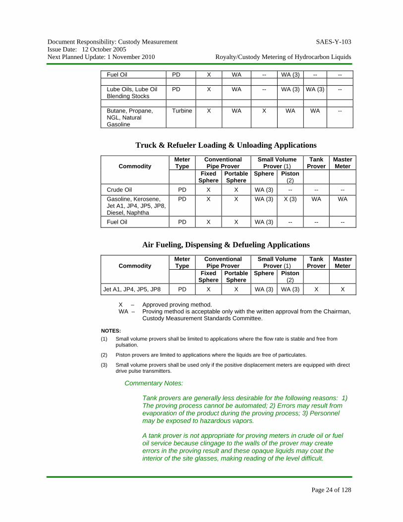
Fuel Oil PD X WA -- WA (3) -- -- Lube Oils, Lube Oil Blending Stocks
PD X WA -- WA (3) WA (3) --
Butane, Propane, NGL, Natural Gasoline
Turbine X WA X WA WA --
Truck & Refueler Loading & Unloading Applications
Commodity
Meter Type
Conventional Pipe Prover
Small Volume Prover (1)
Tank Prover
Master Meter
Fixed Sphere
PortableSphere
Sphere Piston (2)
Crude Oil PD X X WA (3) -- -- -- Gasoline, Kerosene, Jet A1, JP4, JP5, JP8, Diesel, Naphtha
PD X X WA (3) X (3) WA WA
Fuel Oil PD X X WA (3) -- -- --
Air Fueling, Dispensing & Defueling Applications
Commodity
Meter Type
Conventional Pipe Prover
Small Volume Prover (1)
Tank Prover
Master Meter
Fixed Sphere
Portable Sphere
Sphere Piston (2)
Jet A1, JP4, JP5, JP8 PD X X WA (3) WA (3) X X
X – Approved proving method. WA – Proving method is acceptable only with the written approval from the Chairman,
Custody Measurement Standards Committee.
NOTES: (1) Small volume provers shall be limited to applications where the flow rate is stable and free from
pulsation.
(2) Piston provers are limited to applications where the liquids are free of particulates.
(3) Small volume provers shall be used only if the positive displacement meters are equipped with direct drive pulse transmitters.
Commentary Notes:
Tank provers are generally less desirable for the following reasons: 1) The proving process cannot be automated; 2) Errors may result from evaporation of the product during the proving process; 3) Personnel may be exposed to hazardous vapors.
A tank prover is not appropriate for proving meters in crude oil or fuel oil service because clingage to the walls of the prover may create errors in the proving result and these opaque liquids may coat the interior of the site glasses, making reading of the level difficult.

Document Responsibility: Custody Measurement SAES-Y-103 Issue Date: 12 October 2005 Next Planned Update: 1 November 2010 Royalty/Custody Metering of Hydrocarbon Liquids
Page 25 of 128
Master meters are generally less desirable for the following reasons: 1) The overall measurement uncertainty is greater because the meter factors are less directly traceable to the volumetric standard at a recognized national standards agency [e.g., U.S. National Institute of Standards and Technology (NIST)]. 2) Each master meter must be calibrated at least as often as the operational meters for which it will be used. 3) A pipe or small volume prover is required to develop the calibration curves for each master meter.
A master meter is not appropriate for proving meters in heated liquid service because the conditions during the proving of the operating meter cannot be readily duplicated during the calibration of the master meter.
7.2.2 Conventional Pipe Provers
Pipe provers shall be either bi-directional or uni-directional in design. Bi-directional provers shall be furnished in accordance with 34-SAMSS-119. Uni-directional provers shall be furnished in accordance with 34-SAMSS-120.
The volume between detector switches shall be sufficient to ensure the accumulation of at least 10,000 unaltered pulses during each 1-way trip of the prover displacer. The K factor (pulse output per unit volume) used for prover sizing shall equal 95% of the lowest nominal K factor from the meters to be proved. For turbine meters, the K factor for prover sizing will normally come from the largest meter.
If the application involves butane, propane or natural gas liquids (NGL), the prover shall be designed to maintain the displacer velocity above 0.30 m/s (1 ft/s) at the minimum design flow rate for the smallest meter to be proved. For other hydrocarbon liquids, the minimum design velocity shall be 0.15 m/s (0.5 ft/s).
The diameter for a bi-directional prover shall be selected to limit the displacer velocity in the calibrated section to 1.5 m/s (5 ft/s) at the maximum normal linear (continuous) flow rate for the largest meter to be proved. Similarly, the diameter for a uni-directional prover shall be selected to limit the displacer velocity in the calibrated section to 3.0 m/s (10 ft/s).
7.2.3 Small Volume (Compact) Provers
Small volume provers shall conform to the requirements of API Manual of Petroleum Measurement Standards, Chapters 4.2 and 4.6.
Sphere-type small volume provers shall conform to the requirements of Section 7.2.2, except the base prover volume need not be sufficient to
Document Responsibility: Custody Measurement SAES-Y-103 Issue Date: 12 October 2005 Next Planned Update: 1 November 2010 Royalty/Custody Metering of Hydrocarbon Liquids
Page 26 of 128
ensure the accumulation of at least 10,000 unaltered whole pulses per one-trip of the displacer.
7.2.4 Tank Provers
Tank provers shall conform to the requirements of API Manual of Petroleum Measurement Standards, Chapter 4.4.
Each tank prover shall have a volume equal to twice the maximum volume that can pass through the meter in one minute [maximum continuous flow rate (capacity) x 2 minutes]. Typical capacities of tank provers required to meet this requirement for various sizes of positive displacement meter are as follows:
2-inch & smaller 1,000 L (250 U.S. gal)
3-inch 3,200 L (840 U.S. gal)
4-inch 4,500 L (1,200 U.S. gal)
6-inch 7,500 L (2,000 U.S. gal)
Tank provers shall be constructed of stainless steel or mild steel. Tank provers constructed from mild steel shall be internally coated with a baked-on phenolic coating in accordance with 09-SAMSS-080.
The main body of the prover shall consist of a vertical cylinder with a coned or dished bottom and top. A vortex breaker (baffle plate) shall be provided at the outlet of the lower section of the main body.
Each tank prover shall be furnished with upper and lower necks. The upper neck shall be provided with an inverted splash cone for use with top loading metering systems.
The capacity of the upper neck shall be at least 1% of the prover volume. The capacity of the lower neck shall be at least 0.5% of the prover volume.
Secondary drain piping and a drip pan shall be provided to permit final draining of the prover to the reference (zero) on the lower neck. This system shall consist of a 1-inch nominal diameter pipe or tube that protrudes into the lower neck under the reference (zero). The portion of the pipe or tube within the neck shall turn upward to a vertical orientation, and shall be square cut. The square cut edge shall be aligned horizontally in the plane of the reference point (zero). The pipe or tube end external to the neck shall be fitted with a ball valve which discharges to a drip pan having a capacity at least equal to the volume of the lower neck.

Document Responsibility: Custody Measurement SAES-Y-103 Issue Date: 12 October 2005 Next Planned Update: 1 November 2010 Royalty/Custody Metering of Hydrocarbon Liquids
Page 27 of 128
A gauge glass with minimum diameter of 16 mm (5/8 inch) and an armored protector shall be provided for each neck. In each case, the gauge glass(es) shall run the full length of the neck. Gauge or sight glass(es) with armored protection may also be provided for the main body of the prover. Gauge glass fittings shall be installed directly on the walls of the neck or prover body.
Each neck gauge glass shall be provided with a scale constructed from a corrosion resistant metal that has a coefficient of expansion similar to the tank material. Gauge glass scales shall be subdivided into increments equivalent to, or less than, 0.02% of the tank volume. Each gauge glass scale shall be securely mounted behind the gauge glass and shall have provisions for vertical adjustment.
Tapered-style thermowells shall be provided in the main body of each tank prover as follows:
• For each prover with capacity of 1900 L (500 U.S. gal) or less, thermowells shall be provided in the upper one-third and lower one-third of the main body height of the tank. For each prover with capacity greater than 1900 L (500 U.S. gal), thermowells shall be installed in the upper one-third, middle one-third and lower one-third of the main body height of the tank. In each case, the thermowells shall be equally spaced around the tank circumference. Each thermowell shall be installed on an incline of 30 degrees from the horizontal to permit retention of a heat transfer medium.
• Each thermowell shall have a 1-inch NPT threaded connection, a "U" length of 406 mm (16-½ inches) and a bore of 10 mm (0.385 inches). Each thermowell shall be constructed from 316 stainless steel and shall be furnished with a chained plug.
Four (4) thermometers meeting the requirements for tank proving as specified in Section 7.3.1 shall be furnished with each prover.
A minimum of two (2) spirit level indicators shall be provided on the body of the prover. The respective level indicators shall be located 90 degrees circumferentially from each other.
A common inlet/outlet connection shall be provided at the bottom of the lower neck, with inlet and outlet piping provided to and from this connection. Expanding plug valves meeting the requirements of 04-SAMSS-041 shall be provided in the inlet and outlet piping as close as possible to the juncture of the two piping systems.

Document Responsibility: Custody Measurement SAES-Y-103 Issue Date: 12 October 2005 Next Planned Update: 1 November 2010 Royalty/Custody Metering of Hydrocarbon Liquids
Page 28 of 128
Provision shall be made for the installation of a lead seal with stainless steel wire at each of the following locations:
• Each end of the upper scale
• Each end of the lower scale
• Each end of the main body sight glass
• Two locations on the upper neck/main body connection (if flanged)
• Each gauge glass
• Each level indicator
An inspection manway shall be provided to permit a visual inspection of the tank coating to be performed. Provision shall be made for sealing the inspection manway after tank calibration.
An electric motor driven, self-priming pump shall be installed in the outlet piping downstream of the outlet valve. The pump capacity and discharge pressure shall be sufficient to return the product to tankage at a flow rate equivalent to 15% of the prover volume in one minute.
A spring loaded, wafer style check valve shall be provided on the discharge of the pump.
If the dead head pressure of the pump will exceed the maximum allowable working pressure of the plant piping, a relief valve shall be provided on the discharge of the pump.
Each portable tank prover shall be mounted on a trailer that meets the requirements of the U.S. Department of Transportation. A leveling jack shall be provided on each of the four corners of the trailer. Leveling jacks must be able to support the full weight of the tank prover and product.
Each portable tank prover shall be furnished with inlet hose adapter and outlet hose coupler for connection of the prover to the metering system; and tank truck, refueler or product return system, respectively. The adapter and coupler shall meet the requirements of API Recommended Practice 1004.
7.2.5 Master Meters
Master meters shall be provided in accordance with API Manual of Petroleum Measurement Standards, Chapter 4.5.
Document Responsibility: Custody Measurement SAES-Y-103 Issue Date: 12 October 2005 Next Planned Update: 1 November 2010 Royalty/Custody Metering of Hydrocarbon Liquids
Page 29 of 128
Master meters shall be dedicated, double case positive displacement meters.
Master meters shall be portable in all applications except where used to prove or calibrate refueling, defueling and dispensing meters. Portable master meters shall be mounted on a wheeled trolley or other means of transportation.
Each master meter shall be sized to operate between 25 and 75% of the manufacturer's maximum continuous flow rate (capacity).
The size of the master meter shall be selected to permit proving or calibration of the operational meters over the full ranges of operating flow rates. In the case of aircraft fueling or defueling meters, the master meter shall also be sized to permit performing the dynamic slip test at 20 percent of the capacity for each operational meter.
Each master meter shall have repeatability and resolution specifications equal to or better than the meters to be proved.
Each master meter shall be equipped with a pulse generator that furnishes a pulse signal derived directly from the meter's main shaft (without intervening gearing). A pulse generator that employs a film-type disk with alternating etched opaque and transparent slots shall not be used.
Each master meter shall be provided with an electronic device with dual counters and a common timing gate. The dual counters shall accumulate at least 10,000 pulses from the operating meter and the master meter during each proving trial. In each case, the resolution shall be one whole pulse.
A means of indicating the instantaneous flow rate and average flow rate shall be provided with each master meter.
Provisions shall be made to develop product specific calibration curves using a pipe prover. Each curve shall cover the full range of operating flow rates for the respective meters to be proved.
A globe or ball valve shall be installed downstream of each master meter for manual flow control.
A pressure gauge or transmitter, and an RTD/temperature transmitter or thermometer/thermowell shall be installed in the outlet piping within 1 m of the master meter.
Document Responsibility: Custody Measurement SAES-Y-103 Issue Date: 12 October 2005 Next Planned Update: 1 November 2010 Royalty/Custody Metering of Hydrocarbon Liquids
Page 30 of 128
Inlet and outlet hoses with quick connecting couplings, and a drain valve shall be provided.
Protection against vibration, dust and mechanical damage during transportation and handling shall be provided for all master meters.
7.3 Other Equipment
7.3.1 Temperature Instruments
Temperature transmitters shall meet the requirements of API Manual of Petroleum Measurement Standards, Chapter 7 and SAES J-400.
Each transmitter shall be a microprocessor based smart unit that uses a platinum resistance temperature detector (RTD) as its primary element. The RTD shall be Pt100, four-wire design, with an alpha coefficient of 0.00385 per IEC 60751. The calibrated span of the transmitter shall normally be -18 to 65°C (0 to 150°F). The transmitter shall have a 4 to 20 mA DC output. The overall transmitter/RTD accuracy shall be ±0.2% of the calibrated span or better.
Thermometers supplied for tank provers shall be designed in accordance with ASTM E1 and meet the following requirements:
Range: -1˚C to 51˚C (30˚F to 124˚F) or -1˚C to 101˚C (30˚F to 214˚F)
Scale Graduations: 0.25˚C (0.5˚F)
Accuracy: ±0.1˚C (0.2˚F)
Other thermometers shall have a range consistent with the process temperatures and an accuracy of ±0.25°C (±0.5°F) or better, and shall be graduated at increments not exceed 0.5°C (1°F).
The calibration of each thermometer shall be traceable to the temperature standard at a recognized national standards agency [e.g., U.S. National Institute of Standards and Technology (NIST)].
Each thermometer shall be furnished with an aluminum armor case with a diameter not to exceed 12.5 mm (½ inch).
7.3.2 Pressure Instruments
Pressure instruments shall be furnished in accordance with SAES-J-200.
Pressure transmitters shall be microprocessor based smart units with a reference accuracy of ±0.075% of calibrated span or better and shall be provided with over-range protection. Pressure sensor installation

Document Responsibility: Custody Measurement SAES-Y-103 Issue Date: 12 October 2005 Next Planned Update: 1 November 2010 Royalty/Custody Metering of Hydrocarbon Liquids
Page 31 of 128
manifolds shall have vent, drain and test connections. Pressure gauges shall have an accuracy of ±0.5% of span or better. The range of each gauge shall be specified in accordance with SAES-J-200. Pressure gauges shall be glycerin filled.
7.3.3 Density Meters
Density meters shall be of the vibrating, straight-tube design and shall meet the requirements of API Manual of Petroleum Measurement Standards, Chapter 14.6 and 34-SAMSS-517.
Density meters shall have an accuracy of ±0.001 kg/L, repeatability of 0.0005 kg/L and a calibrated range of 0.300 to 1.100 kg/L.
Density meter readings shall be temperature compensated when used in volumetric calculations; and pressure and temperature compensated when used in mass calculations.
Each density meter shall be installed in a fast loop (slip steam) which draws liquid from, and discharges back to, the main stream. The density meter shall be oriented vertically with the flow upward through the instrument. The location of the fast loop inlet shall conform to the requirements of API Manual of Petroleum Measurement Standards, Chapter 8.2, Section 8.
The entrance to the fast loop shall consist of a probe with 45 degree chamfer or 90 degree short radius elbow inlet facing upstream and positioned in the center one-third of the piping upstream of the metering system. The probe design shall conform to API Manual of Petroleum Measurement Standards, Chapter 8.2, Section 11 and Figure 4, Design B or C, respectively.
A pump shall be furnished, to drive the fast loop with sufficient flow for proper operation of the density meter. The pump shall be located downstream of the density meter.
Isolation, vent and drain valves shall be provided to permit air calibration checks and cleaning of the density meter in situ, and maintenance of the density meter. Isolation valves shall be provided on the inlet and outlet of the fast loop (slip stream) to permit maintenance of the pump.
A temperature transmitter, test thermowell, and connections for a pycnometer shall be furnished between the density meter and pump. When pressure compensation of the density meter is required, a pressure transmitter shall also be furnished between the density meter

Document Responsibility: Custody Measurement SAES-Y-103 Issue Date: 12 October 2005 Next Planned Update: 1 November 2010 Royalty/Custody Metering of Hydrocarbon Liquids
Page 32 of 128
and pump. A means shall be provided to detect and alarm a condition of low or no flow in the fast loop.
7.3.4 Automatic Sampling Systems
Automatic sampling systems in crude oil systems shall be flow proportional systems that meet the requirements of API Manual of Petroleum Measurement Standards, Chapter 8.2 and 34-SAMSS-525.
The sampling system shall employ an inline sample extractor except where a fast loop system has been approved by the Chairman, Custody Measurement Standards Committee. A fast loop sampling system may only be considered in situations where the relative elevations between the sampling point and receivers is insufficient or the distance between the sampling point and receivers is too far to permit free flow of the sample to the sample receivers.
Each sample extractor and fast loop probe shall be located at a point where the stream is homogeneous. The following methods are approved as a means to create stream homogeneity:
• Jet mixer
• Static mixer
• Mixing elements (tees, elbows, reducers)
For crude oil applications, the method of stream conditioning shall be selected based on the requirements of API Manual of Petroleum Measurement Standards Chapter 8.2, Table 1 and Appendix B using the worst case conditions. For refined product applications, the method of stream condition shall conform to API Manual of Petroleum Measurement Standards, Chapter 8.2, Table 1.
Unless otherwise approved by the Chairman, Custody Measurement Standards Committee, sample extractors and fast loop probes shall be mounted in the horizontal plane. The inlet of each extractor or fast loop probe shall be positioned in the center one-third of the pipe and shall be oriented in the upstream direction.
The sampler shall be paced uniformly in proportion to the flow of the stream from which the sample is taken. The flow signal may be generated from the royalty or custody transfer meter or meters, an independent, orifice meter, insertion turbine meter or insertion ultrasonic meter. If an orifice meter is used, it shall be designed and installed in accordance with the requirements of SAES-J-100.
Document Responsibility: Custody Measurement SAES-Y-103 Issue Date: 12 October 2005 Next Planned Update: 1 November 2010 Royalty/Custody Metering of Hydrocarbon Liquids
Page 33 of 128
The design sampling rate shall be sufficient to provide a minimum sample volume of 10 liters (2.64 gallons) for the minimum batch (parcel) volume and at least one sample per volume contained within 25 meters (82 feet) of the pipe carrying the stream from which the sample will be taken.
The design sample volume shall be equal to or greater than 1.25 times the required sample volume when sampling at the design sampling rate for a transfer equal to the maximum batch (parcel) volume. If samples are to be collected from more than one point and deposited into a common sample receiver, the design sample volume shall equal the sum of the required sample volumes from individual extractors.
Automatic sampling systems in natural gas liquids (NGL) service shall be flow proportionate, injection pump-type systems that meet the requirements of ASTM D3700.
7.3.5 Manual Sample Probe
Manual sample probes shall be designed in accordance with API Manual of Petroleum Measurement Standards, Chapter 8.1, Section 8.4.2 and Figure 8C. The entrance to the probe shall have a 45-degree beveled, opening facing upstream and positioned in the center one-third of the main pipe. A ball or gate valve shall be provided at the exit of the probe. A short open-ended tube or pipe with a maximum diameter of ¾ inch shall be provided on the discharge from the valve. The opening of this tube or pipe shall face downward to permit collection of a sample in the top of a portable sample container or bottle.
Each sample probe shall be located in accordance with the requirements of API Manual of Petroleum Measurement Standards, Chapter 8.1, Section 8.4.3 and Chapter 8.2, Section 8.
7.3.6 Strainers
Strainer bodies shall be carbon steel and shall be designed, constructed and tested in accordance with ASME SEC VIII D1. An ASME code stamp is not required.
Each strainer shall be sized to provide no more than 15 kPa (2 psi) pressure drop at the maximum design rate for the meter or group of meters when the basket is clean.
Strainers with nominal inlet and outlet size of 6 inches or less shall be equipped with a 304 stainless steel wire basket. Mesh sizes shall
Document Responsibility: Custody Measurement SAES-Y-103 Issue Date: 12 October 2005 Next Planned Update: 1 November 2010 Royalty/Custody Metering of Hydrocarbon Liquids
Page 34 of 128
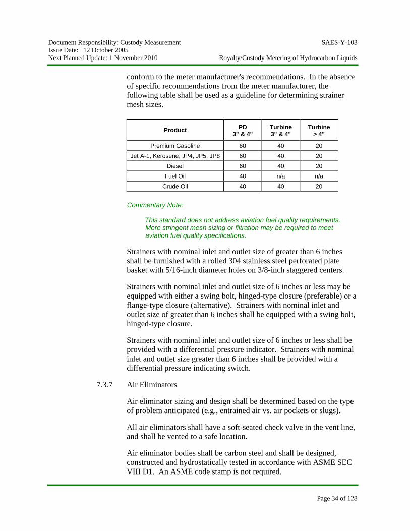
conform to the meter manufacturer's recommendations. In the absence of specific recommendations from the meter manufacturer, the following table shall be used as a guideline for determining strainer mesh sizes.
Product
PD 3" & 4"
Turbine 3" & 4"
Turbine > 4"
Premium Gasoline 60 40 20
Jet A-1, Kerosene, JP4, JP5, JP8 60 40 20
Diesel 60 40 20
Fuel Oil 40 n/a n/a
Crude Oil 40 40 20
Commentary Note:
This standard does not address aviation fuel quality requirements. More stringent mesh sizing or filtration may be required to meet aviation fuel quality specifications.
Strainers with nominal inlet and outlet size of greater than 6 inches shall be furnished with a rolled 304 stainless steel perforated plate basket with 5/16-inch diameter holes on 3/8-inch staggered centers.
Strainers with nominal inlet and outlet size of 6 inches or less may be equipped with either a swing bolt, hinged-type closure (preferable) or a flange-type closure (alternative). Strainers with nominal inlet and outlet size of greater than 6 inches shall be equipped with a swing bolt, hinged-type closure.
Strainers with nominal inlet and outlet size of 6 inches or less shall be provided with a differential pressure indicator. Strainers with nominal inlet and outlet size greater than 6 inches shall be provided with a differential pressure indicating switch.
7.3.7 Air Eliminators
Air eliminator sizing and design shall be determined based on the type of problem anticipated (e.g., entrained air vs. air pockets or slugs).
All air eliminators shall have a soft-seated check valve in the vent line, and shall be vented to a safe location.
Air eliminator bodies shall be carbon steel and shall be designed, constructed and hydrostatically tested in accordance with ASME SEC VIII D1. An ASME code stamp is not required.

Document Responsibility: Custody Measurement SAES-Y-103 Issue Date: 12 October 2005 Next Planned Update: 1 November 2010 Royalty/Custody Metering of Hydrocarbon Liquids
Page 35 of 128
7.3.8 Flow Conditioning Assemblies
Flow conditioning assemblies with straightening elements shall conform to the requirements of API Manual of Petroleum Measurement Standards, Chapter 5.3, Section 5.3.6.1 and Figures 3 and 4.
Flow conditioning assemblies shall be flanged-type and consist of three sections. Two sections shall be installed upstream of the meter (minimum total length of 10 diameters). One section shall be installed downstream of the meter (minimum length of 5 diameters). Each pair of flanges between the respective sections, and between the upstream and downstream sections and the meter, shall be match numbered and doweled to ensure proper alignment.
Straightening elements shall be the flanged-type and constructed from 304 stainless steel.
7.3.9 Block Valves
Gate valves shall conform to 04-SAMSS-001 and ball valves shall conform to 04-SAMSS-051.
7.3.10 Double Block and Bleed Valves
Double block-and bleed valves shall be of the expanding plug type design and shall meet the requirements of 04-SAMSS-041.
7.3.11 Digital Set-Stop Valves
Valves shall be hydraulically operated from the pressure in the process line to which they are connected, and shall be fitted with flow restricting valves in both of the sense lines, to regulate valve stroke times.
Valves shall be provided with both upstream and downstream solenoids for valve control. Solenoids and mode of operation shall be compatible with the output requirements of the selected electronic preset controller.
The valve shall fail closed upon loss of power to the solenoids and upon loss of hydraulic pressure.
7.3.12 Control Valves
Control valves shall meet the requirements specified in SAES J-700 and 34-SAMSS-711.
Document Responsibility: Custody Measurement SAES-Y-103 Issue Date: 12 October 2005 Next Planned Update: 1 November 2010 Royalty/Custody Metering of Hydrocarbon Liquids
Page 36 of 128
The control valve provided downstream of each pipeline meter and meter prover shall be sized to accomplish the following objectives:
• Maintain the flow rate at a selectable value between 10 and 100% of the meter's normal linear capacity. If a common prover is provided for different size meters, the control valve downstream of the prover shall be sized to control the flow rate at any value between 10% of smallest meter's normal linear capacity and 100% of the largest meter's normal linear capacity.
• Maintain the minimum back pressure required downstream of the meter and prover to prevent cavitation in the meter.
The minimum back pressure required for each turbine meter shall be equal to or greater than each of the following requirements:
Pm = 2 * Delta P + 1.25 * Pe
Pm = 20 psig
where:
Pm = Minimum back pressure 5 diameters downstream of the meter (psig)
Delta P = Pressure drop across meter at its maximum normal linear flow rate (psi)
Pe = Absolute equilibrium vapor pressure of the fluid at the maximum operating temperature (psia)
The minimum back pressure required for a positive displacement meter shall be greater than each of the following requirements:
Pm = 5 psi + Pe
Pm = 20 psig
where:
Pm = Minimum back pressure 1 m downstream of the meter (psig)
Pe = Absolute equilibrium vapor pressure of the fluid at the maximum operating temperature (psia)
7.3.13 Check Valves
Check valves shall be spring actuated, double disk, wafer-style valves that meet the requirements of API STD 594.
Document Responsibility: Custody Measurement SAES-Y-103 Issue Date: 12 October 2005 Next Planned Update: 1 November 2010 Royalty/Custody Metering of Hydrocarbon Liquids
Page 37 of 128
7.3.14 Valve Motor Operators
Electric motor operators shall meet the requirements of 34-SAMSS-718.
Each electric motor operator shall be sized to operate the valve with a differential pressure across the valve equal to the valve maximum operating pressure.
Limit switches shall be provided to permit local and remote indication of valve position.
7.3.15 Thermal Relief Valves
Thermal relief valves shall conform to the requirements of SAES-J-600 and SAES-L-140.
7.3.16 Gas Chromatographs
Gas chromatographs shall meet the requirements of 34-SAMSS-511.
7.3.17 Adjustable Frequency Drives (AFD's)
Low voltage adjustable frequency drives shall meet the requirements of SAES-P-116.
8 Testing and Inspection
Piping and piping components shall be hydro-tested in accordance with ANSI B31.3 and 01-SAMSS-010 prior to the application of internal coating, external paint and insulation.
Metering system components (meters, valves, provers, sampling systems, etc.) shall undergo tests as specified in the relevant Saudi Aramco Material Supply System specification.
Each complete metering system shall undergo a Factory Acceptance Test (FAT) at the Vendor's facility in accordance with SAEP-21 or SAEP-50, as applicable. This test shall ensure the system meets all functional and operational requirements. The Vendor shall provide simulators that perform the functions of any missing components.
A similar Site Acceptance Test (SAT) shall be performed after the metering system is permanently installed at the field location. Refer to SAEP-21 or SAEP-50, as applicable.
Each pipe, small volume and tank prover shall be calibrated by the waterdraw method in the vendor's shop prior to shipment, and again after installation. For a permanent
Document Responsibility: Custody Measurement SAES-Y-103 Issue Date: 12 October 2005 Next Planned Update: 1 November 2010 Royalty/Custody Metering of Hydrocarbon Liquids
Page 38 of 128
prover, initial calibration shall be performed as part of the factory acceptance test. Prover calibrations shall conform to API Manual of Petroleum Measurement Standards, Chapters 4, 11 and 12.
In crude oil applications, a water injection test shall be performed for each automatic sampling system prior to placing the system in service. The test shall be conducted in accordance with API Manual of Petroleum Measurement Standards, Chapter 8.2.
Functional tests shall be witnessed and approved by Saudi Aramco or their approved representatives.
9 Shipping Requirements
All necessary repairs, replacements or modifications to hardware, firmware, and software, shall be completed by the Vendor prior to shipment.
The Vendor shall be responsible for ensuring the equipment is properly prepared for shipment, including, but not limited to, the requirements specified hereafter.
9.1 General
All equipment and internals being shipped shall be braced and temporary supports shall be provided, if required, to prevent damage during shipment.
Equipment shall be marked with water-soluble materials that will not attack or damage the equipment at either ambient or operating temperatures. Marking materials shall be free of lead, sulfur, zinc, cadmium, mercury, chlorine and all other halogens.
Markings for export shall conform to the requirements specified on the purchase order.
9.2 Fabricated Equipment
9.2.1 Internal Protection
The internals of all piping, fabricated and assembled equipment shall be completely cleaned and dried to the satisfaction of the Saudi Aramco Inspector.
A non-toxic vapor phase corrosion inhibitor (CORTEC VCI-309 or VCI-307, or equivalent approved by Coordinator, CSD/Mechanical Engineering & Corrosion Control Division) shall be applied to the internal surfaces of all piping, fabricated and assembled equipment.

Document Responsibility: Custody Measurement SAES-Y-103 Issue Date: 12 October 2005 Next Planned Update: 1 November 2010 Royalty/Custody Metering of Hydrocarbon Liquids
Page 39 of 128
Commentary Note:
Vendors are cautioned to allow sufficient lead-time for the purchase and delivery of the vapor phase corrosion inhibitor. Lack of planning by the Vendor will not constitute justification for a waiver of this requirement.
The application rate for the inhibitor shall be 1 kg/m³ of equipment.
The inhibitor shall be blown through the equipment using air with a dew-point that is the lower of the following: 1) -1°C or 2) 5°C below the lowest ambient temperature to be encountered in shipment from the point of manufacture to the final destination. Application of the inhibitor shall continue until the powder can be seen blowing out of the opposite end of the equipment.
Following application of the inhibitor, equipment openings shall be sealed vapor tight with steel covers in accordance with the requirements for external protection.
9.2.2 External Protection
All external surfaces shall be prepared and coated in the shop with the complete Saudi Aramco coating system (primer and final coats) as specified in SAES H-001. If the specified Saudi Aramco approved coating is unavailable or unusable at the Vendor's site, an alternative coating system may be used with the concurrence of the Coordinator, CSD/Materials Engineering and Corrosion Control Division.
All bolts and nuts shall be coated with a temporary protective coating (MIL C16173, Grade IV, or Denso paste or equivalent).
Permanent blind flanges or covers shall be installed with the gaskets and bolts required for service.
The faces of open, flanged connections shall be coated with a temporary protective coating (MIL C16173, Grade IV, or equivalent) which can be easily removed prior to equipment installation. Following application of the protective coating, each connection shall be fitted with a neoprene gasket, and vapor tight steel cover. The cover shall be held in place by a minimum of four equally spaced bolts.
9.3 Electronic and Electrical Equipment
The Vendor shall determine if electronics and instruments are susceptible to damage from shock, weather or extremes of temperature during shipment. If
Document Responsibility: Custody Measurement SAES-Y-103 Issue Date: 12 October 2005 Next Planned Update: 1 November 2010 Royalty/Custody Metering of Hydrocarbon Liquids
Page 40 of 128
required, such items shall be removed after the functional test and shipped separately.
Electronic equipment shall be prepared and protected for shipment in accordance with the manufacturer's recommendations. As a minimum, the equipment shall be fitted with a vapor phase inhibitor emitter (CORTEC VCI-101, VCI-105, VCI-110 or equivalent).
Electrical boxes shall be fitted with vapor phase inhibitor emitters (CORTEC VCI-101, VCI-105, VCI-110 or equivalent).
10 Documentation
Project drawings shall conform to the requirements of SAES-J-004 and SAES-J-005.
Project documentation shall be developed, reviewed, approved and distributed in accordance with SAEP-21 or SAEP-50, as applicable.
Documentation for metering system equipment shall be furnished in accordance with the purchase order(s) and relevant material specifications.
Each strainer and air eliminator shall be assigned a tag number. A data sheet that specifies the maximum operating pressure and other design data shall be provided for each strainer and air eliminator.
Revision Summary 12 October 2005 Major revision.

Document Responsibility: Custody Measurement SAES-Y-103 Issue Date: 12 October 2005 Next Planned Update: 1 November 2010 Royalty/Custody Metering of Hydrocarbon Liquids
Page 41 of 128
Appendix A – Pipeline and Marine Metering Control Systems
This appendix describes the requirements for metering and control systems for pipeline and marine applications. Other system architectures and equipment that provide the same functionality and level of redundancy may be specified with the concurrence of the Chairman, Custody Measurement Standards Committee. Examples of possible alternative designs or equipment which may be acceptable include, but are not limited to:
• Specification of a separate flow computer for meter proving calculations.
• Specification of Distributed Control System (DCS) to perform the functions of the metering supervisory computers.
• Specification of DCS hardware to perform the functions of the programmable logic controllers.
Commentary Note:
Approval of alternate designs and/or equipment by the Chairman, Custody Measurement Standards Committee is required to ensure that all functional requirements are met.
A.1 General
All flow computers, auxiliary counters, indicating lights, etc. shall be mounted in a cabinet designed and constructed to meet the requirements of 34-SAMSS-820 and 34-SAMSS-821.
A.2 Architecture
The system shall be designed such that a single equipment failure will not result in loss of control or degrade the functional capabilities of the system. This requirement does not apply to field equipment such as transmitters and I/O modules unless specified as redundant or dual.
The metering control system shall be arranged in functional blocks. The functional blocks used to construct the system are flow computers, programmable logic controllers (PLC's) and metering supervisory computers (MSC's).
Redundant flow computers shall be furnished for each meter, or group of parallel meters.
The A and B pulse transmitter channels from each meter shall be connected to the primary and secondary flow computers in a crisscross fashion. For each meter, the signal from pulse transmitter A shall be wired to the pulse input A of the primary flow computer and pulse input B of the secondary flow compute.

Document Responsibility: Custody Measurement SAES-Y-103 Issue Date: 12 October 2005 Next Planned Update: 1 November 2010 Royalty/Custody Metering of Hydrocarbon Liquids
Page 42 of 128
The signal from pulse transmitter B shall be wired to the pulse input B of the primary flow compute and pulse input A of the secondary flow computer.
Redundant PLC's, each with its own processor, power supply, and communications, shall be provided to operate all metering systems MOV's. Redundant I/O is not mandatory.
Dual MSC's shall be provided. Each MSC shall include a graphical user interface (GUI) to the metering system for operator interface. Each GUI shall provide operator control selection, report printing, alarming, metering and system graphics, data archiving, and trending capabilities.
With the exception of automatic sampling system(s), the MSC's shall have no direct interface to field devices.
Dual communication links shall be provided between the flow computers and the MSC's with either link selectable at each MSC. A similar arrangement of dual communication links shall be provided between the pair of PLC's and the MSC's. The MSC's shall be masters, and flow computers and PLC's shall be slaves on their respective communication ports.
If an automatic sampling system is provided as part of the metering system, a single communications link shall be provided between the MSC and the sampling system controller.
A single communication link shall be provided for peer-to-peer communications between the flow computers.
If a gas chromatograph is provided as part of the metering system, a single communication link shall be provided between each flow computer and gas chromatograph.
For direct interconnection of metering equipment at distances of 15 m or less, RS-485, RS-422, RS-232-C or Ethernet interfaces are permitted. For direct interconnection distances greater than 15 m, RS-485, RS-422 or Ethernet shall be used. Industry standard protocols (e.g., MODBUS, MODBUS Plus, OPC, TCP/IP, or other standard protocol) shall be used for communication between system components or the metering system and higher level computer system.
All communication links in the system shall support error correction and multiple retries.
A discrete (on/off) output for operation of the prover 4-way valve or interchange shall be hardwired from each flow computer to a common set of PLC inputs. The prover detector switches shall be hardwired to the flow computers.

Document Responsibility: Custody Measurement SAES-Y-103 Issue Date: 12 October 2005 Next Planned Update: 1 November 2010 Royalty/Custody Metering of Hydrocarbon Liquids
Page 43 of 128
The system shall permit the addition of meters simply through the purchase of flow computers (if required), PLC I/O cards and reconfiguration of the MSC's, PLC's and flow computers, as applicable.
A.3 Programmable Logic Controllers
Redundant PLC's shall be provided to operate all metering system MOV's.
Each PLC shall meet the requirements of 34-SAMSS-830.
The PLC shall provide logic functions and sequential control for the following operations:
• Valve line-up in preparation for and after meter proving
• Opening and closing meter runs.
• Operation of the prover 4-way valve or interchange.
The PLC shall provide Open/Stop/Close logic with completion alarm timers, Remote/Local status, and the ability to reverse travel before completion of a command for each MOV.
The PLC shall include interlock logic for sequential control of the metering system MOV's. The logic provided shall include, but not be limited to provisions for preventing the following:
• Opening of the prover inlet valve on more than one meter run at a time
• Closing of a meter run outlet valve prior to opening of the prover inlet and outlet valves
• Closing of a prover inlet or outlet valve prior to opening of the meter run outlet valve
The PLC shall set an alarm flag if an MOV is operated locally.
The PLC shall refuse a sequential operation and set an alarm flag if any of the affected valves is in the LOCAL position.
In response to a "Prove Meter Run" command from the MSC, the PLC shall sequence the valves for proving as follows:
1. Open prover outlet MOV.
2. Open prover inlet MOV for the meter to be proved.
3. Close the meter run outlet MOV.

Document Responsibility: Custody Measurement SAES-Y-103 Issue Date: 12 October 2005 Next Planned Update: 1 November 2010 Royalty/Custody Metering of Hydrocarbon Liquids
Page 44 of 128
If a bi-directional prover is provided, the PLC shall "home" the prover sphere in the left chamber (as observed from the chamber end of the prover) by operating the prover 4-way valve after configuration of the MOV's for proving.
In response to a command from the primary flow computer, the PLC shall initiate operation of the prover 4-way valve or interchange. The PLC shall monitor the status of the prover during proving, including the 4-way valve limit switches if a bi-directional prover is provided. The status shall be made available to the MSC via the communications link
Upon receipt of a command from the MSC, the PLC shall reconfigure the metering system MOV's using the following sequence:
1. Open the meter run outlet MOV.
2. Close the prover inlet MOV for the meter proved.
3. Close the prover outlet MOV.
The PLC shall sequence the valves for an "Open Meter Run" command from the MSC as follows:
1. Ensure the prover inlet MOV on the meter run is closed.
2. Open the inlet MOV for the meter run.
3. Open the outlet MOV for the meter run.
The PLC shall sequence the valves for a "Close Meter Run" command from the MSC as follows:
1. Ensure the prover inlet valve on the meter run is closed.
2. Close the meter run outlet MOV.
3. Close the meter run inlet MOV.
The PLC shall have a discrete input from each strainer differential pressure switch and set an alarm flag if the differential pressure switch is activated.
The PLC shall continuously run a self-diagnostic routine and shall set an alarm flag if it fails.
Each PLC's program and data memory shall have a battery backup with a minimum retention time of two weeks.
Each PLC shall have a minimum of two serial or Ethernet communication ports capable of supporting industry standard protocols (e.g., MODBUS, MODBUS Plus, OPC, TCP/IP or other standard protocol) for communicating with the MSC's.
Document Responsibility: Custody Measurement SAES-Y-103 Issue Date: 12 October 2005 Next Planned Update: 1 November 2010 Royalty/Custody Metering of Hydrocarbon Liquids
Page 45 of 128
A.4 Metering Supervisory Computers (MSC's) and Associated Peripheral Equipment
Dual MSC's shall be furnished to support the metering system. The MSC's shall be interconnected to provide data transparency in their operation to the metering system. Any changes in one MSC shall automatically be updated and displayed in the other MSC. Acknowledgement of alarms on one MSC shall cause them to be acknowledged on the other MSC. Only one of the MSC's shall be in control of the metering system at any instant in time while the other may be used for monitoring purposes.
A configurable GUI, a color CRT display, a pointing device (touch screen, mouse, etc.), and keyboard for alphanumeric entries shall be provided with each MSC. The type of CRT may be either desk or panel mounted. If a desk type CRT is provided, its size shall be a minimum of 21 inches. If a panel-mounted type CRT is provided, its size shall be a minimum of 19 inches.
A pair of laser jet printers shall be provided for the dual MSC's. The printers shall be accessible to both MSC's. However, only the MSC in control shall output to the printers. The operator shall have the capability to designate a particular printer for reports and the other for alarms/event reports. The operator shall be able to designate automatic or manually initiated printing of individual reports. The operator shall be able to select the start and end date and time for each of the alarm/event reports.
The operator shall be able to enter a new date and time via the GUI of the controlling MSC. Upon a change in date and time, the MSC shall automatically synchronize the dates and times of the other system components with the new values.
Each MSC shall contain a database containing the following basic information about each meter, flow computer, prover, as applicable:
• Meter manufacturer, model, size, serial number, nominal K factor, tag number
• Flow computer manufacturer, model, serial number, check sum, and tag number
• Prover manufacturer, base volume, calibration date, outside diameter, wall thickness, prover material, coefficient of cubical expansion, modulus of elasticity, serial number, tag number
Each MSC shall be capable of reading all metering and process data from the flow computers, and valve status from the programmable controllers via the respective communications links. The scan interval for any single piece of data shall be configurable between 5 and 30 seconds. At best, all data can be read at 5-second intervals.
Document Responsibility: Custody Measurement SAES-Y-103 Issue Date: 12 October 2005 Next Planned Update: 1 November 2010 Royalty/Custody Metering of Hydrocarbon Liquids
Page 46 of 128
The MSC shall use data from the primary flow computer for each meter ticket and proving report. In the event that the MSC is initialized or cleared, the MSC shall refresh this data from the flow computer memory.
The controlling MSC shall read the following captured data from the primary and secondary flow computers for each meter at a configurable interval of between 15 minutes to 1 hour: 1) gross standard batch volume, 2) gross batch volume and 3) raw pulses for the batch. The MSC shall calculate the percentage difference between the values from the primary and secondary computer for each meter. The MSC shall set an alarm anytime the percentage difference for a quantity exceeds its configurable limit.
Commentary Note:
For some products, gross standard volume is equivalent to net standard volume.
At the conclusion of a ticket, the controlling MSC shall calculate the percentage difference between the end-of-ticket gross standard volumes from primary and secondary flow computers for each meter. If the percentage difference for any meter exceeds a configurable limit, the MSC shall accomplish the following:
• Set an alarm
• Log the time, ticket number and percentage difference
• Store the following data from the primary and secondary flow computers in a meter-specific file: 1) gross standard volumes, 2) gross volumes, and 3) raw meter pulses.
The MSC shall be capable of automatically selecting and switching the number of meters to accommodate the desired station flow rate. The MSC shall use configurable flow rate criteria for switching from one to two meter operation, two to three meter operation, etc. The operator shall have the capability to pre-designate via the GUI the sequence of meter selection or a rotational sequence (first-on, first-off) to be applied as the flow rate increases and decreases.
For batch pipeline applications, the MSC shall have the capability to initiate a batch change and new tickets for all meters under the following circumstances:
• Batch (interface) volume countdown to zero • Density change as detected by the flow computers
Regardless of the application, the MSC shall be capable of initiating a batch change and new tickets for all meters at a configurable date/time and/or daily time.

Document Responsibility: Custody Measurement SAES-Y-103 Issue Date: 12 October 2005 Next Planned Update: 1 November 2010 Royalty/Custody Metering of Hydrocarbon Liquids
Page 47 of 128
If an automatic sampling system is provided as part of the metering system, the MSC shall issue a command to the sampling system controller to change the sample receivers upon a batch change.
The operator shall be able to issue commands from the GUI to various elements of the system that perform control. Commands shall be issued by a "select-then-execute" one-step command procedure, where the operator selects the item for control by cursor or from a list, and then enters the desired state or value. The MSC shall require entry of any necessary information through the GUI prior to execution of the one-step command.
The operator shall be able to designate a metering activity as either an "official" transfer or a non-transfer.
Normal operational commands and data input for a transfer shall include, but not be limited to:
• Input batch identification
• Input batch volume
• Initiate a new batch
• Initiate a new ticket for a meter
• Accept density from density meter
• Input manual density and temperature
• Input sediment and water content (crude oil applications only)
• Input NGL composition (NGL applications only)
• Initiate open meter run sequence
• Initiate close meter run sequence
• Select flow control mode for a meter (auto/manual)
• Input control set points
• Open/close/stop MOV
• Designate primary flow computer
Commands and data input for a non-transfer shall include, but not be limited to:
• Input initiator identification
• Input reason for non-transfer
• Terminate a non-transfer
Commands and data input for meter proving shall include, but not be limited to:
• Line-up meter for proving
• Designate a proof as "unofficial"
• Input density and density temperature
Document Responsibility: Custody Measurement SAES-Y-103 Issue Date: 12 October 2005 Next Planned Update: 1 November 2010 Royalty/Custody Metering of Hydrocarbon Liquids
Page 48 of 128
• Start proof
• Abort proof
• Terminate proving for a meter
• Rotate prover 4-way valve (bi-directional provers only)
If an automatic sampling system is provided as part of the metering system, commands and input actions which shall be transmitted to the sample system controller shall include, but not be limited to:
• Select sample pacing method (time or flow proportional)
• Input batch size
• Input required sample volume
• Designate sampling interval (seconds per grab) or sampling rate (cubic meters or barrels per grab)
• Designate the active receiver
• Start sampling
• Stop sampling
• Reset sample controller
Each MSC shall be capable of generating the following reports based on data available from the primary flow computer across the communications link:
• Proving Report (Section A6, Attachments 1A through 1D)
• Meter Ticket (Section A6, Attachment 3A through 3D)
• Delivery/Receipt Summary Report (Section A6, Attachments 6A through 6C)
• Meter Calibration Report (Section A6, Attachment 7
• Non-Transfer Activity Report (Section A6, Attachment 8)
• Hourly Report (Section A6, Attachments 9A through 9C).
Each MSC shall be capable of generating the following alarm/event reports:
• Active Alarm Summary • Ticket Alarm/Event Report (for each meter ticket) • Proving Alarm/Event Report (for each proving operation)
GUI displays shall include, but not be limited to the following:
• Display Selection (summary of selectable displays)
• System Overview
• Meter Skid Display(s)
• Prover Display(s)

Document Responsibility: Custody Measurement SAES-Y-103 Issue Date: 12 October 2005 Next Planned Update: 1 November 2010 Royalty/Custody Metering of Hydrocarbon Liquids
Page 49 of 128
• Batch (Parcel) Set-up
• Batch (Parcel) Calculations
• Proving Set-up
• Proving Calculations
• Ticket Set-up
• Ticket Calculations
• Sampling System Set-Up (if applicable)
• Sampling System Status (if applicable)1
• Measured Values2
• Report Selection
• Report Inputs
• Active Alarms
• Alarm History
• Trends
• System, Communications Status & Control
• Settings (Set-points, limits and default values)
• Meter Calibration Data (read only)
• Meter Data
• Flow Computer Data
• Prover Data
1Sampling System Status Screen should include the following information: Active receiver, current flow rate, volume from which sample has been collected, weight/volume in active receiver, ratio of sample volume to receiver volume. 2Measuered Values Screens should be provided for each meter and the station, and should include the following information from each flow computer: Temperature, pressure; density; composition (if a gas chromatograph is provided); gross, gross standard and mass flow rate; gross, gross standard and mass quantities for current batch; gross, gross standard and mass quantities for previous batch.
All values shall be displayed on the GUI in the units appropriate for the application. See Section 5.1 for details.
The GUI shall be able to display the volume differences between the primary and secondary flow computers in tabular and graphical formats.
When an alarm exists, an alarm indicator shall appear on the Display Selection Screen indicating the display on which the alarm condition exists.
Document Responsibility: Custody Measurement SAES-Y-103 Issue Date: 12 October 2005 Next Planned Update: 1 November 2010 Royalty/Custody Metering of Hydrocarbon Liquids
Page 50 of 128
The system shall provide a configuration editor for defining and changing display information. All display formats, contents, paging requirements, related function push-button etc. shall be contained within a display (graphic) definition data file.
As a minimum, the following metering reports and data shall be stored within the MSC's, shall be protected from modification by passcode or keylock, and shall be capable of being printed:
• Delivery/receipt summary reports, tickets, proving reports for the last 1000 batches or all batches for the preceding year, whichever is greater
• Batch comparison data for the last 100 batches • Last 10 failed proving reports for each meter
• Hourly reports for the last three months
Each MSC shall have a minimum of two serial or Ethernet communication ports for communicating with the flow computers and PLC's, and two such ports for communicating with the other MSC. If applicable, an additional communication port shall be provided for communicating with the automatic sampling system. All ports shall support industry standard protocols (e.g., MODBUS, MODBUS Plus, OPC, TCP/IP or other standard protocol). The controlling MSC shall be the master on each of its communication links.
Each MSC shall be capable of communicating data to a higher level computer system (e.g., DCS, Terminal Management System, etc.).
The communication drivers of each MSC shall be capable of reading and writing all metering data. Single and double precision floating-point values shall conform to the IEEE floating-point formats.
A.5 Flow Computers
Flow computers shall be capable of operating in a redundant, primary/secondary configuration. The secondary flow computer shall be a hot standby to the primary flow computer.
Each flow computer shall be capable of calculating flow weighted average flow rate, temperature, pressure, density, composition (if applicable) and meter factors, and calculating and totaling metered volumes. Each flow computer shall also be capable of closed loop control for the metering and proving operations.
Each flow computer shall use the dual pulse inputs provided by each of its assigned meters to perform Level B pulse security in accordance with API Manual of Petroleum Measurement Standards, Chapter 5.5.
Document Responsibility: Custody Measurement SAES-Y-103 Issue Date: 12 October 2005 Next Planned Update: 1 November 2010 Royalty/Custody Metering of Hydrocarbon Liquids
Page 51 of 128
Flow computers shall perform the following operations at least once a second:
• Read all inputs • Compute all factors and volumes • Perform all output control functions
Each flow computer shall retain the totalized meter reading for each assigned meter in an internal register which can be read on the front panel and remotely by the MSC via the communications link but cannot be reset or modified.
Regardless of its primary/secondary designation, each flow computer shall capture the following data for each assigned meter at intervals configurable via the GUI and following the completion of a ticket: 1) gross standard volume, 2) gross volume and 3) raw pulses. The data shall be stored in internal registers that can be read remotely by the MSC via the communications link.
The front panel on each flow computer shall be able to display 8-digit totalized meter readings and batch volume totals. The totalized meter readings and volume totals shall be displayed in whole units (e.g., barrels, cubic meters, etc.). It shall also be possible through the front panel to review and modify setpoints or other non-protected operating data in the flow computer.
The primary flow computer shall control the meter run FCV's, and the prover FCV. The secondary flow computer shall operate as a "hot" standby utilizing its own inputs to read process data for its volume calculations. Non-process data shall be passed from primary to secondary through the peer-to-peer link.
The primary flow computer shall not launch the displacer until the rate of change in meter and prover temperatures, and the flow rate are stable within their respective configurable limits. After the displacer has been launched, the primary flow computer shall monitor the time required to activate the first and second detectors during each pass and set an alarm flag if either time exceeds their respective configurable limits.
The primary flow computer shall abort a proof and set an alarm whenever the prover 4-way valve or interchange has not completely sealed prior to activation of the first detector switch or the seal is lost during either pass of a meter proving trial.
A.5.1 Software
Flow computers shall calculate meter factors, and volume and mass totals for each meter in accordance with API Manual of Petroleum Measurement Standards, Chapters 4.8 and 12.2, the applicable API/ASTM tables specified in Section 5, and Section A.6.
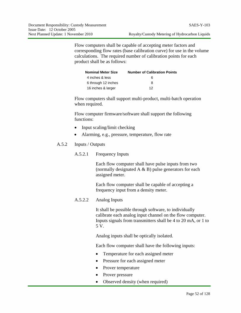
Document Responsibility: Custody Measurement SAES-Y-103 Issue Date: 12 October 2005 Next Planned Update: 1 November 2010 Royalty/Custody Metering of Hydrocarbon Liquids
Page 52 of 128
Flow computers shall be capable of accepting meter factors and corresponding flow rates (base calibration curve) for use in the volume calculations. The required number of calibration points for each product shall be as follows:
Nominal Meter Size Number of Calibration Points 4 inches & less 6 6 through 12 inches 8 16 inches & larger 12
Flow computers shall support multi-product, multi-batch operation when required.
Flow computer firmware/software shall support the following functions:
• Input scaling/limit checking • Alarming, e.g., pressure, temperature, flow rate
A.5.2 Inputs / Outputs
A.5.2.1 Frequency Inputs
Each flow computer shall have pulse inputs from two (normally designated A & B) pulse generators for each assigned meter.
Each flow computer shall be capable of accepting a frequency input from a density meter.
A.5.2.2 Analog Inputs
It shall be possible through software, to individually calibrate each analog input channel on the flow computer. Inputs signals from transmitters shall be 4 to 20 mA, or 1 to 5 V.
Analog inputs shall be optically isolated.
Each flow computer shall have the following inputs:
• Temperature for each assigned meter • Pressure for each assigned meter • Prover temperature • Prover pressure • Observed density (when required)

Document Responsibility: Custody Measurement SAES-Y-103 Issue Date: 12 October 2005 Next Planned Update: 1 November 2010 Royalty/Custody Metering of Hydrocarbon Liquids
Page 53 of 128
• Density temperature (when required) • Density pressure (when required) • Flow control output signal(s) from other flow computer
Each flow computer shall be capable of accepting temperature inputs from 4 wire platinum RTD's and temperature transmitters.
A.5.2.3 Discrete Inputs
The flow computer shall be capable of receiving the following discrete inputs:
• Prover 4-way valve or interchange differential pressure switch
• Prover detector switches • Watchdog status from opposite flow computer • No/low fast-loop flow for density meter
The prover detector switch input shall control a high-speed pulse counter which is dedicated to the proving function.
A.5.2.4 Analog Outputs
Analog outputs shall be 4 to 20 mA.
Flow computers shall have the capability to perform proportional and integral (P+I) flow control with minimum back pressure override for each meter run and the prover. The process value for the prover flow control valve (FCV) shall come from the meter selected for the proof. The ability to change modes, enter a percent (%) output and setpoints, shall be available locally as well as remotely through the communications link.
A.5.2.5 Discrete Outputs
Each flow computer shall have discrete outputs for the following meter proving operations:
• Selection of flow control valve to be used during proving
• Initiate commands for the operation of the prover 4-way valve or interchange
Commentary Note:
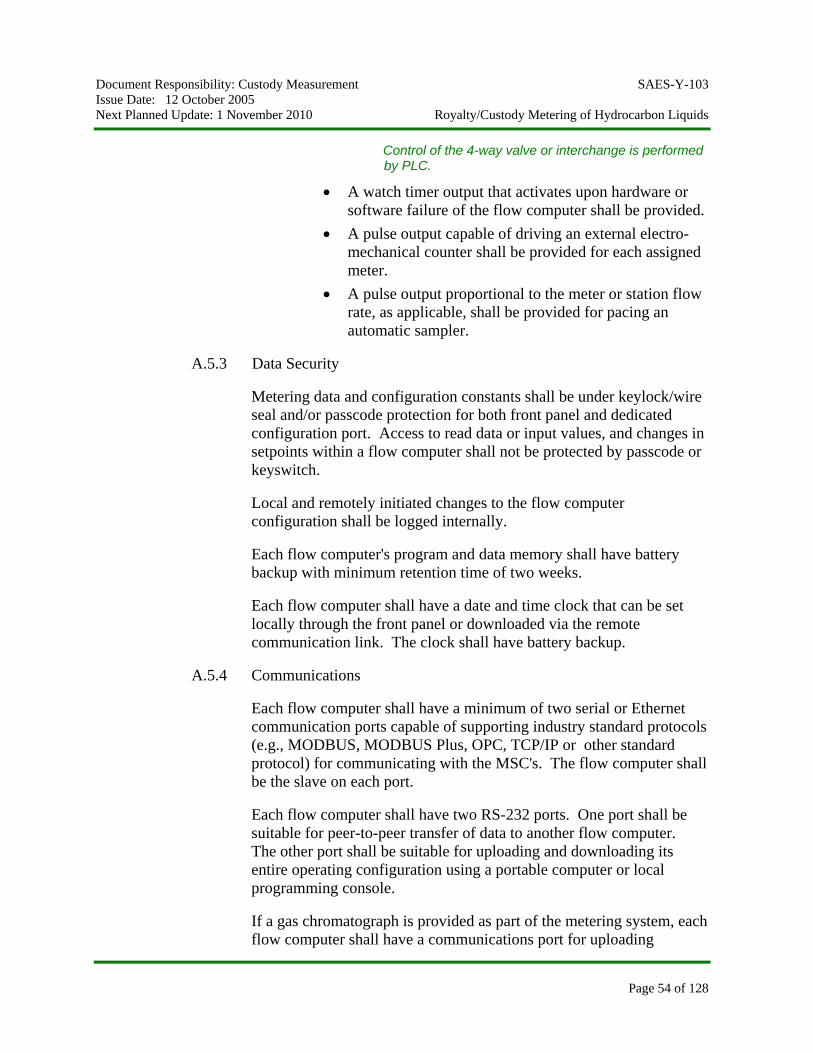
Document Responsibility: Custody Measurement SAES-Y-103 Issue Date: 12 October 2005 Next Planned Update: 1 November 2010 Royalty/Custody Metering of Hydrocarbon Liquids
Page 54 of 128
Control of the 4-way valve or interchange is performed by PLC.
• A watch timer output that activates upon hardware or software failure of the flow computer shall be provided.
• A pulse output capable of driving an external electro-mechanical counter shall be provided for each assigned meter.
• A pulse output proportional to the meter or station flow rate, as applicable, shall be provided for pacing an automatic sampler.
A.5.3 Data Security
Metering data and configuration constants shall be under keylock/wire seal and/or passcode protection for both front panel and dedicated configuration port. Access to read data or input values, and changes in setpoints within a flow computer shall not be protected by passcode or keyswitch.
Local and remotely initiated changes to the flow computer configuration shall be logged internally.
Each flow computer's program and data memory shall have battery backup with minimum retention time of two weeks.
Each flow computer shall have a date and time clock that can be set locally through the front panel or downloaded via the remote communication link. The clock shall have battery backup.
A.5.4 Communications
Each flow computer shall have a minimum of two serial or Ethernet communication ports capable of supporting industry standard protocols (e.g., MODBUS, MODBUS Plus, OPC, TCP/IP or other standard protocol) for communicating with the MSC's. The flow computer shall be the slave on each port.
Each flow computer shall have two RS-232 ports. One port shall be suitable for peer-to-peer transfer of data to another flow computer. The other port shall be suitable for uploading and downloading its entire operating configuration using a portable computer or local programming console.
If a gas chromatograph is provided as part of the metering system, each flow computer shall have a communications port for uploading

Document Responsibility: Custody Measurement SAES-Y-103 Issue Date: 12 October 2005 Next Planned Update: 1 November 2010 Royalty/Custody Metering of Hydrocarbon Liquids
Page 55 of 128
compositional data from the gas chromatograph. The flow computer shall act as the master on this port.
Single and double precision floating-point values shall conform to the IEEE floating-point formats.
Information available to the MSC over the communications links shall include, but not be limited to:
• All dynamic data (e.g., pulse totals, temperatures, pressures, composition, flow rates, volumes)
• I/O & alarm status • Data input locally by the operator
Each flow computer shall accept the download of information from the MSC:
• Setpoints and mode changes • Batch / transaction data (e.g., batch start/stop, ticket start/stop, etc.) • Product, density/API gravity, density temperature, S&W content • Date and time
The flow computer shall be capable of accepting input of floating point, digital and alphanumeric data to its memory via the front panel or via the dedicated RS-232 configuration communications link. Such data shall include, but not be limited to:
• Product menu • Product specific meter factor calibration data for each meter (up to
a maximum of 12 flow rates and corresponding meter factors) • Base meter factor and normal meter flow rate for each meter • Meter data (serial number, nominal K factor) • Prover data (serial number, base volume, outside diameter, wall
thickness, prover material, coefficient of cubical expansion, modulus of elasticity)
It shall not be possible to modify any flow computer-generated ticket or proving data (e.g., volumes, meter factors, average process data, meter calibration data, etc.) through any of the communications links.
A.5.5 Diagnostics/Testing
Each flow computer shall continuously monitor and alarm on the following:
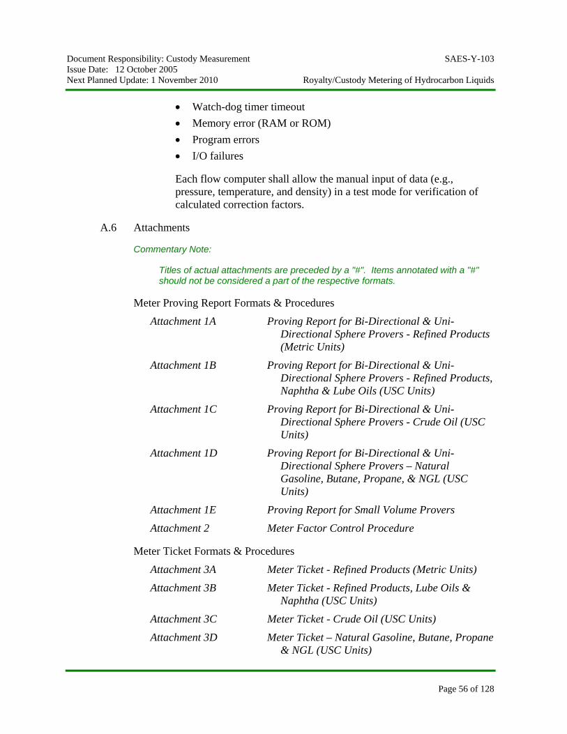
Document Responsibility: Custody Measurement SAES-Y-103 Issue Date: 12 October 2005 Next Planned Update: 1 November 2010 Royalty/Custody Metering of Hydrocarbon Liquids
Page 56 of 128
• Watch-dog timer timeout • Memory error (RAM or ROM) • Program errors • I/O failures
Each flow computer shall allow the manual input of data (e.g., pressure, temperature, and density) in a test mode for verification of calculated correction factors.
A.6 Attachments
Commentary Note:
Titles of actual attachments are preceded by a "#". Items annotated with a "#" should not be considered a part of the respective formats.
Meter Proving Report Formats & Procedures
Attachment 1A Proving Report for Bi-Directional & Uni-Directional Sphere Provers - Refined Products (Metric Units)
Attachment 1B Proving Report for Bi-Directional & Uni-Directional Sphere Provers - Refined Products, Naphtha & Lube Oils (USC Units)
Attachment 1C Proving Report for Bi-Directional & Uni-Directional Sphere Provers - Crude Oil (USC Units)
Attachment 1D Proving Report for Bi-Directional & Uni-Directional Sphere Provers – Natural Gasoline, Butane, Propane, & NGL (USC Units)
Attachment 1E Proving Report for Small Volume Provers
Attachment 2 Meter Factor Control Procedure
Meter Ticket Formats & Procedures
Attachment 3A Meter Ticket - Refined Products (Metric Units)
Attachment 3B Meter Ticket - Refined Products, Lube Oils & Naphtha (USC Units)
Attachment 3C Meter Ticket - Crude Oil (USC Units)
Attachment 3D Meter Ticket – Natural Gasoline, Butane, Propane & NGL (USC Units)
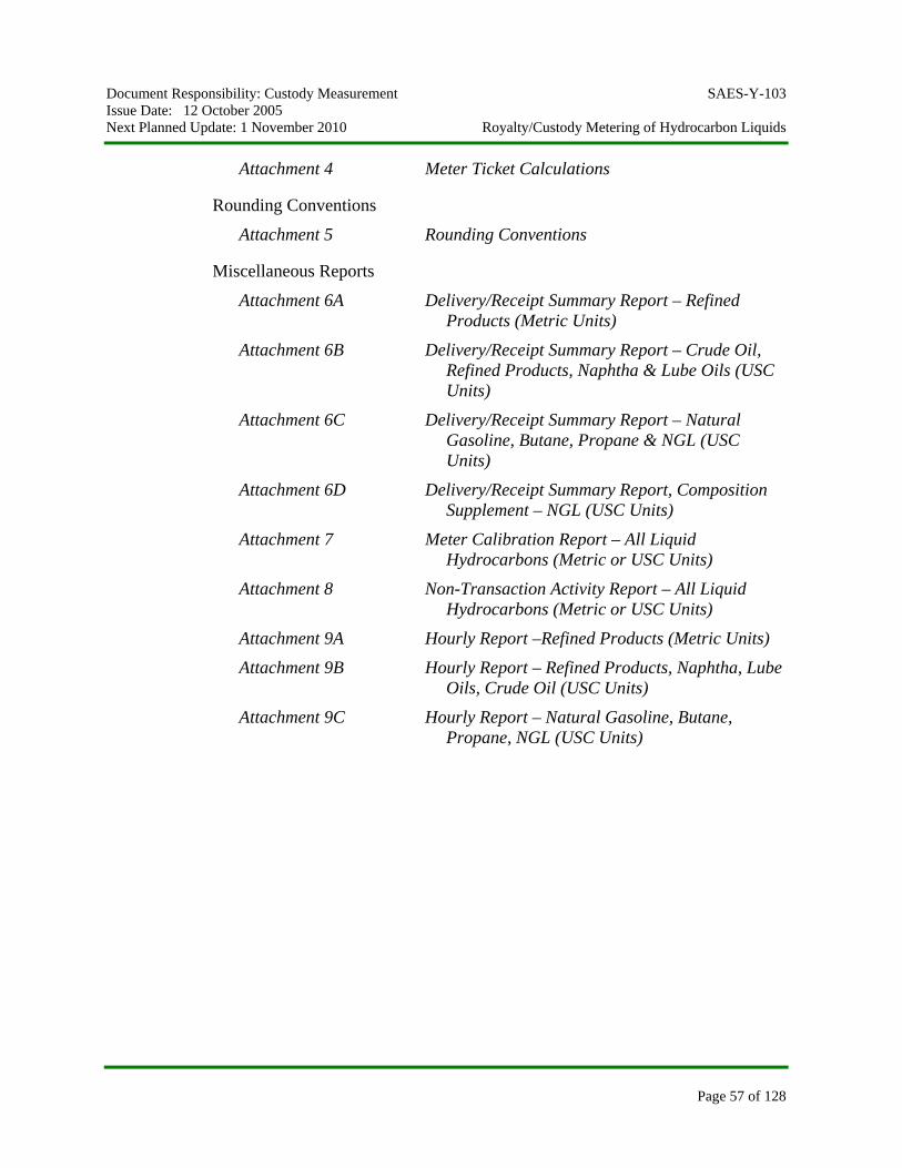
Document Responsibility: Custody Measurement SAES-Y-103 Issue Date: 12 October 2005 Next Planned Update: 1 November 2010 Royalty/Custody Metering of Hydrocarbon Liquids
Page 57 of 128
Attachment 4 Meter Ticket Calculations
Rounding Conventions
Attachment 5 Rounding Conventions
Miscellaneous Reports
Attachment 6A Delivery/Receipt Summary Report – Refined Products (Metric Units)
Attachment 6B Delivery/Receipt Summary Report – Crude Oil, Refined Products, Naphtha & Lube Oils (USC Units)
Attachment 6C Delivery/Receipt Summary Report – Natural Gasoline, Butane, Propane & NGL (USC Units)
Attachment 6D Delivery/Receipt Summary Report, Composition Supplement – NGL (USC Units)
Attachment 7 Meter Calibration Report – All Liquid Hydrocarbons (Metric or USC Units)
Attachment 8 Non-Transaction Activity Report – All Liquid Hydrocarbons (Metric or USC Units)
Attachment 9A Hourly Report –Refined Products (Metric Units)
Attachment 9B Hourly Report – Refined Products, Naphtha, Lube Oils, Crude Oil (USC Units)
Attachment 9C Hourly Report – Natural Gasoline, Butane, Propane, NGL (USC Units)
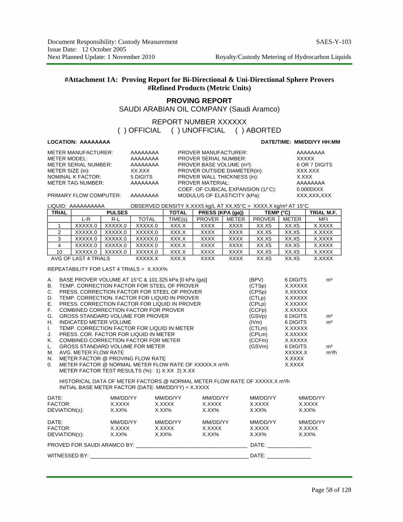
Document Responsibility: Custody Measurement SAES-Y-103 Issue Date: 12 October 2005 Next Planned Update: 1 November 2010 Royalty/Custody Metering of Hydrocarbon Liquids
Page 58 of 128
#Attachment 1A: Proving Report for Bi-Directional & Uni-Directional Sphere Provers #Refined Products (Metric Units)
PROVING REPORT SAUDI ARABIAN OIL COMPANY (Saudi Aramco)
REPORT NUMBER XXXXXX ( ) OFFICIAL ( ) UNOFFICIAL ( ) ABORTED
LOCATION: AAAAAAAA DATE/TIME: MM/DD/YY HH:MM METER MANUFACTURER: AAAAAAAA PROVER MANUFACTURER: AAAAAAAA METER MODEL: AAAAAAAA PROVER SERIAL NUMBER: XXXXX METER SERIAL NUMBER: AAAAAAAA PROVER BASE VOLUME (m³): 6 OR 7 DIGITS METER SIZE (in): XX.XXX PROVER OUTSIDE DIAMETER(in): XXX.XXX NOMINAL K FACTOR: 5 DIGITS PROVER WALL THICKNESS (in): X.XXX METER TAG NUMBER: AAAAAAAA PROVER MATERIAL: AAAAAAAA COEF. OF CUBICAL EXPANSION (1/°C): 0.0000XXX PRIMARY FLOW COMPUTER: AAAAAAAA MODULUS OF ELASTICITY (kPa): XXX,XXX,XXX LIQUID: AAAAAAAAAA OBSERVED DENSITY X.XXX5 kg/L AT XX.X5°C = XXXX.X kg/m³ AT 15°C
TRIAL PULSES TOTAL PRESS (KPA (ga)) TEMP (°C) TRIAL M.F. L-R R-L TOTAL TIME(s) PROVER METER PROVER METER MFt
1 XXXXX.0 XXXXX.0 XXXXX.0 XXX.X XXXX XXXX XX.X5 XX.X5 X.XXXX 2 XXXXX.0 XXXXX.0 XXXXX.0 XXX.X XXXX XXXX XX.X5 XX.X5 X.XXXX 3 XXXXX.0 XXXXX.0 XXXXX.0 XXX.X XXXX XXXX XX.X5 XX.X5 X.XXXX 4 XXXXX.0 XXXXX.0 XXXXX.0 XXX.X XXXX XXXX XX.X5 XX.X5 X.XXXX
10 XXXXX.0 XXXXX.0 XXXXX.0 XXX.X XXXX XXXX XX.X5 XX.X5 X.XXXX AVG OF LAST 4 TRIALS XXXXX.X XXX.X XXXX XXXX XX.X5 XX.X5 X.XXXX
REPEATABILITY FOR LAST 4 TRIALS = X.XXX% A. BASE PROVER VOLUME AT 15°C & 101.325 kPa [0 kPa (ga)] (BPV) 6 DIGITS m³ B. TEMP. CORRECTION FACTOR FOR STEEL OF PROVER (CTSp) X.XXXXX C. PRESS. CORRECTION FACTOR FOR STEEL OF PROVER (CPSp) X.XXXXX D. TEMP. CORRECTION. FACTOR FOR LIQUID IN PROVER (CTLp) X.XXXXX E. PRESS. CORRECTION FACTOR FOR LIQUID IN PROVER (CPLp) X.XXXXX F. COMBINED CORRECTION FACTOR FOR PROVER (CCFp) X.XXXXX G. GROSS STANDARD VOLUME FOR PROVER (GSVp) 6 DIGITS m³ H. INDICATED METER VOLUME (IVm) 6 DIGITS m³ I. TEMP. CORRECTION FACTOR FOR LIQUID IN METER (CTLm) X.XXXXX J. PRESS. COR. FACTOR FOR LIQUID IN METER (CPLm) X.XXXXX K. COMBINED CORRECTION FACTOR FOR METER (CCFm) X.XXXXX L. GROSS STANDARD VOLUME FOR METER (GSVm) 6 DIGITS m³ M. AVG. METER FLOW RATE XXXXX.X m³/h N. METER FACTOR @ PROVING FLOW RATE X.XXXX 0. METER FACTOR @ NORMAL METER FLOW RATE OF XXXXX.X m³/h X.XXXX METER FACTOR TEST RESULTS (%): 1) X.XX 2) X.XX HISTORICAL DATA OF METER FACTORS @ NORMAL METER FLOW RATE OF XXXXX.X m³/h INITIAL BASE METER FACTOR (DATE: MM/DD/YY) = X.XXXX DATE: MM/DD/YY MM/DD/YY MM/DD/YY MM/DD/YY MM/DD/YY FACTOR: X.XXXX X.XXXX X.XXXX X.XXXX X.XXXX DEVIATION(±): X.XX% X.XX% X.XX% X.XX% X.XX% DATE: MM/DD/YY MM/DD/YY MM/DD/YY MM/DD/YY MM/DD/YY FACTOR: X.XXXX X.XXXX X.XXXX X.XXXX X.XXXX DEVIATION(±): X.XX% X.XX% X.XX% X.XX% X.XX% PROVED FOR SAUDI ARAMCO BY: ______________________________________ DATE: _______________ WITNESSED BY: ______________________________________________________ DATE: _______________
Document Responsibility: Custody Measurement SAES-Y-103 Issue Date: 12 October 2005 Next Planned Update: 1 November 2010 Royalty/Custody Metering of Hydrocarbon Liquids
Page 59 of 128
EXPLANATION OF METER PROVING REPORT
1 GENERAL INFORMATION
NOTES: "AAAAAA" - Computer generated alpha-numeric values. "XXX.XX" - Computer generated numeric values.
1.1 METER PROVING REPORT NUMBER – Unique number generated by the metering supervisory computer or flow computer. Numbers are consecutively generated beginning with the first proving for the system.
1.2 OFFICIAL - The report is automatically marked "(X) OFFICIAL" if the operator designates a normal proving when initiating the proving operation, and the meter factor at the normal flow rate is determined to be valid.
1.3 UNOFFICIAL - The report is marked "(X) UNOFFICIAL" if the operator designates such when initiating the proving operation. Such provings are normally initiated during maintenance activities. The results are not incorporated in the metering supervisory or flow computer data base and not used in any volume calculations.
1.4 ABORTED - Report is marked "(X) ABORTED" if the operator manually aborts the proving, the prover sphere (piston) activates the first displacer switch prior to obtaining a 4-way valve or interchange seal, repeatability for the last four of ten trials is greater than 0.05%, or the meter factor at the normal flow rate does not meet the criteria for Test 1 or 2.
An abbreviated proving report shall automatically be generated showing all proving data used in calculating the trial meter factors whenever a proof is aborted.
1.5 LOCATION; METER MANUFACTURER, SIZE & MODEL & TAG NUMBER; PROVER MANUFACTURER –Fixed values entered in the metering system computer or flow computer during initialization.
METER SERIAL NO. & NOMINAL K FACTOR; PROVER SERIAL NO., BASE VOLUME, OUTSIDE DIAMETER, WALL THICKNESS, MATERIAL, CUBICAL COEFFICIENT OF EXPANSION, & MODULUS OF ELASTICITY – Fixed values entered in the flow computer during initialization.
PRIMARY FLOW COMPUTER – Alpha-numeric tag number from the flow computer performing the proving calculations.
1.6 LIQUID - Operator entry.
1.7 OBSERVED DENSITY, OBSERVED TEMPERATURE - Data from the density meter and density temperature transmitter, or data from density test which is entered manually by operator.
1.8 DENSITY AT 15°C - Calculated from computer algorithm for ASTM D1280-04, Generalized Crude Oils or Refined Products Commodity Group using observed density (kg/m³) and observed temperature of density sample (°C).
Commentary Note:
Observed density is entered in kg/L and converted to kg/m³ prior to calculation.
2 PROVING DATA
2.1 PULSES, TEMPERATURES AND PRESSURES - Data logged from field instrumentation during proving.

Document Responsibility: Custody Measurement SAES-Y-103 Issue Date: 12 October 2005 Next Planned Update: 1 November 2010 Royalty/Custody Metering of Hydrocarbon Liquids
Page 60 of 128
2.2 TIME - Time required for left-to-right and right-to-left passes of sphere.
2.3 METER FACTOR (TRIAL) (MFt) - Calculated as shown in Steps A through L of Item 3 below using the pulses, pressure and temperature data recorded for each trial.
2.4 REPEATABILITY:
(Max MFt - Min MFt) * 100 / Min MFt
where:
Max MFt = Maximum meter factor from the last four trials. Min MFt = Minimum meter factor from the last four trials.
3 METER FACTOR CALCULATION
The meter factor at the proving flow rate and the meter factor at the normal meter flow rate are computed in accordance with API MPMS Chapter 12, using average pulses, temperatures and pressures, etc., for the last four trials:
A. BASE PROVER VOLUME (BPV) - Six or seven digit volume entered in the flow computer during initialization. See Item 1.5.
B. CORRECTION FACTOR FOR THE EFFECT OF TEMPERATURE ON THE PROVER STEEL (CTSp):
CTSp = 1 + [ (Tp (avg) - Tb) * Gc]
where:
Tp (avg) = Average prover temperature (°C) Tb = Base Temperature = 15.00°C Gc = Coefficient of cubical expansion of the prover material (1/°C) = 0.0000335/°C for mild carbon steel = 0.0000518/°C for 304 stainless steel = 0.0000477/°C for 316 stainless steel = 0.0000324/°C for 17-4 stainless steel
C. CORRECTION FACTOR FOR THE EFFECT OF PRESSURE ON THE PROVER STEEL (CPSp):
CPSp = 1 + [(Pp (avg) * ID) / (E * WT)]
where :
Pp (avg) = Average prover pressure [kPa (ga)] ID = Internal prover diameter (in) = OD - (2*WT) E = Modulus of elasticity for prover material = 2.07*108/ kPa for mild carbon steel) = 1.93*108/ kPa for 304 stainless steel = 1.93*108/ kPa for 316 stainless steel = 1.97*108/ kPa for 17-4 stainless steel OD = Outside diameter of prover (in) WT = Prover wall thickness (in)
D. CORRECTION FACTOR FOR THE EFFECT OF TEMPERATURE ON THE LIQUID IN THE PROVER (CTLp):
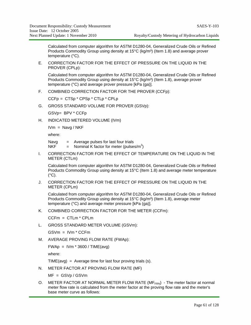
Document Responsibility: Custody Measurement SAES-Y-103 Issue Date: 12 October 2005 Next Planned Update: 1 November 2010 Royalty/Custody Metering of Hydrocarbon Liquids
Page 61 of 128
Calculated from computer algorithm for ASTM D1280-04, Generalized Crude Oils or Refined Products Commodity Group using density at 15°C (kg/m³) (Item 1.8) and average prover temperature (°C).
E. CORRECTION FACTOR FOR THE EFFECT OF PRESSURE ON THE LIQUID IN THE PROVER (CPLp):
Calculated from computer algorithm for ASTM D1280-04, Generalized Crude Oils or Refined Products Commodity Group using density at 15°C (kg/m³) (Item 1.8), average prover temperature (°C) and average prover pressure [kPa (ga)].
F. COMBINED CORRECTION FACTOR FOR THE PROVER (CCFp):
CCFp = CTSp * CPSp * CTLp * CPLp
G. GROSS STANDARD VOLUME FOR PROVER (GSVp):
GSVp = BPV * CCFp
H. INDICATED METERED VOLUME (IVm)
IVm = Navg / NKF
where:
Navg = Average pulses for last four trials NKF = Nominal K factor for meter (pulses/m3)
I. CORRECTION FACTOR FOR THE EFFECT OF TEMPERATURE ON THE LIQUID IN THE METER (CTLm)
Calculated from computer algorithm for ASTM D1280-04, Generalized Crude Oils or Refined Products Commodity Group using density at 15°C (Item 1.8) and average meter temperature (°C).
J. CORRECTION FACTOR FOR THE EFFECT OF PRESSURE ON THE LIQUID IN THE METER (CPLm)
Calculated from computer algorithm for ASTM D1280-04, Generalized Crude Oils or Refined Products Commodity Group using density at 15°C (kg/m³) (Item 1.8), average meter temperature (°C) and average meter pressure [kPa (ga)].
K. COMBINED CORRECTION FACTOR FOR THE METER (CCFm):
CCFm = CTLm * CPLm
L. GROSS STANDARD METER VOLUME (GSVm):
GSVm = IVm * CCFm
M. AVERAGE PROVING FLOW RATE (FWAp):
FWAp = IVm * 3600 / TIME(avg)
where:
TIME(avg) = Average time for last four proving trials (s).
N. METER FACTOR AT PROVING FLOW RATE (MF)
MF = GSVp / GSVm
O. METER FACTOR AT NORMAL METER FLOW RATE (MFFRN) - The meter factor at normal meter flow rate is calculated from the meter factor at the proving flow rate and the meter's base meter curve as follows:
Document Responsibility: Custody Measurement SAES-Y-103 Issue Date: 12 October 2005 Next Planned Update: 1 November 2010 Royalty/Custody Metering of Hydrocarbon Liquids
Page 62 of 128
MFFRN = MF + MFBFRN - MFB
where:
MF = Meter factor at proving flow rate from Item N MFBFRN = Meter factor at normal meter flow rate interpolated from the meter's base
calibration curve. MFB = Meter factor at proving flow rate interpolated from the meter's base
calibration curve.
METER FACTOR TEST RESULTS - The results from meter factor control Tests 1 and 2. See Attachment 2, Meter Factor Control Procedure.
4 HISTORICAL DATA
4.1 NORMAL METER FLOW RATE - The normal meter flow rate is used to permit an evaluation of meter performance over the life of the meter. The normal meter flow rate is selected by P&CSD/PID/CMU & Operations, and is entered in the flow computer at initialization.
4.2 INITIAL BASE METER FACTOR - The meter factor at the normal meter flow rate that is determined from the meter's initial base curve. Factor is entered in the flow computer at initialization.
4.3 HISTORICAL FACTORS AND ASSOCIATED DATA: - Meter factors at normal meter flow rate from the previous 10 valid provings for the specific product, the corresponding dates, and deviations from Test 1 shall be listed with the oldest as No. 1 and newest as No. 10. Factors in this list shall be discarded on a first-in, first-out (FIFO) basis.

Document Responsibility: Custody Measurement SAES-Y-103 Issue Date: 12 October 2005 Next Planned Update: 1 November 2010 Royalty/Custody Metering of Hydrocarbon Liquids
Page 63 of 128
# Attachment 1B: Proving Report for Bi-Directional & Uni-Directional Sphere Provers #Refined Products, Naphtha & Lube Oils(USC Units)
PROVING REPORT SAUDI ARABIAN OIL COMPANY (Saudi Aramco)
REPORT NUMBER XXXXXX ( ) OFFICIAL ( ) UNOFFICIAL ( ) ABORTED
LOCATION: AAAAAAAA DATE/TIME: MM/DD/YY HH:MM METER MANUFACTURER: AAAAAAAA PROVER MANUFACTURER: AAAAAAAA METER MODEL: AAAAAAAA PROVER SERIAL NUMBER: XXXXX METER SERIAL NUMBER: AAAAAAAA PROVER BASE VOLUME (bbl): 6 OR 7 DIGITS METER SIZE (in): XX.XXX PROVER OUTSIDE DIAMETER(in): XXX.XXX NOMINAL K FACTOR: 5 DIGITS PROVER WALL THICKNESS (in): X.XXX METER TAG NUMBER: AAAAAAAA PROVER MATERIAL: AAAAAAAA COEF. OF CUBICAL EXPANSION (1/°F): 0.0000XXX PRIMARY FLOW COMPUTER: AAAAAAAA MODULUS OF ELASTICITY (psi): XX,XXX,XXX LIQUID: AAAAAAAAAA OBSERVED DENSITY XXX.X deg API AT XXX.X°F = XXX.X deg API AT 60°F
TRIAL PULSES TOTAL PRESS (psig) TEMP (°F) TRIAL M.F. L-R R-L TOTAL TIME(s) PROVER METER PROVER METER MFt
1 XXXXX.0 XXXXX.0 XXXXX.0 XXX.X XXX.0 XXX.0 XXX.X XXX.X X.XXXX 2 XXXXX.0 XXXXX.0 XXXXX.0 XXX.X XXX.0 XXX.0 XXX.X XXX.X X.XXXX 3 XXXXX.0 XXXXX.0 XXXXX.0 XXX.X XXX.0 XXX.0 XXX.X XXX.X X.XXXX 4 XXXXX.0 XXXXX.0 XXXXX.0 XXX.X XXX.0 XXX.0 XXX.X XXX.X X.XXXX
10 XXXXX.0 XXXXX.0 XXXXX.0 XXX.X XXX.0 XXX.0 XXX.X XXX.X X.XXXX AVG OF LAST 4 TRIALS XXXXX.X XXX.X XXX.0 XXX.0 XXX.X XXX.X X.XXXX
REPEATABILITY FOR LAST 4 TRIALS = X.XXX% A. BASE PROVER VOLUME AT 60° F & 14.696 psia (BPV) 6 OR 7 DIGITS bbl B. TEMP. CORRECTION FACTOR FOR STEEL OF PROVER (CTSp) X.XXXXX C. PRESS. CORRECTION FACTOR FOR STEEL OF PROVER (CPSp) X.XXXXX D. TEMP. CORRECTION. FACTOR FOR LIQUID IN PROVER (CTLp) X.XXXXX E. PRESS. CORRECTION FACTOR FOR LIQUID IN PROVER (CPLp) X.XXXXX F. COMBINED CORRECTION FACTOR FOR PROVER (CCFp) X.XXXXX G. GROSS STANDARD VOLUME FOR PROVER (GSVp) 6 OR 7 DIGITS bbl H. INDICATED METER VOLUME (IVm) 6 OR 7 DIGITS bbl I. TEMP. CORRECTION FACTOR FOR LIQUID IN METER (CTLm) X.XXXXX J. PRESS. COR. FACTOR FOR LIQUID IN METER (CPLm) X.XXXXX K. COMBINED CORRECTION FACTOR FOR METER (CCFm) X.XXXXX L. GROSS STANDARD VOLUME FOR METER (GSVm) 6 OR 7 DIGITS bbl M. AVG. METER FLOW RATE XXXXX.X bbl/h N. METER FACTOR @ PROVING FLOW RATE X.XXXX 0. METER FACTOR @ NORMAL METER FLOW RATE OF XXXXX.X bbl/h X.XXXX METER FACTOR TEST RESULTS (%): 1) X.XX 2) X.XX HISTORICAL DATA OF METER FACTORS @ NORMAL METER FLOW RATE OF XXXXX.X bbl/h INITIAL BASE METER FACTOR (DATE: MM/DD/YY) = X.XXXX DATE: MM/DD/YY MM/DD/YY MM/DD/YY MM/DD/YY MM/DD/YY FACTOR: X.XXXX X.XXXX X.XXXX X.XXXX X.XXXX DEVIATION(+): X.XX% X.XX% X.XX% X.XX% X.XX% DATE: MM/DD/YY MM/DD/YY MM/DD/YY MM/DD/YY MM/DD/YY FACTOR: X.XXXX X.XXXX X.XXXX X.XXXX X.XXXX DEVIATION(+): X.XX% X.XX% X.XX% X.XX% X.XX% PROVED FOR SAUDI ARAMCO BY: ______________________________________ DATE: _________________ WITNESSED BY: ______________________________________________________ DATE: _______________
Document Responsibility: Custody Measurement SAES-Y-103 Issue Date: 12 October 2005 Next Planned Update: 1 November 2010 Royalty/Custody Metering of Hydrocarbon Liquids
Page 64 of 128
EXPLANATION OF METER PROVING REPORT
1 GENERAL INFORMATION
NOTES: "AAAAAA" - Computer generated alpha-numeric values. "XXX.XX" - Computer generated numeric values.
1.1 METER PROVING REPORT NUMBER - Unique number generated by the metering supervisory computer or flow computer. Numbers are consecutively generated beginning with the first proving for the system.
1.2 OFFICIAL - The report is automatically marked "(X) OFFICIAL" if the operator designates a normal proving when initiating the proving operation, and the meter factor at the normal flow rate is determined to be valid.
1.3 UNOFFICIAL - The report is marked "(X) UNOFFICIAL" if the operator designates such when initiating the proving operation. Such provings are normally initiated during maintenance activities. The results are not incorporated in the metering supervisory or flow computer data base and not used in any volume calculations.
1.4 ABORTED - Report is marked "(X) ABORTED" if the operator manually aborts the proving, the prover sphere (piston) activates the first displacer switch prior to obtaining a 4-way valve or interhcange seal, repeatability for the last four of ten trials is greater than 0.05%, or the meter factor at the normal flow rate does not meet the criteria for Test 1 or 2.
An abbreviated proving report shall automatically be generated showing all proving data used in calculating the trial meter factors whenever a proof is aborted.
1.5 LOCATION; METER MANUFACTURER, SIZE , MODEL, & TAG NUMBER; PROVER MANUFACTURER –Fixed values entered in the metering system computer or flow computer during initialization.
METER SERIAL NO. & NOMINAL K FACTOR; PROVER SERIAL NO., BASE VOLUME, OUTSIDE DIAMETER, WALL THICKNESS, MATERIAL, CUBICAL COEFFICIENT OF EXPANSION, & MODULUS OF ELASTICITY – Fixed values entered in the flow computer during initialization.
PRIMARY FLOW COMPUTER – Alpha-numeric tag number from the flow computer performing the proving calculations.
1.6 LIQUID - Operator entry.
1.7 OBSERVED DENSITY, OBSERVED TEMPERATURE - Data from the density meter and density temperature transmitter, or data from density test which is entered manually by operator.
1.8 DENSITY AT 60°F - Calculated from computer algorithm for ASTM D1250-04, Generalized Crude Oils, Refined Products or Lubricating Oils Commodity Group using observed density (deg API) and observed temperature of density sample (°F).
2 PROVING DATA
2.1 PULSES, TEMPERATURES AND PRESSURES - Data logged from field instrumentation during proving.
2.2 TIME - Time required for left-to-right and right-to-left passes of sphere.
2.3 METER FACTOR (TRIAL) (MFt) - Calculated as shown in Steps A through L of Item 3 below using the pulses, pressure and temperature data recorded for each trial.
Document Responsibility: Custody Measurement SAES-Y-103 Issue Date: 12 October 2005 Next Planned Update: 1 November 2010 Royalty/Custody Metering of Hydrocarbon Liquids
Page 65 of 128
2.4 REPEATABILITY:
(Max MFt - Min MFt) * 100 / Min MFt
where:
Max MFt = Maximum meter factor from the last four trials. Min MFt = Minimum meter factor from the last four trials.
3 METER FACTOR CALCULATION
The meter factor at the proving flow rate and the meter factor at the normal meter flow rate are computed in accordance with API MPMS Chapter 12, using average pulses, temperatures and pressures, etc., for the last four trials:
A. BASE PROVER VOLUME (BPV) - Six or seven digit volume entered in the flow computer during initialization. See Item 1.5.
B. CORRECTION FACTOR FOR THE EFFECT OF TEMPERATURE ON THE PROVER STEEL (CTSp):
CTSp = 1 + [ (Tp (avg) - Tb) * Gc]
where
Tp (avg) = Average prover temperature (°F) Tb = Base Temperature = 60.0°F Gc = Coefficient of cubical expansion of the prover material (1/°F) = 0.0000186/°F for mild carbon steel = 0.0000288/°F for 304 stainless steel = 0.0000265/°F for 316 stainless steel = 0.0000180/°F for 17-4 stainless steel
C. CORRECTION FACTOR FOR THE EFFECT OF PRESSURE ON THE PROVER STEEL (CPSp):
CPSp = 1 + [(Pp (avg) * ID) / (E * WT)]
where :
Pp (avg) = Average prover pressure (psig) ID = Internal prover diameter (in) = OD - (2*WT) E = Modulus of elasticity for prover material (psi) = 3.00*107/ psi for mild carbon steel) = 2.80*107/ psi for 304 stainless steel = 2.80*107/ psi for 316 stainless steel = 2.85*107/ psi for 17-4 stainless steel OD = Outside diameter of prover (in) WT = Prover wall thickness (in)
D. CORRECTION FACTOR FOR THE EFFECT OF TEMPERATURE ON THE LIQUID IN THE PROVER (CTLp):
Calculated from computer algorithm for ASTM D1250-04, Generalized Crude Oils, Refined Products or Lubricating Oils Commodity Group using density at 60°F (deg API) (Item 1.8) and average prover temperature (°F).

Document Responsibility: Custody Measurement SAES-Y-103 Issue Date: 12 October 2005 Next Planned Update: 1 November 2010 Royalty/Custody Metering of Hydrocarbon Liquids
Page 66 of 128
E. CORRECTION FACTOR FOR THE EFFECT OF PRESSURE ON THE LIQUID IN THE PROVER (CPLp):
Calculated from computer algorithm for ASTM D1280-04, Generalized Crude Oils, Refined Products or Lubricating Oils Commodity Group using density at 60°F (deg API) (Item 1.8), average prover temperature (°F) and average prover pressure (psig).
F. COMBINED CORRECTION FACTOR FOR THE PROVER (CCFp):
CCFp = CTSp * CPSp * CTLp * CPLp
G. GROSS STANDARD VOLUME FOR PROVER (GSVp):
GSVp = BPV * CCFp
H. INDICATED METERED VOLUME (IVm)
IVm = Navg / NKF
where:
Navg = Average pulses for last four trials NKF = Nominal K factor for meter (pulses/bbl)
I. CORRECTION FACTOR FOR THE EFFECT OF TEMPERATURE ON THE LIQUID IN THE METER (CTLm)
Calculated from computer algorithm for ASTM D1250-04, Generalized Crude Oils, Refined Products or Lubricating Oils Commodity Group using density at 60°F (deg API) (Item 1.8) and average meter temperature (°F).
J. CORRECTION FACTOR FOR THE EFFECT OF PRESSURE ON THE LIQUID IN THE METER (CPLm)
Calculated from computer algorithm for ASTM D1280-04, Generalized Crude Oils, Refined Products or Lubricating Oils Commodity Group using density at 60°F (deg API) (Item 1.8), average meter temperature (°F) and average meter pressure (psig)..
K. COMBINED CORRECTION FACTOR FOR THE METER (CCFm):
CCFm = CTLm * CPLm
L. GROSS STANDARD METER VOLUME (GSVm):
GSVm = IVm * CCFm
M. AVERAGE PROVING FLOW RATE (FWAp):
FWAp = IVm * 3600 / TIME(avg)
where:
TIME(avg) = Average time for last four proving trials (s).
N. METER FACTOR AT PROVING FLOW RATE (MF)
MF = GSVp / GSVm
O. METER FACTOR AT NORMAL METER FLOW RATE (MFFRN) - The meter factor at normal meter flow rate is calculated from the meter factor at the proving flow rate and the meter's base meter curve as follows:
MFFRN = MF + MFBFRN - MFB
Document Responsibility: Custody Measurement SAES-Y-103 Issue Date: 12 October 2005 Next Planned Update: 1 November 2010 Royalty/Custody Metering of Hydrocarbon Liquids
Page 67 of 128
where:
MF = Meter factor at proving flow rate from Item N MFBFRN = Meter factor at normal meter flow rate interpolated from the meter's base calibration curve. MFB = Meter factor at proving flow rate interpolated from the meter's base
calibration curve.
METER FACTOR TEST RESULTS: - The results from meter factor control Tests 1 and 2. See Attachment 2, Meter Factor Control Procedure.
4 HISTORICAL DATA
4.1 NORMAL METER FLOW RATE - The normal meter flow rate is used to permit an evaluation of meter performance over the life of the meter. The normal meter flow rate is selected by CSD/ESD/CMU & Operations, and is entered in the flow computer at initialization.
4.2 INITIAL BASE METER FACTOR - The meter factor at the normal meter flow rate that is determined from the meter's initial base curve. Factor is entered in the flow computer at initialization.
4.3 HISTORICAL FACTORS AND ASSOCIATED DATA: - Meter factors at normal meter flow rate from the previous 10 valid provings for the specific product, the corresponding dates, and deviations from Test 1 shall be listed with the oldest as No. 1 and newest as No. 10. Factors in this list shall be discarded on a first-in, first-out (FIFO) basis.
Document Responsibility: Custody Measurement SAES-Y-103 Issue Date: 12 October 2005 Next Planned Update: 1 November 2010 Royalty/Custody Metering of Hydrocarbon Liquids
Page 68 of 128
# Attachment 1C: Proving Report for Bi-Directional & Uni-Directional Sphere Provers #Crude Oil (USC Units)
PROVING REPORT SAUDI ARABIAN OIL COMPANY (Saudi Aramco)
REPORT NUMBER XXXXXX ( ) OFFICIAL ( ) UNOFFICIAL ( ) ABORTED
LOCATION: AAAAAAAA DATE/TIME: MM/DD/YY HH:MM METER MANUFACTURER: AAAAAAAA PROVER MANUFACTURER: AAAAAAAA METER MODEL: AAAAAAAA PROVER SERIAL NUMBER: XXXXX METER SERIAL NUMBER: AAAAAAAA PROVER BASE VOLUME (bbl): 6 OR 7 DIGITS METER SIZE (in): XX.XXX PROVER OUTSIDE DIAMETER(in): XXX.XXX NOMINAL K FACTOR: 5 DIGITS PROVER WALL THICKNESS (in): X.XXX METER TAG NUMBER: AAAAAAAA PROVER MATERIAL: AAAAAAAA COEF. OF CUBICAL EXPANSION (1/°F): 0.0000XXX PRIMARY FLOW COMPUTER: AAAAAAAA MODULUS OF ELASTICITY (psi): XX,XXX,XXX LIQUID: AAAAAAAAAA OBSERVED DENSITY XXX.X deg API AT XXX.X°F = XXX.X deg API AT 60°F
TRIAL PULSES TOTAL PRESS (psig) TEMP (°F) TRIAL M.F. L-R R-L TOTAL TIME(s) PROVER METER PROVER METER MFt
1 XXXXX.0 XXXXX.0 XXXXX.0 XXX.X XXX.0 XXX.0 XXX.X XXX.X X.XXXX 2 XXXXX.0 XXXXX.0 XXXXX.0 XXX.X XXX.0 XXX.0 XXX.X XXX.X X.XXXX 3 XXXXX.0 XXXXX.0 XXXXX.0 XXX.X XXX.0 XXX.0 XXX.X XXX.X X.XXXX 4 XXXXX.0 XXXXX.0 XXXXX.0 XXX.X XXX.0 XXX.0 XXX.X XXX.X X.XXXX
10 XXXXX.0 XXXXX.0 XXXXX.0 XXX.X XXX.0 XXX.0 XXX.X XXX.X X.XXXX AVG OF LAST 4 TRIALS XXXXX.X XXX.X XXX.0 XXX.0 XXX.X XXX.X X.XXXX
REPEATABILITY FOR LAST 4 TRIALS = X.XXX% A. BASE PROVER VOLUME AT 60°F & 14.696 psia (BPV) 6 OR 7 DIGITS bbl B. TEMP. CORRECTION FACTOR FOR STEEL OF PROVER (CTSp) X.XXXXX C. PRESS. CORRECTION FACTOR FOR STEEL OF PROVER (CPSp) X.XXXXX D. TEMP. CORRECTION. FACTOR FOR LIQUID IN PROVER (CTLp) X.XXXXX E. PRESS. CORRECTION FACTOR FOR LIQUID IN PROVER (CPLp) X.XXXXX F. COMBINED CORRECTION FACTOR FOR PROVER (CCFp) X.XXXXX G. GROSS STANDARD VOLUME FOR PROVER (GSVp) 6 OR 7 DIGITS bbl H. INDICATED METER VOLUME (IVm) 6 OR 7 DIGITS bbl I. TEMP. CORRECTION FACTOR FOR LIQUID IN METER (CTLm) X.XXXXX J. PRESS. COR. FACTOR FOR LIQUID IN METER (CPLm) X.XXXXX K. COMBINED CORRECTION FACTOR FOR METER (CCFm) X.XXXXX L. GROSS STANDARD VOLUME FOR METER (GSVm) 6 OR 7 DIGITS bbl M. AVG. METER FLOW RATE XXXXX.X bbl/h N. METER FACTOR @ PROVING FLOW RATE X.XXXX 0. METER FACTOR @ NORMAL METER FLOW RATE OF XXXXX.X bbl/h X.XXXX METER FACTOR TEST RESULTS (%): 1) X.XX 2) X.XX HISTORICAL DATA OF METER FACTORS @ NORMAL METER FLOW RATE OF XXXXX.X bbl/h INITIAL BASE METER FACTOR (DATE: MM/DD/YY) = X.XXXX DATE: MM/DD/YY MM/DD/YY MM/DD/YY MM/DD/YY MM/DD/YY FACTOR: X.XXXX X.XXXX X.XXXX X.XXXX X.XXXX DEVIATION(±): X.XX% X.XX% X.XX% X.XX% X.XX% DATE: MM/DD/YY MM/DD/YY MM/DD/YY MM/DD/YY MM/DD/YY FACTOR: X.XXXX X.XXXX X.XXXX X.XXXX X.XXXX DEVIATION(±): X.XX% X.XX% X.XX% X.XX% X.XX% PROVED FOR SAUDI ARAMCO BY: _______________________________________ DATE: _______________ WITNESSED BY: _______________________________________________________ DATE: _______________
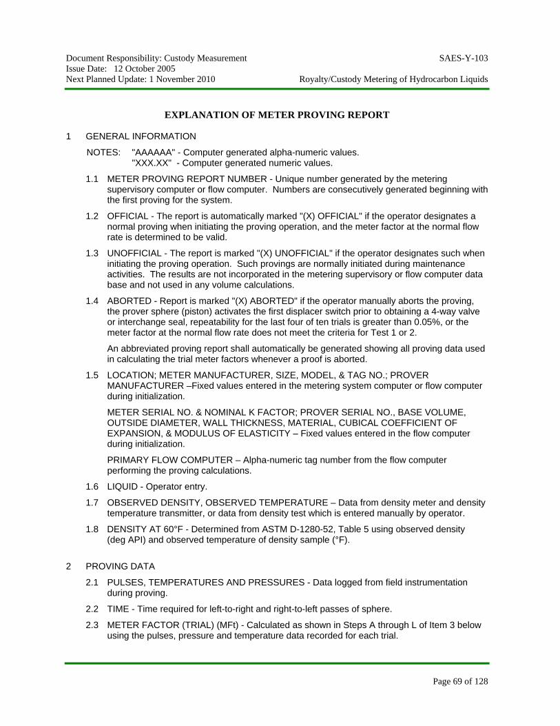
Document Responsibility: Custody Measurement SAES-Y-103 Issue Date: 12 October 2005 Next Planned Update: 1 November 2010 Royalty/Custody Metering of Hydrocarbon Liquids
Page 69 of 128
EXPLANATION OF METER PROVING REPORT
1 GENERAL INFORMATION
NOTES: "AAAAAA" - Computer generated alpha-numeric values. "XXX.XX" - Computer generated numeric values.
1.1 METER PROVING REPORT NUMBER - Unique number generated by the metering supervisory computer or flow computer. Numbers are consecutively generated beginning with the first proving for the system.
1.2 OFFICIAL - The report is automatically marked "(X) OFFICIAL" if the operator designates a normal proving when initiating the proving operation, and the meter factor at the normal flow rate is determined to be valid.
1.3 UNOFFICIAL - The report is marked "(X) UNOFFICIAL" if the operator designates such when initiating the proving operation. Such provings are normally initiated during maintenance activities. The results are not incorporated in the metering supervisory or flow computer data base and not used in any volume calculations.
1.4 ABORTED - Report is marked "(X) ABORTED" if the operator manually aborts the proving, the prover sphere (piston) activates the first displacer switch prior to obtaining a 4-way valve or interchange seal, repeatability for the last four of ten trials is greater than 0.05%, or the meter factor at the normal flow rate does not meet the criteria for Test 1 or 2.
An abbreviated proving report shall automatically be generated showing all proving data used in calculating the trial meter factors whenever a proof is aborted.
1.5 LOCATION; METER MANUFACTURER, SIZE, MODEL, & TAG NO.; PROVER MANUFACTURER –Fixed values entered in the metering system computer or flow computer during initialization.
METER SERIAL NO. & NOMINAL K FACTOR; PROVER SERIAL NO., BASE VOLUME, OUTSIDE DIAMETER, WALL THICKNESS, MATERIAL, CUBICAL COEFFICIENT OF EXPANSION, & MODULUS OF ELASTICITY – Fixed values entered in the flow computer during initialization.
PRIMARY FLOW COMPUTER – Alpha-numeric tag number from the flow computer performing the proving calculations.
1.6 LIQUID - Operator entry.
1.7 OBSERVED DENSITY, OBSERVED TEMPERATURE – Data from density meter and density temperature transmitter, or data from density test which is entered manually by operator.
1.8 DENSITY AT 60°F - Determined from ASTM D-1280-52, Table 5 using observed density (deg API) and observed temperature of density sample (°F).
2 PROVING DATA
2.1 PULSES, TEMPERATURES AND PRESSURES - Data logged from field instrumentation during proving.
2.2 TIME - Time required for left-to-right and right-to-left passes of sphere.
2.3 METER FACTOR (TRIAL) (MFt) - Calculated as shown in Steps A through L of Item 3 below using the pulses, pressure and temperature data recorded for each trial.
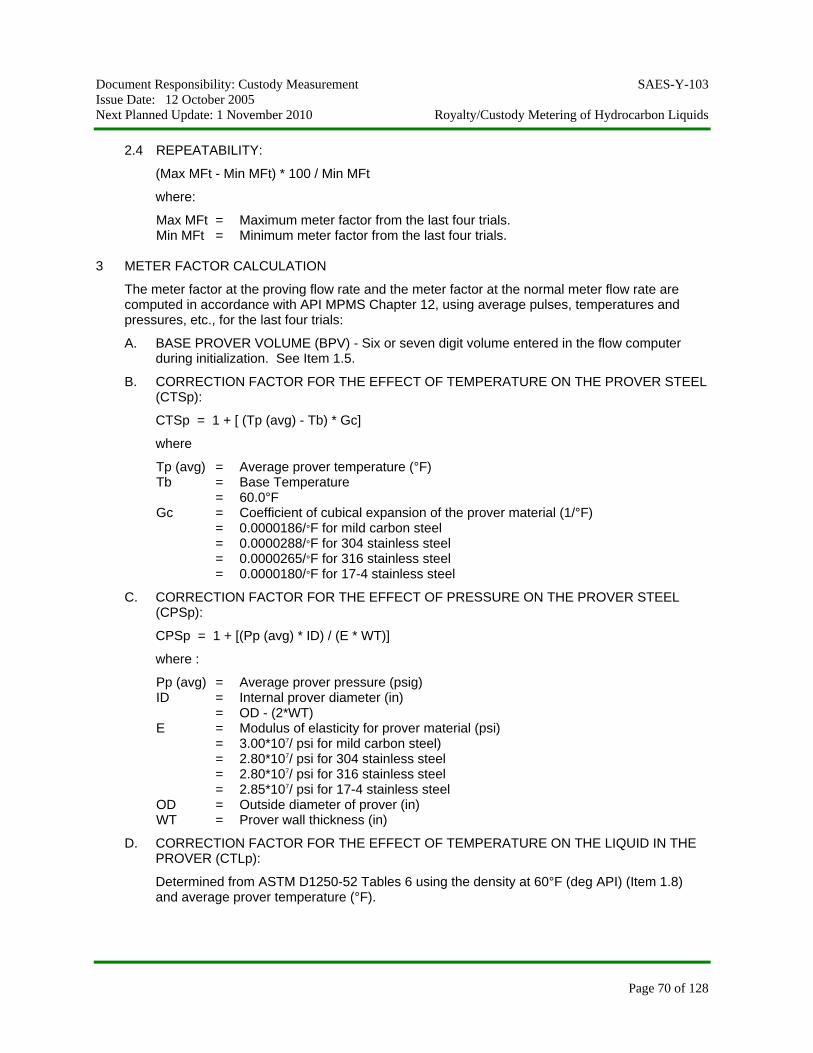
Document Responsibility: Custody Measurement SAES-Y-103 Issue Date: 12 October 2005 Next Planned Update: 1 November 2010 Royalty/Custody Metering of Hydrocarbon Liquids
Page 70 of 128
2.4 REPEATABILITY:
(Max MFt - Min MFt) * 100 / Min MFt
where:
Max MFt = Maximum meter factor from the last four trials. Min MFt = Minimum meter factor from the last four trials.
3 METER FACTOR CALCULATION
The meter factor at the proving flow rate and the meter factor at the normal meter flow rate are computed in accordance with API MPMS Chapter 12, using average pulses, temperatures and pressures, etc., for the last four trials:
A. BASE PROVER VOLUME (BPV) - Six or seven digit volume entered in the flow computer during initialization. See Item 1.5.
B. CORRECTION FACTOR FOR THE EFFECT OF TEMPERATURE ON THE PROVER STEEL (CTSp):
CTSp = 1 + [ (Tp (avg) - Tb) * Gc]
where
Tp (avg) = Average prover temperature (°F) Tb = Base Temperature = 60.0°F Gc = Coefficient of cubical expansion of the prover material (1/°F) = 0.0000186/°F for mild carbon steel = 0.0000288/°F for 304 stainless steel = 0.0000265/°F for 316 stainless steel = 0.0000180/°F for 17-4 stainless steel
C. CORRECTION FACTOR FOR THE EFFECT OF PRESSURE ON THE PROVER STEEL (CPSp):
CPSp = 1 + [(Pp (avg) * ID) / (E * WT)]
where :
Pp (avg) = Average prover pressure (psig) ID = Internal prover diameter (in) = OD - (2*WT) E = Modulus of elasticity for prover material (psi) = 3.00*107/ psi for mild carbon steel) = 2.80*107/ psi for 304 stainless steel = 2.80*107/ psi for 316 stainless steel = 2.85*107/ psi for 17-4 stainless steel OD = Outside diameter of prover (in) WT = Prover wall thickness (in)
D. CORRECTION FACTOR FOR THE EFFECT OF TEMPERATURE ON THE LIQUID IN THE PROVER (CTLp):
Determined from ASTM D1250-52 Tables 6 using the density at 60°F (deg API) (Item 1.8) and average prover temperature (°F).

Document Responsibility: Custody Measurement SAES-Y-103 Issue Date: 12 October 2005 Next Planned Update: 1 November 2010 Royalty/Custody Metering of Hydrocarbon Liquids
Page 71 of 128
E. CORRECTION FACTOR FOR THE EFFECT OF PRESSURE ON THE LIQUID IN THE PROVER (CPLp):
Calculated from computer algorithm for ASTM D1280-04, Generalized Crude Oils Commodity Group using density at 60°F (deg API) (Item 1.8), average prover temperature (°F) and average prover pressure (psig).
F. COMBINED CORRECTION FACTOR FOR THE PROVER (CCFp):
CCFp = CTSp * CPSp * CTLp * CPLp
G. GROSS STANDARD VOLUME FOR PROVER (GSVp):
GSVp = BPV * CCFp
H. INDICATED METERED VOLUME (IVm)
IVm = Navg / NKF
where:
Navg = Average pulses for last four trials NKF = Nominal K factor for meter (pulses/bbl)
I. CORRECTION FACTOR FOR THE EFFECT OF TEMPERATURE ON THE LIQUID IN THE METER (CTLm)
Determined from ASTM D1250-52 Table 6 using density at 60°F (deg API) (Item 1.8) and average meter temperature (°F).
J. CORRECTION FACTOR FOR THE EFFECT OF PRESSURE ON THE LIQUID IN THE METER (CPLm)
Calculated from computer algorithm for ASTM D1280-04, Generalized Crude Oils Commodity Group using density at 60°F (deg API) (Item 1.8), average meter temperature (°F) and average meter pressure (psig).
K. COMBINED CORRECTION FACTOR FOR THE METER (CCFm):
CCFm = CTLm * CPLm
L. GROSS STANDARD METER VOLUME (GSVm):
GSVm = IVm * CCFm
M. AVERAGE PROVING FLOW RATE (FWAp):
FWAp = IVm * 3600 / TIME(avg)
where:
TIME(avg) = Average time for last four proving trials (s).
N. METER FACTOR AT PROVING FLOW RATE (MF)
MF = GSVp / GSVm
O. METER FACTOR AT NORMAL METER FLOW RATE (MFFRN) - The meter factor at normal meter flow rate is calculated from the meter factor at the proving flow rate and the meter's base meter curve as follows:
MFFRN = MF + MFBFRN - MFB
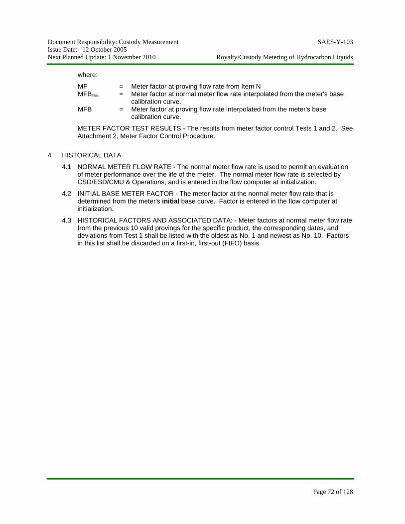
Document Responsibility: Custody Measurement SAES-Y-103 Issue Date: 12 October 2005 Next Planned Update: 1 November 2010 Royalty/Custody Metering of Hydrocarbon Liquids
Page 72 of 128
where:
MF = Meter factor at proving flow rate from Item N MFBFRN = Meter factor at normal meter flow rate interpolated from the meter's base calibration curve. MFB = Meter factor at proving flow rate interpolated from the meter's base
calibration curve.
METER FACTOR TEST RESULTS - The results from meter factor control Tests 1 and 2. See Attachment 2, Meter Factor Control Procedure.
4 HISTORICAL DATA
4.1 NORMAL METER FLOW RATE - The normal meter flow rate is used to permit an evaluation of meter performance over the life of the meter. The normal meter flow rate is selected by CSD/ESD/CMU & Operations, and is entered in the flow computer at initialization.
4.2 INITIAL BASE METER FACTOR - The meter factor at the normal meter flow rate that is determined from the meter's initial base curve. Factor is entered in the flow computer at initialization.
4.3 HISTORICAL FACTORS AND ASSOCIATED DATA: - Meter factors at normal meter flow rate from the previous 10 valid provings for the specific product, the corresponding dates, and deviations from Test 1 shall be listed with the oldest as No. 1 and newest as No. 10. Factors in this list shall be discarded on a first-in, first-out (FIFO) basis.
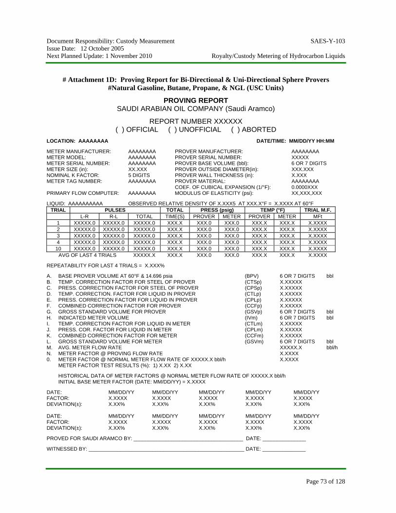
Document Responsibility: Custody Measurement SAES-Y-103 Issue Date: 12 October 2005 Next Planned Update: 1 November 2010 Royalty/Custody Metering of Hydrocarbon Liquids
Page 73 of 128
# Attachment 1D: Proving Report for Bi-Directional & Uni-Directional Sphere Provers
#Natural Gasoline, Butane, Propane, & NGL (USC Units)
PROVING REPORT SAUDI ARABIAN OIL COMPANY (Saudi Aramco)
REPORT NUMBER XXXXXX ( ) OFFICIAL ( ) UNOFFICIAL ( ) ABORTED
LOCATION: AAAAAAAA DATE/TIME: MM/DD/YY HH:MM METER MANUFACTURER: AAAAAAAA PROVER MANUFACTURER: AAAAAAAA METER MODEL: AAAAAAAA PROVER SERIAL NUMBER: XXXXX METER SERIAL NUMBER: AAAAAAAA PROVER BASE VOLUME (bbl): 6 OR 7 DIGITS METER SIZE (in): XX.XXX PROVER OUTSIDE DIAMETER(in): XXX.XXX NOMINAL K FACTOR: 5 DIGITS PROVER WALL THICKNESS (in): X.XXX METER TAG NUMBER: AAAAAAAA PROVER MATERIAL: AAAAAAAA COEF. OF CUBICAL EXPANSION (1/°F): 0.0000XXX PRIMARY FLOW COMPUTER: AAAAAAAA MODULUS OF ELASTICITY (psi): XX,XXX,XXX LIQUID: AAAAAAAAAA OBSERVED RELATIVE DENSITY OF X.XXX5 AT XXX.X°F = X.XXXX AT 60°F
TRIAL PULSES TOTAL PRESS (psig) TEMP (°F) TRIAL M.F. L-R R-L TOTAL TIME(S) PROVER METER PROVER METER MFt
1 XXXXX.0 XXXXX.0 XXXXX.0 XXX.X XXX.0 XXX.0 XXX.X XXX.X X.XXXX 2 XXXXX.0 XXXXX.0 XXXXX.0 XXX.X XXX.0 XXX.0 XXX.X XXX.X X.XXXX 3 XXXXX.0 XXXXX.0 XXXXX.0 XXX.X XXX.0 XXX.0 XXX.X XXX.X X.XXXX 4 XXXXX.0 XXXXX.0 XXXXX.0 XXX.X XXX.0 XXX.0 XXX.X XXX.X X.XXXX
10 XXXXX.0 XXXXX.0 XXXXX.0 XXX.X XXX.0 XXX.0 XXX.X XXX.X X.XXXX AVG OF LAST 4 TRIALS XXXXX.X XXX.X XXX.0 XXX.0 XXX.X XXX.X X.XXXX
REPEATABILITY FOR LAST 4 TRIALS = X.XXX% A. BASE PROVER VOLUME AT 60°F & 14.696 psia (BPV) 6 OR 7 DIGITS bbl B. TEMP. CORRECTION FACTOR FOR STEEL OF PROVER (CTSp) X.XXXXX C. PRESS. CORRECTION FACTOR FOR STEEL OF PROVER (CPSp) X.XXXXX D. TEMP. CORRECTION. FACTOR FOR LIQUID IN PROVER (CTLp) X.XXXXX E. PRESS. CORRECTION FACTOR FOR LIQUID IN PROVER (CPLp) X.XXXXX F. COMBINED CORRECTION FACTOR FOR PROVER (CCFp) X.XXXXX G. GROSS STANDARD VOLUME FOR PROVER (GSVp) 6 OR 7 DIGITS bbl H. INDICATED METER VOLUME (IVm) 6 OR 7 DIGITS bbl I. TEMP. CORRECTION FACTOR FOR LIQUID IN METER (CTLm) X.XXXXX J. PRESS. COR. FACTOR FOR LIQUID IN METER (CPLm) X.XXXXX K. COMBINED CORRECTION FACTOR FOR METER (CCFm) X.XXXXX L. GROSS STANDARD VOLUME FOR METER (GSVm) 6 OR 7 DIGITS bbl M. AVG. METER FLOW RATE XXXXX.X bbl/h N. METER FACTOR @ PROVING FLOW RATE X.XXXX 0. METER FACTOR @ NORMAL METER FLOW RATE OF XXXXX.X bbl/h X.XXXX METER FACTOR TEST RESULTS (%): 1) X.XX 2) X.XX HISTORICAL DATA OF METER FACTORS @ NORMAL METER FLOW RATE OF XXXXX.X bbl/h INITIAL BASE METER FACTOR (DATE: MM/DD/YY) = X.XXXX DATE: MM/DD/YY MM/DD/YY MM/DD/YY MM/DD/YY MM/DD/YY FACTOR: X.XXXX X.XXXX X.XXXX X.XXXX X.XXXX DEVIATION(±): X.XX% X.XX% X.XX% X.XX% X.XX% DATE: MM/DD/YY MM/DD/YY MM/DD/YY MM/DD/YY MM/DD/YY FACTOR: X.XXXX X.XXXX X.XXXX X.XXXX X.XXXX DEVIATION(±): X.XX% X.XX% X.XX% X.XX% X.XX% PROVED FOR SAUDI ARAMCO BY: ______________________________________ DATE: _______________ WITNESSED BY: ______________________________________________________ DATE: _______________
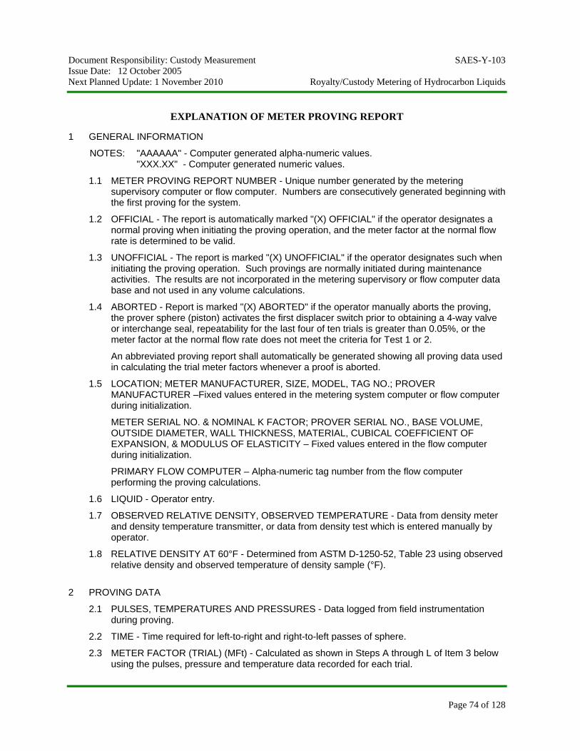
Document Responsibility: Custody Measurement SAES-Y-103 Issue Date: 12 October 2005 Next Planned Update: 1 November 2010 Royalty/Custody Metering of Hydrocarbon Liquids
Page 74 of 128
EXPLANATION OF METER PROVING REPORT
1 GENERAL INFORMATION
NOTES: "AAAAAA" - Computer generated alpha-numeric values. "XXX.XX" - Computer generated numeric values.
1.1 METER PROVING REPORT NUMBER - Unique number generated by the metering supervisory computer or flow computer. Numbers are consecutively generated beginning with the first proving for the system.
1.2 OFFICIAL - The report is automatically marked "(X) OFFICIAL" if the operator designates a normal proving when initiating the proving operation, and the meter factor at the normal flow rate is determined to be valid.
1.3 UNOFFICIAL - The report is marked "(X) UNOFFICIAL" if the operator designates such when initiating the proving operation. Such provings are normally initiated during maintenance activities. The results are not incorporated in the metering supervisory or flow computer data base and not used in any volume calculations.
1.4 ABORTED - Report is marked "(X) ABORTED" if the operator manually aborts the proving, the prover sphere (piston) activates the first displacer switch prior to obtaining a 4-way valve or interchange seal, repeatability for the last four of ten trials is greater than 0.05%, or the meter factor at the normal flow rate does not meet the criteria for Test 1 or 2.
An abbreviated proving report shall automatically be generated showing all proving data used in calculating the trial meter factors whenever a proof is aborted.
1.5 LOCATION; METER MANUFACTURER, SIZE, MODEL, TAG NO.; PROVER MANUFACTURER –Fixed values entered in the metering system computer or flow computer during initialization.
METER SERIAL NO. & NOMINAL K FACTOR; PROVER SERIAL NO., BASE VOLUME, OUTSIDE DIAMETER, WALL THICKNESS, MATERIAL, CUBICAL COEFFICIENT OF EXPANSION, & MODULUS OF ELASTICITY – Fixed values entered in the flow computer during initialization.
PRIMARY FLOW COMPUTER – Alpha-numeric tag number from the flow computer performing the proving calculations.
1.6 LIQUID - Operator entry.
1.7 OBSERVED RELATIVE DENSITY, OBSERVED TEMPERATURE - Data from density meter and density temperature transmitter, or data from density test which is entered manually by operator.
1.8 RELATIVE DENSITY AT 60°F - Determined from ASTM D-1250-52, Table 23 using observed relative density and observed temperature of density sample (°F).
2 PROVING DATA
2.1 PULSES, TEMPERATURES AND PRESSURES - Data logged from field instrumentation during proving.
2.2 TIME - Time required for left-to-right and right-to-left passes of sphere.
2.3 METER FACTOR (TRIAL) (MFt) - Calculated as shown in Steps A through L of Item 3 below using the pulses, pressure and temperature data recorded for each trial.

Document Responsibility: Custody Measurement SAES-Y-103 Issue Date: 12 October 2005 Next Planned Update: 1 November 2010 Royalty/Custody Metering of Hydrocarbon Liquids
Page 75 of 128
2.4 REPEATABILITY:
(Max MFt - Min MFt) * 100 / Min MFt
where:
Max MFt = Maximum meter factor from the last four trials. Min MFt = Minimum meter factor from the last four trials.
3 METER FACTOR CALCULATION
The meter factor at the proving flow rate and the meter factor at the normal meter flow rate are computed in accordance with API MPMS Chapter 12, using average pulses, temperatures and pressures, etc., for the last four trials:
A. BASE PROVER VOLUME (BPV) - Six or seven digit volume entered in the flow computer during initialization. See Item 1.5.
B. CORRECTION FACTOR FOR THE EFFECT OF TEMPERATURE ON THE PROVER STEEL (CTSp):
CTSp = 1 + [ (Tp (avg) - Tb) * Gc]
where
Tp (avg) = Average prover temperature (°F) Tb = Base Temperature = 60.0°F Gc = Coefficient of cubical expansion of the prover material (1/°F) = 0.0000186/°F for mild carbon steel = 0.0000288/°F for 304 stainless steel = 0.0000265/°F for 316 stainless steel = 0.0000180/°F for 17-4 stainless steel
C. CORRECTION FACTOR FOR THE EFFECT OF PRESSURE ON THE PROVER STEEL (CPSp):
CPSp = 1 + [(Pp (avg) * ID) / (E * WT)]
where :
Pp (avg) = Average prover pressure (psig) ID = Internal prover diameter (in) = OD - (2*WT) E = Modulus of elasticity for prover material (psi) = 3.00*107/ psi for mild carbon steel) = 2.80*107/ psi for 304 stainless steel = 2.80*107/ psi for 316 stainless steel = 2.85*107/ psi for 17-4 stainless steel OD = Outside diameter of prover (in) WT = Prover wall thickness (in)
D. CORRECTION FACTOR FOR THE EFFECT OF TEMPERATURE ON THE LIQUID IN THE PROVER (CTLp):
Determined from ASTM D1250-52 Tables 24 using relative density at 60°F (Item 1.8) and average prover temperature (°F).
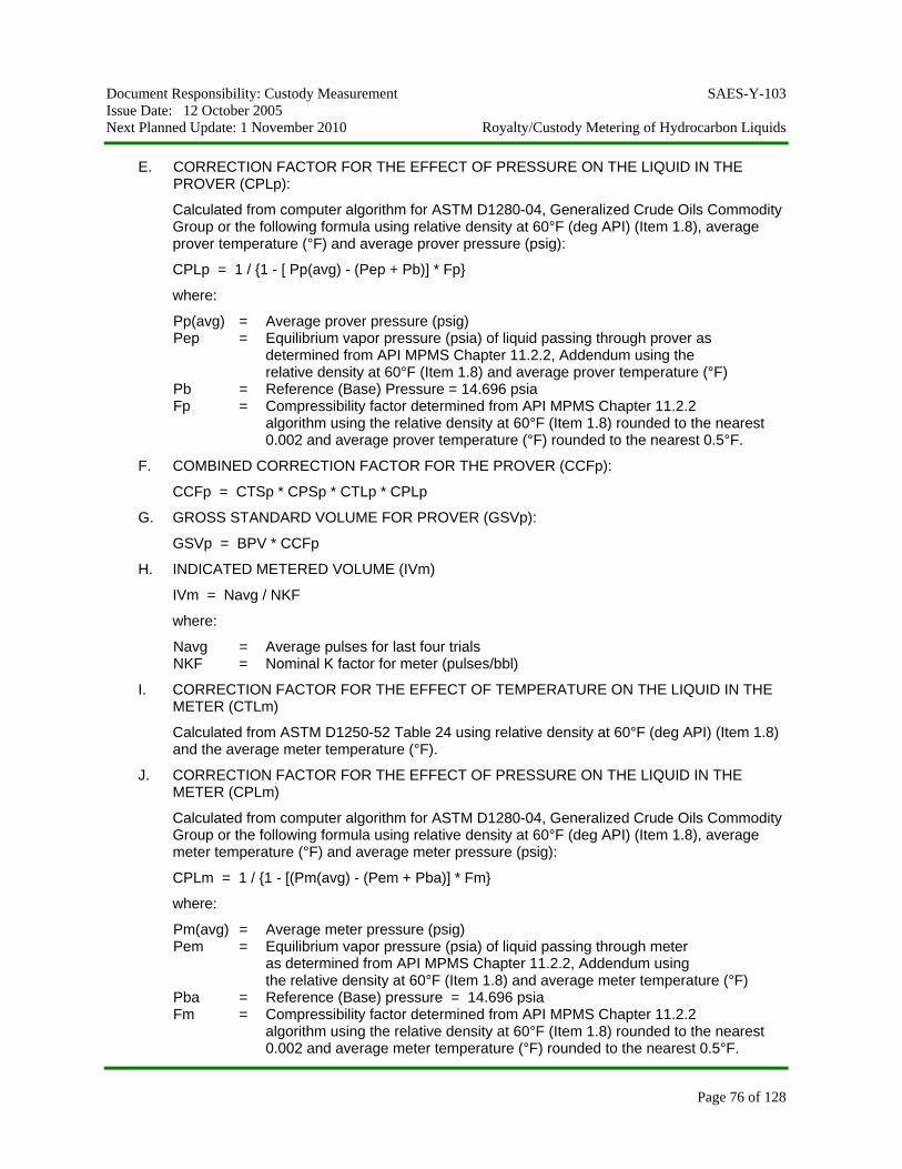
Document Responsibility: Custody Measurement SAES-Y-103 Issue Date: 12 October 2005 Next Planned Update: 1 November 2010 Royalty/Custody Metering of Hydrocarbon Liquids
Page 76 of 128
E. CORRECTION FACTOR FOR THE EFFECT OF PRESSURE ON THE LIQUID IN THE PROVER (CPLp):
Calculated from computer algorithm for ASTM D1280-04, Generalized Crude Oils Commodity Group or the following formula using relative density at 60°F (deg API) (Item 1.8), average prover temperature (°F) and average prover pressure (psig):
CPLp = 1 / {1 - [ Pp(avg) - (Pep + Pb)] * Fp}
where:
Pp(avg) = Average prover pressure (psig) Pep = Equilibrium vapor pressure (psia) of liquid passing through prover as determined from API MPMS Chapter 11.2.2, Addendum using the relative density at 60°F (Item 1.8) and average prover temperature (°F) Pb = Reference (Base) Pressure = 14.696 psia Fp = Compressibility factor determined from API MPMS Chapter 11.2.2 algorithm using the relative density at 60°F (Item 1.8) rounded to the nearest 0.002 and average prover temperature (°F) rounded to the nearest 0.5°F.
F. COMBINED CORRECTION FACTOR FOR THE PROVER (CCFp):
CCFp = CTSp * CPSp * CTLp * CPLp
G. GROSS STANDARD VOLUME FOR PROVER (GSVp):
GSVp = BPV * CCFp
H. INDICATED METERED VOLUME (IVm)
IVm = Navg / NKF
where:
Navg = Average pulses for last four trials NKF = Nominal K factor for meter (pulses/bbl)
I. CORRECTION FACTOR FOR THE EFFECT OF TEMPERATURE ON THE LIQUID IN THE METER (CTLm)
Calculated from ASTM D1250-52 Table 24 using relative density at 60°F (deg API) (Item 1.8) and the average meter temperature (°F).
J. CORRECTION FACTOR FOR THE EFFECT OF PRESSURE ON THE LIQUID IN THE METER (CPLm)
Calculated from computer algorithm for ASTM D1280-04, Generalized Crude Oils Commodity Group or the following formula using relative density at 60°F (deg API) (Item 1.8), average meter temperature (°F) and average meter pressure (psig):
CPLm = 1 / {1 - [(Pm(avg) - (Pem + Pba)] * Fm}
where:
Pm(avg) = Average meter pressure (psig) Pem = Equilibrium vapor pressure (psia) of liquid passing through meter as determined from API MPMS Chapter 11.2.2, Addendum using the relative density at 60°F (Item 1.8) and average meter temperature (°F) Pba = Reference (Base) pressure = 14.696 psia Fm = Compressibility factor determined from API MPMS Chapter 11.2.2 algorithm using the relative density at 60°F (Item 1.8) rounded to the nearest 0.002 and average meter temperature (°F) rounded to the nearest 0.5°F.

Document Responsibility: Custody Measurement SAES-Y-103 Issue Date: 12 October 2005 Next Planned Update: 1 November 2010 Royalty/Custody Metering of Hydrocarbon Liquids
Page 77 of 128
K. COMBINED CORRECTION FACTOR FOR THE METER (CCFm):
CCFm = CTLm * CPLm
L. GROSS STANDARD METER VOLUME (GSVm):
GSVm = IVm * CCFm
M. AVERAGE PROVING FLOW RATE (FWAp):
FWAp = IVm * 3600 / TIME(avg)
where:
TIME(avg) = Average time for last four proving trials (s).
N. METER FACTOR AT PROVING FLOW RATE (MF)
MF = GSVp / GSVm
O. METER FACTOR AT NORMAL METER FLOW RATE (MFFRN) - The meter factor at normal meter flow rate is calculated from the meter factor at the proving flow rate and the meter's base meter curve as follows:
MFFRN = MF + MFBFRN - MFB
where:
MF = Meter factor at proving flow rate from Item N MFBFRN = Meter factor at normal meter flow rate interpolated from the meter's normal calibration curve. MFB = Meter factor at proving flow rate interpolated from the meter's base calibration curve.
METER FACTOR TEST RESULTS - The results from meter factor control Tests 1 and 2. See Attachment 2, Meter Factor Control Procedure.
4 HISTORICAL DATA
4.1 NORMAL METER FLOW RATE - The normal meter flow rate is used to permit an evaluation of meter performance over the life of the meter. The normal meter flow rate is selected by CSD/ESD/CMU & Operations, and is entered in the flow computer at initialization.
4.2 INITIAL BASE METER FACTOR - The meter factor at the normal meter flow rate that is determined from the meter's initial base curve. Factor is entered in the flow computer at initialization.
4.3 HISTORICAL FACTORS AND ASSOCIATED DATA: - Meter factors at normal meter flow rate from the previous 10 valid provings for the specific product, the corresponding dates, and deviations from Test 1 shall be listed with the oldest as No. 1 and newest as No. 10. Factors in this list shall be discarded on a first-in, first-out (FIFO) basis.

Document Responsibility: Custody Measurement SAES-Y-103 Issue Date: 12 October 2005 Next Planned Update: 1 November 2010 Royalty/Custody Metering of Hydrocarbon Liquids
Page 78 of 128
Attachment 1E: Proving Report for Small Volume Provers
The proving report format for small volume provers shall be tailored to the application and shall meet the requirements of API Manual of Petroleum Measurement Standards, Chapter 12.2.3.
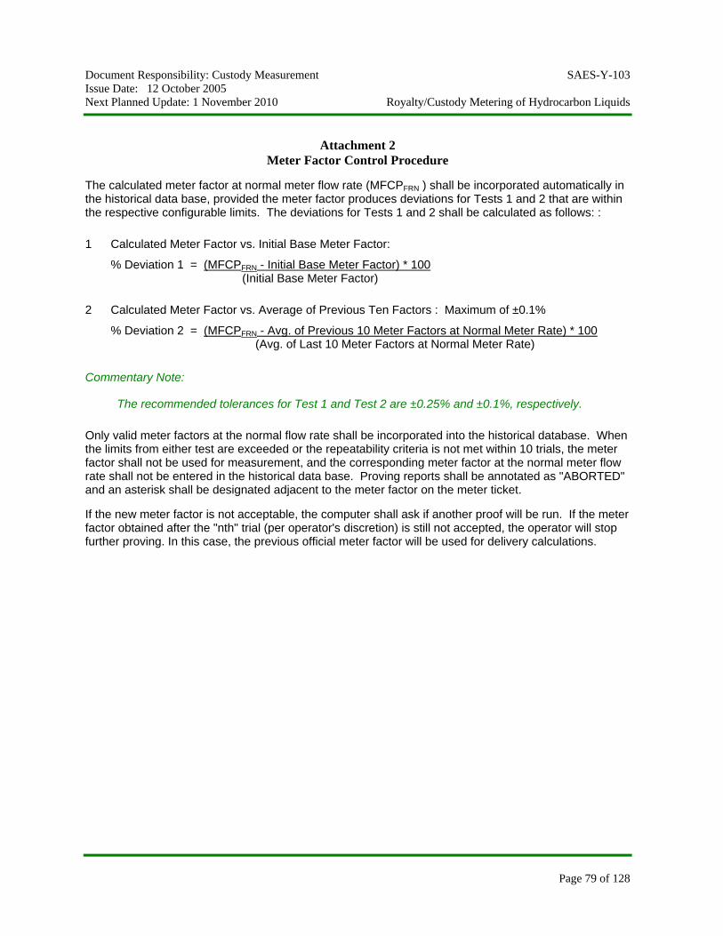
Document Responsibility: Custody Measurement SAES-Y-103 Issue Date: 12 October 2005 Next Planned Update: 1 November 2010 Royalty/Custody Metering of Hydrocarbon Liquids
Page 79 of 128
Attachment 2
Meter Factor Control Procedure The calculated meter factor at normal meter flow rate (MFCPFRN ) shall be incorporated automatically in the historical data base, provided the meter factor produces deviations for Tests 1 and 2 that are within the respective configurable limits. The deviations for Tests 1 and 2 shall be calculated as follows: : 1 Calculated Meter Factor vs. Initial Base Meter Factor:
% Deviation 1 = (MFCPFRN - Initial Base Meter Factor) * 100 (Initial Base Meter Factor)
2 Calculated Meter Factor vs. Average of Previous Ten Factors : Maximum of ±0.1%
% Deviation 2 = (MFCPFRN - Avg. of Previous 10 Meter Factors at Normal Meter Rate) * 100 (Avg. of Last 10 Meter Factors at Normal Meter Rate)
Commentary Note:
The recommended tolerances for Test 1 and Test 2 are ±0.25% and ±0.1%, respectively. Only valid meter factors at the normal flow rate shall be incorporated into the historical database. When the limits from either test are exceeded or the repeatability criteria is not met within 10 trials, the meter factor shall not be used for measurement, and the corresponding meter factor at the normal meter flow rate shall not be entered in the historical data base. Proving reports shall be annotated as "ABORTED" and an asterisk shall be designated adjacent to the meter factor on the meter ticket. If the new meter factor is not acceptable, the computer shall ask if another proof will be run. If the meter factor obtained after the "nth" trial (per operator's discretion) is still not accepted, the operator will stop further proving. In this case, the previous official meter factor will be used for delivery calculations.
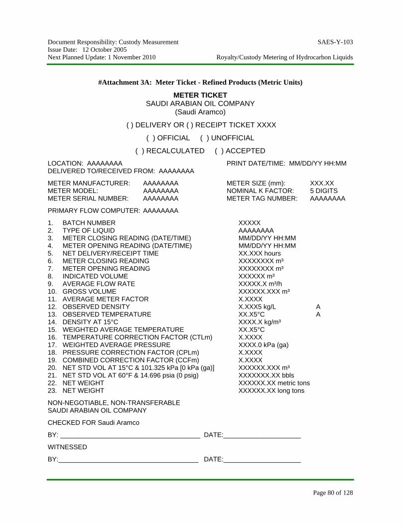
Document Responsibility: Custody Measurement SAES-Y-103 Issue Date: 12 October 2005 Next Planned Update: 1 November 2010 Royalty/Custody Metering of Hydrocarbon Liquids
Page 80 of 128
#Attachment 3A: Meter Ticket - Refined Products (Metric Units)
METER TICKET SAUDI ARABIAN OIL COMPANY
(Saudi Aramco)
( ) DELIVERY OR ( ) RECEIPT TICKET XXXX
( ) OFFICIAL ( ) UNOFFICIAL
( ) RECALCULATED ( ) ACCEPTED
LOCATION: AAAAAAAA PRINT DATE/TIME: MM/DD/YY HH:MM DELIVERED TO/RECEIVED FROM: AAAAAAAA
METER MANUFACTURER: AAAAAAAA METER SIZE (mm): XXX.XX METER MODEL: AAAAAAAA NOMINAL K FACTOR: 5 DIGITS METER SERIAL NUMBER: AAAAAAAA METER TAG NUMBER: AAAAAAAA
PRIMARY FLOW COMPUTER: AAAAAAAA
1. BATCH NUMBER XXXXX 2. TYPE OF LIQUID AAAAAAAA 3. METER CLOSING READING (DATE/TIME) MM/DD/YY HH:MM 4. METER OPENING READING (DATE/TIME) MM/DD/YY HH:MM 5. NET DELIVERY/RECEIPT TIME XX.XXX hours 6. METER CLOSING READING XXXXXXXX m³ 7. METER OPENING READING XXXXXXXX m³ 8. INDICATED VOLUME XXXXXX m³ 9. AVERAGE FLOW RATE XXXXX.X m³/h 10. GROSS VOLUME XXXXXX.XXX m³ 11. AVERAGE METER FACTOR X.XXXX 12. OBSERVED DENSITY X.XXX5 kg/L A 13. OBSERVED TEMPERATURE XX.X5°C A 14. DENSITY AT 15°C XXXX.X kg/m³ 15. WEIGHTED AVERAGE TEMPERATURE XX.X5°C 16. TEMPERATURE CORRECTION FACTOR (CTLm) X.XXXX 17. WEIGHTED AVERAGE PRESSURE XXXX.0 kPa (ga) 18. PRESSURE CORRECTION FACTOR (CPLm) X.XXXX 19. COMBINED CORRECTION FACTOR (CCFm) X.XXXX 20. NET STD VOL AT 15°C & 101.325 kPa [0 kPa (ga)] XXXXXX.XXX m³ 21. NET STD VOL AT 60°F & 14.696 psia (0 psig) XXXXXXX.XX bbls 22. NET WEIGHT XXXXXX.XX metric tons 23. NET WEIGHT XXXXXX.XX long tons
NON-NEGOTIABLE, NON-TRANSFERABLE SAUDI ARABIAN OIL COMPANY
CHECKED FOR Saudi Aramco
BY: ______________________________________ DATE:_____________________
WITNESSED
BY:______________________________________ DATE:_____________________
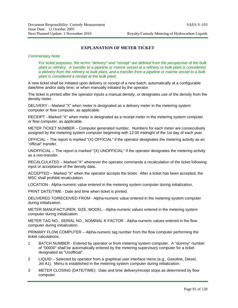
Document Responsibility: Custody Measurement SAES-Y-103 Issue Date: 12 October 2005 Next Planned Update: 1 November 2010 Royalty/Custody Metering of Hydrocarbon Liquids
Page 81 of 128
EXPLANATION OF METER TICKET
Commentary Note:
For ticket purposes, the terms "delivery" and "receipt" are defined from the perspective of the bulk plant or refinery. A transfer to a pipeline or marine vessel at a refinery or bulk plant is considered a delivery from the refinery or bulk plant, and a transfer from a pipeline or marine vessel to a bulk plant is considered a receipt at the bulk plant.
A new ticket shall be initiated upon delivery or receipt of a new batch; automatically at a configurable date/time and/or daily time; or when manually initiated by the operator.
The ticket is printed after the operator inputs a manual density, or designates use of the density from the density meter.
DELIVERY – Marked "X" when meter is designated as a delivery meter in the metering system computer or flow computer, as applicable.
RECEIPT - Marked "X" when meter is designated as a receipt meter in the metering system computer or flow computer, as applicable.
METER TICKET NUMBER – Computer generated number. Numbers for each meter are consecutively assigned by the metering system computer beginning with 12:00 midnight of the 1st day of each year.
OFFICIAL – The report is marked "(X) OFFICIAL" if the operator designates the metering activity as an "official" transfer.
UNOFFICIAL – The report is marked "(X) UNOFFICIAL" if the operator designates the metering activity as a non-transfer.
RECALCULATED – Marked "X" whenever the operator commands a recalculation of the ticket following input or acceptance of the density data.
ACCEPTED – Marked "X" when the operator accepts the ticket. After a ticket has been accepted, the MSC shall prohibit recalculation.
LOCATION - Alpha-numeric value entered in the metering system computer during initialization.
PRINT DATE/TIME - Date and time when ticket is printed.
DELIVERED TO/RECEIVED FROM - Alpha-numeric value entered in the metering system computer during initialization.
METER MANUFACTURER, SIZE, MODEL - Alpha-numeric values entered in the metering system computer during initialization.
METER TAG NO., SERIAL NO., NOMINAL K FACTOR - Alpha-numeric values entered in the flow computer during initialization.
PRIMARY FLOW COMPUTER – Alpha-numeric tag number from the flow computer performing the ticket calculations.
1 BATCH NUMBER - Entered by operator or from metering system computer. A "dummy" number of "00000" shall be automatically entered by the metering supervisory computer for a ticket designated as "Unofficial".
2 LIQUID – Selected by operator from a graphical user interface menu (e.g., Gasoline, Diesel, Jet A1). Menu is established in the metering system computer during initialization.
3 METER CLOSING (DATE/TIME): Date and time delivery/receipt stops as determined by flow computer.
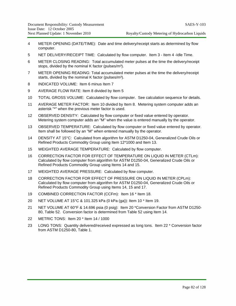
Document Responsibility: Custody Measurement SAES-Y-103 Issue Date: 12 October 2005 Next Planned Update: 1 November 2010 Royalty/Custody Metering of Hydrocarbon Liquids
Page 82 of 128
4 METER OPENING (DATE/TIME): Date and time delivery/receipt starts as determined by flow computer.
5 NET DELIVERY/RECEIPT TIME: Calculated by flow computer. Item 3 - Item 4 -Idle Time.
6 METER CLOSING READING: Total accumulated meter pulses at the time the delivery/receipt stops, divided by the nominal K factor (pulses/m³).
7 METER OPENING READING: Total accumulated meter pulses at the time the delivery/receipt starts, divided by the nominal K factor (pulses/m³).
8 INDICATED VOLUME: Item 6 minus Item 7
9 AVERAGE FLOW RATE: Item 8 divided by Item 5
10 TOTAL GROSS VOLUME: Calculated by flow computer. See calculation sequence for details.
11 AVERAGE METER FACTOR: Item 10 divided by Item 8. Metering system computer adds an asterisk "*" when the previous meter factor is used.
12 OBSERVED DENSITY: Calculated by flow computer or fixed value entered by operator. Metering system computer adds an "M" when the value is entered manually by the operator.
13 OBSERVED TEMPERATURE: Calculated by flow computer or fixed value entered by operator. Item shall be followed by an "M" when entered manually by the operator.
14 DENSITY AT 15°C: Calculated from algorithm for ASTM D1250-04, Generalized Crude Oils or Refined Products Commodity Group using Item 12*1000 and Item 13.
15 WEIGHTED AVERAGE TEMPERATURE: Calculated by flow computer.
16 CORRECTION FACTOR FOR EFFECT OF TEMPERATURE ON LIQUID IN METER (CTLm): Calculated by flow computer from algorithm for ASTM D1250-04, Generalized Crude Oils or Refined Products Commodity Group using Items 14 and 15.
17 WEIGHTED AVERAGE PRESSURE: Calculated by flow computer.
18 CORRECTION FACTOR FOR EFFECT OF PRESSURE ON LIQUID IN METER (CPLm): Calculated by flow computer from algorithm for ASTM D1250-04, Generalized Crude Oils or Refined Products Commodity Group using Items 14, 15 and 17.
19 COMBINED CORRECTION FACTOR (CCFm): Item 16 * Item 18.
20 NET VOLUME AT 15°C & 101.325 kPa (0 kPa (ga)): Item 10 * Item 19.
21 NET VOLUME AT 60°F & 14.696 psia (0 psig): Item 20 *Conversion Factor from ASTM D1250-80, Table 52. Conversion factor is determined from Table 52 using Item 14.
22 METRIC TONS: Item 20 * Item 14 / 1000
23 LONG TONS: Quantity delivered/received expressed as long tons. Item 22 * Conversion factor from ASTM D1250-80, Table 1.
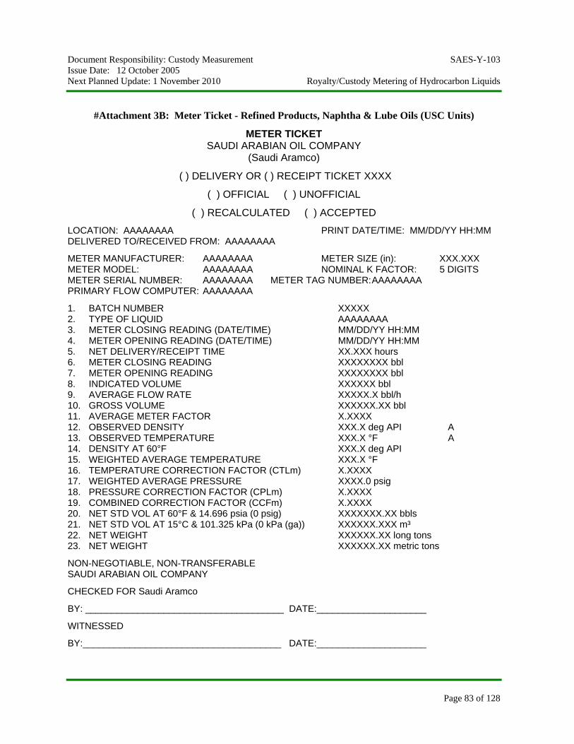
Document Responsibility: Custody Measurement SAES-Y-103 Issue Date: 12 October 2005 Next Planned Update: 1 November 2010 Royalty/Custody Metering of Hydrocarbon Liquids
Page 83 of 128
#Attachment 3B: Meter Ticket - Refined Products, Naphtha & Lube Oils (USC Units)
METER TICKET SAUDI ARABIAN OIL COMPANY
(Saudi Aramco)
( ) DELIVERY OR ( ) RECEIPT TICKET XXXX
( ) OFFICIAL ( ) UNOFFICIAL
( ) RECALCULATED ( ) ACCEPTED
LOCATION: AAAAAAAA PRINT DATE/TIME: MM/DD/YY HH:MM DELIVERED TO/RECEIVED FROM: AAAAAAAA
METER MANUFACTURER: AAAAAAAA METER SIZE (in): XXX.XXX METER MODEL: AAAAAAAA NOMINAL K FACTOR: 5 DIGITS METER SERIAL NUMBER: AAAAAAAA METER TAG NUMBER: AAAAAAAA
PRIMARY FLOW COMPUTER: AAAAAAAA
1. BATCH NUMBER XXXXX 2. TYPE OF LIQUID AAAAAAAA 3. METER CLOSING READING (DATE/TIME) MM/DD/YY HH:MM 4. METER OPENING READING (DATE/TIME) MM/DD/YY HH:MM 5. NET DELIVERY/RECEIPT TIME XX.XXX hours 6. METER CLOSING READING XXXXXXXX bbl 7. METER OPENING READING XXXXXXXX bbl 8. INDICATED VOLUME XXXXXX bbl 9. AVERAGE FLOW RATE XXXXX.X bbl/h 10. GROSS VOLUME XXXXXX.XX bbl 11. AVERAGE METER FACTOR X.XXXX 12. OBSERVED DENSITY XXX.X deg API A 13. OBSERVED TEMPERATURE XXX.X °F A 14. DENSITY AT 60°F XXX.X deg API 15. WEIGHTED AVERAGE TEMPERATURE XXX.X °F 16. TEMPERATURE CORRECTION FACTOR (CTLm) X.XXXX 17. WEIGHTED AVERAGE PRESSURE XXXX.0 psig 18. PRESSURE CORRECTION FACTOR (CPLm) X.XXXX 19. COMBINED CORRECTION FACTOR (CCFm) X.XXXX 20. NET STD VOL AT 60°F & 14.696 psia (0 psig) XXXXXXX.XX bbls 21. NET STD VOL AT 15°C & 101.325 kPa (0 kPa (ga)) XXXXXX.XXX m³ 22. NET WEIGHT XXXXXX.XX long tons 23. NET WEIGHT XXXXXX.XX metric tons
NON-NEGOTIABLE, NON-TRANSFERABLE SAUDI ARABIAN OIL COMPANY
CHECKED FOR Saudi Aramco
BY: ______________________________________ DATE:_____________________
WITNESSED
BY:______________________________________ DATE:_____________________
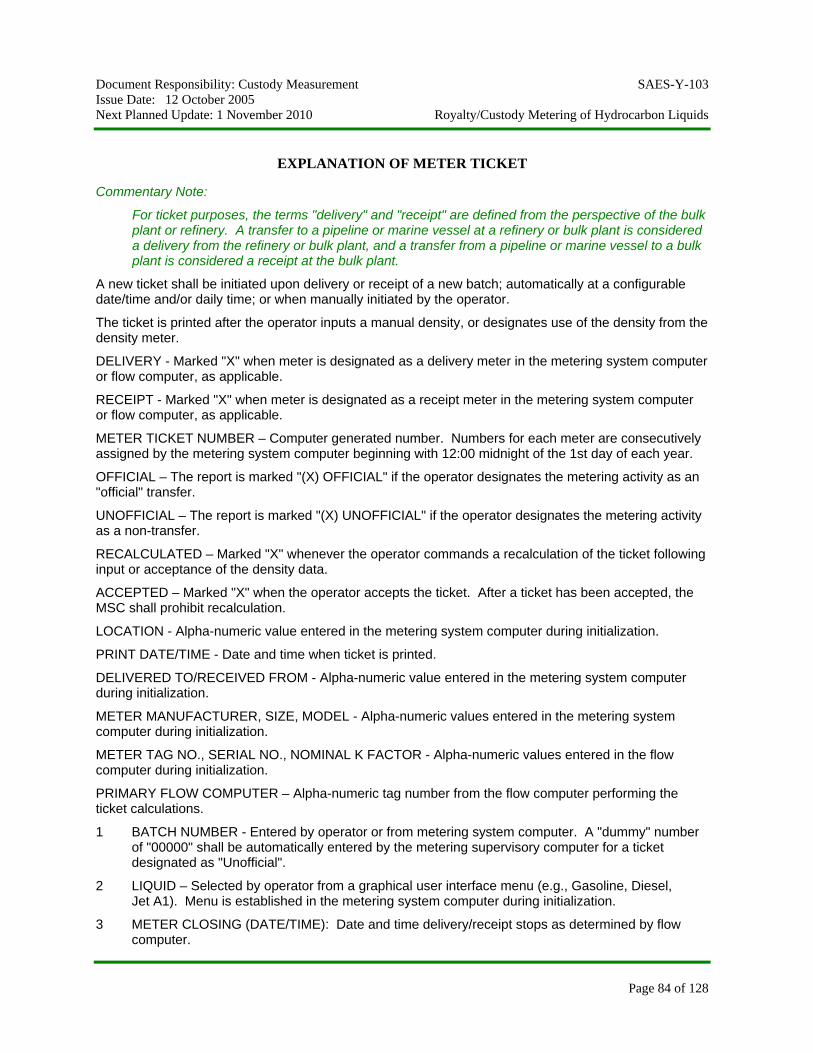
Document Responsibility: Custody Measurement SAES-Y-103 Issue Date: 12 October 2005 Next Planned Update: 1 November 2010 Royalty/Custody Metering of Hydrocarbon Liquids
Page 84 of 128
EXPLANATION OF METER TICKET
Commentary Note:
For ticket purposes, the terms "delivery" and "receipt" are defined from the perspective of the bulk plant or refinery. A transfer to a pipeline or marine vessel at a refinery or bulk plant is considered a delivery from the refinery or bulk plant, and a transfer from a pipeline or marine vessel to a bulk plant is considered a receipt at the bulk plant.
A new ticket shall be initiated upon delivery or receipt of a new batch; automatically at a configurable date/time and/or daily time; or when manually initiated by the operator.
The ticket is printed after the operator inputs a manual density, or designates use of the density from the density meter.
DELIVERY - Marked "X" when meter is designated as a delivery meter in the metering system computer or flow computer, as applicable.
RECEIPT - Marked "X" when meter is designated as a receipt meter in the metering system computer or flow computer, as applicable.
METER TICKET NUMBER – Computer generated number. Numbers for each meter are consecutively assigned by the metering system computer beginning with 12:00 midnight of the 1st day of each year.
OFFICIAL – The report is marked "(X) OFFICIAL" if the operator designates the metering activity as an "official" transfer.
UNOFFICIAL – The report is marked "(X) UNOFFICIAL" if the operator designates the metering activity as a non-transfer.
RECALCULATED – Marked "X" whenever the operator commands a recalculation of the ticket following input or acceptance of the density data.
ACCEPTED – Marked "X" when the operator accepts the ticket. After a ticket has been accepted, the MSC shall prohibit recalculation.
LOCATION - Alpha-numeric value entered in the metering system computer during initialization.
PRINT DATE/TIME - Date and time when ticket is printed.
DELIVERED TO/RECEIVED FROM - Alpha-numeric value entered in the metering system computer during initialization.
METER MANUFACTURER, SIZE, MODEL - Alpha-numeric values entered in the metering system computer during initialization.
METER TAG NO., SERIAL NO., NOMINAL K FACTOR - Alpha-numeric values entered in the flow computer during initialization.
PRIMARY FLOW COMPUTER – Alpha-numeric tag number from the flow computer performing the ticket calculations.
1 BATCH NUMBER - Entered by operator or from metering system computer. A "dummy" number of "00000" shall be automatically entered by the metering supervisory computer for a ticket designated as "Unofficial".
2 LIQUID – Selected by operator from a graphical user interface menu (e.g., Gasoline, Diesel, Jet A1). Menu is established in the metering system computer during initialization.
3 METER CLOSING (DATE/TIME): Date and time delivery/receipt stops as determined by flow computer.
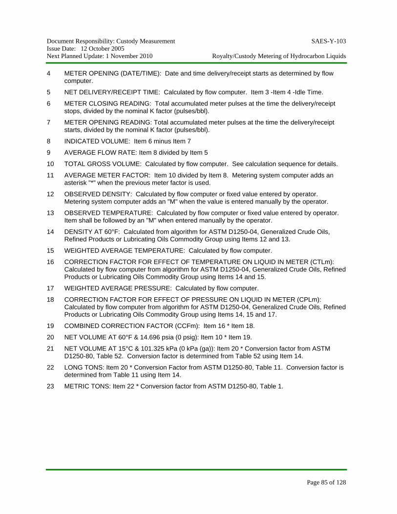
Document Responsibility: Custody Measurement SAES-Y-103 Issue Date: 12 October 2005 Next Planned Update: 1 November 2010 Royalty/Custody Metering of Hydrocarbon Liquids
Page 85 of 128
4 METER OPENING (DATE/TIME): Date and time delivery/receipt starts as determined by flow computer.
5 NET DELIVERY/RECEIPT TIME: Calculated by flow computer. Item 3 -Item 4 -Idle Time.
6 METER CLOSING READING: Total accumulated meter pulses at the time the delivery/receipt stops, divided by the nominal K factor (pulses/bbl).
7 METER OPENING READING: Total accumulated meter pulses at the time the delivery/receipt starts, divided by the nominal K factor (pulses/bbl).
8 INDICATED VOLUME: Item 6 minus Item 7
9 AVERAGE FLOW RATE: Item 8 divided by Item 5
10 TOTAL GROSS VOLUME: Calculated by flow computer. See calculation sequence for details.
11 AVERAGE METER FACTOR: Item 10 divided by Item 8. Metering system computer adds an asterisk "*" when the previous meter factor is used.
12 OBSERVED DENSITY: Calculated by flow computer or fixed value entered by operator. Metering system computer adds an "M" when the value is entered manually by the operator.
13 OBSERVED TEMPERATURE: Calculated by flow computer or fixed value entered by operator. Item shall be followed by an "M" when entered manually by the operator.
14 DENSITY AT 60°F: Calculated from algorithm for ASTM D1250-04, Generalized Crude Oils, Refined Products or Lubricating Oils Commodity Group using Items 12 and 13.
15 WEIGHTED AVERAGE TEMPERATURE: Calculated by flow computer.
16 CORRECTION FACTOR FOR EFFECT OF TEMPERATURE ON LIQUID IN METER (CTLm): Calculated by flow computer from algorithm for ASTM D1250-04, Generalized Crude Oils, Refined Products or Lubricating Oils Commodity Group using Items 14 and 15.
17 WEIGHTED AVERAGE PRESSURE: Calculated by flow computer.
18 CORRECTION FACTOR FOR EFFECT OF PRESSURE ON LIQUID IN METER (CPLm): Calculated by flow computer from algorithm for ASTM D1250-04, Generalized Crude Oils, Refined Products or Lubricating Oils Commodity Group using Items 14, 15 and 17.
19 COMBINED CORRECTION FACTOR (CCFm): Item 16 * Item 18.
20 NET VOLUME AT 60°F & 14.696 psia (0 psig): Item 10 * Item 19.
21 NET VOLUME AT 15°C & 101.325 kPa (0 kPa (ga)): Item 20 * Conversion factor from ASTM D1250-80, Table 52. Conversion factor is determined from Table 52 using Item 14.
22 LONG TONS: Item 20 * Conversion Factor from ASTM D1250-80, Table 11. Conversion factor is determined from Table 11 using Item 14.
23 METRIC TONS: Item 22 * Conversion factor from ASTM D1250-80, Table 1.
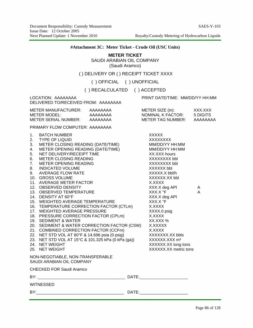
Document Responsibility: Custody Measurement SAES-Y-103 Issue Date: 12 October 2005 Next Planned Update: 1 November 2010 Royalty/Custody Metering of Hydrocarbon Liquids
Page 86 of 128
#Attachment 3C: Meter Ticket - Crude Oil (USC Units)
METER TICKET SAUDI ARABIAN OIL COMPANY
(Saudi Aramco)
( ) DELIVERY OR ( ) RECEIPT TICKET XXXX
( ) OFFICIAL ( ) UNOFFICIAL
( ) RECALCULATED ( ) ACCEPTED
LOCATION: AAAAAAAA PRINT DATE/TIME: MM/DD/YY HH:MM DELIVERED TO/RECEIVED FROM: AAAAAAAA
METER MANUFACTURER: AAAAAAAA METER SIZE (in): XXX.XXX METER MODEL: AAAAAAAA NOMINAL K FACTOR: 5 DIGITS METER SERIAL NUMBER: AAAAAAAA METER TAG NUMBER: AAAAAAAA
PRIMARY FLOW COMPUTER: AAAAAAAA
1. BATCH NUMBER XXXXX 2. TYPE OF LIQUID XXXXXXXX 3. METER CLOSING READING (DATE/TIME) MM/DD/YY HH:MM 4. METER OPENING READING (DATE/TIME) MM/DD/YY HH:MM 5. NET DELIVERY/RECEIPT TIME XX.XXX hours 6. METER CLOSING READING XXXXXXXX bbl 7. METER OPENING READING XXXXXXXX bbl 8. INDICATED VOLUME XXXXXX bbl 9. AVERAGE FLOW RATE XXXXX.X bbl/h 10. GROSS VOLUME XXXXXX.XX bbl 11. AVERAGE METER FACTOR X.XXXX 12. OBSERVED DENSITY XXX.X deg API A 13. OBSERVED TEMPERATURE XXX.X °F A 14. DENSITY AT 60°F XXX.X deg API 15. WEIGHTED AVERAGE TEMPERATURE XXX.X °F 16. TEMPERATURE CORRECTION FACTOR (CTLm) X.XXXX 17. WEIGHTED AVERAGE PRESSURE XXXX.0 psig 18. PRESSURE CORRECTION FACTOR (CPLm) X.XXXX 19. SEDIMENT & WATER XX.XXX % 20. SEDIMENT & WATER CORRECTION FACTOR (CSW) X.XXXXX 21. COMBINED CORRECTION FACTOR (CCFm) X.XXXX 22. NET STD VOL AT 60°F & 14.696 psia (0 psig) XXXXXXX.XX bbls 23. NET STD VOL AT 15°C & 101.325 kPa (0 kPa (ga)) XXXXXX.XXX m³ 24. NET WEIGHT XXXXXX.XX long tons 25. NET WEIGHT XXXXXX.XX metric tons
NON-NEGOTIABLE, NON-TRANSFERABLE SAUDI ARABIAN OIL COMPANY
CHECKED FOR Saudi Aramco
BY: ______________________________________ DATE:_____________________
WITNESSED
BY:______________________________________ DATE:_____________________
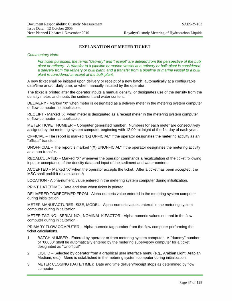
Document Responsibility: Custody Measurement SAES-Y-103 Issue Date: 12 October 2005 Next Planned Update: 1 November 2010 Royalty/Custody Metering of Hydrocarbon Liquids
Page 87 of 128
EXPLANATION OF METER TICKET
Commentary Note:
For ticket purposes, the terms "delivery" and "receipt" are defined from the perspective of the bulk plant or refinery. A transfer to a pipeline or marine vessel at a refinery or bulk plant is considered a delivery from the refinery or bulk plant, and a transfer from a pipeline or marine vessel to a bulk plant is considered a receipt at the bulk plant.
A new ticket shall be initiated upon delivery or receipt of a new batch; automatically at a configurable date/time and/or daily time; or when manually initiated by the operator.
The ticket is printed after the operator inputs a manual density, or designates use of the density from the density meter, and inputs the sediment and water content.
DELIVERY - Marked "X" when meter is designated as a delivery meter in the metering system computer or flow computer, as applicable.
RECEIPT - Marked "X" when meter is designated as a receipt meter in the metering system computer or flow computer, as applicable.
METER TICKET NUMBER – Computer generated number. Numbers for each meter are consecutively assigned by the metering system computer beginning with 12:00 midnight of the 1st day of each year.
OFFICIAL – The report is marked "(X) OFFICIAL" if the operator designates the metering activity as an "official" transfer.
UNOFFICIAL – The report is marked "(X) UNOFFICIAL" if the operator designates the metering activity as a non-transfer.
RECALCULATED – Marked "X" whenever the operator commands a recalculation of the ticket following input or acceptance of the density data and input of the sediment and water content.
ACCEPTED – Marked "X" when the operator accepts the ticket. After a ticket has been accepted, the MSC shall prohibit recalculation.A
LOCATION - Alpha-numeric value entered in the metering system computer during initialization.
PRINT DATE/TIME - Date and time when ticket is printed.
DELIVERED TO/RECEIVED FROM - Alpha-numeric value entered in the metering system computer during initialization.
METER MANUFACTURER, SIZE, MODEL - Alpha-numeric values entered in the metering system computer during initialization.
METER TAG NO., SERIAL NO., NOMINAL K FACTOR - Alpha-numeric values entered in the flow computer during initialization.
PRIMARY FLOW COMPUTER – Alpha-numeric tag number from the flow computer performing the ticket calculations.
1 BATCH NUMBER - Entered by operator or from metering system computer. A "dummy" number of "00000" shall be automatically entered by the metering supervisory computer for a ticket designated as "Unofficial".
2 LIQUID – Selected by operator from a graphical user interface menu (e.g., Arabian Light, Arabian Medium, etc.). Menu is established in the metering system computer during initialization.
3 METER CLOSING (DATE/TIME): Date and time delivery/receipt stops as determined by flow computer.
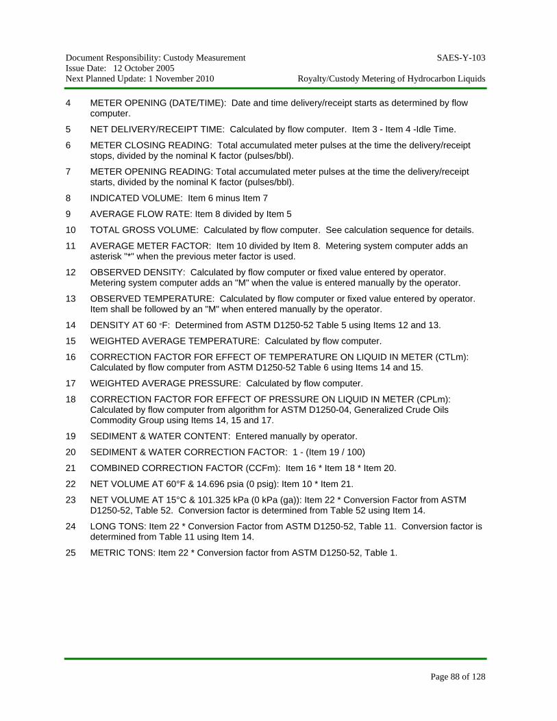
Document Responsibility: Custody Measurement SAES-Y-103 Issue Date: 12 October 2005 Next Planned Update: 1 November 2010 Royalty/Custody Metering of Hydrocarbon Liquids
Page 88 of 128
4 METER OPENING (DATE/TIME): Date and time delivery/receipt starts as determined by flow computer.
5 NET DELIVERY/RECEIPT TIME: Calculated by flow computer. Item 3 - Item 4 -Idle Time.
6 METER CLOSING READING: Total accumulated meter pulses at the time the delivery/receipt stops, divided by the nominal K factor (pulses/bbl).
7 METER OPENING READING: Total accumulated meter pulses at the time the delivery/receipt starts, divided by the nominal K factor (pulses/bbl).
8 INDICATED VOLUME: Item 6 minus Item 7
9 AVERAGE FLOW RATE: Item 8 divided by Item 5
10 TOTAL GROSS VOLUME: Calculated by flow computer. See calculation sequence for details.
11 AVERAGE METER FACTOR: Item 10 divided by Item 8. Metering system computer adds an asterisk "*" when the previous meter factor is used.
12 OBSERVED DENSITY: Calculated by flow computer or fixed value entered by operator. Metering system computer adds an "M" when the value is entered manually by the operator.
13 OBSERVED TEMPERATURE: Calculated by flow computer or fixed value entered by operator. Item shall be followed by an "M" when entered manually by the operator.
14 DENSITY AT 60 °F: Determined from ASTM D1250-52 Table 5 using Items 12 and 13.
15 WEIGHTED AVERAGE TEMPERATURE: Calculated by flow computer.
16 CORRECTION FACTOR FOR EFFECT OF TEMPERATURE ON LIQUID IN METER (CTLm): Calculated by flow computer from ASTM D1250-52 Table 6 using Items 14 and 15.
17 WEIGHTED AVERAGE PRESSURE: Calculated by flow computer.
18 CORRECTION FACTOR FOR EFFECT OF PRESSURE ON LIQUID IN METER (CPLm): Calculated by flow computer from algorithm for ASTM D1250-04, Generalized Crude Oils Commodity Group using Items 14, 15 and 17.
19 SEDIMENT & WATER CONTENT: Entered manually by operator.
20 SEDIMENT & WATER CORRECTION FACTOR: 1 - (Item 19 / 100)
21 COMBINED CORRECTION FACTOR (CCFm): Item 16 * Item 18 * Item 20.
22 NET VOLUME AT 60°F & 14.696 psia (0 psig): Item 10 * Item 21.
23 NET VOLUME AT 15°C & 101.325 kPa (0 kPa (ga)): Item 22 * Conversion Factor from ASTM D1250-52, Table 52. Conversion factor is determined from Table 52 using Item 14.
24 LONG TONS: Item 22 * Conversion Factor from ASTM D1250-52, Table 11. Conversion factor is determined from Table 11 using Item 14.
25 METRIC TONS: Item 22 * Conversion factor from ASTM D1250-52, Table 1.
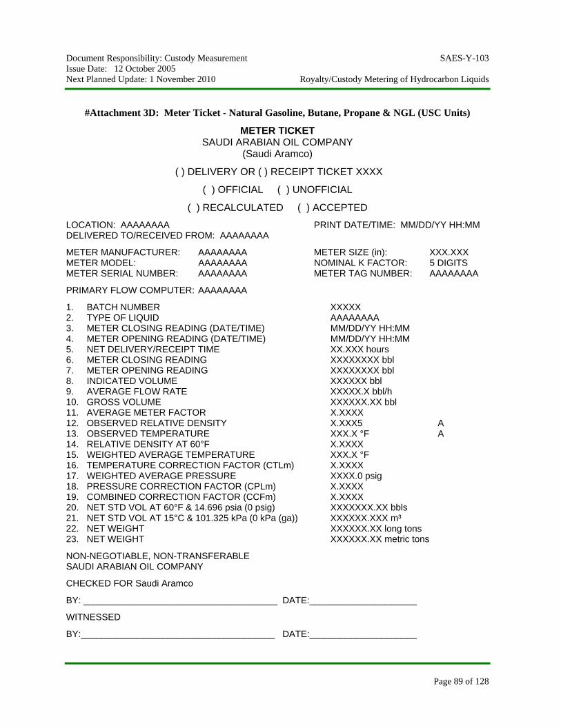
Document Responsibility: Custody Measurement SAES-Y-103 Issue Date: 12 October 2005 Next Planned Update: 1 November 2010 Royalty/Custody Metering of Hydrocarbon Liquids
Page 89 of 128
#Attachment 3D: Meter Ticket - Natural Gasoline, Butane, Propane & NGL (USC Units)
METER TICKET SAUDI ARABIAN OIL COMPANY
(Saudi Aramco)
( ) DELIVERY OR ( ) RECEIPT TICKET XXXX
( ) OFFICIAL ( ) UNOFFICIAL
( ) RECALCULATED ( ) ACCEPTED
LOCATION: AAAAAAAA PRINT DATE/TIME: MM/DD/YY HH:MM DELIVERED TO/RECEIVED FROM: AAAAAAAA
METER MANUFACTURER: AAAAAAAA METER SIZE (in): XXX.XXX METER MODEL: AAAAAAAA NOMINAL K FACTOR: 5 DIGITS METER SERIAL NUMBER: AAAAAAAA METER TAG NUMBER: AAAAAAAA
PRIMARY FLOW COMPUTER: AAAAAAAA
1. BATCH NUMBER XXXXX 2. TYPE OF LIQUID AAAAAAAA 3. METER CLOSING READING (DATE/TIME) MM/DD/YY HH:MM 4. METER OPENING READING (DATE/TIME) MM/DD/YY HH:MM 5. NET DELIVERY/RECEIPT TIME XX.XXX hours 6. METER CLOSING READING XXXXXXXX bbl 7. METER OPENING READING XXXXXXXX bbl 8. INDICATED VOLUME XXXXXX bbl 9. AVERAGE FLOW RATE XXXXX.X bbl/h 10. GROSS VOLUME XXXXXX.XX bbl 11. AVERAGE METER FACTOR X.XXXX 12. OBSERVED RELATIVE DENSITY X.XXX5 A 13. OBSERVED TEMPERATURE XXX.X °F A 14. RELATIVE DENSITY AT 60°F X.XXXX 15. WEIGHTED AVERAGE TEMPERATURE XXX.X °F 16. TEMPERATURE CORRECTION FACTOR (CTLm) X.XXXX 17. WEIGHTED AVERAGE PRESSURE XXXX.0 psig 18. PRESSURE CORRECTION FACTOR (CPLm) X.XXXX 19. COMBINED CORRECTION FACTOR (CCFm) X.XXXX 20. NET STD VOL AT 60°F & 14.696 psia (0 psig) XXXXXXX.XX bbls 21. NET STD VOL AT 15°C & 101.325 kPa (0 kPa (ga)) XXXXXX.XXX m³ 22. NET WEIGHT XXXXXX.XX long tons 23. NET WEIGHT XXXXXX.XX metric tons
NON-NEGOTIABLE, NON-TRANSFERABLE SAUDI ARABIAN OIL COMPANY
CHECKED FOR Saudi Aramco
BY: ______________________________________ DATE:_____________________
WITNESSED
BY:______________________________________ DATE:_____________________
Document Responsibility: Custody Measurement SAES-Y-103 Issue Date: 12 October 2005 Next Planned Update: 1 November 2010 Royalty/Custody Metering of Hydrocarbon Liquids
Page 90 of 128
EXPLANATION OF METER TICKET
Commentary Note:
For ticket purposes, the terms "delivery" and "receipt" are defined from the perspective of the bulk plant or refinery. A transfer to a pipeline or marine vessel at a refinery or bulk plant is considered a delivery from the refinery or bulk plant, and a transfer from a pipeline or marine vessel to a bulk plant is considered a receipt at the bulk plant.
A new ticket shall be initiated upon delivery or receipt of a new batch; automatically at a configurable date/time and/or daily/time; or when manually initiated by the operator.
The ticket is printed after the operator inputs a manual density, or designates use of the density from the density meter.
DELIVERY - Marked "X" when meter is designated as a delivery meter in the metering system computer or flow computer, as applicable.
RECEIPT - Marked "X" when meter is designated as a receipt meter in the metering system computer or flow computer, as applicable.
METER TICKET NUMBER – Computer generated number. Numbers for each meter are consecutively assigned by the metering system computer beginning with 12:00 midnight of the 1st day of each year.
OFFICIAL – The report is marked "(X) OFFICIAL" if the operator designates the metering activity as an "official" transfer.
UNOFFICIAL – The report is marked "(X) UNOFFICIAL" if the operator designates the metering activity as a non-transfer.
RECALCULATED – Marked "X" whenever the operator commands a recalculation of the ticket following input or acceptance of the density data.
ACCEPTED – Marked "X" when the operator accepts the ticket. After a ticket has been accepted, the MSC prohibits recalculation.
LOCATION - Alpha-numeric value entered in the metering system computer during initialization.
PRINT DATE/TIME - Date and time when ticket is printed.
DELIVERED TO/RECEIVED FROM - Alpha-numeric value entered in the metering system computer during initialization.
METER MANUFACTURER, SIZE, MODEL - Alpha-numeric values entered in the metering system computer during initialization.
METER TAG NO., SERIAL NO., NOMINAL K FACTOR - Alpha-numeric values entered in the flow computer during initialization.
PRIMARY FLOW COMPUTER – Alpha-numeric tag number from the flow computer performing the ticket calculations.
1 BATCH NUMBER - Entered by operator or from metering system computer. A "dummy" number of "00000" shall be automatically entered by the metering supervisory computer for a ticket designated as "Unofficial".
2 LIQUID – Selected by operator from a graphical user interface menu (e.g., Propane, Butane, etc.). Menu is established in the metering system computer during initialization.
3 METER CLOSING (DATE/TIME): Date and time delivery/receipt stops as determined by flow computer.
Document Responsibility: Custody Measurement SAES-Y-103 Issue Date: 12 October 2005 Next Planned Update: 1 November 2010 Royalty/Custody Metering of Hydrocarbon Liquids
Page 91 of 128
4 METER OPENING (DATE/TIME): Date and time delivery/receipt starts as determined by flow computer.
5 NET DELIVERY/RECEIPT TIME: Calculated by flow computer. Item 3 - Item 4 - Idle Time
6 METER CLOSING READING: Total accumulated meter pulses at the time the delivery/receipt stops, divided by the nominal K factor (pulses/bbl).
7 METER OPENING READING: Total accumulated meter pulses at the time the delivery/receipt starts, divided by the nominal K factor (pulses/bbl).
8 INDICATED VOLUME: Item 6 minus Item 7
9 AVERAGE FLOW RATE: Item 8 divided by Item 5
10 TOTAL GROSS VOLUME: Calculated by flow computer. See calculation sequence for details.
11 AVERAGE METER FACTOR: Item 10 divided by Item 8. Metering system computer adds an asterisk "*" when the previous meter factor is used.
12 OBSERVED DENSITY: Calculated by flow computer or fixed value entered by operator. Metering system computer adds an "M" when the value is entered manually by the operator.
13 OBSERVED TEMPERATURE: Calculated by flow computer or fixed value entered by operator. Item shall be followed by an "M" when entered manually by the operator.
14 DENSITY AT 60°F: Determined from ASTM D1250-52 Table 23 using Item 12 and 13.
15 WEIGHTED AVERAGE TEMPERATURE: Calculated by flow computer.
16 CORRECTION FACTOR FOR EFFECT OF TEMPERATURE ON LIQUID IN METER (CTLm): Calculated by flow computer from ASTM D1250-52 Table 24 using Items 14 and 15.
17 WEIGHTED AVERAGE PRESSURE: Calculated by flow computer.
18 CORRECTION FACTOR FOR EFFECT OF PRESSURE ON LIQUID IN METER (CPLm): Calculated by flow computer from algorithm for ASTM D1250-04, Generalized Crude Oils or Refined Products Commodity Group or API MPMS 11.2.2 and 11.2.2 Addendum algorithms using Items 14, 15 and 17.
19 COMBINED CORRECTION FACTOR (CCFm): Item 16 * Item 18.
20 NET VOLUME AT 60°F & 14.696 psia (0 psig): Item 10 * Item 19.
21 NET VOLUME AT 15°C & 101.325 kPa (0 kPa (ga)): Item 20 * Conversion factor from ASTM D1250-52, Table 52. Conversion factor is determined from Table 52 using Item 14.
22 LONG TONS: Item 20 * Conversion Factor from ASTM D1250-52, Table 11. Conversion factor is determined from Table 11 using Item 14.
23 METRIC TONS: Item 22 * Conversion factor from ASTM D1250-52, Table 1.
Document Responsibility: Custody Measurement SAES-Y-103 Issue Date: 12 October 2005 Next Planned Update: 1 November 2010 Royalty/Custody Metering of Hydrocarbon Liquids
Page 92 of 128
Attachment 4
Meter Ticket Calculations Commentary Note:
The following calculation sequence which involves delivery/receipt of refined products within Distribution Operations is intended to illustrate the steps to be undertaken by the flow computer for determining the delivery/receipt volumes. Minor modifications to the sequence, volume correction factor tables and/or units of measurement may be required when a delivery/receipt involves a different commodity or location.
SUMMARY 1 At scan intervals not to exceed 1 second, each flow computer reads the process data
and performs volume calculations for its assigned meters. The calculated quantities for each scan include, but are not limited to:
Flow rate for scan Total idle time Meter reading following scan Indicated volume for scan Total indicated volume following scan Gross volume for scan Total gross volume following scan Flow-weighted average observed density Flow-weighted average observed temperature Flow-weighted average meter temperature Flow-weighted average meter pressure
Gross volumes are calculated using a product-specific table consisting of up to 12 meter factors and corresponding flow rates (base meter calibration curve) to determine the meter factors.
2 At the conclusion of the ticket period, the flow computer computes the ticket quantities.
NOMENCLATURE BATCH A distinct volume of a single product shipped in a pipeline, between TIME0 and
TIME3.
CF52A Factor from ASTM D1250-80 Table 52, used to convert net standard volume in cubic meters at 15°C and 101.325 kPa (0 kPa (ga)) to net standard volume in barrels at 60°F and 14.696 psia (0 psig).
CPLm Correction for effect of pressure on metered liquid for ticket.
CTLm Correction for effect of temperature on metered liquid for ticket.
DEN15 Average density at 15°C for ticket.
DENOBS Average observed density (kg/m³).

Document Responsibility: Custody Measurement SAES-Y-103 Issue Date: 12 October 2005 Next Planned Update: 1 November 2010 Royalty/Custody Metering of Hydrocarbon Liquids
Page 93 of 128
FRi Flow rate for any Scan i.
FRN Normal meter flow rate. Entered in computer at initialization.
FRWA Average flow rate for ticket.
GV Gross Volume
GV1 Gross volume for PERIOD1.
GV1i Gross volume following Scan i in PERIOD1.
GV2i Gross volume following Scan i in PERIOD2.
GVC1 Gross volume for PERIOD1 corrected for current meter factor.
IDLE Total idle time for ticket.
IDLE% Configurable percentage of normal meter flow rate below which the scan time is accumulated as idle time.
IDLEi Idle time at conclusion of Scan i.
IV Total indicated volume for ticket.
IV1 Total indicated volume for PERIOD1.
IVi Total indicated volume following any Scan i.
LT Net quantity delivered/received expressed in long tons.
MF1i Meter factor at current flow rate (FRi) during any Scan i in PERIOD 1.
MF2i Meter factor at current flow rate (FRi) during any Scan i in PERIOD 2.
MFA1 Meter factor for PERIOD1 adjusted for current proving.
MFCPFRN Meter factor from proving during current batch adjusted to normal meter flow rate (FRN).
MFPPFRN Meter factor from proving during previous batch adjusted to normal meter flow rate (FRN).
MFBFRN Meter factor interpolated from meter's base calibration curve at the normal meter flow rate (FRN).
MFBi Meter factor interpolated from meter's base calibration curve at the current flow rate (FRi) during any Scan i in PERIOD1 or PERIOD2.
MFWA Average meter factor for ticket.
MFWA1 Average meter factor for PERIOD1 prior to adjustment for current proving.
MRc Closing meter reading at the end of the batch.
MRi Meter reading at the end of the Scan i.
MRi-1 Meter reading at the end of Scan i-1.
MRo Opening meter reading at the beginning of the batch.
MT Net quantity delivered/received expressed in metric tons.
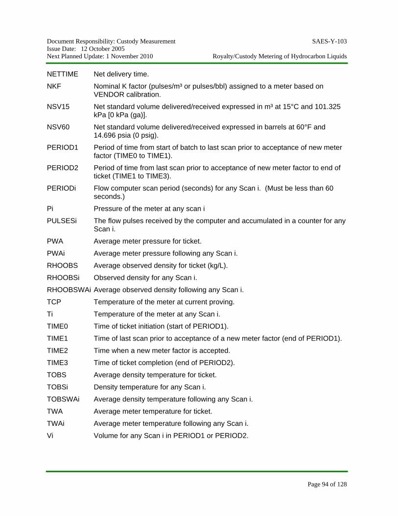
Document Responsibility: Custody Measurement SAES-Y-103 Issue Date: 12 October 2005 Next Planned Update: 1 November 2010 Royalty/Custody Metering of Hydrocarbon Liquids
Page 94 of 128
NETTIME Net delivery time.
NKF Nominal K factor (pulses/m³ or pulses/bbl) assigned to a meter based on VENDOR calibration.
NSV15 Net standard volume delivered/received expressed in m³ at 15°C and 101.325 kPa [0 kPa (ga)].
NSV60 Net standard volume delivered/received expressed in barrels at 60°F and 14.696 psia (0 psig).
PERIOD1 Period of time from start of batch to last scan prior to acceptance of new meter factor (TIME0 to TIME1).
PERIOD2 Period of time from last scan prior to acceptance of new meter factor to end of ticket (TIME1 to TIME3).
PERIODi Flow computer scan period (seconds) for any Scan i. (Must be less than 60 seconds.)
Pi Pressure of the meter at any scan i
PULSESi The flow pulses received by the computer and accumulated in a counter for any Scan i.
PWA Average meter pressure for ticket.
PWAi Average meter pressure following any Scan i.
RHOOBS Average observed density for ticket (kg/L).
RHOOBSi Observed density for any Scan i.
RHOOBSWAi Average observed density following any Scan i.
TCP Temperature of the meter at current proving.
Ti Temperature of the meter at any Scan i.
TIME0 Time of ticket initiation (start of PERIOD1).
TIME1 Time of last scan prior to acceptance of a new meter factor (end of PERIOD1).
TIME2 Time when a new meter factor is accepted.
TIME3 Time of ticket completion (end of PERIOD2).
TOBS Average density temperature for ticket.
TOBSi Density temperature for any Scan i.
TOBSWAi Average density temperature following any Scan i.
TWA Average meter temperature for ticket.
TWAi Average meter temperature following any Scan i.
Vi Volume for any Scan i in PERIOD1 or PERIOD2.
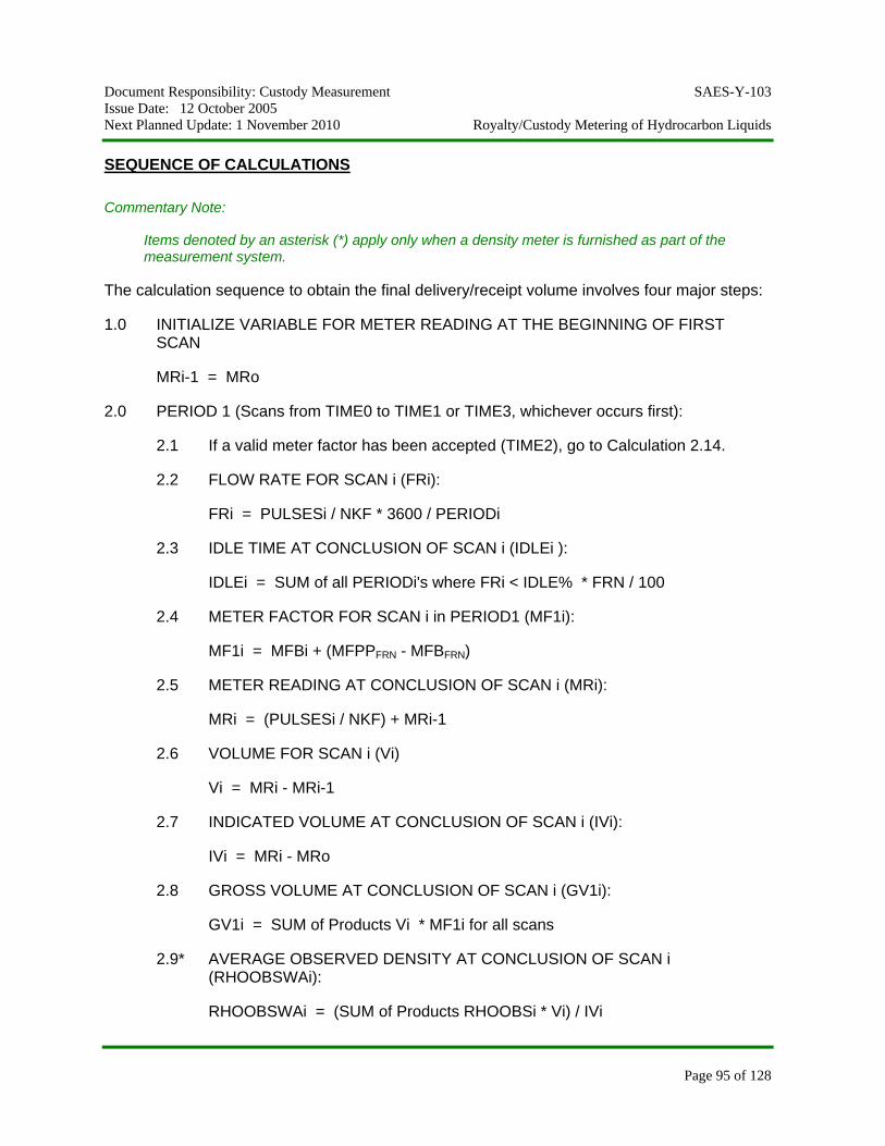
Document Responsibility: Custody Measurement SAES-Y-103 Issue Date: 12 October 2005 Next Planned Update: 1 November 2010 Royalty/Custody Metering of Hydrocarbon Liquids
Page 95 of 128
SEQUENCE OF CALCULATIONS Commentary Note:
Items denoted by an asterisk (*) apply only when a density meter is furnished as part of the measurement system.
The calculation sequence to obtain the final delivery/receipt volume involves four major steps:
1.0 INITIALIZE VARIABLE FOR METER READING AT THE BEGINNING OF FIRST SCAN
MRi-1 = MRo
2.0 PERIOD 1 (Scans from TIME0 to TIME1 or TIME3, whichever occurs first):
2.1 If a valid meter factor has been accepted (TIME2), go to Calculation 2.14.
2.2 FLOW RATE FOR SCAN i (FRi):
FRi = PULSESi / NKF * 3600 / PERIODi
2.3 IDLE TIME AT CONCLUSION OF SCAN i (IDLEi ):
IDLEi = SUM of all PERIODi's where FRi < IDLE% * FRN / 100
2.4 METER FACTOR FOR SCAN i in PERIOD1 (MF1i):
MF1i = MFBi + (MFPPFRN - MFBFRN)
2.5 METER READING AT CONCLUSION OF SCAN i (MRi):
MRi = (PULSESi / NKF) + MRi-1
2.6 VOLUME FOR SCAN i (Vi)
Vi = MRi - MRi-1
2.7 INDICATED VOLUME AT CONCLUSION OF SCAN i (IVi):
IVi = MRi - MRo
2.8 GROSS VOLUME AT CONCLUSION OF SCAN i (GV1i):
GV1i = SUM of Products Vi * MF1i for all scans
2.9* AVERAGE OBSERVED DENSITY AT CONCLUSION OF SCAN i (RHOOBSWAi):
RHOOBSWAi = (SUM of Products RHOOBSi * Vi) / IVi
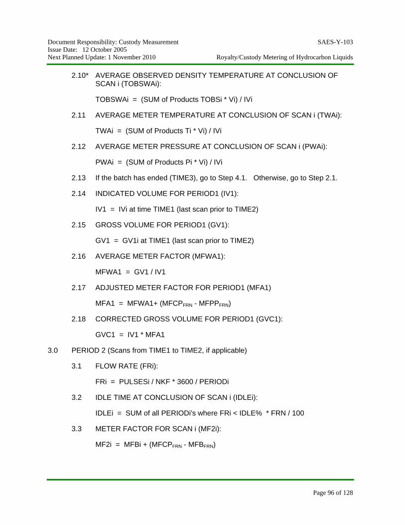
Document Responsibility: Custody Measurement SAES-Y-103 Issue Date: 12 October 2005 Next Planned Update: 1 November 2010 Royalty/Custody Metering of Hydrocarbon Liquids
Page 96 of 128
2.10* AVERAGE OBSERVED DENSITY TEMPERATURE AT CONCLUSION OF SCAN i (TOBSWAi):
TOBSWAi = (SUM of Products TOBSi * Vi) / IVi
2.11 AVERAGE METER TEMPERATURE AT CONCLUSION OF SCAN i (TWAi):
TWAi = (SUM of Products Ti * Vi) / IVi
2.12 AVERAGE METER PRESSURE AT CONCLUSION OF SCAN i (PWAi):
PWAi = (SUM of Products Pi * Vi) / IVi
2.13 If the batch has ended (TIME3), go to Step 4.1. Otherwise, go to Step 2.1.
2.14 INDICATED VOLUME FOR PERIOD1 (IV1):
IV1 = IVi at time TIME1 (last scan prior to TIME2)
2.15 GROSS VOLUME FOR PERIOD1 (GV1):
GV1 = GV1i at TIME1 (last scan prior to TIME2)
2.16 AVERAGE METER FACTOR (MFWA1):
MFWA1 = GV1 / IV1
2.17 ADJUSTED METER FACTOR FOR PERIOD1 (MFA1)
MFA1 = MFWA1+ (MFCPFRN - MFPPFRN)
2.18 CORRECTED GROSS VOLUME FOR PERIOD1 (GVC1):
GVC1 = IV1 * MFA1
3.0 PERIOD 2 (Scans from TIME1 to TIME2, if applicable)
3.1 FLOW RATE (FRi):
FRi = PULSESi / NKF * 3600 / PERIODi
3.2 IDLE TIME AT CONCLUSION OF SCAN i (IDLEi):
IDLEi = SUM of all PERIODi's where FRi < IDLE% * FRN / 100
3.3 METER FACTOR FOR SCAN i (MF2i):
MF2i = MFBi + (MFCPFRN - MFBFRN)

Document Responsibility: Custody Measurement SAES-Y-103 Issue Date: 12 October 2005 Next Planned Update: 1 November 2010 Royalty/Custody Metering of Hydrocarbon Liquids
Page 97 of 128
3.4 METER READING AT CONCLUSION OF SCAN i (MRi):
MRi = (PULSESi / NKF) + MRi-1
3.5 VOLUME FOR SCAN i (Vi)
Vi = MRi - MRi-1
3.6 INDICATED VOLUME AT CONCLUSION OF SCAN i (IVi):
IVi = MRi - MRo
3.7 GROSS VOLUME AT CONCLUSION OF SCAN i in PERIOD2 (GV2i):
GV2i = (SUM of Products Vi * MF2i) + GVC1
3.8* AVERAGE OBSERVED DENSITY AT CONCLUSION OF SCAN i (RHOOBSWAi):
RHOOBSWAi = (SUM of Products RHOOBSi * Vi) / IVi
3.9* AVERAGE OBSERVED TEMPERATURE AT CONCLUSION OF SCAN i (TOBSWAi):
TOBSWAi = (SUM of Products TOBSi * Vi) / IVi
3.10 AVERAGE METER TEMPERATURE AT CONCLUSION OF SCAN i (TWAi):
TWAi = (SUM of Products Ti * Vi) / IVi
3.11 AVERAGE METER PRESSURE AT CONCLUSION OF SCAN i (PWAi):
PWAi = (SUM of Products Pi * Vi) / IVi
3.12 If batch has not ended, repeat calculations from Step 3.1 for next scan.
4.0 FINAL CALCULATIONS (Scans from TIME0 to TIME3)
4.1 FINAL QUANTITIES/PROCESS VARIABLES
4.1.1 INDICATED VOLUME (IV):
IV = IVi at time TIME3
4.1.2 IDLE TIME (IDLE):
IDLE = IDLEi at time TIME3
4.1.3 NET DELIVERY TIME (NETTIME)
NETTIME = TIME3 - TIME0 - IDLE
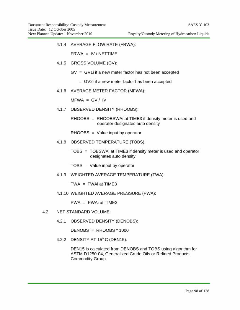
Document Responsibility: Custody Measurement SAES-Y-103 Issue Date: 12 October 2005 Next Planned Update: 1 November 2010 Royalty/Custody Metering of Hydrocarbon Liquids
Page 98 of 128
4.1.4 AVERAGE FLOW RATE (FRWA):
FRWA = IV / NETTIME
4.1.5 GROSS VOLUME (GV):
GV = GV1i if a new meter factor has not been accepted
= GV2i if a new meter factor has been accepted
4.1.6 AVERAGE METER FACTOR (MFWA):
MFWA = GV / IV
4.1.7 OBSERVED DENSITY (RHOOBS):
RHOOBS = RHOOBSWAi at TIME3 if density meter is used and operator designates auto density
RHOOBS = Value input by operator
4.1.8 OBSERVED TEMPERATURE (TOBS):
TOBS = TOBSWAi at TIME3 if density meter is used and operator designates auto density
TOBS = Value input by operator
4.1.9 WEIGHTED AVERAGE TEMPERATURE (TWA):
TWA = TWAi at TIME3
4.1.10 WEIGHTED AVERAGE PRESSURE (PWA):
PWA = PWAi at TIME3
4.2 NET STANDARD VOLUME:
4.2.1 OBSERVED DENSITY (DENOBS):
DENOBS = RHOOBS * 1000
4.2.2 DENSITY AT 15o C (DEN15):
DEN15 is calculated from DENOBS and TOBS using algorithm for ASTM D1250-04, Generalized Crude Oils or Refined Products Commodity Group.
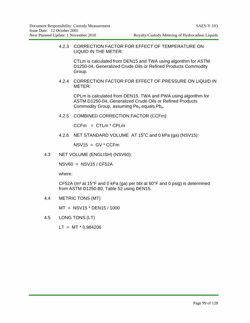
Document Responsibility: Custody Measurement SAES-Y-103 Issue Date: 12 October 2005 Next Planned Update: 1 November 2010 Royalty/Custody Metering of Hydrocarbon Liquids
Page 99 of 128
4.2.3 CORRECTION FACTOR FOR EFFECT OF TEMPERATURE ON LIQUID IN THE METER:
CTLm is calculated from DEN15 and TWA using algorithm for ASTM D1250-04, Generalized Crude Oils or Refined Products Commodity Group.
4.2.4 CORRECTION FACTOR FOR EFFECT OF PRESSURE ON LIQUID IN METER:
CPLm is calculated from DEN15, TWA and PWA using algorithm for ASTM D1250-04, Generalized Crude Oils or Refined Products Commodity Group, assuming Pea equals Pba.
4.2.5 COMBINED CORRECTION FACTOR (CCFm):
CCFm = CTLm * CPLm
4.2.6 NET STANDARD VOLUME AT 15oC and 0 kPa (ga) (NSV15):
NSV15 = GV * CCFm
4.3 NET VOLUME (ENGLISH) (NSV60):
NSV60 = NSV15 / CF52A
where:
CF52A (m³ at 15°F and 0 kPa (ga) per bbl at 60°F and 0 psig) is determined from ASTM D1250-80, Table 52 using DEN15.
4.4 METRIC TONS (MT)
MT = NSV15 * DEN15 / 1000
4.5 LONG TONS (LT)
LT = MT * 0.984206

Document Responsibility: Custody Measurement SAES-Y-103 Issue Date: 12 October 2005 Next Planned Update: 1 November 2010 Royalty/Custody Metering of Hydrocarbon Liquids
Page 100 of 128
Attachment 5 – Rounding Conventions
Values on the proving report and meter ticket shall be rounded in accordance with API MPMS Chapter 12.2., Part 1, Paragraph 1.7.1 and Part 2, Section 7.1, as follows:
• When the figure to the right of the last place to be retained is 5 or greater, the figure in the last place to be retained should be increased by 1.
• If the figure to the right of the last place to be retained is less than 5, the figure in the last place retained should be unchanged.
PROVING REPORT (METRIC UNITS) Observed Density X.XXX5 kg/L Observed Temperature XX.X5°C Density at 15°C XXXX.X kg/m³ Base Prover Volume AB.XXXX m³ A.XXXXX m³ 0.XXXXXX m³ Prover Outside Diameter XXX.XX mm Prover Wall Thickness XX.XX mm Prover Coefficient of Cubical Expansion 0.0000XXX/ °C Prover Modulus of Elasticity XXX,XXX,XXX kPa Prover Temperature XX.X5°C Prover Pressure XXXX kPa (ga) CTSp X.XXXXX CPSp X.XXXXX CTLp X.XXXXX CPLp X.XXXXX CCFp X.XXXXX Gross Standard Volume for Prover AB.XXXX m³ A.XXXXX m³ 0.XXXXXX m³ Nominal K Factor 5 Digits pulses/m³ Meter Indicated Volume AB.XXXX m³ A.XXXXX m³ 0.XXXXXX m³ Meter Temperature XX.X5°C Meter Pressure XXXX kPa (ga) CTLm X.XXXXX CPLm X.XXXXX CCFm X.XXXXX Gross Standard Volume for Meter AB.XXXX m³ A.XXXXX m³ 0.XXXXXX m³ Meter Factor X.XXXX

Document Responsibility: Custody Measurement SAES-Y-103 Issue Date: 12 October 2005 Next Planned Update: 1 November 2010 Royalty/Custody Metering of Hydrocarbon Liquids
Page 101 of 128
RECEIPT/ DELIVERY TICKET (METRIC UNITS) Nominal K Factor 5 Digits pulses/m³ Time XX.XXX hours Opening Meter Reading XXXXXXXX m³ Closing Meter Reading XXXXXXXX m³ Indicated Volume XXXXXX m³ Average Flow Rate XXXXX.X m³/h Gross Volume XXXXXX.XXX m³ Average Meter Factor X.XXXX Observed Density X.XXX5 kg/L Observed Temperature XX.X5°C Density at 15°C XXXX.X kg/m³ Weighted Average Temperature XX.X5°C CTLm X.XXXX Weighted Average Pressure XXXX.0 kPa (ga) CPLm X.XXXX CCFm X.XXXX Net Standard Volume XXXXXX.XXX m³ Net Standard Volume XXXXXX.XX bbls Net Weight XXXXXX.XX metric tons Net Weight XXXXXX.XX long tons PROVING REPORT (USC UNITS) Observed Density XXX.X deg API X.XXX5 RD Observed Temperature XXX.X °F Density at 60°F XXX.X deg API X.XXXX RD Base Prover Volume ABC.XXXX bbl AB.XXXX bbl A.XXXXX bbl 0.XXXXXX bbl Prover Outside Diameter XX.XXX in Prover Wall Thickness X.XXX in Prover Coefficient of Cubical Expansion 0.0000XXX/°F Prover Modulus of Elasticity XX,XXX,XXX psi Prover Temperature XXX.X °F Prover Pressure XXX.0 psig CTSp X.XXXXX CPSp X.XXXXX CTLp X.XXXXX CPLp X.XXXXX CCFp X.XXXXX Gross Standard Volume for Prover ABC.XXXX bbl AB.XXXX bbl A.XXXXX bbl 0.XXXXXX bbl Nominal K Factor 5 Digits pulses/bbl
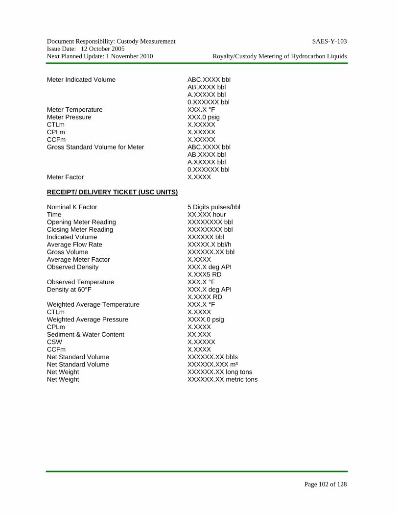
Document Responsibility: Custody Measurement SAES-Y-103 Issue Date: 12 October 2005 Next Planned Update: 1 November 2010 Royalty/Custody Metering of Hydrocarbon Liquids
Page 102 of 128
Meter Indicated Volume ABC.XXXX bbl AB.XXXX bbl A.XXXXX bbl 0.XXXXXX bbl Meter Temperature XXX.X °F Meter Pressure XXX.0 psig CTLm X.XXXXX CPLm X.XXXXX CCFm X.XXXXX Gross Standard Volume for Meter ABC.XXXX bbl AB.XXXX bbl A.XXXXX bbl 0.XXXXXX bbl Meter Factor X.XXXX RECEIPT/ DELIVERY TICKET (USC UNITS) Nominal K Factor 5 Digits pulses/bbl Time XX.XXX hour Opening Meter Reading XXXXXXXX bbl Closing Meter Reading XXXXXXXX bbl Indicated Volume XXXXXX bbl Average Flow Rate XXXXX.X bbl/h Gross Volume XXXXXX.XX bbl Average Meter Factor X.XXXX Observed Density XXX.X deg API X.XXX5 RD Observed Temperature XXX.X °F Density at 60°F XXX.X deg API X.XXXX RD Weighted Average Temperature XXX.X °F CTLm X.XXXX Weighted Average Pressure XXXX.0 psig CPLm X.XXXX Sediment & Water Content XX.XXX CSW X.XXXXX CCFm X.XXXX Net Standard Volume XXXXXX.XX bbls Net Standard Volume XXXXXX.XXX m³ Net Weight XXXXXX.XX long tons Net Weight XXXXXX.XX metric tons
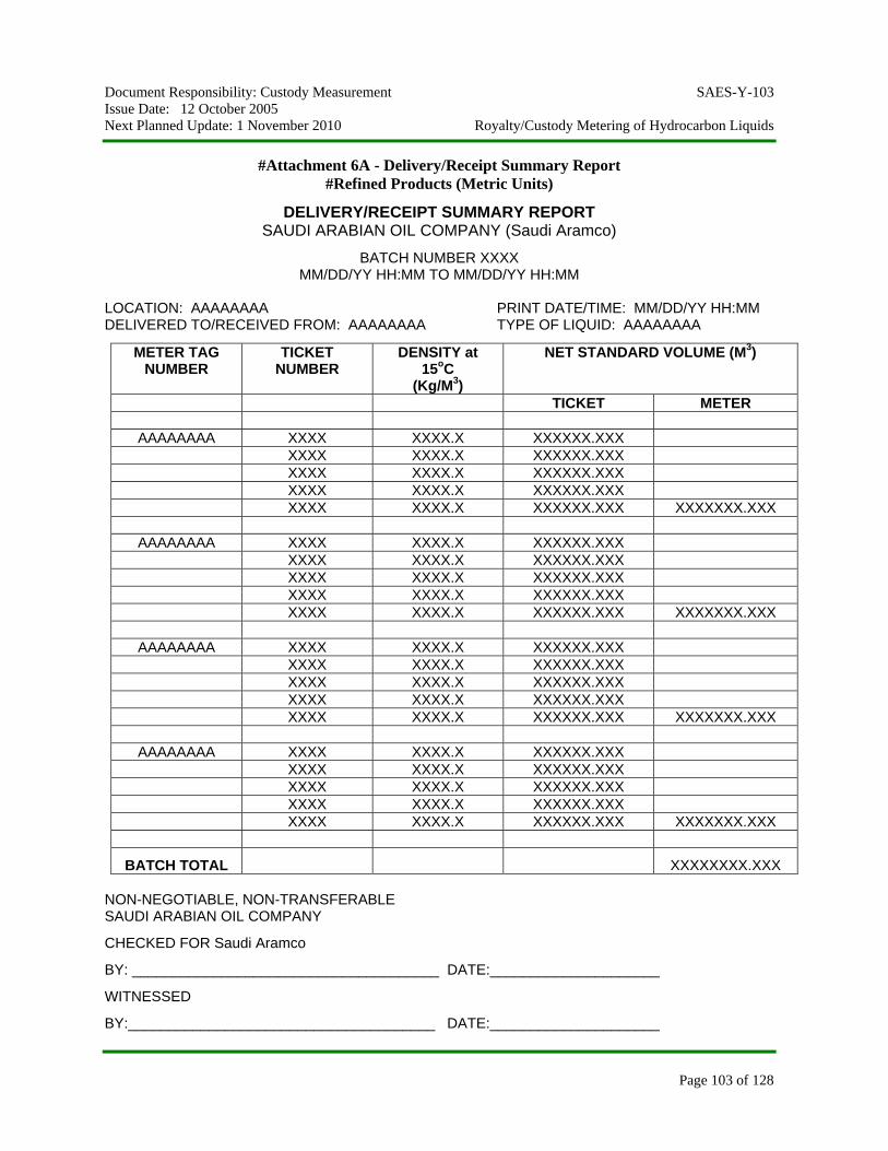
Document Responsibility: Custody Measurement SAES-Y-103 Issue Date: 12 October 2005 Next Planned Update: 1 November 2010 Royalty/Custody Metering of Hydrocarbon Liquids
Page 103 of 128
#Attachment 6A - Delivery/Receipt Summary Report #Refined Products (Metric Units)
DELIVERY/RECEIPT SUMMARY REPORT SAUDI ARABIAN OIL COMPANY (Saudi Aramco)
BATCH NUMBER XXXX MM/DD/YY HH:MM TO MM/DD/YY HH:MM
LOCATION: AAAAAAAA PRINT DATE/TIME: MM/DD/YY HH:MM DELIVERED TO/RECEIVED FROM: AAAAAAAA TYPE OF LIQUID: AAAAAAAA
METER TAG NUMBER
TICKET NUMBER
DENSITY at 15oC
(Kg/M3)
NET STANDARD VOLUME (M3)
TICKET METER
AAAAAAAA XXXX XXXX.X XXXXXX.XXX XXXX XXXX.X XXXXXX.XXX XXXX XXXX.X XXXXXX.XXX XXXX XXXX.X XXXXXX.XXX XXXX XXXX.X XXXXXX.XXX XXXXXXX.XXX
AAAAAAAA XXXX XXXX.X XXXXXX.XXX XXXX XXXX.X XXXXXX.XXX XXXX XXXX.X XXXXXX.XXX XXXX XXXX.X XXXXXX.XXX XXXX XXXX.X XXXXXX.XXX XXXXXXX.XXX
AAAAAAAA XXXX XXXX.X XXXXXX.XXX XXXX XXXX.X XXXXXX.XXX XXXX XXXX.X XXXXXX.XXX XXXX XXXX.X XXXXXX.XXX XXXX XXXX.X XXXXXX.XXX XXXXXXX.XXX
AAAAAAAA XXXX XXXX.X XXXXXX.XXX XXXX XXXX.X XXXXXX.XXX XXXX XXXX.X XXXXXX.XXX XXXX XXXX.X XXXXXX.XXX XXXX XXXX.X XXXXXX.XXX XXXXXXX.XXX
BATCH TOTAL XXXXXXXX.XXX NON-NEGOTIABLE, NON-TRANSFERABLE SAUDI ARABIAN OIL COMPANY
CHECKED FOR Saudi Aramco
BY: ______________________________________ DATE:_____________________
WITNESSED
BY:______________________________________ DATE:_____________________

Document Responsibility: Custody Measurement SAES-Y-103 Issue Date: 12 October 2005 Next Planned Update: 1 November 2010 Royalty/Custody Metering of Hydrocarbon Liquids
Page 104 of 128
EXPLANATION OF DELIVERY/RECEIPT SUMMARY REPORT
LEGEND: "MM/DD/YY" – Month/Day/Year (e.g., 06/23/99)
"HH:MM" – Time in hours/minutes format (e.g., 13:10) "AAAAAA" - Computer generated alpha-numeric value. "XXX.XX" - Computer generated numeric value.
NOTES: The number of meters will likely be different for each location.
The number of tickets for each meter will likely vary from batch-to-batch.
The Delivery/Receipt Summary Report is printed automatically after the last ticket for the batch is printed.
BATCH NUMBER - Entered by operator or from metering system computer.
BATCH START & END DATES/TIMES – Dates and times associated with the start of the first ticket to the end of the last ticket.
LOCATION - Alpha-numeric value entered in the metering system computer during initialization.
PRINT DATE/TIME - Date and time when report is printed.
DELIVERED TO/RECEIVED FROM - Alpha-numeric value entered in the metering system computer during initialization.
TYPE OF LIQUID – Selected by operator from a graphical user interface menu (e.g., Gasoline, Diesel, Jet A1). Menu is established in the metering system computer during initialization.
1. METER TAG NUMBER: Alpha-numeric value entered in the flow computer during initialization.
2. METER TICKET NUMBER: Ticket number from an accepted meter ticket.
3. DENSITY AT 15oC: Density at 15oC from the specified meter ticket.
4. NET STANDARD VOLUME (Ticket): Net standard volume at 15oC & 101.325 kPa (0 kPa (ga)) from the specified meter ticket.
5. NET STANDARD VOLUME (Meter): Sum of net standard volumes from all tickets for a particular meter.
6. BATCH TOTAL: Sum of all meter net standard volumes.
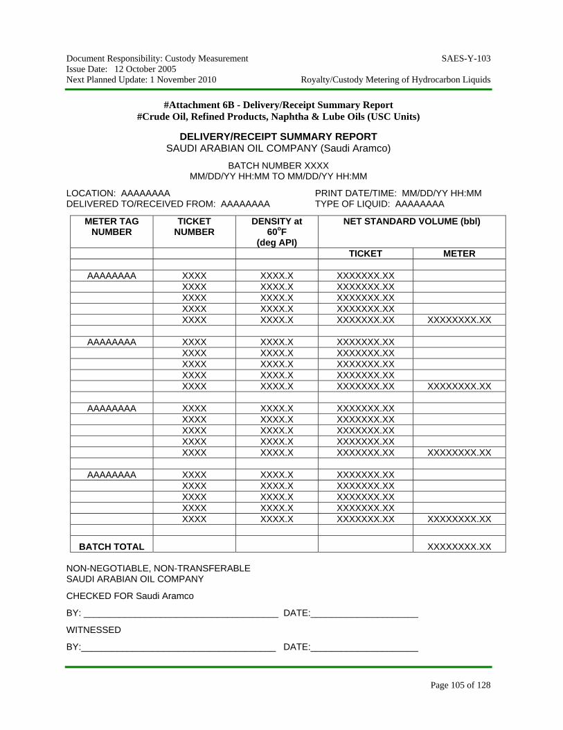
Document Responsibility: Custody Measurement SAES-Y-103 Issue Date: 12 October 2005 Next Planned Update: 1 November 2010 Royalty/Custody Metering of Hydrocarbon Liquids
Page 105 of 128
#Attachment 6B - Delivery/Receipt Summary Report #Crude Oil, Refined Products, Naphtha & Lube Oils (USC Units)
DELIVERY/RECEIPT SUMMARY REPORT
SAUDI ARABIAN OIL COMPANY (Saudi Aramco)
BATCH NUMBER XXXX MM/DD/YY HH:MM TO MM/DD/YY HH:MM
LOCATION: AAAAAAAA PRINT DATE/TIME: MM/DD/YY HH:MM DELIVERED TO/RECEIVED FROM: AAAAAAAA TYPE OF LIQUID: AAAAAAAA
METER TAG NUMBER
TICKET NUMBER
DENSITY at 60oF
(deg API)
NET STANDARD VOLUME (bbl)
TICKET METER
AAAAAAAA XXXX XXXX.X XXXXXXX.XX XXXX XXXX.X XXXXXXX.XX XXXX XXXX.X XXXXXXX.XX XXXX XXXX.X XXXXXXX.XX XXXX XXXX.X XXXXXXX.XX XXXXXXXX.XX
AAAAAAAA XXXX XXXX.X XXXXXXX.XX XXXX XXXX.X XXXXXXX.XX XXXX XXXX.X XXXXXXX.XX XXXX XXXX.X XXXXXXX.XX XXXX XXXX.X XXXXXXX.XX XXXXXXXX.XX
AAAAAAAA XXXX XXXX.X XXXXXXX.XX XXXX XXXX.X XXXXXXX.XX XXXX XXXX.X XXXXXXX.XX XXXX XXXX.X XXXXXXX.XX XXXX XXXX.X XXXXXXX.XX XXXXXXXX.XX
AAAAAAAA XXXX XXXX.X XXXXXXX.XX XXXX XXXX.X XXXXXXX.XX XXXX XXXX.X XXXXXXX.XX XXXX XXXX.X XXXXXXX.XX XXXX XXXX.X XXXXXXX.XX XXXXXXXX.XX
BATCH TOTAL XXXXXXXX.XX NON-NEGOTIABLE, NON-TRANSFERABLE SAUDI ARABIAN OIL COMPANY
CHECKED FOR Saudi Aramco
BY: ______________________________________ DATE:_____________________
WITNESSED
BY:______________________________________ DATE:_____________________
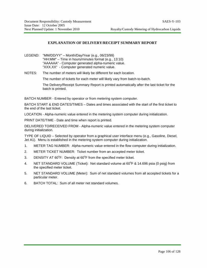
Document Responsibility: Custody Measurement SAES-Y-103 Issue Date: 12 October 2005 Next Planned Update: 1 November 2010 Royalty/Custody Metering of Hydrocarbon Liquids
Page 106 of 128
EXPLANATION OF DELIVERY/RECEIPT SUMMARY REPORT
LEGEND: "MM/DD/YY" – Month/Day/Year (e.g., 06/23/99)
"HH:MM" – Time in hours/minutes format (e.g., 13:10) "AAAAAA" - Computer generated alpha-numeric value. "XXX.XX" - Computer generated numeric value.
NOTES: The number of meters will likely be different for each location.
The number of tickets for each meter will likely vary from batch-to-batch.
The Delivery/Receipt Summary Report is printed automatically after the last ticket for the batch is printed.
BATCH NUMBER - Entered by operator or from metering system computer.
BATCH START & END DATES/TIMES – Dates and times associated with the start of the first ticket to the end of the last ticket.
LOCATION - Alpha-numeric value entered in the metering system computer during initialization.
PRINT DATE/TIME - Date and time when report is printed.
DELIVERED TO/RECEIVED FROM - Alpha-numeric value entered in the metering system computer during initialization.
TYPE OF LIQUID – Selected by operator from a graphical user interface menu (e.g., Gasoline, Diesel, Jet A1). Menu is established in the metering system computer during initialization.
1. METER TAG NUMBER: Alpha-numeric value entered in the flow computer during initialization.
2. METER TICKET NUMBER: Ticket number from an accepted meter ticket.
3. DENSITY AT 60oF: Density at 60oF from the specified meter ticket.
4. NET STANDARD VOLUME (Ticket): Net standard volume at 60oF & 14.696 psia (0 psig) from the specified meter ticket.
5. NET STANDARD VOLUME (Meter): Sum of net standard volumes from all accepted tickets for a particular meter.
6. BATCH TOTAL: Sum of all meter net standard volumes.
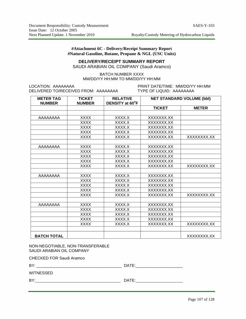
Document Responsibility: Custody Measurement SAES-Y-103 Issue Date: 12 October 2005 Next Planned Update: 1 November 2010 Royalty/Custody Metering of Hydrocarbon Liquids
Page 107 of 128
#Attachment 6C - Delivery/Receipt Summary Report #Natural Gasoline, Butane, Propane & NGL (USC Units)
DELIVERY/RECEIPT SUMMARY REPORT SAUDI ARABIAN OIL COMPANY (Saudi Aramco)
BATCH NUMBER XXXX MM/DD/YY HH:MM TO MM/DD/YY HH:MM
LOCATION: AAAAAAAA PRINT DATE/TIME: MM/DD/YY HH:MM DELIVERED TO/RECEIVED FROM: AAAAAAAA TYPE OF LIQUID: AAAAAAAA
METER TAG NUMBER
TICKET NUMBER
RELATIVE DENSITY at 60oF
NET STANDARD VOLUME (bbl)
TICKET METER
AAAAAAAA XXXX XXXX.X XXXXXXX.XX XXXX XXXX.X XXXXXXX.XX XXXX XXXX.X XXXXXXX.XX XXXX XXXX.X XXXXXXX.XX XXXX XXXX.X XXXXXXX.XX XXXXXXXX.XX
AAAAAAAA XXXX XXXX.X XXXXXXX.XX XXXX XXXX.X XXXXXXX.XX XXXX XXXX.X XXXXXXX.XX XXXX XXXX.X XXXXXXX.XX XXXX XXXX.X XXXXXXX.XX XXXXXXXX.XX
AAAAAAAA XXXX XXXX.X XXXXXXX.XX XXXX XXXX.X XXXXXXX.XX XXXX XXXX.X XXXXXXX.XX XXXX XXXX.X XXXXXXX.XX XXXX XXXX.X XXXXXXX.XX XXXXXXXX.XX
AAAAAAAA XXXX XXXX.X XXXXXXX.XX XXXX XXXX.X XXXXXXX.XX XXXX XXXX.X XXXXXXX.XX XXXX XXXX.X XXXXXXX.XX XXXX XXXX.X XXXXXXX.XX XXXXXXXX.XX
BATCH TOTAL XXXXXXXX.XX NON-NEGOTIABLE, NON-TRANSFERABLE SAUDI ARABIAN OIL COMPANY
CHECKED FOR Saudi Aramco
BY: ______________________________________ DATE:_____________________
WITNESSED
BY:______________________________________ DATE:_____________________
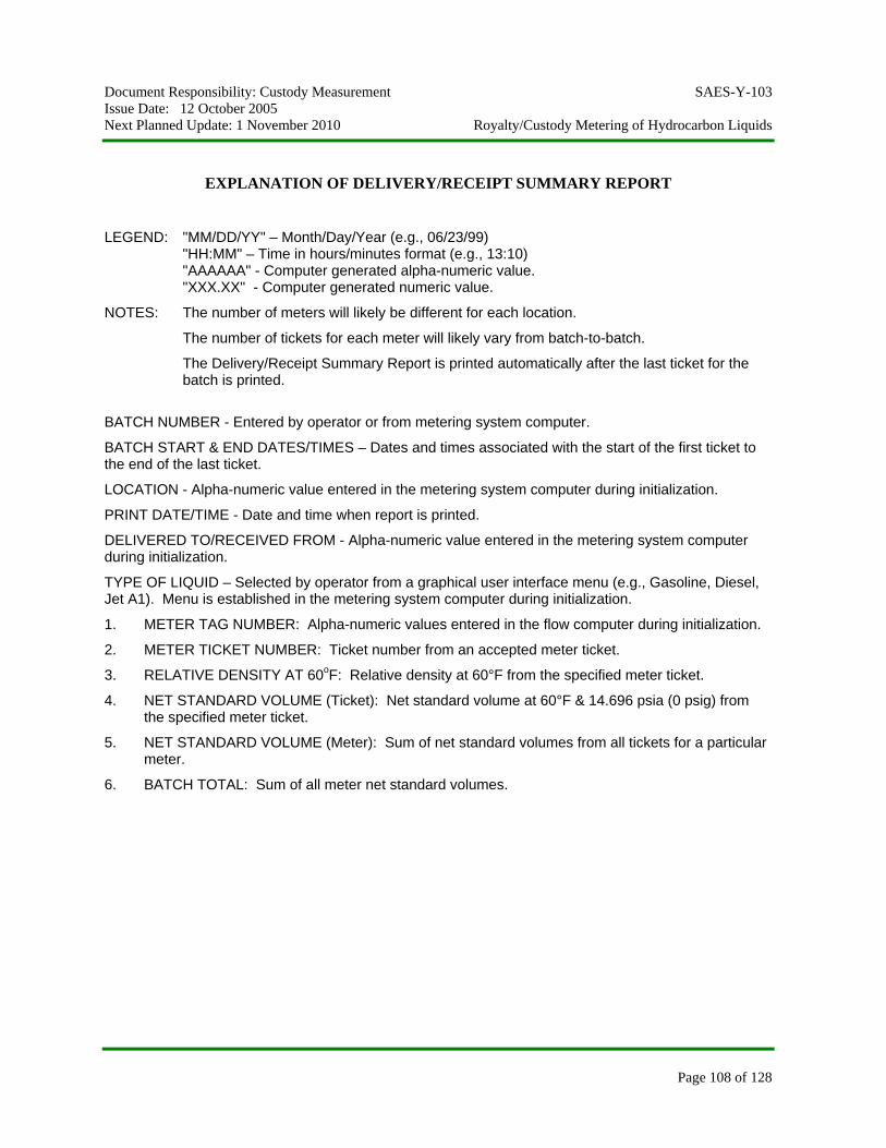
Document Responsibility: Custody Measurement SAES-Y-103 Issue Date: 12 October 2005 Next Planned Update: 1 November 2010 Royalty/Custody Metering of Hydrocarbon Liquids
Page 108 of 128
EXPLANATION OF DELIVERY/RECEIPT SUMMARY REPORT
LEGEND: "MM/DD/YY" – Month/Day/Year (e.g., 06/23/99)
"HH:MM" – Time in hours/minutes format (e.g., 13:10) "AAAAAA" - Computer generated alpha-numeric value. "XXX.XX" - Computer generated numeric value.
NOTES: The number of meters will likely be different for each location.
The number of tickets for each meter will likely vary from batch-to-batch.
The Delivery/Receipt Summary Report is printed automatically after the last ticket for the batch is printed.
BATCH NUMBER - Entered by operator or from metering system computer.
BATCH START & END DATES/TIMES – Dates and times associated with the start of the first ticket to the end of the last ticket.
LOCATION - Alpha-numeric value entered in the metering system computer during initialization.
PRINT DATE/TIME - Date and time when report is printed.
DELIVERED TO/RECEIVED FROM - Alpha-numeric value entered in the metering system computer during initialization.
TYPE OF LIQUID – Selected by operator from a graphical user interface menu (e.g., Gasoline, Diesel, Jet A1). Menu is established in the metering system computer during initialization.
1. METER TAG NUMBER: Alpha-numeric values entered in the flow computer during initialization.
2. METER TICKET NUMBER: Ticket number from an accepted meter ticket.
3. RELATIVE DENSITY AT 60oF: Relative density at 60°F from the specified meter ticket.
4. NET STANDARD VOLUME (Ticket): Net standard volume at 60°F & 14.696 psia (0 psig) from the specified meter ticket.
5. NET STANDARD VOLUME (Meter): Sum of net standard volumes from all tickets for a particular meter.
6. BATCH TOTAL: Sum of all meter net standard volumes.
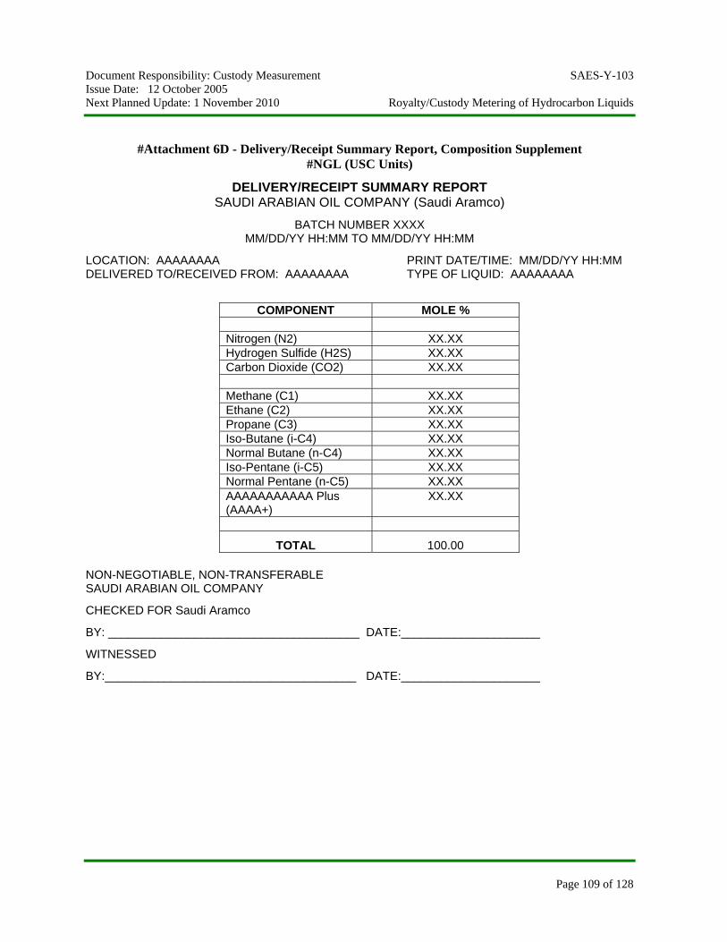
Document Responsibility: Custody Measurement SAES-Y-103 Issue Date: 12 October 2005 Next Planned Update: 1 November 2010 Royalty/Custody Metering of Hydrocarbon Liquids
Page 109 of 128
#Attachment 6D - Delivery/Receipt Summary Report, Composition Supplement
#NGL (USC Units)
DELIVERY/RECEIPT SUMMARY REPORT SAUDI ARABIAN OIL COMPANY (Saudi Aramco)
BATCH NUMBER XXXX MM/DD/YY HH:MM TO MM/DD/YY HH:MM
LOCATION: AAAAAAAA PRINT DATE/TIME: MM/DD/YY HH:MM DELIVERED TO/RECEIVED FROM: AAAAAAAA TYPE OF LIQUID: AAAAAAAA
COMPONENT MOLE %
Nitrogen (N2) XX.XX Hydrogen Sulfide (H2S) XX.XX Carbon Dioxide (CO2) XX.XX
Methane (C1) XX.XX Ethane (C2) XX.XX Propane (C3) XX.XX Iso-Butane (i-C4) XX.XX Normal Butane (n-C4) XX.XX Iso-Pentane (i-C5) XX.XX Normal Pentane (n-C5) XX.XX AAAAAAAAAAA Plus (AAAA+)
XX.XX
TOTAL 100.00 NON-NEGOTIABLE, NON-TRANSFERABLE SAUDI ARABIAN OIL COMPANY
CHECKED FOR Saudi Aramco
BY: ______________________________________ DATE:_____________________
WITNESSED
BY:______________________________________ DATE:_____________________
Document Responsibility: Custody Measurement SAES-Y-103 Issue Date: 12 October 2005 Next Planned Update: 1 November 2010 Royalty/Custody Metering of Hydrocarbon Liquids
Page 110 of 128
EXPLANATION OF DELIVERY/RECEIPT SUMMARY REPORT
COMPOSITION SUPPLEMENT LEGEND: "MM/DD/YY" – Month/Day/Year (e.g., 06/23/99)
"HH:MM" – Time in hours/minutes format (e.g., 13:10) "AAAAAA" - Computer generated alpha-numeric value. "XXX.XX" - Computer generated numeric value.
NOTES: The number of meters will likely be different for each location.
The number of tickets for each meter will likely vary from batch-to-batch.
The Delivery/Receipt Summary Report is printed automatically after the last ticket for the batch is printed.
BATCH NUMBER - Entered by operator or from metering system computer.
BATCH START & END DATES/TIMES – Dates and times associated with the start of the first ticket to the end of the last ticket.
LOCATION - Alpha-numeric value entered in the metering system computer during initialization.
PRINT DATE/TIME - Date and time when report is printed.
DELIVERED TO/RECEIVED FROM - Alpha-numeric value entered in the metering system computer during initialization.
TYPE OF LIQUID – Selected by operator from a graphical user interface menu (e.g., Gasoline, Diesel, Jet A1). Menu is established in the metering system computer during initialization.
1. COMPONENT: Alpha-numeric values entered in the metering supervisory computer during initialization.
2. MOLE %: Average mole percent for batch as calculated by the flow computer from data produced from a gas chromatograph or results from laboratory on a NGL sample entered in the metering supervisory computer .

Document Responsibility: Custody Measurement SAES-Y-103 Issue Date: 12 October 2005 Next Planned Update: 1 November 2010 Royalty/Custody Metering of Hydrocarbon Liquids
Page 111 of 128
#Attachment 7: Meter Calibration Report
All Hydrocarbon Liquids (Metric or USC Units)
METER CALIBRATION REPORT SAUDI ARABIAN OIL COMPANY (Saudi Aramco)
FLOW COMPUTER: AAAAAAAA
LOCATION: AAAAAAAA PRINT DATE/TIME: MM/DD/YY HH:MM
METER TAG NUMBER: AAAAAAAA NOMINAL K FACTOR: 5 DIGITS METER MANUFACTURER: AAAAAAAA METER MODEL: AAAAAAAA METER SERIAL NUMBER: AAAAAAAA METER SIZE (in): XXX.XXX
Type of Liquid: AAAAAAAA Type of Liquid: AAAAAAAA Calibration Date: MM/DD/YY Calibration Date: MM/DD/YY
Flow Rate (M3/h or bbl/h)
Meter Factor Flow Rate (M3/h or bbl/h)
Meter Factor
XXXXX.X X.XXXX XXXXX.X X.XXXX XXXXX.X X.XXXX XXXXX.X X.XXXX XXXXX.X X.XXXX XXXXX.X X.XXXX XXXXX.X X.XXXX XXXXX.X X.XXXX XXXXX.X X.XXXX XXXXX.X X.XXXX XXXXX.X X.XXXX XXXXX.X X.XXXX XXXXX.X X.XXXX XXXXX.X X.XXXX XXXXX.X X.XXXX XXXXX.X X.XXXX XXXXX.X X.XXXX XXXXX.X X.XXXX XXXXX.X X.XXXX XXXXX.X X.XXXX XXXXX.X X.XXXX XXXXX.X X.XXXX XXXXX.X X.XXXX XXXXX.X X.XXXX
Normal Flow Rate (M3/h or bbl/h)
Initial Base Meter Factor
Normal Flow Rate (M3/h or bbl/h)
Initial Base Meter Factor
XXXXX.X X.XXXX XXXXX.X X.XXXX

Document Responsibility: Custody Measurement SAES-Y-103 Issue Date: 12 October 2005 Next Planned Update: 1 November 2010 Royalty/Custody Metering of Hydrocarbon Liquids
Page 112 of 128
EXPLANATION OF METER CALIBRATION REPORT
LEGEND: "MM/DD/YY" – Month/Day/Year (e.g., 06/23/99)
"HH:MM" – Time in hours/minutes format (e.g., 13:10) "AAAAAA" - Computer generated alpha-numeric value. "XXX.XX" - Computer generated numeric value.
FLOW COMPUTER - Alpha-numeric tag number for the flow computer from which the data is read.
LOCATION - Alpha-numeric value entered in the metering system computer during initialization.
PRINT DATE/TIME - Date and time when report is printed.
METER TAG NUMBER - Alpha-numeric value entered in the flow computer during initialization.
NOMINAL K FACTOR – Numeric value as read from the flow computer.
METER MANUFACTURER & MODEL – Alpha-numeric values entered in the metering system computer or flow computer during initialization.
METER SERIAL NO.– Alpha-numeric value entered in the flow computer during initialization.
METER SIZE - Alpha-numeric value entered in the metering system computer or flow computer during initialization.
1. TYPE OF LIQUID – Liquid specified in the flow computer (e.g., Gasoline, Diesel, Jet A1) for which the corresponding base meter factor data is applicable.
2. CALIBRATION DATE – Date on which the calibration data was obtained.
3. FLOW RATES & CORRESPONDING METER FACTORS – Data points on the base meter factor curve as read from the flow computer. Data points are entered in the flow computer during initialization.
4. NORMAL FLOW RATE – The normal meter flow rate is used to permit an evaluation of meter performance over the life of the meter. The normal meter flow rate is selected by P&CSD/PID/CMU & Operations, and is entered in the flow computer at initialization.
5. INITIAL BASE METER FACTOR - The meter factor at the normal meter flow rate that is determined from the meter's initial base curve. Factor is entered in the flow computer at initialization.

Document Responsibility: Custody Measurement SAES-Y-103 Issue Date: 12 October 2005 Next Planned Update: 1 November 2010 Royalty/Custody Metering of Hydrocarbon Liquids
Page 113 of 128
#Attachment 8: Non-Transfer Activity Report – All Hydrocarbon Liquids (Metric or USC Units)
NON-TRANSFER ACTIVITY REPORT SAUDI ARABIAN OIL COMPANY
(Saudi Aramco)
MONTH/YEAR: MMM YYYY
LOCATION: AAAAAAAA PRINT DATE/TIME: MM/DD/YY HH:MM DELIVERED TO/RECEIVED FROM: AAAAAAAA
FLOW COMPUTER: AAAAAAAA METER TAG
NUMBER ID DATE/TIME INDICATED METER READINGS
(M3 or BBL) REASON
OPENING CLOSING OPENING CLOSING
AAAAAAAA AAAAAAAA DD HH:MM DD HH:MM XXXXXXXX XXXXXXXX AAAAAAAAAAA AAAAAAAA DD HH:MM DD HH:MM XXXXXXXX XXXXXXXX AAAAAAAAAAA AAAAAAAA DD HH:MM DD HH:MM XXXXXXXX XXXXXXXX AAAAAAAAAAA AAAAAAAA DD HH:MM DD HH:MM XXXXXXXX XXXXXXXX AAAAAAAAAAA AAAAAAAA DD HH:MM DD HH:MM XXXXXXXX XXXXXXXX AAAAAAAAAAA AAAAAAAA DD HH:MM DD HH:MM XXXXXXXX XXXXXXXX AAAAAAAAAAA AAAAAAAA DD HH:MM DD HH:MM XXXXXXXX XXXXXXXX AAAAAAAAAAA AAAAAAAA DD HH:MM DD HH:MM XXXXXXXX XXXXXXXX AAAAAAAAAAA AAAAAAAA DD HH:MM DD HH:MM XXXXXXXX XXXXXXXX AAAAAAAAAAA AAAAAAAA DD HH:MM DD HH:MM XXXXXXXX XXXXXXXX AAAAAAAAAAA
AAAAAAAA AAAAAAAA DD HH:MM DD HH:MM XXXXXXXX XXXXXXXX AAAAAAAAAAA
AAAAAAAA DD HH:MM DD HH:MM XXXXXXXX XXXXXXXX AAAAAAAAAAA AAAAAAAA DD HH:MM DD HH:MM XXXXXXXX XXXXXXXX AAAAAAAAAAA AAAAAAAA DD HH:MM DD HH:MM XXXXXXXX XXXXXXXX AAAAAAAAAAA AAAAAAAA DD HH:MM DD HH:MM XXXXXXXX XXXXXXXX AAAAAAAAAAA AAAAAAAA DD HH:MM DD HH:MM XXXXXXXX XXXXXXXX AAAAAAAAAAA AAAAAAAA DD HH:MM DD HH:MM XXXXXXXX XXXXXXXX AAAAAAAAAAA AAAAAAAA DD HH:MM DD HH:MM XXXXXXXX XXXXXXXX AAAAAAAAAAA AAAAAAAA DD HH:MM DD HH:MM XXXXXXXX XXXXXXXX AAAAAAAAAAA AAAAAAAA DD HH:MM DD HH:MM XXXXXXXX XXXXXXXX AAAAAAAAAAA

Document Responsibility: Custody Measurement SAES-Y-103 Issue Date: 12 October 2005 Next Planned Update: 1 November 2010 Royalty/Custody Metering of Hydrocarbon Liquids
Page 114 of 128
EXPLANATION OF NON-TRANSFER ACTIVITY REPORT
LEGEND: "MM/DD/YY" – Month/Day/Year (e.g., 06/23/99)
"DD HH:MM" – Two digit date and time in hours/minutes format (e.g., 23 13:10) "AAAAAA" - Computer generated alpha-numeric value. "XXX.XX" - Computer generated numeric value.
NOTES: The number of meters will likely be different for each location.
When enabled, the Non-Transfer Actvity Report is printed automatically at the top after midnight on the first day of each month.
MONTH YEAR – Month/year covered by the report.
LOCATION - Alpha-numeric values entered in the metering system computer during initialization.
PRINT DATE/TIME - Date and time when report is printed.
DELIVERED TO/RECEIVED FROM - Alpha-numeric value entered in the metering system computer during initialization.
FLOW COMPUTER: Flow computer from which the data orginates.
1. METER TAG NUMBER: Alpha-numeric values entered in the flow computer during initialization.
2. ID: Identificaton number for person creating non-transfer activity.
3. DATE/TIME (OPENING): Date/time when non-activity event is initiated.
4. DATE/TIME (CLOSING): Date time when non-activity event is terminated.
5. INDICATED METER READING (OPENING): Indicated meter reading at beginning of the period (final meter reading at the end of the previous period) or the opening reading for the initial ticket of a batch, as applicable.
6. INDICATED METER READING (CLOSING): Indicated meter reading at the end of the period or the closing meter reading for the final ticket of a batch, as applicable.
7. REASON: Reason for event (meter maintenance, circulation, etc.).

Document Responsibility: Custody Measurement SAES-Y-103 Issue Date: 12 October 2005 Next Planned Update: 1 November 2010 Royalty/Custody Metering of Hydrocarbon Liquids
Page 115 of 128
#Attachment 9A: Hourly Report #Refined Products (Metric Units)
HOURLY REPORT SAUDI ARABIAN OIL COMPANY (Saudi Aramco)
DATE: MM/DD/YY PERIOD: HH:MM to HH:MM
LOCATION: AAAAAAAA PRINT DATE/TIME: MM/DD/YY HH:MM DELIVERED TO/RECEIVED FROM: AAAAAAAA
BATCH NUMBER
LIQUID METER TAG NUMBER
AVERAGE DENSITY
(kg/L)
AVERAGE TEMPERATURE
(deg C)
AVERAGE PRESSURE (KPA (ga))
NET STANDARD VOLUME (M3)
METER BATCH
XXXX AAAAAAAA AAAAAAAA X.XXXX XX.XX XXXX XXXXXX.XXX
AAAAAAAA X.XXXX XX.XX XXXX XXXXXX.XXX
AAAAAAAA X.XXXX XX.XX XXXX XXXXXX.XXX
AAAAAAAA X.XXXX XX.XX XXXX XXXXXX.XXX XXXXXX.XXX
XXXX AAAAAAAA AAAAAAAA X.XXXX XX.XX XXXX XXXXXX.XXX
AAAAAAAA X.XXXX XX.XX XXXX XXXXXX.XXX
AAAAAAAA X.XXXX XX.XX XXXX XXXXXX.XXX
AAAAAAAA X.XXXX XX.XX XXXX XXXXXX.XXX XXXXXX.XXX
HOUR TOTAL XXXXXXX.XX
Document Responsibility: Custody Measurement SAES-Y-103 Issue Date: 12 October 2005 Next Planned Update: 1 November 2010 Royalty/Custody Metering of Hydrocarbon Liquids
Page 116 of 128
EXPLANATION OF HOURLY REPORT
LEGEND: "MM/DD/YY" – Month/Day/Year (e.g., 06/23/99)
"HH:MM" – Time in hours/minutes format (e.g., 13:10) "AAAAAA" - Computer generated alpha-numeric value. "XXX.XX" - Computer generated numeric value.
NOTES: The number of meters will likely be different for each location.
When enabled, the hourly report is printed automatically at the end of each hour.
DATE - Date covered by the report.
PERIOD – Time period covered by the report.
LOCATION - Alpha-numeric values entered in the metering system computer during initialization.
PRINT DATE/TIME - Date and time when report is printed.
DELIVERED TO/RECEIVED FROM - Alpha-numeric value entered in the metering system computer during initialization.
1. BATCH NUMBER: Number of any batch that was received or delivered/received during the period. Entered by operator or from metering system computer. The current batch number automatically carries forward to new ticket generated for an active movement at 12:00 midnight.
2. TYPE OF LIQUID: Selected by operator from a graphical user interface menu (e.g., Gasoline, Diesel, Jet A1). Menu is established in the metering system computer during initialization.
3. METER TAG NUMBER: Alpha-numeric values entered in the flow computer during initialization.
4. AVERAGE DENSITY: For a particular batch, the average density at 15oC for the fluid passing through the meter during the period.
5. AVERAGE TEMPERATURE: For a particular batch, the average temperature for the fluid passing through the meter during the period.
6. AVERAGE PRESSURE: For a particular batch, the average pressure for the fluid passing through the meter during the period.
7. NET STANDARD VOLUME (Meter): For a particular batch, the net standard volume at 15oC & 101.325 kPa (0 kPa (ga)) passing through a meter during the period.
8. NET STANDARD VOLUME (Batch): For a particular batch, the total net standard volume passing through all meters during the period.
9. HOURLY TOTAL – Total net standard volume passing through all meters during the period (sum of all batch net standard volumes).
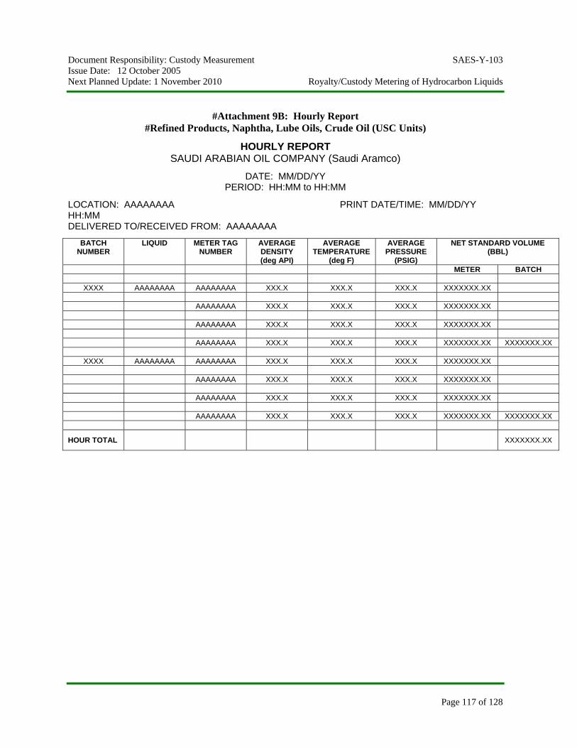
Document Responsibility: Custody Measurement SAES-Y-103 Issue Date: 12 October 2005 Next Planned Update: 1 November 2010 Royalty/Custody Metering of Hydrocarbon Liquids
Page 117 of 128
#Attachment 9B: Hourly Report
#Refined Products, Naphtha, Lube Oils, Crude Oil (USC Units)
HOURLY REPORT SAUDI ARABIAN OIL COMPANY (Saudi Aramco)
DATE: MM/DD/YY PERIOD: HH:MM to HH:MM
LOCATION: AAAAAAAA PRINT DATE/TIME: MM/DD/YY HH:MM DELIVERED TO/RECEIVED FROM: AAAAAAAA
BATCH NUMBER
LIQUID METER TAG NUMBER
AVERAGE DENSITY (deg API)
AVERAGE TEMPERATURE
(deg F)
AVERAGE PRESSURE
(PSIG)
NET STANDARD VOLUME (BBL)
METER BATCH
XXXX AAAAAAAA AAAAAAAA XXX.X XXX.X XXX.X XXXXXXX.XX
AAAAAAAA XXX.X XXX.X XXX.X XXXXXXX.XX
AAAAAAAA XXX.X XXX.X XXX.X XXXXXXX.XX
AAAAAAAA XXX.X XXX.X XXX.X XXXXXXX.XX XXXXXXX.XX
XXXX AAAAAAAA AAAAAAAA XXX.X XXX.X XXX.X XXXXXXX.XX
AAAAAAAA XXX.X XXX.X XXX.X XXXXXXX.XX
AAAAAAAA XXX.X XXX.X XXX.X XXXXXXX.XX
AAAAAAAA XXX.X XXX.X XXX.X XXXXXXX.XX XXXXXXX.XX
HOUR TOTAL XXXXXXX.XX

Document Responsibility: Custody Measurement SAES-Y-103 Issue Date: 12 October 2005 Next Planned Update: 1 November 2010 Royalty/Custody Metering of Hydrocarbon Liquids
Page 118 of 128
EXPLANATION OF HOURLY REPORT
LEGEND: "MM/DD/YY" – Month/Day/Year (e.g., 06/23/99)
"HH:MM" – Time in hours/minutes format (e.g., 13:10) "AAAAAA" - Computer generated alpha-numeric value. "XXX.XX" - Computer generated numeric value.
NOTES: The number of meters will likely be different for each location.
When enabled, the hourly report is printed automatically at the end of each hour.
DATE - Date covered by the report.
PERIOD – Time period covered by the report.
LOCATION - Alpha-numeric values entered in the metering system computer during initialization.
PRINT DATE/TIME - Date and time when report is printed.
DELIVERED TO/RECEIVED FROM - Alpha-numeric value entered in the metering system computer during initialization.
1. BATCH NUMBER: Number of any batch that was received or delivered/received during the period. Entered by operator or from metering system computer. The current batch number automatically carries forward to new ticket generated for an active movement at 12:00 midnight.
2. TYPE OF LIQUID: Selected by operator from a graphical user interface menu (e.g., Gasoline, Diesel, Jet A1). Menu is established in the metering system computer during initialization.
3. METER TAG NUMBER: Alpha-numeric values entered in the flow computer during initialization.
4. AVERAGE DENSITY: For a particular batch, the average density at 60oF for the fluid passing through the meter during the period.
5. AVERAGE TEMPERATURE: For a particular batch, the average temperature for the fluid passing through the meter during the period.
6. AVERAGE PRESSURE: For a particular batch, the average pressure for the fluid passing through the meter during the period.
7. NET STANDARD VOLUME (Meter): For a particular batch, the net standard volume at 60oF & 14.696 psig passing through a meter during the period.
8. NET STANDARD VOLUME (Batch): For a particular batch, the total net standard volume passing through all meters during the period.
9. HOURLY TOTAL – Total net standard volume passing through all meters during the period (sum of all batch net standard volumes).
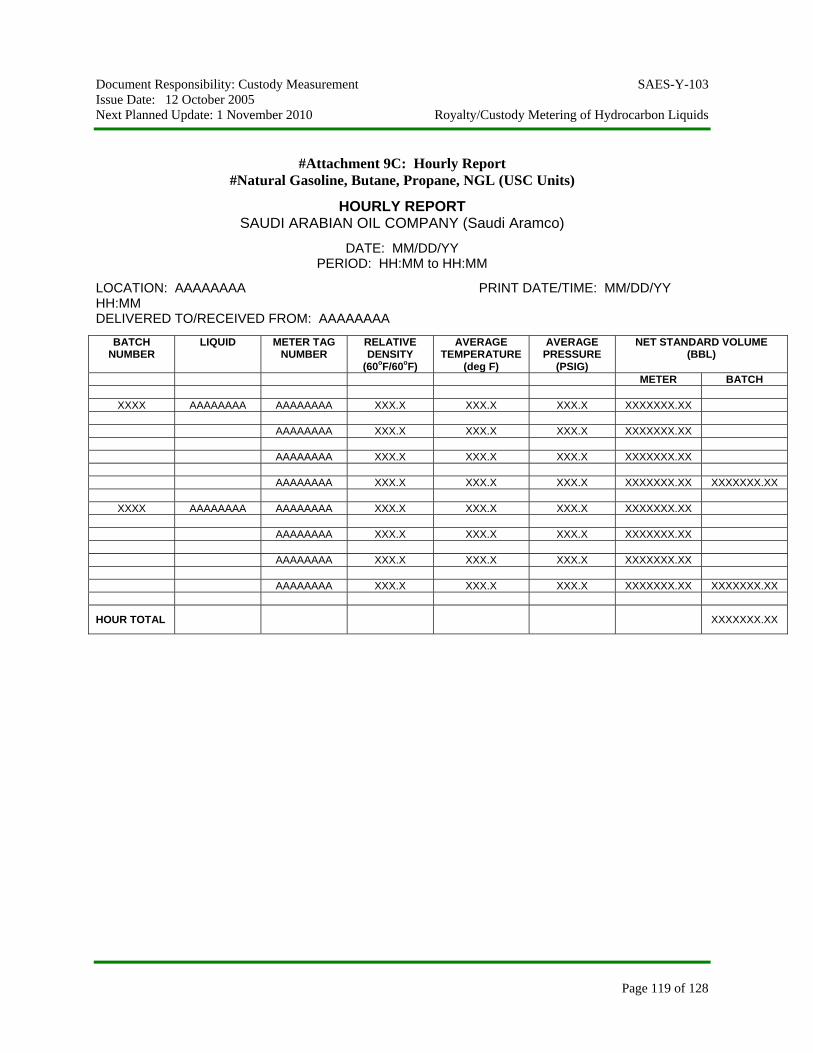
Document Responsibility: Custody Measurement SAES-Y-103 Issue Date: 12 October 2005 Next Planned Update: 1 November 2010 Royalty/Custody Metering of Hydrocarbon Liquids
Page 119 of 128
#Attachment 9C: Hourly Report
#Natural Gasoline, Butane, Propane, NGL (USC Units)
HOURLY REPORT SAUDI ARABIAN OIL COMPANY (Saudi Aramco)
DATE: MM/DD/YY PERIOD: HH:MM to HH:MM
LOCATION: AAAAAAAA PRINT DATE/TIME: MM/DD/YY HH:MM DELIVERED TO/RECEIVED FROM: AAAAAAAA
BATCH NUMBER
LIQUID METER TAG NUMBER
RELATIVE DENSITY
(60oF/60oF)
AVERAGE TEMPERATURE
(deg F)
AVERAGE PRESSURE
(PSIG)
NET STANDARD VOLUME (BBL)
METER BATCH
XXXX AAAAAAAA AAAAAAAA XXX.X XXX.X XXX.X XXXXXXX.XX
AAAAAAAA XXX.X XXX.X XXX.X XXXXXXX.XX
AAAAAAAA XXX.X XXX.X XXX.X XXXXXXX.XX
AAAAAAAA XXX.X XXX.X XXX.X XXXXXXX.XX XXXXXXX.XX
XXXX AAAAAAAA AAAAAAAA XXX.X XXX.X XXX.X XXXXXXX.XX
AAAAAAAA XXX.X XXX.X XXX.X XXXXXXX.XX
AAAAAAAA XXX.X XXX.X XXX.X XXXXXXX.XX
AAAAAAAA XXX.X XXX.X XXX.X XXXXXXX.XX XXXXXXX.XX
HOUR TOTAL XXXXXXX.XX
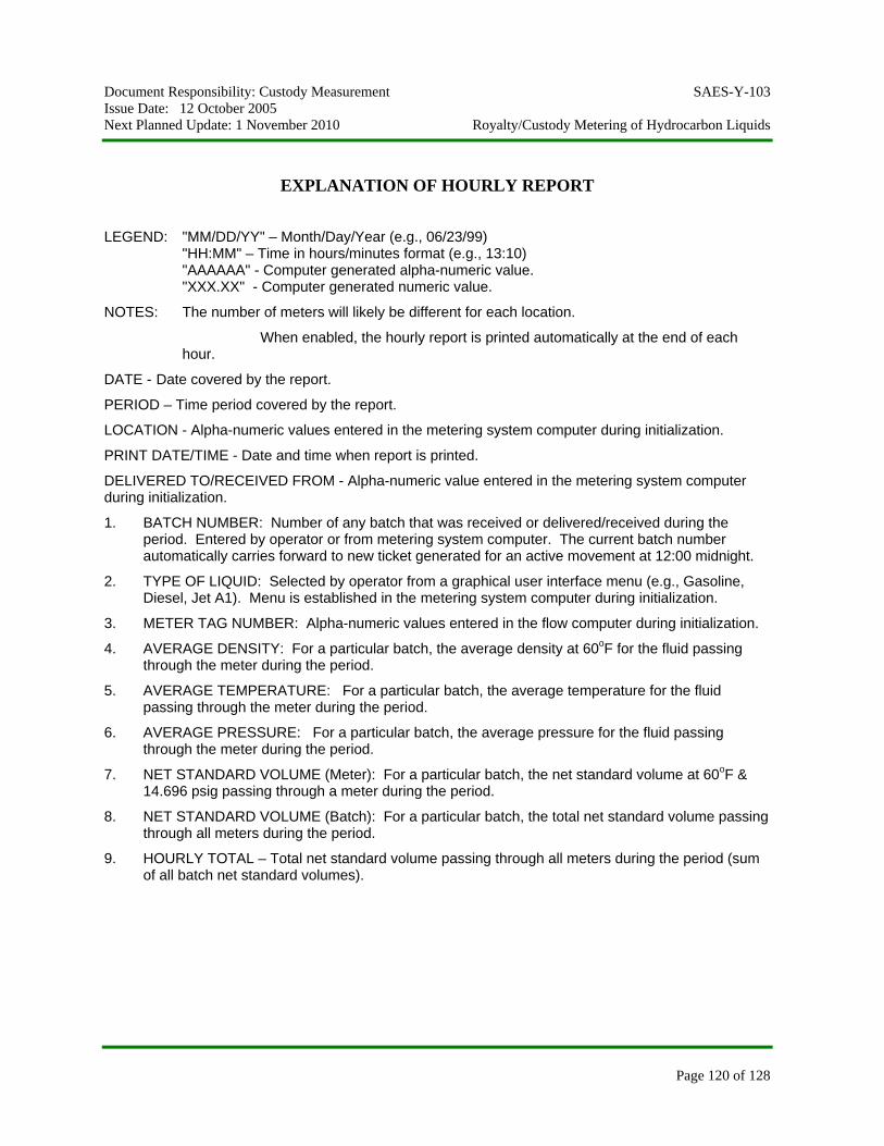
Document Responsibility: Custody Measurement SAES-Y-103 Issue Date: 12 October 2005 Next Planned Update: 1 November 2010 Royalty/Custody Metering of Hydrocarbon Liquids
Page 120 of 128
EXPLANATION OF HOURLY REPORT
LEGEND: "MM/DD/YY" – Month/Day/Year (e.g., 06/23/99)
"HH:MM" – Time in hours/minutes format (e.g., 13:10) "AAAAAA" - Computer generated alpha-numeric value. "XXX.XX" - Computer generated numeric value.
NOTES: The number of meters will likely be different for each location.
When enabled, the hourly report is printed automatically at the end of each hour.
DATE - Date covered by the report.
PERIOD – Time period covered by the report.
LOCATION - Alpha-numeric values entered in the metering system computer during initialization.
PRINT DATE/TIME - Date and time when report is printed.
DELIVERED TO/RECEIVED FROM - Alpha-numeric value entered in the metering system computer during initialization.
1. BATCH NUMBER: Number of any batch that was received or delivered/received during the period. Entered by operator or from metering system computer. The current batch number automatically carries forward to new ticket generated for an active movement at 12:00 midnight.
2. TYPE OF LIQUID: Selected by operator from a graphical user interface menu (e.g., Gasoline, Diesel, Jet A1). Menu is established in the metering system computer during initialization.
3. METER TAG NUMBER: Alpha-numeric values entered in the flow computer during initialization.
4. AVERAGE DENSITY: For a particular batch, the average density at 60oF for the fluid passing through the meter during the period.
5. AVERAGE TEMPERATURE: For a particular batch, the average temperature for the fluid passing through the meter during the period.
6. AVERAGE PRESSURE: For a particular batch, the average pressure for the fluid passing through the meter during the period.
7. NET STANDARD VOLUME (Meter): For a particular batch, the net standard volume at 60oF & 14.696 psig passing through a meter during the period.
8. NET STANDARD VOLUME (Batch): For a particular batch, the total net standard volume passing through all meters during the period.
9. HOURLY TOTAL – Total net standard volume passing through all meters during the period (sum of all batch net standard volumes).

Document Responsibility: Custody Measurement SAES-Y-103 Issue Date: 12 October 2005 Next Planned Update: 1 November 2010 Royalty/Custody Metering of Hydrocarbon Liquids
Page 121 of 128
Appendix B – Automation Requirements for Truck, Rail Car & Refueler Loading Meters
This appendix describes the basic automation requirements for required for truck, rail car and refueler loading meters.
B.1 Preset Controllers
Each meter shall be furnished with an electronic preset controller.
Electronic preset controllers having multiple meter capability may be used provided that control of the meters is independent from one another.
Each preset controller shall provide Level B pulse security as defined in the API Manual of Petroleum Measurement Standards, Chapter 5.5 using the dual inputs provided by each assigned meter.
B.1.1 Software
Each electronic preset controller shall calculate volume totals for each meter in accordance with API Manual of Petroleum Measurement Standards, Chapter 12.2, and the applicable API/ASTM tables specified in Section 5.
In performing volume calculations, each preset controller shall use linearized meter factors derived from at least 4 pre-configured meter factors and corresponding flow rates.
B.1.2 Inputs
The electronic preset controller shall be wired and configured to receive the following input signals as a minimum:
• Frequency inputs for the A & B pickup coil from each meter.
• A temperature input for each meter controlled by the preset controller.
• A pressure input for meter controlled by the preset controller (if specified).
• Two local interlock permissives.
System shall support the later addition of additive injection pump status and volume data.

Document Responsibility: Custody Measurement SAES-Y-103 Issue Date: 12 October 2005 Next Planned Update: 1 November 2010 Royalty/Custody Metering of Hydrocarbon Liquids
Page 122 of 128
B.1.3 Outputs
The electronic preset controller shall be wired and configured to allow outputs for the following:
• Digital set-stop valve(s), solenoid operation (two solenoids per valve)
• Pump start permissive
• Raw (unaltered) meter pulses from each pick-up coil of each meter for remote and local meter proving
System shall support the later addition of additive injection pump, start signals.
B.1.4 Communication
An RS-485 communications interface shall be provided.
It shall be possible to connect multiple units together on a single multi-drop RS-485 communication link.
Through this interface it shall be possible to upload and download the entire operating configuration of the electronic preset controller from a portable computer (IBM Compatible), or through the Terminal Management System.
Information available for upload over the communication link to the Terminal Management System, shall include but not be limited to:
• All dynamic data • I/O status • System configuration/diagnostics data • Data input by the driver/operator
System shall be capable of accepting the download of information from the Terminal Management System. This shall include but not be limited to:
• System configuration data • Driver / operator prompts • Driver / order / transaction data
B.1.5 Data Retention
Delivery ticket data from the last 20 transactions shall be retained in

Document Responsibility: Custody Measurement SAES-Y-103 Issue Date: 12 October 2005 Next Planned Update: 1 November 2010 Royalty/Custody Metering of Hydrocarbon Liquids
Page 123 of 128
non-volatile memory, for later recall by the Terminal Management System or through the local display and keypad.
B.1.6 Operating Parameters
It shall be possible to set operating parameters and control limits within the unit, as required to support safe operation. This shall include but not be limited to such items as maximum flow rate per meter, low flow start, normal and ramped shutdown flow rates.
It shall be possible to stop flow at any time, by depressing the stop button on the electronic preset controller. Interruption of flow by this method shall not cause the transaction counters to reset, and it shall be possible at any time to restart the flow by depressing the start button once again.
Configuration of external shutdown logic shall be the responsibility of Saudi Aramco, unless otherwise noted.
B.1.7 Dynamic Data
Status of the load in progress shall be shown during the loading operation. This shall take the form of an incremental or decremental counter in conjunction with the total batch size.
It shall be possible to call up other displays during a loading operation without affecting the load in progress. Display shall automatically return to the status of the load in progress after a pre-defined period of inactivity.
B.1.8 Configuration Data
It shall be possible through the local keypad, to access and change all configuration and calibration data contained within the unit.
Protection against unauthorized changes to configuration and calibration data shall be provided in the form of a keylock or passcode.
B.2 Meter Tickets
The following information shall be furnished on the bills of lading and/or other accounting documentation associated with the volumes loaded:
General Information
Plant Date and Time
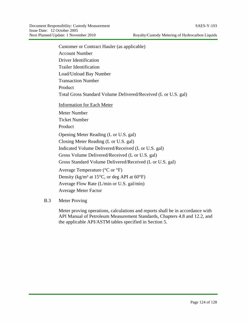
Document Responsibility: Custody Measurement SAES-Y-103 Issue Date: 12 October 2005 Next Planned Update: 1 November 2010 Royalty/Custody Metering of Hydrocarbon Liquids
Page 124 of 128
Customer or Contract Hauler (as applicable) Account Number Driver Identification Trailer Identification Load/Unload Bay Number Transaction Number Product Total Gross Standard Volume Delivered/Received (L or U.S. gal)
Information for Each Meter
Meter Number Ticket Number Product
Opening Meter Reading (L or U.S. gal) Closing Meter Reading (L or U.S. gal) Indicated Volume Delivered/Received (L or U.S. gal) Gross Volume Delivered/Received (L or U.S. gal) Gross Standard Volume Delivered/Received (L or U.S. gal)
Average Temperature (°C or °F) Density (kg/m³ at 15°C, or deg API at 60°F) Average Flow Rate (L/min or U.S. gal/min) Average Meter Factor
B.3 Meter Proving
Meter proving operations, calculations and reports shall be in accordance with API Manual of Petroleum Measurement Standards, Chapters 4.8 and 12.2, and the applicable API/ASTM tables specified in Section 5.
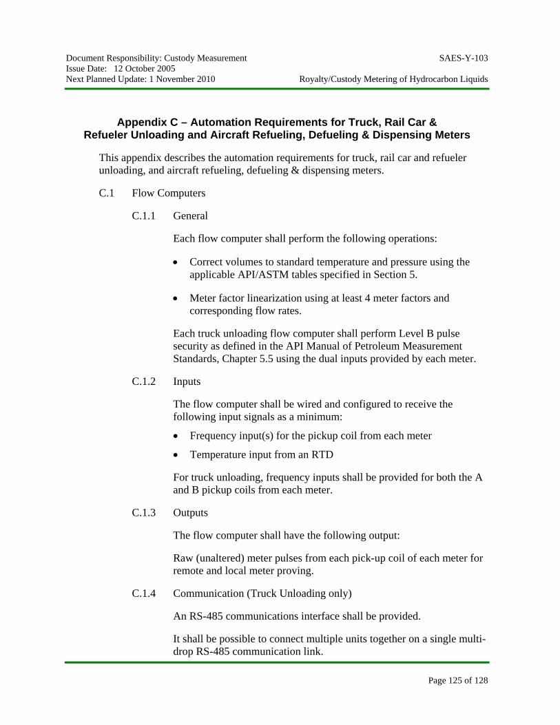
Document Responsibility: Custody Measurement SAES-Y-103 Issue Date: 12 October 2005 Next Planned Update: 1 November 2010 Royalty/Custody Metering of Hydrocarbon Liquids
Page 125 of 128
Appendix C – Automation Requirements for Truck, Rail Car & Refueler Unloading and Aircraft Refueling, Defueling & Dispensing Meters
This appendix describes the automation requirements for truck, rail car and refueler unloading, and aircraft refueling, defueling & dispensing meters.
C.1 Flow Computers
C.1.1 General
Each flow computer shall perform the following operations:
• Correct volumes to standard temperature and pressure using the applicable API/ASTM tables specified in Section 5.
• Meter factor linearization using at least 4 meter factors and corresponding flow rates.
Each truck unloading flow computer shall perform Level B pulse security as defined in the API Manual of Petroleum Measurement Standards, Chapter 5.5 using the dual inputs provided by each meter.
C.1.2 Inputs
The flow computer shall be wired and configured to receive the following input signals as a minimum:
• Frequency input(s) for the pickup coil from each meter
• Temperature input from an RTD
For truck unloading, frequency inputs shall be provided for both the A and B pickup coils from each meter.
C.1.3 Outputs
The flow computer shall have the following output:
Raw (unaltered) meter pulses from each pick-up coil of each meter for remote and local meter proving.
C.1.4 Communication (Truck Unloading only)
An RS-485 communications interface shall be provided.
It shall be possible to connect multiple units together on a single multi-drop RS-485 communication link.
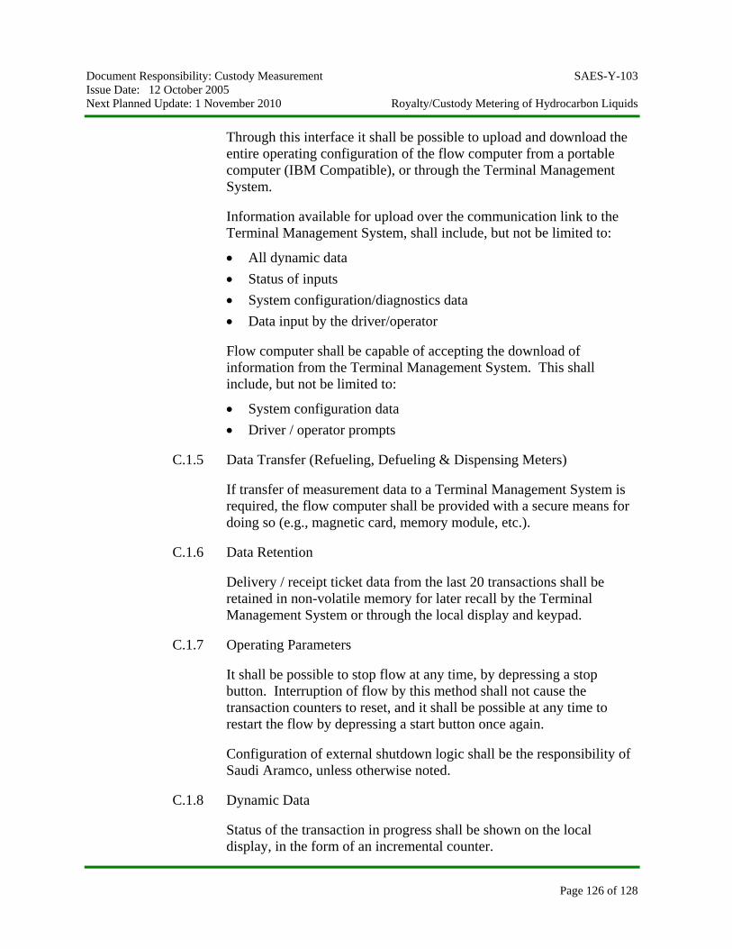
Document Responsibility: Custody Measurement SAES-Y-103 Issue Date: 12 October 2005 Next Planned Update: 1 November 2010 Royalty/Custody Metering of Hydrocarbon Liquids
Page 126 of 128
Through this interface it shall be possible to upload and download the entire operating configuration of the flow computer from a portable computer (IBM Compatible), or through the Terminal Management System.
Information available for upload over the communication link to the Terminal Management System, shall include, but not be limited to:
• All dynamic data • Status of inputs • System configuration/diagnostics data • Data input by the driver/operator
Flow computer shall be capable of accepting the download of information from the Terminal Management System. This shall include, but not be limited to:
• System configuration data • Driver / operator prompts
C.1.5 Data Transfer (Refueling, Defueling & Dispensing Meters)
If transfer of measurement data to a Terminal Management System is required, the flow computer shall be provided with a secure means for doing so (e.g., magnetic card, memory module, etc.).
C.1.6 Data Retention
Delivery / receipt ticket data from the last 20 transactions shall be retained in non-volatile memory for later recall by the Terminal Management System or through the local display and keypad.
C.1.7 Operating Parameters
It shall be possible to stop flow at any time, by depressing a stop button. Interruption of flow by this method shall not cause the transaction counters to reset, and it shall be possible at any time to restart the flow by depressing a start button once again.
Configuration of external shutdown logic shall be the responsibility of Saudi Aramco, unless otherwise noted.
C.1.8 Dynamic Data
Status of the transaction in progress shall be shown on the local display, in the form of an incremental counter.
Document Responsibility: Custody Measurement SAES-Y-103 Issue Date: 12 October 2005 Next Planned Update: 1 November 2010 Royalty/Custody Metering of Hydrocarbon Liquids
Page 127 of 128
It shall be possible to call up other displays during operation, without affecting the transaction in progress. Display shall automatically return to the status of the transaction in progress after a pre-defined period of inactivity.
C.1.9 Configuration Data
It shall be possible through the local keypad, to access and change all configuration and calibration data contained within the unit.
Protection against unauthorized changes to configuration and calibration data shall be provided in the form of a keylock or passcode.
C.2 Meter Tickets
The following information shall be furnished on the bills of lading and/or other accounting documentation associated with volumes loaded or received:
General Information
Plant Date and Time Customer or Contract Hauler (as applicable) Account Number Driver Identification Trailer Identification Load/Unload Bay Number Transaction Number Product Total Gross Standard Volume Delivered/Received (L)
Information for Each Meter
Meter Number Ticket Number Product
Opening Meter Reading (L) Closing Meter Reading (L) Indicated Volume Delivered/Received (L) Gross Volume Delivered/Received (L) Gross Standard Volume Delivered/Received (L)
Average Temperature (°C)
Document Responsibility: Custody Measurement SAES-Y-103 Issue Date: 12 October 2005 Next Planned Update: 1 November 2010 Royalty/Custody Metering of Hydrocarbon Liquids
Page 128 of 128
Density (kg/m³ at 15°C) Average Flow Rate (L/min) Average Meter Factor
C.3 Meter Proving
Meter proving operations, calculations and reports shall be in accordance with API Manual of Petroleum Measurement Standards, Chapters 4.8 and 12.2, and the applicable API/ASTM table(s) specified in Section 5.