
ENGINE MECHANICAL - Grey Matters
113
EM-1 ENGINE MECHANICAL DESCRIPTION EM-2 TROUBLESHOOTING EM-4 Diesel Engine Diagnosis EM-4 Diesel Electrical System Diagnosis EM -14 ENGINETUNE-UP EM-17 COMPRESSION CHECK EM-30 TIMING BELT EM-32 TIMINGGEARS EM-42 CYLINDER HEAD EM-54 CYLINDER BLOCK EM-84 Page
-
Upload
khangminh22 -
Category
Documents
-
view
0 -
download
0
Transcript of ENGINE MECHANICAL - Grey Matters

EM-1
ENGINE MECHANICAL
DESCRIPTION EM-2TROUBLESHOOTING EM-4
Diesel Engine Diagnosis EM-4Diesel Electrical System Diagnosis EM -14
ENGINETUNE-UP EM-17COMPRESSION CHECK EM-30TIMING BELT EM-32TIMINGGEARS EM-42CYLINDER HEAD EM-54CYLINDER BLOCK EM-84
Page

EM-2 ENGINE MECHANICAL - Description
DESCRIPTIONThe 1 PZ engine is an in-line 5-cylinder 3.5 liter OHC engine.The 1 HZ and 1 HD-T engines are an in-line 6-cylinder 4.2 liter OHC engine.
1PZ
1HZ
1HD-T
EM8795 EM8792EM8965 EM8793EM8966 EM8794

EM-3ENGINE MECHANICAL Description
The 1 PZ engine is an in-line 5-cylinder enginewith the cylinders numbered 1 - 2 - 3 - 4 - 5 fromthe front. This engine's injection order is1 - 2 - 4 - 5 - 3 .
The 1 HZ and 1HD-T engines are an in-line6-cylinder engine with the cylinders numbered1 - 2 - 3 - 4 - 5 - 6 from the front. This engine'sinjection order is 1 - 4 - 2 - 6 - 3 - 5 .
The crankshaft is supported by 6 (1 PZ) or 7 (1 HZand 1HD-T) bearings on the inside of the crank-case. These bearings are made of aluminum alloy.The crankshaft is integrated with 10 weights (1 PZ)or 12 weights (1 HZ and 1HD-T) which are castalong with it for balancing. Oil holes are built intothe crankshaft for supplying oil to the connectingrods, bearings and other components.
The crankshaft bearing cap is of ladder frameconstruction and is incorporated into the crankcase.
The cylinder head is made of cast iron with across flow type intake and exhaust layout. Thecombustion chambers are swirl chamber type forthe 1 PZ and 1 HZ engines and direct injection typefor the 1 H D-T engine. The camshaft journal part ofthe cylinder head has camshaft caps made of alu-minum alloy and is made of cast iron on the cylinderhead side. The camshaft journal has no bearings(with the exception of the No.1 journal).
The 1 HZ and 1 HD-T engines has dual-type ex-haust manifolds.
Exhaust and intake valves are equipped withirregular pitch springs which are capable of follow-ing the valves even at high engine speeds.
The camshaft is driven by the timing belt. Thecamshaft journal is supported at 6 places (1 PZ) or7 places (1 HZ and 1HD-T). Lubrication of thecamshaft journal and cam is accomplished by oilbeing supplied through the oiler port in the No.6(1 PZ) or No.7 (1 HZ and 1 HD-T) of the camshaftjournal.
Adjustment of the valve clearance is done bymeans of an outer shim type system, in which valveadjusting shims are located above the valve lifters.This permits replacement of the shims withoutremoval of the camshaft.
Pistons are made of highly temperature-resistantaluminum alloy. As the 1 HD-T engine is the directinjection type, a deep combustion chamber hasbeen provided. The No.1 piston ring groove hasbeen strengthened using a fiber reinforced metal.
Piston pins are the full-floating type, with thepins fastened to neither the connecting rods nor thepiston boss, but with a snap rings fitted to bothends of the pin to prevent the pin from slipping out.
The No.1 compression ring is made of steel andthe No.2 compression ring is made of cast iron. Theoil ring is made of steel. The outer diameter of eachpiston ring is slightly larger than the diameter of thepiston and the flexibility of the rings allows them tohug the cylinder walls when they are mounted onthe piston. Compression rings No.1 and No.2 workto prevent the leakage of gas from the cylinder andthe oil ring works to scrape oil off the cylinder wallsto prevent it from entering the combustion cham-ber.
The cylinder block is made of cast iron. It has 5cylinders (1 PZ) or 6 cylinders (1HZ and 1HD-T)which are approximately 1.7 times the length of thepiston stroke. The top of the cylinders is closed offby the cylinder head and the lower end of thecylinders becomes the crankcase, in which thecrankshaft is installed. In addition, the cylinderblock contains a water jacket, through which cool-ant is pumped to cool the cylinders.
Plastic region tightening bolts are used for thecylinder head bolts, crankshaft bearing cap boltsand connecting rod cap bolts.
The oil pan is bolted onto the bottom of thecrankshaft bearing cap with bolts and nuts. The oilpan is an oil reservoir made of pressed steel sheet.

EM-4 ENGINE MECHANICAL - Troubleshooting (Diesel Engine Diagnosis)
TROUBLESHOOTINGDiesel Engine DiagnosisGENERAL
1. Diesel engine problems are usually caused by the engine or fuel system. The injection pump is very rarelythe cause of fuel system problems.
2. Before beginning fuel system tests, first check that the engine compression, valve timing and other majorsystems are within specifications.
PRELIMINARY CHECKS
1. Before performing fuel system checks, ensure that the engine is in good running condition. If necessary,first check the compression, timing and major components or systems.
2. Check the air filter, and clean or replace it if necessary.
3. Check that there is sufficient fuel in the tank.4. Check if the fuel is contaminated with gasoline or other foreign elements. Only good-quality diesel fuel
should be used.5. Bleed air from the system by pumping the priming.6. Check for water in the fuel filter and fuel tank, and drain as necessary.7. If the engine will not crank or if it cranks slowly, first troubleshoot the electrical system.

EM-5ENGINE MECHANICAL - Troubleshooting (Diesel Engine Diagnosis)
PRECAUTION:1. The basic troubleshooting procedures for the diesel engine (valve clearance, compression,
bearings, valves, pistons, etc.) are the same checks you would make for gasoline engine.2. Repair of the injection pump requires considerable skill and use of a special test bench.
(Possible Cause) (Check Procedure and Correction Method)
1. LOOSE OR CORRODEDBATTERY CABLES
Check cables from battery to starter and make nec-essary repairs.
2. DISCHARGED BATTERY Check alternator output and drive belt.If necessary, repair. (See page CH-5)
3. INOPERATIVE STARTER Check for battery voltage at starter terminals 30 and50.If Okay, see STARTING SYSTEM for repair proce-dure, (see page ST-15)
ENGINE CRANKS SLOWLY-WILL NOT STARTHINT: Minimum cranking speed:
Cold HZJ80 (A/T) and HDJ80 (A/T) 110 rpmOthers 100 rpm
Hot 150 rpm
(Possible Cause) (Check Procedure and Correction Method)
1. LOOSE OR CORRODEDBATTERY CABLES
2. DISCHARGED BATTERY
3. IMPROPER ENGINE OIL
Check cables from battery to starter and make nec-essary repairs.
Check alternator output and drive belt.If necessary, repair. (See page CH-5)
Check engine oil.If improper viscosity, drain and refill with oil of vis-cosity recommended by manufacturer.(See page LU-6)

EM-6 ENGINE MECHANICAL Troubleshooting (Diesel Engine Diagnosis)
ENGINE CRANKS NORMALLY BUT WILL NOT START
(Possible Cause) (Check Procedure and Correction Method)
1. NO FUEL TO NOZZLE
2. NO FUEL CUT SOLENOIDOPERATION
3. NO FUEL INTO INJECTIONPUMP
4. FUEL LEAKAGE FROMINJECTION PIPES
5. INOPERATIVE PREHEATINGOPERATION
Loosen any one injection pipe union nut from itsnozzle holder.Crank engine for about 5 seconds while confirmingthat fuel is being discharged from pipe.If fuel is coming out, begin diagnosis from item 4.If not, begin from item 2.
With starter switch turned ON, check for fuel cutsolenoid operation noise (clicking sound) while re-peatedly connecting and disconnecting fuel cutsolenoid.
If no noise, check if there is battery voltage to sole-noid when starter switch is ON.If battery voltage is confirmed, fuel cut solenoid isfaulty and should be replaced. If no voltage, refer toELECTRICAL DIAGNOSIS and make necessary re-pairs.
Disconnect inlet hoses from fuel filter, and feedclean fuel from separate container directly into fuelpump.
HINT: When feeding fuel tank directly into pump,keep container at same level as vehicle fuel tank.If engine starts, either fuel filter or line between fueltank and filter is clogged and should be repairedaccordingly.
If engine still does not start (no fuel intake), checkfuel line between filter and pump.
If normal, pump is faulty and should be replaced.
Check for loose unions or cracks.
If leaking, tighten to standard torque or, if necessary,replace pipe(s).
With starter switch turned ON and glow plug indi-cator light illuminated, check that there is voltageapplied to glow plug.If not, refer to ELECTRICAL DIAGNOSIS and repairas necessary.

EM-7ENGINE MECHANICAL - Troubleshooting (Diesel Engine Diagnosis)
6. FAULTY GLOW PLUGOPERATION
7. IMPROPER INJECTION TIMING
8. (w/ACSD)IMPROPER COLD STARTADVANCE AND FAST IDLE
9. FAULTY INJECTION NOZZLES
Check glow plug for continuity.If no continuity, a broken wire is indicated and glowplug should be replaced.
Check injection timing. (See page EM-27)
Plunger stroke: 1PZ 0.82 —0.88 mm(0.0323-0.0346 in.)
1HZ 1.03-1.09 mm(0.0406-0.0429 in.)
1HD-T 1.29-1.35 mm(0.0508-0.0531 in.)
If not as above, injection pump is improperlyadjusted.
Check timer piston stroke and fast idle lever openingangle with an injection pump tester when cold startadvance is operated.
Check injection pressure with a nozzle tester.(See page FU-10 or 20)Opening pressure:
1PZand1HZ 135-155 kg/cm2
(1,920-2,205 psi)(13,239-15,200 kPa)
1HD-TNo.1 opening pressure
180-190 kg/cm2
(2,560-2,702 psi)(17,652 - 18,633 kPa)
No.2 opening pressure(Inspection pressure)
132-138 kg/cm2
(1,877-1,963 psi)(12,945-13,533 kPa)
If not as above, nozzle adjustment is improper andpressure should be readjusted.If pressure cannot be adjusted to specification, re-place injection nozzle.

EM-8 ENGINE MECHANICAL Troubleshooting (Diesel Engine Diagnosis)
ROUGH IDLE WITH WARM ENGINE
(Possible Cause) (Check Procedure and Correction Method)
1. IMPROPER ADJUSTMENT OFACCELERATOR CABLE
With accelerator pedal released, check that adjustinglever is in contact with idle speed adjusting screw.Also check if accelerator cable or linkage is catchingon something.If necessary, adjust so that lever is in contact withscrew, or make other required repairs.
2. IDLE SPEED TOO LOW Check idle speed. (See page EM-27)Idle speed:
1PZ 600-700 rpm1HZM/T 600-700 rpm1HZA/T 660-760 rpm1HD-T M/T 600-700 rpm1H D -T A/T 750 - 850 rpm
HINT: If less than standard, idling would normallybe rough.
If not as above, adjust with idle speed adjustingscrew.
Check for leaks at injection pump connections,pump distributive head bolts, injection nozzles anddelivery valve holders.Tighten any loose connections to specified torque orreplace parts as necessary.
Refer to step 7 of ENGINE CRANKS NORMALLYBUT WILL NOT START, above.
4. IMPROPER INJECTION TIMING
3. FUEL LEAKAGE

EM-9ENGINE MECHANICAL - Troubleshooting (Diesel Engine Diagnosis)
5. IMPROPER OPERATION OFINJECTION NOZZLES ORDELIVERY VALVES
With engine idling, loosen injection pipe to eachcylinder in order, and check if idle speed changes.
If no change, a faulty cylinder is indicated.Check according to following procedure.• Faulty injection nozzleCheck injection nozzle with a nozzle tester.(See page FU-10 or 20)Opening pressure:
IPZandiHZ 135-155 kg/cm2
(1,920-2,205 psi)(13,239-15,200 kPa)
1HD-TNo.1 opening pressure
180-190 kg/cm2
(2,560-2,702 psi)(17,652 - 18,633 kPa)
No.2 opening pressure(Inspection pressure)
132-138 kg/cm2
(1,877-1,963 psi)(12,945-13,533 kPa)
If not as above, nozzle adjustment is improper andpressure should be readjusted.If pressure cannot be adjusted to specification, re-place injection nozzle.• Faulty delivery valveIf injection pressure is as specified, delivery vale isdefective and should be replaced.

EM-10 ENGINE MECHANICAL - Troubleshooting (Diesel Engine Diagnosis)
ENGINE SUDDENLY STOPS
(Possible Cause) (Check Procedure and Correction Method)
LACK OF POWER
HINT:• First check that the air cleaner is not clogged or the engine overheating.• Not applicable if the customer desires an output power higher than specified for that vehicle. For accuracy,
adjust with a chassis dynamo.
1. ENGINE WILL NOT RE-START
2. ROUGH IDLE
3. MALFUNCTION OF FUEL CUTSOLENOID
4. NO FUEL INTO INJECTIONPUMP
Check to see if engine re-starts according to pre-scribed procedure.If not, refer to ENGINE CRANKS NORMALLY BUTWILL NOT START, above, and repair as necessary.
Refer to ROUGH IDLE WITH WARM ENGINE andrepair accordingly.
Refer to ENGINE CRANKS NORMALLY BUT WILLNOT START, above, and check accordingly.HINT: No operation noise from fuel cut solenoidmay be due to loose electrical connections, so checkconnectors before proceeding with further repairs.
Refer to step 3 of ENGINE CRANKS NORMALLYBUT WILL NOT START, above.
(Possible Cause) (Check Procedure and Correction Method)
1. IMPROPER ADJUSTMENT OFACCELERATOR CABLE
2. INSUFFICIENT MAXIMUMSPEED
With accelerator fully depressed, check that adjust-ing lever is in contact with maximum speed adjust-ing screw. Also check if accelerator cable or linkageis catching on something.
If necessary, adjust so that lever is in contact withscrew, or make other required repairs.
Check maximum speed. (See page EM-27)Maximum speed:
1 PZ and 1 HZ 4,500-4,700 rpm1HD-T 4,300-4,500 rpm
If not as above, adjust with maximum speed adjust-ing screw.

EM-11ENGINE MECHANICAL Troubleshooting (Diesel Engine Diagnosis)
EXCESSIVE EXHAUST SMOKE
HINT:• Check that the air cleaner is not clogged.• Check with the customer whether or not oil consumption has been excessive.
(Possible Cause) (Check Procedure and Correction Method)
1. IMPROPER INJECTION TIMING~| 1 Refer to step 7 of ENGINE CRANKS NORMALLYB ( j T W | L L N Q T S T A R T
HINT: Black smoke indicates advanced timingwhile white smoke indicates retarded timing. Adjust-ments should be made accordingly.
2. CLOGGED FUEL FILTER | 1 Refer to step 5 of LACK OF POWER.HINT: At high speed (2,000-3,000 rpm), aclogged filter tends to make exhaust smoke white.
3. FAULTY INJECTION NOZZLES | 1 Refer to step 9 of ENGINE CRANKS NORMALLYBUT WILL NOT START.HINT: Excessive exhaust smoke is often caused bynozzle pressure being too low.
3. INTERCHANGED OVERFLOWSCREW (OUT) AND INLET (NOMARK) FITTING
4. FUEL LEAKAGE
5. CLOGGED FUEL FILTER
6. IMPROPER INJECTION TIMING
7. FAULTY INJECTION NOZZLES
1. IMPROPER INJECTION TIMING
2. CLOGGED FUEL FILTER
3. FAULTY INJECTION NOZZLES
HINT: Overflow screw is marked "OUT" and hasan inner jet. Although both fittings are same size,they must not be interchanged.
Refer to step 3 of ROUGH IDLE WITH WARM EN-GINE.
Disconnect inlet hose to fuel filter, and feed cleanfuel directly into pump.
HINT: When feeding fuel directly into pump, keepcontainer at same level as vehicle fuel tank.If engine condition improves, fuel filter is cloggedand should be replaced. (See page FU-4)If no increase in engine condition after replacingfuel filter, check priming pump (hand pump) or per-form other necessary repairs.
Refer to step 7 of ENGINE CRANKS NORMALLYBUT WILL NOT START.
Refer to step 9 of ENGINE CRANKS NORMALLYBUT WILL NOT START.
Refer to step 7 of ENGINE CRANKS NORMALLYBUT WILL NOT START.HINT: Black smoke indicates advanced timingwhile white smoke indicates retarded timing. Adjust-ments should be made accordingly.
Refer to step 5 of LACK OF POWER.HINT: At high speed (2,000-3,000 rpm), aclogged filter tends to make exhaust smoke white.
Refer to step 9 of ENGINE CRANKS NORMALLYBUT WILL NOT START.HINT: Excessive exhaust smoke is often caused bynozzle pressure being too low.

EM-12 ENGINE MECHANICAL - Troubleshooting (Diesel Engine Diagnosis)
EXCESSIVE FUEL CONSUMPTION
HINT: Check whether clutch slipping, brakes grabbing, tires wrong size or air filter clogged.
(Possible Cause) (Check Procedure and Correction Method)
1. FUEL LEAKAGE
2. IDLE SPEED TOO HIGH
3. MAXIMUM SPEED TOO HIGH
4. IMPROPER INJECTION TIMING
5. FAULTY INJECTION NOZZLES
Refer to step 3 of ROUGH IDLE WITH WARMENGINE.
After sufficiently warming up engine, check idlespeed. (See page EM-27)Idle speed:
1PZ 600-700 rpm1HZM/T 600-700 rpm1HZA/T 660-760 rpm1HD-T M/T 600-700 rpm1H D -T A/T 750 - 850 rpm
If not as above, adjust with idle speed adjustingscrew.
Check maximum speed. (See page EM-27)Maximum speed:
1PZ and 1 HZ 4,500 - 4,700 rpm1H D -T 4,300 - 4,500 rpm
If not as above, adjust with maximum speed adjust-ing screw.
Refer to step 7 of ENGINE CRANKS NORMALLYBUT WILL NOT START.
Refer to step 9 of ENGINE CRANKS NORMALLYBUT WILL NOT START.

EM-13ENGINE MECHANICAL - Troubleshooting (Diesel Engine Diagnosis)
ENGINE NOISE WHEN WARM(Cranking Noise with Excessive Vibration)
(Possible Cause) (Check Procedure and Correction Method)
1. ENGINE COOLANTTEMPERATURE TOO LOW
Check coolant temperature with coolant temperaturegauge.If not sufficiently warm, thermostat is faulty andshould be replaced.
2. IMPROPER INJECTION TIMING
3. FAULTY INJECTION NOZZLES
Refer to step 7 of ENGINE CRANKS NORMALLYBUT WILL NOT START.
Refer to step 9 of ENGINE CRANKS NORMALLYBUT WILL NOT START.
ENGINE WILL NOT RETURN TO IDLE
(Possible Cause) (Check Procedure and Correction Method)
BINDING ACCELERATOR CABLE Operate adjusting lever on top of injection pump,and check if engine returns to idle. (See pageEM-27)
If so, accelerator cable is binding or improperly ad-justed and should be repaired accordingly.If engine does not return to idle, injection pump isfaulty and should be replaced.
ENGINE WILL NOT SHUT OFF WITH KEY
(Possible Cause) (Check Procedure and Correction Method)
IMPROPER FUEL CUT SOLENOIDOPERATION
Disconnect connector of fuel cut solenoid, andcheck if engine stops.If so, starter switch is faulty and should be repairedas necessary or replaced.If engine does not stop, either fuel cut solenoid isfaulty or there is interference by foreign particles.Repair as necessary.

EM-14 ENGINE MECHANICAL - Troubleshooting (Diesel Electrical System Diagnosis)
Diesel Electrical System DiagnosisENGINE DOES NOT START COLD
HINT:
• Battery voltage at least 12 V (or 24 V) - starter switch OFF.
• Engine cranks normally.
• Fusible link okay.• Check the voltage marked with an asterisk (.) just as the starter switch is placed at ON because the voltage
will change.
1. Pre-Heating System (Super Glow Type)
Disconnect the water temperaturesensor.
Check if indicator light lights upwith starter switch ON.Light on: 6 - 7 seconds
Yes
NoCheck fuse.(See page ST-2)
Fuse OK
FuseBlown
Check for short circuitand repair if necessary.
Check indicatorlight bulb. Bulb
No Good
Replace bulb.
Bulb OK
Starter switch OFF Check for battery voltage to terminal 3 of pre-heatingtimer connector (on wire harness side).If okay, pre-heating timer is faulty and should bereplaced.
*Check for battery voltage toterminal 1 of pre-heating timerwith starter switch ON.
NoVoltage
*Check that there is 1 V or less to terminal 9.If okay, timer is faulty and should be replaced.
Voltage
No
Yes
Starter switch OFF.
CONTINUED ON PAGE EM-15
*Check if voltage to terminal 1 ofpre-heating timer is terminatedafter engine is started.
Start engine and check/if there is a voltage at terminal9 of pre-heating timer.If faulty, repair charging system as necessary.If okay, timer is faulty and should be replaced.
Pre-Heating Timer
6 5 4 3 1
11 109 7ST0049

EM-15ENGINE MECHANICAL - Troubleshooting (Diesel Electrical System Diagnosis)
CONTINUED FROM PAGE EM-14
* Place starter switch at ON andcheck if current flow to terminal5 of timer is in accordance.Current f low: 120 seconds
Pre-heating Duration Differs from the SpecifiedDuration.
OK
NoVoltage
Timer is faulty and should be replaced.
*After completion of pre-heating,check for voltage at terminal 5again when starter switch is placedat START. No
Voltage
Voltage
Starter switch OFF.
*Place starter switch at ON andcheck for voltage to glow plug afew seconds later. Thereafter, volt-age should drop about 1/2. No
Voltageat ALL
*Check for battery voltage at negative (-) side of glowplug resistor.If no voltage, No.1 glow plug relay is faulty andshould be replaced.
OK
*Check for battery voltage to positive ( + ) side of glowplug resistor.If okay, replace the resistor.If no voltage, No.2 glow plug relay is faulty andshould be replaced.
VoltageRemainsat BatteryVoltage,or Falls to0 V
Check glow plug for resistance.Infinity
Glow plug is faulty and should be replaced.
Approx. 0 Q
Glow plug okay.
Connect water temperature sensor.

EM-16 ENGINE MECHANICAL Troubleshooting (Diesel Electrical System Diagnosis)
2. Fuel Cut Solenoid Valve
With starter switch turned ON,check for fuel cut solenoid valveoperation noise (clicking sound)while repeatedly connecting anddisconnecting fuel cut solenoidvalve.
NoiseFuel cut solenoid valve okay.
No Noise
Check fuse.
Fuse OK
FuseBlown
Check for short circuit, and repair as necessary.
Check wire harness from fuse to fuel cut solenoid.Noise
Apply battery voltage directly tosolenoid, and check for noise.
No Voltage
Replace fuel cut solenoid valve.

EM-17ENGINE MECHANICAL - Engine Tune-Up
ENGINE TUNE-UPINSPECTION OF ENGINE COOLANT(See steps 1 and 2 on page CO-4)
INSPECTION OF ENGINE OIL(See steps 1 and 2 on page LU-5)
INSPECTION OF BATTERY(See pages 1 and 2 on page CH-5)
Standard specific gravity:95D31 R and 95D31L
1.27-1.29 when fully charged at 20°C (68°F)ex. (95D31 R and 95D31L)
1.25-1.27 when fully charged at 20°C (68°F)
INSPECTION OF AIR FILTER(Paper Filter Type)
1. INSPECT AIR FILTERVisually check that the filter element is not excessivelydirty, damaged or oily.
2. CLEAN AIR FILTERClean the filter element with compressed air.First blow from the inside thoroughly. Then blow off theoutside of the filter element.
(Washable Type)
1. INSPECT AIR FILTERVisually check that the filter element is not excessivelydirty, damaged or oily.
2. CLEAN AIR FILTER(a) Blow dirt off in the filter element with compressed air.

EM-18 ENGINE MECHANICAL - Engine Tune-Up
(b) Submerge the filter element in the water and agitate itup and down more than ten times.
(c) Repeat rinsing in clean water unitil rinse water is clear.
(d) Remove excess water by shaking the filter element orblowing with compressed air.
NOTICE: Do not beat or drop filter element.(e) Wipe off dust on the air cleaner case interior.
INSPECTION OF ALTERNATOR DRIVE BELT(See step 3 on page CH-5)
Drive belt deflection:New belt 6 - 7 mm (0.24-0.28 in.)Used belt 8-11 mm (0.31 -0.43 in.)
Drive belt tension (Reference):New belt 45-55 kgUsed belt 20-35 kg
INSPECTION OF GLOW PLUGS(See page ST-7)

EM-19ENGINE MECHANICAL - Engine Tune-Up
ADJUSTMENT OF VALVE CLEARANCEHINT: Adjust the valve clearance while the engine is cold.
1. REMOVE INTAKE PIPE(See step 6 on page EM-34)
2. REMOVE CYLINDER HEAD COVER(See step 7 on page EM-35)
3. SET NO.1 CYLINDER TO TDC/COMPRESSION(a) Turn the crankshaft pulley clockwise, and align its
groove with the timing gear cover groove.(b) (1PZ)
Check that the valve lifters on the No.1 cylinder areloose and exhaust valve lifter on the No.5 cylinder istight.
(c) (1 HZ and 1HD-T)Check that the valve lifters on the No.1 cylinder areloose and valve lifters on the No.6 cylinder are tight.
If not, turn the crankshaft one revolution (360°) and alignthe mark as above.
4. ADJUST VALVE CLEARANCE(a) Check only those valves indicated in the illustration.
• Using a thickness gauge, measure the clearancebetween the valve lifter and camshaft.
• Record the valve clearance measurements whichare out of specification. They will be used later todetermine the required replacement adjusting shim.
Valve clearance (Cold):Intake 0.15-0.25 mm (0.006-0.010 in.)Exhaust 0.35-0.45 mm (0.014-0.018 in.)
(b) Turn the crankshaft one revolution (360°), and alignthe mark as above (See procedure step 3).
(c) Check only the valves indicated in the illustration.Measure the valve clearance.(See procedure step (a))

EM-20 ENGINE MECHANICAL - Engine Tune-Up
(d) Remove the adjusting shim.• Turn the crankshaft to position the cam lobe of the
camshaft on the adjusting valve upward.
• Using SST, press down the valve lifter.
SST 09248-64011HINT: Before pressing down the valve lifter, position thenotch on the exhaust manifold side.
• Remove the adjusting shim with a small screwdriverand magnetic finger.
(e) Determine the replacement adjusting shim size byusing following (Formula or Charts):
• Using a micrometer, measure the thickness of theremoved shim.
• Calculate the thickness of the new shim so thevalve clearance comes within specified value.
T Thickness of used shimA Measured valve clearanceN Thickness of new shim
Intake N = T + (A-0.20 mm (0.008 in.))Exhaust N = T + (A-0.40 mm (0.016 in.))• Select a new shim with a thickness as close as
possible to the calculated values.
HINT: Shims are available in twenty sizes in incrementsof 0.05 mm (0.0020 in.), from 2.35 mm (0.0925 in.) to3.30 mm (0.1299 in.)(f) Install a new adjusting shim.
• Place a new adjusting shim on the valve lifter.
• Remove SST.SST 09248-64011(g) Recheck the valve clearance.
5. REINSTALL CYLINDER HEAD COVER(See step 2 on page EM -38)
6. REINSTALL INTAKE PIPE(See step 3 on page EM-38)

EM-21ENGINE MECHANICAL - Engine Tune-Up
Adjusting Shim Selection Using Chart (Intake)
Intake valve clearance (Cold):0.15-0.25 mm (0.006-0.010 in.)
EXAMPLE: The 2.800 mm (0.1102 in.)shim is installed and the measured clearanceis 0.300 mm (0.0118 in.). Replace the 2.800mm (0.1102 in.) shim with a No.21 shim.

EM-22 ENGINE MECHANICAL - Engine Tune-Up
Adjusting Shim Selection Using Chart (Exhaust)
Exhaust valve clearance:0.35-0.45 mm (0.014-0.018 in.)
EXAMPLE: The 2.800 mm (0.1102 in.)shim is installed and the measured clearanceis 0.300 mm (0.0118 in.). Replace the 2.800mm (0.1102 in.) shim with a No.11 shim.

EM-23ENGINE MECHANICAL - Engine Tune-Up
ADJUSTMENT OF INJECTION TIMING1. (1PZ)
REMOVE TIMING BELT COVER(See step 1 on page EM-33)
2. (1PZ)SET NO.1 CYLINDER TO TDC/COMPRESSIONTurn the crankshaft pulley clockwise, and align each pul-ley groove with the timing marks (TDC mark) as shown inthe illustration.
3. (1 HZ and 1HD-T)SET NO.1 OR NO.6 CYLINDER TOTDC/COMPRESSIONTurn the crankshaft pulley clockwise, and align its groovewith the timing gear cover groove.
4. (1HD-T w/BACS)REMOVE AIR CONTROL VALVE (ACV)
5. INSTALL SST AND DIAL INDICATOR(a) (1HD-T)
Loosen the union nut of the No.5 cylinder injectionpipe.
(b) Remove the plug bolt from the distributive head plugof the injection pump.
(c) Install SST (plunger stroke measuring tool) and a dialindicator to the plug bolt hole of distributive headplug.
SST 09275-54011

EM-24 ENGINE MECHANICAL - Engine Tune-Up
6. (w/ACSD)RELEASE ACSD ADVANCE
(a) Using a screwdriver, turn the cold starting lever coun-terclockwise approx. 20°.
(b) Put a metal plate (thickness of 3.5-7.5 mm(0.135-0.295 in.)) between the cold starting leverand thermo wax plunger.
7. ADJUST INJECTION TIMING
(a) Slowly rotate the crankshaft pulley counterclockwiseand set the dial indicator at 0 mm (0 in.) when the dialindicator reaches the minimum value.
NOTICE: Compared with previous four cylinder en-gines, the 0 mm (0 in.) position (crank angle) is reduced,so perform the operation carefully, (ex. 1PZ)
(b) Turn the crankshaft to the left and right and check thatthe dial indicator shows the minimum value.
NOTICE: Make sure that the minimum value is set at0 mm (0 in.).
(c) Slowly rotate the crankshaft pulley clockwise untilpulley groove is aligned with the timing gear covergroove.
(d) Measure the plunger stroke.
Plunger stroke:1 PZ 0.82-0.88 mm (0.0323-0.0346 in.)1HZ 1.03-1.09 mm (0.0406-0.0429 in.)1HD-T 1.29-1.35 mm (0.0508-0.0531 in.)
(e) Repeat steps (a) to (c) several times.
(f) Loosen the following nuts and bolt:
(1) (1PZ)Five union nuts of injection pipes at injectionpump side.
(2) (1HZ)Six union nuts of injection pipes at injectionpump side.
(3) (1HD-T)Five remaining union nuts of injection pipes atinjection pump side.

EM-25ENGINE MECHANICAL - Engine Tune-Up
(4) Bolt holding injection pump to injection pumpstay.
(5) Two nuts holding injection pump to timing gearcase.
(g) Adjust plunger stroke by slightly tilting the injectionpump body.
If the stroke is less than specification, tilt the pump towardthe engine.If the stroke is greater than specification, tilt the pump awayfrom the engine.
(h) Tighten the following nuts and bolt:(1) Two nuts holding injection pump to timing gear
case.Torque: 185 kg-cm (13 ft-lb, 18 N m)
(2) Bolt holding injection pump to injection pumpstay.
Torque: 700 kg-cm (51 ft-lb, 69 N m)• Recheck the plunger stroke.
8. (w/ ACSD)REMOVE METAL PLATE

EM-26 ENGINE MECHANICAL - Engine Tune-Up
9. REMOVE SST AND DIAL INDICATOR(a) Remove SST and the dial indicator.SST 09275-54011(b) Install a new gasket and the plug bolt of the distrib-
utive head plug.Torque:
IPZ and 1HZ 170 kg-cm (12 ft-lb, 17 Nm)1HD-T 260kg-cm (19 ft-lb, 25 Nm)
10. TORQUE UNION NUTS OF INJECTION PIPESTorque:
1PZ and 1HZ 150kg-cm (11 ft-lb, 15 Nm)1HD-T 250kg-cm (18 ft-lb, 25 N-m)
11. (1HD-T w/BACS)INSTALL AIR CONTROL VALVE (ACV)
12. INSTALL TIMING BELT COVER(See step 9 on page EM-41)
13. START ENGINE AND CHECK FOR LEAKS

EM-27ENGINE MECHANICAL Engine Tune-Up
ADJUSTMENT OF IDLE SPEED ANDMAXIMUM SPEED1. INITIAL CONDITIONS
(a) Engine at reach normal operating temperature(b) Air cleaner installed(c) All accessories switched OFF(d) All vacuum lines properly connected(e) Valve clearance set correctly(f) Injection timing set correctly(g) Transmission in N range
2. CONNECT TACHOMETER
3. ADJUST IDLE SPEED(a) Check that the adjusting lever touches the idle speed
adjusting screw when the accelerator pedal is re-leased.
If not, adjust the accelerator linkage.
(b) Start the engine.(c) Check the idle speed.Idle speed:
1PZ 600-700 rpm1HZ M/T 600-700 rpm1HZ A/T 660-760 rpm1HD-T M/T 600-700 rpm1HD-T A/T 750-850 rpm
(d) Adjust the idle speed.• Disconnect the accelerator linkage.• Loosen the lock nut of the idle speed adjusting
screw.• Adjust the idle speed by turning the IDLE SPEED
ADJUSTING SCREW.Idle speed:
1PZ 650 rpm1HZ M/T 650 rpm1HZ A/T 710 rpm1HD-T M/T 650 rpm1HD-T A/T 800 rpm• Securely tighten the lock nut, and recheck the idle
speed.• Reconnect the accelerator linkage.• After adjustment, adjust the accelerator linkage.
4. ADJUST MAXIMUM SPEED(a) Check that the adjusting lever touches the maximum
speed adjusting screw when the accelerator pedal isdepressed all the way.
If not, adjust the accelerator linkage.

EM-28 ENGINE MECHANICAL Engine Tune-Up
(b) Start the engine.(c) Depress the accelerator pedal all the way.(d) Check the maximum speed.Maximum speed:
1PZ and 1 HZ 4,500 - 4,700 rpm1HD-T 4,300-4,500 rpm
(e) Adjust the maximum speed.• Disconnect the accelerator linkage.• Cut out the seal wire of the maximum speed adjust-
ing screw.• (w/ HAC and 1HD-T)
Using SST, loosen the lock nut of the maximumspeed adjusting screw.
SST 09275-54020• (w/o HAC)
Loosen the lock nut of the maximum speed adjust-ing screw.
• Adjust the maximum speed by turning the MAXI-MUM SPEED ADJUSTING SCREW.
Maximum speed:1 PZ and 1 HZ 4,600 rpm1HD-T 4,400 rpm
HINT: Adjust at idle speed. Then, raise engine speed andrecheck the maximum speed.
• (w/ HAC and 1HD-T)Using SST, securely tighten the lock nut.
SST 09275-54020• (w/o HAC)
Securely tighten the lock nut.• Recheck the maximum speed.• Reconnect the accelerator linkage.• After adjustment, adjust the accelerator linkage.• Seal the maximum speed adjusting screw with a
new seal wire.

EM-29ENGINE MECHANICAL - Engine Tune-Up
ADJUSTMENT OF AIR CONDITIONER IDLE-UPSETTING SPEED
1. INITIAL CONDITIONS(a) Engine at reach normal operating temperature(b) Air cleaner installed(c) All vacuum lines properly connected(d) Valve clearance set correctly(e) Injection timing set correctly(f) Transmission in N range(g) Idle speed set correctly
2. CONNECT TACHOMETER
3. ADJUST AIR CONDITIONER IDLE-UP SETTING SPEED(a) Start the engine.(b) A/C switches ON.(c) Disconnect the vacuum hose from the idle-up actua-
tor.
(d) Apply vacuum to the idle-up actuator.(e) Race the engine to 2,500 rpm for a few seconds,
release the throttle and check the idle-up settingspeed.
A/C idle-up setting speed: 950 rpm
(f) Adjust the idle-up setting speed by turning the IDLE-UP SETTING SPEED ADJUSTING SCREW.
(g) Race the engine to 2,500 rpm for a few seconds,release the throttle and recheck the A/C idle-upsetting speed.
(h) Reconnect the vacuum hose to the idle-up actuator.

EM-30 ENGINE MECHANICAL Compression Check
COMPRESSION CHECKHINT: If there is lack of power, excessive oil consumptionor poor fuel economy, measure the compression pressure.
1. WARM UP AND STOP ENGINEAllow the engine to reach normal operating temperature.
2. DISCONNECT INJECTION PUMP (FUEL CUTSOLENOID) CONNECTOR
3. REMOVE GLOW PLUGS(See step 9 on page EM-57)
4. CHECK CYLINDER COMPRESSION PRESSURE(a) Install SST (attachment) to the glow plug hole.SST 09992-00024 (09992-00160)
(b) Connect SST (compression gauge) to SST (attach-ment).
SST 09992-00024 (09992-001 60, 09992-00211)

EM-31ENGINE MECHANICAL - Compression Check
(c) Fully open the throttle valve.(d) While cranking the engine, measure the compression
pressure.HINT: Always use a fully charged battery to obtain enginerevolution of 250 rpm or more.(e) Repeat steps (a) through (d) for each cylinder.
NOTICE: This measurement must be done in as shorta time as possible.Compression pressure:
IPZ and 1HZ37.0 kg/cm2 (526 psi, 3,628 kPa) or more
1HD-T35.0 kg/cm2 (498 psi, 3,432 kPa) or more
Minimum pressure:IPZ and 1HZ
27.0 kg/cm2 (384 psi, 2,648 kPa) or more1HD-T
25.0 kg/cm2 (356 psi, 2,452 kpa) or moreDifference between each cylinder:
5.0 kg/cm2 (71 psi, 490 kPa) or less(f) If the cylinder compression in one or more cylinders is
low, pour a small amount of engine oil into thecylinder through the glow plug hole and repeat steps(a) through (d) for the cylinder with low compression.
• If adding oil helps the compression chances are thatthe piston rings and/or cylinder bore are worn ordamaged.
• If pressure stays low, a valve may be sticking orseating improperly, or there may be leakage past thegasket.
5. REINSTALL GLOW PLUGS(See step 11 on page EM-81)
6. RECONNECT INJECTION PUMP (FUEL CUTSOLENOID) CONNECTOR

EM-32 ENGINE MECHANICAL - Timing Belt
TIMING BELTHINT: If replacing the timing belt before the timing beltwarning light comes on, (light comes on after 100,000 kmof driving), be sure to reset the timing belt counter of thespeedometer to zero.
COMPONENTS

EM-33ENGINE MECHANICAL - Timing Belt
REMOVAL OF TIMING BELT(See page EM-32)
1. REMOVE TIMING BELT COVER
Remove the three seal washer, bolts, four clips, timingbelt cover and gasket.
2. SET NO.1 CYLINDER TO BDCTurn the crankshaft pulley clockwise, set the No.1 and No.2camshaft pulley grooves at each position (BDC mark).HINT: By positioning the No.1 cylinder at BDC, interfer-ence between the valve and piston is avoided, even if thecamshaft rotates.
3. REMOVE TIMING BELTHINT: If re-using the timing belt, draw a direction arrowon the timing belt (in direction of engine revolution), andplace matchmarks on the pulleys and timing belt.
(a) Using SST, remove the tension spring.
SST 09717-20010

EM-34 ENGINE MECHANICAL - Timing Belt
(c) Remove the timing belt.
4. REMOVE TIMING BELT IDLER PULLEYUsing SST, remove the bolt, timing belt idler pulley andplate.SST 09923-00020
5. REMOVE NO.2 CAMSHAFT TIMING PULLEY(a) Place matchmarks on the camshaft timing pulley No.2
flange and No.2 camshaft timing pulley.(b) Remove the four bolts, camshaft timing pulley No.2
flange, No.2 camshaft timing pulley and camshafttiming pulley No.1 flange.
6. REMOVE INTAKE PIPE(IPZancMHZ)(a) Disconnect the PCV hose.(b) Remove the four bolts, intake pipe and gasket.(c) (1HZ (Eourope))
Remove the intake pipe insulator.
(1HD-T)(a) Disconnect the turbo vacuum hose.(b) Loosen the air hose clamp bolt.(c) Remove the three bolts, intake pipe and gasket.

EM-35ENGINE MECHANICAL Timing Belt
7. REMOVE CYLINDER HEAD COVERRemove the twelve bolts (1PZ) or fourteen bolts (1HZand 1HD-T), two nuts, cylinder head cover and gasket.
8. REMOVE NO.1 CAMSHAFT TIMING PULLEY(a) Hold the hexagonal wrench head portion of the cam-
shaft with a wrench, and remove the No.1 camshafttiming pulley bolt.
(b) Using SST, remove the No.1 camshaft timing pulley.SST 09950-20017
(c) Remove the set key.

EM-36 ENGINE MECHANICAL - Timing Belt
INSPECTION OF TIMING BELT COMPONENTS
1. INSPECT TIMING BELT
NOTICE:• Do not bend, twist or turn the timing belt inside out.
• Do not allow the timing belt to come into contactwith oil, water or steam.
• Do not utilize timing belt tension when installing orremoving the mount bolt of the camshaft timingpulley.
If there are any defects as shown in the illustration, checkthe following points:
(a) Premature parting
• Check for proper installation.
• Check the timing belt cover gasket for damage and,check for proper installation.
(b) If the belt teeth are cracked or damaged, check to seeif the camshaft is locked.
(c) If there are cracks or noticeable wear on the belt face,check to see if there are nicks on one side of the idlerpulley lock.
(d) If there is wear or damage on only one side of the belt,check the alignment of the each pulley.

EM-37ENGINE MECHANICAL Timing Belt
(e) If there is noticeable wear on the belt teeth, checktiming belt cover for damage and check for correctgasket installation. Check for foreign material on thepulley teeth.
If necessary, replace the timing belt.
2. INSPECT IDLER PULLEY
(a) Check the turning smoothness of the idler pulley.If necessary, replace the idler pulley.
(b) Check that the idler pulley and the pulley bolt slidesmoothly.
If necessary, replace the idler pulley.
3. INSPECT TENSION SPRING(a) Measure the free length of the tension spring.Free length: 72.7 mm (2.862 in.)If the free length is not as specified, replace the tensionspring.(b) Measure the tension of the tension spring at the
specified installed length.Installed tension:
23 -28 kg (50.7-61.7 Ib, 225-275 Nm)at 90.1 mm (3.547 in.)
If the installed tension is not as specified, replace thetension spring.

EM-38 ENGINE MECHANICAL - Timing Belt
INSTALLATION OF TIMING BELT(See page EM-32)
1. INSTALL NO.1 CAMSHAFT TIMING PULLEY
(a) Install the set key to the key groove of the cam-shaft.
(b) Align the pulley set key with the key groove of theNo.1 camshaft timing pulley, slide the No.1 cam-shaft timing pulley.
(c) Temporarily install the No.1 timing pulley bolt.
(d) Hold the hexagonal wrench head portion of the cam-shaft with a wrench, and tighten the No.1 camshafttiming bolt.
Torque: 1,000 kg-cm (72 ft-lb, 98 Nm)
2. INSTALL CYLINDER HEAD COVER
(a) Remove any old packing (FIPG) material.
(b) Apply seal packing to the cylinder head as shown inthe illustration.
Seal packing: Part No.08826-00080 or equivalent
(c) Install the gasket to the cylinder head cover.
(d) Install the cylinder head cover with the twelve bolts(1PZ) or fourteen bolts (1 HZ and 1HD-T) and twonuts.
3. INSTALL INTAKE PIPE(1PZand1HZ)
(a) (1HZ (Eourope))Place the intake pipe insulator on the cylinder headcover.
(b) Install a new gasket and intake pipe with the fourbolts.
(c) Connect the PCV hose.
(1HD-T)
(a) Install a new gasket and intake pipe with the threebolts.
(b) Connect the air hose and tighten the hose clamp.
(c) Connect the turbo vacuum hose.

EM -39ENGINE MECHANICAL - Timing Belt
4. INSTALL N0.2 CAMSHAFT TIMING PULLEY(a) Align the knock pin of the injection pump drive gear
with the knock pin hole of the camshaft timing pulleyNo.1 flange and cutout portion of the No.2 camshafttiming pulley.
(b) Align the matchmarks of the No.2 camshaft timingpulley and camshaft timing pulley No.2 flange, andinstall and tighten the four bolts.
Torque: 315 kg-cm (23 ft-lb, 31 N-m)
5. INSTALL TIMING BELT IDLER PULLEYUsing SST, install the plate and timing belt idler pulley withthe bolt.SST 09923-00020Torque: 270 kg-cm (20 ft-lb, 26 N m)
6. SET NO.1 CYLINDER TO BDCSet the timing pulleys at each position.NOTICE: When turning the crankshaft, the valveheads will hit against the piston top. So do not turn itmore than necessary.
7. INSTALL TIMING BELTNOTICE: The engine should be cold.HINT: If re-using the timing belt, align the points markedduring removal, and install the timing belt with the arrowpointing in the direction of engine revolution.

EM-40 ENGINE MECHANICAL - Timing Belt
(a) Remove any oil or water on each pulley, and keepthem clean.
(b) Install the timing belt in following order:(1) No.2 camshaft timing pulley(2) No.1 camshaft timing pulley(3) Timing belt idler pulley
(c) Using SST, install the tension spring.
SST 09718-20010
(d) Install and torque the spring bolt of the timing beltidler.
Torque: 270 kg-cm (20 ft-lb, 26 Nm)
8. CHECK VALVE TIMINGTurn the crankshaft pulley clockwise and check that eachpulley align with the timing marks (TDC mark) as shown inthe illustration.
If the marks do not align, remove the timing belt andreinstall it.

EM-41ENGINE MECHANICAL - Timing Belt
9. INSTALL TIMING BELT COVER(a) Remove any old packing (FIPG) material.(b) Apply seal packing to the camshaft oil seal retainer
and timing gear cover as shown in the illustration.
Seal packing: Part No.08826-00080 or equivalent
(c) Install the gasket to the timing belt cover.(d) Install the timing belt cover with the three seal wash-
ers, three bolts and four clips.
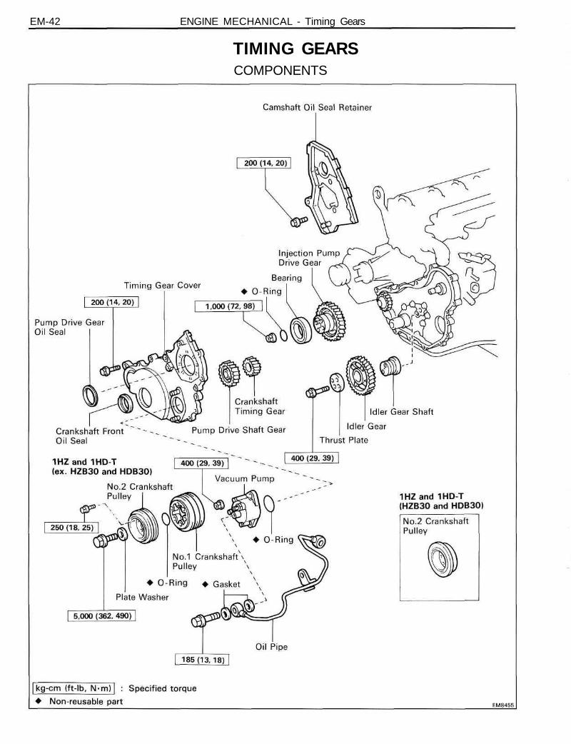
EM-42 ENGINE MECHANICAL - Timing Gears
TIMING GEARSCOMPONENTS

EM-43ENGINE MECHANICAL - Timing Gears
REMOVAL OF TIMING GEARS(See page EM-42)
1. REMOVE DRIVE BELT, FAN AND WATER PUMP PULLEY(See step 2 on page CO-7)
2. REMOVE TIMING BELT AND PULLEYS(See page EM-32)
3. REMOVE CAMSHAFT OIL SEAL RETAINER(See step 14 on page EM-59)
4. REMOVE OIL PIPE
(a) Remove the two union bolts and four gaskets.
(b) Remove the bolt and oil pipe.
5. REMOVE VACUUM PUMP
(a) Remove the two nuts and vacuum pump.
(b) Remove the O-ring.
6. ( IHZandiHD-T)REMOVE NO.2 CRANKSHAFT PULLEY
Remove the six bolts and No.2 crankshaft pulley.
7. REMOVE NO.1 CRANKSHAFT PULLEY
(a) Using SST, remove the pulley bolt and plate.
SST 0921 3-58011 and 09330-00021

EM-44 ENGINE MECHANICAL - Timing Gears
(b) Using SST, remove the No.1 crankshaft pulley.
SST 09213-60017 (09213-00020, 09213-00030,09213-00060) and 09950-20017
(c) Remove the O-ring from the No.1 crankshaft pulley.
8. REMOVE TIMING GEAR COVER(a) Remove the fourteen bolts.
(b) Pry out the timing gear cover.
9. CHECK THRUST CLEARANCE OF IDLER GEARUsing a thickness gauge, measure the thrust clearance.Standard thrust clearance: 0.05-0.15 mm
(0.0020-0.059 in.)Maximum thrust clearance: 0.30 mm (0.0118 in.)If the thrust clearance is greater than maximum, replace thethrust plate. If necessary, replace the idler gear and/or idlergear shaft.
10. REMOVE PUMP DRIVE SHAFT GEARUsing SST, remove the pump drive shaft gear.SST 09213-36020 and 09950-20017

EM-45ENGINE MECHANICAL - Timing Gears
11. REMOVE IDLER GEARRemove the two bolts, thrust plate, idler gear and idler gearshaft.
12. REMOVE INJECTION PUMP DRIVE GEAR(a) Using SST, remove the injection pump drive gear set
nut.SST 09330-00021(b) Remove the O-ring.
(c) Using SST, remove the injection pump drive gear.
SST 09213-60017 (09213-00020, 09213-00030,09213-00060) and 09950-20017
NOTICE:• Tighten the two bolts of SST more than 8 mm (0.31
in.)
• Set the SST so that it is balanced.
13. REMOVE CRANKSHAFT TIMING GEARUsing SST, remove the crankshaft timing gear.SST 09213-36020 and 09950-20017

EM-46 ENGINE MECHANICAL Timing Gears
INSPECTION OF TIMING GEARS1. INSPECT IDLER GEAR
(a) Using a cylinder gauge, measure the inside diameterof the idler gear.
Idler gear inside diameter: 45.000-45.025 mm(1.7717-1.7726 in.)
(b) Using a micrometer, measure the diameter of the idlergear shaft.
Idler gear shaft diameter: 44.950-44.975 mm(1.7697-1.7707 in.)
(c) Subtract the idler gear shaft diameter measurementfrom the idler gear inside diameter measurement.
Standard oil clearance: 0.025-0.075 mm(0.0010-0.0030 in.)
Maximum oil clearance: 0.20 mm (0.0079 in.)If the clearance is greater than maximum, replace the gearand shaft.
2. INSPECT INJECTION PUMP DRIVE GEAR BEARINGCheck that bearing is not rough or worn.
3. IF NECESSARY, REPLACE INJECTION PUMP DRIVEGEAR BEARING
A. Remove bearingUsing SST, remove the bearing.SST 09950-20017

EM-47ENGINE MECHANICAL - Timing Gears
B. Install bearingUsing SST and a press, press in a new bearing.SST 09214-76011
4. CHECK BACKLASH OF TIMING GEARSUsing a dial indicator, measure the backlash.
Standard gear backlash: 0.05-0.15 mm(0.0020-0.0060 in.)
Maximum gear backlash: 0.30 mm (0.0118 in.)If the gear backlash is greater than maximum, replace thegears as a set.

EM-48 ENGINE MECHANICAL - Timing Gears
REPLACEMENT OF CRANKSHAFT FRONT OILSEAL
HINT: There are two methods (A and B) to replace the oilseal as follows:
REPLACE CRANKSHAFT FRONT OIL SEAL
A. If timing gear cover is removed from cylinder block:(a) Using a screwdriver and hammer, tap out the oil seal.
(b) Using SST and a hammer, tap in a new oil seal until itssurface is flush with the timing gear cover edge.
SST 09223-78010(c) Apply MP grease to the oil seal lip.
B. If timing gear cover is installed to the cylinder block:(a) Using SST, remove the oil seal.SST 09308-10010 and 09950-20017
(b) Apply MP grease to a new oil seal lip.(c) Using SST and a hammer, tap in the oil seal until its
surface is flush with the timing gear cover edge.SST 09223-78010

EM-49ENGINE MECHANICAL Timing Gears
REPLACEMENT OF INJECTION PUMP DRIVEGEAR OIL SEAL
HINT: There are two methods (A and B) to replace the oilseal as follows:
REPLACE INJECTION PUMP DRIVE GEAR OIL SEAL
A. If timing gear cover is removed from cylinder block:(a) Using a screwdriver and hammer, tap out the oil seal.
(b) Using SST and a hammer, tap in a new oil seal until itssurface is flush with the timing gear cover edge.
SST 09214-76011(c) Apply MP grease to the oil seal lip.
B. If timing gear cover is installed to the cylinder block:(a) Using a screwdriver, pry out the oil seal.NOTICE: Be careful not to damage the injectionpump drive gear. Tape the screwdriver tip.
(b) Apply MP grease to the oil seal lip.(c) Using SST and a hammer, tap in a new oil seal until its
surface is flush with the timing gear cover edge.
SST 09214-76011

EM-50 ENGINE MECHANICAL - Timing Gears
INSTALLATION OF TIMING GEARS(See page EM-42)
1. INSTALL CRANKSHAFT TIMING GEAR(a) Put the timing crankshaft timing gear with the timing
mark facing frontward.
(b) Align the timing gear set key with the key groove ofthe timing gear.
(c) Using SST and a hammer, tap in the timing gear.SST 09223-00010
2. INSTALL INJECTION PUMP DRIVE GEAR(a) Install the set key to the groove of the injection pump
drive shaft.(b) Align the set key with the key groove of the injection
pump drive gear and install the drive gear.(c) Install a new O-ring to the drive gear.
(d) Install the injection pump drive gear set nut.(e) Using SST, torque the nut.SST 09330-00021
Torque: 1,000 kg-cm (72 ft-lb, 98 N-m)
3. INSTALL IDLER GEAR(a) Install the idler gear shaft.
(b) Align the idler gear timing marks "0" and " 1 " with thecrankshaft timing gear mark "0" and injection pumpdrive gear timing mark " 1 " respectively, and mesh thegears.

EM-51ENGINE MECHANICAL - Timing Gears
(c) Align the thrust plate set bolt holes.
(d) Install the thrust plate with the two bolts. Torque thebolts.
Torque: 400 kg-cm (29 ft-lb, 39 N m)
4. INSTALL PUMP DRIVE SHAFT GEAR(a) Align the pump drive shaft gear set key with the key
groove of the drive shaft gear.(b) Using SST and a hammer, tap in the pump drive shaft
gear.SST 09223-00010
5. INSTALL TIMING GEAR COVER(a) Remove any old packing (FIPG) material and be
careful not to drop any oil on the contact surfaces ofthe timing gear cover and cylinder block.• Using a razor blade and gasket scraper, remove all
the old packing (FIPG) material from the gasketsurfaces and sealing groove.
• Thoroughly clean all components to remove all theloose material.
• Using a non-residue solvent, clean both sealingsurfaces.
(b) Apply seal packing to the timing gear cover as shownin the illustration.
Seal packing: Part No.08826-00080 or equivalent• Install a nozzle that has been cut to a 2 - 3 mm
(0.08-0.12 in.) opening.• Parts must be assembled within 5 minutes of appli-
cation. Otherwise the material must be removedand reapplied.
• Immediately remove nozzle from the tube and rein-stall cap.

EM-52 ENGINE MECHANICAL - Timing Gears
(c) Install the timing gear cover with the fourteen bolts.Torque: 200 kg-cm (14 ft-lb, 20 N m)
6. INSTALL NO.1 CRANKSHAFT PULLEY(a) Install a new O-ring in the No.1 crankshaft pulley
groove.
(b) Align the pulley set key with the key groove of thepulley.
(c) Using SST and a hammer, tap in the pulley.
SST 09214-60010
(d) Using SST, install and torque the plate and bolt.Torque: 5,000 kg-cm (362 ft-lb, 490 N m)
7. (1HZand1HD-T)INSTALL NO.2 CRANKSHAFT PULLEYInstall the No.2 crankshaft pulley with the six bolts.Torque: 250 kg-cm (18 ft-lb, 25 N-m)
EM-53ENGINE MECHANICAL - Timing Gears
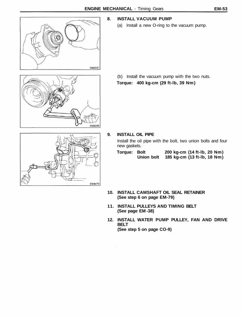
8. INSTALL VACUUM PUMP(a) Install a new O-ring to the vacuum pump.
(b) Install the vacuum pump with the two nuts.Torque: 400 kg-cm (29 ft-lb, 39 Nm)
9. INSTALL OIL PIPEInstall the oil pipe with the bolt, two union bolts and fournew gaskets.Torque: Bolt 200 kg-cm (14 ft-lb, 20 Nm)
Union bolt 185 kg-cm (13 ft-lb, 18 Nm)
10. INSTALL CAMSHAFT OIL SEAL RETAINER(See step 6 on page EM-79)
11. INSTALL PULLEYS AND TIMING BELT(See page EM -38)
12. INSTALL WATER PUMP PULLEY, FAN AND DRIVEBELT(See step 5 on page CO-9)

EM-54 ENGINE MECHANICAL - Cylinder Head
CYLINDER HEADCOMPONENTS

EM-55ENGINE MECHANICAL Cylinder Head
REMOVAL OF CYLINDER HEAD(See page EM-54)
1. DRAIN ENGINE COOLANT (See page CO-4)
2. REMOVE INTAKE PIPE(See step 6 on page EM-34)
3. REMOVE INJECTION PIPES(See step 2 on page FU-9)
4. REMOVE OIL DIPSTICK AND OIL DIPSTICK GUIDE(a) Remove the two bolts, and the oil dipstick guide
assembly.(b) Remove the O-ring from the oil dipstick guide.
5. REMOVE INTAKE MANIFOLD(a) Disconnect the fuel hose from the nozzle leakage pipe.(b) (1PZ)
Remove the ten bolts, seal washers, intake manifoldand five gaskets.
(c) (1 HZ and 1HD-T)Remove the twelve bolts, seal washers, intake mani-fold and six gaskets.
6. REMOVE WATER OUTLET(a) (1HD-T)
Disconnect the water by-pass hose.(b) Remove the two nuts, water outlet and gasket.
7. REMOVE NOZZLE LEAKAGE PIPE(1PZand1HZ)(a) (1PZ)
Remove the five union nuts, nozzle leakage pipe andfive gaskets.
(b) (1HZ)Remove the six union nuts, nozzle leakage pipe andsix gaskets.

EM-56 ENGINE MECHANICAL - Cylinder Head
(1HD-T)Remove the six hollow bolts, nozzle leakage pipe andtwelve gaskets.
8. REMOVE INJECTION NOZZLES(1PZ and 1HZ)(a) (1PZ)
Using SST, remove the five injection nozzles, seatsand gaskets.
SST 09268-64010(b) (1HZ)
Using SST, remove the six injection nozzles, seats andgaskets.
SST 09268-64010
HINT: Arrange the injection nozzles in correct order.
(1HD-T)(a) Remove the bolt, washer, nozzle holder, injection
nozzle and seat.
(b) Remove the O-ring from the injection nozzle.
HINT: Arrange the injection nozzles in correct order.

EM-57ENGINE MECHANICAL - Cylinder Head
9. REMOVE GLOW PLUGS(a) Remove the five screw grommets (1 PZ) or six screw
grommets (1 HZ and 1 HD-T).(b) Remove the five nuts (1PZ) or six nuts (1 HZ and
1HD-T) and glow plug connector.
(c) Using a 12 mm deep socket wrench, remove the fiveglow plugs (1 PZ) or six glow plugs (1 HZ and 1 HD-T).
10. (IPZancMHZ)REMOVE EXHAUST MANIFOLD(a) Remove the four bolts (1 PZ) or five bolts (1 HZ) and
heat insulator.

EM-58 ENGINE MECHANICAL - Cylinder Head
(b) Remove the ten nuts (1 PZ) or twelve nuts (1HZ),exhaust manifold and two gaskets.
11. (1HD-T)REMOVE TURBOCHARGER AND EXHAUSTMANIFOLD ASSEMBLY(See steps 3 to 8 on pages TC-9, 10)
12. (1HZ and 1HD-T)SEPARATE EXHAUST MANIFOLDS(a) Separate the front and rear exhaust manifolds.
(b) Using snap ring pliers, remove the two manifold rings.
13. REMOVE TIMING BELT AND PULLEYS(See steps 1 to 3 and 5 to 7 on pages EM-33 to 35)

EM-59ENGINE MECHANICAL Cylinder Head
14. REMOVE CAMSHAFT OIL SEAL RETAINER(a) Remove the four bolts holding the camshaft oil seal
retainer to the cylinder head.
(b) Pry out the camshaft oil seal retainer.
15. REMOVE CAMSHAFT
(a) (1PZ)Uniformly loosen and remove the twelve bearing capbolts in several passes in the sequence shown.
(b) (1 HZ and 1HD-T)Uniformly loosen and remove the fourteen bearingcap bolts in several passes in the sequence shown.
(c) Remove the six bearing caps (1 PZ) or seven bearingcaps (1 HZ and 1 HD-T) and camshaft.
(d) Remove the two bearings from the No.1 bearing capand No.1 journal of the cylinder head.
(e) Remove the camshaft thrust plate.
HINT: Arrange the bearing caps and bearings in correctorder.

EM-60 ENGINE MECHANICAL - Cylinder Head
16. REMOVE CYLINDER HEAD(a) Using SST, uniformly loosen and remove the twenty-
two cylinder head bolts (1 PZ) or twenty-six cylinderhead bolts (1 HZ and 1 HD-T) in several passes in thesequence shown.
SST 09011-381 21NOTICE: Head warpage or cracking could resultfrom removing bolts in incorrect order.
(b) Lift the cylinder head from the dowels on the cylinderblock and place the head on wooden blocks on abench.
HINT: If the cylinder head is difficult to lift off, pry with ascrewdriver between the cylinder head and block.NOTICE: Be careful not to damage the cylinder headand cylinder block surfaces of cylinder head gasketside.

EM-61ENGINE MECHANICAL - Cylinder Head
DISASSEMBLY OF CYLINDER HEAD(See page EM-54)
1. REMOVE VALVE LIFTERS AND SHIMS
HINT: Arrange the valve lifters and shims in correct order.
2. REMOVE VALVES
(a) Using SST, compress the valve spring and remove thetwo keepers.
SST 09202-43013
(b) Remove the spring retainer, valve spring, valve andspring seat.
HINT: Arrange the valves, valve springs, spring seats andspring retainers in correct order.
(c) Using needle-nose pliers, remove the oil seal.

EM-62 ENGINE MECHANICAL - Cylinder Head
3. (IPZ and 1HZ)REMOVE COMBUSTION CHAMBERSUsing SST, remove the five (1 PZ) and six (1 HZ) combus-tion chambers (and shims).SST 09208-48010
HINT: Arrange the combustion chambers (and shims) incorrect order.
4. REMOVE HALF CIRCULAR PLUG
5. REMOVE FRONT AND REAR ENGINE HANGERS

ENGINE MECHANICAL Cylinder Head EM-63
INSPECTION, CLEANING AND REPAIR OFCYLINDER HEAD COMPONENTS
1. CLEAN TOP OF PISTONS AND TOP OF BLOCK(a) Turn the crankshaft and bring each piston to top dead
center (TDC). Using a gasket scraper, remove all thecarbon from the piston top.
(b) Remove all the gasket material from the top of thecylinder block.
NOTICE: Be careful not to scratch the surfaces.(c) Using compressed air, blow carbon and oil from the
bolt holes.CAUTION: Protect your eyes when using high pres-sure air.
2. REMOVE GASKET MATERIALUsing a gasket scraper, remove all the gasket material fromthe manifold and cylinder head surface.NOTICE: Be careful not to scratch the surfaces.
3. CLEAN COMBUSTION CHAMBERSUsing a wire brush, remove all the carbon from the com-bustion chambers.NOTICE: Be careful not to scratch the head gasketcontact surface.
4. CLEAN VALVE GUIDE BUSHINGSUsing a valve guide bushing brush and solvent, clean allthe guide bushings.
5. CLEAN CYLINDER HEADUsing a soft brush and solvent, thoroughly clean cylinderheads.

EM-64 ENGINE MECHANICAL - Cylinder Head
6. INSPECT CYLINDER HEAD FOR FLATNESSUsing a precision straight edge and thickness gauge,measure the surfaces contacting the cylinder block mani-folds for warpage.
Maximum warpage: 0.20 mm (0.0079 in.)If warpage is greater than maximum, replace the cylinderhead.
7. INSPECT CYLINDER HEAD FOR CRACKSUsing a dye penetrant, check the combustion chamber,intake and exhaust ports, head surface and the top of thehead for cracks.If cracked, replace the cylinder head.
8. CLEAN VALVES(a) Using a gasket scraper, chip any carbon from the valve
head.(b) Using a wire brush, thoroughly clean the valve.
9. INSPECT VALVE STEMS AND GUIDE BUSHINGS(a) Using a caliper gauge, measure the inside diameter of
the guide bushing.Bushing inside diameter:
8.010-8.030 mm (0.3154-0.3161 in.)

EM-65ENGINE MECHANICAL - Cylinder Head
(b) Using a micrometer, measure the diameter of the valvestem.
Valve stem diameter:Intake 7.975-7.990 mm
(0.3140-0.3146 in.)Exhaust 7.960-7.975 mm
(0.3134-0.3140 in.)(c) Subtract the valve stem diameter measurement from
the guide bushing inside diameter measurement.
Standard oil clearance:Intake 0.020-0.055 mm
(0.0008-0.0022 in.)Exhaust 0.035-0.070 mm
(0.0014-0.0028 in.)Maximum oil clearance:
Intake 0.08 mm (0.0031 in.)Exhaust 0.10 mm (0.0039 in.)
If the clearance is greater than maximum, replace the valveand guide bushing.
10. IF NECESSARY, REPLACE VALVE GUIDE BUSHINGS(a) Using SST and a hammer, tap out the guide bushing.
SST 09201-60011
(b) Using a caliper gauge, measure the bushing borediameter of the cylinder head.
(c) Select a new guide bushing (STD size or 0/S 0.05).If the bushing bore diameter of the cylinder head is greaterthan 13.025 mm (0.5128 in.), machine the bushing bore tothe following dimension:Rebored cylinder head bushing bore dimension:
13.054-13.075 mm (0.5139-0.5148 in.)If the bushing bore diameter of the cylinder head is greaterthan 13.075 mm (0.5148 in.), replace the cylinder head.

EM-66 ENGINE MECHANICAL - Cylinder Head
(d) Using SST and a hammer, tap in a new guide bushingto where there is 11.8 - 12.2 mm (0.465 - 0.480 in.)protruding from the cylinder head.
SST 09201-60011
(e) Using a sharp 8 mm reamer, ream the guide bushing toobtain the standard specified clearance (See pageEM-65) between the guide bushing and valve stem.
11. INSPECT AND GRIND VALVES(a) Grind the valve enough to remove pits and carbon.
(b) Check that the valve is ground to the correct valve faceangle.
Valve face angle: 44.5°
(c) Check the valve head margin thickness.Standard margin thickness:
Intake 1.6 mm (0.063 in.)Exhaust 1.7 mm (0.067 in.)
Minimum margin thickness:Intake 1.1 mm (0.043 in.)Exhaust 1.2 mm (0.047 in.)
If the margin thickness is less than minimum, replace thevalve.
(d) Check the valve overall length.
Standard overall length:Intake 103.29-103.69 mm
(4.0665-4.0823 in.)Exhaust 103.14-103.54 mm
(4 .0606-4 .0764 in.)
Minimum overall length:Intake 102.79 mm (4.0468 in.)Exhaust 102.64 mm (4.0409 in.)
If the overall length is less than minimum, replace the valve.

EM-67ENGINE MECHANICAL - Cylinder Head
(e) Check the surface of the valve stem tip for wear.If the valve stem tip is worn, resurface the tip with a grinderor replace the valve.NOTICE: Do not grind off more than the minimumoverall length.
12. INSPECT AND CLEAN VALVE SEATS(a) Using a 45° carbide cutter, resurface the valve seats.
Remove only enough metal to clean the seats.
(b) Check the valve seating position. Apply a thin coat ofPrussian blue (or white lead) to the valve face. Lightlypress the valve against the seat. Do not rotate thevalve.
(c) Check the valve face and seat for the following:• If blue appears 360° around the face, the valve is
concentric. If not, replace the valve.• If blue appears 360° around the valve seat, the
guide and face are concentric. If not, resurface theseat.
• Check that the seat contact is on the middle of thevalve face with the following width:
Intake 1.5-1.9 mm (0.059-0.075 in.)Exhaust 1.8-2.2 mm (0.071 -0.087 in.)
If not, correct the valve seats as follows:(1) If the seating is too high on the valve face, use
25° and 45° cutters to correct the seat.

EM-68 ENGINE MECHANICAL - Cylinder Head
(2) (Intake)If the seating is too low on the valve face, use 70°and 45° cutters to correct the seat.(Exhaust)If the seating is too low on the valve face, use 60°and 45° cutters to correct the seat.
(d) Hand-lap the valve and valve seat with an abrasivecompound.
(e) After hand-lapping, clean the valve and valve seat.
13. INSPECT VALVE SPRINGS(a) Using a steel square, measure the squareness of the
valve spring.Maximum squareness: 2.0 mm (0.075 in.)If squareness is greater than maximum, replace the valvespring.
(b) Using vernier calipers, measure the free length of thevalve spring.
Free length:Yellow painted mark 46.20 mm (1.8189 in.)Blue painted mark 49.14 mm (1.9346 in.)
If the free length is not as specified, replace the valvespring.
(c) Using a spring tester, measure the tension of the valvespring at the specified installed length.
Installed tension:30.7-33.9 kg (67.7-74.7 Ib, 301 -332 N)at 37.0 mm (1.457 in.)
If the installed tension is not as specified, replace the valvespring.

EM-69ENGINE MECHANICAL - Cylinder Head
14. INSPECT CAMSHAFTS AND BEARINGSA. Inspect camshaft for runout
(a) Place the camshaft on V-blocks.(b) Using a dial indicator, measure the circle runout at the
center journal.Maximum circle runout: 0.10 mm (0.0039 in.)If the circle runout is greater than maximum, replace thecamshaft.
B. Inspect cam lobesUsing a micrometer, measure the cam lobe height.
Standard cam lobe height:Intake
1PZ and 1HZ 55.090-55.110 mm(2.1689-2.1697 in.)
1 HD-T 54.440-54.460 mm(2.1433-2.1441 in.)
Exhaust 55.940 - 55.960 mm(2.2024-2.2031 in.)
Minimum cam lobe height:Intake
IPZ and 1HZ 54.59 mm (2.1492 in.)1H-D 53.94 mm (2.1236 in.)
Exhaust 55.44 mm (2.1827 in.)If the cam lobe height is less than minimum, replace thecamshaft.
C. Inspect camshaft journalsUsing a micrometer, measure the journal diameter.
Journal diameter:No.1 journal 34.969-34.985 mm
(1.3767-1.3774 in.)Others 27.986-27.988 mm
(1.1018-1.1023 in.)If the journal diameter is not as specified, check the oilclearance.
D. Inspect camshaft bearingsCheck the bearings for flaking and scoring.
If the bearings are damaged, replace the bearings.

EM-70 ENGINE MECHANICAL - Cylinder Head
E. Inspect camshaft journal oil clearance
(a) Install the camshaft bearings to the No.1 bearing capand No.1 journal of the cylinder head.(See step 4 (b) on page EM-78)
(b) Clean the bearings and camshaft journals.
(c) Place the camshaft on the cylinder head.
(d) Lay a strip of Plastigage across each of the camshaftjournals.
(e) Install the bearing caps.
(See step 4 (c) to (e) on page EM-78)
Torque: 250 kg-cm (18 ft-lb, 25 N m)
HINT: Do not turn the camshaft.
(f) Remove the bearing caps.
(g) Measure the Plastigage at its widest point.
Standard oil clearance:No.1 journal 0.022-0.074 mm
(0.0009-0.0029 in.)Others 0.030-0.066 mm
(0.0012-0.0026 in.)
Maximum oil clearance: 0.10 mm (0.0039 in.)
If the oil clearance is greater than maximum, replace thebearings or camshaft. If necessary, replace the bearing capsand cylinder head.
(h) Completely remove the Plastigage.
F. Inspect camshaft thrust clearance
(a) Install the camshaft.(See step 4 on page EM-78)
(b) Using a dial indicator, measure the thrust clearancewhile moving the camshaft back and forth.
Standard thrust clearance: 0.10-0.20 mm(0.0039-0.0079 in.)
Maximum thrust clearance: 0.30 mm (0.0118 in.)
If the thrust clearance is greater than maximum, replace thethrust plate. If necessary, replace the camshaft.
15. INSPECT VALVE LIFTERS AND LIFTER BORES
(a) Using a caliper gauge, measure the lifter bore diameterof the cylinder head.
Lifter bore diameter: 40.960 — 40.980 mm(1 .6126-1 .6134 in.)
EM-71ENGINE MECHANICAL Cylinder Head
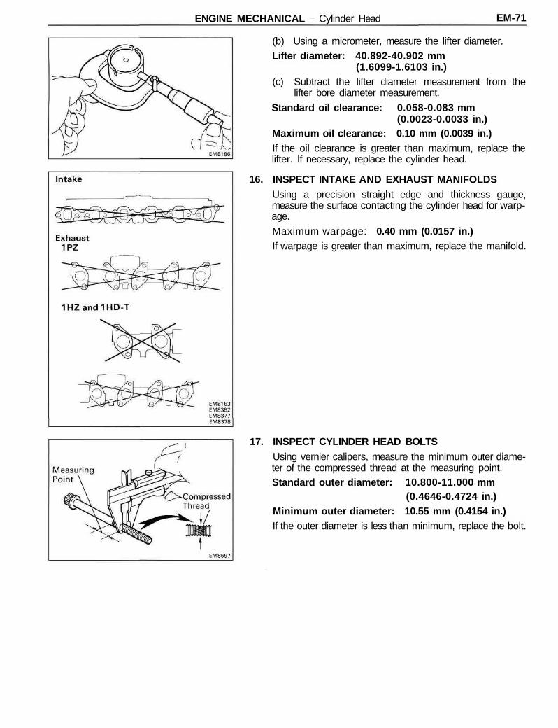
(b) Using a micrometer, measure the lifter diameter.Lifter diameter: 40.892-40.902 mm
(1.6099-1.6103 in.)(c) Subtract the lifter diameter measurement from the
lifter bore diameter measurement.
Standard oil clearance: 0.058-0.083 mm(0.0023-0.0033 in.)
Maximum oil clearance: 0.10 mm (0.0039 in.)If the oil clearance is greater than maximum, replace thelifter. If necessary, replace the cylinder head.
16. INSPECT INTAKE AND EXHAUST MANIFOLDSUsing a precision straight edge and thickness gauge,measure the surface contacting the cylinder head for warp-age.
Maximum warpage: 0.40 mm (0.0157 in.)If warpage is greater than maximum, replace the manifold.
17. INSPECT CYLINDER HEAD BOLTSUsing vernier calipers, measure the minimum outer diame-ter of the compressed thread at the measuring point.Standard outer diameter: 10.800-11.000 mm
(0.4646-0.4724 in.)Minimum outer diameter: 10.55 mm (0.4154 in.)If the outer diameter is less than minimum, replace the bolt.

EM-72 ENGINE MECHANICAL Cylinder Head
REPLACEMENT OF CAMSHAFT OIL SEAL
HINT: There are two methods (A and B) to replace the oilseal as follows:
REPLACE CAMSHAFT OIL SEAL
A. If camshaft oil seal retainer is removed from cylinderhead:(a) Using a screwdriver and hammer, tap out the oil seal.
(b) Using SST and a hammer, tap in a new oil seal until itssurface is flush with the oil seal retainer edge.
SST 09223-46011(c) Apply MP grease to the oil seal lip.
B. If camshaft oil seal retainer is installed to the cylinderhead:(a) Using a screwdriver, pry out the oil seal.NOTICE: Be careful not to damage the camshaft.Tape the screwdriver tip.
(b) Apply MP grease to a new oil seal lip.(c) Using SST and a hammer, tap in the oil seal until its
surface is flush with the oil seal retainer edge.
SST 09223-46011

EM-73ENGINE MECHANICAL Cylinder Head
ASSEMBLY OF CYLINDER HEAD(See page EM-54)
HINT:• Thoroughly clean all parts to be assembled.• Before installing the parts, apply new engine oil to all
sliding and rotating surfaces.• Replace all gaskets and oil seals with new ones.
1. INSTALL FRONT AND REAR ENGINE HANGERSInstall the engine hangers as shown in the illustration.
2. INSTALL HALF CIRCULAR PLUG(a) Remove any old packing (FIPG) material.(b) Apply seal packing to the half circular plug as shown.Seal packing: Part No. 08826-00080 or equivalent(c) Install the half circular plug to the cylinder head.
3. SELECT COMBUSTION CHAMBER SHIM
A. If using new combustion chamber:Using a micrometer, measure the thickness of each usedcombustion chamber at the position shown in the illustra-tion, then select the number of shims to be used.
Shim thickness: 0.03 mm (0.0012 in.)NOTICE: If combustion chamber shims were alreadybeing used, do not perform the above step; use thesame number of shims as were used before.
B. If reusing combustion chamber:Install the combustion chamber back in the same position itwas originally at.
4. (1PZand1HZ)INSTALL COMBUSTION CHAMBERS(a) Align the knock pin of the combustion chamber with
the notch of the cylinder head.(b) Using a plastic-faced hammer, tap in the (shim and)
combustion chamber.

EM-74 ENGINE MECHANICAL - Cylinder Head
(c) Using a dial indicator, measure the protrusion of thecombustion chamber from the cylinder head.
Protrusion: Minus 0.04-Plus 0.04 mm(Minus 0.0016- Plus 0.0016 in.)
If the protrusion is less than specified, adjust with shims.Shim thickness: 0.03 mm (0.0012 in.)If the protrusion is greater than specification, replace thechamber and recheck the protrusion.
5. INSTALL VALVES(a) Install the following parts:
(1) Oil seal(2) Valve(3) Spring seat(4) Valve spring(5) Spring retainer
(b) Using SST, compress the valve spring and place thetwo keepers around the valve stem.
SST 09202-43013
(c) Using a plastic-faced hammer, lightly tap the valvestem tip to assure proper fit.
6. INSTALL VALVE LIFTERS AND SHIMSCheck the valve lifter rotates smoothly by hand.

EM-75ENGINE MECHANICAL Cylinder Head
INSTALLATION OF CYLINDER HEAD(See page EM-54)
1. CHECK PISTON PROTRUSION AND SELECTCYLINDER HEAD GASKET
A. Check piston protrusions each cylinder(a) Clean the cylinder block solvent.(b) Set the piston of the cylinder to be measured to
slightly befor TDC.(c) Place a dial indicator on the cylinder block, and set the
dial indicator at 0 mm (0 in.)HINT:• Use a dial indicator measuring tip as shown in the
illustration.• Make sure that the measuring tip is sqaure to the cylinder
block gasket surface and piston head when taking themeasurments.
(d) Find where the piston head protrudes most by slowlyturning the crankshaft clockwise and counterclock-wise.
(e) Measure each cylinder at two places as shown inthe illustration, making a tatal of ten measurements(1PZ) or twelve measurements (1 HZ and 1HD-T).
(f) For the piston protrusion value of each cylinder, usethe average of the two measurements of each cylinder.
Protrusion:IPZ and 1HZ
0.405-0.655 mm (0.0159-0.0258 in.)1HD-T
0.475-0.725 mm (0.0187-0.0285 in.)(When removing piston and connecting rod assembly)
If the protrusion is not as specified, remove the piston andconnecting rod assembly (See page EM-86) and reinstall it(See page EM-108).

EM-76 ENGINE MECHANICAL - Cylinder Head
1HD-T1HZ
B. Select new cylinder head gasket(1PZ)HINT: There are five types of cylinder head gasket (holenumber 1 to 5) installed at factory, but only three types forsupply parts (hole number " 1 " , "3" and "5"), so whenreplacing the gasket select from one of three types above.
New cylinder head gasket thickness:Hole number " 1 " 1.16-1.24 mm
(0.0457-0.0488 in.)Hole number "3" 1.26-1.34 mm
(0.0496-0.0528 in.)Hole number "5" 1.36-1.44 mm
(0.0535-0.0567 in.)Select the largest piston protrusion value from the measure-ments made, then select the appropriate cylinder headgasket according to the table below.
(1HZ and 1HD-T)HINT: There are five types of cylinder head gasket (cutoutnumber 1 to 5) installed at factory, but only three types forsupply parts (cutout number " 1 " , "3" and "5"), so whenreplacing the gasket select from one of three types above.
New cylinder head gasket thickness:Cutout number " 1 " 1.15-1.25 mm
(0.0453-0.0492 in.)Cutout number "3" 1.25-1.35 mm
(0.0492-0.0531 in.)Cutout number "5" 1.35-1.45 mm
(0.0531 -0.0571 in.)Select the largest piston protrusion value from the measure-ments made, then select the appropriate cylinder headgasket according to the table below.

EM-77ENGINE MECHANICAL Cylinder Head
2. SET N0.1 CYLINDER TO BDCTurn the crankshaft pulley, and align the BDC mark of thetiming gear cover with the No.1 flange groove of the No.2camshaft timing pulley.
3. INSTALL CYLINDER HEAD
A. Place cylinder head on cylinder block(a) Place a new cylinder head gasket in position on the
cylinder block.NOTICE: Be careful of the installation direction.(b) Place the cylinder head in position on the cylinder
head gasket.
B. Install cylinder head boltsHINT:• The cylinder head bolts are tightened in three progressive
steps.• If any of bolts break or deform, replace them.
(a) Apply a light coat of engine oil on the threads andunder the heads of the cylinder head bolts.
(b) First, using SST, install and uniformly tighten thetwenty-two cylinder head bolts (1 PZ) or twenty-sixcylinder head bolts (1 HZ and 1HD-T) in severalpasses in the sequence shown.
SST 09011 -38121
Torque: 700 kg-cm (51 ft-lb, 69 N m)If any one of the bolts does not meet the torque specifica-tion, replace the bolt.
(c) Mark the front of the cylinder head bolt head withpaint.

EM-78 ENGINE MECHANICAL - Cylinder Head
(d) 2nd, retighten the cylinder head bolts 90° in thenumerical order shown above.
(e) 3rd, retighten cylinder head bolts by an additional 90°.(f) Check that the painted mark is now facing rearward.
4. INSTALL CAMSHAFT(a) Install the camshaft thrust plate to the cylinder head.(b) Install the camshaft bearings to the No.1 bearing cap
and No.1 journal of the cylinder head.
(c) Place the camshaft on the cylinder head, facing thekey groove upward.
(d) Install the six (1PZ) or seven (1 HZ and 1HD-T) bear-ing caps in their proper locations.
(e) (1PZ)Install and uniformly tighten the twelve bearing capbolts in several passes in the sequence shown.
Torque:No.1 journal 250 kg-cm (18 ft-lb, 25 N-m)Others 185 kg-cm (13 ft-lb, 18 N-m)

EM-79ENGINE MECHANICAL - Cylinder Head
(f) (1HZ and 1HD-T)Install and uniformly tighten the fourteen bearingcap bolts in several passes in the sequence shown.
Torque:No.1 journal 250 kg-cm (18 ft-lb, 25 N-m)Others 185 kg-cm (13 ft-lb, 18 N-m)
5. ADJUST VALVE CLEARANCE (See page EM-19)Valve clearance (Cold):
Intake 0.15-0.25 mm (0.006-0.010 in.)Exhaust 0.35-0.45 mm (0.014-0.018 in.)
6. INSTALL CAMSHAFT OIL SEAL RETAINER(a) Remove any old packing (FIPG) material and be
careful not to drop any oil on the contact surfaces ofthe camshaft oil seal retainer and cylinder head.• Using a razor blade and gasket scraper, remove all
the old packing (FIPG) material from the gasketsurfaces and sealing groove.
• Thoroughly clean all components to remove all theloose material.
• Using a non-residue solvent, clean both sealingsurfaces.
(b) Apply seal packing to the camshaft oil seal retainer asshown in the illustration.
Seal packing: Part No.08826-00080 or equivalent• Install a nozzle that has been cut to a 2 - 3 mm
(0.08-0.12 in.) opening.
• Parts must be assembled within 5 minutes of appli-cation. Otherwise the material must be removedand reapplied.
• Immediately remove nozzle from the tube and rein-stall cap.
(c) Install the retainer with the four bolts.
Torque: 200 kg-cm (14 ft-lb, 20 N-m)
7. INSTALL PULLEYS AND TIMING BELT(See steps 2 to 4 and 6 to 11 on pages EM-38 to 41)
8. (1HZand1HD-T)ASSEMBLY EXHAUST MANIFOLDS(a) Remove all the O-ring material from the manifold
grooves.(b) Install new O-rings.

EM-80 ENGINE MECHANICAL - Cylinder Head
(c) Using snap ring pliers, install the two manifold rings.
(d) Position the manifold rings so that the ring ends are asshown.
NOTICE: Do not align the ends.
(e) Install the manifold collar.(f) Assembly the front and rear manifolds.
9. ( IPZandiHZ)INSTALL EXHAUST MANIFOLD(a) Install new gaskets in direction as shown in the
illustration.
(b) Install the exhaust manifold with the ten nuts (1PZ)or twelve nuts (1HZ).
Torque: 400 kg-cm (29 ft-lb, 39 N-m)HINT: Apply 330 kg-cm (24 ft-lb, 32 N-m) of torquewhen performing additional tightening of loosed nuts.

EM-81ENGINE MECHANICAL - Cylinder Head
(c) Install the heat insulator with the four bolts (1PZ) orfive bolts (1HZ).
10. (1HD-T)INSTALL TURBOCHARGER AND EXHAUST MANIFOLD(See steps 4 to 10 on pages TC-13 to 15)
11. INSTALL GLOW PLUG(a) Using a 12 mm deep socket wrench, install the five
glow plugs (1PZ) or six glow plugs (1HZ and1HD-T).
Torque: 130 kg-cm (9 ft- lb, 13 N m)
(b) Install the glow plug connector with the five nuts(1 PZ) or six nuts (1 HZ and 1 HD-T).
(c) Install the five screw grommets (1 PZ) and six screwgrommets (1 HZ and 1 HD-T).

EM-82 ENGINE MECHANICAL Cylinder Head
12. INSTALL INJECTION NOZZLES(1PZ and 1HZ)(a) Place new gaskets and the nozzle seats into the
injection nozzle holes of the cylinder head.(b) Using SST, install the injection nozzles.SST 09268-64010
Torque: 650 kg-cm (47 ft-lb, 64 N-m)NOTICE: Over torquing could cause nozzle deforma-tion and needle adhesion or other defects.
(1HD-T)(a) Install a new O-ring to the injection nozzle.
(b) Place new nozzle seats into the injection nozzle holesof the cylinder head.
(c) Install the injection nozzles with the washer and bolt.Torque: 400 kg-cm (29 ft-lb, 39 N m)
13. INSTALL NOZZLE LEAKAGE PIPE(1PZand1HZ)(a) (1PZ)
Install five new gaskets and the leakage pipe with thefive nuts.
Torque: 300 kg-cm (22 ft-lb, 29 N m)(b) (1HZ)
Install six new gaskets and the leakage pipe with thesix nuts.
Torque: 300 kg-cm (22 ft-lb, 29 N-m)
(1HD-T)Install twelve new gaskets and the leakage pipe with the sixhollow bolts.Torque: 125 kg-cm (9 ft-lb, 12 N-m)

EM-83ENGINE MECHANICAL - Cylinder Head
14. INSTALL WATER OUTLET(a) Install a new gasket and water outlet with the two
nuts.Torque: 200 kg-cm (14 ft-lb, 20 Nm)(b) (1HD-T)
Connect the water by-pass hose.
15. INSTALL INTAKE MANIFOLD(a) (1PZ)
Install five new gaskets and the intake manifold withthe ten bolts and seal washers.
Torque: 200 kg-cm (14 ft-lb, 20 Nm)(b) (1 HZ and 1HD-T)
Install six new gaskets and the intake manifold withthe twelve bolts and seal washers.
Torque: 200 kg-cm (14 ft-lb, 20 Nm)
16. INSTALL OIL DIPSTICK GUIDE AND OIL DIPSTICK(a) Install a new O-ring to the dipstick guide.
(b) Install the oil dipstick guide assembly with the twobolts.
Torque:Intake manifold side
200 kg-cm (14 ft-lb, 20 Nm)Oil cooler cover side
200 kg-cm (14 ft-lb, 20 Nm)
17. INSTALL INJECTION PIPES(See step 3 on page FU-15)Torque:
IPZandiHZ 150 kg-cm (11 ft-lb, 15 Nm)1HD-T 250 kg-cm (18 ft-lb, 25 Nm)
18. INSTALL INTAKE PIPE(See step 2 on page EM-38)
19. FILL WIT ENGINE COOLANT (See page CO-5)
20. START ENGINE AND CHECK FOR LEAKS
21. RECHECK ENGINE COOLANT LEVEL AND OIL LEVEL

EM-84 ENGINE MECHANICAL Cylinder Block
CYLINDER BLOCKCOMPONENTS

EM -85ENGINE MECHANICAL - Cylinder Block
PREPARATION FOR DISASSEMBLY
1. (M/T)REMOVE CLUTCH COVER AND DISC
2. (M/T)REMOVE FLYWHEEL
3. (A/T)REMOVE DRIVE PLATE AND FLYWHEELRemove the drive plate rear spacer, drive plate and fly-wheel.
4. REMOVE REAR END PLATERemove the bolt, end plate and dust cover.
5. INSTALL ENGINE TO ENGINE STAND FORDISASSEMBLY
6. REMOVE TIMING BELT AND PULLEYS(See page EM-33)
7. REMOVE CYLINDER HEAD (See page EM-55)
8. REMOVE WATER PUMP (See page CO-6)
9. REMOVE ALTERNATOR
10. REMOVE TIMING GEARS (See page EM-43)
11. REMOVE INJECTION PUMP (See page FU-27)
12. REMOVE OIL PAN AND TIMING GEAR CASE (OIL PUMP)(See page LU-8)
13. REMOVE OIL COOLER (See page LU-14)
14. REMOVE WATER INLET AND THERMOSTAT
15. REMOVE ENGINE MOUNTING

EM-86 ENGINE MECHANICAL - Cylinder Block
DISASSEMBLY OF CYLINDER BLOCK(See page EM-84)
1. REMOVE REAR OIL SEAL RETAINERRemove the six bolts and retainer.
2. CHECK CONNECTING ROD THRUST CLEARANCEUsing a dial indicator, measure the thrust clearance whilemoving the connecting rod back and forth.
Standard thrust clearance: 0.10-0.20 mm(0.0038-0.0079 in.)
Maximum thrust clearance: 0.30 mm (0.0118 in.)If the thrust clearance is greater than maximum, replace theconnecting rod assembly. If necessary, replace the crank-shaft.
3. REMOVE CONNECTING ROD CAPS AND CHECK OILCLEARANCE(a) Using paint, place the matchmarks on the connecting
rod and cap to ensure correct reassembly.
(b) Using SST, remove the connecting rod cap bolts.
SST 09011-381 21
(c) Using the removed connecting rod cap bolts, pry theconnecting rod cap back and forth, and remove theconnecting cap.
HINT: Keep the lower bearing inserted with the connect-ing rod cap.

EM-87ENGINE MECHANICAL Cylinder Block
(d) Clean crank pin and bearing.(e) Check the crank pin and bearing for pitting and
scratches.If the crank pin or bearing is damaged, replace the bearings.If necessary, grind or replace the crankshaft.
(f) Lay a strip of Plastigage across the crank pin.
(g) Install the connecting rod cap.(See step 8 on page EM-111)
Torque: 1st 375 kg-cm (27 ft-lb, 37 Nm)2nd turn 90°
HINT: Do not turn the crankshaft.
(h) Remove the connecting rod cap.(See procedure (b) and (c) above)
(i) Measure the Plastigage at widest point.
Standard oil clearance:STD 0.036-0.054 mm
(0.0014-0.0021 in.)U/S 0.25 and U/S 0.50
0.037 - 0.077 mm(0.0015 - 0.0030 in.)
Maximum oil clearance: 0.10 mm (0.0039 in.)If the oil clearance is greater than maximum, replace thebearings. If necessary, grind or replace the crankshaft.
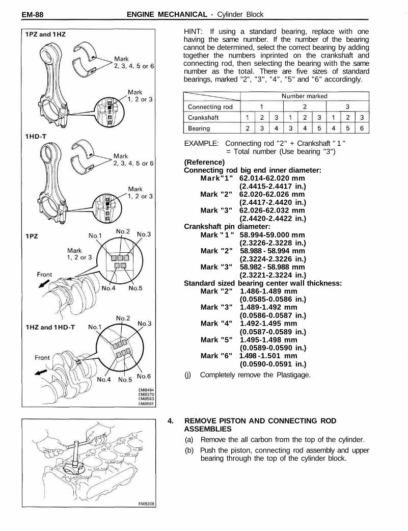
EM-88 ENGINE MECHANICAL - Cylinder Block
HINT: If using a standard bearing, replace with onehaving the same number. If the number of the bearingcannot be determined, select the correct bearing by addingtogether the numbers inprinted on the crankshaft andconnecting rod, then selecting the bearing with the samenumber as the total. There are five sizes of standardbearings, marked "2", "3", "4", "5" and "6" accordingly.
EXAMPLE: Connecting rod "2" + Crankshaft " 1 "= Total number (Use bearing "3")
(Reference)Connecting rod big end inner diameter:
Mark"1" 62.014-62.020 mm(2.4415-2.4417 in.)
Mark "2" 62.020-62.026 mm(2.4417-2.4420 in.)
Mark "3" 62.026-62.032 mm(2.4420-2.4422 in.)
Crankshaft pin diameter:Mark " 1 " 58.994-59.000 mm
(2.3226-2.3228 in.)Mark "2" 58.988 - 58.994 mm
(2.3224-2.3226 in.)Mark "3" 58.982 - 58.988 mm
(2.3221-2.3224 in.)Standard sized bearing center wall thickness:
Mark "2" 1.486-1.489 mm(0.0585-0.0586 in.)
Mark "3" 1.489-1.492 mm(0.0586-0.0587 in.)
Mark "4" 1.492-1.495 mm(0.0587-0.0589 in.)
Mark "5" 1.495-1.498 mm(0.0589-0.0590 in.)
Mark "6" 1.498 -1.501 mm(0.0590-0.0591 in.)
(j) Completely remove the Plastigage.
4. REMOVE PISTON AND CONNECTING RODASSEMBLIES(a) Remove the all carbon from the top of the cylinder.(b) Push the piston, connecting rod assembly and upper
bearing through the top of the cylinder block.

EM-89ENGINE MECHANICAL - Cylinder Block
HINT:• Keep the bearings, connecting rod and cap together.• Arrange the piston and connecting rod assemblies in
correct order.
5. CHECK CRANKSHAFT THRUST CLEARANCEUsing a dial indicator, measure the thrust clearance whileprying the crankshaft back and forth with a screwdriver.
Standard thrust clearance: 0.04-0.24 mm(0.0016-0.0094 in.)
Maximum thrust clearance: 0.30 mm (0.0118 in.)If the thrust clearance is greater than maximum, replace thethrust washers as a set.Thrust washer thickness:
2.930-2.980 mm (0.1154-0.1173 in.)
6. REMOVE MAIN BEARING CAP AND CHECK OILCLEARANCE(a) Remove the thirteen bolts (1 PZ) or fifteen bolts (1 HZ
and 1HD-T).
(b) Uniformly loosen and remove the main bearing capbolts in several passes in the sequence shown.

EM -90 ENGINE MECHANICAL - Cylinder Block
(c) Using a screwdriver, pry out the main bearing cap.HINT: Keep the lower main bearings and main bearingcap together.NOTICE: Do not scratch the surface which will becoated with FIPG.
(d) Lift out the crankshaft.HINT: Keep the upper main bearings and thrust washerstogether with the cylinder block.
(e) Clean each main journal and bearing.(f) Check each main journal and bearing for pitting and
scratches.If the journal or bearing are damaged, replace the bearings.If necessary, grind or replace the crankshaft.
(g) Place the crankshaft on the cylinder block,(h) Lay a strip of Plastigage across each journal.
(i) Install the main bearing cap with the bearings.(See step 6 on page EM-109)
Torque: 1st 1,050 kg-cm (76 ft-lb, 103 N m)2nd turn 90°
HINT: Do not turn the crankshaft.

EM-91ENGINE MECHANICAL - Cylinder Block
(j) Remove the main bearing cap bolts and cap.(k) Measure the Plastigage at its widest point.
Standard clearance:STD 0.036-0.054 mm
(0.0014-0.0021 in.)U/S 0.25 and U/S 0.50 0.037-0.077 mm
(0.0015-0.0030 in.)Maximum clearance: 0.10 mm (0.0039 in.)If the oil clearance is greater than maximum, replace thebearings. If necessary, grind or replace the crankshaft.
HINT: If using a standard bearing, replace with onehaving the same number. If the number of the bearingcannot be determined, select the correct bearing by addingtogether the numbers inprinted on the main bearing capand crankshaft, then selecting the bearing with the samenumber as the total. There are five sizes of standardbearings, marked "2", "3", "4", "5" and "6" accordingly.
EXAMPLE: Main bearing cap "2" " + Crankshaft " 1 "= Total number (Use bearing "3")
(Reference)Cylinder block main journal bore diameter:
Mark " 1 " 71.000 - 71.006 mm(2.7953-2.7955 in.)
Mark "2 " 71.006 - 71.012 mm(2.7955-2.7957 in.)
Mark "3" 71.012-71.018 mm(2.7957-2.7960 in.)
Crankshaft journal diameter:Mark " 1 " 66.994-67.000 mm
(2.6376-2.6378 in.)Mark "2" 66.988-66.994 mm
(2.6373-2.6376 in.)Mark "3" 66.982 66.988 mm
(2.6371-2.6373 in.)

EM-92 ENGINE MECHANICAL - Cylinder Block
(Reference) (Cont'd)Standard sized bearing center wall thickness:
Mark "2" 1.979-1.982 mm(0.0779-0.0780 in.)
Mark "3" 1.982 -1.985 mm(0.0780-0.0781 in.)
Mark "4" 1.985 -1.988 mm(0.0781-0.0783 in.)
Mark "5" 1.988-1.991 mm(0.0783-0.0784 in.)
Mark "6" 1.991 -1.994 mm(0.0784-0.0785 in.)
(I) Completely remove the Plastigage.
7. REMOVE CRANKSHAFT(a) Lift out the crankshaft.(b) Remove the upper main bearings and thrust washers
from the cylinder block.
HINT: Arrange the main bearings and thrust washers incorrect order.
8. REMOVE CHECK VALVES AND OIL NOZZLESRemove the five (1 PZ) or six (1 HZ and 1HD-T) checkvalves and oil nozzles.
9. REMOVE CYLINDER BLOCK OIL HOLE GASKET
10. REMOVE CYLINDER BLOCK ORIFICE

EM-93ENGINE MECHANICAL - Cylinder Block
INSPECTION OF CYLINDER BLOCK
1. REMOVE GASKET MATERIALUsing a gasket scraper, remove all the gasket material fromthe cylinder block surface.
2. CLEAN CYLINDER BLOCK
Using a soft brush and solvent, clean the cylinder block.
3. INSPECT TOP OF CYLINDER BLOCK FOR FLATNESS
Using a precision straight edge and thickness gauge,measure the surfaces contacting the cylinder head gasketfor warpage.
Maximum warpage: 0.20 mm (0.0079 in.)If warpage is greater than maximum, replace the cylinderblock.
4. INSPECT CYLINDER FOR VERTICAL SCRATCHES
Visually check the cylinder for vertical scratches.
If deep scratches are present, rebore all five (1PZ) or six(1HZ and 1HD-T) cylinders. If necessary, replace thecylinder block.
5. INSPECT CYLINDER BORE DIAMETER
HINT: There are three sizes of the standard cylinder borediameter, marked " 1 " , "2" and "3" accordingly. The mark isstamped on the upper left rear of the cylinder block.

EM-94 ENGINE MECHANICAL - Cylinder Block
Using a cylinder gauge, measure the cylinder bore diameterat positions A, B and C in the thrust axial directions.Standard diameter:
STD Mark " 1 " 94.000-94.010 mm(3.7008-3.7012 in.)
Mark "2" 94.010-94.020 mm(3.7012-3.7016 in.)
Mark "3" 94.020 - 94.030 mm(3.7016-3.7020 in.)
Maximum diameter:STD 94.23 mm (3.7098 in.)O/S 0.50 94.73 mm (3.7295 in.)
If the diameter is greater than maximum, rebore all five(1 PZ) or six (1 HZ and 1 HD-T) cylinders.If necessary, replace the cylinder block.
6. REMOVE CYLINDER RIDGEIf the wear is less than 0.2 mm (0.008 in.), use a ridgereamer to machine the piston ring ridge at the top of thecylinder.
7. INSPECT MAIN BEARING CAP BOLTSUsing vernier calipers, measure the minimum diameter ofthe compressed thread at the measuring point.Standard diameter: 11.800-12.000 mm
(0.4646-0.4724 in.)Minimum diameter: 11.50 mm (0.4528 in.)If the diameter is less than minimum, replace the bolt.

EM-95ENGINE MECHANICAL - Cylinder Block
8. INSPECT CYLINDER BLOCK ORIFICECheck that the oifice is not clogged.
DISASSEMBLY OF PISTON ANDCONNECTING ROD ASSEMBLIES1. CHECK FIT BETWEEN PISTON AND PISTON PIN
Try to move the piston back and forth on the piston pin.If any movement is felt, replace the piston and pin as a set.
2. REMOVE PISTON RINGS(a) Using a piston ring expander, remove the two com-
pression rings and oil ring.
(b) Remove the coil by hand.HINT: Arrange the rings in correct order only.
3. DISCONNECT CONNECTING ROD FROM PISTON(a) Using a small screwdriver, remove the snap rings.

EM-96 ENGINE MECHANICAL - Cylinder Block
(b) Gradually heat the piston to approx. 80°C (176°F).
(c) Using a plastic-faced hammer and brass bar, lightlytap out the piston pin and remove the connecting rod.
HINT:• The piston and pin are a matched set.• Arrange the pistons, pins, rings, connecting rods and
bearings in correct order.

EM-97ENGINE MECHANICAL Cylinder Block
INSPECTION AND REPAIR OF PISTON ANDCONNECTING ROD ASSEMBLIES
1. CLEAN PISTON(a) Using a gasket scraper, remove the carbon from the
piston top.
(b) Using a groove cleaning or broken ring, clean thepiston ring grooves.
(c) Using solvent and a brush, thoroughly clean thepiston.
NOTICE: Do not use a wire brush.
2. INSPECT PISTON DIAMETER AND OIL CLEARANCEHINT: There are three sizes of the standard piston diam-eter, marked " 1 " , "2" and "3" accordingly. The mark isstamped on the top of the piston.(a) Using a micrometer, measure the piston diameter at
right angles to the piston pin center line, at theindicated distance from the piston head.
Distance:1PZ and 1 HZ 58.6 mm (2.3071 in.)1HD-T 65.7 mm (2.5866 in.)
Piston diameter:STD Mark " 1 " 93.95-93.96 mm
(3.6988-3.6992 in.)Mark "2" 93.96 - 93.97 mm
(3.6992-3.7000 in.)Mark "3" 93.97-93.98 mm
(3.7000-3.7000 in.)O/S 0.50 94.45 - 94.48 mm
(3.7185-3.7197 in.)

EM-98 ENGINE MECHANICAL - Cylinder Block
(b) Measure the cylinder bore diameter in the thrustdirections. (See step 5 on page EM-93)
(c) Subtract the piston diameter measurement from thecylinder bore diameter measurement.
Standard oil clearance: 0.04-0.06 mm(0.0016-0.0024 in.)
Maximum oil clearance: 0.14 mm (0.0055 in.)If the oil clearance is greater than maximum, replace all five(1 PZ) or six (1 HZ and 1 HD-T) pistons and rebore all five(1 PZ) or six (1 HZ and 1HD-T) cylinders. If necessary,replace the cylinder block.
HINT (Use cylinder block subassembly): When installinga standard piston, install one with the same number mark asthe standard bore diameter mark on the cylinder block.
3. INSPECT CLEARANCE BETWEEN WALL OF RINGGROOVE AND NEW PISTON RING(No.1 Ring)Install new No.1 piston ring to the piston. Using a thicknessgauge, measure the clearance between the piston ring andwall of the piston ring groove.Ring groove clearance:
No.1 0.050-0.095 mm (0.0020-0.0037 in.)
(No.2 and Oil Rings)Using a thickness gauge, measure the clearance betweennew piston ring and the wall of the piston ring groove.
Ring groove clearance:No.2 0.06-0.10 mm (0.0024-0.0039 in.)Oil 0.03-0.07 mm (0.0012-0.0028 in.)
If the clearance is not as specified, replace the piston.
4. INSPECT PISTON RING END CAP(a) Insert the piston ring into the cylinderbore.(b) Using a piston, push the piston ring a little beyond the
bottom of the ring travel, 1 50 mm (5.91 in.) from thetop of the cylinder block.

EM-99ENGINE MECHANICAL - Cylinder Block
(c) Using a thickness gauge, measure the end gap.Standard end gap:
No.1 0.27-0.54 mm(0.0106-0.0213 in.)
No.2 0.40-0.62 mm(0.0157-0.0244 in.)
Oil 0.20-0.52 mm(0.0079-0.0205 in.)
Maximum end gap:No.1 1.34 mm (0.0591 in.)No.2 1.42 mm (0.0551 in.)Oil 1.32 mm (0.0520 in.)
If the end gap is greater than maximum, replace the pistonring. If the end gap is greater than maximum, even with anew piston ring, rebore all five (1 PZ) or six (1 HZ and1 HD-T) cylinders or replace the cylinder block.
5. INSPECT PISTON PIN FITAt 80°C (176°F), you should be able to push the piston pininto the piston pin hole with your thumb.
6. INSPECT CONNECTING ROD
A. Inspect connecting rod alignmentUsing a rod aligner, check the connecting rod alignment.
• Check for bending.Maximum bending:
0.03 mm (0.0012 in.) per 100 mm (3.94 in.)If bent is greater than maximum, replace the connecting rodassembly.
• Check for twist.Maximum twist:
0.15 mm (0.0059 in.) per 100 mm (3.94 in.)If twist is greater than maximum, replace the connectingrod assembly.

EM-100 ENGINE MECHANICAL Cylinder Block
B. Inspect connecting rod boltsUsing vernier calipers, measure the minimum diameter ofthe compressed bolt at the measuring point.Standard diameter: 8.300-8.400 mm
(0.3268-0.3307 in.)Minimum diameter: 7.95 mm (0.3130 in.)If the diameter is less than minimum, replace the connect-ing rod bolt.
C. Inspect piston pin oil clearance(a) Using a caliper gauge, measure the inside diameter of
the connecting rod bushing.Bushing inside diameter:
IPZ and 1HZ29.008-29.020 mm (1.1420-1.1425 in.)
1HD-T33.008-33.020 mm (1.2995-1.3000 in.)
(b) Using a micrometer, measure the piston pin diameter.Piston pin diameter:
1PZ and 1HZ29.000-29.012 mm (1.1417-1.1422 in.)
1HD-T33.000-33.012 mm (1.2992-1.2997 in.)
(c) Subtract the piston pin diameter measurement fromthe bushing inside diameter measurement.
Standard oil clearance: 0.004-0.012 mm(0.0002-0.0005 in.)
Maximum oil clearance: 0.03 mm (0.0012 in.)
7. IF NECESSARY, REPLACE CONNECTING RODBUSHINGS
A. Remove connecting rod bushingsUsing SST and a press, press out the bushing.SST1PZand1HZ 09222-66010
1HD-T 09222-17010(09222-05020,09222-05040)

EM-101ENGINE MECHANICAL - Cylinder Block
B. Install new connecting rod bushings(a) Using a round file, lightly file off any roughness from
the small end of the connecting rod.
(b) (1HD-T)Attach the bushing to SST with the ball of SST insidethe oil hole of the bushing.
SST 09222-17010 (09222-05030)
(c) Align the oil holes of the bushing and connecting rod.

EM-102 ENGINE MECHANICAL - Cylinder Block
(d) Using SST and a press, press in the bushing.SST 1PZ and 1HZ 09222-66010
1HD-T 09222-17010(09222-05020,09222-05030, 09222-05040)
C. Hone connecting rod bushing and check piston pin fit(a) Using a pin hole grinder, hone the bushing to obtain
the standard specified clearance (see page EM-100)between the bushing and piston pin.
(b) Check the piston pin fit at normal room temperature.Coat the piston pin with engine oil, and push it intothe connecting rod with your thumb.

EM-103ENGINE MECHANICAL Cylinder Block
BORING OF CYLINDERS
HINT:• Bore all five (1 PZ) or six (1 HZ and 1 HD-T) cylinders for
the oversized piston outside diameter.• Replace the piston rings with ones to match the over-
sized pistons.
1. KEEP OVERSIZED PISTONSOversized piston diameter:
O/S0.50 94.45-94.48 mm(3.7185-3.7197 in.)
2. CALCULATE AMOUNT TO BORE CYLINDER(a) Using a micrometer, measure the piston diameter at
right angles to the piston pin center line, at theindicated distance from the piston head.
Distance:1 PZ and 1 HZ 58.6 mm (2.3071 in.)1 HD-T 65.7 mm (2.5866 in.)
(b) Calculate the amount each cylinder is to be rebored asfollows:Size to be rebored = P + C- HP = Piston diameterC = Piston oil clearance
0.04-0.06 mm (0.0016-0.0024 in.)H = Allowance for honing
0.02 mm (0.0008 in.) or less
3. BORE AND HONE CYLINDERS TO CALCULATEDDIMENSIONSMaximum honing: 0.02 mm (0.0008 in.)NOTICE: Excess honing will destroy the finishedroundness.

EM-104 ENGINE MECHANICAL - Cylinder Block
INSPECTION AND REPAIR OF CRANKSHAFT1. INSPECT CRANKSHAFT FOR RUNOUT
(a) Place the crankshaft on V-blocks.(b) Using a dial indicator, measure the circle runout at the
center journal.
Maximum circle runout: 0.06 mm (0.0024 in.)If the circle runout is greater than maximum, replace thecrankshaft.
2. INSPECT MAIN JOURNALS AND CRANK PINS(a) Using a micrometer, measure the diameter of each
main journal and crank pin.Main journal diameter:
STD 66.982-67.000 mm(2.6371 -2.6378 in.)
U/S 0.25 66.745 - 66.755 mm(2.6278-2.6281 in.)
U/S 0.50 66.495 - 66.505 mm(2.6179-2.6183 in.)
Crank pin diameter:STD 58.982-59.000 mm
(2.3221-2.3228 in.)U/S 0.25 58.745-58.755 mm
(2.3128-2.3132 in.)U/S 0.50 58.495-58.505 mm
(2.3029-2.3033 in.)If the diameter is not as specified, check the oil clearance(See pages EM-86 to 92).(b) Check each main journal and crank pin for taper and
out-of-round as shown.
Maximum taper and out-of-round: 0.02 mm(0.0008 in.)
If the taper or out-of-round is greater than maximum, grindor replace the crankshaft.
3. IF NECESSARY, GRIND AND HONE MAINJOURNALS AND/OR CRANK PINSGrind and hone the main journals and/or crank pins to thefinished undersized diameter (See procedure step 2).Install new main journal and/or crank pin undersizedbearings.

EM-105ENGINE MECHANICAL - Cylinder Block
REPLACEMENT OF CRANKSHAFT OIL SEAL
HINT: There are two methods (A and B) to replace the oilseal as follows:
REPLACE CRANKSHAFT REAR OIL SEAL
A. If rear oil seal retainer is removed from cylinder block:(a) Using a screwdriver and hammer, tap out the oil seal.
(b) Using SST and a hammer, tap in a new oil seal until itssurface is flush with the rear oil seal retainer edge.
SST 09223-56010(c) Apply MP grease to the oil seal lip.
B. If rear oil seal retainer is installed to cylinder block:(a) Using a knife, cut off the oil seal lip.(b) Using a screwdriver, pry out the oil seal.NOTICE: Be careful not to damage the crankshaft.Tape the screwdriver tip.
(c) Apply MP grease to a new oil seal lip.(d) Using SST and a hammer, tap in the oil seal until its
surface is flush with the rear oil seal retainer edge.SST 09223-56010

EM-106 ENGINE MECHANICAL Cylinder Block
ASSEMBLY OF PISTON AND CONNECTINGROD ASSEMBLIES1. ASSEMBLE PISTON AND CONNECTING ROD
(a) Install a new snap ring on one side of the piston pinhole.• Position the snap ring so that end (B) of the snap
ring is aligned with the hollow, then push the snapring into the piston groove starting from end (A).
(b) Gradually heat the piston to about 80°C (176°F).
(c) Apply a light coat of engine oil to the piston pin.(d) Align the front marks of the piston and connecting
rod, and push in the piston pin with your thumb.(e) Install a new snap ring on the other side of the piston
pin hole using the same method as in (a) above.
2. INSTALL PISTON RINGS(a) Install the coil by hand.(b) Using a piston ring expander, install the oil ring.

EM-107ENGINE MECHANICAL - Cylinder Block
HINT: Face the end gap of the oil ring in the oppositedirection of coil joint.
(c) Using a piston ring expander, install the two compres-sion rings with the code mark facing upward.
Code mark: No.1 1TNo.2 2T
(d) Position the piston rings so that the ring ends are asshown.
NOTICE: Do not align the ring ends.
3. INSTALL BEARINGS(a) Align the bearing claw with the claw groove of the
connecting rod or connecting cap.(b) Install the bearings in the connecting rod and con-
necting rod cap.

EM-108 ENGINE MECHANICAL - Cylinder Block
ASSEMBLY OF CYLINDER BLOCK(See page EM-84)
HINT:• Thoroughly clean all parts to be assembled.• Before installing the parts, apply new engine oil to all
sliding and rotating surfaces.• Replace all gaskets, O-rings and oil seals with new parts.
1. INSTALL NEW CYLINDER BLOCK OIL HOLE GASKET
2. INSTALL CYLINDER BLOCK ORIFICE
3. INSTALL OIL NOZZLES AND CHECK VALVES(a) Align the pin of the oil nozzle with the pin hole of the
cylinder block.(b) Install the oil nozzle with the check valve. Install the
five (1PZ) or six (1 HZ and 1HD-T) oil nozzles andcheck valves.
Torque: 275 kg-cm (20 ft-lb, 27 Nm)
4. INSTALL MAIN BEARINGS(a) Align the bearing claw with the claw groove of the
main bearing cap or cylinder block.(b) Install the bearings in the cylinder block and main
bearing cap.
NOTICE: Install the bearing with the oil hole in thecylinder block.
5. PLACE CRANKSHAFT ON CYLINDER BLOCK

EM-109ENGINE MECHANICAL Cylinder Block
6. INSTALL THRUST WASHERS(a) Push the crankshaft toward the front (rear) side.(b) Install the thrust washers to the No.4 main journal
position of the cylinder block with the oil groovesfacing outward.
7. INSTALL MAIN BEARING CAP
A. Install main bearing cap on cylinder block(a) Remove any old packing (FIPG) material and be
careful not to drop any oil the contact surfaces of themain bearing cap and cylinder block.
• Thoroughly clean all components to remove all the loosematerial.
• Using a non-residue solvent, clean both sealing surfaces.(b) Apply seal packing to the cylinder block as shown in
the illustration.Seal packing: Part No. 08826-00080 or equivalent• Install a nozzle that has been cut to a 5 mm (0.20 in.)
opening.• Parts must be assembled within 5 minutes of application.
Otherwise the material must be removed and reapplied.• Immediately remove nozzle from the tube and reinstall
cap.
B. Install main bearing cap boltsHINT:• The main bearing cap bolts are tightened in two progres-
sive steps.• If any of the main bearing bolts break or deform, replace
them.

EM-110 ENGINE MECHANICAL - Cylinder Block
(a) Apply a light coat of engine oil on the threads andunder the heads of the main bearing cap bolts.
(b) 1st, install and uniformly tighten the twelve (1 PZ) orfourteen (1 HZ and 1 HD-T) main bearing cap bolts inseveral passes in the sequence shown.
Torque: 1,050 kg-cm (76 ft-lb, 103 N m)If any one of the main bearing cap bolts does not meet thetorque specification, replace the main bearing cap bolt.
(c) Mark the front of the main bearing cap bolt head withpaint.
(d) 2nd, retighten the main bearing cap bolts 90° in thenumerical order shown above.
(e) Check that the painted mark is now at a 90° angle tothe front.
(f) Check that the crankshaft turns smoothly.
(g) Check the crankshaft thrust clearance.(See step 5 on page EM-89)
(h) Install and torque the thirteen bolts (1 PZ) or fifteenbolts (1 HZ and 1 HD-T).
Torque: 185 kg-cm (13 ft-lb, 18 Nm)

EM-111ENGINE MECHANICAL - Cylinder Block
8. INSTALL PISTON AND CONNECTING RODASSEMBLIESUsing a piston ring compressor, push the correctly num-bered piston and connecting rod assemblies into eachcylinder with the front mark of the piston facing forward.
9. INSTALL CONNECTING ROD CAPS
A. Place connecting rod cap on connecting rod(a) Match the numbered connecting rod cap with the
connecting rod.
(b) Install the connecting rod cap with the front markfacing forward.
B. Install connecting rod cap boltsHINT:• The connecting rod cap bolts are tightened in two
progressive steps.• If any of the connecting rod bolts break or deform,
replace them.
(a) Apply a light coat of engine oil on the threads andunder the heads of the connecting rod cap bolts.
(b) 1 st, using SST, install and alternately tighten the boltsof the connecting rod cap in several passes.
SST 09011-381 21Torque: 375 kg-cm (27 ft-lb, 37 Nm)If any one of the connecting rod cap bolts does not meetthe torque specification, replace the cap bolt.

EM-112 ENGINE MECHANICAL - Cylinder Block
(c) Mark the front of the connecting rod cap bolt withpaint.
(d) 2nd, retighten the connecting rod cap bolts by anadditional 90°.
(e) Check that the painted mark is now at a 90° angle tothe front.
(f) Check that the crankshaft turns smoothly.(g) Check the connecting rod thrust clearance.
(See step 2 on page EM-86)
10. INSTALL REAR OIL SEAL RETAINER(a) Remove any old packing (FIPG) material and be
careful not to drop any oil on the contact surfaces ofthe rear oil seal retainer and cylinder block.
• Using a razor blade and gasket scraper, remove allthe old packing (FIPG) material from the gasketsurfaces and sealing groove.
• Thoroughly clean all components to remove all theloose material.
• Using a non-residue solvent, clean both sealingsurfaces.
(b) Apply seal packing to the rear oil seal retainer asshown in the illustration.
Seal packing: Part No.08826-00080 or equivalent• Install a nozzle that has been cut to a 2 - 3 mm
(0.08-0.12 in.) opening.
• Parts must be assembled within 5 minutes of appli-cation. Otherwise the material must be removedand reapplied.
• Immediately remove nozzle from the tube and rein-stall cap.
(c) Install the retainer with the six bolts.Torque: 65 kg-cm (56 in.-lb, 6.4 N-m)

EM-113ENGINE MECHANICAL - Cylinder Block
POST ASSEMBLY1. INSTALL ENGINE MOUNTING
2. INSTALL THERMOSTAT AND WATER INLET(See page CO-11)
3. INSTALL OIL COOLER (See page LU-18)
4. INSTALLTIMING GEAR CASE (OIL PUMP) AND OIL PAN(See page LU-12)
5. INSTALL INJECTION PUMP (See page FU-93)
6. INSTALL TIMING GEARS (See page EM-50)
7. INSTALL ALTERNATOR
8. INSTALL WATER PUMP (See page CO-8)
9. INSTALL CYLINDER HEAD (See page EM-75)
10. INSTALL PULLEYS AND TIMING BELT(See page EM-38)
11. REMOVE ENGINE STAND
12. INSTALL REAR END PLATEInstall the end plate with the bolt.Torque: 185 kg-cm (13 ft-lb, 18 Nm)
13. (M/T)INSTALL FLYWHEEL(a) Install the flywheel on the crankshaft.(b) Install and uniformly tighten the eight mount bolts in
several passes, in the sequence shown.
Torque: 1,300 kg-cm (94 ft-lb, 127 N-m)
14. (A/T)INSTALL FLYWHEEL, DRIVE PLATE AND SPACER(See procedure step 13)Torque: 1,300 kg-cm (94 ft-lb, 127 N-m)
15. (M/T)INSTALL CLUTCH DISC AND COVER