Electronics Australia 1978 - Adrian Freed
128
NZ $1.25 > _. y‘ • ”> 1 jRJTOnySi I*^ tfr f f : - --_t---?j psib ;jr 1 ) II o Tj^ w f^~ r '"~> v; - fcfe / M#j7 inf (^TKJr I
-
Upload
khangminh22 -
Category
Documents
-
view
2 -
download
0
Transcript of Electronics Australia 1978 - Adrian Freed

NZ $1.25
> _.
y‘ • ”> 1 jRJTOnySi I*^ tfr f f
:■■■■■- --_t---?j psib ;jr 1 ) II
o Tj^
w f^~ r '"~> v; - fcfe / M#j7 inf
(^TKJr I

WAY OUT FRONT BECAUSE THEY'RE WAY OUT FRONT
SONY'S NEWG SERIES SPEAKERS. WE LINED UP THE SOUND SOURCES -NOT THE SPEAKER EDGES TO GET THE EDGE ON THE FRONT-NAME SPEAKERS.
We admit it, for years our front name reputation in audio and video hasn’t quite been matched by our speakers. So in 1972 we began a total new research programme specifically designed to put our speakers where all of our other stereo components have long been - out front. After years of research and development our engineers
have found the answers: First spring water. Like good whisky, good cone papers depend on the purity of the water used in making them. So we built an entirely new factory at Kofu at the base of Mt. Fuji where we can get all the spring water we need. Next there was the use of carbon fibre in our speaker cone paper. It’s very strong and light. So our speakers are more efficient. And the carbon fibre prevents the cone from bend¬ ing out of shape in the high frequency range. Moreover it doesn’t resonate much. Which cuts out unwanted vibration.
Then so does our use of a cast basket rather than a cheap stamped one. Finally our big breakthrough came by breaking through the standard idea of simply attaching the front of each speaker to the baffle board. By moving our woofer and mid-range forward to a position where the sound waves originate in the same line, we aligned them acoustically. The result is transparently smooth and deep sound over the entire audio frequency range. It’s a sound that specifications alone cannot describe. But some of the toughest critics in the whole audio world can. They heard our new G Series speakers first at the last Japan Stereo Components Contest. Result? They awarded Sony the “Grand Prix”. Now hear this: The new Sony G Series speakers have arrived at your dealers. Listen to them and you’ll hear just how beautiful five years’ research can sound.
Research makes the difference. GAC S.9777

Australia’s largest selling electronics & hi-fi magazine
On sale the first Monday of each month
Vol. 39 No. 10 JANUARY, 1978
This automatic cross-fader unit allows one high level audio source to be faded into a second such source, with control over depth of fade and the fade rate. Full con¬ structional details begin on p48.
Viewdata — the concept has the potential to turn the home com¬ puter terminal into reality! The details are on pi8.
On the cover Sydney engineer Yuli Brown with the engine dynamometer and analyser test setup in his laboratory. Mr Brown has recently received a great deal of media attention for his proposal to use water as a fuel, and on pi2 we give you the facts behind the confusion. Photo by staff photographer David Raffan.
FEATURES SOLA R C E LLS The promise of sunshine electricity.
YULL BROWN & THE OXY-HYDROGEN ECONOMY The facts
VIE W D AT A A versatile communications and information system.
HIFI NEWS & REVIEWS HOW MAGNETIC TAPE IS MADE We visit BASF's German factory
REVIEW Stanton 881S moving magnet cartridge.
THE AUSTRALIAN CB SCENE ELECTROPHONE MOBILE & BASE RIGS A look at two new AM/SSB transceivers. 79 WHAT'S SO SPECIAL ABOUT CB ANTENNA DESIGN?
The gen on antennas. g-j
PROJECTS & CIRCUITS IMPROVED SOLID STATE M U LTIM ETE R Fitting an A C-DC switch .
AN ELECTRONIC CO k\.T\\EyKMOMETElK For wet and dry bulb measurements
SELECTIVE TONE CALLING SYSTEM FOR CB CB monitoring made easy
CAPACITOR DISCHARGE IGNITION FOR M OTO R CYCLES A t last!. AUTOMATIC CROSS-FADER Easy-to-bui/d unit based on CMOS /Cs. AN UNUSUAL AUDIO OSCILLATOR/Vow/t/es/^noses
digital waveform synthesis.
BUILDING A DIGITAL MULTIMETER Unit comes as a kit.
MICROCOMPUTER-BASED SWIMMING POOL ALARM A practical microcomputer project based on Mini Scamp.
INTE L'S 8085 New microprocessor development system.
IMPROVEMENTS TO MINI SCAMP NiCad RAM backup and single step mode
COLUMNS EDITORIAL Japan at the crossroads. 3 FORUM What is ahead for spectrum users? — order or anarchy. 20 THE SE RVICEM AN Curses — hoist with my own petard!. 60 THE AMATEUR BANDS Youth Radio Scheme, dub directory, etc.. 88 SHORTWAVE SCENE 40th anniversary of Radio Sweden. . . .. 95 RECORD REVIEWS Classical. 100 RECORD REVIEWS Devotional, popular, jazz. 103
33 36 42 46 48
53 56
62 66 68
DEPARTMENTS NEWS HIGHLIGHTS — 4/MICROCOMPUTER NEWS & PRODUCTS — 74/CIRCUIT & DESIGN IDEAS — 97/BOOKS & LITERATURE — 108/NEW PRODUCTS — 110/LETTERS TO THE EDITOR — IIS/INFORMATION CENTRE — 117/MARKETPLACE — 118/INDEX TO ADVERTISERS — 120/NOTES & ERRATA - 115
ELECTRONICS Australia, January, 1978 1

Howto own two superb 12" 3-way 40 watt speakere and save about $50 per hour while you assemble them.
The Philips ADI 2 K12 MKII Speaker Kit. Full 40 watts RMS capacity. Modern, completely finished cabinet. Assembles in nine simple steps, taking most people about two hours. The finished job looks like it has been put together by a professional. And you save about $100 per pair on a comparable assembled system!
A modern three-way Hi-Fi system with 1” domed tweeter, 5” mid-range and super 12” woofer, all fully imported, and rated full 40 watts RMS per channel. Power to deal with any reasonable living room. A particularly brilliant sound, with an excellent overall frequency response for the cost. It closely follows the ideal Bruel & Kjaer curve for Hi-fi equipment measured in an actual listening room, using the “Third Octave Pink Noise Method”.
Also available: Other quality systems at similar impressive savings. Phone or send coupon now for full details of all kits.
PHILIPS ELECTRONIC COMPONENTS AND MATERIALS Sydney 427 0888 • Melbourne 699 0300 • Brisbane 44 2471 • Adelaide 223 4022 • Perth 65 4199
ELCOMA Philips Electronic Components and Materials P.O. Box 50, Lane Cove, NSW 2066
Please send me full details and brochures on your loud speaker kits and a list of retailers who stock them
NAME
ADDRESS
..STATE. P/CODE
Electronic Components and Materials PHILIPS
BA.EL. I.
ELECTRONICS Australia, January, 1978

Editorial Viewpoint
EDITOR-IN-CHIEF Neville Williams
M.I.R.E.E. (Aust.) (VK2XV)
EDITOR Jamieson Rowe
B.A. (Sydney), B.Sc (Technology, NSW) M.I.R.E.E. (Aust.) (VK22LO/T)
ASSISTANT EDITOR Philip Watson
A.M.I.R.E.E. (Aust.) (VK2ZPW)
SCIENCE FEATURES Greg Swain, B.Sc. (Hons, Sydney)
PRODUCT REVIEWS Leo Simpson
TECHNICAL PROJECTS David Edwards, B.E. (Hons, Tasmania)
Ian Pogson (VK2AZN/T)
GRAPHICS Robert Flynn
PRODUCTION Danny Hooper
ADVERTISING MANAGER Selwyn Sayers
CIRCULATION MANAGER Alan Parker
Japan at the crossroads ... During late November, I was one of a group of Australian hifi writers invited to
visit Japan by Haco Distributing Agencies and by Matsushita Electric, the manufacturers of Technics, National and Panasonic brand products. It was a busy trip, during which group enthusiasm to see and to talk, and the readiness of our hosts to entertain left little time for relaxation and sleep.
The main purpose of the visit was very effectively served: to allow members of the group to see at first hand the depth of research, the degree of quality control and the huge resources which are behind the particular brand-name products.
I saw computer-controlled equipment align FM receivers precisely and automatically, within seconds; I watched the production of the new Technics/National moving coil cartridge from the minute individual components to the finished product, complete with automatically-drawn response curve; I sat in one of the anechoic chambers and heard the impossible — true and startling binaural effects from conventionally placed stereo loudspeakers.
Some of these subjects I plan to take up in following issues, along with another discussion which really stressed the language barrier — the operating principles of the latest Technics class A + power amplifier.
But, beyond the technical interest and the strong personal rapport which we all experienced with Matsushita management, engineers and sales staff alike, one profound question was implicit in everything we saw: where is it all leading to?
Japan as a nation is bursting with technology and the products of that technology. Alike, the department stores and the crowded stalls of Akihabara are crammed with consumer "goodies", far exceeding the needs of the domestic and the available export markets. And behind the finished products is a huge surplus of raw materials, labour and automated production facilities.
1978 will have to see a massive re-thinking of the Japanese economy, of which the electronic industry is a vital part. It will be a tough year for marketing managers in Japan, Australia and elsewhere, who have to reconcile what the factories can produce with what consumers might elect to buy.
Neville Williams
Registered for posting as a periodical — Category B. Printed by Magazine Printers Pty Ltd. of Regent Street, Sydney and Masterprint Pty Ltd of Dubbo, NSW, for Sungravure Pty Ltd, of Regent St, Sydney.
‘Recommended and maximum price only.
Editorial Office 57-59 Regent St, Sydney 2008 Phone 699 3622 Postal Address: PO Box 163, Beaconsfield 2014. Advertising Offices Sydney — 57-59 Regent St, Sydney 2008 Phone 699 3622
Representative: Narcisco Pimental. Melbourne — 392 Little Collins St, Melbourne 3000. Phone 67 8131
Representative: Keith Watts. Adelaide — Charles F. Brown & Associates Ltd, 168 Melbourne St, North Adelaide 5006 Representative: Tom Duffy, 267 4377. Perth — 454 Murray Street, Perth 6000 Representative: Jack Hansen, 21 8217. Subscriptions Subscription Dept, John Fairfax & Sons Ltd, GPO Box 506, Sydney 2001. Enquiries: Harry Dale, Phone 663 3911, ext 342. Circulation Office 21 Morley Ave, Rosebery, Sydney 2018 Phone 663 3911. Distribution Distributed in NSW by Sungravure Pty Ltd, 57-59 Regent St, Sydney in Victoria by Sungravure Pty Ltd, 392 Little Collins Street, Melbourne; in South Australia by Sungravure Pty Ltd, 101-105
Weymouth St, Adelaide; in Western Australia by Sungravure Pty Ltd, 454 Murray Street, Perth; in Queensland by Gordon and Gotch (A'asia) Ltd; in Tasmania by Ingle Distributors, 93 Macquarie St, Hobart; in New Zealand by Gordon and Gotch (NZ) Ltd, Adelaide Rd, Wellington.
Copyright. Ali rights reserved Devices or arrangments shown or described herein may embody patents. Information is fur¬ nished without responsibility for its use and without prejudice for patent rights. All manuscripts, photographs and other material sub¬ mitted to Electronics Australia for publication must be accompanied by a stamped, addressed envelope. Contributions are submitted at the sender’s risk, and responsibility for loss cannot be accepted by Electronics Australia.
ELECTRONICS Australia, January, 1978 3

News Highlights
Is this the ultimate electronic watch? Pssst!.... wanna buy a watch? How
about this one. Besides teflmg the time it incorporates an alarm, an electronic calculator, a memory, a calander, and timer facilities. And it'll only cost you a lousy $1,000!
Actually, the HP-01 Computing Time Instrument, recently introduced to Australia by Hewlett-Packard, is the most advanced wrist-sized instrument of its type. It's wrong to think of the HP- 01 as just a digital watch with features though — Hewlett-Packard's des¬ cription of it as "a personalised wrist- size time and data system" gives a better idea of its range of capabilities.
The unique features of the HP-01 are made possible by an advanced, low- power microprocessor said to contain the equivalent of around 38,000 transistors. This allowed a design which permits complete interaction between each of the major functions.
For example, a user may perform operations such as dynamic cal¬ culations where a rate may be continuously calculated and displayed.
Twenty-eight keys (six finger- operated, 22 stylus-operated) enable the user to operate the HP-01. It also features 12 different display modes or indicators. The information is displayed on a bright LED display panel.
More than three dozen functions can be performed on the HP-01, according to Hewlett-Packard. Here are just some of the things that user can do: • maintain in its continuous memory a running balance of his cheque account; • use the alarm to remind him of an important meeting during the day; • clock remaining time by counting backwards for time-limit games; • use the timer as another alarm to signal an event up to 100 hours in the future; • use the built-in 200 year calandar to compute any past or future day within 100 years; • store a phone number, birthday date, plane arrival time, etc. in its memory; • perform all normal four-function calculator functions, with answers automatically displayed in scientific notation where necessary; and • time long distance phone calls and see costs accumulate on the display like a taxi meter.
And there are many more features and uses! — for example, time may be displayed in either 12 or 24-hour
, format, or converted to and from decimal hours; the number of days between two dates may be readily
1C chip (upper right) is brain of HP-01 Computing Time Instrument.
calculated; constant operations on a previous result or on new data may be performed; and time can be added or subtracted from the present time.
Two 1.5V batteries power the HP-01's display, while a third battery powers the internal circuitry.
Videodisc saga continues The American magazine "Radio
Electronics" reports in its November 1977 issue that RCA has discontinued pre-production development of its SelectaVision videodisc and has sharply reoriented the product. In fact, RCA has virtually developed a completely new version of its capacitance videodisc system.
According to "Radio Electronics", RCA's new system has a two hour disc playing time — one hour per side — and is thus able to contain a complete motion picture on a single record. The disc is now made of an uncoated plastic material, eliminating the expensive and exacting production step of coating the
disc with the metallic material used previously. RCA says that this new technique will make videodisc production as simple as pressing an audio record.
Although RCA plans to further develop this lower-cost system and build about 100 players, it has no plans to go into production at this stage. Meanwhile, says "Radio Electronics", North American Philips and MCA are undiminished in their enthusiasm for the optical disc system. "Test marketing" in one or two areas, probably with a price around the $500 mark per player, was due around the end of 1977.
4 ELECTRONICS Australia, January, 1978
T eletext/Viewdata decoder from Tl
The first firm with a Teletext decoder, Texas Instruments, plans to be first in the Viewdata market, too, with a microprocessor-based module. This module will essentially be an adapter for Tl's existing Teletext decoder, called Tifax.
Tifax decodes Teletext signals, which are sent during the field-blanking interval of TV transmissions, and displays the data in alphanumeric form on the screen of a TV set. The new module, the VDP-11, has a 9980 16-bit microprocessor that permits the Tifax units to also decode Viewdata signals.

Large diameter silicon ingots
Another example of Japanese determination to forge ahead in semiconductors is a successful laboratory effort to grow single-crystal silicon ingots that are 125mm in diameter! These are not the first 125mm ingots: American firms such as Dow Corning Corporation, Michigan, have samples of this size available. But the Japanese think that they will be able to reduce the number of wafer defects significantly by growing the ingots under low pressure.
The ingots have been grown by the Czochralski method, at the Musashino Electrical Communication Laboratory of the Nippon Telegraph and Telephone Public Corporation. So far, ingots with lengths of 150mm have been grown, and the eventual goal is 1- metre long ingots.
Intergrated circuit manufacturers are hardly ready to handle the 125mm wafers — they are still in the middle of switching their production lines to the 100mm size, both in Japan and in the US. However, there is no question that they will be interested because the larger the wafer the easier it is to develop bigger LSI ICs and to fabricate them economically.
Price rises predicted for Japanese goods
Retail prices for imported Japanese TV sets and sound equipment could soon rise sharply, according to Mr Trevor Thacker, managing director of Toshiba-EMI (Australia) Pty Limited.
The decline in value of the Australian dollar in relation to the Japanese yen, coupled with a recent 11% increase in freight costs, is forcing most importers to plan for price increases which will become effective as soon as existing stocks run out.
"Before devaluation in November last year", said Mr Thacker, "the Australian dollar was worth 361.38 yen. Now it's down to 278.97, which represents a drop of 22.8% in less than a year. Importers and retailers just can¬ not absorb such cost increases."
New Dick Smith store Dick Smith Electronics has opened
yet another store, this time in Adelaide. The new store, in operation since 1st December, 1977, is situated at 203 Wright Street, (telephone 212 1962), and is being managed by Phil Roberts.
The usual wide range of electronic parts, tools, kits, CB gear, radios and hifi equipment will be available from the store, the 8th in a growing chain for Dick Smith.
Kits help student training
Electronics students at Box Hill Technical College, Victoria, have been building stereo amplifiers and tuners as part of their curriculum. The students are first year Radio Technicians, second and third year Radio Apprentices and adults attending evening classes.
Mr Graeme Scott, Lecturer in Electronics at the college, said that the advent of these kits has enabled the students to put their theory training into practice.
The kit projects, apart from providing the students witn experience in interpreting circuit diagrams and high reliability soldering and testing, also
provide an insight into some of the latest developments in solid state technology.
Coupled with the obvious educational advantages are the benefits of incentive and satisfaction to the student in building his own quality amplifier or tuner.
Two kit types are currently being constructed — the amplifier Model 250, rated at 25W per channel; and the AM/FM Tuner Model 620. Both are supplied complete with all parts and a comprehensive set of instructions by Selectronic Components Pty Ltd, 17 Barry St, Bayswater, Victoria 3153.
A sound “cure” lor stammerers
ELECTRONICS Australia, January, 1978 5
An electronic speech aid for helping people who stammer or stutter to speak normally, and which is small enough to fit into a pocket, has been successfully developed by a research team at Edinburgh University, Scotland. Called the "Edinburgh Masker", it has achieved a remarkable 90 percent success rate through seven years of extensive trials.
The device works on the principal that many stammerers find their speech impediment disappears when near certain types and levels of noise because the sound of their own voice is masked. The Masker, about the size and shape of a cigarette packet, produces a sound which the patient nears through small earpieces and which is triggered off automatically each time the patient speaks.
The immediate result in nine cases out of ten is a vast improvement in fluency, enabling the person to carry on a normal conversation, even on the telephone.
The "Edinburgh Masker", which should only be worn on the
professional advice of a doctor or speech therapist, is now being marketed commercially by Findlay Irvine Ltd, Bog Road, Penicuik, Scotland.

BASF gives you original sound... sound as it really is...
BASF the professionals in magnetic tapes since 1934.
BASF LH super double play tape Smaller magnetic oxide particles of equal shape permit higher density and better alignment. Result? Wider dynamic range. Superb sound quality in both high and low frequency bands. Plus 50 percent more sound volume than standard LH tape — with the same low level of distortion.
BASF LH professional hi-fi quality tape Mature electro-acoustical properties. Extreme
low noise. Extreme high output — optimised over the whole frequency range. This high
quality BASF audio tape is a hi-fi version of the well-known LH. With conductive black matt
reverse side. Prevents static charging which leads to crackles and arcing, often experienced
with metal spools. Right for fast-winding machines.
BASF ferrochrom cassettes with SM Highest quality cassette — the result of years of BASF research. A new dual-layer tape combining the best properties of LH super ferric oxide with those of chromium dioxide. Super high and low frequency range. Unsurpassed stereo hi-fi sound, even on recorders without a special FeCr switch. Exceptionally low noise.
BASF chromdioxid cassettes with SM
Brings superb stereo hi-fi quality to cassette technology. Extremely high output — especially
in high frequency range. Low noise. For outstanding high frequency performance, 60, 90
and 120 minutes playing time. Specially designed for machines fitted with Cr02 switch.
More sound—more music ELECTRONICS Australia, January, 1978 6

NEWS HIGHLIGHTS Change of name for E. D. & E.
Colour from black & white Hitachi Ltd has developed a
prototype device capable of reproducing colour television images from b&w microfilm. The device makes possible the storage of "colour images" for long periods at low cost.
Compared to b&w microfilms, colour microfilms tend to fade when stored for lone periods, and their cost is high.
The device developed by Hitachi is a simplified reproduction device composed of a single tube colour television camera and monitor. Special black and white images on the microfilm are converted into the three primary colours — red, blue and green — by the device.
A special camera is not needed to take microphoto pictures for the reproduction of colour images. A stripe filter is attached inside an ordinary
camera close to the emulsion side of the film. The stripe filter is a glass plate, 1.4mm in thickness, with cyanogen and yellow gelatine arranged in a mesh on it.
When the light enters the stripe filter, blue colours pass through the cyanogen mesh and red colours through the yellow mesh. The green colours are not affected by the cyanogen or yellow meshes in passing through the stripe filter. The three colours are thus represented on the film by various black and white shades.
The reproduction device is composed of a light source for the developed microfilm, a single tube colour TV camera employing an image pickup tube without a stripe filter, a TV camera controller and a colour TV monitor.
Silicon ribbon width reaches 75mm Mobil Tyco Solar Energy
Corporation, Massachusetts, has reported that it has been able to pull silicon out of a melt in a ribbon that is 75mm wide. However, there is still much to be done to perfect the system, which relies on the process of edge- defined, film-fed ribbon which Mobil Tyco pioneered.
Previously, Mobil Tyco, formed in January 1975 by Mobil Oil Co. (which owns 80%) and Tyco Laboratories Inc. (20%), has been able to repeatably produce only 25mm and 50mm wide silicon ribbon. Production of the 75mm wide ribbon required a special "cartridge", placed above the troueh- like silicon furnace. The cartridge guides and cools the ribbon as it is pulled through the die, and
incorporates special techniques to prevent ribbon shattering.
Growth is initiated by touching a seed to the silicon meniscus that forms at the top of the die. The seed is then pulled up through the top of the approximately 230mm high cartridge. The shape and thickness of the ribbon is controlled by the dimensions of the slit in the die.
While continuing to refine its cartridge-growth process for silicon ribbon, Mobil Tyco has also reached a new high in solar cell panel efficiency in a panel whose cells were made with its conventional edge-defined, film-fed growth (EFG) process. The figure — 8.49% efficiency for a panel containing some 42 cells, each measuring 25 x 18mm.
ATDA welcomes Hamer report The Australian Telecommunications
Development Association (ATDA) has generally welcomed the report of the Hamer Sub-committee on Foreign Affairs and Defence which has proposed an urgent improvement of the defence capability of the electronics industry.
The committee found that Australia was more dependent on overseas electronics equipment and expertise than at any time since the last war.
Member companies of ATDA made lengthy submissions to the Hamer Committee on all aspects of the
telecommunications manufacturing industry's role in the defence area. Part of the companies' submissions to the Committee said that the Australian Government should ensure that a large proportion of Australia's defence needs in the electronics field should be met in Australia.
The Committee seems to have gone along with that idea and has expressed concern over the sorry state into which the industry had fallen as a result of government inaction and the actions of the Industries Assistance Commission (IAC).
Neville Frolley
As from 7th November 1977, E. D. & E. Sales Pty Ltd has been trading under the name "All Electronic Components". The previous owner, Mr Arthur Marks, who built the business up into a respected establishment, has now decided to retire.
The new owner/proprietor is Mr Neville Frolley who has had over 25 years experience in electronics and instrumentation. His last position was with Kodak Australasia Pty Ltd as Support Operations Manager in the Customer Equipment Service Division.
Existing staff at the store have been retained by Mr Frolley. The store address is 118 Lonsdale St, Melbourne 3000.
Microcomputer course A course on microcomputer
fundamentals will be held at the Adult Education City Centre, William St, Brisbane over a 10 week period commencing 14th February, 1978. The course involves two hours of lectures each week.
An electronics background and a basic knowledge of digital electronics are considered pre-requisites for those contemplating the course. Those seeking enrolment should write to The Superintendent, Technical and Further Education Department, PO Box 29 Mater Hill, Queensland 4101. A cheque for $10 should be enclosed to cover the cost of the course.
PLAY IN 3 WEEKS or pay nothing. * GU ITAR, 'ORGAN or 'MODERN PIANO. It's the best deal ever. FREE Booklet gives all details.
Melody Music School 405 Sussex St Sydney 2000 Please advise me about quick easy learning. FREE.
Name .
Address .
Instrument
Preferred .28
L__i
ELECTRONICS Australia, January, 1978

A great deal of solar energy research is now centred around reducing the cost of solar cell production. This article looks at some present day developments and applications — by Dr Martin Green and Bruce Godfrey, School of Electrical Engineering, University of NSW.
Solar Cells: the promise of sunshine electricity
Solar cells convert sunlight directly into electricity without any moving parts or any polluting byproducts. Although the gap is being rapidly bridged, currently they are too expen¬ sive to allow electricity to be generated at prices competitive with large con¬ ventional power stations.
The major use of solar cells to date has been either extraterrestrial (to power spacecraft such as the Skylab orbital workshop) or in low power applications in remote areas. Despite this rather restricted present day use, it is possible that solar cells will begin generating a significant portion of the world's energy requirements within the next 25 years and the majority within the next 50 years.
In the US, the Energy Research and Development Administration (ERDA) provides the major funding and guidance for energy related research.
During 1975, ERDA set a series of cost and production goals for solar cells over the decade ending in 1986. The aim is to decrease the cost of cells en¬ capsulated into weatherproof arrays from their 1975 value of about $20 per peak watt power output to 50 cents per peak watt in 1986. As an indication of the implications of this latter figure, the capital costs involved in building large coal and nuclear power stations in the USA are now quoted as 53 cents and 75 cents per watt generating capacity respectively.
Looking at the ERDA goals of Fig. 1 more closely, a steady decrease in cost is expected until 1981 when costs are expected to reach about $5/peak watt. In the five years following 1981, a more rapid decrease in costs is anticipated as a result of introducing a new manufac¬ turing technology. The more promising candidates for this new technology will
be described later in this article. Silicon is by far the most important
solar cell material today. Not only is its technology the most advancea, but silicon cells have a demonstrated reliability extending back over 20 years. Silicon is also the second most abun¬ dant element in the Earth's crust, so there will never be any difficulty with depletion of this particular resource.
Silicon solar cells are just large area P- N junction diodes, as shown in Fig. 2. They are presently made by forming a large cylindrical crystal of extremely pure silicon using the Czochralski method. This crystal is then sliced into thin wafers.
A very thin layer of impurities with "N-type" properties is introduced into the wafer which has "P-type" proper¬ ties. This forms a P-N junction near the surface of the silicon.
Electrical contacts are made to both the "P" and "N-type" regions. As shown in Fig. 2, the contact to the "N- type" region is in the form of a grid to let light into the cell. Several cells are connected together electrically and en¬ capsulated together to form a solar panel.
Most of the light striking the top of the cell is coupled in and reaches the bulk P-type region. This light breaks some of the bonds holding the atoms of the silicon crystal together. Electrons which were part of these bonds are then free to move about within the silicon.
Fig. 1: The ERDA cost and production goals. Shown is the manner in which the cost of solar cell arrays is expected to decrease as the volume produced in¬ creases. The goal: to produce arrays costing 50 cents per peak watt output by 1986.

Above: Solar power installation for remote area communications. Left: Typical 12V 7.2W solar cell array.
The P-N junction acts as a very attrac¬ tive region for these electrons which move off toward it. Since electric current is just the flow of electrons, this constitutes a current flow in the cell and in any load connected across it. Similar processes occurring in the N- type region augment this current.
The cells give about 30 milliamps out¬ put current for every square centimetre area, under bright sunlight, at a voltage of around 0.5V. In most solar panels, the cells are connected in series to boost the output voltage.
In a production situation, the ef¬ ficiency of cells in converting sunlight to electricity would normally lie in the range of 11 per cent to 15 per cent. Since the cells are circular, the solar panel area is larger than that of the active cell area so that overall the pan¬ els are usually 7-10 per cent efficient.
The maximum solar energy falling on the Earth's surface is just over IkW for every square metre, which means that solar panels generate about 100 watts maximum per square metre area.
The structure of a new type of high efficiency cell is shown in Fig. 3. The most striking feature of this cell is the pyramids over the surface of the silicon which are formed by attacking it with a
suitable etch. As indicated in Fig. 4, these pyramids ensure that light has two chances of being coupled into the cell.
With this type of surface plus a suitable antireflection coating, less than 3 per cent of the incident light is reflected. The high absorption gives the cells a characteristic black velvet appearance. With this and other im¬ provements, silicon cells of up to 19 per cent efficiency have been made.
At the present stage, lowering the costs of the cells is more important than increasing their efficiency. At the University of New South Wales, our research group has developed a solar cell structure which does not require a P-N junction, thus eliminating the sophisticated and expensive operations required to form it. This also greatly relaxes the quality of the silicon material required in the cells, a feature whose importance will become ap¬ parent later in this article.
The new cells — called Metal- Insulator-Semiconductor (MIS) solar cells — have a layered structure con¬ sisting of silicon, silicon oxide and metal coatings. We have shown that this structure produces cells inherently as efficient as conventional cells using
both single crystal and less expensive polycrystalline silicon.
Currently the silicon used in solar cells is the same as that produced for the larger microelectronics market. No advantage is taken of the fact that poorer quality silicon can be tolerated in solar cells. The cells are processed in batches as in microelectronics and assembled into solar panels largely by hand.
Large cost reductions are possible with the development of techniques more suited to mass production. Another consequence of this develop¬ ment would be the reduction of the energy required to produce a com¬ pleted solar array. With present techniques, it takes three-six years of solar cell operation to pay back this energy. This period is expected to reduce below one year in the future.
Three different approaches look promising for these cost and energy savings.
The first is an approach where, in¬ stead of growing a cylindrical crystal of silicon, the silicon is grown in the form of a thin ribbon. Fig. 5 shows the impor¬ tant features of this process.
Molten silicon rises up the thin space between the two sides of a graphite die.
Fig. 2: Cross section of a conventional solar cell.
pyramidal surface
n* diffused
\-p substrate
j_— p+ blocking contact
Fig. 3: Cross section of new high efficiency solar cell.
ELECTRONICS Australia, January, 1978 9

Solar cells: new applications as costs decrease
silicon cells. The array produces IkW peak power. Large arrays of this type are ex- Solar panels were used to power drif- pected to generate electricity at $2.00 per peak watt output by 1978, with costs ting buoy transmitters as part of a re¬ reduced to around 50 cents per peak watt output by 1986. cent CSIRO marine research program.
the costs of electricity from solar cells depend upon the introduction of a new manufacturing technology. Even with present technology, it is possible to produce solar electricity at reasonable prices by concentrating the sunlight.
In 1976, Sandia Laboratories in the USA completed a prototype IkW peak output array using Fresnel lenses to concentrate sunlight by a factor of 50- 80 onto water cooled silicon cells. San¬ dia estimates that a replica of this system including the lenses and the water cooling and tracking mechanism could be built for $3500 or $3.50 per peak watt output. This price is several years ahead of the ERDA cost goals for non-concentrating systems.
In 1977, Sandia issued contracts for prototypes of a lOkW array to be based on technology to cost less than $2 per peak watt output. They expect other prototype arrays to.be built within the next few years which can be manufac¬ tured at 50 cents per peak watt.
With Sandia's $2/peak watt array, the main costs of a system generating elec¬ tricity from solar cells shift from the generator to the energy storage system.
Since the solar energy input to a terrestrial system is not continuous, some form of energy storage is essen¬ tial. The most common form of energy storage used today is lead-acid batteries. These have limitations in cost and resource availability for future large scale use.
It is seeded at the top of the die and the thin ribbon crystal is drawn off.
Ribbons up to 100mm wide and several metres long have been produc¬ ed by this method. Obviously a can¬ didate for large scale production, the major problems at the moment are with the interaction of the silicon with the graphite die.
A second promising development has occurred recently with Colycrystalline cells. A metnod has
een developed whereby silicon can be cast into large polycrystalline ingots of large polycrystal size (1-3 millimetres). The ingot is then sliced up to form wafers.
Solar cells made from these polycrystalline wafers are only marginally less efficient than those made on single crystal silicon. The
wafers are cheaper and larger than those produced from the Czochralski process, and they can be square, rather than circular. This makes better use of the solar panel area.
A third approach is to deposit thin polycrystalline layers of silicon onto relatively inexpensive substrates. Ceramics, graphite, metals, and impure "metallurgical grade" silicon have all met with a degree of success as sub¬ strates. Cells of about 8 per cent ef¬ ficiency have been reported on the latter. The silicon is usually deposited by the decomposition of a gaseous silicon compound. This makes this ap¬ proach particularly well suited for in¬ tegrating with the processes used to purify the silicon to the level required for solar cell use.
The previous approaches to lowering
Fig. 4: Light ab¬ sorption into the cell can be in¬ creased by for¬ ming pyramids over its surface. Cells of up to 19 percent efficien¬ cy are possible.
10 ELECTRONICS Australia, January, 1978

INTRODUCING -
Several new possibilities are now being investigated for such use, in¬ cluding newer types of batteries, pumped water storage, hydrogen generation, reversible fuel cells, and large flywheels.
Another possibility is the idea proposed by Peter Glaser where a large station is assembled in synchronous or¬ bit in space. This station generates power virtually continuously and beams it back to earth in the form of microwaves. This scheme eliminates storage problems and ensures that the solar cells are being used to their full potential.
Solar cell use in Australia is presently limited to providing small amounts of power for remote locations. Such uses include powering small capacity telephone and other communications services in remote locations, and powering instrumented buoys for research purposes. They are also being considered for powering electric signalling systems on the Trans Australia Railway.
By far the largest use planned for solar cells in Australia to date is by Telecom Australia for a 580 kilometre microwave trunk system between Ten¬ nant Creek and Alice Springs. There will be 13 repeater stations along the new trunk system and each will be powered by its own solar module.
Power consumption at each repeater
Fig. 5: Thin ribbon growth of crystal silicon using a graphite die.
station will be around 125W con¬ tinuous. Telecom studies have in¬ dicated that solar cells have an economic advantage in this type of application for loads up to about 200W. The system is scheduled to begin operation in 1979, and will be the first large capacity multiple station system of its type in the world.
As the costs of the cells decrease further, the range of possible uses will expand. One such use is in generating electricity for outback properties in Australia.
The vast majority of rural Australia is isolated from an electrical power grid. In fact, over 50,000 properties are not connected. The typical power con¬ sumption of these properties lies in the range 4000-12,OOOkW hours per year.
Currently, diesel generators are used to generate the requirements of such properties. The total cost of electricity generated by this means is in the vicini¬ ty of 15-20 cents per kilowatt hour, the major portion being fuel costs. These costs will rise in the future as fuel costs escalate.
A solar cell array of 2-8kW peak rating could also be used to generate the required energy. Using a system consisting of a Sandia concentrating system ($2/peak watt), batteries for short term storage, and a small fossil fuel generator as a back-up for long periods of poor weather, the generating costs are calculated as 15-30 cents per kilowatt hour, depending upon interest rates.
Capital and interest charges form the major part of this cost. It is likely that such a system will have an economic advantage in the near future.
Looking further afield than Australia, solar electricity has a tremendous potential in improving living standards in the less developed nations. Despite the claims of some proponents, nuclear energy is not suited for accomplishing this. Electricity can be generated economically using nuclear reactors only if the reactor is very large. The electricity must then be distributed to a large number of small consumers.
The cost of installing such distribu¬ tion systems is very high. Solar cells, on the other hand, require no fuel, little maintenance, and generate power right where it is required.
Australia as va well-endowed, developed nation is acting irrespon¬ sibly if it sits back and lets other coun¬ tries do all the groundwork in develop¬ ing solar energy. As a developed coun¬ try with a demonstrated large market for solar energy products, we should at least contribute our share towards mak¬ ing solar energy a viable energy resource for the future. ®
OUR GREAT NEW DOUVAR125.
Model 125 has the same woofer as does the Model 18 and therefore the same enclosure, and therefore the same incredible bass re¬ sponse. It has the same tweeter, too. And there¬ fore the same lucid shim¬ mer on higher frequencies.
Most of all, it allows you to make another choice within the class of great— for the price of good.
'Bolivar Speaker Works 6KATF0RTHE PRICE OF GOOD.
HARMAN AUSTRALIA PTY. LTD., P.O. BOX 6, BROOKVALE, N.S.W. 2100
’ PH. (02) 939-2922. TLX. 24873.
ELECTRONICS Australia, January, 1978 11
The facts behind the media confusion:
Yuli Brown & the oxy-hydrogen economy In recent months, newspapers and television news programs have run a number of stories on Mr Yuli Brown and his achievements in the field of energy conversion. Despite the garbled nature of many of the reports and their references to “perpetual motion” and “unlimited energy”, EA’s editor Jim Rowe accepted an invitation to go and see for himself what Yuli Brown has actually achieved. Here is Jim’s report, which we believe readers will find very interesting reading.
If you've seen some of the stories in the press or on television about Mr Yuli Brown and his development of a "water fuel" welder, you probably found them rather unconvincing. With talk of unlimited energy, "secret devices", ships and cars running "indefinitely" on water, death threats and even the claim that he has come up with a "perpetual motion" device, the stories were such as to make most technically aware folk simply wince and turn away — probably concluding that Mr Brown was either a crank or a confidence trickster.
I confess that this tended to be my own reaction, after the first couple of stories had appeared. Nevertheless when some brochures and press releases arrived shortly after that from Mr Brown's company, Water Fuel Holdings, I did look through them in case my initial reaction had been wrong.
In fact the literature turned out to be quite in contrast to the stories in the news media. It still talked of "inexhaustible" energy, to be sure, but the main emphasis seemed to be on things like pollution, the rising costs of liquid and gaseous fuels, and a down- to-earth comparison between the costs and calorific values of two welding fuels: conventional oxygen and acetylene in bottle form, and a mixture of hydrogen and oxygen produced by the electrolysis of water.
But the tning that really caught my eye was a photostat of a testimonial letter from Professor John Bockris, of Flinders University. As many readers will know, Professor Bokris is one of the leading authorities on energy resource management, and a protagonist of the "hydrogen economy" concept.
In his letter Professor Bokris explained that he had accepted an
invitation to visit the Water Fuel Holdings laboratories, and had been very impressed by the work Yuli Brown was doing and the results he had achieved. He described Mr Brown as a remarkably inventive man, and made it clear that he believed Brown's work may represent a significant development in the realisation of a hydrogen economy.
Needless to say, this letter did quite a bit to allay my initial scepticism. Professor Bokris is a highly qualified chemical engineer, an acknowledged energy authority, and a man whose opinions I respect. If he was convinced that Yuli Brown had come up with something significant, this must be the case.
The next development was a telephone call from Mr Paul Keegan, who works with Water Fuel Holdings as their public relations consultant. He had rung to tell me of an item to appear on national television, dealing with Yuli Brown's work, and to ask if I would watch it. I agreed to do so, and to contact WFH afterwards with a view to pursuing the matter further.
I duly watched the item as requested. It still seemed to leave the story rather confused, with talk of inexhaustible energy and secret processes. But by now I was inclined to think that there was more to Mr Brown than met the eye, particularly the eyes of non¬ technical newspaper or television reporters. It seemed likely that Yuli Brown and his work could make an interesting article for EA readers, so I rang up the next morning and arranged to visit the WFH laboratories in Auburn, one of Sydney's western suburbs.
By this stage I thought I had formed a fair idea of what Yuli Brown had actually achieved, and where its significance lay. But just to be on the
12 ELECTRONICS Australia, January, 1978
safe side, I decided to check these ideas with the only expert I knew to be familiar with Brown's work: Professor John Bokris.
Happily, I was able to contact Professor Bokris by telephone just before the visit to WFH was due. He was most helpful, and was able to confirm that I was thinking along the right lines. As a result of this I was able to visit WFH reasonably confident that I had "done my homework", and knowing in broad terms what to expect.
The visit to the WFH laboratories turned out to be very interesting. I was able to have a long talk with Yuli Brown, who was happy to discuss any aspect of himself and his work. In contrast with the news stories about him, he himself made no claims at all concerning the supposed discovery of a source of "inexhaustible energy" or "perpetual motion". Nor was there any suggestion that his achievements to date involve "secret processes". Quite the contrary; having protected himself with patents, the details are now public knowledge and he is happy to answer any questions.
But let's get down to specifics, first about the man and then about his work. Yuli Brown is a solidly built man of medium height, who was born in Bulgaria in 1922. As a young man he studied electrical engineering at university, and after graduating, went to Moscow where he worked in a research organisation. The work was interesting, but he found life in USSR society not at all to his liking.
After spending three years in a forced labour camp for political dissidents, he managed to leave the country. However, in Turkey he was again arrested as a suspected spy, because of his education, and spent a further four years in a prison camp.

Yuli Brown in his office at Water Fuel Holdings. His oxy-hydrogen welder may earn him millions, but already he is more interested in broader applications. (Photographs in this story by David Raffan).
In 1952 he reached Australia, where he decided to settle. Like those of many other refugees, his academic qualifications weren't recognised here; but, despite this, he was eventually able to get a job in a large manufacturing company as a laboratory technician. He became a naturalised Australian citizen, changing his name to Brown from the original Bulgarian surname — which he assures me was almost impossible for Australians to spell or pronounce!
As a laboratory technician he was able to make at least partial use of his training. He designed and built production test instruments and equipment for quality control — some of it quite sophisticated. But the projects were decided upon by others, and on the whole were rather narrow and limited in application. Not only this but when each was finished, all he got was a polite "thank you". So he decided to go into business for himself.
One of his first projects as a private designer was a gun detecting alarm system for banks and airport terminals. Patented in many countries, this uses a magnetic sensing system with three different induction signals to sense the mass, composition and surface conductivity of any metal object passing through the fields. A logic
circuit compares the outputs from the sensors, and activates alarm systems or devices when a pistol or similar weapon is detected.
Although considerably more reliable than existing gun detection methods, the system does not seem to have attracted much interest. Yuli Brown thinks this may be because banks and airports are either not able or not prepared to pay for this degree of protection.
He has apparently been working on the "water fuel" concept for about seven years now. It arose from an awareness of growing world problems concerning hydrocarbon fuels: diminishing reserves, accelerating consumption, and the associated pollution. A far-sighted man, he had given these matters considerable thought well before they had become popular causes.
One of the things which made him think about electrolysis of water, he says, was a prediction by the famous writer Jules Verne. In 1875, Verne wrote in his book "The Mysterious Island" that:
"Water decomposed into its primitive elements, and decomposed doubtless by electricity, which will then have become a powerful and
manageable force ... Yes, my friends, I believe that water will one day be employed as a fuel . . ." Of course the idea of electrolysing
water is anything but new — Michael Faraday established the basic laws of electrolysis way back in 1833. In basic terms, when an electric current is passed through water, the water is dissociated into its two component elements: hydrogen and oxygen. These are released as gases, in the same proportions as they are combined in water molecules. Two volumes of hydrogen are produced for each volume of oxygen.
Needless to say, the hydrogen and oxycen gases produced can be quite easily persuaded to react together, combining to again form water — and at the same time releasing the energy expended in dissociating them.
The idea behind all this is that electrolysis of water provides a potentially simple method of converting energy in electrical form into fuel gas, suitable both for storage and for convenient use in heatine and vehicle propulsion. And a fuel gas which in contrast with hydrocarbon fuels like coal and oil has no pollution problem: the only combustion product is water vapour. (Continued overleaf)
JTRONICS Australia, January, 1978 13

Yuli Brown and the oxy-hydrogen economy
Why hasn't the idea been put into practice? Well, hydrogen is a very inflammable gas, and a lot of people — including many scientists — have been and are still very nervous about its use as a fuel. They get particularly nervous about the idea of storing it together with oxygen, itself a very reactive element.
By tradition, it is very dangerous to mix the two gases together — particularly in the stoichiometric 2:1 proportions such that if they react together, they are both fully consumed.
In line with this view, conventional water electrolysis cells have been designed specifically to keep the generated hydrogen and oxygen separate. This has been done either by giving the cell a "U" shape, with the anode and cathode in separate legs, or by using a liquid-permeable membrane to divide the cell into two separate parts.
The problem with both approaches is that the internal resistance of the cell becomes rather high. As a result, the voltage which must be applied to the cell rises well above the theoretical value required for dissociation to take place. (Note that the quantity of gas produced is proportional to the quantity of electricity passed, measured in Coulombs or alternatively in Ampere-hours; however, the voltage drop of the cell will determine the energy consumption, in Joules or alternatively in Watt-hours.)
Conventional water electrolyser cells have thus been rather inefficient devices, in terms of the electrical energy input for a given output of gas. So that the cost of producing fuel gas by this method has been regarded as relatively high in comparison with the cost of hydrocarbon fuels, at least until recently.
What has Yuli Brown done to change the situation? Well, perhaps the main thing he seems to have done is show that contrary to what many people have believed, hydrogen and oxygen CAN be handled and stored together as a mixture — with no more danger in practice than is associated with many other fuels in common use. That an oxygen-hydrogen gas mixture can be generated in an electrolyser, stored under pressure, and used safely as a fuel in welding torches, room heaters, and conventional internal combustion engines of any desired size.
He has been doing most of these things for years now, and without a single accident. There have been explosions, but of the carefully controlled intentional variety — more about them later.
During my own visit to his laboratories, he spent some time in
14 ELECTRONICS Australia, January, 1
demonstrating just how safely the gas mixture can be handled. Not by taking any foolish risks, merely by taking advantage of modern knowledge of gaseous fuel behaviour and combustion technology.
His second main achievement follows from the first. By taking advantage of his discovery that the generated hydrogen and oxygen don't have to be kept separate, he has been able to simplify the electrolysis cell and improve its efficiency quite significantly. At the current stage of development, his cells consistently produce more than 290 litres of gas (10 cubic feet) per kilowatt-hour of electrical energy input. This is not a figure for special cells in the laboratory, but for production prototypes using simple construction and low cost materials.
To demonstrate the practical and immediate implications of these developments Yuli Brown has designed a small gas welding plant around eight of his small electrolyser cells. Its construction is shown in the diagram. The eight main electrolyser cells are connected in series, with a ninth "control" cell to provide automatic adjustment of current flow. The low voltage DC (around 100 amps at 20V) comes from a transformer- rectifier combination of the type used in a normal electric arc welder. The transformer and rectifier are also available for use in AC or DC arc welding, so that the welder is a "three- way" set.
The cells of the electrolyser produce more than 580 litres (about 20 cubic feet) of hydrogen-oxygen gas mixture per hour, from an electrical input of around two kilowatt-hours. This is at an operating pressure of 690 kiloPascals (lOOpsi).
Compared with the cost of conventional gas welding with oxygen and acetylene in familiar bottled form, Yuli's welder works out at between 4V2 and 15 TIMES cheaper to run. The range is because the cost of bottled gases varies with the size of the bottles you get them in, and also because the cost of running Yuli's welder will depend upon the tariff rate you pay for your electricity.
This comparison is worked out on the basis of heat output in kilojoules per cent of total running cost. The figures for oxy-acetylene vary from 90 to 145kJ
er cent of cost, depending upon ottle size, while those for oxy-
hydrogen from Yuli's electrolyser vary from 660 to 1410kJ per cent of cost.
This assumes 100% efficiency of the transformer/rectifier combination used to supply the electrolyser, it should be pointed out. However, Yuli's welder is
still cheaper to run than an oxy- acetylene welder using bottled gas even when the transformer/rectifier efficiency is as low as 20%!
But how does the welder perform? In terms of actual welding capability, it seems to perform extremely well. The temperature of an oxy-hydrogen flame is very high — around 2800 degrees C, which is about 300 degrees hotter than oxy-acetylene.
Although he admits cheerfully that he isn't a welder, Yuli Brown takes some pride in demonstrating its capabilities: welding various metals including thin aluminium (almost impossible to weld with oxy-acetylene), cutting thin metals, and "tricks" like melting a hole in a common house brick in a very short time. I am told you can do this trick with oxy-acetylene, but It takes quite a while.
While I was at the WFH laboratories, an experienced welder arrived unexpectedly, asking for a demonstration. Yuli was happy to pass over the welding torch to the welder, to try it for himself. He did so, and before long pronounced himself very impressed. In particular he was taken with the ease with which one could 'Veld thin aluminium, and with the clean nature of the welds produced.
The welds do seem to be very clean, even when the metals being welded are not themselves clean to start with. Presumably this is due to the reducing capability of the burning hydrogen, even though it is already mixed with oxygen.
Note that oxy-hydrogen welding with Yuli's welder needs less skill than welding with bottled oxygen and acetylene, because the gasses are already mixed in exactly the right proportions. Also you apparently don't need special goggles, because there is no ultra-violet light produced.
But perhaps the main thing that the welder demonstrates is Yuli Brown's main thesis: that a hydrogen-oxygen gas mixture can be generated, stored and handled safely on a day-to-day, matter of fact basis. This was of course his main idea in developing it — apart from it being a product line to hopefully sell and start returning some money to Yuli and his backers!
Needless to say, the implications of J Yuli Brown's achievement with the hydrogen-oxygen mixture could well I go far beyond gas welders. It has ! obvious potential as a fuel for motor vehicles, as he himself realises very well. In fact he has been running a variety of internal combustion engines i on the gas mixture for some time, and | has done a lot of measurements on them using his laboratory's fully instrumented dynamometer setup. He

also has a small Japanese car which has been modified t<5 run on the gas, although the authorities are nervous and won't allow him to use it on public streets.
It turns out that an internal combustion engine needs very little modification to run on the hydrogen- oxygen mixture. The main thing is removal of the carburettor, and its replacement by a pressure reducer and throttle valve. The only other change needed to the engine itself is re-timing, to allow for the fact that the hydrogen- oxygen mixture has a higher flame speed than the normal petrol-air mixture.
Once modified, engines run particularly well on the mixture. The energy Output is typically around 8% higher than the peak-tune output with normal petrol and air, and of course there is no fall-off due to changes in mixture — the hydrogen and oxygen are always mixed in exactly the right proportions for optimum combustion!
There is also a worthwhile improvement in engine life, as the only product of combustion is water vapour. So there is no carbon build-up on plugs or valves, and no corrosion of the exhaust manifold or muffler due to acid vapours in the exhaust. The engine even runs cooler, due to th£ absorption of heat by the exhaust water vapour as it expands on exhausting from the cylinders.
And, as Yuli Brown hastens to point out, there is no pollution. The exhaust is pure water vapour, which forms part of the normal water cycle in nature.
Now for the crucial factor — cost. The energy/cost figure for hydrogen- oxygen mixture from Yuli Brown's electrolyser varies from 660 to 1410kJ per cent, as noted earlier, depending upon the electrical tariff rate. To compare this with petrol we have to take the calorific value of petrol, which oil industry data quotes as 34983kJ per litre, and divide this by the cost in cents per litre.
If we take the current average cost of petrol in Australia as 18 cents per litre, this gives a figure of 1944kJ per cent — 36% more energy than for the gas. So that petrol is still 36% cheaper than Yuli's gas, at present in Australia. But of course the cost of petrol in Australia is considerably lower than in other countries; most experts agree that it is unrealistically low. For example the cost in many European countries is between 30 and 35 cents per litre, giving between 1166 and lOOOkJ per cent. As you can see this makes the gas alternative quite attractive, already.
Even the most optimistic energy experts are agreed that the cost of petrol is going to rise quite steadily from now on, even in Australia, as the
Yuli Brown with one of his prototype electrolytic gas generators. The latest version generates more than 580 litres of oxy-hydrogen mixture per hour, from an input of less than 2 kilowatt-hours. It occupies about the same volume as that shown, but includes the welding transformer and full-wave rectifier as well. The diagram below shows the basic operation of the generator.
ELECTRONICS Australia, January, 1978

bonfccord
welcome here Drake SSR-1 COMMUNICATIONS RECEIVER
16 ELECTRONICS Australia, January, 1978
Fluke 8020A The DMM For The Professional
• Large, easy-to-read LCD display
• 26 ranges, 7 functions
• 2000-count resolution
• Leakage measurements to 10,000 MH
• Hi/Low power ohms
• Ten times more accurate than quality analog meters
• 10 MH input resistance, ACV and DCV
• Inexpensive 9V battery
• 200-hour battery life
• Low battery indicator
• Meets Mil-spec shock, vibration
• Three-way overload protection
• Autozero, autopolarity
• One-hand operation
• Single custom CMOS LSI chip
• Only 47 parts mean reliability
• Only 3 calibration adjustments
• Recessed input jacks and battery jack for operator protection
• One-year calibration and warranty
• Worldwide service
• Tilt bail for bench use
$179 Excl. tax
EEMEASCO
Instruments Pty. ltd.
N.S.W. 15 McDonald St, Mortlake. 2137 P.O. Box 30
Tel: 736 2888
Vic. 21/23 Anthony Drive, Mt. Waverley. 3149PO Box 107 Tel: 233 4044
Adelaide: 42 6666 Brisbane: 392 2884 Perth: 325 3144
The SSR-1 Receiver provides precision tuning over the short wave spectrum of 0.5 to 30 MHz with capability of reception of a-m (amplitude modulated), cw (continuous wave) and ssb (upper and lower single sideband) signals.
A synthesized/drift-cancelling 1st mixer injection system giving 30 tunable ranges from 0.5 to 30 MHz is derived from a single 10 MHz crystal oscillator providing frequency stability necessary for ssb operation.
A stable low frequency VFO tunes each of the 30 one- MHz ranges with a dial accuracy of better than 5 kHz which is sufficient to locate and identify a station whose frequency is known.
• Synthesized • General Coverage • Low Cost • Selectable Sidebands • All Solid State • Built-in Ac Power Supply • Excellent Performance
$265 Inch tax
Separate detectors (product and diode) are used to provide for best performance whether listening to ssb or a- m signals. Narrow band selectivity for ssb and wide band selectivity for a-m reception is provided.
A manual tuned preselector provides for maximum sen¬ sitivity and maximum interference rejection.
Solid state circuitry throughout allows efficient operation from built-in ac power supply, internal batteries or external 12 V-dc source.

Yuli Brown & the
oxy-hydrogen economy
oil reserves are diminished. So that the cost benefits of using Yuli Brown's gas mixture are going to steadily improve.
Of course for use in vehicles, the gas mixture would have to be stored in useful quantities. At present the only way of doing this is by storing it under pressure in conventional gas bottles. According to Yuli Brown this is quite practical, although the stored energy- to-weight ratio is not as good as for petrol. This is partly because the oxygen needed for combustion is carried along with the hydrogen, whereas with petrol only the fuel itself is carried. This gives a figure of around 4400 watt-hours per kilogram, compared with about 13200 watt-hours per kilogram of petrol.
However, while the energy-to- weight ratio is only about a third that of petrol, it is still much larger than that for batteries. These range from 40 watt- hours per kg for lead-acid types up to about 350 watt-hours per kg for the lithium-sulphur type.
As it happens, Yuli Brown isn't satisfied with the idea of simply storing the gas under pressure in normal bottles. He believes there may be more future in another approach: storing it by adsorption on metallic surfaces. This is a principle which has been known for some time, but as yet the metals which have been used are quite expensive, like palladium. Yuli hopes to do research into achieving the same results with much less costly metals, so that relatively large amounts of gas could be stored easily and safely in quite small volumes.
Apart from working on the use of his hydrogen-oxygen gas mixture in welding and vehicle propulsion, he is also working on a number of other applications. He has adapted the catalytic or "flameless" heater concept for use with the gas, and the two seem ideally suited. As the gas provides its own oxygen, such a heater uses no oxygen from the space it heats. Nor does it produce fumes or carbon monoxide — only a small amount of water vapour.
Another area Yuli is looking into is controlled explosions. He has already patented an idea for the production of heavy water, after finding that this can be produced from the hydrogen- oxygen mixture under controlled explosive combustion.
And as if all these things weren't enough, he is also looking into lots of other energy-related things. Already he seems to have come up with an improved Peltier-effect device, capable of converting electrical energy into a temperature differential and vice-versa. He is also working on an idea for a new
EA editor Jim Rowe gets a demonstration of the heat output from a "flameless" catalytic heater running on the hydrogen-oxygen gas mixture. It gives efficient, no-pollution heating.
type of primary battery. What do the experts think of Yuli
Brown and his work? Well, as 1 wrote earlier, Professor Bokris has seen what he has achieved and has obviously been impressed. While writing this report I have also sought comments and reactions from other scientists and academics, including Dr Geoffrey Sergeant, Senior Lecturer in Fuel Technology at the University of New South Wales, and Dr Neville Gibson, Associate Professor in the Department of Inorganic Chemistry at the University of Sydney.
Although they had not had the opportunity to meet Yuli Brown and examine his results, these learned gentlemen were in general quite prepared to concede that he does seem to have produced some interesting results, and that his work suggests worthwhile avenues for further
research in connection with the longer term energy problems.
In short, despite the rather garbled and unconvincing stories about him, there seems little doubt that Yuli Brown is a serious and credible energy researcher whose work could well prove of considerable relevance in terms of the world's growing energy problems. In the short term, it seems likely to make a big impact on the welding industry, and in the long term it could have the potential to make an even bigger impact in the area of vehicle propulsion.
After meeting Yuli Brown, talking with him for many hours and seeing the current results of his work, I can only agree with Professor Bokris that he is a remarkably inventive man. A man with the vision to see new answers to old questions, and the perseverance to follow them through. ®
ELECTRONICS Australia, January, 1978 17

Viewdata offers one of the most versatile and economic communications and information systems yet devised. It will provide an unparalleled opportunity for business to increase efficiency, and a powerful information retrieval and message handling service for the private citizen.
VIEWDATA Developed by the British Post Office,
Viewdata is a powerful new information retrieval and message handling system for business and the private citizen, with no special skills required by the user. It has the potential to turn the dream of a computer terminal in every home into reality.
In simple terms, Viewdata uses an ordinary telephone linked to a modern TV set to access information stored in a computer database. Viewdata information is fed to the television set by way of the telephone line, and decoded for display by additional decoding circuitry fitted to the set. A separate handheld pushbutton unit — somewhat like a pocket calculator in size and appearance — is connected to the set to enable the user to select the information he requires.
Central to the Viewdata concept is a set of interconnected small computers, located close to large centres of population. Each computer centre
would contain in its random-accessed storage the basic data needed to support local demand.
Tne user would normally access this local centre for most of the information he requires, thus incurring the cost of only a local telephone connection plus a variable charge related to the information used. Provision would also be made for the user to access a regional centre, or even a national centre, for certain items of information for which a sufficiently large demand does not exist locally, but may exist regionally or nationally.
The major attraction of Viewdata is the almost limitless store of information that customers will be able to call up on the screen. This wealth of information will range from up-to-the-minute news to household hints, and from stock market prices to sports results. It will include information on such subjects as leisure activities, jobs, careers, motoring, travel, holidays, education, money, welfare services, business
services, and commodity prices, as well as a wide range of facts and figures.
Independent and government agencies will be responsible for providing the information displayed on Viewdata. This they would supply in a form suitable for direct use by the system. Some 80 organisations ranging from publishing houses to central government are currently developing such contributions in Britain.
But providing information from a computer database is just one facet of Viewdata. Other features include: two- way message transmission capability; interactive facilities for problem solving, for performing calculations, and for education; and the ability to act as a temporary or semi-permanent store of information for an individual's own use (phone numbers, recipes, etc).
Viewdata should thus be considered more as an information medium than as an information source. The two-way message transmission capability will, for example, enable deaf people to communicate via the telephone line for the first time.
The work of transferring information into the database is currently carried out by the Post Office Data Processing Service using special Viewdata terminals. Known as editing terminals, these consist of a television receiver modified by the addition of a Viewdata decoder, and coupled to a keyboard containing standard typewriter letter and number keys plus additional control keys for colour and format.
In operation, the page of information to be entered into the database is first arranged into the standard format for Viewdata (which it shares with Teletext) — up to 24 lines of not more than 40 characters a line to give a page with a maximum of 960 characters using up to seven colours and providing for simple line diagrams. The information is then rewritten in the computer language in which it is stored — Coral 66 — and typed in this form on the editing terminal keyboard.

Control keys on the keyboard allow information to be displayed on the terminal screen for editing. Another key then enables the operator to transfer the information into the database.
To receive Viewdata information a user would first switch on the TV set and then call up the Viewdata centre over the phone by pressing a button on a specially provided pushbutton unit. There would be no need to even lift the telephone receiver.
Then, by depressing a button on the hand-hela keypad unit wired back to the receiver, the Viewdata opening display would appear on the screen. This is an index listing the subjects on which information is available. By following simple instructions displayed on the screen, the user would select the "page" of information wanted by depressing further buttons.
On the other hand, if the "page" number of the information required is known in advance, the particular page can be accessed directly, bypassing the intervening treeing structure. The display would be cut off, and the call ended, also at the touch of a button.
An alternative terminal to the modified domestic TV set is also being considered by the BPO. Known as "Viewdataphone", this is an integrated display unit-cum-telecommunication terminal intended mainly for the business user for desktop operation.
The extra decoding circuitry necessary to receive Viewdata may be either integral with the television set, or external to it. The external adapter approach will be very popular, at least in the initial stages, as it will allow existing sets to be used. The output from the adapter would be fed in either via the aerial lead or via a video input socket.
The integral adapter approach, however, is considered to offer the best solution in the long run. As indicated previously, a standard display format nas been agreed on for both Viewdata and Teletext, and a great deal of the circuitry necessary to decode and
Viewdata provides for online access to a database of useful information adapted TV receiver and the telephone line.
display the information received is now common to both systems. A combined Viewdata/Teletext adapter seems likely in the future.
How does Viewdata differ from Teletext? The answer is that Teletext is strictly a broadcast information system, with a strictly limited database (if access time is to be kept realistic). Typical Teletext broadcasts are currently limited to around 100 pages.
What sets Viewdata apart is its ability to store a vast amount of information with a reasonably short access time, and the two-way message transmission and interactive facilities described above. The main advantage of Teletext, on the
other hand, is the large number of people who are able to access the same item or different items of data simultaneously.
Teletext is thus seen more as a short¬ term news and information system, while Viewdata is more suitable for long-term reference information, message transmission, and personalised data storage.
The two systems are also quite different in a technical sense. In the Teletext system (which is a broadcast system) the whole of the database is contained in a cyclic store which
(Continued on p115)
St. Pr-»**
• CANARIES 1 PORTUGAL
MADEIRA a SPAIN 3 BALEARXCS 4 MALTA _ GIBRALTAR 9 NORTH , APRICA 5 I?awv
7 EASTERN MED.
• CENTRAL fc NORTHERN EUROPE
• eastern Europe
r .'.• -- -^
UtCUOATA MESSAGE SERUICE pace um TO USER 100082 MR S UIR0I SENT ON TUB IS AUG 1977
TMK 4.3.3 16*22*28
PLEASE COMMUNICATE THE CURRENT
PRODUCTION SCHEDULE URCENTLV
UIA VIEWDATA
HESSAOE DESPATCHED KEY *0# TO PETUfcN
L__ __J ELECTRONICS Australia, January, 1978 19

Forum Conducted by Neville Williams
What is ahead for spectrum users —
order or anarchy?
It may, perhaps, be unjustified but it would be easy to conclude that many individuals throughout the electronics industry have a more genuine and realistic concern about law and order on the airwaves than has the Government itself. They fear that the recent policies and attitudes of the Administration can only lead to anarchy.
In the light of the present problems, it is interesting to compare the situation that once was with the situation that now is.
Until about four or five years ago, the control over radio frequency transmissions by the Radio branch of the PMG Department was virtually complete.
Commercial radio and television broadcasters had to toe a very precise line in respect to technical parameters.
Two-way equipment manufacturers and operators had to conform to rigid guidelines in respect to design, manufacture, installation and use of such equipment.
Marine and other mobile communicators had their own peculiar rights and responsibilities.
Amateurs were hobbyists with rather special privileges, but they were privileges which had been won at the examination table and which, by and large, were jealously guarded.
And so on . . . I am not about to say that everything
during that period was good and commendable. For sure there were complaints about the administration. While Radio Branch officers were pleasant enough as individuals, their human qualities were often heavily overlaid by the attitudes of office, sufficient to exaggerate their authority.
Like the Pharisees of old, they were not above adding to the law attitudes and interpretations of their own, which irked many who were expected to live by them.
But one thing was certain: the regulations were known, they were respected (even if grudgingly) and they were observed.
No less important, the system tended to be self-purging, because it threw up and isolated the “pirates” automatically.
Enterprising souls who elected to play at broadcasting within their street usually lasted a week at most.
And even isolated hobbyists who bought disposals gear and put in on the air, instead of stripping it down, were soon frozen out by the licensed operators.
So also were those who ventured too far towards obscenity.
But then 27MHz CB-type equipment began to appear on the horizon, largely as a byproduct of the CB explosion in America. Pressure began to build up to import them into Australia, coming initially from truckers, small boat owners, pastoralists and others who felt that they had a legitimate use and need for such equipment. Gradually others got into the act and, as they did, importers and retailers began to sense a potential growth market.
And this is where the first major fumble occurred.
While, in its own view, the Radio Branch was extremely generous in allocating 27MHz licences on the basis of need, it said “no” to truckers, “no” to pastoral groups and “no” to most others.
Precedent was paramount: “It hadn’t been done before, therefore it couldn’t be done again!”
But the official Radio Branch veto, a clear extension of established conventions, might have prevailed had it not been for the attitude of another arm of Government controlling customs and tariffs. They decided that it was not their job to prevent the import of 27MHz transceivers, provided the requisite formalities and charges were satisfied.
In fact many of the more responsible importers and retailers did not hurry to take advantage of this anomalous situation. Perhaps the bogeyman image of the Radio Branch still loomed too large. They were cautious and they went along with the idea of recording the names of purchasers until it became clear that it was an empty gesture and a waste of their employees’ time. It was simply beyond the resources of the Radio Branch to assert authority over the increasing number of 27MHz users.
Very soon, of course, truckers, farmers, small boaters, neo-amateurs, teenagers and civil libertarians found common cause and began lobbying parliament, with the inevitable result: CB style radio was licensed in principle and it remained for the authorities to work out and impose a system of administration.
So what did they do? They imposed a licence fee of $20
per set, which has since been upped to $25.
Maybe it was a carry-over from commercial licence fees; maybe there was an element of “sock the so-and- sos”; maybe there was a thought that the revenue could be used to set up more effective control facilities.
Whatever the motive(s), one immediate result was to dissuade many unlicensed operators from going “legit” and inheriting an annual fee of $40 for a couple of transceivers, in some cases quite inexpensive ones.
What made the situation worse was an industrial dispute within the
VICOM SAYS
STAMP OUT SPECTRUM ANARCHY PRODUCED BY VICOM AS A CONTRIBUTION TO FREQUENCY MANAGEMENT.
This blue-On-yellow bumper sticker issued by Vicom International Pty Ltd indicates what they think of the present position. You can obtain one — if you want it — by calling or writing. Their address: 139 Auburn Rd, Auburn, Vic 3123.
ELECTRONICS Australia, January, 1978 20

Department which further inhibited the issue of licences over several critical weeks. As a result, the “amnesty” deadline — August 31 — passed, leaving behind a large number of CB transceivers which had not been licensed and which were no longer eligible for licensing.
By force of circumstance and by self¬ ordination, the operators were destined to remain pirates. A new cult had been established and entrenched.
Statistically, a few tens of thousands of unlicensed operators might represent only a small percentage of the ultimate whole but they cannot be dismissed as easily as this. If there are that many people operating without a licence with relative immunity, they provide an example and an incentive for others to follow suit, and this has been happening ever since; a very large number of people saving $25 per set per year.
Now think ahead to June 30, 1982, when the Government says that all CB activity on 27MHz must cease.
We’ve said it before and we say it again: this is a totally illogical proposition which the Government will not be able to enforce. Furthermore, we stick by our opinion that the Government will back off before that date and will legislate for a tapering down period beyond 1982.
But, in the meantime, the threat remains and there are many thousands of CB operators who have already made up their minds that they will go right on using their 27MHz gear as long as they want to. If they’re going to be forced to operate as pirates in 1982, why pay money in the meantime and get their names on the Department’s records, ready to be “picked off”?
Please understand me: I’m not counselling this attitude; I’m merely reporting what’s happening, and why.
There’s another aspect that I believe is worth thinking about:
Seeking to accommodate the wishes of CB protagonists, the Minister and his Department accepted the idea that licensed CBers could use callsigns derived from their club affiliation, in addition to the official number shown on their licence.
But a very practical problem follows in that only a proportion of the legal CB callsigns being used on air are recognisable as such. An operator, firing up his new CB rig, is not faced with an array of recognisable callsigns (as on the amateur bands) but by a seemingly random procession of numbers, letters and nicknames.
The users might be licensed or they might not!
I said, a little way back, that operating conditions up till a few years ago tended to throw up and isolate non-licensed operators.
Just about everything that has happened since on the CB band has had the reverse effect, tending to foster and perpetuate unlicensed operators
TE1EVBHN
-that's where the money is! Stott’s course is totally comprehensive — and includes both sophisticated electronic equipment and project materials you need to gain a thorough
understanding of servicing techniques. Divided into three self-contained sections, the course covers:
Part 1 — Introduction to Electronics (theory and practice) Part 2 — Monochrome Television Receivers
Part 3 — Colour Television, including processing circuitry, service techniques, fault tracing and trouble shooting techniques.
Like all Stott’s courses, you work with your own instructor who is an expert in this exciting and rewarding field, at your own pace, in your own home.
If you are a beginner, Stott’s will teach you everything you need to know concerning television principles and receiver circuitry.
If you are already working in the field, or have completed some studies in electronics, you may be eligible to enter the course at an advanced stage. Whether your aim is to enter the TV service industry or whether you wish to gain a thorough understanding of television theory and servicing as an aid to
sales experience, this is the course which will help you make it!
Other electronics courses offered by Stott’s include: Digital Electronics — AM Radio Receivers —
Radio for Amateurs — Amateur Operator’s Certificate
Stotts V TECHNICAL CORRESPONDENCE COLLEGE
The name to trust in correspondence education Please send me, without obligation, full details of the following courses:
(please PRINT)
Stott's undertake that no sales counsellor will visit
Mr., Mrs., Miss Age
STC28
Address
Postcode_
159 Flinders Lane. Melbourne, 3000. Tel: 63 5583 66 King William St., Kent Town, S.A., 5067. Tel: 42 5798 383 George Street, Sydney, 2000. Tel: 29 2445 89 St. George’s Terrace, Perth, 6000. Tel: 22 5481 290 Adelaide Street, Brisbane,4000. Tel: 31 1627 p.o. Box 3396, Singapore 1
ELECTRONICS Australia, January, 1978 21

FORUM: What’s ahead for spectrum users?
and, as an extension, irresponsible behaviour.
One does not have to listen long on the CB bands any night to appreciate the emptiness of the directive in the P&T Department’s documents RB-14: “A person shall not transmit or make a signal containing profane or obscene words or language . .
Nor does one have to look very far to discover equipment being openly displayed and sold which is flagrantly outside the terms of a CB licence.
Okay; so I’ve had a long bellyache about the situation surrounding the CB band, about CB pirates and CB obscenities. What does that have to do with behaviour by other users in other parts of the spectrum?
Quite a lot, I believe. For decades, commercial, military
and amateur operators alike have accepted the relevant regulations as a means of preserving law and order on the frequency bands. Without trying to present them as a lily-white group of people, they have tended to cooperate with, rather than frustrate, the efforts of the Radio Branch.
Without that cooperation, the Radio Branch could never have made the system work.
Now there are pirates on the air by the tens of thousands, ignoring band limits, ignoring splatter and interference, ignoring procedures and callsigns, ignoring the decencies of public conversation, and ignoring the pronouncements of the P&T Department in its remote public service ivory tower.
Seemingly it has no power to back up its pronouncements, partly from lack of funds and staff, and partly from cohesive government backing. That kind of frustration was behind the recent work bans mentioned earlier.
And so to the emotional reaction which I’ve heard over and again: “If the Government is powerless, or doesn’t care, why should we bust our guts to uphold their (adjectival) regulations?’’
That kind of rot, once set in, all too easily contaminates the whole.
It only needs a couple of people to dump their rubbish into a strip of roadside bushland to encourage others to believe that they can do the same!
Amateurs have other reasons for apprehension. I mention just two.
The first is that some of the smear will wash off pirate CBers on to licensed amateurs. To the media and the man in the street the difference between licensed amateurs and unlicensed CBers is much too subtle to appreciate. They both transmit, don’t they?
The other is that unlicensed CBers, emboldened by their apparent immunity, and looking for new fields to conquer, will equip themselves with amateur band gear and carry right on.
22 ELECTRONICS Australia, January,
Nor need the pirates limit themselves to the amateur bands. A newsletter from the Vicom company in Melbourne notes that they have already trespassed, overseas, on to aeronautical frequencies. And, right here in Australia, there are reportedly “disciples” of the so-called “HF International’’ group who communicate on any frequency they so choose — including 10.7MHz, reserved worldwide as an IF channel for FM receivers.
In saying all of this, I might seem to be championing regulations for their own sake, and to be railing against CBers while upholding other band- users, amateurs in particular.
In fact, my basic concern is with orderly use of the public frequency domain and, if that means living within national and international conventions and controls, so be it.
CB is involved to the extent that, here in Australia, unwise attitudes and decisions have combined to erode the credibility of the administration. Either that credibility has to be restored, or law and order in other parts of the spectrum will be at risk.
Am I alone in these thoughts? Apparently not, to judge by the
number of times the subject comes up in conversation.
Or by an exploratory group which met recently in Sydney under the title “Licensed Spectrum Users’ Association”. It involved licensed amateurs, licensed CBers, representatives of the Volunteer Coastguard, the Volunteer Coastal Patrol etc, along with verbal support from taxi companies and television stations. Their common cause was — and is — to convince the Government of the urgent need to make its own regulations work, before complete anarchy takes over.
Anarchy? I borrowed the word from a yellow
and blue bumper sticker recently released by Vicom International of Melbourne and pictured on the first of these pages. Literature from the same company indicates that they are genuinely concerned about the whole position and prepared to inhibit sales by supplying only licensed operators with equipment.
Talking things over with Vicom Director, Russell Kelly, I gathered that he sees a double task: (a) to strengthen the hand of those who in the P&T Department want to see things done in a logical and orderly manner and (b) counter the attitude in some quarters of Government to get no more involved in spectrum management than they have to.
it will be interesting to see which philosophy emerges, from the new “Wireless Telegraphy” act, assuming the act itself emerges! &
1978
AVAILABLE FROM:
I.C.S. 16 GERTRUDE STREET ARNCLIFFE 597 1444
DISTRIBUTORS:
NORTH J.A. SEVERN
50 BAMBARA CRESCENT BEECROFT 869 1058
SOUTH
BRYAN CATT
INDUSTRIES 105 MIRANDA ROAD MIRANDA 524 4425
EAST
RADIO DESPATCH 869 GEORGE STREET SYDNEY 21 1 0191
WEST
ELECTRONIC ENTHUSIASTS EMPORIUM 7-10 JOYCE STREET PENDLE HILL 636 6222
NEWCASTLE
DIGITRONICS 186 PARRY STREET NEWCASTLE WEST
(049) 61 4991

DISTRIBUTORS FOR THE ELECTRONIC INDUSTRY
Are you
aware?? We offer Top Brand Products at market
prices with one of the largest product ranges available from a single source of supply.
PRODUCTS AVAILABLE AS LISTED:
Semi-conductors Passives Electro-Mechanic DELCO BEYSCHLAG ALCO ELCOMA BOURNS AUGAT GENERAL ELECTRIC ELCOMA CANNON INTERMETAL ERIE ITT ITT ITT J.A.E. NATIONAL (NS) SOANAR JEAN RENAUD NEC (RECTIFIERS) SPRAGUE NATIONAL (RELAY) R.C.A. POMONA SANYO ROTRON
SIGNETICS SWITCHCRAFT T.l. T.l. (1C SOCKETS) INTERSIL THERMALLOY A.M.D. WELLER SOLDERING TOOLS MONOLITHIC MEMORIES
Instant Component Service 16 GERTRUDE STREET. ARNCLIFFE
ELECTRONICS Australia, January, 1978 23

new Leader.
S.500D Specification Features Power output 340WR.M.S. into 4 ohms
500W R.M.S. into 2.5 ohms
Bridged Mono output 900W R.M.S. into 5 ohms 640W R.M.S. into 8 ohms
Intermodulation Distortion Less than 0.02% froml 20Hz to 20KHz FI 60Hz.
Integral "Force Cooled Dissipators" for reliable operation into adverse loads.
Power Bandwidth +0, — IdB from D.C. to 20KHz.
Very low Transient Intermodulation Distortion. Restricted rise time, fast slew rate.
Input sensitivity 0.75V for 300W into 4 ohms. Noise 105dB Below 180W into 8 ohms 10Hz to 20KHz. Unweighted.
Elaborate system protection against short and open circuit operation
Small size 3 Vi" x 19" Rack mounting.
1KVA Toroidal power supply providing 55 joules of energy.
S.500D Module
Each channel is neatly assembled into its own ‘Force Cooled' modular package for ease of service.
The S500-D A higher standard of power amplification design • PROFESSIONAL POWER AMPLIFIERS • INSTRUMENT AMPLIFIERS • P.A. SYSTEMS
• ECHO AND EFFECTS UNITS • MIXERS
SOUNDS A LOT BETTER Literature available from the Australian Distributors: W. C. WEDDERSPOON PTY. LTD., 3 FORD ST., GREENACRE, NS W. 2190 PHONE: 642-3993; 642-2595

HOW MAGNETIC TAPE IS MADE:
WE VISIT BASF’s GERMAN FACTORY
In an attractive rural setting, in the Black Forest area of West Germany, the BASF factory at Willstadt is the source of most of the reel and cassette tapes which are so familiar to hifi enthusiasts in Australia. It was my pleasure, recently, to visit the factory and to talk with some of the people responsible for the development and quality control of BASF tape products.
by NEVILLE WILLIAMS
The Willstadt complex was not the first tape factory I had visited but it is certainly the largest, the most modern and the most deliberately planned. Outside, the vista is one of lawns, trees, cropland and mountains; inside, everything is orderly and dust-free, even in areas not specifically maintained as "white" zones.
Earlier, BASF tape manufacture had been centred at the main chemical complex in Ludwigshafen (see our last issue) but the ever-increasing demands on quality control imposed by video, computer and high definition audio tape made it desirable to re-site the operation in an area remote from industrial and urban pollution. The finer the magnetic particles on a tape become, the more gross in their effect are those foreign particles of dust which might elude filtration barriers
and become part of the tape coating. In seeking a suitable site for a tape
factory, a pollution-free environment is not the only consideration. Generous quantities of water are required at various levels of purity for cooling, for the actual manufacturing processes and for staff use. Surplus water then has to be disposed of, either directly if not polluted, or after mechanical/bio¬ logical purification.
Situated at the junction of the Rhine and Kinzig Rivers, the site at Willstadt offered access to river water, to underground springs and to the municipal system. Electric power was available, plus low-pollution gas for the boilers, while the main complex at Ludwigshafen — the source of most of the raw materials — was only an hour away by rail or autobahn.
Yet another important consideration
was the availability of staff. As in Australia, a factory in a rural centre can draw upon a relatively stable local population, with the difference that, in Willstadt, only a few kilometres from the border, a significant proportion of the staff live in, and commute daily from nearby France.
While the Willstadt factory is modern and forward-looking, BASF's interest in magnetic recording dates back many years — to about 1932, in fact. One of the people I talked to was Heinz Ritter, now export manager for BASF EDP products, but a man who had been part of the audio scene in the early '30s. He had witnessed the birth pangs of audio tape and was more than happy to talk about it.
According to BASF's handout literature, the basic idea behind tape recording — discrete magnetic particles on a non-magnetic thread — was put forward by the American .engineer Oberlin Smith in "The Electrical World" way back in 1888. The idea was sound but he lacked the technology to put it to the test.
Some 10 years later, the Danish physicist Valdemar Poulsen, probably without having seen Oberlin Smith's article, devised a number of experimental magnetic recorders using solid steel wire or strip, thereby doing what Smith had thought to be impractical: separately magnetising adjacent domains in an homogeneous magnetic body.
But while he successfully demonstrated the principle, Poulsen ran into endless mechanical trouble because the steel wire or strip tended to tangle and break. To repair it involved welding, which produced discontinuities in the magnetic pattern. Nevertheless, wire recording was gradually refined and reached a utility peak during World War II. However, it remained essentially an information medium and, despite some optimistic promotion, was never seriously considered for entertainment.
(left) and other peripheral facilities are separate from the main factory.
Aerial view of the Willstadt factory, with a housing estate and river in the foreground, river to the left and rural land beyond. Note how the "power" buildings along the river
ELECTRONICS Australia. January, 1978 25
WHAT GOES IN MUST COME OUT.
Ortofon professional cutter head type DSS 732 in action.
Latest from Ortofon is the M 20 Super—a unique magnetic stereo cartridge, based on our exclusive world-patented Variable Magnetic Shunt (VMS) principle.
When it comes to perfection in recorded sound the principle is as simple as this:
What goes in must come out. Which means that the response from the groove of your favourite
record should be as close as possible to the sound of the original master tape.
With this in mind, we at Ortofon concentrate our activities in two areas only: the production of sophisticated cutting equipment for making master records—and the manufacture of the finest pick-up cartridges to play the discs which they produce.
Most of the major record companies use Ortofon cutters. And because it is only natural that the manufacturer who knows most about making the records should also know most about playing them, our cartridges for many years have been the choice of professionals and discerning music lovers throughout the world.
Ortofon do not make turntables, amplifiers or loudspeakers. We put all our experience into developing advanced products to cover the two most critical sectors in sound reproduction: the cutting and the playback of records.
For us accuracy in sound is more than just a slogan. It’s our reason for being in business.
Distributed by—
HARMAN AUSTRALIA PTY. LTD.. P O Box 6. BROOKVALE. N S W. 2100. Telephone: (02) 939 2922
accuracy in sound Distributed in New Zealand by—
AWA NEW ZEALAND Ltd. P.O. Box 1363. AUCKLAND. Telephone: 76 0129; WELLINGTON. Telephone: 85 1279; CHRISTCHURCH, Telephone: 89 0449.
ELECTRONICS Australia, January, 1978 26

Meanwhile, the* original Oberlin Smith concept had been taken up by the Dresden engineer Fritz Pfleumer around 1927-8; Pfleumer experimented with a coating of steel particles applied to the surface of a paper tape. The coating was rough — reminiscent of sandpaper — and the paper tape itself was frail, but the method neld sufficient promise for his work to be taken over, in 1931, by Allgemeine Electrizitats Gesellschaft, better known as A.E.G.
A.E.G., in turn, sought the cooperation of BASF at Ludwigshafen, which suggested the use of a plastic rather than a paper tape base. In 1934, 50,000 metres of BASF's newly developed tape were delivered to A.E.G. to be used in their specially developed recorder, the "Magnetophon". In the following year, the Magnetophon was shown at the Berlin Broadcasting Exhibition, along with the tape, which was by now coated with iron oxide particles and described as "Magnetophon tape".
On November 19 of the following year, Sir Thomas Beecham and the London Philharmonic Orchestra made the first full-scale recording on magnetic tape at Ludwigshafen — an occasion which Hans Ritter remembered well. A recording of that historic session is preserved in the company archives and I was given a copy — on cassette!
A curious aspect of the story is that, while the inspiration for magnetic recording came from varied sources, and while it was exhibited publicly and involved the use of a British orchestra, it was left to the Germans to develop it, more or less in secret, as an aia to broadcasting during World War II. As recounted in our July 1976 issue, tape recording was virtually rediscovered by the invading allied forces, leading to the now worldwide tape recording industry.
But, getting back to BASF's Willstadt complex, basic planning has been to keep all peripheral activities separate from the tape fabrication buildings, to minimise the risk of air and dust pollution.
Thus, between the main assembly buildings and the adjacent Kinzig River is a group of buildings simply referred to as the "power supply". There are electrical power distribution facilities, connected to a nearby substation, with a further connection back to the main BASF works at Lugwigshafen. Gas is taken from the national grid and fed to three boilers, which produce hot water and steam. There is a compressed air plant, a nitrogen gas plant and yet another to produce coding liquid for air conditioning. Output from the power supply area is transferred to the main assembly buildings by a complex network of pipelines.
One facility is especially worthy of mention. Lacquer solvents feature large in the tape manufacturing process and it would be both hazardous and
A tape coating unit at Willstadt. The clear film is washeddried and surface treated. The magnetic coating is then applied, grain aligned while still wet, then dried and glazed. Finally the coated film is rolled into a finished "block".
; -- I
Film from a roll on the far side of the slitter, passes through precision knives and is slit into separate tapes, which are wound onto the spools as pictured.
wasteful if the vapour from the lacquer (as it hardens on the tape) was allowed to escape in the factory. All but the merest whiff is sucked from the drying ovens to a condenser in the power supply area, where it is recovered, ready for re-use.
Add to all this a maintenance workshop, a water purification plant, staff amenities and canteen, ambulance station, etc, and you have quite a complex before the production of tape even begins! And I haven't mentioned a nearby housing estate which the company had to set up to accommodate key employees transferred from Ludwigshafen.
Once inside the actual factory area, the visitor is given a substantial white coat intended to confine the lint and dust particles which are shed by ordinary street clothing. One does not have to walk very far, so clad, before starting to wish that one could shed the clothing and wear just the coat!
Even so, donning the coat admits one only to the so-called "black" areas of the factory — those areas which are merely clean. Admission to critical "white" areas is limited to those wearing approved dust-free clothing, with access via a special chamber where the person concerned is "scrubbed" with a clean air draught.
Employees working in these areas have their own "white" changing rooms and their own "white" canteen. The "unwashed" — visitors included — can observe the "white" processes only through viewing windows.
The basis for practically all modern recording tape is a base foil of clear polyester, which comes from specialist manufacturers in rolls a metre or so wide. Tape manufacture involves coating one side of the foil with a magnetically sensitive layer, slitting it down to the requisite tape widths, then spooling and packaging for distribution.
BASF's first consumer tape (LGH circa 1950) was about 52um thick (base plus coating) but this "standard" tape was largely superseded in 1953 by their long play tape at 35um thick. In 1958 came double-play tape (26um) and in 1961 triple play (18um). Cassette tapes are thinner again.
Needless to say, the mechanical equipment in a modern tape factory has to be of the highest precision if it is to handle all the requisite base films without applying stresses which might buckle or warp them. A mechanically
ELECTRONICS Australia. January, 1978 27

SPECIAL PURCHASES HIFI NEWS — continued
GARRARD Model SL65B RECORD CHANGER AT LESS THAN 1/3 LIST PRICE - S29.50
(RECOMMENDED RETAIL PRICE $110 00)
SUPPLIED WITH GOLDRING MAGNETIC CARTRIDGE AND DIAMOND STYLUS.
CAN BE SUPPLIED WITH SHURE M75-6 MAGNETIC CARTRIDGE AND DIAMOND STYLUS AT $2.50 EXTRA - ALL CHANGERS NEW IN ORIGINAL CARTONS
SPECIFICATIONS: A precision automatic and manual record-playing unit fitted with Garrard Synchro-Lab4 pole shielded motor to provide constant speed conditions'for the 10V$ inch aluminium turn¬
table. The low resonance tubular pickup arm is counter¬
balanced with a resiliently mounted weight to permit light sensitive tracking, and the slide-in cartridge carrier enables stylus inspection and the interchange or replacement of car¬ tridges to be carried out simply and quickly.
Fine stylus force adjustment and bias compensation
are both calibrated for accurately setting the arm to give optimum playing conditions for the chosen cartridge.
The fluid-damped level-type cue and pause control ensures gentle lowering of the pickup to the surface of the record and the record-stabilizing overarm swings back out of the way for more convenient single-record play.
Up to eight 12-inch 33 1/3 rev/min records of the same speed, size and stylus setting can be played at one loading, single records can be repeated automatically
A short spindle is supplied for single record play records Precision engineering is reflected in the styling of the SL65B, which is elegantly finished in
black and silver Size (including rear and side overhang of pickup arm) 143/4in (374 5mm) wide by 12!4in
(317.5mm) front to rear by 4’/2in (114.5mm) above and 2 15/16in (75mm) below lower edge of
unit plate Performance: Wow and flutter better than 0 14% r.m.s. POST AND PACKING EXTRA. NSW $2 75 Vic.. Rumble (relative to 1 4cm/sec at 100Hz) better than — SA & Qld $4 75 Tas. WA & NT $6 00 (Reg post 46dB $2 00 extra)
BASE AND PERSPEX COVER AVAILABLE AT $25.00 EXTRA Plus Postage
NEW STANDARD PM-403 W-24 WATT STEREO AMPLIFIER AT LESS THAN TRADE PRICE
MANUFACTURED BY STANDARD RADIO CORPORATION — A MAJOR JAPANESE ELECTRONIC MANUFACTURER
SPECIFICATIONS: Continuous power 12 watts RMS per channel at 8 ohms. (24 watts) at IKHz Harmonic distortion at IKHz 0 5% to 10 watts. Power bandwidth 20-20,000Hz at 8 ohms
% Frequency response 1 5-40.000Hz Signal to noise ratio Aux 70db Mag 60db Bass control + 10db at 100Hz Treble control + lOdb at 10.000Hz Input sensitivity Mag. 2.5mv. Cer. T50mv Aux. lOOmv, Tape 500mv • TAPE MONITOR SWITCH • LOUDNESS CONTROL • SPEAKER SELECTOR SWITCH • HEADPHONE JACK • SEPARATE BASS & TREBLE CONTROLS • BALANCE CONTROL Dimensions 13VT by 8" by 4 high SUPPLIED IN WALNUT FINISHED
Dimensions 13!4" by 8” by 4" high SUPPLIED IN WALNUT FINISHED CABINET WITH OPERATION INSTRUCTIONS & SCHEMATIC DIAGRAM
READ REVIEW ON THE STANDARD PM-403W AMPLIFIER IN NOV. ISSUE OF E.A.
SPECIAL PACKAGE OFFER STANDARD PM-403W AMPLIFIER — TWO GOODMAN-FOSTER SPEAKER KITS AND GARRARD SL65B CHANGER WITH SHURE MAGNETIC CARTRIDGE $155.00
Cabinets for speakers and changer not supplied. Freight and packing extra per rail or air freight
CLASSIC RADIO 245 PARRAMATTA RD, HABERFIELD 2045. PHONES 798-7145, 798-6507.
plus post & packing
NSW $3.50
VIC . QLD. SA $5.00 WA. TAS $6.50
(Reg. post $2 00 extra)
distorted tape spells big trouble for the ultimate user.
Extreme care is necessary also in preparing the oxide coating which will ultimately be applied to the polyester base film.
The oxide particles used by BASF in the manufacture of their ferric tape are minute needle-like crystals less than .00004 inch in length and so small that they can only be inspected with the aid of an electron microscope.
These particles are combined with a lacquer and a solvent, and subjected to a protracted pulverising and mixing procedure. The aim is to break up any clumps and to ensure that each single oxide needle is completely wetted by the lacquer and isolated from all other needles. After filtering to separate out any residual clumps or solids, the liquid is stored, agitated and kept ready for transfer to the coating machine through polished stainless steel pipes.
While the consistency of the liquid and other details are matters which tape manufacturers don't talk about, the actual application of the coating to the base film is allied to a printing operation. The ink-like magnetic liquid is applied to a roller system which ensures a very even layer of the required thickness — typically one hundredth of a millimetre — and this is then transferred to the surface of the film.
To ensure good adhesion, however, the polyester film is first washed as it comes off the roll, then dried and given other (unspecified) surface treatment.
Immecfiately after "printing", and while the coating is still in liquid form, the film passes under a magnetic field which causes the needles to move in the coating and to align themselves along the longitudinal axis of the film.
The tape then passes into a hot-air drying tunnel which also collects the lacquer vapour. The now-dry film is electronically monitored for coating thickness, and passed between polished and heated rollers to thoroughly glaze the coated surface. It is then rolled into a completed "block", ready for the next operation.
The exact formulation and the thickness of the coating required depend on what the tape is to be used for: audio reel, cassette, long play, double play, video, data recording, etc.
It may not be a ferric formulation at all, but chromium dioxide with even tinier needle crystals.
Or it may be a double coated tape: chromium oxide on top of ferric oxide. And this is where the obvious question failed to evoke a definitive answer:
"Just how are the two coatings applied? In separate passes?"
"That would be one way of doing it . . . ! next question . . ."
28 ELECTRONICS Australia, January, 1978

Newly spooled tape from the slitter is checked on special equipment to ensure that it conforms to standard. Later, it will be cut into commercial lengths, fitted with coloured leaders and spooled into the familiar reels and cassettes.
Some time later, the "blocks" are loaded on to a slitter which parts the fullwidth coated film into tapes of the required width: approximately seventh-inch, quarter-inch, half-inch, etc. The "knives" must be very sharp, so as not to curl the edges of the tape, and very precisely set — typically within a tolerance of .00004 inch in the case of quarter-inch tape.
Two rolls of tape from each block are diverted to a product testing laboratory, which operates quite separately from the factory's own quality control section. If the specimen rolls fail in any respect, the whole block is condemned. If the rolls pass the lab tests, the remaining rolls are spooled and packaged for distribution but, even in the process, are scanned by photoelectric cells looking for any visual departure from normal.
I gathered that the records for each batch, along with a sample of professional tapes, at least, are filed away for possible future reference. This makes it possible to react in a constructive manner to any user complaints and also to determine whether such complaints are isolated, or add up to a pattern.
The electrical tests involve the kind of procedures and instrumentation one would expect, aimed at verifying the basic magnetic parameters of the coating, as well as the ones most apparent to the user — freedom from noise, dropouts and distortion, frequency response, etc.
Because I was expecting just this kind of instrumentation, I was much more intrigued by the mechanical tests. Those for tensile strength, stretch and breaking strain were obvious in their intent, but the test for curling involved snipping a few centimetres of the tape and resting it in an edgewise loop on a vibrating steel plate; when so agitated, the tape must not curl into a loop of less than a specified diameter. My guide for the occasion, tape engineer Klaus Goetz, explained that tape which had an undue tendency to curl may deviate from the intended path on a deck, and may even tangle if the tension is not maintained.
Cupping of the tape and rough or rippled edges are evaluated by visual comparison with standards. Longitudinal twist is evaluated by laying a metre or so of tape along a gently inclined table and smoothing it into its natural position by allowing a metal cylinder to roll freely down the incline on top of the tape. The rolling cylinder, pushing a slight buckle ahead of it, will smooth a neutral tape into a line straight down the incline. If the tape has any twist — a "memory" of some stress during original manufacture — it will form a gentle arc away from the reference line; this is readily measurable.
While the Willstadt factory produces a variety of open reel tapes for audio, computer and video applications, along
with domestic video cartridges, I gathered that blank compact audio cassettes dominate the present market. Certainly a large and very busy area in the factory is devoted to the task of bringing together cassette shells manufactured in a French BASF factory, and all the tiny bits and pieces, and spooling in the locally made tape.
It is all highly mechanised, with female operators feeding and supervising the machines which do the actual fabrication. Again, random production samples are diverted to the test centre for further checks, including a whole bank of machine-actuated decks which put the cassettes through repeated play, wind and rewind cycles.
One couldn't help but wonder what was being life-tested — the cassettes or the decks!
IN BRIEF:
SONTRON INSTRUMENTS of 17 Arawatta St, Carnegie, Victoria have been appointed as Australian representatives for SIERRA AUDIO, leading professional studio designers. Specialising in acoustic
concepts, Sontron will be able, through this agency arrangement, to supply the specialised equipment requirements for studios, concert halls and broadcasting. The President of Sierra Audio, Mr Kencan Duncan set up the new operation during a recent visit to Australia. It took effect as from September last.
CONCEPT AUDIO Pty Ltd came into being on November 1, their address being given as 13 Rickard Rd, Narrabeen 2101. (Tel. (02) 913-2455, Telex 24369). A letter from Derek Pugh explains that Concept Audio is an outgrowth of Sonab of Sweden Pty Ltd.
But the BASF Willstadt story would not be complete without reference to the computer-controlled bulk store.
Operating largely unseen behind glass viewing ports and sliding fireproof panels, it is comprised essentially of a row of huge steel racks, each of which looked to me about 20 metres high and about as long. Between the racks are mobile stackers running on rails and served by a conveyor belt system along the front.
When a completed carton of tapes, cartridges or cassettes is placed on the conveyor belt, a computer decides where in the various racks it can conveniently be stored. The conveyor belt and a stacker are instructed to put it in that position, while the computer commits to memory what the package was, when it was accepted and where it was put.
When orders are to be fulfilled, the sequence is reversed. The computer notes the incoming order, checks through its memory to identify its stock of the particular item and decides which carton(s) to extract. The appropriate stacker recovers the nominated carton(s) and deposits them on the conveyor belt which delivers them to the dispatcher. At the same time, the computer adjusts the stock records and initiates other paperwork.
The point is that only the computer knows where everything is in what, to a human storeman, would be a huge random stock of cartons. I asked Klaus Goetz what would happen if something catastrophic happened to the computer's memory.
His answer was along the line "God only knows!"
Because supplies of BASF tapes seem still to be coming forward, I can only assume that the computer is still working! ®
ELECTRONICS Australia. January, 1978 29

Each B & W speaker comes with its own written proof of superb performance:
B&W's reputation is based on producing clean natural sound without distortion, even at low volume. Each B&W speaker is tested in an Anechoic Chamber
and issued with its own individual pen graph. You know exactly the performance of the speaker you are buying
B&W DM6 Monitor A brand new design. A high powered dynamic loud¬ speaker with low colouration and very high transient performance.
B&W DM2A Monitor A more conventional design, utilising B&W research into acoustic line rear loading.. Brilliant clarity and lack of distortion.
B&W DM4 Monitor A speaker with large B&W Monitor characteristics; its performance surpasses speakers of much greater size.
B&W DM5 A speaker for small living areas. It has above average performance at moderate cost.
Hear B&W Speakers at:
85 2726; MILVERSON PTY. LTD. (CHATSWOOD) 412 2122 (PARRAMATTA) 635 3588- RIVE RINA HI-FI 938 2663/4; UNITED RADIO DISTRIBUTORS PTY. LTD* 232 3718;ARROW ELECTRON ICS 29 8580; RUSSIN HI-FI 799 2421; PITMAN’S RADIO & T.V. (WAGGA) 25 2155; ALBURY AUDIO CENTRE 25 1712; WROTH CENTRE HI-FI (BATHURST) 31 2088
82 1388; v|CTORIA: ALLANS MUSIC (AUST) LTD. 63 0451; ENCEL EhECTRONICS PTY. LTD. 42 3761; INSTROL HI-FI (VIC) PTY. LTD. (CITY) 67 5831 <ERANSTON 783 7535; SOUTHERN SOUND (CITY) 67 7869 (MOORABBIN) 97 7245;
81 2872; THE SOUND CRAFTSMAN 509 2444; BUY RITE ELECTRIX 42 6200: SMiL^SyiJfi.24 2428; QUEENSLAND: JOHN GIPPS SOUND 36 0080; PREMIER SOUND ffowwcSnWi'VflSry ELECTRONICS (CAIRNS) 53 2715; RUSS ADAM ylOWNSVILLE) 71 5618. TASMANIA: BEL CANTO (HOBART) 34 2008. WEST AUSTRALIA*
SERVICES PTY. LTD. 31 5455. SOUTH AUSTRALIA: BLACKWOOD SOUND 223^218*1 278 1281; ALLANS MUSIC (AUST) PTY. LTD. 223 5533; SOUND SPECTRUM
B&W Sole Australian Agents
Convoy Invernational Pty. Ltd. 4 Dowling Street, Woolloomooloo, 2011
Sydney, N.S.W. Tel: (02) 357-2444
387 George Street, Sydney, NSW.
Tel: (02) 29-1364
30 ELECTRONICS Australia, January, 1978
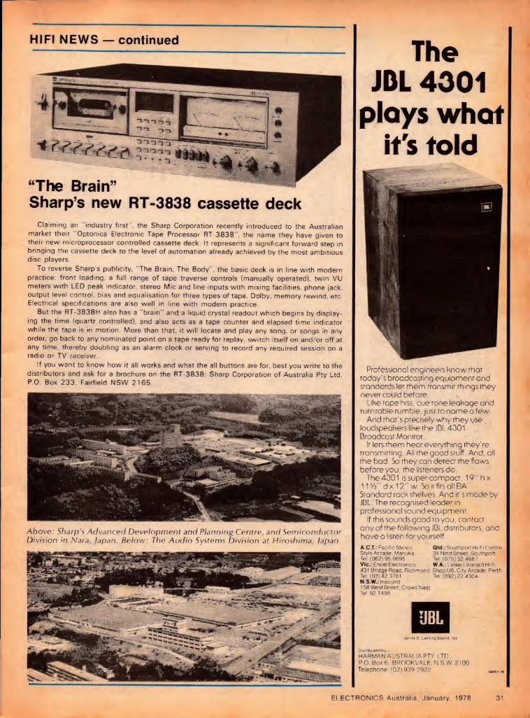
HIFI NEWS — continued
“The Brain” Sharp’s new RT-3838 cassette deck
Claiming an "industry first", the Sharp Corporation recently introduced to the Australian market their "Optonica Electronic Tape Processor RT-3838", the name they have given to their new microprocessor controlled cassette deck. It represents a significant forward step in bringing the cassette deck to the level of automation already achieved by the most ambitious disc players.
To reverse Sharps publicity, "The Brain, The Body", the basic deck is in line with modern practice: front loading, a full range of tape traverse controls (manually operated), twin VU meters with LED peak indicator, stereo Mic and line inputs with mixing facilities, phone jack, output level control, bias and equalisation for three types of tape, Dolby, memory rewind, etc. Electrical specifications are also well in line with modern practice
But the RT-3838H also has a "brain" and a liquid crystal readout which begins by display¬ ing the time (quartz controlled), and also acts as a tape counter and elapsed time indicator while the tape is in motion. More than that, it will locate and play any song, or songs in any order, go back to any nominated point on a tape ready for replay, switch itself on and/or off at any time, thereby doubling as an alarm clock or serving to record any required session on a radio or TV receiver.
If you want to know how it all works and what the all buttons are for, best you write to the distributors and ask for a brochure on the RT-3838: Sharp Corporation of Australia Pty Ltd, P.O. Box 233, Fairfield NSW 2165.
Above: Sharp's Advanced Development and Planning Centre, and Semiconductor Division in Nara, Japan. Below: The Audio Systems Division at Hiroshima, Japan.
The JDL 4001
ploys whof it's fold
today's broadcasting equipment and standards let them transmit things they never could before.
Like tape hiss, cue rone leakage and turntable rumble, just to name a
And that's precisely why they use loudspeakers like the JDL 4301 Broadcast Monitor.
It lets them hear everything rney re transmitting. All the good stuff. And, all the bad. So they can detect the flaws before you, the listeners do.
The 4301 is super-compact, 19"hx 11Vh" dx 12" w. So it fits all EIA Standard rack shelves. And it's made by JBL. The recognised leader in professional sound equipment.
If this sounds good to you, contact any of the following JBL distributors, and have a listen for yourself.
A.C.T.: Pacific Stereo Old.: Southport Hi-Fi Centre Style Arcade. Manuka 34 Nind Street. Southport, Tel: (062) 95 0695 Tel: (075) 32 4687 Vic.: Encel Electronics W.A.: Leslie Leonard Hi-fi 431 Bridge Road. Richmond Shop U8. City Arcade, Perth Tel: (03) 42 3761 Tel: (092) 22 4304 N.S.W.: Insound 108 West Street, Crows Nest Tel: 92 1498
James S. Lansing Sound. Inc
Distributed by— HARMAN AUSTRALIA PTY. LTD.. P.O. Box 6. BROOKVALE, N.S.W. 2100. Telephone: (02)939 2922
ELECTRONICS Australia, January, 1978 31

Stanton 881S moving-magnet cartridge Stanton Magnetics Inc has recently introduced a new top-of-the- line magnetic cartridge, the 881S. It is a moving-magnet design, with a rare-earth magnet and “nude stereohedron” stylus. Outstanding features of the performance are high signal output and excellent tracking.
Now what on earth is a "nude stereohedron"? Before those of you with more fertile imaginations start running riot, I can assure you that it is relatively prosaic. Stereohedron is, in fact, the Stanton CD-4 stylus shape which is similar to Shibata, Ichikawa and others. Like the Japanese variants, the Stereohedron is shaped from a "nude" square shank diamond which (so we're told) results in lower tip mass.
The reason for using a "rare earth" magnet is to obtain a very small but powerful magnet which results in a nigh signal output from the cartridge coils. And the fact that this magnet attached to the stylus cantilever is minuscule means that the effective tip mass is very low. The figure quoted is 0.2 milligrams.
In other respects, the new 881S cartridge is similar to the 681 model which is continuing in production. It has the same shape and same "long¬ hair" brush, 12.7mm mounting centres and colour-coded output terminals.
And as with other Stanton brush- equipped cartridges, the 881S must have a tracking force which is one gram greater than the effective stylus tracking force, to overcome the upward force of the brush. In practice, the tone arm is set for a tracking force of two grams.
If desired the brush can be easily removed. Under these conditions the tone arm is set normally and the tracking force set to 1 + 0.25 grarhs.
Specified load for the 881S is 47k with shunt capacitance, made up of connecting cables and preamplifier input capacitance, of 275 picofarads. DC resistance of the cartridge is 900 ohms while the inductance is 510 millihenries. This last figure means that the cartridge should be relatively tolerant of variations in shunt capacitance away from the specified figure.
Nevertheless, our tests were performed with the specified load.
We found the optimum true stylus tracking force to be 1 gram, with little to be gained at the maximum setting of 1.25 grams. The stylus brush does not affect the tracking in the slightest, although it may render the antislcating adjustment a little more vague. Suffice
32 ELECTRONICS Australia, January, 1978
to say that with the optimum figure of 1 gram, the 881S sailed through every tracking test we could provide. Quite simply, it rendered the best tracking performance we have seen to date.
We did not, however, try the tracking performance at settings below 1 gram.
The Stanton 881S is supplied in an attractive case
which includes a small metal box for
storage of spare styli and other hardware. Also
included is a small screwdriver.
over the whole range from 100Hz to 20kHz.
Square wave response at 1kHz was particularly good, with very small overshoot and absence of ringing. Waveform on sinewaves was not so good in the range above 8kHz, but this normally does not have audible effects.
Output voltage of the cartridge is quoted at 0.9mV/cm/sec and we measured it as 5mV at 5cm/sec. This is a big improvement over the output available from most premium quality cartridges. When combined with the efficient shielding of the 881S, the
There seems little purpose in such an exercise and, in any event, most tone arms become increasingly inaccurate in the tracking settings at figures below 1 gram.
Frequency response and separation between channels was tested with the CBS STR-100 test record. This gave results which did not quite tally with the calibration data supplied with the 881S. For a start, the data quotes the frequency response from 10Hz up but notes that the low frequency response will be a function of the tone arm.
We measured the frequency response at within + 1dB from 60Hz to 18kHz. Below 60Hz, the response showed a slight rise and above 18kHz, a fall of 4.6dB at 20kHz. Separation between channels was —28dB at 1kHz in both directions and in excess of 20dB
result is a very good signal-to-noise ratio.
Sound quality of the Stanton 881S is neutral. It does not sound spectacular — one forgets about the cartridge when it is playing. When you come right down to the nitty-gritty, there can be no better comment than that.
Undeniably, the Stanton 881S is very expensive. Recommended retail price of the 881S is $199. The replacement stylus, D81, is $99. Accessory styli are available for monophonic LPs and 78 rpm discs.
Further information on the 881S and other Stanton cartridges can be obtained from hifi retailers or from the Australian distributors, Leroya Industries Pty Ltd, 266 Hay Street, Subiaco, WA or interstate offices. (L.D.S.) ®

WHY YOUR NEXT CASSETTE SHOULD BE A MAXELL UD
A
3 THE SHELL — Even the best tape can get mangled in a poorly constructed shell. That’s why Maxell protects its tape with a
precisely constructed shell, made of lasting heavy-duty plastic.
No fixed guide posts are used. Instead Maxell uses nylon rollers on
stainless steel pins thus elimi¬ nating the major cause of skipping, jumping and
unwinding. tough teflon (not waxed paper)
slip sheet keeps the tape pack tight and flat. No more bent or nicked tape to
ruin your recording. Maxell doesn’t use a welded seal, but puts the cassette together with pre¬ cision screws. Result — Maxell doesn’t jam.
| ULTRA-DYNAMIC I
THE RESEARCH — More than twenty years ago, Maxell produced their first reel of magnetic tape. At that time, Maxell made a com¬
mitment to produce and sell only the finest magnetic products their technology could create. That commitment still stands today.
2 THE TAPE — This continuous research has lead to the develop¬ ment of the Maxell UD (ultra dynamic) cassette. A tape that has
a coating of super-fine PX gamma ferric oxide particles with an extra smooth mirror-finish surface. All of this adds up to high output, low noise, distortion free performance and a dynamic range equaling that of open reel tapes.
4 THE LEADER — A leader tape that has a four function purpose, a) Non-abrasive head cleaning
leader (cleans recording head for 5 secs.).
b) 5 second cueing line (recording function starts 5 seconds after the line appears).
c) Arrows indicating direction of tape travel.
d) A/B side mark (indicates which side is ready for play).
Now you know why your next cassette should be a Maxell UD (ultra dynamic).
maxell. The sound expert's cassette UD available in C60, C90 and Cl20
Distributed by Hagemeyer (Australasia) B.V. Branches in all States
WT GD 127M

A speaker unlike any other
The Acoustic Matrix yields performance unattainable with a conventional wood enclosure.
Nine drivers are mounted in the Acoustic Matrix enclo¬ sure, four on each rear panel and one facing forward
A tapered Reactive Air Column radiates the lowest bass from the four drivers on each rear panel.
Key to both perform¬ ance and efficiency is the new 901 ID driver, with molded frame and aluminum helical voice coiL
Introducing the Bose
901 Series III. In 1968, Bose introduced an unconventional loudspeaker system: the legendary Bose 901. Now, we are introducing a new speaker of revolutionary concept, design materials, and performance: the Bose 901 Series III.
What you will hear. You will be struck by a sense of immediacy and presence, spaciousness of sound, and accurate stereo image almost anywhere in the room. Equally startling are the realism and accuracy of the timbre of each instrument, the clarity and dynamic range of the deepest bass notes, and the precise definition of individual instruments.
Efficiency Most dramatic, however, is the remarkable efficiency with which this level of performance is achieved: the new 901 Series III can produce the same volume of sound with a 15 watt amplifier as the original 901 with a 50 watt amplifier. This dramatic breakthrough in the basic economics of high-fidelity makes it possible to put together a high performance component system at a lower price than was previously possible, even though the 901 Series III is a more expensive speaker than its predecessor.
Technology Spectacular performance and efficiency are the results of proven Bose
design concepts and technological innovations that include the unique, injection-molded Acoustic Matrix enclosure and a new, ultra-high efficiency driver.
At the same time, the 901 Series III is (as is the original 901), a Direct/Reflecting speaker with a separate electronic equalizer.
To appreciate the spectacular performance of the Bose 901 Series III, simply ask a Bose dealer to play the 901 III in comparison to any other speaker, regardless of size or price.
We submit that the 901 Series III provides more value in concepts, materials and performance than any other loudspeaker.
PLEASE SEND ME THE 16 PAGE COLOUR BROCHURE ON THE BOSE 901 SERIES III
Name.
Address.
State. Postcode.
TO: W. C. WEDDERSPOON PTY. LTD. 3 FORD ST., GREENACRE, NSW 2190 PHONE: 642-3993 AUSTRALIAN DISTRIBUTORS

Improved Solid State Multimeter Here is a brief article explaining how to improve the performance of the authors solid state multimeter design, published originally in the April 1976 issue. The changes are straightforward, and make a very worthwhile improvement to performance.
by COLIN CHRISTENSEN*
The following article outlines two modifications to effect improvements in the Solid State Multimeter I descri¬ bed in the April 1976 issue.
The first eliminates meter drift during "warm-up" which was most noticeable on the lower millivolt ranges. This drift originates in the regulated voltage supply for the MPF105 FET transistor. With the advent of the reasonably pric¬ ed CA3130 MOSFET operational amplifier this problem can be over¬ come. In the revised circuit a CA3130 is used to replace the MPF105, the original IC1 and the regulated supply for the FET.
The second modification is to switch* the output of IC1 directly to the meter for DC measurements, and to reserve the use of the precision rectifier for AC only. This overcomes the previous situation of using the rectifier for both AC and DC, where the measurement of DC having a relatively large AC compo¬ nent superimposed on it would have given an erroneous reading.
A four pole changeover switch is used for this purpose, the original S3 now being designated S3a, one of the poles of this switch. The modified cir¬ cuit diagram shows the additional cir¬ cuitry for the AC-DC switch.
The dotted line encloses that part which is built on the piece of 0.1 inch Veroboard, and should be read in con¬ junction with the rest of the circuit on page 77 of the April issue. The new component layout uses the same board
*17 Centaur St, Redcliffe, Qld 4020
as previously. Note the new position of the 680ohm resistor that replaces the 820ohm one. Take the usual precautions when handling and solder¬ ing the CA3130 as for other MOS devices.
The CA3130 has a maximum rating of 16V so the battery supply has to be reduced to plus and minus 6V. This can be supplied from eight AA size cells housed in a battery holder. Remember that a centre tap of the battery supply is
needed, and is achieved by soldering a length of hookup wire to the ap¬ propriate connector in the battery holder.
The value of R needs to be equal to the meter resistance, nominally 100 ohms. In my case, a value of 120ohms was just right. Try a 120ohm resistor first and connect the completed meter set to one of the mA ranges to a current source so that a near full scale reading is produced.
If R is the correct resistance required, the meter will read the same on AC as on DC. If lower, try different values of resistors starting at say 2.2k, connected in turn across the 120ohm resistor until equal readings on both are achieved. The multimeter will now have to be calibrated again, particularly the IV range. ®
M K C F A
2xZ3V3
The modified circuit for the active part of the multimeter. A CA3130 FET-input op amp replaces the original discrete FET and 741 input 1C, while the meter is now switched for AC and DC.
At left is the component over¬ lay for the new amplifier section, built on a piece of Veroboard identical in size to the original.
Parts List for Conversion
7 CA3130 op-amp 1 four pole, double throw switch 1 8 cell battery holder 1 battery clip 2 10k resistors 1 680ohm resistor hookup wire, solder, etc. 1 lOOpF capacitor 2 zener diodes, 3.3V.
ELECTRONICS Australia, January, 1978 33

DICK SMITH IS GROWING Buy your Christmas presents now Only 355 days to go
, W IGHE
EUCCTRONtC PROJeCT KIT
-WA- ®
SCIENCELRND Scienceland electronic project kits: the kit you don't have to solder. Each kit uses the same basic 'breadboard', you alter the connections as per the explicit instruction booklets that come with each kit. Ideal for the absolute beginner.
4-IN-ONE KIT: Makes 4 different projects inc¬ luding a crystal set. Complete with everything you need. Cat K-2024 .. .$6.95
10-IN-ONE KIT: Similar to above, but makes a total of 10 projects, superb value. Cat K-2026.$9.95
65-IN-ONE KIT: The whopper. 65 different kits, with some really different experiments into electronics possible. Cat K-2028 .$27.50
• ••
t DICK'S VALUE KITS! ? STROBE LIGHT: Ideal
companion to Musicolor! A pulsating, vibrant white light which freezes movement. Kit is complete with expen¬ sive photographic reflector for highest light output. Cat K-3150.$27.95
MUSICOLOR 111; Turn any party into a swinging affair! Colored lights are controlled by music. Complete kit with full instruction manual. Build in time for next Christmas! Cat K-3140.$59.00
n i
IPLAYMASTER AMPS ^Your choice of 25W/channel Cor 40W/channel. Both have {quality finish front panel, ^superb electronics. Comes *with absolutely complete * instruction/construction C manual, competitive value.
125/25 Kit Cat K-3410 c .$95.00 140/40 Kit Cat K 3411
.$119.50
£7^ W vkv YYYYYYVYYYY "C PLAYMASTER SPEAKERS:! « K 2 models, 53 litre 3-way & 751 M * 3-way. Bith superb performers,
J easy to build — save money on t* equivalent commercial units.
53 litre: $189.25/pair (order cat nos C-2044 & C-2624)
4 # 75 Litre: $254.00/pair T (order cat nos C-2042 & C12622)
I Illtl t
HERE ARE OUR 2 NEW STORES: ADELAIDE CITY.
203 WRIGHT STREET, TELEPHONE: 212 1962.
J L GROTE ST
[ GOUGER ST
WRIGHT STREET
STURT ST
I 1-1 WHITMORE
1 SQUARE
GILBERT ST
SOUTH TERRACE r n
“i=r Manager.
Phil Roberts.
MELBOURNE CITY. 399 LONSDALE STREET, TELEPHONE: 67 9834.
J Little Lonsdale Street
Car Parks
■ 11
Manager. Fred Wong
Lonsdale Street
Lonsdale Street Plaza
Car Park
Myer Melbourne | Ltd
Bourke Street
0ICK SMITH ELECTRONICS

up (STORES
HE'S JUST REACHED fi| ES, THAT IS - PLUS 170 DEALERS ACROSS AUSTRALIA!) V *
BACK IN STOCK!
^2^ The Radio Pull Amateur
Handbook! ‘'WlU-xrfM Cat. B-221 8.'
OUR MOST SOUGHT-AFTER
BOOK! For anyone who wants to no moer about amateur radio, electronics and communications.
2°°
BASF CASSETTE HOBBY BOX
«0
i-mm ■ Here's what every cassette owner needs — the BASF ■cassette hobby box. Contains splicing tape, leader, Itape, cassette parts, scissors, tweezers, etc [For editing, caring for or repairing cassettes.
SAVE $5.45: WAS $15.35!
REDUCED TO
GREAT VALUE AT
HEY/ HOME MECHANICS!
YOUR CAR COSTS ARE RISING ALL I THE TIME: so beat them by doing all I your own tuning. This unit checks just about everything electrical — points, rpm, dwell, volts,
I amps. It's easy to keep I your car in tip-top I shape and save lots I doing so! Scale is large, I to-read type with colour I coded bands for instant I identification.
Cat. A-8512.
SUPERB HEW RAMBLER
BELT DRIVE TURHTABLE
WE SEARCHED THE WORLD FOR A QUALITY T'TABLE - here it is. The Rambler Belt Drive. All the features you'd expect on a quality unit, and it is housed in a deluxe plinth with perspex cover. Cartridge supplied, too!
Cat. A-3070.
RECOMMENDED RETAIL IS $181.00!
HANDY [SOLDERING SET
| Even if I you're an old^ I hand at sold¬
ering, you'll find this set
I handy! ■T-2610.
FIGARO GAS SENSORI 3S used in ETI Project. In stock and now ^ only $8.90! Cat. Z-6860.
IDEALWELLER SOLDERING IRON
FOR THE HOBBYIST! WELLER SP25D SOLDERING
IRON. The ideal iron for the beginner or expert. For general elect¬ ronic & service work.
ONLY ""Vs'/'-SpE. UtM?
Amateurs:-
see our advert,
in the Amateur
section]
fan- rrAST'c
% "w rn ^ O/)
o0 9^' - -
A
vo\orr»e v t tVreV (
A
pspk
DICK SMITH ELECTRONICS shop hours Mon Fr. 9AM 5 30PM Sat 9AM - 12 noon (Brisbane ’4 hour earlier) WGlCOfTIG tlGfG
Dick Smith
gift vocher available at any Dick
Smith store!
SYDNEY SYDNEY SYDNEY SYDNEY^ 125 York St 361 Hume Hwy. 162 Pacific Hwy, 30 Grose St, City. Ph 29-1126. Bankstown Ph 709 6600 Gore Hill. Ph 439 5311 Parramatta. Ph 683 1133 Open til 8PM Thursday Open til 8PM Thursday Ample parking at door. 1st floor - friendly store!
MAIL ORDER DEPARTMENT: PO Box 747, Crows Nest NSW 2065. Phone 439 5311. Post & Pack extra
SYDNEY: MELBOURNE MELBOURNE BRISBANE: 30 Grose St 399 Lonsdale St 656 Bridge Rd. 166 Logan Rd, 203 Wright St, Parramatta Ph 683 1133 City Ph 67 9834 Richmond. Ph 42 1614. Buranda. Ph 391-6233 City. ^ 212^1962 1st floor - friendly store! New: right in town! Easy access: huge stock. Opens 8.30AM Now Open. See us
39-5311. Post & Pack extra. WE HAVE DEALERS RIGHT ACROSS AUSTRALIA - THERE'S ONE NEAR YOU!

For wet & dry bulb measurements
An electronic dual thermometer Have you ever wanted to be able to measure temperature in two places at once, either close together, or remotely? Alternatively, you may be interested in weather observations and you would like to have facilities for wet and dry bulb thermometer readings for &Y *AN POGSON checking relative humidity. This little device will do either of these things for you, simply with the flick of a switch.
In September 1968, we described an electronic thermometer using a thermistor as the sensing device. The thermistor does the job very well, but it is not linear in its temper¬ ature/resistance characteristic and a meter scale must be specially calibrated to suit.
Later on, in July 1971, we described another electronic thermometer and * on this occasion the sensing device was a silicon diode. Compared with the thermistor, the forward voltage drop versus temperature characteristic of the silicon diode is almost linear, being about —2mV/°C. This means that it is possible to use a meter with a linear
scale already fitted, an obvious advantage.
The uses for a thermometer are many and varied. Some of the advantages which an electronic thermometer offers over the conventional mercurial thermometer are that the electronic unit is much easier to read, the response to temperature change is fast, and remote readings can be made quite easily, to mention just a few.
The units which we have described previously only provided for one probe and so only one reading could be taken at any one time. However, there are occasions and circumstances where two readings are wanted, either close
to each other physically, or separated by some considerable distance. As an example of the latter, it may be required to take a temperature measurement indoors and one at a remote distance outside of a building. Under bad weather conditions, the advantage of such a system does not have to be stressed!
There could be many instances where two readings may be required in close proximity to each other. One instance which interests the writer is where the temperatures are to be measured in the respective positions of a double oven designed for use with a precision crystal oscillator. Another application, and one which will become obvious, is the classic case where relative humidity is to be measured by means of the wet and dry bulb principle.
With this latter thought in mind, we decided to make up a new unit with two probes, which could be used for relative humidity measurements, or whatever else readers may wish to do with it.
Faced with the idea of coming up with a dual probe thermometer, the next question was how best this could be done. Fairly obviously, an op-amp such as the 741 should be considered. With two input circuits to the 741, it seemed reasonable to consider the possibility of putting a probe in each of the inputs. This idea was investigated and while it could be done, there
36 ELECTRONICS Australia, January, 1978
The completed instrument, housed in a standard case. The wet and dry "bulb" arrangement can be seen at right.

seemed to be too many problems to overcome. In particular, setting up and adjusting the finished unit could be a tedious and difficult task for readers. As an alternative, we considered the idea of using two separate 741s, fed from a common power supply. This is the arrangement which we have adopted.
The circuit shows the two 741s connected as differential amplifiers, with adjustable negative feedback and a silicon probe at one input and an adjustable offset trimpot at the other input. Any small change in the forward voltage drop across the sensing silicon diode is amplified many times in the op-amp, with the amplified signal emerging at the output, pin 6.
With this circuit arrangement, it is possible to set the amount of gain with the trimpot in the feedback circuit and the offset voltage with the trimpot in the other input, such that the output voltage can be made to read out degrees Celsius (or Fahrenheit) directly on the scale of a meter connected across the amplifier output. In actual fact, the feedback trimpot sets the upper limit of the scale, wnile the offset trimpot sets the lower limit.
Metering for both circuits has been arranged by switching a single meter across either of the amplifier outputs. A third metering position has been provided such that the difference between the two output readings can be displayed on the meter. This has an application where it is necessary to determine the difference between the wet and dry bulb temperatures for
computing the relative humidity. No doubt the feature could also be used to advantage in other applications.
In those cases where readers have no interest in making relative humidity readings, the terms "wet bulb" and "dry bulb" will have no significance. Indeed, the "bulbs" really refer to the bulb of a mercurial thermometer, which has been replaced by the bead enclosing the silicon diode element.
The power supply, although fairly straightforward, has a couple of interesting aspects. Rather than complicate the supply by providing positive and negative parts equally about the earth line, we used the alternative of placing a voltage divider consisting of two 470 ohm resistors across the supply. The junction of the two resistors then becomes the centre reference. The second point relates to voltage regulation, which is essential. In order to reduce to a minimum any temperature coefficient effects of a single zener diode, we chose a combination of a 5.1V and a 5.6V in series, giving a nominal 10.7V.
The reason for selecting zener diodes of the values given above, is that zener diodes have a temperature coefficient which is positive on one side and negative on the other side of a line somewhere between 5 and 5.5V. By selecting values as equally as possible about this line and choosing such values as to add up to the wanted voltage, the temperature coefficients virtually cancel each other. This gives a regulated voltage substantially free of
PARTS LIST 7 Case 184mm x 115mm x 118mm,
with aluminium front panel 1 Meter 50uA, 66mm x 58mm 1 Rotary switch 2-pole, 2pos. 1 Toggle switch SPDT 1 Aluminium bracket for mounting
probes (see text) 1 Tagstrip with 8 lugs, including 2
mounting feet 1 PCB 140mm x 58mmf code 77TH12 1 Transformer, 240V primary 24V
C/T secondary. PL24/5VA or similar
2 ICs 741 8-pin DIL 2 Diodes, EM401 or similar 2 Diodes, IN4148 or similar 1 Zener diode, BZX79C5V1 1 Zener diode, BZX79C5V6 1 2500uF 25VW electro 1 Knob
RESISTORS (V2W unless stated otherwise) 3 470 ohms 4 4.7k trimpots (large) 4 15k 2 18k 1 22k 4 47k
MISCELLANEOUS
Coax cable, hookup wire, solder, screws, nuts> spacers, 3-core power flex, 3-pin plug, flex clamp. Note: Resistor wattage rating and capacitor voltage rating are those used in the prototype. Components with higher ratings may generally be used provided they are physically compatible. Components with lower ratings may also be used in some cases, provided the ratings are not exceeded.
temperature effects. In turn, this leads to more accurate results from the instrument, where variations in supply voltage can be a factor.
As shown in the circuit, we used a power supply arrangement with a transformer having a centre tapped secondary winding and full wave rectification with two silicon power diodes. For readers who may have a transformer without a centre tapped secondary winding, we have provided positions on the board for two more silicon diodes so that they may be used in a full wave bridge circuit.
Components used on the unit are normally available through most component distributors but a few comments on some items may be helpful. The case is one made in Melbourne by Australian Transistor Co, and we obtained ours from Radio Despatch Service in Sydney. The meter is imported and sold by University Graham Instruments Pty Ltd and we obtained ours again from Radio Despatch Service. The power transformer is made by Ferguson Transformers and the board is made to
ELECTRONICS Australia, January, 1978 37

Electronic Dual Thermometer
take this particular design. If you wish to use another make which will not fit on the board, then it may be possible to mount the transformer separately and run leads to the board.
Resistors, capacitors and solid state devices should present no problems. We have not used sockets for the two 741 ICs so these are not included in the parts list. However, if you wish to use sockets, there is no reason why you should not do so. But it is wise to use a good quality 1C socket if you do, as inferior ones can give annoying contact troubles.
Construction is straightforward, the main part being the assembly of the printed circuit board. When undertaking this part of the job, the usual principles apply. A small soldering iron should be used and care should be taken to make good soldered joints, without overheating the components. This applies particularly to the ICs and the diodes. Start with the small items first, leaving the transformer until last. It is also most important to make sure that all components are fitted with due respect to polarity, where this applies.
With the PC board finished, the meter, toggle switch and rotary switch may be fitted to the panel. The PC board is fixed to the bottom of the box with screws and 12.5mm spacers. Leads between the board and the front panel items may then be added. The leads for the two silicon diode probes can perhaps most conveniently be run in lightweight insulated coaxial cable. The leads are passed through a hole at the back of the box. According to the
application, the leads may be one metre or less in length, or they may be many metres long, if remote measurements are to be taken.
It will depend also on the application as to what form of mounting will be used for the probes. They may be separated by a considerable distance, in which case the probes will be mounted as separate units. On the other hand, the probes may be close together as in our case. We will describe how we arranged them, so that any variations should suggest themselves to individual readers.
As mentioned earlier, we set out to provide facilities for measuring temperature corresponding to dry and wet bulb readings. This allows us to mount the two sensing devices, or probes, close together, in a similar manner to mercurial thermometers for this purpose. We soldered the diodes to a tagstrip, making use of the< full length of the pigtails provided. The tagstrip, in turn, was fixed to a piece of aluminium bent into an "L" shape, as may be seen in the picture.
The "dry" probe is left bare to give a measurement of the temperature at that position. The second diode has to be arranged to simulate a "wet" bulb.
I have referred to publications by the Commonwealth Director of Meteorology, in relation to "relative humidity" and its measurement. I quote from "Observing the Weather", as follows:
"Humidity can be expressed in a number of ways but most commonly we Use 'relative humidity', stated as a percentage. A relative humidity of 60 per cent means that the air at the time
V7ew of the wet and dry "Bulb" arrangement. An ordinary plastic drinking cup was used as a water reservoir.
contains 60 per cent of the moisture it could contain if saturated at the same temperature. The warmer the air, the greater amount of moisture it can contain, in the form of water vapor.
"One method of determining relative humidity is to set up two thermometers, one of which has its bulb enclosed in muslin kept moist by a wick leading into a jar of water. Evaporation cools the wetted bulb. The difference in dry and wet bulb temperatures is greatest when the air is driest. By reference to tables the relative humidity can be obtained."
Having built the complete device, it now remains to test, calibrate and set it up for whatever type of use is intended. A check should be made of the board
Dry Bulb Difference Between Readings of Wet and Dry Bulbs in Degrees Celsius
0.5 1.0 1.5 2.0 2.5 3.0 3.5 4.0 4.5 5 6 7 8 9 10 11 12 13 14 15 16 18 20 22 24
4 93 85 77 70 63 56 48 41 34 28 15 8 94 87 81 74 68 62 56 50 45 39 28 17
12 94 89 84 78 73 68 63 58 53 48 38 30 21 12 4 16 95 90 85 81 76 71 67 62 58 54 45 37 29 21 14 7
20 96 91 87 82 78 74 70 66 62 58 51 44 36 30 23 17 11 22 96 92 87 83 79 75 72 68 64 60 53 46 40 34 27 21 16 11 24 96 92 88 $5 81 77 74 70 66 63 56 49 43 37 31 26 21 14 10 26 96 92 89 85 81 77 74 71 67 64 57 51 45 39 34 28 23 18 13
28 96 92 89 85 82 78 75 72 68 65 59 53 47 42 37 31 26 21 17 13 30 96 93 89 86 82 79 76 73 70 67 61 55 50 44 39 35 30 24 20 16 12 32 96 93 90 86 83 80 77 74 71 68 62 56 51 46 41 36 32 27 23 19 15 34 97 93 90 87 84 81 77 74 71 69 63 58 53 48 43 38 34 30 26 22 18 10
36 97 93 90 87 84 81 78 75 72 70 64 59 54 50 45 41 36 32 28 24 21 13 38 97 94 90 87 84 81 79 76 73 70 65 60 56 51 46 42 38 34 30 26 23 16 10 40 97 94 91 88 85 82 79 76 74 71 66 61 57 52 48 44 40 36 32 29 25 19 13 44 97 94 91 88 86 83 80 77 75 73 68 63 59 54 50 47 43 39 36 32 29 23 17 12
48 97 94 92 89 86 84 81 78 76 74 69 65 61 56 53 49 45 42 39 35 33 27 21 16 12
38 ELECTRONICS Australia, January, 1978
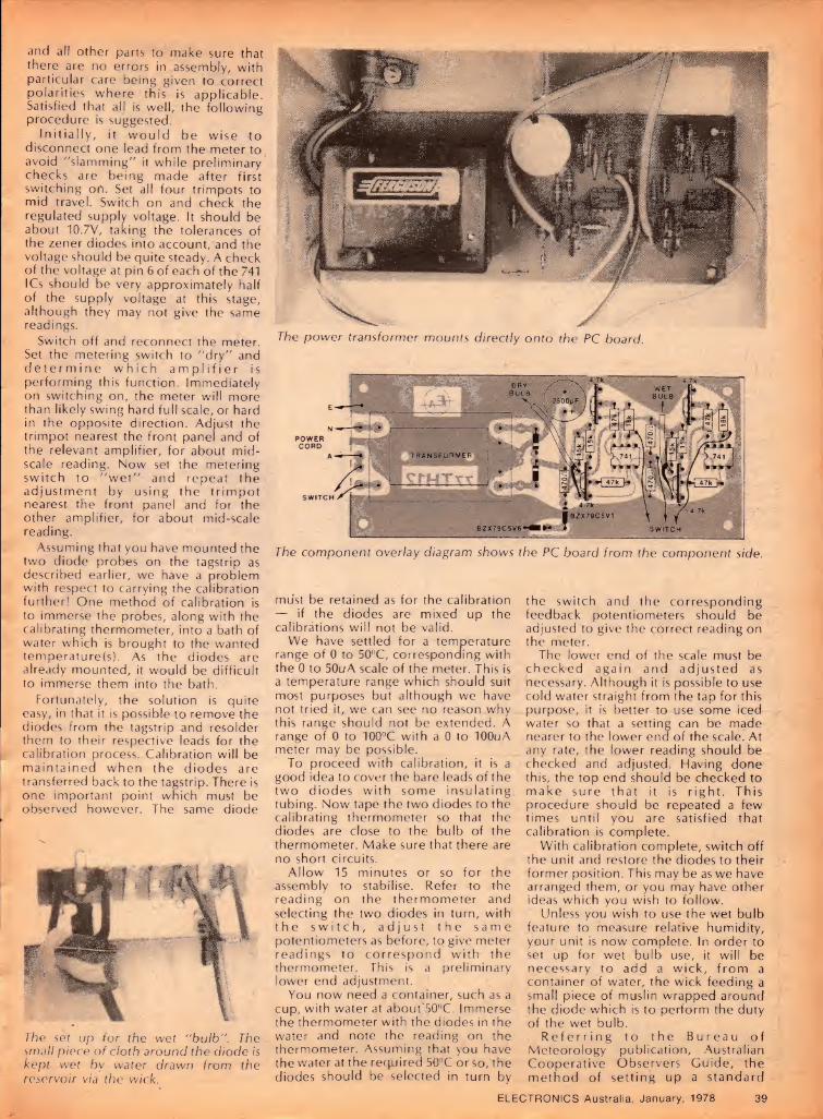
and all other parts to make sure that there are no errors in assembly, with particular care being given to correct polarities where this is applicable. Satisfied that all is well, the following procedure is suggested.
Initially, it would be wise to disconnect one lead from the meter to avoid "slamming" it while preliminary checks are being made after first switching ofi. Set all four trimpots to mid travel. Switch on and check the regulated supply voltage. It should be about 10.7V, taking the tolerances of the zener diodes into account, and the voltage should be quite steady. A check of the voltage at pin 6 of each of the 741 ICs should be very approximately half of the supply voltage at this stage, although they may not give the same readings.
Switch off and reconnect the meter. Set the metering switch to "dry" and determine which amplifier is performing this function. Immediately on switching on, the meter will more than likely swing hard full scale, or hard in the opposite direction. Adjust the trimpot nearest the front panel and of the relevant amplifier, for about mid¬ scale reading. Now set the metering switch to "wet" and repeat the adjustment by using the trimpot nearest the front panel and for the other amplifier, for about mid-scale reading.
Assuming that you have mounted the two diode probes on the tagstrip as described earlier, we have a problem with respect to carrying the calibration further! One method of calibration is to immerse the probes, along with the calibrating thermometer, into a bath of water which is brought to the wanted temperature(s). As the diodes are already mounted, it would be difficult to immerse them into the bath.
Fortunately, the solution is quite easy, in that it is possible to remove the diodes from the tagstrip and resolder them to their respective leads for the calibration process. Calibration will be maintained when the diodes are transferred back to the tagstrip. There is one important point which must be observed however. The same diode
The set up for the wet "bulb". The small piece of cloth around the diode is kept wet by water drawn from the reservoir via the wick.
The component overlay diagram shows the PC board from the component side.
The power transformer mounts directly onto the PC board.
POWER CORD
must be retained as for the calibration — if the diodes are mixed up the calibrations will not be valid.
We have settled for a temperature range of 0 to 50°C, corresponding with the 0 to 50uA scale of the meter. This is a temperature range which should suit most purposes but although we have not tried it, we can see no reason why this range should not be extended. A range of 0 to 100°C with a 0 to lOOuA meter may be possible.
To proceed with calibration, it is a good idea to cover the bare leads of the two diodes with some insulating tubing. Now tape the two diodes to the calibrating thermometer so that the diodes are close to the bulb of the thermometer. Make sure that there are no short circuits.
Allow 15 minutes or so for the assembly to stabilise. Refer to the reading on the thermometer and selecting the two diodes in turn, with the switch, adjust the same potentiometers as before, to give meter readings to correspond with the thermometer. This is a preliminary lower end adjustment.
You now need a container, such as a cup, with water at about'50°C. Immerse the thermometer with the diodes in the water and note the reading on the thermometer. Assuming that you have the water at the required 50°C or so, the diodes should be selected in turn by
the switch and the corresponding feedback potentiometers should be adjusted to give the correct reading on the meter.
The lower end of the scale must be checked again and adjusted as necessary. Although it is possible to use cold water straight from the tap for this purpose, it is better to use some iced water so that a setting can be made nearer to the lower end of the scale. At any rate, the lower reading should be checked and adjusted. Having done this, the top end should be checked to make sure that it is right. This procedure should be repeated a few times until you are satisfied that calibration is complete.
With calibration complete, switch off the unit and restore the diodes to their former position. This may be as we have arranged them, or you may have other ideas which you wish to follow.
Unless you wish to use the wet bulb feature to measure relative humidity, your unit is now complete. In order to set up for wet bulb use, it will be necessary to add a wick, from a container of water, the wick feeding a small piece of muslin wrapped around the diode which is to perform the duty of the wet bulb.
Referring to the Bureau of Meteorology publication, Australian Cooperative Observers Guide, the method of setting up a standard
ELECTRONICS Australia, January, 1978 39

Electronic Dual Thermometer
Above is an interior view of the completed instrumentwhile at right is an actual size reproduction of the PC board.
mercurial thermometer for wet bulb use is very clear. However, the physical form of a diode, compared with the bulb of a thermometer, is different enough to present some problems. It seems that there is some scope here for experimentation.
Here are some extracts from the Guide: "The muslin covering the bulb must be kept wet at all times. Keep the reservoir three quarters full with clean fresh water. Ensure that the cotton wick hangs vertically between the bulb and the water surface in the reservoir. Regularly change the muslin and wicks. When fitting new muslin, draw the muslin over the bulb, ensuring the muslin is taut and not creased around the lower half of the bulb."
With the above information as a guide, this is what we did to follow it as closely as possible. The "reservoir" was an ordinary plastic drinking cup. For a wick, consultation with the lady of the house suggested a piece of cotton cord used for lining piping as used in dressmaking. Muslin, although not difficult to obtain, was not readily available to us at the time the photographs were taken and so we had to compromise with a piece of cotton
40 ELECTRONICS Australia, January,
cloth. The cloth appears to give sensible readings but it would probably be better to use muslin if possible.
On the diode which we used for the wet bulb function, we left about 3mm of axial lead at each end before bending it at right angles. The piece of cloth (or muslin) was then folded around the diode in a "U" shape. The two straight pieces were then clamped with a piece of thin gauge tinned copper wire, formed into a narrow "U" shape which was slid over and then pinched tight. The protruding pieces of muslin were then cut off to about 10mm from the diode.
In order to keep the muslin wet, it is fed by a wick which we obtained from a cord which was rather thick, being made up of three strands like a rope. One strand was unwound and it is a multistrand piece about 3mm in diameter. With a piece of this about 23cm long, we wrapped one end around the muslin covered diode at one end and knotted once. The wick so formed then dropped straight down into the reservoir, with about 90mm between the diode and the top of the water. The close-up picture should clarify just how this has been done.
With the wet bulb now set up, the complete unit is almost operational. To speed up wetting the bulb, a small brush is dipped in the water and the muslin ana wick are "primed". After some minutes, the wet bulb temperature will settle down and is ready for use.
To take a relative humidity reading, set the switch to "dry" and note the temperature. The switch may then be set to "wet" and the temperature noted and the wet temperature subtracted from the dry temperature. Alternatively, the switch may be set to "diff", giving the difference reading directly. We have reproduced the standard set of tables for determining relative humidity by this method. It is then only necessary to consult the table to get the relative humidity reading.
An example may make the procedure clearer. Suppose that the dry bulb temperature is 22°C and the wet bulb temperature is 17°C. The difference is 5°C. Refer to the line on the table corresponding to 22°C and move along the line to the column corresponding with 5° difference. The relative humidity is read off as being 60 per cent. $

Howto crack a highly paid job as an electronics
technician. _ We’ll give you
excellent training - as good as you’ll get anywhere in
Australia. We’ll give you
free medical, dental and hospital treatment.
We’ll provide plenty of good tucker
and a comfortable place to stay. We’ll give you substantial leave,
and on top of all that, we’ll pay you well
while you’re training. On your side, you’ll give us a period
of hard, but interesting and rewarding
work. And, when eventually you leave us, you’ll find yourself a fully qualified
and experienced Electronics Tfechnician. Notabad thing to be, these days.
So, If electronics is your
idea of a great career and you are (at time of entry) approx. 15 to 17 for apprenticeship
and over 17 for an Adult Trainee, join the Navy, Army or Air Force.
Phone us at: Adelaide 2232891. Brisbane 2262626. Canberra (Navy)66 4697. Canberra (Army or Air Force) 47 6530. Hobart 347077. Melbourne 613731. Perth 3224355. Sydney 2121011.
White to either the Navy, Army or Air Force Electronics Tbchnician
Counsellor, GPO Box XYZ in your
nearest State
Capital City (please
include your date of birth).
Learn Electronics
. with us.
tax flACsA
Authorised by Director-General of Recruiting. Dept. Defence.
TSAP4.FP.107
ELECTRONICS Australia, January, 1978 41

Selective tone calling system for CB Some of the CB channels in metropolitan areas have already become so congested that even brief pre-arranged contacts are almost impossible. Here is a simple system, developed by a con¬ tributor, to allow effective signalling in such conditions. It com¬ prises a two-tone hand caller and a tone-controlled muting circuit for the receiver.
by D. HALTERMANN*
During the last few months, Channel 11, the CB call channel, has at times become so crowded that it is almost im¬ possible to contact a particular party at a prearranged time. During peak traffic hours, when workers are on their way home, there often arises a need for a mobile to contact the base station at home. More often than not, one's spouse has become thoroughly tired of the continual din on Channel 11 (not to mention the rude language that some
*P.O. Box 674, Geelong, Victoria 3220.
The tone oscillator circuit for the hand caller is based on an LM567 1C.
HIGH TONE ADJUST
LOW TONE ADJUST
The assembted tone oscillator is small enough to fit inside a pocket radio case.
42 ELECTRONICS Australia, January,
CB operators indulge in under the mantle of anonymity). A further problem is that every operator waits for that moment of quietness, makes his call immediately and then finds he has no chance of hearing any answer.
The equipment described here can¬ not, of course, eliminate the above problems but it circumvents two of the main bugbears associated with the crowded CB call channel. The listener expecting a call from a particular per¬ son does not need to have his or her ears numbed by the constant noise on the call channel. Instead, the receiver is muted and only a specially selected 2- tone call signal will open the muting. Secondly, the caller needs only about two seconds to transmit his call, assured that he will get through the first time. They can then move to a prearranged channel or sequence of channels until a free one is found. The commuter can tell his wife then that he is bringing home two additional dinner guests! — or can be told to bring home some bad¬ ly needed groceries, etc.
When designing this calling system, care was taken to ensure that no access was required to the internal works of the transceivers. Any electronics enthusiast who is capable of precise soldering and who can use a mul¬ timeter intelligently will have no trou¬ ble building this equipment and setting it up.
How does it work? The caller uses a small pocket radio that has been con¬ verted to produce twin beep tones when switched on. He holds it close to his microphone, waits for a silent period of Channel 11 and presses the transmit button for 2-3 seconds. To satisfy authorities he may also give his call sign verbally — caring little if it be heard.
At the receiving end, the transceiver is connected to an extension speaker. On the extension speaker cabinet is a toggle switch. In the CB position the speaker is connected directly to the base station and will faithfully reproduce all the noise and confusion of a busy call channel. Switching the toggle to "standby" will silence the speaker and put into operation a selec¬ tive tone sensor. This consists of 2 ICs which are tuned to the exact frequen¬ cies of the caller, with their output fed to an adder gate.
When both tones are received in rapid sequence, the gate will switch on the relay. This turns the speaker back on and the tones become audible. The listener then switches the toggle to CB and selects the prearranged channel.
Other signals of extreme volume and strong heterodynes can also open the muting for periods of a second or so. However, as this is not accompanied by the distinct 2-tone beep, it can be easily ignored. Judicious adjustment of the sensitivity (the transceiver's volume control) will eliminate most unwanted breakthrough.
The audio from the CB rig goes to pin 6 of the decoder PCB, while pin 7 is the ground return. Cl couples the signal via VR3, the sensitivity preset, and C2 to pins 3 of IC1 and IC2, tne tone decoder ICs (LM567). C3, C4 and C5 determine the sensitivity and selectivity of the ICs. C6, R3 and VR1 determine the accep¬ tance frequency of IC1. Pins 8 on IC1 and IC2 are normally at the positive supply voltage. When the correct tone frequencies are received, both pins go low. C8 near IC2 provides a storage time allowing the two tones to arrive in sequence.
IC3 switches on when pin 2 is lowered to l/3rd of the supply voltage, and stays switched on until the voltage on pin 2 rises above 2/3rds of the supp¬ ly. This not only assures a positive pull- in of the speaker relay but also allows the relay to stay in on one tone only — even though it requires two tones to in¬ itially trigger it.
The tone decoder ICs have a rejec¬ tion ratio of about 40dB. That explains why a very strong signal may oc¬ casionally break through. When the toggle switch is switched to CB the

speaker is connected normally and the power to the tone decoder is dis¬ connected.
The two-tone calling signal recognis¬ ed by the decoder is produced by a hand caller unit made by modifying a low-cost "personal portable" transistor radio. The radio used by the author was from the K-Mart stores, being iden¬ tified as model 767. It cost only $3.45.
The radio is modified by removing the tuning gang, oscillator coil and ferrite rod aerial. This leaves sufficient space to mount a tone oscillator circuit using an LM567 integrated circuit, on a small piece of Veroboard, together with a pushbutton for tone switching. The output of the tone oscillator is con¬ nected into the audio amplifier section of the radio.
To remove the tuning gang, pry loose the stick-on aluminium dial from the tuning knob. Unscrew the centre screw on the knob, and pull off. Remove the two screws holding the gang, and un¬ solder the three terminals on the tun¬ ing gang. Unsolder the oscillator coil and the small parts between this coil and the pot to gain additional room where required. Take care not to short out any PC tracks, as they may short out the battery. Drill a hole to mount the pushbutton on the same side as the volume pot at the extreme top, where the ferrite rod used to be.
Solder the positive lead of the Vero¬ board to 4- terminal from battery. The
negative lead is best soldered to the top of the IF can. Connect the output lead to the 300-390ohm resistor on the radio chassis. Solder two leads from the pushbutton to the Veroboard.
Set both pots to the centre position, and switch on. A tone should be audi¬ ble; if so, turn the volume up to a suitable level. On pressing the
ushbutton the tone should shift to a igher pitch. Glue the Veroboard on
top of the radio PC board with a small blob of Tarzan's Grip, or find a clear space to fit a single screw, taking care not to short out any tracks on the Veroboard or the PC board. Reassem¬ ble and the hand caller is finished.
The trimpots will only come into use where there is more than one hand caller to be used in conjunction with the base station — and of couibe when you want to shift the tones of your base station to change the code.
If you want to avoid having to press the pushbutton on the manual tone caller, this can be achieved by using an LM555 1C and a BC307 transistor as shown in the small supplementary cir¬ cuit. The 555 acts as a very low speed oscillator, turning the transistor on and off to duplicate the action of the pushbuttbn being pressed.
The collector and emitter of the tran¬ sistor connect into the LM567 circuit in place of the pushbutton. The additional circuitry is mounted on a very small piece of Veroboard, as shown. This is
This optional circuit can be used to automatically switch the tone oscillator.
LM555
Component layout of automatic tone switcher circuit on Veroboard.
supported by using stout tinned copper wire for the two power supply wires.
I suggest you build the tone caller initially, with manual switching of the two tones. Then wire up the PC board for the decoder, using PCB pins to make the various connections to the speaker lead, CB rig, 9V battery, toggle switch, relay contacts, relay coil and the speaker. For an initial test and set up, plug the lead into the PA socket of the transceiver. Switch the toggle to CB. Press the transmit button, and sound
ELECTRONICS Australia, January, 1978 43

Selective tone calling system
The component layout shows the PC board from the component side. Ensure correct polarity of polarised components.
*FERRITE ROD * FERRITE ROD
E=dH3=~ I t==c; t=
These two wiring diagrams show the modifications necessary to the two different model K-Mart transistor radios.
At left is the PCB pattern, reproduced here actual size. It can be traced if you prefer to make your own board.
from the mike should come through the speaker. Switch the toggle to stand¬ by and the speaker should be silenced. Use two jumper leads and temporarily short pins 8 on IC1 and IC2 to minus. The speaker should once more come on. Take the hand caller and adjust the two trimpots at about centre position but producing two distinct tones.
Now connect a voltmeter on the 10V range to pin 8 of I Cl. Tape the microphone button in the ON position and place the hand caller (emitting a tone at medium volume) on top of the mike. Adjust trimpot VR1 slowly until the voltage of pin 8 goes low. Reduce volume of tone caller and readjust VR1 until the most sensitive spot has been found. Now advance the volume on the hand caller once more, and short the pushbutton on the caller to produce the second tone. Transfer the meter lead to pin 8 of IC2 and adjust VR2 until the voltage goes low. Reduce volume again until the most sensitive spot is found on VR2 for the second tone. This completes the setting up.
44 ELECTRONICS Australia, January,
If the push button on the hand caller is operated to produce about two to three alternating tones per second the speaker relay will pull in and the beep¬ ing will come through the speaker. You can now make an on-air test. Plug the decoder in the ext-speaker outlet of the transceiver on a busy channel (11). Turn the sensitivity control RV3 full on. Turn up the volume on the receiver un¬ til strong signals break through fre¬ quently.
Now decrease receiver volume until no sound breakthrough occurs. Take the hand caller to the mobile unit in the car, hold the caller tightly to the mike, press the transmit button and alternate the tone about twice per second. This will open the speaker. A test drive with the mobile will soon establish the best setting of the receiver volume control. Decreasing the gain setting of RV3 means the receiver volume can be set higher — increasing the gain setting of RV3 allows the receiver to operate on a lower volume.
A note about the power supply. It is
advantageous to use a Mallory 1604B Duracell in the hand caller. The decoder should have a larger capacity battery or may be operated off the CB power supply. The 8.2 volt zener must have an adequate power rating as the decoder must not receive more than 9 volts maximum.
No details are given regarding the speaker and cabinet or the relay used. Many old speakers are available from old black and white TV sets. Matching is not a great problem with the transformer coupled outputs of CB rigs. I suggest you try a few speakers in a small cabinet with your transceiver and pick the one sounding clearest. Alter¬ natively, Dick Smith Electronics sells an extension speaker in a cabinet and with a lead and plug for about $8.00. D.S.E. also sells a miniature reed switch and a suitable activating coil for less than $1.00. I used similar reeds together with old horizontal oscillator coils from Philips available for 15c each from Elec¬ tronic Disposals in Lonsdale Street, Melbourne. ®

/c< CO-1303D 75mm OSCILLOSCOPE
5MHz bandwidth. ★ ^ Now with
• 75mm CRT
• DC-5MHz lOmV • Compact & lightweight
*219 ■ SPECIFICATIONS
Bandwidth DC to 5MHz f-3dB) Deflection lOmV/div
factor: Attenuator: 1, 1/10. 1/100 Input R.C: 1MJ2, 35pF Sweep ragnt: 10Hz to 100kHz Phosphor: P31
SG-402 RF SIGNAL GENERATOR
• Wide frequency range • Compact
• Amplitude modulation faci'ity
■ SPECIFICATIONS
Frequency
range Output
voltage Int. Mod.
Ext mod.
100kHz to 30MHz
in 6 ranges
0.1 V rms
400Hz.
40% modulation
$100 1.5V rms,
50Hz to 10kHz
AG-202A CR OSCILLATOR
• Wide frequency range • Sme and square wave signals • High output stabilized voltage
■ SPECIFICATIONS
Frequency
range Output
impedance Output
voltage
20Hz to 200kHz
m 4 ranges 1/P 60011
Sine wave: 10V rms.
Square wave: 10Vp-p
TEST INSTRUMENTS ^TRIO
15*1*
CS1560A If you need more
bandwidth-
The 15MHz dual trace
id o*.‘* " x uwv
.s an' . ..soUnH’"' ‘hv J
CS-1560A 130mm DUAL TRACE TRIGGERED SWEEP OSCILLOSCOPE
• 130mm CRT • DC 15MHz lOmV • Automatic sweep I AUTO FREE
RUN) • Display modes (CHI CH2 DUAL
ADD SUB) • Full sensitivity X V operation
• SPECIFICATIONS
Bandwidth Deflection
factor Input R.C Risetime Overshoot Sweep time Maqmfier Linear »?y
DC to 15MHz i 3dBI lOmV div to 20V dtv
IMi: 22pF 23nsec Better than 3% 0 5ms div to 0 5s div * 5 Better than 3°^
Calibrator IVpp (1kHz square wave)
Intensity More than 20Vpp modulation
Phosphor P31 Power AC 100 120 220 240V
50 60Hz. 23W Dimensions W260 x HI90 « D385
Weight 8 4kg
BEST VALUE *485
10MHz CS1562 Dual Trace,
Triggered Sweep *419
30MHz CS1570 ANOTHER
SENSIBLY PRICED SCOPE CS-15S2 130mm DUAL TRACE TRIGGERED SWEEP OSCILLOSCOPE
• '30mm CRT • DC IOVHz-IOihV • Auti'm.i’iv v.\i- [:
tAUTO TREE RU\' • T ,l • . -v X V
• ~Displ.lv modes iCH 1 CH2 DUAL!
• SPECIFICATIONS
B.indwnltii DC to IOMH.m 3dR' Deflection 10mV il v to 20V ,),v
Input R.C IV: : 22pT Riser.nv 35nsec Overshoot Better than 3
M.n;n,t„.. ,5 Lih.Mi.ty Better than 3
Phoviil • • PJ1 P. • At 1 (XT 120-220 240V.
50 60H.- 20W n . W2G0 » hi90 X D3/5
CS-1559 130mm TRIGGERED SWEEP OSCILLOSCOPE 10MHz Single
CS-1570 130mm DUAL TRACE TRIGGERED SWEEP OSCILLOSCOPE
■ SPECIFICATIONS
Bandwidth DC to 30MHz i 3dBi Deflection 5mV div to 5V div
factor Input R.C 1M:.\ 24pF Rtsetime 11 7nsec Overshoot Better than 3°'- Signal rfelay 160nsec Polarity CH2 can be inverted Swpep time 0 2/jS'div to 0.5$ div Magnifier x 5 Linearity Better than 3%
• 130mm mesh PDA e DC-30MHZ 5mV • Delay line • Auto level triggering • Display modes (CHI CH2 DUAL
ADDI • Trigger modes (AC LF Rei
HF Rei DC)
Calibrator 0 5Vpp (1kHz square wave)
Intensity modulation More than 5Vpp Phost)hor P31 Power AC 100 120 220 240V
50 60Hz. 25W Dimensions W260 x H 190 x D375
(mm) 8 5kg
*876
'S*KPRECISION
MODEL 1040 CB SERVICEMASTER
*282
MODEL 1827 30MHz FREQUENCY COUNTER
Greatly simplifies all CB transceiver servicing. Checks complete CB transceiver performance in minutes. Checks AM and SSB No complex hookups or calculations required.
Test results displayed on direct reading meters. Only one hookup required for all tests. Eliminates need for special equipment. Increases your CB service profit by saving you time.
30MHz reading guaran¬ teed. 50MHz typical—
Full 6-digit display with range switch allows 8-digit accuracy. 1Hz resolution-even at 30MHz and beyond. Completely portable for use anywhere. Exclusive battery saver features auto-shutoff of display to reduce battery drain.
Operates on A A size batteries, AC with optional charger/adaptor or 12VDC with optional power cord/adaptor. Complete range of optional accessories for unequalled versatility.
Call in for a demonstration at leading electronics stores or the Australian agents — Parameters Pty. Ltd. Sydney: 68 Alexander St., Crows Nest. 2065 Tel: 439 3288 Melbourne: 53 Governor Rd., Mordialloc 3195 Tel: 90 7444
All prices plus 15% Sales Tax.Recommended Prices only. 9PM70
PARAMETERSItt ELECTRONICS Australia, January, 1978 45
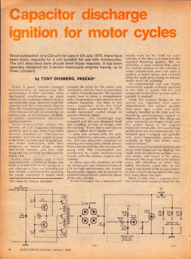
Capacitor discharge ignition for motor cycles Since publication of a CDI unit for cars in EA July 1975, there have been many requests for a unit suitable for use with motorcycles. The unit described here should meet those requests. It has been specially designed for 2-stroke motorcycle engines having up to three cylinders.
by TONY OHSBERG, VK6ZAO*
There is great interest amongst motorcyclists in improving the performance of their machines. Most mechanical modifications are done either by the enthusiast himself or by a specialist bike shop. However, both the amateur and the professional tend to I4ave the standard ignition unmodified, either because of lack of knowledge, or mistrust due to the dubious reliability of earlier commercial electronic ignition systems.
Many motorcyclists realise the benefits of CDI (capacitor-discharge ignition), and in fact, there have been several requests to "Electronics Australia" over the last couple of years to describe a suitable unit. In particular, two stroke motorcylces, with their tendency to fouled plugs, critical fuel/air/oil mixture, and their high firing rate can certainly be improved by fitting CDI.
Some four years ago I was approached by a friend to design and build a reliable CDI for his racing car. I was reluctant at first, not knowing just how reliable a unit would be, knowing the rough treatment it would most
•159 Lawley St, Yorkine, WA 6060.
certainly be given by the owner and mechanics, and the harsh environment in which it would operate. The ignition would have to share a compartment with a large engine and a massive set of exhaust extractors. The heat in this area, together with the high temperatures experienced in WA, would necessitate careful design to prevent thermal failure.
However, the challenge was accepted and the unit designed, built and installed, all free of charge, with the warning "If you lose a race due to ignition failure don't blame me!"
I soon lost contact with the unit, having shifted to a new area, a new job, etc, and was pleasantly surprised on meeting my friend after a break of over three years to find that the unit was still going well. The conversation was overheard by some motorcycling friends, with the obvious request soon coming.
In many ways the problems of CDI for motorcycles are similar to those of CDI for high performance cars. It must be physically rugged, able to operate in extreme temperatures, and must above all be very reliable.
At first I thought that a separate unit
would have to be built for each cylinder of the bike, as is done with the standard Kettering ignition. But, on reflection, I soon realised that unless the fuel-air mixture in the cylinder is under compression when the spark is applied, it won't ignite, and certainly firing the spark plug during an exhaust stroke won't do anything!
An experimental unit was hastily constructed, equally as hastily attached to the bike (a Suzuki 750 GT) and connected to the three ignition coils in parallel. It worked!
Using the original design for the racing car, together with some improvements that weren't possible four years ago, a unit was built, carefully installed in the bike and the resulting performance noted as objectively as possible. The idling was vastly improved, no longer rough, and the power band of the engine improved remarkably. On road testing, acceleration was increased greatly, less frequent gear changing was possible and, most importantly, power was available at high rpm where none existed before!
After several thousand kilometres the plugs were inspected for fouling, the single most troublesome problem on a two stroke, and found to be clean. Previously the plugs had to be cleaned every 500 kilometres or when they failed, whichever came first. At this stage it was found to be an easy matter to add a xenon timing light to the unit, but more about this later.
There is little that is original about the circuit used, except perhaps for the

trigger circuitry. TRi, TR2, Ti and associated components form an inverter producing approximately 400 volts. It has been designed to produce a higher current than is usual in a car ignition, because it has to supply three ignition coils simultaneously. Similarly, the discharge capacitor is 4uF, instead of the usual luF. Resistors R12-R13 ensure that each coil receives equal current. Diodes D5-D7 form a simple NOR gate to enable any of the three points to trigger the SCR.
A printed circuit board was not used in the unit constructed as it was a one- off project and it seemed simpler to use Veroboard, particularly if modifications had to be made. The most time- consuming part of construction is winding the oscillator transformer. It is necessary to exercise great care in doing this, as a fault developing later would be hard to rectify. Fig.2 gives all necessary information.
To mount the transformer to the board, pass a bolt with washer from the underside and secure with a washer and nut. Be careful not to overtighten, as the ferrite is easily cracked. Ensure that the mating faces of the cores are clean and that the wire leads are not crimped by the cores.
The six power resistors were mounted some 2-3mm, from the board to facilitate cooling. As with all other components in this circuit, they are run well within their ratings, dissipating only about 1 watt. However, it would be unwise to use a smaller power rating, as the dissipation capability falls
CDI for motorcycles — This alternative circuit was
submitted by Mr D. Walmsley, Port Macquarie, NSW.
Based on the EA July 1975 CDI, it employs diodes to isolate the trigger circuits and coils. The circuit can be repeated as required to suit the application, and has proved effective on Triumph Bonneville 650 and 750 Trident motorcycles.
Note: with this circuit, the coil "backswing" cannot partially recharge the discharge capacitor. The circuit may therefore not be suitable for higher-revving smaller- capacity bikes.
sharply with increasing ambient temperatures.
A lot of consideration was given to the discharge capacitor. After testing several different types, by running on the bench for up to 100 hours/a Plessey power factor correction capacitor, type 440WXH4, rated at 4uF and 440VAC, was chosen. Its maximum operating temperature is given as 85°C, which would seem to be more than adequate. Although it would be possible to use other capacitors, it would be unwise to do so without first checking on their suitability.
It is important that only 2N3055 transistors are used in the inverter. Types with a 1 or 2 suffix are low voltage rejects and may not be suitable for this application. The transistors are mounted on a heatsink with a thermal resistance of less than 1.5°C/watt, in the usual way using mica washers and heatsink compound. Ensure that all burrs are removed after drilling. Insulating covers are used on the transistors, to prevent accidental shorts. The completed ignition is mounted in a diecast box which is attached to the bike with resilient rubber mountings to lessen vibration. Be sure to provide an earth to the framework if this is done.
On bikes where space is at a premium, the ignition may be split into several sub sections. It would be possible to mount the main electronics in a small diecast case, with the heatsink and transistors placed elsewhere. After it has been established that the ignition is functioning correctly, further protection may be afforded by "potting" the electronics in a rubber compound such as Silastic. This has the advantage that it may be removed at any time, though admittedly with some difficulty, should repairs be needed.
If a xenon flash tube is connected across the primary of one of the ignition coils it will fire simultaneously with the ignition, providing a bright timing light at minimal cost. Maximum power would not be available to the plugs when this is used, but this should not be a problem. ®
an alternative
+ 300V FROM INVERTER BRIDGE RECTIFIER
AUSTRALIA’S FIRST
**************************** HUGE 128 PAGES!!!!
***************************
BOOK ON CB RADIO
There are over 30 books on the market about CB Radios - but they are all about the U.S Service.Now we have one that is exclusively Australian!
WRITTEN BY AUSTRALIA'S
Tliis huge 128 page manual is crammed with the answers to all your questions: * What is CB all about? * What types of rig are there? * What do I watch for when buying? * What are the licensing requirements? * What's the difference between the
Australian and USA systems? * What accessories are available? * How do I speak the lingo? * Where are the CB clubs? * What are all the technical terms? * How do I use the emergency channel?
In addition, the handbook contains the full RB14 regulations which you MUST read before licensing a set, plus a sample RBI3 application form.
NOW AVAILABLE: AT YOUR NEAREST DICK SMITH STORE OR DEALER OR NEWSAGENT.
ELECTRONICS Australia, January, 1978 47

Easy-to-build unit employs CMOS ICs
Auto Cross-Fader In this article we present design and construction details of an automatic cross-fading unit, which will allow one high level source to be faded into a second such source, with complete control over by DAVID EDWARDS the fade rate and the depth of fade. The design is based on modern CMOS digital circuits.
Many situations arise in public address applications where it is desired to make announcements over a system which is normally supplying background music or some similar service. This can be achieved either simply, by switching the inputs to the amplifier, or more elegantly by employing a mixer with cross fading facilities.
Such a mixer normally has a control which allows "he music signal to be attenuated at me same time as the microphone channel is boosted, so that as music fades, the microphone signal increases in loudness. This control is normally operateci by hand, and at a rate selected by the operator.
The circuit presented here eliminates the uncertainties inherent in such a system, while still allowing the operator full control. As an added bonus, a mute
facility is provided, whereby both microphone and music signals can be switched off at will.
The operator is provided with three controls, two being switches and one a potentiometer. The potentiometer is used to vary the rate at which fades occur, with the slowest fade taking about seven seconds, and the fastest less than 100 milliseconds.
The first switch has two positions, labelled "music" and "mic". In the music position, any signals connected to the corresponding input are passed to the output unattenuated, while all signals connected to the mic input are attenuated by about 50dB, which makes them effectively inaudible.
Similarly, in the mic position, the music signals are attenuated, while the mic signals are passed through unattenuated.
When the switch is operated, however, the signal transfer is not instantaneous. In fact, there are eight different steps in the transfer process, and the rate at which these steps occur is determined by the setting of the rate control.
Refer to Fig. 1 for a diagrammatic representation of the way in which the step sizes are arranged. At stage 0 for the mic channel, which corresponds to stage 7 for the music channel, there is effectively no mic signal, and the full music signal is present at the output.
At stage 1(6), the music channel is attenuated by IdB, while the mic channel has been introduced into the output with a level of —21dB.
By stage 3(4), the music signal has been attenuated by 3dB, while the mic channel has been increased in level to —9dB. Thus the combined signal is down 3dB approximately, and the mic signal will be audible in the background of the music signal.
At the next stage, stage 4(3), the situation is reversed. The mic signal is now at the —3dB level, while the music signal is down to —9dB. Thus the music is now audible in the background of the mic signal, with the combined level remaining at about —3dB.
In the remaining stages, the music signal is attenuated more and more, till at stage 0, only the mic signal remains. The steps between all stages are 6dB or less, except for the final step, which occurs when the signal is attenuated by 21dB already. This means that they are effectively inaudible.
Thus the casual listener is only aware of a gradual fading from one signal to another, with the total sound level remaining substantially constant.
The remaining switch simply serves to mute both channels, irrespective of which channel is switched to the output. The remaining front panel fitting is a red LED, which is normally on all the time, but flashes on and off as the cross fade is carried out. Thus it can

I SLOW—FA8T
AUTO
CROSS-FADE
MUSIC
M
# { mute
MIC
be used by the operator as a guide as to when to start using the microphone.
Turning now to Fig. 2, we can examine the operation of the circuit in more detail. A 4029 up/down binary counter, driven by a gated oscillator, is used to control two 4051 8-channel multiplexers, which control the actual cross fading function.
Let us assume that the program switch is in the music position, and that power has just been applied. The network connected to pin 1 will preset the counter to binary 0000. Since pin 10 is held low, the counter will be in the down counting mode, and pin 7, the carry out terminal, will be low.
(The carry out terminal is normally high, and goes low when the maximum count in the up mode has been reached, or when the minimum count in the down mode has been reached.)
The oscillator will thus be disabled, and the counter will remain in the binary 0000 state. Outputs Q2, Q3 and Q4 will be low.
When the program select switch is placed in the mic position, the counter will be placed in the up mode, pin 7 will go high, and the oscillator will start.
Thus the counter will count up, at a rate determined by the 1M rate control, until it reaches the binary 1111 state. Pin 7 will then go low, and disable the counter. This procedure will be reversed when the program select switch is returned to the music position.
The output of the oscillator is used to drive the LED, via a BC548 transistor. The LED is arranged to be emitting whenever the oscillator is stopped, and to flash off while the oscillator is running.
During the counting process, outputs Q2, Q3 and Q4 will change in binary sequence from 000 to 111, or from 0 to 7 in octal. Before continuing, a brief discussion of the 4051 chips is in order, as these may not be familiar to many readers.
The 4051 is a single 8-channel analog multiplexer having three binary control inputs, A, B and C, and an inhibit input. The three binary signals select one of eight analog channels to be turned on, by connecting the common pin (3) to the appropriate separate pin. Note that here we are using the common pin as the input, and the separate pins as outputs — the opposite to a normal multiplexer application.
The connections within the device between the input pin and the output pins are made using CMOS analog switches, similar to those used in the more common 4016 device. The inhibit function, when activated, disconnects the outputs from the input, irrespective of the binary input code applied.
A further facility of the 4051 chip, which we have not used in the present application, is to that it has built in logic level conversion circuits, so that the digital control signals can have, say, + 5V rails, with the analog sections having a + 15V rail.
Returning now to Fig. 2, we can continue the discussion of the circuit. The music and mic input signals are applied to the input terminals (pin 3) of the 4051, and depending on the code applied to the control inputs, connected to the appropriate output pin. Each output pin is fitted with a series resistor, to provide the required attenuation level.
A BC549 transistor is used as a virtual earth active mixer, to combine the selected outputs from the 4051s.
470k resistors have been used to bias the inputs and outputs of the 4051s to half the supply rail. This minimises any switching transients, and gives maximum signal handling capability. The analog supply rail is decoupled from the digital supply rail, to further minimise glitches and noise in the analog output.
The mute facility is provided by using the inhibit inputs of the 4051s. A simple debouncing scheme is provided to
PARTS LIST
SEMICONDUCTORS 1 4011 quad NAND gate 1 4029 up/down binary/decade
counter 2 4051 8-channel analog
multiplexer/dem ultiplexers 1 BC548 or similar NPN silicon
transistor 1 red LED 4 EM401 or similar silicon diodes
CAPACITORS 1 2500uF 16VW pigtail electrolytic 1 IOOuF 16VW PCB mounting
electrolytic 4 IOuF 16VW PCB electrolytics 4 0.22uF polyesters 2 0.1 uF polyesters
RESISTORS 1 2.2M, 8 470k, 2 270k, 2 68k, 4 47 k, 2 18k, 2 12k, 3 10k, 1 6.8k, 2 5.6k, 1 2.2k, 1 470 ohm, 1 100 ohm, 2 10 ohm 1 1M log potentiometer
MISCELLANEOUS 1 printed circuit board, coded 78cf1,
96 x 75mm 1 metal case, see text 1 knob 2 SPDT miniature toggle switches 1 4-way RCA chassis mounting
socket strip 1 mains transformer, 240V to 6V or
9V, DSE 2840, Ferguson PF2851 or similar
1 Mains plug, cord, grommet, clamp and terminal block
PCB pins, hookup wire, solder, tinned copper wire, machine screws and nuts, scrap steel plate.
NOTE: Resistor wattage ratings and capacitor voltage ratings are those used for our prototype. Components with higher ratings may generally be used provided they are physically compatible.
4051 OUTPUT
-COMBINED RESPONSE
-MIC RESPONSE
- --MUSIC RESPONSE
FIG. 1
ELECTRONICS Australia, January, 1978 49

Auto Cross-Fader
TRANSFORMER MIC MUSIC
Component overlay pattern on the PC board. Note the metal shield between the PC board and the transformer.
prevent audible transients occuring during the mute process.
The complete circuit has a current drain of about 25mA, most of which is the current for the LED. We have shown a simple power supply, using a bridge rectifier and filter capacitor, although battery operation is quite feasible.
The complete circuit is accommodated on a small printed circuit board, coded 78cf1, and measuring 96 x 75mm. Three holes are provided on this board to allow access to the control lines of the 4051s. This means that if a stereo unit is required, a second pair of 4051s can be mounted on a second PCB, and wired to the first PCB.
Provision has also been made for an extra resistor on the board. This has been shown dotted on the circuit diagram. It will enable the music
SPECIFICATIONS
OUTPUT CHARACTERISTICS Nominal output voltage: lOOmV RMS Maximum output voltage: 2V RMS Frequency response: —3dB at 35Hz, —0.3dB at 300kHz Insertion loss: —1.3dB at 1kHz and lOOmV RMS Distortion: 0.23% at 300mV RMS Signal to Noise ratio: —51.5dB at 1kHz and lOOmV RMS Crosstalk: —48dB at 100Hz and lOOmV RMS, —51dB at 1kHz and lOOmV RMS, —37dB at 10kHz and lOOmV RMS.
POWER REQUIREMENTS 9-12V DC or 6-9V AC at 25mA. Bridge rectifier and filter capacitor provided on PCB.
channel to be continued in the background at a low level while the mic channel is operative.
On the circuit diagram we have shown a power transformer with a 9V secondary. This gives a nominal supply voltage of 12V. If required, a 6V transformer can be used, giving a nominal supply voltage of 9V. In this case, the 6.8k resistor marked with an asterist (*) should be increased to 8.2k, to maintain correct bias on the collector of the output stage.
If it is desired to use a battery, the LED and associated driver should be deleted, in order to reduce the current drain. Alternatively, the driver transistor could be driven from the clock input of the 4029. This will keep the LED normally off, and it will only flash during the changeover period.
We constructed the prototype in a small utility case, kindly supplied by Dick Smith Electronics Pty Ltd. External dimensions of this case are 150mm x 100mm x 60mm. It has a steel cover and an aluminium base. The general arrangement of the components in the case can be seen in the photographs.
The specifications of the prototype are shown in the accompanying table, and a few comments regarding these are in order. The low frequency response can be improved by increasing the size of the three 0.22uF coupling capacitors. If a high frequency rolloff is required at say 30kHz, add a lOOpF capacitor in parallel with the 47k feedback resistor (between collector and base).
The crosstalk from the attenuated input to the output increases at high frequencies due to the cross coupling inherent in the 4051s. However, in
50 ELECTRONICS Australia, January, 1978
practice it is masked by the signals normally present in the active channel.
The signal to noise ratio of the prototype was not as good as expected, because of some 50 and 100Hz signals induced into the virtual earth circuitry by the transformer. However, in practice the levels achieved were found to be satisfactory. Note that the hum is reduced significantly by the fitting of the steel shield as shown in the photographs.
Further improvements can be obtained by moving the transformer further away from the PCB. This will of course require a larger box. Note that if it is desired to incorporate the unit inside an existing PA amplifier, it would be possible to dispense with the transformer altogether, and power the unit from the amplifier supply rail.
Use the component overlay as a guide during construction. The audio connections to and from the board need only be shielded if long connections are required. The connections to the switches and other front panel controls should be made with hookup wire or rainbow cable.
Provided care is exercised during assembly, sockets are not required for the CMOS devices. Leave the fitting of these until last, and then earth the barrel of your iron to the PCB earth line. Solder the power supply pins of the ICs first, and then the remaining pins. The power supply pins are as follows: pins 7 and 14 for the 4011, pins 8 and 16 for the 4029, and pins 7, 8 and 16 for the 4051s.
When assembly is complete, apply power and check for correct operation. Any faults will most likely be due to incorrect wiring or misplaced components. ®

Above is the circuit diagram, while below are actual size reproductions of the PCS pattern and the front panel artwork.
ELECTRONICS Australia, January, 1978 51

miunumw [PROJECT ELECTBOMICS KITS EDUCATIONAL - PRACTICAL - ECONOMICAL - AND SAFE!
We’re pretty excited about this new range of electronics kits. And we’re sure you’ll think as we do! Project Electronics kits are different to any of the beginners kits you’ve seen before. These were all designed in Australia to suit Australian components. Barry .Wilkinson, the designer (whose projects also appear in Electronics Today magazine) has come up with a range of practical, educational projects which are very simple to con¬ struct. And they’re safe. Every kit is powered by battery - no mains voltages involved! The Project Electronics kits are ideal for school projects — in fact, one of the aims of the series is to provide kits suitable for electronics courses in schools. Have a look at the range of projects below. You’ll find something of interest — and who knows: this may be the start of an exciting new hobby or career!
041 CONTINUITY TESTER Cat. K-2041 . $3.00 043 HEADS AND TAILS Cat. K-2043 . $3.50 044 TWO TONE DOORBELL Cat. K-2044 .$4.00 045 500 SECOND TIMER Cat. K-2045 . $4.50 047 MORSE PRACTISE SET Cat. K-2047 . $3.50 048 BUZZBOARD Cat. K-2048 . $3.90 061 BASIC AMPLIFIER Cat K-2061 . $5.50 062 SIMPLE AM TUNER Cat. K-2062 . $6.50
063 ELECTRONIC BONGOS Cat. K-2063 . $5.00 065 ELECTRONIC SIREN Cat. K-2065 .$5.50 066 TEMPERATURE ALARM Cat. K-2066 .$4.90 067 SINGING MOISTURE METER] Cat. K-2067 .$4.90 068 LED DICE Cat. K-2068 .: $5.90 072 TWO OCTAVE ORGAN Cat. K-2072 .$8.50 511 BATTERY SAVER Cat. K-2511 .$3.90
NOTE: Project Electronics handbook is required to build these kits. See below.
All these kits are complete - resistors, capacitors, semiconductors, printed circuit boards (where used) even solder & hook-up wire1
ha2nn„rC ,StHeqUire,d S°me CaS6S- !e-9’ m°:Se, k6V' °r9an Aboard, etc) These are not supplied but may be available from where you purchase the kits along w.th simple electronics tools, etc. Call in to your nearest Dick Smith store or full dealer and check out the 'Project Electronics' Bar!
PROJECT ELECTRONICS
■iSiSSSSa4SH Cat B-3652
This handbook contains all the information you need to build the above projects, plus a huge amount of valuable reference material and data — particularly use¬ ful if you are a beginner! Tells you how to solder, what components look like and how to read compon¬ ent codes, etc etc etc. Even if you've never built anything electronic in your life, you can with this book. Value!
Also available... Here’s value! Multiple projects from one kit. There’s a choice of 4-in-one, 10-in-one, or the whopper 65-in-one. And the best feature of all: no soldering! All connections are made by spring connectors. You can easily wire up all these projects with absol¬ utely NO knowledge of electronics!
from only $6 4-IN-ONE KIT: Makes a crystal radio (one of our most asked for projects) plus a singing bird, sleeping bell and magic touch. Complete with instructions and perforated base board. Cat K-2024 .$6.95 10-IN-ONE KIT: Too many projects to list - but all easy to build and include handy items. Cat K-2026 .$9.95 65-IN-ONE KIT: Keep anyone amused for weeks! Deluxe kit comes with everything you need to make all these projects. Cat K-2028 .. .. $27.50
AVAILABLE EXCLUSIVELY FROM: DICK SMITH ELECTRONICS # BUT iXPvwict SciD2EY u SmEY SYDNEY MELBOURNE MELBOURNE BRISBANE ADELAIDE 125 York St 361 Hume Hwy. 162 Pacific Hwy. 30 Grose St. 399 Lonsdale St. 656 Bndqe Rd 166 Loaan Rd JOlWnohtlt
Ooen^hl^JPM Thursria ^^^TrpmVh09 5600 a°^H'M ^ 439^311 Pa"a™*ta Ph 683 1133 City. Ph 67 9834 Richmond Ph 42 1614 Buranda Ph 391 6233 City PhW 1962 Open til 8PM Thursday Open til 8PM Thursday Ample parking at door 1st floor - friendly store' New right in town' Easy access huge stock Opens 8 30AM Now Open See us'
MAIL ORDER DEPARTMENT PO Box 747, Crows Nest. NSW 2065 Phone«l39 5311. Post & Pack extra WE HAVE DEALERS RIGHT ACROSS AUSTRALIA THERE'S ONE NEAR YOU'
welcome here

An audio oscillator using digital ICs
«
This unusual audio oscillator circuit uses digital waveform synthesis to generate both sine and square waves. It has somewhat higher distortion than the conventional Wien bridge ADRIAN FREED configuration, but overcomes the stability problems inherent in 20 ln9ara Ave* Miranda 2228 the latter.
The project presented here is an audio oscillator providing sine and square waves from 0.5Hz to 30kHz, in four ranges. Several unusual techni¬ ques have been employed to produce sine waves of low distortion at such low frequencies and to maintain their fre¬ quency and amplitude stability.
The sine wave is generated digitally as shown in Fig. 1. Each half-cycle is divided into 16 time intervals labelled 0-15. Each interval has a voltage associated with it, equal to the value of a sine wave at a point half-way along that interval. Notice from the diagram that the sine wave is symmetrical about T8.
The voltages for the intervals T1 to T7 are the same as those for T9 to T15, but
are in the reverse order. This feature of the sine curve greatly simplifies the cir¬ cuitry and the calibration.
A 555 timer used in the astable mode serves as the clock. Its frequency is con¬ trolled over a 20:1 range using a poten¬ tiometer. SW2 is used to switch timing capacitors to change frequency ranges. In this way the entire audio frequency range is covered.
The output of the 555 clocks the 7493 binary counter, which counts from 0 to 15. Its binary outputs are decoded by the 74154. Appropriate output pairs of the decoder are ORed and inverted using eight two-input NOR gates con¬ tained in two 74C02 packages. The outputs are grouped in this way to take advantage of the voltages common during the count sequence.
Notice that the TO output has no gate connected to it. This is because the sine wave has a value of 0 during this time. In the case of T8, the output is simply inverted. T8 is the peak of the sine wave.
An inverting operational amplifier configuration is used to set up the voltage steps. Referring to Fig. 3 it can be seen that the output of A1 is given by:
Output Voltage = R(V1/R1 + V2/R2 + ... + Vn/Rn)
Since the decoder has only one out¬ put in the high state at any point in time, only one term of this series need be considered. The others are all zero. Therefore:
Output Voltage = R (Vn/Rn)
Vn is the output of the 74C02 gates in the high state (5V), while trimpots are used to determine Rn.
The resistor for T1 and T15 is fixed at 10k, and the other trimpots adjusted with respect to this reference. A2 of the LM324 is used to invert the half cycles presented to it from A1. The two trim¬ pots associated with A2 are to set its gain to precisely -1 and to cancel amplifier offsets. Two CMOS switches are used to select which output of either A1 or A2 is connected to the filter.
The CMOS switches are controlled by one of the flipflops in the 74C73.
This flipflop is cJocked from decoder output T15. This part of the circuit generates a full cycle of the sine wave, by inverting every other half-cycle from the digital circuitry. The zener diode and transistor form a level translater to match the TTL and CMOS voltage levels.
The output of the filter is connected to a potentiometer which acts as a level control for the sine wave output. A3 buffers the output of the poten¬ tiometer.
A square wave is provided by buffer¬ ing the output of the flipflop, using the fourth amplifier in the LM324. No inter¬ stage decoupling capacitors were used since the circuit produces signals at low frequencies.
Tne harmonic distortion en¬ countered with this system of sine wave generation is high, but occurs from the 32nd harmonic and upwards. As the distortion is so far from the fundamen¬ tal, a simple RC filter is effective. A second pole on SW2 switches capacitors on the filter to move the cut¬ off frequency for each of the four ranees.
Tne device could have been built using entirely CMOS logic, but many of the ICs required are expensive and hard to come by. A mixture of
ELECTRONICS Australia, January, 1978 53

+ 5V
POWER PL12/5VA
1
PIN ON DECODER
CMOS and TTL was found to be cheapest, in spite of an increase in complexity.
A 5V power supply is required for the TTL ana some of the CMOS logic. A -5V rail is provided for the op-amps and the rest of the CMOS logic. In the prototype an 1C regulated supply was used. Heatsinks are not required on the voltage regulators as the current consumption of the circuit is quite modest.
The audio oscillator is best calibrated using an oscilloscope. Most applications for the oscillator involve
an oscilloscope, but for those not lucky enough to have one, a calibration procedure will be described.
The outputs of the 7493 are tem¬ porarily disconnected and four switches are connected to the 74154, as shown in Fig. 5. The 16 outputs of the decoder can be selected at will by set¬ ting the switches to the appropriate binary code. A voltmeter, of good accuracy, is needed and is connected to the output of A1.
V2 to V8 are then set to the correct value by adjusting the trimpots. These values can be found from a set of four
figure sine tables. The voltmeter can now be connected
to the output of A2. The zeroing trim- pot is then used to set VO to the same voltage present on A1. The gain control trimpot is then adjusted so that V8 is the same voltage on A1 and A2. They will have different polarity, of course.
Any waveform can be synthesised with this circuit. A second array of trim- pots can be connected to the 74C02 and set to produce a triangle wave, for example. All the wave forms will be locked to the same frequency using this method. ®
ELECTRONICS Australia, January, 1978 54

Electronics is where it’s all happening if you’re into it you’ve got it made!
It’s the world’s fastest growing industry... with new discoveries...new products every day. And, every day, there are more jobs...bigger salaries...better opportunities...for people who are trained.
You can be part of this boom now by training with International Correspondence Schools. Learn to design, build, install, test, control and maintain modern electronic equipment.. .from your own colour TV or hi-fi set to a digital computer.
Your career opportunities are limitless...in broadcasting, industry, the military, aerospace programs, medical science and communications. With your enthusiasm and ICS tuition, a well paid job and a secure future in electronics is well within your grasp.
How do I get into it? ICS have put together a FREE Electronics Career Folder. It tells you all about the many courses open to you including Communications and Broadcasting, Industrial Electronics, Computer Servicing and Audio/Radio Servicing...courses endorsed by the Television and Electronics Technicians Institute of Australia. Post the coupon and the career folder will be on its way to you without obligation. Don’t wait another minute...progress won’t. The big developments in electronics are happening now and the demand for skilled people is growing all the time.
Special Colour TV repair course. Colour TV is booming all over Australia, beyond the | expectations of all the manufacturers, resulting in a shortage of qualified people to fill the service gap.
You could make a successful career in this growing field with the help of the ICS School of TV Servicing. You can benefit by this course - all you need is the enthusiasm to learn and enjoy rewarding work.
Your ICS course could be a start of an exciting j new career or you can use your new-found knowledge to earn extra money in your spare time. j
This special course is endorsed by the Television and Electronics Technicians Institute of Australia.
Send the coupon today. It could be the first step in an exciting new future for you. |
Find out how you can be where it’s all happening - in Electronics. Fill in the coupon and post today!
ICS Home Study ...your passport to success in life!
Your invitation to join the thousands of successful ICS graduates. To: International Correspondence Schools ^ 400 Pacific Highway, Crows Nest. NSW. 2065 £ 18-20 Collins Street, Melbourne VIC. 3000 8 182 Wakefield Street, Wellington. N.Z.
YES! Please send me, entirely without obligation, a copy of the: □ ICS Electronics Career Guidance Kit □ ICS Colour TV Servicing Career Guidance Kit.
MR/MRS/MISS_
ADDRESS_i___
POST CODE
PRESENT OCCUPATION _
Take the first step - Fill in and mail this coupon today!
JtGE
PKB 54430
ELECTRONICS Australia, January, 1978 55

An advertisement in our September issue carried an offer, from the USA, of a 3V2-digit electronic multimeter kit “for less than $60”. At the suggestion of the advertiser, Sabtronics International Ltd, we built up one of the kits, to discover what was involved in terms of time and skill, and to indicate to readers what kind of unit they would be getting for their money.
by NEVILLE WILLIAMS and DAVID EDWARDS
What about money? How much does the kit cost?
The advertised price is $59.95 Australian, plus $9 Australian for air mail and insurance. If you are lucky, that's all it will cost you, as the recipient of a single, isolated air mail package.
However, even isolated air mail packages can attract attention and you may be billed for a 15 per cent sales tax on the purchase price.
There is even a chance that you may be charged duty, although we unders¬ tand that you can argue back on this one, on the basis that it is a kit, not a completed instrument.
If actually collected, duty and sales tax would run the cost up to about $90. Even that figure is very competitive for a 3V2-digit instrument although, of course, there remains the task of put¬ ting it together and making it go!
The specifications of the instrument are certainly attractive. In essence, it is a modern digital equivalent of the still fairly modern analog electronic mul¬ timeter, but with a considerably higher rated accuracy.
There are five ranges of DC volts from lOOmV to 1000V, each with over¬ range to a maximum of 1400PV. The ac¬ curacy is quoted as 0.1 per cent ± 1 digit for the lower ranges, and up to 0.5 per cent and 2 digits for 1000V. The in¬ put impedance is 10 megohms on all ranges, closely approximating that of a conventional analog electronic voltmeter.
The same ranges apply for AC volts but with reduced accuracy: 0.3 per cent
to 1.0 per cent + 1 or 2 digits, at mains frequency, depending on the range. A calibration curve is given, indicating typical frequency response up to 200kHz. The input impedance is quoted as 10 megohms plus 25pF on all ranges.
There are six ranges each for current measurement, DC and AC sine wave: from IOuA to 1000mA, with a 1.999 over-range, and fuse-protected beyond 2A. Accuracy varies from 0.1 per cent + 1 digit on the best case DC, to 0.8 per cent + 2 digits for the worst case AC at 60Hz. A response curve shows the typical frequency characteristic to 20kHz.
The 6 ohms ranges cover from 100 ohms (199.9 over-range) to 19.99 megohms, with accuracy varying from + 0.1 per cent and + 1 digit for the lower four ranges to 0.5 per cent ±_ 5 digits.
As received, the kit is well packaged and contains nominally all the com¬ ponents and hardware necessary to construct the instrument. We say "nominally" because, in the sample kit, one resistor was of the wrong value. Fortunately, it was in a position where we could substitute a normal value high quality resistor from our "spares" box.
A very complete constructional manual comes with the kit but the con¬ structor must provide four C-cells or other suitable batteries, a reel of fine gauge resin-cored solder and, ultimate¬ ly, a pair of test leads.
Who should tackle the construction? Frankly, we believe, only those who have had some experience with simpler
projects, small components and printed wiring boards.
The step-by-step construction guide is very detailed and could ostensibly be followed by anyone capable of reading and understanding a few simple technical terms. But there is still a gap to fill in being able readily to recognise components, to pick the difference ‘between standard and precision resistors, and to interpret colour codes — particularly where the tiny bands have been dulled by an overlay of var¬ nish.
A virtual necessity is a low voltage soldering iron with a fine bit (say Va inch diameter), chisel shaped at the tip and cleanly tinned. A good light and a steady hand is also essential and the wise constructor will pause every now and again to examine the work with a magnifying glass to make sure that no fine solder bridges have been left between adjacent joints or tracks.
Two calibration procedures are provided for the completed instru¬ ment. The first procedure is intended for those building the kit who have no access to specialised test equipment. The second method is for those who do have access to such equipment.
As most constructors will not be able to use the second method, we calibrated the sample using the first method. This is based on data supplied with the kit concerning four special resistors and the internal voltage reference, Z4. The data is supplied in the form of predicted readings on the finished DVM unit.
Three of the resistors are connected in series across the internal voltage reference. When the correct calibrating connections are made, the appropriate trimpots are adjusted until the display
At top left is the completed digital multimeter with its flip-down stand. The digits are read through the panel above the range select buttons. On the right is the complete circuit diagram, redrawn to our familiar format. Its operation is outlined in the text.
56 ELECTRONICS Australia, January, 1978

INP
UT
RA
NG
E
SW
ITC
HIN
G
ELECTRONICS Australia, January, 1978 57
☆ Music ☆ Entertainment ☆ Recording ☆ Professional P.A. ☆ TV and
Radio Studios
ASTATIC with 40 years in microphone design and manufacture, now offers over sixty-five (65) new models of outstanding quality and at surprising Low Cost.
Totally engineered and manufactured in United States of America.
The outstanding 1104C will do wonders for your CB rig.
Write for Specification of ASTATIC MICROPHONES and accessories.
N0MI5 “The Sound People”
NOMIS ELECTRONICS PTY LTD 689 SOUTH ROAD, BLACK FOREST, S.A. 5035. (08) 293 48% FOR SPECIFICATIONS & PRICES CONTACT: N.S.W. — Martin de Launay. Sydney — 29 5834; Newcastle — 24741; Wagga — 21 4644; Wollongong — 28 6020. Qld — Martin de Launay. Brisbane — 52 8467. Vic. — JES Electronic Components. Melbourne — 88 5282. S.A. — Neil Muller, Adelaide — 74 1162. W.A. — Atkins Carlyle. Perth — 22 0191. N.T. — Veneman & Wyatt, Darwin — 81 3491.
58 ELECTRONICS Australia, Jahuary, 1978

BUILDING A DIGITAL MULTIMETER
reading matches the calibration figures provided.
This allows the DC voltage ranges to be calibrated. The ohms and amps ranges are calibrated in a similar manner, using the fourth resistor and its premeasured value.
In order to calibrate the AC ranges, an AC peak detector is built (you have to supply the components), and used the obtain the peak value of the AC mains. This is measured using the DC range of the meter, and a calculation made to determine the equivalent RMS mains voltage.
The appropriate trimpot is then ad¬ justed so that the measured RMS mains voltage corresponds to the calculated value. The accuracy of this method is dependent on the assumption that the mains voltage remains steady, and that its waveform is close to the ideal sinewave.
Operation of the circuit can be seen from the accompanying circuit diagram, which is divided into named subsections. The power supply uses a blocking oscillator (Q1 arid Q2), to generate two negative supply rails (-14.5V and -7.5V) from the + 6V battery rail. Q3 and Q4 are connected as low leakage zener diodes, and are used to regulate the negative supply lines.
Input scaling is achieved by R1 through R6, in conjunction with the three range switches. Compensation capacitors are provided to improve the high frequency response on the AC ranges.
The ohms converter is formed by Z1 and Z2. These are connected as a preci¬ sion constant current source, which is programmed by the input voltage divider. The constant current is passed through the unknown resistor, with the resultant voltage drop being measured and interpreted as a resistance value.
RIO through R13 are the current shunt resistances. In the amp mode, the voltage drop produced across these resistors is measured and interpreted as a current reading.
Z3 and its associated components form a precision rectifier, which is switched into circuit as required. Calibration adjustment R25 sets the scale factor so that RMS values are in¬ dicated for sine wave inputs.
The two reference voltages required for the A/D chip are provided by Z4, which is a precision 1C voltage regulator. This section also includes the calibration resistors.
At the heart of the unit is Z6, which is an LSI dual slode A/D converter chip. The multiplexed outputs of Z6 are pass¬ ed via digit and segment drivers to the LED display. Decimal point switching is provided by appropriate sections of the range and function switches.
Over voltage and over current
An inside view of the Sabtronics digital multimeter, seen from the rear. There are two supplementary PC boards, one mounted on top of the range selector switch bank and the other carrying the LED readouts and screwed to the rear of the front panel. As shown, the meter was operating from four standard C cells.
protection is provided by two triacs and a fuse. The triacs short the appropriate points during the time required for the fuse to blow, thus preventing excessive voltages or currents from reaching delicate sections of the circuit.
Some accessories are now available for use with the unit. The EP-12V is an external power adaptor kit, which enables the meter to work off an exter¬ nal 8-15V DC power source. The AC- 230 is a line power conversion kit, which is used in conjunction with the EP-12V kit. Facilities for charging Ni- Cad batteries are provided with these kits.
Suitable Ni-Cad batteries can be ob¬ tained in the NB-1200 kit. The four batteries supplied will operate the unit
for 12 to 15 hours, with recharging tak¬ ing about 16 hours (using the EP-12V and AC-230 kits).
Cost of the accessories is $3.95 for the EP-12V, $6.95 for the AC-230, and $13.95 for the NB-1200. A 20 per cent extra charge is required for shipping and handling.
In use, we found the meter to be a very useful addition to the test room, witn all controls easily operated, and the display being very easy to read. While we were surprised at the lack of test leads, the unit appeared to be very, good value for money, especially if duty and sales tax are not levied.
For further information on the kit, readers are referred to the Sabtronics advertisement in this issue. ®
SABTRONICS 2000 OMNI KIT Australasian Distributors Wanted
Here’s an excellent opportunity "to market in your area the most popular and hottest selling DMM Kit available anywhere. Plus many other high- quality, low cost instruments to be available soon. Join a progressive and innovative world known company.
For full details write, phone or telex us today. ONLY ESTABLISHED BUSINESS ORGANIZATIONS PLEASE.
PO Box 64683 Dallas, TX75206, USA. Phone (214) 369-7309.
Telex 73-0675 Sabtronics Dal (Business Hours: 1500-2300 Hours GMT)
ELECTRONICS Australia, January, 1978 59

The Serviceman '□1C
Curses — hoist with my own petard!
One of the themes I have constantly flogged in these notes over the years is the necessity for a serviceman to find out exactly what the customer is complaining about, before he starts the job; and that failure to do this is to risk serious misunderstandings and bad will towards the serviceman.
In the light of all my preaching on the subject, there is probably some kind of poetic justice in the fact that I was recently caught out myself in just exactly the situation I have been warning everyone else about for all these years.
The set was a Healing valve type monochrome TV set, model 800; a set which is getting a bit long in the tooth these days. The owner had bought it second hand — for a nominal price I later learned — and asked me if I would come out and look at the set and quote him to fix it.
I am not particularly keen on quoting for repairs. Experience has taught me — and most other servicemen I know — that it is a risky business. If a customer insists I try to make sure that I have added on something for unforeseen circumstances. And if they still want to go ahead, that's fine.
In this casie I visited the customer's home at the first opportunity in my normal daily rounds. His wife showed me into the lounge room and turned the set on. When it warmed up I was greeted with a picture having gross top stretch and bottom cramping.
In these circumstances I felt on pretty safe ground. It is a classic fault, encountered in many sets, and I had seen it often enough in this one. The vertical deflection system is built around a 6GV8 triode-pentode, with the triode as the vertical oscillator and the pentode as the vertical output stage.
Bias for the output stage comes from a 470 ohm resistor between cathode and chassis, bypassed with a IOOuF electrolytic capacitor. And I would have been prepared to wager a colour picture tube to a dud 5Y3 (well, almost!) that this capacitor had dried out. Without adequate capacitance, the stage cannot maintain its bias during the vertical scan period. As a result the bottom of the picture cramps and,
60
invariably, someone tries to correct this by fiddling the height control. All this does is stretch the top.
Since the set seemed to be behaving itself in all other respect, I took a punt and quoted on the basis of replacing the capacitor. The lady seemed quite happy with the figure and I went ahead and fitted a new capacitor on the spot.
As I expected, the linearity came good and, after suitably adjusting the linearity and height controls, I was able to demonstrate a really good picture. The lady was more than happy with the result, paid the bill, and I went on my way. It never occured to me that there could be a kickback.
But there was. Just as I was closing for the night the phone rang. It was the owner, and he was anything but happy. According to him, the set was just as bad as it was before I serviced it, and that it had exactly the same fault in it he had called me in to fix.
Naturally, I was puzzled. His claim simply did not fit in with what I had observed of the set's performance when I left. In the circumstances I told him that I would call first thing in the morning and find out what had happened.
When I arrived the owner had already left for work, and his wife showed me into the lounge room. I switched on the set and waited. Up came the picture, perfect in all respects. I turned to the lady. "What's wrong with that?" I asked.
"Oh," she replied, "It'll run all right for a couple of hours — and then it goes crook." Then she added somewhat sheepishly, "We forgot to tell you that."
I didn't trust myself to comment on that last remark. Instead I suggested that she leave the set running while I made some other calls and arranged to call back in a couple of hours. Sure enough, when I did, the fault had appeared, but it was nothing like the
fault I had already fixed. This time the raster had shrunk to about half its height.
There was no question of doing the job in the home this time. I pulled the chassis out and took it back to the shop. By the time I had set it up on the bench again it had cooled off and behaved normally, so I draped an old blanket over it and let it run.
Sure enough, about an hour and a half later the picture had shrunk to half its normal size. My first step was a quick voltage check around the vertical oscillator and output stages. These were normal for the most part, the only doubtful one being the screen of the output stage, which was down slightly.
Following this up I found that an 820 ohm decoupling resistor, which supplied both plate and screen, had gone high, up to about 1200 ohms. While I considered it unlikely to be the fault, I changed it anyway, and gave the set another heat soak.
I wasn't really surprised when this produced exactly the same result. At the same time I realised that a different approach was needed if I was not to waste a lot of time. Accordingly, I let the set run for some time more under the blanket, to make sure it was well and truly hot, and then attacked each likely component around the vertical stages with an aerosol of instant cold.
I drew a blank with the first few components, but struck the jackpot when I sprayed a O.luF capacitor connected from the plate of the oscillator stage to chassis; part of the wave shaping system. About 30 seconds after I sprayed it the picture started to grow and when I gave it a second shot it came rapidly up to full height.
It was a paper capacitor and apparently was going leaky at high temperatures. I replaced it with a polyester type, gave the set another heat soak and, when this showed no fault after several hours, prepared to take it back to the customer.
Unfortunately, any sense of achievement I may have enjoyed in finding a rather tricky fault quickly disappeared when I faced up to the customer. In view of all the circumstances I felt quite justified in
ELECTRONICS Australia, January, 1978

charging him for the extra work, but this suggestion was not very well received.
His attitude was that the cost of the two calls amounted to something more than he had paid for the set in the first place and, that if he had known that repairs were going to cost that much, he would not have had the job done.
I countered this by pointing out that had I been given all the facts about the set's behaviour before I started on it, the job would have cost a good deal less.
Finally, I agreed to knock a few dollars off as a gesture of goodwill and, somewhat reluctantly, the customer agreed to pay it. Whether he accepted my explanation and will come back next time he wants a job done I cannot say.
More importantly, I think it's necessary to consider just what went wrong with this transaction. Looking at it as I might do had it been another serviceman, I should probably criticise myself for not being more searching in my questioning when I encountered the customer the first time. I allowed myself to be trapped by the obvious nature of the fault, as it appeared then.
On the other hand the customer also fell into a common trap,* that of not bothering to tell the serviceman the whole story. Unfortunately, while it is easy to condemn the customer on this basis, we have to face the fact that it occurs through ignorance. Not only do they not know any better, they never will know any better.
In short, tne responsibility for this Cart of the job lands fairly and squarely ack on our shoulders. If we don't
accept it we have only ourselves to blame if we get caught.
And here is a short story about an un¬ usual cause of colour impurity. Unfor¬ tunately it came to me about third hand, so I cannot vouch for it directly. However, those concerned were ap¬ parently prepared to swear on a stack of service manuals that it is true.
A lady rang a service organisation late one afternoon (about 5.15) and com¬ plained about poor colour perfor¬ mance. Since the address was not far away, one of the technicians decided to make it his last call for the day, on his way home.
One look at the screen was sufficient to show that it has gross impurity, and a quick once-over with the degaussing wand fixed it.
The next day at about the same time the lady rang again to say that the set had developed the same fault again, and added that it happened at exactly 5 o'clock. So another visit, another wave with the wand, and it was fixed.
But, when the lady phoned again the following day, at the same time, with the same story, the technician, to quote my informant's words, ". . . became a little bit suspicious." Having fixed the set for the third time he began to ques¬
tion the lady as to what happened at exactly 5 o'clock, which mignt throw some light on the mystery. And the only answer the lady could give him was that her husband came home.
Accordingly, the technician arranged to be at the house the following after¬ noon a little before 5 o'clock. At almost exactly 5 o'clock the husband drove his car into the garage — and at that mo¬ ment the picture became impure.
Why? The house was split level design with the garage under the lounge room and, as the technician had already established, the car was directly under the TV set.
His theory proven it became necessary to find a cure. Fortunately, it proved quite convenient to move the TV set to another part of the lounge room. In fact, it transpired that the TV set had been moved to the spot above the garage only recently; not long before the trouble became apparent.
The exact mechanism by which the car affected the TV set is not complete¬ ly clear. Hpwever, it must have been something associated with shutting down the car's electrical system, since the mere presence of the car was, ap¬ parently, not sufficient to cause it. Nor, strangely enough, was the starting se¬ quence involved in driving the car out in the morning.
Was it the interior light being switch¬ ed on — or off? It certainly would be closest to the set, but the current in¬ volved is small. The headlights? This is a more likely suggestion, assuming that it happened at that time of the year when headlights were needed at 5 o'clock in the afternoon. (I have no way of know¬ ing exactly when it did happen.)
But this still leaves unanswered the question as to why the very much heavier starter current in the morning did not have a similar effect. Nevertheless, I believe the story is true, and telling it may provide a clue for someone else witn a similar problem.
And, finally, a further report on the use of circular polarisation, as a ghost reducing technique, currently being pursued in the United States. (See these notes for January 1977.)
The latest report is that the FCC has now issued a ruling which should make it relatively easy for the idea to be implemented without either the viewers or the TV stations being disadvantaged by the changeover.
The TV stations are now permitted to use circular polarisation, but are required to effectively double their radiated power so that the horizontal component is at the same level as before.
As a result viewers who retain their existing aerial will receive the same signal level as before, and the TV station's coverage will not be reduced.
On the other hand, those viewers who choose to fit circularly polarised aerials will not only benefit from reduced ghosting, but will also receive a 3dB stronger signal. ®
[printed circuit/ • Accurately machine printed/etched
• Phenolic & fibreglass-gold/tin plated
• Special manufacturers packs of 10 • EA R & H. ET. Philips. Mullard available • Specials to your drawing • POSTAGE small 60c large $ 1 00
t * *
ET135 3.00 ET586 2.80 77MX11 2.50 775C11 3.80 77PS11 2.50 77UP6A 3.00 77MX11 2.50 77SC11 3.60 77PS11 2 50 ET604 2 50 ET585T/R 3 00 ET635 280 ET713 300 ASCII 280 77UP1I 6.50 77TS9 300 ET603 300 ET583 250 ET134 2.60 77AL8 2.50 77T10 2.50 77DVM9 2.80 ET065 2.20 ET071 2 20 ET067 2.20 ET063 2.50 ET083 2.20 ET072 2.50 ET085 2.00 ET084 2.50 ET485 2.80 ET484 3.00 ET581 2.50 ET481M 2.50 ET582B 2.60 ET582A 3 00 ET547 2.50 ET317 2.50 ET712 2.50 77D7 2.50 77B7 .2.80 77DLT7 6.00 77UP6 3.50 77TTY7 2.80 77QBF7 3.20 ET631/2 4.50 ET481PS 3.00 ET444M 2.00 ET444S 3.00 ET316 2.50 ET549A 2 50 ET548 3.20 77TTY6 2.50 HMS276 6.00 77PTY7 2.80 77PTY6 2.50 ET133 2.60 77E05 3 50 77PRE5 2.50 77UP5 8.50 ET081 2.20 ET062 2 50 ET546 250 ET632U 400 ET632 700 77TTY4 250 77CC4 300 77UP2 300 ET132 250 ET632C 8.00 ET632B 6.50 ET632A 650 77UT2 3.00 77F1B 2.50 77F1A 320 ET633FR 600 77UT2 3.00 ET633 6 00 ET632P 2 50 ET632M 7.50 ET482B 2 80 ET482A 6 50 76CL12 2.50 ET630 2.20
76B4 2 60 ET480PS 2 50 ET480 2 80 ET631 7 00 ET630 2 20 ET066 2 20 ET064 2 00 ET449 2 20 ET804 2 80 ET448A 2 20 ET448 2.80 ET711C 2.00 ET711B 2 20 ET068 2 00 ET061 2 00 ET044 2 00 ET043 2 00 76MI9 3 50 ET711R 2 50 ET711D 6 00 Ei*47 2 80 ET544 2 50 76PC9 4 40 76EX10 2 80 ET602 6 50 ET446 2 50 ET533A/C 3 50 ET711A 7 50 ET543B 2.50 ET543A 2 50 ET445 2 50 ET241 2 80 ET780B 2 50 ET780A 3 00 ET54I 2 50 ET444 2 50 76S7 2 50 76M17 2.50 76LM5 2.50 76SS6 3 00 76SW4 2.00 76R4 2 50 76M5 2 50 76VG5 5 00 76E04 3.00 76VG5 5.00 76M5 2.50 76R4 2.50 ET708 2 50 ET740A 4 50 ET740B 3.50 ETS14 2 50 ET707A 2.50 ET707B 2 50 ET706 2 50 ET130 2 50 76RT3 300
76T2 2 50 76A03 2 50 76G3 2.50 78E02 5 50 75SWILA Bpr4 00 DRS-RC1 400
75PC12 2 50 EA7SF1 2 80 ET534 2 50 ET514 250 ET129 2 50 ET28 2 50 ET439 3 00 ET420G 2 50 ET123B 2 50 ET123A 2 50 ET119 2 60 75F2 2 50 75111 2 50 ET438 2.50 75V12 2 50 75F12 2 80 ET1124 2 50 ET122 3 00 75CL9 2 50 75PC12 2 50 ET121 2 50
ET 120 2 50 FT11B 2 50 ET117A-B 2 80 ET704 2 50 ET500 2 50 75T19 2 50 75R7 3 00 75C07 2 50 75FM5 2 50 75TU10 3 50 75FE5 2 50 75TU8 5.00 75TU9 3 50 ET533A-B 2 50 ET440 4 50 ET400 2 50 75W3 2.50 ET532 2 SO ET529B 3 30 ET529A 4 50 ET702 2 50 ET801R 260 ET801P 2 50 E8SRT 3 00 75EM6 2 50 75SD4 2 50 75A01 2 50 ET414E 250 ET41402 3.20 ET43C 2.50 ET314 2 SO ET116 2 50 ESS 3 00 E8K1 3 00 ET528 2 50 ET312 3 00 75D1 2 50 74MX12D 3 50 74MX12C 2 60 74MX12B 3 20 74MX12A 2 60 ET701 2 50 ET527 2 50 ET428 2 80 ET313 2 50 ET530 2 50 ET427 2 50 ET426 2 50
ALL SILICON 30/60w PA PORTABLE AMPLIFIER 6V/'W x 3%"H x 8'/i”D 12-16V two inputs 5 & 100mV 15 ohm output No 763D Also 125 250 500 ohm output No 763A All $70 each. For 240V operation $33 extra. Freight collect
| COILS and IF's Z^ RF CHOKES Plus post 80c
381 AIR 2 5mh 50ma-Pye 70c. 381 IRON lOuh to I.OOOuh 25ma 70c.
FILTERS 27 Line filter 2 *14 29 Lmehlter 10/20amp *37.50. Plus Post * 1 50
MAIL cheque or money order (add postage) direct to —
RCI radio ply ltd 651 FOREST RD BEXLEY
NSW 2207 587 3491
ELECTRONICS Australia, January, 1978 61

Winning entry in the Mini Scamp Competition:
Microcomputer-based Swimming Pool Alarm As promised last month, here are the full details of Mr Kurt Deininger’s winning entry in the Dick Smith-Electronics Australia Mini Scamp Microcomputer Competition. Using very little interfacing hardware and a program which fits in less than 256 bytes, it performs a very worthwhile and practical job: monitoring a swimming pool.
The importance of an effective pool alarm is so obvious that it does not need any discussion. The microcomputer appears to me to be the ideal tool to develop an alarm that doesn't have the drawbacks of conventional alarms. These are either
so sensitive that they give false alarms, which leads to them being switched off or ignored, or they have such a high threshold that they fail in a real emergency. The microcomputer with its inherent flexibility and its potential for "intelligence" should have no limits
in approximating the ideal alarm, simply by increasing memory capacity and software. I have used a Mini Scamp microcomputer together with a protoboard to hold the required IC's, to build a prototype to prove the feasibility of the idea.
Here is a description of the operation: The Mini Scamp constantly monitors the level of the water. The device I used for sensing was a simple piece of 2.5mm spacing Veroboard with 32 tracks. Each track is connected to an input of four 81LS95 IC's (see Fig.1) Those tracks of the Veroboard that are under water will produce a low level input into the 81LS95.
The Mini Scamp can address each of these tracks using 5 bits. I used a 74151 to select 1 of 8 lines using the 3 lowest bits, and a 7404 to enable the selected 81LS95 using the next 2 bits.
This can obviously be expanded to any desired number, although 256
04 seems to be a reasonable limit. D3 Likewise, the Veroboard can be “ replaced by a more suitable device. It do was good enough to demonstrate the
feasibility of the project however. In the prototype I built I used the
data displayed by the LED's as the address to select a track since this was the easiest way to interface. The output of the 74151 multiplexer was fed to SENSE B. To detect the current level of the water the Mini Scamp simply has to set up addresses from zero onwards until it detects through SENSE B a track that is not grounded — i.e., above the water. This provides a resolution of 2.5mm or 1/10 of an inch, which is the track spacing on the Veroboard. A simple way of increasing this resolution is to fix the Veroboard on an angle.
Now a description of the program. In developing the program where there were two restrictions, the memory size of 256 words and the tedium of
Th<* diagram at left shows the very simple interfacing circuitry used to allow Mini Scamp to monitor water level in the pool. A full program listing is shown opposite.
62 ELECTRONICS Australia, January, 1978

ELECTRONICS Australia, January, 1978 63

M icrocomputer- based swimming pool alarm
entering the program through switches. Therefore I can only repeat that my design is only to prove the feasibility of a computer controlled pool alarm. A final design would no doubt be more elegant. The program is designed to sound an alarm when one of two conditions is given:
Condition One: Research has shown that a child struggling in the water causes waves in the 4Hz and above range. The program accordingly measures the interval from one wave peak to another and if a count corresponds to less than .25 sec, it causes the alarm (Flag O) to be set. Since one incidence of an under .25 sec interval is not a reliable measure, an "averaging" procedure is introduced. That means, if the least 10 intervals last less than 2.5 secs, or the last 16 less than 4 secs, for instance, the alarm is set. Thus, an isolated short interval cannot set off the alarm.
The following technique is used to achieve the "averaging" (it is also used to establish Condition Two, therefore it was written as a subroutine):
A stack of 10 bytes (or 16 or as many as desired) is kept. Each newly measured interval (or whatever) is
stored in successive bytes. When the end of the stack is reached, wrap¬ around occurs. A total of all values of all bytes in the stack is kept (requiring 2 bytes). Continually adding up all bytes in the stack would take a lot of time, so instead the value of the existing byte is subtracted and the new value being stored is added. This simply and automatically achieves the desired result: the total always corresponds to the sum of the last 10 (or 16) values entered in the stack.
Condition Two: Since there is the possibility that the child sinks quietly, without generating the above mentioned 4Hz waves, a second check is made. This second test looks for an increase in the water level. Since there is usually some movement in the water, the same sort of "averaging" procedure as above is used. The rise in the level depends of course on the size of the pool and the values need to be adjusted accordingly. Also this may
PRINTED CIRCUIT BOARD _ MOUNTING TRANSFORMERS
Type No. PL6/5VA PL9/5VA PL12/5VA PL15/5VA PL18/5VA PL24/5VA PL30/5VA
SPECIFICATION OF STOCK RANGE Series Connections Parallel Connections
6 volts at0.83 amp 9 volts at 0.56 amp
1 2 volts at 0.42 amp 1 5 voltsat 0.33 amp 1 8 volts at 0.28 amp 24 volts at 0.21 amp 30 volts at 0.1 7 amp
DIMENSIONS
3 voltsat 1.67 amp 4.5 volts at 1.1 1 amp
6 volts at 0.83 amp 7.5 voltsatO.67 amp
9 volts at0.56amp 1 2 voltsat 0.42 amp 1 5 voltsat 0.33 amp
L = 55 mm
W = 42 mm
H = 34 mm
The pins are centred to multiples of a 0.1 inch P C. Grid. Secondary terminals are spaced 0.2"—0.4"— 0.2". Primary terminals are spaced 0.8", spacing between primary and secondary is 1.7".
VARIATIONS AND FEATURES
Double insulated, plastic enclosed, designed to comply with relevant clauses of Australian Stan¬ dard Codes and Telecom Australia Specifications. If required, quick connect terminals enable mains voltages to be kept clear of P.C. Board. May be supplied without plastic enclosure, if size is significant, which reduces dimensions to H = 30 mm, W = 38 mm and L = 51 mm. Variation in volts from No Load to Full Load (5VA) is approximately 1 5%. The transformers may be loaded to 7VA with an extrapolation of regulation. Provision is made for five pin terminals and two quick connect terminals at each end, suitable combinations may be manufactured to order. Plastic mounting lugs enable transformers with quick connect terminals to be fitted to metal chassis.
Available from ELECTRICAL WHOLESALERS
Manufactured by:
FERGUSON TRANSFORMERS P/L
Head Office: 331 High Street. Chatswood. NSW 2067.
Phone (02) 407-0261 — Tele*: AA25728. Branches & Agents in other states
64 ELECTRONICS Australia, January, 1978
Contest winner Kurt Deininger, shown trying out the system he has won.
necessitate a device with a finer resolution than the 2.5mm of the Veroboard. It should however be noted that even an increase of less than 2.5mm would lead to an increase in the "average" since the tracks would remain submerged for a longer time and exposed for a shorter period (see Fig.2).
The program constantly maintains the average level and also maintains the field containing the lowest average so far. That way any drop in the level (through evaporation or leakage or other) leads to an adjustment to the level to be checked against. This is a further advantage over conventional alarms, where a slow drop in level may lead to the alarm not detecting changes.
Further details of program operation should be fairly evident from the listing, which has comments. As you can see the complete program fits in less than 256 bytes, including its stacks.
As noted earlier the interfacing used to allow the Mini Scamp to monitor the pool water level was kept very simple. The few intergrated circuits used were mounted on a prototyping socket board, with wires connecting to the Veroboard water sensor and the Mini Scamp. Note that the sensor's operation depends upon the water in the pool being effectively earthed; this normally occurs via the water piping, but in some cases a separate earth electrode or wire may be needed.
Needless to say, if the pool alarm were to be made into a fully practical unit, the system could be made very much more compact and elegant. The program would be put into a PROM, so that it would be able to run as soon as power is applied. ®
.Mi TTv I u lv> *■**'"■*■ *****

SATE TIME-MAKE HOMEY WITH DICK!
BRILLIANT! AT LAST - A SET OF ISO STANDARD (JAPANESE) REPLACEMENT NUTS, BOLTS & WASHERS FOR SERVICEMEN!
| "The most comprehensive kit I've ever seen . . . . . . my troubles are over with Japanese equipment. .
—The Serviceman, Electronics Aust.
How often have you been fixing a Japanese transistor radio or tape recorder and found a screw missing? if you're typical of most Servicemen, it's an everyday occurence.
Murphy's law says that the screw that's missing is the one the junk box doesn't contain. What you need is a never-ending junk box!
Here it is — and it's far from junk! This is one box of tricks you cannot afford NOT to have in your lab. Nearly 3000 nuts, screws and washers — all of the ISO standard. There's something to fit every application!
HERE'S WHAT YOU GET: Round head screws, c'sk head screws, round head
self tappers, c'sk head self tappers, grub screws for knobs, etc, nuts & washers
of various sizes, plus circlips (for tape recorders, etc).
Each screw assortment comes in this easy-to-see presentation pack. What you see is what you get! $, iOO
Cat T-5650
WHY NOT GET TWO PACKS? KEEP ONE AT HOME IN THE GARAGE!
A NEW CRO? TRIO 30MHz DUAL BEAM
Ideal for CB & TV service and general lab use.
Superb unit, fully professional features. A MUST for the |serious service shop.
Cat Q-1246 $915M 5 "wifappl.
CB RF Output Trans.
2SC1306 2SC1307 or direct equivalents
We've got 'em ... Probably the most popular RF power transis¬ tors in Australia at the moment — and also the scarcest! But we have some; a strictly limited supply. It won't last long, so get some spares now. You never know when you might pop your cork! 2SC1306 (12W M) Cat Z-2501 .. .. $4.50 2SC1307 (25W M) Cat Z 2502 .. .. $6.50
LESS THAN 2.5* EACH
[VICING*. A MUSHROOMING BUSINESS - Get in on the ground floor! CB radio servicing is big business in the USA; it's bound to become so here. You don't need much more gear than what you have for TV work. This CB transceiver checker j combines a number of instruments into one handy package. Save time & money.
DICK SMITH ELECTRONICS SYDNEY: 125 York St, City Ph 29 1126. Open 'til 8PM Thursday
SYDNEY 162 Pacific Hwy,
SYDNEY 361 Hume Hwy, Bankstown Ph 709 6600 Gore Hill Ph 439 5311 Open 'til 8PM Thursday Ample parking at door.
SYDNEY MELBOURNE 30 Grose St, 399 Lonsdale St, Parramatta Ph 683 1133 City Ph 67 9834 1st floor - friendly store! New. right iFatown1
SHOP HOURS Mon Fr. 9AM 5 30PM Sat 9AM - 12 noon (Brisbane Vi hour earlier I welcome here
MELBOURNE 656 Bridge Rd. Richmond. Ph 42 1614 Easy access: huge stock
Order value P&P charge S5 S9 99 SI 00
§10-§24.99 §2 00 §25 §49 99 §3 00 §50 §99 99 §4 00 SI00 or more S5.50
BRISBANE ADELAIDE 166 Logan Rd, 203 Wright St, Buranda. Ph 391 6233 City Ph 212 1962 Opens 8.30AM Now Open. See us!
MAIL ORDER DEPARTMENT PO Box 747, Crows Nest, NSW 2065. Phone 439 5311. Post & Pack extra. WE HAVE DEALERS RIGHT ACROSS AUSTRALIA - THERE'S ONE NEAR YOU1
##*

New microprocessor development system
INTEL’S 8085 The Intel Corporation has recently released an improved version of their 8080 microprocessor, designated the 8085. In this article, we review the SDK-85 System Design Kit, which is a completely self contained single board microprocessor system.
by DAVID EDWARDS
The 8085 is fully software compatible with the earlier 8080 and 8080A designs, but has several important advantages. Firstly, only a single power supply ( + 5V) is required, as against the three required with the earlier designs.
Clock requirements are considerably relaxed. In line with other current microprocessor chips, the clock is implemented by connecting a crystal directly to the 8085 chip, doing away with the previous requirements for a two phase clock driver. In addition, the maximum clock frequency has been increased by 50% to 3MHz.
Two new instructions have been provided on the 8085 (they use unused opcodes from the 8080), wnich initialize and maintain hardware features not found in the 8080.
The RIM (read interrupt mask) instruction loads the accumulator with
the restart interrupt masks, any pending interrupts, and the serial input data line.
The SIM (set interrupt mask) instruction loads the interrupt masks and the serial output latch, using the accumulator contents as programming data.
For information on the remaining instructions, which are all identical with the original 8080, readers are referred to the MCS-80 or 85 User's Manual. Alternatively, a brief resume of these instructions was given in the July 1977 issue, in editor Jim Rowe's review of the 8080A device.
Three new 8080-family components have also been introduced with the 8085 chip. The first of these is the 8155 RAM, I/O and timer. This is a 40 pin chip, containing 256 bytes of RAM, two bidirectional 8-bit input/output ports, a
6bit "handshaking" port, and a programmable interval timer/event timer. Only a single +5V supply is required.
The 8355 chip is a 2k byte mask programmed ROM, which also provides two bidirectional 8-bit input/output ports. A companion device is the pin compatible 8755 2k byte UV-erasable PROM, which also contains the two input/output ports. Thus programs can be developed and debugged using the 8755 device, with final versions mass produced in the 8355 device, but using the same board pattern and layout.
Four new peripheral controllers have also been introduced. These are the 8271 Programmable Floppy Disk Controller, the 8273 SDLC Protocol Controller, the 8275 Programmable CRT Controller, and the 8279
SDK-85 TEST PROGRAM 14.11.77
ADDRESS DATA OR INSTRUCTION.. LABEL MNEMONIC
2000 31 C8 20 START LX1 ! SP 20C8
2003 3E 00 MV1 A 0
2005 06 00 MV1 B 0
2007 21 3A 20 LX1 H 2034
200A CD B7 02 CALL 0UTPT
200D 3E 01 MV1 A 1
2 OOF 06 00 MV1 B 0
2011 21 3E 20 LX1 H 203E
2014 CD B7 02 CALL 0UTPT
2017 11 FF FF LX1 D FFFF
201A CD FI 05 CALL DELAY
201D 3E 00 MV1 A 0
201F 06 00 MV1 B 0
2021 21 40 20 LX1 H 2040
2024 CD B7 02 CALL 0UTPT
2027 3E 01 MV1 A 1
2029 06 00 MV1 B 0
202B 21 40 20 LX1 H 2040
202E CD B7 02 CALL 0UTPT
2031 11 FF FF LX1 D FFFF
2034 CD FI 05 CALL DELAY
2037 C3 00 20 JMP START
203A 14 0E
203C 0A 0D
203E 0E 0A
2040 15 15
2042 15 15
D. EDUARDS
COGENT
DEFINE STACK POINTER
USE ADDRESS FIELD
NO DECIMAL INDICATOR
POINT TO ADDRESS FIELD TEXT
SEND CHAR'S TO DISPLAY
USE DATA FIELD
NO DECIMAL POINT
POINT TO DATA FIELD TEXT
SEND CHAR'S TO DISPLAY
SETUP DELAY VALUE
TIME DELAY
USE ADDRESS FIELD
NO DECIMAL POINT
POINT TO BLANKS
SEND BLANKS TO DISPLAY
USE DATA FIELD
NO DECIMAL POINT
POINT TO BLANKS
SEND BLANKS TO DISPLAY
SET UP DFLAY VALUE
TIME DELAY
RETURN TO START
ADDRESS FIELD TEXT
DATA FIELD TEXT
BLANKS At the left is the small demonstration program written by the author, while above is a photograph of the kit components in their blister pack.
66 ELECTRONICS Australia, January, 1978

Programmable Keyboard/Display Interface.
In order to allow designers to gain hands-on experience of the 8085 chip set, Intel have produced the SDK-85 System Design Kit. A sample kit was made available to us by Warburton Franki Pty Ltd, one of the Australian distributors for Intel devices.
The SDK-85 provides all components required to build a single board 8085 system, and includes a comprehensive set of literature. The hardware supplied with the kit comprises the 8085 CPU chip, an 8355 ROM with resident monitor-debug program, an 8155 RAM, an 8279 Keyboard Display controller, and a hexadecimal keyboard and display. A standard TTY interface is also provided.
It took us just under two hours to assemble the kit, which operated perfectly at the first turn on. (A small trouble-shooting section is provided in the manual if you do run into difficulties.) Note that although a 1.3A 5V power supply is specified , a 1A supply is adequate for the basic kit. We measured the current drain of the prototype at just over 400mA, with all displays illuminated.
The operator has a choice of either using the keyboard and display provided on the main PCB, or operating the system via a teleprinter. These options are selected by a link on the board. In the keyboard mode, the "subst mem" key allows you to read the contents of ROM, and to examine and modify the contents of RAM. The "exam reg" key allows the CPU registers to be examined and altered.
The "go" command allows a starting location to be entered into the program counter, while the "exec" key transfers control to the desired location. The "single step" key allows the operator to step through a program one step at a time.
An unusual feature is the "vect intr" key. This uses one of the interrupt vectors to transfer control to location 20D4 in RAM. The user can insert any three byte instruction here, allowing control to be transferred to a keyboard interrupt routine. If an RST O instruction is included in a program, control will be returned to the monitor.
A RST 1 instruction also returns control to the monitor, but all registers and user memory will be preserved.
Thus this instruction can be used as a breakpoint.
In the teleprinter mode, the commands are basically similar. The I command allows instructions in to be inserted into RAM, while the G command allows programs to be run. The D command allows blocks of memory to be printed out, and the M command allows blocks of memory to be moved about in memory.
Note that the D and I commands do not have compatible formats, and cannot be used to store and reload programs from paper tape or cassettes. The S command allows individual memory locations to be examined and altered, while the X command allows the registers to be examined and altered. Breakpoints are achieved in the same way as with the keyboard routines.
Note that an additional —10V supply is required to drive the teleprinter driver circuitry. It is also worth noting that a 50mA loop current is used for the TTY keyboard circuit — which may need to be modified for use with some VDU terminals.
Full explanations are provided of both hardware and software, so that the user has full access to the routines used by the monitor. Several demonstration programs are provided, so that the user can gain hands-on experience with these routines. In addition, a full listing of the monitor is provided.
To illustrate the use of these routines, we have reproduced here a short novelty program, which displays a flashing message on the displays. Load the program into memory at the addresses shown, and commence execution at location 2000. (In case you are curious, the message displayed is "rEAd EA"!)
In conclusion, we found the SDK-85 kit easy to assemble, and it should give a good insight into the 8085 CPU and its associated chips. At $286.00 plus tax, it seems quite reasonable value for money. The kit and other Intel products are available from Warburton Franki Pty Ltd, who have offices in all states. ®
/'"YO^ompiiter art suppliers of: vA“\j9nd education PAlAs 8700 computer controller
An exceptional price on an applications oriented 6503 based microprocessor system featuring IK bytes RAM locations (512 bytes supplied). IK bytes ROM locations (256 byte monitor included, two 8 bit input ports, two 8 bit output ports, one latched and one buffered
A 24 key touch operated keypad is used by the monitor to allow entry and execution of user programs and is also user definable Two latched seven segment displays are used by the monitor to display memory location and contents, also easily user programmed
An optional Cassette Interface is available that fits entirely on the processor board allowing the use of any audio cassette recorder for program storage.
The 8700 fits in a space reserved in the 8782 Encoded Keyboard's case PAIA software support available for Electronic Music Synthesizer interface
Direct all replies to: COMPUTER ART AND EDUCATION P.O. BOX 147, CROYDON, VIC. 3136. 2 STEPHEN CRESCENT, CROYDON, VIC. 3136
ELECTRONICS Australia, January, 1978 67

NiCad RAM backup, single step mode
Improvements to MINI SCAMP
Here are details of how to add battery backup to the volatile RAM memories of your Mini Scamp microcomputer, so that 256 bytes of memory remain permanently energised and hence retain any nAVin FnwAnnQ programs or data stored in them. A circuit is also presented to by DAVID EDWARDS enable a programmed halt to be implemented, as well as the facility to step through a program a single instruction at a time.
In the June 1977 issue, we presented details of an add-on memory board for use with Dr Kennewell's Mini Scamp design. This enabled memory expan¬ sion to 1024 bytes of RAM, or 768 bytes of RAM and 512 bytes of ROM or PROM. Interfacing circuits to couple into a standard 20mA teleprinter loop were also provided on this board.
This approach, while quite flexible, does suffer from one disadvantage. All user programs must be stored in RAM, and hence are lost whenever power is removed from the circuit. This means that if there is a power failure while you
have programs or data stored in RAM, it will be necessary to reload the RAMs with the appropriate code.
If you operate your system via a teleprinter or video display unit, this is annoying to say the least, as it means that all data has to be re-entered manually via the keyboard. But if you interface to your system via the front panel switches, then such a failure is almost catastrophic, as all those who have attempted to run large programs will testify. Even a skilled switch-flipper will take a long time to feed in 256 eight-bit binary numbers, using the ad¬ dress and data switches.
The obvious solution to this dilemma is never to turn the system off. But this is not completely practical, as power failures do occur, as do well-meaning helpers ("I only unplugged it for a little while, dear, while I dusted behind it"). A solution to this problem does exist, however, in the form of inexpensive rechargeable nickel-cadmium batteries, which are currently available at quite reasonable prices.
The basic idea of this scheme is to arrange a battery supply which will keep the RAMs powered in the absence of mains power, while being kept fully charged whenever mains power is present. The length of time that the mains power can be dispensed with will depend on the capacity of the battery and the current drain of the RAMs.
As well as ensuring that power is applied to the RAMs at all times, it will be necessary to ensure that during the changeover intervals, erroneous data is not written into the memory. The cir¬ cuit we have devised to accomplish these requirements is presented in Fig. 1. It should be read in conjunction with the main Mini Scamp circuit diagram (April 1977, page 67), and the decoding circuits presented in the June 1977 issue (page 80).
The top of the diagram shows the ex¬ isting power supply circuitry. As you can see, we have suggested that an ex¬ tra 2500uF of capacity be wired in parallel with the main supply elec¬ trolytic capacitor. This is required tc ensure reliable functioning of the power transfer circuits.
The standby battery is composed of three AA size Ni-Cad cells, wired in series. This gives a nominal terminal voltage of 3.6V. The battery is trickle-
SIMPLE MONITOR PROGRAM FOR MINI SCAMP. D. EDUARDS 22/9/77.
AODRESS CODE LABEL MNMEMONIC COMMENT
0000 06 NOP
0001 C4 08 RUN LDI 08 LOAD ADDRESS OF
0003 35 XPAH 1 SUITCHES INTO PI
0004 C4 00 LDI 00
0006 31 XPAL 1
0007 Cl 01 LD 1 (1) LOAD P3 UITH HIGH
0009 37 XPAH 3 ORDER ADDRESS
000A 8F FF DLY
000C Cl 01 LD 1 (1) LOAD P3 UITH LOU
000E 33 XPAL 3 ORDER ADDRESS
000F 3F XPPC 3 JUMP TO PROGRAM
0010 90 EF JMP RUN
Use this utility program to jump to the start of saved programs.
68 ELECTRONICS Australia, January, 1978

o o
240V O
/7)77
charged via a Ik resistor and 1N914 diode from the main supply electrolytic capacitor. The diode prevents the battery from discharging via the charg¬ ing resistor when the mains supply is absent.
The RAMs connected to the battery supply are those identified as the "C" pair on the memory extension PCB. They are still normally supplied from the ouput of the three-terminal regulator, but now via a forward biased diode. This gives a 0.7V drop, but in practice this does not affect the opera¬ tion of the RAMs. The diode connec¬ ting the RAM supply line to the battery is reversed biased, preventing the battery from being overcharged.
The chip enable line of the RAMs is driven from the "O" output of the 74LS138 decoder, via two series in¬ verters. These are formed by TR1 and TR2. TR3 is normally saturated, and plays no part in normal operation.
The purpose of TR3 is to ensure that the RAMs are disabled while mains power is absent, and to ensure reliable changeovers from mains to battery and back again. This is achieved in the following way:
Consider first the case of a mains failure. The luF tantalum electrolytic capacitor is normally held charged by the series diode and resistor connected to the transformer secondary. This biases TR3 on, and allows TR1 to con¬ trol the chip enable line in the normal fashion. When a power failure occurs, the luf capacitor discharges rapidly compared with the main supply elec¬ trolytic capacitor.
This photograph shows how the battery assembly is secured to the PCB. Note the additional components.
Thus, before power is removed from the main circuit, TR3 and TR1 are dis¬ abled, and the 10k resistor pulls the chip enable line high, disabling the RAMs. This prevents the rest of the cir¬ cuitry from accessing them during the remainder of the power downtime.
When mains power is restored, the main supply capacitors are recharged immediately, while the luF capacitor takes a longer time to charge, because of the 10k limiting resistor. Thus TR3 does not turn on until power has been fully restored to the remainder of the circuitry, and thus prevents erroneous data from being written into the RAMs.
Typical 2112 memory chips have a current drain of 30mA at 5V. Derating this current linearly to estimate the
current requirements for a 3.6V rail, we find that the current drain for two chips is 43mA. With 450mAH cells, this gives an estimated power downtime of 10 hours.
The specified maximum current for a single chip is given as 60mA, so that the minimum standby time becomes five hours. However, tests on the prototype, showed that current drain in the stand¬ by mode was only 20mA, so that a 20- hour standby time could be achieved.
We do not recommend running more than one pair of memories from the battery, as this will decrease the minimum standby time. Note also that it is not advisable to connect extra cells in parallel with the existing cells, in order to overcome this problem. This is
ELECTRONICS Australia, January, 1978

2650 HOME COMPUTOR SELECTION GAME
DO YOU
WANT TO BUILD
A POWERFUL,
LOW COST
HOME COMPUTER
7 START HERE’
LOW COST TV TERMINAL
A MUST TO GET THE MOST OUT OF YOUR SYSTEM - INCLUDES AUTOMATIC SCROLLING,
CURSOR, FULL EDIT FACILITIES
ETI 632 VDU PLUG IN VERSION.$180.00
632 ECONOMY VERSION.$135.00
CASSETTE LIMITED
INTERFACE For Low Cost
QUANTITY ONLY
Bulk Storage
CT750 (Assembled) $37.50
Radio Electronics low cost ( 15X^ kit with test tape and instructions $22.50 4} “ &
SELECT A BASIC SYSTEM
A. EA BABY 2650 $75.00
B. KT 9500 COMPLETE $199.00
C. EA 2650/KT9500 CONVERSION $142.00
MEMORY
4K STATIC RAM KIT . .
IK RAM STICKS.
_$100.00
. . . . $ 25.50
'<9
y YOU WIN ! ! ^
YOU NOW HAVE A MOST
COST EFFECTIVE HOME
COMPUTER SYSTEM
25 24 23
POWER SUPPLY DECISION
+5,-12V A. 1A LCPS KIT $15.00
B. AT 512 ASSEMBLED UNIT -12
$27.50
C. AT 1250 HI-CURRENT $47.50
SOFTWARE GAMES PACK
TAPE WITH LISTINGS $12.50
ASTRO TREK, HANGMAN, NIM, IPOKER MACHINE, MASTERMIND ETC
2650 USERS GROUP
INITIAL MEMBERSHIP INCLUDES PROFESSIONAL DOCUMENTATION
PACKAGE CONTAINING A MOST COMPREHENSIVE SOFTWARE
LISTINGS INCLUDING TEXT EDITOR
ASSEMBLER BLOCK MOVE ASTRO TREK
BAUDOT ROUTINES VARIOUS GAMES
SORTING ROUTINES MATHEMATICS PACK¬
AGES ETC, ETC $40.00
'20
22
2650 HOME STUDY PROGRAMMING COURSE
CASSETTES AND WORKSHOP NOTES
A vaitable soon
ALSO INCLUDES UP DA TE SERVICE
NEED MORE INFO send $1.00 and return address
for full details
APPLIED TECHNOLOGY P/L 109-111 Hunter St., Hornsby 2077. Phone: 476 4758, 476 3759 Hours: Mon — Fri. 9 — 5, Sat All Day.
70 ELECTRONICS Australia, January, 1978

because the cells may not share the load and charge currents equally, leading to damage to one or more cells.
The June 1977 article gave details of a printed circuit board, coded 77up6, upon which could be mounted the teleprinter interface circuits, as well as the extra RAM and ROM. We found that it was possible to modify the pattern of this board, so as to accom¬ modate the extra components required for battery operation.
The extra components are mounted on the blank areas of board adjacent to the RAMs, while the battery is mounted over the ROM position. We actually modified the prototype PCB by making suitable cuts in the pattern with a razor blade. This process requires a delicate hand, however, and is not recommend¬ ed.
Instead, we have modified the original artwork for this board, and cooed the new version 77up6a. The board measures 131 x 75mm. It is func¬ tionally equivalent to the old board, with one exception.
If the board is to be used as described in the June 1977 issue to accommodate an extra three pairs of RAMs, a link is required in the +5V rail between the "C" RAMs and the "B" RAMs. In all other respects, the board should be wired as per the diagram on page 81 of that issue.
To wire the board for use with the battery standby circuit, follow the overlay diagram, Fig. 2, in this article. Note that two of the links required need to be insulated, as they pass close to other component leads.
We recommend that the cells be mounted in a four-way holder. The fourth cell is replaced by a link, so that the connection clip to the holder can be used in the normal way. Take care when soldering this wire in position not to melt the plastic of the holder, as it melts at quite a low temperature.
The cells should then be taped into the holder, to prevent them from fall¬ ing out as the chassis is moved around. The completed battery can then be wired to the board, using the holes provided for this purpose. At this stage, do not connect the clip to the battery.
The final stage of assembly of the board is to install the RAMs. Ensure firstly that the barrel and bit of your soldering iron are earthed to the board earth, and then insert the ICs and solder them in. It is a good idea to solder the power supply pins (8 and 16) first.
The interconnections to the rest of the Mini Scamp circuitry can now be installed. The link connecting the main- PCB RAMs chip enable line to the "O" output of the 74LS138 must be broken, and these RAMs connected to the "1" output instead. This is so that the buffered RAMs can be connected to the "O" output, so that the stored programs can be run upon initialisa¬ tion.
Make the remaining interconnec¬
- AD7
** AD6
-AD5
- AD4
-AD3
-AD2
-ADI
-ADO
ABOVE: Use this overlay diagram to aid BELOW: This circuit diagram shows the in the placement of components on the additional components required to printed circuit board. implement the single step and halt
functions.
10k
tions as shown on the overlay diagram. If desired, additional, unbuffered extra RAMs can be installed in the "A" and "B" positions. It is also possible to con¬ nect a ROM into the circuit as well, although in this case only one ad¬ ditional pair of RAMs can be installed, due to the Mini Scamp loading limitations.
For details of the additional com¬ ponents and wiring required in this case, readers are referred to the June 1977 issue.
Since it is intended to store utility
Crograms permanently in the lower 256 ytes of RAM, a means is required to
execute them. The CPU requires all programs to start at location 0001, but obviously only one program can start here. We have written a tiny "monitor program", using only 16 locations, which will interrogate the data switches twice, and then do an XPPC 3 instruc¬ tion to transfer program control to the appropriate address.
Fig. 3 is a listing of this program, and its use is quite simple. In response to the DRQ LED, feed in the high order
ELECTRONICS Australia, January, 1978 71

DATA REGL
DEPOSIT
DMA
ABOVE LEFT: This photograph shows the extra components mounted on a piece of Veroboard behind the switches.
f
ABOVE RIGHT: This photograph shows the modified front panel. The extra type could be added using pressure sensitive lettering.
LEFT: This full sized reproduc¬ tion of the PCB pattern can be used to make your own PCBs.
address of the program you wish to run. After a short delay, the DRQ LED will request the low order address. Feed this in, and program control will then be transferred to the address supplied. To return to monitor control, simply in¬ sert an XPPC 3 instruction in your program.
Finally, Fig. 4 shows details of how a single instruction facility and a prpgrammed halt function can be add¬ ed to Mini Scamp. Only two low cost TTL devices are required, along with a small number of passive devices. The RUN/HALT switch now becomes the RUN/SINGLE STEP switch, while an ad¬ ditional momentary action SPDT switch labelled STEP is required.
The GONT input of the SC/MP chip is now driven from the 7474 flipflop
ELECTRONICS Australia, January,
which is clocked by the debounced signal from the STEP switch. Note that the existing 10k pullup resistor and 22uF capacitor should be removed. In the single step mode, the inverted NADS signal is used to clear the flipflop, and drive CONT low. Opera¬ tion of the CPU is then suspended just prior to the next instruction fetch.
Thus each time the STEP switch is operated, a new instruction is fetched and executed. During each fetch cycle the NADS signal appears and clears the flipflop, so that only one instruction is executed.
In the RUN mode, operation is similar, except that the flipflop is now cleared only when DB7 goes high dur¬ ing NADS time. This only occurs when a HALT instruction (code 00) is en-
1978
countered. Program operation will continue when the STEP switch is operated.
By connecting the preset line of the flipflop to the Mini Scamp RESET switch, and by switching to tne single step mode, only a single step will be ex¬ ecuted upon initialisation. To start a program running switch to RUN and press STEP.
The extra switch can be accom¬ modated on the front panel near the DRQ LED, with the remaining com¬ ponents mounted on a small piece of Veroboard mounted on the rear of the switches. The photographs show how the circuitry was positioned in the prototype. The front panel can be modified to suit, using typed labels and glue. $
72
'computer art and education
DEALERS FOR CROMEMCO
Sequence from Cromenco’s Kaleidoscope software. This program runs without keyboard entry, gives you stunning colour display.
As a SPECIAL INTRODUCTORY OFFER WE have reduced the price of the Z-2 Mainframe to $895.00 Assembled (inc. tax). This represents a saving of $100 under the USA price.
CROMEMCO MODULES AVAILABLE* 4MHz CPU Card with Z80 microprocessor. 4K Ram Card. 16K Ram Card. Bytesaver Card. 16K Prom Card. D/A and A/D interface. TU-Art digital interface. ' *TV Dazzler. Z-2D Disc Computer System •
CROMEMCO SOFTWARE INCLUDES: 3K Control Basic Monitor. Resident Operating System Assembler, 16K Basic. Z-80 Macro Assembler. Fortran IV. Dazzler Games
‘ALL CROMEMCO MODULES ARE S 100 BUS COMPATIBLE CROMEMCO ASSEMBLED MODULES ARE BELOW USA PRICE
** SEND $5.00 FOR FULL COLOUR SET OF DAZZLER SLIDES
WE ARE PROUD TO BE APPOINTED SOLE AUSTRALIAN DISTRIBUTORS FOR PAIA.
By anyone's standards this is a BIG synthesizer, as you can see by reviewing the module complement. Like our other packages, it may be used without a computer as a normal monotonic synthesizer With a computer in the loop, you are ready to do polyphonic instruments, multi-track recording work, and innumerable composer and performer assisting functions that are only possible with a computer/synthesizer combination The 4700/J module complement consists of: the 8782 Encoded Keyboard, digital to analog converter, QuASH. two 4710 Balanced Modulator/VCA s three 4720 Voltage Controlled Oscillators. 2720-5 Control Oscillator/Noise Source, three Watt Block Supplies, two Envelope Generators. Reverb and two Wing Cabinets Included are step-by- step instructions and using manual Also includes a 4730 Multi-modal filter and one 4711 Stereo Mixer
Send $3.00 for demonstration cassette of PAIA modules (refundable with purchase). Please write for dealer nearest you.
TRADE ENQUIRIES WELCOME
OTHER SOFTWARE
Chess Program for the 8080 microcomputer. Runs in 4K memory. Easy to interface to any ASCII 1/10 Device. Comes complete with ASCII teletype routines. Includes 28 pages user manual and paper tape. Plays at 3 levels. Can play against itself.
SCIENTIFIC RESEARCH SOFTWARE LIBRARY
The entire library is 1100 pages long, chocked full of program source code, instructions, conversions, memory requirements, examples and much more. ALL are written in compatible BASIC executable in 4K MITS, SPHERE. IMSAI. SWTPC. PDP etc. BASIC Compilers available for 8080 & 6800 under $10 elsewhere.
VOLUME I: Book keeping. Games. Pictures VOLUME III: Advanced Business. Billing. Inventory VOLUME II: Math & Engineering. Plotting & Stat. Payroll
Basic Statement Def VOLUME IV: General Purpose VOLUME V: Experimenter
MUSIC SYNTHESIS BOARD
Features Complete waveform generation control Programmable low pass fitter 256 control levels of volume. Full standard piano range plus 8 higher frequencies 256 control levels of envelope Stereo output with more than one board. Send $3.00 for demonstration cassette. (Refundable with purchase).
As our product range is continually growing please write for latest details. Send $2 00 (refundable with purchase) for complete catalogue of all our products. Clubs note that we offer quantity discounts. Schools write for time sharing system (up to 8 users). We provide full back up service on modules.
Direct all replies to:
COMPUTER ART AND EDUCATION , PO BOX 147, CROYDON. VIC. 3136. 2 STEPHEN CRESCENT. CROYDON. VIC. 3136. TELEPHONE: MELB. 725-8094
lume vi Business System VOLUME VI: Business System VOLUME VII: Word processing package and chess program.
ELECTRONICS Australia, January, 1978 73

Microcomputer News & Products
New teletype A new ASCII teleprinter has been
added to the range of communications equipment made by Teletype Corporation, to supersede the very well known model 33. Called the model 43, the new machine operates at up to 30 characters per second and uses a 9-wire matrix impact printhead for very high printing quality. It prints the full 94- character ASCII character set, with lower case letters having full descenders for legibility.
The printer uses 300mm wide fan- fold paper, and employs tractor feed. It can print lines of 132 character length. True 30cps printing is achieved
by using a receive buffer in conjunction with the printer's catch-up speed capability.
The keyboard is fully solid state, a’i&l is also buffered to allow the operator to type as fast as skill permits.
Data rate of the model 43 may t>e switched between 110 and 300 baud via a user switch. Also switchable are parity and full/half duplex communication modes.
Operation of the model 43 is significantly quieter than earlier models. It is also designed for very easy servicing, with modular construction and all major components readily removable.
Further information on the new model 43 Teletype is available from the local agents, Kenelec Systems Pty Ltd, 142 Highbury Road, Burwood, Victoria.
4k CMOS UV-PROMs Intersil Inc., the Cupertino-based
semiconductor manufacturer, has claimed an industry first on two new products, both 4096-bit UV-erasable CMOS PROMs. Both parts have typical quiescent power dissipation levels of around 15 nanowatts at 5V supply, and 50-100nW at 10V — about six orders of magnitude better than comparable N or P-channel counterparts.
The IM6603 is organised as 1024 words of four bits, while the IM6604 is organised as 512 words of eight bits. Access times are 200-280ns at 5V and 150-200ns at 10V, making them among the fastest EPROMs on the market.
Used with the Intersil IM6100 12-bit CMOS microprocessor, the new PROMs can form a fully CMOS system.
Further information is available from the Australian representatives for Intersil, R&D Electronics Pty Ltd, at 23 Burwood Road, Burwood, Victoria 3125.
Computer clubs At present we know of three
organised clubs, as listed below. Details of other clubs will be published as we are advised of their formation.
SYDNEY: The Microcomputer Enthusiasts Group (MEGs). Meetings are held at 8pm on the first and third monday of each month at the WIA centre, 14 Atcheson Street, Crows Nest. Mail address P.O. Box 3, St. Leonards 2065.
MELBOURNE: The Microcomputer Club of Melbourne (MICOM). Meetings are held at 2pm on the third Saturday of each month at the Model Railways Hall, Glen Iris (opposite railway station). Contact is Roger Edgecombe on (03) 836 1077 (bus. hours).
NEW ENGLAND: The New England Computer Club. Membership is by no means limited to students, and enquiries are invited. Enquiries C/- The Union, University of New England, Armidale, NSW 2351.
Technico 16-bit SBC Innovative Micro Processor And
Computer Technology have introduced to Australia the Technico 9900 single-board computer, based on the Texas Instruments TMS9900 16-bit microprocessor. The board has parallel input/output via a CRU (communications register unit), TTY interface offering both RS232 and 20mA
current loop, interrupt inputs, and address, data and control busses all available via 1C sockets along one edge of the PCB.
74 ELECTRONICS Australia, January, 1978
Also provided on the board is a very useful feature, normally only available in other systems as an add-on option: an inbuilt EPROM programmer.
The basic "Super Starter" or 9900-SS board comes with 512 words of RAM and Ik words of ROM with a resident monitor. This can be expanded by fully populating the PCB, to provide 2k of RAM, 2k of ROM with an Instant Input Assembler as well as the monitor, and 2k of EPROMs.
Further expansion from this level may be done by adding 32k byte RAM boards and a variety of other boards, taking the system right up to full minicomputer level.
The Technico 9900-SS is available in kit form for $360, or assembled and tested for $480, in each case plus sales tax if applicable. Further information is available from Innovative Micro Processor And Computer Technology, PO Box 177, Petersham, NSW 2049.
65kbyte RAM board The Extensys Corporation of
Sunnyvale, California has released a dynamic RAM memory board for microcomputer systems with a capacity of 65,536 bytes — equal to the full memory space addressing capability of most microprocessors. The PCB uses Intel 2108 dynamic RAM chips, measures 128 x 256mm, and is S-100 bus compatible — making it usable on many of the established microcomputer systems.
The RM64 memory board comes completely assembled and tested, with memory chips fitted for either 32k, 48k or 65k bytes. All boards are burnt-in for at least 50 hours to detect faults, and come with a one-year warranty on parts, labour and materials.
Switches on the board allow 8k byte sections of the memory to be given any desired address range. There are also facilities for board selection, allowing multiple boards to be used with bank switching for expansion of systems to more than 1 million bytes.
The Extensys RM64 dynamic memory board is available from Computerland, 55 Clarence Street, Sydney.
Acoustic modem The Sendata 1070 acoustically
coupled modem is a new design from Electromedical Engineering Pty Ltd, of Melbourne. It allows any currently used serial data interface to be connected to a standard Telecom
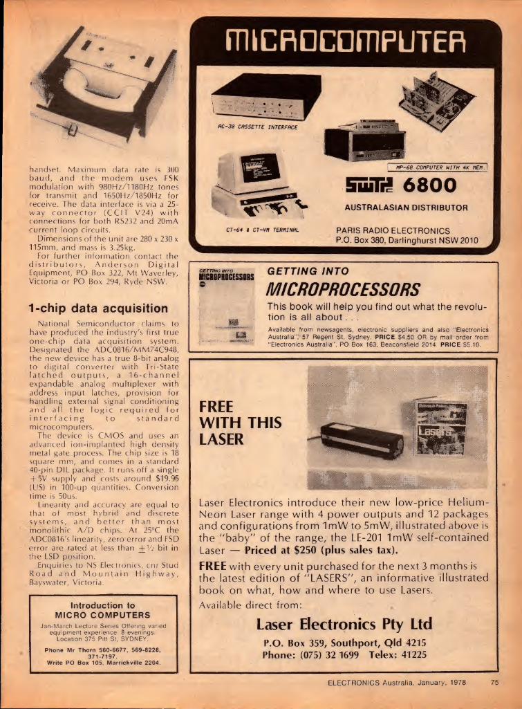
handset. Maximum data rate is 300 baud, and the modem uses FSK modulation with 980Hz/l180Hz tones for transmit and 1650Hz/1850Hz for receive. The data interface is via a 25- way connector (CCIT V24) with connections for both RS232 and 20mA current loop circuits.
Dimensions of the unit are 280 x 230 x 115mm, and mass is 3.25kg.
For further information contact the distributors, Anderson Digital Equipment, PO Box 322, Mt Waverley, Victoria or PO Box 294, Ryde NSW.
1-chip data acquisition National Semiconductor claims to
have produced the industry's first true one-chip data acquisition system. Designated the ADC0816/MM74C948, the new device has a true 8-bit analog to digital converter with Tri-State latched outputs, a 16-channel expandable analog multiplexer with address input latches, provision for handling external signal conditioning and all the logic required for interfacing to standard microcomputers.
The device is CMOS and uses an advanced ion-implanted high density metal gate process. The chip size is 18 square mm, and comes in a standard 40-pin DIL package. It runs off a single + 5V supply and costs around $19.95 (US) in 100-up quantities. Conversion time is 50us.
Linearity and accuracy are equal to that of most hybrid and discrete systems, and better than most monolithic A/D chips. At 25°C the ADC0816's linearity, zero error and FSD error are rated at less than + 1/2 bit in the LSD position.
Enquiries to NS Electronics, cnr Stud Road and Mountain Highway, Bayswater, Victoria.
Introduction to MICRO COMPUTERS
Jan-March Lecture Series Offering varied equipment experience. 8 evenings.
Location 375 Pitt St. SYDNEY.
Phone Mr Thorn 560-6677, 569-8228, 371-7197.
Write PO Box 105, Marrickville 2204.
micflocompuTER
GBTTtNO INTO
MCISPRICESSI8S GETTING INTO
MICROPROCESSORS
mm
This book will help you find out what the revolu¬ tion is all about.. .
*•■. ■y'’
m Available from newsagents, electronic suppliers and also “Electronics Australia”, 57 Regent St, Sydney. PRICE $4.50 OR by mail order from “Electronics Australia”, PO Box 163, Beaconsfield 2014. PRICE $5.10.
FREE WITH THIS LASER
* " i
Laser Electronics introduce their new low-price Helium- Neon Laser range with 4 power outputs and 12 packages and configurations from ImW to 5mW, illustrated above is the "baby" of the range, the LE-201 ImW self-contained Laser — Priced at $250 (plus sales tax).
FREE with every unit purchased for the next 3 months is the latest edition of "LASERS", an informative illustrated book on what, how and where to use Lasers. Available direct from:
Laser Electronics Pty Ltd P.O. Box 359, Southport, Qld 4215
Phone: (075) 32 1699 Telex: 41225
ELECTRONICS Australia, January, 1978 75

DICK SMITH INTRODUCES HIS NEW 18 CHANNEL CD
esigned for Australia HUB mi Economy AH ORIGINAL RELEASE
PRICE $TO}QO There is a basic difference between the new 'Bumblebee ' and all those other rigs: the Bumblebee is easier to use. Just two main controls plus channel selector less than most tranistor radios!!1 That makes the 18 Channel Bumblebee the ideal set for all novice
SPECIAL INTRODUCTORY CBers - find out what CB's all about without spending a fortune! Yet the Bumblebee is a full power unit with the same impressive j performance as its more expensive brothers. 5watts imput, high sensitivity receiver • and it's designed for Australia with the very latest phase-locked loop integrated circuit technology. It is fully
i approved by the Posts & Telecommunications department so you | can obtain your license easily.
Brand new Bumblebee: Cat D-1510.S99.50
PRICE (while 1st shipment lasts):
$9950
Deluxe AM ORIGINAL RELEASE
pr.ce $fe90p
SPECIAL INTRODUCTORY PRICE (while 1st shipment
$12950
Here is the deluxe job the superb AM Wasp. A real little stinger! Most CBers are prepared to pay just a little more to get worth while features - they know that having a little control over their set makes CB in all the more interesting and enjoyable . The Wasp I has the worthwhile features. Like an RF gain control (on an AM set!) and LED digital readout. Switchable noise limiter and blanker. Plus, plus, plus.The Wasp is the AM set for the advanced CBer - or for the CBer who knows one day he will be! Like its brother, the Wasp features the very latest in electronics and, of course, it too is fully approved! Remember with these 18 channel sets you actually get two extra legal channels more than the 23 channel sets. Take advantage of our introductory offer now: stock cannot last long at this incredibly low price!!! Wonderful Wasp: Cat D-1520.$129.50
SSB/AH ORIGINAL RELEASE
pr.ce $29950
SPECIAL INTRODUCTORY PRICE (while 1st shipment lasts): m
$19950
If you're really into CB, you've probably longed for an SSB' Well stand back and feast your eyes on the Hornet1 Did we say the Wasp had a sting...? The Hornet is performance CB from the aerial socket back! When you want that extra range the extra performance that only SSB can give, why settle for second best for no more (in most cases, considerably less at our special introductory offer price) The Hornet features AM operation as well as SSB, so all your friends down there on AM won't miss you! It is finished in the very latest 'black is beaut¬ iful' lines, with its brilliant LED digital readout and large illum¬ inated power strength meter contrasting perfectly. A set you'll be proud to own and use (and at this price what a bargain)! Horny Hornet: Cat. D-1720.S199.50
SI SSB/AH Base Station ORIGINAL RELEASE
pr|ce $34950 SPECIAL INTRODUCTORY
PRICE (while 1st shipment
lasts):
$29950
Sure you can run a mobile* CB as a base station. All you need is a good power supply, probably an SWR meter, a decent speaker, connecting cords, patch cords etc, etc, etc.... If you're L going to go base, why not buy a base station? One that has all I this assembled in one handsome case a piece of furniture, in I fact* This superb Scorpion is our top of the line line It plugs I straight into the power point (but will also work from 12V if f needed) and has an in built SWR meter, extra large speaker all connected up for you and ready to go! It's brilliant! And it's a I rig you'll be proud to place anywhere in your home! Beautiful I lines, beautiful performance on both SSB and AM and a real saving over the cost of individually bought items connected up in an unsightly mess!!!! Superb Scorpion Cat. D-1740.S299.50
All DICK SMITH CB IS GUARANTIED SO DAYS

REGISTERED , TRADE MARK A
Improve your CB enjoyment [with these quality accessories from Dick AT LAST! SJ 90 Scalar base idaptor Cat. D-4504.
Now the people with the Scalar-type thread on their CB antenna bases can use the univ¬ ersal type 3/8 24TPI threaded antennas. Just screw one of these adaptors on!
ANTENNA ILAYDOWN Don't remove your antenna when you go under something low — lay it down! 3 position lay-down eliminates the need for removing the antenna. AS EASY AS 1-2 3!
Quality construction, long lasting.
1
123 $695 D-4506.
Cat. B-2325.
±
y
Dick’s own CB radio book YES! Finally, a book written by Australia's CB
expert on Australian CB radio for Australians . . .
HUGE 128 Page .$395!
729.50
CB RECOVER am&fmtoo Here's value. Quality CB reciever (with Australian 18 channels marked) receives all CB band, plus normal broadcast (am) and music (fm) bands. Complete with carry strap. Inbuilt antenna.
Cat. D-2842.
inc. batteries
/EVERYTHING YOU WANT TO KNOW ABOUT CB!
/ This is the first book written specifically for the Aust¬ ralian CB scene — by the person the government took /notice of! What it's all about, what to buy, what to say,
/ what to expect
********************************* FREE WITH ANY CB RADIO PURCHASE!
NEW! CB Headset Comfy headset with attached microphone on boom. Switch stays in hand (on steering wheel) for top safety. Call in today and see for yourself!
So new we haven’t got a photo
j Save money by SHorn Speaker! your own CB supply. As • ■
[ good as any you’ll buy, ' complete with easy inst-
| ructions. 13.8V @ 4A - °peak. Ideal for 5SB too!
| Cat. K-3448.
IFOR THE CBER WHO'S < JUST A LITTLE MORE CAPABLE $27591
• Use with practically ANY J CB: turns it into a loud Jhailer! Ideal for promotions,* 0 club days, field days, etc etc. I • 8 ohms impedance.
Cat. C-2705.
COAXIAL NOISE suppressor; FINALLY! We now have the best noise suppressor — the co-axial type. Rated at 60 amps and 50. 75 ^ volts, use it on anything that can make a noise on the mobile! Don't put up with electrical noise any longer! Cat A-7928 .... ..$3.75
PROTECTION iviwordirty UARft 0006 why
DOES YOUR CB WORK?
i EXCLUSIVE D.S.N.O.
SYSTEM FULL DETAILS OF EVERY DICK SMITH CB
(INCLUOING THE NON REMOVABLE SERIAL
NUMBER) ARE ENTERED INTO OUR IBM
COMPUTER FROM YOUR WARRANTY
REGISTRATION CARO. THEREFORE. ANY
CB CAN BE INSTANTLY TRACED TO ITS
RIGHTFUL OWNER IN CASE OF THEFT. i
Protect your license with our filters!
. Lo-pass for CB Hi-pass for TV set. Brig. Eliminates By-passes the CB y most of the signals while allow-] fciharmonics that ing TV signals to W cause most TVI. get through. Sim-
Cheap invest- pie but reliable m ment for CBers. cure in most cases. V Cat D-7082 Cat D-7084
$950 Udl U-/ U04
$250
MOST CBERS WANT TO ADD TO THEIR KNOWLEDGE . . . Many want to obtain their novice or amateur license. Start by learning Morse Code. It's easy with our Morse Code tapes — fit any cassette player. Cat D-/106.value .. .. $7.90
MORSE KEYS: If you try to learn Morse with a bit of tin or a crook key you'll do more harm than good! Use atci id a proper key — like the superb Hi- AMATEUR mound. Adjustable, easy to handle. RADIO Cat D-7104.$25.00 HANDBOOK
What is radio? How does skip occur?
What is the differ¬ ence between
AM & SSB? All these quest¬ ions and many more are answ¬ ered in the 'Bible' of electronics:
Cat. B-2218.
$1900 mmm
DICK SMITH ELECTRONICS SHOP HOURS Mon Fr. 9AM 5 30PM Sat 9AM - 12 noon (Brisbane V? hour earlier) welcome here
Order value P&P charge p §8 $25 f49 99 S3 00 S50-S9999 $400 $100 or more $5.50
SYDNEY SYDNEY SYDNEY SYDNEY. 125 York St 361 Hume Hwy, 162 Pacific Hwy, 30 Grose St. City Ph 29 1126. Bankstown. Ph 70^6600. Gore Hill. Ph 439 5311 Parramatta. Ph 683 1133
Open til 8PM Thursday Open 'til 8PM Thursday Ample parking at door. Ict floor - friendly store!
MAIL ORDER DEPARTMENT PO Box 747, Crows Nest, NSW 2065. Phone 439-5311. Post 8i Pack extra.
SYDNEY: MELBOURNE MELBOURNE: BRISBANE. ADELAIDE. 30 Grose St 399 Lonsdale St, 656 Bridge Rd. 166 Logan Rd. 203 Wright St Parramatta. Ph 683-1133 City. Ph 67-9834 Richmond. Ph 42-1614. Buranda. Ph 391-6233 City. Ph 212 1962
!*♦ floor - friendly store! New: right in town! Easy access: huge stock. Opens 8.30aM Now Open. See us!
J9 5311 Post 8i Pack extra. WE HAVE DEALERS RIGHT ACROSS AUSTRALIA - THERE'S ONE NEAR YOU!

SPECIALIST HELICAL ANTENNAS ^
SIMPLY IT’S THE BEST !
yf'pUSH W MOBIIE BHE
Communications systems
BASIC HISTORY of The HELICAL ANJFNNA
ovw 6 vwrs ago MOBILE ONE mad* the fint "DX HELICAL" tor 11 Metre Band today many thousands of people m all state* of Australia are using this revolutionary antenna to assist their everyday communications. MANUFACTURED IN AUSTRALIA FOR AUSTRALIA
OFFICE & FACTORY 17 Sloane St.. Marrickville. 2204 N S W Australia Phone: (02)5164500
Cables: ‘MOBILEONE', Sydney Telex: 21416. MOBILEONE P.O. Box 166, Randwick. NSW. 2031
\/vV * ALL PRODUCTS CARRY 12 MONTHS GUARANTEE TYPE
SKIPWHIP
HELIWHIP C-it \iivrhip
LSD
THUNDERSTICK
SUPERHELICAL
MODEL
DX-IS
DX3B
DX-1/LSD
DX-3/LSD
DX-2B
DX-1B
DESCRIPTION
72 SUPERHELICAL
40 SUPERHELICAL $18
60 SUPERHELICAL LSD
40 SUPERHELICAL LSD
60 SUPERHELICAL $22
ORIGINAL “HELICAL ANTENNA’’
$20
A solid state achievement that mjkes
audio testing, on-line quality control and
general purpose measurements easier
than ever. Features a horizontal dual
trace/dual channel format that lets you
view two independent signals simul¬
taneously and side-by-side on a bright
CRT display. Perfect for inspecting and
aligning the most sophisticated stereo
equipment, the LBO-552 also provides a
single channel input for conventional
readout. Sensitivity is 20mVp-p/cm;
Vert. B'width is DC or 2Hz to 2.5MHz.
Sweep speeds are from 10Hz to lOOKHz
in 4 ranges with input impedance IMA
shunted by 40pF.
250mm h % 180 w x 380 d; 6.5kg
LBO-552 5" Horizontal, Dual Trace/
Dual Chan. Oscilloscope WITH SIMULTANEOUS LEFT/RIGHT
WAVEFORM DISPLAY
356-7333 • BRISBANE 52-7255 • HOBART 23-1841 699-4999 • PERTH 65-7000 • SYDNEY 648-1711
N.Z. 360-154 • WELLINGTON N.Z. 698-272
LMV-186A Dual Chan./ Dual Pointer
AC Millivolt Meter Check stereo signal quality, especially
where a big difference exists in two
points. This instrument uses identical
switches and amplifiers in each channel
to operate without crosstalk effects.
Measuring range is IOOmV to 300V, 12
steps. It has two dB scales: an easy-to-
read meter face; 2 scale readings; built-in
dual amplifier output. Accuracy is ± 2%
full scale (1 KHz). Channels operate
individually, or in common at ch. 2. Scale
calibration reads effective values. With
input cable 240V/50Hz.
150mm h x 200 w x 250 d; 3.5kg.
78 ELECTRONICS Australia, January, 1978

The Australian
ELECTROPHONE MOBILE & BASE FROM RADIO PARTS
Anticipating a keen a continued demand for Australian standard 27MHz CB equipment, the Radio Parts Group have announced the release of two new transceivers, the Electrophone CB-550 mobile SSB/AM unit and an equivalent base station, model CB-590. One of each submitted to us for inspection and possible review.
Externally, the two units look quite different but reference to the user manuals reveals an identical set of specifications suggesting that the basic circuitry is the same.
Without checking every detail of the schematics in the respective manuals — it would be a painstaking task — visual inspection of the two transceivers did ultimately indicate a common basic board, with wires radiating to the appropriate controls, to access sockets, metering, etc. In addition of course, the base unit had an inbuilt mains power supply.
The method of construction does tend to give a somewhat more cluttered appearance to the internal "works" of the mobile unit in particular, and probably adds marginally to its essential dimensions, but not necessarily at the expense of accessibility for service. In fact.
Above, the Electrophone CB-550 5SB/AM transceiver and, below, the CB-590 base station. It would appear that both use much the same PC board assembly, hand wired in each case to the appropriate peripheral controls, metering and access sockets.
controls at the end of wires may well be easier to replace then those soldered — ever so neatly — into one main wiring board.
The mobile transceiver, CB-550, is a fairly large unit in its class, measuring 64mm high, 190mm wide and 260mm deep, excluding knobs and connections. It has a brushed chrome front panel, chrome knobs, and removable black crinkle rear covers.
It also has rather more than the usual number of panel facilities. Knobs control the LED readout for the 18 Australian standard channels, Clarifier, Volume, Squelch and Mode (AM, USB,
LSB). An "on" switch is associated with the volume knob and a "PA" switch with the squelch knob. In addition, there is a knob to control the brightness of the LED display and another to provide a "calibrate" function for SWR, as read directly on the meter.
The meter actually serves three functions: relative signal strength on receive, relative RF output on transmit, and antenna SWR, the latter involving the calibrate control already mentioned and a selector switch. Other switches bring in the noise blanker circuit and provide a hi-lo setting for RF gain. A small indicator lamp flickers to show modulation on the AM transmit setting.
The CB-590 base station is larger, at 96mm tall, 329mm wide and 244mm deep, finished with black panel, chrome surround and a simulated timber grain finish for the rear cover — appropriate for a free-standing unit in a home.
It has all the control facilities of its mobile counterpart but they are separated out for maximum operator convenience. Separate meters are provided for receive and transmit functions, RF gain is continuously variable, the ANL function is brought out to an off-on switch, and a phone jack is provided as well as a forward-
ELECTRONICS Australia, January, 1978

YOU WON'T HAVE ANY LICENCING PROBLEMS WITH THESE FULLY APPROVED RIGS
/P & T N APPROVED'
' MODELS >
I RADIO PARTS „„ I MELBOURNE’S PROFESSIONAL CB RADIO CB CENTRE’S
562, SPENCER ST, WEST MELBOURNE 03-329 7888 1103 DANDENONG ROAD, EAST MALVERN 03-2118122
TRADE ENQUIRIES WELCOME
18 CHANNEL CB RADIOS THE MOST ADVANCED RANGE AVAILABLE IN AUSTRALIA.
240 volt and 12 volt operation — Woodgrain, black and chrome cabinet — Headphone monitoring — add a Vi wave antenna for exceptional long range transmission
$299.00
BUY NOW WHILST STILL DUTY FREE.
CB510 STANDARD AM A low cost unit for the beginner or novice user with all the power of the more expensive models.
$99.50
CB530 DELUXE AM The ultimate AM with 12 Controls — including & unique CB monitor to hear CB messages through the mobile PA speaker whilst out of the car
• Impressive styling with a full range of controls. • Inbuilt SWR Meters (CB530. CB550. CB590). • 2 uncluttered channels (the new Australian
7 & 16 channels). • RF Gain Controls (CB530. CB550. CB590). • The most comprehensive range of models designed
to satisfy even the most discerning buyer • Extremely low noise and low radiation — (these
models have been built to the tough RB249 specifications) The output stages are double shielded to minimise interference with TV etc
• Full service workshop manuals on all models available.
• Spare parts backup — over 7000 spare parts on order. • Sales display material available — 4 colour
brochures — give away leaflets — wall posters — counter display stands with headers housing the
three mobile models.
$148.52
CBS50 AM/SSB DELUXE MOBILE The bright LED Channel Indicator can be read easily from any angle. A dimmer is included for night driving convenience.
$249.64
CB590 AM/SSB BASE STATION
80 ELECTRONICS Australia, January, 1978
The Australian
CB SCEI1E facing loudspeaker.
The CB-590 is set up to operate normally from the AC power mains, with its own in-built supply but it can be operated through a separate power cord from a negative ground DC supply, nominally at 13.8V.
Specifications for the two units indicate the use of a phase-locked loop for frequency control, with a tolerance of +0 005%. The clarifier gives a range of + 800Hz.
In SSB mode, the receiver operates as a single conversion superhet, with a claimed sensitivity of 0.25uV for a 10dB signal/noise ratio and a selectivity of 2.5kHz at 6dB down.
In AM mode, the circuit operates as a double-change supernet with comparative figures of luV and 6kHz.
On transmit, the AM power output is rated at 4W with harmonic content more than 60dB down. On SSB the rating is 12W PEP, with carrier suppression more than 40dB down and unwanted sidebands and harmonics more than 60dB down.
Purely on the basis of convenience, our on-air tests centred mainly around the smaller of the two units. First impression was that the receiver was suspiciously quiet with no input signal, which might suggest a lack of sensitivity. However, observation indicated that the squelch was operating marginally, even with the control fully anti-clockwise, quieting the receiver rather than exposing the operator to the last fractional microvolt of noise. In practical terms there was no lack of either sensitivity or selectivity.
It did appear, however, that the RF gain switch was wired back-to-front in the sample receiver, with maximum gain being evident in the "off" position. This would almost certainly be a wiring error in the individual set. Either that, or the switch had been locked in upside-down.
On "transmit" everything behaved as expected, on both AM ana SSB and, in fact, the SWR meter alerted us to a problem which had developed in our base station antenna. We had to dismantle and fix it before continuing the tests! Its usefulness had been demonstrated in a quite spontaneous manner.
A panel in the owner's manual suggests that full service and spare parts are available through retailers, backed up by the distributors for Electrophone: Radio Parts Pty Ltd, 562 Spencer St, West Melbourne, Victoria.
In answer to our specific question, Radio Parts advised us that both transceivers have been type approved by the P&T Department for licensing in Australia. (W.N.W.) ®

The Australian
IB SCEHE WHAT’S SO SPECIAL ABOUT THE DESIGN OF A CB ANTENNA?
With the performance of CB transceivers largely standardised by regula¬ tion, the heart of any CB installation is really the antenna system. This article seeks to outline, in broad terms, the theory behind CB antenna design. It should provide a background against which the reader can view, choose between and use one of the many antennas which are currently on the market.
RF VOLTAGE
(a)
RF CURRENT
FIG 1 <b)
by NEVILLE WILLIAMS
For those whose experience has been limited largely to listening on the broad¬ cast band, an antenna is a particularly non-critical item—a ferrite rod gadget inside a transistor radio, a telescopic rod on a car, a couple of metres of wire hung from the picture rail or, at most, a somewhat greater length of wire strung outside.
They all seem to work! It is indeed true that the requirements
for broadcast band reception, in most areas, are not critical. But it is also true that the considerable strength of the available signals is due to the fact that transmitter engineers go to a great deal of trouble in planning and siting their antennas to ensure the highest possible radiation efficiency and the greatest pos¬ sible field strength. Their massive towers are not engineering or advertising gim¬ micks; they are built to specific dimen¬ sions, appropriate for the frequency on which the station is transmitting.
At higher signal frequencies, however, it becomes progressively more import¬ ant to ensure that receiving antennas also do their job more efficiently and it is no longer satisfactory to think of an antenna as any random length of wire, or any likely looking telescopic rod. That is why television antennas are specially de¬ signed to work efficiently at the frequen¬ cies used by the various television stations. To be sure, television signals can be picked up, in many areas, using makeshift antennas but the quality of the picture often suffers as a result.
Similar considerations apply to the Citizens Band around 27MHz, and even more critically to the UHF CB band around 470MHz. While it may be pos¬ sible to transmit and intercept signals using random lengths of wire or rod, the efficiency of transmission and reception is likely to be low and the effective range very poor. For best efficiency, good sig¬ nal strength and maximum range, it is essential to use antennas optimised for
27MHz—or 470MHz.
For an antenna to operate efficiently in either "receive" or "transmit" mode, it is essential that its dimensions—most criti¬ cally its length-bear a planned rather than a random relationship to the wavelength (therefore the frequency) of the signal involved.
Expressed in another way, an antenna will intercept and transmit signals most efficiently when its dimensions are so arranged that it is naturally resonant at the signal frequency at which it is desired to operate.
A basic fact, and the one from which most resonant antenna concepts flow, is that an antenna can be made naturally resonant at a particular frequency if it is cut to a length approximating one half wavelength at that frequency. Such an antenna is commonly referred to as a "half-wave dipole" or, more simply, a "dipole".
But why the word "approximating" in the preceding paragraph?
Without going into all the whys and wherefores, what engineers refer to as "end effect", the thickness of the dipole as compared with its length, its proximity to other metallic objects and even to the earth itself, all tend to modify its natural resonance to some degree.
As a rule of thumb, an ordinary dipole tends to resonate at a frequency about 5% lower than one would expect from a simple calculation based on its length. As a result, dipoles generally have to be cut to 0.95 (5% short) of the true signal wavelength.
Let us say that we are interested in working out the length of a half-wave dipole for use on CB channel 9, which is close to the centre of the Australian 18- channel CB band. The frequency is 27.115.
The formula relating frequency and wavelength is:
I = 300/f Where I is in metres and f is in MHz.
Depicting the RF voltage and current distribution on a resonant dipole antenna.
Using a calculator and the figure 27.115MHz, a full wavelength works out at 11.0639 metres. Divide by 2 for a half wavelength and the figure is 5.531 metres.
The length of a dipole is 0.95 of this, or 5.255 metres, equivalent to 525.5cm.
If you prefer imperial measure, divide by 2.54 to yield 206.91 inches. Divide by 12 and the answer is 17.242ft, which is very close to 17ft 3ins.
It is possible to work directly in imperial measurements by rationalising the metre/feet conversion and including the divide by 2 to come up with the for¬ mula:
I = 492/f where I is in feet and f is in MHz.
Resorting again to the calculator, a true half-wavelength works out at 18.14 feet. Multiplying this by 0.95 to account for end effect gives the length of a half-wave dipole for channel 9, once again, as very close to 17ft 3ins.
Remembering that the CB band includes quite a few channels, each on a different frequency, it might be reasoned that one should use an adjust¬ able antenna, or as many separate anten¬ nas as there are channels. Fortunately, this is not necessary because, over the relatively narrow band of frequencies involved in the 23-channel CB system, an antenna resonant in the centre of the band operates quite efficiently on all channels.
In fact, amateur station operators have discovered that many pre-fabricated 27MHz antennas work quite well on the adjacent 28MHz amateur band, either as they are or with a minimum of trimming.
When a half-wave dipole antenna is being excited at its resonant frequency, either by a signal being intercepted, or by one fed to it from an associated trans¬ mitter, oscillations of RF voltage and cur¬ rent are set up in it as depicted in Fig. 1. The RF signal voltage oscillating be¬ tween negative and positive values, is greatest at the two ends, and least in the middle, (Fig. la). However, the RF signal current, flowing to and fro along the
ELECTRONICS Australia, January, 1978 81

CITIZENS BAND ANTENNAS QUALITY SCALAR ANTENNAS ARE
DESIGNED AND MANUFACTURED IN AUSTRALIA
MOBILE, MARINE, BASE STATION Scalar Citizen Band Whip Antennas are de¬ signed to provide efficient performance with reduced length. Either helical, centre or top loading on fibreglass rods. They are available for vehicle or marine installations on standard, or marine base, or for gutter or for trunk lid mounting.
TYPES ILLUSTRATED
A) CB 1220 42" Centre Loaded.
B) CB 1120 30" Centre Loaded.
C) CB 1420 60" Helical.
D) CB 1520 60" Helical/Sector/ Top Loaded.
E) CB 1320 60" Centre Loaded.
A WIDE RANGE OF SCALAR CB ANTENNAS (FROM 30" TO 108" LONG) AND ACCESSSORIES ARE AVAILABLE FROM LEADING RETAILERS AND DISTRIBUTORS THROUGHOUT AUSTRALIA.
TRADE ENQUIRIES WELCOME
SCALAR INDUSTRIES PTV. LTD. COMMUNICATION ANTENNA ENGINEERS.
1 8 SHELLEY AVENUE, KILSYTH, VICTORIA, 3137. TELEPHONE: 725-9677. Cables: Welkin. Telex: AA 34341
N S W 20 THE STRAND, PENSHURST, 2222. Telephone: 570-1 392 OLD. (STD 07) 371-5677. WA. (STD 032) 57-1555. SA. (STD 08) 42-6666
. . . When reliability and performance are essential
TASC TM 3100. 18 CHANNEL AM/SSB CB TRANSCEIVER In keeping with the standard set by the popular TASC TM 1 100
we now present the TASC TM3100 18 channel AM/SSB CB
transceiver designed for the Australian market.
Features • Phase lock loop circuitry • Double conversion •
Inbuilt S/RF/SWR meter • LED Display Channel
readout • Power output 4 watts AM (max. allowable), 12 watts PEP SSB (max. allowable) •
Post & Telecommunications Department type
approved to RB249 specifications.
The TASC TM3100 is distributed through:
NSW: JRS (lllawarra) Car Airconditioning Pty Ltd. 54C Fitzroy Street, Marrickville 2204 Tel. 516 3966
Qld: Banox Manufacturing Co. 226 Lutwyche Road, Windsor 4030. Tel. 57 7807 SA: Bee Jay Electronics. 263 Wright Street. Adelaide 5000 Tel. 51 7288 Tas.: McCann Bros Pty Ltd. 141 Elizabeth Street, Hobart 7000 Tel. 34 4544 WA: WA CB Radio Centre. 129 Fitzgerald Street. West Perth 6005 Tel. 28 6254
SOLE AUSTRALIAN IMPORTERS
C HUPPERT & CO (VIC ) PTY LTD. 175 Grattan Street. Carlton. Victoria Phone 347 7166, AH 459 4501. Telex AA 34086
TRADE ENQUIRIES WELCOME
82 ELECTRONICS Australia, January, 1978

The Australian
CB SCEBE antenna is greatest at the centre and very small at the two ends.
This observation is important when it comes to Connecting any sort of a cable to an antenna. After all, an antenna sup¬ ported in space but not connected to anything is a rather futile piece of hard¬ ware!
At either end of a half-wave dipole, where the RF voltage tends to be high and the current low, the antenna tends to look like a high resistance device: a high resistance source, if it's trying to feed signals down to a receiver, or a high resistance load, if it's trying to accept sig¬ nals from an associated transmitter. This observation follows from Ohm's Law which states that:
Resistance = Voltage/Current. If voltage tends to be high and current
low, then the resistance will tend to be high. In practice, the effective resistance at either end of a dipole is of the order of several thousands of ohms.
At the centre of a half-wave dipole, the situation is reversed: current is high, volt¬ age is low and so also is the effective resistance. If signal is derived from, or.fed to, the centre of a half-wave dipole, the effective resistance turns out to be very close to 70 ohms.
At frequencies other than resonance, a dipole becomes capacitively or induc¬ tively reactive and its impedance bears no obvious relationship to any published value.
Here one point should perhaps be made to avoid possible confusion: it is appropriate to talk about the "resist¬ ance" of a half-wave dipole because, by definition, a dipole is resonant and at that frequency the impedance is predom¬ inantly resistive—as is the impedance of a tuned circuit at resonance. However, the distinction is rarely made in practice and "impedance" is the word most com¬ monly found in antenna specifications, even when they are supposed to be resonant.
RF energy is most commonly fed to, or derived from, dipoles at their centre, where the effective impedance approxi¬ mates 70 ohms, as stated. It involves cut-
FIG 2
SPLIT AT CENTRE
70 OHM 2 WIRE
CABLE
Above: The basic directivity pattern for a dipole and, below, the all-round coverage when mounted vertically well clear of the ground.
ting the dipole at its centre (so that each half becomes an approximate quarter wavelength) and connecting a cable or other signal-feed device between the two inner ends, as shown in Fig. 2.
For efficient energy transfer, the cable (or other feed device) should be so designed that it will most readily handle the signal voltage and signal current in the same ratio as exists at the centre of the dipole. In the simplest case, this means feeding the dipole with a two- wire cable which is itself designed to have a "characteristic impedance" of 70 ohms.
Much more could be said on the sub¬ ject, but this is sufficient for the present.
In terms of directivity, a dipole antenna tends to radiate or intercept signals most efficiently at right angles to the rod or
wire, and least efficiently in line with the ends. In fact, if one were to insert a pencil through the hole in a doughnut, one would have a model of the radiation pat¬ tern around a half-wave dipole in free space. If the dipole is supported horizon¬ tally above ground, radiation and pickup is maximum at right angles, so that it tends to have a bi-directional or figure-of-8 pattern, as shown in Fig. 3.
Mounting a dipole vertically in respect to the ground tips the "doughnut" on its side, as in Fig. 4, and produces an omnidirectional or circular pattern at predominantly low angles of radiation, with a minimum of direct upwards radia¬ tion. This is obviously a very useful pat¬ tern f,or installations where it may be required to communicate between points anywhere in a 360-degree circle.
It so happens that an omnidirectional pattern is appropriate for ordinary CB requirements, because base stations or cars may wish to communicate with other stations or cars anywhere in the district; and, of course, cars may be heading in any direction, during the course of conversation. Directional antennas in such situations would be a liability.
An additional reason for using vertical antennas on a road vehicle or a boat is the fairly obvious one that they are much more practical, as evidenced by the fact that vertical rods or whips are virtually standard for AM and FM broadcast recep¬ tion. Vertical telescopic rods are natural, too, on hand-held portable transceivers.
While vertical antennas are preferred for their omnidirectional qualities and their convenience, their use also means that they will radiate—and receive most
Vcfi'H? One s toe*'no snap do*n antenna case
A handy fitting for the CBer marketed by Mobile One: a fold-down base which can be locked upright for high¬ speed travel by means of a sliding sleeve'.
mmm Pictured above is a group of "Superhelical" 26-29MHz antennas marketed in Australia by Mobile One Pty Ltd, of 17 Sloane St, Marrickville, NSW 2204. The full range includes the DX-9 (108-in hollow fibreglass for marine or other use lacking a groundplane), 72-inch 60-inch and 40-inch typ^s.
along with the DX-27GP Superhelical Ground Plane. They are available in a range of different colours and are backed by 12 months warranty. Also pictured are some of the base mounts and lead assemblies which are carried as stock accessories by Mobile One.
ELECTRONICS Australia, January, 1978 83

From out of the blue comes a dramatic improvement in CB from Telex, the aviation communications experts.
Patented design fits every hand- the same style used by pilots around the world.
Unique aircraft-type front mount eliminates mike fumbling. Mike comes off the bracket in the talk position.
Exclusive Double-Header feature allows use as a conventional power mike or a superior, noise-cancelling power mike.
The first loud and dear
CB mike. Unique Telex CB-73 Double-Header-power mike
with switchable noise-cancelling mode. Puts you through loud-thanks to the power mike-and clear-thanks to the special noise-cancelling mode. Built-in integrated circuit amplifier maxi¬ mizes "talk power” without distortion. In high noise environment, switch to unique noise-cancelling mode. Try it. You’ll get the message-loud and clear.
SYDNEY AUDIO TELEX COMMUNICATIONS 54-56 Alfred Street,
PTY. LTD. Milsons Point 2061 Telephone: 929-9848
MELBOURNE 828 Glenferrie Road. Hawthorne 3122 Telephone: 819-2363
ANTENNA MANUFACTURERS
'DX' PRODUCTS
DX y2 WAVE BASE STATION ANTENNAS.
5ft HELICAL WHIPS. V4 WAVE MOBILE ANTENNAS.
?/T]
CB RADIO 697 CENTRE ROAD,
EAST BENTLEIGH, VIC. 3165
TEL: 579-4758 TRADE ENQUIRIES WELCOME
OPEN 7 DAYS
WILLIS TRADING Co. Pty Ltd 429 MURRAY STREET.
PERTH. W A 6000
I PH 321 7609. 321 7600 I PRICES DO NOT INCLUDE P&P
PERTH G P O BOX X22 i 7 WA 6001
SWTC COMPUTER SYSTEM KITS
Keyboard Kit:
56 key with ascii encoder — selectable upper & lowercase or TTY Style outputs, gold plated contacts $86.00.
PR40 Alphanumeric Printer $395.00 CT1024 Terminal System $420 00 AC30 Cassette Interface $149.00
ELECTRONIC TOOL KIT
Tweezers File Soldering Iron Solder Phillips s/driver 2 screw drivers Long Nose Pliers Flat Nose Cutters End Cutters Vinyl Zip Case
$21.95
DIGITAL WATCH MODULE
Hours & Mins LED display requires two 386 batteries Make a pendant watch SI 0 95
FM MONITOR
RECEIVER
12 Channel Monitor Receiver tor low or high bands
$110 plus crystals
VHF
CONVERTER
110-136 MHz couples to broadcast receiver $7 95
TS520 S
The TS520 is the final word in SSB Tranceivers. a superb creation from KENWOOD Designed and built for serious enthusiasts around the world It features solid state circuit throughout except for the final and drive stages
FT-101 E YAESU
SOLID STATE 160 thru 10 meter transceiver now offers even more value and performance in one An effective RF Speech Processor is a built-in integral part of this exciting transceiver
FLUKE
DIGITAL MULTIMETER
Model 8020A. 29 ranges
$179 plus s/tax
THE CHIBA
18 Channel AM/SSB CB Rolls Royce of CB sets.
The
KITS AVAILABLE
Mosquito Repeller. E A Jan 1976 27MHz Pre-Amp. E A May 1977 Musicolour Mklll. E A. Sept 1976 Twin Twenty Five Amplifier. E A Apr 1976 CDI Units. E A July 1975 Car Burglar Alarm. E A Nov 1976 Morse Code Oscillator. ETI Aug 1975 Logic Probe. ETI Sept 1975
Simple 5 watt Amplifier. ETI Oct. 1976
transistor Ignition, til May iy// Two-Tone Door Bell. ETI Oct 1976
CB
POWER
SUPPLY
KITS
Power mate 105A $20.00 2 5A Peak 4A Si28.00
84 ELECTRONICS Australia, January, 1978

The Australian
CB SCEBE efficiently-signals which are "vertically polarised". Again, without going into all the technical detail this describes the form in which the signal is transmitted and received: in this case with the electric field vertical and the magnetic field horizontal.
What this means in practice is that, if the majority of CBers elect to use vertical antennas—and therefore to radiate ver¬ tically polarised signals-everyone has to follow suit, or else be the odd man out and put up with a reduction in apparent signal strength both ways.
So the convention has emerged: CB communication assumes the radiation of vertically polarised signals and, for all practical purposes, this means the use of antennas with the active elements ver¬ tical rather than horizontal.
While a vertical half-wave dipole, approachng 6 metres long, may be con¬ sidered for a base station, there is no way that such an antenna can be used reasonably or safely on a road vehicle, in fact, reports for overseas suggest that attempts to use very long antennas on vehicles have often ended in tragedy, due to them fouling overhead power wires.
Fortunately, while a dipole is a natural starting point for the consideration of resonant antennas, it is possible to promote a resonance effect at the same frequency from an antenna approxi¬ mating one quarter-wavelength long.
If a quarter-wave antenna is set up above a flat conductive surface (Fig. 5) preferably several wavelengths in all directions, the surface tends to act as a mirror for the RF energy, with voltage and current distributing along the antenna just as if it were one-half of a complete dipole. It has a similar direc¬ tivity pattern, covering the full 360 degrees, and concentrated at a low angle relative to what is known as the "ground plane". In terms of antenna "gain" it suf¬ fers by comparison with a dipole by about 1.8dB—not much.
At a wavelength equivalent to 27MHz, a sufficiently large conductive plane is a rarity but its effect can be simulated by providing a number of "radials" or rods (usually three or four) each a quarter wavelength long and at right angles to the radiating element. As illustrated in Fig. 6, the radials are normally joined metallically to one another at the centre, as well as to the support structure, the whole lot being grounded. The radiating element is also supported from the centre of the structure but insulated from it, so as to create a feedpoint to which a transmission cable can be attached, running away to a transmitter or receiver.
mt: /
MIRROR rr image
If mounted above a large plane metal surface, a quarter-wave antenna has resonant qualities, as explained in the text.
The basic configuration of the popular quarter-wave groundplane antenna.
Fig. 6 seeks to illustrate the principle only, without showing any details of the actual structure—clamps, insulator or the means of connection for the cable. Com¬ mercial manufacturers have their own way of doing things and anyone who buys an antenna kit involving ground plane elements will normally get the explanatory literature that comes with it.
In the physical sense, the natural way to transfer energy to or from a quarter- wave ground plane antenna is by the use of coaxial cable, the outer braid connect¬ ing to the junction point of the radials
The "Southern Star" power and SWR meter, as announced recently by the Dick Smith Electronics Group. Suitable for instant connection to all normal CB installations, it measures power to 70W, SWR to 1:3, and reflected power to 25%. Designated as catalog number Q- 1350, it retails for $19.50.
The A&R Soanar Electronics Group are now marketing a comprehensive range of antenna and cable connectors, as pictured, dummy loads, CB interference suppressors, lightning arresters, high performance antennas, etc. For details of these and other CB items, write to Soanar Electronics Pty Ltd, 30 Lexton Rd, Box Hill, Vic. 3128.
and the inner conductor to the actual radiating element.
There is a problem, however, in that the natural input impedance to a quarter- wave ground plane antenna is about half that to a dipole: hence about 35 ohms. This is lower than the characteristic impedance of readily available coaxial cable. Rather than put up with the result¬ ing mismatch between, say, a 50-ohm cable and a 35-ohm load, manufacturers commonly build an RF matching trans¬ former into the insulating centre piece, or increase the length and add a capaci¬ tor, or adopt some other method of effecting a more accurate impedance match.
One structural method that is com¬ monly adopted is to droop the radials downwards by a selected amount, instead of supporting them horizontally. The more steeply they are drooped, the more the antenna begins to look like a vertical dipole (with the bottom element splayed) and the more the impedance creeps towards 70 ohms. A compromise position yields an antenna that is a cross between a dipole and a ground plane, with an input impedance of around 50 ohms.
Antennas of the ground plane variety are fine for base stations, where there is a reasonable chance of mounting them where the radials are in the clear. But there is generally no way that one can mount a set of 2.7-metre radials on a road vehicle, and much more severe com¬ promises have to be accepted.
If one could mount a full quarter-wave whip in the centre of the roof of a very large car, the position would not be too bad; the antenna would have its full required length, even though the "ground plane"—the metal body of the vehicle—would be too small for 27MHz. But a whip antenna the best part of 3M (9ft) long and mounted on a car roof would be unsightly and rather hazardous. So those who are keen to use a long antenna, at all costs, usually finish up attaching it to a bumper bar and putting up with a very ineffective ground plane— which is just another kind of com¬ promise.
Well then, can something be done to reduce the length of an antenna below a quarter-wave and still maintain a resonant condition? The answer is yes, but...
ELECTRONICS Australia, January, 1978 85
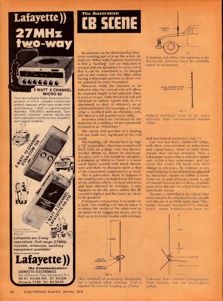
Lafayette))
27MHz two-way
WATT 6 CHANNEL ‘MICRO 66’
From the Lafayette Radio Electronics Cor¬ poration of U S A. Lafayette transceivers embody features which have made them world famous. 1,000's in use throughout Australia, 100,000's world-wide. Gov¬ ernment, industrial, marine, sports and farm applications testify to their versatility and rugged reliability.
'for
All units Telecom Type Approved (Licence Required)
«5rl I a
Lafayette are 2-way 9 specialists. Full range 27MHz crystals, antennas, auxiliary equipment available! Dealer enquiries invited
Lafayette)) the Communicators'
LAFAYETTE ELECTRONICS Div. of Electron Tube Distributors P/L 94 ST. KILDA RD., ST. KILDA Victoria 3182. Tel. 94 6036
The Australian
CB SCENE
An antenna can be shortened by effec¬ tively winding part of it up like a coil—an inductor. What really happens in practice is that a 'loading" coil (or inductor) is wound and encapsulated in such a form that it can be assembled as an integral part of the vertical rod—the latter often having a telescopic portion to allow it to be adjusted for exact resonance.
However, while the insertion of an inductor into the vertical rod will allow its resonant length to be reduced, there is a price to pay. Only the actual rod will intercept or radiate signals and, as it is shortened, so does its efficiency as an antenna diminish. For example, a 1 -metre whip is credited with an efficiency only 20% that of a full quarter-wave whip.
Antennas which are shortened by the inclusion of a loading coil are commonly referred to as "miniwhips".
The nature and position of a loading coil are both very significant to the end result.
The loading coil should have as high a "Q" as possible—therefore wound with thick wire on a large, low loss former, maybe 30mm to 40mm in diameter. Because such a coil would be unsightly, a diameter of 10mm to 15mm is a more usual figure, wound with much thinner wire and likely to dissipate quite a deal of the transmitter output power as heat!
This is particularly likely to happen if the loading coil is included near the base of the antenna where it is least obtrusive and least affected by windage. It also happens to be the place where the RF current is highest and the losses are likely to be greatest!
A frequent compromise is to settle for a fairly slim loading coil but to place it in about the centre of the whip-not so far down as to exaggerate losses, not so high up as to invite trouble with windage
One method of arranging feedpoints for a vertical whip antenna. Coil is tapped for correct loading at 27MHz.
ELECTRONICS Australia, January, 1978
A loading coil allows the antenna to be shortened. Antenna must be carefully tuned to resonance.
HELIX WOUND OVER-- FIBREGLASS WHIP
£ FIG 8
Helical antennas tend to be more efficient than conventional loaded whips.
and mechanical oscillation. (Fig. 7.) Last but not least, shortened whips,
with their concentration of inductance and capacitance, tend to tune more sharply than full-size antennas. Thus, a full quarter-wave whip is critical in length only within a few centimetres, and can cover the entire CB band with little change in efficiency. By contrast, a very small whip has to be trimmed or adjusted by telescopic means to within a centi¬ metre or so and efficiency tends to fall off sharply beyond two or three channels away from the one for which it has been specifically tuned.
Because a miniwhip is so critical, they really need to be adjusted in situ, usually with the aid of an SWR meter (See "Elec¬ tronics Australia" for April 1977). Alterna¬ tively, many transceivers now in-
5/8-wave base antenna configuration. Note loading coil and groundplane radials.
86

corporate an RF power output meter which can serve as a tuning aid of sorts.
The reasons for these statements are quite basic and hold, with very little qualification, irrespective of manufacturers' possible claims. Some antennas may be better constructed than others, exhibit more resistance to windage and corrosion, etc, but the potential efficiency will remain a matter of the effective length of the radiator relative — a full quarter-wave — plus proper installation and setting up.
A type of antenna which has received a lot of attention recently is the helical-wound whip. The basis is usually a flexible frbreglass rod which carries a spiral of wire or copper strip, held in place by a heavy epoxy coating or by shrink-plastic tubing. The pitch of the helix, the number of turns and therefore the overall length of the whip are arranged (often by empirical means) to resonate in the centre of the CB band.
Helical antennas tend to be somewhat more efficient than conventional loaded whips, because the loading inductance is distributed rather than lumped and also because people who go to the expense of buying them, or the trouble of making them, often settle for a greater length than is common with loaded whips. Both factors contribute to efficiency but the ultimate result is still governed by the three main considerations: how does the length compare with a full quarter-wave? How effective is the metal structure beneath the whip as a ground plane? How carefully has it been installed and adjusted?
Vet another approach to the antenna problem is to make use of the existing broadcast radio antenna on the vehicle but to connect it via a passive signal splitter to both the radio receiver and the 27MHz transceiver. The splitter includes tuned trap circuit(s) which are supposed to prevent 27MHz energy from reaching the broadcast receiver, while allowing its free transfer between antenna and transceiver.
Some splitters appear to be very primitive and one would wonder how really effective they could be, even assuming that the telescopic radio antenna was adjusted for optimum results. Other splitters are somewhat more pretentious, with provision for external adjustment and the ability to produce a near unity SWR on the selected channel(s) when carefully set up.
Combination broadcast radio/CB antennas obviously avoid the need for an extra antenna on a vehicle, and also help to disguise the presence of a CB transceiver. How well they work will depend on the effective length of the antenna, its physical condition in terms of corrosion and installation, and how well the splitter does its job. Reactions in overseas literature vary from elaborate praise to "not worth a stamp" — doubtless depending on how the various factors have worked out.
By way of conclusion, it may be helpful to add a few remarks about base station antennas.
As mentioned earlier, a vertical half-wave antenna is an excellent choice for a base station since it is likely to be close to the gain limit of what the Australian P&T Department will license.
With a vertical dipole, it is difficult to arrange centre feed, as implied in Fig. 2, because the feeding should approach the dipole at right angles — a problem with a vertical antenna. In most cases, it is more convenient to "end-feed" a vertical dipole (at the bottom) even though, as we have already seen, the ends of a dipole exhibit a very high apparent resistance.
There are various ways in which this problem can be overcome but the method illustrated in Fig. 9 is typical and interesting. A metal band, clamped directly to the earthed metal mast, is bent into a full circle, with the two ends side- by-side to form a capacitor. The inductance of the circle is so controlled that it will resonate with the capacitive effect to tune to 27MHz. The top of this resonant circuit provides a high impedance point to which the bottom of the antenna can be directly coupled. The arrangement also means that the antenna is earthed as far as DC is concerned, ensuring that it will not accumulate static charges from the atmosphere.
Convert yourCB into a base station
Power your rig direct from mains electricity with an SEC approved power supply. These small portable units provide a factory-set 13.8V DC regulated output for maximum transmitting power. High performance integrated circuitry guarantees clean, hum-free reception. Quick-connect terminals facilitate rapid changeover from static-mobile-static operation.
H2LEC CB radio power supplies
ELECTROPAK PS352
For CB Radios up to 5 Watts Rating
1.8 Amp peak capability. Automatic overload protection. 1.0 Amp continuous output. Size: 140 x 80 x 133mm
SIDEBAND 4 PS353
For CB Radios up to 15 Watts Rating
4 Amp peak capability. Automatic overload protection. 2 Amp continuous output. Size: 140 x 80 x.133mm
See them at your local CB Store or write to A&R Electronic Equipment Co. Pty. Ltd. for further details
A+R ELECTRONIC EQUIPMENT CO. PTY. LTD. A MEMBER OF THE A4-R-SOANAR ELECTRONICS GROUP
SALES OFFICES VICTORIA 89 0661 NSW 78 0281
30 Lexton Road.Box Hill.Vic .3128 s aust 51 698i
Australia. Telex 32286. £UEa^cStLA??cc™5421
|/W\| |SOANAR|
GROUP
Continued on page 7 13
ELECTRONICS Australia, January, 1978 87

The Amateur Bands by Pierce Healy, VK2APQ
Youth Radio Scheme, club directory etc.
Since the Youth Radio Scheme was founded it has continually ex¬ panded to meet the ever increasing interest in amateur radio. It is currently offering a self-instruction kit suited to the novice licence examination. Also featured this month is the first part of the Australian club directory.
The introduction of the YRS in New South Wales 15 years ago and subsequent adoption by other divisions of the Wireless Institute of Australia, has enabled hundreds of young, or not so young, enthusiasts to increase their knowledge of radio and electronics.
Initially, the YRS was intended to assist school pupils to acquire a better understanding of radio and electronics, as an introduction to a hobby or career in electronics. Today those concepts have been expanded to assist persons to qualify for the novice amateur licence, including a large number who have been caught up in "CB" craze but have discovered the limitations of this service.
To cater for these enthusiasts the NSW division, WIA — YRS education service now have available a self study package. It has been compiled by the YRS education service committee, and designed specifically for self instruction. The six elements in the package are: Using the study pack — handbook; Elementary theory notes stage 1 — text book; Manual of questions and answers for the novice licence; 1000 questions for novice licence candidates — with answers; Learning Morse Code — handbook; Learning Morse Code — two C60
cassette tapes. This kit costs $15 posted anywhere in Australia
and is available from the YRS Education Office, David Wilson, VK2ZCA/NMW, Whalan High School, Whalan, NSW 2770 or 63 Superior Street, Seven Hills, NSW 2147.
Another feature is a questions and answer service. Should you have a problem or find a difficult area in the course then contact the YRS question and answer service, using the format set out in the study pack handbook.
Full information of the YRS may be obtained from: NSW — K. Hargreaves, 52 Marlin Avenue,
Floraville 2280. Vic. — Reverend Bro. Frank Whittom, St John's College, 204 Churchill Ave, Braybrook 3019. Qld — Roger Davis, 2/32 Farrington Street, Alderly 4051. SA — Mrs Maxine McEvoy, 3 Tyne Street, Kilburn 5084. Tas. — Reg Emmett, 111 New World Avenue, Trevallyn 7350. Correspondence section — Bill Tremewen, 34 Flower Street, Ferntree Gully 3156. Editor Zero-Beat — Roy Hartkopf, 34 Toolangi Road, Alphington, Vic. 3078.
SPECIAL NOVICE LICENCE EXAM Officers of the P&T Department have agreed to
hold a special examination for novice licence candidates. This is to be held at the conclusion of
the novice licence study course conducted by the University of NSW Amateur Radio Society at the WIC, 14 Atchison Street, Crows Nest. The course is being conducted over the Christmas vacation period. Further details from Sam Voron, VK2BVS, telephone (02) 407-1066.
A proviso is that there are at least 50 candidates for the special examination.
VKCB NET: The first net for those interested in assisting CB operators to upgrade their radio theory, Morse Code, and operating techniques was held on Friday, 18th November, 1977, at 7.30 pm EST summer time on 3570kHz. It is planned to hold these nets on a monthly basis. The aim is to enable groups in all states to provide substantially standard methods for assisting those wishing to gain novice or higher status amateur licence qualifications.
AMATEURS ASSIST AMATEUR The advantage of taking amateur equipment
when travelling was clearly demonstrated on Saturday, 20th August, 1977, when Alan Nutley, VK2BNA of Bathurst, NSW, and his wife Vicky found themselves in a rather difficult situation on the Strezleki Track in north-east South Australia.
Their intention had been to spend about a week in the Flinders Ranges, both being keen, ex¬ perienced bushwalkers. However, at Blanchwater Ruins, an old sheep station on a remote section of the Strezleki Track, the fluid suspension of their car failed and further travel became almost im¬
possible. A call by Alan on 14.180MHz was answered by
Roger Kitney, VK6RI in Northam, West Australia, who sought the assistance of the Northam police. However, Alan's signals faded before arrangements for assistance could be finalised, but the Northam police contacted the police at Leigh Creek advising them of Alan's location.
On Sunday morning Alan was able to contact Karl Khuen-Kryk, VK2IW in Sydney, who immediately phoned the police at Leigh Creek and was able to establish a type of phone patch between Alan at Blanchwater Ruins and Leigh Creek.
Being satisfied that the call was authentic the message was passed to Marree police who provided help.
All luggage and equipment was transferred from the car to the police vehicle, enabling Alan to drive his car very slowly and uncomfortably over very rough roads for 45 km to Murnpeowie Station, 120 km north-east of Leigh Creek.
To Roger VK6R1, Karl VK2IW, and the police officers, Alan and Vicky have expressed their sincere appreciation of the assistance readily
Radio clubs and other organisations, as well as individual amateur operators, are cordially invited to submit news and notes of their activities for inclusion in these columns. Photographs will be published when of sufficient general interest, and where space permits. All material should be sent to Pierce Healy at 69 Taylor Street, Bankstown 2200.
ELECTRONICS Australia, January, 1978
provided. There is no need to record Alan's views on the advantages of amateur radio when travelling through that type of country.
(Certainly a practical experience for Alan VK2BNA, who is the NSW WICEN exercise officer — VK2APQ.)
WIRELESS INSTITUTE NEWS RON WILKINSON AWARD: The federal
president and executive vice-president visited Mrs Mary Wilkinson, widow of the late Ron Wilkinson, VK3AKC of Geelong, early in October 1977 to discuss what kind of award she favoured as a memorial to Ron. Mrs Wilkinson has donated $1100 towards funding this award and this was most gratefully received on behalf of the Institute.
Ron, VK3AKC was probably best known for his exceptional work associated with 1296MHz moonbounce experiments but, in addition, was regarded as a true amateur operator in every way.
At its October 1977 meeting the WIA executive voted in favour of the admission of the ORARI to the International Amateur Radio Union. ORARI is the Indonesian amateur radio society.
WIRELESS INSTITUTE CIVIL EMERGENCY NET
At the annual general meeting of the NSW Volunteer Rescue Association (VRA) held in Sydney at the beginning of October 1977, WICEN was granted affiliation with the association.
At present there are 38 organisations throughout NSW in the VRA. Formed in 1969, the main objects of the assoiciation were defined as being the protection, preservation and saving of human life and property.
Also included were the establishment and training of volunteer rescue squads for the purpose of effecting all forms of rescue operations and to co-ordinate with and assist all Australian emergency services, Natural Disaster Organisation, state police, ambulance, fire brigades, bushfire brigades and State emergency services.
WICEN membership was sought to encourage a closer relationship with organisations within the VRA. A talk outlining amateur radio was given to the delegates at the VRA annual conference which was held at the NSW Police Rescue Squad's headquarters, Marrickville, in Sydney.
WICEN's affiliation with the VRA does not alter the established activation requirements for WICEN. WICEN will be activated only at the request of either the NSW Police or the State Emergency Services.
On Wednesday, 26th October, 1977, WICEN took part in the National Disaster Organisation's third communications test. This was a simulated earthquake in South Australia and a VK1 WICEN station in Canberra handled traffic from VK5 (SA). WICEN groups in other states also participated.
The exercise coincided with the NSW Division WIA exhibition of amateur radio at Overseas Telecommunication Headquarters in Martin Place, Sydney. The general public visiting were able to see the exhibition station VK20TC and the operators in the role of WICEN control station in Sydney.
In a joint WICEN-SES operation the Orange (NSW) WICEN group handled safety communications for fiag marshalls at the 1977 Hardie Ferodo 1000 motor race. The operation was very successful, with the Australian Racing Drivers' Club requesting WICEN assistance at future events and Bathurst State Emergency Service requesting WICEN members to train SES radio operators.
Information on all aspects of WICEN in NSW are available from — WICEN Liaison Officer, Ray Gill, VK2BRF, PO Box 299 Artarmon, NSW 2064. Telephone (AH) (02) 624-3486.
The WIA federal co-ordinator for WICEN is — Brig. Rex Roseblade (RL) VK1QJ, 44 Savige Street, Campbell, Australian Capital Territory 2601.
RADIOTELETYPE The release of teletype equipment to the surplus
market has seen a marked increase in this type of communication.
Pioneer experiments in this mode have seen the advantages to be gained by forming groups for the
88

These three basic programmes provide an excellent overview of contemporary electronics—they'll provide you with the fundamentals you need to follow your interests wherever they may lead you. The programmed learning text is clearly written, with technical material fully explained as it is introduced. Built-in quizzes let you test your knowledge at each step. The records give you a "personal'' outline of text material and additional information, and electronic parts are included for use in the experiments. Each course leads logically into the next, and when you complete all three, you'll have a thorough knowledge of basic electronics.
Education Series—
the fast, easy, low-cost way
to learn electronics!
Schlumberger
Part 1: DC Electronics- electrical fundamentals, theory and
practice— 1. Electron Theory 2. Voltage 3. Resistance 4. Ohm's Law 5. Magnetism
6. Electrical Measurements
7. Network Theorems
8. Inductance and Capacitance
Includes all texts, records, 56 parts for 20 experiments. Average completion time, 20 hours. Programme EE-3101 $65.00
Part 2: AC Electronics- sine waves, inductive and capacitive reactance, impedance, phase shift,
transformers and filters 1. AC Fundamentals 2. AC Measurements 3. Capacitive Circuits 4. Inductive Circuits 5. Transformers 6. Tuned Circuits Includes all texts, records, 1 6 parts for 8 experiments. Average completion time, 1 5 hours. Programme EE-3102 $65.00
Part 3: Semiconductor Devices— transistors, zeners, SCR's, FET's, digital and
linear IC's, LED's, opto electronics 1. Fundamentals 7. FET's 2. Diodes 8. Thyristors 3. Zener Diodes 9. IC's 4. Special Diodes 10. Opto-electronic 5. Bipolar Transistor Devices
Operation 6. Bipolar Characteristics
Includes all texts, records and 27 parts for 1 1 experiments. Average completion time, 30 hours. Programme EE-3103 $65.00
Heathkit Experimenter/Trainer For the Heathkit DC, AC and Semiconductor programs—helps you perform each project quickly and easily. And after you finish the programs, it's ideal for "breadboarding'' your own design projects. Has solderless bread¬ boarding sockets, 2-range variable sine and square wave signal source, dual-variable power supplies for positive and negative voltages (both variable over 1.2 to 16 volts, 1 20 mA, both regulated and short-circuit protected). Built-in Ik and 1 00k linear potentiometers. Center tapped power transformer secondary provides 30 V rms, 50 Hz for line experiments.
Kit ET-3100 $114.00
Heathkit Digital Design Experimenter/ Trainer Use it to perform all the experiments in the Heathkit Digital Techniques Programme, also to develop projects, build and test prototypes, verify circuit operation, check digital IC's. Has solderless breadboard sockets, four binary data switches, 2 "no-bounce" switches to pulse logic circuits, 3-frequency pulse clock genera¬ tor, 4 LED's for visual indication of logic states. Three regulated power supplies: -I-1 2V, 1 00 mA current limited; — 1 2 V, 100 mA current limited; + 5 V, 500 mA,overload protected. Accommodates up to eight, 14 or 1 6-pin dual¬ in-line IC's, also 24, 28 and 40-pin DIP'S.
Kit ET-3200 $132.25
Digital Techniques Program—For the advanced experimenter, technician, hobbyist or engineer.
Learn digital fundamentals, circuit design, TTL, ECL, CMOS, PMOS, NMOS integrated circuits; SSI, MS! and LSI; ROM's, PLA's; microprocessor theory
1.
2.
3.
4.
5.
6.
7.
8.
9.
I
I
I I
I M.
Introduction: techniques and uses, binary numbers, digital codes.
Semiconductor Devices for Digital Circuits.
Digital Logic Circuits: AND gates, OR gates, NAND / NOR logic, etc.
Digital Integrated Circuits: TTL, ECL, CMOS, nMOS, pMOS, how to choose.
Boolean Algebra.
Flip-Flops and Registers: latches, D & JK flip-flops, storage registers, applications.
Sequential Logic Circuits: binary, BCD, modulo N, up/down counters, dividers, shift registers.
Combinational Logic Circuits: encoders, decoders, exclusive OR, comparators, multiplexers, ROM's, PLA's.
Digital Design: combinational and sequential circuits, procedures.
10. Digital Applications: counters, computers, microprocessors.
Update your knowledge of electronics with this program in digital fundamentals. Provides a solid background with particular emphasis on circuit design. Covers the latest integrated circuits; ROM sand PLA's; even microprocessors. Helps you learn to design digital circuits for virtually any application. The program assumes a prior knowledge of electronics fundamentals, either completion of the Heathkit basic electronics programs or equivalent knowledge. It can be successfully completed by technically-oriented people with a math or science background.
The program includes all texts, records and 44 parts for 24 experiments. Av. completion time: 40 hours.
Programme EE-3201 $81.00
ORDER BY COUPON NOW OR COME TO OUR SHOWROOM
Please rush me the programme of my choice. My cheque for pi Programme EE-3101 $ is enclosed plus $2.50 for package & post. *—1
Q Programme EE-3102
^ame . ^Programme EE-3103
Address . Kit ET-3100
.P/Code. \J Kit ET-3200
Q] Programme EE-3201
Send to: W. F. Heathkit Centre, 220 Park St., South Melb. 3205. Phone: 699-4999

Chances are, someone you know just bought a professional 3V2 digit DMM kit for less than s70.
0bppmmhhmmm
sabtronics J
POWTR AC VOtT AMP OHM-
-lOOmV 10V IK V
- lOyA 1mA lOOmA
- 1Mft 10K 100ft *10
mi mi
Vft A
o MAX INPUT
7A-1K V
O Thousands of people have already bought the
Sabtronics Model 2000 ... for two main reasons. First, its incredible accuracy, range and professional features. And second, the incredibly low price of $69.95.
People everywhere appreciate this bench/portable multi¬ meter. They depend on its basic DCV accuracy of 0.1% ±1 digit, its readings to ±1999 and its five functions giving 28 ranges, overload protection and 100% overrange.
The 2000 is automatically appealing to hobbyist and professional alike. With automatic overrange indication, automatic polarity, even automatic zeroing.
Best of all, it’s easy to assemble. All the parts you’ll need, including the high-impact case, come right along with the clear, step-by-step instructions.
The result is a professional quality 3Vz digit DMM that you could have paid a lot more than $69.95 for . . . possibly receiving a lot less. But this one’s from Sabtronics, specialists in digital technology.
Maybe you should order yours before you turn the page.
P.Q. Box B4BB3 Dallas. Texas 752QB C21 A) 360-731 □
SPECIFICATIONS: DC volts in 5 ranges: 100/xV to 1000V. AC volts in 5 ranges: IOOjxV to 1000V. DC current in 6 ranges: 10nA to 2A. AC current in 6 ranges: 10nA to 2A. Resistance in 6 ranges: 111 to 20M11 Input Impedance: 10M11 Display: 9mm (.36") LED. Power requirements: 4.5 VDC to 6.5 VDC (4 "C” cells-not included). Size: 8"W x 6.5"D x 3.0"H. (203W x 165D x 76H mm).
ORDERING INFORMATION
The prices as listed are in Australian dollars and do not include any tax or duty which may be levied upon receipt of the goods. Please send remittance in the form of a Bank Draft for an equivalent amount in U.S. dollars. If an International Postal Money Order is used, include original receipt with order to insure prompt shipment.
Made in U.S.A.
TO: Sabtronics International, P.O. Box 64683, Dallas, TX 75206, U.S.A.
Please send via insured airmail:—
_(qty) Model 2000 DMM kit(s)
@ A$69.95 each subtotal.
Insurance, postage and handling:
AS9.00 per unit subtotal
Amount enclosed A$_*TQTAL
Please print or typewrite
Name_
Address _
City -1-
*1 have enclosed the U.S. dollar equivalent of the A$ total.

mutual exchange of information. This has happened worldwide, no less than in Australia.
The WIA has encouraged the formation of RTTY groups, whether they be members or not. A federal RTTY committee has been set up to co¬ ordinate activities as a liaison between the state groups. These groups offer assistance and supply electronic and mechanical equipment to anyone interested.
Radioteletype is perhaps more frightening than difficult but, from both cost and a technical aspect, is well within the capabilities of the average amateur.
A newsletter is published by at least two groups, NSW and West Aust. Anyone interested will be included in the mailing list if they supply a stamped self-addressed envelope with their request.
Contacts in the various states are: NSW — WIA, 14 Atchison Street, Crows Nest 2065. Vic. — WIA, 412 Brunswick Street, Fitzroy 3065. Qld — N. Wilson, VK4NP, PO Box 81, Albion 4010. SA — I. J. Hunt, VK5QX, 8 Dexter Drive, Salisbury 5108. WA — B. Ross, VK61F, 42 Mayflower Crescent, Craigie 6025. Tas. — WIA, Box 1010, Launceston 7250. ACT — WIA, Box 1173, Canberra City 2601.
The chairman of the WIA federal committee is C. Walker, VK2BXX, Lot 4 Wylde Road, Arcadia, NSW 2159.
NSW plans to set up repeaters for RTTY, and frequencies have been allocated. Kits for demodulators, tone generators and speed converter/regenerators are being prepared to assist newcomers. Similar kit projects are available in West Australia.
The following frequencies have been adopted for RTTY: 3.545MHz; 7.045MHz; 14.090MHz; 21.090MHz; 28.090MHz; 52.075MHz; SSB: 52.090 FM; 144.15MHz SSB; 146.6MHz FM.
RADIO CLUB NEWS CENTRAL COAST AMATEUR RADIO CLUB
21st Annual Field Day Sunday, 19th February, 1978
Gosford Show Ground Full details next month
BENALLA DISTRICT ELECTRONICS AND RADIO CLUB: At the monthly meeting for 6th January, 1978, Senator Button will be the guest of members. He will speak and answer questions on the use and abuse of the radio frequency spectrum, as well as the administration of this precious resource.
Invitations have been sent to groups who may have an interest in the radio frequency spectrum. Included are amateur radio operators, CB radio clubs, commercial broadcasting companies, commercial two-way radio operators, commercial two-way radio service organisations and boating
clubs. Rodney Johnstone, at Tyson Studios, 49a Nunn
Street, Benalla, will be pleased to give further information and receive questions in written form to be put to the Senator.
A meeting was held on Friday, 11th November, 1977, at Wangaratta, initiated the rejuvenation of the North Eastern Zone of the Victorian Division WIA. John Whitehead was elected president; Bruce Riley, vice-president and Henry Simmons, secretary-treasurer. Amateurs and prospective amateurs from Seymour, Shepparton, Albury, Tallangatta and many other places attended.
GOLD COAST RADIO CLUB: At the Queensland Divison WIA convention held on the Gold Coast on the 22nd and 23rd October, 1977, a novel contest was held for the ladies. There were 48
entrants. The contest was in two parts, the first, a
humorous multi-choice questionnaire and the second was the ability of the ladies to correctly recognise 25 items and components found in the
average amateur "shack". From a total of 49 questions two ladies :ied with
only four errors each, so a draw had to be made.
The winner Mrs Brennan, 12 Cornhill Street, Kenmore, Qld.
Mrs Brennan's husband is VK4XJ and her son VK4AXJ.
The other lady was Mrs Parker, her husband being VK4ZLP. The prize was a digital clock donated by Dick Smith Electronics.
For details of all age group classes for those aspiring to gain their novice licence telephone: Eric St Clair, VK4NCQ — 31-3548; Ray Lippold, VK4NDL — 32-2147; Brad Bradmore, VK4AAO — 34-3237. Classes are held at the Education Centre, Surfers Paradise, Friday evenings at 7.30 pm.
ILLAWARRA AMATEUR RADIO SOCIETY: Commencing Friday, 17th February, 1978, the School of General Studies within the Wollongong Technical College will conduct an approved electronics course. The course will cover all the work needed to obtain an amateur licence.
Classes will be held in Room 213, Matthews Building, Wollongong Technical College on Friday of each week between 6.00 pm and 9.00 pm. The
fee is $2.00. The novice section of the course assumes that
students have no previous knowledge of electronics or radio and will prepare them for the October 1978 exam. Recommended study materials will be for sale at classes.
The advanced section of the course starts when the novice section finishes and will cover limited and full licence requirements. Holders of limited licenses wishing to upgrade to full licence may
attend the Morse code classes only. For further information contact Brian Wade,
VK2AXI telephone (042) 84-1381 (AH).
DARWIN AMATEUR RADIO CLUB: Scouting and
Guiding associations in Darwin were provided with facilities for participation in the 1977 Scout Jamboree on the Air by members of the DARC. Four stations were set up in the Darwin area operating under the call signs VK8DA/P DARC station; VK8JD; VK8NT and VK8VE. Over 50 Scouts and Guides participated together with a number of visitors. Seventy overseas contacts were made in addition to the 63 interstate and nine intra-state.
Neville Thomas, VK8NT, Co-ordinator JOTA Darwin, states that he feels sure excellent public relations were created and amateur radio was promoted as a worthwhile activity.
CLUB DIRECTORY As is usual around this time of the year we
present a list of radio clubs within Australia, plus a list of the major international societies. The list of clubs has grown significantly in recent years and, if presented in its entirety, would occupy more space than is normally available for these notes.
For this reason we have decided to spread the directory information over the next two or three issues, as the priority of other material dictates. In this way there will be minimum interruption to the normal amateur news.
MAJOR NATIONAL ORGANISATIONS
The following are some of the larger national societies:
International Amateur Radio Union — C/- 225 Main Street, Newington, Connecticut, USA.
American Radio Relay League — 225 Main Street, Newington, Connecticut, USA.
Radio Society of Great Britain — 35 Doughty Street, London, England.
New Zealand Association of Radio Transmitters — PO Box 1459, Christchurch, New Zealand.
Japan Amateur Radio League — PO Box 377, Tokyo, Japan.
Radio Sports Federation of USSR — PO Box 88 Moscow, USSR.
Federation of Amateur Radio Societies of India — 4 Kurla Industrial Estate, Ghatkopar, Bombay, India.
The Australian national society is the oldest amateur Radio Society in the world, founded in 1911.
Wireless Institute of Australia — Federal Executive, PO Box 150, Toorak, Melbourne, Victoria 3142.
BRIGHT STAR CRYSTALS PTY LTD 35 EILEEN ROAD, CLAYTON, VICTORIA, 546 5076
(ALL MAIL TO:— P.O. BOX 42, SPRINGVALE, VIC. 3171)
MAY WE REMIND YOU THAT BRIGHT STAR CRYSTALS
HAVE MORE THAN 36 YEARS EXPERIENCE IN
* # \
WE WISH TO ADVISE OUR CUSTOMERS THAT WE RE-OPEN AFTER THE CHRISTMAS
BREAK ON JANUARY 2, 1978.
HOSE & EQUIPMENT CO. PTY. LTD. SYDNEY. PHONE 666-8144
COMMUNICATION SYSTEMS PERTH PHONE 76 2566
FRED HOE & SONS PTY LTD BRISBANE PHONE 47 4311
ROGERS ELECTRONICS ADELAIDE PHONE 42 6666
DILMOND INSTRUMENTS HOBART PHONE 47 9077
ELECTRONICS Australia, January, 1978 89

It’s Crystal Clear Hold it!
the FAMOUS MACHINE ! IT'S CRYSTAL CLEAR! The Icom IC22S synthesised 2m FM mobile transceiver features programmable ROM for any frequency multiple of 25KHz from 146 thru 148 MHz. Your new IC22S comes complete with 90 day warranty, mic, mobile mounting bracket and instruction manual. Price $279.
Take hold of the great pair of SSB twins, the IC202 and IC502 tranceivers. Three portable watts on two metres or six!
HELLO 6M DX Yes, the 6m DX season is now on. The IC502 is ideal for your own experimentation on this band. The IC502 covers 52-53MHz with VFO control, RIT, effective noise blanker, provision for external power and antenna and comes complete with carry-strap, mic and English manual. Backed by VICOM 90 day warranty. Price $219.
2M SSB PORTABLE The IC202 is the ideal 2m exciter for those long-haul DX contacts or to work OSCAR. 3 watts ssb and cw. VXO con¬ trol, quality manufacture and comes complete with English manual, carry-strap, mic and VICOM 90 day warranty. Price $219.
ACCESSORIES FOR THE PORTABLES: Rubber Ducky 2m antennas $13 Mobile bracket for portables $18 BC-20 nicad battery pack and reg. $57
IC3PS power supply stand $115 IC50L 6m linear, lOw out $98 IC20L 2m linear, lOw out $98
ALL-MODE for TWO The IC211 is the all-mode ac/dc 2m station featuring twin optically coupled LED readouts, handles FM, USB, LSB and CW operation. Complete with mic, handbook and VICOM 90 day warranty. Price $785.
ICOM
3-150MHz. Each unit is individually calibrated for the Australian ham bands plus CB, high accuracy with power
measurements 12/120 watts with total capability 1000 watts. Comes complete with informative instructions. Price $38
IC-245 The IC245 fm mobile is synthesised with 4 digit readout. Covers 144 thru 148MHz in 5KHz steps! This is the ulti- mate 2m rio. Price $489.
WRITE FOR THE ICOM CATALOG
MORSE KEYS HK.702 deluxe, marble base HK708 economy model HK706 operator’s model MK701 manipulator ED103W electronic keyer
MICROPHONES VM-1 ptt lowZ, noise-cancelling VM-2 base with preamp, low Z
L.P. FILTERS FD30M 32MHz cut-off, IKWpep max FD30LS 32MHz cut-off, 200w max
$35 $19 $20 $38
$159
$8.90 $29.80
$35 $20
asked to produce Purchasers of ham equipment may be
evidence that he-'she is a holder of an Amateur Certificate of Proficiency.
Australia’s TOP ham sunn!ier 1 ** f—if—sn n LIAICr 5BTKCTF t-JT----
YAISty FT101E HF transceiver 160m thru 10m FL2100B HF linear amplifier FRG-7 Receiver FT301D HF solid-state transceiver
I KENWOOD TS820S HF digital transceiver TS520S HF 160-10m transceiver VFO820 vfo for TS820S TV502 2m transverter TV502 2m transverter TV506 6m transverter TR7400 2m fm digital transceiver MC50 desk mic, dynamic
SPEECH PROCESSORS MC330 audio mic compressor, ac/dc RF550 rf speech processor RF440 rf speech processor
ROTATORS ART3000C heavy duty with control box ART8000 super heavy duty AR22XL light duty for small beams
Direction: Russell J. Kelly Peter D, Williams
$859 $578 $338
$1149
S1105 $705 $115
$260 $229 $450 $54
$71 $112 $149
$199 $478 $109
NOISE BRIDGE? TE7-01 Omega, up to 100MHz TE7-02 Omega, up to 300MHz
BALUNS AS-BL(Asahi) for beams BN86 (HyGain) for beams BL50A (Rak) 50 ohm, 4Kw, dipole BL70A (RAK) 70 ohm, 4Kw, dipole
couplers CL65 500w, 2.5 thru 20MHz CL99 200w, 2 metres CSW216 incl swr/pwr meter. 3.5-28MHz
$40 $55
$31 $30 $25 S26
$134 S61
$219
Antennas! You Know% you can count on
hygain
$849 uniden The fabulous Uniden 2020 phase-loeked-loop transceiver offers separate usb/lsb/cw 8-pole crystal filters as standard and 6146B’s in the final with screen voltage stabilisation for minimum distortion products. Features plug-in pcb’s and even the front panel can be swung out for easy servicing. A full spares catalogue is available together with change-ovei pcb’s. Compare the Uniden 2020 with other HF transceivers and you’ll be quickly convinced that it offers the best value!
TH6DXX 6el 10/15/20m Thunderbird TH3MK3 3el tribander 8dB gain TH3Jr 3el tribander, 12’ boom
TRAP VERTICALS V5Jr 6.7m high, 80 thru 10m, no guys V4Jr 4.25m high, 40 thru 10m, no guys
TRAP DIPOLES MidyVN 80 thru 10m AL48DXN 40 & 80 metres, 2Kw
TWO METRES ARX-2 Ringo Ranger base antenna Lindenow wave mobile whip 42S “4 wave mobile whip with cable 82D wave mobile whip with cable
$320 $249 $199
$109 $89
$67 $54
$49 $26 $14 $26
Prices and specifications subject to change without notice.
VICOM 139 AUBURN ROAD, AUBURN, Vic. Telephone: (03) 82.5398, (03) 813.2355 TLX 30566 Adelaide: 43.7981 Brisbane: 38 • 4480 Canberra: 82.3581 Gold Coast: 32.2644 Perth: 446.3232

AMATEUR BANDS
AUSTRALIAN CLUB DIRECTORY
Club name: Amateur and Citizens Radio Club (VKCB Club).
Club call sign: Prefix "Amateur Radio". Meeting place: Novice licence course, Wireless
Institute Centre, 14 Atchison Street, Crows Nest.
Day and time: Each Saturday at 1.00 pm. Affiliation: WIA NSW Division, NCRA NSW
Division and YRS NSW Division. Net frequency: 27.085MHz AM; 27.125MHz AM;
27.155 LSB; 28.5MHz USB and AM; 28.55MHz USB.
Contact: Sam Voron, VK2BVS, telephone (02) 407- 1066.
Club name: Albury Amateur Radio Club. Club call sign: Nil. Meeting place: State Emergency Services Rooms,
Cnr Dean & Thrugoona Streets, Albury. Day and Time: Every second Wednesday evening
at 7.30 pm. Affiliation: Not stated. Net frequency: Nil. Contact: Murray Jardine, VK2BUJ, telephone AH
(060) 21-5460.
Club name: Armidale Radio Club. Club call sign: VK2BAA. Meeting place: Armidale Police Boys' Club. Day and time: Wednesday evenings at 7.30 pm. Affiliation: WIA NSW Division and YRS NSW
Divsion. Net frequency: 146MHz and 10 metre novice
channels. Contact: Bill Laird, VK2BLA, 37 Kentucky Street,
Armidale, NSW 2350, telephone (067) 72-4419 or Max Schultz, VK2NIS, C/- New England Mobile Communications, Lynche's Road, Armidale, NSW 2350.
Club name: Blue Mountains Radio Club. Club call sign: VK2AUX. Meeting place: Springwood Primary School and
Blaxland Primary School. Day and time: Every Friday evening at SPC and first
Monday of each month at BPS at 8.00 pm. Affiliation: YRS NSW Division. Net frequency: Not stated. Contact: Rex Black, VK2YA, 10 David Street,
Springwood 2777 or Peter Willis, telephone (047) 39-2203.
Club name: Central Coast Amateur Radio Club. Club call sign: VK2AFY and repeater VK2RAG. Meeting place: Clubrooms, Dandaloo Street,
Kariong NSW Day and time: First and third Friday, each month at
8.00 pm. Affiliation: WIA NSW Division. Net frequency: VHF repeater channel 3 VK2RAG. Contact: Secretary, Mrs S. J. Wells, PO Box 238,
Gosford, NSW 2250.
Club name: Crestwood Radio Club. Club call sign: None. Meeting place: 16Turon Avenue, Baulkham Hills. Day and time: Every Saturday evening 7.00 pm-
10.30 pm. Affiliation: Nil. Net frequency: Nil. Contact: The Secretary, 16 Turon Avenue,
Baulkham Hills 2153, or telephone (02) 639- 0267.
Club name: Goulburn and District Amateur Radio
Club. Club call sign: Nil. Meeting place: Education Centre, Taralga Road,
North Goulburn, NSW. Day and time: Monthly to suit members. Net frequency: FM Channel 40. Affiliation: NSW Division WIA. Contact: Secretary, Bob Woodman, VK2EY, 38
Dixon Street, Goulburn, NSW 2580, telephone
(048) 21-1020, or David Thompson, VK2BDT, Ridge Street, Goulburn, NSW 2580, telephone (048) 21-5036.
Club name: Griffith Radio Club. Club call sign: Repeater VK2RGF. Meeting place: To suit members. Day and time: As necessary. Affiliation: WIA NSW Division. Net frequency: Channel 5 FM repeater VK2RGF. Contact: W. Marshallsea, VK2ADZ, 28 Probert
Avenue, Griffith, NSW 2680, telephone (069) 62-3718.
Club name: Hornsby & Districts Amateur Radio Club.
Club call sign: VK2APF. Meeting place: Willow Park, 25 Edgeworth David
Avenue, Hornsby. Day and time: Second and fourth Wednesdays of
each month at 8.00 pm. Affiliation: Not stated. Net frequencies: Prime — 146.55MHz (channel 51),
secondary — 3540kHz. Club nets occur on the first, third and fifth Wednesday evenings of each month.
Contact: Barry White, VK2AAB, 28 Redgrave Road, Normanhurst 2076, telephone (02) 487-1428.
Club name: Hunter Branch NSW Division WIA. Club call sign: VK2AWX and repeater VK2RAN. Meeting place: Newcastle Technical College. Day and time: First Friday of each month at 8.00
pm. Affiliation: NSW Division WIA. Net frequency: 3565kHz each Monday night at
7.30 pm. Channel 6 repeater VK2RAN. Contact: Secretary Ray Leban, PO Box 134
Charleston 2290 or Bill Hall, VK2XT, telephone (049) 59-1586.
Club name: lllawarra Amateur Radio Society. Club call sign: VK2AMW and repeater VK2RAW. Meeting place: Wollongong Town Hall Meeting
Room. Day and time: Second Monday of each month at
7.30 pm. Affiliation: NSW Division WIA. Net frequency: Channel 5 repeater VK2RAW. Also
VK2AMW 432MHz Moonbounce (EME) schedules.
Contact: Postal address, PO Box 1838, Wollongong 2500. President Bill Clavert, VK2DJ, telephone (042) 71-3569.
Club name: Liverpool & Districts Amateur Radio
Club. Club call sign: VK2AZD. Meeting place: State Emergency Services Hall,
Christie Street, Liverpool. Day and time: Second Tuesday of the month at
7.30 pm. Weekly instruction classes — Novice licence Tuesdays at 7.30 pm; Youth Radio Scheme Saturdays at 10 am.
Affiliation: NSW YRS. Net frequency: 21.13MHz SSB, 146.5MHz (chan.
50) FM Mondays at 8.00 pm. Contact: Nev Fenton, VK2ZBQ, telephone (02)
607-6261.
Club name: Maitland Radio Club. Club call sign: VK2BHV; VK2ZVM. Meeting place: Club rooms Maize Street, East
Maitland. Day and time: Friday evenings 7.00 pm to 9.00 pm. Affiliation: Not stated. Net frequency: Nil. Contact: Secretary, Clarice Ward, PO Box 59,
Maitland, NSW 2323, telephone (049) 64-8021.
Club name: Manly Warringah District Radio Club.
Club call sign: VK2MB. Meeting place: Old RAAF Radar Station,
Warringah Road, Beacon Hill. Day and time: Wednesday evenings at 7.00 pm.
Affiliation: Not stated. Net frequency: HF and VHF bands on meeting
nights. Contact: Secretary, PO Box 186, Brookvale 2100 or
telephone (AH) Roderick Bird (02) 949-3720 or
Geoff Myers (02) 98-0689.
Club name: Mid South Coast Amateur Radio Club. Club call sign: VK2RMU channel 2 FM repeater. Meeting place: As arranged to suit members
usually at a family picnic resort. Day and time: As arranged. Affiliation: NSW Division WIA. Net frequency: Channel 2 repeater VK2RMU each
Wednesday evening at 8.30 pm. Contact: Frank Hill, VK2HQ, Milton, telephone
(044) 55-1077 or Doug Allen, VK2YDA, Ulladulla, telephone (044) 55-2394.
Club name: North West Amateur Radio Club. Club call sign: Nil. Meeting place: As arranged to suit members. Day and time: To suit members. Affiliation: To be determined. Net frequency: 3574kHz Sunday evenings at 8.00
pm. Contact: Noel Taylor, VK2ASQ, 40 Diane Street,
Tamworth, NSW 2340, telephone (067) 65-7733 (day), (067) 65-9911 (night).
Club name: Novice Amateur Radio Group. Club call sign: VK2BNO. Meeting place: Wireless Institute Centre, 14
Atchison Street, Crows Nest. Day and time: Each Saturday at 1.00 pm. Affiliation: NSW Division WIA. Net frequency: 28.5MHz. Contact: Peter Vernon, VK2PV. Telephone (02)
371-7681.
Club name: Orange and District Amateur Radio Club.
Club call sign: VK2AOA. Meeting place: Orange Technical College, March
Street, Orange. Day and time: Each Friday evening at 7.00 pm
(except during school vacations). Affiliation: WIA NSW Division.
Net frequency: Channel 2 repeater VK2ROA. Contact: Robert Alford, VK2ZRJ telephone (063)
LINEARS 555 . 50c or 10 for $ 4 50 556 $1.30 or 10 for $11.00 741 40c or 10 for $ 3.50 380 $140 or 10 for $12.00 RL4136 (Graphic Equal) $ 3.75
TTL 7400 7401 7403 7404 7405 7408 7409
CMOS 4001 25c 5015 $1.20 4002 25c 4016 55c 4007 25c 4017 $1.40 4011 25c 4023 25c 4012 25c 4024 86c 4013 25c
PRINTED CIRCUIT Fibreglass, precision drilled.
4049
BOARDS
60c
ETI 581 $1.40 ETI 481M $1.60
ETI 480 $1.60 ETI 485 $2 00 ETI ETI
480PS $1.60 445 $1.20
ETI 484 $2.00
ETI 446 $1.40 ETI 481 PS $2.00 ETI 449 $1.20 ETI 134
PACK & POST 50c.
$1.70
ROD IRVING ELECTRONICS
P O BOX 135, NORTHCOTE. VIC. 3070
25c 401b 25c 25c 7420 25c 25c 7451 25c 32c 7454 25c 32c 7490 61c 28c 7492 61c 28c 74121 51c
ELECTRONICS Australia, January, 1978 91

LEARN ||4 MORSE!! Ill
gL fr'We have three ways ICh*tl\ to help you!
$790 1: Morse tapes — easy graduated steps, ideal
7% for beginner or expert. & J Cat D-7106
2: ARRL book 'Learn Radiotelegraph code' As with all ARRL books
really first class, $2.50 well presented.
► Cat B-2216. ^5r '3: Morse practise key,
fantastic value at this f price! Adjustable space $1.80 & tension. Cat D-7105
NOVICE TRANSVERTER KIT
Power kll those 12V projects and transmitters with this supply. In kit form, so you save money! With complete instructions, all components & case. Nothing more to buy. All you need is a couple of hours . . . Voltage internally adjustable, handles up to 4A surge (2A cont).. i||l| Cat. K-3448
Use your old CB rig to good advantage! Transvert it to 80M with this kit — easy to build, legal power output. Needs 0.3 — 3W drive. Ends up in novice section of band, too! Complete kit’ Cat K-3134 ©750 1
IW—80M AMPLIFIER _Find out who the^ pother hams are! J /Calls, names & m /QTH of all AustM /amateurs, plus 1 . I other info
ICat. B-2259 fp
fcEA LOG BOOK V Ideal for all jv radio users — pmateurs, SWL's
CBers. Has loads of useful data, too
Cat. B-2258
YOUR 80 metre QRP rig not quite up to it? This linear amp will take 0.3 i
j to 3W drive and give 30W output. / Easy-to-build circuit, ideal for the / novice, too. Cat. K-3133 /
DICK SMITH ELECTRONICS GROUP % SYDNEY:
125 York St
City. Ph 29 1126
Open 'til 8PM Thursday
SYDNEY: SYDNEY: SYDNEY
361 Hume Hwy 30 Grose St 162 Pacific Hwy
Bankstown Ph 709 6600 Parramatta. Ph 683 1133 Gore Hill Ph 439 5311
Open 'til 8PM Thursday Now Open Ample parking at store
MELBOURNE
656 Bridge Rd
Richmond. Ph 42 1614
Handy location!
MELBOURNE: BRISBANE: ADELAIDE
399 Lonsdale St 166 Bridge Rd 203 Wright St
City. Ph 67 9834 Buranda. Ph 391 6233 City.
NEW! Opp. Myer's Open 8.30AM! Due open shortly!
MAIL ORDER DEPARTMENT: PO Box 747, Crows Nest. NSW; 2065. Post & Pack Extra; Bankcard welcome (at all stores, too!)
136 VICTORIA RD MARRICKVILLE. NSW 2204 PHONE 51 3845
MOBILE TROLLEY
STAND
Ex-Pye Brand new in cartons. On 4 heavy duty castors. 101 uses sq. section mat black steel finish 23%" H 23" L. 16" W. $23.50 F on.Road Rail Air.
REFLEX HORNS
DUC0N ELECTROLYTICS 2200 UF. 63VW Four for $2.65 pp 60c
Ml
RHEOSTAT 10 ohms 50 watts shaft $2.95 pp
45c.
GENERAL ELECTRIC SOLID STATE RELAY
Model GSR 10 BV5DA. 240vAC 5A 3- 30vDC. $8.50 pp 50c
STAINLESS STEEL WIRE Seven strand. 600 lb breaking strain, nylon insulated, ideal aerial or guy wire.
Ten metres for $3.00 pp 60c
MINI RELAYS 48Vac. Four sets of heavy duty change over contacts. Size: 28x21x34mm with
plastic cover Only $1.75 pp 45c.
8inx5in ohms 15x $24.95. 7V$inx4'/2in 8 ohms 5W $22.95. Each has mounting bracket 5Viin round all metal anodised reflex trumpet, with adjustable swivel bracket. 8 ohms 8W $6.95 pp 90c
PERSPEX TV SCREEN COVERS
Smoke tint, heavy duty 3/16” thick. 17V$”x14" with \ti" flange. 1" deep
$2.75 pp 75c
BASF SUPER SCOOP!
LH super cassette tape with SM, 'special mechanism", low noise, high outnut. C 60 five for $10.75 pp 75c
STEREO RECORD PLAYER Motor. T Table and P-U 240V 50Hz Three speeds Counterbalanced Chrome tubular metal tone arm, ceramic cartridge Sapphire stylus, metal turntable with black plastic mat. Two pole motor.
Only $7.90 pp $1 50 Pickup only $5.60
NEW YEAR SUPER SPECIAL AM FM STEREO TUNER AMPLIFIER 5 watts RMS per ch. Front and rear speaker outlets. 8 ohms Headphone jack Inputs. Aux Ceramic. Magnetic Tape in Tape out 300/75 ohm retail (pp $3 75,
Interstate $5.75) $79.(JQ
ELECTRONIC TACHO SALE OUT THEY GO
12 Volt 4 Cy 4 cylinders 8000 RPM. 12 Volt 4 Cy. 6 cylinders 6000 RPM ONLY
$7.50 pp $1 00 May 1977
WE REGRET THAT PRICES ARE SUBJECT TO CHANGE WITHOUT NOTICE
MINI TOGGLE SWITCHES A1 quality. 250V 2 Amp SPST, 75c. SPST centre off 75c. DPDT spring return one side 95c. 4 pole DT and 3 pole DT
$1.25 pp 35c
PHILIPS FX 2240 FERRITE POT CORES
Dia 26mm 2 cup cores 1 former. 1 clamp. $1.85 pp 25c
INSTRUMENT - AMP CABINETS
Heavy Gauge Aluminium Chassis, beautiful black marvie satin finish, aluminium cover. Strong and rigid No. 1 210x140x105mm $ 8.55 No. 2 290x195x110mm $12.00 No 3 440x240x100mm $15.75
pp 75c
16 OHM 200 WATT W/W RESISTORS
$3.50 pp 60c
I SPY EX-PERISCOPE PRISM
3'A"x3V*‘x‘l'? $2.95 pp 75c
SERVICE Moderate Charges — Repairs Guaranteed Radios Taperecorders Cassettes CB Rigs P A Guitar. Amps Stereos, etc
HAMMOND If REVERBERATION UNIT ^ «/2 PRICE
Latest Design Folded Line Model Input 180 1475 ohms Delay 3 1 secs 28v at 1000Hz 19MA Freq 60 6000Hz
$9 95 pp $1 50
92 ELECTRONICS Australia, January, 1978

AMATEUR BANDS
62-4673 (AH), 62-1544 (bus.) or Alan Wright, VK2BVL, telephone (063) 62-1432 (AH).
Club name: Oxley Region Radio Club. Club call sign: VK2BOR, repeater VK2RPM. Meeting place: As convenient to members. Day and time: As convenient to members. Affiliation- **/;a NSW Division. Net freque.i /: Channel 2 repeater VK2RPM.
Contact: Postal — PO Box 712, Port Macquarie, NSW 2444, or Peter Alexander, VK2PA, telephone (065) 83-2033.
Club name: Parkes Amateur Radio Club. Club call sign: VK2BPK. Meeting place: Youth Centre, Currajong Street,
Parkes. Day and time: Tuesday evenings at 7.30 pm. Affiliation: WIA NSW Division. Net frequency: Nil. Contact: Jack Mowtell, VK2BMJ, 247 Clarinda
Street, Parkes, NSW 2870, telephone (068) 62-2010 (bus.), 62-3410 (AH), or Tom Darcy, 308 Clarinda Street, Parkes, NSW 2870, telephone (068) 62-2941 (bus.), 62-1663 (AH).
Club name: St George Amateur Radio Society. Club call sign: VK2LE. Repeater VK2RLE. Meeting place: Assembly Hall, Primary School,
Kingsgrove. Day and time: First Wednesday of each month at
7.30 pm. Affiliation: WIA NSW Division. Net frequency: Sundays — Novice net 3550kHz at
8.00 am. Tuesdays — HF net 14.110MHz at 7.30 pm; HF net 21.130MHz at 8.00 pm. Thursdays — VHF net channel 4 repeater at 8.00 pm.
Contact: President Noel Spratt, VK2BSN, telephone (AH) 525-0536; Secretary Alan Pettiford, VK2BAX telephone (bus.) 70-0661, (AH) 533-4515.
Club name: Summerland Radio Club. Club call sign: VK2AGH, repeater VK2RIC. Meeting place: St Peter's Church of England Hall,
Ballina Road, Goonellabah. Day and time: Friday evenings at 7.30 pm. Affiliation: NSW and Queensland Divisions WIA. Net frequency: Channel 4 repeater VK2RIC
monitored. Contact: Harold Wright, VK2AWH, PO Box 518,
Lismore, NSW 2480, telephone (066) 24-1864.
Club name: Sydney Chapter Quarter Century Wireless Association.
Membership: Holders of an amateur licence for 25 years or more.
Meeting place: North Sydney Anzac Memorial Club, Anzac Street, Cammeray.
Day and time: Second Wednesday of each month at 7.00 pm.
Affiliation: Quarter Century Wireless Association, USA.
Net frequency: 147.2MHz. Contact: Brian Anderson, VK2AND; Harry
Caldecott VK2DA, at their call book addresses.
Club name: Sydney University Amateur Radio Club.
Club call sign: VK2BUS. Meeting place: Sydney University. Day and time: Consult “Daily Bull" for details. Affiliation: WIA NSW Division. Net frequency: 52.525MHz FM and 144.137MHz
SSB. Contact: Philip Cole, VK2BQC, C/- Box 298,
Wentworth Building, Sydney University, NSW 2006.
Club name: Taree Radio Club. Club call sign: Nil. Meeting place: Classes held at Taree Technical
College. Day and time: Wednesday evenings at 7.00 pm. Affiliation: YRS NSW Division.
Net frequency: Nil. Contact: Geoff Hunziker, VK2BGF, 17 Kolang
Street. Old Bar, NSW 2430.
Club name: Tumut and District Radio Club.
Club call sign: Nil. Meeting place: Tumut High School, Dalhunth
Street, Tumut. Day and time: Wednesday evenings at 7.30 pm.
Affiliation: NSW Division WIA. Net frequency: Nil.
Contact: Secretary, R. Chapman, 15 Broughton Street, Tumut, NSW 2720, telephone Tumut
998.
Club name: University of NSW Amateur Radio Society.
Club call sign: VK2BUV. Meeting place: Room 601 top of Electrical
Engineering Building. Day and time: Daily from 1.00 pm to 2.00 pm. Affiliation: WIA NSW Division and YRS NSW
Division. Net frequency: 28.5MHz and two metre FM
repeaters channels 4 and 8. Contact: Chris Simeonoff, VK2ZAX, telephone (02)
46-6217.
Club name: Wagga District Radio Club. Club call sign: VK2WG, repeater VK2RWG. Meeting place: Wagga Rescue Club Headquarters,
Bolton Street. Day and time: Last Friday of each month at 8.00
pm. Affiliation: WIA NSW Division. Net frequency: Channel 3 repeater VK2RWG. Contact: Secretary, Sid Ward, VK2SW, PO Box 71,
Koringal, Wagga 2650.
Club name: Waverley Amateur Radio Club.
Club call sign: VK2BV. Meeting place: 1/6 Blenheim Street, Bondi
Junction.
Day and time: Third Thursday of each month at 8.00 pm.
Affiliation: WIA NSW Division. Net frequency: Nil. Contact: W. Pearce, 5 Spencer Street, Rose Bay,
NSW 2029.
Club name: Westlakes Radio Club. Club call sign: VK2ATZ. Meeting place: Club rooms, York Street, Teralba. Day and time: Each Saturday afternoon and
Wednesday evening. Affiliation: WIA and YRCS NSW Division. Net frequency: 3565kHz Friday evenings at 6.00
pm. Contact: Secretary, Eric Brockbank, VK2ZOP, PO
Box 1, Teralba, NSW 2284. Club telephone (049) 58-1588. 0
SO YOU WANT TO BE A
RADIO AMATEUR? To achieve this aim. why not undertake one of the Courses conducted by the Wireless Institute of Australia? Established in 1910 to further the interests of Amateur Radio, the Institute is well qualified to assist you to your goal.
Personal Classes for 1978 will commence on Tuesday. February 7. 1978. at Crows Nest Applications, which are accepted in order of priority, are now being received Correspondence Courses may be commenced AT ANY TIME
For further information, write to:
THE COURSE SUPERVISOR, W.I.A.
14 ATCHISON STREET,
CROWS NEST, N S W 2065_
ELECTRONICS Australia, January, 1978 93

This electronics house ain’t exactly two guys in a garage.
It takes a lot of research, development, and investigation to turn out a good range of electronic components ... it also takes a lot of world-wide product sourcing... plus a lot of specially- educated and skillfully trained people striving for product and service excellence.
AtDavred Electronics we have accumulated, over twenty-five years* of intensive experience in the manufacture and supply of innovative components and kitsets, products that assure total customer satisfaction. We have built the kind of operation it takes to supply products compatible with today's, as well as tomorrow’s, requirements.
We proudly invite customers and visitors to tour our open-plan, 'pick your own’ warehouse, the nation's finest facility of its type. Here you will see the magnitude of effort that goes into a properly organised open warehouse and mail-order supply. You'll be pleasantly surprised!
Amazing! Yes, build a 20 watt output stage amplifier for the low cost of just $17.50. 8 ohms output and input required of 420 m/V at IKHz. Board, all components and power module included, even an overload fuse and holder. Voltage required 46V D C. or ±23Vat0.72A r\ l
Order Kit 52 „ °"'V $17.50
10 watt Amplifier $11.95 That's right, our Electrokit 51 is a complete 10 watt output stage including P C. board Input of 300 m/V required at IKHz. Supply voltage 34V D C. or ± 17V at 0.5A. 8 ohms output. Designed for HiFi, stereo, musical instruments, public address systems, and other audio applications. Comprehensive building instructions are included in all Electrokits.
Value Price $11.95
PLUGS AND SOCKETS P15 5 pin Din Plug 55c S15 5 pin Din Socket 35c P27 Insulated Phono Rug 25c P33 2 pin AC Adpt'. Plug 35c S33 2 pin AC Adpt. Socket 70c
*The D.j.R. Group have been importing, manufacturing and distributing for more than 25 years.
Time gentlemen please!
A
i i • n 11 i i • u S
- ■ • / Power requirements: 12V 20 mA night; 80 mA day. Accuracy ± 2 secs, per month
You'll always be on time with our Model LU.010 digital car clock. Sorry for the delay to those customers who ordered from our catalogue. The rush was incredible, however, we now have ample supplies ready for despatch. Fits into 50 mm recess.
LED 0.3” display” Model LU.010
Only $19.95
50 volt P.C. MYLAR CAPS One of the most widely used for P.C. boards
10c ACT NOW /
001. 0015. .0022 mfd .0033. .0047. .0068 mfd
.01. .015. .022 mfd
.033. 047. .068 mfd _
.1, .15 mfd
12c 18c Offer expires
February 20th /
SAVE ON DIODES IN4002, IN4003, IN4005, IN4006
1.5W Zeners IS4008A(8V), IS8015A05V) IS4039A (39V), IS4051A (51V)
10W Zeners IS5009A (9.1V), IS5020A (20V)
-L i( T 3! u $i
ONLY
10c ea.
35c ea.
.25 ea.
Mail Order Instructions
ADDITIONAL POSTAL CHARGES
Order value Charge
$5 $9 99 Nil
$10 $24 99 $0 50 me hull* $25 $49 99 $150
Minimum P • P $1 00 $10 $24 99
Orrlnts ovor $9 99 must hh:Iii<I<» $25 $49 99 .Hlrlitinn.il post.il clwiri|(>s (sitn »if|ht) $50 $99 99
$100 or more
Electro-Caps (Pigtail) 200V 2.2 mfd 20c 33 mfd 35c 3.3 mfd 20c 47 mfd 40c 4.7 mfd 24c 100 mfd 60c 10 mfd 28c 220 mfd $1.20 22 mfd 28c
HURRY. WE WON T HAVE THESE AT THESE PRICES AGAIN
SPECIAL —MINI DVM P C. boards for 77 dvm 9 (Sept. E A.) are available while stocks last at a special price of only $3 00 Top quality, pre-drilled. and silk screened ready for assembly.
Only $3.00
New! Because of the tremendous responce to our advert for the little black box, we've decided to produce the same size in white So now, black or white, 40 x 29 x 15 cm PBI - _
18c ea.
SWITCHES SW50 Sub. min. toggle. Fits 4.5 mm mounting hole. Has silver toggle with coloured end in white, blue. red. black, and yellow. SPST 75c
SW51 Same as above but DPDT. Same colours. 85c ea.
SW17 DPDT Audio type. Anodized lever. Spacing 20 mm between screw holes
50c
SW17B P.C. Mount. S.P. 3 pos. Ideal for voltage selection etc.
mew. 39c ■
DAVRED ELECTRONICS PTY. LTD. 104-106 King Street Newtown Sydney Australia P.O. Box 317 Newtown, N S W. 2042.
1 TIE NEW BREED IN ELECTRONICS SERVICE Telephone 516-3544
94 ELECTRONICS Australia, January, 1978

Shortwave Scene by Arthur Cushen, MBE
The BBC Relay base on Antigua is using 15420kHz for a relay of the World Service from 2000-2115GMT while, at the same time, the Relay Station on Ascension uses 15260kHz for the same program.
LISTENING BRIEFS EUROPE
FINLAND: Helsinki has introduced a transmission in English each Sunday for Australia and the Far East. The frequency of 21490kHz is used for the broadcast 0800-0925GMT. The transmitter has a power of 250kW and the station would appreciate reception reports to the Finnish Radio, Helsinki 26, Finland.
This year is the 40th anniversary of Radio Sweden, a station highly rated by short-wave listeners for its keen interest in the radio listen¬ ing hobby. The station now broadcasts in seven languages, the program content designed mainly to inform foreign listeners about life in Sweden.
heard in English 0645-0730GMT on two frequencies: 17700 and 21465kHz. The transmission to the Far East at 1200-1245GMT is broadcast on 15125, 15320 and 21540kHz, while a further service broadcast 1400-1445 is on 15125 and 21540kHz. The station is interested in reception reports, and these should be sent to Radio Berlin International, South East Asia Department. 116, Berlin, East Germany.
When Radio Sweden, the External Service of the Swedish Broadcasting Corporation, made its modest start in 1938, the broadcasts were exclusively in English and on a lOkW transmitter at Motala. Since then six more languages have been added: Swedish, German, French, Portuguese, Spanish and Russian, but English remains their top priority language. The daily half hour transmission in English is repeated 11 times, reaching all parts of the world.
Radio Sweden operates as an autonomous program unit to inform non-Swedish audiences about Sweden, and also to give Swedes living abroad up-to-date information. The transmitters were increased to lOOkW in the 1950s and recently power was increased with three transmitters of 350kW.
Arne Skoog, who conducted Sweden Calling DXers, recently retired after 31 years. During that time, his interest in the short-wave listener placed Radio Sweden at the top of the world's popularity poll some 10 years ago. The session is now being conducted by George Wood.
NEW SWEDISH FREQUENCY The Swedish Broadcasting Corporation is now
using the frequency of 17845kHz for their English transmission to Australia and New Zealand. This channel replaces 15305kHz.
The service is in operation between 1100- 1130GMT daily except Mondays, when the transmitter is off the air for maintenance. The broadcasts include "Sweden Calling DXers", which is heard during the Tuesday transmission.
Recently, the Swedish Telecommunications, the organization handling the technical side of the broadcasts, made its third appointment of an official technical representative. Last year the Telecommunications section appointed two well- known listeners in Africa and South East Asia to the staff, and has now appointed the writer to a similar position. The writer has been supplying technical reports for many years and, when in Sweden in 1969, was able to convince the Swedish authorities that a transmission to Australia and New Zealand would be appreciated.
The daily transmission in Swedish to this area continues on 9650kHz and is broadcast 0630- 0815GMT. This is a relay of the Home Service of Radio Sweden.
SWISS SERVICE The Swiss Broadcasting Corporation at Berne has
made a frequency change for its broadcast to Australia and New Zealand and is now using 17830, replacing 17840kHz. The full transmission is 0700- 0930GMT, with English 0700-0730 and 0900-
Notes from readers should be sent to Arthur Cushen, 212 Earn Street, Invercargill, NZ. All times are GMT; add nine hours for West Aust. summer time, 11 hours for East Aust. summer time and 13 hours for NZ daylight time.
0930GMT. The frequencies of 9560, 11775 and 15305kHz are also being used.
As well as broadcasts in English, there are transmissions in Italian at 0730, French at 0800 and German at 0830GMT on the same frequencies. Ac¬ cording to the charter under which the Swiss Broadcasting Corporation operates, the shortwave service has the twofold aim of strengthening links between Swiss abroad and their homeland, and of presenting Switzerland to a worldwide audience.
CANADIAN SERVICE Radio Canada International at Montreal
discontinued its South Pacific transmission some 15 months ago, but listeners are receiving secondary coverage in this area from the service for listeners in North America.
The afternoon transmission in English is 0200- 0227GMT and 0300-0327GMT on 5960, 6185, 9535 and 9605kHz; and 0400-0427GMT on 5960 and 9535kHz. During the past winter, the channel of 11845kHz provided good reception, but this has been replaced by a lower frequency which is too low to service this area. Listeners therefore will find 9535kHz the best frequency for our reception.
Radio Canada, which dropped its "Shortwave Club" program some months ago, has again introduced this type of program into the schedule. During the Monday broadcast there is now a digest of DX news provided by Glen Hauser.
WINB RED LION The World International Broadcasting Station
WINB has announced some frequency changes which are valid up to March. The station carries gospel programs from its studios in Red Lion Pennsylvania and uses a 50kW transmitter. WINB is broadcasting to Europe and Africa 1700-1800GMT on 15375kHz; 1830-2000 on 15355; and 2000-2200 on 11775. The service to South America is 2200- 2400 on 15385 and 2400-0030GMT on 11710kHz, according to Glen Hauser, reporting on the DX Digest program of Radio Canada. WINB has been heard opening at 2210GMT on 15270kHz, but this frequency has now been replaced by 15385kHz.
BBC CHANGES The BBC World Service to Australia and New
Zealand has shown little in the way of frequency changes for the present transmission period. The service to this area 0545-0915GMT is on 7150 and 9640kHz, and from 0700GMT on 11955kHz. From 0900GMT the best reception is on 9760, 11750, 15070 and 15310kHz. The morning signals for this area from 2000-2245GMT are on 7120, 9410 and 11750kHz, with 9570kHz being used from 2200GMT.
The BBC is also using some new frequencies at present. These are 7255kHz, which is used from 0900 through to 1430GMT relaying the World Service to Europe; 11680kHz, which carries the World Service between 0500 and 0545GMT; and 17840kHz, used from 1500GMT for the service to W'est Africa.
AFRICA SOUTH AFRICA: Radio RSA broadcasts in English to West Africa 0550-0700GMT on 11900, 15220 and 17780kHz. The English broadcast to Europe 2056- 2150GMT on 9585, 11900 and 15155kHz is also beamed to West Africa. The transmission in Lozi 0428-0450GMT has been heard on 9585kHz, and this service is also carried on 7270kHz. TANZANIA: Radio Tanzania has been heard by Paul Edwards of Wellington on 4785kHz at 1900GMT. Reception included the time signal and announcements in Swahili, followed by African music. Another frequency, 6105kHz, has been heard by Barry Williams of Auckland with news in English at 1800GMT, but there is some interference from the Vatican Radio. BENIN: According to the World Radio Handbook Newsletter, the Benin station is broadcasting on 4875kHz with the power of 50 or 30kW weekdays 0415-0800 and 1300-2300GMT, and Sundays 0600- 2300GMT. CAMEROON: A new station is Radio Bertoua reported on 4750kHz. It will use 4750 and 7165kHz with 20kW; also a 20kW medium wave transmitter will operate in the near future. An International Service from Yaounde will soon operate with a lOOkW short-wave transmitter using 5960, 7290, 9745, 11875, 15215 and 17750kHz.
ASIA KUWAIT: Radio Kuwait has two transmissions in English daily from 0500-0800GMT. They use 9650 and 15345kHz, while from 1700-2000 the broadcast is on 9650, 11825 and 12085kHz. JORDAN: Amman is using 11920kHz at 0330GMT for the Arabic transmission. There has been some interference from the Voice of America at this time and later from Radio Moscow. , IRAQ: Baghdad on 11905kHz provides strong signals around 0400GMT. This frequency is in use from 0228-2320GMT in Arabic. IRAN: Teheran, on 9022kHz, now broadcasts in English 1900-1930GMT and is received at good signal strength. AFGHANISTAN: Radio Kabul's Foreign Service operates on 15390kHz at 1000-1030GMT, 15390 1030-1300 and 4775 1300-1430. English broadcasts are 1130-1200 and 1400-1430GMT. BANGLADESH: According to the World Radio Handbook Newsletter, Dacca operates an External Service 0445-0515GMT on 15400, 17890 and 21685kHz; 1230-1300 on 15520 and 17720; and 1815- 1915 on 9500 and 11650.
AMERICAS BRAZIL: Station PRK9, operating on 15190kHz, has
* been heard up to 0302GMT when they close with a goodnight melody. The station has the slogan "Radio Inconfidencia", and broadcasts from Belo Horizonte. COSTA RICA: Station TIFC, "The Lighthouse of the Caribbean", broadcasting from San Jose, has been noted on the new frequency on 5055kHz. The station opens at 1055GMT and then continues with a program of Spanish gospel music. ^
ELECTRONICS Australia, January, 1978 95

E.D.&E. (SALES) PTY LTD NOW
TRADING
AS
ALL ELECTRONIC COMPONENTS
EDUC-8 COMPUTER-COMPLETE KIT (OCT-NOV-DEC 1974) $402.40 (Plus Tax)
OR INDIVIDUAL COMPONENTS AS REQUIRED
MAJOR STOCKISTS OF ALL GENERAL RADIO & ELECTRONIC COMPONENT PARTS - YOU NAME IT - WE WILL QUOTE
Valves — Transistors — Zener & Power Diodes — Semi-Conductors — Diacs — Triacs — S.C.R.'s — l/C's. Speakers — Microphones — Coils — IFT's. Transformers — Inst Cases — Metalwork. Players & Changers — Meters — Relays — Condensers — Resistors — Bezels — Styli — Cartridges — Recording Tape — Probes — Instruments — Potentiometers — Crystals — Ferrite Beads — Cores — Baiuns — Terminals — Co-Axial Plugs & Sockets — Multi Connectors — Printed Circuit Boards — Copper Winding — Wire — Etc. — Etc.
POPULAR KITS - TOP QUALITY - LOWEST PRICES AUDIO
1 Direct Reading A F Gen 2 SQ Wave Gen-1OHz-IMHz 3 Solid Sjate A.F Gen. 4 Additive Freq Meter 5 A F Tone Burst Gen 6 Laboratory Solid State A F
Gen 7 Scaler/Divider Unit 8 Crystal Freq Calibrator 9 Direct Reading A F Meter-
<0-200KHz - 10MV-2V) 10 High Performance A F Gen 1 1 White Noise Gen 12 E.T.I. 1975 Impedance Meter. 13 1976 Millivoltmeter. E.T.I. 14 Heart Rate Monitor
AUTOMOTIVE UNITS 1 5 Tacho & Dwell Angle for Ser¬
vice Stations 16 Dwell Extender Unit. 1 7 Solid State — CDI 18 All Electronic Ignition System 19 Windscreen Vari-Wiper 20 Tacho & Dwell Unit 21 Brake Light Warning. 22 Emergency Flasher 23 High Efficiency Flasher. 24 Solid State Volt Reg 25 Car Theft Alarm System 26 Ignition Analyser & Tach¬
ometer Unit 27 Strobe Adaptor for ignition
Analyser 28 Car Burglar Alarm 29 1975. C D I Unit
BATTERY CHARGERS 30 6 Volt — 1 Amp 31 12 Volt - 1 Amp 32 Automatic H/Duty 33 1-14 Volt - 4 Amp 34 1 973 Automatic Unit 35 Constant Current Unit. 36 - 37 -
CONVERTERS - INVERTERS
39 12 VDC 240 VAC 20W. 40 41 42 43 - 44 -
C.R.O UNITS 45 1963 3" Calibrated 46 1966 3" C R 0 47 1968 3" Audio C R 0 48 C R 0 Electronic Switch. 49 C.R.O Wideband P/Amp 50 C.R.O. Calibrator. 51 - 52 -
INTRUDER WARNING SYSTEM 53 Electronic Thief Trap 54 Infrared Alarm System 55 Simple Burglar Alarm 56 Light Beam Relay 57 Car Burglar Alarm
MULTIMETERS & V.O M 58 Protected D C Multimeter. 59 Meterless Voltmeter 60 Wide Range Voltmeter 61 F E T DC 62 1966 V T V M 63 1 968 Solid State V O M 64 1973 Digital V 0 M (1) 65 1973 Digital V.O.M (2). 66 High Linearity A C Millivolt-
meter 67 - 68 -
PHOTOGRAPHIC UNITS 69 50 Day Delay Timer 70 Regulated Enlarger Line. 71 Slave Flash Unit 72 Sound Triggered Flash 73 Solid State Timer 74 Auto Trigger For Time Lapse
Movies 75 - 76 -
REGULATED POWER SUPPLIES 77 Laboratory Type 30/1 Unit. 78 Laboratory Type Dual Power
Supply 79 Serviceman's Power Supply 80 Solid State H V Unit 81 1C Variable Supply Unit. 82 1972IC Unit (E/T) 83 Simple 5V 1A Unit. 84 Simple 3-6V 3 5A Unit 85 S/C Proof 0 30 VDC at 1A 86 Reg 0-30VDC at 3A O/L
Protected 87 Variable Reg 1 2V-05A 88 Reg0/Load & S/C Protection
60 VDC at 2A (1973) - EA. 89 E.T.I. — 1976 Unit 90 -
R.F. INSTRUMENTS 91 Solid State Test Osc 92 Signal Injector & R/C Bridge 93 Solid State Dip Osc 94 Q Meter. 95 Laser Unit. 96 Digital Freq Meter 200KHz. 97 Digital Freq Meter 70MHz 98 IF Alignment Osc 99 27MHz Field Strength Meter
100 lOOKHz Crystal Cal 101 1MHz Crystal Cal. 102 Solid State Dip Osc 103 V.H F Dip Osc. 104 V.H.F Powermatch.
105 V.H.F. F/S Detector 106 S.W.R Reflectometer 107 R F Impedance Bridge 108 Signal Injector 109 1972 FET Dipper 110 Digital Freq Meter 111 Simple Logic Probe 112 Frequency Counter & DVI
Adaptor 113 Improved Logic Probe 114 Digital Logic Trainer 115 Digital Scaler/Preamp 1t16 Digital Pulser Probe 1*1 7 Antenna Noise Bridge 118 Solid State Signal Tracer 1 19 1 973 Signal Injector 120 Silicon Diode Sweep Gen
TRAIN CONTROL UNITS 124 Model Control 1967 125 Model Controi with Simulated
Inertia 126 Hi-Power unit 1968 127 Power Supply Unit 128 SCR-PUT Unit 1971 129 SCR-PUT unit with Simulated
Inertia 1971 1 30 Electronic Steam Whistle 131 Electronic Chuffer
TV INSTRUMENTS 134 Silicon Diode Sweep Gen 135 Silicon Diode Noise Gen 136 Transistor Pattern Gen 137 TV Synch & Pattern Gen 138 Cross Hatch & Bar-Gen
VOLTAGE CURRENT CONTROL UNITS
142 Auto Light Control. 143 Bright/Dim Unit 1971 144 S C R Speed Controller 145 Fluorescent Light Dimmer 146 Autodim-Triac 6 Amp 147 Van-Light 1973 148 Stage, etc Autodimmer2KW 149 Auto Dimmer 4 & 6KW
RECEIVERS-TRANSMITTERS- CONVERTERS
1 53 3 Band 2 Valve 1 54 3 Band 3 Valve. 155 1967 All Wave 2. 156 1967 All Wave 3 157 1967 All Wave 4 158 1967 All Wave 5. 159 1967 All Wave 6 160 1967 All Wave 7 161 Solid State FET 3 B/C 162 Solid State FET 3 S/W 163 240 Communications RX. 164 27 MHz Radio Control RX 165 All Wave IC2. 166 Fremodyne 4-1970 167 Fremodyne 4-1970 R F Section Only. 168 110 Communications RX. 169 160 Communications RX.
1 70 3 Band Preselector 171 Radio Control Line RX 172 Deltahet MK2 Solid State
Communications RX 173 Interstate 1 Transistor Re¬
ceiver 1 74 Crystal Locked H F RX 175 E/A 1 30 Receiver 176 E A 1 38 Tuner/Receiver 177 Ferranti 1C Receiver 178 Ferranti 1C Rec/Amp 179 7 Transistor Rec 180 - 181 -
TRANSMITTERS 182 52MHz AM 183 52MHz Handset 184 144MHz Handset 184A 184a — Novice Tx.
CONVERTERS 187 MOSFET 52MHz 188 2-6MHz 189 6-19 MHz 190 V.H.F 191 Crystal Locked HF & VHF
AMPLIFIERS PREAMPS & CON TROL UNITS MONAURAL
194 Mullard 3-3 195 Modular 5-10 & 25 Watt
STEREO 196 1972 PM 129 3 Watt 197 Philips Twin 10-10W 198 PM 10 + 10W * 1.99 PM 128-1970 200 PM 132-1971 201 ETI-425 Amp & Preamp 202 ETI-425 Complete System 203 ETI-416 Amp 204 PM 136 Amp 1972 205 PM 137 Amp 1973. 205A PM 143
GUITAR UNITS 209 P/M 125 50W. 210 E/T 100 100W 21 1 P/M 134 21W 212 P/M 138 20W 213 Modular 200W 214 Reverb Unit. 215 Waa-Waa Unit. 216 Fuzz Box. 21 7 Sustain Unit
PUBLIC ADDRESS UNITS 219 Loud Hailer Unit 220 P A Amp & Mixer. 221 P/M 135 12W 222 Modular 25W 223 Modular 50W
CONTROL UNITS 225 P/M 112 226 P/M 120 227 P/M 127
MIXER UNITS 229 FET 4 Channel 230 ETI Master Mixer 231 Simple 3 Channel.
TUNER UNITS 232 P'M 122 233 P/M 123 234 P/M 138. 235 Simple B/C. 236 PM 146 AM-FM
PREAMPLIFIERS 237 Silicon Mono. 238 Silicon Stereo. 239 FET Mono. 240 Dynamic Mic Mono 241 Dynamic Mic Stereo 242 P M 115 Stereo 243 Expander/Compresser 1976
MISCELLANEOUS KITS 244 Geiger Counter. 245 Direct Reading Impedance
Meter 246 - 247 Electronic Anemometer 248 Simple Proximity Alarm 249 Pipe & Wiring Locator 250 Resonance Meter 251 252 Metronome Ace Beat 253 Tiansistor Test Set 254 Electronic Thermometer 255 Flasher Unit 256 Lie Detector 257 Metal Locator. 258 Stroboscope Unit 259 Electronic Canary 260 240V Lamp Flasher 261 Electronic Siren 262 Probe Capacitance Meter. 263 Moisture Alarm 264 AC Line Filter 265 Proximity Switch. 266 Silicon Probe Electronic Ther¬
mometer 267 Transistor/FET Tester 268 Touch Alarm. 269 Intercom Unit. 270 Light Operated Switch 271 Audio/Visual Metronome. 272 Capacitance Leakage 273 Audio Continuity Checker 274 Bongo Drums 275 Simple Metal Locator 276 Keyless Organ. 277 Musicolour 278 Stereo H 'Phone Adaptor 2 79 Attack Decay Unit. 280 Tape Recorder Vox Relay. 281 Tape Slide Synchroniser. 282 Tape Actuated Relay. 283 Auto Drums 284 1C Vol Compressor 285 Audio Attenuator. 286 Thermocouple Meter 287 Door Monitor. 288 Earth R Meter 289 Shorted Turns Tester 290 Zenor Diode Tester 291 Morse Code Osc. 292 Simple Electronic Organ. 293 Pollution & Gas Analyser 294 Universal H/Phone Adaptor. 295 Super Stereo ETI 410 296 Q Multiplier 297 Optomin 298 298 - 1976 Musicolor
PHONE
662 3506 E.D.&E. (SALES)
PTY LTD
NOW
TRADING
AS
ALL ELECTRONIC COMPONENTS
118 LONSDALE ST, MELBOURNE, VIC. 3000
PHONE
662 3506
96 ELECTRONICS Australia, January, 1978
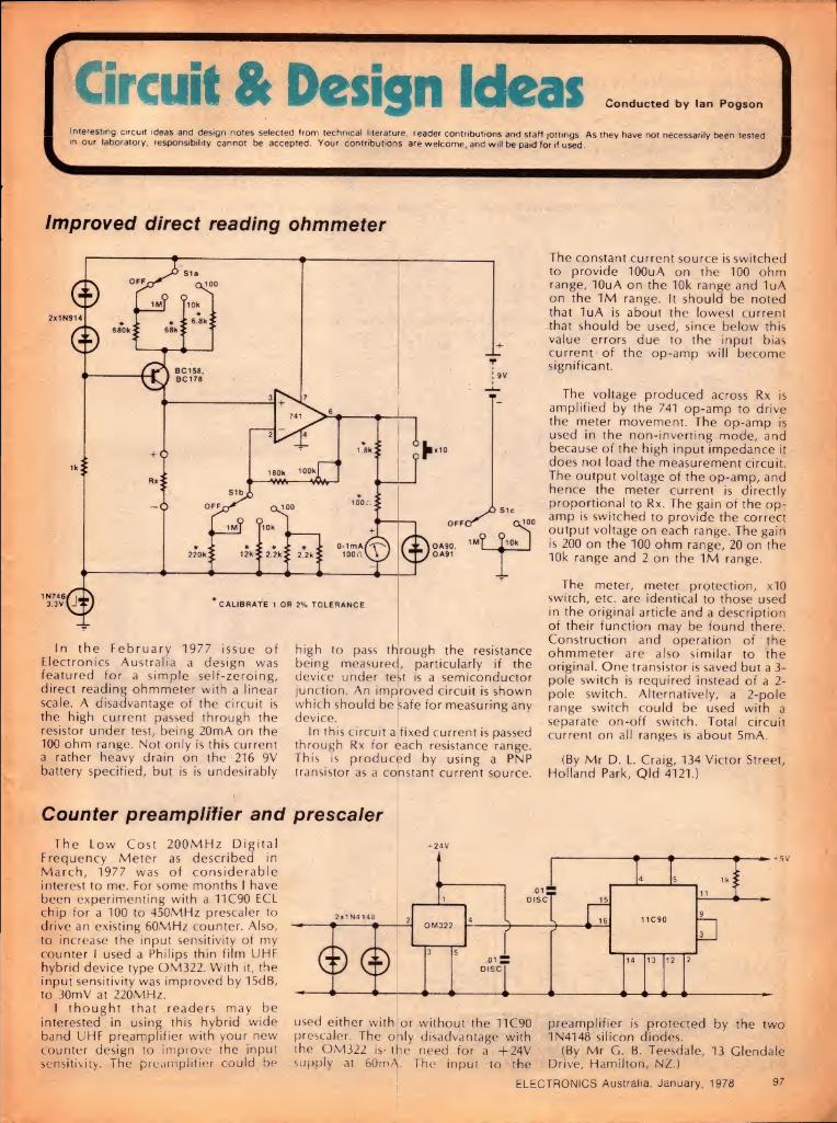
—
(lit & Design Ideas Conducted by Ian Pogson
Interesting circuit ideas and design notes selected from technical literature, reader contributions and staff jottings. As they have not necessarily been tested in our laboratory, responsibility cannot be accepted. Your contributions are welcome, and will be paid for if used.
Improved direct reading ohmmeter
In the February 1977 issue of Electronics Australia a design was featured for a simple self-zeroing, direct reading ohmmeter with a linear scale. A disadvantage of the circuit is the high current passed through the resistor under test, being 20mA on the 100 ohm range. Not only is this current a rather heavy drain on the 216 9V K.v battery specified, but is is undesirably transistor as
high to pass through the resistance being measured, particularly if the device under te^t is a semiconductor junction. An improved circuit is shown which should be safe for measuring any device.
In this circuit a fixed current is passed through Rx for $ach resistance range. This is produced by using a PNP
a cohstant current source.
Counter preamplifier and prescaler The Low Cost 200MHz Digital
Frequency Meter as described in March, 1977 was of considerable interest to me. For some months I have been experimenting with a 11C90 ECL chip for a 100 to 450MHz prescaler to drive an existing 60MHz counter. Also, to increase the input sensitivity of my counter I used a Philips thin film UHF hybrid device type OM322. With it, the input sensitivity was improved by 15dB, to 30mV at 220MHz.
I thought that readers may be interested in using this hybrid wide band UHF preamplifier with your new counter design to improve the input sensitivity. The preamplifier could be
The constant current source is switched to provide IOOuA on the 100 ohm range, IOuA on the 10k range and luA on the 1M range. It should be noted that luA is about the lowest current that should be used, since below this value errors due to the input bias current of the op-amp will become significant.
The voltage produced across Rx is amplified by the 741 op-amp to drive the meter movement. The op-amp is used in the non-inverting mode, and because of the high input impedance it does not load the measurement circuit. The output voltage of the op-amp, and hence the meter current is directly proportional to Rx. The gain of the op- amp is switched to provide the correct output voltage on each range. The gain is 200 on the 100 ohm range, 20 on the 10k range and 2 on the 1M range.
The meter, meter protection, xIO switch, etc. are identical to those used in the original article and a description of their function may be found there. Construction and operation of the ohmmeter are also similar to the original. One transistor is saved but a 3- pole switch is required instead of a 2- pole switch. Alternatively, a 2-pole range switch could be used with a separate on-off switch. Total circuit current on all ranges is about 5mA.
(By Mr D. L. Craig, 134 Victor Street, Holland Park, Qld 4121.)
used either with or without the 11C90 prescaler. The oily disadvantage with the OM322 is- the need for a +24V supply at 60mA. The input to the
preamplifier is protected by the two 1N4148 silicon diodes.
(By Mr G. B. Teesdale, 13 Glendale Drive, Hamilton, NZ.)
ELECTRONICS Australia, January, 1978 97

NOW YOU CAN HAVE LIGHT WHERE YOU NEED IT
For immediate delivery please send cheque to FRANCIS LORD MFG. PTY. LTD. 33 Higginbotham Road. Gladesville, N S W. 2111
Name
Address
trade enquiries welcome
MONEY REFUNDED
WITHIN 7 DAYS IF NOT
COMPLETELY SATISFIED.
FRANCIS LORD MFG. 33 HIGGINBOTHAM RD„ GLADESVILLE
IMv. Ltd. N.S.W. 2111.
Price: $79.73 plus 15% Sales Ta: if applicable. Price do^s not include cost of 2 'D' batteries.
Available in kit form:—
Type 2: (Heavy Duty) as illustrated comprising: Right angle power source 24" x 4mm lightguide Fixed mirror g" with hollow mounting handle
adjustable mirror with hollow mounting handle .P.V.C. Sleeve 2 spare lens bulbs
U" interchangeable mirror head short shaft 1J" interchangeable mirror head short shaft 1" interchangeable mirror—extended shaft 1 case
New FIBRE OPTICS
LIGHT PROBE bends light around corners, gives light to the exact point of inspection, able to direct light where access was pre¬ viously restricted. Ideal for inspection and examination of small components, tubes, locks, fuel systems, engine repairs — where access is limited, instrument inspec¬ tion, search and retrieval of unwanted foreign bodies plus a host of other uses too numerous to mention. A must for the technician, engineer, scientist, mechanic and repairman.
98 ELECTRONICS Australia, January, 1978

CIRCUIT & DESIGN IDEAS
Automatic motor stop for teleprinters
N
the transistor to conduct. The relay then operates from the charged 400uF capacitor. If loop current is not restored or signalling does not start within three seconds, the relay will release as the 400uF capacitor discharges.
The contacts MCI connect the negative side of the charged IOOOuF capacitor to the transistor base to maintain base current until the IOOOuF capacitor is discharged. This discharge time can be varied by adjusting the 470k potentiometer, one to two minutes being possible. Contacts MC2 disconnect the 47k resistor to prevent the transistor from being turned off by the voltage drop across the 82 ohm resistor during subsequent marks.
During signalling, breaks in loop current allow the IOOOuF capacitor to be re-charged from the 400uF capacitor, to reset the delay via the 330 ohm resistor, diode D2, contacts MCI (operated) and the Ik resistor. The contacts MC3 control the power to the motor via the triac.
A quick push of the switch button will start the motor by removing the voltage drop across the circuit. The motor may be stopped without waiting for the delay to expire by simply holding the switch button depressed for three seconds or so.
(By Mr G. R. Leadbeater, 16 Ellison Street, Ringwood, Victoria 3134.)
The circuit operates as follows. Under steady mark conditions 20V will be dropped across the circuit, 16V across the 330 ohm resistor and 4V across the 82 ohm resistor. The 400uF capacitor is charged to 16V via diode D1 and the IOOOuF capacitor is also charged, via the relay contacts MCI (normal) and the Ik resistor. The 4V
In the course of investigating the use of CMOS devices in linear amplifiers, I came up with this arrangement of a diode stabilised Wien bridge oscillator. It works over the range 3.5 to 15V. Output voltage is 2V peak-to-peak and frequency stability is within ±2.5%. With the components indicated, the frequency is about 1000Hz.
Because one was available, a quad NAND gate device was used, although
across the 82 ohm resistor is divided by the 47k and 56k resistors to produce 2V of reverse bias on the transistor, thereby holding it cut off.
At the first break of line current, the luF capacitor is charged from the 400uF capacitor via the 330 ohm resistor and the diode D2. Transistor base current flows through the 56k resistor, causing
of course a hex inverter device such as the 14069 could be used, but with NAND or NOR gates it is possible to have a mute function connected to another gate input. Because of the very high input impedance (lOM) the oscillator is sensitive to noise pickup and this should be taken into account.
(By Jan Martin Noeding, LA8AK/G5BFV, in "Radio Communication".)
RADIO DESPATCH SERVICE
869 GEORGE ST. N S W 2000
(NEAR HARRIS ST)
PHONE 2110816. 2110191
• “Fujicon" 12V Electronic Digital Car Clock. • 12V DC Portable Fluorescent Lantern $10.00 plus Batts. • “Copal" AM FM Digital Clock Radios, two models, RD180 &
RD800. • “Unisound" DM-780 Power CB Base Station Microphone. • CB Mobile Aerials - Roof & Gutter Mount - Helical Whip,
etc. • “Austenna" CB-AFI Interference Filter for TV sets. • Extensive range of CB accessories available. • “Unisound" EM-100 Stereo Microphone 600 ohm imp. • Microphone Stands - Floor & Boom type available. • “Coral" Stereophones, high velocity, model E-80 100 ohm imp. • "Coral" 8SA-1, 85A-5A. 10SA-1. 12SA-1. Speaker Kits, ex¬
stock. • Speaker Cabinet Kits to suit Coral Speaker Kits. Available. • Ttalmar" -222 AM FM Multiplex Stereo Tuner Spec. Price
$58.00. • "Libco" AM FM 10 Transistoi Portable Radio. • 6ft Fibreglass Car Aerials - with Whip Base. • “Ferguson" — ECA140 13-8V -2Amp CB power supply. • Reflex Horn Speaker - 5” . 8 ohms imp - 5 watts. • “Horwood" Aluminium Vinyl Covered Instrument Cases. • TVG-8000 Champion-77 Electronic TV Video Game. • “Calor" Electric Easy-Seal Polythene Bag Make & Sealer. • “Gillette” Pro-Max Styler Hair Dryer. • TV Aerials, Install. Kits and Accessories for Colour BW. • EA and ETI Project Printed Circuit Boards. • Calculators! - Texas Inst., Novus and Microlith.
Open Mon to Fri 8.00a.m. to 5.30p.m.
Saturday 8.00a.m. to 11.45a.m.
Wien bridge oscillator using CMOS gates
ELECTRONICS Australia, January, 1978 99

Classical Recordings
Reviewed by Julian Russell
RCA Gold Seal Stereo Reissues: Good Value
CHOPIN — Scherzo No. 4 in E. RAVEL — The Valley of the Bells. Jeu
d'eau. RACHMANINOV — Three Preludes,
Nos 1, 9 and 10. PROKOFIEFF — Gavotte (from
Conderella). Visions fugitives Nos. 6, 7, 8, 9, 15 and 18. Sviatoslav Richter (pianist). RCA Gold Seal Stereo AGL1 1279. Here are some more reviews of
RCA's reprocessed reissues (Gold Seal), many of which I found so impressive when the first lot came out. This disc is made from tapes recorded at live performances in New York in 1960. They were recorded within two days of each other, December 26 and 28, but in different halls, one at Carnegie Hall the other in Mosque Theatre, Newark, New Jersey.
This latter may explain the slightly different acoustics on the two sides of the disc. The sound on the Chopin/Debussy side is sometimes ultra resonant, at others dry.
Richter takes the Chopin Scherzo at the very top speed, so that if some of its more romantic aspects disappear you have instead an example of terrific virtuosity — often just for its own sake. But for contrast he caresses the middle section like a lover.
RCA's reprocessing has in many cases vastly improved on the sound of the originals made in the early 1960s. But, surprisingly, in this issue there is a moment of coarseness so unexpected that it is as if the pianist had struck you a blow. Despite Richter's great speed the piece just lacks the warm impulsiveness of similar passages when Richter plays Schumann. I always find prolonged applause after an item on a disc deplorable and here it is again.
In the Ravel, Richter's touch and approach to the music changes completely. In the Valley of the Bells one might be tempted to describe it as almost impressionistic, but to me it is completely realistic. Under his beautifully veiled tone, one can appreciate the enormous concentration that went into producing it. But in Jeu d'eau — taken a little faster than is usual — every note sparkles like the droplets depicted so wonderfully!
Here is another example of Richter's
exquisite soft touch when he feels it necessary. He plays it all rather dead pan but that didn't worry me. And that impeccable technique! Never a note out of place however difficult the passage.
The three Rachmaninov Preludes on the reverse may well surprise many by the amount of interest Richter finds in them. None is a show piece but each is a gem — at least the way Richter plays them! In other hands they might well lose much of their interest. I cannot imagine them better played — or as well for that matter. You can hear an occasional cough but so suppressed that it's not likely to worry anyone but the most finnicky listener.
While in the Preludes he is unabashedly romantic, he changes his style again in the more percussive Prokofieff pieces that conlude the recital. Here everything is deliciously crisp and often irresistably rhythmic. I doubt if today any other pianist could produce such a variety of styles on the one disc. The Prokofieff's make a glittering end to a great recital. Listen to the fourth little piece and marvel at his treatment of the immensely difficult repeated notes, and the power when he releases it. Unhesitatingly recommended.
☆ ☆ ☆
TCHAIKOVSKY — Symphony No. 5 in E Minor. Boston Symphony Orchestra conducted by Pierre Monteux. RCA Gold Seal Stereo Reissue AGL1 1264. This record is a disappointment, all
the more so since I have always been a fervent admirer of Monteux. Listening to it, an experienced musician might well think that here is a conductor who just doesn't know what Tchaikovsky is about. Yet I heard the same man give a moving performance of the Pathetique in London years ago.
Monteux was of course French, and it was perhaps in that school that he shone his brightest. He was also a pioneer in the conducting of early Stravinsky and actually conducted the first outrageously unruly performance The Rite of Spring. I seldom heard him conduct German music so on that subject I can add nothing.
In addition to his vast erudition, he
was a man of the most winning charm, witty, tolerant and loved by every orchestra he conducted. I am afraid that RCA's reprocessing team, despite its incomparable skill, could do little to make the present performance attractive, not because of any techanical difficulties but because of the inadequacy of Monteux' performance.
In this recording Tchaikovsky's continuity of line seems to mean little to him. He is constantly breaking it up to substitute an idea of his own and, I am afraid, these eccentricities are seldom effective. First one solo instrument then another seem to compete. The balance in the introduction to the first movement is dicey. Later, in the main body of the movement, the loud passages seem to bluster. And strangely the Boston strings do not always sound faultlessly together.
Here and there during the symphony several subordinate passages are senselessly hurried over for no accountable reason I could think of. And, returning to the first movement, there is a frenzy that is alien even to that composer's music. There does not seem to be any discernible design. The ideas seem to be "chucked" together.
Of course every bar in the symphony is not as bad as I am perhaps making it sound. It even has one or two great moments. But on the whole I am saddened to think that a conductor I admired so much as a musician and liked so much as a man should not only play the work in this way but allow it to be issued. Surely there can be no excuse for permitting a supremely unimportant supporting passage to be brought forward enough to obscure the music's natural line?
☆ ☆ ☆ BERLIOZ — Harold in Italy. William
Primrose (violist) with the Boston Symphony Orchestra conducted by Charles Munch. RCA Gold Seal Stereo Reissue AGL1 1526. I am not so happy with my pressing of
this reissue, though it was producea by the same process as the others. First, and importantly, the surface has more
ELECTRONICS Australia, January, 1978 100

than its share of pops and crackles. And Munch was in one of his uninspiring moods when he made the original, so perhaps the blame does not rest with the reprocessors.
There is a hint of artificiality in some of the climaxes here and there, as if they were imposed on the work. In the solo viola part, William Primrose sounds a little too forward, though none could cavill at the eloquence of his playinc. But no soloist, however fine, could carry Munch and the Boston's lifeless performance.
Despite this the disc is a vast improvement on the 1958 original which I still own and used here for comparison.
I am aware that a note on Berlioz' score states that "the player (viola) must stand near the public and apart from the orchestra". But that was before the days of electronic amplification. Another fact to be considered is that the piece was commissioned by Paganini, who was no blushing violet.
Another fault, in my opinion, is in the pace at which Munch takes the Pilgrims' March. His speed suggests that these pious gentlemen are in a hurry to get to the next pub. The Serenade it taken more sensitively.
The final Brigands' Orgy is very difficult to deliver as Berlioz intended, but surely the Boston could have handled it better than they do here. They make it sound about as orgiastic as a Festival of Light picnic.
However, the background hiss that bedevils my original has been obliterated in this new reissue and, technically, I suppose the recreation can be regarded as something of a tour de force. But musically, the force is missing.
☆ ☆ ☆
MAHLER — Symphony No. 4. Chicago Symphony Orchestra conducted by Fritz Reiner with Lisa della Casa in the final song. RCA Gold Seal reprocessed Stereo Reissue AGL1 1333. Although this was probably originally
recorded early during Reiner's association with the Chicago Symphony, his impact can already be heard on this orchestra which he was to develop to such a high standard.
Some conductors have a tendency to treat this 4th Symphony a little too daintily, as if it were a scherzo among the other, far weightier, symphonies. Reiner doesn't. He gives it true depth of symphonic thought and thus, in particular, makes the final movement sound rather more than a mere child's song.
Reiner had exactly the right feeling for Mahlerian rubatos. My pressing is a splendid example of the RCA technique of reprocessing. Perhaps in the first movement the sleigh bells are placed a little too far back, though that's not as bad as having them too far
forward. The original 1960 recording must have had commendable clarity, though even this has been improved by the reprocessing. Mahler's many strands are easily perceptible and the dynamic range is excellent.
I feel that if Reiner had recorded the original in later days he may have introduced here and there some extra refinements. As it is he hurries the first movement a little too much for my taste. But his tempo in the second movement is more normal — and very graceful — and all through the symphony one can appreciate the orchestra's knife-edged attack and release. Here and there the sound does become a little coarse compared to that in some of the other issues. But let me emphasise that this is rare and by no means annoying.
As usual in the great American orchestras the first desk soloists are delightfully audible without being unnecessarily spotlighted, which used to be the American habit some years ago when the great Stokowosky was one of the worst offenders. The slow movement is not overlaid with schmaltz.
As the sleeve notes point out, if you're unfamiliar with the Mahler symphonies this is the one to start with. It contains no ponderous German mysticism and is also mercifully brief compared to some of his other symphonic mastodons.
The slow movement I mentioned above is toned down to a whisper but never drained of expression because of this. The whole movement displays a quite wonderful control of dynamics. And I might add that there is no need for any additional refinement here.
An English/German translation of the final song is included in the sleeve notes. Soprano Lisa della Casa sings it very nicely, though with a certain lack of innocence. But her voice is always pleasant to listen to.
☆ ☆ ☆ RIMSKY-KORSAKOV — Suite from the
opera Le Coq d'Or. STRAVINSKY — Suite from the ballet
The Firebird. Boston Symphony Orchestra conducted by Erich Leinsdorf. RCA Gold Seal Stereo AGL1 1528.
This suite from the opera Coq d'Or makes great demands on all the first desk soloists, and in this fine orchestra they respond magnificently. The sound is extraordinarily clear (the original dates from 1965), and Leinsdorf seems in a slightly warmer mood then usual. Yet his coolness in the Lullaby is a delight.
Occasionally, though I must stress not often, some of the sound is not quite up to present day standards. But tne disc is still a fine example of reprocessing.
The work is purely decorative — and descriptive — and calls for no deep
emotional involvement, which suites Leinsdorf's style very well. He wins lovely smoothness in the opening to the Queen's dance. There is only one extract that appeals to me less than the others — the rather strait laced opening to the Wedding March. It lacks a little in exhuberance but picks up splendidly by the time the coda is reacned. And the whole of the latter part gets much livelier.
In the opening bars of the Firebird the low, very soft notes come out very well indeed. The whole of the Prelude — before the curtain goes up — is fine, if sometime a wee bit metronomic. The passage when the Firebird crosses the stage for the first time glitters just as it should. The Firebird's and Prince's dance is a little unyielding despite a few subtle tempo changes.
The Golden Apples dance is here played with virtuoso delicacy. Some might not know that Stravinsky died disliking this lovely little movement. During his lifetime he made many attempts to rewrite it but always thought it sounded too much like Mendelssohn.
By the way, at Leinsdorf's fast tempo of this item I should hate to have to dance to it. But everywhere, throughout the difficult score of the whole work, there is nothing less than perfect precision.
I was happy to find the euphonious Ronde des Princesses included although this, too, is a little too dead pan to bring out all its beauties. Leinsdorf uses Stravinsky's own revision for a smaller orchestra than the original, which demanded a gigantic combination, including such exotic instruments as a surrusophone.
To sum up, I prefer Firebird played with just a wee bit more affection. Still, this version will do nicely, especially at its budget price Like so many of the Gold Seal reissues, its darned good value. ®
FUNDAMENTALS OF
SOLID STATE
Fundamentals of Solid State is in its second
reprinting, showing how popular it has been. It
provides a wealth of information on
semiconductor theory and operation, delving
much deeper than very elementary works, but
without the maths and abstract theory which
make many of the more specialised texts very
heavy going. Solid State' has also been
widely acclaimed in colleges as recommended
reading — but it's not just for the student. It's
for anyone who wants to know just a little
more about the operation of semiconductor
devices.
$3.00 plus 60c p & p Electronics Australia
Box 163, Beaconsfield, NSW 2014.
ELECTRONICS Australia, January, 1978 101

It*/ o mod. mod. modular world. Simplify, simplify! Instead of paying more for bigger, bulkier audio control components, pay less for compact Shure modular components that — singly or in combination—handle critical functions flawlessly. Cases in point: (1) the M67 and M68 Microphone Mixers, the original high-performance, low-cost mixers; (2) the M610 Feedback Controller, the compact component that permits dramatically increased gain before feedback; (3) the M63 Audio Master, that gives almost unlimited response shaping characteristics; (4) the M688 Stereo Mixer, for stereo recording and multi-source audio-visual work; (5) the M675 Broadcast Production Master, that works with our M67 to create a complete production console (with cuing!) for a fraction of the cost of conventional consoles; and (6) the SE30 Gated Compressor/Mixer, (not shown above) with the memory circuit that eliminates “pumping.” For more on how to “go modular,” write to:
AUDIO ENGINEERS PTY. LTD.
342 Kent Street, Sydney.
AUDIO ENGINEERS (Vic.) AUDIO ENGINEERS (Old.) p/l ATHOL M. HILL PTY. LTD. 2A Hill Street 51a Castlemaine Street, 33-35 Wittenoom Street, THORNBURY. 3071. Vic. MILTON. 4064. Qld. EAST PERTH 6000 W.A.
102 ELECTRONICS Australia, January, 1978 AE109/FP

Lighter Side Reviews of other recordings
Devotional Records VIEW FROM THE BRIDGE. Tom
Howard. Stereo, Solid Rock Records, SRA-2003. (From Sacred Productions Aust, 181 Clarence St, Sydney and other capitals.)
There is a play here on the words 'solid rock". It has a Gospel connota¬
tion, as expressed by the old hymn "On Christ, the solid rock . . It also has musical overtones in the nature of the music used to convey the Gospel message.
In fact, the very comprehensive notes on an inner sleeve ably justify the producer's approach by drawing atten¬ tion to the fact that some of the hymns which older people regard now as great, traditional and dignified, were once contentious because they utilised folk melodies and popular forms, in an attempt to communicate in their day to the average person.
It makes interesting reading and could well form the basis of a church discussion group, the more so because the lyrics are given in full. Additionally, the arrangements are modern without being as extreme as the name "solid rock" might suggest.
The titles: Come On In — Mansion On The Sand (remember the parable?) — To Learn By Living — We All Mean Very Well — One More Reason — She Likes To Look At Pictures (the emp¬ tiness of movies and TV) — Blessed Are The Children — Marriage Of Our Souls — All Through The Day.
The arrangements are good, the dic¬ tion is good and the sound quality is ex¬ cellent. A good modern Gospel record in its own right and, as I said, one with potential for a discussion -group. (W.N.W.)
☆ ☆ ☆ DANIEL AMOS. Stereo, Maranatha
Music HS-777-24. (From S. John Bacon Pty Ltd, 12-13 Windsor Ave, Mt Waverley, Vic 3149.)
Looking through the credits, Dan Amos is mentioned only in connection with "Other percussive embellishments". But his name is apparently used to identify the basic
group of four, responsible for this album, assisted by other supporting musicians.
While the backing is gentle rhythm through to (very) soft rock, the main emphasis is on the lyrics, which are given in full on the inside of the double-fold jacket. The phrases and images are those of the teen-twenty generation but sentiments and the values are as old as the Gospel itself.
The titles: Jesus Is Jehovah To Me — The Bible — Abidin' — William — Prelude: Servant's Prayer— Don't Light Your Own Fire — Losers And Winners — Walking On The Water — Ridin' Along — Dusty Road — Love In A Yielded Heart — Skeptics' Song.
You probably won't know any or many of the songs by their titles but the obvious intention is that you follow the
lyrics, at least the first time through. Such is the sound and the quality of the recording that you'll almost certainly enjoy the experience. (W.N.W.)
☆ ☆ ☆ SACRED SONGS. June Bronhill with the
John McCarthy Singers and organist Brian Stanborough. Stereo, EMI Axis AXIS.6325. (Also on cassette TC- AXIS.6325.)
Well known for her stage and operatic roles, Australian soprano June Bronhill teams here with the John McCarthy Singers to perform a group of sacred songs, drawn variously from classical sources, from opera and from traditional hymnals.
Nun's Chorus (from "Cassanova") — Flocks in Pastures Green Abiding (Cantata No 208) — Easter Hymn (From "Cavalleria Rusticana") — Ave Maria (Bach-Gounod) — O For The Wings Of A Dove (Mendelssohn) — Nearer My God To Thee — Bless This House — Largo (Handel) — Agnus Dei (Bizet) — The Holy City — O Divine Redeemer — Abide With Me.
Although the album holds promise of considerable pleasure for those who like these well known selections, I fear that it is likely to earn a mixed reception. It is very much a Cerformance — and I stress the word —
y June Bronhill the stage and opera star, and your enjoyment of the album will depend on your ability to accept it on this basis.
But if you lack empathy with operatic sopranos and the thrusting quality they can impart to even traditional hymns, then this record isn't for you, despite the demure portrait on the jacket, the candle and the Bible.
In other words, listen to a couple of representative tracks before you buy.
Incidentally, the album was recorded in 1969 but the sound quality is still in line with today's average. (W.N.W.)
Instrumental, Vocal and Humour HALLELUJAH. The Portsmouth Sinfonia
at The Royal Albert Hall. M7 Records MLF 187.
If you see this record on the stands, don't buy it as a present for anyone who takes their music seriously; it would be a quick way to destory a beautiful friendship. This must be one of the most tongue-in-cheek send-ups ever put on record, with over 350 out- of-key voices and "musicians" creating havoc with such music as the 1812 Overture, William Tell Overture and the Hallelujah Chorus from Handel's "Messiah". Quality, terrible! (N.J.M.)
Reviews in this section are by Neville Williams (W.N.W.), Jamieson Rowe (J.RJ, leo Simpson (1.1).$.), Norman Marks (N.J.M.), David EdwardstD.W.E.), Greg Swain (G.S.), and Danny Eloopet (D.H.j.
A PORTRAH OF BENIAMINO GIGLI. EMI OXLP-7631. Gigli was one of those legendary
voices that has passed into history and this wonderfully remastered release from EMI shows some of the vocal magic that still lingers in the memories of opera lovers.
Considering the fact that the recor¬ ding covers performances as far back as 1921 through to 1943, the quality is in¬ credibly good and, with 16 excerpts to enjoy, the disc is a bargain at any price.
A few of the works represented: II Trovatore — La Traviata — Mefistofele — La Boheme — Lucia Di Lammermoor — Carmen — Faust. This disc would be a wonderful way to husband those precious 78s. (N.J.M.)
ELECTRONICS Australia. January, 1978 103

THE LIGHTER SIDE
A
MICROPHONES
m ZH 062
4
Impedance
Frequency Response
Sensitivity
Dimensions
UNB • DYNAMIC
BOO - 50K(fi)(DUAL)
350- 12000(Hi)
-as *-3(dB)(eoaQ)
*iexsi (•»)
ZM 068
Directional Characteristice UMIOYMAIVIIC
impedance SOO-SOK( Q )(DUAL)
Frequency Response 200- 9000(Hi)
Sensitivity - 71 ± 3( dB) (6000 )
Dimensions ^43x 1 42.7(e)
mm
T
ZM 069
*
Direction
impedance
Frequency Respone
Sensitivity
UPS* DYNAIS/IIC
600 • 50K(S> l(DUAL)
200-10000(Hj)
71 ± 3( dB ) ( BOOU)
**»3x 1 97(«)
-Y4-
I 70 BATESFORD ROAD, CHADSTONE, VICTORIA, 3148, AUSTRALIA
CABLES: ZEPHPROD. TELEPHONE: (03)568 2922
V___J
SOUPA DISCO SOUNDS — 12 FAVOURITE VARIETIES. Disco Orchestral. Harlequin Records L- 25265. Festival release. The cover of this record shows a can
and a can opener, and the contents are about as bland as oyster soup. In my opinion, the record deserves to be "canned". Tracks preserved are: Baby Face — Tangerine — Kojak — Who's Sorry Now — Headline News — We Do It — It Had To Be You — That Old Black Magic — Land Of A Thousand Dances — 7, 6, 5, 4, 3, 2, 1 (Blow Your Whistle) — Help Me Make It Through The Night — Do It Again.
In conclusion, a thoroughly un¬ interesting menu, with only average in¬ gredients. (D.W.E.)
☆ ☆ ☆
PETE SEEGER & BROTHER KIRK VISIT SESAME STREET. Axis stereo 6319. Those readers with young children
possibly share my mixed feelings about the American childrens' TV program "Sesame Street". What is particularly galling is the nonchalant disregard for English grammar. This is carried through to this recording where it is all the more noticeable because of the lack of video distraction. Recording quality is just mediocre although I doubt whether the potential audience will notice.
There are twelve tracks: Hello — Michael Row the Boat Ashore — This Land Is Your Land — Skip To My Lou — She'll Be Coming Round The Mountain — Patty Cake Gorilla — Riding In My Car — Garbage — Old Lady Who Swallowed The Fly — The Ballad Of Martin Luther King — Guantanamera — Sweet Rosyanne. (L.D.S.)
☆ ☆ ☆
DONALD SMITH SINGS FOR YOU. With the Adelaide Symphony Orchestra; arranged and conducted by John Lanchbery. Stereo, EMI OASD 7602. Also on cassette TC OASD 7602. Well known Australian tenor Donald
Smith engages here on a nostalgic journey back through hit tunes from the "talkies", and the prime appeal of the album will be to those who remember the '30s era. There are 14 songs on the two sides:
For You — Would You — I'm In The Mood For Love — Moonlight Becomes You — Over The Rainbow — Diane — If I Had A Talking Picture Of You — Dancing With Tears In My Eyes — I Only Have Eyes For You — You Belong To My Heart — We Were So Young — September In The Rain — You Stepped Out Of A Dream — Giannina Mia.
As a class, operatic tenors tend to I "perform" even simple songs at full
ELECTRONICS Australia, January, 1978
pressure but Donald Smith is much more relaxed, sufficient to evoke the remark from a member of my household: "He's certainly very easy to listen to".
Unfortunately, he is rather let down by the recording itself. The sound is clean enough but so "middly" that it is also reminiscent of the period! And I had to look twice to make sure that it was stereo.
If the music appeals, by all means buy the album but don't expect of it a hi-fi experience. (W.N.W.)
☆ ☆ ☆
FREE & EASY, ROUGH & READY. Free. Island Records L-36069. Festival release.
This is a collection of Free tracks compiled from earlier albums, and as such will probably be only of interest to avid fans or new fans. In order, the tracks are as follows: Walk In My Shadow — The Hunter — Woman — Wishing Well — Fire And Water — Travellin' In Style — Remember — Bodie — On My Way — Oh I Wept.
I'm not a Free fan, and would prefer not to comment on the merits of the various tracks. Suffice it to say that recording quality is good. (D.W.E.)
☆ ☆ ☆
I LOVE TO LOVE. Tina Charles. Stereo. CBS Records SBP-234833.
This is a disco record, probably as good as most and better than some. Tina has an attractive voice, which tends to get overpowered by the insis¬ tent beat of the accompaniment. If you like to eyrate endlessly in your lounge, then this record would be ideal. Otherwise, 1 wouldn't recommend it. (D.W.E.)
☆ ☆ ☆
FEELINGS. Tony Mottola. The Total Sound Inc. L45743/4. Festival Release.
"America's greatest popular guitarist", that's how the cover notes describe Tony Mottola. While this claim could be a matter for some debate, there is no denying that this budget- priced 2-record set does contain some very fine guitar work.
The songs are all hits based on the popular love theme, and Tony's interpretations fit perfectly into the "Feelings" title theme.
Some of the track titles are: This Masquerade — Feelings — Just Say I Love Her — Colour My World — The First Time Ever I Saw Your Face — Nadia's Theme — So Nice — Love Theme From "Romeo and Juliet" — Remember — You Make Me Feel Brand New — Close To You.
104
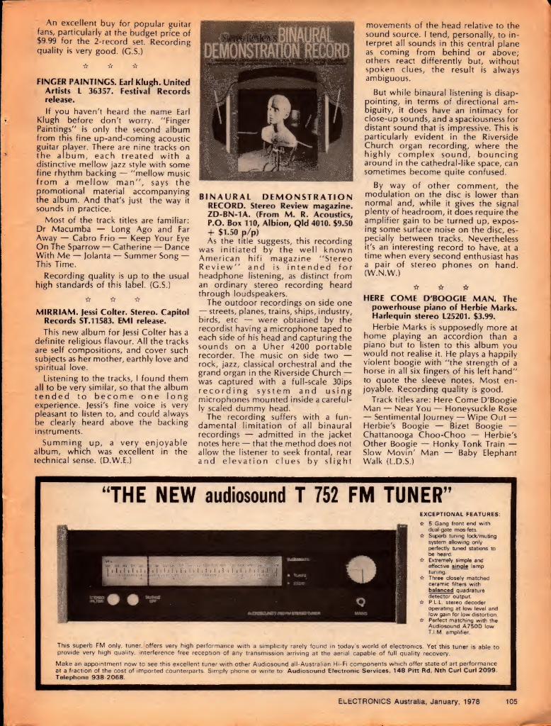
An excellent buy for popular guitar fans, particularly at the budget price of $9.99 for the 2-record set. Recording quality is very good. (G.S.)
☆ ☆ ☆
FINGER PAINTINGS. Earl Klugh. United Artists L 36357. Festival Records release.
If you haven't heard the name Earl Klugh before don't worry. "Finger Paintings" is only the second album from this fine up-and-coming acoustic guitar player. There are nine tracks on the album, each treated with a distinctive mellow jazz style with some fine rhythm backing — "mellow music from a mellow man", says the promotional material accompanying the album. And that's just the way it sounds in practice.
Most of the track titles are familiar: Dr Macumba — Long Ago and Far Away — Cabro Frio — Keep Your Eye On The Sparrow — Catherine — Dance With Me — Jolanta — Summer Song — This Time.
Recording quality is up to the usual high standards of this label. (G.S.)
☆ ☆ ☆
MIRRIAM. Jessi Colter. Stereo. Capitol Records ST.11583. EMI release.
This new album for Jessi Colter has a definite religious flavour. All the tracks are self compositions, and cover such subjects as her mother, earthly love and spiritual love.
Listening to the tracks, I found them all to be very similar, so that the album tended to become one long experience. Jessi's fine voice is very Cleasant to listen to, and could always
e clearly heard above the backing instruments.
Summing up, a very enjoyable album, which was excellent in the technical sense. (D.W.E.)
BINAURAL DEMONSTRATION RECORD. Stereo Review magazine. ZD-BN-1A. (From M. R. Acoustics, P.O. Box 110, Albion, Qld 4010. $9.50 + $1.50 p/p) As the title suggests, this recording
was initiated by the well known American hifi magazine "Stereo Review" and is intended for headphone listening, as distinct from an ordinary stereo recording heard through loudspeakers.
The outdoor recordings on side one — streets, planes, trains, ships, industry, birds, etc — were obtained by the recordist having a microphone taped to each side of his head and capturing the sounds on a Uher 4200 portable recorder. The music on side two — rock, jazz, classical orchestral and the grand organ in the Riverside Church — was captured with a full-scale 30ips recording system and using microphones mounted inside a careful¬ ly scaled dummy head.
The recording suffers with a fun¬ damental limitation of all binaural recordings — admitted in the jacket notes here — that the method does not allow the listener to seek frontal, rear and elevation clues by slight
movements of the head relative to the sound source. I tend, personally, to in¬ terpret all sounds in this central plane as coming from behind or above; others react differently but, without spoken clues, the result is always ambiguous.
But while binaural listening is disap- Cointing, in terms of directional am- iguity, it does have an intimacy for
close-up sounds, and a spaciousness for distant sound that is impressive. This is particularly evident in the Riverside Church organ recording, where the highly complex sound, bouncing around in the cathedral-like space, can sometimes become quite confused.
By way of other comment, the modulation on the disc is lower than normal and, while it gives the signal plenty of headroom, it does require the amplifier gain to be turned up, expos¬ ing some surface noise on the disc, es¬ pecially between tracks. Nevertheless it's an interesting record to have, at a time when every second enthusiast has a pair of stereo phones on hand. (W.N.W.)
☆ ☆ ☆ HERE COME D'BOOGIE MAN. The
powerhouse piano of Herbie Marks. Harlequin stereo L25201. $3.99.
Herbie Marks is supposedly more at home playing an accordion than a piano but to listen to this album you would not realise it. He plays a happily violent boogie with "the strength of a horse in all six fingers of his left hand" to auote the sleeve notes. Most en¬ joyable. Recording quality is good.
Track titles are: Here Come D'Boogie Man — Near You — Honeysuckle Rose — Sentimental Journey — Wipe Out — Herbie's Boogie — Bizet Boogie — Chattanooga Choo-Choo — Herbie's Other Boogie — Honky Tonk Train — Slow Movin' Man — Baby Elephant Walk (L.D.S.)
“THE NEW audiosound T 752 FM TUNER” EXCEPTIONAL FEATURES:
☆ 5 Gang front end with dual-gate mos-fets.
☆ Superb tuning lock/muting system allowing only perfectly tuned stations to be heard.
☆ Extremely simple and effective single lamp tuning.
☆ Three closely matched ceramic filters with balanced quadrature detector output.
☆ P.L.L. stereo decoder operating at low level and low gain for low distortion.
☆ Perfect matching with the Audiosound A750D low T.I.M. amplifier.
This superb FM only, tuner, offers very high performance with a simplicity rarely found in today's world of electronics. Yet this tuner is able to provide very high quality, interference free reception of any transmission arriving at the aerial capable of full quality recovery.
Make an appointment now to see this excellent tuner with other Audiosound all-Australian Hi-Fi components which offer state of art performance at a fraction of the cost of imported counterparts. Simply phone or write to: Audiosound Electronic Services, 148 Pitt Rd, Nth Curl Curl 2099. Telephone 938-2068.
ELECTRONICS Australia, January, 1978 105

r
Now ADC frees you from the job of mounting the cartridge on the shell.
Introducing the pre-mounted
The "Uni-Head" is solidly engineered. It is a beautifully styled and tooled accessory. And it fits into practically all manual tonearms and many of the semi-automatic players.
Illustrated is the ADC ZLM/P which is the top of any line stereo cartridge with all the great ADC unique features: • mk ill/F $'/s
• Nude Aliptic® stylus • QLM32 Mk III/P $60 • Low mass moving system * the QLM30 Mk III/P $47 • Induced magnet principle The 'Uni-Head' is available separately. • One gram tracking - or less 1
ADC cartridges. Other cartridges available with
the pre-mounted 'Uni-head’ (and the respective recommended retail values of each) are:
• ZLM/P $150 • XLM Mk III/P $125 • VLM Mk III/P $105 • QLM36 Mk III/P $95
ADC Audio Dynamics Corporation
A BSR Company. Monarch Works Anne St. St. Marys
Postal Address: Box.2.72 St. Marys NSW 2760 Australia Telephone 6230375/6. Telegrams "BSR" St. Marys Telex 23159
106 ELECTRONICS Australia, January, 1978

THE LIGHTER SIDE
DREAMS OF A LOVE. The Ferrets. Mushroom Records L36437. Festival release. A brand new Australian group to
emerge in 77 is The Ferrets, and their first single reached the coveted No. 1 position on the National Top 40 chart. This single, "Don't Fall In Love" is included in the album, amongst many other top quality tracks, like: — You Belong With Me — Dreams Of A Love (title track — My Old Dog — Just Like The Stars.
All in all, this is an excellent Australian recording, with the National Boys Choir contributing to its tone.
Catch the very closing of the album. It brings a different approach to the conventional finale. (D.H.)
☆ ☆ ☆
THE VERY BEST OF RAY STEVENS. Ray Stevens. Barnaby Records BR-6018. Astor release. Ray Stevens is probably best known
for his funny songs, such as "Ahab The Arab", "Gitarzan" and "The Streak". All these songs, and some of his lesser known ones are present on this album. But Ray has another side as well, and can sing serious songs also. A fair sampling of these are included on this album, among them tracks such as "Nashville" and "Misty".
So whichever of his styles you fancy, they are catered for here. Recording quality is adequate. (D.W.E.)
☆ ☆ ☆
BOULEVARD. Murray McLauchlan. True North Records L-36266. Festival release. Murray McLauchlan wrote all the
songs presented on this album, and erforms them in conjunction with his and, the Silver Tractors. He has a very
sad and melancholy voice, and the songs are all in a similar vein. I found them rather depressing. The recording quality was very clean. (D.W.E.)
☆ ☆ ☆
BRASS ARIA, The Royal Doulton Band. Astor Top Brass Series TBX 3014. Brass band repertoires seem to be ex¬
panding .these days to include jazz and pop themes and they seem to work out well, to everybody's satisfaction.
Unfortunately, this record from the Royal Doulton Band suffers from poor top response, sounding rather muffled, even with the treble turned up. The 12 tracks are all fairly topical: The Duchess Of Duke Street — Queens Own — Aria — Bal Masque — Harry James Concerto For Trumpet — Magic Flute Overture — Jaws — Carnival In Paris — Autumn Song — Trumpet Piece — Mood — In¬ digo La Reine De Saba. Apart from the comment about sound quality, the album is most enjoyable. (N.J.M.)
FOUR. Billy Swan. Monument Records L-36153. Festival release. Billy (I Can Help) Swan is one of the
leading lights in Rockabilly, which is a mixture of rock and roll, tradition and invention. His music has a feel to it; it makes you want to get up and start dancing. In style, his music relates to 1950's style rock and roll, but seems to have modern touches as well.
Billy has a very plaintive, nasal, but endearing voice, and he treats the songs with conviction and respect. The overall result is a very listenable record, which I arn sure wiflimprove with play¬ ing. Technically, the recording was good, with a clean well balanced sound. (D.W.E.)
☆ ☆ ☆
THE COLLECTED BROADCASTS OF IDI AMIN. John Bird. M7 Records MLF188.
I have rather mixed feelings about this album. It's not that John Bird is without talent — it's iust that Idi Amin has long since ceasea to be a laughing matter! Not exactly a record for genteel company either.
Track titles are: Gunboat Dipperlomacy — Star Gittin' Born — Time Check — Findin' De Lady — Public Announcement — Way To De Stars — Costa Uganda — SOS — Up Fo' Grabs — Amazin' Man — Weather Forecast — De Colleckerted Works O' Idi Amin. (G.S.)
☆ ☆ ☆
BARRY WHITE SINGS FOR SOMEONE YOU LOVE. Barry White. 20th Century L36310. Festival release. Yet another addition to the Barry
White collection, typical of his funky, soul sound. The highlight of the album is a seven-minute version of his new single "It's Ecstasy When You Lay Down Next To Me", currently riding high in the US charts.
Other tracks of good quality are "Playing Your Game, Baby", "You're So Good You're Bad" and "Of All The Guys In The World".
The usual female back-up group for Barry White, Love Unlimited, appears on the album. (D.H.)
☆ ☆ ☆
MARVIN CAYE LIVE AT THE LONDON PALLADIUM. Marvin Caye, Stereo, Motown STMLO-10168. EMI release. Marvin Gaye is one of the giant soul
performers of our time. This double album is a recording of one of his re¬ cent English concerts but I found it to be a litle disappointing. At least half of the recorded material consists of medleys, with the remaining tracks be¬ ing new to me. Technically, however, the recording is
excellent, with audience levels kept suitably in the background. If you are interested in performances in this genre, it would be worth an audition. (D.W.E.)
TOCORD ULTIMATE
AUDIO CABLES
Can you hear your speaker cables?
Recent research has confirmed that listening to a quality Hi-Fi music system which utilises stan¬ dard figure eight speaker cable may be compared with viewing a colour slide out of focus!
® Clear P.V.C. outer sheath. (D Braided conductors to cancel
linear inductance. © 144 individually insulated
conductors per side. © Tinned copper ends on 20 ft
lengths.
Specifications: D.C. Resistance .0105 ft /m Impedance 9.15 ft (constant) Inductance 0.15/zH/m
PH. (02) 939-2922. TLX.24873,
HARMAN AUSTRALIA PTY. LTD., 4 P.O. BOX 6, BROOKVALE, w N.S.W. 2100
✓ V ... 'o*
4*
EA 1.78 .
ELECTRONICS Australia, January, 1978 107

Just Released
HAYDEN COMPUTER BOOKS now available in Australia
SPENCER: GAME PLAYING WITH COMPUTERS - REVISED 3rd Edition 1976 $22.00 Cloth
STEINGRABER: FORTRAN FUNDAMENTALS: A Short Course 1975 $6.50 Paper
SMITH: DISCOVERING BASIC: A Problem Solving Approach 1970 $9.00 Paper
LEWIS & DOERR: MINI¬ COMPUTERS: Structures & Programming 1976 $17.00 Cloth
LEDGARD: PROGRAMMING PROVERB FOR FORTRAN PROGRAMMERS 1975 $8.75 Paper
DODES: ASSEMBLY LANGUAGE BASICS: An Annotated Program Book 1975 $8.00 Paper
COAN: BASIC BASIC: An Introduction to Computer Programming in Basic Language 1970 $10.00 Paper
COAN: ADVANCED BASIC APPLICATIONS AND PROBLEMS 1976 $9.00 Paper
FRY: COMPUTER APPRECIATION — 2nd Edition (Butterworths) 1975 $6.00 Paper
FRY: FURTHER COMPUTER APPRECIATION (Butterworths) 1977 $9.00 Paper
GASPERINI: DIGITAL TROUBLESHOOTING: Practical Digital Theory and Troubleshooting Tips 1976 $13.00 Paper
New Book Catalogue available on application. Direct orders and enquiries to:
Computer Art & Education, 2 Stephen Crescent, Croydon, Victoria 3136 Phone: 725 8094
Hayden books are distributed in Australia by: BUTTERWORTHS PTY. LIMITED
Books& Literature
About cassette decks CASSETTE DECKS AND TAPES. Hifi
Choice. By Angus McKenzie. Paper cover, 226 pages, including adver¬ tisements, 197 x 147mm. Revised edi¬ tion. Published 1977 by Aquarius Books, England; Price in Australia $4.25. Pages 23-40 of this book discuss
cassette decks in a general way, cover¬ ing how a cassette recorder works, in¬ put circuits, playback circuits, wow and flutter, spooling indicators, noise re¬ duction systems, &c. This would be compact but helpful reading to anyone contemplating the purchase of a deck.
Pages 43 to 154 are devoted entirely to reports on cassette decks available in Britain at the time of publication — about 60 in number. I would expect to find many of these on offer in Australian hifi shops, although relative prices may differ from those in Britain, affecting value-for-money conclusions which follow the reviews.
Pages 171-203 are devoted to a dis¬ cussion and review of tapes — a rather confusing subject where it is difficult to distinguish between intrinsic tape quality, bias requirements and com¬ patibility with particular decks. In prac¬ tical terms, I doubt that the discussion could do much to alter the idea that one should prefer the tape that works best in your own recorder!
For Australians trying to select a new deck, I see the value of a book like this as alerting the reader to things to con¬ sider, ratner than as a source of firm recommendations.
Our review copy came from Thomas C. Lothian Pty Ltd, 4-12 Tattersall's Lane, Melbourne 3000. (W.N.W.)
Amateur satellites GETTING TO KNOW OSCAR. Edited by
J. P. Kleinman, WA1ZUY. Published by American Radio Relay League Inc. Soft covers. 48 pages 275mm x 207mm. Suggested Australian price $5.10.
This book is made up from 14 articles which originally appeared as a series in the ARRL publication "QST", under the same title — "Getting to Know OSCAR from the Ground Up".
The series was written to acquaint amateurs with the OSCAR program in general and the procedures, technical
and otherwise, required to listen to, or operate through, the current satellite(s).
The article headings give some idea of the contents: Space Communication is for Everyone; Getting Started; Fin¬ ding OSCAR — it's easy; How to use OSCAR 7 Mode B; The Benefits are Yours; The OSCARLOCATOR; The Newest OSCAR; Toward the Ultimate Amateur Satellite; What Phase III Will Do; You ... and Phase III; OSCAR Goes to Schools; Satellites Can Save Lives; OSCAR's Vital Statistics; The Rise and Fall of the OSCARs.
There is also an index and a foldout map on stiff card which forms part of the OSCARLOCATOR. This latter is an ingenious system designed to enable the location of a satellite to be deter¬ mined at any time, using basic d ita published regularly through amateur channels. It consists of the map (of the northern hemisphere centred on the north pole) and two transparent overlays.
The overlays are not supplied but can be obtained free from the ARRL by submitting a coupon in the book. Un¬ fortunately, this would be of little use in the southern hemisphere.
Our copy from tne Technical Book and Magazine Co Pty Ltd, 289 Swanston St, Melbourne, Victoria 3000. (P.G.W.)
Microprocessors PROGRAMMING MICROPROCESS-
ORS. By M. W. McMurran. Tab Books, 1977. Soft cover, 130 x 210mm, 279pp, many illustrations. Price $9.75.
An introductory text on microprocessor operation, use and programming, intended to supplement the literature for specific microprocessors, and allow a user to build up and program working systems. The author is apparently an engineer in the Microelectronic Device Division of Rockwell International Electronics, in the USA.
The book will no doubt prove useful to people beginning to work with microprocessors, although I found it rather unsatisfying. It starts at a com- mendably low level for a book of this type, with introductory chapters on things like number systems and logic principles. But at the same time it assumes that the reader already knows
ELECTRONICS Australia, January, 1978 108

virtually all of the basic concepts of computer operation — like the programmed processor and stored program control.
There is no real introduction to the concepts of machine language programming, instruction types, assembly language and assemblers, and a variety of other basic things. Some of them are mentioned, but often just in passing and with the assumption that the reader is already familiar with the basic ideas.
Considering the book's stated aims, a couple of the chapters near the end seem of dubious relevance. One is devoted to the fabrication of LSI devices, while the other, although titled "Special Programming Techniques," includes a number of rather sketchy descriptions of hardware and/or system architecture matters like interrupt handling, stacks, DMA implementation and non-binary counters.
On the other hand, the chapters on number systems, logic, fixed point and floating point arithmetic are quite reasonable.
In short then, a book which may be of moderate value, although a long way short of the ideal introduction to basic programming.
Review copies were received from both Dick Smith Electronics, of PO Box 747, Crows Nest 2065, and Technical Book and Magazine Co, 289-299 Swanston Street, Melbourne. (J.R.)
Hifi speakers BUILDING HIFI SPEAKER SYSTEMS. By
M. D. Hull, C. Eng., AMIERE. Published 1977 by the Electronic Components and Materials Division of Philips, Eindhoven, Holland. Stiff paper cover, 232 pages, 210 x 148mm. Price in Australia $3.90.
Revised and updated in 1977, the book commemorates the 50th anniver¬ sary of Philips speakers and, especially for those who can remember, it carries a colour picture of a bakelite-enclosed Philips cone speaker of the 1927 vin¬ tage, together with a Philips B-battery eliminator.
Though updated, the book is recognisablv a Philips publication, both in style ana approach.
It opens with carefully written chapters on: Sound Reproduction — Moving Coil Loudspeakers — Loudspeaker Enclosures — Multi-way Speaker Systems — Listening Room Acoustics.
Statements are made without equivocation, backed up by tables, graphs and mathematical expressions, yet explained in sufficient detail to communicate to the non-technical reader as well to the student or engineer.
From page 120 onwards, the author turns to practical matters, such as the
(continued on pi 15)
BOOKS Just some of the books from the biggest range of radio and electronic books in A ustralia. If the book you require is not listed below, it can be ordered from us.
NEW — NEW — NEW Latest editions of some of the most popular books on the
subject: A.R.R.L Handbook 1977 Edition $11.95 R.S.G.B. Handbook (New Edition) Volume 1 $21.95 R.S.G.B. Handbook (New Edition) Volume 2 $18.90 Reference Data for Radio Engineers (New Edition)
ITT $37.50 Radio Handbook (William I. Orr) 20th Edition $26.50 World Radio TV Handbook 1977 $11.95 How to Build Proximity Detectors and Metal Locators
(John Potter Shields) $6.35 Building and Installing Electronic Intrusion Alarms (John
E. Cunningham) $6.35 Australian Radio Amateur Callbook 1977 $2.85
New Books: Master Handbook of Digital Logic Applications
(William L. Hunter) $10.95 111 Digital and Linear 1C Projects (Don Tuite) $8.50 "Miniwatt'' Technical Data — Valves. Picture Tubes,
Semi-conductor Devices (7th Edition) Unique 1C OP-AMP Applications (Walter C.
Jung) 1C OP-AMP Cookbook (Walter C. Jung) TTL Cookbook (Lancaster) TV Typewriter Cookbook (Lancaster) RTL Cookbook (Lancaster) CMOS Cookbook (Lancaster) 1st Edition
1977 Active Filter Cookbook (Lancaster) 1C Timer Cookbook (Jung) Transistor Specifications Manual 8th Edition Transistor Substitution Handbook New Edition
$7.50
$7.00 $17.80 $12.25 $13.50
$6.60
$13.50 $19.00 $13.50
$9.50 $6.75
International Transistor Selector (T. D Towers) $6.95 Master Tube Substitution Handbook (Tab Books) $7.00 Electronic Organs (Norman H. Crowhurst) Vol 3 $9.35 Solid State Design for the Radio Amateur
(ARRL) $14.20 Australian Electncal Wiring Theory and Practice
(Pethebridge & Williams) $9.95
CB Radio Books: CB Radio Antennas (D. Hicks) $6.25 ABC's of Citizens Band Radio (L. Buckwalter) $5.75 Chilton's CB Handbook (New 40 Channel) $5.60 CBer's How-To Book (Leo G. Sands) $6.95 Citizens Band Radio (Allan Lytell) Revised 2nd Ed. $6.95 Easi-Guide to CB Radio for Truckers (Forest H.
Belt) $4.95
Pictorial Guide to CB Radio Installation & Repair (Forest H. Belt) $8.50
CB Radio Operating Procedures (D. Hicks) $5.50 CB Radio Servicing Guide (Leo G. Sands) $6.75
Easi-Guide to Citizen's Band Radio (Forest H. Belt) $4.95 Citizens Band Radio Handbook (David E. Hicks) $7.95 CB Radio Operator's Guide (2nd Edition) (Robert M.
Brown & Paul L Dorweiler) $8.50 CBer's Handybook of Simple Hobby Projects —
114 Tested Performance Improvers (Robert M. Brown) $5.50
Practical CB Radio Troubleshooting and Repair (David F. Norman) $8.50
The Best Book on CB — includes all 40 Channels & 1977 Regulations (Evan Herbert) $6.25
CB Bible — The Complete Guide to Citizens Band 2-way Radio $6.95
The Wonderful Wacky World of CB Radio $5.95
How to Select and Install CB Antennas (Staff of CB Test Labs) $6.95
The Truth About CB Antennas (William I. Orr) $9.40
Microcomputers/Microprocessors Books:
Understanding Microcomputers and Small Computer Systems (N. Wadsworth) $14.20
Programming Microprocessors (M. W McMurran) $9.75
Microprocessors: Technology. Architecture and Applications (Daniel R. McGlynn) $18.80
Microprocessors (Electronics Book Series) $17.65 Microcomputers/Microprocessing: Hardware. Software &
Application (Hilbum & Julich) $29.50 Minicomputer Systems: Organization and Programming
(PDP 11) (Eckhouse) $25.80 Minicomputer Systems: Structure, Implementation and
Application (C. Weitzman) $29.55 Microcomputer Primer (Waite & Pardee) $10.75 Minicomputers for Engineers and Scientists (G.
Korn) $33.15
Prices Subject
For Mail Orders please add: 80c Local $1.50 Interstate
McGILL'S AUTHORISED NEWSAGENCY PTY LTD 187 Elizabeth Street Melbourne Phone: 60 1475-6-7
SC/MP Microprocessor Applications Handbook (National) $7.20
How to Buy and Use Minicomputers and Microcomputers (W. Barden. Jr) $13.50
Microprocessing/Microprogramming Handbook (B. Ward) $9.75
American Radio Relay League
Publications: Hints and Kinks for the Radio Amateur $4.25 The Radio Amateur's VHF Manual $7.20 A.R.R.L. Antenna Handbook $8.80 Understanding Amateur Radio $7.20 The Radio Amateur's Licence Manual $5.60 A Course in Radio Fundamentals $7.20 Special Communications Techniques for the Radio
Amateur $7.20 FM & Repeater for the Radio Amateur $7.20 Single Sideband for the Radio Amateur $7.20 Ham Radio Operating Guide $7.20 Electronics Data Book $7.20
Howard W. Sams Publications: Understanding 1C Operational Amplifiers (Melen &
Garland) 5.60 TV Servicing Guide — Arranged by Trouble Symptoms
(Leslie D. Deane & Calvin C. Young. Jr.) $6.50 Electric Guitar Amplifier Handbook (Jack Darr) $10.20 Transistor Fundamentals — A Programmed Learning
Course Volume 1 — Basic Semiconductor and Circuit Principles (Robert J. Brite) $7.25
Transistor Fundamentals — A Programmed Learning Course Volume 2 — Basic Transistor Circuits (Charles A. Pike) $7.25
Transistor Fundamentals — A Programmed Learning Course Volume 3 — Electronic Equipment Circuits (Martin Gersten) $7.25
Transistor Fundamentals — A Programmed Learning Course Volume 4 — Digital and Special Circuits (Louis Schweitzer & Reginald H. Peniston) $7.25
RCA Publications: Electro-Optics Handbook $8.30 Understanding CMOS $2.85 Solid State Servicing — Hi-Fi, Tape, Records. AM/FM
Mono. Stereo. TV B&W Colour $6.60 RC 30 — Receiving Tube Manual $4.50 SC 16 — Solid State Devices Manual (New Edition of
RCA Transistor Manual) $7.50 RCA Power Devices (RCA Solid State) $7.95
Other Titles: Colour Television Theory (Hutson) $11.30 The Oscilloscope (G. Zwick) $6.75 Radio, Valve and Semiconductor Data 10th Edition
(Compiled by A. Ball) $4.25 MOS Digital IC’s (G. Flynn) $8.60 Wind/Solar Energy — For Radio Communications and
Low Power Electronic/Electric Applications (E. Noll) $10.75
Sound System Engineering (Don & Carolyn Davis) $26.95
Servicing with the Oscilloscope — 2nd Edition (Gordon J King) $11.20
Slow Scan Television Handbook (Miller & Taggart) $7.90 73 Dipole and Long-Wire Antennas (Edward M.
Noll) $6.75 73 Vertical Beam and Triangle Antennas (Noll) $7.50 Basic Television — Principles and Servicing — 4th
Edition (Bernard Grob) New Edition — Soft Cover $13.10
Basic Electronics — 4th Edition (Bernard Grob) $13.50 PAL Colour Television for Servicemen (W. C.
Cook) $15.00 Pin-Point TV Troubles in 10 Minutes — Check Charts —
New TV Trouble Shooting Techniques $8.50
Pickups and Loudspeakers — How to Choose and Use (John Earl) $8.25
Manual of Sound Recording — 2nd Edition (John Aldred) $10.25
Electronic Calculators (H. Edward Roberts) $7.60 Getting the Most Out of Your Electronic Calculator
(William L Hunter) $6.95 FET — Principles. Experiments and Projects (Edward M.
Noll) $12.00 Electronics Pocket Book — 3rd Edition (Editor — P. J.
McGoldrick) $10.10 VHF Handbook for Radio Amateurs (Herbert S. Brier &
William I. Orr) $7.60
to Alteration
ELECTRONICS Australia, January, 1978 109

New Products
Non-Linear Systems MS-15 oscilloscope
Non-Linear Systems have recently released a miniature portable oscilloscope, which operates from internal rechargeable batteries and has a 15MHz bandwidth.
The first impression one gains on see¬ ing the model MS-15 oscilloscope is that it is very small. Overall size is just 160mm wide x 70mm high x 200mm deep, and the CRT screen measures only 35 x 28 mm.
Performance wise, however it is a relative giant. Maximum vertical sen¬ sitivity is lOmV per division (a division is 6mm), while the frequency response extends from DC to 15MHz. The max¬ imum timebase speed is lOOnS per divi¬ sion.
The front of the instrument is divided into four basic areas. In the lower left hand corner is a power switch and in¬ dicating LED. In the absence of external
ower, the internal sealed lead-acid atteries provide an operating time of
three hours when fully charged.
An adapter is provided to enable operation from the mains. This also serves to recharge the batteries. Note however that the batteries will only ful¬ ly recharge when the Miniscope is not operating, so overnight charging is recommended. If the unit is run from the mains continuously, the batteries will level out at approximately half full charge.
Warmup time is stated as five seconds, but the sample submitted for
review seemed to require only one se¬ cond or so. The manufacturer recommends that the battery operating time be prolonged by switching the unit off wnen it is not being looked at.
The remainder of the left hand side of the instrument is taken up by the blue display screen and the vertical in¬ put and controls. A BNC socket is provided for the input.
A three-position toggle switch selects AC or DC coupling for the input, with the centre position grounding the amplifier input. A vertical shift control is provided to enable the trace to be centred.
Vertical sensitivity is adjusted by a four-position slide switch and a three- position toggle switch, giving a total of twelve ranges. The slide switch selects ranges in decades, while the toggle switch functions as a 1-2-5 multiplier.
Minimum sensitivity is 50 volts per division, so the maximum signal which can be displayed is 200V peak to peak. Maximum sensitivity is lOmV per divi¬ sion.
A vernier vertical control is provided. In the calibrate position, amplitudes can be read with a 3% accuracy. Max¬ imum allowable input voltage is 350 volts peak to peak, while the input im-
edance is 1M shunted by 50pF. The igh frequency -3dB point for vertical
amplifier is 15MHz, although this per¬ formance can only be achieved for small deflections.
The centre portion of the front panel is occupied by the horizontal deflec¬ tion controls. Twenty one time base ranges are provided, with selection by a four position slide switch and two toggle switches. The lowest sweep speed is lOOmS per division, while the highest is lOOnS. As with the vertical amplifier, the ranges are selected in decade steps with the toggle switch ac¬ ting as a 1, 2 or 5 times multiplier.
A horizontal shift control is provided, as well as a timebase vernier control. When this is in the calibrate position, periods can be determined with an ac¬ curacy of 3%.
The remainder of the front panel is concerned with the timebase triggering circuits. The timebase can be triggered from the mains (when connected), the display waveform, from an external trigger waveform or from an internal 15kHz IV p-p sauarewave. This latter waveform is made available at a front panel socket for use as a calibrating waveform. Positive or negative slope triggering can be selected, and a trigger level control is provided.
A switch-selected horizontal deflec¬ tion input is provided. This has a sen¬ sitivity (fixed) of IV per division, and a bandwidth of 200kHz. The input im¬ pedance is 1M shunted by 50pF.
Three rear panel controls are
110 ELECTRONICS Australia, January, 1978

Electrocraft 175D25 antenna booster amplifier Electrocraft Manufacturing Pty Ltd is an Australian company which makes and distributes a wide range of television distribution equipment. A typical unit in their range is the 175D25 TV/FM distribution amplifier which is suitable for use in showrooms, home units and homes with 75ohm antenna installations.
The 175D25 is housed in a metal case 80mm in diameter and fitted with a bracket which enables it to be either fitted to the back of a TV set or screwed to a wall near a 75 ohm outlet. It has two 75 ohm Belling-Lee sockets for input and output. There is also a 3.5mm jack socket for connection of the 18V supply.
Included with the 175D25 is a separate power supply which is moulded into a power plug. It supplies 18V DC at 50 milliamps.
One can envisage several situations where a booster of this type would be useful. The first is in a home unit where the tenant finds himself with an existing 75 ohm outlet which gives insufficient signal for good reception — the picture may be snowy or just slightly grainy. Installation of the 175D25 may cure the situation. A second possibility is where the signal may be strong but plagued with ghosts. Rotating the aerial may remove the ghost but result in a snowy picture. Fitting a booster could then restore the situation without (hopefully) restoring the ghost.
A third application exists where the viewer has good reception from local stations but desires reception of a regional station. This could happen say, in the Northern suburbs of Sydney where viewers may have the potential to receive transmissions from Newcastle. This would probably require a separate antenna aimed at Newcastle, with a booster to ensure a good signal. Of course, some sort of switching or signal splitting would be required to mix the local signals with
the signals from the booster.
An important point to be noted is that a booster such as this cannot handle strong signals without overloading. So you cannot hope to improve reception of a weak signal if it is provided by an antenna which provides a strong signal from another station. The strong signal would have to be attenuated by means of a suitable filter (probably some sort of tuned stub) inserted in the input line to the booster.
At the other end of the range, a booster cannot improve reception from an antenna which by virtue of its
Gain of the 175D25 is 25dB. If less gain is required, the similar model 175D16 with 16dB will be adequate. Both these models have a frequency
range of 40 to 860MHz, which covers the whole of the VHF and proposed UFfF Australian television stations. Other models which have two or more outlets have a range of 40 to 230MHz,- which makes them suitable for reception of all existing stations.
We performed a practical test on the 175D25. Reception in our laboratory is very good so we inserted an attenuator in the line to deliberately make the picture snowy. Then, when the booster was added, reception returned to normal with pictures free of snow and grain. This would simulate the situation occuring in many home units with less than adequate antenna distribution systems.
Recommended retail price of the 175D25 is $53.55 complete with power supply, while the lower gain model 175D16 is $45.90. Further information can be obtained from the manufacturers, Electrocraft Pty Ltd, 106a Hampden Road, Artarmon, NSW 2064.
Also supplied with the Electrocraft
175D25 is a "plug- pack" power
supply to provide the required 18V
DC at 50mA.
ECRAFT — t ♦75*025
TV • FM * LINE * AMPLIFIER
t design or environment, has a poor signal-to-noise ratio. In between these two extremes, there are a large number of situations, some noted above, where a booster such as the Electrocraft 175D25 can be useful.
3A 400V diode from Soanar
Oscilloscope continued provided: an intensity control, a focus control, and a DC balance control for vertical amplifier. An input socket for the external power supply/battery charger is also provided.
Accessories supplied with the unit in¬ clude an input cable terminated in crocodile clips, an AC adaptor/battery charger, an instruction manual and four miniature banana plugs to suit the in¬ put and output sockets provided on the front panel.
The overall impression of the unit is that it has a performance far greater
than one would judge by its size, and that it would be quite suitable for either laboratory or field use. Of course, some care is required in operating the con¬ trols, as they are of necessity rather closely spaced. The portability of the unit should however more than make up for this.
Recommended retail price of the Model MS-15 Miniscope is $325.00, plus 15% sales tax if applicable. The unit reviewed was submitted by Radio Despatch Service, of 869 George Street, Sydney 2000. (D.W.E.)
Soanar now have available 3 amp 400V diodes listed as 1N5404. Full ratings apply to junction temperatures of 105 degrees Celsius. Single cycle surge capability is 200 amps. Trade enquiries to Soanar Electronics Pty Ltd, 30 Lexton Road, Box Hill, Victoria 3128.
ELECTRONICS Australia, January, 1978 111

Controlled temperature soldering.
_i ’it _k_u_ From your electronic parts supplier
or enquire from
ADCOLA PRODUCTS
Melbourne 848 3777 Brisbane 52 3166 Hobart 34 2233 B77
Sydney 709 5293 Adelaide 42 6655
Launceston 31 2511 Perth 381 5500
For advanced work on critical or sensitive circuits.
Line Voltage
THERMATIC SOLDERING TOOL Electronic feedback temperature control. All solid state sensing and switching contained within the slim handle. Screwdriver temperature selection, close temperature control.
Low Voltage
ECT SOLDERING STATIONS Electronic feedback temperature control. Zero voltage switching to avoid damage to sensitive solid state components. Temperature is controlled within a narrow band. Selector dial on cabinet.
FULL DESCRIPTIVE LITERATURE AVAILABLE
ELECTROCRAFT PTY LTD TELEVISION AERIAL & DISTRIBUTION EQUIPMENT. CB RADIOS. AERIALS & ACCESSORIES
& TELEVISION
ECRAFT DISTRIBUTION AMPLIFIERS & AMPLIFIER SPLITTERS Medium and high gain distribution. Amplifiers suitable for all TV & FM applications with 1. 2, 3 and 4 outputs. Suitable for small home unit, showroom or household type installations. Type 1.75 D16 has one output, 16db gain with low N/F $45.90*
While Type 4.75.T19 has 4 outputs, 19db of gain with low N/F $61.84*
ANTENNAS. A complete range of TV & FM aerials. Hills Channel Master, Matchmaster and H1.Q.
Hills CA16, High gain phase apray, $45.94. 215.2710, 8 element yagi, $25.29. 2010.2710, Airways screened co- linear, $58.26. EFCI, 75ohm for colour low gain, $36.00. EFC2, 75ohm for colour medium gain, $56.96. EFC3/24, 75ohm for colour high gain, $75.50. Channel Master 3110, 2 element coloray, $27.96. 3111, 6 ele¬ ment super coloray, $41.98. H1.Q Log Periodics, 8
elements and 10 elements, $39.00 (excellent back to front ratio).
ACCESSORIES: Outlet plates, transformer, attenuators, filters, plugs, sockets for 75 ohm and 300 ohm applications. AERIAL: Hardware, wall brackets, chimney mounts,
J brackets, guy wire and rings masts from 8 ft to 5U ft
DEGAUSSING COILS: Complete
with power cord, plug and
pushbutton switch, $14.00.
CB EQUIPMENT
'/« WAVE SPIRAL TUNED BASE STATION AERIAL
Omnidirectional (top view) radiation pattern with excellent ground wave and sky wave characteristics. Ideal for "point to point and "skip" communications. Sturdy plated base bracket, 4 telescopic radials and vertical radiator. Spiral tuning stub at base for quick and easy tuning. SWR of 1.1:1 possible.
Aerial comes ssasay complete with
So239 socket,
U-bolt and saddle « and detailed. — instruction sheet •
— $37.75.
m
CLEARANCE SALE OF ALL OUR CB RADIO STOCK TO MAKE WAY FOR NEW SHIPMENT.
Cobra 132/SSB transceivers. Cobra 21X
transceivers. Cobra 19M transceivers. President
"grant” AM/SSB, Phone for special prices.
MOBILE AERIALS: Royce, Belling Lee Gilco (heavy duty), Topix.
ACCESSORIES: Plugs, sockets, jumper leads, coaxial cable, SWR meters, etc.
ALL TYPES OF CABLE: In stock, coaxial, twin, 200 ohm. 75 and 50 from 30c per metre.
COMPOMENTS
FERGERSON TRANSFORMERS:
240V to 18V, 60VA(low Drofile), $8.95. 240V to 18V 20VA (low profile). $6.55. 240V to 18V.O. 18V 5A. $4.56 (PC type).
PLUG TYPE POWER PACKS: 240V to 18V DC. full wave rectification. 470uF filter capacitor; CW 1 metre lead and 3.5mm plug. $5.50.
METAL BOXES: L = 200mm, W = 135mm. H = 70mm, black vinyl covered, suitable for CB power supply, etc. Ideal project box. $3.50.
106A HAMPDEN ROAD, ARTARMON 2064. PHONES: 411 2989, 411 3772
112 ELECTRONICS Australia, January, 1978

NEW PRODUCTS
Illuminated 12V toggle switch
Swann Electronics Pty Ltd has released a range of 12V illuminated toggle switches suitable for automotive and marine applications.
With this switch range, the requirement for a separate warning light is eliminated, as the toggle section of the switch is illuminated. This can result in savings in front panel area.
The new switches are available with conventional or duck bill toggles, and
feature plain or printed bezels for a varietv of functions. A range of predrilled mounting panels to suit the toggle switches is also available.
For further information contact Swann Electronics Pty Ltd, Cnr Forster and Hardner Roads, Mt Waverley, Victoria 3149. Telephone 544 3033.
V4-wave base station antenna from Electrocraft
Recently released by Electrocraft, this Vi-wave base station antenna is designed to facilitate quick assembly and adjustment.
The radials and vertical radiator are made of telescopic aluminium sections, while the sturdy steel mounting base and "U" bolt mount have been cadmium plated and passivated to give maximum corrosion protection.
Connection to the antenna is by means of a standard S0239 socket located in the mounting bracket. The U" bolt and saddle ensure positive
mounting and will mount on a mast up to 44mm in diameter.
Specifications of the antenna are as follows: Input impedance 50 ohms; SWR less than 1.1:1; polarisation vertical; and radiation pattern omnidirectional.
Electrocraft say that the antenna is suitable for both "point-to-point" and "skip" working.
Enquiries to Electrocraft Pty Ltd, 106A Hampden Rd, Artarmon 2064.
CB antenna design ... ctd from p87
A coaxial feed cable can readily be used by bonding the braid to the region where the spiral meets the mast, and tap¬ ping the centre wire out along the spiral to a point where the apparent imped¬ ance is 50 ohms.
The popular 5/s-wave base antenna is a variation on this general theme. As indicated in Fig. 10, it involves a length of tubing, approximately 5/8-wavelength, plus a loading coil (normally included in the central moulding) and three ground- plane radials. Odd as the dimensions may appear, the design concept behind such an antenna is consistent with what has already been discussed.
The bottom Vs-wavelength of tubing, plus the loading coil, plus the radials are electrically equivalent to a shortened V4-wave ground plane (or miniwhip) resonant in its own right and with a high- voltage high-impedance point Vs-wave- length up from the base moulding.
The remaining half-wavelength of
tubing is virtually a dipole, end fed. Radiation from the bottom Vs-
wavelength modifies that from the upper V2-wavelength, giving about 1.2dB of gain above the dipole of Fig. 9-not a lot but nice to have on your side.
The antenna can accommodate to a 50-ohm coaxial feed cable simply by attaching the braid to the junction of the ground-plane radials and tapping the centre lead up the loading inductor, as appropriate.
Going beyond the 5/s-wave antenna, quite a large array of high-gain beam arrays appear in overseas CB literature but, at present, they are expressly forbid¬ den to CBers in Australia. If you want to know about them, refer to overseas books and magazines. If you want to build and erect one, you do so at your own risk.
Which looks like a good place to wind up this dissertation on CB antennas.
sy AMATEUR RADIO PRODUCT
MANAGER.
To $78,000 P.A.
Owing to planned expansion in the amateur radio market, Dick Smith Electronics is looking for a Product Manager, to specialize in amateur equipment. An amateur license would be a pre-requisite, plus a complete knowledge of Amateur Radio today! Although this position is intended to be full time, consideration will be given to a retired person who may like to work 3 or 4 days per week.
Please apply in writing to;
Mr. Dick Smith. Dick Smith Electronics. P.O. Box 747, Crows Nest. N.S.W. 2065.
LANTHUR ELECTRONICS
69 Buchanan Ave, North Balwyn, Vic. 3104. P.O. Box 162. Ph: 859 4061.
MOTOR SPEED CONTROLLER KITS Suitable all 240v ac/dc brush type. Controls down to stop without loss of torque. Hand tools, lathes, potters wheels, etc Suits motors up to 10 amp 2400 watt
capacity. Price including postage $10.96
LAMP DIMMER KITS Will control incandescent lamps from full to out. 10
amp 2400 watt capacity. Price including postage $8.50
If slider type control required instead of rotary Extra 26c
CABINETS SUITABLE SPEED & DIMMER KITS
Plastic with alum, lid $1.76 Aluminium $2.96
BATTERY SAVER KITS Supplies dc voltages 6 to 15 amp @ 1 amp. Tappec transformer, rect.. capacitor and circuit supplied
$8.95. Plus postage. Vic. $1.00. Others $2.00.
BATTERY CHARGER KITS Will charge 12 volt wet batteries @ 2 amps. Transformer, rect., ballast resistor and circuit supplied
$9.95 Plus postage Vic. $1.00. Others $2.00.
Specialists supply electronic components schools, gov. depts., industry, etc.
ELECTRONICS Australia, January, 1978 113

TjELECTRDniCS THE g.ieat name for electronic m
PTY. LTD.
COMPONENTS IN AUSTRALIA
TRADING HOURS MON-TUES-WED & FRI: 9am-5.30pm. THURS; 9am-7pm. SAT: 9am-12 noon. C.O.D.’s: Please add $2.40 to posting fee. NO ORDERS UNDER $5.00. accepted. For replies please send S.A.E. Post and Packing $1.00 where not included in price. PLEASE . . . PLEASE PRINT YOUR NAME AND ADDRESS ON ALL ORDERS AND CORRESPONDENCE.
164-166 REDFERN ST., REDFERN, P.O. BOX 156 REDFERN, N.S.W: 2016 TEL: 69-5922 or 69-6912 FROM MARCH ‘78
699-5922 or 699-6912
ivi A LEGITIMATE AMATEUR PRODUCT
Finally a true 80-1OM linear amplifier really
designed for amateur use, not a cheap class-C biased "CB" unit. The HF-150 is a true, band switching, class-B linear amplifier. Perfect for use with many of the low-powered HF transceivers now on the market.
An indispensable necessary component in developing handy electronic calcu¬ lators and microprocessors. Can also be adapted for electronic games. Ultra thin, ultra compact.
INSTRUMENT QUALITY The HF-150 is designed and built by Communications Power, Inc., a company well established in the manufacture of industrial power amplifiers and ferrite RF components. •• Thus* the HF-150 has such quality features as -50db minimum harmonic suppression on all bands, with built-in switchable harmonic filters. 10 times better than current FCC and ITU regulations. •• In addition there is absolute stability into all phase angles of a 3:1 VSWR mismatch, plus a built-in 20db gain, low noise receiver pre-amplifier. •• 200W PEP input power
100 W AM-4W drive 160 W PEP SSB-1 2W PEP drive 150 WCW-10W drive
► Typical RF output at 30 MHz 13.6 VDC :
•• positive or negative ground •• SSB-AM-CW operation •• The built in 20db gain, 2db noise figure broadband receiver rf preamplifier operates independently of the power amplifier and is just the thing to perk up a "dead" receiver. •• Compact size: 6.55 "W-2" H-7.75" D •• Provisions for simple plug-in installation of C.P.I's RC-1 remote control head.
Note: Illegal for use on the Citizens Band
“PLAYMEC” KEYBOARD SWITCHES
Current Cap 20 mA. 24 VDC Con¬ tact resist 1 max. Insul res.: 100 m MIN & 24 VDC.. Chattering time 2 m SEC MIN. Size 60 mm x 80 mm Com¬ plete with mount¬ ing bracket set at 160 deg approx.
0 !;
\ i
ONLY
$13.95 p & P $1.00
Heavy Duty Control
Key Switch Rigidly constructed for Industrial use. ON-OFF-ON Change-over. Supplied with 2 keys. For 240V 10 amp. All new & cartoned. LIMITED QUANTITIES ONLY.
P&P SI.00 $4.95
RECHARGEABLE GEL BATTERIES
USE THESE FOR YOUR CB
6 Volt 1.8 AMP HOUR SIZE: 'A' 75mm x 'B' 52mm x 'C' 50mm
-SlST
PRECISION GERMAN MADE
S.E/s Price Only $8.75. P & P$1.25
WORTH DOUBLE
A.M. TUNER MODULE Beautifully constructed with high grade components . . . Fully wired and ready for operating. Complete with data and connecting diagram.
Specifications: Frequency Range . . . 535 to 1605 kHz. Intermediate Frequency .... 455 kHz. Antenna.Ferrite Rod. Sensitivity.80 Microvolts. Signal to Noise.20 dB at 80uV. Image rejection.40 dB at 1 MHz. Power Supply.4 mA at 9V.
MADE TO SELL AT $19.50
OUR PRICE ONLY
$12 KS
7 TRANSISTOR 2 DIODE RADIO
by BENDIX Completely ready wired with volume control and switch. Large tuning dial and complete with 3V2” 8 ohms 6 watt speaker, tottery container included. (Bat¬ teries not included) — Ready to aoM S.E.’s crazy price $3.85 each or 2 for $6.50. P&P
SEALED NEON INDICATOR LAMP BEZELS For 250VAC 1 amp Oper¬ ation. Sturdily constructed, complete with Neons. For that Power Supply Equipment Power Indicator . . . Data-board on/off Indic- icators and many other uses.
Type ‘A’65mm x 23 mm dia. RED or WHITE Lens (please indicate) ONLY 95c Post Free
Type ‘B’25mm x 20 mm dia. RED or ORANGE Lens (please indicate) ONLY 65c Post Free
CAR RADIO FRONT PANEL & KNOB KIT
Will fit most car radio & cassette players. Size of panel: 195mm x 60mm Dist. between holes: 145mm Size of aperture: 113mm x 50mm
LOOK AT THIS - Completely crazy 11
ONLY
P&P 50c
TV GAMES GAME CHIP AY-3-8550
with two joy stick controls, this advanced unit comes complete with joy sticks — all games (6) and scoring etc are the same as game chip AY-3-8500 BUT the bats not only move up and down but forward arid backward too Complete with data sheet. Yours for a value packed $24.00
GAME CHIP AY-3-8500 6 selectable games Tennis, soccer, squash, practiseand rifle shoot Auto score on screen 0 to 15 Selectable bat size, speed, angles, ball speed and sound Complete with 7 pages of instructions to build game using easy to buy parts BC108 etc A gift at $12.50.
P C. BOARDS AVAILABLE IN LIMITED QUANTITY ATi
$3.50 ea. for AY-3-8500 BOTH MODELS IN ELEGANT CHROME BEZEL FINl« and AY-3-8550

Letters to the editor
Software articles I have been following with increasing
interest articles on microprocessors in recent issues of your magazine. While the technical information regarding construction and setting up of such equipment is excellent, there is very lit¬ tle mention of what to do with such equipment once you have it. The only relevant literature I could find was at Dick Smiths (An Introduction to Microcomputers by Adam Osborne) but the book dealt almost entirely with the theory of what happened "inside" the computer as it was being programmed. Even the chapter on programming was treated the same way, but I did learn what the various terms meant and what the various com¬ ponents do (PROM, RAM, CPU, Hex, Mnemonic etc, etc).
I have been in the electronics field for about 20 years and maybe the more precise technical aspects have dulled my mind to the more abstract com¬ puter programming concepts. However, I feel that other readers may have similar problems, so that maybe an article clarifying the situation would be welcome, or at least a mention of relevant literature that might be ap¬ propriate to study up on the subject.
Udo Nirk, Elizabeth Bay, NSW.
COMMENT: Hopefully some of the en¬ tries in our competition will be of in¬ terest to you, in this regard. We'll see what else can be done, also.
Solar Energy I would like to take up the problems
of energy resources and especially solar energy, that you raised in your editorials in the Augur 'nd September issues of Electronics Av alia.
Solar energy is not a a Tiodity that can be exploited in tr. way that deposits of gold, mcKei ui oil can be by their discoverers. With few exceptions it is unlikely that there will be any major industrial plunge into the field of solar
NOTES & ERRATA CRO BANDWIDTH: In the advertisement for BWD Electronics in tbe November 1977 issue, the bandwidth of the BWD 539D oscilloscope should read "DC to 25MHz", not "DC-20MHz".
energy collection. The generation of electricity,
probably the most important and useful form of energy, has long been in the hands of large companies and public utilities where it is generated in huge amounts at high efficiencies and with ever higher technology.
Whether or not use is made of such sources of energy on a large scale, the cost of electricity to the user will rise and rise as the costs of fuels, plant and generation increase. The ordinary man will be unable to affect, in any way, either the developments in large scale power generation or the cost of elec¬ tricity.
It is therefore worth considering what methods readers of Electronics Australia might use to decrease their dependence on this ever more costly commodity.
The solar water heater is now available as an alternative or an aux-
sweeps past a selection device in a preset sequence at a constant rate. The Viewdata system on the other hand is not swept in a continuous fashion. Instead, the data store is a random access store from which information can be extracted on demand by the user.
The BPO has been running a Viewdata pilot trial since January 1976. This has enabled both terminal and TV set manufacturers and the information industry to experiment and gain experience in this new form of communication.
The next important stage will be a market trial, due to commence about mid-1978. Some 1000 users drawn from domestic and business sectors located in London, Birmingham and Norwich will take part in the trial. The aim is to help information providers and the TV industry to test and evaluate the market for information and for television receivers adapted to receive Viewdata.
Users taking part in the trial will be able to access some 60,000 pages at the Viewdata Centre. Their reaction, both to the facilities and to the charges for usage, will be studied in order to gauge whether a public service is likely to prove successful. Given a satisfactory result, it is possible that a public service could be implemented by the early 1980s.
iliary source of hot water, a large domestic consumer of electricity. For some other purposes, such as cooking and heating, gas is a reliable alternative. But what of all the other things we use power for, all the things that go best on 50Hz 240V? Fans, television sets, refrigerators, power tools, fluorescent lights, vacuum cleaners, amplifiers, turntables, air-conditioners?
I suggest that there could be much support for a regular page or two in Electronics Australia on low- technology power generation and better ways to use and save power.
There could be many solutions to such problems and a regular page devoted to them might be a more effective contribution to the energy problem than shouting at the Federal government, in a loud whisper. There is no reason why articles on the genera¬ tion of power from renewable sources on an industrial scale wouldn't also have their appeal and give rise to new ideas.
J. W. F. Hampton Heidelberg, Victoria.
The views expressed by correspondents are their own and are not necessarily endorsed by the editorial staff of “Electronics Australia”. The Editor reserves the right to select letters on the basis of their potential interest to readers and to abbreviate their contents where this appears to be appropriate.
For Britain, Viewdata could easily evolve into a nationwide service, ushering in an era of cheap home and office terminals and electronic mail. The 50,000 or so computer terminals built up in the UK over the past 15 years could soon be outgunned by some 14 million "instant terminals" formed by the combination of a TV set and a telephone.
BOOKS — from page 109
construction of a typical enclosure from basic materials. Then follow es¬ sential details of a variety of designs us¬ ing Philips drivers. Seventeen systems are described, along with response and impedance curves, all but two of them being sealed systems, as distinct from the reflex or ported concept. Values are listed for crossover components but constructors would have to seek out their own source of supply. However, even if you don't use the constructional information directly, the general theory up to page 137 would justify the modest purchase price.
Our review copy came direct from Philips Elcoma at 67 Mars Rd, Lane Cove, NSW 2066. Tel. (02) 427 0888. They advise, however, that the book is also being stocked by some hifi dealers. (W.N.W.)
VIEWDATA ... continued from page 19
ELECTRONICS Australia, January, 1978 115

ZOOM FOCUSING MICROSCOPES 900X
$23.95 Battery
and Mirror
illuminated
Zoom
1200X
Similar To Above $3500
A $1.70. B. $2.25, C $2.40. D. $2.65.
P.M.G. TYPE TELEPHONES Standard desk type with magneto bell calling device. Range 30 miles Uses standard batteries at each phone Any number can be connected together on single line.
$35.00 (2 TELEPHONE SETS)
$2 Cartage to Rail. Freight payable at nearest attended Railway Station.
FOUR CHANNEL VHF TRANSCEIVER
125 to 140 M/hz. 28 volt DC operated AM single crystal locks both TX and RX on same channel complete with generator
$33.00
EX ABC MAGNETIC RECORDING
TAPES Vi" PROFESSIONAL QUALITY
5" x 600' $150 7" x 1200' $2.75
P&P A $1.10, B $2 00, C $2 25. 0 $2 25
MINI-TOGGLE SWITCHES
MIYAMA
SPST 3A 75c SPDT 3A 95c DPDT 3A $125 SPDT Centre-Off 10A $1.25 DPDT Centre-Off 10A $1.65
Please add postage
No 62 TRANSCEIVER With headphones accessories etc
$60
TELEPHONE WIRE 1 mile twin (2 miles) genuine ex-Army Don 8 perfect condition $35 per drum $2.00 car¬ tage to rail freight payable at destination.
RCA 77DX MICROPHONES PROFESSIONAL QUALITY $75
P & PA $1 80 B $3.50 C. $4.55 D. $4.55.
MORSE KEY MORSE KEY BUZZERS $1.75 $4.25 Post 40c Post 60c
KAISE MULTIMETERS A compact and handy tester for workshop or lab where quick circuit checks are required
DC Volts 2 5 to 1.000V (20.000 OHMS per volt) AC Volts 10 to 1000V (10.000 OHMS per volt) DC Current 50 UA 25 MA 250 MA Resistance 40 K OHM 4 MEG OHM Deci¬ bels minus 20 DB plus 62 DB complete with instructions only $23.95 Ea. P.P $ 1 05 Multimeter similar to above 30.000 OHMS per volt $29.50 P.P $1 05.
Only $17.25 ea Post $ 1 05
SIEMENS Typing Perforator
240 Volt Type with Keyboard $57.50
4 DIGIT RELAY COUNTERS 50 volt DC. suit slot car Lap counters,
$1.25 each P 5 P 60c
SENSITIVE ALTEMETERS
Ex RAAF Smiths. $65 each p&p $1.10.
NIFE CELLS 12 Volt, fully charged, 4in x 3in x 1 in 4 AH.
$1 50 each P & P 80c
POSTAGE KEY A: NSW B: Vic. Old, SA C: NT. Tas. D: WA.
5" CRO TUBE 5 BPI $5 50 aach
Post A $1 40 B $2 25 C $2 70. D $3 45
HANDY SIGNAL INJECTOR Produces an Audio Signal in rich harmonics Ideal for Sig Tracing in A F , I F., and R F circuits Powered by 4 Penlight Batteries with On Oft Switch and indicator lamp Site l'V' Diam 5" Long Only
$6.95 Post $1 10
VALVES 6BM8 $1 80 BRAND NEW 6GV8 $1 50 65N7GT tSC CV850 $1 50 5U4G »5< 1H6G 75c
EF50 7SC 832 $5 00
5Y3 $2 25 6X4 $1 80
2x2 7SC VR65 75c
P&P 40c
ARTILLERY DIAL SIGHTS MK2 Can also be adapted as a Dumpy Level or as base for a telescope has full 360° 5Vi" diam gunmetal rotating circle. Adjustable elevation and depression Has top grade 34" diam object lens F.L.10" with cross hairs, eyepiece. Vi" right angle prism —height 10"—weight 3Vikgs With leather carrying case Original cost $300 Our Special only $27.50 P&P A $1 95. B $4 25. C $5.90. D $5 90
ZOOM SPOTTING SCOPES
30x30 LENGTH 12Vz". HEIGHT
10"
WEIGHT 1 V* lb.
$27.50
60x60 Length: 22in Height: 18in Weight: 2kg
$67.50
SPY TELESCOPES 8x17 mag size of a rifle cartridge extends to 8" Only $5.95 each post 60c
BINOCULARS PRISMATIC Coated Lenses Brand new Complete with case
8x30 $32 50 P&P 7x 50 $43 95 A $1 65
10 x 50 $44 95 B $2.75 12 x 50 $46 00 C $3 20 20 x 50 $47.50 D $3 20
SMALL CLIP-ON POCKET TELESCOPE
15X $5.20 Post 60c
RECEIVER No 210 2 16 M/cs $65 Transmitter No 1 1 suits 210 $35 24 volt Power supply to suit above $15. Or complete station with Headphones Mic. Morse Key. Antenna $110
SOLENOIDS Plunger Type 24V 300MA Suit electric camera control, miniature trains, radio etc
S2.99P&P20C 200 MA 24 volt, V%in push r, jvement.
$2.5$ P&P 20c
SELSYN MOTORS MAGSLIP
RECEIVERS 2" MK2 $5.50
TRANSMITTER 3" MK2 $15.00 Post Packing A $1.75 B $2 75 C $2 75 D $3 65
High grade coated lenses.
Ideal for pistol and rifle
ranges or general viewing.
Zooms in from very low to
high powers. Complete with
tripods.
POST A. $1 .70, B $2.25,
C.$2.40,D.$2.65.
TELESCOPES 25 x 30 $7.95
P & P A $1 70 B $2 25
C $2 40 D $2 65
CONDENSER LENS 1 Vj" Diam 4 Vj" F L 75c 2Vj" Diam 2" F L $ 1 50 each Or $ 2 50 per pair P&P 40c
IMPELLER PUMPS New gunmetal body, Stainless Steel Shaft Neoprene impeller Up to 15ft Lift, suitable for almost any type of liquid Self prining ideal boat bilge pump, sullage drams, etc Approx sue 8" x 5"
3/b $25.95 V2" $34.95 %" $39 95
P & P A $1 90 B $2 75 C 53 20 D $3 95
MEGGER Battery Operated No cranking—in vinyl case Ranges Meg Ohm 0-1000 Megs Centre 20 meg Rated voltage 500 volts Low ohm 0-1000 ohm OH 1 range 0-1 meg ohm on Ik range AC voltage 0-250 volts $85.00
Post A. $ 1 .60 B $2 50 C $2 75 D $2 75
Whip Antennas 8ft in 6 tapered sections. copDer plated
steel no base 59.50.
Post $1.10
200M FOCUSING MICROSCOPES Battery & Mirror Illuminated 900X Magnification $23 95
1200X Magnification $35 00
P & P A$1 70. B$2.25; C$2 40; D$2 65
MAGNESIUM DRY CELL BATTERIES
Suits PRC 25 and dozens of other uses 1 5 volts long life only $1.50 ea.
P&PA $1 65 B $2.75 C. $3.20 D $3.20.
AIRCRAFT INSTRUMENTS Directional Gyros. AN5735-1 Air Operated. Dimensions: 6inx5inx5in. Weight: 2kgs $35
Sperry Artificial Horizon. AN5736-1 Air Operated.
Dimensions: Length 9in;
Diam. 4V5in. $45.
Slip and Turn Indicators Electric. Type Mk. 12. 24Vdc. Dimensions: Length 6V$in.
Diam: 3V4in. Weight: 1kg. $17.50. P&P A $1 60 B $2.50. C $2.75. D $2 75.
TRANSCEIVERS Ex Army
No C42 set 36 to 60 MHz with 24V power supply, headphone, mic. leads etc $65.00
No C45 set 23 to 38 MHz with headphones, mic 24V power supply etc. $95.00
$1 00 cartage to rail, freight payable at nearest railway station
EX-ARMY TWO-WAY FM RADIOS
1 2 WATTS OUTPUT SUPERHET
PRC9 AND 9A 27 to 39 M/HZ PRC10 AND 10A 38 to 55 M/HZ
WITH HANDSET ANTENNA $25 EA
Battery $3 50 extra. Harness $4 50 extra
$2 Cartage to Rail Freight payable at nearest attended Railway Station
1 6MM SOUND PROJECTORS IN GOOD WORKING ORDER
240 volts operated Complete with Speaker and Amplifier
RCA $250 BELL & HOWELL $250 00
SIEMENS $375 00
$1 Cartage to Rail Freight payable at nearest attended Railway Station
CB RADIOS PMG Approved Famous Pony Brand on 27 Meg 7 transistor model $55 per set of two (hand held) 11 transistor model Iwatt (hand held) $72 ea 5 watt 6 channel $99 ea. Post A $ 1 65 B $2.75 C $3.20
D $3.20
"KAISE" Trans-Match Ham Tester SWR, RF Power. Modulation Percentage, Relative Field Strength $45.00 P&P A$1.65, B$2.75. C$3 20. D$3 20
"KAISE" SK-100 Multimeter 100,000 ohms per volt, 12 Amps AC or DC $52. P&P A$1 65. B$2 75. C$3 20. D$3 20
3000 TYPE RELAYS P M G TOOOhms — 1'SOOOhm
Coils $2 50 each P & P 60c
P.M.G TYPE KEY SWITCHES. 75c P&P 20c
Deitch Bros. 70 OXFORD STREET, SYDNEY 2010
SORRY NO COO
116 ELECTRONICS Australia, January, 1978
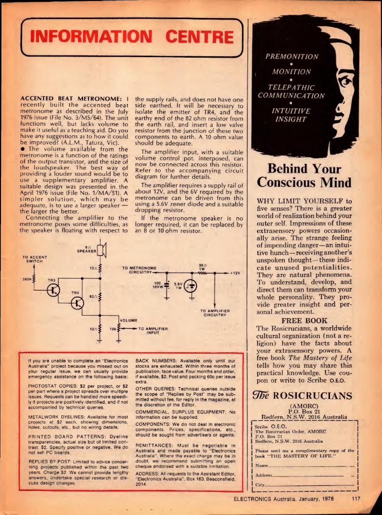
INFORMATION CENTRE
ACCENTED BEAT METRONOME: I recently built the accented beat metronome as described in the July 1976 issue (File No. 3/MS/64). The unit functions well, but lacks volume to make it useful as a teaching aid. Do you have any suggestions as to how it could be improved? (A.L.M., Tatura, Vic). • The volume available from the metronome is a function of the ratings of the output transistor, and the size of the loudspeaker. The best way of providing a louder sound would be to use a supplementary amplifier. A suitable design was presented in, the April 1976 issue (File No. 1/MA/51). A simpler solution, which may be adequate, is to use a larger speaker — the larger the better.
Connecting the amplifier to the metronome poses some difficulties, as the speaker is floating with respect to
the supply rails, and does not have one side earthed. It will be necessary to isolate the emitter of TR4, and the earthy end of the 82 ohm resistor from the earth rail, and insert a low valve resistor from the junction of these two components to earth. A 10 ohm value should be adequate.
The amplifier input, with a suitable volume control pot. interposed, can now be connected across tnis resistor. Refer to the accompanying circuit diagram for further details.
The amplifier requires a supply rail of about 12V, and the 6V required by the metronome can be driven from this using a 5.6V zener diode and a suitable dropping resistor.
If the metronome speaker is no longer required, it can be replaced by an 8 or 10 ohm resistor.
If you are unable to complete an "Electronics Australia” project because you missed out on your regular issue, we can usually provide emergency assistance on the following basis:
PHOTOSTAT COPIES: $2 per project, or $2 per part where a project spreads over multiple issues. Requests can be handled more speedi¬ ly if projects are positively identified, and if not accompanied by technical queries.
METALWORK DYELINES: Available for most projects at $2 each, showing dimensions, holes, cutouts, etc., but no wiring details.
PRINTED BOARD PATTERNS: Dyeline transparencies, actual size but of limited con¬ trast: $2. Specify positive or negative. We do not sell PC boards.
REPLIES BY POST: Limited to advice concer¬ ning projects published within the past two years. Charge $2. We cannot provide lengthy answers, undertake special research or dis¬ cuss design changes.
BACK NUMBERS: Available only until our stocks are exhausted. Within three months of publication, face value. Four months and older, if available, $2. Post and packing 60c per issue extra.
OTHER QUERIES: Technical queries outside the scope of "Replies by Post” may be sub¬ mitted without fee, for reply in the magazine, at the discretion of the Editor.
COMMERCIAL, SURPLUS EQUIPMENT: No information can be supplied.
COMPONENTS: We do not deal in electronic components. Prices, specifications, etc., should be sought from advertisers or agents.
REMITTANCES: Must be negotiable in Australia and made payable to “Electronics Australia”. Where the exact charge may be in doubt, we recommend submitting an open cheque endorsed with a suitable limitation.
ADDRESS: All requests to the Assistant Editor, "Electronics Australia”, Box 163, Beaconsfield, 2014.
PREMONITION
MONITION •
TELEPATHIC COMMUNICATION
•
INTUITIVE INSIGHT
Behind Your Conscious Mind WHY LIMIT YOURSELF to five senses? There is a greater world of realization behind your outer self. Impressions of these extrasensory powers occasion¬ ally arise. The strange feeling of impending danger—an intui¬ tive hunch—receiving another’s unspoken thought—these indi¬ cate unused potentialities. They are natural phenomena. To understand, develop, and direct them can transform your whole personality. They pro¬ vide greater insight and per¬ sonal achievement.
FREE BOOK The Rosicrucians, a worldwide cultural organization (not a re¬ ligion) have the facts about your extrasensory powers. A free book The Mastery of Life tells how you may share this practical knowledge. Use cou¬ pon or write to Scribe O.E.O.
Ufie ROSICRUCIANS (AMORC)
P.O. Box 21 Redfern, N.S.W. 2016 Australia
Scribe O.E.O. The Rosicrucian Order, AMORC P.O. Box 21 Redfern, N.S.W. 2016 Australia
Please send me a complimentary copy of the book “THE MASTERY OF LIFE.”
Name---
Address-—
City-
ELECTRONICS Australia, January, 1978 117

S J ELECTRONICS
P.0. Box 19 Doncaster East 3109. 10 Stafford Court, Doncaster East
Tel. (03) 842 3950 MAIL ORDER KITS
MICRO NUMBER CRUNCHER KIT
MM57109 Interfaces to all systems, just hang on data bus etc. via edge connector NAT. SEMI, circuit 7 IC's on F.G. board. All parts including application notes and
data sheets on MM57109 _PRICE $52.00 POST FREE
_ DIGITAL TACHO KIT 0.5 High 7 Seg. LED display. P.C. board construc¬
tion TTL IC's 10 RPM resolution, will suit 4, 6 & 8
CYL. cars. Accurate calibration. No equip, required.
Circuit & easy instructions included. 4 DIGIT MODEL $48.50 POST FREE
TRAN. IGNITION KIT
ETI MAY 77. Complete with case features c/o switch for std ignition or T.l. Uses stnd ignition coil.
PRICE $28.00 POST FREE
CAR BURGLAR ALARM KIT
E A Nov. 76 Protect your car with a small invest¬ ment Simple to build, light flashes on & off when operating, works on batt volts drop entry & exit delay. 12V ONLY Pos or Neg earth $30.50 POST
FREE
WINDSCREEN WIPER DELAY KIT
Suit 12V cars only, delay 5 to 10 Sec. P C. board, simple to build, full instructions supplied, relay out¬ put not suitable for PERMAG. motors.
$18.75 POST FREE.
TACHO KIT
Suit any 1 M/a meter movement, simple to build. P C board construction, suit beginner or school project, based on I.C chip. $9.50 POST FREE.
DIGITAL STOP WATCH KIT 0.3" high 7 seg. LED display. 6 digits, crystal con¬
trolled .002% accurate, read to 1/100 sec., batt.
operated. P C. board, stop/start can be remote con¬
trolled. suits sports & industrial applications.
$69.00 POST FREE
COMPONENTS SPECIALS
McMurdo flush mount rocker switch DPDT $1 EA. or 10/$7. 30 amp OMRON relay 240V coil $6.50 EA. 1 M/a meters $6.50. 240V neons 50c EA. or 6/$2. 1000MFD 16V PC. electros. 30c EA. or 6/$1.50. 100k pots 30c EA. or 6/S1.50. Varn Cott Spaghetti ass sizes 5x1M $1.50. FND500 display $2 or 6/$11. DL507 display $1.50, 555 IC's 80c or 10/$7, slide sw DPDT 5/$2, MIN trim pots ass 10/$3, 1N914 diodes 10/$1, Resistors 0.5W $3 50/100 of each Red LEDS 10/$3,
$5.00 MIN. Order for components only
POST FREE
Electronics is going digital. This book can help YOU go right along with it.
AN INTRODUCTION TO DIGITAL ELECTRONICS
Available from "Electronics Australia". P.0. Box 163, Beaconsfield. 2014 PRICE $3.60.
COMPUTER CAREERS
Research carried out world wide found that many people with a desire to work in the computer industry had no idea how to enter this profession.
Information Seminars were formulated to meet this need and to explain about computers, the computer industry, job opportunity, training and how to get started in one of the following careers:
Computer Programmer Computer Operator
Phone 870-2656 (Melbourne) or 223-7673 (Adelaide) and ask for an invitation to the next
Seminar.
Marketplace FOR SALE
FREE SEMICONDUCTORS. Send SSAE or 18c stamp for your free pack of 10 Mixed Transistors and Diodes.
Novus Digital Watches. L C D. with seconds, month, date. $39 plus $3 P and P (Cert Mail). Ask for our mail order list of Electronic Kits, Components and Accessories. Special Bulk Buying prices that will save you a packet on all your Electronic Needs. A. E. Cooling. 6 Trimmer Rd. Elizabeth South. SA 5112.
SHORTWAVE LISTENERS AND DXERS: Southern Cross DX Club Inc., GPO Box 336. Adelaide. SA 5001, gives the latest on the medium wave and shortwave scene in our monthly magazine. Details for an 18c stamp, or telephone our representatives — Melbourne: Harry Weatherley (03) 277 2253. Sydney: Jack Buckley (02) 665 1639; Brisbane: Ernie Moore (07) 355 2462 or Adelaide Keith Barton (08) 332 1318.
REPUTABLE ELECTRONIC PARTS outlet in Hong
Kong — If you are seeking reliabile source of quality
supply of ICs. transistors, caps, resistors, digital displays,
buzzers, wide range of AM/FM radio parts, etc. Write to
us now for catalogue list: ProElectro Enterprises. PO
Box 10240, Hong Kong
FUNDAMENTALS OF SOLID STATE It's for anyone who wants to know just a little
bit more about the operation of semiconduc¬
tor devices. $3.00 plus 60c p & p Electronics Australia
Box 163, Beaconsfield, NSW 2014.
DRAKE SW4A SHORT-WAVE RECEIVER. American-
built. good condition. Includes MW directional antenna,
instruction book, crystals, etc. (02) 858-4883.
UNIVERSAL COUNTER TIMER RACAL MODEL
9837. Measures frequency 10Hz-80MHz (AC) DC to
5MHz (DC). Period one microsecond to one sec. Time
interval single and double line one microsecond to 10*
sec. Ration and multiple ration one microsecond to 10s
sec. Totalizing max 5x10® events per sec. Complete
with technical manual and power cord. New with
limited warranty. $600. Ph. 507 0234 work or
630 6830 evening.
DISPLAY ADVERTISEMENTS IN MARKETPLACE are available in sizes from a minimum of 2cm x 1 col rated at $11 per col cm. CLASSIFIED RATES $2 per line per insertion payable in advance. Minimum two lines. CLOSING DATE is six weeks prior to the on-sale date. Issues are on sale the first Monday of each month. ADDRESS all classified orders, copy, enquiries, etc., to: The Advertising Manager, ELEC¬ TRONICS Australia, Box 162, Beaconsfield 2014.
Uf you program microprocessors, 'these sheets are for you
Writing microprocessor programs on blank or plain ruled paper is messy and time consuming. To make the job easier. Electronics Australia has produced these custom-designed programming sheets for use with virtually any microprocessor system. The sheets feature columns for a 4-digit address, up to six digits of instruction code or data, labels, mnemonics, and comments. There is space for 46 lines per sheet, and the sheets are provided with space for program title, date and sheet number. They are also punched for filing in a standard ring binder. All for less than 5 cents per sheet, posted!
PRICED AT $2.00 FOR 50 SHEETS (plus 40c for postage anywhere in Australia)
AUsTRALIA
Available only from Electronics Australia,
57 Regent St., Sydney (P.0. Box 163, Beaconsfield, NSW 2014)
118 ELECTRONICS Australia, January, 1978

COWPER SHEETMETAL WORK FOR
THE ELECTRONICS INDUSTRY
E.A. VIDEO DATA TERMINAL CASES
MINI-SCAMP MICROCOMPUTER
C.S. 108 & 216 Hobby Boxes
108x108x50 + + 216x108x50
Inquiries welcome on
Cases and Panels
Rack Mounting Chassis
Chassis & Covers
Vented Transformer Cases
General Sheetmetal & Welding
COWPER SHEETMETAL &ENG.
11 COWPER STREET GRANVILLE N.SW.2142
PHONE 637 8736 (S.T.D. 02) (A Division of The Star Deha Co. P/L)
VIDEO TECHNICS SHOP 1. BONDI JUNCTION PLAZA. 500 OXFORD ST, BONDI JUNCTION N S W. 2022. TEL: 387-2555.
BRISBALnT4R66!QPURA3B6L1E25VFE BU,LDING- 301 CORONATION DRIVE.
FOCUS INTENSIFIER
Announcing our video focus intensifier to improve the
playback quality of all VCR system video recorders.
This consists of a small circuit board which fits inside
the VCR (Philips etc.)
This circuit detects a change in picture contrast and
inserts a transient — in effect an extra — signal at
this point, which crispens the image. The effect if the
size of this transient is adequate is to recover lost
sharpness, and the principle is indeed very effective
Full fitting instructions included $39.00 + P.P
VIDEO EQUIPMENT—Sony. Akai. Portopacks. Also agents for J.V.C. and
National. All formats and brands Colour and
BW recorders, editors, generators and blank
video tape available. New and used equipment.
Trade and terms. Specials. We have several
BW Porotpacks traded on colour sets.
TUNER VIDEO TECHNICS
COLOUR TV TUNER MODEL HD6709
Record one channel while watching another • No
modification required to existing television sets •
Will record while TV set is off • Usable with any
video recorder BW or Colour with an RF output which
means this tuner allows video recording of TV
programs and playback through aerial input of TV set $295.00 + P.P.
SPECIAL CLOCK TIMERS Can be set to switch equipment up to 4 days ahead.
Starting time
accurate to a second
$195 + P.P.
FRANCHISEES REQUIRED FOR S.A., W.A.. VICTORIA AND TASMANIA
AUDITEC A-SERIES AMPLIFIERS
THE A-SERIES ARE INO-FRILLS BASIC POWER AMPLIFIERS
READY TO CONNECT TO YOUR PREAMPLIFIERS OR MIXER
AND LOUDSPEAKERS
AVAILABLE IN 1 x 100 WATT (1A009, 1A033) 2 x 100 WATT (2A009, 2A033) 1 x 200 WATT (1A027)
AGENTS: MELBOURNE: Zephyr Products. Phone 568 2922 BRISBANE: Delsound Pty Ltd. Phone 229 6155 ADELAIDE: Neil Muller Pty Ltd. Phone 74 1162 BUNDABERG: Bundaberg Hi-Fi. Phone 71 3176 CANBERRA: Musique Boutique. Phone 82 2553 PERTH: Willis Trading Co Pty Ltd. Phone 21 7609 TAMWORTH: Hi-Fi Gallery. Phone 65 7788 MARYBOROUGH (OLD): Keller Electronics. Phone 21 4559 ROCKHAMPTON (OLD): Premier Sound. Phone 28 2701
PARAD,SE (OLD): Beno’s Musical Supplies. Phone 38 1568
WHYALLA (S.A.): Audiolab Sales. Phone 45 7755 DARWIN: Darwin Communications Systems. Phone 85 3184 ALICE SPRINGS: Farmer & Davies Electronics. Phone 52 2967
FOR DESCRIPTIVE LEAFLETS ON THESE AMPLIFIERS CALL, PHONE OR WRITE TO:
AUDITEC AUSTRALIA PTY LTD 10 WAITARA AVENUE, WAITARA, N.S.W. 2077
PHONE: 48 4116
(PACIFIC HIGHWAY SIDE OF WAITARA STATION)
ELECTRONICS Australia, January, 1978 119

Electronics is going digital.
This book can help YOU go
right along with it: Electronic equipment now plays an important role in almost every field of human endeavour. And every day, more and more electronic equipment is "going digital ". Even professional engineers and technicians find it hard to keep pace. In order to understand new developments, you need a good grounding in basic digital concepts, and An Introduction to Digital Electronics can give you that grounding. Tens of thousands of people—engineers, technicians, students and hobbyists—have used the first two editions of this book to find out what the digital revolution is all about. The new third edition has been fully rewritten and updated, to make it of even greater value. The author is Jamieson Rowe, Editor of "Electronics Australia'" magazine, a qualified engineer and experienced technical writer.
PRICE $3.00 Available from newsagents, bookstores, electronic suppliers and also from "Electronics Australia", Box 163, P.O. Beaconsfield 2014. (Post and packing 60c).
Here are the chapter headings: 1. Signals, circuits and logic 2. Basic logic elements 3. Logic circuit "families'' 4. Logic convention and laws 5. Logic design: theory 6. Logic design: practice 7. Numbers, data & codes 8. The flipflop family 9. Flipflops in registers
10. Flipflops in counters 11. Encoding and decoding 12. Basic readout devices 1 3. Multiplexing 14. Binary arithmetic 1 5. Arithmetic circuits 16. Timing & control Glossary of terms
You don't need any previous knowledge of digital electronics—the book starts you right from scratch, and covers all of the basic concepts you need.
SUBSCRIPTION SERVICE Subscription Rates
$A 77.00 per year within Australia. SA20.00 per year elsewhere.
Make sure you receive every copy of the magazine by ordering it from your newsagent or the publisher. For publisher subscriptions post this coupon, with your remittance, to Electronics Australia Subscription Dept., John Fairfax & Sons Ltd, GPO Box 506, Sydney, 2001. Subscription will start with first available issue.
Name.....
Address.
Postcode. Enclosed is.for.years
Advertising Index A & R Soanar Group 87
Ace Radio 92
All Electronic Components 96
Adcola Products Pty Ltd 112
Applied Technology Pty Ltd 70
Audio Engineers Pty Ltd 102
Audio Telex Communications Pty Ltd 84
Audiosound 105
Auditec Australia 119
Australian Government Recruiting 41
BASF 6
Butterworth Pty Ltd 108
Bright Star Crystals Pty Ltd 89
B.S.R. Hi-Fi 106
Classic Radio 28
Computer Art and Education 67, 73
Convoy International Pty Ltd 30
Cowper Sheetmetal & Engineering 119
Davred Electronics 94
Deitch Bros 116
Delta Base CB Radio 84
Dick Smith Electronics Group 34. 35. 47. 52.
65. 76. 77. 92. 113
Development Systems International 118
Electrocraft Pty Ltd 78
Elmeasco Instruments Pty Ltd 16
Ferguson Transformers Pty Ltd 64
Francis Lord Mfg P/L 98
Haco Distributing Agencies OBC
Hagemeyer (Aust.) IBC. facing 32
Harman Australia Pty Ltd 11. 26. 31. 107
Huppert C. & Co. 82
International Correspondence Schools 55
Instant Component Service 22, 23
Lafayette Electronics 86
Lanthur Electronics 113
Laser Electronics Pty Ltd 75
Melody School of Music 7
Mobile One 78
McGills Newsagency Pty Ltd 109
Nomis Electronics Pty Ltd 58
Parameters Pty Ltd 45
Paris Radio Electronics 75
Philips Elcoma 2
RCS Radio 61
Radio Despatch Service 99
Radio Parts Group 80
Rosicruscians 117
Rod Irving Electronics 91
S.M. Electronics 118
Sabtronics International facing 89
Sangster E 75
Scalar Industries Pty Ltd 82
Sheridan Electronics 114
Sony Kemtron Pty Ltd IFC
Stotts Technical College 21
Vicom International 90
Video Technics 119
Warburton Franki Ltd 112, facing 88
Wedderspoon W.C. 24, facing 33
Willis Trading Co. Pty Ltd 84
Wireless Institute of Australia 93
Zephyr Products 104
120 ELECTRONICS Australia, January, 1978

ojAtri lO<
+~
t
JVC’s Quartz-Locked Turntable has perfect pitch,
and that’s the musical truth. Fifty years of continuous devo¬
tion to recording and reproduction techniques has taught us how elusive is the goal of total musical realism.
And yet today, the JVC Audio Engineering Research Laboratory— probably the largest of its kind in the world—has moved even closer to achieving this goal. You see it here in the JVC QL-10 Quartz-Locked Direct Drive Turntable.
The musical truth? The QL-10 is a direct drive turntable whose platter revolves at the exact speeds of 33y3 and 45rpm. It operates on the same principle as a quality quartz timepiece. Its servo control system
works from a quartz oscillator, with the steady, accurate oscillating fre¬ quency locking the revolution speed of the turntable platter. The result is obvious: Complete speed accuracy.
But there’s more from this magnificent turntable. It features the worlds first super-precision pitch control. This permits pitch control of up to ±6Hz from the international standard of 440Hz for note a’. And this in steps of 1Hz each without unlocking the quartz-locked servo control system.
These features, plus the posi¬ tive/negative servo control, digital speed indicator and coreless DC
servo motor, have all been created for a single objective: The accurate reproduction of the original musical performance stored in the disc record.
That’s the musical truth. In the QL-10 and other fine high fidelity products, JVC continues to dedicate its total resources to bring it out in
„. all program sources. You / can count on it.
JVC the right choice
For details on JVC Hi Fi Equipment, write to: JVC Advisory Service, P.O. Box 49, Kensington. N.S.W. 2033.

Technics MK2 Series turntables. Built by perfectionists for perfectionists.
*
T77.11
In 1970 Technics introduced the ultimate turntable drive method ... the direct-drive principle. In developing phases our first direct-drive turntable was succeeded by a whole family of them. A major innovation was the quartz phase- locked servo electronics featured in the SP10 MK2, enabling great speed accuracy to be attained (±0.002%). Its enormous torque and super fast start/stop action make it the choice of top broadcasting stations both in Australia and the rest of the world. Two newly released Technics models—the SL1300 MK2 and SL1400MK2 (automatic and semi-automatic respectively)— are totally quartz controlled drive turntables. You won't find any belts, nears or idlers in these. But
you will find our lowest wow and flutter ever (0.025% WRMS) and inaudible rumble (— 73dB DIN B). Both feature a pitch control of ±9.9% on normal turntable speeds that can be obtained simply by the push of a button. The pitch chosen is displayed in digital form by a LED readout. All controls are located on the front panel of the turntables and can be operated even with the dust cover down. Technics MK2 series of turntables are just a few components in the new Pro. Series from Technics. Reliable as they are precise.
Technics WARRANTY
JC AND SERVICE iCKlBY HACO
hi-fi For a National Technics catalogue, please write to: National Technics Advisory Service, P.O. Box 49, Kensington, N.S.W. 2033