ELECTRONIC SYSTEM DESIGN - Yasser Mostafa Kadah
20
ELECTRONIC SYSTEM DESIGN PART 2: ANALOG FILTERS Prof. Yasser Mostafa Kadah 1
-
Upload
khangminh22 -
Category
Documents
-
view
2 -
download
0
Transcript of ELECTRONIC SYSTEM DESIGN - Yasser Mostafa Kadah
ELECTRONIC SYSTEM DESIGN
PART 2: ANALOG FILTERS
Prof. Yasser Mostafa Kadah
1
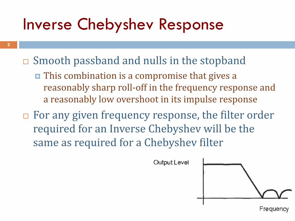
Inverse Chebyshev Response 2
Smooth passband and nulls in the stopband
This combination is a compromise that gives a reasonably sharp roll-off in the frequency response and a reasonably low overshoot in its impulse response
For any given frequency response, the filter order required for an Inverse Chebyshev will be the same as required for a Chebyshev filter
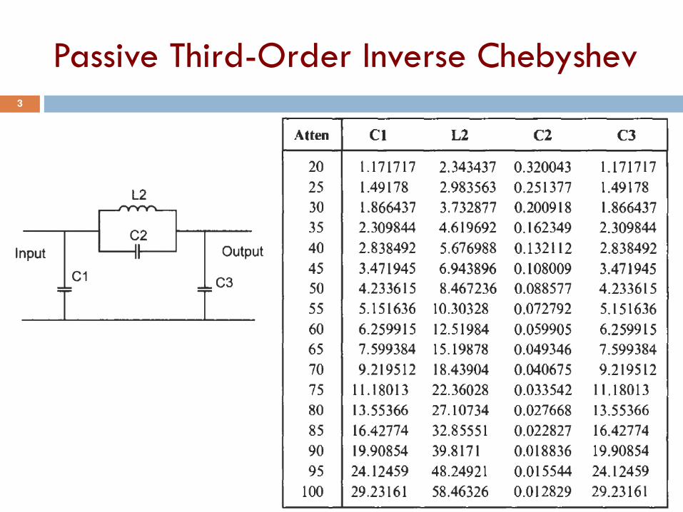
Passive Third-Order Inverse Chebyshev 3
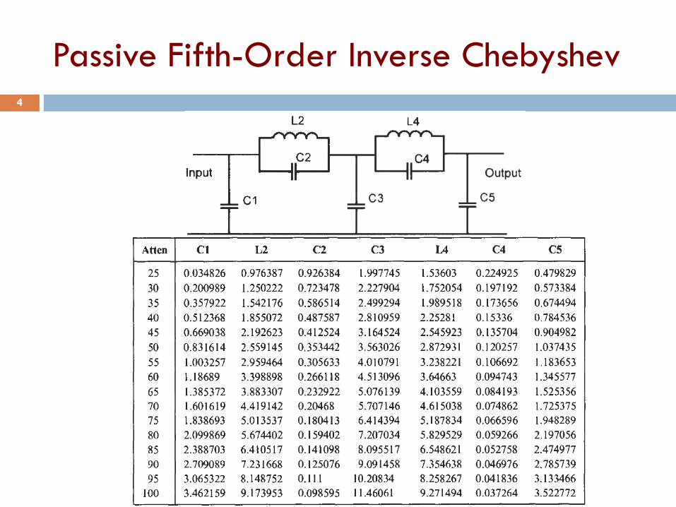
Passive Fifth-Order Inverse Chebyshev 4
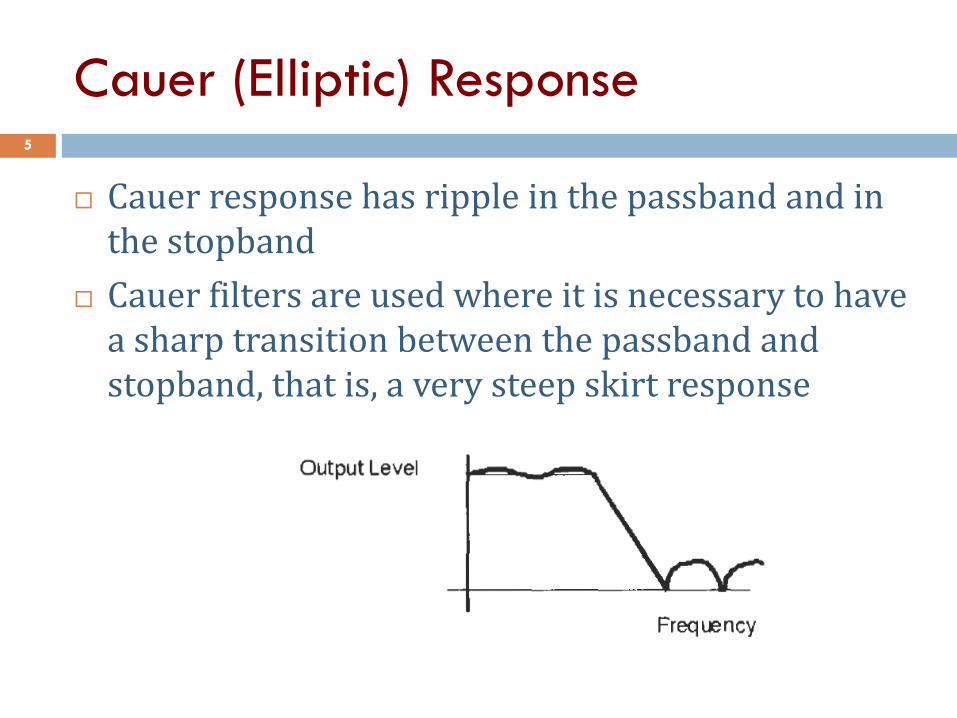
Cauer (Elliptic) Response 5
Cauer response has ripple in the passband and in the stopband
Cauer filters are used where it is necessary to have a sharp transition between the passband and stopband, that is, a very steep skirt response
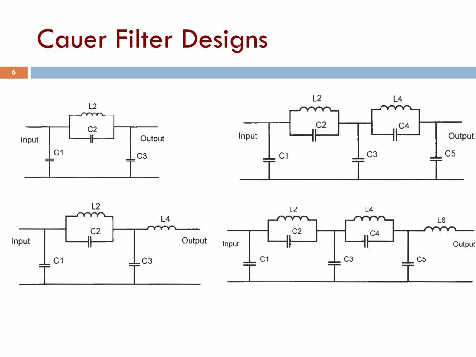
Cauer Filter Designs 6
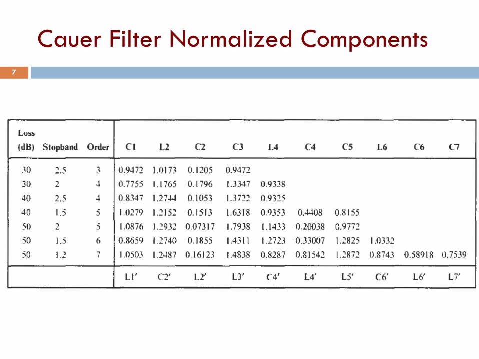
Cauer Filter Normalized Components 7
Highpass Filter Design 8
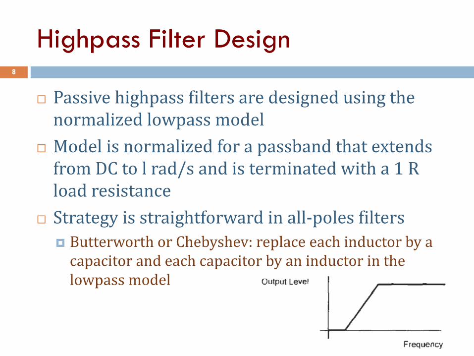
Passive highpass filters are designed using the normalized lowpass model
Model is normalized for a passband that extends from DC to l rad/s and is terminated with a 1 R load resistance
Strategy is straightforward in all-poles filters
Butterworth or Chebyshev: replace each inductor by a capacitor and each capacitor by an inductor in the lowpass model
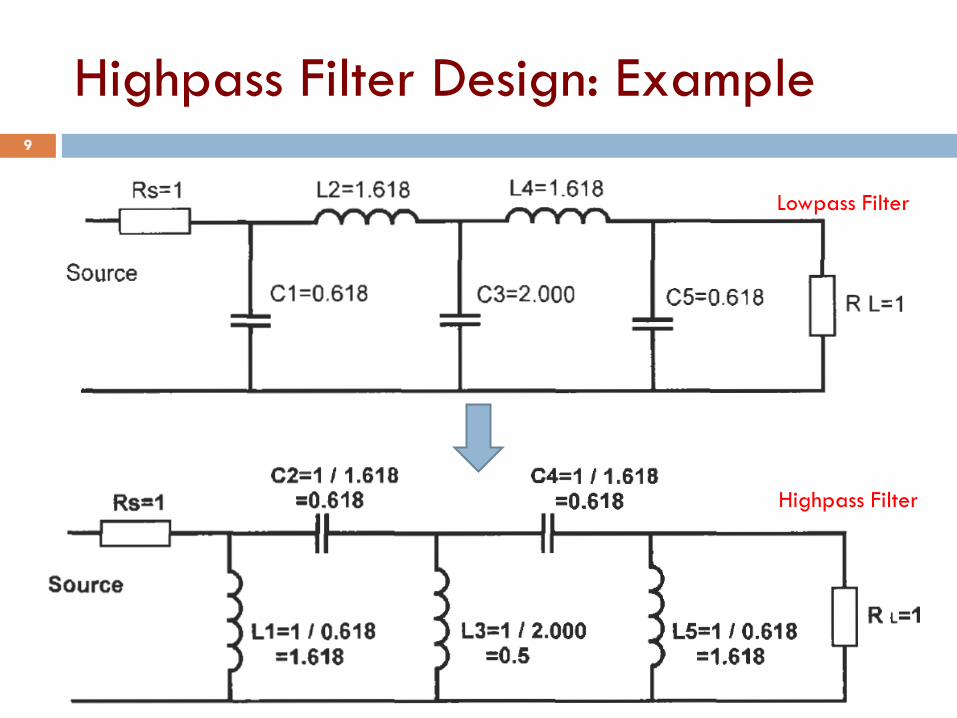
Highpass Filter Design: Example 9
Lowpass Filter
Highpass Filter
Highpass Filter Component
Denormalization 10
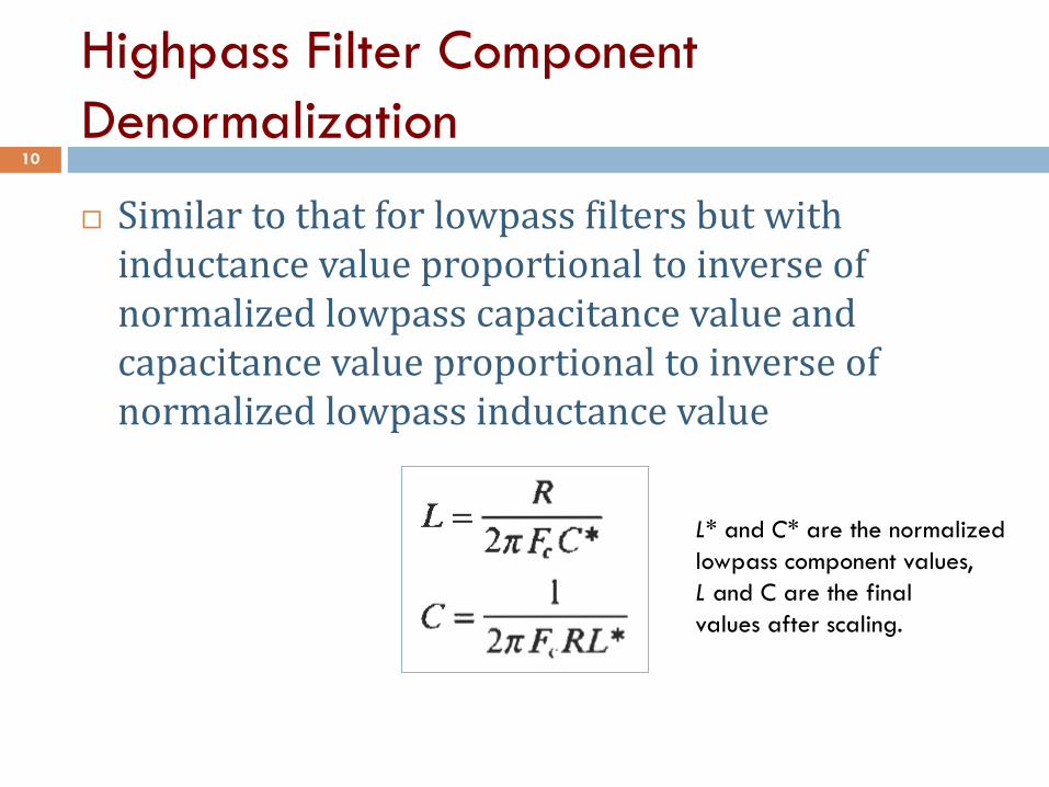
Similar to that for lowpass filters but with inductance value proportional to inverse of normalized lowpass capacitance value and capacitance value proportional to inverse of normalized lowpass inductance value
L* and C* are the normalized
lowpass component values,
L and C are the final
values after scaling.
Bandpass Filters 11
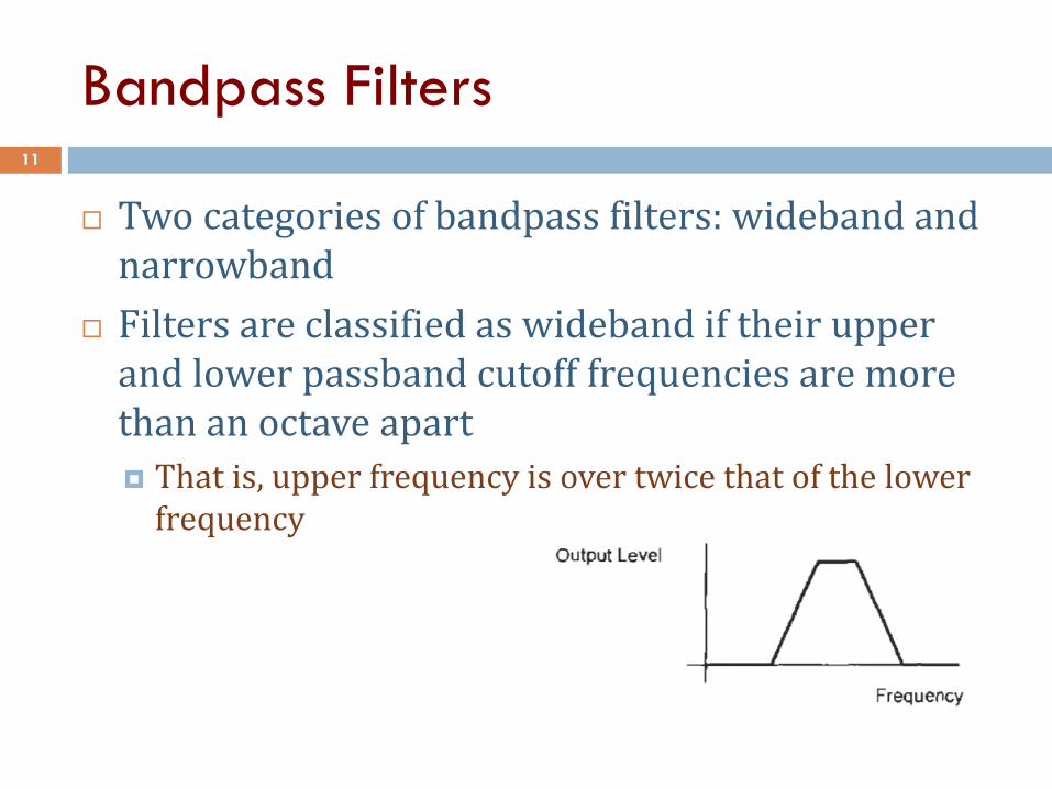
Two categories of bandpass filters: wideband and narrowband
Filters are classified as wideband if their upper and lower passband cutoff frequencies are more than an octave apart
That is, upper frequency is over twice that of the lower frequency
Lowpass to Bandpass Transformation 12
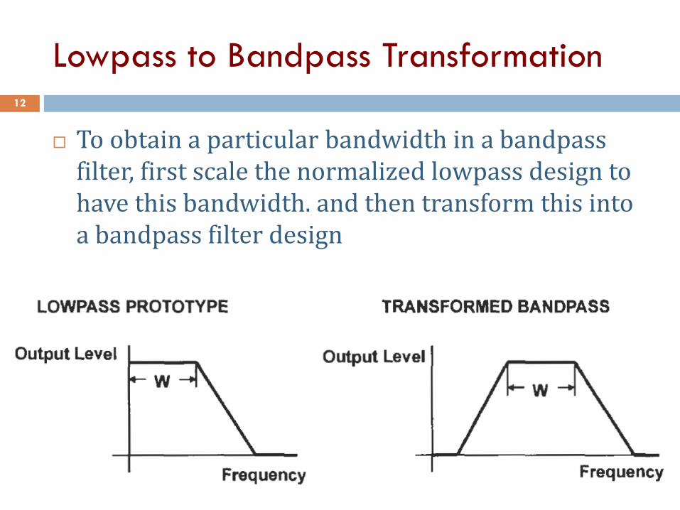
To obtain a particular bandwidth in a bandpass filter, first scale the normalized lowpass design to have this bandwidth. and then transform this into a bandpass filter design
Lowpass to Bandpass Transformation 13
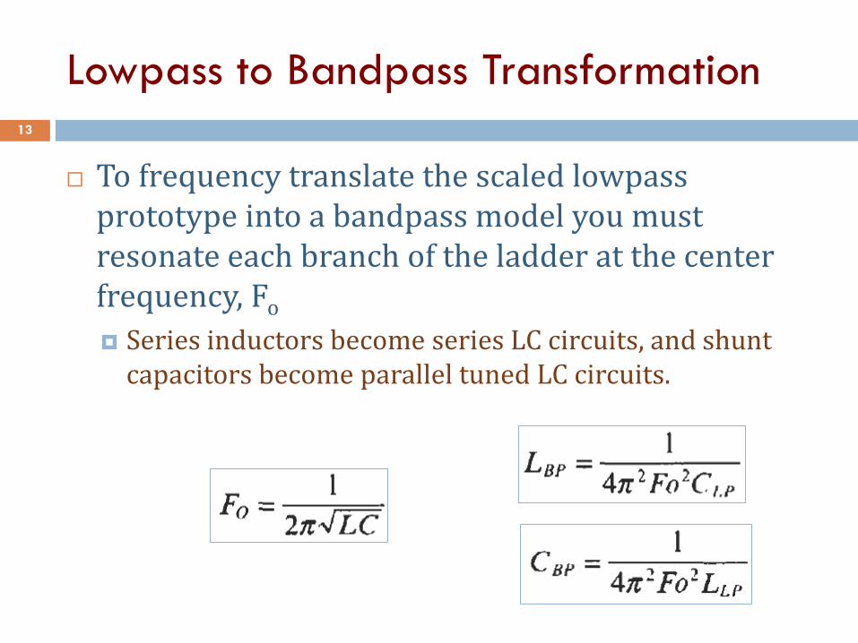
To frequency translate the scaled lowpass prototype into a bandpass model you must resonate each branch of the ladder at the center frequency, Fo
Series inductors become series LC circuits, and shunt capacitors become parallel tuned LC circuits.
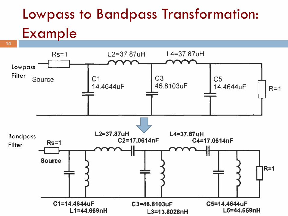
Lowpass to Bandpass Transformation:
Example 14
Lowpass
Filter
Bandpass
Filter
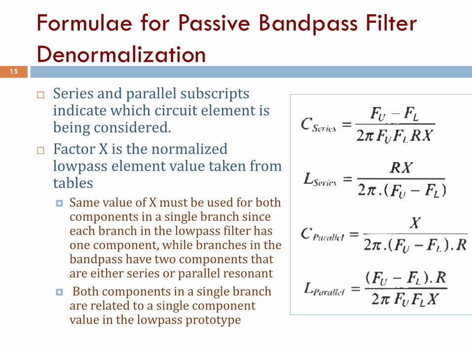
Formulae for Passive Bandpass Filter
Denormalization 15
Series and parallel subscripts indicate which circuit element is being considered.
Factor X is the normalized lowpass element value taken from tables Same value of X must be used for both
components in a single branch since each branch in the lowpass filter has one component, while branches in the bandpass have two components that are either series or parallel resonant
Both components in a single branch are related to a single component value in the lowpass prototype
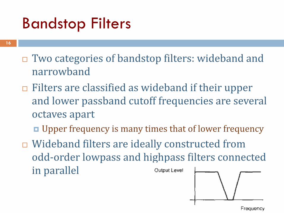
Bandstop Filters 16
Two categories of bandstop filters: wideband and narrowband
Filters are classified as wideband if their upper and lower passband cutoff frequencies are several octaves apart
Upper frequency is many times that of lower frequency
Wideband filters are ideally constructed from odd-order lowpass and highpass filters connected in parallel
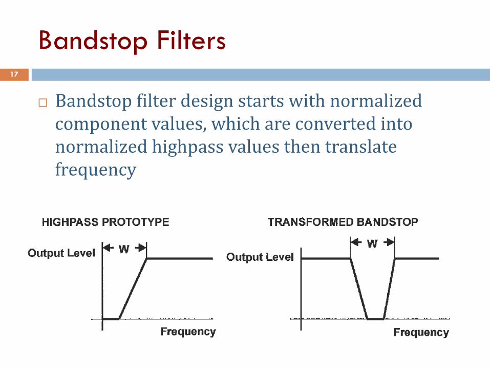
Bandstop Filters 17
Bandstop filter design starts with normalized component values, which are converted into normalized highpass values then translate frequency
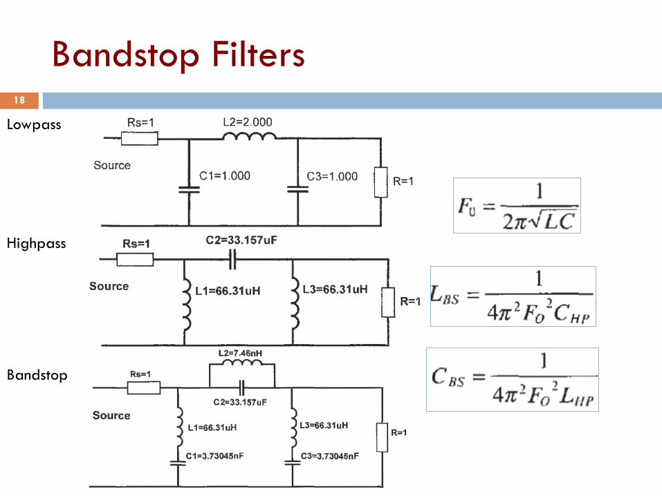
Bandstop Filters 18
Lowpass
Highpass
Bandstop
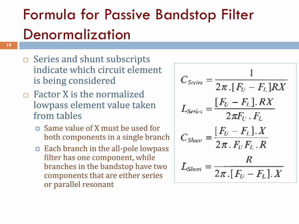
Formula for Passive Bandstop Filter
Denormalization 19
Series and shunt subscripts indicate which circuit element is being considered
Factor X is the normalized lowpass element value taken from tables Same value of X must be used for
both components in a single branch
Each branch in the all-pole lowpass filter has one component, while branches in the bandstop have two components that are either series or parallel resonant
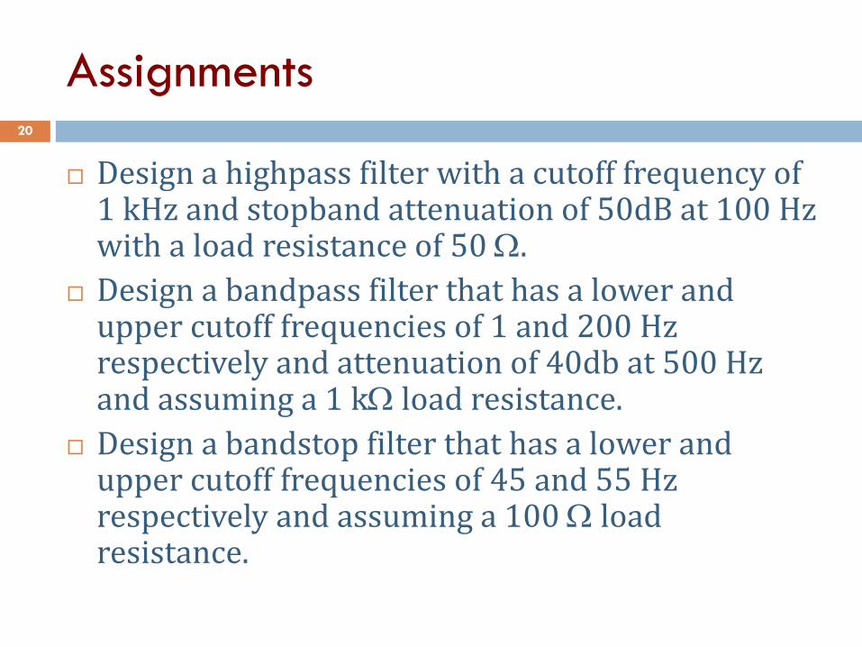
Assignments
Design a highpass filter with a cutoff frequency of 1 kHz and stopband attenuation of 50dB at 100 Hz with a load resistance of 50 .
Design a bandpass filter that has a lower and upper cutoff frequencies of 1 and 200 Hz respectively and attenuation of 40db at 500 Hz and assuming a 1 k load resistance.
Design a bandstop filter that has a lower and upper cutoff frequencies of 45 and 55 Hz respectively and assuming a 100 load resistance.
20