Electronic Flight Bag (EFB) - Advisory Circular
33
AC 98-7-1(Rev 0) 1 17 September 2018 AC 98-7-1(Rev 0) 17 September 2018 Advisory Circular ELECTRONIC FLIGHT BAG (EFB) GENERAL ............................................................................................................ 1 PURPOSE ............................................................................................................ 1 APPLICABILITY ................................................................................................... 1 RELATED REGULATIONS .................................................................................. 1 RELATED ADVISORY CIRCULARS.................................................................... 1 CANCELLATION .................................................................................................. 2 EFFECTIVE DATE ............................................................................................... 2 OTHER REFERENCES ....................................................................................... 2 DEFINITIONS ....................................................................................................... 3 1 BACKGROUND................................................................................................. 4 2 TYPES OF EFB................................................................................................. 4 3 EFB HARDWARE ............................................................................................. 5 4 EFB FUNCTIONS ........................................................................................... 10 5 GUIDANCE FOR EFB SOFTWARE APPLICATIONS .................................... 13 6 HUMAN FACTORS ......................................................................................... 13 7 CREW OPERATING PROCEDURES ............................................................. 13 8 RISK ASSESSMENT ...................................................................................... 14 9 FLIGHT CREW TRAINING ............................................................................. 15 10 EFB MANAGEMENT ................................................................................... 15 11 OPERATIONAL EVALUATION PROCESS ................................................. 16 APPENDIX A PERFORMANCE (TAKE-OFF, LANDING) AND MASS & BALANCE .............................................................................................. 18 APPENDIX B ELECTRONIC CHARTING ................................................... 24 APPENDIX C AIRCRAFT EXTERIOR VIDEO SURVEILLANCE ................ 25 APPENDIX D AIRPORT MOVING MAP (AMM) .......................................... 26 APPENDIX E EFB POLICY AND PROCEDURES MANUAL ...................... 27 APPENDIX F EVALUATION CHECKLIST .................................................. 28 GENERAL Advisory Circulars (ACs) are issued by the Director-General of Civil Aviation (DGCA) from time to time to provide practical guidance or certainty in respect of the statutory requirements for aviation safety. ACs contain information about standards, practices and procedures acceptable to CAAS. An AC may be used, in accordance with section 3C of the Air Navigation Act (Cap. 6) (ANA), to demonstrate compliance with a statutory requirement. The revision number of the AC is indicated in parenthesis in the suffix of the AC number. PURPOSE This AC provides to demonstrate compliance with the requirements regarding, and information related to an application for, an approval for operations with Electronic Flight Bag (EFB). APPLICABILITY This AC is applicable for the operator seeking an approval for operations with EFB. RELATED REGULATIONS This AC relates specifically to Division 7 of ANR-98. RELATED ADVISORY CIRCULARS AC 98-1-1 Application for an Approval to Conduct a Special Operation AC 121-1-2 Use of Portable Electronic Devices onboard Aircraft
-
Upload
khangminh22 -
Category
Documents
-
view
0 -
download
0
Transcript of Electronic Flight Bag (EFB) - Advisory Circular

AC 98-7-1(Rev 0) 1 17 September 2018
AC 98-7-1(Rev 0) 17 September 2018
Advisory Circular
ELECTRONIC FLIGHT BAG (EFB)
GENERAL ............................................................................................................ 1PURPOSE ............................................................................................................ 1APPLICABILITY ................................................................................................... 1RELATED REGULATIONS .................................................................................. 1RELATED ADVISORY CIRCULARS .................................................................... 1CANCELLATION .................................................................................................. 2EFFECTIVE DATE ............................................................................................... 2OTHER REFERENCES ....................................................................................... 2DEFINITIONS ....................................................................................................... 31 BACKGROUND ................................................................................................. 42 TYPES OF EFB ................................................................................................. 43 EFB HARDWARE ............................................................................................. 54 EFB FUNCTIONS ........................................................................................... 105 GUIDANCE FOR EFB SOFTWARE APPLICATIONS .................................... 136 HUMAN FACTORS ......................................................................................... 137 CREW OPERATING PROCEDURES ............................................................. 138 RISK ASSESSMENT ...................................................................................... 149 FLIGHT CREW TRAINING ............................................................................. 1510 EFB MANAGEMENT ................................................................................... 1511 OPERATIONAL EVALUATION PROCESS ................................................. 16APPENDIX A PERFORMANCE (TAKE-OFF, LANDING) AND MASS & BALANCE .............................................................................................. 18APPENDIX B ELECTRONIC CHARTING ................................................... 24APPENDIX C AIRCRAFT EXTERIOR VIDEO SURVEILLANCE ................ 25APPENDIX D AIRPORT MOVING MAP (AMM) .......................................... 26APPENDIX E EFB POLICY AND PROCEDURES MANUAL ...................... 27APPENDIX F EVALUATION CHECKLIST .................................................. 28
GENERAL Advisory Circulars (ACs) are issued by the Director-General of Civil Aviation (DGCA) from time to time to provide practical guidance or certainty in respect of the statutory requirements for aviation safety. ACs contain information about standards, practices and procedures acceptable to CAAS. An AC may be used, in accordance with section 3C of the Air Navigation Act (Cap. 6) (ANA), to demonstrate compliance with a statutory requirement. The revision number of the AC is indicated in parenthesis in the suffix of the AC number. PURPOSE This AC provides to demonstrate compliance with the requirements regarding, and information related to an application for, an approval for operations with Electronic Flight Bag (EFB). APPLICABILITY This AC is applicable for the operator seeking an approval for operations with EFB. RELATED REGULATIONS This AC relates specifically to Division 7 of ANR-98. RELATED ADVISORY CIRCULARS AC 98-1-1 Application for an Approval to Conduct a Special Operation AC 121-1-2 Use of Portable Electronic Devices onboard Aircraft

AC 98-7-1(Rev 0) 2 17 September 2018
CANCELLATION This AC supersedes AC AOC-16. EFFECTIVE DATE This AC is effective from 1 October 2018. OTHER REFERENCES ICAO Doc 10020 Manual of Electronic Flight Bags (EFBs) Hong Kong CAD 562 Electronic Flight Bag (EFB) FAA AC 120-76D Authorization for use of electronic flight bags EASA AMC 20-25 Airworthiness and operational consideration for electronic flight bags
(EFBs)

AC 98-7-1(Rev 0) 3 17 September 2018
DEFINITIONS
AID (Aircraft Interface Device). A device or function that provides an interface between the EFBs and other aircraft systems which protects the aircraft systems and related functions from the undesired effects from non-certified equipment and related functions. AMM (Airport Moving Map). A software application displaying airport maps and using a navigation source to depict the aircraft current position on this map while on ground. Critical phases of flight. Critical phases of flight, as defined by CAAS AC AOC-7(5), includes all ground operations involving taxi, takeoff and landing; all other flight operations conducted below 10,000 feet; and when handling abnormal situations. Data connectivity for EFB systems. Data connectivity for EFB system supports either uni- or bi-directional data communication between the EFB and other aircraft systems (e.g. avionics). Direct interconnectivity between EFBs or direct connectivity between EFBs and ground systems are not covered by this definition. EMI/EMC. Electromagnetic Interference / Electromagnetic Compatibility EFB administrator. An EFB administrator is a person appointed by the operator, held responsible for the administration of the EFB system within the company. The EFB administrator is the primary link between the operator and the EFB system and software suppliers. EFB host platform. When considering an EFB system, the EFB host platform is the equipment (i.e. hardware) in which the computing capabilities and basic software (e.g. operating system, input/output software) reside. EFB risk assessment and mitigation. A process that considers an EFB system, its software applications, and its integration inside a specific aircraft, to identify the potential malfunctions and failure scenarios; analyse their operational repercussions; and, if necessary, propose mitigation means. EFB software application. Software installed on an EFB system that allows specific operational functionality. EFB system. An EFB system comprises the hardware (including any battery, connectivity provision, I/O devices) and software (including databases) needed to support the intended EFB function(s). EFB system supplier. The company responsible for developing, or for having developed, the EFB system or part of it. The EFB system supplier is not necessarily a host platform or aircraft manufacturer. Minor failure conditions. Failure conditions which would not significantly reduce aircraft safety, and which involve crew actions that are well within their capabilities. Minor failure conditions may include, for example, a slight reduction in safety margins or functional capabilities, a slight increase in crew workload, such as routine flight plan changes, or some physical discomfort to passengers or cabin crew. Mounting device. An aircraft certified part which secures portable or installed EFB, and/or its system components

AC 98-7-1(Rev 0) 4 17 September 2018
GUI. Graphical User Interface HMI. Human Machine Interface Installed resources. Hardware/software installed in accordance with airworthiness requirements Independent EFB platforms. Multiple EFBs that are designed in such a way that no single failure makes all of them unavailable Portable Electronic Device (PED). PEDs are typically consumer electronic devices, which have functional capability for communications, entertainment, data processing, and/or utility. There are two basic categories of PEDs – those with and those without intentional transmitting capability SCAP. Standard Computerised Aircraft Performance STC. Supplemental Type Certificate Viewable Stowage. A device that is secured either on the flight crew (e.g. kneeboard) or in/to an existing aircraft part (e.g. suction cups) with the intent to hold a portable EFB (e.g. a tablet) viewable to the pilot at her/his duty station. The device is not necessarily part of the certified aircraft configuration.
1 BACKGROUND 1.1 An Electronic Flight Bag or EFB is defined by ICAO as “An electronic information
system, comprised of equipment and applications for flight crew, which allows for storing, updating, displaying and processing of EFB functions to support flight operations or duties.”
1.2 This AC provides the guidance to understand the intent and objectives of the
requirements for the performance of operational evaluation of the EFB system and its commonly used functions; and, where appropriate, enables the operator to seek the grant operational approval from CAAS.
1.3 This AC does not cover EFB Airworthiness Certification issues. 2 TYPES OF EFB 2.1 EFBs can be either portable EFBs or installed EFBs. 2.2 Portable EFBs are considered PEDs and are not integral to the aircraft configurations.
They generally have self-contained power and may rely on data connectivity to achieve full functionality. Modifications to the aircraft to use portable EFBs require the appropriate airworthiness approval.
2.3 Installed EFBs are integrated into the aircraft and are subject to airworthiness
requirements. The approval of these EFBs is included in the aircraft type certificate (TC) or the supplemental type certificate (STC).

AC 98-7-1(Rev 0) 5 17 September 2018
3 EFB HARDWARE 3.1 Portable EFB 3.1.1 A portable EFB provides a portable host platform, although when used on the flight
deck, it is not part of the certified aircraft configuration. Portable EFBs can be used either as hand-held equipment or secured in a mounting device / viewable stowage solution.
3.1.2 The following are complementary characteristics of a Portable EFB:
(a) A portable EFB is a portable electronic device (PED). (b) It can be operated inside and outside the aircraft. (c) The mass, dimensions, shape, and position of the portable EFB should not
compromise flight safety. (d) A portable EFB may connect to aircraft power, data ports (wired or wireless)
and installed antennas provided those connections have been installed in a certified and approved manner.
(e) If secured with viewable stowage, the portable EFB should be easily removable without the use of tools by the flight crew and the attachment or removal does not constitute a maintenance action.
(f) Portable EFBs may be used in all phases of the flight if secured to a certified mount or securely attached to a viewable stowage device in a manner which allows its normal use. EFBs not meeting this requirement, should be stowed during critical phases of flight.
(g) The portable EFB and its operating components should be easily accessible by the flight crew members in the flight compartment.
3.1.3 Physical characteristics. The size and practicality of the EFB should be evaluated
as some devices may prove to be cumbersome for normal use on a flight deck. 3.1.4 Readability. The EFB data should be legible under the full range of lighting conditions
expected on the flight deck, including direct sunlight. 3.1.5 Environmental. The EFB has to be operable within the foreseeable cockpit operating
conditions including foreseeable high/low temperatures, and after rapid depressurisation if the EFB is intended for use in such an event.
3.1.6 Basic non-interference testing 3.1.6.1 EFB devices intended to be used in all phases of flight should demonstrate that they
meet environmental standards for radiated emissions for equipment operating in an airborne environment. Installed EFBs will be required to demonstrate non-interference with other aircraft systems as part of their certification process
3.1.6.2 As previously noted, portable EFBs are considered to be PEDs. As such, any reference
to PEDs in this section is also applicable to portable EFBs.

AC 98-7-1(Rev 0) 6 17 September 2018
3.1.6.3 To operate a portable EFB during flight, the user/operator is responsible for ensuring
that the EFB will not interfere in any way with the operation of aircraft equipment. The following methods are means to test portable EFBs that are to remain powered (including being in standby mode) throughout the flight, to ensure that they will not electromagnetically interfere with the operation of aircraft equipment.
Method 1: (a) Step 1 is an electromagnetic interference (EMI) test using RTCA/DO-160,
Section 21, Category M. An EFB vendor or other source can conduct this test for an EFB user/operator. An evaluation of the results of the RTCA/DO-160 EMI test can be used to determine if an adequate margin exists between the EMI emitted by the EFB and the interference susceptibility threshold of aircraft equipment. If this step determines that adequate margins exist for all interference, then the test is complete. However, if this step identifies inadequate margins for interference, or either front door or back door susceptibility, then step 2 testing must be conducted.
(b) Step 2 non-interference testing is a complete test in each aircraft using
standard industry practices. This should be done to the extent normally considered acceptable for non-interference testing of a portable EFB or PED in an aircraft for all phases of flight. Credit may be given to other aircraft of the same make and model equipped with the same avionics as the one tested.
Method 2: (a) As an alternative, Step 2 of Method 1 can be used directly to determine non-
interference of the EFB. 3.1.7 Additional Testing for Transmitting Portable EFBs and Other Transmitting PEDs 3.1.7.1 To activate the transmitting function of a portable EFB or other PED during flight in
conditions other than those that may be already certified at aircraft level (e.g. tolerance to specific transmitting PED models) and hence documented in the aircraft flight manual or equivalent, the user/operator is responsible to ensure that the device will not interfere with the operation of the aircraft equipment in any way. The following is an accepted method to test portable EFBs and PEDs that are to remain powered (including being in standby mode) during flight. This test consists of two separate test requirements:
(a) Test Requirement 1. Each model of the device should have an assessment of
potential electro-magnetic interferences (EMI) based on a representative sample of the frequency and power output of it. This EMI assessment should follow a protocol such as the applicable processes set forth in RTCA/DO-294, Guidance on Allowing Transmitting Portable Electronic Devices (T-PEDs) on Aircraft. This frequency assessment must confirm that no interference of aircraft equipment will occur as a result of intentional transmissions from these devices.
(b) Test Requirement 2. Once an EMI assessment has determined that there will
be no interference from the EFB/PED’s intentional transmissions, test each model of the device while powered but not deliberately transmitting, using the basic non-interference testing methodology. Basic non-interference testing should be conducted with and without the transmit function being operative. The position of the transmitting device is critical to non-interference testing;

AC 98-7-1(Rev 0) 7 17 September 2018
hence locations of the EFB and of the transmitter (if applicable) should be clearly defined and adhered to.
Note: For information and guidance on Use of Portable Electronic Devices On-board
Aircraft, refer to CAAS AC 121-1-2. 3.1.8 Power Supply 3.1.8.1 The operator should ensure that power to the EFB, either by battery and/or supplied
power, is available to the extent required for the intended operation. 3.1.8.2 If an operator intends to solely use battery power for the EFB or in the instance of a
power source failure; the EFB discharge rates, battery conservation techniques and minimum EFB charge rates for dispatch should be documented.
3.1.8.3 If the EFB hosts functions essential to safe operation of flight, one of the following must
be available before a flight departs:
(a) an established procedure to recharge the battery from aircraft power during flight operations
(b) a battery or batteries with a combined useful battery life to ensure operational availability during taxi and flight operations to include diversions and reasonable delays considering duration of flight
(c) an acceptable mitigation strategy providing availability of aeronautical information for the entire duration of flight authorised by the Principal Operations Inspector (POI)
3.1.8.4 Connection of EFB power provisions to a non-essential, or to the least critical power
bus, is recommended, so failure or malfunction of the EFB, or power supply, will not affect safe operation of aircraft critical or essential systems.
3.1.8.5 The power source needs to be suitable for the device. The power source may be a
dedicated power source or a general-purpose source already fitted. 3.1.8.6 Means to turn off the power source, other than a circuit breaker, should be reachable
by the pilot when strapped in the normal seated position (e g. access to unplug the EFB or a separate hardware or software switch clearly labelled for the power source, etc.).
3.1.9 Batteries 3.1.9.1 The operator should ensure that the batteries in a portable EFB are compliant with the
applicable Standards for use in an aircraft. 3.1.9.2 The standards referred to in the following subparagraphs are currently accepted
editions: (a) United Nations (UN) Transportation Regulations. UN ST/SG/AC.10/11/Rev.5,
Recommendations on the Transport of Dangerous Goods-Manual of Tests and Criteria.
(b) Underwriters Laboratory (UL). UL 1642, Lithium Batteries; UL 2054, Household and Commercial Batteries; and UL 60950-1,3 Information Technology Equipment - Safety. NOTE: Compliance with UL 2054 indicates compliance with UL 1642.

AC 98-7-1(Rev 0) 8 17 September 2018
(c) International Electrotechnical Commission (IEC). International Standard IEC 62133, Secondary cells and batteries containing alkaline or other non-acid electrolytes – Safety requirements for portable sealed secondary cells, and for batteries made from them, for use in portable applications.
(d) RTCA/DO-311, Minimum Operational Performance Standards for Rechargeable Lithium Battery Systems.
3.1.9.3 An appropriate airworthiness testing standard such as RTCA/DO-311 can be used to
address concerns regarding overcharging, over-discharging, and the flammability of cell components. RTCA/DO-311 is intended to test permanently installed equipment; however, these tests are applicable and sufficient to test EFB rechargeable lithium-type batteries.
3.1.9.4 The operator should consider introducing procedures to handle thermal runaways or
similar battery malfunctions potentially caused by EFB batteries (e.g. lithium-based batteries). At least the following issues should be addressed: (a) risk of leakage; (b) safe storage of spares including the potential for short circuit; and (c) hazards due to on-board continuous charging of the device, including battery
overheat. 3.1.10 Cabling. The operator needs to ensure that any cabling attached to the EFB, whether
in the dedicated mounting or when handheld, does not present an operational or safety hazard. This may be achieved using cable tether straps / clips.
3.1.11 Temperature rise. Operating the proposed EFB device may generate heat. The
placement of the EFB should allow sufficient airflow around the unit, if required. 3.1.12 Data Connectivity between EFBs. If two or more EFBs on the flight deck are
connected to each other, then the operator should demonstrate that this connection does not negatively influence otherwise independent EFB platforms.
3.1.13 Data Connectivity to aircraft systems 3.1.13.1 EFB data connectivity should be validated and verified to ensure non-
interference and isolation from certified aircraft systems during data transmission and reception.
3.1.13.2 Certified aircraft systems should be protected from adverse effects of EFB
system failures by using a certified AID. An AID may be implemented as a dedicated device, e.g. as defined in ARINC 759, or it may be implemented in non-dedicated devices such as an EFB docking station, a Network File Server or other avionics equipment
3.1.14 External connectivity. Some EFB may have the provision for external ports other
than power or data connectivity with aircraft systems (e.g. an antenna or a data connection to a ground network). External connectivity leading to a change to the aircraft type design should require an airworthiness approval. The extent of this information is dependent on the complexity of the interface to the aircraft systems
AC 98-7-1(Rev 0) 9 17 September 2018
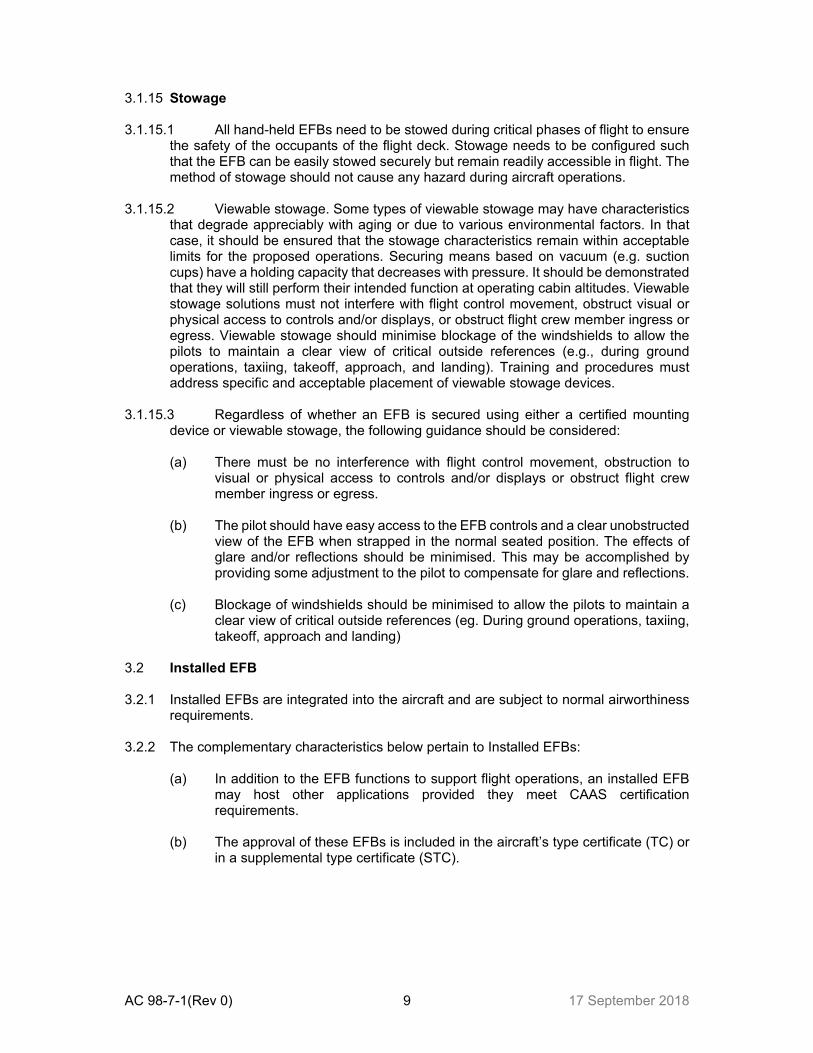
3.1.15 Stowage 3.1.15.1 All hand-held EFBs need to be stowed during critical phases of flight to ensure
the safety of the occupants of the flight deck. Stowage needs to be configured such that the EFB can be easily stowed securely but remain readily accessible in flight. The method of stowage should not cause any hazard during aircraft operations.
3.1.15.2 Viewable stowage. Some types of viewable stowage may have characteristics
that degrade appreciably with aging or due to various environmental factors. In that case, it should be ensured that the stowage characteristics remain within acceptable limits for the proposed operations. Securing means based on vacuum (e.g. suction cups) have a holding capacity that decreases with pressure. It should be demonstrated that they will still perform their intended function at operating cabin altitudes. Viewable stowage solutions must not interfere with flight control movement, obstruct visual or physical access to controls and/or displays, or obstruct flight crew member ingress or egress. Viewable stowage should minimise blockage of the windshields to allow the pilots to maintain a clear view of critical outside references (e.g., during ground operations, taxiing, takeoff, approach, and landing). Training and procedures must address specific and acceptable placement of viewable stowage devices.
3.1.15.3 Regardless of whether an EFB is secured using either a certified mounting
device or viewable stowage, the following guidance should be considered: (a) There must be no interference with flight control movement, obstruction to
visual or physical access to controls and/or displays or obstruct flight crew member ingress or egress.
(b) The pilot should have easy access to the EFB controls and a clear unobstructed
view of the EFB when strapped in the normal seated position. The effects of glare and/or reflections should be minimised. This may be accomplished by providing some adjustment to the pilot to compensate for glare and reflections.
(c) Blockage of windshields should be minimised to allow the pilots to maintain a
clear view of critical outside references (eg. During ground operations, taxiing, takeoff, approach and landing)
3.2 Installed EFB 3.2.1 Installed EFBs are integrated into the aircraft and are subject to normal airworthiness
requirements. 3.2.2 The complementary characteristics below pertain to Installed EFBs:
(a) In addition to the EFB functions to support flight operations, an installed EFB may host other applications provided they meet CAAS certification requirements.
(b) The approval of these EFBs is included in the aircraft’s type certificate (TC) or
in a supplemental type certificate (STC).

AC 98-7-1(Rev 0) 10 17 September 2018
4 EFB FUNCTIONS 4.1 General 4.1.1 Use of multiple software applications in an EFB is allowable. 4.1.2 Operational use of EFB functions require CAAS’ approval. 4.2 Guidance / Criteria for operational use of EFB functions 4.2.1 The following are the guidance / criteria established by CAAS for the operational use
of EFBs that:
(a) the EFB equipment and its associated installation hardware, including interaction with aircraft systems as applicable, meet the CAAS Airworthiness Certification requirements;
(b) the operator/owner has assessed the safety risks associated with the
operations with support by the EFB function(s); (c) the operator/owner has established requirements for redundancy of the
information, as appropriate, contained in and displayed by the EFB functions; (d) the operator/owner has established and documented procedures for the
management of the EFB function(s) including any database it may use; (e) the operator/owner has established and documented the procedures for the
use of, and training requirements for, the EFB and the EFB function(s). 4.3 EFB functions essential to safe operation of flight 4.3.1 EFB functions whose failure, malfunction or misuse would have an adverse effect on
the safety of flight operations (e.g. increase in flight crew workload during critical phases of flight, reduction in functional capabilities or safety margins, etc.) are essential to the safe operation of the flight should be recorded in the operations manual and linked to the operations specifications.
4.3.2 The applications below may be considered examples of such functions, depending on
their use, associated procedures, and failure mitigation means: (a) Document browser displaying information required to be carried by regulations
(subject to State authority approval, where required); (b) Electronic aeronautical chart applications; (c) Airport moving map (AMM) applications, not used as a primary means of
navigation on the ground and used in conjunction with other materials and procedures;
(d) Aircraft performance calculation application to provide take-off, en-route, approach, landing and missed approach performance calculations; and
(e) Mass and balance calculation application.
AC 98-7-1(Rev 0) 11 17 September 2018
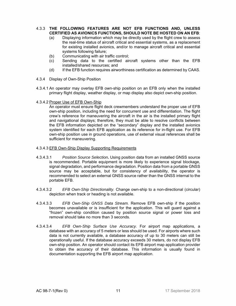
4.3.3 THE FOLLOWING FEATURES ARE NOT EFB FUNCTIONS AND, UNLESS CERTIFIED AS AVIONICS FUNCTIONS, SHOULD NOTE BE HOSTED ON AN EFB: (a) Displaying information which may be directly used by the flight crew to assess
the real-time status of aircraft critical and essential systems, as a replacement for existing installed avionics, and/or to manage aircraft critical and essential systems following failure;
(b) Communicating with air traffic control; (c) Sending data to the certified aircraft systems other than the EFB
installed/shared resources; and (d) If the EFB function requires airworthiness certification as determined by CAAS.
4.3.4 Display of Own-Ship Position 4.3.4.1 An operator may overlay EFB own-ship position on an EFB only when the installed
primary flight display, weather display, or map display also depict own-ship position. 4.3.4.2 Proper Use of EFB Own-Ship
An operator must ensure flight deck crewmembers understand the proper use of EFB own-ship position, including the need for concurrent use and differentiation. The flight crew’s reference for maneuvering the aircraft in the air is the installed primary flight and navigational displays; therefore, they must be able to resolve conflicts between the EFB information depicted on the “secondary” display and the installed avionics system identified for each EFB application as its reference for in-flight use. For EFB own-ship position use in ground operations, use of external visual references shall be sufficient for maneuvering.
4.3.4.3 EFB Own-Ship Display Supporting Requirements 4.3.4.3.1 Position Source Selection. Using position data from an installed GNSS source
is recommended. Portable equipment is more likely to experience signal blockage, signal degradation, and performance degradation. Position data from a portable GNSS source may be acceptable, but for consistency of availability, the operator is recommended to select an external GNSS source rather than the GNSS internal to the portable EFB.
4.3.4.3.2 EFB Own-Ship Directionality. Change own-ship to a non-directional (circular)
depiction when track or heading is not available. 4.3.4.3.3 EFB Own-Ship GNSS Data Stream. Remove EFB own-ship if the position
becomes unavailable or is insufficient for the application. This will guard against a “frozen” own-ship condition caused by position source signal or power loss and removal should take no more than 3 seconds.
4.3.4.3.4 EFB Own-Ship Surface Use Accuracy. For airport map applications, a
database with an accuracy of 5 meters or less should be used. For airports where such data is not currently available, a database accuracy of up to 30 meters can still be operationally useful. If the database accuracy exceeds 30 meters, do not display EFB own-ship position. An operator should contact its EFB airport map application provider to obtain the accuracy of their database. This information is usually found in documentation supporting the EFB airport map application.

AC 98-7-1(Rev 0) 12 17 September 2018
4.4 CONSIDERATIONS FOR ALL EFB FUNCTIONS - SOFTWARE HMI 4.4.1 The EFB system should provide an intuitive, and in general, consistent user interfaces
within and across the various hosted EFB applications. This should include, but not be limited to, data entry methods, color-coding philosophies, and symbology.
4.4.2 Software considerations, including ease of access to common functions, consistency
of symbols, terms and abbreviations, legibility of text, system responsiveness, methods of interaction, use of color, display of system status, error messages, management of multiple applications, off-screen text/content and use of active regions should be addressed.
4.4.3 Use of colors and messages.
(a) The color “red” should be used only to indicate a warning level condition. (b) “Amber” should be used to indicate a caution level condition. (c) Any other color may be used for items other than warnings or cautions,
providing that the colors used differ sufficiently from the colors prescribed to avoid possible confusion.
(d) EFB messages and reminders should be integrated with (or compatible with) presentation of other flight deck system alerts.
(e) EFB aural messages should be inhibited during critical phases of flight. If, however, there is a regulatory requirement that conflicts with the recommendation above, those should have precedence.
4.4.4 System error messages. If an application is fully or partially disabled, or is not visible
or accessible to the user, it may be desirable to have an indication of its status available to the user upon request. It may be desirable to prioritise these EFB status and fault messages.
4.4.5 Data entry and error messages. If user-entered data are not of the correct format or
type needed by the application, the EFB should not accept the data. An error message should be provided that communicates which entry is suspect and specifies what type of data are expected.
4.4.6 Responsiveness of application. The system should provide feedback to the user
when user input is accepted. If the system is busy with internal tasks that preclude immediate processing of user input (e.g. calculations, self-test, or data refresh), the EFB should display a “system busy” indicator (e.g. clock icon) to inform the user that the system is occupied and cannot process inputs immediately. The timeliness of system response to user input should be consistent with an application’s intended function.
4.4.7 Off-screen text and content. If the document segment is not visible in its entirety in
the available display area, such as during “zoom” or “pan” operations, the existence of off-screen content should be clearly indicated in a consistent way. For some intended functions, it may be unacceptable if off-screen content is not indicated. This should be evaluated based on the application and intended operational function.
4.4.8 Electronic Signatures. 4.4.8.1 To be accepted as an equivalent to a handwritten signature, electronic signatures used
in EFB applications need, as a minimum, to fulfil the same objectives and should, as a minimum, assure the same degree of security as the handwritten or any other form of signature it intends to replace. Authenticated certificates and secure signature creation devices are normally not required for EFB operations.

AC 98-7-1(Rev 0) 13 17 September 2018
4.4.8.2 The following documents are requirement and guidance relating to acceptance and
use of electronic signatures: (a) Electronic Transaction Act (Revised Edition 2011) (b) CAAS AC-1-2 Acceptance and use of Electronic Signatures, Electronic
Record-keeping system, Electronic documents Note: For further guidance on electronic signatures refer to ICAO Safety
Management Manual Doc 9859. 5 GUIDANCE FOR EFB SOFTWARE APPLICATIONS 5.1 The Appendices in this AC provide information on best practices and general guidance
for the development of commonly used EFB software applications. 5.2 When developing EFB software applications the operator should carefully consider
operational needs with the aim to maintain the highest safety and reliability standards for his specific-use case.
6 HUMAN FACTORS 6.1 The operator should carry out an assessment of the human-machine interface and
aspects governing crew coordination when using the EFB. Whenever possible, the EFB user interface philosophy should be consistent (but not necessarily identical) with the flight deck design philosophy.
6.2 The review of the complete system should include, but is not limited to:
(a) general considerations including workload, usability, integration of the EFB into the flight deck, display and lighting issues, system shutdown, and system failures;
(b) physical placement issues, including stowage area, use of unsecured EFBs, design and placement of mounting devices;
(c) considerations for interference with anthropometric constraints, cockpit ventilation, and speaker sound;
(d) training and procedures considerations, including training on using EFB applications, the EFB policy and procedures manual, fidelity of the EFB training devices, and mechanisms for gathering user feedback on EFB use;
(e) hardware considerations – refer to paragraph 3; (f) software considerations – refer to paragraph 4.
7 CREW OPERATING PROCEDURES 7.1 General 7.1.1 The operator should have procedures for using the EFB in conjunction with the other
flight deck equipment. 7.1.2 If an EFB generates information similar to that generated by existing flight deck
systems, the procedures should clearly identify: (a) which information source will be primary; (b) which source will be used as secondary information; (c) under what conditions to use the secondary source; and

AC 98-7-1(Rev 0) 14 17 September 2018
(d) what actions to take when information provided by an EFB does not agree with that from other flight deck sources, or, if more than one EFB is used, when one EFB disagrees with another.
7.1.3 The operators should include requirements for EFB availability in the operations
manual and, as appropriate, in the minimum equipment list. 7.2 Revisions and Updates 7.2.1 The operator should have a procedure in place to allow the flight crew to confirm the
revision number and/or date of EFB application software including, where applicable, database versions (e.g. update to the latest aeronautical charts).
7.2.2 Flight crews should not, however, have to confirm the revision dates for databases that
would not, in case of outdated data, adversely affect flight operations. There should be procedures to specify what actions to take if the software applications or databases loaded on the EFB are out of date.
7.3 Workload and Crew Coordination 7.3.1 In general, using an EFB should not increase the crew’s workload during critical
phases of flight. For other flight phases, crew operating procedures should be designed to mitigate and/or control additional workload created by using an EFB.
7.3.2 Workload should be distributed between flight crew members to ensure ease of use
and continued monitoring of other flight crew functions and aircraft equipment. The procedures should include specification of the phases of flight at which the flight crew may not use the EFB, if applicable
7.4 Reporting 7.4.1 A reporting system for EFB failures should be established which includes procedures
to inform maintenance and flight crews about a fault or failure of the EFB and the actions taken to isolate it until corrective action is taken.
8 RISK ASSESSMENT 8.1 General 8.1.1 The EFB risk assessment is a process that should be performed to assess the risks
associated with the use of each EFB function and should allow the operator to keep the risks to an acceptable level by defining the appropriate mitigation means.
8.1.2 This risk assessment should be performed before the beginning of the approval
process (if applicable) and its results should be reviewed on a periodic basis. 8.1.3 The guidance on safety risk assessment is contained in the Safety Management
Manual (SMM) (Doc 9859).

AC 98-7-1(Rev 0) 15 17 September 2018
8.2 EFB Failures and Mitigation Means 8.2.1 Based on the outcome of the EFB risk assessment, the operator should determine the
need for software architectural features, personnel, procedures, and/or equipment that will eliminate, reduce, or control risks associated with an identified failure in a system.
8.2.2 If normal operational procedures require an EFB for each flight deck crew member,
the installation should comply with the definition of independent EFB platforms. 8.2.3 Apart from procedures to inform maintenance and flight crews about a fault or failure
of the EFB and the actions taken to isolate it until corrective action is taken, back-up procedures should also be in place to prevent the use of erroneous information by flight crews.
8.2.4 Mitigation against EFB failure or impairment may be accomplished by one or a
combination of: (a) system design; (b) separate and backup power sources for the EFB; (c) electronic fallback solutions to the last known, stable configuration (e.g. before
an update); (d) redundant EFB applications hosted on independent EFB platforms; (e) paper products carried by selected crew members; (f) complete set of sealed paper backups in the flight deck; and/or (g) procedural means.
9 FLIGHT CREW TRAINING 9.1 The use of the EFB should be conditional upon appropriate training. Training should
be in accordance with the operator’s SOP (including abnormal procedures) and should include: (a) an overview of the system architecture; (b) preflight checks of the system; (c) limitations of the system; (d) the use of each operational software application (e) restrictions on the use of the system, including when some or all of the EFB
functions are not available; (f) the conditions (including phases of flight) under which the EFB may not be
used; (g) procedures for cross-checking data entry and computed information; (h) human performance considerations on the use of the EFB; (i) additional training for new applications, new features of current applications, or
changes to the hardware configuration; (j) recurrent training and proficiency checks; and (k) any area of special emphasis raised during the EFB evaluation with CAAS.
10 EFB MANAGEMENT 10.1 The operator should have an EFB management system in place. The role of an EFB
administrator is a key factor in the management of the EFB system. Complex EFB systems may require more than one individual to support the EFB management system. However, at least one person (e.g. the EFB administrator or dedicated EFB manager, OPS director, etc.) should possess an overview of the complete EFB system, including the distribution of responsibilities within the operator’s management

AC 98-7-1(Rev 0) 16 17 September 2018
structure. This role and accountability can be by delegations and by establishing procedures to ensure compliance
10.2 The EFB administrator is the key link between the operator, the EFB system and the
software suppliers 10.3 The following are responsibilities of the EFB administrator:
(a) Hardware and software configuration management and for ensuring, in particular, that no unauthorised software is installed.
(b) Ensuring that only a valid version of the application software and current data packages are installed on the EFB system.
(c) That the operator establishes the means to carry out their own check of data contents prior to load and/or release for operational use.
(d) Conducting internal quality control measures to ensure that all EFB management personnel comply with the defined procedures.
(e) Ensure that software applications supporting function(s) not directly related to operations conducted by the flight crew on the aircraft (e.g. web browser, email client, picture management, etc.) do not adversely impact the operation of the EFB.
(f) Ensure each person involved in EFB management receive appropriate training in their role and have a good working knowledge of the proposed system hardware, operating system and relevant software applications as well as knowledge about flight operations.
(g) Should establish procedures, documented in an EFB Policy and Procedures Manual, to ensure that no unauthorised changes take place. The EFB Policy and Procedures Manual may be part of the Operator’s Operations Manual
(h) Ensure procedures are established for the maintenance of the EFB.
10.4 The EFB administrator should be responsible for the overall procedures and systems, documented in the EFB Policy and Procedures Manual that maintain EFB security and integrity to the level of EFB security as required by the criticality of the used functions.
11 OPERATIONAL EVALUATION PROCESS 11.1 Operational evaluation process 11.1.1 Subject to CAAS’ operational evaluation and approval, an operator implementing EFB
functions: (a) may choose to start a paperless flight deck operation without paper backup or
a combination of solutions with limited on-board paper backup. (b) may also choose to keep the paper backup as a cross-check against the EFB
information and as a means of mitigation against failure, when transitioning from paper to electronic format.
11.1.2 The operational evaluation process below is designed to lead to specific operational
approval and consists of the following phases of actions. Appendix F provides a sample checklist of evaluation items.
11.2 Phase I – Pre-Application discussion 11.2.1 This phase begins when CAAS meets the operator to establish a common contact and
the understanding of requirements, of what need to be evaluated and how they must be conducted and documented.
AC 98-7-1(Rev 0) 17 17 September 2018
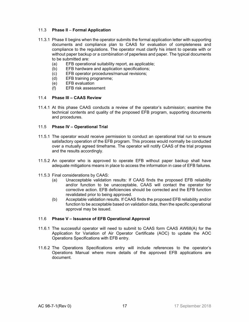
11.3 Phase II – Formal Application 11.3.1 Phase II begins when the operator submits the formal application letter with supporting
documents and compliance plan to CAAS for evaluation of completeness and compliance to the regulations. The operator must clarify his intent to operate with or without paper backup or a combination of paperless and paper. The typical documents to be submitted are: (a) EFB operational suitability report, as applicable; (b) EFB hardware and application specifications; (c) EFB operator procedures/manual revisions; (d) EFB training programme; (e) EFB evaluation (f) EFB risk assessment
11.4 Phase III – CAAS Review 11.4.1 At this phase CAAS conducts a review of the operator’s submission; examine the
technical contents and quality of the proposed EFB program, supporting documents and procedures.
11.5 Phase IV – Operational Trial 11.5.1 The operator would receive permission to conduct an operational trial run to ensure
satisfactory operation of the EFB program. This process would normally be conducted over a mutually agreed timeframe. The operator will notify CAAS of the trial progress and the results accordingly.
11.5.2 An operator who is approved to operate EFB without paper backup shall have
adequate mitigations means in place to access the information in case of EFB failures. 11.5.3 Final considerations by CAAS:
(a) Unacceptable validation results: If CAAS finds the proposed EFB reliability and/or function to be unacceptable, CAAS will contact the operator for corrective action. EFB deficiencies should be corrected and the EFB function revalidated prior to being approved.
(b) Acceptable validation results. If CAAS finds the proposed EFB reliability and/or function to be acceptable based on validation data, then the specific operational approval may be issued.
11.6 Phase V – Issuance of EFB Operational Approval 11.6.1 The successful operator will need to submit to CAAS form CAAS AW68(A) for the
Application for Variation of Air Operator Certificate (AOC) to update the AOC Operations Specifications with EFB entry.
11.6.2 The Operations Specifications entry will include references to the operator’s
Operations Manual where more details of the approved EFB applications are document.

AC 98-7-1(Rev 0) 18 17 September 2018
APPENDIX A PERFORMANCE (TAKE-OFF, LANDING) AND MASS & BALANCE Introduction
(a) The use of EFB to compute aircraft performance as well as mass and balance (M&B)
data has become commonplace in recent years. The computing power and versatility offered particularly by the portable devices such as laptops and tablets in relation to their flexibility for development and use have also allowed the creation of numerous applications for most types of aircraft.
(b) In any event, for the safe operations of flight, the validity and integrity of the aircraft
performance and M&B data are crucial and the applications and the procedures for their use have to be properly evaluated before being used in service.
(c) In that regard, the verification of the aircraft performance data and calculation algorithm
correctness becomes an essential step of the evaluation. The other part of the evaluation is to deal with the user interface and crew procedures. A proper human-machine interface (HMI) on one side, with adequate administration and crew procedures and training on the other, are necessary to mitigate those errors.
1 Performance applications architecture 1.1 Performance applications are usually separated into different layers:
(a) HMI (human-machine interface); (b) calculation module; (c) aircraft-specific information; and (d) airport, runway, obstacle database (AODB).
1.1.2 The figure below shows a typical architecture of a performance application. Individual solutions that are in use by operators might not need to be as modular as shown, but rather, have the different parts integrated into one software.
1.1.3 Alternatively, there might be solutions where modularity is taken to a point where some
or all parts are supplied by different providers.
Input HMI
Airport Runway Obstacle Database
Output HMI
Calculation Module (Calling Module)
Air manufacturer (e.g. SCAP) software with aircraft-specific
Pre-calculated aircraft-specific tables
Aircraft-specific digitized AFM or FCOM data
or or
or

AC 98-7-1(Rev 0) 19 17 September 2018
1.2 HMI - Input and output HMI: The input HMI takes the pilot’s inputs (or data read from the avionics if applicable) and requests the calculation from the calculation module. The results are transferred to the output HMI.
1.3 Calculation module: The calculation module will process the request data from the
input HMI and determine the results, which are then sent back to the output HMI. 1.3.1 Calculation modules are commonly setup using manufacturer SCAP software together
with the respective aircraft-specific database. To obtain the results, the calculation module might call the SCAP software several times. Thus, the expression “calling module” has become widespread in the industry.
1.3.2 Another way for the calculation module to obtain results is to interpolate between pre-
calculated tables (e.g. runway weight limitation charts). Those tables are typically calculated using SCAP software. The SCAP software itself, however, is not specifically part of the performance application.
1.3.3 Where manufacturer software is not available, paper AFM or FCOM charts may have
to be digitised. 1.4 Performance data sources: Different sources of performance data can be used by
performance applications. Performance data can be delivered in a digitised format: (a) SCAP modules or the equivalent delivered by the manufacturer. The SCAP
module is either based on equations of motion or digitised AFM material. Modules may or may not come from an airworthiness approved electronic flight manual;
(b) the operator can build its own digitised performance data, based on the data published in the flight manual; and
(c) data based on pre-calculated take-off or landing performance tables. 1.5 Airport, runway, obstacle database (AODB): Take-off and landing performance
applications require information about airport, runway and obstacles. (a) The AODB should provide this information in a suitable way. Usually, it is the
part of the EFB performance applications that will be updated most often. (b) The management of this data is critical. (c) The operator is ultimately responsible for the data quality, accuracy and
integrity of the runway and obstacle data, and should ensure this together with the data provider.
2 PERFORMANCE AND MASS AND BALANCE (M&B) APPLICATIONS GRAPHICAL USER INTERFACE
2.1 Data error in performance calculations have been identified to have contributed to
Incidents and accidents. A good, well-designed graphical user interface (GUI) can significantly reduce such error risks. Below are examples of design guidelines which are part of software HMI considerations in Chapter 12: (a) input data and output data (results) should be clearly distinctive. All the
information necessary for a given task should be presented together or easily accessible;
(b) all data required for the performance and M&B applications should be prompted-for or displayed, including correct and unambiguous terms (names), units of measurement (e.g. kg or lbs). The units should match those from other cockpit sources for the same type of data;

AC 98-7-1(Rev 0) 20 17 September 2018
(c) field names and abbreviations used in the GUI should correspond to those used in the manuals and should match the labels in the cockpit;
(d) if the application computes both dispatch (regulatory, factored) and other results (e.g. in-flight or not factored), the flight crew should be made aware of the nature of the results;
(e) the application should clearly distinguish user entries from default values or entries imported from other aircraft systems;
(f) the aircraft tail sign used for calculation must be clearly displayed to the flight crews, if relevant differences between tail signs exist. If tail signs are associated with different sub-fleets, the selected sub-fleet should be clearly displayed to the flight crew;
(g) the GUI should be designed so that input data are difficult to enter into the wrong fields of the GUI, by defining data entry rules;
(h) the GUI should only accept input parameters within the aircraft’s operational envelope approved for the operator. Consideration should be given to the plausibility of outputs within the AFM envelope but outside normal operating conditions;
(i) all critical performance calculation assumptions (e.g. use of thrust reversers, full or reduced thrust/power rating) should clearly be displayed. The assumptions made about any calculation should be at least as clear to pilots as similar information would be on a tabular chart;
(j) the GUI should indicate to the pilot if a set of entries results in an unachievable operation (for instance, a negative stopping margin), in accordance with general HMI considerations;
(k) the user should be able to modify its input data easily, especially to account for last-minute changes;
(l) when calculation results are displayed, the most critical input parameters should be visible at the same time;
(m) any active MEL/CDL/special restriction should be clearly visible and identifiable;
(n) in case of multiple runway selection, the output data should be clearly associated with the selected runway; and
(o) changes of runway data by the pilot should be clearly displayed and the changes should be easy to identify.
2.2 The development, testing and approval of a GUI are considerable investments and
system integrators and operators are encouraged to evaluate the usability of an existing GUI before developing a new GUI themselves. It is also recommended to review the GUI after some time of operation in the everyday environment for unforeseeable common human errors with special regard to the specific-use case of the operator, which require changes or enhancement of the given design.
2.3 Any new or modified GUI requires exhaustive testing of this component. 2.4 Any major GUI modification requires a new risk assessment by the operator. 3 PERFORMANCE APPLICATION TESTING 3.1 The criticality of performance calculations and the importance of the correctness of the
calculation results delivered by performance algorithms or calculation modules cannot be over-emphasised and hence the justification for the considerable investment in the development, testing and approval or certification of a performance algorithm or calculation module.
AC 98-7-1(Rev 0) 21 17 September 2018
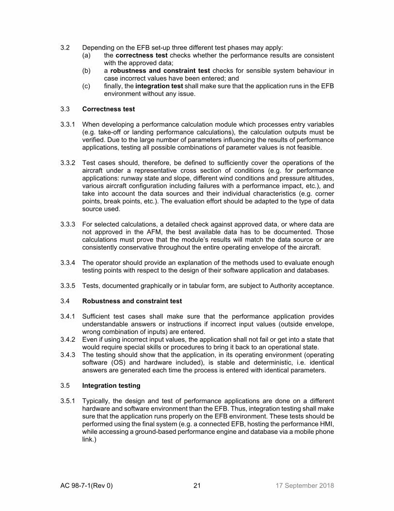
3.2 Depending on the EFB set-up three different test phases may apply: (a) the correctness test checks whether the performance results are consistent
with the approved data; (b) a robustness and constraint test checks for sensible system behaviour in
case incorrect values have been entered; and (c) finally, the integration test shall make sure that the application runs in the EFB
environment without any issue. 3.3 Correctness test 3.3.1 When developing a performance calculation module which processes entry variables
(e.g. take-off or landing performance calculations), the calculation outputs must be verified. Due to the large number of parameters influencing the results of performance applications, testing all possible combinations of parameter values is not feasible.
3.3.2 Test cases should, therefore, be defined to sufficiently cover the operations of the
aircraft under a representative cross section of conditions (e.g. for performance applications: runway state and slope, different wind conditions and pressure altitudes, various aircraft configuration including failures with a performance impact, etc.), and take into account the data sources and their individual characteristics (e.g. corner points, break points, etc.). The evaluation effort should be adapted to the type of data source used.
3.3.3 For selected calculations, a detailed check against approved data, or where data are
not approved in the AFM, the best available data has to be documented. Those calculations must prove that the module’s results will match the data source or are consistently conservative throughout the entire operating envelope of the aircraft.
3.3.4 The operator should provide an explanation of the methods used to evaluate enough
testing points with respect to the design of their software application and databases. 3.3.5 Tests, documented graphically or in tabular form, are subject to Authority acceptance. 3.4 Robustness and constraint test 3.4.1 Sufficient test cases shall make sure that the performance application provides
understandable answers or instructions if incorrect input values (outside envelope, wrong combination of inputs) are entered.
3.4.2 Even if using incorrect input values, the application shall not fail or get into a state that would require special skills or procedures to bring it back to an operational state.
3.4.3 The testing should show that the application, in its operating environment (operating software (OS) and hardware included), is stable and deterministic, i.e. identical answers are generated each time the process is entered with identical parameters.
3.5 Integration testing 3.5.1 Typically, the design and test of performance applications are done on a different
hardware and software environment than the EFB. Thus, integration testing shall make sure that the application runs properly on the EFB environment. These tests should be performed using the final system (e.g. a connected EFB, hosting the performance HMI, while accessing a ground-based performance engine and database via a mobile phone link.)
AC 98-7-1(Rev 0) 22 17 September 2018
3.5.2 Integration testing shall ensure the performance application(s) produces the same results on the EFB as on the computer it was designed and tested on. In addition, the performance application shall not interfere adversely with other EFB applications or vice versa.
3.5.3 Where data from other applications are processed (e.g. T/O performance using results
from the M&B application), the correct interfacing of those data shall be tested. 3.5.4 Finally the overall acceptability of the performance calculation should be assessed.
E.g. the data modification and calculation times should be within acceptable limits to allow quick recalculations in case of dynamic operational conditions like meteorological or last minute runway changes.
4 M&B APPLICATION TESTING (RESERVED) – Reserved – 5 PROCEDURES, MANAGEMENT AND TRAINING 5.1 When approving the operational use of a performance or M&B application(s), due
consideration shall also be given to all other processes that contribute to the use of the application.
5.2 Crew operating procedures 5.2.1 Procedures should be developed that define any new roles that the flight crew and the
flight dispatcher may have in creating, reviewing, and using performance or M&B calculations supported by EFBs.
5.2.2 Performance and M&B calculations should be performed by both the pilots
independently on independent EFBs, if available. 5.2.3 The results should be cross-checked and differences discussed before the results are
used operationally. 5.2.4 Crew procedures should ensure that, in the event of loss of functionality by an EFB
through either the loss of a single application or the failure of the device hosting the application, a high level of safety can be maintained. Consistency with the EFB risk assessment assumptions should be confirmed.
5.3 Procedures for EFB security and quality assurance 5.3.1 Application and data should be checked for integrity and protected against
unauthorised manipulation, e.g. by checking file checksum values at EFB start-up or prior to each calculation.
5.3.2 A quality assurance process should apply for all performance-related software
application modifications.

AC 98-7-1(Rev 0) 23 17 September 2018
5.4 Procedures for addressing EFB failures 5.4.1 Procedures should be developed and introduced to assure that EFB failure events,
especially those where the EFB failure leads to the calculation of misleading information (such as an error in the AODB), is immediately brought to the attention of other pilots who may be affected.
5.4.2 A reporting system shall be in place allowing the operator to detect the nature of
problems and to decide on mitigations. 5.5 Flight crew training 5.5.1 Training should emphasise the importance of executing all performance calculations
in accordance with SOP to assure fully independent calculations. As an example, one pilot should not announce the values to be entered into the HMI of the performance applications, because a wrong announcement could lead to both calculations showing the same misleading results.
5.5.2 Training should include cross-checks (e.g. with avionics or flight plan data) and gross
error check methods (e.g. “rule-of-thumb”) that may be used by pilots to identify order-of-magnitude errors like entering the ZFM as TOM or transposed digits.
5.5.3 It should be understood, that the use of EFBs makes performance calculations simple
and does not eliminate the necessity of good pilot performance knowledge. 5.5.4 Using EFBs, new procedures may be introduced (e.g. the use of multiple flaps settings
for take-off) and pilots should be trained accordingly. 5.6 Management of performance EFB applications 5.6.1 Within the operator’s organisation, the responsibilities between the performance
management, other departments involved and the EFB management should be if separate, clear and well-documented. Furthermore, an operator needs to utilise a designated person/group who is sufficiently trained to provide support for the performance tools. This person/group must have comprehensive knowledge of current regulations, aircraft performance and performance software (e.g. SCAP modules) used on the EFB.

AC 98-7-1(Rev 0) 24 17 September 2018
APPENDIX B ELECTRONIC CHARTING 1 Description 1.1 An EFB software application that supports route planning, route monitoring and
navigation by displaying required information and includes visual, instrument and aerodrome charts.
1.2 Considerations:
(a) electronic aeronautical charts should provide, at least to a minimum, a level of information and usability comparable to paper charts;
(b) for approach charts, the EFB software application should be able to show the entire instrument approach procedure all at once on the intended EFB hardware, with a degree of legibility and clarity equivalent to that of a paper chart;
(c) an EFB display may not be capable of presenting an entire chart (e.g. airport diagram, departure/arrival procedures, etc.) if the chart is the expanded detail (fold-over) type;
(d) panning, scrolling, zooming, rotating, or other active manipulation is permissible; and
(e) for data driven charts, it should be assured that shown symbols and labels remain clearly readable, (e.g. not overlapping each other). Layers of data may be used for de-cluttering.

AC 98-7-1(Rev 0) 25 17 September 2018
APPENDIX C AIRCRAFT EXTERIOR VIDEO SURVEILLANCE 1 Description 1.1 Aircraft exterior surveillance may be an EFB hosted software application to increase
situational awareness during taxi by displaying real-time video of the actual external scene.
2 Considerations:
(a) ensure real-time, live display of received imagery without noticeable time-lapse;
(b) adequate image quality during foreseeable environmental lighting conditions; (c) display of turning or aircraft dimension aids may be provided, (e.g. turning
radius, undercarriage track width, etc.). In such cases, the information provided to the pilot should be verified to be accurate;
(d) connection to one or more installed vision systems. Vision systems include, but are not limited to, visible light cameras, forward-looking infrared sensors and intensifying low-light level images;
(e) operators should establish SOPs for use of the application. Training should emphasise use of as an additional resource and not as a primary means for ground navigation or avoiding obstacles; and
(f) pilot use should not induce disorientation.

AC 98-7-1(Rev 0) 26 17 September 2018
APPENDIX D AIRPORT MOVING MAP (AMM) 1 Introduction 1.1 This section provides some consideration on how to demonstrate the safe operational
use for AMM applications to be hosted on EFBs. 1.2 An EFB AMM with own-ship position symbol is designed to assist flight crews in
orienting themselves on the airport surface to improve pilot positional awareness during taxi operations. The AMM function is not to be used as the primary means of taxiing navigation. This application is limited to ground operations only.
1.3 The AMM application is designed to indicate the aircraft position and heading (in case
the own-ship position symbol is directional) on dynamic maps. The maps graphically portray runways, taxiways and other airport features to support taxi and taxi-related operations. Additionally, warning functions can be provided which notify crews about potentially dangerous conditions, i.e. inadvertently entering a RWY.
2 Considerations for AMM:
(a) an AMM application should not be used as the primary means of taxiing navigation; primary means of taxiing navigation remains the use of normal procedures and direct visual observation out of the cockpit window;
(b) the display of own-ship information in the AMM application should comply with the requirements detailed in para 4.3.4 of this AC.

AC 98-7-1(Rev 0) 27 17 September 2018
APPENDIX E EFB POLICY AND PROCEDURES MANUAL 1 The following are typical contents of an EFB policy and procedures manual that can
be fully or partly integrated in the Operations Manual, as applicable. 2 The structure and content of the EFB policy and procedures manual should correspond
to the size of the operator, the complexity of its activities and the complexity of the EFB used.
• Introduction
EFB general philosophy EFB limitations EFB approved hardware and software applications
• EFB management
Responsibilities Data management Updates and changes management
• Hardware description
EFB system architecture Hardware configuration control
• Software description Operating system description List and description of applications hosted
• Flight crew training
• Operating procedures
• Maintenance considerations
• Security considerations

AC 98-7-1(Rev 0) 28 17 September 2018
APPENDIX F EVALUATION CHECKLIST
Part 1 – HARDWARE
1 Have the installed EFB resources been certified by a CAA to accepted aviation standards either during the certification of the aircraft, service bulletin by the original equipment manufacturer, or by a third-party STC?
Yes □ No □ N/A □
2
Has the operator assessed the physical use of the device on the flight deck to include safe stowage, crashworthiness (mounting devices and EFBs, if installed), safety and use under normal environmental conditions including turbulence?
Yes □ No □ N/A □
3 Will the display be readable in all the ambient lighting conditions, both day and night, encountered on the flight deck?
Yes □ No □ N/A □
4 Has the operator demonstrated that the EFB will not electromagnetically interfere with the operation of aircraft equipment?
Yes □ No □ N/A □
5 Has the EFB been tested to confirm operation in the anticipated environmental conditions (e.g. temperature range, low humidity, altitude, etc.)?
Yes □ No □ N/A □
6 Have procedures been developed to establish the level of battery capacity degradation during the life of the EFB?
Yes □ No □ N/A □
7 Is the capability of connecting the EFB to certified aircraft systems covered by an airworthiness approval?
Yes □ No □ N/A □
8 When using the transmitting functions of a portable EFB during flight, has the operator ensured that the device does not electromagnetically interfere with the operation of the aircraft equipment in any way?
Yes □ No □ N/A □
9 If two or more EFBs on the flight deck are connected to each other, has the operator demonstrated that this connection does not negatively affect otherwise independent EFB platforms?
Yes □ No □ N/A □
10 Can the brightness or contrast of the EFB display be easily adjusted by the flight crew for various lighting conditions?
Yes □ No □ N/A □
Part 2 - INSTALLATION
Mounting
1 Has the installation of the mounting device been approved in accordance with the appropriate airworthiness regulations?
Yes □ No □ N/A □
2
Is it evident that there are no mechanical interference issues between the EFB in its mounting device and any of the flight controls in terms of full and free movement, under all operating conditions and no interference with other equipment such as buckles, oxygen hoses, etc.?
Yes □ No □ N/A □
3 Has it been confirmed that the mounted EFB location does not impede crew ingress, egress and emergency egress path?
Yes □ No □

AC 98-7-1(Rev 0) 29 17 September 2018
N/A □
4 Is it evident that the mounted EFB does not obstruct visual or physical access to aircraft displays or controls?
Yes □ No □ N/A □
5 Does the mounted EFB location minimise the effects of glare and/or reflections?
Yes □ No □ N/A □
6 Does the mounting method for the EFB allow easy access to the EFB controls and a clear unobstructed view of the EFB display?
Yes □ No □ N/A □
7 Is the EFB mounting easily adjustable by flight crew to compensate for glare and reflections?
Yes □ No □ N/A □
8 Does the placement of the EFB allow sufficient airflow around the unit, if required?
Yes □ No □ N/A □
PART 3 - SOFTWARE
Note — This part should be completed multiple times to account for the different software applications being considered.
Software application: _____________________ (fill in name of software application)
1 Is the application considered an EFB function (see paragraph 4 of this AC)? Yes □ No □ N/A □
2 Has the software application been evaluated to confirm that the information being provided to the pilot is a true and accurate representation of the documents or charts being replaced?
Yes □ No □ N/A □
3 Has the software application been evaluated to confirm that the computational solution(s) being provided to the pilot is a true and accurate solution (e.g. performance, and mass and balance (M&B), etc.)?
Yes □ No □ N/A □
4 Does the software application have adequate security measures to ensure data integrity (e.g. preventing unauthorised manipulation)?
Yes □ No □ N/A □
5 Does the EFB system provide, in general, a consistent and intuitive user interface, within and across the various hosted applications?
Yes □ No □ N/A □
6 Has the EFB software been evaluated to consider HMI and workload aspects?
Yes □ No □ N/A □
7 Does the software application follow Human Factors guidance? Yes □ No □ N/A □
8 Can the flight crew easily determine the validity and currency of the software application and databases installed on the EFB, if required?
Yes □ No □ N/A □

AC 98-7-1(Rev 0) 30 17 September 2018
Power connection / Battery
1 Is there a means other than a circuit-breaker to turn off the power source (e.g. can the pilot easily remove the plug from the installed outlet)?
Yes □ No □ N/A □
2 Is the power source suitable for the device? Yes □ No □ N/A □
3 Have guidance/procedures been provided for battery failure or malfunction? Yes □ No □ N/A □
4 Is power to the EFB, either by battery and/or supplied power, available to the extent required for the intended operation?
Yes □ No □ N/A □
5 Has the operator ensured that the batteries are compliant to acceptable standards?
Yes □ No □ N/A □
Cabling
1
Has the operator ensured that any cabling attached to the EFB, whilst mounted or hand-held does not present an operational or safety hazard (e.g. it does not interfere with flight controls movement, egress, oxygen mask deployment, etc.)?
Yes □ No □ N/A □
Stowage
1 If there is no mounting device available, can the EFB be easily stowed securely and readily accessible in flight?
Yes □ No □ N/A □
2 Is it evident that stowage does not cause any hazard during aircraft operations?
Yes □ No □ N/A □
Viewable Stowage
1 Has the operator documented the location of its viewable stowage? Yes □ No □ N/A □
2
Has the operator assessed that the stowage characteristics remain within acceptable limits for the proposed operations?
Yes □ No □ N/A □
3
Has the operator assessed that if the EFB moves or is separated from its stowage, or if the viewable stowage is unsecured from the aircraft (because of turbulence, maneuvering, or other action), it will not interfere with flight controls, damage flight deck equipment, or injure flight crew members? (A full motion flight simulator may be used for this assessment)
Yes □ No □ N/A □

AC 98-7-1(Rev 0) 31 17 September 2018
PART 4 - MANAGEMENT
EFB Management
1 Is there an EFB management system in place? Yes □ No □ N/A □
2 Does one person possess an overview of the complete EFB system and responsibilities within the operator’s management structure?
Yes □ No □ N/A □
3 Are the authorities and responsibilities clearly defined within the EFB management system?
Yes □ No □ N/A □
4 Are there adequate resources assigned for managing the EFB? Yes □ No □ N/A □
5 Are third parties (e.g. software vendor) responsibilities clearly defined? Yes □ No □ N/A □
Crew Procedures
1 Is there a clear description of the system, its operational philosophy and operational limitations?
Yes □ No □ N/A □
2 Are the requirements for EFB availability in the operations manual and / or as part of the minimum equipment list (MEL)?
Yes □ No □ N/A □
3 Have crew procedures for EFB operation been integrated within the existing operations manual?
Yes □ No □ N/A □
4 Are there suitable crew cross-checks for verifying safety-critical data (e.g. performance, mass & balance (M&B) calculations)?
Yes □ No □ N/A □
5 If an EFB generates information similar to that generated by existing flight deck systems, do procedures identify which information will be primary?
Yes □ No □ N/A □
6 Are there procedures when information provided by an EFB does not agree with that from other flight deck sources, or, if more than one EFB is used, when one EFB disagrees with another?
Yes □ No □ N/A □
7 Are there procedures that specify what actions to take if the software applications or databases loaded on the EFB are out of date?
Yes □ No □ N/A □
8 Are there procedures in place to prevent the use of erroneous information by flight crews?
Yes □ No □ N/A □
9 Is there a reporting system for system failures? Yes □ No □ N/A □

AC 98-7-1(Rev 0) 32 17 September 2018
10 Have crew operating procedures been designed to mitigate and/or control additional workload created by using an EFB?
Yes □ No □ N/A □
11 Are there procedures in place to inform maintenance and flight crews about a fault or failure of the EFB, including actions to isolate it until corrective action is taken?
Yes □ No □ N/A □
EFB risk assessment
1 Has an EFB risk assessment been performed? Yes □ No □ N/A □
2 Are there procedures/guidance for loss of data and identification of corrupt/erroneous outputs?
Yes □ No □ N/A □
3 Are there contingency procedures for total or partial EFB failure? Yes □ No □ N/A □
4
Is there a procedure in the event of EFB failure? The operator may employ mitigation strategies to reduce the probability of EFB failures prior to becoming airborne. Adequate mitigations must be employed to ensure pertinent critical information resident on the EFB is available to the flight crew during the flight. In such cases the operator will have to demonstrate to CAAS a full Operational Risk Assessment with suitable means of mitigation against failure or malfunction of all EFBs
Yes □ No □ N/A □
5 Have the EFB dispatch requirements (e.g. minimum number of EFBs on board) been incorporated into the operations manual?
Yes □ No □ N/A □
6 Have MEL or procedures in case of EFB failure been considered and published?
Yes □ No □ N/A □
Training
1 Is the training material appropriate with respect to the EFB equipment and published procedures?
Yes □ No □ N/A □
2 Does the training cover the list of items in paragraph 9 — Flight crew training – of this AC?
Yes □ No □ N/A □
Hardware management procedures
1 Are there documented procedures for the control of EFB hardware configuration?
Yes □ No □ N/A □
2 Do the procedures include maintenance of EFB equipment? Yes □ No □ N/A □
Software Management Procedures

AC 98-7-1(Rev 0) 33 17 September 2018
1 Are there documented procedures for the configuration control of loaded software and software access rights to the EFB?
Yes □ No □ N/A □
2 Are there adequate controls to prevent corruption of operating systems, software, and databases?
Yes □ No □ N/A □
3 Are there adequate security measures to prevent system degradation, malware and unauthorised access?
Yes □ No □ N/A □
4 Are procedures defined to track database expiration/updates? Yes □ No □ N/A □
5 Are there documented procedures for the management of data integrity? Yes □ No □ N/A □
6 If the hardware is assigned to the flight crew, does a policy on private use exist?
Yes □ No □ N/A □