Electricity Experiments for Children - Arvind Gupta Toys
91
537 .011 I1 17J I c
-
Upload
khangminh22 -
Category
Documents
-
view
3 -
download
0
Transcript of Electricity Experiments for Children - Arvind Gupta Toys
537.011R~
I117JI c
ElECTRICITY EXPERIMENTS FOR CHILDRENGA8IIIEl REUBEN
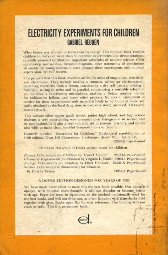
""", ....OOY .., .. oloow .. '""'- ......~; 1 -._...1'''' .. ...., __...~__ "'p<>_.'_~.-........-. ., _ .......~ . u-,•..,.... ,_'. d _ .. __._ ....__ -....- .....-..;.. ,.., -n.r,...,.... .., _ •••_m_~ ......_ ... ._....._ ..._n,"' ~.i , . L--..~ ,I_._ ., ....-~·
•• I p _--pooakl._ _.- ........."" 1__• _ " __ • w.... _ - ..... .-.,... .-. _ ..,. ,..,.ua. 1' I ....__ __ _ ~ _ .. _ f-...., _ _ l ........ .w. __ wI<
-I boo._ ..... ..,... -.,.... -. - .... ..-......." ", CIlt<nOI _. _ , ,.. _ ••Ib~ -... . , .. _ bk _ _ -"""
who ... '" '" _u d.v. _.I _m_ ~
,,,,_ ,it ..,,,,ltd .!lft''-I<i "'" 0._.... l· t'<P".....,,_ ...,... """_,. 0... lOll iIl_.o.- ! ,.1<,•.- .Iu".. lllll'l" '" • 9\00
~ ~,p<'-nd
O,hmo,~ ,10.. 0<, .... oI lloo>ft " le''' ' ll<lu'...... <hikl.."
,.,. ...... ,. ,......, ... '"" t:~old.... by \ t u" d M•• "",,, tlOn.. l " p<'~'odc_.., .., , . ,.,,, _ . ,, ,... C~.WK. by \ " IJI 1 .\r~ll... ftD'l r '."".Lou....""""'" ,.,.,., ",.. nold". by l.lIo<l " ,,, ftOS2X P. """"",,"'".10<...... ,..,..- A _ ....-.. .. ,... UoId"•
... 0... .... \,._ 11I~1 ,~..
A '10"~ I;l)n 1O:- OUlC; .. tU Fo a 1 [AU 0 1 l"st:'
W. _ ""' ,,.,_1.<-_ .. _ _w.. ,_ ._ ,. _I ,""" _ Of ....._ _ ....
•"oJo. "'" - Of __ -- " -"'1 I-..._-..--- '"'-~ , -........ .___ .... _ ""-.,_ llror_ ia_ ~
~__ ' M o " , • ; . {.;., ;-
-•

ELECTRICITYExperimentsfor Children

ELECTRICITYExperiments
for ChildrenFormerly titled ELECTRONICS FOR CHILDREN
by Gabriel Reuben
Illustrated by Bernard Case
Dover Publications, Inc., New York
Copyrig-ht © 1960 by Sterling- Publishing- Co., Inc.All rights reserved under Pan American
and International Copyrig-ht Conventions.
Published in Canada by General Publishing- Company, Ltd..30 Lesmill Road, Don Mills, Toronto, Ontario.
Published in the United King-dom by Constable and Company, Ltd ..10 Orang-e Street. London WC 2...
This Dover edition. first published in 1968, is an unabridgedand unaltered republication of the work originally published in1960 under the title Electronics for Children. The work is reoprinted by special arrang-ement with Sterling Publishing Co., Inc.,publisher of the original edition.
International Standard Book Number: 0·486·2203iJ·3
Library of Congress Catalog Card Number: 68·9307
Manufactured in the United States of America
Dover Publications, Inc.180 Varick Street
New York,~.Y. 10014
CONTENTS
BEFORE YOU BEGIN
MAGNETISM
What Will a Magnet Attract? ... Will Magnetism Pass ThroughMaterials? ... Can You Feel Magnetism? ... Can You See Magnetism? ... How Do the Poles of a Magnet Act? ... How Can YouMake a Temporary Magnet? ... How Can You Make an Electromagnet? ... How Can You Make a Permanent Magnet? ... HowCan You Make a Compass? ... How Can You Tell Time with aCompass? ... What Happens When You Cut a Magnet into Pieces?· .. What Is the Secret of Magnetism? ... How Can You Make anElectric Current with a Magnet?
ELECTRICITY .
How Can You Get Electricity by Rubbing? . How Can YouDetermine What Materials Are Conductors? How Can YouMake an Electroscope? ... How Can You Make an Electrophorus?· .. How Can You Make a Battery? ... How Can You Bring a DeadDry Cell Back to Life? ... How Can You Make a Lead Storage Cell?· .. How Can You Build a Flashlight? ... How Do Switches Work?· .. How Can You Control a Light with Two Switches? .. How CanYou Wire in Series? How Can You Wire in Parallel? ... WhatIs a Short Circuit? How Can You Make an IncandescentBulb? ... How Can You Build an Electric Quiz Game? ... HowCan You Build a Telegraph Set? ... How Can You Build a Telegraph Set with a Bulb? ... How Can You Wire a Bell for YourRoom? .. How Can You Wire a Lamp? .. How Can You Copperplate a Safety Pin? ... How Can You Silverplate a Key? ... HowCan You Build a Microphone? ... How Can You Make a Generator? ... How Can You Make an Electric Motor? ... How Can YouMake a Model Railroad Signal? ... How Can You Make a Rheostat?· .. What Are the Kinds of Electricity We Use? ... What Is aTransformer? ... How Can You Read a Watt-Hour Meter?
5
6
26
ELECTRONICS .
How Can an Unconnected Fluorescent Bulb Glow? ... How Doesan Electron Tube Work? What Are Some Electronic Symbols?... What Are Transistors? What Are Resistors? ... What AreCapacitors? ... What Are Radio Waves? ... How Are Radio WavesUsed for Broadcasting? ... How Can You Make a Simple Radio?
NUCLEAR ENERGY.
How Can You Build a Geiger Counter? ... How Can You Test forRadioactive Fallout in Your Neighborhood?
TABLE OF ELEMENTS
INDEX.
65
76
81
85

BEFORE YOU BEGIN
Learning by doing is the quickest and surest way to understanding. Instead of just reading about how and why something works, you performexperiments yourself and actually see what happens. The experiments in thisbook will help you to understand magnetism, electricity, electronics andnuclear energy - all subjects that are becoming more and more importantin today's world.
With simple equipment, most of which you already have at home, youcan set up your own laboratory in a corner of a room and follow in the footsteps of the great scientists, many of whom began their lifelong interest whenthey were young.
I t is a good idea to perform the experiments in the order in which theyare given, because each one depends, to a large extent, on the knowledgegained in those that came before. Before beginning any experiment, read allthe directions carefully. You'll be anxious to begin immediately, of course,but two of the foremost requirements of a scientist are patience and discipline.After you understand what you are to do, assemble all the equipment youwill need. Then, read each step through again before performing it. Referto the illustrations to make sure you've set the equipment up correctly, and,most important, think about what you are doing and why. Some of the experiments may look complicated at first, but you will find, as you go methodicallyfrom step to step, that everything fits into place. If, by chance, you don'tsucceed the first time, try to figure out what went wrong, and begin again.Another essential trait of a scientist is perseverance, or what some people call"stick-to-itiveness.' ,
While all of the experiments in this book are safe, you must exerciseordinary care and use your common sense. If you follow the directions, everything will work out well. Where warnings are given, be sure to heed them.
After you finish each experiment, store your equipment neatly. Then,if you want to do the experiment again some other time, or go on to the nextone, you will find everything easily.
You will soon discover that learning by doing is fun. You will also getgreat satisfaction from understanding more deeply some of the forces innature that you see and use every day of your life.
5

MAGNETISM
Magnetism is the power of certain stones and metals to attract eachother. According to legend, the discovery of magnetism occurred about 3000years ago in an ancient Middle Eastern country called Magnesia.
One day, the story goes, a shepherd found it difficult to lift his irontipped staff from certain places on the ground. After investigating, he realizedthat he had difficulty only when the iron tip was on a certain type of darkstone. These stones were loadstones (sometimes spelled "lodestone") , whichcontain a kind of iron ore called magnetite.
Since magnetism became known, man has found out much about thispower and devised many uses for it. With the aid of science, he has alsolearned to impart magnetism to certain metals which do not possess itnaturally.
6

WHAT WILL A MAGNET ATTRACT?
Gather the following equipment: A magnet and samples of as manydifferent substances as you are able to find - wood, metals, liquids, rubber,cloth, and so forth. Try to get samples of as many elements as you can locate.Elements are the basic substance of which all matter is made - all liquids,all solids, all gases - even air, which is a mixture of gases. An element is madeup of only one kind of atom. Scientists have found 92 elements in nature andhave created 10 artificial elements. It is quite possible that in the future theywill be able to make more artificial elements. For your experiment, you canprobably find objects made of iron, copper, gold, or silver, which are allnatural elements. On page 81 there is a list of all the known elements.
Follow this procedure: Touch the magnet to each of the materials youhave gathered, and then slowly pull it away.
You will observe: The magnet attracts only those objects which containiron, nickel or cobalt.
Although you can only see the effects of magnetism on iron, nickel andcobalt, scientists believe that magnetism has some effect on all substances.For all practical purposes, however, we say that it affects only iron, nickeland cobalt.
7

WILL MAGNETISM PASS THROUGH MATERIALS?
Gather the following equipment: A magnet; several paper clips, or anyother small objects which you know will be affected by magnetism; a piece ofstring; some cellophane tape; a drinking glass; a small piece of plywood; adishpan filled to a depth of about 3 inches with water; a book; and anempty can.
Follow this procedure: 1. Place the clips in the glass. Then place themagnet beneath the glass as close to the clips as possible. Move the magnetslowly along the surface of the glass.
You will observe: The clips inside the glass follow the movements of themagnet outside the glass.
2. Tie one of the clips to the string. Fasten the other end of the stringto a table. Lift the clip until the string is taut; then hold the magnet about'l4 of an inch from the clip and let go of the clip. Move the magnet slowlyto the left and right, keeping it the same distance from the clip. Then gradually increase the distance between the clip and the magnet.
You will observe: The clip is attracted by the magnet and holds thestring taut as long as the magnet is close to the clip. When you move themagnet more than Y2 an inch away from the clip, the string falls.
8

3. Place the clips on the piece of plywood. Then hold the magnet onthe underside of the plywood, directly under the clips. Move the magnetslowly along the plywood.
You will observe: The clips are attracted by the magnet and move alongthe plywood as you move the magnet on the other side.
4. Place the clips in the dishpan of water. Then put the magnet in thewater and move it very close, within a range of ~ of an inch from the clips.
You will observe: The magnet attracts the clips in the water.5. Place the clips on the front cover of the book. Hold the magnet
against the back cover of the book and move it slowly.You will observe: The clips do not follow the movements of the magnet.
6. Open the cover and three pages of the book. Place some clips on theinside of the open cover and between each of the three pages. Hold the
9
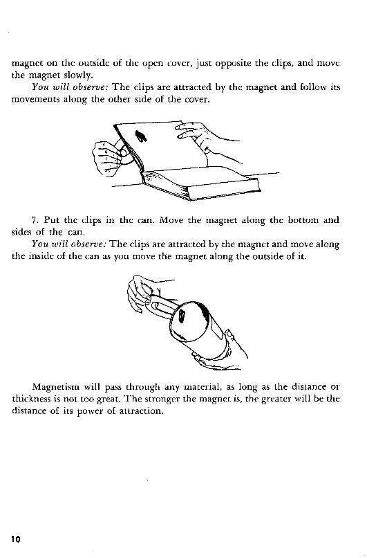
magnet on the outside of the open cover, just opposite the clips, and movethe magnet slowly.
You will observe: The clips are attracted by the magnet and follow itsmovements along the other side of the cover.
7. Put the clips in the can. Move the magnet along the bottom andsides of the can.
You will observe: The clips are attracted by the magnet and move alongthe inside of the can as you move the magnet along the outside of it.
Magnetism will pass through any material, as long as the distance orthickness is not too great. The stronger the magnet is, the greater will be thedistance of its power of attraction.
10
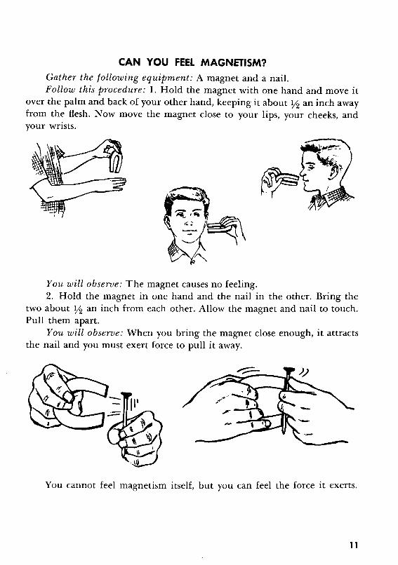
CAN YOU FEEL MAGNETISM?Gather the following equipment: A magnet and a nail.Follow this procedure: 1. Hold the magnet with one hand and move it
over the palm and back of your other hand, keeping it about Y2 an inch awayfrom the flesh. Now move the magnet close to your lips, your cheeks, andyour wrists.
You will observe: The magnet causes no feeling.2. Hold the magnet in one hand and the nail in the other. Bring the
two about Y2 an inch from each other. Allow the magnet and nail to touch.Pull them apart.
You will observe: When you bring the magnet close enough, it attractsthe nail and you must exert force to pull it away.
You cannot feel magnetism itself, but you can feel the force it exerts.
11

CAN YOU SEE MAGNETISM?Gather the following equipment: A magnet; a sheet of paper; and some
iron filings.Follow this procedure: 1. Place some of the iron filings on the sheet of
paper. Move the magnet close enough to the filings to attract them. Watchcarefully as the filings jump to the magnet.
~._.....••,_0-. :.
-: J. <; .;.:._
You will observe: You cannot see the force of magnetism attracting thefilings.
2. Place the magnet under the sheet of paper. Shake the iron filings onthe paper just over the magnet and around it.
You will observe: The filings on the paper form a pattern around thepoles (ends) of the magnet.
You cannot see magnetism itself, but you can see what magnetism does.With the aid of iron filings, you can see the area around a magnet in whichit exerts its force. This area is called the magnet's field of force or magneticfield. The lines formed by the filings are called lines of force.
12
HOW DO THE POLES OF A MAGNET ACT?
Gather the following equipment: Two bar magnets; a piece of string;a shaker of iron filings; and a sheet of paper.
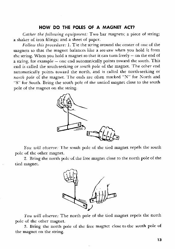
Follow this procedure: 1. Tie the string around the center of one of themagnets so that the magnet balances like a see-saw when you hold it fromthe string. When you hold a magnet so that it can turn freely - on the end ofa string, for example - one end automatically points toward the south. Thisend is called the south-seeking or south pole of the magnet. The other endautomatically points toward the north, and is called the north-seeking ornorth pole of the magnet. The ends are often marked "N" for North and"S" for South. Bring the south pole of the untied magnet close to the southpole of the magnet on the string.
You will observe: The south pole of the tied magnet repels the southpole of the other magnet.
2. Bring the north pole of the free magnet close to the north pole of thetied magnet.
You will observe: The north pole of the tied magnet repels the northpole of the other magnet.
3. Bring the north pole of the free magnet close to the south pole ofthe magnet on the string.
13
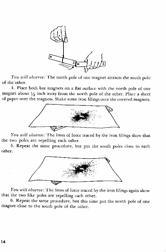
You will observe: The north pole of one magnet attracts the south poleof the other.
4. Place both bar magnets on a flat surface with the north pole of onemagnet about Y2 inch away from the north pole of the other. Place a sheetof paper over the magnets. Shake some iron filings over the covered magnets.
You will observe: The lines of force traced by the iron filings show thatthe two poles are repelling each other.
5. Repeat the same procedure, but put the south poles close to eachother.
You will observe: The lines of force traced by the iron filings again showthat the two like poles are repelling each other.
6. Repeat the same procedure, but this time put the north pole of onemagnet close to the south pole of the other.
14
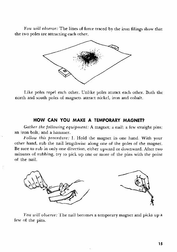
You will observe: The lines of force traced by the iron filings show thatthe two poles are attracting each other.
Like poles repel each other. Unlike poles attract each other. Both thenorth and south poles of magnets attract nickel, iron and cobalt.
HOW CAN YOU MAKE A TEMPORARY MAGNET?
Gather the following equipment: A magnet; a nail; a few straight pins;an iron bolt; and a hammer.
Follow this procedure: 1. Hold the magnet in one hand. With yourother hand, rub the nail lengthwise along one of the poles of the magnet.Be sure to rub in only one direction, either upward or downward. After twominutes of rubbing, try to pick up one or more of the pins with the pointof the nail.
You will observe: The nail becomes a temporary magnet and picks up afew of the pins.
15

2. Hold the iron bolt in one hand. Stand facing north, and point thebolt downward at about a 25-degree angle. 'Then, with a hammer, gentlytap that end of the bolt which is nearer to you. Tap for about a minute. Next,try to pick up some of the pins with that end of the bolt which is fartherfrom you.
You will observe: The bolt becomes a temporary magnet and picks upa few of the pins.
Iron is the softest of the three metals which are affected by magnetism.It is the easiest one to make into a magnet, but it loses its magnetism rapidly.A temporary magnet, made as in this experiment, retains its magnetic powerfor only a few days. See page 24 for an explanation of why this is so.
16
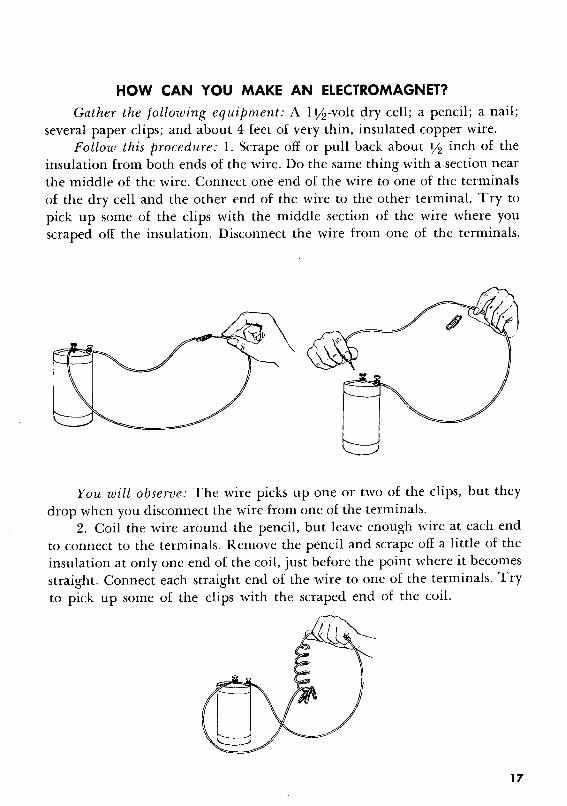
HOW CAN YOU MAKE AN ELECTROMAGNET?
Gather the following equipment: A lY2-volt dry cell; a pencil; a nail;several paper clips; and about 4 feet of very thin, insulated copper wire.
Follow this procedure: 1. Serape off or pull back about Y2 inch of theinsulation from both ends of the wire. Do the same thing with a section nearthe middle of the wire. Connect one end of the wire to one of the terminalsof the dry cell and the other end of the wire to the other terminal. Try topick up some of the clips with the middle section of the wire where youscraped off the insulation. Disconnect the wire from one of the terminals.
You will observe: The wire picks up one or two of the clips, but theydrop when you disconnect the wire from one of the terminals.
2. Coil the wire around the pencil, but leave enough wire at each endto connect to the terminals. Remove the pencil and scrape off a little of theinsulation at only one end of the coil, just before the point where it becomesstraight. Connect each straight end of the wire to one of the terminals. Tryto pick up some of the clips with the scraped end of the coil.
17

You will observe: The coiled wire holds three or four clips.3. Coil another wire tightly around the nail. Connect the ends of the
wire to the dry cell, as you did in the first two parts of this experiment. Holding one end of the nail, try to pick up some of the clips with the other endof it. Disconnect the wire from one of the terminals when you have finished.
You will observe: The nail picks up five or six of the clips.
An electric current flowing through a wire makes the wire magnetic.When you coil the wire, its magnetic power is stronger, and when you puta soft iron core inside the coil, the magnetic power is even stronger. Electromagnets - objects in which magnetism is induced by electricity - aretemporary magnets. When the current is off, the electromagnet loses its power.
18

HOW CAN YOU MAKE A PERMANENT MAGNET?
Gather the following equipment: About 4 feet of very thin, insulated
copper wire; a pencil; two 1Y2-volt dry cells; several paper clips; and a screw
driver.Follow this procedure: Snip off a piece of wire 4 inches long. Scrape the
ends of the wire clean of insulation so that the copper is exposed. With the
wire, connect the negative terminal (the one on the edge) of one dry cell
with the positive terminal (the one in the middle) of the other dry cell.
Be sure the copper makes contact with the terminals. Now take the other
piece of wire. Leave 9 inches of it straight at each end; coil the remainder
of it around the whole length of the pencil. Then remove the pencil. Place
a metal portion of the screw driver in the coil. Scrape the ends of the wire
free of insulation. Connect one end of the wire to the free terminal on one
of the dry cells. Connect the other end of the wire to the free terminal on
the other dry cell. .After about 15 seconds, disconnect one of the wires from
its terminal connection. Remove the screw driver from the coil and try to
pick up some of the clips with the screw driver.
You will observe: The screw driver picks up several clips.
You have just made what is called a permanent magnet} but like all so
called permanent magnets, its magnetic power will last only a few ~ears,
not forever. If the metal were iron, it would lose its magnetic power qUickly.
Screw drivers, however, like most metal tools, are not made of pure iron,
19
but rather of steel, which is an iron alloy. An alloy is a combination of metals,or metals and other substances, melted together to form a new compound.Steel is an alloy of iron and carbon. Alloys with magnetic metals makestronger magnets and hold their magnetism for longer periods of time.
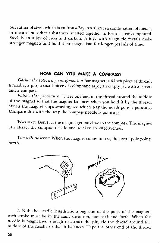
HOW CAN YOU MAKE A COMPASS?Gather the following equipment: A bar magnet; a 6-inch piece of thread;
a needle; a pin; a small piece of cellophane tape; an empty jar with a cover;and a compass.
Follow this procedure: 1. Tie one end of the thread around the middleof the magnet so that the magnet balances when you hold it by the thread.When the magnet stops swaying, see which way the north pole is pointing.Compare this with the way the compass needle is pointing.
WARNING: Don't let the magnet get too close to the compass. The magnetcan attract the compass needle and weaken its effectiveness.
You will observe: When the magnet comes to rest, the north pole pointsnorth.
2. Rub the needle lengthwise along one of the poles of the magnet;each stroke must be in the same direction, not back and forth. When theneedle is magnetized enough to attract the pin, tie the thread around themiddle of the needle so that it balances. Tape the other end of the thread
20
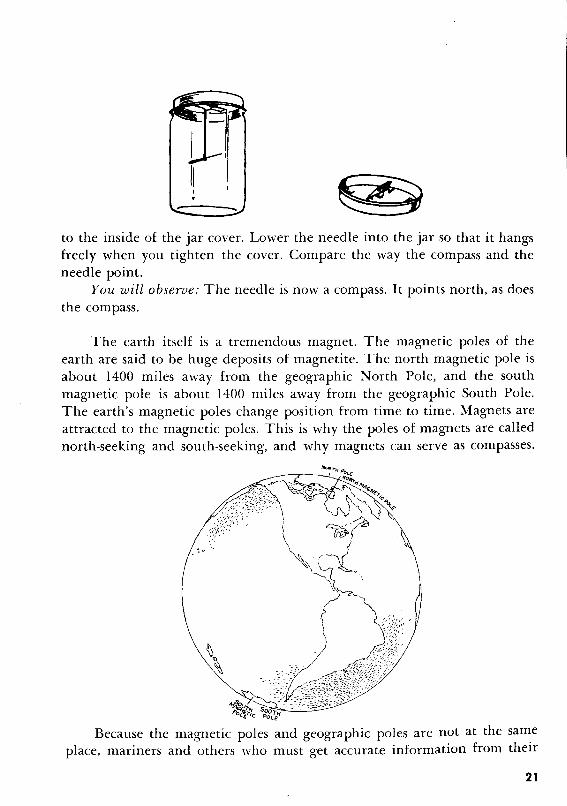
-to the inside of the jar cover. Lower the needle into the jar so that it hangsfreely when you tighten the cover. Compare the way the compass and theneedle point.
You will observe: The needle is now a compass. It points north, as doesthe compass.
The earth itself is a tremendous magnet. The magnetic poles of theearth are said to be huge deposits of magnetite. The north magnetic pole isabout 1400 miles away from the geographic North Pole, and the southmagnetic pole is about 1400 miles away from the geographic South Pole.The earth's magnetic poles change position from time to time. Magnets areattracted to the magnetic poles. This is why the poles of magnets are callednorth-seeking and south-seeking, and why magnets can serve as compasses.
Because the magnetic poles and geographic poles are not at the sameplace, mariners and others who must get accurate information from their
21

compasses correct their compass reading with a chart which compensatesfor the error of the compass in various locations. The disparity between themagnetic and geographic poles is called the angle of declination. The magnetpoints to true north only in those places which lie in a straight line with thenorth geographic pole and the north magnetic pole.
It is said that the earth's magnetic field causes objects made of iron,nickel or cobalt anywhere in the world to become magnetized if they remainunmoved for very long periods of time.
HOW CAN YOU TELL TIME WITH A COMPASS?
Gather the following equipment: A compass and a pencil.Follow this procedure: Take the equipment outdoors on a sunny day.
Stand facing north. Hold the pencil in line with the compass needle, but atan upward angle of 45 degrees; the bottom end of the pencil should rest onthe glass directly above the "S" on the face of the compass.
You will observe: The pencil casts a shadow over the compass. If youregard the "N" on the compass as 12 o'clock, the "W" as 9 o'clock, the "E"as 3 o'clock, and the "S" as 6 o'clock, the shadow gives you the approximatetime.
Of course, you must have sunlight for this experiment to work. Thehour you get will be in terms of standard time. You will recognize that, as ameans of telling time, the compass operates in much the same fashion as asundial.
22

WHAT HAPPENS WHEN YOU CUT A MAGNET INTO PIECES?
Gather the following equipment: A hack saw and an inexpensive barmagnet.
Follow this procedure: 1. Saw the magnet into thirds. Put the magnettogether again as it was by placing the pieces side by side.
You will observe: The parts of the magnet attract each other when youreplace them exactly as they were before you sawed them apart.
2. Pull the two ends away from the middle. Turn them around so thatwhat were the north and south poles of the unsawed magnet are now pointing inward toward the center piece. Move them toward the center piece.
You will observe: The center piece repels each end piece.
3. Take each of the three pieces of the magnet in turn and place firstone end and then the other about ~ of an inch from the hack-saw blade.
You will observe: In each case the hack-saw blade is attracted to themagnet.
When you cut or break a magnet, the cut or broken end becomes theopposite pole to the one on the other end.
A broken magnet does retain its magnetic power, but striking, droppingor vibrating a magnet, as you did when you sawed it apart, weakens it considerably. Magnets also become weaker when they are heated. Bear this inmind, and remember to handle and store magnets with care.
23
WHAT IS THE SECRET OF MAGNETISM?
Scientists have not been able to prove what causes magnetism, but mostof them accept an explanation called the molecule theory. This theory isbased on the fact that all matter is made up of molecules) small groupingsof atoms) which are in turn the smallest particles into which elements canbe divided and still be recognizable. The molecules of iron, nickel and cobalt,according to this theory, are themselves little magnets, each with a northseeking and a south-seeking pole. The theory goes on to explain that whenthe "molecule-magnets" of these metals are arranged at random, with thepoles pointing in all directions, these metals do not behave like magnets.When the molecules of these metals are pulled into line with all the northseeking poles pointing in one direction, and all the south-seeking poles pointing in the opposite direction, then these metals behave like magnets.
In temporary magnets, made of "soft" (pure) iron, the molecules soonbecome disarranged again. Permanent magnets, made of "hard" alloys, holdthe "molecule-magnets" in line for years.
This theory also explains why cobalt, nickel and iron objects becomemagnetized after lying unmoved for years; their "molecule-magnets," subjectto the earth's magnetic field for so long, are gradually pulled into line.Similarly, you can make a magnet by tapping an iron bolt while pointing itin the direction of the north magnetic pole, because the tapping and theinfluence of the earth's magnetic pole combine to jar the "molecule-magnets"of the bolt into line.
According to this theory, the explanation of why magnets weaken whenthey are dropped or struck is that the blow jars the "molecule-magnets" outof line. In the same way, when you heat magnets, the heat sets the "moleculemagnets" into motion, disorganizes them, and thus makes the magnetgrow weaker.
Another theory scientists put forth to explain magnetism is the electrontheory. This theory holds that the electrons of iron, nickel and cobalt causemagnetism. Electrons are unbelievably tiny particles of the atom that circulate around its core, or nucleus. The people who support this theory pointout that electrons circulate around the nucleus of the atom in a variety ofdirections. The supporters of this theory say that when the electrons of iron,nickel or cobalt are caused to circulate in the same direction, by an electriccurrent, for example, they set up in these metals a current, which is magnetism. This theory is less widely accepted than the molecule theory.
24
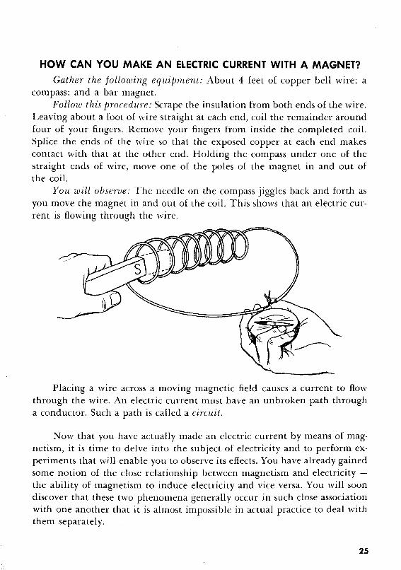
HOW CAN YOU MAKE AN ELECTRIC CURRENT WITH A MAGNET?
Gather the following equipment: About 4 feet of copper bell wire; acompass; and a bar magnet.
Follow this procedure: Scrape the insulation from both ends of the wire.Leaving about a foot of wire straight at each end, coil the remainder aroundfour of your fingers. Remove your fingers from inside the completed coil.Splice the ends of the wire so that the exposed copper at each end makescontact with that at the other end. Holding the compass under one of thestraight ends of wire, move one of the poles of the magnet in and out ofthe coil.
You will observe: The needle on the compass jiggles back and forth asyou move the magnet in and out of the coil. This shows that an electric current is flowing through the wire.
Placing a wire across a moving magnetic field causes a current to flowthrough the wire. An electric current must have an unbroken path througha conductor. Such a path is called a circuit.
Now that you have actually made an electric current by means of magnetism, it is time to delve into the subject of electricity and to perform experiments that will enable you to observe its effects. You have already gainedsome notion of the close relationship between magnetism and electricity the ability of magnetism to induce electricity and vice versa. You will soondiscover that these two phenomena generally occur in such close associationwith one another that it is almost impossible in actual practice to deal withthem separately.
25
ELECTRICITY
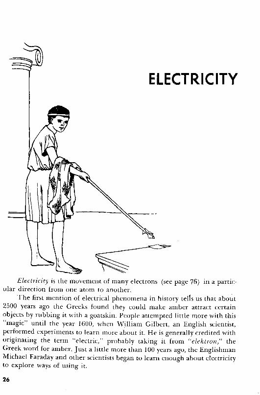
Electricity is the movement of many electrons (see page 76) in a particular direction from one atom to another.
The first mention of electrical phenomena in history tel1s us that abo~t2500 years ago the Greeks found they could make amber attract certainobjects by rubbing it with a goatskin. People attempted little more with this"magic" until the year 1600, when William Gilbert, an English scientist,performed experiments to learn more about it. He is generally credited withoriginating the term "electric," probably taking it from "elektron" theGreek word for amber. Just a little more than 100 years ago, the EnglishmanMichael Faraday and other scientists began to learn enough about electricityto explore ways of using it.
26

HOW CAN YOU GET ELECTRICITY BY RUBBING?
Gather the following equipment: A glass rod; a piece of silk; about 10inches of thread; a pair of scissors; a piece of soft wool; a piece of hard rubber(from an old tire) ; a pair of leather-soled shoes; and a door mat or rug.
Follow this procedure: 1. Cut the thread into about a dozen pieces.Rub the glass rod vigorously for a few moments with the piece of silk. Thenmove the glass rod very close to the pieces of thread.
You will observe: The glass rod attracts the threads.The kind of electricity you have just created is called static electricity)
because it does not flow in a current. The silk cloth rubs some of the electrons from the surface of the glass rod, creating on the rod an imbalancecalled a positive charge. A substance whose atoms are lacking in electronshas a positive charge. When you bring the glass rod close to the threads, therod "pulls" at the electrons on them.
2. Rub the piece of rubber vigorously with the soft wool. Then movethe rubber close to the threads.
You will observe: The rubber attracts the threads.This is also static electricity but in this case, the charge is negative. The
rubber took electrons from the piece of wool. Substances whose atoms havean excess of electrons are negatively charged.
3. Wearing the leather-soled shoes, scuff your feet on the door matfor about 15 seconds; don't touch any surface with your hands until youhave finished scuffing. Then touch a metal door knob.
27
You will observe: A charge of static electricity momentarily "tickles"the part of your hand which first touches the knob. The friction betweenyour feet and the door mat built up a charge in your body. If it is a particularly cold and dry day, you may see a spark and hear it "pop" as it jumpsfrom your hand to the knob. You may have difficulty in getting this experiment to work satisfactorily during the summer or on a damp day.
Damp or moist air is a good conductor of electricity, which means thatelectrons move through it easily. As a result, it carries electrons away, makingit difficult to accumulate enough of them for a charge. Similarly, metals,which are also good conductors of electricity, will not build static electricalcharges. Materials that do not conduct electricity are called non-conductorsor insulators. It is with insulators that you can build static charges.
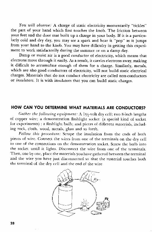
HOW CAN YOU DETERMINE WHAT MATERIALS ARE CONDUCTORS?
Gather the following equipment: A I Y2-voltdry cell; two 8-inch lengthsof copper wire; a demonstration flashlight socket (a special kind of socketfor experiments) ; a flashlight bulb; and pieces of different materials, includ-ing rock, cloth, wood, metals, glass and so forth. .
Follow this procedure: Scrape the insulation from the ends of bothpieces of wire. Connect the wires from one of the terminals on the dry cellto one of the connections on the demonstration socket. Screw the bulb intothe socket until it lights. Disconnect the wire from one of the terminals.Then, one by one, place the materials you have gathered between the terminaland the wire you have just disconnected so that the material touches boththe terminal of the dry cell and the end of the wire.
28

You will observe: The bulb lights up whenever the material you use tocomplete the circuit is a conductor. It does not light when the material youuse is a non-conductor.
For an explanation of why some materials are good conductors whileothers are not, see page 69.
HOW CAN YOU MAKE AN ELECTROSCOPE? '
(An Instrument for Detecting Electric Charges)
Gather the following equipment: A jar or bottle with a cork or rubberstopper to fit it; a paper clip or a 6-inch piece of copper wire; a strip ofaluminum foil about 3 inches long and I inch wide; a comb; a test tube; apiece of silk and a piece of wool.
Follow this procedure: Straighten the clip. Push one end of the clipthrough the center of the stopper so that only about Y2 inch of it sticks upthrough the top and some of it goes through the bottom. Make a little hookor "L" at the bottom end of the clip. Fold the aluminum foil in half so thateach half is I Y2 inches long. Cut a piece of the foil off at the fold so that thetwo halves are held together by only a very narrow strip. Hang the foil on the"L" at the bottom of the clip. Lower the clip and foil into the jar and sealthe jar with the stopper. Rub the comb vigorously with the wool and thentouch the comb to the bit of metal sticking through the stopper. Rub it backand forth on the metal for a moment. Now touch the piece of metal sticking
29
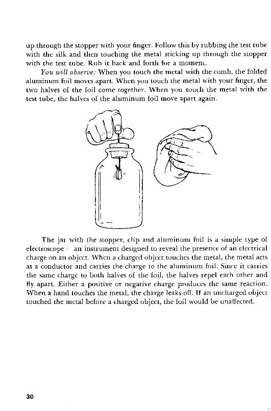
up through the stopper with your finger. Follow this by rubbing the test tubewith the silk and then touching the metal sticking up through the stopperwith the test tube. Rub it back and forth for a moment.
You will observe: When you touch the metal with the comb, the foldedaluminum foil moves apart. When you touch the metal with your finger, thetwo halves of the foil come together. When you touch the metal with thetest tube, the halves of the aluminum foil move apart again.
The jar with the stopper, clip and aluminum foil is a simple type ofelectroscope - an instrument designed to reveal the presence of an electricalcharge on an object. When a charged object touches the metal, the metal actsas a conductor and carries the charge to the aluminum foil. Since it carriesthe same charge to both halves of the foil, the halves repel each other andfly apart. Either a positive or negative charge produces the same reaction.When a hand touches the metal, the charge leaks off. If an uncharged objecttouched the metal before a charged object, the foil would be unaffected.
30
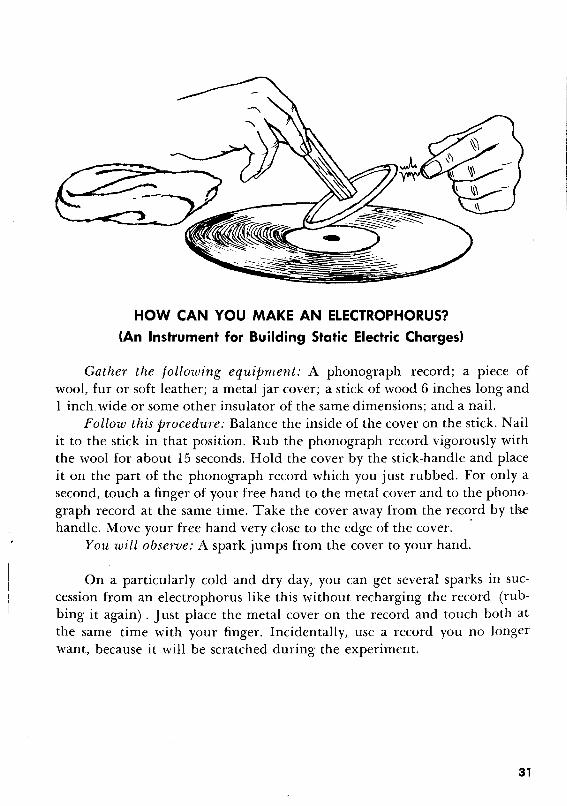
HOW CAN YOU MAKE AN ELECTROPHORUS?
(An Instrument for Building Static Electric Charges)
Gather the following equipment: A phonograph record; a piece ofwool, fur or soft leather; a metal jar cover; a stick of wood 6 inches long and1 inch. wide or some other insulator of the same dimensions; and a nail.
Follow this procedure: Balance the inside of the cover on the stick. Nailit to the stick in that position. Rub the phonograph record vigorously withthe wool for about 15 seconds. Hold the cover by the stick-handle and placeit on the part of the phonograph record which you just rubbed. For only asecond, touch a finger of your free hand to the metal cover and to the phonograph record at the same time. Take the cover away from the record by thehandle. Move your free hand very close to the edge of the cover. .
You will observe: A spark jumps from the cover to your hand.
On a particularly cold and dry day, you can get several sparks in succession from an electrophorus like this without recharging the record (rubbing it again) . Just place the metal cover on the record and touch both atthe same time with your finger. Incidentally, use a record you no longerwant, because it will be scratched during the experiment.
31

HOW CAN YOU MAKE A BATTERY?
Gather the following equipment: A strip of zinc, 1 inch wide and 6~
inches long; a strip of copper of the same size; a small piece of st~el woolor sandpaper; a demonstration flashlight socket; a flashlight bulb; 12 inchesof bell wire; a large piece of blotting paper or cotton; some ammoniumchloride - available in well-equipped drug stores and chemical supplyhouses (heavily salted water will do but not as well); an eye dropper; anda rubber band.
Follow this procedure: Cut the copper and zinc each into five pieces1 inch in length and one piece 1~ inches in length. Punch a tiny hole atone end of each of the 1~-inch-Iong pieces of metal. Cut the bell wire intotwo 6-inch lengths. Scrape the insulation back from all four ends. Connectan end of one of the pieces of wire to the piece of zinc with the hole in it,putting the wire through the hole. In the same manner, connect an end of theother piece of wire to the piece of copper with the hole in it. Rub all ofthe pieces of metal with the steel wool. Cut the blotting paper into elevenI-inch squares. Place a square of blotting paper on the piece of zinc that hasthe wire attached. Fill the eye dropper with ammonium chloride and soakthe blotting paper on the zinc with it. Then, alternately pile copper, saturatedblotting paper, zinc, blotting paper, copper, and so forth until you have the
32

-'piece of copper with the wire attached on top. Remember to soak each pieceof blotting paper with ammonium chloride before you cover it with anotherpiece of metal. Hold the pile together with the rubber band. Screw the bulbinto the socket. Connect the wire extending from one of the metals on thepile to one of the connections on the socket. Connect the wire extendingfrom the other piece of metal on the pile to the second connection on thesocket.
You will observe: The bulb in the socket lights up.To keep the battery working, you must keep the blotting paper soaked
with the ammonium chloride. This battery operates on the same principleas most batteries used in cars and homes although the materials used mayvary. Electricity is conducted from one metal plate to another through asalt solution called an electrolyte. The metal plates are called electrodes. Thistype of battery is called a voltaic or galvanic pile.
HOW CAN YOU BRING A DEAD DRY CELL BACK TO LIFE?
Gather the following equipment: A dead dry cell; a flashlight bulb; alarge jar about % filled with warm water; a salt shaker filled with salt; a 6-inchlength of bell wire; and a piece of cloth.
Follow this procedure: Dissolve all the salt in the jar of water. Punchseveral holes in the top of the dry cell and place it in the jar of water. Letit soak for an hour. Then take it from the water and dry it with the cloth.
33

Scrape the insulation back from both ends of the wire. Curl one end of thewire tightly around the grooves in the metal at the base of the bulb. Then,holding the glass portion of the bulb, place the metal bottom of the bulbagainst the positive terminal of the dry cell. Hold the other end of the wireagainst the bottom of the cell.
You will observe: The bulb lights up.When a dry cell dies, it is usually because the electrolyte has dried out.
You can revive it in the manner just described, but the cell is weaker. Itsability to cause a flow of electrons will not last long because the electrolytewill dry very quickly, due to the holes punched in the top of the cell.
HOW CAN YOU MAKE A LEAD STORAGE CELL?
Gather the following equipment: Two strips of lead, each 5 inches longand I inch wide; one 4-inch and two 1O-inch strips of bell wire; a drinkingglass a little over % filled with water; two I Y2-voltdry cells; a demonstrationflashlight socket; a flashlight bulb; and 2 ounces of sulphuric acid.
WARNING: Sulphuric acid is extremely dangerous. It can burn your skinand put holes in your clothes and furniture. If any of the acid accidentallygets onto your skin, hold that area of your skin under running water for aminute or more.
Follow this procedure: Punch a small hole about ~ of an inch fromthe top of each of the lead strips. Then bend that edge back on both leadstrips so they will hold when hooked to the edge of the glass. Scrape the insulation back at the ends of all three lengths of wire. Attach one end of each ofthe l O-inch lengths of bell wire to the hole in each of the lead strips. Connectone end of the 4-inch length of bell wire to the positive terminal of one ofthe dry cells and the other end to the negative terminal of the other drycell. Now connect the wire leading from one of the lead strips to the freeterminal on one of the dry cells and connect the wire from the second leadstrip to the free terminal on the other dry cell. Place the lead strips into theglass of water with th~ bent edges resting on opposite sides of the top edgeof the glass. Pour the sulphuric acid into the glass. Wait 10 minutes. Thendisconnect all the wires from the dry cells and connect the two coming fromthe lead strips to the connections on the demonstration socket. Screw thebulb into the socket.
34

{, I
I IL--
You will observe: The bulb lights up.
This type of cell, which is called a lead storage cell, is similar to the firstcells ever used. Because the electrolyte spills easily and evaporates rapidly,scientists developed the dry cell which we now use so extensively. The leadstorage battery, however, is still used in automobiles, where the running ofthe motor recharges the battery. You can recharge the cell you have just madeby connecting it to the dry cells until one of the lead plates takes on abrownish color again.
A cell is one set of positive and negative plates. A battery consists ofmore than one cell. That is why, strictly speaking, it is more accurate to refer to a flashlight "battery" or any other single dry cell as a "cell."
3S

HOW CAN YOU BUILD A FLASHLIGHT?
Gather the following equipment: A flashlight dry cell; a flashlight bulb;5 inches of bell wire; and some cellophane tape.
Follow this procedure: Scrape the insulation from both ends of the wire.Make a coil of the wire at one end. Curl the other end of the wire tightlyaround the grooves at the base of the bulb. Tape the coiled end of the wireto the bottom of the dry cell. Then tape the remainder of the wire aroundthe cell, except for a small portion just large enough to permit the groovesof the bulb to reach the positive terminal of the dry cell. Now press thatportion of the wire, so that the bulb makes contact with the positive terminalof the cell.
You will obseroe: The bulb lights up.
36
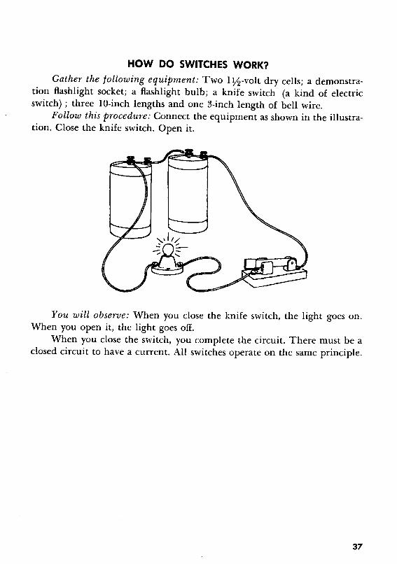
HOW DO SWITCHES WORK?
Gather the following equipment: Two 1y:!-volt dry cells; a demonstration flashlight socket; a flashlight bulb; a knife switch (a kind of electricswitch) ; three lO-inch lengths and one 3-inch length of bell wire.
Follow this procedure: Connect the equipment as shown in the illustration. Close the knife switch. Open it.
You will observe: When you close the knife switch, the light goes on.When you open it, the light goes off.
When you close the switch, you complete the circuit. There must be aclosed circuit to have a current. All switches operate on the same principle.
37
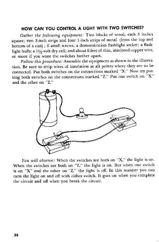
HOW CAN YOU CONTROL A LIGHT WITH TWO SWITCHES?
Gather the following equipment: Two blocks of wood, each 3 inchessquare; two 3-inch strips and four l-inch strips of metal (from the top andbottom of a can) ; 6 small screws; a demonstration flashlight socket; a flashlight bulb; a I Y2-voltdry cell; and about 6 feet of thin, insulated copper wire,or more if you want the switches farther apart.
Follow this procedure: Assemble the equipment as shown in the illustration. Be sure to strip wires of insulation at all points where they are to beconnected. Put both switches on the connections marked "X." Now try putting both switches on the connections marked "Z." Put one switch on "X"and the other on "Z."
You will observe: When the switches are both on "X," the light is on.When the switches 'are both on "Z," the light is on. But when one switchis on "X" and the other on "Z,'· the light is off. In this manner you canturn the light on and off with either switch. It goes on when you completethe circuit and off when you break the circuit.
38
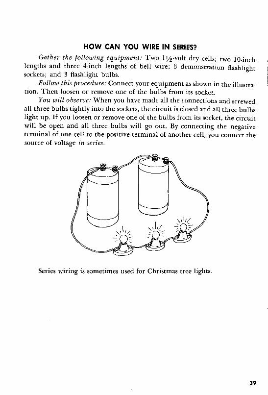
HOW CAN YOU WIRE IN SERIES?
Gather the following equipment: Two I Yl!-volt dry cells; two lO-inchlengths and three 4-inch lengths of bell wire; 3 demonstration flashlightsockets; and 3 flashlight bulbs.
Follow this procedure: Connect your equipment as shown in the illustration. Then loosen or remove one of the bulbs from its socket.
You will observe: When you have made all the connections and screwedall three bulbs tightly into the sockets, the circuit is closed and all three bulbslight up. If you loosen or remove one of the bulbs from its socket, the circuitwill be open and all three bulbs will go out. By connecting the negativeterminal of one cell to the positive terminal of another cell, you connect thesource of voltage in series.
Series wiring is sometimes used for Christmas tree lights.
39
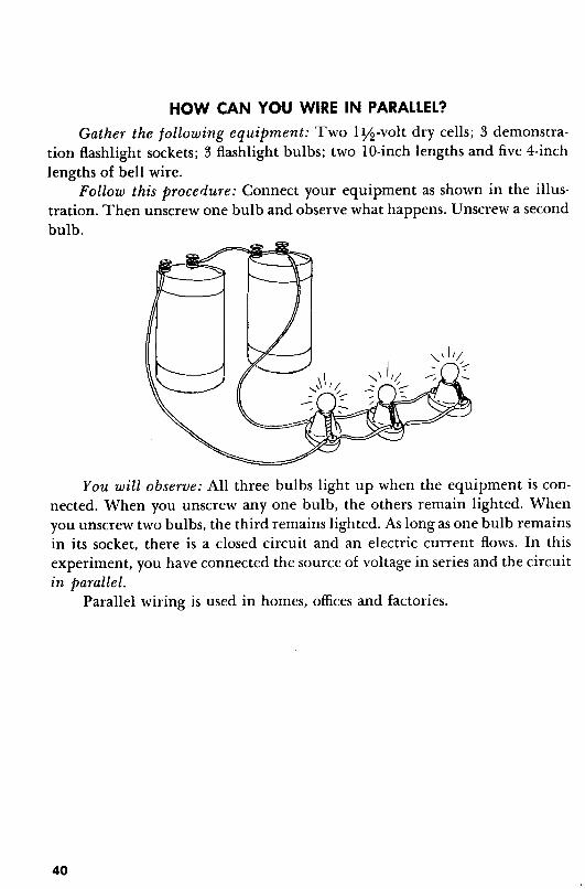
HOW CAN YOU WIRE IN PARALLEL?
Gather the following equipment: Two 1YJ!-volt dry cells; 3 demonstration flashlight sockets; 3 flashlight bulbs; two lO-inch lengths and five 4-inchlengths of bell wire.
Follow this procedure: Connect your equipment as shown in the illustration. Then unscrew one bulb and observe what happens. Unscrew a secondbulb.
You will observe: All three bulbs light up when the equipment is connected. When you unscrew anyone bulb, the others remain lighted. Whenyou unscrew two bulbs, the third remains lighted. As long as one bulb remainsin its socket, there is a closed circuit and an electric current flows. In thisexperiment, you have connected the source of voltage in series and the circuitin parallel.
Parallel wiring is used in homes, offices and factories.
40
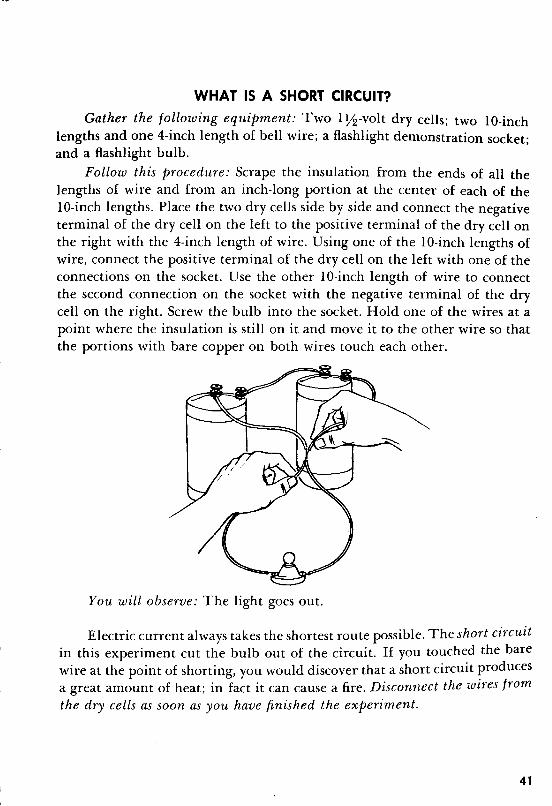
WHAT IS A SHORT CIRCUIT?
Gather the following equipment: Two I Yl?-volt dry cells; two lO-inchlengths and one 4-inch length of bell wire; a flashlight demonstration socket;and a flashlight bulb.
Follow this procedure: Scrape the insulation from the ends of all thelengths of wire and from an inch-long portion at the center of each of thelO-inch lengths. Place the two dry cells side by side and connect the negativeterminal of the dry cell on the left to the positive terminal of the dry cell onthe right with the 4-inch length of wire. Using one of the lO-inch lengths ofwire, connect the positive terminal of the dry cell on the left with one of theconnections on the socket. Use the other lO-inch length of wire to connectthe second connection on the socket with the negative terminal of the drycell on the right. Screw the bulb into the socket. Hold one of the wires at apoint where the insulation is still on it and move it to the other wire so thatthe portions with bare copper on both wires touch each other.
You will observe: The light goes out.
Electric current always takes the shortest route possible. The short circuitin this experiment cut the bulb out of the circuit. If you touched the barewire at the point of shorting, you would discover that a short circuit producesa great amount of heat; in fact it can cause a fire. Disconnect the wires fromthe dry cells as soon as you have finished the experiment.
41
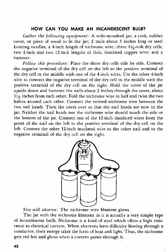
HOW CAN YOU MAKE AN INCANDESCENT BULB?
Gather the following equipment: A wide-mouthed jar; a cork, rubbercover, or piece of wood to fit the jar; 2 nails about 3 inches long or steelknitting needles; a 4-inch length of nichrome wire; three I Y2-volt dry cells;two 4-inch and two l z-inch lengths of thin, insulated copper wire; and ahammer.
Follow this procedure: Place the three dry cells side by side. Connectthe negative terminal of the dry cell on the left to the positive terminal ofthe dry cell in the middle with one of the 4-inch wires. Use the other 4-inchwire to connect the negative terminal of the dry cell in the middle with thepositive terminal of the dry cell on the right. Hold the cover of the jarupside down and hammer the nails about 2 inches through the cover, aboutI Y2 inches from each other. Fold the nichrome wire in half and twist the twohalves around each other. Connect the twisted nichrome wire between thetwo nail heads. Turn the cover over so that the nail heads are now in thejar. Neither the nail heads nor the nichrome wire should touch the side orthe bottom of the jar. Connect one of the 12-inch insulated wires from thepoint of the nail on the left to the positive terminal of the dry cell on theleft. Connect the other 12-inch insulated wire to the other nail and to thenegative terminal of the dry cell on the right.
You will observe: The nichrome wire filament glows.The jar with the nichrome filament in it is actually a very simple type
of incandescent bulb. Nichrome is a kind of steel which offers a high resistance to electrical current. When electrons have difficulty flowing through aconductor, their energy takes the form of heat and light. Thus, the nichromegets red hot and glows when a current passes through it.
42
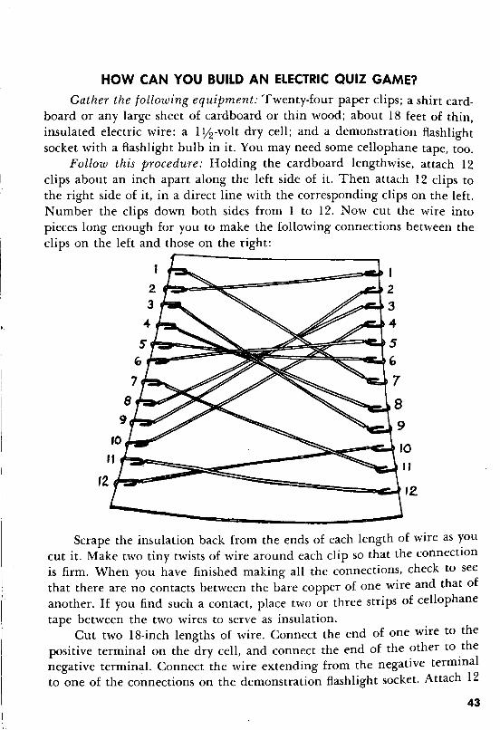
HOW CAN YOU BUILD AN ELECTRIC QUIZ GAME?
Gather the following equipment: Twenty-four paper clips; a shirt cardboard or any large sheet of cardboard or thin wood; about 18 feet of thin,insulated electric wire; a 1Y:2-volt dry cell; and a demonstration flashlightsocket with a flashlight bulb in it. You may need some cellophane tape, too.
Follow this procedure: Holding the cardboard lengthwise, attach 12clips about an inch apart along the left side of it. Then attach 12 clips tothe right side of it, in a direct line with the corresponding clips on the left.Number the clips down both sides from 1 to 12. Now cut the wire intopieces long enough for you to make the following connections between theclips on the left and those on the right:
~~~========:J~3...
~~~!::=~5~~~~====--C:.J. G
7
8
9
Scrape the insulation back from the ends of each length of wire as youcut it. Make two tiny twists of wire around each clip so that the connectionis firm. When you have finished making all the connections, check to seethat there are no contacts between the bare copper of one wire and that ofanother. If you find such a contact, place two or three strips of cellophanetape between the two wires to serve as insulation.
Cut two 18-inch lengths of wire. Connect the end of one wire to thepositive terminal on the dry cell, and connect the end of the other to ,thenegative terminal. Connect the wire extending from the negative termmalto one of the connections on the demonstration flashlight socket. Attach 12
43

inches of wire to the other connection on the flashlight socket. Turn thecardboard over.
St r.:----::;.:::=--=:::::::~'!,
Devise a list of 12 questions. Write them on small slips of paper andput them under each of the 12 clips on the left of the reverse side of thecardboard. Write the answers to the questions on 12 more small slips ofpaper. Put them under the appropriate clips on the right of the reverse sideof the cardboard - the answer to the first question under the second clip,the answer to the second question under the ninth clip, and so on.
44
In one hand, hold the free end of the wire that is connected to the. socket, and in the other hand, hold the free end of the wire that is con
nected to the positive terminal of the dry cell. Place the end of the wire inyour left hand tightly against a clip over one of the questions. Then placethe end of the wire in your right hand tightly against the clip on the correct answer.
You will observe: If you have placed the right-hand wire on the otherend of the wire to which the question is attached, the bulb lights up.
To make the game more interesting, you can make up an unlimitednumber of sets of questions and answers. Instead of writing each questionand each answer on separate pieces of paper, write them at the appropriateplaces on one sheet of paper an inch narrower and shorter than the sheet ofcardboard. Then you can fit the whole question-and-answer sheet under theclips or remove it and replace it with another in a matter of seconds.
HOW CAN YOU BUILD A TELEGRAPH SET?
Gather the following equipment: A I Y2-volt dry cell; 25 feet of thin,insulated wire; 2 iron bolts, each about 2 inches long; a nut to fit one ofthe bolts; four l-inch nails; 3 small screws; 4 blocks of wood, each about3 inches by 3 inches by Y4 of an inch; and 2 strips of metal, each about 2Y2inches long and Y2 inch wide (the metal may be cut from the top or bottom of a can) .
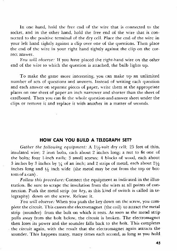
Follow this procedure: Connect the equipment as indicated in the illustration. Be sure to scrape the insulation from the wires at all points of connection. Push the metal strip (or key) as this kind of switch is called in telegraphy) down on the screw. Release it.
You will observe: When you push the key down on the screw, you complete the circuit. This causes the electromagnet (the coil) to attract the metalstrip (sounder) from the bolt on which it rests. As soon as the metal strippulls away from the bolt below, the circuit is broken. The electromagnetthen loses its power and the sounder falls back to the bolt. This completesthe circuit again, with the result that the electromagnet again attracts thesounder. This happens many, many times each second, as long as you hold
45
the key down against the screw; the sounder touches the magnet and thebolt in such quick succession that it makes a buzzing sound.
If you make a telegraph set with longer wires, you can keep the key inone room and the rest of the set, including the dry cell, in another room,and you can send a message from the first room to the second one.
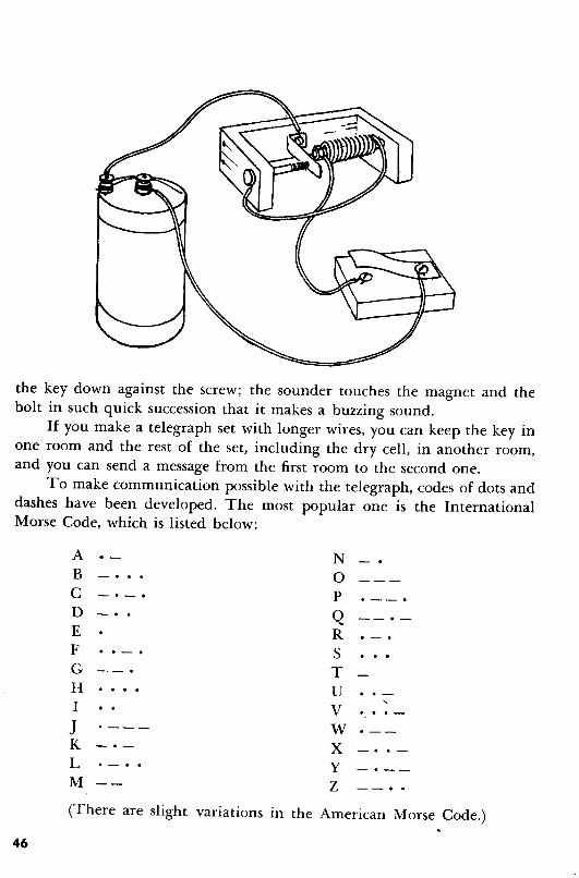
To make communication possible with the telegraph, codes of dots anddashes have been developed. The most popular one is the InternationalMorse Code, which is listed below:
A NB - . . . 0C -. -. p . --.D Q --. -
E RF SG TH UI V . . . -J . --- WK X - . . -
L Y -. --M Z --. .(There are slight variations in the American Morse Code.)
46
,.....
A dot is a very short sound that you make by pressing the key just longenough to get a sound and then releasing it immediately. A dash is a soundthat lasts about three times as long as a dot; to make it, you hold the keydown about three times as long as you would for a dot.
Telegraphers call the dots "dits" and the dashes "dahs." When theyrattle off the letters very quickly, "A" sounds like "di-dah," "X" like "dahdi-di-dah,' and so forth. Saying the code to yourself helps you memorize it.You can "talk" code this way with a friend who knows the code, too.
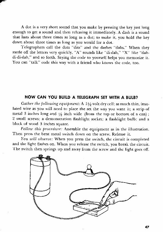
HOW CAN YOU BUILD A TELEGRAPH SET WITH A BULB?
Gather the following equipment: A I yz-volt dry cell; as much thin, insulated wire as you will need to place the set the way you want it; a strip ofmetal 3 inches long and yz inch wide (from the top or bottom of a can) ;2 small screws; a demonstration flashlight socket; a flashlight bulb; and ablock of wood 3 inches square.
Follow this procedure: Assemble the equipment as in the illustration.Then press the bent metal switch down on the screw. Release it.
You will observe: When you press the switch, the circuit is completedand the light flashes on. When you release the switch, you break the circuit.The switch then springs up and away from the screw and the light goes off.
41

HALLW'AYINSIDE
OF
ROOM
HOW CAN YOU WIRE A BELL FOR YOUR ROOM?
Gather the following equipment: A bell; a push button; about 25 feetof thin, insulated wire; a I Y2-volt dry cell; a box of wood staples; and 4small screws.
Follow this procedure: The length of the wires you should use in makingconnections depends on where you decide to place the button, the bell andthe dry cell. The following lengths are suggestions. Place the dry cell on thefloor inside your room, as near as possible to the corner where the door ishinged. Connect a lO-inch wire from the negative terminal on the dry cellto one of the connections on the push button. Connect a 7-inch wire to theother connection on the push button. Then screw the push button to thefloor outside your room, as close as possible to the door hinges. Push the freewire from the push button through the space which appears between thedoor and the wall when the door is open. Then connect that wire to one ofthe connections on the inside of the bell. Connect a lO-inch wire from thesecond connection on the inside of the bell to the positive terminal of thedry cell. Now screw the bell to the inside of the door, near the bottom hinge.Staple those wires which are free and in the way to the floor or door, whichever seems more convenient. Be sureto leave enough play for the door toopen and close without pulling theconnections loose. Step outside thedoor and put your foot on the pushbutton.
You will observe: The bell on theinside of the door rings. The pushbutton acts as the switch to completethe circuit.
48
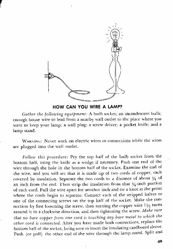
HOW CAN YOU WIRE A LAMP?
Gather the following equipment: A bulb socket; an incandescent bulb;enough house wire to lead from a nearby wall outlet to the place where youwant to keep your lamp; a wall plug; a screw driver; a pocket knife; and alamp stand.
W ARNINC: Never work on electric wires or connections while the wiresare plugged into the wall outlet.
Follow this procedure: Pry the top half of the bulb socket from thebottom half, using the knife as a wedge if necessary. Push one end of thewire through the hole in the bottom half of the socket. Examine the end ofthe wire, and you will see that it is made up of two cords of copper, eachcovered by insulation. Separate the two cords to a distance of about % ofan inch from the end. Then strip the insulation from that %-inch portionof each cord. Pull the wire apart for another inch and tie a knot at the pointwhere the cords begin to separate. Connect each of the stripped halves toone of the connecting screws on the top half of the socket. Make the connection by first loosening the screw, then turning the copper wire 1Y2 turnsaround it in a clockwise direction, and then tightening the screw. Make surethat no bare copper from one cord is touching any bare metal to which theother cord is connected. After you have made both connections, replace thebottom half of the socket, being sure to insert the insulating cardboard sleeve.Push (or pull) the other end of the wire through the lamp stand. Split and
49
strip the free end of th e wire. Push it through th e hol e in the plug towardthe prongs. When yOll have pushed it through far en ough, knot the twowires at the point where th ey begin to separate. T wist each of the wiresaround one of the prongs. Twist it also l lh turns in a cloc kwise directi onaround th e screw beh ind th e prong. T ighten the screws . Then screw thebulb into th e lamp socket. Aga in, be sure tha t no patch es of bare metal toucheach other except at th e connec tio ns. Put the plug into th e wall ou tlet. Turnthe switch on.
You wi ll obse rve: T he light goes on. The two wires are bound together ,th ough separated by insul at ion , to ma ke a complete circui t for the flow ofelect ric current witho u t th e jumble whi ch single wires wou ld invo lve.
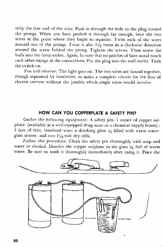
HOW CAN YOU COPPERPLATE A SAFETY PIN?
Gat her th e foll owing equipment: A safety pin ; I ounce of copper sulphate (available at a well-eq uipped drug store or a chemic al su pply hou se) ;3 feet of thin , insulated wire ; a drinking glass % filled with warm water ;glass stirrer; and two l lh-volt dry cell s.
Follow this procedure: Cl ean the safe ty pin thoroughl y with soap andwater or alcohol. Dissolve th e copper su lphate in the glass % full of warmwater. Be sure to wash it thorou ghly immediately after using it. Place th e
50

dry cells side by side behind the glass. Strip the insulation from the ends ofa 4-inch long piece of wire, and use it to connect the negative terminal ofthe dry cell on the left with the positive terminal of the dry cell on the right.Attach one end of an 18-inch length of wire, after stripping the insulation,to the positive terminal of the dry cell on the left. Strip the insulation fromabout 6 inches of the other end of this wire. Fold this 6-inch portion on itselftwice and place it in the glass, keeping it on one side. Connect one end ofthe remaining wire to the negative terminal of the dry cell on the right.Make a hook on the other end of the wire. Place the head of the safety pinon the hook and lower the pin into the glass so that it is completely submerged in the copper sulphate solution. Bend a small section of the wireabove the pin so that it rests on the glass. Be sure that no part of the pin isin contact with the other copper wire. After 30 minutes or more, take the pinout of the solution with the wire hook, and wash it thoroughly.
You will observe: The safety pin is copperplated.
The copper sulphate solution serves as an electrolyte. Not only does itcarry an electric current, but its molecules are actually broken down intotheir component parts by the current. This process is called electrolysis. Thecopper molecules are positively charged. The sulphur-and-oxygen moleculesstay bound together in a chemical unit called a radical. The sulphur-andoxygen radical has a negative charge. When a complete circuit is created, thecopper molecules in the electrolyte, which are positive, are attracted to thesafety pin, which is negative because of its connection to the negative terminalof one of the dry cells. Copper from the copper strip passes into the electrolyte,replacing the copper which settles on the safety pin.
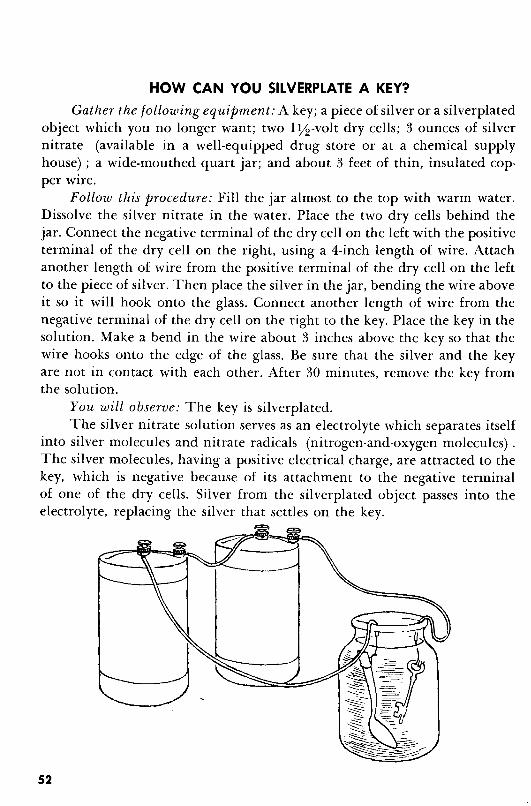
HOW CAN YOU SILVERPLATE A KEY?Gather the following equipment: A key; a piece of silver or a silverplated
object which you no longer want; two 1Y2-volt dry cells; 3 ounces of silvernitrate (available in a well-equipped drug store or at a chemical supplyhouse) ; a wide-mouthed quart jar; and about 3 feet of thin, insulated copper wire.
Follow this procedure: Fill the jar almost to the top with warm water.Dissolve the silver nitrate in the water. Place the two dry cells behind thejar. Connect the negative terminal of the dry cell on the left with the positiveterminal of the dry cell on the right, using a 4-inch length of wire. Attachanother length of wire from the positive terminal of the dry cell on the leftto the piece of silver. Then place the silver in the jar, bending the wire aboveit so it will hook onto the glass. Connect another length of wire from thenegative terminal of the dry cell on the right to the key. Place the key in thesolution. Make a bend in the wire about 3 inches above the key so that thewire hooks onto the edge of the glass. Be sure that the silver and the keyare not in contact with each other. After 30 minutes, remove the key fromthe solution.
You will observe: The key is silverplated.The silver nitrate solution serves as an electrolyte which separates itself
into silver molecules and nitrate radicals (nitrogen-and-oxygen molecules) .The silver molecules, having a positive electrical charge, are attracted to thekey, which is negative because of its attachment to the negative terminalof one of the dry cells. Silver from the silverplated object passes into theelectrolyte, replacing the silver that settles on the key.
52

HOW CAN YOU BUILD A MICROPHONE?
Gather the following equipment: An empty cigar box, candy box orother similar box; 2 dead flashlight dry cells; a wooden pencil, preferablyNo.2; a 1Y2-volt dry cell; 15 feet of thin, insulated wire; a pair of earphonesor a receiver from an old-fashioned two-piece telephone; and a small radio,watch or table clock.
Follow this procedure: Cut the wire into two 3Y2-foot lengths and one8-foot length. Whittle the wood from the pencil until you have an unbrokenand uncovered 3-inch strip of pencil lead (graphite). Take the flashlightdry cells apart carefully until you uncover the carbon core of each of them.Turn the box upside down. Place the two pieces of carbon from the drycells on top of it, parallel to each other and about 2 inches apart. Punctureholes in the box on both sides of each piece of carbon. From the undersideof the box, thread one of the 3Y2-foot lengths of wire up through one of theholes, over a piece of carbon, and back down through the hole on the otherside of the carbon; make sure to strip the insulation from the portion of thewire that is binding the carbon to the box. Tie the wire beneath the carbonin a loop under the box; this will serve the double purpose of keeping contact
53
with the carbon and also holding it in place. Do the same thing with theother piece of carbon, using one end of the 8-foot length of wire. Qraw the3Y:2-foot wire out from under the box and connect it to the negative terminalof the dry cell. Connect the second 3Y:2-foot wire from the positive terminalof the dry cell to one of the wires on the earphones. You may have to unscrewa jack at the end of the wires on the headset. Examine the way the wires areattached to the jack and attach the wire leading from the dry cell to one ofthem. Connect the unattached end of the 8-foot wire to the other wire on theheadset. Make sure that the two wires you have just connected to the headsetare insulated against shorting at the places where the connections are close.Turn on the radio softly and place it, speaker down, on the box near thepieces of carbon. Place the pencil lead on the two pieces of carbon, perpendicular to them both. Put the earphones to your ears.
You will observe: You can hear sounds from the radio in your earphones.
The sounds from the radio cause the box to vibrate. The box, in turn,causes the two pieces of carbon to vibrate. The pieces of carbon cause thepencil lead to vibrate, opening and closing the complete circuit so rapidlythat it causes the sounds the radio produces to be reproduced in the earphones with greater volume.
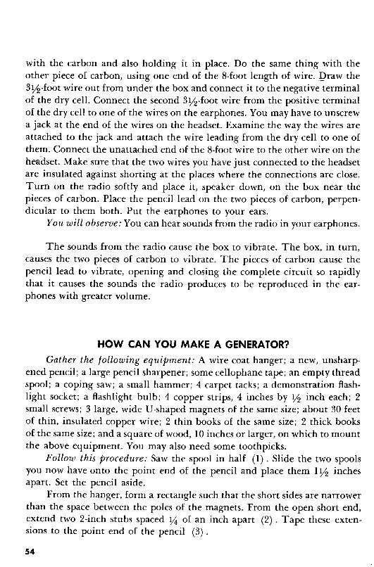
HOW CAN YOU MAKE A GENERATOR?
Gather the following equipment: A wire coat hanger; a new, unsharpened pencil; a large pencil sharpener; some cellophane tape; an empty threadspool; a coping saw; a small hammer; 4 carpet tacks; a demonstration flashlight socket; a flashlight bulb; 4 copper strips, 4 inches by Y:2 inch each; 2small screws; 3 large, wide U'-shaped magnets of the same size; about 30 feetof thin, insulated copper wire; 2 thin books of the same size; 2 thick booksof the same size; and a square of wood, 10 inches or larger, on which to mountthe above equipment. You may also need some toothpicks.
Follow this procedure: Saw the spool in half (1). Slide the two spoolsyou now have onto the point end of the pencil and place them 1Y:2 inchesapart. Set the pencil aside.
From the hanger, form a rectangle such that the short sides are narrowerthan the space between the poles of the magnets. From the open short end,extend two 2-inch stubs spaced 14 of an inch apart (2). Tape these extensions to the point end of the pencil (3).
54
- _--_0_._. ,_.
1.
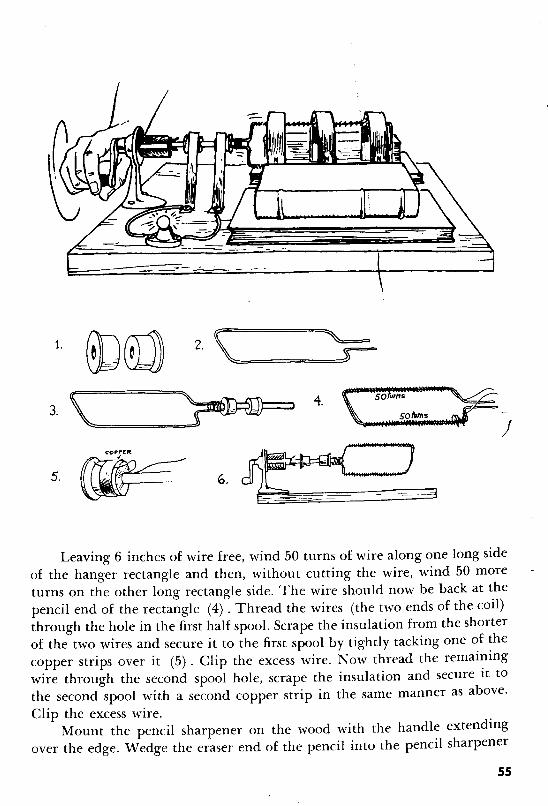
Leaving 6 inches of wire free, wind 50 turns of wire along one long sideof the hanger rectangle and then, without cutting the wire, wind 50 moreturns on the other long rectangle side. The wire should now be back at thepencil end of the rectangle (4). Thread the wires (the two ends of the coil)through the hole in the first half spool. Scrape the insulation from the shorterof the two wires and secure it to the first spool by tightly tacking one of thecopper strips over it (5). Clip the excess wire. Now thread the remainingwire through the second spool hole, scrape the insulation and secure it to
the second spool with a second copper strip in the same manner as above.Clip the excess wire.
Mount the pencil sharpener on the wood with the handle extendingover the edge. Wedge the eraser end of the pencil into the pencil sharpener
55

with the toothpicks, making sure that the pencil turns with rotation of thehandle (6). Attach the two remaining copper strips to the board so that theymake sliding contact with the spools from the same side of the pencil. Attacha wire from each of these strips to a terminal on the flashlight socket. Placethe 3 magnets with all the north poles on the same side in such a way that theyform a tunnel over the rectangle with the coiled wire; make sure that neitherthe coat hanger wire nor the insulated wire touches the magnets. It is desirable for the rectangle, when turning, to be closer to the poles than to thecenter or top of the magnets. To achieve this, it may be necessary to placean edge of each thin book under all the north and south poles, respectively.Wedge the magnets in place by putting two thick books along the sides ofthe tunnel, horizontally, like book ends. Arrange the two copper strips sothat each one now rests on one of the rings. Turn the handle of the sharpenerrapidly.
You will observe: The light goes on and remains on as long as you turnthe handle. When you stop turning the handle, the light goes out.
A generator is a machine designed to change mechanical energy intoelectrical energy. By turning the coils of wire between the poles of the magnets, you are intermittently starting and stopping their magnetic field andare thus inducing an alternating current into the wire. The circuit is completed by extending one of the wires (a.) from the coil to the metal on oneof the rings, (b.) to the copper rubbing on that ring, (c.) to the wire leadingto the bulb, (d.) through the bulb filament, (e.) through the wire leadingto the other strip of metal, (f.) to the ring it is rubbing, (g.) to the wireconnected to the ring, and (h.) back to the coils.
There are three rules governing the amount of electricity you can getwith this kind of generator:
The greater the speed with which the magnetic field is broken, thegreater is the amount of electricity produced.
The greater the number of coils in the wire, the greater is the amountof electricity produced.
The stronger the magnets, the greater is the amount of electricityproduced.
56

HOW CAN YOU MAKE AN ELECTRIC MOTOR?
Gather the following equipment: Three 1Y2-volt dry cells; 2 large, wideU-shaped magnets of the same size; fourteen l-inch nails; 2 thumbtacks;2 paper clips; a new, unsharpened pencil; 2 small screws; some cellophanetape; a spool; 4 strips of thin copper (2 strips measuring 1 inch by 1Yz inches,and 2 strips measuring 3 inches by Y2 inch) ; 5 pieces of wood (l piece measuring 3 inches by 10 inches; 2 pieces measuring 3 inches by 3Y2 inches, and2 pieces measuring 2 inches by 3 inches) ; a 12-inch ruler; and 15 feet of thin,insulated copper wire.
Follow this procedure: Refer to the illustration below in assemblingyour equipment. Nail the wood together, as in the illustration. Tap a nailfirmly into the center of each end of the pencil, being careful not to splitthe pencil. Open the paper clips, so that they each form the number "5."With the thumbtacks, mount the clips under each side of the top of thewooden frame you have made; mount them by the top of the "5," so that,together, they form a cradle for the nails at the ends of the pencil. Thepencil should be able to roll freely. Being careful not to split the pencil, tapa nail firmly in the side of the pencil, 1 inch from the end of it. Tap another
57

nail into the same side of the pencil, 2 inches away from the first nail andin line with it. Turn the pencil over and tap two nails into it directly opposite the nails on the other side. Place the dry cells in a row side by side.With a 4-inch wire, connect the negative terminal of the dry cell on the leftto the positive terminal of the dry cell in the middle. Using another 4-inchwire, connect the negative terminal of the dry cell in the middle with thepositive terminal of the dry cell on the right. Cut two 12-inch wires. Takethe remaining wire, and holding 3 inches of it parallel to the pencil, wind30 coils around the two nails on one side of the pencil. Without cutting thewire, wind 30 coils around the two nails on the other side, leaving 3 inchesof wire parallel to the pencil, opposite the straight piece of wire on the otherside of the pencil. Push the spool onto the long end of the pencil to within11;2 inches of the nails. Take the three inches of wire extending from thecoils and mold it to the pencil, then up and over the nearer top and bottomedges, respectively. Cut and mold two strips of copper. Use each to coverand make contact with the end of one of the wires on the main body of thespool. The copper pieces should be y! of an inch away from each other onboth sides of the main body of the spool. Tape the copper strips into placewith lengthwise strips of tape. Leave at least Y2 inch of the copper stripsbare of tape and thus open to contact. Cradle the pencil on the clips. Screwone edge of each of the remaining two copper strips to the wood in such away that when you lift them, they face each other, rest on, and rub againstthe copper strips on the spool. Connect a wire between the screw on one ofthe copper strips and the positive terminal of the dry cell on the left. Connect a wire between the screw on the other copper strip and the negativeterminal of the dry cell on the right. Place the ruler so that it makes a bridgeacross the gap in the wood frame. Place the magnets one behind the otherwith the three north poles on the same side; lay them astride the ruler so thatthe coils of wire on the pencil are between the poles of the magnets.
You will observe: The pencil spins in its cradle.
An electric motor is a machine designed to change electrical energy tomechanical energy. The current goes from the dry cells, through the wireto the strip of copper (the brush) , to the spool covered by copper (commutator) , through the wire around the pencil (armature), back through theother side of the armature, through the commutator, through the otherbrush, and through the wire leading to the dry cells, thus making a complete
58
circuit. The current running through the coils of the armature causes thearmature to become an electromagnet with poles the same as those it faceson the field (U-shaped) magnets. Because the poles are the same, they repeleach other. As soon as the north poles of the field magnets succeed in attractingthe south pole of the electromagnet (which causes the pencil to turn) , thecurrent reverses itself. The south pole of the electromagnet then changes andbecomes the north pole. A mutual repulsion is again set up between the fieldmagnets and the electromagnet and the pencil turns again. The poles changeso quickly that the pencil rotates continuously.
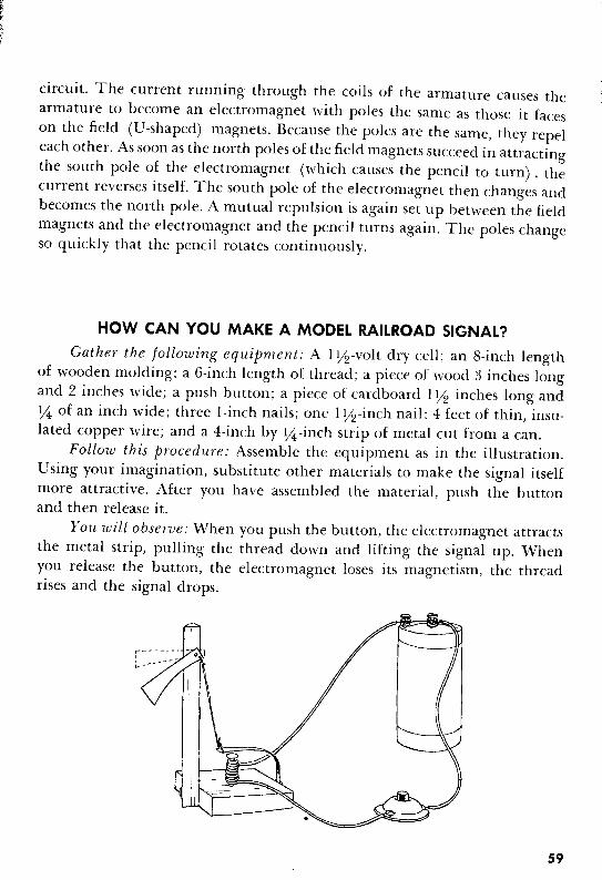
HOW CAN YOU MAKE A MODEL RAILROAD SIGNAL?
Gather the following equipment: A I Y2-volt dry cell; an 8-inch lengthof wooden molding; a 6-inch length of thread; a piece of wood 3 inches longand 2 inches wide; a push button; a piece of cardboard I Y2 inches long andY4 of an inch wide; three I-inch nails; one I Y2-inch nail; 4 feet of thin, insulated copper wire; and a 4-inch by Y4-inch strip of metal cut from a can.
Follow this procedure: Assemble the equipment as in the illustration.Using your imagination, substitute other materials to make the signal itselfmore attractive. After you have assembled the material, push the buttonand then release it.
You will observe: When you push the button, the electromagnet attractsthe metal strip, pulling the thread down and lifting the signal up. Whenyou release the button, the electromagnet loses its magnetism, the threadrises and the signal drops.
S9

HOW CAN YOU MAKE A RHEOSTAT?
(A Device for Regulating an Electric Current)
Gather the following equipment: A lY2-volt dry cell; a pencil (preferably No.2) ; a demonstration flashlight socket; a flashlight bulb; and 3 feetof thin, insulated copper wire.
Follow this procedure: Assemble the equipment as in the illustration.Move the unattached wire back and forth along the length of the exposedpencil lead.
You will observe: As you move the wire, the light gets brighter anddimmer. As you move toward the point of the pencil, that is, closer to oneconnection, the light gets brighter. As you move away from the point towardthe other connection, the light gets dimmer.
The pencil lead in the rheostat you just made is the material that makesit possible to increase or dim the light. The pencil lead is a conductor ofelectricity but a poor one. The greater the distance the current flows in thepencil lead, the weaker it becomes. When you move the end of the wireaway from the point of the pencil, you force the current to travel a greaterdistance through the pencil lead. This causes the current to grow weaker andthe light to grow dimmer. Rheostats are often used to control the volume ofsound in radios and television sets, and to make theatre lights grow dimslowly.
60

WHAT ARE THE KINDS OF ELECTRICITY WE USE?There are two kinds of electric current - direct current (D.C.) and
alternating current (A.C.).Direct current has a steady flow in one direction. It was the first kind
of electric current developed. It is not in extensive use today because itloses much of its energy when carried over great distances. It is still used,however, in automobile, flashlight, and other circuits which get their electricity from batteries or single cells, and for certain tasks, such as electroplating (like the copper- and silverplating which you have already done) .The current must flow steadily in one direction for the metal in the electrolyte to be deposited on the object being electroplated.
Alternating current reverses its flow in a circuit at regular intervals.Each two reversals (back and forth) is referred to as a cycle. The alternating
<Eo-- -.-61

current most of us use in our homes has 60 cycles each second; this rate ofalternation is fast enough so that we don't notice the flickering of our lights,as the current stops very very briefly between each cycle. We use alternatingcurrent more commonly because it can be carried over great distances without substantial loss. To do this, the current must be increased or decreasedaccording to need by use of a device called a transformer.
WHAT IS A TRANSFORMER?
A transformer is a device used to build up or step down the current inan A.C. circuit. It consists of two coils of wire close to each other, one ofwhich forms a complete circuit with a source of alternating current. The coilconnected to the source of energy is called the primary coil, and the othercoil, connected to the object utilizing the energy, is called the secondary coil.The alternating current flows from the source of energy through the primarycoil and induces a current in the secondary coil. If there are more turns inthe secondary coil than in the primary, the voltage is increased. Twice asmany coils double the voltage, three times as many triple it, and so on. Ifthere are fewer turns in the secondary coil than in the primary, the voltageis decreased in the same ratio. An air-core transformer has only air insidethe primary and secondary coils. An iron-core transformer has iron insidethe coils. The iron-core transformer increases and decreases voltage moreefficiently than the air-core transformer.
PRINARY
5V
7 coil
/4eoi/
62
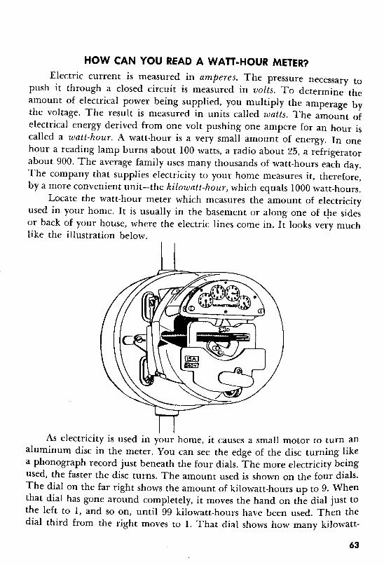
HOW CAN YOU READ A WAn-HOUR METER?
Electric current is measured in amperes. The pressure necessary topush it through a closed circuit is measured in volts. To determine theamount of electrical power being supplied, you multiply the amperage bythe voltage. The result is measured in units called watts. The amount ofelectrical energy derived from one volt pushing one ampere for an hour iscalled a watt-hour. A watt-hour is a very small amount of energy. In onehour a reading lamp burns about 100 watts, a radio about 25, a refrigeratorabout 900. The average family uses many thousands of watt-hours each day.The company that supplies electricity to your home measures it, therefore,by a more convenient unit-the kilowatt-hour) which equals 1000 watt-hours.
Locate the watt-hour meter which measures the amount of electricityused in your home. It is usually in the basement or along one of the sidesor back of your house, where the electric lines come in. It looks very muchlike the illustration below.
As electricity is used in your home, it causes a small motor to turn analuminum disc in the meter. You can see the edge of the disc turning likea phonograph record just beneath the four dials. The more electricity beingused, the faster the disc turns. The amount used is shown on the four dials.The dial on the far right shows the amount of kilowatt-hours up to 9. Whenthat dial has gone around completely, it moves the hand on the dial just tothe left to 1, and so on, until 99 kilowatt-hours have been used. Then thedial third from the right moves to 1. That dial shows how many kilowatt-
63

hours have been used, up to 999. The dial on the left indicates the amount ofkilowatt-hours used, up to 9999.
You read the meter by starting at the left and writing in order the lastnumber passed by the hand on each dial. To determine how much electricalenergy your home has used in one week, take two readings a week apartand subtract the first reading from the second.
64

ELECTRONICS
Electronics deals with the study of the movement of free electrons,especially through a vacuum, through gases, or through semiconductorsmaterials which conduct electricity better than insulators but not so well asconductors. .
One of the earliest developments in what we now call electronics occurred in 1883, when Thomas Edison, who was then studying a weaknessin the filament of his newly developed incandescent lamp, placed a strip ofmetal in the bulb and connected it to a battery. When the bulb was lighted,he found that electrons flowed from the filament to the metal strip, althoughthere was no conductor between them. Edison did not continue to explorethis phenomenon, which later became known as the "Edison effect." Shortlyafter the beginning of this century, however, other scientists did performexperiments to learn more about the Edison effect. Foremost among themwere an Englishmen, Sir John Fleming, and an American, Dr. Lee De Forest.
Although great progress has been made in electronics since then, mostexperts agree that we have only begun to learn about it.
65

HOW CAN AN UNCONNECTED FLUORESCENT BULB GLOW?WARNING: This experiment should be performed ONLY UNDER THE
DIRECT SUPERVISION OF A COMPETENT ADULT.
Gather the following equipment: A fluorescent bulb and a piece ofsoft wool.
Follow this procedure: Take the fluorescent bulb into a dark room orcloset and rub it vigorously with the wool.
WARNING: Be sure not to rub hard enough to break the glass; there isa chemical coating on the inside of it that can be very harmful.
You will observe: As you rub the bulb, it glows around the area wherethe wool touches it.
When you rub the glass, you pull some of the electrons away from theglass. This causes a positive charge on the glass. The imbalance pulls electrons from inside the tube toward the glass.
A fluorescent bulb is a long glass tube with a phosphor coating on theinside of the glass. The ends of the tube are electrodes (metal plates) ; a current of electrons flows between them when the tube is part of a closed circuit. The tube itself is filled with mercury vapor. As the electrons "shoot"through the tube, they bump into the atoms of mercury vapor, which thenemit ultraviolet rays (a type of invisible light ray) . These, in turn, causethe phosphor coating to glow.
66
HOW DOES AN ELECTRON TUBE WORK?
WARNING: This experiment should be performed ONLY UNDER THEDIRECT SUPERVISION OF A COMPETENT ADULT.
Gather the following equipment: A burned-out electron tube (radiotube) ; a small hammer; a glass cutter; and a small paper bag. Use a hacksaw instead of the glass cutter if the tube has a metal bulb.
Follow this procedure: Use the glass cutter to scrape a line around theglass where the bulb meets the base of the tube. Then, holding the base,place the bulb in the bag and tap it gently with the hammer until all theglass has been removed. Be careful not to destroy the insides of the bulb inthe process. Examine the parts of the tube.
You will observe: When the glass breaks, you hear a "pop." On examination, you see that the parts that were enclosed by the bulb form two ormore circuits extending from the prongs at the base of the tube.
In the simplest type of electron tube, the filament in the center is the negative electrode (cathode) . When a current flows through and heats the cathode,it emits electrons. The plate closest to the outside is the positive electrode(anode) ; it attracts the flow of electrons from the cathode. Sometimes thereare wire meshes, called grids, between the anode and cathode; their purposeis to help regulate the number of electrons that reach the anode.
To prevent the cathode from burning up by combining with the oxygenin the air when the cathode is heated, most of the air is removed from thetube just before it is sealed. That is why the electron tube is sometimes calleda vacuum tube. The "pop" you hear when the tube breaks is the air rushing in.
An electron tube which has only an anode and a cathode is called a diode.A tube which has an anode, a cathode and one grid is called a triode. A tubewith an anode, cathode and two grids is a tetrode, and one with an anode,cathode and three grids is a pentode. There are also electron tubes with anumber of other combinations of electrodes and grids, such as tubes withtwo anodes and two cathodes, called duodiodes. Electron tubes are designedaccording to special needs in performing a variety of functions. Among thevarious kinds of electron tubes are oscillators, which generate radio waves(very long invisible light waves) ; modulators, which blend audible waveswith radio waves; amplifiers, which step up current to increase volume ofsound; and detectors, which select audible waves from radio waves servingas carrier waves.
67
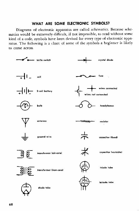
WHAT ARE SOME ELECTRONIC SYMBOLS?
Diagrams of electronic apparatus are called schematics. Because schematics would be extremely difficult, if not impossible, to read without somekind of a code, symbols have been devised for every type of electronic apparatus. The following is a chart of some of the symbols a beginner is likelyto come across.
~...- knife switch -+ crystal diode
-;-J 1_ cell ~ fuse
~II~ ++ wires connected2-cell battery
wires not connected
-@- bulb ~ headphones
68
]II[
antenna
ground wire
transformer telr-cerel
transformer (iron-corel
diode tube
resistor
capacitor (fixedl
capacitor (variablel
triode tube
tetrode tube
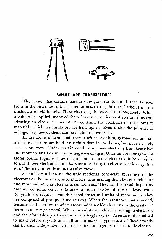
WHAT ARE TRANSISTORS?
The reason that certain materials are good conductors is that the electrons in the outermost orbit of their atoms, that is, the ones farthest from thenucleus, are held loosely. These electrons, therefore, can move freely. Whena voltage is applied, many of them flow in a particular direction, thus constituting an electrical current. By contrast, the electrons in the atoms ofmaterials which are insulators are held tightly. Even under the pressure ofvoltage, very few of them can be made to move freely.
In the atoms of semiconductors, such as selenium, germanium and silicon, the electrons are held less tightly than in insulators, but not so looselyas in conductors. Under certain conditions, these electrons free themselvesand move in small quantities as negative charges. Once an atom or group ofatoms bound together loses or gains one or more electrons, it becomes anion. If it loses electrons, it is a positive ion; if it gains electrons, it is a negativeion. The ions in semiconductors also move.
Scientists can increase the. unidirectional (one-way) movement of theelectrons or the ions in semiconductors, thus making them better conductorsand more valuable as electronic components. They do this by adding a tinyamount of some other substance to each crystal of the semiconductor.(Crystals are regular, smooth-faceted structural units of many solids; they
are composed of groups of molecules.) When the substance that is added,because of the structure of its atoms, adds usable electrons to the crystal, itbecomes an n-type crystal. When the substance added is lacking in electrons,and therefore adds positive ions, it is a p-type crystal. Arsenic is often addedto make n-type crystals and gallium to make p-type crystals. These crystalscan be used independently of each other or together in electronic circuits.
69

When they are combined in crystal "sandwiches," two of one and one of theother (npn or pnp) , they are called transistors.
Transistors can perform the same functions in electronic circuits aselectron, or vacuum tubes. Among the advantages of transistors are that theycause less heat than vacuum tubes, they last much longer than vacuum tubes,and most important, they are smaller than vacuum tubes. They permit theconstruction of smaller, more compact electronic apparatus, such as transistor radios and electronic brains.
WHAT ARE RESISTORS?Most components in an electronic circuit, including the wires, offer some
resistance to the flow of current; each component decreases the flow in proportion to the amount of resistance it offers. This is often an unavoidabledisadvantage. Sometimes, however, parts of an electronic circuit require additional resistance to prevent their being damaged by a large amount of current.This resistance is supplied by a resistor, or high-resistance conductor, such asnichrome.
Resistance is measured in units called ohms; the symbol for ohms is n,the letter omega in the Greek alphabet. Sometimes the measurement megohm(one million ohms) is used. A color code in the form of stripes at one endof the resistor indicates the number of ohms of resistance offered by theresistor.
70
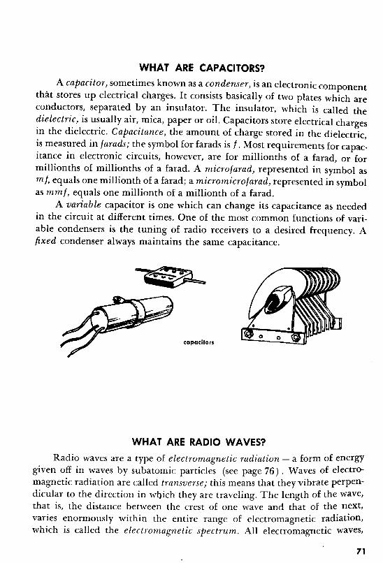
WHAT ARE CAPACITORS?
A capacitor) sometimes known as a condenser) is an electronic componentthat stores up electrical charges. It consists basically of two plates which areconductors, separated by an insulator. The insulator, which is called thedielectric) is usually air, mica, paper or oil. Capacitors store electrical chargesin the dielectric. Capacitance) the amount of charge stored in the dielectric,is measured in farads; the symbol for farads is f. Most requirements for capacitance in electronic circuits, however, are for millionths of a farad, or formillionths of millionths of a farad. A microfarad) represented in symbol asmi. equals one millionth of a farad; a micromicrojarad, represented in symbolas mrn], equals one millionth of a millionth of a farad.
A variable capacitor is one which can change its capacitance as neededin the circuit at different times. One of the most common functions of variable condensers is the tuning of radio receivers to a desired frequency. Afixed condenser always maintains the same capacitance.
capacitors
WHAT ARE RADIO WAVES?
Radio waves are a type of electromagnetic radiation - a form of energygiven off in waves by subatomic particles (see page 76) . Waves of electromagnetic radiation are called transverse; this means that they vibrate perpendicular to the direction in which they are traveling. The length of the wave,that is, the distance between the crest of one wave and that of the next,varies enormously within the entire range of electromagnetic radiation,which is called the electromagnetic spectrum. All electromagnetic waves,
71
regardless of their length, travel at the same speed: 186,000 miles per second.Since this is so, the frequency) that is, the number of waves per second,depends on the length: the shorter the wave, the higher the frequency andVIce versa.
In roughly the central portion of the electromagnetic spectrum arewaves of lengths which can be seen by the human eye; these are light waves.At either end of the spectrum are waves of lengths which are too short or toolong to be seen by the human eye. Those which are too short to be seeninclude ultraviolet rays, X rays, beta rays, gamma rays, and cosmic rays. Theserays have the power of penetrating solid materials, and they are harmful toliving creatures. The waves which are too long to be seen include infraredrays and radio waves. Radio waves range in length from less than Y8 of amile to more than 2Y2 miles. Radio waves do not penetrate solid materials.There has been evidence recently, however, that they can be harmful whenbeamed at certain organs in the body, such as the brain.
The amount of electromagnetic radiation given off by subatomic particles varies according to the energy level of these particles. The higher theenergy level, the more electromagnetic radiation is given off. The sun andstars are sources of stupendous amounts of electromagnetic radiation. All thelight and heat on earth are traceable ultimately to the electromagnetic radiation of the sun. The subatomic particles of materials conducting an electriccurrent are at an energy level high enough to give off considerable amountsof electromagnetic radiation. Thus, electromagnetic waves, including radiowaves, can be generated by means of electricity. Radio waves, partially because of their length, travel through the air over great distances, and are veryuseful, therefore, as carrier waves in radio broadcasting. Radio stations areassigned specific frequencies which they may use.
72

HOW ARE RADIO WAVES USED FOR BROADCASTING?
The basic principle of radio broadcasting is that sounds are convertedinto electrical impulses at the broadcasting station, are sent out and carriedthrough the air on radio waves, and are picked up and reconverted intosounds by the radio receiver.
Sound consists of vibrations caused by friction. The human voice, forexample, consists of sounds caused by friction between air exhaled from thelungs and the vocal cords. These vibrations set up disturbances in air, whichare sound waves. Sound waves are not electromagnetic; they are mechanical.Unlike electromagnetic waves, they are not transverse, but longitudinal) thatis, they vibrate in the same direction in which they are traveling. Soundwaves travel at a speed of about I, I 00 feet per second, and they vary in lengthand frequency. Sound waves of frequencies that cannot be heard by thehuman ear are called ultrasonic.
At the broadcasting station, sounds are amplified by the microphoneand are then combined with carrier waves. The sound waves cause slightirregularities in the carrier waves - a process called modulation. When theirregularities caused by the sound waves affect the frequency of the carrierwaves, the broadcast is of the FM or frequency modulation type. When theyaffect the amplitude (the distance between the crest and base of a wave) ofthe carrier waves, the broadcast is of the AM or amplitude modulation type.The modulated carrier waves are then sent out by the transmitter.
The antenna of the receiver picks up the modulated carrier waves andconducts them inside the radio receiver. In the loud-speaker, they passthrough an electromagnet; as they pass through, they set up vibrations whichdisturb the air, causing sound waves identical to those which entered themicrophone at the broadcasting station. This is a vastly oversimplified explanation of the process of broadcasting; the actual mechanisms involvedand the numerous phases in transmission and reception are of a complexitybeyond the scope of this book.
73

HOW CAN YOU MAKE A SIMPLE RADIO?
Gather the following equipment: About 100 feet of thin, insulatedcopper wire, a 350-micromicrofarad variable capacitor (available at radiorepair shops) , a pair of electromagnetic-type headphones or a discarded telephone receiver, a germanium crystal of the kind designated IN34, an emptycardboard tube from a roll of toilet tissue, and a piece of wood large enoughto mount the above equipment.
Follow this procedure: Assemble the equipment as indicated in theschematic below. Then put on the headphones and slowly turn the knob onthe capacitor.
A .=.G
74

You will observe: You pick up several radio stations.The antenna and coil pick up the radio waves. The capacitor adjusts
the frequency of radio waves picked up by the antenna and coil. In thismanner, you select different radio stations. The crystal serves as a detector;it allows those frequencies on the radio waves that can be changed into audible sound waves to come through to the headphones as stronger and weakerelectrical impulses. The mechanism inside the headphones serves to changethe electrical impulses to mechanical energy, causing sound waves, whichyou hear as voices, music or other sounds.
7S

NUCLEAR ENERGY
Nuclear energy is energy that is released when atoms of one element arechanged into atoms of other elements.
An atom is the tiniest bit of an element which has all the properties ofthat element. Atoms are so tiny that many billions of them are needed to makeup a piece of matter the size of a pinhead. As tiny as they are, however, theyare composed of even tinier parts-protons) neutrons) electrons) and others.
Protons are positively charged particles, held in a bundle together withthe neutrons, which are uncharged particles. This bundle is called the nucleus. Electrons are negatively charged particles which circulate around thenucleus. Normally, an atom contains the same number of protons and electrons. Thus the positive and negative charges balance each other so that thepractical effect is the same as if the atom had no charge at all. When an atomgains or loses one or more electrons, however, the charges of the protons andelectrons no longer counterbalance each other; such an atom is known as anion and has a charge.
The kind of element, of which any given atom forms a part, dependson the number of protons in the nucleus of the atom. When this numberchanges, the atom becomes an atom of another element. The nuclei of atomsof the same element sometimes vary in the number of neutrons they contain.Atoms that vary like this are called isotopes. Most hydrogen atoms, for example, have one proton and no neutrons in their nuclei, but occasionallyhydrogen atoms are found with a neutron as well as a proton in the nucleus.This second type of hydrogen is called deuterium.
Atoms of some elements change themselves by shooting out rays andparticles. This is called decaying or, more popularly, radioactivity. Radioactive elements are called unstable. The radioactive element you are likelyto come across most commonly is radium. It is often used in paint on thenumbers and hands of watches. Its radiation causes a glow which can beseen in the dark.
Scientists have found two other ways of changing atoms to get energy.
76
One is called fission. Fission is the splitting of atoms an,d can occur naturallyas the result of radioactivity. Scientists can achieve fission in an atomicreactor) sometimes called an atomic pile. The U-235 isotope of uranium isone of the elements most commonly used for fission. Fission occurs whenpieces of a suitable element are brought together to create what is calleda critical mass. When this happens, a neutron escaping from one atom strikesthe nucleus of another atom with such force that it splits the nucleus intotwo halves which, with the electrons, form new lighter-weight elements.This process also releases energy and one, two or more neutrons, whichbombard other atoms, causing them to split, release more energy and moreneutrons, and so on, This is called a chain reaction. When it is controlled, itis a source of tremendous amounts of usable energy. When it is uncontrolled,the energy is released so rapidly that it causes an explosion. The atom bombuses the process of fission. "Nuclear energy" is a more accurate term than"atomic energy," because it is the nucleus that yields the most energy.
If a stable element is placed in an atomic pile while a chain reactionis occurring, its atoms do not split; scientists have found, however, that thebombarding neutrons frequently adhere to the nuclei of the stable element.The result sometimes is the creation of radioactive isotopes (radioisotopes),which have many uses in medicine and agricultural research. The radioisotopes are often used in these fields as tracers. By placing them inside aplant or human body and watching their progress with special instruments,research workers and doctors can observe the functioning of the vrgan intowhich they are placed. The atoms of each different radioisotope decay at adefinite rate. Thus the amount of a particular radioisotope found in an object,such as an archeological find, can be used as a basis for calculating the ageof the object. Carbon 14 is the radioisotope commonly used for this purpose.
The second method of changing atoms to get energy is called fusion.Fusion is the welding together of small atoms under tremendous pressureand heat, on the order of 50 million degrees C. Nuclear energy is neededto attain such heat. The small atoms combine to form fewer but larger,atomsof another element. The deuterium isotope of hydrogen is used for fusion,and the element formed is helium. The hydrogen bomb uses the process offusion, which yields more energy than any other process; fusion is the sourceof energy of the sun and stars, Scientists are trying to learn how to controlfusion so that it can be used for nonexplosive purposes.
77
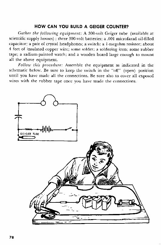
HOW CAN YOU BUILD A GEIGER COUNTER?
Gather the following equipment: A 300-volt Geiger tube (available atscientific supply houses) ; three 300-volt batteries; a .001 microfarad oil-filledcapacitor; a pair of crystal headphones; a switch; a I-megohm resistor; about4 feet of insulated copper wire; some solder; a soldering iron; some rubbertape; a radium-painted watch; and a wooden board large enough to mountall the above equipment.
Follow this procedure: Assemble the equipment as indicated in theschematic below. Be sure to keep the switch in the "off" (open) positionuntil you have made all the connections. Be sure also to cover all exposedwires with the rubber tape once you have made the connections.
GE IGER TUBE
78

WARNING: Place only one hand at a time on the apparatus after youhave made the connections to the batteries to prevent shorting of the circuitthrough your body and consequently a serious shock.
Close the switch and place the tube near the watch.You will observe: You hear a clicking in the headphones.
A Geiger tube has two electrodes in a gas-filled bulb. When it is placednear a radioactive substance, such as radium, shooting particles radiatethrough the gas, ionizing the atoms of the gas as they pass through. Theions have a charge, which causes a flow of current between the electrodes.The mechanism inside the headphones converts the flow of current intoaudible clicks. Each click is referred to as one count and corresponds to oneburst of ionizing radiation.
The Geiger counter is named for one of its inventors, the German scientist Hans Geiger.
HOW CAN YOU TEST FOR RADIOACTIVE FALLOUTIN YOUR NEIGHBORHOOD?
Gather the following equipment: The Geiger counter you made or aprofessional instrument (which might be available at school or at your localCivil Defense center) ; a clean can; some very wide cellophane tape; and acookie sheet.
Follow this procedure: Wind the cellophane tape around the cookiesheet with the gummed side up until you have covered the entire top surfaceof the sheet. Test the surface with the Geiger counter to determine the
79
...
amount of radioactivity on it. To do this, hold the counter close to thecookie sheet for one minute. Write down the count. Place the cookie sheet,gummed side up, outside your house-in the back yard, on the roof, or anywhere else where it won't be disturbed. Wait a full day. Then cut the tapefrom the top of the tin. Place it in the can and burn it. Test the residue withthe Geiger counter. Subtract any count you may have gotten the previousday from this second count.
You will observe: The count you get after the subtraction representsthe amount of radioactive fallout during the day the cookie sheet was outside.The burning of the cellophane tape served merely to concentrate the radioactivity, which cannot be burned away.
There is always some radioactivity in the air. A large percentage of itcomes from natural causes, and is called natural background radiation. Someof it is also man-made, however, and comes chiefly from test explosions ofatomic and hydrogen bombs. Most scientists are concerned about the risinglevel of radioactive fallout as a result of these test explosions. While they allagree that too much radioactive fallout can be dangerous to the populationof the world, there is little agreement among them on how much is "toomuch" and even on how properly to calculate the present amounts.
80
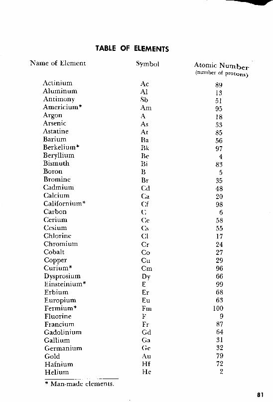
Name of Element
ActiniumAluminumAntimonyAmericium"ArgonArsenicAstatineBariumBerkelium"BerylliumBismuthBoronBromineCadmiumCalciumCalifornium*CarbonCeriumCesiumChlorineChromiumCobaltCopperCuriurn"DysprosiumEinsteinium*ErbiumEuropiumFermium"FluorineFranciumGadoliniumGalliumGermaniumGoldHafniumHelium
TABLE OF ELEMENTS
Symbol
AcAlSbAmAAsAtBaBkBeBiBBrCdCaCfCCeCsClCrCoCuCmDyEErEuFmFFrGdGaGeAuHfHe
Atomic Numbel'(number of protons)
891351951833855697
4835
35482098
65855172427299666996863
1009
8764313279722
* Man-made elements.
81
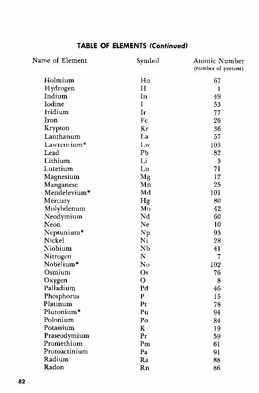
TABLE OF ELEMENTS (Continued)
82
Name of Element
HolmiumHydrogenIndiumIodineIridiumIronKryptonLanthanumLawrencium"LeadLithiumLutetiumMagnesiumManganeseMendelevium*MercuryMolybdenumNeodymiumNeonNeptunium"NickelNiobiumNitrogenNobelium"OsmiumOxygenPalladiumPhosphorusPlatinumPlutonium"PoloniumPotassiumPraseodymiumPromethiumProtoactiniumRadiumRadon
Symbol
HoHInIIrFeKrLaLwPbLiLuMgMnMdHgMoNdNeNpNiNbNNoOsoPdPPtPuPoKPrPmPaRaRn
Atomic Number(number of protons)
671
495377263657
10382
3711225
101804260109328417
102768
4615789484195961918886
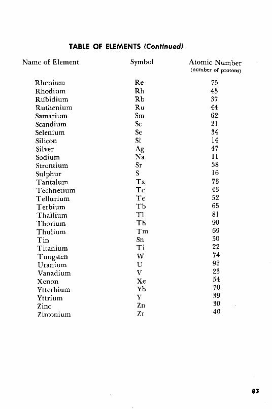
TABLE OF ELEMENTS (Continued)
Name of Element
RheniumRhodiumRubidiumRutheniumSamariumScandiumSeleniumSiliconSilverSodiumStrontiumSulphurTantalumTechnetiumTelluriumTerbiumThalliumThoriumThuliumTinTitaniumTungstenUraniumVanadiumXenonYtterbiumYttriumZincZirconium
Symbol
ReRhRbRuSmScSeSiAgNaSrSTaTcTeTbTlThTmSnTiWUVXeYbYZnZr
Atomic Number(number of protons)
7545374462213414471138167343526581906950227492235470393040
83


IN D EX
air-core transformer, 62alloy, 20alternating current, 61-62ampere, 63amplifier, 67amplitude modulation, 73anode, 67armature, 58-59atom, 76
bomb,77electrons, 24, 76neutrons, 76-77nucleus of, 76-77protons, 76
atomic energy. See nuclear energy.atomic reactor, 77
battery, 32-33beta rays, 72brush,58bulb
fluorescent, 66incandescent, 42
capacitance, 71capacitor, 71
fixed, 71variable, 71
carrier waves. See radio waves.cathode, 67charge, electric, 27-28
accumulation of, 31detecting presence of, 29-30negative, 27positive, 27
cell, 35lead storage, 34-35
chain reaction, 77circuit, electric, 25
short, 40-41commutator, 58
compass, 20-21making a, 20-21telling time with a, 22use of in navigation, 21-22
condenser. See capacitor.conductor, 28-29, 69copperplating, 50-51cosmic rays, 72critical mass, 77crystal, 73-74, 69-70
n-type,69p-type,69
current, electricalternating, 69-70conductors of, 28-29, 69direct, 61induction of by magnetism, 25insulators of, 28-29, 69semiconductors of, 69resistance to, 70
declination, angle of, 22detector, 67dielectric, 71diode, 67direct current, 61dry cell, reviving old, 33-34duodiode, 67
Edison effect, 65electric motor, 57-59electric quiz game, 43-45electricity, 26-64
static, 27-28electrode, 33, 67
anode, 67cathode, 67grid, 67
electrolysis, 51, 52electrolyte, 33
85

86
electromagnet, 17-18permanent magnet, 19-20
electromagnetic waves, 71-72electron, 24, 76electronics, 65-75electronic symbols, 68electron tube, 67electrophorus, 31electroplating, 61
copperplating, 50-51silverplating, 52
electroscope, 29-30elements, 7
table of, 81-83unstable, 76
farad,71field magnets, 59field of force, magnetic, 12filament, 42, 67fission, 77fixed capacitor, 71flashlight, 36fluorescent bulb, 66frequency modulation, 73fuse, 41fusion, 77
galvanic pile. See voltaic pile.gamma rays, 72Geiger counter, 83-84, 78, 79-80generator, 54-56geographic poles, 21-22grid, 67
hydrogen bomb, 77
incandescent bulb, 42infrared rays, 72insulator, 28, 69ions, 69iron-core transformer, 62isotopes, 76-77
kilowatt, 63
kilowatt-hour, 63
lead storage cell, 34-35light waves, 72lines of force, magnetic, 12loadstone, 6longitudinal waves, 73
magnetic field, 12magnetic lines of force, 12magnetic poles, 13-15magnetism, 6-25
attraction of, 7explanatory theories about, 24feeling the force of, 11induction of by electricity,
17-18, 19-20invisibility of, 12materials affected by, 7penetration of materials by, 8-10seeing the effects of, 12
magnetite, 6magnets
cutting of, 23electromagnets, 17-18field, 59permanent, 19-20, 24poles of, 13-15temporary, 15-16,24
megohm, 70microfarad, 71micromicrofarad, 71microphone, 53-54model railroad signal, 59modulation, 73modulator, 67molecule, 24Morse code, 46
neutrons, 76-77n-type crystal, 69-70north pole, 13, 21-22nuclear energy, 76-80nucleus of atom, 24, 76
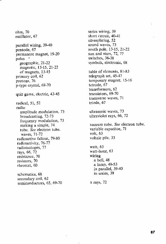
ohm, 70oscillator, 67
parallel wiring, 39-40pentode,67permanent magnet, 19-20poles •
geographic, 21-22magnetic, 13-15, 21-22of magnets, 13-15
primary coil, 62protons, 76p-type crystal, 69-70
quiz game, electric, 43-45
radical, 51, 52radio
amplitude modulation, 73broadcasting, 72-73frequency modulation, 73making a simple, 74tube. See electron tube.waves, 71-72
radioactive fallout, 79-80radioactivity, 76-77radioisotopes, 77rays, 66, 72resistance, 70resistors, 70rheostat, 60
schematics, 68secondary coil, 62semiconductors, 65, 69-70
series wiring, 39short circuit, 40-41si1verp1ating, 52sound waves, 73south pole, 13-15,21-22sun and stars, 72, 77switches, 36-38symbols, electronic, 68
table of elements, 81-83telegraph set, 45-47temporary magnet, 15-16tetrode, 67transformers, 62transistors, 69-70transverse waves, 71triode, 67
ultrasonic waves, 73ultraviolet rays, 66, 72
vacuum tube. See electron tube.variable capacitor, 71volt, 63voltaic pile, 33
watt, 63watt-hour, 63wiring
a bell, 48a lamp, 49-53in parallel, 39-40in series, 39
x rays, 72
87