ELECTRIC POTENTIAL AND CAPACITANCE - SelfStudys
108
19. ELECTRIC POTENTIAL AND CAPACITANCE 1. INTRODUCTION Associating a potential energy with a force allows us to apply the principle of the conservation of mechanical energy to closed systems involving the force. The principle allows us to calculate the results of experiments for which force calculations alone would be very difficult. In this chapter, we first define this type of potential energy and then put it to use. We will also discuss the behavior of conductors which can store the charges in it, in the presence of the electric field. 2. ELECTRIC POTENTIAL An electric field at any point can be defined in two different ways: (i) by the field strength E , and (ii) by the electric potential V at the point under consideration. Both E and V are functions of position and there is a fixed relationship between these two. Of these the field strength E is a vector quantity while the electric potential V is a scalar quantity. The electric potential at any point in an electric field is defined as the potential energy per unit charge, and similarly, the field strength is defined as the force per unit charge. Thus, 0 U V q = or 0 U qV = The SI unit of potential is volt (V) which is equal to joule per coulomb. So, 1V 1volt 1J/C 1 joule / coulomb = = = According to the definition of potential energy, the work done by the electrostatic force in displacing a test charge q 0 from point a to point b in an electric field is defined as the negative of change in potential energy between them, or ab U W − ∆ =− b a ab U U W − ∴ − =− Dividing this equation by q, ο b a ab U U W q q q − ο ο ο − =− or ab a b W V V q − ο − = since U V q ο = Thus, the work done per unit charge by the electric force when a charge body moves from point a to point b is equal to the potential at point a minus the potential at point b. We sometimes abbreviate this difference as ab a b V V V. = −
-
Upload
khangminh22 -
Category
Documents
-
view
1 -
download
0
Transcript of ELECTRIC POTENTIAL AND CAPACITANCE - SelfStudys

19. E L E C T R I C P O T E N T I A L A N D C A P A C I T A N C E
1. INTRODUCTION
Associating a potential energy with a force allows us to apply the principle of the conservation of mechanical energy to closed systems involving the force. The principle allows us to calculate the results of experiments for which force calculations alone would be very difficult. In this chapter, we first define this type of potential energy and then put it to use. We will also discuss the behavior of conductors which can store the charges in it, in the presence of the electric field.
2. ELECTRIC POTENTIAL
An electric field at any point can be defined in two different ways:
(i) by the field strength E
, and
(ii) by the electric potential V at the point under consideration.
Both E
and V are functions of position and there is a fixed relationship between these two. Of these the field strength E
is a vector quantity while the electric potential V is a scalar quantity. The electric potential at any point in an electric field is defined as the potential energy per unit charge, and similarly, the field strength is defined as the force per unit charge. Thus,
0
UVq
= or 0U q V=
The SI unit of potential is volt (V) which is equal to joule per coulomb. So,
1V 1volt 1J / C 1 joule / coulomb= = =
According to the definition of potential energy, the work done by the electrostatic force in displacing a test charge q0 from point a to point b in an electric field is defined as the negative of change in potential energy between them, or a bU W −∆ = − b a a bU U W −∴ − = −
Dividing this equation by q ,ο
b a a bU U Wq q q
−
ο ο ο
− = − or a ba b
WV V
q−
ο
− = since UVqο
=
Thus, the work done per unit charge by the electric force when a charge body moves from point a to point b is equal to the potential at point a minus the potential at point b. We sometimes abbreviate this difference as ab a bV V V .= −

19.2 | Electric Potential and Capacitance
PLANCESS CONCEPTS
Another way to interpret the potential difference Vab is that it is , equal to the work that must be done by an external force to move a unit positive charge from point b to point a against the electric force. Thus,
( )b a externalforce
a b
WV V
q−
ο
− =
In the equation i
i i
q1V4 rο
=πε ∑ or 1 dqV
4 rο
=πε ∫ , if the whole charge is at equal distance ro from the
point where V is to be evaluated, then we can write, netq1V .4 rο ο
=πε
, where netq is the algebraic sum of
all the charges of which the system is made.
Vaibhav Gupta (JEE 2009 AIR 54)
Illustration 1: Consider a non-conducting rod of length having a uniform
L
y
r’
x’
’
O dx’
y
P
x
Figure 19.1
charge density λ . Find the electric potential at P at a perpendicular distance y above the midpoint of the rod (JEE MAIN)
Sol: The potential due to the small length element dx of the rod at a point p
at distance r apart is given byo
dq 1dV4 r
= ×πε
where dq is the charge on dx.
The electric field due to the rod is given by VEr
∂= −
∂.
Consider a differential element of length dx’ which carries a charge dq dx'= λ. As shown in Fig.19.1, the source element is located at (x’, 0), while the field point P is located on the y-axis at (0,y).
The distance from dx’ to P is ( )1/2'2 2r x y= + .
Its contribution to the potential is given by ( )1/2'2 2
1 dq 1 dx'dV4 r 4 x yο ο
λ= =
πε πε +
Taking V to be zero at infinity, the total potential due to the entire rod is
/2/2 '2 2/2 '2 2 /2
dx'V ln x' x y4 4x y−
−ο ο
λ λ = = + + πε πε+∫
Figure 19.2
4
3
2
1
-4 -2 2 4y/t
V /V(y) O
( ) ( )( ) ( )
2 2
2 2
/ 2 / 2 yln
4 / 2 / 2 yο
+ + λ
= πε − + +
Where we have used the integration formula
' '2 2
'2 2
dx' In x x yx y
= + + +
∫
A plot of ( )V y / Vο , where V / 4ο ο= λ πε , as a function of y / is shown in Fig. 19.2. (Electric potential along the axis that passes through the midpoint of a non-conducting rod.)

Physics | 19.3
In the limit y , the potential becomes
( ) ( )( ) ( )
( )( )
2 2
2 2
/ 2 / 2 1 2y / 1 1 2y /V ln ln
4 4/ 2 / 2 1 2y / 1 1 2y /ο ο
+ + + + λ λ
= = πε πε − + + − + +
2
2 2 2
2ln ln ln4 4 2 y2y / yο ο ο
λ λ λ≈ = = πε πε πε
The corresponding electric field can be obtained as ( )
y 2 2
V / 2Ey 2 y / 2 yο
∂ λ= − =
∂ πε+
Illustration 2: Consider a uniformly charged ring of radius R and charge
Figure 19.3
r
Z
R
Z
y
xdp
density λ . What is the electric potential at a distance z from the central axis? (JEE MAIN)
The Fig. 19.3 shows a non-conducting ring of radius R with uniform charge density λ
Sol: The point lies along the axis of the ring hence, the potential at the
point due to the charge on the ring is given by o
dqV dV4 r
= =πε∫ ∫ where
r is the distance of point from ring. As the point lies on the z axis, the
field due to ring is given by ZVEz
∂= −
∂.
Consider a small differential element d Rd '= φ on the ring. The element carries a charge dq d Rd '= λ = λ φ , and its
contribution to the electric potential at P is 2 2
1 dq 1 Rd 'dV4 r 4 R zο ο
λ φ= =
πε πε +
The electric potential at P due to the entire ring is 2 2 2 2 2 2
1 R 1 2 R 1 QV dV d '4 4 4R Z R z R zο ο ο
λ πλ= = φ = =
πε πε πε+ + +∫ ∫
Where we have substituted Q 2 R= π λ for the total charge on the ring. In the limit z R,
The potential approaches its “point-charge” limit: 1 QV4 zο
≈πε
The z-component of the electric field may be obtained as ( )
2 3/22 2 2 2
V 1 Q 1 QzEz z 4 4R z R zο ο
∂ ∂ = − = − = ∂ ∂ πε πε+ +
Illustration 3: Consider a uniformly charged disk of radius R and charge density σ
Figure 19.4
P
zdq
z
R
x
y
r
r’dr’
lying in the xy-plane. What is the electric potential at a distance z from the central axis? (JEE ADVANCED)
Sol: The disc can be assumed to be composed of many co-centric rings. Thus
the potential due to small ring is o
dqdV4 r
=πε
where r is the distance from the
surface of ring. As the point lie on the z axis the field due to ring is given by
ZVEz
∂= −
∂.

19.4 | Electric Potential and Capacitance
Consider a small differential circular ring element of radius r’ and width dr’. The charge on the ring is( )dq' dA' 2 r 'dr '= σ = σ π . The field at point P located along the z-axis a distance z from the plane of the disk is to
be calculated. From the Fig. 19.4, we also see that the distance from a point on the ring to P is ( )1/2'2 2r r z= + .
Therefore, the contribution to the electric potential at P is ( )
'2 2
2 r 'dr '1 dq 1dV4 r 4 r zο ο
σ π= =
πε πε +
By summing over all the rings that make up the disk, we have
RR '2 2 2 2
'2 2
2 r 'dr 'V r z R z z4 2 2r zο
οο ο ο
σ π σ σ = = + = + − πε ε ε+∫
In the limit z R , 1/22 2
2 22 2
R RR Z z 1 z 1 .... ,z 2z
+ = + = + +
And the potential simplifies to the point-charge limit:
( )22 RR 1 1 QV .2 4 42 z z zο ο ο
σ πσ≈ = =
ε πε πε
As expected, at large distance, the potential due to a non-conducting charged disk is the same as that of a point charge Q. A comparison of the electric potentials of the disk and a point charge is shown in Fig. 19.5.
V/VO
1
23
4
5
6
Point charge
Disk
-3 -2.5 -2 -1.5 -1 -0.5 0.5 1 1.5 2 2.5 3Z/R’
Figure 19.5
The electric potential is measured in terms of V Q / 4 Rο ο= πε .
Note that the electric potential at the center of the disk (z=0) is finite, and its value is
c 2
R Q R 1 2QV . 2V2 2 4 RR ο
ο ο ο
σ= = = =
ε ε πεπ
This is the amount of work that needs to be done to bring a unit charge from infinity and place it at the center of the disk.
The corresponding electric field at P can be obtained as:
z 2 2
V z zEZ 2 z R zο
∂ σ = − = −
∂ ε +
In the limit R z, the above equation becomes 2E / 2 ο= σ ε , which is the electric field for an infinitely large non-conducting sheet.
Illustration 4: Consider a metallic spherical shell of radius ‘a’ and charge Q, as shown in Fig. 19.6.
(a) Find the electric potential everywhere.
(b) Calculate the potential energy of the system. (JEE MAIN)

Physics | 19.5
Sol: The sphere is symmetrical body. Thus the potential at the surface is constant while
E=0
+
+
+++++++++++
+++++
+++++
+++++++++++
Figure 19.6
the potential changes outside of the sphere at a distance a r< < ∞ .
2
Q r, r aE 4 r
0, r aο
>
= πε <
The electric potential may be calculated by BB A A
V V E.ds− = −∫
For r>a, we have ( ) ( ) re'2
Q 1 Q QV r V dr ' k4 r r4 r∞
οο
− ∞ = − = =πεπε∫
We have chosen ( )V 0∞ = as our reference point. On the other hand, for r<a,
Figure 19.7
V
K Qe
rK Qe
a
ar
the potential becomes
( ) ( ) ( )a r
aV r V drE r a drE(r a)
∞− ∞ = − > − <∫ ∫
ae2
Q 1 Q Qdr k4 a a4 r∞
οο
= − = =πεπε∫
A plot of the electric potential is shown in Fig. 19.7. Note that potential V is constant inside a conductor.
Illustration 5: An insulated solid sphere of radius a has a uniform charge densityρ . Compute the electric potential everywhere. (JEE MAIN)
Sol:
2
3
Q r, r a4 r
EQr r, r a
4 r
ο
ο
>
πε= < πε
Figure 19.8
a
P2
r
P1
For r > a,
( ) ( ) r1 e'2
Q 1 Q QV r V dr ' k4 r r4 r∞
οο
− ∞ = − = =πεπε∫
On the other hand, the electric potential at 2P inside the sphere is given by
( ) ( ) ( ) ( )a r a r2 2 3a a
Q QrV r V drE r a E r a dr dr ' r '4 r 4 a∞ ∞
ο ο
− ∞ = − > − < = − −πε πε∫ ∫ ∫ ∫
Figure 19.9
V
3k Qe
2a
k Qe
a
a r
( )2
2 23 2
1 Q 1 Q 1 1 Q rr a 34 a 4 2 8 aa aο ο ο
= − − = − πε πε πε
2
e 2
Q rk 32a a
= −
A plot of electric potential as a function of r is given in Fig. 19.9.

19.6 | Electric Potential and Capacitance
2.1 Deriving Electric Field from the Electric Potential In previous equations, we established the relation between E
and V. If we consider two points which are separated by a small distance ds
, the following differential form is obtained:
dV E.ds= −
In Cartesian coordinates, x y 2ˆ ˆ ˆE E i E j E k= + +
and ˆ ˆ ˆds dxi dyj dzk= + +
, we have
( ) ( )x y 2 x y zˆ ˆ ˆ ˆ ˆ ˆdV E i E j E k . dxi dyj dzk E dx E dy E dz= + + + + = + +
Which implies
x y zV V VE ,E ,Ex y z
∂ ∂ ∂= − = − = −
∂ ∂ ∂
By introducing a differential quantity called the “del (gradient) operator”
ˆ ˆ ˆi j kx y z∂ ∂ ∂
∇ = + +∂ ∂ ∂
The electric field can be written as
x y 2V V Vˆ ˆ ˆ ˆ ˆ ˆ ˆ ˆ ˆE E i E j E k i j k i j k V Vx y z x y z
∂ ∂ ∂ ∂ ∂ ∂= + + = − + + = − + + = −∇ ∂ ∂ ∂ ∂ ∂ ∂
E V= −∇
3. EQUIPOTENTIAL SURFACES
The equipotential surfaces in an electric field have the same basic idea as topographic maps used by civil engineers or mountain climbers. On a topographic map, contour lines are drawn passing through the points having the same elevation. The potential energy of a mass m does not change along a contour line as the elevation is same everywhere.
By analogy to contour lines on a topographic map, an equipotential surface is a three dimensional surface on which the electric potential V is the same at every point on it. An equipotential surface has the following characteristics.
(a) Potential difference between any two points in an equipotential surface is zero.
(b) If a test charge q0 is moved from one point to the other on such a surface, the electric potential energy q0V remains constant.
(c) No work is done by the electric force when the test charge is moved along this surface.
(d) Two equipotential surfaces can never intersect each other because otherwise the point of intersection will have two potentials which is of course not acceptable.
(e) As the work done by electric force is zero when a test charge is moved along the equipotential surface, it follows that E
must be perpendicular to the surface at every point so that the electric force q Eο
will always be perpendicular to the displacement of a charge moving on the surface, causing the work done to be 0. Thus, field lines and equipotential surfaces are always mutually perpendicular. Some equipotential surfaces are shown in Fig. 19.10.
The equipotential surfaces are a family of concentric spheres for a point charge or a sphere of charge and are a family of concentric cylinders for a line of charge or cylinder of charge. For a special case of a uniform field, where the field lines are straight, parallel and equally spaced the equipotential are parallel planes perpendicular to the field lines.

Physics | 19.7
PLANCESS CONCEPTS
10V20V
30V40V
+
10V20V
30V40V
-
40V 30V 20V
E
Figure 19.10
While drawing the equipotential surfaces we should keep in mind the two main points.
• These are perpendicular to field lines at all places.
• Field lines always flow from higher potential to lower potential.
Anurag Saraf (JEE 2011 AIR 226)
Illustration 6: Suppose the electric potential due to a certain charge distribution can be written in Cartesian Coordinates as ( ) 2 2V x, y,z Ax y Bxyz= + where A,B and C are constants. What is the associated electric field? (JEE MAIN)
Sol: The field is given by rVEr
∂= −
∂ where r is the respective Cartesian co-ordinate.
2x
VE 2Axy Byzx
∂= − = − −
∂ ; 2
yVE 2Ax y Bxzy∂
= − = − −∂
; zVE Bxyz
∂= − = −
∂
Therefore, the electric field is ( ) ( )2 2ˆ ˆ ˆE 2Axy Byz i 2Ax y Bxz j Bxyk= − − − + −
4. ELECTRIC POTENTIAL ENERGY
The electric force between two charges is directed along the line of the charges and is proportional to the inverse square of their separation, the same as the gravitational force between two masses. Like the gravitational force, the electric force is conservative, so there is a potential energy function U associated with it.
When a charged particle moves in an electric field, the field exerts a force that can do work on the particle. This work can always be expressed in terms of electric potential energy. Just as gravitational potential energy depends on the height of a mass above the earth’s surface, electric potential energy depends on the position of the charged particle in the electric field. When a force F
acts on a particle that moves from point a to point b, the work a bW →
done by the force is given by, b ba b a a
W F.ds F cos ds→ = = θ∫ ∫
Here a bW → is the work done in displacing the particle from a to b by the conservative force (here electrostatic) not by us. Moreover we can see from Eq. (i) that if a bW → is positive, the change in potential energy U∆ is negative and the potential energy decreases. So, whenever the work done by a conservative force is positive, the potential energy of the system decreases and vice-versa. That’s what happens when a particle is thrown upwards, the work done by gravity is negative, and the potential energy increases.

19.8 | Electric Potential and Capacitance
4.1 Potential Energy in a System of ChargesIf a system of charges is assembled by an external agent, then extU W W .∆ = − = +
q2
P
r12
q1
Figure 19.11
That is, the change in potential energy of the system is the work that must be put in by an external agent to assemble the configuration. A simple example is lifting a mass m through a height h. The work done by an external agent you, is +mgh (The gravitational field does work -mgh). The charges are brought in from infinity without acceleration i.e. they are at rest at the end of the process. Let’s start with just two charges q1 and q2. Let the potential due to q1 at a point P be V1 (See Fig. 19.11).
The work W2 done by an agent in bringing the second charge q2 from infinity to P is then 2 2 1W q V= . (No work is required to set up the first charge and W1 = 0). Since
1 1 0 12V q / 4 r= πε , where q1 and r12 is the distance measured from q1 to P, we have
1 212 2
0 12
q q1U W4 r
= =πε
If q1 and q2 have the same sign, positive work must be done to overcome
Figure 19.12
q2
q1
r13
r12
r23
q2
P
the electrostatic repulsion and the potential energy of the system is positive, U12 > 0. On the other hand, if the signs are opposite, then U12 < 0 due to the attractive force between the charges. To add a third charge 3q to the system, the work required is
( ) 3 1 23 3 1 2
13 23
q q qW q V V
4 r rο
= + = + πε
The potential energy of this configuration is then
1 3 2 31 22 3 12 13 23
12 13 23
q q q qq q1U W W U U U4 r r rο
= + = + + = + + πε
The equation shows that the total potential energy is simply the sum of the contributions from distinct pairs.
Generalizing to a system of N charges, we have N N
i j
i 1 j 1 ijj i
q q1U4 r= =ο
>
=πε ∑∑
Where the constraint j>i is placed to avoid double counting each pair. Alternatively, one may count each pair twice and divide the result by 2. This leads to
( )N N N N N
i j ji i i
i 1 j 1 i 1 j 1 i 1ij ijj i j i
q q q1 1 1 1U q q V r8 r 2 4 r 2= = = = =ο ο
≠ ≠
= = = πε πε
∑∑ ∑ ∑ ∑
Where ( )iV r , the quantity in the parenthesis is the potential at ir
(location of qi) due to all the other charges.
4.2 Continuous Charge DistributionIf the charge distribution is continuous, the potential at a point P can be found by summing
Figure 19.13
r
P
E
q
r
>
over the contributions from individual differential elements of charge dq.
Consider the charge distribution shown in Fig. 19.13. Taking infinity as our reference point with
zero potential, the electric potential at P due to dq is 1 dqdV4 rο
=πε
Summing over contributions from all differential elements, we have 1 dqV4 rο
=πε ∫

Physics | 19.9
Illustration 7: Find the potential due to a uniformly charged sphere of radius R and charge
Figure 19.14
R
per unit volume ρ at different points in space. (JEE MAIN)
Sol: The field due to uniformly charged solid sphere is 3
2 2o o
q RE4 r 3 r
ρ= =
πε ε. The potential
inside the sphere is always constant while outside sphere at a distance R r< < ∞ is given
by rr
1 R RV Edl = ∫
For a point outside the sphere, we can integrate the electric field outside to obtain an expression for the electric field outside.
3 3r r
2
R RV E.dl dx3 r3 x∞ ∞
οο
ρ ρ= − = − =
εε∫ ∫ ∫
The dots represent a spherically symmetric distribution of charge of radius R, whose
Figure 19.15
v
-R R
3kQ
2R
r
volume charge density ρ is a constant.
For finding the potential at an inside point, we integrate as before. Keep in mind that the lower limit in this integration cannot be infinity, as infinity does not lie inside the sphere. But lower limit can be assumed to be R where potential is not zero but a known value.
( )2 2V r rinV R RR
R rxdV E.dl dx3 6ο ο
ρ −ρ= − = − =
ε ε∫ ∫ ∫
;( )2 22
R r
3R rRV V3 6ο ο
ρ −ρ= ⇒ =
ε ε.
This potential is plotted in Fig. 19.15.
Illustration 8: A non-conducting disc of radius a and uniform positive surface charge density σ is placed on the ground with its axis vertical. A particle of mass m and positive charge q is dropped, along the axis of the disc from a height H with zero initial velocity. The particle has q / m 4 g /ο= ε σ
(a) Find the value of H if the particle just reaches the disc.
(b) Sketch the potential energy of the particle as a function of its height and find its equilibrium position. (JEE ADVANCED)
Sol: It is known that, for non conducting disc the potential at a point situated at height H above
Figure 19.16
H
a O
P qm
the disc is given by 2 2pV a H H
2 ο
σ = + − ε where a is the radius of the disc. When the charge of
the particle of mass m falls along the axis of the disc, the change in the gravitational portential energy is equal to gain in its electric potential energy. As we required minimum H, the kinetic energy, will be zero.
As we have derived in the theory, 2 2pV a H H
2 ο
σ = + − ε
Potential at centre, (O) will be aV2ο
ο
σ=
ε (H=0)
(a) Particle is released from P and it just reaches point O. Therefore, from observation of mechanical energy
Decrease in gravitational potential energy = increase in electrostatic potential energy ( KE 0∆ = because i fK K 0= = )
mgH q V Vο ρ ∴ = − or 2 2qgH a a H H
m 2 ο
σ = − + + ε … (i)

19.10 | Electric Potential and Capacitance
4 gqm
οε=σ
q 2g
2 mο
σ∴ =
ε
Substituting in Eq. (i), we get
2 2gH 2g a H a H = + − + or ( ) 2 2H a H a H
2= + − + or 2 2 Ha H a
2+ = +
or 2
2 2 2 Ha H a aH4
+ = + + or 23 H aH4
= or 4H a3
= and H 0= ( )H 4 / 3 a∴ =
(b) Potential energy of the particle at height H = Electrostatic potential energy + gravitational potential energy
U qV mgH= +
Here V=potential at height H
2 2qU a H H mgH2 ο
σ = + − + ε … (ii)
At equilibrium position, dUF 0dH−
= =
Differentiating E.q. (ii) w.r.t.H
or ( )2 2
q 1 1mg 2H 1 02 2 a Hο
σ+ − = ε +
q 2mg2 ο
σ=
ε
2 2
Hmg 2mg 1 0a H
∴ + − =
+ or
2 2
2H1 2 0a H
+ − =+
2 2
2H 1a H
=+
or 2
2 2
H 14a H
=+
or 2 23H a= or aH3
=
From Eq. (ii), we can see that,
U 2mga= at H 0= and minU U 3mga= = at aH3
=
U
2mga
3mga
O aA 3 H
Figure 19.17
Therefore, U-H graph will be as shown.
Note that at aH3
= , U is minimum.
Therefore, aH3
= is stable equilibrium position.
5. ELECTRIC DIPOLE
An electric dipole is a system of equal and opposite charges separated by a fixed distance. Every electric dipole is characterized by its electric dipole moment which is a vector P
directed from the negative to the positive charge.
The magnitude of dipole moment is, P=(2a)q; Here, 2a is the distance between the two charges.
5.1 Electric Potential and Field Due to an Electric Dipole
Consider an electric dipole lying along positive y-direction with its center at origin.
Figure 19.18
+q-qP
2a
ˆP 2aqj=

Physics | 19.11
The electric potential due to this dipole at point A(x, y, z) as shown
Figure 19.19
y
z
x + z + (y-a)2 2 2
+q+
-
a
a
x + z + (y+a)2 2 2
A (x, y, z)
-q
is simply the sum of the potentials due to the two charges. Thus,
( ) ( )2 22 2 2 2
1 q qV4 x y a z x y a zο
= − πε + − + + + +
By differentiating this function, we obtain the electric field of the dipole.
( ) ( )x 3/2 3/22 22 2 2 2
V q x xEx 4
x y a z x y a zο
∂ = = −
∂ πε + − + + + +
( ) ( )y 3/2 3/22 22 2 2 2
y a y aV qEy 4
x y a z x y a zο
− +∂ = = −
∂ πε + − + + + +
( ) ( )z 3/2 3/22 22 2 2 2
V q z xEz 4
x y a z x y a zο
∂ = = −
∂ πε + − + + + +
Special Cases
(i) On the axis of the dipole (say, along y-axis) X=0, z=0
( )2 2
q 1 1 2aqV4 y a y a 4 y aο ο
∴ = − = πε − + πε −
or ( )2 2
pV4 y aο
=πε −
(as 2aq = p) i.e., at a distance r from the Centre of the dipole(y=r)
( )2 2
pV4 r aο
≈πε −
or axis 2
pV4 rο
=πε
(for r a )
V is positive when the point under consideration is towards positive charge and negative if it is towards negative charge.
Moreover the components of electric field are as under,
x zE 0,E 0= = (as x = 0, z = 0)
and ( ) ( )
y 2 2
q 1 1E4 y a y aο
= − πε − +
( )22 2
4ayq
4 y aο
=πε −
or ( )
y 22 2
2py1E4 y aο
=πε −
Note that yE is along positive y-direction or parallel to P
. Further, at a distance r from the centre of the dipole (y=r).
( )y 22 2
1 2prE4 r aο
=πε −
or axis 3
1 2pE .4 rο
≈πε
for r a
(ii) On the perpendicular bisector of dipole
Say along x-axis (it may be along z-axis also). y = 0, z = 0

19.12 | Electric Potential and Capacitance
2 2 2 2
1 q qV 04 x a x aο
∴ = − =
πε + + or
bisectorV 0⊥ =
Moreover the components of electric field are as under, x zE 0 E 0= =
and ( ) ( )
y 3/2 3/22 2 2 2
q a aE4 x a x aο
−
= = − πε + +
( )3/22 2
2aq
4 x aο
−=
πε +;
( )y 3/22 2
1 PE .4 x aο
=πε +
Here, negative sign implies that the electric field is along negative y-direction or antiparallel to P
. Further, at a distance r from the Centre of dipole (x = r), the magnitude of electric field is,
( )3/22 2
1 PE4 r aο
=πε +
or bisector 3
1 PE .4 r⊥
ο
≈πε
(for r a )
5.2 Force on DipoleSuppose an electric dipole of dipole moment P 2aq=
is
F1
E
+q
Aa
O
-q
a
F2
B
P
E
Figure 19.20
placed in a uniform electric field E
at an angle θ . Here, θ is the angle between P
and E
. A force 1F qE=
will act on positive charge and
2F qE= −
on negative charge. Since, 1 2F andF
are equal in magnitude but opposite in direction. Hence, 1 2F F 0+ =
or netF 0=
Thus, net force on a dipole in uniform electric field is zero. While in non-uniform electric field it may or may not be zero.
5.3 Torque on Dipole
The torque of 1F
about O, ( )11 OA F q OA Eτ = × = ×
And torque of 2F
about O is, ( )22 OB F q OB Eτ = × = − ×
( )q BO E= ×
The net torque acting on the dipole is,
( ) ( )1 2 q OA E q BO Eτ = τ + τ = × + ×
( )q OA BO E= × ×
( )q BA E= ×
or P xEτ =
Thus, the magnitude of torque is PEsinτ = θ . The direction of torque is perpendicular to the plane of paper inwards. Further this torque is zero at 0οθ = or 180οθ = , i.e., when the dipole is parallel or antiparallel to E
and maximum at 90οθ = .
5.4 Potential Energy of DipoleWhen an electric dipole is placed in an electric field E
, a torque P Eτ = ×
acts on it.
Figure 19.21
+q
90o
-q
If we rotate the dipole through a small angle dθ , the work done by the torque is,
dW d= τ θ ; dW PEsin d= − θ θ
The work is negative as the rotation dθ is opposite to the torque. The change in electric potential energy of the dipole is therefore.
dU dW PEsin d= − = θ θ

Physics | 19.13
Now, at angle θ = 90°, the electric potential energy of the dipole may be assumed to be zero as net work done by the electric forces in bringing the dipole from infinity to this position will be zero.
Integrating, dU PEsin d= θ θ
From 090 toθ , we have 90 90
dU PEsin dθ θο ο= θ θ∫ ∫ or ( ) ( ) 90
U U 90 PE cosθοο θ − = − θ
( )U PEcos P E∴ θ = − θ = − ⋅
If the dipole is rotated from an angle θ1 to θ2 then
Work done by external forces = ( ) ( )2 1U Uθ − θ or ( )ext.forces 2 1W PEcos PEcos= − θ − − θ
Or ( )ext.forces 1 2W PE cos cos= θ − θ and work done by electric forces, ( )electric force ext.force 2 1W W PE cos cos= − = θ − θ
Illustration 9: Figure 19.22 is a graph of Ex, the x component of the electric field,
Figure 19.22
2000
1000
E (V/m)X
V=-Area
0 x(m)0 1 x
versus position along the x axis. Find and graph V(x). Assume V = 0; V at x = 0m. (JEE MAIN)
Sol: The potential V(x) is given by V=E•dx=Area of the shaded region of the graph.
The potential difference is the negative of the area under the curve.
xE is positive throughout this region of space, meaning that E
points in the positive x direction.
If we integrate from x-0, then iV V(x 0) 0= − − . The potential for x>0 is the negative of the triangular area under the xE curve. We can see that xE 1000xV / m= , where x is in meters(m). Thus,
( )tV V x 0= = − (Area under the xE curve)
Figure 19.23
1000
2000
1 2x
v(x) = -500x V2
v(v)
( )( ) 21 1base height x 1000x 500x V.2 2× × = − = −
Figure 19.23 shows that the electric potential in this region of space is parabolic, decreasing from 0 V at x=0 m to -2000V at x=2m.
The electric field points in the direction in which V is decreasing. We’ll soon see that as this is a general rule.
Illustration 10: The electric potential at any point on the central axis of a uniformly charged disk is given by 2 2V z R z .
2 ο
σ = + − ε
Starting with this expression, derive an expression for the electric field at any point on the axis of the disk. (JEE MAIN)
Sol: As the point lie on the z axis the field due to ring is given by ZVEz
∂= −
∂.
Conceptualize/Classify: We want the electric field E
as a function of distance z along the axis of the disk. For any value of z, the direction of E
must be along that axis because the disk has circular symmetry about that axis. Thus, we want the component zE of E
in the direction of z. This component is the negative of the rate at which the electric potential changes with distance z.
Compute: Thus, from the previous equations, we can write
2 2z
V dE z R zz 2 dzο
∂ σ = − = − + − ∂ ε
; 2 2
z12 z Rο
σ = − ε +
.

19.14 | Electric Potential and Capacitance
6. CAPACITOR
A capacitor is a combination of two conductors placed close to each other. It is used to store energy electrostatically in an electric field. The ‘non-conducting’ dielectric acts to increase the capacitor’s charge capacity. Capacitors are widely used as parts of electrical circuits in many common electrical devices. Unlike a resistor, a capacitor does not dissipate energy. Instead, a capacitor stores energy in the form of an electrostatic field between its plates.
The physics of capacitors can be utilized to any scenario involving electric fields. For example, Earth’s atmospheric electric field is analyzed by meterologists as being produced by a huge spherical capacitor that partially discharges via lightning. The charge that is collected as they slide along snow can be modeled as being stored in a capacitor that frequently discharges as sparks.
7. CAPACITANCE
There are 2 conductors in a capacitor. One conductor has positive charge (positive plate)
Figure 19.24
and the other has an equal and opposite negative charge (negative plate). The charge on the positive plate is called the charge on the capacitor and the potential difference between the plates is called the potential of the capacitor. For a given capacitor, the charge Q on the capacitor is proportional to the potential difference V between the plates Thus, Q∝V or, Q=CV.
The proportionality constant C is called the capacitance of the capacitor. It depends on the shape, size and geometrical placing of the conductors and the medium between them.
The SI unit of capacitance is coulomb per volt which is written as Farad. The symbol F is used for it.
Illustration 12: A Capacitor gets a charge of 60µC when it is connected to a battery of emf 12V. Calculate the capacitance of the capacitor. (JEE MAIN)
Sol: The capacitance is given by QCV
=
The potential difference between the plates is the same as the emf of the battery which is 12V.
Thus, the capacitance is Q 60 CC 5 F.V 12V
µ= = = µ
8. CALCULATING CAPACITANCE
To calcutate the capacitance of a capacitor once we know its geometry:-
(a) Assume a charges q and –q on the plates ;
(b) Calculate the electric field E between the plates in terms of this charge, using Gauss’ law;
(c) Knowing E , calculate the potential difference V between the plates.
(d) Calculate C.
9. TYPES OF CAPACITORS
9.1 Parallel Plate CapacitorA parallel-plate capacitor contains two large plane plates parallel to each other +Q
-Q
d
Figure 19.25
with a small separation between them. Suppose, the area of each of the surfaces is A and the separation between the two plates is d. Also, assume that vacuum fills the space between the plates.
Physics | 19.15
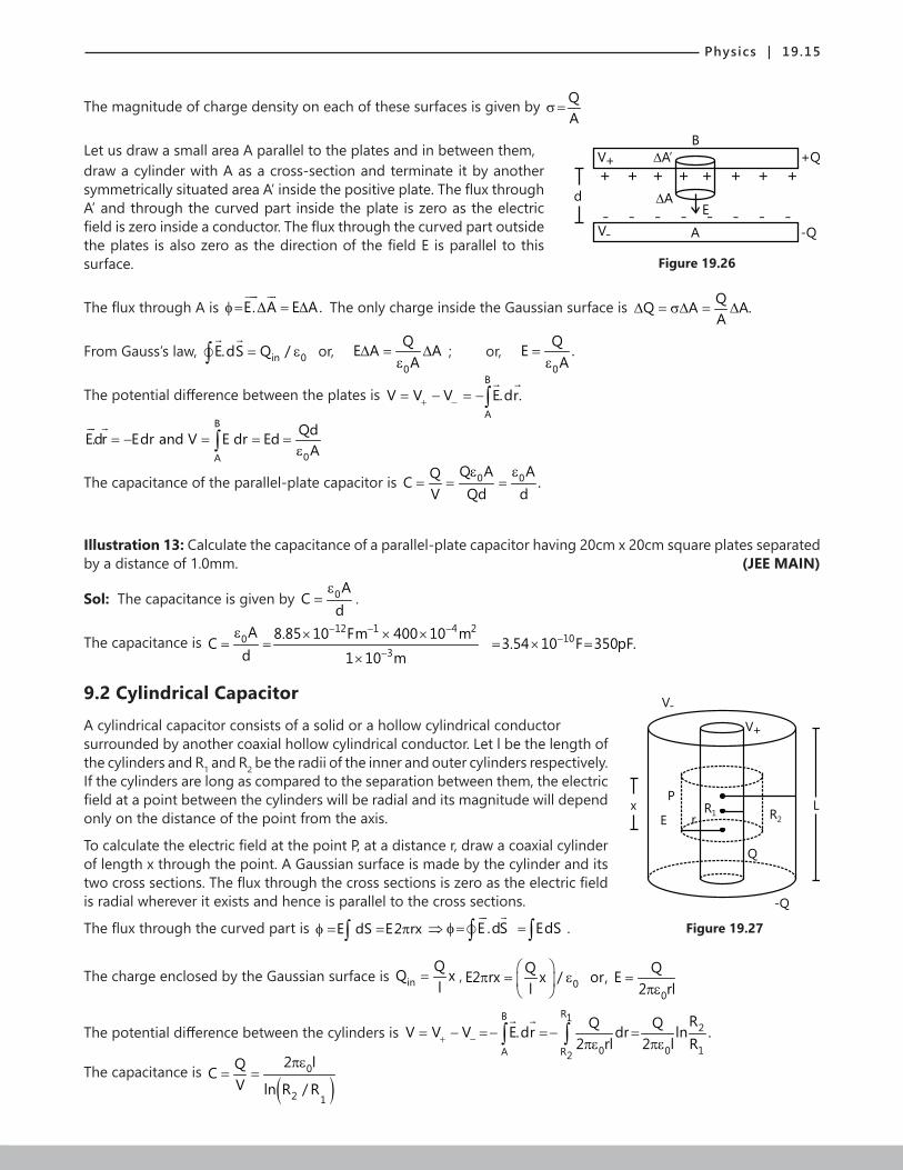
The magnitude of charge density on each of these surfaces is given by QA
σ=
Let us draw a small area A parallel to the plates and in between them,
Figure 19.26
B
V+ A’
AE
+ + + + + + + +
V- A -Q- - - - - - - -
+Q
d
draw a cylinder with A as a cross-section and terminate it by another symmetrically situated area A’ inside the positive plate. The flux through A’ and through the curved part inside the plate is zero as the electric field is zero inside a conductor. The flux through the curved part outside the plates is also zero as the direction of the field E is parallel to this surface.
The flux through A is E. A E A.φ= ∆ = ∆
The only charge inside the Gaussian surface is QQ A A.A
∆ = σ∆ = ∆
From Gauss’s law, in 0E.dS Q /= ε∫
or, 0
QE A AA
∆ = ∆ε
; or, 0
QE .A
=ε
The potential difference between the plates is B
A
V V V E.dr.+ −= − = −∫
B
0A
QdE.dr Edr and V E dr EdA
= − = = =ε∫
The capacitance of the parallel-plate capacitor is 0 0Q A AQC .V Qd d
ε ε= = =
Illustration 13: Calculate the capacitance of a parallel-plate capacitor having 20cm x 20cm square plates separated by a distance of 1.0mm. (JEE MAIN)
Sol: The capacitance is given by 0AC
dε
= .
The capacitance is 12 1 4 2
1003
A 8.85 10 Fm 400 10 mC 3.54 10 F 350pF.
d 1 10 m
− − −−
−
ε × × ×= = = × =
×
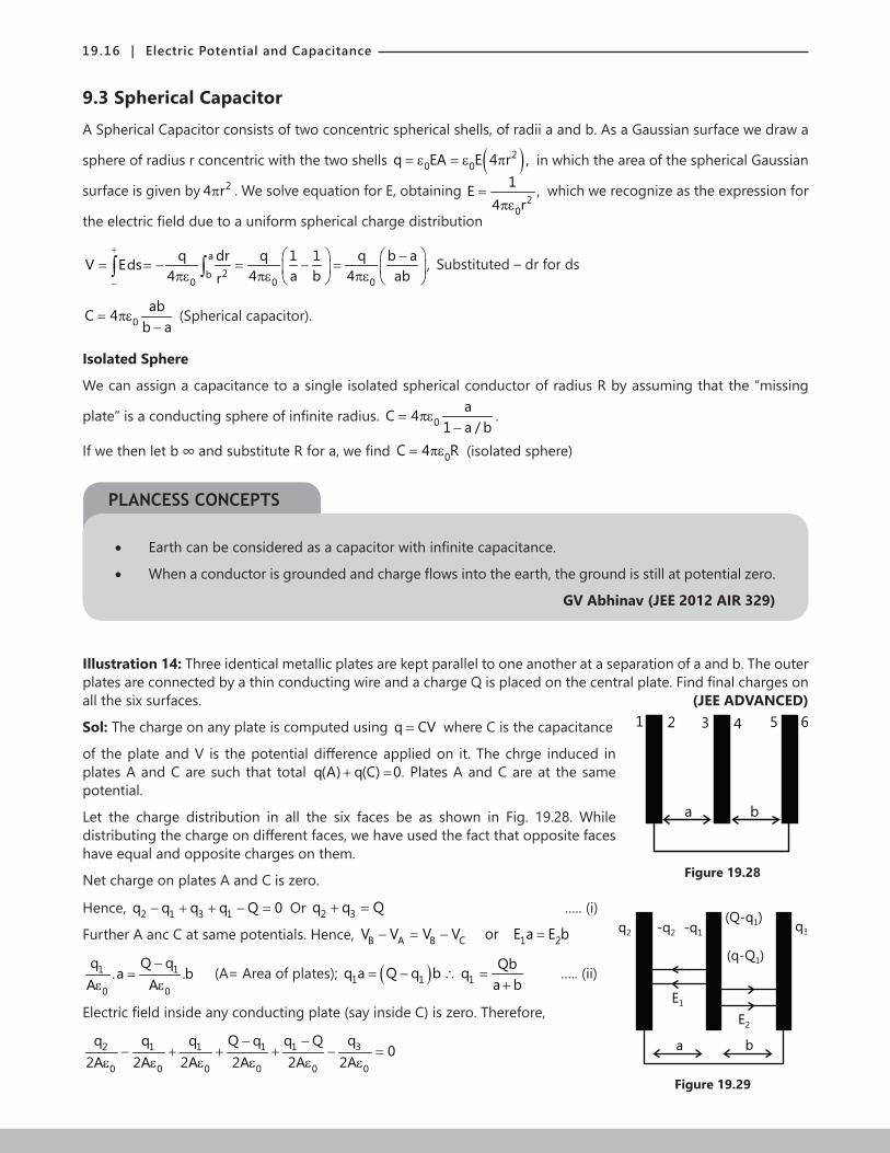
9.2 Cylindrical CapacitorA cylindrical capacitor consists of a solid or a hollow cylindrical conductor
Figure 19.27
V+
V-
x R1 R2
P
E r
Q
L
-Q
surrounded by another coaxial hollow cylindrical conductor. Let l be the length of the cylinders and R1 and R2 be the radii of the inner and outer cylinders respectively. If the cylinders are long as compared to the separation between them, the electric field at a point between the cylinders will be radial and its magnitude will depend only on the distance of the point from the axis.
To calculate the electric field at the point P, at a distance r, draw a coaxial cylinder of length x through the point. A Gaussian surface is made by the cylinder and its two cross sections. The flux through the cross sections is zero as the electric field is radial wherever it exists and hence is parallel to the cross sections.
The flux through the curved part is E dS E2 rxφ = = π∫ E .dS EdS⇒ φ= =∫ ∫
.
The charge enclosed by the Gaussian surface is in 00
Q Q QQ x. E2 rx x / or, El l 2 rl
= π = ε = πε
, in 00
Q Q QQ x. E2 rx x / or, El l 2 rl
= π = ε = πε
The potential difference between the cylinders is RB 1
2
0 0 1A R2
RQ QV V V E.dr dr ln .2 rl 2 l R+ −= − =− =− =πε πε∫ ∫
The capacitance is ( )
0
2 1
2 lQCV ln R / R
πε= =
19.16 | Electric Potential and Capacitance
PLANCESS CONCEPTS
9.3 Spherical CapacitorA Spherical Capacitor consists of two concentric spherical shells, of radii a and b. As a Gaussian surface we draw a
sphere of radius r concentric with the two shells ( )20 0q EA E 4 r ,= ε = ε π
in which the area of the spherical Gaussian
surface is given by 24 rπ . We solve equation for E, obtaining 2
0
1E ,4 r
=πε
which we recognize as the expression for
the electric field due to a uniform spherical charge distribution
a
2b0 0 0
q dr q 1 1 q b aV Eds ,4 4 a b 4 abr
+
−
−= = − = − = πε πε πε ∫ ∫ Substituted – dr for ds
0abC 4
b a= πε
− (Spherical capacitor).
Isolated Sphere
We can assign a capacitance to a single isolated spherical conductor of radius R by assuming that the “missing
plate” is a conducting sphere of infinite radius. 0aC 4
1 a / b= πε
−.
If we then let b ∞ and substitute R for a, we find 0C 4 R= πε (isolated sphere)
• Earth can be considered as a capacitor with infinite capacitance.
• When a conductor is grounded and charge flows into the earth, the ground is still at potential zero.
GV Abhinav (JEE 2012 AIR 329)
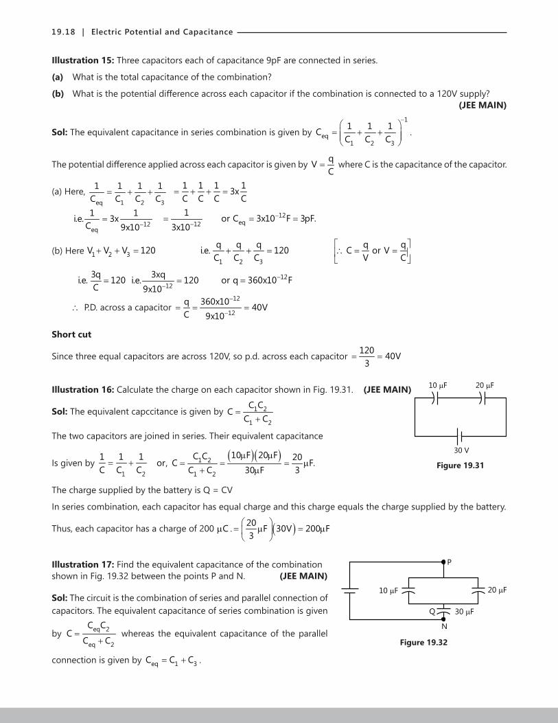
Illustration 14: Three identical metallic plates are kept parallel to one another at a separation of a and b. The outer plates are connected by a thin conducting wire and a charge Q is placed on the central plate. Find final charges on all the six surfaces. (JEE ADVANCED)
Sol: The charge on any plate is computed using q CV= where C is the capacitance
Figure 19.28
1 2 3 4 5 6
a b
of the plate and V is the potential difference applied on it. The chrge induced in plates A and C are such that total q(A) q(C) 0+ = . Plates A and C are at the same potential.
Let the charge distribution in all the six faces be as shown in Fig. 19.28. While distributing the charge on different faces, we have used the fact that opposite faces have equal and opposite charges on them.
Net charge on plates A and C is zero.
Hence, 2 1 3 1q q q q Q 0− + + − = Or 2 3q q Q+ = ….. (i)
a b
E1
E2
q2 -q2 -q1
(Q-q )1
(q-Q )1
q3
Figure 19.29
Further A anc C at same potentials. Hence, B A B C 1 2V V V V or E a E b− = − =
1 1
0 0
q Q q.a .b
A A−
=ε ε
(A= Area of plates); ( )1 1 1Qbq a Q q b q
a b= − ∴ =
+ ….. (ii)
Electric field inside any conducting plate (say inside C) is zero. Therefore,
32 1 1 1 1
0 0 0 0 0 0
qq q q Q q q Q0
2A 2A 2A 2A 2A 2A− −
− + + + − =ε ε ε ε ε ε

Physics | 19.17
PLANCESS CONCEPTS
Solving these three equations, we get 1 2 3Qb Qq , q q
a b 2= = =
+
10. COMBINATION OF CAPACITORS
The desired value of capacitance can be obtained by combining more than one
Figure 19.30
V1 V2 V3
Q Q Q+C- +C- +C-
Vn
Q+C-n
V
+ -
capacitor. We shall discuss two ways in which more then one capacitor can be connected.
10.1 Series Combination of capacitors:There is equal amount of charge Q deposited on each capacitor; but the potential difference between their plates is different (if the capacitance of each of the capacitors is different)
1 2 3 nV V V V .......... V= + + + + 1 2 3 n
Q Q Q Q Q..... (from C )C C C C V
= + + + + = ;
1 2 3 n
V 1 1 1 1.....Q C C C C
∴ = + + + +
If C is the resultant capacitance of C1, C2……, Cn which are connected
In series then V 1Q C
= ; 1 2 3 n
1 1 1 1 1.....C C C C C
∴ = + + + +
The value of C is smaller than the smallest of the values of the capacitors which are connected in series.
B Rajiv Reddy (JEE 2012 AIR 111)
10.2 Parallel Combination of CapacitorsIn this arrangement of the capacitors the charge accumulated on each of the capacitors is different while the potential difference between them is the same and is equal to potential difference between the common points A and B of such a connection.
Now, 1 1 2 2 3 3Q C V,Q C V,Q C V= = =
The total electric charge, ( )1 2 3 1 2 3Q Q Q Q C C C V= + + = + +
In general, 1 2 3QC C C C .....,V
= = + + +
Hence, by connecting capacitors in a parallel combination, a resultant capacitance can be obtained, whose value is equal to the sum of all capacitances connected in parallel.
• When a potential difference V is applied across several capacitors connected in parallel, it is applied across each capacitor. The total charge q stored on the capacitors is the sum of the charges stored on all the capacitors.
• Capacitors connected in parallel can be replaced with an equivalent capacitor that has the same total charge q and the same potential difference V as the actual capacitors.
• When a potential difference V is applied across serveral capacitors connected in series, the capacitors have identical charge q. The sum of the potential differences across all the capacitors is equal to the applied potential difference V.
19.18 | Electric Potential and Capacitance
Illustration 15: Three capacitors each of capacitance 9pF are connected in series.
(a) What is the total capacitance of the combination?
(b) What is the potential difference across each capacitor if the combination is connected to a 120V supply? (JEE MAIN)
Sol: The equivalent capacitance in series combination is given by 1
eq1 2 3
1 1 1CC C C
−
= + +
.
The potential difference applied across each capacitor is given by qVC
= where C is the capacitance of the capacitor.
(a) Here, eq 1 2 3
1 1 1 1C C C C
= + + 1 1 1 13xC C C C
= + + =
12
eq
1 1i.e. 3xC 9x10−
= 12
13x10−
= 12eqor C 3x10 F 3pF.−= =
(b) Here 1 2 3(b) Here V V V 120+ + = 1 2 3
q q q q qi.e. 120 C or VC C C V C
+ + = ∴ = =
3qi.e. 120C
= 12
3xqi.e. 1209x10−
= 12or q 360x10 F−=
∴ P.D. across a capacitor 12
12
q 360x10 40VC 9x10
−
−= = =
Short cut
Since three equal capacitors are across 120V, so p.d. across each capacitor 120 40V3
= =
Illustration 16: Calculate the charge on each capacitor shown in Fig. 19.31. (JEE MAIN) 10 F 20 F
30 V
Figure 19.31
Sol: The equivalent capccitance is given by 1 2
1 2
C CC
C C=
+
The two capacitors are joined in series. Their equivalent capacitance
Is given by 1 2
1 1 1C C C= +
( )( )1 2
1 2
10 F 20 FC C 20or, C F.C C 30 F 3
µ µ= = = µ
+ µ
The charge supplied by the battery is Q = CV
In series combination, each capacitor has equal charge and this charge equals the charge supplied by the battery.
Thus, each capacitor has a charge of 200 Cµ . ( )20 F 30V 200 F3
= µ = µ
Illustration 17: Find the equivalent capacitance of the combination
Figure 19.32
20 F10 F
P
Q 30 F
N
shown in Fig. 19.32 between the points P and N. (JEE MAIN)
Sol: The circuit is the combination of series and parallel connection of capacitors. The equivalent capacitance of series combination is given
by eq 2
eq 2
C CC
C C=
+ whereas the equivalent capacitance of the parallel
connection is given by eq 1 3C C C= + .

Physics | 19.19
The 10µF and 20µF capacitors are connected in parallel. Their equivalent capacitance is 10µF +20µF = 30µF.
We can replace the 10µF and the 20µF capacitors by a single capacitor of capacitance 30µF between P and Q.
This is connected in series with the given 30µF capacitor. The equivalent capacitance C of this combination is given
by 1 1 1 or,C 15 FC 30 F 30 F= + = µ
µ µ.
11. ENERGY STORED IN AN ELECTRIC FIELD OF A CAPACITOR
The work that needs to be done by an external force to charge a capacitor is visualized as electric potential energy U stored in the electric field between the plates. This energy can be recovered by discharging the capacitor in a circuit.
Suppose that, at a given instant, a charge q’ has been transferred from one plate of a capacitor to the other. The potential difference V’ between the plates at that instant is q’/C. The work required to increase the charge by dq’ i
qdW V'dq' dq'C
= =
The work required to bring the total capacitor charge up to a final value q is 2q
0
1 qw dW q'dq' .C 2C
= = =∫ ∫
This work is stored as potential energy U in the capacitor, so that we can also write this as 2qU
2C= (Potential energy).
• The potential energy of a charged capacitor may be viewed as being stored in the electrc field between its plates.
Illustration 18: A parallel plate air capacitor is made using two plates
Figure 19.33
E
+
+
+
-
-
-
d1
E
+
+
+
-
-
-
d2
0.2 m square, spaced 1 cm apart. It is connected to a 50V battery. (JEE ADVANCED)
(a) What is the capacitance?
(b) What is the charge on each plate?
(c) What is the energy stored in the capacitor?
(d) What is the electric field between the plates?
(e) If the battery is disconnected and then the plates are pulled apart to a separation of 2cm, what are the answers to the above parts?
Sol: The capacitance, charge on capacitor, energy stored in capacitor, the electric field between plates of capacitor,
are given by 2oA 1 VC ; Q CV; U CV and Ed 2 dε
= = = = respectively.
(a) 12
00
0
A 8.85X10 X0.2X0.2Cd 0.01
−ε= = ; 5
0C 3.54X10 F−= µ
(b) 5 30 0 0Q C V (3.54X10 X50) C 1.77X10 C− −= = µ = µ
(c) 2 11 20 0 0
1U C V 1 / 2(3.54X10 )(50)2
−= = ; 80U 4.42X10 J.−=
(d) 00
0
V 50E 5000V / m.d 0.01
= = =

19.20 | Electric Potential and Capacitance
(e) If the battery is disconnected, the charge on the capacitor plates remain constant while the potential difference between plates can change.
50
0
AC : 1.77X10 F
2d−ε
= = µ ; 30Q Q 1.77X10 C−= = µ ; 0
00
QQV 2V 100Volts.C C / 2
= = = = ;
( )22
800
0
Q1 Q 1U 2U 8.84X10 J2 C 2 C / 2
−= = = = , 00
0
2VE E 5000V / m.
2d= = =
Work has to be against the attraction of plates when they are separated. This gets stored in the energy of the capacitor.
Illustration 19: Find the energy stored in a capacitor of capacitance 100 Fµ when it is charged to a potential difference of 20V. (JEE MAIN)
Sol: The energy stored in the capacitor is given by 21U CV2
= .
The energy stored in the capacitor is ( )( )221 1U CV 100 F 20V 0.02J2 2
= = µ =
Illustration 20: Prove that in charging a capacitor half of the C
S
V
C
S
q
V
+
+ -
q
Figure 19.34
energy supplied by the battery is dissipated in the form of heat. (JEE ADVANCED)
Sol: When the swich S is closed, q=CV charge is stored in the
capacitor. Charge transferred from the battery is also q. Hence,
energy supplied by the battery 2qV (CV)(V) CV= = = Half, of
its Energy, i.e., 21 CV2
is stored in the capacitor and the remaining 50% or 21 CV2
is dissipated as heat.
11.1 Energy DensityNeglecting fringing, the electric field in a parallel-plate capacitor has same value at all points between the plates. The energy density u, which is the potential energy per unit volume between the plates should also be uniform. We
can find u by dividing the total potential energy by the volume Ad of the space between the plates 2
between the Plat U CVes u .Ad 2Ad
= = ,
C = ε0A/d, this result becomes2
01 Vu2 d
= ε
V/d equals the electric field magnitude E; so ( )20 Energy de1
2yE tu nsi= ε
Although we derived this result for the special case of a parallel-plate capacitor, it holds generally, whatever may be the source of the electric field.

Physics | 19.21
12. FORCE BETWEEN THE PLATES OF A CAPACITOR
Consider a parallel plate capacitor with plate area A. Suppose a positive charge q is given to q -q
+++++++
-------
Figure 19.35
one plate and a negative charge – q to the other plate. The electric field on the negative plate due to positive charge is
0 0
qE2 2Aσ
= =ε ε
qA
σ=
The magnitude of force on the charge in negative plate is 2
0
qF qE2A
= =ε
This is the force with both the plates attract each other. Thus, 2
0
qF2A
=ε
13. DIELECTRICS
If the medium between the plates of a capacitor is filled with an insulating substance (dielectric), the electric field due to the charges plates induces a net dipole moment in
Figure 19.36
+++++++++++++
-------------
+++++++++++++
-------------
+-
+-
+-
+-
+-
+-
+-
Electric field lines with
vacuum between the
plates
The induced charges on
the faces of the dielectric
reduce the electric field
(a) (b)
the dielectric. This effect called polarization, gives rise to a field in the opposite direction. Due to this, the potential difference between the plates is reduced. Consequently, the capacitance C increases from its value C0 when there is no medium (vacuum). The dielectric constant K is defined by
the relation dielectric
vacuum 0
C CKC C
= =
Where vacuumC = capacity of a capacitor when there is vacuum between the plates. Thus, the dielectric constant of a substance is the factor by which the capacitance increases from its vacuum value, when dielectric is inserted fully between the plates.
13.1 Dielectrics at an Atomic ViewWhat happens, in atomic and molecular terms, when we put a dielectric in an electric field? There are two possibilities, depending on the type of molecule:-
(a) Polar Dielectrics: The molecules of some dielectrics, like water, have permanent electric dipole moments. In such cases, the electric dipoles tend to line up with an external electric field because the molecules are continuously jostling each other as a result of their random thermal motion. This alignment becomes more complete as the magnitude of the applied field is increased (or as the temperature, and thus the jostling, are decreased). The alignment of the electric dipoles produces an electric field that is directed opposite to the applied field and is smaller in magnitude.
(b) Nonpolar moments: Even nonpolar molecules acquire dipole moments by induction when placed in an external electric field. This occurs because the external field tends to “stretch” the molecules, slightly separating the centres of negative and positive charge.

19.22 | Electric Potential and Capacitance
PLANCESS CONCEPTS
(a)
++
+ +
+
+
+
+
+
+
+
+
+
+ +
+
+
+
+
+
+
+ +
(b)
Figure 19.37
Molecules with a permanent electric dipole moment, showing their random orientation in the absence of an external electric field.
An electric field is applied producing partial alignment of the dipoles. Thermal agitation prevents complete alignment
(a)
E =00
+
+
+
+
+
+
+
+
-
-
-
-
-
-
-
-
E0
+- +- +- +-
+- +- +- +-
+- +- +- +-
+
+
+
+
+
+
+
+
-
-
-
-
-
-
-
-
+
+
+E0
E0
E
(b) ( )c
Figure 19.38
(i) A nonpolar dielectric slab. The circles represent the electrically neutral atoms within the slab.
(ii) An electric field is applied via charged capacitor plates; the field slightly stretches the atoms, separating the centres of positive and negative charge.
(iii) The separation produces surface charges on the slab faces. These charges set up a field E
’, which opposes
the applied field 0E
. The resultant field E
inside the dielectric (the vector sum of 0E
and E
’) has the same
direction as 0E
but a smaller magnitude.
Real Capacitors
• Real capacitors used in circuits are parallel plate capacitors with a dielectric material inserted in between the plates and rolled into a cylinder.
• This model reduces the size to get maximum capacitance.
Nitin Chandrol (JEE 2012 AIR 134)

Physics | 19.23
Illustration 21: A parallel plate capacitor is to be designed with a voltage rating 1kV, using a material of dielectric constant 3 and dielectric strength about 107
Vm-1. (Dielectric strength is the maximum electric field a material
can tolerate without breakdown, i.e. without starting to conduct electricity through partial ionization.) For safety, we should like the field never to exceed, say 10% of the dielectric strength. What minimum area of the plates is required to have a capacitance of 50pF? (JEE ADVANCED)
Sol: The area of the capacitor is given by C DA ⋅=
ε where 0 r x
lim→∞
ε = ε ⋅ ε is the permittivity of the medium.
10% of the given field i.e. 107 Vm-1.
Given E=0.1x10⁷ Cm-1
.
Using dVEdr−
= ; Vi.e. E ,wegetr
= we get; 37
V 1000r 10 mE 0.1x10
−= = =
Using C 0 rA ,d
ε ε= we get;
( ) ( )12 132
30 r 0 r
450x10 10Cd CrA 19cm8.854x10 3
− −
−= = = =ε ε ε ε ×
Illustration 22: A parallel plate capacitor with air between the plates has a capacitance of 8pF (1pF = 1210− F.) What will be the capacitance if the distance between the plates is reduced by half, and the space between them is filled with a substance of dielectric constant 6? (JEE MAIN)
Sol: The capacitance is k ACdε
= where k is the dielectric constant. If d reduces to ½ and k changes to 6 then new
capacitance is 12 times the original capacitance.
Using C’ = 0 rAC ,d
ε ε= C' ∈r C = 12(8 × 10‒12) = 96 × 10‒12F = 96pF
Illustration 23: Two parallel-plate capacitors, each of capacitance 40 Fµ , are connected in series. The space between the plates of one capacitor is filled with a dielectric material of dielectric constant K=4. Find the equivalent capacitance of the system. (JEE ADVANCED)
Sol: The equivalent capacitance of series connection is 1 2eq
1 2
C CC
C C=
+.
The capacitance of the capacitor with the dielectric is C1 = KC0 = 4 × 40 µF = 160 µF.
The other capacitor has capacitance C2 = 40 µF.
As they are connected in series, the equivalent capacitance is ( )( )1 2
1 2
160 F 40 FC CC 32 F
C C 200 F
µ µ= = = µ
+ µ
13.4 Dielectrics and Gauss lawFrom parallel plate capacitor with a dielectric equation we can write Gauss’ law in the form 0 Kε ∫ E.dA q=
(Gauss’ law with dielectric)
This equation, although derived for a parallel-plate capacitor, is true generally and is the most general form in which Gauss’ law can be written.
Some more information about capacitors
(a) If charge is held constant, i.e. battery disconnected and dielectric is inserted between plates.
(i) Charge remains unchanged, i.e., q = q0, as in an isolated system, charge is conserved.
(ii) Capacity increases, i.e. C = KC0, as by presence of a dielectric capacity becomes K times.
(iii) P.D. between the plate decreases, i.e., V=(V0/ K) 00 0
qqV as q q and c KCC KC
= = = = as,

19.24 | Electric Potential and Capacitance
00 0
qqV as q q and c KCC KC
= = = =
(iv) E between the plates decreases, i.e., ( )0E E / K ,= as, 0 0 0 00
V E V VVE as V and Ed Kd K K d
= = = = =
(v) Energy stored in the capacitor decreases, i.e. ( )0U U / K= .
220 0
0 0q UqU as q q and C KC
2C Kd K = = = = =
q0
+ + + + + + + + + +
- - - - - - - - - -
C0 V0 E0 U0, , ,
(a)
q+ + + + + + + + + +
- - - - - - - - - -
C, V, E, U K
(b)
Figure 19.39
(b) If potential is held constant, i.e., battery remains attached and dielectric in inserted between plates.
(i) PD remains constant, i.e. V = V0, as battery is a source of constant potential difference.
(ii) Capacity increases, i.e., C = KC0, as by presence of a dielectric capacity becomes K times.
(iii) Charge on capacitor increases, i.e., q = Kq0 ( )0 0 0 0as q CV KC V Kq as q C V = = = =
(iv) Electric field remains unchanged, i.e., E = E0,0 0
0 0 0V VVE E as V V and E
d d d
= = = = =
(v) Energy stored in the capacitor increases, i.e., U = KU0
As, ( )( )220 0
1 1U CV (KC V2 2
= = ; 2
0 0 0 0 01 1KU as C KC and U C V2 2
= = =
Illustration 24: A parallel-plate capacitor has plate area A and b
c
a
dx
Figure 19.40
plate separation d. The space between the plates is filled up to a thickness x(<d) with a dielectric of dielectric constant K. Calculate the capacitance of the system. (JEE ADVANCED)
Sol: As the distance between the plates is filled with dielectric material upto a distance x<d, this system represent
two capacitors connected in series. Thus equivalent capacitance is 1 2eq
1 2
C CC
C C=
+where each capacitance depends
on the dielectric constant K and distance from the plate of capacitor.
The situation is shown in Fig. 19.40. The given system is equivalent to the series combination of two capacitors, one between a and c and the other between c and b.
Here c represents the upper surface of the dielectric. This is because the potential at the upper surface of the dielectric is constant and we can imagine a thin metal plate being placed there.

Physics | 19.25
The capacitance of the capacitor between a and c is 01
K AC
xε
= and that between c and b is 02
AC
d xε
=−
.
The equivalent capacitance is ( )01 2
1 2
K AC CC
C C Kd x K 1ε
= =+ − −
Illustration 25: In the situation shown in Fig. 19.41 the area of the
V K
x
L
d
Figure 19.41
plates is A. The dielectric slab is released from rest. Prove that the slab will execute periodic motion and find its time period. Mass of the slab is m. (JEE ADVANCED)
Sol: As the slab is moving in constant electric field applied between the plates of capacitors, the force acting on it is constant.
The acceleration is obtained by Fam
= .When the slab moves
completly out side the plates the electric force pulls the slab slides
inside the plates of capacitor. The time period of oscillation is given by 2sta
= where s is the distance travelled by
the slab. After using, dUFdx
= − , where U→ Potential energy. Constant force, ( )2
0Constant force,bV K 1
F2d
ε −=
Here, Ab width of plateL
= =
∴ Acceleration of slab Fam
=
or ( ) ( )2
0 A / l V K 1a
2md
ε −=
The equilibrium position of the slab is, at the instant when the slab is fully inside the plates. So, the slab will execute oscillations in the phases as shown in Fig. 19.42.
x x
x
(a) (b) ( )c
(d) (e)
x x
x
(a) (b) ( )c
(d) (e)
Figure 19.42
T4
= time taken to reach from position (a) to position (b) = t (say) ; using
( )
( )( ) ( )
( )( )
2
22 00 A/l V K 1
1using S at2
2swe have t ;a
2 l x 4 l x mdl
AV K 1
2md
S l x
−
=
=
− −= =
ε ε
=
−
−
We have ( )
( )( ) ( )
( )( )
2
22 00 A/l V K 1
1using S at2
2swe have t ;a
2 l x 4 l x mdl
AV K 1
2md
S l x
−
=
=
− −= =
ε ε
=
−
−( ) ( ) ( )( )2
00
2(A/l)V (K 1)
2 l x 4 l x mdl
AV K 1
2md
S l xε −
− −= =
ε−
−=
The desired time period is, ( )( )2
0
L x mdlThe desired time period is, T 4t 8
AV K 1
−= =
ε −

19.26 | Electric Potential and Capacitance
Illustration 26: Three concentric conducting shells A, B and C of radii a, b and c are
Figure 19.43
A
B
C
a
b
c
a shown in Fig. 19.43. A dielectric of dielectric constant K is filled between A and B, find the capacitance between A and C. (JEE ADVANCED)
Sol: The potential difference in the region dr between the shells is given by V E dr∆ = ⋅∫ where E is the electric field. Capacitance is the ratio of charge and
potential difference. Let the sphere A have a charge q. When the dielectric is filled between A and B, the electric field will change in this region. Therefore the potential difference and hence the capacitance of the system will change. So, first find the electric field E(r) in the region a r c≤ ≤ . Then find the potential difference (V)
between A and C and finally the capacitance of the system is qCV
= , 2
0
qE(r) for a r b4 r
= ≤ ≤πε for
20
qE(r) for a r b4 r
= ≤ ≤πε
2
0
q for b r c4 r
= ≤ ≤πε
. Using, dv E.dr= −∫
Here potential difference between A and C is, b bA C 2 2a a
0 0
q qV V V .dr dr4 Kr 4 r
= − = −πε πε∫ ∫
( ) ( )0 0
b a c bq 1 1 1 1 1 q4 K a b b c 4 Kab bc
− − = − + − = + πε πε
( ) ( )0
q c b a Ka c b4 kabc
= − + − πε
The desired capacitance is ( ) ( )
04 KabcqCV Ka c b c b a
πε= =
− + −
14. R-C CIRCUITS
To understand the charging of a capacitor in C-R circuit, let us first consider the charging of a capacitor without resistance.
C
S V V
q =CV0+ -
Figure 19.44
Consider a capacitor connected to a battery of emf V through a switch S. When we close the q
q0
Figure 19.45
switch, the capacitor gets charged immediately. Charging takes no time. A charge q0 = CV comes in the capacitor as soon as switch is closed and the q-t graph in this case is a straight line parallel to t-axis as shown.
But if there is some resistance in the circuit charging takes some time. Because resistance
Figure 19.46
C
S V
opposes the charging (or current flow in the circuit).
Final charge (called steady state charge) is still q0 but it is acquired after a long period of time.
The q-t equation in this case is, ( )t/ c0q q l e− τ= −

Physics | 19.27
Here, q0 = CV and cτ = CR = time constant.
q-t graph is an exponentially increasing graph. The charge q increases
Figure 19.47
q0
q0
q
t=C t
0.632exponentially from 0 to q0.
From the graph and equation we see that at t = 0, q = 0 and at t = ∞, q = q0
14.1 Charging When a capacitor C is connected to a battery through a resistance R, the plates of a capacitor will acquire equal and opposite charge and the potential difference across it becomes equal to the emf of the battery. The process (called charging) takes sometime and during this time there is an electric current through the resistance. If at any time t, I is the current through the resistance R and q is the charge on capacitor C, the equation of emf for the circuit will be C RV V E, i.e., V IR E+ = + =
But I (dq/ dt)= and q CV=
so, dq qR Edt C
+ = or ( )
q t
0 0
dq dtCRCE q
= −−∫ ∫
Which on solving for q gives ( )t/CR0q q l e−= − with ( )0q CE for t= = ∞ …..(i)
This is the required result and from this it is clear that:
(a) During charging, charge on the capacitor increases from 0 to 0q (=CE) non-linearly.
(b) The density CR is called capacitive time constant τ of the circuit [as it has dimensions of time] and physically represents the time in which charge on the capacitor reaches 0.632 times of its maximum value during charging.
(c) During charging current at any time t in the circuit will be
( ) ( )t/CR t/CR0 0 0
dq d EI q l e I e with I at t 0dt dt R
− − = = − = = =
i.e., initially it acts as short circuit or as a simple conducting wire. If t , I 0→ ∞ → , i.e., it acts as open circuit or as a broken wire.
14.2 Discharging
If a charged capacitor C having charge 0q is discharged through a resistance R, then at any time t,
V = IR but as ( )I dq / dt and q CV= − =
dq qR 0dt C
+ = i,e., q t
q 00
dq dtdt CR
= −∫ ∫ or t/CR0q q e−=
This is the required result and from this it is clear that
(a) During discharging, the charge on capacitor decreases exponentially from q0 to 0
(b) The capacitive time constant CRτ = is the time in which charge becomes (l/e), i.e., 0.368 times of its initial value (q0)
(c) During discharging current at any time t in the circuit:
( )t/CR t/CR
0 0 0dq d EI q e I e with Idt dt R
− −= − = − = = with ( )t/CR t/CR0 0 0
dq d EI q e I e with Idt dt R
− −= − = − = = and its direction is opposite to that of charging.

19.28 | Electric Potential and Capacitance
(d) As in discharging of a capacitor through a resistance t/CR0q q e−= i.e.,
e 0
tRClog (q / q)
=
So resistance R can be determined from the value of t and ( )0q / q , i.e. ( )0V / V . Using this concept in laboratory we determine the value of high resistances ( )MΩ by the so called ‘Leakage method’.
Definition of cτ At t = cτ , q = q0 (1-e-1) = 0.632 q0
Hence, cτ can be defined as the time in which 63.2% charging is over in a C-R circuit. Note that cτ is the time.
Hence, c time τ = or 0 0CR M L T = .
15. VAN DE GRAAFF GENERATOR
Van de Graaff generator is a device that can generate a potential
Figure 19.48
Metal brushPulley
Metal brush
delivering
charge from
source
Insulating beltto carry anddeliver charge
Insulatingsupportingcolumn
Motor drivenpulley
Grounded
metal base
Principle of construction of
Van de Graaff generation
+ +
+
+
+
+
+
+
+
+
+
++
+
+
+
+
+
+
+
+
+
+
+++++++++++++
+++
++ ++
difference of a few million volts. The highly intense electric field produced in this matching is used to accelerate charged particles, which can then be used to study the composition of matter at the microscopic level.
Principle: let us presume (See Fig. 19.48) that charge Q is
residing on an isolated conducting shell, having radius R.
There is another conducting sphere having charge q and radius equal to r at the centre of the above mentioned spherical shell (r<R)
The electric potential on the spherical shell of radius R is equal to
RkQ kqVR R
= +
The electric potential on the surface of the sphere of radius r is, rkQ kqVR r
= +
Therefore, the potential difference between the surfaces of the two sphere is, r RkQ kq kQ kq 1 1V V kqR r R R r R−
= + − − = −
The above equation shows that the smaller sphere is at a higher electric potential in comparison to the larger spherical shell. If the smaller sphere is brought in contact with the larger spherical shell then electric charge will flow from the smaller sphere towards the larger spherical shell. Note if charge can be continuously transferred to the smaller sphere in some way, it will keep getting accumulated on the larger shell, thereby increasing its electric potential to a very high value.
Construction: S is a large spherical conducting shell with a radius of a few meters. This is erected to suitable height over the insulating pillars, C1 and C2. A long narrow belt of insulating material moves continuously between 2 pulleys P1 and P2 as shown in the Fig. 19.48. B1 and B2 are two sharply pointed brushes fixed near pulleys, P1 and P2 respectively, such that B2 touches the belt near the pulley P2. B1 is called the spray brush and B2 is called the collector brush.
Working: The spray brush is given a positive potential w.r.t. the earth by high tension source known as E.H.T. around the sharp points of B1, the high potential causes the air to ionize and this sprays positive charges on the belt. As the belt moves, and reaches the sphere S, the collecting brush B2, which touches the belt near pulley P2, collects the positive charge, which spreads on the outer surface of S. the uncharged belt returns down and again collects the positive charge from B1. As the belt moves continuously between P1 and P2 the positive charge starts accumulating on sphere S and the charge due to ionization is minimized by enclosing the metallic shell in an earth connected steel tank filled with air at high pressure. The charge particles may accelerate in this large potential to high kinetic energies of the order of more than 2 MeV.

Physics | 19.29
PROBLEM-SOLVING TACTICS
Below we illustrate how the above methodologies can be employed to compute the electric potential for a line of charge, a ring of charge and a uniformly charged disk.
Charged Rod Charged Ring Charged disk
Figure
L
y
r’
x’
’
O dx’
y
P
x
Figure 19.49
r
Z
R
P
y
xdp
z
Figure 19.50
P
zdq
z
R
x
y
r
r’
dr’
Figure 19.51
(2) Express dq in terms of charge density
'dq dx= λ dq dl= λ dq dA= σ
(3) Substitute dq into expression for dV
'
edxdV kr
λ= e
dldV krλ
= edAdV kr
σ=
(4) Rewrite r and the differential element in terms of the appropriate coordinates
'
'2 2
dx
r x y= +2 2
dl Rd
r R z
= φ
= +
' '
'2 2
dA 2 r dr
r r z
= π
= +
(5) Rewrite dV '
e '2 2 1/2
dxdV k(x y )
λ=
+
'
e 2 2 1/2
RddV k(R z )
λ φ=
+
' '
e '2 2 1/2
2 r drdV k(r z )
πσ=
+
(6) Integrate to get V 1/2
/2 '2 20
0
2 2
2 2
dxV4 x y
ln4
( / 2) ( / 2) y
( / 2) ( / 2) y
−
λ=
πε +
λ=
πε
+ + − + +
∫
'e 2 2 1/2
e 2 2
e 2 2
RV k d(R z )
(2 R )kR z
QkR z
λ= φ
+π λ
=+
=+
∫' 'R
e '2 2 1/20
2 2e
2 2e2
r drV k 2(r z )
2k z R z
2k Qz R z
R
= πσ+
= πσ + −
= + −
∫
Derive E from V
( )
y
2 20
VEy
/ 22 y / 2 y
∂= −
∂λ
=πε
+
( )e Z
z 3/22 2
k QVEz R z
∂= − =
∂ +z
e2 2 2
VEz
2k Q z zzR z R
∂= −
∂ = − +
Point- charge limit for E e
y 2
k QE y
y≈ >> e
z 2
k QE z R
z≈ >> e
z 2
k QE z R
z≈ >>
19.30 | Electric Potential and Capacitance
For any given combination, one may proceed as follows:
Step 1: Identify the two points between which the equivalent capacitance is to be calculated. Call any one of them as P and the other as N.
Step 2: Connect (mentally) a battery between P and N with the positive terminal connected to P and the negative terminal to N. Send a charge +Q from the positive terminal of the battery.
Step 3: Write the charges appearing on each of the plates of the capacitors. The charge conservation principle may be used. The facing surfaces of a capacitor will always have equal and opposite charges. Assume variables Q1, Q2 …, etc., for charges wherever needed.
Step 4: Take the potential of the negative terminal N to be zero and that of the positive terminal P to be V. Write the potential of each of the plates. If necessary, assume variables V1, V2….
Step 5: Write the capacitor equation Q = CV for each capacitor. Eliminate Q1, Q2 …and V1, V2…., etc., to obtain the equivalent capacitance C=Q/V.
FORMULAE SHEET
S. No FORMULA
1. q CV=
2. 0 E.dA q.ε =∫
3. f
1 2 iV V E.dS.− = ∫
4.d
0V Eds E ds Ed
+
−= = =∫ ∫
5. 0q EA.= ε
6. 0AC
dε
= (parallel-plate capacitor)
7. ( )0LC 2
ln b / a= πε (cylindrical capacitor)
8.0
abC 4b a
= πε−
(spherical capacitor)
9. 0C 4 R= πε (isolated sphere)
10. n
eq Jj 1
C C=
= ∑ (n capacitors in parallel)
11.n
j 1eq J
1 1C C=
= ∑ (n capacitors in series)

Physics | 19.31
S. No FORMULA
12. 21U CV2
= (potential energy)
13.2qU
2C= (potential energy)
14. 20
1u E2
= ε (energy density)
15. 20
qE4 K r
=π ε
16. 0 KE.dA qε =∫
(Gauss’ law with dielectric).
17. Force on a Dielectric Slab inside a Capacitor( )2
0bV K 1F
2d
ε −=
Electric Potential Formulae
S. No Term Description
1 Electric Potential energy
∆U = -W Where ∆U = Change in potential energy and W= Work done by the electric lines of force.
For a system of two particles U(r) = q1q2 / 4πεr
Where r is the separation between the charges.
We assume U to be zero at infinity.
Similarly for a system of n charges
U = Sum of potential energy of all the distinct pairs in the system
For example for three charges
U = 1 2 12 2 3 23 1 3 13(1 / 4 )(q q / r q q / r q q / r )πε + +
2 Electric PE of a charge
= qV where V is the potential.
3 Electric Potential Like Electric field intensity is used to define the electric field; we can also use Electric Potential to define the field. Potential at any point P is equal to the work done per unit test charge by the external agent in moving the test charge from the reference point (without Change in KE)
Vp = Wext / q. So for a point charge V0 = Q / 4πεr
Where r is the distance of the point from charge.

19.32 | Electric Potential and Capacitance
S. No Term Description
4. Some points about Electric potential
1. It is scalar quantity
2. Potential at a point due to system of charges will be obtained by the summation of potential of each charge at that point
V = V1 + V2 + V3 + V4
3. Electric forces are conservative forcew so work done by the electric force between two points is independent of the path taken
4. 2 1V V E.dr− = −∫5. In Cartesian coordinates system
x y zdV E.dr; dV (E dx E dy E dz)= − = − + +
So x y zE V / x, E V / y and E V / z,= ∂ ∂ = ∂ ∂ = ∂ ∂
Also ( ) ( ) ( )E V / x i V / y i V / z k = ∂ ∂ + ∂ ∂ + ∂ ∂ 6. Surface where electric potential is same everywhere is called equipotential surface.
Electric field components parallel to equipotential surface are always zero.
5 Electric dipole A combination of two charges +q and –q separated by a distance d has a dipole moment p = qd, where d is the vector joining negative to positive charge.
6 Electric potential due to dipole
2V (1 / 4 ) (pcos / r )= πε × θ
Where r is the distance from the center and θ is angle made by the line from the axis of dipole.
7 Electric field due to dipole
3 3r
2 2 3 2r
E (1 / 4 )(psin / r ); E (1 / 4 ) (2pcos / r )
Total E E E (p/ 4 r )( (3cos 1)
θ
θ
= πε θ = πε × θ
= + = πε θ +
Torque on dipole = p × E
Potential Energy U = ‒p.E
8 Few more points 1. E.dl∫ over closed path is zero
2. Electric potential in the spherical charge conductor is Q / 4πεR where R is the radius of the shell and the potential is same everywhere in the conductor.
3. Conductor surface is a equipotential surface
Electric potential due to various charge distributions
Name/Type Formula Note Graph
Point Charge Kqr
• q is source charge
• r is the distance of the point from the point charge.
V
r
Ring (uniform/non uniform charge distribution)
At centre, KQR
At axis, 2 2
KQ
R x+
• Q is source charge
• x is distance of the point from centre.
V

Physics | 19.33
Name/Type Formula Note Graph
Uniformly charged hollow conducting/ non - conducting sphere or solid conducting sphere
For KQr R,VR
≥ =
For KQr R,VR
≤ =
• R is radius of sphere
• r is distance of the point from centre of the sphere
• Q is total charge ( 2( 4 R )= σ π
V
Rr
KQ/R
Uniformly charged solid non - conducting sphere (insulating material)
For KQr R, Vr
≥ =
For r R,≤
2 2
3
2 2
0
KQ(3R r )V2R
(3R r )6
−=
ρ= −
ε
• R is radius of sphere
• r is distance of point from centre of the sphere.
• Q is total charge 34( R )3
= ρ π
• centre surface3V V2
=
• Inside sphere potential varies parabolically.
• Outside potential varies hyperbolically.
V
Rr
3KQ/2R
KQ/R
Line charge Not defined • Absolute potential is not defined
• Potential difference between two points is given by formula
B A B AV V 2K ln(r / r )− = − λ , where
lambda is the charge per unit length
Infinite nonconducting thin sheet
Not defined • Absolute potential Is not defined
• Potential difference between two points is given by formula
B A B A0
V V (r r )2σ
− = − −ε
, where
sigma is the charge density
Infinite charged conducting thin sheet
Not defined • Absolute potential is not defined
• Potential difference between two point is given by formula
B A B A0
V V (r r )σ− = − −
ε, where
sigma is the charge density
Electric dipole moment: ˆp qdz= , where two charges of charge q± are placed along the z axis at z d
2= ±
Electric dipole field: Along the z axis (z>>d): 3
0
1 p ˆE z2 z
=πε
, in the +z direction.
Along the x axis(x>>d): 3
0
1 p ˆE x2 x
=πε
in the +x direction.
Along the x axis(y>>d): 3
0
1 p ˆE y2 y
=πε
in the +y direction.

19.34 | Electric Potential and Capacitance
Potential difference across C4 and 200 PF is in the ratio 2:1 i.e. 200 V across C4
∴ Charge on C4 = C4 V4; =100 × 200 × 1012 = 2 × 10‒8 C
Potential difference across C1=100V
Charge on C1= C1 × V1 = 100 × 100 × 10‒12 =1 × 10‒8 C
Potential difference across C2 and C3 is 50V each
∴ Charge on C2 or C3= C2V2 = 200 × 50 × 1012 = 10‒8 C.
Example 2: The connection shown in figure are established with the switch S open. How much charge will flow through the switch if it is closed?
1 F
1
24V+-
2 F
4
S
1 F
3
2 F
2
-Q1 Q1 -Q2Q2
1 F 2 F1 2
S
V02 F 1 F34
Q2 Q2
24V
0
+-
(a)
(b)
Sol: Find the initial charge on capacitors. After the switch is closed, 1 and 2 become parallel and 3 and 4 become parallel.
When the switch is open, capacitors (2) and (3) are in
series. Their equivalent capacitance is The charge appering on each of t2 eF3
hesµ .
The charge appering on each of these capacitors is,
therefore, 224V F 16 C3
× µ = µ
The equivalent capacitance of (1) and (4), which are
also connected in series, is also 2 F3µ and the charge
on each on each of these capacitors is also 16 Cµ . The total charge on the two plates of (1) and (4) connected to the switch is, therefore, zero.
Solved Examples
JEE Main/Boards
Example 1: Obtain the equivalent capacitance of the network in figure. For a 300V supply, determine the charge and voltage across each capacitor.
100pF
200pF200pF
100pF
C1
C2 C3
C4
300V+
-
Sol: The circuit is made up of series and parallel combinations of the capacitors. The charge on the capacitor is given by q = CV.
100pF
C4 C2 C3
C1100pF
200pF 200pF
300 V
The equivalent circuit is as shown below:
100pF
C4
100pF
300 V
100pF
100pF 200pF
300 V

Physics | 19.35
The situation when the switch S is closed is shown in figure. Let the charges be distributed as shown in the figure. Q1 and Q2 are arbitrarily chosen for the positive plate of (1) and (2).
Take the potential at the negative terminal to the zero and at the switch to be V0
Writing equations for the capacitors (i), (ii), (iii) and (iv).
Q1 = (24V ‒ V0) × 1µF … (i)
Q2 = (24V ‒ V0) × 2µF … (ii)
Q1 = V0 × 1µF ... (iii)
Q2 = V0 × 2µF … (iv)
From (i) and (iii), V0 =12V, Thus, from (iii) and (iv),
1Q 12 C= µ and 2Q 24 C= µ .
The charge on the two plates of (1) and (4) which are connected to the switch is, therefore 2 1Q Q 12 C− = µ . When the switch was open, this charge was zero. Thus, 12µC of charge has passed through the switch after it was closed.
Example 3: Find the capacitance of the infinite ladder shown in figure.
C P C C
C C C C
A
BQ
Sol: Capacitance between points P and Q is same as that between A and B. The equivalent capacitance of the circuit is deduced by reducing it to simple network. The simplified circuit is a parallel combination of the capacitors whose capacitance is given by
1eq
1
CCC C
C C= +
+.
As the ladder is infinitely long, the capacitance of the ladder to the right of the points P, Q is the same as that of the ladder to the right of the points A, B. If the equivalent capacitance of the ladder is C, the given ladder may be replaced by the connections shown in figure.
C P
C C1
A
BQ
The equivalent capacitance between A being equivalent to the original ladder, the equivalent capacitance is also C
Thus, 11
1
CCC C
C C= +
+ or 2 2
1 1 1C C C C 2CC+ = +
Or 2 21 1C CC C 0− − = ,
Giving 2 2
1C C 4C 1 5C C
2 2+ + +
= =
Negative value of C1 is rejected.
Example 4: A parallel-plate capacitor has plates of area 200 cm2 and separation between the plates 1.00 mm. What potential difference will be developed if a charge of 1.00 nC (i.e., 1.00 × 10‒9C) is given to the capacitor? If the plate separation is now increased to 2.00 mm, what will be the new potential difference?
Sol: Capacitance is given by 0AC
dε
= and the potential
difference is given by QVC
=
The capacitance of the capacitor is
0AC
dε
=4 2
12 13
200x10 m8.85x10 Fm x1x10 m
−− −
−=
90.177x10 F 0.177nF.−= =
The potential difference between the plates is Q 1nCV 5.65 Volts.C 0.177nF
= = =
If the separation is increased from 1.00 mm to 2.00 mm, the capacitance is decreased by a factor of 2. Thus, the new potential difference will be 5.65 volts × 2 = 11.3 volts.
Example 5: An isolated sphere has a capacitance of 50pF.
(a) Calculate its radius.
(b) How much charge should be placed on it to raise its potential to 104 V?
Sol: For sphere, radius R is given by 0C 4 R= πε . To raise the potential to 104 V, the charge to be placed on sphere is given by Q = CV.
(a) The capacitance of an isolated sphere is
0C 4 R.= πε Thus, 129 1
R50x10 F9x10 mF
−−
=
or 12 9R 50x10 x9x10 m 45cm.−= =
(b) 12 4Q CV 50X10 FX10 V 0.5 C−= = = µ

19.36 | Electric Potential and Capacitance
Example 6: A parallel-plate capacitor of capacitance 100 Fµ if connected to a power supply of 200V. A dielectric slab of dielectric constant 5 is now inserted into the gap between the plates.
(a) Find the extra charge flown through the power supply and the work done by the supply.
(b) Find the charge in the electrostatic energy of the electric field in the capacitor.
Sol: After inserting the dielectric the capacitance is changed, thus the charge stored in the capacitor is given by Q = CV and work done by supply is CV2 = qV.
The energy stored in the capacitor is given by 21U CV2
=
(a) The original capacitance was 100µF. The charge on the capacitor before the insertion of the dielectric was, therefore, Q1 = 1000F × 200V = 20mC
After the dielectric slab is introduced, the capacitance is increased to 500µF. The new charge on the capacitor is,
Therefore, 500 Fx200v 100mCµ = .
The charge flown through the power supply is, therefore, 100 mC 20 mC 80 mC− = .
The work done by the power supply is 200V × 80mC = 16J.
(b) the electrostatic field energy of the capacitor without the dielectric slab is
21
1U CV2
= ( ) ( )1 100 F X 200V 2J2
= µ =
And that after the slab is inserted is
( ) ( )221U 500 F X 200V 10J2
= µ = thus, the energy is
increased by 8J.
Example 7: Each of the three plates shown in figure has an area of 200cm2 on one side and the gap between the adjacent plates is 0.2mm. The emf of the battery is 20V. Find the distribution of charge on various surfaces of the plates. What is the equivalent capacitance of the system between the terminal points?
A B
+
-
C A B
+
-
C
20V
Q/2
-Q/2
Q/2
-Q/2
(a) (b)
Sol: As the charge distribute symmetrically around the central plate. Due to this there is equal amount
of charge induced in other plates. The capacitance is
between any two surfaces is given by 0AC
dε
= .
Suppose the negative terminal of the battery gives a charge – Q to the plate B. As the situation is symmetric on the two sides of B, the two faces of the plate B will share equal charge – Q/2 each. From Gauss’s law, the facing surfaces will have charge Q/2 each. As the positive terminal of the battery has supplied just this much charge (+Q) to A and C, the outer surfaces of A and C will have no charge. The distribution will be as shown in figure. The capacitance between the plates A and B is
4 2120
4
A 200 10 mC 8.85 10 F / md 2 10 m
− −−
−
ε ×= = × ×
× 108.85X10 F 0.885nF−= =
Thus, Q 8.85nFx20V 17.7nC= =
The distribution of charge on various surfaces may be written from figure.
The equivalent capacitance is Q 1.77nF20V
=
Example 8: The emf of the cell in the circuit is 12 volts and the capacitors are: C1 = 1µF, C2 = 3µF, C3 = 2µF, C4 = 4µF
Calculate the charge on each capacitor and the total charge drawn from the cell when
(a) The switch s is closed
(b) The switch s is open.
C4C3
C1 C2
Cell+ -
12 V
Sol: When the switch is closed the equivalent
capacitance is given by ( )( )( ) ( )
1 3 2 4
1 3 2 4
C C C CC
C C C C
+ +=
+ + +
and the charge stored in the circuit is given by Q=CV. When the switch is open the capacitance is given
by 3 41 2
1 2 3 4
C CC CC
C C C C= +
+ +. The charge stored in the
capacitor is given by
(a) Switch S is closed:

Physics | 19.37
( )( )( ) ( )
1 3 2 4
1 3 2 4
C C C C 3 7C ; C 2.1 F
3 7C C C C
+ + ×= = = µ
++ + +;
Total charge drawn from the cell is:
Q = CV = 2.1µF × 12 volts = 25.2µC
1C , 3C are in parallel and C2, C4 are in parallel.
C4C3
C2C1
Q
-12V+
Charge on C1
11
1 3
C 1Q Q 25.2 C 8.4 CC C 1 2
= = × µ = µ+ +
Charge on C3
33
1 3
C 2Q Q 25.2 C 16.8 CC C 1 2
= = × µ = µ+ +
Charge on C2
22
2 4
C 3Q Q 25.2 C 10.8 CC C 3 4
= = × µ = µ+ +
Charge on C4
44
2 4
C 4Q Q 25.2 C 14.4 CC C 3 4
= = × µ = µ+ +
(c) switch S is open :
3 41 2
1 2 3 4
C CC CC
C C C C= +
+ +1X3 2X4 25C F1 3 2 4 12
= + = µ+ +
Total charge drawn from battery is:25Q CV 12 25 C12
= = × = µ
C4C3
C2C1
12V+ -
C1 and C2 are in series and the potential difference across combination is 12 volts charge on
C1= charge on C2
3 4
3 4
C C 8V 12 16 CC C 6
= = × = µ +
C3 & C4 are in series and the potential difference across combination is 12 volts charge on
C3= charge on C4
3 4
3 4
C C 8V 12 16 CC C 6
= = × = µ +
Example 9: Two capacitors A and B with capacities 3 Fµ and 2 Fµ are changed to a potential difference of 100V and 180V respectively. The plates of the capacitors are connected as shown in the figure with one wire of each capacitor free. The upper plate of A is positive and that of B is negative. An uncharged 2 Fµ capacitor C with lead wires falls on the free ends to complete the circuit. Calculate:
q2B C
A D
+ -
3 4
3 F q1
+
-
2
12 F
+
-5
6 q3
(i) The final charge on the three capacitors, and
(ii) The amount of electrostatic energy stored in the system before and after the completion of the circuit.
Sol: The charge stored in each capacitor when they are not connected to each other is given by q = CV. When the capacitors are connected to each other then the charge stored in each the capacitor is obtained by applying Kirchoff’s 2nd law to the circuit. The energy
stored in the capacitor is given by 21U CV2
=
(i) charge on capacitor A, before joining with an uncharged capacitor,
Aq CV (100) 3 c 300 c= = + µ = µ
Similarly charge on capacitor B,
Bq 180 2 c 360 c= × µ = µ
Let q1, q2 and q3 be the charges on the three capacitors after joining them as shown.
From conservation of charge,

19.38 | Electric Potential and Capacitance
Net charge on plates 2 and 3 before joining
= Net charge after joining
1 2300 q q∴ = + …… (i)
Similarly, net charge on plates 4 and 5 before
Joining = Net charge after joining
2 3360 q q− = − − ; 2 3360 q q= + ...…(ii)
Applying Kirchoff’s 2nd law in loop ABCDA,
31 2 qq q0
3 2 2− + =
1 2 32q 3q 3q 0− + = ..… (iii)
From equations (i), (ii) and (iii),
1 2 3q 90 C,q 90 C and q 150 C= µ = µ = µ
(iii) (a) Electrostatic energy stored before completing the circuit,
21U CV2
=
= 4.74x10⁻²J = 47.4mJ.
2 F
2 F
C
3 FA B
+ -
(b) Electrostatic energy stored after completing the circuit,
( )26f 6
1 1U 90X102 3x10
−−
=
( )266
1 190x102 2x10
−−
+
( )266
1 1150x102 2x10
−−
+ ; 2
1 qU2 c
=
490x10 J−= 90mJ=
Example 10: A capacitor of capacitance 4 Fµ is charged to a potential difference of 100V and another of capacitance 6 Fµ is charged to a potential of 200V.These capacitances are now joined with plates of like charges connected together. Calculate:
(a) The total potential across each after joining
(b) The total electrical energy stored before joining
(c) The total electrical energy stored after joining200V
+ -
6 F
100V
4 F
+ -
S
How do you account for the difference in energies in (b) and (c) ?
Sol: When the capacitors are connected to each other then the total charge stored in the circuit is given by
1 2 1 1 2 2Q Q Q C V C V= + = + . The energy stored in each
capacitor is given by 21U CV2
= .
1 1V 100V,C 4 F= = µ , 61 1 1Q C V 4 10 100−= = × ×
44 10 C−= × ; 2 2V 200V,C 6 F= = µ6 4
2 2 2Q C V 6X10 200 12 10 C− −= = × = ×
When the plates with like charges are connected together, both capacitors have the same potential after redistribution of charge.
(a) Total charge = 1 2Q Q Q= +
( ) 4 34 12 10 1.6 10 C− −= + × ×
Capacitance of the combination in parallel
( )1 2C C C 4 6 F 10 F= = + = + µ = µ
Potential across each capacitor after joining3
6
q 1.6 10V 160VC 10 10
−
−
×= = = =
×
(b) Electrical energies U1 and U2 before joining are given as :
( ) ( )22 6 21 1 1
1 1U C V 4X10 100 2X10 J2 2
− −= = × × =
( ) ( )22 6 22 2 2
1 1U C V 6X10 200 12X10 J2 2
− −= = × × =
Energy before joining
i 1 2U U U= = + ; ( ) 212 2 10 0.14J−= + × =
(c) Electrical energy after joining of capacitors
6 2f
1U 10 0 (160) 0.128J2
−= = × × × =
The stored electrical energy after joining is less by (0.14-0.128) J i.e. 0.012J. the energy is dissipated as heat energy through the connecting wires as current flows.

Physics | 19.39
Example 11: What charges will flow thorugh A, B and C in the directions shown in Fig. 19.69 when switch S is closed?
2 F
3 F
A
B
S
C
30V
60V
-
Sol: The charges stored in capacitor is given by Q = CV.
The equivalent capacitance is 1 2eq
1 2
C CC
C C=
+. To find the
charges flowing in each capacitor we use the Kirchoff’s 2nd law.
Let us draw two figures as shown in figure and find the charge on both the capacitors before closing the switch and after closing the switch. Refer figure (a) when switch is open: both capacitors are in series. Hence, their equivalent capacitance is,
1 2eq
1 2
C C (2)(3) 6C FC C 2 3 5
= = = µ+ +
Therefore, charge on both capacitors will be same. Hence, using q = CV, we get
2 F
3 F
30V
60V
q
q
+
-
+
-
2 F
3 F
A
B
C
30V
60V
B
( ) 6q 30 60 C 108 C5
= + µ = µ
Refer figure (b), when switch is closed: let q1 and q2 be the charges (in Cµ ) on two capacitors. Then applying Kirchoff’s 2nd law in upper and lower loop, we have
1q30 0
2− = Or q1 = 60µC;
2q60 0
3− = Or q2 = 180µC
Charges q1 and q2 can be calculated alternatively by seeing that upper plate of 2 Fµ capacitor is connected with positive terminal of 30V battery. Therefore, they are at the same potential. Similarly, the lower plate of this capacitor is at the same potential as that of the negative terminal of 30V battery. So, we can say that P.D. across 2 Fµ capacitor is also 30V.
1q (C)(P.D) (2)(30) C= = µ
Similarly, P.D. across 3 Fµ capacitor is same as that between 60V battery. Hence, 2q (3)(60) 180 C= = µ . Now let Aq charge goes to the upper plate of 2 Fµ capacitor. Initially it had a charge +q and finally charge on it is + 1q . Hence, 1 Aq q q= + or A 1q q q 60 180= − = −
48 C= − µ
2 F
3 F
48 F
C
30V
60V
--
-
--
48 C
48 C72 C
72 C
+
Similary, charge qB goes to the upper plate of 3 Fµ capacitor and lower plate of 2 Fµ capacitor. Initially both the plates had a charge +q, -q or zero. And finally they have a charge 2 1(q q )− .
Hence, 2 1 Bq q q 0− = +
B 2 1q q q180 60
∴ = −
= −
120 C= µ Initially it had a charge-q and finally 2q− .
Hence, 2qc q q 108 180= − = − 72 C= − µ
Example 12: If 100 volts of potential difference is applied between a and b in the circuit of figure, find the potential difference between c & d.
Sol: The charge stored in each capacitor is given by Q = CV. To find the potential difference at point’s c and d we apply Kirchoff’s law to the circuit.
The charge distribution on different plates is shown in figure. Suppose charge Q1 + Q2 is given by the positive terminal of the battery, out of which Q1 resides on the positive plate of capacitor (1) 2and Q on that of (2). The remaining plates will have charges as shown in the figure. Take the potential at the point b to be zero. The potential at a will be 100V. Let the potentials at points c and d be Vc and Vd respectively. Writing the equation Q=CV for the four capacitors, we get,
1Q 6 F 100V 600 C= µ × = µ …..(i)
2 cQ 6 F (100V V )= µ × − …..(ii)
2 c dQ 6 F (V V )= µ × − …..(iii)
2 dQ 6 F V −= µ × …..(iv)

19.40 | Electric Potential and Capacitance
From (ii) and (iii)( ) ( ) c c dFrom ii and iii 100V V V V− = −
or ( )c d2V V 100V .. v− = … …..(v)
( ) ( ) c d dAnd from iii a V V v Vnd i − =
or ( )c dV 2V .. vi− …= …..(vi)
From (v) and (vi)
From (v) and (vi) ( ) ( ) d c 1Fro 00 200V V and V V3 3
m v and vi = =
So that c d100V V V
3So that − =
Example.13 A regular hexagon of side 10 cm has a charge 5µC at each of its vertices. Calculate the potential at the center of the hexagon.
q
q
q
q
q q
O
10 cm
Sol: The potential at the center of the hexagon is due to 6 charges placed at its vertices. It is given by
0
1 qV 64 r
= × πε
6 F
6 F
6 F
6 F
a c
d
(a)
a c
d
b
b
Q2 -Q2
Q2-Q2
-Q1
Q
-Q2
Q2100V 1
23
(b)
Total potential at O is given by,
69 6
0
1 q 5 10V 6 6 (9 10 ) 2.7 104 r 0.1
− ×= × = × × × = × πε
volt.
JEE Advanced/Boards
Example 1: Two capacitors 1C 1 F= µ and 2C 4 F= µ are charged to a potential difference of 100 volts and 200 volts respectively. The charged capacitors are now connected to each other with terminals of opposite sign connected together. What is the
V
- -+ +
C1 C2
- -+ +
- -+ +
C2+ +
C1
+ +
V1
V1
(a) Final charge on each capacitor in steady state?
(b) Decrease in the energy of the system?
Sol: The capacitors are connected parallel to each other. Thus the equivalent capacitance is given by C = C1+C2. The charges stored in capacitor is given by Q = CV. The
energy stored in each capacitor is given by 21U CV2
= .
initial charge on 1 1 1C C V 100 F= = µ ;
Initial charge on 2 2 2C C V 800 F= = µ ; 1 1 2 2C V C V<
When the terminals of opposite polarity are connected together, the magnitude of net charge finally is equal to the difference of magnitude of charges before connection.
(Charge on 2C )i - (charge on 1C ) i
= (charge on 2C )f - (charge on 1C ) f
Let V be the final common potential difference across each.
The charges will be redistributed and the system attains a steady state when potential difference across each capacitor becomes same.
2 2 1 1 2 1C V C V C V C V− = +
1 2 1 2
2 1
C V C V 800 100V 140 voltsC C 5
− −= = =
+
Note that because 1 1C V 2 2C V< , the final charge
polarities are same as that of 2C before connection.
Final charge on 1 1C C V 140 C= = µ
Final charge on 2 2C C V 560 C= = µ
Loss of energy= i fU U−
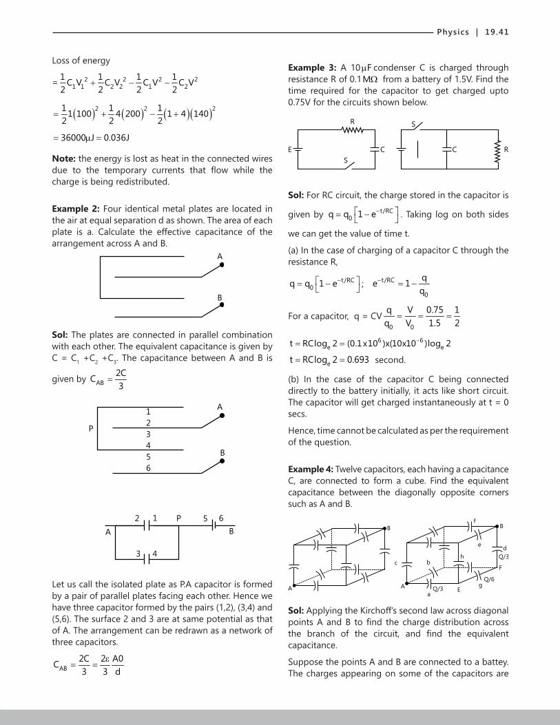
Physics | 19.41
Loss of energy
= 2 2 2 21 1 2 2 1 2
1 1 1 1C V C V C V C V2 2 2 2
+ − −
( ) ( ) ( )( )2 2 21 1 11 100 4 200 1 4 1402 2 2
= + − +
36000 J 0.036J= µ =
Note: the energy is lost as heat in the connected wires due to the temporary currents that flow while the charge is being redistributed.
Example 2: Four identical metal plates are located in the air at equal separation d as shown. The area of each plate is a. Calculate the effective capacitance of the arrangement across A and B.
A
B
Sol: The plates are connected in parallel combination with each other. The equivalent capacitance is given by C = C1 +C2 +C3. The capacitance between A and B is
given by AB2CC3
=
A
B
1
2
3
4
5
6
P
12
3 4
5P 6
BA
Let us call the isolated plate as P.A capacitor is formed by a pair of parallel plates facing each other. Hence we have three capacitor formed by the pairs (1,2), (3,4) and (5,6). The surface 2 and 3 are at same potential as that of A. The arrangement can be redrawn as a network of three capacitors.
AB2C 2 A0C3 3 d
ε= =
Example 3: A 10 Fµ condenser C is charged through resistance R of 0.1MΩ from a battery of 1.5V. Find the time required for the capacitor to get charged upto 0.75V for the circuits shown below.
R
S
E C RC
S
Sol: For RC circuit, the charge stored in the capacitor is
given by t/RC0q q 1 e− = − . Taking log on both sides
we can get the value of time t.
(a) In the case of charging of a capacitor C through the resistance R,
t/RC0q q 1 e− = − ; t/RC
0
qe 1q
− = −
For a capacitor, q = CV0 0
q V 0.75 1q V 1.5 2
= = =
6 6e et RClog 2 (0.1x10 )x(10x10 )log 2−= =
et RClog 2 0.693= = second.
(b) In the case of the capacitor C being connected directly to the battery initially, it acts like short circuit. The capacitor will get charged instantaneously at t = 0 secs.
Hence, time cannot be calculated as per the requirement of the question.
Example 4: Twelve capacitors, each having a capacitance C, are connected to form a cube. Find the equivalent capacitance between the diagonally opposite corners such as A and B.
F
A
B
A
B
c b
f
e
h
aE
gQ/6
Q/3
d
Q/3
Sol: Applying the Kirchoff’s second law across diagonal points A and B to find the charge distribution across the branch of the circuit, and find the equivalent capacitance.
Suppose the points A and B are connected to a battey. The charges appearing on some of the capacitors are

19.42 | Electric Potential and Capacitance
shown in figure suppose the positive terminal of the battery supplies a charge +Q through the point A. This charge is divided on the three plates connected to A. Looking from A, the three sides of the cube have identical properties and hence, the charge will be equally distributed on the three plates. Each of the capacitors a, b and c will receive a charge Q/3. The negative terminal of the battey supplies a charge –Q through the point B. This is again divided equally on the three plates connected to B. Each of the capacitors d, e and f gets equal charge Q/3.
Now consider the capacitors g and h. As the three plates connected to the point E form an isolated system, their total charge must be zero. The negative plate of the capacitor has a charge -Q/3. The two plates of g and h connected to E should have a total charge Q/3. By symmetry, these two plates should have equal charges and hence each of these has a charge Q/6. The capacitors a, g and d have charges Q/3, Q/6 and Q/3 respectively.
We have, ( ) ( ) ( )A B A E E F F BV V V V V V V V− = − + − + −
Q / 3 Q / 6 Q / 3 5QC C C 6C
= + + =
eqA B
Q 6C C.V V 5
= =−
Example 5: The Capacitance of a parallel plate capacitor with plate area A and separation d is C. The space between the plates is filled with two wedges of dielectric constants 1K and 2K respectively (figure). Find the capacitance of the resulting capacitor.
A
dK1
K2
Sol: As represented in the figure the dielectric material are connected in series with each other across diagonal.
Consider one thin strip of the capacitor. The equivalent
capacitance is given by 1 2
1 1 1dC dC dC
= + .
These strips are connected to each other parallely such that the equivalent capacitance of the capacitor is given by
x L
x 0
C dC=
=
= ∫
Let length and breadth of the capacitor be l and b respectively and d be the distance between the plates as shown in figure then consider a strip at a distance x of width dx.
Now QR=x tan θ
And PQ = d-x tan θ ; where
tan θ =d/l,Capacitance of PQ
A
L
b
1 0 1 01
k (bdx) k (bdx)dC
xdd x tan dl
ε ε= =
− θ −
( ) ( )1 0 1 0
1k b / dx k A
dCd l x d l xε ε
= =− −
And 2dC = capacitance of QR ( )2 02
k b dxdC
d tan
ε=
θ;
( )2 02
k A dxdC
Xd
ε= … dtan
l ∴ θ =
Now 1dC and 2dC are in series. Therefore, their resulatant capacity dC will be given by
1 2
1 1 1dc dC dC
= + , then ( )
( ) ( )1 0 1 0
d l x1 X.ddC K A dx K A dx
−= +
ε ε
( ) 1 20
1 d l x Xdc K KA dx
−= + ε
( )( )
2 1
0 1 2
d K l x K X
AK K dx
− + =ε
( )0 1 2
2 1
AK KdC dx
d K l x K X
ε=
− + ,
( )0 1 2
2 1 1
AK KdC dx
d K l K K X
ε=
+ −
All such elemental capacitor representing DC are connected in parallel.
Now the capacitance of the given parallel plate capacitor is obtained by adding such infinitesimal capacitors parallel from
X = 0 to X = L. x L
x 0
i.e. C dC=
=
= ∫ ;
P
dc1
Q
dc2
K1
K2
xdx
R
L
d

Physics | 19.43
( )L
0 1 2
0 2 1 2
AK Kdx
d K l K K X
ε=
+ − ∫ ;
( )1 2 0 2
11 2
K K A KC In
KK K dε
=−
ln( )1 2 0 2
11 2
K K A KC In
KK K dε
=−
Example 6: Figure (a) shows a parallel-plate capacitor having square plates of edge a and plate-separtion d. The gap between the plates is filled with a dielectric medium of dielectric constant K which varies parallel to an edge as 0K K ax= +
a
K
a
dx(x)(a)
(b)
d
Where K and α are constants and x is the distance from the left end. Calculate the capacitance.
Sol: As the medium varies, consider a small strip of the dielectric medium such that its capacitance is
( )0 0K x adxdC
d
+ α ε= . These strips are connected
in parallel so the equivalent capacitance is given by a
0C dC= ∫ where a is the length of plates.
Consider a small strip of width dx at a separation x from the left end. This strip forms a small capacitor of plate
area adx. Its capacitance is ( )0 0K x adx
dCd
+ α ε=
The given capacitor may be divided into such strips with x varying from 0 to A. All these strips are connected in parallel. The capacitance of the given capacitor is,
QD
hA B
+ + + + + + + +
-Q/K
-Q(1-1/K)- - -
( )a0 0
0
K x adxC
d
+ α ε= ∫ ;
20
0a aKd 2
ε α= +
Example 7: A parallel-plate capacitor is placed in such a way that its plates are horizontal and the lower plate is dipped into a liquid of dielectric constant K and density ρ . Each plate has an area A. the plates are now
connected to a battery which supplies a positive charge of magnitude Q to the upper plate. Find the rise in the level of the liquid in the space between the plates.
Sol: The dielectric liquid experiences a electric force due to which it rises to the height h. This force is balanced by weight of liquid.
The situation is shown in figure. A charge 1Q 1K
− −
is
induced on the upper surface of the liquid and 1Q 1K
−
at the surface in contact with the lower plate. The net
charge on the lower plate is 1 QQ Q 1K K
− + − = −
.
Consider the equilibrium of the liquid in the volume
ABCD. The forces on this liquid are
(a) The force due to the electric field at CD,
(b) The weight of the liquid,
(c) The force due to atmospheric pressure and
(d) The force due to the pressure of the liquid below AB.
As AB is in the same horizontal level as the outside surface, the pressure here is the same as the atmospheric pressure. The forces in (c) and (d), therefore, balance each other. Hence, for equilibrium, the forces in (a) and (b) should balance each other.
The electric field at CD due to the charge Q is 10
QE2A
=ε
In the downward direction.
The field at CD due to the charge –Q/K is 20
QE2A K
=ε
Also in the downward direction.
The net field at CD is ( )
1 20
K 1 QE E
2A K
++ =
ε.
The force on the charge 1Q 1K
− −
at CD is
( )0
K 1 Q1F Q 1K 2A K
+ = − ε
; ( )2 2
20
K 1 Q
2A K
−=
ε
In the upward direction. The weight of the liquid considered is hA g.ρ
thus, ( )2 2
20
K 1 QhA g
2A K
−ρ =
ε; or
( )2 2
2 20
K 1 Qh
2A K g
−=
ε ρ

19.44 | Electric Potential and Capacitance
JEE Main/Boards
Exercise 1
Q.1 Calculate the equivalent capacitance in the following circuit
4.5 F3 F 3 F
4.5 F
Q.2 Find the potential of a sphere having charge of 5 Cµ and capacitance of 1nF.
Q. 3 Find the equivalent capacitance between A and B in the given figure. Take 2C 10 F= µ and B in the given figure. Take 2C 10 F= µ and 1 3 4 5C ,C ,C ,C each equal to 4 Fµ
C4
C1 C2 C3
C5
A B
Q.4 Find the value of C if the equivalent capacitance between the points A and B in the given figure is 1 Fµ
1 F
8 F
2 F
A C
2 F
6 F
12 F
4 F
B
Q.5 A 4x10⁻⁶F capacitor is charged by a 200V supply. It is then disconnected from the supply and is connected across another uncharged 2x10⁻⁶F capacitor. How much energy of the first capacitor is lost?
Q.6 The plates of a parallel plate capacitor of area 100cm2 each and are separated by 2.0mm. The capacitor is charged by a 100V supply. Find energy store by the capacitor.
Q.7 What capacitance is required to store an energy of 100kW h at a potential difference of 104 V?
Q.8 A capacitor is filled with two dielectrics of the same dimensions but of dielectric constants 2 and 3 respectively. Find the ratio of capacitances in the two arrangements shown in figure A and B.
A B A
+ - + - + -
B
d
(A)(B)
d/4 d/2 d/4
Q.9 Two metal plates separated by a distance d constitute a parallel plate capacitor. A metal slab of thickness (d/2) and same area as the plate is inserted between the plates. What is the ratio of the capacitances in the two cases?
dK2
K1
C2
C1 d/2
d/2
(A)
d
C3
K1
A/2
C4
K2
A/2
(B)
Q.10 Keeping the voltage of the charging source constant, what would be the percentage change in the energy stored in a parallel plate capacitor if the separation between its plates were to be decreased by 10%?
Q.11 A parallel plate air capacitor with its plates spaced 2cm apart is charged to a potential of 300 volts. What will be the electric field intensity inside the capacitor, if the plates are moved apart to a distance of 5cm without disconnecting the power source? Calculate the change in energy of the capacitor. Area of the plates is equal to A = 100cm2. Also solve the problem assuming

Physics | 19.45
the entire operation was done after disconnecting the power source. Account for the change in energy in both
the cases. ( )120 9x10 SI units−∈ =
Q.12 Find the charge on the capacitor C in the following circuit in steady state.
12V 2
2 C4
6
Q.13 Three uncharged capacitors of capacitance C1,C2 and C3 are connected as shown in figure to one another and to points A, B and D potentials (φA), (φB) and (φD). Determine the potential (φO) at point O.
A
C2 C3
C1
B D
O
Q.14 Determine the current through the battery in the circuit shown.
E
R1
K
A
C1
C2 B
R2
R3
(i) Immediately after the key K is closed and
(ii) In a long time interval, assuming that the parameters of the circuit are known.
Q.15 The lower plate of a parallel plate capacitor lies on an insulating plane. The upper plate is suspended from one end of a balance. The two plates are joined together by a thin wire and subsequently disconnected. The balance is then counterpoised. A voltage V=5000 volt is applied between the plates. What additional mass should be placed to maintain balance? The distance between the plates is d=5mm and the area of each plate is A=100cm2? [all the elements other than plates are massless and nonconducting]
Rigid road
Q.16 Two charge particulars one is electron and other is negatively charged ion have a velocity directed parallel to the plates. They are sent separately into the field. Both the electron and the ion have reveived their initial kinetic energy by passing the same potential difference. Which of the two particles will travel a greater distance (parallel to plates shown by ‘I’) before hitting the positively charged plate, if both fly into the capacitor at a point that is exactly in the middle of the distance between the plates?
V
L+
_
Q.17 A 3 Fµ capacitor is charged to a potential of 300 volt and 2 Fµ is charged to 200 volt. The capacitor are connected so that the plates of same polarity are connected together. What is the final potential difference between the plates of the capacitor after they are connected? If instead of this the plates of opposite polarity were joined together, what amount of charge will flow and from which capacitor does it come?
Q.18 In the following circuit, internal resistance of the battery r 1= Ω .
C1
C2
R=2
R=1
R=3
E
C3
C4
E = 4V, 1C 8 F= µ , 2C 2 F= µ , 3C 6 F= µ , 4C 4 F= µ .
Find the charge on plate of each capacitor.
Q.19 In the network given in the figure a potential difference of 10 volts is applied across the two points A and B find;
5 F 4 F
6 F 6 F
8 F
8 F3 F
A2 F
B
(i) The potential difference across the capacitor of 2 Fµ .
(ii) The charge in both of 6 Fµ capacitors.

19.46 | Electric Potential and Capacitance
Q.20 In the figure shown here, each capacitance C1 in the network is 3 Fµ and each capacitance C2 is 2 Fµ
(i) Compute the equivalent capacitance of the network between the points a and b.
(ii) Calculate charge on each capacitors nearest to a and b when abV =900volt.
(iii) With 900 volt across a and b, compute Vcd
C1 C C1C1
C1
C2 C2
C1 D C1
C1
a
b
Q.21 If you have serval 2.0 Fµ capacitors, each capable of withstantding 200 volts without breakdown, how would you assemble a combination having an equivalent capacitance of;
(a) 0.40 Fµ or of
(b) 1.2 Fµ , each capable of withstanding 100 volts.
Q.22 Six 1 Fµ capacitors are so arranged that their equivalent capacitance is 0.70 Fµ . If a potential difference of 600 volt is applied to the combination, what charge will appear on each capacitor?
Q.23 Two condensers are in parallel and the energy of the combination is 103 J, when the difference of potential between their terminals is 2 volts. With the same two condensers in series, the energy is 1.6x10² J for the same differences of potential across the series combination. What are their capacities?
Q.24 A capacitor of capacitance C1=1.0 Fµ charged upto a voltage V = 110V is connected in a parallel to the terminals of a circuit consisting of two uncharged capacitor connected in series and possessing the capacitance C2 = 2.0 Fµ and C3 = 3.0 Fµ . What charge will flow through the connecting wires?
Q.25 Two capacitors A and B are connected in series across a 100V supply and it is observed that the potential difference across them are 60V and 40V. A capacitor of 2 Fµ capacitance is now connected in parallel with A and the potential difference across with A and the potential difference acorss B rise to 90V. Determine the capacitance of A and B.
Q.26 A capacitor of capacitance C1=1.0µF withstands the maximum voltage V1=6.0 kV while a capacitor of capacitance C2 = 2.0µF withstands maximum voltage V2 = 4.0 kV. What voltage will the system of these two capacitors withstand, if they are connected in series?
Q.27 Two identical parallel plate air capacitors are connected in one case in parallel and in the other in series. In each case the plates of one capacitor are brought closer together by a distance a and the plates of the other are moved apart by the same distance a. How will the total capacitance of each system change as result of such manipulation ?
Q.28 A 3 mega ohm resistor and 1 Fµ capacitor are connected in a single loop circuit with a source of constant 4 volt. At one second after the connection is made what are the rates at which;
(i) The charge on the capacitor is increasing
(ii) Energy is being stored in the capacitor
(iii) Joule heat is appearing in the resistor
(iv) Energy is being delived by the source
Q.29 A capacitor of capacity 1 Fµ is connected in closed series circuit with a resistance of 107 ohms, an open key and a cell of 2V with negligible internal resistance:
(i) When the key is switched on at time t=0, find;
(a) The time constant for the circuit.
(b) The charge on the capacitor at steady state.
(c) Time taken to deposit charge equaling half that at steady state.
(ii) If after fully charging the capacitor, the cell is shorted by zero resistance at time t=0, find the charge on the capacitor at t = 50s.
Q.30 An electric dipole, when held at o30 with respect to a uniform electric field of 30 × 410 1NC− experiences a torque of 27 × 2610 N m. Calculate the dipole moment of the dipole.
Q.31 A regular hexagon of side 10 cm has a charge 5µC at each of its vertices. Calculate the potential at the center of the hexagon.
Q.32 What is the work done in moving a 2µC point charge from corner A to B of a square ABCD, when a 10µC charge exists at the center of the square?
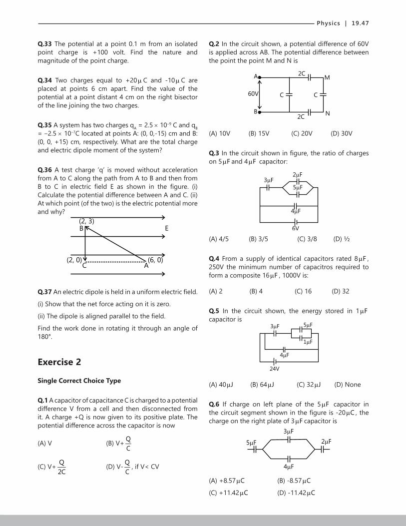
Physics | 19.47
Q.33 The potential at a point 0.1 m from an isolated point charge is +100 volt. Find the nature and magnitude of the point charge.
Q.34 Two charges equal to +20µC and -10µC are placed at points 6 cm apart. Find the value of the potential at a point distant 4 cm on the right bisector of the line joining the two charges.
Q.35 A system has two charges qA = 2.5 × 10‒9 C and qB = ‒2.5 × 10‒7C located at points A: (0, 0,-15) cm and B: (0, 0, +15) cm, respectively. What are the total charge and electric dipole moment of the system?
Q.36 A test charge ‘q’ is moved without acceleration from A to C along the path from A to B and then from B to C in electric field E as shown in the figure. (i) Calculate the potential difference between A and C. (ii) At which point (of the two) is the electric potential more and why?
E(2, 3)
(2, 0)
B
C A(6, 0)
Q.37 An electric dipole is held in a uniform electric field.
(i) Show that the net force acting on it is zero.
(ii) The dipole is aligned parallel to the field.
Find the work done in rotating it through an angle of 180°.
Exercise 2
Single Correct Choice Type
Q.1 A capacitor of capacitance C is charged to a potential difference V from a cell and then disconnected from it. A charge +Q is now given to its positive plate. The potential difference across the capacitor is now
(A) V (B) V+ QC
(C) V+ Q2C
(D) V- QC
, if V< CV
Q.2 In the circuit shown, a potential difference of 60V is applied across AB. The potential difference between the point the point M and N is
A 2C
60V C C
M
2CNB
(A) 10V (B) 15V (C) 20V (D) 30V
Q.3 In the circuit shown in figure, the ratio of charges on 5 Fµ and 4 Fµ capacitor:
3 F5 F
4 F
6V
2 F
(A) 4/5 (B) 3/5 (C) 3/8 (D) ½
Q.4 From a supply of identical capacitors rated 8 Fµ , 250V the minimum number of capacitros required to form a composite 16 Fµ , 1000V is:
(A) 2 (B) 4 (C) 16 (D) 32
Q.5 In the circuit shown, the energy stored in 1 Fµcapacitor is
3 F 5 F
1 F
4 F
24V
(A) 40 Jµ (B) 64 Jµ (C) 32 Jµ (D) None
Q.6 If charge on left plane of the 5 Fµ capacitor in the circuit segment shown in the figure is -20 Cµ , the charge on the right plate of 3 Fµ capacitor is
3 F
4 F
2 F5 F
(A) +8.57 Cµ (B) -8.57 Cµ
(C) +11.42 Cµ (D) -11.42 Cµ

19.48 | Electric Potential and Capacitance
Q.7 What is equivalent capacitance of the system of capacitors between A & B.
A
C C C
B
(A) 7.6C (B) 1.6C (C) C (D) none
Q.8 Three capacitors 2 Fµ , 3 Fµ and 5 Fµ can withstand voltages to 3V, 2V and IV respectively. Their series combination can withstand a maximum voltage equal to
(A) 5Volts (B) (31/6) Volts
(C) (26/5) Volts (D) None
Q.9 A parallel plate capacitor has an electric field of 105V/m between the plates. If the charge on the capacitor plate is 1 Cµ , then the force on each capacitor plate is
(A) 0.1 N (B) 0.05 N (C) 0.02 N (D) 0.01 N
Q.10 A capacitor is connected to a battery. The force of attraction between the plates when the separation between them is halved.
(A) Remains the same (B) Becomes eight times
(C) Becomes four times (D) Becomes two times
Q.11 A parallel plate capacitor is
k2k1 k2
d/2 d/2
d
make as shown in figure. Find capacirance and equivalent dielectric constant.
(A) 0 1 2
1 2
2 A(k k )k kε
+ (B) 0 1 2
1 2
4 A(k k )k kε
+
(C) 0 1 2
1 2
5 A(k k )k k
ε (D) 0 1 2
1 2
3 A(k k )k kε
+
Q.12 A capacitor stores 60 Cµ charge when connected across a battery. When the gap between the plates is filled with a dielectric, a charge of 120 Cµ flows through the battery. The dielectric constant of the material inserted is :
(A) 1 (B) 2 (C) 3 (D) None
Previous Years’ Questions
Q.1 Seven capacitors each capacitance 2 Fµ are connected in a configuration to obtain an effective
capacitance 10 F11
µ . Which of the following combinations
will achieve the desired result? (1990)
(A) (B)
(D)( )C(A) (B)
(D)( )C
(A) (B)
(D)( )C(A) (B)
(D)( )C
Q.2 A parallel combination of 0.1MΩ resistor and a 10 Fµ capacitor is connected across a 1.5V source of negligible resistance. The time required for the capacitor to get charged upto 0.75V is approximately (in second) (1997)
(A) Infinite (B) loge2 (C) log102 (D) Zero
Q.3 For the circuit shown, which of the following statement is true? (1999)
V = 30 V1
S1C = 2p F1
+ -
V = 20 V2
+ -
S3 S2C = 2p F2
(A) With S1 closed, V1=15V, V2=20V
(B) With S3 closed,V1= V2 = 25V
(C) With S1 and S2 closed, V1 = V2 = 0
(D) With S3 closed, V1 = 30 V, V2 = 20V

Physics | 19.49
Q.4 Consider the situation shown in the figure. The capacitor A has a charge q on it whereas B is uncharged. The charge appearing on the capacitor B after a long time after the switch is closed is (2001)
q
++++++
------
A B
S
(A) Zero (B) q/2 (C) q (D) 2q
Q.5 A parallel plate capacitor C with plates of unit are and separation d is filled with a liquid of dielectric
constant K=2. The level of liquid is d3
initially. Suppose
the liquid level decreases at a constant speed V, the time constant as a function of time t is (2008)
C
d d3
R
(A) 06 R5d 3vt
ε
+ (B)
( ) 02 2 2
15d 9vt R
2d 3dvt 9v t
+ ε
− −
(C) 06 R5d 3vt
ε
− (D)
( ) 02 2 2
15d 9vt R
2d 3dvt 9v t
− ε
+ −
Q.6 When a negative charge is released and moves in electric field, it moves towards a position of (1982)
(A) Lower electric potential and lower potential energy
(B) Lower electric potential and higher potential energy
(C) Higher electric potential and lower potential energy
(D) Higher electric potential and higher potential energy
Q.7 An infinite non - conducting sheet of charge has a surface charge density of 10–7 C/m2. The separation between two equipotential surfaces near the sheet whose potential differ by 5V is (1983)
(A) 0.88 cm (B) 0.88 mm (C) 0.88 m (D) 5 × 10‒7 m
Q.8 4 charges are placed each at distance ‘a’ from origin. The dipole moment of configuration is (1983)
y
3q
q
-2q -2qx
(A) ˆ2 q a j (B) ˆ3 q a j
(C) ˆ ˆ2 a q [i j]+ (D) None
Q.9 n small drops of same size are charged to V volts each. If they coalesce to form a single large drop, then its potential will be (1985)
(A) V/n (B) Vn (C) 1/3Vn (D) 2/3Vn
Q.10 A hollow metal sphere of radius 5 cm is charged such that the potential on its surface is 10 V. The potential at the center of the sphere is (1998)
(A) 0 V
(B) 10 V
(C) Same as at point 5 cm away from the surface outside sphere.
(D) Same as a point 25 cm away from the surface.
Q.11 If the electric potential of the inner metal sphere is 10 volt & that of the outer shell is 5 volt, then the potential at the center will be: (1999)
(A) 10 volt (B) 5 volt (C) 15 volt (D) 0
Q.12 Three concentric metallic spherical shell A, B and C or radii a, b and c (a<b<c) have surface charge densities - σ , + σ , and - σ respectively. The potential of shell A is : (1986)
(A) (σ 0ε ) [a+b-c] (B) (σ 0ε ) [a-b+c]
(C) (σ 0ε ) [b-a-c] (D) None
Q.13 A hollow metal sphere of radius 5 cm is charged such that the potential on its surface is 10 V. The potential at the centre of the sphere is (1983)
(A) Zero
(B) 10 V
(C) Same as at a point 5 cm away from the surface(D) Same as at a point 25 cm away from the surface

19.50 | Electric Potential and Capacitance
Q.14 A solid conducting sphere having a charge Q is surrounded by an uncharged concentric conducting hollow spherical shell. Let the potential difference between the surface of the solid sphere and that of the outer surface of the hollow shell be V. If the shell is now given a change of -3Q, the new potential difference between the same two surfaces is (1989)
(A) V (B) 2 V (C) 4 V (D) -2 V
Q.15 Two identical thin rings, each of radius R, are coaxially placed a distance R apart. If 1 2Q and Q are respectively the charges uniformly spread on the two rings, the work done in moving a charge q from the center of one ring to that of the other is (1992)
(A) Zero
(B) 1 2 0q(Q Q )( 2 1) / 2(4 R)− − πε
(C) 1 2 0q 2(Q Q ) / (4 R)+ πε
(D) 1 2 0q(Q / Q )( 2 1) 2(4 R)+ πε
Q.16 Two point charges +q and –q are held fixed at (-d, 0) and (d, 0) respectively of a x-y co-ordinate system. Then (1995)
(A) The electric field E at all point on the x-axis has the same direction.
(B) Work has to be done in bringing a test charge from ∞ to the origin
(C) Electric field at all point on y-axis is along x-axis
(D) The dipole moment is 2qd along the x-axis
Q.17 A parallel plate capacitor of capacitance C is connected to a battery and is charged to a potential difference V. Another capacitor of capacitance 2C is similarly charged to a potential difference 2V. The charging battery is now disconnected and the capacitors are connected in parallel to each other in such a way that the positive terminal of one is connected to the negative terminal of the other. The final energy of configuration is (1995)
(A) Zero (B) 23 CV2
(C) 225 CV6
(D) 29 CV2
Q.18 A charge +q is fixed at each of the points 0 0 0x x , x 3x , x 5x .....= = = ∞ on the x-axis
and a charge –q is fixed at each of the points 0 0 0x 2x , x 4x , x 6x .....= = = ∞ . Here, 0x is a positive
constant. Take the electric potential at a point due to a charge Q at a distance r from it to be Q/ 04 rπε .
Then the potential at the origin due to the above system of charges is (1998)
(A) Zero (B) 0 0
q8 x ln2πε
(C) Infinite (D) 0 0
q ln(2)4 xπε
Q.19 Two identical metal plates are given positive charges 1 2 1Q and Q ( Q )< respectively. If they are now brought close together to form a parallel plate capacitor with capacitance C, the potential difference between them is (1999)
(A) 1 2(Q Q ) / 2C+ (B) 1 2(Q Q ) / C+
(C) 1 2(Q Q ) / C− (D) 1 2(Q Q ) / 2C−
Q.20 A parallel plate capacitor of area A, plate separation d and capacitance C is filled with three different dielectric materials having dielectric constants
1 2 3K ,K and K as shown, If a single dielectric material is to be used to have the same capacitance C in this capacitor then its dielectric constant K is given by (2000)
A/2 A/2
K1 K2
K3
d
d2
(A) 1 2 3
1 1 1 1K K K 2K= + + (B)
1 2 3
1 1 1K K K 2K= +
+
(C) 1 23
1 2
K K1 2KK K K= +
+ (D) 1 3 2 3
1 3 2 3
K K K KK
K K K K= +
+ +
Q.21 A uniform electric field pointing in positive x-direction exists in a region. Let A be origin, B be he point on the x-axis at x=+1 cm and C be the point on the y-axis at y=+1 cm. Then the potentials at the points A, B and C satisfy (2001)
(A) A BV V< (B) A BV V>
(C) A CV V< (D) A CV V>
Q.22 Two equal point charges are fixed at x=-a and x=+a on the x-axis. Another point charge Q is placed at the origin. The change in the electrical potential energy of Q, when it is displaced by a small distance x along the x-axis, is approximately proportional to (2002)
(A) x (B) 2x (C) 3x (D) 1/x

Physics | 19.51
Q.23 Two identical capacitors, have the same capacitance C. One of them is charged to potential
1V and the other to 2V . Likely charged plates are then connected. Then, the decrease in energy of the combined system is (2002)
(A) 2 21 2
1 C(V V )4
− (B) 2 21 2
1 C(V V )4
+
(C) 21 2
1 C(V V )4
− (D) 21 2
1 C(V V )4
+
Q.24 A long, hollow conducting cylinder is kept coaxially inside another long, hollow conducting cylinder of larger radius. Both the cylinders are initially electrically neutral. (2007)
(A) A potential difference appears between the two cylinders when a charge density is given to the inner cylinder
(B) A potential difference appears between the two cylinders when a charge density is given to the outer cylinder
(C) No potential difference appears between the two cylinders when a uniform line charge is kept along the axis of the cylinders
(D) No potential difference appears between the two cylinders when same charge density is given to both the cylinders
Q.25 Positive and negative point charges of equal
magnitude are kept at a0,0,2
and a0,0,2
−
,
respectively. The work done by the electric field when another positive point charge in moved from (-a, 0, 0) to (0, a, 0) is (2007)
(A) Positive
(B) Negative
(C) Zero
(D) Depends on the path connecting the initial and final position
Q.26 Consider a system of three charges q q 2q, and3 3 3
−
placed at points A, B and C respectively, as shown in the figure. Take O to the center of the circle of radius R and angle CAB= o60 (2008)
y
B
O
C
60o
A
x
(A) The electric field at point O is 2
0
q8 Rπε
directed along the negative x-axis
(B) The potential energy of the system is zero
(C) The magnitude of the force between the charges at
C and B is 2
20
q54 Rπε
(D) The potential at point O is 0
q12 Rπε
Q.27 A parallel plate capacitor C with plates of unit area and separation d is filled with a liquid of dielectric
constant K = 2. The level of liquid is d3
initially. Suppose
the liquid level decreases at a constant speed v, the time constant as a function of time t is (2008)
C
d d3
R
(A) 06 R5d 3vt
ε
+ (B) 0
2 2 2
(15d 9vt) R
2d 3dvt 9v t
+ ε
− −
(C) 06 R5d 3vt
ε
− (D) 0
2 2 2
(15d 9vt) R
2d 3dvt 9v t
− ε
+ −

19.52 | Electric Potential and Capacitance
Q.28 A 2µF capacitor is charged as shown in the figure. The percentage of its stored energy dissipated after the switch S is turned to potion 2 is (2011)
1 2
2 F 8 F
(A) 0% (B) 20% (C) 75% (D) 80%
Q.29 Two capacitors 1C and 2C are charged to 120 V and 200 V respectively. It isfound that by connecting them together the potential on each one can be madezero. Then: (2013)
(A) 1 23C 5C= (B) 1 23C 5C 0+ =
(C) 1 29C 4C= (D) 1 25C 3C=
Q.30 A charge Q is uniformly distributed over a long rod AB oflength L as shown in the figure. The electric potential at the point O lying at a distance L from the end A is: (2013)
L L
A BO
(A) 0
3Q4 Lπε
(B) 0
Q4 L ln 2πε
(C) 0
Q ln 24 Lπε
(D) 0
Q8 Lπε
Q.31 A parallel plate capacitor is made of two circular plates separated by a distance of 5 mm and with a dielectric of dielectric constant 2.2 between them. When the electric field in the dielectric is 3 × 10⁴ V/m, the charge density of the positive plate will be close to: (2014)
(A) 4 23 10 C / m× (B) 4 26 10 C / m×
(C) 7 26 10 C / m−× (D) 7 23 10 C / m−×
Q.32 Assume that an electric field 2 ˆE 30 x i=
exists in space. Then the potential difference A 0V V− , where 0V is the potential at the origin and AV the potential at x = 2 m is: (2014)
(A) – 80 V (B) 80 V
(C) 120 V (D) None of these
Q.33 A uniformly charged solid sphere of radius R has potential 0V (measured with respect to ∞ ) on its surface. For this sphere the equipotential surfaces
with potentials 0 0 03V 5V 3V, ,
2 4 4 and 0V
4 have radius
1 2 3R ,R ,R and 4R respectively. Then (2015)
(A) 1R 0≠ and ( ) ( )2 1 4 3R R R R− > −
(B) 1R 0= and ( )2 4 3R R R< −
(C) 42R R<
(D) 1R 0= and ( )2 4 3R R R> −
Q.34 In the given circuit, charge 2Q on the 2 Fµcapacitor changes as C is varied from 1 Fµ to 3 Fµ . 2Qas a function of ‘C’ is given properly by : (figures are drawn schematically and are not to scale) (2015)
C2 F
1 F
E
1 F 3 F
Charge
Q2
C1 F 3 F
Charge
Q2
C
1 F 3 F
Charge
Q2
C1 F 3 F
Charge
Q2
C
(A) (B)
( )C (D)
Q.35 A combination of capacitors is set up as shown in the figure. The magnitude of the electric field, due to a point charge Q (having a charge equal to the sum of the charges on the 4 Fµ and 9 Fµ capacitors), at a point distant 30 m from it, would equal: (2016)
(A) 360 N/C (B) 420 N/C
(C) 480 N/C (D) 240 N/C

Physics | 19.53
JEE Advanced/Boards
Exercise 1
Q.1 A parallel plate capacitor has plate area 100 cm2 and place separation 1 cm. A glass plate (k = 6) of thickness 6 mm and an ebonite plate (k = 4) are inserted to fill the gap between the plates. Find new capacitance.
Q.2 In the given network (See figure) if Potential difference between p and q is 2V and C2=3C1. Then find difference between a & b.
aC1
C2
pq
C1 C2
b
+ -
Q.3 Find field produced in the circuit shown in figure on closing the switch S.
2 F
+20 C -20 C
+50 C -50 C
5 F
S
Q.4 In the following circuit (See figure), the resultant capacitance between A and B is 1 Fµ . Find equivalent capacitance of the circuit.
1 F 1 F 10V
1 F 1 F1 F1 F 1 F
1 F 1 F 1 F1 F 1 F C=1 F 1 F
1 F 1 F 1 F 1 F 1 F
Q.5 Find the charge on the capacitor C=1 Fµ in the circuit shown in the figure.
C 1 F
8 F
2 F
6 F
2 F 12 F
4 F
Q.6 The figure shows a circuit consisting of four capacitors. Find the effective capacitance between X and Y
1 F 1 F1 F
2 FX Y
Q.7 Five identical capacitor plates, each of area A are arranged such that adjacent plates are at a distance‘d’ apart, the plates are connected to a source of emf V as shown in figure. The charge on plate 1 is ------ and that on plate 4 is ----
1 2 3 4 5V
+
-
Q.8 Find the capacitance of the system shown in figure. Plate area = A
k = 1
k = 3
k = 2
k = 4
d
d
Q.9 Figure shows three concentric conducting spherical shells with inner and outer shells earthed and the middle shell is given a charge q. find the electrostatic energy of the system stored in the region I and II.
3.5r
q
2.5r III
III

19.54 | Electric Potential and Capacitance
Q.10 Find the ratio between the erergy stored in 5µF capacitor to the 4 Fµ capacitor in the given circuit in stedy state.
5 F5
44 F
2V
Q.11 A solid conducting sphere of radius 10cm is enclosed by a thin metallic shell of radius 20cm. a charge q=20 Cµ is given to the inner sphere. Find the heat generated in the process, the inner sphere is connected to the shell by a conducting wire.
Q.12 In the circuit shown here, At the steady state, the charge on the capacitor is ------------.
R1
R2R3
EC
Q.13 For the arrangement shown in the figure, the key is closed at t=0. C2 is initially uncharged while C1 has a charge of 2 Cµ
30 C2
2 F
1 F C1
30 60
K 9V
(a) Find the current coming out of the battery just after switch is closed.
(b) Find the charge on the capacitors in the steady state condition.
Q.14 In the circuit shown in figure R1=R2=6R3= 300MΩ , C=0.01 Fµ and E=10V. The switch is closed at t=0, find
R1
R2
R3
CE
S
(a) Charge on capacitor as a function of time.
(b) Energy of the capacitor at t=20s.
Q.15 In the circuit shown in figure the capacitance of each capacitor is equal to C and resistance R. One of the capacitor was charged to a voltage V and then at the moment t=0 was shorted by means of the switch S. find:
R
C C
SW
(a) The current in the circuit as a function of time t.
(b) The amount of generated heat.
Q.16 The two identical parallel plates are given charges as shown in figure. If the plate area of either face of each plate is A and separation between plates is d, then find the amount of heat liberated after closing the switch.
+3q +q
S
Q.17 Five identical conducting plates 1, 2, 3, 4 & 5 are fixed parallel to and equidistant from each other (see figure). Plates 2 & 5 are connected by a conductor while 1 & 3 are joined by another conductor. The junction of 1 & 3 and the plate 4 are connected to a source of constant e.m.f. V0 find:
1
2
34
5
-
+
(i) The effective capacity of the system between the terminals of the source.
(ii) The charges on plates 3 & 5. Given
D = Distance between any 2 successive plate &
A = Area of either face of each plate.

Physics | 19.55
Q.18 Find the charge flown through the switch from A to B when it is closed.
3 F
5V
6 F
3 F 10V3 F
6 F
5V 6 FA B10V
Q.19 Three capacitors of 2 Fµ , 3 Fµ and 5 Fµ are independently charged with batteries of emf’s 5V, 20V and 10V respectively. After disconnecting from the voltage source. These capacitors are connected as shown in figure with their positive polarity plates connected to A and negative polarity is earthed. Now a battery of 20V and an uncharged capacitor of 4 Fµcapacitance are connected to the junction A as shown with a switch S. when switch is closed, find:
2 F3 F
A
5 F20 V 4 F
(a) The potential of the junction A.
(b) Final charge on all four capacitros.
Q.20 In the circuit shown in figure, find the amount of heat generated when switch s is closed.
2 F S
10V5V
4 F
3 F
Q.21 the connection shown in figure are established with the switch S open. How much charge will flow through the switch if it is closed?
2 F1 F
2 F 1 F
24VS
Q.22 The figure shows two identical parallel plate capacitors connected to a battery with the switch S closed. The switch is now opened and the free space between the plates of the capacitors is filled with a
dielectric of dielectric
A CV B C
S
constant (or relative permittivity) 3. Find the ratio of the total electrostatic enegry stored in both capacitors before and after the introduction of the dielectric.
Q.23 A parallel plate capacitor has plates with area A & separation d. A battey charges the plates to a potential difference of V0. The battery is then disconnected & a di-electric slab of constant K & thickness d is introduced. Calculate the positive work done by the system (capacitor+slab) on the man who introduces the slab.
Q.24 A parallel plate capacitor is filled by a di-electric whose relative permittivity varies with the applied voltage according to the law=α V, where α=1 per volt. The same (but containing no di-electric) capacitor charged to a voltage V=156 volt is connected in parallel to the first “non-linear” uncharged capacitor. Determine the final voltage Vf across the capacitors.
Q.25 Two parallel plate capacitors A & B have the same separation d=8.85+104m between the plates. The plate areas of A & B are 0.04 m2 & 0.02m2 respectively. A slab of di-electric constant (relative permittivity) K=9 has dimensions such that it can exactly fill the space between the plates of capacitor B.
A
10V
BAB
(i) The di-electric slab is placed inside A and A is then charged to a potential difference of 110volt. Calculate the capacitance of A and the energy stored in it.
(ii) The battery is disconnectd & then the di-electric slab is removed from A. find the work done by the external agency in removing the slab from A.
(iii) The same di-electric slab is now placed inside B, filling it completely. The two capacitors A & B are then connected. Calculate the energy stored in the system.
Q.26 Two square metallic plates of 1m side are kept 0.01m apart, like a parallel plate capacitor, in air in such a way that one of their edges is perpendicular, to an oil surface in a tank filled with an insulating oil. The plates are connected

19.56 | Electric Potential and Capacitance
to a battery of e.m.f. 500 volt. The plates are then lowered vertically into the oil at a speed of 0.001 m/s. calculate the current drawn from the battery during the process.
[Di-electric constant of oil= 12 2 2 20 8.85x10 C / N mε = ]
Q.27 A 10 Fµ and 20 Fµ capacitor are connected to a 10V cell in parallel for some time after which the capacitors are disconnected from the cell and reconnected at t=0 with each other, in series, through wires of finite resistance. The +ve plate of the first capacitor. Draw the graph which best describes the charge on the +ve plate of the 20 Fµ capacitor with increasing time.
Q.28 A capacitor of capacitance C0 is charged to a potential V0 and then isolated. A small capacitor C is then charged from C0, discharged and charged again, the process being repeated in times. The potential of the large capacitor has now fallen to V. Find the capacitance of the small capacitor. If V0=100volts, V=35volts, find the value of n for C0=0.2 Fµ and C=0.01075 Fµ . Is it possible to remove charge on C0 this way?
Q.29 In the figure shown initially switch is open for a long time. Now the switch is closed at t=0. Find the charge on the rightmost capacitor as a function of time given that it was initially unchanged.
R
V R C
S
C
Q.30 Two capacitors A and B with capacitor are connected as shown in figure with one wire from each capacitor free. The upper plate of A is positive and that of B is negative. An uncharged 2 Fµ capacitor C with lead wires falls on the free ends to complete the circuit. Calculate:
2 F
3 F100VA
+2 F
B
-
180V
C
(i) The final charges on the three capacitors (ii) The amount of electrostatic energy stored in the system before and after the completion of the circuit.
Q.31 Three charges 0.1 coulomb each are placed on the comers of an equilateral triangle of side 1 m. If the energy is supplied to this system at the rate of 1 kW, how much time would be required to move one of the charges onto the midpoint of the line joining the other two?
Q.32 A dipole is placed at origin of coordinate system as shown in figure, find the electric field at point P (0, y).
y
P (0,y)
P 45o
x
Q.33 Two concentric rings of radii r and 2r are placed with center at origin. Two charges +q each are fixed at the diametrically opposite points of the rings as shown in figure. Smaller ring is now rotated by an angle 90c about Z-axis then it is again rotated by o90 about Y-axis. Find the work done by electrostatic force in each step. If finally larger ring is rotated by o90 about X-axis, find the total work required to perform all three steps.
y
+q
+q
+q
+qz
x
Q.34 A cone made of insulating material has a total charge Q spread uniformly over its sloping surface. Calculate the energy required to take a test charge q from infinity to apex A of cone.
A
B
AB=L
The slant length is L.
Q.35 A non-conducting disc of radius a and uniform positive surface charge density σ is placed on the ground, with its axis vertical. A particle of mass m & positive charge q is dropped, along the axis of the disc, from a height H with zero initial velocity. The particle
has 04 gqm
ε=
σ.
(a) Find the value of H if the particle just reaches the disc.
(b) Sketch the potential energy of the particle as a function of its height and find its equilibrium position.

Physics | 19.57
Exercise 2
Single Correct Choice Type
Q.1 Two capacitor having capacitance 8 Fµ and 16Fµ have breaking voltage 20V and 80V. They are
combined in series. The maximum charge they can store individually in the combination is:
(A) 160 Cµ (B) 200 Cµ
(C) 1280 Cµ (D) None of these
Q.2 Three plate A, B and C each of area
10V
ABC
0.1m2 are separated by 0.885mm from each other as shown in the figure. A 10V battery is used to charge the system. The energy stored in the system is
(A) 1µ J (B) 10-1µ J (C) 10-2µ J (D) 10-3µ J
Q.3 A capacitor of capacitance C is initially charge to a potential difference of V. Now it is connected to battery of 2V with opposite polarity. The ratio of heat generated to the final erergy stored in the capacitor will be
(A) 1.75 (B) 2.25 (C) 2.5 (D) ½
Q.4 Five conducting parallel plates having A B
E
1 2 3 4 5area A and separation between them being d, are placed as shown in the figure. Plate number 2 and 4 are connected with a wire and between point A and B, a cell of emf E is connected. The charge flown
(A) 0AE34 dε
(B) 0AE23 dε
(C) 04 AEdε
(D) 0AE2dε
Q.5 The plates S and T of an uncharged parallel plate capacitor are connected acorss a battey. The battery is then disconnected in a system as shown in the figure. The system shown is in equilibrium. All the strings are insulating and massless. The magnitude of charge on one of the capacitor plates is: [Area of plates = A]
S Tk
m
(A) 02mgAε (B) 04mgAk
ε
(C) 0mgAε (D) 02mgAkε
Q.6 Four metallic plates are arranged as shown in the figure. If the distance between each plate is d, The capacitance of the given system between points A and B is (Given d<<A)
A B
d
d
d
(A) 0Adε
(B) 02 Adε
(C) 03 Adε
(D) 04 Adε
Q.7 Find the equivalent capacitance across A and B
A B
d
d
d
(A) 0Adε
(B) 02 Adε
(C) 03 Adε
(D) 04 Adε
Q.8 The diagram shows four capacitors with capacitances and break down voltage as mentioned. What should be the maximum value of the external emf source such that no capacitor breaks down? [Hint: First of all find out the break down voltage of each branch. After that compare them.]
1 2
E
3C; 1kV 2C; 2kV
7C; 1kV 3C; 2kV
(A) 2.5kV (B) 10/3kV (C) 3kV (D) 1kV
Q.9 A conducting body 1 has some initial charge Q, and its capacitance is C. There are two other conducting bodies, 2 and 3, having capacitances: C2=2C and C3→ ∞. Bodies 2 and 3 are initially uncharged. “Body 2 is touched with body 1 and touched with body 3, and the removed.” This process is repeated N times. Then, the charge on body 1 at the end must be
(A) Q/3n (B) Q/3n-1 KCEK 1+
(C) Q/2n (D) None
Q.10 In the adjoining figure, capacitor (1) and (2) have a capacitance ‘C’ each. When the dielectric of dielectric constant K is inserted between the plates of one of the capacitor, the total charge flowing through battery is

19.58 | Electric Potential and Capacitance
Conductor Dielectric
x-0 x-0x-2d x-3d x-4dx-5d
(A) From B to C;
(B) KCEK 1+
From C to B
(C) (K 1)CE2(K 1)−+
From B to C;
(D) (K 1)CE2(K 1)−+
From C to B
Q.11 The distance between plates of a parallel plate capacitor is 5d. Let the positively charged plate is at X = 0 and negatively charged plate is at X = 5d. Two slabs one of conductor and other of a dielectric of equal thickness d are inserted between the plates as shown in figure.
Potential versus distance graph will look like:
(A)
v
x
(B)
v
x
v
x
(D)
v
x
( )C
Q.12 The distance between the plates of a charged parallel plate capacitor is 5cm and electric field inside the plates is 200V cm-1. An uncharged metal bar of width 2cm is fully immersed into the capacitor. The length of the metal bar is same as that of plate of capacitor. The voltage across capacitor after the immersion of the bar is
(A) Zero (B) 400V
(C) 600V (D) 100V
Q.13 Condenser A has a capacity of 15µF when it is filled with a medium of dielectric constant 15. Another condenser B has a capcity 1 Fµ with air between the plates. Both are charged separately by a battery of 100V. After charging, both are connected in parallel without the battery and the dielectric material being removed. The common potential now is
n
n
n
C
9V
S
(A) 400V (B) 800V
(C) 1200V (D) 1600V
Q.14 Two identical capacitors 1 and 2 are connected in series to a battery as shown in figure. Capacitor 2 contains a dielectric slab of dielectric constant k as shown. Q1 and Q2 are the charges stored in the capacitors. Now the dielectric slab is removed and the corresponding charges are Q’1 and Q’2. Then
E
C C
1 2D
C
CB
A
(A) 1
1
Q k 1Q k′ += (B) 2
2
Q k 1Q 2′ +=
(C) 2
2
Q k 1Q 2k′ += (D) 1Q k
Q1 2′=
Q.15 Four identical plates 1, 2, 3 and 4 are placed parallel to each other at equal distance as shown in the figure. Plates 1 and 4 are joined together and the space between 2 and 3 is filled with a dielectric of dielectric constant k=2. The capacitance of the system between 1 and 3 & 2 and 4 are C1 and C2 respectively.
The ratio 1
2
CC
is:
1
2
3
4
(A) 53
(B) 1 (C) 35
(D) 57

Physics | 19.59
Q.16 A charged capacitor is allowed to discharge through a resistance 2Ω by closing the switch S at the instant t = 0. At time t = ln2 sµ , the reading of the ammeter falls half of its initial value. The resistance of the ammeter is equal to
0.5 F
S
2A
+ -
(A) 0 (B) 2Ω (C) 2KΩ (D) 2MΩ
Q.17 A capacitor C = 100 Fµ is connected to three resistor each of resistance 1kΩ and a battery of emf 9V. The switch S has been closed for long time so as to charge the capacitor. When switch S is opened, the capacitor discharges with time constant
C-0.5 F
+ -
2A
(A) 33ms (B) 5ms (C) 3.3ms (D) 50ms
Q.18 In the circuit shown, when the key k is pressed at time t=0, which of the following statements about current I in the resistor AB is true.
10002V
K B
1000
(A) I = 2mA at all t
(B) I oscillates between 1mA and 2mA
(C) I = 1mA at all t
(D) At t = 0, I = 2mA and with time it goes to 1mA
Q.19 In the R-C circuit shown in the figure the total energy of 3.6x10⁻³ J is dissipated in the 10Ω resistor when the switch S is closed. The initial charge on the capacitor is
2 FS
10
(A) 60 Cµ (B) 120 Cµ (C) 60 2 Cµ (D) 60 C2µ
Q.20 A charged capacitor is allowed to discharge through a resistor by closing the key at the instant t=0. At the instant t=(ln 4) Sµ , the reading of the ammeter falls half the initial value. The resistance of the ammeter is equal to
(A) 1MΩ (B) 1Ω (C) 2Ω (D) 2MΩ
Multiple Correct Choice Type
Q.21 Two capacitors of 2 Fµ and 3 Fµ are charged to 150 volt and 120 volt respectively. The plates of capacitor are connected as shown in the figure. A discharged capacitor of capacity 1.5 Fµ falls to the free ends of the wire. Then
1.5 F
A
150V 120V2 F 3 F -+
+
-
(A) Charge on the 1.5 Fµ capacitors is 180 Cµ
(B) Charge on the 2µ F capacitor is 120µC
(C) Positive charge flows through A from right to left.
(D) Positive charge flows thorugh A from left to right.
Q.22 In the circuit shown, each capacitor has a capacitance C. The emf of the cell is E. If the switch S is closed C
C C
+ -
E
(A) Positive charge will flow out of the positive terminal of the cell.
(B) Positive charge will enter the positive terminal of the cell
(C) The amount of charge flowing through the cell will be CE.
(D) The amount of charge flowing through the cell will be 4/3 CE.
Q.23 A circuit shown in the figure consists of a battery of emf 10V and two capacitance C1 and C2 of capacitances 1.0 Fµ and 2.0 Fµ respectively. Which of the options are correct?
C1 C2
A Be

19.60 | Electric Potential and Capacitance
(A) Charge on capacitor C1 is equal to charge on capacitor C2
(B) Voltage across capacitor C1 is 5V
(C) Voltage across capacitor C2 is 10V
(D) Energy stored in capacitor C1 is two times the energy stored in capacitor C2.
Q.24 If Q is the charge on the plates of a capacitor of capacitance C, V the potential difference between the plates, A the area of each plate and d the distance between the plates, The force of attraction between the plates is
(A) 2
0
1 Q2 A
ε
(B) 21 CV
2 d
(C) 2
0
1 CV2 A
ε
(D) 2
20
1 Q4 d
πε
Q.25 Four capacitors and a battery are connected as shown. The potential drop across the 7 Fµ capacitor is 6V. Then the;
12 F
7 F
3 F3.9 F
E
(A) Potential difference across the 3 Fµ capacitor is 10V
(B) Charge on the 3 Fµ capacitor is 42 Cµ
(C) Emf on the battery is 30V
(D) Potential difference across the 12 Fµ capacitor is 10V
Q.26 The capacitance of a parallel plate capacitor is C when the region between the plates has air. This region is now filled with a dielectric slab of dielectric constant k. the capacitor is connected to a cell of emf E, and the slab is taken out
(A) Charge CE (k-1) flows through the cell
(B) Energy E2C (k-1) is absorbed by the cell.
(C) The energy stored in the capacitor is reduced by E2C (k-1)
(D) The external agent has to do 21 E C(k 1)2
− amount of work to take the slab out.
Q.27 A parallel plate air-core capacitor is connected across a source of constant potential difference. When a dielectric plate is introduced between the two plates then:
(A) Some charge from the capacitor will flow back into the source.
(B) Some extra charge from the sourch will flow back into the capacitor.
(C) The electric field intensity between the two plates does not charge.
(D) The electric field intensity between the two plates will decrease.
Q.28 A parallel plate capacitor of plate area A and plate separation d is charged to potential difference V and then the battery is disconnected. A slab of dielectric constant K is then inserted between the plates of the capacitor so as to fill the space between the plates. If Q, E and W denote respectively, the magnitude of charge on each plate, the electric field between the plates (after the slab is inserted) and the work done on the system, in question, in the process of inserting the slab, then
(A) 0AVQ
dε
= (B) 0KAVQ
dε
=
(C) VEKd
= (D) 2
0AV 1W 12d K
ε = −
Q.29 A parallel plate capacitor has a parallel slab of copper inserted between and parallel to the two plates, without touching the plates. The capacity of the capacitor after the introduction of the copper sheet is:
(A) minimum when the copper slab touches one of the plates.
(B) Maximum when the copper slab touches one of the plates.
(C) Invariant for all positions of the slab between the plates.
(D) Greater than that before introducing the slab.
Q.30 The plates of a parallel plate capacitor with no dielectric are connected to a voltage source. Now a dielectric of dielectric constant K is inserted to fill the whole space between the plates with voltage source remaining connected to the capacitor.
(A) The energy stored in the capacitor will become K-times
(B) The electric field inside the capacitor will decrease to K-times

Physics | 19.61
(C) The force of attraction between the plates will increase to K2 times.
(D) The charge on the capacitor will increase to K-times
Q.31 A parallel-plate capacitor is connected to a cell. Its positive plate A and its negative palte B have charges +Q and –Q respectively. A third plate C, identical to A and B, with charge+Q, is now introduced midway between A and B, parallel to them, which of the following are correct?
(A) The charge on the inner face of B is now 3Q2
−
(B) There is no change in the potential difference between A and B.
(C) The potential difference between A and C is one-third of the potential difference between B and C.
(D) The charge on the inner face of A is now Q/2.
Q.32 The circuit shown in the figure consists of a battery of emf ε=10V; a capacitor of capacitance C=1.0 Fµ and three resistor of values R1=2Ω , R2=2Ω and R3=1Ω . Initially the capacitor is completely uncharged and the switch S is open. The switch S is closed at t=0.
R1
R2 R3
S
(A) The current through resistor R3 at the moment the switch closed is zero.
(B) The current through resistor R3 a long time after the switch closed is 5A
(C) The ratio of current through R1 and R2 is always constant.
(D) The maximum charge on the capacitor during the operation is 5 Cµ
Q.33 In the circuit shown in figure C1=C2=2 Fµ Then charge stored in
1 2 3
C1 C2
1 32
120V
(A) Capacitor C1 is zero (B) Capacitor C2 is zero
(C) Both capacitor is zero (D) Capacitor C1 is 40 Cµ
Assertion Reasoning Type
(A) Statement-I is true, statement-II is true and statement-2 is correct explanation for statement-I.
(B) Statement-I is true, statement-II is true and statement-II is not the correct explatnation for statement-I.
(C) Statement-I is true, statement-II is false.
(D) Statement-I is false, statement-II is true.
Q.34 Statement-I: The electrostatic force between the plates of a charged isolated capacitor decreases when dielectric fills whole space between plates.
Statement-II: The electric field between the plates of a charged isolated capacitance decreases when dielectric fills whole space between plates.
y
(d,0) (3d,0)x
y
(d,0) (3d,0)x
y
(d,0) (3d,0)x
y
(d, 0) (3d,0)x
(A) (B)
( )C(D)
Q.35 Statement-I: If temperature is increased, the dielectric constant of a polar dielectrc decreases whereas that of a non-polar dielectric does not change significantly.
Statement-II: The magnitude of dipole moment of individual polar molecule decreases significantly with increase in temperature.
Q.36 Statement-I: The heat produced by a resistor in any time t during the charging of a capacitor in a series circuit is half the energy stored in the capacitor by that time.
Statement-II: Current in the circuit is equal to the rate of increase in charge on the capacitor.

19.62 | Electric Potential and Capacitance
Comprehension Type
Paragraph 1: Two capacitors each having area A and plate separation‘d’ are connected as shown in the circuit. Each capacitor carries charge Q0/2.
Q0
2
Q0
2
The plates of one capacitor are slowly pulled apart by an external agent till the separation between them becomes 2d. The other capacitor is not disturbed.
Q.37 The force applied by the external agent when the separation between the plates is ‘X’ is given by
(A) 2
0
0
Q d3Aε
(B) 2
0
0
Q d12Aε
(C) 20
0
Q2Aε
(D)2
0
0
Q d6Aε
Q.38 At this position the potential difference across the capacitors is given by
(A) 0
0
Q xd2A (x d)ε +
(B) 0
0
Q xdA (x d)ε +
(C) 0
0
Q xd4A (x d)ε +
(D) 0
0
Q d2A xε
Paragraph 2: In the circuit as shown in figure the switch is closed at t = 0.
R1
R2E C
S
Q.39 At the instant of closing the switch
(A) The battery delivers maximum current
(B) No current flows through C
(C) Voltage drop across R2 is zero
(D) The current through the battery decreases with time and finally becomes zero.
Q.40 A long time after closing the switch
(A) Voltage drop acorss the capacitor is E
(B) Current through the battery is 1 2
ER R+
(C) Energy stores in the capacitor is 2
2
1 2
R E1 C2 R R
+
(D) Current through the capacitor becomes zero.
Paragraph 3: The charge across the capacitor in two different RC circuit 1 and 2 are plotted as shown in figure. q
qmax 12
O t
Q.41 Choose the correct statement (S) related to the two circuits.
(A) Both the capacitors are charged to the same charge.
(B) The emf’s of cells in both the circuit are equal.
(C) The emf’s of the cell may be different.
(D) The emf’s E1 is more than E2
Q.42 Identify the correct statement (s) related to the R1, R2, C1 and C2 of the two RC circuits.
(A) R1 > R2 if E1 =E2 (B) C1< C2 If E1=E2
(C) R1C1> R2C2 (D) 1 2
2 1
R CR C
<
Previous Years’ Questions
Q.1 A parallel plate capacitor of capacitance C is connected to a battery and is charged to a potential difference V. Another capacitor of capacitance 2C is similarly charged to a potential difference 2V. The charging battery is now disconnected and the capacitors are connected in parallel to each other in such a way that the positive terminal of one is connected to the negative terminal of the other. The final energy of the configuration is (1995)
(A) Zero (B) 23 CV2
(C) 225 CV6
(D) 29 CV2

Physics | 19.63
Q.2 Two identical metal plates are given positive charges Q1 and Q2(<Q1) respectively. If they are now brought close together to form a parallel plate capacitor with capacitance C, the potential difference between them is (1999)
(A) (Q1+Q2)/2C (B) (Q1+Q2)/C
(C) (Q1-Q2)/C (D) (Q1-Q2)/2C
Q.3 A parallel plate capacitor of area A, plate separation d and capacitance C is filled with three different dielectric materials having dielectric constants K1, K2 and K3 as shown. If a single dielectric material is to be used to have the same capacitance C in this capacitor then its dielectric constant K is given by (2000)
K2K1
K3
A/2 A/2
d
d2
A = Area of plates
(A) 1 2 3
1 1 1 1K K K 2K= + + (B)
1 2 3
1 1 1K K K 2K= +
+
(C) 1 23
1 2
K K1 2KK K K= +
+ (D) 1 3 2 3
1 3 2 3
K K K KK
K K K K= +
+ +
Q.4 Two identical capacitors, have the same capacitance C. One to them is charged to potential V1 and the other to V2. Likely charged plates are then connected. Then, the decrease in energy of the combined system is (2002)(A) ( )2 2
1 21 C V V4
− (B) ( )2 21 2
1 C V V4
+
(C) ( )21 21 C V V4
− (D) ( )21 21 C V V4
+
Q.5 A 2 Fµ capacitor is charged as 1 2
2 F 8 F
shown in the figure. The percentage of its stored energy dissipated after the switch S is turned to position 2 is (2011)
(A) 0% (B) 20%
(C) 75% (D) 80%
Q.6 A parallel plate air capacitor is connected to a battery. The quantities charge, voltage, electric field and energy associated with this capacitor are given by Q0, V0, E0 and U0 respectively. A dielectric slab is now introduced to fill the space between the plates with the battery still in connection. The corresponding quantities now given by Q, V, E and U are related to the previous one as (1985)
(A) Q>Q0 (B) V>V0
(C) E>E0 (D) U> U0
Q.7 A parallel plate capacitor is charged and the charging battery is then disconnected. If the plates of the capacitor are moved farther apart by means of insulating handles (1987)
(A) The charge on the capacitor increases
(B) The voltage across the plates increases
(C) The capacitance increases
(D) The electrostatic energy stored in the capacitor increases.
Q.8 A parallel plate capacitor of plate area A and plate separation d is charged to potential difference V and then the battery is disconnected. A slab of dielectric constant K is then inserted between the plates of the capacitor so as to fill the space between the plates. If Q, E and W denote respectively, the magnitude of charge on each plate, the electric field between the plates (after the slab in inserted), and work done on the system, in question, in the process of inserting the slab, then (1991)
(A) 0AVQ
dε
= (B) 0KAVQ
dε
=
V(c) EKd
= (D) 2
0AV 1W 12d K
ε = −
Q.9 A dielectric slab of thickness d is inserted in a parallel plate capacitor whose negative plate is at X=0 and positive plate is at X=3d. the slab is equidistant from the plates. The capacitor is given some charge. As X goes from 0 to 3d (1998)
(A) The magnitude of the electric field remains the same
(B) The direction of the electric field remains the same
(C) The electric potential increases continuously
(D) The electric potential increases at first, then decreases and again increases

19.64 | Electric Potential and Capacitance
Q.10 Two point charges Q and –Q/4 are separated by a distance x. Then (2001)
Q x -Q/4
(A) Potential is zero at a point on the axis which is x/3 on the right side of the charge –Q/4.
(B) Potential is zero at a point on the axis which is x/5 on the left side of the charge –Q/4.
(C) Electric field is zero at a point on the axis which is at a distance x on the right side of the charge –Q/4.
(D) There exists two points on the axis where electric field is zero.
Q.11 An electric charge 810− C is placed at the point (4m, 7m, 2m). At the point (1m, 3m, 2m), the electric (2000)
(A) Potential will be 18 V
(B) Field has no Y-component
(C) Field will be along Z-axis
(D) Potential will be 1.8 V
Q.12 Potential at a point A is 3 volt and at a point B is 7 volt, an electron is moving towards A from B. (2004)
(A) It must have some K.E. at B to reach A
(B) It need not have any K.E at B to reach A
(C) to reach A it must have more than or equal to 4 eV K. E at B.
(D) When it will reach A, it will have K.E. more than or at least equal to 4eV if it was released from rest at B.
Q.13 The figure shows a non - conducting ring which has positive and negative charge non uniformly distributed on it such that the total charge is zero. Which of the following statements is true? (2007)
axisO
++
+++
++
+++
-----
--
---
(A) The potential at all the points on the axis will be zero.
(B) The electric field at all the points on the axis will be zero.
(C) The direction of electric field at all points on the axis will be along the axis.
(D) If the ring is placed inside a uniform external electric field then net torque and force acting on the ring would be zero.
Q.14 An electric dipole is placed at the center of a sphere. Mark the correct answer (2003)
(A) The flux of the electric field through the sphere is zero
(B) The electric field is zero at every point of the sphere.
(C) The electric potential is zero everywhere on the sphere.
(D) The electric potential is zero on a circle on the surface.
Q.15 For the situation shown in the figure below (assume r>> length of dipole) mark out the correct statement (s) (2002)
Qp
r
(small dipole)
(A) Force acting on the dipole is zero
(B) Force acting on the dipole is approximately 3
0
pQ4 rπεand is acting upward
(C) Torque acting on the dipole is 2
0
pQ4 rπε
in clockwise direction
(D) Torque acting on the dipole is 2
0
pQ4 rπε
in anti-clockwise direction.
Q.16 For the situation shown in the figure below, mark out the correct statement (s) (2006)
B
Rd
Hollow neutral conductor
q
(A) Potential of the conductor is 0
q4 (d R)πε +
.
(B) Potential of the conductor is 0
q4 dπε
.
(C) Potential of the conductor can’t be determined as nature of distribution of induced charges is not known
(D) Potential at point B due to induced charges is
0
qR4 (d R)d
−πε +

Physics | 19.65
Paragraph for Question No. 17 to 19
Four metallic plates are placed as shown in the figure. Plate 2 is given a charge Q whereas all other plates are uncharged. Plates 1 and 4 are jointed together. The area of each plate is same.
1 2Q
3 4
d 2d d
Q.17 The charge appearing on the right on the right side of plate 3 is (2009)
(A) Zero (B)+Q/4 (C) -3Q/4 (D)Q/2
Q.18 The charge appearing on right side of plate 4 is (2009)
(A) Zero (B) Q/4 (C) -3Q/4 (D)+Q/2
Q.19 The potential difference between plates 1 and 2 is (2009)
(A)0
3 Qd2 Aε
(B)0
QdAε
(C)0
3 Qd4 Aε
(D)0
3QdAε
(A) If statement-I is true, statement-II is true; statement II is the correct explanation for statement-I.
(B) If statement-I is true, statement-II is true; statement- II is not a correct explanation for statement-I.
(C) If statement-I is true; statement-II is false.
(D) If statement-I is false; statement-II is true.
Q.20 Statement-I: For practical purposes, the earth is used as a reference at zero potential in electrical circuits.
Statement-II: The electrical potential of a sphere of radius R with charge Q uniformly distributed on the
surface is given by 0
Q4 Rπ∈
(2008)
Q.21 Six point charges, each of the same magnitude q, are arranged in different manners as shown in column II. In each case, a point M and line PQ passing through M (potential at infinity is zero) due to the given charge distribution when it is at rest. Now, the whole system is set into rotation with a constant angular velocity about the line PQ. Let B be the magnetic field at M and µbe the magnetic moment of the system in this condition. Assume each rotating charge to be equivalent to a steady current. (2009)
Column I Column II
(A) E = 0 (p)
Q
M
P+ -
+ -
+-
Charges are at the comers of a regular hexagon. M is at the centre of the hexagon. PQ is perpendicular to the hexagon.
(B) V ≠ 0 (q)
P
Q
M+- - + - +
Charges are on a line perpendicular to PQ at equal intervals. M is the mid-point between the two innermost charges.
(C) B = 0 (r)
P
+
+
+-
-- M
Q Charges are placed on two coplanar insulation rings at equal intervals. M is the common centre of the rings. PQ is perpendicular to the plane of the rings.

19.66 | Electric Potential and Capacitance
Column I Column II
(D) µ ≠ 0(s) P
Q
+ -
+ + - -M
Charges are placed at the corners of a rectangle of the sides a and 2a and at the mid points of the longer sides. M is at the centre of the rectangle. PQ is parallel to the longer sides.
(t)
QPM
+
+
-
-
-
-
Charges are placed on two coplanar, identical insulating rings at equal intervals. M is the mid points between the centres of the rings. PQ is perpendicular to the line joining the centres and coplanar to the rings.
Q.22 A parallel plate air capacitor is connected to a battery. The quantities charge, voltage, electric field and energy associated with this capacitor are given by 0 0 0 0Q ,V ,E and U respectively. A dielectric slab is now introduced to fill the space between the plates with the battery still in connection. The corresponding quantities now given by Q,V,Eand Uare related to the previous one as (1985)
(A) 0Q Q> (B) 0V V> (C) 0E E> (D) 0U U>
Q.23 A parallel plate capacitor is charged and the charging battery is then disconnected. If the plates of the capacitor are moved farther apart by means of insulating handles (1987)
(A) The charge on the capacitor increases.
(B) The voltage across the plates increases.
(C) The capacitance increases.
(D) The electrostatic energy stored in the capacitor increases.
Q.24 A parallel plate capacitor of plate area A and plate separation d is charged to potential difference V and then the battery is disconnected. A slab of dielecric constant K is then inserted between the plates of the capacitor so as to fill the space between the plates If Q, E and W denote respectively, the magnitude of charge on each plate, the electric field between the plates (after the slab is inserted), and work done on the system, in question, in the process of inserting the slab, then (1991)
(A) 0AVQ
dε
= (B) 0KAVQ
dε
=
(C) VEKd
= (D)2
0AV 1W 12d K
ε = −
Q.25 A dielectric slab of thickness d is inserted in a parallel plate capacitor whose negative plate is at x=0 and positive plate is at x=3d. The slab is equidistant from the plates. The capacitor is given some charge. As x goes from 0 to 3d (1998)
(A) The magnitude of the electric field remains the same
(B) The direction of the electric field remains the same
(C) The electric potential increases continuously
(D) The electric potential increases at first, then decreases and again increases
Q.26 An elliptical cavity is carved within a perfect conductor. A positive charge q is placed at the center of the cavity. The points A and B are on the cavity surface as shown in the figure. Then (1999)
A
Bq
(A) Electric field near A in the cavity = electric field near B in the cavity.
(B) Charge density at A= potential at B.
(C) Potential at A=potential at B.
(D) Total electric field flux through the surface of the cavity is q/ 0ε .
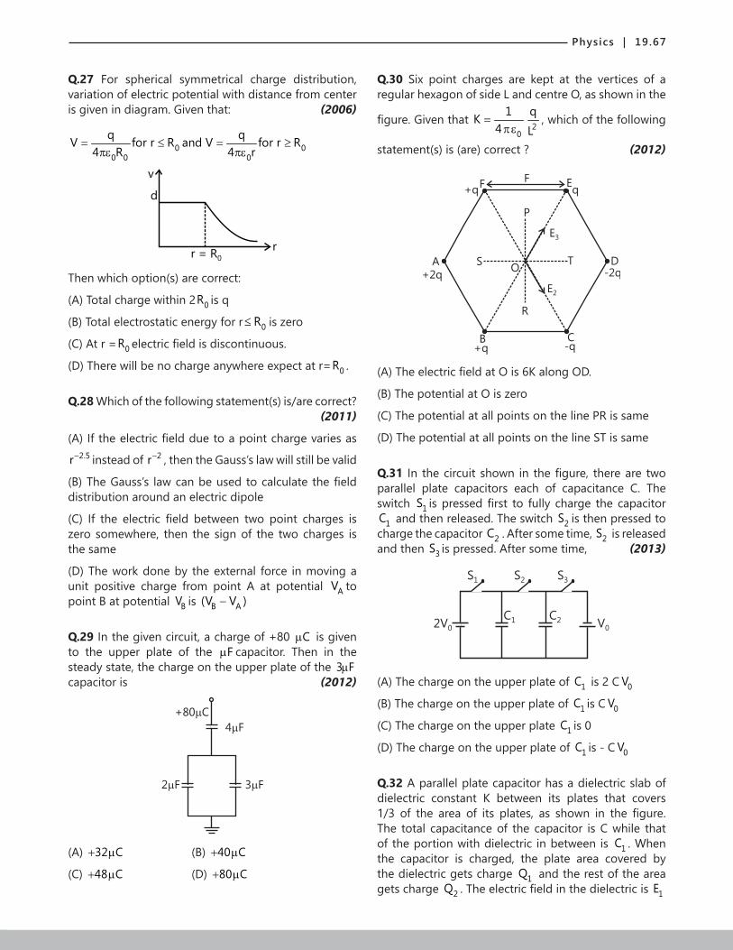
Physics | 19.67
Q.27 For spherical symmetrical charge distribution, variation of electric potential with distance from center is given in diagram. Given that: (2006)
0 00 0 0
q qV for r R and V for r R4 R 4 r
= ≤ = ≥πε πε
d
v
rr = R0
Then which option(s) are correct:
(A) Total charge within 2 0R is q
(B) Total electrostatic energy for r 0R≤ is zero
(C) At r = 0R electric field is discontinuous.
(D) There will be no charge anywhere expect at r= 0R .
Q.28 Which of the following statement(s) is/are correct? (2011)
(A) If the electric field due to a point charge varies as 2.5r− instead of 2r− , then the Gauss’s law will still be valid
(B) The Gauss’s law can be used to calculate the field distribution around an electric dipole
(C) If the electric field between two point charges is zero somewhere, then the sign of the two charges is the same
(D) The work done by the external force in moving a unit positive charge from point A at potential AV to point B at potential BV is B A(V V )−
Q.29 In the given circuit, a charge of +80 Cµ is given to the upper plate of the Fµ capacitor. Then in the steady state, the charge on the upper plate of the 3 Fµ capacitor is (2012)
4 F
3 F2 F
+80 C
(A) 32 C+ µ (B) 40 C+ µ
(C) 48 C+ µ (D) 80 C+ µ
Q.30 Six point charges are kept at the vertices of a regular hexagon of side L and centre O, as shown in the
figure. Given that 2
0
1 qK4 L
=πε
, which of the following
statement(s) is (are) correct ? (2012)
FF
SO
P
T
R
E2
Eq+q
A
B C
D-2q+2q
+q -q
E3
(A) The electric field at O is 6K along OD.
(B) The potential at O is zero
(C) The potential at all points on the line PR is same
(D) The potential at all points on the line ST is same
Q.31 In the circuit shown in the figure, there are two parallel plate capacitors each of capacitance C. The switch 1S is pressed first to fully charge the capacitor
1C and then released. The switch 2S is then pressed to charge the capacitor 2C . After some time, 2S is released and then 3S is pressed. After some time, (2013)
S1 S2 S3
C2C12V0 V0
(A) The charge on the upper plate of 1C is 2 C 0V
(B) The charge on the upper plate of 1C is C 0V
(C) The charge on the upper plate 1C is 0
(D) The charge on the upper plate of 1C is - C 0V
Q.32 A parallel plate capacitor has a dielectric slab of dielectric constant K between its plates that covers 1/3 of the area of its plates, as shown in the figure. The total capacitance of the capacitor is C while that of the portion with dielectric in between is 1C . When the capacitor is charged, the plate area covered by the dielectric gets charge 1Q and the rest of the area gets charge 2Q . The electric field in the dielectric is 1E
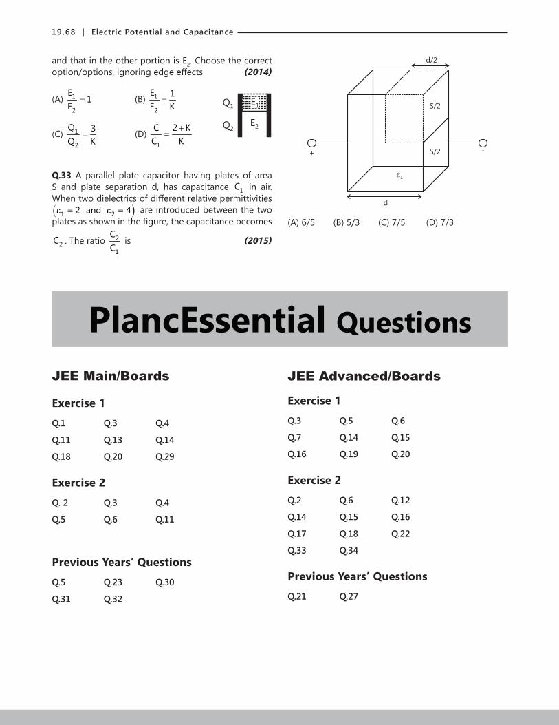
19.68 | Electric Potential and Capacitance
and that in the other portion is E2. Choose the correct option/options, ignoring edge effects (2014)
(A) 1
2
E1
E= (B) 1
2
E 1E K
=
Q1
Q2
E1
E2
(C) 1
2
Q 3Q K
= (D) 1
C 2 KC K
+=
Q.33 A parallel plate capacitor having plates of area S and plate separation d, has capacitance 1C in air. When two dielectrics of different relative permittivities ( )1 22 and 4ε = ε = are introduced between the two plates as shown in the figure, the capacitance becomes
2C . The ratio 2
1
CC
is (2015)
d/2
S/2
S/2
1
d
2
+ -
(A) 6/5 (B) 5/3 (C) 7/5 (D) 7/3
PlancEssential QuestionsJEE Main/Boards
Exercise 1 Q.1 Q.3 Q.4
Q.11 Q.13 Q.14
Q.18 Q.20 Q.29
Exercise 2 Q. 2 Q.3 Q.4
Q.5 Q.6 Q.11
Previous Years’ Questions Q.5 Q.23 Q.30
Q.31 Q.32
JEE Advanced/Boards
Exercise 1 Q.3 Q.5 Q.6
Q.7 Q.14 Q.15
Q.16 Q.19 Q.20
Exercise 2 Q.2 Q.6 Q.12
Q.14 Q.15 Q.16
Q.17 Q.18 Q.22
Q.33 Q.34
Previous Years’ Questions Q.21 Q.27
Physics | 19.69
Answer Key
JEE Main/Boards
Exercise 1
Q.1 1.29 Fµ
Q.2 35x10 V
Q.3 4 Fµ
Q.4 1.39 Fµ
Q.5 22.67x10 J−
Q.6 72.21x10 J−
Q.7 7.2F
Q.8 C 24C' 25
=
Q.9 0C 2C=
Q.10 11.1% energy is increased
Q.11 3 8
8
6x10 V/ m, E 12.15x10 J
E 30.4X10 J
−
−
∆ = −
∆ =
Q.12 18 Cµ
Q.13 A 1 B 2 D 30
1 2 3
C C CC C C
φ + φ + φφ =
+ +
Q.14 (i) 1
ER
(ii) 3
1
ER R+
Q.15 4.5g
Q.16 Both will travel the same distance
Q.17 260volts, 6x10⁻⁴C charge flows from 3 Fµ to 2 Fµ
Q.18 12 Cµ , 3 Cµ , 9 Cµ , 6 Cµ
Q.19 (i) 2.04V; (ii) 6.12 Cµ
Q.21 (a) Five 2 Cµ capacitors in series;
(b) 3 parallel rows; each consisting of five;
2.0 Fµ capacitors in series
Q.22 420 Cµ one one, 180 Cµ on two,
60 Cµ on remaining 3 capacitors
Q.23 2 24x10 F,10 F
Q.24 60 Cµ
Q.25 0.16 F,0.24 Fµ µ
Q.26 maxV 9 kV<
Q.27 (i) In parallel → new capacitance greater than the initial one (ii) In series → unchanged
Q.28 (i) 0.9 C / sµ ; (ii) 61.09 10 J / s−× ;
(iii) 62.73x10 J / s− ; (iv) 63.82 10 J / s−×
Q.29 (i) (a) 10s ; (b) 2 Cµ ; (c) 6.94s
(ii) 8q 1.348 10 C−= ×
Q.30 1.8 2410× Cm
Q.31 62.7 10 V×
Q.32 0
Q.33 91.11 10 C−× positive
Q.34 61.8 10 V×
Q.35 Total charge is zero. Dipole moment =7.5 × 10‒8m along z-axis.
Q.36 (i) dV=4E, (ii) c AV V>
Q.37 (i) 0
Exercise 2
Q.1 C Q.2 D Q.3 C Q.4 D Q.5 C Q.6 A
Q.7 B Q.8 B Q.9 B Q.10 C Q.11 A Q.12 C

19.70 | Electric Potential and Capacitance
Previous Years’ Questions Q.1 A Q.2 D Q.3 D Q.4 A Q.5 A Q.6 C
Q.7 B Q.8 A Q.9 D Q.10 B Q.11 A Q.12 C
Q.13 B Q.14 A Q.15 B Q.16 C Q.17 B Q.18 D
Q.19 D Q.20 D Q.21 B Q.22 B Q.23 C Q.24 A
Q.25 C Q.26 C Q.27 A Q.28 D Q.29 A Q.30 C
Q.31 C Q.32 D Q.33 B C Q.34 A Q.35 B
JEE Advanced/Boards
Exercise 1
Q.1 44.25pF
Q.2 30V
Q.3 0
Q.4 32 F23
µ
Q.5 10 Cµ
Q.6 8 F3µ
Q.7 0A Vdε
Q.8 025 A24 dε
Q.9 22k(q x)
35r−
Q.10 0.8
Q.11 9J
Q.12 31 3
EC RR R +
Q.13 (a) 7 A50
(b) 1 2Q 9 C, Q 0= µ =
Q.14 (a) t/20.05 1 e C− − µ ;
(b) 0.125 Jµ
Q.15 (a) 2t/Rc0VI e
R−= ; (b) 2
01 CV4
Q.16 2
0
1 q d2 Aε
Q.17 (i) 0A53 d ε
;
(ii) 03
AV4Q3 d ε
=
; 05
AV2Q3 d ε
=
Q.18 69 mC
Q.19 (a) 100 Volts7
(b) 28.56mC, 42.84mC,
71.4mC, 22.88mC
Q.20 150 Jµ
Q.21 16 Cµ
Q.22 35
Q.23 20 0
1 1W A V 1 '2 K
= ε −
Q.24 12Volt
Q.25 (i) 8 50.2 10 F,1.2 10 J;− −× ×
(ii) 54.84 10 J−×
(iii) 51.1 10 J−×

Physics | 19.71
Q.26 4.425 × 10‒5 Amp
Q.27 12V
2 C
2
4
6
C
q( C)200
O t
Q.28 1/n
00
VC C 1 0.01078 F,n 20,No
V
= − = µ =
Q.29 ( )t/RCCVq 1 e2
−= −
Q.30 A B C i
f
Q 90 C,Q 150 C,Q 210 C,U47.4mJ,U 18mJ= µ = µ = µ
= =
Q.31 1.8 × 10⁵ sec
Q.32 3
kP ( i 2 j)2y
− −
Q.33 2
first step secondstep total8 4 KqW ,W 0,W 03 r5
= − = =
Q.340
Qq2 Lπ∈
Q.35 (a) 4aH3
= ,
(b)U=mg 2 22 h a h + − equilibrium at h= a
3
Exercise 2
Single Correct Choice Type
Q.1 A Q.2 B Q.3 B Q.4 B Q.5 A Q.6 B
Q.7 B Q.8 A Q.9 A Q.10 D Q.11 B Q.12 C
Q.13 B Q.14 C Q.15 B Q.16 A Q.17 D Q.18 D
Q.19 B Q.20 C
Multiple Correct Choice Type
Q.21 A, B, C Q.22 A, D Q.23 A, D Q.24 A, B Q.25 B, C, D Q.26 A, B, D
Q.27 B, C Q.28 A, C, D Q.29 C, D Q.30 A, C, D Q.31 A, B, C, D Q.32 A, B, C, D
Q.33 B,D
Assertion Reasoning Type
Q.34 D Q.35 C Q.36 D
Comprehension Type
Paragraph 1: Q.37 B Q.38 B Paragraph 2: Q.39 A, C Q.40 A, B, C
Paragraph 3: Q.41 A, C Q.42 D

19.72 | Electric Potential and Capacitance
Previous Years’ Questions Q.3 D Q.4 C Q.5 D Q.6 A, D Q.7 B, D Q.8 A, C, D
Q.9 B, C Q.10 A, B, C Q.11 A Q.12 A, C Q.13 A Q.14 A, D
Q.15 B, C Q.16 A, D Q.17 B Q.18 B Q.19 C Q.20 B
Q.21 A → p, r, s; B → r, s; C → p, q, t; D → r, s Q.22 A, D Q.23 B, D Q.24 A, C, D
Q.25 B, C Q.26 C, D Q.27 A, B, C, D Q.28 C, D Q.29 C Q.30 A, B, C
Q.31 B, D Q.32 A, D Q.33 D
Solutions
JEE Main/Boards
Exercise 1
Sol 1: Parallel ⇒ 2(4.5 4.5) F 9 F C'+ µ = µ =
Total ⇒ total
1 1 1 1C 3 3 9
= + +
3 F 3 FC '2
totaltotal
1 7 C 9 / 7 F 1.29 FC 9
= ⇒ = µ = µ
Sol 2: We have 6Q CV 5 10 C V−= ⇒ × = ×
⇒ 6
9
5 10V10
−
−
×=
= 5000 V
Sol 3: A
C4
C1 C5
C3
C2
D
E
B
Now from symmetry, we can argue that the charge at 2C must be zero and hence potential diff. across D and E.
So 1(capacitance across ADB)− = 4 3
1 1 1 1 1C C 4 4 2
+ = + =
⇒ Capacitance across ADB = 2 Fµ
Similarly, Capacitance across AEB = 2 Fµ
So total capacitance = 2 + 2 = 4 Fµ
Sol 4:
6 F 12 F
11 F
G
C
E F
2 F8 F
DC F
4 F
A B
Capacitance b/w C and D
=1
1 14 F F6 12
−
µ + + µ
= 4 F 3 Fµ + µ
= 7 Fµ
Let capacitance b/w E and F
= 2 + 2 = 4 Fµ
Net capa. b/w G and B
= 1 1
1 1F 1 F8 4 7
− − 1
+ µ + + µ
= 8 7 F3 8
+ µ
= 64 21 85F F
24 24+
µ = µ
Now 1 241C 85
= +
⇒ C 85c F 1.39 F61
= µ = µ

Physics | 19.73
Sol 5: Now Q = 64 10 200−× × 800HQ=
4 F
-(Q-q)2 F
Q-q
-q q
2 F
Q/3
2Q/3
400V-Q Q
Now, an applying Kirchhoff’s law,
Q q q 04 F 2 F−
− =µ µ
Q 3q q Q / 3= ⇒ =
initialE = 21 C V2× × = 6 21 4 10 (200)
2−× × ×
= 28 10−×
finalE
2 22 21 1 2 2
1 2
4Q QQ / 2C Q / 2C9 2C 2C 9
= + = +× ×
= 2
1 2
2 1Q9C 18C
+
4 26 6
2 1(8 10 )9 4 10 18 2 10
−− −
= × +
× × × × =
264 102 6
−××
= 25.33 10 J−×
⇒ Energy lost = 8 5.33− = 22.67 10 J−×
Sol 6: 12 4
03
A 8.854 10 100 10Cd 2 10
− −
−
ε × × ×= =
×
= 118.854 10
2
−× = 114.427 10 F−×
So, 21E C V2
= × ×
= 11 21 4.427 10 (100)2
−× × × = 74.427 10
2−× = 0.221 Jµ
Sol 7: = 2 31 CV 100 10 36002
= × ×
⇒3
2
200 10 3600C
(104)
× ×= = 7.2 F
Sol 8: (A) (Capacitance total ) = 1 2
1 1C C
+
⇒1 0 2 0
d d2 k A 2 k A
+× ε × ε
1Capacitance − = 0 1 2
d 1 1.2 A k k
+
ε
⇒1
0A
1 2
2 A 1 1C .d k k
− ε
= +
(B) Capacitance Total = 1 2C C+
= 1 0 2 0k (A / 2) k . .(A / 2)d d
ε ε+
⇒ 0B 1 2
AC (k k ).
2dε
= +
So,=
1
01 2
A B1 2 0
1 12 A / d.k k
C / C(k k ). A / 2d
−
ε + =
+ ε
A 1 22
B 1 2
C 4 k kC (k k )
⋅= =
+ 2
4 2 3(5)× ×
=2425
=
Sol 9: 0A
AC
dε
= and 1
B1 2
1 1CC C
− = +
= 0 0 0
d d d4 A 4 A 2 A
+ =ε ε ε
⇒ 0B
2 AC
dε
=
So A BC / C 1/ 2=
Sol 10: We have Q = CV
Now energy = 21 CV2×
V = Same, but 01
AC
dε
= and 02
AC
0.9dε
=
So energy change
= 2 20 0A A1 1V V2 d 2 0.9d
ε ε− × × + × ×
= 20A1 1V . 1
2 d 0.9ε
× × −
= initialE [0.111]
⇒ 11.1 % energy is increased.
Sol 11: 12 4
02
A 9 10 100 10Cd 2 10
− −
−
ε × × ×= =
×

19.74 | Electric Potential and Capacitance
= 4.5 × 10‒12 F
Change in energy = 2 21 2
1 1C V C V2 2× × − × ×
= initial finalE E− = 21 2
1 V . C C2
× −
= 20
1 2
1 1 1(300) . A2 d d
× ε −
=4 12 4
2
9 10 9 10 100 10 1 12 52 10
− −
−
× × × × ×× −
×
= 840.5 10 3 / 10− ×
= 71.215 10 J−×
0
0 0 2 0
AQ CVE VA A d . A
ε= = = ⋅ε ε ε
= 22
300 60 105 10−
= ××
= 36 10 V / m×
Now in 2nd case , Q constant=
We have Q CV=
= 124.5 10 300−× × = 1013.5 10 C−× ⋅
= 9Q 1.35 10 C−= × ⋅
Now change in energy: initial finalE E−
⇒ 2 2 2
1 2
1 1 0 0
d dQ Q Q .2C 2C 2 A A
− = − ε ε
= 2
1 20
Q [d d ]2 A
−ε
= 2
1 2
0
Q .(d d )2 A
−ε
= 9 2 2
12 2
(1.35 10 ) .(2 5) 102 9 10 10
− −
− −
× − ×
× × ×=
9 2
12
(1.35 10 ) ( 3)2 9 10
−
−
× × −
× ×
= 9 2
12
(1.35 10 )2 3 10
−
−
− ×
× ×= 60.3 10−− × = 73 10−− × Joules
Sol 12:
12V 2
4
6
Now no current will pass through the capacitor.
So, i 12 / 8= = 3 / 2A
Thus, potential diff. across capacitor
= 6 3 / 2 9V× = ⇒ Q = CV = 18µC.
Sol 13:
A
B D
C2q1 q3
C3v0
q1 C1
O
We have 1 2 3q q q 0+ + =
⇒ 1 0 A 2 0 B 3 0 DC .( ) C .( ) C .( )φ − φ + φ − φ + φ − φ
⇒ 1 2 3 0 1 A 2 B 3 D(C C C ) C C C+ + φ = φ + φ + φ
⇒ 1 A 2 B 3 D0
1 2 3
C C CC C Cφ + φ + φ
φ =+ +
Sol 14: (i) Now, at just t = 0, charge at 1C 0= and charge at 2C 0= so V Q / C 0= = so potential diff. between AB = 0
1 AB 1i E / R R E / R= + =
(ii) After long time , no current through both capacitors
⇒ 1 3E iR iR= + ⇒1 3
EiR R
=+
Sol 15: E due to one plate = 0
Q2 Aε
So force = 2
0 0
Q QQ.2 A 2 A
× =ε ε
So 2
0
QT mg2 A
= =ε
mg = 2 2
0
C V2 Aε
m = 22 2
0
0
A.VC V2 A.g 2gd2
ε=
ε=
12 12 8 2
3 2
9 10 10 (5 10 )2 10 (5 10 )
− −
−
× × × ×
× × ×
= 34.5 10 kg−× = 4.5 gm
Sol 16: Let there, masses be me and mi
Then 2 2e e i i
1 1Vd m v M V2 2
= = × × …. (i)
Now acceleratio of particles ⇒ ee
Ee am
= and = ii
Ee aM
=
So time to hit the plate ⇒ 21S ut at2
= +
⇒ ee
e
2d.m2d ta Ee
= =

Physics | 19.75
Similarly, ii
i
2d.M2dta Ee
= =
Now distance = e eV t×
= e
e
2d.m2Vdm Ee
×
= V2d.Ee
(independent of mass)
Same distance can be found for the ion and hence the time is same.
Sol 17: Q 3 300 900 C.= × = µ
And 2Q 2 200 400 C.= × = µ
Q1
Q2
Q -q1
Q +q2
+ -
So using Kirchhoff’s law, ⇒ 1 2Q q (Q q)0
3 2− +
− =
⇒ 1 22Q 2q 3Q 3q− = + ⇒ 1 22Q 3Qq
5−
=
C1
C1
q1
1 2q q 900 400 500 C+ = − = µ
(from charge conservation)
Also 1 2q q0
3 2− = ⇒ 1 22q 3q= ⇒ 1
2
q 3q 2
=
⇒ 1 2q 300 C and q 200 C= µ = µ
1 2q q 1300 C+ = µ
q1
q2
q1
.. ⇒ 1 2q q3 2= ⇒ 1 2
3q q2
=
2q 520 C= µ , 1q 780 C= µ
Potential difference = 520 C260 Volts
2 Fµ
=µ
Thus the charge will flow from each positive terminal to the negative terminal.
Sol 18: No current will pass through, the upper portion, and voltage difference between the capacitors would be same as ε .
1
total1 2 3 4
1 1CC C C C
−
= + + + =
11 1 5 F
10 10
−
+ = µ
Actual emf = (4) 1(3 1)
ε − ×+
= 1 3Vε − =
So Q CV 5 F 9 15 C= = µ × = µ
q1
q2
q3
q1
Now, 1 2q q 15 C+ = µ …(ii)
and 1 2
1 2
q q0
C C− =
⇒ 1 2q q8 2= ⇒ 1 2q 4q= …. (i)
⇒ 1 2q 12 C, q 3 C= µ = µ
Also 3 4(q q ) 15+ =
3 4
3 4
q q0
c c− =
3 4q q6 4
= ⇒ 3
4
q 3q 2
=
⇒ 3q 9 C= µ ⇒ 4q 6 C= µ

19.76 | Electric Potential and Capacitance
Sol 19: Diagram-12 F
4 F
q1
5 F-q1
A G
q4 -q4
q5 -q5D
B
q2 q2
-q3q3
3 F q6 -q6
6 F
6 F
-q6q6
8 F 8 F
Diagram-2
4 F
5 F
3 F 12 F
2 Fq4
4 Fq5
A B
2.4 F
5 F2.4 F
BA
Diagram-3
4 F
5 F
3 F 12 F
2 Fq4
4 Fq5
A B
2.4 F
5 F2.4 F
BA
1
total
1
1 1C5 4.8
1 5 120 2.45 F5 24 49
−
−
= +
= + = = µ
1
total
1
1 1C5 4.8
1 5 120 2.45 F5 24 49
−
−
= +
= + = = µ
So, Q CV 2.45 10= = × = 24.5 Cµ
Now from diagram (3), capacitance = same ⇒ charge is equally divided.
⇒ 2 324.5q q 12.25 C
2= = = µ
Now from diagram (2)
4 5 2q q q+ =
And 54 qq0
2 4− =
⇒ 4 52q q−
So q4 = 12.25/3µC = 4.08µC and 512.25 2q 8.166 C
3×
= = µ
(i) So voltage diff. = 4.08 Cq / c 2.04 V
2 Fµ
= =µ
(ii) Charge = 12.25 C
2µ
= 6.12 Cµ
3 6 3[q 12.25 Cand2q q ]= µ =
Sol 20: (i)
C1 C1
C1C1
C2 C2 C1
e c
f dC1
C1
C2 C ’T
e c
f d
q’’
-q’’ q’’
q’’
C2 CT
e
f
q’’
a
b
a
b
a
b
C ’’’T
a
b
’’
We have 1 1
T1 1 1 2 1C (6 / 7) C3 3 2 3 2
− −
= + + = + = µ
Now T6 20C ' 2 C7 7
= + = µ
Now 1 1
T7 2 61 60C " C
20 3 60 61
− −
= + = = µ
⇒ T60 182C '" 2 C61 61
= + = µ
1 1
Total61 1 1 61 2C 1 C
182 3 3 182 3
− −
= + + = + = µ

Physics | 19.77
(ii) Q CV 1 900= = × 900 C= µ
(iii)
900
0
2
600V
300V
C 500V
d 400V
300 C600 C
Q 900 C= µ
⇒900v 300V
3∆ = =
Now between e and c = 300 100V3
=
So, between c and d 500 400V= − 100V=
Sol 21: (a) a b
All in series
(b)
a b
C =1.2 Fnet
netC 1.2 F= µ
Sol 22: By trial and error
A 1 C B
A 1 C Ctot B
⇒ C1 Ctot
BA
AC CBV V 600+ = ….. (i)
And AC tot CB1 V C V× = ×
AC CB7V V3
= × ⇒ AC CB7V .V3
⇒
⇒ AC600V 710
= × = 420 V and CB3V 600
10= ×
= 180 V
⇒ ACQ CV 1 C 420= = µ × = 420 Cµ
And BCQ 180 1 180 C= × = µ
And in each 3 , q will be equally distributed
q 420 2 180= − × ( on each)
Sol 23: We have 2 2 21 2
1 1C (2) C .(2) 10 102 2× × + × = ×
⇒ 1 2C C 500+ =
And 2 2
1 2
Q Q1602C 2C
= + ⇒ 2
1 2
1 1320 QC C
= +
= 2
2 2eq
1 2
1 2
1 1 VV CC C 1 1
C C
× + =
+ 2
1 2
1 2
V C C320
C C⋅ ⋅
=+
1 21 2
C C80 C C 40000
500⋅
⇒ = ⇒ ⋅ = …(i)
1On solving, C 400⇒ = , 2C 100=
Sol 24:
q1
2 F 3 F
-q1
-q2q2
-110 C110 C-q3q3
1 F
We have 3 1q q 110 C+ = µ
and 2 1q q 0− =
2 1q q⇒ = and 3 1 2q q q0
1 2 3− − =
1 2
3q q
q2 3
⇒ = +
11 1
5 q 6 110110 q q 606 11⋅ ×
− = ⇒ = = 1q 60 C⇒ = µ
So, 2q 60 C= µ and 5q 50 C= µ
So, 110 50− 60 C= µ charge passes through wire.
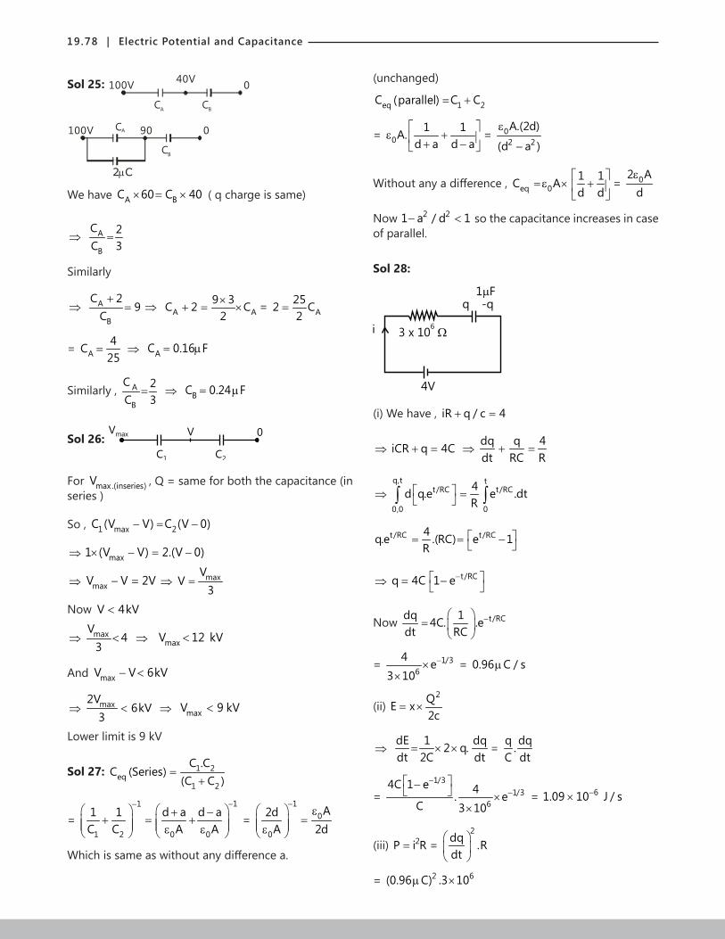
19.78 | Electric Potential and Capacitance
Sol 25: CA CB
40V 0100V
CA
CB
90 0100V
2 Cµ
We have A BC 60 C 40× = × ( q charge is same)
⇒ A
B
C 2C 3
=
Similarly
⇒ A
B
C 29
C+
= ⇒ A A9 3C 2 C
2×
+ = × = A252 C2
=
= A4C
25= ⇒ AC 0.16 F= µ
Similarly , A
B
C 2C 3
= ⇒ BC 0.24 F= µ
Sol 26: Vmax V
C1 C2
0
For max .(inseries)V , Q = same for both the capacitance (in series )
So , 1 max 2C (V V) C (V 0)− = −
⇒ max1 (V V) 2.(V 0)× − = −
⇒ maxV V 2V− = ⇒ maxVV
3=
Now V 4kV<
⇒ maxV4
3< ⇒ maxV 12 kV<
And maxV V 6kV− <
⇒ max2V6kV
3< ⇒ maxV 9 kV<
Lower limit is 9 kV
Sol 27: 1 2eq
1 2
C .CC (Series)
(C C )=
+
= 11
1 2 0 0
1 1 d a d aC C A A
−− + −
+ = + ε ε =
10
0
A2dA 2d
− ε
= ε
Which is same as without any difference a.
(unchanged)
eq 1 2C (parallel) C C= +
= 01 1A.
d a d a
ε + + − = 0
2 2
A.(2d)
(d a )
ε
−
Without any a difference , eq 01 1C Ad d
=ε × +
= 02 Adε
Now 2 21 a / d 1− < so the capacitance increases in case of parallel.
Sol 28:
1 F
3 x 10⁶
4V
q -q
i
(i) We have , iR q / c 4+ =
⇒ iCR q 4C+ = ⇒dq q 4dt RC R
+ =
⇒q,t t
t/RC t/RC
0,0 0
4d q.e e .dtR
= ∫ ∫
t/RC t/RC4q.e .(RC) e 1R
= = −
⇒ t/RCq 4C 1 e− = −
Now t/RCdq 14C. .edt RC
− =
= 1/36
4 e3 10
−××
= 0.96 C / sµ
(ii) 2QE x
2c= ×
⇒ dE 1 dq2 q.dt 2C dt
= × × = q dq.C dt
= 1/3
1/36
4C 1 e 4. eC 3 10
−−
− ××
= 61.09 10 J / s−×
(iii) 2P i R= = 2
dq .Rdt
= 2 6(0.96 C) .3 10µ ×

Physics | 19.79
= 2(0.96) 3 J× µ = 2.73 J / sµ
(iv) Energy = Energy in Resistance + Energy in capacitance
= 6(2.73 1.09) 10 J / s−+ ×
= 63.82 10 J / s−×
Sol 29:
2V
(i)
(a) t = RC = 107 × 10–6 = 10 sec
(b) Q = CV = 2 × 1 µC = 2µC
(c) Now , as in Ques. 29 above, t/10q 2 C [1 e ]−= ×µ −
⇒ t/101 1 e2
−= −
⇒ t/10e 2=
⇒ t = 10ln2 = 6.94 sec
(ii)
We have t/RC0q q e−=
Now 50/10q 2 e−= × = 52.e− = 0.0135 Cµ
Sol 30:
30o
2+
E=
30x
10N
C-1
4
T = (Eq) (2 ) sin 30°
T = E sin 30°. (q.2l)
⇒ Dipole moment (D)
= q.2 l = TEsin30°
= 6
4
27 1030 10 1/ 2
2×
× ×
= 1.8 × 1024 cm
Sol 31: 5 C
5 C
5 C
5 C
5 C
5 C
10cm
10cm
Potential at center due to one charge = kqr
= 9 6
1
9 10 5 1010
−
−
× × × = 45 × 104 V
Potential at center due to all the charges
= 6 × Vq = 2.7 × 10⁶ V
Sol 32: D C
A B
10 C
2 C
VA = µ(k)(10 C)a2
= 2ka
(10 µC)
VB = µ
(k)(10 C)a2
= 2ka
(10 µC)
Work done is moving charge of 2µC = q(VB - VA) = 2µC (0) = 0
Sol 33: q
r = 0.1m
v = 100 volts
⇒ kqr
= 100 ⇒ q = 100 0.1k×
= 1.1 × 10⁻⁹ C (positive)

19.80 | Electric Potential and Capacitance
Sol 34:
20 c 6cm
4cm
-10 c3cm 1cm
7cm
P
1 2 1 2p
1 2 1 2
q q q qV = K k k
r r r r
+ = +
q1 = 10 c− µ , r1 = 1 cm
q2 = 20 cµ , r2 = 7 cm
Put the values in the equation for Vp,
Vp = – 1.8 × 10⁶ V
Sol 35:
(0, 0
, 15)
-2.5
x10
C-7
-2.5
x10
C-7
(0, 0
, 15)
Total charge of system
= -2.5 × 10⁻⁷ C + 2.5 × 10⁻⁷ C = 0
Dipole moment of system
= -2.5 × 10⁻⁷ × (-15 – 15) × 10-2
=-7.5 × 10⁻⁸ Cm (along –ve z-axis)
Sol 36: The motion perpendicular to electric field won’t account in work
∴ Work done in moving charge from A to B is
E(6 – 2) = 4E
∴ Potential difference between A and B = 4E also
VB = VC (since no parallel movement along E)
⇒ VC – VA = 4E and VC > VA
Sol 37: (i)Eq
Eq
+
-
∴ Net force = Eq – Eq = 0 (Assuming length of dipole is small)
(ii) Ui = - P.E
= -PE
Uf = P.E
= PE
Uf – Ui = 2PE = work done is rotating dipole
Exercise 2
Single Correct Choice Type
Sol 1: (C)
CV + Q
d-CV
1
0 0 0 0 0 0
CV CV Q CV Q CV2 2A 2 A 2A 2A A
σ ++ = + = + ε ε ε ε ε ε
(per unit charge) 0 0
Q d dwork done E d CV2 A A
= × = + ×ε ε
Q 1 QC V' V2C C 2C
= + × × = +
Sol 2: (D) 1
eq1 1 1C C C C / 2 3C / 2C 2C 2C
−
= + + = + =
Q 60 3C / 2 90C= × =
1 2q qNow
C C / 2= ; 1 2 1 2q 2q and q q 90C= + =
2q 30C. So potential differenceQ / C 30V
⇒ =
= =
Sol 3: (C)
q2
q3
q4
q1
4 F6 Q
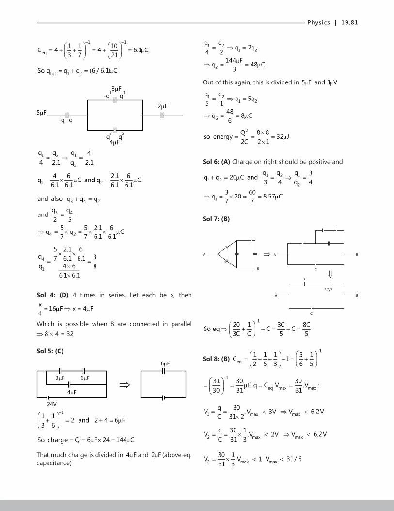
Physics | 19.81
1 1
eq1 1 10C 4 4 6.1 C.3 7 21
− −
= + + = + = µ
tot 1 2So q q q (6 / 6.1) C= + = µ
3 F
2 F5 F
-q
-q1
q
-q2
q2
4 F
q1
1 2 1
2
q q q 44 2.1 q 2.1= ⇒ =
1 24 6 2.1 6q C and q C
6.1 6.1 6.1 6.1= × µ = × µ
3 4 2and also q q q+ =
3 4
4 2
q qand
2 55 5 2.1 6q q C7 7 6.1 6.1
=
⇒ = × = × × µ
4
1
5 2.1 6q 37 6.1 6.1
4 6q 86.1 6.1
× ×= =
××
Sol 4: (D) 4 times in series. Let each be x, then x 16 F x 4 F4= µ ⇒ = µ
Which is possible when 8 are connected in parallel ⇒ 8 × 4 = 32
Sol 5: (C)
3 F 6 F
4 F
24V
6 F
11 1 2 and 2 4 6 F3 6
−
+ = + = µ
So charge Q 6 F 24 144 C= = µ × = µ
That much charge is divided in 4 Fµ and 2 Fµ (above eq. capacitance)
1 21 2
2
q qq 2q
4 2144 Fq 48 C
3
= ⇒ =
µ⇒ = = µ
Out of this again, this is divided in 5 Fµ and 1 Vµ
1 21 2
6
q qq 5q
5 148q 8 C6
= ⇒ =
⇒ = = µ
2Q 8 8so energy 32 J2C 2 1
×= = = µ
×
Sol 6: (A) Charge on right should be positive and
1 2 11 2
2
q q q 3q q 20 C and3 4 q 4
+ = µ = ⇒ =
13 60q 20 8.57 C7 7
⇒ = × = = µ
Sol 7: (B)
A A
B
B
C
A B
C
C
3C/2
120 1 3C 8CSo eq C C3C C 5 5
−
⇒ + + = + =
Sol 8: (B) 1
eq1 1 1 5 1C 12 5 3 6 5
−
= + + − = +
131 30 F30 31
−
= = µ
eq max max30q C .V .V31
= = ;
1 maxq 30V .V 3VC 31 2
= = <×
maxV 6.2V⇒ <
2 maxq 30 1V .V 2VC 31 3
= = × < maxV 6.2V⇒ <
2 max30 1V .V 131 3
= × < maxV 31/ 6<

19.82 | Electric Potential and Capacitance
Sol 9: (B) 5 5
0 010 V / m 0.5 10 V / m
2σ σ
= ⇒ = ×ε ε
5
0Now, force Q 0.5 10 1 C 0.05 N
2σ
= × = × × µ =ε
Sol 10: (C) 2
0 0
QForce Q2 2Aσ
= × =ε ε
so 2Force Q∝
3V 2V 1V
2 3 5
Vmax
(1) (2) (3)
O
Now, when d is halved ⇒ C is doubled; Q=CV ⇒ Q is doubled.
So 2Force Q∝ ⇒ F becomes four times.
Sol 11: (A) 1 2eff
1 2 1 2
k kd/ 2 d/ 2d d
k k 2k k +
= + =
1 2eff
eff 1 2
2k kdkd k k
∴ = =+
Also, 0 1 20
eff 1 2
2 A(k k )ACd k k
∈= ∈ =
+
Sol 12: (C)
Capacitance increases = kC0
Now,
i i f fq C V 60 C and q C V 180 C(60 120)= = µ = = µ +
f i iC kC k C .V 180 C k 3⇒ = ⇒ = = µ ⇒ =
Previous Years’ Questions
Sol 1: (A) In series, C = 1 2
1 2
C CC C+
10 F
1 F
Cnet = (10)(1)10 1+
= 1011
µF
Sol 2: (D) Since, the capacitor plates are directly connected to the battery, it will take no time in charging
C
R
V
Sol 3: (D) When S3 is closed, due to attraction with opposite charge, no flow of charge takes place through S3. Therefore, potential difference across capacitor plates remains unchanged or V1 = 30V and V2 = 20V
Alternate solution
Charges on the capacitors are
q1 = (30)(2) = 60pC and
q2 = (20)(3) = 60pC or q1 = q2 = q(say)
The situation is similar as the two capacitors in series are first charged with a battery of emf 50 V and then disconnected.
2pF 2pF
q q
+ - + -
50V
q=60pC q=60pC
+ - + -
V =30V1 V =20V1
∴ When S3 is closed, V1 = 30V and V2 = 20 V.

Physics | 19.83
Sol 4: (A) Due to attraction with positive charge, the negative charge on capacitor A will not flow through the switch S.
Sol 5: (A) After time t, thickness of liquid will
remain d – vt3
Now, time constant as function of time:
tc = CR = 0(1)Rd d / 3 – vtd – – vt3 2
ε
+
0AApplying C
td – tk
ε
= +
= 06 R5d 3Vt
ε
+
Sol 6: (C) Option C is correct because electron gets attracted towards positive charge (moves against electric field) larger the potential, lower the potential energy for electron.∴ U = V(-q)
Sol 7: (B) σ = 10-7 C/m2
Given, V = 5 volts
but V = 0
σε
.r
⇒ r = 0(V)ε
σ =
12
7
8.854 10 1010
−
−
× ×
= 8.8 × 10⁻⁴ m = 0.88 mm
Sol 8: (A) 3q
-2q -2q
q
(Center of charge) of negative charges is origin
(center of charge) of positive charges is
3q(a) q(a)4q− = q
2
Dipole moment
4q
-4q
a/2
P = 4q a j2
= 2qa j
Sol 9: (D) Potential of each drop = V = kqR
⇒ q = VRk
If n drops coalse, Q = nq = n VRk
Radius R’ = n1/3 R
The potential of new drop = 1/3
nkVRkn R
= Vn2/3
Sol 10: (B) The potential at center is same as that of the surface.
∴ V = 10 Volts
Sol 11: (A)
b
a 10V 5V
At center the potential will be same as the potential of the sphere enclosing it first
If it is any other potential, there will exist a electric field inside sphere contradicting gauss law.
Sol 12: (C)
b
ca
-
+
-
Potential at a due to charge of a = - 0( / )σ ∈ (a)
Potential at b due to charge of b = 0( / )σ ∈ (b)
Potential at C due to charge of c = 0( / )− σ ∈ (c)
∴ Potential at a = 0
σ∈
(b – a – c)

19.84 | Electric Potential and Capacitance
Sol 13: (B) Electric potential at any point inside a hollow metallic sphere is constant. Therefore, if potential at surface is 10 V, potential at centre will also be 10 V.
Sol 14: (A) In such situation potential difference depends only on the charge on inner sphere. Since, charge on inner sphere is unchanged. Therefore, potential difference V will remain unchanged.
Sol 15: (B) C1V = Q1
V = Q2V =
0
14πε
1QR
+0
14πε
2Q
R 2
= 0
14 Rπε
21
2
+
Similarly C2V =
0
14 Rπε
12
2
+
C1
Q1
R 2
R C1
Q2
R
∴ DV = C1V – C2
V
=0
14 Rπε 1 2 1 2
1(Q – Q ) – (Q – Q )2
= 1 2
0
Q – Q
2(4 R)πε( 2 –1)
W = qDV = q(Q1 – Q2)( 2 – 1)/ 2 (4πε0R)
Sol 16: (C) The diagrammatic representation of the given question is shown in figure.
y
x
q
Eq
E
E-q
(-d, 0) (d, 0)-q
The electrical field E→
at all points on the x-axis will not have the same direction.
For – d ≤ x ≤ d, electric field is along positive x-axis while for all other points it is along negative x-axis. The
electric field E→
at all points on the y-axis will be parallel to the x-axis (i.e., i )
The electrical potential at the origin due to both the charges is zero, hence no work is done in bringing a test charge from infinity of the origin.
Dipole moment is directed from the –q charge to the +q charge (i.e.,– i direction)
Sol 17: (B) The diagrammatic representation of given problem is shown in figure.
The net charge shared between the two capacitors is
Q’ = Q2 – Q1 = 4CV – CV = 3CV
Q =C V =CV1 1 1
Q =C V =(2C)(2V)=4CV2 2 2
+++++
-----
+++++
-----
The two capacitors will have the same potential, say V’
The net capacitance of the parallel combination of the two capacitors will be
C’ = C1 + C2 = C + 2C = 3C
The potential difference across the capacitors will be
V’ = Q'C'
= 3CV3C
= V
The electrostatic energy of the capacitors will be
U’ = 12
C’V’2 = 12
(3C)V2 = 32
CV2
Sol 18: (D) Potential at origin will be given by
V = 0
q4πε 0 0 0 0
1 1 1 1– – .......x 2x 3x 4x
+ +
=0
q4πε
. 0
1x
1 1 11– – .......2 3 4
+ +
=
0 0
q4 xπε
ln(2)

Physics | 19.85
Sol 19: (D) Electric field within the plates Q Q1 2E E E→ → →= +
E = E1 – E2 = 1 2
0 0
Q Q–
2A 2Aε ε, E = 1 2
0
Q – Q2Aε
∴ Potential difference between the plates E
→
+Q1 +Q2 E2 E1
1 2
VA – VB = Ed = 1 2
0
Q – Q2A
ε
d = 1 2
0
Q – QA
2d
ε
= 1 2Q – Q2C
Sol 20: (D) Applying C= 0
1 21 2
1 2
At t
d – t – tK K
ε
+ +, we have
0
1 3
(A / 2)d / 2 d / 2d – d / 2 – d / 2K K
ε
+ +
+ 0
2 3
(A / 2)d / 2 d / 2d – d / 2 – d / 2K K
ε
+ + = 0K A
dε
Solving this equation, we get
A/2
d/2
d/2
A/2
+K1
K3
K2
K3
d/2
d/2 K
A
d
In parallel
K = 1 3
1 3
K KK K+
+ 2 3
2 3
K KK K+
Sol 21: (B) Potential decreases in the direction of electric field. Dotted lines are equipotential lines.
y
C
A B
E
x
∴ VA = VC and VA > VB
Sol 22: (B) q Q q
x=–a x=0 x=+a
q Q q
x=–a x=x x=a
Initial Position
Final position
Ui = 2KQqq
+ K.q.q2a
and Uf = KQq 1 1a x a – x
+ + + K.q.q
2a
Here, K = 0
14πε
DU = Uf – Ut or |DU| = 2
3
2KQqxa
for x << a ∴ DU ∝ x2
Sol 23: (C) DU = decrease in potential energy
= Ui – Uf
= 12
C( 21V + 2
2V ) – 12
(2C)2
1 2V V2
+
= 14
C(V1 – V2)2
Sol 24: (A) There will be an electric field between two cylinders (using Gauss theorem). This electric field will produce a potential difference,
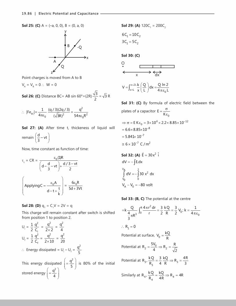
19.86 | Electric Potential and Capacitance
Sol 25: (C) A = (–a, 0, 0), B = (0, a, 0)y
B -Q
Q
A
z
x
Point charges is moved from A to B
VA = VB = 0 ∴ W = 0
Sol 26: (C) Distance BC= AB sin 60°=(2R) 32
= 3 R
∴ |FeBC|=0
14πε 2
(q / 3)(2q / 3)
( 3R)=
2
20
q54 Rπε
Sol 27: (A) After time t, thickeness of liquid will
remain d – vt3
Now, time constant as function of time:
tc = CR = 0(1)Rd d / 3 – vtd – – vt3 2
ε
+
0AApplyingC
td – tk
ε
= +
= 06 R5d 3Vt
ε
+
Sol 28: (D) q1 = C1V = 2V = q
This charge will remain constant after switch is shifted from position 1 to position 2.
Ui = 12
2
i
qC
= 2q
2 2× =
2q4
Uf = 12
2
f
qC
= 2q
2 10× =
2q20
∴ Energy dissipated = Ui – Uf = 2q
5
This energy dissipated 2q
5
=
is 80% of the initial
stored energy 2q
4
=
Sol 29: (A) 120C1 = 200C2
1 26C 10C=
1 23C 5C=
Sol 30: (C)
O
x dx
x 2L
x L0
Q ln 2k QV dxx L 4 L
=
=
= = πε ∫
Sol 31: (C) By formula of electric field between the
plates of a capacitor 0
EKσ
=ε
4 120E K 3 10 2.2 8.85 10−⇒ σ = ε = × × × ×
86.6 8.85 10−= × ×75.841 10−= ×
7 26 10 C / m−≅ ×
Sol 32: (A) 2 ˆE 30x i=
dV E.dx= − ∫V 2A
2
V 00
dV 30 x dx=−∫ ∫
A 0V V 80 volt− = −
Sol 33: (B, C) The potential at the centre
2R003 0
4 r dr k QQ 3 3 1k V ; k4 r 2 R 2 4R3
π= = = =
πεπ∫
1R 0∴ =
Potential at surface, 0kQVR
=
Potential at 02 2
5V RR R4 2
= ⇒ =
Potential at 3 33
k Q 4R3 kQR , RR 4 R 3
= ⇒ =
Similarly at 4 44
k Q kQR , R 4RR 4R
= ⇒ =

Physics | 19.87
Sol 34: (A) Let the potential at P be V,
Then, C (E – V) 1 V 2 V= × + × (we take C in Fµ )
C
2 F
1 FV
P
E
Or, CEV3 C
=+
22CEQ3 C
∴ =+
Sol 35: (B) Charge on 9 Fµ capacitor = 18 Cµ
Charge on 4 Fµ capacitor = 24 Cµ
Q 24 18 42 C∴ = + = µ
( )
9 6
2 2
KQ 9 10 42 10 420 N / Cr 30
−× × ×∴ = =
JEE Advanced/Boards
Exercise 1
Sol 1: eff6 mm 4 mm
d 2 mm6 4
= + =
0eff
ACd
∴ = ∈
12 4
3
8.85 10 100 1044.25 pF
2 10
− −
−
× × ×= =
×
Sol 2:
a
+ -
C1 C2
C2C1
b
q
Now pq 2 1q 2 C 6C= × =
So voltage difference across b and p
= 1 16C / C 6V=
Now 2 2 2q on C 8C 24C= =
So total charge = (24 + 6)C1 = 30C1
Same charge would be there at capacitor b/w a and b
So , 1
1
30 CV 30V
C∆ = =
Sol 3: initialE = 2(20 C)
2 2 Fµ
× µ +
( )250 C
2 5 F
µ
× µ
= 2500100 J J10
µ + µ = 350 Jµ
Now 1 2q q2 5= ⇒ 1
2q 70 C7
= × µ = 20 Cµ
q1
2 F
5 Fq2
And thus , 2q 50 C= µ
initialE = same (thus there would be no heat produced)
Sol 4:
4 F
1 F
8 F4 F
4 F
AC
8 F
1 F
8/3 F
8/9 F8/3 F
A
B
C
32/9 F
A
B
C
Now, 1 91C 32
= +
⇒32 9 1
32 C−
= ⇒ 32C F23
= µ

19.88 | Electric Potential and Capacitance
Sol 5: V 10V∆ =
So, Q CV 10 1 C= = × µ
(The ends of C 1 F= µ are connected to the terminals of the battery)
Sol 6: Suppose a charge q is given to the system.
q1 -q1 q4 -q4
-q2
q2
1
1
2
q3 -q3
1 2 yx
Then, 1 2 3q q q q+ + = …… (i)
And 4 3q q q+ = ….. (ii)
Also , applying kirchoffs law in loop (i)
1 2q q0
1 1−
+ = ⇒ 1 2q q= …(iii)
And 3 2 4q q q0
2 2 1− − =
⇒ 3 2 4q 2(q q )= +
Now, 1 32q q q+ = (form (i))
⇒ 32 1
(q q )q q
2−
= =
⇒ 33 3
(q q )q 2. q q
2 −
= + −
⇒ 3 3 34q q q 2q 2q= − + −
⇒ 3q 3q / 4=
Now, 1 3qV 3q / 4 V2 8
∆ = × =
So Capacitance = 8q / V F3
∆ = µ
Sol 7: The Circuit can be converted to all branches have the same capacitance and are connected in parallel.
(A,1,3,5) (2,4,B)
Q Q
Q Q
Q Q
Q Q
1 2
3 2
3 4
5 4
4Q = (4C)V = ε
04 AV
d
0AVQ
dε
⇒ =
So, the charge on plate 1 is 0AVd
ε and that on plate 4
is 02 AVd
ε−
Sol 8: Capacitance (left side): 1 2
1 2
C .CC C+
= 0 0
0
1 (A / 2). 3 (A / 2)..
d d(A / 2).
4.d
× ε × ε
ε= 0 03A 3A
8d 8dε ε
=
Capacitance: (right side)
= 0 0
0
2 (A / 2). 4 (A / 2)..
d d(A / 2).
6.d
× ε × ε
ε = 0A4
6 dε
= 02A3dε
So 0 0total
3A 2AC
8d 3dε ε
= +
0 0total
A A9 16 25C24 d 24 d
ε ε += =
Sol 9:
q2
-xp
x
q-x
-q+x
II
I
Now V at outer must = 0
⇒ 2k[( q x) q ]k.( x) kq 03.5r 3.5r 3.5r
− + +−+ + =
⇒ 2kq 0= ⇒ 2q 0=
And now potential at inner cell = 0
k.( q x) k(q x) k.x kx 03.5r 2.5r 2.5r r− + −
+ + − =
⇒k( q x) kq kx 0
3.5r 2.5r r− +
+ − =

Physics | 19.89
(x q) q x 03.5 2.5−
+ − =
2(x q) 2q x 07 5−
+ − =
⇒ 10(x q) 14q 35x 0− + − =
⇒ 4q 25x=
⇒ x 4q / 25=
So in region (I), 2
kxEr
=
2.5r2 2
0r
1Energy .E .(4 r ).dr2
= ε π∫
= 2.5
2 20 2
r
1 14 .kx r .dr2 r×ε × π ∫
= 2kx 21
2r 5 −
= 23k .x
10r where x = 4q/25
Similarly in region II
2 2
kx k(q)Er r−
= + = 2
k( x q)r
− +
⇒ Energy = 3.5r
2 20
2.5r
1 E (4 r )dr2ε π∫
= 2k(q x) 2 2
2r 5 7 −
−
= 22k(q x)
35r−
Sol 10: i 2 / 4 5 2 / 9= + =
So V for 4 F iR∆ µ = = 2 105 V9 9
× =
And 2 8V for 5 F iR 4 v9 9
∆ µ = = × =
So Energy ratio = 2
2
1/ 2 5 (8 / 9)
1/ 2 4 (10 / 9)
× ×
× ×
= 5 64 4 0.84 100 5× = =
Sol 11: Now after connection all the 30 C
100m
20m
charge will transfer to be outer shall. Now, the heat generated would be same as then energy of the region between the sphere and the shell (Electric field elsewhere is same)
So, 2
kqEr
=
So 20
2 20
10
1Energy .E .(4 r ).dr2
= ε π∫
= 2 2 20010 2
dr. 4 .k q2 r
επ ∫
= 2kq 1 1.
2 0.1 0.2
−
= 25kq
2
= 9 2 125 9 10 (20) 10
2
−× × × ×
= 9 J
Sol 12: 1 3
EiR R
=+
So, 33
1 3
R Ev R .i
R R∆ = =
+
Now, 3
1 3
CR EQ C ( V)
R R= × ∆ =
+
Sol 13: (A)
2 F
30
60302V
1 F
O
+
-
9V
-2V
+
-or
(a) 2 CVacross 1 F 2V
1 Fµ
∆ µ = =µ
Now so current = 1
9 2
1 13060 30
−
−
+ +
= 7 7 A 0.14 A30 20 50
= =+
(b) Current = 0; So, C1q 9 1 9 C= × = µ
And 2C 22
q ( V) C 0 C 0= ∆ × = × =

19.90 | Electric Potential and Capacitance
Sol 14: R1
R2E
i i1
R2
qC+-
⇒ 1 1 3qE iR i R 0C
− − − = ….. (i)
And 1 2 2E iR i R 0− − = ….. (ii)
1 2i i i= + …… (iii)
So 2 2 1 3qi R i R 0C
− − =
1 2 1 3q(i i ) R i R 0C
− − − =
2 1 2 3qiR i (R R ) 0c
− + − =
⇒ 21 1 2 3
1
R qiR . i (R R )R C
= + +
⇒ 21 3 1 2 3
1
Rq qE i R . i (R R )C R C
− − = + +
⇒ 3 221 2 3
1 1 1
R .RR q RE. i R R 1R R C R
= + + + +
⇒ 2 1 1 2 1 3 3 2 1 2qE.R i (R .R R .R R .R ) .[R .R ]C
= + + +
⇒ 1 2
1 2 1 2
q(R R )2 dqR .R dt c.( R .R )
+= +
∑ ∑
⇒
t.(R R ) t.(R R )1 2 1 2q,tt dtc( R .R ) c.( R R )2 1 2 1 2
1 2 0 0,0
E.Re d q.e
R .R
+ +
∑ ∑ + = ∑
∫ ∫
⇒
t(R R ) t(R R )1 2 1 2C( R .R ) C( R .R )2 1 2 1 2 1 2
1 2 1 2
E.R C( R .R ). e 1 q.e
(R .R ) (R R )
+ +
∑ ∑
∑ − = ∑ +
⇒ 2 1 2
1 2 1 2
ECR t(R R )1 e q
(R R ) C( R .R ) − +− =
+ ∑
t(300 300) 26 60.01 10 [300 300 300 50 300 50 18 ]10 0.01 300q . 1 e
300 300
− + ×
× × + × + × ×
× × = − +
= t/20.1. 1 e2
− − = t/20.05 1 e C− − µ
(b) Energy = 2 t/2 2 22 (0.05) .[1 e ] ( c)Q
2C 2 0.01( F)
−− × µ=
× µ
= 2105 0.05 1 e
2−× −
0.125 Jµ
Sol 15:
(a) q1
q2
= 1 2dq dqi
dt dt= =
And 1 2q qiRC
C C− =
and 1 2q q CV+ =
⇒ 1 1q iRC CV q− = −
⇒ 11
dq2q .(RC) CV
dt+ =
⇒ 1 12q dqV / R
C dt+ =
⇒ ( )q,t t
2t/RC 2t/RC1
q 00,0
Vd q .e .e .dtR
=∫ ∫
⇒ 2t/RC 2t/RC1 0
V (RC)q .e q . . e 1R 2
− = −
⇒ 2t/RC 2t/RC1 0
VCq q .e . 1 e2
− − = + −
So, 2/RC 2t/RC10
dq 2 VC 2q . .e .edt RC 2 RC
− − −= +
= 2t/RC 2t/RCV V2.e .eR R
− −−× +
= 2t/RC1dq Vi .dt R
−= − = +
(b) Heat generated = initial finalE E−
= 2
01 1 CV 1CV 22 2 2 C
2 × − × × ×
= 2 2
0 0CV CV2 4
− = 2
0CV4

Physics | 19.91
Sol 16: 0 0 0
3q q qE2A 2A A
= − =ε ε ε
⇒ Voltage = 0
qd qE dA C
× = =ε
So energy initial = 21 C V2× ×
= 2
1 qC2 C
× ×
=
2q2C
= 2
0
q d2Aε
and finalE = 0 (both have q = 2q)
So initialE = finalE + heat
⇒ 2
0
q d Heat2A
=ε
Sol 17: 1
2345
6
78
-
+
1 2 3 4 5 6 7
7 8
-q3q3
q-q1
q11
2
q2
-q2
4
3 -q4
q4 5
6 BA
Let q charge be given to the system.
1 2q q q+ = …. (i)
3 4 2q q q q+ + = ….. (ii)
3 43 4
q q0 q q
1 1− = ⇒ =
…. (iii)
1 2 4q q q 0− + =
1 4 2q q q+ = ….. (iv)
So on solving,
⇒ 2q 3q / 5=
So V 3q / 5C∆ = (C = capacitance of each capacitors)
So capacitance = Q / DV
= q / 3q / 5c
= 5C3
= 05A3dε
(ii) Charge on plate 3 4q⇒
4 22q q q+ = (from 2 and 3)
⇒ 4q q / 10= −
Now, we have v 3q / 5C∆ = , So 0v 3q / 5C=
⇒ 05V Cq
3=
⇒ 0 05V A. q
3 dε
=
So, 0 04
A .Vq on plate 3
6dε
= ⇒
And charge on plate 15 q=
Now, 1 2q q q+ =
⇒ 1q 2q / 5=
= 0 05V .A25 3d
ε× = 0 0V A2
3 dε
Sol 18:
5V
6 F
3 F
Q -Q1 o
3 F
Qo Q2Q -Qo 2
6 F5V
10V 6 F
Q1 A B
Qo 10V
Qo
3 F
Set up potential drop equations to get the values of Q0, Q1, and Q2
Now, close the switch ‘AB’ and draw a similar charge distribution diagram.
This will give you the new charges across all the plates.
By using appropriate arithmetic, you can easily get to the charge flown across the switch AB.

19.92 | Electric Potential and Capacitance
Sol 19:
60 C
A
50 C20 V 4 F
10 C-10 C
3 FV
5 F
20 V 4 F2 F
1
2
3
V-20
Charge is conserved
(V 0) 3 (V 0) 2 (V 0) 5 (V 20) 4 10 60 50− × + − × + − × + − × = + +
= 10 + 60 + 50
⇒ 14V 80 120− =
⇒ AV 200 / 14= = 100 / 7
(b) 1q 2 (100 / 7)= × , 2300q 3 V C
7= × = µ
And 35 100 300q C
7 7×
= = µ
= 4 Aq (V 20) 4 F= − × µ = 100 20 4 F7
− × µ
= 160 F7
−µ = 22.88
Sol 20:
3 F10V
(V+10)
5
2 F
4 F0
5V
- +
q2
Now, 1 2q q 0+ =
⇒ (V 5)2 (V 10)4 0− + + = (Cons. of charge)
⇒ 6V 30 0+ =
⇒ V 5= −
So 1q ( 5 5)2 20 C= − − =− µ
And 2q ( 5 10) 4 20 C= − + × = µ
After the switch is closed, the above neq s would s + 111 be valid , and hence 1 2q and q would be same.
Only change would be there In 3q
3q CV 3 F 10 30 F= = µ × = µ
So energy or heat generated = work done by battery - energy stored in capacitor
= 2110 30 3 (10)2
× − × × = 300 150 150 J− = µ
Sol 21: 1 1
eq1 1C 1 12 2
− −
= + + +
= 2 2 4 F3 3 3+ = µ
So , eq4Q C .V 24 32 C3
= = × = µ
This will be divided equally, as the capacitor are
equal Q 16 C⇒ = µ
1 F
1
24V+-
2' F
4
S
1 F
3
2 F
2
-Q1 Q1 -Q2Q2
1 F 2 F1 2
S
V02 F 1 F34
Q2 Q2
24V
0
+-
(a)
(b)
-Q1 Q1
1 F
1
24V+-
2' F
4
S
1 F
3
2 F
2
-Q1 Q1 -Q2Q2
1 F 2 F1 2
S
V02 F 1 F34
Q2 Q2
24V
0
+-
(a)
(b)
-Q1 Q1
When the switch S is closed as shown in the figure (b), then the charges stored across positive plates capacitors 1 and be Q1 and Q2. The same charges will be distributed across negative plates of capacitor 3 and 4. Let the potential at the negative terminal is zero, then the charges across capacirots 1, 2, 3 and 4 will be
( )1 oQ 24 V 1 F= − × µ …(i)
( )2 oQ 24 V 2 F= − × µ …(ii)
3 0Q V 1 F= × µ …(iii)
4 0Q V 2 F= × µ …(iv)
Thus from (i) and (iii) V0 = 12V and thus the charges be
1 3 2 4Q Q 12 F and Q Q 24 F= = µ = = µ

Physics | 19.93
Thus when switch is zero, 12µF charge is passed through the switch.
Sol 22: Before opening the switch potential difference across both the capacitors is V, as they are in parallel. Hence, energy stored in them is,
2A B
1U U CV2
= =
2Total iU CV U∴ = = …(i)
After opening the switch, potential difference across it is V and its capacity is 3C
2 2A
1 3U (3C)V CV2 2
∴ = =
In case of capacitor B, charge stored in it is q = CV and its capacity is also 3C.
Therefore, 2 2
Bq CVU
2(3C) 6= =
2 2
Total3CV CVU
2 6∴ = +
22
f10 5CVCV U6 3
= = …(ii)
From eqs. (i) and (ii) i
f
U 3U 5
=
Sol 23: 0AC
dε
= , So 0 00 0
A AVQ CV V .
d dε
= = × = ε
So, 0 0AVQ
dε
= , initialE = 2
2
0 0
QQ2C 2C
=
= 20 0
1 C V2× = 20
0A1 . V
2 dε
×
initialE = 2
0 0AV2d
ε
finalE =
220
0 20 02
f 0
AV
d V AQ.
2C 2k dA2.k.
d
ε ε = =
ε
finalE + work done = initialE
⇒2 2
0 0 0 0A V A V1. W2d k 2dε ε
+ = ⇒
20 0A V 1W 12d kε
= −
Sol 24: q1
q2
C
VC
VF 0
So, Q 156 C= ×
Thus, 1 2q q 156C+ =
⇒ 2CV CV 156C+ α =
⇒ 2V V 156 0+ − =
⇒ (V 12)( V 13) 0− + =
⇒ V 12Volts=
Sol 25: (i) 0 0(A/ 2) K (A/ 2)C
d dε ε
= +
= -12
-48.85×10 [0.02+0.18]8.85×10
= 0.2 ×10⁻⁸ F
Energy = 2 51 CV 1.2 10 J2
−= ×
(ii) Q = CV
Find the new capacitance, C' = 0Adε
Work done = 2 2
5Q Q– 4.84 10 J2C' 2C
−= ×
(iii) C’kc2
Find the new charge distribution, and proceed as (i) & (ii)
Energy of system = 1.1×10⁻⁵ J
Sol 26:
x
(1-x)
Now area of air = 21 (1 x)m× − = 2(1 x)m−
= area of air = xm2

19.94 | Electric Potential and Capacitance
So both are in parallel connection.
Capacitance = 0 0(1 x). 11 x.d d
− ε × ε+
= 0 010xd dε ε
+ = 0 1 10xdε
+
Now, Q CV=
⇒ dC dCi .(V)dt dt
= =
= 0 dV. [1 10x]d dtε
+
= 012
V. dx 500 10 0.00110d dt 0.01 8.85 10−
ε × ×× × =
× ×
= 10 55 8.85 10 4.425 10− −× × = × Amp.
Sol 27: We have eqC 30 F= µ
10 F
20 F
+ -
10V
So, q 30 10 300 C= × = µ
Thus, q on 20 F 200 Cµ = µ
And q on 20 F 200 Cµ = µ
Now, -q1q1
-q2 q2
R
Now, 2 1q q 200 100 100 CNow,− = − = µ
1 2dq dqi
dt dt−
= = −
And, 1 2q qiR 0
10 20+ − =
⇒ 1 2q qiR 0
C 2C+ − =
⇒ 1 1 1q q 100 qd.R 0
C 2C dt +
+ + =
⇒ 1 13q dq50 .R 02CR RC dt
++ + =
⇒ 11
dq 3 .q 50 / RCdt 2CR
+ = −
⇒q t d1
t/20R/3 t/2RC/31
100,0 q
50d(q .e ) . e .dtRC−
=∫ ∫
⇒ t/2CR/3 150 2CR . eRC 3
−− ×
⇒ t/2CR/3 (t/2RC/3)1
100q e 100 e 13
− − = −
⇒ t/RC/3 t/2RC/31
100q 100.e . 1 e3
− − = − −
⇒ t/2RC/32 1
200 400q q 100 C .e3 3
−= + µ = +
200
3
t
Charge
( C)
Sol 28: Q = C0V0
Now,
q1 q2
C0 C
So, 1 2 1 2
0 0
q q q q0
C C C C− = ⇒ =
⇒ 01
2
Cqq C
=
So, 01 1 2
0
Cq (q q )
(C C)= +
+ (After first)
= 2
0 0
0
C V(C C)+
(After First)

Physics | 19.95
After 2nd 0 0
1 0 00 0
200 0
0
C Cq . .(C V )
(C C) (C C)
Cs .C V
C C
=+ +
= +
Now after n ⇒ 00 0 1
0
C.C V q
C C
= +
So voltage n
010
0 0
CqV 35
C C C
= = +
⇒ n
0
0
C0.35
C C
= +
= n
0.2 0.350.2 0.01075
= +
⇒ n(0.094899) 0.35=
⇒ ln(0.35)n
ln(0.94899)=
⇒ n = 20
Sol 29:
q2
i2C
C
q1V
SRi
R
i1
i3
1 2 3i i i i= + +
1 21 2
dq dqi , i
dt dt= =
And 1 2q q0
C C− = ⇒ 1 2q q+ …. (i)
⇒ 1 21 2
dq dqi i
dt dt= = =
⇒ 23 2 3
di R q i RC
C= ⇒ =
⇒ 23
qi
RC= …. (ii)
1qV iR 0
C− − =
(Kirchoff’s Law in bigger loop)
⇒ 1 11 2 3
q qV i i i iR RC RC= + = + + +
⇒ 1 12dq 2qV2R dt C
= + (from i and ii)
⇒qt t/RC t/RC1,t
0 0,0 1V e d.(q .e )2R
=∫ ∫
⇒ t/RC t/RC1
VC . e. 1 q .e2
− =
⇒ t/RC1
VCq 1 e2
− = −
Sol 30:
300 C
-300 C 360 C
-360 C
3 F 2 F
2 F
q1 -q1
-q3
q3
-q2
q2
300 C
-300 C 360 C
-360 C
3 F 2 F
2 F
q1 -q1
-q3
q3
-q2
q2
(i) Now Kirchhoff’s law : 3 1 2q q q0
3 2 2−
− + =
= 2 1 33q 3q 2q= + …. (i)
and charge conservation
⇒ 1 3q q 300 C− = µ
2 3q q 60 C− = µ
= 3 3 33 60 q 3 300 q 2q − = + +
= 3 3 3180 3q 900 3q 2q− = + + = 3720 8q− =
= 3q 90 C=− µ
And thus, 2q 150 C= µ
And 1q 210 C= µ
(ii) Einitial = 2
2 2
1 2
Q Q1 12 C 2 C× + ×
= 2 21 (300) 1 (360)
2 3 F 2 2 F× + ×
µ µ
= (300 50 360 90) J× + × µ = 0.0474 J
Efinal = 2 2 2(210) (90) (150)
2 2 2 3 2 2+ +
× × ×
= (5625 1350 11025) J 0.018 J+ + µ =

19.96 | Electric Potential and Capacitance
Sol 31:
+q
+q+q
a a
a
e
Initial
Ui = 2kq 3
a×
a/2 a/2
eq eq eq
Final
Uf = 2kq
a +
2kq 2a2
×
Work done = Uf – Ui
= 25kq
a -
23kqa
= 22kq
a
Work done = Power × Time
⇒ t = 22kq
ap
= 9 2
3
2 9 10 101 10
−× × ×
× = 18×104 sec
Sol 32:
y
(0,y)P
45o
P
x
E1
o,y
P
2+
(0,y)E2
P
2
1E
= Pk2
30
1y
ˆ( i)−
2E
+ 2k P
2
3
1y
ˆ( j)−
E
= 1E
+ 2E
= 3
kP
2y
ˆ ˆ( i 2 j)− −
Sol 33:
I. +q
+q
+q
+q
r
r
r
r
O
II. +q
2v
+q
r
r
2r
O
r
+q +q
UI=2kq
r × 2 +
2kq2r
+ 2kq
3r × 2 +
2kq4r
UII = 2kq
4r +
2kq2r
+ 2kq
5r × 4
Wfirst step = UII – UI = 2kq
r 8 4
3 5
−
III.
2v
r
2r
r
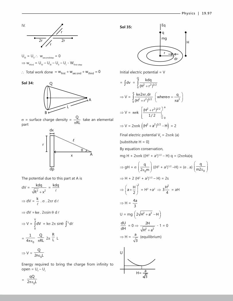
Physics | 19.97
IV.
2r 2r
r
r
UIII = UII ∴ wsecondstep = 0
⇒ wthird = UIV – UIII – UII – UI - Wfirst step
∴ Total work done first second thirdkl total w w w 0∴ = + + =
Sol 34: Q
B
L
A
σ = surface charge density = QRLπ
take an elemental part
dx
dp
r
x A
The potential due to this part at A is
dV = 2 2
kdq
R x+ = kdq
⇒ dV = k
. σ . 2πr d
⇒ dV =kσ . 2πsin θ d
⇒ V = V
0
dV∫ = kσ 2π sinθ L d∫
= 0
14πε
QRLπ 2π
RL L
⇒ V = 0
Q2n Lε
Energy required to bring the charge from infinity to open = Uf – Ui
= 0
qQ2 Lπε
Sol 35:
Eq
mg
q
r
dr
H
Initial electric potential = V
= dv∫ = Q
2 2 1/20
kdq(H r )+∫
⇒ V = a
2 2 1/20
k 2 r,dr(H r )σ π
+∫ 2
qwherea
σ =
π
⇒ V = kπσ a2 2 1/2
0
(H r )1/ 2
+
⇒ V = 2πσk ( )2 2 1/2(H a ) H+ − = 2
Final electric potential Vf = 2πσk (a)
[substitute H = 0]
By equation conservation,
mg H + 2πσk ((H2 + a2)1/2 – H) q = (2πσka)q
⇒ gH + σ 0
q2 m
ε
((H2 + a2)1/2 –H) = (σ . a) 0
qm2 ε
⇒ H + 2 (H2 + a2)1/2 – H) = 2s
⇒ 2
Ha2
+
= H2 +a2 ⇒
2H34
= aH
⇒ H = 4a3
U = mg 2 22 H a H + −
dUdH
= 0 ⇒ 2 2
2H
H a+ - 1 = 0
⇒ H = a
3 (equilibrium)
U
H=a
3

19.98 | Electric Potential and Capacitance
Exercise 2
Single Correct Choice Type
Sol 1: (A) Vmax16/3
O
1
eq1 1 16C C8 16 3
−
= + = µ
then let maxv = the max
voltage across the capacitors
So charge =Q= max max16Cv v3
= ×
Now1 max
16 1 Qv v3 16 C
= × ×
maxmax
v80 v 240V
3= < ⇒ <
2 max
max max
16 1and v v3 8
2 v 20 v 30V3
= × ×
= < ⇒ <
maxso v 30V= .
16 30Thus Q 160 C3×
= = µ
Sol 2: (B) eqC 2C= where C= capacitance of each plate.
So 2eq
1energy C V2
= × ×
1212 2
3
(0.1)(8.85 10 )CV 10 10 J0.885 10
−−
−
×= = × = µ
×
Sol 3: (B)
CV -CV
2V
CV 2CV
Initial Final
Now, initial energy + work done by battery
= Final energy + heat generated
2
2
1 C V 2V.(3CV)2
1 C (2V) Heat generated2
∴ × × +
= × × +
⇒
2 2 21 CV 6CV 2CV Heat generated2
+ = +
24.5CV Heat generated⇒ =2 2ratio 4.5CV / 2CV 2.25= =
Sol 4: (B)
(A, 1)
E
(3, B)
(5)oA
d
(2, 4)
oA
d
oA
d
oA
d
Net capacitance =
0 0
0
2 A Ad d
3 Ad
ε ε
ε
= 0A23 dε
Charge flown = 0 0A A2 2E3 d 3 d
ε ε=
E
Sol 5: (A) Force between plates = mg
And 2 2
0 0 0
A QA mg mg2 2 2Aσ σ
×σ = = ⇒ =ε ε ε
⇒ 02mgA Qε =
Sol 6: (B) Now across point c and d DV = 0
q1
q2
2C
C
⇒ The capacitance is 0 for that
eq 1 2 0C C C 2A / d⇒ = + = ε

Physics | 19.99
Sol 7: (B)
3C 2C
q1 -q1
v2
q1 -q1
v2
q2 -q2
v2
q2 -q2
v2
A
oA
d
oA
d
oA
d
B
Net Capacitance = 02 Adε
Sol 8: (A) 1 1
eq1 1 1 1C
3C 2C 7C 3C
− −
= + + +
6C 21C 33C 3.3C5 10 10
= + = =
max max eq maxQ V C V (3.3C)= × =
1 2 1
2
q q q 4Now ;6 / 5C 21/ 10C q 7
= =
1 max max4Now q V (3.3C) 1.2V C11
= × × =
2 max max7q V (3.3C) 2.1V C11
= × × =
A
c
d
B
max1 max max 2.5 KV
1.2 V .CV 0.4V 1KV V
3C<= = < ⇒
max1 max max KV
1.2V .C 10V' 0.6V 2 KV V2C 3
<= = < ⇒
max2 max max KV
2.1 V .C 10V 0.3V 1KV V7C 3
<= = < ⇒
max2 max max KV
2.1V .C 20V' 0.7V 2 KV V3C 7
<= = < ⇒
= 2.5 KV
Sol 9: (A)
q1
q2
1 F
1 F
Let there be a charge Q on body 1.
So 1 2 1
2
q q q 11 2 q 2= ⇒ =
1 2 1and q q Q q Q / 3 where q initial charge+ = ⇒ = = nq Q/ 3⇒ =
Sol 10: (D) Total charge now= ECE.C / 22
=
Now after dielectric is inserted,
eff netkC.C kC kCEC so Q
(kC C) (k 1) (k 1)= = =
+ + +
KCE CE (K 1)CEso Q flowed from B to Ak 1 2 2(k 1)
−= − =
+ +
as capacitance increases.
Sol 11: (B) Voltage would be highest at x = 0. And E = constant V x⇒ ∝ so it would decrease linearly, from x = 0 to x-d, will remain constant from x = d to x = 2d.
Sol 12: (C)
1000V 0V
V E d 200 5 1000V.∆ = × ∆ = × =
Now the electric field would be same so
V E d 200 3 600V.∆ = × ∆ = × =

19.100 | Electric Potential and Capacitance
Sol 13: (B) 1 2Q 1500 C and Q 100 C= µ = µ
1 21 2 1 2
q qq q 1600 C and q q 800 C
1 1+ = µ = ⇒ = = µ
V q / c 800 C / 1 C 800V∆ = = µ µ =
Sol 14: (C) 1 2 eqE.kCQ Q C .E(k 1)
= = =+
1 2 eqECand Q ' Q ' C .E2
= = = ; 2
2
Q ' k 1Q 2k
+=
Sol 15: (B) From the symmetry, we can say that the capacitance would be same.
1.5 F300 C
-300 C-360 C+360 C
1.5 Fq3 -q3
-q1
q1
2 F-q2
q2
3 F
Sol 16: (A) t/0q q .e where (2 r)0.5 F− τ= τ= + µ
t/0qdq .edt z
− τ⇒ =
t/ ln2 se 1/ 2 ln2 t / ln2z
− τ ×µ= ⇒ = τ ⇒ =
1 s (2 r) 1/ 2 (r 0)⇒ τ = µ = + × ⇒ = r = 0
1.5 F300 C
-300 C-360 C+360 C
1.5 Fq3 -q3
-q1
q1
2 F-q2
q2
3 F
Sol 17: (D) 3eq
1R C 100 F 102
× = × µ ×
5 60.5 10 10 0.05sec−= × × =
Sol 18: (D) As at t = 0 the capacitor is assumed as a wire.
Sol 19: (B) t/RC t/RC00
qdqq q .e .re idt RC
− −= ⇒ = =
t/RC 2 306
qi .e Now i R.dt 3.6 10
2 10 10− −
−⇒ = = ×
× × ∫
230
2
q RCR 1 3.6 10 22(RC)
−⇒ × × × = × ×
2 3 60q 7.2 10 2 10− −⇒ = × × ×
9 1014.4 10 144 10− −= × = ×5
0q 12 10−⇒ = ×
Sol 20: (C) t/ t/0 0
dq 1q q .e q . .edt
− τ − τ = ⇒ = − τ
;
0qi .e t /= − − τ
τ
6RC (r 2)0.5 10 sec−τ = = + ×
|t 0 |t ln4 s.1and thus i i2 = = µ× =
612 s (r 2) 10 r 22
−τ = µ = + × × ⇒ = Ω
t/ t/0 0q q1 .e e 22
ln 2 ln 4 /
− τ τ ⇒ × − = − = = τ τ ⇒ ⇒ τ
Multiple Correct Choice Type
Sol 21: (A, B, C) Now from charge conservation
1 2 3 1q q 60 C ... (i); q q 300 C ... (ii)+ = µ − = µ
2 3q q 360 C⇒ + = µ31 2
1 3 2qq q
0 ; 3q 4q 2q ... (iii)2 1.5 3+ − = + =
3 3 33(q 300) 4q 2(360 q )− + = −
3 3 37q 900 720 2q 9q 1620− = − ⇒ =
31620q 180 C
9⇒ = = µ
1 2and q 120 C and q 180 C= − µ = µ
Sol 22: (A, D) 1
eff1 1 2C 2CEC so chargeC 2C 3 3
−
= + =
effFinal C 2C charge 2CE= ⇒ =
2CE 2CE / 3 4CE / 3− =
Sol 23: (A, D)
1 F v v+10 2 F
C1 C2
5 O

Physics | 19.101
From charge conservation C C1 2Q Q=
1 2(5 V) C (v 10) C ; 5 V (V 10)2− × = + × − = +
15 3V V 5V− = ⇒ = −
2 2C C1 2
1 1E 1 (10) 50 J ; E 2 (5) 25 J2 2
= × × = µ = × × = µ
C C1 12E E⇒ =
Sol 24: (A, B) We have 0
E2σ
=ε
(by one plate)
So force 02σ
=ε
. 2
0
QQ2A
=ε
2 2 2
0
C V d CVQ CV F2A d 2d
= ⇒ = × =ε
Sol 25: (B, C, D)
12 F Ceq
q1
q1
7 F
3 F
q2
3.9 F
KCV+ -
V
KCV+ -
V
1
eq1 1C ' 3.9 3.9 2.1 6 F3 7
−
= + + = + = µ
1
eq1 1C 3.9 4 F6 12
−
= + + = µ
so q 4E C.= µ
1 21 2 1
q q 2.1q q 4E and q 4E2.1 3.9 6
+ = = ⇒ = ×
0.7 2E 1.4E= × =
0.7 2E Cso V across 7 F q1/ 7 F 67 F 10× µ
∆ µ ⇒ µ = =µ ×
E 30V⇒ =
1q 0.7 2 30 42 C.⇒ = × × = µqV across 3 F 14V
3 F∆ µ = =
µ ;
30V across 12 F 4 10V12
∆ µ = × =
CE/3
CE/3
2CE/3
E
+ -
CE/3
CE/3
o
E
+ -
+ -
+ -
Sol 26: (A, B, D) Charge = KCV – CV=(K-1)CV
Energy absorbed 2(K 1)CV= −
Energy 2 21 (K 1)energy K C V .CV2 2
−= × × × =
2 2 21 1Now K C V work C V (K 1)CV2 2× × × + = × × = −
⇒ Work 21work (K 1)CV2
⇒ = −
Sol 27: (B, C) same sameV E d= , so E=same.
Sol 28: (A, C, D) 0AC
dε
= and Q = CV 0A Vdε
=
Now netQ CV VV E dC KC K
= = = = × E V / Kd⇒ =
And energy initial + work done=energy final2 2Q Qwork done
2C 2KC+ =
Work 2 2Q 1 CV 1work 1 1
2C K 2 K
= − = − −
Putting the value of "C" from the first line, we get 2
0AV 1W 12d K
ε = −
Sol 29: (C, D) 1
eq1 2
1 1CC C
−
= +
1
0 0
x d x tA A
− − −
= + ε ε 1
0
0
Ad tA d t
− ε−
= = ε −

19.102 | Electric Potential and Capacitance
Sol 30: (A, C, D) KCVCV
V V
Q=C’V=KCV
2 2initial final initial
1 1E CV E K CV K E2 2
= = × × = ×
same sameAs V E d so E same= × =, so E = same
2 2 22
0 0
Q C VF K2A 2AV
= =ε
Sol 31: (A, B, C, D)
Q -Q
d
A B Q-qq
-(Q-q)
2Q-q-2Q+q
Q-q
d/2 d/2
100
C1 C2
60
80 60
V
i1
i2
120
Now the charge on outer surfaces should be same q Q q q Q / 2= − ⇒ =
So (A) 2Q Q / 2 3Q / 2= − + = −
Charge on A=Q/2 and charge on B = 3Q/2
So as E Q and V E V Q∝ ∝ ⇒ ∝ and hence C is correct.
Sol 32: (A, B, C, D) (A) at t=0 consider it as wire.
(B) 1
eq
10 10 10i 5AR 21 11
2 2
−= = = =
+ +
(C) From kirchoff 's law
i11 1 2 2R i R= 1 2
2 1
i Rconstant
i R⇒ = =
V iR 5A 1 5V.∆ = = × Ω =
So Q CV 1 F 5 5 F= = µ × = µ
Sol 33: (B, D)
1eq
120 120i 40AR 1 1
2 2
−= = =
+
Now this I will be divided equally, so 1 2i 20A,i 20A= =
Now 2( V ) 0.... (B)∆ =
C1Q 20 2 C 40 C.....(D)= × µ = µ
Assertion Reasoning Type
Sol 34: (D) Statement-I is false electrostatic force remains the same.
Sol 35: (C) Statement-II is false.
Sol 36: (D) Q ( iR)C i ( Q / C).1/ R= ε − ⇒ = ε −
Work done by battery .Q ( iR)= ε = ε ε −
And energy in capacitor =2 2Q ( iR) C
2C 2ε −
=
2( iR) C iR.( iR).C2
ε −= + ε −
⇒ Statement-I is false.
Comprehension Type
Sol 37, 38: (B, B) C1
C2
0 21 1 22
1 2 2
Q qC .d q q xCx C C q d
−= = ⇒ =
0
2
Q x1q d
⇒ = + 02
x1d
⇒ = +

Physics | 19.103
Now force
d
t
x d-(x-t)
= 222
022
0 0 0
QqQ2A 2A (1 x/ d) 2A
= =ε ε + ε
2 2d0
20 d
Q 1And work done2A (1 x/ d)
=ε +∫
2 20 0
0 0
Q Q dd2A 6 12A
= × =ε ε
And potential difference = q1/C
0 0 01 0
Q Q (x/ d) Q xq Q
1 x / d 1 x / d x d= − = =
+ + +
01 1
0
Q xdpotential q / C
(x d)A=
+ ε
Sol 39: (A, C) i=E/R1
Sol 40: (A, B, C) 1 2
E(B) CurrentR R
=+
Voltage 2
1 2
E R(A) voltage
(R R )×
=+ ;
22 2
1 2
ER1 1(C) CV C2 2 (R R )
× = × × +
Sol 41: (A, C) max(A) q same.=
(B) is wrong option as q CV Now, C can be different=
(D) Not necessarily, depends on 1 2R and R also.
Sol.42: (D) 1 2 1 1 2 2; R C R C ;τ < τ <
1 1 2 2Now E C E C (charge same)=
1 2 1 2C C R R⇒ = ⇒ < ; 1 2
2 1
R CR C
<
Previous Years’ Questions
Sol 1: The diagrammatic representation of given problem is shown in figure.
Q =C V =CV1 1 1
Q =C V =(2C)(2V)=4CV2 2 2
+++++
-----
+++++
-----
The net charge shared between the two capacitors is
Q’ = Q2 – Q1 = 4CV – CV = 3CV
The two capacitors will have the same potential, say V’
The net capacitance of the parallel combination of the two capacitors will be
C’ = C1 + C2 = C + 2C = 3C
The potential difference across the capacitors will be
V’ = Q'C'
= 3CV3C
= V
The electrostatic energy of the capacitors will be
U’ = 12
C’V’2 = 12
(3C)V2 = 32
CV2
Sol 2: Electric field within the plates Q Q1 2E E E→ → →= +
E
+Q1 +Q2
E2 E1
1 2
E = E1 – E2 = 1 2
0 0
Q Q–
2A 2Aε ε, E = 1 2
0
Q – Q2Aε
∴ Potential difference between the plates
VA – VB = Ed = 1 2
0
Q – Q2A
ε
d = 1 2
0
Q – QA
2d
ε
= 1 2Q – Q2C

19.104 | Electric Potential and Capacitance
Sol 3: (D) Applying C = 0
1 21 2
1 2
At t
d – t – tK K
ε
+ +,
we have
A/2
d/2
d/2
A/2
+K1
K3
K2
K3
d/2
d/2 K
A
d
In parallel
0
1 3
(A / 2)d / 2 d / 2d – d / 2 – d / 2K K
ε
+ +
+ 0
2 3
(A / 2)d / 2 d / 2d – d / 2 – d / 2K K
ε
+ + = 0K A
dε
Solving this equation, we get K = 1 3
1 3
K KK K+
+ 2 3
2 3
K KK K+
Sol 4: (C) DU = decrease in potential energy = Ui – Uf
= 12
C( 21V + 2
2V ) – 12
(2C)2
1 2V V2
+
= 14
C(V1 – V2)2
Sol 5: (D) q1 = C1V = 2V = q
This charge will remain constant after switch is shifted from position 1 to position 2.
Ui = 12
2
i
qC
= 2q
2 2× =
2q4
Uf = 12
2
f
qC
= 2q
2 10× =
2q20
∴ Energy dissipated = Ui – Uf = 2q
5
This energy dissipated 2q
5
=
is 80% of the initial
stored energy 2q
4
=
Sol 6: (A, D) When dielectric slab is introduced capacity gets increased while potential difference remains unchanged.
∴ V = V0, C > C0
Q = CV∴ Q > Q0
U = 12
CV2∴ U > U0
E = Vd
but V and d both are unchanged
Therefore, E = E0
Sol 7: (B, D) Charging battery is removed. Therefore, q = constant Distance between the plates is increased. Therefore, C decreases.
Now, V = qC
, q is constant and C is decreasing
Therefore, V should increase.
U = 12
2qC
again q is constant and c is decreasing
Therefore U should increase.
Sol 8: (A, C, D) Battery is revoved. Therefore, charge stored in the plates will remain constant
Q =CV = 0AV
dε
Q = constant.
Now, dielectric slab is inserted. Therefore, C will increase. New capacity will be
C’ = KC = 0KAd
ε
V’ = QC'
= VK
And new electric field E = V'd
= VK.d
Potential energy stored in the capacitor,
Initially, Ui =
12 CV2 =
20AV2d
ε
Finally, Uf = 12
C’V’2 = 12
0K Ad
ε
2VK
= 2
0AV2Kdε
Work done on the system will be
|DU| = 2
0AV2d
ε 11–K
Sol 9: (B, C) The magnitude and direction of electric field at different points are shown in figure. The direction of the electric field remains the same. Hence, option (b) is correct. Similarly, electric lines always flow from higher

Physics | 19.105
to lower potential, therefore, electric potential increase continuously as we move from x = 0 to x = 3d.
q1 q1
++++++++++
----------
E0x=0 x=e x=2e x=3d
E0
+ -
+ -
+ -E /K0
Therefore, option (c) is also correct. The variation of electric field (E) and potential (V) with x will be as follows
E
d 2d 3dx
V
V0
AB
O d 2d 3dx
OA||BC and (Slope)OA > (Slope)AB
Because E0–d = E2d–3d
And E0–d > Ed–2d
Sol 10: (A, B, C)
PQ n P -Q/4
d
Potential at P is zero
If (d>x)
⇒ kQd
- kQ4(d x)−
= 0 ⇒ d = 4d – 4x
⇒ x = 3d4
= d = 4x3
if (d < n)
⇒ kQd
- kQ4(x d)−
= 0 ⇒ 4x5
= d
Electric field at P is zero
d
+Q -Q/4
xE /4 E-Q Q
f
⇒ 2
kQd
= 2
kQ4(d x)−
⇒ d – x = d2±
⇒ x = 3d2
or x = d2
⇒ d = 2x3
or d = 2x
(since d > x)
Sol 11: (A) ˆ ˆ ˆr (i 3 j 2k)= + +
- ˆ ˆ ˆ(4i 7 j 2k)+ +
= ˆ ˆ ˆ3i 4 j 0k− − +
| r | = 5
V = k qr× =
9 89 10 105
−× × = 18 v
Field is parallel to r and thus has no 3-component
Sol 12: (A, C) It must have any K.E. at B to reach A
Since
AU – BU = -e (VA – VB) = +4eV
(K.E.)f – (k.E.)i = UB – UA = -4eV
Sol 13: (A)+
++
++
++
+++
-----
--
---
By symmetry potential due to negative part =(potential due to particle part). (Also every small charge is equidistant from axis)
∴ Potential at all potential axis is zero

19.106 | Electric Potential and Capacitance
Direction of field is perpendicular to axis and towards negative side
There will be a torque when placed in uniform field
Sol 14: (A, D) Electric field due to dipole exists inside sphere only a circle on the sphere has zero potential which is equidistant from poles of dipole
Zero potential
+- q =0enclosed
Electric flux = 0
Sol 15: (B, C)
+qF
2
r+
r+-q
Qr
FR = 2 2
2F.
a +
(= 2F sin θ) = 2 2
2
r +
2 2
kQ .qr
+
= 2 2 3/2
kQ(P)(r )+
⇒ FR = 0
14πε .
3
pQr
(r >>
)
Torque on dipole = 2 2 1/2
F.r(r )+
(2 )
= (=2 F cos θ )
⇒ T = 2 2 1/2
r.(2 )(r )+
2 20
l Q. .q4 r
πε +
⇒ T = 0
14πε
2
pQr
(r >> )
Sol 16: (A, D)
q R B R C
Potential at center of sphee = 0
kq4 (d R)π∈ +
(It is independent of presence of conductor because induced charges provides zero potential at center)
Potential B = Potential at C
(Since electric field inside conduction is zero)
⇒ V = constant
∴ Potential at B due induced charges
= Potential at B – potential at B due to q
= 0
kq4 (d R)π∈ +
- 0
kq4 dπ∈
= 0
kqR4 (R d)d
−π∈ +
Sol 17: (B) Let the distribution of charges be
d
y
(1) (2) (3) (4)
x Q-x -Q+x y
-x -Q+x Q-x
2d d
Since the potential difference between plates (1) and (4) is zero.
⇒ 0
x.dA−∈
+ 0
Q x(2d)A−∈
+ 0
(Q x)dA−∈
= 0
⇒ x = 3Q4
∴ Option B
⇒ Charge on right side of plate 3 = Q – x = Q/4
Sol 18: (B) Also Charge is conserved on plate 1 and 4
⇒ y + (-x) + Q – x + y = 0 + 0
⇒ y = Q4
∴ Option B
∴ Charge on right side of plate 4 = Q2
Sol 19: (C) Potential difference between (i) and (ii)
= ( )
0 0
x d 3QdA 4A
=∈ ∈
Sol 20: (B) Obviously, both statements are correct. But, Statement-II is not a correct explanation of statement-I.
Sol 21: Refer theory on Superposition of electric field & Ampere’s Loop Law.

Physics | 19.107
Sol 22: (A, D) Q = KQ0 V → Constant
( ) 2 20
1 1U KC V CV k KU2 2
= = =
0E E / k=
Sol 23: (B, D) 1Cd
∝
Sol 24: (A, C, D) Q – remains constant.
C changes from 0 0A k Ato
d d∈ ∈
Hence, other variable also change.
Sol 25: (B, C)-Q +Q
x=0 x=3dd
( )
2
outside0
2
inside0
QEA
So, Q is wrongQE
K A
=
∈ →= ∈
(B) is correct as the direction of field remain the same.
(C) As we are going in the opposite direction of electric field, potential would rise.
Sol 26: (C, D) Using Gauss’s Law
in
0
qNet Flux E.ds= =
∈∫
It electric field is same at all the points of a surface, it is knows as equipotential surface.
Sol 27: (A, B, C, D) Refer Theory.
Sol 28: (C, D) Refer Theory.
Sol 29: (C) 2 F & 3 Fµ µ are in parallel combination.
Sol 30: (A, B, C)+q -q
O
E3
E1
E2
+2q -2q
+q -q
2 3 2
2kqE EL
= =
1 2
4kqEL
=
all 1 2 3E E E E= + +
2 20
6kq 1 q6 6K4L L
= = × =πε
(Along OD)
atV O 0=
atV line PR is zero because this line is equatorial axis for three dipole.
Sol 31: (B, D) After switch 1S is closed, 1C is charged by 02CV when switch 2S is closed, 1C and 2C both have upper plate charge 0CV .
When 3S is closed, the upper plate of 2C becomes charged by 0CV− and lower plate by 0CV+ .
Sol 32: (A, D) As E = V/d 1 2E / E 1= (both parts have common potential difference)
Assume 0C be the capacitance without dielectric for whole capacitor.
0 0C 2Ck C
3 3+ =
1
C 2 kC k
+=
1
2
Q kQ 2
= .

19.108 | Electric Potential and Capacitance
Sol 33: (D)
+80
-80
80
q2
25
= x 80 = 32
+32
-32
q135
= x 80 = 48
+48
-48
0 010
S4 4 S2Cd / 2 d
ε ε= =
0 020 30
2 S SC , C
d dε ε
= =
10 10 10 0
1 1 1 d 11C' C C 2 S 2
= + = + ε
010
4 SC'
3dε
⇒ =
02 30 10
7 SC C C'
3dε
= + =
2
1
C 7C 3
=
C10 C20
C30