eikon e6 Service & Parts Manual
64
eikon e6 Service & Parts Manual Merrychef USA, LLC 1111 North Hadley Road Fort Wayne, Indiana 46804 United States of America Technical Support Hotline: (800) 678-9511 Telephone: (260) 459-8200 www.merrychefusa.com NOTE: PLEASE READ COMPLETELY BEFORE ATTEMPTING TO INSTALL, OPERATE OR SERVICE THIS EQUIPMENT CAUTION MICROWAVE EMISSIONS: DO NOT BECOME EXPOSED TO EMISSIONS FROM THE MICROWAVE GENERATOR OR PARTS CONDUCTING MICROWAVE ENERGY.
-
Upload
khangminh22 -
Category
Documents
-
view
2 -
download
0
Transcript of eikon e6 Service & Parts Manual

eikon e6 Service & Parts Manual
Merrychef USA, LLC 1111 North Hadley Road
Fort Wayne, Indiana 46804 United States of America
Technical Support Hotline: (800) 678-9511 Telephone: (260) 459-8200
www.merrychefusa.com
NOTE: PLEASE READ COMPLETELY BEFORE ATTEMPTING TO INSTALL, OPERATE OR SERVICE THIS EQUIPMENT
CAUTION MICROWAVE EMISSIONS: DO NOT BECOME EXPOSED TO EMISSIONS FROM THE MICROWAVE GENERATOR OR PARTS CONDUCTING MICROWAVE ENERGY.

E6 SERVICE MANUAL REV C 06/12 2
TABLE OF CONTENTS SYMBOLS .................................................................................................................................................................. 4 SAFETY REQUIREMENTS ....................................................................................................................................... 5 PRODUCT OVERVIEW & FUNCTIONS .................................................................................................................... 6 MAIN FEATURES ...................................................................................................................................................... 7 TECHNICAL SPECIFICATIONS ................................................................................................................................ 8
SPECIFICATIONS ....................................................................................................................................................... 8 SERIAL NUMBER (RATING PLATE): ............................................................................................................................. 8
OVEN PLACEMENT/INSTALLATION ....................................................................................................................... 9 INSPECT OVEN ..................................................................................................................................................... 9 OVEN PLACEMENT .............................................................................................................................................. 9
ELECTRICAL INSTALLATION................................................................................................................................. 10 QUICK START GUIDE: QUICK SERVICE OVEN .................................................................................................... 11
START UP ............................................................................................................................................................ 11 USING A COOKING PROGRAM ......................................................................................................................... 12
OPERATING GUIDE: FULL SERVICE OVEN ......................................................................................................... 13 EASYTOUCH MAIN MENU & KEYBOARD SCREEN ............................................................................................ 13 DEVELOPMENT MODE: CREATING A COOK PROGRAM ................................................................................ 14 RUNNING AND SAVING THE PROGRAM ...................................................................................................................... 14 PRESS & GO ........................................................................................................................................................ 15 USING A COOKBOOK PROGRAM ..................................................................................................................... 15 USING A COOKBOOK PROGRAM (CONT’D) .................................................................................................... 16 CHANGING THE OVEN TEMPERATURE ........................................................................................................... 16 VIEWING & EDITING PROGRAMS ..................................................................................................................... 16 ADDING A NEW PROGRAM GROUP ................................................................................................................. 17 MOVE A PROGRAM WITHIN A PROGRAM GROUP .......................................................................................... 17 ADDING A PROGRAM TO A GROUP .................................................................................................................. 18 MANAGING PROGRAM GROUPS ...................................................................................................................... 18
OVEN CONTROL SETTINGS .................................................................................................................................. 19 OVEN MODE/NAVIGATION SETTINGS (A) ................................................................................................................... 19 LANGUAGE OPTIONS (B).......................................................................................................................................... 19 OVEN TEMPERATURE SETTINGS AND LABELS (C) ...................................................................................................... 19 RECIPE COUNTERS (E) ........................................................................................................................................... 20 DATE AND TIME SETTINGS (F) ................................................................................................................................. 20 SOUND LEVELS (G) ................................................................................................................................................. 20 OVEN TIMER (H) ..................................................................................................................................................... 20 USB OVEN PROGRAMS (J) ...................................................................................................................................... 21 RESTORE FACTORY DEFAULTS (K) .......................................................................................................................... 21 TEMPERATURE BAND (L) ......................................................................................................................................... 21 CHANGE PASSWORD (M) ........................................................................................................................................ 21
COOLING THE OVEN DOWN BEFORE CLEANING .............................................................................................. 22 OVEN COOL DOWN .................................................................................................................................................. 22 PREPARING TO CLEAN THE OVEN ............................................................................................................................. 22
COLD OVEN CLEANING INSTRUCTIONS E6 ........................................................................................................... 23 SERVICING THE OVEN .......................................................................................................................................... 24
SERVICING PROCEDURE: ........................................................................................................................................ 24 ENTER SERVICE MODE: ........................................................................................................................................... 24
ERROR & DIAGNOSTICS ....................................................................................................................................... 25 ERROR MESSAGES ........................................................................................................................................... 25 COPYING ERROR MESSAGES: ......................................................................................................................... 25 ERROR LOG ........................................................................................................................................................ 25 OVEN COUNTERS .............................................................................................................................................. 25 VISUAL VIEW ....................................................................................................................................................... 26
FIRMWARE UPDATES ............................................................................................................................................ 27 SRB FIRMWARE UPDATE .................................................................................................................................. 28 QTS FIRMWARE UPDATE .................................................................................................................................. 28
OVEN TESTING ....................................................................................................................................................... 29 EQUIPMENT REQUIRED: ........................................................................................................................................... 29 EARTH/INSULATION TEST: ....................................................................................................................................... 29 SCREEN CALIBRATION: ............................................................................................................................................ 29 OVEN TESTS ....................................................................................................................................................... 30

E6 SERVICE MANUAL REV C 06/12 3
MICROWAVE POWER TEST ...................................................................................................................................... 30 MICROWAVE LEAKAGE TEST ................................................................................................................................... 31 TEMPERATURE CONTROL TEST ............................................................................................................................... 32 RECOMMISSION TEST ............................................................................................................................................. 33
HIGH VOLTAGE COMPONENTS ............................................................................................................................ 34 POWER TRANSFORMER TEST .................................................................................................................................. 34 HIGH VOLTAGE RECTIFIER TEST (DIODE BOARD) ..................................................................................................... 34 HIGH VOLTAGE CAPACITOR TEST ............................................................................................................................ 35 HIGH VOLTAGE MAGNETRON TEST .......................................................................................................................... 35
MAINS VOLTAGE COMPONENTS ......................................................................................................................... 36 DOOR INTERLOCK ADJUSTMENT .............................................................................................................................. 36 CONVECTION FAN MOTOR & CONTROLLER .............................................................................................................. 37
OVEN COMPONENTS ............................................................................................................................................ 38 SRB REPLACEMENT................................................................................................................................................ 40 QTS REPLACEMENT................................................................................................................................................ 40
SPARE PARTS EXPLODED VIEW .......................................................................................................................... 42 SPARE PARTS .................................................................................................................................................... 43
ERROR CODES DISPLAYED.................................................................................................................................. 45 SRB & QTS CIRCUIT BOARDS ............................................................................................................................... 53
QTS LEDS ............................................................................................................................................................ 53 QTS TERMINAL LOCATIONS .................................................................................................................................... 53 SRB LED’S: .......................................................................................................................................................... 54 SRB TERMINAL LOCATIONS: ................................................................................................................................... 55
CIRCUIT DIAGRAMS ............................................................................................................................................... 56 COMMISSIONING THE OVEN ................................................................................................................................ 61 LIMITED WARRANTY .............................................................................................................................................. 62
E6 SERVICE MANUAL REV C 06/12 4
SYMBOLS The symbols below are used, where applicable, as visual guidance throughout this manual
DANGER
This symbol is shown if there is a high risk of severe personal physical injury. The relevant safety precautions MUST be observed and implemented at all times.
WARNING
This symbol is shown if there is a possible risk of personal physical injury or if damage may occur to the equipment. The relevant safety precautions MUST be observed and implemented at all times.
INFORMATION
This symbol is used to highlight useful or important information. For example: The manual consists of main sections followed by the main subject heading, sub-headings and text. Text with a reference number or letter, such as (1) refers to the same reference on the image.

E6 SERVICE MANUAL REV C 06/12 5
CAUTION WARNING TO SERVICE TECHNICIANS PRECAUTIONS TO BE OBSERVED BEFORE AND DURING SERVICING TO AVOID POSSIBLE EXPOSURE TO EXCESSIVE MICROWAVE ENERGY 17 Do not operate or allow the oven to be operated with
the door open. 18 Make the following safety checks on all ovens to be
serviced before activating the magnetron or other microwave source, and make repairs as necessary:
• Interlock operation. • Proper door closing. • Seal and sealing surfaces (arcing, wear, and other
damage). • Damage to or loosening of hinges and latches. • Evidence of dropping or abuse.
19 Before turning on microwave power for any service test or inspection within the microwave generating compartments, check the magnetron, wave guide or transmission line, and cavity for proper alignment, integrity and connections.
20 Any defective or misadjusted components in the interlock, monitor, door seal, and microwave generation and transmission systems shall be repaired, replaced, or adjusted by procedures described in this manual before the oven is released to the owner.
21 A microwave leakage check to verify compliance with the Federal Performance Standard for the U.S.A. or the Canadian Regulation, HEALTH AND WELFARE, SOR/79 920 for Canada must be performed on each oven prior to release to the owner.
IF SMOKE IS OBSERVED: SWITCH OFF THE OVEN - DISCONNECT/ISOLATE FROM THE ELECTRICAL SUPPLY - KEEP THE OVEN DOOR CLOSED TO STIFLE ANY FLAMES
WARNING: ALWAYS DISCHARGE THE HT CAPACITORS BEFORE WORKING ON THE OVEN USING A SUITABLY INSULATED 10MO RESISTOR.
DANGER: BEFORE REMOVING THE OVEN CASING, ISOLATE THE OVEN FROM THE MAINS ELECTRICITY POWER SUPPLY; SWITCH OFF, DISCONNECT OVEN PLUG FROM WALL SOCKET, TURN OFF ISOLATOR SWITCH TO DISCONNECT FIXED WIRED OVENS AND LOCK-OFF.
SAFETY REQUIREMENTS Important: This manual provides technical guidance for engineers who have successfully undertaken a recognized product familiarization and training course run by Merrychef to carry out service/repair tasks to the appliance/s shown on the front cover of this manual which must not be used for any other make or model of appliance. Please remember that it is wiser not to attempt a service task if you are unsure of being able to complete it competently, quickly, and above all safely. To avoid injury to yourself or others and to protect the appliance from possible damage, ensure you have read and understand all the relevant instructions and ALWAYS follow the Safety Codes when servicing an oven. Before attempting to repair the oven, check the oven for microwave emissions using a calibrated microwave emission detector. Check that the oven is not emitting microwaves, even when supposedly not in operation. Check that the oven is not operating continuously, whether the display indicates cooking or not. Never manipulate the mains power lead whilst it is live. Before removing the oven casing ALWAYS isolate the oven from the mains electricity power supply; switch off and disconnect the oven plug from the wall socket, turn off isolator switch to disconnect fixed wired ovens. NOTE: The oven switch does not provide adequate protection against electric shock as it does not isolate all of the internal wiring from the mains. The equipment must be locked-off to prevent the oven from being inadvertently powered up. Do not leave the oven unattended without the oven panels fitted and keep within sight of other personnel when testing the oven, ensuring persons other than trained engineers are denied access. The minimum number of panels should be removed and the HT capacitors must be discharged before working on the oven using a suitably insulated 10 MΩ Resistor. Temporary insulation should be used to prevent accidental contact with dangerous conductors. Do not touch any internal wiring within the Oven, whether you believe it is live or not and avoid touching the Metalwork (Casing, Panels, etc) of the Oven with your Body. Only use electrically rated screwdrivers for adjusting ‘Pots’ etc., ensuring the tool touches nothing else. Ensure the Test Equipment is set correctly before use. Test equipment such as meter test leads or clamps must be fitted and removed whilst the unit is dead, for each and every test. Do not undertake functional Magnetron testing with the oven panels removed. Avoid touching the Test Equipment, unless necessary for the operation. Upon completion of a service follow the steps for ‘Commissioning the oven’ under the Commissioning section of this manual.

E6 SERVICE MANUAL REV C 06/12 6
HOW IT WORKS: The convection fan pulls air in through the grease filters, which removes the majority of particulates from the air flow. The air is then heated and returned to the cavity through the Planar Plumes and lower jet plate to produce an even heat pattern in the oven. This heat layout minimizes the areas where grease can build up, allowing food to cook evenly to produce a crisp golden finish.
PRODUCT OVERVIEW & FUNCTIONS CONSTRUCTION
• Stainless Steel cavity and casework. CONTROL SYSTEM
• Color touchscreen, icon driven. • Storage for up to 1024 programs with 6
stages per cooking program providing a user instruction for each stage.
• USB memory stick data transfer. • Support for optional remote communications
Ethernet module. • Safety system: ensures control area
temperature is within limits. MICROWAVE POWER
• Microwave magnetron.
• Distribution system, rotating active antenna.
• Microwave settings, off or 5-100% in 1% increments.
• Safety system: agency approved monitored interlock door system, current monitoring and overheat detection for the magnetrons.
CONVECTED HEAT
• Temperature settings 0°F off and from 212°F to 527°F in 1° F steps.
• Distribution system, re-circulating Planar Plume airflow.
START UP SEQUENCE
With the oven switch in the OFF position and the mains power ON, the QTS & SRB boards boot up. When the oven switch is turned ON the splash screen briefly displays oven information and the cabinet cooling fans are activated.
After completing a successful logic test, the safety relay is energized and the oven preheats or displays a preheat temperature choice. Once preheated the oven displays the main menu if in FS mode or a recipe selection if in QSR mode.
SHUTTING DOWN SEQUENCE When oven switch is turned OFF the screen displays ‘Shutting Down’ and the cooling fan operates until the cabinet temperature has been sufficiently reduced (cavity temperature of 122F/50C).
The safety relay is de-energized and the QTS & SRB boards remain active.
Catalytic Converter
Planar Plumes
Grease Filter
Convection Fan
Lower Jet Plate
Heating Element
E6 SERVICE MANUAL REV C 06/12 7
1 3
8
9 10 11 12
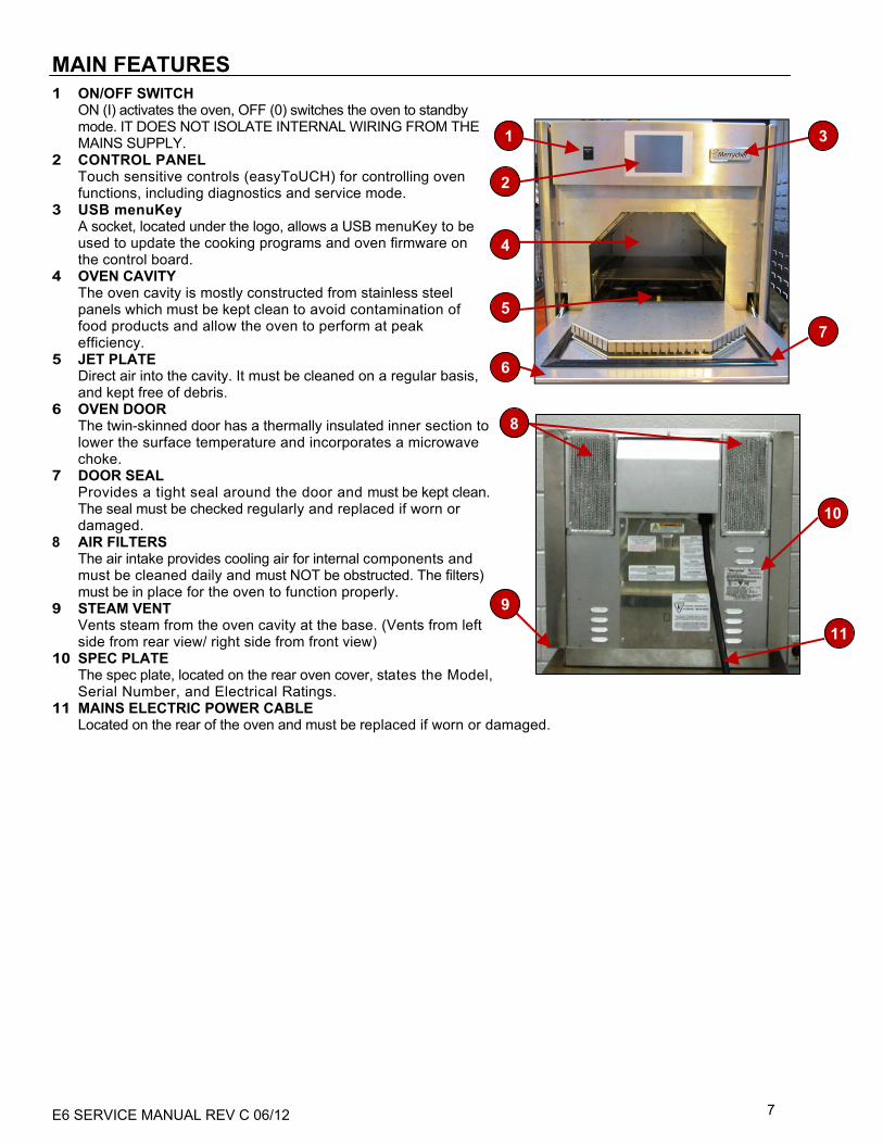
MAIN FEATURES
1 ON/OFF SWITCH ON (I) activates the oven, OFF (0) switches the oven to standby mode. IT DOES NOT ISOLATE INTERNAL WIRING FROM THE MAINS SUPPLY.
2 CONTROL PANEL Touch sensitive controls (easyToUCH) for controlling oven functions, including diagnostics and service mode.
3 USB menuKey A socket, located under the logo, allows a USB menuKey to be used to update the cooking programs and oven firmware on the control board.
4 OVEN CAVITY The oven cavity is mostly constructed from stainless steel panels which must be kept clean to avoid contamination of food products and allow the oven to perform at peak efficiency.
5 JET PLATE Direct air into the cavity. It must be cleaned on a regular basis, and kept free of debris.
6 OVEN DOOR The twin-skinned door has a thermally insulated inner section to lower the surface temperature and incorporates a microwave choke.
7 DOOR SEAL Provides a tight seal around the door and must be kept clean. The seal must be checked regularly and replaced if worn or damaged.
8 AIR FILTERS The air intake provides cooling air for internal components and must be cleaned daily and must NOT be obstructed. The filters) must be in place for the oven to function properly.
9 STEAM VENT Vents steam from the oven cavity at the base. (Vents from left side from rear view/ right side from front view)
10 SPEC PLATE The spec plate, located on the rear oven cover, states the Model, Serial Number, and Electrical Ratings.
11 MAINS ELECTRIC POWER CABLE Located on the rear of the oven and must be replaced if worn or damaged.
2
3
4
5
6
7
1
11
8
9
10
E6 SERVICE MANUAL REV C 06/12 8
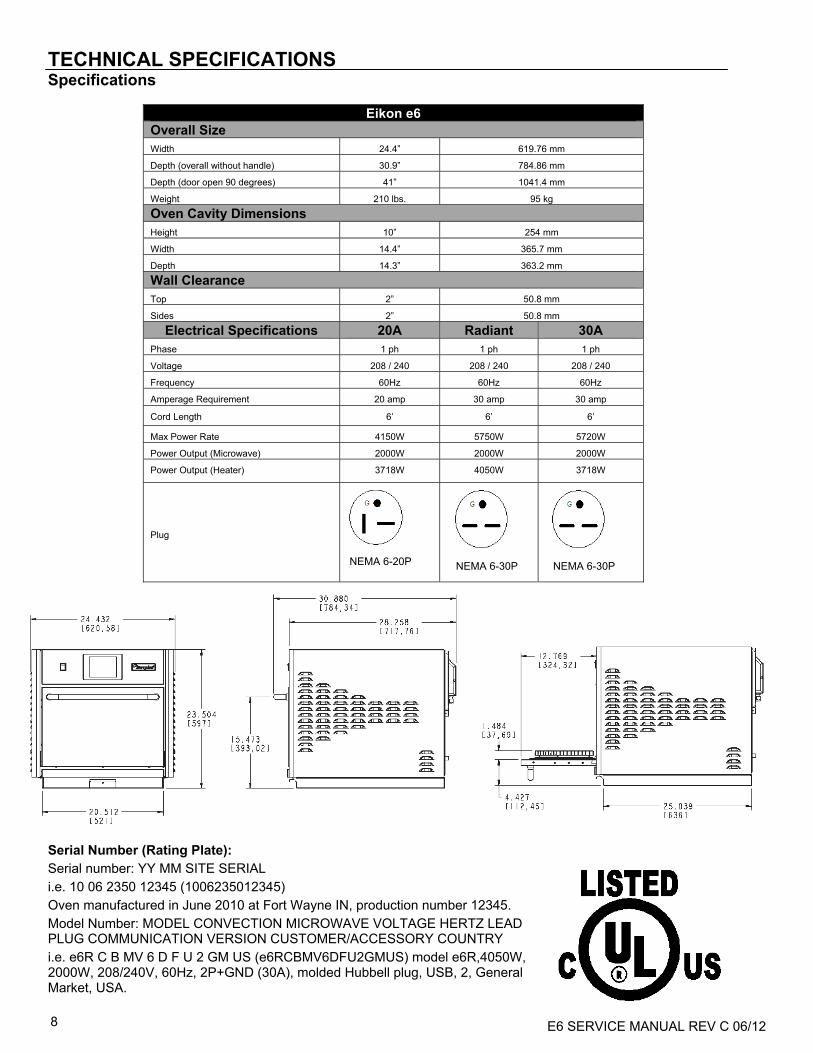
TECHNICAL SPECIFICATIONS Specifications
Serial Number (Rating Plate):
Serial number: YY MM SITE SERIAL
i.e. 10 06 2350 12345 (1006235012345)
Oven manufactured in June 2010 at Fort Wayne IN, production number 12345.
Model Number: MODEL CONVECTION MICROWAVE VOLTAGE HERTZ LEAD PLUG COMMUNICATION VERSION CUSTOMER/ACCESSORY COUNTRY
i.e. e6R C B MV 6 D F U 2 GM US (e6RCBMV6DFU2GMUS) model e6R,4050W, 2000W, 208/240V, 60Hz, 2P+GND (30A), molded Hubbell plug, USB, 2, General Market, USA.
Eikon e6 Overall Size Width 24.4” 619.76 mm
Depth (overall without handle) 30.9” 784.86 mm
Depth (door open 90 degrees) 41” 1041.4 mm
Weight 210 lbs. 95 kg
Oven Cavity Dimensions Height 10” 254 mm
Width 14.4” 365.7 mm
Depth 14.3” 363.2 mm
Wall Clearance Top 2” 50.8 mm
Sides 2” 50.8 mm
Electrical Specifications 20A Radiant 30A Phase 1 ph 1 ph 1 ph
Voltage 208 / 240 208 / 240 208 / 240
Frequency 60Hz 60Hz 60Hz
Amperage Requirement 20 amp 30 amp 30 amp
Cord Length 6’ 6’ 6’
Max Power Rate 4150W 5750W 5720W
Power Output (Microwave) 2000W 2000W 2000W
Power Output (Heater) 3718W 4050W 3718W
Plug
NEMA 6-20P NEMA 6-30P NEMA 6-30P

E6 SERVICE MANUAL REV C 06/12 9
OVEN PLACEMENT/INSTALLATION
INSPECT OVEN • Inspect oven for damage such as dents in door or inside oven cavity. • Report any dents or breakage to source of purchase immediately. Do not attempt to use oven if damaged. • Remove all packing materials from oven interior.
(Note: Check all packing material as accessories may be stored in oven interior.) • If oven has been stored in extremely cold area, wait a few hours before connecting power. OVEN PLACEMENT • Do not install oven next to or above source of heat, such as pizza oven or deep fat fryer. This could cause microwave
oven to operate improperly and could shorten life of electrical parts • Install oven on level countertop surface • If provided, place warning label in a conspicuous place close to microwave oven • Outlet should be located so that plug is accessible when oven is in place • Provide clearance as shown in Figure 5 and described in the following paragraphs:
a) The unit must have 2” (51 mm) of air gap on either side as well as at the rear. b) Air intake temperature should not exceed 110°F/45°C. Excessive temperature will lead to reduced operating duty
cycle, or premature aging of internal components. Failure to comply with these conditions will invalidate the warranty.
c) A built-in catalytic converter eliminates the need for a ventilation hood so the oven can operate in virtually any environment.
HANDLING & STORAGE:
• When moving an oven always observe and follow National and local requirements for lifting and moving heavy objects. Do not use the oven door handle to lift oven.
• When not in use, electrically disconnect the oven and store safely in dry cool place, do not stack ovens.
NOTE: Upon receipt of this unit, immediately unpack and inspect for possible concealed shipping damage. If unit is found to be damaged, save all packing materials and contact your delivery carrier immediately. Failure to follow these instructions will negate Merrychef USA’s or your ability to file claims and receive compensation for shipping damage. IF THERE IS APPARENT DAMAGE: United States and Canada: Arrangements should be made to file a claim against the carrier. As Interstate Commerce Regulations require that the claim must be initiated by the consignee. All shipments to other countries: Freight terms will be developed and extended on an individual basis. Proper and secure storage facilities should be arranged for the oven(s), if necessary, to protect from outdoor or damp conditions at all times before installation.
Figure 5 Oven Clearance Dimensions

E6 SERVICE MANUAL REV C 06/12 10
DANGER! THIS APPLIANCE MUST BE EARTHED. FAILURE TO DO SO MAY RESULT IN ELECTRIC SHOCK AND DEATH.
ELECTRICAL INSTALLATION FOR ALL CORD CONNECTED APPLIANCES: GROUNDING INSTRUCTIONS This appliance must be grounded. In the event of an electrical short circuit, grounding reduces the risk of electric shock by providing an escape wire for the electric current. This appliance is equipped with a cord having a grounding wire with a grounding plug. The plug must be plugged into an outlet that is properly installed and grounded. WARNING - Improper use of the grounding can result in the risk of electric shock. Consult a qualified electrician or Serviceman if the grounding instructions are not completely understood or if doubt exists as to whether the appliance is properly grounded. Do not use an extension cord. If the power supply cord is too short, have a qualified electrician or serviceman installs an outlet near the appliance. IN CASE OF RADIO OR TELEVISION INTERFERENCE This equipment generates and uses radio frequency energy and if not installed and operated correctly, in strict accordance with the manufacturer’s instructions, may cause harmful interference to authorized radio communication services. This product complies with the relevant requirements of CFR 47 Ch.1 Part 18, which are designed to provide reasonable protection against such interference. However, there is no guarantee that interference will not occur in a particular installation. If this equipment does cause interference to radio or television reception, which can be determined by turning the equipment off and on, the user is encouraged to try and correct the interference by one or more of the following measures:
1) Re-orientate the receiving antenna. 2) Relocate the microwave with respect to the receiver. 3) Plug the microwave into a different outlet so that the receiver and microwave are on different branch circuits.
If necessary the user should consult the dealer or an experienced radio/television technician for additional suggestions. Note: Modifications should only be carried out by the manufacturer or authorized representative to ensure continuing conformance. This device complies with Part 18 of the FCC rules

E6 SERVICE MANUAL REV C 06/12 11
QUICK START GUIDE: QUICK SERVICE OVEN
The easyToUCH screen display, layout and icons shown herein, are for guidance purposes only and are not intended to be an exact representation of those supplied with the oven. START UP
21
3
4
STOP/CANCEL
5COOKBOOK DISPLAY
DISPLAYS ALL COOKING PROGRAMS (Optional)
SHOWS PROGRAM GROUPS
FAVORITES (Option al)
PROGRAM GROUP
Each group contains a collection of cooking programs.
CHANGE OVEN TEMPERATURE (Optional)
1. Switch the oven on; Make all the relevant safety checks and ensure the oven is clean and empty before pressing the oven switch down to activate the oven.
2. The easyToUCH screen illuminates with the display briefly showing the serial number and oven data. Lightly tap the screen once to freeze the display, tap again to continue.
3. When the oven is setup with two or more preheating temperatures a choice is displayed.
Scroll arrows at the bottom of the screen indicates there are more temperature choices not shown on screen, if necessary, use the scroll arrows, then select the temperature required to start preheating the oven.
4. During preheating the display shows the progress as the oven heats up to the set temperature. (To stop the oven heating, touch the red ‘X’ symbol.)
5. The oven is ready to use when the ‘COOKBOOK’ is displayed.

E6 SERVICE MANUAL REV C 06/12 12
USING A COOKING PROGRAM
AIR FILTER
1 2 3
4 5PROGRAM STAGE
WARNING: Taking all the necessary precautions to ensure you do not burn yourself, open the oven door to place the food into the hot oven and close the door.
IMPORTANT: Clean the Air Filters (6) at the back of the oven and ensure air filter is in place and properly fitted before operating the oven. See ‘Cleaning & Maintenance’ section in this manual.
6
1. Select a program group, for example, ‘BURGERS’ to display the individual cooking programs.
2. Select a cook program to start, for example, 2 BURGERS.
3. Follow instructions if displayed on the screen and touch the green ‘check mark’ to cook.
4. The cooking time counts down for each program stage.
5. When the program ends a red bar is displayed usually with an audible sound - open the door or touch the red ‘X’ to return to the cook program.
Note: Opening the oven door during cooking stops the cooking program and displays a warning. Closing the door allows the user to continue or cancel the cooking program.
E6 SERVICE MANUAL REV C 06/12 13
OPERATING GUIDE: FULL SERVICE OVEN
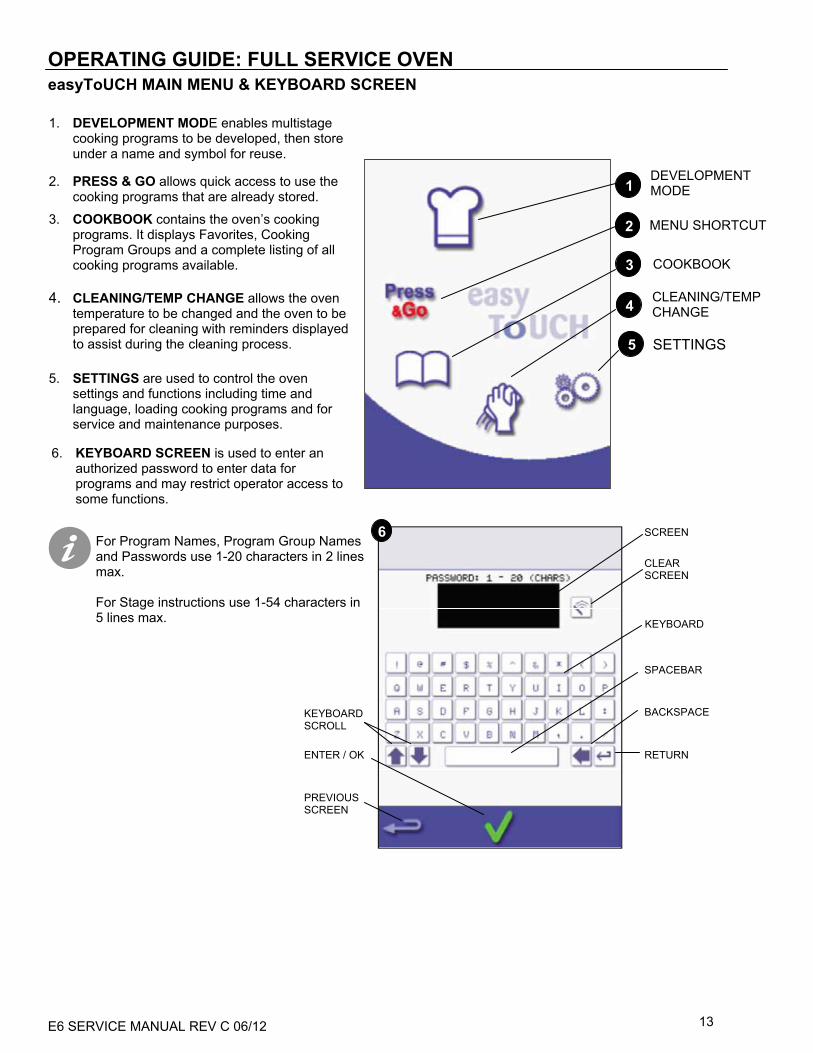
easyToUCH MAIN MENU & KEYBOARD SCREEN
For Program Names, Program Group Names and Passwords use 1-20 characters in 2 lines max. For Stage instructions use 1-54 characters in 5 lines max.
1. DEVELOPMENT MODE enables multistage cooking programs to be developed, then store under a name and symbol for reuse.
2. PRESS & GO allows quick access to use the cooking programs that are already stored.
3. COOKBOOK contains the oven’s cooking programs. It displays Favorites, Cooking Program Groups and a complete listing of all cooking programs available.
4. CLEANING/TEMP CHANGE allows the oven temperature to be changed and the oven to be prepared for cleaning with reminders displayed to assist during the cleaning process.
5. SETTINGS are used to control the oven settings and functions including time and language, loading cooking programs and for service and maintenance purposes.
6. KEYBOARD SCREEN is used to enter an authorized password to enter data for programs and may restrict operator access to some functions.
COOKBOOK
DEVELOPMENT MODE 1
MENU SHORTCUT 2
3
5 SETTINGS
4 CLEANING/TEMP CHANGE
6
KEYBOARD SCROLL
ENTER / OK
PREVIOUS SCREEN
CLEAR SCREEN
KEYBOARD
SCREEN
SPACEBAR
BACKSPACE
RETURN

E6 SERVICE MANUAL REV C 06/12 14
Example below; setting the cooking time (step 3): To set the cooking time select the Time symbol.
Enter the cooking time on the pad.
Select OK to accept the time.
DEVELOPMENT MODE: CREATING A COOK PROGRAM 1. Select the ‘chef’s hat’ symbol from the main menu to
enter development mode. Enter stage 1 of the program
2. The temperature displays the set preheated oven
temperature.
To increase or decrease the temperature required, select the temperature symbol (2), enter the temperature in the keypad within the limits displayed and select OK.
3. Select and set the cooking time up to a maximum of 10 minutes.
For example: Enter 110 (1minute and 10 seconds).
4. Select and set the Microwave Power [0, 5-100%]
5. Select and set a Fan speed (if available) within the limits shown.
6. Select the information icon to enter an instruction
(Optional). The instruction appears in the display at the beginning of that stage. For example: ‘Stage 1 place product in the oven’.
Enter stage 2 of the program (Optional). 7. Programs can have up to a maximum of 6 stages.
Repeat the steps 2-6 from stage 1 above.
Running and saving the program 1. Select OK to confirm the Program. 2. Run the program (optional).If the results are not
satisfactory, select the backspace, change the cooking settings and retest.
3. Select the save Cookbook symbol to record the program to the cookbook.
4. Select an image to represent the program. (Use the scroll arrows for more pictures.)
5. Enter the name for the cooking program, using a maximum of 20 characters, for example, ‘1 BURGER’, then select OK to save the program to the Cookbook.
6. A symbol with a green tick on a book is displayed to indicate that the program has been successfully saved to the Cookbook.
CLEAR
2
3
4
5
6
1
2 31
654
STAGE 1 DISPLAYED
STAGE 2 DISPLAYED
ADD STAGE
DELETE STAGE BACK TO STAGE 1
7
WARNING: ENSURE PRODUCT IS IN THE OVEN AND ALL SAFETY PRECAUTIONS ARE FOLLOWED BEFORE RUNNING THE PROGRAM

E6 SERVICE MANUAL REV C 06/12 15
PRESS & GO Running a cooking program from the Press & Go menu: 1. Select ‘PRESS & GO’ from the main menu
screen. 2. Select the item required to cook. 3. The display shows the temperature, cooking
time, fan speed and microwave power while the timer counts down. The timer bar turns red to indicate the cooking cycle has finished.
Choosing which cooking programs are shown in the ‘PRESS & GO’ menu screen. 1. After selecting ‘PRESS & GO’ from the main
menu screen, select the EDIT symbol. 2. Two lists are displayed, the ‘PRESS & GO’
menu items are shown in the upper list and the lower list shows other menu items which are available. Both lists can be scrolled up or down using the arrows on the extreme right.
3. Select an item, then choose whether to change its order within the menu or to remove it into the lower list.
4. Select an item to move into the upper list, making it available in the ‘PRESS & GO’ menu.
5. Select backspace to return to the menu screen when finished.
USING A COOKBOOK PROGRAM To find the required Program in the cookbook:
1. Select ‘COOKBOOK’ from the main menu screen. 2. Select the ALL MENUS symbol. 3. Use scroll up/down arrows to find the program. NOTE: if an image has a red line around it the oven temperature is set too high or too low for that recipe. See ‘CHANGING THE OVEN TEMPERATURE’. Taking all the necessary precautions to ensure you do not burn yourself, place the food product into the hot oven cavity and close the door.
5
Change the order of a selected item shown in the Press & Go screen.
Move a selected item to or from the Press & Go screen.
Select to scroll a list up or down.
1
4
21 3
3
2
ENSURE THERE IS FOOD PRODUCT IN THE OVEN BEFORE STARTING A COOKING PROGRAM.
WARNING:
1 2 3
WARNING: HOT SURFACE HAZARD

E6 SERVICE MANUAL REV C 06/12 16
USING A COOKBOOK PROGRAM (CONT’D)
4. Select the required cooking program to start cooking.
For example, ‘1 BURGER’.
5. The program either starts immediately displaying a countdown timer, or an instruction is displayed first; follow the stage instruction then select OK to start cooking. If the oven door is not opened within 30 seconds a warning message appears.
6. The cooking timer counts down to zero and makes a sound to indicate an operator action is required at the end of a cooking stage or the end of a cooking program.
Once the cooking program has finished, opening the oven door to remove the food returns the display to the ‘COOKBOOK’ screen.
Note; opening the oven door during cooking stops the cooking program and displays a warning. Closing the door allows the user to continue or cancel the cooking program.
To check the oven temperature when cooking, lightly tap the temperature displayed, the oven cavity temperature is shown with an asterisk.
CHANGING THE OVEN TEMPERATURE Take note of the temperature required for the recipe and select OK.
1. Select the temperature symbol.
2. An asterisk next to the number indicates the present oven temperature; select the required oven temperature for the recipe. Once the oven is at the required temperature continue from selecting the ‘COOKBOOK’ in step 1.
VIEWING & EDITING PROGRAMS 1. Select ‘COOKBOOK’ from the main menu screen. 2. Select the ALL MENUS symbol. 3. Select ‘EDIT COOKBOOK’. 4. Use the up/down scroll arrows on the right side
of the screen to find the cooking program, for example 1 BURGER and select the view/edit cooking program symbol.
5. View or adjust the program as required, see Development mode for details.
4 5 6
21 3
31 2
54

E6 SERVICE MANUAL REV C 06/12 17
ADDING A NEW PROGRAM GROUP To add a new Program Group: 1. Select ‘COOKBOOK’ from the main menu
screen.
2. Select ‘EDIT COOKBOOK’.
3. Select the ‘ADD A NEW GROUP’ symbol.
4. Enter a name for the new Program Group (max. 20 characters).
5. Select an image to represent the Group. (Use the scroll arrows for more pictures.)
6. Select OK to save the Program Group to the Cookbook.
Select backspace to return to the ‘COOKBOOK’.
MOVE A PROGRAM WITHIN A PROGRAM GROUP Example moving the position of the ‘4 BURGERS’ cooking program within the program group called ‘BURGERS’. 1. Select ‘COOKBOOK’ from the main menu
screen.
2. Select the ‘BURGERS’ program group.
3. Select ‘EDIT COOKBOOK’. 4. Use the up/down scroll arrows on the right
side of the upper part of the edit screen to view the cooking programs in the group.
Then select the cooking program to be moved (‘4 BURGERS’) and use the up/down arrows on the left side of the upper screen to move the selected program within the program group.
Select backspace to return to the ‘COOKBOOK’ screen.
1 2 3
4Program Group
Move the selected program within the Program Group
Scroll to show programs in the current Program Group
4 5 6
1 32
E6 SERVICE MANUAL REV C 06/12 18
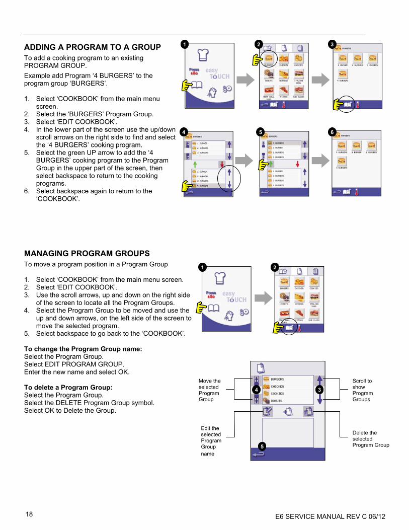
ADDING A PROGRAM TO A GROUP
To add a cooking program to an existing PROGRAM GROUP.
Example add Program ‘4 BURGERS’ to the program group ‘BURGERS’. 1. Select ‘COOKBOOK’ from the main menu
screen. 2. Select the ‘BURGERS’ Program Group. 3. Select ‘EDIT COOKBOOK’. 4. In the lower part of the screen use the up/down
scroll arrows on the right side to find and select the ‘4 BURGERS’ cooking program.
5. Select the green UP arrow to add the ‘4 BURGERS’ cooking program to the Program Group in the upper part of the screen, then select backspace to return to the cooking programs.
6. Select backspace again to return to the ‘COOKBOOK’.
MANAGING PROGRAM GROUPS
To move a program position in a Program Group 1. Select ‘COOKBOOK’ from the main menu screen. 2. Select ‘EDIT COOKBOOK’. 3. Use the scroll arrows, up and down on the right side
of the screen to locate all the Program Groups. 4. Select the Program Group to be moved and use the
up and down arrows, on the left side of the screen to move the selected program.
5. Select backspace to go back to the ‘COOKBOOK’.
To change the Program Group name: Select the Program Group. Select EDIT PROGRAM GROUP. Enter the new name and select OK.
To delete a Program Group: Select the Program Group. Select the DELETE Program Group symbol. Select OK to Delete the Group.
Move the selected Program Group
Edit the selected Program Group name
Scroll to show Program Groups
Delete the selected Program Group
3 4
5
654
321
1 2
E6 SERVICE MANUAL REV C 06/12 19
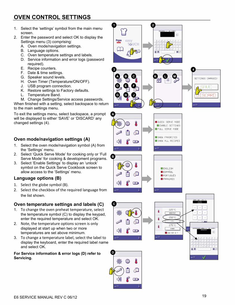
OVEN CONTROL SETTINGS
1. Select the ‘settings’ symbol from the main menu screen.
2. Enter the password and select OK to display the Settings menu (3) comprising: A. Oven mode/navigation settings. B. Language options. C. Oven temperature settings and labels. D. Service information and error logs (password
required). E. Recipe counters. F. Date & time settings. G. Speaker sound levels. H. Oven Timer (Temperature/ON/OFF). J. USB program connection. K. Restore settings to Factory defaults. L. Temperature Band. M. Change Settings/Service access passwords.
When finished with a setting, select backspace to return to the main settings menu.
To exit the settings menu, select backspace, a prompt will be displayed to either ‘SAVE’ or ‘DISCARD’ any changed settings (4). Oven mode/navigation settings (A)
1. Select the oven mode/navigation symbol (A) from the ‘Settings’ menu.
2. Select ‘Quick Serve Mode’ for cooking only or ‘Full Serve Mode’ for cooking & development programs.
3. Select ‘Enable Settings’ to display an ‘unlock’ symbol on the Quick Serve Cookbook screen to allow access to the ‘Settings’ menu.
Language options (B)
1. Select the globe symbol (B). 2. Select the checkbox of the required language from
the list shown.
Oven temperature settings and labels (C) 1. To change the oven preheat temperature, select
the temperature symbol (C) to display the keypad, enter the required temperature and select OK.
2. Note, the temperature options screen is only displayed at start up when two or more temperatures are set above minimum.
3. To change a temperature label, select the label to display the keyboard, enter the required label name and select OK.
For Service information & error logs (D) refer to Servicing.
1 2
A
B
C
D
3 4
A B C
D E F
G H J
K L M
E6 SERVICE MANUAL REV C 06/12 20
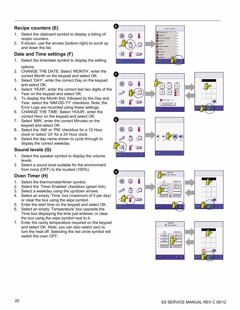
Recipe counters (E)
1. Select the clipboard symbol to display a listing of recipe counters.
2. If shown, use the arrows (bottom right) to scroll up and down the list.
Date and Time settings (F)
1. Select the time/date symbol to display the setting options.
2. CHANGE THE DATE: Select ‘MONTH’, enter the correct Month on the keypad and select OK.
3. Select ‘DAY’, enter the correct Day on the keypad and select OK.
4. Select ‘YEAR’, enter the correct last two digits of the Year on the keypad and select OK.
5. To display the Month first, followed by the Day and Year, select the ‘MM-DD-YY’ checkbox. Note; the Error Logs are recorded using these settings.
6. CHANGE THE TIME: Select ‘HOUR’, enter the correct Hour on the keypad and select OK.
7. Select ‘MIN’, enter the correct Minutes on the keypad and select OK.
8. Select the ‘AM’ or ‘PM’ checkbox for a 12 Hour clock or select ‘24’ for a 24 Hour clock.
9. Select the day name shown to cycle through to display the correct weekday.
Sound levels (G)
1. Select the speaker symbol to display the volume levels.
2. Select a sound level suitable for the environment from none (OFF) to the loudest (100%).
Oven Timer (H)
1. Select the thermometer/timer symbol. 2. Select the ‘Timer Enabled’ checkbox (green tick). 3. Select a weekday using the up/down arrows. 4. Select an empty ‘Time’ box (maximum of 5 per day)
or clear the box using the wipe symbol. 5. Enter the start time on the keypad and select OK. 6. Select an empty ‘Temperature’ box opposite the
Time box displaying the time just entered, or clear the box using the wipe symbol next to it.
7. Enter the cavity temperature required on the keypad and select OK. Note; you can also select zero to turn the heat off. Selecting the red circle symbol will switch the oven OFF.
E
F
G
H

E6 SERVICE MANUAL REV C 06/12 21
USB oven programs (J)
IMPORTANT: Downloading from a USB will clear all the existing programs.
Check that the key has the correct number/code for the programs you want to load into the oven memory.
1. Select USB from the settings screen.
2. Slide the USB cover (logo on the oven front) upwards to insert the USB into the slot.
3. When the inserted USB stick has finished flashing select the required USB symbol, for example; RECIPES.
4. Select the new file using the scroll arrows if required to locate the file. Note; a tinted band over a file name indicates the file is not available to use.
5. Double check the file is correct before selecting OK, if not, select ‘X’ and locate the correct file.
6. Progress of the file update is displayed. Once completed the oven restarts and commences heating up to the PREHEAT temperature ready to cook.
7. Remove the USB and keep in a safe place. Reposition the USB cover.
Restore Factory Defaults (K)
1. Select the factory symbol to replace the existing oven settings with the original factory default settings. Note; this action cannot be undone.
2. Select OK, or select the red cross to cancel and keep the existing settings.
Temperature Band (L)
1. Select the ‘Temp Band’ symbol at which the oven controls i.e. ±10°C.
2. Select the required temperature band checkbox, shown by a green tick. Note; although the lowest practical Temp Band should be used, if the set oven temperature falls by more than the selected Temp Band, the ready to cook mode and Temp Band are deactivated until the oven reaches the preheat temperature.
Change Password (M)
1. Select the key symbol to change the oven passwords.
2. Select the oven Settings or Service symbol. 3. Enter the existing password and select OK to
confirm. 4. Enter the new password, select OK. 5. Confirm new password, select OK.
K
L
M
J
E6 SERVICE MANUAL REV C 06/12 22
3 4
1 2
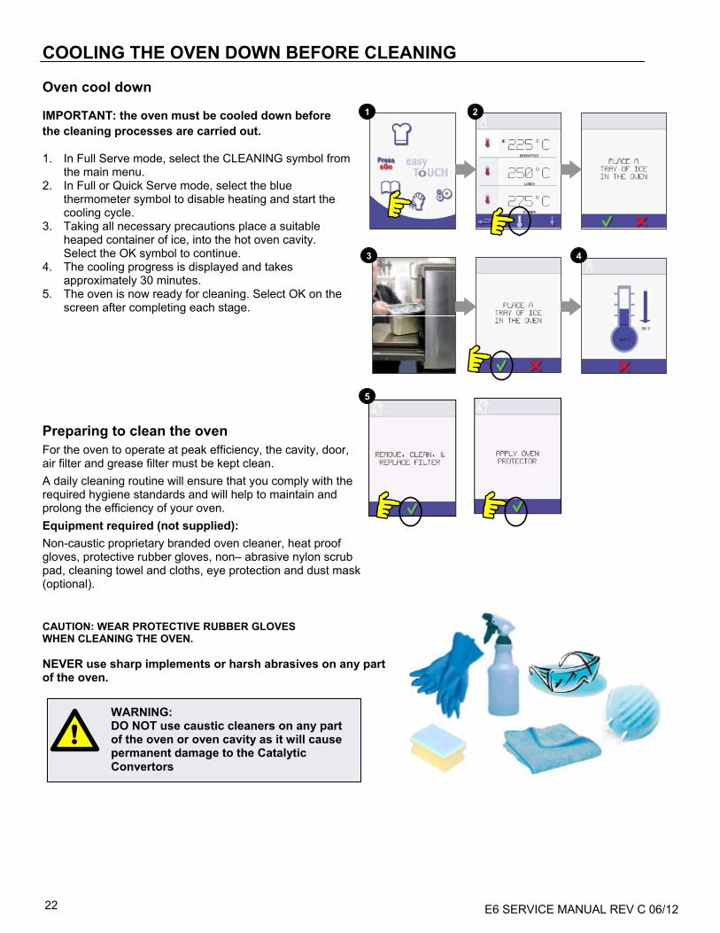
COOLING THE OVEN DOWN BEFORE CLEANING Oven cool down IMPORTANT: the oven must be cooled down before the cleaning processes are carried out.
1. In Full Serve mode, select the CLEANING symbol from the main menu.
2. In Full or Quick Serve mode, select the blue thermometer symbol to disable heating and start the cooling cycle.
3. Taking all necessary precautions place a suitable heaped container of ice, into the hot oven cavity. Select the OK symbol to continue.
4. The cooling progress is displayed and takes approximately 30 minutes.
5. The oven is now ready for cleaning. Select OK on the screen after completing each stage.
Preparing to clean the oven
For the oven to operate at peak efficiency, the cavity, door, air filter and grease filter must be kept clean.
A daily cleaning routine will ensure that you comply with the required hygiene standards and will help to maintain and prolong the efficiency of your oven.
Equipment required (not supplied):
Non-caustic proprietary branded oven cleaner, heat proof gloves, protective rubber gloves, non– abrasive nylon scrub pad, cleaning towel and cloths, eye protection and dust mask (optional). CAUTION: WEAR PROTECTIVE RUBBER GLOVES WHEN CLEANING THE OVEN. NEVER use sharp implements or harsh abrasives on any part of the oven.
WARNING: DO NOT use caustic cleaners on any part of the oven or oven cavity as it will cause permanent damage to the Catalytic Convertors
5

E6 SERVICE MANUAL REV C 06/12 23
1
Cold Oven CLEANING INSTRUCTIONS e6
Complete COOL DOWN procedure and allow oven and accessories to cool before commencing cleaning. REMOVE & CLEAN Oven Parts:
1. Remove the air filters from the back of the oven. 2. Open the oven door, remove the cook plate, bottom jet plate, and grease filters. Wash all parts in warm soapy water. Wash off using a clean cloth and plenty of clean, warm water. Dry by using a fresh, clean cloth. CLEAN THE OVEN 1. Remove any spillages with disposable paper wipes.
Use a dry clean brush to remove any food particles from between the oven floor and the inside of the front door.
2. Wear protective rubber gloves and protective glasses, carefully spray a non-caustic proprietary branded Oven Cleaner onto all the internal surfaces of the oven except the door seal (A).
3. For difficult areas, leave to soak for 10 minutes with the oven door open.
Use a non–abrasive nylon scrub pad/sponge to clean the cavity, roof and the inside of the door. Do not scrub the door seal or use metallic scourers.
4. Wash off using a clean cloth and plenty of clean warm water and dry using a fresh clean cloth or paper towel.
Replace all the cleaned oven parts.
Close the oven door and wipe the outside of the oven with a damp cloth.
APPLY OVEN PROTECTOR:
1. Only apply to a clean oven. Spray proprietary branded Oven Protector onto a sponge.
2. Spread Oven Protector lightly onto all internal surfaces of the oven.
3. Spread Oven Protector lightly onto the internal surface of the oven door avoiding the door seal.
Switch on the oven and preheat. When the oven has reached operating temperature it will take about 30mins to cure the Oven Protector.
Note: Oven protector turns light brown when cured.
22
3
WARNING: DO NOT USE OVEN WITHOUT A CLEAN AIR FILTER IN PLACE
WARNING: DO NOT USE TOOLS
Cook Plate Jet Plate (Under cook plate
& IR Element)
Grease Filters
Air Filters

E6 SERVICE MANUAL REV C 06/12 24
WARNING: ALLOW OVEN TO COOL AND OBSERVE AND FOLLOW ALL SAFETY PRECAUTIONS INCLUDING THOSE DESCRIBED UNDER THE SAFETY REGULATIONS SECTION OF THIS MANUAL BEFORE ATTEMPTING A SERVICE OR REPAIR .
SERVICING THE OVEN Servicing Procedure: 1. Disconnect/isolate the oven from the power
supply. 2. Check the oven is correctly installed as described
in the Installation Instructions (Product Details
section). 3. Visually check the cleanliness/condition of the
power supply/cable/gland, oven casing, cavity and door for signs of wear, damage, distortion etc., if required, refer to the ‘Spares & Replacement’ section.
4. Complete an ‘Earth/Insulation test’ (Testing Components section) on the oven before switching on.
5. Check the display for Error messages, if an Error is shown, refer to ‘Errors & Diagnostics’ (Servicing section).
6. Note: If a Firmware update is required, follow the instructions under ‘Firmware Updates’ (Servicing section) before continuing with the service procedure.
Enter Service mode: 1 On start up, tap the top right of the main menu
screen to bypass oven preheat. 2 Enter the authorized user password, for example,
MANAGER and select OK to display the Settings menu.
3 Select the spanner symbol. 4 Enter the service password, for example SERVICE
on the keyboard and select OK to display the error log, service information and test options. 1. Check the Error Log for details of any logged
oven errors. See ‘Errors & Diagnostics’ (Servicing section) for more details.
2. Check the ‘Oven Counters’ to find the usage of components and the Controls area temperature within the cabinet. (‘Errors & Diagnostics’, Servicing section).
3. Check the operational performance of the main components using the Visual or Data View (‘Errors & Diagnostics’, Servicing section).
4. Perform the Oven tests, (Testing Components section). If required refer to the ‘Spares and Replacement’ section for any repairs needed before continuing with the Oven Tests.
5. Follow the procedures under the ‘Commissioning’ section before commissioning the oven for use.
4
DANGER: BEFORE REMOVING THE OVEN CASING, ISOLATE THE OVEN FROM THE MAINS ELECTRICITY POWER SUPPLY; SWITCH OFF, DISCONNECT OVEN PLUG FROM WALL SOCKET, TURN OFF ISOLATOR SWITCH TO DISCONNECT FIXED WIRED OVENS AND LOCK-OFF.
CAUTION MICROWAVE EMISSIONS: DO NOT BECOME EXPOSED TO EMISSIONS FROM THE MICROWAVE GENERATOR OR PARTS CONDUCTING MICROWAVE ENERGY.
1 2 3
E6 SERVICE MANUAL REV C 06/12 25
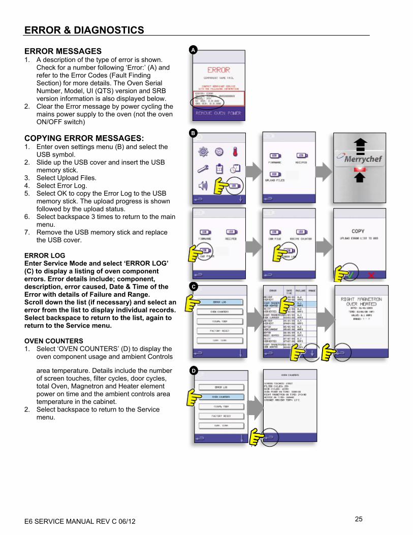
ERROR & DIAGNOSTICS
ERROR MESSAGES 1. A description of the type of error is shown.
Check for a number following ‘Error:’ (A) and refer to the Error Codes (Fault Finding Section) for more details. The Oven Serial Number, Model, UI (QTS) version and SRB version information is also displayed below.
2. Clear the Error message by power cycling the mains power supply to the oven (not the oven ON/OFF switch)
COPYING ERROR MESSAGES: 1. Enter oven settings menu (B) and select the
USB symbol. 2. Slide up the USB cover and insert the USB
memory stick. 3. Select Upload Files. 4. Select Error Log. 5. Select OK to copy the Error Log to the USB
memory stick. The upload progress is shown followed by the upload status.
6. Select backspace 3 times to return to the main menu.
7. Remove the USB memory stick and replace the USB cover.
ERROR LOG Enter Service Mode and select ‘ERROR LOG’ (C) to display a listing of oven component errors. Error details include; component, description, error caused, Date & Time of the Error with details of Failure and Range. Scroll down the list (if necessary) and select an error from the list to display individual records. Select backspace to return to the list, again to return to the Service menu. OVEN COUNTERS 1. Select ‘OVEN COUNTERS’ (D) to display the
oven component usage and ambient Controls
area temperature. Details include the number of screen touches, filter cycles, door cycles, total Oven, Magnetron and Heater element power on time and the ambient controls area temperature in the cabinet.
2. Select backspace to return to the Service menu.
B
A
C
D

E6 SERVICE MANUAL REV C 06/12 26
VISUAL VIEW Select VISUAL VIEW (E) to check the main oven components. Select a component symbol to switch on (red), select again to increase the level or turn off (green). (Screen shots are for illustration purposes only and may not represent true image found on the oven) 1. Open the oven door and check the color
changes from green to red on the display to check the door microswitch/interlock circuit is operating. Place door spacers onto the oven door (refer to Door Interlock Adjustment (Testing Components Section) for details), close the door and check the color on the display. Green indicates the door adjustment is ok, red indicates that the Door Interlock Adjustment procedure must be completed.
2. Select the cooling fan and check it’s operating correctly.
3. Place a microwave safe container of water into the oven, close the oven door and select a magnetron to test the current draw at maximum output, this will time-out after 30 seconds. For dual magnetron models, test the magnetrons individually and together. Using heat proof gloves remove the container and close the oven door.
4. Select the Convection Fan and check it is operating correctly.
5. Select the Heating Element; it increases to maximum temperature then cycles (the Convection Fan is on by default). Check the cavity temperature and heater element current draw at maximum are correct.
E

E6 SERVICE MANUAL REV C 06/12 27
FIRMWARE UPDATES
Note: if icons are not displayed on the screen, press in the same positions on screen as the missing icons to select. 1. Tap the top right of the screen (1) or the same
position if it is not displayed to bypass oven preheat.
2. Enter a password (i.e. “Manager”) and select OK (2) or the same position if the green tick symbol is not displayed.
3. Select the USB symbol (3) or the same position if it is not displayed.
4. Select one of the USB options (4) or the same position if it is not displayed: ‘Firmware’ for QTS & SRB updates and ‘Recipe’ for Icons. Install the SRB update first, the QTS update second and Icons third.
5. Select the firmware to install and select OK (5) to confirm or the same position for the OK (green tick symbol), if it is not displayed.
6. The update screen displays the file version and product, select OK (green tick symbol) to confirm installation (6) or the same position if it is not displayed.
1 2
3
4
5
6

E6 SERVICE MANUAL REV C 06/12 28
IMPORTANT: Downloading from a USB will clear all existing programs. Update the ‘SRB’ first, the ‘QTS’ second and the ‘Icons’ third (found under the USB ‘Recipe’ heading). 7. Switch on the oven and tap the top right of
the screen (1) to bypass the preheat stage. 8. Enter the password and select OK to display
the Settings menu, see (2). 9. Select the USB symbol (4). 10. Slide the Merrychef badge (oven front top
right) upwards and insert the USB Memory Stick into the slot (3).
11. Once the USB has stopped flashing, select
the ‘FIRMWARE’ USB symbol (5). 12. The current QTS (Touch Screen) & SRB
(Smart Relay Board) Firmware versions are displayed at the top left of the screen (6).
SRB FIRMWARE UPDATE 13. Select the ‘SRB’ file required (7). 14. Check the file information is correct before
selecting OK (8). 15. Update progress is displayed (9). 16. Select backspace (10) 3x to return to the
USB screen shown (11). 17. If the firmware versions are far apart an SRB
conflict could cause an error message (12) to be displayed.
QTS FIRMWARE UPDATE 18. Select the ‘QTS’ file (13) with the correct file
version number. Note; a tinted band over a file name indicates the file is not valid for that oven.
19. Check the file information shown is correct before selecting OK (14), if not, select ‘X’ and locate the correct file.
20. The file update progress is displayed (15). At 50% the cooling fan stops operating, after 100% various screen displays appear as the software reboots.
21. Check the screen shows the correct QTS version was installed (16), if not, repeat the process using the correct file.
22. Remove the USB and keep in a safe place. Reposition the USB cover.
21 3
54 6
87 9
1110 12
1413 15
16
DO NOT REMOVE USB DURING DOWNLOAD SEQUENCE AS THIS COULD CORRUPT THE USB DATA.

E6 SERVICE MANUAL REV C 06/12 29
B
OVEN TESTING Equipment required:
• Digital Multi-meter (D.M.M.). • Microwave detection / leakage meter.
Earth/Insulation Test: 1. Disconnect/isolate the oven from the power
supply. 2. Connect the leads of a DMM
(Portable Application Tester). 3. Connect the Earth from the P.A.T. to the oven
hinge (A). 4. Place the P.A.T. in an open area, such as the
floor, away from any persons. 5. Perform a Class 1 test, a PASS indicates the
oven earthing circuit is functioning ok. 6. If a FAIL is indicated, remove the oven casing
and check ALL earth connections before retesting.
7. NEVER operate an oven that has failed this test as it could be potentially dangerous.
Screen calibration: 1. Apply continuous light pressure to the top
right of the screen while switching the oven on.
2. Using a non-abrasive pointer, such as a ball point pen, accurately press the center of each crosshair displayed on the screen. Once calibrated, the screen will display the oven information.
DANGER: BEFORE REMOVING THE OVEN CASING, ISOLATE THE OVEN FROM THE MAINS ELECTRICITY POWER SUPPLY; SWITCH OFF, DISCONNECT OVEN PLUG FROM WALL SOCKET, TURN OFF ISOLATOR SWITCH TO DISCONNECT FIXED WIRED OVENS AND LOCK-OFF.
WARNING: ALLOW OVEN TO COOL AND OBSERVE AND FOLLOW ALL SAFETY PRECAUTIONS INCLUDING THOSE DESCRIBED UNDER THE SAFETY REGULATIONS SECTION OF THIS MANUAL BEFORE ATTEMPTING A SERVICE OR REPAIR .
CAUTION MICROWAVE EMISSIONS: DO NOT BECOME EXPOSED TO EMISSIONS FROM THE MICROWAVE GENERATOR OR PARTS CONDUCTING MICROWAVE ENERGY.
DANGER: THIS APPLIANCE MUST BE EARTHED. FAILURE TO DO SO MAY RESULT IN ELECTRIC SHOCK AND DEATH.
B

E6 SERVICE MANUAL REV C 06/12 30
OVEN TESTS 1. Enter Service mode (Servicing section). 2. Select the down arrow to display the individual
Oven tests (A) for the oven to perform.
Microwave Power Test
Measuring the power output Note: The power output is established under IEC 705 standard method which is only workable in laboratory controlled conditions. Power output is also affected by line voltage under load, so this test is an approximation only. 1. Ensure the oven is cold, then enter Service mode to
bypass oven preheating. 2. Select Visual View (B) to check the oven cavity
temperature reading is as close to room temperature as possible.
a) Fill a microwave safe container (glass or plastic) with one liter (33.56 oz) of tap water at about 68°F (20°C).
b) Measure and record the water temperature in the container using a temperature sensor capable of reading ±0.1 degree increments.
c) Place the container centrally inside the oven. d) Select “Microwave Power Test” (C) from the
service mode tests. (Microwave power 100% for 63 seconds, fan minimum).
e) When the countdown has finished, remove the container from the oven, immediately stir with a plastic implement and measure the water temperature.
f) Calculate the temperature rise of the water (end temperature minus the start temperature).
The Temperature Rise should be: 41 to 52°F rise (23 to 29°C rise)
If the temperature rise is outside these limits:
• Check the microwave circuit and components, (Testing Components section).
A
B
C
MICROWAVE POWER TEST
VISUAL VIEW

E6 SERVICE MANUAL REV C 06/12 31
A
Microwave Leakage Test
Note before measuring: • Make sure that the survey meter you are using
has been calibrated and is suitable for measuring frequencies of 2,450 MHz.
• Do not exceed meter full scale deflection, leakage meter should initially be set to the highest scale, then adjusted down as necessary to ensure that low readings are measured on the most sensitive range.
• To prevent false readings, hold the probe on the grip provided and move at 1” (2.5cm) / second.
• Always hold the probe at right angles to the oven and point of measurement, ensuring the probe is reading 2” (50mm) from the test area.
• With any casework removed the leakage should not exceed 5mW/cm².
Procedure: 1. Add 9oz/275ml of cold water into a 20oz/600ml
microwave safe container. 2. Place the 600ml container in the center of
oven and close the door. 3. Enter Service mode and select ‘Microwave leakage
test’ (A) from the oven tests. 4. Set the leakage meter to the appropriate scale/range. 5. Move the survey meter probe across all casework joins and vent areas
including those marked in yellow, shown opposite. 6. When the Magnetron circuit stops after 30 seconds, change the water
and re-select the test to continue. 7. Select the red ‘X’ on the display to stop the test at any time. 8. Readings must be below 5mW/cm². If a level greater than 5mW/cm² is
observed, this should be reported to Merrychef Service Department immediately.
9. Notes should be kept of any leakage that is observed in terms of the level and position on the oven. This information should be kept with the service documentation.
A
MICROWAVE LEAKAGE TEST
Back
Front
Left sideRight side
E6 SERVICE MANUAL REV C 06/12 32
A B
C D
E
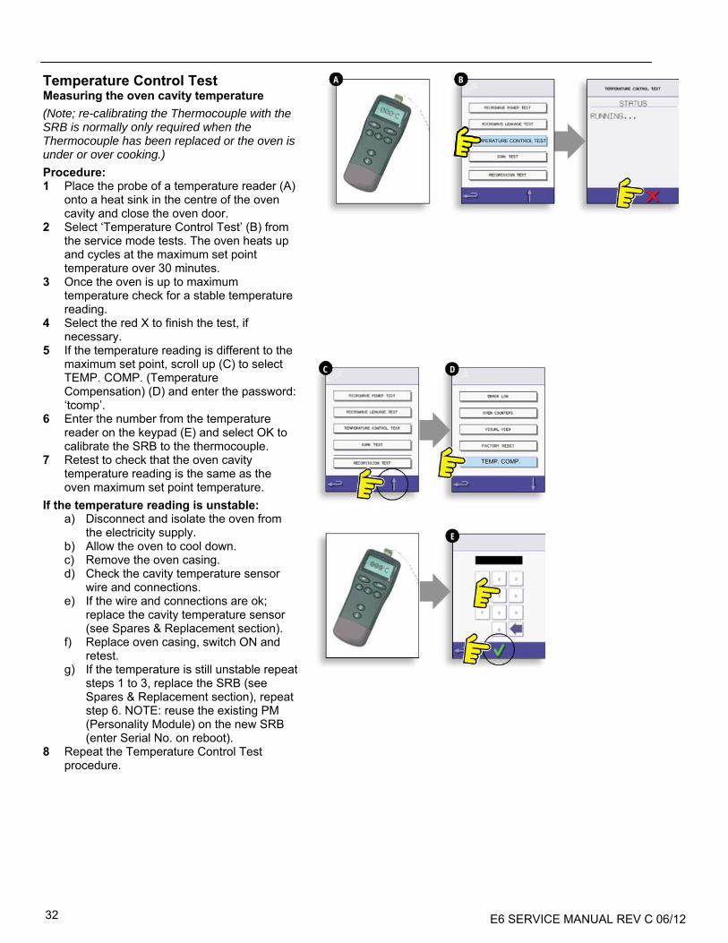
Temperature Control Test Measuring the oven cavity temperature
(Note; re-calibrating the Thermocouple with the SRB is normally only required when the Thermocouple has been replaced or the oven is under or over cooking.)
Procedure: 1 Place the probe of a temperature reader (A)
onto a heat sink in the centre of the oven cavity and close the oven door.
2 Select ‘Temperature Control Test’ (B) from the service mode tests. The oven heats up and cycles at the maximum set point temperature over 30 minutes.
3 Once the oven is up to maximum temperature check for a stable temperature reading.
4 Select the red X to finish the test, if necessary.
5 If the temperature reading is different to the maximum set point, scroll up (C) to select TEMP. COMP. (Temperature Compensation) (D) and enter the password: ‘tcomp’.
6 Enter the number from the temperature reader on the keypad (E) and select OK to calibrate the SRB to the thermocouple.
7 Retest to check that the oven cavity temperature reading is the same as the oven maximum set point temperature.
If the temperature reading is unstable: a) Disconnect and isolate the oven from
the electricity supply. b) Allow the oven to cool down. c) Remove the oven casing. d) Check the cavity temperature sensor
wire and connections. e) If the wire and connections are ok;
replace the cavity temperature sensor (see Spares & Replacement section).
f) Replace oven casing, switch ON and retest.
g) If the temperature is still unstable repeat steps 1 to 3, replace the SRB (see Spares & Replacement section), repeat step 6. NOTE: reuse the existing PM (Personality Module) on the new SRB (enter Serial No. on reboot).
8 Repeat the Temperature Control Test procedure.
TEMP. COMP.
TEMPERATURE CONTROL TEST

E6 SERVICE MANUAL REV C 06/12 33
Recommission Test
The Recommission tests are performed following the completion of a service or repair to ensure the oven is operational before handing back to the customer.
Some of the tests have a countdown timer where failing to carry out a test within the time limit will cause a test failure and the Recommission test will have to be restarted. Procedure: 1 Select ‘Recommission Test’ (A) from the service
mode oven tests and follow the on screen instructions to perform the tests. Do not select the red ‘X unless you want to stop the test.
2 After a test has successfully passed, select OK to continue.
3 When all the tests have been successfully performed the display shows the Recommission test has passed, select OK to confirm.
4 In the event of a Recommission test failure, the detail will be recorded in the Error log. Any error should be rectified and the Recommission test run again.
A
RECOMMISSION TEST

E6 SERVICE MANUAL REV C 06/12 34
2
3
DANGER: BEFORE REMOVING THE OVEN CASING, ISOLATE THE OVEN FROM THE MAINS ELECTRICITY POWER SUPPLY; SWITCH OFF, DISCONNECT OVEN PLUG FROM WALL SOCKET, TURN OFF ISOLATOR SWITCH TO DISCONNECT FIXED WIRED OVENS AND LOCK-OFF.
WARNING: ALWAYS DISCHARGE THE HT CAPACITORS BEFORE WORKING ON THE OVEN USING A SUITABLY INSULATED 10MΩ RESISTOR.
WARNING: ALLOW OVEN TO COOL AND OBSERVE AND FOLLOW ALL SAFETY PRECAUTIONS INCLUDING THOSE DESCRIBED UNDER THE SAFETY REGULATIONS SECTION OF THIS MANUAL BEFORE ATTEMPTING A SERVICE OR REPAIR.
CAUTION MICROWAVE EMISSIONS: DO NOT BECOME EXPOSED TO EMISSIONS FROM THE MICROWAVE GENERATOR OR PARTS CONDUCTING MICROWAVE ENERGY.
HIGH VOLTAGE COMPONENTS
High voltages and large currents are present at the High Voltage Capacitors. It is very dangerous to work near this part when the oven is on. NEVER make any voltage measurements at the High Voltage circuits, including the magnetron filaments when connected to mains power supply. Even when the oven is not cooking, the High Voltage Capacitors have High Voltages present. Power Transformer Test 1 Disconnect and isolate the oven from the
electricity supply. 2 Allow the oven to cool down. 3 Remove the oven casing. 4 Ensure that the High Voltage Capacitors are
discharged before commencing work. 5 Remove all connections from the Power
Transformers. 6 Using a D.M.M., check the resistance of the
windings (A). Results should be as follows: a) Mains winding (208V) across (1) and (2), between
0.5 Ω and 1.0 Ω b) Mains winding (240V) across (1) and (3), between
0.5 Ω and 1.0 Ω c) Mains winding to unit chassis ground or to
baseplate of transformer, making sure varnish on baseplate is scraped at test point. Reading should be infinite resistance.
d) High Voltage winding, across (1) and (4), resistance reading should be infinite.
e) High Voltage winding (4) to unit chassis ground or to baseplate of transformer, making sure varnish on baseplate is scraped at test point, between 45 Ω and 60 Ω.
f) Filament winding, across (5) and (6), between 0.1 Ω and 0.3 Ω.
g) Filament winding, across (1) and (5), reading should be infinite resistance.
High Voltage Rectifier Test (Diode Board)
1 Disconnect and isolate the oven from the electricity supply. 2 Allow the oven to cool down. 3 Remove the oven casing. 4 Ensure that the High Voltage Capacitors are discharged before
commencing work. 5 Remove all connections from the High Voltage Rectifier
(diode). 6 Using an Analog Meter, test for continuity in both directions (a
then b). Results should be as follows: • Open circuit both ways - FAIL • Conducts one-way only - PASS • Short circuit both ways - FAIL • Conducts one way, leaks the other – FAIL
a
b

E6 SERVICE MANUAL REV C 06/12 35
2
2
1
High voltages and large currents are present at the High Voltage Capacitors. It is very dangerous to work near this part when the oven is on. NEVER make any voltage measurements at the High Voltage circuits, including the magnetron filaments when connected to mains power supply.
Even when the oven is not cooking, the High Voltage Capacitors have High Voltages present because of the Soft Start circuit. High Voltage Capacitor Test 1 Disconnect and isolate the oven from the electricity
supply. 2 Allow the oven to cool down. 3 Remove the oven casing. 4 Ensure that the High Voltage Capacitors are
discharged before commencing work. 5 Remove all connections from the High Voltage
Capacitors. 6 Using a D.M.M., check for continuity between the
terminals. Results should be as follows: a) Across Terminals, pass if approx. 10 MΩ b) Across Terminals and case, pass if open circuit.
High Voltage Magnetron Test 1 Disconnect and isolate the oven from the electricity
supply. 2 Allow the oven to cool down. 3 Remove the oven casing. 4 Ensure that the High Voltage Capacitors are
discharged before commencing work. 5 Remove all connections from the High Voltage
Magnetrons.
6 Using a D.M.M. check for continuity. Results should be as follows:
a) Filament terminals pass if 1 Ω or less. b) Between each filament terminal and the metal
outer case should read open.
a
b
a
b

E6 SERVICE MANUAL REV C 06/12 36
SW2 SW1
2
3
MAINS VOLTAGE COMPONENTS
Door Interlock Adjustment Located on the door hinges are 3 safety interlock microswitches, to prevent microwave emissions escaping when the oven door is opened:
The Primary (SW3) breaks the electrical supply circuit to the transformers.
The Secondary (SW2) breaks the microwave circuit if the
primary fails.
The Monitor switch (SW1) will short out the Microwave circuit blowing the fuse if both Primary and Secondary interlocks fail.
IMPORTANT: In the event that the Monitor switch causes
the Microwave circuit fuse to blow, the Secondary (SW2) and Monitor (SW1) microswitches must be replaced due to exposure from high short-circuit currents.
The purpose of the following adjustment procedure is to set the interlock to switch off the Microwave circuit when the door is opened and for the Microwave circuit to operate when the door is closed and the door seal expands.
Door Interlock Adjustment procedure: Disconnect and isolate the oven from the electricity supply. Allow the oven to cool down. Remove the oven casing. Ensure that the High Voltage Capacitors are discharged before
commencing work. 1 Place a red 2mm spacer over each top corner of the door seal
and carefully close the door. 2 On the left side slightly loosen the pivot screw. 3 Then slightly loosen the adjusting screws and pivot the
microswitch backplate downwards until the microswitch (SW3) just clicks and tighten all the screws.
4 Open door to replace the red 2mm spacers with green 4mm spacers and carefully close the door.
5 On the ride side, slightly loosen the pivot screw.
6 Then slightly loosen the adjusting screws and pivot the microswitch backplate downwards until the microswitch (SW2) just clicks and tighten all the screws.
7 Ensure that all the screws are tightened. 8 Remove spacers, then open and close the
oven door 5 – 10 times.
IMPORTANT: CHECK THE SWITCHES OPERATE IN THE FOLLOWING SEQUENCE AS MICROSWITCH SW3 MUST SWITCH THE LOAD CURRENT.
Opening the door: • SW3 opens first • SW2 opens second • SW1 closes third
Closing the door: • SW1 opens first • SW2 closes second • SW3 closes third
1
4
56
SW1
SW2
SW3
2
3
OVEN DOOR OPEN
OVEN DOOR CLOSED
SW2 SW3
SW1
SW3SW2
L1
L2
L2
SW1
L1

E6 SERVICE MANUAL REV C 06/12 37
67
66
68
2 3 A
Convection Fan Motor & Controller
Convection Fan Motor
The convection motor is a 3-phase AC motor having a maximum speed of 3600 rpm controlled by a motor speed controller.
The windings are thermally protected and in the event of a thermal fault a trip inside the motor will operate and shut down the motor speed controller.
Motor Controller
Provides a 3-phase AC switched mode drive to the convection motor and is controlled by a 0 - 10 Volt signal from the SRB. This allows the motor to be adjusted from approximately 360 rpm to 3600 rpm. • Door Open, 360 RPM • Door Closed (not cooking), 1080 RPM • Door Closed (cooking), speed as specified by
program or setting up to a Maximum of 3600 RPM
LED Status display (A): • Inverter Off/No supply, LED OFF. • Power On/Ready, LED flashes ON/OFF x1
per second. • Inverter Running, LED ON continuously. • General Warning LED ON/OFF x2 per
second. • Fault Condition, LED ON/OFF x10 per
second.
Convection Fan Motor & Controller tests: Disconnect and isolate the oven from the
electricity supply. Allow the oven to cool down. Remove the oven casing. Ensure that the High Voltage Capacitors are
discharged before commencing work. Check the following:
1 Electrical supply into motor controller. 2 Three phase connections to motor. 3 Speed Controller connections to SRB. 4 Motor thermal cut-out (short circuit). 5 Motor rotates freely/not seized. 6 Motor winding resistances:
• Blue to Black ~36Ω • Black to Brown ~36Ω • Brown to Blue ~36Ω • Black, Brown, or Blue to Earth — Open
2
1
3
A

E6 SERVICE MANUAL REV C 06/12 38
DANGER: BEFORE REMOVING THE OVEN CASING, ISOLATE THE OVEN FROM THE MAINS ELECTRICITY POWER SUPPLY; SWITCH OFF, DISCONNECT OVEN PLUG FROM WALL SOCKET, TURN OFF ISOLATOR SWITCH TO DISCONNECT FIXED WIRED OVENS AND LOCK-OFF.
CAUTION MICROWAVE EMISSIONS: DO NOT BECOME EXPOSED TO EMISSIONS FROM THE MICROWAVE GENERATOR OR PARTS CONDUCTING MICROWAVE ENERGY.
WARNING: ALLOW OVEN TO COOL AND OBSERVE AND FOLLOW ALL SAFETY PRECAUTIONS INCLUDING THOSE DESCRIBED UNDER THE SAFETY REGULATIONS SECTION OF THIS MANUAL BEFORE ATTEMPTING A SERVICE OR REPAIR.
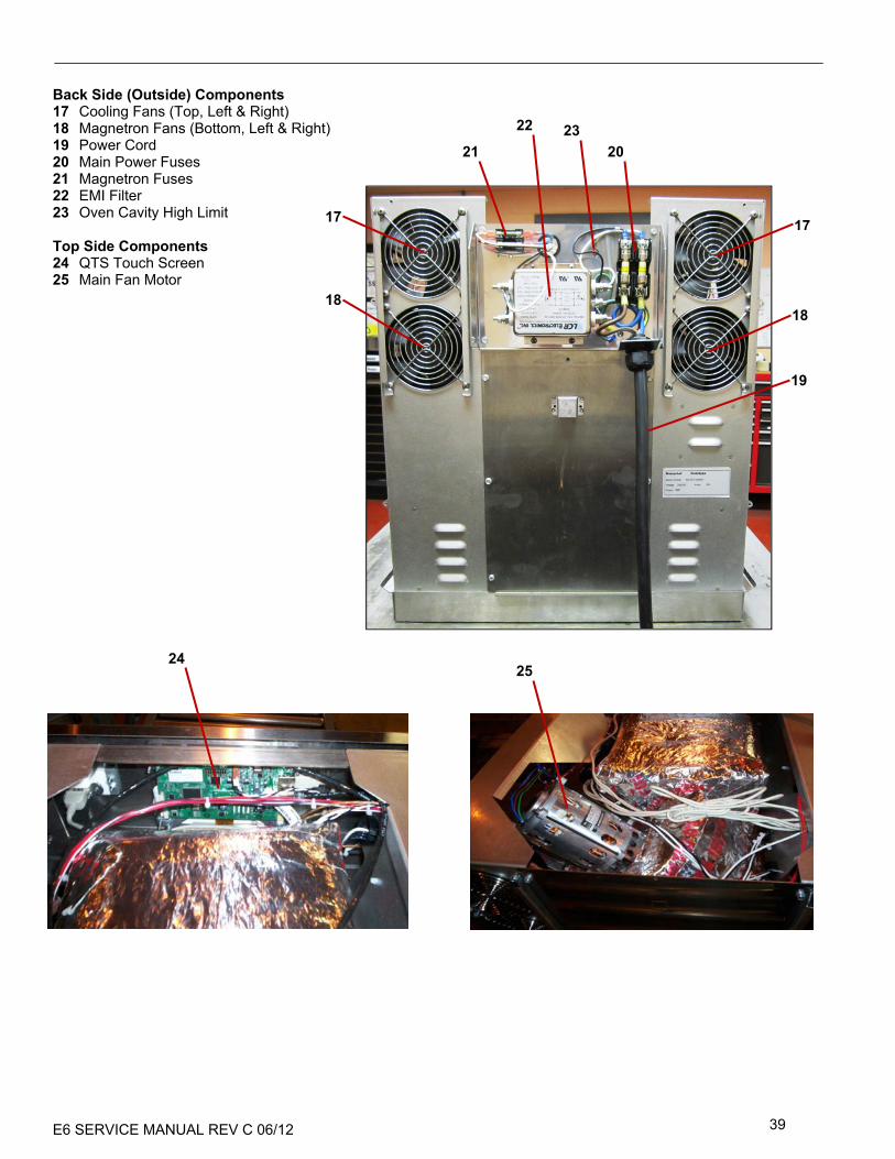
OVEN COMPONENTS Right Side Components
1 Monitor & Secondary Door Switch, SW1, SW2
2 RH Door Hinge Assembly 3 Motor Controller
Left Side Components
4 Smart Relay Board (SRB) 5 Step Down 24V Transformer 6 LH Door Hinge Assembly 7 Primary Door Switch, SW1 8 Thermocouple 9 Speaker (Backside)
Left & Right Side Components
10 Stirrer Motor 11 HV Capacitor 12 Waveguide 13 HV Magnetron 14 Magnetron High Limit 15 HV Diode Board 16 HV Transformer
1
3
2
10
11
12 13 14
15
7
9 45
68
10
11 12
13 14
15
16
16
E6 SERVICE MANUAL REV C 06/12 39
Back Side (Outside) Components 17 Cooling Fans (Top, Left & Right) 18 Magnetron Fans (Bottom, Left & Right) 19 Power Cord 20 Main Power Fuses 21 Magnetron Fuses 22 EMI Filter 23 Oven Cavity High Limit Top Side Components 24 QTS Touch Screen 25 Main Fan Motor
2021
22
17
18
23
19
17
18
2425

E6 SERVICE MANUAL REV C 06/12 40
1 2
4
SRB & QTS CIRCUIT BOARDS SRB replacement 1 Disconnect and isolate the oven from the electricity
supply. 2 Allow the oven to cool down. 3 Remove the oven casing. 4 Ensure that the High Voltage Capacitors are
discharged before commencing work. 5 Taking anti-static precautions disconnect all
connections on the SRB. 6 Remove the PM (Personality Module) (1) from the
SRB and place safely aside.
7 Release retaining standoffs and remove the SRB (2). 8 Replace SRB and press onto standoffs. 9 Reconnect all connections to the SRB, for details see
‘SRB Terminal Locations’ (Electrical Circuits section).
Note: Refit the PM removed from the old SRB to the new SRB. Refer to the following section on PM replacement if a new PM is fitted.
QTS replacement 1 Disconnect and isolate the oven from the electricity
supply. 2 Allow the oven to cool down. 3 Remove the oven casing. 4 Ensure that the High Voltage Capacitors are
discharged before commencing work. 5 Remove the top front panel. 6 Taking anti-static precautions disconnect all
connections on the QTS. 7 Remove the PM (Personality Module) (3) from the
QTS and place safely aside. 8 Release the four retaining nuts and remove the QTS assembly (4). 9 Refit the PM removed from the old QTS to the new QTS. Refer to the following section on PM replacement if a new
PM is fitted. 10 Replace the QTS assembly and secure with the retaining nuts. 11 Reconnect all connections to the QTS, for details see
‘QTS Terminal Locations’ (Electrical Circuits section).
(3)
(4)
(1)(2)

E6 SERVICE MANUAL REV C 06/12 41
(Personality Module) Replacement
The PM on the SRB contains the Firmware. The PM on the QTS contains the Firmware, Oven Serial Number, Temperature Calibration, Cooking Programs, Application Icons and the Recipe Images.
1 With a new PM fitted and casing refitted, switch on the oven and tap the screen to hold and check the QTS and SRB versions (1) are the latest release, if not, execute a Firmware update using the latest versions. For details see ‘Firmware Updates’ (Servicing section).
2 Tap the top right of the screen to bypass the preheat stage (2).
3 Enter the manager password and select OK to display the Settings menu, see (3).
4 Select the USB symbol (4). 5 Slide the Merrychef badge upwards and
insert the USB Memory Stick into the slot (5).
6 Once the oven has recognized the USB device, select the required USB symbol (6).
7 Select the Application Icons file to download (7). Note; a tinted band over a file name indicates the file is not valid for that oven.
8 Check the file information shown is correct before selecting OK (8), if not, select ‘X’ and locate the correct file.
9 When completed, select recipes to load the cooking programs (9). Once the programs are loaded the oven restarts.
10 Enter the Date & Time settings (10). For details see under ‘Oven Control Settings’ (Product Information section).
11 Turn the oven switch OFF/ON. 12 Remove the USB and keep in a safe
place. Reposition the USB cover.
1
2 3 4
5 6 7
8 9 10
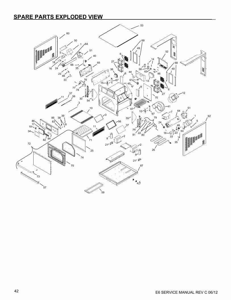
E6 SERVICE MANUAL REV C 06/12 42
SPAR
ES &
REPLA
CEMEN
T
SPARE PARTS EXPLODED VIEW
53
60
50 1
5
18
16 24
51
2348
33
64
66 35
40
65
7778
76
27
36
6
27
6
69
68
49
49
52
13
6358
14
46
12
41
9 44
61
9 45
6715
11 37
56
3 30
54
10
3
563711
8
21
2
2
21
8
42
55
29
79
81 2280
1567
70
7 64 51
1
5
50
62
24
35
1633
48
23
26
87
59
71
25
74
75
73
57
72
34
191786
82 84
8385 38
39

E6 SERVICE MANUAL REV C 06/12 43
SPARE PARTS Parts list
Item # Spare Part # Description 1 333000 MAGNETRON, TOSHIBA 2 333002 TRANSFORMER, HV 3 333013 RESISTAN GASKET 4 N/A OMITTED – REPLACED BY ITEM #11 5 333034 HI‐LIMIT, MAGNETRON 6 333036 FAN GUARD 7 333044 SPEED CONTROL SIEMENS 8 333047 CAPACITOR‐HV .88uF 9 333055 CATALYST, 6.4~X2.5~X1.0~ 10 333056 COOK PLATE, 603 OVEN 11 333058 FILTER HOUSING ASSEMBLY 12 333070 BLOWER ASSEMBLY 13 333075 RFI FILTER 14 333076 FUSE‐MAIN CIRCUIT 15 333078 DIODE BOARD ASSEMBLY 16 333080 STIRRER MOTOR,SAIA BURG 17 333084 BUDGET TOUCH SCREEN, QTS 18 333085 TRANSFORMER, LV 19 333087 SWITCH ON/OFF 20 333094 CORDSET,30A 6‐30P PLUG (NOT SHOWN) 21 333096 CLAMP, CAPACITOR 22 333097 DOOR SWITCH SPACER, 603 23 333098 GEAR, STIRRER 24 333099 GEAR, STIRRER MOTOR 25 333100 DOOR GASKET 26 333107 HEATING ELEM‐RAD WATLOW 27 333110 CABINET FAN, SUNON 28 333111 FUSE BK/MDA‐20‐R T‐LAG 29 333112 RIGHT DOOR HINGE 30 333113 LEFT DOOR HINGE 31 333121 CUT‐OFF BULB MOUNT (NOT SHOWN) 32 333138 SEALANT RTV 106 TUBE (NOT SHOWN) 33 333166 STIRRER ANTENNA 34 333189 TOUCH SCREEN OVERLAY 35 333196 CAVITY THERMOCOUPLE ASSY 36 333205 HARMONISED SPEAKER 37 333206 Borosilicate Partition 38 333210 MERRYCHEF BADGE GUIDE 39 333212 USB ADAPTER MODULE 40 369125 TERMINAL BLOCK 2POLE 41 333215 SCROLL HOUSING‐CW 42 333216 TOP HEATER, RADIANT OVEN 43 333217 LOCTITE 2620 HI TEMP (NOT SHOWN)

E6 SERVICE MANUAL REV C 06/12 44
Item # Spare Part # Description 44 333109 THERMAL CUTTOFF, COTHERM 45 333060 BACK VENT TUBE 90001303 46 333006 FUSE HOLDER,SINGLE SMALL 47 333218 Data Cable for Merrychef (NOT SHOWN) 48 333219 STIRRER EXTENSION 49 333220 AIR FILTER 50 333221 MAG EXHAUST SHROUD 51 333222 MAG INLET SHROUD 52 333223 FUSE BOX COVER, E6/63R 53 333224 TOP PANEL, E6/63R 54 333225 LEFT HINGE SHIM 55 333226 RIGHT HINGE SHIM 56 333227 PARTITION PLATE BRACKET 57 333228 UNDER DOOR COVER 58 333008 FUSE HOLDER,SINGLE LARGE 59 333229 GREASE DRAWER WELDMENT 60 333230 SIDE PANEL ASSY, LH e6 61 370749 STRAIN RELIEF WITH LOCKNUT 62 333231 SIDE PANEL ASSY, RH e6 63 333232 BUSHING SNAP 64 333233 WAVEGUIDE ASSEMBLY 65 333234 SRB, E6 66 333235 SRB PERSONALITY MODULE 67 333236 DIODE BOARD BRACKET, E6 68 333237 RIGHT AIR FILTER MOUNT 69 333238 LEFT AIR FILTER MOUNT 70 333239 BACK ACCESS PANEL ASSY 71 333240 JET PLATE WELDMENT 72 333241 DOOR ASM COMPLETE e6/63r 73 333242 HANDLE ‐ DOOR 74 333243 CHOKE ASSEMBLY 75 333244 DOOR INNER ASSEMBLY 76 333245 SWITCH ASSY, LARGE e6 77 333246 MICROSWITCH (LARGE) 78 333247 SWITCH BRKT ASM LARGE e6 79 333248 SWITCH ASSY, SMALL e6 80 333249 MICROSWITCH HONEYWELL 81 333250 SECONDARY SWITCH ASSY 82 333251 MERRYCHEF BADGE, LARGE 83 333252 MERRYCHEF BADGE SLIDERLG 84 333253 MERRYCHEF BADGE SEAL LG 85 333254 BADGE SPRING 86 333255 QTS PERSONALITY MODULE 87 333256 BASE ASSEMBLY, E6/63R

E6 SERVICE MANUAL REV C 06/12 45
ERROR CODES DISPLAYED Error Code
Oven Series Error/Event Condition
Description Trigger Error Level
System Response
E000 All OK
Communication between the QTS and the SRB has been reestablished.
The SRB was previously in a communication error state (E107) and the error has now cleared.
N/A
"E088 OK" message is displayed in the error log.
This message is di l d
E083 E2, E6 Incompatible SRB software version
SRB firmware version is incompatible with the QTS version
The QTS has found that the firmware running the SRB is not supported.
Critical
"E083 SRB VERSION CONFLICT" message is displayed in the error log.
E084
E2, E6 Invalid Date
The QTS has determined that the state of the Real Time Clock (RTC) is invalid
Only tested for when oven turns on. The QTS has found that the system date is 2010 or earlier.
Warning
"E084 INVALID DATE" message is displayed in the error log.
"INVALID DATE"
Only tested for when oven turns on. The QTS has found that the RTC has an invalid date/time setting or
E085 None Recommission fail - Elevator
The elevator failed the recommission test
N/A
N/A
"E085 RECOMMISSION FAIL ELEVATOR" message is displayed in the
E086 E2, E6 Recommission fail - Radiant
The radiant heater failed the recommission test
Pressing the "Red X" when "RADIANT TEST IN PROGRESS " is displayed
N/A
"E086 RECOMMISSION FAIL RADIANT" message is displayed in the
E087 E6 Recommission fail - Low Heater
The low convection heater failed the recommission test
Pressing the "Red X" when "LOW HEATER TEST IN PROGRESS" is displayed
N/A
"E087 RECOMMISSION FAIL LOW HEATER" message is displayed in the
E088 All Low or High line voltage
The Mains AC supply voltage is out of range
The QTS determines that the AC mains voltage read from the SRB is out of the ±10% tolerance range
Warning
"E088 SUPPLY VOLTAGE (V) OUT OF RANGE" message is displayed in the

E6 SERVICE MANUAL REV C 06/12 46
Error Code
Oven Series Error/Event Condition
Description Trigger Error Level
System Response
At oven start up the QTS senses that the AC mains voltage read from the SRB is out of the ±10%
“SUPPLY VOLTAGE (V) OUT OF RANGE" message is displayed on the
E089
E3, E4, E5 Recommission fail - Cooling fan(s)
The cooling fan(s) failed the recommission test
Pressing the "Red X" when "CONFIRM COOLING FAN IS RUNNING" is displayed
N/A
"E089 RECOMMISSION FAIL COOLING FAN" message is displayed in the
E2, E6
Pressing the "Red X" when "CONFIRM COOLING FANS ARE RUNNING" is displayed
"E089 RECOMMISSION FAIL COOLING FANS" message is displayed in
E090 All Recommission fail - Convection fan
The convection fan failed the recommission test
Pressing the "Red X" when "CONFIRM CONVECTION FAN IS RUNNING" is displayed
N/A
"E090 RECOMMISSION FAIL CONVECTION FAN" message is written to the
E091 E3 Recommission fail – Turn Table
The turn table failed the recommission test
Pressing the "Red X" when "OPEN DOOR CONFIRM TURNTABLE IS ROTATING" is displayed
N/A
"E091 RECOMMISSION FAIL TURNTABLE" message is written to the
E092
E2, E3, E4, E5 Recommission fail – Convection Heater
The Convection Heater failed the recommission test
Pressing the "Red X" when "HEATER TEST IN PROGRESS" is displayed
N/A
"E092 RECOMMISSION FAIL HEATER" message is written to the
E6 Recommission fail – High Convection Heater
The high convection heater failed the recommission test
Pressing the "Red X" when "HIGH HEATER TEST IN PROGRESS" is displayed
"E092 RECOMMISSION FAIL HIGH HEATER" message is written to the
E093 All Recommission fail – Magnetron(s)
The magnetron(s) failed the recommission test
Pressing the "Red X" when "MAGNETRON TEST IN PROGRESS" is displayed
"E093 RECOMMISSION FAIL MAGNETRON" message is written to the

E6 SERVICE MANUAL REV C 06/12 47
Error Code
Oven Series Error/Event Condition
Description Trigger Error Level
System Response
E094 E3, E4, E5 Recommission fail - Filter in
The oven does not sense that the filter is installed
The SRB does not see the magnetic switch input from the air filter while the “INSTALL AIR FILTER” message
N/A
"E094 RECOMMISSION FAIL FILTER INSTALL" message is written to the
E095 E3, E4, E5 Recommission fail - Filter out
The oven does not sense that the filter has been removed
The SRB does not see the magnetic switch input from the air filter while the “REMOVE AIR FILTER” message
N/A
"E095 RECOMMISSION FAIL FILTER REMOVAL" message is written to the
E096 All Recommission fail - Door close
The oven door switch has failed the door close test
The SRB does not see the switch input from the door while the “CLOSE OVEN DOOR” message is
N/A
"E096 RECOMMISSION FAIL DOOR CLOSE" message is written to the
E097 All Recommission fail - Door open
The oven door switch has failed the door open test
The SRB does not see the magnetic switch input from the air filter while the “OPEN OVEN DOOR” message
N/A
"E097 RECOMMISSION FAIL DOOR OPEN" message is written to the
E098 All Incomplete Cleaning
The QTS has determined that the cleaning process was started but not completed
Only tested for when oven turns on. The QTS has found that during the previous oven on period, a
Warning
"E098 INCOMPLETE CLEANING" message is displayed in the error log.
E099 E3, E4, E5 Filter Override
User has removedthe filter and elected to continue cooking
User removes the air filter. On the screen where the message “AIR FILTER REMOVED” and
Warning
"E099 FILTER OVERRIDE" message is displayed in the error log.
E100 All Main power ON
The AC power to the oven is energized
The SRB is reset after 25V AC power is applied from the transformer
N/A
"E100 MAIN POWER ON" message is written to the ovens error log
E101 All Magnetron failed
Magnetron failed to turn On when requested
The current measured by the SRB was outside of the tolerance range
Critical
"E101 MAGNETRON FAILED" message is written to the error log.

E6 SERVICE MANUAL REV C 06/12 48
Error Code
Oven Series Error/Event Condition
Description Trigger Error Level
System Response
E102
E2, E3, E4, E5 Heater On
Convection Heater element failed to turn OFF when requested
The current measured by the SRB is >1 amp with the convection heater OFF
Critical
"E102 HEATER ON WITHOUT REQUEST" message is written to the error log.
E6 High Heater On
High Convection Heater element failed to turn OFF when requested
The current measured by the SRB is >1 amp with the high heater OFF
Critical
"E102 HIGH HEATER ON WITHOUT REQUEST" message is written to the
E103 All Ambient overheat
The temperature measured inside the ovens cabinet is too high
The ambient temperature measured by the QTS and or SRB is >70°C (158°F)
Warning
"E103 AMBIENT OVERHEAT. PLEASE REMOVE, CLEAN AND REPLACE THE
E104
All Overheat stats released
The cavity temperature is above the high limit
Cavity thermal switch's (TCO) have opened Critical
"E104 OVERHEAT STATS RELEASED" message is written to the
The magnetron(s) temperature is above the high limit and the magnetron(s) are off
Magnetron thermal switch's (TCO) have opened and the Magnetron(s) are off
E105 All High or low freq
The frequency is outside of the ovens range of operation
The SRB's line monitoring circuit detects that that the frequency is outside of the ± 2Hz range
Critical
"E105 SUPPLY FREQUENCY (Hz) OUT OF RANGE" message is written to the
E106 All Cavity overheat
Cavity temperature is higher than the set point range while cooking
The SRB has detected that the cavity temperature is greater than 25°C (77°F) above the setpoint the
Critical
"E106CAVITY OVERHEATED" message is displayed in the error log.
"E106CAVITY
E107
All Comm error
There is no communication between the QTS and the SRB
The QTS can no longer send or receive data from the SRB.
Critical
“E107 COMM ERROR" message is displayed on the screen.
If h bl i
The SRB no longer receives data from the QTS.
SRB writes error to the log.

E6 SERVICE MANUAL REV C 06/12 49
Error Code
Oven Series Error/Event Condition
Description Trigger Error Level
System Response
E108 All QTS PM error
Wrong QTS PM found / no QTS PM found
The QTS has an incorrect PM (personality module) installed or no PM is installed
Critical
“E108 QTS PM FAILED" message is displayed on the screen.
Thi i
E109 All SRB PM error
Wrong SRB PM found / no SRB PM found
The SRB has an incorrect PM (personality module) installed or no PM is installed
Critical
“E109 SRB PM FAILED" message is displayed on the screen.
Thi i t
E110
All Incompatible SRB software version
SRB firmware version is incompatible with the SRB
The SRB has found that the firmware running the SRB is not supported.
Critical
This error is not recorded in the error log.
"E110 SRB VERSION CONFLICT"
E3, E4, E5
SRB firmware version is incompatible with the QTS version
The QTS has found that the firmware running the SRB is not supported.
E111 All Cavity sensor error
The cavity temperature sensor is no longer operating
The SRB is reading an open or shorted thermocouple input
Critical
"E111 CAVITY SENSOR" message is displayed in the error log.
"E111 CAVITY
E112
E3, E4, E5 SRB board sensor failed
The temperature sensor on the SRB board is no longer operating
The SRB is reading an open or shorted sensor mounted on the board
Critical
"E112 CAVITY SENSOR CIRCUIT FAILED" message is displayed in the
E2, E6
"E112 SRB AMBIENT SENSOR CIRCUIT FAILED" message is
E113 All Magnetron On without request
Magnetron failed to turn OFF
The magnetron current measured by the SRB was outside of the tolerance range
Critical
"E113 MAGNETRON ON WITHOUT REQUEST" message is written to the

E6 SERVICE MANUAL REV C 06/12 50
Error Code
Oven Series Error/Event Condition
Description Trigger Error Level
System Response
E114 None Spare (not used)
N/A N/A
N/A N/A
E115 E6 Convection Fan failed
The convection fan has failed
The feedback from the convection fan controller has indicated to the SRB that the controller has
Critical
"E115 CONVECTION FAN FEEDBACK" message is written to the
E116
E2, E3, E4, E5 Heater off
Convection heater element failed to turn On
The SRB senses that the heater current is <1 amp when requested to be ON
Critical
"E116 NO HEATER ON REQUEST" message is written to the error log.
E6 High Heater off
High convection heater element failed to turn On
The SRB senses that the high heater current is <1 amp when requested to be ON
"E116 NO HIGH HEATER ON REQUEST" message is written to the error log.
E117
E3, E4, E5 Magnetron overheat
One or both of the magnetrons thermal switch's has released but the condition clears in time
One or both of the magnetron thermal cut-outs has released while one or both magnetrons are
Warning
"E117 MAGNETRON OVERHEAT" message is written to the error log.
One or both of the magnetrons thermal switch's has released but the condition does not clear in time
One or both of the magnetron thermal cut-outs has released while one or both magnetrons are
Critical
"E117 MAGNETRON OVERHEAT" message is displayed in the error log.
E2, E3 Magnetron overheat
The magnetron thermal switch has released but the condition clears in time
The magnetron thermal cut-outs has released while the magnetron is running and the condition clears
Warning
"E117 MAGNETRON OVERHEAT" message is written to the error log.
The magnetron thermal switch has released but the condition does not clear in time
The magnetron thermal cut-outs has released while the magnetron is running and the condition has not
Critical
"E117 MAGNETRON OVERHEAT" message is displayed in the error log.

E6 SERVICE MANUAL REV C 06/12 51
Error Code
Oven Series Error/Event Condition
Description Trigger Error Level
System Response
E6 Right Magnetron overheat
The right magnetron thermal switch has released but the condition clears in time
The right magnetron thermal cut-out has released while the right magnetron is running and the
Warning
"E117 RIGHT MAGNETRON OVER HEATED" message is written to the
The right magnetron thermal switch has released but the condition does not clear in time
The right magnetron thermal cut-out has released while the right magnetron is running and the
Critical
"E117 RIGHT MAGNETRON OVER HEATED" message is displayed in the
E118 N/A Bottom Convection Fan failed
The bottom convection fan has failed
The feedback from the bottom convection fan controller has indicated to the SRB that the
Critical
"E118 Bottom CONVECTION FAN FEEDBACK" message is written to the
E119 E6 Low Heater On
Low convection heater element failed to turn Off when requested
The current measured by the SRB is higher than what is expected. The calculation is affected by the
Critical
"E119 LOW HEATER ON WITHOUT REQUEST" message is written to the
E120 E6 Low Heater Off
Low convection heater element failed to turn On
The current measured by the SRB is lower than what is expected. The calculation is affected by the
Critical
"E120 NO LOW HEATER ON REQUEST" message is written to the error log.
E121
E2 Radiant On
Radiant heater element failed to turn Off when requested
Not Implemented Yet
Critical
"E121 RADIANT ON WITHOUT REQUEST" message is written to the error log.
The current measured by the SRB is higher than what is expected. The calculation is affected by the
E6

E6 SERVICE MANUAL REV C 06/12 52
Error Code
Oven Series Error/Event Condition
Description Trigger Error Level
System Response
E122
E2 Radiant Off
Radiant heater element failed to turn On
Not Implemented Yet
Critical
"E122 NO RADIANT ON REQUEST" message is written to the error log.
E6
The current measured by the SRB is lower than what is expected. The calculation is affected by the
E123 None Elevator failed
The food elevator has failed.
The system determined that the food elevator is not operating correctly.
Critical
"E123 ELEVATOR FAILED" message is displayed in the error log.
E124
E6 Left Magnetron overheat
The left magnetron thermal switch has released but the condition clears in time
The left magnetron thermal cut-out has released while the left magnetron is running and the condition clears
Warning
"E124 LEFT MAGNETRON OVER HEATED" message is displayed in the
The left magnetron thermal switch has released but the condition does not clear in time
The left magnetron thermal cut-out has released while the left magnetron is running and the condition has not
Critical
"E124 LEFT MAGNETRON OVER HEATED" message is displayed in the
E125 None Left Magnetron failed
Left Magnetron failed to turn On when requested
The current measured by the SRB was outside of the tolerance range
Critical
"E125 LEFT MAGNETRON FAILED" message is written to the error log.
E126 None Left Magnetron On without request
Left magnetron failed to turn OFF
The left magnetron current measured by the SRB was outside of the tolerance range
Critical
"E126 LEFT MAGNETRON ON WITHOUT REQUEST" message is written to the
E127 E2, E6 QTS board sensor failed
The temperature sensor on the QTS board is no longer operating
The QTS is reading an open or shorted sensor mounted on the board
Critical
"E127 QTS AMBIENT SENSOR CIRCUIT FAILED" message is

E6 SERVICE MANUAL REV C 06/12 53
2
1
3
4 5 6
8 7
SRB & QTS CIRCUIT BOARDS QTS LEDs • Run - Pulsing 1 second flash, indicating that the
board has booted up. • Power - Lit to show that there is a power supply
from the SRB. • P-Bus - Irregular flashing, indicating data
communication with SRB. • C-Bus - Lit to show data being loaded from the PM
onto the QTS. • LD5 - Lit to show.
1 LD5 2 Power, Run, P-Bus, C-Bus.
QTS Terminal Locations 3 X6 - Speaker 4 X5 - USB socket
5 X4 - Communications to SRB 6 X11 - Screen backlight 7 X13 - Touch pad 8 X9 - Display Screen PCB
1
2
3
4 5 6
78

E6 SERVICE MANUAL REV C 06/12 54
SRB LED’s:
LED Circuit Description 1 Motors Aux safety relay supply 2 Microwave Mag safety relay supply 3 Cavity Limit Cavity high limit proving 4 Motor Cooling fan drive 5 Microwave Right mag drive 6 Heater High heater drive
7 Motor Stirrer motor and mag fan drive
9 Microwave Left mag drive 10 Door Door proving
11 QTS
Communication to and from QTS - P-Bus - Irregular flashing, indicating data communication with BTS.
12 Heater Heater safety relay supply
13 QTS
Communication to and from QTS - Run - Pulsing 1 second flash, indicating that the board has booted
14 DC 5 volt supply - Lit to show voltage outputs from transformer.
15 DC 12 volt supply - Lit to show voltage outputs from transformer.
16 Motor Motor controller drive 17 Heater Radiant heater drive 18 Heater Low heater drive 19 Mag High Limit Right mag high limit proving 20 Mag High Limit Left mag high limit proving 21 Motor Main fan motor proving 22 Power Switch Power switch proving

E6 SERVICE MANUAL REV C 06/12 55
SRB Terminal Locations:
Connector Wire # Description X1-1 14 Input, L1 from main terminal
block X1-2 15 Input, L2 from main terminal
block X2-1 16 Output, L1 to 24V control
transformer X2-2 17 Output, L2 to 24V control
transformer X3-1 64 Output, L1 to motor controller
(when activated) X3-2 65 Output, L2 to motor controller X4 32 Input, L1 from main terminal
block (for high heater circuit) X5 10 Input, L1 from main terminal
block (for low and radiant heater circuit)
X6 24 Input, L1 from primary door switch (if door closed) (for microwave circuit)
X7 13 Input, L2 from main terminal block (for microwave circuit)
X8-1 20 Input, L1 from secondary door switch to connection block (if door closed)
X8-2 22 Input, L2 from monitor door switch to connection block (if door open)
X8-3 23 Output, L1 to primary door switch (if door closed), L2 (if door open)
X9-1 58 Output, L1 to left cooling fan (when activated)
X9-2 33 Output, L1 to right cooling fan (when activated)
X10 Currently not used X11-1 35 Output, L1 to right stirrer motor
(when activated) X11-2 36 Output, L1 to right mag fan
(when activated) X11-3 37 Output, L1 to left stirrer motor
(when activated) X11-4 38 Output, L1 to left mag fan (when
activated) X12-1 39 Output, L2 to right stirrer motor X12-2 40 Output, L2 to right mag fan X12-3 41 Output, L2 to left stirrer motor X12-4 42 Output, L2 to left mag fan X13-1 59 Output, L2 to left cooling fan X13-2 34 Output, L2 to right cooling fan X13-3 Currently not used X14 blu Output, L1 to high heater (when
activated) X15-1 wht Output, L1 to radiant heater
(when activated) X15-2 yel Output, L1 to low heater (when
activated)

E6 SERVICE MANUAL REV C 06/12 56
CIRCUIT DIAGRAMS
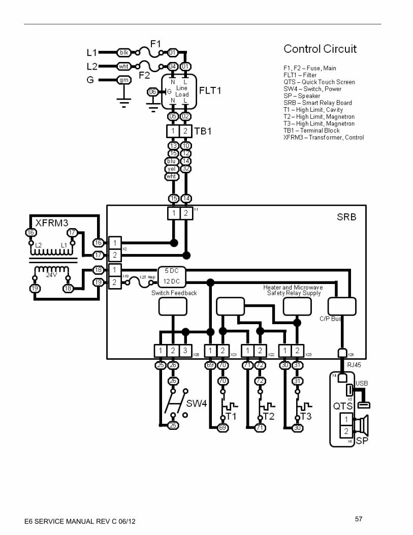
E6 SERVICE MANUAL REV C 06/12 57
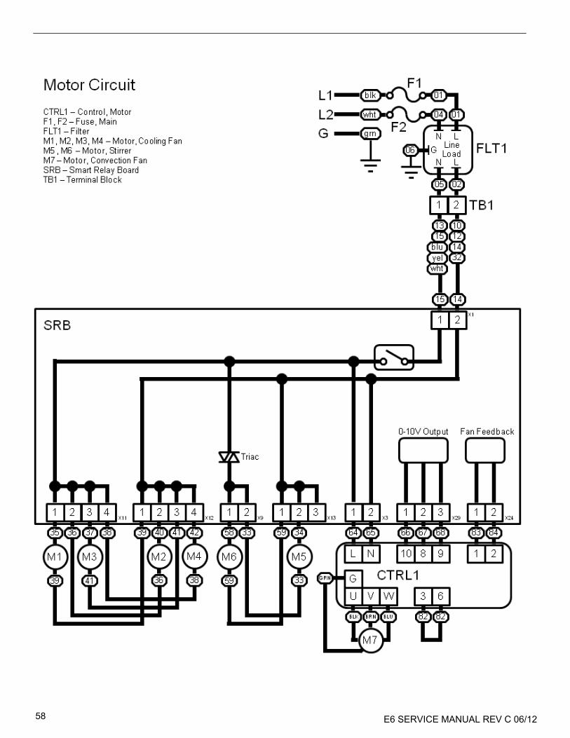
E6 SERVICE MANUAL REV C 06/12 58

E6 SERVICE MANUAL REV C 06/12 59

E6 SERVICE MANUAL REV C 06/12 60

E6 SERVICE MANUAL REV C 06/12 61
COMMISSIONING THE OVEN Initial Installation 1. Unpack the Oven and check for damage. 2. Check Oven Accessories. 3. Check location will provide adequate Ventilation. 4. Locate Oven onto a strong, level, non-flammable
Surface. 5. Remove panels & check all wiring and components
for security. 6. Refit panels. 7. Position the Oven with a minimum air gap of 2”
(50mm) sides & rear. 8. Check Electrical supply and connect. 9. Place a container of water in the oven and switch it
on. 10. Record Model version & check against serial plate. 11. Record QTS (UI) version. 12. Record SRB version. 13. Record Serial Number & check against serial plate. 14. Enter Service Mode. 15. Record Voltage & Frequency. 16. Record Magnetron Current Draw. 17. Check for Microwave leakage. 18. Record Heater current. 19. Check door opening on display. 20. Check filter removal on display. 21. Check fan speed. 22. Turn off the oven and remove the water. 23. Switch on oven and run up to temperature. 24. Operate Oven, Cooking a Standard Batch. 25. Supply User information & contact details to
Customer. 26. Instruct Users with an Overview of the equipment,
Operation & Safety (Hazards). 27. Complete Service Report.
After Service Complete the following checks after the Oven has been Serviced/Repaired/Tested before connecting to the mains electricity power supply:
All internal electrical connections are correct (see wiring diagrams).
All wiring insulation is correct and is not touching any sharp edges.
All grounding connections are electrically and mechanically secure.
All door safety interlocks are secure and mechanically sound.
The door activates all of the door interlock switches and in the correct order.
The door operation is smooth, and the arms run freely in the slots.
The temperature sensor is correctly connected to the SRB.
The casing is securely refitted with no trapped wires.
Before finishing a service call, recheck the following points:
Run the Recommission tests to ensure the oven is functioning correctly and the touch screen is working.
Microwave emissions are below permissible limit of 5mW/cm².
The power output of the oven is checked in accordance with the procedure.
The oven has correct 2” (50mm) air gap all round and 2” (50mm) above. Air flow should not be restricted.
Complete the Service Report.
E6 SERVICE MANUAL REV C 06/12 62
LIMITED WARRANTY FOR COMMERCIAL PRODUCTS LIMITED WARRANTY Merrychef USA, (“Merrychef”) warrants this product to be free from defects in material and workmanship for a period of one (1) year from the date the product is installed or eighteen months (18) months from the date of shipment from our facility, whichever comes first. During the warranty period, Merrychef shall, at Merrychef’s option, repair or replace parts determined by Merrychef to be defective in material or workmanship, and with respect to services, shall re-perform any defective portion of said services. The foregoing shall be the sole obligation of Merrychef under this Limited Warranty with respect to the equipment, products and services. With respect to equipment, materials, parts and accessories manufactured by others, Merrychef’s sole obligation shall be to use reasonable efforts to obtain the full benefit of the manufacturer’s warranties. Merrychef shall have no liability, whether in contract, tort, negligence, or otherwise, with respect to non-Merrychef manufactured products. WHO IS COVERED This Limited Warranty is available only to the original purchaser of the product and is not transferable. EXCLUSIONS FROM COVERAGE • Repair or replacement of parts required because of misuse, improper care or storage, negligence, alteration, accident, use of incompatible supplies or lack of specified maintenance shall be excluded • Normal maintenance items, including but not limited to, light bulbs, fuses, gaskets, door seals, O-rings, air filters, interior and exterior finishes, lubrication, de-liming, broken glass, etc. • Failures caused be erratic voltages • Improper or unauthorized repair • Changes in adjustment and calibration after ninety (90) days from equipment installation date • This Limited Warranty will not apply to any parts subject to damage beyond the control of Merrychef, or to equipment which has been subject to alteration, misuse or improper installation, accidents, damage in shipment, fire, floods, power changes, other hazards or acts of God that are beyond the control of Merrychef. • This Limited Warranty does not apply, and shall not cover any products or equipment manufactured or sold by Merrychef when such products or commercial equipment is installed or used in a residential or non-commercial application. Installations not within the applicable building or fire codes render this Limited Warranty and any responsibility or obligations associated therein null and void. This includes any damage, costs or legal actions resulting from the installation of any Merrychef commercial cooking equipment in a non-commercial application or installation, where the equipment is being used for applications other than those approved for by Merrychef.
• If any product is cleaned without using an approved Merrychef cleaning solution, this Limited Warranty shall be voided. LIMITATIONS OF LIABILITY The preceding paragraphs set forth the exclusive remedy for all claims based on failure of, or defect in, products or services sold hereunder, whether the failure or defect arises before or during the warranty period, and whether a claim, however instituted, is based on contract, indemnity, warranty, tort (including negligence), strict liability, implied by statute, common-law or otherwise, and Merrychef its servants and agents shall not be liable for any claims for personal injuries or consequential damages or loss, howsoever caused. Upon the expiration of the warranty period, all such liability shall terminate. THE FOREGOING WARRANTIES ARE EXCLUSIVE AND IN LEIU OF ALL OTHER WARRANTIES, WHETHER WRITTEN, ORAL, IMPLIED OR STATUTORY. NO IMPLIED WARRANTY OF MERCHANTABILITY OR FITNESS FOR PARTICULAR PURPOSE SHALL APPLY, MERRYCHEF DOES NOT WARRANT ANY PRODUCTS OR SERVICES OF OTHERS. REMEDIES The liability of Merrychef for breach of any warranty obligation hereunder is limited to: (i) the repair or replacement of the equipment on which the liability is based, or with respect to services, re-performance of the services; or (ii) at Merrychef’s option, the refund of the amount paid for said equipment or services. Any breach by Merrychef with respect to any item or unit of equipment or services shall be deemed a breach with respect to that item or unit or service only. WARRANTY CLAIM PROCEDURE Customer shall be responsible to: • Immediately advise the Dealer or Merrychef’s Authorized Service Agent of the equipment serial number and the nature of the problem. • Verify the problem is a factory responsibility. Improper installation or misuse of equipment, are not covered under this Limited Warranty. • Cooperate with the Service Agency so that warranty service may be completed during normal working hours. GOVERNING LAW For equipment, products and services sold in the United States this Limited Warranty shall be governed by the laws of the state of Delaware, USA, excluding their conflicts of law principles. The United Nations Convention on Contracts for the International Sale of Goods is hereby excluded in its entirety from application to this Limited Warranty. Merrychef USA 1111 North Hadley Road Fort Wayne, Indiana 46804 USA 112305

E6 SERVICE MANUAL REV C 06/12 63
Notes:

E6 SERVICE MANUAL REV C 06/12 64
Merrychef USA, LLC 1111 North Hadley Road
Fort Wayne, Indiana 46804 United States of America
Technical Support Hotline: (800) 678-9511 Telephone: (260) 459-8200
www.merrychefusa.com