EDI convection measurements at 5–6 R E in the post-midnight region
11
EDI convection measurements at 5-6 RE in the post-midnight region J. M. Quinn, G. Paschmann, N. Sckopke, V. K. Jordanova, H. Vaith, O. H. Bauer, W. Baumjohann, W. Fillius, G. Haerendel, S. S. Kerr, et al. To cite this version: J. M. Quinn, G. Paschmann, N. Sckopke, V. K. Jordanova, H. Vaith, et al.. EDI convec- tion measurements at 5-6 RE in the post-midnight region. Annales Geophysicae, European Geosciences Union, 1999, 17 (12), pp.1503-1512. <hal-00316716> HAL Id: hal-00316716 https://hal.archives-ouvertes.fr/hal-00316716 Submitted on 1 Jan 1999 HAL is a multi-disciplinary open access archive for the deposit and dissemination of sci- entific research documents, whether they are pub- lished or not. The documents may come from teaching and research institutions in France or abroad, or from public or private research centers. L’archive ouverte pluridisciplinaire HAL, est destin´ ee au d´ epˆ ot et ` a la diffusion de documents scientifiques de niveau recherche, publi´ es ou non, ´ emanant des ´ etablissements d’enseignement et de recherche fran¸cais ou ´ etrangers, des laboratoires publics ou priv´ es.
Transcript of EDI convection measurements at 5–6 R E in the post-midnight region

EDI convection measurements at 5-6 RE in the
post-midnight region
J. M. Quinn, G. Paschmann, N. Sckopke, V. K. Jordanova, H. Vaith, O. H.
Bauer, W. Baumjohann, W. Fillius, G. Haerendel, S. S. Kerr, et al.
To cite this version:
J. M. Quinn, G. Paschmann, N. Sckopke, V. K. Jordanova, H. Vaith, et al.. EDI convec-tion measurements at 5-6 RE in the post-midnight region. Annales Geophysicae, EuropeanGeosciences Union, 1999, 17 (12), pp.1503-1512. <hal-00316716>
HAL Id: hal-00316716
https://hal.archives-ouvertes.fr/hal-00316716
Submitted on 1 Jan 1999
HAL is a multi-disciplinary open accessarchive for the deposit and dissemination of sci-entific research documents, whether they are pub-lished or not. The documents may come fromteaching and research institutions in France orabroad, or from public or private research centers.
L’archive ouverte pluridisciplinaire HAL, estdestinee au depot et a la diffusion de documentsscientifiques de niveau recherche, publies ou non,emanant des etablissements d’enseignement et derecherche francais ou etrangers, des laboratoirespublics ou prives.

EDI convection measurements at 5±6 RE in the post-midnight region
J. M. Quinn1, G. Paschmann2, N. Sckopke2, V. K. Jordanova1, H. Vaith2, O. H. Bauer2, W. Baumjohann2, W. Fillius3,G. Haerendel2, S. S. Kerr3, C. A. Kletzing4, K. Lynch1, C. E. McIlwain3, R. B. Torbert1, E. C. Whipple5
1 Space Science Center, Morse Hall, University of New Hampshire, Durham, NH, 03824, USA2Max-Planck-Institut f. extraterrestrische Physik, 85740 Garching, Germany3Center for Astrophysics and Space Sciences, University of California, San Diego, La Jolla, CA, 92093, USA4Department of Physics and Astronomy, University of Iowa, Iowa City, IO, 52242, USA5Geophysics Program, University of Washington, Seattle, WA, 98195, USA
Received: 8 March 1999 / Revised: 10 May 1999 /Accepted: 12 May 1999
Abstract. We present the ®rst triangulation measure-ments of electric ®elds with the electron drift instrument(EDI) on Equator-S. We show results from ®ve high-data-rate passes of the satellite through the near-midnight equatorial region, at geocentric distances ofapproximately 5±6 RE, during geomagnetically quietconditions. In a co-rotating frame of reference, themeasured electric ®elds have magnitudes of a few tenthsof mV/m, with the E � B drift generally directedsunward but with large variations. Temporal variationsof the electric ®eld on time scales of several seconds tominutes are large compared to the average magnitude.Comparisons of the ``DC'' baseline of the EDI-mea-sured electric ®elds with the mapped Weimer iono-spheric model and the Rowland and Wygant CRRESmeasurements yield reasonable agreement.
Key words. Magnetospheric physics (electric ®elds;plasma convection; instruments and techniques)
1 Introduction
The electron drift instrument (EDI)was developed for theCluster mission with the objective of measuring electric®elds over a large range of plasma, magnetic-®eld, andelectric-®eld regimes (Paschmann et al., 1998). Becausethe instrument incorporated complex, closed-loop con-trol algorithms and several newly developed hardwarecomponents, its ®rst ¯ight on Equator-S provided anextremely valuable opportunity to obtain experience withits operation and to verify its measurement capabilities.
One of the many goals for EDI was to provide anaccurate and sensitive measurement of the highly vari-
able convection electric ®elds in the key region neargeosynchronous orbit, where plasma is injected into theinner magnetosphere. Despite the importance of thisregion to plasma transport and energization, the devel-opment of a reliable, empirically based model of electric®elds has been challenging for several reasons. Thetypical electric ®eld magnitude is relatively small; theplasma conditions are highly variable; and there havebeen only a limited number of spacecraft instrumented tomake su�ciently sensitive electric-®eld measurements inthis part of the magnetosphere. Average convectionelectric ®elds based on large data-sets have been obtainedusing several approaches. McIlwain (1972) derived aninner-magnetosphere electric-®eld model from analysisof detailed convection features seen in plasma data atdi�erent local times near geosynchronous orbit. May-nard et al. (1983) used a year of ISEE-1 double-probemeasurements to determine average ®eld maps at variousgeomagnetic activity levels. Measurements by theGEOS-2 beam experiment were analyzed by Baumjoh-ann et al. (1985) and Baumjohann and Haerendel (1985)to study dependencies of the convection ®eld at 6.6 RE asa function of geomagnetic activity and solar-windconditions. Recently Rowland and Wygant (1998) havepublished a study of convection ®elds as a function of Kp
for L < 8.5 using CRRES double-probe measurementsfrom a 10-month period. In addition to the models basedon equatorial measurements, ionospheric models havebeen developed that, in many instances, can be mappedto the equatorial region (e.g., Weimer, 1995, 1996).
We present equatorial measurements by EDI in thenear-midnight region at 5±6 RE, during ®ve high-data-rate passes of the satellite during late March and April,1998. This location provides a good test of the instru-ment's ability to measure sensitively the weak electric®elds of convection and waves.
2 Measurement technique
The electron drift instrument measures the electron driftvelocity by detecting the displacement of two electron
Correspondence to: J. QuinnE-mail: [email protected]
Ann. Geophysicae 17, 1503±1512 (1999) Ó EGS ± Springer-Verlag 1999

beams ®red perpendicular to the ambient magnetic ®eld.(The drift velocity is usually dominated by the E�Bdrift, however the ÑB drift can also be important). Thebeams are ®red by a pair of electron guns and detectedafter one (or more) gyro orbit(s). The instrument usestwo complementary techniques to measure the electrondrift. In the ``triangulation'' technique the ®ring direc-tions of the electron beams are used to determine theelectron drift velocity, as described later. In this studywe rely exclusively on the triangulation technique. Thesecond technique, based on measuring di�erences in thetimes-of-¯ight of the two electron beams, is described inthe companion work by Paschmann et al. (1999).
The EDI triangulation technique is based on mea-suring the distortion of the electron's gyro orbit by theelectric ®eld. In a uniform magnetic ®eld with no otherforces acting, an electron ®red in any direction perpen-dicular to the ambient magnetic ®eld B will execute acircular gyro orbit and return to its starting point. In thepresence of a transverse electric ®eld E, the trajectoriesare distorted and the electrons no longer return to theirstarting position after one gyro period. Speci®cally, allelectrons starting at a particular location will bedisplaced by the same amount in one gyro period dueto the E�B drift. This displacement is independent ofthe electrons' energy and original direction of travel, asneither the E�B drift velocity nor the gyro perioddepend on energy. We de®ne the drift step, d, to be thenet displacement during a single gyro period, Tg, due toa drift velocity, Vd.
d � VdTg:
A measurement of the drift step, together with know-ledge of the gyro period, is thus equivalent to measuringthe drift velocity. EDI used this relationship to deter-mine the drift velocity by measuring the drift step, usinga weak beam of electrons as test particles.
The EDI triangulation technique is illustrated con-ceptually by Fig. 1 in the plane perpendicular to B (the``B^ plane''). There are two electron guns, with adetector (Det) located halfway between. The beams arerepresented by the dashed and dotted lines. The mag-nitude and orientation of the drift step, d, are speci®edby the ambient ®elds as described above. We havedrawn d with its head positioned at the detector. Theelectron gyro radius is very large (³1 km) compared tothe scale of the ®gure (�1 m), and so the gyrotrajectories of the beams appear as nearly straight lines.By de®nition, any 90°-pitch-angle electron originating atthe tail-end of d will be displaced by the drift velocityand will hit the detector exactly one gyro period later.Therefore, an electron beam aimed so that the electronspass through the tail of d will return to hit the detectorafter one gyro orbit. We thus call the tail of d the``target''. Electrons ®red in other directions, and notpassing through the target position, will not hit thedetector, except for those ®red in the opposite direction,which also have a virtual source at the tail of d. Whenthe guns are aimed in the unique directions that allowtheir beams to hit the detector after one gyro orbit, onecan determine from triangulation the beam intersection
point, which corresponds to the tail of d. Using theknown locations of the guns and detector, one can thencalculate the vector d. Together with knowledge of thegyro period, this measurement of d determines the driftvelocity of the electrons.
The EDI gun-detector con®guration on Equator-S isdi�erent from that shown in Fig. 1, but it is geometricallyequivalent. There are two gun-detector units (GDUs),mounted on opposite sides of the spacecraft and havingoppositely directed ®elds-of-view. Each gun is capable of®ring its beam in any direction within somewhat morethan a full hemisphere, at polar angles up to 96°, to anaccuracy of better than 1°. Similarly, each detector is ableto detect electrons coming from any selected directionwithin a hemispherical ®eld of view for polar angles up to100°. The beam ®red by each gun is received by thedetector on the opposite side of the spacecraft. Thus, forthe purposes of triangulation, the baseline separating agun and its corresponding detector is the spacecraftdiameter projected into the B^ plane. At any instant, onegun ®res at a detector that is displaced from it in the B^plane by a baseline b, while the other ®res at a detectordisplaced by )b. Therefore the con®guration is geomet-rically identical to that shown in Fig. 1, with the two gunsseparated from the detector by equal distances inopposite directions. Each gun is separated from itsdetector on the opposite side of the spacecraft by equaland oppositely directed vectors. This is equivalent tohaving the two guns equidistant from a centrally locateddetector, as illustrated in Fig. 1. For the purposes ofdisplaying triangulation data we will continue to use thispicture, i.e., two guns and a single ``virtual detector''located halfway between, at a distance of one spacecraftdiameter from each gun. The triangulation baseline,formed by the projection of the gun-detector separationvectors in the B^ plane, varies with the orientation of theambient magnetic ®eld and spacecraft spin phase.
Gun 2Gun 1 Det
d
Returning beams
d (Vdrift gyro) (T )
B
Fig. 1. Triangulation geometry for determining the drift-step vector d.Firing directions of the two guns (dashed and dotted lines) locate the tailof d when the guns are aimed so that after one gyro orbit the beamsreturn to the detector (Det). The gyro radius is large compared to the®gure, so the beam trajectories appear as straight lines on this scale
1504 J. M. Quinn et al.: EDI convection measurements at 5±6 RE in the post-midnight region
The technical implementation of EDI is described indetail by Paschmann et al. (1997, 1998). The keyelements for the present study are the beam ®ring anglesof the guns, the beam recognition by the detector, andthe beam acquisition and tracking algorithms whichallow su�ciently frequent ``hits'' to make good trian-gulation measurements. The angles in the triangulationmeasurement are taken from the gun ®ring directions,which are calibrated prior to launch over the entire gunsolid angle. Since the beam can only return to thespacecraft if it is ®red within approximately 1 degree(the beam width) of the B^ plane, we can check andupdate these calibrations in orbit by analyzing thedistribution of beam hits over the gun solid angle forvarious magnetic ®eld orientations. On Equator-S, wefound that the guns' ground calibrations were preservedextremely well throughout the mission lifetime.
Each EDI gun-detector pair independently acquiresand tracks the target by controlling the gun ®ringdirections with a ¯exible, onboard servo algorithm.Equator-S employed a 1 keV beam energy; however theinstrument is designed to use 500 eV beams also. In orderto measure the electrons' time-of-¯ight, and to helpdiscriminate against the background ¯ux of ambientelectrons, the beams are amplitude-modulated by a 15-chip pseudo-noise code, and the detected counts areprocessed by a 15-channel correlator (Vaith et al., 1998).To acquire the target, the beam ®ring-direction is steppedat a constant angular rate in the B^ plane until the beam-recognition algorithm records a hit by comparing countsin the various correlator channels. When the beam isdetected, the onboard tracking algorithm reverses theangular stepping direction so that the beam is sweptrepeatedly back and forth across the target direction.
The accuracy with which one can determine the driftstep through triangulation depends on several factors,including the knowledge of the beam ®ring direction andthe relative magnitude and orientation of the gun-detector baseline b, projected into the B^ plane, withrespect to the drift step, d. In general, triangulation ismost accurate when the baseline is comparable inmagnitude to the drift step. However, with ®ring anglesknown to 1° the drift steps can be measured to betterthan 20% over a satisfactory dynamic range to coverinner-magnetospheric drifts. When drift steps are a fewtens of times larger than the baseline, the drift directionis known accurately, but the magnitude obtained bytriangulation becomes increasingly uncertain. In thislarge-d regime, the time-of-¯ight technique is preferred(see Paschmann et al., 1999).
The EDI technique has the advantage that it isessentially geometrical in nature, and thus the absoluteaccuracy can be quite high. While the complexities ofbeam acquisition and tracking are challenging, once thereturn beams are detected the resulting triangulationyields a rather unambiguous result. For a given baselineand drift step orientation, the error analysis arising fromuncertainties in the beam ®ring directions is straightfor-ward.
The electron beam triangulation technique was ®rstdeveloped by the group at MPE, and ¯own on the
GEOS-2 satellite (Melzner et al., 1978). While theGEOS experiment clearly established the viability ofthe measurement technique, its time resolution waslimited to the 6-s spacecraft spin period, and its beamde¯ection capability was restricted to a narrow range ofmagnetic-®eld orientations. The EDI instrument for theCluster and Equator-S missions was developed toremove these limitations as well as to incorporate thetime-of-¯ight technique and other improvements thatwould be necessary to accommodate the wide range ofanticipated magnetic ®elds, electric ®elds, and ambient(background) electron ¯uxes.
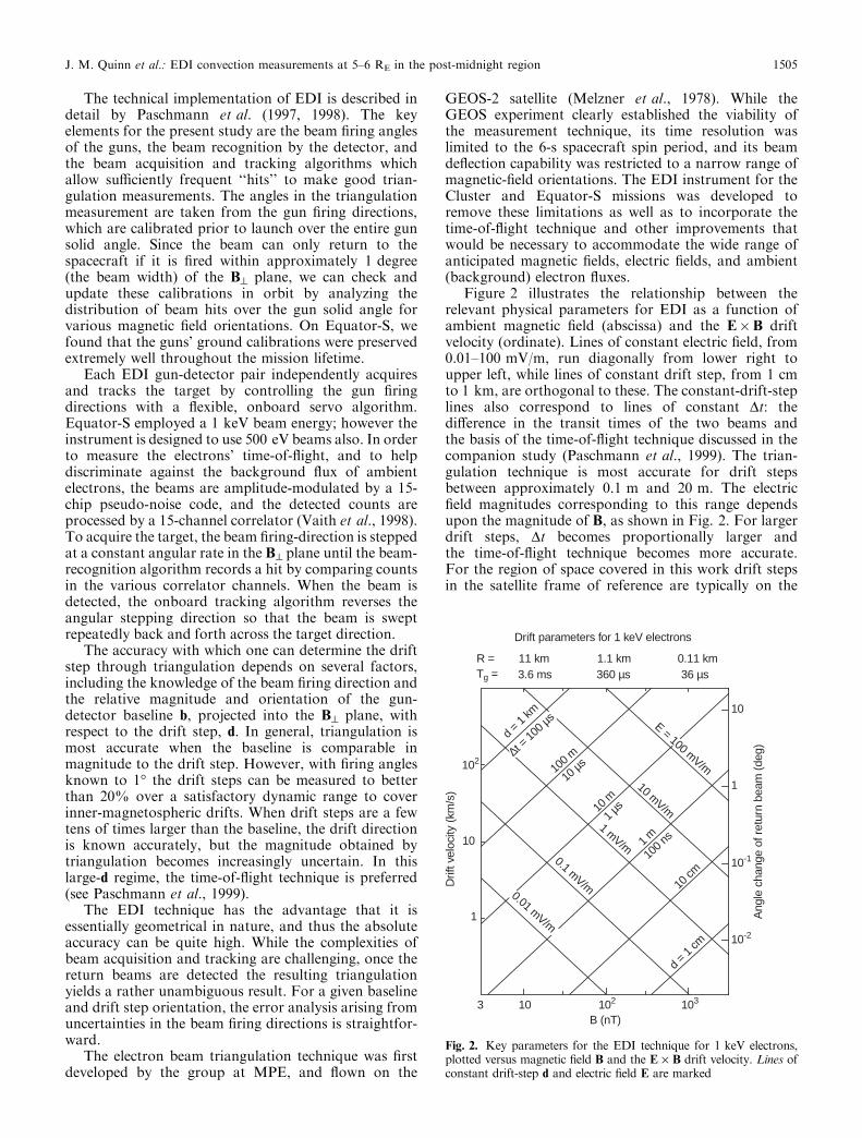
Figure 2 illustrates the relationship between therelevant physical parameters for EDI as a function ofambient magnetic ®eld (abscissa) and the E�B driftvelocity (ordinate). Lines of constant electric ®eld, from0.01±100 mV/m, run diagonally from lower right toupper left, while lines of constant drift step, from 1 cmto 1 km, are orthogonal to these. The constant-drift-steplines also correspond to lines of constant Dt: thedi�erence in the transit times of the two beams andthe basis of the time-of-¯ight technique discussed in thecompanion study (Paschmann et al., 1999). The trian-gulation technique is most accurate for drift stepsbetween approximately 0.1 m and 20 m. The electric®eld magnitudes corresponding to this range dependsupon the magnitude of B, as shown in Fig. 2. For largerdrift steps, Dt becomes proportionally larger andthe time-of-¯ight technique becomes more accurate.For the region of space covered in this work drift stepsin the satellite frame of reference are typically on the
3 10 102
10-2
10-1
102
103
Drift parameters for 1 keV electrons
R =T =g
11 km 1.1 km 0.11 km3.6 ms 360 µs 36 µs
10
1
B (nT)
10
1
E = 100 mV/m
10 mV/m1 mV/m
0.1 mV/m0.01 mV/m
d = 1
km
100 m
10 m
1 m
10 cm
10 µs
1 µs
100 n
s
d = 1
cm
t = 10
0 µs
∆
Drif
t vel
ocity
(km
/s)
Ang
le c
hang
e of
ret
urn
beam
(de
g)
Fig. 2. Key parameters for the EDI technique for 1 keV electrons,plotted versus magnetic ®eld B and the E ´ B drift velocity. Lines ofconstant drift-step d and electric ®eld E are marked
J. M. Quinn et al.: EDI convection measurements at 5±6 RE in the post-midnight region 1505

order of 1 m, which is ideal for triangulation withbaselines on the order of the spacecraft diameter.
An important feature of EDI is that the technique islargely independent of the orientations of the electricand magnetic ®elds with respect to the spacecraft. This isan inherent di�erence between the EDI and double-probe measurements of electric ®elds. EDI is sensitive tothe two components of the E in the B^ plane, while thedouble-probe technique is most sensitive to the compo-nents in the satellite spin plane. Thus while EDI doesnot measure the component of E parallel to B, itmeasures both perpendicular components without re-gard to the angle of B with respect to the spin axis.
3 Equator-S EDI observations
We examine ®ve intervals in late March and April, 1998,when Equator-S apogee was in the early-morning sector.During this period the satellite was operated occasion-ally in high-rate telemetry for approximately one-hourperiods while traversing outbound orbital legs, atgeocentric distances of approximately 5±6 RE. Thehigh-rate intervals are chosen because this telemetryincludes supplementary data that enable more completevalidation of the results. We present here results from®ve passes for which high-rate EDI data are available, assummarized in Table 1.
Figure 3 illustrates EDI detection of the returningbeam during a 4-s period on April 28. Subscripts 1 and 2in the ®gure panel labels denote data from each of thetwo EDI detectors. The panels labeled ``Max1'' and``Max2'' show the detected counts in the onboardcorrelator channel having the maximum signal. Theseare the counts during 1 ms accumulation intervals,sampled by telemetry every 16 ms. The periods of beamhits on the detector are clearly evident as count levels ofseveral hundred, compared to the ambient backgroundlevels of 20±50. The small panel labeled ``MaxCh''indicates the number of the correlator channel (0±15)that received the maximum counts. When the beam isdetected, the correlator hardware attempts to adjust itstime delays so that the maximum counts remain inchannel 7. This correlator tracking feature is usedprimarily for the time-of-¯ight measurements (see Pas-chmann et al., 1999). The panels labeled ``s2b'' show thederived signal-to-noise ratio squared, where ``noise'' isthe square root of the ambient background counts. Thisquantity is calculated from comparison of counts in themaximum correlator channel with those in another
channel (Vaith et al., 1998). Since s2b is calculatedindependently for each sample period, it can be used toidentify beam hits during periods of rapidly changingambient background ¯uxes. The s2b parameter is usedby EDI as part of the beam recognition algorithm andalso as part of the instrument's onboard control of beamcurrent, detector-optics state, and other operationalparameters. Finally, the panels labeled ``q'' are beamquality indices, which are used to select data in thetriangulation calculations. The quality of the hits isderived from a combination of the s2b parameter, athreshold on the ``Max'' counts, and a requirement thatthe ``Max Channel'' is channel 7 � 1. This combinationof conditions can be set to eliminate false beamidenti®cations very e�ectively. The quality parameterhas 4 values, 0±3, and is plotted upward from the centerof the ®gure for detector 1, and downward from thecenter for detector 2.
During the 4-s interval shown in Fig. 3, which istypical for the periods presented here, the beam is aimedsuccessfully to hit the detector somewhat less than halfof the time. The gap between beam acquisitions is oftenon the order of 1 s, with periods of tracking, or nearlycontinuous beam re-acquisition lasting of the order of1/2 s. The tracking duty cycle will be improved signif-icantly for Cluster with a modi®ed beam recognitionalgorithm that we have tested using the Equator-S data.We address beam acquisition and tracking issues inmore detail following the discussion of Fig. 4.
The triangulation measurements for the 4-s period ofFig. 3 are illustrated for 1-s intervals in Fig. 4. Theformat of each panel is very similar to Fig. 1, exceptrather than showing only a single hit from each gun, allhigh-quality (q = 3) hits during the 1-s interval areshown. The plane of the ®gure is perpendicular to theambient magnetic ®eld (the B^ plane), with the virtualdetector at the center of the ®gure. The X-axis is the linein the B^ plane closest to the Sun direction, as indicatedby the small symbol at the end of the axis, and themagnetic ®eld direction is out of the page. As thesatellite spins, the positions of the guns with respect tothe detector, projected into B^ plane, sweep out anellipse represented in the ®gure by the gray area. Duringthis interval, the angle between B and the spacecraft spinaxis is 66°, as noted at the bottom of Fig. 3. For each hitthat satis®es the q = 3 constraints, the gun's ®ringposition is marked with a symbol and the ®ring directionis plotted as a line through the gun position. Trianglesare plotted for beams ®red from gun 2 to detector 1, andasterisks for beams ®red from gun 1 to detector 2. For agiven hit, one knows that the target (the tail of the driftstep vector in Fig. 1) is somewhere along the electrontrajectory that passes through the gun at the properangle. Because there is no way of knowing, a priori,whether the target is located before or after the gunposition on this trajectory, the beam is plotted as a lineextending both forward and backward from the gun. Inthe regime of these measurements the gyro radius for1 keV electrons is on the order of 1 km, so the use ofstraight lines for the trajectories is a very good approx-imation on the scale of these ®gures.
Table 1. Periods of inner-magnetosphere EDI high-rate data fromMarch 25 through the end of the mission
Date UT R (RE) LT
25 March 98 21:53±22:46 5.0±6.4 01:48±02:2602 April 98 08:17±08:59 5.0±6.1 01:22±01:5406 April 98 01:33±02:12 5.1±6.1 01:33±01:4113 April 98 11:54±12:36 5.0±6.1 00:45±01:1728 April 98 08:43±09:25 5.0±6.1 23:56±00:29
1506 J. M. Quinn et al.: EDI convection measurements at 5±6 RE in the post-midnight region

In the absence of time variations, and with perfectlymeasured ®ring angles, the intersection of any pair ofbeams determines the position of the tail of the drift stepvector by triangulation, as shown in Fig. 1. In theextreme of a highly varying environment, the two hitsmust be nearly simultaneous to avoid serious errors intriangulation. However, in many cases the time varia-tion over the time scale of spacecraft rotation isrelatively small. In this situation, it is useful to displayall hits over an extended period. When data are used
from a signi®cant fraction of a spacecraft spin, thechanging gun position provides a variety of baselines,frequently allowing triangulation with data from onlyone gun. If a consistent beam intersection is obtainedduring such an extended period, then one has fairly highcon®dence that time variations were small during theinterval.
From inspection of the four 1-s intervals in Fig. 4 it isevident that the time variation during this period is notappreciable. While there is some spread in the beam
28 April 1998EDI-EqS HR WW: Max/Min
103
103
102
102
10
10
103
103
102
102
10
10
7
7
Max
1M
axC
h 1M
axC
h 2M
ax2
1s2
b**
2s2
b**
1,2
q*
cts
cts
cts
cts
43210
Seconds since UT = 09:20:00.000; width = 4.000raw,start ″<B> = 122 nT, b.spin = 66°
Fig. 3. EDI-detected signals, during a 4-s period on April 28, 1998,for detectors 1 and 2 (subscripts). ``Max'' shows the detected counts inthe correlator channel with the highest counts during a 1 ms period(sampled at 16 ms intervals). ``s2b'' is a derived indication of signal(beam electrons) strength compared to the background (ambient
electrons). MaxCh shows which of the 15 correlator channels had themaximum counts. Bottom panel (q*) shows the calculated beam``quality'' level, ranging from 0±3. Quality is plotted from the center ofthe panel, upward in the upper portion for Detector 1, and downwardin the bottom portion for Detector 2
J. M. Quinn et al.: EDI convection measurements at 5±6 RE in the post-midnight region 1507

intersections, it is quite small compared to the magni-tude of the drift step. In order to compare the variationsfrom panel-to-panel, a crossed diamond symbol isplotted in the same location on each plot, very nearthe beam intersection in the upper left panel.
The electron drift velocity in the spacecraft frame ofreference can be estimated immediately from plots suchas Fig. 4. For this example, the drift step, de®ned as thevector from the beam intersection to the center of the®gure, has a magnitude of approximately 1.3 m. In amagnetic ®eld of 122 nT, corresponding to a gyro periodof about 0.3 ms, the calculated drift velocity is 4.3 km/s.
The drift direction is approximately 60° from sunward.For comparison, the drift contribution due to thespacecraft velocity is marked by the square, indicatingthe spacecraft motion during one gyro period. (If theplasma's only motion in the spacecraft frame were dueto the spacecraft's velocity, then the beams wouldintersect at the square).
Before proceeding to examine the results of thetriangulation analyses, we discuss brie¯y the non-track-ing (no return beam) periods that are seen in Figs. 3 and4. While there are a number of adjustable parameters inthe EDI beam control software that can a�ect beam
09:20:03.500 0.500"±
q* = 3q* = 3
09:20:02.500 0.500"±
09:20:01.500 0.500"±
q* = 3
-3
-3 -3
-3-2
-2 -2
-2-1
-1 -1
-10
0 0
01
1 1
12
2 2
23
3 3
3Xgyro (m)
Xgyro (m) Xgyro (m)
Xgyro (m)
Ygy
ro(m
)Y
gyro
(m)
Ygy
ro(m
)Y
gyro
(m)
-3
-3 -3
-3
-2
-2 -2
-2
-1
-1 -1
-1
0
0 0
0
1
1 1
1
2
2 2
2
3
3 3
309:20:00.500 0.500"±
q* = 3
EqS-EDI (HR) Triangulation 28 April 1998
Fig. 4. Beam ®ring directions, plotted forward and backward, for allquality = 3 hits during four 1-s periods. Gun positions at the time ofeach hit, projected into the plane perpendicular to B, are shown astriangles and asterisks for the two guns. The virtual detector is at thecenter of the ellipse. The beam-intersection point, near the ®xed-
position crossed-diamond symbol, determines the tail of the drift-stepvector, as indicated in Fig. 1. For comparison, the drift due to thespacecraft velocity over one gyro period is marked by the square in thelower left quadrant
1508 J. M. Quinn et al.: EDI convection measurements at 5±6 RE in the post-midnight region

acquisition and tracking, there were two signi®cantfactors that limited the capability of EDI on Equator-S.First, during the abbreviated Equator-S mission thesatellite spin axis was in the process of being rotated toits ®nal orientation via magnetic torquing at perigee.Operation of the magnetic torquer coils induced aresidual magnetic moment in the spacecraft, which atthe location of the scienti®c magnetometer accountedfor a magnetic ®eld of up to several nT. Becausemagnetic torquing was performed during most perigees,with di�ering residual magnetization, it was typicallynot possible to prepare and upload up-to-date magnetico�sets for the EDI Controller to use in accurateonboard determination of the magnetic ®eld direction.As an example, during the April 28 period shown inFigs. 3 and 4, unoptimized magnetic o�sets in theonboard software were responsible for a spin-dependenterror in the magnetic ®eld direction of approximately0.5°. An error of this size can signi®cantly impact thecritical capability of ®ring the beam in the B^ plane.This is one factor in the spin-phase dependence of thehits in Fig. 4. It is important to note that for aspacecraft that is not actively using magnetic torquing,such as Cluster, the e�ects of a residual magneticmoment are quickly and easily accounted for in theonboard software. Indeed, as described by Paschmannet al. (1999), the EDI time-of-¯ight measurements pro-vide an excellent method for determining the spin-axiscomponent of the o�set, which can be di�cult toascertain otherwise.
The second major factor contributing to the rela-tively long periods between beam acquisitions arisesfrom the beam recognition algorithm that was used onEquator-S. In analysis of the Equator-S data we havediscovered that our beam recognition algorithm wasoverly sensitive to false positives, due to improperlyhandled counting statistics at moderate- to low-countrates. This led to sporadic false beam identi®cations inthe ambient background ¯uxes which would delay thebeam acquisition sequence. These false identi®cationsare easily avoided in the ground data analysis and by acorrected onboard algorithm that we have developedand tested using Equator-S data. We expect the newalgorithm to greatly reduce false beam identi®cationson Cluster.
The drift velocities presented here were derived usingtriangulation plots similar to Fig. 4. For each 8-sinterval, a complete sequence of triangulation plotswere made, with time widths ranging from 0.1 to 1 s. Weexamined the plots to determine an unambiguous beamintersection with at least three beams, such as displayedin the upper left panel of Fig. 4. Within each 8-s period,one stable intersection was identi®ed and marked, andall the relevant data stored in a ®le. In cases where therewas no well-de®ned beam intersection, no data werestored. When signi®cant target motion occurred withinthe 8-s interval, a single measurement was chosen basedon having an unambiguous beam intersection within thetime sub-interval. Thus while there is often signi®canttime variation within an 8-s interval, each samplerepresents a well-de®ned measurement.
Figure 5 shows the triangulation results for the April28 high-rate pass in a frame co-rotating with the earth.The top panel shows the electric-®eld magnitude corre-sponding to the measured drift velocity. The middlepanel shows the angle of the drift projected into the X-YGSE plane (0° is sunward). The bottom panel shows theYGSE component of the electric ®eld, which is chosen tocompare with other studies as described later. Althoughthe choice of the co-rotating frame is somewhatarbitrary, it is useful for comparison with otherpublished results. Also, because the contribution of co-rotation can be signi®cant at these altitudes, the co-rotating frame yields lower average drift velocities thanthe non-rotating frame for the periods in this study. Thetwo data gaps (08:59±09:02 and 09:07±09:16) are inter-vals when the EDI telemetry was allocated to testingspecial instrument modes, so that triangulation data arenot available. These diagnostic tests were scheduled forseveral minutes of each high-rate pass during Equator-Soperations in March and April.
The electric ®elds presented here have not beencorrected for ÑB drifts, which are included in the driftstep that is measured by EDI. While the instrument isdesigned to use di�erent beam energies for separatingthe (energy-independent) E�B drift from the (energy-dependent) ÑB drift, this mode was not operated on
0
0.5
1.0
-180
-90
0
90
180
08:38 08:58 09:18 09:38UT
0.5
1.0
0
EQ-S EDI 28 April 1998Co-rotating frame
(mV
/m)
E(d
eg)
PH
Igse
V(m
V/m
)E
gse
Y
Fig. 5. EDI triangulation results for April 28, 1998, in the frame co-rotating with the Earth. The electric-®eld magnitude (top), driftdirection in the X-YGSE plane (center), and the YGSE component ofthe electric ®eld are shown by dots at approximately 8-s sampling. Thedashed black line (top and bottom) represents the mapped Weimermodel for a 40-min solar wind average. The dotted line (bottom) areRowland and Wygant (1998) CRRES results, parameterized by Kp.Missing data (08:59±09:02 and 09:07±09:16), are periods when EDItriangulation telemetry are unavailable due to testing of otherinstrument modes
J. M. Quinn et al.: EDI convection measurements at 5±6 RE in the post-midnight region 1509

Equator-S. The magnitude of the ÑB drift can beestimated by considering an equatorial dipole magnetic®eld at geocentric radii between 5 and 6 RE. For 1 keVelectrons, the gradient drift in this ®eld would be 0.38and 0.54 km/s in the eastward direction for radii of 5and 6 RE respectively. In the absence of a ÑB correc-tion, this drift could be misinterpreted as arising from anE�B drift. For the same dipole magnetic ®eld, thesevelocities would correspond to radially-inward-directedelectric ®elds of 0.093 and 0.078 mV/m.
The triangulation data in Fig. 5 show a relatively weakelectric ®eld, with an average magnitude of approximate-ly 0.1 mV/m, and variations of a similar magnitude on atime scale of tens of seconds or less. The drift direction isquite variable, but is typically within about �90° ofsunward. This drift is comparable in magnitude to thatexpected from the ÑB drift, but in approximately theperpendicular direction. Thus a ÑB correction would besigni®cant quantitatively, but not qualitatively. In par-ticular, the clear trend of drift direction in the GSE X-Yplane, seen in the middle panel of Fig. 5, is not alteredsigni®cantly by theÑB drift. Using a dipole magnetic ®eldmodel, the drift angle at the beginning of the pass changesfrom approximately 45° to a ÑB-corrected value of 65°,while at the end of the pass the direction changes fromabout )60° to a corrected value of )45°.
In order to provide a comparison with the EDImeasurements, we use results from empirical studies byWeimer (1995, 1996) and Rowland and Wygant (1998).Weimer's ionospheric-potential model (1995, 1996) isparameterized by solar wind and IMF conditions, whichwe obtained from the Wind MFI and SWE instrumentsfor this study. The solar-wind parameters used as inputswere averaged over a 40-min period, as were the solar-wind data in Weimer's study. These parameters weretime-shifted for the transit period from Wind to theearth, and shifted by another 40 min to approximate thetime for convection ®elds to be established in responseto solar-wind conditions. The resulting Weimer poten-tial model was then mapped to the location of Equator-S using the Tsyganenko-96 magnetic ®eld model(Tsyganenko, 1996). The magnitude of the mappedWeimer electric ®eld is indicated in the top panel by thelarge black dot and the dashed line. The YGSE compo-nent of the model is shown in the bottom panel with thesame symbol. It is important to note that the Weimermodel is derived from ionospheric data having a timescale of a low-altitude satellite pass, and is parameter-ized by 40-min time-averaged solar-wind inputs. It is notintended to reproduce the short-term variations that areapparent in the EDI data and are due at least in part tolocal wave-®elds. However, the model does provide an
estimate of the background ``steady state'' ®eld forcomparison with the EDI results. Indeed the baseline ofthe EDI ¯uctuating ®eld measurements shown in Fig. 5agrees well with the Weimer model value.
A second comparison for the EDI results can bemade with averaged data from the CRRES double-probe instrument. Rowland and Wygant (1998) used 10months of CRRES measurements to determine theaverage YGSE component of the electric ®eld as afunction of L and Kp, for local times between 1200 and0400. The bottom panel of Fig. 5 shows the Rowlandand Wygant (1998) result, for the Kp interval containingthe EDI measurements, as a gray circle and dotted line.As with the Weimer model, this is an average value,meant to provide a reference for the ``DC'' componentof the electric ®eld.
The interplanetary and geomagnetic conditions usedas inputs for the two empirical models, and theTsyganenko (1996) mapping ®eld, are shown in Table 2.All ®ve cases are relatively quiet geomagnetically, with amaximum Kp of 2).
Figures 6±9 show EDI results for the four other high-rate passes in the same format as Fig. 5. As before,values from the Weimer model (1995, 1996), and theRowland and Wygant (1998), CRRES study are shownfor comparison baselines. The most notable di�erencesbetween the April 28 case discussed previously and thefour other cases are the degree of variability in themagnitudes and directions of the ®elds. April 28 showsrelatively small ¯uctuations in both magnitude anddirection; April 2 has large directional variations but afairy stable magnitude; April 13 has a more stabledirection but variable magnitude; while March 25 andApril 6 are quite variable in both parameters. Thesedi�erences represent the diversity of physical processescontributing to the electric-®eld environment even inrelatively quiet times. Considering that the Weimer(1995, 1996) and the Rowland and Wygant (1998) modelvalues are derived from averaged data sets containingsimilar variability, and parameterized with a small set ofinputs, the agreement with the EDI results is quite good.
The data in Figs. 5±9 emphasize again the largetemporal variability of the convection ®elds that trans-port plasma in this region. In particular, while slowlyvarying, large-scale convection-®eld models successfullyexplain many aspects of transport and energization, it isclearly necessary to be aware of the highly variablenature of the convection. For example, conclusionsdepending on slow variations over an ion bounce-periodwould certainly be questionable for the cases presentedhere. It has been known for some time that large-scaleconvection surges on time scales shorter than a bounce
Table 2. Interplanetary andgeomagnetic conditions. Thesolar wind conditions are aver-aged over a 40 min interval,o�set from the EDI measure-ments as described in the text
Date Center UT VSW NP IMF BY IMF BZ DST KP
(km/s) (cm)3) (NT) (nT)
25 March 98 22:20 416 19 7 5 )46 2)02 April 98 08:37 319 7 2 1 )16 0+06 April 98 01:53 350 9 3 1 )9 1+13 April 98 12:15 405 7 2 4 )17 0+28 April 98 09:05 455 4 )2 0 )36 2)
1510 J. M. Quinn et al.: EDI convection measurements at 5±6 RE in the post-midnight region

period can play a signi®cant role in determining the ionpitch-angle structure in the vicinity of geosynchronousorbit (Quinn and Southwood, 1982; Mauk, 1986). Itmay be that electric ®eld variations that violate thesecond adiabatic invariant have an important e�ect
during even the quietest times, such as presented in thisstudy. We look forward to studying the spatial scale ofthese electric-®eld variations with the Cluster spacecraft.
In an e�ort to identify possible electromagnetic-wavesources of the electric-®eld variations, we have examinedthe Equator-S magnetic-®eld data during the ®ve
0
0.5
1.0
-180
-90
0
90
180
21:48 22:08 22:28 22:48UT
0.5
1.0
0
EQ-S EDI 25 March 1998Co-rotating frame
(mV
/m)
E(d
eg)
PH
Igse
V(m
V/m
)E
Ygs
e
Fig. 6. March 25, 1998 measurements in the co-rotating frame. Sameformat as Fig. 5. Missing data (22:08±22:12, 22:20±22:24, 22:35±22:39) are gaps in the EDI triangulation telemetry during diagnostictesting
08:12 08:32 08:52 09:12UT
EQ-S EDI 2 April 1998Co-rotating frame
0
0.5
1.0
-180
-90
0
90
180
0.5
1.0
0
(mV
/m)
E(d
eg)
PH
Igse
V(m
V/m
)E
Ygs
e
Fig. 7. April 2, 1998 measurements in the co-rotating frame. Sameformat as Fig. 5. Missing data (08:32±08:37 and 08:44±08:49) are gapsin EDI triangulation telemetry during diagnostic testing
01:28 01:48 02:08 02:28UT
EQ-S EDI 6 April 1998Co-rotating frame
0
0.5
1.0
-180
-90
0
90
180
0.5
1.0
0
(mV
/m)
E(d
eg)
PH
Igse
V(m
V/m
)E
Ygs
e
Fig. 8. April 6, 1998 measurements in the co-rotating frame. Sameformat as Fig. 5. Missing data (01:45±01:49 and 01:56±02:02) are gapsin EDI triangulation telemetry during diagnostic testing
11:49 12:09 12:29 12:49UT
EQ-S EDI 13 April 1998Co-rotating frame
0
0.5
1.0
-180
-90
0
90
180
0.5
1.0
0
(mV
/m)
E(d
eg)
PH
Igse
V(m
V/m
)E
Ygs
e
Fig. 9. April 13, 1998 measurements in the co-rotating frame. Sameformat as Fig. 5. Missing data (12:09±12:13 and 12:20±12:26) are gapsin EDI triangulation telemetry during diagnostic testing
J. M. Quinn et al.: EDI convection measurements at 5±6 RE in the post-midnight region 1511

intervals at highest resolution. The magnetic ®eld for all®ve cases is extremely quiet, varying smoothly in bothmagnitude and direction. The electric-®eld variationsseen in Figs. 5±9 are apparently electrostatic, except fora possible electromagnetic contribution at frequencieswell above 50 Hz, which would not be visible to themagnetometer.
4 Summary
Equator-S EDI measurements in the 5±6 RE, post-midnight region demonstrate the instrument's capabilityto measure accurately the quiet-time �0.1 mV/m ®eldsin this region of space. During ®ve 1-h passes ingeomagnetically quiet times, convection in the frameco-rotating with the Earth was, on average, in thesunward direction, but with variations in direction ofapproximately �90° over time scales of a few minutesor less. The ®eld magnitudes in this frame were a fewtenths mV/m, with variations of approximately 100%over periods of <1 min. Comparison of the EDImeasurements with the ``steady state'' empirical valuesfrom the Weimer (1995, 1996) ionospheric model andthe Rowland and Wygani (1998) CRRES results yieldreasonable agreement, although, as noted, the short-term temporal variations are comparable to or greaterthan the ``DC'' level. The large variability of the electric®elds in this region of space is presumably an importantfactor in properly treating plasma convection andenergization in this region of space, and its injectioninto the inner magnetosphere.
The Cluster ¯ight of EDI will bene®t greatly fromour Equator-S experience, and we expect large improve-ments in the instrument's beam-tracking duty cycle.Without the magnetic torquing that was ongoingthroughout the lifetime of Equator-S, we will be ableto compensate e�ectively for any residual spacecraftmagnetic moments or other o�sets in the onboardmagnetic ®eld. This will allow accurate ®ring of thebeam in the B^ plane, which is critical for ®nding andtracking the beam. In addition, the improved beamrecognition algorithm that has been developed andtested with Equator-S data will signi®cantly reduce thenumber of false hits, thus improving tracking and beamacquisition. Finally, on Cluster we will operate theinstrument using two di�erent beam energies, allowingfor a model-independent subtraction of ÑB drifts.
Acknowledgements. The authors would like to thank the manypeople who have made the EDI experiment possible through yearsof development, testing, and operational support. In particular,EDI on Equator-S owes great thanks to B. Briggs, R. Frenzel, S.Frey, W. GoÈ bel, J. Googins, G. King, S. Longworth, R. Maheu, F.Melzner, U. Pagel, P. Parriger, D. Simpson, K. Strickler, and C.Young. We are grateful to the Equator-S spacecraft team,including H. HoÈ fner, F. Melzner, G. Needell, P. Parriger, and J.StoÈ ker; and the mission operations team at DLR/GSOC, especiallyA. Braun and T. Kuch. We thank R. Lepping and K. Ogilvie foruse of the Wind MFI and SWE key parameter data used in this
study. The authors thank the referee for several helpful comments.This work was supported by NASA grant NAG5-6935 and theGerman Space Agency DLR, through grant 50OC89043. TheEquator-S project was supported through DLR grant 50OC94024.
The Editor in-Chief thanks K. Torkar for his help in evaluatingthis paper.
References
Baumjohann, W., and G. Haerendel, Magnetospheric convectionobserved between 0600 and 2100 LT: solar wind and IMFdependence, J. Geophys. Res., 90, 6370, 1985.
Baumjohann, W., G. Haerendel, and F. Melzner, Magnetosphericconvection observed between 0600 and 2100 LT: variations withKp, J. Geophys. Res., 90, 393, 1985.
Mauk, B. H., Quantitative modeling of the ``convection surge''mechanism of ion acceleration, J. Geophys. Res., 91, 13 423,1986.
Maynard, N. C., T. L. Aggson, and J. P. Heppner, The plasma-spheric electric ®eld as measured by ISEE I. J. Geophys. Res.,88, 3991, 1983.
McIlwain, C. E., Plasma convection in the vicinity of thegeosynchronous orbit, in Earth's Magnetospheric Process, Ed,B. M. McCormac 268, 1972.
Melzner, F., G. Melzner, and D. Antrack, The Geos electron beamexperiment, S 329, Space Sci Instru., 4, 45, 1978.
Paschmann, G., F. Melzner, R. Frenzel, H. Vaith, P. Parrigger,U. Pagel, O. H. Bauer, G. Haerendel, W. Baumjohann,N. Sckopke, R. B. Torbert, B. Briggs, J. Chan, K. Lynch,K. Morey, J. M. Quinn, D. Simpson, C. Young, C. E. McIl-wain, W. Fillius, S. S. Kerr, R. Maheu, and E. C. Whipple,The electron drift instrument for Cluster, Space Sci. Rev., 79,233, 1997.
Paschmann, G., C. E. McIlwain, J. M. Quinn, R. B. Torbert, and E.C. Whipple, The electron drift technique for measuring electricand magnetic ®elds, in Measurement Techniques in SpacePlasmas: Fields. Geophysical Monograph 103, Am. Geophys.Union, 1998.
Paschmann, G., N. Sckopke, H. Vaith, J. M. Quinn, O. H. Bauer,W. Baumjohann, W. Fillius, G. Haerendel, S. S. Kerr, C. A.Kletzing, K. Lynch, C. E. McIlwain, R. B. Torbert, and E. C.Whipple, EDI electron gyro time measurements on Equator-S,Ann. Geophysicae, this issue, 1999.
Rowland, D. E., and J. R. Wygant, Dependence of the large-scale,inner magnetospheric electron ®eld on geomagnetic activity,J. Geophys. Res., 103, 14 959, 1998.
Quinn, J. M., and D. J. Southwood, Observations of parallel ionenergization in the equatorial region, J. Geophys. Res., 87,10 536, 1982.
Tsyganenko, N. A., E�ects of the solar wind conditions on theglobal magnetospheric con®gurations as deduced from data-based ®eld models, Proc. Third International Conference onSubstorms (ICS-3), Eur. Space Agency Spec. Publ., SP-389, 181,1996.
Vaith, H., R. Frenzel, G. Paschmann, and F. Melzner, Electron gyrotime measurement technique for determining electric andmagnetic ®elds, in Measurement Techniques in Space Plasmas:Fields, Eds. Pfa�, Borovsky, and Young Geophysical Mono-graph 103, 47, American Geophysical Union, 1998.
Weimer, D. R., Models of high-latitude electric potentials derivedwith a least error ®t of spherical harmonic coe�cients,J. Geophys. Res., 100, 19 595, 1995.
Weimer, D. R., A ¯exible, IMF dependent model of high-latitudeelectric potentials having ``space weather'' applications, Geo-phys. Res. Lett., 23, 2549, 1996.
1512 J. M. Quinn et al.: EDI convection measurements at 5±6 RE in the post-midnight region