
ECH440 & ECH440LE Service Manual - Kohler
108
1 17 690 14 Rev. C KohlerEngines.com ECH440 & ECH440LE Service Manual 2 Safety 3 Maintenance 5 Specifications 28 Tools and Aids 31 Troubleshooting 35 Air Cleaner/Intake 37 Electronic Fuel Injection (EFI) System 65 Governor System 66 Lubrication System 68 Electrical System 74 Starter System 79 Disassembly/Inspection and Service 94 Reassembly IMPORTANT: Read all safety precautions and instructions carefully before operating equipment. Refer to operating instruction of equipment that this engine powers. Ensure engine is stopped and level before performing any maintenance or service.
-
Upload
khangminh22 -
Category
Documents
-
view
1 -
download
0
Transcript of ECH440 & ECH440LE Service Manual - Kohler

117 690 14 Rev. C KohlerEngines.com
ECH440 & ECH440LEService Manual
2 Safety3 Maintenance5 Specifi cations
28 Tools and Aids31 Troubleshooting35 Air Cleaner/Intake37 Electronic Fuel Injection (EFI) System65 Governor System66 Lubrication System68 Electrical System74 Starter System79 Disassembly/Inspection and Service94 Reassembly
IMPORTANT: Read all safety precautions and instructions carefully before operating equipment. Refer to operating instruction of equipment that this engine powers.
Ensure engine is stopped and level before performing any maintenance or service.

2
Safety
KohlerEngines.com 17 690 14 Rev. C
SAFETY PRECAUTIONS WARNING: A hazard that could result in death, serious injury, or substantial property damage. CAUTION: A hazard that could result in minor personal injury or property damage.NOTE: is used to notify people of important installation, operation, or maintenance information.
WARNINGExplosive Fuel can cause fi res and severe burns.Do not fi ll fuel tank while engine is hot or running.
Gasoline is extremely fl ammable and its vapors can explode if ignited. Store gasoline only in approved containers, in well ventilated, unoccupied buildings, away from sparks or fl ames. Spilled fuel could ignite if it comes in contact with hot parts or sparks from ignition. Never use gasoline as a cleaning agent.
WARNINGRotating Parts can cause severe injury.Stay away while engine is in operation.
Keep hands, feet, hair, and clothing away from all moving parts to prevent injury. Never operate engine with covers, shrouds, or guards removed.
WARNINGCarbon Monoxide can cause severe nausea, fainting or death.Avoid inhaling exhaust fumes. Never run engine indoors or in enclosed spaces.
Engine exhaust gases contain poisonous carbon monoxide. Carbon monoxide is odorless, colorless, and can cause death if inhaled.
WARNINGHot Parts can cause severe burns.Do not touch engine while operating or just after stopping.
Never operate engine with heat shields or guards removed.
WARNINGAccidental Starts can cause severe injury or death.Disconnect and ground spark plug lead(s) before servicing.
Before working on engine or equipment, disable engine as follows: 1) Disconnect spark plug lead(s). 2) Disconnect negative (–) battery cable from battery.
WARNINGCleaning Solvents can cause severe injury or death.Use only in well ventilated areas away from ignition sources.
Carburetor cleaners and solvents are extremely fl ammable. Follow cleaner manufacturer’s warnings and instructions on its proper and safe use. Never use gasoline as a cleaning agent.
CAUTIONElectrical Shock can cause injury.Do not touch wires while engine is running.
CAUTIONDamaging Crankshaft and Flywheel can cause personal injury.
Using improper procedures can lead to broken fragments. Broken fragments could be thrown from engine. Always observe and use precautions and procedures when installing fl ywheel.
CAUTIONFailure to utilize or reassemble debris screen as designed could result in debris screen failure and serious personal injury.
WARNINGHigh Pressure Fluids can puncture skin and cause severe injury or death.Do not work on fuel system without proper training or safety equipment.
Fluid puncture injuries are highly toxic and hazardous. If an injury occurs, seek immediate medical attention.
WARNINGExplosive Fuel can cause fi res and severe burns.Fuel system ALWAYS remains under HIGH PRESSURE.
Wrap a shop towel completely around fuel pump module connector. Press release button(s) and slowly pull connector away from fuel pump module allowing shop towel to absorb any residual fuel in high pressure fuel line. Any spilled fuel must be completely wiped up immediately.
WARNINGUncoiling Spring can cause severe injury.Wear safety goggles or face protection when servicing retractable starter.
Retractable starters contain a powerful, recoil spring that is under tension. Always wear safety goggles when servicing retractable starters and carefully follow instructions in Retractable Starter for relieving spring tension.

3
Maintenance
17 690 14 Rev. C KohlerEngines.com
MAINTENANCE INSTRUCTIONS
WARNINGBefore working on engine or equipment, disable engine as follows: 1) Disconnect spark plug lead(s). 2) Disconnect negative (–) battery cable from battery.
Accidental Starts can cause severe injury or death.Disconnect and ground spark plug lead(s) before servicing.
Normal maintenance, replacement or repair of emission control devices and systems may be performed by any repair establishment or individual; however, warranty repairs must be performed by a Kohler authorized dealer.MAINTENANCE SCHEDULE
After fi rst 5 Hours● Change oil (NOT required if using KOHLER PRO 10W-50 full-synthetic oil). Lubrication System
Every 50 Hours or Annually● Service/replace Quad-Clean™ precleaner. Air Cleaner/Intake
Every 100 Hours or Annually¹● Clean low-profi le air cleaner element. Air Cleaner/Intake● Change oil. Lubrication System● Clean cooling areas. Air Cleaner/Intake
Every 200 Hours● Replace Quad-Clean™ air cleaner element. Air Cleaner/Intake
Every 300 Hours● Replace low-profi le air cleaner element. Air Cleaner/Intake● Check fuel fi lters (tank outlet fi lter and in-line fi lter) clean or replace if needed (if
equipped). Fuel System
Every 300 Hours¹● Replace unique Electronic Fuel Injection (EFI) fuel fi lter.
Every 300 Hours²● Check and adjust valve clearance when engine is cold. Reassembly
Every 300 Hours³ (Not available for ECH440LE engine model)● Change oil (KOHLER PRO 10W-50 oil only). Lubrication System
Every 500 Hours or Annually¹● Replace spark plug and set gap. Electrical System
¹ Perform these procedures more frequently under severe, dusty, dirty conditions.² Have a Kohler authorized dealer perform this service.³ Option only if using KOHLER® PRO oil.
REPAIRS/SERVICE PARTSKohler genuine service parts can be purchased from Kohler authorized dealers. To fi nd a local Kohler authorized dealer visit KohlerEngines.com or call 1-800-544-2444 (U.S. and Canada).

4
Maintenance
KohlerEngines.com 17 690 14 Rev. C
OIL RECOMMENDATIONSECH440All-season KOHLER® PRO 10W-50 Synthetic Oil is the ideal oil for KOHLER engines. It is specifi cally formulated to extend the oil change interval to 300 Hours. Contact your Kohler authorized dealer for availability.Alternative oils (including synthetic) may be used, but then oil change interval must be 100 hours. Extending oil change intervals beyond 100 hours with non-Kohler PRO 10W-50 oil will void warranty. Oil must be API (American Petroleum Institute) service class SJ or higher. Select viscosity based on air temperature at time of operation as shown in table below.
°F -20 0 20 32 40 6050 80 100°C -30 -20 -10 0 10 20 30 40
5W-30
10W-30
SAE 30
Kohler PRO 10W-50
ECH440LEUse ILSAC (International Lubricants Standardization and Approval Committee) GF-5 motor oils for best performance. Select viscosity based on air temperature at time of operation as shown in table below.
°F -20 0 20 32 40 6050 80 100°C -30 -20 -10 0 10 20 30 40
5W-30
10W-30
SAE 30
FUEL RECOMMENDATIONS
WARNINGExplosive Fuel can cause fi res and severe burns.Do not fi ll fuel tank while engine is hot or running.
Gasoline is extremely fl ammable and its vapors can explode if ignited. Store gasoline only in approved containers, in well ventilated, unoccupied buildings, away from sparks or fl ames. Spilled fuel could ignite if it comes in contact with hot parts or sparks from ignition. Never use gasoline as a cleaning agent.
NOTE: E15, E20 and E85 are NOT approved and should NOT be used; eff ects of old, stale or contaminated fuel are not warrantable.
Fuel must meet these requirements:● Clean, fresh, unleaded gasoline.● Octane rating of 87 (R+M)/2 or higher.● Research Octane Number (RON) 90 octane minimum.● Gasoline up to 10% ethyl alcohol, 90% unleaded is
acceptable.● Methyl Tertiary Butyl Ether (MTBE) and unleaded
gasoline blend (max 15% MTBE by volume) are approved.
● Do not add oil to gasoline.● Do not overfi ll fuel tank.● Do not use gasoline older than 30 days.
STORAGEIf engine will be out of service for 2 months or more follow procedure below.1. Add Kohler PRO Series fuel treatment or equivalent
to fuel tank. Run engine 2-3 minutes to get stabilized fuel into fuel system (failures due to untreated fuel are not warrantable).
2. Change oil while engine is still warm from operation (NOT required if using KOHLER PRO 10W-50 full-synthetic oil). Remove spark plug(s) and pour about 1 oz. of engine oil into cylinder(s). Replace spark plug(s) and crank engine slowly to distribute oil.
3. Disconnect negative (-) battery cable.4. Store engine in a clean, dry place.

5
Specifi cations
17 690 14 Rev. C KohlerEngines.com
Engine Dimensions with Quad-CleanTM Air Cleaner and Fuel Tank-Cylinder Head Side
F
E
G
H
I
K
A
B
D
C
J
L
M
NO
P
Q
R
A 157.9 mm (6.22 in.) B 108.0 mm (4.25 in.) C Cylinder Center Line D 238.3 mm (9.38 in.)
E Spark Plug F Wiring Harness G ECU H 2 X Ø 11.25 mm (0.44 in.)
I Oil Drain Plug J 6.0 mm (0.24 in.) K 103 mm (4.06 in.) L 73.8 mm (2.91 in.)
M 2 X 33.0 mm (1.30 in.) N 17.0 mm (0.67 in.) O
2 X Ø 11.0 mm (0.43 in.) X 28.0 mm
(1.10 in.) SlotP 2 X 10.5 mm
(0.41 in.)
Q 57.0 mm (2.25 in.) R PTO Mounting Surface
6
Specifi cations
KohlerEngines.com 17 690 14 Rev. C
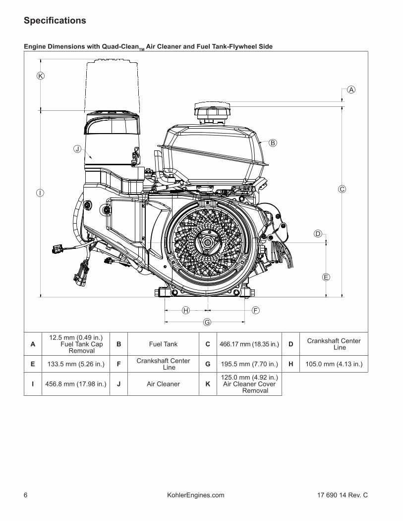
Engine Dimensions with Quad-CleanTM Air Cleaner and Fuel Tank-Flywheel Side
F
E
G
H
I
K
A
B
D
C
J
A12.5 mm (0.49 in.)
Fuel Tank Cap Removal
B Fuel Tank C 466.17 mm (18.35 in.) D Crankshaft Center Line
E 133.5 mm (5.26 in.) F Crankshaft Center Line G 195.5 mm (7.70 in.) H 105.0 mm (4.13 in.)
I 456.8 mm (17.98 in.) J Air Cleaner K125.0 mm (4.92 in.)Air Cleaner Cover
Removal

7
Specifi cations
17 690 14 Rev. C KohlerEngines.com
Engine Dimensions with Quad-CleanTM Air Cleaner and Fuel Tank-Top Side
A
B
C
A 493.0 mm (19.41 in.) B 195.6 mm (7.70 in.) C 498.2 mm (19.62 in.)

8
Specifi cations
KohlerEngines.com 17 690 14 Rev. C
Engine Dimensions with Quad-CleanTM Air Cleaner and Fuel Tank-PTO Side
G
F
H
I
J
B
C
E
D
K
B
D
E A
A Dipstick and Oil Fill Tube B 35.0 mm (1.38 in.) C
4 X M8 X 1.25-6H 18.00 mm
(0.71 in.) DeepD 45°
E 30° F 4 X 45° G 103.0 mm (4.06 in.) H Starter Motor
I Ø 127.0 mm (5.00 in.) J Ø 165.1 mm
(6.50 in.) K4 X M8 X 1.25-6H
20.00 mm (0.79 in.) Deep

9
Specifi cations
17 690 14 Rev. C KohlerEngines.com
Engine Dimensions with Quad-CleanTM Air Cleaner and Muffl er-Cylinder Head Side
F
E
G
HI
K
A
B
D
C
J
LM
N
OP
Q
RS
T
A 188.4 mm (7.42 in.) B 121.6 mm (4.79 in.) C Cylinder Center Line D 238.3 mm (9.38 in.)E Muffl er F Spark Plug G Wiring Harness H ECU
I 2 X Ø 11.25 mm (0.44 in.) J Oil Drain Plug K 6.0 mm (0.24 in.) L 103 mm (4.06 in.)
M 74.0 mm (2.91 in.) N 2 X 33.0 mm (1.30 in.) O 17.0 mm (0.67 in.) P2 X Ø 11.0 mm
(0.43 in.) X 28.0 mm (1.10 in.) Slot
Q 2 X 10.5 mm (0.41 in.) R 87.4 mm (3.44 in.) S PTO Mounting
Surface T 444.3 mm (17.49 in.)

10
Specifi cations
KohlerEngines.com 17 690 14 Rev. C
Engine Dimensions with Quad-CleanTM Air Cleaner and Muffl er-Flywheel Side
F
E
G
H
A
B
D
C
A Crankshaft Center Line B 133.5 mm (5.26 in.) C Crankshaft Center
Line D 195.5 mm (7.70 in.)
E 105.0 mm (4.13 in.) F 456.8 mm (17.98 in.) G Air Cleaner H125.0 mm (4.92 in.)
Air Cleaner Cover Removal

11
Specifi cations
17 690 14 Rev. C KohlerEngines.com
Engine Dimensions with Quad-CleanTM Air Cleaner and Muffl er-Top Side
A
B
C
A 465.1 mm (18.31 in.) B 165.3 mm (6.51 in.) C 468.6 mm (18.45 in.)

12
Specifi cations
KohlerEngines.com 17 690 14 Rev. C
Engine Dimensions-Quad CleanTM Air Cleaner and Muffl er PTO Side
F
E
G
H
I
A
B
D
J
A
C
K
L
F
E
A 35.0 mm (1.38 in.) B Dipstick Assembly C6 X 5/16-24 UNF-2B
Inch 18.00 mm (0.71 in.) Deep
D 103.0 mm (4.06 in.)
E 45° F 30° G 4 X 45° H Oxygen Sensor
I4 X 3/8-16 UNC-2B
Inch 20.00 mm (0.79 in.) Deep
J Ø 127.0 mm (5.00 in.) K Ø 165.1 mm
(6.50 in.) L Starter Motor
13
Specifi cations
17 690 14 Rev. C KohlerEngines.com
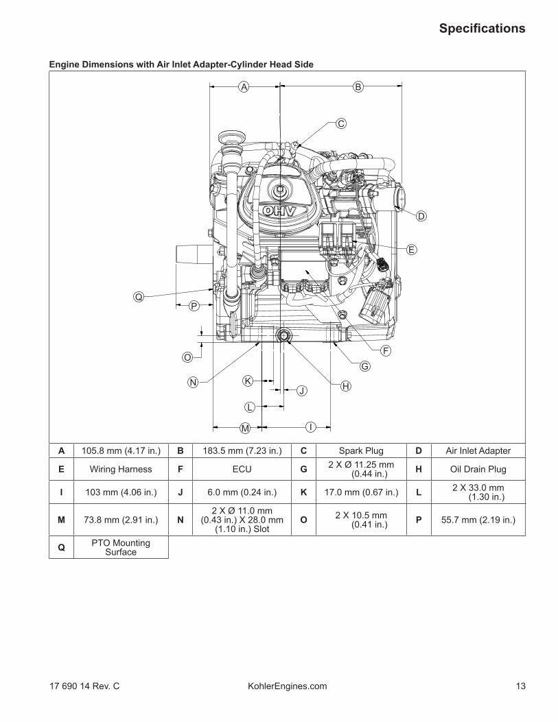
Engine Dimensions with Air Inlet Adapter-Cylinder Head Side
F
E
G
H
I
K
A B
D
C
J
L
M
N
O
PQ
A 105.8 mm (4.17 in.) B 183.5 mm (7.23 in.) C Spark Plug D Air Inlet Adapter
E Wiring Harness F ECU G 2 X Ø 11.25 mm (0.44 in.) H Oil Drain Plug
I 103 mm (4.06 in.) J 6.0 mm (0.24 in.) K 17.0 mm (0.67 in.) L 2 X 33.0 mm (1.30 in.)
M 73.8 mm (2.91 in.) N2 X Ø 11.0 mm
(0.43 in.) X 28.0 mm (1.10 in.) Slot
O 2 X 10.5 mm (0.41 in.) P 55.7 mm (2.19 in.)
Q PTO MountingSurface

14
Specifi cations
KohlerEngines.com 17 690 14 Rev. C
Engine Dimensions with Air Inlet Adapter-Flywheel Side
F
E
G
HI
K
A
B
D
C
J
L
M
A 265.0 mm (10.43 in.) B Dipstick and Oil FIll Tube C Air Inlet Adapter D 302.4 mm (11.91 in.)
E Crankshaft Center Line F 133.5 mm (5.26 in.) G Dipstick H Crankshaft Center
LineI 105.0 mm (4.13 in.) J 195.5 mm (7.70 in.) K 193.2 mm (7.61 in.) L 216.8 mm (8.54 in.)M 320.8 mm (12.63 in.)

15
Specifi cations
17 690 14 Rev. C KohlerEngines.com
Engine Dimensions with Air Inlet Adapter-Top Side
A
B
D
C
E
A 452.7 mm (17.82 in.) B 155.6 mm (6.13 in.) C 482.2 mm (18.99 in.) D Blower Housing
E Valve Cover

16
Specifi cations
KohlerEngines.com 17 690 14 Rev. C
Engine Dimensions with Air Inlet Adapter-PTO Side
F
E
G
H
I
A
B
D
JA
C
E
F
A 35.0 mm (1.38 in.) B Dipstick and Oil Fill Tube C
6 X M8 X 1.25-6H 18.00 mm
(0.71 in.) DeepD 103.0 mm (4.06 in.)
E 45° F 30° G 4 X 45° H4 X M8 X 1.25-6H
20.00 mm (0.79 in.) Deep
I Ø 127.0 mm (5.00 in.) J Ø 165.1 mm
(6.50 in.)

17
Specifi cations
17 690 14 Rev. C KohlerEngines.com
Engine Dimensions with Low-Profi le Air Cleaner and ECH440LE Muffl er-Cylinder Head Side
FE
GA
B
DC
A 343.1 mm (13.51 in.) B2 X Ø 11.0 mm
(0.43 in.) X 28.0 mm (1.10 in.) Slot
C 73.8 mm (2.91 in.) D 17.0 mm (0.67 in.)
E 106.8 mm (4.21 in.) F 176.8 mm (6.96 in.) G 2 X Ø 11.25 mm (0.44 in.)
18
Specifi cations
KohlerEngines.com 17 690 14 Rev. C
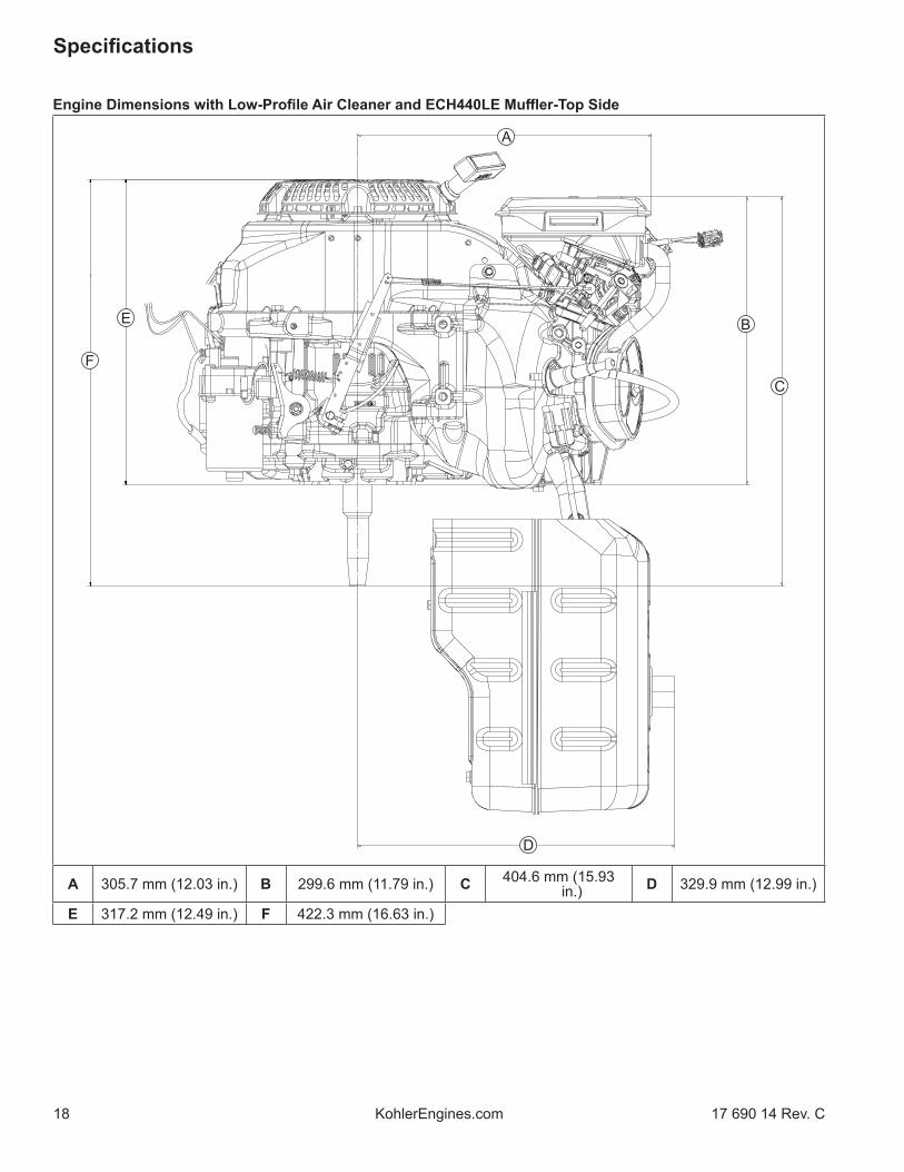
Engine Dimensions with Low-Profi le Air Cleaner and ECH440LE Muffl er-Top Side
F
E
A
B
D
C
A 305.7 mm (12.03 in.) B 299.6 mm (11.79 in.) C 404.6 mm (15.93 in.) D 329.9 mm (12.99 in.)
E 317.2 mm (12.49 in.) F 422.3 mm (16.63 in.)

19
Specifi cations
17 690 14 Rev. C KohlerEngines.com
Engine Dimensions with Low-Profi le Air Cleaner and ECH440LE Muffl er-PTO Side
G
F
HI
J
B
C
M
N
K
L
D
E
A
A 313.2 mm (12.33 in.) B 35.0 mm (1.38 in.) C 70.0 mm (2.76 in.) D 133.5 mm (5.26 in.)
E
Metric Flange: 6 X M8 X 1.25-6H 18.00 mm
(0.71 in.) DeepSAE B Flange: 6 X
5/16-24 UNF-2B Inch 18.00 mm (0.71 in.)
Deep
F 195.5 mm (7.70 in.) G 105.0 mm (4.13 in.) H 4 X 45°
I4 X 3/8-16 UNC-2B Inch
18.0 mm (0.71 in.) Deep
J Ø 127.0 mm (5.00 in.) K 265.1 mm (10.44 in.) L Ø 165.1 mm
(6.50 in.)
M 2 X 30° N 103.0 mm (4.06 in.)

20
Specifi cations
KohlerEngines.com 17 690 14 Rev. C
ENGINE IDENTIFICATION NUMBERSKohler engine identifi cation numbers (model, specifi cation and serial) should be referenced for effi cient repair, ordering correct parts, and engine replacement.
Model . . . . . . . . . . . . . . . . . . . . . ECH440EFI Command Engine
Horizontal ShaftNumerical Designation
Specifi cation . . . . . . . . . . . . . . . ECH440-3001Serial . . . . . . . . . . . . . . . . . . . . . 4923500328
Year Manufactured Code Factory Code Code Year 49 2019 50 2020 51 2021
GENERAL SPECIFICATIONS4,5 ECH440 ECH440LEBore 89 mm (3.5 in.)Stroke 69 mm (2.7 in.)Displacement 429 cc (26.2 cu. in.)Oil Capacity (refi ll) 1.1 L (1.16 U.S. qt.)Maximum Angle of Operation (@ full oil level)6 25°
TORQUE SEQUENCES ECH440 ECH440LE(Refer to Torque Specifi cations for torque values).Closure Plate
5
1
7
3
6
2
4
Cylinder Head1
4
2
3
4 Values are in Metric units. Values in parentheses are English equivalents.5 Any and all horsepower (hp) references by Kohler are Certifi ed Power Ratings and per SAE J1940 & J1995 hp standards. Details on Certifi ed Power Ratings can be found at KohlerEngines.com.6 Exceeding maximum angle of operation may cause engine damage from insuffi cient lubrication.

21
Specifi cations
17 690 14 Rev. C KohlerEngines.com
4 Values are in Metric units. Values in parentheses are English equivalents.7 Lubricate threads with engine oil prior to assembly.
TORQUE SPECIFICATIONS4,7 ECH440 ECH440LE
Air CleanerQuad-Clean™ Air Cleaner Base Mounting Nuts 8.0 N·m (71 in. lb.)Quad-Clean™ Air Cleaner Base Mounting Screw 8.0 N·m (71 in. lb.)Quad-Clean™ Base Cover Mounting Nuts 4.0 N·m (35 in. lb.)Quad-Clean™ Base Cover Mounting Screws 1.3 N·m (12 in. lb.)Low-Profi le Air Cleaner Base Mounting Nuts 8.0 N·m (71 in. lb.)Low-Profi le Air Cleaner Base Mounting Screw 6.7 N·m (59 in. lb.)Air Inlet Adapter Mounting Nuts 8.0 N·m (71 in. lb.)
Blower Housing and Sheet MetalM6 Screw 10 N·m (89 in. lb.)Lower Shield to Crankcase 8.5 N·m (75 in. lb.) into new holes
4.0 N·m (35 in. lb.) into used holesUpper Shield to Crankcase 6.2 N·m (55 in. lb.) into new holes
4.0 N·m (35 in. lb.) into used holesBlower Housing Screen Fastener 7.3 N·m (65 in. lb.)
Connecting RodCap Fastener (torque in increments) 20 N·m (177 in. lb.)
CrankcaseEngine Temperature Sensor Fastener 11.9 N·m (105 in. lb.)Extended Oil Fill Tube Bracket Screw (if equipped) 5.4 N·m (48 in. lb.)Oil Drain Plug 18 N·m (13 ft. lb.)Oil Sentry™ Level Switch Screw 8 N·m (71 in. lb.)Oil Sentry™ Module Screw 3.5 N·m (31 in. lb.)Oil Sentry™ Wire Lead Nut 10 N·m (89 in. lb.)
Closure Plate Screw (torque sequence on page 20)Fastener 24 N·m (212 in. lb.)
Cylinder Head (torque sequence on page 20)Fastener (torque in 2 increments) First to 25 N·m (221 in. lb.)
Finally to 57.5 N·m (509 in. lb.)Rocker Arm Stud 13.6 N·m (120 in. lb.)Rocker Arm Pivot Jam Nut 10 N·m (89 in. lb.)
TORQUE SEQUENCES ECH440 ECH440LE(Refer to Torque Specifi cations for torque values).Stator (18 Amp)
4
31
2

22
Specifi cations
KohlerEngines.com 17 690 14 Rev. C
TORQUE SPECIFICATIONS4,7 ECH440 ECH440LE
FlywheelRetaining Nut 113 N·m (1000 in. lb.)
Fuel Tank and BracketsMounting Nut 24 N·m (212 in. lb.)Mounting Screw 24 N·m (212 in. lb.)Side Strap Screw 10 N·m (89 in. lb.)Inlet Fitting 1.5 N·m (13 in. lb.)
GovernorLever Nut 12 N·m (106 in. lb.)Throttle Control Lever Nut (wave washer used) 5.3 N·m (47 in. lb.)Throttle Control Lever Nut (no wave washer used) 9 N·m (80 in. lb.)
IgnitionElectronic Control Unit (ECU) to Lower Shield Fastener 6.2 N·m (55 in. lb.) into new holes
4.0 N·m (35 in. lb.) into used holesSpark Plug 27 N·m (20 ft. lb.)Ignition Coil Fastener 10.2 N·m (90 in. lb.)Crankshaft Position Sensor to Bracket Screw 4.2 N·m (37 in. lb.)Crankshaft Position Sensor Bracket to Crankcase Screw 7.3 N·m (65 in. lb.)Ground Wire Fastener 7.3 N·m (65 in. lb.)
ECH440 Muffl erExhaust Screw M10 35 N·m (310 in. lb.)Muffl er Bracket or Flange M8 25 N·m (221 in. lb.)Muffl er Guard or Bracket Screw M6 10 N·m (89 in. lb.)Oxygen Sensor 14 mm (9/16 in.) wrench size 18 N·m (159 in. lb.)Spark Arrestor Screw M5 2.0 N·m (18 in. lb.)
ECH440LE Muffl erExhaust Screw M10 35 N·m (310 in. lb.)Muffl er Shield ScrewM6 ScrewM5 Screw
14 N·m (124 in. lb.)5.0 N·m (44 in. lb.)
Oxygen Sensor 14 mm (9/16 in.) wrench size 18 N·m (159 in. lb.)Spark Arrestor Screw M5 2.0 N·m (18 in. lb.)
Retractable StarterCover Screw 5.4 N·m (48 in. lb.)Center Screw 10 N·m (89 in. lb.)
Starter AssemblyMounting Screw 24 N·m (212 in. lb.)Starter Relay Mounting Screw 3.2 N·m (28 in. lb.)Starter Relay Nut 4.5 N·m (40 in. lb.)
4 Values are in Metric units. Values in parentheses are English equivalents.7 Lubricate threads with engine oil prior to assembly.

23
Specifi cations
17 690 14 Rev. C KohlerEngines.com
TORQUE SPECIFICATIONS4,7 ECH440 ECH440LE
Throttle BodyStuds 10 N·m (89 in. lb.)Primary Mounting Nuts 8.0 N·m (71 in. lb.)Temperature/Manifold Absolute Pressure (TMAP) Sensor Fastener 7.3 N·m (65 in. lb.)Throttle Position Sensor (TPS) 1.3 N·m (11.5 in. lb.)Fuel Cap Bracket Fastener 7.3 N·m (65 in. lb.)
Stator (torque sequence on page 21)Fastener 8.8 N·m (78 in. lb.)Stator Wire Bracket Fastener 10 N·m (89 in. lb.)
Valve CoverFastener 10 N·m (89 in. lb.)
CLEARANCE SPECIFICATIONS4 ECH440 ECH440LE
CamshaftRunning Clearance 0.016/0.052 mm (0.0006/0.0020 in.)Bore I.D. New 16.000/16.018 mm (0.6299/0.6306 in.) Max. Wear Limit 16.068 mm (0.6326 in.)Camshaft Bearing Surface O.D. New 15.975 mm (0.6289 in.) Max. Wear Limit 15.90 mm (0.626 in.)Cam Lobe Profi le (minimum dimension, measured from base circle to top of lobe) Intake - New 32.286 mm (1.271 in.) Max. Wear Limit 32.032 mm (1.261 in.) Exhaust - New 32.506 mm (1.280 in.) Max. Wear Limit 32.252 mm (1.270 in.)
Connecting RodCrankpin End I.D. @ 21°C (70°F) New 37.020/37.030 mm (1.4575/1.4579 in.) Max. Wear Limit 37.08 mm (1.460 in.)Connecting Rod-to-Crankpin Side Clearance New 0.56 mm (0.022 in.) Max. Wear Limit 1.06 mm (0.042 in.)Connecting Rod-to-Piston Pin Running Clearance 0.008/0.025 mm (0.0003/0.0010 in.)Piston Pin End I.D. @ 21°C (70°F) New 20.006/20.017 mm (0.7876/0.7881 in.) Max. Wear Limit 20.03 mm (0.789 in.)
CrankcaseGovernor Cross Shaft Bore I.D. New 8.000/8.024 mm (0.3150/0.3159 in.) Max. Wear Limit 8.075 mm (0.3179 in.)
4 Values are in Metric units. Values in parentheses are English equivalents.7 Lubricate threads with engine oil prior to assembly.

24
Specifi cations
KohlerEngines.com 17 690 14 Rev. C
CLEARANCE SPECIFICATIONS4 ECH440 ECH440LE
CrankshaftEnd Play (free) 0.0508/0.254 mm (0.002/0.010 in.)Ball Bearing Internal Clearance 0.006/0.020 mm (0.0002/0.0008 in.)Crankshaft O.D. (new) PTO end 34.975/34.989 mm (1.3770/1.3775 in.)
35.009/35.027 mm (1.3783/1.3790 in.) Flywheel endConnecting Rod Journal O.D. New 36.975/36.985 mm (1.4557/1.4561 in.) Max. Wear Limit 36.92 mm (1.4535 in.) Max. Taper Max. Out-of-Round
2.5 microns (0.0001 in.)12.7 microns (0.0005 in.)
Width 28.30/28.36 mm (1.1142/1.1165 in.)Runout (either end) 0.025 mm (0.001 in.)Main Bearing I.D. (Crankcase/Closure Plate) New (installed) 34.988/35.000 mm (1.3775/1.3779 in.)
Cylinder BoreBore I.D. New 89.000/89.015 mm (3.5039/3.5045 in.) Max. Wear Limit 89.185 mm (3.5112 in.) Max. Out-of-Round Max. Taper
12.7 microns (0.0005 in.)12.7 microns (0.0005 in.)
Cylinder HeadMax. Out-of-Flatness 0.1 mm (0.0039 in.)
GovernorGovernor Cross Shaft -to-Crankcase Running Clearance
0.020/0.069 mm (0.0008/0.0027 in.)
Governor Cross Shaft O.D. New 7.955/7.980 mm (0.3132/0.3142 in.) Max. Wear Limit 7.900 mm (0.3110 in.)Governor Gear Shaft-to-Governor Gear Running Clearance
0.022/0.134 mm (0.0009/0.0053 in.)
Governor Gear Shaft O.D. New Max. Wear Limit
6.016/6.028 mm (0.2368/0.2373 in.)6.003 mm (0.2363 in.)
IgnitionSpark Plug Gap 1.02 mm (0.040 in.)
4 Values are in Metric units. Values in parentheses are English equivalents.

25
Specifi cations
17 690 14 Rev. C KohlerEngines.com
CLEARANCE SPECIFICATIONS4 ECH440 ECH440LE
Piston, Piston Rings, and Piston PinPiston-to-Piston Pin Running Clearance 0.002/0.016 mm (0.0001/0.0006 in.)Piston Pin Bore I.D. New 20.000/20.008 mm (0.7874/0.7877 in.) Max. Wear Limit 20.05 mm (0.7894 in.)Piston Pin O.D. New 19.992/19.998 mm (0.7871/0.7873 in.) Max. Wear Limit 19.95 mm (0.7854 in.)Top and Center Compression Ring Side Clearance New Bore 0.045 mm (0.0018 in.) Used Bore (Max.) 0.10 mm (0.004 in.)Top Compression Ring End Gap New Bore 0.250/0.400 mm (0.010/0.016 in.) Used Bore (Max.) 1.00 mm (0.039 in.)Center Compression Ring End Gap New Bore 0.640/0.800 mm (0.025/0.032 in.) Used Bore (Max.) 1.50 mm (0.059 in.)Oil Control Ring-to-Groove Side Clearance 0.09/0.15 mm (0.0035/0.0059 in.)Piston Thrust Face O.D. New 88.955/88.975 mm (3.502/3.503 in.)8
Max. Wear Limit 88.82 mm (3.497 in.)Piston Thrust Face-to-Cylinder Bore Running Clearance 0.025/0.060 mm (0.001/0.002 in.)8
4 Values are in Metric units. Values in parentheses are English equivalents.8 Measure 29.8-30.2 mm (1.1732-1.1890 in.) above bottom of piston skirt at right angles to piston pin.

26
Specifi cations
KohlerEngines.com 17 690 14 Rev. C
CLEARANCE SPECIFICATIONS4 ECH440 ECH440LE
Valves and Valve LiftersIntake Valve Lash 0.0762/0.127 mm
(0.003/0.005 in.)0.0762/0.127 mm
(0.003/0.005 in.)Exhaust Valve Lash 0.0762/0.127 mm
(0.003/0.005 in.)0.1778/0.2286 mm
(0.007/0.009 in.)Intake Valve Stem-to-Valve Guide Running Clearance 0.025/0.055 mm (0.0010/0.0022 in.)Exhaust Valve Stem-to-Valve Guide Running Clearance 0.040/0.07 mm (0.0016/0.0028 in.)Intake Valve Stem O.D. New 6.57 mm (0.259 in.) Max. Wear Limit 6.40 mm (0.252 in.)Exhaust Valve Stem O.D. New 6.55 mm (0.258 in.) Max. Wear Limit 6.41 mm (0.252 in.)Intake Valve Stem to Guide New 0.025/0.055 mm (0.0010/0.0022 in.) Max. Wear Limit 0.14 mm (0.0055 in.)Exhaust Valve Stem to Guide New 0.040/0.070 mm (0.0016/0.0028 in.) Max. Wear Limit 0.11 mm (0.0043 in.)Valve Guide Reamer Size Standard Intake 6.608 mm (0.2602 in.) Standard Exhaust 6.608 mm (0.2602 in.)Valve Seat Width 1.20 mm (0.0472 in.)Nominal Valve Face Angle 45°
4 Values are in Metric units. Values in parentheses are English equivalents.

27
Specifi cations
17 690 14 Rev. C KohlerEngines.com
GENERAL TORQUE VALUES
Metric Fastener Torque Recommendations for Standard ApplicationsProperty Class Noncritical
Fasteners Into AluminumSize 4.8 5.8 8.8 10.9 12.9
Tightening Torque: N·m (in. lb.) ± 10%M4 1.2 (11) 1.7 (15) 2.9 (26) 4.1 (36) 5.0 (44) 2.0 (18)M5 2.5 (22) 3.2 (28) 5.8 (51) 8.1 (72) 9.7 (86) 4.0 (35)M6 4.3 (38) 5.7 (50) 9.9 (88) 14.0 (124) 16.5 (146) 6.8 (60)M8 10.5 (93) 13.6 (120) 24.4 (216) 33.9 (300) 40.7 (360) 17.0 (150)
Tightening Torque: N·m (ft. lb.) ± 10%M10 21.7 (16) 27.1 (20) 47.5 (35) 66.4 (49) 81.4 (60) 33.9 (25)M12 36.6 (27) 47.5 (35) 82.7 (61) 116.6 (86) 139.7 (103) 61.0 (45)M14 58.3 (43) 76.4 (56) 131.5 (97) 184.4 (136) 219.7 (162) 94.9 (70)
Torque ConversionsN·m = in. lb. x 0.113 in. lb. = N·m x 8.85N·m = ft. lb. x 1.356 ft. lb. = N·m x 0.737
English Fastener Torque Recommendations for Standard ApplicationsBolts, Screws, Nuts and Fasteners Assembled Into Cast Iron or Steel Grade 2 or 5 Fasteners
Into Aluminum
Size Grade 2 Grade 5 Grade 8Tightening Torque: N·m (in. lb.) ± 20%
8-32 2.3 (20) 2.8 (25) — 2.3 (20)10-24 3.6 (32) 4.5 (40) — 3.6 (32)10-32 3.6 (32) 4.5 (40) — —1/4-20 7.9 (70) 13.0 (115) 18.7 (165) 7.9 (70)1/4-28 9.6 (85) 15.8 (140) 22.6 (200) —
5/16-18 17.0 (150) 28.3 (250) 39.6 (350) 17.0 (150)5/16-24 18.7 (165) 30.5 (270) — —3/8-16 29.4 (260) — — —3/8-24 33.9 (300) — — —
Tightening Torque: N·m (ft. lb.) ± 20%5/16-24 — — 40.7 (30) —3/8-16 — 47.5 (35) 67.8 (50) —3/8-24 — 54.2 (40) 81.4 (60) —
7/16-14 47.5 (35) 74.6 (55) 108.5 (80) —7/16-20 61.0 (45) 101.7 (75) 142.5 (105) —1/2-13 67.8 (50) 108.5 (80) 155.9 (115) —1/2-20 94.9 (70) 142.4 (105) 223.7 (165) —
9/16-12 101.7 (75) 169.5 (125) 237.3 (175) —9/16-18 135.6 (100) 223.7 (165) 311.9 (230) —5/8-11 149.5 (110) 244.1 (180) 352.6 (260) —5/8-18 189.8 (140) 311.9 (230) 447.5 (330) —3/4-10 199.3 (147) 332.2 (245) 474.6 (350) —3/4-16 271.2 (200) 440.7 (325) 637.3 (470) —

Tools and Aids
28 17 690 14 Rev. CKohlerEngines.com
Certain quality tools are designed to help you perform specifi c disassembly, repair, and reassembly procedures. By using these tools, you can properly service engines easier, faster, and safer! In addition, you’ll increase your service capabilities and customer satisfaction by decreasing engine downtime.Here is a list of tools and their source.NOTE: Not all tools listed are required to service this engine.SEPARATE TOOL SUPPLIERSKohler Tools Contact your local Kohler source of supply.
SE Tools 415 Howard St.Lapeer, MI 48446Phone 810-664-2981Toll Free 800-664-2981Fax 810-664-8181
Design Technology Inc.768 Burr Oak DriveWestmont, IL 60559Phone 630-920-1300Fax 630-920-0011
TOOLSDescription Source/Part No.Alcohol Content TesterFor testing alcohol content (%) in reformulated/oxygenated fuels.
Kohler 25 455 11-S
Camshaft Endplay PlateFor checking camshaft endplay.
SE Tools KLR-82405
Camshaft Seal Protector (Aegis)For protecting seal during camshaft installation.
SE Tools KLR-82417
Cylinder Leakdown TesterFor checking combustion retention and if cylinder, piston, rings, or valves are worn.Individual component available:Adapter 12 mm x 14 mm (Required for leakdown test on XT-6 engines)
Kohler 25 761 05-S
Design Technology Inc.DTI-731-03
Dealer Tool Kit (Domestic)Complete kit of Kohler required tools.Components of 25 761 39-SIgnition System TesterCylinder Leakdown TesterOil Pressure Test KitRectifi er-Regulator Tester (120 V AC/60Hz)
Kohler 25 761 39-S
Kohler 25 455 01-SKohler 25 761 05-SKohler 25 761 06-SKohler 25 761 20-S
Dealer Tool Kit (International)Complete kit of Kohler required tools.Components of 25 761 42-SIgnition System TesterCylinder Leakdown TesterOil Pressure Test KitRectifi er-Regulator Tester (240 V AC/50Hz)
Kohler 25 761 42-S
Kohler 25 455 01-SKohler 25 761 05-SKohler 25 761 06-SKohler 25 761 41-S
Digital Vacuum/Pressure TesterFor checking crankcase vacuum.Individual component available:Rubber Adapter Plug
Design Technology Inc.DTI-721-01
Design Technology Inc.DTI-721-10
Electronic Fuel Injection (EFI) Diagnostic SoftwareFor Laptop or Desktop PC.
Kohler 25 761 23-S
EFI Service KitFor troubleshooting and setting up an EFI engine.Components of 24 761 01-SFuel Pressure TesterNoid Light90° AdapterCode Plug, Red WireCode Plug, Blue WireShrader Valve Adapter HoseWire Probe Set (2 pieces regular wire with clip; 1 piece fused wire)Hose Removal Tool, Dual Size/End (also sold as individual Kohler tool)K-Line Adapter Jumper Lead Wiring Harness
Kohler 24 761 01-S
Design Technology Inc.DTI-019DTI-021DTI-023DTI-027DTI-029DTI-037DTI-031DTI-033
Kohler 25 176 23-SKohler Wireless Diagnostic System Module (Bluetooth®)For wireless Android EFI diagnostics.Individual component available:Wireless Diagnostic System Interface Cable
Kohler 25 761 45-S
Kohler 25 761 44-S

Tools and Aids
2917 690 14 Rev. C KohlerEngines.com
TOOLSDescription Source/Part No.Flywheel PullerFor properly removing fl ywheel from engine.
SE Tools KLR-82408
Hose Removal Tool, Dual Size/End (also available in EFI Service Kit)Used to properly remove fuel hose from engine components.
Kohler 25 455 20-S
Hydraulic Valve Lifter ToolFor removing and installing hydraulic lifters.
Kohler 25 761 38-S
Ignition System TesterFor testing output on all systems, including CD.
Kohler 25 455 01-S
Inductive Tachometer (Digital)For checking operating speed (RPM) of an engine.
Design Technology Inc.DTI-110
Off set Wrench (K and M Series) For removing and reinstalling cylinder barrel retaining nuts.
Kohler 52 455 04-S
Oil Pressure Test KitFor testing/verifying oil pressure on pressure lubricated engines.
Kohler 25 761 06-S
Rectifi er-Regulator Tester (120 volt current)Rectifi er-Regulator Tester (240 volt current)For testing rectifi er-regulators.Components of 25 761 20-S and 25 761 41-SCS-PRO Regulator Test HarnessSpecial Regulator Test Harness with Diode
Kohler 25 761 20-SKohler 25 761 41-S
Design Technology Inc.DTI-031RDTI-033R
Spark Advance Module (SAM) TesterFor testing SAM (ASAM and DSAM) on engines with SMART-SPARK™.
Kohler 25 761 40-S
Starter Servicing Kit (All Starters)For removing and reinstalling drive retaining rings and brushes.Individual component available:Starter Brush Holding Tool (Solenoid Shift)
SE Tools KLR-82411
SE Tools KLR-82416Stepper Motor Controller ToolFor testing operation of stepper motor/Digital Linear Actuator (DLA).
Kohler 25 455 21-S
Jumper Lead ToolFor use with Stepper Motor Controller Tool to test rotary stepper motor.
Kohler 25 518 43-S
Triad/OHC Timing Tool SetFor holding cam gears and crankshaft in timed position while installing timing belt.
Kohler 28 761 01-S
Valve Guide Reamer (K and M Series)For properly sizing valve guides after installation.
Design Technology Inc.DTI-K828
Valve Guide Reamer O.S. (Command Series)For reaming worn valve guides to accept replacement oversize valves. Can be used in low-speed drill press or with handle below for hand reaming.
Kohler 25 455 12-S
Reamer HandleFor hand reaming using Kohler 25 455 12-S reamer.
Design Technology Inc.DTI-K830
AIDSDescription Source/Part No.Camshaft Lubricant (Valspar ZZ613) Kohler 25 357 14-SDielectric Grease (GE/Novaguard G661) Kohler 25 357 11-SDielectric Grease Loctite® 51360Kohler Electric Starter Drive Lubricant (Inertia Drive) Kohler 52 357 01-SKohler Electric Starter Drive Lubricant (Solenoid Shift) Kohler 52 357 02-SRTV Silicone Sealant Loctite® 5900® Heavy Body in 4 oz. aerosol dispenser. Only oxime-based, oil resistant RTV sealants, such as those listed, are approved
for use. Permatex® the Right Stuff ® 1 Minute Gasket™ or Loctite® Nos. 5900® or 5910® are recommended for best sealing characteristics.
Kohler 25 597 07-SLoctite® 5910®
Loctite® Ultra Black 598™Loctite® Ultra Blue 587™
Loctite® Ultra Copper 5920™Permatex® the Right Stuff ® 1
Minute Gasket™Spline Drive Lubricant Kohler 25 357 12-S

Tools and Aids
30 17 690 14 Rev. CKohlerEngines.com
FLYWHEEL HOLDING TOOL ROCKER ARM/CRANKSHAFT TOOL
A fl ywheel holding tool can be made out of an old junk fl ywheel ring gear and used in place of a strap wrench.1. Using an abrasive cut-off wheel, cut out a six tooth
segment of ring gear as shown.2. Grind off any burrs or sharp edges.3. Invert segment and place it between ignition bosses
on crankcase so tool teeth engage fl ywheel ring gear teeth. Bosses will lock tool and fl ywheel in position for loosening, tightening, or removing with a puller.
A spanner wrench to lift rocker arms or turn crankshaft may be made out of an old junk connecting rod.1. Find a used connecting rod from a 10 HP or larger
engine. Remove and discard rod cap.2. Remove studs of a Posi-Lock rod or grind off
aligning steps of a Command rod, so joint surface is fl at.
3. Find a 1 in. long capscrew with correct thread size to match threads in connecting rod.
4. Use a fl at washer with correct I.D. to slip on capscrew and approximately 1 in. O.D. Assemble capscrew and washer to joint surface of rod.

3117 690 14 Rev. C KohlerEngines.com
Troubleshooting
Engine Cranks But Will Not Start● Battery connected backwards.● Blown fuses.● Clogged fuel line or fuel fi lter.● Empty fuel tank.● Faulty ignition coil.● Faulty spark plug.● Fuel pump malfunction-vacuum hose clogged or
leaking.● Fuel shut-off valve closed.● Insuffi cient voltage to electronic control unit.● Interlock switch is engaged or faulty.● Key switch or kill switch in OFF position.● Quality of fuel (dirt, water, stale, mixture).● Spark plug lead disconnected.Engine Starts But Does Not Keep Running● Faulty cylinder head gasket.● Faulty or misadjusted throttle controls.● Fuel pump malfunction-vacuum hose clogged or
leaking.● Intake system leak.● Loose wires or connections that intermittently ground
ignition kill circuit.● Quality of fuel (dirt, water, stale, mixture).● Restricted fuel tank cap vent.Engine Starts Hard● Clogged fuel line or fuel fi lter.● Engine overheated.● Faulty ACR mechanism (if equipped).● Faulty spark plug.● Flywheel key sheared.● Fuel pump malfunction-vacuum hose clogged or
leaking.● Interlock switch is engaged or faulty.● Loose wires or connections that intermittently ground
ignition kill circuit.● Low compression.● Quality of fuel (dirt, water, stale, mixture).● Weak spark.Engine Will Not Crank● Battery is discharged.● Faulty electric starter or solenoid.● Faulty key switch or ignition switch.● Interlock switch is engaged or faulty.● Loose wires or connections that intermittently ground
ignition kill circuit.● Pawls not engaging in drive cup (Retractable Start).● Seized internal engine components.
TROUBLESHOOTING GUIDEWhen troubles occur, be sure to check simple causes which, at fi rst, may seem too obvious to be considered. For example, a starting problem could be caused by an empty fuel tank.NOTE: A battery is required to supply power to EFI system to start engine with a retractable starter. An EFI engine
will not operate without a battery connected to system.Some general common causes of EFI engine troubles are listed below and vary by engine specifi cation. Use these to locate causing factors.
Engine Runs But Misses● Fuel system issue (Fuel Injector).● Engine overheated.● Faulty spark plug.● Ignition coil faulty.● Incorrect crankshaft position sensor air gap.● Interlock switch is engaged or faulty.● Loose wires or connections that intermittently ground
ignition kill circuit.● Quality of fuel (dirt, water, stale, mixture).● Spark plug lead disconnected.● Spark plug lead boot loose on plug.● Spark plug lead loose.Engine Will Not Idle● Engine overheated.● Faulty spark plug.● Idle speed adjusting screw improperly set.● Inadequate fuel supply.● Low compression.● Quality of fuel (dirt, water, stale, mixture).● Restricted fuel tank cap vent.Engine Overheats● Cooling fan broken.● Excessive engine load.● High crankcase oil level.● Lean fuel mixture.● Low crankcase oil level.● Cooling system components clogged or restricted.Engine Knocks● Excessive engine load.● Incorrect valve lash adjustment.● Incorrect oil viscosity/type.● Internal wear or damage.● Low crankcase oil level.● Quality of fuel (dirt, water, stale, mixture).● Loose/worn pulley/clutch on crankshaft PTO.

Troubleshooting
32 17 690 14 Rev. CKohlerEngines.com
Engine Loses Power● Dirty air cleaner element.● Engine overheated.● Excessive engine load.● Restricted exhaust.● Faulty spark plug.● High crankcase oil level.● Incorrect governor setting.● Low battery.● Low compression.● Low crankcase oil level.● Quality of fuel (dirt, water, stale, mixture).Engine Uses Excessive Amount of Oil● Loose or improperly torqued fasteners.● Blown head gasket/overheated.● Breather reed broken.● Clogged, broken, or inoperative crankcase breather.● Crankcase overfi lled.● Incorrect oil viscosity/type.● Worn cylinder bore.● Worn or broken piston rings.● Worn valve stems/valve guides.Oil Leaks from Oil Seals, Gaskets● Breather reed broken.● Clogged, broken, or inoperative crankcase breather.● Loose or improperly torqued fasteners.● Piston blow by, or leaky valves.● Restricted exhaust.
EXTERNAL ENGINE INSPECTIONNOTE: It is good practice to drain oil at a location away
from workbench. Be sure to allow ample time for complete drainage.
Before cleaning or disassembling engine, make a thorough inspection of its external appearance and condition. This inspection can give clues to what might be found inside engines (and cause) when it is disassembled.● Check for buildup of dirt and debris on crankcase,
cooling fi ns, grass screen, and other external surfaces. Dirt or debris on these areas can cause overheating.
● Check for obvious fuel and oil leaks, and damaged components. Excessive oil leakage can indicate a clogged or inoperative breather, worn or damaged seals or gaskets, or loose fasteners.
● Check air cleaner cover and base for damage or indications of improper fi t and seal.
● Check air cleaner element. Look for holes, tears, cracked or damaged sealing surfaces, or other damage that could allow unfi ltered air into engine. A dirty or clogged element could indicate insuffi cient or improper maintenance.
● Check throttle body throat for dirt. Dirt in throat is further indication that air cleaner was not functioning properly.
● Check if oil level is within operating range on dipstick. If it is above, sniff for gasoline odor.
● Check condition of oil. Drain oil into a container; it should fl ow freely. Check for metal chips and other foreign particles.
Sludge is a natural by-product of combustion; a small accumulation is normal. Excessive sludge formation could indicate over rich fuel settings, weak ignition, overextended oil change interval or wrong weight or type of oil was used.
CLEANING ENGINE
WARNINGCleaning Solvents can cause severe injury or death.Use only in well ventilated areas away from ignition sources.
Carburetor cleaners and solvents are extremely fl ammable. Follow cleaner manufacturer’s warnings and instructions on its proper and safe use. Never use gasoline as a cleaning agent.
After inspecting external condition of engine, clean engine thoroughly before disassembly. Clean individual components as engine is disassembled. Only clean parts can be accurately inspected and gauged for wear or damage. There are many commercially available cleaners that will quickly remove grease, oil, and grime from engine parts. When such a cleaner is used, follow manufacturer’s instructions and safety precautions carefully.Make sure all traces of cleaner are removed before engine is reassembled and placed into operation. Even small amounts of these cleaners can quickly break down lubricating properties of engine oil.

3317 690 14 Rev. C KohlerEngines.com
Troubleshooting
Condition ConclusionCrankcase breather clogged or inoperative. NOTE: If breather is integral part of valve cover and
cannot be serviced separately, replace valve cover and recheck pressure.
Disassemble breather, clean parts thoroughly, check sealing surfaces for fl atness, reassemble, and recheck pressure.
Seals and/or gaskets leaking. Loose or improperly torque fasteners.
Replace all worn or damaged seals and gaskets. Make sure all fasteners are tightened securely. Use appropriate torque valves and sequences when necessary.
Piston blow by or leaky valves (confi rm by inspecting components).
Recondition piston, rings, cylinder bore, valves and valves guides.
Restricted exhaust. Check exhaust screen/spark arrestor (if equipped). Clean or replace as needed. Repair or replace any other damaged/restricted muffl er or exhaust system parts.
CRANKCASE VACUUM TEST
WARNINGCarbon Monoxide can cause severe nausea, fainting or death.Avoid inhaling exhaust fumes. Never run engine indoors or in enclosed spaces.
Engine exhaust gases contain poisonous carbon monoxide. Carbon monoxide is odorless, colorless, and can cause death if inhaled.
To test crankcase vacuum with manometer:1. Insert rubber stopper into oil fi ll hole. Be sure pinch
clamp is installed on hose and use tapered adapters to connect hose between stopper and one manometer tube. Leave other tube open to atmosphere. Check that water level in manometer is at 0 line. Make sure pinch clamp is closed.
2. Start engine and run no-load high speed.3. Open clamp and note water level in tube. Level in engine side should be a minimum of
10.2 cm (4 in.) above level in open side. If level in engine side is less than specifi ed (low/no
vacuum), or level in engine side is lower than level in open side (pressure), check for conditions in table below.
4. Close pinch clamp before stopping engine.
To test crankcase vacuum with vacuum/pressure gauge:1. Remove dipstick or oil fi ll plug/cap.2. Install adapter into oil fi ll//dipstick tube opening,
upside down over end of a small diameter dipstick tube, or directly into engine if a tube is not used. Insert barbed gauge fi tting into hole in stopper.
3. Run engine and observe gauge reading. Analog tester–needle movement to left of 0 is a
vacuum, and movement to right indicates a pressure. Digital tester–depress test button on top of tester. Crankcase vacuum should be a minimum of 10.2 cm
(4 in.) of water. If reading is below specifi cation, or if pressure is present, check table below for possible causes and conclusions.
WARNING
Rotating Parts can cause severe injury.Stay away while engine is in operation.
Keep hands, feet, hair, and clothing away from all moving parts to prevent injury. Never operate engine with covers, shrouds, or guards removed.
A partial vacuum should be present in crankcase when engine is operating. Pressure in crankcase (normally caused by a clogged or improperly assembled breather) can cause oil to be forced out at oil seals, gaskets, or other available spots.Crankcase vacuum is best measured with either a water manometer or a vacuum gauge. Complete instructions are provided in kits.

Troubleshooting
34 17 690 14 Rev. CKohlerEngines.com
COMPRESSION TESTA compression test is best performed on a warm engine. Clean any dirt or debris away from base of spark plug before removing it. Be sure battery is fully charged, unplug ECU, and throttle is wide open during test. Compression should be at least 160 psi.Some models may be equipped with an automatic compression release (ACR) mechanism. It is diffi cult to obtain an accurate compression reading because of ACR mechanism. As an alternative, use cylinder leakdown test described below.CYLINDER LEAKDOWN TESTA cylinder leakdown test can be a valuable alternative to a compression test. By pressurizing combustion chamber from an external air source you can determine if valves or rings are leaking, and how badly.Cylinder leakdown tester is a relatively simple, inexpensive leakdown tester for small engines. This tester includes a quick-connect for attaching adapter hose and a holding tool.1. Run engine for 3-5 minutes to warm it up.2. Remove spark plug and air fi lter from engine.3. Rotate crankshaft until piston (of cylinder being tested) is at top dead center (TDC) of compression stroke. Hold
engine in this position while testing. Holding tool supplied with tester can be used if PTO end of crankshaft is accessible. Lock holding tool onto crankshaft. Install a 3/8 in. breaker bar into hole/slot of holding tool, so it is perpendicular to both holding tool and crankshaft PTO.
If fl ywheel end is more accessible, use a breaker bar and socket on fl ywheel nut/screw to hold it in position. An assistant may be needed to hold breaker bar during testing. If engine is mounted in a piece of equipment, it may be possible to hold it by clamping or wedging a driven component. Just be certain that engine cannot rotate off of TDC in either direction.
4. Install adapter into spark plug hole, but do not attach it to tester at this time.5. Turn regulator knob completely counterclockwise.6. Connect an air source of at least 50 psi to tester.7. Turn regulator knob clockwise (increase direction) until gauge needle is in yellow set area at low end of scale.8. Connect tester quick-connect to adapter hose. While fi rmly holding engine at TDC, gradually open tester valve.
Note gauge reading and listen for escaping air at combustion air intake, exhaust outlet, and crankcase breather.
Condition ConclusionAir escaping from crankcase breather. Ring or cylinder worn.Air escaping from exhaust system. Defective exhaust valve/improper seating.Air escaping from intake. Defective intake valve/improper seating.Gauge reading in low (green) zone. Piston rings and cylinder in good condition.Gauge reading in moderate (yellow) zone. Engine is still usable, but there is some wear present.
Customer should start planning for overhaul or replacement.
Gauge reading in high (red) zone. Rings and/or cylinder have considerable wear. Engine should be reconditioned or replaced.

35
Air Cleaner/Intake
17 690 14 Rev. C KohlerEngines.com
AIR CLEANERThese systems are CARB/EPA certifi ed and components should not be altered or modifi ed in any way.Quad-Clean™ Air Cleaner Components
B
GD
C
F
A
E
A Air Cleaner Cover B BailC Precleaner D Paper Element
E Air Cleaner Base F Air Cleaner Base Cover
G Breather HoseLow-Profi le Air Cleaner Components
K
L
JI
H
H Screw I Air Cleaner CoverJ Foam Element K Air Cleaner BaseL Breather Hose
Air Inlet Adapter Components
N
M
M Air Inlet Adapter N Breather Hose
NOTE: Running engine with cover positioned for cold weather operation in normal conditions can damage engine.
NOTE: Operating engine with loose or damaged air cleaner components could cause premature wear and failure. Replace all bent or damaged components.
Quad-Clean™
Move bails on air cleaner cover down; remove latches from under tabs on base; remove cover.Precleaner1. Remove precleaner.2. Replace or wash precleaner in warm water with
detergent. Rinse and allow to air dry.3. Lightly oil precleaner with new engine oil; squeeze
out excess oil.4. Reinstall precleaner.Paper Element1. Separate precleaner from element; service
precleaner and replace paper element.2. Install new paper element on base; install precleaner
over paper element.Position air cleaner cover for normal operation (sun decal out) or cold weather operation (snowfl ake decal out); place latches under tabs on base; lift up bails to secure cover.
Low-Profi le1. Remove screw and air cleaner cover.2. Remove foam element from base.3. Wash foam element in warm water with detergent.
Rinse and allow to air dry.4. Lightly oil foam element with new engine oil;
squeeze out excess oil.5. Reinstall foam element into base.6. Reinstall cover and secure with screw.

36
Air Cleaner/Intake
KohlerEngines.com 17 690 14 Rev. C
Air Inlet AdapterNOTE: Refer to equipment manufacturer's manual for
air cleaner they supply.1. Disconnect one end of breather hose from valve
cover or air inlet adapter.2. Remove nuts securing air inlet adapter to throttle
body.3. Remove air inlet adapter and gasket from mounting
studs.BREATHER TUBEEnsure both ends of breather tube are properly connected.
AIR COOLING
WARNINGHot Parts can cause severe burns.Do not touch engine while operating or just after stopping.
Never operate engine with heat shields or guards removed.
Proper cooling is essential. To prevent over heating, clean screens, cooling fi ns, and other external surfaces of engine. Avoid spraying water at wiring harness or any electrical components. Refer to Maintenance Schedule.

3717 690 14 Rev. C KohlerEngines.com
EFI SYSTEM
WARNINGExplosive Fuel can cause fi res and severe burns.Do not fi ll fuel tank while engine is hot or running.
Gasoline is extremely fl ammable and its vapors can explode if ignited. Store gasoline only in approved containers, in well ventilated, unoccupied buildings, away from sparks or fl ames. Spilled fuel could ignite if it comes in contact with hot parts or sparks from ignition. Never use gasoline as a cleaning agent.
NOTE: Engines in this series have fuel pump module, lift fuel pump, and EFI fuel fi lter installed by OEM in application. Refer to equipment manufacturer's manual for installation information. Refer to KohlerEngines.com site for replacement parts.
NOTE: Some fuel/vent lines are supplied by OEM. Refer to equipment manufacturer's manual for fuel/vent line information.
Typical electronic fuel injection (EFI) system and related components include:● Fuel pump module and lift pump.● Fuel fi lter.● High pressure fuel line.● Fuel line(s).● Fuel injector.● Throttle body.● Electronic control unit (ECU).● Ignition coil.● Engine temperature sensor.● Throttle position sensor (TPS).● Crankshaft position sensor.● Oxygen sensor.● Temperature/Manifold Absolute Pressure (TMAP)
sensor.● Wire harness assembly & affi liated wiring.● 10 Amp fuse (ignition switch).● 10 Amp fuse (battery power).● Malfunction indicator light (MIL) - optional.
FUEL RECOMMENDATIONSRefer to Maintenance.FUEL LINELow permeation fuel line must be installed on all Kohler Co. engines to maintain EPA and CARB regulatory compliance.OPERATIONNOTE: When performing voltage or continuity tests,
avoid putting excessive pressure on or against connector pins. Pin probes (maximum diameter 0.81 mm (0.032 in.) approximately) are recommended for testing to avoid spreading or bending terminals.
EFI system is designed to provide peak engine performance with optimum fuel effi ciency and lowest possible emissions. Ignition and injection functions are electronically controlled, monitored and continually corrected during operation to maintain ideal air/fuel ratio.
Central component of system is Electronic Control Unit (ECU) which manages system operation, determining best combination of fuel mixture and ignition timing for current operating conditions.A lift fuel pump is used to move fuel from tank through an in-line fuel fi lter and fuel line. Fuel is then pumped to fuel pump module. Fuel pump module regulates fuel pressure to a system operating pressure of 39 psi. Fuel is delivered from fuel pump module through high pressure fuel line into injector, which injects fuel into intake port. ECU controls amount of fuel by varying length of time that injector is on. This can range from 2 to over 12 milliseconds depending on fuel requirements. Controlled injection of fuel occurs every other crankshaft revolution, or once for each 4-stroke cycle. When intake valve opens, air/fuel mixture is drawn into combustion chamber, where it is compressed, ignited, and burned.ECU controls amount of fuel being injected and ignition timing by monitoring primary sensor signals for engine temperature, speed (RPM), and throttle position (load). These primary signals are compared to preprogrammed maps in ECU computer chip, and ECU adjusts fuel delivery to match mapped values. After engine reaches operating temperature, an exhaust gas oxygen sensor provides feedback to ECU based upon amount of unused oxygen in exhaust, indicating whether fuel mixture being delivered is rich or lean. Based upon this feedback, ECU further adjusts fuel input to re-establish ideal air/fuel ratio. This operating mode is referred to as closed loop operation. EFI system operates closed loop when all three of following conditions are met:● Engine temperature is greater than 50°C (122°F).● Oxygen sensor has warmed suffi ciently to provide a
signal (minimum 400°C, 752°F).● Engine operation is at a steady state (not starting,
warming up, accelerating, etc.).
During closed loop operation ECU has ability to readjust temporary and learned adaptive controls, providing compensation for changes in overall engine condition and operating environment, so it will be able to maintain ideal air/fuel ratio. This system requires a minimum engine temperature of 50°C (122°F) to properly adapt. These adaptive values are maintained as long as ECU is not reset.During certain operating periods such as cold starts, warm up, acceleration, high load, etc., a richer air/fuel ratio is required and system operates in an open loop mode. In open loop operation oxygen sensor output is used to ensure engine is running rich, and controlling adjustments are based on primary sensor signals and programmed maps only. This system operates open loop whenever three conditions for closed loop operation (above) are not being met.ECU is brain or central processing computer of entire EFI system. During operation, sensors continuously gather data which is relayed through wiring harness to input circuits within ECU. Signals to ECU include: ignition (on/off ), crankshaft position and speed (RPM), throttle position, engine temperature, intake air temperature, exhaust oxygen levels, manifold absolute pressure, and battery voltage.

EFI SYSTEM
38 17 690 14 Rev. CKohlerEngines.com
ECU compares input signals to programmed maps in its memory to determine appropriate fuel and spark requirements for immediate operating conditions. ECU then sends output signals to set injector duration and ignition timing.ECU continually performs a diagnostic check of itself, each sensor, and system performance. If a fault is detected, ECU can turn on a Malfunction Indicator Light (MIL) (if equipped) on equipment control panel, store fault code in its fault memory, and go into a default operating mode. Depending on signifi cance or severity of fault, normal operation may continue. A technician can access stored fault code using a fault code diagnosis fl ashed out through MIL. An optional computer software diagnostic program is also available, see Tools and Aids.ECU requires a minimum of 6.0 volts to operate.To prevent engine over-speed and possible failure, a rev-limiting feature is programmed into ECU. If maximum RPM limit (4500) is exceeded, ECU suppresses injection signals, cutting off fuel fl ow. This process repeats itself in rapid succession, limiting operation to preset maximum.Wiring harness used in EFI system connects electrical components, providing current and ground paths for system to operate. All input and output signaling occurs through two special all weather connectors that attach and lock to ECU. Connectors are Black and Grey and keyed diff erently to prevent being attached to ECU incorrectly.Condition of wiring, connectors, and terminal connections is essential to system function and performance. Corrosion, moisture, and poor connections are as likely cause of operating problems and system errors as an actual component. Refer to Electrical System for additional information.EFI system is a 12 VDC negative ground system, designed to operate down to a minimum of 6.0 volts. If system voltage drops below this level, operation of voltage sensitive components such as ECU, fuel pump, ignition coil, and injector will be intermittent or disrupted, causing erratic operation or hard starting. A fully charged, 12 volt battery with a minimum of 350 cold cranking amps is important in maintaining steady and reliable system operation. Battery condition and state of charge should always be checked fi rst when troubleshooting an operational problem.For systems with a retractable starter, a minimum battery of 12 volts, 4 amp hours is required.Keep in mind that EFI-related problems are often caused by wiring harness or connections. Even small amounts of corrosion or oxidation on terminals can interfere with milliamp currents used in system operation.Cleaning connectors and grounds will solve problems in many cases. In an emergency situation, simply disconnecting and reconnecting connectors may clean up contacts enough to restore operation, at least temporarily.If a fault code indicates a problem with an electrical component, disconnect ECU connector and test for continuity between component connector terminals and corresponding terminals in ECU connector using an ohmmeter. Little or no resistance should be measured, indicating that wiring of that particular circuit is OK.
Crankshaft position sensor is essential to engine operation; constantly monitoring rotation and speed (RPM) of crankshaft. There are 23 consecutive teeth cast into fl ywheel. One tooth is missing and is used to reference crankshaft position for ECU.When ignition is turned ON, ECU captures and records battery voltage. During engine start (cranking) voltage drops 2+ volts. When ECU receives voltage drop input, it then looks for a signal from crankshaft position sensor. During rotation, an AC voltage pulse is created within sensor for each passing tooth. ECU calculates engine speed from time interval between consecutive pulses. Gap from missing tooth creates an interrupted input signal, corresponding to specifi c crankshaft position near BDC for cylinder. This signal serves as a reference for control of ignition timing by ECU. Synchronization of inductive speed pickup and crankshaft position takes place during fi rst two revolutions each time engine is started. Sensor must be properly connected at all times. If sensor becomes disconnected for any reason, engine will quit running.Throttle position sensor (TPS) is used to indicate throttle plate angle to ECU. Since throttle (by way of governor) reacts to engine load, angle of throttle plate is directly related to load on engine.Mounted on throttle body and operated directly off end of throttle shaft, TPS works by varying voltage signal to ECU in direct correlation to angle of throttle plate. This signal, along with other sensor signals, is processed by ECU and compared to internal preprogrammed maps to determine required fuel and ignition settings for amount of load.Correct position of TPS is established and set at factory. Do not loosen TPS or alter mounting position unless absolutely required by fault code diagnosis. If TPS is loosened or repositioned, appropriate TPS Learn Procedure must be performed to re-establish baseline relationship between ECU and TPS.Engine temperature sensor is used by system to help determine fuel requirements for starting (a cold engine needs more fuel than one at or near operating temperature).Mounted on cylinder head, it has a temperature-sensitive resistor. Resistance changes with engine temperature, altering voltage sent to ECU. Using a table stored in its memory, ECU correlates voltage drop to a specifi c temperature. Using fuel delivery maps, ECU then knows how much fuel is required for starting at that temperature.Temperature/Manifold Absolute Pressure (TMAP) sensor is an integrated sensor that checks both intake air temperature and manifold absolute pressure.Intake Air Temperature control is a thermally sensitive resistor that exhibits a change in electrical resistance with a change in its temperature. When sensor is cold, resistance of sensor is high. As sensor warms up, resistance drops and voltage signal increases. From voltage signal, ECU can determine temperature of intake air.

3917 690 14 Rev. C KohlerEngines.com
EFI SYSTEM
Purpose of sensing air temperature is to help ECU calculate air density. Higher air temperature less dense air becomes. As air becomes less dense ECU knows that it needs to lessen fuel fl ow to achieve correct air/fuel ratio. If fuel fl ow was not changed engine would become rich, possibly losing power and consuming more fuel.Manifold Absolute Pressure check provides immediate manifold pressure information to ECU. TMAP sensor measures diff erence in pressure between outside atmosphere and vacuum level inside intake passage and monitors pressure in passage as primary means of detecting load. Data is used to calculate air density and determine engine's mass air fl ow rate, which in turn determines required ideal fueling. TMAP also stores instant barometric pressure reading when key is turned ON.Oxygen sensor functions like a small battery, generating a voltage signal to ECU based upon diff erence in oxygen content between exhaust gas and an air reference signal.Tip of sensor, protruding into exhaust gas, is hollow. Outer portion of tip is surrounded by exhaust gas, using a pumping current to maintain nominal air reference of approximately 21% oxygen in air reference chamber of sensor, diff erences between exhaust and air reference are sent using a generated voltage signal of up to 1.0 volt to ECU. Voltage signal tells ECU if engine is straying from ideal fuel mixture, and ECU then adjusts injector pulse accordingly.Oxygen sensor functions after being heated to a minimum of 400°C (752°F). A heater inside sensor heats electrode to optimum temperature in about 10 seconds. Oxygen sensor receives ground through wire, eliminating need for proper grounding through muffl er. If problems indicate a bad oxygen sensor, check all connections and wire harness. Oxygen sensor can also be contaminated by leaded fuel, certain RTV and/or other silicone compounds, fuel injector cleaners, etc. Use only those products indicated as O2 Sensor Safe.Fuel injector mounts on throttle body and high pressure fuel line attaches to cap on fuel injector. Replaceable O-rings on both ends of injector prevent external fuel leakage and also insulate it from heat and vibration. A special clip connects injector and fuel injector cap. O-rings and retaining clip must be replaced any time fuel injector is separated from its normal mounting position.When key switch is on, fuel pump module will pressurize high pressure fuel line to 39 psi, and voltage is present at injector. At proper instant, ECU completes ground circuit, energizing injector. Valve needle in injector is opened electromagnetically, and pressure in high pressure fuel line forces fuel down through injector. Director plate at tip of injector contains a series of calibrated openings which directs fuel into intake passage in a cone-shaped spray pattern.
Injector has sequential fueling that opens and closes once every other crankshaft revolution. Amount of fuel injected is controlled by ECU and determined by length of time valve needle is held open, also referred to as injection duration or pulse width. Time injector is open (milliseconds) may vary in duration depending on speed and load requirements of engine.A high-voltage, solid-state, battery ignition system is used with EFI system. ECU controls ignition output and timing through transistorized control of primary current delivered to coil. Based on input from crankshaft position sensor, ECU determines correct fi ring point for speed at which engine is running. At proper instant, it interrupts fl ow of primary current in coil, causing electromagnetic fl ux fi eld to collapse. Flux collapse induces an instantaneous high voltage in coil secondary which is strong enough to bridge gap on spark plug. Coil fi res every other revolution.These EFI engines are equipped with either a 10 or 18 amp charging system to accommodate combined electrical demands of ignition system and specifi c application. Charging system troubleshooting information is provided in Electrical System. If equipment this engine powers has a starter generator, refer to equipment manufacturer's manual for charging system troubleshooting information.An electric fuel pump module and a lift pump are used to transfer fuel in EFI system. Pumping action within lift pump is created by oscillation of positive and negative pressures within crankcase through a hose. Internal check valves prevent fuel from going backward through pump. Fuel pump module receives fuel from lift pump, increases and regulates pressure for fuel injector.Fuel pump module is rated for a minimum output of 13.5 liters per hour and regulated at 270 kilopascals (39 psi).When key switch is turned ON and all safety switch requirements are met, ECU activates fuel pump module for about six seconds (prime process), which pressurizes system for start-up. If key switch is not promptly turned to start position, engine fails to start, or engine is stopped with key switch ON (as in case of an accident), ECU switches off pump preventing continued delivery of fuel. In this situation, MIL will go on, but it will go back off after 4 cranking revolutions if system function is OK. Once engine is running, fuel pump remains on.Precision components inside fuel pump module are not serviceable. DO NOT attempt to open fuel pump module. Damage to components will result and warranty will be void. Because fuel pump module is not serviceable, engines are equipped with a special 10-micron EFI fuel fi lter to prevent harmful contamination from entering module.If there are two fi lters in system, one before lift pump will be a standard 51-75 micron fi lter, and one after lift pump will be special 10-micron fi lter. Be sure to use an approved 10-micron fi lter for replacement.
EFI SYSTEM
40 17 690 14 Rev. CKohlerEngines.com
High pressure fuel line assembly (OEM supplied on some engines) attaches to injector cap and fuel pump module using connectors. High pressure fuel line feeds fuel to top of injector through injector cap.High pressure fuel line is serviced as a complete assembly to prevent tampering and safety hazards. Components are not individually serviceable.Vent hose assembly (OEM supplied) is intended to vent fuel vapor out of fuel pump module and direct fuel vapor into throttle body. All EFI engines are equipped with an engine mounted purge port. Purge port is located on throttle body. This capped purge port can be used by OEM to vent fuel tanks or used in conjunction with a carbon canister kit for Tier III evaporative emissions compliance. Purge port connects to vent hose assembly and directs all fuel vapor into throttle body. If purge port remains unused, port must remain capped to prevent dirt from entering engine.EFI engines have no carburetor, so throttle function (regulate incoming combustion airfl ow) is achieved with a throttle valve in a separate throttle body attached to cylinder head/intake port/air cleaner. Throttle body provides mounting for fuel injector, throttle position sensor, TMAP sensor, high pressure fuel line, idle speed screw, and air cleaner assembly.Idle speed is only adjustment that may be performed on throttle body. Standard idle speed setting for EFI engines is 1500 RPM, but certain applications might require a diff erent setting. Check equipment manufacturer’s recommendation.For starting and warm up, ECU will adjust fuel and ignition timing, based upon ambient temperature, engine temperature, and loads present. In cold conditions, idle speed will probably be diff erent than normal for a few moments. Under other conditions, idle speed may actually start lower than normal, but gradually increase to established setting as operation continues. Do not attempt to circumvent this warm up period, or readjust idle speed during this time. Engine must be completely warmed up, in closed loop operating mode for accurate idle adjustment.
IMPORTANT NOTES!● Cleanliness is essential and must be maintained at all
times when servicing or working on EFI system. Dirt, even in small quantities, can cause signifi cant problems.
● Clean any joint or fi tting with parts cleaning solvent before opening to prevent dirt from entering system.
● Always depressurize fuel system through fuel connector on fuel pump module before disconnecting or servicing any fuel system components.
● Never attempt to service any fuel system component while engine is running or ignition switch is ON.
● Do not use compressed air if system is open. Cover any parts removed and wrap any open joints with plastic if they will remain open for any length of time. New parts should be removed from their protective packaging just prior to installation.
● Avoid direct water or spray contact with system components.
● Do not disconnect or reconnect ECU wiring harness connector or any individual components with ignition on. This can send a damaging voltage spike through ECU.
● Do not allow battery cables to touch opposing terminals. When connecting battery cables attach positive (+) cable to positive (+) battery terminal fi rst, followed by negative (-) cable to negative (-) battery terminal.
● Never start engine when cables are loose or poorly connected to battery terminals.
● Never disconnect battery while engine is running.
● Never use a quick battery charger to start engine.
● Do not charge battery with key switch ON.
● Always disconnect negative (-) battery cable before charging battery, and also unplug harness from ECU before performing any welding on equipment.

4117 690 14 Rev. C KohlerEngines.com
EFI SYSTEM
ELECTRICAL COMPONENTSElectronic Control Unit (ECU)Pinout of ECU
Black Connector SidePin # Function
1 Ignition Coil Ground2 Battery Ground3 Diagnostic Communication Line4 Speed Sensor input5 Fuel Injector Output Ground6 Not Used7 Oxygen Sensor Heater8 Intake Air Temperature (TMAP) sensor input9 Fuel Pump Ground
10 Ground for TPS, TMAP, O2 and Oil Sensors
11 Manifold Absolute Pressure (TMAP) sensor input
12 Throttle Position Sensor (TPS) input13 Speed Sensor Ground14 Oil Temperature Sensor input15 Crankshaft Position Sensor Switch (Switched +12V)16 Power for TPS and TMAP Sensors (+5V)17 Oxygen Sensor (O2) input18 Battery Power (Permanent +12V)
Grey Connector SidePin # Description
1 Not Used2 Not Used3 Malfunction Indicator Light (MIL) Ground4 Not Used5 Not Used6 Not Used7 Not Used8 Not Used9 Battery Ground
10 Not Used11 Not Used12 Not Used13 Not Used14 Safety Switch Ground15 Not Used16 ECU17 Fuel Pump Control (+12V)18 Not Used
BLACK CONNECTOR SIDE GREY CONNECTOR SIDEECU
Pinout of ECU
EFI SYSTEM
42 17 690 14 Rev. CKohlerEngines.com
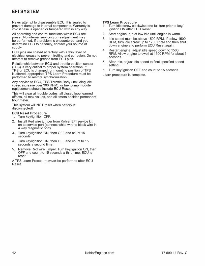
Never attempt to disassemble ECU. It is sealed to prevent damage to internal components. Warranty is void if case is opened or tampered with in any way.All operating and control functions within ECU are preset. No internal servicing or readjustment may be performed. If a problem is encountered, and you determine ECU to be faulty, contact your source of supply. ECU pins are coated at factory with a thin layer of electrical grease to prevent fretting and corrosion. Do not attempt to remove grease from ECU pins.Relationship between ECU and throttle position sensor (TPS) is very critical to proper system operation. If TPS or ECU is changed, or mounting position of TPS is altered, appropriate TPS Learn Procedure must be performed to restore synchronization.Any service to ECU, TPS/Throttle Body (including idle speed increase over 300 RPM), or fuel pump module replacement should include ECU Reset.This will clear all trouble codes, all closed loop learned off sets, all max values, and all timers besides permanent hour meter.This system will NOT reset when battery is disconnected!ECU Reset Procedure1. Turn key/ignition OFF.2. Install Red wire jumper from Kohler EFI service kit
on to service port (connect white wire to black wire in 4 way diagnostic port).
3. Turn key/ignition ON, then OFF and count 15 seconds.
4. Turn key/ignition ON, then OFF and count to 15 seconds a second time.
5. Remove Red wire jumper. Turn key/ignition ON, then OFF and count to 15 seconds a third time. ECU is reset.
A TPS Learn Procedure must be performed after ECU Reset.
TPS Learn Procedure1. Turn idle screw clockwise one full turn prior to key/
ignition ON after ECU Reset.2. Start engine, run at low idle until engine is warm.3. Idle speed must be above 1500 RPM. If below 1500
RPM, turn idle screw up to 1700 RPM and then shut down engine and perform ECU Reset again.
4. Restart engine, adjust idle speed down to 1500 RPM. Allow engine to dwell at 1500 RPM for about 3 seconds.
5. After this, adjust idle speed to fi nal specifi ed speed setting.
6. Turn key/ignition OFF and count to 15 seconds.Learn procedure is complete.

4317 690 14 Rev. C KohlerEngines.com
EFI SYSTEM
AR
edB
Red
/Bla
ckC
Red
/Whi
teD
Yello
wE
Ligh
t Gre
enF
Dar
k G
reen
GD
ark
Blue
HPu
rple
IPi
nkJ
Tan
KW
hite
LG
rey
MBl
ack
NC
harg
ing
Syst
emO
Batte
ry
PFu
el P
ump
Mod
ule
Q8-
Term
inal
Cus
tom
er
Con
nect
orR
Star
ter M
otor
SO
il Le
vel S
witc
hT
MIL
(opt
iona
l)
U10
A Fu
se
(Igni
tion
Switc
h)V
10A
Fuse
(B
atte
ry P
ower
)W
Blac
k C
onne
ctor
XG
rey
Con
nect
orY
Fuel
Inje
ctor
ZIg
nitio
n C
oil
AA
Cra
nksh
aft P
ositi
on
Sens
orA
BO
xyge
n Se
nsor
AC
Thro
ttle
Posi
tion
Sens
orA
DTM
AP S
enso
r
AE
Engi
ne T
empe
ratu
re
Sens
orA
FD
iagn
ostic
Con
nect
orA
GSt
ator
AH
10 A
mp
Rec
tifi e
r-R
egul
ator
Har
ness
(O
EM s
uppl
ied)
Wiri
ng D
iagr
am 1
0 A
mp
ABC
12
DA
BC
12
1 9
10 18
1 9
10 18
12
34
CA
B3
12
4
AH
BG
CF
DE
1
23
AB
Q
J
GB
BM
HD
BF
HM
GL
EF
M
MJ
KG
B
K
V
AI
UM
OP
R
S
YAA
ABAC
AF
AE
F
A
B
WX
ML
G
M
C
N
Z
T
A
KB
H
D
DAH
AH
AG
AD

EFI SYSTEM
44 17 690 14 Rev. CKohlerEngines.com
AR
edB
Red
/Bla
ckC
Red
/Whi
teD
Yello
wE
Ligh
t Gre
enF
Dar
k G
reen
GD
ark
Blue
HPu
rple
IPi
nkJ
Tan
KW
hite
LG
rey
MBl
ack
NC
harg
ing
Syst
emO
Batte
ry
PFu
el P
ump
Mod
ule
Q8-
Term
inal
Cus
tom
er
Con
nect
orR
Star
ter M
otor
SO
il Le
vel S
witc
hT
MIL
(opt
iona
l)
U10
A Fu
se
(Igni
tion
Switc
h)V
10A
Fuse
(B
atte
ry P
ower
)W
Blac
k C
onne
ctor
XG
rey
Con
nect
orY
Fuel
Inje
ctor
ZIg
nitio
n C
oil
AA
Cra
nksh
aft P
ositi
on
Sens
orA
BO
xyge
n Se
nsor
AC
Thro
ttle
Posi
tion
Sens
orA
DTM
AP S
enso
r
AE
Engi
ne T
empe
ratu
re
Sens
orA
FD
iagn
ostic
Con
nect
orA
GSt
ator
AH
Rec
tifi e
r-Reg
ulat
or
Har
ness
Con
nect
orA
I25
A Fu
se in
Rec
tifi e
r-R
egul
ator
Har
ness
Wiri
ng D
iagr
am 1
8 A
mp
AB
ABC
DA
BC
121 9
10 18
1 9
10 18
12
34
CA
B3
12
4
AH
BG
CF
DE
1
23
12
Q
J
GB
BM
HD
FH
MG
LE
FM
MJ
KG
B
K
V
A
I
UM
OP
R
S
YAA
ABAC
AF
AE
F
A
B
X W
ML
G
M
C
N
Z
T
KB
H
D
D
AG
AH
AI
B
A
AD

4517 690 14 Rev. C KohlerEngines.com
EFI SYSTEM
Crankshaft Position SensorA sealed, non-serviceable assembly. If fault code P0337 is present and engine does not start/run, proceed to step 1. If P0337 is present and engine operates, clear codes and retest. If Fault Code diagnosis indicates a problem within this area, test and correct as follows.1. Inspect wiring and connections for damage or
problems.2. Make sure engine has resistor type spark plug.3. Disconnect Black connector from ECU.4. Connect an ohmmeter between #4 and #13 pin
terminals. A resistance value of 325-395 Ω at room temperature (20°C, 68°F) should be obtained. If resistance is correct, remove blower housing to check sensor mounting, fl ywheel teeth (damage, run-out, etc.), and fl ywheel key. Follow procedures in Disassembly to remove blower housing.
5. Disconnect crankshaft position sensor connector from wiring harness. Test resistance between terminals. A reading of 325-395 Ω should again be obtained.
a. If resistance is incorrect, remove screw securing sensor to bracket and replace sensor.
b. If resistance in step 4 was incorrect, but resistance of sensor alone was correct, test wire harness circuits between sensor connector terminals and corresponding pin terminals (#4 and #13) in main connector. Correct any observed problem, reconnect sensor, and perform step 4 again.
6. When fault is corrected and engine starts, clear fault codes following ECU Reset procedure.
Throttle Position Sensor (TPS)TPS is a sealed, non-serviceable assembly. If diagnosis indicates a bad sensor, complete replacement is necessary. If a fault code indicates a problem with TPS, it can be tested as follows:Diagnostics of sensor: ECU will have electrical faults captured in fault codes P0122 and P0123. Fault code P0122 detecting low voltage, open circuit, and P0123 for high voltage conditions between ECU, wire harness, and sensor. Tip: when working with any electrical connection, remember to keep connections clean & dry. This is best accomplished by cleaning connection thoroughly prior to disassembly. Contaminated sensor connections can cause premature engine faults. Functionally testing sensor can no longer be done with simple resistance checks. If either of these two faults is present or a TPS fault is suspected, recommended diagnostic test is as follows:If a computer with diagnostic software is availableObserve throttle percent and raw TPS values through diagnostic software. With diagnostic software communicating to ECU and key ON engine not running, these values can be observed while throttle is moved from closed to full open position. There should be a smooth and repeatable throttle percent value starting at closed position reading between 0 and 3% to WOT position reading of 93 to 100%. If one of these values is outside of specifi ed range and output transitions in a smooth manner, reset ECU and run test again.
Since there is no longer any wear elements inside sensor, most likely faults will be in electrical connections between sensor and wire harness and wire harness to ECU. With service software communicating to ECU and engine not running, a small load or gentle back and forth motion can be applied to connectors or wires just outside connectors to detect a faulty connection.If only a volt meter is availableMeasure voltage supply to sensor from ECU. This voltage should be 5.00 +/- 0.20 volts. This can be measured by gently probing terminals B & C on harness side with TPS connector removed from TPS and key ON. This will generate a P0122 fault that can be cleared with an ECU reset. If voltage is low, battery, harness and ECU should be investigated. If supply voltage is good, plug sensor back into harness. Probe sensor signal wire with volt meter, terminal A at TPS or pin Black 12 at ECU. This signal should start between 0.6-1.2 volts at low idle and grow smoothly as throttle is opened to 4.3-4.8 volts at full open (WOT). Since there is no longer any wear elements inside sensor, most likely faults will be in electrical connections between sensor and wire harness and wire harness to ECU.Replace TPS
CD
CA
B A
A TPS Screws B TPS
C Magnet Assembly C Magnet Installation Depth
Magnet assembly is captured in a small plastic housing that is press fi t to end of throttle shaft. If replacement is required, it can be replaced as follows:1. Remove screws securing TPS to throttle body.
Remove sensor from throttle body, exposing round magnet assembly.
2. A pair of fl at blade screw drivers or a spanner tool can be used to pry this off shaft. Caution should be used to avoid damage to machined fl at surface that sensor seals against. Also, make sure throttle blade is in full open position to avoid driving throttle blade into throttle bore causing damage to blade and/or bore.

EFI SYSTEM
46 17 690 14 Rev. CKohlerEngines.com
3. When replacing magnet assembly, alignment is critical. There is a D-shaped drive feature on end of shaft and a matching pocket in magnet assembly. On outer diameter of magnet assembly is a notch that aligns with center of fl at feature of D. Align this notch and fl at of D feature in shaft and preassemble parts.
4. With throttle blade in full open position (WOT), press magnet assembly fully on to throttle shaft. Full insertion can be checked by measuring height from throttle body sensor mounting face to end of magnet assembly. This should be no more than 8.6 mm (0.34 in.). Installation process requires signifi cant force, so take care that all parts are aligned. Tapping magnet assembly on can fracture/damage brittle magnet within assembly and throttle body assembly and is NOT RECOMMENDED.
5. Install sensor and secure with screws. Torque screws to 1.3 N·m (11.5 in. lb.).
Engine Temperature Sensor
A
A Engine Temperature SensorNOTE: Engine temperature sensor resembles a ground
wire.A sealed, non-serviceable assembly. A faulty sensor requires a wire harness replacement. If a fault code indicates a problem with temperature sensor, it can be tested as follows:1. Shut off engine and allow it to return to room
temperature (25°C, 77°F).2. With sensor still connected, check temperature
sensor circuit resistance between Black pin 10 and 14 terminals. Value should be 9000-11000 Ω.
3. If resistance is out of specifi cations, replace wire harness.
Temperature/Manifold Absolute Pressure (TMAP) SensorA sealed non-serviceable integrated sensor that checks both intake air temperature and manifold absolute pressure. Complete replacement is required if it is faulty. Sensor and wiring harness can be checked as follows.If a fault code indicates a problem with Intake Air Temperature (TMAP) Sensor Circuit (P0112 or P0113), it can be tested as follows:1. Remove TMAP sensor from throttle body.2. Allow it to reach room temperature (20°C, 68°F).3. Unplug Black connector from ECU.4. With sensor still connected, check temperature
sensor circuit resistance between Black pin 10 and 8 pin terminals. Value should be 1850-2450 Ω.
5. Unplug sensor from wire harness and check sensor resistance separately across pin. Resistance value should again be 1850-2450 Ω.
a. If resistance is out of specifi cations, check local temperature. Sensor resistance will go down as temperature is higher. Replace TMAP sensor if determined to be faulty.
b. If it is within specifi cations, proceed to Step 6.6. Check circuits (input, ground), from main harness
connector to sensor plug for continuity, damage, etc. Connect one ohmmeter lead to Black pin 8 in main harness connector (as in step 4). Connect other lead to terminal #3 in sensor plug. Continuity should be indicated. Repeat test between Black pin 10 and terminal #4 in sensor plug.
7. Reinstall sensor.If a fault code indicates a problem with Manifold Absolute Pressure (TMAP) Sensor Circuit (P0107 or P0108), it can be tested as follows:1. Make sure all connections are making proper
contact and are free of dirt and debris. Slide locking tab out and pull off TMAP connector. Turn key switch to ON and check with a volt meter by contacting red lead to pin 1 and black lead to pin 2. There should be 5 volts present, indicating ECU and wiring harness are functioning.
2. Check continuity in wire harness. Ohms between Pin 3 at sensor connector and Black pin 11 connector at ECU should be near zero ohms. If no continuity is measured or very high resistance, replace wire harness.
3. Check to make sure throttle body is not loose and TMAP sensor is not loose. Loose parts would allow a vacuum leak, making TMAP sensor report misleading information to ECU.
a. Tighten all hardware and perform an ECU Reset and a TPS Learn Procedure to see if MIL will display a fault with sensor again. If MIL fi nds a fault with TMAP sensor, replace it.

4717 690 14 Rev. C KohlerEngines.com
EFI SYSTEM
Oxygen Sensor (O2)Detail
Pin DPin C
Pin B
Pin A
A B
Pin A Purple Wire, Heater + Pin B White Wire,
Heater -
Pin C Grey Wire, Sensor Output Pin D Black Wire, Sensor
Ground
A 14 mm or 9/16 in. Wrench Size B 12 mm x 1.25
Thread SizeInstallation Torque 18 N·m (159 in. lb.)
Cutaway Oxygen Sensor (O2) Components
AB
C
DE F
G
A Protection Shield B Planar Elementand Heater
C Lower Insulator D Stainless SteelHousing
E Upper Insulator F Terminal Connectionto Element
G High TempWater Seal
Temperature must be controlled very accurately and gas constituents measured to a high degree of accuracy for absolute sensor measurements. This requires laboratory equipment to determine a good or bad sensor in fi eld. Furthermore, as with most devices, intermittent problems are diffi cult to diagnose. Still, with a good understanding of system and sensor, it is possible to diagnose many sensor problems in fi eld.Using diagnostic software connected to ECU is a useful technique for observing sensor performance. However, user must understand that such software reads a signal generated by ECU. If there is an ECU or wiring problem, readings could be misinterpreted as a sensor problem. Digital nature of signal to software means that it is not reading continuous output of sensor. A voltmeter can also be used as an eff ective tool in diagnosing sensors.
It is advisable to use an electronic meter such as a digital voltmeter. Simple mechanical meters may place a heavy electrical load on sensor and cause inaccurate readings. Since resistance of sensor is highest at low temperatures, such meters will cause largest inaccuracies when sensor is in a cool exhaust.Visual InspectionSensor Wire Detail
A
A Keep a minimum of 25 mm (1.0 in.) radius at grommet.
NOTE: Always route harness away from hot exhaust and away from moving parts.
NOTE: Do not attempt to clean sensor. Replace as needed.
1. Look for a damaged or disconnected sensor-to-engine harness connection.
2. Look for damage to sensor lead wire or associated engine wiring due to cutting, chaffi ng or melting on a hot surface.
3. Disconnect sensor connector and look for corrosion in connector.
4. Try reconnecting sensor and observe if problem has cleared.
5. Correct any problems found during visual check.6. Inspect for any exhaust system leaks upstream or
downstream of oxygen sensor. Confi rm oxygen sensor is secured to 18 N·m (159 in. lb.).
All leaks must be repaired and an ECU/TPS reset must be performed before proceeding with sensor testing.
7. Using diagnostic software, document any trouble codes. Determine if historic trouble codes are logically related to current fault experienced. If uncertain, clear codes and retest.
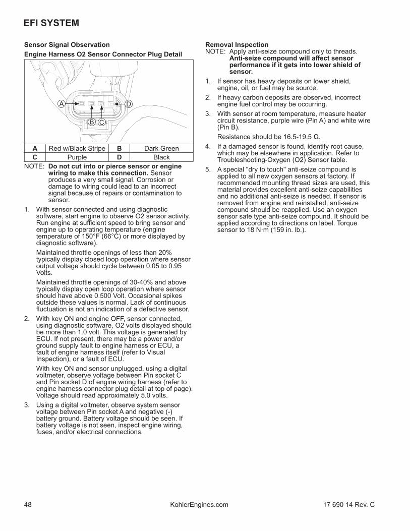
EFI SYSTEM
48 17 690 14 Rev. CKohlerEngines.com
Sensor Signal ObservationEngine Harness O2 Sensor Connector Plug Detail
D
B C
A
A Red w/Black Stripe B Dark GreenC Purple D Black
NOTE: Do not cut into or pierce sensor or engine wiring to make this connection. Sensor produces a very small signal. Corrosion or damage to wiring could lead to an incorrect signal because of repairs or contamination to sensor.
1. With sensor connected and using diagnostic software, start engine to observe O2 sensor activity. Run engine at suffi cient speed to bring sensor and engine up to operating temperature (engine temperature of 150°F (66°C) or more displayed by diagnostic software).
Maintained throttle openings of less than 20% typically display closed loop operation where sensor output voltage should cycle between 0.05 to 0.95 Volts.
Maintained throttle openings of 30-40% and above typically display open loop operation where sensor should have above 0.500 Volt. Occasional spikes outside these values is normal. Lack of continuous fl uctuation is not an indication of a defective sensor.
2. With key ON and engine OFF, sensor connected, using diagnostic software, O2 volts displayed should be more than 1.0 volt. This voltage is generated by ECU. If not present, there may be a power and/or ground supply fault to engine harness or ECU, a fault of engine harness itself (refer to Visual Inspection), or a fault of ECU.
With key ON and sensor unplugged, using a digital voltmeter, observe voltage between Pin socket C and Pin socket D of engine wiring harness (refer to engine harness connector plug detail at top of page). Voltage should read approximately 5.0 volts.
3. Using a digital voltmeter, observe system sensor voltage between Pin socket A and negative (-) battery ground. Battery voltage should be seen. If battery voltage is not seen, inspect engine wiring, fuses, and/or electrical connections.
Removal InspectionNOTE: Apply anti-seize compound only to threads.
Anti-seize compound will aff ect sensor performance if it gets into lower shield of sensor.
1. If sensor has heavy deposits on lower shield, engine, oil, or fuel may be source.
2. If heavy carbon deposits are observed, incorrect engine fuel control may be occurring.
3. With sensor at room temperature, measure heater circuit resistance, purple wire (Pin A) and white wire (Pin B).
Resistance should be 16.5-19.5 Ω.4. If a damaged sensor is found, identify root cause,
which may be elsewhere in application. Refer to Troubleshooting-Oxygen (O2) Sensor table.
5. A special "dry to touch" anti-seize compound is applied to all new oxygen sensors at factory. If recommended mounting thread sizes are used, this material provides excellent anti-seize capabilities and no additional anti-seize is needed. If sensor is removed from engine and reinstalled, anti-seize compound should be reapplied. Use an oxygen sensor safe type anti-seize compound. It should be applied according to directions on label. Torque sensor to 18 N·m (159 in. lb.).

4917 690 14 Rev. C KohlerEngines.com
EFI SYSTEM
Troubleshooting-Oxygen (O2) SensorCondition Possible Cause Conclusion
Continuous low voltage output (less than 400mV) observed with throttle openings of 30-40% or more.
Fault codes P0131, P0171, or P0174 may set.
Shorted sensor or sensor circuit.Shorted lead wire.Wiring shorted to ground.
Replace sensor or replace and properly route wiring.
Upstream or downstream exhaust leaks observed.Air leak at sensor.
Repair all exhaust leaks and torque sensor to 18 N·m (159 in. lb.).
Restricted fuel supply. Resolve fuel supply issues from tank to engine. Test fuel pressure. Perform repairs necessary.
Misfi re A misfi re causing incomplete combustion will result in lean (low voltage) values.
Sensor failure-stuck lean. Replace sensor.Continuous high voltage output (600mV or more) observed with throttle openings of 20% or less.
Fault codes P0172 or P0132 may set.
Silica poisoning. Replace sensor. Identify and resolve root cause.
Contaminated gasoline. Purge fuel system and retest.Wiring shorted to voltage. Replace damaged harness.Overly rich condition due to unmetered fuel entering combustion chamber.
Test fuel pressure. Inspect fuel pump vent and evaporative emissions hoses for raw fuel fl ow.Inspect engine oil for fuel contamination; drain and refi ll if suspect.Perform repairs as necessary.
Cold engine. Engine temperature below 150°F (66°C) as displayed by diagnostic software.
Normal operation, or engine operated in an excessively cold environment.
Sensor failure-stuck rich. Replace sensor.No activity from sensor.
Diagnostic software displays 1.015 Volts continuously.
Fault codes P0031 or P0032 may set.
Heater circuit open or shorted. Replace sensor.Engine keyed ON with sensor disconnected.Historic codes.
Secure and/or confi rm sensor connection and clear codes.
Contaminated gasoline. Purge fuel system and retest.
Broken wire.Damaged sensor.
Replace sensor.

EFI SYSTEM
50 17 690 14 Rev. CKohlerEngines.com
Injector clogging is usually caused by a buildup of deposits on director plate, restricting fl ow of fuel, resulting in a poor spray pattern. Some contributing factors to injector clogging include higher than normal operating temperatures, short operating intervals, and dirty, incorrect, or poor quality fuel. Cleaning of clogged injector is not recommended; it should be replaced. Additives and higher grades of fuel can be used as a preventative measure if clogging has been a problem.An electrical problem usually will cause injector to stop functioning. Several methods may be used to check if injector is operating. 1. With engine running at idle, listen for a buzzing or
clicking sound.2. Disconnect electrical connector from injector and
engine should stop running. If engine continues to run, disconnect vent line at air cleaner base. If engine continues to run, injector is suspect.
If an injector is not operating, it can indicate either a bad injector, or a wiring/electrical connection problem. Check as follows:1. Disconnect electrical connector from injector. Plug a
12 volt noid light into connector.2. Make sure all safety switch requirements are met.
Crank engine and check for fl ashing of noid light. a. If fl ashing occurs, use an ohmmeter (Rx1 scale)
and check resistance of injector across two terminals. Proper resistance is 11-13 Ω. If injector resistance is correct, check whether connector and injector terminals are making a good connection. If resistance is not correct, replace injector.
Check all electrical connections, connectors, and wiring harness leads if resistance is incorrect.Injector leakage is very unlikely, but in those rare instances it can be internal (past tip of valve needle), or external (weeping around injector O-ring). Loss of system pressure from leakage can cause hot restart problems and longer cranking times. Refer to Disassembly for removal of injector.1. Remove throttle body from engine leaving TPS, high
pressure fuel line, injector and fuel line connections intact. Discard old gaskets.
2. Position throttle body over an appropriate container to capture fuel and turn key switch ON to activate fuel pump and pressurize system. Do not turn switch to START position.
3. If injector exhibits leakage of more than two to four drops per minute from tip, or shows any sign of leakage around outer shell, turn ignition switch OFF and replace injector as follows.
4. Depressurize fuel system and disconnect high pressure fuel line from fuel injector cap.
5. Clean any dirt accumulation from sealing/mounting area of faulty injector and disconnect electrical connector.
Fuel Injector
WARNINGExplosive Fuel can cause fi res and severe burns.Fuel system ALWAYS remains under HIGH PRESSURE.
Wrap a shop towel completely around fuel pump module connector. Press release button(s) and slowly pull connector away from fuel pump module allowing shop towel to absorb any residual fuel in high pressure fuel line. Any spilled fuel must be completely wiped up immediately.
Details
AB
C
E
F
H IG
D
A Electrical Connection B Upper O-ringC Solenoid Winding D ArmatureE Valve Housing F Valve SeatG Valve End H Lower O-ringI Director Plate
NOTE: Do not apply voltage to fuel injector. Excessive voltage will burn out injector. Do not ground injector with ignition ON. Injector will open/turn on if relay is energized.
NOTE: When cranking engine with injector disconnected, fault codes will be registered in ECU and will need to be cleared using software fault clear or an ECU Reset and TPS Learn Procedure.
Injector problems typically fall into three general categories: electrical, dirty/clogged, or leakage. Injector problems due to dirt or clogging are generally unlikely due to design of injector, high fuel pressure, and detergent additives in gasoline. Symptoms that could be caused by dirty/clogged injector include rough idle, hesitation/stumbling during acceleration, or triggering of fault codes related to fuel delivery.

5117 690 14 Rev. C KohlerEngines.com
EFI SYSTEM
FUEL COMPONENTS
WARNINGExplosive Fuel can cause fi res and severe burns.Fuel system ALWAYS remains under HIGH PRESSURE.
Wrap a shop towel completely around fuel pump module connector. Press release button(s) and slowly pull connector away from fuel pump module allowing shop towel to absorb any residual fuel in high pressure fuel line. Any spilled fuel must be completely wiped up immediately.
NOTE: Engines in this series have fuel pump module, lift fuel pump, and EFI fuel fi lter installed by OEM in application. Refer to equipment manufacturer's manual for installation information.
NOTE: Some fuel/vent lines are supplied by OEM. Refer to equipment manufacturer's manual for fuel/vent line information.
Fuel Pump Module (FPM)FPM is not serviceable and must be replaced if determined to be faulty. If a FPM problem is suspected, make certain pump is being activated, all electrical connections are properly secured and fuses are good. If required, testing of FPM may be conducted.NOTE: FPM pins are coated with a thin layer of
electrical grease to prevent fretting and corrosion. Do not attempt to remove electrical grease from fuel pump module pins.
1. Relieve fuel pressure at FPM. Press release button(s) and slowly pull connector away from FPM allowing shop towel to absorb any residual fuel in high pressure fuel line. Insert pressure test jumper (from Kohler EFI Service Kit) between high pressure fuel line and FPM.
2. Connect black hose of Pressure Tester. Route clear hose into a portable gasoline container or equipment fuel tank.
3. Turn on key switch to activate pump and check system pressure on gauge. It may take several key cycles to compress air introduced into system and reach regulated pressure. Turn key OFF for at least 15 seconds between tests to allow ECU to go to sleep and reawake. System pressure of 39 psi ± 3 should be present. Turn key switch OFF and depress valve button on tester to relieve system pressure.
a. If pressure is too high or too low, proceed to troubleshooting.
4. If pump did not activate (step 3), confi rm that safety system on equipment is not active. One potential cause of unnecessary FPM replacement may involve measuring voltage at FPM electrical connector. Using a Digital Volt Ohm Meter (DVOM) will provide a reading near battery voltage, even when ECU is not grounding FPM circuit.
6. Pull retaining clip to separate fuel injector cap/bracket assembly from injector. Remove screw holding fuel injector cap/bracket assembly to throttle body. Lift injector from throttle body.
7. Reverse appropriate procedures to install new injector and reassemble engine. Use new O-ring and retaining clip any time an injector is removed (new replacement injector includes new O-rings and retaining clip). Lubricate O-rings lightly with clean engine oil. Use installation tool provided with O-rings to install new upper O-ring. Place tool into fuel injector inlet. Place one side of O-ring into O-ring groove and roll O-ring over tool onto fuel injector. Torque screw securing fuel injector cap to 7.3 N·m (65 in. lb.). An ECU Reset and TPS Learn Procedure will need to be completed.
Ignition CoilIf coil is determined to be faulty, replacement is necessary. An ohmmeter may be used to test wiring and coil windings.NOTE: Do not ground coil with ignition ON as it may
overheat or spark.NOTE: Always disconnect spark plug lead from spark
plug before performing following tests.NOTE: If ignition coil is disabled and an ignition
fault is registered, system will automatically disable corresponding fuel injector drive signal. Fault must be corrected to ignition coil and ECU power (switch) must be turned OFF for 15 seconds for injector signal to return. This is a safety measure to prevent bore washing and oil dilution.
TestingUsing an ohmmeter set on Rx1 scale, check resistance in circuit as follows:1. To check ignition coil, disconnect Black connector
from ECU and test between Black pins 1 and 15. Wiring and coil primary circuit is OK if reading is 0.85-1.15
2. If reading is not within specifi ed range, check and clean connections and retest.
3. If reading is still not within specifi ed range, test coil separately from main harness as follows:
a. Remove mounting screw retaining coil and disconnect primary lead connector.
b. Connect an ohmmeter set on Rx1 scale to primary terminals of coil. Primary resistance should be 0.5-0.8 Ω.
c. Connect an ohmmeter set on Rx10K scale between spark plug boot terminal and B+ primary terminal. Secondary resistance should be 14.5-18.5k Ω.
d. If either coil primary or secondary circuit test shorted or open, coil is faulty and needs to be replaced.
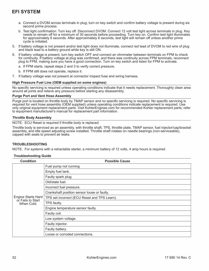
EFI SYSTEM
52 17 690 14 Rev. CKohlerEngines.com
a. Connect a DVOM across terminals in plug, turn on key switch and confi rm battery voltage is present during six second prime process.
b. Test light confi rmation: Turn key off . Disconnect DVOM. Connect 12 volt test light across terminals in plug. Key needs to remain off for a minimum of 30 seconds before proceeding. Turn key on. Confi rm test light illuminates for approximately 6 seconds. After approximately 6 seconds, test light will remain off unless another prime cycle is initiated.
5. If battery voltage is not present and/or test light does not illuminate, connect red lead of DVOM to red wire of plug and black lead to a battery ground while key is still ON.
6. If battery voltage is present, turn key switch OFF and connect an ohmmeter between terminals on FPM to check for continuity. If battery voltage at plug was confi rmed, and there was continuity across FPM terminals, reconnect plug to FPM, making sure you have a good connection. Turn on key switch and listen for FPM to activate.
a. If FPM starts, repeat steps 2 and 3 to verify correct pressure. b. If FPM still does not operate, replace it.7. If battery voltage was not present at connector inspect fuse and wiring harness.
High Pressure Fuel Line (OEM supplied on some engines)No specifi c servicing is required unless operating conditions indicate that it needs replacement. Thoroughly clean area around all joints and relieve any pressure before starting any disassembly. Purge Port and Vent Hose AssemblyPurge port is located on throttle body by TMAP sensor and no specifi c servicing is required. No specifi c servicing is required for vent hose assembly (OEM supplied) unless operating conditions indicate replacement is required. Use only original equipment replacement parts. Visit KohlerEngines.com for recommended Kohler replacement parts; refer to equipment manufacturer's manual for replacement part information.
Throttle Body AssemblyNOTE: ECU Reset is required if throttle body is replaced.Throttle body is serviced as an assembly, with throttle shaft, TPS, throttle plate, TMAP sensor, fuel injector/cap/bracket assembly, and idle speed adjusting screw installed. Throttle shaft rotates on needle bearings (non-serviceable), capped with seals to prevent air leaks.
TROUBLESHOOTINGNOTE: For systems with a retractable starter, a minimum battery of 12 volts, 4 amp hours is required.
Troubleshooting GuideCondition Possible Cause
Engine Starts Hard or Fails to Start
When Cold.
Fuel pump not running.Empty fuel tank.Faulty spark plug.Old/stale fuel.Incorrect fuel pressure.Crankshaft position sensor loose or faulty.TPS set incorrect (ECU Reset and TPS Learn).TPS faulty.Engine temperature sensor faulty.Faulty coil.Low system voltage.Faulty injector.Faulty battery.Loose or corroded connections.
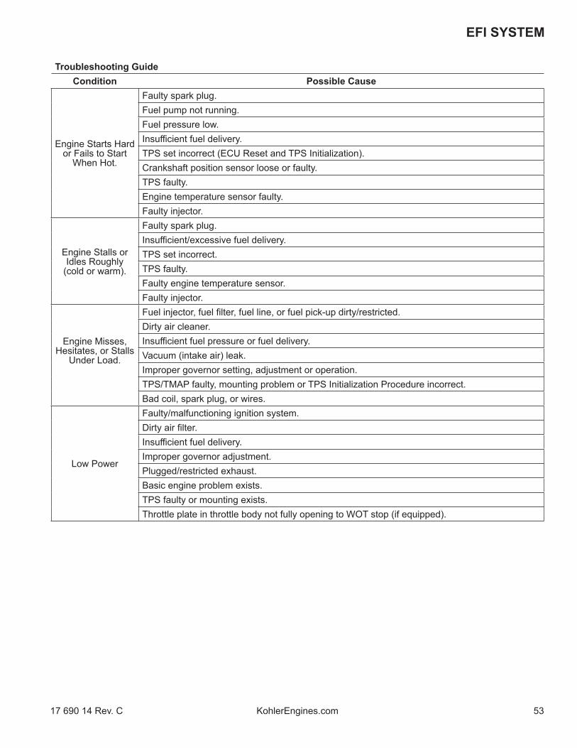
5317 690 14 Rev. C KohlerEngines.com
EFI SYSTEM
Troubleshooting GuideCondition Possible Cause
Engine Starts Hard or Fails to Start
When Hot.
Faulty spark plug.Fuel pump not running.Fuel pressure low.Insuffi cient fuel delivery.TPS set incorrect (ECU Reset and TPS Initialization).Crankshaft position sensor loose or faulty.TPS faulty.Engine temperature sensor faulty.Faulty injector.
Engine Stalls or Idles Roughly
(cold or warm).
Faulty spark plug.Insuffi cient/excessive fuel delivery.TPS set incorrect.TPS faulty.Faulty engine temperature sensor.Faulty injector.
Engine Misses, Hesitates, or Stalls
Under Load.
Fuel injector, fuel fi lter, fuel line, or fuel pick-up dirty/restricted.Dirty air cleaner.Insuffi cient fuel pressure or fuel delivery.Vacuum (intake air) leak.Improper governor setting, adjustment or operation.TPS/TMAP faulty, mounting problem or TPS Initialization Procedure incorrect.Bad coil, spark plug, or wires.
Low Power
Faulty/malfunctioning ignition system.Dirty air fi lter.Insuffi cient fuel delivery.Improper governor adjustment.Plugged/restricted exhaust.Basic engine problem exists.TPS faulty or mounting exists.Throttle plate in throttle body not fully opening to WOT stop (if equipped).

EFI SYSTEM
54 17 690 14 Rev. CKohlerEngines.com
Function Test
WARNINGHigh Pressure Fluids can puncture skin and cause severe injury or death.Do not work on fuel system without proper training or safety equipment.
Fluid puncture injuries are highly toxic and hazardous. If an injury occurs, seek immediate medical attention.
NOTE: For systems with a retractable starter, a minimum battery of 12 volts, 4 amp hours is required.
Function of fuel system is to provide suffi cient delivery of fuel at system operating pressure of 39 psi ± 3. If an engine starts hard, or turns over but will not start, it may indicate a problem with EFI fuel system. A quick test will verify if system is operating.1. Disconnect and ground spark plug lead.2. Complete all safety interlock requirements and crank
engine for approximately 3 seconds.3. Remove spark plug and check for fuel at tip. a. If there is fuel at tip of spark plug fuel pump and
injector are operating. b. If there is no fuel at tip of spark plug, check
following: 1. Make sure fuel tank contains clean, fresh,
proper fuel. 2. Make sure that vent in fuel tank is open. 3. Make sure fuel tank valve (if equipped) is fully
opened. 4. Make sure battery is supplying proper voltage. 5. Check that fuses are good, and that no
electrical or fuel line connections are damaged or broken.
6. Test fuel pump module operation as described earlier under Fuel Pump Module (FPM).
Fault CodesExample of Diagnostic Display
One second pause
One second pause
One second pause
One second pause
Three second pause
(0)
(0)
(7)
(6)
(1)
(1)
End Code 61
FaultCode0107

5517 690 14 Rev. C KohlerEngines.com
EFI SYSTEM
Diagnostic Fault Code SummaryFault Code Connection or Failure Description
0031 Oxygen Sensor Heater Circuit Low Voltage0032 Oxygen Sensor Heater Circuit High Voltage0107 Manifold Absolute Pressure (TMAP) Circuit Low Voltage or Open0108 Manifold Absolute Pressure (TMAP) Circuit High Voltage0112 Intake Air Temperature (TMAP) Circuit Low Voltage0113 Intake Air Temperature (TMAP) Circuit High Voltage or Open0117 Coolant/Oil Temperature Sensor Circuit Low Voltage0118 Coolant/Oil Temperature Sensor Circuit High Voltage or Open0122 Throttle Position Sensor Circuit Low Voltage or Open0123 Throttle Position Sensor Circuit High Voltage0131 Oxygen Sensor 1 Circuit Low Voltage, or Open0132 Oxygen Sensor 1 Circuit High Voltage0171 Maximum Adaptation Limit Exceeded0172 Minimum Adaptation Limit Exceeded0174 Lean Fuel Condition at High Load (Open Loop)0201 Injector Circuit Malfunction0230 Fuel Pump Module Circuit Low Voltage or Open0232 Fuel Pump Module Circuit High Voltage0336 Crankshaft Position Sensor Noisy Signal0337 Crankshaft Position Sensor No Signal0351 Ignition Coil Malfunction0562 System Voltage Low0563 System Voltage High0650 MIL Circuit Malfunction
61 End of Code Transmission
ECU continuously monitors engine operation against preset performance limits. If operation is outside limits, ECU activates MIL, if equipped, and stores a diagnostic code in its fault memory. If component or system returns to proper function, ECU will turn off MIL. If MIL stays illuminated, it warns customer a fault is currently happening, and dealer service is required. Upon receipt, dealer technician can access fault code(s) to help determine what portion of system is malfunctioning.Codes are accessed through key switch and displayed as blinks or fl ashes of MIL. Access codes as follows:1. Check that battery voltage is above 11 volts.2. Start with key switch OFF.3. Turn key switch to ON and OFF, then ON and OFF,
then ON, leaving it on in third sequence. Do not start engine. Time between sequences must be less than 2.5 seconds.
4. MIL will blink a series of times. Number of times MIL blinks represents a number in fault code.
5. A sequence of four digits make up a fault code. There is a one (1) second pause between blinks of a fault code. There is a three (3) second pause between separate fault codes. After fault code(s) are blinked a two digit 61 is blinked to indicate program has completed.
a. It’s a good idea to write down codes as they appear, as they may not be in numerical sequence.
b. Code 61 will always be last code displayed, indicating end of code transmission. If code 61 appears immediately, no other fault codes are present.
After problem has been corrected, fault codes may be cleared by following ECU Reset and TPS Learn Procedures.Diagnostic Fault Code Summary lists fault codes, and what they correspond to. Diagnostic Code Summary is a list of individual codes with an explanation of what triggers them, what symptoms might be expected, and probable causes.A MIL may not be provided with engine. If equipment manufacturer has not added a MIL to equipment, one can be added easily for quick diagnostics. Main engine to vehicle connection will have a tan wire which is ground for MIL. Either incandescent or LED type bulbs can be used for MIL as long as they do not draw more than 0.1 amps. Bulb needs to be rated at 1.4 Watts or less, or needs to have a total resistance of 140 Ω or more. LEDs typically draw less than 0.03 amps. Attach +12 volts to positive terminal of bulb and attach ground terminal of bulb to tan wire.

EFI SYSTEM
56 17 690 14 Rev. CKohlerEngines.com
Diagnostic Code SummaryCode 0031NOTE: Codes 0031 and 0032 may have been
mistakenly activated by turning key ON with oxygen sensor disconnected. If either code status is historic, that code may have set during assembly or a previous repair and may not be related to current event. Clear codes and retest to confi rm. If code status is current, refer to Oxygen Sensor (O2) earlier in this section, to test and troubleshoot.
Component: Oxygen Sensor HeaterFault: O2S Heater Circuit Low VoltageCondition: System voltage too low, open connection
or faulty sensor. Conclusion: Engine Wiring Harness Related
● Pin circuit wiring or connectors. ECU black pin 7 or broken wire.
Oxygen Sensor Related● Sensor connector or wiring problem.
Poor system ground from ECU to engine or battery to engine.
Code 0032NOTE: Codes 0031 and 0032 may have been
mistakenly activated by turning key ON with oxygen sensor disconnected. If either code status is historic, that code may have set during assembly or a previous repair and may not be related to current event. Clear codes and retest to confi rm. If code status is current, refer to Oxygen Sensor (O2) earlier in this section, to test and troubleshoot.
Component: Oxygen Sensor HeaterFault: O2S Heater Circuit High VoltageCondition: System voltage too high, shorted
connection or faulty sensor.Conclusion: Oxygen Sensor Related
● Sensor connector or wiring problem.● Sensor damaged.● Pin circuit wiring or connectors at Black
7.
ECU Related● ECU-to-harness connection problem.
Code 0107Component: Manifold Absolute Pressure (TMAP)Fault: MAP Circuit Low Voltage or OpenCondition: Throttle body leak, open connection or
faulty sensor.Conclusion: TMAP Sensor Related
● Sensor malfunction.● Vacuum leaks from loose throttle body
or sensor.
Wire Harness Related● Poor grounding or open circuit.● Wire harness and connectors loose,
damaged or corroded.● Pin circuit wiring or connectors at Black
10, 11 and 16.
Bad TPS Learn.
Code 0108Component: Manifold Absolute Pressure (TMAP)Fault: MAP Circuit High VoltageCondition: Throttle body leak, shorted connection or
faulty sensor.Conclusion: TMAP Sensor Related
● Sensor malfunction.● Vacuum leaks from loose throttle body
or sensor.
Wire Harness Related● Poor grounding.● Pin circuit wiring or connectors at Black
11.
Bad TPS Learn.

5717 690 14 Rev. C KohlerEngines.com
EFI SYSTEM
Code 0112Component: Intake Air Temperature (TMAP)Fault: Intake Air Temperature Sensor Circuit
Low VoltageCondition: Shorted connection, faulty sensor or
shorted wire.Conclusion: TMAP Sensor Related
● Sensor wiring or connection.
Engine Wiring Harness Related● Pin circuits Black 10 and Black 8 may
be damaged or routed near noisy signal (coil, alternator, etc.).
● ECU-to-harness connection problem.
Code 0113Component: Intake Air Temperature (TMAP)Fault: Intake Air Temperature Sensor Circuit
High Voltage or OpenCondition: Shorted connection, faulty sensor, broken
wire or connection.Conclusion: TMAP Related
● Sensor wiring or connection.
Engine Wiring Harness Related● Pin circuits ECU Black pin 10 and 8
may be damaged.● ECU-to-harness connection problem or
broken wire.
Code 0117Component: Coolant/Oil SensorFault: Coolant/Oil Temperature Sensor Circuit
Low VoltageCondition: Shorted connection, faulty sensor or
shorted wire.Conclusion: Temperature Sensor Related
● Sensor wiring or connection.
Engine Wiring Harness Related● Pin circuits Black 10 and Black 14
maybe damaged or routed near noisy signal (coils, stator, etc.).
● ECU-to-harness connection problem.
Code 0118Component: Coolant/Oil SensorFault: Coolant/Oil Temperature Sensor Circuit
High Voltage or OpenCondition: Shorted connection, faulty sensor, open
connection or broken wire.Conclusion: Temperature Sensor Related
● Sensor wiring or connection.
Engine Wiring Harness Related● Pin circuits ECU Black pin 10 and 14
may be damaged.● ECU-to-harness connection problem or
broken wire.
System Related● Engine is operating above 176°C
(350°F) temperature sensor limit.

EFI SYSTEM
58 17 690 14 Rev. CKohlerEngines.com
Code 0122Component: Throttle Position Sensor (TPS)Fault: TPS Circuit Low Voltage or OpenCondition: Open connection, broken wire or faulty
sensor.Conclusion: TPS Related
● TPS bad or worn internally.
Engine Wiring Harness Related● Broken or shorted wire in harness. ECU Black pin 10 to TPS pin B. ECU Black pin 12 to TPS pin A. ECU Black pin 16 to TPS pin C.
Throttle Body Related● Throttle shaft inside TPS worn, broken,
or damaged.● Throttle plate loose or misaligned.● Throttle plate bent or damaged
allowing extra airfl ow past, or restricting movement.
ECU Related● Circuit providing voltage or ground to
TPS damaged.● TPS signal input circuit damaged.
Code 0123Component: Throttle Position Sensor (TPS)Fault: TPS Circuit High VoltageCondition: Shorted connection or faulty sensor.Conclusion: TPS Sensor Related
● Sensor connector or wiring. ● Sensor output aff ected or disrupted by
dirt, grease, oil, wear.● Sensor loose on throttle body.
Throttle Body Related● Throttle shaft or bearings worn/
damaged.
Engine Wiring Harness Related● ECU pins Black 10, 12 and 16
damaged (wiring, connectors).● ECU pins Black 10, 12 and 16 routed
near noisy electrical signal (coil, alternator).
● Intermittent 5 volt source from ECU (pin Black 16).
● ECU-to-harness connection problem.
Code 0131Component: Oxygen SensorFault: O2S 1 Circuit Low VoltageCondition: Open connection, broken wire or faulty
sensor.Conclusion: Oxygen Sensor Related
● Sensor connector or wiring problem.● Sensor contaminated, corroded or
damaged.● Poor ground path.● Pin circuit wiring or connectors. ECU Black pin 10 or 17.
TPS Learn Procedure Incorrect● Lean condition (check oxygen sensor
signal with VOA and see Oxygen Sensor section).
Engine wiring harness related such as a cut wire, broken or pinched.
Code 0132Component: Oxygen SensorFault: O2S 1 Circuit High VoltageCondition: Shorted connection or faulty sensor.Conclusion: Oxygen Sensor Related
● Sensor connector or wiring problem.● Sensor contaminated or damaged.● Poor ground path.● Pin circuit wiring or connectors. ECU Black pin 10 or Black pin 17.
Engine Wiring Harness Related● Diff erence in voltage between sensed
voltage and actual sensor voltage.● Short in wire harness.

5917 690 14 Rev. C KohlerEngines.com
EFI SYSTEM
Code 0171Component: Fuel SystemFault: Maximum adaptation limit exceededCondition: Fuel inlet screen/fi lter plugged, low
pressure at high pressure fuel line, TPS malfunction, shorted connection, faulty sensor, low fuel or wrong fuel type.
Conclusion: Oxygen Sensor Related● Corrosion or poor connection.● Sensor contaminated or damaged.● Air leak into exhaust.● Poor ground path.● Pin circuit wiring or connectors. ECU Black pin 10 or Black pin 17.
TPS Sensor Related● Throttle plate position incorrect during
Learn procedure.● TPS problem or malfunction.
Engine Wiring Harness Related● Diff erence in voltage between sensed
voltage and actual sensor voltage. ● Problem in wiring harness.● ECU-to-harness connection problem.
Systems Related● Ignition (spark plug, plug wire, ignition
coil).● Fuel (fuel type/quality, injector, fuel
pressure too low, fuel pump module or lift pump).
● Combustion air (air cleaner dirty/restricted, intake leak, throttle bore).
● Base engine problem (rings, valves).● Exhaust system leak (muffl er, fl ange,
oxygen sensor mounting boss, etc.).● Fuel in crankcase oil.
Code 0172Component: Fuel SystemFault: Minimum adaptation limit exceededCondition: Too high pressure at high pressure fuel
line, TPS malfunction, shorted connection, faulty sensor or fuel pump module failure.
Conclusion: Oxygen Sensor Related● Sensor connector or wiring.● Sensor contaminated or damaged.● Poor ground path.● Pin circuit wiring or connectors. ECU Black pin 10 or 17.
TPS Sensor Related● Throttle plate position incorrect during
Learn procedure.● TPS problem or malfunction.
Engine Wiring Harness Related● Diff erence in voltage between sensed
voltage and actual sensor voltage. ● Problem in wiring harness.● ECU-to-harness connection problem.
Systems Related● Ignition (spark plug, plug wire, ignition
coil).● Fuel (fuel type/quality, injector, fuel
pressure too high, fuel pump module or lift pump).
● Combustion air (air cleaner dirty/restricted).
● Base engine problem (rings, valves).● Fuel in crankcase oil.● Fuel pump module is over fi lled.● Lift pump diaphragm is ruptured.

EFI SYSTEM
60 17 690 14 Rev. CKohlerEngines.com
Code 0174Component: Fuel SystemFault: Lean fuel conditionCondition: Fuel inlet screen/fi lter plugged, low
pressure at high pressure fuel line, TPS malfunction, shorted connection or faulty sensor.
Conclusion: TPS Learn Incorrect● Lean condition (check oxygen sensor
signal with VOA and see Oxygen Sensor).
Engine Wiring Harness Related● Pin circuit wiring or connectors. ECU pin Black 10, 12, 16 and 17.
Low Fuel Pressure● Plugged fi lters.● Bad lift pump.
Oxygen Sensor Related● Sensor connector or wiring problem.● Exhaust leak.● Poor ground.
Poor system ground from ECU to engine, causing rich running while indicating lean.
Fuel pump module connection. See Fuel Components.
Code 0201Component: Fuel InjectorFault: Injector Circuit MalfunctionCondition: Injector damaged or faulty, shorted or
open connection.Conclusion: Injector Related
● Injector coil shorted or opened.
Engine Wiring Harness Related● Broken or shorted wire in harness. ECU pin Black 5.● Wiring from Ignition.
ECU Related● Circuit controlling injector damaged.
Code 0230Component: Fuel PumpFault: Circuit Low Voltage or OpenCondition: Shorted or open connection.Conclusion: Fuel Pump Related
● Fuel pump module open or shorted internally.
Engine Wiring Harness related● Broken or shorted wire in harness. ECU pin Black 9 or Grey 17.
ECU Related● ECU is damaged.
Code 0232Component: Fuel PumpFault: Circuit High VoltageCondition: Shorted connection.Conclusion: Fuel Pump Related
● Fuel pump module damaged internally.
Charging Output System Too High.

6117 690 14 Rev. C KohlerEngines.com
EFI SYSTEM
Code 0336Component: Crankshaft Position SensorFault: Crankshaft Position Sensor Noisy SignalCondition: Loose sensor, faulty/bad battery, shorted
or faulty connection, faulty sensor or faulty sensor grounding.
Conclusion: Crankshaft Position Sensor Related● Sensor connector or wiring.● Sensor loose.
Crankshaft Position Sensor Wheel Related● Damaged teeth.● Gap section not registering.
Engine Wiring Harness Related● Pin circuit wiring or connectors. ECU pin Black 4 and Black 13.● ECU-to-harness connection problem.
Ignition System Related● Non-resistor spark plug used.● Faulty or disconnected ignition coil or
secondary lead.
Code 0337NOTE: If fault code P0337 is present and engine does
not start/run, proceed to step 1 of Crankshaft Position Sensor earlier in this section. If P0337 is present and engine operates, clear codes and retest.
Component: Crankshaft Position SensorFault: Crankshaft Position Sensor No SignalCondition: Loose sensor, open or shorted
connection (sensor connector or battery connections) or faulty sensor.
Conclusion: Crankshaft Position Sensor Related● A false fault code P0337 is triggered by
a voltage drop with key ON and engine off . Voltage drop may be caused by a poor/inadequate battery connection, battery charger connected or disconnected, or any event that may interrupt voltage signal to ECU like a power interruption or heavy load from equipment that results in a recordable voltage drop.
● Sensor connector or wiring.● Sensor loose.
Crankshaft Position Sensor Wheel Related● Damaged teeth.
Engine Wiring Harness Related● Pin circuit wiring or connectors. ECU pin Black 4 or Black 13.● ECU-to-harness connection problem.
If code is stored in fault history and starts normally. Clear code, no other service required.

EFI SYSTEM
62 17 690 14 Rev. CKohlerEngines.com
Code 0351Component: Ignition CoilFault: Ignition Coil MalfunctionCondition: Broken wire in harness (may not be
visible), shorted connection or faulty sensor.
Conclusion: Engine Wiring Harness Related● Connection to ignition or fuse.● Pin circuit wiring or connectors.● ECU pin Black 1.● ECU-to-harness connection problem.
Ignition System Related● Incorrect spark plug used.● Poor connection to spark plug.
Code 0562Component: System VoltageFault: System Voltage LowCondition: Faulty voltage regulator, bad fuse or
shorted connection.Conclusion: Corroded Connections
Bad Stator
Bad Battery● Low output charging system.● Poor magnet in fl ywheel.● Bad or missing fuse.
Code 0563Component: System VoltageFault: System Voltage HighCondition: Faulty voltage regulator or shorted
connection.Conclusion: Faulty Rectifi er-Regulator
Bad Stator.
Bad Battery.
Code 0650Component: MIL CircuitFault: MIL Circuit MalfunctionCondition: Failure in MIL circuit detected.Conclusion: Bad ECU.
Bad Connection.
Broken Wire.
Code 61Component: End of Code Transmission
Troubleshooting Flow ChartFollowing a fl ow chart provides an alternative method of troubleshooting EFI system. Chart will enable you to review entire system in about 10-15 minutes. Using chart, accompanying diagnostic aids (listed chart), and any signaled fault codes, you should be able to quickly locate any problems within system.

6317 690 14 Rev. C KohlerEngines.com
EFI SYSTEM
EFI Diagnostic Flow Diagram
START OF TEST
KEY ON
MALFUNCTION INDICATOR LIGHT
ON
ARE FAULT CODES PRESENT?
NO
DOES ENGINE START?
NO
CRANK ENGINE. DOES MIL GO OFF?
YES
KEY OFF AND KEY ON1. LISTEN FOR FUEL PUMP.
DOES FUEL PUMP RUN2?
YES
WHILE CRANKING, CHECK IGNITION SYSTEM
SPARK?
YES
WHILE CRANKING, CHECK INJECTOR FUEL DELIVERY.
WET SPARK PLUG?
YES
INSTALL IN-LINE PRESSURE GAUGE AND KEY ON.
FUEL PRESSURE IN SPECIFICATION?
NO
YES
YES MIL GOES OFF?
YES
NO
NO
NO
NO
NO
YES
REFER TO DIAGNOSTIC AID #1 SYSTEM POWER
REFER TO DIAGNOSTIC FAULT CODE SUMMARY
CLEAR CODES
NO REFER TO DIAGNOSTIC AID #3 RUN/ON
OPERATE AT VARIOUS SPEED/LOAD CONDITIONS
ARE FAULT CODES PRESENT?
NO
END OF TEST
REFER TO DIAGNOSTIC AID #4 CRANKSHAFT POSITION SENSOR
REFER TO DIAGNOSTIC AID #5 FUEL PUMP
REFER TO DIAGNOSTIC AID #6 IGNITION SYSTEM
REFER TO DIAGNOSTIC AID #7 FUEL SYSTEM ELECTRICAL
REFER TO DIAGNOSTIC AID #8 FUEL SYSTEM
REFER TO DIAGNOSTIC AID #9 BASIC ENGINE
YES REFER TO DIAGNOSTIC FAULT CODE SUMMARY
CLEAR CODES
PROC
EED
TO S
TART
OF
TEST
FOR
RET
EST
PROCEED TO START OF TEST FOR RETEST
1. After turning key to OFF, wait 30 seconds before turning to ON to allow ECU to initiate another prime cycle.
2. Fuel pump module can be heard or a vibration can be felt to establish pump cycle. Fuel pump module will run for one 4-6 second prime cycle after key switch remains off for a minimum of 30 seconds.

EFI SYSTEM
64 17 690 14 Rev. CKohlerEngines.com
Flow Chart Diagnostic Aids
Diagnostic Aid #1 SYSTEM POWER(MIL does not illuminate when key is turned ON)NOTE: MIL is installed by vehicle OEM. Twelve volt
supply to bulb will be part of vehicle wire harness. Kohler key switch model will have MIL on engine with 12V supply to bulb.
Conclusion● Battery● Main system fuse● MIL light bulb burned out● MIL electrical circuit problem Pin circuits Grey 3.● Ignition switch● Permanent ECU power circuit problem Pin circuit Black 18.● Switched ECU power circuit problem Pin circuit Black 15.● ECU grounds● ECU
Diagnostic Aid #2 FAULT CODESRefer to Diagnostic Fault Code Summary.NOTE: If fault code P0337 is present and engine does
not start/run, proceed to step 1 of Crankshaft Position Sensor earlier in this section. If P0337 is present and engine operates, clear codes and retest.
Diagnostic Aid #3 RUN/ON(MIL remains ON while engine is running)NOTE: Either incandescent or LED type bulbs can be
used for MIL as long as they do not draw more than 0.1 amps. Bulb needs to be rated at 1.4 Watts or less, or needs to have a total resistance of 140 Ω or more. LEDs typically draw less than 0.03 amps.
Conclusion● All current fault codes will turn on MIL when engine is
running.
Diagnostic Aid #4 CRANKSHAFT POSITION SENSOR(MIL does not turn off during cranking)Condition● Crankshaft position sensor● Crankshaft position sensor circuit problem, pin circuits
Black 4 and Black 13.● Crankshaft position sensor/toothed wheel air gap● Toothed wheel● Flywheel key sheared● ECU
Diagnostic Aid #5 FUEL PUMP(fuel pump not turning on)Condition● Inspect fuse(s)● Fuel pump circuit problem, pin circuits Black 9 and
Grey 17.● Fuel pump module
Diagnostic Aid #6 IGNITION SYSTEM(no spark)Condition● Spark plug● Plug wire● Coil● Coil circuit, pin circuits Grey 10 and Black 1.● ECU grounds● ECU● Vehicle safety interlocks, ground signal on safety wire.
Diagnostic Aid #7 FUEL SYSTEM ELECTRICAL(no fuel delivery)Condition● No fuel● Air in high pressure fuel line● Fuel valve shut OFF● Fuel fi lter/line plugged● Injector circuit, pin circuits Black 5 and Black 6● Injector● ECU grounds● ECU● Lift pump not working
Diagnostic Aid #8 FUEL SYSTEM(fuel pressure)Low Fuel Pressure-Condition● No fuel● Fuel fi lter(s) plugged● Fuel supply line plugged● Lift fuel pump - insuffi cient fuel supply● Fuel pump (lift or module) - internally plugged● Pressure regulator not functioning properly inside fuel
pump module.
Diagnostic Aid #9 BASIC ENGINE(cranks but will not run)Condition● Refer to basic engine troubleshooting charts within
Troubleshooting.

65
Governor System
17 690 14 Rev. C KohlerEngines.com
GOVERNOR
Governor Components
A
A
B
C
E
F
C
D
A Flyweight B Regulating PinC Cross Shaft D Governor LeverE Throttle Linkage F Throttle Lever
Governed speed setting is determined by position of throttle control. It can be variable or constant, depending on engine application.Governor is designed to hold engine speed constant under changing load conditions. Most engines are equipped with a centrifugal fl yweight mechanical governor. Governor gear/fl yweight mechanism of mechanical governor is mounted inside crankcase and is driven off gear on camshaft.This governor design works as follows:● Centrifugal force acting on rotating governor gear
assembly causes fl yweights to move outward as speed increases. Governor spring tension moves them inward as speed decreases.
● As fl yweights move outward, they cause regulating pin to move outward.
● Regulating pin contacts tab on cross shaft causing shaft to rotate.
● One end of cross shaft protrudes through crankcase. Rotating action of cross shaft is transmitted to throttle lever of throttle body through external throttle linkage.
● When engine is at rest, and throttle is in fast position, tension of governor spring holds throttle plate open. When engine is operating, governor gear assembly is rotating. Force applied by regulating pin against cross shaft tends to close throttle plate. Governor spring tension and force applied by regulating pin balance each other during operation, to maintain engine speed.
● When load is applied and engine speed and governor gear speed decreases, governor spring tension moves governor arm to open throttle plate wider. This allows more fuel into engine, increasing engine speed. As speed reaches governed setting, governor spring tension and force applied by regulating pin will again off set each other to hold a steady engine speed.
Governor AdjustmentsNOTE: Make sure throttle body is mounted and secured in place when adjustment is being made/checked.Initial Adjustment ProcedureMake this initial adjustment whenever governor lever is loosened or removed from cross shaft. To ensure proper setting, make sure throttle linkage is connected to governor lever and to throttle body throttle lever.1. Close fuel shut-off valve.2. Remove air cleaner outer cover. Then either
reposition fuel tank to access governor cross shaft and lever joint, or disconnect fuel line and remove tank from engine.
3. Loosen governor lever mounting nut.4. Move governor lever counterclockwise until it stops.
Rotate governor cross shaft counterclockwise until it stops.
5. Hold both in this position and torque governor lever nut to 12 N·m (106 in. lb.).

66
Lubrication System
These engines use a splash lubrication system, supplying necessary lubrication to crankshaft, camshaft, connecting rod and valve train components.Lubrication Components
KohlerEngines.com 17 690 14 Rev. C
OIL RECOMMENDATIONSRefer to Maintenance.CHECK OIL LEVELNOTE: To prevent extensive engine wear or damage,
never run engine with oil level below or above operating range indicator on dipstick.
Ensure engine is cool and level. Clean oil fi ll/dipstick areas of any debris.1. Check oil level using dipstick or oil fi ll plug. a. Threaded cap dipstick: Remove dipstick; wipe oil
off . Reinsert dipstick into tube; rest on oil fi ll neck; turn counterclockwise until cap drops down to lowest point of thread leads; do not thread cap onto tube. Remove dipstick; check oil level. Level should be at top of indicator on dipstick.
b. Push-on cap dipstick: Remove dipstick; wipe oil off . Reinsert dipstick into tube; press down completely. Remove dipstick; check oil level. Level should be at top of indicator on dipstick.
or c. Remove oil fi ll plug. Level should be up to point of
overfl owing fi ller neck.
2. If oil is low, add oil up to top of indicator mark on dipstick or to point of overfl owing fi ller neck.
3. Reinstall and secure dipstick or oil fi ll plug.CHANGE OILChange oil while engine is warm.1. Clean area around oil fi ll plug/dipstick and drain
plug.2. Remove drain plug and oil fi ll plug/dipstick. Drain oil
completely.3. Reinstall drain plug. Torque to 18 N·m (13 ft. lb.).4. Fill crankcase with new oil, up to point of overfl owing
fi ller neck.5. Reinstall oil fi ll plug/dipstick and tighten securely.6. Dispose of used oil in accordance with local
ordinances.
C
C C
C
A
A
B
D
E
A Dipstick B Oil Fill Plug C Oil Drain PlugD Oil Fill/Dipstick E Oil Fill Tube

67
Lubrication System
17 690 14 Rev. C KohlerEngines.com
OIL SENTRY™ (if equipped)This switch is designed to prevent engine from starting in a low oil or no oil condition. Oil Sentry™ may not shut down a running engine before damage occurs. In some applications this switch may activate a warning signal. Read your equipment manuals for more information.Oil Sentry™ Oil Level Sensor Switch Testing (if equipped)Some engines are equipped with an oil level sensor switch. This switch is connected to equipment through 8-pin customer connector. It provides a switching mechanism using continuity to indicate a safe operating oil level.No continuity from switch indicates a safe (full) operating oil level.Continuity from switch indicates a unsafe (low) operating oil level.Review these troubleshooting guidelines.1. Set an ohmmeter to Rx1 scale and zero meter.
Connect one ohmmeter lead to Oil Sentry™ oil level switch lead (yellow with green sleeve) and touch other lead to a bare spot on crankcase (ground). Drain oil from crankcase and repeat test.
With oil at proper level, no continuity should have been indicated. After oil was drained, continuity should have been indicated.
Condition ConclusionNo continuity indicated. Remove closure plate
from engine and remove oil level switch for further testing (steps 1a and 1b).
a. If continuity was indicated with and without oil above, check if insulation has been scraped off oil level switch lead.
Condition ConclusionLead wire is bare. Allowing it to short, repair
with electrical tape or replace oil level switch.
A
B
A Upright = ContinuityB Upside down = No Continuity
b. With oil level switch removed, connect one ohmmeter lead to oil level switch lead terminal and connect other lead to mounting bracket. Test resistance with switch in normal position and inverted. Repeat test 2 or 3 times in each direction.
Condition ConclusionSwitch continuity should be as indicated.
If not, replace it.

Electrical System
68 17 690 14 Rev. CKohlerEngines.com
BATTERY CHARGING SYSTEM (if equipped)
CAUTIONElectrical Shock can cause injury.Do not touch wires while engine is running.
NOTE: Observe following guidelines to avoid damage to electrical system and components:
● Make sure battery polarity is correct. A negative (–) ground system is used.
● Disconnect rectifi er-regulator plug, electronic control unit (ECU), and/or wiring harness plug before doing any electric welding on equipment powered by engine. Also, disconnect all other electrical accessories in common ground with engine.
● Prevent stator (AC) leads from touching or shorting while engine is running. This could damage stator.
These engines are equipped with a 10 or 18 amp regulated charging system or an original equipment manufacturer (OEM) supplied starter generator. Refer to OEM manual for starter generator charging system troubleshooting information.
10/18 Amp Regulated Charging System
1
2 3
1
2 3
F
HD
C
A B
IG
E
A 10 Amp Stator B 18 Amp Stator C Battery D Red (OEM Supplied Battery Source)
E To Starter Relay (Solenoid) F
Rectifi er-Regulator Wiring Harness 25
Amp FuseG Purple H Rectifi er-Regulator
I Flywheel Stator Assembly
StatorStator is mounted on crankcase behind fl ywheel. Follow procedures in Disassembly/Inspection and Service and Reassembly if stator replacement is necessary.
Rectifi er-RegulatorRectifi er-regulator is application mounted. To replace it, disconnect plug and remove mounting screws.

Electrical System
6917 690 14 Rev. C KohlerEngines.com
Troubleshooting Guide
10/18 Amp Battery Charging SystemNOTE: Always zero meter on each scale before testing
to ensure accurate readings. Voltage tests should be made with engine running at 3600 RPM - no load. Battery must be good and fully charged.
When problems occur in keeping battery charged or battery charges at too high a rate, problem can usually be found somewhere in charging system or with battery.
Test Charging System for No Charge to Battery
A
A B+ Terminal on Rectifi er Regulator1. With engine off , test and record battery voltage.
Voltage should be above 12 volts to proceed. With voltmeter attached to battery, start engine. Set engine speed to high RPM position, battery voltage should increase (for example: 12.6 volts engine off ; 13.4 volts engine running). Actual voltage increase will diff er depending on state of charge in battery.
2. If no voltage increase is seen at battery, turn engine off and move voltmeter red lead to purple B+ lead on rectifi er-regulator and black ground meter lead to ground. Recorded battery voltage from step 1 should be seen. If battery voltage is not seen, a blown fuse or bad connection may be at fault.
Inspect (25 amp) charging system fuse in regulator wiring harness for blown fuse and/or corroded fuse terminals. Inspect rectifi er-regulator and ensure mounting screws are secure.
3. If recorded battery voltage is seen, but no increase while running engine, proceed to step 2 of Test Charging System Output, for component diagnostic testing.
4. If a slight voltage increase is seen, but system output may be in question, proceed to step 1 of Test Charging System Output.
BatteryA 12-volt battery with 400 cold cranking amps (cca) is generally recommended for starting in all conditions. A smaller capacity battery is often suffi cient if an application is started only in warmer temperatures. Refer to following table for minimum capacities based on anticipated ambient temperatures. Actual cold cranking requirement depends on engine size, application, and starting temperatures. Cranking requirements increase as temperatures decrease and battery capacity shrinks. Refer to operating instructions of equipment for specifi c battery requirements.
Battery Size RecommendationsTemperature Battery Required
Above 32°F (0°C) 300 cca minimum0°F to 32°F (-18°C to 0°C) 300 cca minimum
-5°F to 0°F (-21°C to -18°C) 300 cca minimum-10°F (-23°C) or below 400 cca minimum
If battery charge is insuffi cient to turn over engine, recharge battery.
Battery MaintenanceRegular maintenance is necessary to prolong battery life.
Battery TestTo test battery, follow manufacturer's instructions.
FUSESThis engine has 2 blade type automotive fuses. Replacement fuses must have same rating as blown fuse. Use fuse chart below to determine correct fuse.
Wire Color Fuse Rating1 Red Wire w/Black Stripe1 Red Wire w/White Stripe 10-amp Fuse
2 Red Wires 10-amp Fuse
Fuse Replacement1. Shut engine off and remove key.2. Locate fuse holders.3. Remove fuse cover and pull out fuse holder. Inspect
condition of fuse holder.4. Inspect fuse for a solid fusible link or a broken
fusible link. Replace fuse if fusible link is broken. If you are not sure if fusible link is broken, replace fuse.
5. Insert fuse into fuse holder until it is seated properly. Install fuse cover.
6. If replacement fuse fails, there is a problem within circuit. Diagnostics are required. Identify which circuit is aff ected (see EFI System for electrical schematic) by identifying failed fuse/circuit. Perform troubleshooting procedures appropriate for circuit fuse that failed.
7. Install fuse holder into fuse cover.

Electrical System
70 17 690 14 Rev. CKohlerEngines.com
Test Charging System Output1. Perform test a or b. a. Insert an ammeter in B+ wire (purple wire
covered with black heat shrink tubing) at rectifi er-regulator connector. With engine running at 3600 RPM and B+ (at terminal on rectifi er-regulator) to ground using a DC voltmeter. If voltage is 13.8 volts or more, place a minimum load of 5 amps (turn on lights if 60 watts or more, or place a 2.5 ohm, 100 watt resistor across battery terminals) on battery to reduce voltage. Observe ammeter.
b. If a carbon pile test tool is available, start and run engine at high speed (3600 RPM optimal), adjust carbon pile voltage to 12 volts and observe amperage on amp meter. Displayed amperage should be near or at maximum rated system output. (Follow tool directions for carbon pile test procedures.)
Condition ConclusionCharge rate increases when load is applied.
Charging system is OK and battery was fully charged.
Charge rate does not increase when load is applied.
Test stator and rectifi er-regulator (steps 2 and 3).
2. With engine off , remove connector from rectifi er-regulator. Start engine and with engine running at 3600 RPM, measure AC voltage across yellow stator leads using an AC voltmeter.
Condition ConclusionVoltage is 20 volts or more.
Stator is OK. Test rectifi er-regulator.
Voltage is less than 20 volts.
Stator is faulty; replace. Test stator further using an ohmmeter (steps 3 and 4).
3. With engine stopped, measure resistance from each stator lead to ground using an ohmmeter.
Condition ConclusionResistance is infi nity ohms (no continuity).
Stator is OK (not shorted to ground).
Resistance (or continuity) measured.
Stator leads are shorted to ground; replace.
Test Charging System for Battery Continuously Charging at High Rate1. With engine running at 3600 RPM, measure voltage
from B+ lead to ground using a DC voltmeter.
Condition ConclusionVoltage is 14.7 volts or less.
Charging system is OK. Battery is unable to hold charge; service or replace.
Voltage is more than 14.7 volts.
Faulty rectifi er-regulator; replace.
Test Rectifi er-RegulatorNOTE: When installing rectifi er-regulator, take note of
terminal markings and install plug(s) accordingly.NOTE: Disconnect all electrical connections attached to
rectifi er-regulator. Testing may be performed with rectifi er-regulator mounted or loose. Repeat applicable test procedure two or three times to determine condition of part.
NOTE: A fl ashing LOW light can also occur as a result of an inadequate ground lead connection. Make certain connection location is clean and clamp is secure.
Testing rectifi er-regulator may be performed as follows, using appropriate rectifi er-regulator tester.1. Connect tester ground lead (with spring clamp) to
body of rectifi er-regulator.2. Connect red lead from tester to middle terminal
labeled B+.3. Connect black leads from tester to both outer AC
terminals on rectifi er-regulator.4. Plug tester into proper AC outlet/power supply for
tester being used. Turn on power switch. POWER light should be illuminated and one of four status lights may be lit as well. This does not represent condition of part.
5. Press TEST button until a click is heard and then release. Momentarily one of four status lights will illuminate indicating partial condition of part.
Condition ConclusionOK (green) light comes on and stays steady.
Disconnect tester black lead attached to 1 AC terminal and reconnect it to other AC terminal. Repeat test. If OK (green) light comes on again, part is good and may be used.
NOTE: A fl ashing LOW light can also occur as a result of an inadequate ground lead connection. Make certain connection location is clean and clamp is secure.
Other lights come on.
Rectifi er-regulator is faulty and should not be used.

Electrical System
7117 690 14 Rev. C KohlerEngines.com
IGNITION SYSTEM
Spark Plug
Component and Details
B
A
C D
A Wire Gauge B Spark PlugC Ground Electrode D Gap
NOTE: Do not clean spark plug in a machine using abrasive grit. Some grit could remain in spark plug and enter engine causing extensive wear and damage.
Engine misfi re or starting problems are often caused by a spark plug that has improper gap or is in poor condition.Engine is equipped with following spark plug:
Gap 1.02 mm (0.040 in.)Thread Size 14 mmReach 19.1 mm (3/4 in.)Hex Size 15.9 mm (5/8 in.)
Refer to Maintenance for Repairs/Service Parts.
ServiceClean out spark plug recess. Remove plug and replace.1. Check gap using wire feeler gauge. Adjust gap to
1.02 mm (0.040 in.).2. Install plug into cylinder head.3. Torque plug to 27 N·m (20 ft. lb.).
InspectionInspect spark plug as it is removed from cylinder head. Deposits on tip are an indication of general condition of piston rings, valves, and fuel mixture.Normal and fouled plugs are shown in following photos:
Normal
Plug taken from an engine operating under normal conditions will have light tan or gray colored deposits. If center electrode is not worn, plug can be set to proper gap and reused.
Worn
On a worn plug, center electrode will be rounded and gap will be greater than specifi ed gap. Replace a worn spark plug immediately.
Wet Fouled
A wet plug is caused by excess fuel or oil in combustion chamber. Excess fuel could be caused by a restricted air cleaner, a fuel mixture problem. Oil in combustion chamber is usually caused by a restricted air cleaner, a breather problem, worn piston rings, or valve guides.

Electrical System
72 17 690 14 Rev. CKohlerEngines.com
Carbon Fouled
Soft, sooty, black deposits indicate incomplete combustion caused by a restricted air cleaner, over rich fuel mixture, weak ignition, or poor compression.
Overheated
Chalky, white deposits indicate very high combustion temperatures. This condition is usually accompanied by excessive gap erosion. Lean fuel mixture settings, an intake air leak, or incorrect spark timing are normal causes for high combustion temperatures.
Troubleshooting Guide
Test Ignition SystemNOTE: If engine starts or runs during testing, you may need to ground kill lead to shut it down. Because you have
interrupted kill circuit, it may not stop using switch.Isolate and verify trouble is within engine.1. If Kohler diagnostic software is available, review "Safety System Active" status in Data Display screen. If yes is
displayed, equipment safety circuit is active (seat switch/PTO switch/Safety interlocks, brake switch, etc.). This must be corrected prior to continuing testing.
If diagnostic software is not available, locate connectors where wiring harnesses from engine and equipment are joined. Separate connectors and remove white kill lead from engine connector. Rejoin connectors and position or insulate kill lead terminal so it cannot touch ground. Try to start engine to verify whether reported problem is still present.
Condition Possible Cause ConclusionProblem goes away. Electrical System Check key switch, wires, connections,
safety interlocks, etc.Problem persists. Ignition or Electrical System Leave kill lead isolated until all testing
is completed.Identify white kill lead of engine wiring harness connector. Establish a connection to a known good ground location. Engine should kill completely. If not, test ignition coil.

Electrical System
7317 690 14 Rev. C KohlerEngines.com
Test for SparkNOTE: Do not crank engine or perform tests with spark plug lead disconnected and not grounded, or permanent coil
damage may occur.1. With engine stopped, disconnect spark plug lead. Connect spark plug lead to post terminal of spark tester and
attach tester clip to a good engine ground.2. Crank engine over, establishing a minimum of 350-450 RPM, and observe tester for spark.
Condition Possible Cause ConclusionCylinder is not fi ring or has intermittent spark.
Wiring, Connections, or System Power
Using a DVOM, attach black (-) lead of meter to battery ground, remove primary plug from coil, test voltage at red wire with black tracer at coil primary connector with ignition key ON. Battery voltage should be seen. If no voltage, check all fuses. Key OFF, perform continuity test between black primary wire connector and corresponding terminal connector on black ECU connector (see EFI System Wiring Diagram). If no continuity is found, repair or replace electrical wiring harness. If continuity is found, refer to EFI System, Ignition Coil Testing, test circuit (power and ground). Repair/replace as needed. Test ignition coil and connection. Refer to Test Ignition System (on previous page).
Tester shows spark but engine misses or won’t run.
Spark Plug Try new spark plug.Flywheel Key Remove fl ywheel, inspect key, replace key if damaged.
No spark. Ignition Switch, EFI System, Kill Lead
Test for "Safety System Active" as described in step 1 of Test Ignition System (on previous page). Inspect red 10 amp fuses. Replace fuse if found blown. If fuse is OK, using a DVOM, attach black (-) lead of meter to battery ground, key ON, test for voltage at 2 red 10 amp fuses. Battery voltage should be seen on both sides of fuses. If voltage is found on 1 side of fuse only, inspect for blown fuse or inspect fuse holder/terminals for arching or corrosion. If no voltage is seen at any fuse, further electrical testing inspection is required (application, key switch, ground connections, etc.) Recheck position of ignition switch and check for shorted kill lead.
Good spark but engine runs poorly or existing plug condition is questionable.
Spark Plug Install new spark plug and retest engine performance.Flywheel Key Remove fl ywheel, inspect key, replace key if damaged.

74
Starter System
KohlerEngines.com 17 690 14 Rev. C
NOTE: Do not crank engine continuously for more than 10 seconds. Allow a 60 second cool down period between starting attempts. Failure to follow these guidelines can burn out starter motor.
NOTE: If engine develops suffi cient speed to disengage starter but does not keep running (a false start), engine rotation must be allowed to come to a complete stop before attempting to restart engine. If starter is engaged while fl ywheel is rotating, starter pinion and fl ywheel ring gear may clash and damage starter.
NOTE: If starter does not crank engine, shut off starter immediately. Do not make further attempts to start engine until condition is corrected.
NOTE: Do not drop starter or strike starter housing. Doing so can damage starter.Engines in this series use inertia drive electric starters or retractable starters. If equipment this engine powers has a starter generator, refer to equipment manufacturer's manual for starter system troubleshooting information.
Troubleshooting-Starting Diffi cultiesCondition Possible Cause Conclusion
Starter does not energize. Battery Check specifi c gravity of battery. If low, recharge or replace battery as necessary.
Wiring Check fuse condition.Clean corroded connections and tighten loose connections.Replace wires in poor condition and with frayed or broken insulation.
Starter Switchor Solenoid
Check switch or relay operation. If starter cranks normally, replace faulty components.
Starter energizes but turns slowly.
Battery Check specifi c gravity of battery. If low, recharge or replace battery as necessary.
Wiring Check for corroded connections, poor ground connection.Transmission
orEngine
Make sure clutch or transmission is disengaged or placed in neutral. This is especially important on equipment with hydrostatic drive. Transmission must be exactly in neutral to prevent resistance which could keep engine from starting.Check for seized engine components such as bearings, connecting rod, and piston.
Electric Starting System Tests1. Test battery on unit. a. Connect a DC voltmeter across battery terminals
and read battery voltage (key switch OFF). b. Turn key switch to start position and read battery
voltage again. Turn switch OFF.
Condition ConclusionVoltage less than 12 volts. Charge battery.
Battery voltage should not fall below 9 volts during cranking.
If it does, battery may be faulty or there may be a short in starting circuit. Have battery load tested. If battery passes load test, check circuitry.
2. Check fuse inside holder.
Condition ConclusionFuse is blown. Check for a wiring
problem (bare wire, short circuit). Correct problem and replace fuse. Try to start engine. If it still won’t start, go to step 3.
3. Disconnect blue relay lead. Be sure transmission is in neutral and PTO is OFF. Connect one end of a jumper lead to positive terminal of battery. Connect other end to terminal of relay.
Condition ConclusionRelay engages and starter begins to crank.
Key switch is faulty, or there is a wiring problem to/from key switch. Check wiring and test key switch circuits with an ohmmeter.

75
Starter System
17 690 14 Rev. C KohlerEngines.com
4. Disconnect leads from starter relay and remove it from starter for testing.
a. Set an ohmmeter on Rx1 scale and zero meter. Connect one ohmmeter lead to terminal of blue lead from relay. Connect other ohmmeter lead to relay mounting bracket.
Condition ConclusionMeter reading less than 3.4 ohms, or an open circuit is indicated (infi nity ohms).
Relay is faulty and must be replaced.
b. With ohmmeter still on Rx1 scale, connect leads to two large post terminals. Meter should indicate an open circuit (infi nity ohms, no continuity).
c. Leave ohmmeter leads connected to large terminals. Connect a jumper lead from positive terminal of battery to terminal of blue relay lead. Connect another jumper lead from negative terminal of battery to relay mounting bracket.
Condition ConclusionWhen circuit is completed, applying 12 volts to energizing coil, an audible click should be heard as relay engages, and ohmmeter should then indicate continuity between large terminals.
Results are other than indicated, replace relay.
INERTIA DRIVE ELECTRIC STARTERS (if equipped)
WARNING
Accidental Starts can cause severe injury or death.Disconnect and ground spark plug lead(s) before servicing.
Before working on engine or equipment, disable engine as follows: 1) Disconnect spark plug lead(s). 2) Disconnect negative (–) battery cable from battery.
Two diff erent starters are used on engines in this series. First type can be serviced as a complete starter replacement or relay (solenoid) replacement. Second type can be serviced as a complete starter replacement, relay (solenoid) replacement, or drive replacement.
Type I Starter
A
B
A Boot on Side of Starter B Relay (Solenoid)
is Serviced
Relay (Solenoid) Replacement Type I Starter1. Disconnect all lead wires from relay (solenoid). Note
location for reassembly.2. Remove screws securing relay (solenoid), and
remove relay (solenoid) from starter assembly.3. Install new relay (solenoid) to starter assembly and
secure with screws. Torque screws to 3.2 N·m (28 in. lb.).
4. Reconnect all lead wires to relay (solenoid). Torque nuts to 4.5 N·m (40 in. lb.).

76
Starter System
KohlerEngines.com 17 690 14 Rev. C
Type II Starter
D
C
C Square Boot at Front of Starter D Relay (Solenoid)
is Serviced
E
F
G
H
I
I
I
E Drive Assembly is Serviced F Shim
G Relay (Solenoid) Nuts H Motor to Starter
Drive AssemblyI Four Screws
Relay (Solenoid) Replacement Type II Starter1. Disconnect all lead wires from relay (solenoid). Note
location for reassembly.2. Remove screws securing relay (solenoid), and
remove relay (solenoid) from starter assembly.3. Install new relay (solenoid) to starter assembly and
secure with screws. Torque screws to 3.2 N·m (28 in. lb.).
4. Reconnect all lead wires to relay (solenoid). Torque nuts to 4.5 N·m (40 in. lb.).
Drive Replacement Type II StarterNOTE: If access is available to remove screws (4) and
separate drive end from motor gear end, starter removal is not necessary. If access is not available, remove starter assembly from engine.
1. Disconnect all lead wires from starter. Note location of each for reassembly.
2. Move square boot to access and remove brush lead connector wire screw.
3. Remove 4 screws and separate starter.4. Remove drive assembly and retain shim.5. Lubricate motor to drive assembly gears with Kohler
starter drive lubricant.6. Install shim on motor side of new drive assembly.7. Reassemble starter components in reverse order.
Torque 4 screws to 5.8 N·m (51 in. lb.). Torque brush lead connector wire screw to 1.7 N·m (15 in. lb.).
8. If starter assembly was removed from engine, reinstall and torque mounting screws to 24 N·m (212 in. lb.).

77
Starter System
17 690 14 Rev. C KohlerEngines.com
RETRACTABLE STARTER (if equipped)
WARNING Retractable starters contain a powerful, recoil spring that is under tension. Always wear safety goggles when servicing retractable starters and carefully follow instructions in Retractable Starter for relieving spring tension.
Uncoiling Spring can cause severe injury.Wear safety goggles or face protection when servicing retractable starter.
Retractable Starter ComponentsA
B
C
D
F
G
I
E
J
H
A Center Screw B Drive Plate C Friction Spring D Drive Pawl (Dogs)E Drive Pawl Springs F Pulley G Recoil Spring H Starter RopeI Starter Handle J Double Left-Hand Knot

78
Starter System
KohlerEngines.com 17 690 14 Rev. C
Remove Starter1. Remove screws securing starter to blower housing.2. Remove starter assembly.
Rope ReplacementNOTE: Do not allow pulley/spring to unwind. Enlist aid
of a helper if necessary. Rope can be replaced without complete starter disassembly. 1. Remove starter assembly from engine.2. Pull rope out approximately 12 in. and tie a
temporary (slip) knot in it to keep it from retracting into starter.
3. Pull knot end out of handle, untie knot, and slide handle off .
4. Hold pulley fi rmly and untie slipknot. Allow pulley to rotate slowly as spring tension is released.
5. When all spring tension on starter pulley is released, remove rope from pulley.
6. Tie a double left-hand knot in one end of new rope.7. Rotate pulley counterclockwise to pre-tension spring
(approximately 4 full turns of pulley).8. Continue rotating pulley counterclockwise until rope
hole in pulley is aligned with rope guide bushing of starter housing.
9. Insert unknotted end of new rope through rope hole in starter pulley and rope guide bushing of housing.
10. Tie a slipknot approximately 12 in. from free end of rope. Hold pulley fi rmly and allow it to rotate slowly until slipknot reaches guide bushing of housing.
11. Insert starter rope through starter handle and tie a double, left-hand knot at end of starter rope. Insert knot into hole in handle.
12. Untie slip knot and pull on starter handle until starter rope is fully extended. Slowly retract starter rope into starter assembly. If recoil spring is properly tensioned, starter rope will retract fully and starter handle will stop against starter housing.
Pawls (dogs) Replacement1. Install a clamp to hold pulley in starter housing and
prevent it from rotating.2. Unscrew center screw and lift off drive plate. 3. Note positions of pawls and pawl springs before
removing. Remove parts from pulley.4. Install pawl springs and pawls into pawl slots of
pulley. All parts must by dry.5. Position drive plate over pawls, aligning actuating
slots in place with raised sections on each drive pawl. Torque center screw to 10 N·m (89 in. lb.).
6. Remove clamp and pull starter rope out part way to check operation of pawls.
Install Starter1. Install retractable starter onto blower housing leaving
screws slightly loose.2. Pull starter handle out until pawls engage in drive
cup. Hold handle in this position and tighten screws securely.

79
Disassembly/Inspection and Service
17 690 14 Rev. C KohlerEngines.com
External Engine Components
J
A
D
H
G
F
E
M
I K
L
C
BB
O
N
A Muffl er Assembly B Fuel Support Bracket C Engine Temperature Sensor D Oil Drain Plug
E Breather Hose F Fuel Line G Fuel Tank H Quad-Clean™ Cover
I Quad-Clean™ Element/Precleaner J Quad-Clean™ Base K Quad-Clean™
Base Cover L Air Inlet Adapter
M Low-Profi le Air Cleaner N Throttle Body Gasket O Spacer
WARNINGBefore working on engine or equipment, disable engine as follows: 1) Disconnect spark plug lead(s). 2) Disconnect negative (–) battery cable from battery.
Accidental Starts can cause severe injury or death.Disconnect and ground spark plug lead(s) before servicing.

80
Disassembly/Inspection and Service
KohlerEngines.com 17 690 14 Rev. C
Clean all parts thoroughly as engine is disassembled. Only clean parts can be accurately inspected and gauged for wear or damage. There are many commercially available cleaners that will quickly remove grease, oil, and grime from engine parts. When such a cleaner is used, follow manufacturer’s instructions and safety precautions carefully.Make sure all traces of cleaner are removed before engine is reassembled and placed into operation. Even small amounts of these cleaners can quickly break down lubricating properties of engine oil.NOTE: Engines in this series have fuel pump module,
lift fuel pump, EFI fuel fi lter, and rectifi er-regulator installed by OEM in application. Refer to equipment manufacturer's manual for Disassembly/Reassembly information. Refer to KohlerEngines.com site for replacement parts.
NOTE: Some fuel/vent lines are supplied by OEM. Refer to equipment manufacturer's manual for fuel/vent line information.
Disconnect Spark Plug LeadNOTE: Pull on boot only, to prevent damage to spark
plug lead.1. Disconnect lead from spark plug.2. Turn off fuel at fuel supply.
Drain Oil From Crankcase1. Remove 1 oil drain plug and 1 oil fi ll plug.2. Allow ample time for oil to drain from crankcase.
ECH440 Remove Muffl er and Heat Shield Assembly (if equipped)NOTE: Unless oxygen sensor is damaged or
malfunctioning, disassembly from muffl er is unnecessary.
1. Disconnect oxygen sensor connector from wire harness.
2. Remove screws from exhaust fl ange.3. Remove muffl er assembly from exhaust outlet.4. Remove exhaust gasket from outlet.
ECH440LE Remove Catalyst Muffl er AssemblyNOTE: Unless oxygen sensor is damaged or
malfunctioning, disassembly from muffl er is unnecessary.
NOTE: Unless muffl er, bracket, or guards are damaged, disassembly is unnecessary.
1. Disconnect oxygen sensor connector from wire harness.
2. Remove screws securing exhaust elbow to exhaust fl ange. Remove exhaust gasket from outlet
3. Remove screws and washers securing catalyst muffl er/back guard/mounting bracket to alternator rear casting.
4. Lift muffl er assembly from application. Disassemble if any components need to be replaced.
Remove Air Cleaner Assembly (if equipped)Remove air cleaner components from air cleaner base. Refer to Air Cleaner/Intake.
Remove Air Inlet Adapter (if equipped)1. Remove nuts securing air inlet adapter.2. Disconnect breather hose from valve cover.3. Remove air inlet adapter and throttle body gasket
from mounting studs.
Remove Quad-Clean™ Base (if equipped)Remove air cleaner base from engine as follows:1. Remove nuts and screws securing air cleaner base
cover (if equipped).2. Remove screw and spacer securing air cleaner base
to cylinder head.3. Remove nuts securing air cleaner base onto
mounting studs.4. Disconnect one end of breather hose from valve
cover or air cleaner base.5. Slide air cleaner base off studs.6. Remove throttle body gasket from mounting studs.
Remove Low-Profi le Air Cleaner Base (if equipped)Remove air cleaner base from engine as follows:1. Remove screw and spacer securing air cleaner base
to blower housing.2. Remove nuts securing air cleaner base onto
mounting studs.3. Disconnect one end of breather hose from valve
cover or air cleaner base.4. Slide air cleaner base off studs.5. Remove throttle body gasket from mounting studs.

81
Disassembly/Inspection and Service
17 690 14 Rev. C KohlerEngines.com
Remove Fuel Tank (if equipped)Components
A
B
A Fuel Tank Mounting Bracket B Throttle Return
Spring1. Ensure fuel tank is empty.2. Using a needle nose pliers, carefully unhook throttle
return spring from rear fuel tank mounting bracket.3. Loosen clamp and disconnect fuel line from tank.4. Remove screws and nuts securing fuel tank to
brackets and remove tank.
Disconnect Remote Control Linkage (if equipped)Components
BD
A
C
A Linkage Retaining Bushing B Control Lever
C Remote Control Linkage D Control System
Bracket Assembly1. Unhook bushing from remote control linkage.
Remove linkage from bushing; remove bushing from control lever and snap on linkage.
2. Unhook other end of remote control linkage from throttle control lever.
Remove External Throttle (if equipped) and Governor ControlsComponents
BI
F
HC
E
A
G
D
A Throttle Linkage B Linkage SpringC Governor Lever D Governor Spring
E Throttle Return Spring F Nut and Control
Lever Washer
G Control Bracket Assembly H Throttle Control
LeverI Pivot Lever
NOTE: Unless control assembly bracket is damaged, removal of threaded stud and this bracket from crankcase is unnecessary.
1. Unhook bushing from throttle linkage. Remove throttle linkage from bushing. Unhook linkage spring from throttle body.
2. Unhook linkage spring from governor lever. Remove linkage with linkage spring from governor lever.
3. Remove nut, control lever washer, spring washer (if equipped) securing throttle control lever to threaded stud in crankcase. Slide lever off pivot lever of control bracket assembly (secured to crankcase). Remove plastic washer and fl at washer. Unhook throttle return spring (if equipped).
4. Mark hole location of governor spring. Loosen nut and screw securing governor lever to governor cross shaft.
5. Remove governor lever and unhook governor spring from governor lever and pivot lever.

82
Disassembly/Inspection and Service
KohlerEngines.com 17 690 14 Rev. C
Throttle Body Components
E
D C B
L
H
G
F
I
J
M
A
K
A TMAP Sensor B Insulator to Cylinder Head Gasket C Throttle Body
Insulator D Insulator to Throttle Body Gasket
E Throttle PositionSensor (TPS) F Throttle Body Gasket G Throttle Body H Fuel Injector
I Metal Retaining Clip JFuel Injector Cap/Fuel Cap Bracket/
RetainerK Throttle Linkage
Bushing L Linkage Spring
M Throttle Linkage
Remove Throttle Body1. With a screwdriver, slide locking tab on electrical
connector of TMAP. Detach connector.2. Disconnect fuel injector electrical connector.3. Disconnect throttle position sensor connector.4. Slide throttle body off intake studs and remove
insulator to throttle body gasket, insulator, and insulator to cylinder head gasket.
Remove Fuel InjectorNOTE: Unless fuel injector is damaged or
malfunctioning, disassembly from throttle body is unnecessary.
NOTE: Make note of fuel injector position before removing.
NOTE: Unless fuel injector cap or fuel cap bracket are damaged, removing retainer securing them is unnecessary.
1. Disconnect fuel injector electrical connector.2. Remove screw and pull injector out of throttle body.3. When removed, pull metal retaining clip connecting
fuel injector to fuel injector cap/fuel cap bracket. There may be some fuel left in line. Any spilled fuel must be cleaned up immediately.
Remove Temperature/Manifold Absolute Pressure (TMAP) SensorNOTE: Unless TMAP sensor is damaged or
malfunctioning, disassembly from throttle body is unnecessary.
1. With a screwdriver, slide locking tab on electrical connector.
2. Detach connector.3. Remove screw and pull TMAP sensor out of throttle
body.

83
Disassembly/Inspection and Service
17 690 14 Rev. C KohlerEngines.com
Remove Engine Temperature Sensor and Upper Shield1. Note position of engine temperature sensor. Remove
screw and remove sensor.2. Remove screws and remove upper shield.
Remove Fuel Support Brackets (if equipped)NOTE: To ease reassembly, label wires for proper
reconnection as wiring colors may not match.NOTE: Unless oil alert unit control is damaged or
malfunctioning, disassembly from fuel support bracket is unnecessary.
1. Disconnect wires from Oil Sentry level switch and oil alert unit control.
2. Remove screws securing both fuel support brackets to engine and remove brackets.
Remove FusesRemove fuses from holders located on lower shield.
Remove Electronic Control Unit (ECU)1. Remove screws and remove ECU and cable clip
with wiring harness from lower shield.2. Disconnect Black and Grey electrical connectors
from ECU.
Remove Lower ShieldNOTE: Unless ignition coil is damaged or
malfunctioning, disassembly from lower shield is unnecessary.
1. Disconnect ignition coil electrical connector.2. Remove screws and remove lower shield.
Blower Housing Components
K
G
C
A
H
I
F
E
D
CB
L
J
A Engine Temperature Sensor B Upper Shield C Fuel Support Bracket D Electric Starter
E Lower Shield F Electronic Control Unit (ECU) G Cable Clip H Blower Housing
I Retractable Starter J Blower Housing Screen K Ignition Coil L Fuse Holder

84
Disassembly/Inspection and Service
KohlerEngines.com 17 690 14 Rev. C
Remove Retractable Starter (if equipped)NOTE: Unless retractable starter is damaged or
malfunctioning, disassembly from blower housing is unnecessary.
Remove screws securing retractable starter to blower housing. Remove retractable starter.
Install Blower Housing Screen (if equipped)NOTE: Unless blower housing screen is damaged,
disassembly from blower housing is unnecessary.
Remove screws securing blower housing screen to blower housing and remove screen.
Remove Blower HousingRemove screws securing blower housing to engine and remove blower housing.
Remove Electric Starter (if equipped)NOTE: To ease reassembly, label wires for proper
reconnection as wiring colors may not match.1. Disconnect wires from Oil Sentry™.2. Unplug blue wire from starter relay (solenoid).3. Remove screws securing electric starter to
crankcase, and remove electric starter.
Flywheel/Ignition Components
G
JI
F
DB
A
E H
C
A Flywheel Retaining Nut B Drive Cup
C Grass Screen Assembly D Flywheel Fan
E Flywheel F Crankshaft PositionSensor
G Crankshaft PositionSensor Bracket H 18 Amp Stator
I Stator Wire Bracket J 10 Amp Stator
Remove Crankshaft Position SensorNOTE: Do not remove sensor from bracket unless
sensor is being replaced.1. Unplug crankshaft position sensor electrical
connector.2. Remove upper screw securing crankshaft position
sensor bracket to crankcase post.3. Remove lower screw securing crankshaft position
sensor bracket to crankcase post and also securing ground wire.
4. Remove crankshaft position sensor assembly.
Remove Flywheel/IgnitionNOTE: Whenever possible, an impact wrench should be
used to loosen fl ywheel retaining nut. A fl ywheel strap wrench may be used to hold fl ywheel when loosening or tightening fl ywheel retaining nut.
NOTE: Always use a puller to remove fl ywheel from crankshaft. Do not strike fl ywheel or crankshaft as these parts could become cracked or damaged.
1. Remove fl ywheel retaining nut.2. Remove drive cup or grass screen assembly and fan
from fl ywheel.3. Remove fl ywheel from crankshaft using a suitable
puller.4. Remove fl ywheel key from crankshaft keyway.InspectionInspect fl ywheel for cracks and fl ywheel keyway for damage. Replace fl ywheel if it is cracked. Replace fl ywheel, crankshaft, and key if fl ywheel key is sheared or keyway is damaged.Remove Stator (if equipped)1. Remove screw securing stator wire bracket and
remove bracket.2. Slide rubber grommet with stator lead from
crankcase.3. Remove screws securing stator to crankcase.
Remove Wiring HarnessPick up wiring harness from on top of crankcase, thread through hole and remove.

85
Disassembly/Inspection and Service
17 690 14 Rev. C KohlerEngines.com
Remove Valve Cover/Breather, Rocker Arms, Push Rods, and Cylinder Head AssemblyNOTE: Mark location of push rods and any other part removed being reused.1. Remove screw and washer and remove valve cover and gasket from engine. Breather assembly is inside valve
cover.2. Loosen and remove rocker arm lock and adjuster nuts. Remove rocker arms and push rods.3. Remove spark plug.4. Remove screws securing cylinder head.5. Remove cylinder head, dowel pins, and cylinder head gasket.Breather SystemBreather system is designed to control amount of oil in head area and still maintain necessary vacuum in crankcase.When piston move downward, crankcase gases are pushed past reed through mesh fi lter into intake system. Upward travel of piston closes reed and creates a low vacuum in lower crankcase. Any oil separated out through fi lter drains back into crankcase.Remove ValvesNOTE: Mark locations of any part removed being reused.1. Supporting head of valve from below, depress valve spring retainer and valve spring until retainer can be released
from valve stem. Remove valve spring and valve from head. Repeat this procedure for remaining valve.2. Remove and replace valve stem seals whenever cylinder head is serviced or disassembled.
Cylinder Head Components
J
K
IH
E D
C
M
L
N
GF
O
AB
N
A Valve Cover B Valve Cover Gasket C Adjuster Nut D Rocker Arm
E Rocker Arm Stud F Push Rod Guide G Push Rod H Valve Spring Retainer
I Valve Spring J Valve Stem Seal K Spark Plug L Cylinder Head
M Valve N Dowel Pin O Cylinder Head Gasket

86
Disassembly/Inspection and Service
KohlerEngines.com 17 690 14 Rev. C
Valve Seat InsertsHardened steel alloy intake and exhaust valve seat inserts are press-fi tted into cylinder head. Inserts are not replaceable but can be reconditioned if not too badly pitted or distorted. If cracked or badly warped, cylinder head should be replaced.Recondition valve seat inserts following instructions provided with valve seat cutter being used. Final cut should be made with a 44.5° cutter as specifi ed for valve seat angle. Cutting proper 45° valve face angle, as specifi ed, and proper valve seat angle (44.5°, half of full 89° angle) will achieve desired 0.5° (1.0° full cut) interference angle where maximum pressure occurs on outside diameters of valve face and seat.Lapping ValvesReground or new valves must be lapped in, to provide proper fi t. Use a hand valve grinder with suction cup for fi nal lapping. Lightly coat valve face with fi ne grade of grinding compound, then rotate valve on seat with grinder. Continue grinding until smooth surface is obtained on seat and on valve face. Thoroughly clean cylinder head in soap and hot water to remove all traces of grinding compound. After drying cylinder head, apply a light coating of SAE 10 oil to prevent rusting.Valve Stem SealsThese engines use valve stem seals on intake and exhaust valves.Always use new seals when valves are removed from cylinder head. Seals should also be replaced if deteriorated or damaged in any way. Never reuse old seals.
Inspection and ServiceAfter cleaning, check fl atness of cylinder head and corresponding top surface of crankcase, using a surface plate or precision straight edge and feeler gauge. Maximum allowable out of fl atness is 0.1 mm (0.0039 in.).Carefully inspect valve mechanism parts. Inspect valve springs and related hardware for excessive wear or distortion. Check valves and valve seat area or inserts for evidence of deep pitting, cracks, or distortion.Check clearance of valve stems in guides. See valve details and specifi cations.Hard starting, or loss of power accompanied by high fuel consumption may be symptoms of faulty valves. Although these symptoms could also be attributed to worn rings, remove and check valves fi rst. After removal, clean valve heads, faces, and stems with a power wire brush.Then, carefully inspect each valve for defects such as warped head, excessive corrosion, or worn stem end. Replace valves found to be in bad condition.Valve GuidesIf a valve guide is worn beyond specifi cations, it will not guide valve in a straight line. This may result in burnt valve faces or seats, loss of compression, and excessive oil consumption.To check valve guide-to-valve stem clearance, thoroughly clean valve guide and, using a split-ball gauge, measure inside diameter of guide. Then, using an outside micrometer, measure diameter of valve stem at several points on stem where it moves in valve guide. Use largest stem diameter to calculate clearance by subtracting stem diameter from guide diameter. If intake or exhaust clearance exceeds specifi cations in Valve Specifi cation table, determine whether valve stem or guide is responsible for excessive clearance.If guides are within limits but valve stems are worn beyond limits, install new valves.

87
Disassembly/Inspection and Service
17 690 14 Rev. C KohlerEngines.com
Valve Details
DD
A
CD
EE
B
Valve Specifi cationsItem Dimension Intake Exhaust
A Head Diameter 35.875-36.125 mm (1.4124-1.4222 in.)
32.875-33.125 mm (1.2943-1.3041 in.)
B Valve Length 86.175-86.375 mm(3.3927-3.4006 in.)
86.341-86.541 mm(3.3993-3.4071 in.)
C Stem Diameter 6.560-6.575 mm(0.2583-0.2589 in.)
6.545-6.560 mm(0.2577-0.2583 in.)
D Face/Seat Width - Maximum 1.5 mm (0.059 in.) 1.5 mm (0.059 in.)E Face/Seat Angle 45°-44.5° 45°-44.5°

88
Disassembly/Inspection and Service
KohlerEngines.com 17 690 14 Rev. C
Crankase/Crankshaft/Camshaft/Closure Plate Components
B
D
E F
N
W
GH
I J
V
Z
RS
M
Y
L
T
XU
O P
A
Q
C
K
A Closure Plate Oil Seal B Closure Plate C Closure Plate Gasket D Closure Plate Bearing
E Closure Plate Balance Shaft Bearing F Balance Shaft G Governor Shaft H Governor Washer
I Governor Gear J Governor Cup K Crankshaft L Connector Rod End Cap
M Connector Rod N Piston Pin Retainer O Piston Pin P Piston
Q Piston Ring Set R Camshaft S Oil Sentry™ Level Switch T Oil Sentry™ Wire
U Tappet V Crankcase Balance Shaft Bearing W Crankcase Bearing X Crankcase
Y Governor Cross Shaft Z Crankcase Oil Seal

89
Disassembly/Inspection and Service
17 690 14 Rev. C KohlerEngines.com
Remove Extended Oil Fill Tube (if equipped)Oil Fill Tube Details
A
BC
A Oil Fill Tube B Oil Fill Tube BracketC Bracket Screw
NOTE: Unless oil fi ll tube is damaged, disassembly from closure plate is unnecessary.
1. Remove bracket screw and oil fi ll tube bracket.2. If necessary, remove tube from closure plate. If not,
allow oil fi ll tube to remain in closure plate. Tube will be removed with closure plate as an assembly.
Remove Closure PlateNOTE: Do not pry on gasket surface of crankcase or
closure plate, as this can cause damage and leakage.
1. Remove screws securing closure plate to crankcase.2. Remove closure plate, gasket, and dowel pins (if
required) from crankcase.3. Remove closure plate and oil fi ll tube as an
assembly, if equipped.4. Remove shims from crankshaft and camshaft.InspectionInspect main bearing surface for wear or damage (refer to Specifi cations). Replace closure plate if required.Remove Balance ShaftRemove balance shaft by pulling it straight out of crankcase.Remove Camshaft and Valve Tappets1. Remove camshaft by pulling it straight out of
crankcase.2. Remove valve tappets by pulling them straight out of
crankcase. Mark their positions.
Automatic Compression Release (ACR) (if equipped)ACR Operation Details
BC
ED
A
A Camshaft B Exhaust Cam Lobe
C Decompression Weight D Return Spring
E Arm
ACR mechanism consists of a spring-loaded arm and sliding pin mounted to camshaft. When engine is rotating at low cranking speeds, arm holds pin so it protrudes above heel of exhaust cam. This holds exhaust valve off of its seat during fi rst part of compression stroke.After engine speed increases centrifugal force causes spring-loaded arm to move outward causing pin to retract. When in this position pin has no eff ect on exhaust valve and engine operates at full compression and power.Benefi tsAs a result of reduced compression at cranking speeds, several important benefi ts are obtained:1. Manual (retractable) starting is much easier. Without
ACR, manual starting would be virtually impossible.2. Electric start models can use a smaller starter and
battery more practical for application.3. ACR eliminates need for a spark retard/advance
mechanism. A spark retard/advance mechanism would be required on engines without ACR to prevent kickback which would occur during starting. ACR eliminates this kickback making manual starting safer.
4. Engines with ACR start much faster in cold weather than engines without ACR.
5. Engines with ACR can be started with worn or fouled spark plugs. Engines without ACR are more diffi cult to start with those same spark plugs.

90
Disassembly/Inspection and Service
KohlerEngines.com 17 690 14 Rev. C
Inspection and ServiceDimension A
A
Cam Lobe
INTAKE 32.286 mm (1.271 in.)
32.032 mm (1.261 in.)
EXHAUST 32.506 mm (1.280 in.)
32.252 mm (1.270 in.)
Dimension BB
Cam Lobe Specifi cationsValve Dimension B Service Limit
INTAKE 25.94 mm (1.021 in.)
25.68 mm (1.011 in.)
EXHAUST 25.94 mm (1.021 in.)
25.68 mm (1.011 in.)
Dimension C
C
Camshaft Journal Specifi cationsDimension C Limit
15.975 mm (0.6289 in.) 15.900 mm (0.6260 in.)
Inspect gear teeth of camshaft. If teeth are badly worn, chipped, or some are missing, replacement of camshaft will be necessary. If unusual wear or damage is evident on either lobe or mating tappet, camshaft and both tappets must be replaced. Check condition and operation of ACR mechanism.Measure cam lobe profi le, A and B, using an outside micrometer and compare with specifi cations listed.Measure camshaft journals, C, which fi t in ball bearings, for wear using a micrometer. Compare with specifi cations listed.
Remove Piston, Connecting Rod and CrankshaftNOTE: If a carbon ridge is present at top of cylinder
bore, use a ridge reamer to remove it before attempting to remove piston.
1. Remove screws securing end cap to connecting rod. Remove end cap. Carefully guiding connecting rod, slide piston and connecting rod from cylinder bore.
2. Remove crankshaft from crankcase.Connecting Rod Inspection and ServiceCheck bearing area (big end) for excessive wear, score marks, running and side clearances (see Specifi cations and Tolerances). Replace rod and cap if scored or excessively worn.Service replacement connecting rods are available in STD size and 0.25 mm (0.010 in.) undersize. 0.25 mm (0.010 in.) undersized rods have an identifi cation marking on lower end of rod shank. Always refer to appropriate parts information to ensure correct replacements are used.

91
Disassembly/Inspection and Service
17 690 14 Rev. C KohlerEngines.com
Piston and Rings InspectionScuffi ng and scoring of piston and cylinder wall occurs when internal engine temperatures approach welding point of piston. Temperatures high enough to do this are created by friction, which is usually attributed to improper lubrication and/or overheating of engine.Normally, very little wear takes place in piston boss-piston pin area. If original piston and connecting rod can be reused after new rings are installed, original pin can also be reused but new piston pin retainers are required. Piston pin is included as part of piston assembly – if pin boss in piston or pin are worn or damaged, a new piston assembly is required.Ring failure is usually indicated by excessive oil consumption and blue exhaust smoke. When rings fail, oil is allowed to enter combustion chamber where it is burned along with fuel. High oil consumption can also occur when piston ring end gap is incorrect because ring cannot properly conform to cylinder wall under this condition. Oil control is also lost when ring gaps are not staggered during installation.When cylinder temperatures get too high, lacquer and varnish collect on pistons causing rings to stick, which results in rapid wear. A worn ring usually takes on a shiny or bright appearance.Scratches on rings and piston are caused by abrasive material such as carbon, dirt, or pieces of hard metal. Detonation damage occurs when a portion of fuel charge ignites spontaneously from heat and pressure shortly after ignition. This creates 2 fl ame fronts, which meet and explode to create extreme hammering pressures on a specifi c area of piston. Detonation generally occurs from using low octane fuels.Preignition, or ignition of fuel charge before timed spark can cause damage similar to detonation. Preignition damage is often more severe than detonation damage. Preignition is caused by a hot spot in combustion chamber such as glowing carbon deposits, blocked cooling fi ns, an improperly seated valve, or wrong spark plug.Replacement pistons are available in STD bore size, and 0.25 mm (0.010 in.) oversize. Replacement pistons include new piston ring sets and new piston pins.Replacement ring sets are also available separately for STD, and 0.25 mm (0.010 in.) oversize pistons. Always use new piston rings when installing pistons. Never use old rings.Some important points to remember when servicing piston rings:1. Cylinder bore must be deglazed before service ring
sets are used.2. If cylinder bore does not need reboring and if old
piston is within wear limits and free of score or scuff marks, old piston may be reused.
3. Remove old rings and clean up grooves. Never reuse old rings.
4. Before installing new rings on piston, place top 2 rings, each in turn, in its running area in cylinder bore and check end gap. Refer to Specifi cations.
5. After installing new compression (top and middle) rings on piston, check piston-to-ring side clearance. Refer to Specifi cations. If side clearance is greater than specifi ed, a new piston must be used.
Piston and RingsInspectionPiston and Rings Components and Details
CDEF
B
A
A Top Compression Ring B Middle Compression
RingC Oil Control Ring D Top RailE Expander Ring F Bottom Rail
Install New Piston RingsPiston Ring Orientation
EA
DB
C
A Top Oil Rail Gap B Bottom Oil Rail Gap
C Middle Ring Gap D Oil Ring Expander Gap
E Top Ring GapNOTE: Rings must be installed correctly. Use a piston
ring expander to install rings. Install bottom (oil control) ring fi rst and top compression ring last.
To install new piston rings, proceed as follows:1. Oil control ring (bottom groove): Install expander and
then rails. Make sure ends of expander are not overlapped.
2. Middle compression ring (center groove): Install center ring using a piston ring installation tool. Make sure identifi cation mark is up or colored dye stripe (if contained), is to left of end gap.

92
Disassembly/Inspection and Service
KohlerEngines.com 17 690 14 Rev. C
3. Top compression ring (top groove): Install top ring using a piston ring expander. Make sure identifi cation mark is up or colored dye stripe (if contained), is to left of end gap.
Crankshaft Inspection and ServiceInspect gear teeth of crankshaft. If teeth are badly worn, chipped, or some are missing, replacement of crankshaft will be necessary.Inspect crankshaft bearing surfaces for scoring, grooving, etc. Measure running clearance between crankshaft journals and their respective bearing bores. Use an inside micrometer or telescoping gauge to measure inside diameter of both bearing bores in vertical and horizontal planes. Use an outside micrometer to measure outside diameter of crankshaft main bearing journals. Subtract journal diameters from their respective bore diameters to get running clearances. Check results against values in Specifi cations and Tolerances. If running clearances are within specifi cation, and there is no evidence of scoring, grooving, etc., no further reconditioning is necessary. If bearing surfaces are worn or damaged, crankcase and/or closure plate will need to be replaced.Inspect crankshaft keyways. If worn or chipped, replacement of crankshaft will be necessary. Inspect crankpin for score marks or metallic pickup. Slight score marks can be cleaned with crocus cloth soaked in oil. If wear limits are exceeded, as stated in Specifi cations, it will be necessary to replace crankshaft.
Remove Oil Sentry™ System1. Remove nut securing Oil Sentry™ lead wire grommet
assembly in crankcase. 2. Pull grommet assembly from inside of crankcase.3. Remove screws securing Oil Sentry™ level switch to
crankcase. Remove switch assembly.
Remove Governor AssemblyNOTE: Do not pry on gasket surface of closure plate, as
this can cause damage and leakage.NOTE: Take note of orientation of governor gear
components.NOTE: Governor gear shaft is pressed into closure
plate, and should not be removed unless damaged.
1. Governor gear is located in closure plate. To remove governor gear, pry underneath gear to lift it off shaft.
2. If governor gear shaft is bent or damaged, remove it by pulling straight out.
3. Remove hitch pin and washer from governor cross shaft.
4. Remove cross shaft from inside crankcase.InspectionInspect governor gear teeth. Replace gear if it is worn, chipped, or if any teeth are missing. Inspect governor weights. They should move freely in governor gear.
Remove Crankcase and Closure Plate Seals and BearingsNOTE: Inspect bearings for signs of wear by rotating
inner race and examine for marring or cracks. Check to make sure race moves easily and is not sloppy. If bearing is tight and rotates smoothly, removal is not necessary. If you feel any roughness or chattering or bearing is sloppy, it should be replaced.
1. Remove oil seal from crankcase.2. Using a suitable press, push crankshaft bearing from
crankcase.3. Remove oil seal from closure plate.4. Using a suitable press, push crankshaft bearing from
closure plate.Crankcase Inspection and ServiceCylinder Bore Detail
NOTE: A 0.25 mm (0.010 in.) oversize piston is available if resizing is selected. Initially, resize using a boring bar, then follow procedures for honing cylinder.
Check all gasket surfaces to make sure they are free of gasket fragments. Gasket surfaces must also be free of deep scratches or nicks.Check cylinder bore for scoring. In severe cases, unburned fuel can cause scuffi ng and scoring of cylinder wall. It washes necessary lubricating oils off piston and cylinder wall. As raw fuel seeps down cylinder wall, piston rings make metal to metal contact with wall. Scoring of cylinder wall can also be caused by localized hot spots resulting from blocked cooling fi ns or from inadequate or contaminated lubrication.If cylinder bore is badly scored, excessively worn, tapered, or out-of-round, resizing is necessary. Use an inside micrometer to determine amount of wear (refer to Specifi cations).

93
Disassembly/Inspection and Service
17 690 14 Rev. C KohlerEngines.com
HoningCrosshatch Detail
A
A 23°-33° Crosshatch
NOTE: Kohler pistons are custom-machined to exacting tolerances. When over-sizing a cylinder, it should be machined exactly 0.25 mm (0.010 in.) over new diameter (Specifi cations and Tolerances). Oversize Kohler replacement piston will then fi t correctly.
While most commercially available cylinder hones can be used with either portable drills or drill presses, use of a low speed drill press is preferred as it facilitates more accurate alignment of bore in relation to crankshaft crossbore. Honing is best accomplished at a drill speed of about 250 RPM and 60 strokes per minute. After installing coarse stones in hone, proceed as follows:1. Lower hone into bore and after centering, adjust
stones so they are in contact with cylinder wall. Use of a commercial cutting-cooling agent is recommended.
2. With lower edge of each stone positioned even with lowest edge of bore, start drill and honing process. Move hone up and down while resizing to prevent formation of cutting ridges. Check size frequently.
3. When bore is within 0.064 mm (0.0025 in.) of desired size, remove coarse stones and replace them with burnishing stones. Continue with burnishing stones until bore is within 0.013 mm (0.0005 in.) of desired size and then use fi nish stones (220-280 grit) and polish bore to its fi nal size. A crosshatch should be observed if honing is done correctly. Crosshatch should intersect at approximately 23°-33° off horizontal. Too fl at an angle could cause rings to skip and wear excessively, and too steep an angle will result in high oil consumption.
4. After resizing, check bore for roundness, taper, and size. Use an inside micrometer, telescoping gauge, or bore gauge to take measurements. These measurements should be taken at 3 locations in cylinder – at top, middle, and bottom. Two measurements should be taken (perpendicular to each other) at each location.
Clean Cylinder Bore After HoningProper cleaning of cylinder walls following boring and/or honing is very critical to a successful overhaul. Machining grit left in cylinder bore can destroy an engine in less than one hour of operation after a rebuild.Final cleaning operation should always be a thorough scrubbing with a brush and hot, soapy water. Use a strong detergent capable of breaking down machining oil while maintaining a good level of suds. If suds break down during cleaning, discard dirty water and start again with more hot water and detergent. After scrubbing, rinse cylinder with very hot, clear water, dry it completely, and apply a light coating of engine oil to prevent rusting.Measuring Piston-to-Bore ClearancePiston Details
A
A 29.8-30.2 mm (1.1732-1.1890 in.)
NOTE: Do not use a feeler gauge to measure piston-to-bore clearance, it will yield inaccurate measurements. Always use a micrometer.
Before installing piston into cylinder bore, it is necessary that clearance be accurately checked. This step is often overlooked, and if clearances are not within specifi cations, engine failure will usually result.Use following procedure to accurately measure piston-to-bore clearance:1. Use a micrometer and measure diameter of piston
above bottom of piston skirt and perpendicular to piston pin.
2. Use an inside micrometer, telescoping gauge, or bore gauge and measure cylinder bore. Take measurement approximately 7.0 mm (0.2760 in.) below top of bore and perpendicular to piston pin.
3. Piston-to-bore clearance is diff erence between bore diameter and piston diameter (step 2 minus step 1).

94
Reassembly
KohlerEngines.com 17 690 14 Rev. C
Crankcase/Crankshaft/Camshaft/Closure Plate Components
B
D
E F
N
W
GH
I J
V
Z
RS
M
Y
L
T
XU
O P
A
Q
C
K
AA
A Closure Plate Oil Seal B Closure Plate C Closure Plate Gasket D Closure Plate Bearing
E Closure Plate Balance Shaft Bearing F Balance Shaft G Governor Shaft H Governor Washer
I Governor Gear J Governor Cup K Crankshaft L Connector Rod End Cap
M Connector Rod N Piston Pin Retainer O Piston Pin P Piston
Q Piston Ring Set R Camshaft S Oil Sentry™ Level Switch T Oil Sentry™ Wire
U Tappet V Crankcase Balance Shaft Bearing W Crankcase Bearing X Crankcase
Y Governor Cross Shaft Z Crankcase Oil Seal AA Crankcase Dowel Pin
NOTE: Engines in this series have fuel pump module, lift fuel pump, EFI fuel fi lter, and rectifi er-regulator installed by OEM in application. Refer to equipment manufacturer's manual for Disassembly/Reassembly information. Refer to KohlerEngines.com site for replacement parts.
NOTE: Some fuel/vent lines are supplied by OEM. Refer to equipment manufacturer's manual for fuel/vent line information.

95
Reassembly
17 690 14 Rev. C KohlerEngines.com
Install Governor Assembly
Governor Details
BA
C
H
G
D E
F
K
IJ
L
A Closure Plate Sealing Surface B Governor Gear
ShaftC Height D Pin RimE Ring F WeightsG Governor Gear H Thrust WasherI Washer J Hitch PinK Thrust Washer L Governor Cross
NOTE: Make sure engine is assembled using all specifi ed torque values, tightening sequences, and clearances. Failure to observe specifi cations could cause severe engine wear or damage. Always use new gaskets.
Install Crankcase Bearings and Oil Seals
Details
A
B
C
A Outer Surface B SealC Depth
NOTE: Oil bearings liberally with engine oil when installing.
NOTE: In steps 3 and 4, position oil seals with manufacturer’s identifi cation marks visible and facing you.
1. Make sure there are no nicks, burrs, or damage in bores for bearings. Crankcase and closure plate must be clean.
2. Use an arbor press to make sure bearings are installed straight into their respective bores, until fully seated.
3. Using an appropriate seal driver, install oil seal into closure plate to depth of 8.2 mm (0.323 in.) from outer surface.
4. Using an appropriate seal driver, install oil seal into crankcase to depth of 0.0-1.0 mm (0.0-0.039 in.) from outer surface.
5. Apply a light coating of lithium grease to seal lips after installing.
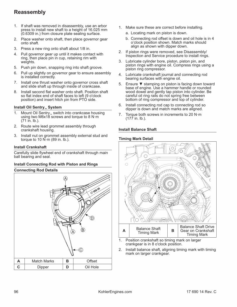
96
Reassembly
KohlerEngines.com 17 690 14 Rev. C
1. If shaft was removed in disassembly, use an arbor press to install new shaft to a height of 16.025 mm (0.6309 in.) from closure plate sealing surface.
2. Place washer onto shaft, then place governor gear onto shaft.
3. Press a new ring onto shaft about 1/8 in.4. Pull governor gear up until it makes contact with
ring, then place pin in cup, retaining rim with weights.
5. Push pin down, snapping ring into shaft groove.6. Pull up slightly on governor gear to ensure assembly
is installed correctly.7. Install one thrust washer onto governor cross shaft
and slide shaft up through inside of crankcase.8. Install second fl at washer onto shaft. Position shaft
so fl at index end of shaft faces to left (9 o'clock position) and insert hitch pin from PTO side.
Install Oil Sentry™ System1. Mount Oil Sentry™ switch into crankcase housing
using two M6x18 screws and torque to 8 N·m (71 in. lb.).
2. Route wire lead grommet assembly through crankshaft housing.
3. Install nut on grommet assembly external stud and torque to 10 N·m (89 in. lb.).
Install CrankshaftCarefully slide fl ywheel end of crankshaft through main ball bearing and seal.
Install Connecting Rod with Piston and RingsConnecting Rod Details
A
C
D
A B
A Match Marks B Off setC Dipper D Oil Hole
1. Make sure these are correct before installing. a. Locating mark on piston is down. b. Connecting rod off set is down and oil hole is in 4
o’clock position shown. Match marks should align as shown with dipper down.
2. If piston rings were removed, see Disassembly/ Inspection and Service procedure to install rings.
3. Lubricate cylinder bore, piston, piston pin, and piston rings with engine oil. Compress rings using a piston ring compressor.
4. Lubricate crankshaft journal and connecting rod bearing surfaces with engine oil.
5. Ensure ▼ stamping on piston is facing down toward base of engine. Use a hammer handle or rounded wood dowel and gently tap piston into cylinder. Be careful oil ring rails do not spring free between bottom of ring compressor and top of cylinder.
6. Install connecting rod cap to connecting rod so dipper is down and match marks are aligned.
7. Torque both screws in increments to 20 N·m (177 in. lb.).
Install Balance Shaft
Timing Mark Detail
A
B
A Balance Shaft Timing Mark B
Balance Shaft Drive Gear on Crankshaft
Timing Mark1. Position crankshaft so timing mark on larger
crankgear is in 8 o'clock position.2. Install balance shaft, aligning timing mark with timing
mark on larger crankgear.

97
Reassembly
17 690 14 Rev. C KohlerEngines.com
Install Valve Tappets and Camshaft
Timing Mark Detail
A
B
A Camshaft Gear Timing Mark B
Camshaft Drive Gear on Crankshaft
Timing Mark1. Lubricate face and stem of each tappet with engine
oil. Install each into their respective bores.2. Lubricate camshaft bearing surfaces and cam lobes
as well as camshaft bore in crankcase with engine oil.
3. Rotate crankshaft to TDC so timing mark (dimple) on smaller crankgear is in 4 o’clock position. Install camshaft into crankcase, aligning timing marks on two gears.
4. Install original shims on crankshaft and camshaft.
Install Extended Oil Fill Tube (if equipped)Oil Fill Tube Details
A
BC
A Oil Fill Tube B Oil Fill Tube BracketC Bracket Screw
1. If oil fi ll tube was removed from closure plate, apply a small amount of Loctite® 620TM (or equivalent) to end of tube, then press into closure plate until tube bead seats in closure plate. Tube should be parallel to closure plate PTO face.
2. Place bracket over tube and secure with bracket screw. Tighten screw until bracket is tight all around tube; then torque to 5.4 N·m (48 in. lb.).
Install Closure Plate
Torque Sequence
1
2
34
5
6
7NOTE: Make sure governor lever is against cup on
governor gear assembly.1. Check to make sure sealing surfaces of crankcase
and closure plate are clean and free of nicks/burrs.2. Install two dowel pins into locations shown in
crankcase. Install new closure plate gasket (dry) onto dowel pins.
3. Install closure plate to crankcase. Carefully seat ends of camshaft and balance shaft into their mating bearings. Rotate crankshaft slightly to help engage governor gear teeth.
4. Install screws securing closure plate to crankcase. Torque screws in sequence shown to 24 N·m (212 in. lb.).

98
Reassembly
KohlerEngines.com 17 690 14 Rev. C
Cylinder Head Components
1
2
3
4
J
K
IH
E D
C
M
L
N
GF
O
AB
P
N
A Valve Cover B Valve Cover Gasket C Adjuster Nut D Rocker Arm
E Rocker Arm Stud F Push Rod Guide G Push Rod H Valve Spring Retainer
I Valve Spring J Valve Stem Seal K Spark Plug L Cylinder Head
M Valve N Dowel Pin O Cylinder Head Gasket P Torque Sequence
Assemble Cylinder HeadNOTE: Engine utilizes valve stem seals on valves.
Always use a new seal when valves are installed in cylinder head. Never reuse old seals.
1. Install valves into their respective positions.2. Install new valve seals on stem of valves.3. Install valve springs and retainers into their
respective locations in cylinder head. Support valve heads from underneath. Using hand pressure, compress each valve spring and slide each retainer onto valve stem to lock in place.
Install Cylinder Head1. Check to make sure there are no nicks or burrs on
sealing surfaces of cylinder head or crankcase.2. Rotate crankshaft to position piston at TDC on
compression stroke.3. Install dowel pins into recesses around upper
cylinder head bolt holes.4. Install a new cylinder head gasket.5. Apply clean engine oil under head of each cylinder
head screw.6. Install cylinder head and start screws. Finger tighten
screws, then torque screws in increments using sequence shown. Torque screws fi rst to 25 N·m (221 in. lb.), then fi nally to 57.5 N·m (509 in. lb.).

99
Reassembly
17 690 14 Rev. C KohlerEngines.com
Flywheel/Ignition Components
1
24
3K
G
JI
F
DB
A
E H
C
A Flywheel Retaining Nut B Drive Cup
C Grass Screen Assembly D Flywheel Fan
E Flywheel F Crankshaft PositionSensor
G Crankshaft PositionSensor Bracket H 18 Amp Stator
I Stator Wire Bracket J 10 Amp StatorK Torque Sequence
Install Stator (if equipped)1. Position stator aligning mounting holes so leads are
in 3 o'clock position.2. Install and torque screws to 8.8 N·m (78 in. lb.) in
sequence of 1, 2, 3, 4 and then torque 1 again.3. Route stator leads along crankcase and out notch on
side. Insert rubber grommet with stator leads into crankcase.
4. Position bracket over stator leads and install and torque screw to 10 N·m (89 in. lb.).
Install Wiring HarnessRoute wiring harness through castings on crankcase.
Install Push Rods and Rocker ArmsNOTE: Push rods should always be installed in original
location.1. Identify proper position of each push rod. Dip ends
of push rods in engine oil and install them in their respective locations, seating each into tappet socket.
2. Install push rod guide plate, aligning holes for rocker arm studs. Screw in rocker arm studs and torque to 13.6 N·m (120 in. lb.).
3. Assemble rocker arms, adjusters, and locknuts onto studs and push rods. Finger tighten rocker arm pivot jam locknuts.
4. Adjust valve tappet clearance as follows: a. Make sure piston is still at top of compression
stroke. b. Insert a fl at feeler gauge between rocker arm and
valve stem. ECH440 recommended valve to rocker arm
clearance for intake and exhaust is 0.076-0.127 mm (0.003-0.005 in.)(Cold).
ECH440LE recommended valve to rocker arm clearance for intake is 0.076-0.127 mm (0.003-0.005 in.) and exhaust is 0.1778-0.2286 mm (0.007-0.009 in.)(Cold).
c. Adjust clearance as required by loosening locknut and turning adjuster.
Turn clockwise to decrease clearance.Turn counterclockwise to increase clearance.
d. Hold adjuster from turning and tighten locknut. Torque locknut to 10 N·m (89 in. lb.).
e. Recheck clearance is correct.5. Set gap of a new spark plug to 1.02 mm (0.040 in.).6. Install spark plug in cylinder head and torque to
27 N·m (20 ft. lb.).
Install Valve Cover1. Install a new valve cover gasket onto valve cover.2. Position valve cover/gasket assembly on head.
Install screw and washer; torque screw to 10 N·m (89 in. lb.).

100
Reassembly
KohlerEngines.com 17 690 14 Rev. C
Install Flywheel
CAUTIONDamaging Crankshaft and Flywheel can cause personal injury.
Using improper procedures can lead to broken fragments. Broken fragments could be thrown from engine. Always observe and use precautions and procedures when installing fl ywheel.
NOTE: Before installing fl ywheel make sure crankshaft taper and fl ywheel hub bore are clean, dry, and completely free of lubricants. Presence of lubricants can cause fl ywheel to be over stressed and damaged when nut is torqued to specifi cation.
NOTE: Make sure fl ywheel key is installed properly in keyway. Flywheel can become cracked or damaged if key is not installed properly.
1. Install woodruff key into keyway of crankshaft. Make sure key is properly seated and parallel with taper of shaft.
2. Install fl ywheel onto crankshaft, being careful not to shift position of woodruff key.
3. Install fan bosses into matching holes in fl ywheel.4. Position grass screen assembly or drive cup on
fl ywheel, engaging boss on its base with corresponding hole in fan. Hold in position and install nut. Finger tighten to keep cup indexed.
5. Use a fl ywheel holding tool and torque wrench to tighten fl ywheel nut. Torque nut to 113 N·m (1000 in. lb.).
Install Crankshaft Position SensorNOTE: Ensure all parts are clean, undamaged and free
of debris and make sure electrical connectors have seal in place.
NOTE: When mounting ground wire on bottom screw of bracket, ensure ground wire is routed outside and away from fl ywheel.
1. Install crankshaft position sensor to bracket. Torque screw to 4.2 N·m (37 in. lb.).
2. Install crankshaft position sensor and bracket assembly to crankcase posts.
3. Secure bracket assembly to crankcase posts. Torque bracket screws to 7.3 N·m (65 in. lb.).
4. Push electrical connector on crankshaft position sensor making sure a good connection is made.

101
Reassembly
17 690 14 Rev. C KohlerEngines.com
Blower Housing Components
K
G
C
A
H
I
F
E
D
CB
L
J
A Engine Temperature Sensor B Upper Shield C Fuel Support Bracket D Electric Starter
E Lower Shield F Electronic Control Unit (ECU) G Cable Clip H Blower Housing
I Retractable Starter J Blower Housing Screen K Ignition Coil L Fuse Holder
Install Electric Starter (if equipped)1. Connect wire lead (green) to Oil Sentry™ terminal.2. Align and mount electric starter onto crankcase.
Install and torque screws to 24 N·m (212 in. lb.).3. Connect blue wire to starter relay (solenoid).
Install Blower HousingInstall blower housing on crankcase with screws. Torque screws to 10 N·m (89 in. lb.).
Install Blower Housing Screen (if equipped)Install blower housing screen on blower housing using screws. Torque screws to 7.3 N·m (65 in. lb.).
Install Retractable Starter (if equipped)1. Install retractable starter on blower housing using
screws. Finger tighten mounting screws only.2. Pull rope handle to engage pawls and center starter
to drive cup. Hold in this position and torque mounting screws to 5.4 N·m (48 in. lb.).
Install Lower Shield1. Install lower shield on crankcase. Torque screws to
8.5 N·m (75 in. lb.) into new holes or 4.0 N·m (35 in. lb.) into used holes.
2. If removed, install ignition coil onto lower shield. Torque screw to 10.2 N·m (90 in. lb.).
3. Plug connector into ignition coil.

102
Reassembly
KohlerEngines.com 17 690 14 Rev. C
Install Electronic Control Unit (ECU)NOTE: ECU pins should be coated with a thin layer of
electrical grease to prevent fretting and corrosion and may need to be reapplied if ECU is being reused.
1. Connect Black and Grey electrical connectors. Connectors and ECU are keyed in such a way so they cannot be installed incorrectly.
2. Install ECU to lower shield using screws. Wire harness clip secures with screw closest to fl ywheel. Torque screws to 6.2 N·m (55 in. lb.) into new holes or 4.0 N·m (35 in. lb.) into used holes.
3. Install fuses into holders on lower shield.
Install Upper Shield1. Position upper shield on crankcase and start screws.
Do not tighten screws at this time.2. Secure engine temperature sensor to upper shield
with screw. Torque screw to 11.9 N·m (105 in. lb.).
Install Fuel Support Brackets (if equipped)1. Connect black (male) wire from harness to green
(female) wire from oil sentry.2. Connect green (female) wire from control unit to
yellow (male) sensor wire (from crankcase).3. Route wires behind starter and position both tank
support brackets on crankcase and install with screws. Torque to 24 N·m (212 in. lb.).
4. Install oil alert unit control on fuel support bracket (starter side of engine). Torque screw to 3.5 N·m (31 in. lb.).
Throttle Body Components
E
D C B
L
H
G
F
I
J
M
A
K
A TMAP Sensor B Insulator to Cylinder Head Gasket C Throttle Body
Insulator D Insulator to Throttle Body Gasket
E Throttle PositionSensor (TPS) F Throttle Body Gasket G Throttle Body H Fuel Injector
I Metal Retaining Clip JFuel Injector Cap/Fuel Cap Bracket/
RetainerK Throttle Linkage
Bushing L Linkage Spring
M Throttle Linkage

103
Reassembly
17 690 14 Rev. C KohlerEngines.com
Install Throttle BodyNOTE: Ensure all parts are clean, undamaged, and free
of debris and make sure electrical connector has seal in place.
1. Install new insulator to cylinder head gasket, insulator, and insulator to throttle body gasket as shown.
Ensure notched section of each gasket is outward and points to fl ywheel side.
Ensure arrow on insulator points toward cylinder head.
2. Install throttle body on studs.3. Install nuts to hold throttle body in place but do not
tighten at this time. (Nuts will be removed later to install air cleaner base or air inlet adapter.)
4. Push electrical connector onto throttle position sensor (TPS) making sure a good connection is made.
Install Temperature/Manifold Absolute Pressure (TMAP) SensorNOTE: Ensure all parts are clean, undamaged, and free
of debris and make sure electrical connector has seal in place.
1. Lightly oil TMAP sensor O-ring and push sensor into bore in throttle body.
2. Torque screw to 7.3 N·m (65 in. lb.).3. Push electrical connector on TMAP sensor making
sure a good connection is made. Slide down lock tab.
Install Fuel InjectorNOTE: Ensure all parts are clean, undamaged, and free
of debris and make sure electrical connectors have seal in place.
NOTE: O-rings and retaining clip should be replaced any time fuel injector is separated from its normal mounting position.
1. Lightly lubricate fuel injector O-rings with clean engine oil.
2. Push retaining clip onto fuel injector, aligning clip.3. Press fuel injector cap/fuel cap bracket onto fuel
injector until retaining clip snaps into place.4. Press fuel injector into bore in throttle body and
rotate to original position, as noted in Disassembly/Inspection and Service.
5. Install fuel injector cap/fuel cap bracket screw into throttle body and torque to 7.3 N·m (65 in. lb.).
6. Push electrical connector on fuel injector making sure a good connection is made.
Install Throttle Link, Governor Lever, Governor Spring, and Throttle Lever1. Connect throttle linkage and linkage spring to arm of
governor lever.2. Install governor lever onto cross shaft. Assemble
screw and lock nut, but do not tighten.3. Install governor spring in governor and throttle levers
in holes previously marked in disassembly. Install throttle lever and a fender washer on threaded stud of fuel tank bracket.
4. Install a nylon washer, wave spring, and tabbed washer (with tab engaged in slot) on stud above throttle lever and secure with nut.
On Variable Speed with Remote Throttle Control or Fixed Speed Control (without a wave washer), torque nut to 9 N·m (80 in. lb.).
On Variable Speed (with a wave washer), torque nut to 5.3 N·m (47 in. lb.).
5. Ensure throttle return spring (if equipped) is attached to throttle control lever.
Governor Lever Hole Position/RPM ChartVariable Speed with Remote Throttle Control
5
1
43 A
BC
2
Engine Speed RPM
6-12% Droop
Spring Color Hole Combination
3601-3800 None #2-B

104
Reassembly
KohlerEngines.com 17 690 14 Rev. C
Variable Speed Control
ABC
5
1
43
2
Engine Speed RPM
6-12% Droop
Spring Color Hole Combination
3925-4075 None #3-B
Variable Speed Control Governor Lever Only (OEM Supplied Throttle Controls)
1
4
3
2
Engine Speed RPM
6-12% Droop
Spring Color Hole
3650-3850 White 4
Fixed Speed Control
AB
5
1
43
2
Engine Speed RPM
6-12% Droop
Spring Color Hole Combination
3601-3800 None #2-B
Connect Remote Control Linkage (if equipped)Components
BD
A
C
A Linkage Retaining Bushing B Control Lever
C Remote Control Linkage D Control System
Bracket Assembly1. Hook end of remote control linkage into throttle
control lever on control system bracket assembly.2. Install linkage retaining bushing into control lever,
then install linkage and snap bushing onto linkage.

105
Reassembly
17 690 14 Rev. C KohlerEngines.com
External Engine Components
J
A
D
H
G
F
E
M
I K
L
C
BB
O
N
A Muffl er Assembly with Heat Shield B Fuel Support Bracket C Engine Temperature
Sensor D Oil Drain Plug
E Breather Hose F Fuel Line G Fuel Tank H Quad-Clean™ Cover
I Quad-Clean™ Element/Precleaner J Quad-Clean™ Base K Quad-Clean™
Base Cover L Air Inlet Adapter
M Low-Profi le Air Cleaner N Throttle Body Gasket O Spacer

106
Reassembly
KohlerEngines.com 17 690 14 Rev. C
Install Air Inlet Adapter (if equipped)1. Remove nuts from mounting studs.2. Install a new throttle body gasket onto mounting
studs followed by air inlet adapter.3. Secure air inlet adapter with nuts on mounting
studs. Torque nuts to 8 N·m (71 in. lb.).4. Attach breather hose onto air inlet adapter
connection port; position hose clamp to secure. Connect opposite end of breather hose to valve cover.
Install Quad-Clean™ Base (if equipped)1. Remove nuts from mounting studs.2. Install a new throttle body gasket onto mounting
studs followed by air cleaner base. Attach breather hose onto air cleaner base connection port. Connect opposite end of breather hose to valve cover.
3. Secure base with nuts on mounting studs. Ensure spacer is in proper position under arm of air cleaner base and secure with screw into crankcase. Torque hardware to 8 N·m (71 in. lb.).
4. If equipped with base cover, install onto mounting studs and secure with nuts. Torque nuts to 4 N·m (35 in. lb.). Install screws to secure base cover to blower housing. Torque screws to 1.3 N·m (12 in. lb.).
Install Low-Profi le Air Cleaner Base (if equipped)1. Remove nuts from mounting studs.2. Install a new throttle body gasket onto mounting
studs followed by air cleaner base. Attach breather hose onto air cleaner base connection port. Connect opposite end of breather hose to valve cover.
3. Secure base with nuts on mounting studs. Torque nuts to 8 N·m (71 in. lb.) Secure base to blower housing with screw. Torque screw to 6.7 N·m (59 in. lb.).
Torque Upper Shield ScrewsFully tighten upper shield and torque screws to 6.2 N·m (55 in. lb.) into new holes or 4.0 N·m (35 in. lb.) into used holes.
Adjust Governor LeverPush governor lever away from throttle body and hold in this position. Turn governor cross shaft counterclockwise until it stops. Tighten nut on governor lever clamp bolt to lock lever on shaft. Torque nut to 12 N·m (106 in. lb.).
Install Fuel Tank (if equipped)1. Position fuel tank on mounting brackets. Secure with
screws on inner mounting bracket and on PTO side strap.
2. Install nuts on fuel tank studs.3. Torque side strap screw to 10 N·m (89 in. lb.).4. Torque remaining screw and nuts to 24 N·m
(212 in. lb.).5. Position fuel line in clip on bottom of tank. Connect
fuel line to throttle body and secure with clamp.6. Using a needle nose pliers,carefully hook throttle
return spring into rear fuel tank mounting bracket.
ECH440 Install Muffl er Assembly with Heat Shield (if equipped)1. Position a new exhaust gasket and install muffl er
assembly with heat shield to exhaust outlet fl ange.2. Torque screws to 35 N·m (310 in. lb.).3. Install oxygen sensor, torque to 18 N·m (159 in. lb.),
and connect to wire harness.
ECH440LE Install Catalyst Muffl er AssemblyNOTE: Catalyst muffl er assembly secures to engine
exhaust port and on frame of equipment.NOTE: It is important to follow these reassembly steps
to ensure proper operation of exhaust system.1. Install exhaust elbow and exhaust gasket to cylinder
head exhaust port; secure with 2 M10 x 25 screws. Torque screws to 35 N·m (310 in. lb.).
2. Install muffl er back cover guard to catalyst muffl er; secure with 4 M6 x 12 screws. Torque screws to 10 N·m (89 in. lb.).
3. Loosely assemble muffl er mounting bracket to catalyst muffl er/back guard; secure with 3 M6 screws and fl at washers. Do not tighten.
4. Loosely install catalyst muffl er/back guard/mounting bracket assembly to alternator rear casting; secure with 2 M8 x 20 screws and fl at washers. Do not tighten.
5. Position muffl er assembly so that exhaust elbow fl ange and muffl er inlet fl ange are perfectly lined up. Tighten 2 M8 x 20 screws (from step 4), holding bracket to top and bottom of alternator rear casting. Torque screws to 25 N·m (221 in. lb.).
6. Confi rm that fl anges are still aligned and tighten 3 M6 screws (from step 3). Start with center screw and torque to 10 N·m (89 in. lb.).
7. Confi rm that muffl er inlet fl ange and exhaust elbow fl ange are still aligned and insert an exhaust gasket between fl anges. Then secure fl anges together using two M8 x 20 screws and lock washers. Torque screws to 25 N·m (221 in. lb.).

107
Reassembly
17 690 14 Rev. C KohlerEngines.com
8. Loosen M8 screws that secure exhaust elbow fl ange to muffl er inlet fl ange and confi rm that fl anges are in alignment and that no excessive preload has occurred. If fl anges are separated by more than 3 mm (0.12 in.), readjust either 3 M6 screws securing catalyst muffl er and muffl er bracket, or 2 M8 screws securing bracket to alternator rear casting; then repeat tightening/torque process.
9. Install oxygen sensor in elbow, torque sensor to 18 N·m (159 in. lb.) and connect sensor to wiring harness.
10. Install muffl er front cover guard (with rubber gaskets on top and bottom) to catalyst muffl er using 4 M6 x 12 screws. Torque screws to 10 N·m (89 in. lb.).
11. Install spark arrestor with defl ector in catalyst muffl er outlet and orient exhaust slightly downward and away from frame tire (if equipped).
Install Air Cleaner Element and Cover (if equipped)Install Quad-Clean™ Air Cleaner1. Place air cleaner element with precleaner onto boss
on air cleaner base.2. Position air cleaner cover as required for seasonal
operation and engage both cover clips to secure it to base.
Install Low-Profi le Air Cleaner1. Place foam element in air cleaner base.2. Position air cleaner cover onto base and secure with
screw.
Connect Spark Plug LeadConnect lead to spark plug.
Prepare Engine for OperationNOTE: If ECU, throttle body, TPS, or fuel pump module
were replaced, an ECU Reset and TPS Learn is required. Refer to EFI System Reset and TPS Learn procedure.
Engine is now reassembled. Before starting or operating engine be sure to do following:1. Make sure all hardware is properly torqued.2. Make sure oil drain plugs, oil fi ll plugs and Oil
SentryTM wire lead bushing are tightened securely.3. Fill crankcase with correct oil. Refer to Maintenance
and Lubrication System for oil recommendations and procedures.
4. Make sure all fuel and vent lines are connected. Refer to equipment manufacturer's manual for Reassembly information.
5. Ensure all electrical connectors are installed and secure.
6. Turn on fuel supply.
Testing Engine1. Check gas and oil levels. Start engine and run for
5-10 minutes between idle and midrange. Adjust throttle body settings as required. Low idle speed should be set to 1800 RPM (±150) or application specifi cations. Check equipment manufacturer’s recommendation.
2. Maximum no load high engine speed is 3750 RPM or application specifi cations. Check equipment manufacturer’s recommendation.
If equipped, adjust high speed adjusting stop screw as necessary.

108
8 85612 52081 4
1P17 690 14
© 2021 by Kohler Co. All rights reserved.
KohlerEngines.com 17 690 14 Rev. C