E/A Design Division CAD Standard - Port Authority of New ...
287
E/A Design Division CAD Standard Engineering Department Last Updated: 07/01/2019 Reviewed/Released 2019 v3.0
-
Upload
khangminh22 -
Category
Documents
-
view
32 -
download
0
Transcript of E/A Design Division CAD Standard - Port Authority of New ...
E/A Design Division CAD
Standard
Engineering Department
Last Updated: 07/01/2019
Reviewed/Released 2019 v3.0
Engineering Department Manual
E/A Design Division CAD Standard
Last Updated: 07/01/2019 Page i
Reviewed/Released 2019 v3.0
TABLE OF CONTENTS
1.0 E/A DESIGN DIVISION CAD STANDARD .................................................... 1
1.1 FOREWORD ............................................................................................................................ 1
1.2 PURPOSE ............................................................................................................................... 1
1.2.1 ABOUT THIS STANDARD ............................................................................................ 1
1.3 ACRONYMS AND ABBREVIATIONS ............................................................................................ 2
1.4 DELIVERABLES ....................................................................................................................... 2
1.4.1 SCHEDULE ............................................................................................................... 3
1.4.2 MEDIA AND FORMAT ................................................................................................. 3
1.4.3 IDENTIFICATION ........................................................................................................ 3
1.4.4 PROJECT WEBSITES ................................................................................................. 3
1.5 ACCESSING THE E/A DESIGN DIVISION CAD STANDARD .......................................................... 4
1.5.1 USING THE STANDARD FILES .................................................................................... 5
1.5.2 AUTOCAD CIVIL 3D ................................................................................................. 5
1.5.3 AUTODESK REVIT ..................................................................................................... 5
1.6 PROJECT DIRECTORY STRUCTURE AND FILE NAMING CONVENTION .......................................... 5
1.6.1 PROJECT DIRECTORY STRUCTURE ............................................................................ 6
1.6.2 PROJECT IDENTIFICATION NUMBER ........................................................................... 7
1.6.3 DISCIPLINE FOLDERS ................................................................................................ 7
1.6.4 SAMPLE PROJECT .................................................................................................. 12
1.6.5 FILE NAMING CONVENTION ..................................................................................... 12
1.6.6 DRAWING NUMBER CONVENTIONS .......................................................................... 19
1.6.7 FOLDER NAMING CONVENTION................................................................................ 20
1.6.8 LAYERING SCHEME DEFINITION ............................................................................... 20
1.7 PROJECT DIRECTORY STRUCTURE AND FILE NAMING CONVENTION (VAULT PROJECTS).......... 21
1.7.1 PROJECT DIRECTORY STRUCTURE .......................................................................... 21
1.7.2 PROJECT IDENTIFICATION NUMBER ......................................................................... 22
1.7.3 CIVIL 3D DATA ....................................................................................................... 22
1.7.4 DISCIPLINE FOLDERS .............................................................................................. 22
1.7.5 SAMPLE VAULT PROJECT FOLDER ........................................................................... 28
1.7.6 FILE NAMING CONVENTION ..................................................................................... 28
1.7.7 DRAWING NUMBER CONVENTION ............................................................................ 31
1.7.8 FOLDER NAMING CONVENTION................................................................................ 31
1.7.9 LAYERING SCHEME DEFINITION ............................................................................... 31
Engineering Department Manual
E/A Design Division CAD Standard
Last Updated: 07/01/2019 Page ii
Reviewed/Released 2019 v3.0
1.8 CAD PRACTICES AND PROCEDURES ..................................................................................... 31
1.8.1 COORDINATE SYSTEMS .......................................................................................... 32
1.8.2 ENTITY AND LAYER LINETYPES ................................................................................ 32
1.8.3 SYMBOLOGY .......................................................................................................... 32
1.8.4 PLOTTED LINEWEIGHTS .......................................................................................... 33
1.8.5 TEXT STYLES AND HEIGHTS .................................................................................... 35
1.8.6 DIMENSION AND LEADER STYLES ............................................................................ 36
1.8.7 TABLE STYLES ....................................................................................................... 36
1.8.8 EXTERNAL REFERENCE FILES ................................................................................. 36
1.8.9 EXTERNAL REFERENCE FILES (FOR VAULT ONLY) .................................................... 36
1.8.10 SUBMISSIONS ......................................................................................................... 37
1.8.11 SUBMISSIONS (FOR VAULT PROJECT ONLY) .............................................................. 38
1.8.12 CATEGORIES (FOR PA EMPLOYEES USING VAULT) ................................................... 40
1.8.13 LIFECYCLE STATE (FOR PA EMPLOYEES USING VAULT) ............................................ 40
1.8.14 CAD ENVIRONMENT SETUP .................................................................................... 42
1.8.15 TEMPLATE DRAWING SETUP ................................................................................... 42
1.8.16 UNITS .................................................................................................................... 42
1.9 PLOT SETUP ......................................................................................................................... 43
1.9.1 PAGE SETUPS ........................................................................................................ 43
1.9.2 STAGE I PROJECT DIRECTORY STRUCTURE ............................................................. 43
1.9.3 STAGE I EXTERNAL REFERENCE FILES .................................................................... 44
1.10 PLAN SET PREPARATION ...................................................................................................... 45
1.10.1 AUTOCAD 2018 CONFIGURATION (PLOTTING BY LAYOUT) ....................................... 45
1.10.2 PLAN SET TITLE SHEET .......................................................................................... 45
1.10.3 PLAN SET PLOT SHEETS ......................................................................................... 48
1.11 SPECIAL PROJECTS .............................................................................................................. 55
1.11.1 CONFIDENTIAL PROJECTS ....................................................................................... 55
1.12 CAD STANDARDS REVIEW REPORT ...................................................................................... 58
1.12.1 INTERIM CAD REVIEW ............................................................................................ 58
1.12.2 CONSTRUCTION CONTRACT PA WIDE CAD REVIEW ................................................ 59
1.12.3 WORK ORDER CAD REVIEW ................................................................................... 59
1.12.4 CONFIDENTIAL PRIVILEGED PROJECTS .................................................................... 63
1.13 UPDATE AND REVISION PROCEDURES ................................................................................... 65
1.14 CONTACT AND SUPPORT INFORMATION ................................................................................. 65
1.15 CONCLUSION ........................................................................................................................ 65
Engineering Department Manual
E/A Design Division CAD Standard
Last Updated: 07/01/2019 Page iii
Reviewed/Released 2019 v3.0
1.16 APPENDIX A – ARCHITECTURAL DISCIPLINE ........................................................................... 66
1.16.1 CONTENT PREFERENCES ........................................................................................ 66
1.16.2 LAYER STRATAGEM ................................................................................................ 66
1.16.3 LINETYPES ............................................................................................................. 78
1.16.4 SYMBOLS ............................................................................................................... 80
1.16.5 CONTENT PREFERENCES ........................................................................................ 92
1.16.6 MODEL FOLDER FILE TYPES ................................................................................... 93
1.16.7 PLOTSHEETS FOLDER FILE TYPES......................................................................... 118
1.16.8 PUBLISH FOLDER FILE TYPES ............................................................................... 122
1.16.9 STAGE IV FILE TYPES ........................................................................................... 126
1.17 APPENDIX B – CIVIL DISCIPLINE .......................................................................................... 128
1.17.1 CONTENT PREFERENCES ...................................................................................... 128
1.17.2 LAYER STRATAGEM .............................................................................................. 129
1.17.3 LINETYPES ........................................................................................................... 131
1.17.4 SYMBOLS ............................................................................................................. 132
1.17.5 CIVIL 3D .............................................................................................................. 135
1.18 APPENDIX C – ELECTRICAL DISCIPLINE ............................................................................... 140
1.18.1 CONTENT PREFERENCES ...................................................................................... 140
1.18.2 LAYER STRATAGEM .............................................................................................. 140
1.18.3 LINETYPES ........................................................................................................... 141
1.18.4 SYMBOLS ............................................................................................................. 142
1.19 APPENDIX D – ENVIRONMENTAL DISCIPLINE ........................................................................ 176
1.19.1 CONTENT PREFERENCES ...................................................................................... 176
1.19.2 LAYER STRATAGEM .............................................................................................. 176
1.19.3 LINETYPES ........................................................................................................... 177
1.19.4 SYMBOLS ............................................................................................................. 178
1.20 APPENDIX E – GEOTECHNICAL DISCIPLINE .......................................................................... 180
1.20.1 CONTENT PREFERENCES ...................................................................................... 180
1.20.2 LAYER STRATAGEM .............................................................................................. 180
1.20.3 LINETYPES ........................................................................................................... 181
1.20.4 SYMBOLS ............................................................................................................. 181
1.21 APPENDIX F – MECHANICAL DISCIPLINE .............................................................................. 184
1.21.1 CONTENT PREFERENCES ...................................................................................... 184
1.21.2 LAYER STRATAGEM .............................................................................................. 184
1.21.3 LINETYPES ........................................................................................................... 188
Engineering Department Manual
E/A Design Division CAD Standard
Last Updated: 07/01/2019 Page iv
Reviewed/Released 2019 v3.0
1.21.4 SYMBOLS ............................................................................................................. 193
1.22 APPENDIX G – STRUCTURAL DISCIPLINE ............................................................................. 223
1.22.1 CONTENT PREFERENCES ...................................................................................... 223
1.22.2 LAYER STRATAGEM .............................................................................................. 223
1.22.3 LINETYPES ........................................................................................................... 225
1.22.4 SYMBOLS ............................................................................................................. 226
1.23 APPENDIX H – TRAFFIC DISCIPLINE ..................................................................................... 228
1.23.1 CONTENT PREFERENCES ...................................................................................... 228
1.23.2 LAYER STRATAGEM .............................................................................................. 228
1.23.3 LINETYPES ........................................................................................................... 230
1.23.4 SYMBOLS ............................................................................................................. 231
1.24 APPENDIX I – COMMON SYMBOLOGY ................................................................................... 257
1.24.1 GRAPHIC SCALE BARS .......................................................................................... 257
1.24.2 NORTH ARROWS .................................................................................................. 258
1.25 APPENDIX K – CONTRACT BORDERS AND TITLE SHEETS ...................................................... 259
1.25.1 TITLE SHEET ........................................................................................................ 259
1.25.2 TITLE SHEET OVERSIZED (OS) ............................................................................. 260
1.25.3 TITLE SHEET PATH .............................................................................................. 261
1.25.4 TITLE SHEET PATH OVERSIZED (OS) ................................................................... 262
1.25.5 CONTRACT BORDER ............................................................................................. 263
1.25.6 CONTRACT BORDER OVERSIZED (OS) .................................................................. 264
1.25.7 CONTRACT BORDER PATH................................................................................... 265
1.25.8 CONTRACT BORDER PATH OVERSIZED (OS) ........................................................ 266
1.26 APPENDIX K – DISTRIBUTION FILES ..................................................................................... 267
1.27 APPENDIX L – USING STANDARD FORMS ON EOL (INTERNAL USE ONLY) ............................. 270
1.27.1 PID SEARCH ........................................................................................................ 270
1.27.2 REQUEST PROJECT ARCHIVAL .............................................................................. 271
1.27.3 REQUEST PROJECT CAD DRAWINGS .................................................................... 272
1.27.4 REQUEST FOR MANDATORY CAD REVIEW ............................................................. 273
1.27.5 REQUEST FOR NON-MANDATORY CAD REVIEW..................................................... 275
1.27.6 REQUEST FOR MANDATORY WORK ORDER CAD REVIEW ...................................... 277
1.27.7 REQUEST PROJECT FOLDER STRUCTURE .............................................................. 279
1.28 APPENDIX M – REQUEST TO CHANGE STANDARD ................................................................ 281
1.29 APPENDIX N - CHANGES TO THE STANDARDS ...................................................................... 282
Engineering Department Manual
E/A Design Division CAD Standard
Last Updated: 07/01/2019 Page 1
Reviewed/Released 2019 v3.0
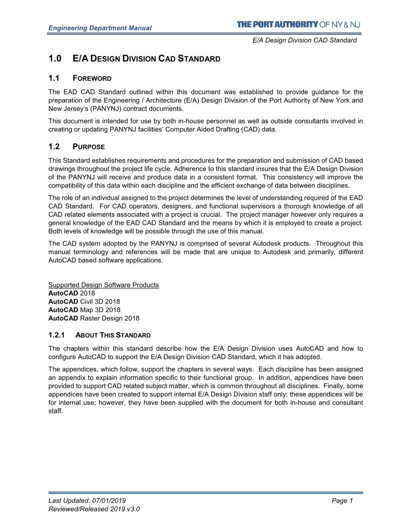
1.0 E/A DESIGN DIVISION CAD STANDARD
1.1 FOREWORD
The EAD CAD Standard outlined within this document was established to provide guidance for the
preparation of the Engineering / Architecture (E/A) Design Division of the Port Authority of New York and
New Jersey’s (PANYNJ) contract documents.
This document is intended for use by both in-house personnel as well as outside consultants involved in
creating or updating PANYNJ facilities’ Computer Aided Drafting (CAD) data.
1.2 PURPOSE
This Standard establishes requirements and procedures for the preparation and submission of CAD based
drawings throughout the project life cycle. Adherence to this standard insures that the E/A Design Division
of the PANYNJ will receive and produce data in a consistent format. This consistency will improve the
compatibility of this data within each discipline and the efficient exchange of data between disciplines.
The role of an individual assigned to the project determines the level of understanding required of the EAD
CAD Standard. For CAD operators, designers, and functional supervisors a thorough knowledge of all
CAD related elements associated with a project is crucial. The project manager however only requires a
general knowledge of the EAD CAD Standard and the means by which it is employed to create a project.
Both levels of knowledge will be possible through the use of this manual.
The CAD system adopted by the PANYNJ is comprised of several Autodesk products. Throughout this
manual terminology and references will be made that are unique to Autodesk and primarily, different
AutoCAD based software applications.
Supported Design Software Products AutoCAD 2018
AutoCAD Civil 3D 2018
AutoCAD Map 3D 2018
AutoCAD Raster Design 2018
1.2.1 ABOUT THIS STANDARD
The chapters within this standard describe how the E/A Design Division uses AutoCAD and how to
configure AutoCAD to support the E/A Design Division CAD Standard, which it has adopted.
The appendices, which follow, support the chapters in several ways. Each discipline has been assigned
an appendix to explain information specific to their functional group. In addition, appendices have been
provided to support CAD related subject matter, which is common throughout all disciplines. Finally, some
appendices have been created to support internal E/A Design Division staff only; these appendices will be
for internal use; however, they have been supplied with the document for both in-house and consultant
staff.
Engineering Department Manual
E/A Design Division CAD Standard
Last Updated: 07/01/2019 Page 2
Reviewed/Released 2019 v3.0
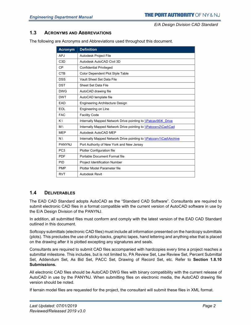
1.3 ACRONYMS AND ABBREVIATIONS
The following are Acronyms and Abbreviations used throughout this document.
Acronym Definition
APJ Autodesk Project File
C3D Autodesk AutoCAD Civil 3D
CP Confidential Privileged
CTB Color Dependent Plot Style Table
DSS Vault Sheet Set Data File
DST Sheet Set Data File
DWG AutoCAD drawing file
DWT AutoCAD template file
EAD Engineering Architecture Design
EOL Engineering on Line
FAC Facility Code
K:\ Internally Mapped Network Drive pointing to \\Patcav56\K_Drive
M:\ Internally Mapped Network Drive pointing to \\Patccsrv2\Cad\Cad
MEP Autodesk AutoCAD MEP
N:\ Internally Mapped Network Drive pointing to \\Patccsrv1\Cad\Archive
PANYNJ Port Authority of New York and New Jersey
PC3 Plotter Configuration file
PDF Portable Document Format file
PID Project Identification Number
PMP Plotter Model Parameter file
RVT Autodesk Revit
1.4 DELIVERABLES
The EAD CAD Standard adopts AutoCAD as the “Standard CAD Software”. Consultants are required to
submit electronic CAD files in a format compatible with the current version of AutoCAD software in use by
the E/A Design Division of the PANYNJ.
In addition, all submitted files must conform and comply with the latest version of the EAD CAD Standard
outlined in this document.
Softcopy submittals (electronic CAD files) must include all information presented on the hardcopy submittals
(plots). This precludes the use of sticky-backs, graphic tapes, hand lettering and anything else that is placed
on the drawing after it is plotted excepting any signatures and seals.
Consultants are required to submit CAD files accompanied with hardcopies every time a project reaches a
submittal milestone. This includes, but is not limited to, PA Review Set, Law Review Set, Percent Submittal
Set, Addendum Set, As Bid Set, PACC Set, Drawing of Record Set, etc. Refer to Section 1.8.10
Submissions.
All electronic CAD files should be AutoCAD DWG files with binary compatibility with the current release of
AutoCAD in use by the PANYNJ. When submitting files on electronic media, the AutoCAD drawing file
version should be noted.
If terrain model files are requested for the project, the consultant will submit these files in XML format.
Engineering Department Manual
E/A Design Division CAD Standard
Last Updated: 07/01/2019 Page 3
Reviewed/Released 2019 v3.0
If alignment files are requested for the project, the consultant will submit alignment files in XML format.
If a coordinate geometry point database is requested for a project, the consultant will supply this database
as an XML file.
When requested, these files will be submitted with the project structure intact, as outlined in Section 1.5.2
AutoCAD Civil 3D.
1.4.1 SCHEDULE
DWG and PDF files are required for each milestone during both Stage II and Stage III. If the project does
not have a milestone scheduled prior to the PA Wide Review submission, DWG and PDF files will be
submitted no later than 3 weeks prior to the PA Wide Review submission.
1.4.2 MEDIA AND FORMAT
AutoCAD drawing files will be submitted on media CDs. All disks are to be delivered virus free.
Final hardcopies of each sheet must use the PANYNJ Contract Border identified in this standard and must
be submitted at full size, either 22x34 or 34x56. Submitted hardcopies must use archival paper with
Permalife® plotter paper specifications. Engineering Department staff will verify that submissions contain
the “Permalife 25% cotton content” watermark. Authorized professional signatures must use blue ink.
1.4.3 IDENTIFICATION
All CDs submitted to the E/A Design Division of the PANYNJ will be labeled with the following information:
• Consultant’s name and Project Identification Number (PID)
• Contact name and phone number of consulting project manager
• Discipline-Facility (e.g. Civil-JFK)
• Submittal Date and Percent Completed
• Data Format (e.g. AutoCAD Version .dwg)
• File Name(s) on CD
• As much information as possible should be printed on both the CD label and the CD case. If
all the information will not fit on either the CD label or the CD case, the information can be listed
in an orderly manner in a text file that will be copied to the CD in electronic format.
1.4.4 PROJECT WEBSITES
The PANYNJ developed a “Project Extranet” to enhance collaboration between in-house designers and
outside consultants, as well as with different departments and divisions throughout the agency. All Project Websites have a folder structure similar to that described in 1.6 Project Directory Structure and File
Naming Convention of this standard.
Please refer to the project specifics to determine if a Project Website is available for use. If so, all transfer
of digital information should be made via the website. Transfer of data via email or CDs is not permitted if
a project website is available.
If a Project Website is available for the project the Project Website link will be provided along with a
Username and a Password.
Engineering Department Manual
E/A Design Division CAD Standard
Last Updated: 07/01/2019 Page 4
Reviewed/Released 2019 v3.0
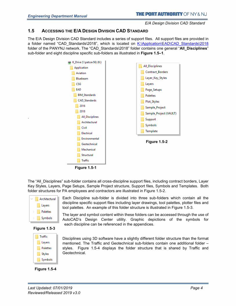
1.5 ACCESSING THE E/A DESIGN DIVISION CAD STANDARD
The E/A Design Division CAD Standard includes a series of support files. All support files are provided in
a folder named “CAD_Standards\2018”, which is located on K:\Application\EAD\CAD_Standards\2018
folder of the PANYNJ network. The “CAD_Standards\2018” folder contains one general “All_Disciplines”
sub-folder and eight discipline specific sub-folders as illustrated in Figure 1.5–1.
.
The “All_Disciplines” sub-folder contains all cross-discipline support files, including contract borders, Layer
Key Styles, Layers, Page Setups, Sample Project structure, Support files, Symbols and Templates. Both
folder structures for PA employees and contractors are illustrated in Figure 1.5-2.
Each Discipline sub-folder is divided into three sub-folders which contain all the
discipline specific support files including layer drawings, tool palettes, plotter files and
tool palettes. An example of this folder structure is illustrated in Figure 1.5-3.
The layer and symbol content within these folders can be accessed through the use of
AutoCAD’s Design Center utility. Graphic depictions of the symbols for
each discipline can be referenced in the appendices.
Disciplines using 3D software have a slightly different folder structure than the format
mentioned. The Traffic and Geotechnical sub-folders contain one additional folder –
styles. Figure 1.5-4 displays the folder structure that is shared by Traffic and
Geotechnical.
Figure 1.5-3
Figure 1.5-4
Figure 1.5-2
Figure 1.5-1
Engineering Department Manual
E/A Design Division CAD Standard
Last Updated: 07/01/2019 Page 5
Reviewed/Released 2019 v3.0
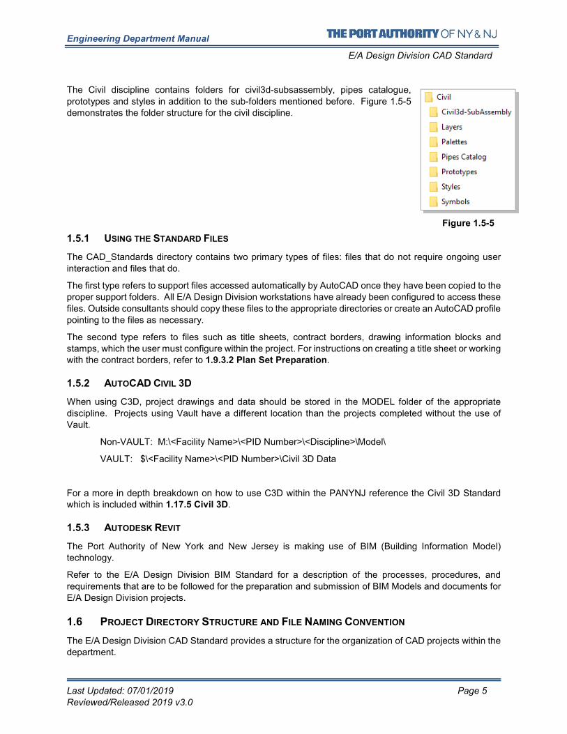
The Civil discipline contains folders for civil3d-subsassembly, pipes catalogue,
prototypes and styles in addition to the sub-folders mentioned before. Figure 1.5-5
demonstrates the folder structure for the civil discipline.
1.5.1 USING THE STANDARD FILES
The CAD_Standards directory contains two primary types of files: files that do not require ongoing user
interaction and files that do.
The first type refers to support files accessed automatically by AutoCAD once they have been copied to the
proper support folders. All E/A Design Division workstations have already been configured to access these
files. Outside consultants should copy these files to the appropriate directories or create an AutoCAD profile
pointing to the files as necessary.
The second type refers to files such as title sheets, contract borders, drawing information blocks and
stamps, which the user must configure within the project. For instructions on creating a title sheet or working with the contract borders, refer to 1.9.3.2 Plan Set Preparation.
1.5.2 AUTOCAD CIVIL 3D
When using C3D, project drawings and data should be stored in the MODEL folder of the appropriate
discipline. Projects using Vault have a different location than the projects completed without the use of
Vault.
Non-VAULT: M:\<Facility Name>\<PID Number>\<Discipline>\Model\
VAULT: $\<Facility Name>\<PID Number>\Civil 3D Data
For a more in depth breakdown on how to use C3D within the PANYNJ reference the Civil 3D Standard which is included within 1.17.5 Civil 3D.
1.5.3 AUTODESK REVIT
The Port Authority of New York and New Jersey is making use of BIM (Building Information Model)
technology.
Refer to the E/A Design Division BIM Standard for a description of the processes, procedures, and
requirements that are to be followed for the preparation and submission of BIM Models and documents for
E/A Design Division projects.
1.6 PROJECT DIRECTORY STRUCTURE AND FILE NAMING CONVENTION
The E/A Design Division CAD Standard provides a structure for the organization of CAD projects within the
department.
Figure 1.5-5
Engineering Department Manual
E/A Design Division CAD Standard
Last Updated: 07/01/2019 Page 6
Reviewed/Released 2019 v3.0
The primary goals of this structure are to improve coordination between functional groups of E/A Design
Division and its consultants, as well as to develop CAD projects in a way that will facilitate the further use
of the electronic information beyond the initial contract.
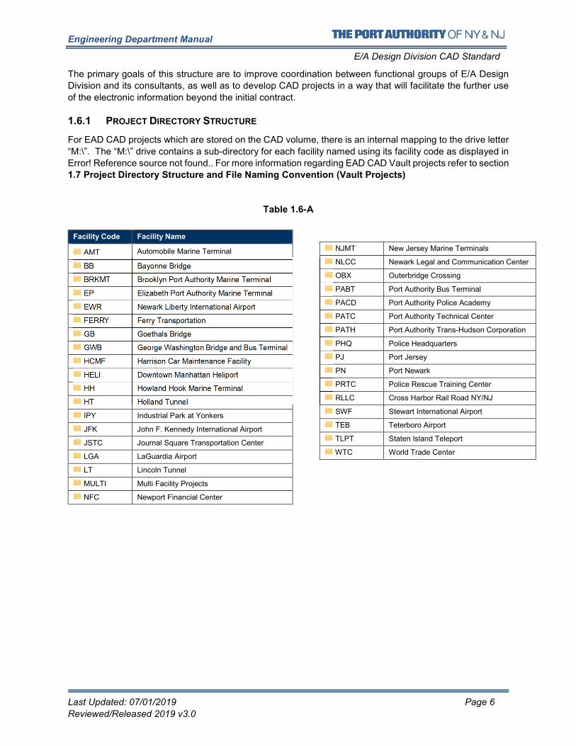
1.6.1 PROJECT DIRECTORY STRUCTURE
For EAD CAD projects which are stored on the CAD volume, there is an internal mapping to the drive letter
“M:\”. The “M:\” drive contains a sub-directory for each facility named using its facility code as displayed in
Error! Reference source not found.. For more information regarding EAD CAD Vault projects refer to section
1.7 Project Directory Structure and File Naming Convention (Vault Projects)
Table 1.6-A
Facility Code Facility Name
AMT Automobile Marine Terminal
BB Bayonne Bridge
BRKMT Brooklyn Port Authority Marine Terminal
EP Elizabeth Port Authority Marine Terminal
EWR Newark Liberty International Airport
FERRY Ferry Transportation
GB Goethals Bridge
GWB George Washington Bridge and Bus Terminal
HCMF Harrison Car Maintenance Facility
HELI Downtown Manhattan Heliport
HH Howland Hook Marine Terminal
HT Holland Tunnel
IPY Industrial Park at Yonkers
JFK John F. Kennedy International Airport
JSTC Journal Square Transportation Center
LGA LaGuardia Airport
LT Lincoln Tunnel
MULTI Multi Facility Projects
NFC Newport Financial Center
NJMT New Jersey Marine Terminals
NLCC Newark Legal and Communication Center
OBX Outerbridge Crossing
PABT Port Authority Bus Terminal
PACD Port Authority Police Academy
PATC Port Authority Technical Center
PATH Port Authority Trans-Hudson Corporation
PHQ Police Headquarters
PJ Port Jersey
PN Port Newark
PRTC Police Rescue Training Center
RLLC Cross Harbor Rail Road NY/NJ
SWF Stewart International Airport
TEB Teterboro Airport
TLPT Staten Island Teleport
WTC World Trade Center
Engineering Department Manual
E/A Design Division CAD Standard
Last Updated: 07/01/2019 Page 7
Reviewed/Released 2019 v3.0
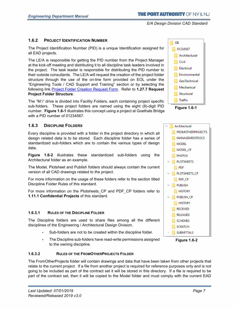
1.6.2 PROJECT IDENTIFICATION NUMBER
The Project Identification Number (PID) is a unique Identification assigned for
all EAD projects.
The LE/A is responsible for getting the PID number from the Project Manager
at the kick-off meeting and distributing it to all discipline task leaders involved in
the project. The task leader is responsible for distributing the PID number to
their outside consultants. The LE/A will request the creation of the project folder
structure through the use of the on-line form provided on EOL under the
“Engineering Tools / CAD Support and Training” section or by selecting the
following link Project Folder Creation Request Form. Refer to 1.27.7 Request
Project Folder Structure.
The “M:\” drive is divided into Facility Folders, each containing project specific
sub-folders. These project folders are named using the eight (8)-digit PID number. Figure 1.6-1 illustrates this concept using a project at Goethals Bridge
with a PID number of 01234567.
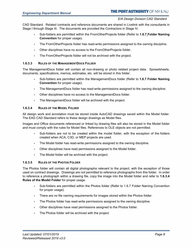
1.6.3 DISCIPLINE FOLDERS
Every discipline is provided with a folder in the project directory in which all
design related data is to be stored. Each discipline folder has a series of
standardized sub-folders which are to contain the various types of design
data.
Figure 1.6-2 illustrates these standardized sub-folders using the
Architectural folder as an example.
The Model, Plotsheet and Publish folders should always contain the current
version of all CAD drawings related to the project.
For more information on the usage of these folders refer to the section titled
Discipline Folder Rules of this standard.
For more information on the Plotsheets_CP and PDF_CP folders refer to 1.11.1 Confidential Projects of this standard.
1.6.3.1 RULES OF THE DISCIPLINE FOLDER
The Discipline folders are used to share files among all the different
disciplines of the Engineering / Architectural Design Division.
• Sub-folders are not to be created within the discipline folder.
• The Discipline sub-folders have read-write permissions assigned
to the owning discipline.
1.6.3.2 RULES OF THE FROMOTHERPROJECTS FOLDER
The FromOtherProjects folder will contain drawings and data that have been taken from other projects that
relate to the current project. If a file from another project is required for reference purposes only and is not
going to be included as part of the contract set it will be stored in this directory. If a file is required to be
part of the contract set, then it will be copied to the Model folder and must comply with the current EAD
Figure 1.6-1
Figure 1.6-2
Engineering Department Manual
E/A Design Division CAD Standard
Last Updated: 07/01/2019 Page 8
Reviewed/Released 2019 v3.0
CAD Standard. Related contracts and reference documents are shared in Livelink with the consultants in
Stage I through Stage III. The documents are provided the Contractors in Stage IV.
• Sub-folders are permitted within the FromOtherProjects folder (Refer to 1.6.7 Folder Naming
Convention for proper usage).
• The FromOtherProjects folder has read-write permissions assigned to the owning discipline.
• Other disciplines have no access to the FromOtherProjects folder.
• The FromOtherProjects folder will not be archived with the project.
1.6.3.3 RULES OF THE MANAGEMENTDOCS FOLDER
The ManagementDocs folder will contain all non-drawing or photo related project data. Spreadsheets,
documents, specifications, memos, estimates, etc. will be stored in this folder.
• Sub-folders are permitted within the ManagementDocs folder (Refer to 1.6.7 Folder Naming
Convention for proper usage).
• The ManagementDocs folder has read-write permissions assigned to the owning discipline.
• Other disciplines have no access to the ManagementDocs folder.
• The ManagementDocs folder will be archived with the project.
1.6.3.4 RULES OF THE MODEL FOLDER
All design work and annotation must be stored inside AutoCAD drawings saved within the Model folder.
The EAD CAD Standard refers to these design drawings as Model files.
Images and Office documents referenced or linked by drawing files will also be stored in the Model folder
and must comply with the rules for Model files. References to OLE objects are not permitted.
• Sub-folders are not to be created within the model folder, with the exception of the folders
created when ACA, C3D, or MEP projects are used.
• The Model folder has read-write permissions assigned to the owning discipline.
• Other disciplines have read permissions assigned to the Model folder.
• The Model folder will be archived with the project.
1.6.3.5 RULES OF THE PHOTOS FOLDER
The Photos folder will contain all digital photographs relevant to the project, with the exception of those
used on contract drawings. Drawings are not permitted to reference photographs from this folder. In order
to reference a photograph within a drawing file, copy the image into the Model folder and refer to 1.6.3.4
Rules of the Model Folder for proper usage.
• Sub-folders are permitted within the Photos folder (Refer to 1.6.7 Folder Naming Convention
for proper usage).
• There are no file naming requirements for images stored within the Photos folder.
• The Photos folder has read-write permissions assigned to the owning discipline.
• Other disciplines have read permissions assigned to the Photos folder.
• The Photos folder will be archived with the project.
Engineering Department Manual
E/A Design Division CAD Standard
Last Updated: 07/01/2019 Page 9
Reviewed/Released 2019 v3.0
1.6.3.6 RULES OF THE PLOTSHEETS FOLDER
All layouts for plotted sheets will be saved inside AutoCAD drawings stored within the Plotsheets folder.
The EAD CAD Standard refers to these layout drawings as Plotsheet Files. These files are assembled
sheets used for plotting. These drawings consist of a series of external references.
• Sub-folders are not permitted within the Plotsheets folder
• Only Plotsheet files will be stored within the Plotsheets folder.
• The Plotsheets folder has read-write permissions assigned to the owning discipline.
• Other disciplines have read permissions assigned to the Plotsheets folder.
• The Plotsheets folder will be archived with the project.
No line work or annotation is allowed in either Model Space or Paper Space of the Plotsheet files with the
following exceptions:
• Blocks provided within this standard whose name begins with “Drawing_Info”
• Match lines and associated Match line annotations.
• Revision clouds and associated Revision cloud annotations.
• Scale Bars
• North Arrows
• View Titles
All paper drawings in the Contract Set will have a corresponding Plotsheet file in the Plotsheets folder, the only exception is the Title Sheet. Multiple contract sheets MAY NO LONGER be saved in a single Plotsheet
file, there may only a single layout containing a Contract Border per file.
This change is enacted to provide cross-compatibility with the Port Authority Autodesk Vault environment.
1.6.3.7 RULES OF THE PDF FOLDER
A Portable Document Format file (PDF) is an industry standard non-editable file format. PDF files will be
created at full-size, directly from the AutoCAD drawing files and stored in the PDF folder. The use of PDF's
officially replaces the use of DWF files within EA/D (c.10/2018). It is no longer necessary to produce DWF
files, and the submission of DWF’s will not satisfy these revised requirements to properly create PDF files
at each milestone submission.
The PDF folder will always contain the most recent milestone version of the PDF file(s). Earlier milestone
files once copied to the SUBMITTALS folder for the milestone will be either deleted from the PDF folder or
overwritten in place.
• Sub-folders are not permitted within the PDF folder.
• The PDF folder has read-write permissions assigned to the owning discipline.
• Other disciplines have read permissions assigned to the PDF folder.
• The PDF folder will be archived with the project.
1.6.3.8 RULES OF THE PUBLISH FOLDER
The Publish folder will be used as a sharing mechanism between disciplines. A discipline may copy Model
files into its own Publish folder, making them available for other disciplines to reference. Other disciplines
are not permitted to copy these files but will instead externally reference them directly from the owner’s
Publish folder. The lead discipline’s Publish folder will contain the Contract Border.
Engineering Department Manual
E/A Design Division CAD Standard
Last Updated: 07/01/2019 Page 10
Reviewed/Released 2019 v3.0
There will be only one Contract Border per project. The only exception to this rule is when new
drawings are added to the Contract Set as part of a Stage IV – PACC. Refer to 1.8.10.7 StageIV_PACC
for instructions.
It is important that this methodology for referencing design files from other disciplines be followed. If a user
copies design files from another discipline’s Model, Plotsheets or Publish folder then they must take
ownership of the file. By taking ownership the discipline copying the file will then be responsible for all EAD
CAD Standards compliance of that file (ex. file (re-)name, layers used etc..) as if it were created by that
discipline.
• The History folder is the only sub-folder permitted within the Publish folder.
• Only copies of Model files shall be stored in the Publish folder, with the exception of the
Contract Border.
• A discipline will not reference a file from within its own Publish folder, with the exception of the
Contract Border for the Lead Discipline.
• The Publish folder has read-write permissions assigned to the owning discipline.
• Other disciplines have read permissions assigned to the Publish folder.
• The Publish folder will be archived with the project.
1.6.3.9 RULES OF THE HISTORY FOLDER
If a single file is to be published more than once, the file that exists in the Publish folder will be moved to a
dated sub-folder within the History folder. The updated version of the file will then be copied into the root
of the Publish folder. This will allow other disciplines to continue to reference older or time-phased versions
of reference drawings if required by their design schedule by changing the external reference path to the
dated sub-folder within the History folder.
• Sub-folders are permitted within the History folder (Refer to 1.6.7 Folder Naming Convention
for proper usage).
• Only copies of previously Published files will be copied to the History folder.
• The History folder has read-write permissions assigned to the owning discipline.
• Other disciplines have read permissions assigned to the History folder.
• The History folder will be archived with the project.
1.6.3.10 RULES OF THE _DATASHORTCUTS FOLDER
The _DataShortcuts folder is only populated in folder structure for disciplines that use AutoCAD Civil3D as
an authoring application. This folder exists only under CIVIL and GEOTECHNICAL Publish folder.
• Sub-folders are permitted within the _DataShortcuts folder (Refer to 1.6.7 Folder Naming
Convention for proper usage).
• The _DataShortcuts folder has read-write permissions assigned to the owning discipline.
• Other disciplines have read permissions assigned to the _DataShortcuts folder.
• The _DataShortcuts folder will be archived with the project.
Engineering Department Manual
E/A Design Division CAD Standard
Last Updated: 07/01/2019 Page 11
Reviewed/Released 2019 v3.0
1.6.3.11 RULES OF THE RECEIVED FOLDER
The Received folder will contain a dated archive of design information received from outside sources. This
folder is intended as a record to identify exactly what information consultants provided on what date.
• Sub-folders are permitted within the Received folder (Refer to 1.6.7 Folder Naming
Convention for proper usage).
• The Received folder has read-write permissions assigned to the owning discipline.
• Other disciplines have no access to the Received folder.
• The Received folder will not be archived with the project.
1.6.3.12 RULES OF THE RELEASED FOLDER
The Released folder will contain a dated archive of design information provided to outside sources. This
folder is intended as a record to identify exactly what information consultants were provided with and on
what date.
• Sub-folders are permitted within the Released folder (Refer to 1.6.7 Folder Naming
Convention for proper usage).
• The Released folder has read-write permissions assigned to the owning discipline.
• Other disciplines have no access to the Released folder.
• The Released folder will not be archived with the project.
1.6.3.13 RULES OF THE SCHEMES FOLDER
The Schemes folder will contain various schemes of a design as well as any temporary design data. This
folder provides the designer with an area in which to make trial changes to a design and a place to store
temporary files. If a scheme is created and is later chosen as the final design version, the files stored under
that scheme are to be copied to the Model folder.
• Sub-folders are permitted within the Schemes folder (Refer to 1.6.7 Folder Naming
Convention for proper usage).
• The Received folder has read-write permissions assigned to the owning discipline.
• Other disciplines have no access to the Received folder.
• The Schemes folder will not be archived with the project.
1.6.3.14 RULES OF THE SHAREDDOCS FOLDER
The SharedDocs folder will be used as a sharing mechanism between disciplines. A discipline may copy
ManagementDocs files into its own SharedDocs folder, making them available for other disciplines to
reference. Files stored within the SharedDocs folder are not to be referenced into any contract drawings
and are provided as references only.
• Sub-folders are permitted within the SharedDocs folder (Refer to 1.6.7 Folder Naming
Convention for proper usage).
• Only copies of ManagementDocs files shall be stored in the SharedDocs folder, Model files are
not permitted within the SharedDocs folder.
• Other Disciplines have read permissions assigned to the SharedDocs folder.
• The SharedDocs folder will not be archived with the project.
Engineering Department Manual
E/A Design Division CAD Standard
Last Updated: 07/01/2019 Page 12
Reviewed/Released 2019 v3.0
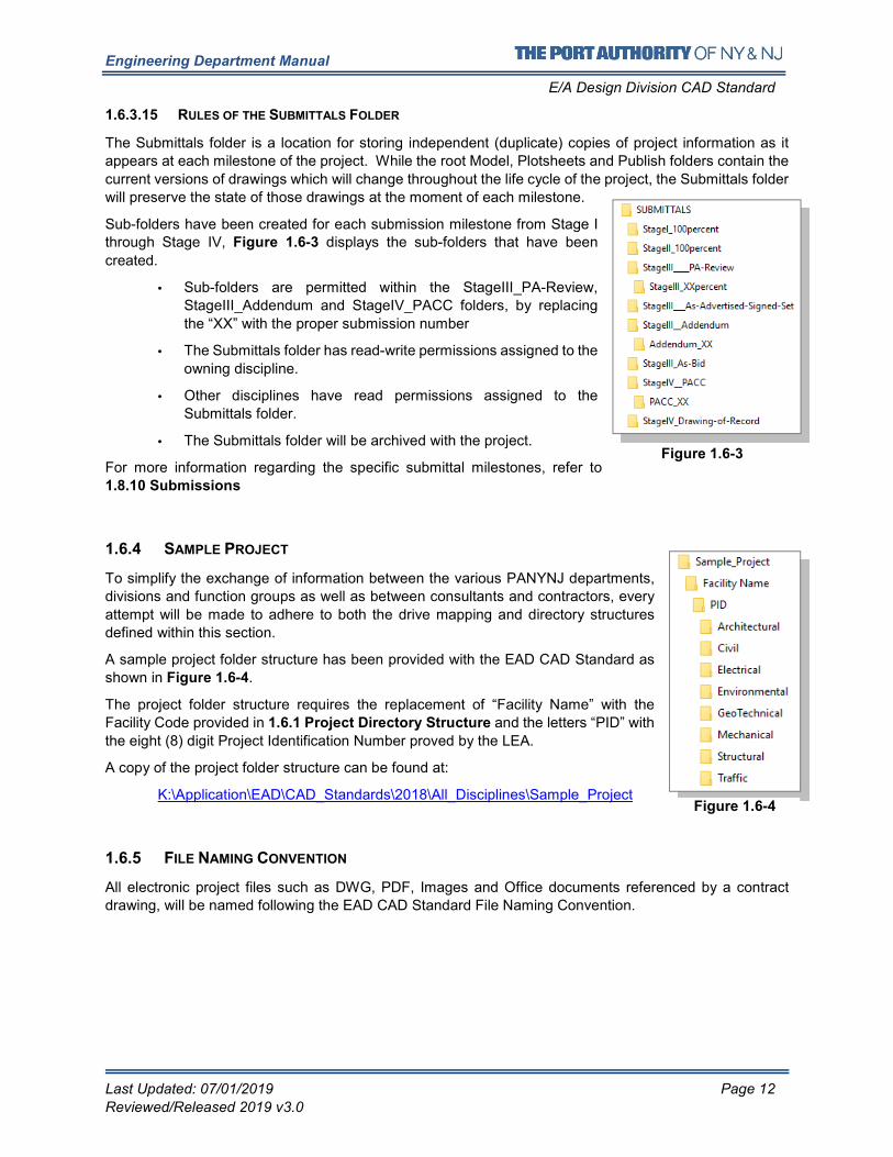
1.6.3.15 RULES OF THE SUBMITTALS FOLDER
The Submittals folder is a location for storing independent (duplicate) copies of project information as it
appears at each milestone of the project. While the root Model, Plotsheets and Publish folders contain the
current versions of drawings which will change throughout the life cycle of the project, the Submittals folder
will preserve the state of those drawings at the moment of each milestone.
Sub-folders have been created for each submission milestone from Stage I through Stage IV, Figure 1.6-3 displays the sub-folders that have been
created.
• Sub-folders are permitted within the StageIII_PA-Review,
StageIII_Addendum and StageIV_PACC folders, by replacing
the “XX” with the proper submission number
• The Submittals folder has read-write permissions assigned to the
owning discipline.
• Other disciplines have read permissions assigned to the
Submittals folder.
• The Submittals folder will be archived with the project.
For more information regarding the specific submittal milestones, refer to
1.8.10 Submissions
1.6.4 SAMPLE PROJECT
To simplify the exchange of information between the various PANYNJ departments,
divisions and function groups as well as between consultants and contractors, every
attempt will be made to adhere to both the drive mapping and directory structures
defined within this section.
A sample project folder structure has been provided with the EAD CAD Standard as
shown in Figure 1.6-4.
The project folder structure requires the replacement of “Facility Name” with the
Facility Code provided in 1.6.1 Project Directory Structure and the letters “PID” with
the eight (8) digit Project Identification Number proved by the LEA.
A copy of the project folder structure can be found at:
K:\Application\EAD\CAD_Standards\2018\All_Disciplines\Sample_Project
1.6.5 FILE NAMING CONVENTION
All electronic project files such as DWG, PDF, Images and Office documents referenced by a contract
drawing, will be named following the EAD CAD Standard File Naming Convention.
Figure 1.6-3
Figure 1.6-4
Engineering Department Manual
E/A Design Division CAD Standard
Last Updated: 07/01/2019 Page 13
Reviewed/Released 2019 v3.0
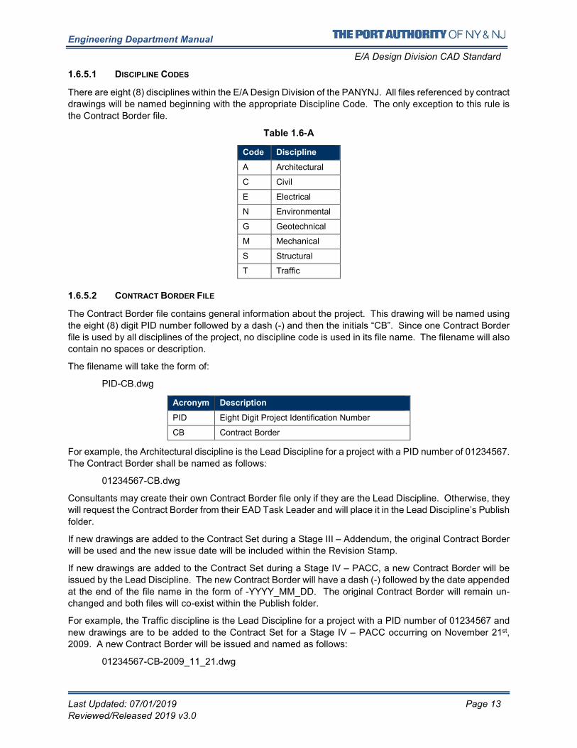
1.6.5.1 DISCIPLINE CODES
There are eight (8) disciplines within the E/A Design Division of the PANYNJ. All files referenced by contract
drawings will be named beginning with the appropriate Discipline Code. The only exception to this rule is
the Contract Border file.
Table 1.6-A
Code Discipline
A Architectural
C Civil
E Electrical
N Environmental
G Geotechnical
M Mechanical
S Structural
T Traffic
1.6.5.2 CONTRACT BORDER FILE
The Contract Border file contains general information about the project. This drawing will be named using
the eight (8) digit PID number followed by a dash (-) and then the initials “CB”. Since one Contract Border
file is used by all disciplines of the project, no discipline code is used in its file name. The filename will also
contain no spaces or description.
The filename will take the form of:
PID-CB.dwg
Acronym Description
PID Eight Digit Project Identification Number
CB Contract Border
For example, the Architectural discipline is the Lead Discipline for a project with a PID number of 01234567.
The Contract Border shall be named as follows:
01234567-CB.dwg
Consultants may create their own Contract Border file only if they are the Lead Discipline. Otherwise, they
will request the Contract Border from their EAD Task Leader and will place it in the Lead Discipline’s Publish
folder.
If new drawings are added to the Contract Set during a Stage III – Addendum, the original Contract Border
will be used and the new issue date will be included within the Revision Stamp.
If new drawings are added to the Contract Set during a Stage IV – PACC, a new Contract Border will be
issued by the Lead Discipline. The new Contract Border will have a dash (-) followed by the date appended
at the end of the file name in the form of -YYYY_MM_DD. The original Contract Border will remain un-
changed and both files will co-exist within the Publish folder.
For example, the Traffic discipline is the Lead Discipline for a project with a PID number of 01234567 and
new drawings are to be added to the Contract Set for a Stage IV – PACC occurring on November 21st,
2009. A new Contract Border will be issued and named as follows:
01234567-CB-2009_11_21.dwg
Engineering Department Manual
E/A Design Division CAD Standard
Last Updated: 07/01/2019 Page 14
Reviewed/Released 2019 v3.0
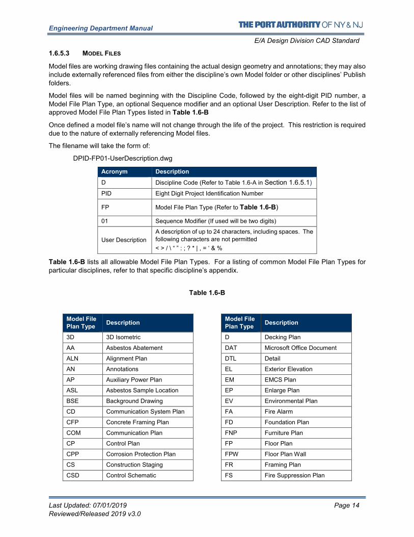
1.6.5.3 MODEL FILES
Model files are working drawing files containing the actual design geometry and annotations; they may also
include externally referenced files from either the discipline’s own Model folder or other disciplines’ Publish
folders.
Model files will be named beginning with the Discipline Code, followed by the eight-digit PID number, a
Model File Plan Type, an optional Sequence modifier and an optional User Description. Refer to the list of approved Model File Plan Types listed in Table 1.6-B
Once defined a model file’s name will not change through the life of the project. This restriction is required
due to the nature of externally referencing Model files.
The filename will take the form of:
DPID-FP01-UserDescription.dwg
Acronym Description
D Discipline Code (Refer to Table 1.6-A in Section 1.6.5.1)
PID Eight Digit Project Identification Number
FP Model File Plan Type (Refer to Table 1.6-B)
01 Sequence Modifier (If used will be two digits)
User Description
A description of up to 24 characters, including spaces. The
following characters are not permitted
< > / \ “ ” : ; ? * | , = ‘ & %
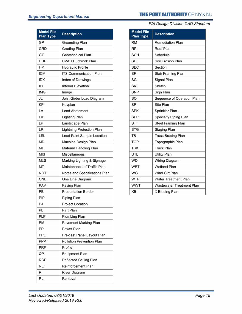
Table 1.6-B lists all allowable Model File Plan Types. For a listing of common Model File Plan Types for
particular disciplines, refer to that specific discipline’s appendix.
Table 1.6-B
Model File
Plan Type Description
3D 3D Isometric
AA Asbestos Abatement
ALN Alignment Plan
AN Annotations
AP Auxiliary Power Plan
ASL Asbestos Sample Location
BSE Background Drawing
CD Communication System Plan
CFP Concrete Framing Plan
COM Communication Plan
CP Control Plan
CPP Corrosion Protection Plan
CS Construction Staging
CSD Control Schematic
Model File
Plan Type Description
D Decking Plan
DAT Microsoft Office Document
DTL Detail
EL Exterior Elevation
EM EMCS Plan
EP Enlarge Plan
EV Environmental Plan
FA Fire Alarm
FD Foundation Plan
FNP Furniture Plan
FP Floor Plan
FPW Floor Plan Wall
FR Framing Plan
FS Fire Suppression Plan
Engineering Department Manual
E/A Design Division CAD Standard
Last Updated: 07/01/2019 Page 15
Reviewed/Released 2019 v3.0
Model File
Plan Type Description
GP Grounding Plan
GRD Grading Plan
GT Geotechnical Plan
HDP HVAC Ductwork Plan
HP Hydraulic Profile
ICM ITS Communication Plan
IDX Index of Drawings
IEL Interior Elevation
IMG Image
JL Joist Girder Load Diagram
KP Keyplan
LA Lead Abatement
LIP Lighting Plan
LP Landscape Plan
LR Lightning Protection Plan
LSL Lead Paint Sample Location
MD Machine Design Plan
MH Material Handling Plan
MIS Miscellaneous
MLS Marking Lighting & Signage
MT Maintenance of Traffic Plan
NOT Notes and Specifications Plan
ONL One Line Diagram
PAV Paving Plan
PB Presentation Border
PIP Piping Plan
PJ Project Location
PL Part Plan
PLP Plumbing Plan
PM Pavement Marking Plan
PP Power Plan
PPL Pre-cast Panel Layout Plan
PPP Pollution Prevention Plan
PRF Profile
QP Equipment Plan
RCP Reflected Ceiling Plan
RE Reinforcement Plan
RI Riser Diagram
RL Removal
Model File
Plan Type Description
RM Remediation Plan
RP Roof Plan
SCH Schedule
SE Soil Erosion Plan
SEC Section
SF Stair Framing Plan
SG Signal Plan
SK Sketch
SNP Sign Plan
SO Sequence of Operation Plan
SP Site Plan
SPK Sprinkler Plan
SPP Specialty Piping Plan
ST Steel Framing Plan
STG Staging Plan
TB Truss Bracing Plan
TOP Topographic Plan
TRK Track Plan
UTL Utility Plan
WD Wiring Diagram
WET Wetland Plan
WG Wind Girt Plan
WTP Water Treatment Plan
WWT Wastewater Treatment Plan
XB X Bracing Plan
Engineering Department Manual
E/A Design Division CAD Standard
Last Updated: 07/01/2019 Page 16
Reviewed/Released 2019 v3.0
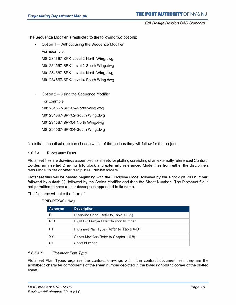
The Sequence Modifier is restricted to the following two options:
• Option 1 – Without using the Sequence Modifier
For Example:
M01234567-SPK-Level 2 North Wing.dwg
M01234567-SPK-Level 2 South Wing.dwg
M01234567-SPK-Level 4 North Wing.dwg
M01234567-SPK-Level 4 South Wing.dwg
• Option 2 – Using the Sequence Modifier
For Example:
M01234567-SPK02-North Wing.dwg
M01234567-SPK02-South Wing.dwg
M01234567-SPK04-North Wing.dwg
M01234567-SPK04-South Wing.dwg
Note that each discipline can choose which of the options they will follow for the project.
1.6.5.4 PLOTSHEET FILES
Plotsheet files are drawings assembled as sheets for plotting consisting of an externally referenced Contract
Border, an inserted Drawing_Info block and externally referenced Model files from either the discipline’s
own Model folder or other disciplines’ Publish folders.
Plotsheet files will be named beginning with the Discipline Code, followed by the eight digit PID number,
followed by a dash (-), followed by the Series Modifier and then the Sheet Number. The Plotsheet file is
not permitted to have a user description appended to its name.
The filename will take the form of:
DPID-PTXX01.dwg
Acronym Description
D Discipline Code (Refer to Table 1.6-A)
PID Eight Digit Project Identification Number
PT Plotsheet Plan Type (Refer to Table 6-D)
XX Series Modifier (Refer to Chapter 1.6.8)
01 Sheet Number
1.6.5.4.1 Plotsheet Plan Type
Plotsheet Plan Types organize the contract drawings within the contract document set, they are the
alphabetic character components of the sheet number depicted in the lower right-hand corner of the plotted
sheet.
Engineering Department Manual
E/A Design Division CAD Standard
Last Updated: 07/01/2019 Page 17
Reviewed/Released 2019 v3.0
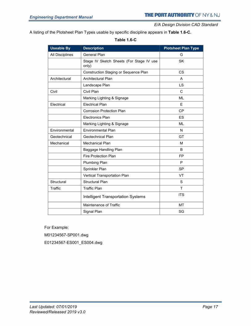
A listing of the Plotsheet Plan Types usable by specific discipline appears in Table 1.6-C.
Table 1.6-C
Useable By Description Plotsheet Plan Type
All Disciplines General Plan G
Stage IV Sketch Sheets (For Stage IV use
only)
SK
Construction Staging or Sequence Plan CS
Architectural Architectural Plan A
Landscape Plan LS
Civil Civil Plan C
Marking Lighting & Signage ML
Electrical Electrical Plan E
Corrosion Protection Plan CP
Electronics Plan ES
Marking Lighting & Signage ML
Environmental Environmental Plan N
Geotechnical Geotechnical Plan GT
Mechanical Mechanical Plan M
Baggage Handling Plan B
Fire Protection Plan FP
Plumbing Plan P
Sprinkler Plan SP
Vertical Transportation Plan VT
Structural Structural Plan S
Traffic Traffic Plan T
Intelligent Transportation Systems ITS
Maintenance of Traffic MT
Signal Plan SG
For Example:
M01234567-SP001.dwg
E01234567-ES001_ES004.dwg
Engineering Department Manual
E/A Design Division CAD Standard
Last Updated: 07/01/2019 Page 18
Reviewed/Released 2019 v3.0
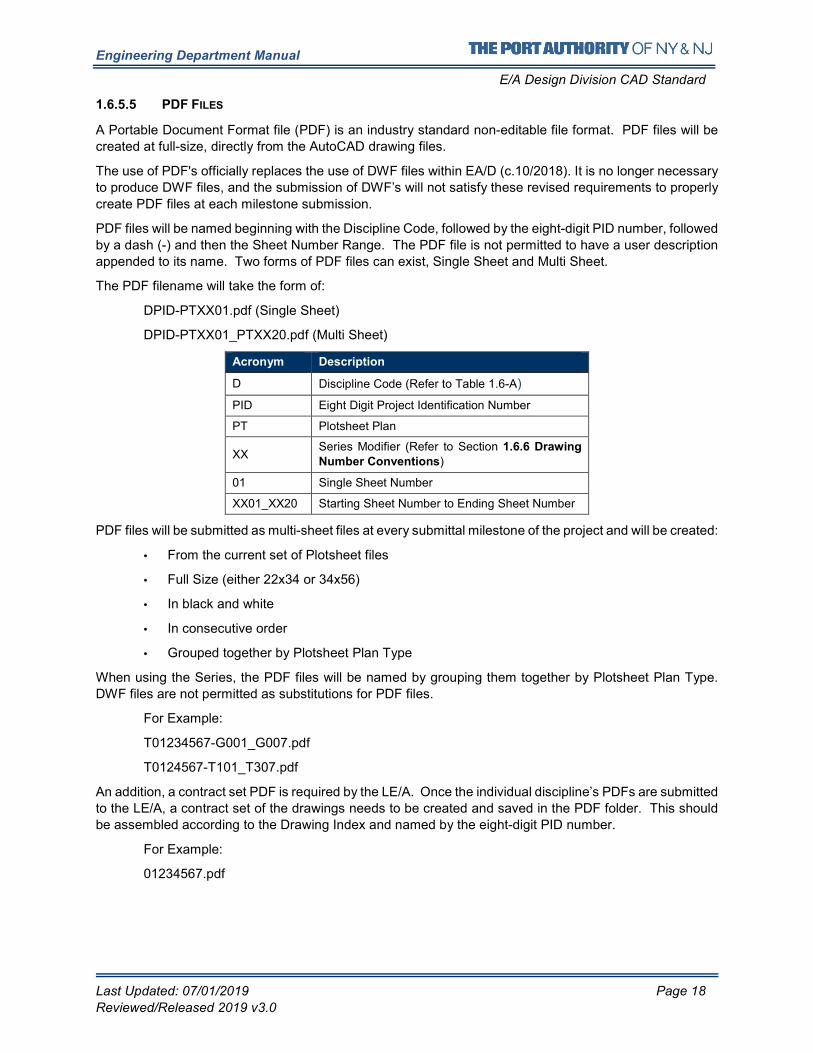
1.6.5.5 PDF FILES
A Portable Document Format file (PDF) is an industry standard non-editable file format. PDF files will be
created at full-size, directly from the AutoCAD drawing files.
The use of PDF's officially replaces the use of DWF files within EA/D (c.10/2018). It is no longer necessary
to produce DWF files, and the submission of DWF’s will not satisfy these revised requirements to properly
create PDF files at each milestone submission.
PDF files will be named beginning with the Discipline Code, followed by the eight-digit PID number, followed
by a dash (-) and then the Sheet Number Range. The PDF file is not permitted to have a user description
appended to its name. Two forms of PDF files can exist, Single Sheet and Multi Sheet.
The PDF filename will take the form of:
DPID-PTXX01.pdf (Single Sheet)
DPID-PTXX01_PTXX20.pdf (Multi Sheet)
Acronym Description
D Discipline Code (Refer to Table 1.6-A)
PID Eight Digit Project Identification Number
PT Plotsheet Plan
XX Series Modifier (Refer to Section 1.6.6 Drawing
Number Conventions)
01 Single Sheet Number
XX01_XX20 Starting Sheet Number to Ending Sheet Number
PDF files will be submitted as multi-sheet files at every submittal milestone of the project and will be created:
• From the current set of Plotsheet files
• Full Size (either 22x34 or 34x56)
• In black and white
• In consecutive order
• Grouped together by Plotsheet Plan Type
When using the Series, the PDF files will be named by grouping them together by Plotsheet Plan Type.
DWF files are not permitted as substitutions for PDF files.
For Example:
T01234567-G001_G007.pdf
T0124567-T101_T307.pdf
An addition, a contract set PDF is required by the LE/A. Once the individual discipline’s PDFs are submitted
to the LE/A, a contract set of the drawings needs to be created and saved in the PDF folder. This should
be assembled according to the Drawing Index and named by the eight-digit PID number.
For Example:
01234567.pdf
Engineering Department Manual
E/A Design Division CAD Standard
Last Updated: 07/01/2019 Page 19
Reviewed/Released 2019 v3.0
1.6.6 DRAWING NUMBER CONVENTIONS
The Port Authority CAD Standards supports three sheet numbering schemes, numbering by “One-Digit-
Series”, numbering by “Two-Digit-Series” or numbering by “Counter” alone. Each organize the Contract
Drawings within the Contract Document set however, at the start of each project the LE/A will determine
which numbering scheme will be used. This (and only this) scheme will be used by all disciplines for every
contract drawing produced for the project.
Where a “Series” numbering system is chosen by the LE/A, each disciplines Task Leader will be responsible
for the determination of what drawing types are assigned to each of the available counters in the series.
This information will be distributed within the discipline by the Task Leader.
For Example:
The LE/A on a project is from Structural and decides that only “9 or less” series are needed. Structural
would select option one. Electrical, however, decides that “10 or more” series will be needed. For Electrical
to be permitted to use option two, they must make this request to the LE/A is from the Structural discipline.
With the concurrence of the LE/A, all disciplines will be required to use the two-digit series option. These three formats cannot co-exist on the same project.
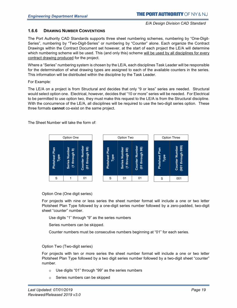
The Sheet Number will take the form of:
Option One
Plo
tsh
eet
Pla
n
Typ
e
Seri
es N
um
ber
(1 t
hro
ug
h 9
)
Co
un
ter
Nu
mb
er
(01 t
hro
ug
h 9
9)
S 1 01
Option Two
Plo
tsh
eet
Pla
n
Typ
e
Seri
es N
um
ber
(1 t
hro
ug
h 0
9)
Co
un
ter
Nu
mb
er
(01 t
hro
ug
h 9
9)
S 01 01
Option Three
Plo
tsh
eet
Pla
n
Typ
e
Co
un
ter
Nu
mb
er
(001 t
hro
ug
h 0
99) S 001
Option One (One digit series)
For projects with nine or less series the sheet number format will include a one or two letter
Plotsheet Plan Type followed by a one-digit series number followed by a zero-padded, two-digit
sheet “counter” number.
Use digits “1” through “9” as the series numbers
Series numbers can be skipped.
Counter numbers must be consecutive numbers beginning at “01” for each series.
Option Two (Two-digit series)
For projects with ten or more series the sheet number format will include a one or two letter
Plotsheet Plan Type followed by a two digit series number followed by a two-digit sheet “counter”
number.
o Use digits “01” through “99” as the series numbers
o Series numbers can be skipped
Engineering Department Manual
E/A Design Division CAD Standard
Last Updated: 07/01/2019 Page 20
Reviewed/Released 2019 v3.0
o Counter numbers must be consecutive numbers beginning at “01” for each series.
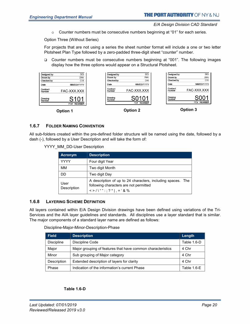
Option Three (Without Series)
For projects that are not using a series the sheet number format will include a one or two letter
Plotsheet Plan Type followed by a zero-padded three-digit sheet “counter” number.
� Counter numbers must be consecutive numbers beginning at “001”. The following images
display how the three options would appear on a Structural Plotsheet.
Option 1
Option 2
Option 3
1.6.7 FOLDER NAMING CONVENTION
All sub-folders created within the pre-defined folder structure will be named using the date, followed by a
dash (-), followed by a User Description and will take the form of:
YYYY_MM_DD-User Description
Acronym Description
YYYY Four digit Year
MM Two digit Month
DD Two digit Day
User
Description
A description of up to 24 characters, including spaces. The
following characters are not permitted
< > / \ “ ” : ; ? * | , = ‘ & %
1.6.8 LAYERING SCHEME DEFINITION
All layers contained within E/A Design Division drawings have been defined using variations of the Tri-
Services and the AIA layer guidelines and standards. All disciplines use a layer standard that is similar.
The major components of a standard layer name are defined as follows:
Discipline-Major-Minor-Description-Phase
Field Description Length
Discipline Discipline Code Table 1.6-D
Major Major grouping of features that have common characteristics 4 Chr
Minor Sub grouping of Major category 4 Chr
Description Extended description of layers for clarity 4 Chr
Phase Indication of the information’s current Phase Table 1.6-E
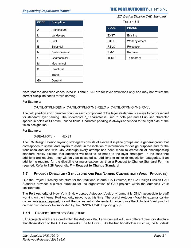
Table 1.6-D
Engineering Department Manual
E/A Design Division CAD Standard
Last Updated: 07/01/2019 Page 21
Reviewed/Released 2019 v3.0
CODE Discipline
A Architectural CODE PHASE
L Landscape EXST Existing
C Civil OTHR Work by others
E Electrical RELO Relocation
N Environmental RMVL Removal
G Geotechnical TEMP Temporary
M Mechanical
S Structural
T Traffic
GN General
Note that the discipline codes listed in Table 1.6-D are for layer definitions only and may not reflect the
correct discipline codes for file naming.
For Example:
C-UTIL-STRM-IDEN or C-UTIL-STRM-SYMB-RELO or C-UTIL-STRM-SYMB-RMVL
The field position and character count in each component of the layer stratagem is always to be preserved
for standard layer naming. The underscore “_” character is used to both pad and fill unused character
spaces in fields or fill entire unused fields. Character padding is always appended to the right side of the
fields designation.
For Example:
S-BEAM-STL_-____-EXST
The E/A Design Division layering stratagem consists of eleven discipline groups and a general group that
corresponds to spatial data layers to assist in the isolation of information for design purposes and for the
translation and use with GIS. Although every attempt has been made to create an all-encompassing
standard, reality dictates that additions will need to be made to the layer stratagem. In the case that
additions are required, they will only be accepted as additions to minor or description categories. If an
addition is required for the discipline or major categories, then a Request to Change Standard Form is
required. Refer to 1.28 Appendix M – Request to Change Standard.
1.7 PROJECT DIRECTORY STRUCTURE AND FILE NAMING CONVENTION (VAULT PROJECTS)
Like the Project Directory Structure for the traditional internal CAD volume, the E/A Design Division CAD
Standard provides a similar structure for the organization of CAD projects within the Autodesk Vault
environment.
The Port Authority of New York & New Jersey Autodesk Vault environment is ONLY accessible to staff
working on the internal Port Authority network, at this time. The use of Autodesk Vault by external call-in-
consultants is not required, nor will the consultant’s independent choice to use the Autodesk Vault product
on their own network be supported by the PANYNJ CAD Support group.
1.7.1 PROJECT DIRECTORY STRUCTURE
EA/D projects which are stored within the Autodesk Vault environment will use a different directory structure
than those stored on the CAD volume (aka. The M: Drive). Like the traditional folder structure, the Autodesk
Table 1.6-E
Engineering Department Manual
E/A Design Division CAD Standard
Last Updated: 07/01/2019 Page 22
Reviewed/Released 2019 v3.0
Vault system contains a sub-directory for each facility named using its facility code as displayed in Table
1.6-A .
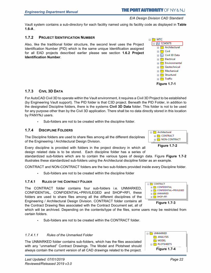
1.7.2 PROJECT IDENTIFICATION NUMBER
Also, like the traditional folder structure, the second level uses the Project
Identification Number (PID) which is the same unique Identification assigned
for all EAD projects described earlier please see section 1.6.2 Project
Identification Number.
1.7.3 CIVIL 3D DATA
For AutoCAD Civil 3D to operate within the Vault environment, it requires a Civil 3D Project to be established
(by Engineering Vault support). The PID folder is that C3D project. Beneath the PID Folder, in addition to the designated Discipline folders, there is the systems Civil 3D Data folder. This folder is not to be used
for any purpose other than by the Civil 3D application. There shall be no data directly stored in this location
by PANYNJ users.
• Sub-folders are not to be created within the discipline folder.
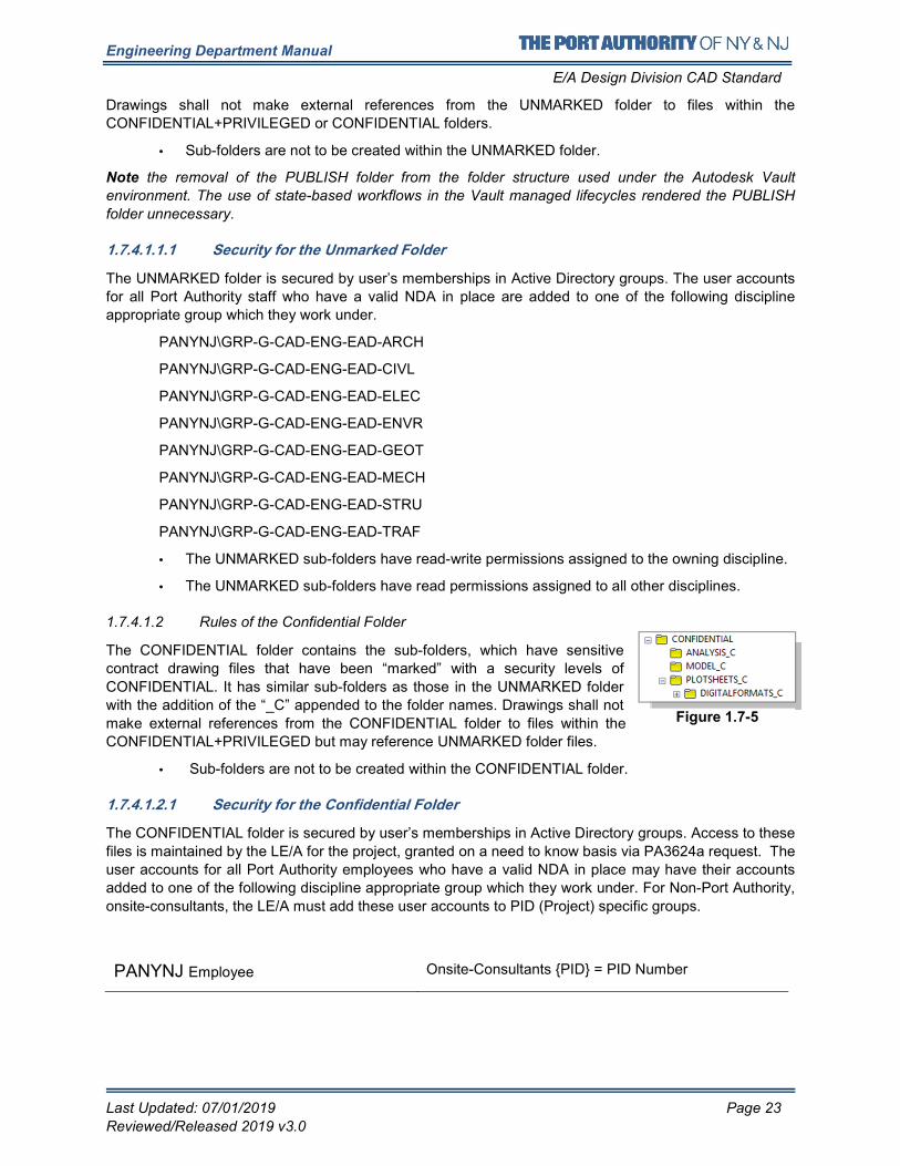
1.7.4 DISCIPLINE FOLDERS
The Discipline folders are used to share files among all the different disciplines
of the Engineering / Architectural Design Division.
Every discipline is provided with folders in the project directory in which all
design related data is to be stored. Each discipline folder has a series of
standardized sub-folders which are to contain the various types of design data. Figure Figure 1.7-2
illustrates these standardized sub-folders using the Architectural discipline folder as an example.
CONTRACT and NON-CONTRACT folders are the two sub-folders provided inside every Discipline folder.
• Sub-folders are not to be created within the discipline folder
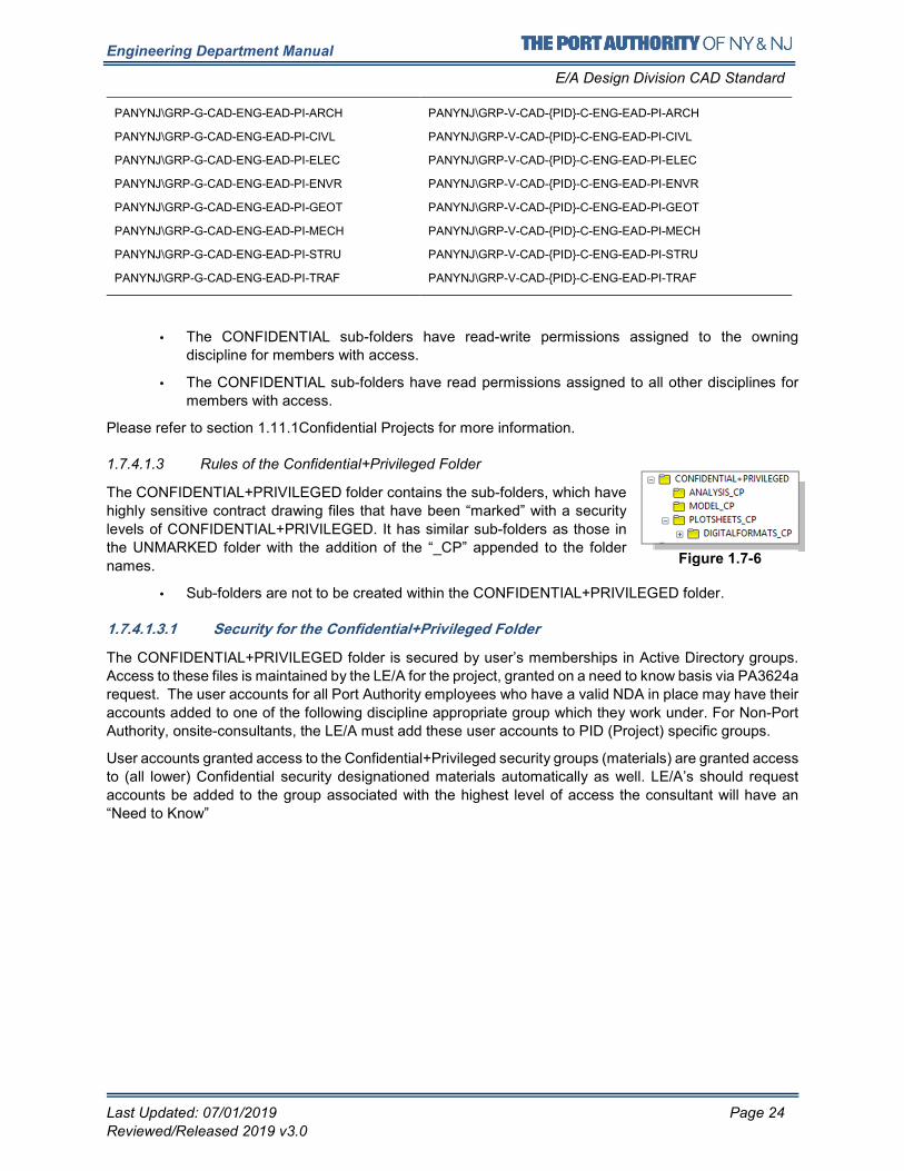
1.7.4.1 RULES OF THE CONTRACT FOLDER
The CONTRACT folder contains four sub-folders i.e. UNMARKED,
CONFIDENTIAL, CONFIDENTIAL+PRIVILEGED and SHOP+RFI, these
folders are used to share files among all the different disciplines of the
Engineering / Architectural Design Division. CONTRACT folder contains all
the Contract Drawing files associated with the Contract Document set, all of
which will be archived. Depending on the contents/type of the files, some users may be restricted from
certain folders.
• Sub-folders are not to be created within the CONTRACT folder.
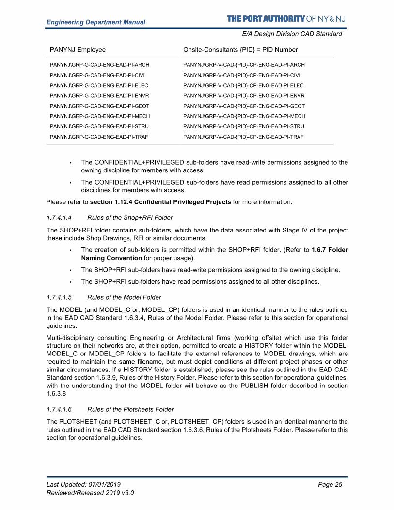
1.7.4.1.1 Rules of the Unmarked Folder
The UNMARKED folder contains sub-folders, which has the files associated
with any “unmarked” Contract Drawings. The Model and Plotsheet should
always contain the current version of all CAD drawings related to the project.
Figure 1.7-1
Figure 1.7-2
Figure 1.7-3
Figure 1.7-4
Figure 1.7-2
Engineering Department Manual
E/A Design Division CAD Standard
Last Updated: 07/01/2019 Page 23
Reviewed/Released 2019 v3.0
Drawings shall not make external references from the UNMARKED folder to files within the
CONFIDENTIAL+PRIVILEGED or CONFIDENTIAL folders.
• Sub-folders are not to be created within the UNMARKED folder.
Note the removal of the PUBLISH folder from the folder structure used under the Autodesk Vault
environment. The use of state-based workflows in the Vault managed lifecycles rendered the PUBLISH
folder unnecessary.
1.7.4.1.1.1 Security for the Unmarked Folder
The UNMARKED folder is secured by user’s memberships in Active Directory groups. The user accounts
for all Port Authority staff who have a valid NDA in place are added to one of the following discipline
appropriate group which they work under.
PANYNJ\GRP-G-CAD-ENG-EAD-ARCH
PANYNJ\GRP-G-CAD-ENG-EAD-CIVL
PANYNJ\GRP-G-CAD-ENG-EAD-ELEC
PANYNJ\GRP-G-CAD-ENG-EAD-ENVR
PANYNJ\GRP-G-CAD-ENG-EAD-GEOT
PANYNJ\GRP-G-CAD-ENG-EAD-MECH
PANYNJ\GRP-G-CAD-ENG-EAD-STRU
PANYNJ\GRP-G-CAD-ENG-EAD-TRAF
• The UNMARKED sub-folders have read-write permissions assigned to the owning discipline.
• The UNMARKED sub-folders have read permissions assigned to all other disciplines.
1.7.4.1.2 Rules of the Confidential Folder
The CONFIDENTIAL folder contains the sub-folders, which have sensitive
contract drawing files that have been “marked” with a security levels of
CONFIDENTIAL. It has similar sub-folders as those in the UNMARKED folder
with the addition of the “_C” appended to the folder names. Drawings shall not
make external references from the CONFIDENTIAL folder to files within the
CONFIDENTIAL+PRIVILEGED but may reference UNMARKED folder files.
• Sub-folders are not to be created within the CONFIDENTIAL folder.
1.7.4.1.2.1 Security for the Confidential Folder
The CONFIDENTIAL folder is secured by user’s memberships in Active Directory groups. Access to these
files is maintained by the LE/A for the project, granted on a need to know basis via PA3624a request. The
user accounts for all Port Authority employees who have a valid NDA in place may have their accounts
added to one of the following discipline appropriate group which they work under. For Non-Port Authority,
onsite-consultants, the LE/A must add these user accounts to PID (Project) specific groups.
PANYNJ Employee Onsite-Consultants {PID} = PID Number
Figure 1.7-5
Engineering Department Manual
E/A Design Division CAD Standard
Last Updated: 07/01/2019 Page 24
Reviewed/Released 2019 v3.0
PANYNJ\GRP-G-CAD-ENG-EAD-PI-ARCH
PANYNJ\GRP-G-CAD-ENG-EAD-PI-CIVL
PANYNJ\GRP-G-CAD-ENG-EAD-PI-ELEC
PANYNJ\GRP-G-CAD-ENG-EAD-PI-ENVR
PANYNJ\GRP-G-CAD-ENG-EAD-PI-GEOT
PANYNJ\GRP-G-CAD-ENG-EAD-PI-MECH
PANYNJ\GRP-G-CAD-ENG-EAD-PI-STRU
PANYNJ\GRP-G-CAD-ENG-EAD-PI-TRAF
PANYNJ\GRP-V-CAD-{PID}-C-ENG-EAD-PI-ARCH
PANYNJ\GRP-V-CAD-{PID}-C-ENG-EAD-PI-CIVL
PANYNJ\GRP-V-CAD-{PID}-C-ENG-EAD-PI-ELEC
PANYNJ\GRP-V-CAD-{PID}-C-ENG-EAD-PI-ENVR
PANYNJ\GRP-V-CAD-{PID}-C-ENG-EAD-PI-GEOT
PANYNJ\GRP-V-CAD-{PID}-C-ENG-EAD-PI-MECH
PANYNJ\GRP-V-CAD-{PID}-C-ENG-EAD-PI-STRU
PANYNJ\GRP-V-CAD-{PID}-C-ENG-EAD-PI-TRAF
• The CONFIDENTIAL sub-folders have read-write permissions assigned to the owning
discipline for members with access.
• The CONFIDENTIAL sub-folders have read permissions assigned to all other disciplines for
members with access.
Please refer to section 1.11.1Confidential Projects for more information.
1.7.4.1.3 Rules of the Confidential+Privileged Folder
The CONFIDENTIAL+PRIVILEGED folder contains the sub-folders, which have
highly sensitive contract drawing files that have been “marked” with a security
levels of CONFIDENTIAL+PRIVILEGED. It has similar sub-folders as those in
the UNMARKED folder with the addition of the “_CP” appended to the folder
names.
• Sub-folders are not to be created within the CONFIDENTIAL+PRIVILEGED folder.
1.7.4.1.3.1 Security for the Confidential+Privileged Folder
The CONFIDENTIAL+PRIVILEGED folder is secured by user’s memberships in Active Directory groups.
Access to these files is maintained by the LE/A for the project, granted on a need to know basis via PA3624a
request. The user accounts for all Port Authority employees who have a valid NDA in place may have their
accounts added to one of the following discipline appropriate group which they work under. For Non-Port
Authority, onsite-consultants, the LE/A must add these user accounts to PID (Project) specific groups.
User accounts granted access to the Confidential+Privileged security groups (materials) are granted access
to (all lower) Confidential security designationed materials automatically as well. LE/A’s should request
accounts be added to the group associated with the highest level of access the consultant will have an
“Need to Know”
Figure 1.7-6
Engineering Department Manual
E/A Design Division CAD Standard
Last Updated: 07/01/2019 Page 25
Reviewed/Released 2019 v3.0
PANYNJ Employee Onsite-Consultants {PID} = PID Number
PANYNJ\GRP-G-CAD-ENG-EAD-PI-ARCH
PANYNJ\GRP-G-CAD-ENG-EAD-PI-CIVL
PANYNJ\GRP-G-CAD-ENG-EAD-PI-ELEC
PANYNJ\GRP-G-CAD-ENG-EAD-PI-ENVR
PANYNJ\GRP-G-CAD-ENG-EAD-PI-GEOT
PANYNJ\GRP-G-CAD-ENG-EAD-PI-MECH
PANYNJ\GRP-G-CAD-ENG-EAD-PI-STRU
PANYNJ\GRP-G-CAD-ENG-EAD-PI-TRAF
PANYNJ\GRP-V-CAD-{PID}-CP-ENG-EAD-PI-ARCH
PANYNJ\GRP-V-CAD-{PID}-CP-ENG-EAD-PI-CIVL
PANYNJ\GRP-V-CAD-{PID}-CP-ENG-EAD-PI-ELEC
PANYNJ\GRP-V-CAD-{PID}-CP-ENG-EAD-PI-ENVR
PANYNJ\GRP-V-CAD-{PID}-CP-ENG-EAD-PI-GEOT
PANYNJ\GRP-V-CAD-{PID}-CP-ENG-EAD-PI-MECH
PANYNJ\GRP-V-CAD-{PID}-CP-ENG-EAD-PI-STRU
PANYNJ\GRP-V-CAD-{PID}-CP-ENG-EAD-PI-TRAF
• The CONFIDENTIAL+PRIVILEGED sub-folders have read-write permissions assigned to the
owning discipline for members with access
• The CONFIDENTIAL+PRIVILEGED sub-folders have read permissions assigned to all other
disciplines for members with access.
Please refer to section 1.12.4 Confidential Privileged Projects for more information.
1.7.4.1.4 Rules of the Shop+RFI Folder
The SHOP+RFI folder contains sub-folders, which have the data associated with Stage IV of the project
these include Shop Drawings, RFI or similar documents.
• The creation of sub-folders is permitted within the SHOP+RFI folder. (Refer to 1.6.7 Folder
Naming Convention for proper usage).
• The SHOP+RFI sub-folders have read-write permissions assigned to the owning discipline.
• The SHOP+RFI sub-folders have read permissions assigned to all other disciplines.
1.7.4.1.5 Rules of the Model Folder
The MODEL (and MODEL_C or, MODEL_CP) folders is used in an identical manner to the rules outlined
in the EAD CAD Standard 1.6.3.4, Rules of the Model Folder. Please refer to this section for operational
guidelines.
Multi-disciplinary consulting Engineering or Architectural firms (working offsite) which use this folder
structure on their networks are, at their option, permitted to create a HISTORY folder within the MODEL,
MODEL_C or MODEL_CP folders to facilitate the external references to MODEL drawings, which are
required to maintain the same filename, but must depict conditions at different project phases or other
similar circumstances. If a HISTORY folder is established, please see the rules outlined in the EAD CAD
Standard section 1.6.3.9, Rules of the History Folder. Please refer to this section for operational guidelines,
with the understanding that the MODEL folder will behave as the PUBLISH folder described in section
1.6.3.8
1.7.4.1.6 Rules of the Plotsheets Folder
The PLOTSHEET (and PLOTSHEET_C or, PLOTSHEET_CP) folders is used in an identical manner to the
rules outlined in the EAD CAD Standard section 1.6.3.6, Rules of the Plotsheets Folder. Please refer to this
section for operational guidelines.
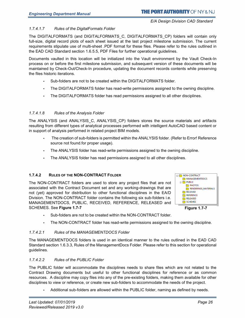
Engineering Department Manual
E/A Design Division CAD Standard
Last Updated: 07/01/2019 Page 26
Reviewed/Released 2019 v3.0
1.7.4.1.7 Rules of the DigitalFormats Folder
The DIGITALFORMATS (and DIGITALFORMATS_C, DIGITALFORMATS_CP) folders will contain only
full-size, digital record plots of each sheet issued at the last project milestone submission. The current
requirements stipulate use of multi-sheet .PDF format for these files. Please refer to the rules outlined in
the EAD CAD Standard section 1.6.5.5, PDF Files for further operational guidelines.
Documents vaulted in this location will be initialized into the Vault environment by the Vault Check-In
process on or before the first milestone submission, and subsequent version of these documents will be
maintained by Check-Out/Check-In procedure, updating the document records contents while preserving
the files historic iterations.
• Sub-folders are not to be created within the DIGITALFORMATS folder.
• The DIGITALFORMATS folder has read-write permissions assigned to the owning discipline.
• The DIGITALFORMATS folder has read permissions assigned to all other disciplines.
1.7.4.1.8 Rules of the Analysis Folder
The ANALYSIS (and ANALYSIS_C, ANALYSIS_CP) folders stores the source materials and artifacts
resulting from different types of analytical processes performed with intelligent AutoCAD based content or
in support of analysis performed in related project BIM models.
• The creation of sub-folders is permitted within the ANALYSIS folder. (Refer to Error! Reference
source not found.for proper usage).
• The ANALYSIS folder has read-write permissions assigned to the owning discipline.
• The ANALYSIS folder has read permissions assigned to all other disciplines.
1.7.4.2 RULES OF THE NON-CONTRACT FOLDER
The NON-CONTRACT folders are used to store any project files that are not
associated with the Contract Document set and any working-drawings that are
not (yet) approved for distribution to other functional disciplines in the EA/D
Division. The NON-CONTRACT folder contains the following six sub-folders i.e.
MANAGEMENTDOCS, PUBLIC, RECEIVED, REFERENCE, RELEASED and
SCHEMES. See Figure 1.7-7
• Sub-folders are not to be created within the NON-CONTRACT folder.
• The NON-CONTRACT folder has read-write permissions assigned to the owning discipline.
1.7.4.2.1 Rules of the MANAGEMENTDOCS Folder
The MANAGEMENTDOCS folders is used in an identical manner to the rules outlined in the EAD CAD
Standard section 1.6.3.3, Rules of the ManagementDocs Folder. Please refer to this section for operational
guidelines.
1.7.4.2.2 Rules of the PUBLIC Folder
The PUBLIC folder will accommodate the disciplines needs to share files which are not related to the
Contract Drawing documents but useful to other functional disciplines for reference or as common
resources. A discipline may copy files into any of the pre-existing folders, making them available for other
disciplines to view or reference, or create new sub-folders to accommodate the needs of the project.
• Additional sub-folders are allowed within the PUBLIC folder, naming as defined by needs.
Figure 1.7-7
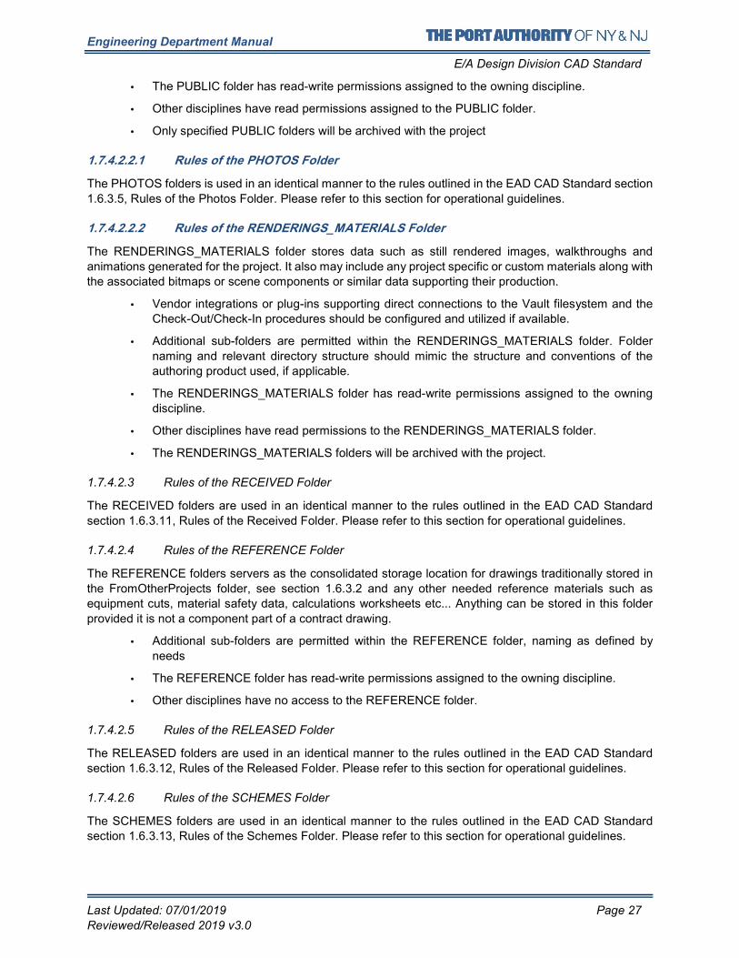
Engineering Department Manual
E/A Design Division CAD Standard
Last Updated: 07/01/2019 Page 27
Reviewed/Released 2019 v3.0
• The PUBLIC folder has read-write permissions assigned to the owning discipline.
• Other disciplines have read permissions assigned to the PUBLIC folder.
• Only specified PUBLIC folders will be archived with the project
1.7.4.2.2.1 Rules of the PHOTOS Folder
The PHOTOS folders is used in an identical manner to the rules outlined in the EAD CAD Standard section
1.6.3.5, Rules of the Photos Folder. Please refer to this section for operational guidelines.
1.7.4.2.2.2 Rules of the RENDERINGS_MATERIALS Folder
The RENDERINGS_MATERIALS folder stores data such as still rendered images, walkthroughs and
animations generated for the project. It also may include any project specific or custom materials along with
the associated bitmaps or scene components or similar data supporting their production.
• Vendor integrations or plug-ins supporting direct connections to the Vault filesystem and the
Check-Out/Check-In procedures should be configured and utilized if available.
• Additional sub-folders are permitted within the RENDERINGS_MATERIALS folder. Folder
naming and relevant directory structure should mimic the structure and conventions of the
authoring product used, if applicable.
• The RENDERINGS_MATERIALS folder has read-write permissions assigned to the owning
discipline.
• Other disciplines have read permissions to the RENDERINGS_MATERIALS folder.
• The RENDERINGS_MATERIALS folders will be archived with the project.
1.7.4.2.3 Rules of the RECEIVED Folder
The RECEIVED folders are used in an identical manner to the rules outlined in the EAD CAD Standard
section 1.6.3.11, Rules of the Received Folder. Please refer to this section for operational guidelines.
1.7.4.2.4 Rules of the REFERENCE Folder
The REFERENCE folders servers as the consolidated storage location for drawings traditionally stored in
the FromOtherProjects folder, see section 1.6.3.2 and any other needed reference materials such as
equipment cuts, material safety data, calculations worksheets etc... Anything can be stored in this folder
provided it is not a component part of a contract drawing.
• Additional sub-folders are permitted within the REFERENCE folder, naming as defined by
needs
• The REFERENCE folder has read-write permissions assigned to the owning discipline.
• Other disciplines have no access to the REFERENCE folder.
1.7.4.2.5 Rules of the RELEASED Folder
The RELEASED folders are used in an identical manner to the rules outlined in the EAD CAD Standard
section 1.6.3.12, Rules of the Released Folder. Please refer to this section for operational guidelines.
1.7.4.2.6 Rules of the SCHEMES Folder
The SCHEMES folders are used in an identical manner to the rules outlined in the EAD CAD Standard
section 1.6.3.13, Rules of the Schemes Folder. Please refer to this section for operational guidelines.
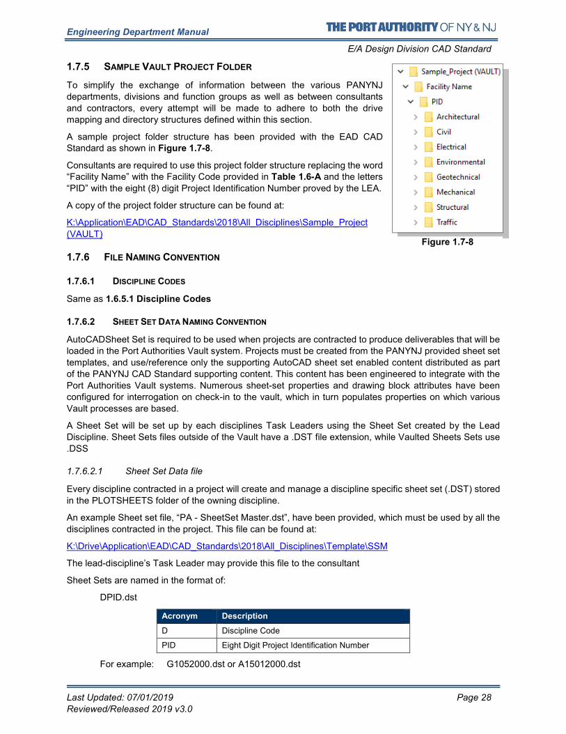
Engineering Department Manual
E/A Design Division CAD Standard
Last Updated: 07/01/2019 Page 28
Reviewed/Released 2019 v3.0
1.7.5 SAMPLE VAULT PROJECT FOLDER
To simplify the exchange of information between the various PANYNJ
departments, divisions and function groups as well as between consultants
and contractors, every attempt will be made to adhere to both the drive
mapping and directory structures defined within this section.
A sample project folder structure has been provided with the EAD CAD Standard as shown in Figure 1.7-8.
Consultants are required to use this project folder structure replacing the word “Facility Name” with the Facility Code provided in Table 1.6-A and the letters
“PID” with the eight (8) digit Project Identification Number proved by the LEA.
A copy of the project folder structure can be found at:
K:\Application\EAD\CAD_Standards\2018\All_Disciplines\Sample_Project
(VAULT)
1.7.6 FILE NAMING CONVENTION
1.7.6.1 DISCIPLINE CODES
Same as 1.6.5.1 Discipline Codes
1.7.6.2 SHEET SET DATA NAMING CONVENTION
AutoCADSheet Set is required to be used when projects are contracted to produce deliverables that will be
loaded in the Port Authorities Vault system. Projects must be created from the PANYNJ provided sheet set
templates, and use/reference only the supporting AutoCAD sheet set enabled content distributed as part
of the PANYNJ CAD Standard supporting content. This content has been engineered to integrate with the
Port Authorities Vault systems. Numerous sheet-set properties and drawing block attributes have been
configured for interrogation on check-in to the vault, which in turn populates properties on which various
Vault processes are based.
A Sheet Set will be set up by each disciplines Task Leaders using the Sheet Set created by the Lead
Discipline. Sheet Sets files outside of the Vault have a .DST file extension, while Vaulted Sheets Sets use
.DSS
1.7.6.2.1 Sheet Set Data file
Every discipline contracted in a project will create and manage a discipline specific sheet set (.DST) stored
in the PLOTSHEETS folder of the owning discipline.
An example Sheet set file, “PA - SheetSet Master.dst”, have been provided, which must be used by all the
disciplines contracted in the project. This file can be found at:
K:\Drive\Application\EAD\CAD_Standards\2018\All_Disciplines\Template\SSM
The lead-discipline’s Task Leader may provide this file to the consultant
Sheet Sets are named in the format of:
DPID.dst
Acronym Description
D Discipline Code
PID Eight Digit Project Identification Number
For example: G1052000.dst or A15012000.dst
Figure 1.7-8
Engineering Department Manual
E/A Design Division CAD Standard
Last Updated: 07/01/2019 Page 29
Reviewed/Released 2019 v3.0
Sheet Creation and Sheet Storage Location shall be set to the PLOTSHEETS folder of the owning
discipline. Sheet Set “Subsets” shall be configured to support CONFIDENTIAL or
CONFIDENTIAL+PRIVILEGED project data with the required security/access control. The Sheet Storage
Location(s) for these subsets shall be configured to store their drawings in their respective
CONFIDENTIAL\PLOTSHEETS_C, or CONFIDENTIAL+PRIVILEGED\PLOTSHEETS_CP folder
structures for the owning discipline.
1.7.6.2.2 Sheet Set Template
Based on the discipline trades desired drawing units, New sheets must be created using one of the provided
Sheet creation template,
“PA - SSM Contract Boarders - arch-inch.dwt”
or
“PA - SSM Contract Boarders - deci-feet.dwt”.
These files can be found: K:\Drive\Application\EAD\CAD_Standards\2018\All_Disciplines\Template\SSM
Sheet set properties as shown
1.7.6.3 DATA STANDARDS (FOR PA EMPLOYEES USING VAULT)
Data Standard is a data control feature for the Autodesk Vault Client and AutoCAD that allows
administrators to enforce how users enter Vault data. Data Standard plugin will be installed by the PA CAD
support group for the vault Project team.
When starting a new Model or Plot sheet file, create a new document using the PA standard CAD template
(PA – Arch-inch.dwt or PA – Deci-feet.dwt) and Navigate to the Data standard Ribbon and select Data Set, the Data Standard dialog (As shown in Figure 1.7-10 Data Sheet tool and New File Dialog Box) appears
requesting the project data for the file. Once the user completes all the fields, Data Standard generates the
PANYNJ compliant filenames, as well as perform the initial Check-In and save the file to the correct project
location based on the data. The Save button becomes active only when all required fields are complete.
Figure 1.7-9 Sheet Set Properties
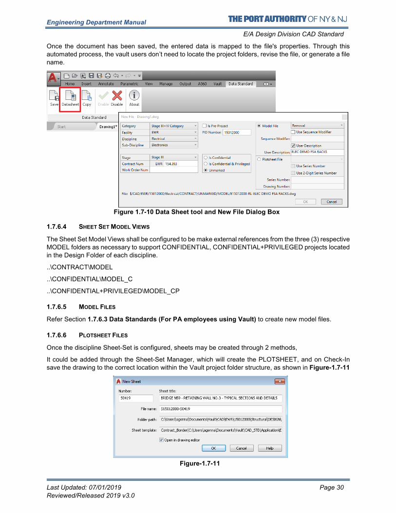
Engineering Department Manual
E/A Design Division CAD Standard
Last Updated: 07/01/2019 Page 30
Reviewed/Released 2019 v3.0
Once the document has been saved, the entered data is mapped to the file's properties. Through this
automated process, the vault users don’t need to locate the project folders, revise the file, or generate a file
name.
1.7.6.4 SHEET SET MODEL VIEWS
The Sheet Set Model Views shall be configured to be make external references from the three (3) respective
MODEL folders as necessary to support CONFIDENTIAL, CONFIDENTIAL+PRIVILEGED projects located
in the Design Folder of each discipline.
..\CONTRACT\MODEL
..\CONFIDENTIAL\MODEL_C
..\CONFIDENTIAL+PRIVILEGED\MODEL_CP
1.7.6.5 MODEL FILES
Refer Section 1.7.6.3 Data Standards (For PA employees using Vault) to create new model files.
1.7.6.6 PLOTSHEET FILES
Once the discipline Sheet-Set is configured, sheets may be created through 2 methods,
It could be added through the Sheet-Set Manager, which will create the PLOTSHEET, and on Check-In
save the drawing to the correct location within the Vault project folder structure, as shown in Figure-1.7-11
Figure 1.7-10 Data Sheet tool and New File Dialog Box
Figure-1.7-11
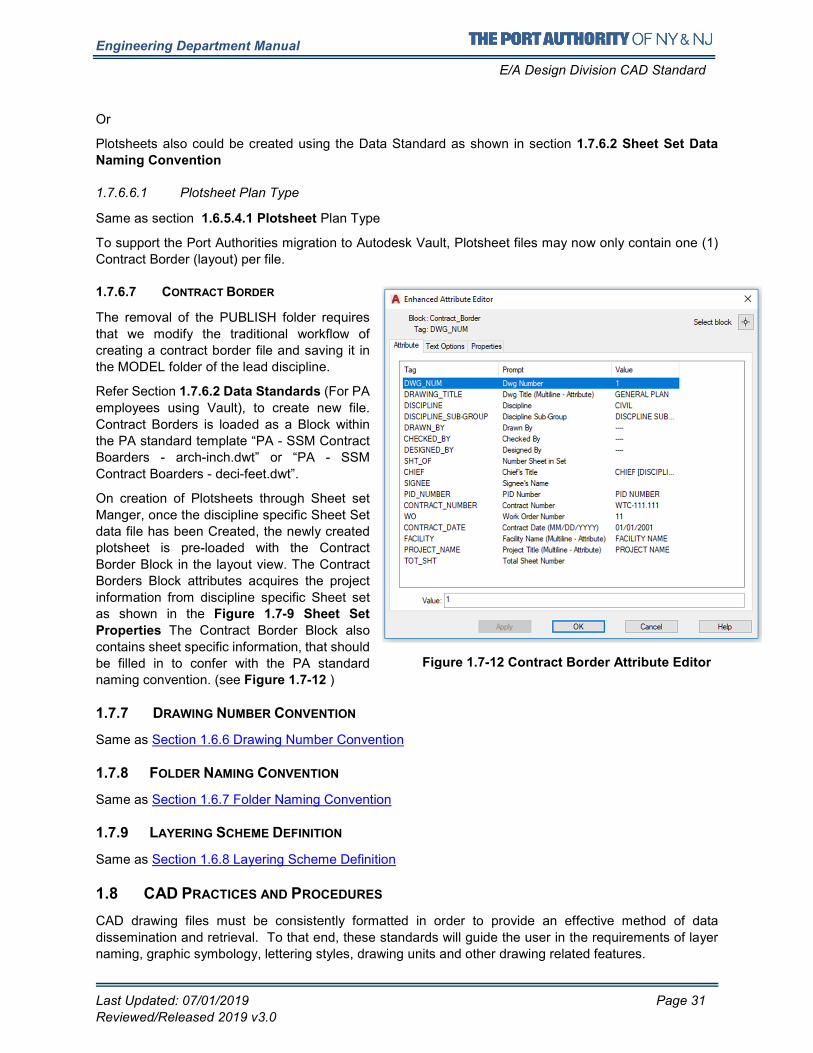
Engineering Department Manual
E/A Design Division CAD Standard
Last Updated: 07/01/2019 Page 31
Reviewed/Released 2019 v3.0
Or
Plotsheets also could be created using the Data Standard as shown in section 1.7.6.2 Sheet Set Data
Naming Convention
1.7.6.6.1 Plotsheet Plan Type
Same as section 1.6.5.4.1 Plotsheet Plan Type
To support the Port Authorities migration to Autodesk Vault, Plotsheet files may now only contain one (1)
Contract Border (layout) per file.
1.7.6.7 CONTRACT BORDER
The removal of the PUBLISH folder requires
that we modify the traditional workflow of
creating a contract border file and saving it in
the MODEL folder of the lead discipline.
Refer Section 1.7.6.2 Data Standards (For PA
employees using Vault), to create new file.
Contract Borders is loaded as a Block within
the PA standard template “PA - SSM Contract
Boarders - arch-inch.dwt” or “PA - SSM
Contract Boarders - deci-feet.dwt”.
On creation of Plotsheets through Sheet set
Manger, once the discipline specific Sheet Set
data file has been Created, the newly created
plotsheet is pre-loaded with the Contract
Border Block in the layout view. The Contract
Borders Block attributes acquires the project
information from discipline specific Sheet set as shown in the Figure 1.7-9 Sheet Set
Properties The Contract Border Block also
contains sheet specific information, that should
be filled in to confer with the PA standard
naming convention. (see Figure 1.7-12 )
1.7.7 DRAWING NUMBER CONVENTION
Same as Section 1.6.6 Drawing Number Convention
1.7.8 FOLDER NAMING CONVENTION
Same as Section 1.6.7 Folder Naming Convention
1.7.9 LAYERING SCHEME DEFINITION
Same as Section 1.6.8 Layering Scheme Definition
1.8 CAD PRACTICES AND PROCEDURES
CAD drawing files must be consistently formatted in order to provide an effective method of data
dissemination and retrieval. To that end, these standards will guide the user in the requirements of layer
naming, graphic symbology, lettering styles, drawing units and other drawing related features.
Figure 1.7-12 Contract Border Attribute Editor
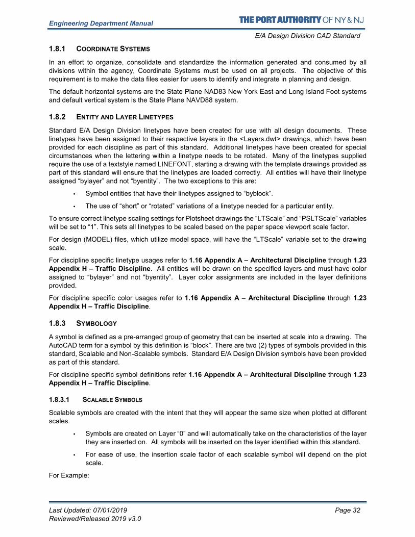
Engineering Department Manual
E/A Design Division CAD Standard
Last Updated: 07/01/2019 Page 32
Reviewed/Released 2019 v3.0
1.8.1 COORDINATE SYSTEMS
In an effort to organize, consolidate and standardize the information generated and consumed by all
divisions within the agency, Coordinate Systems must be used on all projects. The objective of this
requirement is to make the data files easier for users to identify and integrate in planning and design.
The default horizontal systems are the State Plane NAD83 New York East and Long Island Foot systems
and default vertical system is the State Plane NAVD88 system.
1.8.2 ENTITY AND LAYER LINETYPES
Standard E/A Design Division linetypes have been created for use with all design documents. These
linetypes have been assigned to their respective layers in the <Layers.dwt> drawings, which have been
provided for each discipline as part of this standard. Additional linetypes have been created for special
circumstances when the lettering within a linetype needs to be rotated. Many of the linetypes supplied
require the use of a textstyle named LINEFONT, starting a drawing with the template drawings provided as
part of this standard will ensure that the linetypes are loaded correctly. All entities will have their linetype
assigned “bylayer” and not “byentity”. The two exceptions to this are:
• Symbol entities that have their linetypes assigned to “byblock”.
• The use of “short” or “rotated” variations of a linetype needed for a particular entity.
To ensure correct linetype scaling settings for Plotsheet drawings the “LTScale” and “PSLTScale” variables
will be set to “1”. This sets all linetypes to be scaled based on the paper space viewport scale factor.
For design (MODEL) files, which utilize model space, will have the “LTScale” variable set to the drawing
scale.
For discipline specific linetype usages refer to 1.16 Appendix A – Architectural Discipline through 1.23
Appendix H – Traffic Discipline. All entities will be drawn on the specified layers and must have color
assigned to “bylayer” and not “byentity”. Layer color assignments are included in the layer definitions
provided.
For discipline specific color usages refer to 1.16 Appendix A – Architectural Discipline through 1.23
Appendix H – Traffic Discipline.
1.8.3 SYMBOLOGY
A symbol is defined as a pre-arranged group of geometry that can be inserted at scale into a drawing. The
AutoCAD term for a symbol by this definition is “block”. There are two (2) types of symbols provided in this
standard, Scalable and Non-Scalable symbols. Standard E/A Design Division symbols have been provided
as part of this standard.
For discipline specific symbol definitions refer 1.16 Appendix A – Architectural Discipline through 1.23
Appendix H – Traffic Discipline.
1.8.3.1 SCALABLE SYMBOLS
Scalable symbols are created with the intent that they will appear the same size when plotted at different
scales.
• Symbols are created on Layer “0” and will automatically take on the characteristics of the layer
they are inserted on. All symbols will be inserted on the layer identified within this standard.
• For ease of use, the insertion scale factor of each scalable symbol will depend on the plot
scale.
For Example:
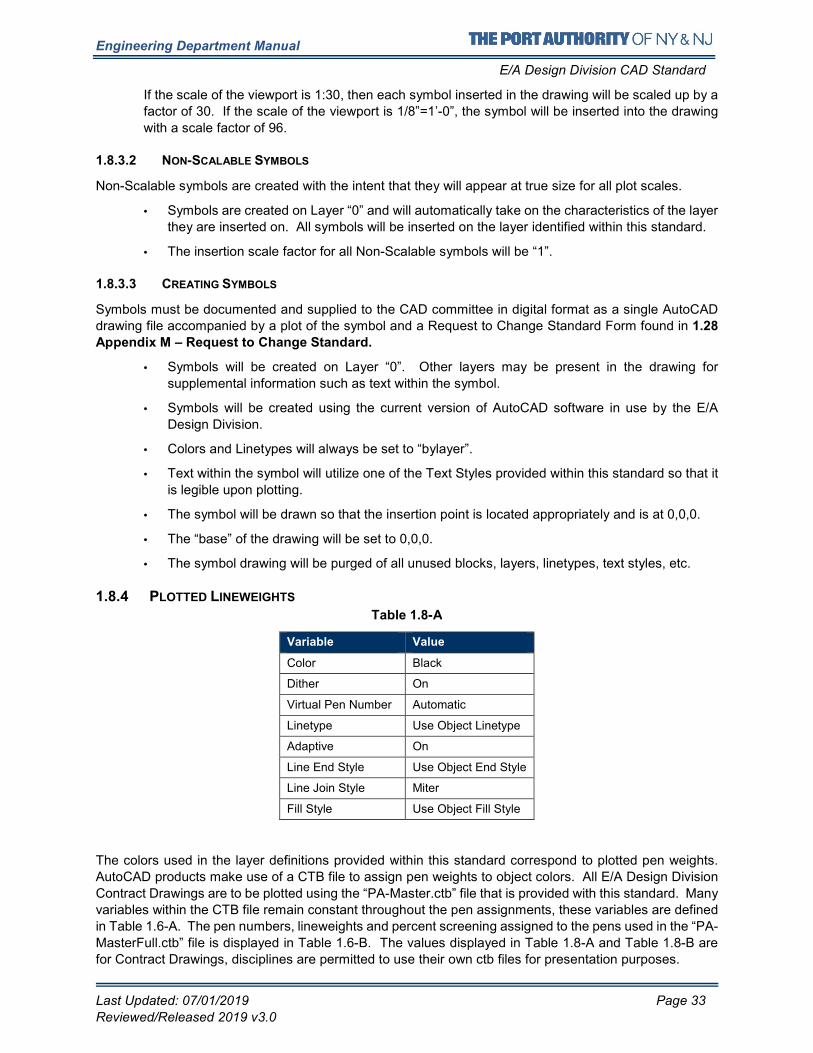
Engineering Department Manual
E/A Design Division CAD Standard
Last Updated: 07/01/2019 Page 33
Reviewed/Released 2019 v3.0
If the scale of the viewport is 1:30, then each symbol inserted in the drawing will be scaled up by a
factor of 30. If the scale of the viewport is 1/8”=1’-0”, the symbol will be inserted into the drawing
with a scale factor of 96.
1.8.3.2 NON-SCALABLE SYMBOLS
Non-Scalable symbols are created with the intent that they will appear at true size for all plot scales.
• Symbols are created on Layer “0” and will automatically take on the characteristics of the layer
they are inserted on. All symbols will be inserted on the layer identified within this standard.
• The insertion scale factor for all Non-Scalable symbols will be “1”.
1.8.3.3 CREATING SYMBOLS
Symbols must be documented and supplied to the CAD committee in digital format as a single AutoCAD
drawing file accompanied by a plot of the symbol and a Request to Change Standard Form found in 1.28
Appendix M – Request to Change Standard.
• Symbols will be created on Layer “0”. Other layers may be present in the drawing for
supplemental information such as text within the symbol.
• Symbols will be created using the current version of AutoCAD software in use by the E/A
Design Division.
• Colors and Linetypes will always be set to “bylayer”.
• Text within the symbol will utilize one of the Text Styles provided within this standard so that it
is legible upon plotting.
• The symbol will be drawn so that the insertion point is located appropriately and is at 0,0,0.
• The “base” of the drawing will be set to 0,0,0.
• The symbol drawing will be purged of all unused blocks, layers, linetypes, text styles, etc.
1.8.4 PLOTTED LINEWEIGHTS
Table 1.8-A
Variable Value
Color Black
Dither On
Virtual Pen Number Automatic
Linetype Use Object Linetype
Adaptive On
Line End Style Use Object End Style
Line Join Style Miter
Fill Style Use Object Fill Style
The colors used in the layer definitions provided within this standard correspond to plotted pen weights.
AutoCAD products make use of a CTB file to assign pen weights to object colors. All E/A Design Division
Contract Drawings are to be plotted using the “PA-Master.ctb” file that is provided with this standard. Many
variables within the CTB file remain constant throughout the pen assignments, these variables are defined
in Table 1.6-A. The pen numbers, lineweights and percent screening assigned to the pens used in the “PA-
MasterFull.ctb” file is displayed in Table 1.6-B. The values displayed in Table 1.8-A and Table 1.8-B are
for Contract Drawings, disciplines are permitted to use their own ctb files for presentation purposes.
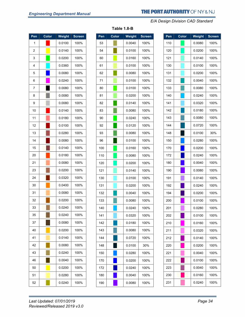
Engineering Department Manual
E/A Design Division CAD Standard
Last Updated: 07/01/2019 Page 34
Reviewed/Released 2019 v3.0
Table 1.8-B
Pen Color Weight Screen
1 0.0100 100%
2 0.0140 100%
3 0.0200 100%
4 0.0360 100%
5 0.0080 100%
6 0.0240 100%
7 0.0080 100%
8 0.0080 100%
9 0.0080 100%
10 0.0140 100%
11 0.0180 100%
12 0.0100 100%
13 0.0280 100%
14 0.0080 100%
15 0.0140 100%
20 0.0180 100%
21 0.0080 100%
23 0.0200 100%
24 0.0320 100%
30 0.0400 100%
31 0.0080 100%
32 0.0200 100%
33 0.0240 100%
35 0.0240 100%
37
0.0080 100%
40 0.0200 100%
41 0.0140 100%
42 0.0080 100%
43 0.0240 100%
46 0.0040 100%
50 0.0200 100%
51 0.0280 100%
52 0.0240 100%
Pen Color Weight Screen
53 0.0040 100%
54 0.0100 100%
60 0.0160 100%
61 0.0100 100%
62 0.0080 100%
71 0.0100 100%
80 0.0100 100%
81 0.0200 100%
82 0.0140 100%
83 0.0080 100%
90 0.0240 100%
92 0.0120 100%
93 0.0080 100%
96 0.0100 100%
100 0.0160 100%
110 0.0080 100%
120 0.0200 100%
121 0.0140 100%
130 0.0100 100%
131 0.0200 100%
132 0.0040 100%
133 0.0080 100%
140 0.0240 100%
141 0.0320 100%
142 0.0180 100%
143 0.0080 100%
144
0.0720 100%
148 0.0100 30%
150 0.0280 100%
170 0.0200 100%
172 0.0240 100%
180 0.0040 100%
190
0.0080 100%
Pen Color Weight Screen
110 0.0080 100%
120 0.0200 100%
121 0.0140 100%
130 0.0100 100%
131 0.0200 100%
132 0.0040 100%
133 0.0080 100%
140 0.0240 100%
141 0.0320 100%
142 0.0180 100%
143 0.0080 100%
144
0.0720 100%
148 0.0100 30%
150 0.0280 100%
170 0.0200 100%
172 0.0240 100%
180 0.0040 100%
190
0.0080 100%
191 0.0140 100%
192 0.0240 100%
194 0.0200 100%
200 0.0100 100%
201 0.0280 100%
202 0.0100 100%
210 0.0160 100%
211 0.0320 100%
212 0.0140 100%
220 0.0200 100%
221 0.0040 100%
222 0.0100 100%
223 0.0040 100%
230 0.0160 100%
231
0.0240 100%
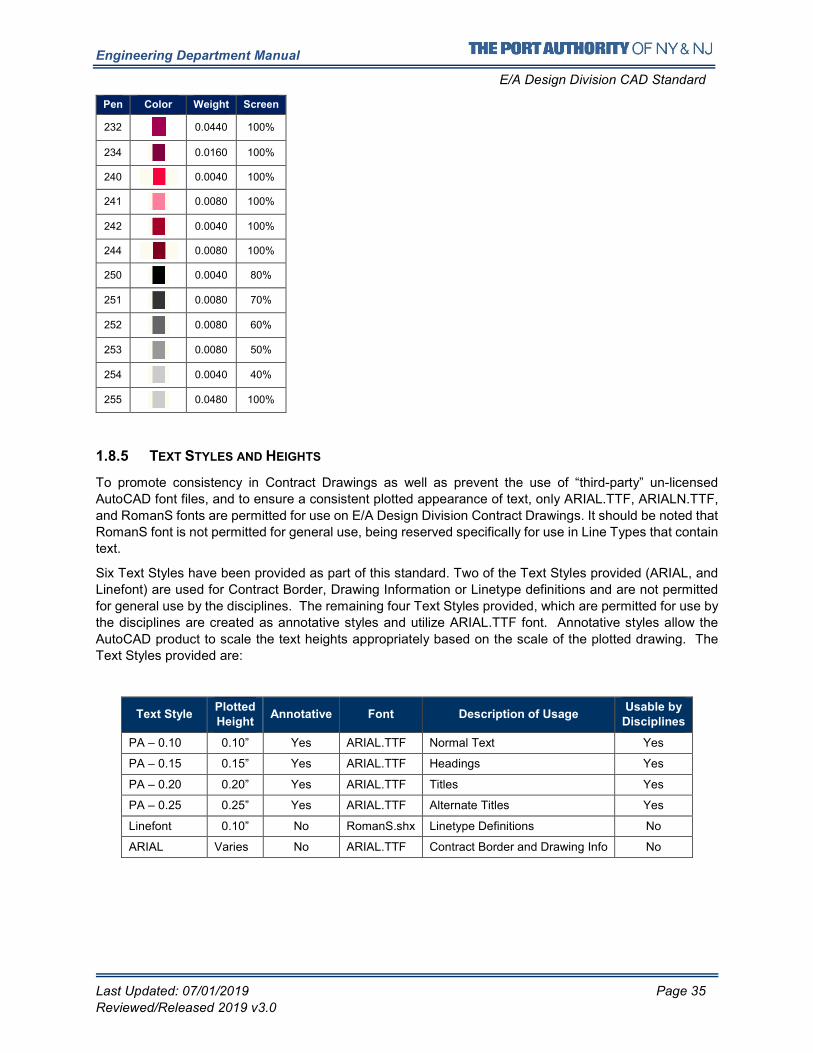
Engineering Department Manual
E/A Design Division CAD Standard
Last Updated: 07/01/2019 Page 35
Reviewed/Released 2019 v3.0
1.8.5 TEXT STYLES AND HEIGHTS
To promote consistency in Contract Drawings as well as prevent the use of “third-party” un-licensed
AutoCAD font files, and to ensure a consistent plotted appearance of text, only ARIAL.TTF, ARIALN.TTF,
and RomanS fonts are permitted for use on E/A Design Division Contract Drawings. It should be noted that
RomanS font is not permitted for general use, being reserved specifically for use in Line Types that contain
text.
Six Text Styles have been provided as part of this standard. Two of the Text Styles provided (ARIAL, and
Linefont) are used for Contract Border, Drawing Information or Linetype definitions and are not permitted
for general use by the disciplines. The remaining four Text Styles provided, which are permitted for use by
the disciplines are created as annotative styles and utilize ARIAL.TTF font. Annotative styles allow the
AutoCAD product to scale the text heights appropriately based on the scale of the plotted drawing. The
Text Styles provided are:
Text Style Plotted
Height Annotative Font Description of Usage
Usable by
Disciplines
PA – 0.10 0.10” Yes ARIAL.TTF Normal Text Yes
PA – 0.15 0.15” Yes ARIAL.TTF Headings Yes
PA – 0.20 0.20” Yes ARIAL.TTF Titles Yes
PA – 0.25 0.25” Yes ARIAL.TTF Alternate Titles Yes
Linefont 0.10” No RomanS.shx Linetype Definitions No
ARIAL Varies No ARIAL.TTF Contract Border and Drawing Info No
Pen Color Weight Screen
232
0.0440 100%
234 0.0160 100%
240 0.0040 100%
241 0.0080 100%
242 0.0040 100%
244 0.0080 100%
250 0.0040 80%
251 0.0080 70%
252 0.0080 60%
253 0.0080 50%
254 0.0040 40%
255 0.0480 100%
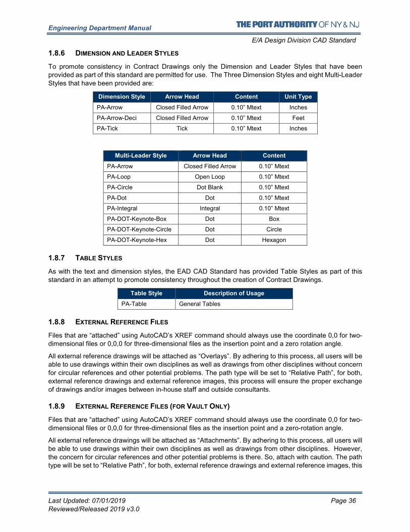
Engineering Department Manual
E/A Design Division CAD Standard
Last Updated: 07/01/2019 Page 36
Reviewed/Released 2019 v3.0
1.8.6 DIMENSION AND LEADER STYLES
To promote consistency in Contract Drawings only the Dimension and Leader Styles that have been
provided as part of this standard are permitted for use. The Three Dimension Styles and eight Multi-Leader
Styles that have been provided are:
Dimension Style Arrow Head Content Unit Type
PA-Arrow Closed Filled Arrow 0.10” Mtext Inches
PA-Arrow-Deci Closed Filled Arrow 0.10” Mtext Feet
PA-Tick Tick 0.10” Mtext Inches
Multi-Leader Style Arrow Head Content
PA-Arrow Closed Filled Arrow 0.10” Mtext
PA-Loop Open Loop 0.10” Mtext
PA-Circle Dot Blank 0.10” Mtext
PA-Dot Dot 0.10” Mtext
PA-Integral Integral 0.10” Mtext
PA-DOT-Keynote-Box Dot Box
PA-DOT-Keynote-Circle Dot Circle
PA-DOT-Keynote-Hex Dot Hexagon
1.8.7 TABLE STYLES
As with the text and dimension styles, the EAD CAD Standard has provided Table Styles as part of this
standard in an attempt to promote consistency throughout the creation of Contract Drawings.
Table Style Description of Usage
PA-Table General Tables
1.8.8 EXTERNAL REFERENCE FILES
Files that are “attached” using AutoCAD’s XREF command should always use the coordinate 0,0 for two-
dimensional files or 0,0,0 for three-dimensional files as the insertion point and a zero rotation angle.
All external reference drawings will be attached as “Overlays”. By adhering to this process, all users will be
able to use drawings within their own disciplines as well as drawings from other disciplines without concern
for circular references and other potential problems. The path type will be set to “Relative Path”, for both,
external reference drawings and external reference images, this process will ensure the proper exchange
of drawings and/or images between in-house staff and outside consultants.
1.8.9 EXTERNAL REFERENCE FILES (FOR VAULT ONLY)
Files that are “attached” using AutoCAD’s XREF command should always use the coordinate 0,0 for two-
dimensional files or 0,0,0 for three-dimensional files as the insertion point and a zero-rotation angle.
All external reference drawings will be attached as “Attachments”. By adhering to this process, all users will
be able to use drawings within their own disciplines as well as drawings from other disciplines. However,
the concern for circular references and other potential problems is there. So, attach with caution. The path
type will be set to “Relative Path”, for both, external reference drawings and external reference images, this
Engineering Department Manual
E/A Design Division CAD Standard
Last Updated: 07/01/2019 Page 37
Reviewed/Released 2019 v3.0
process will ensure the proper exchange of drawings and/or images between in-house staff and outside
consultants.
1.8.10 SUBMISSIONS
CAD files in DWG and PDF format, accompanied with hardcopies are required at every Submittal Milestone.
Until project completion, all current working drawings are saved in the MODEL, PLOTSHEETS and
PUBLISH folders of each discipline’s root directory.
At every Submittal milestone, the working project information will be copied into the SUBMITTALS folder
for archiving, to preserve the state of the drawings at the moment of that milestone. At the completion of
every milestone, each discipline will copy its MODEL, PLOTSHEETS and PUBLISH folders, along with the
MANAGEMENTDOCS and PHOTOS folders, into the appropriate milestone sub-folder within
SUBMITTALS. Refer to 1.6.3.15 Rules of the Submittals Folder for a listing of Submittal Folders provided.
Once the folders have been copied, the involved Task Leaders will notify the LEA, who will then notify the
CAD Support Group by filling out the Project Archival Request Form on EOL. Refer to 1.27.2 Request
Project Archival. Upon notification, the CAD Support Group will move the files to the Archive server,
mapped internally as the “N:\” drive, leaving behind a text file named ARCHIVED YYYY-MM-DD.txt
containing the exact location where the files can be found.
The CAD Support Group will only move files from the discipline’s SUBMITTALS folder to the ARCHIVE
server.
The SUBMITTALS folder is for internal use only. Consultants are required to submit the entire Project Folder Structure as outlined in 1.6.1 Project Directory Structure and File Naming Convention containing not
only the Discipline folder in which their drawings are saved but also all other Discipline folders from which
external references were made.
Consultants will submit their folder structure directly to their own Discipline’s Task Leader. The Task Leader
will copy the consultant’s MODEL, PLOTSHEETS and PUBLISH folders, along with the
MANAGEMENTDOCS and PHOTOS folders, into both the discipline’s root directory and the appropriate
milestone sub-folder within SUBMITTALS.
1.8.10.1 STAGEI_100PERCENT
Stage I (Conceptual Design) is necessary for some projects to develop design concepts, determine
anticipated construction costs and schedules, and to compare alternatives before proceeding with Design
Development (Stage II) or Final Design (Stage III).
1.8.10.2 STAGEII_100PERCENT
Stage II (Design Development) is necessary to develop the chosen design concept, further refine
anticipated construction costs and schedules before proceeding with contract documents.
1.8.10.3 STAGEIII_PA-REVIEW
The Stage III (Final Design) effort includes preparation of contract documents that will be used for
construction. The procedures vary for alternate delivery methods such as Quick Bid Contracts, Work Order
Contracts, Design/Build Contracts and Design/Build/Operate/Maintain Contracts.
PA Review usually happens when the project is between 90% to 95% complete, this may vary depending
on the project specifics. When a project reaches PA-Review, drawings are required so the Electronic
Review Process can begin.
Engineering Department Manual
E/A Design Division CAD Standard
Last Updated: 07/01/2019 Page 38
Reviewed/Released 2019 v3.0
1.8.10.4 STAGEIII_AS-ADVERTISED-SIGNED-SET
The signed and sealed 100% submission plotted on Permalife® paper is the “As Advertised Signed Set”.
1.8.10.5 STAGEIII_ADDENDUM
The Addendum Set contains drawings that have been modified or new drawings that have been issued
after the original As Advertised Signed Set was signed and issued. Not all addenda contain drawings;
some may only contain specifications. Therefore, an Addendum Set may contain non-consecutive addenda
sub-folders. The StageIII_Addendum folder should only contain the Addenda sub-folder in which drawings
were required. This folder should not contain the entire set of CAD files; it should only contain the Addenda
files.
The revision procedures detailed in section 1.10.3.5 Making Revisions in Contract Drawings apply to
Addenda.
1.8.10.6 STAGEIII_AS-BID
The As-Bid Set is the Bid and Awarded Set of Drawings, which incorporates all the addenda that have been
issued.
1.8.10.7 STAGEIV_PACC
The PACC Set (Post Award Contract Changes) contains drawings that have been modified or new drawings
that have been issued after the Contract was awarded.
The revision procedures detailed in section 1.10.3.5 Making Revisions in Contract Drawings apply to
PACC Sets.
1.8.10.8 STAGEIV_DRAWING-OF-RECORD
The Drawing-of-Record Set is the set of drawings created after construction is completed.
1.8.11 SUBMISSIONS (FOR VAULT PROJECT ONLY)
External consultant still needs to provide CAD files in DWG and PDF format, accompanied with hardcopies
are required at every Submittal Milestone.
Until project completion, all current working drawings are saved, by consultants, in the MODEL,
PLOTSHEETS and PUBLISH folders of each discipline’s root directory. In-house projects will be saved in
the MODEL and PLOTSHEET folders in the Vault environment. For the In-house submission process, look
at the following sections.
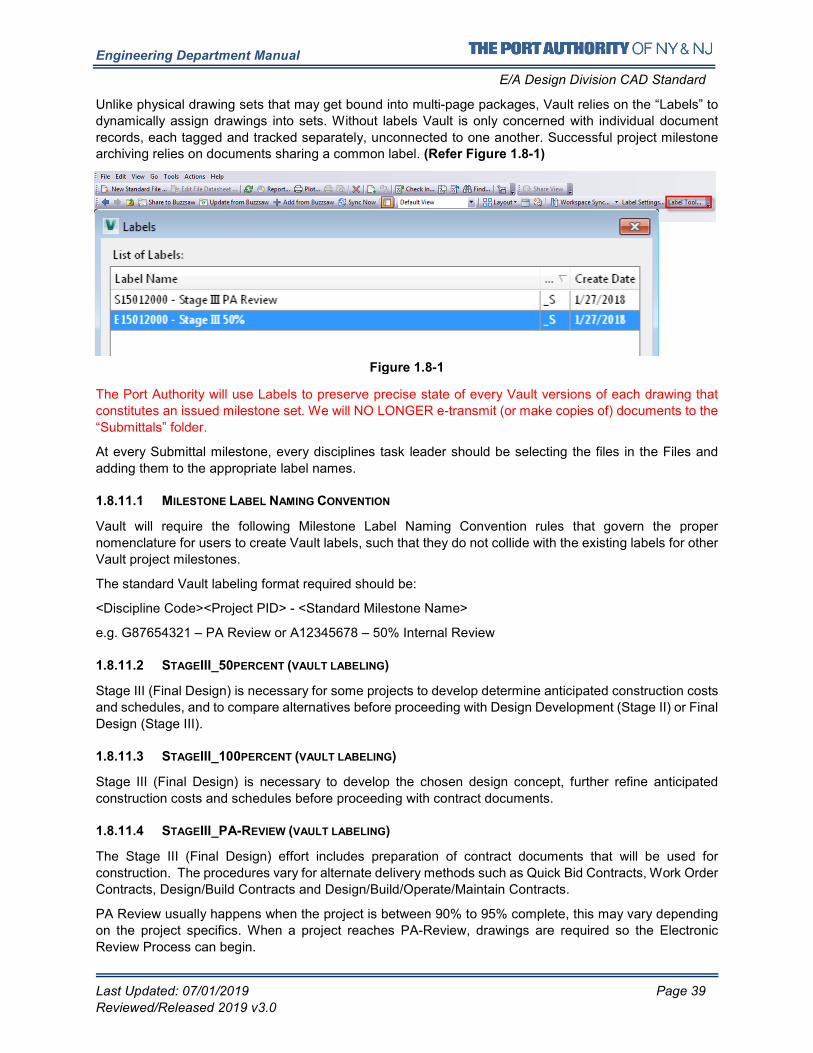
Engineering Department Manual
E/A Design Division CAD Standard
Last Updated: 07/01/2019 Page 39
Reviewed/Released 2019 v3.0
Unlike physical drawing sets that may get bound into multi-page packages, Vault relies on the “Labels” to
dynamically assign drawings into sets. Without labels Vault is only concerned with individual document
records, each tagged and tracked separately, unconnected to one another. Successful project milestone archiving relies on documents sharing a common label. (Refer Figure 1.8-1)
The Port Authority will use Labels to preserve precise state of every Vault versions of each drawing that
constitutes an issued milestone set. We will NO LONGER e-transmit (or make copies of) documents to the
“Submittals” folder.
At every Submittal milestone, every disciplines task leader should be selecting the files in the Files and
adding them to the appropriate label names.
1.8.11.1 MILESTONE LABEL NAMING CONVENTION
Vault will require the following Milestone Label Naming Convention rules that govern the proper
nomenclature for users to create Vault labels, such that they do not collide with the existing labels for other
Vault project milestones.
The standard Vault labeling format required should be:
<Discipline Code><Project PID> - <Standard Milestone Name>
e.g. G87654321 – PA Review or A12345678 – 50% Internal Review
1.8.11.2 STAGEIII_50PERCENT (VAULT LABELING)
Stage III (Final Design) is necessary for some projects to develop determine anticipated construction costs
and schedules, and to compare alternatives before proceeding with Design Development (Stage II) or Final
Design (Stage III).
1.8.11.3 STAGEIII_100PERCENT (VAULT LABELING)
Stage III (Final Design) is necessary to develop the chosen design concept, further refine anticipated
construction costs and schedules before proceeding with contract documents.
1.8.11.4 STAGEIII_PA-REVIEW (VAULT LABELING)
The Stage III (Final Design) effort includes preparation of contract documents that will be used for
construction. The procedures vary for alternate delivery methods such as Quick Bid Contracts, Work Order
Contracts, Design/Build Contracts and Design/Build/Operate/Maintain Contracts.
PA Review usually happens when the project is between 90% to 95% complete, this may vary depending
on the project specifics. When a project reaches PA-Review, drawings are required so the Electronic
Review Process can begin.
Figure 1.8-1
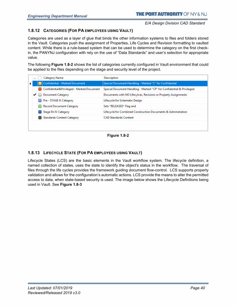
Engineering Department Manual
E/A Design Division CAD Standard
Last Updated: 07/01/2019 Page 40
Reviewed/Released 2019 v3.0
1.8.12 CATEGORIES (FOR PA EMPLOYEES USING VAULT)
Categories are used as a layer of glue that binds the other information systems to files and folders stored
in the Vault. Categories push the assignment of Properties, Life Cycles and Revision formatting to vaulted
content. While there is a rule-based system that can be used to determine the category on the first check-
in, the PANYNJ configuration with rely on the use of “Data Standards” and user’s selection for appropriate
value.
The following Figure 1.8-2 shows the list of categories currently configured in Vault environment that could
be applied to the files depending on the stage and security level of the project.
1.8.13 LIFECYCLE STATE (FOR PA EMPLOYEES USING VAULT)
Lifecycle States (LCS) are the basic elements in the Vault workflow system. The lifecycle definition, a
named collection of states, uses the state to identify the object's status in the workflow. The traversal of
files through the life cycles provides the framework guiding document flow-control. LCS supports property
validation and allows for the configuration’s automatic actions. LCS provide the means to alter the permitted
access to data, when state-based security is used. The image below shows the Lifecycle Definitions being
used in Vault. See Figure 1.8-3
Figure 1.8-2
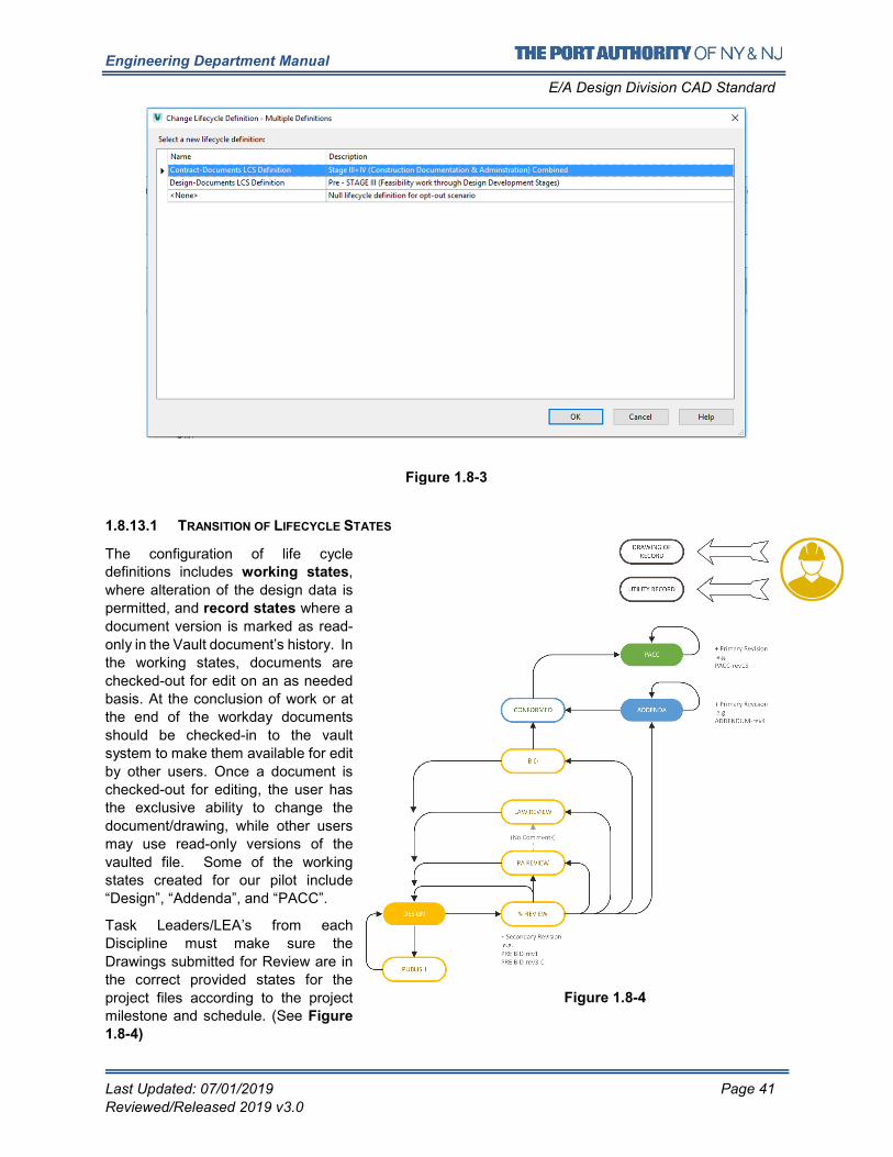
Engineering Department Manual
E/A Design Division CAD Standard
Last Updated: 07/01/2019 Page 41
Reviewed/Released 2019 v3.0
1.8.13.1 TRANSITION OF LIFECYCLE STATES
The configuration of life cycle definitions includes working states,
where alteration of the design data is
permitted, and record states where a
document version is marked as read-
only in the Vault document’s history. In
the working states, documents are
checked-out for edit on an as needed
basis. At the conclusion of work or at
the end of the workday documents
should be checked-in to the vault
system to make them available for edit
by other users. Once a document is
checked-out for editing, the user has
the exclusive ability to change the
document/drawing, while other users
may use read-only versions of the
vaulted file. Some of the working
states created for our pilot include
“Design”, “Addenda”, and “PACC”.
Task Leaders/LEA’s from each
Discipline must make sure the
Drawings submitted for Review are in
the correct provided states for the
project files according to the project milestone and schedule. (See Figure
1.8-4)
Figure 1.8-3
Figure 1.8-4
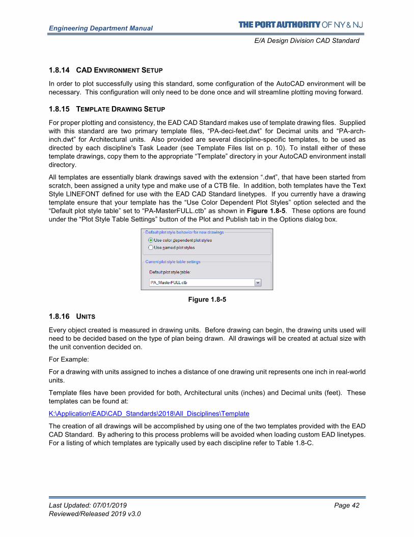
Engineering Department Manual
E/A Design Division CAD Standard
Last Updated: 07/01/2019 Page 42
Reviewed/Released 2019 v3.0
1.8.14 CAD ENVIRONMENT SETUP
In order to plot successfully using this standard, some configuration of the AutoCAD environment will be
necessary. This configuration will only need to be done once and will streamline plotting moving forward.
1.8.15 TEMPLATE DRAWING SETUP
For proper plotting and consistency, the EAD CAD Standard makes use of template drawing files. Supplied
with this standard are two primary template files, “PA-deci-feet.dwt” for Decimal units and “PA-arch-
inch.dwt” for Architectural units. Also provided are several discipline-specific templates, to be used as
directed by each discipline's Task Leader (see Template Files list on p. 10). To install either of these
template drawings, copy them to the appropriate “Template” directory in your AutoCAD environment install
directory.
All templates are essentially blank drawings saved with the extension “.dwt”, that have been started from
scratch, been assigned a unity type and make use of a CTB file. In addition, both templates have the Text
Style LINEFONT defined for use with the EAD CAD Standard linetypes. If you currently have a drawing
template ensure that your template has the “Use Color Dependent Plot Styles” option selected and the
“Default plot style table” set to “PA-MasterFULL.ctb” as shown in Figure 1.8-5. These options are found
under the “Plot Style Table Settings” button of the Plot and Publish tab in the Options dialog box.
Figure 1.8-5
1.8.16 UNITS
Every object created is measured in drawing units. Before drawing can begin, the drawing units used will
need to be decided based on the type of plan being drawn. All drawings will be created at actual size with
the unit convention decided on.
For Example:
For a drawing with units assigned to inches a distance of one drawing unit represents one inch in real-world
units.
Template files have been provided for both, Architectural units (inches) and Decimal units (feet). These
templates can be found at:
K:\Application\EAD\CAD_Standards\2018\All_Disciplines\Template
The creation of all drawings will be accomplished by using one of the two templates provided with the EAD
CAD Standard. By adhering to this process problems will be avoided when loading custom EAD linetypes.
For a listing of which templates are typically used by each discipline refer to Table 1.8-C.
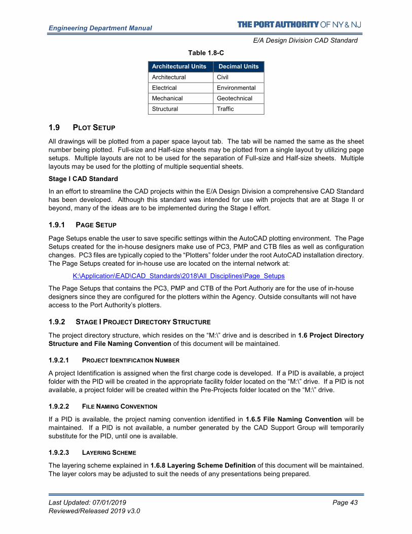
Engineering Department Manual
E/A Design Division CAD Standard
Last Updated: 07/01/2019 Page 43
Reviewed/Released 2019 v3.0
Table 1.8-C
Architectural Units Decimal Units
Architectural Civil
Electrical Environmental
Mechanical Geotechnical
Structural Traffic
1.9 PLOT SETUP
All drawings will be plotted from a paper space layout tab. The tab will be named the same as the sheet
number being plotted. Full-size and Half-size sheets may be plotted from a single layout by utilizing page
setups. Multiple layouts are not to be used for the separation of Full-size and Half-size sheets. Multiple
layouts may be used for the plotting of multiple sequential sheets.
Stage I CAD Standard
In an effort to streamline the CAD projects within the E/A Design Division a comprehensive CAD Standard
has been developed. Although this standard was intended for use with projects that are at Stage II or
beyond, many of the ideas are to be implemented during the Stage I effort.
1.9.1 PAGE SETUP
Page Setups enable the user to save specific settings within the AutoCAD plotting environment. The Page
Setups created for the in-house designers make use of PC3, PMP and CTB files as well as configuration
changes. PC3 files are typically copied to the “Plotters” folder under the root AutoCAD installation directory.
The Page Setups created for in-house use are located on the internal network at:
K:\Application\EAD\CAD_Standards\2018\All_Disciplines\Page_Setups
The Page Setups that contains the PC3, PMP and CTB of the Port Authoriy are for the use of in-house
designers since they are configured for the plotters within the Agency. Outside consultants will not have
access to the Port Authority’s plotters.
1.9.2 STAGE I PROJECT DIRECTORY STRUCTURE
The project directory structure, which resides on the “M:\” drive and is described in 1.6 Project Directory
Structure and File Naming Convention of this document will be maintained.
1.9.2.1 PROJECT IDENTIFICATION NUMBER
A project Identification is assigned when the first charge code is developed. If a PID is available, a project
folder with the PID will be created in the appropriate facility folder located on the “M:\” drive. If a PID is not
available, a project folder will be created within the Pre-Projects folder located on the “M:\” drive.
1.9.2.2 FILE NAMING CONVENTION
If a PID is available, the project naming convention identified in 1.6.5 File Naming Convention will be
maintained. If a PID is not available, a number generated by the CAD Support Group will temporarily
substitute for the PID, until one is available.
1.9.2.3 LAYERING SCHEME
The layering scheme explained in 1.6.8 Layering Scheme Definition of this document will be maintained.
The layer colors may be adjusted to suit the needs of any presentations being prepared.
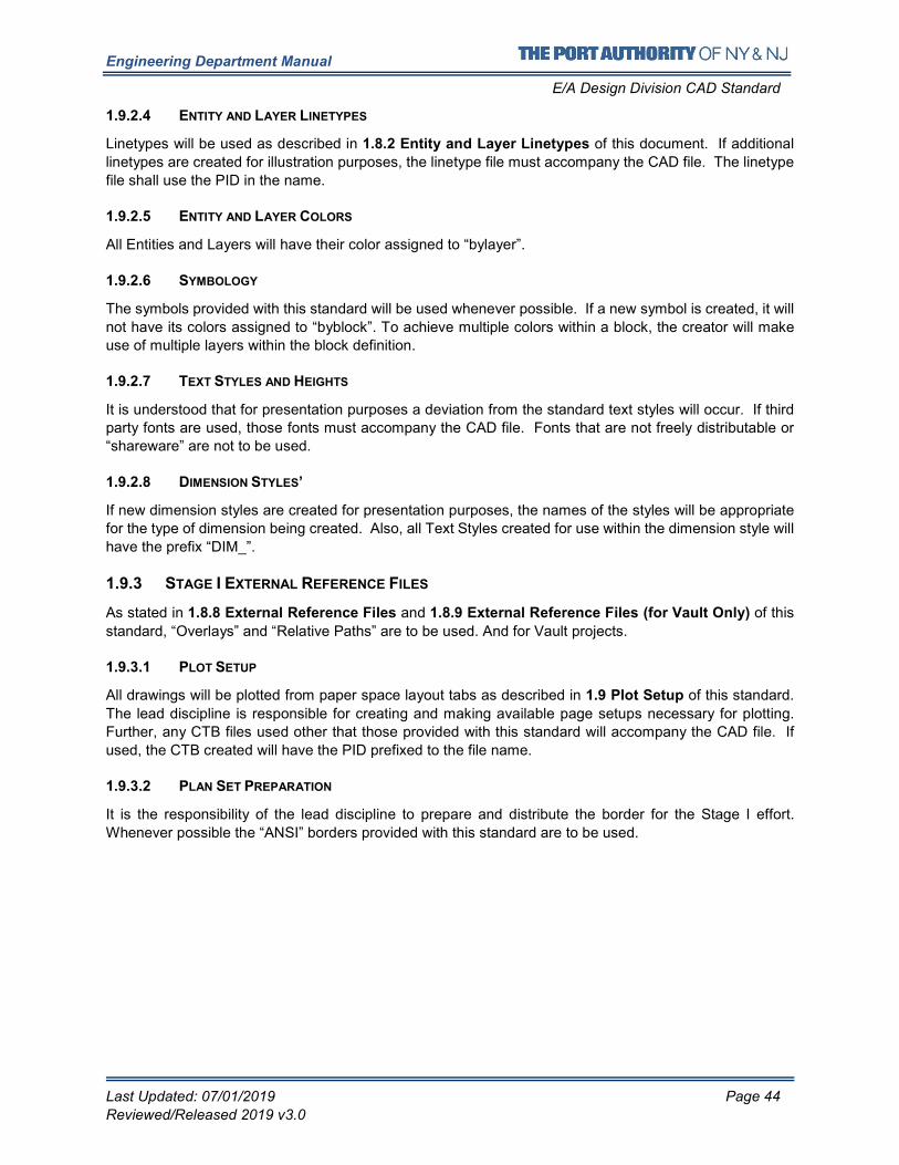
Engineering Department Manual
E/A Design Division CAD Standard
Last Updated: 07/01/2019 Page 44
Reviewed/Released 2019 v3.0
1.9.2.4 ENTITY AND LAYER LINETYPES
Linetypes will be used as described in 1.8.2 Entity and Layer Linetypes of this document. If additional
linetypes are created for illustration purposes, the linetype file must accompany the CAD file. The linetype
file shall use the PID in the name.
1.9.2.5 ENTITY AND LAYER COLORS
All Entities and Layers will have their color assigned to “bylayer”.
1.9.2.6 SYMBOLOGY
The symbols provided with this standard will be used whenever possible. If a new symbol is created, it will
not have its colors assigned to “byblock”. To achieve multiple colors within a block, the creator will make
use of multiple layers within the block definition.
1.9.2.7 TEXT STYLES AND HEIGHTS
It is understood that for presentation purposes a deviation from the standard text styles will occur. If third
party fonts are used, those fonts must accompany the CAD file. Fonts that are not freely distributable or
“shareware” are not to be used.
1.9.2.8 DIMENSION STYLES’
If new dimension styles are created for presentation purposes, the names of the styles will be appropriate
for the type of dimension being created. Also, all Text Styles created for use within the dimension style will
have the prefix “DIM_”.
1.9.3 STAGE I EXTERNAL REFERENCE FILES
As stated in 1.8.8 External Reference Files and 1.8.9 External Reference Files (for Vault Only) of this
standard, “Overlays” and “Relative Paths” are to be used. And for Vault projects.
1.9.3.1 PLOT SETUP
All drawings will be plotted from paper space layout tabs as described in 1.9 Plot Setup of this standard.
The lead discipline is responsible for creating and making available page setups necessary for plotting.
Further, any CTB files used other that those provided with this standard will accompany the CAD file. If
used, the CTB created will have the PID prefixed to the file name.
1.9.3.2 PLAN SET PREPARATION
It is the responsibility of the lead discipline to prepare and distribute the border for the Stage I effort.
Whenever possible the “ANSI” borders provided with this standard are to be used.
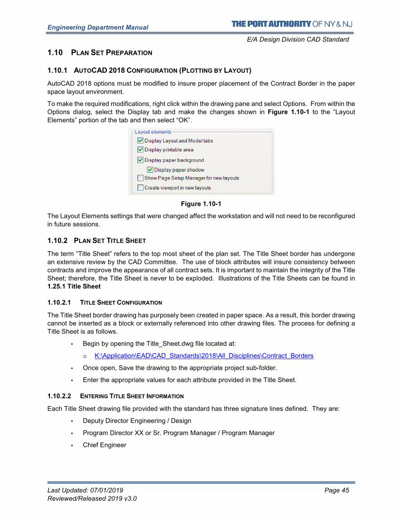
Engineering Department Manual
E/A Design Division CAD Standard
Last Updated: 07/01/2019 Page 45
Reviewed/Released 2019 v3.0
1.10 PLAN SET PREPARATION
1.10.1 AUTOCAD 2018 CONFIGURATION (PLOTTING BY LAYOUT)
AutoCAD 2018 options must be modified to insure proper placement of the Contract Border in the paper
space layout environment.
To make the required modifications, right click within the drawing pane and select Options. From within the
Options dialog, select the Display tab and make the changes shown in Figure 1.10-1 to the “Layout
Elements” portion of the tab and then select “OK”.
Figure 1.10-1
The Layout Elements settings that were changed affect the workstation and will not need to be reconfigured
in future sessions.
1.10.2 PLAN SET TITLE SHEET
The term “Title Sheet” refers to the top most sheet of the plan set. The Title Sheet border has undergone
an extensive review by the CAD Committee. The use of block attributes will insure consistency between
contracts and improve the appearance of all contract sets. It is important to maintain the integrity of the Title
Sheet; therefore, the Title Sheet is never to be exploded. Illustrations of the Title Sheets can be found in 1.25.1 Title Sheet
1.10.2.1 TITLE SHEET CONFIGURATION
The Title Sheet border drawing has purposely been created in paper space. As a result, this border drawing
cannot be inserted as a block or externally referenced into other drawing files. The process for defining a
Title Sheet is as follows.
• Begin by opening the Title_Sheet.dwg file located at:
o K:\Application\EAD\CAD_Standards\2018\All_Disciplines\Contract_Borders
• Once open, Save the drawing to the appropriate project sub-folder.
• Enter the appropriate values for each attribute provided in the Title Sheet.
1.10.2.2 ENTERING TITLE SHEET INFORMATION
Each Title Sheet drawing file provided with the standard has three signature lines defined. They are:
• Deputy Director Engineering / Design
• Program Director XX or Sr. Program Manager / Program Manager
• Chief Engineer
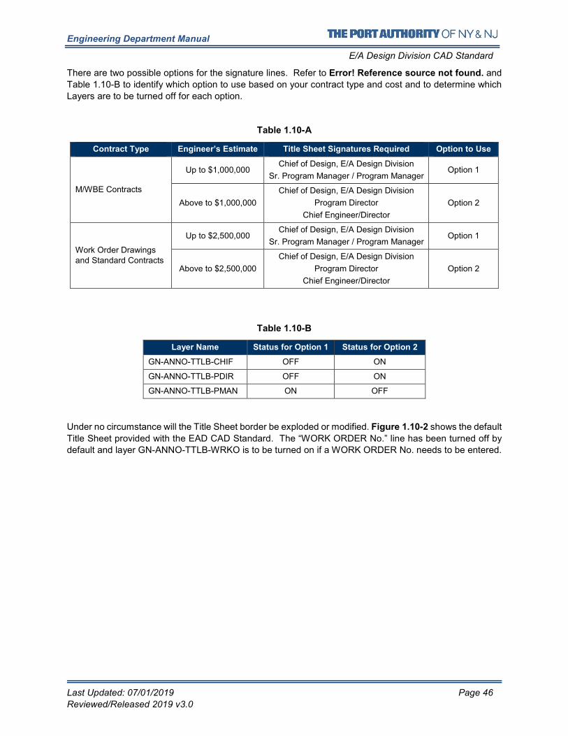
Engineering Department Manual
E/A Design Division CAD Standard
Last Updated: 07/01/2019 Page 46
Reviewed/Released 2019 v3.0
There are two possible options for the signature lines. Refer to Error! Reference source not found. and
Table 1.10-B to identify which option to use based on your contract type and cost and to determine which
Layers are to be turned off for each option.
Table 1.10-A
Contract Type Engineer’s Estimate Title Sheet Signatures Required Option to Use
M/WBE Contracts
Up to $1,000,000 Chief of Design, E/A Design Division
Sr. Program Manager / Program Manager Option 1
Above to $1,000,000
Chief of Design, E/A Design Division
Program Director
Chief Engineer/Director
Option 2
Work Order Drawings
and Standard Contracts
Up to $2,500,000 Chief of Design, E/A Design Division
Sr. Program Manager / Program Manager Option 1
Above to $2,500,000
Chief of Design, E/A Design Division
Program Director
Chief Engineer/Director
Option 2
Table 1.10-B
Layer Name Status for Option 1 Status for Option 2
GN-ANNO-TTLB-CHIF OFF ON
GN-ANNO-TTLB-PDIR OFF ON
GN-ANNO-TTLB-PMAN ON OFF
Under no circumstance will the Title Sheet border be exploded or modified. Figure 1.10-2 shows the default
Title Sheet provided with the EAD CAD Standard. The “WORK ORDER No.” line has been turned off by
default and layer GN-ANNO-TTLB-WRKO is to be turned on if a WORK ORDER No. needs to be entered.
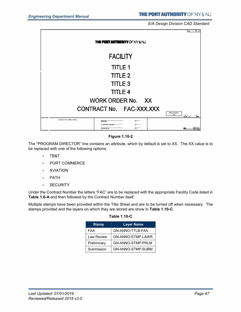
Engineering Department Manual
E/A Design Division CAD Standard
Last Updated: 07/01/2019 Page 47
Reviewed/Released 2019 v3.0
Figure 1.10-2
The “PROGRAM DIRECTOR” line contains an attribute, which by default is set to XX. The XX value is to
be replaced with one of the following options:
• TB&T
• PORT COMMERCE
• AVIATION
• PATH
• SECURITY
Under the Contract Number the letters “FAC” are to be replaced with the appropriate Facility Code listed in Table 1.6-A and then followed by the Contract Number itself.
Multiple stamps have been provided within the Title Sheet and are to be turned off when necessary. The stamps provided and the layers on which they are stored are show in Table 1.10-C.
Table 1.10-C
Stamp Layer Name
FAA GN-ANNO-TTLB-FAA
Law Review GN-ANNO-STMP-LAWR
Preliminary GN-ANNO-STMP-PRLM
Submission GN-ANNO-STMP-SUBM
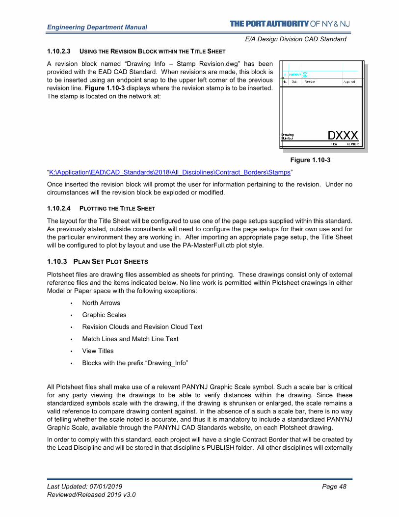
Engineering Department Manual
E/A Design Division CAD Standard
Last Updated: 07/01/2019 Page 48
Reviewed/Released 2019 v3.0
1.10.2.3 USING THE REVISION BLOCK WITHIN THE TITLE SHEET
A revision block named “Drawing_Info – Stamp_Revision.dwg” has been
provided with the EAD CAD Standard. When revisions are made, this block is
to be inserted using an endpoint snap to the upper left corner of the previous revision line. Figure 1.10-3 displays where the revision stamp is to be inserted.
The stamp is located on the network at:
“K:\Application\EAD\CAD_Standards\2018\All_Disciplines\Contract_Borders\Stamps”
Once inserted the revision block will prompt the user for information pertaining to the revision. Under no
circumstances will the revision block be exploded or modified.
1.10.2.4 PLOTTING THE TITLE SHEET
The layout for the Title Sheet will be configured to use one of the page setups supplied within this standard.
As previously stated, outside consultants will need to configure the page setups for their own use and for
the particular environment they are working in. After importing an appropriate page setup, the Title Sheet
will be configured to plot by layout and use the PA-MasterFull.ctb plot style.
1.10.3 PLAN SET PLOT SHEETS
Plotsheet files are drawing files assembled as sheets for printing. These drawings consist only of external
reference files and the items indicated below. No line work is permitted within Plotsheet drawings in either
Model or Paper space with the following exceptions:
• North Arrows
• Graphic Scales
• Revision Clouds and Revision Cloud Text
• Match Lines and Match Line Text
• View Titles
• Blocks with the prefix “Drawing_Info”
All Plotsheet files shall make use of a relevant PANYNJ Graphic Scale symbol. Such a scale bar is critical
for any party viewing the drawings to be able to verify distances within the drawing. Since these
standardized symbols scale with the drawing, if the drawing is shrunken or enlarged, the scale remains a
valid reference to compare drawing content against. In the absence of a such a scale bar, there is no way
of telling whether the scale noted is accurate, and thus it is mandatory to include a standardized PANYNJ
Graphic Scale, available through the PANYNJ CAD Standards website, on each Plotsheet drawing.
In order to comply with this standard, each project will have a single Contract Border that will be created by
the Lead Discipline and will be stored in that discipline’s PUBLISH folder. All other disciplines will externally
Figure 1.10-3
Engineering Department Manual
E/A Design Division CAD Standard
Last Updated: 07/01/2019 Page 49
Reviewed/Released 2019 v3.0
reference the border from the Lead Discipline’s PUBLISH folder. This border will contain all information
pertinent to the project itself. Once the Contract Border is properly referenced into each sheet the
appropriate “Drawing_Information” block is to be inserted into each layout tab. The Drawing_Information
block will contain all drawing specific information. Illustrations of the Contract Borders provided can be found in 1.25 Appendix K – Contract Borders and Title Sheets.
Outside consultants are required to reproduce the folder structure as specified in 1.6 Project Directory
Structure and File Naming Convention by copying the Sample Project and replacing the Facility name
and PID with those of the current project. All backgrounds (including the Contract Border) provided by the
E/A Design Division will go into their respective discipline folders.
1.10.3.1 CONFIGURING THE CONTRACT BORDER
To create the project border, open the “Contract_Border.dwg” file provided with this standard fill in all
attribute information requested and save it to your discipline’s PUBLISH folder with the name following the
format described in 1.6.5.2 Contract Border File.
As with the Title Sheet, the “WORK ORDER No.” line has been turned off by default and layer GN-ANNO-
TTLB-WRKO is to be turned on if a WORK ORDER No. needs to be entered.
For a listing of Contract Border files that have been provided with this standard refer to 1.26 Appendix K –
Distribution Files.
1.10.3.2 REFERENCING THE CONTRACT BORDER
To create a Plotsheet file, begin by externally referencing the Contract Border that was configured in the
previous section. The border is to be referenced into a paper space layout, that has been configured
following the steps outlined in 1.9 Plot Setup, with an insertion point of 0,0. Under no circumstances will
the contract border be exploded, renamed or modified.
1.10.3.3 INSERTING THE DRAWING INFORMATION
Once the Contract Border has been externally referenced the “Drawing_Info.dwg” block will need to be
inserted. This block will be inserted with an insertion point of 0,0 and all attribute information is to be filled
out.
The “Drawing_Info.dwg” block contains a pair of lines that state “Original Signed By” and “Original Signee”.
These lines of text are stored on the layer GN-ANNO-TTLB-SIGN, which by default is turned off. The
“Original_Signee” attribute field is to be filled in using the name of the person that signed the drawings. The
layer this information is to be turned on when PDF files are created for any Stage of the drawings beyond
signature. Figure 1.10-4 and Figure 1.10-5 display this text OFF and ON. Note, this attribute is only
required for internal use and outside consultants need not turn on this layer. For information on the correct
process for outside consultants refer to Using the Signature Stamps titled Using the Signature Stamps.

Engineering Department Manual
E/A Design Division CAD Standard
Last Updated: 07/01/2019 Page 50
Reviewed/Released 2019 v3.0
Figure 1.10-4
Figure 1.10-5
When entering the “Discipline Group” and “Discipline Sub-Group” attribute fields users will need to refer to
Table 1.10-D for the proper values to be used within these fields.
Table 1.10-D
Discipline Group Discipline Sub-Group
Architecture
Landscape
Civil
Electrical
Power
Electronics
Corrosion Protection
Environmental
General
Construction Staging
Geotechnical
Mechanical
Fire Protection
HVAC
Plumbing
Structural
Traffic
To promote consistency and easy identification of the people involved in the project the Designed By, Drawn
By and Checked By attribute fields are to be filled out using the first initial, followed by a period and then
the first ten characters of the last name. Note that spaces before or after the period are not permitted.
For Example:
Filippo Brunelleschi would fill out the field as F.Brunellesc, truncating the last name at ten characters.
Editing the Contract Border
The process used to create Contract Borders allows for flexibility in editing and updating information both
at the project level as well as at the drawing level. If a project level change is required, then the PID-
CB.dwg file can be opened and modified and if a drawing level change is required then the individual
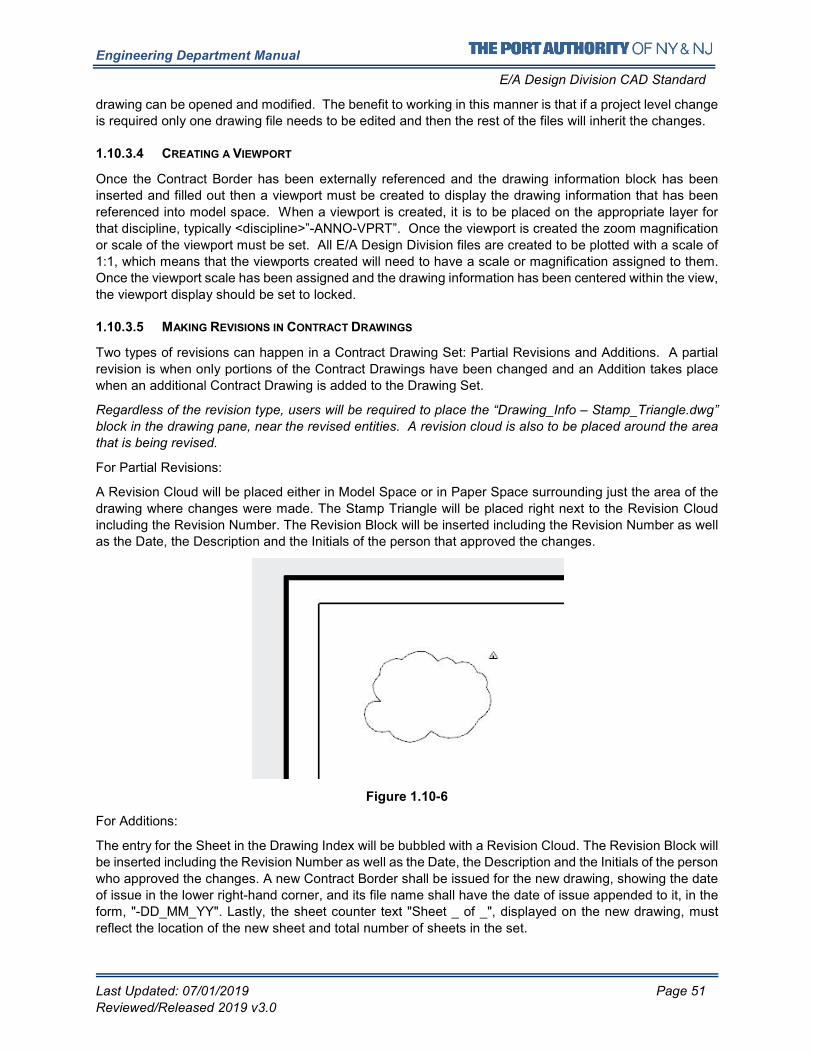
Engineering Department Manual
E/A Design Division CAD Standard
Last Updated: 07/01/2019 Page 51
Reviewed/Released 2019 v3.0
drawing can be opened and modified. The benefit to working in this manner is that if a project level change
is required only one drawing file needs to be edited and then the rest of the files will inherit the changes.
1.10.3.4 CREATING A VIEWPORT
Once the Contract Border has been externally referenced and the drawing information block has been
inserted and filled out then a viewport must be created to display the drawing information that has been
referenced into model space. When a viewport is created, it is to be placed on the appropriate layer for
that discipline, typically <discipline>”-ANNO-VPRT”. Once the viewport is created the zoom magnification
or scale of the viewport must be set. All E/A Design Division files are created to be plotted with a scale of
1:1, which means that the viewports created will need to have a scale or magnification assigned to them.
Once the viewport scale has been assigned and the drawing information has been centered within the view,
the viewport display should be set to locked.
1.10.3.5 MAKING REVISIONS IN CONTRACT DRAWINGS
Two types of revisions can happen in a Contract Drawing Set: Partial Revisions and Additions. A partial
revision is when only portions of the Contract Drawings have been changed and an Addition takes place
when an additional Contract Drawing is added to the Drawing Set.
Regardless of the revision type, users will be required to place the “Drawing_Info – Stamp_Triangle.dwg”
block in the drawing pane, near the revised entities. A revision cloud is also to be placed around the area
that is being revised.
For Partial Revisions:
A Revision Cloud will be placed either in Model Space or in Paper Space surrounding just the area of the
drawing where changes were made. The Stamp Triangle will be placed right next to the Revision Cloud
including the Revision Number. The Revision Block will be inserted including the Revision Number as well
as the Date, the Description and the Initials of the person that approved the changes.
Figure 1.10-6
For Additions:
The entry for the Sheet in the Drawing Index will be bubbled with a Revision Cloud. The Revision Block will
be inserted including the Revision Number as well as the Date, the Description and the Initials of the person
who approved the changes. A new Contract Border shall be issued for the new drawing, showing the date
of issue in the lower right-hand corner, and its file name shall have the date of issue appended to it, in the
form, "-DD_MM_YY". Lastly, the sheet counter text "Sheet _ of _", displayed on the new drawing, must
reflect the location of the new sheet and total number of sheets in the set.
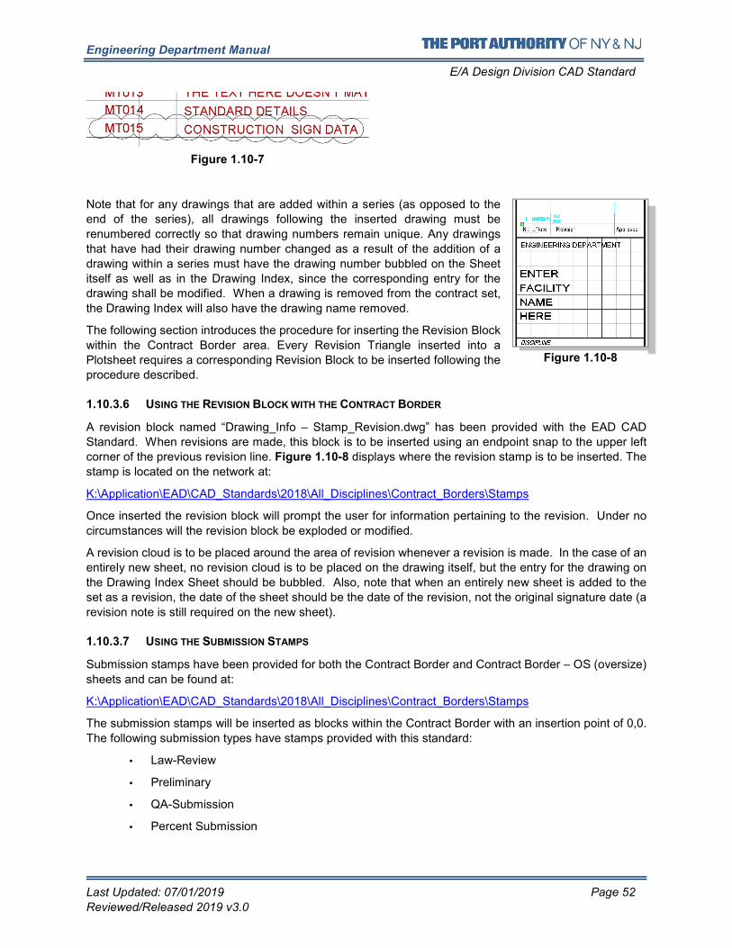
Engineering Department Manual
E/A Design Division CAD Standard
Last Updated: 07/01/2019 Page 52
Reviewed/Released 2019 v3.0
Note that for any drawings that are added within a series (as opposed to the
end of the series), all drawings following the inserted drawing must be
renumbered correctly so that drawing numbers remain unique. Any drawings
that have had their drawing number changed as a result of the addition of a
drawing within a series must have the drawing number bubbled on the Sheet
itself as well as in the Drawing Index, since the corresponding entry for the
drawing shall be modified. When a drawing is removed from the contract set,
the Drawing Index will also have the drawing name removed.
The following section introduces the procedure for inserting the Revision Block
within the Contract Border area. Every Revision Triangle inserted into a
Plotsheet requires a corresponding Revision Block to be inserted following the
procedure described.
1.10.3.6 USING THE REVISION BLOCK WITH THE CONTRACT BORDER
A revision block named “Drawing_Info – Stamp_Revision.dwg” has been provided with the EAD CAD
Standard. When revisions are made, this block is to be inserted using an endpoint snap to the upper left
corner of the previous revision line. Figure 1.10-8 displays where the revision stamp is to be inserted. The
stamp is located on the network at:
K:\Application\EAD\CAD_Standards\2018\All_Disciplines\Contract_Borders\Stamps
Once inserted the revision block will prompt the user for information pertaining to the revision. Under no
circumstances will the revision block be exploded or modified.
A revision cloud is to be placed around the area of revision whenever a revision is made. In the case of an
entirely new sheet, no revision cloud is to be placed on the drawing itself, but the entry for the drawing on
the Drawing Index Sheet should be bubbled. Also, note that when an entirely new sheet is added to the
set as a revision, the date of the sheet should be the date of the revision, not the original signature date (a
revision note is still required on the new sheet).
1.10.3.7 USING THE SUBMISSION STAMPS
Submission stamps have been provided for both the Contract Border and Contract Border – OS (oversize)
sheets and can be found at:
K:\Application\EAD\CAD_Standards\2018\All_Disciplines\Contract_Borders\Stamps
The submission stamps will be inserted as blocks within the Contract Border with an insertion point of 0,0.
The following submission types have stamps provided with this standard:
• Law-Review
• Preliminary
• QA-Submission
• Percent Submission
Figure 1.10-7
Figure 1.10-8
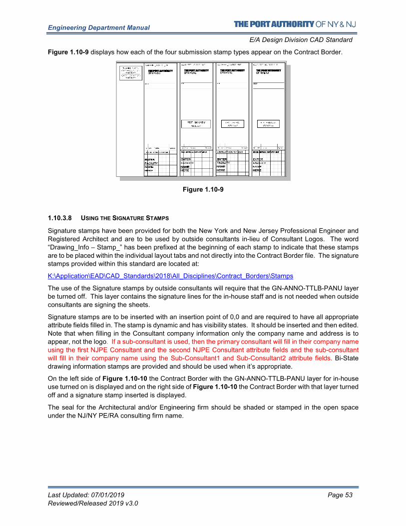
Engineering Department Manual
E/A Design Division CAD Standard
Last Updated: 07/01/2019 Page 53
Reviewed/Released 2019 v3.0
Figure 1.10-9 displays how each of the four submission stamp types appear on the Contract Border.
Figure 1.10-9
1.10.3.8 USING THE SIGNATURE STAMPS
Signature stamps have been provided for both the New York and New Jersey Professional Engineer and
Registered Architect and are to be used by outside consultants in-lieu of Consultant Logos. The word
“Drawing_Info – Stamp_” has been prefixed at the beginning of each stamp to indicate that these stamps
are to be placed within the individual layout tabs and not directly into the Contract Border file. The signature
stamps provided within this standard are located at:
K:\Application\EAD\CAD_Standards\2018\All_Disciplines\Contract_Borders\Stamps
The use of the Signature stamps by outside consultants will require that the GN-ANNO-TTLB-PANU layer
be turned off. This layer contains the signature lines for the in-house staff and is not needed when outside
consultants are signing the sheets.
Signature stamps are to be inserted with an insertion point of 0,0 and are required to have all appropriate
attribute fields filled in. The stamp is dynamic and has visibility states. It should be inserted and then edited.
Note that when filling in the Consultant company information only the company name and address is to
appear, not the logo. If a sub-consultant is used, then the primary consultant will fill in their company name
using the first NJPE Consultant and the second NJPE Consultant attribute fields and the sub-consultant
will fill in their company name using the Sub-Consultant1 and Sub-Consultant2 attribute fields. Bi-State
drawing information stamps are provided and should be used when it’s appropriate.
On the left side of Figure 1.10-10 the Contract Border with the GN-ANNO-TTLB-PANU layer for in-house
use turned on is displayed and on the right side of Figure 1.10-10 the Contract Border with that layer turned
off and a signature stamp inserted is displayed.
The seal for the Architectural and/or Engineering firm should be shaded or stamped in the open space
under the NJ/NY PE/RA consulting firm name.
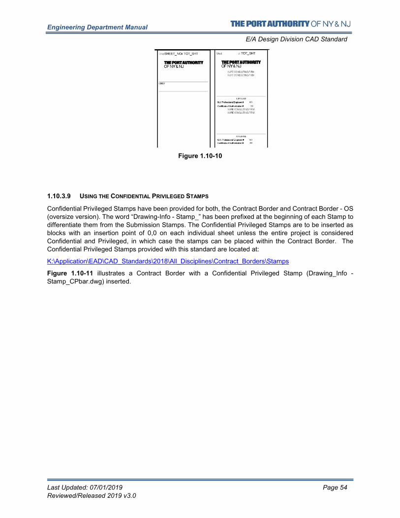
Engineering Department Manual
E/A Design Division CAD Standard
Last Updated: 07/01/2019 Page 54
Reviewed/Released 2019 v3.0
Figure 1.10-10
1.10.3.9 USING THE CONFIDENTIAL PRIVILEGED STAMPS
Confidential Privileged Stamps have been provided for both, the Contract Border and Contract Border - OS
(oversize version). The word “Drawing-Info - Stamp_” has been prefixed at the beginning of each Stamp to
differentiate them from the Submission Stamps. The Confidential Privileged Stamps are to be inserted as
blocks with an insertion point of 0,0 on each individual sheet unless the entire project is considered
Confidential and Privileged, in which case the stamps can be placed within the Contract Border. The
Confidential Privileged Stamps provided with this standard are located at:
K:\Application\EAD\CAD_Standards\2018\All_Disciplines\Contract_Borders\Stamps
Figure 1.10-11 illustrates a Contract Border with a Confidential Privileged Stamp (Drawing_Info -
Stamp_CPbar.dwg) inserted.
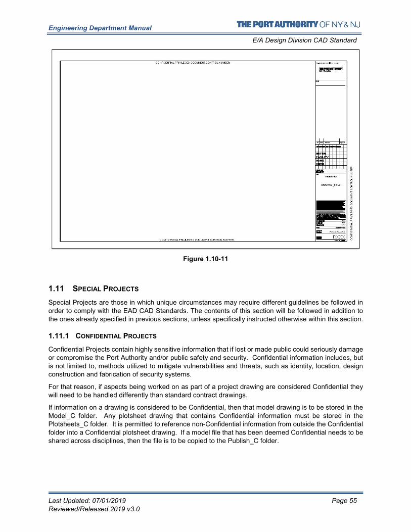
Engineering Department Manual
E/A Design Division CAD Standard
Last Updated: 07/01/2019 Page 55
Reviewed/Released 2019 v3.0
Figure 1.10-11
1.11 SPECIAL PROJECTS
Special Projects are those in which unique circumstances may require different guidelines be followed in
order to comply with the EAD CAD Standards. The contents of this section will be followed in addition to
the ones already specified in previous sections, unless specifically instructed otherwise within this section.
1.11.1 CONFIDENTIAL PROJECTS
Confidential Projects contain highly sensitive information that if lost or made public could seriously damage
or compromise the Port Authority and/or public safety and security. Confidential information includes, but
is not limited to, methods utilized to mitigate vulnerabilities and threats, such as identity, location, design
construction and fabrication of security systems.
For that reason, if aspects being worked on as part of a project drawing are considered Confidential they
will need to be handled differently than standard contract drawings.
If information on a drawing is considered to be Confidential, then that model drawing is to be stored in the
Model_C folder. Any plotsheet drawing that contains Confidential information must be stored in the
Plotsheets_C folder. It is permitted to reference non-Confidential information from outside the Confidential
folder into a Confidential plotsheet drawing. If a model file that has been deemed Confidential needs to be
shared across disciplines, then the file is to be copied to the Publish_C folder.
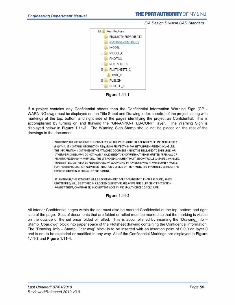
Engineering Department Manual
E/A Design Division CAD Standard
Last Updated: 07/01/2019 Page 56
Reviewed/Released 2019 v3.0
Figure 1.11-1
If a project contains any Confidential sheets then the Confidential Information Warning Sign (CP -
WARNING.dwg) must be displayed on the Title Sheet and Drawing Index sheet(s) of the project, along with
markings at the top, bottom and right side of the pages identifying the project as Confidential. This is
accomplished by turning on and thawing the “GN-ANNO-TTLB-CONF” layer. The Warning Sign is displayed below in Figure 1.11-2. The Warning Sign Stamp should not be placed on the rest of the
drawings in the document.
Figure 1.11-2
All interior Confidential pages within the set must also be marked Confidential at the top, bottom and right
side of the page. Sets of documents that are folded or rolled must be marked so that the marking is visible
on the outside of the set once folded or rolled. This is accomplished by inserting the “Drawing_Info –
Stamp_Cbar.dwg” block into paper space of the Plotsheet drawing containing the Confidential information.
The “Drawing_Info – Stamp_Cbar.dwg” block is to be inserted with an insertion point of 0,0,0 on layer 0
and is not to be exploded or modified in any way. All of the Confidential Markings are displayed in Figure
1.11-3 and Figure 1.11-4.
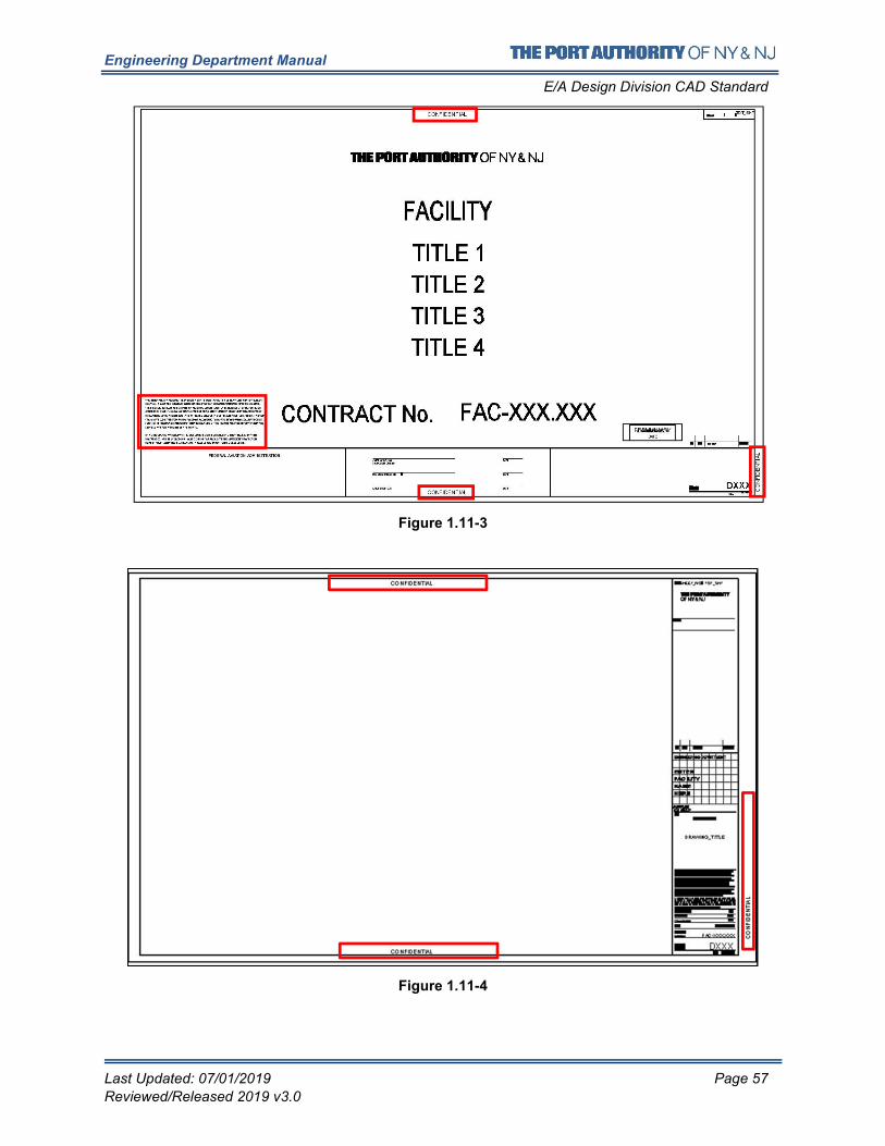
Engineering Department Manual
E/A Design Division CAD Standard
Last Updated: 07/01/2019 Page 57
Reviewed/Released 2019 v3.0
Figure 1.11-3
Figure 1.11-4
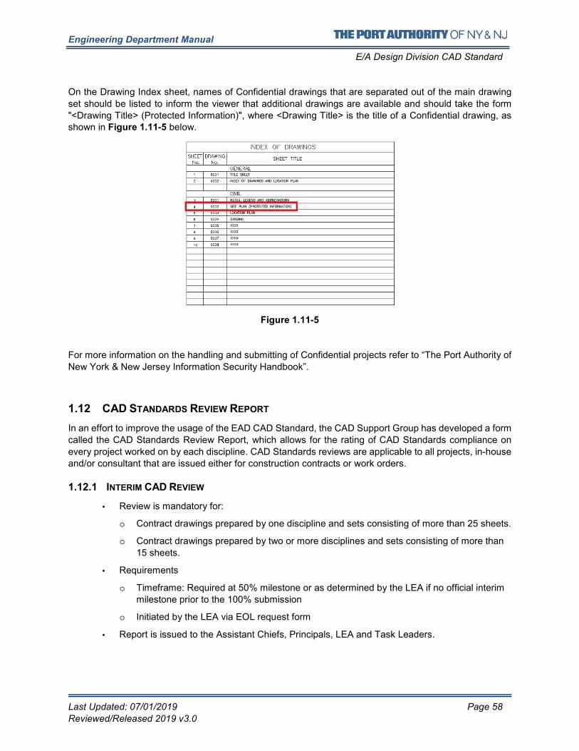
Engineering Department Manual
E/A Design Division CAD Standard
Last Updated: 07/01/2019 Page 58
Reviewed/Released 2019 v3.0
On the Drawing Index sheet, names of Confidential drawings that are separated out of the main drawing
set should be listed to inform the viewer that additional drawings are available and should take the form
"<Drawing Title> (Protected Information)", where <Drawing Title> is the title of a Confidential drawing, as shown in Figure 1.11-5 below.
Figure 1.11-5
For more information on the handling and submitting of Confidential projects refer to “The Port Authority of
New York & New Jersey Information Security Handbook”.
1.12 CAD STANDARDS REVIEW REPORT
In an effort to improve the usage of the EAD CAD Standard, the CAD Support Group has developed a form
called the CAD Standards Review Report, which allows for the rating of CAD Standards compliance on
every project worked on by each discipline. CAD Standards reviews are applicable to all projects, in-house
and/or consultant that are issued either for construction contracts or work orders.
1.12.1 INTERIM CAD REVIEW
• Review is mandatory for:
o Contract drawings prepared by one discipline and sets consisting of more than 25 sheets.
o Contract drawings prepared by two or more disciplines and sets consisting of more than
15 sheets.
• Requirements
o Timeframe: Required at 50% milestone or as determined by the LEA if no official interim
milestone prior to the 100% submission
o Initiated by the LEA via EOL request form
• Report is issued to the Assistant Chiefs, Principals, LEA and Task Leaders.
Engineering Department Manual
E/A Design Division CAD Standard
Last Updated: 07/01/2019 Page 59
Reviewed/Released 2019 v3.0
1.12.2 CONSTRUCTION CONTRACT PA WIDE CAD REVIEW
• Review is mandatory for all Contract Drawings
o Initial failures are issued to the LEA and Task Leaders
• 3 weeks are provided for the correction of the files
o At the end of the 3-week period a Report is issued to the Assistant Chiefs, Principals,
LEA and Task Leaders
o During the PA Wide Review drawings will be analyzed and a FINAL pass/fail Report will
be issued.
• Drawings will not be reviewed after the PA Wide Review period.
• Requirements
o Timeframe: Required at the on-set of PA Wide Review
o Initiated by the LEA via EOL request form
• Upon receipt of the request the CAD Support Group is to upload the files to Live Link
for electronic review and notify the Contract Engineer of the initiation of PA Wide
Review.
• Final Report is issued the Assistant Chiefs, Principals, LEA and Task Leaders
1.12.3 WORK ORDER CAD REVIEW
• Review is mandatory for:
o Mandatory for all Contract Drawings.
o Initial failures are issued to the LEA and Task Leaders
• 3 weeks are provided for the correction of the files
o At the end of the 3 weeks a Report is issued to the Assistant Chiefs, Principals, LEA and
Task Leaders
• Requirements
o Initiated by the LEA via EOL request form
• Report is issued to the Assistant Chiefs, Principals, LEA and Task Leaders at the end of the 3-
week period.
Engineering Department Manual
E/A Design Division CAD Standard
Last Updated: 07/01/2019 Page 60
Reviewed/Released 2019 v3.0
The CAD Standards Review Report is divided into 3 section; the first section contains all the Mandatory
Fields for which compliance with EAD CAD Standards is required in order for the project to pass, the second
section contains all the Non-Mandatory Fields followed by a third section that includes notes and comments
pertaining to the review. Items included within this Report are:
• File Availability, Filename and Folder Structure
o Project drawings, PDF’s and files referenced within them must be named according to the
EAD CAD Standard and must be located within the sub-folders defined in this standard.
• Plan Set Preparation
o The Discipline/Sub-Group must be included. All External Referenced files and\or images
shall be contained within the PID Folder Structure. The Title Sheet, Contract Border and
Drawing Information block along with the Professional Stamps provided within the EAD
CAD Standard shall be used without any modifications and/or alterations.
• CAD Practice
o The layers provided within the EAD CAD Standard must be used in all drawing files. These
layers are pre-configured to work in conjunction with each discipline’s pen settings (CTB).
All External Referenced files and\or images shall be set as “Overlay” and “Relative
Pathing”. Note: Existing Background layers are not reviewed.
• Plot Setup
o Drawings must be prepared using the PA-MasterFull.ctb file (pen settings). This will ensure
consistency of plotting drawings from any workstation within Engineering.
• Submittals Information
o PDF files are required at each submittal. They are to be created in full size, multi-sheet and
grouped together by Plotsheet Type and Series (if used).
• Civil 3D Objects Files (Civil Only)
Surfaces, alignments and profiles should be, but is not limited to, referenced into civil
design files with data shortcuts. The Civil 3D Data shortcut folder must be available for
archiving and located within the Model Folder. Data Shortcuts are essential for linking data
to drawing objects. Port Authority surfaces must be created with data collected and
approved by the Port Authority. Points and or contours should be imported and used with
the proper surface guidelines and the CAD standard naming scheme should be applied.
Alignments provided to the Port Authority should use the Port Authority approved styles.
Alignments should not be polylines representing alignments and must contain features
related to this object. Profiles should be created using the Port Authority issued styles.
When Alignments are used profiles should also be provided. Profiles are not applicable
yet.
This form will be reviewed on a regular basis and is subject to changes. If a change is approved, it
will be posted on the E/A Design Division CAD Standard website http://www.panynj.gov/business-
opportunities/engineering-documents-bim-cad-standards.html and incorporated into the next
revision of this document.
The following two pages illustrate the first two sections of the CAD Standards Review Report and
are to be used as a checklist for checking CAD Standard compliance prior to submitting drawings. (See Figure 1.12-1 and Figure 1.12-2)
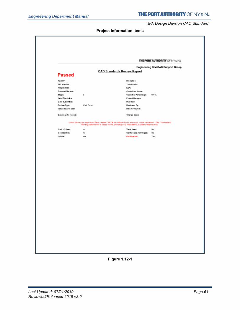
Engineering Department Manual
E/A Design Division CAD Standard
Last Updated: 07/01/2019 Page 61
Reviewed/Released 2019 v3.0
Project information Items
Figure 1.12-1
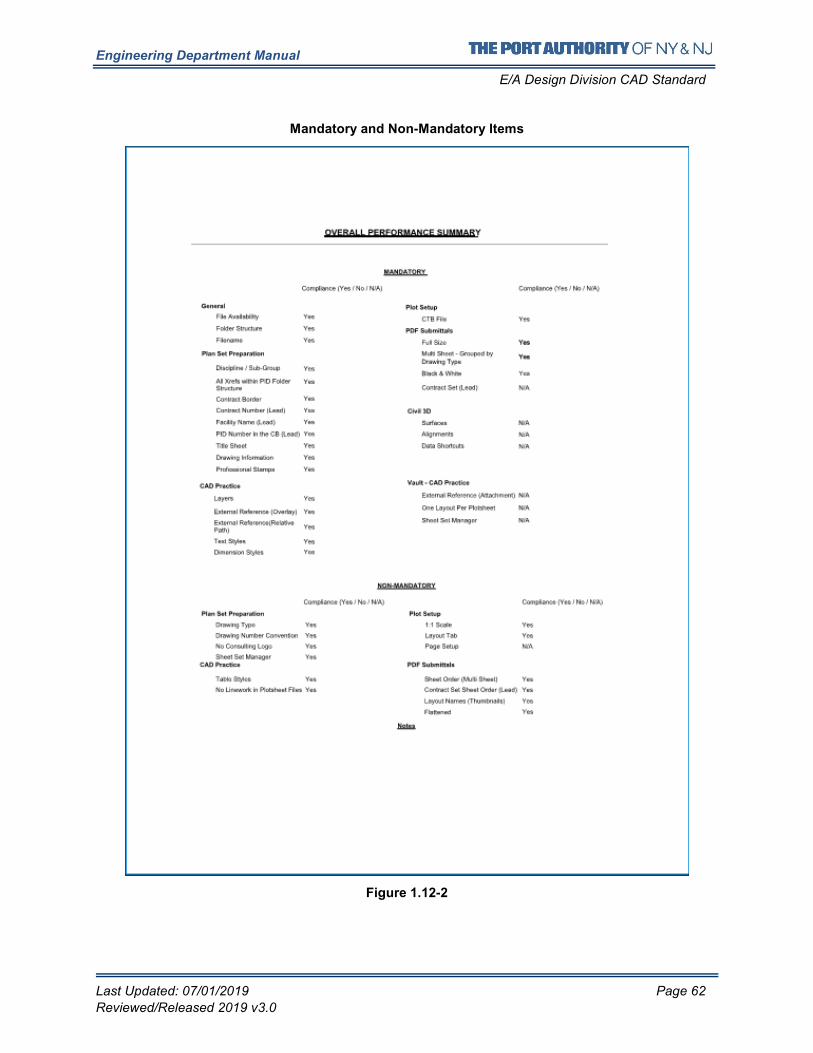
Engineering Department Manual
E/A Design Division CAD Standard
Last Updated: 07/01/2019 Page 62
Reviewed/Released 2019 v3.0
Mandatory and Non-Mandatory Items
Figure 1.12-2
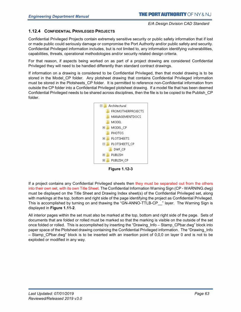
Engineering Department Manual
E/A Design Division CAD Standard
Last Updated: 07/01/2019 Page 63
Reviewed/Released 2019 v3.0
1.12.4 CONFIDENTIAL PRIVILEGED PROJECTS
Confidential Privileged Projects contain extremely sensitive security or public safety information that if lost
or made public could seriously damage or compromise the Port Authority and/or public safety and security.
Confidential Privileged information includes, but is not limited to, any information identifying vulnerabilities,
capabilities, threats, operational methodologies and/or security related design criteria.
For that reason, if aspects being worked on as part of a project drawing are considered Confidential
Privileged they will need to be handled differently than standard contract drawings.
If information on a drawing is considered to be Confidential Privileged, then that model drawing is to be
stored in the Model_CP folder. Any plotsheet drawing that contains Confidential Privileged information
must be stored in the Plotsheets_CP folder. It is permitted to reference non-Confidential information from
outside the CP folder into a Confidential Privileged plotsheet drawing. If a model file that has been deemed
Confidential Privileged needs to be shared across disciplines, then the file is to be copied to the Publish_CP
folder.
Figure 1.12-3
If a project contains any Confidential Privileged sheets then they must be separated out from the others
into their own set, with its own Title Sheet. The Confidential Information Warning Sign (CP - WARNING.dwg)
must be displayed on the Title Sheet and Drawing Index sheet(s) of the Confidential Privileged set, along
with markings at the top, bottom and right side of the page identifying the project as Confidential Privileged.
This is accomplished by turning on and thawing the “GN-ANNO-TTLB-CP__” layer. The Warning Sign is displayed in Figure 1.11-2.
All interior pages within the set must also be marked at the top, bottom and right side of the page. Sets of
documents that are folded or rolled must be marked so that the marking is visible on the outside of the set
once folded or rolled. This is accomplished by inserting the “Drawing_Info – Stamp_CPbar.dwg” block into
paper space of the Plotsheet drawing containing the Confidential Privileged information. The “Drawing_Info
– Stamp_CPbar.dwg” block is to be inserted with an insertion point of 0,0,0 on layer 0 and is not to be
exploded or modified in any way.
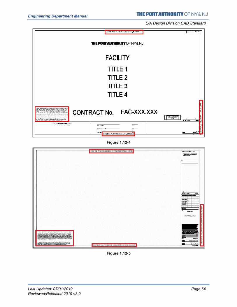
Engineering Department Manual
E/A Design Division CAD Standard
Last Updated: 07/01/2019 Page 64
Reviewed/Released 2019 v3.0
Figure 1.12-4
Figure 1.12-5
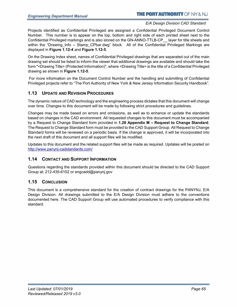
Engineering Department Manual
E/A Design Division CAD Standard
Last Updated: 07/01/2019 Page 65
Reviewed/Released 2019 v3.0
Projects identified as Confidential Privileged are assigned a Confidential Privileged Document Control
Number. This number is to appear on the top, bottom and right side of each printed sheet next to the
Confidential Privileged markings and is also stored on the GN-ANNO-TTLB-CP__ layer for title sheets and
within the “Drawing_Info – Stamp_CPbar.dwg” block. All of the Confidential Privileged Markings are displayed in Figure 1.12-4 and Figure 1.12-5.
On the Drawing Index sheet, names of Confidential Privileged drawings that are separated out of the main
drawing set should be listed to inform the viewer that additional drawings are available and should take the
form "<Drawing Title> (Protected Information)", where <Drawing Title> is the title of a Confidential Privileged drawing as shown in Figure 1.12-5.
For more information on the Document Control Number and the handling and submitting of Confidential
Privileged projects refer to “The Port Authority of New York & New Jersey Information Security Handbook”.
1.13 UPDATE AND REVISION PROCEDURES
The dynamic nature of CAD technology and the engineering process dictates that this document will change
over time. Changes to this document will be made by following strict procedures and guidelines.
Changes may be made based on errors and omissions, as well as to enhance or update the standards
based on changes in the CAD environment. All requested changes to this document must be accompanied by a Request to Change Standard form provided in 1.28 Appendix M – Request to Change Standard.
The Request to Change Standard form must be provided to the CAD Support Group. All Request to Change
Standard forms will be reviewed on a periodic basis. If the change is approved, it will be incorporated into
the next draft of this document and all support files will be modified.
Updates to this document and the related support files will be made as required. Updates will be posted on
http://www.panynj-cadstandards.com/
1.14 CONTACT AND SUPPORT INFORMATION
Questions regarding the standards provided within this document should be directed to the CAD Support
Group at: 212-435-6102 or [email protected]
1.15 CONCLUSION
This document is a comprehensive standard for the creation of contract drawings for the PANYNJ, E/A
Design Division. All drawings submitted to the E/A Design Division must adhere to the conventions
documented here. The CAD Support Group will use automated procedures to verify compliance with this
standard.
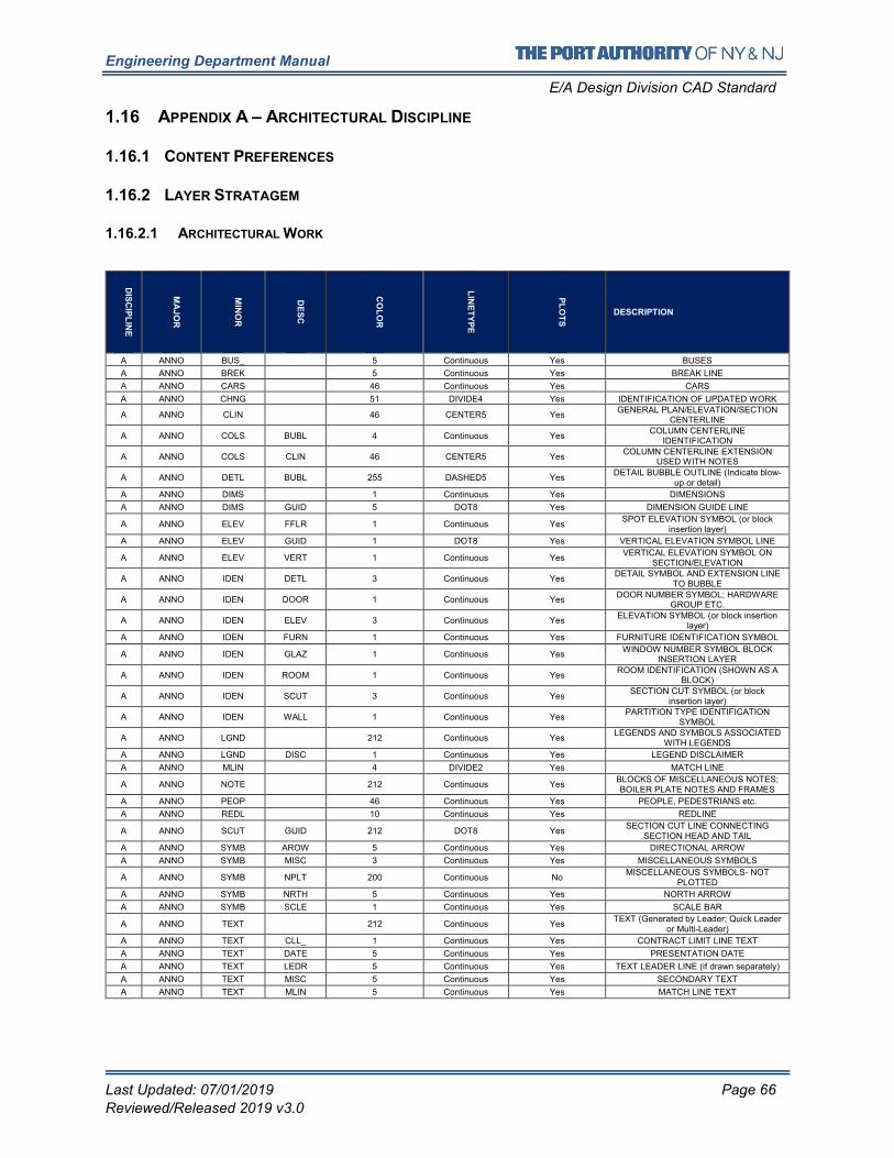
Engineering Department Manual
E/A Design Division CAD Standard
Last Updated: 07/01/2019 Page 66
Reviewed/Released 2019 v3.0
1.16 APPENDIX A – ARCHITECTURAL DISCIPLINE
1.16.1 CONTENT PREFERENCES
1.16.2 LAYER STRATAGEM
1.16.2.1 ARCHITECTURAL WORK
DIS
CIP
LIN
E
MA
JO
R
MIN
OR
DE
SC
CO
LO
R
LIN
ET
YP
E
PL
OT
S
DESCRIPTION
A ANNO BUS_ 5 Continuous Yes BUSES
A ANNO BREK 5 Continuous Yes BREAK LINE
A ANNO CARS 46 Continuous Yes CARS
A ANNO CHNG 51 DIVIDE4 Yes IDENTIFICATION OF UPDATED WORK
A ANNO CLIN 46 CENTER5 Yes GENERAL PLAN/ELEVATION/SECTION
CENTERLINE
A ANNO COLS BUBL 4 Continuous Yes COLUMN CENTERLINE
IDENTIFICATION
A ANNO COLS CLIN 46 CENTER5 Yes COLUMN CENTERLINE EXTENSION
USED WITH NOTES
A ANNO DETL BUBL 255 DASHED5 Yes DETAIL BUBBLE OUTLINE (Indicate blow-
up or detail)
A ANNO DIMS 1 Continuous Yes DIMENSIONS
A ANNO DIMS GUID 5 DOT8 Yes DIMENSION GUIDE LINE
A ANNO ELEV FFLR 1 Continuous Yes SPOT ELEVATION SYMBOL (or block
insertion layer)
A ANNO ELEV GUID 1 DOT8 Yes VERTICAL ELEVATION SYMBOL LINE
A ANNO ELEV VERT 1 Continuous Yes VERTICAL ELEVATION SYMBOL ON
SECTION/ELEVATION
A ANNO IDEN DETL 3 Continuous Yes DETAIL SYMBOL AND EXTENSION LINE
TO BUBBLE
A ANNO IDEN DOOR 1 Continuous Yes DOOR NUMBER SYMBOL; HARDWARE
GROUP ETC.
A ANNO IDEN ELEV 3 Continuous Yes ELEVATION SYMBOL (or block insertion
layer)
A ANNO IDEN FURN 1 Continuous Yes FURNITURE IDENTIFICATION SYMBOL
A ANNO IDEN GLAZ 1 Continuous Yes WINDOW NUMBER SYMBOL BLOCK
INSERTION LAYER
A ANNO IDEN ROOM 1 Continuous Yes ROOM IDENTIFICATION (SHOWN AS A
BLOCK)
A ANNO IDEN SCUT 3 Continuous Yes SECTION CUT SYMBOL (or block
insertion layer)
A ANNO IDEN WALL 1 Continuous Yes PARTITION TYPE IDENTIFICATION
SYMBOL
A ANNO LGND 212 Continuous Yes LEGENDS AND SYMBOLS ASSOCIATED
WITH LEGENDS
A ANNO LGND DISC 1 Continuous Yes LEGEND DISCLAIMER
A ANNO MLIN 4 DIVIDE2 Yes MATCH LINE
A ANNO NOTE 212 Continuous Yes BLOCKS OF MISCELLANEOUS NOTES; BOILER PLATE NOTES AND FRAMES
A ANNO PEOP 46 Continuous Yes PEOPLE, PEDESTRIANS etc.
A ANNO REDL 10 Continuous Yes REDLINE
A ANNO SCUT GUID 212 DOT8 Yes SECTION CUT LINE CONNECTING
SECTION HEAD AND TAIL
A ANNO SYMB AROW 5 Continuous Yes DIRECTIONAL ARROW
A ANNO SYMB MISC 3 Continuous Yes MISCELLANEOUS SYMBOLS
A ANNO SYMB NPLT 200 Continuous No MISCELLANEOUS SYMBOLS- NOT
PLOTTED
A ANNO SYMB NRTH 5 Continuous Yes NORTH ARROW
A ANNO SYMB SCLE 1 Continuous Yes SCALE BAR
A ANNO TEXT 212 Continuous Yes TEXT (Generated by Leader; Quick Leader
or Multi-Leader)
A ANNO TEXT CLL_ 1 Continuous Yes CONTRACT LIMIT LINE TEXT
A ANNO TEXT DATE 5 Continuous Yes PRESENTATION DATE
A ANNO TEXT LEDR 5 Continuous Yes TEXT LEADER LINE (if drawn separately)
A ANNO TEXT MISC 5 Continuous Yes SECONDARY TEXT
A ANNO TEXT MLIN 5 Continuous Yes MATCH LINE TEXT
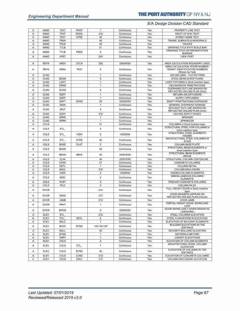
Engineering Department Manual
E/A Design Division CAD Standard
Last Updated: 07/01/2019 Page 67
Reviewed/Released 2019 v3.0
A ANNO TEXT PROP 1 Continuous Yes PROPERTY LINE TEXT
A ANNO TEXT ROWL 212 Continuous Yes RIGHT OF WAY TEXT
A ANNO TEXT STRE 46 Continuous Yes STREET NAME TEXT
A ANNO TRAN 46 Continuous Yes TRAINS, SUBWAYS & MONORAILS
A ANNO TRUK 46 Continuous Yes TRUCKS
A ANNO TTLB 51 Continuous Yes DRAWING TITLE WITH SCALE BAR
A ANNO TTLB PRES 5 Continuous Yes DRAWING TITLE ON PRESENTATION
BORDER
A ANNO VPRT 200 Continuous Yes VIEW PORT
A REFN AREA OTLN 255 DASHED4 Yes AREA CALCULATION BOUNDARY LINES
A REFN AREA TEXT 6 Continuous Yes AREA CALCULATION, ROOM NUMBER, TENANT IDENTIFICATION NUMBERS
(Shown As Text)
A CLNG 1 Continuous Yes CEILING GRID - TILE PATTERN
A CLNG BEAM 5 Continuous Yes STEEL BEAM IN RCP PLANS
A CLNG LGHT 1 Continuous Yes LIGHT FIXTURES or block insertion layer
A CLNG OPNG 1 Continuous Yes CEILING/ROOF PENETRATIONS
A CLNG OVHG 5 Continuous Yes OVERHANG OUT-LINE SHOWN ON REFLECTED CEILING PLAN (Only)
A CLNG RDFF 1 Continuous Yes RETURN AIR DIFFUSERS
A CLNG SDFF 1 Continuous Yes SUPPLY DIFFUSERS
A CLNG SHFT OVHD 46 DASHED5 Yes SHAFT PENETRATIONS OVERHEAD
A CLNG SIGN 1 Continuous Yes GENERAL OVERHEAD SIGNAGE
A CLNG SKLT 5 Continuous Yes SKYLIGHT OUT-LINE SHOWN ON REFLECTED CEILING PLAN (Only)
A CLNG SOFF 212 Continuous Yes CEILING SOFFIT EDGES
A CLNG SPKR 1 Continuous Yes SPEAKER
A CLNG SPRN 1 Continuous Yes SPRINKLER
A COLS 51 Continuous Yes COLUMNS or block insertion layer
A COLS STL_ 3 Continuous Yes STRUCTURAL STEEL FOR COLUMNS or
block insertion layer
A COLS STL_ HIDN 5 HIDDEN4 Yes STRUCTURAL STEEL ELEMENTS
HIDDEN
A COLS STL_ STRS 46 Continuous Yes ARCHITECTURAL STEEL COLUMNS IN
STAIR
A COLS BASE PLAT 5 Continuous Yes COLUMN BASE PLATE
A COLS BEAM 46 Continuous Yes STRUCTURAL BEAM ELEMENTS or
block insertion layer
A COLS BEAM ABVE 46 DASHED5 Yes STRUCTURAL BEAM ELEMENTS
ABOVE
A COLS CLIN 46 CENTER5 Yes STRUCTURAL COLUMN CENTERLINE
A COLS CONC 51 Continuous Yes CONCRETE COLUMNS
A COLS DETL 1 Continuous Yes COLUMN DETAIL
A COLS ENCL 212 Continuous Yes COLUMN ENCLOSURE
A COLS HIDN 5 HIDDEN4 Yes HIDDEN COLUMN ELEMENTS
A COLS MISC 5 Continuous Yes MISCELLANEOUS COLUMNS
ELEMENTS
A COLS PCST 3 Continuous Yes PRECAST CONCRETE COLUMNS
A COLS PILE 5 Continuous Yes COLUMN PILES
A DOOR 212 Continuous Yes FULL HEIGHT DOOR or block insertion
layer
A DOOR HEAD 212 Continuous Yes DOOR HEADERS (APPEAR ON
REFLECTED CEILING PLAN (Only)S)
A DOOR JAMB 212 Continuous Yes DOOR JAMB
A DOOR PRHT 1 Continuous Yes PARTIAL HEIGHT DOOR; SWING AND
LEAF
A DOOR SWNG 5 DASHED4 Yes DOOR SWING (ONLY WHEN DRAWN AS
LINEWORK)
A ELEV STL_ 212 Continuous Yes STEEL COLUMNS ELEVATION
A ELEV STL_ DETL 5 Continuous Yes STEEL FLANGE/WEB IN ELEVATION
A ELEV BALC 1 Continuous Yes ELEVATION OF BALCONY ELEMENTS
A ELEV BLDG BYND 145,145,145 Continuous Yes BUILDING ELEVATIONS IN THE
DISTANCE
A ELEV BOLL 46 Continuous Yes SECURITY BOLLARD ELEVATION
A ELEV BYND 1 Continuous Yes MATERIALS BEYOND
A ELEV CNPY 1 Continuous Yes CANOPY ELEVATIONS
A ELEV COLS 5 Continuous Yes ELEVATION OF COLUMN ELEMENTS
A ELEV COLS STL_ 1 Continuous Yes ARCHITECTURAL STEEL COLUMN
ELEVATION
A ELEV COLS BYND 46 Continuous Yes ELEVATION OF COLUMNS IN THE
DISTANCE
A ELEV COLS CONC 212 Continuous Yes ELEVATION OF CONCRETE COLUMNS
A ELEV COLS ENCL 212 Continuous Yes COLUMN ENCLOSURE ELEVATION
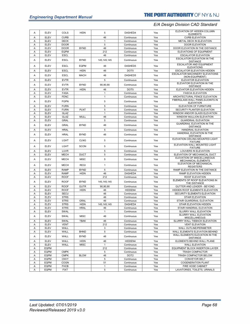
Engineering Department Manual
E/A Design Division CAD Standard
Last Updated: 07/01/2019 Page 68
Reviewed/Released 2019 v3.0
A ELEV COLS HIDN 5 DASHED4 Yes ELEVATION OF HIDDEN COLUMN
ELEMENTS
A ELEV CURB 46 Continuous Yes CURB ELEVATION
A ELEV DECK 1 Continuous Yes METAL DECK IN ELEVATION
A ELEV DOOR 5 Continuous Yes DOOR ELEVATION
A ELEV DOOR BYND 46 Continuous Yes DOOR ELEVATION IN THE DISTANCE
A ELEV EQPM 212 Continuous Yes ELEVATIONS OF EQUIPMENT
A ELEV ESCL 46 Continuous Yes ESCALATOR ELEVATION
A ELEV ESCL BYND 145,145,145 Continuous Yes ESCALATOR ELEVATION IN THE
DISTANCE
A ELEV ESCL EQPM 46 DASHED5 Yes ESCALATOR AND EQUIPMENT
ELEVATIONS
A ELEV ESCL HIDN 46 DOT5 Yes ESCALATOR ELEVATION HIDDEN
A ELEV ESCL MACH 46 DASHED5 Yes ESCALATOR MACHINERY ELEVATIONS
(NON-EQUIPMENT)
A ELEV EVTR 5 Continuous Yes ELEVATOR ELEVATION
A ELEV EVTR BYND 90,90,90 Continuous Yes ELEVATOR ELEVATION IN THE
DISTANCE
A ELEV EVTR HIDN 46 DOT5 Yes ELEVATOR ELEVATION HIDDEN
A ELEV FASA 1 Continuous Yes FASCIA ELEVATION
A ELEV FENC 1 Continuous Yes ARCHITECTURAL FENCE ELEVATION
A ELEV FGPN 5 Continuous Yes FIBERGLASS WALL PANELS/JOINTS IN
ELEVATION
A ELEV FURN 5 Continuous Yes ELEVATION OF FURNITURE
A ELEV FURN PLNT 5 Continuous Yes SECURITY PLANTER ELEVATION
A ELEV GLAZ 1 Continuous Yes WINDOW AND/OR GLASS ELEVATION
A ELEV GLAZ MULL 46 Continuous Yes WINDOW MULLION ELEVATION
A ELEV GRAL 5 Continuous Yes GUARDRAIL ELEVATION
A ELEV GRAL BYND 46 Continuous Yes GUARDRAIL ELEVATION IN THE
DISTANCE
A ELEV HRAL 5 Continuous Yes HANDRAIL ELEVATION
A ELEV HRAL BYND 46 Continuous Yes HANDRAIL ELEVATION IN THE
DISTANCE
A ELEV LGHT CLNG 5 Continuous Yes ELEVATION CEILING MOUNTED LIGHT
FIXTURE
A ELEV LGHT SCON 5 Continuous Yes ELEVATION WALL MOUNTED LIGHT
FIXTURE
A ELEV LUVR 5 Continuous Yes LOUVERS IN ELEVATION
A ELEV MECH DUCT 5 Continuous Yes ELEVATION OF MECHANICAL DUCT
A ELEV MECH MISC 5 Continuous Yes ELEVATION OF MISCELLANEOUS
MECHANICAL ELEMENTS
A ELEV MECH REGI 1 Continuous Yes ELEVATION OF MECHANICAL
REGISTERS
A ELEV RAMP BYND 5 Continuous Yes RAMP ELEVATION IN THE DISTANCE
A ELEV RAMP HIDN 46 DASHED4 Yes RAMP ELEVATION HIDDEN
A ELEV ROOF 212 Continuous Yes ROOF ELEVATION
A ELEV ROOF BYND 145,145,145 Continuous Yes ELEMENTS OF ROOF ELEVATIONS IN
THE DISTANCE
A ELEV ROOF GUTR 90,90,90 Continuous Yes GUTTER AND LEADER - BEYOND
A ELEV ROOF HIDN 46 HIDDEN4 Yes HIDDEN ROOF ELEMENTS ELEVATION
A ELEV SECU 46 Continuous Yes SECURITY ELEMENTS ELEVATION
A ELEV STRS 46 Continuous Yes STAIR ELEVATION
A ELEV STRS GRAL 46 Continuous Yes STAIR GUARDRAIL ELEVATION
A ELEV STRS HIDN 145,145,145 DASHED4 Yes STAIR ELEVATION HIDDEN
A ELEV STRS HRAL 46 Continuous Yes STAIR HANDRAIL ELEVATION
A ELEV SWAL 1 Continuous Yes SLURRY WALL ELEVATION
A ELEV SWAL MISC 46 Continuous Yes SLURRY WALL ELEVATION
MISCELLANEOUS
A ELEV SWAL TBAK 46 Continuous Yes SLURRY WALL TIEBACK ELEVATION
A ELEV VENT 212 Continuous Yes VENT ELEVATION
A ELEV WALL 3 Continuous Yes WALL OUTLINE/PERIMETER
A ELEV WALL BHND 5 Continuous Yes WALL ELEMENTS ELEVATION BEHIND
A ELEV WALL BYND 46 Continuous Yes WALL ELEMENTS ELEVATION IN THE
DISTANCE
A ELEV WALL HIDN 46 HIDDEN4 Yes ELEMENTS BEHIND WALL PLANE
A ELEV WALL MISC 1 Continuous Yes WALL ELEVATION
A EQPM 212 Continuous Yes EQUIPMENT BLOCK INSERTION LAYER
A EQPM CMPK 5 Continuous Yes TRASH COMPACTOR
A EQPM CMPK BLOW 46 DOT2 Yes TRASH COMPACTOR BELOW
A EQPM CNVY 5 Continuous Yes CONVEYOR BELT
A EQPM COGN 51 Continuous Yes COGENERATION PLANT
A EQPM FHCB 1 Continuous Yes FIRE HOSE CABINET
A EQPM FIXT 5 Continuous Yes LAVATORIES, TOILETS, URINALS
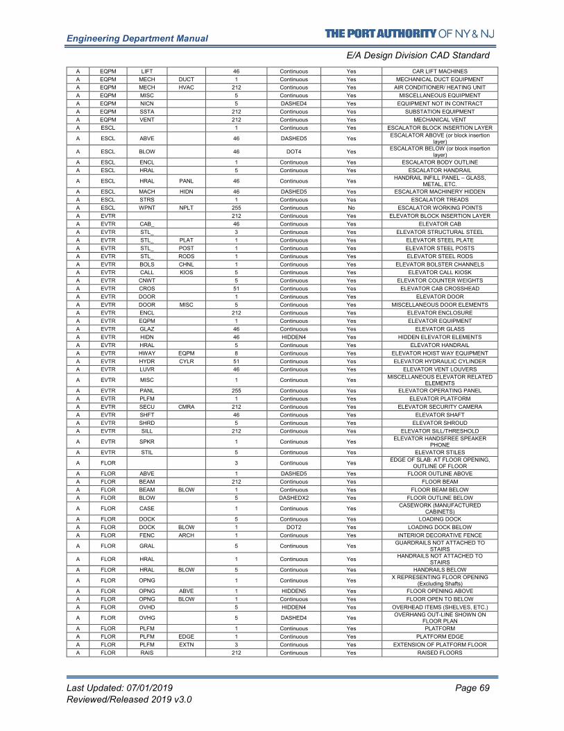
Engineering Department Manual
E/A Design Division CAD Standard
Last Updated: 07/01/2019 Page 69
Reviewed/Released 2019 v3.0
A EQPM LIFT 46 Continuous Yes CAR LIFT MACHINES
A EQPM MECH DUCT 1 Continuous Yes MECHANICAL DUCT EQUIPMENT
A EQPM MECH HVAC 212 Continuous Yes AIR CONDITIONER/ HEATING UNIT
A EQPM MISC 5 Continuous Yes MISCELLANEOUS EQUIPMENT
A EQPM NICN 5 DASHED4 Yes EQUIPMENT NOT IN CONTRACT
A EQPM SSTA 212 Continuous Yes SUBSTATION EQUIPMENT
A EQPM VENT 212 Continuous Yes MECHANICAL VENT
A ESCL 1 Continuous Yes ESCALATOR BLOCK INSERTION LAYER
A ESCL ABVE 46 DASHED5 Yes ESCALATOR ABOVE (or block insertion
layer)
A ESCL BLOW 46 DOT4 Yes ESCALATOR BELOW (or block insertion
layer)
A ESCL ENCL 1 Continuous Yes ESCALATOR BODY OUTLINE
A ESCL HRAL 5 Continuous Yes ESCALATOR HANDRAIL
A ESCL HRAL PANL 46 Continuous Yes HANDRAIL INFILL PANEL – GLASS,
METAL, ETC.
A ESCL MACH HIDN 46 DASHED5 Yes ESCALATOR MACHINERY HIDDEN
A ESCL STRS 1 Continuous Yes ESCALATOR TREADS
A ESCL WPNT NPLT 255 Continuous No ESCALATOR WORKING POINTS
A EVTR 212 Continuous Yes ELEVATOR BLOCK INSERTION LAYER
A EVTR CAB_ 46 Continuous Yes ELEVATOR CAB
A EVTR STL_ 3 Continuous Yes ELEVATOR STRUCTURAL STEEL
A EVTR STL_ PLAT 1 Continuous Yes ELEVATOR STEEL PLATE
A EVTR STL_ POST 1 Continuous Yes ELEVATOR STEEL POSTS
A EVTR STL_ RODS 1 Continuous Yes ELEVATOR STEEL RODS
A EVTR BOLS CHNL 1 Continuous Yes ELEVATOR BOLSTER CHANNELS
A EVTR CALL KIOS 5 Continuous Yes ELEVATOR CALL KIOSK
A EVTR CNWT 5 Continuous Yes ELEVATOR COUNTER WEIGHTS
A EVTR CROS 51 Continuous Yes ELEVATOR CAB CROSSHEAD
A EVTR DOOR 1 Continuous Yes ELEVATOR DOOR
A EVTR DOOR MISC 5 Continuous Yes MISCELLANEOUS DOOR ELEMENTS
A EVTR ENCL 212 Continuous Yes ELEVATOR ENCLOSURE
A EVTR EQPM 1 Continuous Yes ELEVATOR EQUIPMENT
A EVTR GLAZ 46 Continuous Yes ELEVATOR GLASS
A EVTR HIDN 46 HIDDEN4 Yes HIDDEN ELEVATOR ELEMENTS
A EVTR HRAL 5 Continuous Yes ELEVATOR HANDRAIL
A EVTR HWAY EQPM 8 Continuous Yes ELEVATOR HOIST WAY EQUIPMENT
A EVTR HYDR CYLR 51 Continuous Yes ELEVATOR HYDRAULIC CYLINDER
A EVTR LUVR 46 Continuous Yes ELEVATOR VENT LOUVERS
A EVTR MISC 1 Continuous Yes MISCELLANEOUS ELEVATOR RELATED
ELEMENTS
A EVTR PANL 255 Continuous Yes ELEVATOR OPERATING PANEL
A EVTR PLFM 1 Continuous Yes ELEVATOR PLATFORM
A EVTR SECU CMRA 212 Continuous Yes ELEVATOR SECURITY CAMERA
A EVTR SHFT 46 Continuous Yes ELEVATOR SHAFT
A EVTR SHRD 5 Continuous Yes ELEVATOR SHROUD
A EVTR SILL 212 Continuous Yes ELEVATOR SILL/THRESHOLD
A EVTR SPKR 1 Continuous Yes ELEVATOR HANDSFREE SPEAKER
PHONE
A EVTR STIL 5 Continuous Yes ELEVATOR STILES
A FLOR 3 Continuous Yes EDGE OF SLAB: AT FLOOR OPENING,
OUTLINE OF FLOOR
A FLOR ABVE 1 DASHED5 Yes FLOOR OUTLINE ABOVE
A FLOR BEAM 212 Continuous Yes FLOOR BEAM
A FLOR BEAM BLOW 1 Continuous Yes FLOOR BEAM BELOW
A FLOR BLOW 5 DASHEDX2 Yes FLOOR OUTLINE BELOW
A FLOR CASE 1 Continuous Yes CASEWORK (MANUFACTURED
CABINETS)
A FLOR DOCK 5 Continuous Yes LOADING DOCK
A FLOR DOCK BLOW 1 DOT2 Yes LOADING DOCK BELOW
A FLOR FENC ARCH 1 Continuous Yes INTERIOR DECORATIVE FENCE
A FLOR GRAL 5 Continuous Yes GUARDRAILS NOT ATTACHED TO
STAIRS
A FLOR HRAL 1 Continuous Yes HANDRAILS NOT ATTACHED TO
STAIRS
A FLOR HRAL BLOW 5 Continuous Yes HANDRAILS BELOW
A FLOR OPNG 1 Continuous Yes X REPRESENTING FLOOR OPENING
(Excluding Shafts)
A FLOR OPNG ABVE 1 HIDDEN5 Yes FLOOR OPENING ABOVE
A FLOR OPNG BLOW 1 Continuous Yes FLOOR OPEN TO BELOW
A FLOR OVHD 5 HIDDEN4 Yes OVERHEAD ITEMS (SHELVES, ETC.)
A FLOR OVHG 5 DASHED4 Yes OVERHANG OUT-LINE SHOWN ON
FLOOR PLAN
A FLOR PLFM 1 Continuous Yes PLATFORM
A FLOR PLFM EDGE 1 Continuous Yes PLATFORM EDGE
A FLOR PLFM EXTN 3 Continuous Yes EXTENSION OF PLATFORM FLOOR
A FLOR RAIS 212 Continuous Yes RAISED FLOORS
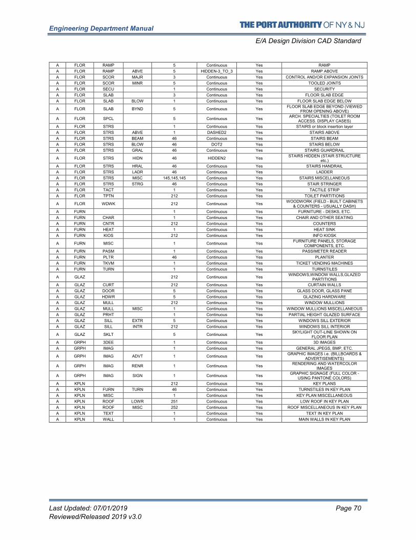
Engineering Department Manual
E/A Design Division CAD Standard
Last Updated: 07/01/2019 Page 70
Reviewed/Released 2019 v3.0
A FLOR RAMP 5 Continuous Yes RAMP
A FLOR RAMP ABVE 5 HIDDEN-3_TO_3 Yes RAMP ABOVE
A FLOR SCOR MAJR 3 Continuous Yes CONTROL AND/OR EXPANSION JOINTS
A FLOR SCOR MINR 5 Continuous Yes TOOLED JOINTS
A FLOR SECU 1 Continuous Yes SECURITY
A FLOR SLAB 3 Continuous Yes FLOOR SLAB EDGE
A FLOR SLAB BLOW 1 Continuous Yes FLOOR SLAB EDGE BELOW
A FLOR SLAB BYND 5 Continuous Yes FLOOR SLAB EDGE BEYOND (VIEWED
FROM OPENING ABOVE)
A FLOR SPCL 5 Continuous Yes ARCH. SPECIALTIES (TOILET ROOM
ACCESS. DISPLAY CASES)
A FLOR STRS 1 Continuous Yes STAIRS or block insertion layer
A FLOR STRS ABVE 1 DASHED2 Yes STAIRS ABOVE
A FLOR STRS BEAM 46 Continuous Yes STAIRS BEAM
A FLOR STRS BLOW 46 DOT2 Yes STAIRS BELOW
A FLOR STRS GRAL 46 Continuous Yes STAIRS GUARDRAIL
A FLOR STRS HIDN 46 HIDDEN2 Yes STAIRS HIDDEN (STAIR STRUCTURE
etc.)
A FLOR STRS HRAL 46 Continuous Yes STAIRS HANDRAIL
A FLOR STRS LADR 46 Continuous Yes LADDER
A FLOR STRS MISC 145,145,145 Continuous Yes STAIRS MISCELLANEOUS
A FLOR STRS STRG 46 Continuous Yes STAIR STRINGER
A FLOR TACT 1 Continuous Yes TACTILE STRIP
A FLOR TPTN 212 Continuous Yes TOILET PARTITIONS
A FLOR WDWK 212 Continuous Yes WOODWORK (FIELD - BUILT CABINETS
& COUNTERS - USUALLY DASH)
A FURN 1 Continuous Yes FURNITURE - DESKS, ETC.
A FURN CHAR 1 Continuous Yes CHAIR AND OTHER SEATING
A FURN CNTR 212 Continuous Yes COUNTERS
A FURN HEAT 1 Continuous Yes HEAT SINK
A FURN KIOS 212 Continuous Yes INFO KIOSK
A FURN MISC 1 Continuous Yes FURNITURE PANELS, STORAGE
COMPONENTS, ETC.
A FURN PASM 1 Continuous Yes PASSIMETER READER
A FURN PLTR 46 Continuous Yes PLANTER
A FURN TKVM 1 Continuous Yes TICKET VENDING MACHINES
A FURN TURN 1 Continuous Yes TURNSTILES
A GLAZ 212 Continuous Yes WINDOWS,WINDOW WALLS,GLAZED
PARTITIONS
A GLAZ CURT 212 Continuous Yes CURTAIN WALLS
A GLAZ DOOR 5 Continuous Yes GLASS DOOR, GLASS PANE
A GLAZ HDWR 5 Continuous Yes GLAZING HARDWARE
A GLAZ MULL 212 Continuous Yes WINDOW MULLIONS
A GLAZ MULL MISC 1 Continuous Yes WINDOW MULLIONS MISCELLANEOUS
A GLAZ PRHT 1 Continuous Yes PARTIAL HEIGHT GLAZED SURFACE
A GLAZ SILL EXTR 5 Continuous Yes WINDOWS SILL EXTERIOR
A GLAZ SILL INTR 212 Continuous Yes WINDOWS SILL INTERIOR
A GLAZ SKLT 5 Continuous Yes SKYLIGHT OUT-LINE SHOWN ON
FLOOR PLAN
A GRPH 3DEE 1 Continuous Yes 3D IMAGES
A GRPH IMAG 1 Continuous Yes GENERAL JPEGS, BMP, ETC.
A GRPH IMAG ADVT 1 Continuous Yes GRAPHIC IMAGES i.e. (BILLBOARDS &
ADVERTISEMENTS)
A GRPH IMAG RENR 1 Continuous Yes RENDERING AND WATERCOLOR
IMAGES
A GRPH IMAG SIGN 1 Continuous Yes GRAPHIC SIGNAGE (FULL COLOR -
USING PANTONE COLORS)
A KPLN 212 Continuous Yes KEY PLANS
A KPLN FURN TURN 46 Continuous Yes TURNSTILES IN KEY PLAN
A KPLN MISC 1 Continuous Yes KEY PLAN MISCELLANEOUS
A KPLN ROOF LOWR 251 Continuous Yes LOW ROOF IN KEY PLAN
A KPLN ROOF MISC 252 Continuous Yes ROOF MISCELLANEOUS IN KEY PLAN
A KPLN TEXT 1 Continuous Yes TEXT IN KEY PLAN
A KPLN WALL 1 Continuous Yes MAIN WALLS IN KEY PLAN
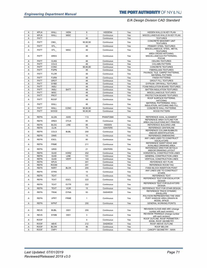
Engineering Department Manual
E/A Design Division CAD Standard
Last Updated: 07/01/2019 Page 71
Reviewed/Released 2019 v3.0
A KPLN WALL HIDN 8 HIDDEN4 Yes HIDDEN WALLS IN KEY PLAN
A KPLN WALL MISC 1 Continuous Yes MISCELLANEOUS WALLS IN KEY PLAN
A PATT 46 Continuous Yes TEXTURES
A PATT CMU_ 90,90,90 Continuous Yes CONCRETE MASONRY UNIT
TEXTURES
A PATT STL_ 46 Continuous Yes PRIMARY STEEL TEXTURES
A PATT STL_ MISC 46 Continuous Yes MISCELLANEOUS, STEEL, METAL
TEXTURES
A PATT AREA 46 Continuous Yes AREA CROSS HATCHING,
MISCELLANEOUS PATTERNING, POCHE
A PATT CLNG 46 Continuous Yes CEILING TEXTURES
A PATT COLS 46 Continuous Yes COLUMN PATTERN
A PATT CONC 90,90,90 Continuous Yes CONCRETE TEXTURES
A PATT FGPN 46 Continuous Yes FIBERGLASS TEXTURES
A PATT FLOR 46 Continuous Yes PAVINGS, TILE, CARPET PATTERNS,
MATERIAL PATTERN
A PATT FURN 46 Continuous Yes FINISH PATTERNS
A PATT GROT 46 Continuous Yes GROUT FILL TEXTURES
A PATT GYBD 46 Continuous Yes GYPSUM / DRYWALL TEXTURES
A PATT INSU 46 Continuous Yes FOAM INSULATION BOARD TEXTURES
A PATT INSU BATT 46 Continuous Yes BATTEN INSULATION TEXTURES
A PATT MISC 46 Continuous Yes MISCELLANEOUS TEXTURES
A PATT PROT 46 Continuous Yes PROTECTION BOARD TEXTURES
A PATT ROOF 46 Continuous Yes ROOF SURFACE PATTERNS,
HATCHING
A PATT WALL 46 Continuous Yes MATERIAL PATTERNING, WALL
INSULATION, HATCHING AND FILL
A PATT WALL CONC 90,90,90 Continuous Yes CONCRETE WALL PATTERNS
A PATT WOOD 90,90,90 Continuous Yes WOOD PATTERN
A REFN ALGN AXIS 113 PHANTOM4 Yes REFERENCE AXIAL ALIGNMENT
A REFN AREA OTLN 85 Continuous Yes REFERENCE AREA OUTLINE FOR
AREA CALCULATIONS NOT PRINTED
A REFN BLDG LINE 85 HIDDEN Yes REFERENCE BUILDING LINE
A REFN CLIN 75 CENTER5 Yes REFERENCE CENTERLINE
A REFN COLS BUBL 200 Continuous Yes REFERENCE COLUMN BUBBLES
AND/OR IDENTIFICATION
A REFN DIMS 15 Continuous Yes REFERENCE DIMENSIONS
A REFN ESCL 85 Continuous Yes ANY LINES USED TO CONSTRUCT
ESCALATORS
A REFN FRME 211 Continuous Yes REFERENCE SHEET EDGE AND
AVAILABLE DRAWING AREA
A REFN GRID 21 CENTER5 Yes REFERENCE GRID FOR DETAILS
AND/OR DRAWING LAYOUT
A REFN GUID HORZ 252 Continuous Yes HORIZONTAL CONSTRUCTION LINES
A REFN GUID LINE 151 Continuous Yes GENERAL CONSTRUCTION LINES
A REFN GUID VERT 143 Continuous Yes VERTICAL CONSTRUCTION LINES
A REFN KPLN 201 Continuous Yes REFERENCE KEY PLAN
A REFN ROOM 201 Continuous Yes REFERENCE ROOM TAG
A REFN NSRT BLOK 255 Continuous Yes FIXED BLOCK INSERTION POINT
A REFN STRS 15 Continuous Yes ANY LINES USE TO CONSTRUCT
STAIRS
A REFN TEXT 15 Continuous Yes REFERENCE TEXT
A REFN TEXT ESCL 222 Continuous Yes REFERENCE TEXT FOR ESCALATOR
DESIGN
A REFN TEXT EVTR 222 Continuous Yes REFERENCE TEXT FOR ELEVATORS
DESIGN
A REFN TEXT VCIR 15 Continuous Yes REFERENCE TEXT FOR STAIR DESIGN
A REFN TRAK DYNA 93 DASHED5 Yes REFERENCE TRACK DYNAMIC
ENVELOPE
A REFN VPRT FRME 1 Continuous Yes POLYGON REPRESENTING THE VIEW
PORT WINDOW AREA DRAWN IN MODEL SPACE
A REFN WPNT 255 Continuous Yes GENERAL WORKING POINTS
A REVS BUBL 0001 255 Continuous Yes REVISION CLOUD AND ARC (change
number with each revision)
A REVS SYMB 0001 3 Continuous Yes REVISION TRIANGLE (change number
with each revision)
A ROOF 4 Continuous Yes ROOF OUTLINE, ROOF PERIMETER /
EDGE, ROOF GEOMETRY
A ROOF ABVE 212 DASHED4 Yes ROOF ABOVE OUTLINE
A ROOF BLOW 46 Continuous Yes ROOF BELOW
A ROOF CNPY 51 Continuous Yes CANOPY GEOMETRY - MAIN
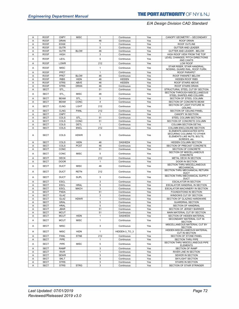
Engineering Department Manual
E/A Design Division CAD Standard
Last Updated: 07/01/2019 Page 72
Reviewed/Released 2019 v3.0
A ROOF CNPY MISC 1 Continuous Yes CANOPY GEOMETRY – SECONDARY
A ROOF DRAN 46 Continuous Yes ROOF DRAIN
A ROOF EDGE 1 Continuous Yes ROOF OUTLINE
A ROOF GUTR 5 Continuous Yes GUTTER AND LEADER
A ROOF GUTR BLOW 46 Continuous Yes GUTTER AND LEADER - BELOW
A ROOF HIGH 3 Continuous Yes HIGH ROOF VIEW FROM THE TOP
A ROOF LEVL 5 Continuous Yes LEVEL CHANGES, PITCH DIRECTIONS
AND CANTS
A ROOF LOWR 212 Continuous Yes LOW ROOF
A ROOF MISC 1 Continuous Yes STAIR RISER, STAIR HANDRAIL,
NOSING, GUARD RAIL, ROOF FURN.
A ROOF PPET 1 Continuous Yes ROOF PARAPET
A ROOF PPET BLOW 46 Continuous Yes ROOF PARAPET BELOW
A ROOF RIBS HIDN 46 HIDDEN Yes HIDDEN ROOF RIBS
A ROOF STRS ABVE 46 HIDDEN Yes ROOF STAIRS ABOVE
A ROOF STRS DRAN 46 Continuous Yes ROOF STAIRS DRAIN
A SECT STL_ 51 Continuous Yes STRUCTURAL STEEL CUT BY SECTION
A SECT STL_ MISC 46 Continuous Yes SECTION THROUGH MISCELLANEOUS
STEEL SHAPES AND COLUMN
A SECT BEAM STL_ 5 Continuous Yes SECTION OF STEEL COLUMN
A SECT BEAM CONC 4 Continuous Yes SECTION OF CONCRETE BEAM
A SECT CLNG LGHT 212 Continuous Yes SECTION OF LIGHT FIXTURE IN
CEILING
A SECT CLNG PANL 212 Continuous Yes SECTION OF CEILING PANEL
A SECT CNPY 1 Continuous Yes CANOPY IN SECTION
A SECT COLS STL_ 51 Continuous Yes STEEL COLUMN SECTION
A SECT COLS CONC 51 Continuous Yes SECTION OF CONCRETE COLUMN
A SECT COLS DETL 1 Continuous Yes COLUMN SECTION DETAIL
A SECT COLS ENCL 212 Continuous Yes COLUMN ENCLOSURE SECTION
A SECT COLS HDWR 5 Continuous Yes
ELEMENTS ASSOCIATED WITH SECURING COLUMNS TO OTHER ELEMENTS LIKE NUTS, BOLTS,
SCREWS, etc.
A SECT COLS HIDN 46 DASHED4 Yes HIDDEN COLUMN SECTION
A SECT COLS PCST 46 Continuous Yes SECTION OF PRECAST CONCRETE
A SECT CONC 51 Continuous Yes SECTION OF CONCRETE
A SECT CONC MISC 5 Continuous Yes SECTION OF MISCELLANEOUS
CONCRETE
A SECT DECK 212 Continuous Yes METAL DECK IN SECTION
A SECT DOOR 1 Continuous Yes DOOR IN SECTION
A SECT DUCT MISC 46 Continuous Yes SECTION THRU MISCELLANEOUS
MECHANICAL
A SECT DUCT RETN 212 Continuous Yes SECTION THRU MECHANICAL RETURN
DUCT
A SECT DUCT SUPL 3 Continuous Yes SECTION THRU MECHANICAL SUPPLY
DUCT
A SECT ESCL 3 Continuous Yes ESCALATOR IN SECTION
A SECT ESCL HRAL 5 Continuous Yes ESCALATOR HANDRAIL IN SECTION
A SECT ESCL MACH 3 Continuous Yes ESCALATOR MACHINERY IN SECTION
A SECT FNDA 51 Continuous Yes FOUNDATIONS IN SECTION
A SECT GLAZ 3 Continuous Yes WINDOWS CUT BY SECTION
A SECT GLAZ HDWR 1 Continuous Yes SECTION OF GLAZING HARDWARE
A SECT GRAL 5 Continuous Yes GUARDRAIL SECTION
A SECT HRAL 5 Continuous Yes SECTION OF HANDRAIL
A SECT JBAR 51 Continuous Yes SECTION OF JERSEY BARRIER
A SECT MCUT 51 Continuous Yes MAIN MATERIAL CUT BY SECTION
A SECT MCUT HIDN 1 DASHED5 Yes SECTION OF HIDDEN MATERIAL
A SECT MCUT MISC 1 Continuous Yes SECONDARY MATERIAL CUT IN
SECTION
A SECT MISC 3 Continuous Yes MISCELLANEOUS MATERIAL CUT BY
SECTION
A SECT MISC HIDN 1 HIDDEN-3_TO_3 Yes HIDDEN MISCELLANEOUS MATERIAL
CUT IN SECTION
A SECT PANL STNE 212 Continuous Yes SECTION OF STONE PANEL
A SECT PIPE 1 Continuous Yes SECTION THRU PIPE
A SECT PIPE MISC 5 Continuous Yes SECTION THRU MISCELLANEOUS PIPE
ELEMENTS
A SECT RAMP 3 Continuous Yes SECTION OF RAMP
A SECT RIVR 1 Continuous Yes RIVER LINE IN SECTION
A SECT SEWR 3 Continuous Yes SEWER IN SECTION
A SECT SKLT 5 Continuous Yes SKYLIGHT SECTION
A SECT STRS 3 Continuous Yes STAIRS IN SECTION
A SECT STRS STRG 3 Continuous Yes SECTION OF STAIR STRINGER
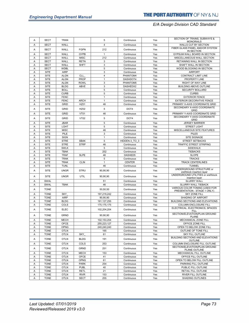
Engineering Department Manual
E/A Design Division CAD Standard
Last Updated: 07/01/2019 Page 73
Reviewed/Released 2019 v3.0
A SECT TRAN 5 Continuous Yes SECTION OF TRAINS, SUBWAYS &
MONORAILS
A SECT WALL 4 Continuous Yes WALLS CUT BY SECTION
A SECT WALL FGPN 212 Continuous Yes FIBER GLASS PANEL AND/OR SYSTEM
IN SECTION
A SECT WALL GYPB 1 Continuous Yes GYPSUM WALL BOARD IN SECTION
A SECT WALL MISC 212 Continuous Yes MISCELLANEOUS WALL SECTION
A SECT WALL RETN 3 Continuous Yes RETAINING WALL IN SECTION
A SECT WALL SHFT 3 Continuous Yes SHAFT WALL IN SECTION
A SECT WDBL 5 Continuous Yes WOOD BLOCKING IN SECTION
A SITE AIRP 3 Continuous Yes AIRPORT
A SITE ALGN CLL_ 4 PHANTOM4 Yes CONTRACT LIMIT LINE
A SITE ALGN PROP 1 DASHDOT4 Yes PROPERTY LINE
A SITE ALGN ROWL 3 PHANTOM5 Yes RIGHT OF WAY LINE
A SITE BLDG ABVE 3 DASHEDX2 Yes BUILDING ABOVE OUTLINE
A SITE BOLL 5 Continuous Yes SECURITY BOLLARD
A SITE CURB 5 Continuous Yes CURBS
A SITE FENC 1 Continuous Yes EXTERIOR FENCE
A SITE FENC ARCH 1 Continuous Yes EXTERIOR DECORATIVE FENCE
A SITE GRID HZ01 46 Continuous Yes PRIMARY X-AXIS COORDINATE GRID
A SITE GRID HZ02 5 DOT4 Yes SECONDARY X-AXIS COORDINATE
GRID
A SITE GRID VT01 46 Continuous Yes PRIMARY Y-AXIS COORDINATE GRID
A SITE GRID VT02 5 DOT4 Yes SECONDARY Y-AXIS COORDINATE
GRID
A SITE JBAR 5 Continuous Yes JERSEY BARRIER
A SITE LGHT 5 Continuous Yes STREET LIGHT
A SITE MISC 46 Continuous Yes MISCELLANEOUS SITE FEATURES
A SITE PILE 3 Continuous Yes PILES
A SITE SIGN 1 Continuous Yes SITE SIGNAGE
A SITE STRE SBAK 5 HIDDEN-3_TO_3 Yes STREET SETBACKS
A SITE STRE STRP 46 Continuous Yes TRAFFIC STREET STRIPING
A SITE SWLK 5 Continuous Yes SIDEWALK
A SITE TBAK 252 Continuous Yes TIEBACKS
A SITE TRAF SLPE 46 DASHED5 Yes SLOPE
A SITE TRAK 5 Continuous Yes TRACKS
A SITE TRAK CLIN 1 CENTER Yes TRACK CENTERLINES
A SITE TUNL 46 Continuous Yes TUNNEL
A SITE UNGR STRU 90,90,90 Continuous Yes UNDERGROUND STRUCTURE or
xref/block insertion layer
A SITE UNGR UTIL 90,90,90 Continuous Yes UNDERGROUND UTILITIES or xref/block
insertion layer
A SWAL 51 Continuous Yes SLURRY WALL
A SWAL TBAK 46 Continuous Yes SLURRY WALL TIEBACK
A TONE 50,50,50 Continuous Yes VARIOUS COLOR TONING (USED FOR
PRESENTATION - STAGE 1 ONLY)
A TONE SKY_ 197,219,242 Continuous Yes SKY ZONE FILL
A TONE AIRP 90,90,90 Continuous Yes SHADING OF AIRPORT
A TONE BLDG 191,127,255 Continuous Yes BUILDING SECTIONS AND ELEVATIONS
A TONE COLS 175,175,175 Continuous Yes COLUMN ENCLOSURE FILL
A TONE ELEC 102,204,204 Continuous Yes ELECTRICAL, ELECTRONICS, SPACES
FILL
A TONE GRND 90,90,90 Continuous Yes SECTION/ELEVATION/PLAN GROUND
PLANE
A TONE MECH 102,153,204 Continuous Yes MECHANICAL ZONE FILL
A TONE OFCE 255,223,127 Continuous Yes OFFICE ZONE FILL
A TONE OPNG 240,240,240 Continuous Yes OPEN TO BELOW ZONE FILL
A TONE OTLN 165 Continuous Yes OUTLINE OF TONE FILL
A TONE OTLN SKY_ 61 Continuous Yes SKY FILL OUTLINE
A TONE OTLN BLDG 191 Continuous Yes BUILDING SECTIONS AND ELEVATIONS
OUTLINE
A TONE OTLN COLS 253 Continuous Yes COLUMN ENCLOSURE FILL OUTLINE
A TONE OTLN GRND 251 Continuous Yes SECTION/ELEVATION/PLAN GROUND
PLANE OUTLINE
A TONE OTLN MECH 153 Continuous Yes MECHANICAL FILL OUTLINE
A TONE OTLN OFCE 41 Continuous Yes OFFICE FILL OUTLINE
A TONE OTLN OPNG 61 Continuous Yes OPEN TO BELOW FILL OUTLINE
A TONE OTLN PARK 254 Continuous Yes PARKING FILL OUTLINE
A TONE OTLN PUBL 40 Continuous Yes PUBLIC FILL OUTLINE
A TONE OTLN RETL 21 Continuous Yes RETAIL FILL OUTLINE
A TONE OTLN RIVR 153 Continuous Yes RIVER FILL OUTLINE
A TONE OTLN SECT 255 Continuous Yes SHADING OUTLINES
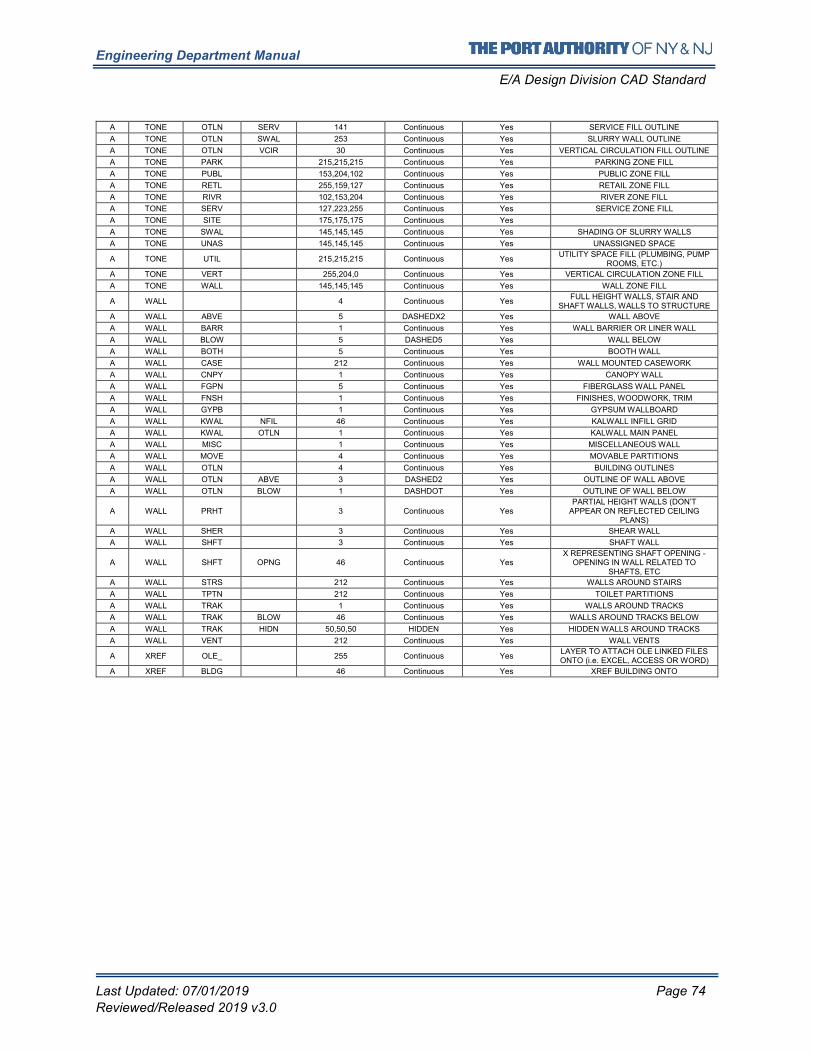
Engineering Department Manual
E/A Design Division CAD Standard
Last Updated: 07/01/2019 Page 74
Reviewed/Released 2019 v3.0
A TONE OTLN SERV 141 Continuous Yes SERVICE FILL OUTLINE
A TONE OTLN SWAL 253 Continuous Yes SLURRY WALL OUTLINE
A TONE OTLN VCIR 30 Continuous Yes VERTICAL CIRCULATION FILL OUTLINE
A TONE PARK 215,215,215 Continuous Yes PARKING ZONE FILL
A TONE PUBL 153,204,102 Continuous Yes PUBLIC ZONE FILL
A TONE RETL 255,159,127 Continuous Yes RETAIL ZONE FILL
A TONE RIVR 102,153,204 Continuous Yes RIVER ZONE FILL
A TONE SERV 127,223,255 Continuous Yes SERVICE ZONE FILL
A TONE SITE 175,175,175 Continuous Yes
A TONE SWAL 145,145,145 Continuous Yes SHADING OF SLURRY WALLS
A TONE UNAS 145,145,145 Continuous Yes UNASSIGNED SPACE
A TONE UTIL 215,215,215 Continuous Yes UTILITY SPACE FILL (PLUMBING, PUMP
ROOMS, ETC.)
A TONE VERT 255,204,0 Continuous Yes VERTICAL CIRCULATION ZONE FILL
A TONE WALL 145,145,145 Continuous Yes WALL ZONE FILL
A WALL 4 Continuous Yes FULL HEIGHT WALLS, STAIR AND
SHAFT WALLS, WALLS TO STRUCTURE
A WALL ABVE 5 DASHEDX2 Yes WALL ABOVE
A WALL BARR 1 Continuous Yes WALL BARRIER OR LINER WALL
A WALL BLOW 5 DASHED5 Yes WALL BELOW
A WALL BOTH 5 Continuous Yes BOOTH WALL
A WALL CASE 212 Continuous Yes WALL MOUNTED CASEWORK
A WALL CNPY 1 Continuous Yes CANOPY WALL
A WALL FGPN 5 Continuous Yes FIBERGLASS WALL PANEL
A WALL FNSH 1 Continuous Yes FINISHES, WOODWORK, TRIM
A WALL GYPB 1 Continuous Yes GYPSUM WALLBOARD
A WALL KWAL NFIL 46 Continuous Yes KALWALL INFILL GRID
A WALL KWAL OTLN 1 Continuous Yes KALWALL MAIN PANEL
A WALL MISC 1 Continuous Yes MISCELLANEOUS WALL
A WALL MOVE 4 Continuous Yes MOVABLE PARTITIONS
A WALL OTLN 4 Continuous Yes BUILDING OUTLINES
A WALL OTLN ABVE 3 DASHED2 Yes OUTLINE OF WALL ABOVE
A WALL OTLN BLOW 1 DASHDOT Yes OUTLINE OF WALL BELOW
A WALL PRHT 3 Continuous Yes PARTIAL HEIGHT WALLS (DON’T
APPEAR ON REFLECTED CEILING PLANS)
A WALL SHER 3 Continuous Yes SHEAR WALL
A WALL SHFT 3 Continuous Yes SHAFT WALL
A WALL SHFT OPNG 46 Continuous Yes X REPRESENTING SHAFT OPENING -
OPENING IN WALL RELATED TO SHAFTS, ETC
A WALL STRS 212 Continuous Yes WALLS AROUND STAIRS
A WALL TPTN 212 Continuous Yes TOILET PARTITIONS
A WALL TRAK 1 Continuous Yes WALLS AROUND TRACKS
A WALL TRAK BLOW 46 Continuous Yes WALLS AROUND TRACKS BELOW
A WALL TRAK HIDN 50,50,50 HIDDEN Yes HIDDEN WALLS AROUND TRACKS
A WALL VENT 212 Continuous Yes WALL VENTS
A XREF OLE_ 255 Continuous Yes LAYER TO ATTACH OLE LINKED FILES ONTO (i.e. EXCEL, ACCESS OR WORD)
A XREF BLDG 46 Continuous Yes XREF BUILDING ONTO
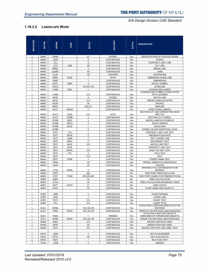
Engineering Department Manual
E/A Design Division CAD Standard
Last Updated: 07/01/2019 Page 75
Reviewed/Released 2019 v3.0
1.16.2.2 LANDSCAPE WORK
DIS
CIP
LIN
E
MA
JO
R
MIN
OR
DE
SC
CO
LO
R
LIN
ET
YP
E
PL
OT
S
DESCRIPTION
L GNRL CHNG 51 DIVIDE4 Yes IDENTIFICATION OF UPDATED WORK
L ANNO _BUS 5 CONTINUOUS Yes BUSES
L ANNO _CLL 4 CONTINUOUS Yes CONTRACT LIMIT LINE
L ANNO _CUT LINE 46 CONTINUOUS Yes CUT LINE
L ANNO BREK 5 CONTINUOUS Yes BREAK LINE
L ANNO sCARS 46 CONTINUOUS Yes CARS
L ANNO CLIN 46 CENTER5 Yes CENTERLINE
L ANNO DIMS GUID 1 DOT8 Yes DIMENSION GUIDE LINE
L ANNO DIMS 1 CONTINUOUS Yes DIMENSIONS
L ANNO DETL IDEN 3 CONTINUOUS Yes DETAIL SYMBOL
L ANNO GDLN 102,204,153 CONTINUOUS Yes GUIDELINE
L ANNO LGND DISC 1 CONTINUOUS Yes LEGEND DISCLAIMER
L ANNO LGND 212 CONTINUOUS Yes LEGENDS AND SYMBOLS ASSOCIATED
WITH LEGENDS
L ANNO MLIN 4 DIVIDE2 Yes MATCH LINE
L ANNO NOTE 212 CONTINUOUS Yes MISCELLANEOUS NOTES
L ANNO PEOP 46 CONTINUOUS Yes PEOPLE
L ANNO REDL 255,0,0 CONTINUOUS Yes REDLINE
L ANNO SCUT AROW 5 CONTINUOUS Yes DIRECTIONAL ARROW
L ANNO SCUT GUID 212 DOT8 Yes SECTION CUT LINE CONNECTING HEAD
AND TAIL
L ANNO SCUT SYMB 3 CONTINUOUS Yes SECTION CUT SYMBOL
L ANNO SYMB MISC 3 CONTINUOUS Yes MISCELLANEOUS SYMBOLS
L ANNO SYMB NRTH 5 CONTINUOUS Yes NORTH ARROW
L ANNO SYMB SCLE 1 CONTINUOUS Yes SCALE BAR
L ANNO SYMB 3 CONTINUOUS Yes SYMBOL BLOCK INSERTION LAYER
L ANNO TEXT _CLL 1 CONTINUOUS Yes CONTRACT LIMIT LINE TEXT
L ANNO TEXT DATE 5 CONTINUOUS Yes PRESENTATION DATE
L ANNO TEXT LEDR 5 CONTINUOUS Yes TEXT LEADER LINE
L ANNO TEXT MISC 5 CONTINUOUS Yes SECONDARY TEXT
L ANNO TEXT MLIN 212 CONTINUOUS Yes MATCH LINE TEXT
L ANNO TEXT PLIN 1 CONTINUOUS Yes PROPERTY LINE TEXT
L ANNO TEXT ROWL 212 CONTINUOUS Yes RIGHT OF WAY TEXT
L ANNO TEXT TITL 3 CONTINUOUS Yes TITLE TEXT
L ANNO TEXT 212 CONTINUOUS Yes TEXT
L ANNO TEXT STRE 1 CONTINUOUS Yes STREET NAME TEXT
L ANNO TRAN 46 CONTINUOUS Yes TRAINS, SUBWAYS & MONORAILS
L ANNO TRUK 46 CONTINUOUS Yes TRUCKS
L ANNO TTLB PRES 5 CONTINUOUS Yes DRAWING TITLE ON PRESENTATION
BORDER
L ANNO VPRT 200 CONTINUOUS No VIEW PORT CREATION LAYER
L ANNO VPRT TONE 255,255,255 CONTINUOUS Yes VIEW PORT SHADE (FOR PRESENTATION)
L AREA IDEN 40 CONTINUOUS No AREA CALCULATION
L AREA OTLN 40 CONTINUOUS No AREA CALCULATION BOUNDARY LINES
L AREA PATT HTCH 41 CONTINUOUS No AREA HATCH
L AREA PLNT 40 CONTINUOUS No PLANT NAME AND QUANTITY
L CHRT _BDR 3 CONTINUOUS Yes CHART BORDER
L CHRT LINE 1 CONTINUOUS Yes CHART LINE
L CHRT TEXT 212 CONTINUOUS Yes CHART TEXT
L CHRT TITL 212 CONTINUOUS Yes CHART TITLE
L ELEV BYND 135,135,135 CONTINUOUS Yes ELEVATION or SECTION OBJECTS IN THE
DISTANCE
L ELEV TREE BYND 135,135,135 CONTINUOUS Yes TREES IN THE DISTANCE (BACKGROUND)
L ELEV HIDN 1 HIDDEN2 Yes ELVATION or SECTION OBJECTS
OBSCURED BY FORGROUND OBJECTS
L ELEV SHRB BYND 135,135,135 CONTINUOUS Yes SHRUB THE DISTANCE (BACKGROUND)
L GRAD INDX 212 CONTINUOUS Yes MAJOR CONTOUR LINES
L GRAD INTR 46 CONTINUOUS Yes MINOR CONTOUR LINES
L GRAD TEXT 212 CONTINUOUS Yes MAJOR CONTOUR LINE LABEL TEXT
L KPLN _BDR 3 CONTINUOUS Yes KEY PLAN BORDER
L KPLN HTCH 46 CONTINUOUS Yes KEY PLAN HATCH
L KPLN TEXT 1 CONTINUOUS Yes KEY PLAN TEXT
L PLAN _HDR 5 CONTINUOUS Yes HEADER
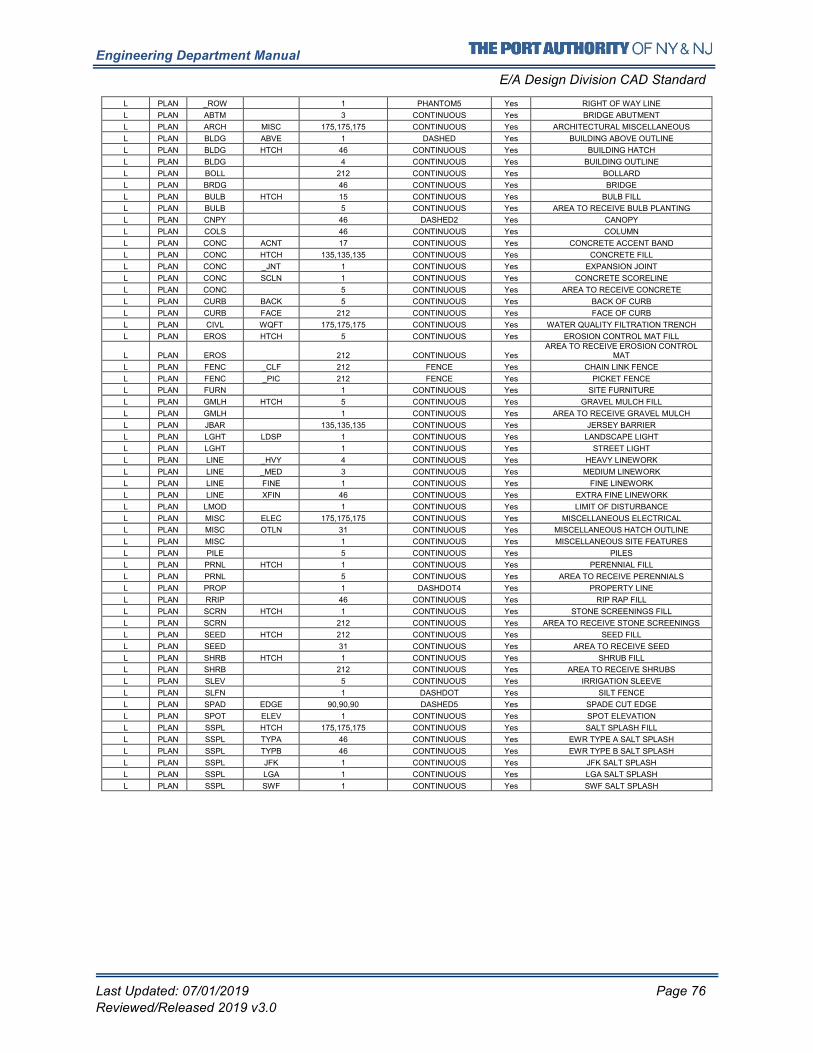
Engineering Department Manual
E/A Design Division CAD Standard
Last Updated: 07/01/2019 Page 76
Reviewed/Released 2019 v3.0
L PLAN _ROW 1 PHANTOM5 Yes RIGHT OF WAY LINE
L PLAN ABTM 3 CONTINUOUS Yes BRIDGE ABUTMENT
L PLAN ARCH MISC 175,175,175 CONTINUOUS Yes ARCHITECTURAL MISCELLANEOUS
L PLAN BLDG ABVE 1 DASHED Yes BUILDING ABOVE OUTLINE
L PLAN BLDG HTCH 46 CONTINUOUS Yes BUILDING HATCH
L PLAN BLDG 4 CONTINUOUS Yes BUILDING OUTLINE
L PLAN BOLL 212 CONTINUOUS Yes BOLLARD
L PLAN BRDG 46 CONTINUOUS Yes BRIDGE
L PLAN BULB HTCH 15 CONTINUOUS Yes BULB FILL
L PLAN BULB 5 CONTINUOUS Yes AREA TO RECEIVE BULB PLANTING
L PLAN CNPY 46 DASHED2 Yes CANOPY
L PLAN COLS 46 CONTINUOUS Yes COLUMN
L PLAN CONC ACNT 17 CONTINUOUS Yes CONCRETE ACCENT BAND
L PLAN CONC HTCH 135,135,135 CONTINUOUS Yes CONCRETE FILL
L PLAN CONC _JNT 1 CONTINUOUS Yes EXPANSION JOINT
L PLAN CONC SCLN 1 CONTINUOUS Yes CONCRETE SCORELINE
L PLAN CONC 5 CONTINUOUS Yes AREA TO RECEIVE CONCRETE
L PLAN CURB BACK 5 CONTINUOUS Yes BACK OF CURB
L PLAN CURB FACE 212 CONTINUOUS Yes FACE OF CURB
L PLAN CIVL WQFT 175,175,175 CONTINUOUS Yes WATER QUALITY FILTRATION TRENCH
L PLAN EROS HTCH 5 CONTINUOUS Yes EROSION CONTROL MAT FILL
L PLAN EROS 212 CONTINUOUS Yes AREA TO RECEIVE EROSION CONTROL
MAT
L PLAN FENC _CLF 212 FENCE Yes CHAIN LINK FENCE
L PLAN FENC _PIC 212 FENCE Yes PICKET FENCE
L PLAN FURN 1 CONTINUOUS Yes SITE FURNITURE
L PLAN GMLH HTCH 5 CONTINUOUS Yes GRAVEL MULCH FILL
L PLAN GMLH 1 CONTINUOUS Yes AREA TO RECEIVE GRAVEL MULCH
L PLAN JBAR 135,135,135 CONTINUOUS Yes JERSEY BARRIER
L PLAN LGHT LDSP 1 CONTINUOUS Yes LANDSCAPE LIGHT
L PLAN LGHT 1 CONTINUOUS Yes STREET LIGHT
L PLAN LINE _HVY 4 CONTINUOUS Yes HEAVY LINEWORK
L PLAN LINE _MED 3 CONTINUOUS Yes MEDIUM LINEWORK
L PLAN LINE FINE 1 CONTINUOUS Yes FINE LINEWORK
L PLAN LINE XFIN 46 CONTINUOUS Yes EXTRA FINE LINEWORK
L PLAN LMOD 1 CONTINUOUS Yes LIMIT OF DISTURBANCE
L PLAN MISC ELEC 175,175,175 CONTINUOUS Yes MISCELLANEOUS ELECTRICAL
L PLAN MISC OTLN 31 CONTINUOUS Yes MISCELLANEOUS HATCH OUTLINE
L PLAN MISC 1 CONTINUOUS Yes MISCELLANEOUS SITE FEATURES
L PLAN PILE 5 CONTINUOUS Yes PILES
L PLAN PRNL HTCH 1 CONTINUOUS Yes PERENNIAL FILL
L PLAN PRNL 5 CONTINUOUS Yes AREA TO RECEIVE PERENNIALS
L PLAN PROP 1 DASHDOT4 Yes PROPERTY LINE
L PLAN RRIP 46 CONTINUOUS Yes RIP RAP FILL
L PLAN SCRN HTCH 1 CONTINUOUS Yes STONE SCREENINGS FILL
L PLAN SCRN 212 CONTINUOUS Yes AREA TO RECEIVE STONE SCREENINGS
L PLAN SEED HTCH 212 CONTINUOUS Yes SEED FILL
L PLAN SEED 31 CONTINUOUS Yes AREA TO RECEIVE SEED
L PLAN SHRB HTCH 1 CONTINUOUS Yes SHRUB FILL
L PLAN SHRB 212 CONTINUOUS Yes AREA TO RECEIVE SHRUBS
L PLAN SLEV 5 CONTINUOUS Yes IRRIGATION SLEEVE
L PLAN SLFN 1 DASHDOT Yes SILT FENCE
L PLAN SPAD EDGE 90,90,90 DASHED5 Yes SPADE CUT EDGE
L PLAN SPOT ELEV 1 CONTINUOUS Yes SPOT ELEVATION
L PLAN SSPL HTCH 175,175,175 CONTINUOUS Yes SALT SPLASH FILL
L PLAN SSPL TYPA 46 CONTINUOUS Yes EWR TYPE A SALT SPLASH
L PLAN SSPL TYPB 46 CONTINUOUS Yes EWR TYPE B SALT SPLASH
L PLAN SSPL JFK 1 CONTINUOUS Yes JFK SALT SPLASH
L PLAN SSPL LGA 1 CONTINUOUS Yes LGA SALT SPLASH
L PLAN SSPL SWF 1 CONTINUOUS Yes SWF SALT SPLASH
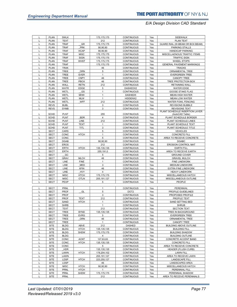
Engineering Department Manual
E/A Design Division CAD Standard
Last Updated: 07/01/2019 Page 77
Reviewed/Released 2019 v3.0
L PLAN SWLK 175,175,175 CONTINUOUS Yes SIDEWALK
L PLAN TEXT 212 CONTINUOUS Yes PLAN TEXT
L PLAN TRAF __GR 175,175,175 CONTINUOUS Yes GUARD RAIL (W-BEAM OR BOX BEAM)
L PLAN TRAF _PRK 90,90,90 CONTINUOUS Yes PARKING STALLS
L PLAN TRAF HCAP 90,90,90 CONTINUOUS Yes HANDICAP PARKING
L PLAN TRAF MISC 175,175,175 CONTINUOUS Yes MISCELLAENOUS TRAFFIC ITEMS
L PLAN TRAF SIGN 175,175,175 CONTINUOUS Yes TRAFFIC SIGN
L PLAN TRAF WHST 175,175,175 CONTINUOUS Yes WHEEL STOPS
L PLAN TRAF 175,175,175 CONTINUOUS Yes GENERAL PAVEMENT MARKINGS
L PLAN TRAK 46 CONTINUOUS Yes TRACKS
L PLAN TREE _ORN 5 CONTINUOUS Yes ORNAMENTAL TREE
L PLAN TREE EVER 1 CONTINUOUS Yes EVERGREEN TREE
L PLAN TREE CNPY 46 CONTINUOUS Yes CANOPY TREE
L PLAN TREE PBOX 46 CONTINUOUS Yes TREE PROTECTION BOX
L PLAN WALL RETN 212 CONTINUOUS Yes RETAINING WALL
L PLAN WATR EDGE 5 DASHEDX2 Yes WATER EDGE
L PLAN WETL __GS 1 CONTINUOUS Yes GOOSE STAKE FLAG
L PLAN WETL MHW 1 DASHED5 Yes MEAN HIGH WATER
L PLAN WETL MLW 1 HIDDENX2 Yes MEAN LOW WATER
L PLAN WETL _WFF 212 CONTINUOUS Yes WATER FOWL FENCING
L REVS BUBL 3 CONTINUOUS Yes REVISIONS BUBBLE
L REVS SYMB 3 CONTINUOUS Yes REVISIONS TEXT
L SCHD PLNT 255 CONTINUOUS Yes PLANT SCHEDULE INSERTION LAYER
(AutoCAD Table)
L SCHD PLNT _BDR 4 CONTINUOUS Yes PLANT SCHEDULE BORDER
L SCHD PLNT LINE 212 CONTINUOUS Yes PLANT SCHEDULE LINES
L SCHD PLNT TEXT 1 CONTINUOUS Yes PLANT SCHEDULE TEXT
L SCHD PLNT TITL 3 CONTINUOUS Yes PLANT SCHEDULE TITLE
L SECT CARS 5 CONTINUOUS Yes VEHICLES
L SECT CONC HTCH 1 CONTINUOUS Yes CONCRETE FILL
L SECT CONC 5 CONTINUOUS Yes AREA TO RECEIVE CONCRETE
L SECT DGAB 90,90,90 CONTINUOUS Yes DGABC
L SECT EROS 212 CONTINUOUS Yes EROSION CONTROL MAT
L SECT ERTH HTCH 135,135,135 CONTINUOUS Yes EARTH FILL
L SECT ERTH 255,191,0 CONTINUOUS Yes AREA TO RECEIVE EARTH
L SECT __GC 5 CONTINUOUS Yes GROUND COVER
L SECT GRAV MLCH 46 CONTINUOUS Yes GRAVEL MULCH
L SECT LINE FINE 1 CONTINUOUS Yes FINE LINEWORK
L SECT LINE _MED 3 CONTINUOUS Yes MEDIUM LINEWORK
L SECT LINE XFIN 46 CONTINUOUS Yes EXTRA FINE LINEWORK
L SECT LINE _HVY 4 CONTINUOUS Yes HEAVY LINEWORK
L SECT MISC HTCH 175,175,175 CONTINUOUS Yes MISCELLANEOUS HATCH
L SECT MISC OTLN 255,191,127 CONTINUOUS Yes MISCELLANEOUS OUTLINE
L SECT PEOP 5 CONTINUOUS Yes PEOPLE
L SECT PRNL 1 CONTINUOUS Yes PERENNIAL
L SECT PROF __GL 5 DOT2 Yes PROFILE GUIDELINES
L SECT PROF 3 CONTINUOUS Yes PROPOSED PROFILE
L SECT PROF TEXT 212 CONTINUOUS Yes PROFILE TEXT
L SECT SAND HTCH 1 CONTINUOUS Yes SAND SETTING BED
L SECT SHRB 1 CONTINUOUS Yes SHRUB
L SECT TEXT 212 CONTINUOUS Yes SECTION TEXT
L SECT TREE BYND 135,135,135 CONTINUOUS Yes TREE IN BACKGROUND
L SECT TREE EVRG 5 CONTINUOUS Yes EVERGREEN TREE
L SECT TREE _ORN 46 CONTINUOUS Yes ORNAMENTAL TREE
L SECT TREE 1 CONTINUOUS Yes CANOPY TREE
L SITE BLDG ABVE 212 DASHED Yes BUILDING ABOVE OUTLINE
L SITE BLDG HTCH 135,135,135 CONTINUOUS Yes BUILDING FILL
L SITE BLDG SHDW 175,175,175 CONTINUOUS Yes BUILDING SHADOW
L SITE BLDG 4 CONTINUOUS Yes BUILDING OUTLINE
L SITE CONC ACNT 127,63,63 CONTINUOUS Yes CONCRETE ACCENT BAND
L SITE CONC HTCH 135,135,135 CONTINUOUS Yes CONCRETE FILL
L SITE CONC 5 CONTINUOUS Yes AREA TO RECEIVE CONCRETE
L SITE _HDR 135,135,135 CONTINUOUS Yes HEADER (FLUSH CURB)
L SITE LAWN HTCH 178,204,102 CONTINUOUS Yes LAWN FILL
L SITE LAWN 255,191,127 CONTINUOUS Yes AREA TO RECEIVE LAWN
L SITE LDSP HTCH 223,255,127 CONTINUOUS Yes LANDSCAPE FILL
L SITE LDSP 46 CONTINUOUS Yes LANDSCAPED AREA
L SITE MISC HTCH 90,90,90 CONTINUOUS Yes MISCELLANEOUS HATCH
L SITE PRNL HTCH 1 CONTINUOUS Yes PERENNIAL FILL
L SITE PRNL SHDW 175,175,175 CONTINUOUS Yes PERENNIAL SHADOW
L SITE PRNL 212 CONTINUOUS Yes AREA TO RECEIVE PERENNIALS
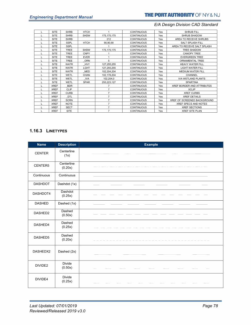
Engineering Department Manual
E/A Design Division CAD Standard
Last Updated: 07/01/2019 Page 78
Reviewed/Released 2019 v3.0
L SITE SHRB HTCH 1 CONTINUOUS Yes SHRUB FILL
L SITE SHRB SHDW 175,175,175 CONTINUOUS Yes SHRUB SHADOW
L SITE SHRB 212 CONTINUOUS Yes AREA TO RECEIVE SHRUBS
L SITE SSPL HTCH 90,90,90 CONTINUOUS Yes SALT SPLASH FILL
L SITE SSPL 1 CONTINUOUS Yes AREA TO RECEIVE SALT SPLASH
L SITE TREE SHDW 175,175,175 CONTINUOUS Yes TREE SHADOW
L SITE TREE CNPY 1 CONTINUOUS Yes CANOPY TREE
L SITE TREE EVER 1 CONTINUOUS Yes EVERGREEN TREE
L SITE TREE _ORN 5 CONTINUOUS Yes ORNAMENTAL TREE
L SITE WATR _HVY 127,255,255 CONTINUOUS Yes HEAVY WATER FILL
L SITE WATR LGHT 127,255,255 CONTINUOUS Yes LIGHT WATER FILL
L SITE WATR _MED 102,204,204 CONTINUOUS Yes MEDIUM WATER FILL
L SITE WETL CHAN 102,178,204 CONTINUOUS Yes CHANNEL
L SITE WETL _IVA 102,204,0 CONTINUOUS Yes IVA WETLAND PLANTS
L SITE WETL SPAR 255,223,127 CONTINUOUS Yes SPARTINA
L XREF _BDR 7 CONTINUOUS Yes XREF BORDER AND ATTRIBUTES
L XREF CLIP 7 CONTINUOUS Yes XCLIP
L XREF CURB 7 CONTINUOUS Yes XREF CURBS
L XREF _DTL 7 CONTINUOUS Yes XREF DETAILS
L XREF SCRN 7 CONTINUOUS Yes XREF OF SCREENED BACKGROUND
L XREF NOTE 7 CONTINUOUS Yes XREF SPECS AND NOTES
L XREF SECT 7 CONTINUOUS Yes XREF SECTIONS
L XREF SITE 7 CONTINUOUS Yes XREF SITE PLAN
1.16.3 LINETYPES
Name Description Example
CENTER Centerline
(1x)
CENTER5 Centerline
(0.20x)
Continuous Continuous
DASHDOT Dashdot (1x)
DASHDOT4 Dashdot (0.25x)
DASHED Dashed (1x)
DASHED2 Dashed (0.50x)
DASHED4 Dashed (0.25x)
DASHED5 Dashed
(0.20x)
DASHEDX2 Dashed (2x)
DIVIDE2 Divide (0.50x)
DIVIDE4 Divide
(0.25x)
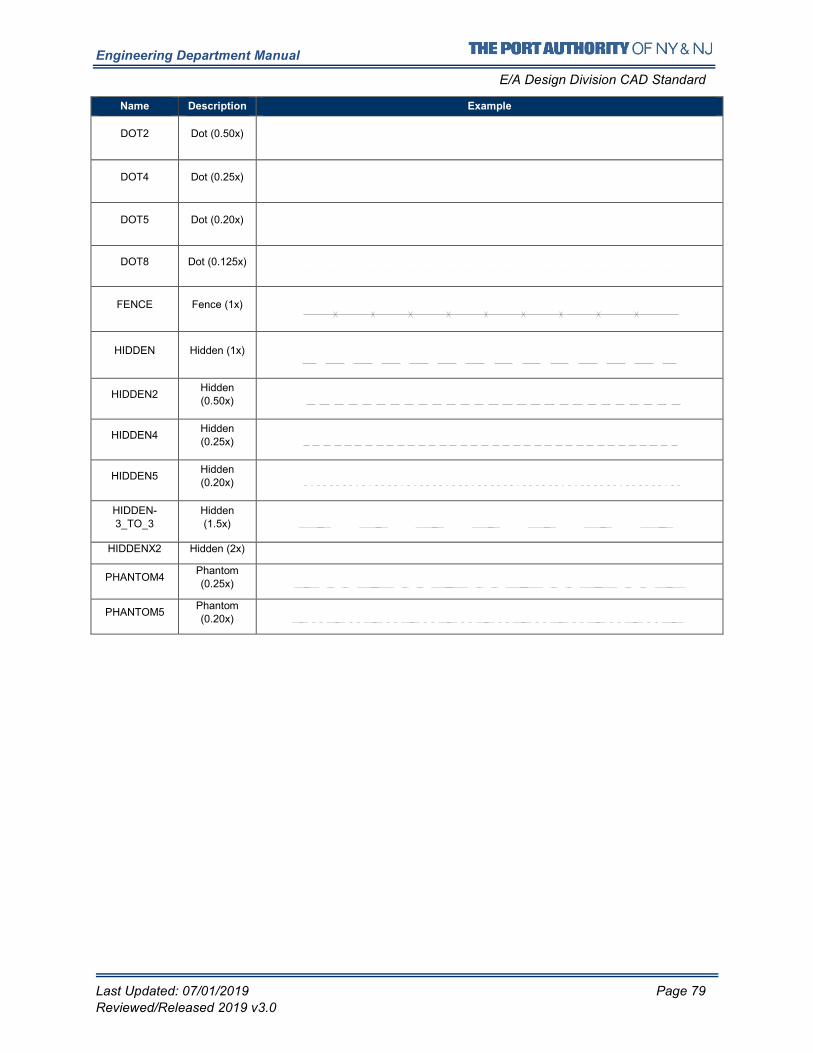
Engineering Department Manual
E/A Design Division CAD Standard
Last Updated: 07/01/2019 Page 79
Reviewed/Released 2019 v3.0
Name Description Example
DOT2 Dot (0.50x)
DOT4 Dot (0.25x)
DOT5 Dot (0.20x)
DOT8 Dot (0.125x)
FENCE Fence (1x)
HIDDEN Hidden (1x)
HIDDEN2 Hidden (0.50x)
HIDDEN4 Hidden (0.25x)
HIDDEN5 Hidden (0.20x)
HIDDEN-3_TO_3
Hidden (1.5x)
HIDDENX2 Hidden (2x)
PHANTOM4 Phantom (0.25x)
PHANTOM5 Phantom (0.20x)
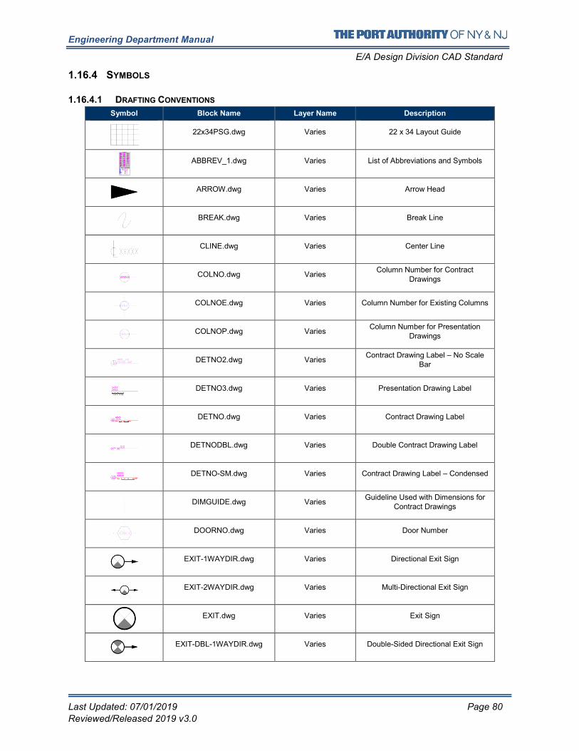
Engineering Department Manual
E/A Design Division CAD Standard
Last Updated: 07/01/2019 Page 80
Reviewed/Released 2019 v3.0
1.16.4 SYMBOLS
1.16.4.1 DRAFTING CONVENTIONS
Symbol Block Name Layer Name Description
22x34PSG.dwg Varies 22 x 34 Layout Guide
ABBREV_1.dwg Varies List of Abbreviations and Symbols
ARROW.dwg Varies Arrow Head
BREAK.dwg Varies Break Line
CLINE.dwg Varies Center Line
COLNO.dwg Varies Column Number for Contract
Drawings
COLNOE.dwg Varies Column Number for Existing Columns
COLNOP.dwg Varies Column Number for Presentation
Drawings
DETNO2.dwg Varies Contract Drawing Label – No Scale
Bar
DETNO3.dwg Varies Presentation Drawing Label
DETNO.dwg Varies Contract Drawing Label
DETNODBL.dwg Varies Double Contract Drawing Label
DETNO-SM.dwg Varies Contract Drawing Label – Condensed
DIMGUIDE.dwg Varies Guideline Used with Dimensions for
Contract Drawings
DOORNO.dwg Varies Door Number
EXIT-1WAYDIR.dwg Varies Directional Exit Sign
EXIT-2WAYDIR.dwg Varies Multi-Directional Exit Sign
EXIT.dwg Varies Exit Sign
EXIT-DBL-1WAYDIR.dwg Varies Double-Sided Directional Exit Sign
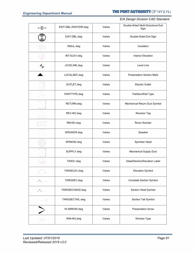
Engineering Department Manual
E/A Design Division CAD Standard
Last Updated: 07/01/2019 Page 81
Reviewed/Released 2019 v3.0
EXIT-DBL-2WAYDIR.dwg Varies Double-Sided Multi-Directional Exit
Sign
EXIT-DBL.dwg Varies Double-Sided Exit Sign
INSUL.dwg Varies Insulation
INT-ELEV.dwg Varies Interior Elevation
LEVELINE.dwg Varies Level Line
LOCALSEC.dwg Varies Presentation Section Mark
OUTLET.dwg Varies Electric Outlet
PARTTYPE.dwg Varies Partition/Wall Type
RETURN.dwg Varies Mechanical Return Duct Symbol
REV-NO.dwg Varies Revision Tag
RM-NO.dwg Varies Room Number
SPEAKER.dwg Varies Speaker
SPNKHD.dwg Varies Sprinkler Head
SUPPLY.dwg Varies Mechanical Supply Duct
TARG1.dwg Varies Detail/Section/Elevation Label
TARGELEV.dwg Varies Elevation Symbol
TARGSEC.dwg Varies Complete Section Symbol
TARGSECHEAD.dwg Varies Section Head Symbol
TARGSECTAIL.dwg Varies Section Tail Symbol
W-ARROW.dwg Varies Presentation Arrow
WIN-NO.dwg Varies Window Type
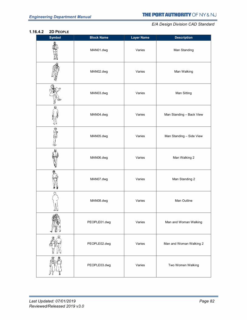
Engineering Department Manual
E/A Design Division CAD Standard
Last Updated: 07/01/2019 Page 82
Reviewed/Released 2019 v3.0
1.16.4.2 2D PEOPLE
Symbol Block Name Layer Name Description
MAN01.dwg Varies Man Standing
MAN02.dwg Varies Man Walking
MAN03.dwg Varies Man Sitting
MAN04.dwg Varies Man Standing – Back View
MAN05.dwg Varies Man Standing – Side View
MAN06.dwg Varies Man Walking 2
MAN07.dwg Varies Man Standing 2
MAN08.dwg Varies Man Outline
PEOPLE01.dwg Varies Man and Woman Walking
PEOPLE02.dwg Varies Man and Woman Walking 2
PEOPLE03.dwg Varies Two Women Walking
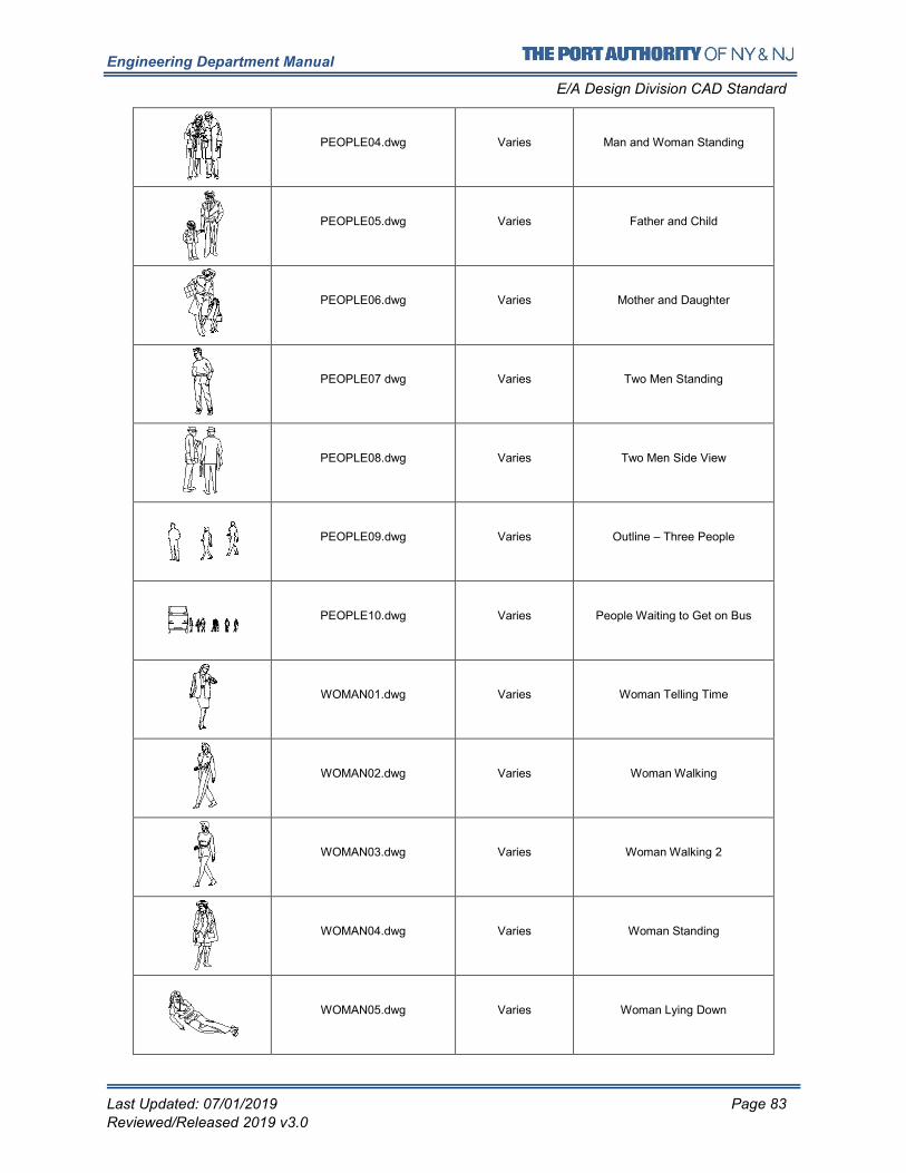
Engineering Department Manual
E/A Design Division CAD Standard
Last Updated: 07/01/2019 Page 83
Reviewed/Released 2019 v3.0
PEOPLE04.dwg Varies Man and Woman Standing
PEOPLE05.dwg Varies Father and Child
PEOPLE06.dwg Varies Mother and Daughter
PEOPLE07 dwg Varies Two Men Standing
PEOPLE08.dwg Varies Two Men Side View
PEOPLE09.dwg Varies Outline – Three People
PEOPLE10.dwg Varies People Waiting to Get on Bus
WOMAN01.dwg Varies Woman Telling Time
WOMAN02.dwg Varies Woman Walking
WOMAN03.dwg Varies Woman Walking 2
WOMAN04.dwg Varies Woman Standing
WOMAN05.dwg Varies Woman Lying Down
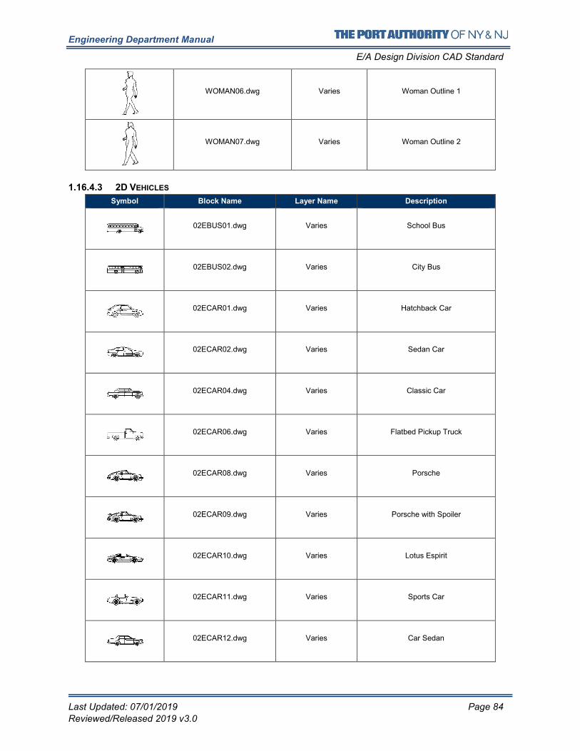
Engineering Department Manual
E/A Design Division CAD Standard
Last Updated: 07/01/2019 Page 84
Reviewed/Released 2019 v3.0
WOMAN06.dwg Varies Woman Outline 1
WOMAN07.dwg Varies Woman Outline 2
1.16.4.3 2D VEHICLES
Symbol Block Name Layer Name Description
02EBUS01.dwg Varies School Bus
02EBUS02.dwg Varies City Bus
02ECAR01.dwg Varies Hatchback Car
02ECAR02.dwg Varies Sedan Car
02ECAR04.dwg Varies Classic Car
02ECAR06.dwg Varies Flatbed Pickup Truck
02ECAR08.dwg Varies Porsche
02ECAR09.dwg Varies Porsche with Spoiler
02ECAR10.dwg Varies Lotus Espirit
02ECAR11.dwg Varies Sports Car
02ECAR12.dwg Varies Car Sedan
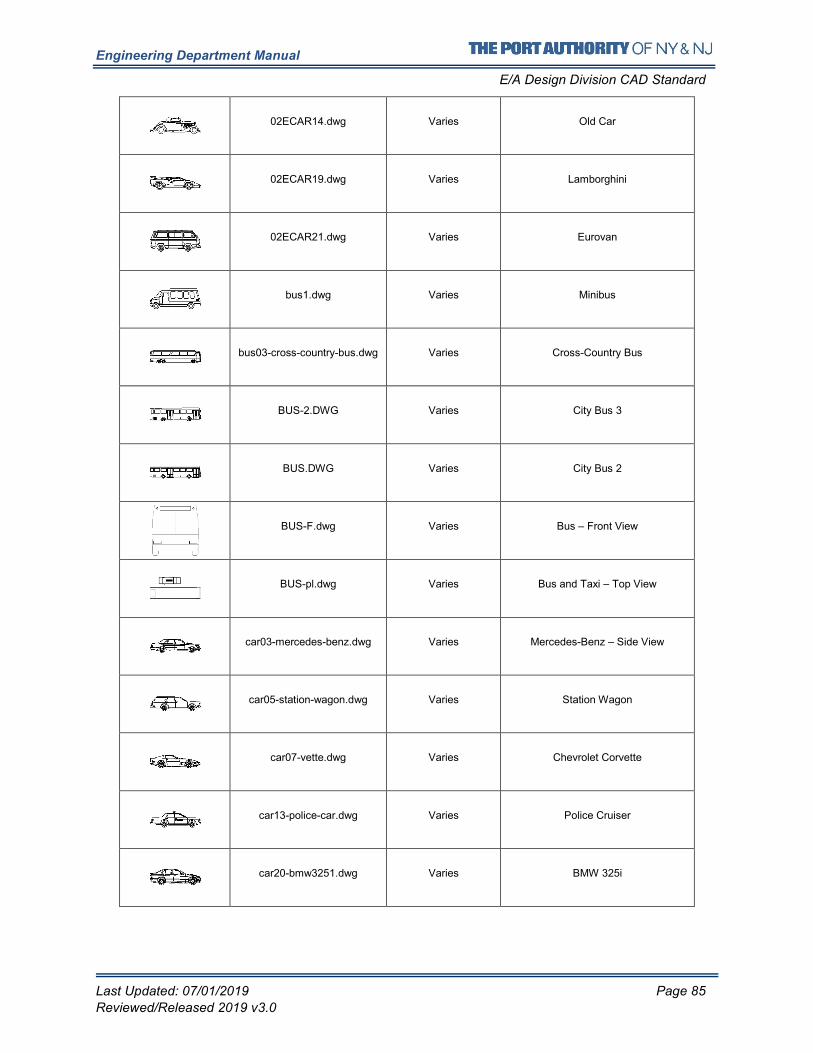
Engineering Department Manual
E/A Design Division CAD Standard
Last Updated: 07/01/2019 Page 85
Reviewed/Released 2019 v3.0
02ECAR14.dwg Varies Old Car
02ECAR19.dwg Varies Lamborghini
02ECAR21.dwg Varies Eurovan
bus1.dwg Varies Minibus
bus03-cross-country-bus.dwg Varies Cross-Country Bus
BUS-2.DWG Varies City Bus 3
BUS.DWG Varies City Bus 2
BUS-F.dwg Varies Bus – Front View
BUS-pl.dwg Varies Bus and Taxi – Top View
car03-mercedes-benz.dwg Varies Mercedes-Benz – Side View
car05-station-wagon.dwg Varies Station Wagon
car07-vette.dwg Varies Chevrolet Corvette
car13-police-car.dwg Varies Police Cruiser
car20-bmw3251.dwg Varies BMW 325i
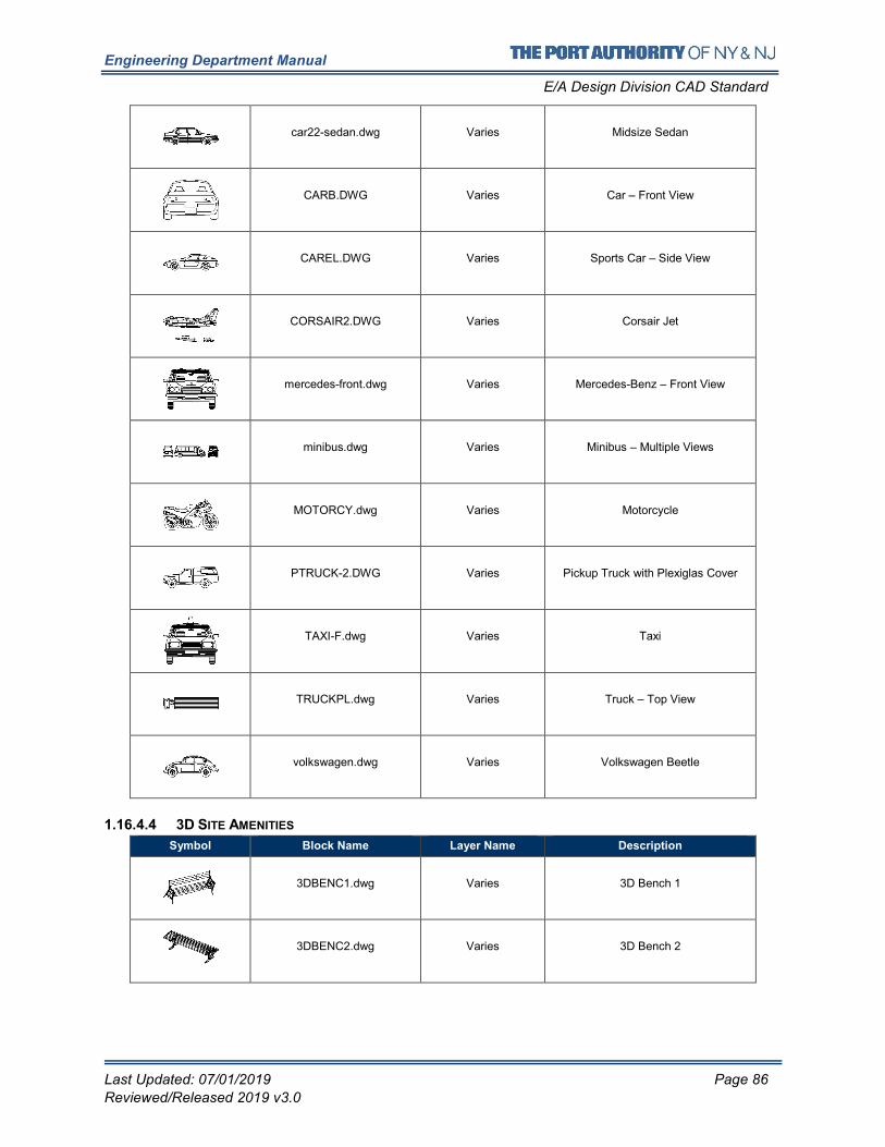
Engineering Department Manual
E/A Design Division CAD Standard
Last Updated: 07/01/2019 Page 86
Reviewed/Released 2019 v3.0
car22-sedan.dwg Varies Midsize Sedan
CARB.DWG Varies Car – Front View
CAREL.DWG Varies Sports Car – Side View
CORSAIR2.DWG Varies Corsair Jet
mercedes-front.dwg Varies Mercedes-Benz – Front View
minibus.dwg Varies Minibus – Multiple Views
MOTORCY.dwg Varies Motorcycle
PTRUCK-2.DWG Varies Pickup Truck with Plexiglas Cover
TAXI-F.dwg Varies Taxi
TRUCKPL.dwg Varies Truck – Top View
volkswagen.dwg Varies Volkswagen Beetle
1.16.4.4 3D SITE AMENITIES
Symbol Block Name Layer Name Description
3DBENC1.dwg Varies 3D Bench 1
3DBENC2.dwg Varies 3D Bench 2
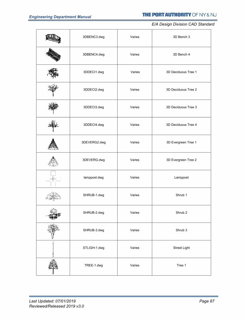
Engineering Department Manual
E/A Design Division CAD Standard
Last Updated: 07/01/2019 Page 87
Reviewed/Released 2019 v3.0
3DBENC3.dwg Varies 3D Bench 3
3DBENC4.dwg Varies 3D Bench 4
3DDECI1.dwg Varies 3D Deciduous Tree 1
3DDECI2.dwg Varies 3D Deciduous Tree 2
3DDECI3.dwg Varies 3D Deciduous Tree 3
3DDECI4.dwg Varies 3D Deciduous Tree 4
3DEVERG2.dwg Varies 3D Evergreen Tree 1
3DEVERG.dwg Varies 3D Evergreen Tree 2
lamppost.dwg Varies Lamppost
SHRUB-1.dwg Varies Shrub 1
SHRUB-2.dwg Varies Shrub 2
SHRUB-3.dwg Varies Shrub 3
STLIGH-1.dwg Varies Street Light
TREE-1.dwg Varies Tree 1
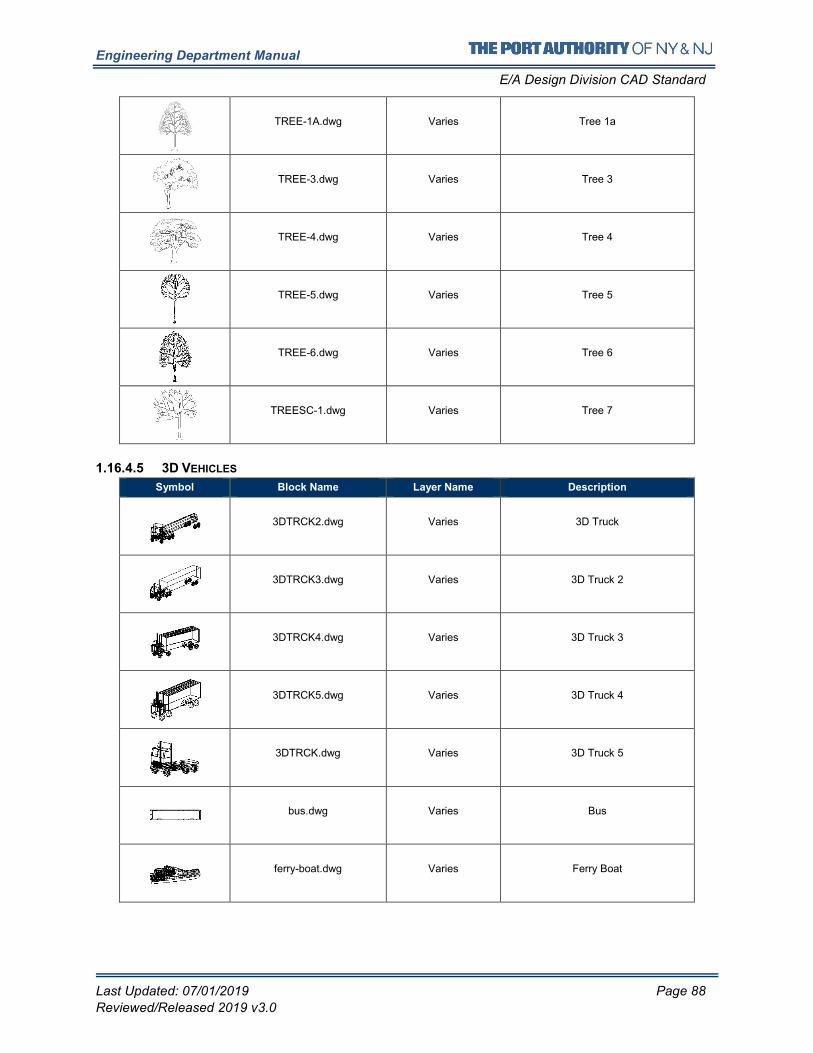
Engineering Department Manual
E/A Design Division CAD Standard
Last Updated: 07/01/2019 Page 88
Reviewed/Released 2019 v3.0
TREE-1A.dwg Varies Tree 1a
TREE-3.dwg Varies Tree 3
TREE-4.dwg Varies Tree 4
TREE-5.dwg Varies Tree 5
TREE-6.dwg Varies Tree 6
TREESC-1.dwg Varies Tree 7
1.16.4.5 3D VEHICLES
Symbol Block Name Layer Name Description
3DTRCK2.dwg Varies 3D Truck
3DTRCK3.dwg Varies 3D Truck 2
3DTRCK4.dwg Varies 3D Truck 3
3DTRCK5.dwg Varies 3D Truck 4
3DTRCK.dwg Varies 3D Truck 5
bus.dwg Varies Bus
ferry-boat.dwg Varies Ferry Boat
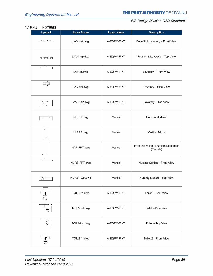
Engineering Department Manual
E/A Design Division CAD Standard
Last Updated: 07/01/2019 Page 89
Reviewed/Released 2019 v3.0
1.16.4.6 FIXTURES
Symbol Block Name Layer Name Description
LAV4-frt.dwg A-EQPM-FIXT Four-Sink Lavatory – Front View
LAV4-top.dwg A-EQPM-FIXT Four-Sink Lavatory – Top View
LAV-frt.dwg A-EQPM-FIXT Lavatory – Front View
LAV-sid.dwg A-EQPM-FIXT Lavatory – Side View
LAV-TOP.dwg A-EQPM-FIXT Lavatory – Top View
MIRR1.dwg Varies Horizontal Mirror
MIRR2.dwg Varies Vertical Mirror
NAP-FRT.dwg Varies Front Elevation of Napkin Dispenser
(Female)
NURS-FRT.dwg Varies Nursing Station – Front View
NURS-TOP.dwg Varies Nursing Station – Top View
TOIL1-frt.dwg A-EQPM-FIXT Toilet – Front View
TOIL1-sid.dwg A-EQPM-FIXT Toilet – Side View
TOIL1-top.dwg A-EQPM-FIXT Toilet – Top View
TOIL2-frt.dwg A-EQPM-FIXT Toilet 2 – Front View
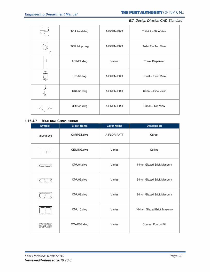
Engineering Department Manual
E/A Design Division CAD Standard
Last Updated: 07/01/2019 Page 90
Reviewed/Released 2019 v3.0
TOIL2-sid.dwg A-EQPM-FIXT Toilet 2 – Side View
TOIL2-top.dwg A-EQPM-FIXT Toilet 2 – Top View
TOWEL.dwg Varies Towel Dispenser
URI-frt.dwg A-EQPM-FIXT Urinal – Front View
URI-sid.dwg A-EQPM-FIXT Urinal – Side View
URI-top.dwg A-EQPM-FIXT Urinal – Top View
1.16.4.7 MATERIAL CONVENTIONS
Symbol Block Name Layer Name Description
CARPET.dwg A-FLOR-PATT Carpet
CEILING.dwg Varies Ceiling
CMU04.dwg Varies 4-Inch Glazed Brick Masonry
CMU06.dwg Varies 6-Inch Glazed Brick Masonry
CMU08.dwg Varies 8-Inch Glazed Brick Masonry
CMU10.dwg Varies 10-Inch Glazed Brick Masonry
COARSE.dwg Varies Coarse, Pourus Fill
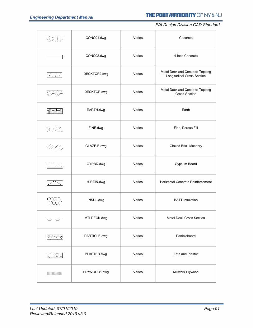
Engineering Department Manual
E/A Design Division CAD Standard
Last Updated: 07/01/2019 Page 91
Reviewed/Released 2019 v3.0
CONC01.dwg Varies Concrete
CONC02.dwg Varies 4-Inch Concrete
DECKTOP2.dwg Varies Metal Deck and Concrete Topping
Longitudinal Cross-Section
DECKTOP.dwg Varies Metal Deck and Concrete Topping
Cross-Section
EARTH.dwg Varies Earth
FINE.dwg Varies Fine, Porous Fill
GLAZE-B.dwg Varies Glazed Brick Masonry
GYPBD.dwg Varies Gypsum Board
H-REIN.dwg Varies Horizontal Concrete Reinforcement
INSUL.dwg Varies BATT Insulation
MTLDECK.dwg Varies Metal Deck Cross Section
PARTICLE.dwg Varies Particleboard
PLASTER.dwg Varies Lath and Plaster
PLYWOOD1.dwg Varies Millwork Plywood
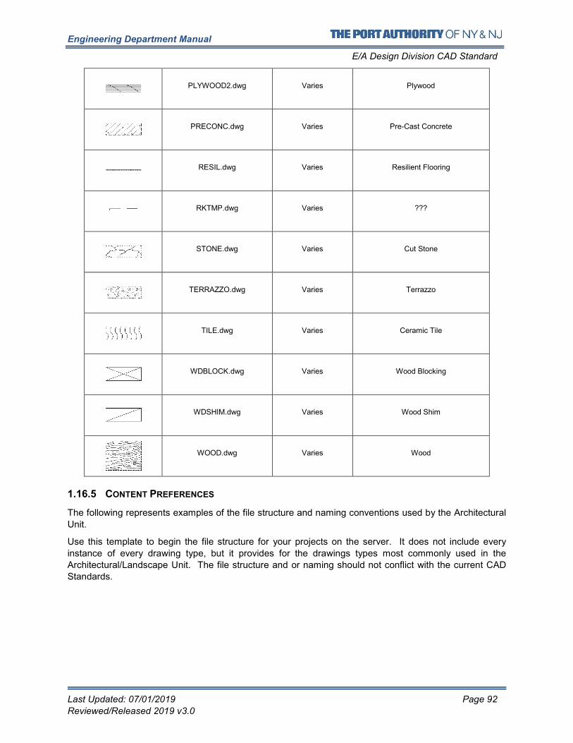
Engineering Department Manual
E/A Design Division CAD Standard
Last Updated: 07/01/2019 Page 92
Reviewed/Released 2019 v3.0
PLYWOOD2.dwg Varies Plywood
PRECONC.dwg Varies Pre-Cast Concrete
RESIL.dwg Varies Resilient Flooring
RKTMP.dwg Varies ???
STONE.dwg Varies Cut Stone
TERRAZZO.dwg Varies Terrazzo
TILE.dwg Varies Ceramic Tile
WDBLOCK.dwg Varies Wood Blocking
WDSHIM.dwg Varies Wood Shim
WOOD.dwg Varies Wood
1.16.5 CONTENT PREFERENCES
The following represents examples of the file structure and naming conventions used by the Architectural
Unit.
Use this template to begin the file structure for your projects on the server. It does not include every
instance of every drawing type, but it provides for the drawings types most commonly used in the
Architectural/Landscape Unit. The file structure and or naming should not conflict with the current CAD
Standards.
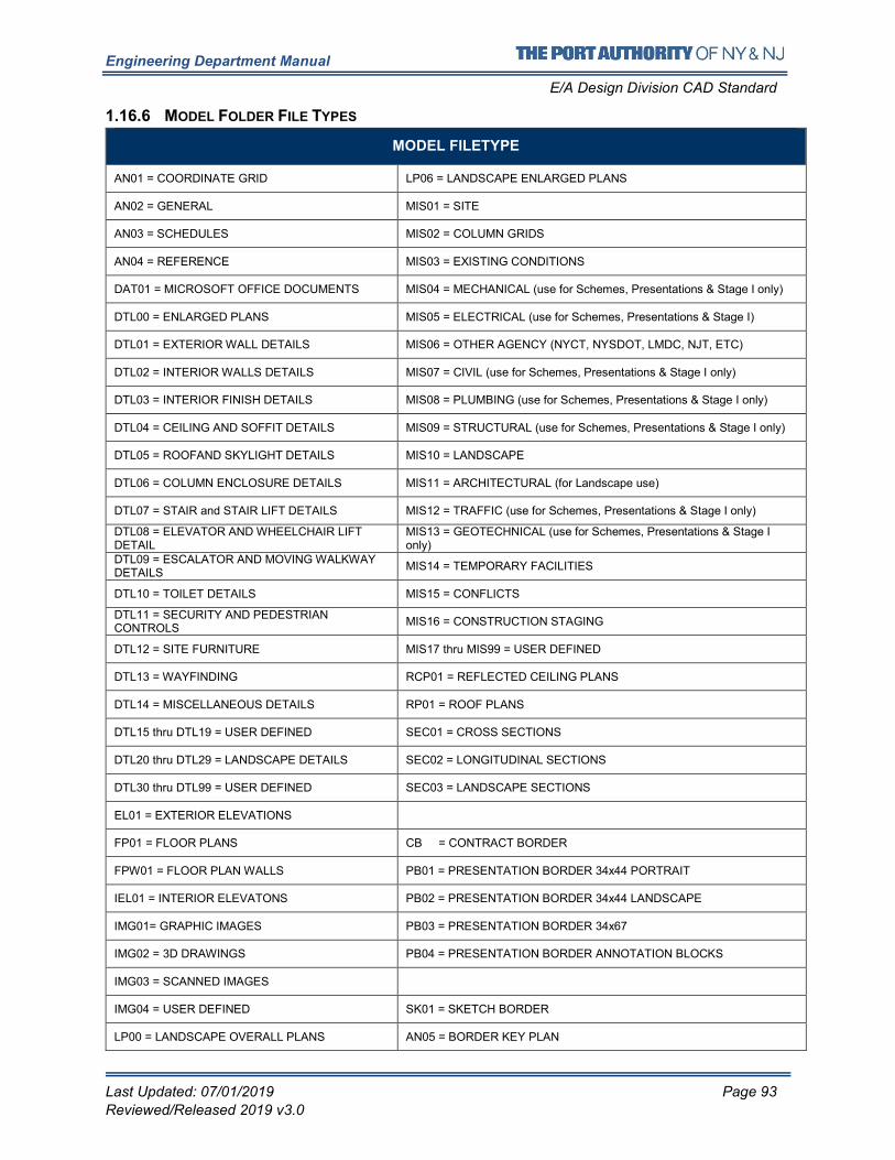
Engineering Department Manual
E/A Design Division CAD Standard
Last Updated: 07/01/2019 Page 93
Reviewed/Released 2019 v3.0
1.16.6 MODEL FOLDER FILE TYPES
MODEL FILETYPE
AN01 = COORDINATE GRID LP06 = LANDSCAPE ENLARGED PLANS
AN02 = GENERAL MIS01 = SITE
AN03 = SCHEDULES MIS02 = COLUMN GRIDS
AN04 = REFERENCE MIS03 = EXISTING CONDITIONS
DAT01 = MICROSOFT OFFICE DOCUMENTS MIS04 = MECHANICAL (use for Schemes, Presentations & Stage I only)
DTL00 = ENLARGED PLANS MIS05 = ELECTRICAL (use for Schemes, Presentations & Stage I)
DTL01 = EXTERIOR WALL DETAILS MIS06 = OTHER AGENCY (NYCT, NYSDOT, LMDC, NJT, ETC)
DTL02 = INTERIOR WALLS DETAILS MIS07 = CIVIL (use for Schemes, Presentations & Stage I only)
DTL03 = INTERIOR FINISH DETAILS MIS08 = PLUMBING (use for Schemes, Presentations & Stage I only)
DTL04 = CEILING AND SOFFIT DETAILS MIS09 = STRUCTURAL (use for Schemes, Presentations & Stage I only)
DTL05 = ROOFAND SKYLIGHT DETAILS MIS10 = LANDSCAPE
DTL06 = COLUMN ENCLOSURE DETAILS MIS11 = ARCHITECTURAL (for Landscape use)
DTL07 = STAIR and STAIR LIFT DETAILS MIS12 = TRAFFIC (use for Schemes, Presentations & Stage I only)
DTL08 = ELEVATOR AND WHEELCHAIR LIFT DETAIL
MIS13 = GEOTECHNICAL (use for Schemes, Presentations & Stage I only)
DTL09 = ESCALATOR AND MOVING WALKWAY DETAILS
MIS14 = TEMPORARY FACILITIES
DTL10 = TOILET DETAILS MIS15 = CONFLICTS
DTL11 = SECURITY AND PEDESTRIAN CONTROLS
MIS16 = CONSTRUCTION STAGING
DTL12 = SITE FURNITURE MIS17 thru MIS99 = USER DEFINED
DTL13 = WAYFINDING RCP01 = REFLECTED CEILING PLANS
DTL14 = MISCELLANEOUS DETAILS RP01 = ROOF PLANS
DTL15 thru DTL19 = USER DEFINED SEC01 = CROSS SECTIONS
DTL20 thru DTL29 = LANDSCAPE DETAILS SEC02 = LONGITUDINAL SECTIONS
DTL30 thru DTL99 = USER DEFINED SEC03 = LANDSCAPE SECTIONS
EL01 = EXTERIOR ELEVATIONS
FP01 = FLOOR PLANS CB = CONTRACT BORDER
FPW01 = FLOOR PLAN WALLS PB01 = PRESENTATION BORDER 34x44 PORTRAIT
IEL01 = INTERIOR ELEVATONS PB02 = PRESENTATION BORDER 34x44 LANDSCAPE
IMG01= GRAPHIC IMAGES PB03 = PRESENTATION BORDER 34x67
IMG02 = 3D DRAWINGS PB04 = PRESENTATION BORDER ANNOTATION BLOCKS
IMG03 = SCANNED IMAGES
IMG04 = USER DEFINED SK01 = SKETCH BORDER
LP00 = LANDSCAPE OVERALL PLANS AN05 = BORDER KEY PLAN
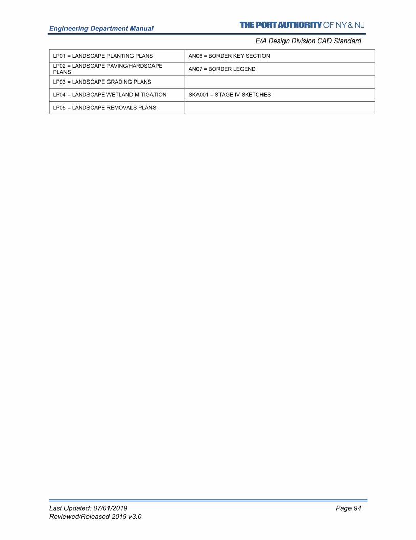
Engineering Department Manual
E/A Design Division CAD Standard
Last Updated: 07/01/2019 Page 94
Reviewed/Released 2019 v3.0
LP01 = LANDSCAPE PLANTING PLANS AN06 = BORDER KEY SECTION
LP02 = LANDSCAPE PAVING/HARDSCAPE PLANS
AN07 = BORDER LEGEND
LP03 = LANDSCAPE GRADING PLANS
LP04 = LANDSCAPE WETLAND MITIGATION SKA001 = STAGE IV SKETCHES
LP05 = LANDSCAPE REMOVALS PLANS
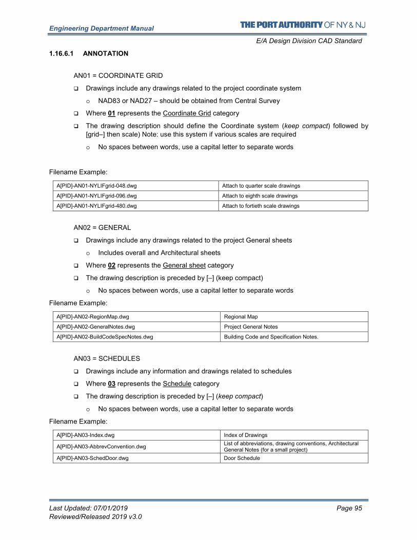
Engineering Department Manual
E/A Design Division CAD Standard
Last Updated: 07/01/2019 Page 95
Reviewed/Released 2019 v3.0
1.16.6.1 ANNOTATION
AN01 = COORDINATE GRID
� Drawings include any drawings related to the project coordinate system
o NAD83 or NAD27 – should be obtained from Central Survey
� Where 01 represents the Coordinate Grid category
� The drawing description should define the Coordinate system (keep compact) followed by
[grid–] then scale) Note: use this system if various scales are required
o No spaces between words, use a capital letter to separate words
Filename Example:
A[PID]-AN01-NYLIFgrid-048.dwg Attach to quarter scale drawings
A[PID]-AN01-NYLIFgrid-096.dwg Attach to eighth scale drawings
A[PID]-AN01-NYLIFgrid-480.dwg Attach to fortieth scale drawings
AN02 = GENERAL
� Drawings include any drawings related to the project General sheets
o Includes overall and Architectural sheets
� Where 02 represents the General sheet category
� The drawing description is preceded by [–] (keep compact)
o No spaces between words, use a capital letter to separate words
Filename Example:
A[PID]-AN02-RegionMap.dwg Regional Map
A[PID]-AN02-GeneralNotes.dwg Project General Notes
A[PID]-AN02-BuildCodeSpecNotes.dwg Building Code and Specification Notes.
AN03 = SCHEDULES
� Drawings include any information and drawings related to schedules
� Where 03 represents the Schedule category
� The drawing description is preceded by [–] (keep compact)
o No spaces between words, use a capital letter to separate words
Filename Example:
A[PID]-AN03-Index.dwg Index of Drawings
A[PID]-AN03-AbbrevConvention.dwg List of abbreviations, drawing conventions, Architectural General Notes (for a small project)
A[PID]-AN03-SchedDoor.dwg Door Schedule
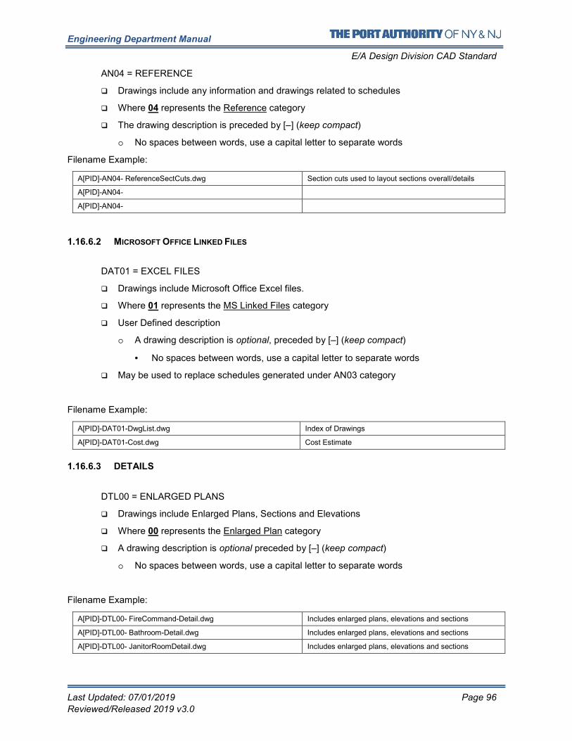
Engineering Department Manual
E/A Design Division CAD Standard
Last Updated: 07/01/2019 Page 96
Reviewed/Released 2019 v3.0
AN04 = REFERENCE
� Drawings include any information and drawings related to schedules
� Where 04 represents the Reference category
� The drawing description is preceded by [–] (keep compact)
o No spaces between words, use a capital letter to separate words
Filename Example:
A[PID]-AN04- ReferenceSectCuts.dwg Section cuts used to layout sections overall/details
A[PID]-AN04-
A[PID]-AN04-
1.16.6.2 MICROSOFT OFFICE LINKED FILES
DAT01 = EXCEL FILES
� Drawings include Microsoft Office Excel files.
� Where 01 represents the MS Linked Files category
� User Defined description
o A drawing description is optional, preceded by [–] (keep compact)
• No spaces between words, use a capital letter to separate words
� May be used to replace schedules generated under AN03 category
Filename Example:
A[PID]-DAT01-DwgList.dwg Index of Drawings
A[PID]-DAT01-Cost.dwg Cost Estimate
1.16.6.3 DETAILS
DTL00 = ENLARGED PLANS
� Drawings include Enlarged Plans, Sections and Elevations
� Where 00 represents the Enlarged Plan category
� A drawing description is optional preceded by [–] (keep compact)
o No spaces between words, use a capital letter to separate words
Filename Example:
A[PID]-DTL00- FireCommand-Detail.dwg Includes enlarged plans, elevations and sections
A[PID]-DTL00- Bathroom-Detail.dwg Includes enlarged plans, elevations and sections
A[PID]-DTL00- JanitorRoomDetail.dwg Includes enlarged plans, elevations and sections
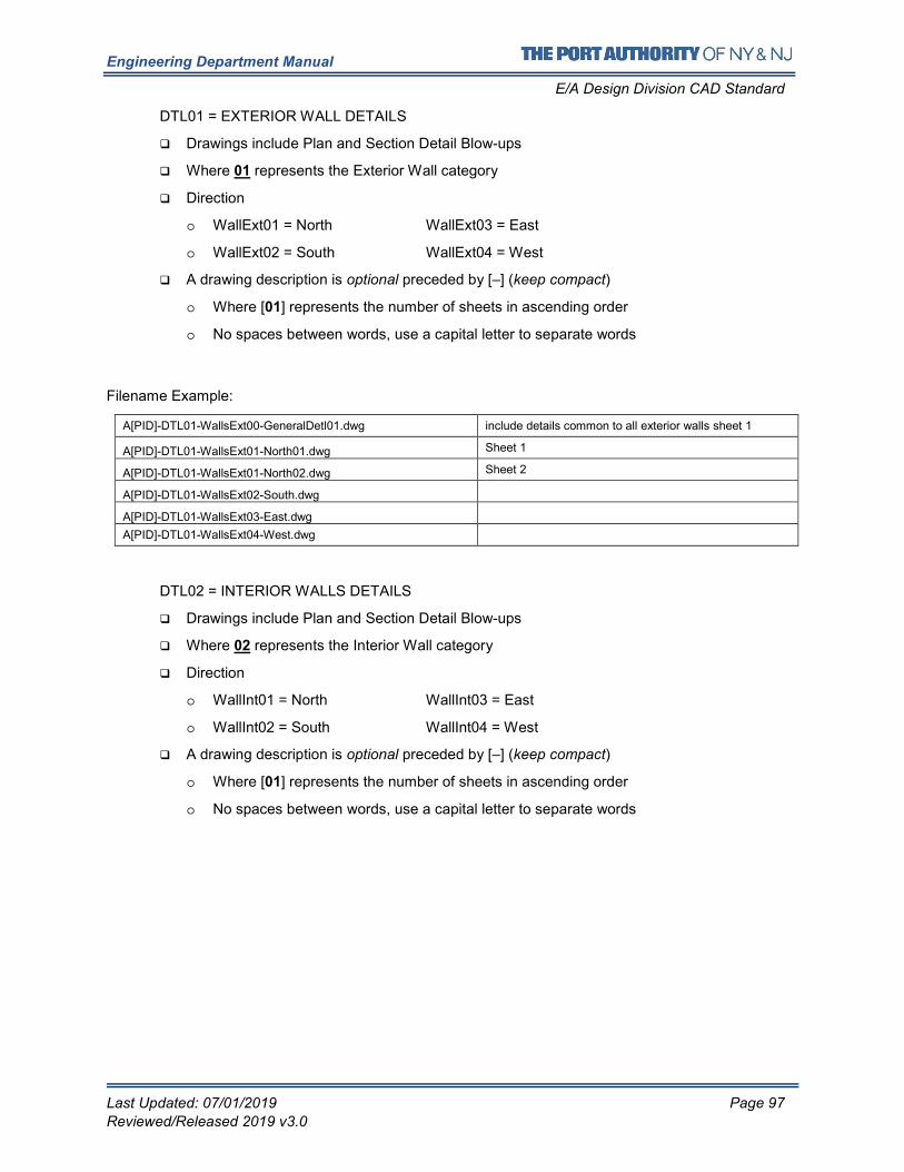
Engineering Department Manual
E/A Design Division CAD Standard
Last Updated: 07/01/2019 Page 97
Reviewed/Released 2019 v3.0
DTL01 = EXTERIOR WALL DETAILS
� Drawings include Plan and Section Detail Blow-ups
� Where 01 represents the Exterior Wall category
� Direction
o WallExt01 = North WallExt03 = East
o WallExt02 = South WallExt04 = West
� A drawing description is optional preceded by [–] (keep compact)
o Where [01] represents the number of sheets in ascending order
o No spaces between words, use a capital letter to separate words
Filename Example:
A[PID]-DTL01-WallsExt00-GeneralDetl01.dwg include details common to all exterior walls sheet 1
A[PID]-DTL01-WallsExt01-North01.dwg Sheet 1
A[PID]-DTL01-WallsExt01-North02.dwg Sheet 2
A[PID]-DTL01-WallsExt02-South.dwg
A[PID]-DTL01-WallsExt03-East.dwg
A[PID]-DTL01-WallsExt04-West.dwg
DTL02 = INTERIOR WALLS DETAILS
� Drawings include Plan and Section Detail Blow-ups
� Where 02 represents the Interior Wall category
� Direction
o WallInt01 = North WallInt03 = East
o WallInt02 = South WallInt04 = West
� A drawing description is optional preceded by [–] (keep compact)
o Where [01] represents the number of sheets in ascending order
o No spaces between words, use a capital letter to separate words
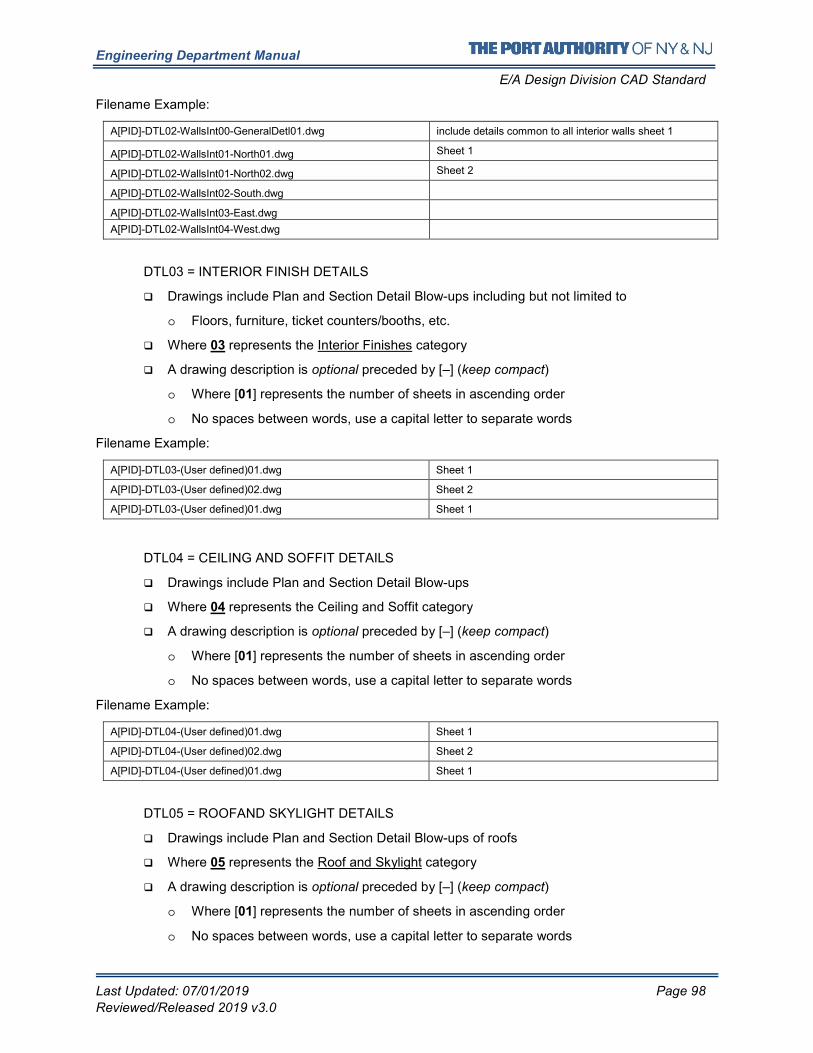
Engineering Department Manual
E/A Design Division CAD Standard
Last Updated: 07/01/2019 Page 98
Reviewed/Released 2019 v3.0
Filename Example:
A[PID]-DTL02-WallsInt00-GeneralDetl01.dwg include details common to all interior walls sheet 1
A[PID]-DTL02-WallsInt01-North01.dwg Sheet 1
A[PID]-DTL02-WallsInt01-North02.dwg Sheet 2
A[PID]-DTL02-WallsInt02-South.dwg
A[PID]-DTL02-WallsInt03-East.dwg
A[PID]-DTL02-WallsInt04-West.dwg
DTL03 = INTERIOR FINISH DETAILS
� Drawings include Plan and Section Detail Blow-ups including but not limited to
o Floors, furniture, ticket counters/booths, etc.
� Where 03 represents the Interior Finishes category
� A drawing description is optional preceded by [–] (keep compact)
o Where [01] represents the number of sheets in ascending order
o No spaces between words, use a capital letter to separate words
Filename Example:
A[PID]-DTL03-(User defined)01.dwg Sheet 1
A[PID]-DTL03-(User defined)02.dwg Sheet 2
A[PID]-DTL03-(User defined)01.dwg Sheet 1
DTL04 = CEILING AND SOFFIT DETAILS
� Drawings include Plan and Section Detail Blow-ups
� Where 04 represents the Ceiling and Soffit category
� A drawing description is optional preceded by [–] (keep compact)
o Where [01] represents the number of sheets in ascending order
o No spaces between words, use a capital letter to separate words
Filename Example:
A[PID]-DTL04-(User defined)01.dwg Sheet 1
A[PID]-DTL04-(User defined)02.dwg Sheet 2
A[PID]-DTL04-(User defined)01.dwg Sheet 1
DTL05 = ROOFAND SKYLIGHT DETAILS
� Drawings include Plan and Section Detail Blow-ups of roofs
� Where 05 represents the Roof and Skylight category
� A drawing description is optional preceded by [–] (keep compact)
o Where [01] represents the number of sheets in ascending order
o No spaces between words, use a capital letter to separate words
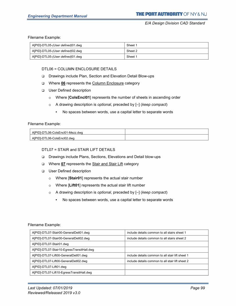
Engineering Department Manual
E/A Design Division CAD Standard
Last Updated: 07/01/2019 Page 99
Reviewed/Released 2019 v3.0
Filename Example:
A[PID]-DTL05-(User defined)01.dwg Sheet 1
A[PID]-DTL05-(User defined)02.dwg Sheet 2
A[PID]-DTL05-(User defined)01.dwg Sheet 1
DTL06 = COLUMN ENCLOSURE DETAILS
� Drawings include Plan, Section and Elevation Detail Blow-ups
� Where 06 represents the Column Enclosure category
� User Defined description
o Where [ColsEncl01] represents the number of sheets in ascending order
o A drawing description is optional, preceded by [–] (keep compact)
• No spaces between words, use a capital letter to separate words
Filename Example:
A[PID]-DTL06-ColsEncl01-Mezz.dwg
A[PID]-DTL06-ColsEncl02.dwg
DTL07 = STAIR and STAIR LIFT DETAILS
� Drawings include Plans, Sections, Elevations and Detail blow-ups
� Where 07 represents the Stair and Stair Lift category
� User Defined description
o Where [Stair01] represents the actual stair number
o Where [Lift01] represents the actual stair lift number
o A drawing description is optional, preceded by [–] (keep compact)
• No spaces between words, use a capital letter to separate words
Filename Example:
A[PID]-DTL07-Stair00-GeneralDetl01.dwg include details common to all stairs sheet 1
A[PID]-DTL07-Stair00-GeneralDetl02.dwg include details common to all stairs sheet 2
A[PID]-DTL07-Stair01.dwg
A[PID]-DTL07-Stair10-EgressTransitHall.dwg
A[PID]-DTL07-Lift00-GeneralDetl01.dwg include details common to all stair lift sheet 1
A[PID]-DTL07-Lift00-GeneralDetl02.dwg include details common to all stair lift sheet 2
A[PID]-DTL07-Lift01.dwg
A[PID]-DTL07-Lift10-EgressTransitHall.dwg
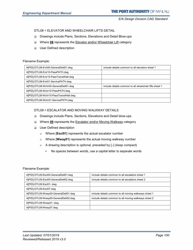
Engineering Department Manual
E/A Design Division CAD Standard
Last Updated: 07/01/2019 Page 100
Reviewed/Released 2019 v3.0
DTL08 = ELEVATOR AND WHEELCHAIR LIFTS DETAIL
� Drawings include Plans, Sections, Elevations and Detail Blow-ups
� Where 08 represents the Elevator and/or Wheelchair Lift category
� User Defined description
Filename Example:
A[PID]-DTL08-Evtr00-GeneralDetl01.dwg include details common to all elevators sheet 1
A[PID]-DTL08-Evtr10-PassPATH.dwg
A[PID]-DTL08-Evtr15-PassTransitHall.dwg
A[PID]-DTL08-Evtr01-ServicePATH.dwg
A[PID]-DTL08-Wchr00-GeneralDetl01.dwg include details common to all wheelchair lifts sheet 1
A[PID]-DTL08-Wchr10-PassPATH.dwg
A[PID]-DTL08-Wchr15-PassTransitHall.dwg
A[PID]-DTL08-Wchr01-ServicePATH.dwg
DTL09 = ESCALATOR AND MOVING WALKWAY DETAILS
� Drawings include Plans, Sections, Elevations and Detail blow-ups
� Where 09 represents the Escalator and/or Moving Walkway category
� User Defined description
o Where [Escl01] represents the actual escalator number
o Where [Wway01] represents the actual moving walkway number
o A drawing description is optional, preceded by [–] (keep compact)
• No spaces between words, use a capital letter to separate words
Filename Example:
A[PID]-DTL09-Escl00-GeneralDetl01.dwg include details common to all escalators sheet 1
A[PID]-DTL09-Escl00-GeneralDetl02.dwg include details common to all escalators sheet 2
A[PID]-DTL09-Escl01-.dwg
A[PID]-DTL09-Escl07.dwg
A[PID]-DTL09-Wway00-GeneralDetl01.dwg include details common to all moving walkways sheet 1
A[PID]-DTL09-Wway00-GeneralDetl02.dwg include details common to all moving walkways sheet 2
A[PID]-DTL09-Wway01-.dwg
A[PID]-DTL09-Wway07.dwg
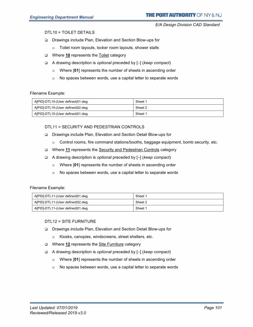
Engineering Department Manual
E/A Design Division CAD Standard
Last Updated: 07/01/2019 Page 101
Reviewed/Released 2019 v3.0
DTL10 = TOILET DETAILS
� Drawings include Plan, Elevation and Section Blow-ups for
o Toilet room layouts, locker room layouts, shower stalls
� Where 10 represents the Toilet category
� A drawing description is optional preceded by [–] (keep compact)
o Where [01] represents the number of sheets in ascending order
o No spaces between words, use a capital letter to separate words
Filename Example:
A[PID]-DTL10-(User defined)01.dwg Sheet 1
A[PID]-DTL10-(User defined)02.dwg Sheet 2
A[PID]-DTL10-(User defined)01.dwg Sheet 1
DTL11 = SECURITY AND PEDESTRIAN CONTROLS
� Drawings include Plan, Elevation and Section Detail Blow-ups for
o Control rooms, fire command stations/booths, baggage equipment, bomb security, etc.
� Where 11 represents the Security and Pedestrian Controls category
� A drawing description is optional preceded by [–] (keep compact)
o Where [01] represents the number of sheets in ascending order
o No spaces between words, use a capital letter to separate words
Filename Example:
A[PID]-DTL11-(User defined)01.dwg Sheet 1
A[PID]-DTL11-(User defined)02.dwg Sheet 2
A[PID]-DTL11-(User defined)01.dwg Sheet 1
DTL12 = SITE FURNITURE
� Drawings include Plan, Elevation and Section Detail Blow-ups for
o Kiosks, canopies, windscreens, street shelters, etc.
� Where 12 represents the Site Furniture category
� A drawing description is optional preceded by [–] (keep compact)
o Where [01] represents the number of sheets in ascending order
o No spaces between words, use a capital letter to separate words
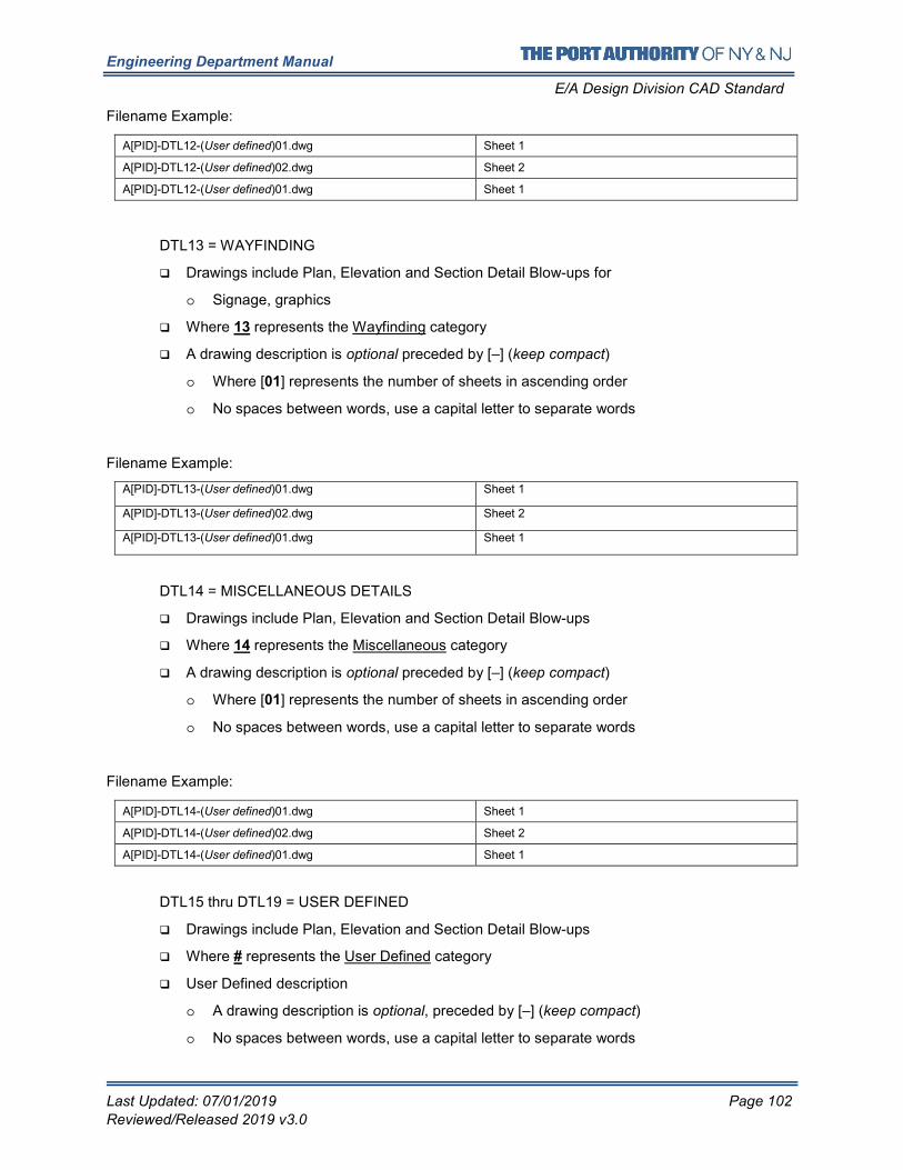
Engineering Department Manual
E/A Design Division CAD Standard
Last Updated: 07/01/2019 Page 102
Reviewed/Released 2019 v3.0
Filename Example:
A[PID]-DTL12-(User defined)01.dwg Sheet 1
A[PID]-DTL12-(User defined)02.dwg Sheet 2
A[PID]-DTL12-(User defined)01.dwg Sheet 1
DTL13 = WAYFINDING
� Drawings include Plan, Elevation and Section Detail Blow-ups for
o Signage, graphics
� Where 13 represents the Wayfinding category
� A drawing description is optional preceded by [–] (keep compact)
o Where [01] represents the number of sheets in ascending order
o No spaces between words, use a capital letter to separate words
Filename Example:
A[PID]-DTL13-(User defined)01.dwg Sheet 1
A[PID]-DTL13-(User defined)02.dwg Sheet 2
A[PID]-DTL13-(User defined)01.dwg Sheet 1
DTL14 = MISCELLANEOUS DETAILS
� Drawings include Plan, Elevation and Section Detail Blow-ups
� Where 14 represents the Miscellaneous category
� A drawing description is optional preceded by [–] (keep compact)
o Where [01] represents the number of sheets in ascending order
o No spaces between words, use a capital letter to separate words
Filename Example:
A[PID]-DTL14-(User defined)01.dwg Sheet 1
A[PID]-DTL14-(User defined)02.dwg Sheet 2
A[PID]-DTL14-(User defined)01.dwg Sheet 1
DTL15 thru DTL19 = USER DEFINED
� Drawings include Plan, Elevation and Section Detail Blow-ups
� Where # represents the User Defined category
� User Defined description
o A drawing description is optional, preceded by [–] (keep compact)
o No spaces between words, use a capital letter to separate words
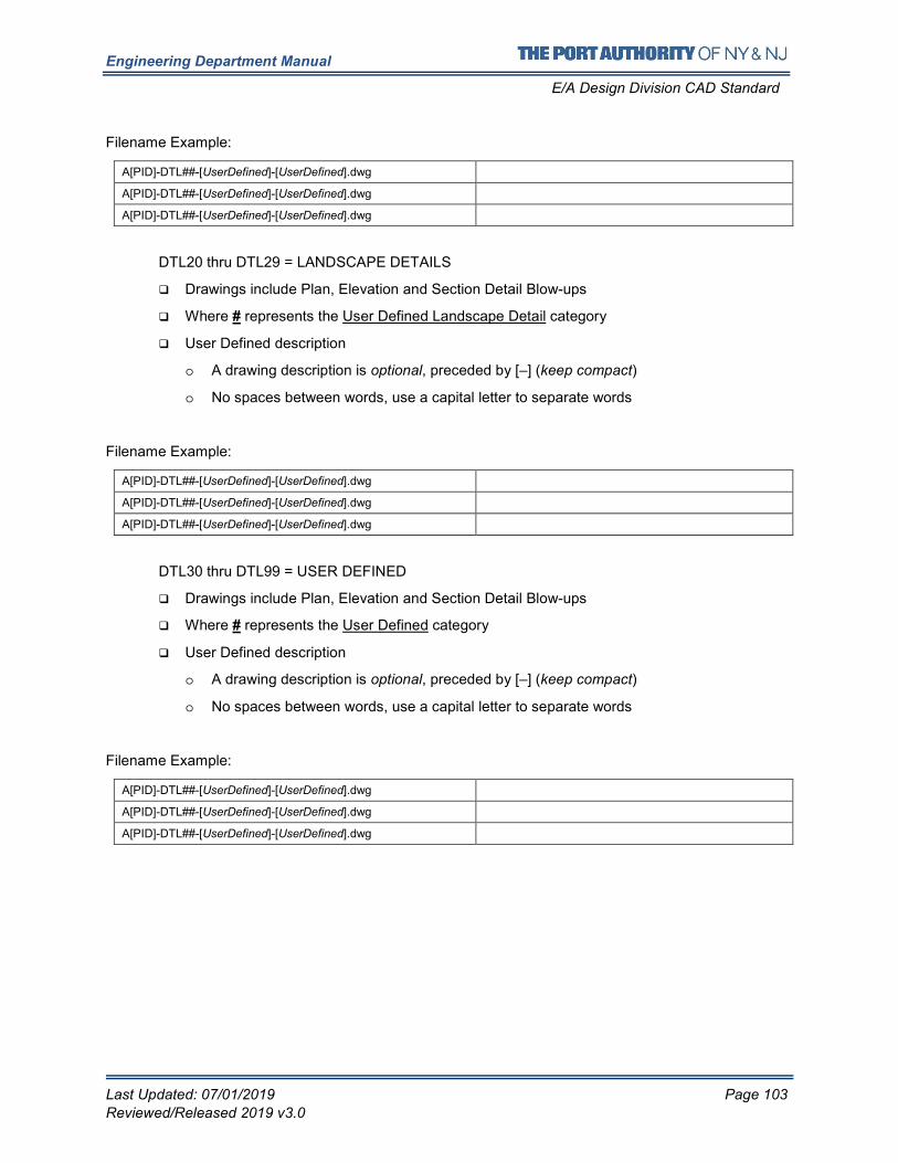
Engineering Department Manual
E/A Design Division CAD Standard
Last Updated: 07/01/2019 Page 103
Reviewed/Released 2019 v3.0
Filename Example:
A[PID]-DTL##-[UserDefined]-[UserDefined].dwg
A[PID]-DTL##-[UserDefined]-[UserDefined].dwg
A[PID]-DTL##-[UserDefined]-[UserDefined].dwg
DTL20 thru DTL29 = LANDSCAPE DETAILS
� Drawings include Plan, Elevation and Section Detail Blow-ups
� Where # represents the User Defined Landscape Detail category
� User Defined description
o A drawing description is optional, preceded by [–] (keep compact)
o No spaces between words, use a capital letter to separate words
Filename Example:
A[PID]-DTL##-[UserDefined]-[UserDefined].dwg
A[PID]-DTL##-[UserDefined]-[UserDefined].dwg
A[PID]-DTL##-[UserDefined]-[UserDefined].dwg
DTL30 thru DTL99 = USER DEFINED
� Drawings include Plan, Elevation and Section Detail Blow-ups
� Where # represents the User Defined category
� User Defined description
o A drawing description is optional, preceded by [–] (keep compact)
o No spaces between words, use a capital letter to separate words
Filename Example:
A[PID]-DTL##-[UserDefined]-[UserDefined].dwg
A[PID]-DTL##-[UserDefined]-[UserDefined].dwg
A[PID]-DTL##-[UserDefined]-[UserDefined].dwg
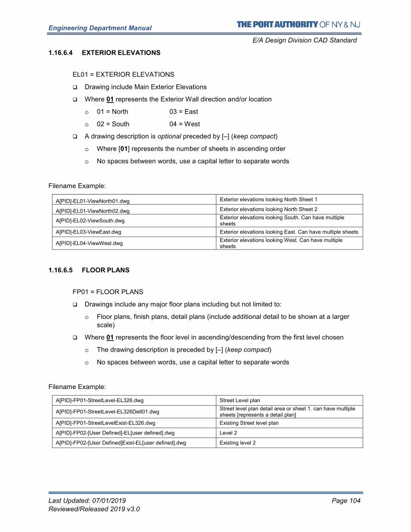
Engineering Department Manual
E/A Design Division CAD Standard
Last Updated: 07/01/2019 Page 104
Reviewed/Released 2019 v3.0
1.16.6.4 EXTERIOR ELEVATIONS
EL01 = EXTERIOR ELEVATIONS
� Drawing include Main Exterior Elevations
� Where 01 represents the Exterior Wall direction and/or location
o 01 = North 03 = East
o 02 = South 04 = West
� A drawing description is optional preceded by [–] (keep compact)
o Where [01] represents the number of sheets in ascending order
o No spaces between words, use a capital letter to separate words
Filename Example:
A[PID]-EL01-ViewNorth01.dwg Exterior elevations looking North Sheet 1
A[PID]-EL01-ViewNorth02.dwg Exterior elevations looking North Sheet 2
A[PID]-EL02-ViewSouth.dwg Exterior elevations looking South. Can have multiple sheets
A[PID]-EL03-ViewEast.dwg Exterior elevations looking East. Can have multiple sheets
A[PID]-EL04-ViewWest.dwg Exterior elevations looking West. Can have multiple sheets
1.16.6.5 FLOOR PLANS
FP01 = FLOOR PLANS
� Drawings include any major floor plans including but not limited to:
o Floor plans, finish plans, detail plans (include additional detail to be shown at a larger
scale)
� Where 01 represents the floor level in ascending/descending from the first level chosen
o The drawing description is preceded by [–] (keep compact)
o No spaces between words, use a capital letter to separate words
Filename Example:
A[PID]-FP01-StreetLevel-EL326.dwg Street Level plan
A[PID]-FP01-StreetLevel-EL326Detl01.dwg Street level plan detail area or sheet 1. can have multiple sheets [represents a detail plan]
A[PID]-FP01-StreetLevelExist-EL326.dwg Existing Street level plan
A[PID]-FP02-[User Defined]-EL[user defined].dwg Level 2
A[PID]-FP02-[User Defined]Exist-EL[user defined].dwg Existing level 2
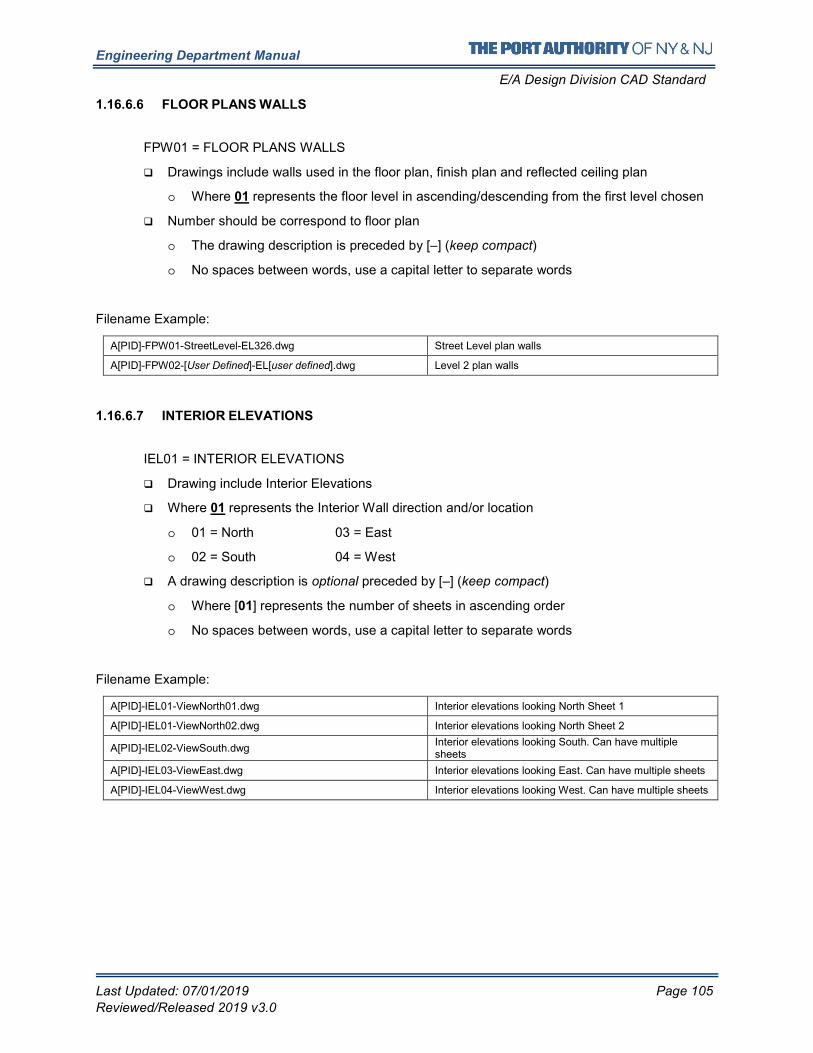
Engineering Department Manual
E/A Design Division CAD Standard
Last Updated: 07/01/2019 Page 105
Reviewed/Released 2019 v3.0
1.16.6.6 FLOOR PLANS WALLS
FPW01 = FLOOR PLANS WALLS
� Drawings include walls used in the floor plan, finish plan and reflected ceiling plan
o Where 01 represents the floor level in ascending/descending from the first level chosen
� Number should be correspond to floor plan
o The drawing description is preceded by [–] (keep compact)
o No spaces between words, use a capital letter to separate words
Filename Example:
A[PID]-FPW01-StreetLevel-EL326.dwg Street Level plan walls
A[PID]-FPW02-[User Defined]-EL[user defined].dwg Level 2 plan walls
1.16.6.7 INTERIOR ELEVATIONS
IEL01 = INTERIOR ELEVATIONS
� Drawing include Interior Elevations
� Where 01 represents the Interior Wall direction and/or location
o 01 = North 03 = East
o 02 = South 04 = West
� A drawing description is optional preceded by [–] (keep compact)
o Where [01] represents the number of sheets in ascending order
o No spaces between words, use a capital letter to separate words
Filename Example:
A[PID]-IEL01-ViewNorth01.dwg Interior elevations looking North Sheet 1
A[PID]-IEL01-ViewNorth02.dwg Interior elevations looking North Sheet 2
A[PID]-IEL02-ViewSouth.dwg Interior elevations looking South. Can have multiple sheets
A[PID]-IEL03-ViewEast.dwg Interior elevations looking East. Can have multiple sheets
A[PID]-IEL04-ViewWest.dwg Interior elevations looking West. Can have multiple sheets
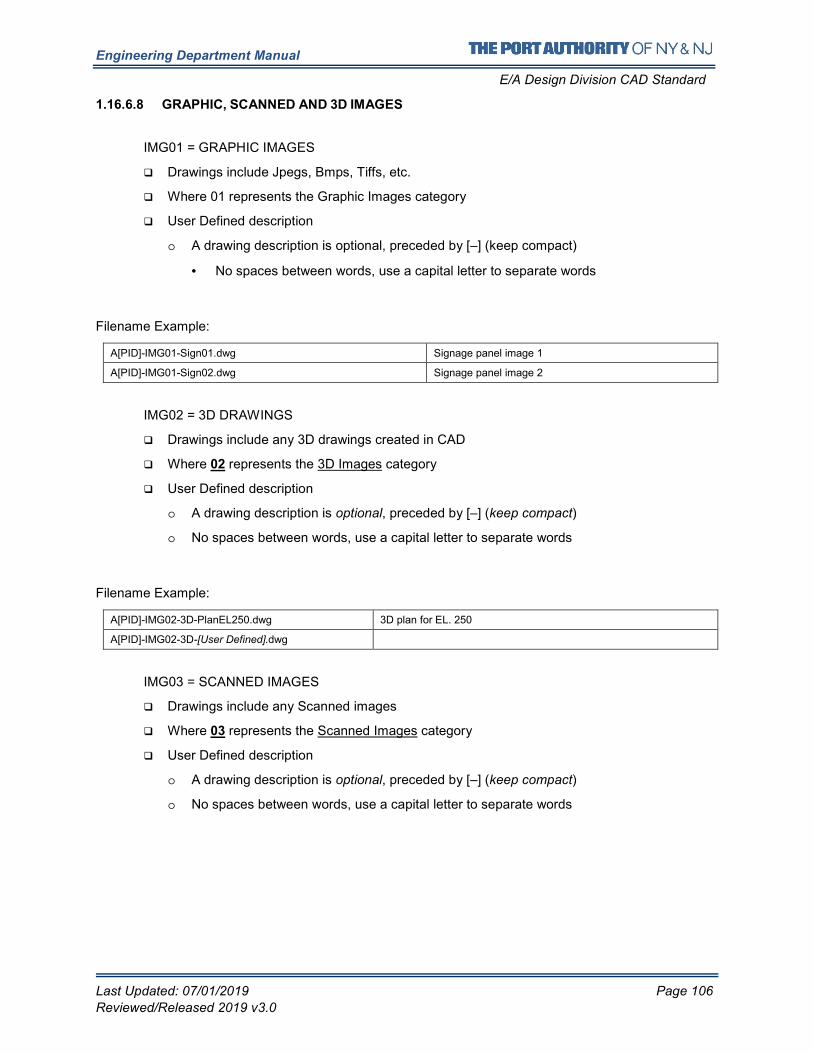
Engineering Department Manual
E/A Design Division CAD Standard
Last Updated: 07/01/2019 Page 106
Reviewed/Released 2019 v3.0
1.16.6.8 GRAPHIC, SCANNED AND 3D IMAGES
IMG01 = GRAPHIC IMAGES
� Drawings include Jpegs, Bmps, Tiffs, etc.
� Where 01 represents the Graphic Images category
� User Defined description
o A drawing description is optional, preceded by [–] (keep compact)
• No spaces between words, use a capital letter to separate words
Filename Example:
A[PID]-IMG01-Sign01.dwg Signage panel image 1
A[PID]-IMG01-Sign02.dwg Signage panel image 2
IMG02 = 3D DRAWINGS
� Drawings include any 3D drawings created in CAD
� Where 02 represents the 3D Images category
� User Defined description
o A drawing description is optional, preceded by [–] (keep compact)
o No spaces between words, use a capital letter to separate words
Filename Example:
A[PID]-IMG02-3D-PlanEL250.dwg 3D plan for EL. 250
A[PID]-IMG02-3D-[User Defined].dwg
IMG03 = SCANNED IMAGES
� Drawings include any Scanned images
� Where 03 represents the Scanned Images category
� User Defined description
o A drawing description is optional, preceded by [–] (keep compact)
o No spaces between words, use a capital letter to separate words
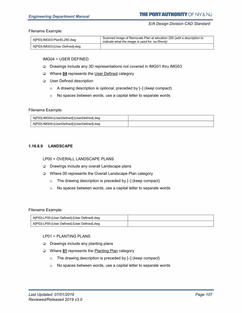
Engineering Department Manual
E/A Design Division CAD Standard
Last Updated: 07/01/2019 Page 107
Reviewed/Released 2019 v3.0
Filename Example:
A[PID]-IMG03-PlanEL250.dwg Scanned image of Removals Plan at elevation 250 (add a description to indicate what the image is used for. ex:Rmvls)
A[PID]-IMG03-[User Defined].dwg
IMG04 = USER DEFINED
� Drawings include any 3D representations not covered in IMG01 thru IMG03
� Where 04 represents the User Defined category
� User Defined description
o A drawing description is optional, preceded by [–] (keep compact)
o No spaces between words, use a capital letter to separate words
Filename Example:
A[PID]-IMG04-[UserDefined]-[UserDefined].dwg
A[PID]-IMG04-[UserDefined]-[UserDefined].dwg
1.16.6.9 LANDSCAPE
LP00 = OVERALL LANDSCAPE PLANS
� Drawings include any overall Landscape plans
� Where 00 represents the Overall Landscape Plan category
o The drawing description is preceded by [–] (keep compact)
o No spaces between words, use a capital letter to separate words
Filename Example:
A[PID]-LP00-[User Defined]-[User Defined].dwg
A[PID]-LP00-[User Defined]-[User Defined].dwg
LP01 = PLANTING PLANS
� Drawings include any planting plans
� Where 01 represents the Planting Plan category
o The drawing description is preceded by [–] (keep compact)
o No spaces between words, use a capital letter to separate words
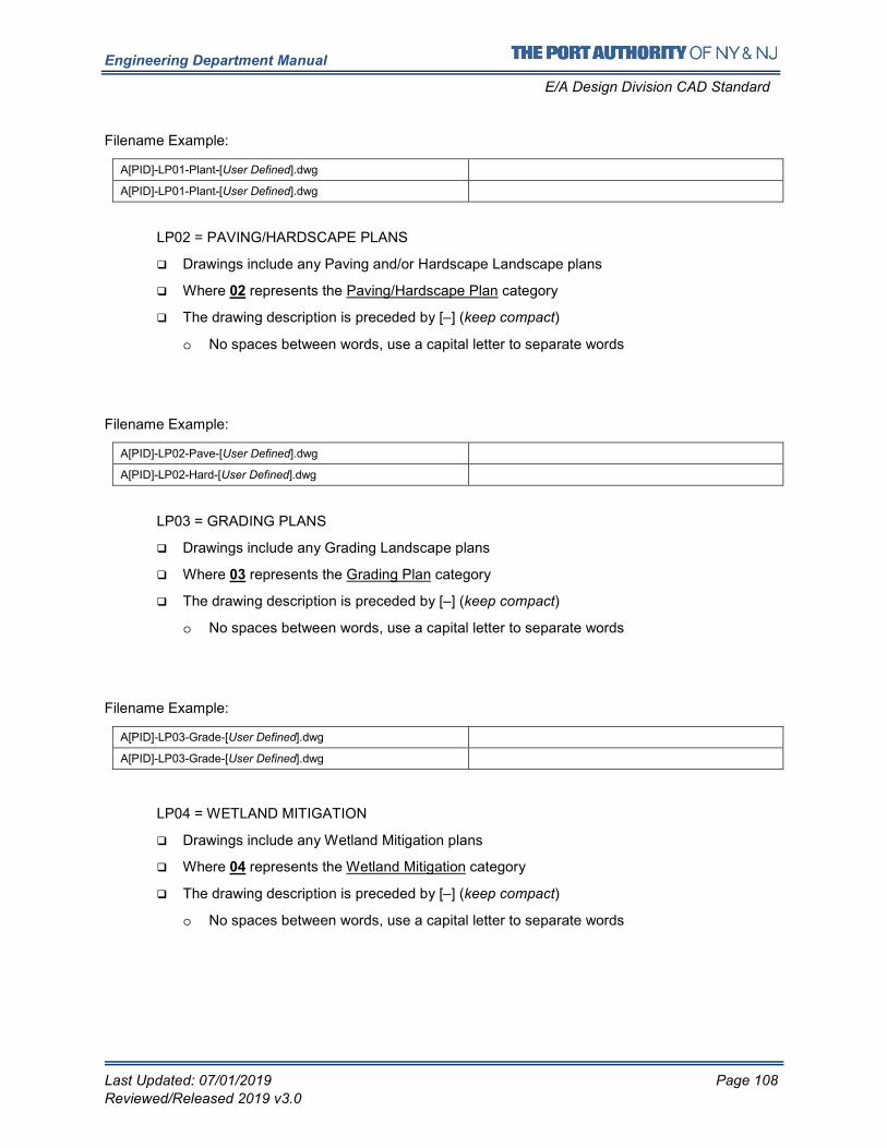
Engineering Department Manual
E/A Design Division CAD Standard
Last Updated: 07/01/2019 Page 108
Reviewed/Released 2019 v3.0
Filename Example:
A[PID]-LP01-Plant-[User Defined].dwg
A[PID]-LP01-Plant-[User Defined].dwg
LP02 = PAVING/HARDSCAPE PLANS
� Drawings include any Paving and/or Hardscape Landscape plans
� Where 02 represents the Paving/Hardscape Plan category
� The drawing description is preceded by [–] (keep compact)
o No spaces between words, use a capital letter to separate words
Filename Example:
A[PID]-LP02-Pave-[User Defined].dwg
A[PID]-LP02-Hard-[User Defined].dwg
LP03 = GRADING PLANS
� Drawings include any Grading Landscape plans
� Where 03 represents the Grading Plan category
� The drawing description is preceded by [–] (keep compact)
o No spaces between words, use a capital letter to separate words
Filename Example:
A[PID]-LP03-Grade-[User Defined].dwg
A[PID]-LP03-Grade-[User Defined].dwg
LP04 = WETLAND MITIGATION
� Drawings include any Wetland Mitigation plans
� Where 04 represents the Wetland Mitigation category
� The drawing description is preceded by [–] (keep compact)
o No spaces between words, use a capital letter to separate words
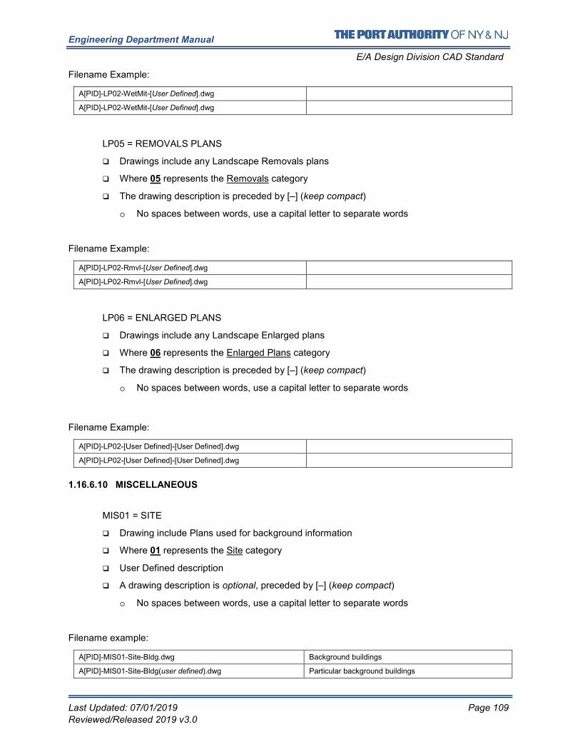
Engineering Department Manual
E/A Design Division CAD Standard
Last Updated: 07/01/2019 Page 109
Reviewed/Released 2019 v3.0
Filename Example:
A[PID]-LP02-WetMit-[User Defined].dwg
A[PID]-LP02-WetMit-[User Defined].dwg
LP05 = REMOVALS PLANS
� Drawings include any Landscape Removals plans
� Where 05 represents the Removals category
� The drawing description is preceded by [–] (keep compact)
o No spaces between words, use a capital letter to separate words
Filename Example:
A[PID]-LP02-Rmvl-[User Defined].dwg
A[PID]-LP02-Rmvl-[User Defined].dwg
LP06 = ENLARGED PLANS
� Drawings include any Landscape Enlarged plans
� Where 06 represents the Enlarged Plans category
� The drawing description is preceded by [–] (keep compact)
o No spaces between words, use a capital letter to separate words
Filename Example:
A[PID]-LP02-[User Defined]-[User Defined].dwg
A[PID]-LP02-[User Defined]-[User Defined].dwg
1.16.6.10 MISCELLANEOUS
MIS01 = SITE
� Drawing include Plans used for background information
� Where 01 represents the Site category
� User Defined description
� A drawing description is optional, preceded by [–] (keep compact)
o No spaces between words, use a capital letter to separate words
Filename example:
A[PID]-MIS01-Site-Bldg.dwg Background buildings
A[PID]-MIS01-Site-Bldg(user defined).dwg Particular background buildings
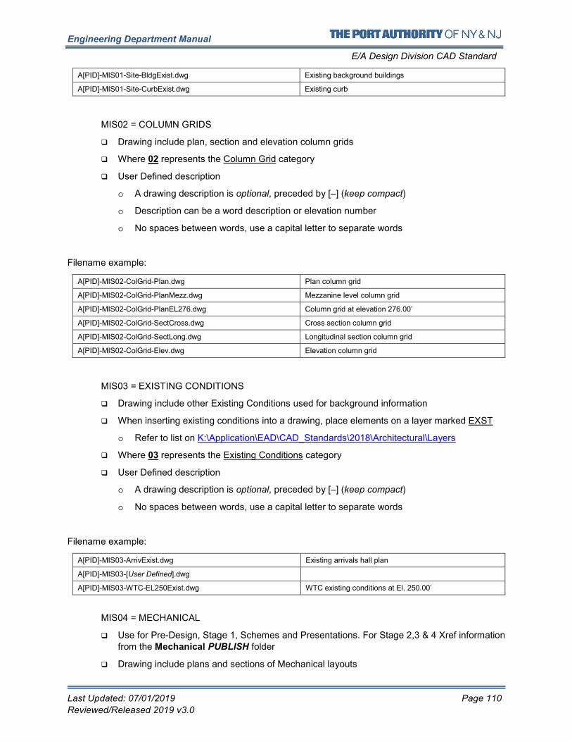
Engineering Department Manual
E/A Design Division CAD Standard
Last Updated: 07/01/2019 Page 110
Reviewed/Released 2019 v3.0
A[PID]-MIS01-Site-BldgExist.dwg Existing background buildings
A[PID]-MIS01-Site-CurbExist.dwg Existing curb
MIS02 = COLUMN GRIDS
� Drawing include plan, section and elevation column grids
� Where 02 represents the Column Grid category
� User Defined description
o A drawing description is optional, preceded by [–] (keep compact)
o Description can be a word description or elevation number
o No spaces between words, use a capital letter to separate words
Filename example:
A[PID]-MIS02-ColGrid-Plan.dwg Plan column grid
A[PID]-MIS02-ColGrid-PlanMezz.dwg Mezzanine level column grid
A[PID]-MIS02-ColGrid-PlanEL276.dwg Column grid at elevation 276.00’
A[PID]-MIS02-ColGrid-SectCross.dwg Cross section column grid
A[PID]-MIS02-ColGrid-SectLong.dwg Longitudinal section column grid
A[PID]-MIS02-ColGrid-Elev.dwg Elevation column grid
MIS03 = EXISTING CONDITIONS
� Drawing include other Existing Conditions used for background information
� When inserting existing conditions into a drawing, place elements on a layer marked EXST
o Refer to list on K:\Application\EAD\CAD_Standards\2018\Architectural\Layers
� Where 03 represents the Existing Conditions category
� User Defined description
o A drawing description is optional, preceded by [–] (keep compact)
o No spaces between words, use a capital letter to separate words
Filename example:
A[PID]-MIS03-ArrivExist.dwg Existing arrivals hall plan
A[PID]-MIS03-[User Defined].dwg
A[PID]-MIS03-WTC-EL250Exist.dwg WTC existing conditions at El. 250.00’
MIS04 = MECHANICAL
� Use for Pre-Design, Stage 1, Schemes and Presentations. For Stage 2,3 & 4 Xref information from the Mechanical PUBLISH folder
� Drawing include plans and sections of Mechanical layouts
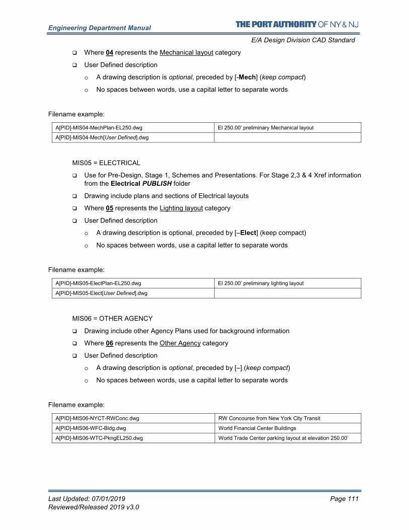
Engineering Department Manual
E/A Design Division CAD Standard
Last Updated: 07/01/2019 Page 111
Reviewed/Released 2019 v3.0
� Where 04 represents the Mechanical layout category
� User Defined description
o A drawing description is optional, preceded by [-Mech] (keep compact)
o No spaces between words, use a capital letter to separate words
Filename example:
A[PID]-MIS04-MechPlan-EL250.dwg El 250.00’ preliminary Mechanical layout
A[PID]-MIS04-Mech[User Defined].dwg
MIS05 = ELECTRICAL
� Use for Pre-Design, Stage 1, Schemes and Presentations. For Stage 2,3 & 4 Xref information
from the Electrical PUBLISH folder
� Drawing include plans and sections of Electrical layouts
� Where 05 represents the Lighting layout category
� User Defined description
o A drawing description is optional, preceded by [–Elect] (keep compact)
o No spaces between words, use a capital letter to separate words
Filename example:
A[PID]-MIS05-ElectPlan-EL250.dwg El 250.00’ preliminary lighting layout
A[PID]-MIS05-Elect[User Defined].dwg
MIS06 = OTHER AGENCY
� Drawing include other Agency Plans used for background information
� Where 06 represents the Other Agency category
� User Defined description
o A drawing description is optional, preceded by [–] (keep compact)
o No spaces between words, use a capital letter to separate words
Filename example:
A[PID]-MIS06-NYCT-RWConc.dwg RW Concourse from New York City Transit
A[PID]-MIS06-WFC-Bldg.dwg World Financial Center Buildings
A[PID]-MIS06-WTC-PkngEL250.dwg World Trade Center parking layout at elevation 250.00’
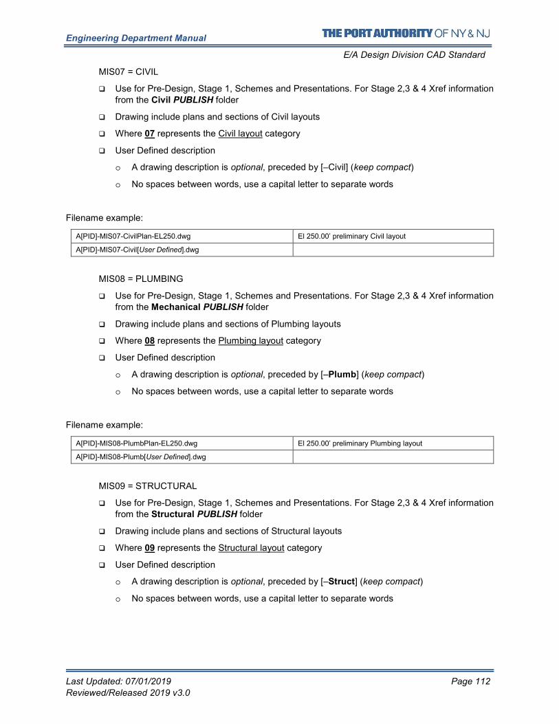
Engineering Department Manual
E/A Design Division CAD Standard
Last Updated: 07/01/2019 Page 112
Reviewed/Released 2019 v3.0
MIS07 = CIVIL
� Use for Pre-Design, Stage 1, Schemes and Presentations. For Stage 2,3 & 4 Xref information
from the Civil PUBLISH folder
� Drawing include plans and sections of Civil layouts
� Where 07 represents the Civil layout category
� User Defined description
o A drawing description is optional, preceded by [–Civil] (keep compact)
o No spaces between words, use a capital letter to separate words
Filename example:
A[PID]-MIS07-CivilPlan-EL250.dwg El 250.00’ preliminary Civil layout
A[PID]-MIS07-Civil[User Defined].dwg
MIS08 = PLUMBING
� Use for Pre-Design, Stage 1, Schemes and Presentations. For Stage 2,3 & 4 Xref information from the Mechanical PUBLISH folder
� Drawing include plans and sections of Plumbing layouts
� Where 08 represents the Plumbing layout category
� User Defined description
o A drawing description is optional, preceded by [–Plumb] (keep compact)
o No spaces between words, use a capital letter to separate words
Filename example:
A[PID]-MIS08-PlumbPlan-EL250.dwg El 250.00’ preliminary Plumbing layout
A[PID]-MIS08-Plumb[User Defined].dwg
MIS09 = STRUCTURAL
� Use for Pre-Design, Stage 1, Schemes and Presentations. For Stage 2,3 & 4 Xref information
from the Structural PUBLISH folder
� Drawing include plans and sections of Structural layouts
� Where 09 represents the Structural layout category
� User Defined description
o A drawing description is optional, preceded by [–Struct] (keep compact)
o No spaces between words, use a capital letter to separate words
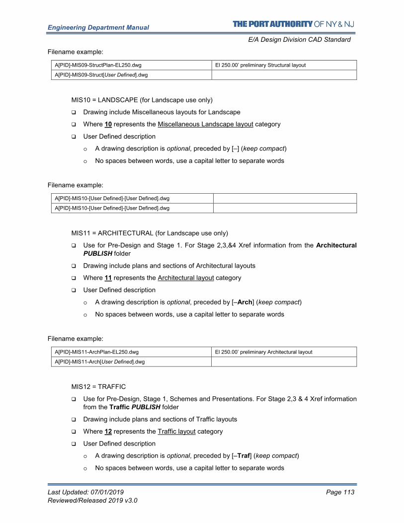
Engineering Department Manual
E/A Design Division CAD Standard
Last Updated: 07/01/2019 Page 113
Reviewed/Released 2019 v3.0
Filename example:
A[PID]-MIS09-StructPlan-EL250.dwg El 250.00’ preliminary Structural layout
A[PID]-MIS09-Struct[User Defined].dwg
MIS10 = LANDSCAPE (for Landscape use only)
� Drawing include Miscellaneous layouts for Landscape
� Where 10 represents the Miscellaneous Landscape layout category
� User Defined description
o A drawing description is optional, preceded by [–] (keep compact)
o No spaces between words, use a capital letter to separate words
Filename example:
A[PID]-MIS10-[User Defined]-[User Defined].dwg
A[PID]-MIS10-[User Defined]-[User Defined].dwg
MIS11 = ARCHITECTURAL (for Landscape use only)
� Use for Pre-Design and Stage 1. For Stage 2,3,&4 Xref information from the Architectural
PUBLISH folder
� Drawing include plans and sections of Architectural layouts
� Where 11 represents the Architectural layout category
� User Defined description
o A drawing description is optional, preceded by [–Arch] (keep compact)
o No spaces between words, use a capital letter to separate words
Filename example:
A[PID]-MIS11-ArchPlan-EL250.dwg El 250.00’ preliminary Architectural layout
A[PID]-MIS11-Arch[User Defined].dwg
MIS12 = TRAFFIC
� Use for Pre-Design, Stage 1, Schemes and Presentations. For Stage 2,3 & 4 Xref information
from the Traffic PUBLISH folder
� Drawing include plans and sections of Traffic layouts
� Where 12 represents the Traffic layout category
� User Defined description
o A drawing description is optional, preceded by [–Traf] (keep compact)
o No spaces between words, use a capital letter to separate words
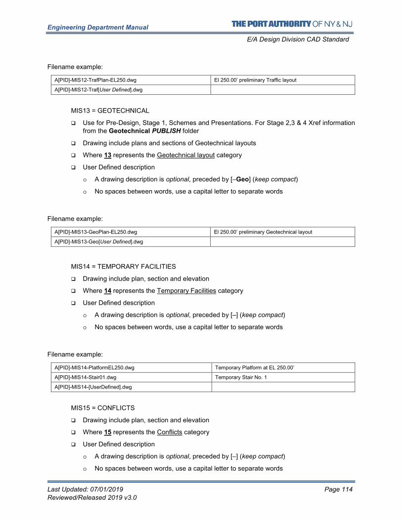
Engineering Department Manual
E/A Design Division CAD Standard
Last Updated: 07/01/2019 Page 114
Reviewed/Released 2019 v3.0
Filename example:
A[PID]-MIS12-TrafPlan-EL250.dwg El 250.00’ preliminary Traffic layout
A[PID]-MIS12-Traf[User Defined].dwg
MIS13 = GEOTECHNICAL
� Use for Pre-Design, Stage 1, Schemes and Presentations. For Stage 2,3 & 4 Xref information from the Geotechnical PUBLISH folder
� Drawing include plans and sections of Geotechnical layouts
� Where 13 represents the Geotechnical layout category
� User Defined description
o A drawing description is optional, preceded by [–Geo] (keep compact)
o No spaces between words, use a capital letter to separate words
Filename example:
A[PID]-MIS13-GeoPlan-EL250.dwg El 250.00’ preliminary Geotechnical layout
A[PID]-MIS13-Geo[User Defined].dwg
MIS14 = TEMPORARY FACILITIES
� Drawing include plan, section and elevation
� Where 14 represents the Temporary Facilities category
� User Defined description
o A drawing description is optional, preceded by [–] (keep compact)
o No spaces between words, use a capital letter to separate words
Filename example:
A[PID]-MIS14-PlatformEL250.dwg Temporary Platform at EL 250.00’
A[PID]-MIS14-Stair01.dwg Temporary Stair No. 1
A[PID]-MIS14-[UserDefined].dwg
MIS15 = CONFLICTS
� Drawing include plan, section and elevation
� Where 15 represents the Conflicts category
� User Defined description
o A drawing description is optional, preceded by [–] (keep compact)
o No spaces between words, use a capital letter to separate words
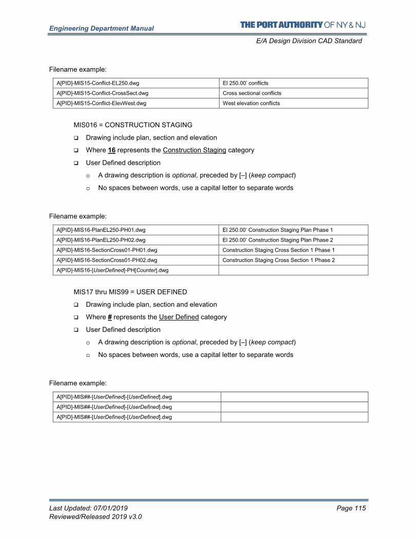
Engineering Department Manual
E/A Design Division CAD Standard
Last Updated: 07/01/2019 Page 115
Reviewed/Released 2019 v3.0
Filename example:
A[PID]-MIS15-Conflict-EL250.dwg El 250.00’ conflicts
A[PID]-MIS15-Conflict-CrossSect.dwg Cross sectional conflicts
A[PID]-MIS15-Conflict-ElevWest.dwg West elevation conflicts
MIS016 = CONSTRUCTION STAGING
� Drawing include plan, section and elevation
� Where 16 represents the Construction Staging category
� User Defined description
o A drawing description is optional, preceded by [–] (keep compact)
o No spaces between words, use a capital letter to separate words
Filename example:
A[PID]-MIS16-PlanEL250-PH01.dwg El 250.00’ Construction Staging Plan Phase 1
A[PID]-MIS16-PlanEL250-PH02.dwg El 250.00’ Construction Staging Plan Phase 2
A[PID]-MIS16-SectionCross01-PH01.dwg Construction Staging Cross Section 1 Phase 1
A[PID]-MIS16-SectionCross01-PH02.dwg Construction Staging Cross Section 1 Phase 2
A[PID]-MIS16-[UserDefined]-PH[Counter].dwg
MIS17 thru MIS99 = USER DEFINED
� Drawing include plan, section and elevation
� Where # represents the User Defined category
� User Defined description
o A drawing description is optional, preceded by [–] (keep compact)
o No spaces between words, use a capital letter to separate words
Filename example:
A[PID]-MIS##-[UserDefined]-[UserDefined].dwg
A[PID]-MIS##-[UserDefined]-[UserDefined].dwg
A[PID]-MIS##-[UserDefined]-[UserDefined].dwg
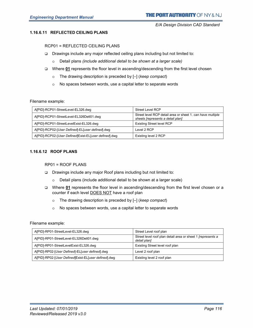
Engineering Department Manual
E/A Design Division CAD Standard
Last Updated: 07/01/2019 Page 116
Reviewed/Released 2019 v3.0
1.16.6.11 REFLECTED CEILING PLANS
RCP01 = REFLECTED CEILING PLANS
� Drawings include any major reflected ceiling plans including but not limited to:
o Detail plans (include additional detail to be shown at a larger scale)
� Where 01 represents the floor level in ascending/descending from the first level chosen
o The drawing description is preceded by [–] (keep compact)
o No spaces between words, use a capital letter to separate words
Filename example:
A[PID]-RCP01-StreetLevel-EL326.dwg Street Level RCP
A[PID]-RCP01-StreetLevel-EL326Detl01.dwg Street level RCP detail area or sheet 1. can have multiple sheets [represents a detail plan]
A[PID]-RCP01-StreetLevelExist-EL326.dwg Existing Street level RCP
A[PID]-RCP02-[User Defined]-EL[user defined].dwg Level 2 RCP
A[PID]-RCP02-[User Defined]Exist-EL[user defined].dwg Existing level 2 RCP
1.16.6.12 ROOF PLANS
RP01 = ROOF PLANS
� Drawings include any major Roof plans including but not limited to:
o Detail plans (include additional detail to be shown at a larger scale)
� Where 01 represents the floor level in ascending/descending from the first level chosen or a
counter if each level DOES NOT have a roof plan
o The drawing description is preceded by [–] (keep compact)
o No spaces between words, use a capital letter to separate words
Filename example:
A[PID]-RP01-StreetLevel-EL326.dwg Street Level roof plan
A[PID]-RP01-StreetLevel-EL326Detl01.dwg Street level roof plan detail area or sheet 1 [represents a detail plan]
A[PID]-RP01-StreetLevelExist-EL326.dwg Existing Street level roof plan
A[PID]-RP02-[User Defined]-EL[user defined].dwg Level 2 roof plan
A[PID]-RP02-[User Defined]Exist-EL[user defined].dwg Existing level 2 roof plan
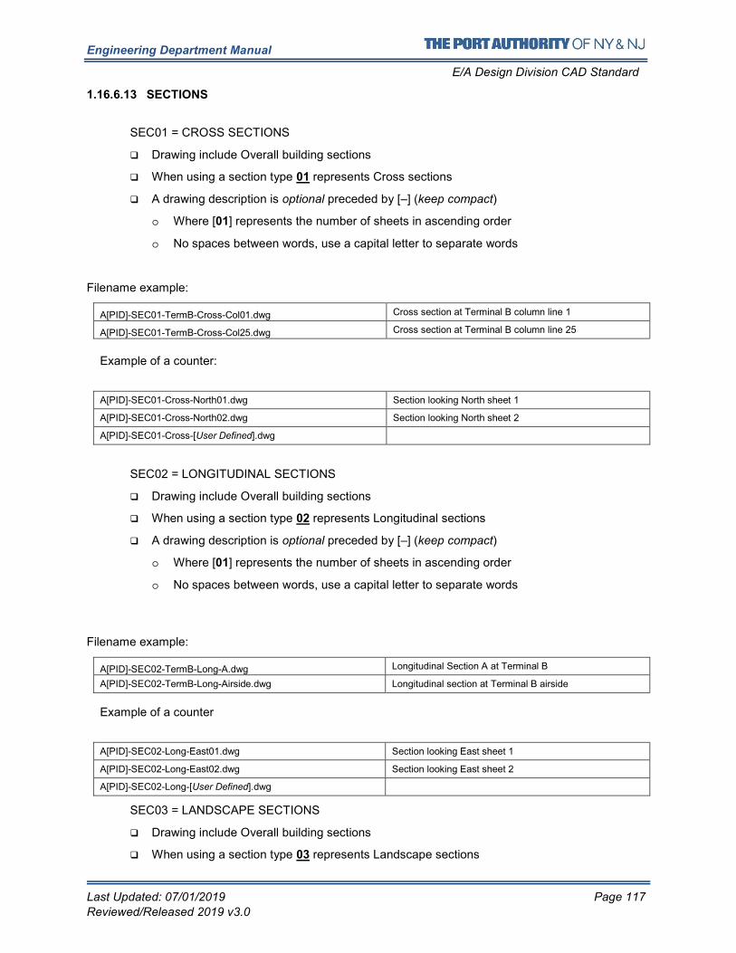
Engineering Department Manual
E/A Design Division CAD Standard
Last Updated: 07/01/2019 Page 117
Reviewed/Released 2019 v3.0
1.16.6.13 SECTIONS
SEC01 = CROSS SECTIONS
� Drawing include Overall building sections
� When using a section type 01 represents Cross sections
� A drawing description is optional preceded by [–] (keep compact)
o Where [01] represents the number of sheets in ascending order
o No spaces between words, use a capital letter to separate words
Filename example:
A[PID]-SEC01-TermB-Cross-Col01.dwg Cross section at Terminal B column line 1
A[PID]-SEC01-TermB-Cross-Col25.dwg Cross section at Terminal B column line 25
Example of a counter:
A[PID]-SEC01-Cross-North01.dwg Section looking North sheet 1
A[PID]-SEC01-Cross-North02.dwg Section looking North sheet 2
A[PID]-SEC01-Cross-[User Defined].dwg
SEC02 = LONGITUDINAL SECTIONS
� Drawing include Overall building sections
� When using a section type 02 represents Longitudinal sections
� A drawing description is optional preceded by [–] (keep compact)
o Where [01] represents the number of sheets in ascending order
o No spaces between words, use a capital letter to separate words
Filename example:
A[PID]-SEC02-TermB-Long-A.dwg Longitudinal Section A at Terminal B
A[PID]-SEC02-TermB-Long-Airside.dwg Longitudinal section at Terminal B airside
Example of a counter
A[PID]-SEC02-Long-East01.dwg Section looking East sheet 1
A[PID]-SEC02-Long-East02.dwg Section looking East sheet 2
A[PID]-SEC02-Long-[User Defined].dwg
SEC03 = LANDSCAPE SECTIONS
� Drawing include Overall building sections
� When using a section type 03 represents Landscape sections
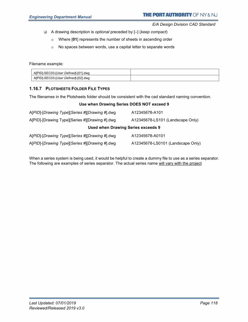
Engineering Department Manual
E/A Design Division CAD Standard
Last Updated: 07/01/2019 Page 118
Reviewed/Released 2019 v3.0
� A drawing description is optional preceded by [–] (keep compact)
o Where [01] represents the number of sheets in ascending order
o No spaces between words, use a capital letter to separate words
Filename example:
A[PID]-SEC03-[User Defined]-[01].dwg
A[PID]-SEC03-[User Defined]-[02].dwg
1.16.7 PLOTSHEETS FOLDER FILE TYPES
The filenames in the Plotsheets folder should be consistent with the cad standard naming convention.
Use when Drawing Series DOES NOT exceed 9
A[PID]-[Drawing Type][Series #][Drawing #].dwg A12345678-A101
A[PID]-[Drawing Type][Series #][Drawing #].dwg A12345678-LS101 (Landscape Only)
Used when Drawing Series exceeds 9
A[PID]-[Drawing Type][Series #][Drawing #].dwg A12345678-A0101
A[PID]-[Drawing Type][Series #][Drawing #].dwg A12345678-LS0101 (Landscape Only)
When a series system is being used, it would be helpful to create a dummy file to use as a series separator.
The following are examples of series separator. The actual series name will vary with the project
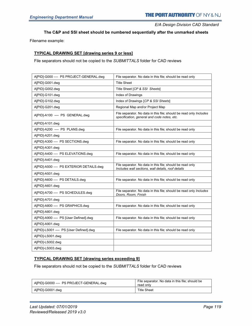
Engineering Department Manual
E/A Design Division CAD Standard
Last Updated: 07/01/2019 Page 119
Reviewed/Released 2019 v3.0
The C&P and SSI sheet should be numbered sequentially after the unmarked sheets
Filename example:
TYPICAL DRAWING SET [drawing series 9 or less]
File separators should not be copied to the SUBMITTALS folder for CAD reviews
A[PID]-G000 ---- PS PROJECT-GENERAL.dwg File separator. No data in this file; should be read only
A[PID]-G001.dwg Title Sheet
A[PID]-G002.dwg Title Sheet [CP & SSI Sheets]
A[PID]-G101.dwg Index of Drawings
A[PID]-G102.dwg Index of Drawings [CP & SSI Sheets]
A[PID]-G201.dwg Regional Map and/or Project Map
A[PID]-A100 ---- PS GENERAL.dwg File separator. No data in this file; should be read only Includes specification, general and code notes, etc.
A[PID]-A101.dwg
A[PID]-A200 ---- PS PLANS.dwg File separator. No data in this file; should be read only
A[PID]-A201.dwg
A[PID]-A300 ---- PS SECTIONS.dwg File separator. No data in this file; should be read only
A[PID]-A301.dwg
A[PID]-A400 ---- PS ELEVATIONS.dwg File separator. No data in this file; should be read only
A[PID]-A401.dwg
A[PID]-A500 ---- PS EXTERIOR DETAILS.dwg File separator. No data in this file; should be read only Includes wall sections, wall details, roof details
A[PID]-A501.dwg
A[PID]-A600 ---- PS DETAILS.dwg File separator. No data in this file; should be read only
A[PID]-A601.dwg
A[PID]-A700 ---- PS SCHEDULES.dwg File separator. No data in this file; should be read only Includes Doors, Room, Finish
A[PID]-A701.dwg
A[PID]-A800 ---- PS GRAPHICS.dwg File separator. No data in this file; should be read only
A[PID]-A801.dwg
A[PID]-A900 ---- PS [User Defined].dwg File separator. No data in this file; should be read only
A[PID]-A901.dwg
A[PID]-LS001 ---- PS [User Defined].dwg File separator. No data in this file; should be read only
A[PID]-LS001.dwg
A[PID]-LS002.dwg
A[PID]-LS003.dwg
TYPICAL DRAWING SET [drawing series exceeding 9]
File separators should not be copied to the SUBMITTALS folder for CAD reviews
A[PID]-G0000 ---- PS PROJECT-GENERAL.dwg File separator. No data in this file; should be read only
A[PID]-G0001.dwg Title Sheet
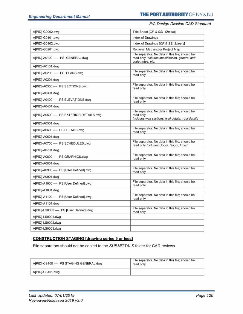
Engineering Department Manual
E/A Design Division CAD Standard
Last Updated: 07/01/2019 Page 120
Reviewed/Released 2019 v3.0
A[PID]-G0002.dwg Title Sheet [CP & SSI Sheets]
A[PID]-G0101.dwg Index of Drawings
A[PID]-G0102.dwg Index of Drawings [CP & SSI Sheets]
A[PID]-G0201.dwg Regional Map and/or Project Map
A[PID]-A0100 ---- PS GENERAL.dwg File separator. No data in this file; should be read only Includes specification, general and code notes, etc.
A[PID]-A0101.dwg
A[PID]-A0200 ---- PS PLANS.dwg File separator. No data in this file; should be read only
A[PID]-A0201.dwg
A[PID]-A0300 ---- PS SECTIONS.dwg File separator. No data in this file; should be read only
A[PID]-A0301.dwg
A[PID]-A0400 ---- PS ELEVATIONS.dwg File separator. No data in this file; should be read only
A[PID]-A0401.dwg
A[PID]-A0500 ---- PS EXTERIOR DETAILS.dwg File separator. No data in this file; should be read only Includes wall sections, wall details, roof details
A[PID]-A0501.dwg
A[PID]-A0600 ---- PS DETAILS.dwg File separator. No data in this file; should be read only
A[PID]-A0601.dwg
A[PID]-A0700 ---- PS SCHEDULES.dwg File separator. No data in this file; should be read only Includes Doors, Room, Finish
A[PID]-A0701.dwg
A[PID]-A0800 ---- PS GRAPHICS.dwg File separator. No data in this file; should be read only
A[PID]-A0801.dwg
A[PID]-A0900 ---- PS [User Defined].dwg File separator. No data in this file; should be read only
A[PID]-A0901.dwg
A[PID]-A1000 ---- PS [User Defined].dwg File separator. No data in this file; should be read only
A[PID]-A1001.dwg
A[PID]-A1100 ---- PS [User Defined].dwg File separator. No data in this file; should be read only
A[PID]-A1101.dwg
A[PID]-LS0000 ---- PS [User Defined].dwg File separator. No data in this file; should be read only
A[PID]-LS0001.dwg
A[PID]-LS0002.dwg
A[PID]-LS0003.dwg
CONSTRUCTION STAGING [drawing series 9 or less]
File separators should not be copied to the SUBMITTALS folder for CAD reviews
A[PID]-CS100 ---- PS STAGING GENERAL.dwg File separator. No data in this file; should be
read only
A[PID]-CS101.dwg
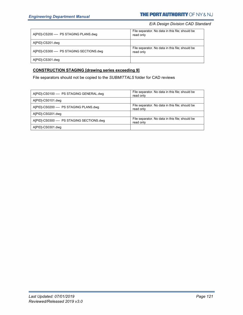
Engineering Department Manual
E/A Design Division CAD Standard
Last Updated: 07/01/2019 Page 121
Reviewed/Released 2019 v3.0
A[PID]-CS200 ---- PS STAGING PLANS.dwg File separator. No data in this file; should be
read only
A[PID]-CS201.dwg
A[PID]-CS300 ---- PS STAGING SECTIONS.dwg File separator. No data in this file; should be read only
A[PID]-CS301.dwg
CONSTRUCTION STAGING [drawing series exceeding 9]
File separators should not be copied to the SUBMITTALS folder for CAD reviews
A[PID]-CS0100 ---- PS STAGING GENERAL.dwg File separator. No data in this file; should be read only
A[PID]-CS0101.dwg
A[PID]-CS0200 ---- PS STAGING PLANS.dwg File separator. No data in this file; should be read only
A[PID]-CS0201.dwg
A[PID]-CS0300 ---- PS STAGING SECTIONS.dwg File separator. No data in this file; should be read only
A[PID]-CS0301.dwg
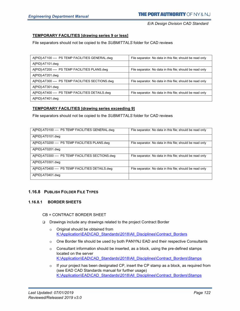
Engineering Department Manual
E/A Design Division CAD Standard
Last Updated: 07/01/2019 Page 122
Reviewed/Released 2019 v3.0
TEMPORARY FACILITIES [drawing series 9 or less]
File separators should not be copied to the SUBMITTALS folder for CAD reviews
A[PID]-AT100 ---- PS TEMP FACILITIES GENERAL.dwg File separator. No data in this file; should be read only
A[PID]-AT101.dwg
A[PID]-AT200 ---- PS TEMP FACILITIES PLANS.dwg File separator. No data in this file; should be read only
A[PID]-AT201.dwg
A[PID]-AT300 ---- PS TEMP FACILITIES SECTIONS.dwg File separator. No data in this file; should be read only
A[PID]-AT301.dwg
A[PID]-AT400 ---- PS TEMP FACILITIES DETAILS.dwg File separator. No data in this file; should be read only
A[PID]-AT401.dwg
TEMPORARY FACILITIES [drawing series exceeding 9]
File separators should not be copied to the SUBMITTALS folder for CAD reviews
A[PID]-AT0100 ---- PS TEMP FACILITIES GENERAL.dwg File separator. No data in this file; should be read only
A[PID]-AT0101.dwg
A[PID]-AT0200 ---- PS TEMP FACILITIES PLANS.dwg File separator. No data in this file; should be read only
A[PID]-AT0201.dwg
A[PID]-AT0300 ---- PS TEMP FACILITIES SECTIONS.dwg File separator. No data in this file; should be read only
A[PID]-AT0301.dwg
A[PID]-AT0400 ---- PS TEMP FACILITIES DETAILS.dwg File separator. No data in this file; should be read only
A[PID]-AT0401.dwg
1.16.8 PUBLISH FOLDER FILE TYPES
1.16.8.1 BORDER SHEETS
CB = CONTRACT BORDER SHEET
� Drawings include any drawings related to the project Contract Border
o Original should be obtained from
K:\Application\EAD\CAD_Standards\2018\All_Disciplines\Contract_Borders
o One Border file should be used by both PANYNJ EAD and their respective Consultants
o Consultant information should be inserted, as a block, using the pre-defined stamps
located on the server
K:\Application\EAD\CAD_Standards\2018\All_Disciplines\Contract_Borders\Stamps
o If your project has been designated CP, insert the CP stamp as a block, as required from
(see EAD CAD Standards manual for further usage)
K:\Application\EAD\CAD_Standards\2018\All_Disciplines\Contract_Borders\Stamps
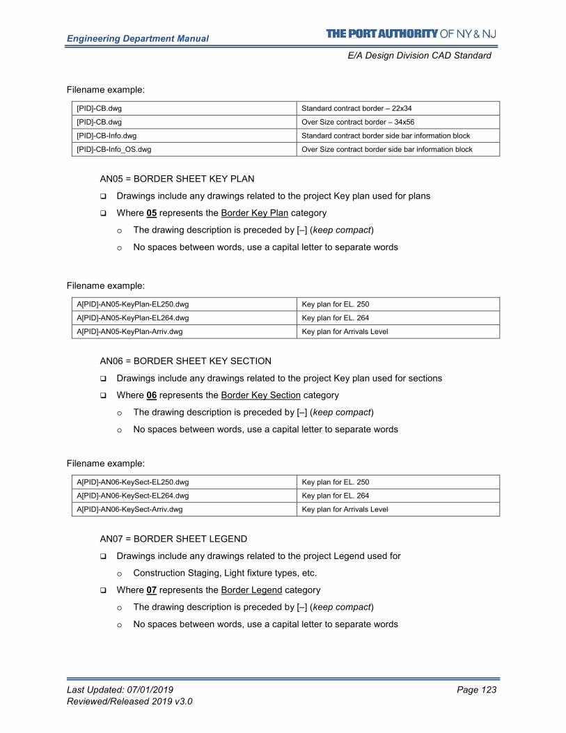
Engineering Department Manual
E/A Design Division CAD Standard
Last Updated: 07/01/2019 Page 123
Reviewed/Released 2019 v3.0
Filename example:
[PID]-CB.dwg Standard contract border – 22x34
[PID]-CB.dwg Over Size contract border – 34x56
[PID]-CB-Info.dwg Standard contract border side bar information block
[PID]-CB-Info_OS.dwg Over Size contract border side bar information block
AN05 = BORDER SHEET KEY PLAN
� Drawings include any drawings related to the project Key plan used for plans
� Where 05 represents the Border Key Plan category
o The drawing description is preceded by [–] (keep compact)
o No spaces between words, use a capital letter to separate words
Filename example:
A[PID]-AN05-KeyPlan-EL250.dwg Key plan for EL. 250
A[PID]-AN05-KeyPlan-EL264.dwg Key plan for EL. 264
A[PID]-AN05-KeyPlan-Arriv.dwg Key plan for Arrivals Level
AN06 = BORDER SHEET KEY SECTION
� Drawings include any drawings related to the project Key plan used for sections
� Where 06 represents the Border Key Section category
o The drawing description is preceded by [–] (keep compact)
o No spaces between words, use a capital letter to separate words
Filename example:
A[PID]-AN06-KeySect-EL250.dwg Key plan for EL. 250
A[PID]-AN06-KeySect-EL264.dwg Key plan for EL. 264
A[PID]-AN06-KeySect-Arriv.dwg Key plan for Arrivals Level
AN07 = BORDER SHEET LEGEND
� Drawings include any drawings related to the project Legend used for
o Construction Staging, Light fixture types, etc.
� Where 07 represents the Border Legend category
o The drawing description is preceded by [–] (keep compact)
o No spaces between words, use a capital letter to separate words
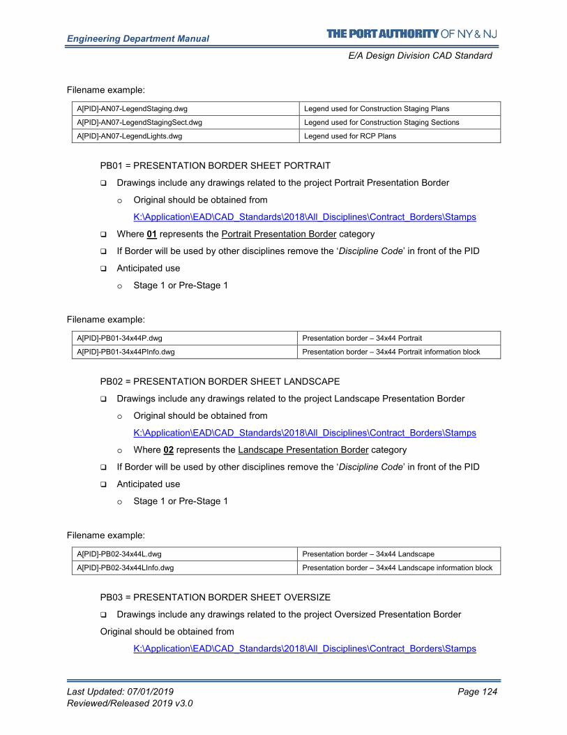
Engineering Department Manual
E/A Design Division CAD Standard
Last Updated: 07/01/2019 Page 124
Reviewed/Released 2019 v3.0
Filename example:
A[PID]-AN07-LegendStaging.dwg Legend used for Construction Staging Plans
A[PID]-AN07-LegendStagingSect.dwg Legend used for Construction Staging Sections
A[PID]-AN07-LegendLights.dwg Legend used for RCP Plans
PB01 = PRESENTATION BORDER SHEET PORTRAIT
� Drawings include any drawings related to the project Portrait Presentation Border
o Original should be obtained from
K:\Application\EAD\CAD_Standards\2018\All_Disciplines\Contract_Borders\Stamps
� Where 01 represents the Portrait Presentation Border category
� If Border will be used by other disciplines remove the ‘Discipline Code’ in front of the PID
� Anticipated use
o Stage 1 or Pre-Stage 1
Filename example:
A[PID]-PB01-34x44P.dwg Presentation border – 34x44 Portrait
A[PID]-PB01-34x44PInfo.dwg Presentation border – 34x44 Portrait information block
PB02 = PRESENTATION BORDER SHEET LANDSCAPE
� Drawings include any drawings related to the project Landscape Presentation Border
o Original should be obtained from
K:\Application\EAD\CAD_Standards\2018\All_Disciplines\Contract_Borders\Stamps
o Where 02 represents the Landscape Presentation Border category
� If Border will be used by other disciplines remove the ‘Discipline Code’ in front of the PID
� Anticipated use
o Stage 1 or Pre-Stage 1
Filename example:
A[PID]-PB02-34x44L.dwg Presentation border – 34x44 Landscape
A[PID]-PB02-34x44LInfo.dwg Presentation border – 34x44 Landscape information block
PB03 = PRESENTATION BORDER SHEET OVERSIZE
� Drawings include any drawings related to the project Oversized Presentation Border
Original should be obtained from
K:\Application\EAD\CAD_Standards\2018\All_Disciplines\Contract_Borders\Stamps
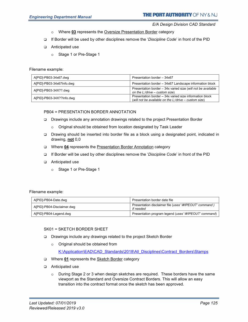
Engineering Department Manual
E/A Design Division CAD Standard
Last Updated: 07/01/2019 Page 125
Reviewed/Released 2019 v3.0
o Where 03 represents the Oversize Presentation Border category
� If Border will be used by other disciplines remove the ‘Discipline Code’ in front of the PID
� Anticipated use
o Stage 1 or Pre-Stage 1
Filename example:
A[PID]-PB03-34x67.dwg Presentation border – 34x67
A[PID]-PB03-34x67Info.dwg Presentation border – 34x67 Landscape information block
A[PID]-PB03-34X??.dwg Presentation border – 34x varied size (will not be available on the L:/drive – custom size)
A[PID]-PB03-34X??Info.dwg Presentation border – 34x varied size information block (will not be available on the L:/drive – custom size)
PB04 = PRESENTATION BORDER ANNOTATION
� Drawings include any annotation drawings related to the project Presentation Border
o Original should be obtained from location designated by Task Leader
� Drawing should be inserted into border file as a block using a designated point, indicated in drawing, not 0,0
� Where 04 represents the Presentation Border Annotation category
� If Border will be used by other disciplines remove the ‘Discipline Code’ in front of the PID
� Anticipated use
o Stage 1 or Pre-Stage 1
Filename example:
A[PID]-PB04-Date.dwg Presentation border date file
A[PID]-PB04-Disclaimer.dwg Presentation disclaimer file (uses’ WIPEOUT’ command ) if needed
A[PID]-PB04-Legend.dwg Presentation program legend (uses’ WIPEOUT’ command)
SK01 = SKETCH BORDER SHEET
� Drawings include any drawings related to the project Sketch Border
o Original should be obtained from
K:\Application\EAD\CAD_Standards\2018\All_Disciplines\Contract_Borders\Stamps
� Where 01 represents the Sketch Border category
� Anticipated use
o During Stage 2 or 3 when design sketches are required. These borders have the same
viewport as the Standard and Oversize Contract Borders. This will allow an easy
transition into the contract format once the sketch has been approved.
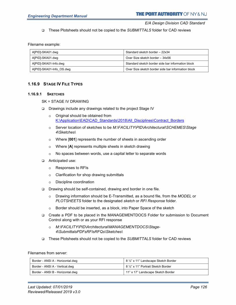
Engineering Department Manual
E/A Design Division CAD Standard
Last Updated: 07/01/2019 Page 126
Reviewed/Released 2019 v3.0
� These Plotsheets should not be copied to the SUBMITTALS folder for CAD reviews
Filename example:
A[PID]-SKA01.dwg Standard sketch border – 22x34
A[PID]-SKA01.dwg Over Size sketch border – 34x56
A[PID]-SKA01-Info.dwg Standard sketch border side bar information block
A[PID]-SKA01-Info_OS.dwg Over Size sketch border side bar information block
1.16.9 STAGE IV FILE TYPES
1.16.9.1 SKETCHES
SK = STAGE IV DRAWING
� Drawings include any drawings related to the project Stage IV
o Original should be obtained from
K:\Application\EAD\CAD_Standards\2018\All_Disciplines\Contract_Borders
o Server location of sketches to be M:\FACILITY\PID\Architectural\SCHEMES\Stage
4\Sketches\
o Where [001] represents the number of sheets in ascending order
o Where [A] represents multiple sheets in sketch drawing
o No spaces between words, use a capital letter to separate words
� Anticipated use:
o Responses to RFIs
o Clarification for shop drawing submittals
o Discipline coordination
� Drawing should be self-contained, drawing and border in one file.
o Drawing information should be E-Transmitted, as a bound file, from the MODEL or
PLOTSHEETS folder to the designated sketch or RFI Response folder.
o Border should be inserted, as a block, into Paper Space of the sketch
� Create a PDF to be placed in the MANAGEMENTDOCS Folder for submission to Document
Control along with or as your RFI response
o M:\FACILITY\PID\Architectural\MANAGEMENTDOCS\Stage-
4\SubmittalsPDFsRFIsRFQs\Sketches\
� These Plotsheets should not be copied to the SUBMITTALS folder for CAD reviews
Filenames from server:
Border - ANSI A - Horizontal.dwg 8 ½” x 11” Landscape Sketch Border
Border - ANSI A - Vertical.dwg 8 ½” x 11” Portrait Sketch Border
Border - ANSI B - Horizontal.dwg 11” x 17” Landscape Sketch Border
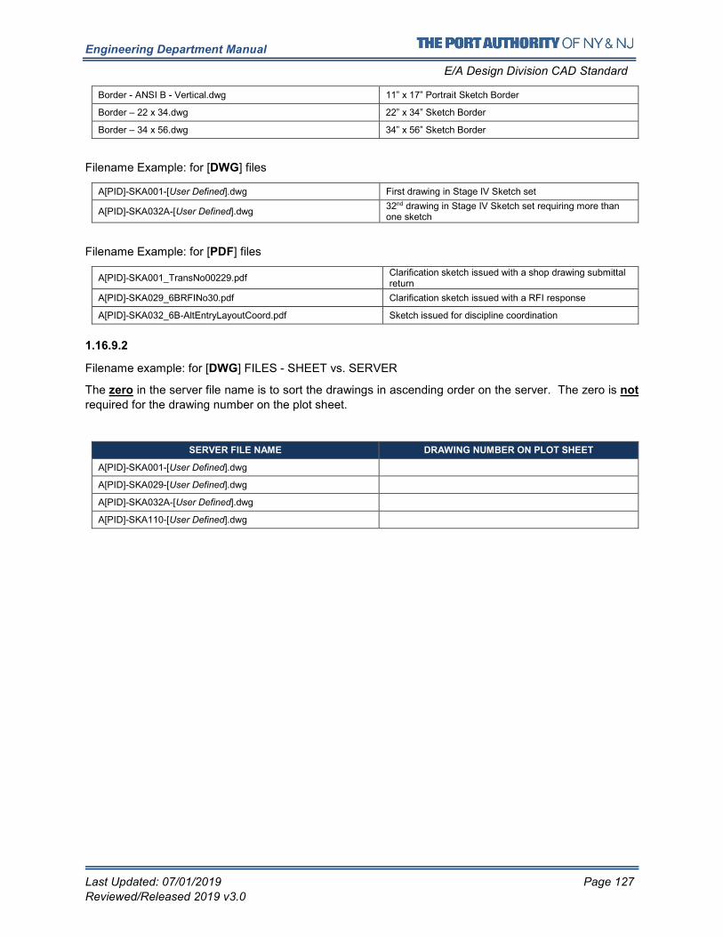
Engineering Department Manual
E/A Design Division CAD Standard
Last Updated: 07/01/2019 Page 127
Reviewed/Released 2019 v3.0
Border - ANSI B - Vertical.dwg 11” x 17” Portrait Sketch Border
Border – 22 x 34.dwg 22” x 34” Sketch Border
Border – 34 x 56.dwg 34” x 56” Sketch Border
Filename Example: for [DWG] files
A[PID]-SKA001-[User Defined].dwg First drawing in Stage IV Sketch set
A[PID]-SKA032A-[User Defined].dwg 32nd drawing in Stage IV Sketch set requiring more than one sketch
Filename Example: for [PDF] files
A[PID]-SKA001_TransNo00229.pdf Clarification sketch issued with a shop drawing submittal return
A[PID]-SKA029_6BRFINo30.pdf Clarification sketch issued with a RFI response
A[PID]-SKA032_6B-AltEntryLayoutCoord.pdf Sketch issued for discipline coordination
1.16.9.2
Filename example: for [DWG] FILES - SHEET vs. SERVER
The zero in the server file name is to sort the drawings in ascending order on the server. The zero is not
required for the drawing number on the plot sheet.
SERVER FILE NAME DRAWING NUMBER ON PLOT SHEET
A[PID]-SKA001-[User Defined].dwg SKA1
A[PID]-SKA029-[User Defined].dwg SKA29
A[PID]-SKA032A-[User Defined].dwg SKA32A
A[PID]-SKA110-[User Defined].dwg SKA110
Engineering Department Manual
E/A Design Division CAD Standard
Last Updated: 07/01/2019 Page 128
Reviewed/Released 2019 v3.0
1.17 APPENDIX B – CIVIL DISCIPLINE
1.17.1 CONTENT PREFERENCES
This Section Is Under Construction
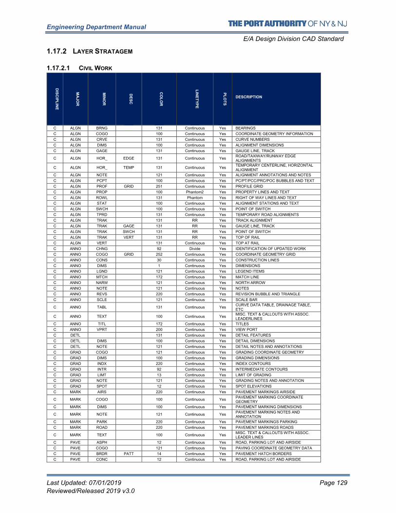
Engineering Department Manual
E/A Design Division CAD Standard
Last Updated: 07/01/2019 Page 129
Reviewed/Released 2019 v3.0
1.17.2 LAYER STRATAGEM
1.17.2.1 CIVIL WORK
DIS
CIP
LIN
E
MA
JO
R
MIN
OR
DE
SC
CO
LO
R
LIN
ET
YP
E
PL
OT
S
DESCRIPTION
C ALGN BRNG 131 Continuous Yes BEARINGS
C ALGN COGO 100 Continuous Yes COORDINATE GEOMETRY INFORMATION
C ALGN CRVE 131 Continuous Yes CURVE NUMBERS
C ALGN DIMS 100 Continuous Yes ALIGNMENT DIMENSIONS
C ALGN GAGE 131 Continuous Yes GAUGE LINE, TRACK
C ALGN HOR_ EDGE 131 Continuous Yes ROAD/TAXIWAY/RUNWAY EDGE ALIGNMENTS
C ALGN HOR_ TEMP 131 Continuous Yes TEMPORARY CENTERLINE, HORIZONTAL ALIGNMENT
C ALGN NOTE 121 Continuous Yes ALIGNMENT ANNOTATIONS AND NOTES
C ALGN PCPT 100 Continuous Yes PC/PT/PCC/PRC/POC BUBBLES AND TEXT
C ALGN PROF GRID 251 Continuous Yes PROFILE GRID
C ALGN PROP 100 Phantom2 Yes PROPERTY LINES AND TEXT
C ALGN ROWL 131 Phantom Yes RIGHT OF WAY LINES AND TEXT
C ALGN STAT 100 Continuous Yes ALIGNMENT STATIONS AND TEXT
C ALGN SWCH 100 Continuous Yes POINT OF SWITCH
C ALGN TPRD 131 Continuous Yes TEMPORARY ROAD ALIGNMENTS
C ALGN TRAK 131 RR Yes TRACK ALIGNMENT
C ALGN TRAK GAGE 131 RR Yes GAUGE LINE, TRACK
C ALGN TRAK SWCH 131 RR Yes POINT OF SWITCH
C ALGN TRAK VERT 131 RR Yes TOP OF RAIL
C ALGN VERT 131 Continuous Yes TOP AT RAIL
C ANNO CHNG 92 Divide Yes IDENTIFICATION OF UPDATED WORK
C ANNO COGO GRID 252 Continuous Yes COORDINATE GEOMETRY GRID
C ANNO CONS 30 Continuous Yes CONSTRUCTION LINES
C ANNO DIMS 1 Continuous Yes DIMENSIONS
C ANNO LGND 121 Continuous Yes LEGEND ITEMS
C ANNO MTCH 172 Continuous Yes MATCH LINE
C ANNO NARW 121 Continuous Yes NORTH ARROW
C ANNO NOTE 121 Continuous Yes NOTES
C ANNO REVS 220 Continuous Yes REVISION BUBBLE AND TRIANGLE
C ANNO SCLE 121 Continuous Yes SCALE BAR
C ANNO TABL 131 Continuous Yes CURVE DATA TABLE, DRAINAGE TABLE, ETC
C ANNO TEXT 100 Continuous Yes MISC. TEXT & CALLOUTS WITH ASSOC. LEADERLINES
C ANNO TITL 172 Continuous Yes TITLES
C ANNO VPRT 200 Continuous Yes VIEW PORT
C DETL 131 Continuous Yes DETAIL FEATURES
C DETL DIMS 100 Continuous Yes DETAIL DIMENSIONS
C DETL NOTE 121 Continuous Yes DETAIL NOTES AND ANNOTATIONS
C GRAD COGO 121 Continuous Yes GRADING COORDINATE GEOMETRY
C GRAD DIMS 100 Continuous Yes GRADING DIMENSIONS
C GRAD INDX 220 Continuous Yes INDEX CONTOURS
C GRAD INTR 92 Continuous Yes INTERMEDIATE CONTOURS
C GRAD LIMT 13 Continuous Yes LIMIT OF GRADING
C GRAD NOTE 121 Continuous Yes GRADING NOTES AND ANNOTATION
C GRAD SPOT 12 Continuous Yes SPOT ELEVATIONS
C MARK AIRS 220 Continuous Yes PAVEMENT MARKINGS AIRSIDE
C MARK COGO 100 Continuous Yes PAVEMENT MARKING COORDINATE GEOMETRY
C MARK DIMS 100 Continuous Yes PAVEMENT MARKING DIMENSIONS
C MARK NOTE 121 Continuous Yes PAVEMENT MARKING NOTES AND ANNOTATION
C MARK PARK 220 Continuous Yes PAVEMENT MARKINGS PARKING
C MARK ROAD 220 Continuous Yes PAVEMENT MARKINGS ROADS
C MARK TEXT 100 Continuous Yes MISC. TEXT & CALLOUTS WITH ASSOC. LEADER LINES
C PAVE ASPH 12 Continuous Yes ROAD, PARKING LOT AND AIRSIDE
C PAVE COGO 121 Continuous Yes PAVING COORDINATE GEOMETRY DATA
C PAVE BRDR PATT 14 Continuous Yes PAVEMENT HATCH BORDERS
C PAVE CONC 12 Continuous Yes ROAD, PARKING LOT AND AIRSIDE
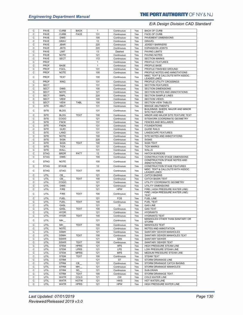
Engineering Department Manual
E/A Design Division CAD Standard
Last Updated: 07/01/2019 Page 130
Reviewed/Released 2019 v3.0
C PAVE CURB BACK 1 Continuous Yes BACK OF CURB
C PAVE CURB FACE 131 Continuous Yes FACE OF CURB
C PAVE DIMS 100 Continuous Yes PAVEMENT DIMENSIONS
C PAVE GRAV 12 Continuous Yes GRAVEL
C PAVE JBAR 220 Continuous Yes JERSEY BARRIERS
C PAVE JNTS 220 Continuous Yes EXPANSION JOINTS
C PAVE LIMT 13 Dashed Yes PAVING LIMITS
C PAVE NOTE 121 Continuous Yes PAVING NOTES
C PAVE SECT 172 Continuous Yes SECTION MARKS
C PROF 1 Continuous Yes PROFILE FEATURES
C PROF BASE 1 Continuous Yes PROFILE BASE
C PROF FGCL 131 Continuous Yes PROFILE FINISHED GROUND
C PROF NOTE 100 Continuous Yes PROFILE NOTES AND ANNOTATIONS
C PROF TEXT 100 Continuous Yes MISC. TEXT & CALLOUTS WITH ASSOC. LEADER LINES
C PROF XING 131 Continuous Yes PROFILE UTILITY CROSSINGS
C SECT 131 Continuous Yes SECTION FEATURES
C SECT DIMS 100 Continuous Yes SECTION DIMENSIONS
C SECT NOTE 121 Continuous Yes SECTION NOTES AND ANNOTATIONS
C SECT SMPL 220 Continuous Yes SECTION SAMPLE LINES
C SECT VIEW 100 Continuous Yes SECTION VIEWS
C SECT VIEW TABL 100 Continuous Yes SECTION VIEW TABLES
C SITE ABUT 131 Continuous Yes BRIDGE ABUTMENTS
C SITE BLDG 131 Continuous Yes BUILDINGS, SHEDS, MAJOR AND MINOR SITE FEATURES
C SITE BLDG TEXT 100 Continuous Yes MINOR AND MAJOR SITE FEATURE TEXT
C SITE COGO 121 Continuous Yes SITEWORK COORDINATE GEOMETRY
C SITE FNCE 131 Continuous Yes FENCES AND BOLLARDS
C SITE FNDN 131 Continuous Yes FOUNDATIONS
C SITE GUID 131 Continuous Yes GUIDE RAILS
C SITE LAND 131 Continuous Yes LANDSCAPE FEATURES
C SITE NOTE 100 Continuous Yes SITE NOTES AND ANNOTATIONS
C SITE SIGN 220 Continuous Yes SIGNS
C SITE SIGN TEXT 100 Continuous Yes SIGN TEXT
C SITE TICK 121 Continuous Yes TICK MARKS
C SITE WALL 131 Continuous Yes WALLS
C STAG BRDR PATT 12 Continuous Yes HATCH BORDERS
C STAG DIMS 100 Continuous Yes CONSTRUCTION STAGE DIMENSIONS
C STAG NOTE 100 Continuous Yes CONSTRUCTION STAGE NOTES AND ANNOTATIONS
C STAG STAGE 12 Continuous Yes CONSTRUCTION STAGE FEATURES
C STAG STAG TEXT 100 Continuous Yes MISC. TEXT & CALLOUTS WITH ASSOC. LEADER LINES
C UTIL CB__ 121 Continuous Yes CATCH BASINS
C UTIL CB__ TEXT 100 Continuous Yes CATCH BASIN TEXT
C UTIL COGO 121 Continuous Yes UTILITY COORDINATE GEOMETRY
C UTIL DIMS 121 Continuous Yes UTILITY DIMENSIONS
C UTIL FIRE 121 HPW Yes FIRE ( HIGH PRESSURE WATER LINE)
C UTIL FIRE TEXT 100 Continuous Yes FIRE ( HIGH PRESSURE WATER LINE) TEXT
C UTIL FUEL 121 FOS Yes FUEL LINE
C UTIL FUEL TEXT 100 Continuous Yes FUEL TEXT
C UTIL GASL 121 G Yes GAS LINE
C UTIL GASL TEXT 100 Continuous Yes GAS TEXT
C UTIL HYDR 121 Continuous Yes HYDRANTS
C UTIL HYDR TEXT 100 Continuous Yes HYDRANTS TEXT
C UTIL MH__ 121 Continuous Yes MANHOLES OTHER THAN SANITARY OR STORM
C UTIL MH__ TEXT 100 Continuous Yes MANHOLES TEXT
C UTIL NOTE 121 Continuous Yes NOTES AND ANNOTATION
C UTIL SSMH 121 Continuous Yes SANITARY SEWER MANHOLES
C UTIL SSMH TEXT 100 Continuous Yes SANITARY SEWER MANHOLES TEXT
C UTIL SSWR 121 SAN Yes SANITARY SEWER
C UTIL SSWR TEXT 100 Continuous Yes SANITARY SEWER TEXT
C UTIL STEM HPRS 121 HPS Yes HIGH PRESSURE STEAM LINE
C UTIL STEM LPRS 121 LPS Yes LOW PRESSURE STEAM LINE
C UTIL STEM MPRS 121 MPS Yes MEDIUM PRESSURE STEAM LINE
C UTIL STEM TEXT 100 Continuous Yes STEAM TEXT
C UTIL STRM 121 ST Yes STORM DRAINAGE LINE
C UTIL STRM CB__ 121 Continuous Yes STORM DRAINAGE CATCH BASINS
C UTIL STRM MH__ 121 Continuous Yes STORM DRAINAGE MANHOLES
C UTIL STRM SD__ 121 Continuous Yes SUB-DRAIN
C UTIL STRM TEXT 100 Continuous Yes STORM DRAINAGE TEXT
C UTIL WATR COLD 121 CW Yes COLD WATER LINE
C UTIL WATR HOTW 121 HWS Yes HOT WATER LINE
C UTIL WATR HPRS 121 HPW Yes HIGH PRESSURE WATER LINE
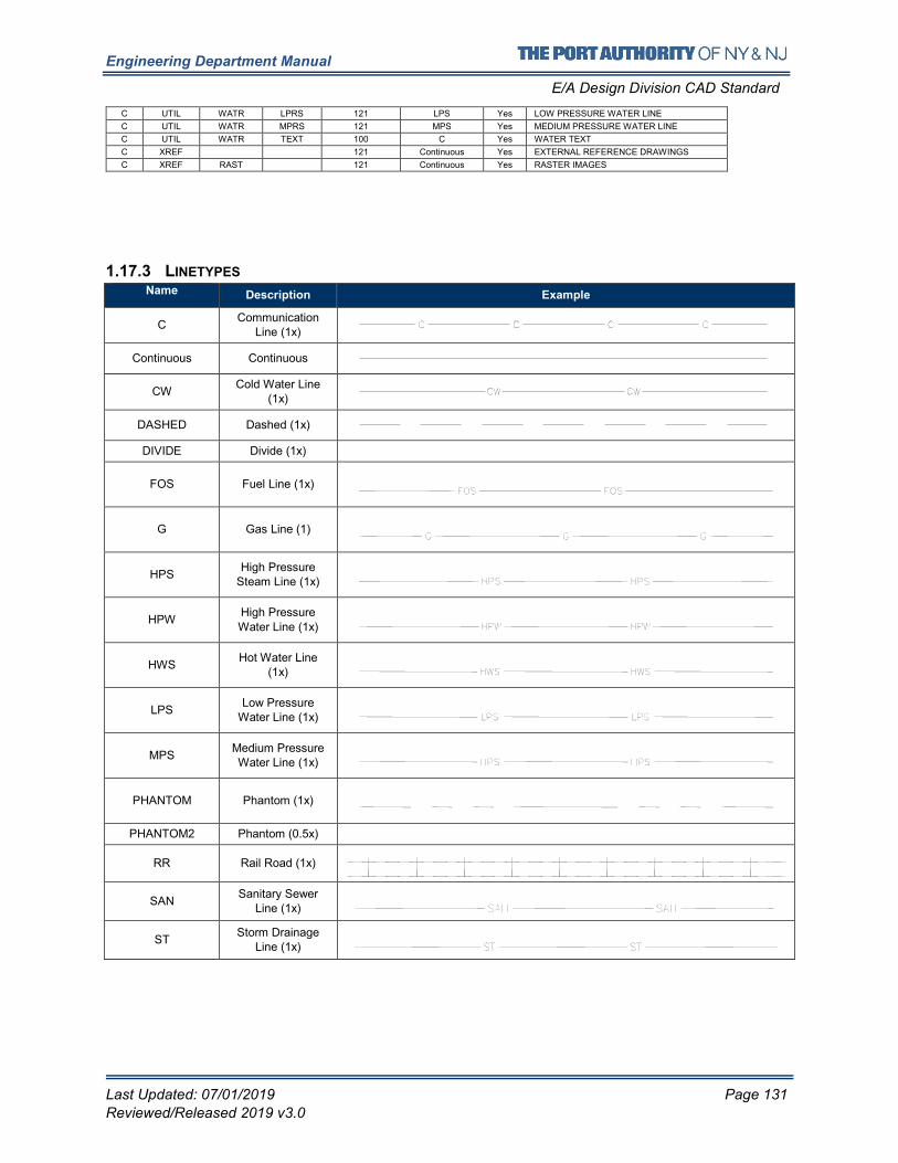
Engineering Department Manual
E/A Design Division CAD Standard
Last Updated: 07/01/2019 Page 131
Reviewed/Released 2019 v3.0
C UTIL WATR LPRS 121 LPS Yes LOW PRESSURE WATER LINE
C UTIL WATR MPRS 121 MPS Yes MEDIUM PRESSURE WATER LINE
C UTIL WATR TEXT 100 C Yes WATER TEXT
C XREF 121 Continuous Yes EXTERNAL REFERENCE DRAWINGS
C XREF RAST 121 Continuous Yes RASTER IMAGES
1.17.3 LINETYPES Name Description Example
C Communication
Line (1x)
Continuous Continuous
CW Cold Water Line
(1x)
DASHED Dashed (1x)
DIVIDE Divide (1x)
FOS Fuel Line (1x)
G Gas Line (1)
HPS High Pressure
Steam Line (1x)
HPW High Pressure Water Line (1x)
HWS Hot Water Line
(1x)
LPS Low Pressure
Water Line (1x)
MPS Medium Pressure Water Line (1x)
PHANTOM Phantom (1x)
PHANTOM2 Phantom (0.5x)
RR Rail Road (1x)
SAN Sanitary Sewer
Line (1x)
ST Storm Drainage
Line (1x)
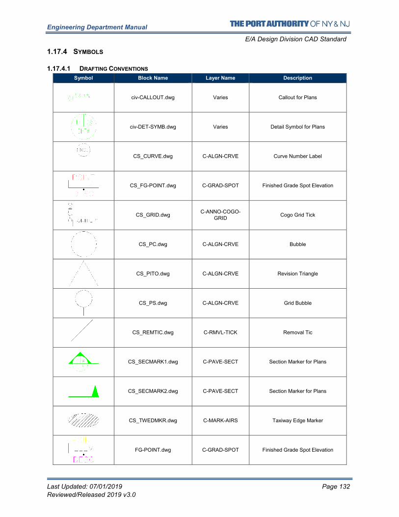
Engineering Department Manual
E/A Design Division CAD Standard
Last Updated: 07/01/2019 Page 132
Reviewed/Released 2019 v3.0
1.17.4 SYMBOLS
1.17.4.1 DRAFTING CONVENTIONS
Symbol Block Name Layer Name Description
civ-CALLOUT.dwg Varies Callout for Plans
civ-DET-SYMB.dwg Varies Detail Symbol for Plans
CS_CURVE.dwg C-ALGN-CRVE Curve Number Label
CS_FG-POINT.dwg C-GRAD-SPOT Finished Grade Spot Elevation
CS_GRID.dwg C-ANNO-COGO-
GRID Cogo Grid Tick
CS_PC.dwg C-ALGN-CRVE Bubble
CS_PITO.dwg C-ALGN-CRVE Revision Triangle
CS_PS.dwg C-ALGN-CRVE Grid Bubble
CS_REMTIC.dwg C-RMVL-TICK Removal Tic
CS_SECMARK1.dwg C-PAVE-SECT Section Marker for Plans
CS_SECMARK2.dwg C-PAVE-SECT Section Marker for Plans
CS_TWEDMKR.dwg C-MARK-AIRS Taxiway Edge Marker
FG-POINT.dwg C-GRAD-SPOT Finished Grade Spot Elevation
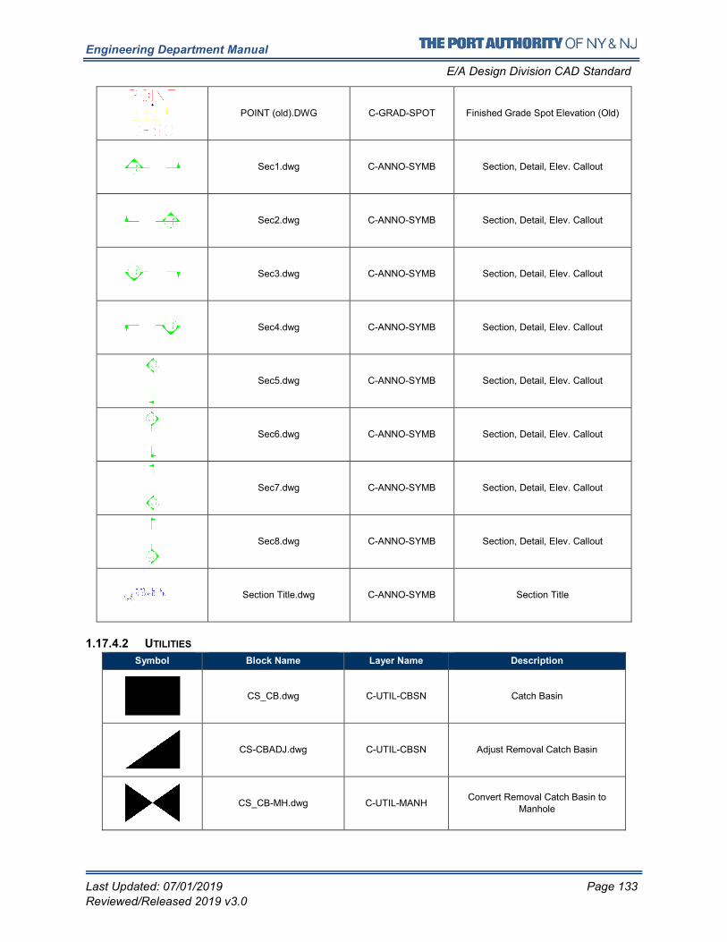
Engineering Department Manual
E/A Design Division CAD Standard
Last Updated: 07/01/2019 Page 133
Reviewed/Released 2019 v3.0
POINT (old).DWG C-GRAD-SPOT Finished Grade Spot Elevation (Old)
Sec1.dwg C-ANNO-SYMB Section, Detail, Elev. Callout
Sec2.dwg C-ANNO-SYMB Section, Detail, Elev. Callout
Sec3.dwg C-ANNO-SYMB Section, Detail, Elev. Callout
Sec4.dwg C-ANNO-SYMB Section, Detail, Elev. Callout
Sec5.dwg C-ANNO-SYMB Section, Detail, Elev. Callout
Sec6.dwg C-ANNO-SYMB Section, Detail, Elev. Callout
Sec7.dwg C-ANNO-SYMB Section, Detail, Elev. Callout
Sec8.dwg C-ANNO-SYMB Section, Detail, Elev. Callout
Section Title.dwg C-ANNO-SYMB Section Title
1.17.4.2 UTILITIES
Symbol Block Name Layer Name Description
CS_CB.dwg C-UTIL-CBSN Catch Basin
CS-CBADJ.dwg C-UTIL-CBSN Adjust Removal Catch Basin
CS_CB-MH.dwg C-UTIL-MANH Convert Removal Catch Basin to
Manhole
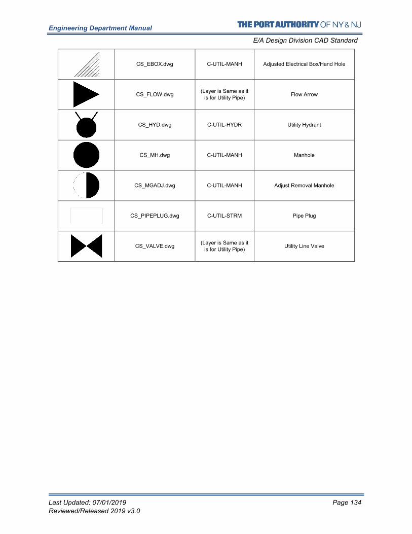
Engineering Department Manual
E/A Design Division CAD Standard
Last Updated: 07/01/2019 Page 134
Reviewed/Released 2019 v3.0
CS_EBOX.dwg C-UTIL-MANH Adjusted Electrical Box/Hand Hole
CS_FLOW.dwg (Layer is Same as it
is for Utility Pipe) Flow Arrow
CS_HYD.dwg C-UTIL-HYDR Utility Hydrant
CS_MH.dwg C-UTIL-MANH Manhole
CS_MGADJ.dwg C-UTIL-MANH Adjust Removal Manhole
CS_PIPEPLUG.dwg C-UTIL-STRM Pipe Plug
CS_VALVE.dwg (Layer is Same as it
is for Utility Pipe) Utility Line Valve
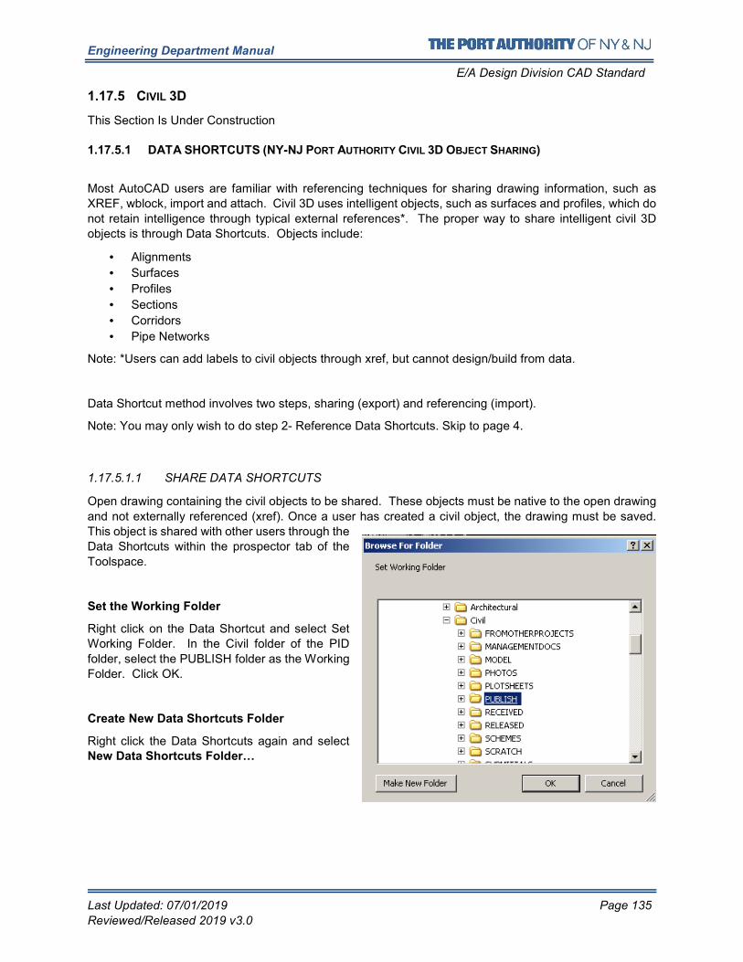
Engineering Department Manual
E/A Design Division CAD Standard
Last Updated: 07/01/2019 Page 135
Reviewed/Released 2019 v3.0
1.17.5 CIVIL 3D
This Section Is Under Construction
1.17.5.1 DATA SHORTCUTS (NY-NJ PORT AUTHORITY CIVIL 3D OBJECT SHARING)
Most AutoCAD users are familiar with referencing techniques for sharing drawing information, such as
XREF, wblock, import and attach. Civil 3D uses intelligent objects, such as surfaces and profiles, which do
not retain intelligence through typical external references*. The proper way to share intelligent civil 3D
objects is through Data Shortcuts. Objects include:
• Alignments
• Surfaces
• Profiles
• Sections
• Corridors
• Pipe Networks
Note: *Users can add labels to civil objects through xref, but cannot design/build from data.
Data Shortcut method involves two steps, sharing (export) and referencing (import).
Note: You may only wish to do step 2- Reference Data Shortcuts. Skip to page 4.
1.17.5.1.1 SHARE DATA SHORTCUTS
Open drawing containing the civil objects to be shared. These objects must be native to the open drawing
and not externally referenced (xref). Once a user has created a civil object, the drawing must be saved.
This object is shared with other users through the
Data Shortcuts within the prospector tab of the
Toolspace.
Set the Working Folder
Right click on the Data Shortcut and select Set
Working Folder. In the Civil folder of the PID
folder, select the PUBLISH folder as the Working
Folder. Click OK.
Create New Data Shortcuts Folder
Right click the Data Shortcuts again and select New Data Shortcuts Folder…
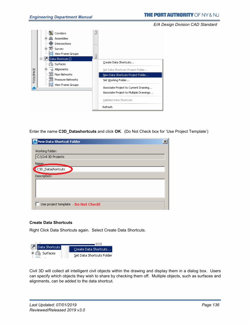
Engineering Department Manual
E/A Design Division CAD Standard
Last Updated: 07/01/2019 Page 136
Reviewed/Released 2019 v3.0
Enter the name C3D_Datashortcuts and click OK. (Do Not Check box for ‘Use Project Template’)
Create Data Shortcuts
Right Click Data Shortcuts again. Select Create Data Shortcuts.
Civil 3D will collect all intelligent civil objects within the drawing and display them in a dialog box. Users
can specify which objects they wish to share by checking them off. Multiple objects, such as surfaces and
alignments, can be added to the data shortcut.
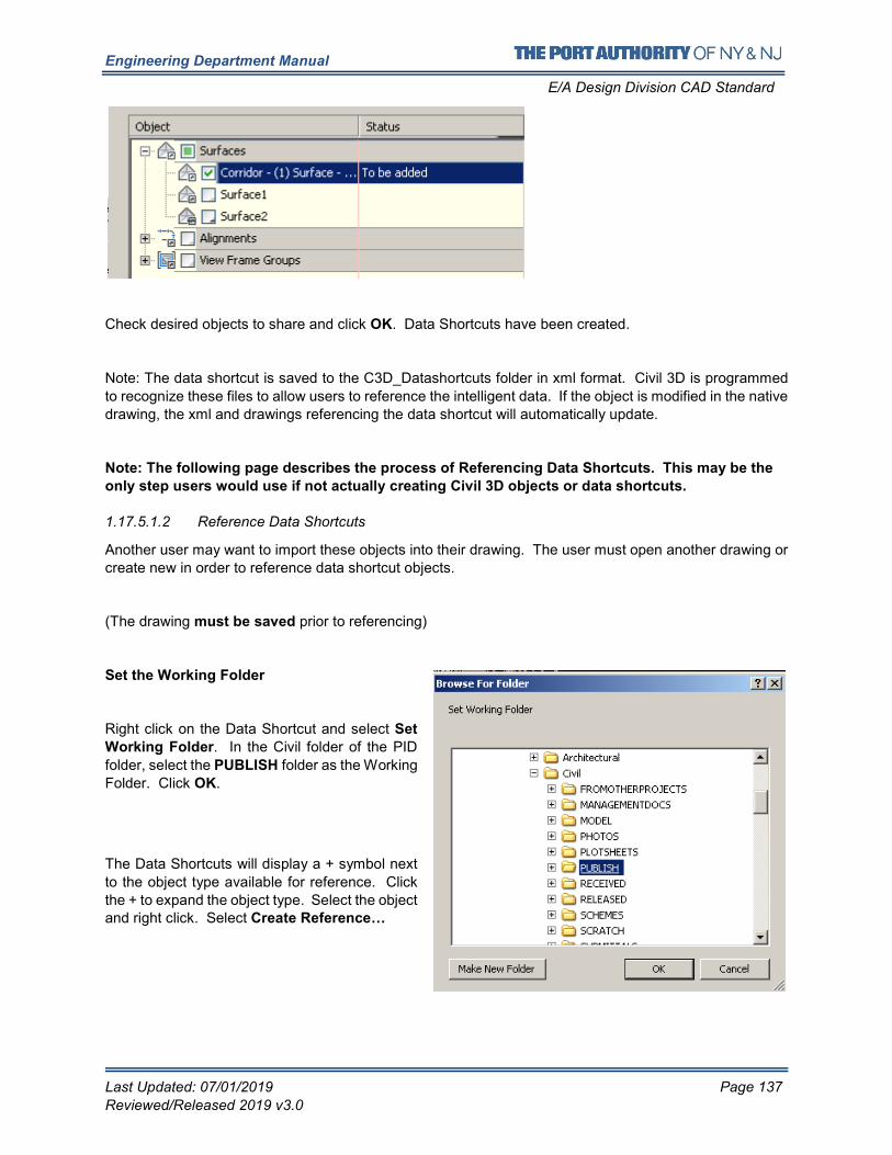
Engineering Department Manual
E/A Design Division CAD Standard
Last Updated: 07/01/2019 Page 137
Reviewed/Released 2019 v3.0
Check desired objects to share and click OK. Data Shortcuts have been created.
Note: The data shortcut is saved to the C3D_Datashortcuts folder in xml format. Civil 3D is programmed
to recognize these files to allow users to reference the intelligent data. If the object is modified in the native
drawing, the xml and drawings referencing the data shortcut will automatically update.
Note: The following page describes the process of Referencing Data Shortcuts. This may be the
only step users would use if not actually creating Civil 3D objects or data shortcuts.
1.17.5.1.2 Reference Data Shortcuts
Another user may want to import these objects into their drawing. The user must open another drawing or
create new in order to reference data shortcut objects.
(The drawing must be saved prior to referencing)
Set the Working Folder
Right click on the Data Shortcut and select Set
Working Folder. In the Civil folder of the PID
folder, select the PUBLISH folder as the Working
Folder. Click OK.
The Data Shortcuts will display a + symbol next
to the object type available for reference. Click
the + to expand the object type. Select the object and right click. Select Create Reference…
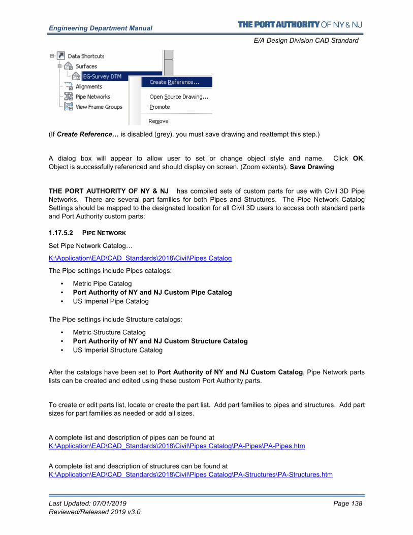
Engineering Department Manual
E/A Design Division CAD Standard
Last Updated: 07/01/2019 Page 138
Reviewed/Released 2019 v3.0
(If Create Reference… is disabled (grey), you must save drawing and reattempt this step.)
A dialog box will appear to allow user to set or change object style and name. Click OK.
Object is successfully referenced and should display on screen. (Zoom extents). Save Drawing
THE PORT AUTHORITY OF NY & NJ has compiled sets of custom parts for use with Civil 3D Pipe
Networks. There are several part families for both Pipes and Structures. The Pipe Network Catalog
Settings should be mapped to the designated location for all Civil 3D users to access both standard parts
and Port Authority custom parts:
1.17.5.2 PIPE NETWORK
Set Pipe Network Catalog…
K:\Application\EAD\CAD_Standards\2018\Civil\Pipes Catalog
The Pipe settings include Pipes catalogs:
• Metric Pipe Catalog
• Port Authority of NY and NJ Custom Pipe Catalog
• US Imperial Pipe Catalog
The Pipe settings include Structure catalogs:
• Metric Structure Catalog
• Port Authority of NY and NJ Custom Structure Catalog
• US Imperial Structure Catalog
After the catalogs have been set to Port Authority of NY and NJ Custom Catalog, Pipe Network parts
lists can be created and edited using these custom Port Authority parts.
To create or edit parts list, locate or create the part list. Add part families to pipes and structures. Add part
sizes for part families as needed or add all sizes.
A complete list and description of pipes can be found at
K:\Application\EAD\CAD_Standards\2018\Civil\Pipes Catalog\PA-Pipes\PA-Pipes.htm
A complete list and description of structures can be found at
K:\Application\EAD\CAD_Standards\2018\Civil\Pipes Catalog\PA-Structures\PA-Structures.htm
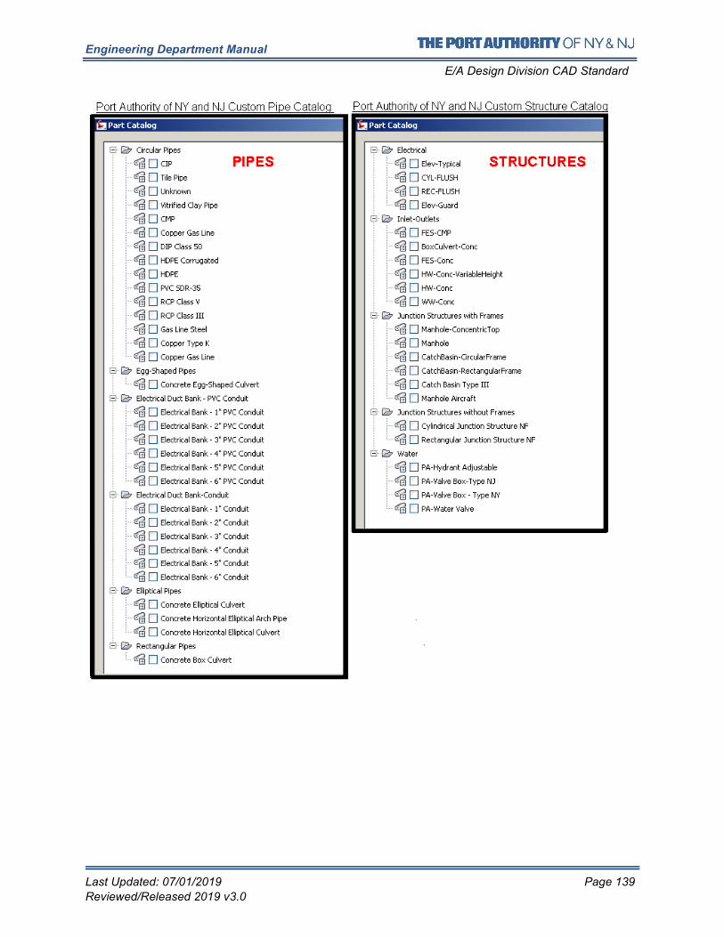
Engineering Department Manual
E/A Design Division CAD Standard
Last Updated: 07/01/2019 Page 139
Reviewed/Released 2019 v3.0
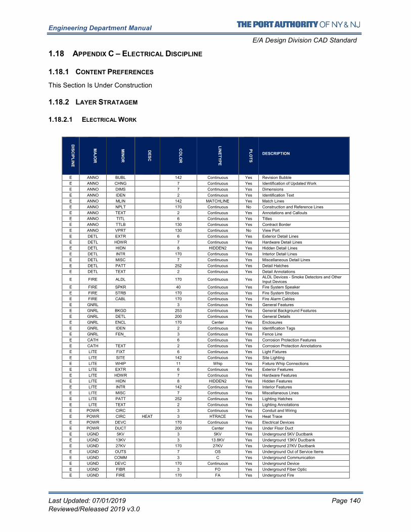
Engineering Department Manual
E/A Design Division CAD Standard
Last Updated: 07/01/2019 Page 140
Reviewed/Released 2019 v3.0
1.18 APPENDIX C – ELECTRICAL DISCIPLINE
1.18.1 CONTENT PREFERENCES
This Section Is Under Construction
1.18.2 LAYER STRATAGEM
1.18.2.1 ELECTRICAL WORK
DIS
CIP
LIN
E
MA
JO
R
MIN
OR
DE
SC
CO
LO
R
LIN
ET
YP
E
PL
OT
S
DESCRIPTION
E ANNO BUBL 142 Continuous Yes Revision Bubble
E ANNO CHNG 7 Continuous Yes Identification of Updated Work
E ANNO DIMS 7 Continuous Yes Dimensions
E ANNO IDEN 2 Continuous Yes Identification Text
E ANNO MLIN 142 MATCHLINE Yes Match Lines
E ANNO NPLT 170 Continuous No Construction and Reference Lines
E ANNO TEXT 2 Continuous Yes Annotations and Callouts
E ANNO TITL 6 Continuous Yes Titles
E ANNO TTLB 130 Continuous Yes Contract Border
E ANNO VPRT 130 Continuous No View Port
E DETL EXTR 6 Continuous Yes Exterior Detail Lines
E DETL HDWR 7 Continuous Yes Hardware Detail Lines
E DETL HIDN 8 HIDDEN2 Yes Hidden Detail Lines
E DETL INTR 170 Continuous Yes Interior Detail Lines
E DETL MISC 7 Continuous Yes Miscellaneous Detail Lines
E DETL PATT 252 Continuous Yes Detail Hatches
E DETL TEXT 2 Continuous Yes Detail Annotations
E FIRE ALDL 170 Continuous Yes ALDL Devices - Smoke Detectors and Other Input Devices
E FIRE SPKR 40 Continuous Yes Fire System Speaker
E FIRE STRB 170 Continuous Yes Fire System Strobes
E FIRE CABL 170 Continuous Yes Fire Alarm Cables
E GNRL 3 Continuous Yes General Features
E GNRL BKGD 253 Continuous Yes General Background Features
E GNRL DETL 200 Continuous Yes General Details
E GNRL ENCL 170 Center Yes Enclosures
E GNRL IDEN 2 Continuous Yes Identification Tags
E GNRL FEN_ 3 Continuous Yes Fence Line
E CATH 6 Continuous Yes Corrosion Protection Features
E CATH TEXT 2 Continuous Yes Corrosion Protection Annotations
E LITE FIXT 6 Continuous Yes Light Fixtures
E LITE SITE 142 Continuous Yes Site Lighting
E LITE WHIP 11 Whip Yes Fixture Whip Connections
E LITE EXTR 6 Continuous Yes Exterior Features
E LITE HDWR 7 Continuous Yes Hardware Features
E LITE HIDN 8 HIDDEN2 Yes Hidden Features
E LITE INTR 142 Continuous Yes Interior Features
E LITE MISC 7 Continuous Yes Miscellaneous Lines
E LITE PATT 252 Continuous Yes Lighting Hatches
E LITE TEXT 2 Continuous Yes Lighting Annotations
E POWR CIRC 3 Continuous Yes Conduit and Wiring
E POWR CIRC HEAT 3 HTRACE Yes Heat Trace
E POWR DEVC 170 Continuous Yes Electrical Devices
E POWR DUCT 200 Center Yes Under Floor Duct
E UGND 5KV 3 5KV Yes Underground 5KV Ductbank
E UGND 13KV 3 13.8KV Yes Underground 13KV Ductbank
E UGND 27KV 170 27KV Yes Underground 27KV Ductbank
E UGND OUTS 7 OS Yes Underground Out of Service Items
E UGND COMM 3 C Yes Underground Communication
E UGND DEVC 170 Continuous Yes Underground Device
E UGND FIBR 3 FO Yes Underground Fiber Optic
E UGND FIRE 170 FA Yes Underground Fire
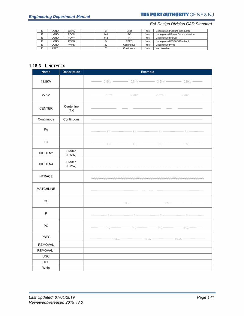
Engineering Department Manual
E/A Design Division CAD Standard
Last Updated: 07/01/2019 Page 141
Reviewed/Released 2019 v3.0
E UGND GRND 3 GND Yes Underground Ground Conductor
E UGND PCOM 140 PC Yes Underground Power Communication
E UGND POWR 142 P Yes Underground Power
E UGND PSEG 3 PSEG Yes Underground PSE&G Ductbank
E UGND WIRE 20 Continuous Yes Underground Wire
E XREF 7 Continuous Yes Xref Insertion
1.18.3 LINETYPES
Name Description Example
13.8KV
27KV
CENTER Centerline
(1x)
Continuous Continuous
FA
FO
HIDDEN2 Hidden (0.50x)
HIDDEN4 Hidden (0.25x)
HTRACE
MATCHLINE
OS
P
PC
PSEG
REMOVAL
REMOVAL1
UGC
UGE
Whip
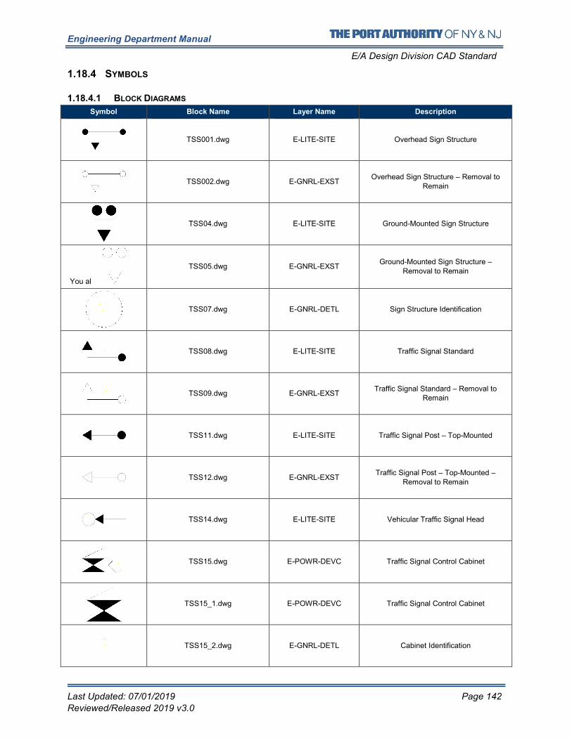
Engineering Department Manual
E/A Design Division CAD Standard
Last Updated: 07/01/2019 Page 142
Reviewed/Released 2019 v3.0
1.18.4 SYMBOLS
1.18.4.1 BLOCK DIAGRAMS
Symbol Block Name Layer Name Description
TSS001.dwg E-LITE-SITE Overhead Sign Structure
TSS002.dwg E-GNRL-EXST Overhead Sign Structure – Removal to
Remain
TSS04.dwg E-LITE-SITE Ground-Mounted Sign Structure
You al
TSS05.dwg E-GNRL-EXST Ground-Mounted Sign Structure –
Removal to Remain
TSS07.dwg E-GNRL-DETL Sign Structure Identification
TSS08.dwg E-LITE-SITE Traffic Signal Standard
TSS09.dwg E-GNRL-EXST Traffic Signal Standard – Removal to
Remain
TSS11.dwg E-LITE-SITE Traffic Signal Post – Top-Mounted
TSS12.dwg E-GNRL-EXST Traffic Signal Post – Top-Mounted –
Removal to Remain
TSS14.dwg E-LITE-SITE Vehicular Traffic Signal Head
TSS15.dwg E-POWR-DEVC Traffic Signal Control Cabinet
TSS15_1.dwg E-POWR-DEVC Traffic Signal Control Cabinet
TSS15_2.dwg E-GNRL-DETL Cabinet Identification
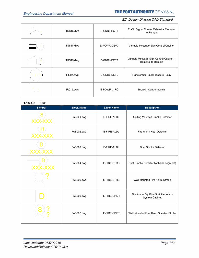
Engineering Department Manual
E/A Design Division CAD Standard
Last Updated: 07/01/2019 Page 143
Reviewed/Released 2019 v3.0
TSS16.dwg E-GNRL-EXST Traffic Signal Control Cabinet – Removal
to Remain
TSS18.dwg E-POWR-DEVC Variable Message Sign Control Cabinet
TSS19.dwg E-GNRL-EXST Variable Message Sign Control Cabinet –
Removal to Remain
IR007.dwg E-GNRL-DETL Transformer Fault Pressure Relay
IR015.dwg E-POWR-CIRC Breaker Control Switch
1.18.4.2 FIRE
Symbol Block Name Layer Name Description
FAS001.dwg E-FIRE-ALDL Ceiling Mounted Smoke Detector
FAS002.dwg E-FIRE-ALDL Fire Alarm Heat Detector
FAS003.dwg E-FIRE-ALDL Duct Smoke Detector
FAS004.dwg E-FIRE-STRB Duct Smoke Detector (with line segment)
FAS005.dwg E-FIRE-STRB Wall-Mounted Fire Alarm Strobe
FAS006.dwg E-FIRE-SPKR Fire Alarm Dry Pipe Sprinkler Alarm
System Cabinet
FAS007.dwg E-FIRE-SPKR Wall-Mounted Fire Alarm Speaker/Strobe
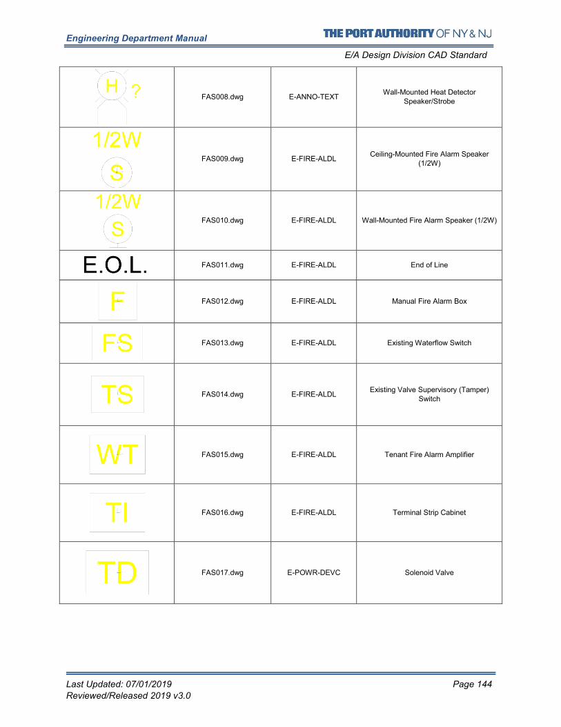
Engineering Department Manual
E/A Design Division CAD Standard
Last Updated: 07/01/2019 Page 144
Reviewed/Released 2019 v3.0
FAS008.dwg E-ANNO-TEXT Wall-Mounted Heat Detector
Speaker/Strobe
FAS009.dwg E-FIRE-ALDL Ceiling-Mounted Fire Alarm Speaker
(1/2W)
FAS010.dwg E-FIRE-ALDL Wall-Mounted Fire Alarm Speaker (1/2W)
FAS011.dwg E-FIRE-ALDL End of Line
FAS012.dwg E-FIRE-ALDL Manual Fire Alarm Box
FAS013.dwg E-FIRE-ALDL Existing Waterflow Switch
FAS014.dwg E-FIRE-ALDL Existing Valve Supervisory (Tamper)
Switch
FAS015.dwg E-FIRE-ALDL Tenant Fire Alarm Amplifier
FAS016.dwg E-FIRE-ALDL Terminal Strip Cabinet
FAS017.dwg E-POWR-DEVC Solenoid Valve
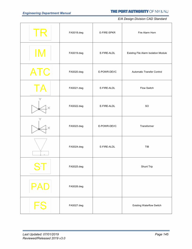
Engineering Department Manual
E/A Design Division CAD Standard
Last Updated: 07/01/2019 Page 145
Reviewed/Released 2019 v3.0
FAS018.dwg E-FIRE-SPKR Fire Alarm Horn
FAS019.dwg E-FIRE-ALDL Existing File Alarm Isolation Module
FAS020.dwg E-POWR-DEVC Automatic Transfer Control
FAS021.dwg E-FIRE-ALDL Flow Switch
FAS022.dwg E-FIRE-ALDL SO
FAS023.dwg E-POWR-DEVC Transformer
FAS024.dwg E-FIRE-ALDL TIB
FAS025.dwg Shunt Trip
FAS026.dwg
FAS027.dwg Existing Waterflow Switch
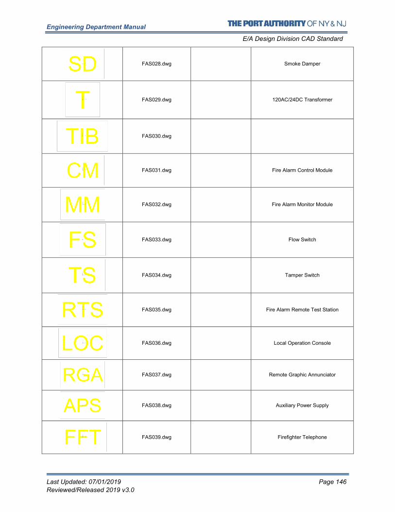
Engineering Department Manual
E/A Design Division CAD Standard
Last Updated: 07/01/2019 Page 146
Reviewed/Released 2019 v3.0
FAS028.dwg Smoke Damper
FAS029.dwg 120AC/24DC Transformer
FAS030.dwg
FAS031.dwg Fire Alarm Control Module
FAS032.dwg Fire Alarm Monitor Module
FAS033.dwg Flow Switch
FAS034.dwg Tamper Switch
FAS035.dwg Fire Alarm Remote Test Station
FAS036.dwg Local Operation Console
FAS037.dwg Remote Graphic Annunciator
FAS038.dwg Auxiliary Power Supply
FAS039.dwg Firefighter Telephone
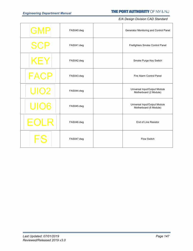
Engineering Department Manual
E/A Design Division CAD Standard
Last Updated: 07/01/2019 Page 147
Reviewed/Released 2019 v3.0
FAS040.dwg Generator Monitoring and Control Panel
FAS041.dwg Firefighters Smoke Control Panel
FAS042.dwg Smoke Purge Key Switch
FAS043.dwg Fire Alarm Control Panel
FAS044.dwg Universal Input/Output Module
Motherboard (2 Module)
FAS045.dwg Universal Input/Output Module
Motherboard (6 Module)
FAS046.dwg End of Line Resistor
FAS047.dwg Flow Switch
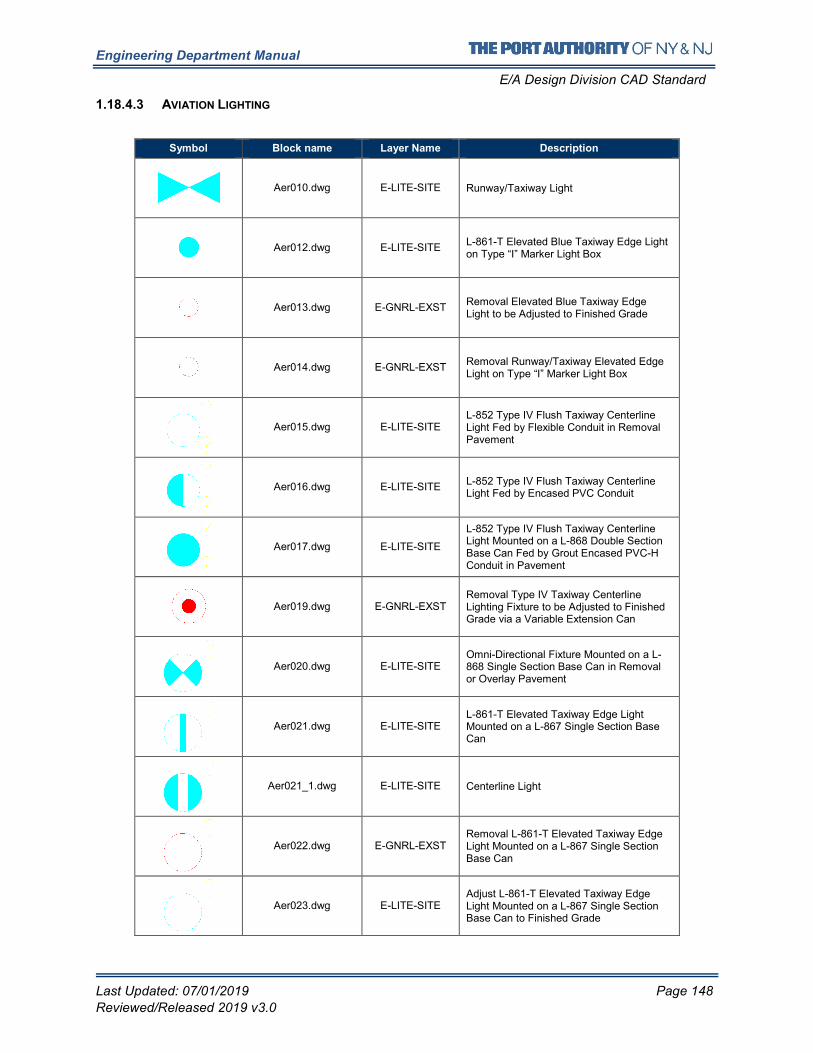
Engineering Department Manual
E/A Design Division CAD Standard
Last Updated: 07/01/2019 Page 148
Reviewed/Released 2019 v3.0
1.18.4.3 AVIATION LIGHTING
Symbol Block name Layer Name Description
Aer010.dwg E-LITE-SITE Runway/Taxiway Light
Aer012.dwg E-LITE-SITE L-861-T Elevated Blue Taxiway Edge Light on Type “I” Marker Light Box
Aer013.dwg E-GNRL-EXST Removal Elevated Blue Taxiway Edge Light to be Adjusted to Finished Grade
Aer014.dwg E-GNRL-EXST Removal Runway/Taxiway Elevated Edge Light on Type “I” Marker Light Box
Aer015.dwg E-LITE-SITE L-852 Type IV Flush Taxiway Centerline Light Fed by Flexible Conduit in Removal Pavement
Aer016.dwg E-LITE-SITE L-852 Type IV Flush Taxiway Centerline Light Fed by Encased PVC Conduit
Aer017.dwg E-LITE-SITE
L-852 Type IV Flush Taxiway Centerline Light Mounted on a L-868 Double Section Base Can Fed by Grout Encased PVC-H Conduit in Pavement
Aer019.dwg E-GNRL-EXST Removal Type IV Taxiway Centerline Lighting Fixture to be Adjusted to Finished Grade via a Variable Extension Can
Aer020.dwg E-LITE-SITE Omni-Directional Fixture Mounted on a L-868 Single Section Base Can in Removal or Overlay Pavement
Aer021.dwg E-LITE-SITE L-861-T Elevated Taxiway Edge Light Mounted on a L-867 Single Section Base Can
Aer021_1.dwg E-LITE-SITE Centerline Light
Aer022.dwg E-GNRL-EXST Removal L-861-T Elevated Taxiway Edge Light Mounted on a L-867 Single Section Base Can
Aer023.dwg E-LITE-SITE Adjust L-861-T Elevated Taxiway Edge Light Mounted on a L-867 Single Section Base Can to Finished Grade
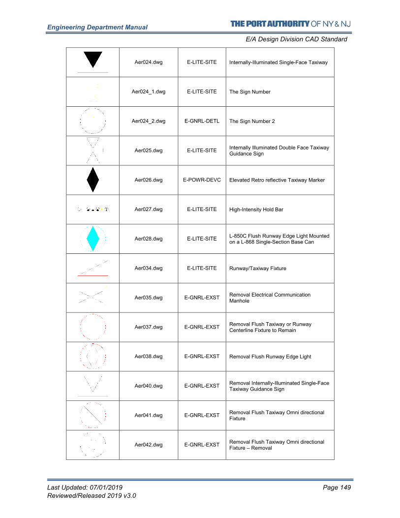
Engineering Department Manual
E/A Design Division CAD Standard
Last Updated: 07/01/2019 Page 149
Reviewed/Released 2019 v3.0
Aer024.dwg E-LITE-SITE Internally-Illuminated Single-Face Taxiway
Aer024_1.dwg E-LITE-SITE The Sign Number
Aer024_2.dwg E-GNRL-DETL The Sign Number 2
Aer025.dwg E-LITE-SITE Internally Illuminated Double Face Taxiway Guidance Sign
Aer026.dwg E-POWR-DEVC Elevated Retro reflective Taxiway Marker
Aer027.dwg E-LITE-SITE High-Intensity Hold Bar
Aer028.dwg E-LITE-SITE L-850C Flush Runway Edge Light Mounted on a L-868 Single-Section Base Can
Aer034.dwg E-LITE-SITE Runway/Taxiway Fixture
Aer035.dwg E-GNRL-EXST Removal Electrical Communication Manhole
Aer037.dwg E-GNRL-EXST Removal Flush Taxiway or Runway Centerline Fixture to Remain
Aer038.dwg E-GNRL-EXST Removal Flush Runway Edge Light
Aer040.dwg E-GNRL-EXST Removal Internally-Illuminated Single-Face Taxiway Guidance Sign
Aer041.dwg E-GNRL-EXST Removal Flush Taxiway Omni directional Fixture
Aer042.dwg E-GNRL-EXST Removal Flush Taxiway Omni directional Fixture – Removal
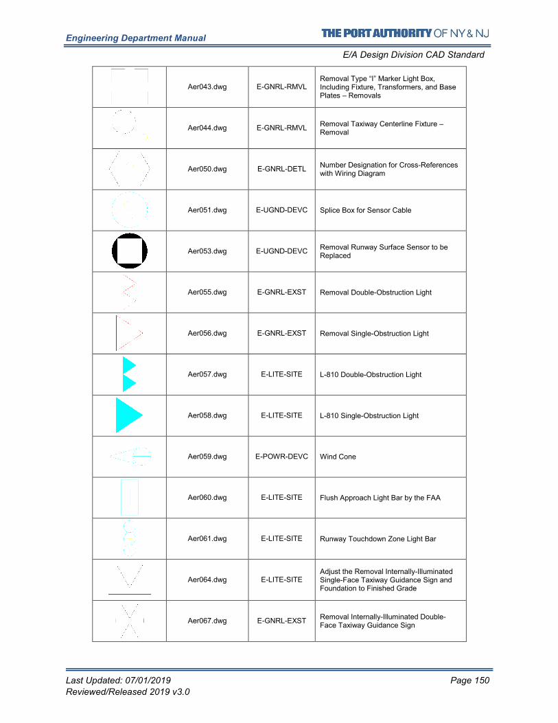
Engineering Department Manual
E/A Design Division CAD Standard
Last Updated: 07/01/2019 Page 150
Reviewed/Released 2019 v3.0
Aer043.dwg E-GNRL-RMVL Removal Type “I” Marker Light Box, Including Fixture, Transformers, and Base Plates – Removals
Aer044.dwg E-GNRL-RMVL Removal Taxiway Centerline Fixture – Removal
Aer050.dwg E-GNRL-DETL Number Designation for Cross-References with Wiring Diagram
Aer051.dwg E-UGND-DEVC Splice Box for Sensor Cable
Aer053.dwg E-UGND-DEVC Removal Runway Surface Sensor to be Replaced
Aer055.dwg E-GNRL-EXST Removal Double-Obstruction Light
Aer056.dwg E-GNRL-EXST Removal Single-Obstruction Light
Aer057.dwg E-LITE-SITE L-810 Double-Obstruction Light
Aer058.dwg E-LITE-SITE L-810 Single-Obstruction Light
Aer059.dwg E-POWR-DEVC Wind Cone
Aer060.dwg E-LITE-SITE Flush Approach Light Bar by the FAA
Aer061.dwg E-LITE-SITE Runway Touchdown Zone Light Bar
Aer064.dwg E-LITE-SITE Adjust the Removal Internally-Illuminated Single-Face Taxiway Guidance Sign and Foundation to Finished Grade
Aer067.dwg E-GNRL-EXST Removal Internally-Illuminated Double-Face Taxiway Guidance Sign
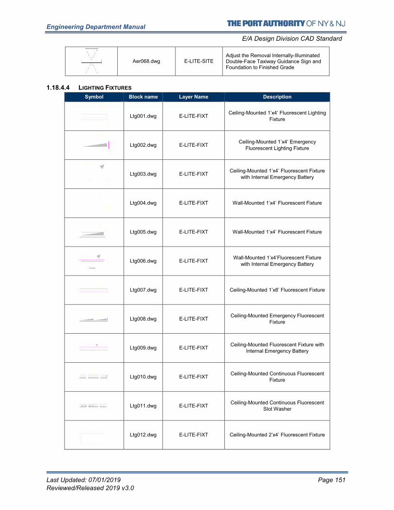
Engineering Department Manual
E/A Design Division CAD Standard
Last Updated: 07/01/2019 Page 151
Reviewed/Released 2019 v3.0
Aer068.dwg E-LITE-SITE Adjust the Removal Internally-Illuminated Double-Face Taxiway Guidance Sign and Foundation to Finished Grade
1.18.4.4 LIGHTING FIXTURES
Symbol Block name Layer Name Description
Ltg001.dwg E-LITE-FIXT Ceiling-Mounted 1’x4’ Fluorescent Lighting
Fixture
Ltg002.dwg E-LITE-FIXT Ceiling-Mounted 1’x4’ Emergency
Fluorescent Lighting Fixture
Ltg003.dwg E-LITE-FIXT Ceiling-Mounted 1’x4’ Fluorescent Fixture
with Internal Emergency Battery
Ltg004.dwg E-LITE-FIXT Wall-Mounted 1’x4’ Fluorescent Fixture
Ltg005.dwg E-LITE-FIXT Wall-Mounted 1’x4’ Fluorescent Fixture
Ltg006.dwg E-LITE-FIXT Wall-Mounted 1’x4’Fluorescent Fixture
with Internal Emergency Battery
Ltg007.dwg E-LITE-FIXT Ceiling-Mounted 1’x8’ Fluorescent Fixture
Ltg008.dwg E-LITE-FIXT Ceiling-Mounted Emergency Fluorescent
Fixture
Ltg009.dwg E-LITE-FIXT Ceiling-Mounted Fluorescent Fixture with
Internal Emergency Battery
Ltg010.dwg E-LITE-FIXT Ceiling-Mounted Continuous Fluorescent
Fixture
Ltg011.dwg E-LITE-FIXT Ceiling-Mounted Continuous Fluorescent
Slot Washer
Ltg012.dwg E-LITE-FIXT Ceiling-Mounted 2’x4’ Fluorescent Fixture
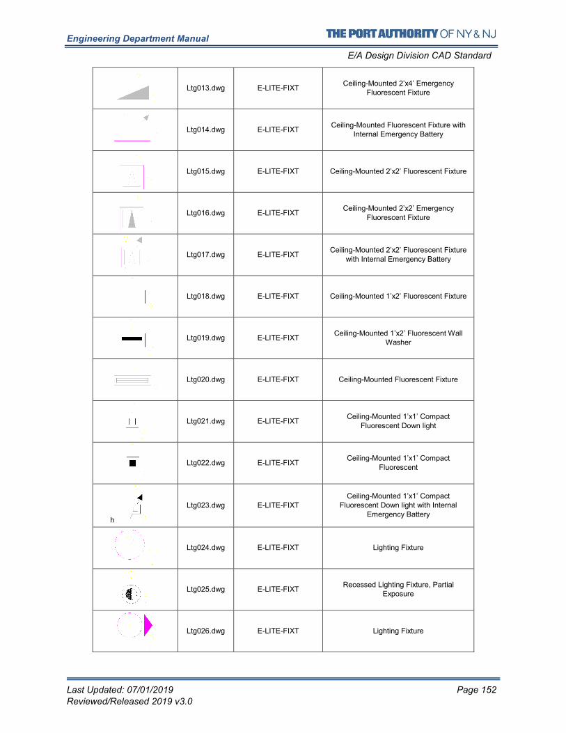
Engineering Department Manual
E/A Design Division CAD Standard
Last Updated: 07/01/2019 Page 152
Reviewed/Released 2019 v3.0
Ltg013.dwg E-LITE-FIXT Ceiling-Mounted 2’x4’ Emergency
Fluorescent Fixture
Ltg014.dwg E-LITE-FIXT Ceiling-Mounted Fluorescent Fixture with
Internal Emergency Battery
Ltg015.dwg E-LITE-FIXT Ceiling-Mounted 2’x2’ Fluorescent Fixture
Ltg016.dwg E-LITE-FIXT Ceiling-Mounted 2’x2’ Emergency
Fluorescent Fixture
Ltg017.dwg E-LITE-FIXT Ceiling-Mounted 2’x2’ Fluorescent Fixture
with Internal Emergency Battery
Ltg018.dwg E-LITE-FIXT Ceiling-Mounted 1’x2’ Fluorescent Fixture
Ltg019.dwg E-LITE-FIXT Ceiling-Mounted 1’x2’ Fluorescent Wall
Washer
Ltg020.dwg E-LITE-FIXT Ceiling-Mounted Fluorescent Fixture
Ltg021.dwg E-LITE-FIXT Ceiling-Mounted 1’x1’ Compact
Fluorescent Down light
Ltg022.dwg E-LITE-FIXT Ceiling-Mounted 1’x1’ Compact
Fluorescent
h
Ltg023.dwg E-LITE-FIXT
Ceiling-Mounted 1’x1’ Compact Fluorescent Down light with Internal
Emergency Battery
Ltg024.dwg E-LITE-FIXT Lighting Fixture
Ltg025.dwg E-LITE-FIXT Recessed Lighting Fixture, Partial
Exposure
Ltg026.dwg E-LITE-FIXT Lighting Fixture
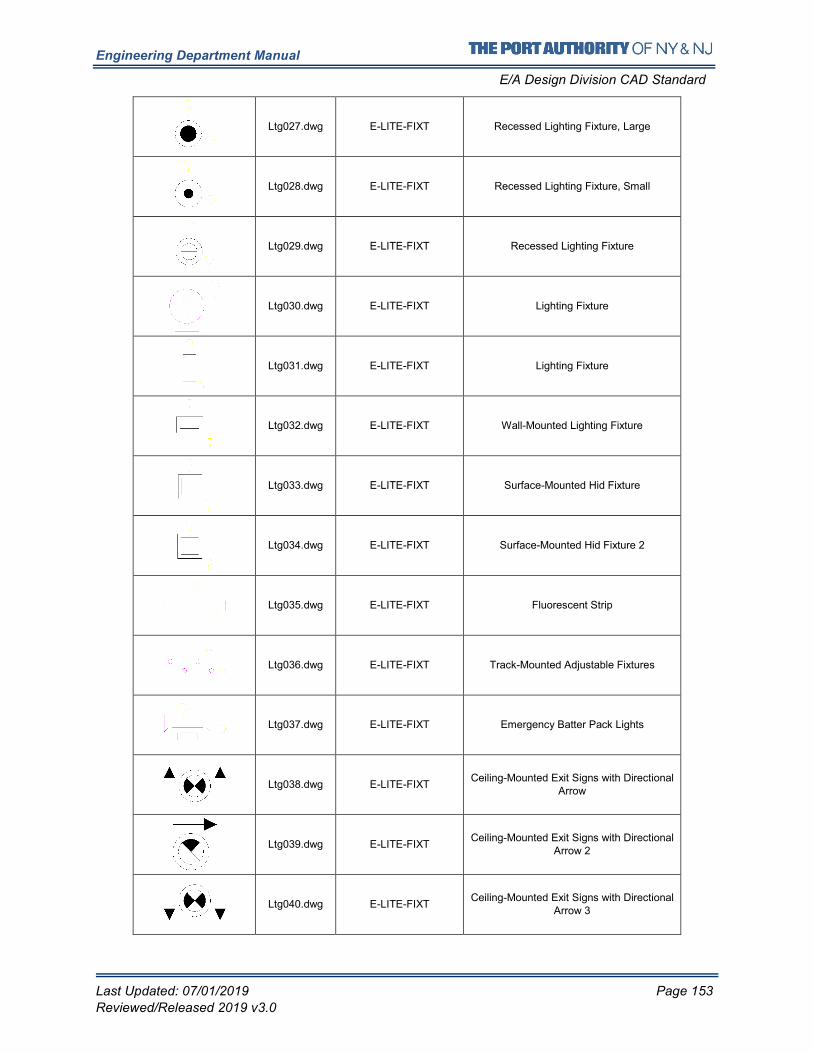
Engineering Department Manual
E/A Design Division CAD Standard
Last Updated: 07/01/2019 Page 153
Reviewed/Released 2019 v3.0
Ltg027.dwg E-LITE-FIXT Recessed Lighting Fixture, Large
Ltg028.dwg E-LITE-FIXT Recessed Lighting Fixture, Small
Ltg029.dwg E-LITE-FIXT Recessed Lighting Fixture
Ltg030.dwg E-LITE-FIXT Lighting Fixture
Ltg031.dwg E-LITE-FIXT Lighting Fixture
Ltg032.dwg E-LITE-FIXT Wall-Mounted Lighting Fixture
Ltg033.dwg E-LITE-FIXT Surface-Mounted Hid Fixture
Ltg034.dwg E-LITE-FIXT Surface-Mounted Hid Fixture 2
Ltg035.dwg E-LITE-FIXT Fluorescent Strip
Ltg036.dwg E-LITE-FIXT Track-Mounted Adjustable Fixtures
Ltg037.dwg E-LITE-FIXT Emergency Batter Pack Lights
Ltg038.dwg E-LITE-FIXT Ceiling-Mounted Exit Signs with Directional
Arrow
Ltg039.dwg E-LITE-FIXT Ceiling-Mounted Exit Signs with Directional
Arrow 2
Ltg040.dwg E-LITE-FIXT Ceiling-Mounted Exit Signs with Directional
Arrow 3
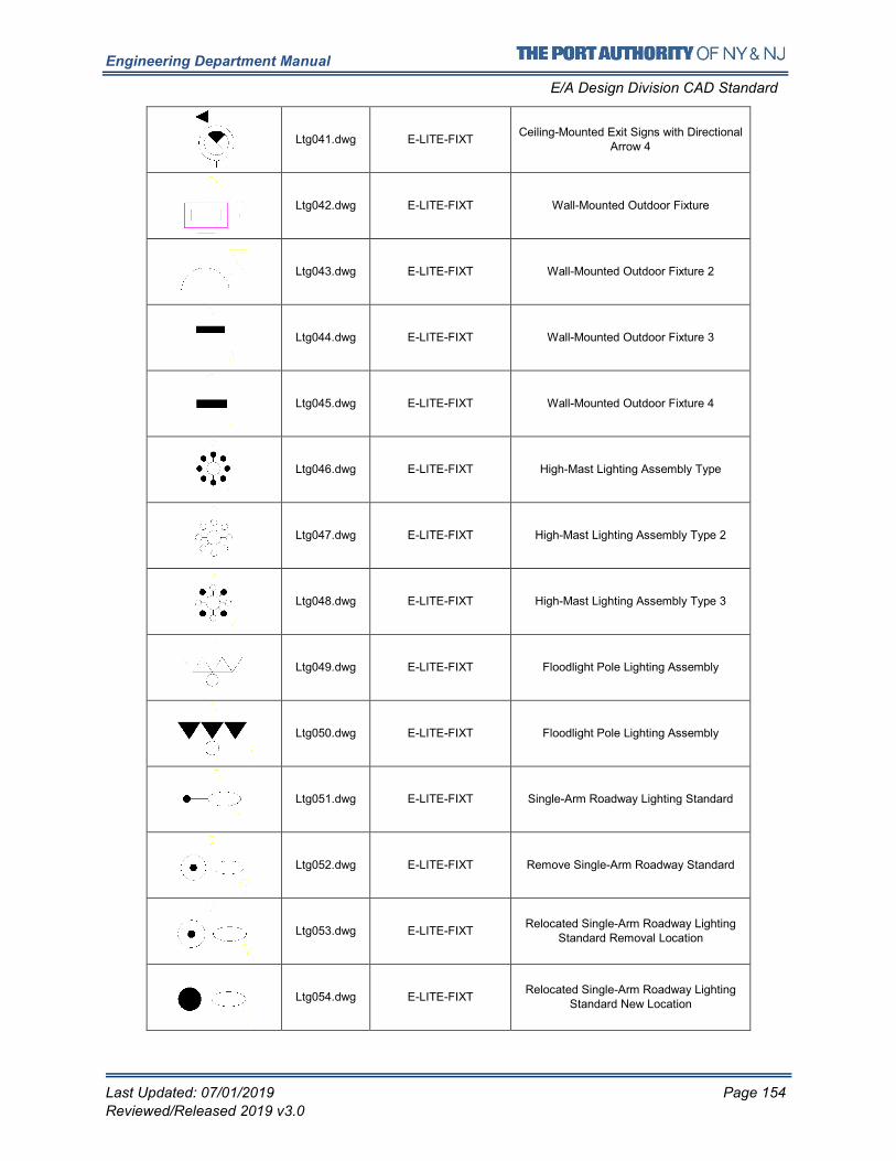
Engineering Department Manual
E/A Design Division CAD Standard
Last Updated: 07/01/2019 Page 154
Reviewed/Released 2019 v3.0
Ltg041.dwg E-LITE-FIXT Ceiling-Mounted Exit Signs with Directional
Arrow 4
Ltg042.dwg E-LITE-FIXT Wall-Mounted Outdoor Fixture
Ltg043.dwg E-LITE-FIXT Wall-Mounted Outdoor Fixture 2
Ltg044.dwg E-LITE-FIXT Wall-Mounted Outdoor Fixture 3
Ltg045.dwg E-LITE-FIXT Wall-Mounted Outdoor Fixture 4
Ltg046.dwg E-LITE-FIXT High-Mast Lighting Assembly Type
Ltg047.dwg E-LITE-FIXT High-Mast Lighting Assembly Type 2
Ltg048.dwg E-LITE-FIXT High-Mast Lighting Assembly Type 3
Ltg049.dwg E-LITE-FIXT Floodlight Pole Lighting Assembly
Ltg050.dwg E-LITE-FIXT Floodlight Pole Lighting Assembly
Ltg051.dwg E-LITE-FIXT Single-Arm Roadway Lighting Standard
Ltg052.dwg E-LITE-FIXT Remove Single-Arm Roadway Standard
Ltg053.dwg E-LITE-FIXT Relocated Single-Arm Roadway Lighting
Standard Removal Location
Ltg054.dwg E-LITE-FIXT Relocated Single-Arm Roadway Lighting
Standard New Location
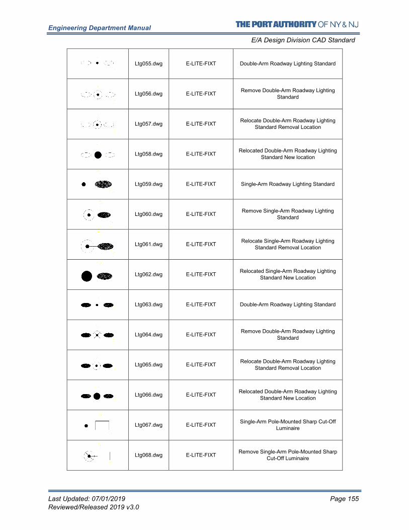
Engineering Department Manual
E/A Design Division CAD Standard
Last Updated: 07/01/2019 Page 155
Reviewed/Released 2019 v3.0
Ltg055.dwg E-LITE-FIXT Double-Arm Roadway Lighting Standard
Ltg056.dwg E-LITE-FIXT Remove Double-Arm Roadway Lighting
Standard
Ltg057.dwg E-LITE-FIXT Relocate Double-Arm Roadway Lighting
Standard Removal Location
Ltg058.dwg E-LITE-FIXT Relocated Double-Arm Roadway Lighting
Standard New location
Ltg059.dwg E-LITE-FIXT Single-Arm Roadway Lighting Standard
Ltg060.dwg E-LITE-FIXT Remove Single-Arm Roadway Lighting
Standard
Ltg061.dwg E-LITE-FIXT Relocate Single-Arm Roadway Lighting
Standard Removal Location
Ltg062.dwg E-LITE-FIXT Relocated Single-Arm Roadway Lighting
Standard New Location
Ltg063.dwg E-LITE-FIXT Double-Arm Roadway Lighting Standard
Ltg064.dwg E-LITE-FIXT Remove Double-Arm Roadway Lighting
Standard
Ltg065.dwg E-LITE-FIXT Relocate Double-Arm Roadway Lighting
Standard Removal Location
Ltg066.dwg E-LITE-FIXT Relocated Double-Arm Roadway Lighting
Standard New Location
Ltg067.dwg E-LITE-FIXT Single-Arm Pole-Mounted Sharp Cut-Off
Luminaire
Ltg068.dwg E-LITE-FIXT Remove Single-Arm Pole-Mounted Sharp
Cut-Off Luminaire
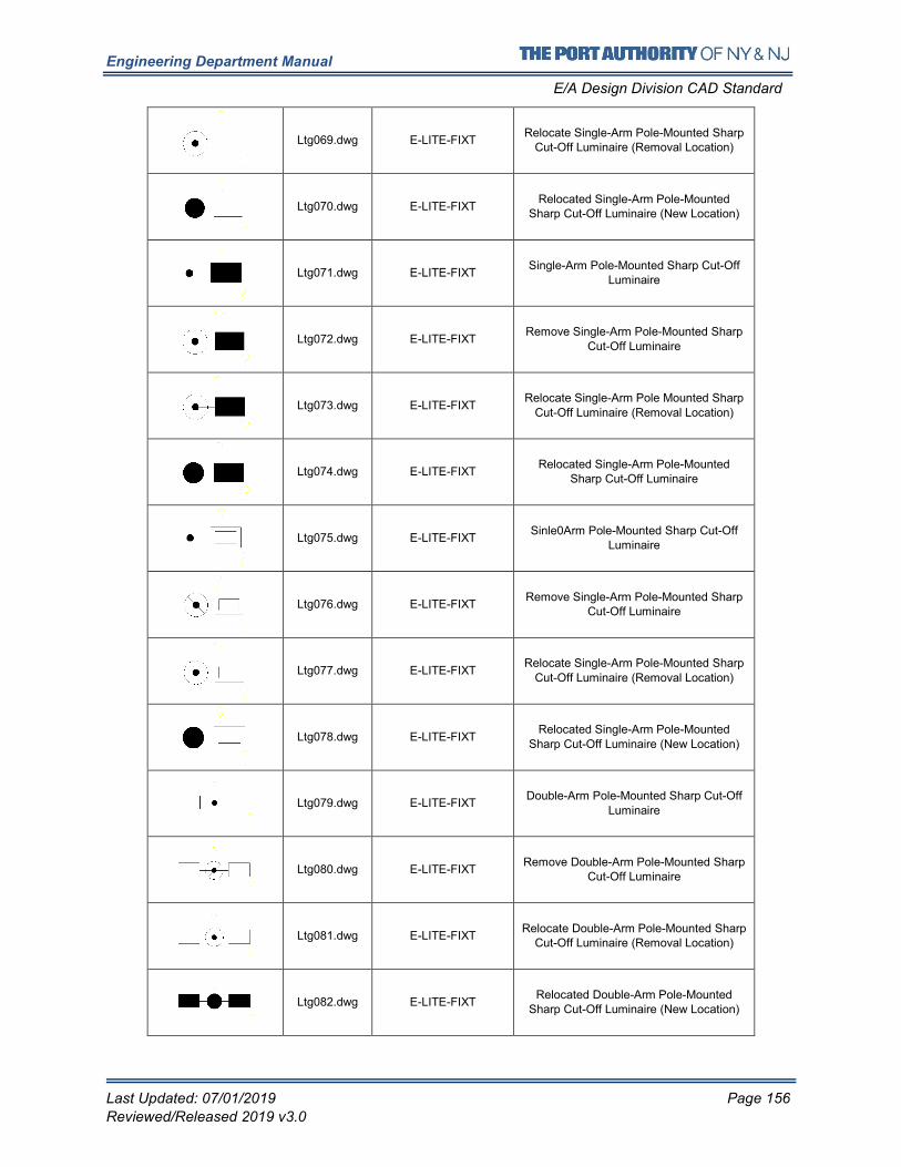
Engineering Department Manual
E/A Design Division CAD Standard
Last Updated: 07/01/2019 Page 156
Reviewed/Released 2019 v3.0
Ltg069.dwg E-LITE-FIXT Relocate Single-Arm Pole-Mounted Sharp
Cut-Off Luminaire (Removal Location)
Ltg070.dwg E-LITE-FIXT Relocated Single-Arm Pole-Mounted
Sharp Cut-Off Luminaire (New Location)
Ltg071.dwg E-LITE-FIXT Single-Arm Pole-Mounted Sharp Cut-Off
Luminaire
Ltg072.dwg E-LITE-FIXT Remove Single-Arm Pole-Mounted Sharp
Cut-Off Luminaire
Ltg073.dwg E-LITE-FIXT Relocate Single-Arm Pole Mounted Sharp
Cut-Off Luminaire (Removal Location)
Ltg074.dwg E-LITE-FIXT Relocated Single-Arm Pole-Mounted
Sharp Cut-Off Luminaire
Ltg075.dwg E-LITE-FIXT Sinle0Arm Pole-Mounted Sharp Cut-Off
Luminaire
Ltg076.dwg E-LITE-FIXT Remove Single-Arm Pole-Mounted Sharp
Cut-Off Luminaire
Ltg077.dwg E-LITE-FIXT Relocate Single-Arm Pole-Mounted Sharp
Cut-Off Luminaire (Removal Location)
Ltg078.dwg E-LITE-FIXT Relocated Single-Arm Pole-Mounted
Sharp Cut-Off Luminaire (New Location)
Ltg079.dwg E-LITE-FIXT Double-Arm Pole-Mounted Sharp Cut-Off
Luminaire
Ltg080.dwg E-LITE-FIXT Remove Double-Arm Pole-Mounted Sharp
Cut-Off Luminaire
Ltg081.dwg E-LITE-FIXT Relocate Double-Arm Pole-Mounted Sharp
Cut-Off Luminaire (Removal Location)
Ltg082.dwg E-LITE-FIXT Relocated Double-Arm Pole-Mounted
Sharp Cut-Off Luminaire (New Location)
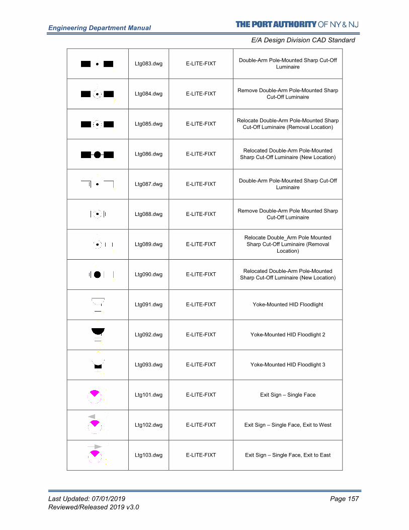
Engineering Department Manual
E/A Design Division CAD Standard
Last Updated: 07/01/2019 Page 157
Reviewed/Released 2019 v3.0
Ltg083.dwg E-LITE-FIXT Double-Arm Pole-Mounted Sharp Cut-Off
Luminaire
Ltg084.dwg E-LITE-FIXT Remove Double-Arm Pole-Mounted Sharp
Cut-Off Luminaire
Ltg085.dwg E-LITE-FIXT Relocate Double-Arm Pole-Mounted Sharp
Cut-Off Luminaire (Removal Location)
Ltg086.dwg E-LITE-FIXT Relocated Double-Arm Pole-Mounted
Sharp Cut-Off Luminaire (New Location)
Ltg087.dwg E-LITE-FIXT Double-Arm Pole-Mounted Sharp Cut-Off
Luminaire
Ltg088.dwg E-LITE-FIXT Remove Double-Arm Pole Mounted Sharp
Cut-Off Luminaire
Ltg089.dwg E-LITE-FIXT Relocate Double_Arm Pole Mounted Sharp Cut-Off Luminaire (Removal
Location)
Ltg090.dwg E-LITE-FIXT Relocated Double-Arm Pole-Mounted
Sharp Cut-Off Luminaire (New Location)
Ltg091.dwg E-LITE-FIXT Yoke-Mounted HID Floodlight
Ltg092.dwg E-LITE-FIXT Yoke-Mounted HID Floodlight 2
Ltg093.dwg E-LITE-FIXT Yoke-Mounted HID Floodlight 3
Ltg101.dwg E-LITE-FIXT Exit Sign – Single Face
Ltg102.dwg E-LITE-FIXT Exit Sign – Single Face, Exit to West
Ltg103.dwg E-LITE-FIXT Exit Sign – Single Face, Exit to East
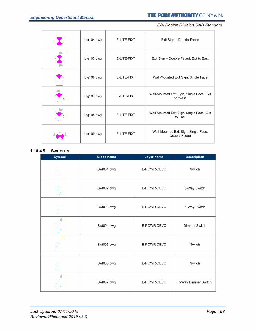
Engineering Department Manual
E/A Design Division CAD Standard
Last Updated: 07/01/2019 Page 158
Reviewed/Released 2019 v3.0
Ltg104.dwg E-LITE-FIXT Exit Sign – Double-Faced
Ltg105.dwg E-LITE-FIXT Exit Sign – Double-Faced, Exit to East
Ltg106.dwg E-LITE-FIXT Wall-Mounted Exit Sign, Single Face
Ltg107.dwg E-LITE-FIXT Wall-Mounted Exit Sign, Single Face, Exit
to West
Ltg108.dwg E-LITE-FIXT Wall-Mounted Exit Sign, Single Face, Exit
to East
Ltg109.dwg E-LITE-FIXT Wall-Mounted Exit Sign, Single Face,
Double-Faced
1.18.4.5 SWITCHES
Symbol Block name Layer Name Description
Swt001.dwg E-POWR-DEVC Switch
Swt002.dwg E-POWR-DEVC 3-Way Switch
Swt003.dwg E-POWR-DEVC 4-Way Switch
Swt004.dwg E-POWR-DEVC Dimmer Switch
Swt005.dwg E-POWR-DEVC Switch
Swt006.dwg E-POWR-DEVC Switch
Swt007.dwg E-POWR-DEVC 3-Way Dimmer Switch
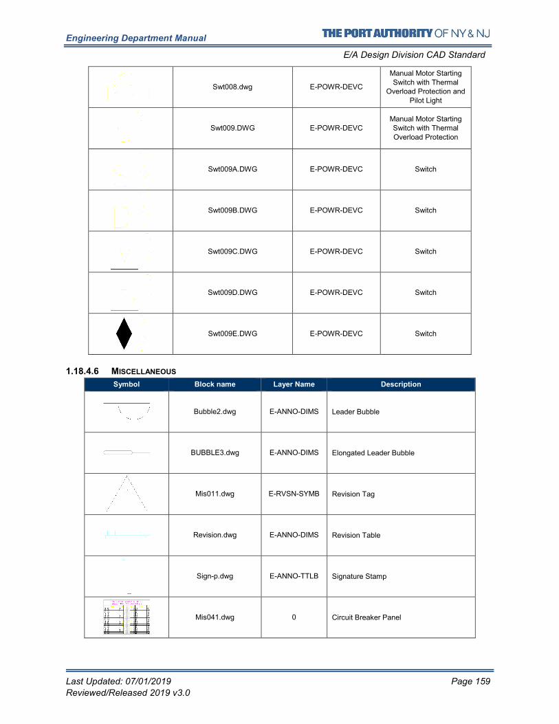
Engineering Department Manual
E/A Design Division CAD Standard
Last Updated: 07/01/2019 Page 159
Reviewed/Released 2019 v3.0
Swt008.dwg E-POWR-DEVC
Manual Motor Starting
Switch with Thermal Overload Protection and
Pilot Light
Swt009.DWG E-POWR-DEVC Manual Motor Starting Switch with Thermal
Overload Protection
Swt009A.DWG E-POWR-DEVC Switch
Swt009B.DWG E-POWR-DEVC Switch
Swt009C.DWG E-POWR-DEVC Switch
Swt009D.DWG E-POWR-DEVC Switch
Swt009E.DWG E-POWR-DEVC Switch
1.18.4.6 MISCELLANEOUS
Symbol Block name Layer Name Description
Bubble2.dwg E-ANNO-DIMS Leader Bubble
BUBBLE3.dwg E-ANNO-DIMS Elongated Leader Bubble
Mis011.dwg E-RVSN-SYMB Revision Tag
Revision.dwg E-ANNO-DIMS Revision Table
Sign-p.dwg E-ANNO-TTLB Signature Stamp
Mis041.dwg 0 Circuit Breaker Panel
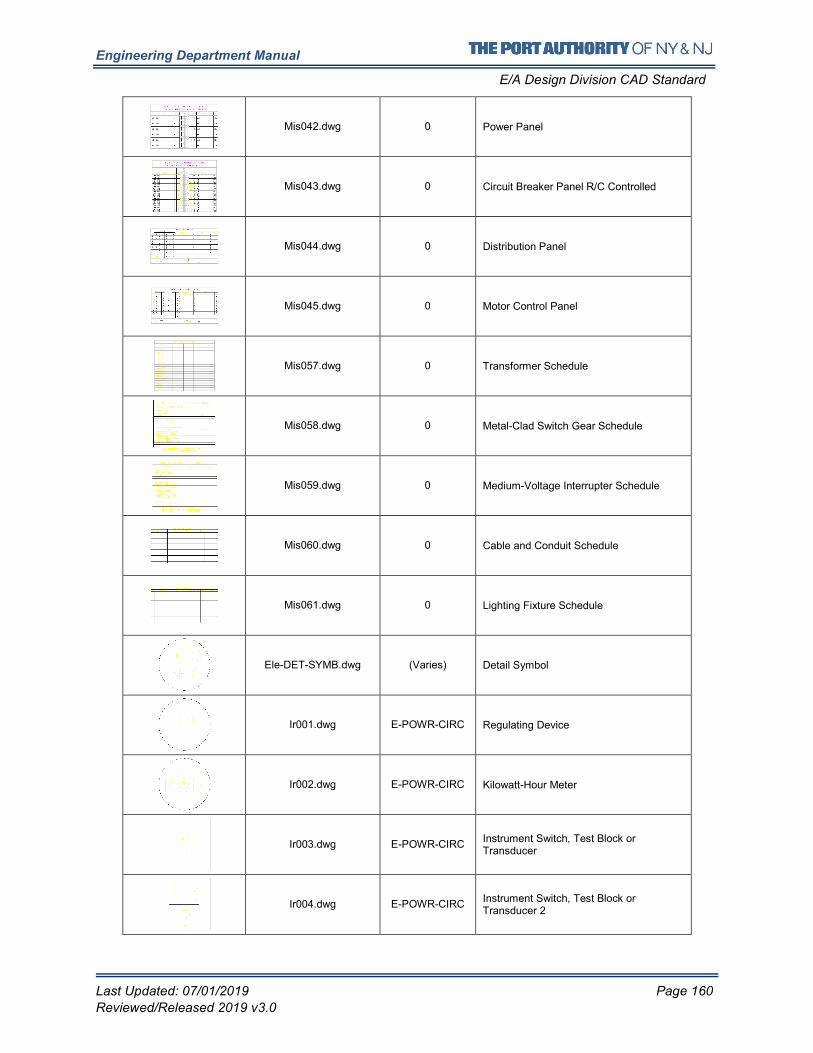
Engineering Department Manual
E/A Design Division CAD Standard
Last Updated: 07/01/2019 Page 160
Reviewed/Released 2019 v3.0
Mis042.dwg 0 Power Panel
Mis043.dwg 0 Circuit Breaker Panel R/C Controlled
Mis044.dwg 0 Distribution Panel
Mis045.dwg 0 Motor Control Panel
Mis057.dwg 0 Transformer Schedule
Mis058.dwg 0 Metal-Clad Switch Gear Schedule
Mis059.dwg 0 Medium-Voltage Interrupter Schedule
Mis060.dwg 0 Cable and Conduit Schedule
Mis061.dwg 0 Lighting Fixture Schedule
Ele-DET-SYMB.dwg (Varies) Detail Symbol
Ir001.dwg E-POWR-CIRC Regulating Device
Ir002.dwg E-POWR-CIRC Kilowatt-Hour Meter
Ir003.dwg E-POWR-CIRC Instrument Switch, Test Block or Transducer
Ir004.dwg E-POWR-CIRC Instrument Switch, Test Block or Transducer 2
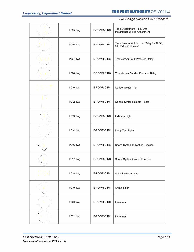
Engineering Department Manual
E/A Design Division CAD Standard
Last Updated: 07/01/2019 Page 161
Reviewed/Released 2019 v3.0
Ir005.dwg E-POWR-CIRC Time Overcurrent Relay with Instantaneous Trip Attachment
Ir006.dwg E-POWR-CIRC Time Overcurrent Ground Relay for All 50, 51, and 50/51 Relays.
Ir007.dwg E-POWR-CIRC Transformer Fault Pressure Relay
Ir008.dwg E-POWR-CIRC Transformer Sudden Pressure Relay
Ir010.dwg E-POWR-CIRC Control Switch Trip
Ir012.dwg E-POWR-CIRC Control Switch Remote – Local
Ir013.dwg E-POWR-CIRC Indicator Light
Ir014.dwg E-POWR-CIRC Lamp Test Relay
Ir016.dwg E-POWR-CIRC Scada System Indication Function
Ir017.dwg E-POWR-CIRC Scada System Control Function
Ir018.dwg E-POWR-CIRC Solid-State Metering
Ir019.dwg E-POWR-CIRC Annunciator
Ir020.dwg E-POWR-CIRC Instrument
Ir021.dwg E-POWR-CIRC Instrument
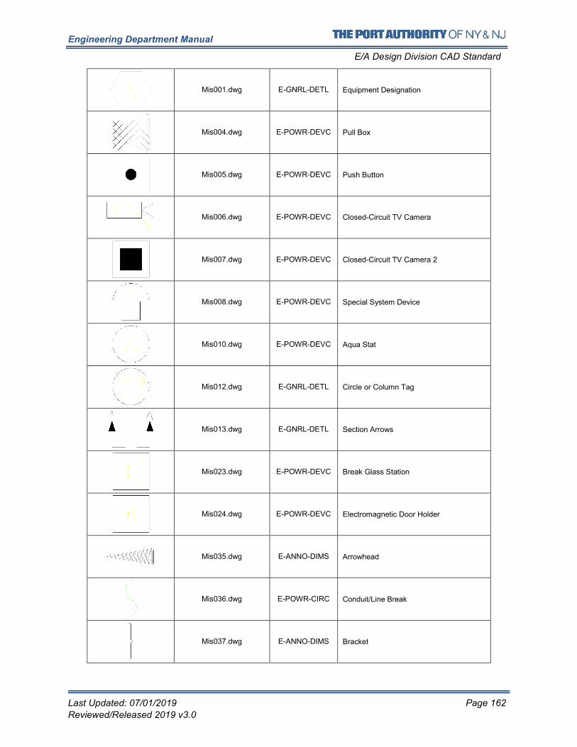
Engineering Department Manual
E/A Design Division CAD Standard
Last Updated: 07/01/2019 Page 162
Reviewed/Released 2019 v3.0
Mis001.dwg E-GNRL-DETL Equipment Designation
Mis004.dwg E-POWR-DEVC Pull Box
Mis005.dwg E-POWR-DEVC Push Button
Mis006.dwg E-POWR-DEVC Closed-Circuit TV Camera
Mis007.dwg E-POWR-DEVC Closed-Circuit TV Camera 2
Mis008.dwg E-POWR-DEVC Special System Device
Mis010.dwg E-POWR-DEVC Aqua Stat
Mis012.dwg E-GNRL-DETL Circle or Column Tag
Mis013.dwg E-GNRL-DETL Section Arrows
Mis023.dwg E-POWR-DEVC Break Glass Station
Mis024.dwg E-POWR-DEVC Electromagnetic Door Holder
Mis035.dwg E-ANNO-DIMS Arrowhead
Mis036.dwg E-POWR-CIRC Conduit/Line Break
Mis037.dwg E-ANNO-DIMS Bracket
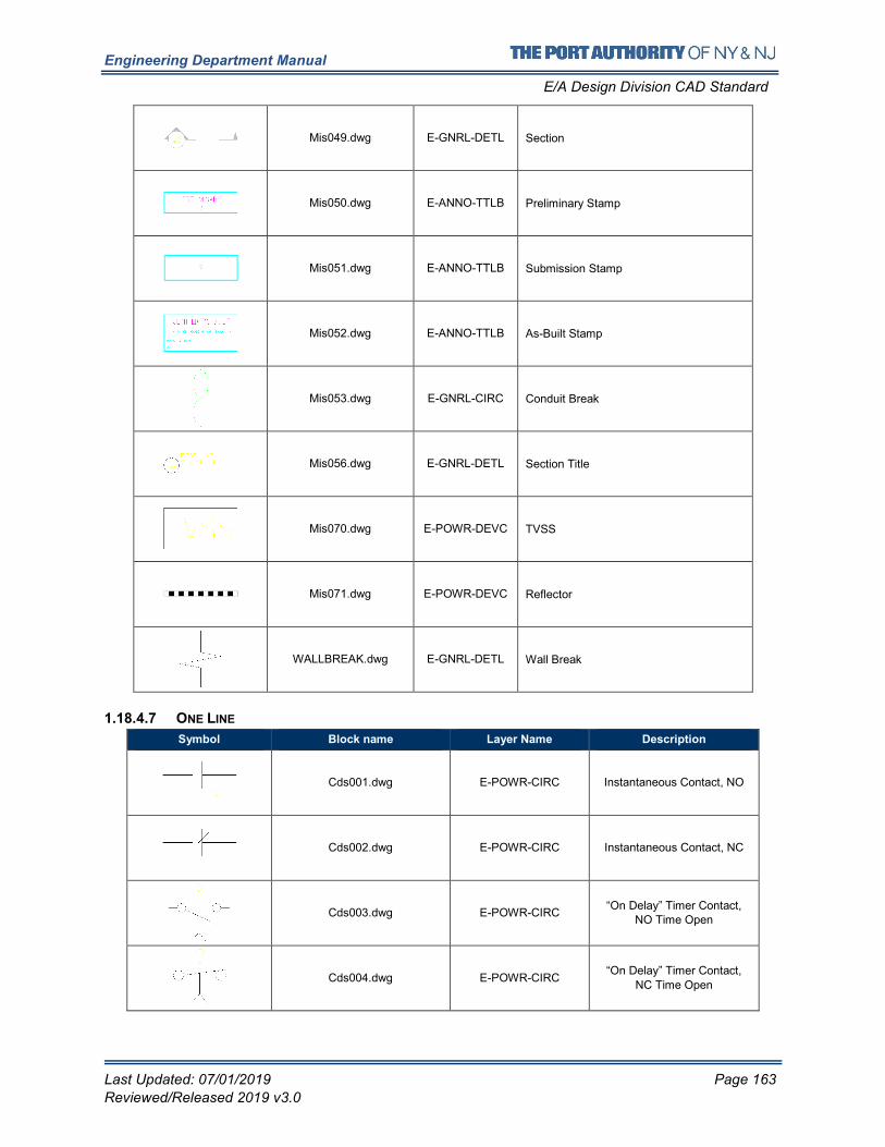
Engineering Department Manual
E/A Design Division CAD Standard
Last Updated: 07/01/2019 Page 163
Reviewed/Released 2019 v3.0
Mis049.dwg E-GNRL-DETL Section
Mis050.dwg E-ANNO-TTLB Preliminary Stamp
Mis051.dwg E-ANNO-TTLB Submission Stamp
Mis052.dwg E-ANNO-TTLB As-Built Stamp
Mis053.dwg E-GNRL-CIRC Conduit Break
Mis056.dwg E-GNRL-DETL Section Title
Mis070.dwg E-POWR-DEVC TVSS
Mis071.dwg E-POWR-DEVC Reflector
WALLBREAK.dwg E-GNRL-DETL Wall Break
1.18.4.7 ONE LINE
Symbol Block name Layer Name Description
Cds001.dwg E-POWR-CIRC Instantaneous Contact, NO
Cds002.dwg E-POWR-CIRC Instantaneous Contact, NC
Cds003.dwg E-POWR-CIRC “On Delay” Timer Contact,
NO Time Open
Cds004.dwg E-POWR-CIRC “On Delay” Timer Contact,
NC Time Open
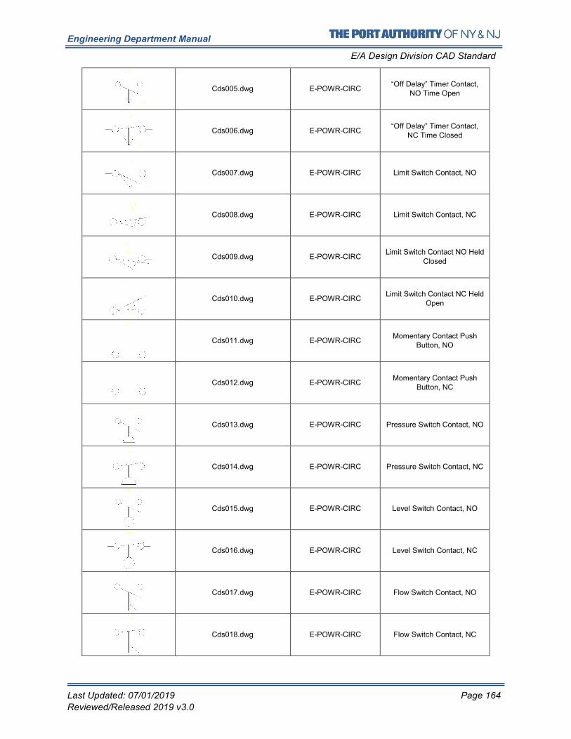
Engineering Department Manual
E/A Design Division CAD Standard
Last Updated: 07/01/2019 Page 164
Reviewed/Released 2019 v3.0
Cds005.dwg E-POWR-CIRC “Off Delay” Timer Contact,
NO Time Open
Cds006.dwg E-POWR-CIRC “Off Delay” Timer Contact,
NC Time Closed
Cds007.dwg E-POWR-CIRC Limit Switch Contact, NO
Cds008.dwg E-POWR-CIRC Limit Switch Contact, NC
Cds009.dwg E-POWR-CIRC Limit Switch Contact NO Held
Closed
Cds010.dwg E-POWR-CIRC Limit Switch Contact NC Held
Open
Cds011.dwg E-POWR-CIRC Momentary Contact Push
Button, NO
Cds012.dwg E-POWR-CIRC Momentary Contact Push
Button, NC
Cds013.dwg E-POWR-CIRC Pressure Switch Contact, NO
Cds014.dwg E-POWR-CIRC Pressure Switch Contact, NC
Cds015.dwg E-POWR-CIRC Level Switch Contact, NO
Cds016.dwg E-POWR-CIRC Level Switch Contact, NC
Cds017.dwg E-POWR-CIRC Flow Switch Contact, NO
Cds018.dwg E-POWR-CIRC Flow Switch Contact, NC
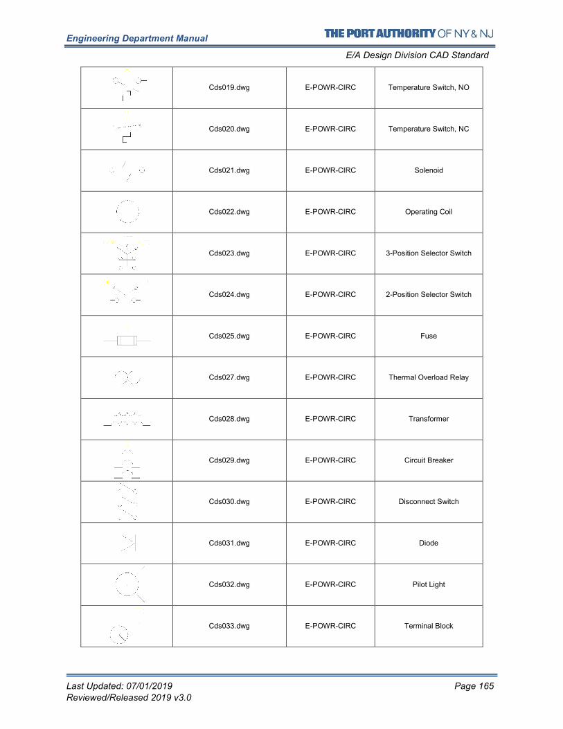
Engineering Department Manual
E/A Design Division CAD Standard
Last Updated: 07/01/2019 Page 165
Reviewed/Released 2019 v3.0
Cds019.dwg E-POWR-CIRC Temperature Switch, NO
Cds020.dwg E-POWR-CIRC Temperature Switch, NC
Cds021.dwg E-POWR-CIRC Solenoid
Cds022.dwg E-POWR-CIRC Operating Coil
Cds023.dwg E-POWR-CIRC 3-Position Selector Switch
Cds024.dwg E-POWR-CIRC 2-Position Selector Switch
Cds025.dwg E-POWR-CIRC Fuse
Cds027.dwg E-POWR-CIRC Thermal Overload Relay
Cds028.dwg E-POWR-CIRC Transformer
Cds029.dwg E-POWR-CIRC Circuit Breaker
Cds030.dwg E-POWR-CIRC Disconnect Switch
Cds031.dwg E-POWR-CIRC Diode
Cds032.dwg E-POWR-CIRC Pilot Light
Cds033.dwg E-POWR-CIRC Terminal Block
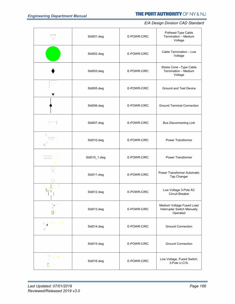
Engineering Department Manual
E/A Design Division CAD Standard
Last Updated: 07/01/2019 Page 166
Reviewed/Released 2019 v3.0
Sld001.dwg E-POWR-CIRC Pothead-Type Cable
Termination – Medium
Voltage
Sld002.dwg E-POWR-CIRC Cable Termination – Low
Voltage
Sld003.dwg E-POWR-CIRC
Stress Cone –Type Cable
Termination – Medium Voltage
Sld005.dwg E-POWR-CIRC Ground and Test Device
Sld006.dwg E-POWR-CIRC Ground Terminal Connection
Sld007.dwg E-POWR-CIRC Bus Disconnecting Link
Sld010.dwg E-POWR-CIRC Power Transformer
Sld010_1.dwg E-POWR-CIRC Power Transformer
Sld011.dwg E-POWR-CIRC Power Transformer Automatic
Tap Changer
Sld012.dwg E-POWR-CIRC Low Voltage 3-Pole AC
Circuit Breaker
Sld013.dwg E-POWR-CIRC Medium Voltage Fused Load Interrupter Switch Manually
Operated
Sld014.dwg E-POWR-CIRC Ground Connection
Sld015.dwg E-POWR-CIRC Ground Connection
Sld016.dwg E-POWR-CIRC Low Voltage, Fused Switch,
3-Pole U.O.N.
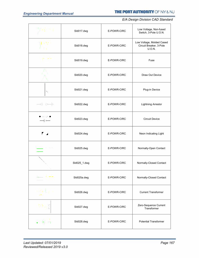
Engineering Department Manual
E/A Design Division CAD Standard
Last Updated: 07/01/2019 Page 167
Reviewed/Released 2019 v3.0
Sld017.dwg E-POWR-CIRC Low Voltage, Non-fused Switch, 3-Pole U.O.N.
Sld018.dwg E-POWR-CIRC Low Voltage, Molded Cased
Circuit Breaker, 3-Pole
U.O.N.
Sld019.dwg E-POWR-CIRC Fuse
Sld020.dwg E-POWR-CIRC Draw Out Device
Sld021.dwg E-POWR-CIRC Plug-in Device
Sld022.dwg E-POWR-CIRC Lightning Arrestor
Sld023.dwg E-POWR-CIRC Circuit Device
Sld024.dwg E-POWR-CIRC Neon Indicating Light
Sld025.dwg E-POWR-CIRC Normally-Open Contact
Sld025_1.dwg E-POWR-CIRC Normally-Closed Contact
Sld025a.dwg E-POWR-CIRC Normally-Closed Contact
Sld026.dwg E-POWR-CIRC Current Transformer
Sld027.dwg E-POWR-CIRC Zero-Sequence Current
Transformer
Sld028.dwg E-POWR-CIRC Potential Transformer
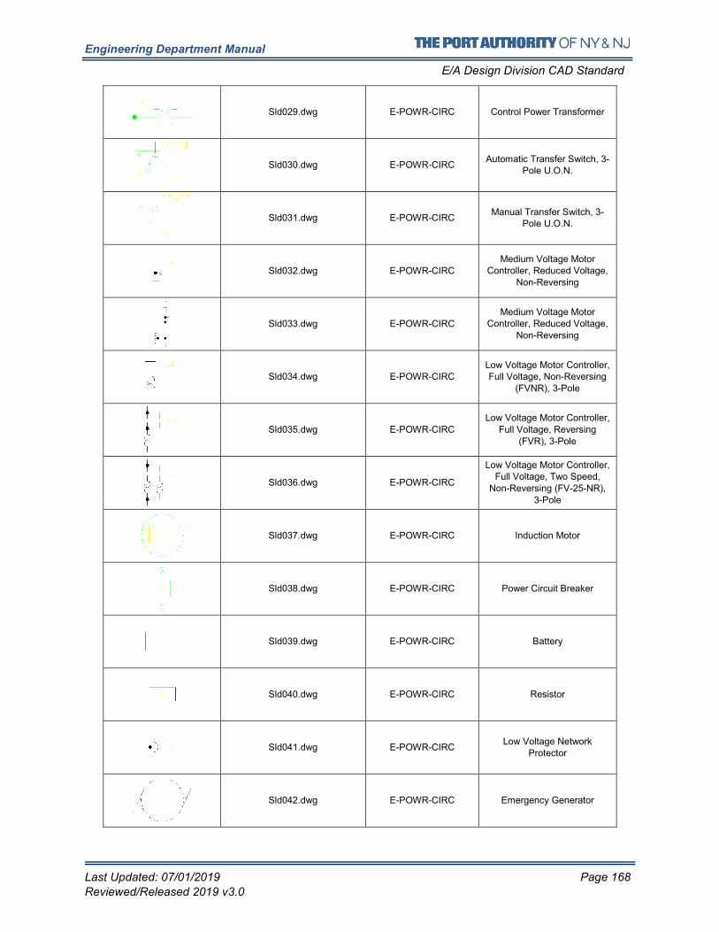
Engineering Department Manual
E/A Design Division CAD Standard
Last Updated: 07/01/2019 Page 168
Reviewed/Released 2019 v3.0
Sld029.dwg E-POWR-CIRC Control Power Transformer
Sld030.dwg E-POWR-CIRC Automatic Transfer Switch, 3-
Pole U.O.N.
Sld031.dwg E-POWR-CIRC Manual Transfer Switch, 3-
Pole U.O.N.
Sld032.dwg E-POWR-CIRC
Medium Voltage Motor Controller, Reduced Voltage,
Non-Reversing
Sld033.dwg E-POWR-CIRC
Medium Voltage Motor Controller, Reduced Voltage,
Non-Reversing
Sld034.dwg E-POWR-CIRC Low Voltage Motor Controller, Full Voltage, Non-Reversing
(FVNR), 3-Pole
Sld035.dwg E-POWR-CIRC Low Voltage Motor Controller,
Full Voltage, Reversing (FVR), 3-Pole
Sld036.dwg E-POWR-CIRC
Low Voltage Motor Controller, Full Voltage, Two Speed,
Non-Reversing (FV-25-NR), 3-Pole
Sld037.dwg E-POWR-CIRC Induction Motor
Sld038.dwg E-POWR-CIRC Power Circuit Breaker
Sld039.dwg E-POWR-CIRC Battery
Sld040.dwg E-POWR-CIRC Resistor
Sld041.dwg E-POWR-CIRC Low Voltage Network
Protector
Sld042.dwg E-POWR-CIRC Emergency Generator
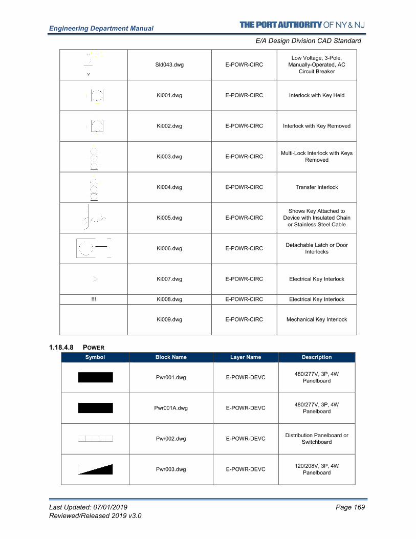
Engineering Department Manual
E/A Design Division CAD Standard
Last Updated: 07/01/2019 Page 169
Reviewed/Released 2019 v3.0
Sld043.dwg E-POWR-CIRC Low Voltage, 3-Pole,
Manually-Operated, AC
Circuit Breaker
Ki001.dwg E-POWR-CIRC Interlock with Key Held
Ki002.dwg E-POWR-CIRC Interlock with Key Removed
Ki003.dwg E-POWR-CIRC Multi-Lock Interlock with Keys
Removed
Ki004.dwg E-POWR-CIRC Transfer Interlock
Ki005.dwg E-POWR-CIRC Shows Key Attached to
Device with Insulated Chain or Stainless Steel Cable
Ki006.dwg E-POWR-CIRC Detachable Latch or Door
Interlocks
Ki007.dwg E-POWR-CIRC Electrical Key Interlock
!!! Ki008.dwg E-POWR-CIRC Electrical Key Interlock
Ki009.dwg E-POWR-CIRC Mechanical Key Interlock
1.18.4.8 POWER
Symbol Block Name Layer Name Description
Pwr001.dwg E-POWR-DEVC 480/277V, 3P, 4W
Panelboard
Pwr001A.dwg E-POWR-DEVC 480/277V, 3P, 4W
Panelboard
Pwr002.dwg E-POWR-DEVC Distribution Panelboard or
Switchboard
Pwr003.dwg E-POWR-DEVC 120/208V, 3P, 4W
Panelboard
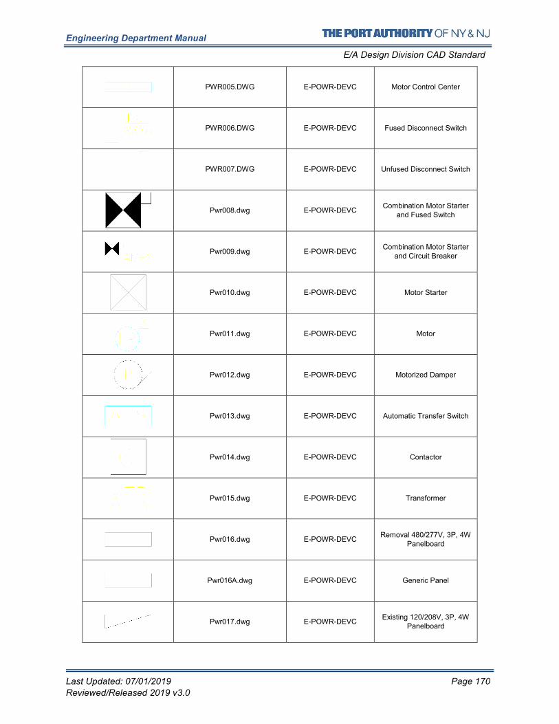
Engineering Department Manual
E/A Design Division CAD Standard
Last Updated: 07/01/2019 Page 170
Reviewed/Released 2019 v3.0
PWR005.DWG E-POWR-DEVC Motor Control Center
PWR006.DWG E-POWR-DEVC Fused Disconnect Switch
PWR007.DWG E-POWR-DEVC Unfused Disconnect Switch
Pwr008.dwg E-POWR-DEVC Combination Motor Starter
and Fused Switch
Pwr009.dwg E-POWR-DEVC Combination Motor Starter
and Circuit Breaker
Pwr010.dwg E-POWR-DEVC Motor Starter
Pwr011.dwg E-POWR-DEVC Motor
Pwr012.dwg E-POWR-DEVC Motorized Damper
Pwr013.dwg E-POWR-DEVC Automatic Transfer Switch
Pwr014.dwg E-POWR-DEVC Contactor
Pwr015.dwg E-POWR-DEVC Transformer
Pwr016.dwg E-POWR-DEVC Removal 480/277V, 3P, 4W
Panelboard
Pwr016A.dwg E-POWR-DEVC Generic Panel
Pwr017.dwg E-POWR-DEVC Existing 120/208V, 3P, 4W
Panelboard
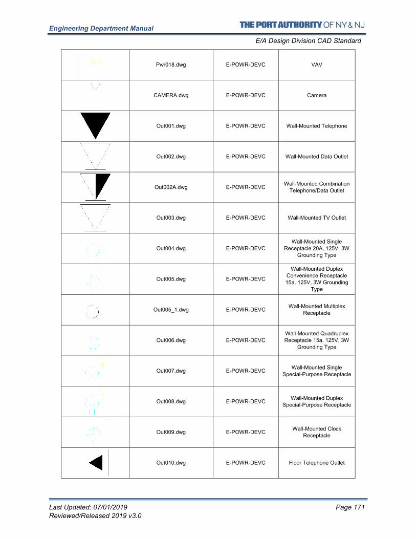
Engineering Department Manual
E/A Design Division CAD Standard
Last Updated: 07/01/2019 Page 171
Reviewed/Released 2019 v3.0
Pwr018.dwg E-POWR-DEVC VAV
CAMERA.dwg E-POWR-DEVC Camera
Out001.dwg E-POWR-DEVC Wall-Mounted Telephone
Out002.dwg E-POWR-DEVC Wall-Mounted Data Outlet
Out002A.dwg E-POWR-DEVC Wall-Mounted Combination
Telephone/Data Outlet
Out003.dwg E-POWR-DEVC Wall-Mounted TV Outlet
Out004.dwg E-POWR-DEVC Wall-Mounted Single
Receptacle 20A, 125V, 3W Grounding Type
Out005.dwg E-POWR-DEVC
Wall-Mounted Duplex Convenience Receptacle 15a, 125V, 3W Grounding
Type
Out005_1.dwg E-POWR-DEVC Wall-Mounted Multiplex
Receptacle
Out006.dwg E-POWR-DEVC Wall-Mounted Quadruplex Receptacle 15a, 125V, 3W
Grounding Type
Out007.dwg E-POWR-DEVC Wall-Mounted Single
Special-Purpose Receptacle
Out008.dwg E-POWR-DEVC Wall-Mounted Duplex
Special-Purpose Receptacle
Out009.dwg E-POWR-DEVC Wall-Mounted Clock
Receptacle
Out010.dwg E-POWR-DEVC Floor Telephone Outlet
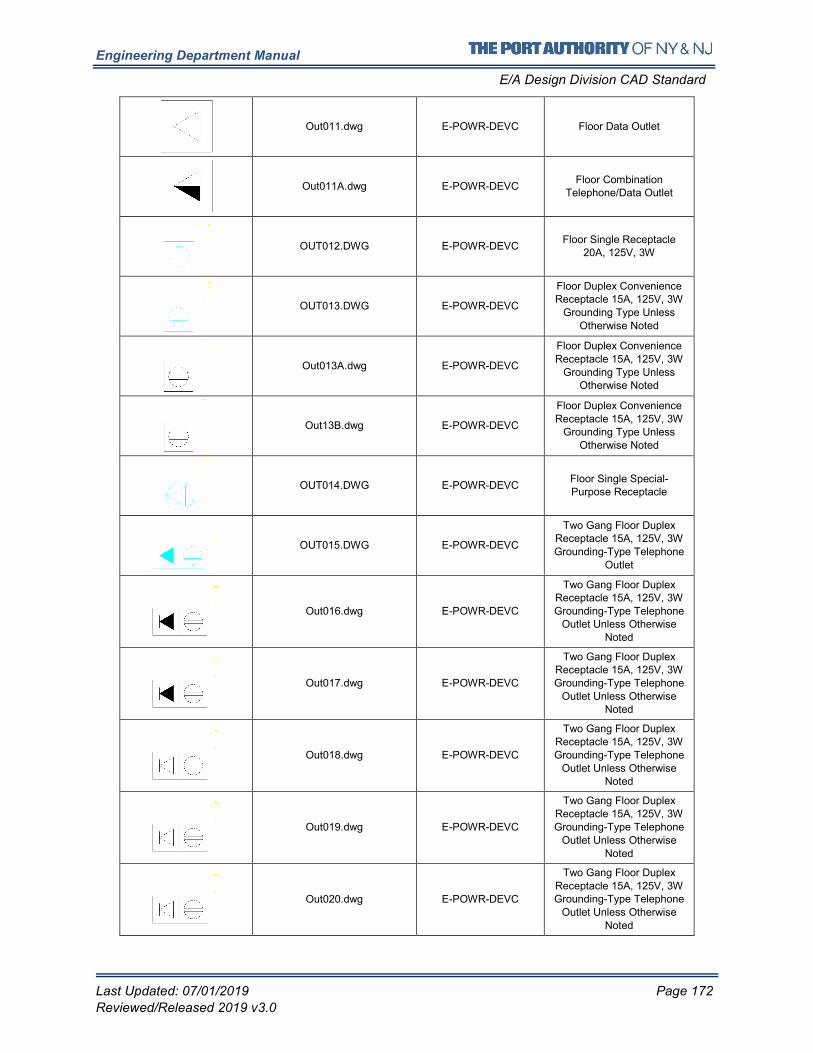
Engineering Department Manual
E/A Design Division CAD Standard
Last Updated: 07/01/2019 Page 172
Reviewed/Released 2019 v3.0
Out011.dwg E-POWR-DEVC Floor Data Outlet
Out011A.dwg E-POWR-DEVC Floor Combination
Telephone/Data Outlet
OUT012.DWG E-POWR-DEVC Floor Single Receptacle
20A, 125V, 3W
OUT013.DWG E-POWR-DEVC
Floor Duplex Convenience Receptacle 15A, 125V, 3W
Grounding Type Unless
Otherwise Noted
Out013A.dwg E-POWR-DEVC
Floor Duplex Convenience
Receptacle 15A, 125V, 3W Grounding Type Unless
Otherwise Noted
Out13B.dwg E-POWR-DEVC
Floor Duplex Convenience Receptacle 15A, 125V, 3W
Grounding Type Unless Otherwise Noted
OUT014.DWG E-POWR-DEVC Floor Single Special-Purpose Receptacle
OUT015.DWG E-POWR-DEVC
Two Gang Floor Duplex Receptacle 15A, 125V, 3W Grounding-Type Telephone
Outlet
Out016.dwg E-POWR-DEVC
Two Gang Floor Duplex Receptacle 15A, 125V, 3W Grounding-Type Telephone
Outlet Unless Otherwise Noted
Out017.dwg E-POWR-DEVC
Two Gang Floor Duplex Receptacle 15A, 125V, 3W Grounding-Type Telephone
Outlet Unless Otherwise Noted
Out018.dwg E-POWR-DEVC
Two Gang Floor Duplex Receptacle 15A, 125V, 3W
Grounding-Type Telephone
Outlet Unless Otherwise Noted
Out019.dwg E-POWR-DEVC
Two Gang Floor Duplex Receptacle 15A, 125V, 3W
Grounding-Type Telephone Outlet Unless Otherwise
Noted
Out020.dwg E-POWR-DEVC
Two Gang Floor Duplex
Receptacle 15A, 125V, 3W Grounding-Type Telephone
Outlet Unless Otherwise Noted
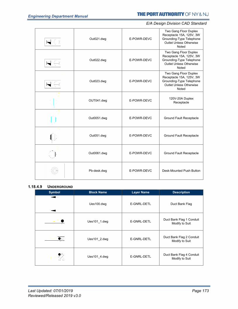
Engineering Department Manual
E/A Design Division CAD Standard
Last Updated: 07/01/2019 Page 173
Reviewed/Released 2019 v3.0
Out021.dwg E-POWR-DEVC
Two Gang Floor Duplex Receptacle 15A, 125V, 3W
Grounding-Type Telephone
Outlet Unless Otherwise
Noted
Out022.dwg E-POWR-DEVC
Two Gang Floor Duplex
Receptacle 15A, 125V, 3W Grounding-Type Telephone
Outlet Unless Otherwise
Noted
Out023.dwg E-POWR-DEVC
Two Gang Floor Duplex
Receptacle 15A, 125V, 3W Grounding-Type Telephone
Outlet Unless Otherwise
Noted
OUT041.dwg E-POWR-DEVC 120V-20A Duplex
Receptacle
Out0051.dwg E-POWR-DEVC Ground Fault Receptacle
Out051.dwg E-POWR-DEVC Ground Fault Receptacle
Out0061.dwg E-POWR-DEVC Ground Fault Receptacle
Pb-desk.dwg E-POWR-DEVC Desk-Mounted Push Button
1.18.4.9 UNDERGROUND
Symbol Block Name Layer Name Description
Ues100.dwg E-GNRL-DETL Duct Bank Flag
Ues101_1.dwg E-GNRL-DETL Duct Bank Flag 1 Conduit
Modify to Suit
Ues101_2.dwg E-GNRL-DETL Duct Bank Flag 2 Conduit
Modify to Suit
Ues101_4.dwg E-GNRL-DETL Duct Bank Flag 4 Conduit
Modify to Suit
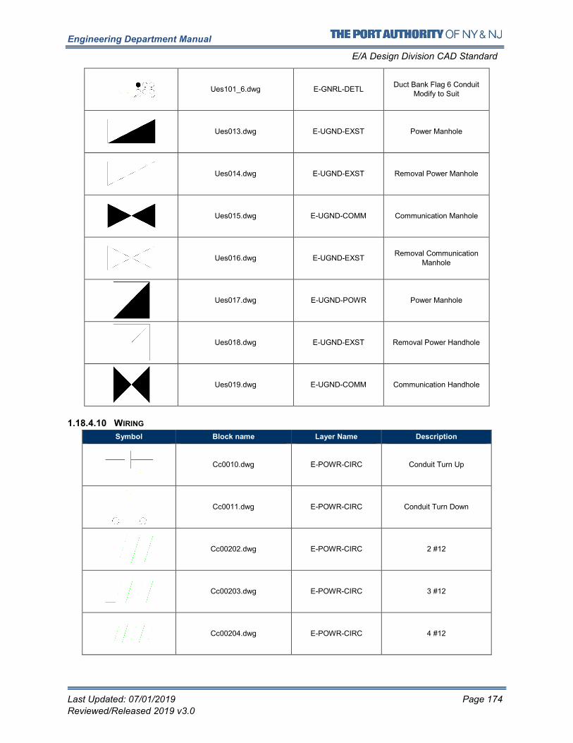
Engineering Department Manual
E/A Design Division CAD Standard
Last Updated: 07/01/2019 Page 174
Reviewed/Released 2019 v3.0
Ues101_6.dwg E-GNRL-DETL Duct Bank Flag 6 Conduit
Modify to Suit
Ues013.dwg E-UGND-EXST Power Manhole
Ues014.dwg E-UGND-EXST Removal Power Manhole
Ues015.dwg E-UGND-COMM Communication Manhole
Ues016.dwg E-UGND-EXST Removal Communication
Manhole
Ues017.dwg E-UGND-POWR Power Manhole
Ues018.dwg E-UGND-EXST Removal Power Handhole
Ues019.dwg E-UGND-COMM Communication Handhole
1.18.4.10 WIRING
Symbol Block name Layer Name Description
Cc0010.dwg E-POWR-CIRC Conduit Turn Up
Cc0011.dwg E-POWR-CIRC Conduit Turn Down
Cc00202.dwg E-POWR-CIRC 2 #12
Cc00203.dwg E-POWR-CIRC 3 #12
Cc00204.dwg E-POWR-CIRC 4 #12
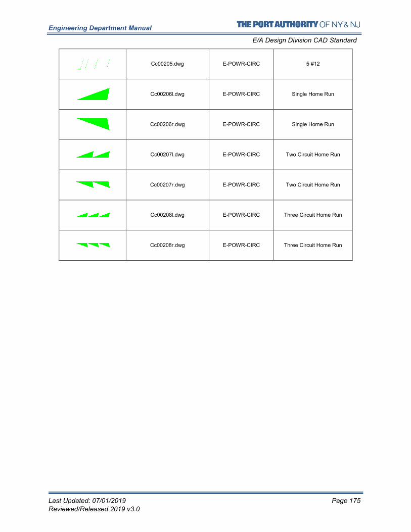
Engineering Department Manual
E/A Design Division CAD Standard
Last Updated: 07/01/2019 Page 175
Reviewed/Released 2019 v3.0
Cc00205.dwg E-POWR-CIRC 5 #12
Cc00206l.dwg E-POWR-CIRC Single Home Run
Cc00206r.dwg E-POWR-CIRC Single Home Run
Cc00207l.dwg E-POWR-CIRC Two Circuit Home Run
Cc00207r.dwg E-POWR-CIRC Two Circuit Home Run
Cc00208l.dwg E-POWR-CIRC Three Circuit Home Run
Cc00208r.dwg E-POWR-CIRC Three Circuit Home Run
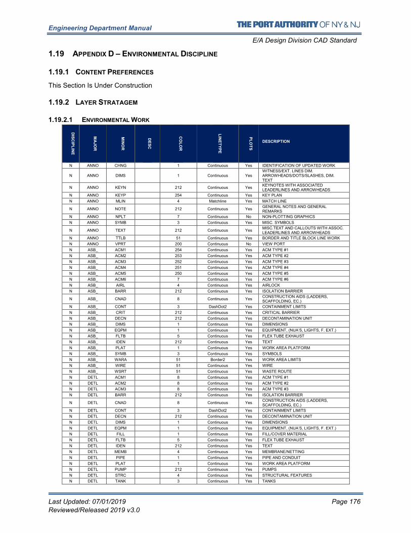
Engineering Department Manual
E/A Design Division CAD Standard
Last Updated: 07/01/2019 Page 176
Reviewed/Released 2019 v3.0
1.19 APPENDIX D – ENVIRONMENTAL DISCIPLINE
1.19.1 CONTENT PREFERENCES
This Section Is Under Construction
1.19.2 LAYER STRATAGEM
1.19.2.1 ENVIRONMENTAL WORK
DIS
CIP
LIN
E
MA
JO
R
MIN
OR
DE
SC
CO
LO
R
LIN
ET
YP
E
PL
OT
S
DESCRIPTION
N ANNO CHNG 1 Continuous Yes IDENTIFICATION OF UPDATED WORK
N ANNO DIMS 1 Continuous Yes WITNESS/EXT. LINES DIM. ARROWHEADS/DOTS/SLASHES, DIM. TEXT
N ANNO KEYN 212 Continuous Yes KEYNOTES WITH ASSOCIATED LEADERLINES AND ARROWHEADS
N ANNO KEYP 254 Continuous Yes KEY PLAN
N ANNO MLIN 4 Matchline Yes MATCH LINE
N ANNO NOTE 212 Continuous Yes GENERAL NOTES AND GENERAL REMARKS
N ANNO NPLT 7 Continuous No NON-PLOTTING GRAPHICS
N ANNO SYMB 3 Continuous Yes MISC. SYMBOLS
N ANNO TEXT 212 Continuous Yes MISC.TEXT AND CALLOUTS WITH ASSOC. LEADERLINES AND ARROWHEADS
N ANNO TTLB 51 Continuous Yes BORDER AND TITLE BLOCK LINE WORK
N ANNO VPRT 200 Continuous No VIEW PORT
N ASB_ ACM1 254 Continuous Yes ACM TYPE #1
N ASB_ ACM2 253 Continuous Yes ACM TYPE #2
N ASB_ ACM3 252 Continuous Yes ACM TYPE #3
N ASB_ ACM4 251 Continuous Yes ACM TYPE #4
N ASB_ ACM5 250 Continuous Yes ACM TYPE #5
N ASB_ ACM6 7 Continuous Yes ACM TYPE #6
N ASB_ AIRL 4 Continuous Yes AIRLOCK
N ASB_ BARR 212 Continuous Yes ISOLATION BARRIER
N ASB_ CNAD 8 Continuous Yes CONSTRUCTION AIDS (LADDERS, SCAFFOLDING, EC.)
N ASB_ CONT 3 DashDot2 Yes CONTAINMENT LIMITS
N ASB_ CRIT 212 Continuous Yes CRITICAL BARRIER
N ASB_ DECN 212 Continuous Yes DECONTAMINATION UNIT
N ASB_ DIMS 1 Continuous Yes DIMENSIONS
N ASB_ EQPM 1 Continuous Yes EQUIPMENT, (NUA’S, LIGHTS, F. EXT.)
N ASB_ FLTB 5 Continuous Yes FLEX TUBE EXHAUST
N ASB_ IDEN 212 Continuous Yes TEXT
N ASB_ PLAT 1 Continuous Yes WORK AREA PLATFORM
N ASB_ SYMB 3 Continuous Yes SYMBOLS
N ASB_ WARA 51 Border2 Yes WORK AREA LIMITS
N ASB_ WIRE 51 Continuous Yes WIRE
N ASB_ WSRT 51 Continuous Yes WASTE ROUTE
N DETL ACM1 8 Continuous Yes ACM TYPE #1
N DETL ACM2 8 Continuous Yes ACM TYPE #2
N DETL ACM3 8 Continuous Yes ACM TYPE #3
N DETL BARR 212 Continuous Yes ISOLATION BARRIER
N DETL CNAD 8 Continuous Yes CONSTRUCTION AIDS (LADDERS, SCAFFOLDING, EC.)
N DETL CONT 3 DashDot2 Yes CONTAINMENT LIMITS
N DETL DECN 212 Continuous Yes DECONTAMINATION UNIT
N DETL DIMS 1 Continuous Yes DIMENSIONS
N DETL EQPM 1 Continuous Yes EQUIPMENT, (NUA’S, LIGHTS, F. EXT.)
N DETL FILL 1 Continuous Yes FILL/COVER MATERIAL
N DETL FLTB 5 Continuous Yes FLEX TUBE EXHAUST
N DETL IDEN 212 Continuous Yes TEXT
N DETL MEMB 4 Continuous Yes MEMBRANE/NETTING
N DETL PIPE 1 Continuous Yes PIPE AND CONDUIT
N DETL PLAT 1 Continuous Yes WORK AREA PLATFORM
N DETL PUMP 212 Continuous Yes PUMPS
N DETL STRC 4 Continuous Yes STRUCTURAL FEATURES
N DETL TANK 3 Continuous Yes TANKS
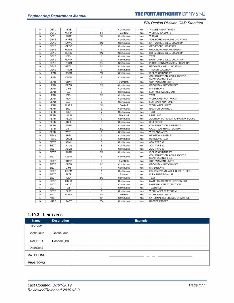
Engineering Department Manual
E/A Design Division CAD Standard
Last Updated: 07/01/2019 Page 177
Reviewed/Released 2019 v3.0
N DETL VLVE 1 Continuous Yes VALVES AND FITTINGS
N DETL WARA 51 Border2 Yes WORK AREA LIMITS
N DETL WIRE 51 Continuous Yes WIRING
N GENE BORE 4 Continuous Yes SOIL BORE SAMPLING LOCATION
N GENE EXWL 212 Continuous Yes EXTRACTION WELL LOCATION
N GENE GEOP 3 Continuous Yes GEO-PROBE LOCATION
N GENE GWAT 7 Continuous Yes GROUND WATER GRADIENT
N GENE HORW 212 Continuous Yes HORIZONTAL WELL LOCATION
N GENE IDEN 1 Continuous Yes TEXT
N GENE MONW 3 Continuous Yes MONITORING WELL LOCATION
N GENE PLUM 254 Continuous Yes PLUME CONTAMINATION LOCATION
N GENE REWL 212 Continuous Yes RECOVERY WELL LOCATION
N GENE TRCH 3 Continuous Yes TRENCH LOCATION
N LEAD BARR 212 Continuous Yes ISOLATION BARRIER
N LEAD CNAD 8 Continuous Yes CONSTRUCTION AIDS (LADDERS, SCAFFOLDING, EC.)
N LEAD CONT 3 DashDot2 Yes CONTAINMENT LIMITS
N LEAD DECN 212 Continuous Yes DECONTAMINATION UNIT
N LEAD DIMS 1 Continuous Yes DIMENSIONS
N LEAD FABT 8 Continuous Yes LCM FULL ABATEMENT
N LEAD IDEN 212 Continuous Yes TEXT
N LEAD PLAT 1 Continuous Yes WORK AREA PLATFORM
N LEAD SABT 7 Continuous Yes LCM SPOT ABATEMENT
N LEAD WARA 51 Border2 Yes WORK AREA LIMITS
N PERM ERCT 5 Continuous Yes EROSION CONTROL
N PERM IDEN 7 Continuous Yes TEXT
N PERM LMLN 3 Phantom2 Yes LIMIT LINE
N PERM REUS 5 Continuous Yes ADDITION TO PERMIT APPICTION SCOPE
N PERM SILT 5 Continuous Yes SILT FENCE
N PERM ENTR 1 Continuous Yes CONSTRUCTION ENTRANCE
N PERM CB__ 212 Continuous Yes CATCH BASIN PROTECTION
N PERM WETL 1 Continuous Yes WETLAND AREA
N REVS BUBL 3 Continuous Yes REVISIONS BUBBLE
N REVS SYMB 3 Continuous Yes REVISIONS TEXT
N SECT ACM1 8 Continuous Yes ACM TYPE #1
N SECT ACM2 8 Continuous Yes ACM TYPE #2
N SECT ACM3 8 Continuous Yes ACM TYPE #3
N SECT BARR 212 Continuous Yes ISOLATION BARRIER
N SECT CNAD 8 Continuous Yes CONSTRUCTION AIDS (LADDERS, SCAFFOLDING, EC.)
N SECT CONT 3 DashDot2 Yes CONTAINMENT LIMITS
N SECT DECN 212 Continuous Yes DECONTAMINATION UNIT
N SECT DIMS 1 Continuous Yes DIMENSIONS
N SECT EQPM 1 Continuous Yes EQUIPMENT, (NUA’S, LIGHTS, F. EXT.)
N SECT FLTB 5 Exhaust Yes FLEX TUBE EXHAUST
N SECT IDEN 212 Continuous Yes TEXT
N SECT MBND 8 Continuous Yes MATERIAL BEYOND SECTION CUT
N SECT MCUT 1 Continuous Yes MATERIAL CUT BY SECTION
N SECT PATT 8 Continuous Yes TEXTURES
N SECT PLAT 1 Continuous Yes WORK AREA PLATFORM
N SECT WARA 51 Border2 Yes WORK AREA LIMITS
N XREF 254 Continuous Yes EXTERNAL REFERENCE DRAWINGS
N XREF RAST 254 Continuous Yes RASTER IMAGES
1.19.3 LINETYPES
Name Description Example
Border2
Continuous Continuous
DASHED Dashed (1x)
DashDot2
MATCHLINE
PHANTOM2
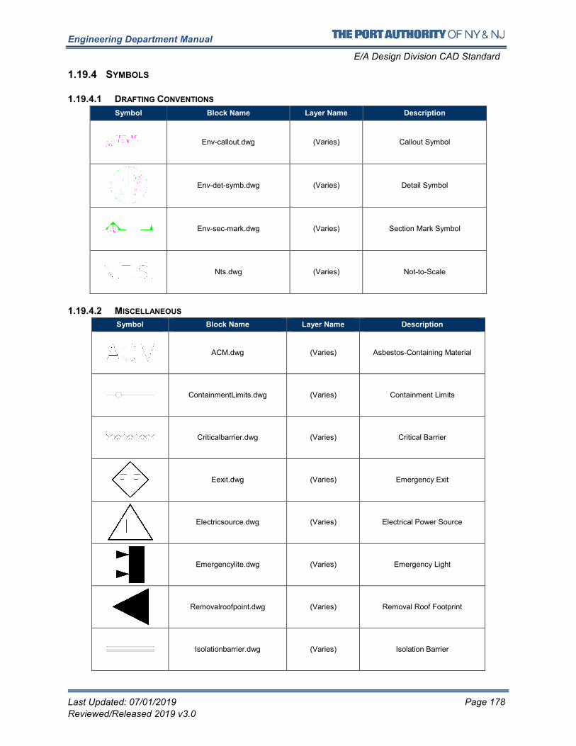
Engineering Department Manual
E/A Design Division CAD Standard
Last Updated: 07/01/2019 Page 178
Reviewed/Released 2019 v3.0
1.19.4 SYMBOLS
1.19.4.1 DRAFTING CONVENTIONS
Symbol Block Name Layer Name Description
Env-callout.dwg (Varies) Callout Symbol
Env-det-symb.dwg (Varies) Detail Symbol
Env-sec-mark.dwg (Varies) Section Mark Symbol
Nts.dwg (Varies) Not-to-Scale
1.19.4.2 MISCELLANEOUS
Symbol Block Name Layer Name Description
ACM.dwg (Varies) Asbestos-Containing Material
ContainmentLimits.dwg (Varies) Containment Limits
Criticalbarrier.dwg (Varies) Critical Barrier
Eexit.dwg (Varies) Emergency Exit
Electricsource.dwg (Varies) Electrical Power Source
Emergencylite.dwg (Varies) Emergency Light
Removalroofpoint.dwg (Varies) Removal Roof Footprint
Isolationbarrier.dwg (Varies) Isolation Barrier
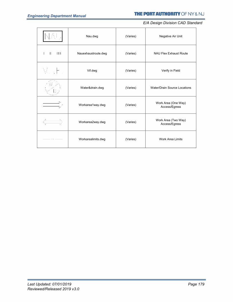
Engineering Department Manual
E/A Design Division CAD Standard
Last Updated: 07/01/2019 Page 179
Reviewed/Released 2019 v3.0
Nau.dwg (Varies) Negative Air Unit
Nauexhaustroute.dwg (Varies) NAU Flex Exhaust Route
Vif.dwg (Varies) Verify in Field
Water&drain.dwg (Varies) Water/Drain Source Locations
Workarea1way.dwg (Varies) Work Area (One Way)
Access/Egress
Workarea2way.dwg (Varies) Work Area (Two Way)
Access/Egress
Workarealimits.dwg (Varies) Work Area Limits
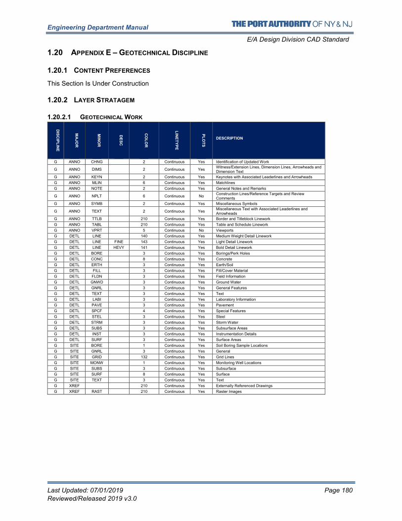
Engineering Department Manual
E/A Design Division CAD Standard
Last Updated: 07/01/2019 Page 180
Reviewed/Released 2019 v3.0
1.20 APPENDIX E – GEOTECHNICAL DISCIPLINE
1.20.1 CONTENT PREFERENCES
This Section Is Under Construction
1.20.2 LAYER STRATAGEM
1.20.2.1 GEOTECHNICAL WORK
DIS
CIP
LIN
E
MA
JO
R
MIN
OR
DE
SC
CO
LO
R
LIN
ET
YP
E
PL
OT
S
DESCRIPTION
G ANNO CHNG 2 Continuous Yes Identification of Updated Work
G ANNO DIMS 2 Continuous Yes Witness/Extension Lines, Dimension Lines, Arrowheads and Dimension Text
G ANNO KEYN 2 Continuous Yes Keynotes with Associated Leaderlines and Arrowheads
G ANNO MLIN 6 Continuous Yes Matchlines
G ANNO NOTE 2 Continuous Yes General Notes and Remarks
G ANNO NPLT 6 Continuous No Construction Lines/Reference Targets and Review Comments
G ANNO SYMB 2 Continuous Yes Miscellaneous Symbols
G ANNO TEXT 2 Continuous Yes Miscellaneous Text with Associated Leaderlines and Arrowheads
G ANNO TTLB 210 Continuous Yes Border and Titleblock Linework
G ANNO TABL 210 Continuous Yes Table and Schedule Linework
G ANNO VPRT 5 Continuous No Viewports
G DETL LINE 140 Continuous Yes Medium Weight Detail Linework
G DETL LINE FINE 143 Continuous Yes Light Detail Linework
G DETL LINE HEVY 141 Continuous Yes Bold Detail Linework
G DETL BORE 3 Continuous Yes Borings/Perk Holes
G DETL CONC 8 Continuous Yes Concrete
G DETL ERTH 3 Continuous Yes Earth/Soil
G DETL FILL 3 Continuous Yes Fill/Cover Material
G DETL FLDN 3 Continuous Yes Field Information
G DETL GNWD 3 Continuous Yes Ground Water
G DETL GNRL 3 Continuous Yes General Features
G DETL TEXT 3 Continuous Yes Text
G DETL LABI 3 Continuous Yes Laboratory Information
G DETL PAVE 3 Continuous Yes Pavement
G DETL SPCF 4 Continuous Yes Special Features
G DETL STEL 3 Continuous Yes Steel
G DETL STRM 3 Continuous Yes Storm Water
G DETL SUBS 3 Continuous Yes Subsurface Areas
G DETL INST 3 Continuous Yes Instrumentation Details
G DETL SURF 3 Continuous Yes Surface Areas
G SITE BORE 1 Continuous Yes Soil Boring Sample Locations
G SITE GNRL 3 Continuous Yes General
G SITE GRID 132 Continuous Yes Grid Lines
G SITE MONW 1 Continuous Yes Monitoring Well Locations
G SITE SUBS 3 Continuous Yes Subsurface
G SITE SURF 8 Continuous Yes Surface
G SITE TEXT 3 Continuous Yes Text
G XREF 210 Continuous Yes Externally Referenced Drawings
G XREF RAST 210 Continuous Yes Raster Images
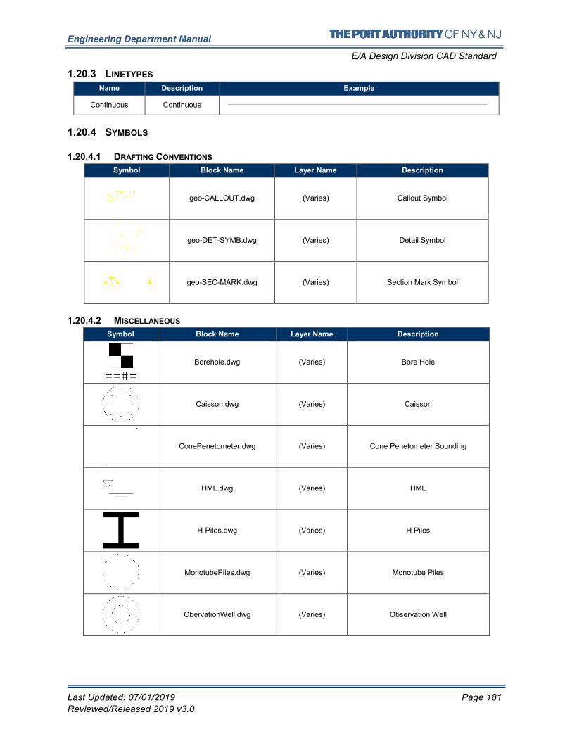
Engineering Department Manual
E/A Design Division CAD Standard
Last Updated: 07/01/2019 Page 181
Reviewed/Released 2019 v3.0
1.20.3 LINETYPES
Name Description Example
Continuous Continuous
1.20.4 SYMBOLS
1.20.4.1 DRAFTING CONVENTIONS
Symbol Block Name Layer Name Description
geo-CALLOUT.dwg (Varies) Callout Symbol
geo-DET-SYMB.dwg (Varies) Detail Symbol
geo-SEC-MARK.dwg (Varies) Section Mark Symbol
1.20.4.2 MISCELLANEOUS
Symbol Block Name Layer Name Description
Borehole.dwg (Varies) Bore Hole
Caisson.dwg (Varies) Caisson
ConePenetometer.dwg (Varies) Cone Penetometer Sounding
HML.dwg (Varies) HML
H-Piles.dwg (Varies) H Piles
MonotubePiles.dwg (Varies) Monotube Piles
ObervationWell.dwg (Varies) Observation Well
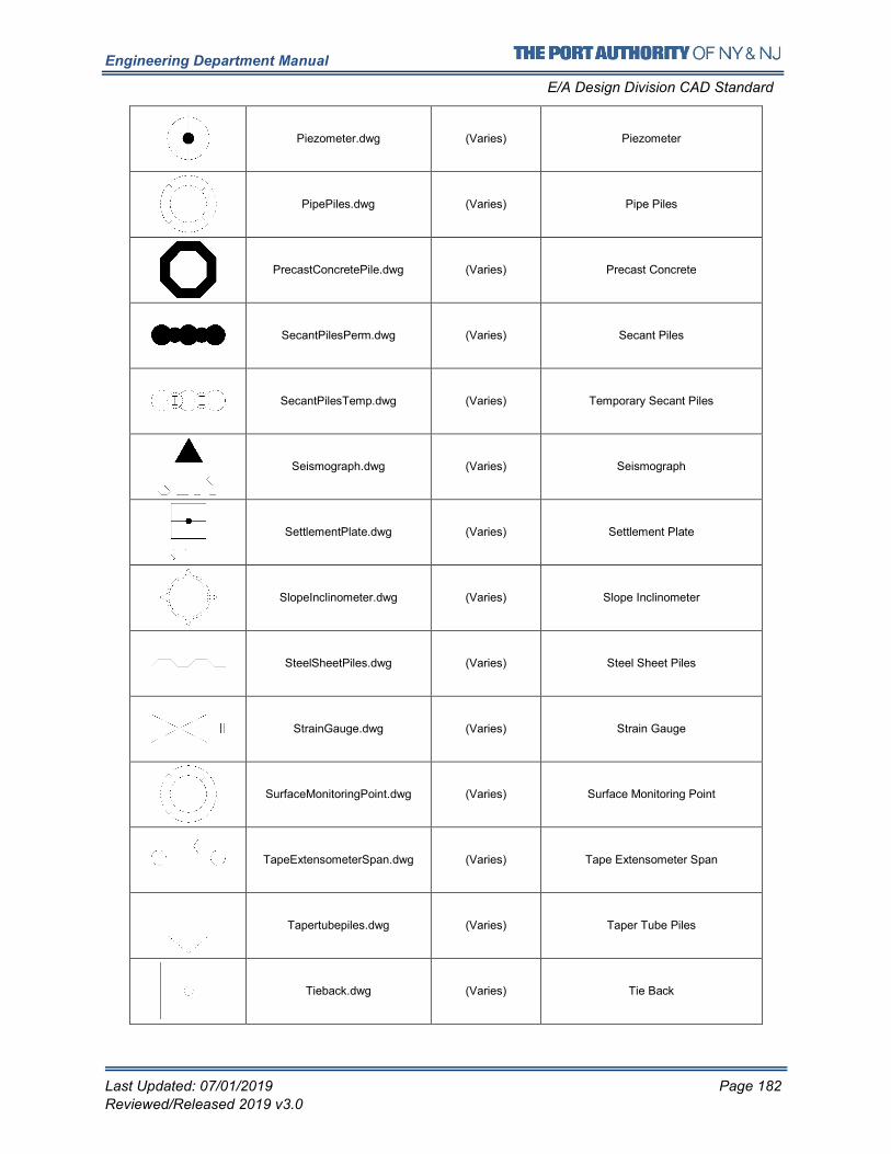
Engineering Department Manual
E/A Design Division CAD Standard
Last Updated: 07/01/2019 Page 182
Reviewed/Released 2019 v3.0
Piezometer.dwg (Varies) Piezometer
PipePiles.dwg (Varies) Pipe Piles
PrecastConcretePile.dwg (Varies) Precast Concrete
SecantPilesPerm.dwg (Varies) Secant Piles
SecantPilesTemp.dwg (Varies) Temporary Secant Piles
Seismograph.dwg (Varies) Seismograph
SettlementPlate.dwg (Varies) Settlement Plate
SlopeInclinometer.dwg (Varies) Slope Inclinometer
SteelSheetPiles.dwg (Varies) Steel Sheet Piles
StrainGauge.dwg (Varies) Strain Gauge
SurfaceMonitoringPoint.dwg (Varies) Surface Monitoring Point
TapeExtensometerSpan.dwg (Varies) Tape Extensometer Span
Tapertubepiles.dwg (Varies) Taper Tube Piles
Tieback.dwg (Varies) Tie Back
Engineering Department Manual
E/A Design Division CAD Standard
Last Updated: 07/01/2019 Page 183
Reviewed/Released 2019 v3.0
Timberpiles.dwg (Varies) Timber Piles
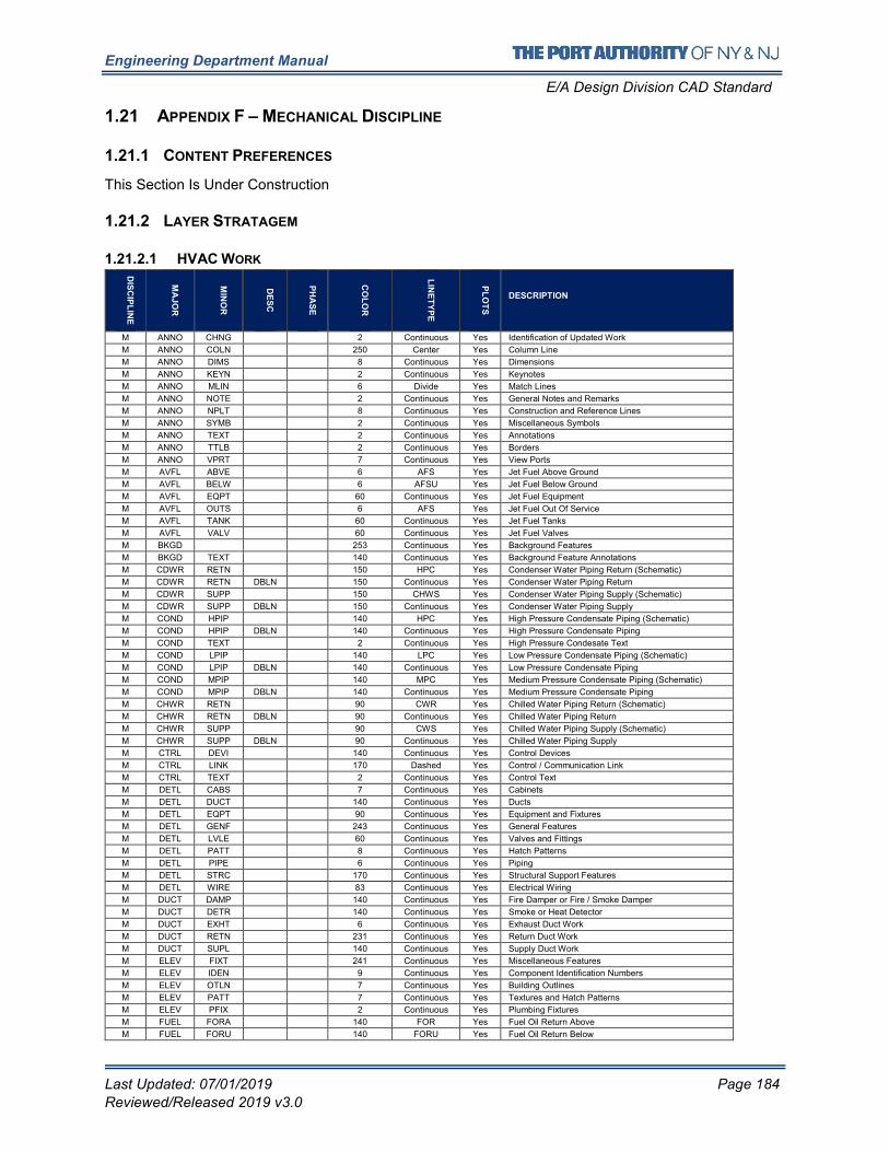
Engineering Department Manual
E/A Design Division CAD Standard
Last Updated: 07/01/2019 Page 184
Reviewed/Released 2019 v3.0
1.21 APPENDIX F – MECHANICAL DISCIPLINE
1.21.1 CONTENT PREFERENCES
This Section Is Under Construction
1.21.2 LAYER STRATAGEM
1.21.2.1 HVAC WORK
DIS
CIP
LIN
E
MA
JO
R
MIN
OR
DE
SC
PH
AS
E
CO
LO
R
LIN
ET
YP
E
PL
OT
S
DESCRIPTION
M ANNO CHNG 2 Continuous Yes Identification of Updated Work
M ANNO COLN 250 Center Yes Column Line
M ANNO DIMS 8 Continuous Yes Dimensions
M ANNO KEYN 2 Continuous Yes Keynotes
M ANNO MLIN 6 Divide Yes Match Lines
M ANNO NOTE 2 Continuous Yes General Notes and Remarks
M ANNO NPLT 8 Continuous Yes Construction and Reference Lines
M ANNO SYMB 2 Continuous Yes Miscellaneous Symbols
M ANNO TEXT 2 Continuous Yes Annotations
M ANNO TTLB 2 Continuous Yes Borders
M ANNO VPRT 7 Continuous Yes View Ports
M AVFL ABVE 6 AFS Yes Jet Fuel Above Ground
M AVFL BELW 6 AFSU Yes Jet Fuel Below Ground
M AVFL EQPT 60 Continuous Yes Jet Fuel Equipment
M AVFL OUTS 6 AFS Yes Jet Fuel Out Of Service
M AVFL TANK 60 Continuous Yes Jet Fuel Tanks
M AVFL VALV 60 Continuous Yes Jet Fuel Valves
M BKGD 253 Continuous Yes Background Features
M BKGD TEXT 140 Continuous Yes Background Feature Annotations
M CDWR RETN 150 HPC Yes Condenser Water Piping Return (Schematic)
M CDWR RETN DBLN 150 Continuous Yes Condenser Water Piping Return
M CDWR SUPP 150 CHWS Yes Condenser Water Piping Supply (Schematic)
M CDWR SUPP DBLN 150 Continuous Yes Condenser Water Piping Supply
M COND HPIP 140 HPC Yes High Pressure Condensate Piping (Schematic)
M COND HPIP DBLN 140 Continuous Yes High Pressure Condensate Piping
M COND TEXT 2 Continuous Yes High Pressure Condesate Text
M COND LPIP 140 LPC Yes Low Pressure Condensate Piping (Schematic)
M COND LPIP DBLN 140 Continuous Yes Low Pressure Condensate Piping
M COND MPIP 140 MPC Yes Medium Pressure Condensate Piping (Schematic)
M COND MPIP DBLN 140 Continuous Yes Medium Pressure Condensate Piping
M CHWR RETN 90 CWR Yes Chilled Water Piping Return (Schematic)
M CHWR RETN DBLN 90 Continuous Yes Chilled Water Piping Return
M CHWR SUPP 90 CWS Yes Chilled Water Piping Supply (Schematic)
M CHWR SUPP DBLN 90 Continuous Yes Chilled Water Piping Supply
M CTRL DEVI 140 Continuous Yes Control Devices
M CTRL LINK 170 Dashed Yes Control / Communication Link
M CTRL TEXT 2 Continuous Yes Control Text
M DETL CABS 7 Continuous Yes Cabinets
M DETL DUCT 140 Continuous Yes Ducts
M DETL EQPT 90 Continuous Yes Equipment and Fixtures
M DETL GENF 243 Continuous Yes General Features
M DETL LVLE 60 Continuous Yes Valves and Fittings
M DETL PATT 8 Continuous Yes Hatch Patterns
M DETL PIPE 6 Continuous Yes Piping
M DETL STRC 170 Continuous Yes Structural Support Features
M DETL WIRE 83 Continuous Yes Electrical Wiring
M DUCT DAMP 140 Continuous Yes Fire Damper or Fire / Smoke Damper
M DUCT DETR 140 Continuous Yes Smoke or Heat Detector
M DUCT EXHT 6 Continuous Yes Exhaust Duct Work
M DUCT RETN 231 Continuous Yes Return Duct Work
M DUCT SUPL 140 Continuous Yes Supply Duct Work
M ELEV FIXT 241 Continuous Yes Miscellaneous Features
M ELEV IDEN 9 Continuous Yes Component Identification Numbers
M ELEV OTLN 7 Continuous Yes Building Outlines
M ELEV PATT 7 Continuous Yes Textures and Hatch Patterns
M ELEV PFIX 2 Continuous Yes Plumbing Fixtures
M FUEL FORA 140 FOR Yes Fuel Oil Return Above
M FUEL FORU 140 FORU Yes Fuel Oil Return Below
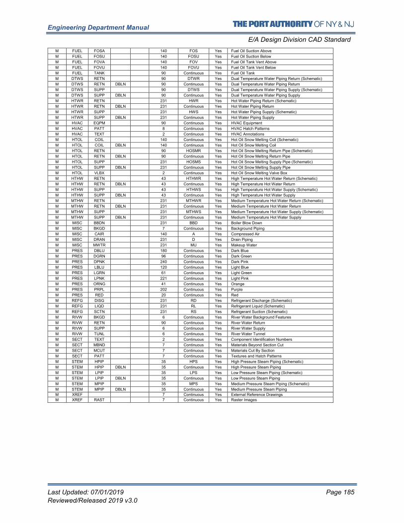
Engineering Department Manual
E/A Design Division CAD Standard
Last Updated: 07/01/2019 Page 185
Reviewed/Released 2019 v3.0
M FUEL FOSA 140 FOS Yes Fuel Oil Suction Above
M FUEL FOSU 140 FOSU Yes Fuel Oil Suction Below
M FUEL FOVA 140 FOV Yes Fuel Oil Tank Vent Above
M FUEL FOVU 140 FOVU Yes Fuel Oil Tank Vent Below
M FUEL TANK 90 Continuous Yes Fuel Oil Tank
M DTWS RETN 90 DTWR Yes Dual Temperature Water Piping Return (Schematic)
M DTWS RETN DBLN 90 Continuous Yes Dual Temperature Water Piping Return
M DTWS SUPP 90 DTWS Yes Dual Temperature Water Piping Supply (Schematic)
M DTWS SUPP DBLN 90 Continuous Yes Dual Temperature Water Piping Supply
M HTWR RETN 231 HWR Yes Hot Water Piping Return (Schematic)
M HTWR RETN DBLN 231 Continuous Yes Hot Water Piping Return
M HTWR SUPP 231 HWS Yes Hot Water Piping Supply (Schematic)
M HTWR SUPP DBLN 231 Continuous Yes Hot Water Piping Supply
M HVAC EQPM 90 Continuous Yes HVAC Equipment
M HVAC PATT 8 Continuous Yes HVAC Hatch Patterns
M HVAC TEXT 2 Continuous Yes HVAC Annotations
M HTOL COIL 140 Continuous Yes Hot Oil Snow Melting Coil (Schematic)
M HTOL COIL DBLN 140 Continuous Yes Hot Oil Snow Melting Coil
M HTOL RETN 90 HOSMR Yes Hot Oil Snow Melting Return Pipe (Schematic)
M HTOL RETN DBLN 90 Continuous Yes Hot Oil Snow Melting Return Pipe
M HTOL SUPP 231 HOSMS Yes Hot Oil Snow Melting Supply Pipe (Schematic)
M HTOL SUPP DBLN 231 Continuous Yes Hot Oil Snow Melting Supply Pipe
M HTOL VLBX 2 Continuous Yes Hot Oil Snow Melting Valve Box
M HTHW RETN 43 HTHWR Yes High Temperature Hot Water Return (Schematic)
M HTHW RETN DBLN 43 Continuous Yes High Temperature Hot Water Return
M HTHW SUPP 43 HTHWS Yes High Temperature Hot Water Supply (Schematic)
M HTHW SUPP DBLN 43 Continuous Yes High Temperature Hot Water Supply
M MTHW RETN 231 MTHWR Yes Medium Temperature Hot Water Return (Schematic)
M MTHW RETN DBLN 231 Continuous Yes Medium Temperature Hot Water Return
M MTHW SUPP 231 MTHWS Yes Medium Temperature Hot Water Supply (Schematic)
M MTHW SUPP DBLN 231 Continuous Yes Medium Temperature Hot Water Supply
M MISC BBDN 231 BBD Yes Boiler Blow Down
M MISC BKGD 7 Continuous Yes Background Piping
M MISC CAIR 140 A Yes Compressed Air
M MISC DRAN 231 D Yes Drain Piping
M MISC MWTR 231 MU Yes Makeup Water
M PRES DBLU 180 Continuous Yes Dark Blue
M PRES DGRN 96 Continuous Yes Dark Green
M PRES DPNK 240 Continuous Yes Dark Pink
M PRES LBLU 120 Continuous Yes Light Blue
M PRES LGRN 61 Continuous Yes Light Green
M PRES LPNK 221 Continuous Yes Light Pink
M PRES ORNG 41 Continuous Yes Orange
M PRES PRPL 202 Continuous Yes Purple
M PRES RED 20 Continuous Yes Red
M REFG DISG 231 RD Yes Refrigerant Discharge (Schematic)
M REFG LIQD 231 RL Yes Refrigerant Liquid (Schematic)
M REFG SCTN 231 RS Yes Refrigerant Suction (Schematic)
M RIVW BKGD 6 Continuous Yes River Water Background Features
M RIVW RETN 90 Continuous Yes River Water Return
M RIVW SUPP 6 Continuous Yes River Water Supply
M RIVW TUNL 6 Continuous Yes River Water Tunnel
M SECT TEXT 2 Continuous Yes Component Identification Numbers
M SECT MBND 7 Continuous Yes Materials Beyond Section Cut
M SECT MCUT 7 Continuous Yes Materials Cut By Section
M SECT PATT 7 Continuous Yes Textures and Hatch Patterns
M STEM HPIP 35 HPS Yes High Pressure Steam Piping (Schematic)
M STEM HPIP DBLN 35 Continuous Yes High Pressure Steam Piping
M STEM LPIP 35 LPS Yes Low Pressure Steam Piping (Schematic)
M STEM LPIP DBLN 35 Continuous Yes Low Pressure Steam Piping
M STEM MPIP 35 MPS Yes Medium Pressure Steam Piping (Schematic)
M STEM MPIP DBLN 35 Continuous Yes Medium Pressure Steam Piping
M XREF 7 Continuous Yes External Reference Drawings
M XREF RAST 7 Continuous Yes Raster Images
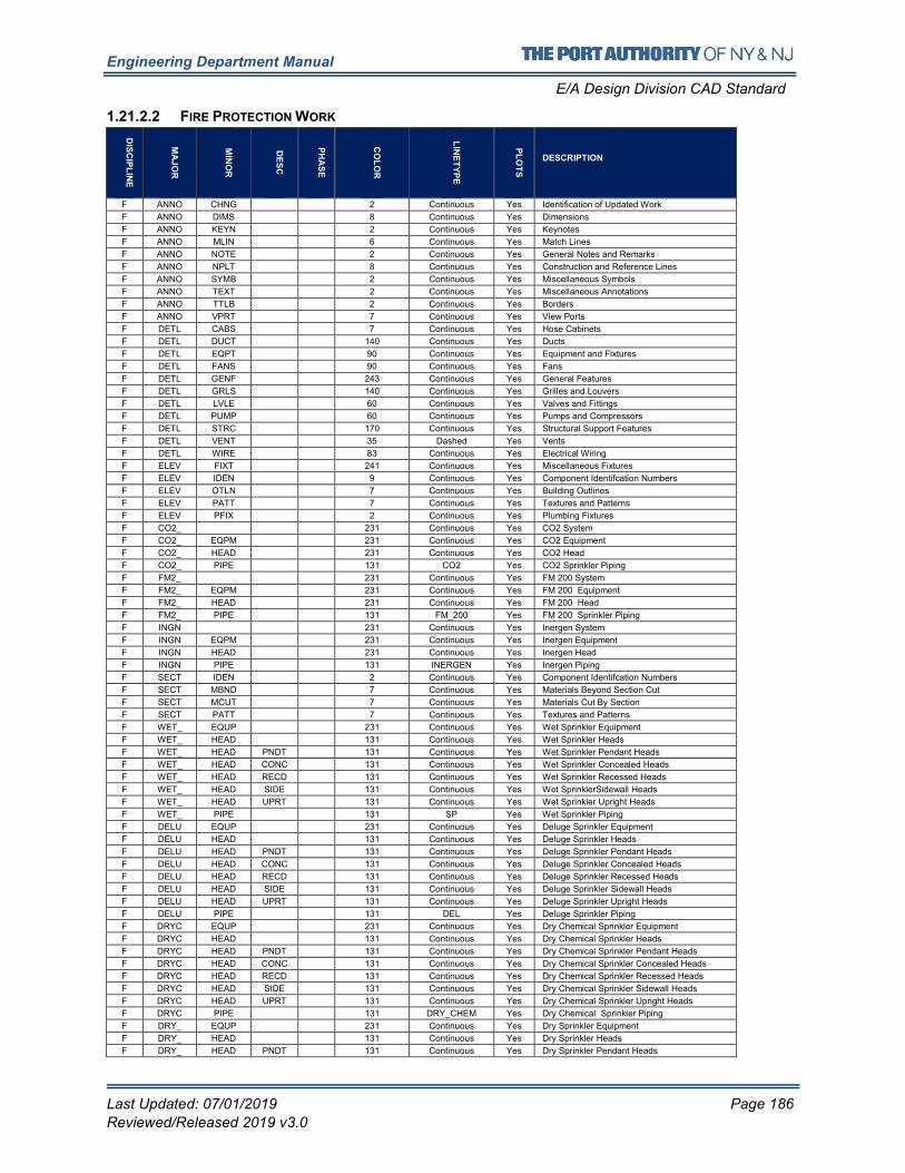
Engineering Department Manual
E/A Design Division CAD Standard
Last Updated: 07/01/2019 Page 186
Reviewed/Released 2019 v3.0
1.21.2.2 FIRE PROTECTION WORK
DIS
CIP
LIN
E
MA
JO
R
MIN
OR
DE
SC
PH
AS
E
CO
LO
R
LIN
ET
YP
E
PL
OT
S
DESCRIPTION
F ANNO CHNG 2 Continuous Yes Identification of Updated Work
F ANNO DIMS 8 Continuous Yes Dimensions
F ANNO KEYN 2 Continuous Yes Keynotes
F ANNO MLIN 6 Continuous Yes Match Lines
F ANNO NOTE 2 Continuous Yes General Notes and Remarks
F ANNO NPLT 8 Continuous Yes Construction and Reference Lines
F ANNO SYMB 2 Continuous Yes Miscellaneous Symbols
F ANNO TEXT 2 Continuous Yes Miscellaneous Annotations
F ANNO TTLB 2 Continuous Yes Borders
F ANNO VPRT 7 Continuous Yes View Ports
F DETL CABS 7 Continuous Yes Hose Cabinets
F DETL DUCT 140 Continuous Yes Ducts
F DETL EQPT 90 Continuous Yes Equipment and Fixtures
F DETL FANS 90 Continuous Yes Fans
F DETL GENF 243 Continuous Yes General Features
F DETL GRLS 140 Continuous Yes Grilles and Louvers
F DETL LVLE 60 Continuous Yes Valves and Fittings
F DETL PUMP 60 Continuous Yes Pumps and Compressors
F DETL STRC 170 Continuous Yes Structural Support Features
F DETL VENT 35 Dashed Yes Vents
F DETL WIRE 83 Continuous Yes Electrical Wiring
F ELEV FIXT 241 Continuous Yes Miscellaneous Fixtures
F ELEV IDEN 9 Continuous Yes Component Identifcation Numbers
F ELEV OTLN 7 Continuous Yes Building Outlines
F ELEV PATT 7 Continuous Yes Textures and Patterns
F ELEV PFIX 2 Continuous Yes Plumbing Fixtures
F CO2_ 231 Continuous Yes CO2 System
F CO2_ EQPM 231 Continuous Yes CO2 Equipment
F CO2_ HEAD 231 Continuous Yes CO2 Head
F CO2_ PIPE 131 CO2 Yes CO2 Sprinkler Piping
F FM2_ 231 Continuous Yes FM 200 System
F FM2_ EQPM 231 Continuous Yes FM 200 Equipment
F FM2_ HEAD 231 Continuous Yes FM 200 Head
F FM2_ PIPE 131 FM_200 Yes FM 200 Sprinkler Piping
F INGN 231 Continuous Yes Inergen System
F INGN EQPM 231 Continuous Yes Inergen Equipment
F INGN HEAD 231 Continuous Yes Inergen Head
F INGN PIPE 131 INERGEN Yes Inergen Piping
F SECT IDEN 2 Continuous Yes Component Identifcation Numbers
F SECT MBND 7 Continuous Yes Materials Beyond Section Cut
F SECT MCUT 7 Continuous Yes Materials Cut By Section
F SECT PATT 7 Continuous Yes Textures and Patterns
F WET_ EQUP 231 Continuous Yes Wet Sprinkler Equipment
F WET_ HEAD 131 Continuous Yes Wet Sprinkler Heads
F WET_ HEAD PNDT 131 Continuous Yes Wet Sprinkler Pendant Heads
F WET_ HEAD CONC 131 Continuous Yes Wet Sprinkler Concealed Heads
F WET_ HEAD RECD 131 Continuous Yes Wet Sprinkler Recessed Heads
F WET_ HEAD SIDE 131 Continuous Yes Wet SprinklerSidewall Heads
F WET_ HEAD UPRT 131 Continuous Yes Wet Sprinkler Upright Heads
F WET_ PIPE 131 SP Yes Wet Sprinkler Piping
F DELU EQUP 231 Continuous Yes Deluge Sprinkler Equipment
F DELU HEAD 131 Continuous Yes Deluge Sprinkler Heads
F DELU HEAD PNDT 131 Continuous Yes Deluge Sprinkler Pendant Heads
F DELU HEAD CONC 131 Continuous Yes Deluge Sprinkler Concealed Heads
F DELU HEAD RECD 131 Continuous Yes Deluge Sprinkler Recessed Heads
F DELU HEAD SIDE 131 Continuous Yes Deluge Sprinkler Sidewall Heads
F DELU HEAD UPRT 131 Continuous Yes Deluge Sprinkler Upright Heads
F DELU PIPE 131 DEL Yes Deluge Sprinkler Piping
F DRYC EQUP 231 Continuous Yes Dry Chemical Sprinkler Equipment
F DRYC HEAD 131 Continuous Yes Dry Chemical Sprinkler Heads
F DRYC HEAD PNDT 131 Continuous Yes Dry Chemical Sprinkler Pendant Heads
F DRYC HEAD CONC 131 Continuous Yes Dry Chemical Sprinkler Concealed Heads
F DRYC HEAD RECD 131 Continuous Yes Dry Chemical Sprinkler Recessed Heads
F DRYC HEAD SIDE 131 Continuous Yes Dry Chemical Sprinkler Sidewall Heads
F DRYC HEAD UPRT 131 Continuous Yes Dry Chemical Sprinkler Upright Heads
F DRYC PIPE 131 DRY_CHEM Yes Dry Chemical Sprinkler Piping
F DRY_ EQUP 231 Continuous Yes Dry Sprinkler Equipment
F DRY_ HEAD 131 Continuous Yes Dry Sprinkler Heads
F DRY_ HEAD PNDT 131 Continuous Yes Dry Sprinkler Pendant Heads
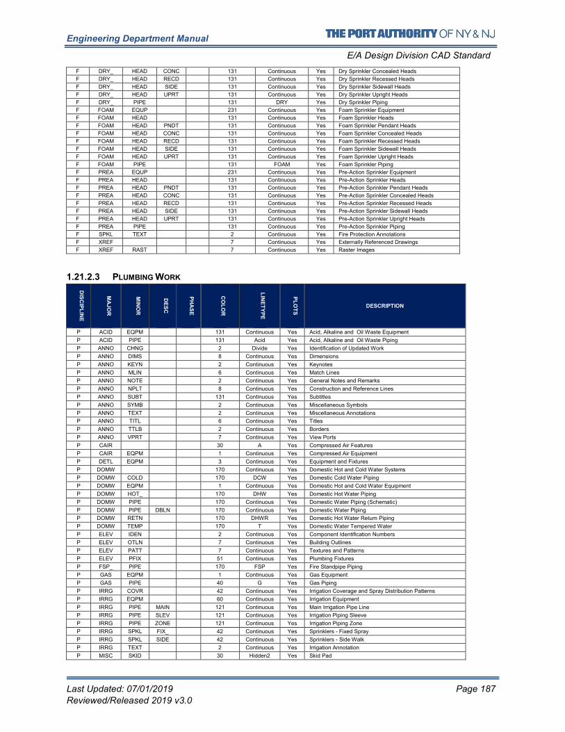
Engineering Department Manual
E/A Design Division CAD Standard
Last Updated: 07/01/2019 Page 187
Reviewed/Released 2019 v3.0
F DRY_ HEAD CONC 131 Continuous Yes Dry Sprinkler Concealed Heads
F DRY_ HEAD RECD 131 Continuous Yes Dry Sprinkler Recessed Heads
F DRY_ HEAD SIDE 131 Continuous Yes Dry Sprinkler Sidewall Heads
F DRY_ HEAD UPRT 131 Continuous Yes Dry Sprinkler Upright Heads
F DRY_ PIPE 131 DRY Yes Dry Sprinkler Piping
F FOAM EQUP 231 Continuous Yes Foam Sprinkler Equipment
F FOAM HEAD 131 Continuous Yes Foam Sprinkler Heads
F FOAM HEAD PNDT 131 Continuous Yes Foam Sprinkler Pendant Heads
F FOAM HEAD CONC 131 Continuous Yes Foam Sprinkler Concealed Heads
F FOAM HEAD RECD 131 Continuous Yes Foam Sprinkler Recessed Heads
F FOAM HEAD SIDE 131 Continuous Yes Foam Sprinkler Sidewall Heads
F FOAM HEAD UPRT 131 Continuous Yes Foam Sprinkler Upright Heads
F FOAM PIPE 131 FOAM Yes Foam Sprinkler Piping
F PREA EQUP 231 Continuous Yes Pre-Action Sprinkler Equipment
F PREA HEAD 131 Continuous Yes Pre-Action Sprinkler Heads
F PREA HEAD PNDT 131 Continuous Yes Pre-Action Sprinkler Pendant Heads
F PREA HEAD CONC 131 Continuous Yes Pre-Action Sprinkler Concealed Heads
F PREA HEAD RECD 131 Continuous Yes Pre-Action Sprinkler Recessed Heads
F PREA HEAD SIDE 131 Continuous Yes Pre-Action Sprinkler Sidewall Heads
F PREA HEAD UPRT 131 Continuous Yes Pre-Action Sprinkler Upright Heads
F PREA PIPE 131 Continuous Yes Pre-Action Sprinkler Piping
F SPKL TEXT 2 Continuous Yes Fire Protection Annotations
F XREF 7 Continuous Yes Externally Referenced Drawings
F XREF RAST 7 Continuous Yes Raster Images
1.21.2.3 PLUMBING WORK
DIS
CIP
LIN
E
MA
JO
R
MIN
OR
DE
SC
PH
AS
E
CO
LO
R
LIN
ET
YP
E
PL
OT
S
DESCRIPTION
P ACID EQPM 131 Continuous Yes Acid, Alkaline and Oil Waste Equipment
P ACID PIPE 131 Acid Yes Acid, Alkaline and Oil Waste Piping
P ANNO CHNG 2 Divide Yes Identification of Updated Work
P ANNO DIMS 8 Continuous Yes Dimensions
P ANNO KEYN 2 Continuous Yes Keynotes
P ANNO MLIN 6 Continuous Yes Match Lines
P ANNO NOTE 2 Continuous Yes General Notes and Remarks
P ANNO NPLT 8 Continuous Yes Construction and Reference Lines
P ANNO SUBT 131 Continuous Yes Subtitles
P ANNO SYMB 2 Continuous Yes Miscellaneous Symbols
P ANNO TEXT 2 Continuous Yes Miscellaneous Annotations
P ANNO TITL 6 Continuous Yes Titles
P ANNO TTLB 2 Continuous Yes Borders
P ANNO VPRT 7 Continuous Yes View Ports
P CAIR 30 A Yes Compressed Air Features
P CAIR EQPM 1 Continuous Yes Compressed Air Equipment
P DETL EQPM 3 Continuous Yes Equipment and Fixtures
P DOMW 170 Continuous Yes Domestic Hot and Cold Water Systems
P DOMW COLD 170 DCW Yes Domestic Cold Water Piping
P DOMW EQPM 1 Continuous Yes Domestic Hot and Cold Water Equipment
P DOMW HOT_ 170 DHW Yes Domestic Hot Water Piping
P DOMW PIPE 170 Continuous Yes Domestic Water Piping (Schematic)
P DOMW PIPE DBLN 170 Continuous Yes Domestic Water Piping
P DOMW RETN 170 DHWR Yes Domestic Hot Water Return Piping
P DOMW TEMP 170 T Yes Domestic Water Tempered Water
P ELEV IDEN 2 Continuous Yes Component Identification Numbers
P ELEV OTLN 7 Continuous Yes Building Outlines
P ELEV PATT 7 Continuous Yes Textures and Patterns
P ELEV PFIX 51 Continuous Yes Plumbing Fixtures
P FSP_ PIPE 170 FSP Yes Fire Standpipe Piping
P GAS EQPM 1 Continuous Yes Gas Equipment
P GAS PIPE 40 G Yes Gas Piping
P IRRG COVR 42 Continuous Yes Irrigation Coverage and Spray Distribution Patterns
P IRRG EQPM 60 Continuous Yes Irrigation Equipment
P IRRG PIPE MAIN 121 Continuous Yes Main Irrigation Pipe Line
P IRRG PIPE SLEV 121 Continuous Yes Irrigation Piping Sleeve
P IRRG PIPE ZONE 121 Continuous Yes Irrigation Piping Zone
P IRRG SPKL FIX_ 42 Continuous Yes Sprinklers - Fixed Spray
P IRRG SPKL SIDE 42 Continuous Yes Sprinklers - Side Walk
P IRRG TEXT 2 Continuous Yes Irrigation Annotation
P MISC SKID 30 Hidden2 Yes Skid Pad
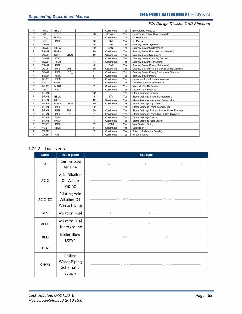
Engineering Department Manual
E/A Design Division CAD Standard
Last Updated: 07/01/2019 Page 188
Reviewed/Released 2019 v3.0
P MISC BKGD 7 Continuous Yes Background Features
P MISC HTRC 26 HTRACE Yes Heat Tacing (Draw Over Linework)
P OIL_ EQPM 1 Continuous Yes Oil Equipment
P OIL_ PIPE 32 OW Yes Oil Piping
P SSWR 141 SAN Yes Sanitary Sewer Systems
P SSWR BELW 141 SANU Yes Sanitary Sewer Underground
P SSWR EQPM 10 Continuous Yes Sanitary Sewer Equipment (Schematic)
P SSWR EQPM DBLN 10 Continuous Yes Sanitary Sewer Equipment
P SSWR FIXT 51 Continuous Yes Sanitary Sewer Plumbing Fixtures
P SSWR FLDR 1 Continuous Yes Sanitary Sewer Floor Drains
P SSWR PIPE 141 SAN Yes Sanitary Sewer Piping (Schematic)
P SSWR PIPE SML_ 50 Continuous Yes Sanitary Sewer Piping 4 Inch or Under Diameter
P SSWR PIPE LRG_ 51 Continuous Yes Sanitary Sewer Piping Over 4 Inch Diameter
P SSWR RISR 51 Continuous Yes Sanitary Sewer Risers
P SECT IDEN 2 Continuous Yes Component Identification Numbers
P SECT MBND 7 Continuous Yes Materials Beyond Section Cut
P SECT MCUT 7 Continuous Yes Materials Cut By Section
P SECT PATT 7 Continuous Yes Textures and Patterns
P DRAN 141 ST Yes Storm Drainage System
P DRAN BELW 141 STU Yes Storm Drainage System Underground
P DRAN EQPM 10 Continuous Yes Storm Drainage Equipment (Schematic)
P DRAN EQPM DBLN 10 Continuous Yes Storm Drainage Equipment
P DRAN PIPE 141 ST Yes Storm Drainage Piping (Schematic)
P DRAN PIPE SML_ 50 Continuous Yes Storm Drainage Piping 4 Inch or Under Diameter
P DRAN PIPE LRG_ 51 Continuous Yes Storm Drainage Piping Over 4 Inch Diameter
P DRAN RISR 51 Continuous Yes Storm Drainage Risers
P DRAN ROOF 1 Continuous Yes Storm Drainage Roof Drains
P VENT PIPE 32 VENT Yes Vent System Piping
P VENT RISR 51 Continuous Yes Vent Riser
P XREF 7 Continuous Yes External Reference Drawings
P XREF RAST 7 Continuous Yes Raster Images
1.21.3 LINETYPES
Name Description Example
A Compressed
Air Line
ACID
Acid Alkaline
Oil Waste
Piping
ACID_EX
Existing Acid
Alkaline Oil
Waste Piping
AFS Aviation Fuel
AFSU Aviation Fuel
Underground
BBD Boiler Blow
Down
Center
CHWS
Chilled
Water Piping
Schematic
Supply
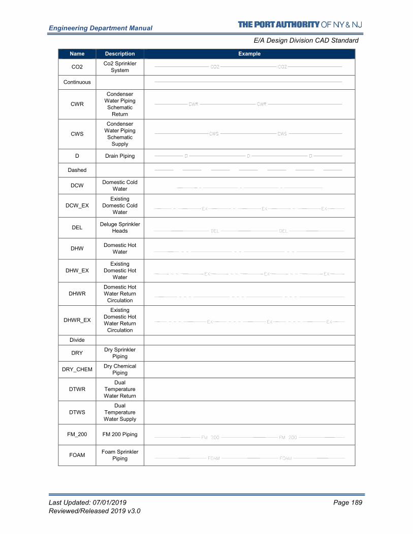
Engineering Department Manual
E/A Design Division CAD Standard
Last Updated: 07/01/2019 Page 189
Reviewed/Released 2019 v3.0
Name Description Example
CO2 Co2 Sprinkler
System
Continuous
CWR
Condenser Water Piping
Schematic
Return
CWS
Condenser
Water Piping
Schematic Supply
D Drain Piping
Dashed
DCW Domestic Cold
Water
DCW_EX Existing
Domestic Cold Water
DEL Deluge Sprinkler
Heads
DHW Domestic Hot
Water
DHW_EX Existing
Domestic Hot Water
DHWR Domestic Hot Water Return
Circulation
DHWR_EX
Existing Domestic Hot Water Return
Circulation
Divide
DRY Dry Sprinkler
Piping
DRY_CHEM Dry Chemical
Piping
DTWR Dual
Temperature
Water Return
DTWS
Dual
Temperature
Water Supply
FM_200 FM 200 Piping
FOAM Foam Sprinkler
Piping
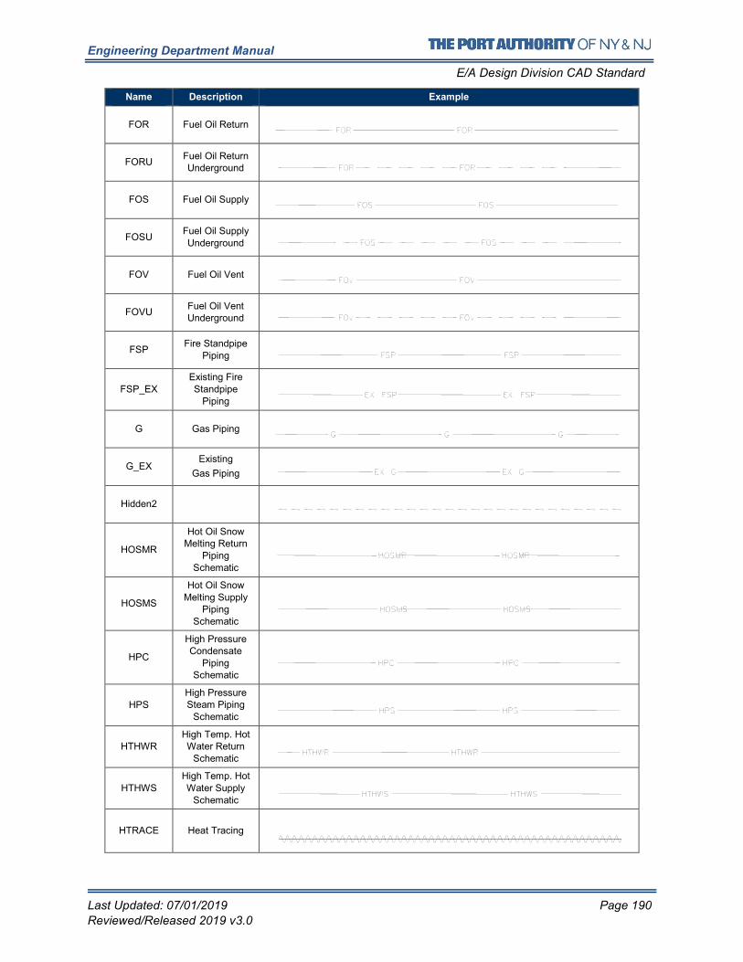
Engineering Department Manual
E/A Design Division CAD Standard
Last Updated: 07/01/2019 Page 190
Reviewed/Released 2019 v3.0
Name Description Example
FOR Fuel Oil Return
FORU Fuel Oil Return Underground
FOS Fuel Oil Supply
FOSU Fuel Oil Supply
Underground
FOV Fuel Oil Vent
FOVU Fuel Oil Vent Underground
FSP Fire Standpipe
Piping
FSP_EX Existing Fire Standpipe
Piping
G Gas Piping
G_EX Existing
Gas Piping
Hidden2
HOSMR
Hot Oil Snow Melting Return
Piping Schematic
HOSMS
Hot Oil Snow Melting Supply
Piping Schematic
HPC
High Pressure Condensate
Piping Schematic
HPS High Pressure Steam Piping
Schematic
HTHWR High Temp. Hot Water Return
Schematic
HTHWS
High Temp. Hot
Water Supply
Schematic
HTRACE Heat Tracing
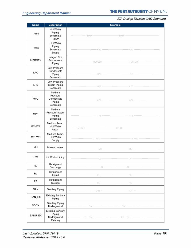
Engineering Department Manual
E/A Design Division CAD Standard
Last Updated: 07/01/2019 Page 191
Reviewed/Released 2019 v3.0
Name Description Example
HWR
Hot Water
Piping Schematic
Return
HWS
Hot Water Piping
Schematic Supply
INERGEN
Inergen Fire Suppressent
Piping
LPC
Low Pressure Condensate
Piping
Schematic
LPS
Low Pressure
Steam Piping Schematic
MPC
Medium Pressure
Condensate Piping
Schematic
MPS
Medium Pressure Steam
Piping Schematic
MTHWR Medium Temp.
Hot Water Return
MTHWS Medium Temp.
Hot Water Supply
MU Makeup Water
OW Oil Water Piping
RD Refrigerant Discharge
RL Refrigerant
Liquid
RS Refrigerant
Suction
SAN Sanitary Piping
SAN_EX Existing Sanitary
Piping
SANU Sanitary Piping Underground
SANU_EX
Existing Sanitary Piping
Underground Existing
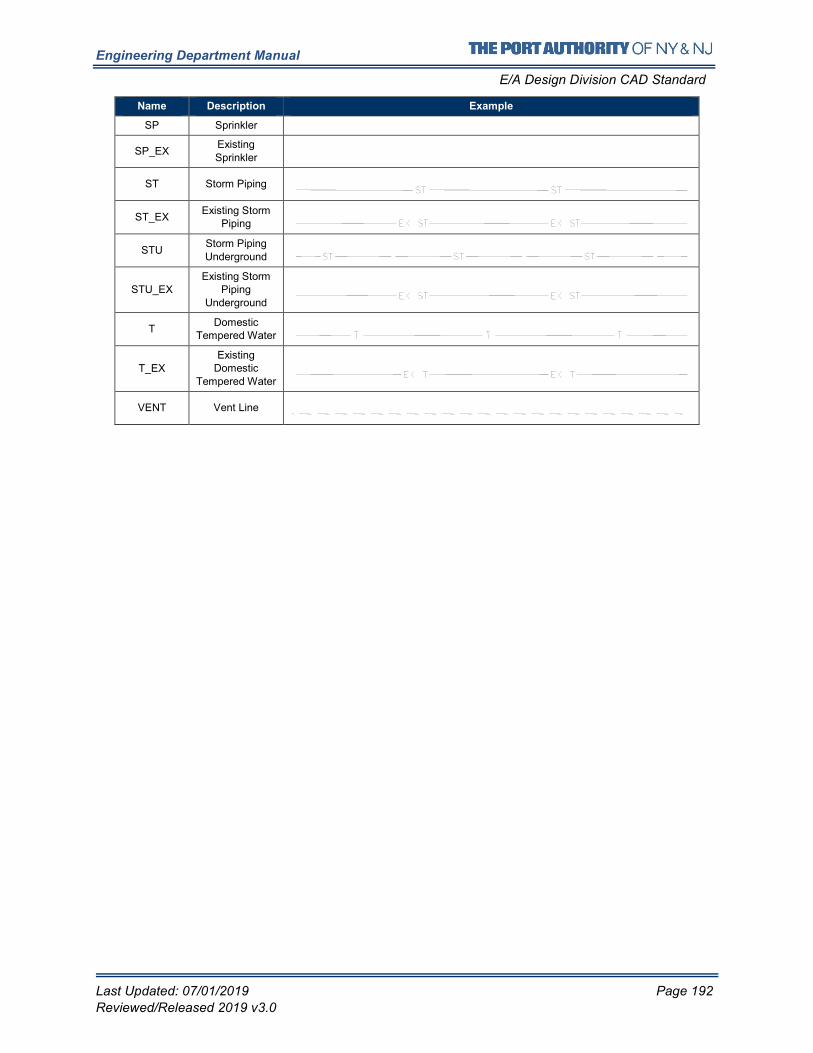
Engineering Department Manual
E/A Design Division CAD Standard
Last Updated: 07/01/2019 Page 192
Reviewed/Released 2019 v3.0
Name Description Example
SP Sprinkler
SP_EX Existing
Sprinkler
ST Storm Piping
ST_EX Existing Storm
Piping
STU Storm Piping
Underground
STU_EX Existing Storm
Piping
Underground
T Domestic
Tempered Water
T_EX
Existing Domestic
Tempered Water
VENT Vent Line
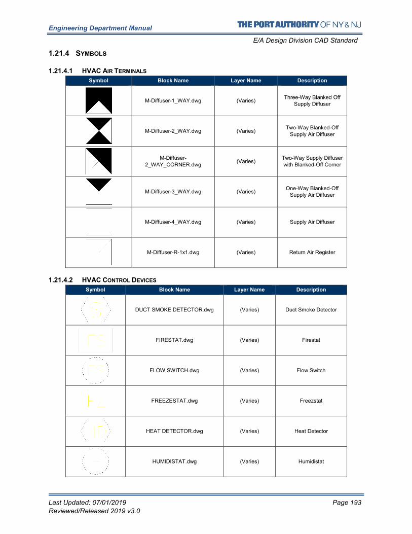
Engineering Department Manual
E/A Design Division CAD Standard
Last Updated: 07/01/2019 Page 193
Reviewed/Released 2019 v3.0
1.21.4 SYMBOLS
1.21.4.1 HVAC AIR TERMINALS
Symbol Block Name Layer Name Description
M-Diffuser-1_WAY.dwg (Varies) Three-Way Blanked Off
Supply Diffuser
M-Diffuser-2_WAY.dwg (Varies) Two-Way Blanked-Off
Supply Air Diffuser
M-Diffuser-
2_WAY_CORNER.dwg (Varies)
Two-Way Supply Diffuser
with Blanked-Off Corner
M-Diffuser-3_WAY.dwg (Varies) One-Way Blanked-Off
Supply Air Diffuser
M-Diffuser-4_WAY.dwg (Varies) Supply Air Diffuser
M-Diffuser-R-1x1.dwg (Varies) Return Air Register
1.21.4.2 HVAC CONTROL DEVICES
Symbol Block Name Layer Name Description
DUCT SMOKE DETECTOR.dwg (Varies) Duct Smoke Detector
FIRESTAT.dwg (Varies) Firestat
FLOW SWITCH.dwg (Varies) Flow Switch
FREEZESTAT.dwg (Varies) Freezstat
HEAT DETECTOR.dwg (Varies) Heat Detector
HUMIDISTAT.dwg (Varies) Humidistat
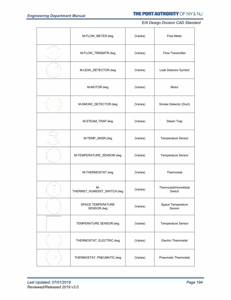
Engineering Department Manual
E/A Design Division CAD Standard
Last Updated: 07/01/2019 Page 194
Reviewed/Released 2019 v3.0
M-FLOW_METER.dwg (Varies) Flow Meter
M-FLOW_TRNSMTR.dwg (Varies) Flow Transmitter
M-LEAK_DETECTOR.dwg (Varies) Leak Detector Symbol
M-MOTOR.dwg (Varies) Motor
M-SMOKE_DETECTOR.dwg (Varies) Smoke Detector (Duct)
M-STEAM_TRAP.dwg (Varies) Steam Trap
M-TEMP_SNSR.dwg (Varies) Temperature Sensor
M-TEMPERATURE_SENSOR.dwg (Varies) Temperature Sensor
M-THERMOSTAT.dwg (Varies) Thermostat
M-THERMST_HUMIDIST_SWITCH.dwg
(Varies) Thermostat/Humidistat
Switch
SPACE TEMPERATURE SENSOR.dwg
(Varies) Space Temperature
Sensor
TEMPERATURE SENSOR.dwg (Varies) Temperature Sensor
THERMOSTAT, ELECTRIC.dwg (Varies) Electric Thermostat
THERMOSTAT, PNEUMATIC.dwg (Varies) Pneumatic Thermostat
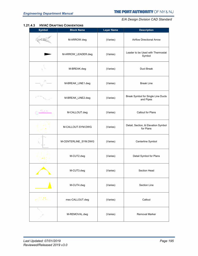
Engineering Department Manual
E/A Design Division CAD Standard
Last Updated: 07/01/2019 Page 195
Reviewed/Released 2019 v3.0
1.21.4.3 HVAC DRAFTING CONVENTIONS
Symbol Block Name Layer Name Description
M-ARROW.dwg (Varies) Airflow Directional Arrow
M-ARROW_LEADER.dwg (Varies) Leader to be Used with Thermostat
Symbol
M-BREAK.dwg (Varies) Duct Break
M-BREAK_LINE1.dwg (Varies) Break Line
M-BREAK_LINE2.dwg (Varies) Break Symbol for Single Line Ducts
and Pipes
M-CALLOUT.dwg (Varies) Callout for Plans
M-CALLOUT-SYM.DWG (Varies) Detail, Section, & Elevation Symbol
for Plans
M-CENTERLINE_SYM.DWG (Varies) Centerline Symbol
M-CUT2.dwg (Varies) Detail Symbol for Plans
M-CUT3.dwg (Varies) Section Head
M-CUT4.dwg (Varies) Section Line
mec-CALLOUT.dwg (Varies) Callout
M-REMOVAL.dwg (Varies) Removal Marker
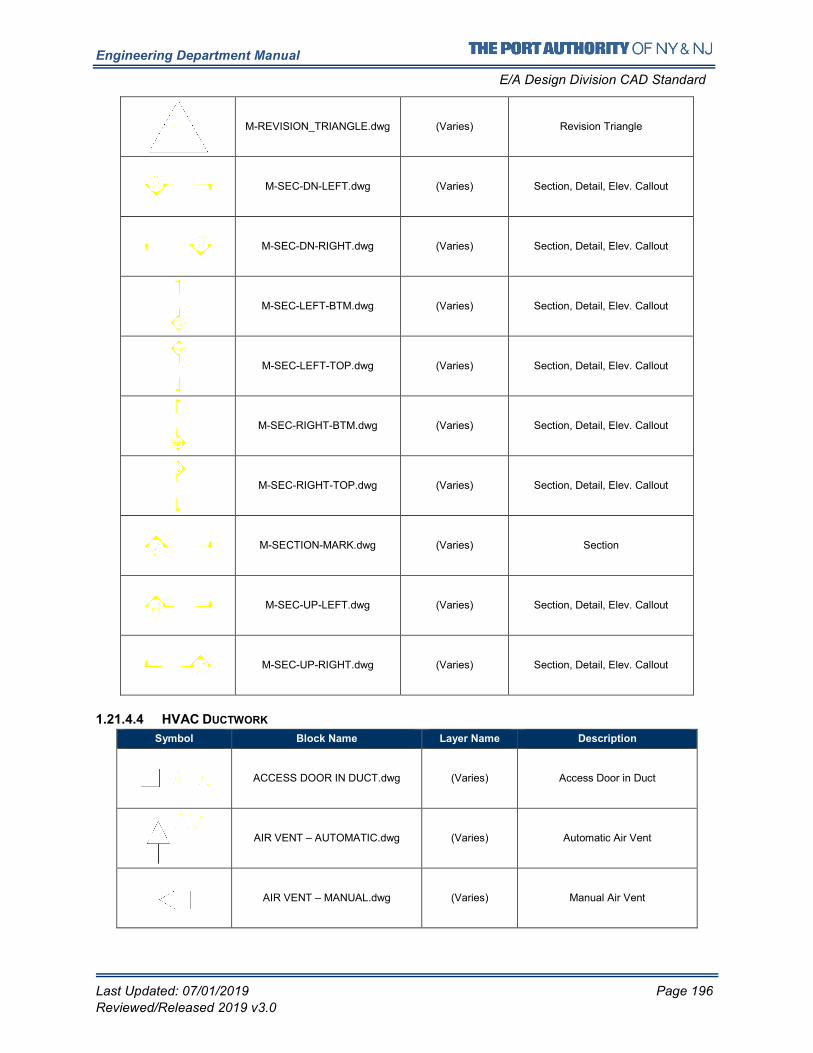
Engineering Department Manual
E/A Design Division CAD Standard
Last Updated: 07/01/2019 Page 196
Reviewed/Released 2019 v3.0
M-REVISION_TRIANGLE.dwg (Varies) Revision Triangle
M-SEC-DN-LEFT.dwg (Varies) Section, Detail, Elev. Callout
M-SEC-DN-RIGHT.dwg (Varies) Section, Detail, Elev. Callout
M-SEC-LEFT-BTM.dwg (Varies) Section, Detail, Elev. Callout
M-SEC-LEFT-TOP.dwg (Varies) Section, Detail, Elev. Callout
M-SEC-RIGHT-BTM.dwg (Varies) Section, Detail, Elev. Callout
M-SEC-RIGHT-TOP.dwg (Varies) Section, Detail, Elev. Callout
M-SECTION-MARK.dwg (Varies) Section
M-SEC-UP-LEFT.dwg (Varies) Section, Detail, Elev. Callout
M-SEC-UP-RIGHT.dwg (Varies) Section, Detail, Elev. Callout
1.21.4.4 HVAC DUCTWORK
Symbol Block Name Layer Name Description
ACCESS DOOR IN DUCT.dwg (Varies) Access Door in Duct
AIR VENT – AUTOMATIC.dwg (Varies) Automatic Air Vent
AIR VENT – MANUAL.dwg (Varies) Manual Air Vent
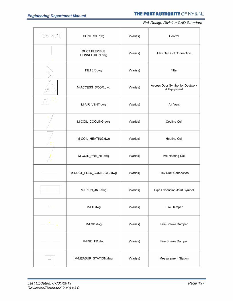
Engineering Department Manual
E/A Design Division CAD Standard
Last Updated: 07/01/2019 Page 197
Reviewed/Released 2019 v3.0
CONTROL.dwg (Varies) Control
DUCT FLEXIBLE CONNECTION.dwg
(Varies) Flexible Duct Connection
FILTER.dwg (Varies) Filter
M-ACCESS_DOOR.dwg (Varies) Access Door Symbol for Ductwork
& Equipment
M-AIR_VENT.dwg (Varies) Air Vent
M-COIL_COOLING.dwg (Varies) Cooling Coil
M-COIL_HEATING.dwg (Varies) Heating Coil
M-COIL_PRE_HT.dwg (Varies) Pre-Heating Coil
M-DUCT_FLEX_CONNECT2.dwg (Varies) Flex Duct Connection
M-EXPN_JNT.dwg (Varies) Pipe Expansion Joint Symbol
M-FD.dwg (Varies) Fire Damper
M-FSD.dwg (Varies) Fire Smoke Damper
M-FSD_FD.dwg (Varies) Fire Smoke Damper
M-MEASUR_STATION.dwg (Varies) Measurement Station
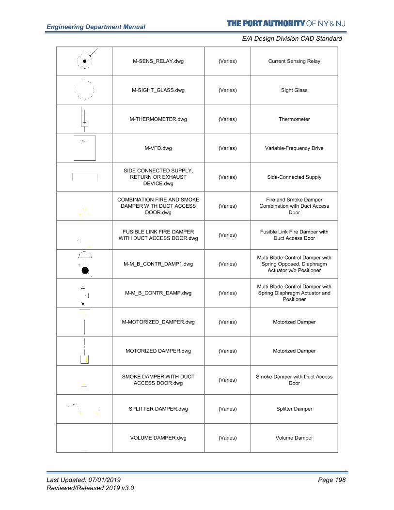
Engineering Department Manual
E/A Design Division CAD Standard
Last Updated: 07/01/2019 Page 198
Reviewed/Released 2019 v3.0
M-SENS_RELAY.dwg (Varies) Current Sensing Relay
M-SIGHT_GLASS.dwg (Varies) Sight Glass
M-THERMOMETER.dwg (Varies) Thermometer
M-VFD.dwg (Varies) Variable-Frequency Drive
SIDE CONNECTED SUPPLY, RETURN OR EXHAUST
DEVICE.dwg (Varies) Side-Connected Supply
COMBINATION FIRE AND SMOKE DAMPER WITH DUCT ACCESS
DOOR.dwg (Varies)
Fire and Smoke Damper Combination with Duct Access
Door
FUSIBLE LINK FIRE DAMPER WITH DUCT ACCESS DOOR.dwg
(Varies) Fusible Link Fire Damper with
Duct Access Door
M-M_B_CONTR_DAMP1.dwg (Varies) Multi-Blade Control Damper with
Spring Opposed, Diaphragm Actuator w/o Positioner
M-M_B_CONTR_DAMP.dwg (Varies) Multi-Blade Control Damper with Spring Diaphragm Actuator and
Positioner
M-MOTORIZED_DAMPER.dwg (Varies) Motorized Damper
MOTORIZED DAMPER.dwg (Varies) Motorized Damper
SMOKE DAMPER WITH DUCT ACCESS DOOR.dwg
(Varies) Smoke Damper with Duct Access
Door
SPLITTER DAMPER.dwg (Varies) Splitter Damper
VOLUME DAMPER.dwg (Varies) Volume Damper
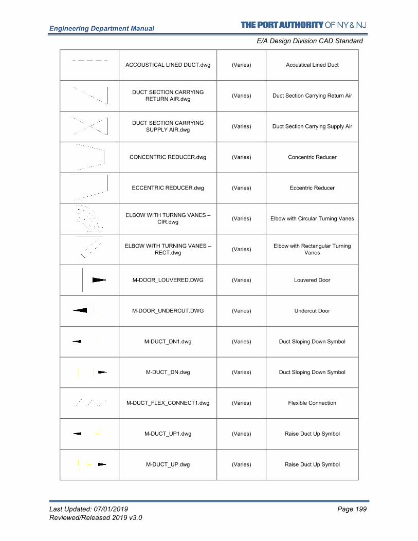
Engineering Department Manual
E/A Design Division CAD Standard
Last Updated: 07/01/2019 Page 199
Reviewed/Released 2019 v3.0
ACCOUSTICAL LINED DUCT.dwg (Varies) Acoustical Lined Duct
DUCT SECTION CARRYING RETURN AIR.dwg
(Varies) Duct Section Carrying Return Air
DUCT SECTION CARRYING SUPPLY AIR.dwg
(Varies) Duct Section Carrying Supply Air
CONCENTRIC REDUCER.dwg (Varies) Concentric Reducer
ECCENTRIC REDUCER.dwg (Varies) Eccentric Reducer
ELBOW WITH TURNNG VANES – CIR.dwg
(Varies) Elbow with Circular Turning Vanes
ELBOW WITH TURNING VANES – RECT.dwg
(Varies) Elbow with Rectangular Turning
Vanes
M-DOOR_LOUVERED.DWG (Varies) Louvered Door
M-DOOR_UNDERCUT.DWG (Varies) Undercut Door
M-DUCT_DN1.dwg (Varies) Duct Sloping Down Symbol
M-DUCT_DN.dwg (Varies) Duct Sloping Down Symbol
M-DUCT_FLEX_CONNECT1.dwg (Varies) Flexible Connection
M-DUCT_UP1.dwg (Varies) Raise Duct Up Symbol
M-DUCT_UP.dwg (Varies) Raise Duct Up Symbol
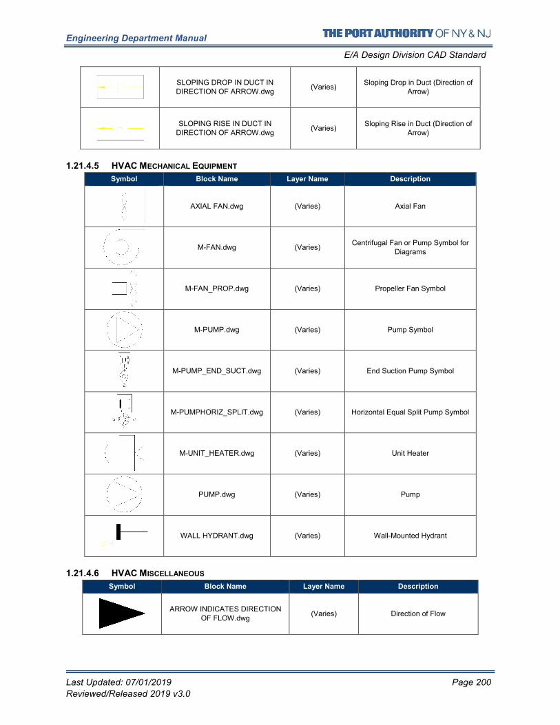
Engineering Department Manual
E/A Design Division CAD Standard
Last Updated: 07/01/2019 Page 200
Reviewed/Released 2019 v3.0
SLOPING DROP IN DUCT IN DIRECTION OF ARROW.dwg
(Varies) Sloping Drop in Duct (Direction of
Arrow)
SLOPING RISE IN DUCT IN DIRECTION OF ARROW.dwg
(Varies) Sloping Rise in Duct (Direction of
Arrow)
1.21.4.5 HVAC MECHANICAL EQUIPMENT
Symbol Block Name Layer Name Description
AXIAL FAN.dwg (Varies) Axial Fan
M-FAN.dwg (Varies) Centrifugal Fan or Pump Symbol for
Diagrams
M-FAN_PROP.dwg (Varies) Propeller Fan Symbol
M-PUMP.dwg (Varies) Pump Symbol
M-PUMP_END_SUCT.dwg (Varies) End Suction Pump Symbol
M-PUMPHORIZ_SPLIT.dwg (Varies) Horizontal Equal Split Pump Symbol
M-UNIT_HEATER.dwg (Varies) Unit Heater
PUMP.dwg (Varies) Pump
WALL HYDRANT.dwg (Varies) Wall-Mounted Hydrant
1.21.4.6 HVAC MISCELLANEOUS
Symbol Block Name Layer Name Description
ARROW INDICATES DIRECTION
OF FLOW.dwg (Varies) Direction of Flow
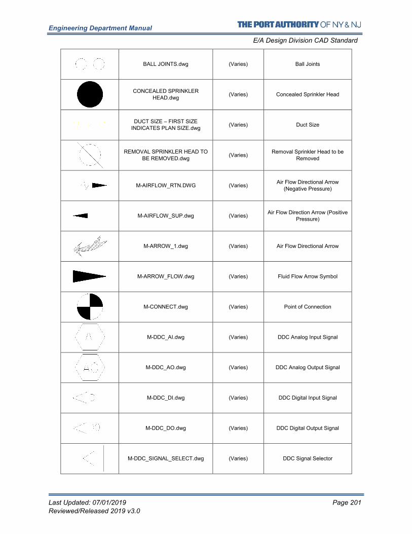
Engineering Department Manual
E/A Design Division CAD Standard
Last Updated: 07/01/2019 Page 201
Reviewed/Released 2019 v3.0
BALL JOINTS.dwg (Varies) Ball Joints
CONCEALED SPRINKLER HEAD.dwg
(Varies) Concealed Sprinkler Head
DUCT SIZE – FIRST SIZE INDICATES PLAN SIZE.dwg
(Varies) Duct Size
REMOVAL SPRINKLER HEAD TO
BE REMOVED.dwg (Varies)
Removal Sprinkler Head to be
Removed
M-AIRFLOW_RTN.DWG (Varies) Air Flow Directional Arrow
(Negative Pressure)
M-AIRFLOW_SUP.dwg (Varies) Air Flow Direction Arrow (Positive
Pressure)
M-ARROW_1.dwg (Varies) Air Flow Directional Arrow
M-ARROW_FLOW.dwg (Varies) Fluid Flow Arrow Symbol
M-CONNECT.dwg (Varies) Point of Connection
M-DDC_AI.dwg (Varies) DDC Analog Input Signal
M-DDC_AO.dwg (Varies) DDC Analog Output Signal
M-DDC_DI.dwg (Varies) DDC Digital Input Signal
M-DDC_DO.dwg (Varies) DDC Digital Output Signal
M-DDC_SIGNAL_SELECT.dwg (Varies) DDC Signal Selector
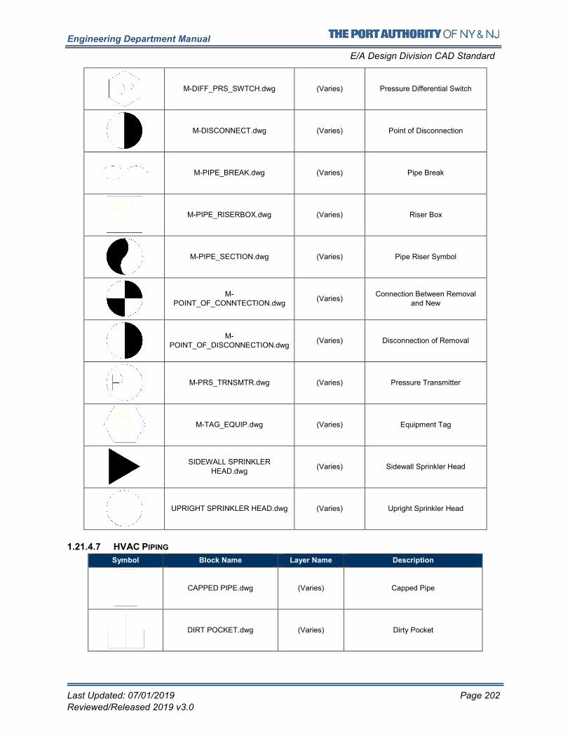
Engineering Department Manual
E/A Design Division CAD Standard
Last Updated: 07/01/2019 Page 202
Reviewed/Released 2019 v3.0
M-DIFF_PRS_SWTCH.dwg (Varies) Pressure Differential Switch
M-DISCONNECT.dwg (Varies) Point of Disconnection
M-PIPE_BREAK.dwg (Varies) Pipe Break
M-PIPE_RISERBOX.dwg (Varies) Riser Box
M-PIPE_SECTION.dwg (Varies) Pipe Riser Symbol
M-POINT_OF_CONNTECTION.dwg
(Varies) Connection Between Removal
and New
M-POINT_OF_DISCONNECTION.dwg
(Varies) Disconnection of Removal
M-PRS_TRNSMTR.dwg (Varies) Pressure Transmitter
M-TAG_EQUIP.dwg (Varies) Equipment Tag
SIDEWALL SPRINKLER HEAD.dwg
(Varies) Sidewall Sprinkler Head
UPRIGHT SPRINKLER HEAD.dwg (Varies) Upright Sprinkler Head
1.21.4.7 HVAC PIPING
Symbol Block Name Layer Name Description
CAPPED PIPE.dwg (Varies) Capped Pipe
DIRT POCKET.dwg (Varies) Dirty Pocket
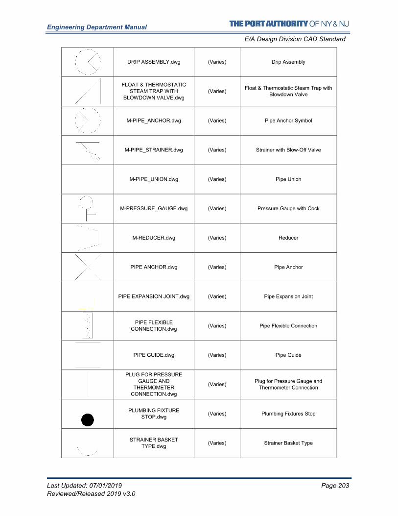
Engineering Department Manual
E/A Design Division CAD Standard
Last Updated: 07/01/2019 Page 203
Reviewed/Released 2019 v3.0
DRIP ASSEMBLY.dwg (Varies) Drip Assembly
FLOAT & THERMOSTATIC STEAM TRAP WITH
BLOWDOWN VALVE.dwg
(Varies) Float & Thermostatic Steam Trap with
Blowdown Valve
M-PIPE_ANCHOR.dwg (Varies) Pipe Anchor Symbol
M-PIPE_STRAINER.dwg (Varies) Strainer with Blow-Off Valve
M-PIPE_UNION.dwg (Varies) Pipe Union
M-PRESSURE_GAUGE.dwg (Varies) Pressure Gauge with Cock
M-REDUCER.dwg (Varies) Reducer
PIPE ANCHOR.dwg (Varies) Pipe Anchor
PIPE EXPANSION JOINT.dwg (Varies) Pipe Expansion Joint
PIPE FLEXIBLE CONNECTION.dwg
(Varies) Pipe Flexible Connection
PIPE GUIDE.dwg (Varies) Pipe Guide
PLUG FOR PRESSURE
GAUGE AND THERMOMETER
CONNECTION.dwg
(Varies) Plug for Pressure Gauge and
Thermometer Connection
PLUMBING FIXTURE STOP.dwg
(Varies) Plumbing Fixtures Stop
STRAINER BASKET TYPE.dwg
(Varies) Strainer Basket Type
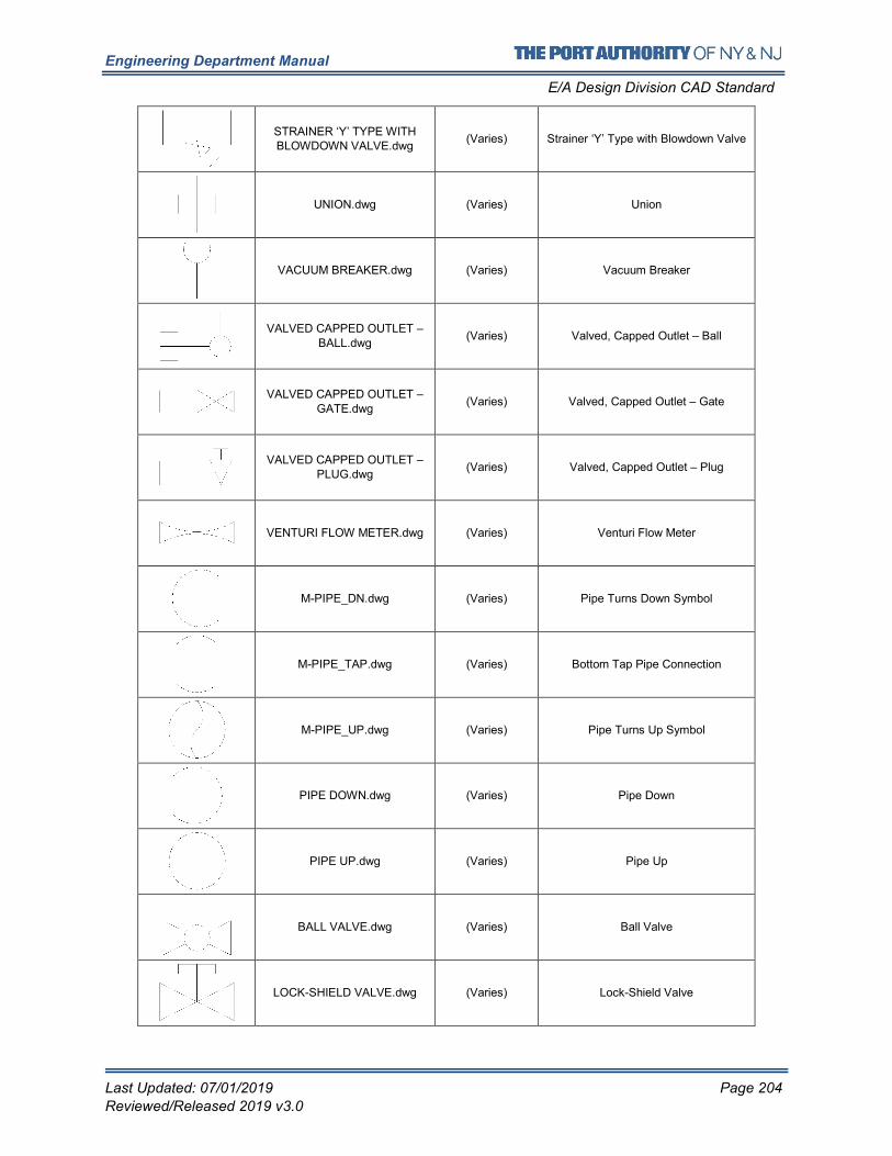
Engineering Department Manual
E/A Design Division CAD Standard
Last Updated: 07/01/2019 Page 204
Reviewed/Released 2019 v3.0
STRAINER ‘Y’ TYPE WITH BLOWDOWN VALVE.dwg
(Varies) Strainer ‘Y’ Type with Blowdown Valve
UNION.dwg (Varies) Union
VACUUM BREAKER.dwg (Varies) Vacuum Breaker
VALVED CAPPED OUTLET –
BALL.dwg (Varies) Valved, Capped Outlet – Ball
VALVED CAPPED OUTLET – GATE.dwg
(Varies) Valved, Capped Outlet – Gate
VALVED CAPPED OUTLET – PLUG.dwg
(Varies) Valved, Capped Outlet – Plug
VENTURI FLOW METER.dwg (Varies) Venturi Flow Meter
M-PIPE_DN.dwg (Varies) Pipe Turns Down Symbol
M-PIPE_TAP.dwg (Varies) Bottom Tap Pipe Connection
M-PIPE_UP.dwg (Varies) Pipe Turns Up Symbol
PIPE DOWN.dwg (Varies) Pipe Down
PIPE UP.dwg (Varies) Pipe Up
BALL VALVE.dwg (Varies) Ball Valve
LOCK-SHIELD VALVE.dwg (Varies) Lock-Shield Valve
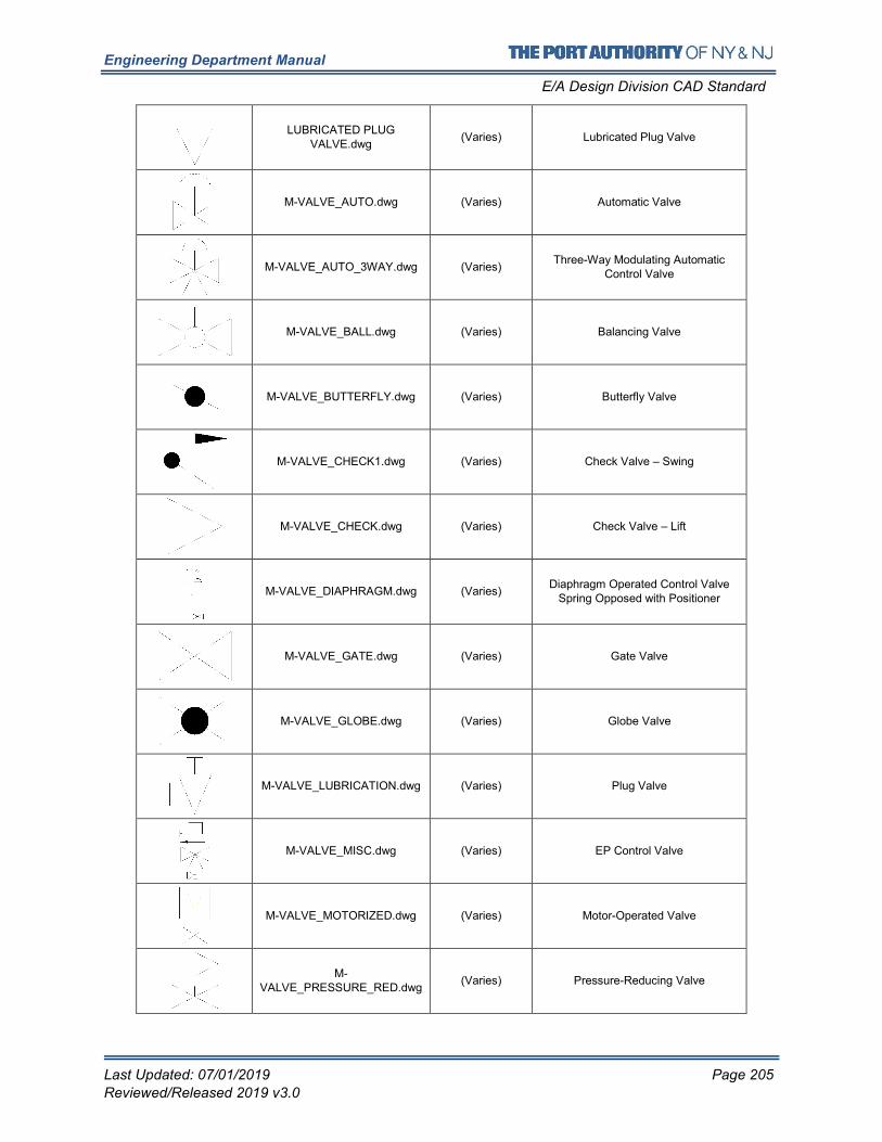
Engineering Department Manual
E/A Design Division CAD Standard
Last Updated: 07/01/2019 Page 205
Reviewed/Released 2019 v3.0
LUBRICATED PLUG VALVE.dwg
(Varies) Lubricated Plug Valve
M-VALVE_AUTO.dwg (Varies) Automatic Valve
M-VALVE_AUTO_3WAY.dwg (Varies) Three-Way Modulating Automatic
Control Valve
M-VALVE_BALL.dwg (Varies) Balancing Valve
M-VALVE_BUTTERFLY.dwg (Varies) Butterfly Valve
M-VALVE_CHECK1.dwg (Varies) Check Valve – Swing
M-VALVE_CHECK.dwg (Varies) Check Valve – Lift
M-VALVE_DIAPHRAGM.dwg (Varies) Diaphragm Operated Control Valve
Spring Opposed with Positioner
M-VALVE_GATE.dwg (Varies) Gate Valve
M-VALVE_GLOBE.dwg (Varies) Globe Valve
M-VALVE_LUBRICATION.dwg (Varies) Plug Valve
M-VALVE_MISC.dwg (Varies) EP Control Valve
M-VALVE_MOTORIZED.dwg (Varies) Motor-Operated Valve
M-VALVE_PRESSURE_RED.dwg
(Varies) Pressure-Reducing Valve
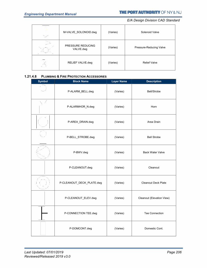
Engineering Department Manual
E/A Design Division CAD Standard
Last Updated: 07/01/2019 Page 206
Reviewed/Released 2019 v3.0
M-VALVE_SOLONOID.dwg (Varies) Solenoid Valve
PRESSURE REDUCING VALVE.dwg
(Varies) Pressure-Reducing Valve
RELIEF VALVE.dwg (Varies) Relief Valve
1.21.4.8 PLUMBING & FIRE PROTECTION ACCESSORIES
Symbol Block Name Layer Name Description
P-ALARM_BELL.dwg (Varies) Bell/Strobe
P-ALARMHOR_N.dwg (Varies) Horn
P-AREA_DRAIN.dwg (Varies) Area Drain
P-BELL_STROBE.dwg (Varies) Bell Strobe
P-BWV.dwg (Varies) Back Water Valve
P-CLEANOUT.dwg (Varies) Cleanout
P-CLEANOUT_DECK_PLATE.dwg (Varies) Cleanout Deck Plate
P-CLEANOUT_ELEV.dwg (Varies) Cleanout (Elevation View)
P-CONNECTION TEE.dwg (Varies) Tee Connection
P-DOMCONT.dwg (Varies) Domestic Cont.

Engineering Department Manual
E/A Design Division CAD Standard
Last Updated: 07/01/2019 Page 207
Reviewed/Released 2019 v3.0
P-DRAIN_FLOOR.dwg (Varies) Floor Drain
P-DRAIN_FLOOR_RISER.dwg (Varies) Floor Drain Riser
P-DRAIN_FUNNEL.dwg (Varies) Funnel Drain
P-DRAIN_PTRAP_PRIMER.dwg (Varies) PTrap Drain Primer
P-DRAIN_ROOF_RISER.dwg (Varies) Drain Riser
P-DRAIN_STANDPIPE.dwg (Varies) Drain Standpipe
P-FA_INLET.dwg (Varies) Fresh Air Inlet
P-FA_INTAKE.dwg (Varies) Fresh Air Intake
P-FD.dwg (Varies) Floor Drain
P-FHC.dwg (Varies) Fire Hose Connection
P-FHC_PLAN.dwg (Varies) Fire Hose Connection (Plan)
P-FHR.dwg (Varies) Fire Hose Rack
P-FHR_PLAN.dwg (Varies) Fire Hose Rack (Plan)
P-FIRE_HOSE_CABINET_PLAN.dwg (Varies) Fire Hose & Cabinet
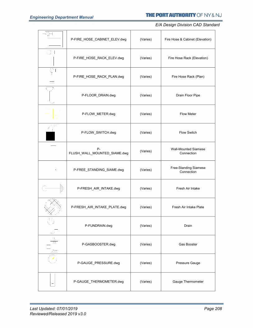
Engineering Department Manual
E/A Design Division CAD Standard
Last Updated: 07/01/2019 Page 208
Reviewed/Released 2019 v3.0
P-FIRE_HOSE_CABINET_ELEV.dwg (Varies) Fire Hose & Cabinet (Elevation)
P-FIRE_HOSE_RACK_ELEV.dwg (Varies) Fire Hose Rack (Elevation)
P-FIRE_HOSE_RACK_PLAN.dwg (Varies) Fire Hose Rack (Plan)
P-FLOOR_DRAIN.dwg (Varies) Drain Floor Pipe
P-FLOW_METER.dwg (Varies) Flow Meter
P-FLOW_SWITCH.dwg (Varies) Flow Switch
P-FLUSH_WALL_MOUNTED_SIAME.dwg
(Varies) Wall-Mounted Siamese
Connection
P-FREE_STANDING_SIAME.dwg (Varies) Free-Standing Siamese
Connection
P-FRESH_AIR_INTAKE.dwg (Varies) Fresh Air Intake
P-FRESH_AIR_INTAKE_PLATE.dwg (Varies) Fresh Air Intake Plate
P-FUNDRAIN.dwg (Varies) Drain
P-GASBOOSTER.dwg (Varies) Gas Booster
P-GAUGE_PRESSURE.dwg (Varies) Pressure Gauge
P-GAUGE_THERMOMETER.dwg (Varies) Gauge Thermometer
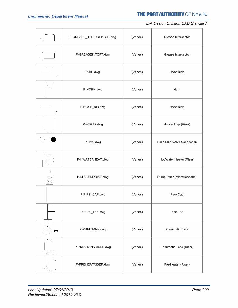
Engineering Department Manual
E/A Design Division CAD Standard
Last Updated: 07/01/2019 Page 209
Reviewed/Released 2019 v3.0
P-GREASE_INTERCEPTOR.dwg (Varies) Grease Interceptor
P-GREASEINTCPT.dwg (Varies) Grease Interceptor
P-HB.dwg (Varies) Hose Bibb
P-HORN.dwg (Varies) Horn
P-HOSE_BIB.dwg (Varies) Hose Bibb
P-HTRAP.dwg (Varies) House Trap (Riser)
P-HVC.dwg (Varies) Hose Bibb Valve Connection
P-HWATERHEAT.dwg (Varies) Hot Water Heater (Riser)
P-MISCPMPRISE.dwg (Varies) Pump Riser (Miscellaneous)
P-PIPE_CAP.dwg (Varies) Pipe Cap
P-PIPE_TEE.dwg (Varies) Pipe Tee
P-PNEUTANK.dwg (Varies) Pneumatic Tank
P-PNEUTANKRISER.dwg (Varies) Pneumatic Tank (Riser)
P-PREHEATRISER.dwg (Varies) Pre-Heater (Riser)
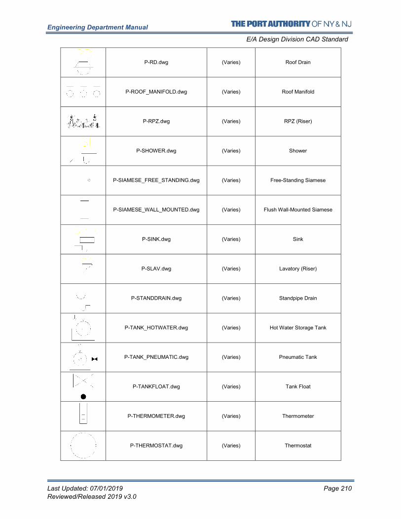
Engineering Department Manual
E/A Design Division CAD Standard
Last Updated: 07/01/2019 Page 210
Reviewed/Released 2019 v3.0
P-RD.dwg (Varies) Roof Drain
P-ROOF_MANIFOLD.dwg (Varies) Roof Manifold
P-RPZ.dwg (Varies) RPZ (Riser)
P-SHOWER.dwg (Varies) Shower
P-SIAMESE_FREE_STANDING.dwg (Varies) Free-Standing Siamese
P-SIAMESE_WALL_MOUNTED.dwg (Varies) Flush Wall-Mounted Siamese
P-SINK.dwg (Varies) Sink
P-SLAV.dwg (Varies) Lavatory (Riser)
P-STANDDRAIN.dwg (Varies) Standpipe Drain
P-TANK_HOTWATER.dwg (Varies) Hot Water Storage Tank
P-TANK_PNEUMATIC.dwg (Varies) Pneumatic Tank
P-TANKFLOAT.dwg (Varies) Tank Float
P-THERMOMETER.dwg (Varies) Thermometer
P-THERMOSTAT.dwg (Varies) Thermostat
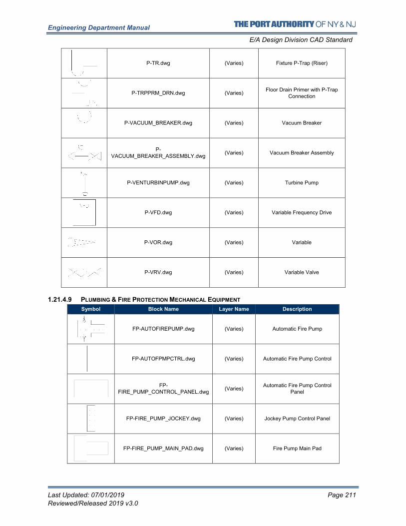
Engineering Department Manual
E/A Design Division CAD Standard
Last Updated: 07/01/2019 Page 211
Reviewed/Released 2019 v3.0
P-TR.dwg (Varies) Fixture P-Trap (Riser)
P-TRPPRM_DRN.dwg (Varies) Floor Drain Primer with P-Trap
Connection
P-VACUUM_BREAKER.dwg (Varies) Vacuum Breaker
P-
VACUUM_BREAKER_ASSEMBLY.dwg (Varies) Vacuum Breaker Assembly
P-VENTURBINPUMP.dwg (Varies) Turbine Pump
P-VFD.dwg (Varies) Variable Frequency Drive
P-VOR.dwg (Varies) Variable
P-VRV.dwg (Varies) Variable Valve
1.21.4.9 PLUMBING & FIRE PROTECTION MECHANICAL EQUIPMENT
Symbol Block Name Layer Name Description
FP-AUTOFIREPUMP.dwg (Varies) Automatic Fire Pump
FP-AUTOFPMPCTRL.dwg (Varies) Automatic Fire Pump Control
FP-FIRE_PUMP_CONTROL_PANEL.dwg
(Varies) Automatic Fire Pump Control
Panel
FP-FIRE_PUMP_JOCKEY.dwg (Varies) Jockey Pump Control Panel
FP-FIRE_PUMP_MAIN_PAD.dwg (Varies) Fire Pump Main Pad
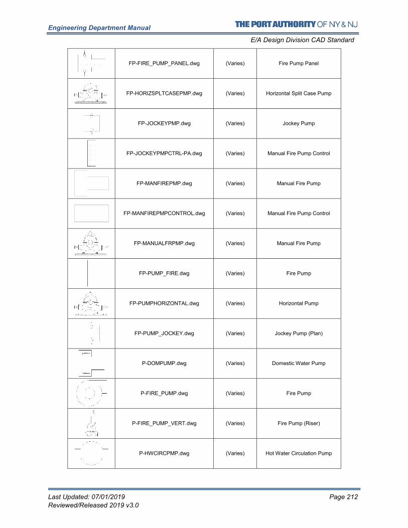
Engineering Department Manual
E/A Design Division CAD Standard
Last Updated: 07/01/2019 Page 212
Reviewed/Released 2019 v3.0
FP-FIRE_PUMP_PANEL.dwg (Varies) Fire Pump Panel
FP-HORIZSPLTCASEPMP.dwg (Varies) Horizontal Split Case Pump
FP-JOCKEYPMP.dwg (Varies) Jockey Pump
FP-JOCKEYPMPCTRL-PA.dwg (Varies) Manual Fire Pump Control
FP-MANFIREPMP.dwg (Varies) Manual Fire Pump
FP-MANFIREPMPCONTROL.dwg (Varies) Manual Fire Pump Control
FP-MANUALFRPMP.dwg (Varies) Manual Fire Pump
FP-PUMP_FIRE.dwg (Varies) Fire Pump
FP-PUMPHORIZONTAL.dwg (Varies) Horizontal Pump
FP-PUMP_JOCKEY.dwg (Varies) Jockey Pump (Plan)
P-DOMPUMP.dwg (Varies) Domestic Water Pump
P-FIRE_PUMP.dwg (Varies) Fire Pump
P-FIRE_PUMP_VERT.dwg (Varies) Fire Pump (Riser)
P-HWCIRCPMP.dwg (Varies) Hot Water Circulation Pump
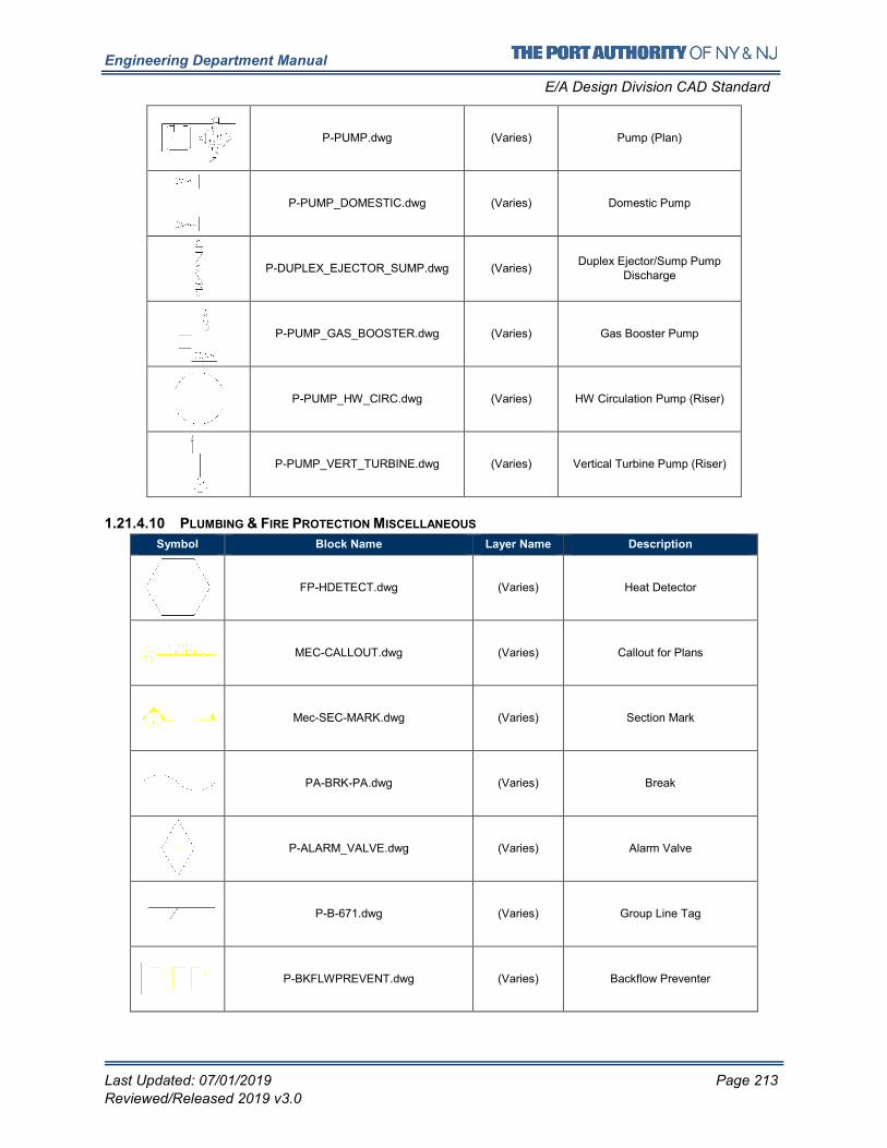
Engineering Department Manual
E/A Design Division CAD Standard
Last Updated: 07/01/2019 Page 213
Reviewed/Released 2019 v3.0
P-PUMP.dwg (Varies) Pump (Plan)
P-PUMP_DOMESTIC.dwg (Varies) Domestic Pump
P-DUPLEX_EJECTOR_SUMP.dwg (Varies) Duplex Ejector/Sump Pump
Discharge
P-PUMP_GAS_BOOSTER.dwg (Varies) Gas Booster Pump
P-PUMP_HW_CIRC.dwg (Varies) HW Circulation Pump (Riser)
P-PUMP_VERT_TURBINE.dwg (Varies) Vertical Turbine Pump (Riser)
1.21.4.10 PLUMBING & FIRE PROTECTION MISCELLANEOUS
Symbol Block Name Layer Name Description
FP-HDETECT.dwg (Varies) Heat Detector
MEC-CALLOUT.dwg (Varies) Callout for Plans
Mec-SEC-MARK.dwg (Varies) Section Mark
PA-BRK-PA.dwg (Varies) Break
P-ALARM_VALVE.dwg (Varies) Alarm Valve
P-B-671.dwg (Varies) Group Line Tag
P-BKFLWPREVENT.dwg (Varies) Backflow Preventer
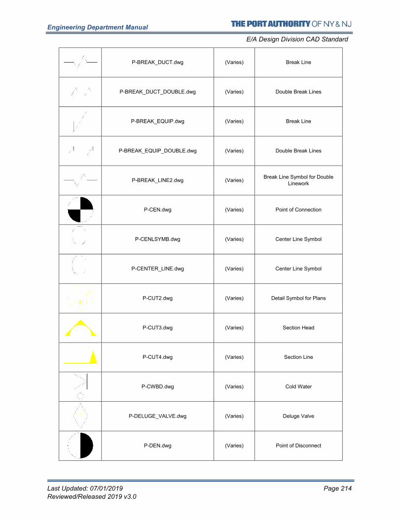
Engineering Department Manual
E/A Design Division CAD Standard
Last Updated: 07/01/2019 Page 214
Reviewed/Released 2019 v3.0
P-BREAK_DUCT.dwg (Varies) Break Line
P-BREAK_DUCT_DOUBLE.dwg (Varies) Double Break Lines
P-BREAK_EQUIP.dwg (Varies) Break Line
P-BREAK_EQUIP_DOUBLE.dwg (Varies) Double Break Lines
P-BREAK_LINE2.dwg (Varies) Break Line Symbol for Double
Linework
P-CEN.dwg (Varies) Point of Connection
P-CENLSYMB.dwg (Varies) Center Line Symbol
P-CENTER_LINE.dwg (Varies) Center Line Symbol
P-CUT2.dwg (Varies) Detail Symbol for Plans
P-CUT3.dwg (Varies) Section Head
P-CUT4.dwg (Varies) Section Line
P-CWBD.dwg (Varies) Cold Water
P-DELUGE_VALVE.dwg (Varies) Deluge Valve
P-DEN.dwg (Varies) Point of Disconnect
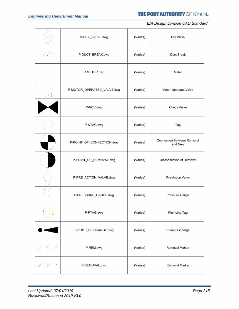
Engineering Department Manual
E/A Design Division CAD Standard
Last Updated: 07/01/2019 Page 215
Reviewed/Released 2019 v3.0
P-DRY_VALVE.dwg (Varies) Dry Valve
P-DUCT_BREAK.dwg (Varies) Duct Break
P-METER.dwg (Varies) Meter
P-MOTOR_OPERATED_VALVE.dwg (Varies) Motor-Operated Valve
P-NCV.dwg (Varies) Check Valve
P-NTAG.dwg (Varies) Tag
P-POINT_OF_CONNECTION.dwg (Varies) Connection Between Removal
and New
P-POINT_OF_REMOVAL.dwg (Varies) Disconnection of Removal
P-PRE_ACTION_VALVE.dwg (Varies) Pre-Action Valve
P-PRESSURE_GAUGE.dwg (Varies) Pressure Gauge
P-PTAG.dwg (Varies) Plumbing Tag
P-PUMP_DISCHARGE.dwg (Varies) Pump Discharge
P-REM.dwg (Varies) Removal Marker
P-REMOVAL.dwg (Varies) Removal Marker
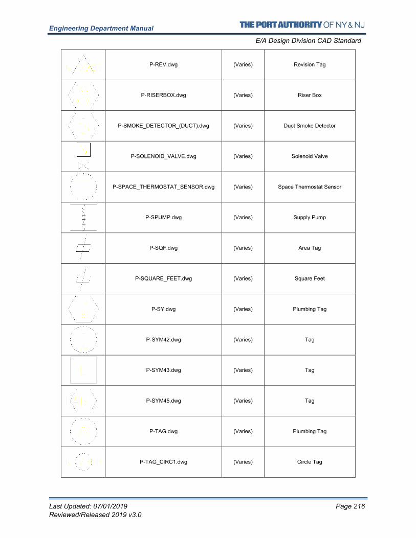
Engineering Department Manual
E/A Design Division CAD Standard
Last Updated: 07/01/2019 Page 216
Reviewed/Released 2019 v3.0
P-REV.dwg (Varies) Revision Tag
P-RISERBOX.dwg (Varies) Riser Box
P-SMOKE_DETECTOR_(DUCT).dwg (Varies) Duct Smoke Detector
P-SOLENOID_VALVE.dwg (Varies) Solenoid Valve
P-SPACE_THERMOSTAT_SENSOR.dwg (Varies) Space Thermostat Sensor
P-SPUMP.dwg (Varies) Supply Pump
P-SQF.dwg (Varies) Area Tag
P-SQUARE_FEET.dwg (Varies) Square Feet
P-SY.dwg (Varies) Plumbing Tag
P-SYM42.dwg (Varies) Tag
P-SYM43.dwg (Varies) Tag
P-SYM45.dwg (Varies) Tag
P-TAG.dwg (Varies) Plumbing Tag
P-TAG_CIRC1.dwg (Varies) Circle Tag
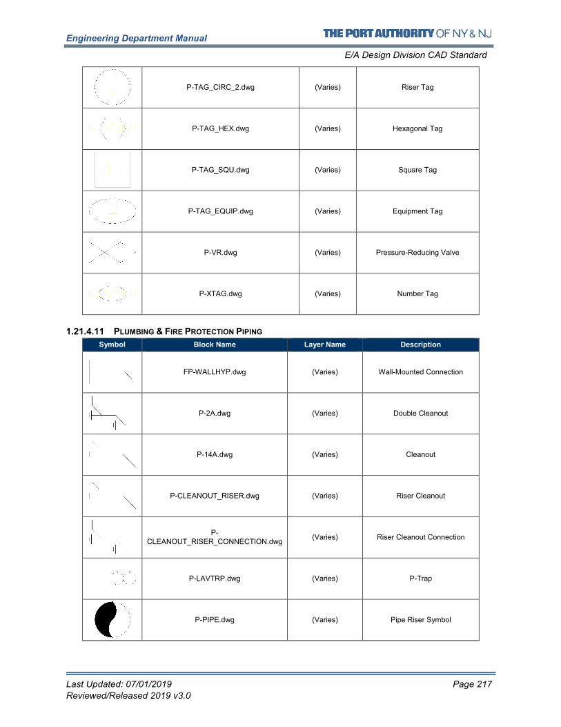
Engineering Department Manual
E/A Design Division CAD Standard
Last Updated: 07/01/2019 Page 217
Reviewed/Released 2019 v3.0
P-TAG_CIRC_2.dwg (Varies) Riser Tag
P-TAG_HEX.dwg (Varies) Hexagonal Tag
P-TAG_SQU.dwg (Varies) Square Tag
P-TAG_EQUIP.dwg (Varies) Equipment Tag
P-VR.dwg (Varies) Pressure-Reducing Valve
P-XTAG.dwg (Varies) Number Tag
1.21.4.11 PLUMBING & FIRE PROTECTION PIPING
Symbol Block Name Layer Name Description
FP-WALLHYP.dwg (Varies) Wall-Mounted Connection
P-2A.dwg (Varies) Double Cleanout
P-14A.dwg (Varies) Cleanout
P-CLEANOUT_RISER.dwg (Varies) Riser Cleanout
P-CLEANOUT_RISER_CONNECTION.dwg
(Varies) Riser Cleanout Connection
P-LAVTRP.dwg (Varies) P-Trap
P-PIPE.dwg (Varies) Pipe Riser Symbol
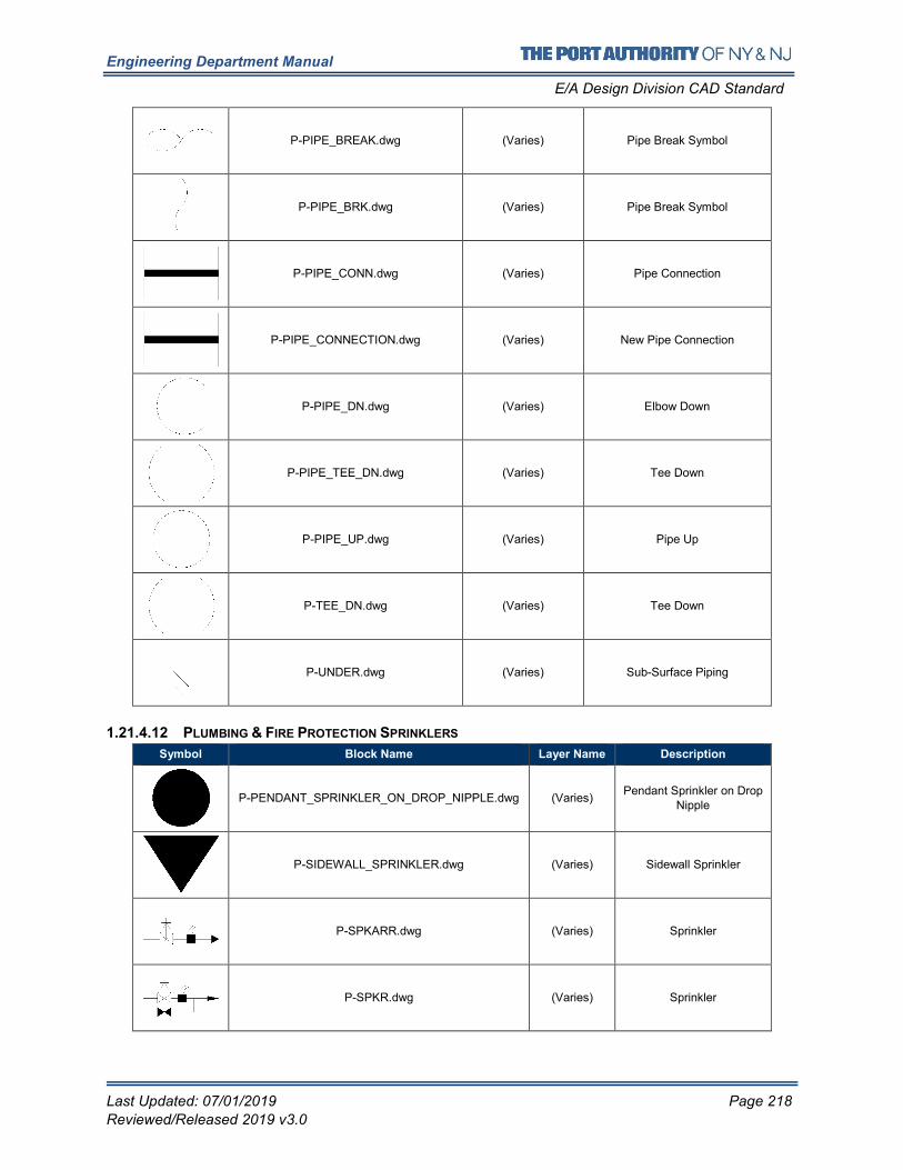
Engineering Department Manual
E/A Design Division CAD Standard
Last Updated: 07/01/2019 Page 218
Reviewed/Released 2019 v3.0
P-PIPE_BREAK.dwg (Varies) Pipe Break Symbol
P-PIPE_BRK.dwg (Varies) Pipe Break Symbol
P-PIPE_CONN.dwg (Varies) Pipe Connection
P-PIPE_CONNECTION.dwg (Varies) New Pipe Connection
P-PIPE_DN.dwg (Varies) Elbow Down
P-PIPE_TEE_DN.dwg (Varies) Tee Down
P-PIPE_UP.dwg (Varies) Pipe Up
P-TEE_DN.dwg (Varies) Tee Down
P-UNDER.dwg (Varies) Sub-Surface Piping
1.21.4.12 PLUMBING & FIRE PROTECTION SPRINKLERS
Symbol Block Name Layer Name Description
P-PENDANT_SPRINKLER_ON_DROP_NIPPLE.dwg (Varies) Pendant Sprinkler on Drop
Nipple
P-SIDEWALL_SPRINKLER.dwg (Varies) Sidewall Sprinkler
P-SPKARR.dwg (Varies) Sprinkler
P-SPKR.dwg (Varies) Sprinkler
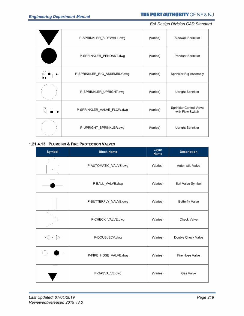
Engineering Department Manual
E/A Design Division CAD Standard
Last Updated: 07/01/2019 Page 219
Reviewed/Released 2019 v3.0
P-SPRINKLER_SIDEWALL.dwg (Varies) Sidewall Sprinkler
P-SPRINKLER_PENDANT.dwg (Varies) Pendant Sprinkler
P-SPRINKLER_RIG_ASSEMBLY.dwg (Varies) Sprinkler Rig Assembly
P-SPRINKLER_UPRIGHT.dwg (Varies) Upright Sprinkler
P-SPRINKLER_VALVE_FLOW.dwg (Varies) Sprinkler Control Valve
with Flow Switch
P-UPRIGHT_SPRINKLER.dwg (Varies) Upright Sprinkler
1.21.4.13 PLUMBING & FIRE PROTECTION VALVES
Symbol Block Name Layer
Name Description
P-AUTOMATIC_VALVE.dwg (Varies) Automatic Valve
P-BALL_VALVE.dwg (Varies) Ball Valve Symbol
P-BUTTERFLY_VALVE.dwg (Varies) Butterfly Valve
P-CHECK_VALVE.dwg (Varies) Check Valve
P-DOUBLECV.dwg (Varies) Double Check Valve
P-FIRE_HOSE_VALVE.dwg (Varies) Fire Hose Valve
P-GASVALVE.dwg (Varies) Gas Valve
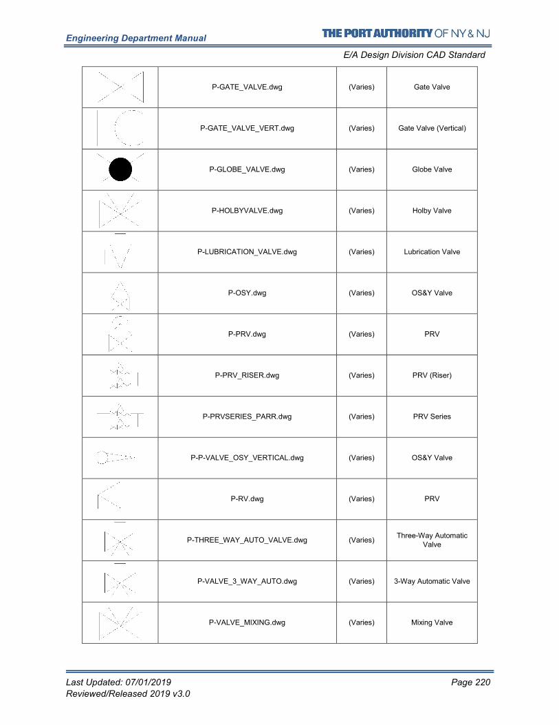
Engineering Department Manual
E/A Design Division CAD Standard
Last Updated: 07/01/2019 Page 220
Reviewed/Released 2019 v3.0
P-GATE_VALVE.dwg (Varies) Gate Valve
P-GATE_VALVE_VERT.dwg (Varies) Gate Valve (Vertical)
P-GLOBE_VALVE.dwg (Varies) Globe Valve
P-HOLBYVALVE.dwg (Varies) Holby Valve
P-LUBRICATION_VALVE.dwg (Varies) Lubrication Valve
P-OSY.dwg (Varies) OS&Y Valve
P-PRV.dwg (Varies) PRV
P-PRV_RISER.dwg (Varies) PRV (Riser)
P-PRVSERIES_PARR.dwg (Varies) PRV Series
P-P-VALVE_OSY_VERTICAL.dwg (Varies) OS&Y Valve
P-RV.dwg (Varies) PRV
P-THREE_WAY_AUTO_VALVE.dwg (Varies) Three-Way Automatic
Valve
P-VALVE_3_WAY_AUTO.dwg (Varies) 3-Way Automatic Valve
P-VALVE_MIXING.dwg (Varies) Mixing Valve
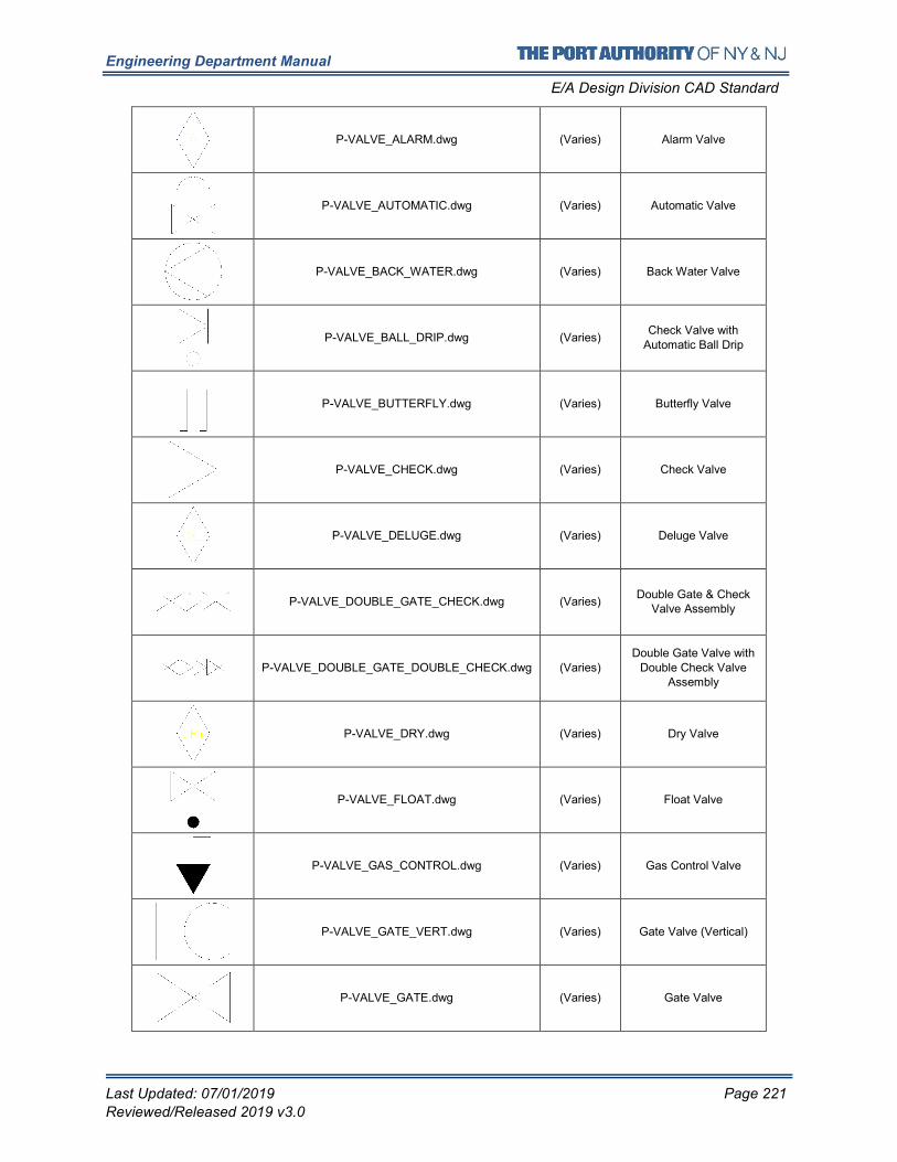
Engineering Department Manual
E/A Design Division CAD Standard
Last Updated: 07/01/2019 Page 221
Reviewed/Released 2019 v3.0
P-VALVE_ALARM.dwg (Varies) Alarm Valve
P-VALVE_AUTOMATIC.dwg (Varies) Automatic Valve
P-VALVE_BACK_WATER.dwg (Varies) Back Water Valve
P-VALVE_BALL_DRIP.dwg (Varies) Check Valve with
Automatic Ball Drip
P-VALVE_BUTTERFLY.dwg (Varies) Butterfly Valve
P-VALVE_CHECK.dwg (Varies) Check Valve
P-VALVE_DELUGE.dwg (Varies) Deluge Valve
P-VALVE_DOUBLE_GATE_CHECK.dwg (Varies) Double Gate & Check
Valve Assembly
P-VALVE_DOUBLE_GATE_DOUBLE_CHECK.dwg (Varies) Double Gate Valve with
Double Check Valve Assembly
P-VALVE_DRY.dwg (Varies) Dry Valve
P-VALVE_FLOAT.dwg (Varies) Float Valve
P-VALVE_GAS_CONTROL.dwg (Varies) Gas Control Valve
P-VALVE_GATE_VERT.dwg (Varies) Gate Valve (Vertical)
P-VALVE_GATE.dwg (Varies) Gate Valve
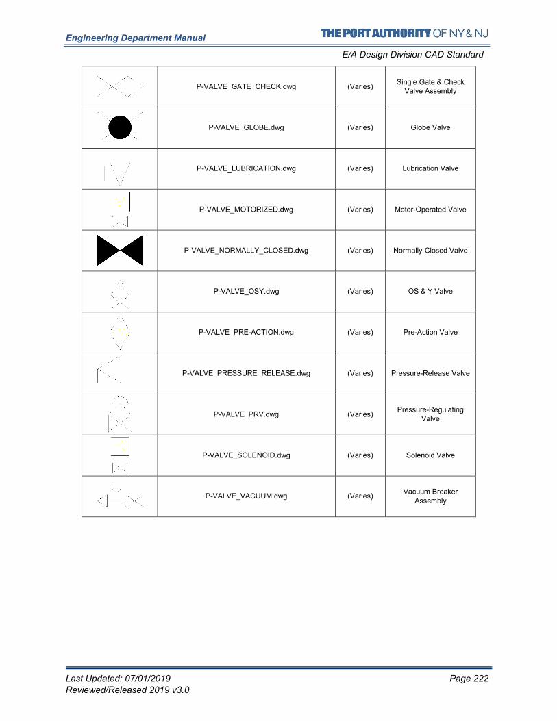
Engineering Department Manual
E/A Design Division CAD Standard
Last Updated: 07/01/2019 Page 222
Reviewed/Released 2019 v3.0
P-VALVE_GATE_CHECK.dwg (Varies) Single Gate & Check
Valve Assembly
P-VALVE_GLOBE.dwg (Varies) Globe Valve
P-VALVE_LUBRICATION.dwg (Varies) Lubrication Valve
P-VALVE_MOTORIZED.dwg (Varies) Motor-Operated Valve
P-VALVE_NORMALLY_CLOSED.dwg (Varies) Normally-Closed Valve
P-VALVE_OSY.dwg (Varies) OS & Y Valve
P-VALVE_PRE-ACTION.dwg (Varies) Pre-Action Valve
P-VALVE_PRESSURE_RELEASE.dwg (Varies) Pressure-Release Valve
P-VALVE_PRV.dwg (Varies) Pressure-Regulating
Valve
P-VALVE_SOLENOID.dwg (Varies) Solenoid Valve
P-VALVE_VACUUM.dwg (Varies) Vacuum Breaker
Assembly
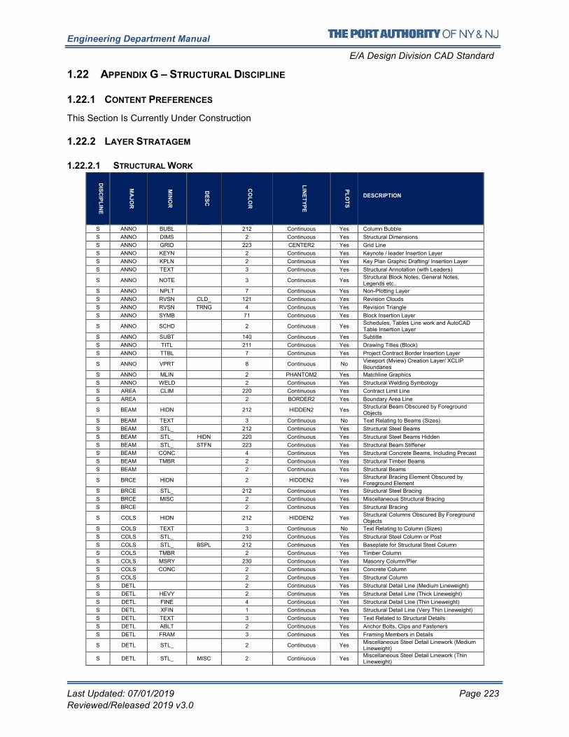
Engineering Department Manual
E/A Design Division CAD Standard
Last Updated: 07/01/2019 Page 223
Reviewed/Released 2019 v3.0
1.22 APPENDIX G – STRUCTURAL DISCIPLINE
1.22.1 CONTENT PREFERENCES
This Section Is Currently Under Construction
1.22.2 LAYER STRATAGEM
1.22.2.1 STRUCTURAL WORK
DIS
CIP
LIN
E
MA
JO
R
MIN
OR
DE
SC
CO
LO
R
LIN
ET
YP
E
PL
OT
S
DESCRIPTION
S ANNO BUBL 212 Continuous Yes Column Bubble
S ANNO DIMS 2 Continuous Yes Structural Dimensions
S ANNO GRID 223 CENTER2 Yes Grid Line
S ANNO KEYN 2 Continuous Yes Keynote / leader Insertion Layer
S ANNO KPLN 2 Continuous Yes Key Plan Graphic Drafting/ Insertion Layer
S ANNO TEXT 3 Continuous Yes Structural Annotation (with Leaders)
S ANNO NOTE 3 Continuous Yes Structural Block Notes, General Notes, Legends etc..
S ANNO NPLT 7 Continuous Yes Non-Plotting Layer
S ANNO RVSN CLD_ 121 Continuous Yes Revision Clouds
S ANNO RVSN TRNG 4 Continuous Yes Revision Triangle
S ANNO SYMB 71 Continuous Yes Block Insertion Layer
S ANNO SCHD 2 Continuous Yes Schedules, Tables Line work and AutoCAD Table Insertion Layer
S ANNO SUBT 140 Continuous Yes Subtitle
S ANNO TITL 211 Continuous Yes Drawing Titles (Block)
S ANNO TTBL 7 Continuous Yes Project Contract Border Insertion Layer
S ANNO VPRT 8 Continuous No Viewport (Mview) Creation Layer/ XCLIP Boundaries
S ANNO MLIN 2 PHANTOM2 Yes Matchline Graphics
S ANNO WELD 2 Continuous Yes Structural Welding Symbology
S AREA CLIM 220 Continuous Yes Contract Limit Line
S AREA 2 BORDER2 Yes Boundary Area Line
S BEAM HIDN 212 HIDDEN2 Yes Structural Beam Obscured by Foreground Objects
S BEAM TEXT 3 Continuous No Text Relating to Beams (Sizes)
S BEAM STL_ 212 Continuous Yes Structural Steel Beams
S BEAM STL_ HIDN 220 Continuous Yes Structural Steel Beams Hidden
S BEAM STL_ STFN 223 Continuous Yes Structural Beam Stiffener
S BEAM CONC 4 Continuous Yes Structural Concrete Beams, Including Precast
S BEAM TMBR 2 Continuous Yes Structural Timber Beams
S BEAM 2 Continuous Yes Structural Beams
S BRCE HIDN 2 HIDDEN2 Yes Structural Bracing Element Obscured by Foreground Element
S BRCE STL_ 212 Continuous Yes Structural Steel Bracing
S BRCE MISC 2 Continuous Yes Miscellaneous Structural Bracing
S BRCE 2 Continuous Yes Structural Bracing
S COLS HIDN 212 HIDDEN2 Yes Structural Columns Obscured By Foreground Objects
S COLS TEXT 3 Continuous No Text Relating to Column (Sizes)
S COLS STL_ 210 Continuous Yes Structural Steel Column or Post
S COLS STL_ BSPL 212 Continuous Yes Baseplate for Structural Steel Column
S COLS TMBR 2 Continuous Yes Timber Column
S COLS MSRY 230 Continuous Yes Masonry Column/Pier
S COLS CONC 2 Continuous Yes Concrete Column
S COLS 2 Continuous Yes Structural Column
S DETL 2 Continuous Yes Structural Detail Line (Medium Lineweight)
S DETL HEVY 2 Continuous Yes Structural Detail Line (Thick Lineweight)
S DETL FINE 4 Continuous Yes Structural Detail Line (Thin Lineweight)
S DETL XFIN 1 Continuous Yes Structural Detail Line (Very Thin Lineweight)
S DETL TEXT 3 Continuous Yes Text Related to Structural Details
S DETL ABLT 2 Continuous Yes Anchor Bolts, Clips and Fasteners
S DETL FRAM 3 Continuous Yes Framing Members in Details
S DETL STL_ 2 Continuous Yes Miscellaneous Steel Detail Linework (Medium Lineweight)
S DETL STL_ MISC 2 Continuous Yes Miscellaneous Steel Detail Linework (Thin Lineweight)
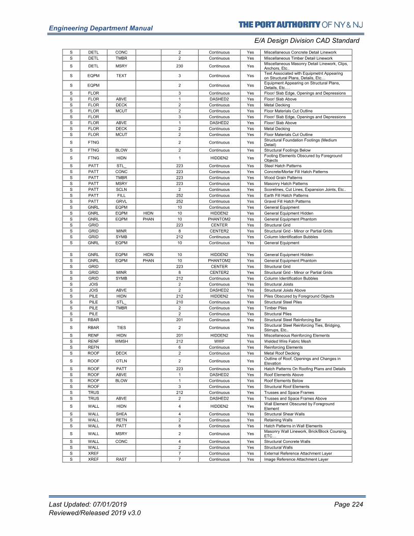
Engineering Department Manual
E/A Design Division CAD Standard
Last Updated: 07/01/2019 Page 224
Reviewed/Released 2019 v3.0
S DETL CONC 2 Continuous Yes Miscellaneous Concrete Detail Linework
S DETL TMBR 2 Continuous Yes Miscellaneous Timber Detail Linework
S DETL MSRY 230 Continuous Yes Miscellaneous Masonry Detail Linework, Clips, Anchors, Etc..
S EQPM TEXT 3 Continuous Yes Text Associated with Equipmetnt Appearing on Structural Plans, Details, Etc…
S EQPM 2 Continuous Yes Equipment Appearing on Structural Plans, Details, Etc.…
S FLOR 3 Continuous Yes Floor/ Slab Edge, Openings and Depressions
S FLOR ABVE 1 DASHED2 Yes Floor/ Slab Above
S FLOR DECK 2 Continuous Yes Metal Decking
S FLOR MCUT 2 Continuous Yes Floor Materials Cut Outline
S FLOR 3 Continuous Yes Floor/ Slab Edge, Openings and Depressions
S FLOR ABVE 1 DASHED2 Yes Floor/ Slab Above
S FLOR DECK 2 Continuous Yes Metal Decking
S FLOR MCUT 2 Continuous Yes Floor Materials Cut Outline
S FTNG 2 Continuous Yes Structural Foundation Footings (Medium Detail)
S FTNG BLOW 2 Continuous Yes Structural Footings Below
S FTNG HIDN 1 HIDDEN2 Yes Footing Elements Obscured by Foreground Objects
S PATT STL_ 223 Continuous Yes Steel Hatch Patterns
S PATT CONC 223 Continuous Yes Concrete/Mortar Fill Hatch Patterns
S PATT TMBR 223 Continuous Yes Wood Grain Patterns
S PATT MSRY 223 Continuous Yes Masonry Hatch Patterns
S PATT SCLN 2 Continuous Yes Scorelines, Cut Lines, Expansion Joints, Etc..
S PATT FILL 252 Continuous Yes Earth Fill Hatch Patterns
S PATT GRVL 252 Continuous Yes Gravel Fill Hatch Patterns
S GNRL EQPM 10 Continuous Yes General Equipment
S GNRL EQPM HIDN 10 HIDDEN2 Yes General Equipment Hidden
S GNRL EQPM PHAN 10 PHANTOM2 Yes General Equipment Phantom
S GRID 223 CENTER Yes Structural Grid
S GRID MINR 8 CENTER2 Yes Structural Grid - Minor or Partial Grids
S GRID SYMB 212 Continuous Yes Column Identification Bubbles
S JOIS 2 Continuous Yes Structural Joists
S JOIS ABVE 2 DASHED2 Yes Structural Joists Above
S PILE HIDN 212 HIDDEN2 Yes Piles Obscured by Foreground Objects
S PILE STL_ 210 Continuous Yes Structural Steel Piles
S PILE TMBR 2 Continuous Yes Timber Piles
S PILE 2 Continuous Yes Structural Piles
S RBAR 201 Continuous Yes Structural Steel Reinforcing Bar
S RBAR TIES 2 Continuous Yes Structural Steel Reinforcing Ties, Bridging, Stirrups, Etc..
S RENF HIDN 201 HIDDEN2 Yes Miscellaneous Reinforcing Elements
S RENF WMSH 212 WWF Yes Welded Wire Fabric Mesh
S REFN 6 Continuous Yes Reinforcing Elements
S ROOF DECK 2 Continuous Yes Metal Roof Decking
S ROOF OTLN 2 Continuous Yes Outline of Roof, Openings and Changes in Elevation
S ROOF PATT 223 Continuous Yes Hatch Patterns On Roofing Plans and Details
S ROOF ABVE 1 DASHED2 Yes Roof Elements Above
S ROOF BLOW 1 Continuous Yes Roof Elements Below
S ROOF 3 Continuous Yes Structural Roof Elements
S TRUS 212 Continuous Yes Trusses and Space Frames
S TRUS ABVE 2 DASHED2 Yes Trusses and Space Frames Above
S WALL HIDN 4 HIDDEN2 Yes Wall Element Obscured by Foreground Element
S WALL SHEA 4 Continuous Yes Structural Shear Walls
S WALL RETN 2 Continuous Yes Retaining Walls
S WALL PATT 8 Continuous Yes Hatch Patterns in Wall Elements
S WALL MSRY 2 Continuous Yes Masonry Wall Linework, Brick/Block Coursing, ETC…
S WALL CONC 4 Continuous Yes Structural Concrete Walls
S WALL 2 Continuous Yes Structural Walls
S XREF 7 Continuous Yes External Reference Attachment Layer
S XREF RAST 7 Continuous Yes Image Reference Attachment Layer
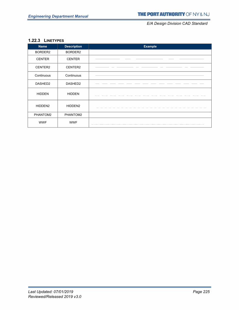
Engineering Department Manual
E/A Design Division CAD Standard
Last Updated: 07/01/2019 Page 225
Reviewed/Released 2019 v3.0
1.22.3 LINETYPES
Name Description Example
BORDER2 BORDER2
CENTER CENTER
CENTER2 CENTER2
Continuous Continuous
DASHED2 DASHED2
HIDDEN HIDDEN
HIDDEN2 HIDDEN2
PHANTOM2 PHANTOM2
WWF WWF
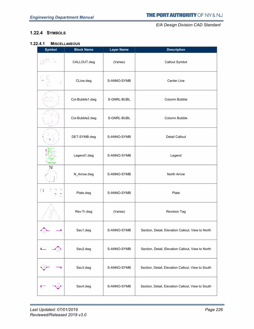
Engineering Department Manual
E/A Design Division CAD Standard
Last Updated: 07/01/2019 Page 226
Reviewed/Released 2019 v3.0
1.22.4 SYMBOLS
1.22.4.1 MISCELLANEOUS
Symbol Block Name Layer Name Description
CALLOUT.dwg (Varies) Callout Symbol
CLine.dwg S-ANNO-SYMB Center Line
Col-Bubble1.dwg S-GNRL-BUBL Column Bubble
Col-Bubble2.dwg S-GNRL-BUBL Column Bubble
DET-SYMB.dwg S-ANNO-SYMB Detail Callout
Legend1.dwg S-ANNO-SYMB Legend
N_Arrow.dwg S-ANNO-SYMB North Arrow
Plate.dwg S-ANNO-SYMB Plate
Rev-Tr.dwg (Varies) Revision Tag
Sec1.dwg S-ANNO-SYMB Section, Detail, Elevation Callout, View to North
Sec2.dwg S-ANNO-SYMB Section, Detail, Elevation Callout, View to North
Sec3.dwg S-ANNO-SYMB Section, Detail, Elevation Callout, View to South
Sec4.dwg S-ANNO-SYMB Section, Detail, Elevation Callout, View to South
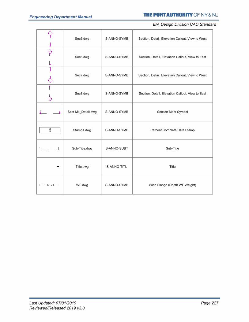
Engineering Department Manual
E/A Design Division CAD Standard
Last Updated: 07/01/2019 Page 227
Reviewed/Released 2019 v3.0
Sec5.dwg S-ANNO-SYMB Section, Detail, Elevation Callout, View to West
Sec6.dwg S-ANNO-SYMB Section, Detail, Elevation Callout, View to East
Sec7.dwg S-ANNO-SYMB Section, Detail, Elevation Callout, View to West
Sec8.dwg S-ANNO-SYMB Section, Detail, Elevation Callout, View to East
Sect-Mk_Detail.dwg S-ANNO-SYMB Section Mark Symbol
Stamp1.dwg S-ANNO-SYMB Percent Complete/Date Stamp
Sub-Title.dwg S-ANNO-SUBT Sub-Title
Title.dwg S-ANNO-TITL Title
WF.dwg S-ANNO-SYMB Wide Flange (Depth WF Weight)
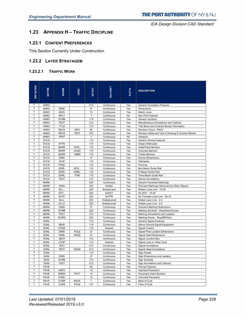
Engineering Department Manual
E/A Design Division CAD Standard
Last Updated: 07/01/2019 Page 228
Reviewed/Released 2019 v3.0
1.23 APPENDIX H – TRAFFIC DISCIPLINE
1.23.1 CONTENT PREFERENCES
This Section Currently Under Construction
1.23.2 LAYER STRATAGEM
1.23.2.1 TRAFFIC WORK
DIS
CIP
LIN
E
MA
JO
R
MIN
OR
DE
SC
CO
LO
R
LIN
ET
YP
E
PL
OT
S
DESCRIPTION
T ANNO 212 Continuous Yes Generic Annotation Features
T ANNO DIMS 37 Continuous Yes Dimensions
T ANNO MLIN 13 Continuous Yes Match Lines
T ANNO NPLT 7 Continuous No Non Plot Features
T ANNO SYMB 110 Continuous Yes Generic Symbols
T ANNO TEXT 212 Continuous Yes Miscellaneous Annotations and Callouts
T ANNO TTLB 110 Continuous Yes Title Block and Contract Border Information
T ANNO REVS 0001 80 Continuous Yes Revision Cloud - PACC
T ANNO REVS TEXT 212 Continuous Yes Revision Delta and Text in Drawing & Contract Border
T ANNO VPRT 7 Continuous No Viewport
T DVCS 110 Continuous Yes Generic Device Features
T DVCS ATTN 110 Continuous Yes Impact Attenuator
T DVCS BARR WFB_ 110 Continuous Yes WaterFilled Barriers
T DVCS BARR CONC 110 Continuous Yes Concrete Barriers
T DVCS BARR TMBR 110 Continuous Yes Timber Barriers
T DVCS DIMS 37 Continuous Yes Device Dimensions
T DVCS DLIN 110 Continuous Yes Delineator
T DVCS FENC 110 Continuous Yes Fencing
T DVCS GDRL BOX_ 110 Continuous Yes Box Beam Guide Rail
T DVCS GDRL WBM_ 110 Continuous Yes W Beam Guide Rail
T DVCS GDRL THRI 110 Continuous Yes Thrie Beam Guide Rail
T DVCS TEXT 212 Continuous Yes Device Annotations
T MARK 220 Continuous Yes Generic Pavement Markings
T MARK HIDN 220 Hidden Yes Pavment Markings Obscured by Other Objects
T MARK BLL_ 220 BrokenLane Yes Broken Lane Line - 15-25
T MARK DOT_ 220 NJDOT Yes NJ DOT - 10-30
T MARK NJTP 220 NJTPK Yes NJ Turnpike Lane Line - 30-10
T MARK DLLL 220 DottedLane4 Yes Dotted Lane Line - 2-4
T MARK DLLS 220 DottedLane2 Yes Dotted Lane Line - 2-2
T MARK DIMS 37 Continuous Yes Pavment Marking Dimensions
T MARK SYMB 220 Continuous Yes Marking Symbols - Directional Arrows
T MARK TEXT 212 Continuous Yes Marking Annotations and Leaders
T MARK WORD 220 Continuous Yes Marking Words - Stop/MPH/etc.
T SGNL 110 Continuous Yes Generic Signal Features
T SGNL ABVE 110 Continuous Yes Above Ground Signal Equipment
T SGNL COND 110 Dashed Yes Signal Conduit
T SGNL DIMS POLE 37 Continuous Yes Signal Pole Location Dimensions
T SGNL DIMS HEAD 37 Continuous Yes Signal Head Dimensions
T SGNL JBOX 110 Continuous Yes Signal Junction Box
T SGNL LOOP 110 Dashed Yes Signal Loop or Video Zone
T SGNL TEXT 212 Continuous Yes Signal Annotations
T SGNL TEXT HEAD 212 Continuous Yes Signal Head Annotations
T SIGN 110 Continuous Yes Sign Panels
T SIGN DIMS 37 Continuous Yes Sign Dimensions and Leaders
T SIGN SYMB 110 Continuous Yes Sign Symbols
T SIGN TEXT 212 Continuous Yes Sign Annotations and Callouts
T PAVE 80 Continuous Yes Paving Features
T PAVE ASPH 12 Continuous Yes Asphault Pavement
T PAVE BRDR PATT 14 Continuous Yes Pavement Hatch Borders
T PAVE CONC 12 Continuous Yes Concrete Pavement
T PAVE CURB BACK 1 Continuous Yes Back of Curb
T PAVE CURB FACE 131 Continuous Yes Face of Curb
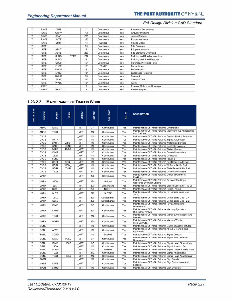
Engineering Department Manual
E/A Design Division CAD Standard
Last Updated: 07/01/2019 Page 229
Reviewed/Released 2019 v3.0
T PAVE DIMS 37 Continuous Yes Pavement Dimensions
T PAVE GRAV 12 Continuous Yes Gravel Pavement
T PAVE JBAR 220 Continuous Yes Jersey Barriers
T PAVE JNTS 220 Continuous Yes Expansion Joints
T PAVE LIMT 13 Dashed Yes Paving Limits
T SITE 80 Continuous Yes Site Features
T SITE ABUT 131 Continuous Yes Bridge Abutments
T SITE ABVE 250 Continuous Yes Site Elements Overhead
T SITE BLDG TEXT 212 Continuous Yes Building and Shed Annotations
T SITE BLDG 131 Continuous Yes Building and Shed Features
T SITE COLS 191 Continuous Yes Columns, Piers and Posts
T SITE FNCE 131 FENCE Yes Fence Lines
T SITE FNDN 131 Continuous Yes Foundations
T SITE LAND 131 Continuous Yes Landscape Features
T SITE SWLK 80 Continuous Yes Sidewalk
T SITE TEXT 212 Continuous Yes Sitework Text
T SITE WALL 131 Continuous Yes Walls
T XREF 7 Continuous Yes External Reference Drawings
T XREF RAST 7 Continuous Yes Raster Images
1.23.2.2 MAINTENANCE OF TRAFFIC WORK
DIS
CIP
LIN
E
MA
JO
R
MIN
OR
DE
SC
PH
AS
E
CO
LO
R
LIN
ET
YP
E
PL
OT
S
DESCRIPTION
T ANNO DIMS _MPT 37 Continuous Yes Maintainance Of Traffic Patterns Dimensions
T ANNO TEXT _MPT 212 Continuous Yes Maintainance Of Traffic Patterns Miscellaneous Annotations And Callouts
T DVCS _MPT 110 Continuous Yes Maintainance Of Traffic Patterns Generic Device Features
T DVCS ATTN _MPT 110 Continuous Yes Maintainance Of Traffic Patterns Impact Attenuator
T DVCS BARR WFB_ _MPT 110 Continuous Yes Maintainance Of Traffic Patterns Waterfilled Barriers
T DVCS BARR CONC _MPT 110 Continuous Yes Maintainance Of Traffic Patterns Concrete Barriers
T DVCS BARR TMBR _MPT 110 Continuous Yes Maintainance Of Traffic Patterns Timber Barriers
T DVCS DIMS _MPT 37 Continuous Yes Maintainance Of Traffic Patterns Device Dimensions
T DVCS DLIN _MPT 110 Continuous Yes Maintainance Of Traffic Patterns Delineator
T DVCS FENC _MPT 110 Continuous Yes Maintainance Of Traffic Patterns Fencing
T DVCS GDRL BOX_ _MPT 110 Continuous Yes Maintainance Of Traffic Patterns Box Beam Guide Rail
T DVCS GDRL WBM_ _MPT 110 Continuous Yes Maintainance Of Traffic Patterns W Beam Guide Rail
T DVCS GDRL THRI _MPT 110 Continuous Yes Maintainance Of Traffic Patterns Thrie Beam Guide Rail
T DVCS TEXT _MPT 212 Continuous Yes Maintainance Of Traffic Patterns Device Annotations
T MARK _MPT 220 Continuous Yes Maintainance Of Traffic Patterns Generic Pavement Markings
T MARK HIDN _MPT 220 Hidden Yes Maintainance Of Traffic Patterns Pavment Markings Obscured By Other Objects
T MARK BLL_ _MPT 220 BrokenLane Yes Maintainance Of Traffic Patterns Broken Lane Line - 15-25
T MARK DOT_ _MPT 220 NJDOT Yes Maintainance Of Traffic Patterns Nj Dot - 10-30
T MARK NJTP _MPT 220 NJTPK Yes Maintainance Of Traffic Patterns Nj Turnpike Lane Line - 30-10
T MARK DLLL _MPT 220 DottedLane4 Yes Maintainance Of Traffic Patterns Dotted Lane Line - 2-4
T MARK DLLS _MPT 220 DottedLane2 Yes Maintainance Of Traffic Patterns Dotted Lane Line - 2-2
T MARK DIMS _MPT 37 Continuous Yes Maintainance Of Traffic Patterns Pavment Marking Dimensions
T MARK SYMB _MPT 220 Continuous Yes Maintainance Of Traffic Patterns Marking Symbols - Directional Arrows
T MARK TEXT _MPT 212 Continuous Yes Maintainance Of Traffic Patterns Marking Annotations And Leaders
T MARK WORD _MPT 220 Continuous Yes Maintainance Of Traffic Patterns Marking Words - Stop/Mph/Etc.
T SGNL _MPT 110 Continuous Yes Maintainance Of Traffic Patterns Generic Signal Features
T SGNL ABVE _MPT 110 Continuous Yes Maintainance Of Traffic Patterns Above Ground Signal Equipment
T SGNL COND _MPT 110 Dashed Yes Maintainance Of Traffic Patterns Signal Conduit
T SGNL DIMS POLE _MPT 37 Continuous Yes Maintainance Of Traffic Patterns Signal Pole Location Dimensions
T SGNL DIMS HEAD _MPT 37 Continuous Yes Maintainance Of Traffic Patterns Signal Head Dimensions
T SGNL JBOX _MPT 110 Continuous Yes Maintainance Of Traffic Patterns Signal Junction Box
T SGNL LOOP _MPT 110 Dashed Yes Maintainance Of Traffic Patterns Signal Loop Or Video Zone
T SGNL TEXT _MPT 212 Continuous Yes Maintainance Of Traffic Patterns Signal Annotations
T SGNL TEXT HEAD _MPT 212 Continuous Yes Maintainance Of Traffic Patterns Signal Head Annotations
T SIGN _MPT 110 Continuous Yes Maintainance Of Traffic Patterns Sign Panels
T SIGN DIMS _MPT 37 Continuous Yes Maintainance Of Traffic Patterns Sign Dimensions And Leaders
T SIGN SYMB _MPT 110 Continuous Yes Maintainance Of Traffic Patterns Sign Symbols
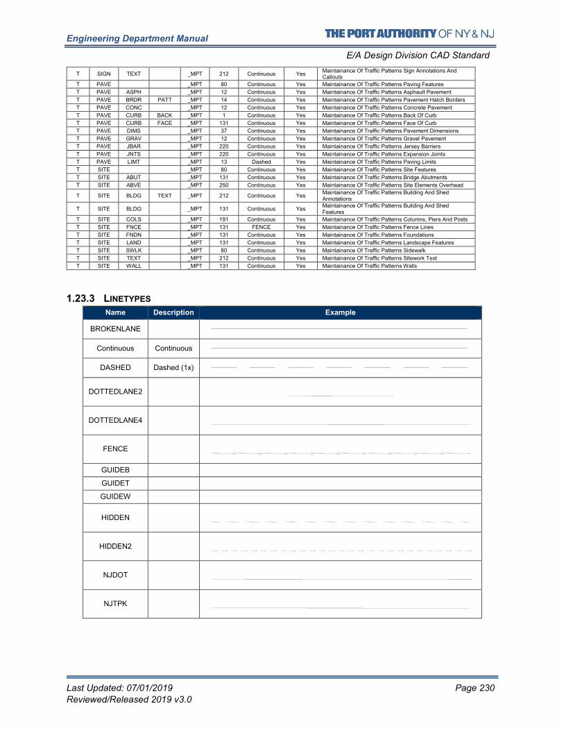
Engineering Department Manual
E/A Design Division CAD Standard
Last Updated: 07/01/2019 Page 230
Reviewed/Released 2019 v3.0
T SIGN TEXT _MPT 212 Continuous Yes Maintainance Of Traffic Patterns Sign Annotations And Callouts
T PAVE _MPT 80 Continuous Yes Maintainance Of Traffic Patterns Paving Features
T PAVE ASPH _MPT 12 Continuous Yes Maintainance Of Traffic Patterns Asphault Pavement
T PAVE BRDR PATT _MPT 14 Continuous Yes Maintainance Of Traffic Patterns Pavement Hatch Borders
T PAVE CONC _MPT 12 Continuous Yes Maintainance Of Traffic Patterns Concrete Pavement
T PAVE CURB BACK _MPT 1 Continuous Yes Maintainance Of Traffic Patterns Back Of Curb
T PAVE CURB FACE _MPT 131 Continuous Yes Maintainance Of Traffic Patterns Face Of Curb
T PAVE DIMS _MPT 37 Continuous Yes Maintainance Of Traffic Patterns Pavement Dimensions
T PAVE GRAV _MPT 12 Continuous Yes Maintainance Of Traffic Patterns Gravel Pavement
T PAVE JBAR _MPT 220 Continuous Yes Maintainance Of Traffic Patterns Jersey Barriers
T PAVE JNTS _MPT 220 Continuous Yes Maintainance Of Traffic Patterns Expansion Joints
T PAVE LIMT _MPT 13 Dashed Yes Maintainance Of Traffic Patterns Paving Limits
T SITE _MPT 80 Continuous Yes Maintainance Of Traffic Patterns Site Features
T SITE ABUT _MPT 131 Continuous Yes Maintainance Of Traffic Patterns Bridge Abutments
T SITE ABVE _MPT 250 Continuous Yes Maintainance Of Traffic Patterns Site Elements Overhead
T SITE BLDG TEXT _MPT 212 Continuous Yes Maintainance Of Traffic Patterns Building And Shed Annotations
T SITE BLDG _MPT 131 Continuous Yes Maintainance Of Traffic Patterns Building And Shed Features
T SITE COLS _MPT 191 Continuous Yes Maintainance Of Traffic Patterns Columns, Piers And Posts
T SITE FNCE _MPT 131 FENCE Yes Maintainance Of Traffic Patterns Fence Lines
T SITE FNDN _MPT 131 Continuous Yes Maintainance Of Traffic Patterns Foundations
T SITE LAND _MPT 131 Continuous Yes Maintainance Of Traffic Patterns Landscape Features
T SITE SWLK _MPT 80 Continuous Yes Maintainance Of Traffic Patterns Sidewalk
T SITE TEXT _MPT 212 Continuous Yes Maintainance Of Traffic Patterns Sitework Text
T SITE WALL _MPT 131 Continuous Yes Maintainance Of Traffic Patterns Walls
1.23.3 LINETYPES
Name Description Example
BROKENLANE
Continuous Continuous
DASHED Dashed (1x)
DOTTEDLANE2
DOTTEDLANE4
FENCE
GUIDEB
GUIDET
GUIDEW
HIDDEN
HIDDEN2
NJDOT
NJTPK
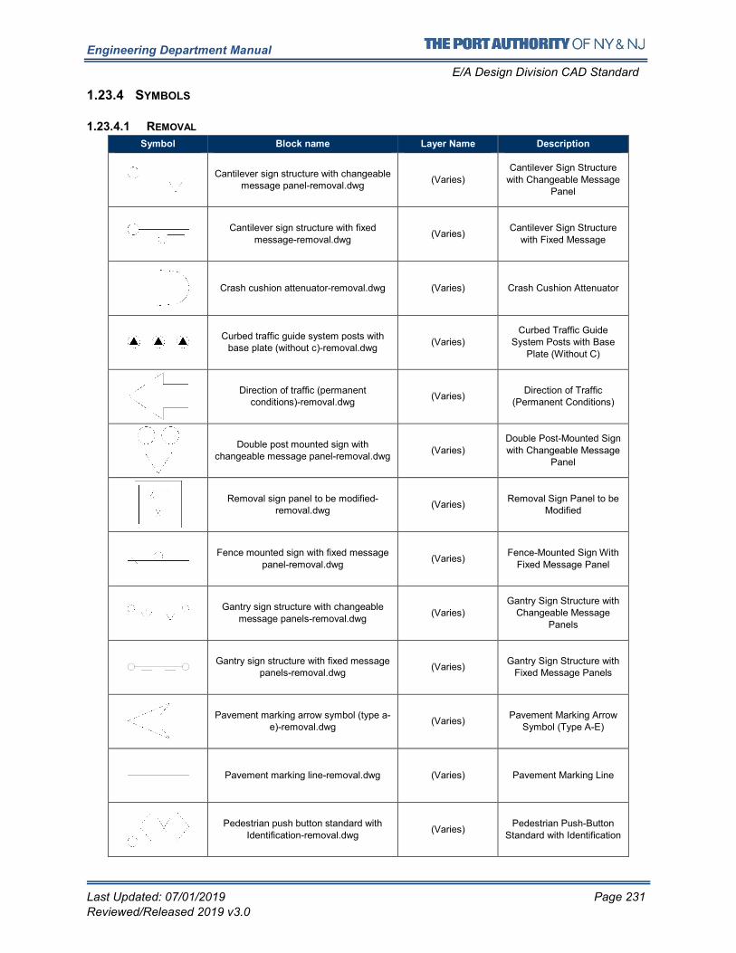
Engineering Department Manual
E/A Design Division CAD Standard
Last Updated: 07/01/2019 Page 231
Reviewed/Released 2019 v3.0
1.23.4 SYMBOLS
1.23.4.1 REMOVAL
Symbol Block name Layer Name Description
Cantilever sign structure with changeable message panel-removal.dwg
(Varies)
Cantilever Sign Structure
with Changeable Message Panel
Cantilever sign structure with fixed
message-removal.dwg (Varies)
Cantilever Sign Structure
with Fixed Message
Crash cushion attenuator-removal.dwg (Varies) Crash Cushion Attenuator
Curbed traffic guide system posts with base plate (without c)-removal.dwg
(Varies) Curbed Traffic Guide
System Posts with Base Plate (Without C)
Direction of traffic (permanent conditions)-removal.dwg
(Varies) Direction of Traffic
(Permanent Conditions)
Double post mounted sign with changeable message panel-removal.dwg
(Varies) Double Post-Mounted Sign with Changeable Message
Panel
Removal sign panel to be modified-removal.dwg
(Varies) Removal Sign Panel to be
Modified
Fence mounted sign with fixed message panel-removal.dwg
(Varies) Fence-Mounted Sign With
Fixed Message Panel
Gantry sign structure with changeable message panels-removal.dwg
(Varies) Gantry Sign Structure with
Changeable Message
Panels
Gantry sign structure with fixed message panels-removal.dwg
(Varies) Gantry Sign Structure with
Fixed Message Panels
Pavement marking arrow symbol (type a-e)-removal.dwg
(Varies) Pavement Marking Arrow
Symbol (Type A-E)
Pavement marking line-removal.dwg (Varies) Pavement Marking Line
Pedestrian push button standard with Identification-removal.dwg
(Varies) Pedestrian Push-Button
Standard with Identification
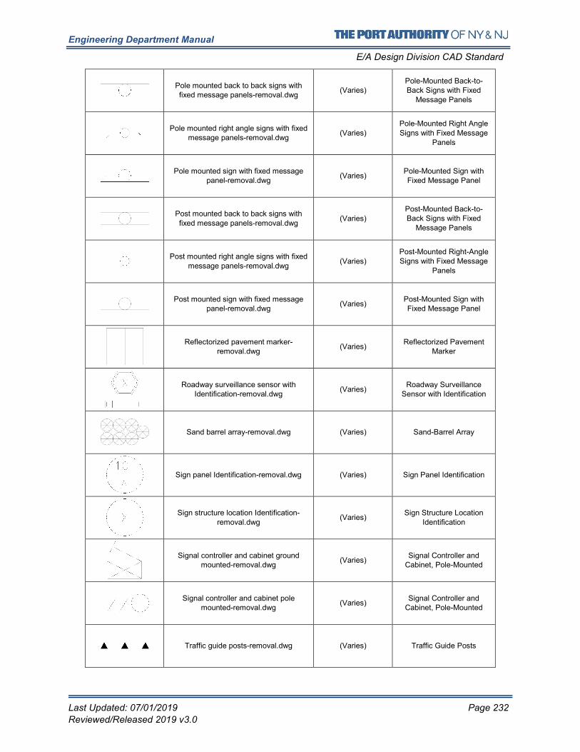
Engineering Department Manual
E/A Design Division CAD Standard
Last Updated: 07/01/2019 Page 232
Reviewed/Released 2019 v3.0
Pole mounted back to back signs with fixed message panels-removal.dwg
(Varies) Pole-Mounted Back-to-Back Signs with Fixed
Message Panels
Pole mounted right angle signs with fixed message panels-removal.dwg
(Varies) Pole-Mounted Right Angle Signs with Fixed Message
Panels
Pole mounted sign with fixed message panel-removal.dwg
(Varies) Pole-Mounted Sign with Fixed Message Panel
Post mounted back to back signs with
fixed message panels-removal.dwg (Varies)
Post-Mounted Back-to-Back Signs with Fixed
Message Panels
Post mounted right angle signs with fixed message panels-removal.dwg
(Varies)
Post-Mounted Right-Angle Signs with Fixed Message
Panels
Post mounted sign with fixed message panel-removal.dwg
(Varies) Post-Mounted Sign with Fixed Message Panel
Reflectorized pavement marker-removal.dwg
(Varies) Reflectorized Pavement
Marker
Roadway surveillance sensor with Identification-removal.dwg
(Varies) Roadway Surveillance
Sensor with Identification
Sand barrel array-removal.dwg (Varies) Sand-Barrel Array
Sign panel Identification-removal.dwg (Varies) Sign Panel Identification
Sign structure location Identification-removal.dwg
(Varies) Sign Structure Location
Identification
Signal controller and cabinet ground mounted-removal.dwg
(Varies) Signal Controller and
Cabinet, Pole-Mounted
Signal controller and cabinet pole mounted-removal.dwg
(Varies) Signal Controller and
Cabinet, Pole-Mounted
Traffic guide posts-removal.dwg (Varies) Traffic Guide Posts
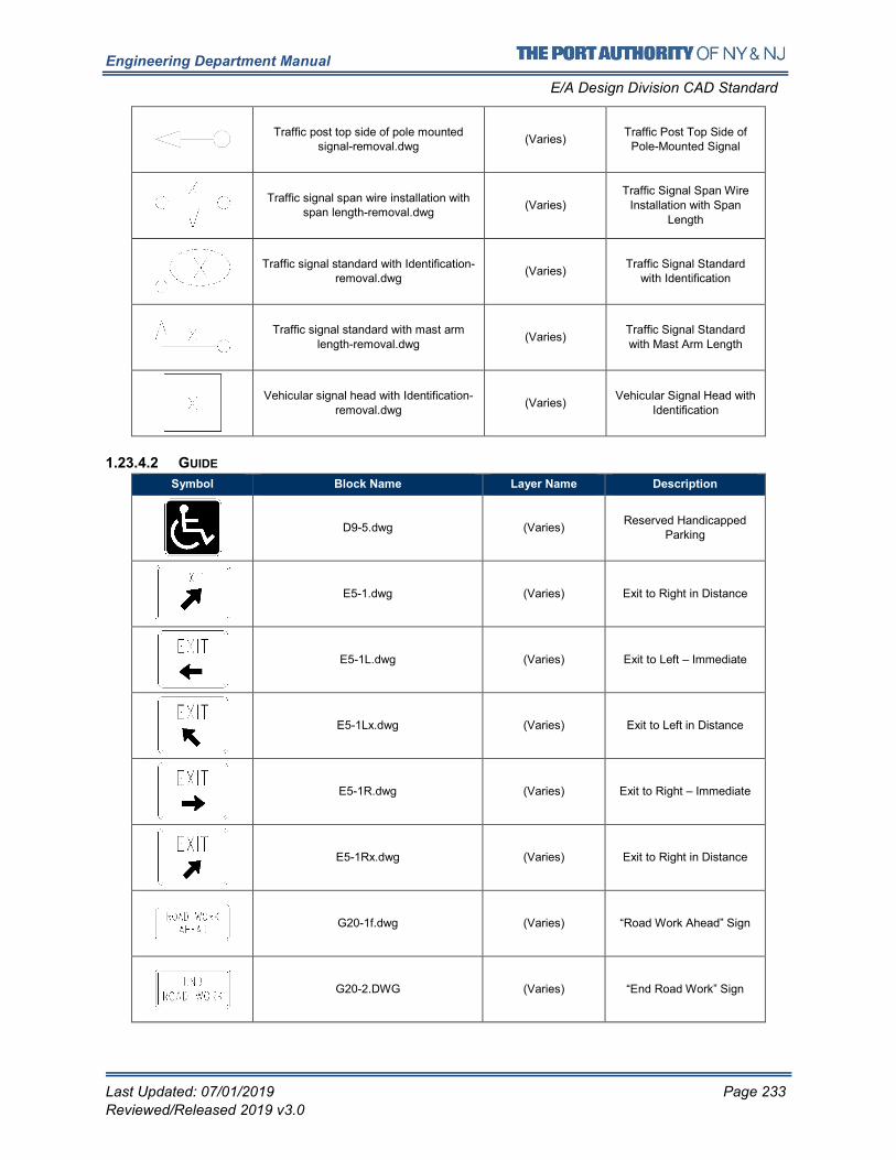
Engineering Department Manual
E/A Design Division CAD Standard
Last Updated: 07/01/2019 Page 233
Reviewed/Released 2019 v3.0
Traffic post top side of pole mounted signal-removal.dwg
(Varies) Traffic Post Top Side of
Pole-Mounted Signal
Traffic signal span wire installation with span length-removal.dwg
(Varies) Traffic Signal Span Wire
Installation with Span
Length
Traffic signal standard with Identification-removal.dwg
(Varies) Traffic Signal Standard
with Identification
Traffic signal standard with mast arm
length-removal.dwg (Varies)
Traffic Signal Standard
with Mast Arm Length
Vehicular signal head with Identification-removal.dwg
(Varies) Vehicular Signal Head with
Identification
1.23.4.2 GUIDE
Symbol Block Name Layer Name Description
D9-5.dwg (Varies) Reserved Handicapped
Parking
E5-1.dwg (Varies) Exit to Right in Distance
E5-1L.dwg (Varies) Exit to Left – Immediate
E5-1Lx.dwg (Varies) Exit to Left in Distance
E5-1R.dwg (Varies) Exit to Right – Immediate
E5-1Rx.dwg (Varies) Exit to Right in Distance
G20-1f.dwg (Varies) “Road Work Ahead” Sign
G20-2.DWG (Varies) “End Road Work” Sign
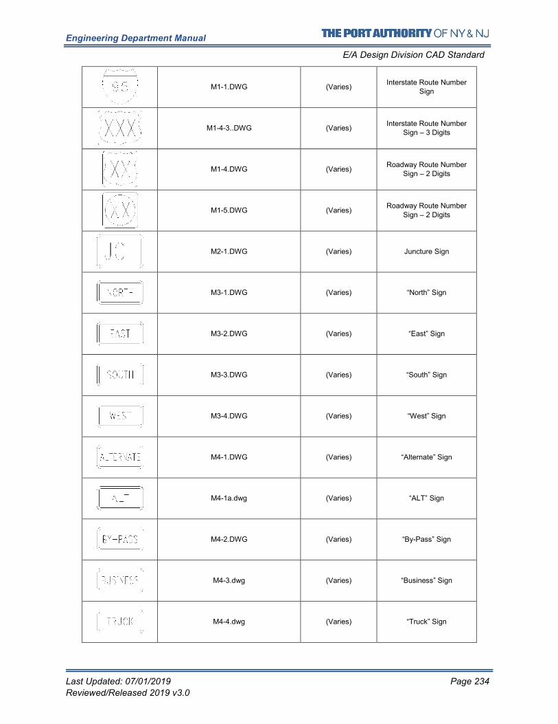
Engineering Department Manual
E/A Design Division CAD Standard
Last Updated: 07/01/2019 Page 234
Reviewed/Released 2019 v3.0
M1-1.DWG (Varies) Interstate Route Number
Sign
M1-4-3..DWG (Varies) Interstate Route Number
Sign – 3 Digits
M1-4.DWG (Varies) Roadway Route Number
Sign – 2 Digits
M1-5.DWG (Varies) Roadway Route Number
Sign – 2 Digits
M2-1.DWG (Varies) Juncture Sign
M3-1.DWG (Varies) “North” Sign
M3-2.DWG (Varies) “East” Sign
M3-3.DWG (Varies) “South” Sign
M3-4.DWG (Varies) “West” Sign
M4-1.DWG (Varies) “Alternate” Sign
M4-1a.dwg (Varies) “ALT” Sign
M4-2.DWG (Varies) “By-Pass” Sign
M4-3.dwg (Varies) “Business” Sign
M4-4.dwg (Varies) “Truck” Sign
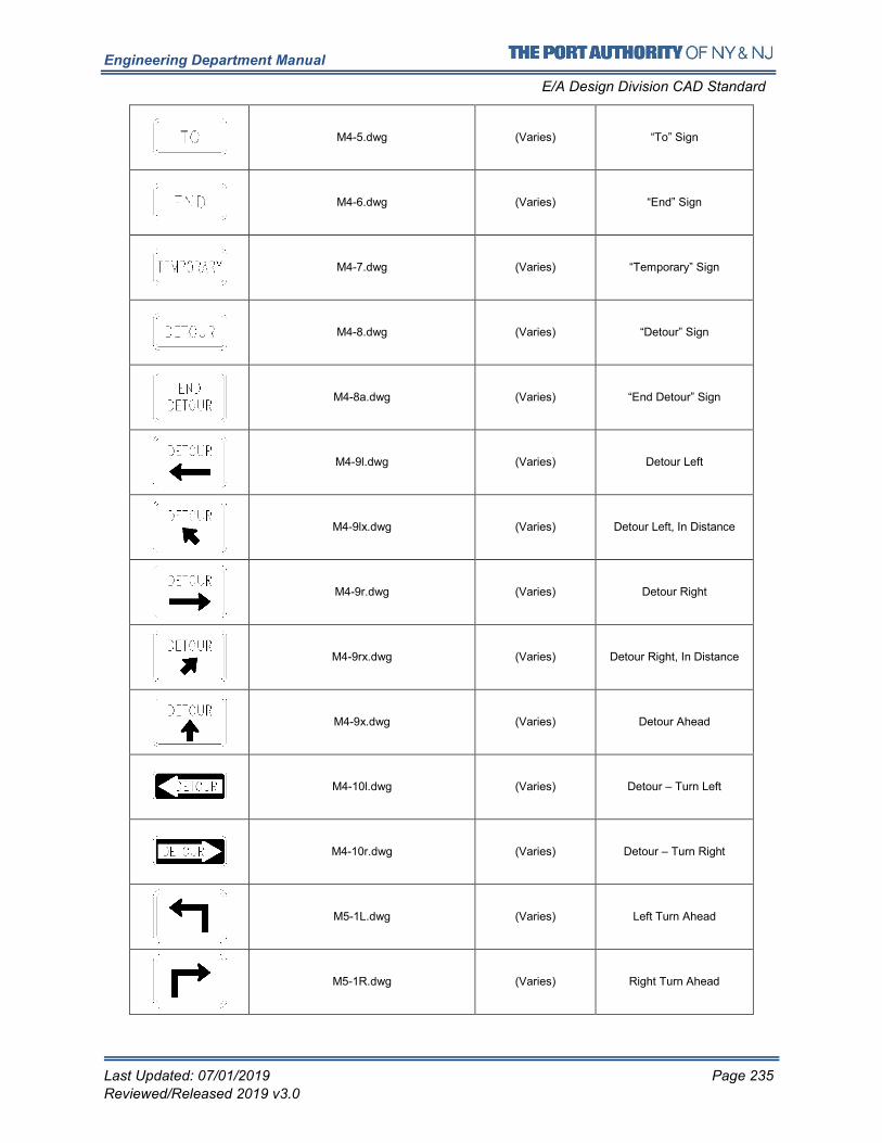
Engineering Department Manual
E/A Design Division CAD Standard
Last Updated: 07/01/2019 Page 235
Reviewed/Released 2019 v3.0
M4-5.dwg (Varies) “To” Sign
M4-6.dwg (Varies) “End” Sign
M4-7.dwg (Varies) “Temporary” Sign
M4-8.dwg (Varies) “Detour” Sign
M4-8a.dwg (Varies) “End Detour” Sign
M4-9l.dwg (Varies) Detour Left
M4-9lx.dwg (Varies) Detour Left, In Distance
M4-9r.dwg (Varies) Detour Right
M4-9rx.dwg (Varies) Detour Right, In Distance
M4-9x.dwg (Varies) Detour Ahead
M4-10l.dwg (Varies) Detour – Turn Left
M4-10r.dwg (Varies) Detour – Turn Right
M5-1L.dwg (Varies) Left Turn Ahead
M5-1R.dwg (Varies) Right Turn Ahead
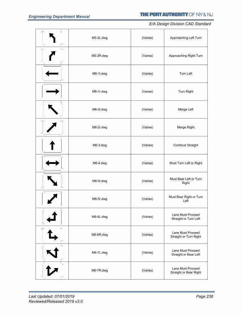
Engineering Department Manual
E/A Design Division CAD Standard
Last Updated: 07/01/2019 Page 236
Reviewed/Released 2019 v3.0
M5-2L.dwg (Varies) Approaching Left Turn
M5-2R.dwg (Varies) Approaching Right Turn
M6-1l.dwg (Varies) Turn Left
M6-1r.dwg (Varies) Turn Right
M6-2l.dwg (Varies) Merge Left
M6-2r.dwg (Varies) Merge Right
M6-3.dwg (Varies) Continue Straight
M6-4.dwg (Varies) Must Turn Left or Right
M6-5l.dwg (Varies) Must Bear Left or Turn
Right
M6-5r.dwg (Varies) Must Bear Right or Turn
Left
M6-6L.dwg (Varies) Lane Must Proceed Straight or Turn Left
M6-6R.dwg (Varies) Lane Must Proceed
Straight or Turn Right
M6-7L.dwg (Varies) Lane Must Proceed Straight or Bear Left
M6-7R.dwg (Varies) Lane Must Proceed
Straight or Bear Right
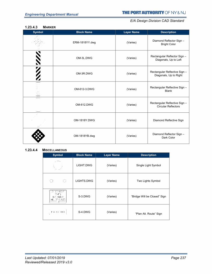
Engineering Department Manual
E/A Design Division CAD Standard
Last Updated: 07/01/2019 Page 237
Reviewed/Released 2019 v3.0
1.23.4.3 MARKER
Symbol Block Name Layer Name Description
ERM-1818YY.dwg (Varies) Diamond Reflector Sign –
Bright Color
OM-3L.DWG (Varies) Rectangular Reflector Sign –
Diagonals, Up to Left
OM-3R.DWG (Varies) Rectangular Reflective Sign –
Diagonals, Up to Right
OM-612-3.DWG (Varies) Rectangular Reflective Sign –
Blank
OM-612.DWG (Varies) Rectangular Reflective Sign –
Circular Reflectors
OM-1818Y.DWG (Varies) Diamond Reflective Sign
OM-1818YB.dwg (Varies) Diamond Reflector Sign –
Dark Color
1.23.4.4 MISCELLANEOUS
Symbol Block Name Layer Name Description
LIGHT.DWG (Varies) Single Light Symbol
LIGHTS.DWG (Varies) Two Lights Symbol
S-3.DWG (Varies) “Bridge Will be Closed” Sign
S-4.DWG (Varies)
“Plan Alt. Route” Sign
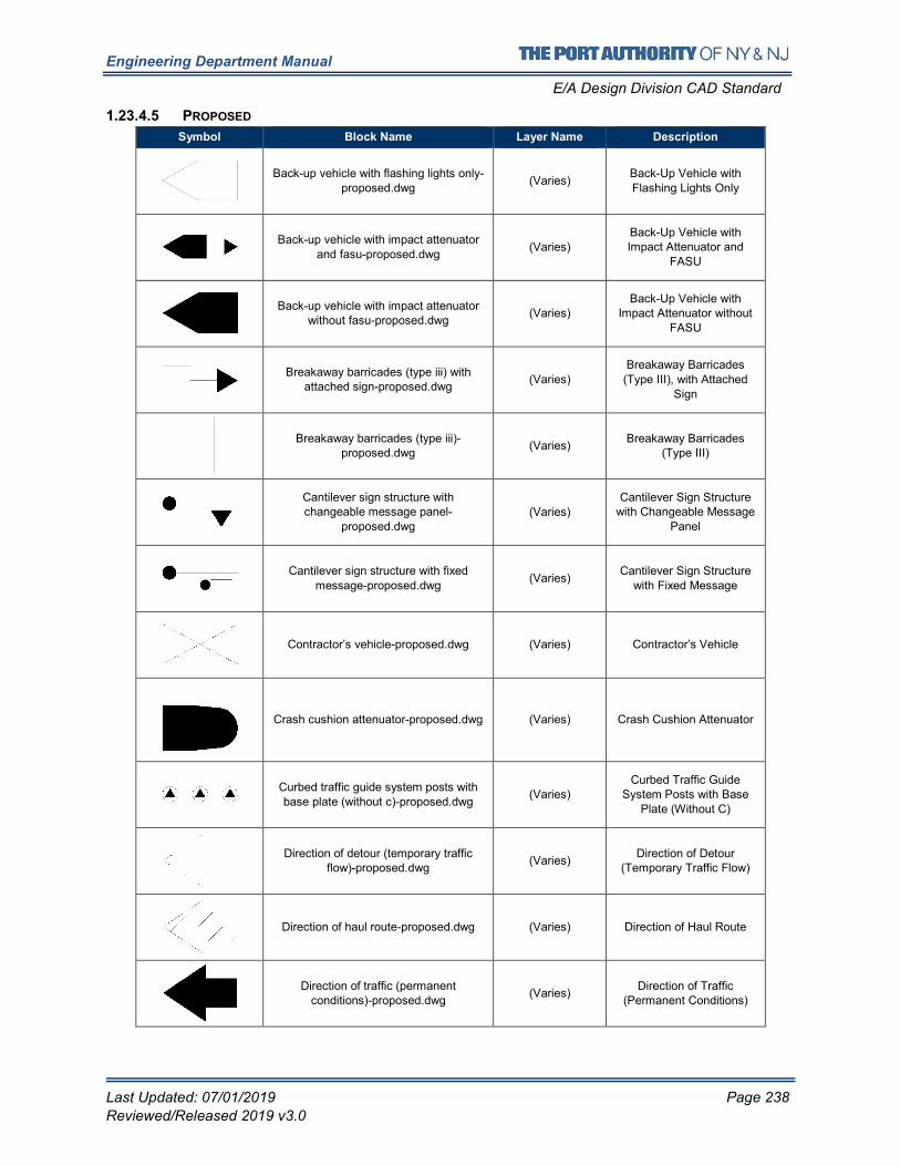
Engineering Department Manual
E/A Design Division CAD Standard
Last Updated: 07/01/2019 Page 238
Reviewed/Released 2019 v3.0
1.23.4.5 PROPOSED
Symbol Block Name Layer Name Description
Back-up vehicle with flashing lights only-
proposed.dwg (Varies)
Back-Up Vehicle with
Flashing Lights Only
Back-up vehicle with impact attenuator
and fasu-proposed.dwg (Varies)
Back-Up Vehicle with Impact Attenuator and
FASU
Back-up vehicle with impact attenuator without fasu-proposed.dwg
(Varies) Back-Up Vehicle with
Impact Attenuator without
FASU
Breakaway barricades (type iii) with attached sign-proposed.dwg
(Varies)
Breakaway Barricades
(Type III), with Attached
Sign
Breakaway barricades (type iii)-proposed.dwg
(Varies) Breakaway Barricades
(Type III)
Cantilever sign structure with changeable message panel-
proposed.dwg (Varies)
Cantilever Sign Structure with Changeable Message
Panel
Cantilever sign structure with fixed message-proposed.dwg
(Varies) Cantilever Sign Structure
with Fixed Message
Contractor’s vehicle-proposed.dwg (Varies) Contractor’s Vehicle
Crash cushion attenuator-proposed.dwg (Varies) Crash Cushion Attenuator
Curbed traffic guide system posts with
base plate (without c)-proposed.dwg (Varies)
Curbed Traffic Guide System Posts with Base
Plate (Without C)
Direction of detour (temporary traffic flow)-proposed.dwg
(Varies) Direction of Detour
(Temporary Traffic Flow)
Direction of haul route-proposed.dwg (Varies) Direction of Haul Route
Direction of traffic (permanent conditions)-proposed.dwg
(Varies) Direction of Traffic
(Permanent Conditions)
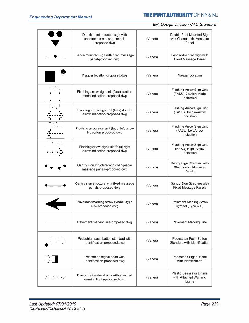
Engineering Department Manual
E/A Design Division CAD Standard
Last Updated: 07/01/2019 Page 239
Reviewed/Released 2019 v3.0
Double post mounted sign with changeable message panel-
proposed.dwg
(Varies) Double Post-Mounted Sign with Changeable Message
Panel
Fence mounted sign with fixed message panel-proposed.dwg
(Varies) Fence-Mounted Sign with
Fixed Message Panel
Flagger location-proposed.dwg (Varies) Flagger Location
Flashing arrow sign unit (fasu) caution
mode indication-proposed.dwg (Varies)
Flashing Arrow Sign Unit (FASU) Caution Mode
Indication
Flashing arrow sign unit (fasu) double arrow indication-proposed.dwg
(Varies)
Flashing Arrow Sign Unit (FASU) Double-Arrow
Indication
Flashing arrow sign unit (fasu) left arrow indication-proposed.dwg
(Varies) Flashing Arrow Sign Unit
(FASU) Left Arrow Indication
Flashing arrow sign unit (fasu) right arrow indication-proposed.dwg
(Varies) Flashing Arrow Sign Unit
(FASU) Right Arrow Indication
Gantry sign structure with changeable message panels-proposed.dwg
(Varies) Gantry Sign Structure with
Changeable Message Panels
Gantry sign structure with fixed message panels-proposed.dwg
(Varies) Gantry Sign Structure with
Fixed Message Panels
Pavement marking arrow symbol (type a-e)-proposed.dwg
(Varies) Pavement Marking Arrow
Symbol (Type A-E)
Pavement marking line-proposed.dwg (Varies) Pavement Marking Line
Pedestrian push button standard with Identification-proposed.dwg
(Varies) Pedestrian Push-Button
Standard with Identification
Pedestrian signal head with Identification-proposed.dwg
(Varies) Pedestrian Signal Head
with Identification
Plastic delineator drums with attached warning lights-proposed.dwg
(Varies) Plastic Delineator Drums with Attached Warning
Lights
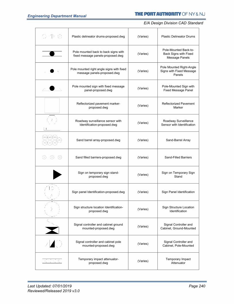
Engineering Department Manual
E/A Design Division CAD Standard
Last Updated: 07/01/2019 Page 240
Reviewed/Released 2019 v3.0
Plastic delineator drums-proposed.dwg (Varies) Plastic Delineator Drums
Pole mounted back to back signs with fixed message panels-proposed.dwg
(Varies) Pole-Mounted Back-to-Back Signs with Fixed
Message Panels
Pole mounted right angle signs with fixed message panels-proposed.dwg
(Varies)
Pole Mounted Right-Angle
Signs with Fixed Message Panels
Pole mounted sign with fixed message
panel-proposed.dwg (Varies)
Pole-Mounted Sign with
Fixed Message Panel
Reflectorized pavement marker-proposed.dwg
(Varies) Reflectorized Pavement
Marker
Roadway surveillance sensor with Identification-proposed.dwg
(Varies) Roadway Surveillance
Sensor with Identification
Sand barrel array-proposed.dwg (Varies) Sand-Barrel Array
Sand filled barriers-proposed.dwg (Varies) Sand-Filled Barriers
Sign on temporary sign stand-proposed.dwg
(Varies) Sign on Temporary Sign
Stand
Sign panel Identification-proposed.dwg (Varies) Sign Panel Identification
Sign structure location Identification-proposed.dwg
(Varies) Sign Structure Location
Identification
Signal controller and cabinet ground mounted-proposed.dwg
(Varies) Signal Controller and
Cabinet, Ground-Mounted
Signal controller and cabinet pole mounted-proposed.dwg
(Varies) Signal Controller and
Cabinet, Pole-Mounted
Temporary impact attenuator-proposed.dwg
(Varies) Temporary Impact
Attenuator
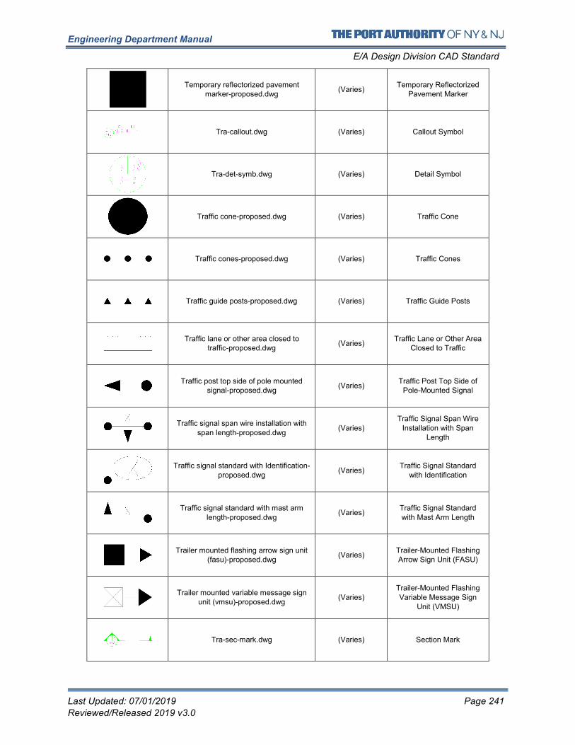
Engineering Department Manual
E/A Design Division CAD Standard
Last Updated: 07/01/2019 Page 241
Reviewed/Released 2019 v3.0
Temporary reflectorized pavement marker-proposed.dwg
(Varies) Temporary Reflectorized
Pavement Marker
Tra-callout.dwg (Varies) Callout Symbol
Tra-det-symb.dwg (Varies) Detail Symbol
Traffic cone-proposed.dwg (Varies) Traffic Cone
Traffic cones-proposed.dwg (Varies) Traffic Cones
Traffic guide posts-proposed.dwg (Varies) Traffic Guide Posts
Traffic lane or other area closed to traffic-proposed.dwg
(Varies) Traffic Lane or Other Area
Closed to Traffic
Traffic post top side of pole mounted signal-proposed.dwg
(Varies) Traffic Post Top Side of
Pole-Mounted Signal
Traffic signal span wire installation with span length-proposed.dwg
(Varies) Traffic Signal Span Wire
Installation with Span Length
Traffic signal standard with Identification-proposed.dwg
(Varies) Traffic Signal Standard
with Identification
Traffic signal standard with mast arm length-proposed.dwg
(Varies) Traffic Signal Standard
with Mast Arm Length
Trailer mounted flashing arrow sign unit (fasu)-proposed.dwg
(Varies) Trailer-Mounted Flashing Arrow Sign Unit (FASU)
Trailer mounted variable message sign unit (vmsu)-proposed.dwg
(Varies) Trailer-Mounted Flashing Variable Message Sign
Unit (VMSU)
Tra-sec-mark.dwg (Varies) Section Mark
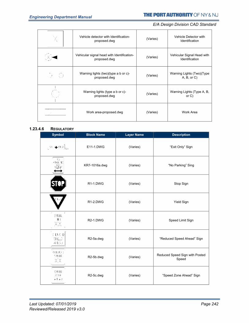
Engineering Department Manual
E/A Design Division CAD Standard
Last Updated: 07/01/2019 Page 242
Reviewed/Released 2019 v3.0
Vehicle detector with Identification-proposed.dwg
(Varies) Vehicle Detector with
Identification
Vehicular signal head with Identification-proposed.dwg
(Varies) Vehicular Signal Head with
Identification
Warning lights (two)(type a b or c)-proposed.dwg
(Varies) Warning Lights (Two)(Type
A, B, or C)
Warning lights (type a b or c)-
proposed.dwg (Varies)
Warning Lights (Type A, B,
or C)
Work area-proposed.dwg (Varies) Work Area
1.23.4.6 REGULATORY
Symbol Block Name Layer Name Description
E11-1.DWG (Varies) “Exit Only” Sign
KR7-1016a.dwg (Varies) “No Parking” Sing
R1-1.DWG (Varies) Stop Sign
R1-2.DWG (Varies) Yield Sign
R2-1.DWG (Varies) Speed Limit Sign
R2-5a.dwg (Varies) “Reduced Speed Ahead” Sign
R2-5b.dwg (Varies) Reduced Speed Sign with Posted
Speed
R2-5c.dwg (Varies) “Speed Zone Ahead” Sign
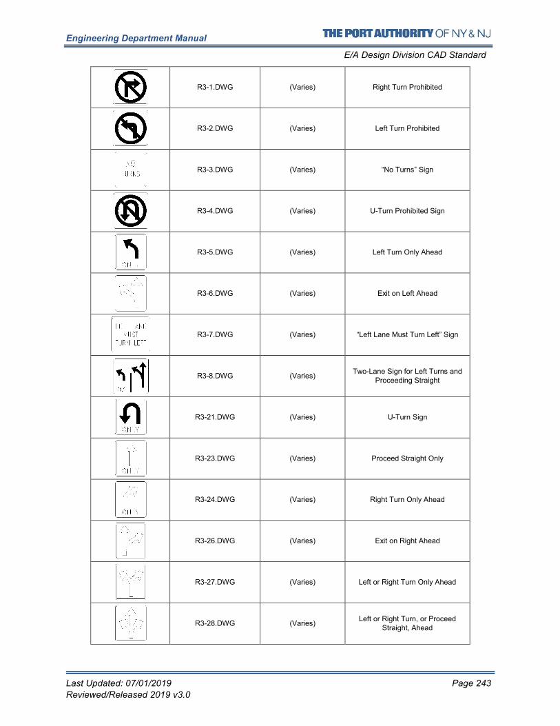
Engineering Department Manual
E/A Design Division CAD Standard
Last Updated: 07/01/2019 Page 243
Reviewed/Released 2019 v3.0
R3-1.DWG (Varies) Right Turn Prohibited
R3-2.DWG (Varies) Left Turn Prohibited
R3-3.DWG (Varies) “No Turns” Sign
R3-4.DWG (Varies) U-Turn Prohibited Sign
R3-5.DWG (Varies) Left Turn Only Ahead
R3-6.DWG (Varies) Exit on Left Ahead
R3-7.DWG (Varies) “Left Lane Must Turn Left” Sign
R3-8.DWG (Varies) Two-Lane Sign for Left Turns and
Proceeding Straight
R3-21.DWG (Varies) U-Turn Sign
R3-23.DWG (Varies) Proceed Straight Only
R3-24.DWG (Varies) Right Turn Only Ahead
R3-26.DWG (Varies) Exit on Right Ahead
R3-27.DWG (Varies) Left or Right Turn Only Ahead
R3-28.DWG (Varies) Left or Right Turn, or Proceed
Straight, Ahead
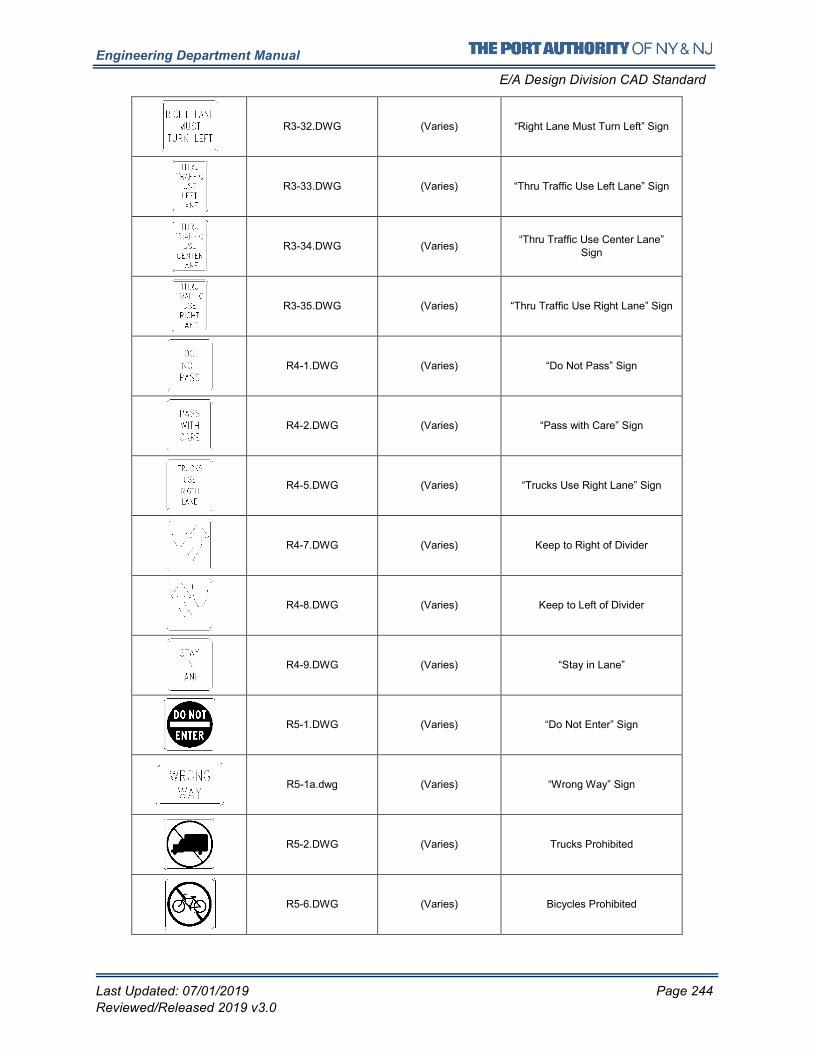
Engineering Department Manual
E/A Design Division CAD Standard
Last Updated: 07/01/2019 Page 244
Reviewed/Released 2019 v3.0
R3-32.DWG (Varies) “Right Lane Must Turn Left” Sign
R3-33.DWG (Varies) “Thru Traffic Use Left Lane” Sign
R3-34.DWG (Varies) “Thru Traffic Use Center Lane”
Sign
R3-35.DWG (Varies) “Thru Traffic Use Right Lane” Sign
R4-1.DWG (Varies) “Do Not Pass” Sign
R4-2.DWG (Varies) “Pass with Care” Sign
R4-5.DWG (Varies) “Trucks Use Right Lane” Sign
R4-7.DWG (Varies) Keep to Right of Divider
R4-8.DWG (Varies) Keep to Left of Divider
R4-9.DWG (Varies) “Stay in Lane”
R5-1.DWG (Varies) “Do Not Enter” Sign
R5-1a.dwg (Varies) “Wrong Way” Sign
R5-2.DWG (Varies) Trucks Prohibited
R5-6.DWG (Varies) Bicycles Prohibited
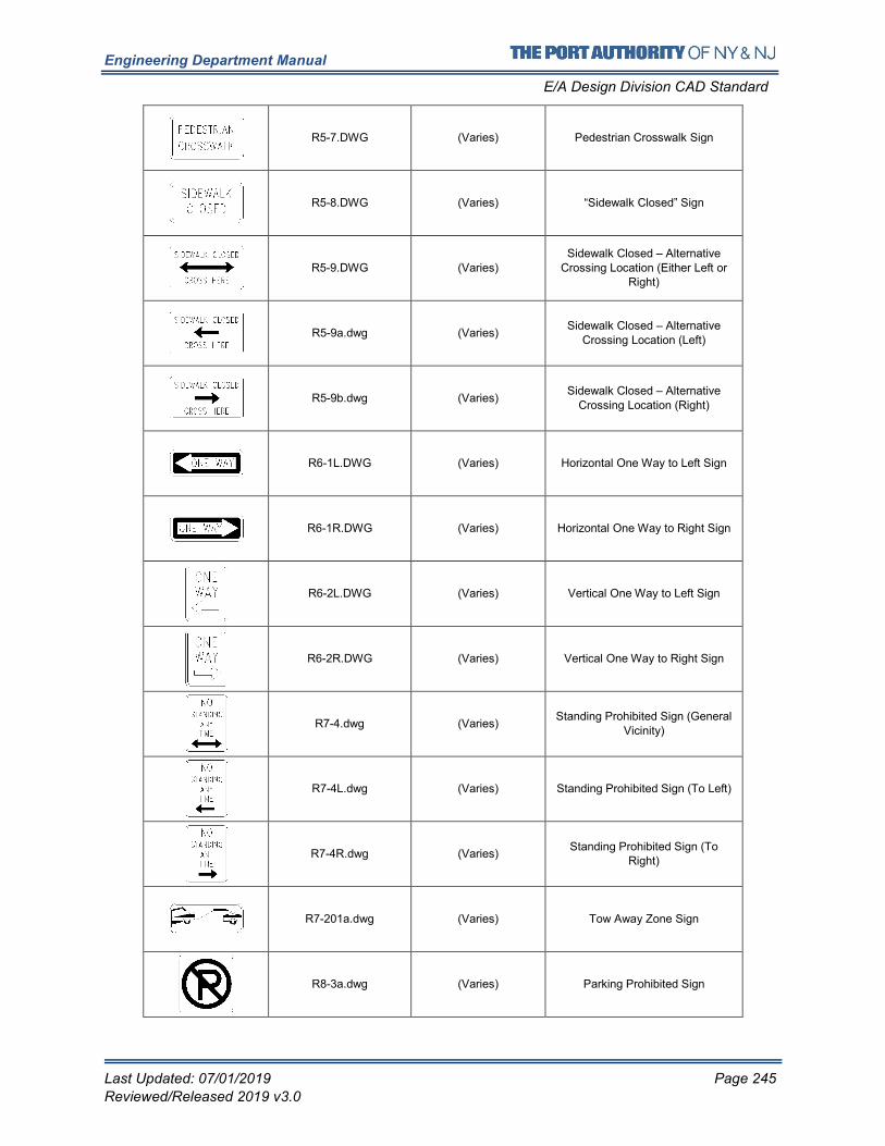
Engineering Department Manual
E/A Design Division CAD Standard
Last Updated: 07/01/2019 Page 245
Reviewed/Released 2019 v3.0
R5-7.DWG (Varies) Pedestrian Crosswalk Sign
R5-8.DWG (Varies) “Sidewalk Closed” Sign
R5-9.DWG (Varies)
Sidewalk Closed – Alternative
Crossing Location (Either Left or Right)
R5-9a.dwg (Varies) Sidewalk Closed – Alternative
Crossing Location (Left)
R5-9b.dwg (Varies) Sidewalk Closed – Alternative
Crossing Location (Right)
R6-1L.DWG (Varies) Horizontal One Way to Left Sign
R6-1R.DWG (Varies) Horizontal One Way to Right Sign
R6-2L.DWG (Varies) Vertical One Way to Left Sign
R6-2R.DWG (Varies) Vertical One Way to Right Sign
R7-4.dwg (Varies) Standing Prohibited Sign (General
Vicinity)
R7-4L.dwg (Varies) Standing Prohibited Sign (To Left)
R7-4R.dwg (Varies) Standing Prohibited Sign (To
Right)
R7-201a.dwg (Varies) Tow Away Zone Sign
R8-3a.dwg (Varies) Parking Prohibited Sign
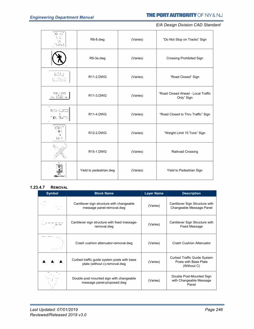
Engineering Department Manual
E/A Design Division CAD Standard
Last Updated: 07/01/2019 Page 246
Reviewed/Released 2019 v3.0
R8-8.dwg (Varies) “Do Not Stop on Tracks” Sign
R9-3a.dwg (Varies) Crossing Prohibited Sign
R11-2.DWG (Varies) “Road Closed” Sign
R11-3.DWG (Varies) “Road Closed Ahead - Local Traffic
Only” Sign
R11-4.DWG (Varies) “Road Closed to Thru Traffic” Sign
R12-2.DWG (Varies) “Weight Limit 10 Tons” Sign
R15-1.DWG (Varies) Railroad Crossing
Yield to pedestrian.dwg (Varies) Yield to Pedestrian Sign
1.23.4.7 REMOVAL
Symbol Block Name Layer Name Description
Cantilever sign structure with changeable message panel-removal.dwg
(Varies) Cantilever Sign Structure with Changeable Message Panel
Cantilever sign structure with fixed message-removal.dwg
(Varies) Cantilever Sign Structure with
Fixed Message
Crash cushion attenuator-removal.dwg (Varies) Crash Cushion Attenuator
Curbed traffic guide system posts with base plate (without c)-removal.dwg
(Varies)
Curbed Traffic Guide System
Posts with Base Plate (Without C)
Double post mounted sign with changeable message panel-proposed.dwg
(Varies)
Double Post-Mounted Sign with Changeable Message
Panel
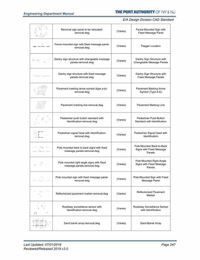
Engineering Department Manual
E/A Design Division CAD Standard
Last Updated: 07/01/2019 Page 247
Reviewed/Released 2019 v3.0
Removal sign panel to be relocated-removal.dwg
(Varies) Fence-Mounted Sign with
Fixed Message Panel
Fence mounted sign with fixed message panel-removal.dwg
(Varies) Flagger Location
Gantry sign structure with changeable message panels-removal.dwg
(Varies) Gantry Sign Structure with
Changeable Message Panels
Gantry sign structure with fixed message
panels-removal.dwg (Varies)
Gantry Sign Structure with
Fixed Message Panels
Pavement marking arrow symbol (type a-e)-removal.dwg
(Varies) Pavement Marking Arrow
Symbol (Type A-E)
Pavement marking line-removal.dwg (Varies) Pavement Marking Line
Pedestrian push button standard with Identification-removal.dwg
(Varies) Pedestrian Push-Button
Standard with Identification
Pedestrian signal head with Identification-removal.dwg
(Varies) Pedestrian Signal Head with
Identification
Pole mounted back to back signs with fixed message panels-removal.dwg
(Varies) Pole-Mounted Back-to-Back Signs with Fixed Message
Panels
Pole mounted right angle signs with fixed message panels-removal.dwg
(Varies) Pole Mounted Right-Angle Signs with Fixed Message
Panels
Pole mounted sign with fixed message panel-removal.dwg
(Varies) Pole-Mounted Sign with Fixed
Message Panel
Reflectorized pavement marker-removal.dwg (Varies) Reflectorized Pavement
Marker
Roadway surveillance sensor with Identification-removal.dwg
(Varies) Roadway Surveillance Sensor
with Identification
Sand barrel array-removal.dwg (Varies) Sand-Barrel Array
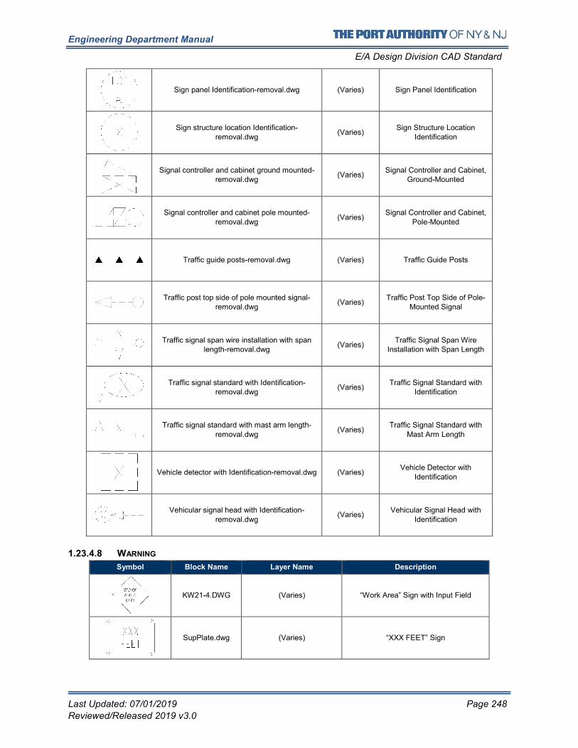
Engineering Department Manual
E/A Design Division CAD Standard
Last Updated: 07/01/2019 Page 248
Reviewed/Released 2019 v3.0
Sign panel Identification-removal.dwg (Varies) Sign Panel Identification
Sign structure location Identification-removal.dwg
(Varies) Sign Structure Location
Identification
Signal controller and cabinet ground mounted-removal.dwg
(Varies) Signal Controller and Cabinet,
Ground-Mounted
Signal controller and cabinet pole mounted-
removal.dwg (Varies)
Signal Controller and Cabinet,
Pole-Mounted
Traffic guide posts-removal.dwg (Varies) Traffic Guide Posts
Traffic post top side of pole mounted signal-removal.dwg
(Varies) Traffic Post Top Side of Pole-
Mounted Signal
Traffic signal span wire installation with span length-removal.dwg
(Varies) Traffic Signal Span Wire
Installation with Span Length
Traffic signal standard with Identification-removal.dwg
(Varies) Traffic Signal Standard with
Identification
Traffic signal standard with mast arm length-removal.dwg
(Varies) Traffic Signal Standard with
Mast Arm Length
Vehicle detector with Identification-removal.dwg (Varies) Vehicle Detector with
Identification
Vehicular signal head with Identification-removal.dwg
(Varies) Vehicular Signal Head with
Identification
1.23.4.8 WARNING
Symbol Block Name Layer Name Description
KW21-4.DWG (Varies) “Work Area” Sign with Input Field
SupPlate.dwg (Varies) “XXX FEET” Sign
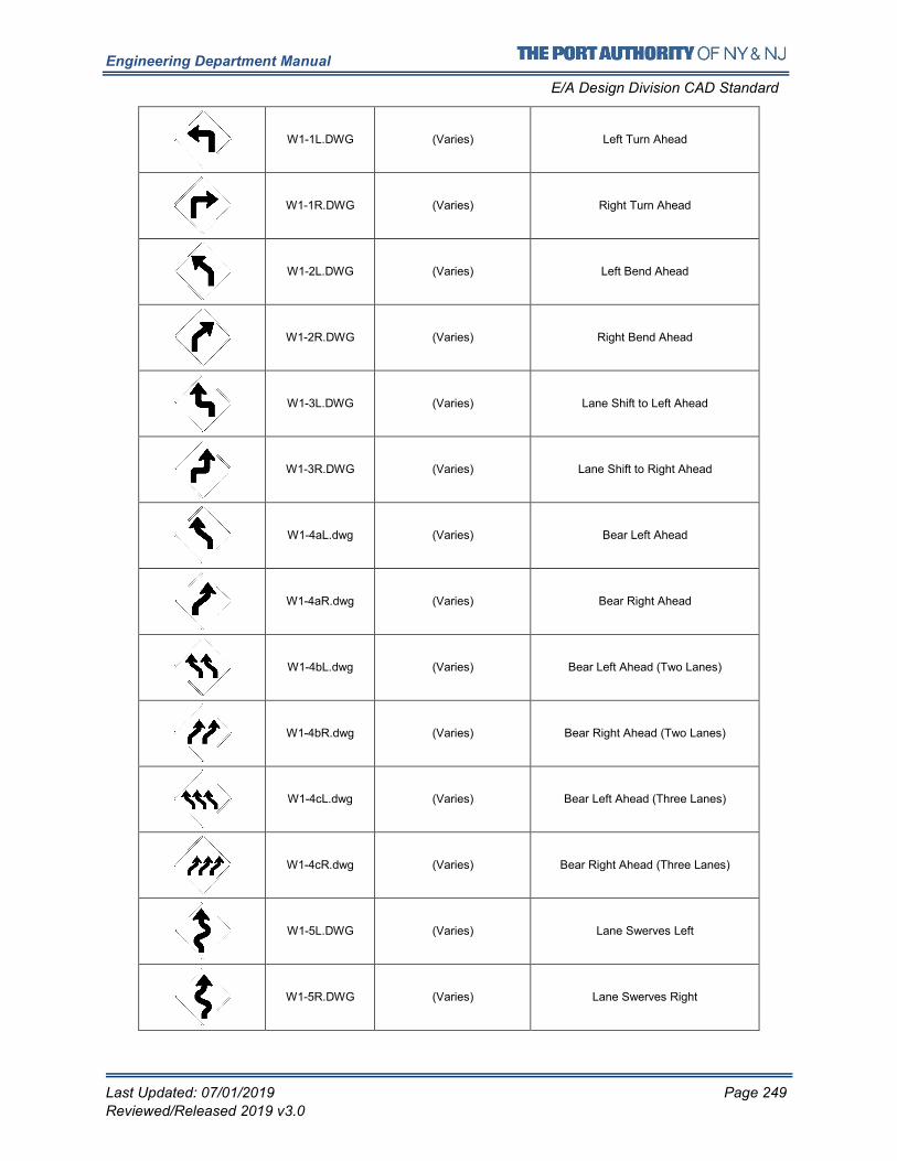
Engineering Department Manual
E/A Design Division CAD Standard
Last Updated: 07/01/2019 Page 249
Reviewed/Released 2019 v3.0
W1-1L.DWG (Varies) Left Turn Ahead
W1-1R.DWG (Varies) Right Turn Ahead
W1-2L.DWG (Varies) Left Bend Ahead
W1-2R.DWG (Varies) Right Bend Ahead
W1-3L.DWG (Varies) Lane Shift to Left Ahead
W1-3R.DWG (Varies) Lane Shift to Right Ahead
W1-4aL.dwg (Varies) Bear Left Ahead
W1-4aR.dwg (Varies) Bear Right Ahead
W1-4bL.dwg (Varies) Bear Left Ahead (Two Lanes)
W1-4bR.dwg (Varies) Bear Right Ahead (Two Lanes)
W1-4cL.dwg (Varies) Bear Left Ahead (Three Lanes)
W1-4cR.dwg (Varies) Bear Right Ahead (Three Lanes)
W1-5L.DWG (Varies) Lane Swerves Left
W1-5R.DWG (Varies) Lane Swerves Right
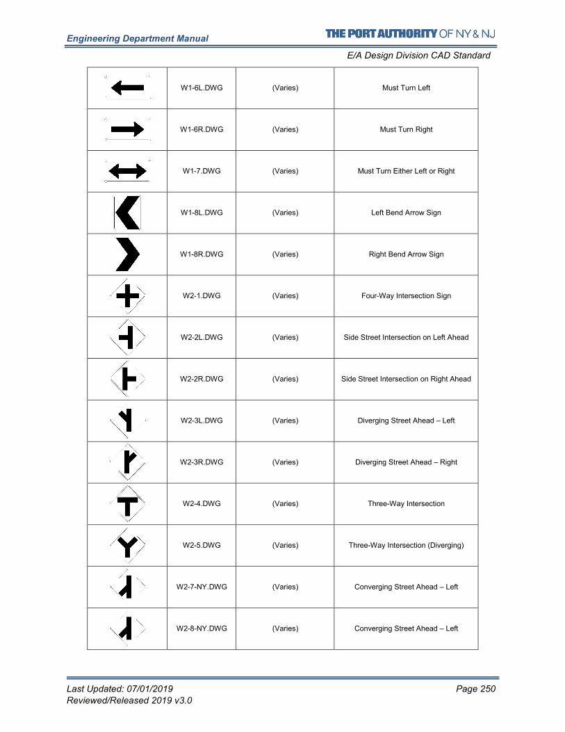
Engineering Department Manual
E/A Design Division CAD Standard
Last Updated: 07/01/2019 Page 250
Reviewed/Released 2019 v3.0
W1-6L.DWG (Varies) Must Turn Left
W1-6R.DWG (Varies) Must Turn Right
W1-7.DWG (Varies) Must Turn Either Left or Right
W1-8L.DWG (Varies) Left Bend Arrow Sign
W1-8R.DWG (Varies) Right Bend Arrow Sign
W2-1.DWG (Varies) Four-Way Intersection Sign
W2-2L.DWG (Varies) Side Street Intersection on Left Ahead
W2-2R.DWG (Varies) Side Street Intersection on Right Ahead
W2-3L.DWG (Varies) Diverging Street Ahead – Left
W2-3R.DWG (Varies) Diverging Street Ahead – Right
W2-4.DWG (Varies) Three-Way Intersection
W2-5.DWG (Varies) Three-Way Intersection (Diverging)
W2-7-NY.DWG (Varies) Converging Street Ahead – Left
W2-8-NY.DWG (Varies) Converging Street Ahead – Left
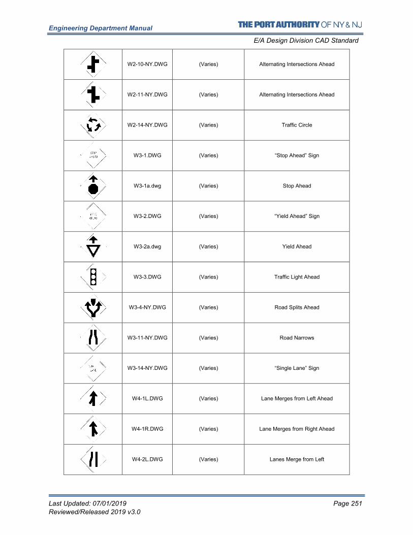
Engineering Department Manual
E/A Design Division CAD Standard
Last Updated: 07/01/2019 Page 251
Reviewed/Released 2019 v3.0
W2-10-NY.DWG (Varies) Alternating Intersections Ahead
W2-11-NY.DWG (Varies) Alternating Intersections Ahead
W2-14-NY.DWG (Varies) Traffic Circle
W3-1.DWG (Varies) “Stop Ahead” Sign
W3-1a.dwg (Varies) Stop Ahead
W3-2.DWG (Varies) “Yield Ahead” Sign
W3-2a.dwg (Varies) Yield Ahead
W3-3.DWG (Varies) Traffic Light Ahead
W3-4-NY.DWG (Varies) Road Splits Ahead
W3-11-NY.DWG (Varies) Road Narrows
W3-14-NY.DWG (Varies) “Single Lane” Sign
W4-1L.DWG (Varies) Lane Merges from Left Ahead
W4-1R.DWG (Varies) Lane Merges from Right Ahead
W4-2L.DWG (Varies) Lanes Merge from Left
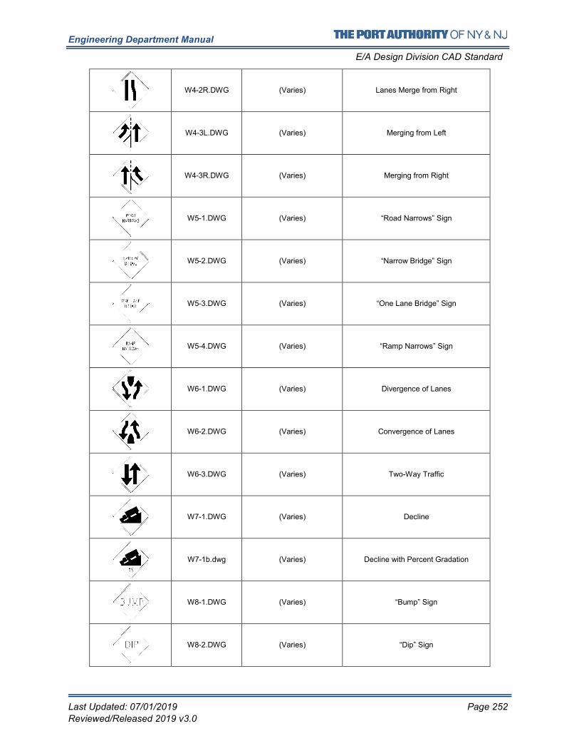
Engineering Department Manual
E/A Design Division CAD Standard
Last Updated: 07/01/2019 Page 252
Reviewed/Released 2019 v3.0
W4-2R.DWG (Varies) Lanes Merge from Right
W4-3L.DWG (Varies) Merging from Left
W4-3R.DWG (Varies) Merging from Right
W5-1.DWG (Varies) “Road Narrows” Sign
W5-2.DWG (Varies) “Narrow Bridge” Sign
W5-3.DWG (Varies) “One Lane Bridge” Sign
W5-4.DWG (Varies) “Ramp Narrows” Sign
W6-1.DWG (Varies) Divergence of Lanes
W6-2.DWG (Varies) Convergence of Lanes
W6-3.DWG (Varies) Two-Way Traffic
W7-1.DWG (Varies) Decline
W7-1b.dwg (Varies) Decline with Percent Gradation
W8-1.DWG (Varies) “Bump” Sign
W8-2.DWG (Varies) “Dip” Sign
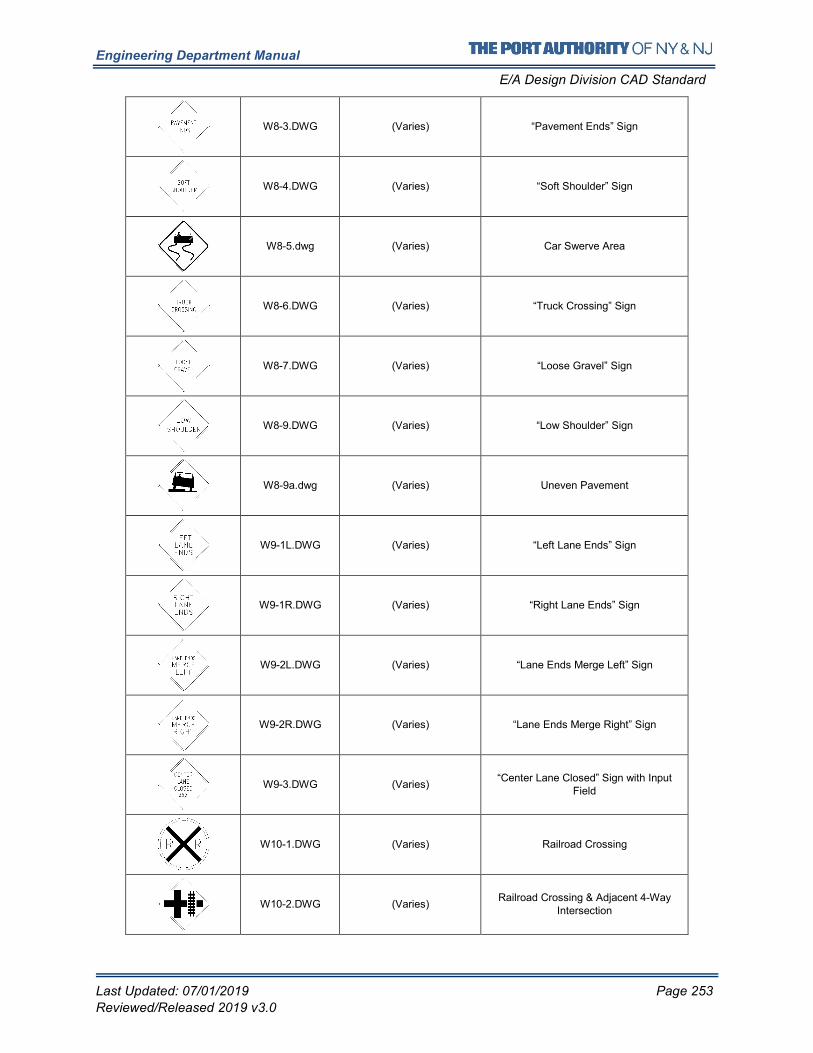
Engineering Department Manual
E/A Design Division CAD Standard
Last Updated: 07/01/2019 Page 253
Reviewed/Released 2019 v3.0
W8-3.DWG (Varies) “Pavement Ends” Sign
W8-4.DWG (Varies) “Soft Shoulder” Sign
W8-5.dwg (Varies) Car Swerve Area
W8-6.DWG (Varies) “Truck Crossing” Sign
W8-7.DWG (Varies) “Loose Gravel” Sign
W8-9.DWG (Varies) “Low Shoulder” Sign
W8-9a.dwg (Varies) Uneven Pavement
W9-1L.DWG (Varies) “Left Lane Ends” Sign
W9-1R.DWG (Varies) “Right Lane Ends” Sign
W9-2L.DWG (Varies) “Lane Ends Merge Left” Sign
W9-2R.DWG (Varies) “Lane Ends Merge Right” Sign
W9-3.DWG (Varies) “Center Lane Closed” Sign with Input
Field
W10-1.DWG (Varies) Railroad Crossing
W10-2.DWG (Varies) Railroad Crossing & Adjacent 4-Way
Intersection
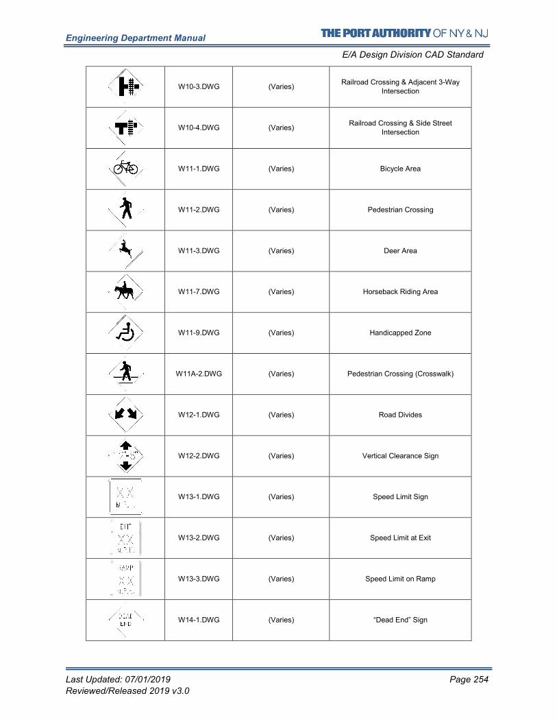
Engineering Department Manual
E/A Design Division CAD Standard
Last Updated: 07/01/2019 Page 254
Reviewed/Released 2019 v3.0
W10-3.DWG (Varies) Railroad Crossing & Adjacent 3-Way
Intersection
W10-4.DWG (Varies) Railroad Crossing & Side Street
Intersection
W11-1.DWG (Varies) Bicycle Area
W11-2.DWG (Varies) Pedestrian Crossing
W11-3.DWG (Varies) Deer Area
W11-7.DWG (Varies) Horseback Riding Area
W11-9.DWG (Varies) Handicapped Zone
W11A-2.DWG (Varies) Pedestrian Crossing (Crosswalk)
W12-1.DWG (Varies) Road Divides
W12-2.DWG (Varies) Vertical Clearance Sign
W13-1.DWG (Varies) Speed Limit Sign
W13-2.DWG (Varies) Speed Limit at Exit
W13-3.DWG (Varies) Speed Limit on Ramp
W14-1.DWG (Varies) “Dead End” Sign
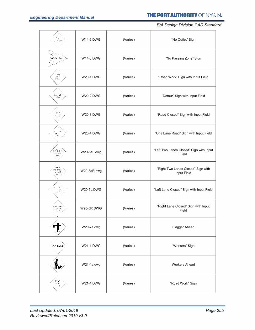
Engineering Department Manual
E/A Design Division CAD Standard
Last Updated: 07/01/2019 Page 255
Reviewed/Released 2019 v3.0
W14-2.DWG (Varies) “No Outlet” Sign
W14-3.DWG (Varies) “No Passing Zone” Sign
W20-1.DWG (Varies) “Road Work” Sign with Input Field
W20-2.DWG (Varies) “Detour” Sign with Input Field
W20-3.DWG (Varies) “Road Closed” Sign with Input Field
W20-4.DWG (Varies) “One Lane Road” Sign with Input Field
W20-5aL.dwg (Varies) “Left Two Lanes Closed” Sign with Input
Field
W20-5aR.dwg (Varies) “Right Two Lanes Closed” Sign with
Input Field
W20-5L.DWG (Varies) “Left Lane Closed” Sign with Input Field
W20-5R.DWG (Varies) “Right Lane Closed” Sign with Input
Field
W20-7a.dwg (Varies) Flagger Ahead
W21-1.DWG (Varies) “Workers” Sign
W21-1a.dwg (Varies) Workers Ahead
W21-4.DWG (Varies) “Road Work” Sign
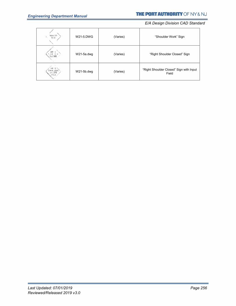
Engineering Department Manual
E/A Design Division CAD Standard
Last Updated: 07/01/2019 Page 256
Reviewed/Released 2019 v3.0
W21-5.DWG (Varies) “Shoulder Work” Sign
W21-5a.dwg (Varies) “Right Shoulder Closed” Sign
W21-5b.dwg (Varies) “Right Shoulder Closed” Sign with Input
Field
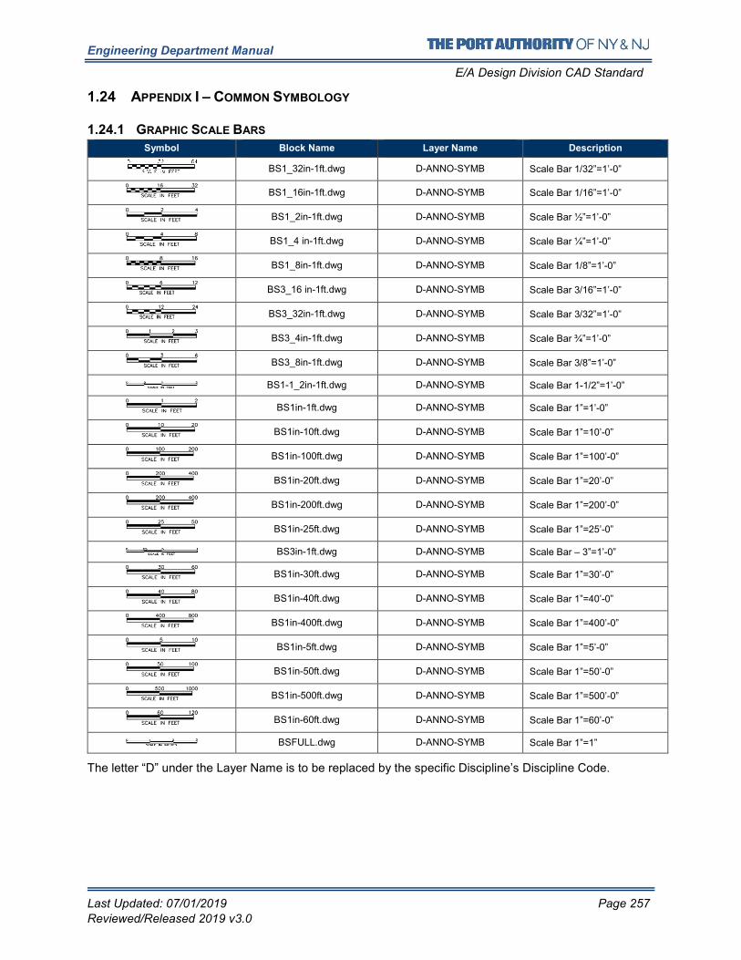
Engineering Department Manual
E/A Design Division CAD Standard
Last Updated: 07/01/2019 Page 257
Reviewed/Released 2019 v3.0
1.24 APPENDIX I – COMMON SYMBOLOGY
1.24.1 GRAPHIC SCALE BARS
Symbol Block Name Layer Name Description
BS1_32in-1ft.dwg D-ANNO-SYMB Scale Bar 1/32”=1’-0”
BS1_16in-1ft.dwg D-ANNO-SYMB Scale Bar 1/16”=1’-0”
BS1_2in-1ft.dwg D-ANNO-SYMB Scale Bar ½”=1’-0”
BS1_4 in-1ft.dwg D-ANNO-SYMB Scale Bar ¼”=1’-0”
BS1_8in-1ft.dwg D-ANNO-SYMB Scale Bar 1/8”=1’-0”
BS3_16 in-1ft.dwg D-ANNO-SYMB Scale Bar 3/16”=1’-0”
BS3_32in-1ft.dwg D-ANNO-SYMB Scale Bar 3/32”=1’-0”
BS3_4in-1ft.dwg D-ANNO-SYMB Scale Bar ¾”=1’-0”
BS3_8in-1ft.dwg D-ANNO-SYMB Scale Bar 3/8”=1’-0”
BS1-1_2in-1ft.dwg D-ANNO-SYMB Scale Bar 1-1/2”=1’-0”
BS1in-1ft.dwg D-ANNO-SYMB Scale Bar 1”=1’-0”
BS1in-10ft.dwg D-ANNO-SYMB Scale Bar 1”=10’-0”
BS1in-100ft.dwg D-ANNO-SYMB Scale Bar 1”=100’-0”
BS1in-20ft.dwg D-ANNO-SYMB Scale Bar 1”=20’-0”
BS1in-200ft.dwg D-ANNO-SYMB Scale Bar 1”=200’-0”
BS1in-25ft.dwg D-ANNO-SYMB Scale Bar 1”=25’-0”
BS3in-1ft.dwg D-ANNO-SYMB Scale Bar – 3”=1’-0”
BS1in-30ft.dwg D-ANNO-SYMB Scale Bar 1”=30’-0”
BS1in-40ft.dwg D-ANNO-SYMB Scale Bar 1”=40’-0”
BS1in-400ft.dwg D-ANNO-SYMB Scale Bar 1”=400’-0”
BS1in-5ft.dwg D-ANNO-SYMB Scale Bar 1”=5’-0”
BS1in-50ft.dwg D-ANNO-SYMB Scale Bar 1”=50’-0”
BS1in-500ft.dwg D-ANNO-SYMB Scale Bar 1”=500’-0”
BS1in-60ft.dwg D-ANNO-SYMB Scale Bar 1”=60’-0”
BSFULL.dwg D-ANNO-SYMB Scale Bar 1”=1”
The letter “D” under the Layer Name is to be replaced by the specific Discipline’s Discipline Code.
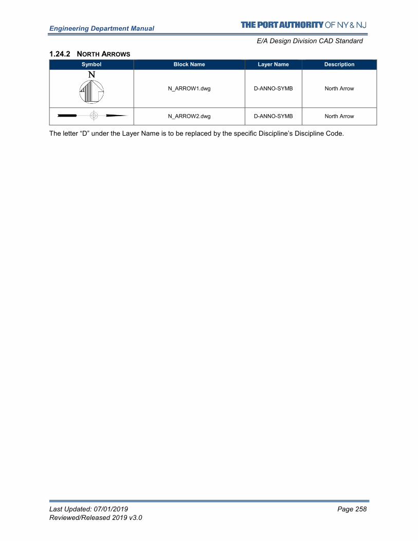
Engineering Department Manual
E/A Design Division CAD Standard
Last Updated: 07/01/2019 Page 258
Reviewed/Released 2019 v3.0
1.24.2 NORTH ARROWS
Symbol Block Name Layer Name Description
N_ARROW1.dwg D-ANNO-SYMB North Arrow
N_ARROW2.dwg D-ANNO-SYMB North Arrow
The letter “D” under the Layer Name is to be replaced by the specific Discipline’s Discipline Code.
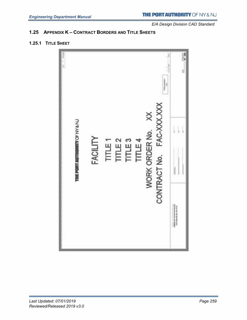
Engineering Department Manual
E/A Design Division CAD Standard
Last Updated: 07/01/2019 Page 259
Reviewed/Released 2019 v3.0
1.25 APPENDIX K – CONTRACT BORDERS AND TITLE SHEETS
1.25.1 TITLE SHEET
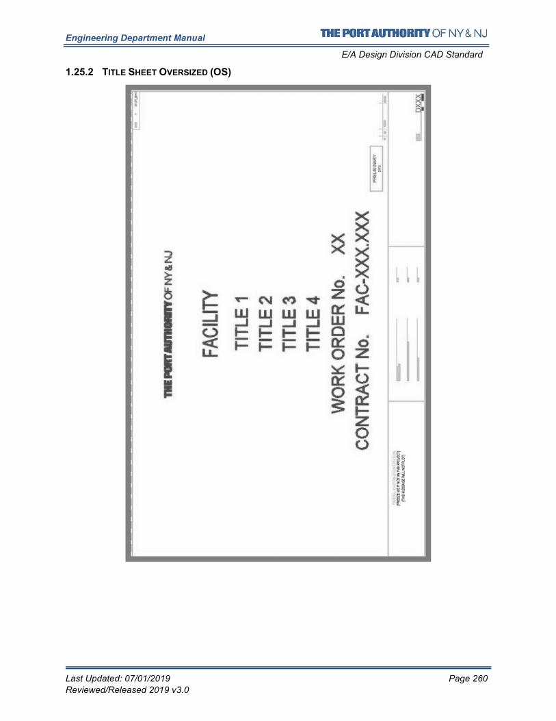
Engineering Department Manual
E/A Design Division CAD Standard
Last Updated: 07/01/2019 Page 260
Reviewed/Released 2019 v3.0
1.25.2 TITLE SHEET OVERSIZED (OS)
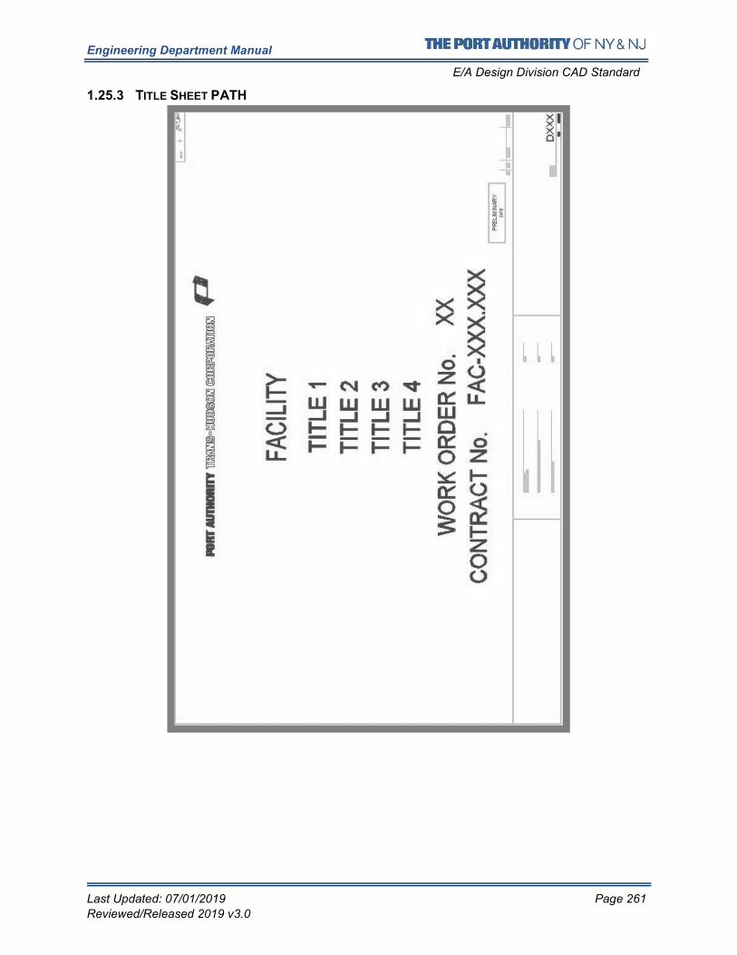
Engineering Department Manual
E/A Design Division CAD Standard
Last Updated: 07/01/2019 Page 261
Reviewed/Released 2019 v3.0
1.25.3 TITLE SHEET PATH
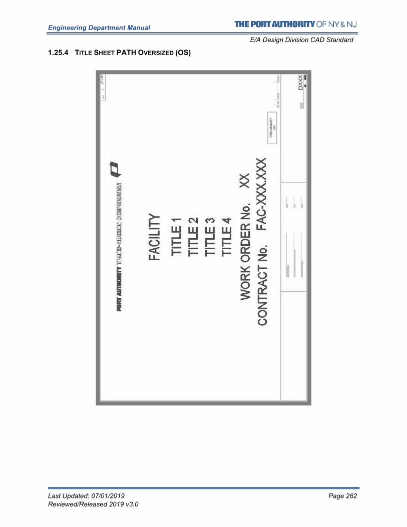
Engineering Department Manual
E/A Design Division CAD Standard
Last Updated: 07/01/2019 Page 262
Reviewed/Released 2019 v3.0
1.25.4 TITLE SHEET PATH OVERSIZED (OS)
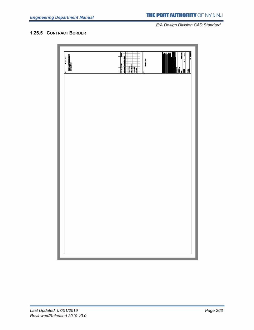
Engineering Department Manual
E/A Design Division CAD Standard
Last Updated: 07/01/2019 Page 263
Reviewed/Released 2019 v3.0
1.25.5 CONTRACT BORDER
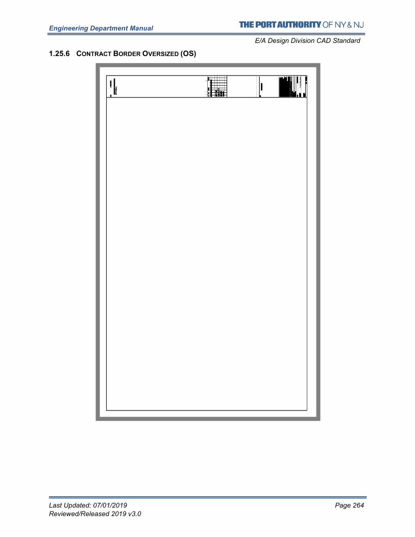
Engineering Department Manual
E/A Design Division CAD Standard
Last Updated: 07/01/2019 Page 264
Reviewed/Released 2019 v3.0
1.25.6 CONTRACT BORDER OVERSIZED (OS)
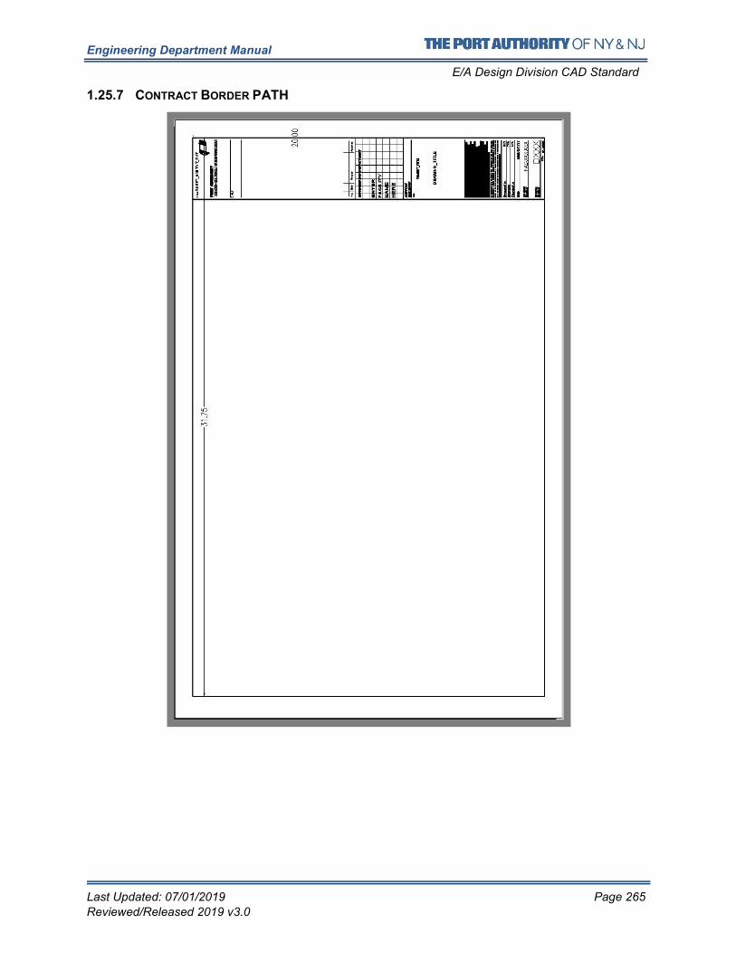
Engineering Department Manual
E/A Design Division CAD Standard
Last Updated: 07/01/2019 Page 265
Reviewed/Released 2019 v3.0
1.25.7 CONTRACT BORDER PATH
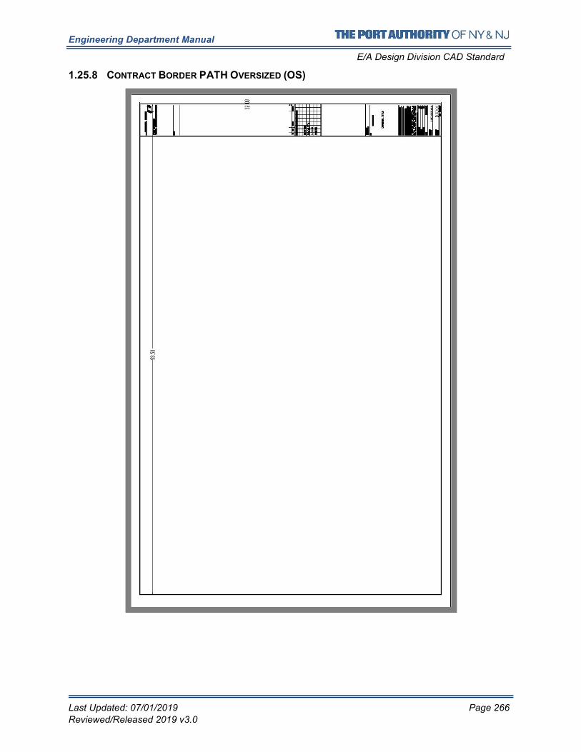
Engineering Department Manual
E/A Design Division CAD Standard
Last Updated: 07/01/2019 Page 266
Reviewed/Released 2019 v3.0
1.25.8 CONTRACT BORDER PATH OVERSIZED (OS)
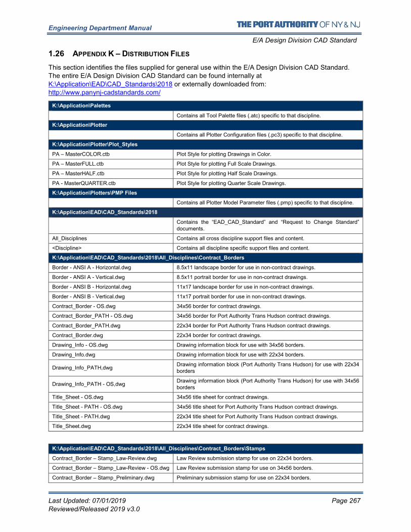
Engineering Department Manual
E/A Design Division CAD Standard
Last Updated: 07/01/2019 Page 267
Reviewed/Released 2019 v3.0
1.26 APPENDIX K – DISTRIBUTION FILES
This section identifies the files supplied for general use within the E/A Design Division CAD Standard.
The entire E/A Design Division CAD Standard can be found internally at
K:\Application\EAD\CAD_Standards\2018 or externally downloaded from:
http://www.panynj-cadstandards.com/
K:\Application\Palettes
Contains all Tool Palette files (.atc) specific to that discipline.
K:\Application\Plotter
Contains all Plotter Configuration files (.pc3) specific to that discipline.
K:\Application\Plotter\Plot_Styles
PA – MasterCOLOR.ctb Plot Style for plotting Drawings in Color.
PA – MasterFULL.ctb Plot Style for plotting Full Scale Drawings.
PA – MasterHALF.ctb Plot Style for plotting Half Scale Drawings.
PA - MasterQUARTER.ctb Plot Style for plotting Quarter Scale Drawings.
K:\Application\Plotters\PMP Files
Contains all Plotter Model Parameter files (.pmp) specific to that discipline.
K:\Application\EAD\CAD_Standards\2018
Contains the “EAD_CAD_Standard” and “Request to Change Standard” documents.
All_Disciplines Contains all cross discipline support files and content.
<Discipline> Contains all discipline specific support files and content.
K:\Application\EAD\CAD_Standards\2018\All_Disciplines\Contract_Borders
Border - ANSI A - Horizontal.dwg 8.5x11 landscape border for use in non-contract drawings.
Border - ANSI A - Vertical.dwg 8.5x11 portrait border for use in non-contract drawings.
Border - ANSI B - Horizontal.dwg 11x17 landscape border for use in non-contract drawings.
Border - ANSI B - Vertical.dwg 11x17 portrait border for use in non-contract drawings.
Contract_Border - OS.dwg 34x56 border for contract drawings.
Contract_Border_PATH - OS.dwg 34x56 border for Port Authority Trans Hudson contract drawings.
Contract_Border_PATH.dwg 22x34 border for Port Authority Trans Hudson contract drawings.
Contract_Border.dwg 22x34 border for contract drawings.
Drawing_Info - OS.dwg Drawing information block for use with 34x56 borders.
Drawing_Info.dwg Drawing information block for use with 22x34 borders.
Drawing_Info_PATH,dwg Drawing information block (Port Authority Trans Hudson) for use with 22x34 borders
Drawing_Info_PATH - OS,dwg Drawing information block (Port Authority Trans Hudson) for use with 34x56 borders
Title_Sheet - OS.dwg 34x56 title sheet for contract drawings.
Title_Sheet - PATH - OS.dwg 34x56 title sheet for Port Authority Trans Hudson contract drawings.
Title_Sheet - PATH.dwg 22x34 title sheet for Port Authority Trans Hudson contract drawings.
Title_Sheet.dwg 22x34 title sheet for contract drawings.
K:\Application\EAD\CAD_Standards\2018\All_Disciplines\Contract_Borders\Stamps
Contract_Border – Stamp_Law-Review.dwg Law Review submission stamp for use on 22x34 borders.
Contract_Border – Stamp_Law-Review - OS.dwg Law Review submission stamp for use on 34x56 borders.
Contract_Border – Stamp_Preliminary.dwg Preliminary submission stamp for use on 22x34 borders.
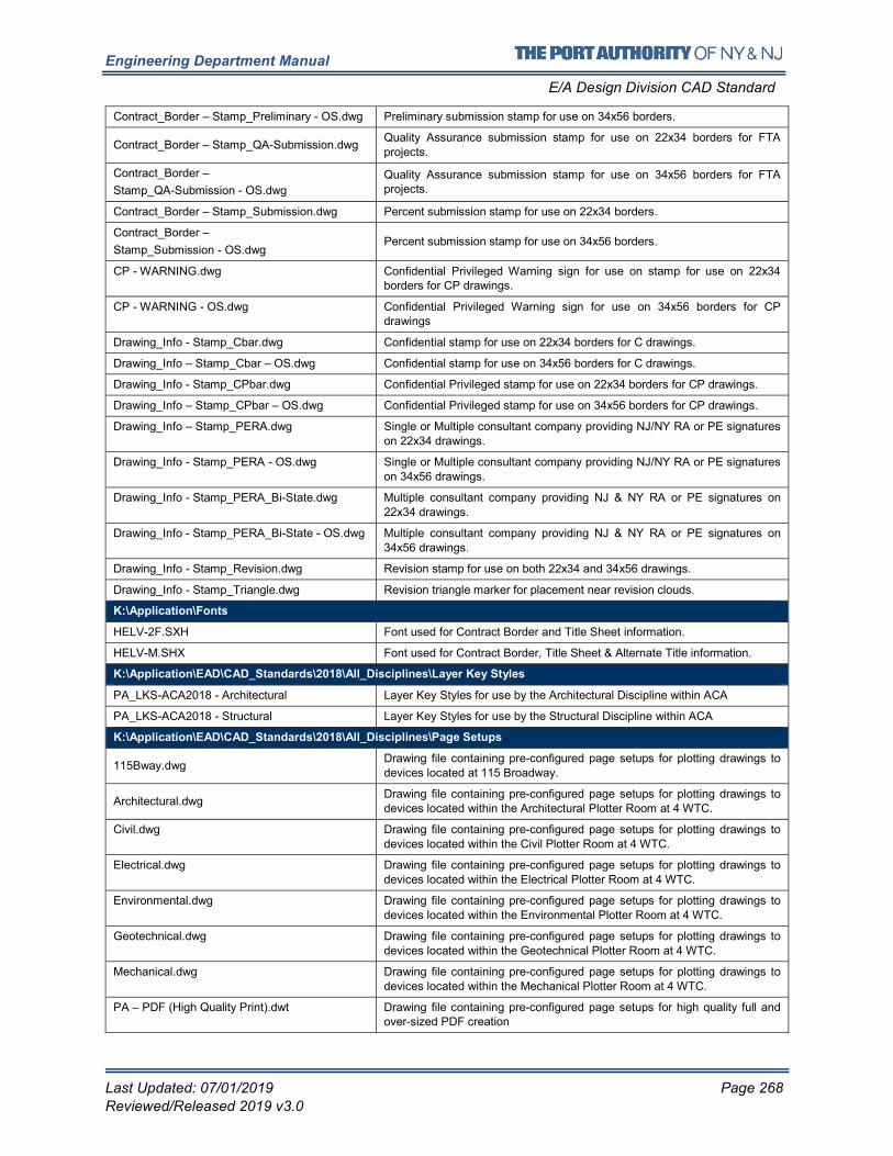
Engineering Department Manual
E/A Design Division CAD Standard
Last Updated: 07/01/2019 Page 268
Reviewed/Released 2019 v3.0
Contract_Border – Stamp_Preliminary - OS.dwg Preliminary submission stamp for use on 34x56 borders.
Contract_Border – Stamp_QA-Submission.dwg Quality Assurance submission stamp for use on 22x34 borders for FTA
projects.
Contract_Border –
Stamp_QA-Submission - OS.dwg
Quality Assurance submission stamp for use on 34x56 borders for FTA projects.
Contract_Border – Stamp_Submission.dwg Percent submission stamp for use on 22x34 borders.
Contract_Border –
Stamp_Submission - OS.dwg Percent submission stamp for use on 34x56 borders.
CP - WARNING.dwg Confidential Privileged Warning sign for use on stamp for use on 22x34 borders for CP drawings.
CP - WARNING - OS.dwg Confidential Privileged Warning sign for use on 34x56 borders for CP drawings
Drawing_Info - Stamp_Cbar.dwg Confidential stamp for use on 22x34 borders for C drawings.
Drawing_Info – Stamp_Cbar – OS.dwg Confidential stamp for use on 34x56 borders for C drawings.
Drawing_Info - Stamp_CPbar.dwg Confidential Privileged stamp for use on 22x34 borders for CP drawings.
Drawing_Info – Stamp_CPbar – OS.dwg Confidential Privileged stamp for use on 34x56 borders for CP drawings.
Drawing_Info – Stamp_PERA.dwg Single or Multiple consultant company providing NJ/NY RA or PE signatures on 22x34 drawings.
Drawing_Info - Stamp_PERA - OS.dwg Single or Multiple consultant company providing NJ/NY RA or PE signatures on 34x56 drawings.
Drawing_Info - Stamp_PERA_Bi-State.dwg Multiple consultant company providing NJ & NY RA or PE signatures on 22x34 drawings.
Drawing_Info - Stamp_PERA_Bi-State - OS.dwg Multiple consultant company providing NJ & NY RA or PE signatures on 34x56 drawings.
Drawing_Info - Stamp_Revision.dwg Revision stamp for use on both 22x34 and 34x56 drawings.
Drawing_Info - Stamp_Triangle.dwg Revision triangle marker for placement near revision clouds.
K:\Application\Fonts
HELV-2F.SXH Font used for Contract Border and Title Sheet information.
HELV-M.SHX Font used for Contract Border, Title Sheet & Alternate Title information.
K:\Application\EAD\CAD_Standards\2018\All_Disciplines\Layer Key Styles
PA_LKS-ACA2018 - Architectural Layer Key Styles for use by the Architectural Discipline within ACA
PA_LKS-ACA2018 - Structural Layer Key Styles for use by the Structural Discipline within ACA
K:\Application\EAD\CAD_Standards\2018\All_Disciplines\Page Setups
115Bway.dwg Drawing file containing pre-configured page setups for plotting drawings to devices located at 115 Broadway.
Architectural.dwg Drawing file containing pre-configured page setups for plotting drawings to
devices located within the Architectural Plotter Room at 4 WTC.
Civil.dwg Drawing file containing pre-configured page setups for plotting drawings to
devices located within the Civil Plotter Room at 4 WTC.
Electrical.dwg Drawing file containing pre-configured page setups for plotting drawings to
devices located within the Electrical Plotter Room at 4 WTC.
Environmental.dwg Drawing file containing pre-configured page setups for plotting drawings to
devices located within the Environmental Plotter Room at 4 WTC.
Geotechnical.dwg Drawing file containing pre-configured page setups for plotting drawings to
devices located within the Geotechnical Plotter Room at 4 WTC.
Mechanical.dwg Drawing file containing pre-configured page setups for plotting drawings to
devices located within the Mechanical Plotter Room at 4 WTC.
PA – PDF (High Quality Print).dwt Drawing file containing pre-configured page setups for high quality full and over-sized PDF creation
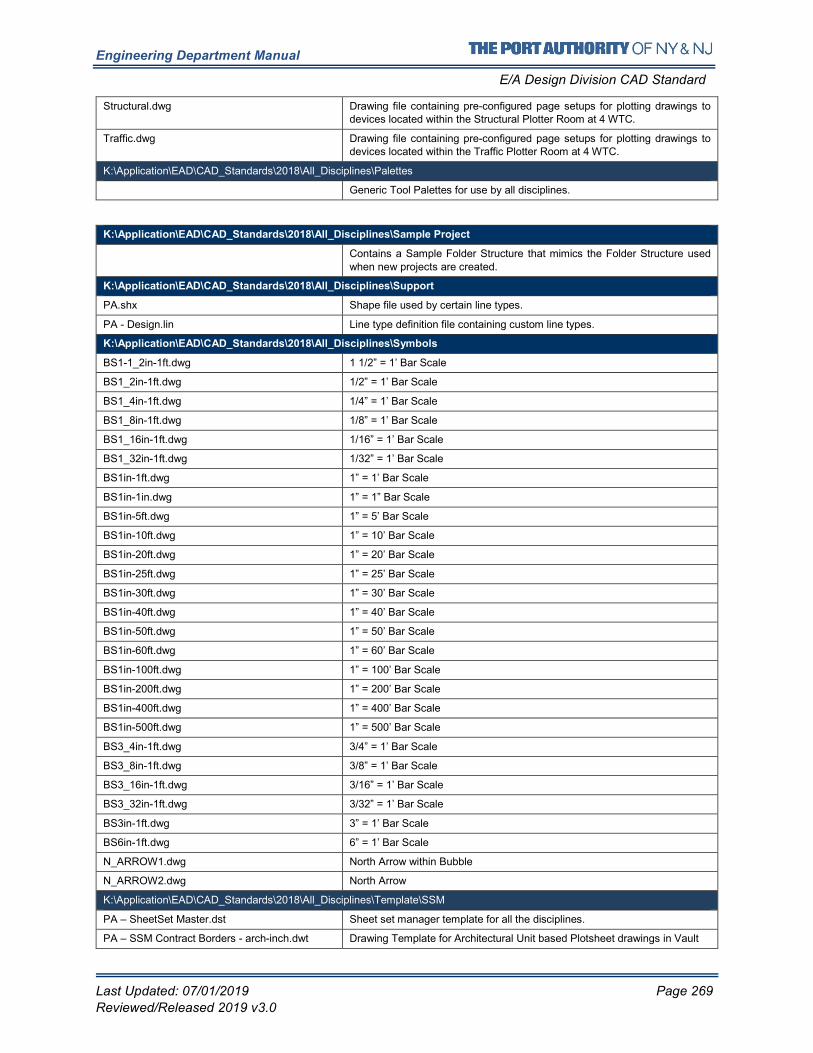
Engineering Department Manual
E/A Design Division CAD Standard
Last Updated: 07/01/2019 Page 269
Reviewed/Released 2019 v3.0
Structural.dwg Drawing file containing pre-configured page setups for plotting drawings to devices located within the Structural Plotter Room at 4 WTC.
Traffic.dwg Drawing file containing pre-configured page setups for plotting drawings to devices located within the Traffic Plotter Room at 4 WTC.
K:\Application\EAD\CAD_Standards\2018\All_Disciplines\Palettes
Generic Tool Palettes for use by all disciplines.
K:\Application\EAD\CAD_Standards\2018\All_Disciplines\Sample Project
Contains a Sample Folder Structure that mimics the Folder Structure used
when new projects are created.
K:\Application\EAD\CAD_Standards\2018\All_Disciplines\Support
PA.shx Shape file used by certain line types.
PA - Design.lin Line type definition file containing custom line types.
K:\Application\EAD\CAD_Standards\2018\All_Disciplines\Symbols
BS1-1_2in-1ft.dwg 1 1/2” = 1’ Bar Scale
BS1_2in-1ft.dwg 1/2” = 1’ Bar Scale
BS1_4in-1ft.dwg 1/4” = 1’ Bar Scale
BS1_8in-1ft.dwg 1/8” = 1’ Bar Scale
BS1_16in-1ft.dwg 1/16” = 1’ Bar Scale
BS1_32in-1ft.dwg 1/32” = 1’ Bar Scale
BS1in-1ft.dwg 1” = 1’ Bar Scale
BS1in-1in.dwg 1” = 1” Bar Scale
BS1in-5ft.dwg 1” = 5’ Bar Scale
BS1in-10ft.dwg 1” = 10’ Bar Scale
BS1in-20ft.dwg 1” = 20’ Bar Scale
BS1in-25ft.dwg 1” = 25’ Bar Scale
BS1in-30ft.dwg 1” = 30’ Bar Scale
BS1in-40ft.dwg 1” = 40’ Bar Scale
BS1in-50ft.dwg 1” = 50’ Bar Scale
BS1in-60ft.dwg 1” = 60’ Bar Scale
BS1in-100ft.dwg 1” = 100’ Bar Scale
BS1in-200ft.dwg 1” = 200’ Bar Scale
BS1in-400ft.dwg 1” = 400’ Bar Scale
BS1in-500ft.dwg 1” = 500’ Bar Scale
BS3_4in-1ft.dwg 3/4” = 1’ Bar Scale
BS3_8in-1ft.dwg 3/8” = 1’ Bar Scale
BS3_16in-1ft.dwg 3/16” = 1’ Bar Scale
BS3_32in-1ft.dwg 3/32” = 1’ Bar Scale
BS3in-1ft.dwg 3” = 1’ Bar Scale
BS6in-1ft.dwg 6” = 1’ Bar Scale
N_ARROW1.dwg North Arrow within Bubble
N_ARROW2.dwg North Arrow
K:\Application\EAD\CAD_Standards\2018\All_Disciplines\Template\SSM
PA – SheetSet Master.dst Sheet set manager template for all the disciplines.
PA – SSM Contract Borders - arch-inch.dwt Drawing Template for Architectural Unit based Plotsheet drawings in Vault
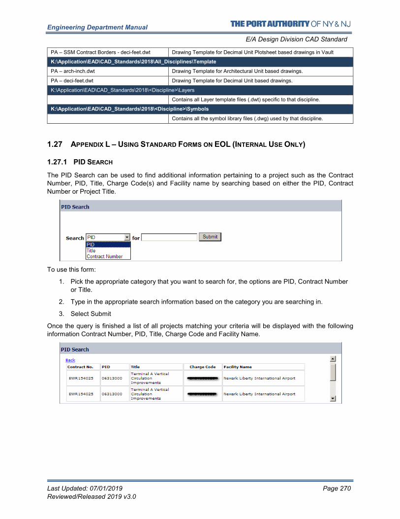
Engineering Department Manual
E/A Design Division CAD Standard
Last Updated: 07/01/2019 Page 270
Reviewed/Released 2019 v3.0
PA – SSM Contract Borders - deci-feet.dwt Drawing Template for Decimal Unit Plotsheet based drawings in Vault
K:\Application\EAD\CAD_Standards\2018\All_Disciplines\Template
PA – arch-inch.dwt Drawing Template for Architectural Unit based drawings.
PA – deci-feet.dwt Drawing Template for Decimal Unit based drawings.
K:\Application\EAD\CAD_Standards\2018\<Discipline>\Layers
Contains all Layer template files (.dwt) specific to that discipline.
K:\Application\EAD\CAD_Standards\2018\<Discipline>\Symbols
Contains all the symbol library files (.dwg) used by that discipline.
1.27 APPENDIX L – USING STANDARD FORMS ON EOL (INTERNAL USE ONLY)
1.27.1 PID SEARCH
The PID Search can be used to find additional information pertaining to a project such as the Contract
Number, PID, Title, Charge Code(s) and Facility name by searching based on either the PID, Contract
Number or Project Title.
To use this form:
1. Pick the appropriate category that you want to search for, the options are PID, Contract Number
or Title.
2. Type in the appropriate search information based on the category you are searching in.
3. Select Submit
Once the query is finished a list of all projects matching your criteria will be displayed with the following
information Contract Number, PID, Title, Charge Code and Facility Name.
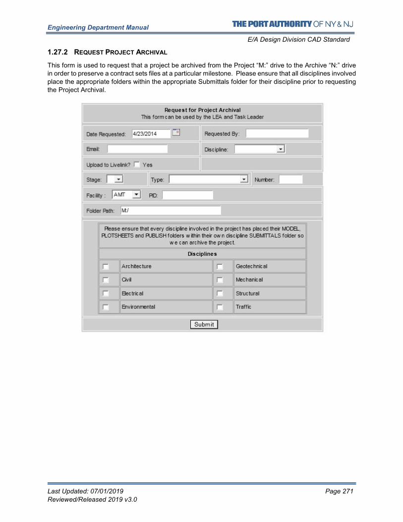
Engineering Department Manual
E/A Design Division CAD Standard
Last Updated: 07/01/2019 Page 271
Reviewed/Released 2019 v3.0
1.27.2 REQUEST PROJECT ARCHIVAL
This form is used to request that a project be archived from the Project “M:” drive to the Archive “N:” drive
in order to preserve a contract sets files at a particular milestone. Please ensure that all disciplines involved
place the appropriate folders within the appropriate Submittals folder for their discipline prior to requesting
the Project Archival.
Engineering Department Manual
E/A Design Division CAD Standard
Last Updated: 07/01/2019 Page 272
Reviewed/Released 2019 v3.0
To use this form:
1. Requested By: Either the LEA or the Task Leader may request for an Archival.
2. Email: It is mandatory that you supply a valid email address to receive a confirmation of your
request. This email will also be used to notify you as soon as the request has been processed.
3. Discipline: Pick which Discipline you belong to.
4. Upload to Livelink: Check this box if you would like files uploaded to a project website on
Livelink.
5. Stage: Enter what stage the project is in, I, II, III or IV.
6. Type: Enter the type of submittal this is, PA Review, As-Advertised, 50% Submittal, etc.
7. Number: Fill this out only if your project is either a PACC or an Addendum.
8. Facility: Enter the facility the project is for.
9. PID: Enter the PID of the project
10. Folder Path: Provide the path to the folder that needs to be archived.
11. Disciplines: Check all the disciplines involved in this project. This will ensure that all the
involved disciplines’ folders are archived.
1.27.3 REQUEST PROJECT CAD DRAWINGS
This Section Currently Under Construction
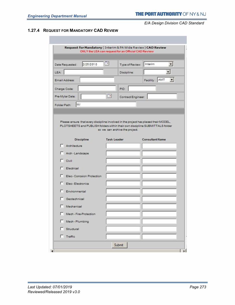
Engineering Department Manual
E/A Design Division CAD Standard
Last Updated: 07/01/2019 Page 273
Reviewed/Released 2019 v3.0
1.27.4 REQUEST FOR MANDATORY CAD REVIEW
Engineering Department Manual
E/A Design Division CAD Standard
Last Updated: 07/01/2019 Page 274
Reviewed/Released 2019 v3.0
1. Type of Review: Pick the type of Review (Interim or PA Wide Review)
2. LEA: Only the LEA may request for a Mandatory CAD Review. It is important to provide the
name of the LEA for the results of the CAD Review.
3. Email: It is mandatory that you provide a valid email address to receive a confirmation of your
request. This email will also be used to notify you as soon as the request has been processed.
4. Discipline: Enter the discipline that the LEA belongs to.
5. Facility Name: Enter the facility the project is for.
6. Charge Code: Enter the Charge Code to be used by the CAD Support Group for CAD Standards
Review.
7. PID: Enter the PID of the project.
8. PA Wide Review Date: Provide the PA Wide Review date of the project.
9. Contract Engineer: Provide the name of the Contract Engineer that is to be notified once the
PDF files have been uploaded to Livelink for PA Wide Review.
10. Disciplines/Taskleaders/Consultant name: Check all the disciplines involved in this project.
This will ensure that all the involved disciplines’ drawings are reviewed. Please ensure that all
disciplines place their drawings in their appropriate submittal folders. It is important that the
names of the Task leaders are provided in order to provide them with the results of the CAD
Standards review. If a consultant has prepared the drawings for a particular discipline the
consultant company name must also be provided because the requirements of CAD Standards
compliance are slightly different for consultants.
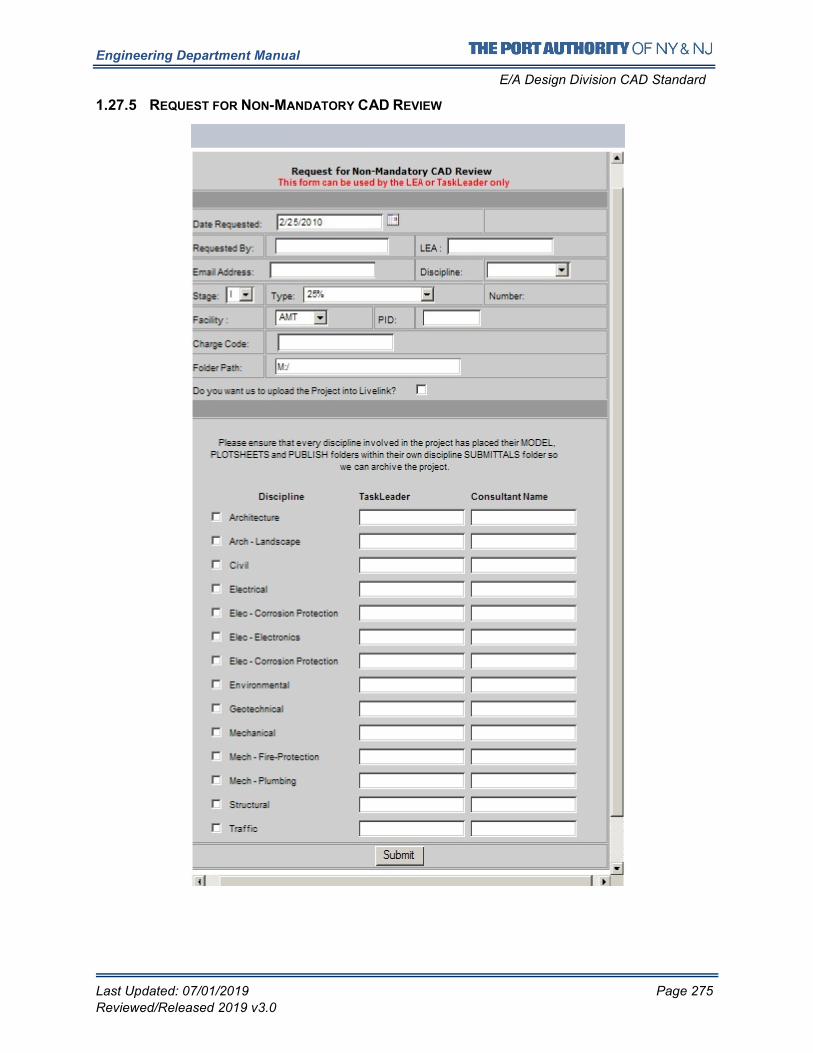
Engineering Department Manual
E/A Design Division CAD Standard
Last Updated: 07/01/2019 Page 275
Reviewed/Released 2019 v3.0
1.27.5 REQUEST FOR NON-MANDATORY CAD REVIEW
Engineering Department Manual
E/A Design Division CAD Standard
Last Updated: 07/01/2019 Page 276
Reviewed/Released 2019 v3.0
1. Requested By: Either the LEA or Task Leader may request for a Non-Mandatory CAD Review.
2. LEA: It is important to provide the name of the LEA for the results of the CAD Review.
3. Email: It is mandatory that you provide a valid email address to receive a confirmation of your
request. This email will also be used to notify you as soon as the request has been processed.
4. Discipline: Enter the discipline that the requestor belongs to.
5. Stage: Enter what stage the project is in, I, II, III or IV.
6. Type: Enter the type of submittal this is, PA Review, As-Advertised, 50% Submittal, etc.
7. Number: Fill this out only if your project is either a PACC or an Addendum.
8. Facility: Enter the facility the project is for.
9. PID: Enter the PID of the project
10. Charge Code: Enter the Charge Code to be used by the CAD Support Group for CAD Standards
Review.
11. Folder Path: Provide the path to the folder that needs to be reviewed.
12. Upload to Livelink: Check this box if you would like files uploaded to a project website on
Livelink.
13. Disciplines/Taskleaders/Consultant name: Check all the disciplines involved in this project.
This will ensure that all the involved disciplines’ drawings are reviewed. Please ensure that all
disciplines place their drawings in their appropriate submittal folders. It is important that the
names of the Task leaders are provided in order to provide them with the results of the CAD
Standards review. If a consultant has prepared the drawings for a particular discipline the
consultant company name must also be provided because the requirements of CAD Standards
compliance are slightly different for consultants.
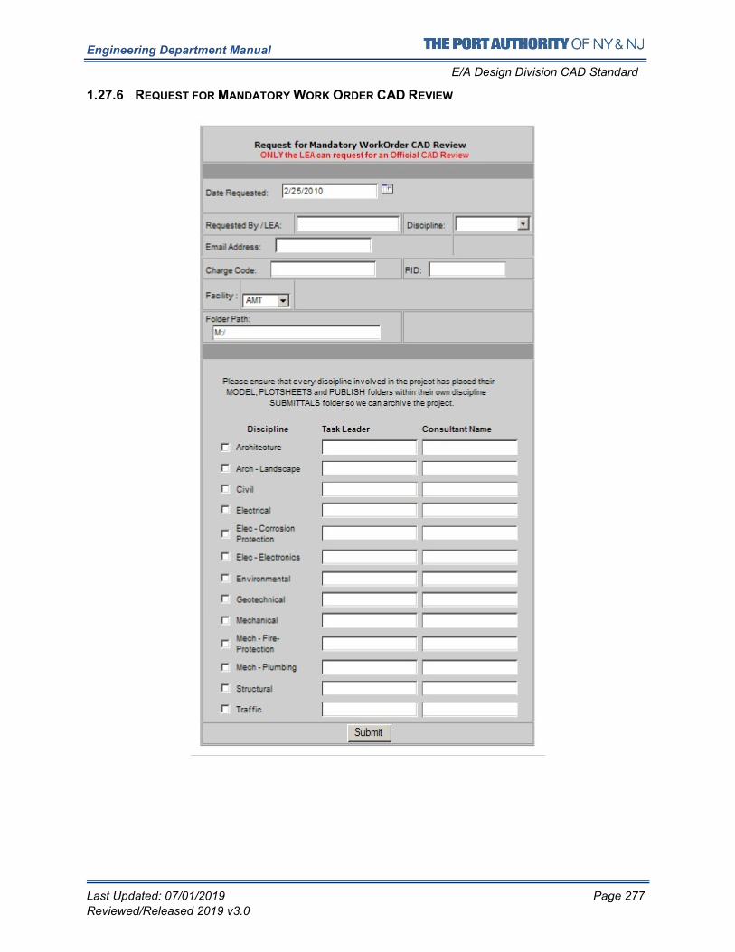
Engineering Department Manual
E/A Design Division CAD Standard
Last Updated: 07/01/2019 Page 277
Reviewed/Released 2019 v3.0
1.27.6 REQUEST FOR MANDATORY WORK ORDER CAD REVIEW
Engineering Department Manual
E/A Design Division CAD Standard
Last Updated: 07/01/2019 Page 278
Reviewed/Released 2019 v3.0
1. LEA: Only the LEA may request for a Work Order CAD Review. It is important to provide the
name of the LEA for the results of the CAD Review.
2. Email: It is mandatory that you provide a valid email address to receive a confirmation of your
request. This email will also be used to notify you as soon as the request has been processed.
3. Discipline: Enter the discipline that the LEA belongs to.
4. Charge Code: Enter the Charge Code to be used by the CAD Support Group for CAD Standards
Review.
5. PID: Enter the PID of the project.
6. Facility Name: Enter the facility the project is for.
7. Folder Path: Provide the path to the folder that needs to be reviewed.
8. Disciplines/Taskleaders/Consultant name: Check all the disciplines involved in this project.
This will ensure that all the involved disciplines’ drawings are reviewed. Please ensure that all
disciplines place their drawings in their appropriate submittal folders. It is important that the
names of the Task leaders are provided in order to provide them with the results of the CAD
Standards review. If a consultant has prepared the drawings for a particular discipline the
consultant company name must also be provided because the requirements of CAD Standards
compliance are slightly different for consultants.
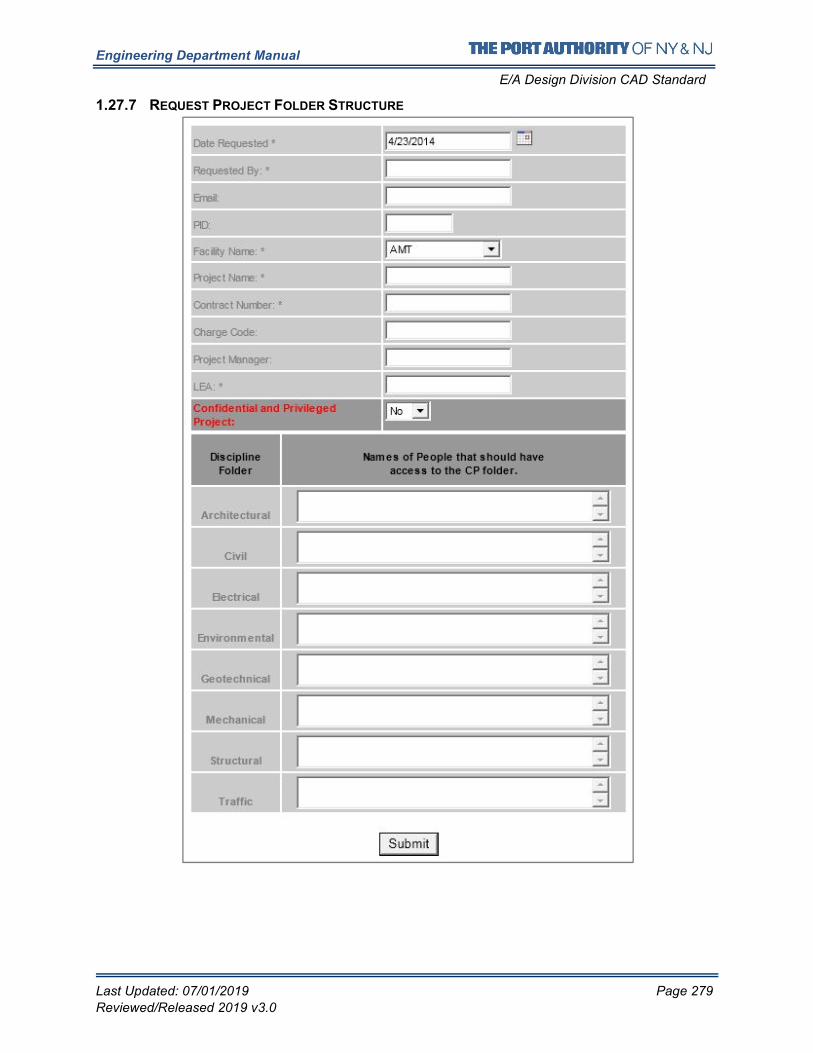
Engineering Department Manual
E/A Design Division CAD Standard
Last Updated: 07/01/2019 Page 279
Reviewed/Released 2019 v3.0
1.27.7 REQUEST PROJECT FOLDER STRUCTURE
Engineering Department Manual
E/A Design Division CAD Standard
Last Updated: 07/01/2019 Page 280
Reviewed/Released 2019 v3.0
1. Requested By: Person requesting the creation of the folder structure
2. Email: It is mandatory that you provide a valid email address to receive a confirmation of your
request. This email will also be used to notify you as soon as the request has been processed
3. PID: Enter the PID of the project
4. Facility Name: Enter the facility the project is for
5. Project Name: Complete title of the project
6. Contract Number: Enter the Contract Number
7. Charge Code: Enter the Charge Code to be used by the CAD Support Group for CAD Standards
Review.
8. Project Manager: Enter the name of the Project Manager.
9. LEA: Name of the LEA
10. Confidential Privileged Project: Specify if it is a Confidential Privileged project or not
11. Names of People that should have access to the CP folder: If this is a Confidential Privileged
project, the person requesting for the folder structure must specify the names of the people who
should be granted access to the CP folder.
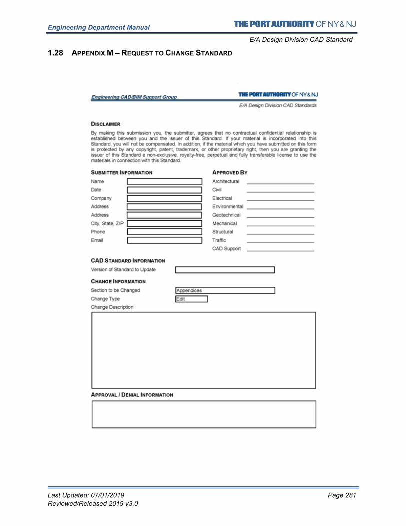
Engineering Department Manual
E/A Design Division CAD Standard
Last Updated: 07/01/2019 Page 281
Reviewed/Released 2019 v3.0
1.28 APPENDIX M – REQUEST TO CHANGE STANDARD
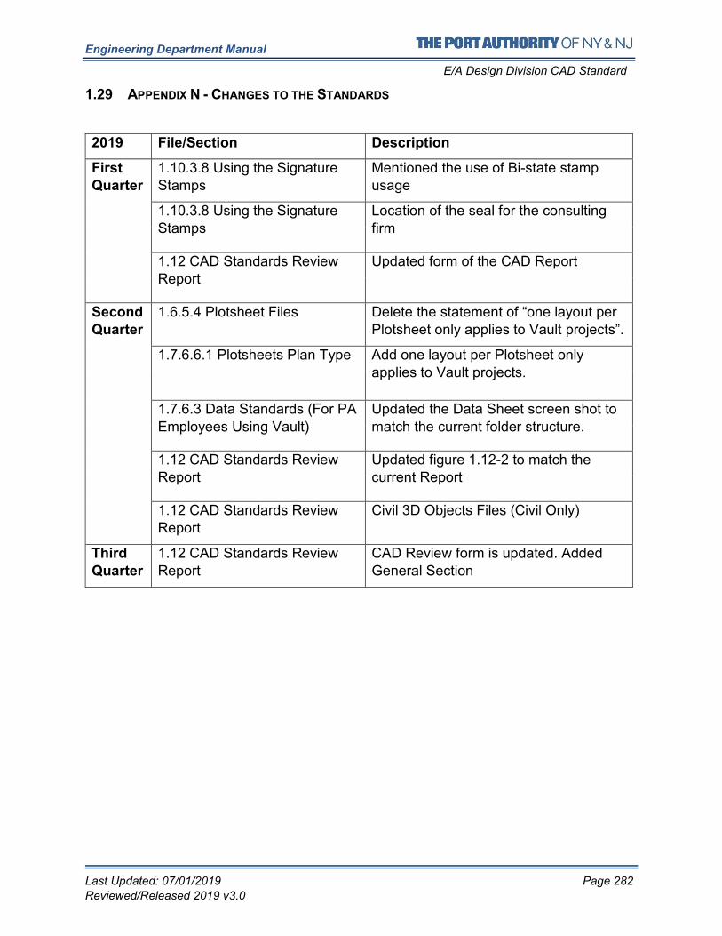
Engineering Department Manual
E/A Design Division CAD Standard
Last Updated: 07/01/2019 Page 282
Reviewed/Released 2019 v3.0
1.29 APPENDIX N - CHANGES TO THE STANDARDS
2019 File/Section Description
First
Quarter
1.10.3.8 Using the Signature
Stamps
Mentioned the use of Bi-state stamp
usage
1.10.3.8 Using the Signature
Stamps
Location of the seal for the consulting
firm
1.12 CAD Standards Review
Report
Updated form of the CAD Report
Second
Quarter
1.6.5.4 Plotsheet Files Delete the statement of “one layout per
Plotsheet only applies to Vault projects”.
1.7.6.6.1 Plotsheets Plan Type Add one layout per Plotsheet only
applies to Vault projects.
1.7.6.3 Data Standards (For PA
Employees Using Vault)
Updated the Data Sheet screen shot to
match the current folder structure.
1.12 CAD Standards Review
Report
Updated figure 1.12-2 to match the
current Report
1.12 CAD Standards Review
Report
Civil 3D Objects Files (Civil Only)
Third
Quarter
1.12 CAD Standards Review
Report
CAD Review form is updated. Added
General Section