Dynamic Multi-Pathing 7.0 Administrator's Guide - Solaris
175
Dynamic Multi-Pathing 7.0 Administrator's Guide - Solaris December 2015
-
Upload
khangminh22 -
Category
Documents
-
view
2 -
download
0
Transcript of Dynamic Multi-Pathing 7.0 Administrator's Guide - Solaris

Dynamic Multi-Pathing 7.0Administrator's Guide -Solaris
December 2015

Dynamic Multi-Pathing Administrator's GuideThe software described in this book is furnished under a license agreement and may be usedonly in accordance with the terms of the agreement.
Product version: 7.0
Document version: 7.0 Rev 1
Legal NoticeCopyright © 2015 Veritas Technologies LLC. All rights reserved.
Veritas, the Veritas Logo, and NetBackup are trademarks or registered trademarks of VeritasTechnologies LLC or its affiliates in the U.S. and other countries. Other names may betrademarks of their respective owners.
The product described in this document is distributed under licenses restricting its use, copying,distribution, and decompilation/reverse engineering. No part of this document may bereproduced in any form by any means without prior written authorization of Veritas TechnologiesLLC and its licensors, if any.
THE DOCUMENTATION IS PROVIDED "AS IS" AND ALL EXPRESS OR IMPLIEDCONDITIONS, REPRESENTATIONS AND WARRANTIES, INCLUDING ANY IMPLIEDWARRANTY OF MERCHANTABILITY, FITNESS FOR A PARTICULAR PURPOSE ORNON-INFRINGEMENT, ARE DISCLAIMED, EXCEPT TO THE EXTENT THAT SUCHDISCLAIMERS ARE HELD TO BE LEGALLY INVALID. VERITAS TECHNOLOGIESCORPORATION SHALL NOT BE LIABLE FOR INCIDENTAL OR CONSEQUENTIALDAMAGES IN CONNECTION WITH THE FURNISHING, PERFORMANCE, OR USE OFTHIS DOCUMENTATION. THE INFORMATION CONTAINED IN THIS DOCUMENTATIONIS SUBJECT TO CHANGE WITHOUT NOTICE.
The Licensed Software and Documentation are deemed to be commercial computer softwareas defined in FAR 12.212 and subject to restricted rights as defined in FAR Section 52.227-19"Commercial Computer Software - Restricted Rights" and DFARS 227.7202, et seq."Commercial Computer Software and Commercial Computer Software Documentation," asapplicable, and any successor regulations, whether delivered by Veritas as on premises orhosted services. Any use, modification, reproduction release, performance, display or disclosureof the Licensed Software and Documentation by the U.S. Government shall be solely inaccordance with the terms of this Agreement.

Veritas Technologies LLC500 E Middlefield RoadMountain View, CA 94043
http://www.veritas.com

Technical SupportTechnical Support maintains support centers globally. Technical Support’s primaryrole is to respond to specific queries about product features and functionality. TheTechnical Support group also creates content for our online Knowledge Base. TheTechnical Support group works collaboratively with the other functional areas withinthe company to answer your questions in a timely fashion.
Our support offerings include the following:
■ A range of support options that give you the flexibility to select the right amountof service for any size organization
■ Telephone and/or Web-based support that provides rapid response andup-to-the-minute information
■ Upgrade assurance that delivers software upgrades
■ Global support purchased on a regional business hours or 24 hours a day, 7days a week basis
■ Premium service offerings that include Account Management Services
For information about our support offerings, you can visit our website at the followingURL:
www.veritas.com/support
All support services will be delivered in accordance with your support agreementand the then-current enterprise technical support policy.
Contacting Technical SupportCustomers with a current support agreement may access Technical Supportinformation at the following URL:
www.veritas.com/support
Before contacting Technical Support, make sure you have satisfied the systemrequirements that are listed in your product documentation. Also, you should be atthe computer on which the problem occurred, in case it is necessary to replicatethe problem.
When you contact Technical Support, please have the following informationavailable:
■ Product release level
■ Hardware information
■ Available memory, disk space, and NIC information

■ Operating system
■ Version and patch level
■ Network topology
■ Router, gateway, and IP address information
■ Problem description:
■ Error messages and log files
■ Troubleshooting that was performed before contacting Technical Support
■ Recent software configuration changes and network changes
Licensing and registrationIf your product requires registration or a license key, access our technical supportWeb page at the following URL:
www.veritas.com/support
Customer serviceCustomer service information is available at the following URL:
www.veritas.com/support
Customer Service is available to assist with non-technical questions, such as thefollowing types of issues:
■ Questions regarding product licensing or serialization
■ Product registration updates, such as address or name changes
■ General product information (features, language availability, local dealers)
■ Latest information about product updates and upgrades
■ Information about upgrade assurance and support contracts
■ Advice about technical support options
■ Nontechnical presales questions
■ Issues that are related to CD-ROMs, DVDs, or manuals

Support agreement resourcesIf you want to contact us regarding an existing support agreement, please contactthe support agreement administration team for your region as follows:
[email protected] (except Japan)

Technical Support ............................................................................................ 4
Chapter 1 Understanding DMP ......................................................... 11
About Dynamic Multi-Pathing (DMP) ................................................ 11How DMP works .......................................................................... 12
How DMP monitors I/O on paths ................................................ 16Load balancing ...................................................................... 18Dynamic Reconfiguration ......................................................... 18DMP support for the ZFS root pool ............................................. 18About booting from DMP devices ............................................... 18DMP in a clustered environment ................................................ 19
Multiple paths to disk arrays ........................................................... 20Device discovery .......................................................................... 20Disk devices ............................................................................... 20Disk device naming in DMP ............................................................ 21
About operating system-based naming ....................................... 21About enclosure-based naming ................................................. 22
Chapter 2 Setting up DMP to manage native devices ............... 27
About setting up DMP to manage native devices ................................. 27Displaying the native multi-pathing configuration ................................ 29Migrating ZFS pools to DMP ........................................................... 29Migrating to DMP from EMC PowerPath ............................................ 30Migrating to DMP from Hitachi Data Link Manager (HDLM) ................... 31Migrating to DMP from Solaris Multiplexed I/O (MPxIO) ........................ 32Using Dynamic Multi-Pathing (DMP) devices with Oracle Automatic
Storage Management (ASM) .................................................... 33Enabling Dynamic Multi-Pathing (DMP) devices for use with Oracle
Automatic Storage Management (ASM) ................................ 33Removing Dynamic Multi-Pathing (DMP) devices from the listing
of Oracle Automatic Storage Management (ASM) disks ............ 35Migrating Oracle Automatic Storage Management (ASM) disk
groups on operating system devices to Dynamic Multi-Pathing(DMP) devices ................................................................. 35
Enabling and disabling DMP support for the ZFS root pool .................... 39
Contents

Adding DMP devices to an existing ZFS pool or creating a new ZFSpool ..................................................................................... 42
Removing DMP support for native devices ......................................... 44
Chapter 3 Administering DMP ........................................................... 45
About enabling and disabling I/O for controllers and storageprocessors ............................................................................ 45
About displaying DMP database information ...................................... 46Displaying the paths to a disk .......................................................... 46Setting customized names for DMP nodes ......................................... 49DMP coexistence with native multi-pathing ........................................ 50Managing DMP devices for the ZFS root pool .................................... 51
Configuring a mirror for the ZFS root pool using a DMPdevice ............................................................................ 51
Updating the boot device settings .............................................. 54Using DMP devices as swap devices or dump devices ................... 55Cloning the boot environment with DMP ...................................... 56Creating a snapshot of an existing boot environment ..................... 58
Administering DMP using the vxdmpadm utility ................................... 59Retrieving information about a DMP node .................................... 60Displaying consolidated information about the DMP nodes .............. 61Displaying the members of a LUN group ..................................... 63Displaying paths controlled by a DMP node, controller, enclosure,
or array port .................................................................... 63Displaying information about controllers ...................................... 66Displaying information about enclosures ..................................... 67Displaying information about array ports ...................................... 68Displaying information about devices controlled by third-party
drivers ............................................................................ 68Displaying extended device attributes ......................................... 70Suppressing or including devices from VxVM control ..................... 72Gathering and displaying I/O statistics ........................................ 73Setting the attributes of the paths to an enclosure ......................... 80Displaying the redundancy level of a device or enclosure ............... 81Specifying the minimum number of active paths ............................ 82Displaying the I/O policy .......................................................... 82Specifying the I/O policy .......................................................... 83Disabling I/O for paths, controllers, array ports, or DMP
nodes ............................................................................ 88Enabling I/O for paths, controllers, array ports, or DMP
nodes ............................................................................ 90Renaming an enclosure ........................................................... 91
8Contents

Configuring the response to I/O failures ...................................... 91Configuring the I/O throttling mechanism ..................................... 93Configuring Subpaths Failover Groups (SFG) ............................... 94Configuring Low Impact Path Probing (LIPP) ................................ 94Displaying recovery option values .............................................. 95Configuring DMP path restoration policies ................................... 96Stopping the DMP path restoration thread ................................... 97Displaying the status of the DMP path restoration thread ................ 98Configuring Array Policy Modules .............................................. 98
Chapter 4 Administering disks ......................................................... 100
About disk management .............................................................. 100Discovering and configuring newly added disk devices ....................... 100
Partial device discovery ......................................................... 101About discovering disks and dynamically adding disk arrays .......... 102About third-party driver coexistence .......................................... 105How to administer the Device Discovery Layer ............................ 105
VxVM coexistence with ZFS .......................................................... 117Changing the disk device naming scheme ....................................... 119
Displaying the disk-naming scheme .......................................... 120Regenerating persistent device names ...................................... 121Changing device naming for enclosures controlled by third-party
drivers .......................................................................... 122Simple or nopriv disks with enclosure-based naming .................... 123
Discovering the association between enclosure-based disk names andOS-based disk names ........................................................... 125
Chapter 5 Dynamic Reconfiguration of devices ........................ 126
About online Dynamic Reconfiguration ........................................... 126Reconfiguring a LUN online that is under DMP control ........................ 127
Removing LUNs dynamically from an existing target ID ................ 127Adding new LUNs dynamically to a target ID .............................. 129Replacing LUNs dynamically from an existing target ID ................ 129Changing the characteristics of a LUN from the array side ............. 130
Replacing a host bus adapter online ............................................... 131Upgrading the array controller firmware online .................................. 132
Chapter 6 Event monitoring .............................................................. 134
About the Dynamic Multi-Pathing (DMP) event source daemon(vxesd) ............................................................................... 134
Fabric Monitoring and proactive error detection ................................. 135
9Contents

Dynamic Multi-Pathing (DMP) automated device discovery ................. 136Dynamic Multi-Pathing (DMP) discovery of iSCSI and SAN Fibre
Channel topology ................................................................. 137DMP event logging ...................................................................... 137Starting and stopping the Dynamic Multi-Pathing (DMP) event source
daemon .............................................................................. 138
Chapter 7 Performance monitoring and tuning ........................... 139
About tuning Dynamic Multi-Pathing (DMP) with templates .................. 139DMP tuning templates ................................................................. 140Example DMP tuning template ...................................................... 142Tuning a DMP host with a configuration attribute template ................... 144Managing the DMP configuration files ............................................. 146Resetting the DMP tunable parameters and attributes to the default
values ................................................................................ 146DMP tunable parameters and attributes that are supported for
templates ............................................................................ 146DMP tunable parameters .............................................................. 147
Appendix A DMP troubleshooting ...................................................... 155
Displaying extended attributes after upgrading to DMP 7.0 .................. 155Recovering from errors when you exclude or include paths to
DMP .................................................................................. 156Downgrading the array support ...................................................... 157
Appendix B Reference .......................................................................... 160
Command completion for Veritas commands .................................... 160
Glossary ........................................................................................................... 162
Index .................................................................................................................. 170
10Contents

Understanding DMPThis chapter includes the following topics:
■ About Dynamic Multi-Pathing (DMP)
■ How DMP works
■ Multiple paths to disk arrays
■ Device discovery
■ Disk devices
■ Disk device naming in DMP
About Dynamic Multi-Pathing (DMP)Dynamic Multi-Pathing (DMP) provides multi-pathing functionality for the operatingsystem native devices that are configured on the system. DMP creates DMPmetadevices (also known as DMP nodes) to represent all the device paths to thesame physical LUN.
DMP is also available as a standalone product, which extends DMP metadevicesto support ZFS. You can create ZFS pools on DMP metadevices. Starting withSolaris 11 update 1, DMP supports both root and non-root ZFS pools. For earlierversions of Solaris, DMP supports only non-root ZFS file systems.
Veritas Volume Manager (VxVM) volumes and disk groups can co-exist with ZFSpools, but each device can only support one of the types. If a disk has a VxVMlabel, then the disk is not available to ZFS. Similarly, if a disk is in use by ZFS, thenthe disk is not available to VxVM.
1Chapter

How DMP worksDynamic Multi-Pathing (DMP) provides greater availability, reliability, andperformance by using the path failover feature and the load balancing feature.These features are available for multiported disk arrays from various vendors.
Disk arrays can be connected to host systems through multiple paths. To detectthe various paths to a disk, DMP uses a mechanism that is specific to eachsupported array. DMP can also differentiate between different enclosures of asupported array that are connected to the same host system.
The multi-pathing policy that DMP uses depends on the characteristics of the diskarray.
DMP supports the following standard array types:
Table 1-1
DescriptionArray type
Allows several paths to be used concurrently forI/O. Such arrays allow DMP to provide greater I/Othroughput by balancing the I/O load uniformlyacross the multiple paths to the LUNs. In the eventthat one path fails, DMP automatically routes I/Oover the other available paths.
Active/Active (A/A)
A/A-A or Asymmetric Active/Active arrays can beaccessed through secondary storage paths withlittle performance degradation. The behavior issimilar to ALUA, except that it does not supportthe SCSI commands that an ALUA array supports.
Asymmetric Active/Active (A/A-A)
DMP supports all variants of ALUA.Asymmetric Logical Unit Access (ALUA)
12Understanding DMPHow DMP works

Table 1-1 (continued)
DescriptionArray type
Allows access to its LUNs (logical units; real disksor virtual disks created using hardware) via theprimary (active) path on a single controller (alsoknown as an access port or a storage processor)during normal operation.
In implicit failover mode (or autotrespass mode),an A/P array automatically fails over by schedulingI/O to the secondary (passive) path on a separatecontroller if the primary path fails. This passive portis not used for I/O until the active port fails. In A/Parrays, path failover can occur for a single LUN ifI/O fails on the primary path.
This array mode supports concurrent I/O and loadbalancing by having multiple primary paths into acontroller. This functionality is provided by acontroller with multiple ports, or by the insertion ofa SAN switch between an array and a controller.Failover to the secondary (passive) path occursonly if all the active primary paths fail.
Active/Passive (A/P)
The appropriate command must be issued to thearray to make the LUNs fail over to the secondarypath.
This array mode supports concurrent I/O and loadbalancing by having multiple primary paths into acontroller. This functionality is provided by acontroller with multiple ports, or by the insertion ofa SAN switch between an array and a controller.Failover to the secondary (passive) path occursonly if all the active primary paths fail.
Active/Passive in explicit failover modeor non-autotrespass mode (A/PF)
13Understanding DMPHow DMP works

Table 1-1 (continued)
DescriptionArray type
For Active/Passive arrays with LUN group failover(A/PG arrays), a group of LUNs that are connectedthrough a controller is treated as a single failoverentity. Unlike A/P arrays, failover occurs at thecontroller level, and not for individual LUNs. Theprimary controller and the secondary controller areeach connected to a separate group of LUNs. If asingle LUN in the primary controller’s LUN groupfails, all LUNs in that group fail over to thesecondary controller.
This array mode supports concurrent I/O and loadbalancing by having multiple primary paths into acontroller. This functionality is provided by acontroller with multiple ports, or by the insertion ofa SAN switch between an array and a controller.Failover to the secondary (passive) path occursonly if all the active primary paths fail.
Active/Passive with LUN group failover(A/PG)
An array policy module (APM) may define array types to DMP in addition to thestandard types for the arrays that it supports.
Dynamic Multi-Pathing uses DMP metanodes (DMP nodes) to access disk devicesconnected to the system. For each disk in a supported array, DMP maps one nodeto the set of paths that are connected to the disk. Additionally, DMP associates theappropriate multi-pathing policy for the disk array with the node.
For disks in an unsupported array, DMP maps a separate node to each path thatis connected to a disk. The raw and block devices for the nodes are created in thedirectories /dev/vx/rdmp and /dev/vx/dmp respectively.
Figure 1-1 shows how DMP sets up a node for a disk in a supported disk array.
14Understanding DMPHow DMP works

Figure 1-1 How DMP represents multiple physical paths to a disk as onenode
Host
Disk
Multiple paths
Multiple paths
Single DMP node
Mapped by DMPc2c1
VxVM
DMP
DMP implements a disk device naming scheme that allows you to recognize towhich array a disk belongs.
Figure 1-2 shows an example where two paths, c1t99d0 and c2t99d0, exist to asingle disk in the enclosure, but VxVM uses the single DMP node, enc0_0, to accessit.
Figure 1-2 Example of multi-pathing for a disk enclosure in a SANenvironment
enc0_0Mappedby DMP
VxVM
DMP
Host
Fibre Channelswitches
Disk enclosureenc0
Disk is c1t99d0 or c2t99d0depending on the path
c2t99d0c1t99d0
c1 c2
See “About enclosure-based naming” on page 22.
15Understanding DMPHow DMP works

See “Changing the disk device naming scheme” on page 119.
How DMP monitors I/O on pathsIn VxVM prior to release 5.0, DMP had one kernel daemon (errord) that performederror processing, and another (restored) that performed path restoration activities.
From release 5.0, DMP maintains a pool of kernel threads that are used to performsuch tasks as error processing, path restoration, statistics collection, and SCSIrequest callbacks. The name restored has been retained for backward compatibility.
One kernel thread responds to I/O failures on a path by initiating a probe of the hostbus adapter (HBA) that corresponds to the path. Another thread then takes theappropriate action according to the response from the HBA. The action taken canbe to retry the I/O request on the path, or to fail the path and reschedule the I/O onan alternate path.
The restore kernel task is woken periodically (by default, every 5 minutes) to checkthe health of the paths, and to resume I/O on paths that have been restored. Assome paths may suffer from intermittent failure, I/O is only resumed on a path if thepath has remained healthy for a given period of time (by default, 5 minutes). DMPcan be configured with different policies for checking the paths.
See “Configuring DMP path restoration policies” on page 96.
The statistics-gathering task records the start and end time of each I/O request,and the number of I/O failures and retries on each path. DMP can be configured touse this information to prevent the SCSI driver being flooded by I/O requests. Thisfeature is known as I/O throttling.
If an I/O request relates to a mirrored volume, VxVM specifies the FAILFAST flag.In such cases, DMP does not retry failed I/O requests on the path, and insteadmarks the disks on that path as having failed.
See “Path failover mechanism” on page 16.
See “I/O throttling” on page 17.
Path failover mechanismDMP enhances system availability when used with disk arrays having multiplepaths. In the event of the loss of a path to a disk array, DMP automatically selectsthe next available path for I/O requests without intervention from the administrator.
DMP is also informed when a connection is repaired or restored, and when youadd or remove devices after the system has been fully booted (provided that theoperating system recognizes the devices correctly).
16Understanding DMPHow DMP works

If required, the response of DMP to I/O failure on a path can be tuned for the pathsto individual arrays. DMP can be configured to time out an I/O request either aftera given period of time has elapsed without the request succeeding, or after a givennumber of retries on a path have failed.
See “Configuring the response to I/O failures” on page 91.
Subpaths Failover Group (SFG)A subpaths failover group (SFG) represents a group of paths which could fail andrestore together. When an I/O error is encountered on a path in an SFG, DMP doesproactive path probing on the other paths of that SFG as well. This behavior addsgreatly to the performance of path failover thus improving I/O performance. Currentlythe criteria followed by DMP to form the subpaths failover groups is to bundle thepaths with the same endpoints from the host to the array into one logical storagefailover group.
See “Configuring Subpaths Failover Groups (SFG)” on page 94.
Low Impact Path Probing (LIPP)The restore daemon in DMP keeps probing the LUN paths periodically. This behaviorhelps DMP to keep the path states up-to-date even when no I/O occurs on a path.Low Impact Path Probing adds logic to the restore daemon to optimize the numberof the probes performed while the path status is being updated by the restoredaemon. This optimization is achieved with the help of the logical subpaths failovergroups. With LIPP logic in place, DMP probes only a limited number of paths withina subpaths failover group (SFG), instead of probing all the paths in an SFG. Basedon these probe results, DMP determines the states of all the paths in that SFG.
See “Configuring Low Impact Path Probing (LIPP)” on page 94.
I/O throttlingIf I/O throttling is enabled, and the number of outstanding I/O requests builds upon a path that has become less responsive, DMP can be configured to prevent newI/O requests being sent on the path either when the number of outstanding I/Orequests has reached a given value, or a given time has elapsed since the lastsuccessful I/O request on the path. While throttling is applied to a path, the new I/Orequests on that path are scheduled on other available paths. The throttling isremoved from the path if the HBA reports no error on the path, or if an outstandingI/O request on the path succeeds.
See “Configuring the I/O throttling mechanism” on page 93.
17Understanding DMPHow DMP works

Load balancingBy default, DMP uses the Minimum Queue I/O policy for load balancing acrosspaths for all array types. Load balancing maximizes I/O throughput by using thetotal bandwidth of all available paths. I/O is sent down the path that has the minimumoutstanding I/Os.
For Active/Passive (A/P) disk arrays, I/O is sent down the primary paths. If all ofthe primary paths fail, I/O is switched over to the available secondary paths. As thecontinuous transfer of ownership of LUNs from one controller to another results insevere I/O slowdown, load balancing across primary and secondary paths is notperformed for A/P disk arrays unless they support concurrent I/O.
For other arrays, load balancing is performed across all the currently active paths.
You can change the I/O policy for the paths to an enclosure or disk array. Thisoperation is an online operation that does not impact the server or require anydowntime.
See “Specifying the I/O policy” on page 83.
Dynamic ReconfigurationDynamic Reconfiguration (DR) is a feature that is available on some high-endenterprise systems. It allows some components (such as CPUs, memory, and othercontrollers or I/O boards) to be reconfigured while the system is still running. Thereconfigured component might be handling the disks controlled by VxVM.
See “About enabling and disabling I/O for controllers and storage processors”on page 45.
DMP support for the ZFS root poolStarting with the Solaris 11 update 1 release, DMP supports the ZFS root pool.When you enable native device support for DMP, DMP migrates the ZFS root poolto DMP control. You must reboot the system for the changes to take effect. Afterthe reboot, you can use the DMP devices to create mirrors, snapshots, or clonesof the root disks. You can also use raw DMP devices to create swap devices anddump devices.
See “Managing DMP devices for the ZFS root pool ” on page 51.
About booting from DMP devicesWhen the root disk is placed under VxVM control, it is automatically accessed asa DMP device with one path if it is a single disk, or with multiple paths if the disk ispart of a multiported disk array. By encapsulating and mirroring the root disk, system
18Understanding DMPHow DMP works

reliability is enhanced against loss of one or more of the existing physical paths toa disk.
Note: The SAN bootable LUN must be controlled by DMP. PowerPath and MPxIOcontrol of SAN bootable LUNs is not supported.
DMP in a clustered environmentIn a clustered environment where Active/Passive (A/P) type disk arrays are sharedby multiple hosts, all nodes in the cluster must access the disk through the samephysical storage controller port. Accessing a disk through multiple pathssimultaneously can severely degrade I/O performance (sometimes referred to asthe ping-pong effect). Path failover on a single cluster node is also coordinatedacross the cluster so that all the nodes continue to share the same physical path.
Prior to release 4.1 of VxVM, the clustering and DMP features could not handleautomatic failback in A/P arrays when a path was restored, and did not supportfailback for explicit failover mode arrays. Failback could only be implementedmanually by running the vxdctl enable command on each cluster node after thepath failure had been corrected. From release 4.1, failback is now an automaticcluster-wide operation that is coordinated by the master node. Automatic failbackin explicit failover mode arrays is also handled by issuing the appropriate low-levelcommand.
Note: Support for automatic failback of an A/P array requires that an appropriateArray Support Library (ASL) is installed on the system. An Array Policy Module(APM) may also be required.
See “About discovering disks and dynamically adding disk arrays” on page 102.
For Active/Active type disk arrays, any disk can be simultaneously accessed throughall available physical paths to it. In a clustered environment, the nodes do not needto access a disk through the same physical path.
See “How to administer the Device Discovery Layer” on page 105.
See “Configuring Array Policy Modules” on page 98.
About enabling or disabling controllers with shared diskgroupsPrior to release 5.0, Veritas Volume Manager (VxVM) did not allow enabling ordisabling of paths or controllers connected to a disk that is part of a shared Veritas
19Understanding DMPHow DMP works

Volume Manager disk group. From VxVM 5.0 onward, such operations are supportedon shared DMP nodes in a cluster.
Multiple paths to disk arraysSome disk arrays provide multiple ports to access their disk devices. These ports,coupled with the host bus adaptor (HBA) controller and any data bus or I/O processorlocal to the array, make up multiple hardware paths to access the disk devices.Such disk arrays are called multipathed disk arrays. This type of disk array can beconnected to host systems in many different configurations, (such as multiple portsconnected to different controllers on a single host, chaining of the ports through asingle controller on a host, or ports connected to different hosts simultaneously).
See “How DMP works” on page 12.
Device discoveryDevice discovery is the term used to describe the process of discovering the disksthat are attached to a host. This feature is important for DMP because it needs tosupport a growing number of disk arrays from a number of vendors. In conjunctionwith the ability to discover the devices attached to a host, the Device Discoveryservice enables you to add support for new disk arrays. The Device Discovery usesa facility called the Device Discovery Layer (DDL).
The DDL enables you to add support for new disk arrays without the need for areboot.
This means that you can dynamically add a new disk array to a host, and run acommand which scans the operating system’s device tree for all the attached diskdevices, and reconfigures DMP with the new device database.
See “How to administer the Device Discovery Layer” on page 105.
Disk devicesThe device name (sometimes referred to as devname or disk access name) definesthe name of a disk device as it is known to the operating system.
Such devices are usually, but not always, located in the /dev/[r]dsk directories.Devices that are specific to hardware from certain vendors may use their own pathname conventions.
Dynamic Multi-Pathing (DMP) uses the device name to create metadevices in the/dev/vx/[r]dmp directories. DMP uses the metadevices (or DMP nodes) torepresent disks that can be accessed by one or more physical paths, perhaps via
20Understanding DMPMultiple paths to disk arrays

different controllers. The number of access paths that are available depends onwhether the disk is a single disk, or is part of a multiported disk array that isconnected to a system.
You can use the vxdisk utility to display the paths that are subsumed by a DMPmetadevice, and to display the status of each path (for example, whether it is enabledor disabled).
See “How DMP works” on page 12.
Device names may also be remapped as enclosure-based names.
See “Disk device naming in DMP” on page 21.
Disk device naming in DMPDevice names for disks are assigned according to the naming scheme which youspecify to DMP. The format of the device name may vary for different categoriesof disks.
See “Disk categories” on page 103.
Device names can use one of the following naming schemes:
■ operating system-based naming.See “About operating system-based naming” on page 21.
■ enclosure-based naming.See “About enclosure-based naming” on page 22.
Devices with device names longer than 31 characters always use enclosure-basednames.
By default, DMP uses enclosure-based naming. You can change the disk devicenaming scheme if required.
See “Changing the disk device naming scheme” on page 119.
About operating system-based namingIn the OS-based naming scheme, all disk devices are named using the c#t#d#s#
format.
The syntax of a device name is c#t#d#s#, where c# represents a controller on ahost bus adapter, t# is the target controller ID, d# identifies a disk on the targetcontroller, and s# represents a partition (or slice) on the disk.
21Understanding DMPDisk device naming in DMP

Note: For non-EFI disks, the slice s2 represents the entire disk. For both EFI andnon-EFI disks, the entire disk is implied if the slice is omitted from the device name.
DMP assigns the name of the DMP meta-device (disk access name) from themultiple paths to the disk. DMP sorts the names by controller, and selects thesmallest controller number. For example, c1 rather than c2. If multiple paths areseen from the same controller, then DMP uses the path with the smallest targetname. This behavior make it easier to correlate devices with the underlying storage.
If a CVM cluster is symmetric, each node in the cluster accesses the same set ofdisks. This naming scheme makes the naming consistent across nodes in asymmetric cluster.
The boot disk (which contains the root file system and is used when booting thesystem) is often identified to VxVM by the device name c0t0d0.
By default, OS-based names are not persistent, and are regenerated if the systemconfiguration changes the device name as recognized by the operating system. Ifyou do not want the OS-based names to change after reboot, set the persistenceattribute for the naming scheme.
See “Changing the disk device naming scheme” on page 119.
About enclosure-based namingEnclosure-based naming provides an alternative to operating system-based devicenaming. This allows disk devices to be named for enclosures rather than for thecontrollers through which they are accessed. In a Storage Area Network (SAN) thatuses Fibre Channel switches, information about disk location provided by theoperating system may not correctly indicate the physical location of the disks. Forexample, c#t#d#s# naming assigns controller-based device names to disks inseparate enclosures that are connected to the same host controller. Enclosure-basednaming allows DMP to access enclosures as separate physical entities. Byconfiguring redundant copies of your data on separate enclosures, you cansafeguard against failure of one or more enclosures.
Figure 1-3 shows a typical SAN environment where host controllers are connectedto multiple enclosures through a Fibre Channel switch.
22Understanding DMPDisk device naming in DMP

Figure 1-3 Example configuration for disk enclosures connected through aFibre Channel switch
enc0 enc2
Host
Fibre Channelswitch
Disk enclosures
c1
enc1
In such a configuration, enclosure-based naming can be used to refer to each diskwithin an enclosure. For example, the device names for the disks in enclosure enc0
are named enc0_0, enc0_1, and so on. The main benefit of this scheme is that itlets you quickly determine where a disk is physically located in a large SANconfiguration.
In most disk arrays, you can use hardware-based storage management to representseveral physical disks as one LUN to the operating system. In such cases, VxVMalso sees a single logical disk device rather than its component disks. For thisreason, when reference is made to a disk within an enclosure, this disk may beeither a physical disk or a LUN.
Another important benefit of enclosure-based naming is that it enables VxVM toavoid placing redundant copies of data in the same enclosure. This is a good thingto avoid as each enclosure can be considered to be a separate fault domain. Forexample, if a mirrored volume were configured only on the disks in enclosure enc1,the failure of the cable between the switch and the enclosure would make the entirevolume unavailable.
If required, you can replace the default name that DMP assigns to an enclosurewith one that is more meaningful to your configuration.
23Understanding DMPDisk device naming in DMP

Figure 1-4 shows a High Availability (HA) configuration where redundant-loop accessto storage is implemented by connecting independent controllers on the host toseparate switches with independent paths to the enclosures.
Figure 1-4 Example HA configuration using multiple switches to provideredundant loop access
enc0 enc2
Host
Fibre Channelswitches
Disk enclosures
c1 c2
enc1
Such a configuration protects against the failure of one of the host controllers (c1and c2), or of the cable between the host and one of the switches. In this example,each disk is known by the same name to VxVM for all of the paths over which itcan be accessed. For example, the disk device enc0_0 represents a single disk forwhich two different paths are known to the operating system, such as c1t99d0 andc2t99d0.
See “Disk device naming in DMP” on page 21.
See “Changing the disk device naming scheme” on page 119.
To take account of fault domains when configuring data redundancy, you can controlhow mirrored volumes are laid out across enclosures.
Summary of enclosure-based namingBy default, DMP uses enclosure-based naming.
Enclosure-based naming operates as follows:
24Understanding DMPDisk device naming in DMP

■ All fabric or non-fabric disks in supported disk arrays are named using theenclosure_name_# format. For example, disks in the supported disk array,enggdept are named enggdept_0, enggdept_1, enggdept_2 and so on.You can use the vxdmpadm command to administer enclosure names.See the vxdmpadm(1M) manual page.
■ Disks in the DISKS category (JBOD disks) are named using the Disk_# format.
■ Disks in the OTHER_DISKS category (disks that are not multipathed by DMP) arenamed using the c#t#d#s# format.
By default, enclosure-based names are persistent, so they do not change after areboot.
If a CVM cluster is symmetric, each node in the cluster accesses the same set ofdisks. Enclosure-based names provide a consistent naming system so that thedevice names are the same on each node.
To display the native OS device names of a DMP disk (such as mydg01), use thefollowing command:
# vxdisk path | grep diskname
See “Renaming an enclosure” on page 91.
See “Disk categories” on page 103.
See “Enclosure based naming with the Array Volume Identifier (AVID) attribute”on page 25.
Enclosure based naming with the Array Volume Identifier(AVID) attributeBy default, Dynamic Multi-Pathing (DMP) assigns enclosure-based names to DMPmetadevices using an array-specific attribute called the Array Volume ID (AVID).The AVID provides a unique identifier for the LUN that is provided by the array. TheASL corresponding to the array provides the AVID property. Within an arrayenclosure, DMP uses the Array Volume Identifier (AVID) as an index in the DMPmetanode name. The DMP metanode name is in the format enclosureID_AVID.
With the introduction of AVID to the enclosure-based naming (EBN) naming scheme,identifying storage devices becomes much easier. The array volume identifier (AVID)enables you to have consistent device naming across multiple nodes connected tothe same storage. The disk access name never changes, because it is based onthe name defined by the array itself.
Note: DMP does not support AVID with PowerPath names.
25Understanding DMPDisk device naming in DMP

If DMP does not have access to a device’s AVID, it retrieves another unique LUNidentifier called the LUN serial number. DMP sorts the devices based on the LUNSerial Number (LSN), and then assigns the index number. All hosts see the sameset of devices, so all hosts will have the same sorted list, leading to consistentdevice indices across the cluster. In this case, the DMP metanode name is in theformat enclosureID_index.
DMP also supports a scalable framework, that allows you to fully customize thedevice names on a host by applying a device naming file that associates customnames with cabinet and LUN serial numbers.
If a CLuster Volume Manager (CVM) cluster is symmetric, each node in the clusteraccesses the same set of disks. Enclosure-based names provide a consistentnaming system so that the device names are the same on each node.
The Dynamic Multi-Pathing (DMP) utilities such as vxdisk list display the DMPmetanode name, which includes the AVID property. Use the AVID to correlate theDMP metanode name to the LUN displayed in the array management interface(GUI or CLI) .
For example, on an EMC CX array where the enclosure is emc_clariion0 and thearray volume ID provided by the ASL is 91, the DMP metanode name isemc_clariion0_91. The following sample output shows the DMP metanode names:
$ vxdisk list
emc_clariion0_91 auto:cdsdisk emc_clariion0_91 dg1 online shared
emc_clariion0_92 auto:cdsdisk emc_clariion0_92 dg1 online shared
emc_clariion0_93 auto:cdsdisk emc_clariion0_93 dg1 online shared
emc_clariion0_282 auto:cdsdisk emc_clariion0_282 dg1 online shared
emc_clariion0_283 auto:cdsdisk emc_clariion0_283 dg1 online shared
emc_clariion0_284 auto:cdsdisk emc_clariion0_284 dg1 online shared
# vxddladm get namingscheme
NAMING_SCHEME PERSISTENCE LOWERCASE USE_AVID
==========================================================
Enclosure Based Yes Yes Yes
26Understanding DMPDisk device naming in DMP
Setting up DMP tomanage native devices
This chapter includes the following topics:
■ About setting up DMP to manage native devices
■ Displaying the native multi-pathing configuration
■ Migrating ZFS pools to DMP
■ Migrating to DMP from EMC PowerPath
■ Migrating to DMP from Hitachi Data Link Manager (HDLM)
■ Migrating to DMP from Solaris Multiplexed I/O (MPxIO)
■ Using Dynamic Multi-Pathing (DMP) devices with Oracle Automatic StorageManagement (ASM)
■ Enabling and disabling DMP support for the ZFS root pool
■ Adding DMP devices to an existing ZFS pool or creating a new ZFS pool
■ Removing DMP support for native devices
About setting up DMP to manage native devicesYou can use DMP instead of third-party drivers for advanced storage management.This section describes how to set up DMP to manage ZFS pools and any ZFS filesystems that operate on those pools.
After you install DMP, set up DMP for use with ZFS. To set up DMP for use withZFS, turn on the dmp_native_support tunable. When this tunable is turned on, DMPenables support for ZFS on any device that does not have a VxVM label and is not
2Chapter

in control of any third party multi-pathing (TPD) software. In addition, turning on thedmp_native_support tunable migrates any ZFS pools that are not in use onto DMPdevices.
The dmp_native_support tunable enables DMP support for ZFS, as follows:
If the ZFS pools are not in use, turning on native support migratesthe pools to DMP devices.
If the ZFS pools are in use, then perform the steps to turn off thepools and migrate the pools to DMP.
ZFS pools
Native support is not enabled for any device that has a VxVMlabel. To make the device available for ZFS, remove the VxVMlabel.
VxVM devices can coexist with native devices under DMP control.
Veritas Volume Manager(VxVM) devices
If a disk is already multi-pathed with a third-party driver (TPD),DMP does not manage the devices unless you remove TPDsupport. After removing TPD support, turn on thedmp_native_support tunable to migrate the devices.
If ZFS pools are constructed over TPD devices, then perform thesteps to migrate the ZFS pools onto DMP devices.
See “Migrating ZFS pools to DMP” on page 29.
Devices that aremulti-pathed withThird-party drivers(TPD)
To turn on the dmp_native_support tunable, use the following command:
# vxdmpadm settune dmp_native_support=on
The first time this operation is performed, the command reports if a pool is in use,and does not migrate that pool. To migrate the pool onto DMP, stop the pool. Thenexecute the vxdmpadm settune command again to migrate the pool onto DMP.
Starting with Solaris 11.1 release, the same procedure also enables DMP supportfor the ZFS root pool.
Enabling the dmp_native_support tunable may take a long time to complete,depending on the number of LUNs and zpools configured on the system. Do notabort the command.
To verify the value of the dmp_native_support tunable, use the following command:
# vxdmpadm gettune dmp_native_support
Tunable Current Value Default Value
-------------------------- ------------- ---------------
dmp_native_support on off
28Setting up DMP to manage native devicesAbout setting up DMP to manage native devices

Displaying the native multi-pathing configurationWhen DMP is enabled for native devices, the dmp_native_support tunable is setto ON. When the tunable is ON, all DMP disks are available for native volumesexcept:
■ Devices that have a VxVM labelIf you initialize a disk for VxVM use, then the native multi-pathing feature isautomatically disabled for the disk.You can use the disks for native multi-pathing if you remove them from VxVMuse.
■ Devices that are multi-pathed with Third-party driversIf a disk is already multi-pathed with a third-party driver (TPD), DMP does notmanage the devices unless TPD support is removed.
To display whether DMP is enabled
1 Display the attribute dmp_native_support.
# vxdmpadm gettune dmp_native_support
Tunable Current Value Default Value
------------------ ------------- -------------
dmp_native_support on off
2 When the dmp_native_support tunable is ON, use the vxdisk list commandto display available disks. Disks available to ZFS display with the TYPEauto:none. Disks that are already in use by ZFS display with the TYPEauto:ZFS.
Migrating ZFS pools to DMPYou can use DMP instead of third-party drivers for advanced storage management.This section describes how to set up DMP to manage ZFS pools and the file systemsoperating on them.
To set up DMP, migrate the devices from the existing third-party device drivers toDMP.
Table 2-1 shows the supported native solutions and migration paths.
29Setting up DMP to manage native devicesDisplaying the native multi-pathing configuration

Table 2-1 Supported migration paths
Migration procedureNative solutionOperating system
See “Migrating to DMP from EMCPowerPath” on page 30.
EMC PowerPathSolaris
See “Migrating to DMP from HitachiData Link Manager (HDLM)”on page 31.
Hitachi Data LinkManager (HDLM)
Solaris
See “Migrating to DMP from SolarisMultiplexed I/O (MPxIO)” on page 32.
Solaris Multiplexed I/O(MPxIO)
Solaris
Migrating to DMP from EMC PowerPathThis procedure describes removing devices from EMC PowerPath control andenabling DMP on the devices.
Make sure that all paths belonging to the migrating PowerPath devices are in healthystate during the migration.
Plan for application downtime for the following procedure.
To remove devices from EMC PowerPath control and enable DMP
1 Stop the applications that use the PowerPath meta-devices.
In a VCS environment, stop the VCS service group of the application, whichwill stop the application.
2 Unmount any file systems that use the pool on the PowerPath device.
3 Export the ZFS pools that use the PowerPath device.
# zpool export poolname
4 Remove the disk access names for the PowerPath devices from VxVM.
# vxdisk rm emcpowerXXXX
Where emcpowerXXXX is the name of the EMC PowerPath device.
5 Take the device out of PowerPath control:
# powermt unmanage dev=pp_device_name
or
# powermt unmanage class=array_class
30Setting up DMP to manage native devicesMigrating to DMP from EMC PowerPath

6 Verify that the PowerPath device has been removed from PowerPath control.
# powermt display dev=all
7 Run a device scan to bring the devices under DMP control:
# vxdisk scandisks
8 Turn on the DMP support for the ZFS pool.
# vxdmpadm settune dmp_native_support=on
9 Mount the file systems.
10 Restart the applications.
Migrating to DMP fromHitachi Data Link Manager(HDLM)
This procedure describes removing devices from HDLM control and enabling DMPon the devices.
Note: DMP cannot co-exist with HDLM; HDLM must be removed from the system.
Plan for application and system downtime for the following procedure.
To remove devices from Hitachi Data Link Manager (HDLM) and enable DMP
1 Stop the applications using the HDLM meta-device
2 Unmount any file systems that use the pool on the HDLM device.
In a VCS environment, stop the VCS service group of the application, whichwill stop the application.
3 Export the ZFS pools that use the HDLM device.
# zpool export poolname
4 Uninstall the HDLM package.
5 Turn on the DMP support for the ZFS pool.
# vxdmpadm settune dmp_native_support=on
6 Reboot the system.
31Setting up DMP to manage native devicesMigrating to DMP from Hitachi Data Link Manager (HDLM)

7 After the reboot, DMP controls the devices. If there were any ZFS pools onHDLM devices they are migrated onto DMP devices.
8 Mount the file systems.
9 Restart the applications.
Migrating to DMP from Solaris Multiplexed I/O(MPxIO)
This procedure describes removing devices from Solaris Multiplexed I/O (MPxIO)control and enabling DMP on the devices.
Starting with Solaris 11 update 1 release, the same procedure also enables DMPsupport for the ZFS root pool.
Caution: The commands should be run in the order below. The system may becomeunbootable if you do not follow the steps exactly.
Plan for application and system downtime for the following procedure.
To take devices out of MPxIO control and enable DMP on the devices
1 Stop the applications that use MPxIO devices.
In a VCS environment, stop the VCS service group of the application, whichwill stop the application.
2 Unmount all the file systems that use MPxIO devices.
3 Deactivate the ZFS pools operating on MPxIO devices.
4 Turn on the DMP support for the ZFS pools.
# vxdmpadm settune dmp_native_support=on
If DMP support for ZFS root file system is enabled, you are prompted to rebootthe system.
Before you reboot the system, you must disable MPxIO as mentioned in step5.
5 Disable MPxIO using the following command.
# stmsboot -d
32Setting up DMP to manage native devicesMigrating to DMP from Solaris Multiplexed I/O (MPxIO)

6 Reboot the system.
After the reboot, DMP controls the ZFS pools. Any ZFS pools are migratedonto DMP devices.
For supported Solaris versions, the ZFS root pool is also migrated to DMP.
7 Mount the file systems.
8 Restart the applications and restart the VCS service groups.
Using Dynamic Multi-Pathing (DMP) devices withOracle Automatic Storage Management (ASM)
This release of DMP supports using DMP devices with Oracle Automatic StorageManagement (ASM). DMP supports the following operations:
■ See “Enabling Dynamic Multi-Pathing (DMP) devices for use with OracleAutomatic Storage Management (ASM)” on page 33.
■ See “Removing Dynamic Multi-Pathing (DMP) devices from the listing of OracleAutomatic Storage Management (ASM) disks” on page 35.
■ See “Migrating Oracle Automatic Storage Management (ASM) disk groups onoperating system devices to Dynamic Multi-Pathing (DMP) devices” on page 35.
Enabling Dynamic Multi-Pathing (DMP) devices for use with OracleAutomatic Storage Management (ASM)
Enable DMP support for Oracle Automatic Storage Management (ASM) to makeDMP devices visible to ASM as available disks. DMP support for ASM is availablefor char devices (/dev/vx/rdmp/*).
33Setting up DMP to manage native devicesUsing Dynamic Multi-Pathing (DMP) devices with Oracle Automatic Storage Management (ASM)

To make DMP devices visible to ASM
1 From ASM, make sure ASM_DISKSTRING is set to the correct value:
/dev/vx/rdmp/*
For example:
SQL> show parameter ASM_DISKSTRING;
NAME TYPE VALUE
-------------------- ----------- ---------------
asm_diskstring string /dev/vx/rdmp/*
2 As root user, enable DMP devices for use with ASM.
# vxdmpraw enable username groupname mode [devicename ...]
where username represents the ASM user running the ASM instance,groupname represents the UNIX/Linux groupname of the specified user-id,and mode represents the permissions to set on the device. If you specify oneor more devicenames, DMP support for ASM is enabled for those devices. Ifyou do not specify a devicename, DMP support is enabled for all devices inthe system that have an ASM signature.
For example:
# vxdmpraw enable oracle dba 765 eva4k6k0_1
ASM support is enabled. The access permissions for the DMP device are setto the permissions specified by mode. The changes are persistent acrossreboots.
3 From ASM, confirm that ASM can see these new devices.
SQL> select name,path,header_status from v$asm_disk;
NAME PATH HEADER_STATUS
---------------------------------------------
... ....... ....
/dev/vx/rdmp/eva4k6k0_1 CANDIDATE
... ....... ....
4 From ASM, increase the Oracle heartbeat wait time from the default value of15 seconds. To prevent the Oracle application from marking the disk as offlineduring the DMP failover, increase the default value for _asm_hbeatiowait.
■ For example, to set the value to 360 seconds:
SQL> alter system set "_asm_hbeatiowait"=360 scope=spfile sid='*';
34Setting up DMP to manage native devicesUsing Dynamic Multi-Pathing (DMP) devices with Oracle Automatic Storage Management (ASM)

■ Restart the ASM instance for the new parameter to take effect.
5 To reduce the delay in failing the I/O or the SCSI command from the FC driver,set the following options.
In the /kernel/drv/fp.conf file, add the following line:
fp_offline_ticker=15;
In the /kernel/drv/fcp.conf file, add the following line:
fcp_offline_delay=10;
Removing Dynamic Multi-Pathing (DMP) devices from the listing ofOracle Automatic Storage Management (ASM) disks
To remove DMP devices from the listing of ASM disks, disable DMP support forASM from the device. You cannot remove DMP support for ASM from a device thatis in an ASM disk group.
To remove the DMP device from the listing of ASM disks
1 If the device is part of any ASM disk group, remove the device from the ASMdisk group.
2 As root user, disable DMP devices for use with ASM.
# vxdmpraw disable diskname
For example:
# vxdmpraw disable eva4k6k0_1
Migrating Oracle Automatic Storage Management (ASM) disk groupson operating system devices to Dynamic Multi-Pathing (DMP) devices
When an existing ASM disk group uses operating system native devices as disks,you can migrate these devices to Dynamic Multi-Pathing control. If the OS devicesare controlled by other multi-pathing drivers, this operation requires system downtimeto migrate the devices to DMP control.
Plan for system downtime for the following procedure.
After this procedure, the ASM disk group uses the migrated DMP devices as itsdisks.
"From ASM" indicates that you perform the step as the user running the ASMinstance.
35Setting up DMP to manage native devicesUsing Dynamic Multi-Pathing (DMP) devices with Oracle Automatic Storage Management (ASM)

"As root user" indicates that you perform the step as the root user.
Tomigrate an ASM disk group from operating system devices to DMP devices
1 Stop the applications and shut down the database.
2 From ASM, identify the ASM disk group that you want to migrate, and identifythe disks under its control.
3 From ASM, dismount the ASM disk group.
4 If the devices are controlled by other multi-pathing drivers, migrate the devicesto DMP control. Perform these steps as root user.
Migrate from MPxIO or PowerPath.
See “About setting up DMP to manage native devices” on page 27.
5 As root user, enable DMP support for the ASM disk group identified in step 2.
# vxdmpraw enable username groupname mode [devicename ...]
where username represents the ASM user running the ASM instance,groupname represents the UNIX/Linux groupname of the specified user-id,and mode represents the permissions to set on the device. If you specify oneor more devicenames, DMP support for ASM is enabled for those devices. Ifyou do not specify a devicename, DMP support is enabled for all devices inthe system that have an ASM signature.
6 From ASM, set ASM_DISKSTRING as appropriate. The preferred setting is/dev/vx/rdmp/*
7 From ASM, confirm that the devices are available to ASM.
8 From ASM, mount the ASM disk groups. The disk groups are mounted on DMPdevices.
36Setting up DMP to manage native devicesUsing Dynamic Multi-Pathing (DMP) devices with Oracle Automatic Storage Management (ASM)

Example: To migrate an ASM disk group from operating system devices toDMP devices
1 From ASM, identify the ASM disk group that you want to migrate, and identifythe disks under its control.
SQL> select name, state from v$asm_diskgroup;
NAME STATE
------------------------------ -----------
ASM_DG1 MOUNTED
SQL> select path,header_status from v$asm_disk;
NAME PATH HEADER_STATUS
------------------------------------------------------------
ASM_DG1_0001 /dev/rdsk/c2t5006016130206782d9s6 MEMBER
ASM_DG1_0000 /dev/rdsk/c2t50001FE1500A8F08d1s6 MEMBER
2 From ASM, dismount the ASM disk group.
SQL> alter diskgroup ASM_DG1 dismount;
Diskgroup altered.
SQL> select name , state from v$asm_diskgroup;
NAME STATE
------------------------------ -----------
ASM_DG1 DISMOUNTED
3 If the devices are controlled by other multi-pathing drivers, migrate the devicesto DMP control. Perform these steps as root user.
See “About setting up DMP to manage native devices” on page 27.
4 As root user, enable DMP support for the ASM disk group identified in step 2,in one of the following ways:
■ To migrate selected ASM diskgroups, use the vxdmpadm command todetermine the DMP nodes that correspond to the OS devices.
# vxdmpadm getdmpnode nodename=c2t5d9
NAME STATE ENCLR-TYPE PATHS ENBL DSBL ENCLR-NAME
========================================================
EVA4K6K0_0 ENABLED EVA4K6K 4 4 0 EVA4K6K0
Use the device name in the command below:
# vxdmpraw enable oracle dba 660 eva4k6k0_0 \
eva4k6k0_9 emc_clariion0_243
37Setting up DMP to manage native devicesUsing Dynamic Multi-Pathing (DMP) devices with Oracle Automatic Storage Management (ASM)

■ If you do not specify a devicename, DMP support is enabled for all devicesin the disk group that have an ASM signature. For example:
# vxdmpraw enable oracle dba 660
5 From ASM, set ASM_DISKSTRING.
SQL> alter system set ASM_DISKSTRING='/dev/vx/rdmp/*';
System altered.
SQL> show parameter ASM_DISKSTRING;
NAME TYPE VALUE
-------------------------- --------- -------------------
asm_diskstring string /dev/vx/rdmp/*
6 From ASM, confirm that the devices are available to ASM.
SQL> select path , header_status from v$asm_disk where
header_status='MEMBER';
NAME PATH HEADER_STATUS
-------------------------------------------------------
/dev/vx/rdmp/EVA4K6K0_0s6 MEMBER
/dev/vx/rdmp/EMC_CLARiiON0_208s6 MEMBER
7 From ASM, mount the ASM disk groups. The disk groups are mounted on DMPdevices.
SQL> alter diskgroup ASM_DG1 mount;
Diskgroup altered.
SQL> select name, state from v$asm_diskgroup;
NAME STATE
------------------------------ -----------
ASM_DG1 MOUNTED
SQL> select name,path,header_status from v$asm_disk where
header_status='MEMBER';
NAME PATH HEADER_STATUS
-----------------------------------------------------------
ASM_DG1_0000 /dev/vx/rdmp/EVA4K6K0_0s6 MEMBER
ASM_DG1_0001 /dev/vx/rdmp/EMC_CLARiiON0_208s6 MEMBER
38Setting up DMP to manage native devicesUsing Dynamic Multi-Pathing (DMP) devices with Oracle Automatic Storage Management (ASM)

Enabling and disabling DMP support for the ZFSroot pool
DMP support for the ZFS root pool is provided as part of DMP support for nativedevices. DMP support for ZFS root pool requires Solaris 11.1 or later.
The dmp_native_support tunable automatically enables or disables support forthe ZFS root pool along with other zpools. DMP native support can be enabled forroot pools created on EFI or SMI labeled disks.
39Setting up DMP to manage native devicesEnabling and disabling DMP support for the ZFS root pool

To enable the DMP support for ZFS root
1 To enable the DMP support for ZFS root, turn on the dmp_native_supporttunable. The command prompts you to reboot the system if the ZFS root poolhas to be migrated to DMP.
# zpool status
pool: rpool
state: ONLINE
scan: resilvered 24.6G in 0h4m with 0 errors on Tue Feb 5
17:56:57 2013
config:
NAME STATE READ WRITE CKSUM
rpool ONLINE 0 0 0
c4t50060E8006D43C30d4s0 ONLINE 0 0 0
# vxdmpadm settune dmp_native_support=on
VxVM vxdmpadm INFO V-5-1-0 DMP Native Support is enabled
for root pool. Please reboot the system for changes to
take effect.
On system reboot, the ZFS root pool starts using DMP devices.
2 To make the system bootable from any of the paths of the DMP devices, setthe eeprom boot-device variable to the paths of the DMP devices.
See “Updating the boot device settings” on page 54.
40Setting up DMP to manage native devicesEnabling and disabling DMP support for the ZFS root pool

3 Use ZFS utilities like zpool and zdb to verify that DMP devices are shownunder the root pool.
# zpool status rpool
pool: rpool
state: ONLINE
scan: resilvered 24.6G in 0h4m with 0 errors on Tue Feb
5 17:56:57 2013
config:
NAME STATE READ WRITE CKSUM
rpool ONLINE 0 0 0
hitachi_vsp0_00f4s0 ONLINE 0 0 0
errors: No known data errors
# zdb -C rpool
MOS Configuration:
version: 34
name: 'rpool'
state: 0
txg: 291980
pool_guid: 10008700897979933591
timestamp: 1360279240
hostid: 2224483892
hostname: 'sfqasol68'
vdev_children: 1
vdev_tree:
type: 'root'
id: 0
guid: 10008700897979933591
create_txg: 4
children[0]:
type: 'disk'
id: 0
guid: 2845745816652566832
path: '/dev/dsk/hitachi_vsp0_00f4s0'
devid: 'id1,dmp@x001738000e9523e4/x001738000e9523e4-a'
phys_path: '/pseudo/vxdmp@0:x001738000e9523e4-a'
whole_disk: 0
metaslab_array: 27
metaslab_shift: 28
41Setting up DMP to manage native devicesEnabling and disabling DMP support for the ZFS root pool

ashift: 9
asize: 32195739648
is_log: 0
DTL: 606
create_txg:
To disable the ZFS root support
1 To disable the ZFS root support, turn off the dmp_native_support as shownbelow:
# vxdmpadm settune dmp_native_support=off
VxVM vxdmpadm INFO V-5-1-0 DMP Native Support is disabled
for root pool. Please reboot the system for changes to
take effect.
2 On system reboot, ZFS root pool will show OS devices.
# zpool status
pool: rpool
state: ONLINE
scan: resilvered 24.6G in 0h4m with 0 errors on Tue Feb 5
17:56:57 2013
config:
NAME STATE READ WRITE CKSUM
rpool ONLINE 0 0 0
c4t50060E8006D43C30d4s0 ONLINE 0 0 0
Adding DMP devices to an existing ZFS pool orcreating a new ZFS pool
When the dmp_native_support is ON, you can create a new ZFS pool on an availableDMP device. You can also add an available DMP device to an existing ZFS pool.After the ZFS pools are on DMP devices, you can use any of the ZFS commandsto manage the pools.
To create a new ZFS pool on a DMP device or add a DMP device to an existingZFS pool
1 Choose disks that are available for use by ZFS.
Use the vxdisk list command to identify these types of disks.
■ Disks that are not in use by VxVM
42Setting up DMP to manage native devicesAdding DMP devices to an existing ZFS pool or creating a new ZFS pool

The output of vxdisk list shows these disks with the Type auto:none andthe Status as online invalid.Do not run zpool commands on disks with VxVM labels, as these operationscan cause data corruption.
■ Disks previously used by a ZFS pool, if the ZFS pool has been destroyed.The output of vxdisk list shows these disks with the Type auto:ZFS andthe Status as ZFS.
The example shows available disks.
# vxdisk list
DEVICE TYPE DISK GROUP STATUS
. . .
tagmastore-usp0_0079 auto:none - - online invalid
tagmastore-usp0_0080 auto:none - - online invalid
tagmastore-usp0_0080 auto:ZFS - - ZFS
2 Create a new ZFS pool on a DMP device.
# zpool create newpool tagmastore-usp0_0079s2
# zpool status newpool
pool: newpool
state: ONLINE
scrub: none requested
config:
NAME STATE READ WRITE CKSUM
newpool ONLINE 0 0 0
tagmastore-usp0_0079s2 ONLINE 0 0 0
3 Add a DMP device to an existing ZFS pool.
# zpool add newpool tagmastore-usp0_0080s2
# zpool status newpool
pool: newpool
state: ONLINE
scrub: none requested
config:
NAME STATE READ WRITE CKSUM
newpool ONLINE 0 0 0
tagmastore-usp0_0079s2 ONLINE 0 0 0
tagmastore-usp0_0080s2 ONLINE 0 0 0
errors: No known data errors
43Setting up DMP to manage native devicesAdding DMP devices to an existing ZFS pool or creating a new ZFS pool

4 Run the following command to trigger DMP discovery of the devices:
# vxdisk scandisks
5 After the discovery completes, the disks are shown as in use by ZFS:
# vxdisk list
. . .
tagmastore-usp0_0079 auto:ZFS - - ZFS
tagmastore-usp0_0080 auto:ZFS - - ZFS
Removing DMP support for native devicesThe dmp_native_support tunable is persistent across reboots and product upgrades.You can disable native support for an individual device if you initialize it for VxVM,or if you set up TPD multi-pathing for that device.
To remove support for native devices from all DMP devices, turn off thedmp_native_support tunable.
To turn off the dmp_native support tunable:
# vxdmpadm settune dmp_native_support=off
To view the value of the dmp_native_support tunable:
# vxdmpadm gettune dmp_native_support
Tunable Current Value Default Value
--------------------- ---------------- --------------
dmp_native_support off off
44Setting up DMP to manage native devicesRemoving DMP support for native devices

Administering DMPThis chapter includes the following topics:
■ About enabling and disabling I/O for controllers and storage processors
■ About displaying DMP database information
■ Displaying the paths to a disk
■ Setting customized names for DMP nodes
■ DMP coexistence with native multi-pathing
■ Managing DMP devices for the ZFS root pool
■ Administering DMP using the vxdmpadm utility
About enabling and disabling I/O for controllersand storage processors
DMP lets you to turn off I/O through a Host Bus Adapter (HBA) controller or thearray port of a storage processor so that you can perform administrative operations.This feature can be used when you perform maintenance on HBA controllers onthe host, or array ports that are attached to disk arrays supported by DMP. I/Ooperations to the HBA controller or the array port can be turned back on after themaintenance task is completed. You can accomplish these operations using thevxdmpadm command.
For Active/Active type disk arrays, when you disable the I/O through an HBAcontroller or array port, the I/O continues on the remaining paths. For Active/Passivetype disk arrays, if disabling I/O through an HBA controller or array port resulted inall primary paths being disabled, DMP will failover to secondary paths and I/O willcontinue on them.
3Chapter

After the administrative operation is over, use the vxdmpadm command to re-enablethe paths through the HBA controllers or array ports.
See “Disabling I/O for paths, controllers, array ports, or DMP nodes” on page 88.
See “Enabling I/O for paths, controllers, array ports, or DMP nodes” on page 90.
You can also perform certain reconfiguration operations dynamically online.
See “About online Dynamic Reconfiguration ” on page 126.
About displaying DMP database informationYou can use the vxdmpadm command to list DMP database information and performother administrative tasks. This command allows you to list all controllers that areconnected to disks, and other related information that is stored in the DMP database.You can use this information to locate system hardware, and to help you decidewhich controllers need to be enabled or disabled.
The vxdmpadm command also provides useful information such as disk array serialnumbers, which DMP devices (disks) are connected to the disk array, and whichpaths are connected to a particular controller, enclosure, or array port.
See “Administering DMP using the vxdmpadm utility” on page 59.
Displaying the paths to a diskThe vxdisk command is used to display the multi-pathing information for a particularmetadevice. The metadevice is a device representation of a physical disk havingmultiple physical paths through the system’s HBA controllers. In DynamicMulti-Pathing (DMP,) all the physical disks in the system are represented asmetadevices with one or more physical paths.
46Administering DMPAbout displaying DMP database information

To display the multi-pathing information on a system
◆ Use the vxdisk path command to display the relationships between the devicepaths, disk access names, disk media names, and disk groups on a systemas shown here:
# vxdisk path
SUBPATH DANAME DMNAME GROUP STATE
c1t0d0s2 c1t0d0s2 mydg01 mydg ENABLED
c4t0d0s2 c1t0d0s2 mydg01 mydg ENABLED
c1t1d0s2 c1t1d0s2 mydg02 mydg ENABLED
c4t1d0s2 c1t1d0s2 mydg02 mydg ENABLED
.
.
.
This shows that two paths exist to each of the two disks, mydg01 and mydg02,and also indicates that each disk is in the ENABLED state.
47Administering DMPDisplaying the paths to a disk

To view multi-pathing information for a particular metadevice
1 Use the following command:
# vxdisk list devicename
For example, to view multi-pathing information for c2t0d0s2, use the followingcommand:
# vxdisk list c2t0d0s2
The output from the vxdisk list command displays the multi-pathinginformation, as shown in the following example:
Device c2t0d0
devicetag c2t0d0
type sliced
hostid sys1
.
.
.
Multipathing information:
numpaths: 2
c2t0d0s2 state=enabled type=primary
c1t0d0s2 state=disabled type=secondary
The numpaths line shows that there are 2 paths to the device. The next twolines in the "Multipathing information" section of the output show that one pathis active (state=enabled) and that the other path has failed (state=disabled).
The type field is shown for disks on Active/Passive type disk arrays such asthe EMC CLARiiON, Hitachi HDS 9200 and 9500, Sun StorEdge 6xxx, andSun StorEdge T3 array. This field indicates the primary and secondary pathsto the disk.
The type field is not displayed for disks on Active/Active type disk arrays suchas the EMC Symmetrix, Hitachi HDS 99xx and Sun StorEdge 99xx Series, andIBM ESS Series. Such arrays have no concept of primary and secondary paths.
48Administering DMPDisplaying the paths to a disk

2 Alternately, you can use the following command to view multi-pathinginformation:
# vxdmpadm getsubpaths dmpnodename=devicename
For example, to view multi-pathing information for eva4k6k0_6, use the followingcommand:
# vxdmpadm getsubpaths dmpnodename=eva4k6k0_6
Typical output from the vxdmpadm getsubpaths command is as follows:
NAME STATE[A] PATH-TYPE[M] CTLR-NAME ENCLR-TYPE ENCLR-NAME ATTRS
======================================================================================
c0t50001FE1500A8F08d7s2 ENABLED(A) PRIMARY c0 EVA4K6K eva4k6k0 -
c0t50001FE1500A8F09d7s2 ENABLED(A) PRIMARY c0 EVA4K6K eva4k6k0 -
c0t50001FE1500A8F0Cd7s2 ENABLED SECONDARY c0 EVA4K6K eva4k6k0 -
c0t50001FE1500A8F0Dd7s2 ENABLED SECONDARY c0 EVA4K6K eva4k6k0 -
Setting customized names for DMP nodesThe Dynamic Multi-Pathing (DMP) node name is the metadevice name thatrepresents the multiple paths to a disk. The Device Discovery Layer (DDL) generatesthe DMP node name from the device name according to the Dynamic Multi-Pathing(DMP) naming scheme.
See “Disk device naming in DMP” on page 21.
You can specify a customized name for a DMP node. User-specified names arepersistent even if names persistence is turned off.
You cannot assign a customized name that is already in use by a device. However,if you assign names that follow the same naming conventions as the names thatthe DDL generates, a name collision can potentially occur when a device is added.If the user-defined name for a DMP device is the same as the DDL-generated namefor another DMP device, the vxdisk list command output displays one of thedevices as 'error'.
To specify a custom name for a DMP node
◆ Use the following command:
# vxdmpadm setattr dmpnode dmpnodename name=name
You can also assign names from an input file. This enables you to customize theDMP nodes on the system with meaningful names.
49Administering DMPSetting customized names for DMP nodes

To specify a custom name for an enclosure
◆ Use the following command:
# vxdmpadm setattr enclosure enc_name name=custom_name
To assign DMP nodes from a file
1 To obtain a file populated with the names of the devices in your configuration,use the following command:
# vxddladm -l assign names > filename
The sample file shows the format required and serves as a template to specifyyour customized names.
You can also use the script vxgetdmpnames to get a sample file populated fromthe devices in your configuration.
2 Modify the file as required. Be sure to maintain the correct format in the file.
3 To assign the names, specify the name and path of the file to the followingcommand:
# vxddladm assign names file=pathname
To clear custom names
◆ To clear the names, and use the default operating system-based naming orenclosure-based naming, use the following command:
# vxddladm -c assign names
DMP coexistence with native multi-pathingDynamic Multi-Pathing (DMP) supports using multi-pathing with raw devices. Thedmp_native_multipathing tunable controls the behavior. If thedmp_native_multipathing tunable is set to on, DMP intercepts I/O requests,operations such as open, close, and ioctls sent on the raw device path.
If the dmp_native_multipathing tunable is set to off, these requests are sentdirectly to the raw device. In A/PF arrays, the format command on Solaris platformdoes not show the extra attributes (like vendor ID, product ID, and geometryinformation) of the passive paths. To avoid this issue, enable thedmp_native_multipathing tunable. DMP intercepts the request and routes it onthe primary path.
50Administering DMPDMP coexistence with native multi-pathing

For A/P arrays, turning on the dmp_native_multipathing feature enables thecommands to succeed without trespassing. The feature has no benefit for A/A orA/A-A arrays.
DMP native multi-pathing should not be enabled if one of the following tools arealready managing multi-pathing:
■ EMC PowerPath
■ Sun StorEdge Traffic Manager (also called MPxIO)
If EMC PowerPath is installed first, the command to set dmp_native_multipathingto on fails. If Veritas Volume Manager (VxVM) is installed first, ensure thatdmp_native_multipathing is set to off before installing EMC PowerPath.
After you install EMC PowerPath, restart the vxesd daemon either by rebooting thesystem or running the following command:
# vxddladm restart eventsource
Managing DMP devices for the ZFS root poolWhen the ZFS root pool is under DMP control, you can use the DMP devices tocreate mirrors, snapshots, or clones of the root disks. You can also use raw DMPdevices to create swap devices and dump devices. The following sections explainthe common ZFS root pool operations with DMP.
See “Configuring a mirror for the ZFS rootpool using a DMP device” on page 51.
Mirroring the ZFS root pool.
See “Creating a snapshot of an existing bootenvironment” on page 58.
Creating a snapshot of the ZFS root pool.
See “Cloning the boot environment with DMP”on page 56.
Cloning the ZFS root pool.
See “Using DMP devices as swap devices ordump devices” on page 55.
Creating swap devices on raw DMP devices.
See “Using DMP devices as swap devices ordump devices” on page 55.
Creating dump devices on raw DMP devices.
Configuring a mirror for the ZFS root pool using a DMP deviceAfter the root pool is in DMP control, you can add any DMP device as a mirror tothe ZFS root pool. You can attach or detach the DMP device using the zpool
commands.
51Administering DMPManaging DMP devices for the ZFS root pool

To replace a disk of root pool, you can use the following procedure to add the newdevice as a mirror to the ZFS root pool. After the new device is resilvered, you candetach the original device.
The following examples show attaching and detaching the DMP devicehitachi_vsp0_00f3s0 to the ZFS root pool.
To configure a mirror for the ZFS root pool using a DMP device.
1 Make sure the dmp_native_support tunable is set to on.
# vxdmpadm gettune dmp_native_support
Tunable Current Value Default Value
-------------------------- ------------- ---------------
dmp_native_support on off
If the dmp_native_support tunable is not on, you must enable DMP supportfor native devices.
See “About setting up DMP to manage native devices” on page 27.
2 View the status of the root pool using the following command:
# zpool status rpool
pool: rpool
state: ONLINE
scan: none requested
config:
NAME STATE READ WRITE CKSUM
rpool ONLINE 0 0 0
hitachi_vsp0_00f4s0 ONLINE 0 0 0
3 Use the format command or the fmthard command to format the partitiontable on the DMP device that you want to add to the root pool. Create thepartition the same as the partition of the original device. In this example, thenew device hitachi_vsp0_00f3 is formatted to have the similar partitions asthe original devicehitachi_vsp0_00f4.
4 Attach the DMP device hitachi_vsp0_00f3 to the root pool.
# zpool attach rpool hitachi_vsp0_00f4s0 hitachi_vsp0_00f3s0
52Administering DMPManaging DMP devices for the ZFS root pool

5 Make sure to wait until the resilvering operation is completed, before you rebootthe system.
# zpool status rpool
pool: rpool
state: DEGRADED
status: One or more devices is currently being resilvered.
The pool will continue to function in a degraded
state.
action: Wait for the resilver to complete.
Run 'zpool status -v' to see device specific details.
scan: resilver in progress since Fri Feb 8 05:06:26 2013
10.6G scanned out of 20.0G at 143M/s, 0h1m to go
10.6G resilvered, 53.04% done
config:
NAME STATE READ WRITE CKSUM
rpool DEGRADED 0 0 0
mirror-0 DEGRADED 0 0 0
hitachi_vsp0_00f4s0 ONLINE 0 0 0
hitachi_vsp0_00f3s0 DEGRADED 0 0 0 (resilvering)
For the system to be bootable with the mirror disk, update the eeprom variableboot-device with the paths of the mirrored DMP device.
See “Updating the boot device settings” on page 54.
You can perform these steps while the resilvering is in progress.
6 If the resilvering operation is completed, then verify booting from mirror disk.
# zpool status rpool
pool: rpool
state: ONLINE
scan: resilvered 20.0G in 0h10m with 0 errors on Wed Mar
6 05:02:36 2013
config:
NAME STATE READ WRITE CKSUM
rpool ONLINE 0 0 0
mirror-0 ONLINE 0 0 0
hitachi_vsp0_00f4s0 ONLINE 0 0 0
hitachi_vsp0_00f3s0 ONLINE 0 0 0
53Administering DMPManaging DMP devices for the ZFS root pool

7 Update the ZFS bootloader for the new mirror disk.
# bootadm install-bootloader hitachi_vsp0_00f3s0
or
# /sbin/installboot -F zfs -f /usr/plaftform/'uname -m' \
/lib/fs/zfs/bootblk /dev/vx/rdmp/hitachi_vsp0_00f3s0
Updating the boot device settingsFor the system to be bootable with the mirror disk, update the eeprom variableboot-device with the paths of the mirrored DMP device.
The boot-device variable has a string limit. To add multiple physical path nameswithout exceeding the string limit, use aliases for the physical paths.
To configure a mirror for the ZFS root pool using a DMP device.
1 Display the subpaths of the DMP device.
# vxdmpadm getsubpaths dmpnodename=hitachi_vsp0_00f3
NAME STATE[A] PATH-TYPE[M] CTLR-NAME ENCLR-TYPE ENCLR-NAME ATTRS
========================================================================================
c3t50060E8006D43C20d3s2 ENABLED(A) - c3 Hitachi_VSP hitachi_vsp0 -
c3t50060E8006D43C30d3s2 ENABLED(A) - c3 Hitachi_VSP hitachi_vsp0 -
c4t50060E8006D43C20d3s2 ENABLED(A) - c4 Hitachi_VSP hitachi_vsp0 -
c4t50060E8006D43C30d3s2 ENABLED(A) - c4 Hitachi_VSP hitachi_vsp0 -
2 Obtain the physical path of each of the active enabled paths in step 1.
# readlink /dev/dsk/c3t50060E8006D43C20d3s0
../../devices/pci@780/SUNW,qlc@0/fp@0,0/ssd@w5006016141e048ee,2:a
3 Display the settings for the boot-device variable. The command shows thephysical path for the existing boot device.
# eeprom boot-device
boot-device=/pci@780/SUNW,qlc@0/fp@0,0/ssd@w5006016941e048ee,4:a
4 To ensure that the eeprom boot-device settings are persistent, disable theldmd services before changing the settings.
# svcs disable svc:/ldoms/ldmd:default
54Administering DMPManaging DMP devices for the ZFS root pool

5 Make sure that the attribute use-nvramrc? is set to true.
# eeprom use-nvramrc?
use-nvramrc?=true
6 Create aliases for the physical paths using the devalias command. Thefollowing command shows creation of aliases vxdmp1 and vxdmp2 for twopaths of root disk:
# eeprom "nvramrc=devalias vxdmp1 /pci@780/SUNW,qlc@0/fp@0,0/disk@w5006016941e048ee,4:a \
vxdmp2 /pci@780/SUNW,qlc@0/fp@0,0/disk@w5006016141e048ee,2:a"
7 Add the device alias for each physical path to the boot device, to enable bootingfrom the path.
# eeprom "boot-device=vxdmp1 vxdmp2"
8 Verify that the paths are added to the boot-device variable.
# eeprom boot-device
boot-device=vxdmp1 vxdmp2
9 Enable the ldmd services as follows:
# svcs enable svc:/ldoms/ldmd:default
Using DMP devices as swap devices or dump devicesOracle recommends that the swap device and the dump device are ZFS volumes.Oracle also recommends that you use the ZFS root pool to create both swapvolumes and dump volumes. If both swap and dump devices are ZFS volumescreated on the root pool, DMP automatically controls the swap and dump deviceswhen you enable DMP support for native devices. That is, when you turn on thedmp_native_support tunable, the swap and dump devices are migrated to DMPcontrol.
You can also add DMP devices as swap and dump devices.
55Administering DMPManaging DMP devices for the ZFS root pool

To add a DMP devices as a swap device
1 To add the DMP device hitachi_vsp0_058as1 as a swap device, run thefollowing command.
# swap -a /dev/dsk/hitachi_vsp0_058as1
To permanently add the value, update the /etc/vfstab file.
/dev/dsk/hitachi_vsp0_058as1 - - swap - no -
2 To verify the status of the swap device, use the following command.
# swap -l
swapfile dev swaplo blocks free
/dev/dsk/hitachi_vsp0_058as1 287,169 16 3071984 3071984
To delete the DMP device from swap
◆ To delete the DMP device from swap, run the following command.
# swap -d /dev/dsk/hitachi_vsp0_058as2
To add a DMP device as a dump device
◆ To add the DMP device hitachi_vsp0_058as2 as a dump device, run thefollowing command.
# dumpadm -d /dev/dsk/hitachi_vsp0_058as2
Dump content: all pages
Dump device: /dev/dsk/hitachi_vsp0_058as2 (dedicated)
Savecore directory: /var/crash
Savecore enabled: yes
Save compressed: on
Cloning the boot environment with DMPWhen the ZFS root pool is on DMP, you can use the beadm create command tocreate a clone of the boot environment.
See the Oracle website for more details.
If you intend to use multiple boot environments (BEs) in a root pool under DMPcontrol, create the new BEs after you enable the dmp_native_support tunableparameter.
56Administering DMPManaging DMP devices for the ZFS root pool

If multiple boot environments (BEs) exist in a root pool before you enable thedmp_native_support tunable parameter, then only the current BE is bootable afteryou enable dmp_native_support tunable parameter. To boot using another inactiveBE, you must disable the dmp_native_support tunable parameter.
To clone the boot environment in the existing root pool
1 To clone the boot environment in the existing root pool, run the followingcommand.
# beadm create newBE
2 Activate the new boot environment.
# beadm activate newBE
3 Reboot the system using any of the new paths to boot from the new BE.
To clone the boot environment in a new pool
1 Create the new zpool using a DMP device.
# zpool create new_rpool hitachi_vsp0_058s0
2 Run the following command to apply the DMP-related configuration changes:
# bootadm update-archive
3 Clone the boot environment in the new zpool.
# beadm create -p new_rpool newBE
4 Install the bootblock on the DMP device using one of the following commands:
# installboot -F zfs - /platform/`uname -i`/lib/fs/zfs/bootblk \
/dev/rdsk/hitachi_vsp0_058s0
# sync
OR
# bootadm install-bootloader -fv -P new_rpool
OR
# zpool set bootfs=rpool/ROOT/solaris new_rpool
57Administering DMPManaging DMP devices for the ZFS root pool
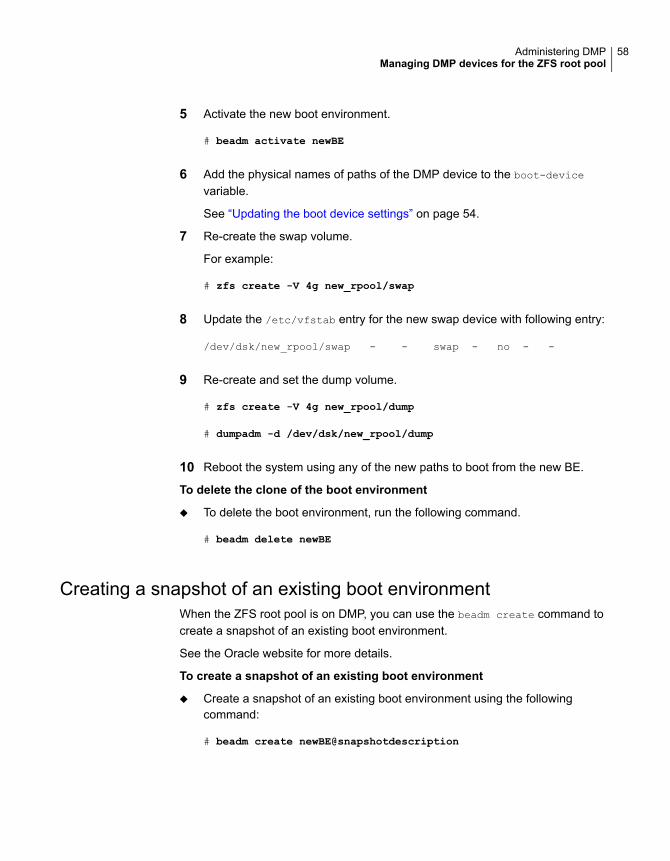
5 Activate the new boot environment.
# beadm activate newBE
6 Add the physical names of paths of the DMP device to the boot-device
variable.
See “Updating the boot device settings” on page 54.
7 Re-create the swap volume.
For example:
# zfs create -V 4g new_rpool/swap
8 Update the /etc/vfstab entry for the new swap device with following entry:
/dev/dsk/new_rpool/swap - - swap - no - -
9 Re-create and set the dump volume.
# zfs create -V 4g new_rpool/dump
# dumpadm -d /dev/dsk/new_rpool/dump
10 Reboot the system using any of the new paths to boot from the new BE.
To delete the clone of the boot environment
◆ To delete the boot environment, run the following command.
# beadm delete newBE
Creating a snapshot of an existing boot environmentWhen the ZFS root pool is on DMP, you can use the beadm create command tocreate a snapshot of an existing boot environment.
See the Oracle website for more details.
To create a snapshot of an existing boot environment
◆ Create a snapshot of an existing boot environment using the followingcommand:
# beadm create newBE@snapshotdescription
58Administering DMPManaging DMP devices for the ZFS root pool

To recreate the boot environment from an existing snapshot
◆ Recreate the boot environment from an existing snapshot using the followingcommand:
# beadm create -e newBE@snapshotdescription <bename>
Administering DMP using the vxdmpadm utilityThe vxdmpadm utility is a command-line administrative interface to DynamicMulti-Pathing (DMP).
You can use the vxdmpadm utility to perform the following tasks:
■ Retrieve the name of the DMP device corresponding to a particular path.See “Retrieving information about a DMP node” on page 60.
■ Display consolidated information about the DMP nodes.See “Displaying consolidated information about the DMP nodes” on page 61.
■ Display the members of a LUN group.See “Displaying the members of a LUN group” on page 63.
■ List all paths under a DMP device node, HBA controller, enclosure, or arrayport.See “Displaying paths controlled by a DMP node, controller, enclosure, or arrayport” on page 63.
■ Display information about the HBA controllers on the host.See “Displaying information about controllers” on page 66.
■ Display information about enclosures.See “Displaying information about enclosures” on page 67.
■ Display information about array ports that are connected to the storageprocessors of enclosures.See “Displaying information about array ports” on page 68.
■ Display information about devices that are controlled by third-party multi-pathingdrivers.See “Displaying information about devices controlled by third-party drivers”on page 68.
■ Display extended devices attributes.See “Displaying extended device attributes” on page 70.
■ See “Suppressing or including devices from VxVM control” on page 72.Suppress or include devices from DMP control.
59Administering DMPAdministering DMP using the vxdmpadm utility

■ Gather I/O statistics for a DMP node, enclosure, path, or controller.See “Gathering and displaying I/O statistics” on page 73.
■ Configure the attributes of the paths to an enclosure.See “Setting the attributes of the paths to an enclosure” on page 80.
■ Display the redundancy level of a device or enclosure.See “Displaying the redundancy level of a device or enclosure” on page 81.
■ Specify the minimum number of active paths.See “Specifying the minimum number of active paths” on page 82.
■ Display or set the I/O policy that is used for the paths to an enclosure.See “Specifying the I/O policy” on page 83.
■ Enable or disable I/O for a path, HBA controller or array port on the system.See “Disabling I/O for paths, controllers, array ports, or DMP nodes” on page 88.
■ Rename an enclosure.See “Renaming an enclosure” on page 91.
■ Configure how DMP responds to I/O request failures.See “Configuring the response to I/O failures” on page 91.
■ Configure the I/O throttling mechanism.See “Configuring the I/O throttling mechanism” on page 93.
■ Control the operation of the DMP path restoration thread.See “Configuring DMP path restoration policies” on page 96.
■ Configure array policy modules.See “Configuring Array Policy Modules” on page 98.
■ Get or set the values of various tunables used by DMP.See “DMP tunable parameters” on page 147.
See the vxdmpadm(1M) manual page.
Retrieving information about a DMP nodeThe following command displays the Dynamic Multi-Pathing (DMP) node thatcontrols a particular physical path:
# vxdmpadm getdmpnode nodename=pathname
The physical path is specified by argument to the nodename attribute, which mustbe a valid path listed in the device directory.
The device directory is the /dev/rdsk directory.
The command displays output similar to the following example output.
60Administering DMPAdministering DMP using the vxdmpadm utility

# vxdmpadm getdmpnode nodename=c0t5006016041E03B33d0s2
NAME STATE ENCLR-TYPE PATHS ENBL DSBL ENCLR-NAME
====================================================================
emc_clariion0_16 ENABLED EMC_CLARiiON 6 6 0 emc_clariion0
Use the -v option to display the LUN serial number and the array volume ID.
# vxdmpadm -v getdmpnode nodename=c0t5006016041E03B33d0s2
NAME STATE ENCLR-TYPE PATHS ENBL DSBL ENCLR-NAME SERIAL-NO ARRAY_VOL_ID
=====================================================================================
emc_clariion0_16 ENABLED EMC_CLARiiON 6 6 0 emc_clariion0 600601606 16
Use the enclosure attribute with getdmpnode to obtain a list of all DMP nodes forthe specified enclosure.
# vxdmpadm getdmpnode enclosure=enc0
NAME STATE ENCLR-TYPE PATHS ENBL DSBL ENCLR-NAME
=========================================================
c2t1d0s2 ENABLED T300 2 2 0 enc0
c2t1d1s2 ENABLED T300 2 2 0 enc0
c2t1d2s2 ENABLED T300 2 2 0 enc0
c2t1d3s2 ENABLED T300 2 2 0 enc0
Use the dmpnodename attribute with getdmpnode to display the DMP information fora given DMP node.
# vxdmpadm getdmpnode dmpnodename=emc_clariion0_158
NAME STATE ENCLR-TYPE PATHS ENBL DSBL ENCLR-NAME
==================================================================
emc_clariion0_158 ENABLED EMC_CLARiiON 1 1 0 emc_clariion0
Displaying consolidated information about the DMP nodesThe vxdmpadm list dmpnode command displays the detail information of a DynamicMulti-Pathing (DMP) node. The information includes the enclosure name, LUNserial number, port id information, device attributes, and so on.
The following command displays the consolidated information for all of the DMPnodes in the system:
# vxdmpadm list dmpnode all
61Administering DMPAdministering DMP using the vxdmpadm utility

Use the enclosure attribute with list dmpnode to obtain a list of all DMP nodesfor the specified enclosure.
# vxdmpadm list dmpnode enclosure=enclosurename
For example, the following command displays the consolidated information for allof the DMP nodes in the enc0 enclosure.
# vxdmpadm list dmpnode enclosure=enc0
Use the dmpnodename attribute with list dmpnode to display the DMP informationfor a given DMP node. The DMP node can be specified by name or by specifyinga path name. The detailed information for the specified DMP node includes pathinformation for each subpath of the listed DMP node.
The path state differentiates between a path that is disabled due to a failure and apath that has been manually disabled for administrative purposes. A path that hasbeen manually disabled using the vxdmpadm disable command is listed asdisabled(m).
# vxdmpadm list dmpnode dmpnodename=dmpnodename
For example, the following command displays the consolidated information for theDMP node emc_clariion0_158.
# vxdmpadm list dmpnode dmpnodename=emc_clariion0_158
dmpdev = emc_clariion0_158
state = enabled
enclosure = emc_clariion0
cab-sno = CK200070400359
asl = libvxCLARiiON.so
vid = DGC
pid = DISK
array-name = EMC_CLARiiON
array-type = CLR-A/PF
iopolicy = MinimumQ
avid = 158
lun-sno = 600601606D121B008FB6E0CA8EDBDB11
udid = DGC%5FDISK%5FCK200070400359%5F600601606D121B008FB6E0CA8EDBDB11
dev-attr = lun
###path = name state type transport ctlr hwpath aportID aportWWN attr
path = c0t5006016141E03B33d1s2 enabled(a) primary FC c0
/pci@1e,600000/SUNW,emlxs@3/fp@0,0 A5 50:06:01:61:41:e0:3b:33 -
path = c0t5006016041E03B33d1s2 enabled(a) primary FC c0
/pci@1e,600000/SUNW,emlxs@3/fp@0,0 A4 50:06:01:60:41:e0:3b:33 -
62Administering DMPAdministering DMP using the vxdmpadm utility

path = c0t5006016841E03B33d1s2 enabled secondary FC c0
/pci@1e,600000/SUNW,emlxs@3/fp@0,0 B4 50:06:01:68:41:e0:3b:33 -
path = c1t5006016141E03B33d1s2 enabled(a) primary FC c1
/pci@1e,600000/SUNW,emlxs@3,1/fp@0,0 A5 50:06:01:61:41:e0:3b:33 -
path = c1t5006016841E03B33d1s2 enabled secondary FC c1
/pci@1e,600000/SUNW,emlxs@3,1/fp@0,0 B4 50:06:01:68:41:e0:3b:33 -
path = c1t5006016041E03B33d1s2 enabled(a) primary FC c1
/pci@1e,600000/SUNW,emlxs@3,1/fp@0,0 A4 50:06:01:60:41:e0:3b:33 -
Displaying the members of a LUN groupThe following command displays the Dynamic Multi-Pathing (DMP) nodes that arein the same LUN group as a specified DMP node:
# vxdmpadm getlungroup dmpnodename=dmpnode
For example:
# vxdmpadm getlungroup dmpnodename=c11t0d10s2
The above command displays output such as the following:
NAME STATE ENCLR-TYPE PATHS ENBL DSBL ENCLR-NAME
===============================================================
c11t0d8s2 ENABLED ACME 2 2 0 enc1
c11t0d9s2 ENABLED ACME 2 2 0 enc1
c11t0d10s2 ENABLED ACME 2 2 0 enc1
c11t0d11s2 ENABLED ACME 2 2 0 enc1
Displaying paths controlled by a DMP node, controller, enclosure,or array port
The vxdmpadm getsubpaths command lists all of the paths known to DynamicMulti-Pathing (DMP). The vxdmpadm getsubpaths command also provides optionsto list the subpaths through a particular DMP node, controller, enclosure, or arrayport. To list the paths through an array port, specify either a combination of enclosurename and array port id, or array port worldwide name (WWN).
To list all subpaths known to DMP:
# vxdmpadm getsubpaths
NAME STATE[A] PATH-TYPE[M] DMPNODENAME ENCLR-NAME CTLR ATTRS
=======================================================================
c1t65d0s2 ENABLED(A) - Disk_1 Disk c1 -
63Administering DMPAdministering DMP using the vxdmpadm utility

c1t66d0s2 ENABLED(A) - Disk_2 Disk c1 -
c2t65d0s2 ENABLED(A) - Disk_1 Disk c2 -
c2t66d0s2 ENABLED(A) - Disk_2 Disk c2 -
c3t2d0s2 ENABLED(A) - EMC0_1 EMC0 c3 -
c3t2d1s2 ENABLED(A) - EMC0_2 EMC0 c3 -
c4t2d0s2 ENABLED(A) - EMC0_1 EMC0 c4 -
c4t2d1s2 ENABLED(A) - EMC0_2 EMC0 c4 -
The vxdmpadm getsubpaths command combined with the dmpnodename attributedisplays all the paths to a LUN that are controlled by the specified DMP node namefrom the /dev/vx/rdmp directory:
# vxdmpadm getsubpaths dmpnodename=c2t66d0s2
NAME STATE[A] PATH-TYPE[M] CTLR-NAME ENCLR-TYPE ENCLR-NAME ATTRS
=======================================================================
c2t66d0s2 ENABLED(A) PRIMARY c2 ACME enc0 -
c1t66d0s2 ENABLED PRIMARY c1 ACME enc0 -
For A/A arrays, all enabled paths that are available for I/O are shown as ENABLED(A).
For A/P arrays in which the I/O policy is set to singleactive, only one path isshown as ENABLED(A). The other paths are enabled but not available for I/O. If theI/O policy is not set to singleactive, DMP can use a group of paths (all primaryor all secondary) for I/O, which are shown as ENABLED(A).
See “Specifying the I/O policy” on page 83.
Paths that are in the DISABLED state are not available for I/O operations.
A path that was manually disabled by the system administrator displays asDISABLED(M). A path that failed displays as DISABLED.
You can use getsubpaths to obtain information about all the paths that areconnected to a particular HBA controller:
# vxdmpadm getsubpaths ctlr=c2
NAME STATE[-] PATH-TYPE[-] DMPNODENAME ENCLR-TYPE ENCLR-NAME ATTRS
======================================================================
c2t1d0s2 ENABLED(A) PRIMARY c2t1d0s2 ACME enc0 -
c2t2d0s2 ENABLED(A) PRIMARY c2t2d0s2 ACME enc0 -
c2t3d0s2 DISABLED SECONDARY c2t3d0s2 ACME enc0 -
c2t4d0s2 ENABLED SECONDARY c2t4d0s2 ACME enc0 -
64Administering DMPAdministering DMP using the vxdmpadm utility

You can also use getsubpaths to obtain information about all the paths that areconnected to a port on an array. The array port can be specified by the name ofthe enclosure and the array port ID, or by the WWN identifier of the array port:
# vxdmpadm getsubpaths enclosure=enclosure portid=portid
# vxdmpadm getsubpaths pwwn=pwwn
For example, to list subpaths through an array port through the enclosure and thearray port ID:
# vxdmpadm getsubpaths enclosure=HDS9500-ALUA0 portid=1A
NAME STATE[A] PATH-TYPE[M] DMPNODENAME ENCLR-NAME CTLR ATTRS
=======================================================================
c1t65d0s2 ENABLED(A) PRIMARY c1t65d0s2 HDS9500-ALUA0 c1 -
c1t66d0s2 ENABLED(A) PRIMARY c1t66d0s2 HDS9500-ALUA0 c1 -
For example, to list subpaths through an array port through the WWN:
# vxdmpadm getsubpaths pwwn=20:00:00:E0:8B:06:5F:19
NAME STATE[A] PATH-TYPE[M] DMPNODENAME ENCLR-NAME CTLR ATTRS
=======================================================================
c1t65d0s2 ENABLED(A) PRIMARY c1t65d0s2 HDS9500-ALUA0 c1 -
c1t66d0s2 ENABLED(A) PRIMARY c1t66d0s2 HDS9500-ALUA0 c1 -
You can use getsubpaths to obtain information about all the subpaths of anenclosure.
# vxdmpadm getsubpaths enclosure=enclosure_name [ctlr=ctlrname]
To list all subpaths of an enclosure:
# vxdmpadm getsubpaths enclosure=Disk
NAME STATE[A] PATH-TYPE[M] DMPNODENAME ENCLR-NAME CTLR ATTRS
=====================================================================
c1t65d0s2 ENABLED(A) - Disk_1 Disk c1 -
c1t66d0s2 ENABLED(A) - Disk_2 Disk c1 -
c2t65d0s2 ENABLED(A) - Disk_1 Disk c2 -
c2t66d0s2 ENABLED(A) - Disk_2 Disk c2 -
To list all subpaths of a controller on an enclosure:
# vxdmpadm getsubpaths enclosure=Disk ctlr=c1
NAME STATE[A] PATH-TYPE[M] DMPNODENAME ENCLR-NAME CTLR ATTRS
=====================================================================
65Administering DMPAdministering DMP using the vxdmpadm utility

c1t65d0s2 ENABLED(A) - Disk_1 Disk c1 -
c1t66d0s2 ENABLED(A) - Disk_2 Disk c1 -
By default, the output of the vxdmpadm getsubpaths command is sorted byenclosure name, DMP node name, and within that, path name.
To sort the output based on the pathname, the DMP node name, the enclosurename, or the host controller name, use the -s option.
To sort subpaths information, use the following command:
# vxdmpadm -s {path | dmpnode | enclosure | ctlr} getsubpaths \
[all | ctlr=ctlr_name | dmpnodename=dmp_device_name | \
enclosure=enclr_name [ctlr=ctlr_name | portid=array_port_ID] | \
pwwn=port_WWN | tpdnodename=tpd_node_name]
See “Setting customized names for DMP nodes” on page 49.
Displaying information about controllersThe following Dynamic Multi-Pathing (DMP) command lists attributes of all HBAcontrollers on the system:
# vxdmpadm listctlr all
CTLR-NAME ENCLR-TYPE STATE ENCLR-NAME PATH_COUNT
==============================================================
c1 OTHER ENABLED other0 3
c2 X1 ENABLED jbod0 10
c3 ACME ENABLED enc0 24
c4 ACME ENABLED enc0 24
This output shows that the controller c1 is connected to disks that are not in anyrecognized DMP category as the enclosure type is OTHER.
The other controllers are connected to disks that are in recognized DMP categories.
All the controllers are in the ENABLED state, which indicates that they are availablefor I/O operations.
The state DISABLED is used to indicate that controllers are unavailable for I/Ooperations. The unavailability can be due to a hardware failure or due to I/Ooperations being disabled on that controller by using the vxdmpadm disable
command.
The following forms of the command lists controllers belonging to a specifiedenclosure or enclosure type:
66Administering DMPAdministering DMP using the vxdmpadm utility

# vxdmpadm listctlr enclosure=enc0
or
# vxdmpadm listctlr type=ACME
CTLR-NAME ENCLR-TYPE STATE ENCLR-NAME PATH_COUNT
===============================================================
c2 ACME ENABLED enc0 10
c3 ACME ENABLED enc0 24
The vxdmpadm getctlr command displays HBA vendor details and the ControllerID. For iSCSI devices, the Controller ID is the IQN or IEEE-format based name.For FC devices, the Controller ID is the WWN. Because the WWN is obtained fromESD, this field is blank if ESD is not running. ESD is a daemon process used tonotify DDL about occurrence of events. The WWN shown as ‘Controller ID’ mapsto the WWN of the HBA port associated with the host controller.
# vxdmpadm getctlr c5
LNAME PNAME VENDOR CTLR-ID
===================================================
c5 c5 qlogic 20:07:00:a0:b8:17:e1:37
Displaying information about enclosuresDynamic Multi-Pathing (DMP) can display the attributes of the enclosures, includingthe enclosure type, enclosure serial number, status, array type, number of LUNs,and the firmware version, if available.
To display the attributes of a specified enclosure, use the following DMP command:
# vxdmpadm listenclosure emc0
ENCLR_NAME ENCLR_TYPE ENCLR_SNO STATUS ARRAY_TYPE LUN_COUNT FIRMWARE
==================================================================================
emc0 EMC 000292601383 CONNECTED A/A 30 5875
To display the attrtibutes for all enclosures in a system, use the following DMPcommand:
# vxdmpadm listenclosure all
ENCLR_NAME ENCLR_TYPE ENCLR_SNO STATUS ARRAY_TYPE LUN_COUNT FIRMWARE
====================================================================================
Disk Disk DISKS CONNECTED Disk 6 -
emc0 EMC 000292601383 CONNECTED A/A 1 5875
67Administering DMPAdministering DMP using the vxdmpadm utility

hitachi_usp-vm0 Hitachi_USP-VM 25847 CONNECTED A/A 1 6008
emc_clariion0 EMC_CLARiiON CK20007040035 CONNECTED CLR-A/PF 2 0324
If an A/P or ALUA array is under the control of MPxIO, then DMP claims the devicesin A/A mode. The output of the above commands shows the ARRAY_TYPE as A/A.For arrays under MPxIO control, DMP does not store A/P-specific attributes orALUA-specific attributes. These attributes include primary/secondary paths, portserial number, and the array controller ID.
Displaying information about array portsUse the Dynamic Multi-Pathing (DMP) commands in this section to displayinformation about array ports. The information displayed for an array port includesthe name of its enclosure, its ID, and its worldwide name (WWN) identifier.
Note:DMP does not report information about array ports for LUNs that are controlledby the native multi-pathing driver. DMP reports pWWN information only if thedmp_monitor_fabric tunable is on, and the event source daemon (esd) is running.
To display the attributes of an array port that is accessible through a path, DMPnode or HBA controller, use one of the following commands:
# vxdmpadm getportids path=path_name
# vxdmpadm getportids dmpnodename=dmpnode_name
# vxdmpadm getportids ctlr=ctlr_name
The following form of the command displays information about all of the array portswithin the specified enclosure:
# vxdmpadm getportids enclosure=enclr_name
The following example shows information about the array port that is accessiblethrough DMP node c2t66d0s2:
# vxdmpadm getportids dmpnodename=c2t66d0s2
NAME ENCLR-NAME ARRAY-PORT-ID pWWN
==============================================================
c2t66d0s2 HDS9500V0 1A 20:00:00:E0:8B:06:5F:19
Displaying information about devices controlled by third-party driversThe third-party driver (TPD) coexistence feature allows I/O that is controlled bythird-party multi-pathing drivers to bypass Dynamic Multi-Pathing (DMP) while
68Administering DMPAdministering DMP using the vxdmpadm utility

retaining the monitoring capabilities of DMP. The following commands allow youto display the paths that DMP has discovered for a given TPD device, and the TPDdevice that corresponds to a given TPD-controlled node discovered by DMP:
# vxdmpadm getsubpaths tpdnodename=TPD_node_name
# vxdmpadm gettpdnode nodename=TPD_path_name
See “Changing device naming for enclosures controlled by third-party drivers”on page 122.
For example, consider the following disks in an EMC Symmetrix array controlledby PowerPath, which are known to DMP:
# vxdisk list
DEVICE TYPE DISK GROUP STATUS
emcpower10s2 auto:sliced disk1 ppdg online
emcpower11s2 auto:sliced disk2 ppdg online
emcpower12s2 auto:sliced disk3 ppdg online
emcpower13s2 auto:sliced disk4 ppdg online
emcpower14s2 auto:sliced disk5 ppdg online
emcpower15s2 auto:sliced disk6 ppdg online
emcpower16s2 auto:sliced disk7 ppdg online
emcpower17s2 auto:sliced disk8 ppdg online
emcpower18s2 auto:sliced disk9 ppdg online
emcpower19s2 auto:sliced disk10 ppdg online
The following command displays the paths that DMP has discovered, and whichcorrespond to the PowerPath-controlled node, emcpower10s2:
# vxdmpadm getsubpaths tpdnodename=emcpower10s2
NAME TPDNODENAME PATH-TYPE[-]DMP-NODENAME ENCLR-TYPE ENCLR-NAME
===================================================================
c7t0d10s2emcpower10s2- emcpower10s2 EMC EMC0
c6t0d10s2emcpower10s2- emcpower10s2 EMC EMC0
Conversely, the next command displays information about the PowerPath nodethat corresponds to the path, c7t0d10s2, discovered by DMP:
# vxdmpadm gettpdnode nodename=c7t0d10s2
NAME STATE PATHS ENCLR-TYPE ENCLR-NAME
===================================================================
emcpower10s2 ENABLED 2 EMC EMC0
69Administering DMPAdministering DMP using the vxdmpadm utility

Displaying extended device attributesDevice Discovery Layer (DDL) extended attributes are attributes or flagscorresponding to a Veritas Volume Manager (VxVM) or Dynamic Multi-Pathing(DMP) LUN or disk and that are discovered by DDL. These attributes identify a LUNto a specific hardware category.
Table 3-1 describes the list of categories.
Table 3-1 Categories for extended attributes
DescriptionCategory
Displays what kind of Storage RAID Group theLUN belongs to
Hardware RAID types
Displays the LUN’s thin reclamation abilitiesThin Provisioning Discovery andReclamation
Displays the type of media –whether SSD (solidstate disk )
Device Media Type
Displays whether the LUN is a SNAPSHOT or aCLONE of a PRIMARY LUN
Storage-based Snapshot/Clone
Displays if the LUN is part of a replicated groupacross a remote site
Storage-based replication
Displays what kind of HBA is used to connect tothis LUN (FC, SATA, iSCSI)
Transport
Each LUN can have one or more of these extended attributes. DDL discovers theextended attributes during device discovery from the Array Support Library (ASL).If Veritas Operations Manager (VOM) is present, DDL can also obtain extendedattributes from the VOM Management Server for hosts that are configured asmanaged hosts.
The vxdisk -p list command displays DDL extended attributes. For example,the following command shows attributes of std, fc, and RAID_5 for this LUN:
# vxdisk -p list
DISK : tagmastore-usp0_0e18
DISKID : 1253585985.692.rx2600h11
VID : HITACHI
UDID : HITACHI%5FOPEN-V%5F02742%5F0E18
REVISION : 5001
PID : OPEN-V
PHYS_CTLR_NAME : 0/4/1/1.0x50060e8005274246
70Administering DMPAdministering DMP using the vxdmpadm utility

LUN_SNO_ORDER : 411
LUN_SERIAL_NO : 0E18
LIBNAME : libvxhdsusp.sl
HARDWARE_MIRROR: no
DMP_DEVICE : tagmastore-usp0_0e18
DDL_THIN_DISK : thick
DDL_DEVICE_ATTR: std fc RAID_5
CAB_SERIAL_NO : 02742
ATYPE : A/A
ARRAY_VOLUME_ID: 0E18
ARRAY_PORT_PWWN: 50:06:0e:80:05:27:42:46
ANAME : TagmaStore-USP
TRANSPORT : FC
The vxdisk -x attribute -p list command displays the one-line listing for theproperty list and the attributes. The following example shows two Hitachi LUNs thatsupport Thin Reclamation through the attribute hdprclm:
# vxdisk -x DDL_DEVICE_ATTR -p list
DEVICE DDL_DEVICE_ATTR
tagmastore-usp0_0a7a std fc RAID_5
tagmastore-usp0_065a hdprclm fc
tagmastore-usp0_065b hdprclm fc
User can specify multiple -x options in the same command to display multiple entries.For example:
# vxdisk -x DDL_DEVICE_ATTR -x VID -p list
DEVICE DDL_DEVICE_ATTR VID
tagmastore-usp0_0a7a std fc RAID_5 HITACHI
tagmastore-usp0_0a7b std fc RAID_5 HITACHI
tagmastore-usp0_0a78 std fc RAID_5 HITACHI
tagmastore-usp0_0a79 std fc RAID_5 HITACHI
tagmastore-usp0_065a hdprclm fc HITACHI
tagmastore-usp0_065b hdprclm fc HITACHI
tagmastore-usp0_065c hdprclm fc HITACHI
tagmastore-usp0_065d hdprclm fc HITACHI
Use the vxdisk -e list command to show the DLL_DEVICE_ATTR property inthe last column named ATTR.
# vxdisk -e list
DEVICE TYPE DISK GROUP STATUS OS_NATIVE_NAME ATTR
tagmastore-usp0_0a7a auto - - online c10t0d2 std fc RAID_5
71Administering DMPAdministering DMP using the vxdmpadm utility

tagmastore-usp0_0a7b auto - - online c10t0d3 std fc RAID_5
tagmastore-usp0_0a78 auto - - online c10t0d0 std fc RAID_5
tagmastore-usp0_0655 auto - - online c13t2d7 hdprclm fc
tagmastore-usp0_0656 auto - - online c13t3d0 hdprclm fc
tagmastore-usp0_0657 auto - - online c13t3d1 hdprclm fc
For a list of ASLs that supports Extended Attributes, and descriptions of theseattributes, refer to the hardware compatibility list (HCL) at the following URL:
http://www.symantec.com/docs/TECH211575
Note: DMP does not support Extended Attributes for LUNs that are controlled bythe native multi-pathing driver.
Suppressing or including devices from VxVM controlThe vxdmpadm exclude command suppresses devices from Veritas VolumeManager (VxVM) based on the criteria that you specify. When a device issuppressed, Dynamic Multi-Pathing (DMP) does not claim the device so that thedevice is not available for VxVM to use. You can add the devices back into VxVMcontrol with the vxdmpadm include command. The devices can be included orexcluded based on VID:PID combination, paths, controllers, or disks. You can usethe bang symbol (!) to exclude or include any paths or controllers except the onespecified.
The root disk cannot be suppressed. The operation fails if the VID:PID of an externaldisk is the same VID:PID as the root disk and the root disk is encapsulated underVxVM.
Note: The ! character is a special character in some shells. The following syntaxshows how to escape it in a bash shell.
# vxdmpadm exclude { all | product=VID:PID |
ctlr=[\!]ctlrname | dmpnodename=diskname [ path=[\!]pathname] }
# vxdmpadm include { all | product=VID:PID |
ctlr=[\!]ctlrname | dmpnodename=diskname [ path=[\!]pathname] }
where:
all devicesall
all devices with the specified VID:PIDproduct=VID:PID
72Administering DMPAdministering DMP using the vxdmpadm utility

all devices through the given controllerctlr=ctlrname
all paths under the DMP nodedmpnodename=diskname
all paths under the DMP node except the onespecified
dmpnodename=diskname path=\!pathname
Gathering and displaying I/O statisticsYou can use the vxdmpadm iostat command to gather and display I/O statisticsfor a specified DMP node, enclosure, path, port, or controller.
The statistics displayed are the CPU usage and amount of memory per CPU usedto accumulate statistics, the number of read and write operations, the number ofkilobytes read and written, and the average time in milliseconds per kilobyte thatis read or written.
To enable the gathering of statistics, enter this command:
# vxdmpadm iostat start [memory=size]
The memory attribute limits the maximum amount of memory that is used to recordI/O statistics for each CPU. The default limit is 32k (32 kilobytes) per CPU.
To reset the I/O counters to zero, use this command:
# vxdmpadm iostat reset
To display the accumulated statistics at regular intervals, use the following command:
# vxdmpadm iostat show {filter} [interval=seconds [count=N]]
The above command displays I/O statistics for the devices specified by the filter.The filter is one of the following:
■ all
■ ctlr=ctlr-name
■ dmpnodename=dmp-node
■ enclosure=enclr-name [portid=array-portid ] [ctlr=ctlr-name]
■ pathname=path-name
■ pwwn=array-port-wwn [ctlr=ctlr-name]
Use the interval and count attributes to specify the interval in seconds betweendisplaying the I/O statistics, and the number of lines to be displayed. The actualinterval may be smaller than the value specified if insufficient memory is availableto record the statistics.
73Administering DMPAdministering DMP using the vxdmpadm utility

DMP also provides a groupby option to display cumulative I/O statistics, aggregatedby the specified criteria.
See “Displaying cumulative I/O statistics” on page 74.
To disable the gathering of statistics, enter this command:
# vxdmpadm iostat stop
Displaying cumulative I/O statisticsThe vxdmpadm iostat command provides the ability to analyze the I/O loaddistribution across various I/O channels or parts of I/O channels. Select theappropriate filter to display the I/O statistics for the DMP node, controller, arrayenclosure, path, port, or virtual machine. Then, use the groupby clause to displaycumulative statistics according to the criteria that you want to analyze. If the groupby
clause is not specified, then the statistics are displayed per path.
When you combine the filter and the groupby clause, you can analyze the I/O loadfor the required use case scenario. For example:
■ To compare I/O load across HBAs, enclosures, or array ports, use the groupbyclause with the specified attribute.
■ To analyze I/O load across a given I/O channel (HBA to array port link), usefilter by HBA and PWWN or enclosure and array port.
■ To analyze I/O load distribution across links to an HBA, use filter by HBA andgroupby array port.
Use the following format of the iostat command to analyze the I/O loads:
# vxdmpadm [-u unit] iostat show [groupby=criteria] {filter} \
[interval=seconds [count=N]]
The above command displays I/O statistics for the devices specified by the filter.The filter is one of the following:
■ all
■ ctlr=ctlr-name
■ dmpnodename=dmp-node
■ enclosure=enclr-name [portid=array-portid ] [ctlr=ctlr-name]
■ pathname=path-name
■ pwwn=array-port-wwn[ctlr=ctlr-name]
You can aggregate the statistics by the following groupby criteria:
74Administering DMPAdministering DMP using the vxdmpadm utility

■ arrayport
■ ctlr
■ dmpnode
■ enclosure
By default, the read/write times are displayed in milliseconds up to 2 decimal places.The throughput data is displayed in terms of BLOCKS, and the output is scaled,meaning that the small values are displayed in small units and the larger valuesare displayed in bigger units, keeping significant digits constant. You can specifythe units in which the statistics data is displayed. The -u option accepts the followingoptions:
Displays throughput in the highest possible unit.h or H
Displays throughput in kilobytes.k
Displays throughput in megabytes.m
Displays throughput in gigabytes.g
Displays throughput in exact number of bytes.bytes| b
Displays average read/write time in microseconds.us
To group by DMP node:
# vxdmpadm [-u unit] iostat show groupby=dmpnode \
[all | dmpnodename=dmpnodename | enclosure=enclr-name]
For example:
# vxdmpadm iostat show groupby=dmpnode dmpnodename=c5t0d1s2
OPERATIONS BLOCKS AVG TIME(ms)
DMPNODENAME READS WRITES READS WRITES READS WRITES
c5t0d1s2 0 0 0 0 0.00 0.00
To group by controller:
# vxdmpadm [-u unit] iostat show groupby=ctlr [ all | ctlr=ctlr ]
For example:
# vxdmpadm iostat show groupby=ctlr ctlr=c5
75Administering DMPAdministering DMP using the vxdmpadm utility

OPERATIONS BLOCKS AVG TIME(ms)
CTLRNAME READS WRITES READS WRITES READS WRITES
c5 224 14 54 7 4.20 11.10
To group by arrayport:
# vxdmpadm [-u unit] iostat show groupby=arrayport [ all \
| pwwn=array_pwwn | enclosure=enclr portid=array-port-id ]
For example:
# vxdmpadm -u m iostat show groupby=arrayport \
enclosure=HDS9500-ALUA0 portid=1A
OPERATIONS BYTES AVG TIME(ms)
PORTNAME READS WRITES READS WRITES READS WRITES
1A 743 1538 11m 24m 17.13 8.61
To group by enclosure:
# vxdmpadm [-u unit] iostat show groupby=enclosure [ all \
| enclosure=enclr ]
For example:
# vxdmpadm -u h iostat show groupby=enclosure enclosure=EMC_CLARiiON0
OPERATIONS BLOCKS AVG TIME(ms)
ENCLOSURENAME READS WRITES READS WRITES READS WRITES
EMC_CLARiiON0 743 1538 11392k 24176k 17.13 8.61
You can also filter out entities for which all data entries are zero. This option isespecially useful in a cluster environment that contains many failover devices. Youcan display only the statistics for the active paths.
To filter all zero entries from the output of the iostat show command:
# vxdmpadm [-u unit] -z iostat show [all|ctlr=ctlr_name |
dmpnodename=dmp_device_name | enclosure=enclr_name [portid=portid] |
pathname=path_name|pwwn=port_WWN][interval=seconds [count=N]]
For example:
# vxdmpadm -z iostat show dmpnodename=c2t16d4s2
OPERATIONS BLOCKS AVG TIME(ms)
PATHNAME READS WRITES READS WRITES READS WRITES
76Administering DMPAdministering DMP using the vxdmpadm utility

c3t16d4s2 10 110 2 25 12.00 27.96
c2t17d4s2 20 126 4 29 9.50 19.41
To display average read/write times in microseconds.
# vxdmpadm -u us iostat show pathname=c2t17d4s2
OPERATIONS BLOCKS AVG TIME(microsec)
PATHNAME READS WRITES READS WRITES READS WRITES
c2t17d4s2 20 126 4 29 9500.00 19413.79
Displaying statistics for queued or erroneous I/OsUse the vxdmpadm iostat show command with the -q option to display the I/Osqueued in Dynamic Multi-Pathing (DMP) for a specified DMP node, or for a specifiedpath or controller. For a DMP node, the -q option displays the I/Os on the specifiedDMP node that were sent to underlying layers. If a path or controller is specified,the -q option displays I/Os that were sent to the given path or controller and notyet returned to DMP.
See the vxdmpadm(1m) manual page for more information about the vxdmpadm
iostat command.
To display queued I/O counts on a DMP node:
# vxdmpadm -q iostat show [filter] [interval=n [count=m]]
For example:
# vxdmpadm -q iostat show dmpnodename=c5t2d1s2
QUEUED I/Os Pending I/Os
DMPNODENAME READS WRITES
c5t2d1s2 2 15 30
To display the count of I/Os that returned with errors on a DMP node, path, orcontroller:
# vxdmpadm -e iostat show [filter] [interval=n [count=m]]
For example, to show the I/O counts that returned errors on a path:
# vxdmpadm -e iostat show pathname=c1t5006016041E03B33d6s2 interval=1
cpu usage = 168144us per cpu memory = 409600b
ERROR I/Os
PATHNAME READS WRITES
77Administering DMPAdministering DMP using the vxdmpadm utility

c1t5006016041E03B33d6s2 0 0
c1t5006016041E03B33d6s2 0 0
Examples of using the vxdmpadm iostat commandDynamic Multi-Pathing (DMP) enables you to gather and display I/O statistics withthe vxdmpadm iostat command. This section provides an example session usingthe vxdmpadm iostat command.
The first command enables the gathering of I/O statistics:
# vxdmpadm iostat start
The next command displays the current statistics including the accumulated totalnumbers of read and write operations, and the kilobytes read and written, on allpaths.
# vxdmpadm -u k iostat show all
cpu usage = 7952us per cpu memory = 8192b
OPERATIONS BYTES AVG TIME(ms)
PATHNAME READS WRITES READS WRITES READS WRITES
c0t0d0 1088 0 557056k 0 0.00 0.00
c2t118d0 87 0 44544k 0 0.00 0.00
c3t118d0 0 0 0 0 0.00 0.00
c2t122d0 87 0 44544k 0 0.00 0.00
c3t122d0 0 0 0 0 0.00 0.00
c2t115d0 87 0 44544k 0 0.00 0.00
c3t115d0 0 0 0 0 0.00 0.00
c2t103d0 87 0 44544k 0 0.00 0.00
c3t103d0 0 0 0 0 0.00 0.00
c2t102d0 87 0 44544k 0 0.00 0.00
c3t102d0 0 0 0 0 0.00 0.00
c2t121d0 87 0 44544k 0 0.00 0.00
c3t121d0 0 0 0 0 0.00 0.00
c2t112d0 87 0 44544k 0 0.00 0.00
c3t112d0 0 0 0 0 0.00 0.00
c2t96d0 87 0 44544k 0 0.00 0.00
c3t96d0 0 0 0 0 0.00 0.00
c2t106d0 87 0 44544k 0 0.00 0.00
c3t106d0 0 0 0 0 0.00 0.00
c2t113d0 87 0 44544k 0 0.00 0.00
c3t113d0 0 0 0 0 0.00 0.00
c2t119d0 87 0 44544k 0 0.00 0.00
c3t119d0 0 0 0 0 0.00 0.00
78Administering DMPAdministering DMP using the vxdmpadm utility

The following command changes the amount of memory that vxdmpadm can use toaccumulate the statistics:
# vxdmpadm iostat start memory=4096
The displayed statistics can be filtered by path name, DMP node name, andenclosure name (note that the per-CPU memory has changed following the previouscommand):
# vxdmpadm -u k iostat show pathname=c3t115d0s2
cpu usage = 8132us per cpu memory = 4096b
OPERATIONS BYTES AVG TIME(ms)
PATHNAME READS WRITES READS WRITES READS WRITES
c3t115d0s2 0 0 0 0 0.00 0.00
# vxdmpadm -u k iostat show dmpnodename=c0t0d0s2
cpu usage = 8501us per cpu memory = 4096b
OPERATIONS BYTES AVG TIME(ms)
PATHNAME READS WRITES READS WRITES READS WRITES
c0t0d0s2 1088 0 557056k 0 0.00 0.00
# vxdmpadm -u k iostat show enclosure=Disk
cpu usage = 8626us per cpu memory = 4096b
OPERATIONS BYTES AVG TIME(ms)
PATHNAME READS WRITES READS WRITES READS WRITES
c0t0d0s2 1088 0 57056k 0 0.00 0.00
You can also specify the number of times to display the statistics and the timeinterval. Here the incremental statistics for a path are displayed twice with a 2-secondinterval:
# vxdmpadm iostat show dmpnodename=emc_clariion0_342 interval=1 count=2
cpu usage = 164687us per cpu memory = 409600b
OPERATIONS BLOCKS AVG TIME(ms)
PATHNAME READS WRITES READS WRITES READS WRITES
c0t5006016041E03B33d6s2 3 0 33 0 0.02 0.00
c0t5006016141E03B33d6s2 3 0 3 0 0.16 0.00
c0t5006016841E03B33d6s2 0 0 0 0 0.00 0.00
c1t5006016041E03B33d6s2 1 0 16 0 0.02 0.00
c1t5006016141E03B33d6s2 2 0 2 0 0.18 0.00
c1t5006016841E03B33d6s2 0 0 0 0 0.00 0.00
c0t5006016041E03B33d6s2 0 0 0 0 0.00 0.00
c0t5006016141E03B33d6s2 0 0 0 0 0.00 0.00
79Administering DMPAdministering DMP using the vxdmpadm utility

c0t5006016841E03B33d6s2 0 0 0 0 0.00 0.00
c1t5006016041E03B33d6s2 0 0 0 0 0.00 0.00
c1t5006016141E03B33d6s2 0 0 0 0 0.00 0.00
c1t5006016841E03B33d6s2 0 0 0 0 0.00 0.00
Setting the attributes of the paths to an enclosureYou can use the vxdmpadm setattr command to set the attributes of the paths toan enclosure or disk array.
The attributes set for the paths are persistent across reboots or product upgrades.
You can set the following attributes:
Changes a standby (failover) path to an active path. The followingexample specifies an active path for an array:
# vxdmpadm setattr path c2t10d0s2 pathtype=active
active
Restores the original primary or secondary attributes of a path. Thisexample restores the path to a JBOD disk:
# vxdmpadm setattr path c3t10d0s2 pathtype=nomanual
nomanual
Restores the normal priority of a path. The following example restoresthe default priority to a path:
# vxdmpadm setattr path c1t20d0s2 \pathtype=nopreferred
nopreferred
Specifies a path as preferred, and optionally assigns a priority numberto it. If specified, the priority number must be an integer that is greaterthan or equal to one. Higher priority numbers indicate that a path isable to carry a greater I/O load.
See “Specifying the I/O policy” on page 83.
This example first sets the I/O policy to priority for an Active/Activedisk array, and then specifies a preferred path with an assigned priorityof 2:
# vxdmpadm setattr enclosure enc0 \iopolicy=priority
# vxdmpadm setattr path c1t20d0s2 \pathtype=preferred priority=2
preferred[priority=N]
80Administering DMPAdministering DMP using the vxdmpadm utility

Defines a path as being the primary path for a JBOD disk array. Thefollowing example specifies a primary path for a JBOD disk array:
# vxdmpadm setattr path c3t10d0s2 \pathtype=primary
primary
Defines a path as being the secondary path for a JBOD disk array. Thefollowing example specifies a secondary path for a JBOD disk array:
# vxdmpadm setattr path c4t10d0s2 \pathtype=secondary
secondary
Marks a standby (failover) path that it is not used for normal I/Oscheduling. This path is used if there are no active paths available forI/O. The next example specifies a standby path for an A/P-C disk array:
# vxdmpadm setattr path c2t10d0s2 \pathtype=standby
standby
Displaying the redundancy level of a device or enclosureUse the vxdmpadm getdmpnode command to list the devices with less than therequired redundancy level.
To list the devices on a specified enclosure with fewer than a given number ofenabled paths, use the following command:
# vxdmpadm getdmpnode enclosure=encl_name redundancy=value
For example, to list the devices with fewer than 3 enabled paths, use the followingcommand:
# vxdmpadm getdmpnode enclosure=EMC_CLARiiON0 redundancy=3
NAME STATE ENCLR-TYPE PATHS ENBL DSBL ENCLR-NAME
=====================================================================
emc_clariion0_162 ENABLED EMC_CLARiiON 3 2 1 emc_clariion0
emc_clariion0_182 ENABLED EMC_CLARiiON 2 2 0 emc_clariion0
emc_clariion0_184 ENABLED EMC_CLARiiON 3 2 1 emc_clariion0
emc_clariion0_186 ENABLED EMC_CLARiiON 2 2 0 emc_clariion0
To display the minimum redundancy level for a particular device, use the vxdmpadm
getattr command, as follows:
81Administering DMPAdministering DMP using the vxdmpadm utility

# vxdmpadm getattr enclosure|arrayname|arraytype \
component-name redundancy
For example, to show the minimum redundancy level for the enclosureHDS9500-ALUA0:
# vxdmpadm getattr enclosure HDS9500-ALUA0 redundancy
ENCLR_NAME DEFAULT CURRENT
=============================================
HDS9500-ALUA0 0 4
Specifying the minimum number of active pathsYou can set the minimum redundancy level for a device or an enclosure. Theminimum redundancy level is the minimum number of paths that should be activefor the device or the enclosure. If the number of paths falls below the minimumredundancy level for the enclosure, a message is sent to the system console andalso logged to the Dynamic Multi-Pathing (DMP) log file. Also, notification is sentto vxnotify clients.
The value set for minimum redundancy level is persistent across reboots and productupgrades. If no minimum redundancy level is set, the default value is 0.
You can use the vxdmpadm setattr command to set the minimum redundancylevel.
To specify the minimum number of active paths
◆ Use the vxdmpadm setattr command with the redundancy attribute as follows:
# vxdmpadm setattr enclosure|arrayname|arraytype component-name
redundancy=value
where value is the number of active paths.
For example, to set the minimum redundancy level for the enclosureHDS9500-ALUA0:
# vxdmpadm setattr enclosure HDS9500-ALUA0 redundancy=2
Displaying the I/O policyTo display the current and default settings of the I/O policy for an enclosure, array,or array type, use the vxdmpadm getattr command.
82Administering DMPAdministering DMP using the vxdmpadm utility

The following example displays the default and current setting of iopolicy forJBOD disks:
# vxdmpadm getattr enclosure Disk iopolicy
ENCLR_NAME DEFAULT CURRENT
---------------------------------------
Disk MinimumQ Balanced
The next example displays the setting of partitionsize for the enclosure enc0,on which the balanced I/O policy with a partition size of 2MB has been set:
# vxdmpadm getattr enclosure enc0 partitionsize
ENCLR_NAME DEFAULT CURRENT
---------------------------------------
enc0 512 4096
Specifying the I/O policyYou can use the vxdmpadm setattr command to change the Dynamic Multi-Pathing(DMP) I/O policy for distributing I/O load across multiple paths to a disk array orenclosure. You can set policies for an enclosure (for example, HDS01), for allenclosures of a particular type (such as HDS), or for all enclosures of a particulararray type (such as A/A for Active/Active, or A/P for Active/Passive).
Note: I/O policies are persistent across reboots of the system.
Table 3-2 describes the I/O policies that may be set.
Table 3-2 DMP I/O policies
DescriptionPolicy
This policy attempts to maximize overall I/O throughput from/to the disks by dynamicallyscheduling I/O on the paths. It is suggested for use where I/O loads can vary over time.For example, I/O from/to a database may exhibit both long transfers (table scans) andshort transfers (random look ups). The policy is also useful for a SAN environment wheredifferent paths may have different number of hops. No further configuration is possibleas this policy is automatically managed by DMP.
In this example, the adaptive I/O policy is set for the enclosure enc1:
# vxdmpadm setattr enclosure enc1 \iopolicy=adaptive
adaptive
83Administering DMPAdministering DMP using the vxdmpadm utility

Table 3-2 DMP I/O policies (continued)
DescriptionPolicy
Similar to the adaptive policy, except that I/O is scheduled according to the length ofthe I/O queue on each path. The path with the shortest queue is assigned the highestpriority.
adaptiveminq
This policy is designed to optimize the use of caching in disk drives and RAID controllers.The size of the cache typically ranges from 120KB to 500KB or more, depending on thecharacteristics of the particular hardware. During normal operation, the disks (or LUNs)are logically divided into a number of regions (or partitions), and I/O from/to a given regionis sent on only one of the active paths. Should that path fail, the workload is automaticallyredistributed across the remaining paths.
You can use the partitionsize attribute to specify the size for the partition. The partitionsize in blocks is adjustable in powers of 2 from 2 up to 231. A value that is not a powerof 2 is silently rounded down to the nearest acceptable value.
Specifying a partition size of 0 is equivalent to specifying the default partition size.
The default value for the partition size is 512 blocks (256k). Specifying a partition sizeof 0 is equivalent to the default partition size of 512 blocks (256k).
The default value can be changed by adjusting the value of thedmp_pathswitch_blks_shift tunable parameter.
See “DMP tunable parameters” on page 147.
Note: The benefit of this policy is lost if the value is set larger than the cache size.
For example, the suggested partition size for an Hitachi HDS 9960 A/A array is from32,768 to 131,072 blocks (16MB to 64MB) for an I/O activity pattern that consists mostlyof sequential reads or writes.
The next example sets the balanced I/O policy with a partition size of 4096 blocks (2MB)on the enclosure enc0:
# vxdmpadm setattr enclosure enc0 \iopolicy=balanced partitionsize=4096
balanced[partitionsize=size]
This policy sends I/O on paths that have the minimum number of outstanding I/O requestsin the queue for a LUN. No further configuration is possible as DMP automaticallydetermines the path with the shortest queue.
The following example sets the I/O policy to minimumq for a JBOD:
# vxdmpadm setattr enclosure Disk \iopolicy=minimumq
This is the default I/O policy for all arrays.
minimumq
84Administering DMPAdministering DMP using the vxdmpadm utility

Table 3-2 DMP I/O policies (continued)
DescriptionPolicy
This policy is useful when the paths in a SAN have unequal performance, and you wantto enforce load balancing manually. You can assign priorities to each path based on yourknowledge of the configuration and performance characteristics of the available paths,and of other aspects of your system.
See “Setting the attributes of the paths to an enclosure” on page 80.
In this example, the I/O policy is set to priority for all SENA arrays:
# vxdmpadm setattr arrayname SENA \iopolicy=priority
priority
This policy shares I/O equally between the paths in a round-robin sequence. For example,if there are three paths, the first I/O request would use one path, the second would usea different path, the third would be sent down the remaining path, the fourth would godown the first path, and so on. No further configuration is possible as this policy isautomatically managed by DMP.
The next example sets the I/O policy to round-robin for all Active/Active arrays:
# vxdmpadm setattr arraytype A/A \iopolicy=round-robin
round-robin
This policy routes I/O down the single active path. This policy can be configured for A/Parrays with one active path per controller, where the other paths are used in case offailover. If configured for A/A arrays, there is no load balancing across the paths, andthe alternate paths are only used to provide high availability (HA). If the current activepath fails, I/O is switched to an alternate active path. No further configuration is possibleas the single active path is selected by DMP.
The following example sets the I/O policy to singleactive for JBOD disks:
# vxdmpadm setattr arrayname Disk \iopolicy=singleactive
singleactive
Scheduling I/O on the paths of an AsymmetricActive/Active or an ALUA arrayYou can specify the use_all_paths attribute in conjunction with the adaptive,balanced, minimumq, priority, and round-robin I/O policies to specify whetherI/O requests are to be scheduled on the secondary paths in addition to the primarypaths of an Asymmetric Active/Active (A/A-A) array or an ALUA array. Dependingon the characteristics of the array, the consequent improved load balancing can
85Administering DMPAdministering DMP using the vxdmpadm utility

increase the total I/O throughput. However, this feature should only be enabled ifrecommended by the array vendor. It has no effect for array types other than A/A-Aor ALUA.
For example, the following command sets the balanced I/O policy with a partitionsize of 4096 blocks (2MB) on the enclosure enc0, and allows scheduling of I/Orequests on the secondary paths:
# vxdmpadm setattr enclosure enc0 iopolicy=balanced \
partitionsize=4096 use_all_paths=yes
The default setting for this attribute is use_all_paths=no.
You can display the current setting for use_all_paths for an enclosure, arrayname,or arraytype. To do this, specify the use_all_paths option to the vxdmpadm
gettattr command.
# vxdmpadm getattr enclosure HDS9500-ALUA0 use_all_paths
ENCLR_NAME ATTR_NAME DEFAULT CURRENT
===========================================
HDS9500-ALUA0 use_all_paths no yes
The use_all_paths attribute only applies to A/A-A arrays and ALUA arrays. Forother arrays, the above command displays the message:
Attribute is not applicable for this array.
Example of applying load balancing in a SANThis example describes how to use Dynamic Multi-Pathing (DMP) to configure loadbalancing in a SAN environment where there are multiple primary paths to anActive/Passive device through several SAN switches.
As shown in this sample output from the vxdisk list command, the devicec3t2d15s2 has eight primary paths:
# vxdisk list c3t2d15s2
Device: c3t2d15s2
.
.
.
numpaths: 8
c2t0d15s2 state=enabled type=primary
c2t1d15s2 state=enabled type=primary
c3t1d15s2 state=enabled type=primary
86Administering DMPAdministering DMP using the vxdmpadm utility

c3t2d15s2 state=enabled type=primary
c4t2d15s2 state=enabled type=primary
c4t3d15s2 state=enabled type=primary
c5t3d15s2 state=enabled type=primary
c5t4d15s2 state=enabled type=primary
In addition, the device is in the enclosure ENC0, belongs to the disk group mydg, andcontains a simple concatenated volume myvol1.
The first step is to enable the gathering of DMP statistics:
# vxdmpadm iostat start
Next, use the dd command to apply an input workload from the volume:
# dd if=/dev/vx/rdsk/mydg/myvol1 of=/dev/null &
By running the vxdmpadm iostat command to display the DMP statistics for thedevice, it can be seen that all I/O is being directed to one path, c5t4d15s2:
# vxdmpadm iostat show dmpnodename=c3t2d15s2 interval=5 count=2
.
.
.
cpu usage = 11294us per cpu memory = 32768b
OPERATIONS KBYTES AVG TIME(ms)
PATHNAME READS WRITES READS WRITES READS WRITES
c2t0d15s2 0 0 0 0 0.00 0.00
c2t1d15s2 0 0 0 0 0.00 0.00
c3t1d15s2 0 0 0 0 0.00 0.00
c3t2d15s2 0 0 0 0 0.00 0.00
c4t2d15s2 0 0 0 0 0.00 0.00
c4t3d15s2 0 0 0 0 0.00 0.00
c5t3d15s2 0 0 0 0 0.00 0.00
c5t4d15s2 10986 0 5493 0 0.41 0.00
The vxdmpadm command is used to display the I/O policy for the enclosure thatcontains the device:
# vxdmpadm getattr enclosure ENC0 iopolicy
ENCLR_NAME DEFAULT CURRENT
============================================
ENC0 MinimumQ Single-Active
87Administering DMPAdministering DMP using the vxdmpadm utility

This shows that the policy for the enclosure is set to singleactive, which explainswhy all the I/O is taking place on one path.
To balance the I/O load across the multiple primary paths, the policy is set toround-robin as shown here:
# vxdmpadm setattr enclosure ENC0 iopolicy=round-robin
# vxdmpadm getattr enclosure ENC0 iopolicy
ENCLR_NAME DEFAULT CURRENT
============================================
ENC0 MinimumQ Round-Robin
The DMP statistics are now reset:
# vxdmpadm iostat reset
With the workload still running, the effect of changing the I/O policy to balance theload across the primary paths can now be seen.
# vxdmpadm iostat show dmpnodename=c3t2d15s2 interval=5 count=2
.
.
.
cpu usage = 14403us per cpu memory = 32768b
OPERATIONS KBYTES AVG TIME(ms)
PATHNAME READS WRITES READS WRITES READS WRITES
c2t0d15s2 2041 0 1021 0 0.39 0.00
c2t1d15s2 1894 0 947 0 0.39 0.00
c3t1d15s2 2008 0 1004 0 0.39 0.00
c3t2d15s2 2054 0 1027 0 0.40 0.00
c4t2d15s2 2171 0 1086 0 0.39 0.00
c4t3d15s2 2095 0 1048 0 0.39 0.00
c5t3d15s2 2073 0 1036 0 0.39 0.00
c5t4d15s2 2042 0 1021 0 0.39 0.00
The enclosure can be returned to the single active I/O policy by entering the followingcommand:
# vxdmpadm setattr enclosure ENC0 iopolicy=singleactive
Disabling I/O for paths, controllers, array ports, or DMP nodesDisabling I/O through a path, HBA controller, array port, or Dynamic Multi-Pathing(DMP) node prevents DMP from issuing I/O requests through the specified path,or the paths that are connected to the specified controller, array port, or DMP node.
88Administering DMPAdministering DMP using the vxdmpadm utility

If the specified paths have pending I/Os, the vxdmpadm disable command waitsuntil the I/Os are completed before disabling the paths.
Before detaching a system board, stop all I/O to the HBA controllers that are locatedon the board. To do this, execute the vxdmpadm disable command, and then runthe Dynamic Reconfiguration (DR) facility provided by Oracle.
DMP does not support the operation to disable I/O for the controllers that useThird-Party Drivers (TPD) for multi-pathing.
To disable I/O for one or more paths, use the following command:
# vxdmpadm [-c|-f] disable path=path_name1[,path_name2,path_nameN]
To disable I/O for the paths connected to one or more HBA controllers, use thefollowing command:
# vxdmpadm [-c|-f] disable ctlr=ctlr_name1[,ctlr_name2,ctlr_nameN]
To disable I/O for the paths connected to an array port, use one of the followingcommands:
# vxdmpadm [-c|-f] disable enclosure=enclr_name portid=array_port_ID
# vxdmpadm [-c|-f] disable pwwn=array_port_WWN
where the array port is specified either by the enclosure name and the array portID, or by the array port’s worldwide name (WWN) identifier.
The following examples show how to disable I/O on an array port:
# vxdmpadm disable enclosure=HDS9500V0 portid=1A
# vxdmpadm disable pwwn=20:00:00:E0:8B:06:5F:19
To disable I/O for a particular path, specify both the controller and the portID, whichrepresent the two ends of the fabric:
# vxdmpadm [-c|-f] disable ctlr=ctlr_name enclosure=enclr_name \
portid=array_port_ID
To disable I/O for a particular DMP node, specify the DMP node name.
# vxdmpadm [-c|-f] disable dmpnodename=dmpnode
You can use the -c option to check if there is only a single active path to the disk.
The last path disable operation fails with -f option irrespective whether the deviceis in use or not.
The disable operation fails if it is issued to a controller that is connected to theroot disk through a single path, and there are no root disk mirrors configured on
89Administering DMPAdministering DMP using the vxdmpadm utility

alternate paths. If such mirrors exist, the command succeeds. The disable operationfails if it is issued to a controller that is connected to the swap device through asingle path.
Enabling I/O for paths, controllers, array ports, or DMP nodesEnabling a controller allows a previously disabled path, HBA controller, array port,or Dynamic Multi-Pathing (DMP) node to accept I/O again. This operation succeedsonly if the path, controller, array port, or DMP node is accessible to the host, andI/O can be performed on it. When connecting Active/Passive disk arrays, the enable
operation results in failback of I/O to the primary path. The enable operation canalso be used to allow I/O to the controllers on a system board that was previouslydetached.
Note: This operation is supported for controllers that are used to access disk arrayson which cluster-shareable disk groups are configured.
DMP does not support the operation to enable I/O for the controllers that useThird-Party Drivers (TPD) for multi-pathing.
To enable I/O for one or more paths, use the following command:
# vxdmpadm enable path=path_name1[,path_name2,path_nameN]
To enable I/O for the paths connected to one or more HBA controllers, use thefollowing command:
# vxdmpadm enable ctlr=ctlr_name1[,ctlr_name2,ctlr_nameN]
To enable I/O for the paths connected to an array port, use one of the followingcommands:
# vxdmpadm enable enclosure=enclr_name portid=array_port_ID
# vxdmpadm enable pwwn=array_port_WWN
where the array port is specified either by the enclosure name and the array portID, or by the array port’s worldwide name (WWN) identifier.
The following are examples of using the command to enable I/O on an array port:
# vxdmpadm enable enclosure=HDS9500V0 portid=1A
# vxdmpadm enable pwwn=20:00:00:E0:8B:06:5F:19
To enable I/O for a particular path, specify both the controller and the portID, whichrepresent the two ends of the fabric:
90Administering DMPAdministering DMP using the vxdmpadm utility

# vxdmpadm enable ctlr=ctlr_name enclosure=enclr_name \
portid=array_port_ID
To enable I/O for a particular DMP node, specify the DMP node name.
# vxdmpadm enable dmpnodename=dmpnode
Renaming an enclosureThe vxdmpadm setattr command can be used to assign a meaningful name to anexisting enclosure, for example:
# vxdmpadm setattr enclosure emc0 name=GRP1
This example changes the name of an enclosure from emc0 to GRP1.
Note: The maximum length of the enclosure name prefix is 23 characters.
The following command shows the changed name:
# vxdmpadm listenclosure all
ENCLR_NAME ENCLR_TYPE ENCLR_SNO STATUS ARRAY_TYPE LUN_COUNT FIRMWARE
====================================================================================
Disk Disk DISKS CONNECTED Disk 6 -
GRP1 EMC 000292601383 CONNECTED A/A 1 5875
hitachi_usp-vm0 Hitachi_USP-VM 25847 CONNECTED A/A 1 6008
emc_clariion0 EMC_CLARiiON CK20007040035 CONNECTED CLR-A/PF 2 0324
Configuring the response to I/O failuresYou can configure how Dynamic Multi-Pathing (DMP) responds to failed I/O requestson the paths to a specified enclosure, disk array name, or type of array. By default,DMP is configured to retry a failed I/O request up to five minutes on various activepaths.
To display the current settings for handling I/O request failures that are applied tothe paths to an enclosure, array name, or array type, use the vxdmpadm getattr
command.
See “Displaying recovery option values” on page 95.
To set a limit for the number of times that DMP attempts to retry sending an I/Orequest on a path, use the following command:
91Administering DMPAdministering DMP using the vxdmpadm utility

# vxdmpadm setattr \
{enclosure enc-name|arrayname name|arraytype type} \
recoveryoption=fixedretry retrycount=n
The value of the argument to retrycount specifies the number of retries to beattempted before DMP reschedules the I/O request on another available path, orfails the request altogether.
As an alternative to specifying a fixed number of retries, you can specify the amountof time DMP allows for handling an I/O request. If the I/O request does not succeedwithin that time, DMP fails the I/O request. To specify an iotimeout value, use thefollowing command:
# vxdmpadm setattr \
{enclosure enc-name|arrayname name|arraytype type} \
recoveryoption=timebound iotimeout=seconds
The default value of iotimeout is 300 seconds. For some applications such asOracle, it may be desirable to set iotimeout to a larger value. The iotimeout valuefor DMP should be greater than the I/O service time of the underlying operatingsystem layers.
Note: The fixedretry and timebound settings are mutually exclusive.
The following example configures time-bound recovery for the enclosure enc0, andsets the value of iotimeout to 360 seconds:
# vxdmpadm setattr enclosure enc0 recoveryoption=timebound \
iotimeout=360
The next example sets a fixed-retry limit of 10 for the paths to all Active/Activearrays:
# vxdmpadm setattr arraytype A/A recoveryoption=fixedretry \
retrycount=10
Specifying recoveryoption=default resets DMP to the default settings for recovery.
For example, the following command sets the default settings:
# vxdmpadm setattr arraytype A/A recoveryoption=default
For PCI devices, the default settings are recoveryoption=fixedretry
retrycount=5.
92Administering DMPAdministering DMP using the vxdmpadm utility

For all other devices, the default settings are recoveryoption=timebound
iotimeout=300
Specifying recoveryoption=defaultalso has the effect of configuring I/O throttlingwith the default settings.
See “Configuring the I/O throttling mechanism” on page 93.
Note: The response to I/O failure settings is persistent across reboots of the system.
Configuring the I/O throttling mechanismBy default, Dynamic Multi-Pathing (DMP) is configured with I/O throttling turned offfor all paths. To display the current settings for I/O throttling that are applied to thepaths to an enclosure, array name, or array type, use the vxdmpadm getattr
command.
See “Displaying recovery option values” on page 95.
If enabled, I/O throttling imposes a small overhead on CPU and memory usagebecause of the activity of the statistics-gathering daemon. If I/O throttling is disabled,the daemon no longer collects statistics, and remains inactive until I/O throttling isre-enabled.
To turn off I/O throttling, use the following form of the vxdmpadm setattr command:
# vxdmpadm setattr \
{enclosure enc-name|arrayname name|arraytype type} \
recoveryoption=nothrottle
The following example shows how to disable I/O throttling for the paths to theenclosure enc0:
# vxdmpadm setattr enclosure enc0 recoveryoption=nothrottle
The vxdmpadm setattr command can be used to enable I/O throttling on the pathsto a specified enclosure, disk array name, or type of array:
# vxdmpadm setattr \
{enclosure enc-name|arrayname name|arraytype type}\
recoveryoption=throttle [iotimeout=seconds]
If the iotimeout attribute is specified, its argument specifies the time in secondsthat DMP waits for an outstanding I/O request to succeed before invoking I/Othrottling on the path. The default value of iotimeout is 10 seconds. Setting
93Administering DMPAdministering DMP using the vxdmpadm utility

iotimeout to a larger value potentially causes more I/O requests to become queuedup in the SCSI driver before I/O throttling is invoked.
The following example sets the value of iotimeout to 60 seconds for the enclosureenc0:
# vxdmpadm setattr enclosure enc0 recoveryoption=throttle \
iotimeout=60
Specify recoveryoption=default to reset I/O throttling to the default settings, asfollows:
# vxdmpadm setattr arraytype A/A recoveryoption=default
The above command configures the default behavior, corresponding torecoveryoption=nothrottle. The above command also configures the defaultbehavior for the response to I/O failures.
See “Configuring the response to I/O failures” on page 91.
Note: The I/O throttling settings are persistent across reboots of the system.
Configuring Subpaths Failover Groups (SFG)The Subpaths Failover Groups (SFG) feature can be turned on or off using thetunable dmp_sfg_threshold. The default value of the tunable is 1, which representsthat the feature is on.
To turn off the feature, set the tunable dmp_sfg_threshold value to 0:
# vxdmpadm settune dmp_sfg_threshold=0
To turn on the feature, set the dmp_sfg_threshold value to the required numberof path failures that triggers SFG.
# vxdmpadm settune dmp_sfg_threshold=N
To see the Subpaths Failover Groups ID, use the following command:
# vxdmpadm getportids {ctlr=ctlr_name | dmpnodename=dmp_device_name \
| enclosure=enclr_name | path=path_name}
Configuring Low Impact Path Probing (LIPP)The Low Impact Path Probing (LIPP) feature can be turned on or off using thevxdmpadm settune command:
94Administering DMPAdministering DMP using the vxdmpadm utility

# vxdmpadm settune dmp_low_impact_probe=[on|off]
Path probing will be optimized by probing a subset of paths connected to the sameHBA and array port. The size of the subset of paths can be controlled by thedmp_probe_threshold tunable. The default value is set to 5.
# vxdmpadm settune dmp_probe_threshold=N
Displaying recovery option valuesTo display the current settings for handling I/O request failures that are applied tothe paths to an enclosure, array name, or array type, use the following DynamicMulti-Pathing (DMP) command:
# vxdmpadm getattr \
{enclosure enc-name|arrayname name|arraytype type} \
recoveryoption
The following example shows the vxdmpadm getattr command being used todisplay the recoveryoption option values that are set on an enclosure.
# vxdmpadm getattr enclosure HDS9500-ALUA0 recoveryoption
ENCLR-NAME RECOVERY-OPTION DEFAULT[VAL] CURRENT[VAL]
===============================================================
HDS9500-ALUA0 Throttle Nothrottle[0] Nothrottle[0]
HDS9500-ALUA0 Error-Retry Timebound[300] Timebound[300]
The command output shows the default and current policy options and their values.
Table 3-3 summarizes the possible recovery option settings for retrying I/O afteran error.
Table 3-3 Recovery options for retrying I/O after an error
DescriptionPossible settingsRecovery option
DMP retries a failed I/Orequest for the specifiednumber of times if I/O fails.
Fixed-Retry (retrycount)recoveryoption=fixedretry
DMP retries a failed I/Orequest for the specified timein seconds if I/O fails.
Timebound (iotimeout)recoveryoption=timebound
Table 3-4 summarizes the possible recovery option settings for throttling I/O.
95Administering DMPAdministering DMP using the vxdmpadm utility

Table 3-4 Recovery options for I/O throttling
DescriptionPossible settingsRecovery option
I/O throttling is not used.Nonerecoveryoption=nothrottle
DMP throttles the path if anI/O request does not returnwithin the specified time inseconds.
Timebound (iotimeout)recoveryoption=throttle
Configuring DMP path restoration policiesDynamic Multi-Pathing (DMP) maintains a kernel task that re-examines the conditionof paths at a specified interval. The type of analysis that is performed on the pathsdepends on the checking policy that is configured.
Note: The DMP path restoration task does not change the disabled state of thepath through a controller that you have disabled using vxdmpadm disable.
When configuring DMP path restoration policies, you must stop the path restorationthread, and then restart it with new attributes.
See “Stopping the DMP path restoration thread” on page 97.
Use the vxdmpadm settune dmp_restore_policy command to configure one ofthe following restore policies. The policy remains in effect until the restore threadis stopped or the values are changed using the vxdmpadm settune command.
■ check_all
The path restoration thread analyzes all paths in the system and revives thepaths that are back online, as well as disabling the paths that are inaccessible.The command to configure this policy is:
# vxdmpadm settune dmp_restore_policy=check_all
■ check_alternate
The path restoration thread checks that at least one alternate path is healthy.It generates a notification if this condition is not met. This policy avoids inquirycommands on all healthy paths, and is less costly than check_all in caseswhere a large number of paths are available. This policy is the same ascheck_all if there are only two paths per DMP node. The command to configurethis policy is:
# vxdmpadm settune dmp_restore_policy=check_alternate
96Administering DMPAdministering DMP using the vxdmpadm utility

■ check_disabled
This is the default path restoration policy. The path restoration thread checksthe condition of paths that were previously disabled due to hardware failures,and revives them if they are back online. The command to configure this policyis:
# vxdmpadm settune dmp_restore_policy=check_disabled
■ check_periodic
The path restoration thread performs check_all once in a given number ofcycles, and check_disabled in the remainder of the cycles. This policy maylead to periodic slowing down (due to check_all) if a large number of paths areavailable. The command to configure this policy is:
# vxdmpadm settune dmp_restore_policy=check_periodic
The default number of cycles between running the check_all policy is 10.
The dmp_restore_interval tunable parameter specifies how often the pathrestoration thread examines the paths. For example, the following command setsthe polling interval to 400 seconds:
# vxdmpadm settune dmp_restore_interval=400
The settings are immediately applied and are persistent across reboots. Use thevxdmpadm gettune command to view the current settings.
See “DMP tunable parameters” on page 147.
If the vxdmpadm start restore command is given without specifying a policy orinterval, the path restoration thread is started with the persistent policy and intervalsettings previously set by the administrator with the vxdmpadm settune command.If the administrator has not set a policy or interval, the system defaults are used.The system default restore policy is check_disabled. The system default intervalis 300 seconds.
Warning: Decreasing the interval below the system default can adversely affectsystem performance.
Stopping the DMP path restoration threadUse the following command to stop the Dynamic Multi-Pathing (DMP) pathrestoration thread:
# vxdmpadm stop restore
97Administering DMPAdministering DMP using the vxdmpadm utility

Warning: Automatic path failback stops if the path restoration thread is stopped.
Displaying the status of the DMP path restoration threadUse the vxdmpadm gettune command to display the tunable parameter values thatshow the status of the Dynamic Multi-Pathing (DMP) path restoration thread. Thesetunables include:
the status of the automatic path restoration kernel thread.dmp_restore_state
the polling interval for the DMP path restoration thread.dmp_restore_interval
the policy that DMP uses to check the condition of paths.dmp_restore_policy
To display the status of the DMP path restoration thread
◆ Use the following commands:
# vxdmpadm gettune dmp_restore_state
# vxdmpadm gettune dmp_restore_interval
# vxdmpadm gettune dmp_restore_policy
Configuring Array Policy ModulesDynamic Multi-Pathing (DMP) provides Array Policy Modules (APMs) for use withan array. An APM is a dynamically loadable kernel module (or plug-in) that definesarray-specific procedures and commands to:
■ Select an I/O path when multiple paths to a disk within the array are available.
■ Select the path failover mechanism.
■ Select the alternate path in the case of a path failure.
■ Put a path change into effect.
■ Respond to SCSI reservation or release requests.
DMP supplies default procedures for these functions when an array is registered.An APM may modify some or all of the existing procedures that DMP provides, orthat another version of the APM provides.
You can use the following command to display all the APMs that are configured fora system:
# vxdmpadm listapm all
98Administering DMPAdministering DMP using the vxdmpadm utility

The output from this command includes the file name of each module, the supportedarray type, the APM name, the APM version, and whether the module is currentlyloaded and in use.
To see detailed information for an individual module, specify the module name asthe argument to the command:
# vxdmpadm listapm module_name
To add and configure an APM, use the following command:
# vxdmpadm -a cfgapm module_name [attr1=value1 \
[attr2=value2 ...]]
The optional configuration attributes and their values are specific to the APM foran array. Consult the documentation from the array vendor for details.
Note: By default, DMP uses the most recent APM that is available. Specify the -u
option instead of the -a option if you want to force DMP to use an earlier versionof the APM. The current version of an APM is replaced only if it is not in use.
Specify the -r option to remove an APM that is not currently loaded:
# vxdmpadm -r cfgapm module_name
See the vxdmpadm(1M) manual page.
99Administering DMPAdministering DMP using the vxdmpadm utility

Administering disksThis chapter includes the following topics:
■ About disk management
■ Discovering and configuring newly added disk devices
■ VxVM coexistence with ZFS
■ Changing the disk device naming scheme
■ Discovering the association between enclosure-based disk names and OS-baseddisk names
About disk managementDynamic Multi-Pathing (DMP) is used to administer multiported disk arrays.
See “How DMP works” on page 12.
DMP uses the Device Discovery Layer (DDL) to handle device discovery andconfiguration of disk arrays. DDL discovers disks and their attributes that are requiredfor DMP operations. Use the vxddladm utility to administer the DDL.
See “How to administer the Device Discovery Layer” on page 105.
Discovering and configuring newly added diskdevices
The vxdiskconfig utility scans and configures new disk devices attached to thehost, disk devices that become online, or Fibre Channel devices that are zoned tohost bus adapters connected to this host. The command calls platform-specificinterfaces to configure new disk devices and brings them under control of theoperating system. It scans for disks that were added since DMP’s configuration
4Chapter

daemon was last started. These disks are then dynamically configured andrecognized by DMP.
vxdiskconfig should be used whenever disks are physically connected to the hostor when Fibre Channel devices are zoned to the host.
vxdiskconfig calls vxdctl enable to rebuild volume device node directories andupdate the Dynamic Multi-Pathing (DMP) internal database to reflect the new stateof the system.
You can also use the vxdisk scandisks command to scan devices in the operatingsystem device tree, and to initiate dynamic reconfiguration of multipathed disks.
If you want DMP to scan only for new devices that have been added to the system,and not for devices that have been enabled or disabled, specify the -f option toeither of the commands, as shown here:
# vxdctl -f enable
# vxdisk -f scandisks
However, a complete scan is initiated if the system configuration has been modifiedby changes to:
■ Installed array support libraries.
■ The list of devices that are excluded from use by VxVM.
■ DISKS (JBOD), SCSI3, or foreign device definitions.
See the vxdctl(1M) manual page.
See the vxdisk(1M) manual page.
Partial device discoveryDynamic Multi-Pathing (DMP) supports partial device discovery where you caninclude or exclude paths to a physical disk from the discovery process.
The vxdisk scandisks command rescans the devices in the OS device tree andtriggers a DMP reconfiguration. You can specify parameters to vxdisk scandisks
to implement partial device discovery. For example, this command makes DMPdiscover newly added devices that were unknown to it earlier:
# vxdisk scandisks new
The next example discovers fabric devices:
# vxdisk scandisks fabric
101Administering disksDiscovering and configuring newly added disk devices

The above command discovers devices with the characteristic DDI_NT_FABRIC
property set on them.
The following command scans for the devices c1t1d0s2 and c2t2d0s2:
# vxdisk scandisks device=c1t1d0s2,c2t2d0s2
Alternatively, you can specify a ! prefix character to indicate that you want to scanfor all devices except those that are listed.
Note: The ! character is a special character in some shells. The following examplesshow how to escape it in a bash shell.
# vxdisk scandisks \!device=c1t1d0s2,c2t2d0s2
You can also scan for devices that are connected (or not connected) to a list oflogical or physical controllers. For example, this command discovers and configuresall devices except those that are connected to the specified logical controllers:
# vxdisk scandisks \!ctlr=c1,c2
The next command discovers devices that are connected to the specified physicalcontroller:
# vxdisk scandisks pctlr=/pci@1f,4000/scsi@3/
The items in a list of physical controllers are separated by + characters.
You can use the command vxdmpadm getctlr all to obtain a list of physicalcontrollers.
You should specify only one selection argument to the vxdisk scandisks command.Specifying multiple options results in an error.
See the vxdisk(1M) manual page.
About discovering disks and dynamically adding disk arraysDynamic Multi-Pathing (DMP) uses array support libraries (ASLs) to providearray-specific support for multi-pathing. An array support library (ASL) is adynamically loadable shared library (plug-in for DDL). The ASL implementshardware-specific logic to discover device attributes during device discovery. DMPprovides the device discovery layer (DDL) to determine which ASLs should beassociated to each disk array.
In some cases, DMP can also provide basic multi-pathing and failover functionalityby treating LUNs as disks (JBODs).
102Administering disksDiscovering and configuring newly added disk devices

How DMP claims devicesFor fully optimized support of any array and for support of more complicated arraytypes, Dynamic Multi-Pathing (DMP) requires the use of array-specific array supportlibraries (ASLs), possibly coupled with array policy modules (APMs). ASLs andAPMs effectively are array-specific plug-ins that allow close tie-in of DMP with anyspecific array model.
See the Hardware Compatibility List for the complete list of supported arrays.
http://www.symantec.com/docs/TECH211575
During device discovery, the DDL checks the installed ASL for each device to findwhich ASL claims the device.
If no ASL is found to claim the device, the DDL checks for a corresponding JBODdefinition. You can add JBOD definitions for unsupported arrays to enable DMP toprovide multi-pathing for the array. If a JBOD definition is found, the DDL claimsthe devices in the DISKS category, which adds the LUNs to the list of JBOD (physicaldisk) devices used by DMP. If the JBOD definition includes a cabinet number, DDLuses the cabinet number to group the LUNs into enclosures.
See “Adding unsupported disk arrays to the DISKS category” on page 113.
DMP can provide basic multi-pathing to arrays that comply with the AsymmetricLogical Unit Access (ALUA) standard, even if there is no ASL or JBOD definition.DDL claims the LUNs as part of the aluadisk enclosure. The array type is shownas ALUA. Adding a JBOD definition also enables you to group the LUNs intoenclosures.
Disk categoriesDisk arrays that have been certified for use with Dynamic Multi-Pathing (DMP) aresupported by an array support library (ASL), and are categorized by the vendor IDstring that is returned by the disks (for example, “HITACHI”).
Disks in JBODs that are capable of being multi-pathed by DMP, are placed in theDISKS category. Disks in unsupported arrays can also be placed in the DISKS
category.
See “Adding unsupported disk arrays to the DISKS category” on page 113.
Disks in JBODs that do not fall into any supported category, and which are notcapable of being multi-pathed by DMP are placed in the OTHER_DISKS category.
Adding DMP support for a new disk arrayYou can dynamically add support for a new type of disk array. The support comesin the form of Array Support Libraries (ASLs) that are developed by Symantec.
103Administering disksDiscovering and configuring newly added disk devices

Symantec provides support for new disk arrays through updates to the VRTSaslapm
package. To determine if an updated VRTSaslapm package is available for download,refer to the hardware compatibility list tech note. The hardware compatibility listprovides a link to the latest package for download and instructions for installing theVRTSaslapm package. You can upgrade the VRTSaslapm package while the systemis online; you do not need to stop the applications.
To access the hardware compatibility list, go to the following URL:
http://www.symantec.com/docs/TECH211575
Each VRTSaslapm package is specific for the Dynamic Multi-Pathing version. Besure to install the VRTSaslapm package that supports the installed version of DynamicMulti-Pathing.
The new disk array does not need to be already connected to the system when theVRTSaslapm package is installed. If any of the disks in the new disk array aresubsequently connected, and if vxconfigd is running, vxconfigd immediatelyinvokes the DDL device discovery and includes the new disks in the VxVM devicelist.
See “Adding new LUNs dynamically to a target ID” on page 129.
If you need to remove the latest VRTSaslapm package, you can revert to thepreviously installed version. For the detailed procedure, refer to the Veritas InfoScaleTroubleshooting Guide.
Enabling discovery of new disk arraysThe vxdctl enable command scans all of the disk devices and their attributes,updates the DMP device list, and reconfigures DMP with the new device database.There is no need to reboot the host.
Warning: This command ensures that Dynamic Multi-Pathing is set up correctlyfor the array. Otherwise, VxVM treats the independent paths to the disks as separatedevices, which can result in data corruption.
To enable discovery of a new disk array
◆ Type the following command:
# vxdctl enable
104Administering disksDiscovering and configuring newly added disk devices

About third-party driver coexistenceThe third-party driver (TPD) coexistence feature of Dynamic Multi-Pathing (DMP)allows I/O that is controlled by some third-party multi-pathing drivers to bypassDynamic Multi-Pathing (DMP) while retaining the monitoring capabilities of DMP.If a suitable Array Support Library (ASL) is available and installed, devices that useTPDs can be discovered without requiring you to set up a specification file, or torun a special command. The TPD coexistence feature of DMP permits coexistencewithout requiring any change in a third-party multi-pathing driver.
See “Changing device naming for enclosures controlled by third-party drivers”on page 122.
See “Displaying information about devices controlled by third-party drivers”on page 68.
How to administer the Device Discovery LayerThe Device Discovery Layer (DDL) allows dynamic addition of disk arrays. DDLdiscovers disks and their attributes that are required for Dynamic Multi-Pathing(DMP) operations.
The DDL is administered using the vxddladm utility to perform the following tasks:
■ List the hierarchy of all the devices discovered by DDL including iSCSI devices.
■ List all the Host Bus Adapters including iSCSI.
■ List the ports configured on a Host Bus Adapter.
■ List the targets configured from a Host Bus Adapter.
■ List the devices configured from a Host Bus Adapter.
■ Get or set the iSCSI operational parameters.
■ List the types of arrays that are supported.
■ Add support for an array to DDL.
■ Remove support for an array from DDL.
■ List information about excluded disk arrays.
■ List disks that are claimed in the DISKS (JBOD) category.
■ Add disks from different vendors to the DISKS category.
■ Remove disks from the DISKS category.
■ Add disks as foreign devices.
The following sections explain these tasks in more detail.
105Administering disksDiscovering and configuring newly added disk devices

See the vxddladm(1M) manual page.
Listing all the devices including iSCSIYou can display the hierarchy of all the devices discovered by DDL, including iSCSIdevices.
To list all the devices including iSCSI
◆ Type the following command:
# vxddladm list
The following is a sample output:
HBA c2 (20:00:00:E0:8B:19:77:BE)
Port c2_p0 (50:0A:09:80:85:84:9D:84)
Target c2_p0_t0 (50:0A:09:81:85:84:9D:84)
LUN c2t0d0s2
. . .
HBA c3 (iqn.1986-03.com.sun:01:0003ba8ed1b5.45220f80)
Port c3_p0 (10.216.130.10:3260)
Target c3_p0_t0 (iqn.1992-08.com.netapp:sn.84188548)
LUN c3t0d0s2
LUN c3t0d1s2
Target c3_t1 (iqn.1992-08.com.netapp:sn.84190939)
. . .
Listing all the Host Bus Adapters including iSCSIYou can obtain information about all the Host Bus Adapters (HBAs) configured onthe system, including iSCSI adapters.
Table 4-1 shows the HBA information.
Table 4-1 HBA information
DescriptionField
Driver controlling the HBA.Driver
Firmware version.Firmware
The discovery method employed for the targets.Discovery
Whether the device is Online or Offline.State
The hardware address.Address
106Administering disksDiscovering and configuring newly added disk devices

To list all the Host Bus Adapters including iSCSI
◆ Use the following command to list all of the HBAs, including iSCSI devices,configured on the system:
# vxddladm list hbas
Listing the ports configured on a Host Bus AdapterYou can obtain information about all the ports configured on an HBA. The displayincludes the following information:
The parent HBA.HBA-ID
Whether the device is Online or Offline.State
The hardware address.Address
To list the ports configured on a Host Bus Adapter
◆ Use the following command to obtain the ports configured on an HBA:
# vxddladm list ports
PORT-ID HBA-ID STATE ADDRESS
------------------------------------------------------
c2_p0 c2 Online 50:0A:09:80:85:84:9D:84
c3_p0 c3 Online 10.216.130.10:3260
Listing the targets configured from a Host Bus Adapter ora portYou can obtain information about all the targets configured from a Host Bus Adapteror a port.
Table 4-2 shows the target information.
Table 4-2 Target information
DescriptionField
The alias name, if available.Alias
Parent HBA or port.HBA-ID
Whether the device is Online or Offline.State
107Administering disksDiscovering and configuring newly added disk devices

Table 4-2 Target information (continued)
DescriptionField
The hardware address.Address
To list the targets
◆ To list all of the targets, use the following command:
# vxddladm list targets
The following is a sample output:
TARGET-ID ALIAS HBA-ID STATE ADDRESS
-----------------------------------------------------------------
c2_p0_t0 - c2 Online 50:0A:09:80:85:84:9D:84
c3_p0_t1 - c3 Online iqn.1992-08.com.netapp:sn.84190939
To list the targets configured from a Host Bus Adapter or port
◆ You can filter based on a HBA or port, using the following command:
# vxddladm list targets [hba=hba_name|port=port_name]
For example, to obtain the targets configured from the specified HBA:
# vxddladm list targets hba=c2
TARGET-ID ALIAS HBA-ID STATE ADDRES
--------------------------------------------------------------
c2_p0_t0 - c2 Online 50:0A:09:80:85:84:9D:84
Listing the devices configured from a Host Bus Adapterand targetYou can obtain information about all the devices configured from a Host Bus Adapter.
Table 4-3 shows the device information.
Table 4-3 Device information
DescriptionField
The device name.Device
The parent target.Target-ID
Whether the device is Online or Offline.State
108Administering disksDiscovering and configuring newly added disk devices

Table 4-3 Device information (continued)
DescriptionField
Whether the device is claimed by DDL. If claimed, the outputalso displays the ASL name.
DDL status
To list the devices configured from a Host Bus Adapter
◆ To obtain the devices configured, use the following command:
# vxddladm list devices
Device Target-ID State DDL status (ASL)
-------------------------------------------------------
c2t0d2s2 c2_p0_t0 Online CLAIMED (libvxemc.so)
c3t1d2s2 c3_p0_t1 Online SKIPPED (libvxemc.so)
c4t1d2s2 c4_p0_t1 Offline ERROR
c4t1d2s2 c4_p0_t2 Online EXCLUDED
c4t5d2s2 c4_p0_t5 Offline MASKED
To list the devices configured from a Host Bus Adapter and target
◆ To obtain the devices configured from a particular HBA and target, use thefollowing command:
# vxddladm list devices target=target_name
Getting or setting the iSCSI operational parametersDDL provides an interface to set and display certain parameters that affect theperformance of the iSCSI device path. However, the underlying OS framework mustsupport the ability to set these values. The vxddladm set command returns anerror if the OS support is not available.
Table 4-4 Parameters for iSCSI devices
MaximumvalueMinimum valueDefault valueParameter
yesnoyesDataPDUInOrder
yesnoyesDataSequenceInOrder
3600020DefaultTime2Retain
360002DefaultTime2Wait
200ErrorRecoveryLevel
109Administering disksDiscovering and configuring newly added disk devices

Table 4-4 Parameters for iSCSI devices (continued)
MaximumvalueMinimum valueDefault valueParameter
1677721551265535FirstBurstLength
yesnoyesInitialR2T
yesnoyesImmediateData
16777215512262144MaxBurstLength
6553511MaxConnections
6553511MaxOutStandingR2T
167772155128182MaxRecvDataSegmentLength
To get the iSCSI operational parameters on the initiator for a specific iSCSItarget
◆ Type the following commands:
# vxddladm getiscsi target=tgt-id {all | parameter}
You can use this command to obtain all the iSCSI operational parameters.
# vxddladm getiscsi target=c2_p2_t0
The following is a sample output:
PARAMETER CURRENT DEFAULT MIN MAX
--------------------------------------------------------
DataPDUInOrder yes yes no yes
DataSequenceInOrder yes yes no yes
DefaultTime2Retain 20 20 0 3600
DefaultTime2Wait 2 2 0 3600
ErrorRecoveryLevel 0 0 0 2
FirstBurstLength 65535 65535 512 16777215
InitialR2T yes yes no yes
ImmediateData yes yes no yes
MaxBurstLength 262144 262144 512 16777215
MaxConnections 1 1 1 65535
MaxOutStandingR2T 1 1 1 65535
MaxRecvDataSegmentLength 8192 8182 512 16777215
110Administering disksDiscovering and configuring newly added disk devices

To set the iSCSI operational parameters on the initiator for a specific iSCSItarget
◆ Type the following command:
# vxddladm setiscsi target=tgt-id parameter=value
Listing all supported disk arraysUse this procedure to obtain values for the vid and pid attributes that are usedwith other forms of the vxddladm command.
To list all supported disk arrays
◆ Use the following command:
# vxddladm listsupport all
Excluding support for a disk array libraryYou can exclude support for disk arrays that depends on a particular disk arraylibrary. You can also exclude support for disk arrays from a particular vendor.
To exclude support for a disk array library
◆ To exclude support for a disk array library, specify the array library to thefollowing command.
# vxddladm excludearray libname=libname
You can also exclude support for disk arrays from a particular vendor, as shownin this example:
# vxddladm excludearray vid=ACME pid=X1
Re-including support for an excluded disk array libraryIf you previously excluded support for all arrays that depend on a particular diskarray library, use this procedure to include the support for those arrays. Thisprocedure removes the library from the exclude list.
111Administering disksDiscovering and configuring newly added disk devices

To re-include support for an excluded disk array library
◆ If you have excluded support for all arrays that depend on a particular diskarray library, you can use the includearray keyword to remove the entry fromthe exclude list.
# vxddladm includearray libname=libname
This command adds the array library to the database so that the library canonce again be used in device discovery. If vxconfigd is running, you can usethe vxdisk scandisks command to discover the arrays and add their detailsto the database.
Listing excluded disk arraysTo list all disk arrays that are currently excluded from use by Veritas VolumeManager (VxVM)
◆ Type the following command:
# vxddladm listexclude
Listing disks claimed in the DISKS categoryTo list disks that are claimed in the DISKS (JBOD) category
◆ Type the following command:
# vxddladm listjbod
Displaying details about an Array Support LibraryDynamic Multi-Pathing (DMP) enables you to display details about the Array SupportLibraries (ASL).
112Administering disksDiscovering and configuring newly added disk devices

To display details about an Array Support Library
◆ Type the following command:
# vxddladm listsupport libname=library_name.so
This command displays the vendor IDs (VIDs), product IDs (PIDs) for the arrays,array types (for example, A/A or A/P), and array names. The following is sampleoutput.
# vxddladm listsupport libname=libvxfujitsu.so
ATTR_NAME ATTR_VALUE
=================================================
LIBNAME libvxfujitsu.so
VID vendor
PID GR710, GR720, GR730
GR740, GR820, GR840
ARRAY_TYPE A/A, A/P
ARRAY_NAME FJ_GR710, FJ_GR720, FJ_GR730
FJ_GR740, FJ_GR820, FJ_GR840
Adding unsupported disk arrays to the DISKS categoryDisk arrays should be added as JBOD devices if no Array Support Library (ASL)is available for the array.
JBODs are assumed to be Active/Active (A/A) unless otherwise specified. If asuitable ASL is not available, an A/A-A, A/P, or A/PF array must be claimed as anActive/Passive (A/P) JBOD to prevent path delays and I/O failures. If a JBOD isALUA-compliant, it is added as an ALUA array.
See “How DMP works” on page 12.
Warning: This procedure ensures that Dynamic Multi-Pathing (DMP) is set upcorrectly on an array that is not supported by Veritas Volume Manager (VxVM).Otherwise, VxVM treats the independent paths to the disks as separate devices,which can result in data corruption.
113Administering disksDiscovering and configuring newly added disk devices

To add an unsupported disk array to the DISKS category
1 Use the following command to identify the vendor ID and product ID of thedisks in the array:
# /etc/vx/diag.d/vxscsiinq device_name
where device_name is the device name of one of the disks in the array. Notethe values of the vendor ID (VID) and product ID (PID) in the output from thiscommand. For Fujitsu disks, also note the number of characters in the serialnumber that is displayed.
The following example output shows that the vendor ID is SEAGATE and theproduct ID is ST318404LSUN18G.
Vendor id (VID) : SEAGATE
Product id (PID) : ST318404LSUN18G
Revision : 8507
Serial Number : 0025T0LA3H
2 Stop all applications, such as databases, from accessing VxVM volumes thatare configured on the array, and unmount all file systems and StorageCheckpoints that are configured on the array.
3 If the array is of type A/A-A, A/P, or A/PF, configure it in autotrespass mode.
4 Enter the following command to add a new JBOD category:
# vxddladm addjbod vid=vendorid [pid=productid] \
[serialnum=opcode/pagecode/offset/length] \
[cabinetnum=opcode/pagecode/offset/length] policy={aa|ap}]
where vendorid and productid are the VID and PID values that you found fromthe previous step. For example, vendorid might be FUJITSU, IBM, or SEAGATE.For Fujitsu devices, you must also specify the number of characters in theserial number as the length argument (for example, 10). If the array is of typeA/A-A, A/P, or A/PF, you must also specify the policy=ap attribute.
Continuing the previous example, the command to define an array of disks ofthis type as a JBOD would be:
# vxddladm addjbod vid=SEAGATE pid=ST318404LSUN18G
5 Use the vxdctl enable command to bring the array under VxVM control.
# vxdctl enable
See “Enabling discovery of new disk arrays” on page 104.
114Administering disksDiscovering and configuring newly added disk devices

6 To verify that the array is now supported, enter the following command:
# vxddladm listjbod
The following is sample output from this command for the example array:
VID PID SerialNum CabinetNum Policy
(Cmd/PageCode/off/len) (Cmd/PageCode/off/len)
==============================================================
SEAGATE ALL PIDs 18/-1/36/12 18/-1/10/11 Disk
SUN SESS01 18/-1/36/12 18/-1/12/11 Disk
115Administering disksDiscovering and configuring newly added disk devices

7 To verify that the array is recognized, use the vxdmpadm listenclosure
command as shown in the following sample output for the example array:
# vxdmpadm listenclosure
ENCLR_NAME ENCLR_TYPE ENCLR_SNO STATUS ARRAY_TYPE LUN_COUNT FIRMWARE
=======================================================================
Disk Disk DISKS CONNECTED Disk 2 -
The enclosure name and type for the array are both shown as being set toDisk. You can use the vxdisk list command to display the disks in the array:
# vxdisk list
DEVICE TYPE DISK GROUP STATUS
Disk_0 auto:none - - online invalid
Disk_1 auto:none - - online invalid
...
8 To verify that the DMP paths are recognized, use the vxdmpadm getdmpnode
command as shown in the following sample output for the example array:
# vxdmpadm getdmpnode enclosure=Disk
NAME STATE ENCLR-TYPE PATHS ENBL DSBL ENCLR-NAME
=====================================================
Disk_0 ENABLED Disk 2 2 0 Disk
Disk_1 ENABLED Disk 2 2 0 Disk
...
The output in this example shows that there are two paths to the disks in thearray.
For more information, enter the command vxddladm help addjbod.
See the vxddladm(1M) manual page.
See the vxdmpadm(1M) manual page.
Removing disks from the DISKS categoryUse the procedure in this section to remove disks from the DISKS category.
To remove disks from the DISKS category
◆ Use the vxddladm command with the rmjbod keyword. The following exampleillustrates the command for removing disks that have the vendor id of SEAGATE:
# vxddladm rmjbod vid=SEAGATE
116Administering disksDiscovering and configuring newly added disk devices

Foreign devicesThe Device Discovery Layer (DDL) may not be able to discover some devices thatare controlled by third-party drivers, such as those that provide multi-pathing orRAM disk capabilities. Such foreign devices can be made available as simple disksto Veritas Volume Manager (VxVM) by using the vxddladm addforeign command.This also has the effect of bypassing DMP for handling I/O. The following exampleshows how to add entries for block and character devices in the specified directories:
# vxddladm addforeign blockdir=/dev/foo/dsk chardir=/dev/foo/rdsk
By default, this command suppresses any entries for matching devices in theOS-maintained device tree that are found by the autodiscovery mechanism. Youcan override this behavior by using the -f and -n options as described on thevxddladm(1M) manual page.
After adding entries for the foreign devices, use either the vxdisk scandisks orthe vxdctl enable command to discover the devices as simple disks. These disksthen behave in the same way as autoconfigured disks.
Foreign device support has the following limitations:
■ A foreign device is always considered as a disk with a single path. Unlike anautodiscovered disk, it does not have a DMP node.
■ It is not supported for shared disk groups in a clustered environment. Onlystandalone host systems are supported.
■ It is not supported for Persistent Group Reservation (PGR) operations.
■ It is not under the control of DMP, so enabling of a failed disk cannot beautomatic, and DMP administrative commands are not applicable.
■ Enclosure information is not available to VxVM. This can reduce the availabilityof any disk groups that are created using such devices.
■ The I/O fencing and Cluster File System features are not supported for foreigndevices.
If a suitable ASL is available and installed for an array, these limitations are removed.
See “About third-party driver coexistence” on page 105.
VxVM coexistence with ZFSZFS is a type of file system presenting a pooled storage model that is provided byOracle for Solaris. File systems can directly draw from a common storage pool(zpool). Veritas Volume Manager (VxVM) can be used on the same system as ZFSdisks.
117Administering disksVxVM coexistence with ZFS

VxVM protects devices in use by ZFS from any VxVM operations that may overwritethe disk. These operations include initializing the disk for use by VxVM orencapsulating the disk. If you attempt to perform one of these VxVM operations ona device that is in use by ZFS, VxVM displays an error message.
Before you can manage a ZFS disk with VxVM, you must remove it from ZFScontrol. Similarly, to begin managing a VxVM disk with ZFS, you must remove thedisk from VxVM control.
To determine if a disk is in use by ZFS
◆ Use the vxdisk list command:
# vxdisk list
DEVICE TYPE DISK GROUP STATUS
c1t0d0s2 auto:none - - online invalid
c1t1d0s2 auto:none - - online invalid
c2t5006016130603AE5d2s2 auto:ZFS - - ZFS
c2t5006016130603AE5d3s2 auto:SVM - - SVM
c2t5006016130603AE5d4s2 auto:cdsdisk - - online
c2t5006016130603AE5d5s2 auto:cdsdisk - - online
To reuse a VxVM disk as a ZFS disk
1 If the disk is in a disk group, remove the disk from the disk group or destroythe disk group.
To remove the disk from the disk group:
# vxdg [-g diskgroup] rmdisk diskname
To destroy the disk group:
# vxdg destroy diskgroup
2 Remove the disk from VxVM control
# /usr/lib/vxvm/bin/vxdiskunsetup diskname
3 You can now initialize the disk as a ZFS device using ZFS tools.
See the Oracle documentation for details.
You must perform step 1 and step 2 in order for VxVM to recognize a disk asZFS device.
118Administering disksVxVM coexistence with ZFS

To reuse a ZFS disk as a VxVM disk
1 Remove the disk from the zpool, or destroy the zpool.
See the Oracle documentation for details.
2 Clear the signature block using the dd command:
# dd if=/dev/zero of=/dev/rdsk/c#t#d#s# oseek=16 bs=512 count=1
Where c#t#d#s# is the disk slice on which the ZFS device is configured. If thewhole disk is used as the ZFS device, clear the signature block on slice 0.
3 You can now initialize the disk as a VxVM device using the vxdiskadm commandor the vxdisksetup command.
Changing the disk device naming schemeYou can either use enclosure-based naming for disks or the operating system’snaming scheme. DMP commands display device names according to the currentnaming scheme.
The default naming scheme is enclosure-based naming (EBN).
When you use Dynamic Multi-Pathing (DMP) with native volumes, the disk namingscheme must be EBN, the use_avid attribute must be on, and the persistenceattribute must be set to yes.
Note: Devices with very long device names (longer than 31 characters) arerepresented by enclosure-based names regardless of the naming scheme. If theOS-based names include WWN identifiers, the device name displays with the WWNidentifier as long as the device name is less than 31 characters. If any device nameis longer than 31 characters, that device name displays with an enclosure name.
119Administering disksChanging the disk device naming scheme

To change the disk-naming scheme
◆ Select Change the disk naming scheme from the vxdiskadm main menu tochange the disk-naming scheme that you want DMP to use. When prompted,enter y to change the naming scheme.
OR
Change the naming scheme from the command line. Use the followingcommand to select enclosure-based naming:
# vxddladm set namingscheme=ebn [persistence={yes|no}] \
[use_avid={yes|no}] [lowercase={yes|no}]
Use the following command to select operating system-based naming:
# vxddladm set namingscheme=osn [persistence={yes|no}] \
[lowercase=yes|no]
The optional persistence argument allows you to select whether the namesof disk devices that are displayed by DMP remain unchanged after diskhardware has been reconfigured and the system rebooted. By default,enclosure-based naming is persistent. Operating system-based naming is notpersistent by default.
To change only the naming persistence without changing the naming scheme,run the vxddladm set namingscheme command for the current naming scheme,and specify the persistence attribute.
By default, the names of the enclosure are converted to lowercase, regardlessof the case of the name specified by the ASL. The enclosure-based devicenames are therefore in lowercase. Set the lowercase=no option to suppressthe conversion to lowercase.
For enclosure-based naming, the use_avid option specifies whether the ArrayVolume ID is used for the index number in the device name. By default,use_avid=yes, indicating the devices are named as enclosure_avid. If use_avidis set to no, DMP devices are named as enclosure_index. The index numberis assigned after the devices are sorted by LUN serial number.
The change is immediate whichever method you use.
See “Regenerating persistent device names” on page 121.
Displaying the disk-naming schemeIn Dynamic Multi-Pathing (DMP), disk naming can be operating system-basednaming or enclosure-based naming.
120Administering disksChanging the disk device naming scheme

The following command displays whether the DMP disk-naming scheme is currentlyset. It also displays the attributes for the disk naming scheme, such as whetherpersistence is enabled.
To display the current disk-naming scheme and its mode of operations, use thefollowing command:
# vxddladm get namingscheme
NAMING_SCHEME PERSISTENCE LOWERCASE USE_AVID
===============================================
Enclosure Based Yes Yes Yes
See “Disk device naming in DMP” on page 21.
Regenerating persistent device namesThe persistent device naming feature makes the names of disk devices persistentacross system reboots. The Device Discovery Layer (DDL) assigns device namesaccording to the persistent device name database.
If operating system-based naming is selected, each disk name is usually set to thename of one of the paths to the disk. After hardware reconfiguration and asubsequent reboot, the operating system may generate different names for thepaths to the disks. Therefore, the persistent device names may no longer correspondto the actual paths. This does not prevent the disks from being used, but theassociation between the disk name and one of its paths is lost.
Similarly, if enclosure-based naming is selected, the device name depends on thename of the enclosure and an index number. If a hardware configuration changesthe order of the LUNs exposed by the array, the persistent device name may notreflect the current index.
To regenerate persistent device names
◆ To regenerate the persistent names repository, use the following command:
# vxddladm [-c] assign names
The -c option clears all user-specified names and replaces them withautogenerated names.
If the -c option is not specified, existing user-specified names are maintained,but operating system-based and enclosure-based names are regenerated.
121Administering disksChanging the disk device naming scheme

Changing device naming for enclosures controlled by third-partydrivers
By default, enclosures controlled by third-party drivers (TPD) use pseudo devicenames based on the TPD-assigned node names. If you change the device namingto native, the devices are named in the same format as other Dynamic Multi-Pathing(DMP) devices. The devices use either operating system names (OSN) orenclosure-based names (EBN), depending on which naming scheme is set.
See “Displaying the disk-naming scheme” on page 120.
To change device naming for TPD-controlled enclosures
◆ For disk enclosures that are controlled by third-party drivers (TPD) whosecoexistence is supported by an appropriate Array Support Library (ASL), thedefault behavior is to assign device names that are based on the TPD-assignednode names. You can use the vxdmpadm command to switch between thesenames and the device names that are known to the operating system:
# vxdmpadm setattr enclosure enclosure_name tpdmode=native|pseudo
The argument to the tpdmode attribute selects names that are based on thoseused by the operating system (native), or TPD-assigned node names (pseudo).
The use of this command to change between TPD and operating system-basednaming is illustrated in the following example for the enclosure named EMC0.In this example, the device-naming scheme is set to OSN.
# vxdisk list
DEVICE TYPE DISK GROUP STATUS
emcpower10s2 auto:sliced disk1 mydg online
emcpower11s2 auto:sliced disk2 mydg online
emcpower12s2 auto:sliced disk3 mydg online
emcpower13s2 auto:sliced disk4 mydg online
emcpower14s2 auto:sliced disk5 mydg online
emcpower15s2 auto:sliced disk6 mydg online
emcpower16s2 auto:sliced disk7 mydg online
emcpower17s2 auto:sliced disk8 mydg online
emcpower18s2 auto:sliced disk9 mydg online
emcpower19s2 auto:sliced disk10 mydg online
# vxdmpadm setattr enclosure EMC0 tpdmode=native
# vxdisk list
122Administering disksChanging the disk device naming scheme

DEVICE TYPE DISK GROUP STATUS
c6t0d10s2 auto:sliced disk1 mydg online
c6t0d11s2 auto:sliced disk2 mydg online
c6t0d12s2 auto:sliced disk3 mydg online
c6t0d13s2 auto:sliced disk4 mydg online
c6t0d14s2 auto:sliced disk5 mydg online
c6t0d15s2 auto:sliced disk6 mydg online
c6t0d16s2 auto:sliced disk7 mydg online
c6t0d17s2 auto:sliced disk8 mydg online
c6t0d18s2 auto:sliced disk9 mydg online
c6t0d19s2 auto:sliced disk10 mydg online
If tpdmode is set to native, the path with the smallest device number isdisplayed.
Simple or nopriv disks with enclosure-based namingIf you change from operating system-based naming to enclosure-based naming,simple or nopriv disks may be put in the error state and cause Veritas VolumeManager (VxVM) objects on those disks to fail.
You can use the vxdarestore command to handle simple and nopriv disk failuresthat arise from changing to the enclosure-based naming scheme. You do not needto use this command if your system does not have any simple or nopriv disks, or ifthe devices on which any simple or nopriv disks are present are not automaticallyconfigured by VxVM (for example, non-standard disk devices such as ramdisks).
Note: You cannot run vxdarestore if operating system-based naming is in use.Additionally, vxdarestore does not handle failures on simple or nopriv disks thatare caused by renaming enclosures, by hardware reconfiguration that changesdevice names, or by changing the naming scheme on a system that includespersistent sliced disk records.
See “Removing the error state for simple or nopriv disks in the boot disk group”on page 124.
See “Removing the error state for simple or nopriv disks in non-boot disk groups”on page 124.
See the vxdarestore(1M) manual page.
123Administering disksChanging the disk device naming scheme

Removing the error state for simple or nopriv disks in theboot disk groupIf the boot disk group (usually aliased as bootdg) is comprised of only simple and/ornopriv disks, the vxconfigd daemon goes into the disabled state after the namingscheme change.
To remove the error state for simple or nopriv disks in the boot disk group
1 Use vxdiskadm to change back to operating system-based (c#t#d#s#) naming.
2 Enter the following command to restart the Veritas Volume Manager (VxVM)configuration daemon:
# vxconfigd -kr reset
3 If you want to use enclosure-based naming, use vxdiskadm to add a sliceddisk to the bootdg disk group, change back to the enclosure-based namingscheme, and then run the following command:
# vxdarestore
Removing the error state for simple or nopriv disks innon-boot disk groupsIf an imported disk group, other than bootdg, is comprised of only simple and/ornopriv disks, the disk group is in the online dgdisabled state after the change tothe enclosure-based naming scheme.
To remove the error state for simple or nopriv disks in non-boot disk groups
1 Deport the disk group using the following command:
# vxdg deport diskgroup
2 Use the vxdarestore command to restore the failed disks, and to recover theobjects on those disks:
# vxdarestore
3 Re-import the disk group using the following command:
# vxdg import diskgroup
124Administering disksChanging the disk device naming scheme

Discovering the association betweenenclosure-based disk names and OS-based disknames
If you enable enclosure-based naming, the vxprint command displays the structureof a volume using enclosure-based disk device names (disk access names) ratherthan OS-based names.
To discover the association between enclosure-based disk names andOS-based disk names
◆ To discover the operating system-based names that are associated with agiven enclosure-based disk name, use either of the following commands:
# vxdisk list enclosure-based_name
# vxdmpadm getsubpaths dmpnodename=enclosure-based_name
For example, to find the physical device that is associated with disk ENC0_21,the appropriate commands would be:
# vxdisk list ENC0_21
# vxdmpadm getsubpaths dmpnodename=ENC0_21
To obtain the full pathname for the block disk device and the character diskdevice from these commands, append the displayed device name to/dev/vx/dmp/ or /dev/vx/rdmp/.
125Administering disksDiscovering the association between enclosure-based disk names and OS-based disk names

Dynamic Reconfigurationof devices
This chapter includes the following topics:
■ About online Dynamic Reconfiguration
■ Reconfiguring a LUN online that is under DMP control
■ Replacing a host bus adapter online
■ Upgrading the array controller firmware online
About online Dynamic ReconfigurationSystem administrators and storage administrators may need to modify the set ofLUNs provisioned to a server. You can change the LUN configuration dynamically,without performing a reconfiguration reboot on the host.
You can perform the following kinds of online dynamic reconfigurations:
■ Reconfiguring a LUN online that is under Dynamic Multi-Pathing (DMP) controlSee “Reconfiguring a LUN online that is under DMP control” on page 127.
■ Replacing a host bus adapter (HBA) onlineSee “Replacing a host bus adapter online” on page 131.
■ Updating the array controller firmware, also known as a nondisruptive upgradeSee “Upgrading the array controller firmware online” on page 132.
5Chapter

Reconfiguring a LUN online that is under DMPcontrol
System administrators and storage administrators may need to modify the set ofLUNs provisioned to a server. You can change the LUN configuration dynamically,without performing a reconfiguration reboot on the host.
The operations are as follows:
■ Dynamic LUN removal from an existing target IDSee “Removing LUNs dynamically from an existing target ID” on page 127.
■ Dynamic new LUN addition to a new target IDSee “Adding new LUNs dynamically to a target ID” on page 129.
■ Replacing a LUN on an existing target IDSee “Replacing LUNs dynamically from an existing target ID” on page 129.
■ Changing the LUN characteristicsSee “Changing the characteristics of a LUN from the array side” on page 130.
Removing LUNs dynamically from an existing target IDDynamic Multi-Pathing (DMP) provides a Dynamic Reconfiguration tool to simplifythe removal of LUNs from an existing target ID. Each LUN is unmapped from thehost. DMP issues an operating system device scan and cleans up the operatingsystem device tree.
Warning: Do not run any device discovery operations outside of the DynamicReconfiguration tool until the device operation is completed.
In a cluster, perform the steps on all nodes in the cluster.
To remove LUNs dynamically from an existing target ID
1 Stop all applications and volumes that are hosted on the LUNs that are to beremoved.
For LUNs that are in use by ZFS, export the zpool.
2 Start the vxdiskadm utility:
# vxdiskadm
3 Select the Dynamic Reconfiguration operations option from the vxdiskadm
menu.
127Dynamic Reconfiguration of devicesReconfiguring a LUN online that is under DMP control

4 Select the Remove LUNs option.
5 Type list or pressReturn to display a list of LUNs that are available for removal.A LUN is available for removal if it is not in use.
The following shows an example output:
Select disk devices to remove: [<pattern-list>,all,list]: list
LUN(s) available for removal:
eva4k6k0_0
eva4k6k0_1
eva4k6k0_2
eva4k6k0_3
eva4k6k0_4
emc0_017e
6 Enter the name of a LUN, a comma-separated list of LUNs, or a regularexpression to specify the LUNs to remove.
For example, enter emc0_017e.
7 At the prompt, confirm the LUN selection.
DMP removes the LUN from VxVM usage.
8 At the following prompt, remove the LUN from the array/target.
Enclosure=emc0 AVID=017E
Device=emc0_017e Serial=830017E000
--------------------------------------------------------------
PATH=c15t0d6 ctlr=c15 port=7e-a [50:01:43:80:12:08:3c:26]
PATH=c17t0d6 ctlr=c17 port=7e-a [50:01:43:80:12:08:3a:76]
--------------------------------------------------------------
Please remove LUNs with above details from array and
press 'y' to continue removal (default:y):
9 Return to the Dynamic Reconfiguration tool and select y to continue the removalprocess.
DMP completes the removal of the device from VxVM usage. Output similarto the following displays:
Luns Removed
-------------------------
emc0_017e
DMP updates the operating system device tree and the VxVM device tree.
10 Select exit to exit the Dynamic Reconfiguration tool.
128Dynamic Reconfiguration of devicesReconfiguring a LUN online that is under DMP control

Adding new LUNs dynamically to a target IDDynamic Multi-Pathing (DMP) provides a Dynamic Reconfiguration tool to simplifythe addition of new LUNs to a new or existing target ID. One or more new LUNsare mapped to the host by way of multiple HBA ports. An operating system devicescan is issued for the LUNs to be recognized and added to DMP control.
Warning: Do not run any device discovery operations outside of the DynamicReconfiguration tool until the device operation is completed.
In a cluster, perform the steps on all the nodes in the cluster.
To add new LUNs dynamically to a target ID
1 Start the vxdiskadm utility:
# vxdiskadm
2 Select the Dynamic Reconfiguration operations option from the vxdiskadm
menu.
3 Select the Add LUNs option.
4 When the prompt displays, add the LUNs from the array/target.
5 Select y to continue to add the LUNs to DMP.
DMP updates the operating system device tree and the VxVM device tree. Thenewly-discovered devices are now visible.
Luns Added
---------------------------------------------------------------
Enclosure=emc0 AVID=017E
Device=emc0_017e Serial=830017E000
PATH=c15t0d6 ctlr=c15 port=7e-a [50:01:43:80:12:08:3c:26]
PATH=c17t0d6 ctlr=c17 port=7e-a [50:01:43:80:12:08:3a:76]
6 Select a label to add to the disk.
7 Select exit to exit the Dynamic Reconfiguration tool.
Replacing LUNs dynamically from an existing target IDDynamic Multi-Pathing (DMP) provides a Dynamic Reconfiguration tool to simplifythe replacement of new LUNs from an existing target ID. Each LUN is unmappedfrom the host. DMP issues an operating system device scan and cleans up theoperating system device tree.
129Dynamic Reconfiguration of devicesReconfiguring a LUN online that is under DMP control

Warning: Do not run any device discovery operations outside of the DynamicReconfiguration tool until the device operation is completed.
In a cluster, perform the steps on all the nodes in the cluster.
To replace LUNs dynamically from an existing target ID
1 Stop all applications and volumes that are hosted on the LUNs that are to beremoved.
For LUNs that are in use by ZFS, export the zpool.
2 Start the vxdiskadm utility:
# vxdiskadm
3 Select the Dynamic Reconfiguration operations option from the vxdiskadm
menu.
4 Select the Replace LUNs option.
The output displays a list of LUNs that are available for replacement. A LUNis available for replacement if there is no open on the LUN, and the state isonline or nolabel.
5 Select one or more LUNs to replace.
6 At the prompt, confirm the LUN selection.
7 Remove the LUN from the array/target.
8 Return to the Dynamic Reconfiguration tool and select y to continue the removal.
After the removal completes successfully, the Dynamic Reconfiguration toolprompts you to add a LUN.
9 When the prompt displays, add the LUNs from the array/target.
10 Select y to continue to add the LUNs.
DMP updates the operating system device tree and the VxVM device tree. Thenewly-discovered devices are now visible.
Changing the characteristics of a LUN from the array sideSome arrays provide a way to change the properties of LUNs. In most cases, youmust completely stop usage of the device before the device shows the changedcharacteristics. We recommend taking the device offline before changing the LUNproperties, and bringing the device back online again afterwards.
130Dynamic Reconfiguration of devicesReconfiguring a LUN online that is under DMP control
In certain cases, such as EMC BCV and SRDF operations, the device can remainonline during this procedure.
In a cluster, perform the steps on all the nodes in the cluster.
To change the properties of a LUN
1 Stop all applications and volumes that are hosted on the device.
If the device is in use by Veritas Volume Manager (VxVM), perform the followingsteps:
For LUNs that are in use by ZFS, remove the device from the zpool or exportthe zpool.
2 Change the LUN characteristics.
3 Bring the device online.
For a Veritas Volume Manager disk:
For a ZFS device, add the device back into the zpool or import the zpool.
4 Use DMP to perform a device scan.
In a cluster, perform this command on all the nodes.
# vxdisk scandisks
Replacing a host bus adapter onlineDynamic Multi-Pathing (DMP) provides a Dynamic Reconfiguration tool to simplifythe removal of host bus adapters from an existing system.
To replace a host bus adapter online
1 Start the vxdiskadm utility:
# vxdiskadm
2 Select the Dynamic Reconfiguration operations option from the vxdiskadm
menu.
3 Select the Replace HBAs option.
The output displays a list of HBAs that are available to DMP.
4 Select one or more HBAs to replace.
5 At the prompt, confirm the HBA selection.
131Dynamic Reconfiguration of devicesReplacing a host bus adapter online

6 Replace the host bus adapter.
7 Return to the Dynamic Reconfiguration tool and select y to continue thereplacement process.
DMP updates the operating system device tree.
Upgrading the array controller firmware onlineStorage array subsystems need code upgrades as fixes, patches, or featureupgrades. You can perform these upgrades online when the file system is mountedand I/Os are being served to the storage.
Storage subsystems contain multiple controllers for redundancy. An online upgradeis done one controller at a time. Dynamic Multi-Pathing (DMP) fails over all I/O toan alternate controller while one of the controllers is undergoing an Online ControllerUpgrade. After the controller has completely staged the code, it reboots, resets,and comes online with the new version of the code. The other controller goesthrough the same process, and I/O fails over to the alternate controller.
Note: Throughout this process, application I/O is not affected.
Array vendors have different names for this process. For example, EMC calls it anondisruptive upgrade (NDU) for CLARiiON arrays.
A/A type arrays require no special handling during this online upgrade process. ForA/P, A/PF, and ALUA type arrays, DMP performs array-specific handling throughvendor-specific array policy modules (APMs) during an online controller codeupgrade.
When a controller resets and reboots during a code upgrade, DMP detects thisstate through the SCSI status. DMP immediately fails over all I/O to the nextcontroller.
If the array does not fully support NDU, all paths to the controllers may beunavailable for I/O for a short period of time. Before beginning the upgrade, set thedmp_lun_retry_timeout tunable to a period greater than the time that you expectthe controllers to be unavailable for I/O. DMP does not fail the I/Os until the end ofthe dmp_lun_retry_timeout period, or until the I/O succeeds, whichever happensfirst. Therefore, you can perform the firmware upgrade without interrupting theapplication I/Os.
For example, if you expect the paths to be unavailable for I/O for 300 seconds, usethe following command:
# vxdmpadm settune dmp_lun_retry_timeout=300
132Dynamic Reconfiguration of devicesUpgrading the array controller firmware online

DMP does not fail the I/Os for 300 seconds, or until the I/O succeeds.
To verify which arrays support Online Controller Upgrade or NDU, see the hardwarecompatibility list (HCL) at the following URL:
http://www.symantec.com/docs/TECH211575
133Dynamic Reconfiguration of devicesUpgrading the array controller firmware online

Event monitoringThis chapter includes the following topics:
■ About the Dynamic Multi-Pathing (DMP) event source daemon (vxesd)
■ Fabric Monitoring and proactive error detection
■ Dynamic Multi-Pathing (DMP) automated device discovery
■ Dynamic Multi-Pathing (DMP) discovery of iSCSI and SAN Fibre Channeltopology
■ DMP event logging
■ Starting and stopping the Dynamic Multi-Pathing (DMP) event source daemon
About the Dynamic Multi-Pathing (DMP) eventsource daemon (vxesd)
The event source daemon (vxesd) is a Dynamic Multi-Pathing (DMP) componentprocess that receives notifications of any device-related events that are used totake appropriate actions. The benefits of vxesd include:
■ Monitoring of SAN fabric events and proactive error detection (SAN event)See “Fabric Monitoring and proactive error detection” on page 135.
■ Logging of DMP events for troubleshooting (DMP event)See “DMP event logging” on page 137.
■ Automated device discovery (OS event)
■ Discovery of SAN components and HBA-array port connectivity (Fibre Channeland iSCSI)See “Dynamic Multi-Pathing (DMP) discovery of iSCSI and SAN Fibre Channeltopology” on page 137.
6Chapter

See “Starting and stopping the Dynamic Multi-Pathing (DMP) event source daemon”on page 138.
Fabric Monitoring and proactive error detectionDMP takes a proactive role in detecting errors on paths.
The DMP event source daemon vxesd uses the Storage Networking IndustryAssociation (SNIA) HBA API library to receive SAN fabric events from the HBA.
DMP checks devices that are suspect based on the information from the SANevents, even if there is no active I/O. New I/O is directed to healthy paths whileDMP verifies the suspect devices.
During startup, vxesd queries the HBA (by way of the SNIA library) to obtain theSAN topology. The vxesd daemon determines the Port World Wide Names (PWWN)that correspond to each of the device paths that are visible to the operating system.After the vxesd daemon obtains the topology, vxesd registers with the HBA for SANevent notification. If LUNs are disconnected from a SAN, the HBA notifies vxesd
of the SAN event, specifying the PWWNs that are affected. The vxesd daemonuses this event information and correlates it with the previous topology informationto determine which set of device paths have been affected.
The vxesd daemon sends the affected set to the vxconfigd daemon (DDL) so thatthe device paths can be marked as suspect.
When the path is marked as suspect, DMP does not send new I/O to the path unlessit is the last path to the device. In the background, the DMP restore task checksthe accessibility of the paths on its next periodic cycle using a SCSI inquiry probe.If the SCSI inquiry fails, DMP disables the path to the affected LUNs, which is alsologged in the event log.
If the LUNs are reconnected at a later time, the HBA informs vxesd of the SANevent. When the DMP restore task runs its next test cycle, the disabled paths arechecked with the SCSI probe and re-enabled if successful.
Note: If vxesd receives an HBA LINK UP event, the DMP restore task is restartedand the SCSI probes run immediately, without waiting for the next periodic cycle.When the DMP restore task is restarted, it starts a new periodic cycle. If the disabledpaths are not accessible by the time of the first SCSI probe, they are re-tested onthe next cycle (300s by default).
The fabric monitor functionality is enabled by default. The value of thedmp_monitor_fabric tunable is persistent across restarts.
135Event monitoringFabric Monitoring and proactive error detection

To display the current value of the dmp_monitor_fabric tunable, use the followingcommand:
# vxdmpadm gettune dmp_monitor_fabric
To disable the Fabric Monitoring functionality, use the following command:
# vxdmpadm settune dmp_monitor_fabric=off
To enable the Fabric Monitoring functionality, use the following command:
# vxdmpadm settune dmp_monitor_fabric=on
Dynamic Multi-Pathing (DMP) automated devicediscovery
In releases before Veritas Volume Manager (VxVM) 4.0, VxVM device discoveryrequired manual invocation of commands such as vxdisk scandisks or vxdctl
enable. vxesd automates the discovery process by interfacing with theReconfiguration Coordination Manager (RCM) framework.
The vxesd daemon registers the script es_devfs.pl with the Solaris syseventd
daemon for device arrival events. In the event that cfgadm is invoked to attach anew device to the system, the syseventd daemon executes the scripts that areregistered for device arrival events, including es_devfs.pl. The es_devfs.pl
script establishes a socket with vxesd and transfers the event parameter (physicalpath of device) to the daemon. The vxesd daemon in turn connects to the vxconfigd
daemon to initiate device discovery with the Device Discovery Layer (DDL) for thedevice that had arrived. The whole operation takes place asynchronously so thatthe cfgadm command returns after the event has been added to the syseventd
queue.
In the event that a device is removed with cfgadm, a similar process exists thatuses the es_rcm.pl script to disable the relevant DMP paths. The removal operationis synchronous so that the cfgadm command waits until all the registered detachscripts have completed execution.
Note:On systems with EMC PowerPath, a slow PowerPath discovery process maylead to a device being automatically claimed and controlled by DMP control. In suchscenarios, the vxesd daemon may be stopped before the addition of the disk andrestart after PowerPath has claimed control of the device.
136Event monitoringDynamic Multi-Pathing (DMP) automated device discovery

Dynamic Multi-Pathing (DMP) discovery of iSCSIand SAN Fibre Channel topology
The vxesd builds a topology of iSCSI and Fibre Channel (FC) devices that arevisible to the host. On Solaris, the vxesd daemon uses the iSCSI management API(IMA) to build the topology.
To display the hierarchical listing of Fibre Channel and iSCSI devices, use thefollowing command:
# vxddladm list
See the vxddladm(1M) manual page.
DMP event loggingSee “About the Dynamic Multi-Pathing (DMP) event source daemon (vxesd)”on page 134.
The event source daemon (vxesd) is a Dynamic Multi-Pathing (DMP) componentprocess that receives notifications of any device-related events that are used totake appropriate actions.
DMP notifies vxesd of major events, and vxesd logs the event in a log file. Theseevents include:
■ Marking paths or dmpnodes enabled
■ Marking paths or dmpnodes disabled
■ Throttling of paths
■ I/O error analysis
■ HBA and SAN events
You can change the level of detail that is displayed in the system or console logabout the DMP events. Use the tunable dmp_log_level. Valid values are 1 through9. The default level is 1.
# vxdmpadm settune dmp_log_level=X
The current value of dmp_log_level can be displayed with:
# vxdmpadm gettune dmp_log_level
For details on the various log levels, see the vxdmpadm(1M) manual page.
137Event monitoringDynamic Multi-Pathing (DMP) discovery of iSCSI and SAN Fibre Channel topology

Starting and stopping the Dynamic Multi-Pathing(DMP) event source daemon
By default, Dynamic Multi-Pathing (DMP) starts the event source daemon, vxesd,at boot time.
To stop the vxesd daemon, use the vxddladm utility:
# vxddladm stop eventsource
To start the vxesd daemon, use the vxddladm utility:
# vxddladm start eventsource [logfile=logfilename]
To view the status of the vxesd daemon, use the vxddladm utility:
# vxddladm status eventsource
138Event monitoringStarting and stopping the Dynamic Multi-Pathing (DMP) event source daemon

Performance monitoringand tuning
This chapter includes the following topics:
■ About tuning Dynamic Multi-Pathing (DMP) with templates
■ DMP tuning templates
■ Example DMP tuning template
■ Tuning a DMP host with a configuration attribute template
■ Managing the DMP configuration files
■ Resetting the DMP tunable parameters and attributes to the default values
■ DMP tunable parameters and attributes that are supported for templates
■ DMP tunable parameters
About tuning Dynamic Multi-Pathing (DMP) withtemplates
Dynamic Multi-Pathing has multiple tunable parameters and attributes that you canconfigure for optimal performance. DMP provides a template method to updateseveral tunable parameters and attributes with a single operation. The templaterepresents a full or partial DMP configuration, showing the values of the parametersand attributes of the host.
To view and work with the tunable parameters, you can dump the configurationvalues of the DMP tunable parameters to a file. Edit the parameters and attributes,
7Chapter

if required. Then, load the template file to a host to update all of the values in asingle operation.
You can load the configuration file to the same host, or to another similar host. Thetemplate method is useful for the following scenarios:
■ Configure multiple similar hosts with the optimal performance tuning values.Configure one host for optimal performance. After you have configured the host,dump the tunable parameters and attributes to a template file. You can thenload the template file to another host with similar requirements. Symantecrecommends that the hosts that use the same configuration template have thesame operating system and similar I/O requirements.
■ Define multiple specialized templates to handle different I/O load requirements.When the load changes on a host, you can load a different template for the bestperformance. This strategy is appropriate for predictable, temporary changesin the I/O load. As the system administrator, after you define the system's I/Oload behavior, you can customize tuning templates for particular loads. You canthen automate the tuning, since there is a single load command that you canuse in scripts or cron jobs.
At any time, you can reset the configuration, which reverts the values of the tunableparameters and attributes to the DMP default values.
You can manage the DMP configuration file with the vxdmpadm config commands.
See the vxdmpadm(1m) man page.
DMP tuning templatesThe template mechanism enables you to tune DMP parameters and attributes bydumping the configuration values to a file, or to standard output.
DMP supports tuning the following types of information with template files:
■ DMP tunable parameters.
■ DMP attributes defined for an enclosure, array name, or array type.
■ Symantec naming scheme parameters.
The template file is divided into sections, as follows:
Applied to all enclosures and arrays.DMP Tunables
Applied to all enclosures and arrays.Namingscheme
Use to customize array types. Applied to allof the enclosures of the specified array type.
Arraytype
140Performance monitoring and tuningDMP tuning templates

Use if particular arrays need customization;that is, if the tunables vary from those appliedfor the array type.
Attributes in this section are applied to all ofthe enclosures of the specified array name.
Arrayname
Applied to the enclosures of the specified Cabserial number and array name.
Use if particular enclosures needcustomization; that is, if the tunables varyfrom those applied for the array type andarray name.
Enclosurename
Loading is atomic for the section. DMP loads each section only if all of the attributesin the section are valid. When all sections have been processed, DMP reports thelist of errors and warns the user. DMP does not support a partial rollback. DMPverifies the tunables and attributes during the load process. However, Symantecrecommends that you check the configuration template file before you attempt toload the file. Make any required corrections until the configuration file validatescorrectly.
The attributes are given priority in the following order when a template is loaded:
Enclosure Section > Array Name Section > Array Type Section
If all enclosures of the same array type need the same settings, then remove thecorresponding array name and enclosure name sections from the template. Definethe settings only in the array type section. If some of the enclosures or array namesneed customized settings, retain the attribute sections for the array names orenclosures. You can remove the entries for the enclosures or the array names ifthey use the same settings that are defined for the array type.
When you dump a configuration file from a host, that host may contain some arrayswhich are not visible on the other hosts. When you load the template to a targethost that does not include the enclosure, array type, or array name, DMP ignoresthe sections.
You may not want to apply settings to non-shared arrays or some host-specificarrays on the target hosts. Be sure to define an enclosure section for each of thosearrays in the template. When you load the template file to the target host, theenclosure section determines the settings. Otherwise, DMP applies the settingsfrom the respective array name or array type sections.
141Performance monitoring and tuningDMP tuning templates

Example DMP tuning templateThis section shows an example of a DMP tuning template.
DMP Tunables
dmp_cache_open=on
dmp_daemon_count=10
dmp_delayq_interval=15
dmp_restore_state=enabled
dmp_fast_recovery=on
dmp_health_time=60
dmp_log_level=1
dmp_low_impact_probe=on
dmp_lun_retry_timeout=30
dmp_path_age=300
dmp_pathswitch_blks_shift=9
dmp_probe_idle_lun=on
dmp_probe_threshold=5
dmp_restore_cycles=10
dmp_restore_interval=300
dmp_restore_policy=check_disabled
dmp_retry_count=5
dmp_scsi_timeout=30
dmp_sfg_threshold=1
dmp_stat_interval=1
dmp_monitor_ownership=on
dmp_native_multipathing=off
dmp_monitor_fabric=on
dmp_monitor_osevent=off
dmp_native_support=off
Namingscheme
namingscheme=ebn
persistence=yes
lowercase=yes
use_avid=yes
Arraytype
arraytype=CLR-A/PF
iopolicy=minimumq
partitionsize=512
recoveryoption=nothrottle
recoveryoption=timebound iotimeout=300
redundancy=0
Arraytype
142Performance monitoring and tuningExample DMP tuning template

arraytype=ALUA
iopolicy=adaptive
partitionsize=512
use_all_paths=no
recoveryoption=nothrottle
recoveryoption=timebound iotimeout=300
redundancy=0
Arraytype
arraytype=Disk
iopolicy=minimumq
partitionsize=512
recoveryoption=nothrottle
recoveryoption=timebound iotimeout=300
redundancy=0
Arrayname
arrayname=EMC_CLARiiON
iopolicy=minimumq
partitionsize=512
recoveryoption=nothrottle
recoveryoption=timebound iotimeout=300
redundancy=0
Arrayname
arrayname=EVA4K6K
iopolicy=adaptive
partitionsize=512
use_all_paths=no
recoveryoption=nothrottle
recoveryoption=timebound iotimeout=300
redundancy=0
Arrayname
arrayname=Disk
iopolicy=minimumq
partitionsize=512
recoveryoption=nothrottle
recoveryoption=timebound iotimeout=300
redundancy=0
Enclosure
serial=CK200051900278
arrayname=EMC_CLARiiON
arraytype=CLR-A/PF
iopolicy=minimumq
partitionsize=512
recoveryoption=nothrottle
143Performance monitoring and tuningExample DMP tuning template

recoveryoption=timebound iotimeout=300
redundancy=0
dmp_lun_retry_timeout=30
Enclosure
serial=50001FE1500A8F00
arrayname=EVA4K6K
arraytype=ALUA
iopolicy=adaptive
partitionsize=512
use_all_paths=no
recoveryoption=nothrottle
recoveryoption=timebound iotimeout=300
redundancy=0
dmp_lun_retry_timeout=30
Enclosure
serial=50001FE1500BB690
arrayname=EVA4K6K
arraytype=ALUA
iopolicy=adaptive
partitionsize=512
use_all_paths=no
recoveryoption=nothrottle
recoveryoption=timebound iotimeout=300
redundancy=0
dmp_lun_retry_timeout=30
Enclosure
serial=DISKS
arrayname=Disk
arraytype=Disk
iopolicy=minimumq
partitionsize=512
recoveryoption=nothrottle
recoveryoption=timebound iotimeout=300
redundancy=0
dmp_lun_retry_timeout=30
Tuning a DMP host with a configuration attributetemplate
You can use a template file to upload a series of changes to the DMP configurationto the same host or to another similar host.
144Performance monitoring and tuningTuning a DMP host with a configuration attribute template

Symantec recommends that you load the DMP template to a host that is similar tothe host that was the source of the tunable values.
To configure DMP on a host with a template
1 Dump the contents of the current host configuration to a file.
# vxdmpadm config dump file=filename
2 Edit the file to make any required changes to the tunable parameters in thetemplate.
The target host may include non-shared arrays or host-specific arrays. To avoidupdating these with settings from the array name or array type, define anenclosure section for each of those arrays in the template. When you load thetemplate file to the target host, the enclosure section determines the settings.Otherwise, DMP applies the settings from the respective array name or arraytype sections.
3 Validate the values of the DMP tunable parameters.
# vxdmpadm config check file=filename
DMP displays no output if the configuration check is successful. If the filecontains errors, DMP displays the errors. Make any required corrections untilthe configuration file is valid. For example, you may see errors such as thefollowing:
VxVM vxdmpadm ERROR V-5-1-0 Template file 'error.file' contains
following errors:
Line No: 22 'dmp_daemon_count' can not be set to 0 or less
Line No: 44 Specified value for 'dmp_health_time' contains
non-digits
Line No: 64 Specified value for 'dmp_path_age' is beyond
the limit of its value
Line No: 76 'dmp_probe_idle_lun' can be set to either on or off
Line No: 281 Unknown arraytype
4 Load the file to the target host.
# vxdmpadm config load file=filename
During the loading process, DMP validates each section of the template. DMPloads all valid sections. DMP does not load any section that contains errors.
145Performance monitoring and tuningTuning a DMP host with a configuration attribute template

Managing the DMP configuration filesYou can display the name of the template file most recently loaded to the host. Theinformation includes the date and time when DMP loaded the template file.
To display the name of the template file that the host currently uses
◆ # vxdmpadm config show
TEMPLATE_FILE DATE TIME
==============================================
/tmp/myconfig Feb 09, 2011 11:28:59
Resetting the DMP tunable parameters andattributes to the default values
DMP maintains the default values for the DMP tunable parameters and attributes.At any time, you can restore the default values to the host. Any changes that youapplied to the host with template files are discarded.
To reset the DMP tunables to the default values
◆ Use the following command:
# vxdmpadm config reset
DMP tunable parameters and attributes that aresupported for templates
DMP supports tuning the following tunable parameters and attributes with aconfiguration template.
See “DMP tunable parameters” on page 147.DMP tunable parameters
■ iopolicy■ partitionsize■ use_all_paths■ recoveryoption attributes ( retrycount or
iotimeout)■ redundancy■ dmp_lun_retry_timeout
DMP attributes defined for an enclosure, arrayname, or array type.
146Performance monitoring and tuningManaging the DMP configuration files

■ naming scheme■ persistence■ lowercase■ use_avid
Naming scheme attributes:
The following tunable parameters are NOT supported with templates:
■ OS tunables
■ TPD mode
■ Failover attributes of enclosures (failovermode)
DMP tunable parametersDMP provides various parameters that you can use to tune your environment.
Table 7-1 shows the DMP parameters that can be tuned. You can set a tunableparameter online, without a reboot.
Table 7-1 DMP parameters that are tunable
DescriptionParameter
If this parameter is set to on, the first open of a deviceis cached. This caching enhances the performance ofdevice discovery by minimizing the overhead that iscaused by subsequent opens on the device. If thisparameter is set to off, caching is not performed.
The default value is on.
DMP support for native multi-pathing requires that thecaching is on. Therefore, you cannot set thedmp_cache_open parameter to off if thedmp_native_multipathing parameter is set to on.
dmp_cache_open
The number of kernel threads that are available forservicing path error handling, path restoration, andother DMP administrative tasks.
The default number of threads is 10.
dmp_daemon_count
How long DMP should wait before retrying I/O after anarray fails over to a standby path. Some disk arraysare not capable of accepting I/O requests immediatelyafter failover.
The default value is 15 seconds.
dmp_delayq_interval
147Performance monitoring and tuningDMP tunable parameters

Table 7-1 DMP parameters that are tunable (continued)
DescriptionParameter
Whether DMP should try to obtain SCSI errorinformation directly from the HBA interface. Setting thevalue to on can potentially provide faster errorrecovery, if the HBA interface supports the error enquiryfeature. If this parameter is set to off, the HBAinterface is not used.
The default setting is on.
dmp_fast_recovery
DMP detects intermittently failing paths, and preventsI/O requests from being sent on them. The value ofdmp_health_time represents the time in secondsfor which a path must stay healthy. If a path’s statechanges back from enabled to disabled within this timeperiod, DMP marks the path as intermittently failing,and does not re-enable the path for I/O untildmp_path_age seconds elapse.
The default value is 60 seconds.
A value of 0 prevents DMP from detecting intermittentlyfailing paths.
dmp_health_time
The level of detail that is displayed for DMP consolemessages. The following level values are defined:
1 — Displays all DMP log messages that are critical.
2 — Displays level 1 messages plus messages thatrelate to path or disk addition or removal, SCSI errors,IO errors and DMP node migration.
3 — Displays level 1 and 2 messages plus messagesthat relate to path throttling, suspect path, idle path andinsane path logic.
4 — Displays level 1, 2 and 3 messages plus messagesthat relate to setting or changing attributes on a pathand tunable related changes.
5 or higher — Displays level 1, 2, 3 and 4 messagesplus more verbose messages.
The default value is 1.
dmp_log_level
148Performance monitoring and tuningDMP tunable parameters

Table 7-1 DMP parameters that are tunable (continued)
DescriptionParameter
Determines if the path probing by restore daemon isoptimized or not. Set it to on to enable optimizationand off to disable. Path probing is optimized onlywhen restore policy is check_disabled or duringcheck_disabled phase of check_periodic policy.
The default value is on.
dmp_low_impact_probe
Specifies a retry period for handling transient errorsthat are not handled by the HBA and the SCSI driver.
Specify the time in seconds.
In general, no such special handling is required.Therefore, the default value of thedmp_lun_retry_timeout tunable parameter is 30.When all paths to a disk fail, DMP fails the I/Os to theapplication. The paths are checked for connectivityonly once.
In special cases when DMP needs to handle thetransient errors, configure DMP to delay failing the I/Osto the application for a short interval. Set thedmp_lun_retry_timeout tunable parameter to anon-zero value to specify the interval. If all of the pathsto the LUN fail and I/Os need to be serviced, then DMPprobes the paths every five seconds for the specifiedinterval. If the paths are restored within the interval,DMP detects this and retries the I/Os. DMP does notfail I/Os to a disk with all failed paths until the specifieddmp_lun_retry_timeout interval or until the I/Osucceeds on one of the paths, whichever happens first.
dmp_lun_retry_timeout
The default setting is off for releases before 5.0 thathave been patched to support this DDL feature. Thedefault setting is on for 5.0 and later releases.
dmp_monitor_fabric
149Performance monitoring and tuningDMP tunable parameters

Table 7-1 DMP parameters that are tunable (continued)
DescriptionParameter
Determines whether the Event Source daemon (vxesd)monitors operating system events such asreconfiguration operations.
If this parameter is set to on, vxesd monitorsoperations such as attaching operating system devices.
If this parameter is set to off, vxesd does not monitoroperating system operations.
The default setting is on. When DMP co-exists withEMC PowerPath, vxesd does not monitor operatingsystem operations, regardless of the setting of thedmp_monitor_osevent tunable.
dmp_monitor_osevent
Determines whether the ownership monitoring isenabled for ALUA arrays. When this tunable is set toon, DMP polls the devices for LUN ownership changes.The polling interval is specified by thedmp_restore_interval tunable. The default value is on.
When the dmp_monitor_ownership tunable is off,DMP does not poll the devices for LUN ownershipchanges.
dmp_monitor_ownership
Determines whether DMP will intercept the I/Os directlyon the raw OS paths or not.
Set the tunable to on to have DMP do multi-pathing ofIOs done directly on raw paths, otherwise set it to off.
The default value is off.
DMP support for native multi-pathing requires that thecaching is on. Therefore, you cannot set thedmp_native_multipathing to on if thedmp_cache_open parameter is set to off.
dmp_native_multipathing
150Performance monitoring and tuningDMP tunable parameters

Table 7-1 DMP parameters that are tunable (continued)
DescriptionParameter
Determines whether DMP will do multi-pathing fornative devices.
Set the tunable to on to have DMP do multi-pathingfor native devices.
When Dynamic Multi-Pathing is installed as acomponent of another Veritas InfoScale product, thedefault value is off.
When Dynamic Multi-Pathing is installed as astand-alone product, the default value is on.
dmp_native_support
The time for which an intermittently failing path needsto be monitored as healthy before DMP again tries toschedule I/O requests on it.
The default value is 300 seconds.
A value of 0 prevents DMP from detecting intermittentlyfailing paths.
dmp_path_age
The default number of contiguous I/O blocks that aresent along a DMP path to an array before switching tothe next available path. The value is expressed as theinteger exponent of a power of 2; for example 9represents 512 blocks.
The default value is 9. In this case, 512 blocks (256k)of contiguous I/O are sent over a DMP path beforeswitching. For intelligent disk arrays with internal datacaches, better throughput may be obtained byincreasing the value of this tunable. For example, forthe HDS 9960 A/A array, the optimal value is between15 and 17 for an I/O activity pattern that consists mostlyof sequential reads or writes.
This parameter only affects the behavior of thebalanced I/O policy. A value of 0 disablesmulti-pathing for the policy unless the vxdmpadmcommand is used to specify a different partition sizefor an array.
See “Specifying the I/O policy” on page 83.
dmp_pathswitch_blks_shift
151Performance monitoring and tuningDMP tunable parameters

Table 7-1 DMP parameters that are tunable (continued)
DescriptionParameter
If DMP statistics gathering is enabled, set this tunableto on (default) to have the DMP path restoration threadprobe idle LUNs. Set this tunable to off to turn off thisfeature. (Idle LUNs are VM disks on which no I/Orequests are scheduled.) The value of this tunable isonly interpreted when DMP statistics gathering isenabled. Turning off statistics gathering also disablesidle LUN probing.
The default value is on.
dmp_probe_idle_lun
If the dmp_low_impact_probe is turned on,dmp_probe_threshold determines the number of pathsto probe before deciding on changing the state of otherpaths in the same subpath failover group.
The default value is 5.
dmp_probe_threshold
If the DMP restore policy is check_periodic, thenumber of cycles after which the check_all policyis called.
The default value is 10.
See “Configuring DMP path restoration policies”on page 96.
dmp_restore_cycles
The interval attribute specifies how often the pathrestoration thread examines the paths. Specify the timein seconds.
The default value is 300.
The value of this tunable can also be set using thevxdmpadm start restore command.
See “Configuring DMP path restoration policies”on page 96.
dmp_restore_interval
152Performance monitoring and tuningDMP tunable parameters

Table 7-1 DMP parameters that are tunable (continued)
DescriptionParameter
The DMP restore policy, which can be set to one ofthe following values:
■ check_all
■ check_alternate
■ check_disabled
■ check_periodic
The default value is check_disabled
The value of this tunable can also be set using thevxdmpadm start restore command.
See “Configuring DMP path restoration policies”on page 96.
dmp_restore_policy
If this parameter is set to enabled, it enables the pathrestoration thread to be started.
See “Configuring DMP path restoration policies”on page 96.
If this parameter is set to disabled, it stops anddisables the path restoration thread.
If this parameter is set to stopped, it stops the pathrestoration thread until the next device discovery cycle.
The default is enabled.
See “Stopping the DMP path restoration thread”on page 97.
dmp_restore_state
Determines the timeout value to be set for any SCSIcommand that is sent via DMP. If the HBA does notreceive a response for a SCSI command that it hassent to the device within the timeout period, the SCSIcommand is returned with a failure error code.
The default value is 30 seconds.
dmp_scsi_timeout
Determines the minimum number of paths that shouldbe failed in a failover group before DMP startssuspecting other paths in the same failover group. Thevalue of 0 disables the failover logic based on subpathfailover groups.
The default value is 1.
dmp_sfg_threshold
153Performance monitoring and tuningDMP tunable parameters

Table 7-1 DMP parameters that are tunable (continued)
DescriptionParameter
The time interval between gathering DMP statistics.
The default and minimum value are 1 second.
dmp_stat_interval
154Performance monitoring and tuningDMP tunable parameters

DMP troubleshootingThis appendix includes the following topics:
■ Displaying extended attributes after upgrading to DMP 7.0
■ Recovering from errors when you exclude or include paths to DMP
■ Downgrading the array support
Displaying extended attributes after upgrading toDMP 7.0
You may see the following changes in functionality when you upgrade to DMP 7.0from the Storage Foundation 5.1 release:
■ The device names that are listed in the vxdisk list output do not display theArray Volume IDs (AVIDs).
■ The vxdisk -e list output does not display extended attributes.
■ An Active/Passive (A/P) or ALUA array is claimed as Active/Active (A/A).
This behavior may be because the LUNs are controlled by the native multi-pathingdriver, MPxIO. When a LUN is controlled by TPD drivers like MPxIO, then in DMPthose enclosures are claimed as A/A (irrespective of what array mode LUN has atarray). This is because multi-pathing is done from the TPD driver and DMP onlysees or uses the TPD metanode to route commands. For TPD, DMP also suppressesthe value-add extended attributes like AVID, media_type, and so on. If you migrateLUN multi-pathing to DMP, those extended attributes start showing with actual theLUN array mode as per the Array Support Library (ASL).
AAppendix

To check whether LUNs are controlled by the native multi-pathing driver
◆ Check the output of the following command. The LUN is controlled by MPxIOif the controller of the affected LUN has the physical name (PNAME) as/scsi_vhci:
# vxdmpadm getctlr all
You can migrate the LUNs from the control of the native multi-pathing driver to DMPcontrol.
■ To migrate to DMP with Veritas Volume Manager, refer to the section on disablingMPxIO in the Storage Foundation Administrator's Guide.
■ To migrate to DMP with OS native volume support, refer to the section onmigrating to DMP from MPxIO in the Dynamic Multi-Pathing Adminstrator'sGuide.
Recovering from errors when you exclude orinclude paths to DMP
You can exclude a path from DMP with the vxdmpadm exclude command. You canreturn a previously excluded path to DMP control with the vxdmpadm include
command. These commands use the vxvm.exclude file to store the excluded paths.The include path and exclude path operations cannot complete successfully if thevxvm.exclude file is corrupted.
The following error displays if the vxvm.exclude file is corrupted:
# vxdmpadm exclude ctlr=c0
VxVM vxdmpadm ERROR V-5-1-3996 File not in correct format
DMP saves the corrupted file with the name vxvm.exclude.corrupt. DMP createsa new vxvm.exclude file. You must manually recover from this situation.
156DMP troubleshootingRecovering from errors when you exclude or include paths to DMP

To recover from a corrupted exclude file
1 Reissue the vxdmpadm include command or the vxdmpadm exclude commandthat displayed the error.
# vxdmpadm exclude ctlr=c0
2 View the saved vxvm.exclude.corrupt file to find any entries for the excludedpaths that are relevant.
# cat /etc/vx/vxvm.exclude.corrupt
exclude_all 0
paths
controllers
c4 /pci@1f,4000/pci@4/scsi@4/fp@0,0
3 Reissue the vxdmpadm exclude command for the paths that you noted in step2.
# vxdmpadm exclude ctlr=c4
4 Verify that the excluded paths are in the vxvm.exclude file.
# cat /etc/vx/vxvm.exclude
exclude_all 0
paths
#
controllers
c0 /pci@1f,4000/scsi@3
c4 /pci@1f,4000/pci@4/scsi@4/fp@0,0
#
product
#
Downgrading the array supportThe array support is available in a single package, VRTSaslapm, that includes ArraySupport Libraries (ASLs) and Array Policy Modules (APMs). Each major releaseof Dynamic Multi-Pathing includes the supported VRTSaslapm package, which isinstalled as part of the product installation. Between major releases, Symantec mayprovide additional array support through updates to the VRTSaslapm package.
157DMP troubleshootingDowngrading the array support

If you have issues with an updated VRTSaslapm package, Symantec may recommendthat you downgrade to a previous version of the ASL/APM package. You can onlyrevert to a package that is supported for the installed release of DynamicMulti-Pathing. To perform the downgrade while the system is online, do not removethe installed package. Instead, you can install the previous version of the packageover the new package. This method prevents multiple instances of the VRTSaslapm
package from being installed.
Use the following method to downgrade the VRTSaslapm package.
To downgrade the ASL/APM package for Solaris 10
1 Create a response file to the pkgadd command that specifiesinstance=overwrite. The following example shows a response file:
#
# Copyright 2004 Sun Microsystems, Inc. All rights reserved.
# Use is subject to license terms.
#
#ident "@(#)default 1.7 04/12/21 SMI"
#
mail=
instance=overwrite
partial=ask
runlevel=ask
idepend=ask
rdepend=ask
space=ask
setuid=ask
conflict=ask
action=ask
networktimeout=60
networkretries=3
authentication=quit
keystore=/var/sadm/security
proxy=
basedir=default
2 To downgrade the package, use the following command:
# pkgadd -a <response_file> -d ./VRTSaslapm.pkg
158DMP troubleshootingDowngrading the array support

To downgrade the ASL/APM package for Solaris 11
◆ To downgrade the package, use the following command:
# pkg update -g ./VRTSaslapm.p5p VRTSaslapm
159DMP troubleshootingDowngrading the array support

ReferenceThis appendix includes the following topics:
■ Command completion for Veritas commands
Command completion for Veritas commandsDynamic Multi-Pathing supports command completion for Dynamic Multi-Pathing(DMP) commands.
In this release, command completion is supported only on the bash shell. The shellmust be bash version 2.4 or later.
To use this feature, press Tab while entering a supported VxVM or DMP command.The command is completed as far as possible. When there is a choice, the commandcompletion displays the next valid options for the command. Enter one of thedisplayed values. A value in brackets indicates a user-specified value.
Note: Platform-specific options are not supported with command completion.
By default, you can use the command completion feature by invoking the bash shellon every log in. If you want to permanently enable the command completion, usethe following command:
# vxdctl cmdcompletion enable
The enable command completion creates the .bash_profile file, if it is not present.
To permanently disable the command completion, use the following command:
# vxdctl cmdcompletion disable
See the vxdctl(1M) manual page.
The following commands support command completion:
BAppendix

■ vxddladm
■ vxdisk
■ vxdmpadm
161ReferenceCommand completion for Veritas commands

Active/Active diskarrays
This type of multi-pathed disk array allows you to access a disk in the disk arraythrough all the paths to the disk simultaneously, without any performancedegradation.
Active/Passive diskarrays
This type of multipathed disk array allows one path to a disk to be designated asprimary and used to access the disk at any time. Using a path other than thedesignated active path results in severe performance degradation in some diskarrays.
associate The process of establishing a relationship between VxVM objects; for example, asubdisk that has been created and defined as having a starting point within a plexis referred to as being associated with that plex.
associated plex A plex associated with a volume.
associated subdisk A subdisk associated with a plex.
attached A state in which a VxVM object is both associated with another object and enabledfor use.
block The minimum unit of data transfer to or from a disk or array.
bootdg A reserved disk group name that is an alias for the name of the boot disk group.
clean node shutdown The ability of a node to leave a cluster gracefully when all access to shared volumeshas ceased.
cluster A set of hosts (each termed a node) that share a set of disks.
cluster manager An externally-provided daemon that runs on each node in a cluster. The clustermanagers on each node communicate with each other and inform VxVM of changesin cluster membership.
cluster-shareable diskgroup
A disk group in which access to the disks is shared by multiple hosts (also referredto as a shared disk group).
column A set of one or more subdisks within a striped plex. Striping is achieved by allocatingdata alternately and evenly across the columns within a plex.
concatenation A layout style characterized by subdisks that are arranged sequentially andcontiguously.
configuration copy A single copy of a configuration database.
Glossary

configurationdatabase
A set of records containing detailed information on existing VxVM objects (such asdisk and volume attributes).
DCO (data changeobject)
A VxVM object that is used to manage information about the FastResync maps inthe DCO volume. Both a DCO object and a DCO volume must be associated witha volume to implement Persistent FastResync on that volume.
data stripe This represents the usable data portion of a stripe and is equal to the stripe minusthe parity region.
DCO volume A special volume that is used to hold Persistent FastResync change maps and dirtyregion logs. See also see dirty region logging.
detached A state in which a VxVM object is associated with another object, but not enabledfor use.
device name The device name or address used to access a physical disk, such as c0t0d0s2.The c#t#d#s# syntax identifies the controller, target address, disk, and slice (orpartition).
In a SAN environment, it is more convenient to use enclosure-based naming, whichforms the device name by concatenating the name of the enclosure (such as enc0)with the disk’s number within the enclosure, separated by an underscore (forexample, enc0_2). The term disk access name can also be used to refer to a devicename.
dirty region logging The method by which the VxVM monitors and logs modifications to a plex as abitmap of changed regions. For a volumes with a new-style DCO volume, the dirtyregion log (DRL) is maintained in the DCO volume. Otherwise, the DRL is allocatedto an associated subdisk called a log subdisk.
disabled path A path to a disk that is not available for I/O. A path can be disabled due to realhardware failures or if the user has used the vxdmpadm disable command on thatcontroller.
disk A collection of read/write data blocks that are indexed and can be accessed fairlyquickly. Each disk has a universally unique identifier.
disk access name An alternative term for a device name.
disk access records Configuration records used to specify the access path to particular disks. Each diskaccess record contains a name, a type, and possibly some type-specific information,which is used by VxVM in deciding how to access and manipulate the disk that isdefined by the disk access record.
disk array A collection of disks logically arranged into an object. Arrays tend to provide benefitssuch as redundancy or improved performance.
disk array serialnumber
This is the serial number of the disk array. It is usually printed on the disk arraycabinet or can be obtained by issuing a vendor- specific SCSI command to the
163Glossary

disks on the disk array. This number is used by the DMP subsystem to uniquelyidentify a disk array.
disk controller In the multi-pathing subsystem of VxVM, the controller (host bus adapter or HBA)or disk array connected to the host, which the operating system represents as theparent node of a disk.
For example, if a disk is represented by the device name/dev/sbus@1f,0/QLGC,isp@2,10000/sd@8,0:c then the path componentQLGC,isp@2,10000 represents the disk controller that is connected to the host fordisk sd@8,0:c.
disk enclosure An intelligent disk array that usually has a backplane with a built-in Fibre Channelloop, and which permits hot-swapping of disks.
disk group A collection of disks that share a common configuration. A disk group configurationis a set of records containing detailed information on existing VxVM objects (suchas disk and volume attributes) and their relationships. Each disk group has anadministrator-assigned name and an internally defined unique ID. The disk groupnames bootdg (an alias for the boot disk group), defaultdg (an alias for the defaultdisk group) and nodg (represents no disk group) are reserved.
disk group ID A unique identifier used to identify a disk group.
disk ID A universally unique identifier that is given to each disk and can be used to identifythe disk, even if it is moved.
disk media name An alternative term for a disk name.
disk media record A configuration record that identifies a particular disk, by disk ID, and gives thatdisk a logical (or administrative) name.
disk name A logical or administrative name chosen for a disk that is under the control of VxVM,such as disk03. The term disk media name is also used to refer to a disk name.
dissociate The process by which any link that exists between two VxVM objects is removed.For example, dissociating a subdisk from a plex removes the subdisk from the plexand adds the subdisk to the free space pool.
dissociated plex A plex dissociated from a volume.
dissociated subdisk A subdisk dissociated from a plex.
distributed lockmanager
A lock manager that runs on different systems in a cluster, and ensures consistentaccess to distributed resources.
enabled path A path to a disk that is available for I/O.
encapsulation A process that converts existing partitions on a specified disk to volumes. If anypartitions contain file systems, /etc/vfstab entries are modified so that the filesystems are mounted on volumes instead.
164Glossary

enclosure See disk enclosure.
enclosure-basednaming
See device name.
fabric mode disk A disk device that is accessible on a Storage Area Network (SAN) via a FibreChannel switch.
FastResync A fast resynchronization feature that is used to perform quick and efficientresynchronization of stale mirrors, and to increase the efficiency of the snapshotmechanism.
Fibre Channel A collective name for the fiber optic technology that is commonly used to set up aStorage Area Network (SAN).
file system The organization of files on storage devices. The term file system can refer eitherto the entire file system or to a subsection of that file system, contained within adisk section or a logical volume that can be mounted or unmounted from that tree.
free subdisk A subdisk that is not associated with any plex and has an empty putil[0] field.
hostid A string that identifies a host to VxVM. The host ID for a host is stored in its volbootfile, and is used in defining ownership of disks and disk groups.
hot-relocation A technique of automatically restoring redundancy and access to mirrored andRAID-5 volumes when a disk fails. This is done by relocating the affected subdisksto disks designated as spares and/or free space in the same disk group.
hot-swap Refers to devices that can be removed from, or inserted into, a system without firstturning off the power supply to the system.
initiating node The node on which the system administrator is running a utility that requests achange to VxVM objects. This node initiates a volume reconfiguration.
JBOD (just a bunch ofdisks)
The common name for an unintelligent disk array which may, or may not, supportthe hot-swapping of disks.
log plex A plex used to store a RAID-5 log. The term log plex may also be used to refer toa Dirty Region Logging plex.
log subdisk A subdisk that is used to store a dirty region log.
master node A node that is designated by the software to coordinate certain VxVM operationsin a cluster. Any node is capable of being the master node.
mastering node The node to which a disk is attached. This is also known as a disk owner.
mirror A duplicate copy of a volume and the data therein (in the form of an orderedcollection of subdisks). Each mirror consists of one plex of the volume with whichthe mirror is associated.
165Glossary

mirroring A layout technique that mirrors the contents of a volume onto multiple plexes. Eachplex duplicates the data stored on the volume, but the plexes themselves may havedifferent layouts.
multi-pathing Where there are multiple physical access paths to a disk connected to a system,the disk is called multi-pathed. Any software residing on the host, (for example, theDMP driver) that hides this fact from the user is said to provide multi-pathingfunctionality.
node One of the hosts in a cluster.
node abort A situation where a node leaves a cluster (on an emergency basis) withoutattempting to stop ongoing operations.
node join The process through which a node joins a cluster and gains access to shared disks.
Non-PersistentFastResync
A form of FastResync that cannot preserve its maps across reboots of the systembecause it stores its change map in memory.
object An entity that is defined to and recognized internally by VxVM. The VxVM objectsare: volume, plex, subdisk, disk, and disk group. There are actually two types ofdisk objects—one for the physical aspect of the disk and the other for the logicalaspect.
parity A calculated value that can be used to reconstruct data after a failure. While datais being written to a RAID-5 volume, parity is also calculated by performing anexclusive OR (XOR) procedure on data. The resulting parity is then written to thevolume. If a portion of a RAID-5 volume fails, the data that was on that portion ofthe failed volume can be recreated from the remaining data and the parity.
parity stripe unit A RAID-5 volume storage region that contains parity information. The data containedin the parity stripe unit can be used to help reconstruct regions of a RAID-5 volumethat are missing because of I/O or disk failures.
partition The standard division of a physical disk device, as supported directly by the operatingsystem and disk drives.
path When a disk is connected to a host, the path to the disk consists of the HBA (HostBus Adapter) on the host, the SCSI or fibre cable connector and the controller onthe disk or disk array. These components constitute a path to a disk. A failure onany of these results in DMP trying to shift all I/O for that disk onto the remaining(alternate) paths.
pathgroup In the case of disks which are not multipathed by vxdmp, VxVM will see each pathas a disk. In such cases, all paths to the disk can be grouped. This way only oneof the paths from the group is made visible to VxVM.
Persistent FastResync A form of FastResync that can preserve its maps across reboots of the system bystoring its change map in a DCO volume on disk).
166Glossary

persistent statelogging
A logging type that ensures that only active mirrors are used for recovery purposesand prevents failed mirrors from being selected for recovery. This is also known askernel logging.
physical disk The underlying storage device, which may or may not be under VxVM control.
plex A plex is a logical grouping of subdisks that creates an area of disk spaceindependent of physical disk size or other restrictions. Mirroring is set up by creatingmultiple data plexes for a single volume. Each data plex in a mirrored volumecontains an identical copy of the volume data. Plexes may also be created torepresent concatenated, striped and RAID-5 volume layouts, and to store volumelogs.
primary path In Active/Passive disk arrays, a disk can be bound to one particular controller onthe disk array or owned by a controller. The disk can then be accessed using thepath through this particular controller.
private disk group A disk group in which the disks are accessed by only one specific host in a cluster.
private region A region of a physical disk used to store private, structured VxVM information. Theprivate region contains a disk header, a table of contents, and a configurationdatabase. The table of contents maps the contents of the disk. The disk headercontains a disk ID. All data in the private region is duplicated for extra reliability.
public region A region of a physical disk managed by VxVM that contains available space andis used for allocating subdisks.
RAID (redundant arrayof independent disks)
A disk array set up with part of the combined storage capacity used for storingduplicate information about the data stored in that array. This makes it possible toregenerate the data if a disk failure occurs.
read-writeback mode A recovery mode in which each read operation recovers plex consistency for theregion covered by the read. Plex consistency is recovered by reading data fromblocks of one plex and writing the data to all other writable plexes.
root configuration The configuration database for the root disk group. This is special in that it alwayscontains records for other disk groups, which are used for backup purposes only.It also contains disk records that define all disk devices on the system.
root disk The disk containing the root file system. This disk may be under VxVM control.
root file system The initial file system mounted as part of the UNIX kernel startup sequence.
root partition The disk region on which the root file system resides.
root volume The VxVM volume that contains the root file system, if such a volume is designatedby the system configuration.
rootability The ability to place the root file system and the swap device under VxVM control.The resulting volumes can then be mirrored to provide redundancy and allowrecovery in the event of disk failure.
167Glossary

secondary path In Active/Passive disk arrays, the paths to a disk other than the primary path arecalled secondary paths. A disk is supposed to be accessed only through the primarypath until it fails, after which ownership of the disk is transferred to one of thesecondary paths.
sector A unit of size, which can vary between systems. Sector size is set per device (harddrive, CD-ROM, and so on). Although all devices within a system are usuallyconfigured to the same sector size for interoperability, this is not always the case.
A sector is commonly 512 bytes.
shared VM disk A VM disk that belongs to a shared disk group in a cluster.
sparse plex A plex that is not as long as the volume or that has holes (regions of the plex thatdo not have a backing subdisk).
SAN (storage areanetwork)
A networking paradigm that provides easily reconfigurable connectivity betweenany subset of computers, disk storage and interconnecting hardware such asswitches, hubs and bridges.
stripe size The sum of the stripe unit sizes comprising a single stripe across all columns beingstriped.
striping A layout technique that spreads data across several physical disks using stripes.The data is allocated alternately to the stripes within the subdisks of each plex.
swap area A disk region used to hold copies of memory pages swapped out by the systempager process.
swap volume A VxVM volume that is configured for use as a swap area.
transaction A set of configuration changes that succeed or fail as a group, rather thanindividually. Transactions are used internally to maintain consistent configurations.
VM disk A disk that is both under VxVM control and assigned to a disk group. VM disks aresometimes referred to as VxVM disks.
volboot file A small file that is used to locate copies of the boot disk group configuration. Thefile may list disks that contain configuration copies in standard locations, and canalso contain direct pointers to configuration copy locations. The volboot file isstored in a system-dependent location.
volume A virtual disk, representing an addressable range of disk blocks used by applicationssuch as file systems or databases. A volume is a collection of from one to 32 plexes.
volume configurationdevice
The volume configuration device (/dev/vx/config) is the interface through whichall configuration changes to the volume device driver are performed.
volume device driver The driver that forms the virtual disk drive between the application and the physicaldevice driver level. The volume device driver is accessed through a virtual diskdevice node whose character device nodes appear in /dev/vx/rdsk, and whoseblock device nodes appear in /dev/vx/dsk.
168Glossary

volume event log The device interface (/dev/vx/event) through which volume driver events arereported to utilities.
vxconfigd The VxVM configuration daemon, which is responsible for making changes to theVxVM configuration. This daemon must be running before VxVM operations canbe performed.
169Glossary

Symbols/dev/vx/dmp directory 14/dev/vx/rdmp directory 14
AA/A disk arrays 12A/A-A disk arrays 12A/P disk arrays 13A/P-C disk arrays 13–14A/PF disk arrays 13A/PG disk arrays 14about
DMP 11access port 13active path attribute 80active paths
devices 81–82Active/Active disk arrays 12Active/Passive disk arrays 13adaptive load-balancing 83adaptiveminq policy 84APM
configuring 98array policy module (APM)
configuring 98array ports
disabling for DMP 89displaying information about 68enabling for DMP 90
array support library (ASL) 103Array Volume ID
device naming 120arrays
DMP support 102ASL
array support library 102–103Asymmetric Active/Active disk arrays 12attributes
active 80nomanual 80nopreferred 80
attributes (continued)preferred priority 80primary 81secondary 81setting for paths 80, 82standby 81
autotrespass mode 13
Bbalanced path policy 84
Cc# 21c#t#d#s# 21c#t#d#s# based naming 21c0d0t0 22categories
disks 103check_all policy 96check_alternate policy 96check_disabled policy 97check_periodic policy 97clusters
use of DMP in 19Configuring DMP
using templates 139Controller ID
displaying 67controllers
disabling for DMP 89disabling in DMP 45displaying information about 66enabling for DMP 90
customized namingDMP nodes 49
Dd# 21DDI_NT_FABRIC property 102
Index

DDL 20Device Discovery Layer 105
device discoveryintroduced 20partial 101
Device Discovery Layer 105Device Discovery Layer (DDL) 20, 105device names 20
configuring persistent 121user-specified 49
devicesadding foreign 117fabric 101JBOD 103listing all 106metadevices 21path redundancy 81–82pathname 21
disabled paths 48disk arrays
A/A 12A/A-A 12A/P 13A/P-G 14A/PF 13Active/Active 12Active/Passive 13adding disks to DISKS category 114Asymmetric Active/Active 12excluding support for 111JBOD devices 103listing claimed disks in DISKS category 112listing excluded 112listing supported 111multipathed 20re-including support for 112removing disks from DISKS category 116supported with DMP 111
disk namesconfiguring persistent 121
disks 103adding to DISKS category 114array support library 103c0t0d0 22categories 103changing naming scheme 119configuring newly added 101configuring persistent names 121Device Discovery Layer 105
disks (continued)disabled path 48discovery of by DMP 101discovery of by VxVM 102displaying naming scheme 120enabled path 48enclosures 22invoking discovery of 104listing those claimed in JBODs 112metadevices 21naming schemes 21OTHER_DISKS category 103primary path 48removing from DISKS category 116scanning for 101secondary path 48
DISKS category 103adding disks 114listing claimed disks 112removing disks 116
displayingDMP nodes 61HBA information 67redundancy levels 81supported disk arrays 111
displaying statisticserroneous I/Os 77queued I/Os 77
DMPbooting from DMP devices 19check_all restore policy 96check_alternate restore policy 96check_disabled restore policy 97check_periodic restore policy 97configuring disk devices 101configuring DMP path restoration policies 96configuring I/O throttling 93configuring response to I/O errors 91, 95disabling array ports 89disabling controllers 89disabling paths 89disk discovery 101displaying DMP database information 46displaying DMP node for a path 60displaying DMP node for an enclosure 61–62displaying DMP nodes 61–62displaying information about array ports 68displaying information about controllers 66displaying information about enclosures 67
171Index

DMP (continued)displaying information about paths 46displaying LUN group for a node 63displaying paths controlled by DMP node 64displaying paths for a controller 64displaying paths for an array port 65displaying recoveryoption values 95displaying status of DMP path restoration
thread 98displaying TPD information 69dynamic multi-pathing 12enabling array ports 90enabling controllers 90enabling paths 90enclosure-based naming 15gathering I/O statistics 73in a clustered environment 19load balancing 18logging levels 148metanodes 14nodes 14path aging 148path failover mechanism 16path-switch tunable 151renaming an enclosure 91restore policy 96scheduling I/O on secondary paths 86setting the DMP restore polling interval 96stopping the DMP restore daemon 97tuning with templates 139vxdmpadm 59
DMP nodesdisplaying consolidated information 61setting names 49
DMP supportJBOD devices 103
dmp_cache_open tunable 147dmp_daemon_count tunable 147dmp_delayq_interval tunable 147dmp_fast_recovery tunable 148dmp_health_time tunable 148dmp_log_level tunable 148dmp_low_impact_probe 149dmp_lun_retry_timeout tunable 149dmp_monitor_fabric tunable 149dmp_monitor_osevent tunable 150dmp_monitor_ownership tunable 150dmp_native_multipathing tunable 150dmp_native_support tunable 151
dmp_path_age tunable 151dmp_pathswitch_blks_shift tunable 151dmp_probe_idle_lun tunable 152dmp_probe_threshold tunable 152dmp_restore_cycles tunable 152dmp_restore_interval tunable 152dmp_restore_state tunable 153dmp_scsi_timeout tunable 153dmp_sfg_threshold tunable 153dmp_stat_interval tunable 154DR
dynamic reconfiguration 18dynamic reconfiguration 18
Eenabled paths
displaying 48enclosure-based naming 22, 24, 119
displayed by vxprint 125DMP 15
enclosures 22discovering disk access names in 125displaying information about 67issues with nopriv disks 123issues with simple disks 123path redundancy 81–82setting attributes of paths 80, 82
erroneous I/Osdisplaying statistics 77
errord daemon 16errors
handling transient errors 149explicit failover mode 13
Ffabric devices 101FAILFAST flag 16failover mode 13foreign devices
adding 117
HHBA information
displaying 67HBAs
listing ports 107listing supported 107listing targets 107
172Index

II/O
gathering statistics for DMP 73scheduling on secondary paths 86throttling 16
I/O policydisplaying 82example 86specifying 83
I/O throttling 93I/O throttling options
configuring 95idle LUNs 152implicit failover mode 13iSCSI parameters
administering with DDL 109setting with vxddladm 109
JJBOD
DMP support 103JBODs
adding disks to DISKS category 114listing claimed disks 112removing disks from DISKS category 116
Llisting
DMP nodes 61supported disk arrays 111
load balancing 12displaying policy for 82specifying policy for 83
logical units 13LUN 13LUN group failover 14LUN groups
displaying details of 63LUNs
idle 152
Mmetadevices 21metanodes
DMP 14minimum queue load balancing policy 84minimum redundancy levels
displaying for a device 81
minimum redundancy levels (continued)specifying for a device 82
mrlkeyword 81
multi-pathingdisplaying information about 46
Nnames
device 20naming
DMP nodes 49naming scheme
changing for disks 119changing for TPD enclosures 122displaying for disks 120
naming schemesfor disks 21
nodesDMP 14
nomanual path attribute 80non-autotrespass mode 13nopreferred path attribute 80nopriv disks
issues with enclosures 123
OOS-based naming 21OTHER_DISKS category 103
Ppartial device discovery 101partition size
displaying the value of 83specifying 84
partitionss2 22
path aging 148path failover in DMP 16paths
disabling for DMP 89enabling for DMP 90setting attributes of 80, 82
performanceload balancing in DMP 18
persistencedevice naming option 120
persistent device name database 121
173Index

persistent device naming 121ping-pong effect 19polling interval for DMP restore 96ports
listing 107preferred priority path attribute 80primary path 13, 48primary path attribute 81priority load balancing 85
Qqueued I/Os
displaying statistics 77
Rrecovery option values
configuring 95redundancy levels
displaying for a device 81specifying for a device 82
redundant-loop access 24restore policy
check_all 96check_alternate 96check_disabled 97check_periodic 97
restored daemon 16retry option values
configuring 95round-robin
load balancing 85
Ss# 21s2 partition 22scandisks
vxdisk subcommand 101secondary path 13secondary path attribute 81secondary path display 48setting
path redundancy levels 82simple disks
issues with enclosures 123single active path policy 85slices
s2 22
specifyingredundancy levels 82
standby path attribute 81statistics gathering 16storage processor 13
Tt# 21targets
listing 107third-party driver (TPD) 105throttling 16TPD
displaying path information 69support for coexistence 105
tpdmode attribute 122tunables
dmp_cache_open 147dmp_daemon_count 147dmp_delayq_interval 147dmp_fast_recovery 148dmp_health_time 148dmp_log_level 148dmp_low_impact_probe 149dmp_lun_retry_timeout 149dmp_monitor_fabric 149dmp_monitor_osevent 150dmp_monitor_ownership 150dmp_native_multipathing 150dmp_native_support 151dmp_path_age 151dmp_pathswitch_blks_shift 151dmp_probe_idle_lun 152dmp_probe_threshold 152dmp_restore_cycles 152dmp_restore_interval 152dmp_restore_state 153dmp_scsi_timeout 153dmp_sfg_threshold 153dmp_stat_interval 154
Tuning DMPusing templates 139
Uuse_all_paths attribute 86use_avid
vxddladm option 120user-specified device names 49
174Index

Vvxdarestore
handling simple/nopriv disk failures 123vxdctl enable
invoking device discovery 104vxddladm
adding disks to DISKS category 114adding foreign devices 117changing naming scheme 120displaying the disk-naming scheme 120listing all devices 106listing claimed disks in DISKS category 112listing configured devices 109listing configured targets 108listing excluded disk arrays 112, 114listing ports on a Host Bus Adapter 107listing supported disk arrays 111listing supported HBAs 107removing disks from DISKS category 116–117setting iSCSI parameters 109used to exclude support for disk arrays 111used to re-include support for disk arrays 112
vxdiskdiscovering disk access names 125displaying multi-pathing information 48scanning disk devices 101
vxdisk scandisksrescanning devices 101scanning devices 101
vxdiskadmchanging the disk-naming scheme 119
vxdiskconfigpurpose of 101
vxdmpadmchanging TPD naming scheme 122configuring an APM 99configuring I/O throttling 93configuring response to I/O errors 91, 95disabling controllers in DMP 45disabling I/O in DMP 89discovering disk access names 125displaying APM information 98displaying DMP database information 46displaying DMP node for a path 60, 63displaying DMP node for an enclosure 61–62displaying I/O error recovery settings 95displaying I/O policy 83displaying I/O throttling settings 95displaying information about controllers 66
vxdmpadm (continued)displaying information about enclosures 67displaying partition size 83displaying paths controlled by DMP node 64displaying status of DMP restoration thread 98displaying TPD information 69enabling I/O in DMP 90gathering I/O statistics 73listing information about array ports 68removing an APM 99renaming enclosures 91setting I/O policy 84–85setting path attributes 80setting restore polling interval 96specifying DMP path restoration policy 96stopping DMP restore daemon 97
vxdmpadm listdisplaying DMP nodes 61
vxprintenclosure-based disk names 125used with enclosure-based disk names 125
VxVMdisk discovery 102
Wworldwide name identifiers 21, 119WWN identifiers 21, 119
175Index