dyna-hoist - dc series - Richards-Wilcox
32
DC Direct Drive Commercial Door Operator Installation Manual and Setup/User Instructions FOR USE ONLY WITH PROPERLY BALANCED SECTIONAL DOORS AND ROLLING STEEL Dyna-Hoist DC Installation Manual and Setup/User Instructions-R0 www. rwdoors .ca/dynahoist DYNA-HOIST DC SERIES
-
Upload
khangminh22 -
Category
Documents
-
view
0 -
download
0
Transcript of dyna-hoist - dc series - Richards-Wilcox

PB 1
DC Direct Drive Commercial Door Operator
Installation Manual and Setup/User Instructions
FOR USE ONLY WITH PROPERLY BALANCED SECTIONAL DOORS AND ROLLING STEEL
Dyna-Hoist DC Installation Manual and Setup/User Instructions-R0
Engineered for Life
www.rwdoors.ca/dynahoist
DYNA-HOISTDC SERIES

2 3
TABLE OF CONTENTSGeneral Overview ................................................................................................................................................................Page 3Meeting UL 325 Requirements ........................................................................................................................................Page 3Box Inventory .........................................................................................................................................................................Page 3 Operator Technical Overview ............................................................................................................................................Pages 3-4Pre-Installation Assembly Requirements ........................................................................................................................Pages 5-7Mounting Installation Instruction .......................................................................................................................................Pages 8-10Wiring Instructions ...............................................................................................................................................................Pages 11-12Wiring Diagrams...................................................................................................................................................................Pages 13-17Startup Procedure ...............................................................................................................................................................Page 18-20 Testing for Spring Balance ....................................................................................................................................Page 18 Accessing STARTUP MENU ................................................................................................................................Page 18 Set Closing Timer ....................................................................................................................................................Page 18 Set Voltage ................................................................................................................................................................Page 19 Set Motor Position ...................................................................................................................................................Page 19 Set Door Limits ........................................................................................................................................................Page 19 Set Door Speed .......................................................................................................................................................Page 19-20 Jog Mode ...................................................................................................................................................................Page 20 Exiting STARTUP MENU & Testing .....................................................................................................................Page 20ADVANCED MENU Programming ..................................................................................................................................Page 21 Set Reversing Timer ................................................................................................................................................Page 21 Set PWM Frequency ..............................................................................................................................................Page 21 Set Dynamic Brake ..................................................................................................................................................Page 21 Set Opening Force ..................................................................................................................................................Page 21 Set Closing Force ...................................................................................................................................................Page 21 Set Open Slow Speed ...........................................................................................................................................Page 22 Set Close Slow Speed ..........................................................................................................................................Page 22 Set Open Rampdown Distance ...........................................................................................................................Page 22 Set Close Rampdown Distance ...........................................................................................................................Page 22 Set Open Limit Options (Push Button & Remote) ...........................................................................................Page 22 Set Output Relay .....................................................................................................................................................Page 22 Set Calibration .........................................................................................................................................................Page 23 Set Maintenance Schedule ...................................................................................................................................Page 23 Set Red Flashing .....................................................................................................................................................Page 23 Set Advanced Red ..................................................................................................................................................Page 23 Set Open Limit Switch ...........................................................................................................................................Page 23 Set Close Ramp-Up Time .....................................................................................................................................Page 23 Set Motion Detect Time .........................................................................................................................................Page 24 Set Factory Reset ....................................................................................................................................................Page 24 Exiting ADVANCED Menu .....................................................................................................................................Page 25Power Outage Operation ...................................................................................................................................................Page 25Battery Information ..............................................................................................................................................................Page 25Car Wash/Water Resistant Applications .......................................................................................................................Page 25 Components .........................................................................................................................................................................Page 26Troubleshooting Guide .......................................................................................................................................................Page 27-29Replacement Parts List ......................................................................................................................................................Page 29Warranty .................................................................................................................................................................................Page 30
FOR DYNA-HOIST DC SERIES TECHNICAL SUPPORTPLEASE CALL 1-833-785-7332
2 3
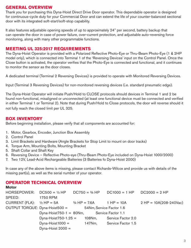
GENERAL OVERVIEWThank you for purchasing this Dyna-Hoist Direct Drive Door operator. This dependable operator is designed for continuous-cycle duty for your Commercial Door and can extend the life of your counter-balanced sectional door with its integrated soft-start/soft-stop capability.
It also features adjustable opening speeds of up to approximately 24” per second, battery backup that can operate the door in case of power failure, over-current protection, and adjustable auto-reversing force monitoring, along with many other programmable functions.
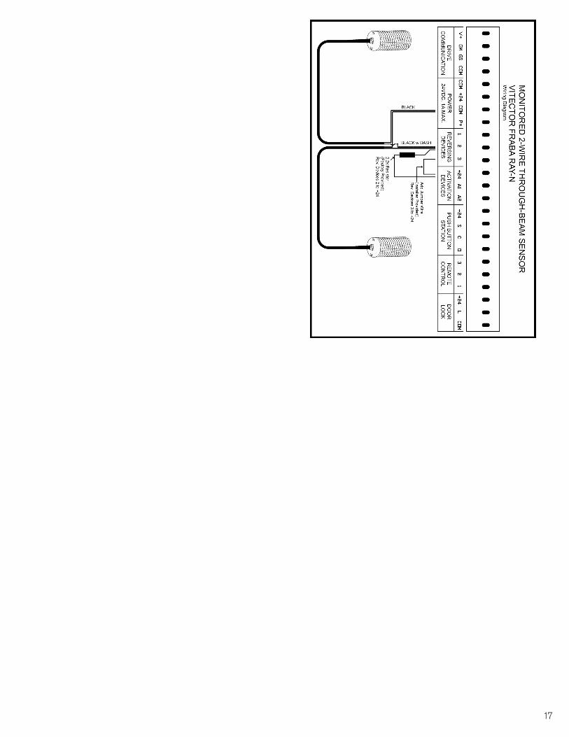
MEETING UL 325:2017 REQUIREMENTSThe Dyna-Hoist Operator is provided with a Polarized Reflective Photo-Eye or Thru-Beam Photo-Eye (1 & 2HP model only), which is connected into Terminal 1 of the ‘Reversing Devices’ input on the Control Panel. Once the Close button is activated, the operator verifies that the Photo-Eye is connected and functional, and it continues to monitor the sensor as the door closes.
A dedicated terminal (Terminal 2 Reversing Devices) is provided to operate with Monitored Reversing Devices.
Input (Terminal 3 Reversing Devices) for non-monitored reversing devices (i.e. standard pneumatic edge).
The Dyna-Hoist Operator will initiate Push/Hold to CLOSE protocols should devices in Terminal 1 and 2 be found non-functional, misaligned or unconnected (at least one functional device must be connected and verified in either Terminal 1 or Terminal 2). Note that during Push/Hold to Close protocols, the door will reverse should it not fully reach the closed limit per UL 325.
BOX INVENTORYBefore beginning installation, please verify that all components are accounted for:
1. Motor, Gearbox, Encoder, Junction Box Assembly2. Control Panel3. Limit Brackets and Hardware (Angle Brackets for Stop Limit to mount on door tracks)4. Torque Arm, Mounting Bolts, Mounting Bracket5. Shaft Collar and Shaft Key6. Reversing Device – Reflective Photo-eye (Thru-Beam Photo-Eye included on Dyna-Hoist 1000/2000)7. Two 12V, Lead-Acid Rechargeable Batteries (3 Batteries fo Dyna-Hoist 2000)
In case any of the above items is missing, please contact Richards-Wilcox and provide us with details of the missing part(s), as well as the serial number of your operator.
OPERATOR TECHNICAL OVERVIEWMotorHORSEPOWER: DC500 = ½ HP DC750 = ¾ HP DC1000 = 1 HP DC2000 = 2 HP SPEED: 1750 RPMCURRENT (FLA): ½ HP = 5A ¾ HP = 7.6A 1 HP = 10A 2 HP = 10A(208-240Vac)OUTPUT TORQUE: Dyna-Hoist500 = 54Nm, Service Factor 1.6 Dyna-Hoist750-1 = 80Nm, Service Factor 1.1 Dyna-Hoist750-1.25 = 108Nm, Service Factor 2.0 Dyna-Hoist1000 = 147Nm, Service Factor 1.5 Dyna-Hoist 2000 =

4 5
ElectricalSUPPLY VOLTAGE: 110-130 or 208-240V Vac, 1ph Input (All incoming power to be connected in provided junction box)BATTERIES: ½ HP= 2 x 5Ah, ¾ HP= 2 x 7Ah, 1 HP= 2 x 9Ah, 2 HP= 3 x 9AhCONTROL VOLTAGE: 24Vdc, 1A Power/Connections supplied for activation and reversing devicesAUX RELAY: 1 SPDT Programmable Relay (factory default to activate on Open Limits)
SafetyPHOTO-EYE or THRU-BEAM Polarized Photo-eye Sensor/Reflector with Bracket or Thru-Beam SENSOR: sensor provided with unit as non-impact reversing device protection.POWER OUTAGE Battery Backup to open/close the door in case of power-outage.OPERATION: 3/8” ratchet socket for manual crank open/close as added r edundancy.
Maximum Recommended Counter balance Sectional Door sizeDyna-Hoist 500: up to 200 Square FeetDyna-Hoist 750: up to 350 Square FeetDyna-Hoist 1000: up to 500 Square FeetDyna-Hoist 2000: over 500 Square Feet
IMPORTANTWARNING – These instructions are intended for experienced personnel trained for service and in-
stallation of sectional doors and operators. All safety precautions and local codes must be followed.
1. READ AND FOLLOW ALL INSTALLATION INSTRUCTIONS.
2. Have qualified service personnel make necessary repairs to ensure door is operating smoothly without any unusual noise. Install operator only on a smoothly operating and well balanced door.
3. Remove all pull ropes and remove locks (unless mechanically and/or electrically interlocked to the power unit) connected to the door before installing the operator.
4. A commercial/industrial door operator that has exposed moving parts capable of causing injury to persons or employs a motor deemed indirectly accessible by clause 10.6 by virtue of its location above the floor shall include: a. Install the door operator at least 2.44m (8 ft) or more above the floor: or b. If the operator must be installed less than 2.44m (8ft) above the floor, then exposed moving parts must be protected by covers or guarding; or c. Both a. and b.
5. Do not connect the operator to the supply power until instructed to do so.
6. Locate the control station: (a) within sight of the door, and (b) at a minimum height of 1.53m (5 ft) above floors, landings, steps, or any other adjacent walking surface and (c) away from all moving parts.
7. Install an Entrapment Warning Placard next to the control station in a prominent location.
4 5
PRE-INSTALLATION ASSEMBLY REQUIREMENTS
BEFORE INSTALLATION, ENSURE THAT YOUR DOOR IS PROPERLY BALANCED AND RUNNING SMOOTHLY. ALSO ENSURE THAT THE LIMIT BRACKETS (SUPPLIED) ARE INSTALLED AND
SECURED PROPERLY. BUMPER/PUSHER SPRINGS MAY BE USED IN PLACE OF, OR IN ADDITION TO LIMIT BRACKETS FOR DYNA-HOIST OPERATORS, BUT MUST BE INSTALLED PRIOR TO OPERATION.
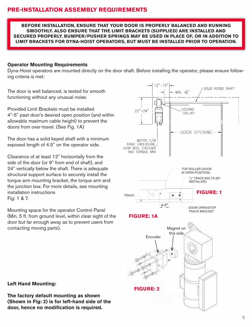
Operator Mounting RequirementsDyna-Hoist operators are mounted directly on the door shaft. Before installing the operator, please ensure follow-ing criteria is met:
The door is well balanced, is tested for smooth functioning without any unusual noise.
Provided Limit Brackets must be installed 4"-5" past door's desired open position (and within allowable maximum cable height) to prevent the doors from over-travel. (See Fig. 1A)
The door has a solid keyed shaft with a minimum exposed length of 4.5” on the operator side.
Clearance of at least 12” horizontally from the side of the door (or 9” from end of shaft), and 24” vertically below the shaft. There is adequate structural support surface to securely install the torque arm mounting bracket, the torque arm and the junction box. For more details, see mounting installation instructionsFig: 1 & 7.
Mounting space for the operator Control Panel (Min. 5 ft. from ground level, within clear sight of the door but far enough away as to prevent users from contacting moving parts).
Left Hand Mounting:
The factory default mounting as shown (Shown in Fig: 2) is for left-hand side of the door, hence no modification is required.
FIGURE: 1
FIGURE: 2
Magnet on this side
Encoder
FIGURE: 1A
6 7
Right Hand Mounting:The software and hardware must be modified for right-hand side mounting. Refer to “OPERATOR START-UP/SET-UP, MOTOR POSITION.
Field Adjustment of the Encoder for Right-Hand Mounting:
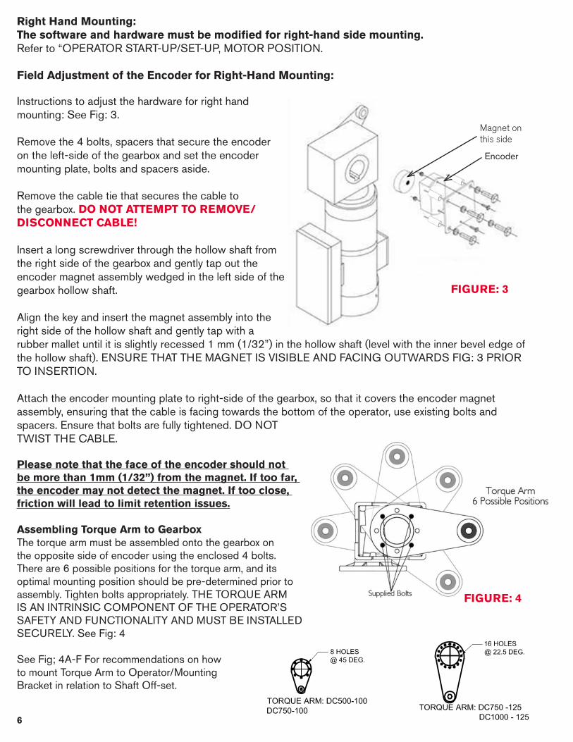
Instructions to adjust the hardware for right hand mounting: See Fig: 3.
Remove the 4 bolts, spacers that secure the encoder on the left-side of the gearbox and set the encoder mounting plate, bolts and spacers aside.
Remove the cable tie that secures the cable to the gearbox. DO NOT ATTEMPT TO REMOVE/DISCONNECT CABLE!
Insert a long screwdriver through the hollow shaft from the right side of the gearbox and gently tap out the encoder magnet assembly wedged in the left side of the gearbox hollow shaft.
Align the key and insert the magnet assembly into the right side of the hollow shaft and gently tap with a rubber mallet until it is slightly recessed 1 mm (1/32”) in the hollow shaft (level with the inner bevel edge of the hollow shaft). ENSURE THAT THE MAGNET IS VISIBLE AND FACING OUTWARDS FIG: 3 PRIOR TO INSERTION.
Attach the encoder mounting plate to right-side of the gearbox, so that it covers the encoder magnet assembly, ensuring that the cable is facing towards the bottom of the operator, use existing bolts and spacers. Ensure that bolts are fully tightened. DO NOT TWIST THE CABLE.
Please note that the face of the encoder should not be more than 1mm (1/32”) from the magnet. If too far, the encoder may not detect the magnet. If too close, friction will lead to limit retention issues.
Assembling Torque Arm to GearboxThe torque arm must be assembled onto the gearbox on the opposite side of encoder using the enclosed 4 bolts. There are 6 possible positions for the torque arm, and its optimal mounting position should be pre-determined prior to assembly. Tighten bolts appropriately. THE TORQUE ARM IS AN INTRINSIC COMPONENT OF THE OPERATOR’S SAFETY AND FUNCTIONALITY AND MUST BE INSTALLED SECURELY. See Fig: 4
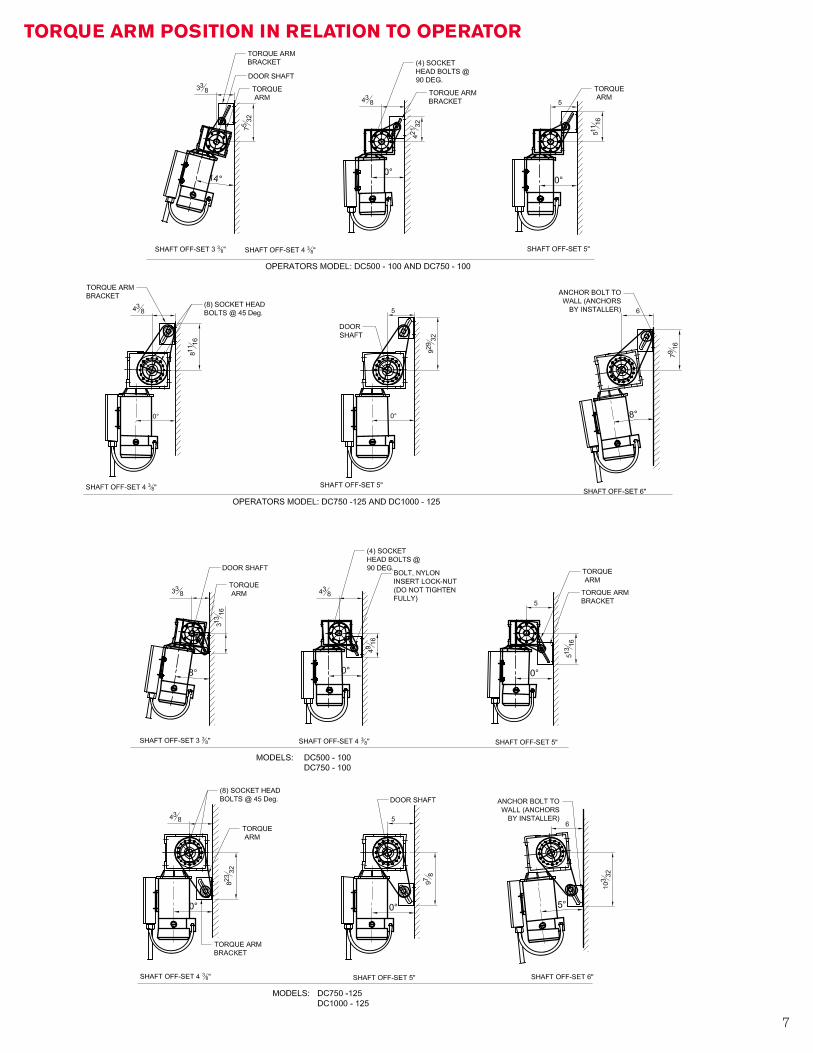
See Fig; 4A-F For recommendations on howto mount Torque Arm to Operator/MountingBracket in relation to Shaft Off-set.
FIGURE: 3
FIGURE: 4
Magnet on this side
Encoder
6 7
TORQUE ARM POSITION IN RELATION TO OPERATOR

8 9
WARNING• TO REDUCE THE RISK OF PERSONAL INJURY OR DEATH, DO NOT CONNECT ELECTRICAL POWER UNTIL
COMPLETE OPERATOR, JUNCTION BOX AND CONTROL PANEL ARE INSTALLED, SECURED AND PROTECTED PER FOLLOWING INSTRUCTIONS.
• ENSURE THAT AREA IS CLEAR OF PERSONNEL AND CORDONED OFF TO ACCESS WHILE INSTALLING OPERATOR.
• USE PROPER SAFETY PROTOCOLS ACCORDING TO INTERNAL, LOCAL AND FEDERAL REQUIREMENTS.
MANDATORY FIRST STEP - Limit Bracket InstallationIf your door is not already equipped with bumper/pusher springs, it is mandatory to install the supplied Limit Brackets. Mount one bracket to the top of each track (See Figure 1A) to prevent over-travel of the door, and enable automatic encoder recalibration prior to setting limits and after a power-loss. These should be mounted inside the door-tracks at the door’s maximum allowable travel point, and are required to be located at the same exact position on both tracks so that the top rollers of the door rest against them in a level position.
To install, manually open the door to the uppermost opening position allowable by the cables, clamp the door in place, and secure the brackets to the track as shown Figure 1A using the top rollers as the reference points for the brackets.
IN THE ABSENCE OF BUMPER/PUSHER SPRINGS, INSTALLATION OF LIMIT BRACKETS IS MANDATORY PRIOR TO OPERATOR INSTALLATION. WITHOUT PHYSICAL LIMITS, THE DOOR CAN RUN OUT OF ITS TRACKS AND CAUSE SEVERE PERSONAL INJURY AND/OR CAUSE SEVERE DAMAGE TO THE DOOR. FURTHERMORE, YOU WILL BE UNABLE TO SET THE LIMITS.
MOUNTING INSTALLATION INSTRUCTION
Shaft Collar/Key Installation
The Shaft Collar serves as an end-stop for the gearbox on the shaft to prevent possible damage to the encoder magnet. It is important that it is securely fastened prior to installation of the operator, and needs to be mounted in conjunction with the key as shown in Fig: 5.
Adjust the door so that the shaft keyway is facing up (you may have to open/wedge/clamp the door open slightly to achieve this).
Loosen the Shaft Collar set screw and slide it over the shaft approximately 3 ½” from its end.
Insert the 3 inch long key (provided with operator) into the door shaft keyway with one end flush to the end of the shaft.
Slide the collar back so that it touches the key, which should still be flush with the shaft end on its opposite side (the key sits in the keyway between the collar and the end of the shaft), see Fig: 5.Firmly tighten the set screw of the collar onto the shaft. Fasten the Torque Arm to the gearbox on the opposite side as the encoder, and at an appropriate position as suggested on Drawing Figs: 4A-F)
Please note that in order to keep this collar as close to the door frame as possible and to accommodate fastening of the torque arm, you may be required to cut the shaft to an appropriate length.
FIGURE: 5

8 9
FIGURE: 5
WARNINGWARNING: THE OPERATOR ASSEMBLY IS HEAVY AND CAN CAUSE SERIOUS INJURY OR DEATH SHOULD IT BE DROPPED DURING INSTALLATION. TAKE ALL NECESSARY SAFETY PRECAUTIONS TO AVOID DROPPING
THE OPERATOR (I.E. TETHER/TIE DOWN) PRIOR TO ATTEMPTING INSTALLATION. SCAFFOLDING OR SCISSOR-LIFTS/PLATFORM-LIFTS ARE ADVISED FOR OPERATOR INSTALLATION. NEVER ATTEMPT TO INSTALL AN
OPERATOR ABOVE EYE-LEVEL OR FROM A LADDER.
Operator Installation
ENSURE THAT PREVIOUS STEPS FOR SHAFT COLLAR/KEY INSTALLATION HAVE BEEN PROPERLY FOLLOWED BEFORE PROCEEDING. FAILURE TO DO SO COULD RESULT IN DAMAGE TO THE ENCODER DURING OPERATOR INSTALLATION.
Align the keyway of the gearbox with the pre-mounted key (see Key Shaft Collar/Key Installation on previous page) located on the mounting side of the shaft.
Slide the gearbox onto the shaft until it makes contact with the Key Shaft Collar.
Assemble the Torque Arm Bracket to the Torque arm using the fastener provided. NOTE: DO NOT TIGHTEN THE NUT FULLY). Anchor the Torque Arm Bracket to the solid structural support.
Fasten the torque arm to structural support by means of the supplied bolt, locking nut and washers. The supplied bracket may be required. If the torque arm does not align with structural support, you may try adjusting the torque arm position on the gearbox (see Assembling Torque Arm to Gearbox) accordingly or use the Torque Arm Bracket.
Junction Box Mounting
The junction box contains terminals for power connections, as well as battery/communication connections for the control panel. Mount the junction box, by means of the mounting flanges and in accordance with the electrical code, in a conspicuous location that will provide access for both electrical power and control panel wiring connections. The junction box is pre-wired with 2 feet of flexible conduit, if longer lengths are required, consult with factory. Do not mount the junction box near moving parts or in an inaccessible area.
FIGURE: 6
FIGURE: 7
FAILURE TO SECURELY FASTEN TORQUE ARM COULD RESULT IN DAMAGE, SERIOUS INJURIES OR DEATH AND WILL VOID THE WARRANTY.

10 11
Control Panel MountingThe control panel should be securely mounted at or around eye level (minimum 5 ft. from floor) on the same side as the operator/junction box. Ensure that the control panel is mounted far enough away from the door as to avoid user contact with the door while in operation, but close enough that the user has clear view of the door at all times. Four (4) control mounting brackets are provided to facilitate mounting. See Fig: 8
Photo-Eye or Thru-Beam Sensor MountingThe included reflective photo-eye or thru-beam sensor should be mounted so that it scans area that spans the entire width of the door at a height of no more than 6 inches from the ground. The sensor (reflective photo-eye) or receiver (thru-beam) should be mounted on the operator side (as it will be wired into the control panel), while the reflector or transmitter should be mounted on the opposite side of the door, facing the sensor/receiver so that its center meets the beam. Use the included mounting bracket(s) to secure to either the door tracks or the wall. Refer to the specific mounting details provided with the sensor. For final alignment of the sensor, put unit in STARTUP MENU (see page 18) to apply power to the sensor (after WIRING – see page 13 for additional wiring diagram). Once properly aligned in STARTUP MENU, the indicator will light up in confirmation. Note that upon exit from the STARTUP MENU, the sensor will only become active when the door is closing.See Fig: 9 for mounting reference.
FIGURE: 8
FIGURE: 9

10 11
WARNINGTO REDUCE THE RISK OF PERSONAL INJURY OR DEATH, ENSURE THAT THE FOLLOWING PRECAUTIONS HAVE BEEN FOLLOWED PRIOR TO MAKING ELECTRICAL CONNECTIONS:
WIRING INSTRUCTIONS
Junction Box Connections
Terminals inside the junction box are labeled and provided for input power (100-240Vac 1 Ph), and to connect power the battery backup, and supply low voltage power and communication for the control panel. Optional terminals are also provided for Fully Open Limit Reset connection to an external switch.
Power Connections (100-240Vac Single Phase)1. ENSURE POWER IS DISCONNECTED!2. Run power wires to junction box in accordance with local and national regulations.3. Connect incoming power to L/L1 and N/L2, and ensure that ground wire is properly affixed.
Control Panel Connections (24Vdc)1. Using minimum of 18AWG cable, connect individual wires to V+, GM, GS and COM terminals in the junction box.
Richards-Wilcox recommends using wiring kit (Part# PDC-CABKIT) or equivalent. 2. These will match the connections in the Control Panel and will be terminated in the same sequence (as labeled) to
match the junction box (all control panel wiring shall enter through the bottom of the enclosure).
Battery Connections (24Vdc) 2 Batteries Connected in Series1. Using minimum of 18 AWG insulated stranded wire; connect to B+ and B- inside the junction box (two separate wires).
NOTE: 14AWG is recommended for Dyna-Hoist 1000 Operators.2. These wires should be run together with the Control Panel Connections (through the bottom of the enclosure) and
connect to the ‘+’ and ‘-‘DRIVE terminals on the board.3. Place the batteries into the Control Panel. Connect the wires to the batteries as labeled (fused lead connects to the
Positive – Red – contact, blue lead to the Negative – Black – contact).
Fully Open Reset Limit Switch Connections (24Vdc)(Optional)1. Using minimum of 18 AWG insulated stranded wire; connect to H1 and H2 inside the junction box (two separate wires)2. Connect these wires through NO Contact of Limit Switch, Proximity Sensor, Reed Switch, etc., set to activate at
uppermost limit of door. This is used in advance of physical stop limits (limit brackets) to reset encoder at startup or menu reset (fully open position) and to avoid rollers coming into contact with the brackets. Also used as Fully Open position settings in Menu. Note that installation of limit brackets (or alternate physical stopping device) is still mandatory as a redundant safety stop in case of switch failure. If using external switch in lieu of limit brackets for Fully Open Position Reset, a menu setting must be changed. See Page 24.
1. Disconnect power at fuse box/source and follow proper lockout/tag-out procedures per national and local electrical codes.
2. Ensure that all electrical connections are made by qualified electricians/technicians only and meet national and local electrical codes.
3. All wiring should be on a dedicated circuit and properly protected.

12 13
Control Panel Board ConnectionsThe Control Panel provides power and inputs for your Reversing Devices (up to 3), Activation Devices (up to 2), as well as a wired Push Button Station, and a Remote Radio Receiver. Two on-board relays provide signaling for a variety of programmable options. Further connections are available for Traffic Signals, a buzzer and flashing Amber signal (while the door is in motion) and a door lock switch (prevents the door from moving while activated). A receptacle for Richards-Wilcox’s wireless peripheral devices (impact/tilt sensor, reversing edge, etc.) is also provided.
Reversing DevicesThe Dyna-Hoist accepts UL325 Monitored Devices, as well as standard non-monitored Devices. Connect the provided reflective photo-eye into the terminal labelled ‘1’. Any UL325 'monitored' reversing device should be connected into the terminal labelled ‘2’. Any other added reversing photo-eyes, light curtains and reversing edges should be connected into the terminal labelled ‘3’. Follow the wiring diagrams included in this manual, and installation instructions provided with your reversing device for further mounting and connection details. Please note that without a connected, functional reversing device, the Closing Timer and Single Push auto-closing features of the door are de-activated – Push/Hold to Close protocols will be initiated.
Activation DevicesAutomated, wired activation devices, such as Floor Loop Detectors, Pull Cords, Motion Detectors and Photo-Eyes (up to a maximum of 2 wired devices) used to open the door are connected here. Follow wiring diagram below and refer to the instructions provided with your activation device for precise connection and mounting details. Note that all devices connected to terminal A1will open the door to a position just shy of the full opening height, and devices connected to terminal A2 will open the door to the set limit.
Push Button StationConnect an added Push Button station to the other side of your door using these inputs. N/O dry contacts are required. Note that Push Button Stations can be programmed to raise the door to the fully open or set limit position. Refer to the wiring diagram for further connection details. Push Button Stations are available from RW, please contact us for details.
Remote RadioConnect your receiver to the provided terminals – as the Dyna-Hoist control panel enclosure is non-metallic, external antenna not necessarily required. Note that Remote Radio can be programmed to raise the door to the fully open, or set limit position. Refer to the wiring diagram for further connection details. Remote radio transmitters and receivers are available from Richards-Wilcox, please contact us for details.
Door LockThese terminals are available to de-activate door functionality, whether it is a simple switch, or a sensor providing a signal when the door is locked for the night. Another available option is connecting this to a programmable timer relay to allow door operation for a pre-determined schedule. Refer to the wiring diagram for further connection details. Contact Richards-Wilcox for information on their Door Lock Sensor Kit.
Traffic LightTo install an LED stop and go light, use the provided terminals at the bottom of the board. The red connects to the ‘R’ terminal, the green connects to the ‘G’ terminal and the common should be wired into the ‘+24’ terminal. Ensure that you are using LED traffic lights (not incandescent) with a maximum consumption of no more than 100mA. The traffic light will stay red when the door is in motion or the closed position, and will be green in the fully open position only. The red can also be programmed to flash when the door is in motion, and in advance of close when using the closing timer (See Page 22 for futher details). The ‘Y’ terminal is for a secondary flashing Amber LED beacon and/or audible signal to indicate when the door is in motion. While accessing the Setup Menu, the traffic lights will turn off, and the Amber beacon, if installed, will flash. LED Stop and Go Lights from Richards-Wilcox are highly recommended, please contact us for details. Refer to the wiring diagram for further connection details. Note: DO NOT USE INCANDESCENT SIGNALS WITH THIS OPERATOR. LED LIGHTS ONLY.
Output Relay ConnectionsNO and NC relay output connections are provided for interlocking with other material handling equipment (i.e. dock leveller) or security/fire systems. These outputs can be programmed (see Output Relay Setup) to energize when the door is at the Open or Closed Limit. Refer to the wiring diagram for further instructions.

12 13
WIRING DIAGRAMS

14 15

14 15

16 17
16 17

18 19
CAUTION!
STARTUP PROCEDURE
TESTING FOR DOOR SPRING BALANCETHIS STEP MUST BE DONE BEFORE POWER IS CONNECTED. The Dyna-Hoist operator is intended for use only with balanced doors. Improperly balanced doors could significantly affect the performance of the operator. We recommend that once the door and operator are completely installed that you test the door’s balance prior to power up. To do this, ensure that the batteries are connected, power is off, and attempt one full cycle up and down under battery power (push and hold the OPEN button, and push and hold the CLOSE button). The door should travel at a slow, steady pace upwards and downwards. If the door can achieve a full cycle under battery power, it is setup properly for use with the Dyna-Hoist operator. If the battery cannot move the door in either direction fully, the spring tension on the door must be adjusted.
POWER UP
Apply power to the unit. The Control Panel LED Screen should light up and run a self-diagnostic. If LCD screen is not lit, refer to Trouble Shooting on Page 25. Once it has run through its self-diagnostic, the screen will read ‘Door is Ready’. DO NOT TRY TO OPEN THE DOOR AFTER INITIAL POWER UP - ACCESS QUICKSTART MENU ONLY!
QUICK START MENU & ACCESSING ALL MENU SELECTIONSNOTE THAT ALL FACTORY MENU SETTINGS ARE RECOMMENDED FORSECTIONAL DOORS ONLY. CONTACT Richards-Wilcox FOR SETTINGS FOR OTHER DOOR STYLES (i.e. Rolling Steel, etc.)
For access to the QUICKSTART MENU press and hold the STOP BUTTON FOR 10 SECONDS - do not release until QUICKSTART MENU appears on the screen. Once accomplished, you can scroll between the various QUICKSTART MENU options by pressing the OPEN and CLOSE buttons. Once you have reached a selection that you would like to alter, press the STOP button. Use the OPEN and CLOSE buttons to scroll/toggle between options within the selection, and then press STOP to save your selection and return to the QUICKSTART MENU.
CLOSING TIMER
IT IS NOT RECOMMENDED TO SET THE CLOSING TIMER UNTIL AFTER THE UNIT HAS BEEN FULLY TESTED.
The Closing Timer will automatically close the door after opening by the preset number of seconds that have been programmed using this QUICKSTART MENU option.
Once you have accessed this option, use the OPEN and CLOSE buttons to increase or decrease the closing timer value in 1 second intervals. If it is not required, ensure that the Closing Timer is set to OFF. If it is required, set it to any number of seconds from 1 to 99. Remember that this is the number of seconds that the door will remain open before automatically closing. Press the STOP button to save the value and return to the QUICKSTART MENU.
The Closing Timer will de-activate in the event that a reversing device fails, and manual Push and Hold to Close protocols will apply to door closing operations.
Before applying power to the Dyna-Hoist operator, ensure that the unit is firmly in positioned on the door shaft and securely fastened to the torque arm/bolt. Also that Limit brackets are in place and that the encoder is properly fastened on the gearbox.
Please refer to the QUICK START STEP-BY-STEP PROGRAMMING GUIDE included with your DC Operator for essential steps to set up
and program your operator. The below information are more detailed instructions on each feature and setting.
18 19
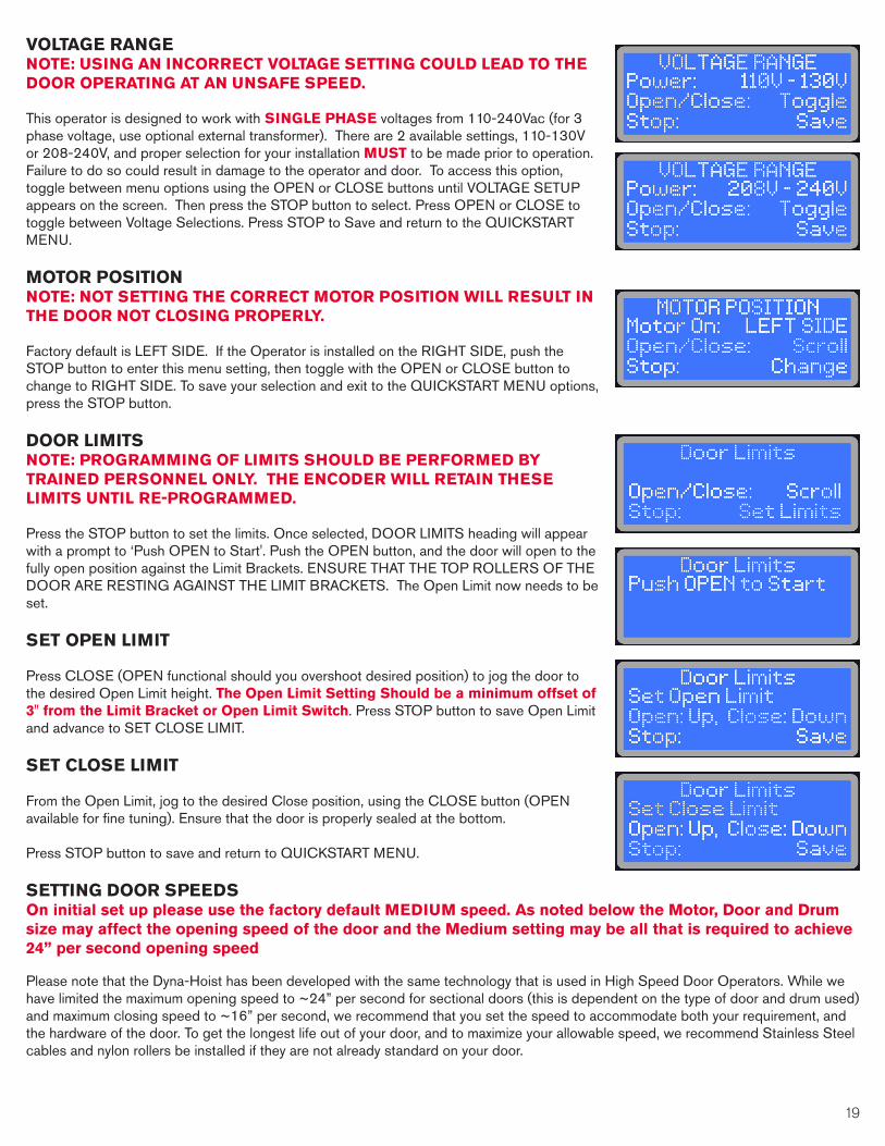
VOLTAGE RANGENOTE: USING AN INCORRECT VOLTAGE SETTING COULD LEAD TO THE DOOR OPERATING AT AN UNSAFE SPEED.
This operator is designed to work with SINGLE PHASE voltages from 110-240Vac (for 3 phase voltage, use optional external transformer). There are 2 available settings, 110-130V or 208-240V, and proper selection for your installation MUST to be made prior to operation. Failure to do so could result in damage to the operator and door. To access this option, toggle between menu options using the OPEN or CLOSE buttons until VOLTAGE SETUP appears on the screen. Then press the STOP button to select. Press OPEN or CLOSE to toggle between Voltage Selections. Press STOP to Save and return to the QUICKSTART MENU.
MOTOR POSITIONNOTE: NOT SETTING THE CORRECT MOTOR POSITION WILL RESULT IN THE DOOR NOT CLOSING PROPERLY.
Factory default is LEFT SIDE. If the Operator is installed on the RIGHT SIDE, push the STOP button to enter this menu setting, then toggle with the OPEN or CLOSE button to change to RIGHT SIDE. To save your selection and exit to the QUICKSTART MENU options, press the STOP button.
DOOR LIMITSNOTE: PROGRAMMING OF LIMITS SHOULD BE PERFORMED BY TRAINED PERSONNEL ONLY. THE ENCODER WILL RETAIN THESE LIMITS UNTIL RE-PROGRAMMED.
Press the STOP button to set the limits. Once selected, DOOR LIMITS heading will appear with a prompt to ‘Push OPEN to Start'. Push the OPEN button, and the door will open to the fully open position against the Limit Brackets. ENSURE THAT THE TOP ROLLERS OF THE DOOR ARE RESTING AGAINST THE LIMIT BRACKETS. The Open Limit now needs to be set.
SET OPEN LIMIT
Press CLOSE (OPEN functional should you overshoot desired position) to jog the door to the desired Open Limit height. The Open Limit Setting Should be a minimum offset of 3" from the Limit Bracket or Open Limit Switch. Press STOP button to save Open Limit and advance to SET CLOSE LIMIT.
SET CLOSE LIMIT
From the Open Limit, jog to the desired Close position, using the CLOSE button (OPEN available for fine tuning). Ensure that the door is properly sealed at the bottom.
Press STOP button to save and return to QUICKSTART MENU.
SETTING DOOR SPEEDSOn initial set up please use the factory default MEDIUM speed. As noted below the Motor, Door and Drum size may affect the opening speed of the door and the Medium setting may be all that is required to achieve 24” per second opening speed
Please note that the Dyna-Hoist has been developed with the same technology that is used in High Speed Door Operators. While we have limited the maximum opening speed to ~24” per second for sectional doors (this is dependent on the type of door and drum used) and maximum closing speed to ~16” per second, we recommend that you set the speed to accommodate both your requirement, and the hardware of the door. To get the longest life out of your door, and to maximize your allowable speed, we recommend Stainless Steel cables and nylon rollers be installed if they are not already standard on your door.

20 21
OPENING SPEED
To access the Open Speed Settings, ensure you are in QUICKSTART MENU (see above instructions), then toggle between options using the OPEN or CLOSE buttons until Open Speed appears on the screen. Then press the STOP button to access and macke changes.
The Dyna-Hoist operator is factory equipped with 5 options of open speed settings, designated as 1 (slowest) to 5 (fastest - approximately 24"/s). Toggle between these 5 options by using the OPEN and/or CLOSE buttons, and press the Stop button once the desired selection appears on the screen to save and return to the QUICKSTART menu.
CLOSING SPEED
To access the Closing Speed Settings, ensure you are in QUICKSTART MENU (see above instructions), then toggle between options using the OPEN or CLOSE buttons until Close Speed appears on the screen. Then press the STOP button to select.
The Dyna-Hoist operator is factory equipped with 5 options of close speed settings, from 1(slowest) to 5 (fastest - approximately 16"/s). Toggle between these 5 options by using the OPEN and/or CLOSE buttons, and press the Stop button once the desired selection appears on the screen to save and return to the QUICKSTART menu.
JOG MODE
To access the Jog Mode Setting, ensure you are in QUICKSTART MENU (see above instructions), then toggle between options using the OPEN or CLOSE buttons until Jog Mode appears on the screen. Then press the STOP button to begin using.
Jog Mode enables manual control of the door using the OPEN and CLOSE buttons. During Jog Mode, all limits are de-activated, and push-hold protocols are initiated. This selection can be used to test door functionality without the encoder, ensure proper door balance, or as a method to operate the door under power should the encoder malfunction. The door will travel in each direction at the set OPEN SLOW SPEED and CLOSE SLOW SPEED (see Page 22), for safe operation.
EXITING QUICKSTART MENU - CALIBRATION & TESTING
To exit from the QUICKSTART Menu, press and release the STOP button while QUICKSTART MENU appears on the LCD. If you have saved changes to the operator speed, or have reset limits, you will be required to do a quick system calibration. Screen prompts will provide real-time instruction on calibration requirements. See Page 22 for more detailed information on Calibration.
Once Calibration is completed or if it was not required, the system will run a quick diagnostic, and the LCD will read 'Door is Ready Press Open to Start'. This prompt to open the door is in order to reset the encoder, and also appears whenever there is a power reset. Once the door is opened (press the OPEN button, door will rise at slow speed until it rests against Limit Brackets), normal door function will resume. BEFORE OPERATING THE DOOR, ENSURE THAT THE DOOR LIMIT BRACKETS (OR PUSHER SPRINGS OR LIMIT SWITCH) ARE IN PLACE, AND DOOR LIMITS HAVE BEEN SET.
Testing of the door is now required. Observe whether the door is running smoothly and is stopping at the appropriate limits. Ensure that the door is set at the required speeds, and test each reversing and activation device to confirm their functionality.

20 21
ADVANCED MENU NOTE: THESE FEATURES SHOULD BE ACCESSED ONLY BY A TRAINED TECHNICIAN AFTER INITIAL SET UP AND TESTING, ONLY IF REQUIRED.
For access to the ADVANCED MENU options press and hold the STOP BUTTON FOR 10 SECONDS while on the QUICKSTART MENU screen. Do not release until ADVANCED MENU appears on the screen.
REVERSING TIMER
Use this to set desired delay time for Door Reversing. If a reversing device or function is activated when door is closing (i.e. photo-eye, load-sensing, etc.) the door will pause by the set amount of time indicated.
Select between 0.5, 1.0, 1.5 seconds, or turn OFF. If turned OFF, door will not reverse, but remain in place until user intervention (This is recommended when using Closing Timer). Press STOP to Save this Setting and return to the ADVANCED MENU.
PWM FREQUENCY
This Setting allows the user to change the operating frequency for the motor between 2.4 kHz, 12kHz and 20kHz. Certain frequencies can interfere with third-party accessories, and adjustment may be necessary. Factory default is set to 12kHz. Do not alter this setting unless advised by Technical Support.
DYNAMIC BRAKE
For doors that may be heavier than standard or have improperly balanced springs that cause high closing inertia, this operator has Dynamic Braking Options. If the door does not noticeably slow down during its intended ‘soft stop’ (approximately in the last foot of travel), it is likely that the door will require dynamic braking compensation.
Factory default is for no Dynamic Braking (OFF), and is recommended for standard operation. Should Dynamic Braking prove necessary, press the OPEN/CLOSE buttons to toggle between choices (Low, Medium & High).
Note that the addition of Dynamic Braking is intended to assist doors with high inertia in achievement of a ‘soft stop’. It is recommend that before setting Dynamic Braking, you first test the door at a lower closing speed. Failing this, when setting Dynamic Braking you should start with the LOW setting first, and test the door. If further braking is required, move to the MEDIUM setting and test, and then the high setting. If you notice that the door makes a ‘jerking’ motion near the bottom of its travel, the setting is too high, and it should be lowered.
OPENING FORCE
If the door is obstructed from opening (ie. due to ice buildup, the door latch is engaged, etc.) this current monitoring feature will stop the door to prevent damage. The sensitivity of this monitoring can be changed in this setting, or the feature can be turned off entirely.
Opening Force sensitivity can be adjusted from 1-20 (1 being most sensitive to obstructions/jams/imbalance) or OFF. Factory default is ‘5’.
CLOSING FORCE
If the door is obstructed from closing (ie. due to obstruction, jam, etc.) this current monitoring feature will stop and reverse the door to prevent damage. The sensitivity of this monitoring can be changed in this setting, or the feature can be turned off entirely.Closing Force sensitivity can be adjusted from 1-20 (1 being most sensitive to obstructions/jams/imbalance) or OFF. Factory default is ‘3’.
22 23
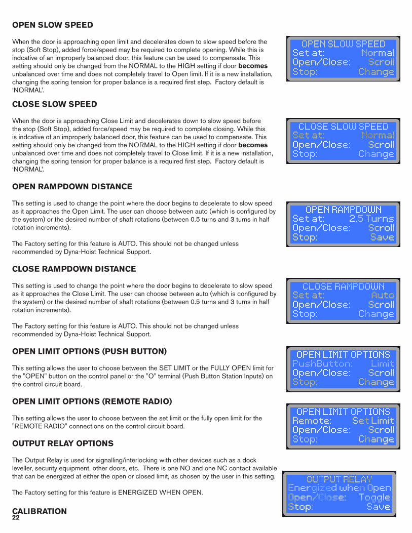
OPEN SLOW SPEED
When the door is approaching open limit and decelerates down to slow speed before the stop (Soft Stop), added force/speed may be required to complete opening. While this is indcative of an improperly balanced door, this feature can be used to compensate. This setting should only be changed from the NORMAL to the HIGH setting if door becomes unbalanced over time and does not completely travel to Open limit. If it is a new installation, changing the spring tension for proper balance is a required first step. Factory default is ‘NORMAL’.
CLOSE SLOW SPEED
When the door is approaching Close Limit and decelerates down to slow speed before the stop (Soft Stop), added force/speed may be required to complete closing. While this is indcative of an improperly balanced door, this feature can be used to compensate. This setting should only be changed from the NORMAL to the HIGH setting if door becomes unbalanced over time and does not completely travel to Close limit. If it is a new installation, changing the spring tension for proper balance is a required first step. Factory default is ‘NORMAL’.
OPEN RAMPDOWN DISTANCE
This setting is used to change the point where the door begins to decelerate to slow speed as it approaches the Open Limit. The user can choose between auto (which is configured by the system) or the desired number of shaft rotations (between 0.5 turns and 3 turns in half rotation increments).
The Factory setting for this feature is AUTO. This should not be changed unless recommended by Dyna-Hoist Technical Support.
CLOSE RAMPDOWN DISTANCE
This setting is used to change the point where the door begins to decelerate to slow speed as it approaches the Close Limit. The user can choose between auto (which is configured by the system) or the desired number of shaft rotations (between 0.5 turns and 3 turns in half rotation increments).
The Factory setting for this feature is AUTO. This should not be changed unless recommended by Dyna-Hoist Technical Support.
OPEN LIMIT OPTIONS (PUSH BUTTON)
This setting allows the user to choose between the SET LIMIT or the FULLY OPEN limit for the "OPEN" button on the control panel or the "O" terminal (Push Button Station Inputs) on the control circuit board.
OPEN LIMIT OPTIONS (REMOTE RADIO)
This setting allows the user to choose between the set limit or the fully open limit for the "REMOTE RADIO" connections on the control circuit board.
OUTPUT RELAY OPTIONS
The Output Relay is used for signalling/interlocking with other devices such as a dock leveller, security equipment, other doors, etc. There is one NO and one NC contact available that can be energized at either the open or closed limit, as chosen by the user in this setting.
The Factory setting for this feature is ENERGIZED WHEN OPEN.
CALIBRATION

22 23
This feature is required to calibrate load-sensing. Screen prompts guide user through calibration.
NOTE: IF YOU CHANGE ANY OF THE FOLLOWING SETTINGS, THE OPERATOR WILL PROMPT YOU TO RECALIBRATE WHEN EXITING THE MENU: Voltage Range, Motor position, Door Limits, Open Speed, Close Speed, PWM Frequency, Open Rampdown and Close Rampdown.
THE CALIBRATION OF THE DOOR INVOLVES THE FOLLOWING STEPS: • An automatic slow opening cycle of the door. (You will be prompted to open the door)• A manual close cycle of the door. Press and Hold the CLOSE button through this cycle.
If the CLOSE button isn't held until door is fully closed, the Operator will abort this step and prompt you to start again.
• You will be prompted to open the door to Calibrate Opening Force. • Resetting the Encoder. Once the door is fully open, you will have to press OPEN again to
reset the Encoder (The LCD screen will say "DOOR IS READY" as a prompt before the Encoder is to be reset.)
MAINTENANCE SCHEDULE
This feature sets a reminder, displayed on the LCD, to schedule maintenance after a selected number of operator cycles. Factory default is set to notify of Maintenance after 250,000 cycles (recommended for Motor Brush Replacement). It can be lowered in 1,000 cycle increments. Press the OPEN or CLOSE buttons to change, and Press and Hold the buttons for rapid scrolling to your required cycle setting.
RED FLASHING
Set this feature to ON if you prefer the red light of an attached LED Stop & Go Light to flash while the door is in motion.
ADVANCED RED
Used in conjuction with the CLOSING TIMER (Page 18), this safety feature turns on the red light (or flashing red light if this setting has been enabled) of an attached LED Stop & GO light in advance of the door closing by a programmed number of seconds. Note that should you choose a value that is greater than the CLOSING TIMER pre-set, it will begin at the same time. Factory Default is the 'OFF' setting, with options for 1-9 seconds of ADVANCED RED.
OPEN LIMIT SWITCH
If choosing to use a Switch (limit, proximity, reed, etc) to signal the door's fully open position for encoder reset (connecting to H1 & H2 in junction box), set this selection to YES. USING A SWITCH STILL REQUIRES INSTALLATION OF LIMIT BRACKETS AS A SAFETY REDUNDANCY IN CASE OF SWITCH FAILURE.
CLOSE RAMP-UP TIME
On the Close cycle, from the open position, you can adjust the amount of time that it takes the door to accelerate from its resting position to its full speed. This is particularly beneficial when using standard lift doors and/or large drums, or when the unit is mounted on a balanced rolling steel door. This can be adjusted in 0.5s increments from 0.5 to 3.0 Seconds. Factory Default is 1.0s

24 25
MOTION DETECT TIME
As an added safety feature, the encoder monitors the rotation of the shaft. Should it detect no motion where there should be motion, the system will halt the cycle command, and show a fault display of 'NO MOTION DETECTED'. The allowable delay before this fault is recognized by the system can be adjusted from 0.2s to 0.6s, but should not be altered from the Factory Default setting of 0.3s unless instructed to do so by technical support personnel.
FACTORY RESET
This setting allows for a reset of all menu options to the factory default. These are the Factory Settings:
QUICKSTART MENUClosing Timer: ...................................................... OFFVoltage Range: ................................................... 208V-240VMotor Position: ................................................... Left Door Limits Setup: ............................................. 4 Rotations - Must be Re-Programmed by InstallerOpen Speed: ...................................................... 3Close Speed: ...................................................... 3ADVANCED SETUP MENUReversing Timer:.................................................. 1.0 SecondsPWM Frequency: ............................................... 12 kHz Dynamic Brake: .................................................. OFFOpening Force: ................................................... 10Closing Force: .................................................... 2Open Slow Speed: ............................................. NormalClose Slow Speed: ............................................ NormalClose Rampdown: .............................................. AutoOpen Rampdown: ............................................. AutoOpen Limit Options - Push Button: ................ Set LimitOpen Limit Options - Remote Radio: ............ Set LimitOutput Relay: ....................................................... Energized When OpenRed Flashing: ....................................................... OFFAdvanced Red: .................................................... OFFMaintenance Schedule: ..................................... 250,000 CyclesOpen Limit Switch: ............................................. NoClose Ramp-Up Time ........................................ 1.0 SecondsMotion Detect Time ............................................ 0.3 SecondsAfter performing factory reset (if deemed necessary), adjust settings as required, and re-program limit settings and perform calibration thereafter.
EXITING ADVANCED MENU - CALIBRATION & TESTING
To exit from the ADVANCED MENU, press and release the STOP button while ADVANCED MENU appears on the LCD. This will bring you back to the QUICKSTART MENU. Press and release the STOP button again to exit all menus and to test the settings that you have changed. If, while you were in the ADVANCED MENU and have saved changes to the PWM Frequency, Open Rampdown or Close Rampdown you will be required to do a quick system calibration. Screen prompts will provide real-time instruction on calibration requirements. See Page 21 for more detailed informaiton on Calibration.
Once Calibration is completed or if it was not required, the system will run a quick diagnostic, and the LCD will read 'DOOR IS READY, PRESS OPEN TO BEGIN'. This is a prompt to open the door and reset the encoder, and also appears whenever there is a power reset. Once the door is opened (press the OPEN button, door will rise at slow speed until it rests against Limit Brackets), normal door function of the operator will resume. It is now that testing of any of the changed settings can commence.

24 25
PATENTED BATTERY BACKUP - POWER OUTAGE OPERATION
The Dyna-Hoist is factory equipped with a patented battery backup system and it is automatically activated during a power outage. This battery backup even works if there is board damage occurring due to external forces such as lightning or impact.
Simply push and hold the OPEN button in order to open the door, and push and hold the CLOSE button in order close the door – the door will respond accordingly, but note that speeds will be reduced. All safety devices will be disabled during a battery backup operation and any personnel operating the door should maintain a clear line of sight with the doorway in order to reduce the risk of possible door impact with personnel or equipment, and to ensure the door operates safely. To enable battery backup functionality when the power is available, please disconnect the power to the operator.
In case the batteries are fully drained or missing, the base of the motor is also equipped with a 3/8” ratchet entry. TURN OFF POWER TO THE OPERATOR (even if the power seems out), secure a crankshaft, socket wrench or power drill with 3/8” ratchet head (not included) inside the ratchet entry and rotate it in the appropriate direction in order to open or close the door. Turn on the power once manual operation is no longer required.
NOTE ON BATTERIES
Provided lead-acid batteries are 2 x 12V connected in series to provide 24Vdc (3 x 12V for 36Vdc on Dyna-Hoist 2000) . The controller provides a monitored trickle charger in order to maintain the batteries' life. Should the batteries be fully drained and no longer accept a charge, please replace them with equivalent batteries, and dispose of the expired units according to local environmental regulations. NEVER remove the provided jumper between the batteries unless in the process of replacement, and be sure to re-connect in the event battery replacement is required.
CAR WASH/WATER-RESISTANT APPLICATIONS
Richards-Wilcox recommends an available upgrade for all Car Wash/Water Resistant applications. Standard Dyna-Hoist Operator Drives are rated IP54, and could be vulnerable to water ingress. Furthermore, reflective photo-eye sensors have a tendency to be detrimentally affected by condensation on the reflector, preventing reliable operation in such conditions. Richards-Wilcox offers a cost-effective Water-resistant upgrade that both seals all ingress points, and includes a thru-beam sensor in place of a reflective photo-eye. Please contact Richards-Wilcox for details and pricing.

26 27
DYNA-HOIST OPERATOR COMPONENTS

26 27
TROUBLE SHOOTING GUIDESYMPTOM PROBABLE CAUSE SUGGESTED ACTION
NO DISPLAY AT THE LCD
PANEL
NO POWER.
Check power is on at circuit breaker, disconnect switch, and check wiring connections.
Check fuse (refer to fuse specs in theinstallation instructions) in the junction box.
LOOSE CONNECTION(S).Check connections in the J/box (near operator)and control panel; check that the ribbon cable to LCD display is firmly connected at both ends.
VOLTAGE DROP IN WIRINGBETWEEN OPERATOR
JUNCTION BOX TO CONTROL PANEL.
Check voltage between terminal +24 and COM,if no power or Dyna-Hoist voltage is less than 23V, checkwiring between Junction box (near operator)and control panel.
LCD PANEL ASSEMBLY. If 24Vdc is detected and ribbon cable is connected then replacement of LCD panel assembly may be required.
CONTROL PANEL CIRCUIT BOARD.
Disconnect +24V wire (from the J/box) in the control panel, check voltage between disconnected wire and COM terminal, if voltage is 24Vdc then replacement of control panel circuit board may be required.
DOOR STOPS AT RANDOM (DOES NOT RECOGNIZE
LIMITS) POSITION.
ENCODER WORN, IMPROPERLY INSTALLED
OR HAS MOVED.
Check encoder for wear, re-position if necessary. It is critical that the set collar on the shaft be set at 3" from the end. Run limits setup, replace encoder if problem persist.
DOOR CONSTANTLY STOPS SHORT OF CLOSE POSITION
MOTOR POSITION SETTING MAY BE INCORRECT.
Check Motor Position from SETUP menu, (Operator position LH or RH as viewed from Interior) and change if necessary. Reset Limits. Note: All operators are factory setup for LH mounting.
DOOR REVERSES BEFORE REACHING
CLOSE POSITION OR AS SOON AS
THE CLOSE BUTTON IS RELEASED
PHOTO-EYE/REFLECTOR/THRU-BEAM SENSOR
MISALIGNED/OBSTRUCTED/MISWIRED.
Clean, re-align and/or clear obstruction in front of the sensors/reflector. Re-check wiring as shown in Diagram 1 on Page 13.
FORCE MONITORING IS TOO SENSITIVE
Adjust the Closing Force setting in the Advanced Menu. 1 is most sensitive, and 20 is least sensitive.
THIRD PARTY REVERSING DEVICES MALFUNCTIONING.
Disconnect third party reversing devices, install jumper between reversing input terminal 3 and +24 and test again. Reconnect reversing devices one at a time to isolate the defected device, (refer to page 11-17 In the installation manual).

28 29
TROUBLE SHOOTING GUIDESYMPTOM PROBABLE CAUSE SUGGESTED ACTION
'DOOR IS STOPPED' MESSAGE ON LCD
PANEL
OBSTRUCTION OR DOOR JAMMED DUE TO
OBSTRUCTION.
Remove obstruction or free up the door, turn "OFF" the AC power and test operate the door with batteries power.
PUSHER SPRINGS MAY BE PREVENTING DOOR FROM
REACHING THE OPEN LIMITS.
Remove Pusher Springs and install upper limit brackets supplied with operator or set OPEN limit so that Pusher Spring are not engaged.
ENCODER NOT PROPERLY POSITIONED.
Check and adjust operator Encoder as described in the installation manual.
DOOR MOVES FEW INCHES AFTER OPEN/CLOSE
COMMAND AND STOPS
JUMPER BETWEEN THE ‘S’ AND ‘+24’ TERMINAL HAS
BEEN REMOVED.
If no push-button station has been wired in its place, re-install the jumper.
THE REMOTE PUSH BUTTON DOES NOT HAVE THE NC
(NORMALLY CLOSED) CONTACT FOR THE STOP
BUTTON.
Replace the push button station (or the contact for the STOP button) for one that has an NC contact on the STOP button.
REMOTE PUSH BUTTON STATION WIRED INCORRECTLY.
Check and correct wiring as necessary.
DOOR DOES NOT CLOSE ON REMOTE OR CLOSE TIMER
PUSHER SPRINGS MAY BE PREVENTING DOOR TO OPEN FULLY TO THE OPEN
LIMIT (SCREEN READS 'DOOR IS STOPPED') .
Remove pusher springs and replace with supplied Limit Brackets; or adjust Set Open Limit so that it does not engage pusher springs and set all activation devices to open the door to Set Limit.
CLOSE TIMER NOT SET APPROPRIATELY.
Reset Close Timer, (refer to Pg 18 in the installation manual).
NO FUNCTIONAL REVERSING DEVICE IN R1
OR R2 TERMINAL
Ensure that 1 appropriate and functional device is install in at least one of these terminals. If installed, check wiring, alignment and functionality

28 29
SYMPTOM PROBABLE CAUSE SUGGESTED ACTION
DOOR DOES NOT WORK ON BATTERY
POWER
IN-LINE FUSE ON BATTERY RED WIRE MAY BE BLOWN. Replace Fuse, refer to fuse specs in the installation manual.
BATTERIES MAY BE DRAINED, OR DEAD OR DEFECTIVE CONTROL
BOARD.
Check batteries voltage, if low let it charge for 24 hours with AC power ON. Replace batteries if still not charged. Replace control board if the batteries are charged.
DOOR OUT OF BALANCE. Check and balance the door properly.
THE POWER MAY BE STILL BE ON. Ensure the main power to the unit is off.
LOAD SENSING NOT WORKING
PROPERLY
CLOSING FORCE IS NOT SET PROPERLY
Adjust the Closing and/or Opening Force. Directions are shown on Pages 21-22.
Increase or decrease based on door weight/side and application of the door
REPLACEMENT PART DESCRIPTION Dyna-Hoist 500-100 Dyna-Hoist 750-100 Dyna-Hoist 1000-125
Motor Dyna-HoistM-P500-1800 Dyna-HoistM-P750-1800 Dyna-HoistM-P1000-1800
Motor Brush Set (2) Dyna-HoistM-BRUSH Dyna-HoistM-BRUSH Dyna-HoistM-BRUSHGearbox GB-50-1.0 GB-50-1.0 GB-75-1.25
Drive Controls Enclosure PDyna-Hoist-ENC-ALBK PDyna-Hoist-ENC-ALBK PDyna-Hoist-ENC-ALBK
Drive Replacement Board PCB-PDyna-HoistDRIVE3 PCB-PDyna-HoistDRIVE3 PCB-PDyna-HoistDRIVE3
Torque Arm TQARM-50 TQARM-50 TQARM-75
Torque Arm Bracket TQBKT-50 TQBKT-50 TQBKT-75Limit Stop Brackets w/ Hardware PDyna-Hoist-LMTBKT PDyna-Hoist-LMTBKT PDyna-Hoist-LMTBKT
Shaft Collar SHCOL-1.0 SHCOL-1.0 SHCOL-1.25Shaft Key SHKEY-3 SHKEY-3 SHKEY-3Encoder PDyna-Hoist-ENC50 PDyna-Hoist-ENC50 PDyna-Hoist-ENC75
Battery (single piece) BTRY-5A BTRY-7A BTRY-9ABattery Set BTRY-5A2 BTRY-7A2 BTRY-9A2
Reflective Photo Eye Set RPE-100SET RPE-100SET RPE-1000SETPhoto-Eye RPE-100 RPE-100 RPE-100
Photo-Eye Bracket RPESTB-BRKT RPESTB-BRKT RPESTB-BRKTPhoto-Eye Reflector RPE-RFLC RPE-RFLC RPE-RFLC1000
Control Panel Enclosure (Complete) PDyna-Hoist-CP1-RW500 PDyna-Hoist-CP1-RW750 PDyna-Hoist-CP1-
RW1000Control Panel Replacement Board PCB-PDyna-HoistOP-500 PCB-PDyna-HoistOP-750 PCB-PDyna-HoistOP-100
Ribbon Cable RIBCAB-1 RIBCAB-2 RIBCAB-2Push Button PDyna-Hoist-PB1 PDyna-Hoist-PB1 PDyna-Hoist-PB1
DYNA-HOIST OPERATOR REPLACEMENT PARTS
TROUBLE SHOOTING GUIDE

30 31
Coverage DYNA-HOIST Operators are fully warrantied for a period of 2 years or 1,000,000 cycles (whichever comes first) from their purchase date. This warranty is inclusive of, and limited to, all component and manufacturing defects only, and does not cover possible failure due to external forces including irregularities caused by impact, improper installation and/or connection, voltage surges and any and all other user and/or environmentally caused failures. This warranty is valid for replacement or repair of defective product only, and does not include any labour incurred for the removal or installation of defective part(s), re-installation of replacement/repaired product, shipping charges for the return of the product, or other possible costs related to the inoperability of the operator.
Software reliability and performance is also covered under our warranty, but does not include software updates, upgrades and/or custom modifications unless so authorized in writing by Richards-Wilcox.
ClaimsBefore making a warranty claim, please call Dyna-Hoist Tech Support at 1-833-785-7332 and ask for troubleshooting assistance. DO NOT REMOVE THE PRODUCT , until so authorized.
NoteUpon request, Richards-Wilcox can also provide field assistance (additional fees may apply) and/or advice with installation, troubleshooting, product enhancement or improvement of our product.
Under the terms of this limited warranty, for any door components that are found to be defective upon inspection by authorized Richards-Wilcox personnel, Richards-Wilcox will replace the defective door components. Labour charges for installation or repairs shall be the responsibility of the customer and must be performed by an authorized R-W Dealer. This warranty applies only to doors that are professional installed by an authorized Richards-Wilcox dealer. In the case that one of the door model or part is discontinued or becomes obsolete, R-W reserves the right to replace the product with a suitable alternative.
Richards-Wilcox shall not be liable for any consequential or incidental damages. All other warranties, express or implied, including any warranty of merchantability, are hereby expressly excluded. Some jurisdictions do not allow the exclusion or limitation of consequential or incidental damages, so The above limitation or exclusion may not apply to you. This warranty gives you specific legal rights, and you may also have other rights which vary from jurisdiction to jurisdiction. To make a claim under these warranties, contact Richards-Wilcox.
Richards-Wilcox5100 Timberlea Boulevard Mississauga, Ontario, L4W 2S5 Canada1-800-667-1572
DYNA-HOIST DC SERIES WARRANTY

30 31
NOTES:

32 PB
RICHARDS-WILCOX GARAGE DOORS 5100 Timberlea Boulevard, Mississauga, Ontario Canada L4W 2S5
Toll Free: 1-800-667-1572 Dyna-Hoist Technical Support: 1-833-785-7332
Tel: 905-625-0037 Fax: 905-625-0057
Email: [email protected]
www.rwdoors.com/dynahoist
DYNA-HOISTDC SERIES