
Dual-Axis Motor Control Using FCL and SFRA On a Single ...
56
1 SPRACO3 – October 2019 Submit Documentation Feedback Copyright © 2019, Texas Instruments Incorporated Dual-Axis Motor Control Using FCL and SFRA On a Single C2000™ MCU Application Report SPRACO3 – October 2019 Dual-Axis Motor Control Using FCL and SFRA On a Single C2000™ MCU Ramesh T Ramamoorthy and Yanming Luo ABSTRACT The latest C2000 family of microcontrollers supports fast current loop (FCL) implementation for high bandwidth control of motor drives over a wide speed range in high end multi axes industrial servo or robotics applications. Due to the stringent computational demands of the control algorithm and the demands of interfacing to various position feedback sensors used in these applications, traditionally FPGAs and discrete analog-to-digital converters (ADCs) have been widely used to implement the core control solution. However, recent C2000 MCUs can cost effectively replace FPGAs and external ADCs in these applications and exceed the functional requirements due to superior features. This design guide helps to evaluate the fast current loop (FCL) algorithm for high-bandwidth inner loop current control of dual-axis PM servo drives based on the TMS320F2837x or TMS320F28004x MCUs using TI’s LaunchPad kit, inverter BoosterPack kit and the C2000Ware MotorControl SDK. The test bench used in this reference design consists of a motor-generator set (2MTR-DYNO), a TMS320F28379D LaunchPad or TMS320F280049C LaunchPad and TI’s low voltage inverter module based on BOOSTXL-3PHGANINV. This design guide describes the following topics: • Set up development hardware platform • Incremental build levels calling modular FOC, FCL and SFRA functions in software • Experimental results on the hardware platform Contents 1 Introduction ................................................................................................................... 3 2 Benefits of the C2000 for High-Bandwidth Current Loop .............................................................. 4 3 Current Loops in Servo Drives ............................................................................................ 5 4 PWM Update Latency for Dual Motor .................................................................................... 6 5 Outline of the Fast Current Loop Library ................................................................................. 6 6 Evaluation Platform Setup ................................................................................................. 8 7 System Software Integration and Testing .............................................................................. 24 8 Summary ................................................................................................................... 55 9 References .................................................................................................................. 55 List of Figures 1 Basic Scheme of FOC for AC Motor ..................................................................................... 5 2 Motor Phase Current Sampling and PWM Update for Dual Motor ................................................... 6 3 Fast Current Loop Block Diagram ........................................................................................ 7 4 Layout of LAUNCHXL-F28379D and Switches Setting ................................................................ 9 5 Layout of LAUNCHXL-F280049C and Switches Setting .............................................................. 10 6 BOOSTXL-3PhGaNInv Functional Block Diagram .................................................................... 11 7 Dual Motor Control Assembly With LAUNCHXL-F28379D and BOOSTXL-3PhGaNInv ......................... 12 8 Two Motor Dyno Set ...................................................................................................... 13 9 CCS Workspace Launcher ................................................................................................ 16 10 Adding Dual-Axis Drive Project to Workspace ......................................................................... 16 11 New Target Configuration ................................................................................................. 17
-
Upload
khangminh22 -
Category
Documents
-
view
0 -
download
0
Transcript of Dual-Axis Motor Control Using FCL and SFRA On a Single ...

1SPRACO3–October 2019Submit Documentation Feedback
Copyright © 2019, Texas Instruments Incorporated
Dual-Axis Motor Control Using FCL and SFRA On a Single C2000™ MCU
Application ReportSPRACO3–October 2019
Dual-Axis Motor Control Using FCL and SFRA On a SingleC2000™ MCU
Ramesh T Ramamoorthy and Yanming Luo
ABSTRACTThe latest C2000 family of microcontrollers supports fast current loop (FCL) implementation for highbandwidth control of motor drives over a wide speed range in high end multi axes industrial servo orrobotics applications. Due to the stringent computational demands of the control algorithm and thedemands of interfacing to various position feedback sensors used in these applications, traditionallyFPGAs and discrete analog-to-digital converters (ADCs) have been widely used to implement the corecontrol solution. However, recent C2000 MCUs can cost effectively replace FPGAs and external ADCs inthese applications and exceed the functional requirements due to superior features. This design guidehelps to evaluate the fast current loop (FCL) algorithm for high-bandwidth inner loop current control ofdual-axis PM servo drives based on the TMS320F2837x or TMS320F28004x MCUs using TI’s LaunchPadkit, inverter BoosterPack kit and the C2000Ware MotorControl SDK. The test bench used in this referencedesign consists of a motor-generator set (2MTR-DYNO), a TMS320F28379D LaunchPad orTMS320F280049C LaunchPad and TI’s low voltage inverter module based on BOOSTXL-3PHGANINV.
This design guide describes the following topics:• Set up development hardware platform• Incremental build levels calling modular FOC, FCL and SFRA functions in software• Experimental results on the hardware platform
Contents1 Introduction ................................................................................................................... 32 Benefits of the C2000 for High-Bandwidth Current Loop .............................................................. 43 Current Loops in Servo Drives ............................................................................................ 54 PWM Update Latency for Dual Motor .................................................................................... 65 Outline of the Fast Current Loop Library ................................................................................. 66 Evaluation Platform Setup ................................................................................................. 87 System Software Integration and Testing .............................................................................. 248 Summary ................................................................................................................... 559 References .................................................................................................................. 55
List of Figures
1 Basic Scheme of FOC for AC Motor ..................................................................................... 52 Motor Phase Current Sampling and PWM Update for Dual Motor ................................................... 63 Fast Current Loop Block Diagram ........................................................................................ 74 Layout of LAUNCHXL-F28379D and Switches Setting ................................................................ 95 Layout of LAUNCHXL-F280049C and Switches Setting.............................................................. 106 BOOSTXL-3PhGaNInv Functional Block Diagram .................................................................... 117 Dual Motor Control Assembly With LAUNCHXL-F28379D and BOOSTXL-3PhGaNInv ......................... 128 Two Motor Dyno Set ...................................................................................................... 139 CCS Workspace Launcher................................................................................................ 1610 Adding Dual-Axis Drive Project to Workspace ......................................................................... 1611 New Target Configuration ................................................................................................. 17

www.ti.com
2 SPRACO3–October 2019Submit Documentation Feedback
Copyright © 2019, Texas Instruments Incorporated
Dual-Axis Motor Control Using FCL and SFRA On a Single C2000™ MCU
12 Selecting the F2837x_RAM Configuration .............................................................................. 1813 Configuring the Expressions Window ................................................................................... 1914 Variables Import for Project ............................................................................................... 2015 Graph Window Settings ................................................................................................... 2116 CCS IDE Showing Edit Perspective ..................................................................................... 2217 CCS IDE Showing Debug Perspective .................................................................................. 2318 Level 1 Block Diagram..................................................................................................... 2419 PWM_UH of Motor 1 and Motor 2 on Scope Plots .................................................................... 2520 Voltage Vector Angle and SVGEN Ta, Tb, and Tc Using Graph Tool .............................................. 2621 DAC Outputs Showing Ta, Tb Waveform .............................................................................. 2722 Level 2 Block Diagram..................................................................................................... 2923 DAC Outputs on Scope Showing Reference Angle and Rotor Position ............................................ 3124 Reference and Feedback Speed Expressions Window............................................................... 3225 Level 3 Block Diagram Showing Inner Control Loop - FCL .......................................................... 3326 Expressions Window Snapshot For Latency of Motor 1 .............................................................. 3527 Expressions Window Snapshot For Latency of Motor 1 and Motor 2 ............................................... 3528 Level 4 Block Diagram Showing Speed Loop for Dual Motor With Inner FCL ..................................... 3729 Flux and Torque Current Under Step-Load and 0.6-pu Speed ...................................................... 3930 Level 5 Block Diagram Showing Position Loop for Dual Motor With Inner FCL ................................... 4131 DACs in Scope Plot of Reference Position to Servo and Feedback Position...................................... 4332 Level 6 Block Diagram With Inner FCL and SFRA .................................................................... 4533 SFRA GUI ................................................................................................................... 4734 SFRA GUI MC .............................................................................................................. 4735 GUI Setup Diagram ........................................................................................................ 4836 SFRA Open Loop Bode Plots of the Current Loop Showing Magnitude and Phase Angle ...................... 5037 SFRA Closed Loop Bode Plots of the Current Loop Showing Magnitude and Phase Angle .................... 5138 SFRA Open Loop Bode Plots of the Current Loop - Current Feedback With High SNR ......................... 5239 SFRA Closed Loop Bode Plots of the Current Loop - Current Feedback With High SNR ....................... 5340 Plot of Gain Cross over Frequency vs Phase Margin as Experimentally Obtained ............................... 54
List of Tables
1 Acronyms and Descriptions ................................................................................................ 42 Summary of FCL Interface Functions .................................................................................... 83 Encoder Wires Connections for Reference Kit ......................................................................... 114 Motor Phase Connections for Reference Kit ........................................................................... 125 Functions Verified in Each Incremental System Build ................................................................ 156 Functional Modules Used in Each Incremental System Build ....................................................... 15
TrademarksC2000 is a trademark of Texas Instruments.

www.ti.com Introduction
3SPRACO3–October 2019Submit Documentation Feedback
Copyright © 2019, Texas Instruments Incorporated
Dual-Axis Motor Control Using FCL and SFRA On a Single C2000™ MCU
1 IntroductionHigh performance motor drives in servo control and robotics applications are expected to provide highprecision and high bandwidth control of current, speed and position loops for superior control of endapplications such as robotic arm, CNC machines, and so forth. Since the current loop makes up the innermost control loop, it must have a high bandwidth to enable the outer speed or position loops to be faster.Hence, a high bandwidth FCL is needed in high performance industrial servo control applications.However, the delays due to ADC conversion and algorithm execution limit the current controller bandwidthto about a tenth of the sampling frequency.
Until recently, because of the time critical computational demand of the control algorithm and interfacedemands of various position encoders, FPGAs and external ADCs were needed to implement the fastcurrent loop. However, with the advent of latest C2000 Delfino and Piccolo family of microcontrollers, it isnow possible to replace FPGAs and external ADCs with these MCUs for a cost effective solution. Thispaper outlines the implementation of fast current loop on a C2000 platform running two motors, andverifies the frequency response of the control loops using TI’s Software Frequency Response Analyzer(SFRA) software library. Dynamic frequency response analysis in real-time on a motor drive system isunique among MCU suppliers and is currently capable only on C2000 MCUs.
Using the released FCL algorithm for this device and the Software Frequency Response Analyzer (SFRA)library for C2000 MCUs from TI, the control bandwidth of fast current loop and the operating speed rangeof motor are experimentally verified. This design guide documents the test platform setup, procedure andthe quantitative results obtained. It is important to note that when the PWM carrier frequency is 10 KHz,the current loop bandwidth obtained is 5 KHz for a phase margin of 45° over a wide speed range.Compared to the traditional MCU based systems, FCL software can potentially triple a drive system’storque response and double its maximum speed without increasing the PWM carrier frequency.
The Delfino F2837x and Piccolo F28004x series of C2000 microcontroller enable a new value point fordual-axis drives that also delivers very robust motion-control performance. The value comes not only fromthe achievable control performance and ability to drive two motors concurrently, but also from the highdegree of on-chip integration of other key electronic system functions. Since both F2837x and F28004xdevices support CPU and CLA cores, CPU offload encoder-feedback and torque control processing to thecontrol law accelerator (CLA) to maximize the performance of dual-axis servo drive.

Introduction www.ti.com
4 SPRACO3–October 2019Submit Documentation Feedback
Copyright © 2019, Texas Instruments Incorporated
Dual-Axis Motor Control Using FCL and SFRA On a Single C2000™ MCU
1.1 Acronyms and Descriptions
Table 1. Acronyms and Descriptions
Acronym DescriptionACIM AC Induction MotorADC Analog-to-Digital ConverterCLA Control Law Accelerator (in C2000 MCU)CLB Configurable Logic Block (in C2000 MCU)CMPSS Comparator Subsystem Peripheral (in C2000 MCU)CNC Computer Numerical ControlDMC Digital Motor ControleCAP Enhanced Capture ModuleePWM Enhanced Pulse Width ModulatoreQEP Enhanced Quadrature Encoder Pulse ModuleFCL Fast Current LoopFOC Field-Oriented ControlFPGA Field Programmable Gate ArrayINV InverterMCU Microcontroller UnitPMSM Permanent Magnet Synchronous MotorPWM Pulse Width ModulationSFRA Software Frequency Response AnalyzerTMU Trigonometric Mathematical Unit (in C2000 MCU)
2 Benefits of the C2000 for High-Bandwidth Current LoopThe C2000 family of MCUs possesses the desired computation power to execute complex controlalgorithms along with the correct combination of peripherals such as ADC, enhanced pulse widthmodulator (ePWM), enhanced quadrature encoder pulse (eQEP) and enhanced capture (eCAP) tointerface with various components of the digital motor control (DMC) hardware. These peripherals havenecessary hooks to provide flexible PWM protection, such as trip zones for PWMs and comparators.
Both F2837x and F28004x MCUs contain additional hardware features such as the following:• Higher CPU and control law accelerator (CLA) clock frequency• Parallel processing floating point core (CLA) augmenting the main CPU• Trigonometric Math Unit (TMU) to support high speed, precision trigonometric and math functions• Four high speed precision 12bit and 16bit ADCs on F2837x, or three high speed precision 12-bit ADCs
on F28004x.• Configurable Logic Blocks (CLB) - using PM library from TI, a range of absolute encoders can be
interfaced
Together, these features provide enough hardware support to increase computational bandwidth per CPUcore compared to its predecessors and offer superior real-time control performance. In addition, theC2000 ecosystem of software (libraries and application software) and hardware (LAUNCHXL-F28379D,LAUNCHXL-F280049C, BOOSTXL-3PhGaNInv) help to reduce the time and effort needed to develop ahigh-end digital motor control solution.

www.ti.com Current Loops in Servo Drives
5SPRACO3–October 2019Submit Documentation Feedback
Copyright © 2019, Texas Instruments Incorporated
Dual-Axis Motor Control Using FCL and SFRA On a Single C2000™ MCU
3 Current Loops in Servo DrivesFigure 1 shows the basic speed control block diagram of a field oriented control (FOC) based AC motorcontrol system used in servo drives. The current loop is highlighted here because this is the inner mostloop and has a higher influence on the bandwidth of the outer speed and position loops. For the outer loopto have a higher bandwidth, the inner loop must have a far higher bandwidth, typically more than threetimes.
Figure 1. Basic Scheme of FOC for AC Motor
In the current loop, any two of the motor phase currents are measured, while the third can be estimatedfrom these two sensing currents. These measurements feed the Clarke transformation module. Theoutputs of this projection are designated Iα and Iβ. These two components of the current along with therotor flux position are the inputs of the Park transformation, which transform them to currents (Id and Iq ) inD-Q rotating reference frame. The Id and Iq components are compared to the references Idref (the fluxreference) and Iqref (the torque reference). At this point, the control structure shows an interestingadvantage; it can be used to control either synchronous (PM) or asynchronous (ACIM) machines bysimply changing the flux reference and obtaining the rotor flux position. In the synchronous permanentmagnet motor, the rotor flux is fixed as determined by the magnets, so there is no need to create it.Therefore, when controlling a PMSM motor, Idref can be set to zero, except during field weakening. UnlikePM motor, ACIM motors do not have a rotor flux by default. Since the flux need to be created, the fluxreference current must be greater than zero.
The torque command Iqref can be fed from the output of the speed regulator. The outputs of the currentregulators are Vdref and Vqref. These outputs are applied to the inverse Park transformation. Using theposition of rotor flux, this projection generates Vαref and Vβref, which are the components of the stator vectorvoltage in the stationary orthogonal reference frame. These components are the inputs of the PWMgeneration block. The outputs of this block are the signals that drive the inverter.
Both Park and inverse Park transformations need the rotor flux position. Obtaining this rotor flux positiondepends on the choice of AC machine observer in sensorless control or the position encoder in the casesensored control.

Sample(n)
PWM Update(n)
FCL execution and PWM
update < 2us
Tcarrier
PWM Update(n+1) PWM Update(n+2)
PWM Update(n) PWM Update(n+1)
FCL execution and PWM
update < 2us
Tsample=Tcarrier/2
(double sampling mode)
FCL execution and PWM
update < 2us
FCL execution and PWM
update < 2us
Tsample=Tcarrier
(single sampling mode)
Tshift=Tcarrier/4
Motor 1
Motor 2
Sample(n+1)
Sample(n) Sample(n+1)
Sample(n+2)
Sample(n+2)
PWM timing difference between inverters
PWM 1, 2, 3
PWM 4, 5, 6
PWM Update Latency for Dual Motor www.ti.com
6 SPRACO3–October 2019Submit Documentation Feedback
Copyright © 2019, Texas Instruments Incorporated
Dual-Axis Motor Control Using FCL and SFRA On a Single C2000™ MCU
4 PWM Update Latency for Dual MotorThe major challenge in implementing the current loop lies in reducing the latency between feedbacksampling and PWM updates. In traditional control schemes, this latency is typically one sampling period,thereby, delaying the control action. In other words, it leads to one sampling period of inaction to anydisturbances in the loop. For a fast current loop, this delay must be as small as possible to improve theloop performance over the wide operating speed range of the motor. Typically, a latency of onemicrosecond or less is considered acceptable in many applications that requires a controller with a fastcompute engine, a fast ADC, low latency control peripherals and a superior control algorithm.
On a single F2837x or F28004x, it is possible to run two independent FCLs in less than 2 µs while stillsupporting the high control bandwidth and double sampling of each axis. In order to maintain the goal ofmeasuring the currents of each motor during voltage transitions, the ADC double sampling is interleavedbetween each motor so that the sampling and subsequent FOC processing does not need to happen backto back. The motor 1 carrier lags motor 2 by a fixed 90°, then the ADC sampling period is consistentacross both motors but interleaved between them as shown in Figure 2. Each ADC sample andconversion is followed by the C2000 CPU performing the FOC algorithm and updating the PWMs. In thisway, the sample-to-PWM update remains very consistent for each execution, whether it’s the first orsecond sample of motor 1 or motor 2.
Figure 2. Motor Phase Current Sampling and PWM Update for Dual Motor
5 Outline of the Fast Current Loop LibraryThe major challenge in digital motor control systems is the influence of the sample and hold (S/H) , as wellas transportation delay inside the loop that slows down the system, impacting its performance at higherfrequencies and running speeds. A minimal current loop time not only helps to improve the controlbandwidth, but it also enables a higher modulation index (M-I) for the inverter. A higher M-I translates intothe higher phase voltage that the inverter can apply on the motor. Higher loop latency will reduce themaximum available voltage and can restrict the rate of current change in the motor, thereby, adverselyimpacting the controller performance.
To overcome these challenges, a controller with high computational power, right set of control peripheralsand superior control algorithm are needed. The TMS320F2837x and TMS20F28004x provide thenecessary hardware support for higher performance, and the FCL algorithm from TI that runs on theC2000 MCU provides the needed algorithmic support.

PWM1A
PWM1B
PWM2A
PWM2B
PWM3A
PWM3B
Ia
Ib
Ic
QEPA
QEPB
QEPI
IqRef
IdRef
lsw
Rg.out
ElecTheta
MechTheta
CPU
CLA
FCL_runPICtrl_M1/M2
FCL_runPICtrlWrap_M1/M2
FCL_runComplexCtrl_M1/M2
FCL_runComplexCtrlWrap_M1/M2
Cla1Task1/5(), compute angle
Cla1Task2/6(), PI controller for Iq
Cla1Task3/7(), Complex controller for
Iq
Cla1Task4/8(), QEP operation
www.ti.com Outline of the Fast Current Loop Library
7SPRACO3–October 2019Submit Documentation Feedback
Copyright © 2019, Texas Instruments Incorporated
Dual-Axis Motor Control Using FCL and SFRA On a Single C2000™ MCU
To improve the operational range of FCL, the latency between feedback sampling and PWM updateshould be as small as possible. Typically, a latency of 2 µS or less is considered acceptable in manyapplications. Traditionally, this task is implemented using a combination of high end FPGAs, externalADCs and MCUs.
The FCL algorithm utilizes the following features in the F2837x or F28004x MCUs.• Floating-Point Unit (FPU)• Trigonometric and Math Unit (TMU)• Three high speed 12-bit ADCs• Multiple parallel processing blocks such as Control Law Architecture (CLA)
Figure 3 shows the block diagram of FCL algorithm with its inputs and outputs. The FCL partitions itsalgorithm across the CPU, CLA and TMU to bring down the latency to under 1.0 µs compared to theacceptable 2.0 µs. Further optimization is possible if the algorithm is written in assembly.
Figure 3. Fast Current Loop Block Diagram
The FCL algorithm supports two types of current regulators, a typical PI controller and a complexcontroller. The complex controller can provide additional bandwidth over the typical PI controller at higherspeeds. Both current regulators are provided for user evaluation. In the example project, the currentregulator can be selected by setting the FCL_CNTLR macro appropriately and studying how theycompare.

Evaluation Platform Setup www.ti.com
8 SPRACO3–October 2019Submit Documentation Feedback
Copyright © 2019, Texas Instruments Incorporated
Dual-Axis Motor Control Using FCL and SFRA On a Single C2000™ MCU
Table 2 lists the FCL API functions and their descriptions.
Table 2. Summary of FCL Interface Functions
API Function Descriptionuint32_t FCL_getSwVersion(void ); Returns a 32-bit constant and for this version the value returned is 0x00000008.void FCL_initPWM(MOTOR_Vars_t *ptrMotor,uint32_t basePhaseU, uint32_t basePhaseV,uint32_t basePhaseW);
Initializes all motor control PWMs for FCL operation, this function is called by the userapplication during initialization process. Both motors call the same function, thedifference is the passed parameters.
void FCL_initQEP(MOTOR_Vars_t *ptrMotor,const uint32_t baseA)
Assigned QEP base address of all motor control for FCL operation, this function iscalled by the user application during initialization process. Both motors call the samefunction, the difference is the passed parameters.
void FCL_resetController(MOTOR_Vars_t*ptrMotor) Reset the FCL variables when user wants to stop the motor and restart the motor.
void FCL_runPICtrl_Mn(MOTOR_Vars_t *pMotor); Function that performs the PI Control as part of the Fast Current Loop. (n=1 or 2 formotor 1 or motor 2)
void FCL_runPICtrlWrap_Mn(MOTOR_Vars_t*pMotor );
Wrap up function to be called by the user application at the completion of FCL in PIControl Mode. (n=1 or 2 for motor 1 or motor 2)
void FCL_runComplexCtrl_Mn(MOTOR_Vars_t *pMotor );
Function that performs the Complex control as part of the Fast Current Loop . (n=1 or 2for motor 1 or motor 2)
voidFCL_runComplexCtrlWrap_Mn(MOTOR_Vars_t*pMotor );
Wrap up function to be called by the user application at the completion of FCL inComplex Control Mode . (n=1 or 2 for motor 1 or motor 2)
For more information on the FCL algorithm, the source codes is available at :\ti\c2000\C2000Ware_MotorControl_SDK_version\libraries\fcl\source.
The algorithm is written in a modular format and is able to port over to user platforms using F2837x,F28004x, or F2838x devices if the following conditions are met:• Motor phase current feedback are read into variables internal to the FCL functions. However, D-axis
and Q-axis current feedback are available.• PWM modules controlling motor phase A, B, and C are linked to the FCL.• A QEP module connecting to the QEP encoder is linked to the FCL algorithm.• CLA tasks one through eight are used by the FCL algorithm. This must be accommodated in the user
application.
6 Evaluation Platform SetupThe example projects are evaluated on hardware kit that is readily available from TI. It consists of anF28379D- or an F280049C-based LaunchPad, inverter BoosterPack based on GaN+INA240, and a motor-dyno set for load testing the drive motor, their details are given in Section 6.1. This evaluation set up willuse GaN+INA240 as the power stage to make use of line current sensing facility available in thishardware.
Example Project Features:• Sensored FOC of PMSM motor• FCL algorithm source code• Position, speed and torque control loops• Position sensor support: incremental encoder (QEP)• Current sensing: analog feedback using ADC (from inline shunt resistor)• SFRA tool for tuning current and speed loop

J15: Connect
to motor 2
QEP encoder
J14: Connect to
motor 1 QEP
encoder
S1-1: Up
S1-2: Up
S1-3: UP
Up
www.ti.com Evaluation Platform Setup
9SPRACO3–October 2019Submit Documentation Feedback
Copyright © 2019, Texas Instruments Incorporated
Dual-Axis Motor Control Using FCL and SFRA On a Single C2000™ MCU
6.1 HardwareThe details of the evaluation hardware, most of which are available from the TI Store, and references tothe user's guide are listed below:• CPU - LAUNCHXL-F28379D - one unit - LAUNCHXL-F28379D Overview User's Guide or LAUNCHXL-
F280049C - one unit - C2000™ Piccolo™ F28004x Series LaunchPad™Development Kit• Inverter (INV) -BOOSTXL-3PhGaNInv - two units - BOOSTXL-3PhGaNInv Evaluation Module User's
Guide• Motor Dyno Set - 2MTR-DYNO - one unit (two motors)• A variable DC power supply rated at 48V/5A
6.1.1 LAUNCHXL-F28379D or LAUNCHXL-F280049CFigure 4 shows the layout of LAUNCHXL-F28379D. For further details, see the LAUNCHXL-F28379DOverview User's Guide .
Figure 4. Layout of LAUNCHXL-F28379D and Switches Setting

J13: Connect to
motor 2 QEP
encoder
J12: Connect to
motor 1 QEP
encoder
S4: Up->ALT
S2-1: Up->+3V3
S2-2: Up->+3V3
S8: Up->28/29
Populate all Jumpers
S3-1: Down->QEP
S3-2: Down->QEP
Up
S6: Down->UART
figure_5
Evaluation Platform Setup www.ti.com
10 SPRACO3–October 2019Submit Documentation Feedback
Copyright © 2019, Texas Instruments Incorporated
Dual-Axis Motor Control Using FCL and SFRA On a Single C2000™ MCU
Figure 5 shows the layout of LAUNCHXL-F280049C. For further details, see the C2000™ Piccolo™F28004x Series LaunchPad™Development Kit.
Figure 5. Layout of LAUNCHXL-F280049C and Switches Setting
6.1.1.1 DACsBoth F28379D and F280049C LaunchPads have a couple of DACs available on jumper pins J3-30 andJ7-70. To use these DACs that needs to remove the R20 resistor on the 3PhGaNInv board or disconnecttheJ3-30 and J7-70 to Inverter BOOSTXL-3PhGanInv.

www.ti.com Evaluation Platform Setup
11SPRACO3–October 2019Submit Documentation Feedback
Copyright © 2019, Texas Instruments Incorporated
Dual-Axis Motor Control Using FCL and SFRA On a Single C2000™ MCU
6.1.1.2 QEPsBoth F28379D and F280049C LaunchPads have a couple of QEPs available on pins J14 and J15(F28379D LaunchPad), J12 and J13 (F280049C LaunchPad). The connections between the LaunchPadand motor encoder are listed in Table 3.
Table 3. Encoder Wires Connections for Reference Kit
J14/J15 (F28379D), J12/J13 (F280049C) Encoder Wires of Motor1 QEPA A Blue2 QEPB B Orange3 QEPI Index Brown4 +5V +5VDC Red5 GND GND Black
6.1.2 Inverter BoosterPack - GaN + INA240Figure 6 shows the layout and pin out diagram of BOOSTXL-3PhGaNInv. For more details, see theBOOSTXL-3PhGaNInv Evaluation Module User's Guide.
Figure 6. BOOSTXL-3PhGaNInv Functional Block Diagram

Evaluation Platform Setup www.ti.com
12 SPRACO3–October 2019Submit Documentation Feedback
Copyright © 2019, Texas Instruments Incorporated
Dual-Axis Motor Control Using FCL and SFRA On a Single C2000™ MCU
Figure 7 shows a dual BoosterPack assembly with LAUNCHXL-F28379D. The motor wires connectionsare as listed in Table 4.
Figure 7. Dual Motor Control Assembly With LAUNCHXL-F28379D and BOOSTXL-3PhGaNInv
Table 4. Motor Phase Connections for Reference Kit
Inverter 3PhGanInv, J3 Connector M-2310P-LNK-04 MotorPin Name Pin Color3 VA Phase R Black2 VB Phase S Red1 VC Phase T White

www.ti.com Evaluation Platform Setup
13SPRACO3–October 2019Submit Documentation Feedback
Copyright © 2019, Texas Instruments Incorporated
Dual-Axis Motor Control Using FCL and SFRA On a Single C2000™ MCU
6.1.3 Two Motor DynoThe two motor dyno setups help to perform load test on the drive motor by mechanically coupling it to theother motor that acts as a generator. The kit comes with a coupler, mounting screws and key. Assemblethe motor-dyno set as shown in Figure 8.
Figure 8. Two Motor Dyno Set
6.1.4 System Hardware ConnectionsThere are various jumpers present on the LaunchPad. For more information, see the LAUNCHXL-F28379D Overview User's Guide and the C2000™ Piccolo™ F28004x Series LaunchPad™DevelopmentKit separately. Before mounting the BoosterPacks, ensure that jumpers in the LaunchPad are set correctlyas shown in Figure 4 and Figure 5.
The motor that comes with 2MTR-DYNO kit is a PMSM motor with both QEP and HALL sensors availableon its headers J4 and J10, respectively. The control scheme is based on QEP feedback; therefore, itsQEP header J4 is fed into the LaunchPad. Do not use the HALL sensor header J10.
The BoosterPacks suggested for this evaluation will mount directly on to the LaunchPad LAUNCHXL-F28379D or LAUNCHXL-F280049C. This connects the analog/digital IOs of the BoosterPack to theappropriate IOs of the CPU. Make sure to match the orientation of inverter BoosterPacks as shown inFigure 7 before mounting. Mount one inverter BoosterPack on LaunchPad connectors J1-J4, let us call itinverter INV1. Likewise, mount the other inverter on launchpad connectors J5-J8, and call it inverter INV2.
Until instructed, leave the INV output headers and QEP headers open. When instructed to connect motor1, connect motor 1 terminal A, B and C to INV1 connector terminal Va, Vb and Vc and motor’s QEPheader to QEP-A on LaunchPad. Likewise, when instructed, connect motor 2 to INV2 and its QEP headerto QEP-B on LaunchPad.

Evaluation Platform Setup www.ti.com
14 SPRACO3–October 2019Submit Documentation Feedback
Copyright © 2019, Texas Instruments Incorporated
Dual-Axis Motor Control Using FCL and SFRA On a Single C2000™ MCU
6.1.5 Powering Up the SetupThe following are important points to keep in mind while powering the setup:• The max voltage of BoostXL-3PhGanInv is limited to 48 V.• The current limit on power supply can be set at 2A. Depending on need, the current limit can be
increased up to 5A.• The +3.3 V power supply of controller on LaunchPad can be provided by USB or one of two
BoosterPacks. You can only choose one source to avoid circulating currents between the +3.3 Vpower supplies of the two INVs and USB.– Using the +3.3 V power supply from LaunchPad.
• Remove jumper J5 from both INV1 and INV2 BoosterPacks.• Make sure that jumpers JP1~JP5 on the LaunchPad are populated if using LAUNCHXL-
F28379D.• Or, jumpers JP1-JP3, and JP8 on the LaunchPad are populated if using LAUNCHXL-F28009C.
– Using the +3.3 V power supply from one of the two BoosterPacks.• Make sure that jumpers JP1~JP5 on the LaunchPad are removed if using LAUNCHXL-
F28379D.• Or, jumpers JP1-JP3, and JP8 are removed, and JP9 is populated on the LaunchPad if using
LAUNCHXL-F28009C.• Populate J5 on one BoosterPack. Only one J5 is populated on INV1 or INV2 at the same time to
avoid circulating currents between the 3.3 V power supplies of the two INVs.
6.2 SoftwareThe software is developed using FCL algorithm code and SFRA library which are released in C2000WareMotorControl SDK. FCL is used to improve the current loop bandwidth and SFRA is used to do frequencyresponse analysis of any control loops. As mentioned earlier, in this release, the FCL algorithm iscustomized and executed out of CPU and CLA in parallel to control two motors.
The project for F28379D can be found at:"ti\c2000\C2000Ware_MotorControl_SDK_<version>\solutions\boostxl_3phganinv\f2837x\ccs\sensored_foc ".
The project for F280049C can be found at:"\ti\c2000\C2000Ware_MotorControl_SDK_<version>\solutions\boostxl_3phganinv\f28004x\ccs\sensored_foc".
The FCL algorithm source code can be found at:"\ti\c2000\C2000Ware_MotorControl_SDK_<version>\libraries\fcl ".
The SFRA software library can be found at:"\ti\c2000\C2000Ware_MotorControl_SDK_<version>\libraries\sfra ".
The software is built such that two different motors can be controlled independently.

www.ti.com Evaluation Platform Setup
15SPRACO3–October 2019Submit Documentation Feedback
Copyright © 2019, Texas Instruments Incorporated
Dual-Axis Motor Control Using FCL and SFRA On a Single C2000™ MCU
6.2.1 Incremental BuildThe system is incrementally built up in order for the final system can be confidently operated. Six phasesof the incremental system build are designed to verify the major modules in the system. In each buildlevel, a certain operation of the system, could be hardware or software, is verified and integratedincrementally. In the final build level, all operations are integrated to make a complete system. Softwaremodules are written as either C macros or C callable functions.
Table 5 and Table 6 summarize the core functions integrated and tested at each build level in theincremental build approach.
Table 5. Functions Verified in Each Incremental System Build
Build Level Functional IntegrationLevel 1 Basic PWM generationLevel 2 Open loop control of motor and calibration of feedbacksLevel 3 CURRENT MODE - Closing current loop using FCL libraryLevel 4 SPEED MODE - Closing speed loop using inner FCL verified in LEVEL 3Level 5 POSITION MODE - Closing position loop using inner speed loop verified in LEVEL 4Level 6 SFRA ANALYSIS - Performing SFRA on current loop running motor in speed mode (LEVEL 4)
Table 6. Functional Modules Used in Each Incremental System Build
Software Module Level 1 Level 2 Level 3 Level 4 Level 5 Level 6PWM Generation √√ √ √ √ √ √QEP Interface in CLA √√ √ √ √ √FOC functions √√ √ √ √FCL √√ √√ √ √Position controller √√SFRA functions √√Note: the symbol √ means this module is using and the symbol √√ means this module is testing in this phase.
6.2.2 Software Setup for Dual-Axis Servo Drive ProjectsInstalling Code Composer Studio and MotoControl SDK1. Go to http://www.ti.com/ccstudio to download the latest version of Code Composer Studio and run the
installer.2. Go to http://www.ti.com/tool/C2000WARE-MOTORCONTROL-SDK to download and run the
MotorControl SDK installer. Allow the installer to download and update any automatically checkedsoftware for C2000.
Setting up Code Composer Studio for Project Evaluation1. Open Code Composer Studio. Note that this document assumes version 9.1.0 or later .2. Once Code Composer Studio opens, the workspace launcher may appear as Figure 9 that would ask
to select a workspace location.a. Click the “Browse…” button as Figure.b. Create the path below by making new folders as necessary, like
"C:\ti\mcsdk_projects\dual_axis_drive".c. Uncheck the box that says “Use this as the default and do not ask again”, and then click "Launch".

Evaluation Platform Setup www.ti.com
16 SPRACO3–October 2019Submit Documentation Feedback
Copyright © 2019, Texas Instruments Incorporated
Dual-Axis Motor Control Using FCL and SFRA On a Single C2000™ MCU
Figure 9. CCS Workspace Launcher
3. This will open a "Getting Started" tab with links to various tasks from creating a new project, importingan existing project to watching a Tutorial on CCS.
4. Add the motor control projects into the current workspace by clicking “Project->Import CCS Project”.a. Select the evaluation project by browsing as shown in Figure 10 to:
"\ti\c2000\C2000Ware_MotorControl_SDK_<version>\solutions\boostxl_3phganinv\f2837x\ccs\sensored_foc".
b. If there are multiple projects in this directory, then click and choose the projects to import. ClickFinish. This copies all of the selected projects into the workspace. In Figure 10, there is only oneproject. Select it and click Finish.
Figure 10. Adding Dual-Axis Drive Project to Workspace

www.ti.com Evaluation Platform Setup
17SPRACO3–October 2019Submit Documentation Feedback
Copyright © 2019, Texas Instruments Incorporated
Dual-Axis Motor Control Using FCL and SFRA On a Single C2000™ MCU
Setting up the Target Configuration1. Configure Code Composer Studio to know which MCU it will be connecting to. This is done by setting
up the "Target Configuration". All of these are already set up and configured in“TMS320F28379D.ccxml” provided as part of the files in project. You can skip to step 5, if needed.However, for general information regarding setting up this configuration file, steps 1, 2 and 3 can beused.
2. A new configuration file can be set by clicking “File → New- → Target Configuration File" on the menubar. This will open the Target Configuration window. In this window, give a name to the newconfiguration file depending on the target device. If “Use shared location” checkbox is checked, thenthis configuration file can be stored in a common location by CCS for use by other projects as well.Then, click Finish.
3. This should open up a new tab as shown in Figure 11. Select and enter the options as shown:a. Connection – Texas Instruments XDS100v2 USB Debug Probe.b. Device – the C2000 MCU on the control card, TMS320F28379D.c. Click Save and close.
Figure 11. New Target Configuration
4. To use this configuration file, click “View->Target Configurations” on the menu bar. In the “UserDefined” section, find the file that was created in step 1, 2 and 3. Right-click on this file and select “Setas Default”.
5. To use the configuration file supplied with the project, click “View->Target Configurations", then expand“dual_axis_servo_drive_fcl_qep_f2837x” and right-click on the file “TMS320F28379D.ccxml” and “Setas Default”. This tab also allows you to reuse existing target configurations and link them to specificprojects.

Evaluation Platform Setup www.ti.com
18 SPRACO3–October 2019Submit Documentation Feedback
Copyright © 2019, Texas Instruments Incorporated
Dual-Axis Motor Control Using FCL and SFRA On a Single C2000™ MCU
Configuring a Project1. The project can be configured to create code and run in either flash or RAM. You may select either of
the two, however, for lab experiments use the RAM configuration most of the time and move to theFLASH configuration for production. As shown in Figure 12, right-click on an individual project andselect "Build Configurations->Set Active->F2837x_RAM" configuration.
Figure 12. Selecting the F2837x_RAM Configuration
Build and Load the Project1. The example project is provided with incremental builds where different components / macro blocks of
the system are pieced together one by one to form the entire system. This helps in step by step debugand understanding of the system. From the CCS Edit Perspective, open the file"dual_axis_servo_drive_settings.h" and make sure that BUILDLEVEL is set to FCL_LEVEL1.
2. Open the "dual_axis_servo_drive.c" file and go to the function motor1ControlISR(). Locate the followingpiece of code in incremental build FCL_LEVEL1 and confirm that the datalog buffers are pointing to theright variables. These datalog buffers are large arrays that contain value-triggered data that can thenbe displayed to a graph. Note that in other incremental builds different variables may be put into thisbuffer to be graphed.
3. Now Right Click on the Project Name and click on “Rebuild Project” and watch the Console window.Any errors in the project will be displayed, which needs to be fixed. There may be some warningmessages about certain functions or variables not being used. Such warning messages may beignored, as they may be used in another build level.

www.ti.com Evaluation Platform Setup
19SPRACO3–October 2019Submit Documentation Feedback
Copyright © 2019, Texas Instruments Incorporated
Dual-Axis Motor Control Using FCL and SFRA On a Single C2000™ MCU
Connecting the Hardware to Computer1. Mount BoosterPack BOOSTXL-3PhGaNInv on LaunchPad headers J1-J4. DO NOT connect motor
right now. Connect the LaunchPad to computer through an USB cable, this will light some LEDs on theemulator section of LaunchPad, indicating that the emulator is on. Power the BoosterPack withappropriate input dc voltage, 24V. This will glow various LEDs on both BoosterPack and LaunchPad.
2. Continuing from step 3 of "Build and Load the Project", on successful completion of the build, clickthe “Debug” button , located in the top-left side of the screen.
3. The IDE will now connect to the target, load the output file into the device and change to the Debugperspective.
4. Click “Tools → Debugger Options → Program / Memory Load Options”. You can enable the debuggerto reset the processor each time it reloads program by checking “Reset the target on program load orrestart” and click “Remember My Settings” to make this setting permanent.
5. Now click on the “Enable silicon real-time mode” button which also auto selects “Enable polite real-
time mode” button . This allows you to edit and view variables in real-time. Do not reset the CPUwithout disabling these real time options!
6. A message box may appear. If so, select "YES" to enable debug events. This will set bit 1 (DGBM bit)of status register 1 (ST1) to a “0”. The DGBM is the debug enable mask bit. When the DGBM bit is setto “0”, memory and register values can be passed to the host processor for updating the debuggerwindows.
Configuring Expressions Window1. Click "View- → Expressions" on the menu bar to open an Expressions window to view the variables
being used in the project. Add variables to the expressions window as shown below. It uses thenumber format associated with variables during declaration. You can select a desired number formatfor the variable by right clicking on it and choosing. Figure 13 shows a typical expressions window.
Figure 13. Configuring the Expressions Window

Evaluation Platform Setup www.ti.com
20 SPRACO3–October 2019Submit Documentation Feedback
Copyright © 2019, Texas Instruments Incorporated
Dual-Axis Motor Control Using FCL and SFRA On a Single C2000™ MCU
2. Alternately, a group of variables can be imported into the Expressions window, by right clicking withinExpressions Window and clicking Import, and browse to the .txt file containing these variables. Here,browse to the directory of the project at"\ti\c2000\C2000Ware_MotorControl_SDK_<version>\solutions\common\sensored_foc\debug\" andpick "dual_axis_servo_drive_vars.txt" and click OK to import the variables shown in Figure 14.
Figure 14. Variables Import for Project

www.ti.com Evaluation Platform Setup
21SPRACO3–October 2019Submit Documentation Feedback
Copyright © 2019, Texas Instruments Incorporated
Dual-Axis Motor Control Using FCL and SFRA On a Single C2000™ MCU
3. The structure variables 'motorVars[0]' and 'motorVars[1]' have references to all peripherals andvariables that are related to controlling dual motor. By expanding this variable, you can see them alland edit as needed.
4. Click on the Continuous Refresh button in the expressions window. This enables the window to runwith real-time mode. By clicking the down arrow in this expressions window, you may select“Customize Continuous Refresh Interval” and edit the refresh rate of the expressions window. Note thatchoosing too fast an interval may affect performance.
Setting up Graphs1. The datalog buffers point to different system variables depending on the build level. They provide a
means to visually inspect the variables and judge system performance. Open and setup time graphwindows to plot the data log buffers as shown below. Alternatively, the graph configurations files canbe imported in the project folder by clicking 'Tools → Graph → DualTime" on the menu bar and selectimport and browse to the following location at"\ti\c2000\C2000Ware_MotorControl_SDK_<version>\solutions\common\sensored_foc\debug" andselect "dual_axis_servo_drive_graph1.graphProp", the Graph Properties window should now look likethe Figure 15. Click OK, this should add the Graphs to your debug perspective. Click on ContinuousRefresh button on the top left corner of the graph tab. If there is no real time graph in the window,click the Reset Graph button , and then click Continuous Refresh button again.
Figure 15. Graph Window Settings
NOTE:• If a second graph window is used, you could import
dual_axis_servo_drive_graph2.graphProp, the start Addresses for this should beDBUFF_4CH3 and DBUFF_4CH4.
• The default 'dlog.prescaler' is set to 5 which will allow the dlog function to only log oneout of every five samples.
• The default 'dlog.trig_value' should be set to the right value to generate trigger for theplot as in oscilloscopes.
Project files Console window to display
build progress or errorsSummary of build errors or warnings
Active source file Outline of the active file Edit perspective
Evaluation Platform Setup www.ti.com
22 SPRACO3–October 2019Submit Documentation Feedback
Copyright © 2019, Texas Instruments Incorporated
Dual-Axis Motor Control Using FCL and SFRA On a Single C2000™ MCU
Run the Code1. Run the code by clicking Run Button in the Debug Tab2. In the Expressions window, set the variable ‘enableFlag’ to 1.3. The project should now run, and the values in the graphs and expressions window should continuously
update. Figure 16 and Figure 17 are some screen captures of typical CCS perspectives while usingthis project. You may want to resize the windows according to your preference. At this time, details ofvariables and graph are not discussed as they will be discussed in later sections
4. Once complete, turn off Real Time mode, then reset the processor (Run->Reset->CPU Reset) andthen terminate the debug session by clicking Terminate in the Debug Tab. This halts the programand disconnects Code Composer from the MCU.
Figure 16. CCS IDE Showing Edit Perspective
Disassembly window
Expressions window
Source code window
Debug window
Real time graph window
Debug perspective
www.ti.com Evaluation Platform Setup
23SPRACO3–October 2019Submit Documentation Feedback
Copyright © 2019, Texas Instruments Incorporated
Dual-Axis Motor Control Using FCL and SFRA On a Single C2000™ MCU
Figure 17. CCS IDE Showing Debug Perspective
Step 10. Next Operations1. It is not necessary to terminate the debug session each time you change or run the code again.
Instead the following procedure can be followed.a. Disable real time options, terminate the project, reset CPU (Run->Reset->CPU Reset) , rebuild and
reload the project if changed the code.b. Disable real time options, terminate the project, reset CPU (Run->Reset->CPU Reset) , (Run-
>Restart ), and enable realtime options if without changing the code.c. Terminate the project if the target device or the configuration is changed (Ram to Flash or Flash to
Ram) prior to shutting down CCS.2. The header file "dual_axis_servo_drive_settings.h" and "dual_axis_servo_drive_user.h" in the CCS
Edit Perspective has macro definitions for motor control. You can change these parameters as neededafter thinking through the impact of such change.
3. You can proceed to experiment various build levels in detail.

SVGEN
MACRO
PWM1 A/B
PWM2 A/B
PWM3 A/B
Mfunc_C1
Mfunc_C3
Mfunc_C2
Ta
Tc
Tb
Ualpha
Ubeta
Var1
Var2On chip
DACs
DATALOG
DlogCh1
DlogCh2
DlogCh3
DlogCh4
ScopeGraph
Window
Alpha
Beta
IPARK
MACRO
Ds
Angle
Qs
VdTesting
VqTesting
TargetValue
RC
MACROSetPointValue
RG
MACROFreq
Watch
Window
PWM
MACRO
PWM
HW
System Software Integration and Testing www.ti.com
24 SPRACO3–October 2019Submit Documentation Feedback
Copyright © 2019, Texas Instruments Incorporated
Dual-Axis Motor Control Using FCL and SFRA On a Single C2000™ MCU
7 System Software Integration and TestingThis section deals with various incremental build levels starting from first level up to the final level wherethe system is fully integrated. After full integration, SFRA GUI is called into initiate frequency responseanalysis in the selected loop and the Bode plot is displayed by the GUI. Various trials can be performed atthis point tweaking various parameters for performance tuning.
7.1 Incremental Build Level 1The block diagram of the system built in BUILD LEVEL 1 is shown in Figure 18. During this step, keep themotor disconnected.
Figure 18. Level 1 Block Diagram
Assuming the load and build steps described in the Section 6.2.2 completed successfully. This sectiondescribes the steps for a minimum system check-out, which confirms operation of system interrupt, theperipheral and target independent inverse park transformation, space vector generator modules, and theperipheral dependent PWM initialization and update modules.1. Open "dual_axis_servo_drive_settings.h" from the project directory. Select the level 1 incremental build
option by setting the BUILDLEVEL to FCL_LEVEL1 (#define BUILDLEVEL FCL_LEVEL1).2. Right click on the project name and click Rebuild Project.3. When the build is complete, click on debug button, reset CPU, restart, enable real time mode, and run.4. Add variables to the expressions window by right clicking within the Expressions Window and importing
the file "dual_axis_servo_drive_vars.txt" from the debug directory and the expressions window will lookas shown in Figure 14 in Section 6.2.2.
5. Set 'enableFlag' to 1 in the expressions window. The variables named 'motorVars[0].isrTicker' and'motorVars[1].isrTicker' are incrementally increased as shown in Expressions window to confirm theinterrupts are working properly. In the software, the key variables within the structure of 'motorVars[0]'and 'motorVars[1]' to be adjusted are summarized below:a. motorVars[0].speedRef: for changing the rotor speed in per-unit.b. VdTesting: for changing the d-qxis voltage in per-unit.c. VqTesting: for changing the q-axis voltage in per-unit.
NOTE: The tests suggested below for motor 1 by setting 'motorVars[0]' that can be repeated formotor 2 by setting 'motorVars[1]' also to verify the hardware and software integrity insubsequent build levels.

www.ti.com System Software Integration and Testing
25SPRACO3–October 2019Submit Documentation Feedback
Copyright © 2019, Texas Instruments Incorporated
Dual-Axis Motor Control Using FCL and SFRA On a Single C2000™ MCU
7.1.1 SVGEN TestThe 'speedRef' value is fed into the ramp control module to ramp up the speed command. The output ofthe ramp module is fed into a ramp generator to generate the angle for sine wave generation. This angleas well as the variables VdTesting and VqTesting feeds into inverse park transformation block which thenfeeds into space vector modulation modules to generate three phase PWMs.
The PWM outputs from C2000 controller can be probed on scope a shown in Figure 19. There is a 90°shift between the PWM output of motor 1 and motor 2.
Figure 19. PWM_UH of Motor 1 and Motor 2 on Scope Plots
The outputs from space vector generation module can be viewed using the graph tool from the debugenvironment as "Setup Graphs" operation step in Section 6.2.2.

System Software Integration and Testing www.ti.com
26 SPRACO3–October 2019Submit Documentation Feedback
Copyright © 2019, Texas Instruments Incorporated
Dual-Axis Motor Control Using FCL and SFRA On a Single C2000™ MCU
Figure 20 shows the voltage vector angle, and the pulse width values for the phases A, B, and C and aredenoted as Ta, Tb, and Tc, where Ta, Tb, and Tc waveform are 120° apart from each other. Specifically,Tb lags Ta by 120° and Tc leads Ta by 120°.These are generated based on the values of'motorVars[0].speedRef','VdTesting' and 'VqTesting'. These values can be changed to see the impact onthese waveform. Check the PWM test points on the board to observe PWM pulses and ensure that thePWM module is running properly.
Figure 20. Voltage Vector Angle and SVGEN Ta, Tb, and Tc Using Graph Tool
NOTE: The operation suggested above for motor 1 by setting 'motorVars[0]' that can be repeated formotor 2 by setting 'motorVars[1]' also to verify the related modules. To use the graph tool formotor 2, change the datalog pointer to the space vector generator module of motor 2 as thefollowing example code in motor1ControlISR() in " dual_axis_servo_drive.c".
// -----------------------------------------------------------------------------// Connect inputs of the DATALOG module// -----------------------------------------------------------------------------
dlogCh1 = motorVars[1].ptrFCL->rg.Out;dlogCh2 = motorVars[1].svgen.Ta;dlogCh3 = motorVars[1].svgen.Tb;dlogCh4 = motorVars[1].svgen.Tc;

www.ti.com System Software Integration and Testing
27SPRACO3–October 2019Submit Documentation Feedback
Copyright © 2019, Texas Instruments Incorporated
Dual-Axis Motor Control Using FCL and SFRA On a Single C2000™ MCU
7.1.2 Testing SVGEN With DACsTo monitor internal signal values in real time, on-chip DACs are used. DACs are part of the analog moduleDACs A and B are available for this purpose. This is shown in Figure 21.
Figure 21. DAC Outputs Showing Ta, Tb Waveform
The operation suggested above for motor 1 that can be repeated for motor 2 also to verify the relatedmodules. To use DACs for motor 2, change the linked variables to DACs for motor 2 as the followingexample code in motor1ControlISR() in " dual_axis_servo_drive.c".//------------------------------------------------------------------------------// Variable display on DACs//------------------------------------------------------------------------------
DAC_setShadowValue(hal.dacHandle[0], DAC_MACRO_PU(motorVars[1].svgen.Ta));DAC_setShadowValue(hal.dacHandle[1], DAC_MACRO_PU(motorVars[1].svgen.Tb));
NOTE: Remove the R20 on both BOOSTXL-3PhGaNInv boards, or disconnect J3-30 and J7-70 pinsto both BOOSTXL-3PhGaNInv boards.

System Software Integration and Testing www.ti.com
28 SPRACO3–October 2019Submit Documentation Feedback
Copyright © 2019, Texas Instruments Incorporated
Dual-Axis Motor Control Using FCL and SFRA On a Single C2000™ MCU
7.1.3 Inverter Functionality VerificationAfter verifying the space vector generation and PWM modules, the 3-phase inverter hardware can betested by looking at inverter outputs U, V, and W on a scope. This can be compared against the PWMpulses fed into the inverter. It is advisable to gradually increase the DC bus voltage or change 'VdTesting'and 'VqTesting' values during this test. Check inverter outputs U, V, and W using an oscilloscope withrespect to the inverter GND, while taking care of scope isolation requirements. This ensures that theinverter is working properly.
CAUTIONAfter verifying this, take the controller out of real time mode (disable), reset theprocessor. Note that after each test, this step needs to be repeated for safetypurposes, otherwise an improper shutdown might halt the PWMs at certainstates where the inverter can draw currents high enough to damage itself.Hence caution needs to be taken while doing these experiments.

SV
GE
N
MA
CR
O
PW
M1
A/B
PW
M2
A/B
PW
M3
A/B
Mfu
nc_
C1
Mfu
nc_
C3
Mfu
nc_
C2
Ta
Tc
Tb
Ua
lph
a
Ub
eta
Va
r1
Va
r2O
n c
hip
DA
Cs
DA
TA
LOG
Dlo
gC
h1
Dlo
gC
h2
Dlo
gC
h3
Dlo
gC
h4
Sco
pe
Gra
ph
Win
do
w
Alp
ha
Be
ta
Ds
An
gle
Qs
Vd
Te
stin
g
Vq
Te
stin
g
Ta
rge
tVa
lue
RC
MA
CR
OS
etP
oin
tVa
lue
RG
MA
CR
OF
req
PM
Mo
tor
3-P
ha
se
Inve
rte
r
PW
M
MA
CR
O
PW
M
HW
Iph
1 (
Ia)
Iph
2 (
Ib)
Iph
3 (
Ic)
IPA
RK
MA
CR
O
Ou
t
QE
P
SP
EE
D F
R
MA
CR
O
Ele
cTh
eta
Po
siti
on
En
cod
er
Su
ite
Sp
ee
d
Sp
ee
dR
pm
QE
P I
nte
rfa
ce
www.ti.com System Software Integration and Testing
29SPRACO3–October 2019Submit Documentation Feedback
Copyright © 2019, Texas Instruments Incorporated
Dual-Axis Motor Control Using FCL and SFRA On a Single C2000™ MCU
7.2 Incremental Build Level 2The control block diagram of the system built in BUILDLEVEL 2 for each motor is shown in Figure 22.Assuming build 1 is completed successfully, this section verifies the over current protection limits of theinverter and QEP interface running out of CLA. In this build, the motor is run in open loop.
Figure 22. Level 2 Block Diagram

System Software Integration and Testing www.ti.com
30 SPRACO3–October 2019Submit Documentation Feedback
Copyright © 2019, Texas Instruments Incorporated
Dual-Axis Motor Control Using FCL and SFRA On a Single C2000™ MCU
7.2.1 Connecting motor to INVsTesting both motors at the same time with a coupled shaft, as shown in Figure 8, leads to chaoticbehavior. If the assembly is already made, then it is better to test only one motor at a given time. Turn offDC bus voltage before connecting or disconnecting motor 1 or 2 to INV1 or INV2. To test motor 1, connectmotor 1 power terminals to INV1 while keeping motor 2 terminals disconnected and safely insulated fromeach other. This is to avoid any short circuit between motor 2 phases whenever the shaft spins. Oncemotor 1 / INV1 test is complete, disconnect motor 1 from INV1 and keep its terminals safely insulated fromeach other. Then connect motor 2 terminals to INV2 for motor 2/ INV2 tests.
If the motor shafts are disengaged, then both motors can be connected to INV1 and INV2 and testedsimultaneously. This operation is required in subsequent build levels.
7.2.2 Testing the Motors and INVsThe motor and INV can be tested by following the steps given below, as the PWM signals are alreadysuccessfully proven through level 1 incremental build. Connect motor 1 to INV1 and / or motor 2 to INV2as discussed earlier.1. Open "dual_axis_servo_drive_settings.h" and select level 2 incremental build option by setting the
BUILDLEVEL to LEVEL2 (#define BUILDLEVEL FCL_LEVEL2).2. Select POSITION_ENCODER to QEP_POS_ENCODER. (The same setting for subsequent build
levels).3. Right-click on the project name and click "Rebuild Project".4. When the build is complete, click on debug button, reset CPU, restart, enable real time mode, and run.5. Set 'enableFlag' to 1 in the expressions window. The variables named 'motorVars[0].isrTicker' and
'motorVars[1].isrTicker' are incrementally increased as shown in Expressions window to confirm theinterrupts are working properly. Now set the variable named 'motorVars[0].runMotor' to MOTOR_RUN,the motor 1 starts spinning after a few seconds if enough voltage is applied to the DC-Bus. In thesoftware, the key variables to be adjusted are as follows:a. motorVars[0].speedRef: for changing the rotor speed in per-unitb. VdTesting: for changing the d-axis voltage in per-unitc. VqTesting: for changing the q-axis voltage in per-unit
During the open loop tests, the variables 'VdTesting', 'VdTesting', 'motorVars[0].speedRef' and DC busvoltage must be adjusted carefully so that the motor runs smoothly without stalling or vibrating.
NOTE: Set 'motorVars[0].clearTripFlagDMC' or 'motorVars[1].clearTripFlagDMC' to 1 to clear thefault flag if the variable, 'motorVars[0].tripFlagDMC' or 'motorVars[1].tripFlagDMC' equals to1, otherwise, the motorVars[0].runMotor or motorVars[1].runMotor cannot be set toMOTOR_RUN.
7.2.3 Setting Over-current Limit in the SoftwareOver-current monitoring is provided using on-chip comparator subsystem (CMPSS) module. The modulehas a programmable comparator and a programmable digital filter, the comparator generates theprotection signal. The reference to the comparator is user programmable for both positive and negativecurrents limits. The digital filter module qualifies the comparator output signal, verifying its integrity byperiodically sampling and validating the signal for a certain count time within a certain count window,where the periodicity, count, and count window are user programmable.
In the Expressions window, you can see the 'motorVars[0].curLimit' variable that sets the permitted currentmaximum through inline current shunt sensor.
'motorVars[0].tripFlagDMC' is a flag variable that represents the over-current trip status of the inverter. Ifthis flag is set, then you can adjust the above settings and retry running the inverter by setting the flag'motorVars[0].clearTripFlagDMC' to 1. This clears 'motorVars[0].tripFlagDMC', and clears the status inrelated CMPSS registers, and restarts the PWMs for the inverter.
www.ti.com System Software Integration and Testing
31SPRACO3–October 2019Submit Documentation Feedback
Copyright © 2019, Texas Instruments Incorporated
Dual-Axis Motor Control Using FCL and SFRA On a Single C2000™ MCU
The default current limit setting is to shut down the inverter if the phase current magnitude is greater than6A. You can fine tune any of these settings to suit their needs. Once satisfactory values are identified,write them down, modify the code with these new values, and rebuild and reload for further tests.
7.2.4 Setting Current Regulator LimitsThe outputs of the current regulators control the voltages applied on the d-axis and q-axis of the motor.The vector sum of the d and q outputs must be less than 1.0, which refers to the maximum duty cycle forPWM generation algorithm. In this particular application, the maximum allowed duty cycle is lesser than1.0 due to the impact of ADC conversion time and PWM computation time. Higher computational speedsallow higher duty cycle operation and better use of the DC bus voltage.
The current regulator output is represented by the variable 'motorVars[0].pi_id.out' and'motorVars[0].ptrFCL->pi_iq.out'. The regulator limits are set by 'motorVars[0].pi_id.Umax/min', and'motorVars[0].ptrFCL->pi_iq.Umax/min'.
Bring the system to a safe stop by reducing the bus voltage to zero, taking the controller out of real-timemode, and resetting.
7.2.5 Position Encoder FeedbackDuring all the above tests, the QEP interface was continuously estimating position information. When themotor is commanded to run, it is taken through an initial alignment stage where the electrical angle andthe QEP angle count are set to zero, before the rotor spins continuously. Reference position(motorVars[0].ptrFCL → rg.Out) and encoder feedback angle (motorVars[0].ptrFCL->qep.ElecTheta)signals, when plotted using DACs on J3-30 and J7-70 pins, should look as shown in Figure 23
Figure 23. DAC Outputs on Scope Showing Reference Angle and Rotor Position
The waveform of channel 1 represents the reference position, while channel 2 represents the feedbackposition from QEP encoder. The ripple in feedback position estimate is indicative of the fact that the motorruns with some minor speed oscillation. Because of open loop control, the rotor position and referenceposition may not align. However, it is important to make sure that the sense of change of estimated angleshould be same as that of the reference; otherwise, it indicates that the motor has a reverse sense ofrotation. This can be fixed by swapping any two wires connecting the motor.

System Software Integration and Testing www.ti.com
32 SPRACO3–October 2019Submit Documentation Feedback
Copyright © 2019, Texas Instruments Incorporated
Dual-Axis Motor Control Using FCL and SFRA On a Single C2000™ MCU
To ensure that the function runSpeedFR() works, change the 'motorVars[0].speedRef' variable in theExpressions window as shown in Figure 24, and check whether the estimated speed variable,'motorVars[0].speed.Speed', follows the commanded speed. Because the motor is a PM motor, wherethere is no slip, the running speed follows the commanded speed regardless of the control being openloop.
Figure 24. Reference and Feedback Speed Expressions Window
When the tests are complete, set ‘motorVars[0].runMotor’ to MOTOR_STOP to stop the motor, bring thesystem to a safe stop by reducing the bus voltage, taking the controller out of real-time mode, andresetting it. Now, the motor stops.
The same set of tests can be done on motor 2 by working with structure variable 'motorVars[1]'. Oncedone, take the controller out of real time mode and reset.

IqRef
IdRef
TargetValue
RC
MACROSetPointValue
RG
MACROFreq
PM
Motor
3-Phase
Inverter
SPEED FR
MACROSpeed
SpeedRpm
Out
Constant 0lsw=0
lsw=1, 2
lsw
FAST CURRENT LOOP
PWM1 A/B
PWM2 A/B
PWM3 A/BIdRef
Iph1 (Ia)
Iph2 (Ib)
Iph3 (Ic)
Rg.Out
QEP
ElecTheta
lsw
IqRef
MechTheta
www.ti.com System Software Integration and Testing
33SPRACO3–October 2019Submit Documentation Feedback
Copyright © 2019, Texas Instruments Incorporated
Dual-Axis Motor Control Using FCL and SFRA On a Single C2000™ MCU
7.3 Incremental Build Level 3Assuming the previous section is completed successfully, this section verifies the dq-axis currentregulation performed by the FCL. One of the two current controllers can be chosen: PI or complex. Theloop bandwidth can be set in the debug window. The implementation block diagram is given in Figure 25.The two motors shafts must be kept disconnected for more clarity.
Figure 25. Level 3 Block Diagram Showing Inner Control Loop - FCL
WARNINGIn this build, control is done based on the actual rotor position andthe motor can run at higher speeds if the commanded ‘IqRef’ ishigher and if there is no load on the motor. Therefore, it is advisedto either add some mechanical load on the motor before the test orto apply lower values of ‘IqRef’.At start up, the motors are taken through QEP calibration phasewhere each motor takes turns to calibrate its QEP’s angular offsetwith respect to its stator angle zero. To start with, motor goesthrough an alignment and then spins slowly based on an enforcedangle waiting on index pulse for calibration. After the index pulseis received, it goes to float mode.After calibration is done, when any of the motor is commanded torun, it runs in full self-control mode based on its own angularposition. This calibration step happens for this build level andbeyond. Since the calibration routine calibrates both motors,connect both motors but the shafts need not be connectedtogether necessarily yet. If the shafts are already coupled, only onemotor can be tested at a given time, otherwise both motors can betested simultaneously.

System Software Integration and Testing www.ti.com
34 SPRACO3–October 2019Submit Documentation Feedback
Copyright © 2019, Texas Instruments Incorporated
Dual-Axis Motor Control Using FCL and SFRA On a Single C2000™ MCU
1. Open "dual_axis_servo_drive_settings.h" and select level 3 incremental build option by setting theBUILDLEVEL to FCL_LEVEL3 (#define BUILDLEVEL FCL_LEVEL3). The current loop regulator canbe selected to be the PI controller or the complex controller by setting FCL_CNTLR to PI_CNTLR orCMPLX_CNTLR. The current and position feedbacks can be sampled once or twice per PWM perioddepending on the sampling method. The sampling is synchronized to carrier max in single samplingmethod and to carrier max and carrier zero in double sampling method. This sample method selectionis done in the example by selecting SAMPLING_METHOD to SINGLE_SAMPLING orSAMPLING_METHOD to DOUBLE_SAMPLING.
NOTE: The maximum modulation index changes from 0.98 in SINGLE_SAMPLING method to 0.96in DOUBLE_SAMPLING method. If the PWM_FREQUENCY is changed from 10 KHz, themaximum modulation index also changes.
2. Right-click on the project name, then click Rebuild Project.3. When the build is complete, click the Debug button, reset the CPU, restart, enable real-time mode, and
run. In the software, within the 'motorVars[0]' structure, the key variables to add, adjust, or monitor aresummarized as follows:a. motorVars[0].runMotor : flag to MOTOR_RUN or MOTOR_STOP the motor.b. motorVars[0].maxModIndex: maximum modulation index.c. motorVars[0].IdRef_run : changes the d-axis voltage in per-unit.d. motorVars[0].IqRef : changes the q-axis voltage in per-unit.e. motorVars[0].FCL_params.WccD : preferred bandwidth of d-axis current loop.f. motorVars[0].FCL_params.WccQ : preferred bandwidth of q-axis current loop.g. motorVars[0].fclLatencyInMicroSec: shows latency between ADC and QEP sampling, and PWM in
µs.h. motorVars[0].fclClrCnt: flag to clear the variable motorVars[0].fclLatencyInMicroSec and let it
refresh.4. Set 'enableFlag' to '1' in the expressions window. The variables named 'motorVars[0].isrTicker' and
"'motorVars[1].isrTicker' are incrementally increased as shown in Expressions window to confirm theinterrupts are working properly.
5. Verify if the 'motorVars[0].maxModIndex' value is either 0.96 in double-sampling method or 0.98 insingle-sampling method.
6. Set 'motorVars[0].speedRef' to 0.3 pu (or another suitable value if the base speed is different),'motorVars[0].IdRef_run' to zero, and 'motorVars[0].IqRef' to 0.05 pu (or another suitable value).'motorVars[0].speedRef' helps only until the QEP index pulse is received. Thereafter, the motor iscontrolled based on its rotor position. The soft-switch variable (motorVars[0].ptrFCL->lsw) is autopromoted in a sequence inside the FCL. In the code, 'motorVars[0].ptrFCL->lsw' manages the loopsetting as follows:a. lsw = ENC_ALIGNMENT --> lock the rotor of the motorb. lsw = ENC_WAIT_FOR_INDEX --> motor in running mode, waiting for first instance of QEP Index
pulsec. lsw = ENC_CALIBRATION_DONE --> motor in running mode, first Index pulse of encoder
occurred7. Gradually increase voltage at DC power supply to, for example, 20% of the rated voltage.8. Set 'motorVars[0].runMotor' flag to MOTOR_RUN to run the motor.9. Check 'motorVars[0].pi_id.fbk' in the watch windows with continuous refresh feature and see if it can
track 'motorVars[0].IdRef'.10. Check 'motorVars[0].ptrFCL->pi_iq.fbk' in the watch windows with continuous refresh feature and see
if it can track 'motorVars[0].IqRef'.11. To confirm these two current regulator modules, try different values of 'motorVars[0].pi_id.ref' and
'motorVars[0].ptrFCL->pi_iq.ref' by changing 'motorVars[0].IdRef_run' and 'motorVars[0].IqRef'respectively.
www.ti.com System Software Integration and Testing
35SPRACO3–October 2019Submit Documentation Feedback
Copyright © 2019, Texas Instruments Incorporated
Dual-Axis Motor Control Using FCL and SFRA On a Single C2000™ MCU
12. Try different bandwidths for the current loop by tweaking the values of'motorVars[0].FCL_params.wccD' and 'motorVars[0].FCL_params.wccQ'. The default setting for thebandwidth is 1/18 of the sampling frequency.
13. If the motor shaft can be held tight, then the 'motorVars[0].IqRef' value can be changed back and forthfrom 0.5 to–0.5, to study the effect of loop bandwidth.
14. Set ‘motorVars[0].runMotor’ to MOTOR_STOP to stop the motor.15. Bring the system to a safe stop by reducing the bus voltage, taking the controller out of real-time
mode, and resetting. Now the motor stops.The same set of tests can be done on motor 2 by working with structure variable 'motorVars[1]'.
7.3.1 Observation One – LatencyWhile running the motor in this build level and subsequent build levels, observe the variable'motorVars[0].fcl_LatencyInMicroSec' in the Expressions window. Figure 26 shows a snapshot of theExpressions window.
Figure 26. Expressions Window Snapshot For Latency of Motor 1
This variable indicates the amount of time elapsed between the feedback sampling and PWM updating.The elapsed time, or latency, is computed based on the count of the EPWM timer right after the PWMupdate. The value shown here is more than the actual update time by a few clock cycles. Immediatelyafter setting the 'motorVars[0].runMotor' to MOTOR_RUN and the motor begins to run, the latency timeshows up as nearly 1.25µS due to initial setup in the code. This amount of latency occurs at a time whenthe duty cycle is moderate and is therefore acceptable. After this period, you can refresh the latency timeby setting 'motorVars[0].fclClrCntr' to 1. Regardless of SAMPLING_METHOD, latency remains the samefor a given FCL_CNTLR. (see the following note).
NOTE:• These times can be reduced further by around 0.1µs range using code inline and other
optimization techniques.• The sampling window for ADC is kept wide enough to ensure a cleaner signal
acquisition. Depending on board layout and circuits feeding in to ADC channels, itmaybe possible to reduce this time window by nearly 60%.
Do the same test on motor 2 by working with structure variable motorVars[1],Figure 27 shows a snapshotof the Expressions window during the motor 1 and motor 2 run simultaneously.
Figure 27. Expressions Window Snapshot For Latency of Motor 1 and Motor 2

System Software Integration and Testing www.ti.com
36 SPRACO3–October 2019Submit Documentation Feedback
Copyright © 2019, Texas Instruments Incorporated
Dual-Axis Motor Control Using FCL and SFRA On a Single C2000™ MCU
7.4 Incremental Build Level 4Assuming the previous section is completed successfully, this section verifies the speed PI module andspeed loop. The implementation block diagram is given in Figure 28. The motor shafts must be keptdisconnected to run these motors at different speed settings simultaneously or only one motor can betested at a given time. When the motor is commanded to run, it is subjected to an initial alignment stagewhere the electrical angle and the QEP angle count are set to zero. After ensuring a stable alignment, themotor starts running.

QEP
PM
Motor
3-P
ha
se
Inve
rte
r
SP
EE
D F
R
MA
CR
OS
pe
ed
PI
MA
CR
O
Sp
d R
eg
Fb
k
SpeedRef
Au
to s
wit
che
d
fro
m s
tart
F
AS
T C
UR
RE
NT
LO
OP
PW
M1
A/B
PW
M2
A/B
PW
M3
A/B
IdRef
Iph
1 (
Ia)
Iph
2 (
Ib)
Iph
3 (
Ic)
Rg
.Ou
t
Q
EP
Ele
cTh
eta
lsw
IqRef
Me
chT
he
ta
QEP
PM
Motor
3-P
ha
se
Inve
rte
r
SP
EE
D F
R
MA
CR
OS
pe
ed
PI
MA
CR
O
Sp
d R
eg
Fb
k
SpeedRef
Au
to s
wit
che
d
fro
m s
tart
F
AS
T C
UR
RE
NT
LO
OP
PW
M1
A/B
PW
M2
A/B
PW
M3
A/B
IdRef
Iph
1 (
Ia)
Iph
2 (
Ib)
Iph
3 (
Ic)
Rg
.Ou
t
Q
EP
Ele
cTh
eta
lsw
IqRef
Me
chT
he
ta
MO
TO
R 1
MO
TO
R 2
www.ti.com System Software Integration and Testing
37SPRACO3–October 2019Submit Documentation Feedback
Copyright © 2019, Texas Instruments Incorporated
Dual-Axis Motor Control Using FCL and SFRA On a Single C2000™ MCU
Figure 28. Level 4 Block Diagram Showing Speed Loop for Dual Motor With Inner FCL
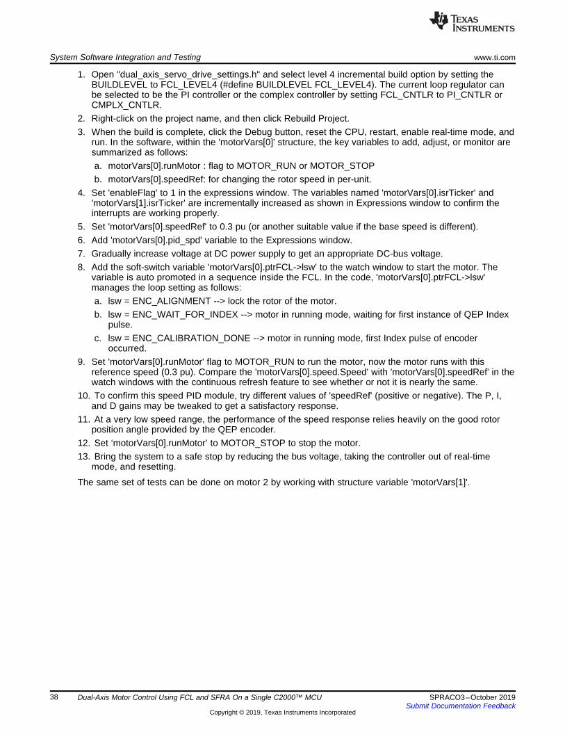
System Software Integration and Testing www.ti.com
38 SPRACO3–October 2019Submit Documentation Feedback
Copyright © 2019, Texas Instruments Incorporated
Dual-Axis Motor Control Using FCL and SFRA On a Single C2000™ MCU
1. Open "dual_axis_servo_drive_settings.h" and select level 4 incremental build option by setting theBUILDLEVEL to FCL_LEVEL4 (#define BUILDLEVEL FCL_LEVEL4). The current loop regulator canbe selected to be the PI controller or the complex controller by setting FCL_CNTLR to PI_CNTLR orCMPLX_CNTLR.
2. Right-click on the project name, and then click Rebuild Project.3. When the build is complete, click the Debug button, reset the CPU, restart, enable real-time mode, and
run. In the software, within the 'motorVars[0]' structure, the key variables to add, adjust, or monitor aresummarized as follows:a. motorVars[0].runMotor : flag to MOTOR_RUN or MOTOR_STOPb. motorVars[0].speedRef: for changing the rotor speed in per-unit.
4. Set 'enableFlag' to 1 in the expressions window. The variables named 'motorVars[0].isrTicker' and'motorVars[1].isrTicker' are incrementally increased as shown in Expressions window to confirm theinterrupts are working properly.
5. Set 'motorVars[0].speedRef' to 0.3 pu (or another suitable value if the base speed is different).6. Add 'motorVars[0].pid_spd' variable to the Expressions window.7. Gradually increase voltage at DC power supply to get an appropriate DC-bus voltage.8. Add the soft-switch variable 'motorVars[0].ptrFCL->lsw' to the watch window to start the motor. The
variable is auto promoted in a sequence inside the FCL. In the code, 'motorVars[0].ptrFCL->lsw'manages the loop setting as follows:a. lsw = ENC_ALIGNMENT --> lock the rotor of the motor.b. lsw = ENC_WAIT_FOR_INDEX --> motor in running mode, waiting for first instance of QEP Index
pulse.c. lsw = ENC_CALIBRATION_DONE --> motor in running mode, first Index pulse of encoder
occurred.9. Set 'motorVars[0].runMotor' flag to MOTOR_RUN to run the motor, now the motor runs with this
reference speed (0.3 pu). Compare the 'motorVars[0].speed.Speed' with 'motorVars[0].speedRef' in thewatch windows with the continuous refresh feature to see whether or not it is nearly the same.
10. To confirm this speed PID module, try different values of 'speedRef' (positive or negative). The P, I,and D gains may be tweaked to get a satisfactory response.
11. At a very low speed range, the performance of the speed response relies heavily on the good rotorposition angle provided by the QEP encoder.
12. Set ‘motorVars[0].runMotor’ to MOTOR_STOP to stop the motor.13. Bring the system to a safe stop by reducing the bus voltage, taking the controller out of real-time
mode, and resetting.
The same set of tests can be done on motor 2 by working with structure variable 'motorVars[1]'.
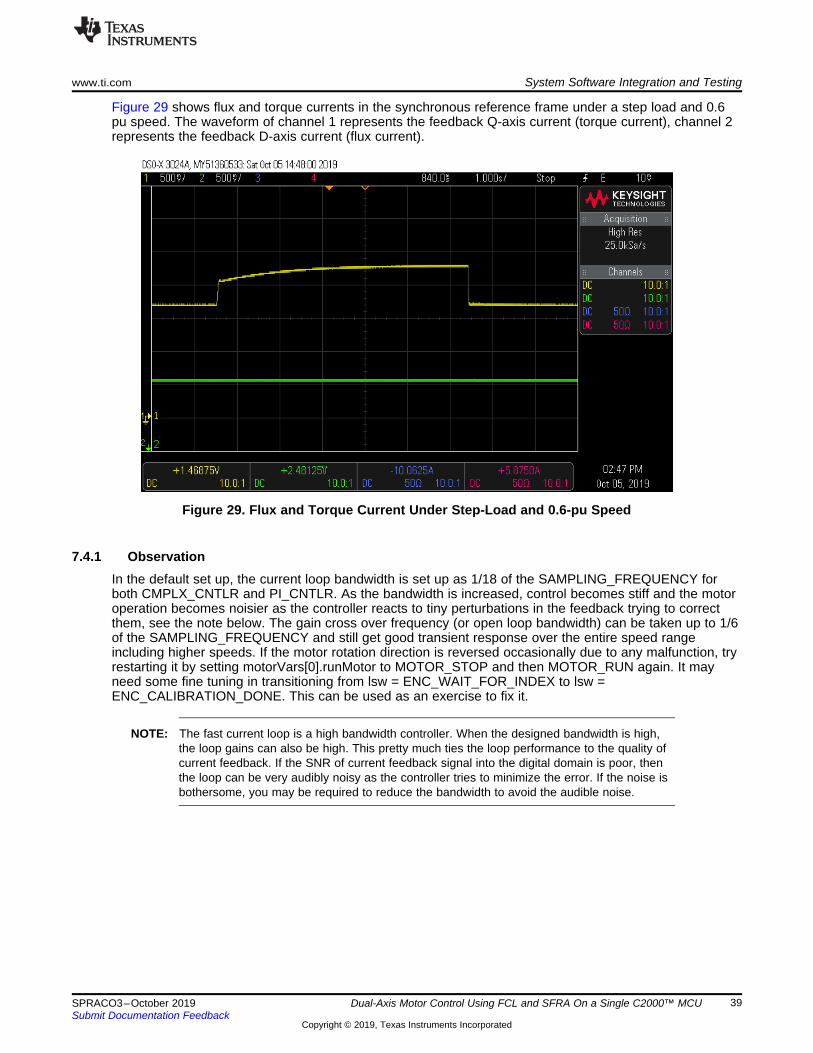
www.ti.com System Software Integration and Testing
39SPRACO3–October 2019Submit Documentation Feedback
Copyright © 2019, Texas Instruments Incorporated
Dual-Axis Motor Control Using FCL and SFRA On a Single C2000™ MCU
Figure 29 shows flux and torque currents in the synchronous reference frame under a step load and 0.6pu speed. The waveform of channel 1 represents the feedback Q-axis current (torque current), channel 2represents the feedback D-axis current (flux current).
Figure 29. Flux and Torque Current Under Step-Load and 0.6-pu Speed
7.4.1 ObservationIn the default set up, the current loop bandwidth is set up as 1/18 of the SAMPLING_FREQUENCY forboth CMPLX_CNTLR and PI_CNTLR. As the bandwidth is increased, control becomes stiff and the motoroperation becomes noisier as the controller reacts to tiny perturbations in the feedback trying to correctthem, see the note below. The gain cross over frequency (or open loop bandwidth) can be taken up to 1/6of the SAMPLING_FREQUENCY and still get good transient response over the entire speed rangeincluding higher speeds. If the motor rotation direction is reversed occasionally due to any malfunction, tryrestarting it by setting motorVars[0].runMotor to MOTOR_STOP and then MOTOR_RUN again. It mayneed some fine tuning in transitioning from lsw = ENC_WAIT_FOR_INDEX to lsw =ENC_CALIBRATION_DONE. This can be used as an exercise to fix it.
NOTE: The fast current loop is a high bandwidth controller. When the designed bandwidth is high,the loop gains can also be high. This pretty much ties the loop performance to the quality ofcurrent feedback. If the SNR of current feedback signal into the digital domain is poor, thenthe loop can be very audibly noisy as the controller tries to minimize the error. If the noise isbothersome, you may be required to reduce the bandwidth to avoid the audible noise.

System Software Integration and Testing www.ti.com
40 SPRACO3–October 2019Submit Documentation Feedback
Copyright © 2019, Texas Instruments Incorporated
Dual-Axis Motor Control Using FCL and SFRA On a Single C2000™ MCU
7.4.2 Dual Motor Run With Speed LoopIn the software, motor 1 and motor 2 can be controlled as above steps separately. Or, both motors can becontrolled simultaneously. The key variables to add, adjust, or monitor are summarized as follow to controldual motor.• flagSyncRun: flag to 0 that control dual motor separately, flag to 1 that control dual motor
simultaneously.• runMotor : flag to MOTOR_RUN or MOTOR_STOP for setting 'motorVars[0].runMotor' and
'motorVars[1].runMotor' simultaneously.• speedRef: for changing the motorVars[0].speedRef and motorVars[0].speedRef in per-unit with the
same setting value.1. Set 'enableFlag' to 1 in the expressions window.2. Set 'flagSyncRun' to 1 to enable controlling dual motor simultaneously.3. Set 'speedRef' to 0.1pu (or another suitable value if the base speed is different). The variables,
'motorVars[0].speedRef' and 'motorVars[0].speedRef' are changed to the value equals to 'speedRef'.4. Set 'runMotor' flag to MOTOR_RUN to run the dual motor, now both motors run with this reference
speed (0.1 pu).5. Set 'runMotor’ to MOTOR_STOP to stop the dual motor.6. Bring the system to a safe stop by reducing the bus voltage, taking the controller out of real-time
mode, and resetting.
7.5 Incremental Build Level 5Assuming the previous build levels are verified successfully, this section verifies the position PI moduleand position loop with a QEP. When the motor is commanded to run, it is subjected to an initial alignmentstage where the electrical angle and the QEP angle count are set to zero. After ensuring a stablealignment, the motor starts to run.
The implementation block diagram is given in Figure 30. The motor shafts must be kept disconnected torun these motors at different position settings simultaneously or only one motor can be tested at a giventime.1. Open "dual_axis_servo_drive_settings.h" and select level 5 incremental build option by setting the
BUILDLEVEL to FCL_LEVEL5 (#define BUILDLEVEL FCL_LEVEL5). The current loop regulator canbe selected to be the PI controller or the complex controller by setting FCL_CNTLR to PI_CNTLR orCMPLX_CNTLR.
2. Right-click on the project name, and then click Rebuild Project.3. When the build is complete, click the Debug button, reset the CPU, restart, enable real-time mode, and
run.

QEP
PM
Motor
3-P
ha
se
Inve
rte
r
SP
EE
D F
R
MA
CR
OS
pe
ed
PI
MA
CR
O
Sp
d R
eg
Fb
k
SpeedRef
Au
to s
wit
che
d
fro
m s
tart
PW
M1
A/B
PW
M2
A/B
PW
M3
A/B
IdRef
Iph
1 (
Ia)
Iph
2 (
Ib)
Iph
3 (
Ic)
Rg
.Ou
t
Q
EP
Ele
cTh
eta
lsw
IqRef
Me
chT
he
ta
QEP
PM
Motor
3-P
ha
se
Inve
rte
r
SP
EE
D F
R
MA
CR
OS
pe
ed
PI
MA
CR
O
Sp
d R
eg
Fb
k
SpeedRef
Au
to s
wit
che
d
fro
m s
tart
PW
M1
A/B
PW
M2
A/B
PW
M3
A/B
IdRef
Iph
1 (
Ia)
Iph
2 (
Ib)
Iph
3 (
Ic)
Rg
.Ou
t
Q
EP
Ele
cTh
eta
lsw
IqRef
Me
chT
he
ta
MO
TO
R 1
MO
TO
R 2
PI
MA
CR
O
Po
s R
eg
Re
f
Fb
k
PositionRef
Re
f
PI
MA
CR
O
Po
s R
eg
Re
f
Fb
k
PositionRef
Re
f
FA
ST
CU
RR
EN
T L
OO
PF
AS
T C
UR
RE
NT
LO
OP
www.ti.com System Software Integration and Testing
41SPRACO3–October 2019Submit Documentation Feedback
Copyright © 2019, Texas Instruments Incorporated
Dual-Axis Motor Control Using FCL and SFRA On a Single C2000™ MCU
Figure 30. Level 5 Block Diagram Showing Position Loop for Dual Motor With Inner FCL

System Software Integration and Testing www.ti.com
42 SPRACO3–October 2019Submit Documentation Feedback
Copyright © 2019, Texas Instruments Incorporated
Dual-Axis Motor Control Using FCL and SFRA On a Single C2000™ MCU
4. The software runs the motor through predefined motion profiles and position settings as set by therefPosGen() module. This module basically cycles the position reference through a set of values asdefined in an array 'posArray[]'. These values represent the number of the rotations and turns withrespect to the initial alignment position. Once a certain position value as defined in the array isreached, it pauses for a while before slewing toward the next position in the array. Therefore, thesearray values can be referred to as parking positions. During transition from one parking position to thenext, the rate of transition (or speed) is set by 'motorVars[0].posSlewRate'. The number of positions in'posArray[]' through which it passes before restarting from the first value is decided by 'ptrMax'. Hence,add the key variables 'posArray', 'ptrMax', and 'motorVars[0].posSlewRate' to the Expressions windowas follows:a. motorVars[0].runMotor : flag to MOTOR_RUN or MOTOR_STOPb. motorVars[0].ptrFCL->lsw: the soft-switch flag that is auto promoted in a sequence inside the FCL.c. motorVars[0].posSlewRate: the rate of transition from one parking position to the next position.d. motorVars[0].pi_pos: the position PI controller structure variable.e. posArray: the position reference for dual motor.f. ptrMax: the maximum position sets.
5. Set “enableFlag” to 1 in the expressions window. The variables named 'motorVars[0].isrTicker' and'motorVars[1].isrTicker' are incrementally increased as shown in Expressions window to confirm theinterrupts are working properly.
6. Gradually increase voltage at DC power supply to get an appropriate DC-bus voltage.7. Set 'motorVars[0].runMotor' flag to MOTOR_RUN to run the motor, now the motor must be turning to
follow the commanded position (see the following note if the motor does not turn properly).8. The parking positions in 'posArray[]' can be changed to different values to determine if the motor turns
as many rotations as set.9. The number of parking positions 'ptrMax' can also be changed to set a rotation pattern.10. The position slew rate can be changed using 'motorVars[0].posSlewRate'. This rate represents the
angle (in pu) per sampling instant.11. The proportional and integral gains of the speed and position PI controllers may be returned to get
satisfactory responses. TI advises to first tune the speed loop and then the position loop.12. Set 'motorVars[0].runMotor' to MOTOR_STOP to stop the motor.13. Bring the system to a safe stop by reducing the bus voltage, taking the controller out of real-time
mode, and resetting.
The same set of tests can be done on motor 2 by working with structure variable 'motorVars[1]'.

www.ti.com System Software Integration and Testing
43SPRACO3–October 2019Submit Documentation Feedback
Copyright © 2019, Texas Instruments Incorporated
Dual-Axis Motor Control Using FCL and SFRA On a Single C2000™ MCU
Figure 31 shows the position reference, and position feedback are plotted in the scope plot using DACs.They are aligned with negligible lag, which may be attributed to software. If the Kp and Ki gains of theposition loop controller are not chosen properly, this may lead to oscillations in the feedback or a laggedresponse.
Figure 31. DACs in Scope Plot of Reference Position to Servo and Feedback Position
NOTE:• If the motor response is erratic, then the sense of turn of the motor shaft and the
encoder may be opposite. Swap any two phase connections to the motor and repeat thetest.
• The position control implemented here is based on an initial aligned electrical position(=0). If the motor has multiple pole pairs, then this alignment can leave the shaft indifferent mechanical positions depending on the prestart mechanical position of therotor. If the mechanical position repeat ability or consistency is needed, then the QEPindex pulse must be used to set a reference point. This may be taken as an exercise .
7.5.1 Dual Motor Run with Position LoopIn the software, motor 1 and motor 2 can be controlled as above steps separately. Or, both motors can becontrolled simultaneously. The key variables to add, adjust, or monitor are summarized as follow to controldual motor.• flagSyncRun: flag to 0 that control dual motor separately, flag to 1 that control dual motor
simultaneously.• runMotor : flag to MOTOR_RUN or MOTOR_STOP for setting 'motorVars[0].runMotor' and
'motorVars[1].runMotor' simultaneously.1. Set 'enableFlag' to 1 in the expressions window.2. Set 'flagSyncRun' to 1 to enable controlling dual motor simultaneously.3. Set 'runMotor' flag to 'MOTOR_RUN' to run the dual motor, now both motors run with this reference
speed (0.1 pu).4. Set 'runMotor’ to 'MOTOR_STOP' to stop the dual motor.5. Bring the system to a safe stop by reducing the bus voltage, taking the controller out of real-time
mode, and resetting.
System Software Integration and Testing www.ti.com
44 SPRACO3–October 2019Submit Documentation Feedback
Copyright © 2019, Texas Instruments Incorporated
Dual-Axis Motor Control Using FCL and SFRA On a Single C2000™ MCU
7.6 Incremental Build Level 6Assuming the previous build levels are successfully completed, this build level attempts to study thefrequency response analysis of the FCL using C2000’s Software Frequency Response Analyzer (SFRA)tool, available as a library in the C2000ware MotorControl SDK.
7.6.1 Integrating SFRA LibraryThe SFRA tool runs only on C2000 MCU platform to study the frequency response analysis of any controlloop that it controls. It consists of an embedded firmware part that runs on the MCU and a graphical userinterface part (GUI) that runs on the development computer.
C2000™ Software Frequency Response Analyzer (SFRA) Library and Compensation Designer in SDKFramework describes the SFRA tool and guides you into integrating it into the C2000 platform. This canbe found at: \ti\c2000\C2000Ware_MotorControl_SDK_<version>\libraries\sfra\Doc.
The embedded firmware is available as a library in the MotorControl SDK at:\ti\c2000\C2000Ware_MotorControl_SDK_<version>\libraries\sfra
The SFRA GUIs are available as executable applications in the MotorControl SDK at:\ti\c2000\C2000Ware_MotorControl_SDK_<version>\libraries\sfra\gui
Some example projects to understand SFRA are available at:\ti\c2000\C2000Ware_MotorControl_SDK_<version>\libraries\sfra\examples
In the ISR code, there are two functions as follows that inject noise for SFRA and then collect thefeedback data from the loop.• injectSFRA()• collectSFRA()
The roles of these functions are self-explanatory from their names. They should be used in the code tocollect the data in right sequence.
NOTE:• The disturbances due to analog signal path and quantization will impact the loop
performance and hinder high bandwidth selections that can be verified using SFRAresults. Therefore it is important to provide a current feedback with a higher SNR.
• When evaluating current loops, if it is possible to hold the motor speed constant, it willhelp to minimize the impact of speed jitter related errors in the SFRA results. This isparticularly useful when studying the Iq loop. If the voltage decoupling of current loop isgood, then this requirement may not matter.
This tool provides the ability to study the D-axis or Q-axis current loops or the speed loop. The motor canbe run at different speed / load conditions and at different bandwidths and the performance can beevaluated at each of these conditions. It can be seen that the controller can provide the designedbandwidth under all these conditions with a certain tolerance.
The implementation block diagram is given in Figure 32. The SFRA tool injects noise signal into thesystem at various frequencies and analyzes the system response and provides a Bode Plot of the actualphysical system as seen during the test.

QEP
PM
Motor
3-P
ha
se
Inve
rte
r
SP
EE
D F
R
MA
CR
O
Sp
ee
d
PI
MA
CR
O
Sp
d R
eg
Fb
k
SpeedRef
Au
to s
wit
che
d
fro
m s
tart
PW
M1
A/B
PW
M2
A/B
PW
M3
A/B
IdRef
Iph
1 (
Ia)
Iph
2 (
Ib)
Iph
3 (
Ic)
Rg
.Ou
t
Q
EP
Ele
cTh
eta
lswIqRef
Me
chT
he
ta
QEP
PM
Motor
3-P
ha
se
Inve
rte
r
SP
EE
D F
R
MA
CR
OS
pe
ed
PI
MA
CR
O
Sp
d R
eg
Fb
k
SpeedRef
Au
to s
wit
che
d
fro
m s
tart
PW
M1
A/B
PW
M2
A/B
PW
M3
A/B
IdRef
Iph
1 (
Ia)
Iph
2 (
Ib)
Iph
3 (
Ic)
Rg
.Ou
t
Q
EP
Ele
cTh
eta
lsw
IqRef
Me
chT
he
ta
MO
TO
R 1
MO
TO
R 2
IdFbk
SF
RA
Co
ntr
ol
FA
ST
CU
RR
EN
T L
OO
P
SF
RA
Co
ntr
ol
IdFbk
FA
ST
CU
RR
EN
T L
OO
P
www.ti.com System Software Integration and Testing
45SPRACO3–October 2019Submit Documentation Feedback
Copyright © 2019, Texas Instruments Incorporated
Dual-Axis Motor Control Using FCL and SFRA On a Single C2000™ MCU
Figure 32. Level 6 Block Diagram With Inner FCL and SFRA

System Software Integration and Testing www.ti.com
46 SPRACO3–October 2019Submit Documentation Feedback
Copyright © 2019, Texas Instruments Incorporated
Dual-Axis Motor Control Using FCL and SFRA On a Single C2000™ MCU
7.6.2 Initial Setup Before Starting SFRAThe setting up involves co-ordination between the debug environment and the SFRA GUI. Until gettingfamiliar with connecting the SFRA GUI to the target platform, it is a good idea to turn off the power supplyinput to the inverter board.1. Open ’dual_axis_servo_drive_settings.h’ and select level 6 incremental build option by setting the
BUILDLEVEL to FCL_LEVEL6 (#define BUILDLEVEL FCL_LEVEL6) . Also, in this file, watch out forthe definitions:a. SFRA_FREQ_STARTb. SFRA_FREQ_LENGTHc. FREQ_STEP_MULTIPLY
These definitions inform the GUI about the starting value of noise frequency, number of differentnoise frequencies to sweep and the ratio between successive sweep frequencies, respectively.More information is available in the C2000™ Software Frequency Response Analyzer (SFRA)Library and Compensation Designer User's Guide associated with SFRA. In the context of thisevaluation project, it is important to know and appreciate these parameters to tweak them forfurther repeat tests.The default setting of the code is that SFRA will be performed on motor1. To do SFRA on motor 2,call the SFRA functions with the motor 2 handle (or pointer) by setting the SFRA_MOTOR toMOTOR_2 (#define SFRA_MOTOR MOTOR_2) in "dual_axis_servo_drive_settings.h".In this motor control project, there are three different loops such as the speed loop, D axis currentloop and Q axis current loop. Any of these loops could be analyzed for frequency response.Technically, this could be performed on position loop as well, but is not included in this projectscope.
2. Right click on the project name and click Rebuild Project.3. Once the build is complete click on debug button, reset CPU, restart, enable real time mode and run.4. Add the following variable in the Expressions window:
a. sfraTestLoop : for selecting the control loop on which to evaluate SFRA, letting you choosebetween the following settings.i. SFRA_TEST_D_AXIS - D axis current loopii. SFRA_TEST_Q_AXIS - Q axis current loopiii. SFRA_TEST_SPEEDLOOP - speed loop
5. Set 'enableFlag' to 1 in the watch window. The variable named 'motorVars[0].isrTicker' and'motorVars[1].isrTicker' will be incrementally increased as seen in watch windows to confirm theinterrupt working properly.
6. The SCI initialization needed to communicate with the GUIs should be complete by now.7. Further steps with the debug window will follow after setting up the GUI to connect to target platform.
7.6.3 SFRA GUIsThere are two GUIs available to perform the frequency response analysis: one (SFRA_GUI) to plot openloop and plant Bode diagram, and another (SFRA_GUI_MC) to plot open loop and closed loop Bodediagram. They can be invoked and connected to the target platform to study the control loops. The GUIexecutables are available in the location as mentioned in Section 7.6.1.1. Double click on the choice of GUI executable and the GUI screen will appear as shown in Figure 33 for
SFRA_GUI or in Figure 34 for SFRA_GUI_MC. They look almost identical, the difference is in the pulldown menu under 'FRA Settings' starting with the label 'Open Loop'.a. In the SFRA_GUI, this pull down menu helps to select between Open Loop Model and Plant
Model.b. In the SFRA_GUI_MC, this pull down menu helps to select between Open Loop Model and Closed
Loop Model.

www.ti.com System Software Integration and Testing
47SPRACO3–October 2019Submit Documentation Feedback
Copyright © 2019, Texas Instruments Incorporated
Dual-Axis Motor Control Using FCL and SFRA On a Single C2000™ MCU
Figure 33. SFRA GUI
Figure 34. SFRA GUI MC
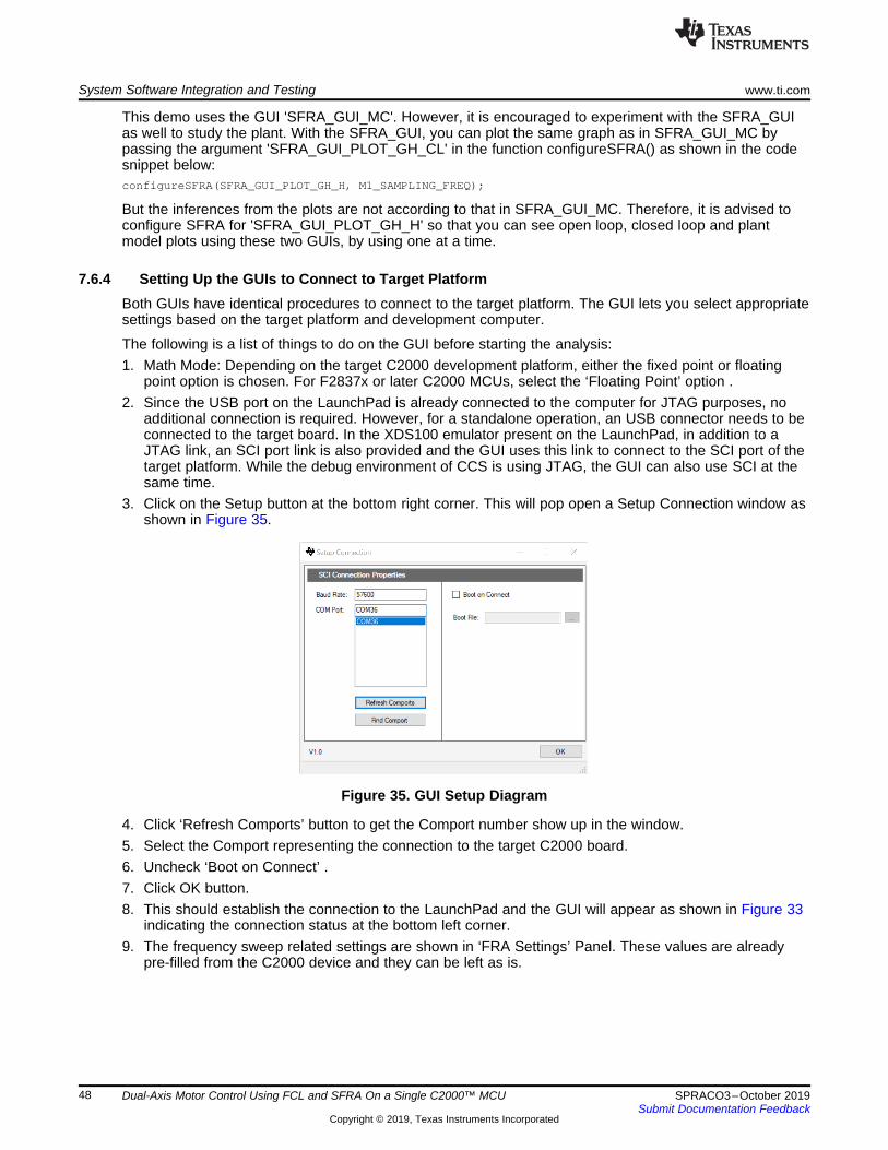
System Software Integration and Testing www.ti.com
48 SPRACO3–October 2019Submit Documentation Feedback
Copyright © 2019, Texas Instruments Incorporated
Dual-Axis Motor Control Using FCL and SFRA On a Single C2000™ MCU
This demo uses the GUI 'SFRA_GUI_MC'. However, it is encouraged to experiment with the SFRA_GUIas well to study the plant. With the SFRA_GUI, you can plot the same graph as in SFRA_GUI_MC bypassing the argument 'SFRA_GUI_PLOT_GH_CL' in the function configureSFRA() as shown in the codesnippet below:configureSFRA(SFRA_GUI_PLOT_GH_H, M1_SAMPLING_FREQ);
But the inferences from the plots are not according to that in SFRA_GUI_MC. Therefore, it is advised toconfigure SFRA for 'SFRA_GUI_PLOT_GH_H' so that you can see open loop, closed loop and plantmodel plots using these two GUIs, by using one at a time.
7.6.4 Setting Up the GUIs to Connect to Target PlatformBoth GUIs have identical procedures to connect to the target platform. The GUI lets you select appropriatesettings based on the target platform and development computer.
The following is a list of things to do on the GUI before starting the analysis:1. Math Mode: Depending on the target C2000 development platform, either the fixed point or floating
point option is chosen. For F2837x or later C2000 MCUs, select the ‘Floating Point’ option .2. Since the USB port on the LaunchPad is already connected to the computer for JTAG purposes, no
additional connection is required. However, for a standalone operation, an USB connector needs to beconnected to the target board. In the XDS100 emulator present on the LaunchPad, in addition to aJTAG link, an SCI port link is also provided and the GUI uses this link to connect to the SCI port of thetarget platform. While the debug environment of CCS is using JTAG, the GUI can also use SCI at thesame time.
3. Click on the Setup button at the bottom right corner. This will pop open a Setup Connection window asshown in Figure 35.
Figure 35. GUI Setup Diagram
4. Click ‘Refresh Comports’ button to get the Comport number show up in the window.5. Select the Comport representing the connection to the target C2000 board.6. Uncheck ‘Boot on Connect’ .7. Click OK button.8. This should establish the connection to the LaunchPad and the GUI will appear as shown in Figure 33
indicating the connection status at the bottom left corner.9. The frequency sweep related settings are shown in ‘FRA Settings’ Panel. These values are already
pre-filled from the C2000 device and they can be left as is.

www.ti.com System Software Integration and Testing
49SPRACO3–October 2019Submit Documentation Feedback
Copyright © 2019, Texas Instruments Incorporated
Dual-Axis Motor Control Using FCL and SFRA On a Single C2000™ MCU
10. As mentioned earlier, the visual difference between the two GUIs is in the pull down menu under 'FRASettings' starting with Open Loop.a. In the SFRA_GUI, this pull down menu helps to select between Open Loop Model and Plant
Model.b. In the SFRA_GUI_MC, this pull down menu helps to select between Open Loop Model and Closed
Loop Model.c. This menu becomes relevant after a complete noise injection sweep of the system at various
frequencies. Then, you can pick and view the plot of choice using this menu.d. Bandwidth reporting is different as mentioned earlier. Gain cross over frequency is reported in the
open loop plot of the SFRA_GUI_MC instead of bandwidth as in SFRA_GUI.11. This completes the initial setup of GUI environment.
7.6.5 Running the SFRA GUIsIf the power supply to the inverter board is turned off before, restore it back now. From the debugenvironment, the steps to be followed are as shown below:1. Verify that sfraTestLoop is set to SFRA_TEST_D_AXIS so as to test Id loop.2. Set 'motorVars[0].FCL_params.wccD' to the desired value, within limits, (when test is performed for Q
axis, adjust this parameter for Q axis - motorVars[0].FCL_params.wccQ)3. Set motorVars[0].speedRef = 0.05 (in pu, 1 pu = 250Hz) and then set motorVars[0].runMotor =
MOTOR_RUN to run the motor. Now motor shaft should start spinning and settle at the commandedspeed.
4. The state machine variable (motorVars[0].ptrFCL->lsw) is auto promoted in a sequence, its states areas follows:a. lsw = ENC_ALIGNMENT --> lock the rotor of the motor.b. lsw = ENC_WAIT_FOR_INDEX --> motor in run mode and waiting for the first instance of QEP
index pulse.c. lsw = ENC_CALIBRATION_DONE --> motor in run mode - QEP index pulse occurred.
5. Now, the GUI can be called into perform a frequency sweep of the D axis current loop by clicking onthe "Start Sweep" button in the GUI. The sweep progress will be indicated by a green bar in thelocation marked as "NO DATA".
6. When the frequency sweep is fully done, it will compute the Bode plot and display the results as shownin Figure 36 and Figure 37.

System Software Integration and Testing www.ti.com
50 SPRACO3–October 2019Submit Documentation Feedback
Copyright © 2019, Texas Instruments Incorporated
Dual-Axis Motor Control Using FCL and SFRA On a Single C2000™ MCU
Figure 36. SFRA Open Loop Bode Plots of the Current Loop Showing Magnitude and Phase Angle

www.ti.com System Software Integration and Testing
51SPRACO3–October 2019Submit Documentation Feedback
Copyright © 2019, Texas Instruments Incorporated
Dual-Axis Motor Control Using FCL and SFRA On a Single C2000™ MCU
Figure 37. SFRA Closed Loop Bode Plots of the Current Loop Showing Magnitude and Phase Angle
7. The GUI also computes and displays the loop bandwidth, gain margin and phase margin.8. Repeat the test, if desired, by changing the variable 'motorVars[0].FCL_params.wccD', and at different
speed and load conditions.9. To disconnect the GUI, click the 'Disconnect' button on the GUI.10. To stop the motor, set 'motorVars[0].runMotor' to 'MOTOR_STOP'.11. After the motor stops, take the controller out of real-time mode and reset.
The same set of tests can be done on motor 2 by working with structure variable 'motorVars[1]', and bychanging the SFRA_MOTOR to MOTOR_2 (#define SFRA_MOTOR MOTOR_2) in"dual_axis_servo_drive_settings.h".
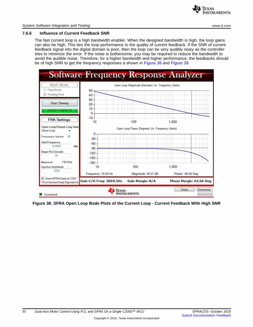
System Software Integration and Testing www.ti.com
52 SPRACO3–October 2019Submit Documentation Feedback
Copyright © 2019, Texas Instruments Incorporated
Dual-Axis Motor Control Using FCL and SFRA On a Single C2000™ MCU
7.6.6 Influence of Current Feedback SNRThe fast current loop is a high bandwidth enabler. When the designed bandwidth is high, the loop gainscan also be high. This ties the loop performance to the quality of current feedback. If the SNR of currentfeedback signal into the digital domain is poor, then the loop can be very audibly noisy as the controllertries to minimize the error. If the noise is bothersome, you may be required to reduce the bandwidth toavoid the audible noise. Therefore, for a higher bandwidth and higher performance, the feedbacks shouldbe of high SNR to get the frequency responses a shown in Figure 38 and Figure 39.
Figure 38. SFRA Open Loop Bode Plots of the Current Loop - Current Feedback With High SNR

www.ti.com System Software Integration and Testing
53SPRACO3–October 2019Submit Documentation Feedback
Copyright © 2019, Texas Instruments Incorporated
Dual-Axis Motor Control Using FCL and SFRA On a Single C2000™ MCU
Figure 39. SFRA Closed Loop Bode Plots of the Current Loop - Current Feedback With High SNR
NOTE: With the hardware platform LaunchPad and BoosterPack, there is scope for improving theSNR of the current signal feeding into the ADCs of the MCU. Therefore, higher bandwidthtests can be more noisier (chattering in nature) on this platform.
7.6.7 Inferences• Bandwidth determination from closed loop plot.
– The controller implemented for the open loop and closed loop plots shown in Figure 38 andFigure 39 is a dead beat controller where the output catches up to the input in just one samplecycle without any overshoots or requiring multiple cycles. From the closed loop plot, it is clear thatthe closed loop gain is always 0dB (unity gain) at all frequencies and, therefore, magnitude-basedbandwidth determination is not practical. Hence, the phase plot is chosen as reference and thefrequency at which the phase lag goes beyond 90° is taken as bandwidth per the NEMA ICS 16(speed loop). In this test case, the PWM frequency is chosen as 10 KHz and the samplingfrequency is 20 KHz and the current loop bandwidth obtained from the closed loop plot is about5000Hz per these guidelines.
• Phase margin determination from open loop plot.– From the open loop plots, the phase margin obtained is about 65°. Such a high margin should give
a very robust performance across the frequency ranges within the bandwidth obtained.

System Software Integration and Testing www.ti.com
54 SPRACO3–October 2019Submit Documentation Feedback
Copyright © 2019, Texas Instruments Incorporated
Dual-Axis Motor Control Using FCL and SFRA On a Single C2000™ MCU
Maximum modulation index determination from PWM update time.From Section 7.3.1, the time lapse between feedback sampling instantiation to PWM update is about1.75 µs. In this system where the PWM frequency is 10 KHz, the maximum modulation index is limitedby the sampling method as follows:– Double sampling - just above 96% (F2837x), or 93% (F28004x)– Single sampling - just about 98% (F2837x), or 96% (F28004x)This is quite comparable to FPGA based systems where the entire algorithm is implemented inhardware.
• Voltage decoupling in current loop– The SFRA test can be performed at zero speed (by rigidly locking the shaft if needed) to get one
plot as reference. The gain crossover frequency and phase margin at zero speed may be noteddown. Then at different speeds and load conditions, this test can be repeated to verify if there isany change in bandwidth or phase margin. Any variation in the plot at different speed is indicativeof the quality of decoupling in current loops.
7.6.8 Phase Margin vs Gain Crossover FrequencyBy varying the control bandwidth and repeating these tests and noting down the resulting gain cross overfrequency and phase margin, a set of plots are obtained for Id loop as shown in Figure 40. Two sets oftests are performed: one based on classical current control method and the other based on FCL. Boththese tests were performed using different current regulators. They all gave converging results.
Figure 40. Plot of Gain Cross over Frequency vs Phase Margin as Experimentally Obtained

www.ti.com Summary
55SPRACO3–October 2019Submit Documentation Feedback
Copyright © 2019, Texas Instruments Incorporated
Dual-Axis Motor Control Using FCL and SFRA On a Single C2000™ MCU
8 SummaryThis evaluation platform helps to control two different motors with FCL technology, and with or withoutSFRA. The FCL shows a substantial improvement in control bandwidth and phase margin. The SFRA toolshows the impact of FCL on control bandwidth and phase margin, and evaluates the current and speedcontrol loop performance.
The presence of fast ADC, control law architecture (CLA) and trigonometric math unit (TMU) helped toreduce the latency between feedback sampling and PWM update, in turn, resulted in higher controlbandwidth and increase in maximum modulation index. Higher modulation index helps to improve the DCbus utilization by the drive and to increase the control speed range of the motor.
Depending on the control speed range of motors in target applications, it is possible to control dual motorsin multi-axes configurations using FCL with a single F2837x or F28004x series controller, this makes itsuitable for high end servo control applications.
9 References• Texas Instruments: Fast Current Loop Driverlib Library• Texas Instruments: LAUNCHXL-F28379D Overview User's Guide• Texas Instruments: C2000™ Piccolo™ F28004x Series LaunchPad™Development Kit• Texas Instruments: BOOSTXL-3PhGaNInv Evaluation Module User's Guide• Texas Instruments: C2000™ Software Frequency Response Analyzer (SFRA) Library and
Compensation Designer User's Guide• Texas Instruments: Performance Analysis of Fast Current Loop (FCL) in Servo Drives Using SFRA on
C2000™ Platform• Texas Instruments: Dual Motor Control Using FCL and Performance Analysis Using SFRA on
TMS320F28379D LaunchPad• Texas Instruments: C2000™ Software Frequency Response Analyzer (SFRA) Library and
Compensation Designer in SDK Framework

IMPORTANT NOTICE AND DISCLAIMERTI PROVIDES TECHNICAL AND RELIABILITY DATA (INCLUDING DATA SHEETS), DESIGN RESOURCES (INCLUDING REFERENCE DESIGNS), APPLICATION OR OTHER DESIGN ADVICE, WEB TOOLS, SAFETY INFORMATION, AND OTHER RESOURCES “AS IS” AND WITH ALL FAULTS, AND DISCLAIMS ALL WARRANTIES, EXPRESS AND IMPLIED, INCLUDING WITHOUT LIMITATION ANY IMPLIED WARRANTIES OF MERCHANTABILITY, FITNESS FOR A PARTICULAR PURPOSE OR NON-INFRINGEMENT OF THIRD PARTY INTELLECTUAL PROPERTY RIGHTS.These resources are intended for skilled developers designing with TI products. You are solely responsible for (1) selecting the appropriate TI products for your application, (2) designing, validating and testing your application, and (3) ensuring your application meets applicable standards, and any other safety, security, regulatory or other requirements.These resources are subject to change without notice. TI grants you permission to use these resources only for development of an application that uses the TI products described in the resource. Other reproduction and display of these resources is prohibited. No license is granted to any other TI intellectual property right or to any third party intellectual property right. TI disclaims responsibility for, and you will fully indemnify TI and its representatives against, any claims, damages, costs, losses, and liabilities arising out of your use of these resources.TI’s products are provided subject to TI’s Terms of Sale or other applicable terms available either on ti.com or provided in conjunction with such TI products. TI’s provision of these resources does not expand or otherwise alter TI’s applicable warranties or warranty disclaimers for TI products.TI objects to and rejects any additional or different terms you may have proposed. IMPORTANT NOTICE
Mailing Address: Texas Instruments, Post Office Box 655303, Dallas, Texas 75265Copyright © 2022, Texas Instruments Incorporated