Drive, Assembly and Handling Products - Carr Lane Roemheld
96
Linear Actuators ■ Modular Units for Assembly & Handling ■ Assembly Tables Drive, Assembly and Handling Products
-
Upload
khangminh22 -
Category
Documents
-
view
2 -
download
0
Transcript of Drive, Assembly and Handling Products - Carr Lane Roemheld

Linear Actuators Modular Units for Assembly & Handling Assembly Tables
CARR
LANE
ROEMHELD
MFG
CO
ASSY
12
2017
Drive, Assembly and Handling Products
Authorized Distributor:
Carr Lane Roemheld Mfg. Co.927 Horan Drive Fenton, MO 63026
Phone (636) 386-8022 Fax (636) 386-8034Free Engineering Support 1-800-827-2526
www.roemheld-usa.com
Connect with us: COPYRIGHT © 2017 CARR LANE ROEMHELD MANUFACTURING CO. PRINTED IN U.S.A. ASSY-1217

Carr Lane Roemheld Mfg. Co.
OUR STORYIn 1982 an independent joint venture was established to marry the proven product expertise of Roemheld with the marketing know-how and distribution network of Carr Lane Manufacturing. This partnership now offers to the American manufacturer the complete benefits of the finest in international assembly and handling, as well as power workholding, combined with the best in local service and support.
After initial tests by many companies, both small and large, the word had spread confirming the quality and reliability obtained when using Roemheld products.
We invite you to review this catalog in depth and to call us with any questions about your applications. We at Carr Lane Roemheld welcome the opportunity to help you manufacture your quality product in the most productive way possible — with the world’s most dependable assembly and handling equipment.
Founded in 1952 in St. Louis, Missouri by Earl E. Walker to make standardized tooling components, Carr Lane Manufacturing has grown, through constant innovation, to become the foremost supplier to the American Machine Tool Industry. Now the most complete line available, Carr Lane Manufacturing offers Jig and Fixture Components, Toggle Clamps, Hoist Rings, Alignment Pins, Drill Bushings, Spring Plungers, and Modular Fixturing. Setting the standard for American Tool Engineers, Carr Lane Manufacturing’s catalog is recognized as the manufacturing engineer’s tooling reference.
Drawing upon a centuries-old tradition of German craftsmanship, metalworking was already well established in Laubach, Germany when the Romheld family began to manage operations in 1870. Development of the hydraulic workholding components began in the early 1960’s and soon grew to dominate the European market.
Today, Roemheld GmbH is by far the world leader in this productivity-enhancing technology, offering a tremendous range of types and sizes of superior design and the highest quality.
WE CAN HANDLE YOUR
ASSEMBLY!
View assembly products at: www.roemheld-usa.com
Fenton, MO 63026(636) 386-8022
Increase Productivity In Your Assembly Area!
OUR STORY WE CAN PRECISION MACHINE VISES INCREASE PRODUCTIVITY
• Reduce set up time by as much as 90% with zero point mounting
• Existing fixtures can be easily adapted
• Highly accurate positioning and repeatability
• Increased productivity
Zero Point Mounting System for Quick Change Fixturing
REDUCE SET-UP AND DOWNTIME!
View Zero Point Mounting at:
www.roemheld-usa.com
• Fast payback• Set-up times slashed• Fixture life extended
Zero Point Mounting
REDUCE SET-UP AND DOWNTIME!
This comprehensive system utilizes clamping components and insertion nipples, which provide an immediate zero point orientation.
Use in Conjunction with the Zero Point Mounting System for Faster, More Accurate Fixture Set Ups
Fenton, MO 63026(636) 386-8022
Your Assembly Area!
Linear ActuatorsControl, adjust and move with your choice of electric or hydraulic linear actuators.
Centrick Workpiece PositionerFor Heavy Loads
Assembles products up to 4,400 lbs,tilts up to 90° and rotates 360°.
Centrick is quiet, requires just 230 V and little space.
Modular UnitsCombine units for
safe, efficient handling. Achieve rotating, tilting
and lifting of workpieces, and use with carts, floor modules, plates, clamps,
or adjustable tables.

INNOVATIVE CLAMPING SOLUTIONSThe highest quality power workholding systems to help you remain competitive in today’s manufacturing environment.
Power Workholding For CNC Machining
Work Supports
Swing Clamps
Concentric Clamping Elements
Valves, Fittings &Accessories
CNC Machine Vises
Zero Point Mounting
For More Information On Our Supporting Product Lines,Visit carrlaneroemheld.com.
Quick Die Change
Quick Mold Change for Plastics Quick Mold Change for Rubber
5-Axis Quick-Change Vises
Power Sources
Compact Clamps and Cylinders
Die Handling
1
Carr Lane Roemheld Mfg. Co. Sales — Phone (636) 386-8022 Fax (636) 386-8034
Engineering — Phone 1-800-827-2526 Web roemheld-usa.comSubject to change.
11/17

CARR LANE ROEMHELDGUARANTEE OF QUALITY
Carr Lane Roemheld components are carefully designed, manufactured, inspected, and individually tested prior to shipment. In the unlikely case you find a defect in materials or workmanship within 12 months after receipt, we will promptly repair or replace the component, in accordance with our Limited Warranty below. Our liability is limited to replacement of the part and this warranty does not apply to altered or misapplied products.
Limited Warranty
Seller warrants that the product described herein will be free from defects in material and workmanship. If any failure to conform to this warranty be found within six (6) months, from date of receipt of the product by Buyer, and Seller is given immediate notification thereof, Seller, upon being satisfied of the existence of such nonconformity, will correct the same by replacement of the defective product or making suitable repairs. If the Seller is unable to correct such nonconformity by replacement of the product or making suitable repairs, whether due to the nature of such nonconformity, the use made by the Buyer of the product, or for any other reason, it will return to Buyer the price set forth herein, or where appropriate, the unit price for such number or quantity of products as shall have such nonconformity which Seller is unable to correct, upon Seller’s receipt of the nonconforming product f.o.b. its plant; provided, however, no product shall be returned to Seller without its express written consent; and provided further that such receipt of any nonconforming product will not be required where it is no longer possible for Buyer to return the same to Seller. In no event shall Seller be liable to Buyer, either directly or by way of contribution or indemnity, for direct, special, incidental or consequential damages such as, but not limited to, property damage, loss of profit, damages based on loss of use of the product, or damages for cover, whether the claim for any such damages be based on warranty, express or implied, contract, tort, or otherwise. THE FOREGOING IS SELLER’S SOLE WARRANTY WITH RESPECT TO THE PRODUCT. SELLER MAKES NO OTHER WARRANTIES, EXPRESS OR IMPLIED, INCLUDING IMPLIED WARRANTIES OF MERCHANTABILITY AND FITNESS FOR A PARTICULAR PURPOSE.
11/17
Carr Lane Roemheld Mfg. Co. Sales — Phone (636) 386-8022 Fax (636) 386-8034
Engineering — Phone 1-800-827-2526 Web roemheld-usa.comSubject to change.
2

Linear Actuators Control, adjust and move with your choice of electric(12 VDC or 24 VDC) or hydraulic linear actuators.
RA 600Data Sheet L1.101, p. 10-12
RA 60KData Sheet L4.202, p. 13-15
Rotating Module Horizontal AxisRotate your workpiece about the horizontal axis via manual, hand lever, or hydromechanical operation. A 4 x 90˚ indexable version is available. Maximum weight is 200 kg (450 lbs). Data sheet: M1.101.
Rotating Module, Electric,Horizontal or Vertical AxisRotate your workpiece from 0˚ to 90˚ via electric operation. Versions for horizontal or vertical rotation. Maximum weight is 600 kg (1,350 lbs). Data sheet: M1.201.
Rotating Module Vertical AxisRotate your workpiece about the vertical axis via manual or hydromechanical operation. Standard version is indexable 4 x 90˚. Special index angles available upon request. Maximum weight is 600 kg (1,350 lbs). Data sheet: M1.301.
Lifting ModulesPrecison lifting and lowering of your workpiece. Electric and self-contained hydraulic versions. Electric versions can be synchronized. Telescoping versions available too. Maximum weight is 100 - 600 kg (225 – 1,350 lbs). Maximum stroke is 200 - 1000 mm (7.87" – 39.4"). Data sheets: M4.005, M4.101, M4.202, M4.203, M4.301, M4.401, M4.402, M4.501.
Cart ModulesHeavy duty carts are designed to interface and move individual modules or modular combinations, with or without their workpiece. All carts are equipped with a parking brake. Data sheet: M5.101.
Floor ModulesHeavy duty floor modules come equipped with leveling feet and you can mount one or more individual modules on the same base. Data sheet: M6.101.
AccessoriesBase Plates, Flange Plates, Table PlatesAdaptor Plates, Clamping Modules, Power Supply Units, Hand Panels & Foot SwitchesData sheets: M8.100, M8.110, M8.120, M8.130, M8.131, M8.200, M8.201, M8.203, M8.300, M8.301, M8.302.
Tilting ModuleTilt or swivel your workpiece from 0˚ to 90˚ via manual or electric operation. Maximum weight is 100 kg (225 lbs). Data sheets: M2.101, M2.201.
pp. 26-30
pp. 31-33
pp. 34-36
pp. 37-40
pp. 61-62
pp. 63-64
pp. 65-84
3
Carr Lane Roemheld Mfg. Co. Sales — Phone (636) 386-8022 Fax (636) 386-8034
Engineering — Phone 1-800-827-2526 Web roemheld-usa.comSubject to change.
11/17
RH 1250Data Sheet L7.101, p. 16-19
Centrick A three-dimensional workpiece positioner for heavy load assembly. Products up to 4,000 lbs can be tilted 90° and rotated 360°. Centrick is the latest sought out innovation of assembly products that will help reduce down time and prevent accidents. Data sheet: M9.201.
WorkbenchWorkbench with electrical height adjustment used for manual workstations. Users can adjust to optimum ergonomic working height in production areas. Data sheet M9.9101.
pp. 86-90
p. 85
pp. 41-60
Modular Units Combine these modules in numerous ways to meet your assembly and handling needs.
pp. 21-85Case Study, pp. 91-92
pp. 4-20Case Study, p. 20

11/17
Carr Lane Roemheld Mfg. Co. Sales — Phone (636) 386-8022 Fax (636) 386-8034
Engineering — Phone 1-800-827-2526 Web roemheld-usa.comSubject to change.
4
Electro-mechanical linear actuators
Line RA 600 RA 60 K
Data sheet L 1.101 L 4.202
Supply and control voltage 24 VDC 12 VDC
Max. push force 1,000 | 2,000 | 4,000 | 6,000 N 300 | 600 N
Max. pull force 80% of the max. push force 100% of the max. push force
Static retention force 125% of the max. push force 200 | 600 N
Strokes 100 | 150 | 200 | 300 | 400 | 500 | 600 mm 100 | 150 | 200 mm
Speed 37 … 8.5 mm/s (idle running) 29 … 5 mm/s (loaded)
28 … 16 mm/s (idle running) 18 … 7 mm/s (loaded)
Current consumption 5 | 5.5 | 6 | 7 A 3.5 | 4 A
Installation length (retracted) 310 … 850 mm 270 … 370 mm
Mounting position any any
Admissible ambient temperature [°C] – 20° to + 70 °C – 20° to + 70 °C
Resistant to corrosion, cleaning agents and disinfectantscorrosion, diesel, oil, cleaning agents,
fertilizers and salts
Fixation 2 fork eyes Ø 12 mm (Ø 10 mm with accessory bearing sleeve)
2 fork eyes Ø 10 mm
Drive DC motor with worm gearbox and spindle drive
DC motor with planetary gear and spindle drive
Versions with limit switches or with incremental stroke measuring system
with limit switches or with absolute stroke measuring system
Control with accessory control module or via external 24 VDC control
via external 12 VDC control or via bus interface (option)
Electric connection 3.0 m cable with plug-type connector 1.5 m cable with wire end
Code class IP66 or IP69K IP69K
Max. duty cycle: 15% [max. 1.5 min. ON] 15% [max. 1.5 min. ON]
MaterialHousing polyamide, black, glass fibre reinforced polyamide, black, glass fibre reinforced
Guiding tube anodized aluminium aluminium, anodized and powder coated
Pushing rod stainless steel stainless steel
AccessoriesControl modules for 1, 2, 3 or 4 linear actuators no
Foot switch or hand panel yes no
Electric connection plug plug-type connector set
Bearing sleeve inner Ø 10 mm no
Versions on requestSupply and control voltage 12 VDC version 24 VDC version
Bus systems LIN or CAN bus LIN or CAN bus
Absolute stroke measuring system (up to 200 mm stroke) on request standard
Reinforcement for high vibration load on request -
Especially protected against corrosion on request standard
Synchronization: RA linear actuators can also be operated with synchronization control. For this purpose, they must be equipped with a stroke measuring system.
Program summary DRIVE TECHNOLOGY

5
Carr Lane Roemheld Mfg. Co. Sales — Phone (636) 386-8022 Fax (636) 386-8034
Engineering — Phone 1-800-827-2526 Web roemheld-usa.comSubject to change.
11/17
Hydro-mechanical linear actuators
Line RH 1250
Data sheet L 7.101
Operation (extend and retract) manually with a foot pedal or hand lever
Max. push force 4,500 | 6,500 | 9,500 | 12,500 N
Max. pull force pull forces cannot be generated
Strokes 80 | 140 | 200 | 250 mm
Pump strokes to extend per 100 mm stroke 7 … 22
Maximum torque for pumping 160 … 120 Nm
Force required to retract at least 100 N
Descent speed 4.5 ±1 s / 100 mm stroke
Installation length (retracted) 192 … 431 mm
Mounting positions 2 (dependent on the operating direction of the lever)
Admissible ambient temperature [°C] + 10° to + 40 °C
Resistant to corrosion, cleaning agents and disinfectants up to +70 °C
Valve technology with speed control and pressure relief valve
Mounting variants centring pivot at the housing Ø 38 mm fork or flange mounting Ø 12.1 mm (up to a lifting force of 6.500 N)
Fixation on the plunger bore hole Ø 12.1 mm
Operating shaftself-resetting Ø 18 f8 mm
with bore hole Ø 6 H12 mm perpendicular or parallel to the plunger or undrilled
MaterialHousing aluminium
Plunger steel, corrosion resistant, chromium plated
Operating shaft stainless steel
Lacquering unlacquered or lacquered in traffic white | white aluminium | black | light gray | agate gray
AccessoriesFoot pedal or hand lever with bore hole Ø 18 mm F7 or undrilled
Bearing block for centring pivot Ø 38 mm
Pedal cover (black) for user-specific lever or as spare part
Versions on requestStrokes in increments of 50 mm up to 600 mm (up to lifting force of 6,500 N)
Plunger with thread M8 at the front face
Lacquering colour as per customer specification
Descent actuation descent actuation by pushing or turning
Descent speeds as per customer specification
Versions for MRI applications with low residual magnetism
Customer-specific linear actuators as per customer specification

Linear ActuatorsApplication Examples
11/17
Carr Lane Roemheld Mfg. Co. Sales — Phone (636) 386-8022 Fax (636) 386-8034
Engineering — Phone 1-800-827-2526 Web roemheld-usa.comSubject to change.
6

Linear ActuatorsApplication Examples
7
Carr Lane Roemheld Mfg. Co. Sales — Phone (636) 386-8022 Fax (636) 386-8034
Engineering — Phone 1-800-827-2526 Web roemheld-usa.comSubject to change.
11/17

Linear ActuatorsApplication Examples
11/17
Carr Lane Roemheld Mfg. Co. Sales — Phone (636) 386-8022 Fax (636) 386-8034
Engineering — Phone 1-800-827-2526 Web roemheld-usa.comSubject to change.
8

Linear ActuatorsApplication Examples
9
Carr Lane Roemheld Mfg. Co. Sales — Phone (636) 386-8022 Fax (636) 386-8034
Engineering — Phone 1-800-827-2526 Web roemheld-usa.comSubject to change.
11/17

11/17
Carr Lane Roemheld Mfg. Co. Sales — Phone (636) 386-8022 Fax (636) 386-8034
Engineering — Phone 1-800-827-2526 Web roemheld-usa.comSubject to change.
108 8/16
Subject to change.
L1.101Issue 10-13 E
Linear Actuators RA 600Max. lifting force 1,000 and 6,000 N, stroke from 100 to 600 mm,version with limit switches or stroke measuring system
Technical characteristicsMax. push force: 1.000 - 6.000 NMax. pull force 80% of the push forceStroke: 100 up to 600 mmMax. duty cycle: 15% Code class: IP66 or IP69K
Operational modes•Touch control with supply unit and
hand panel or foot switch (as per data sheet M 8.200)•Control by external 24 V DC control
Electrical interfacePlug-type connector 24 V DC
Mechanical interface2 fork eyes Ø 12 mm (Ø 10 mm with accessory bearing sleeve)
Accessories•Bearing sleeve Ø 12 / Ø 10 mm•Foot switch and hand panel
as per data sheet M 8.200•electrical supply units
for 1, 2, 3 or 4 linear actuators as per data sheet M 8.200•Plug
L 1.101Linear Actuators RA 600Max. lifting force 1,000 to 6,000 N, stroke from 100 to 600 mmVersion with limit switches or stroke measuring system
Issue 10-13 E
Advantages N High operating safety by self-locking spindle drive N High static retention force N Sturdy design by high-quality drive components N Resistant against corrosion and disinfectants N Press and splash water protection as per code class IP69K (optional) N Reliable even with rough environmental conditions N Compact design N Mounting position: any N Maintenance free N Industrial design
Principal use•Machine tool building•Food machines•Building services engineering•Conveyor and dosing technology•Chemical industry•Solar technology •Renewable energy generation
ApplicationLinear actuators RA 600 are used for electri-cally-operated adjustments and as actuating elements in applications with control-oriented demands in short-time service.The actuators are suited for manifold industrial applications, indoors and outdoors.
Fixing and installationThe linear actuators RA 600 have two fork eyes with Ø 12 mm for the connection of user’s con-structions.It has to be considered that the linear actuator has to be mounted protected against torsion. The pushing rod must be installed without any side loads.The connecting construction has to be de-signed so that no forced conditions act on the pushing rod.The electrical connection is made by coded plug-type connectors.
DescriptionLinear actuators RA 600 consist of a 24 V DC direct current drive, whose drive energy is transferred over a worm gear and a spindle lifting gear to the pushing rod.The self-locking spindle lifting gear stops the actuator in case of power failure and maintains it safely in the reached position.Features of the sturdy design are the generous dimensioning of the actuator and the solid design of the housing. Alternative to code class IP66 also a press and splash water protection as per code class IP69K is available as an option.Linear actuators RA 600 are protected against corrosion and function without any troubles also in rough operating and environmental con-ditions. Since they are maintenance-free, this is guaranteed permanently. The version with limit switches is equipped with 2 sensors, that prevent an unintentional move-ment to the mechanical stroke ends and thus the overload of the mechanics. The version with stroke measuring system allows the realisation of control-oriented applications and the operation of several linear actuators in synchronism. The stroke ends are freely definable by means of the digital signal.
OperationLinear actuators RA 600 can optionally be ope-rated by hand panel or foot switch and supply units of the accessory programme as per data sheet M 8.200 with touch control or by an external control with 24 V output.The version with stroke measuring system delivers the user incremental signals of the stroke measuring system.
MaterialCylinder body: polyamide, black,
glass fibre reinforcedGuiding tube: aluminium,
naturally anodisedPushing rod: stainless steel
Important notes!The linear actuators RA 600 are resistant against corrosion, detergents and disinfectants. The admissible environmental temperature is – 20° up to + 70 °C
Linear actuatorsRA 600 - 24 V DC
Part-no. I6-XX-XX-2-X-XS1A
Available variantsLinear actuators RA 600 are optionally available in the variants:•12 V supply voltage•Absolute stroke measuring system
(up to 200 mm stroke)•Reinforced for high vibration load•Especially protected against corrosion•LIN-BUS control
Subject to change without prior notice
Actual issue see www.roemheld.comRömheld GmbH · Postfach 1253 · 35317 Laubach, Germany · Tel.: +49 (0) 6405 / 89-0 · Fax: +49 (0) 6405 / 89-211
CARR LANE ROEMHELD MFG. CO.Sales — Phone (636) 386-8022 Fax (636) 386-8034
Engineering — Phone 1-800-827-2526 Web www.carrlaneroemheld.com

11
Carr Lane Roemheld Mfg. Co. Sales — Phone (636) 386-8022 Fax (636) 386-8034
Engineering — Phone 1-800-827-2526 Web roemheld-usa.comSubject to change.
11/178/16 9
Subject to change.
Version with limit switches
Version with limit switches
DescriptionThe version with limit switches has 2 integrated Hall-effect sensors, which automatically switch off the motor brake as soon as the upper or lower stroke end position is obtained.This guarantees that the linear actuator does not mechanically push against the stop. At the plug-type connector of this version the pins 3 and 4 have to be connected to 24 VDC. By changing the polarity, switching over from retracting to extending is effected.
Current consumptionAs a function of the load the current consump-tion amounts linearly up to 6 A at nominal load. For a safe power supply, a supply current of at least 8 A is required.
Static retention forceThe static retention force can exceed the maxi-mum lifting force by up to 25%.
Velocity Force Idle
runningloaded Current
consumpt.Duty cycle
[N] [mm/s] [mm/s] [Ampere] [max 1.5 min.]
1000 37 29 6 max. 15 %2000 21 18 5 max. 15 %4000 11 7 5.5 max. 15 %6000 8.5 5 7 max. 15 %
Technical characteristics
Stroke L L + stroke Weight[mm] [mm] [mm] [kg]100 310 410 3.2150 360 510 3.6200 410 610 4.0300 510 810 4.5400 650 1050 5.0500 750 1250 5.7600 850 1450 6.4
Note: Linear actuators RA 600 with a stroke of 400 mm or more are equipped with an enlarged guiding length.
Bestell-Nr. I6-XX-XX-2-X-ES1A
Maximum lifting force (Push force)
01 = 1,000 N02 = 2,000 N04 = 4,000 N06 = 6,000 N
Stroke10 = 100 mm15 = 150 mm20 = 200 mm30 = 300 mm40 = 400 mm50 = 500 mm60 = 600 mm
Code classB = IP66C = IP69K
Code for part numbers
Variant 12 V available on request.
Accessories See next page.
Important notes!Only RA 600 with incremental stroke measu-ring system can be operated in synchronism! If the supply unit (see next page) is not used, the user has to provide a current limitation of 10 A.
Circuit diagram and connection of plug-type connector for RA 600 with stroke end disconnection
4 3
4 (blue) “-“ (Extend) “+“(Retract)
3 (brown) “+“ (Extend) “-“ (Retract)
10,5 11
27
110
26
6241,5
61
29
12 +
1
Ø 3
2
12 +
1 29
30,5
160*
Ø 12,1 ± 0,1 Ø 12,1 ± 0,1
Ø 7
8
L ±2
3m cable with plug-type connector
StrokeDimensions
Subject to change without prior noticeL 1.101 / 10 -13 E
2 Actual issue see www.roemheld.com Römheld GmbH
* at 1 kN = 146.5 mm
CARR LANE ROEMHELD MFG. CO.Sales — Phone (636) 386-8022 Fax (636) 386-8034
Engineering — Phone 1-800-827-2526 Web www.carrlaneroemheld.com

11/17
Carr Lane Roemheld Mfg. Co. Sales — Phone (636) 386-8022 Fax (636) 386-8034
Engineering — Phone 1-800-827-2526 Web roemheld-usa.comSubject to change.
1210 8/16
Subject to change.
Version with stroke measuring system
Version with stroke measuring system
DescriptionThe stroke of linear actuators is transmitted by potential-free square wave signals, which are generated by the rotating spindle, to an exter-nal control. An additional reference point, that initialises the stroke measuring system, is in the retracted stroke end position. This reference point can also be used to switch off the retracted stroke end position.With the incremental stroke measuring system control-oriented applications and the com-pound of several linear actuators in synchro-nism can be realised.Due to the incremental acquisition of the positi-on, faults of linearity are excluded. Supply units as per page M 8.200 treat the actuators and the user’s connecting construc-tion with care due to a special control and thus contribute to the increase of the service life.
Technical characteristicsSee page 2.
Resolution of the stroke measuring system
0
1
Stroke [mm]
1 kN: 0.75 mm stroke = 1 edge to edge distance
2 kN: 0.75 mm stroke = 1 edge to edge distance
4 kN: 0.5 mm stroke = 1 edge to edge distance
6 kN: 0.375 mm stroke = 1 edge to edge distance
Part-no. I6-XX-XX-2-X-IS1A
Maximum lifting force (Push force)
01 = 1,000 N02 = 2,000 N04 = 4,000 N06 = 6,000 N
Stroke10 = 100 mm15 = 150 mm20 = 200 mm30 = 300 mm40 = 400 mm50 = 500 mm60 = 600 mm
Code classB = IP66C = IP69K
Code for part numbers
Accessories •Bearing sleeve for fork eyeDU bushing Ø12 / Ø10 Part-no. 3301-936
Ø 18
Ø 10 + 0,1
1
Ø 12
Electrical accessoriesSee data sheet M 8.200
•Foot switch for touch control up–down with connecting cable 3.0 mPart-no. 3823-038
•Hand panelfor touch control up– downwith connecting cable 1.6 mPart-no. 3823-025
•Supply unit with control for one linear actuatorPart-no. 3821-246
•Mains cable 230 VACwith earthing type plug for supply units
Mains cable smooth, 3.0 mPart-no. 3823-040
Circuit diagram and connection of plug-type connector for RA 600 with stroke measuring system
Important notes!The stroke end positions must not be loaded mechanically. An approach in creep speed or switching off 3 mm before reaching the stroke end positions is required. For supply units with synchronization control this is met by the programmed soft stop function.The positioning accuracy with touch control amounts to ± 2 mm, depending on the opera-tor and the load.Place task with higher demands on the posi-tioning accuracy can be realised with special controls.Therewith place accuracies can be realised within the size range of the resolution of the stroke measuring sys tem.In addition, there is the possibility to store temporarily up to 3 positions for reproducible approach.
6
3
1
4
5
6 (red) reed impulse
1 (yellow) COM
5 (black) limit switch
4 (blue) “-“ (Extend) “+“(Retract)
3 (brown) “+“(Extend) “-“ (Retract)
•Plugfor user’s control with 5 solded strands and blade receptacles Part-no. 3823-048
DimensionsSee page 2.
Subject to change without prior noticeL 1.101 / 10 -13 E
Römheld GmbH Actual issue see www.roemheld.com 3
CARR LANE ROEMHELD MFG. CO.Sales — Phone (636) 386-8022 Fax (636) 386-8034
Engineering — Phone 1-800-827-2526 Web www.carrlaneroemheld.com
13
Carr Lane Roemheld Mfg. Co. Sales — Phone (636) 386-8022 Fax (636) 386-8034
Engineering — Phone 1-800-827-2526 Web roemheld-usa.comSubject to change.
11/1714 8/16
Subject to change.
L4.202Issue 1-16 E
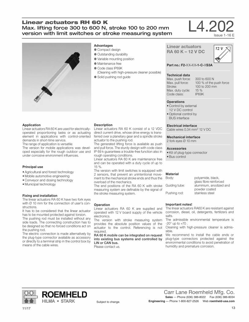
Linear actuators RH 60 KMax. lifting force 300 to 600 N, stroke 100 to 200 mmversion with limit switches or stroke measuring system
L 4.202Issue 1-16 E
Linear actuatorsRA 60 K – 12 V DC
Part no.: F2-XX-XX-1-C-XS3A
Technical data Max. push force: 300 to 600 NMax. pull force: 100 % of the push forceStroke: 100 to 200 mmMax. duty cycle: 15 %Code class: IP69K
Operations •Control by external 12 V DC control •Optional control by BUS interface
Electrical interfaceCable wires 0.34 mm2 12 V DC
Mechanical interface2 fork eyes Ø 10 mm
Accessories •Kit of plug-type connector •Bus control
Linear Actuators RA 60 KMax. lifting force 300 to 600 N, stroke from 100 to 200 mm version with limit switches or stroke measuring system
DescriptionLinear actuators RA 60 K consist of a 12 VDC direct current drive, whose drive energy is trans-ferred over a planetary gear and a spindle stroke actuator to the pushing rod.The generated lifting force is available as push and pull force. The sturdy design with code class IP 69 k guarantees a trouble-free function also in rough operating conditions.Linear actuators RA 60 K are maintenance free and can be operated with a duty cycle of up to 15 %.The version with limit switches is equipped with 2 sensors, that prevent an unintentional move-ment to the mechanical stroke ends and thus the overload of the mechanics. The end positions of the RA 60 K with stroke measuring system are definable by the signal of the stroke measuring system.
OperationLinear actuators RA 60 K are supplied and operated with 12 V board supply of the vehicle electronics.The version with stroke measuring system provides the absolute position values of the actuator to the control. Referencing is not r equired.RA 60 K mobile can be integrated on request into existing bus systems and controlled by LIN or CAN bus.Please contact us.
Advantages Compact design Outstanding durability Variable mounting position Maintenance free Code class IP69K (Cleaning with high-pressure cleaner possible) Solid pushing rod guide
MaterialBody: polyamide, black, glass fibre reinforcedGuiding tube: aluminium, anodized and powder coatedPushing rod: stainless steel
Important notes!The linear actuators RA60 K are resistant against corrosion, diesel, oil, detergents, fertilizers and salts.The admissible environmental temperature is -20° up to +70.Cleaning with high-pressure cleaner is admis-sible.We recommend to install the cable ends or plug-type connectors protected against the environmental conditions to avoid penetration of humidity and premature corrosion.
ApplicationLinear actuators RA 60 K are used for electrically-operated proportioning tasks or as actuating element in applications with control-oriented demands in short-time service.The range of application is versatile:The version for mobile applications was devel-oped especially for the rough outdoor use and under corrosive environment influences.
Principal use
•Agricultural and forest technology •Mobile automotive engineering •Conveyor and dosing technology •Municipal technology
Fixing and installationThe linear actuators RA 60 K have two fork eyes with Ø 10 mm for the connection of user's con-structions.It has to be considered that the linear actuator has to be mounted protected against torsion.The pushing rod must be installed without any side loads. The connecting construction has to be designed so that no forced conditions act on the pushing rod.The electric connection is made alternatively by the plug-type connector available as accessory or directly to a terminal strip in the control box by means of the cable wires.
Subject to modifications
Actual issue see www.roemheld.comRömheld GmbH · Postfach 1253 · 35317 Laubach, Germany · Tel.: +49 (0) 6405 / 89-0 · Fax: +49 (0) 6405 / 89-211
CARR LANE ROEMHELD MFG. CO.Sales — Phone (636) 386-8022 Fax (636) 386-8034
Engineering — Phone 1-800-827-2526 Web www.carrlaneroemheld.com

11/17
Carr Lane Roemheld Mfg. Co. Sales — Phone (636) 386-8022 Fax (636) 386-8034
Engineering — Phone 1-800-827-2526 Web roemheld-usa.comSubject to change.
148/16 15
Subject to change.
Version with limit switches
Version with limit switches
Subject to modificationsL 4.202 / 1-16 E
2 Actual issue see www.roemheld.com Römheld GmbH
DescriptionThe version with limit switches has 2 integrated sensors, which automatically switch off the mo-tor as soon as the upper or lower stroke end po-sition is obtained.This guarantees that the linear actuator does not mechanically push against the stop.The wires brown and white of this version are to be connected to 12 V DC. By changing the po-larity, switching over from retracting to extending is effected.
Current consumptionAs a function of the load the current consump-tion amounts lineraly up to 4.5 A at nominal load.For a safe power supply, a supply current of at least 6 A is required.
Code class IP69K (exception: cable end)
Static retention force200 N at lifting force 300 N600 N at lifting force 600 NSince the actuators are designed without hold-ing brake, the piston rod can be displaced in case of higher loads or vibrations and the actua-tor has to be readjusted, if necessary.
Technical data
SpeedForce Idle
runningloaded Current
cons.Duty cycle
[N] [mm/s] [mm/s] [A] [max. 1.5 min.]300 28 18 3.5 max. 15 %600 16 7 4 max. 15 %
Stroke L L + stroke Weight
[mm] [mm] [mm] [kg]100 270 370 1.0150 320 470 1.1200 370 570 1.2
Code for part numbersPart no. F2-XX-XX-1-C-ES3A
Maximum lifting force(push force)03 = 300 N06 = 600 N
Stroke10 = 100 mm15 = 150 mm20 = 200 mm
Variant 24 V available on request.
Important notes!Only RA 60 K with stroke measuring system can be operated synchronously! The user has to provide a current limitation of 5.5 A.In the case of a blockade, the control has to provide for a switching off of the power supply at the latest after 10 second to prevent an overload of the actuator.
Accessories See next page.
Dimensions
white “+“ (extend) “-“ (retract)
brown “+“ (extend) “-“ (retract)
Circuit diagram and configuration of cables for RA 60 K with stroke end disconnection
27 ±1
L ±2 13,58,5
16
6,1
±0,
2
6,2
±0,
5
34 +
1
60 +
1
14,2
±1
Ø 10,2 +0,1
70 ±5
12,816,2
39 +1Ø 10,2 +0,1
34,5 15
1.5 m cable with wire ends
Cable wires isolated with wire bushs 0.34 mm2 x 8 long gastight square pressed
CARR LANE ROEMHELD MFG. CO.Sales — Phone (636) 386-8022 Fax (636) 386-8034
Engineering — Phone 1-800-827-2526 Web www.carrlaneroemheld.com
15
Carr Lane Roemheld Mfg. Co. Sales — Phone (636) 386-8022 Fax (636) 386-8034
Engineering — Phone 1-800-827-2526 Web roemheld-usa.comSubject to change.
11/1716 8/16
Subject to change.
Version with stroke measuring system Version with stroke measuring system
Subject to modificationsL 4.202 / 1-16 E
Römheld GmbH Actual issue see www.roemheld.com 3
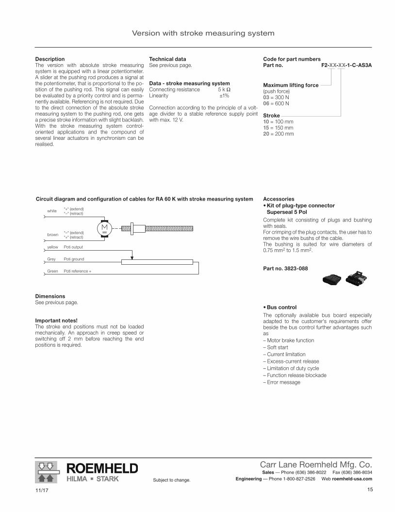
yellow Poti output
Grey Poti ground
Green Poti reference +
“–“ (extend) brown “+“ (retract)
“+“ (extend) white “–“ (retract)
Accessories •Kit of plug-type connector Superseal 5 Pol
Complete kit consisting of plugs and bushing with seals.For crimping of the plug contacts, the user has to remove the wire bushs of the cable.The bushing is suited for wire diameters of 0.75 mm2 to 1.5 mm2.
Part no. 3823-088
Circuit diagram and configuration of cables for RA 60 K with stroke measuring system
DimensionsSee previous page.
Important notes!The stroke end positions must not be loaded mechanically. An approach in creep speed or switching off 2 mm before reaching the end positions is required.
•Bus controlThe optionally available bus board especially adapted to the customer's requirements offer beside the bus control further advantages such as– Motor brake function– Soft start– Current limitation– Excess-current release– Limitation of duty cycle– Function release blockade– Error message
DescriptionThe version with absolute stroke measuring system is equipped with a linear potentiometer. A slider at the pushing rod produces a signal at the potentiometer, that is proportional to the po-sition of the pushing rod. This signal can easily be evaluated by a priority control and is perma-nently available. Referencing is not required. Due to the direct connection of the absolute stroke measuring system to the pushing rod, one gets a precise stroke information with slight backlash.With the stroke measuring system control- oriented applications and the compound of several linear actuators in synchronism can be realised.
Technical dataSee previous page.
Data - stroke measuring systemConnecting resistance 5 k ΩLinearity ±1%
Connection according to the principle of a volt-age divider to a stable reference supply point with max. 12 V.
Code for part numbers Part no. F2-XX-XX-1-C-AS3A
Maximum lifting force(push force)03 = 300 N06 = 600 N
Stroke10 = 100 mm15 = 150 mm20 = 200 mm
CARR LANE ROEMHELD MFG. CO.Sales — Phone (636) 386-8022 Fax (636) 386-8034
Engineering — Phone 1-800-827-2526 Web www.carrlaneroemheld.com

11/17
Carr Lane Roemheld Mfg. Co. Sales — Phone (636) 386-8022 Fax (636) 386-8034
Engineering — Phone 1-800-827-2526 Web roemheld-usa.comSubject to change.
168/16 17
Subject to change.
CARR LANE ROEMHELD MFG. CO.Sales — Phone (636) 386-8022 Fax (636) 386-8034
Engineering — Phone 1-800-827-2526 Web www.carrlaneroemheld.com
Linear actuators RH 1250Max. lifting force 4.5 to 12.5 N, stroke 80 to 250 mmmanual-hydraulic version
L7.101Issue 6-15 E
L 7.101Issue 6-15 E
Linear actuatorsRH 1250 manually operated
Part no.: M8-XX-XX-X-A-X-L-X-X
Technical data
Max. push force: 4,500 – 12,500 NStroke: 80 – 250 mm
Operations
• Foot pedal or hand lever
Mechanical interface
Plunger eye Ø 12 mm Centring pivot Ø 38 mmOptional extra: Fork or flange mounting
Accessories
• Footpedal• Handlever• Bearingblocks
Subjecttomodifications
Actual issue see www.roemheld.comRömheld GmbH ·Postfach1253·35317Laubach,Germany·Tel.:+49(0)6405/89-0·Fax:+49(0)6405/89-211
Linear Actuators RH 1250Max. lifting force 4.5 to 12.5 kN, stroke from 80 to 250 mm manual-hydraulic version
DescriptionLinearactuatorsRH1250aremanuallyoperated,hermeticallysealed,hydro-mechanicalactuatorsforlinearadjustingprocedures.Thecompactdesigncontains thepumppistonand the valve technology. Also the oil reservoir and the plunger cylinder are integrated.The hydraulic transmission in connectionwiththemanualoperationallowsagooddosageofvery high forces.Important for that are also themechanicswithminimum clearance as well as the sensitiveresponding valves with exactly defined switch-ing points.Inprincipleonlypushforcescanbegenerated.
Advantages Highoperatingsafetybyspeedlimitingvalveand pressure relief valve Optionaldescentactuationbypushingorturning Optional fork or flange mounting Precise plunger guide Independentofexternalpowersupply Noobligatorytestsasperelectricalsafetyregulations Compact design Single-leveroperation Maintenance free Resistant against disinfectants Different lacquerings as an option
MaterialBody: AluminiumOperating shaft: Steel, corrosion resistantPlunger: Steel, corrosion resistant
ApplicationLinear actuators RH1250 are universally usedasmanually-operatedactuatorsforlinearmove-ments.
Principal use • Heightadjustmentofhospitalandnursingbedsaswellasmobilenursingchairs • Heightadjustmentofpatienttransportersandtherapy couches • Adjustmentofexaminationandcarechairsaswellaschildbirthbeds • Heightadjustmentofinstrumenttables • Actuatorforliftingmodulesandliftingtables
Fixing and installationThe linear actuators RH1250 have 1 locationhole Ø 12.1 mm in the plunger and 2 centring pivots Ø 38 mm for the connection of user's constructions.Theuser'sconstructionmustexcludesideloadsand forced conditions. ThecentringpivotsØ38mmareunlacquered.
There are two different operating directions ofthepumplever:clockwiseandcounterclockwiseoperation of the pump lever, depending on the user's construction.
OperationTheplungerrod isextendedbyreversiblerota-tionofapprox.40°byanoperating leverattheoperating shaft. The recommended lever length is approx.300 mm.To retract the plunger cylinder, the operatingshaft has to be turned to the opposite direc-tionbyapprox.10°.Theoperatingshaftreturns automatically.
Important notes!The linear actuators RH1250 are resistantagainst corrosion, detergents and disinfectants upto+70°C.Theadmissibleoperatingtemperatureis10°upto 40 °C.To retract the plunger of the linear actuator apush load of at least 100 N is required.

17
Carr Lane Roemheld Mfg. Co. Sales — Phone (636) 386-8022 Fax (636) 386-8034
Engineering — Phone 1-800-827-2526 Web roemheld-usa.comSubject to change.
11/1718 8/16
Subject to change.
CARR LANE ROEMHELD MFG. CO.Sales — Phone (636) 386-8022 Fax (636) 386-8034
Engineering — Phone 1-800-827-2526 Web www.carrlaneroemheld.com
Technical data and code for part numbers
Technical data and code for part numbers
Lifting force Pump strokes Required pump torque
v Descent Releasetorque
Descent
Release angle
Descent[N] [per 100 mm] [Nm/fullload] [s/100mm] [Nm/fullload] [°]
4500 7±1 160 4.5±1 10 2 – 10
6500 9±1 160 4.5±1 11 2 – 10
9500 13±1 160 4.5±1 15 2 – 10
12500 22±1 120 4.5±1 17 2 – 10
Technical data
Part no. M8-XX-XX-X-A-X-L-X-X
Maximum lifting force (pushforce)
04 = 4,500 N06=6,500N09=9,500N12 = 12,500 N
Stroke08 = 80 mm14 = 140 mm20 = 200 mm25 = 250 mm
Bore hole operating shaft1 = perpendicular to the plungerØ6mm (seedrawingpage3)2=paralleltotheplungerØ6mm3=withoutborehole
Fixation(page3)S = StandardG=Fork(upto6,500Nliftingforce)F=Flange(upto6,500Nliftingforce)
Colour1 = unlacquered2=RAL9016trafficwhite3=RAL9006whitealuminium4=RAL9005black5 = RAL 7035 light grey6 = RAL 7038 agate grey
Operating directionA=pumplevercounterclockwise
D=pumpleverclockwise
Code for part numbers
Admissible mounting positions for operating direction
90° +10°90° +10°
30°
Available on request: • Strokelengthsupto600mmingradationsof50mm(uptoliftingforce6,500N)
• DescentactuationbypushingVariantforemergencyadjustmentinhospitalbeds.Bypushingthedescentbolt,addition-ally mounted at the actuator, the plunger can besafelypushedin.Thedescentboltreturnsautomatically.
• DescentactuationbyturningVariantforemergencyadjustmentinhospitalbeds.Byrotatingadescentshaft,additionally
mountedattheactuator,theplungercanbesafely retracted. Thedescentactuationbyturningdoesnotreturn automatically.
• Front-sidethreadM8intheplunger
• VersionswithlowresidualmagnetismforMRTapplications
•Other descent speeds
•Other colours
•Customised special actuators
SubjecttomodificationsL7.101/6-15E
2 Actual issue see www.roemheld.com Römheld GmbH
FunctioningAllversionsoftheRH1250areoperatedwithanoperating lever, that is pinned at the operating shaft.Theintegratedflowcontrolvalveprovidesforanuniform descent speed in all load conditions.Due to thepossibility toget adrilledoperatingshaft, theactuatorcanquicklybe installedandput into operation.
Ithastobeconsideredthattheuser'sconstruc-tionalwaysactswithpushforceontotheactua-tor.Theactuatorhasahighsafetyagainstoverload.Inthecaseofoverloaditisnotpossibletocon-tinuepumpingtheactuator,butdescentispos-sible. The operator has to make sure that theactuator is not overloaded.
Important notes!Theindicatedtorquesarethemaximumtorquesrequired for operation.Thereturn torqueof theoperatingshaft for thepumpstrokeismax.6Nm.Thereturntorqueofthe operating shaft for the descent is max. 2 Nm. Theindicatedreturntorquesmusnotbeexceeded
by the user's constructions of the operatinglever. Otherwise, it could be possible that theoperating lever will not be moved back to theoff-position or an unintentional descent of theactuator could occur.

11/17
Carr Lane Roemheld Mfg. Co. Sales — Phone (636) 386-8022 Fax (636) 386-8034
Engineering — Phone 1-800-827-2526 Web roemheld-usa.comSubject to change.
188/16 19
Subject to change.
CARR LANE ROEMHELD MFG. CO.Sales — Phone (636) 386-8022 Fax (636) 386-8034
Engineering — Phone 1-800-827-2526 Web www.carrlaneroemheld.com
Mounting variants
Mounting variants
TheRH 1250isavailableindifferentmountingvariants. Besides the standardmountingwith centringpivot Ø 38 mm mounted at the housing, the RH1250canbedeliverdwithforkmountingorflangemounting.
Part no. M8-XX-XX-X-A-X-L-X-X
MountingS = StandardG = ForkF = Flange
Fork **Foreasymountingbymeansofflangeandbolt.
64 ±1
45 ±1
Ø 12,1 +0,1
27 +
1
46 ± 1
22 ±1
32 ±0,5
L1 ±2
Flange **Often selected variant for example in therapy couches. Integration of the actuator in a steel structurebymeansofforkandbolt.
69 ±1
37 ±0,5
Ø12,1 +0,1
27 +
1
29 ±1
50 ±1
L2 ±2
Important note!Toavoidanoverloadof theactuator,externalstopsaretobeprovidedfortheoperatingele-ments in order to limit the pump angle to 40°. Alsoforextensionswithfar-offleverssupportsfortorquecompensationhavetobeprovided.
Stroke L1 L1 + stroke Weight[mm] [mm] [mm] [kg]80 256 336 2.2140 316 456 3200 376 576 3.5250 426 676 4
Stroke L2 L2 + stroke Weight[mm] [mm] [mm] [kg]80 261 341 2.2140 321 461 3 200 381 581 3.5250 431 681 4
Stroke L L + stroke Weight[mm] [mm] [mm] [kg]80 192 272 2.2140 252 392 3200 312 512 3.5250 362 612 4
StandardThestandardversionoftheactuatorislocatedby forksoreyes in theuser'sconstructionatthe centring pivots Ø 38 mm and is secured withaboltØ12mm.Ithastobeconsideredthat the user's construction always actswithpush force onto the actuator.
** Forkandflangemountinguptoaliftingforceof6.500Navailable.
Forksandflangeshavedrafts.
SubjecttomodificationsL7.101/6-15E
Römheld GmbH Actual issue see www.roemheld.com 3
Ø 1
8 f8
L ±1,532 ±1
10
12,1 +0,1102 ±1
27,5
±1
80 ±
1
60 ±
0,5
86 -0
,5
110
±0,5
160
±1
Ø 6 H12
Ø 1
9
Ø 2
0*
20
28 ±1
Ø 5
5 ±
1
1010
Ø 6 H121
10°40°Pump angle to descent
Stroke-4 Ø38-0.2(unlacquered)
Plunger
Centring pivot
Operating shaft
*Ø22fortheversionwith lifting force 12500 N
19
Carr Lane Roemheld Mfg. Co. Sales — Phone (636) 386-8022 Fax (636) 386-8034
Engineering — Phone 1-800-827-2526 Web roemheld-usa.comSubject to change.
11/1720 8/16
Subject to change.
CARR LANE ROEMHELD MFG. CO.Sales — Phone (636) 386-8022 Fax (636) 386-8034
Engineering — Phone 1-800-827-2526 Web www.carrlaneroemheld.com
Version with limit switches
AccessoriesImportant notes
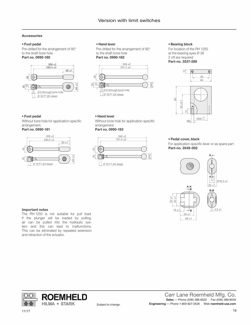
Important notesThe RH1250 is not suitable for pull load.If the plunger will be loaded by pulling,air can be pulled into the hydraulic sys-tem and this can lead to malfunctions. This can be eliminated by repeated extensionand retraction of the actuator.
• Foot pedalPre-drilledforthearrangementof90° totheshaftborehole Part no. 0990-180
• Pedal cover, blackForapplication-specificleverorassparepart Part-no. 3549-002
•Hand leverPre-drilledforthearrangementof90° totheshaftborehole Part no. 0990-182
•Bearing blockForlocationoftheRH1250 atthebearingeyesØ38 2 off are required Part-no. 3537-289
Accessories
308 ±2290,5 ±2
1345
80 ±1
64 ±
1
35
Ø6(throughborehole)
Ø18F7(24deep)
308 ±2290,5 ±2
45
80 ±1
64 ±
1
35
Ø18F7(24deep)
A
A
A-A
Ø16,3 ±1
16 ±1
56 ±1
66 ±1
52 ±
1
50 ±
1
35 ±1
1
B
B B-B
4,5 ±1
349 ±2331,5 ±2
1345
Ø4035
Ø6(throughborehole)
Ø18F7(24deep)
349 ±2331,5 ±2
45
Ø4035
Ø18F7(24deep)
M6
15
80
56 ±
0,1
6048
12
Ø38+0,4+0,1
•Hand leverWithoutboreholeforapplication-specific arrangement. Part no. 0990-183
• Foot pedalWithoutboreholeforapplication-specificarrangement. Part no. 0990-181
SubjecttomodificationsL7.101/6-15E
4 Actual issue see www.roemheld.com Römheld GmbH

11/17
Carr Lane Roemheld Mfg. Co. Sales — Phone (636) 386-8022 Fax (636) 386-8034
Engineering — Phone 1-800-827-2526 Web roemheld-usa.comSubject to change.
20
An additional driver of the project was the hope to reduce the amount of inventory being held in our warehouse.”
Carr Lane Roemheld’s linear actuators fit the bill
Rifton then researched others in the field, and found that linear actuators from Carr Lane Roemheld were comparable to the original design. “After acquiring samples, and submitting them to an exhaustive validation/testing process, we determined that the new product was actually an upgrade on several fronts,” said Wareham. “Prior to making a final decision, we then paid a visit to the Carr Lane Roemheld facility in Fenton, Missouri, in the hopes of establishing a strong and long-term relationship.”
Wareham continued to find benefits to the new partnership. “Carr Lane Roemheld offered a price that would save us a significant amount of money. They also made some minor design modifications to meet our requirements, including custom packaging specifications. Our designers felt that the Carr Lane Roemheld pump was actually an upgrade in quality. Because Carr Lane Roemheld agreed to hold stock for us, and to deliver on a one-week lead time, we were able to reduce our inventory by over $100,000. We also received a visit from an engineer from the manufacturing plant in Germany, to review quality expectations and design features; this was very helpful. Carr Lane Roemheld also offered us an early-pay discount. Although there was a minor problem with the first order, they stood behind their product and resolved the issue for us in a timely fashion.”
The bottom line? “I would certainly highly recommend Carr Lane Roemheld as a valued supplier to any business,” Wareham said.
Carr Lane Roemheld In the News...
Linear Actuators Provide Upgraded Quality to Activity Chair, at Lower Price
A linear actuator from Carr Lane Roemheld was built in to the base of the chair
to allow height adjustment. The chair is designed for
ease in therapy, feeding and other activities, with a client
weight up to 225 lbs.
Challenge: Rifton Equipment designed, and brought to market, a new seating system called the Activity Chair. One of the required features was a base that allowed height adjustment with a 225-lb client in the chair. This was accomplished by use of a foot-operated hydraulic pump. The previous supplier provided a pump that functioned well, but when it proved costly, was reluctant to work with Rifton to economize. Rifton felt it was important to reduce costs on the chair where possible.
Solution: Rifton turned to linear actuators from Carr Lane Roemheld. After acquiring samples, and submitting them to an exhaustive validation/testing process, Rifton determined that the new product was actually an upgrade in quality on several fronts.
Carr Lane Roemheld saved Rifton a significant amount of money, and provided some minor design modifications to meet their requirements, including custom packaging specifications.
Need for cost control, while retaining quality
Rifton’s new Activity Chair is designed for feeding, speech therapy, active learning, and for clients with sensory processing challenges. “One of the required features was a base that allowed height adjustment with a 225-lb client in the chair,” said Kirk Wareham, Rifton’s Director of Product Design. This was accomplished by use of a foot-operated hydraulic pump. While the pump from the original supplier functioned well, it was quite costly. “We
felt it was only responsible to reduce our costs where possible, and ask for a price reduction commensura te with the d r a m a t i c a l l y rising sales of the
Activity Chair,” said Wareham about the original supplier. “Also, since we are able to pay our bills promptly we typically request, and are typically granted, an early-pay discount. Communication is vital to a thriving and mutually beneficial relationship, and we were disappointed to find that the supplier would not even entertain a discussion on either point. There were also some minor quality issues.

21
Carr Lane Roemheld Mfg. Co. Sales — Phone (636) 386-8022 Fax (636) 386-8034
Engineering — Phone 1-800-827-2526 Web roemheld-usa.comSubject to change.
11/17
• Combine our modular units to Lift, Tilt, Rotate or Move your assembly• Easily move your assembly to optimal position to increase productivity
and reduce fatigue• Preset positions for long runs or adjustable locations for flexibility
Versatile Modular UnitsFor Assembly and Handling
Modular Units Enhance Productivity in Assembly Operations

Modular UnitsApplication and combination examples
Lifting module operated by foot pedal with rotating module vertical axis
Here a complex hydraulic subassembly requires access to 5 sides during the installation of its components.The employee can rotate the workpiece 360˚ in both directions about the vertical axis of this rotating module. Now the employee can select the most ergonomic position via manual or electric operation. Model versions with indexing are available too; standard index angles are 45˚, 60˚, 90˚, 120˚.
The appropriate working height is adjusted by the foot pedal of the self-contained hydraulic lifting module.
Lifting module operated by hand pendant with rotating module horizontal axis
Multi-shift organizations know that every shift change also ushers in the change of each and every employee’s size and ability. Modular combinations adapt to such changes and this one is composed of two modules: electric lift and horizontal-axis rotating. The electric lifting module effortlessly adjusts to an employee‘s height via a hand
or foot push-button pendant. The horizontal-axis rotating module does just what its name implies; it spins a workpiece about its horizontal axis. It has 360˚ of rotation in both directions. Push or pull your workpiece to rotate the version without indexing or automatically index to your next position using the hand-lever or foot-pedal versions.
Electrically operated lifting module in sync
Assembly of truck axles is carried out by two employees at the same time. Components are installed and fastened from above as well as from both ends. The working height is adjusted via a foot pendant that controls two synchronized electric lifting modules. The synchronized lifts guarantee a level work surface throughout the entire stroke. The lifting modules are mounted to a floor module to improve stability.
Lifting module operated by hand pendant with rotating module horizontal axis
The assembly and testing of heavy workpieces such as axial piston machines is carried out at many stations. Transfer from station to station is made easy by fastening a tabletop plate to a hydraulic lift module that is mounted on top of a cart module.Applying the brake on the cart module locks the unit in place. The operator can easily raise or lower the tabletop by pumping the foot pedal of the hydraulic lifting module.
Lifting module operated by foot pedal with tilting module and rotating module vertical axis
Optimum assembly of car seats requires the ability to quickly and easily move the seat into different positions. This modular combination allows the employee to raise, lower, rotate and tilt the seat. The tilting module is equipped with a pneumatic balancer that counteracts almost all of the tilting torques. This means very little force is required of the employee to tilt heavy objects.
Lifting module operated by foot pedal with tilting module
Here the employee is carrying out the final assembly of an electric motor followed by a series of tests.The working height is adjusted by the foot pedal of the hydraulic lifting module. The tilting module mounted on top of the lifting module allows the employee to tilt the motor back and forth by 90˚. The integrated pneumatic-counterbalance feature makes tilting the motor a nearly effortless task.
11/17
Carr Lane Roemheld Mfg. Co. Sales — Phone (636) 386-8022 Fax (636) 386-8034
Engineering — Phone 1-800-827-2526 Web roemheld-usa.comSubject to change.
22

The modulog module principle All modulog modules in the program summary can be used individually, since they are independent functional units.In addition, all modules which are in one column on top of each other can be combined to multi-functional units.
Operationsmanual Modules marked with this symbol are operated by hand. Operation is effected directly at the work-
piece or at the assembly fixture.
Hand lever Operation of the module is made by means of a hand lever acting directly at the cinematics.
Foot pedal Operation of the module is made hydraulically by pumping on a foot pedal. Defined lowering by lifting the foot pedal.
Hand panel Operation of the module is made electrically by means of a hand panel touching the buttons "up" and "down". The module is supplied and controlled via a connecting cable by an electrical supply unit. Also the hand panel is connected to the electrical supply unit.
Foot switch Operation of the module is made electrically by means of a foot panel touching the buttons "up" and "down". The module is supplied and controlled via a connecting cable by an electrical supply unit. Also the foot panel is connected to the electrical supply unit.
Maximum load For each module the maximum load is indicated in kg. The load may also be eccentrically, since the modules are in the position to compensate load moments. Information on the exact admissible load moments is indicated on the corresponding data sheets.As a rule, the load limits and the potential combinations of modules are determined by the maximum occurring torques.
ModulesRotating module - horizontal axis
The rotating module horizontal axis effects a rotatory movement around the horizontal axis of the workpiece. Rotation of the workpiece is made manually either directly at the workpiece or by means of an operation, for example a hand lever at the rotating module. Indexing of the rotational position is 4 x 90°. Alternatively models with electric drive are available.
Tilting module The tilting module effects a rotatory, reversible swivel movement around a defined axis between the final positions 0° and 90°. Tilting of a workpiece is made manually, the weight of the workpiece will be balanced. Indexing of the final positions is 0° and 90°. Alternatively models with electric drive are available.
Rotating module - vertical axis
The rotating module vertical axis effects a rotatory movement around the vertical axis of the workpiece. Rotation of the workpiece is made directly at the workpiece. Indexing of the rotational position is 4 x 90°. Alternatively models with electric drive are available.
Lifting modules Lifting modules effect a guided, translational movement in the vertical axis. The lifting movement is effected power-supported by a hydraulic or electrical actuator against the weight of the workpiece to be moved. The lowering movement is a defined lowering by use of the weight.
Cart modules Cart modules offer the possibility to displace manually individual modules or module combinations with workpieces. All cart modules are equipped with a parking brake.
Floor modules Floor modules compensate unevennesses of the floor place and guarantee a high stability.The offer includes two versions with one or two mounting plates for mounting of other modulog modules.
engl_Übersicht_MHT_1112.indd 4 24.01.13 16:3523
Carr Lane Roemheld Mfg. Co. Sales — Phone (636) 386-8022 Fax (636) 386-8034
Engineering — Phone 1-800-827-2526 Web roemheld-usa.comSubject to change.
11/17
11/17
Carr Lane Roemheld Mfg. Co. Sales — Phone (636) 386-8022 Fax (636) 386-8034
Engineering — Phone 1-800-827-2526 Web roemheld-usa.comSubject to change.
24
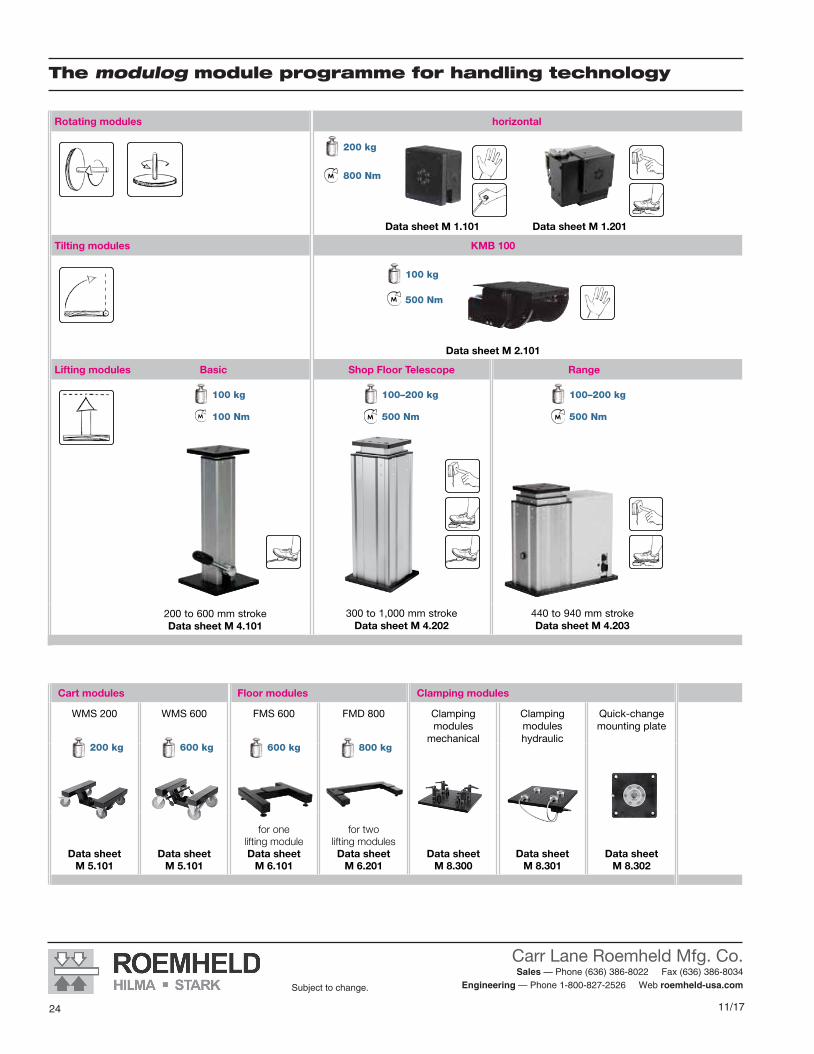
The modulog module programme for handling technology
Rotating modules horizontal vertical
Data sheet M 1.101 Data sheet M 1.201 Data sheet M 1.301 Data sheet M 1.201
Tilting modules KMB 100 KMB 100
Data sheet M 2.101 ROEMHELD Information M012
Lifting modules Basic Shop Floor Telescope Range Shop-Floor Strong Solid Twin-Strong
200 to 600 mm strokeData sheet M 4.101
300 to 1,000 mm strokeData sheet M 4.202
440 to 940 mm stroke Data sheet M 4.203
200 to 600 mm strokeData sheet M 4.301
200 to 400 mm strokeData sheet M 4.401
200 to 400 mm strokeData sheet M 4.402
200 to 400 mm strokeData sheet M 4.501
Cart modules Floor modules Clamping modules Electrical accessories Plates
WMS 200 WMS 600 FMS 600 FMD 800 Clamping modules
mechanical
Clamping modules hydraulic
Quick-change mounting plate
Control modules Power supply for mobile systems
with battery
Electrical operating elements
Base plates Adaptor plates Table plates
Data sheet M 5.101
Data sheet M 5.101
for one lifting moduleData sheet
M 6.101
for two lifting modulesData sheet
M 6.201Data sheet
M 8.300Data sheet
M 8.301Data sheet
M 8.302Data sheet
M 8.200Data sheet
M 8.201 Data sheet M 8.203Data sheet
M 8.100Data sheet
M 8.110 / M 8.120Data sheet
M 8.130 / M 8.131
800 kg600 kg200 kg 600 kg
The modulog module programme for handling technology
200 kg
100 kg
100 kg 100–200 kg 100–200 kg
800 Nm
500 Nm
100 Nm 500 Nm 500 Nm
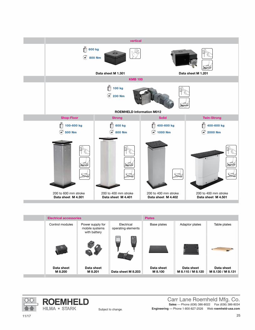
25
Carr Lane Roemheld Mfg. Co. Sales — Phone (636) 386-8022 Fax (636) 386-8034
Engineering — Phone 1-800-827-2526 Web roemheld-usa.comSubject to change.
11/17
Rotating modules horizontal vertical
Data sheet M 1.101 Data sheet M 1.201 Data sheet M 1.301 Data sheet M 1.201
Tilting modules KMB 100 KMB 100
Data sheet M 2.101 ROEMHELD Information M012
Lifting modules Basic Shop Floor Telescope Range Shop-Floor Strong Solid Twin-Strong
200 to 600 mm strokeData sheet M 4.101
300 to 1,000 mm strokeData sheet M 4.202
440 to 940 mm stroke Data sheet M 4.203
200 to 600 mm strokeData sheet M 4.301
200 to 400 mm strokeData sheet M 4.401
200 to 400 mm strokeData sheet M 4.402
200 to 400 mm strokeData sheet M 4.501
Cart modules Floor modules Clamping modules Electrical accessories Plates
WMS 200 WMS 600 FMS 600 FMD 800 Clamping modules
mechanical
Clamping modules hydraulic
Quick-change mounting plate
Control modules Power supply for mobile systems
with battery
Electrical operating elements
Base plates Adaptor plates Table plates
Data sheet M 5.101
Data sheet M 5.101
for one lifting moduleData sheet
M 6.101
for two lifting modulesData sheet
M 6.201Data sheet
M 8.300Data sheet
M 8.301Data sheet
M 8.302Data sheet
M 8.200Data sheet
M 8.201 Data sheet M 8.203Data sheet
M 8.100Data sheet
M 8.110 / M 8.120Data sheet
M 8.130 / M 8.131
100 kg
600 kg
400-600 kg 400-600 kg100-600 kg 600 kg
800 Nm
230 Nm
500 Nm 800 Nm 1000 Nm 2000 Nm

11/17
Carr Lane Roemheld Mfg. Co. Sales — Phone (636) 386-8022 Fax (636) 386-8034
Engineering — Phone 1-800-827-2526 Web roemheld-usa.comSubject to change.
2626 8/16
Subject to change.
M1.101Issue 5-16 E
Rotating Module - Horizontal Axis DMH 200Max. load 2,000 Nmanual operation
CARR LANE ROEMHELD MFG. CO.Sales — Phone (636) 386-8022 Fax (636) 386-8034
Engineering — Phone 1-800-827-2526 Web www.carrlaneroemheld.com
Issue 5-16 E
M 1.101Rotating Module – Horizontal Axis DMH 200Max. load 2,000 Nmanual operation
Subject to change without prior notice
Actual issue see www.roemheld.comRömheld GmbH · Postfach 1253 · 35317 Laubach, Germany · Tel.: +49 (0) 6405 / 89-0 · Fax: +49 (0) 6405 / 89-211
modulog Rotating module – horizontal axis DMH 200Part-no. 650X-0X-XX-X-X
DescriptionThe rotating module - horizontal axis DMH is a double supported rotation axis that can compensate high axial and radial forces. The angle of rotation in both directions is 360°. Due to special bearings it is insensitive to shocks and thrusts.The design of the rotating module allows its integration in applications with light as well as with heavy loads.When using the rotating module in assembly processes, component parts can be rotated rationally, quickly and safely and can be assembled ergonomically from all sides.The rotating module is equipped with an optional indexing (see page 3 to 5 of this series).
Principal use• Gear assembly• Motor assembly• Pump construction• Turning operations during
product transfer
Advantages N Rotating in both directions N Safe indexing N Rotating and indexing possible by one-hand operation N Compact device N Sturdy design for industrial assembly N Allows ergonomic working N Safe and quick handling in assembly processes N 4 function variants N Easily combinable with other modulog modules
MaterialBody: steel, black oxideRotating plate: steel, black oxideIndexing mechanism: steel, hardenedBearing: steel, hardened
OperationThe basic version of the rotating modules does not have any operating elements.The rotating operation is manually effected at the workpiece or at the assembly fixture. Alternatively, versions with hand lever are available. The indexing is operated by a hand lever of the rotating module or a separate hand lever or foot pedal.
Technical characteristics
Max. load: 2,000 NMax. torque:axial: 800 Nmradial: 800 NmAngle of rotation: 360°
Operations• Manual • Hand lever
Indexing
Operation with• Hand lever• Foot pedal
Combinable with the modules
• Tilting module KMB 100 as per data sheet M 2.101
• Rotating module – vertical axis DMV 600 as per data sheet M 1.301
• Lifting module as per data sheet M 4.XXX
modulog interfaces
• Flange plate: 140 x 140 - M10• Body: 140 x 140 - Ø 10.5 mm
Accessories
• Adaptor plates as per data sheet M 8.110
• Flange plate as per data sheet M 8.120
ApplicationRotating module for universal use in assembly and handling processes in the industry.
MountingTo fix modulog modules or components of the user, the rotating module has a 140 x 140 modulog interface in the flange plate and the body.In addition, at the bottom of the body 4 fixing threads are provided to allow vertical mounting of the rotating module.As accessory for the vertical mounting onto other modulog modules an adaptor plate with an 140 x 140 modulog interface is available.As accessory for individual fixing holes a round flange plate without 140 x 140 interface is available.
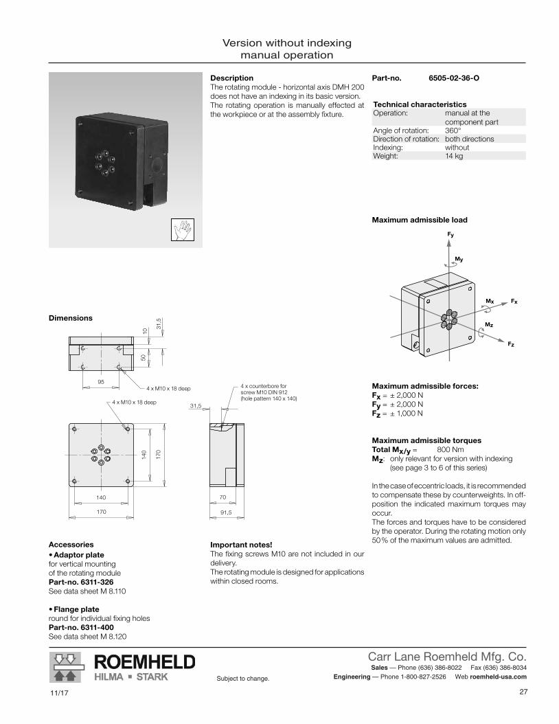
27
Carr Lane Roemheld Mfg. Co. Sales — Phone (636) 386-8022 Fax (636) 386-8034
Engineering — Phone 1-800-827-2526 Web roemheld-usa.comSubject to change.
11/178/16 27
Subject to change.
CARR LANE ROEMHELD MFG. CO.Sales — Phone (636) 386-8022 Fax (636) 386-8034
Engineering — Phone 1-800-827-2526 Web www.carrlaneroemheld.com
Version without indexingmanual operation
Version without indexing manual operation
DescriptionThe rotating module - horizontal axis DMH 200 does not have an indexing in its basic version.The rotating operation is manually effected at the workpiece or at the assembly fixture.
Accessories• Adaptor plate for vertical mounting of the rotating modulePart-no. 6311-326See data sheet M 8.110
• Flange plateround for individual fixing holesPart-no. 6311-400See data sheet M 8.120
Important notes!The fixing screws M10 are not included in our delivery.The rotating module is designed for applications within closed rooms.
Maximum admissible forces:Fx = ± 2,000 NFy = ± 2,000 NFz = ± 1,000 N
Maximum admissible torquesTotal Mx/y = 800 NmMz: only relevant for version with indexing (see page 3 to 6 of this series)
In the case of eccentric loads, it is recommended to compensate these by counterweights. In off-position the indicated maximum torques may occur.The forces and torques have to be considered by the operator. During the rotating motion only 50 % of the maximum values are admitted.
Dimensions
Part-no. 6505-02-36-O
91,5
70
170
140
140
170
95
5010
31,5
31,5
4 x counterbore for screw M10 DIN 912 (hole pattern 140 x 140)
4 x M10 x 18 deep
4 x M10 x 18 deep
Mx
My
Fz
Mz
Fx
Fy
Maximum admissible load
Technical characteristicsOperation: manual at the
component partAngle of rotation: 360°Direction of rotation: both directions Indexing: withoutWeight: 14 kg
Subject to change without prior noticeM 1.101 / 5 -16 E
2 Actual issue see www.roemheld.com Römheld GmbH

11/17
Carr Lane Roemheld Mfg. Co. Sales — Phone (636) 386-8022 Fax (636) 386-8034
Engineering — Phone 1-800-827-2526 Web roemheld-usa.comSubject to change.
2828 8/16
Subject to change.
CARR LANE ROEMHELD MFG. CO.Sales — Phone (636) 386-8022 Fax (636) 386-8034
Engineering — Phone 1-800-827-2526 Web www.carrlaneroemheld.com
Automatic indexingoperation with hand lever
346
95
5010
114
70
91,5
156,5
32
140
170
140
170
31,5
Automatic indexing operation with hand lever
Dimensions
DescriptionThe rotating module - horizontal axis DMH 200 with automatic indexing is a compact and functional unit.Rotating as well as indexing are ergonomically operated by one hand lever only.
OperationTo rotate the component part the hand lever is operated in any direction.Every 90° indexing of the position is made automatically. Engagement and disengagement of the indexing is also effected automatically.The off-position of the hand lever can be engaged in steps of 90°, so that for every rotation the desired off-position can be adjusted. The standard indexing and engagement positions of the hand lever are set to 4 x 90°.
Accessories• Adaptor plate for vertical mounting of the rotating module of the rotating modulePart-no. 6311-326See data sheet M 8.110
• Flange plateround for individual fixing holesPart-no. 6311-400See data sheet M 8.120
Important notes!In case of vertical mounting of the rotating module - for example on a lifting module - it has to be considered that the hand lever can only be rotated by max. 270° in such applications.The fixing screws M10 are not included in our delivery. (Recommended property class 10.9)The rotating module is designed for applications within closed rooms.
Part-no. 6505-01-36-M
Technical characteristicsOperation: with hand leverAngle of rotation: 360°Direction of rotation: both directions Indexing: mechanical, automatic
Operation with hand lever Indexing positions 4 x 90° Positioning precision < ±1°
Weight: 19 kg
4x M10 x 18 deep
4x counterbore for screw M10 DIN 912 (hole pattern 140 x 140)
4x M10 x 18 deep
Application example
Rotating module DMH 200, with adaptor plate vertically mounted on a lifting module.
Maximum admissible loadAccording to the version without indexing (see page 2).
Maximum admissible torque around the rotation axis MzThe maximum torque around the rotation axis of the rotating module Mz in engaged mode is 250 Nm.The maximum torque to rotate the workpiece must not exceed 15 Nm.The module may only be moved in a controlled way to the indexing positions. If the indexing bolt engages in full motion, the module will be dynamically overloaded.
Subject to change without prior noticeM 1.101 / 5 -16 E
Römheld GmbH Actual issue see www.roemheld.com 3
Maximum admissible loadAccording to the version without indexing (see previous page).
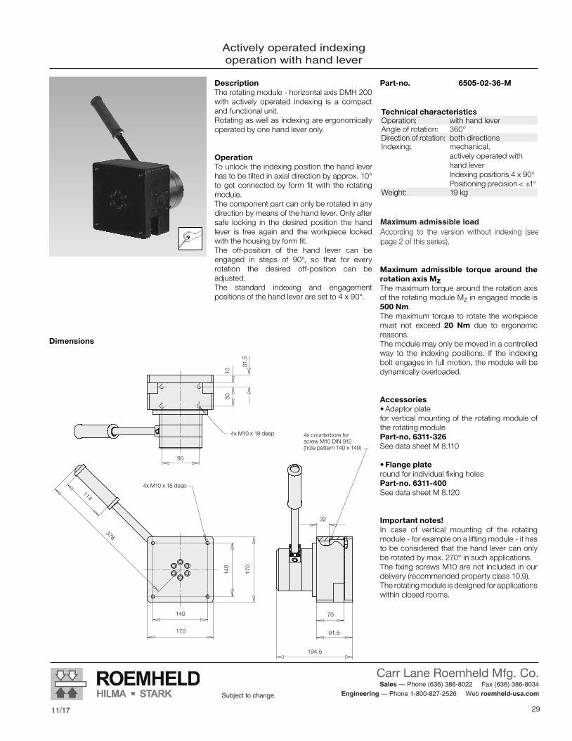
29
Carr Lane Roemheld Mfg. Co. Sales — Phone (636) 386-8022 Fax (636) 386-8034
Engineering — Phone 1-800-827-2526 Web roemheld-usa.comSubject to change.
11/178/16 29
Subject to change.
CARR LANE ROEMHELD MFG. CO.Sales — Phone (636) 386-8022 Fax (636) 386-8034
Engineering — Phone 1-800-827-2526 Web www.carrlaneroemheld.com
Actively operated indexingoperation with hand lever
376
140
170
70
91,5
194,5
32
140
170
5010
95
114
31,5
Dimensions
Actively operated indexing operation with hand lever
Subject to change without prior noticeM 1.101 / 5 -16 E
Römheld GmbH Actual issue see www.roemheld.com 4
4x M10 x 18 deep
4x M10 x 18 deep 4x counterbore for screw M10 DIN 912 (hole pattern 140 x 140)
DescriptionThe rotating module - horizontal axis DMH 200 with actively operated indexing is a compact and functional unit. Rotating as well as indexing are ergonomically operated by one hand lever only.
OperationTo unlock the indexing position the hand lever has to be tilted in axial direction by approx. 10° to get connected by form fit with the rotating module.The component part can only be rotated in any direction by means of the hand lever. Only after safe locking in the desired position the hand lever is free again and the workpiece locked with the housing by form fit.The off-position of the hand lever can be engaged in steps of 90°, so that for every rotation the desired off-position can be adjusted. The standard indexing and engagement positions of the hand lever are set to 4 x 90°.
Part-no. 6505-02-36-M
Maximum admissible load According to the version withoutindexing (see page 2)
Maximum admissible torque around the rotation axis MzThe maximum torque around the rotation axis of the rotating module Mz in engaged mode is 500 Nm.The maximum torque to rotate the workpiece must not exceed 20 Nm due to ergonomic reasons.The module may only be moved in a controlled way to the indexing positions. If the indexing bolt engages in full motion, the module will be dynamically overloaded.
Accessories• Adaptor plate for vertical mounting of the rotating module of the rotating modulePart-no. 6311-326See data sheet M 8.110
• Flange plateround for individual fixing holes Part-no. 6311-400See data sheet M 8.120
Important notes!In case of vertical mounting of the rotating module - for example on a lifting module - it has to be considered that the hand lever can only be rotated by max. 270° in such applications.The fixing screws M10 are not included in our delivery (recommended property class 10.9).The rotating module is designed for applications within closed rooms.
Technical characteristicsOperation: with hand leverAngle of rotation: 360°Direction of rotation: both directions Indexing: mechanical,
actively operated with hand lever Indexing positions 4 x 90° Positioning precision < ±1°
Weight: 19 kg
Maximum admissible loadAccording to the version without indexing (see page 2 of this series).

11/17
Carr Lane Roemheld Mfg. Co. Sales — Phone (636) 386-8022 Fax (636) 386-8034
Engineering — Phone 1-800-827-2526 Web roemheld-usa.comSubject to change.
3030 8/16
Subject to change.
CARR LANE ROEMHELD MFG. CO.Sales — Phone (636) 386-8022 Fax (636) 386-8034
Engineering — Phone 1-800-827-2526 Web www.carrlaneroemheld.com
Indexing with foot pedalmanual operation
128,5
84,9
84,9
110
95
Ø 8,5 (4x)
1050
92,5
91,5
32
170
140
170
140 70
259
145
35°
128,5
84,9
84,9
110
95
Ø 8,5 (4x)
1050
92,5
91,5
32
170
140
170
140 70
259
145
35°
Indexing with foot pedal manual operation
DescriptionThe rotating module - vertical axis DMH 200 with indexing with foot pedal is a compact and functional unit.It consists of a basic module with integrated indexing mechanism and an operating unit with foot pedal, connected by a 2 m long hydraulic hose.This flexible connection allows the individual placement of the operating unit at the most favourable ergonomic position.The rotating operation is manually effected at the workpiece or at the assembly fixture.
Operation of the indexingBy operating the foot pedal by 35° downwards the index is released and the workpiece or the fixture can be rotated.If the foot pedal is not operated, the index bolt engages automatically into the next indexing position.The operation with a foot pedal guarantees that the operator always has both hands free.The standard indexing positions are set to 8 x 45°, 6 x 60°, 4 x 90° and 3 x 120°. Other angles are available on request.
Important notes!The fixing screws M10 are not included in our delivery (recommended property class 10.9).
The rotating module is designed for applications within closed rooms.The module may only be moved in a controlled way to the indexing positions. If the indexing bolt engages in full motion, the module will be dynamically overloaded.
Maximum admissible load According to the version without indexing (see page 2)
Maximum admissible torque around the rotation axis MzThe maximum torque around the rotation axis of the rotating module Mz in engaged mode is 800 Nm.In the case of eccentric loads, it is recommended to compensate these by counterweights. In off-position the indicated maximum torques may occur.The forces and torques have to be considered by the operator. During the rotating motion only 50% of the maximum values are admitted.
Accessories• Adaptor platefor vertical mounting of the rotating module Part-no. 6311-326See data sheet M 8.110
• Flange plateround for individual fixing holes Part-no. 6311-400See data sheet M 8.120
DeliveryThe rotating module and the indexing unit including hydraulic hose and hydraulic oil are delivered as completely assembled unit ready for use.
Dimensions
4x M10 x 18 deep
4x M10 x 18 deep
4x counterbore for screw M10 DIN 912 (hole pattern 140 x 140)
Hydraulic hose 2m
Operating angle
Technical characteristicsOperation: manual at the
component partAngle of rotation: 360°Direction of rotation: both directions Indexing: hydromechanical
Operation with foot pedalWeight: 25 kg
Code for part numbersPart-no.: 6508-02-XX-O-I
Engagement position45 = 8 x 45° 60 = 6 x 60° 36 = 4 x 90° 12 = 3 x 120°
Subject to change without prior noticeM 1.101 / 5 -16 E
Römheld GmbH Actual issue see www.roemheld.com 5
128,5
84,9
84,9
110
95
Ø 8,5 (4x)
1050
92,5
91,5
32
170
140
170
140 70
259
145
35°
128,5
84,9
84,9
110
95
Ø 8,5 (4x)
1050
92,5
91,5
32
170
140
170
140 70
259
145
35°
Indexing with foot pedal manual operation
DescriptionThe rotating module - vertical axis DMH 200 with indexing with foot pedal is a compact and functional unit.It consists of a basic module with integrated indexing mechanism and an operating unit with foot pedal, connected by a 2 m long hydraulic hose.This flexible connection allows the individual placement of the operating unit at the most favourable ergonomic position.The rotating operation is manually effected at the workpiece or at the assembly fixture.
Operation of the indexingBy operating the foot pedal by 35° downwards the index is released and the workpiece or the fixture can be rotated.If the foot pedal is not operated, the index bolt engages automatically into the next indexing position.The operation with a foot pedal guarantees that the operator always has both hands free.The standard indexing positions are set to 8 x 45°, 6 x 60°, 4 x 90° and 3 x 120°. Other angles are available on request.
Important notes!The fixing screws M10 are not included in our delivery (recommended property class 10.9).
The rotating module is designed for applications within closed rooms.The module may only be moved in a controlled way to the indexing positions. If the indexing bolt engages in full motion, the module will be dynamically overloaded.
Maximum admissible load According to the version without indexing (see page 2)
Maximum admissible torque around the rotation axis MzThe maximum torque around the rotation axis of the rotating module Mz in engaged mode is 800 Nm.In the case of eccentric loads, it is recommended to compensate these by counterweights. In off-position the indicated maximum torques may occur.The forces and torques have to be considered by the operator. During the rotating motion only 50% of the maximum values are admitted.
Accessories• Adaptor platefor vertical mounting of the rotating module Part-no. 6311-326See data sheet M 8.110
• Flange plateround for individual fixing holes Part-no. 6311-400See data sheet M 8.120
DeliveryThe rotating module and the indexing unit including hydraulic hose and hydraulic oil are delivered as completely assembled unit ready for use.
Dimensions
4x M10 x 18 deep
4x M10 x 18 deep
4x counterbore for screw M10 DIN 912 (hole pattern 140 x 140)
Hydraulic hose 2m
Operating angle
Technical characteristicsOperation: manual at the
component partAngle of rotation: 360°Direction of rotation: both directions Indexing: hydromechanical
Operation with foot pedalWeight: 25 kg
Code for part numbersPart-no.: 6508-02-XX-O-I
Engagement position45 = 8 x 45° 60 = 6 x 60° 36 = 4 x 90° 12 = 3 x 120°
Subject to change without prior noticeM 1.101 / 5 -16 E
Römheld GmbH Actual issue see www.roemheld.com 5

31
Carr Lane Roemheld Mfg. Co. Sales — Phone (636) 386-8022 Fax (636) 386-8034
Engineering — Phone 1-800-827-2526 Web roemheld-usa.comSubject to change.
11/178/16 31
Subject to change.
CARR LANE ROEMHELD MFG. CO.Sales — Phone (636) 386-8022 Fax (636) 386-8034
Engineering — Phone 1-800-827-2526 Web www.carrlaneroemheld.com
Rotating Module DMHe 200 / DMVe 600Electrically operatedMax. load 2,000 N, max. torque 120 Nm
M1.201Issue 10-16 E
Operations• Foot switch • Hand panel
Combinable with the modules
Lifting modules
• Shop Floor Telescope: as per data sheet M 4.202
• Range: as per data sheet M 4.203• Shop-Floor: as per data sheet M 4.301• Strong: as per data sheet M 4.401• Solid: as per data sheet M 4.402
modulog interfaces
• Flange plate: 140 x 140 - M10• Body: 140 x 140 - M10
Accessories• Switching power supply Part no. 6863-020• Hand panel as per data sheet M 8.203• Foot switch as per data sheet M 8.203
M 1.201Issue 1-16 E
Principal use• Assembly of automotive parts• Motor assembly• Gear assembly• Pump construction
OperationThe module is operated with touch control by means of an optionally available hand panel or foot switch with two push-buttons. It can safely stop in every angular position. An auto-matic stop is preset at all 90° positions.The zero position of the automatic stop can be preset to any position by pushing both push-buttons.
DescriptionRotating modules are used in assembly and handling processes to transform electrical en-ergy into a rotating movement. When using the rotating module, component parts can be rotated rationally, quickly and safely and can be assembled ergonomically from all sides.The strongly reduced worm gear allows high holding torques in standstill.
The double-bearing drive shaft compensates high axial and radial forces.
The rotating module is designed for a long service life. The electronically commutated DC motor is virtually wear-free.
The mechanical components and sealing elements are designed for 1,000,000 indexing cycles within the indicated load limits.
The rotating modules – horizontal axis and vertical axis are nearly identical in construc-tion, thus the axis alignment can be retrofitted for different applications.
- horizontal axisDMHe 200Part no. 6508-02-36-E
Max. load: 2,000 N
Rotating Module DMHe 200 / DMVe 600 – electrically-operatedmax. load 2,000 N / 6,000 N, max. torque 120 Nm
Advantages Versions for horizontal or vertical axisof rotation Rotating in both directions Auto stop Low-backlash gear Self-locking in any position Compact design Sturdy design Convertible Ergonomic working Safe and quick handling in assembly processes Long service life Checked in compliance with DIN EN 1570with quadruple static overload
modulog rotating moduleselectrically operated
Technical data
Angle of rotation: 360°Max. torque: 120 NmMax. holding torque 350 NmMax. torque: 800 NmRotation: anyindex: 90° standard
optionally 45° / 60° / 180°
– verticalDMVe 600Part no. 6509-10-36-E
Max. load: 6,000 N
Subject to modifications
Actual issue see www.roemheld.comRömheld GmbH · Postfach 1253 · 35317 Laubach, Germany · Tel.: +49 (0)6405 / 89-0 · Fax: +49 (0)6405 / 89-211

11/17
Carr Lane Roemheld Mfg. Co. Sales — Phone (636) 386-8022 Fax (636) 386-8034
Engineering — Phone 1-800-827-2526 Web roemheld-usa.comSubject to change.
3232 8/16
Subject to change.
CARR LANE ROEMHELD MFG. CO.Sales — Phone (636) 386-8022 Fax (636) 386-8034
Engineering — Phone 1-800-827-2526 Web www.carrlaneroemheld.com
Rotating modulehorizontal axis DMHe 200
Technical dataMax. total Fx/Fy [N] 2,000Max. Fz [N] 1,000Max. driving torque Mz [Nm] 120Max. holding torque Mz [Nm] 350Max. total of all torques Mx/My/Mz
[Nm] 800
Max. cycle time (ED) 25 %, 60 s OnCode class IP 54Current consumption [A] 6 … 16Max. admissible current consumption
[A] 20
Supply voltage [V DC] 24 – 30
Adjust the speed of rotation by trimming potentiometer 2.5 to 7.5 rpm.Adjust the indexing angles 45, 60, 90 and 180 degree by trimming potentiometer.Adjust the soft stops by trimming potentio-meter.
Rotating module – horizontal axis DMHe 200
Fz
Mz
Fx
Fy
Maximum admissible load
Maximum admissible forces:Fx = ± 2,000 NFy = ± 2,000 NFz = ± 1,000 N
Maximum admissible torques:Mx or My = 800 NmMz = 350 Nm (in standstill)
The total of all occurring forces or torques must not exceed the highest single value.
The rotating module is checked in compliance with DIN EN 1570 with quadruple static over-load.
InstallationThe rotating module has a modulog interface 140 x140 mm and can be mounted by 4 screws M10 onto a fixture or another module.The power supply is made by the separately available switching power supply.An electronic control is integrated.
Subject to modificationsM 1.201 / 1-16 E
2 Actual issue see www.roemheld.com Römheld GmbH
Dimensions
Part no. 6508-02-36-E
240
±1
140170
140
140
170
170
20
155
37 ±
1
20
271 ±2
260
±1
95
25
4x M 10 x 13 deep
4x M 10 x 20 deep 2x M 8
Tapped through hole

33
Carr Lane Roemheld Mfg. Co. Sales — Phone (636) 386-8022 Fax (636) 386-8034
Engineering — Phone 1-800-827-2526 Web roemheld-usa.comSubject to change.
11/178/16 33
Subject to change.
CARR LANE ROEMHELD MFG. CO.Sales — Phone (636) 386-8022 Fax (636) 386-8034
Engineering — Phone 1-800-827-2526 Web www.carrlaneroemheld.com
Rotating modulevertical axis DMVe 200
Rotating module – vertical axis DMVe 600
Dimensions
140
140
170
220
110
2013
M10
M10
277
±3
132
±1
198
±2
15
140
170
(271
)
(19,5)
277 ±2
Adjust the speed of rotation by trimming poten-tiometer 2.5 to 7.5 rpm.Adjust the indexing angles 45, 60, 90 and 180 degree by trimming potentiometer.Adjust the soft stops by trimming potentio-meter.
Technical dataMax. total Fx/Fy [N] 2,000Max. Fz [N] 6,000Max. driving torque Mz [Nm] 120Max. holding torque Mz [Nm] 350Max. total of all torques Mx/My/Mz
[Nm] 800
Max. cycle time (ED) 25 %, 60 s OnCode class IP 54Current consumption [A] 6 …16Max. admissible current consumption
[A] 20
Supply voltage [V DC] 24 – 30
Fz
Mz
Fx
Fy
Maximum admissible load
M 10 13 deep (4x)
M 10
20 deep (4x)
View from above
View from below
Maximum admissible forces:Fx = ± 2,000 NFy = ± 2,000 N Fz = + 6,000 N
Maximum admissible torquesMx or My = 800 NmMz = 350 Nm (in standstill)
The total of all occurring forces or torques must not exceed the highest single value.
The rotating module is checked in compliance with DIN EN 1570 with quadruple static over-load.
Part no. 6509-10-36-E
InstallationThe rotating module has a modulog inter-face 140 x140 mm and can be mounted by 4 screws M10 onto a fixture or another module.The power supply is made by the separately available switching power supply.An electronic control is integrated.When mounting onto a flat surface an elevation of the module has to be provided because of protruding components.
Subject to modificationsM 1.201 / 1-16 E
Römheld GmbH Actual issue see www.roemheld.com 3

11/17
Carr Lane Roemheld Mfg. Co. Sales — Phone (636) 386-8022 Fax (636) 386-8034
Engineering — Phone 1-800-827-2526 Web roemheld-usa.comSubject to change.
3434 8/16
Subject to change.
M1.301Issue 1-16 E
Rotating Module - Vertical Axis DMV 200Max. load 6,000 Nmanual operation
CARR LANE ROEMHELD MFG. CO.Sales — Phone (636) 386-8022 Fax (636) 386-8034
Engineering — Phone 1-800-827-2526 Web www.carrlaneroemheld.com
Issue 1-16 E
M 1.301Rotating Module – Vertical Axis DMV 600Max. load 6,000 N manual operation
Subject to change without prior notice
Actual issue see www.roemheld.comRömheld GmbH · Postfach 1253 · 35317 Laubach, Germany · Tel.: +49 (0) 6405 / 89-0 · Fax: +49 (0) 6405 / 89-211
DescriptionThe rotating module - horizontal axis DMV is a plain bearing rotation axis that can compensate high axial and radial forces. The angle of rotation in both directions is 360°. Due to special bearings it is insensitive to shocks and thrusts.The design of the rotating module allows its integration in applications with light as well as with heavy loads.When using the rotating module in assembly processes, component parts can be rotated rationally, quickly and safely and can be assembled ergonomically from all sides.The rotating module is equipped with an optional indexing (see page 3 of this series).
OperationThe basic version of the rotating modules does not have any operating elements.The rotating operation is manually effected at the workpiece or at the assembly fixture.The indexing is operated by a foot pedal.
Advantages N Rotating in both directions N Safe indexing N Compact device N Sturdy design for industrial assembly N Allows ergonomic working N Safe and quick handling in assembly processes N Easily combinable with other modulog modules
ApplicationHighly-stressable rotating module for universal use in assembly and handling processes in the industry.
Principal use•Assembly of car seats•Motor assembly•Plant construction•Construction of power units
MaterialBody: steel, black oxideRotating plate: steel, black oxideIndexing mechanism: steel, hardenedBearing: PTFE
MountingTo fix modulog modules or components of the user, the rotating module has a 140 x 140 modulog interface in the flange plate and the body.As accessory for individual fixing holes a round flange plate without 140 x 140 interface is available.
modulog Rotating module– vertical axisDMV 600Part-no. 650X-10-XX-O-X
Technical characteristics
Max. load: 6,000 NMax. torque:axial: 800 Nmradial: 800 NmAngle of rotation: 360°
Operations
•Manual
Indexing
Operation with•Foot pedal
Combinable with the modules
•Rotating module – horizontal axis DMH 200 as per data sheet M 1.101
•Tilting module KMB 100 as per data sheet M 2.101
•Lifting module as per data sheet M 4.XXX
modulog interfaces
•Flange plate: 140 x 140 - M10•Body: 140 x 140 - Ø 10.5 mm
Accessories
•Flange plate as per data sheet M 8.120
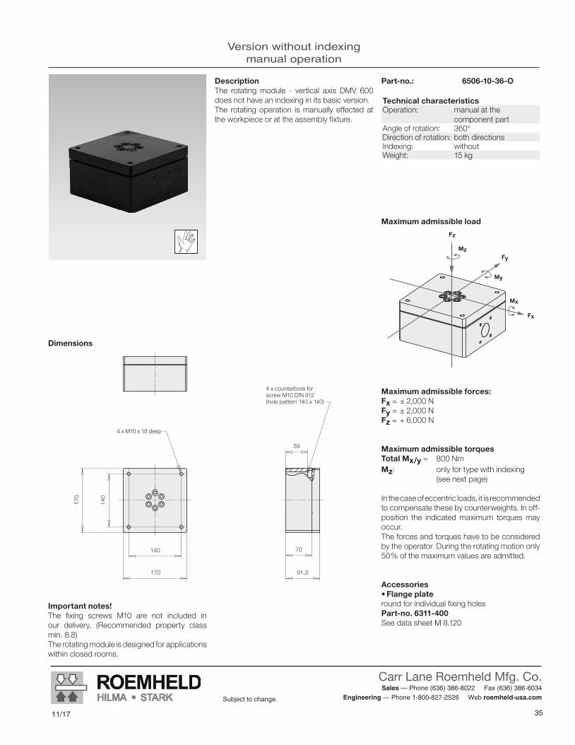
35
Carr Lane Roemheld Mfg. Co. Sales — Phone (636) 386-8022 Fax (636) 386-8034
Engineering — Phone 1-800-827-2526 Web roemheld-usa.comSubject to change.
11/178/16 35
Subject to change.
CARR LANE ROEMHELD MFG. CO.Sales — Phone (636) 386-8022 Fax (636) 386-8034
Engineering — Phone 1-800-827-2526 Web www.carrlaneroemheld.com
Version without indexingmanual operation
59
140
170
140
170
70
91,5
Mx
My
Fz
Mz
Fx
Fy
Version without indexing manual operation
DescriptionThe rotating module - vertical axis DMV 600 does not have an indexing in its basic version.The rotating operation is manually effected at the workpiece or at the assembly fixture.
Part-no.: 6506-10-36-O
Important notes!The fixing screws M10 are not included in our delivery. (Recommended property class min. 8.8)The rotating module is designed for applications within closed rooms.
Maximum admissible forces:Fx = ± 2,000 NFy = ± 2,000 NFz = + 6,000 N
Maximum admissible torquesTotal Mx/y = 800 NmMz: only for type with indexing (see next page)
In the case of eccentric loads, it is recommended to compensate these by counterweights. In off-position the indicated maximum torques may occur.The forces and torques have to be considered by the operator. During the rotating motion only 50 % of the maximum values are admitted.
Accessories•Flange plateround for individual fixing holes Part-no. 6311-400See data sheet M 8.120
Dimensions
4 x counterbore for screw M10 DIN 912 (hole pattern 140 x 140)
4 x M10 x 18 deep
Maximum admissible load
Technical characteristicsOperation: manual at the
component partAngle of rotation: 360°Direction of rotation: both directions Indexing: withoutWeight: 15 kg
Subject to change without prior noticeM 1.301 / 1 -16 E
2 Actual issue see www.roemheld.com Römheld GmbH

11/17
Carr Lane Roemheld Mfg. Co. Sales — Phone (636) 386-8022 Fax (636) 386-8034
Engineering — Phone 1-800-827-2526 Web roemheld-usa.comSubject to change.
3636 8/16
Subject to change.
CARR LANE ROEMHELD MFG. CO.Sales — Phone (636) 386-8022 Fax (636) 386-8034
Engineering — Phone 1-800-827-2526 Web www.carrlaneroemheld.com
Version with indexingmanual operation
170
140
92,5
140
170
59
70
91,5
130
84,9
84,9
128,5145
35°
259
Version with indexing manual operation
Code for part numbersPart-no.: 6509-10-XX-O-I
Engagement position45 = 8 x 45° 60 = 6 x 60° 36 = 4 x 90° 12 = 3 x 120°
Maximum admissible forces:Fx = ± 2,000 NFy = ± 2,000 NFz = + 6,000 N
Maximum admissible torquesTotal Mx/y = 800 Nm
Maximum admissible torque around the rotation axis MzThe maximum torque around the rotation axis of the rotating module Mz in engaged mode is 800 Nm.In the case of eccentric loads, it is recommended to compensate these by counterweights. In off-position the indicated maximum torques may occur.The forces and torques have to be considered by the operator. During the rotating motion only 50% of the maximum values are admitted.
Accessories•Flange plateround for individual fixing holesPart-no. 6311-400See data sheet M 8.120
Mx
My
Fz
Mz
Fx
Fy
Maximum admissible load
Dimensions
Operation of the indexingBy operating the foot pedal by 35° downwards the index is released and the workpiece or the fixture can be rotated.If the foot pedal is not operated, the index bolt engages automatically by spring force into the next indexing position. Release of the index is made by means of the sturdy hydraulics.The operation with a foot pedal guarantees that the operator always has both hands free.The standard indexing positions are set to 8 x 45°, 6 x 60°, 4 x 90° and 3 x 120°. Other angles are available on request.
Important notes!The fixing screws M10 are not included in our delivery.The rotating module is designed for applications within closed rooms.The module may only be moved in a controlled way to the indexing positions. If the indexing bolt engages in full motion, the module will be dynamically overloaded.
DeliveryThe rotating module and the indexing unit including hydraulic hose and hydraulic oil are delivered as completely assembled unit ready for use.
4 x counterbore for screw M10 DIN 912 (hole pattern 140 x 140)
Hydraulic hose 2m
4 x M10 x 18 deep
Counterbore M8 DIN 912 (4x)
4 x M10 x 18 deep
Operating angle
Technical characteristicsOperation: manual at the component
partAngle of rotation: 360°Direction of rotation: both directions Indexing: hydromechanical
Operation with foot pedalWeight: 25 kg
DescriptionThe rotating module - vertical axis DMV 600 with pedal-operated indexing is a compact and functional unit.It consists of a basic module with integrated indexing mechanism and an operating unit with foot pedal, connected by a 2 m long hydraulic hose.This flexible connection allows the individual placement of the operating unit at the most favourable ergonomic position.The rotating operation is manually effected at the workpiece or at the assembly fixture.
Subject to change without prior noticeM 1.301 / 1 -16 E
Römheld GmbH Actual issue see www.roemheld.com 3
170
140
92,5
140
170
59
70
91,5
130
84,9
84,9
128,5145
35°
259
Version with indexing manual operation
Code for part numbersPart-no.: 6509-10-XX-O-I
Engagement position45 = 8 x 45° 60 = 6 x 60° 36 = 4 x 90° 12 = 3 x 120°
Maximum admissible forces:Fx = ± 2,000 NFy = ± 2,000 NFz = + 6,000 N
Maximum admissible torquesTotal Mx/y = 800 Nm
Maximum admissible torque around the rotation axis MzThe maximum torque around the rotation axis of the rotating module Mz in engaged mode is 800 Nm.In the case of eccentric loads, it is recommended to compensate these by counterweights. In off-position the indicated maximum torques may occur.The forces and torques have to be considered by the operator. During the rotating motion only 50% of the maximum values are admitted.
Accessories•Flange plateround for individual fixing holesPart-no. 6311-400See data sheet M 8.120
Mx
My
Fz
Mz
Fx
Fy
Maximum admissible load
Dimensions
Operation of the indexingBy operating the foot pedal by 35° downwards the index is released and the workpiece or the fixture can be rotated.If the foot pedal is not operated, the index bolt engages automatically by spring force into the next indexing position. Release of the index is made by means of the sturdy hydraulics.The operation with a foot pedal guarantees that the operator always has both hands free.The standard indexing positions are set to 8 x 45°, 6 x 60°, 4 x 90° and 3 x 120°. Other angles are available on request.
Important notes!The fixing screws M10 are not included in our delivery.The rotating module is designed for applications within closed rooms.The module may only be moved in a controlled way to the indexing positions. If the indexing bolt engages in full motion, the module will be dynamically overloaded.
DeliveryThe rotating module and the indexing unit including hydraulic hose and hydraulic oil are delivered as completely assembled unit ready for use.
4 x counterbore for screw M10 DIN 912 (hole pattern 140 x 140)
Hydraulic hose 2m
4 x M10 x 18 deep
Counterbore M8 DIN 912 (4x)
4 x M10 x 18 deep
Operating angle
Technical characteristicsOperation: manual at the component
partAngle of rotation: 360°Direction of rotation: both directions Indexing: hydromechanical
Operation with foot pedalWeight: 25 kg
DescriptionThe rotating module - vertical axis DMV 600 with pedal-operated indexing is a compact and functional unit.It consists of a basic module with integrated indexing mechanism and an operating unit with foot pedal, connected by a 2 m long hydraulic hose.This flexible connection allows the individual placement of the operating unit at the most favourable ergonomic position.The rotating operation is manually effected at the workpiece or at the assembly fixture.
Subject to change without prior noticeM 1.301 / 1 -16 E
Römheld GmbH Actual issue see www.roemheld.com 3

37
Carr Lane Roemheld Mfg. Co. Sales — Phone (636) 386-8022 Fax (636) 386-8034
Engineering — Phone 1-800-827-2526 Web roemheld-usa.comSubject to change.
11/17
Tilting Module KMB 100Max. load 1,000 N, load balancedmanual operation
M2.101Issue 10-14 E
ApplicationTilting module for universal use in assembly and handling processes in the industry.
DescriptionThe tilting module KMB 100 with pedal- operated indexing offers the possibility of easy manual tilting of heavy components by ± 90° and their reliable fixing.The tilting module is equipped with a pneu-matic balancer that compensates almost completely generated torques during tilting. Therefore only little forces are required for tilt-ing of the component part.The balancer is adapted to the weight of the component part by a pneumatic pressure reducing valve.The operating unit of the indexing is connect-ed by a 2 m long hydraulic hose to the tilting module.This flexible connection allows the individual placement of the operating unit at the most favourable ergonomic position.The standard indexing positions are set to 0° and 90°. Other engagement positions are available on request (e.g. 0, 30, 45, 60 and 90 degrees).The tilting module is equipped with a hydraulic brake for maximum operating safety.
OperationThe tilting module does not have any operat-ing elements. The tilting operation is effected manually directly at the component part or at the assembly fixture.The indexing is operated by a foot pedal. By operating the foot pedal by 35° the index is re-leased and the component part or the fixture can be tilted.If the foot pedal is not operated, the index bolt engages automatically into the next indexing position.The operation with a foot pedal guarantees that the operator always has both hands free.
Advantages Easy tilting and fixing of components in angle positions 0° and 90° Compensation of the tilting torques by pneumatic balancer and brake cylinder Locking of individual tilting positions 0°/ 90° High load potential Suitable for table mounting Good accessibility from all sides Optimised ergonomics Easily combinable with other modulog modules
Tilting Module KMB 100Max. load 1,000 N, load balancedmanual operation
M 2.101Issue 10-14 E
modulog Tilting module
Part-no. 6507-01-90-OIL
Technical data Max. load: 1,000 NMax. torque: 500 NmMax. balanceable torque: 180 Nm
Operation• Manual
IndexingIndexing angle: 0 / 90°Operation by pedal
Combinable with the modules• Rotating module - vertical axis DMV 1000 as per data sheet M 3.101
• Lifting modules as per data sheet M 4.XXX
modulog interfaces
• Flange plate 140 x 140 - M10
• Body: 140 x 140 - Ø 10.5 mm
Functional principle
90°
Important notesThe pneumatic balancer requires compressed air supply.
Principal use• Assembly of car seats• Motor assembly• Plant construction• Construction of power units
MaterialBody: steel, black oxideRotating plate: steel, black oxideBody balancer: aluminium Body indexing: aluminium Indexing mechanism: steel, hardened
FixationTo fix modulog modules or components of the user, the tilting module has a 140 x 140 inter-face in the flange plate and the body.
Subject to modifications
Actual issue see www.roemheld.comRömheld GmbH · Postfach 1253 · 35317 Laubach, Germany · Tel.: +49 (0) 6405 / 89-0 · Fax: +49 (0) 6405 / 89-211

38
Carr Lane Roemheld Mfg. Co. Sales — Phone (636) 386-8022 Fax (636) 386-8034
Engineering — Phone 1-800-827-2526 Web roemheld-usa.comSubject to change.
11/1738 8/16
Subject to change.
CARR LANE ROEMHELD MFG. CO.Sales — Phone (636) 386-8022 Fax (636) 386-8034
Engineering — Phone 1-800-827-2526 Web www.carrlaneroemheld.com
Technical datadimensions
512
(290)
75 140
20
67,5
37,5
20
70122 140
110
84,9
290
25
35°
145
276
110
14517
0
90°
122
107
225
181
Technical dataDimensions
Mz
My
Mx
Fx
Fy
Fz
Maximum admissible load
Technical data
Dimensions Part-no. 6507-01-90-OIL
Important notesThe adjusted compensation weight or torque is always effective. Therefore the tilting module must only be loaded and unloaded in horizon-tal position. In tilted position, unlocking must not be made without load.
For the pneumatic connection a compressed air coupling ND 7.2 is recommended.
The fixing screws M10 are not included in our delivery.
The tilting module is designed for applications within closed rooms.
Operation: manualTilting angle:
0° and 90°
Balancer: pneumatic,max. balanceabletorque 180 Nm (with regard to the centre of rotation)compressed air 0 to 10 bar (adjusting range)
Indexing: hydro-mechanical,operation with foot pedalindexing positions 0° / 90°positioning precision < ±1°
Weight: 55 kg
Maximum admissible forces:Fx = ± 1,000 N
Fy = ± 1,000 N
Fz = + 1,000 N
Maximum admissible torquesMx or Mz = 500 Nm
My = 500 Nm (for the engaged mode)
My = 180 Nm (for the engaged mode)
The total of all occurring forces or torques must not exceed the highest single value.
DeliveryThe tilting module and the indexing unit are de-livered as a completely assembled unit ready for use.
Application example
Tilting module KMB 100 – mounted on lifting module Shop-Floor
Balanceable torqueThe pneumatic balancer can balance torques up to 180 Nm.
The torque, which will be balanced, depends on the existing pneumatic pressure that can be adjusted at the pneumatic pressure reducing valve of the balancer.Range of adjustment: 0 to 10 bar
Hydraulic hose 2 m
Tilt angle
Pneumatic balance cylinder Bottom plate
Fixing thread M 10 x 20 deep (4x)
Mounting holes D 17 (2x)
Pressure reducing valve with con-nection plug KS3/A G1/8
Operating unit of indexing
Counterbore for M 8
Hydraulic brake cylinder(adjustable)
Top plate
Centre of rotation
Fixing thread M 10 x 20 deep (4x)
Subject to modificationsM 2.101 / 10 -14 E
2 Actual issue see www.roemheld.com Römheld GmbH

39
Carr Lane Roemheld Mfg. Co. Sales — Phone (636) 386-8022 Fax (636) 386-8034
Engineering — Phone 1-800-827-2526 Web roemheld-usa.comSubject to change.
11/17
ApplicationTilting module for universal use in assembly and handling processes in the industry.
Principal use• Assembly of car seats• Motor assembly• Plant construction• Construction of power units
Fixing and installationFor fixing of modulog modules or other com-ponents of the user, the tilting module has an interface 140 x 140 at the base plate and the tilting clamping surface.
Mains cable 5 x 1.5 mm²To be connected by the customer to the termi-nal strip in the control module (mains cable is not included in our delivery).
OperationTilting is made in touch control with hand panel or foot switch. After releasing the hand panel or foot switch, the tilting movement will be stopped immediately.
DescriptionThe electric tilting module is equipped with a worm gear motor and offers the possibility to tilt components by up to 90° and to hold them in position in non-actuated mode. The desired position is approached by pressing a hand panel or foot switch in touch control.When the push-button is released, the tilting module stops in any desired position.The tilting module is automatically stopped by sensors in the positions 0° and 90°.With the electric tilting module, assembly pro-cesses can be realised quickly and efficiently. Ergonomic working conditions are fulfilled.
Available on request:Tilting position 0, 30, 60 and 90 degrees.Tilting position 0, 30, 45, 60 and 90 degrees.Tilting position 0, 45 and 90 degrees.
Advantages Easy tilting and fixing of components in angle positions 0° and 90° Holds self-locking in any intermediate position High load potential Good accessibility from all sides Easily combinable with other modulog modules Ergonomic working conditions Safe and quick working
Tilting Module KME 100Max. load 1,000 N, electrical operation
modulog Tilting module
Part no. 6400-752
Technical data Max. load: 1,000 NMax. torque: 230 Nmin relation to the rotating axis
Operation• Foot switch • Hand panel
Combinable with the modules• Rotating module – vertical axis
DMV 600 as per data sheet M 1.301
• Lifting modules as per data sheet M 4.XXX
modulog interfaces
• Flange plate: 140 x 140 - M10• Body: 140 x 140 - Ø 10.5 mm
Accessories• Electrical operating elements
as per data sheet M 8.203
M 2.201Issue 10-16 E
Tilting and control module are supplied with a 3 m long hard-wired cable.
Control module 6862-717included in our delivery
210 380
380
20
20
8,5
Lock
Pilot light Control voltage
Main switchred / yellow
Connector for hand panel or foot switch as per data sheet M 8.203
Screwed cable gland for mains cable VAC
Subject to modifications
Actual issue see www.roemheld.comRömheld GmbH · Postfach 1253 · 35317 Laubach, Germany · Tel.: +49 (0) 6405 / 89-0 · Fax: +49 (0) 6405 / 89-211
Tilting module KME 100max. load 1,000 N, electrical operation M2.201
Issue 10-16 E
ApplicationTilting module for universal use in assembly and handling processes in the industry.
Principal use• Assembly of car seats• Motor assembly• Plant construction• Construction of power units
Fixing and installationFor fixing of modulog modules or other com-ponents of the user, the tilting module has an interface 140 x 140 at the base plate and the tilting clamping surface.
Mains cable 5 x 1.5 mm²To be connected by the customer to the termi-nal strip in the control module (mains cable is not included in our delivery).
OperationTilting is made in touch control with hand panel or foot switch. After releasing the hand panel or foot switch, the tilting movement will be stopped immediately.
DescriptionThe electric tilting module is equipped with a worm gear motor and offers the possibility to tilt components by up to 90° and to hold them in position in non-actuated mode. The desired position is approached by pressing a hand panel or foot switch in touch control.When the push-button is released, the tilting module stops in any desired position.The tilting module is automatically stopped by sensors in the positions 0° and 90°.With the electric tilting module, assembly pro-cesses can be realised quickly and efficiently. Ergonomic working conditions are fulfilled.
Available on request:Tilting position 0, 30, 60 and 90 degrees.Tilting position 0, 30, 45, 60 and 90 degrees.Tilting position 0, 45 and 90 degrees.
Advantages Easy tilting and fixing of components in angle positions 0° and 90° Holds self-locking in any intermediate position High load potential Good accessibility from all sides Easily combinable with other modulog modules Ergonomic working conditions Safe and quick working
Tilting Module KME 100Max. load 1,000 N, electrical operation
modulog Tilting module
Part no. 6400-752
Technical data Max. load: 1,000 NMax. torque: 230 Nmin relation to the rotating axis
Operation• Foot switch • Hand panel
Combinable with the modules• Rotating module – vertical axis
DMV 600 as per data sheet M 1.301
• Lifting modules as per data sheet M 4.XXX
modulog interfaces
• Flange plate: 140 x 140 - M10• Body: 140 x 140 - Ø 10.5 mm
Accessories• Electrical operating elements
as per data sheet M 8.203
M 2.201Issue 10-16 E
Tilting and control module are supplied with a 3 m long hard-wired cable.
Control module 6862-717included in our delivery
210 380
380
20
20
8,5
Lock
Pilot light Control voltage
Main switchred / yellow
Connector for hand panel or foot switch as per data sheet M 8.203
Screwed cable gland for mains cable VAC
Subject to modifications
Actual issue see www.roemheld.comRömheld GmbH · Postfach 1253 · 35317 Laubach, Germany · Tel.: +49 (0) 6405 / 89-0 · Fax: +49 (0) 6405 / 89-211

11/17
Carr Lane Roemheld Mfg. Co. Sales — Phone (636) 386-8022 Fax (636) 386-8034
Engineering — Phone 1-800-827-2526 Web roemheld-usa.comSubject to change.
40
Maximum admissible load
Dimensions Part no. 6400-752170140
140
170
209
15
(150
)
(359
)
475
140
(560
)
112,5
140
140
170
209
M10 (4x) 15
15
Tilting angle 90° - 0°
M10
- 1
5 de
ep (4
x)
Maximum admissible forcesFx = ± 1,000 NFy = ± 1,000 NFz = ± 1,000 N
Maximum admissible torquesMx = 100 NmMy = 230 NmMz = 100 Nm
The total of all occurring forces or torques must not exceed the highest single value.
DeliveryThe electrical tilting modules are delivered with control module ready for connection. Electrical operating elements are available as accesso-ries.
Important notes!The electrical tilting module is designed for applications within closed rooms.
Technical dataOperation Switching contact or
foot switch or hand panelTilting angle 0° to 90°Supply voltage 230 V, 50 HzCode class IP 54Max. rotation speed
4.5 min-1
Technical dataDimensions
Mx
My
Fz
Mz
Fy
Fz
Tilting position 90°
Tilting position 0°
Subject to modificationsM 2.201 / 10 -16 E
2 Actual issue see www.roemheld.com Römheld GmbH

41
Carr Lane Roemheld Mfg. Co. Sales — Phone (636) 386-8022 Fax (636) 386-8034
Engineering — Phone 1-800-827-2526 Web roemheld-usa.comSubject to change.
11/17
Operation of Electrical Lifting Modulesin SynchronismRemarks for application
M4.005Issue 9-17 E
Compensation of basic heights When lifting modules are operated in synchro-nism, the top plates of the lifting modules must have the same height in retracted position.
The differences in height of the customer's connecting construction are for example due to uneven floors or manufacturing tolerances must be compensated.
A flatness of the top plates of maximally 0.20 mm is required.
Parallel alignmentThe lifting modules must be arranged parallel to each other, otherwise the guide of the lifting mod-ules can be damaged by the resulting forces.
A parallelism of the lifting modules of maximally 0.50 mm is required.
Version with fixed and floating bearing When operating several lifting modules in syn-chronism, in practice, there are constantly small height differences between the individual lifting units which are recognized as control deviation from the synchronization control and are com-pensated. This is the reason why lifting modules must not be firmly connected to the rigid connecting con-struction. Thus, the connection must be made with spherical bearings or elastic elements. This is the only way to ensure that no tension will be produced when moving the lifting modules. The connection must be protected against the introduction of tensile and shearing forces.
Uniform load distribution An unequal load distribution can cause an over-load of the lifting modules.The admissible lifting force of each lifting module must not be exceeded.
Synchronization When operating two or more electrical lifting modules in synchronism, the following guidelines are to be observed:
• Compensation of basic heights • Parallel alignment • Version with fixed and floating bearing • Uniform load distribution
Achievable lifting forces The achievable lifting force of several lifting mod-ules in synchronism is not the sum of the lifting force of all individual lifting modules but smaller by a factor.This is a result of the influences of the connect-ing construction and the interaction between the lifting modules.In practice, the following correction factors have proven to be successful having regard to the above guidelines:
4 lifting modules max. lifting force = 4 x max. lifting force of the
individual module x 0.6
3 lifting modules max. lifting force = 3 x max. lifting force of the
individual module x 0.7
2 lifting modules max. lifting force = 2 x max. lifting force of the
individual module x 0.8
Incorrect Correct
Fixed bearing Floating
bearing
Rigid connection
L1
L2
L1 = L2
Application example: table plate with two lifting modules in synchronism
Accessories1 set of compensating elements consisting of:4 off buffer, Ø 50 x 30 mm long4 off socket head cap screw, M10 x 16Part no. 0891-885
Note:The compensating elements must only be sub-ject to compressive load and not to tensile load!
Subject to modificationsActual issue see www.roemheld-group.com
Römheld GmbH · Postfach 1253 · 35317 Laubach, Germany · Tel.: +49 (0) 6405 / 89-0 · Fax: +49 (0) 6405 / 89-211 · [email protected]
M10Ø 50
3010
KopfplatteTop plate
Operation of Electrical Lifting Modules in SynchronismRemarks for application
M 4.005Issue 9-17 E

11/17
Carr Lane Roemheld Mfg. Co. Sales — Phone (636) 386-8022 Fax (636) 386-8034
Engineering — Phone 1-800-827-2526 Web roemheld-usa.comSubject to change.
428/16 39
Subject to change.
CARR LANE ROEMHELD MFG. CO.Sales — Phone (636) 386-8022 Fax (636) 386-8034
Engineering — Phone 1-800-827-2526 Web www.carrlaneroemheld.com
Lifting Module BasicMax. lifting force 1,000 N, stroke from 200 to 600 mm,manual-hydraulic version
M4.101Issue 5-16 E
modulog Lifting module
Part no. 8910-01-X0-H
DescriptionThe stroke movement is obtained by a hydraulic linear unit with single-lever actuation with oil being pumped by means of a piston pump into a plunger cylinder.
For lowering the oil returns by the weight of the load from the cylinder back to the reservoir.
The lifting units are ideal for height adjustment of tables, demonstration objects and similar equipments as well as for medical treatment equipments.
Principal use • Industrial assembly working places • Height adjustment of assembly working places in workshops • Maintenance works • Assembly fixtures • Adjusting systems in supply processes of mid-sized objects • Handling systems for product packing and transfer
Advantages Elegant and slim design Optimised ergonomics Simple operation No coupling stroke required Working in ergonomically optimum height
MaterialLifting profile: aluminium, naturally anodised
Top and bottom plate aluminium, black anodised
Technical characteristics Max. lifting force: 1,000 NMax. torque: 100 NmStroke: 200 up to 600 mm
Operations• Foot pedal
Kombinierbar mit den Modulen• Rotating module - horizontal axis DMH 200 as per data sheet M 1.101
• Tilting module KMB 100 as per data sheet M 2.101
• Rotating module - vertical axis DMV 600 as per data sheet M 1.301
• Cart modules WMS as per data sheet M 5.101
• Floor modules FMS as per data sheet M 6.101
modulog interfaces
• Top plate: 140 x 140 - Ø 10.5 mm
• Bottom plate 200 x 200 - Ø 10.5 mm
Accessories
• Base and adaptor plates as per data sheet M 8.100 and M 8.110
• Table plates as per data sheet M 8.130
ApplicationLifting module for ergonomic design of working places.
OperationTo lift the load, the foot pedal has to be depressed by approx. 45° several times. The pedal returns to its off-position by means of a return spring.
For a stroke of 100 mm 8 pump motions are required.
To descend the load, the foot pedal has to be moved upwards by approx. 10°.
Fixing and installationFor fixing of modulog modules or other com-ponents of the user at the top plate the lifting module has an interface 140 x 140.
For fixing of modulog modules at the bottom plate the lifting module has an interface 200 x 200.
If the lifting module has to be fixed on a flat level floor, 4 screws M10 of property class 10.9 as well as heavy-duty plugs have to be used.
For increased stability also a base plate, which can be delivered as accessory, can be fixed at the bottom plate.
Lifting Module BasicMax. lifting force 1,000 N, stroke from 200 to 600 mm,manual-hydraulic version
M 4.101Issue 5-16 E
Subject to modifications
Actual issue see www.roemheld.comRömheld GmbH · Postfach 1253 · 35317 Laubach, Germany · Tel.: +49 (0) 6405 / 89-0 · Fax: +49 (0) 6405 / 89-211

43
Carr Lane Roemheld Mfg. Co. Sales — Phone (636) 386-8022 Fax (636) 386-8034
Engineering — Phone 1-800-827-2526 Web roemheld-usa.comSubject to change.
11/1740 8/16
Subject to change.
CARR LANE ROEMHELD MFG. CO.Sales — Phone (636) 386-8022 Fax (636) 386-8034
Engineering — Phone 1-800-827-2526 Web www.carrlaneroemheld.com
Technical characteristicsdimensions
Technical CharacteristicsDimensions
Mx
My
Fz
Mz
Maximum lifting force and maximum admissible torque load
Maximum lifting force Fz: 1,000 N
Maximum torque load:
Total Mx/y: 100 Nm
Mz: 50 Nm
≈45°
≈10°
1515
97
85
196
140
170
200
225
140
170
200
225
Ø 10,5Ø 10,5
Aliftdescend
Stroke
Stroke [mm]
A [mm]
A + Stroke [mm]
Weight [kg]
200 420 620 9.5300 520 820 10400 620 1020 11.5500 720 1220 13600 820 1420 14.5
Technical characteristics
Dimensions
Part no. 8910-01-X0-H
Stroke2 = 200 mm3 = 300 mm4 = 400 mm5 = 500 mm6 = 600 mm
Code for part numbers
Accessories Base plate for increased stability Part no.: 6311-412
See data sheet M 8.100
Important notes!To descend the lifting module a minimum load of approx. 200 N is required.The lifting module must only be pressure loa-ded. The centre of gravity should be within the traverse of the fixing screws.If the centre of gravity is outside, the dowelled joint with the floor has to be dimensioned correspondingly. In such cases it is recom-mended to use a larger base plate.
In case of eccentric load of more than 250 mm, the column cannot descend auto matically be-cause of too high friction forces.
The lifting module is designed for applications within closed rooms.
In the case of eccentric loads, it is recommen-ded to compensate these by counterweights. In off-position the indicated maximum torques may occur.The forces and torques have to be considered by the operator. During the lifting motion only 50% of the maximum values are admitted.
Subject to modificationsM 4.101 / 5 -16 E
2 Actual issue see www.roemheld.com Römheld GmbH

11/17
Carr Lane Roemheld Mfg. Co. Sales — Phone (636) 386-8022 Fax (636) 386-8034
Engineering — Phone 1-800-827-2526 Web roemheld-usa.comSubject to change.
448/16 41
Subject to change.
CARR LANE ROEMHELD MFG. CO.Sales — Phone (636) 386-8022 Fax (636) 386-8034
Engineering — Phone 1-800-827-2526 Web www.carrlaneroemheld.com
Lifting Module Shop-Floor TelescopeMax. lifting force 1,000 and 2,000 N, stroke from 300 to 600 mm, manual-hydraulic and electro-mechanical version
M4.202Issue 5-16 E
M 4.202Issue 5-16 E
modulog Lifting module
Part no. 8918-0X-X0-X
DescriptionThe lifting module Shop-Floor Telescope is particularly suitable for lifting and lowering assembly fixtures, working tables and demon-stration objects in industrial applications as well as for medical treatment equipments in medi-cal applications.In general, lifting modules are used as base unit of devices for controlled lifting and lowering of loads or for height adjustment only. This ver-sion excels particularly by the low base height and the very high strokes.
Advantages N Low basic height
N Large strokes
N Simple and intuitive operation
N Working in ergonomically optimum height
N Sturdy industrial design
N Increase of quality in manufacturing and assembly processes
N Short amortisation time
N Increase of assembly throughput and productivity
N High level of safety against static overloads
N Checked in compliance with DIN EN 1570 with quadruple static overload
MaterialLifting profile: aluminium, naturally anodised Top and bottom plate: aluminium, black anodised
Technical characteristics Max. lifting force: 1,000, 2,000 NMax. bending moment: 500 NmStroke: 300 up to 1,000 mm
Operations• Foot pedal • Foot switch • Hand panel
Combinable with the modules
• Rotating modules - horizontal axis as per data sheet M 1.101 / M 1.201
• Rotating modules - vertical axis as per data sheet M 1.301
• Tilting modules as per data sheet M 2.101 / M 2.201
• Cart modules WMS as per data sheet M 5.101
• Floor modules FMS as per data sheet M 6.101 FMD as per data sheet M 6.201
modulog interfaces• Top plate: 140 x 140 – Ø 10.5 mm• Base plate: 200 x 200 – Ø 10.5 mm
Accessories• Foot switch and hand panel
as per data sheet M 8.200• Extension cable
as per data sheet M 8.200 • Electrical supply unit
as per data sheet M 8.200• Base and adaptor plates
as per data sheet M 8.100 and M 8.110• Table plates
as per data sheet M 8.130 and M 8.131
ApplicationLifting module for workshop applications in the industry.
Principal use• Industrial assembly working places• Height adjustment of assembly working
places in workshops• Service• Assembly fixtures• Adjusting systems in supply processes
of mid-sized objects• Handling systems for product packing
and transfer
Fixing and installationFor fixing of modulog modules or other com-ponents of the user at the top plate the lifting module has an interface 140 x 140.For fixing of modulog modules at the bottom plate the lifting module has an interface 200 x 200. This plate can also be used to fix the lifting module on a flat level floor. For fixing 4 screws M10 of property class 10.9 as well as heavy-duty plugs are to be used.For increased stability also a base plate, which can be delivered as accessory, can be fixed at the bottom plate.
Lifting Module Shop-Floor TelescopeMax. lifting force 1,000 and 2,000 N, stroke from 300 to 1,000 mm,manual-hydraulic and electro-mechanical version
Subject to change without prior notice
Actual issue see www.roemheld.comRömheld GmbH · Postfach 1253 · 35317 Laubach, Germany · Tel.: +49 (0) 6405 / 89-0 · Fax: +49 (0) 6405 / 89-211
M 4.202Issue 9-16 E
modulog Lifting module
Part no. 8918-0X-X0-X
DescriptionThe lifting module Shop-Floor Teleskop is par-ticularly suitable for lifting and lowering assem-bly fixtures, working tables and demonstration objects in industrial applications as well as for medical treatment equipments in medical ap-plications.In general, lifting modules are used as a base unit of devices for controlled lifting and lowering of loads or for height adjustment only. This ver-sion excels particularly by the low base height and the very high strokes.
Advantages N Low basic height
N Large strokes
N Simple and intuitive operation
N Working in ergonomically optimum height
N Sturdy industrial design
N Increase of quality in manufacturing and assembly processes
N Short amortisation time
N Increase of assembly throughput and productivity
N High level of safety against static overloads
N Checked in compliance with DIN EN 1570 with quadruple static overload
MaterialLifting profile: aluminium, naturally anodised Top and bottom plate: aluminium, black anodised
Technical data Max. lifting force: 1,000, 2,000 NMax. bending moment: 500 NmStroke: 300 to 1,000 mm
Operations• Foot pedal • Foot switch • Hand panel
Combinable with the modules
• Rotating modules – horizontal axis DMH 200 as per data sheet M 1.101, DMHe 200 as per data sheet M 1.201
• Tilting modules KMB 100 as per data sheet M 2.101 KME 100 as per data sheet M 2.201
• Rotating modules – vertical axis DMV 600 as per data sheet M 1.301, DMVe 600 as per data sheet M 1.201
• Cart modules WMS as per data sheet M 5.101
• Floor modules FMS as per data sheet M 6.101 FMD as per data sheet M 6.201
modulog interfaces• Top plate: 140 x 140 - Ø 10.5 mm• Bottom plate: 200 x 200 - Ø 10.5 mm
Accessories• Electronic control modules
for 1, 2, 3 or 4 lifting modules as per data sheet M 8.200
• Control modules with battery holder as per data sheet M 8.201
• Electrical operating elements, lines and connectors as per data sheet M 8.203
• Base and adaptor plates as per data sheet M 8.100 and M 8.110
• Table plates as per data sheet M 8.130 and M 8.131
ApplicationLifting module for workshop applications in the industry.
Principal use• Industrial assembly working places• Height adjustment of assembly working
places in workshops• Service• Assembly fixtures• Adjusting systems in supply processes of
mid-sized objects• Handling systems for product packing and
transfer
Fixing and installationFor fixing of modulog modules or other com-ponents of the user at the top plate, the lifting module has an interface 140 x 140.For fixing of modulog modules at the bottom plate, the lifting module has an interface 200 x 200. This plate can also be used to fix the lifting module on a flat level floor. For fixing, 4 screws M10 of property class 10.9 as well as heavy-duty plugs are to be used.For increased stability, a base plate, which can be mounted to the bottom plate, is available as accessory. Fixing on the floor is made by means of the base plate.
Lifting Modules Shop-Floor TelescopeMax. lifting force 1,000 and 2,000 N, stroke from 300 to 1,000 mm,manual-hydraulic and electro-mechanical version
Subject to modifications
Actual issue see www.roemheld.comRömheld GmbH · Postfach 1253 · 35317 Laubach, Germany · Tel.: +49 (0) 6405 / 89-0 · Fax: +49 (0) 6405 / 89-211
M 4.202Issue 9-16 E
Lifting Module Shop-Floor TelescopeMax. lifting force 1,000 and 2,000 N, stroke from 300 to 600 mm,manual-hydraulic and electro-mechanical version

45
Carr Lane Roemheld Mfg. Co. Sales — Phone (636) 386-8022 Fax (636) 386-8034
Engineering — Phone 1-800-827-2526 Web roemheld-usa.comSubject to change.
11/1742 8/16
Subject to change.
CARR LANE ROEMHELD MFG. CO.Sales — Phone (636) 386-8022 Fax (636) 386-8034
Engineering — Phone 1-800-827-2526 Web www.carrlaneroemheld.com
Manual-hydraulic versionoperation with foot pedal
Manual-hydraulic version operation with foot pedal
31,5
Ø 10,5 (4x)
26
296
64
180
ca. 4
0°ca
. 10°
80
1515
A
180
133
Ø 10,5 (4x)
ca. 3
0°
140
170
200
225
DescriptionThe stroke movement is obtained by a hydrau-lic linear unit with single-lever actuation with oil being pumped by means of a piston pump into a plunger cylinder.During retraction the oil returns due to the weight of the load from the cylinder back to the reservoir. A defined speed reduction is effected, independent of the load.The manual-hydraulic variant is particularly sturdy and durable. This variant meets high safety demands and withstands jerking and knocking loads in applications.According to the application 2 different force levels can be selected. The number of pump strokes depends on the force level.
Accessories Base plate for increased stability Part no. 6311-412See data sheet M 8.100
Code for part numbers Part no. 8918-0X-X0-H
Maximum lifting force 1 = 1,000 N 2 = 2,000 N
Stroke 3 = 300 mm 4 = 400 mm 6 = 600 mm 8 = 800 mm10 = 1,000 mm
Mz
Fz
y x
Z
Maximum lifting force FzAlternatively 1,000 N, 2,000 N
Maximum torque load: Total Mx/y: 500 NmMz: 300 Nm
In the case of eccentric loads, it is recom-mended to compensate these by counter-weights. In off-position the indicated maxi-mum torques may occur.The forces and torques have to be considered by the operator. During the lifting motion only 50 % of the maximum values are admitted.
Maximum lifting force and maximum admissible torque load
Important notes!To descend the lifting module a minimum load of approx. 200 N is required.The lifting module must only be pressure loaded. The centre of gravity should be within the traverse of the fixing screws. If the centre of gravity is outside, the dowelled joint with the floor has to be dimensioned correspondingly. In such cases it is recommended to use a larger base plate.In case of eccentric load of more than 250 mm, the column cannot descend automatically because of too high friction forces.The lifting module is designed for applications within closed rooms.
Lifting force
Pump strokes per 100 mm
Descent speed
[N] [mm/s]1,000 2.2 approx. 902,000 3.5 approx. 60
Lifting
Lowering
Stroke A A + stroke
Weight
[mm] [mm] [mm] [kg]300 420 720 15400 470 870 20600 570 1,170 25800 670 1,470 30
1,000 770 1,770 35
Dimensions
Subject to change without prior noticeM 4.202 / 5-16 E
2 Actual issue see www.roemheld.com Römheld GmbH
OperationTo lift the load, the foot pedal has to be depressed by approx. 40° several times. The pedal returns to its off-position by means of a return spring.To lower the load, the foot pedal has to be moved upwards by approx. 10°.
42 8/16
Subject to change.
CARR LANE ROEMHELD MFG. CO.Sales — Phone (636) 386-8022 Fax (636) 386-8034
Engineering — Phone 1-800-827-2526 Web www.carrlaneroemheld.com
Manual-hydraulic versionoperation with foot pedal
Manual-hydraulic version operation with foot pedal
31,5
Ø 10,5 (4x)
26
296
64
180
ca. 4
0°ca
. 10°
80
1515
A
180
133
Ø 10,5 (4x)
ca. 3
0°
140
170
200
225
DescriptionThe stroke movement is obtained by a hydrau-lic linear unit with single-lever actuation with oil being pumped by means of a piston pump into a plunger cylinder.During retraction the oil returns due to the weight of the load from the cylinder back to the reservoir. A defined speed reduction is effected, independent of the load.The manual-hydraulic variant is particularly sturdy and durable. This variant meets high safety demands and withstands jerking and knocking loads in applications.According to the application 2 different force levels can be selected. The number of pump strokes depends on the force level.
Accessories Base plate for increased stability See data sheet M 8.100
Code for part numbers Part no. 8918-0X-X0-H
Maximum lifting force 1 = 1,000 N 2 = 2,000 N
Stroke 3 = 300 mm 4 = 400 mm 6 = 600 mm 8 = 800 mm10 = 1,000 mm
Mz
Fz
y x
Z
Maximum lifting force FzAlternatively 1,000 N, 2,000 N
Maximum torque load: Total Mx/y: 500 NmMz: 300 Nm
In the case of eccentric loads, it is recom-mended to compensate these by counter-weights. In off-position the indicated maxi-mum torques may occur.The forces and torques have to be considered by the operator. During the lifting motion only 50 % of the maximum values are admitted.
Maximum lifting force and maximum admissible torque load
Important notes!To descend the lifting module a minimum load of approx. 200 N is required.The lifting module must only be pressure loaded. The centre of gravity should be within the traverse of the fixing screws. If the centre of gravity is outside, the dowelled joint with the floor has to be dimensioned correspondingly. In such cases it is recommended to use a larger base plate.In case of eccentric load of more than 250 mm, the column cannot descend automatically because of too high friction forces.The lifting module is designed for applications within closed rooms.Qebevaol ) j kr iifcqfkdaofsb` kkl q_bl mbo)^qbat fqepvk` eol kfw qfl k` l kqol i+
Lifting force
Pump strokes per 100 mm
Descent speed
[N] [mm/s]1,000 2.2 approx. 902,000 3.5 approx. 60
Lifting
Lowering
Stroke A A + stroke
Weight
[mm] [mm] [mm] [kg]300 420 720 15400 470 870 20600 570 1,170 25800 670 1,470 30
1,000 770 1,770 35
Dimensions
Subject to change without prior noticeM 4.202 / 5-16 E
2 Actual issue see www.roemheld.com Römheld GmbH
OperationTo lift the load, the foot pedal has to be depressed by approx. 40° several times. The pedal returns to its off-position by means of a return spring.To lower the load, the foot pedal has to be moved upwards by approx. 10°.
11/17
Carr Lane Roemheld Mfg. Co. Sales — Phone (636) 386-8022 Fax (636) 386-8034
Engineering — Phone 1-800-827-2526 Web roemheld-usa.comSubject to change.
42
42 8/16
Subject to change.
CARR LANE ROEMHELD MFG. CO.Sales — Phone (636) 386-8022 Fax (636) 386-8034
Engineering — Phone 1-800-827-2526 Web www.carrlaneroemheld.com
Manual-hydraulic versionoperation with foot pedal
Manual-hydraulic version operation with foot pedal
31,5
Ø 10,5 (4x)
26
296
64
180
ca. 4
0°ca
. 10°
80
1515
A
180
133
Ø 10,5 (4x)
ca. 3
0°
140
170
200
225
DescriptionThe stroke movement is obtained by a hydrau-lic linear unit with single-lever actuation with oil being pumped by means of a piston pump into a plunger cylinder.During retraction the oil returns due to the weight of the load from the cylinder back to the reservoir. A defined speed reduction is effected, independent of the load.The manual-hydraulic variant is particularly sturdy and durable. This variant meets high safety demands and withstands jerking and knocking loads in applications.According to the application 2 different force levels can be selected. The number of pump strokes depends on the force level.
Accessories Base plate for increased stability See data sheet M 8.100
Code for part numbers Part no. 8918-0X-X0-H
Maximum lifting force 1 = 1,000 N 2 = 2,000 N
Stroke 3 = 300 mm 4 = 400 mm 6 = 600 mm 8 = 800 mm10 = 1,000 mm
Mz
Fz
y x
Z
Maximum lifting force FzAlternatively 1,000 N, 2,000 N
Maximum torque load: Total Mx/y: 500 NmMz: 300 Nm
In the case of eccentric loads, it is recom-mended to compensate these by counter-weights. In off-position the indicated maxi-mum torques may occur.The forces and torques have to be considered by the operator. During the lifting motion only 50 % of the maximum values are admitted.
Maximum lifting force and maximum admissible torque load
Important notes!To descend the lifting module a minimum load of approx. 200 N is required.The lifting module must only be pressure loaded. The centre of gravity should be within the traverse of the fixing screws. If the centre of gravity is outside, the dowelled joint with the floor has to be dimensioned correspondingly. In such cases it is recommended to use a larger base plate.In case of eccentric load of more than 250 mm, the column cannot descend automatically because of too high friction forces.The lifting module is designed for applications within closed rooms.The hydro-manual lifting drive can not be oper-ated with synchronization control.
Lifting force
Pump strokes per 100 mm
Descent speed
[N] [mm/s]1,000 2.2 approx. 902,000 3.5 approx. 60
Lifting
Lowering
Stroke A A + stroke
Weight
[mm] [mm] [mm] [kg]300 420 720 15400 470 870 20600 570 1,170 25800 670 1,470 30
1,000 770 1,770 35
Dimensions
Subject to change without prior noticeM 4.202 / 5-16 E
2 Actual issue see www.roemheld.com Römheld GmbH
OperationTo lift the load, the foot pedal has to be depressed by approx. 40° several times. The pedal returns to its off-position by means of a return spring.To lower the load, the foot pedal has to be moved upwards by approx. 10°.
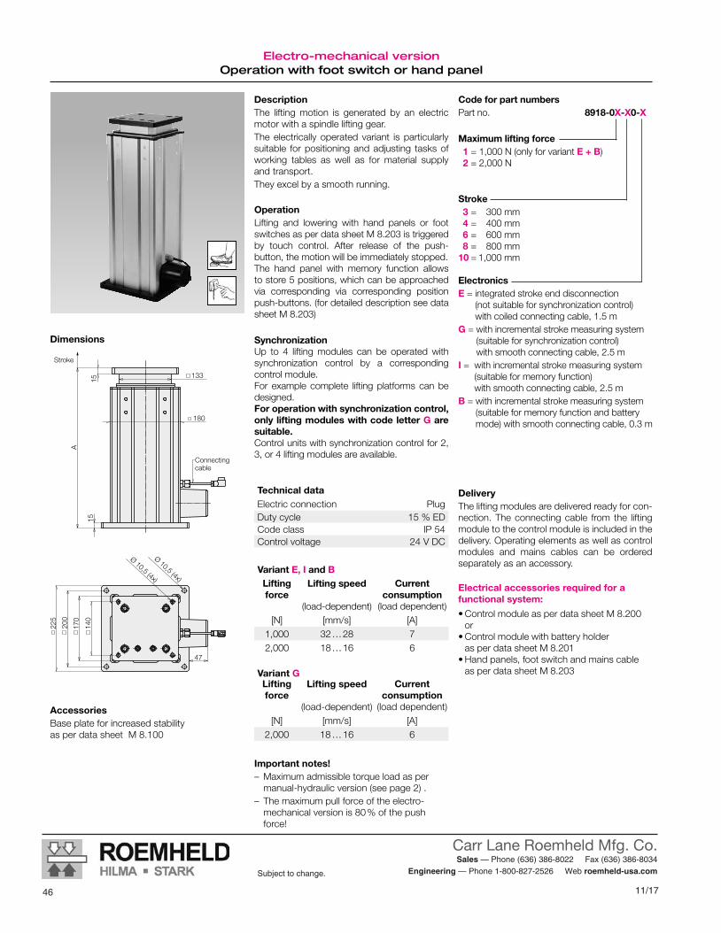
11/17
Carr Lane Roemheld Mfg. Co. Sales — Phone (636) 386-8022 Fax (636) 386-8034
Engineering — Phone 1-800-827-2526 Web roemheld-usa.comSubject to change.
46
DescriptionThe lifting motion is generated by an electric motor with a spindle lifting gear. The electrically operated variant is particularly suitable for positioning and adjusting tasks of working tables as well as for material supply and transport.They excel by a smooth running.
Code for part numbersPart no. 8918-0X-X0-X
Maximum lifting force 1 = 1,000 N (only for variant E + B) 2 = 2,000 N
Stroke 3 = 300 mm 4 = 400 mm 6 = 600 mm 8 = 800 mm10 = 1,000 mm
ElectronicsE = integrated stroke end disconnection
(not suitable for synchronization control) with coiled connecting cable, 1.5 m
G = with incremental stroke measuring system (suitable for synchronization control) with smooth connecting cable, 2.5 m
I = with incremental stroke measuring system (suitable for memory function) with smooth connecting cable, 2.5 m
B = with incremental stroke measuring system (suitable for memory function and battery mode) with smooth connecting cable, 0.3 m
Dimensions
DeliveryThe lifting modules are delivered ready for con-nection. The connecting cable from the lifting module to the control module is included in the delivery. Operating elements as well as control modules and mains cables can be ordered separately as an accessory.
Electrical accessories required for a functional system:
• Control module as per data sheet M 8.200 or
• Control module with battery holder as per data sheet M 8.201
• Hand panels, foot switch and mains cable as per data sheet M 8.203
Accessories Base plate for increased stabilityas per data sheet M 8.100
Electro-mechanical version Operation with foot switch or hand panel
OperationLifting and lowering with hand panels or foot switches as per data sheet M 8.203 is triggered by touch control. After release of the push- button, the motion will be immediately stopped. The hand panel with memory function allows to store 5 positions, which can be approached via corresponding via corresponding position push-buttons. (for detailed description see data sheet M 8.203)
SynchronizationUp to 4 lifting modules can be operated with synchronization control by a corresponding control module.For example complete lifting platforms can be designed. For operation with synchronization control, only lifting modules with code letter G are suitable. Control units with synchronization control for 2, 3, or 4 lifting modules are available.
Variant GLifting force
Lifting speed
(load-dependent)
Current consumption
(load dependent)[N] [mm/s] [A]
2,000 18 … 16 6
Variant E, I and BLifting force
Lifting speed
(load-dependent)
Current consumption
(load dependent)[N] [mm/s] [A]
1,000 32 … 28 72,000 18 … 16 6
Technical dataElectric connection PlugDuty cycle 15 % EDCode class IP 54Control voltage 24 V DC
Important notes! – Maximum admissible torque load as per manual-hydraulic version (see page 2) .
– The maximum pull force of the electro- mechanical version is 80 % of the push force!
140
170
225
200
Ø 10,5 (4x)
1515
133
180
A
47
Ø 10,5 (4x)
Stroke
Connecting cable
Subject to modificationsM 4.202 / 9 -16 E
Römheld GmbH Actual issue see www.roemheld.com 3

47
Carr Lane Roemheld Mfg. Co. Sales — Phone (636) 386-8022 Fax (636) 386-8034
Engineering — Phone 1-800-827-2526 Web roemheld-usa.comSubject to change.
11/17
Issue 09-16 E
M 4.203Lifting Modules RangeMax. lifting force 2,000 N, stroke from 440 to 940 mm,electro-mechanical Telescope version
Subject to modifications
Actual issue see www.roemheld.comRömheld GmbH · Postfach 1253 · 35317 Laubach, Germany · Tel.: +49 (0) 6405 / 89-0 · Fax: +49 (0) 6405 / 89-211
modulog Lifting module
Part no. 8924-02-XX-E
DescriptionThe drive of the telescopic lifting module Range consists of a 230 V A.C. motor and a spindle drive with trapezoidal spindle. A motor brake in combination with the trape-zoidal spindle guarantees safe holding of the driven position.The telescopic guide unit consists of a precise aluminium profile section with a pre-stressed plain bearing with low friction and without clearance for exact positioning. The compact construction with low height and small width guarantees an unhindered accessi-bility to the workpiece from all sides.Mechanical and electric interfaces can be easi-ly integrated in the process of automation.
Principal use• Automation• Drive technology, gears box assembly• Couplings, cardan shafts• Compressors, pumps, hydraulic elements• Industrial fittings• Materials-handling technology• Automotive industry and their suppliers• Mechanical engineering• Building and agricultural machines• Electronics
Advantages N Low basic height N Good accessibility N Very high flexibility N Improved productivity N Simple integration N Optimised ergonomics N Simple operation
OperationThe operation is made by hand panel or foot switch or alternatively by a primary electric control. Lifting and lowering is triggered by push- buttons with touch control contact. After r e-lease of the push-button, the motion will be immediately stopped.
Technical data Max. lifting force: 2,000 NMax. torque: 500 NmStroke: 440 to 940 mm
Operations• Foot switch • Hand panel
Combinable with the modules• Rotating module – horizontal axis
DMH 200 as per data sheet M 1.101, DMHe 200 as per data sheet M 1.201
• Rotating module – vertical axis DMV 600 as per data sheet M 1.301, DMVe 600 as per data sheet M 1.201
• Tilting modules KMB 100 as per data sheet M 2.101 KME 100 as per data sheet M 2.201
modulog interfaces• Top plate: 140 x 140 - Ø 10.5 mm• Bottom plate: 200 x 200 - Ø 10.5 mm
Accessories• Electrical operating elements
as per data sheet M 8.203 • Mains cable 230 V AC
see page 2• Base and adaptor plates
as per data sheet M 8.100 and M 8.110• Table plates
as per data sheet M 8.130 and M 8.131
ApplicationDouble telescopic lifting module for workshop applications in the industry.
Fixing and installationFor fixing of modulog modules or other com-ponents of the user at the top plate, the lifting module has an interface 140 x 140.The bottom plate with double interface 200 x 200 is used to fix the lifting module on the flat level floor.For fixing, 6 screws M10 of property class 10.9 as well as heavy-duty plugs are to be used.For increased stability, a base plate, which can be mounted to the bottom plate, is available as accessory. Fixing on the floor is made by means of the base plate.
MaterialLifting profile: aluminium, naturally anodised Top and bottom plate: aluminium, black anodisedProtection cap: steel, black-lacquered
44 8/16
Subject to change.
M4.203Issue 1-16 E
Lifting Module RangeMax. lifting force 6,000 N, stroke from 440 to 940 mm,electro-mechanical telescope version
CARR LANE ROEMHELD MFG. CO.Sales — Phone (636) 386-8022 Fax (636) 386-8034
Engineering — Phone 1-800-827-2526 Web www.carrlaneroemheld.com
Issue 01-16 E
M 4.203Lifting Module RangeMax. lifting force 2,000 N, stroke from 440 to 940 mm,electro-mechanical Telescope version
Subject to change without prior notice
Actual issue see www.roemheld.comRömheld GmbH · Postfach 1253 · 35317 Laubach, Germany · Tel.: +49 (0) 6405 / 89-0 · Fax: +49 (0) 6405 / 89-211
modulog Lifting module
Part no. 8924-02-XX-E
DescriptionThe drive of the telescopic lifting module Range consists of a 230 V A.C. motor and a spindle drive with trapezoidal spindle. A motor brake in combination with the trap-ezoidal spindle guarantees safe holding of the driven position.The telescopic guide unit consists of a precise aluminium profile section with a pre-stressed plain bearing with low friction and without clearance for exact positioning. The compact construction with low height and small width guarantees an unhindered acces-sibility to the workpiece from all sides.Mechanical and electric interfaces can be easily integrated in the process of automation.
OperationThe operation is made by hand panel or foot switch or alternatively by a primary electric con-trol. Lifting and lowering is triggered by push-but-tons with touch control contact. After release of the push-button, the motion will be immedi-ately stopped.
MaterialLifting profile: aluminium, naturally anodised Top and bottom plate: aluminium, black anodisedProtection cap: steel, black-lacquered
Advantages N Low basic height N Good accessibility N Very high flexibility N Improved productivity N Simple integration N Optimised ergonomics N Simple operation
Technical data Max. lifting force: 2,000 NMax. torque: 500 NmStroke: 440 to 940 mm
Operations• Footswitch•Handpanel
Combinable with the modules
• Rotating module – horizontal axis DMH200 as per data sheet M 1.101 DMHe200 as per data sheet M 1.201
• Rotating module – vertical axis DMV 600 as per data sheet M 1.301 DMVe 600 as per data sheet M 1.201
• Tilting module KMB 100 as per data sheet M 2.101 KME 100 asperdatasheetRHI-M012
modulog interfaces• Top plate: 140 x 140 - Ø 10.5 mm• Bottom plate: 200 x 200 - Ø 10.5 mm
Accessories• Base and adaptor plates
as per data sheet M 8.100 and M 8.110• Table plates
as per data sheet M 8.130 and M 8.131• Electrical operating elements,
lines and connectors as per data sheet M 8.203
ApplicationDouble telescopic lifting module for workshop applications in the industry.
Principal use• Automation• Drive technology, gears box assembly• Couplings, cardan shafts• Compressors, pumps, hydraulic elements• Industrial fittings•Materials-handling technology• Automotive industry and their suppliers•Mechanical engineering• Building and agricultural machines• Electronics
Fixing and installationFor fixing of modulog modules or other com-ponents of the user at the top plate, the lifting module has an interface 140 x 140.The bottom plate with double interface 200 x 200 is used to fix the lifting module on the flat level floor.For fixing, 6 screws M 10 of property class 10.9 as well as heavy-duty plugs are to be used.
Issue 09-16 E
M 4.203Lifting Modules RangeMax. lifting force 2,000 N, stroke from 440 to 940 mm,electro-mechanical Telescope version
Subject to modifications
Actual issue see www.roemheld.comRömheld GmbH · Postfach 1253 · 35317 Laubach, Germany · Tel.: +49 (0) 6405 / 89-0 · Fax: +49 (0) 6405 / 89-211
modulog Lifting module
Part no. 8924-02-XX-E
DescriptionThe drive of the telescopic lifting module Range consists of a 230 V A.C. motor and a spindle drive with trapezoidal spindle. A motor brake in combination with the trape-zoidal spindle guarantees safe holding of the driven position.The telescopic guide unit consists of a precise aluminium profile section with a pre-stressed plain bearing with low friction and without clearance for exact positioning. The compact construction with low height and small width guarantees an unhindered accessi-bility to the workpiece from all sides.Mechanical and electric interfaces can be easi-ly integrated in the process of automation.
Principal use• Automation• Drive technology, gears box assembly• Couplings, cardan shafts• Compressors, pumps, hydraulic elements• Industrial fittings• Materials-handling technology• Automotive industry and their suppliers• Mechanical engineering• Building and agricultural machines• Electronics
Advantages N Low basic height N Good accessibility N Very high flexibility N Improved productivity N Simple integration N Optimised ergonomics N Simple operation
OperationThe operation is made by hand panel or foot switch or alternatively by a primary electric control. Lifting and lowering is triggered by push- buttons with touch control contact. After r e-lease of the push-button, the motion will be immediately stopped.
Technical data Max. lifting force: 2,000 NMax. torque: 500 NmStroke: 440 to 940 mm
Operations• Foot switch • Hand panel
Combinable with the modules• Rotating module – horizontal axis
DMH 200 as per data sheet M 1.101, DMHe 200 as per data sheet M 1.201
• Rotating module – vertical axis DMV 600 as per data sheet M 1.301, DMVe 600 as per data sheet M 1.201
• Tilting modules KMB 100 as per data sheet M 2.101 KME 100 as per data sheet M 2.201
modulog interfaces• Top plate: 140 x 140 - Ø 10.5 mm• Bottom plate: 200 x 200 - Ø 10.5 mm
Accessories• Electrical operating elements
as per data sheet M 8.203 • Mains cable 230 V AC
see page 2• Base and adaptor plates
as per data sheet M 8.100 and M 8.110• Table plates
as per data sheet M 8.130 and M 8.131
ApplicationDouble telescopic lifting module for workshop applications in the industry.
Fixing and installationFor fixing of modulog modules or other com-ponents of the user at the top plate, the lifting module has an interface 140 x 140.The bottom plate with double interface 200 x 200 is used to fix the lifting module on the flat level floor.For fixing, 6 screws M10 of property class 10.9 as well as heavy-duty plugs are to be used.For increased stability, a base plate, which can be mounted to the bottom plate, is available as accessory. Fixing on the floor is made by means of the base plate.
MaterialLifting profile: aluminium, naturally anodised Top and bottom plate: aluminium, black anodisedProtection cap: steel, black-lacquered
M 4.203Issue 9-16 E
Lifting Module RangeMax. lifting force 6,000 N, stroke from 440 to 940 mm,electro-mechanical telescope version

11/17
Carr Lane Roemheld Mfg. Co. Sales — Phone (636) 386-8022 Fax (636) 386-8034
Engineering — Phone 1-800-827-2526 Web roemheld-usa.comSubject to change.
488/16 45
Subject to change.
CARR LANE ROEMHELD MFG. CO.Sales — Phone (636) 386-8022 Fax (636) 386-8034
Engineering — Phone 1-800-827-2526 Web www.carrlaneroemheld.com
Technical datadimensions • accessories
Technical dataDimensions • Accessories
Lifting speed 70 mm/sElectric connection 1/PE(230VAC/50Hz)Rating 0.75 kWControl voltage 24 VDCDuty cycle 20 % EDCode class IP 54
Technical data
Part no. 8924-02-XX-E
Stroke44 = 440 mm54 = 540 mm74 = 740 mm94 = 940 mm
MxMy
Fz
Mz
Stroke A A + stroke Weight[mm] [mm] [mm] [kg]
440 470 910 73540 520 1060 77740 620 1360 84940 720 1660 91
Maximum lifting force Fz: 2,000 N
Maximum torque load Total Mx/y: 500 NmMz: 300 Nm
In the case of eccentric loads, it is recom-mended to compensate these by counter-weights. In off-position the indicated maxi-mum torques may occur.The forces and torques have to be considered by the operator. During the lifting motion only 50 % of the maximum values are admitted.
Maximum lifting force and maximum admissible torque load
Code for part numbersImportant notes The lifting module must only be pressure loaded. The centre of gravity should be within the traverse of the fixing screws.If the centre of gravity is outside, the dowelled joint with the floor has to be dimensioned cor-respondingly. In such cases it is recommend-ed to use a larger base plate.The lifting module is designed for applications within closed rooms. Not suitable for applica-tions with impact load or vibration.
Accessories Base plate for increased stability as per data sheet M 8.100
Subject to modificationsM 4.203 / 1 -16 E
2 Actual issue see www.roemheld.com Römheld GmbH
405
1515
A
Stroke
Dimensions
Sockets for mains cable as well as hand panel or foot switch
225
140
140
170
337,5
(4x)Ø 10,5
200
200
450
25
170
(6x)Ø 10,5
200
DeliveryThe lifting modules are delivered ready for connection. Electrical operating elements and mains cables can be ordered separately as an accessory.
Electrical accessories required for a functional system:
• Electrical operating elements, lines and connectors as per data sheet M 8.203
•Mains cable 230 V AC Mains cable, smooth with earthing type plug, 3 m Part no. 3829-202
Technical dataDimensions • Accessories
Lifting speed 70 mm/sElectric connection 1/ PE (230 V AC / 50 Hz)Rating 0.75 kWControl voltage 24 VDCDuty cycle 20 % EDCode class IP 54
Technical data
Part no. 8924-02-XX-E
Stroke44 = 440 mm54 = 540 mm74 = 740 mm94 = 940 mm
MxMy
Fz
Mz
Stroke A A + stroke Weight[mm] [mm] [mm] [kg]
440 470 910 73540 520 1060 77740 620 1360 84940 720 1660 91
Maximum lifting force Fz: 2,000 N
Maximum torque load Total Mx/y: 500 NmMz: 300 Nm
In the case of eccentric loads, it is recommend-ed to compensate these by counterweights. In off-position, the indicated maximum torques may occur.The forces and torques have to be considered by the operator. During the lifting motion, only 50 % of the maximum values are admitted.
Maximum lifting force and maximum admissible torque load
Code for part numbersImportant notes The lifting module must only be pressure load-ed. The centre of gravity should be within the traverse of the fixing screws.If the centre of gravity is outside, the dowelled joint with the floor has to be dimensioned cor-respondingly. In such cases it is recommended to use a larger base plate.The lifting module is designed for applications within closed rooms. Not suitable for applica-tions with impact load or vibration.
Accessories Base plate for increased stability as per data sheet M 8.100
405
1515
A
Stroke
Dimensions
Sockets for mains cable as well as hand panel or foot switch
225
140
140
170
337,5
(4x)Ø 10,5
200
200
450
25
170
(6x)Ø 10,5
200
DeliveryThe lifting modules are delivered ready for connection. Electrical operating elements and mains cables can be ordered separately as an accessory.
Electrical accessories required for a functional system:
• Hand panels and foot switch as per data sheet M 8.203
• Mains cable 230 V AC Mains cable, smooth with earthing type plug, 3 m Part no. 3829-202
Subject to modificationsM 4.203 / 9 -16 E
2 Actual issue see www.roemheld.com Römheld GmbH

49
Carr Lane Roemheld Mfg. Co. Sales — Phone (636) 386-8022 Fax (636) 386-8034
Engineering — Phone 1-800-827-2526 Web roemheld-usa.comSubject to change.
11/1746 8/16
Subject to change.
M4.301Issue 5-16 E
Lifting Module Shop FloorMax. lifting force 1,000 to 6,000 N, stroke from 200 to 600 mm, manual-hydraulic and electro-mechanical version
CARR LANE ROEMHELD MFG. CO.Sales — Phone (636) 386-8022 Fax (636) 386-8034
Engineering — Phone 1-800-827-2526 Web www.carrlaneroemheld.com
M 4.301Issue 5-16 E
modulog Lifting module
Part no. 8915-0X-X0-X
DescriptionThe lifting module Shop-Floor is particu-larly suitable for lifting and lowering assembly fixtures, working tables and demonstration objects in industrial applications as well as for medical treatment equipments in medical applications.In general, lifting modules are used as a base unit of devices for controlled lifting and lowering of loads or for height adjustment only.
Advantages N Simple and intuitive operation N Working in ergonomically optimum height N Sturdy industrial design N Increase of quality in manufacturing and assembly processes N Short amortisation time N Increase of assembly throughput and productivity N High level of safety against static overloads
MaterialLifting profile: aluminium, naturally anodised Top and bottom plate: aluminium, black anodised
Technical data Max. lifting force: 1,000 up to 6,000 NMax. bending moment: 500 NmStroke: 200 to 600 mm
Operation• Foot pedal • Foot switch • Hand panel
Combinable with the modules
• Rotating module – horizontal axis DMH 200 as per data sheet M 1.101 / M 1.201
• Tilting modules KMB 100 as per data sheet M 2.101 / M 2.201
• Rotating module – vertical axis DMV 600 as per data sheet M 1.301
• Cart modules WMS as per data sheet M 5.101
• Floor modules FMS as per data sheet M 6.101 FMD as per data sheet M 6.201
modulog interfaces• Top plate: 140 x 140 – Ø 10.5 mm• Bottom plate: 200 x 200 – Ø 10.5 mm
Accessories
• Electrical control modules for 1, 2, 3 or 4 lifting modules as per data sheet M 8.200
• Control module with battery holder as per data sheet M 8.201
• Electrical operating elements, lines and connectors as per data sheet M 8.203
• Base and adaptor plates as per data sheet M 8.100 and M 8.110
• Table plates as per data sheet M 8.130 and M 8.131
Lifting Module Shop-FloorMax. lifting force 1,000 to 6,000 N, stroke from 200 to 600 mm,manual-hydraulic and electro-mechanical version
ApplicationLifting module for workshop and assembly applications in the industry.
Principal use• Industrial assembly working places• Height adjustment of assembly working
places in workshops• Service• Assembly fixtures• Adjusting systems in supply processes of
mid-sized objects• Handling systems for product packing
and transfer
Fixing and installationFor fixing of modulog modules or other com-ponents of the user at the top plate the lifting module has an interface 140 x 140.For fixing of modulog modules at the bottom plate the lifting module has an interface 200 x 200. This plate can also be used to fix the lifting module on a flat level floor. For fixing 4 screws M10 of property class 10.9 as well as heavy-duty plugs are to be used.For increased stability, a base plate (separately available as an accessory) can be fixed to the bottom plate.
Subject to modifications
Actual issue see www.roemheld.comRömheld GmbH · Postfach 1253 · 35317 Laubach, Germany · Tel.: +49 (0) 6405 / 89-0 · Fax: +49 (0) 6405 / 89-211
M 4.301Issue 10-16 E
Lifting Module Shop FloorMax. lifting force 1,000 to 6,000 N, stroke from 200 to 600 mm,manual-hydraulic and electro-mechanical version
M 4.301Issue 10-16 E
modulog Lifting module
Part no. 8915-0X-X0-X
DescriptionThe lifting module Shop-Floor is particularly suitable for lifting and lowering assembly fix-tures, working tables and demonstration objects in industrial applications as well as for medical treatment equipments in medical applications.In general, lifting modules are used as a base unit of devices for controlled lifting and lowering of loads or for height adjustment only.
Advantages N Simple and intuitive operation N Working in ergonomically optimum height N Sturdy industrial design N Increase of quality in manufacturing and assembly processes N Increase of assembly throughput and productivity N High level of safety against static overloads
MaterialLifting profile: aluminium, naturally anodised Top and bottom plate: aluminium, black anodised
Technical data Max. lifting force: 1,000 to 6,000 NMax. bending moment: 500 NmStroke: 200 to 600 mm
Operation• Foot pedal • Foot switch • Hand panel
Combinable with the modules
• Rotating modules – horizontal axis DMH 200 as per data sheet M 1.101, DMHe 200 as per data sheet M 1.201
• Tilting modules KMB 100 as per data sheet M 2.101 KME 100 as per data sheet M 2.201
• Rotating modules – vertical axis DMV 600 as per data sheet M 1.301, DMVe 600 as per data sheet M 1.201
• Cart modules WMS as per data sheet M 5.101
• Floor modules FMS as per data sheet M 6.101 FMD as per data sheet M 6.201
modulog interfaces• Top plate: 140 x 140 - Ø 10.5 mm• Bottom plate: 200 x 200 - Ø 10.5 mm
Accessories
• Electronic control modules for 1, 2, 3 or 4 lifting modules as per data sheet M 8.200
• Control modules with battery holder as per data sheet M 8.201
• Electrical operating elements, lines and connectors as per data sheet M 8.203
• Base and adaptor plates as per data sheet M 8.100 and M 8.110
• Table plates as per data sheet M 8.130 and M 8.131
Lifting Modules Shop-FloorMax. lifting force 1,000 to 6,000 N, stroke from 200 to 600 mm,manual-hydraulic and electro-mechanical version
ApplicationLifting module for workshop and assembly applications in the industry.
Principal use• Industrial assembly working places• Height adjustment of assembly working
places in workshops• Service• Assembly fixtures• Adjusting systems in supply processes of
mid-sized objects• Handling systems for product packing and
transfer
Fixing and installationFor fixing of modulog modules or other com-ponents of the user at the top plate, the lifting module has an interface 140 x 140.For fixing of modulog modules at the bot-tom plate, the lifting module has an interface 200 x 200. This plate can also be used to fix the lifting module on a flat level floor. For fixing, 4 screws M10 of property class 10.9 as well as heavy-duty plugs are to be used.For increased stability, a base plate, which can be mounted to the bottom plate, is available as accessory. Fixing on the floor is made by means of the base plate.
Subject to modifications
Actual issue see www.roemheld.comRömheld GmbH · Postfach 1253 · 35317 Laubach, Germany · Tel.: +49 (0) 6405 / 89-0 · Fax: +49 (0) 6405 / 89-21146 8/16
Subject to change.
M4.301Issue 5-16 E
Lifting Module Shop FloorMax. lifting force 1,000 to 6,000 N, stroke from 200 to 600 mm, manual-hydraulic and electro-mechanical version
CARR LANE ROEMHELD MFG. CO.Sales — Phone (636) 386-8022 Fax (636) 386-8034
Engineering — Phone 1-800-827-2526 Web www.carrlaneroemheld.com
M 4.301Issue 5-16 E
modulog Lifting module
Part no. 8915-0X-X0-X
DescriptionThe lifting module Shop-Floor is particu-larly suitable for lifting and lowering assembly fixtures, working tables and demonstration objects in industrial applications as well as for medical treatment equipments in medical applications.In general, lifting modules are used as a base unit of devices for controlled lifting and lowering of loads or for height adjustment only.
Advantages N Simple and intuitive operation N Working in ergonomically optimum height N Sturdy industrial design N Increase of quality in manufacturing and assembly processes N Short amortisation time N Increase of assembly throughput and productivity N High level of safety against static overloads
MaterialLifting profile: aluminium, naturally anodised Top and bottom plate: aluminium, black anodised
Technical data Max. lifting force: 1,000 up to 6,000 NMax. bending moment: 500 NmStroke: 200 to 600 mm
Operation• Foot pedal • Foot switch • Hand panel
Combinable with the modules
• Rotating module – horizontal axis DMH 200 as per data sheet M 1.101 / M 1.201
• Tilting modules KMB 100 as per data sheet M 2.101 / M 2.201
• Rotating module – vertical axis DMV 600 as per data sheet M 1.301
• Cart modules WMS as per data sheet M 5.101
• Floor modules FMS as per data sheet M 6.101 FMD as per data sheet M 6.201
modulog interfaces• Top plate: 140 x 140 – Ø 10.5 mm• Bottom plate: 200 x 200 – Ø 10.5 mm
Accessories
• Electrical control modules for 1, 2, 3 or 4 lifting modules as per data sheet M 8.200
• Control module with battery holder as per data sheet M 8.201
• Electrical operating elements, lines and connectors as per data sheet M 8.203
• Base and adaptor plates as per data sheet M 8.100 and M 8.110
• Table plates as per data sheet M 8.130 and M 8.131
Lifting Module Shop-FloorMax. lifting force 1,000 to 6,000 N, stroke from 200 to 600 mm,manual-hydraulic and electro-mechanical version
ApplicationLifting module for workshop and assembly applications in the industry.
Principal use• Industrial assembly working places• Height adjustment of assembly working
places in workshops• Service• Assembly fixtures• Adjusting systems in supply processes of
mid-sized objects• Handling systems for product packing
and transfer
Fixing and installationFor fixing of modulog modules or other com-ponents of the user at the top plate the lifting module has an interface 140 x 140.For fixing of modulog modules at the bottom plate the lifting module has an interface 200 x 200. This plate can also be used to fix the lifting module on a flat level floor. For fixing 4 screws M10 of property class 10.9 as well as heavy-duty plugs are to be used.For increased stability, a base plate (separately available as an accessory) can be fixed to the bottom plate.
Subject to modifications
Actual issue see www.roemheld.comRömheld GmbH · Postfach 1253 · 35317 Laubach, Germany · Tel.: +49 (0) 6405 / 89-0 · Fax: +49 (0) 6405 / 89-211

11/17
Carr Lane Roemheld Mfg. Co. Sales — Phone (636) 386-8022 Fax (636) 386-8034
Engineering — Phone 1-800-827-2526 Web roemheld-usa.comSubject to change.
508/16 47
Subject to change.
CARR LANE ROEMHELD MFG. CO.Sales — Phone (636) 386-8022 Fax (636) 386-8034
Engineering — Phone 1-800-827-2526 Web www.carrlaneroemheld.com
Manual-hydraulic versionoperation with foot pedal
DescriptionThe stroke movement is obtained by a hydrau-lic lifting drive with single-lever actuation, with oil being pumped by means of a piston pump into a plunger cylinder.During retraction the oil returns due to the weight of the load from the cylinder back to the reservoir. A defined speed reduction is effected, independent of the load.The manual-hydraulic variant is particularly sturdy and durable. This variant meets high safety demands and withstands jerking and knocking loads in applications.According to the application 3 different force levels can be selected. The number of pump strokes depends on the force level.
OperationTo lift the load, the foot pedal has to be depressed by approx. 40° several times. The pedal returns to its off-position by means of a return spring.To lower the load, the foot pedal has to be moved upwards by approx. 10°.
Accessories • Base plate for increased stability
as per data sheet M 8.100
Code for part numbers Part no. 8915-0X-X0-H
Maximum lifting force 2 = 2,000 N4 = 4,000 N6 = 6,000 N
Stroke2 = 200 mm3 = 300 mm4 = 400 mm5 = 500 mm6 = 600 mm
Maximum lifting force FzOptionally 2,000 N, 4,000 N or 6,000 N (1,000 N only for the electro-mechanical ver-sion)
Maximum torque load: Total Mx/y: 500 NmMz: 300 Nm
In the case of eccentric loads, it is recom-mended to compensate these by counter-weights. In off-position the indicated maxi-mum torques may occur.The forces and torques have to be considered by the operator. During the lifting motion only 50 % of the maximum values are ad-mitted.
Maximum lifting force and maximum admissible torque load
Important notes!To descend the lifting module a minimum load of approx. 200 N is required.The lifting module must only be pressure load-ed. The centre of gravity should be within the traverse of the fixing screws. If the centre of gravity is outside, the dowelled joint with the floor has to be dimensioned correspondingly. In such cases it is recommended to use a larger base plate.In case of eccentric load of more than 250 mm, the column cannot descend automatically be-cause of too high friction forces.The lifting module is designed for applications within closed rooms.The hydro-manual lift drive can not be operated with synchronization control.
Manual-hydraulic version Operation with foot pedal
Lifting force
Pump strokes
Descent speed
[N] per 100 mm [mm/s]2,000 5 approx. 454,000 7 approx. 226,000 9 approx. 22
Subject to modificationsM 4.301 / 5 -16 E
2 Actual issue see www.roemheld.com Römheld GmbH
Stroke A A + stroke Weight[mm] [mm] [mm] [kg]200 420 620 15300 520 820 20400 620 1,020 25500 720 1,220 30600 820 1,420 35
1515
296
140
170
200
225
Ø10,5
40°
150
133
A
25
Ø25
Ø10,5
7
10°
liftdescend
Stroke
Dimensions
Mx
My
Fz
Mz

51
Carr Lane Roemheld Mfg. Co. Sales — Phone (636) 386-8022 Fax (636) 386-8034
Engineering — Phone 1-800-827-2526 Web roemheld-usa.comSubject to change.
11/17
DescriptionThe lifting motion is generated by an electric mo-tor with a spindle lifting gear. The electrically operated variant is particularly suitable for positioning and adjusting tasks of working tables as well as for material supply and transport.They excel by a smooth running.
OperationLifting and lowering with hand panels or foot switches as per data sheet M 8.203 is triggered by touch control. After release of the push- button, the motion will be immediately stopped. The hand panel with memory function allows to store 5 positions, which can be approached via corresponding via corresponding position push-buttons. (for detailed description see data sheet M 8.203)
SynchronizationUp to 4 lifting modules can be operated with synchronization control by a corresponding control module.For example complete lifting platforms can be designed. For operation with synchronization control, only lifting modules with code letter G are suitable. Control units with synchronization control for 2, 3, or 4 lifting modules are available.
Code for part numbersPart no. 8915-0X-X0-X
Maximum lifting force1 = 1,000 N (only for variant E + B)2 = 2,000 N4 = 4,000 N6 = 6,000 N
Stroke2 = 200 mm3 = 300 mm4 = 400 mm5 = 500 mm6 = 600 mm
ElectronicsE = integrated stroke end disconnection
(not suitable for synchronization control) with coiled connecting cable, 1.5 m
G = with incremental stroke measuring system (suitable for synchronization control) with smooth connecting cable, 2.5 m
I = with incremental stroke measuring system (suitable for memory function) with smooth connecting cable, 2.5 m
B = with incremental stroke measuring system (suitable for memory function and battery mode) with smooth connecting cable, 0.3 m
DeliveryThe lifting modules are delivered ready for con-nection. The connecting cable from the lifting module to the control module is included in the delivery. Operating elements as well as control modules and mains cables can be ordered separately as an accessory.
Electrical accessories required for a func-tional system:
• Control module as per data sheet M 8.200 or• Control module with battery holder
as per data sheet M 8.201• Hand panels, foot switch and mains cable
as per data sheet M 8.203
Accessories • Base plate for increased stability
as per data sheet M 8.100
Electro-mechanical version
Variant G
Lifting force
Lifting speed (load-dependent)
Current consumption
(load dependent)[N] [mm/s] [A]
2,000 18 … 16 64,000 8 … 6 4.56,000 6 … 4 5.5
Variant E, I and B
Lifting force
Lifting speed (load-dependent)
Current consumption
(load dependent)[N] [mm/s] [A]
1,000 32 … 28 72,000 18 … 16 64,000 10 … 8 66,000 7 … 5 7.5
Technical dataElectric connection PlugDuty cycle 15 % EDCode class IP 54Control voltage 24 V DC
1515
19
140
170
200
225
Ø10,5
122
Ø 7
1
18,5
150
133
A
25Ø25
Ø10,5
7
connecting cable
Stroke
Dimensions
Important notes! – Maximum admissible torque load as per manual-hydraulic version (see page 2) .
– The maximum pull force of the electro-me-chanical version is 80 % of the push force!
Subject to modificationsM 4.301 / 10 -16 E
Römheld GmbH Actual issue see www.roemheld.com 3

11/17
Carr Lane Roemheld Mfg. Co. Sales — Phone (636) 386-8022 Fax (636) 386-8034
Engineering — Phone 1-800-827-2526 Web roemheld-usa.comSubject to change.
528/16 49
Subject to change.
CARR LANE ROEMHELD MFG. CO.Sales — Phone (636) 386-8022 Fax (636) 386-8034
Engineering — Phone 1-800-827-2526 Web www.carrlaneroemheld.com
Electro-mechanical version
Electro-mechanical version
Circuit diagram and connection plug-type connectors for lifting modules with stroke end disconnection (with last digit E)
4 3
4 (blue) “-“ (extend) “+“(retract)
3 (brown) “+“ (extend) “-“ (retract)
Resolution of the incremental stroke measuring system
0
1
a
aStroke [mm]
1 kN: a = 0.75 mm stroke2 kN: a = 0.75 mm stroke4 kN: a = 0.5 mm stroke6 kN: a = 0.375 mm stroke
Circuit diagram and connection plug-type connectors for lifting modules with incremental stroke measuring system (with last digit I, B and G)
6
3
1
4
5
6 (red) reed impulse
1 (yellow) COM
5 (black) limit switch
4 (blue) “-“ (extend) “+“ (retract)
3 (brown) “+“(extend) “-“ (retract)
Subject to modificationsM 4.301 / 5 -16 E
4 Actual issue see www.roemheld.com Römheld GmbH

53
Carr Lane Roemheld Mfg. Co. Sales — Phone (636) 386-8022 Fax (636) 386-8034
Engineering — Phone 1-800-827-2526 Web roemheld-usa.comSubject to change.
11/1750 8/16
Subject to change.
M4.401Issue 5-16 E
Lifting Module StrongMax. lifting force 6,000 N, stroke from 200 to 400 mm,manual-hydraulic and electro-mechanical version
CARR LANE ROEMHELD MFG. CO.Sales — Phone (636) 386-8022 Fax (636) 386-8034
Engineering — Phone 1-800-827-2526 Web www.carrlaneroemheld.com
M 4.401Issue 5-16 E
Subject to change without prior notice
Actual issue see www.roemheld.comRömheld GmbH · Postfach 1253 · 35317 Laubach, Germany · Tel.: +49 (0) 6405 / 89-0 · Fax: +49 (0) 6405 / 89-211
modulog Lifting module
Part-no. 8919-06-X0-X
DescriptionThe lifting module Strong has a high-tensile cylinder tube profile with chromium-plated sur-faces. The high precision of the tube profile en-ables a guiding system without clearance and perfect smooth running.The guiding profile is protected against rotary motion by a key connection with minimum clearance. The guiding system works without fat and oil lubrication. High-quality materials for plain bearings are used.Characteristic are applications with indifferent, dynamically swelling rotating motions and shock motions.
Advantages N Lifting force up to 6,000 N
N High load by steel guiding profile with high section modulus
N Rigid guiding system without clearance
N Sturdy and tough
N Compact design
N Ergonomic design
N Safe and precise handling
MaterialGuiding system, top and base plates are made of steel. Materials for plain bearings are made on the base of polymers.
Technical characteristics Max. lifting force: 6,000 NMax. bending moment: 800 NmStroke: 200 up to 400 mm
Operations• Foot pedal • Foot switch • Hand panel
Combinable with the modules
• Rotating modules – horizontal axis as per data sheet M 1.101, and M 1.201
• Tilting modules KMB 100 as per data sheet M 2.101
• Rotating modules – vertical axis DMV 600 as per data sheet M 1.301
• Cart modules WMS as per data sheet M 5.101
• Floor modules FMS as per data sheet M 6.101
modulog interfaces• Top plate: 140 x 140 – Ø 10.5 mm• Bottom plate: 200 x 200 – Ø 10.5 mm
Accessories• Foot switch and hand panel
as per data sheet M 8.200• Extension cable as per data sheet M 8.200• Electrical supply units
as per data sheet M 8.200• Base and adaptor plates
as per data sheet M 8.100 and M 8.110• Table plates
as per data sheet M 8.130
Lifting module StrongMax. lifting force 6,000 N, stroke from 200 to 400 mm,manual-hydraulic and electro-mechanical version
ApplicationLifting modules for high demands in the indus-trial assembly.
Principal use• Industrial production plants• Automotive industry• Assembly of car seats• Drive technology, axes, cardan shafts• Compressors, hydraulic elements, pumps• Turbines, motors, gearbox construction• Applications with frequent load changes
Fixing and installationFor fixing of modulog modules or other com-ponents of the user at the top plate the lifting module has an interface 140 x 140.For fixing of modulog modules at the bottom plate the lifting module has an interface 200 x 200. This plate can also be used to fix the lifting module on a flat level floor. For fixing 4 screws M10 of property class 10.9 as well as heavy-duty plugs are to be used.For increased stability also a base plate, which can be delivered as accessory, can be fixed at the bottom plate.
M4.401Issue 10-16 E
Lifting Module StrongMax. lifting force 6,000 N, stroke from 200 to 400 mm,manual-hydraulic and electro-mechanical version
Technical data Max. lifting force: 6,000 NMax. bending moment: 800 NmStroke: 200 to 400 mm
Operations• Foot pedal • Foot switch • Hand panel
Combinable with the modules
• Rotating modules – horizontal axis DMH 200 as per data sheet M 1.101, DMHe 200 as per data sheet M 1.201
• Tilting modules KMB 100 as per data sheet M 2.101 KME 100 as per data sheet M 2.201
• Rotating modules – vertical axis DMV 600 as per data sheet M 1.301, DMVe 600 as per data sheet M 1.201
• Cart modules WMS as per data sheet M 5.101
• Floor modules FMS as per data sheet M 6.101
modulog interfaces• Top plate: 140 x 140 - Ø 10.5 mm• Bottom plate: 200 x 200 - Ø 10.5 mm
Accessories• Electronic control modules
for 1, 2, 3 or 4 lifting modules as per data sheet M 8.200
• Control modules with battery holder as per data sheet M 8.201
• Electrical operating elements, lines and connectors as per data sheet M 8.203
• Base and adaptor plates as per data sheet M 8.100 and M 8.110
• Table plates as per data sheet M 8.130 and M 8.131
M 4.401Issue 10-16 E
Subject to modifications
Actual issue see www.roemheld.comRömheld GmbH · Postfach 1253 · 35317 Laubach, Germany · Tel.: +49 (0) 6405 / 89-0 · Fax: +49 (0) 6405 / 89-211
modulog Lifting module
Part no. 8919-06-X0-X
DescriptionThe lifting module Strong has a high-tensile cylinder tube profile with chromium-plated sur-faces. The high precision of the tube profile en-ables a guiding system without clearance and perfect smooth running.The guiding profile is protected against rota-ry motion by a key connection with minimum clearance. The guiding system works without fat and oil lubrication. High-quality materials for plain bearings are used.Characteristic are applications with indifferent, dynamically swelling rotating motions and shock motions.
Advantages N Lifting force up to 6,000 N
N High load by steel guiding profile with high section modulus
N Rigid guiding system without clearance
N Sturdy and tough
N Compact design
N Ergonomic design
N Safe and precise handling
MaterialGuiding system, top and base plates are made of steel. Materials for plain bearings are made on the base of polymers.
Lifting Modules StrongMax. lifting force 6,000 N, stroke from 200 to 400 mm,manual-hydraulic and electro-mechanical version
ApplicationLifting modules for high demands in the indus-trial assembly.
Principal use• Industrial production plants• Automotive industry• Assembly of car seats• Drive technology, axes, cardan shafts• Compressors, hydraulic elements, pumps• Turbines, motors, gearbox construction• Applications with frequent load changes
Fixing and installationFor fixing of modulog modules or other com-ponents of the user at the top plate, the lifting module has an interface 140 x 140.For fixing of modulog modules at the bottom plate, the lifting module has an interface 200 x 200. This plate can also be used to fix the lifting module on a flat level floor. For fixing, 4 screws M10 of property class 10.9 as well as heavy-duty plugs are to be used.For increased stability also a base plate, which can be delivered as accessory, can be fixed at the bottom plate.

11/17
Carr Lane Roemheld Mfg. Co. Sales — Phone (636) 386-8022 Fax (636) 386-8034
Engineering — Phone 1-800-827-2526 Web roemheld-usa.comSubject to change.
548/16 51
Subject to change.
CARR LANE ROEMHELD MFG. CO.Sales — Phone (636) 386-8022 Fax (636) 386-8034
Engineering — Phone 1-800-827-2526 Web www.carrlaneroemheld.com
Manual-hydraulic versionoperation with foot pedal
DescriptionThe stroke movement is obtained by a hydrau-lic lifting jack with single-lever actuation, with oil being pumped by means of a piston pump into a plunger cylinder.During retraction the oil returns due to the weight of the load from the cylinder back to the reservoir. A defined speed reduction is effected.The manual-hydraulic version is particularly sturdy and durable. This variant meets high safety demands and withstands jerking and knocking loads in applications.
OperationTo lift the load, the foot pedal has to be de-pressed by approx. 40° several times. The pedal returns to its off-position by means of a return spring.To lower the load, the foot pedal has to be moved upwards by approx. 10°. Per 100 mm stroke 10 pump motions are required.Descent speed approx. 25 mm/sec.
Accessories Base plate for increased stability Part-no. 6311-412See data sheet M 8.100
Code for part numbers Part-no. 8919-06-X0-H
Stroke2 = 200 mm3 = 300 mm4 = 400 mm
Maximum lifting force Fz: 6,000 N
Maximum torque load: Total Mx/y: 800 NmMz: 400 Nm
In the case of eccentric loads, it is recom-mended to compensate these by counter-weights. In off-position the indicated maxi-mum torques may occur.The forces and torques have to be considered by the operator. During the lifting motion only 50 % of the maximum values are admitted.
Important notes!To descend the lifting module a minimum load of approx. 100 N is required. The lifting module must only be pres-sure loaded. The centre of gravity should be within the traverse of the fixing screws. If the centre of gravity is outside, the dowelled joint with the floor has to be dimensioned correspondingly. In such cases it is recom-mended to use a larger base plate.In case of eccentric load of more than 250 mm, the column cannot descend automatically because of too high friction forces.The lifting module is designed for applications within closed rooms.
Dimensions
Mx
My
Fz
Mz
Technical characteristics
225
200
170
140
150
1515
40°
Ø 10,
5
225
200
170
140
Ø 10,
5
10°
286
A
liftdescend
Stroke
Stroke A A + stroke Weight[mm] [mm] [mm] [kg]200 520 720 50300 620 920 55400 720 1,120 60
Maximum lifting force and maximum admissible torque load
Manual-hydraulic version Operation with foot pedal
Subject to change without prior noticeM 4.401 / 5 -16 E
2 Actual issue see www.roemheld.com Römheld GmbH

55
Carr Lane Roemheld Mfg. Co. Sales — Phone (636) 386-8022 Fax (636) 386-8034
Engineering — Phone 1-800-827-2526 Web roemheld-usa.comSubject to change.
11/17
Subject to modificationsM 4.401 / 10 -16 E
Römheld GmbH Actual issue see www.roemheld.com 3
DescriptionThe lifting motion is generated by an electric motor with a spindle lifting gear. The electrically operated variant is particularly suitable for positioning and adjusting tasks of working tables as well as for material supply and transport.They excel by a smooth running.
OperationLifting and lowering with hand panels or foot switches as per data sheet M 8.203 is triggered by touch control. After release of the push-but-ton, the motion will be immediately stopped. The hand panel with memory function allows to store 5 positions, which can be approached via corresponding position push-buttons. (for detailed description see data sheet M 8.203)
SynchronizationUp to 4 lifting modules can be operated with synchronization control by a corresponding control module.For example, complete lifting platforms can be designed. For operation with synchronization con-trol, only lifting modules with code letter G are suitable. Control units with synchronization control for 2, 3, or 4 lifting modules are available.
Accessories Base plate for increased stabilityas per data sheet M 8.100
Electro-mechanical version operation with foot switch or hand panel
Dimensions
Maximum lifting force Fz 6,000 NLifting speed (load-dependent) Electronics E I B Electronics G
7...5 mm/s 6...4 mm/s
Electric connection PlugDuty cycle 15 % EDCode class IP 54Control voltage 24 VDC (Power input 200 W)Current consumption max. 8 A
Technical data
47
225
200
170
140
150
A
15125
15
75 225
200
170
140
Ø 10,
5
Ø 10,
5
Stroke
Cable smooth usable length approx. 2.5m
Part no. 8919-06-X0-X
Stroke2 = 200 mm3 = 300 mm4 = 400 mm
ElectronicsE = integrated stroke end disconnection
(not suitable for synchronization control) with coiled connecting cable, 1.5 m
G = with incremental stroke measuring system (suitable for synchronization control) with smooth connecting cable, 2.5 m
I = with incremental stroke measuring system (suitable for memory function) with smooth connecting cable, 2.5 m
B = with incremental stroke measuring system (suitable for memory function and battery mode) with smooth connecting cable, 0.3 m
Code for part numbers
DeliveryThe lifting modules are delivered ready for con-nection. The connecting cable from the lifting module to the control module is included in the delivery. Operating elements as well as control modules and mains cables can be ordered separately as an accessory.
Electrical accessories required for a functional system:
• Control module as per data sheet M 8.200 or
• Control module with battery holder as per data sheet M 8.201
• Hand panels, foot switch and mains cable as per data sheet M 8.203
Important notes! – Maximum admissible torque load as per manual-hydraulic version (see page 2) .
– The maximum pull force of the electro-me-chanical version is 80 % of the push force!

11/17
Carr Lane Roemheld Mfg. Co. Sales — Phone (636) 386-8022 Fax (636) 386-8034
Engineering — Phone 1-800-827-2526 Web roemheld-usa.comSubject to change.
568/16 53
Subject to change.
CARR LANE ROEMHELD MFG. CO.Sales — Phone (636) 386-8022 Fax (636) 386-8034
Engineering — Phone 1-800-827-2526 Web www.carrlaneroemheld.com
Lifting Module SolidMax. lifting force 4,000 N, stroke from 200 to 400 mm, manual-hydraulic version
M4.402Issue 5-16 E
modulog Lifting module
Part no. 8926-0X-X0-H
DescriptionThe lifting module has an integrated roller guid-ing element. This allows a backlash-free guid-ing system with very good smooth running and the introduction of high moments into the lifting module.The guiding system is lifetime lubricated. To obtain high robustness, all components are made of high-quality materials. Characteristic are applications with indifferent, dynamically swelling rotating motions and shock motions.
MaterialAll essential elements are made of steel to obtain a high robustness.
VariantsDrive variants with brushless electric motor 48 V DC or hydraulic cylinder can be realised on request as per customer's specifications. Service life and lifting speed is perfect for cycle-related assemblies.
Advantages N Lifting force up to 6,000 N N Displacement with low friction is also given with high torque load N High load by roller guiding element with high section modulus N Sturdy and tough N Compact design N Safe and precise handling N Checked in compliance with DIN EN 1570 with quadruple static overload N Better working with lower load N Integrated stop for pedal
Technical data Max. lifting force: 4,000 N, 6,000 NMax. bending moment: 1,000 NmStroke: 200 up to 400 mm
Operations• Foot pedal
Combinable with the modules
• Rotating module – horizontal axis as per data sheet M 1.101 and M 1.201
• Tilting module KMB 100 as per data sheet M 2.101
• Rotating module – vertical axis DMV 600 as per data sheet M 1.301
modulog interfaces
• Top plate: 140 x 140 – M 10 200 x 200 – Ø 10.5 mm• Bottom plate: 200 x 200 – Ø 10.5 mm
Accessories• Base and adaptor plates
as per data sheet M 8.100 and M 8.110• Table plates
as per data sheet M 8.130
Lifting Module SolidMax. lifting force 4,000 N and 6,000 N, stroke from 200 to 400 mmmanual-hydraulic version
ApplicationLifting modules for high demands on perfor-mance and service life in the industrial assembly.
Principal use• Ergonomic design of working places• Industrial production plants• Automotive industry• Assembly of car seats• Assembly of drive components, axes and
cardan shafts• Assembly of compressors, hydraulic compo-
nents and pumps• Assembly of turbines, motors and gear
boxes• Applications with frequent load changes
Fixing and installationFor fixing of modulog modules or other com-ponents of the user at the top plate, the lift-ing module has an interface 140 x 140 and 200 x 200.For fixing of modulog modules at the bot-tom plate, the lifting module has an interface 200 x 200. This plate can also be used to fix the lifting module on a flat level floor. For fixing, screws M10 of property class 10.9 as well as heavy-duty plugs are to be used.For increased stability, a base plate, which can be mounted to the bottom plate, is available as accessory. Fixing on the floor is made by means of the base plate.
Subject to modifications
Actual issue see www.roemheld.comRömheld GmbH · Postfach 1253 · 35317 Laubach, Germany · Tel.: +49 (0) 6405 / 89-0 · Fax: +49 (0) 6405 / 89-211
M 4.402Issue 5-16 E
Lifting Module SolidMax. lifting force 4,000 N, stroke from 200 to 600 mm, manual-hydraulic version
M4.402Issue 9-16 E
modulog Lifting module
Part no. 8926-0X-X0-H
DescriptionThe lifting module has an integrated roller guid-ing element. This allows a backlash-free guid-ing system with very good smooth running and the introduction of high moments into the lifting module.The guiding system is lifetime lubricated. To obtain high robustness, all components are made of high-quality materials. Characteristic are applications with indifferent, dynamically swelling rotating motions and shock motions.
MaterialAll essential elements are made of steel to obtain a high robustness.
VariantsDrive variants with brushless electric motor 48 V DC or hydraulic cylinder can be realised on request as per customer's specifications. Service life and lifting speed is perfect for cycle-related assemblies.
Advantages N Lifting force up to 6,000 N N Displacement with low friction is also given with high torque load N High load by roller guiding element with high section modulus N Sturdy and tough N Compact design N Safe and precise handling N Checked in compliance with DIN EN 1570 with quadruple static overload N Better working with lower load N Integrated stop for pedal
Technical data Max. lifting force: 4,000 N; 6,000 NMax. bending moment: 1,000 NmStroke: 200 to 400 mm
Operations• Pedal
Combinable with the modules
• Rotating modules – horizontal axis DMH 200 as per data sheet M 1.101, DMHe 200 as per data sheet M 1.201
• Tilting modules KMB 100 as per data sheet M 2.101 KME 100 as per data sheet M 2.201
• Rotating modules – vertical axis DMV 600 as per data sheet M 1.301, DMVe 600 as per data sheet M 1.201
• Cart modules WMS as per data sheet M 5.101
• Floor modules FMS as per data sheet M 6.101
modulog interfaces
• Top plate: 140 x 140 – M 10 200 x 200 – Ø 10.5 mm• Bottom plate: 200 x 200 - Ø 10.5 mm
Accessories• Base and adaptor plates
as per data sheet M 8.100 and M 8.110• Table plates
as per data sheet M 8.130
Lifting modules SolidMax. lifting force 4,000 N and 6,000 N, stroke from 200 to 400 mmmanual-hydraulic version
ApplicationLifting modules for high demands on perfor-mance and service life in the industrial assem-bly.
Principal use• Ergonomic design of working places• Industrial production plants• Automotive industry• Assembly of car seats• Assembly of drive components, axes and
cardan shafts• Assembly of compressors, hydraulic compo-
nents and pumps• Assembly of turbines, motors and gear
boxes• Applications with frequent load changes
Fixing and installationFor fixing of modulog modules or other com-ponents of the user at the top plate, the lifting module has an interface 140 x 140 and 200 x 200.For fixing of modulog modules at the bottom plate, the lifting module has an interface 200 x 200. This plate can also be used to fix the lifting module on a flat level floor. For fixing, screws M10 of property class 10.9 as well as heavy-duty plugs are to be used.For increased stability, a base plate, which can be mounted to the bottom plate, is available as accessory. Fixing on the floor is made by means of the base plate.
M 4.402Issue 9-16 E
Subject to modifications
Actual issue see www.roemheld.comRömheld GmbH · Postfach 1253 · 35317 Laubach, Germany · Tel.: +49 (0) 6405 / 89-0 · Fax: +49 (0) 6405 / 89-211

57
Carr Lane Roemheld Mfg. Co. Sales — Phone (636) 386-8022 Fax (636) 386-8034
Engineering — Phone 1-800-827-2526 Web roemheld-usa.comSubject to change.
11/17
140
256,
5
Ø 10,5 (4x)
7
15
A
191
15
10°±
2
30°
200
225
5 x 45°
296 ±3
40°
±5
M 10 (4x)
Ø 10,5 (4x)
Ø 18 (4x)
DescriptionThe stroke movement is obtained by a man-ual-hydraulic lifting drive with single-lever ac-tuation, with oil being pumped by means of a piston pump into a plunger cylinder.During retraction, the oil returns due to the weight of the load from the cylinder back to the reservoir. A defined speed control is effected.The manual-hydraulic version is particularly sturdy and durable. This variant meets high safety demands and withstands jerking and knocking loads in applications.
Accessories Base plate for increased stability as per data sheet M 8.100
Code for part numbers Part no. 8926-0X-X0-H
Maximum lifting force
4 = 4,000 N6 = 6,000 N
Stroke
2 = 200 mm3 = 300 mm4 = 400 mm
Maximum lifting force Fz: Alternatively 4,000 N or 6,000 N
Maximum torque load: Total Mx/y: 1,000 NmMz: 1,000 Nm
In the case of eccentric loads, it is recommend-ed to compensate these by counterweights. In off-position, the indicated maximum torques may occur.The forces and torques have to be considered by the operator. During the lifting motion, only 50 % of the maximum values are ad-mitted.
Manual-hydraulic version operation with foot pedal
Dimensions
Mx
My
Fz
Mz
Technical data
lift
descend
Stroke A A + stroke Weight[mm] [mm] [mm] [kg]200 420 620 56300 520 820 64400 620 1,020 73
Lifting force
Pump strokes per 100 mm
Descent speed
[N] [mm/s]4,000 7 approx. 226,000 9 approx. 22
Maximum lifting force and maximum admissible torque load
OperationTo lift the load, the foot pedal has to be de-pressed by approx. 40° several times. The pedal returns to its off-position by means of a return spring.To lower the load, the foot pedal has to be moved upwards by approx. 10°.
Important notes!To descend the lifting module, a minimum load of approx. 200 N is required.The lifting module must only be pressure load-ed. The centre of gravity should be within the traverse of the fixing screws. If the centre of gravity is outside, the dowelled joint with the floor has to be dimensioned correspondingly. In such cases it is recommended to use a larger base plate.In case of eccentric load of more than 250 mm, the column cannot descend automatically be-cause of too high friction forces.The lifting module is designed for applications within closed rooms.The hydro-manual lifting drive can not be oper-ated with synchronization control.
Subject to modificationsM 4.402 / 9 -16 E
2 Actual issue see www.roemheld.com Römheld GmbH

58
Carr Lane Roemheld Mfg. Co. Sales — Phone (636) 386-8022 Fax (636) 386-8034
Engineering — Phone 1-800-827-2526 Web roemheld-usa.comSubject to change.
11/17
Lifting Module Twin-StrongMax. lifting force 4,000 and 6,000 N, stroke from 200 to 400 mm, manual-hydraulic and electro-mechanical version
M4.501Issue 10-16 E
Lifting Modules Twin-StrongMax. lifting force 4,000 and 6,000 N, stroke from 200 to 400 mm,manual-hydraulic and electro-mechanical version
M 4.501Issue 10-16 E
modulog Lifting module
Part no. 8914-06-X0-X
DescriptionThe lifting module Twin-Strong has two high-tensile cylinder tube profiles with chro-mium-plated surfaces. The design with solid profiles allows a stable guiding system with perfect smooth running. The high precision of the profiles permits a guiding system without clearance and perfect smooth running.The guiding system works without fat and oil lubrication. High-quality materials for plain bearings are used.Characteristic are applications with indiffer-ent, dynamically swelling rotating motions and shock motions.
Advantages Lifting force up to 6,000 N Extreme load due to double steel guides Very high section modulus Rigid guiding system without clearance Sturdy and tough Compact design Modular standard design, easy to combine Less load on the operator due to ergonomic design Safe and precise handling Safety factor 2.0 against static overload
MaterialDouble guiding system, top and base plates are made of steel. Materials for plain bearings are made on the base of polymers.
Technical data Max. lifting force: 4.000, 6.000 NMax. torque: 2,000 NmStroke: 200 to 400 mm
Operations• Foot pedal • Foot switch • Hand panel
Combinable with the modules
• Rotating modules – horizontal axis DMH 200 as per data sheet M 1.101, DMHe 200 as per data sheet M 1.201
• Tilting modules KMB 100 as per data sheet M 2.101 KME 100 as per data sheet M 2.201
• Rotating modules – vertical axis DMV 600 as per data sheet M 1.301, DMVe 600 as per data sheet M 1.201
modulog interfaces
• Top plate: 140 x 140 - Ø 10.5 mm
• Bottom plate 200 x 200 - Ø 10.5 mm
Accessories
• Electronic control modules for 1, 2, 3 or 4 lifting modules as per data sheet M 8.200
• Control modules with battery holder as per data sheet M 8.201
• Electrical operating elements, lines and connectors as per data sheet M 8.203
• Base and adaptor plates as per data sheet M 8.100 and M 8.110
• Table plates as per data sheet M 8.130 and M 8.131
ApplicationLifting module for extreme loads.
Principal use • Industrial production with difficult application conditions • Automotive industry • Assembly of car seats • Drive technology, axes, cardan shafts • Compressors, hydraulic elements, pumps • Turbines, motors, gearbox construction • Applications with frequent load changes and high torque loads
Fixing and installationFor fixing of modulog modules or other com-ponents of the user at the top plate, the lifting module has a triple interface 140 x 140.For fixing of the lifting module on a flat level floor, the lifting module has a double interface 200 x 200. For fixing, 6 screws M10 of property class 10.9 as well as heavy-duty plugs are to be used.
Subject to modifications
Actual issue see www.roemheld.comRömheld GmbH · Postfach 1253 · 35317 Laubach, Germany · Tel.: +49 (0) 6405 / 89-0 · Fax: +49 (0) 6405 / 89-211

59
Carr Lane Roemheld Mfg. Co. Sales — Phone (636) 386-8022 Fax (636) 386-8034
Engineering — Phone 1-800-827-2526 Web roemheld-usa.comSubject to change.
11/17
Manual-hydraulic versionOperation with foot pedal
DescriptionThe stroke movement is obtained by a hydrau-lic lifting jack with single-lever actuation, with oil being pumped by means of a piston pump into a plunger cylinder.
During retraction the oil returns due to the weight of the load from the cylinder back to the reservoir. A defined speed reduction is effect-ed.
The manual-hydraulic variant is particularly sturdy and durable. This variant meets high safety demands and withstands jerking and knocking loads in applications.
OperationTo lift the load, the foot pedal has to be de-pressed by approx. 40° several times. The pedal returns to its off-position by means of a return spring.
To lower the load, the foot pedal has to be moved upwards by approx. 10°.
170
225
Ø 1
0,5
(8x)
200 200(25)
140
200
140 140 140
(15)
450
1515
A
370
40°
10°
Ø 10,5 (6x)
Stro
ke
Dimensions
Stroke A A + stroke Weight[mm] [mm] [mm] [kg]200 420 620 95300 520 820 100
400 620 1020 105
Maximum torque load: Mx: 2000 Nm or My: 1200 NmMz: 600 Nm
In the case of eccentric loads, it is recommend-ed to compensate these by counterweights. In off-position, the indicated maximum torques may occur.The forces and torques have to be considered by the operator. During the lifting motion, only 50 % of the maximum values are admitted.
Mx
My
Fz
Mz
Maximum lifting force and maximum admissible torque load
Technical data
Important notes!To descend the lifting module a minimum load of approx. 200 N is required.The lifting module must only be pressure load-ed. The centre of gravity should be within the traverse of the fixing screws. If the centre of gravity is outside, the dowelled joint with the floor has to be dimensioned correspondingly. In such cases it is recommended to use a larger base plate.In case of eccentric load of more than 250 mm, the column cannot descend automatically be-cause of too high friction forces.
The lifting module is designed for applications within closed rooms.
Code for part numbers Part no. 8914-0X-X0-H
Maximum lifting force 4 = 4,000 N 6 = 6,000 N
Stroke 2 = 200 mm 3 = 300 mm 4 = 400 mm
Lifting force
Pump strokes per 100 mm
Descent speed
[N] [mm/s]4,000 7 approx. 226,000 9 approx. 22
Accessories Base plate for increased stability as per data sheet M 8.100
Subject to modificationsM 4.501 / 10 -16 E
2 Actual issue see www.roemheld.com Römheld GmbH
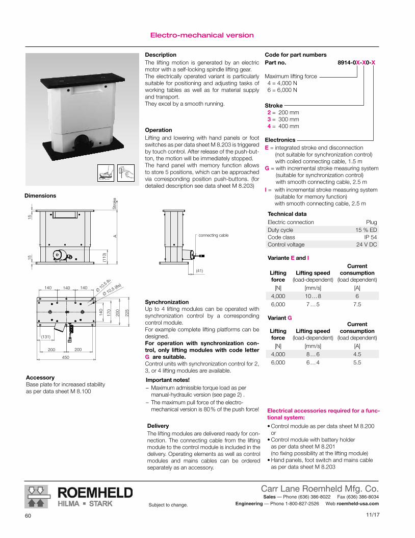
11/17
Carr Lane Roemheld Mfg. Co. Sales — Phone (636) 386-8022 Fax (636) 386-8034
Engineering — Phone 1-800-827-2526 Web roemheld-usa.comSubject to change.
60
Code for part numbers Part no. 8914-0X-X0-X
Maximum lifting force 4 = 4,000 N 6 = 6,000 N
Stroke 2 = 200 mm 3 = 300 mm 4 = 400 mm
ElectronicsE = integrated stroke end disconnection
(not suitable for synchronization control) with coiled connecting cable, 1.5 m
G = with incremental stroke measuring system (suitable for synchronization control) with smooth connecting cable, 2.5 m
I = with incremental stroke measuring system (suitable for memory function) with smooth connecting cable, 2.5 m
Electro-mechanical version
DescriptionThe lifting motion is generated by an electric motor with a self-locking spindle lifting gear. The electrically operated variant is particularly suitable for positioning and adjusting tasks of working tables as well as for material supply and transport.They excel by a smooth running.
Dimensions
DeliveryThe lifting modules are delivered ready for con-nection. The connecting cable from the lifting module to the control module is included in the delivery. Operating elements as well as control modules and mains cables can be ordered separately as an accessory.
Electrical accessories required for a func-tional system:
•Control module as per data sheet M 8.200 or •Control module with battery holder as per data sheet M 8.201 (no fixing possibility at the lifting module) •Hand panels, foot switch and mains cable as per data sheet M 8.203
OperationLifting and lowering with hand panels or foot switches as per data sheet M 8.203 is triggered by touch control. After release of the push-but-ton, the motion will be immediately stopped. The hand panel with memory function allows to store 5 positions, which can be approached via corresponding position push-buttons. (for detailed description see data sheet M 8.203)
225
170
450
200
140
140 140 140
200 200
(131)
1515
(110
)
A
(41)
Ø 10,5 (6x)
Ø 10,5 (8x)
Stro
ke
connecting cable
Accessory Base plate for increased stability as per data sheet M 8.100
SynchronizationUp to 4 lifting modules can be operated with synchronization control by a corresponding control module.For example complete lifting platforms can be designed. For operation with synchronization con-trol, only lifting modules with code letter G are suitable. Control units with synchronization control for 2, 3, or 4 lifting modules are available.
Important notes! – Maximum admissible torque load as per manual-hydraulic version (see page 2) .
– The maximum pull force of the electro- mechanical version is 80 % of the push force!
Variant G
Lifting force
Lifting speed (load-dependent)
Current consumption
(load dependent)[N] [mm/s] [A]
4,000 8 … 6 4.56,000 6 … 4 5.5
Variante E and I
Lifting force
Lifting speed
(load-dependent)
Current consumption
(load dependent)[N] [mm/s] [A]
4,000 10 … 8 66,000 7 … 5 7.5
Technical dataElectric connection PlugDuty cycle 15 % EDCode class IP 54Control voltage 24 V DC
Subject to modificationsM 4.501 / 10 -16 E
Römheld GmbH Actual issue see www.roemheld.com 3

61
Carr Lane Roemheld Mfg. Co. Sales — Phone (636) 386-8022 Fax (636) 386-8034
Engineering — Phone 1-800-827-2526 Web roemheld-usa.comSubject to change.
11/1758 8/16
Subject to change.
M5.101Issue 5-16 E
Cart Modules WMSMax. load 2,000 to 6,000 N
CARR LANE ROEMHELD MFG. CO.Sales — Phone (636) 386-8022 Fax (636) 386-8034
Engineering — Phone 1-800-827-2526 Web www.carrlaneroemheld.com
modulog
Cart module WMS
Part-no. 8900-0X-01-O
DescriptionThe cart modules WMS are offered for two different loads. For the cart module WMS 200 the maximum admissible load is 2,000 N and for WMS 600 the maximum load is 6,000 N.The cart modules WMS consist of a welded sturdy steel frame with two fixed rollers and two steering rollers, which are equipped with a parking brake. the parking brakes of WMS 200 are individually operated. In version WMS 600 the brakes are coupled and can be operated from both sides by means of a foot pedal.In the centre of the steel frame there is a moun-ting plate. This plate is used for fixation of lifting modules.Alternatively workshop setups can be mounted at the steel frame.
Principal use • Material supply • Production plants • Test area for quality assurance • Logistics • Movable working stations
Advantages Suitable for workshop setups Easily combinable with modulog lifting modules Easy transport of heavy components or fixtures Low driving resistance even with high loads Parking brakes with foot pedal operation at both sides Fixed rollers and steering rollers Good accessibility Optimised ergonomics Simple operation
MaterialFrame: steel, black-lacqueredTires: PUR
Technical characteristics Max. loadWMS 200: 2,000 NWMS 600: 6,000 N
Operations • Manual
Combinable with the modules
• Lifting modules as per data sheet M 4.XXX
modulog interface • 200 x 200 - M10
Accessories • Adaptor plates as per data sheet M 8.110 • Table plates as per data sheet M 8.130Application
Cart modules for the transport of devices, assembly fixtures or testing devices within the production. Cart modules in combination with lifting mo-dules are avantageously used in assembly or production processes, if components have to be transported to working places with different working heights. Lifting carts can also be used as working sur-face. The lifting carts with the components will be pushed to the individual working places and adjusted to the optimum ergonomic working height, loading and unloading of the compon-ents is not required.
MountingFor mounting of modulog modules or other componets the cart modules have in the centre of the steel frame an interface 200 x 200.As accessory an adaptor plate is available to mount workshop setups and modulog mo-dules with interface 140 x 140.To combine lifting carts, appropriate table plates with handles are available as accessory.
WMS 200: maximum load 2,000 N
WMS 600: maximum load 6,000 N
Important notesTo move the cart module the user has to pro-vide handles.The cart modules may only be moved at walking pace.
Application example
Lifting cart – combined by cart module WMS 600, lifting module Shop-Floor and a table plate.
Cart Modules WMSMax. load 2,000 to 6,000 N
M 5.101Issue 5-16 E
Subject to change without prior notice
Actual issue see www.roemheld.comRömheld GmbH · Postfach 1253 · 35317 Laubach, Germany · Tel.: +49 (0) 6405 / 89-0 · Fax: +49 (0) 6405 / 89-211

11/17
Carr Lane Roemheld Mfg. Co. Sales — Phone (636) 386-8022 Fax (636) 386-8034
Engineering — Phone 1-800-827-2526 Web roemheld-usa.comSubject to change.
628/16 59
Subject to change.
CARR LANE ROEMHELD MFG. CO.Sales — Phone (636) 386-8022 Fax (636) 386-8034
Engineering — Phone 1-800-827-2526 Web www.carrlaneroemheld.com
Technical characteristicsdimensions
Technical characteristicsDimensions
Part-no.:WMS 200: 8900-02-01-OWMS 600: 8900-06-01-O
Accessories •Adaptor plate 140 - 200 to fix modulog modules with 140 x 140er interface Part-no. 6311-417
See data sheet M 8.110
•Table plates made of wood or steel
See data sheet M 8.130
Important noteDue to stability reasons, only center load of the cart modules is admitted.For cart modules with special dimensions and larger base are available as special versions, please enquire.
Dimensions
700
600
300
200
560
200
21543
Ø 125
28
FzMaximum admissible load Fz
WMS 200: Fz = 2,000 NWMS 600: Fz = 6,000 N
7203085
346
140
330
30
Ø 2
00
225
200
625
360
200
225
M 10 (4x)
WMS 200 WMS 600
Weight = 40 kg Weight = 85 kg
Subject to change without prior noticeM 5.101 / 5-16 E
2 Actual issue see www.roemheld.com Römheld GmbH
140 x 140 mm user interface

63
Carr Lane Roemheld Mfg. Co. Sales — Phone (636) 386-8022 Fax (636) 386-8034
Engineering — Phone 1-800-827-2526 Web roemheld-usa.comSubject to change.
11/1760 8/16
Subject to change.
M6.101Issue 5-16 E
Floor Module FMSMax. load 6,000 N, with one modulog interface
CARR LANE ROEMHELD MFG. CO.Sales — Phone (636) 386-8022 Fax (636) 386-8034
Engineering — Phone 1-800-827-2526 Web www.carrlaneroemheld.com
modulog Floor module FMS
Part no. 8901-06-01-O
DescriptionThe floor module FMS consists of a welded, stable steel frame with four height-adjustable feet.The adjustable feet have a steel thread and are equipped with a stable spherical cap.In the centre of the steel frame a mounting plate with a modulog interface 200 x 200 is fixed. This plate is used to fix modulog modules.Alternatively workshop setups can be mounted onto the steel frame.
Advantages: Stable steel construction with high load capacity Height-adjustable feet Solid and upright position even on uneven floors Good accessibility Suitable for workshop setups Suitable as base frame for working tables modulog interface
MaterialFrame: steel, black-lacquered
Technical dataMax. load: 6,000 N
Combinable with the modules• Lifting modules as per data sheet M 4.XXX
modulog interface
• 200 x 200 - M10
Accessories
• Table plates as per data sheet M 8.130
MountingFor mounting of modulog modules or other components the floor module has in the centre of the steel frame an interface 200 x 200.As accessory an adaptor plate is available to mount modulog modules with interface 140 x 140.To combine working tables appropriate table plates with handles are available as accessory.
Application example
Floor module FMS 600 with mounted electrical lifting module Shop-Floor.
Principal use •Production plants • Test area for quality assurance •Height-adjustable standing working places •Height-adjustable working tables
ApplicationFloor modules for use as base frame for height-adjustable working places. Working stations or height-adjustable working tables can be easily realised with floor modules combined with lifting units.Floor modules are a stable base that can be adapted to uneven floors for further setups with high stability.
Important notesWhen installing the floor module pay attention to a stable floor.Protruding loads have to be avoided as this may cause instability.
InstallationThe floor module with adjustable feet has to be adjusted so that all sides are supported on the floor. Afterwards the adjustable feet have to be lo-cked by lock nuts.
Floor Module FMSMax. load 6,000 N, with one modulog interface
M 6.101Issue 5-16 E
Subject to modifications
Actual issue see www.roemheld.comRömheld GmbH · Postfach 1253 · 35317 Laubach, Germany · Tel.: +49 (0) 6405 / 89-0 · Fax: +49 (0) 6405 / 89-211

11/17
Carr Lane Roemheld Mfg. Co. Sales — Phone (636) 386-8022 Fax (636) 386-8034
Engineering — Phone 1-800-827-2526 Web roemheld-usa.comSubject to change.
648/16 61
Subject to change.
CARR LANE ROEMHELD MFG. CO.Sales — Phone (636) 386-8022 Fax (636) 386-8034
Engineering — Phone 1-800-827-2526 Web www.carrlaneroemheld.com
Technical datadimensions
Part no. 8901-06-01-O
Accessories •Adaptor plate 140 - 200
to mount modulog modules with interface 140 x 140 Part no. 6311-417See data sheet M 8.110
•Table plates made of wood or steelSee data sheet M 8.130
Spare part •Adjustable foot
Part no. 6351-568
Maximum admissible load Fz = 6,000 N
Dimensions
FzMaximum admissible load Fz
Due to stability reasons, only symmetrical load is admitted for the floor module.
60
800
680680
190
100
225
200
200
225
800
490
4 x M10 / 10 deep
Weight = 50 kg
Technical data Dimensions
Subject to modificationsM 6.101 / 5 -16 E
2 Actual issue see www.roemheld.com Römheld GmbH

65
Carr Lane Roemheld Mfg. Co. Sales — Phone (636) 386-8022 Fax (636) 386-8034
Engineering — Phone 1-800-827-2526 Web roemheld-usa.comSubject to change.
11/1764 8/16
Subject to change.
M 8.100Issue 11-13 E
Base Platesfor modulog lifting modules
Issue 11-13 E
M 8.100Base Platesfor modulog lifting modules
Subject to change without prior notice
Actual issue see www.roemheld.comRömheld GmbH · Postfach 1253 · 35317 Laubach, Germany · Tel.: +49 (0) 6405 / 89-0 · Fax: +49 (0) 6405 / 89-211
Advantages N modulog interface N Increased stability N Installation possible on many sub-floors N Simple mounting
ApplicationBase plates are primarily used with lifting modules. They are screwed to the lifting module and the floor to get a larger support surface and an increased stability of the lifting module.The use of base plates is especially recommen-ded for uneven sub-floors and high moment loads.
MaterialSteel, black oxide
For lifting modules:•Basic•Shop-Floor•Strong
200
460
500
15
200
460
500
Through hole Ø 10.5
Tapped through hole M10
Base plate 500 x 500 mmwith simple interface 200 x 200Part-no.: 6311-412
Base plate 750 x 500 mmwith simple and double interface 200 x 200Part-no.: 6311-460
200200
710
750
200
460
500
15
200
Through hole Ø 10.5Tapped through hole M10
Base plate 500 x 500 mm
For lifting modules:•Basic•Range•Shop-Floor•Strong•Twin-Strong•Shop-Floor Teleskop
Base plate 600 x 250 mmwith simple interface 200 x 200Part-no.: 6312-161
For lifting modules:•Basic•Shop-Floor
modulog Base plate
Part-no. 631X-XXX
Combinable with the module•Lifting modules
as per data sheet M 4.XXX
modulog interface•200 x 200 - M10
Important note!The fixing screws M10 are not included in our delivery.
Application example
Lifting module Shop-Floor with base plate
1514
0
200
560
600
140
200
210
250
Through hole Ø 10.5
Tapped through hole M10
CARR LANE ROEMHELD MFG. CO.Sales — Phone (636) 386-8022 Fax (636) 386-8034
Engineering — Phone 1-800-827-2526 Web www.carrlaneroemheld.com

11/17
Carr Lane Roemheld Mfg. Co. Sales — Phone (636) 386-8022 Fax (636) 386-8034
Engineering — Phone 1-800-827-2526 Web roemheld-usa.comSubject to change.
66
Adaptor platesfor modulog interfaces M8.110
Issue 9-16 E
Adaptor plate DMH 140 Advantages modulog interface Simple vertical mounting of the rotating module - horizontal axis DMH Easy mounting Standard plate
ApplicationThe adaptor plate DMH 140 allows vertical mounting of the rotating module - horizontal axis DMH 200 on modules with a modulog interface 140 x 140.
modulog Adaptor platefor rotating modules DMH 200
Part no. 6311-326
modulog interface • 140 x 140 mm – M10
Material steel, black oxide
NoteThe fixing screws M10 are not included in our delivery.
Adaptor Platesfor modulog interfaces
M 8.110Issue 9-16 E
Application exampleDimensions
170
95
140
140
170
2010
50
100
Counterbores for screws M10 as per DIN 912
Rotating module - horizontal axis DMH 200 vertically mounted on a lifting module Shop-Floor
Mounting scheme - example
Rotating module - horizontal axis DMH with interface 95 x 50 mm – M10
Adaptor plate DMH 140
Lifting module with top plate interface 140 x 140 – Ø 10.5 mm
Subject to modifications
Actual issue see www.roemheld.comRömheld GmbH · Postfach 1253 · 35317 Laubach, Germany · Tel.: +49 (0) 6405 / 89-0 · Fax: +49 (0) 6405 / 89-211

67
Carr Lane Roemheld Mfg. Co. Sales — Phone (636) 386-8022 Fax (636) 386-8034
Engineering — Phone 1-800-827-2526 Web roemheld-usa.comSubject to change.
11/17
Adaptor Plates
modulog Adaptor plateInterface 140 to 200
Part no. 6311-417
modulog interface • 140 x 140 mm – M10
• 200 x 200 mm – Ø 10.5 mm
Adaptor plate 140 – 200 Advantages Simple mounting of modulog modules with different interfaces Easy mounting Standard plate
ApplicationBy means of the adaptor plate 140 – 200 mod-ules with a 140 x 140 mm modulog interface can be mounted onto a 200 x 200 mm modulog interface.For example a rotating module - vertical axis on a cart or floor module.
Materialsteel, black oxide
NoteThe fixing screws M10 are not included in our delivery.
140
200225
140
200
225
20
Mounting scheme - example
Rotating module - vertical axis DMV with interface 140 x 140 mm – M10.5
Adaptor plate 140 – 200
Cart module WMS with interface 200 x 200 – M10
Through hole Ø 10.5Tapped through hole M10
Advantages Simple mounting of modulog modules with different interfaces Easy mounting Standard plate
ApplicationBy means of the adaptor plate 200 – 140 mod-ules with a 200 x 200 mm modulog interface can be mounted onto a 140 x 140 mm modulog interface.For example a lifting module on a rotating mod-ule - vertical axis.
Material steel, black oxide
NoteThe fixing screws M10 are not included in our delivery.
Adaptor plate 200 – 140
140
200
225
20
140
200
225
modulog Adaptor plateInterface 200 to 140
Part no. 6311-423
modulog interface• 200 x 200 mm – M10
• 140 x 140 mm – Ø 10.5 mm
Mounting scheme - example
Lifting module with base plate interface 200 x 200 mm – Ø 10.5
Adaptor plate 200 – 140
Rotating module - vertical axis DMV with interface 140 x 50 mm – M10
Tapped through hole M10
Counterbore for M10 DIN912
modulog Adaptor platePedal-operated indexing
Part no. 6312-748
modulog interface • 200 x 200 mm – Ø 10.5 mm
Advantages Easy installation of indexing with foot pedal Easy mounting Standard plate
ApplicationThe indexing mechanism of the rotating mod-ules can be fixed on the floor with the adaptor plate 6312-748. With the adaptor plate, all foot pedals for rotating and tilting modules such as per data sheet M 1.101 can be quickly and safe-ly fixed.The application is optimised for cart modules below the base plate of lifting modules.
Material aluminium, black anodised
NoteThe fixing screws M8 are not included in our delivery.
340
84,9 ±0,2 15
225
(12,
5)20
0 ±
0,2 84
,9 ±
0,2
20
125
225
200 ±0,2
15
Adaptor plate 6312-748
Tapped through hole 8
Through hole Ø 11
Subject to modificationsM 8.110 / 9 -16 E
2 Actual issue see www.roemheld.com Römheld GmbH

11/17
Carr Lane Roemheld Mfg. Co. Sales — Phone (636) 386-8022 Fax (636) 386-8034
Engineering — Phone 1-800-827-2526 Web roemheld-usa.comSubject to change.
688/16 67
Subject to change.
M 8.120Issue 9-07 E
Flange Platefor modulog rotating modules
modulogFlange plate
Part-no. 6311-400
M 8.120Issue 9-07 E
Flange Platefor modulog rotating modules
Subject to change without prior notice
Römheld GmbH · Postfach 1253 · 35317 Laubach, Germany · Tel.: +49 (0) 64 05 / 89-0 · Fax: +49 (0) 64 05 / 89-211 Actual issue see www.roemheld.com
ApplicationThe flange plate can be used instead of the modulog flange plate of the rotating modules -horizontal axis DMH and rotating modules -vertical axis DMV.
Compared with the modulog flange plate, thisplate does not have an 140 x 140 moduloginterface.
This plate offers the possibility to design individual fixing for component parts. Specific bore patterns or other provisions forthe location of component parts or fixturescan be provided by the user.
The flange plate can be easily exchangedagainst the modulog flange plate.
Material
Steel, black oxide
Combinable with the modules• Rotating module –
horizontal axis DMH 200as per data sheet M 1.101
• Rotating module – vertical axisDMV 1000as per data sheet M 3.101
NoteFixing of the flange plate at the rotating module is made by the available screws M10of the rotating module.
Advantages: Individual design for fixing of component
parts
Simple mounting
Standard plate
Application example
Ø 170
20
Ø 406x counterborefor DIN 912 M10
Dimensions
Rotating module - vertical axis DMV 1000 with flange plate Ø 170
Flange plate Ø 170 mm
CARR LANE ROEMHELD MFG. CO.Sales — Phone (636) 386-8022 Fax (636) 386-8034
Engineering — Phone 1-800-827-2526 Web www.carrlaneroemheld.com

69
Carr Lane Roemheld Mfg. Co. Sales — Phone (636) 386-8022 Fax (636) 386-8034
Engineering — Phone 1-800-827-2526 Web roemheld-usa.comSubject to change.
11/1768 8/16
Subject to change.
M8.130Issue 5-16 E
Table Plate with one modulog interfacewith or without handles
CARR LANE ROEMHELD MFG. CO.Sales — Phone (636) 386-8022 Fax (636) 386-8034
Engineering — Phone 1-800-827-2526 Web www.carrlaneroemheld.com
Table Plate with one modulog Interfacewith or without handles
M 8.130Issue 5-16 E
modulog Table plate
Part no. 6505-040
Technical dataMaximum load: 6,000 N centric
Application
Table plate with two handles for example to move the lifting carts.
Material
Table plate: Stainless steel, bright surface
Handles: Steel profile, welded, black-lacquered
Combinable with the modules• Rotating module – vertical axis DMV 600 as per data sheet M 1.301
• Lifting modules as per data sheet M 4.XXX
modulog interface• centric 140 x 140 - Ø 10.5 mm
NotesThe fixing screws M10 are completely covered below the steel sheet plate and are not inclu-ded in our delivery.
Length of the screws = 3 mm + screw-in depth.
Steel table plate with 2 handles – 600 x 600 mm
Advantages Very stable version Integrated sturdy handles modulog interface
Principal use •Workpiece carriers •Height-adjustable working tables •Assembly carts •Rotatable assembly working plates
modulog Table plate
Part no. 6505-051
Technical dataMaximum load: 2,000 N centric
Combinable with the modules• Rotating module – vertical axis DMV 600 as per data sheet M 1.301
• Lifting modules as per data sheet M 4.XXX
modulog interface• centric 140 x 140 - Ø 10.5 mm
NoteThe fixing screws M10 are not included in our delivery. Length of the screws = 35 mm + screw-in depth.
Screw plugs for the counterbores are included in our delivery.
Material
Table plate: Multiplex beech, 50 mm, surface clear coated
Handles: anodized aluminium
Advantages Stable and stylish version Integrated sturdy handles modulog interface
Application example
Wodden table plate with 2 handles – 600 x 600 mm
Application
Table plate with two handles for example to move the lifting carts.
Principal use •Workpiece carriers •Height-adjustable working tables •Assembly carts •Rotatable assembly working plates Wooden table plate – mounted on the lifting
module Shop-Floor and cart module WMS
600
760
600
500
44
140
140
Counterbores for M10 DIN 912
140
600
750
140
600
440
50
Counterbores for M10 DIN 912 with screw plugs
Subject to modifications
Actual issue see www.roemheld.comRömheld GmbH · Postfach 1253 · 35317 Laubach, Germany · Tel.: +49 (0) 6405 / 89-0 · Fax: +49 (0) 6405 / 89-211

11/17
Carr Lane Roemheld Mfg. Co. Sales — Phone (636) 386-8022 Fax (636) 386-8034
Engineering — Phone 1-800-827-2526 Web roemheld-usa.comSubject to change.
708/16 69
Subject to change.
CARR LANE ROEMHELD MFG. CO.Sales — Phone (636) 386-8022 Fax (636) 386-8034
Engineering — Phone 1-800-827-2526 Web www.carrlaneroemheld.com
Table plates without handles
Table plates without handles
Wooden table plate with steel strengthe-ning, without handles – 900 x 850 mm modulog
Table plate
Part no. 6505-050
Technical dataMaximum load: 4,000 N centric
Combinable with the modules• Rotating module – vertical axis DMV 600 as per data sheet M 1.301
• Lifting modules as per data sheet M 4.XXX
modulog interface• eccentric 140 x 140 mm - M10
Application
Table plate with radiused edges and eccentric modulog interface.
Supported by a reinforcing plate made of steel for high loads.
Fields of application are, for example, industrial applications with standing work places.
Material
Table plate: Multiplex beech, 50 mm, surface clear coated
Reinforcing plate: steel lacquered
Advantages Strengthened and stylish version modulog interface
NoteThe fixing screws M10 are not included in our delivery.
Principal use •Ergonomic assembly places •Height-adjustable working tables
140
140
900
850
240
50 60
Thread 4x M10 x 10 deep
View ”Z”
View ”Z”
Subject to modificationsM 8.130 / 5 -16 E
2 Actual issue see www.roemheld.com Römheld GmbH

71
Carr Lane Roemheld Mfg. Co. Sales — Phone (636) 386-8022 Fax (636) 386-8034
Engineering — Phone 1-800-827-2526 Web roemheld-usa.comSubject to change.
11/1770 8/16
Subject to change.
M 8.131Issue 9-11 E
Table plate with two modulog interfaces
Wooden table plate with steel strengthening – 1750 x 850 mmwith reinforcing plates modulog
Table plate
Part-no. 6505-060
Technical characteristicsMaximum load: 4.000 N
plane
Combinable with the modules• Lifting modules
as per data sheet M 4.301
modulog interfaces• eccentric 2 off 140 x 140 mm - M10
Application
Table plate with radiused edges and two eccentric modulog interfaces.
Supported by a reinforcing plate made of steelfor high loads.
Fields of application are, for example, industrialapplications with standing work places. Material
Table plate: Multiplex beech, 50 mm,clear coated
Reinforcing plate: steel lacquered
Advantages Strengthened and stylish version
modulog interfaces
NoteThe fixing screws M10 are not included in ourdelivery.
Principal use Ergonomic assembly places
Height-adjustable working tables
140
330
850
1750
50 60
1395
140 140Thread 4x M10 x 10 deep
Application example
Height-adjustable working tables composed bythe table plate 1750 x 850 m, two electrically-operated lifting modules Shop-Floor with supplyunit and the floor module FMD 800.
View ”Z”
View ”Z”
Subject to change without prior notice
Römheld GmbH · Postfach 1253 · 35317 Laubach, Germany · Tel.: +49 (0) 6405 / 89-0 · Fax: +49 (0) 6405 / 89-211 Actual issue see www.roemheld.com
M 8.131Issue 9-11 E
Table plate with two modulog interfaces
Wooden table plate – 2000 x 800 mmwith reinforcing plates modulog
Table plate
Part-no. 6505-061
Technical characteristicsMaximum load: 3.000 N
plane
Combinable with the modules• Lifting modules
as per data sheet M 4.301
modulog interfaces• eccentric 2 off 140 x 140 mm - M10
140
330
800
2000
50
1600
140 140Thread 4x M10 x 10 deep
View ”Z”
View ”Z”
CARR LANE ROEMHELD MFG. CO.Sales — Phone (636) 386-8022 Fax (636) 386-8034
Engineering — Phone 1-800-827-2526 Web www.carrlaneroemheld.com

11/17
Carr Lane Roemheld Mfg. Co. Sales — Phone (636) 386-8022 Fax (636) 386-8034
Engineering — Phone 1-800-827-2526 Web roemheld-usa.comSubject to change.
728/16 71
Subject to change.
CARR LANE ROEMHELD MFG. CO.Sales — Phone (636) 386-8022 Fax (636) 386-8034
Engineering — Phone 1-800-827-2526 Web www.carrlaneroemheld.com
Control ModulesFor modulog modules
M8.200Issue 5-16 E
M 8.200Control Modulesfor modulog modules
Issue 5-16 E
modulog Control modulefor 1 modulog module with memory functionPart no. 3821-XXX
DescriptionThe control module is used for power sup-ply and control of one modulog lifting module with one operating element (as per data sheet M 8.203).
VariantErgonomically reasonable working heights for persons of different height as well as differently defined, reproducible nominal working heights within an assembly process can be stored with the memory function. The memory function allows to store up to five height positions of the lifting module. These can be recalled again and again or newly stored. Operation is made via a hand panel that allows to store the height positions as well as to call them. Due to safety reasons, a movement is always made by touch control.
Advantages Power supply and control in one device Plug-in connections for all devices to be connected Voltage supply 230 V AC Mains connection with shaped plug Compact and sturdy version Overload protection device
Combinable with the modules• Lifting modules
as per data sheet M 4.XXX
Required accessoriesElectrical operating elements, lines and connectors as per data sheet M 8.203
ApplicationElectronic control module for one modulog module and one operating element.
NoteThe mains cable 230 VAC for power supply of the control module is not included in our delivery; it can be ordered separately as an accessory.
MaterialBody: ABS
Fixing and installationThe control module is fixed with 4 screws M 6 at the external clips. Operating elements, mains cables and lifting modules are connected with plug connections secured by screws to the control module.Control modules with memory function or synchronization control are equipped with a setting mode that allows the operation of lifting modules with different force levels and stroke lengths with the control.During the first start up, the setting mode has to be activated by the user. The control auto-matically adapts itself to the connected lifting module. The process in detail, see operating manual.
Technical dataSupply voltage 230 V AC, 50 cyclesOperating voltage 24 V DCRating 240 VAElectronic current limitation 10 ADuty cycle 15 % – 1.5 min ONProtection class II Code class IP 66Electrical connections
Plug connection secured by screw
Control module Part no.for 1 module with code letter E 3821-246
100
131
200
182
75
6,5
120
Ports for mains cable, operating element and module
DimensionsFor 1 module
75 120
131
340
322
6,5
110
Ports for mains cable, operating element and modules
DimensionsFor 1 module with memory function
Part numbers
Control module with memory function
Part no.
for 1 module with code letter B or I
3821-415M
Subject to modifications
Actual issue see www.roemheld.comRömheld GmbH · Postfach 1253 · 35317 Laubach, Germany · Tel.: +49 (0) 6405 / 89-0 · Fax: +49 (0) 6405 / 89-211
Part numbers
Control module for 1 module Part no.with code letter E 230 VAC 3821-246 110 VAC 3821-246-U
Control module with memory functionfor 1 module Part no.with code letter B or I 230 VAC 3821-415M 110 VAC 3821-415M-U

73
Carr Lane Roemheld Mfg. Co. Sales — Phone (636) 386-8022 Fax (636) 386-8034
Engineering — Phone 1-800-827-2526 Web roemheld-usa.comSubject to change.
11/1772 8/16
Subject to change.
CARR LANE ROEMHELD MFG. CO.Sales — Phone (636) 386-8022 Fax (636) 386-8034
Engineering — Phone 1-800-827-2526 Web www.carrlaneroemheld.com
Control modules for 2, 3, or 4 modulog moduleswith synchronization control — memory function
DescriptionThe control module is used for power supply and control of either 2, 3 or 4 modulog lifting modules with one operating element.
AccessoryElectrical operating elements, lines and connectors as per data sheet M 8.203
VariantsControl modules with additional connections for external limit switches are available on request.
Important note!When using lifting modules with synchronization control, the following conditions must be met.• All lifting units must be arranged parallel to
each other and aligned. Especially in case of high loads on the system, considerable fric-tion forces can occur in case of insufficient parallelism due to deformation of the system which can impair their function.• The load must be located so that a small
difference in height of the lifting modules cannot lead to a possible danger of per-sons or forced conditions between the lifting modules. • A bearing with longitudinal compensa-
tion transverse to the lifting modules (fixed bearing-floating bearing) or an elastic buffer between the lifting modules and the fixtures is recommended.
Advantages Power supply and control for 2, 3 or 4 modulog modules and one hand panel or foot switch in one device Simple start up of installations with modules with synchronization control Plug-in connections for all devices to be connected Voltage supply 230 V AC Simple mains connection with shaped plug Compact design and sturdy version
ApplicationElectronic control module for 2, 3 or 4 modulog modules with synchronization control and one hand panel or foot switch.
NoteThe mains cable 230 VAC for power supply of the control module is not included in our delivery; it can be ordered separately as an accessory.
MaterialBody: ABS
Fixing and installationThe control module is fixed with screws M6 at the external clips. Mains cables, operating elements and lifting modules are connected with plug connections secured by screws to the control module.
75 120
131
340
322
6,5
110
Ports for mains cable, operating element and modules
Dimensions
Control module Part no.for 2 modules with synchroniza-tion control with code letter G 3821-416for 3 modules with synchroniza-tion control with code letter G 3821-417for 4 modules with synchroniza-tion control with code letter G 3821-418
Control module with memory function (5 Pos.) Part no.for 2 modules with synchroniza-tion control with code letter G 3821-416Mfor 3 modules with synchroniza-tion control with code letter G 3821-417Mfor 4 modules with synchroniza-tion control with code letter G 3821-418M
For 2 modules For 3 or 4 modules
75 120
131
322182
6,5
110
100
200 340
Ports for mains cable, operating element and modules
Control modules for 2, 3 or 4 modulog modules – with synchronization control – memory function
modulog Control modulefor 2, 3 or 4 modulog modulesPart no. 3821-41XX
Combinable with the modules• Lifting modules
as per data sheet M 4.301
Technical data
Supply voltage 230 V AC, 50 cyclesOperating voltage 24 V DCRating 240/480 VAElectronic current limitation
depending on the version:11 A or 22 A
Duty cycle 15 % – 1.5 min ONProtection class II Code class IP 66Electrical connections
Plug connection secured by screw
Subject to modificationsM 8.200 / 5 -16 E
2 Actual issue see www.roemheld.com Römheld GmbH
Part numbers
DescriptionThe control module is used for power supply and control of either 2, 3 or 4 modulog lifting modules with one operating element.
AccessoryElectrical operating elements, lines and connectors as per data sheet M 8.203
VariantsControl modules with additional connections for external limit switches are available on request.
Important note!When using lifting modules with synchronization control, the following conditions must be met.• All lifting units must be arranged parallel to
each other and aligned. Especially in case of high loads on the system, considerable fric-tion forces can occur in case of insufficient parallelism due to deformation of the system which can impair their function.• The load must be located so that a small
difference in height of the lifting modules cannot lead to a possible danger of per-sons or forced conditions between the lifting modules. • A bearing with longitudinal compensa-
tion transverse to the lifting modules (fixed bearing-floating bearing) or an elastic buffer between the lifting modules and the fixtures is recommended.
Advantages Power supply and control for 2, 3 or 4 modulog modules and one hand panel or foot switch in one device Simple start up of installations with modules with synchronization control Plug-in connections for all devices to be connected Voltage supply 230 V AC Simple mains connection with shaped plug Compact design and sturdy version
ApplicationElectronic control module for 2, 3 or 4 modulog modules with synchronization control and one hand panel or foot switch.
NoteThe mains cable 230 VAC for power supply of the control module is not included in our delivery; it can be ordered separately as an accessory.
MaterialBody: ABS
Fixing and installationThe control module is fixed with screws M6 at the external clips. Mains cables, operating elements and lifting modules are connected with plug connections secured by screws to the control module.
75 120
131
340
322
6,5
110
Ports for mains cable, operating element and modules
Dimensions
Control module Part no.for 2 modules with synchroniza-tion control with code letter G 3821-416for 3 modules with synchroniza-tion control with code letter G 3821-417for 4 modules with synchroniza-tion control with code letter G 3821-418
Control module with memory function (5 Pos.) Part no.for 2 modules with synchroniza-tion control with code letter G 3821-416Mfor 3 modules with synchroniza-tion control with code letter G 3821-417Mfor 4 modules with synchroniza-tion control with code letter G 3821-418M
For 2 modules For 3 or 4 modules75 12
0
131
322182
6,5
110
100
200 340
Ports for mains cable, operating element and modules
Control modules for 2, 3 or 4 modulog modules – with synchronization control – memory function
modulog Control modulefor 2, 3 or 4 modulog modulesPart no. 3821-41XX
Combinable with the modules• Lifting modules
as per data sheet M 4.301
Technical data
Supply voltage 230 V AC, 50 cyclesOperating voltage 24 V DCRating 240/480 VAElectronic current limitation
depending on the version:11 A or 22 A
Duty cycle 15 % – 1.5 min ONProtection class II Code class IP 66Electrical connections
Plug connection secured by screw
Subject to modificationsM 8.200 / 5 -16 E
2 Actual issue see www.roemheld.com Römheld GmbH
Part numbers

11/17
Carr Lane Roemheld Mfg. Co. Sales — Phone (636) 386-8022 Fax (636) 386-8034
Engineering — Phone 1-800-827-2526 Web roemheld-usa.comSubject to change.
74
Power Supply for Mobile SystemsControl module with battery holder for modulog modules
M8.201Issue 9-17 E
Technical dataVoltage 24 VCapacity 4.5 Ah
Part numbers
Rechargeable battery 3822-184
Quick battery charger 3822-177
Standard control module 3821-270with memory function 3821-270M
Combinable with the modules
•Lifting module – electro-mechanical as per data sheet M 4.202, M 4.301, M 4.401, M 4.501 with code letter B or I
•Cart module WMS as per data sheet M 5.101
•Linear actuator – electro-mechanical as per data sheet L 1.101 with code letter I
•Electrical operating elements, lines and connectors as per data sheet M 8.203
M 8.201Power Supply for Mobile SystemsControl module with battery holder for modulog modules
Issue 8-15 E
modulog Power supply for mobile systems
DescriptionA system with different individual components allows a network-independent power supply for electrical lifting modules. A rechargeable battery supplies the drive unit with energy. The battery can be recharged by an external quick battery charger. In order to guarantee working without down-time, it is recommended to have a second re-chargeable battery.Control modules with battery holder for a sin-gle module are used to control lifting modules.Various operating elements allow an efficient functionality.
The following items are required for an opera-tional system.
•Rechargeable battery•Control module with battery holder•Operating element•Quick battery charger
VariantsThe standard variant offers the functions "up/down" in jog mode. All variants are intended for use with lifting modules with code letter B or I.The integrated electronic ensures in combina-tion with the stroke measuring system of the lifting modules a soft start and stop to protect all components.Also, current limitation and duty cycle limita-tion help to increase the service life.
Further variants of the control modules with battery holder allow the functions of storable intermediate positions for reproducible ap-proach. On request, the functions synchro-nization control and individually preset stroke end positions are possible.
Advantages Off-grid power supply Use in mobile systems Compact design No downtime Fast charging High process times by powerful battery Long service life Ergonomic design Safe and precise handling Modular system with many possible com-binations Integrated protection functions Protection against deep discharge
ApplicationThe individual components are used for power supply for mobile systems in industrial assem-bly. They are suitable for electro-mechanical lifting modules or linear actuators with 24 V.
Fixing and installationThe control module with battery holder can be fixed with two screws M8 to the provided threads in the lifting modules at the outer pro-files.The supply line of the electrical actuator and the operating element are plugged in at the carrier plate of the control module.
Installation example
MaterialAll essential elements are made of shock- resistant plastic to obtain a high robustness.
Hand panel
Control module with battery holder
Rechargeable battery
Subject to modifications
Actual issue see www.roemheld.comRömheld GmbH · Postfach 1253 · 35317 Laubach, Germany · Tel.: +49 (0) 6405 / 89-0 · Fax: +49 (0) 6405 / 89-211

75
Carr Lane Roemheld Mfg. Co. Sales — Phone (636) 386-8022 Fax (636) 386-8034
Engineering — Phone 1-800-827-2526 Web roemheld-usa.comSubject to change.
11/17
DescriptionThe control module with battery holder is the key element of the system to which all further components are connected. It is suitable for a lifting module with different force levels / stroke lengths and incremental stroke meas-uring system. The holder for the rechargeable battery is already integrated in the control module and forms a compact unit for supply and control of the drive module. The control unit in the control module has connections for the lifting module, for one operating element and control signals for optional functions.
Optional functions
The memory function allows to store up to five height positions. These can be recalled again and again or newly stored. Thus ergo-nomically reasonable working heights can be obtained for different persons or different working heights within one assembly process can be determined. Operation is made via an operating panel that allows to store the height positions as well as to call them. Due to safety reasons a movement is always made by touch control.
Control module with battery holder for modulog lifting modules
Technical data
Operating voltage (battery) 25.2 VElectronic current limitation 8 ADuty cycle 15 %, 1.5 min ONProtection class IIICode class (in mated condition) IP 30Standby current consumption approx. 7 mAElectrical connections
Plug connection secured by screw
Weight approx. 700 g
Subject to modificationsM 8.201 / 8-15 E
2 Actual issue see www.roemheld.com Römheld GmbH
Advantages Microprocessor controlled Controlled positioning in stroke end posi-tions and memory positions Soft start Protective functions: Electronic current limitation, overcurrent cut-off, detection of blockades, duty cycle limitation Charge state warning via LED Extensive fault diagnostic Fault signalling via flash code
Dimensions
modulog Control module with battery holder for 1 modulog module with incremental stroke measuring systemPart no. 3821-270
Accessories•Electrical operating elements,
cables and connectors as per data sheet M 8.203
modulog Control module with battery holder with memory function
for 1 modulog module with incremental stroke measuring systemPart no. 3821-270M
Accessories•Electrical operating elements,
cables and connectors as per data sheet M 8.203
Fixing and installationFixation and installation of the control module can be carried out directly at the lifting module in prepared bore holes.
Stroke [mm] L1 [mm] L2 [mm] L3 [mm]200 420 360 60300 520 460 135400 620 560 185500 720 660 235600 820 760 285
L3
L2190
±2
L1
150
5
15 Str
oke
2 x threaded holes M 8Max. screw-in depth 6 mm

11/17
Carr Lane Roemheld Mfg. Co. Sales — Phone (636) 386-8022 Fax (636) 386-8034
Engineering — Phone 1-800-827-2526 Web roemheld-usa.comSubject to change.
76
Subject to modificationsM 8.201 / 8-15 E
Römheld GmbH Actual issue see www.roemheld.com 3
Technical dataNominal voltage 25.2 VNominal capacity 4500 mAhCharging current max. 3AOperating temperature Charging 10 °C … + 40 °COperating temperature Discharging 0 °C … + 50 °CStorage temperature – 20 °C … + 35 °CDimensions (L x W x H) 135 x 85 x 91 mmWeight approx. 860 g
Rechargeable battery and quick battery charger
modulog Rechargeable battery
Part no. 3822-184
DescriptionThe rechargeable battery is a Li-Ion battery and is used with its 25.2 V and 4500 mAh for ROEMHELD lifting modules as an energy source. The high capacity in a compact hous-ing allows an efficient and flexible use.
Important notesFor charging of the batteries exclusively the quick battery charger part-no. 3822-177 from ROEMHELD may be used.
Technical dataSupply voltage 220 … 240 V ± 10 %Frequency of the supply voltage 50 … 60 HzOutput voltage 9.6 … 28.8 VCharging current 2.9 A ± 10 %Power limitation max. 55 … 70 WCharging time for 4.5 Ah approx. 2 hAmbient temperature Storage – 20 °C … + 60 °CAmbient temperatureOperation + 5 °C … + 40 °CProtection class IICode class IP 30Dimensions (L x W x H) 152 x 86 x 76 mmWeight approx. 550 g
modulog Quick battery charger
Part no. 3822-177
DescriptionThe quick battery charger is used to recharge the rechargeable battery (part-no. 3822-184).
VariantsQuick battery charger for use at 100 … 120 V AC 50 … 60 Hz
Part no. 3822-182
Important notesThe battery charger is equipped with a Euro plug. A plug adaptor is country-specific re-quired.
Capacity of the rechargeable batteryBased on the following diagrams, the possible number of cycles with a completely charged battery can roughly be determined.They are presented as a function of the dif-ferent force levels and stroke lengths using an individually-operated lifting module as an example.
900
800
700
600
500
400
300
200
100
00 200 400 600 800 1000 1200
real lifting force [N]
Lift
ing
cycl
es
Lifting module 1000 N
800
700
600
500
400
300
200
100
00 500 1000 1500 2000 2500
Lift
ing
cycl
es
real lifting force [N]
Lifting module 2000 N
Lift
ing
cycl
es 400
350
300
250
200
150
100
50
00 1000 2000 3000 4000 5000
real lifting force [N]
Lifting module 4000 N
200
180
160
120
100
80
40
20
00 2000 4000 6000 8000
60
140
real lifting force [N]
Lift
ing
cycl
es
Lifting module 6000 N
➀ = 100 mm stroke ➃= 400 mm stroke ➁ = 200 mm stroke ➄ = 500 mm stroke ➂ = 300 mm stroke ➅ = 600 mm stroke
Rechargeable battery and quick battery charger
Subject to modificationsM 8.201 / 8-15 E
Römheld GmbH Actual issue see www.roemheld.com 3
Technical dataNominal voltage 25.2 VNominal capacity 4500 mAhCharging current max. 3AOperating temperature Charging 10 °C … + 40 °COperating temperature Discharging 0 °C … + 50 °CStorage temperature – 20 °C … + 35 °CDimensions (L x W x H) 135 x 85 x 91 mmWeight approx. 860 g
Rechargeable battery and quick battery charger
modulog Rechargeable battery
Part no. 3822-184
DescriptionThe rechargeable battery is a Li-Ion battery and is used with its 25.2 V and 4500 mAh for ROEMHELD lifting modules as an energy source. The high capacity in a compact hous-ing allows an efficient and flexible use.
Important notesFor charging of the batteries exclusively the quick battery charger part-no. 3822-177 from ROEMHELD may be used.
Technical dataSupply voltage 220 … 240 V ± 10 %Frequency of the supply voltage 50 … 60 HzOutput voltage 9.6 … 28.8 VCharging current 2.9 A ± 10 %Power limitation max. 55 … 70 WCharging time for 4.5 Ah approx. 2 hAmbient temperature Storage – 20 °C … + 60 °CAmbient temperatureOperation + 5 °C … + 40 °CProtection class IICode class IP 30Dimensions (L x W x H) 152 x 86 x 76 mmWeight approx. 550 g
modulog Quick battery charger
Part no. 3822-177
DescriptionThe quick battery charger is used to recharge the rechargeable battery (part-no. 3822-184).
VariantsQuick battery charger for use at 100 … 120 V AC 50 … 60 Hz
Part no. 3822-182
Important notesThe battery charger is equipped with a Euro plug. A plug adaptor is country-specific re-quired.
Capacity of the rechargeable batteryBased on the following diagrams, the possible number of cycles with a completely charged battery can roughly be determined.They are presented as a function of the dif-ferent force levels and stroke lengths using an individually-operated lifting module as an example.
900
800
700
600
500
400
300
200
100
00 200 400 600 800 1000 1200
real lifting force [N]
Lift
ing
cycl
es
Lifting module 1000 N
800
700
600
500
400
300
200
100
00 500 1000 1500 2000 2500
Lift
ing
cycl
es
real lifting force [N]
Lifting module 2000 N
Lift
ing
cycl
es 400
350
300
250
200
150
100
50
00 1000 2000 3000 4000 5000
real lifting force [N]
Lifting module 4000 N
200
180
160
120
100
80
40
20
00 2000 4000 6000 8000
60
140
real lifting force [N]
Lift
ing
cycl
es
Lifting module 6000 N
➀ = 100 mm stroke ➃= 400 mm stroke ➁ = 200 mm stroke ➄ = 500 mm stroke ➂ = 300 mm stroke ➅ = 600 mm stroke

77
Carr Lane Roemheld Mfg. Co. Sales — Phone (636) 386-8022 Fax (636) 386-8034
Engineering — Phone 1-800-827-2526 Web roemheld-usa.comSubject to change.
11/1776 8/16
Subject to change.
M8.203Issue 8-15 E
Electrical Operating Elements, Lines and Connectorsfor modulog modules
CARR LANE ROEMHELD MFG. CO.Sales — Phone (636) 386-8022 Fax (636) 386-8034
Engineering — Phone 1-800-827-2526 Web www.carrlaneroemheld.com
M 8.203Electrical Operating Elements, Lines and Connectorsfor modulog modules
Issue 8-15 E
Subject to modifications
Actual issue see www.roemheld.comRömheld GmbH · Postfach 1253 · 35317 Laubach, Germany · Tel.: +49 (0) 6405 / 89-0 · Fax: +49 (0) 6405 / 89-211
Advantages Comfortable operation Flexible positioning in an ergonomically favourable place Coiled cable Plug secured by screws
DescriptionThe hand panel has two buttons which oper-ate the functions "up" and "down".At the back of the body there is a hook to hang up the hand panel in an ergonomically favour-able place. The relaxed coiled cable is approx. 0.9 m long and can be pulled up to a length of 1.6 m.
OperationPush the buttons "up" and "down" with the thumb in touch control mode.When releasing a push-button the connected module stops immediately.
MaterialBody: PolyamideConnecting cable: PUR
ApplicationElectrical operating elements for the operation of electrical modulog modules.
InstallationVoltage supply and control of the hand panel is made by a modulog control module.The hand panel is ready for use after connec-tion of the plug to the control module.
Technical dataDimensions 56 x 130 x 23 mmCode class IP 66Connecting cable Coiled cable 1.6 m
(usable length) with connector
DescriptionThe hand panel with memory function has two push-buttons "up" and "down" to adjust the lifting modules and 5 programmable buttons for the memory function. To store a position, the lifting module is moved into the desired position and either the "M" button is operated at the same time with one of the position push-buttons "1 – 5" or the "M" button and shortly afterwards one of the five position push-buttons. The stored positions "1 – 5" can be approached by means of the position push-buttons. The stored positions are durably kept until they are overwritten by a new storage process.
OperationPush the buttons "up" and "down" or "1 – 5" with the thumb in touch control mode.
MaterialBody: PolyamideConnecting cable: PUR
ApplicationElectrical operating elements for the operation of electrical modulog modules with memory function
InstallationVoltage supply and control of the hand panel is made by a modulog control module.The hand panel is ready for use after connec-tion of the plug to the control module.
Technical dataDimensions 56 x 130 x 23 mmCode class IP 66
Connecting cable
Coiled cable 1.9 m (usable length) with connector
modulog Hand panelwith up / down function
Part no. 3823-025
Combinable with the modules
•Rotating modules as per data sheet M 1.201 and M 3.201
•Control modules as per data sheet M 8.200
•Control module with battery holder as per data sheet M 8.201
modulog Hand panel with memory function
Part no. 3823-160
Combinable with the modules
•Control modules as per data sheet M 8.200
•Control module with battery holder as per data sheet M 8.201

11/17
Carr Lane Roemheld Mfg. Co. Sales — Phone (636) 386-8022 Fax (636) 386-8034
Engineering — Phone 1-800-827-2526 Web roemheld-usa.comSubject to change.
788/16 77
Subject to change.
CARR LANE ROEMHELD MFG. CO.Sales — Phone (636) 386-8022 Fax (636) 386-8034
Engineering — Phone 1-800-827-2526 Web www.carrlaneroemheld.com
Foot switch, lines and connectorsfor modulog modules
Combinable with the modules
•Rotating modules as per data sheet M 1.201 and M 3.201
•Control modules as per data sheet M 8.200
•Control module with battery holder as per data sheet M 8.201
Extension cableCable version smooth smooth smoothNominal voltage 24 V DC 24 V DC 24 V DCLength 5 m 8 m 10 mMaterial of isolation PVC PVC PVCPart no. 3823-175L050 3823-175L080 3823-175L100
Subject to modificationsM 8.203 / 8 -15 E
2 Actual issue see www.roemheld.com Römheld GmbH
Mains cableCable version smooth with shaped plugNominal voltage 230 V ACLength 3 mMaterial of isolation PURPart no. 3823-040
Connector Part no.Cable socket for self-assembly control ports 3141-868Cable socket for self-assembly power supply 3141-871Device plug for connection ofROEMHELD actuator to user control 3823-048
DescriptionThe foot switch is equipped with two push-buttons for the functions "up" and "down".The bottom side is skid-proof so that also in industrial applications a fixed position can be guaranteed.
OperationPush the buttons "up" and "down" with the foot in touch control mode.When releasing a push-button the connected module stops immediately.
MaterialBody: PolyamideConnecting cable: PUR
ApplicationElectrical operating elements for the operation of electrical modulog lifting modules.
Accessories
InstallationVoltage supply and control of the foot switch is made by a modulog control module.The foot switch is ready for use after connec-tion of the plug to the control module.
Technical data
Dimensions 109 x 209 x 38 mmCode class IP 65Connecting cable 3 m,
smooth with connector
modulog Foot switchwith up / down function
Part no. 3823-038
For the connection of the lifting module to the control or from the operating elements to the control.
85 ±5
1
2
3
6
5
4
Device plug 3823-048
Foot switch, lines and connectors für modulog modules Combinable with the modules
•Rotating modules as per data sheet M 1.201 and M 3.201
•Control modules as per data sheet M 8.200
•Control module with battery holder as per data sheet M 8.201
Extension cableCable version smooth smooth smoothNominal voltage 24 V DC 24 V DC 24 V DCLength 5 m 8 m 10 mMaterial of isolation PVC PVC PVCPart no. 3823-175L050 3823-175L080 3823-175L100
Subject to modificationsM 8.203 / 8 -15 E
2 Actual issue see www.roemheld.com Römheld GmbH
Mains cableCable version smooth with shaped plugNominal voltage 230 V ACLength 3 mMaterial of isolation PURPart no. 3823-040
Connector Part no.Cable socket for self-assembly control ports 3141-868Cable socket for self-assembly power supply 3141-871Device plug for connection ofROEMHELD actuator to user control 3823-048
DescriptionThe foot switch is equipped with two push-buttons for the functions "up" and "down".The bottom side is skid-proof so that also in industrial applications a fixed position can be guaranteed.
OperationPush the buttons "up" and "down" with the foot in touch control mode.When releasing a push-button the connected module stops immediately.
MaterialBody: PolyamideConnecting cable: PUR
ApplicationElectrical operating elements for the operation of electrical modulog lifting modules.
Accessories
InstallationVoltage supply and control of the foot switch is made by a modulog control module.The foot switch is ready for use after connec-tion of the plug to the control module.
Technical data
Dimensions 109 x 209 x 38 mmCode class IP 65Connecting cable 3 m,
smooth with connector
modulog Foot switchwith up / down function
Part no. 3823-038
For the connection of the lifting module to the control or from the operating elements to the control.
85 ±5
1
2
3
6
5
4
Device plug 3823-048
Foot switch, lines and connectors für modulog modules
Combinable with the modules
•Rotating modules as per data sheet M 1.201 and M 3.201
•Control modules as per data sheet M 8.200
•Control module with battery holder as per data sheet M 8.201
Extension cableCable version smooth smooth smoothNominal voltage 24 V DC 24 V DC 24 V DCLength 5 m 8 m 10 mMaterial of isolation PVC PVC PVCPart no. 3823-175L050 3823-175L080 3823-175L100
Subject to modificationsM 8.203 / 8 -15 E
2 Actual issue see www.roemheld.com Römheld GmbH
Mains cableCable version smooth with shaped plugNominal voltage 230 V ACLength 3 mMaterial of isolation PURPart no. 3823-040
Connector Part no.Cable socket for self-assembly control ports 3141-868Cable socket for self-assembly power supply 3141-871Device plug for connection ofROEMHELD actuator to user control 3823-048
DescriptionThe foot switch is equipped with two push-buttons for the functions "up" and "down".The bottom side is skid-proof so that also in industrial applications a fixed position can be guaranteed.
OperationPush the buttons "up" and "down" with the foot in touch control mode.When releasing a push-button the connected module stops immediately.
MaterialBody: PolyamideConnecting cable: PUR
ApplicationElectrical operating elements for the operation of electrical modulog lifting modules.
Accessories
InstallationVoltage supply and control of the foot switch is made by a modulog control module.The foot switch is ready for use after connec-tion of the plug to the control module.
Technical data
Dimensions 109 x 209 x 38 mmCode class IP 65Connecting cable 3 m,
smooth with connector
modulog Foot switchwith up / down function
Part no. 3823-038
For the connection of the lifting module to the control or from the operating elements to the control.
85 ±5
1
2
3
6
5
4
Device plug 3823-048
Foot switch, lines and connectors für modulog modules

79
Carr Lane Roemheld Mfg. Co. Sales — Phone (636) 386-8022 Fax (636) 386-8034
Engineering — Phone 1-800-827-2526 Web roemheld-usa.comSubject to change.
11/1778 8/16
Subject to change.
M8.300Issue 9-08 E
Clamping Modules — mechanicalClamps or swing clamps with universal clamping plate,max. clamping force 6 and 10 kN
CARR LANE ROEMHELD MFG. CO.Sales — Phone (636) 386-8022 Fax (636) 386-8034
Engineering — Phone 1-800-827-2526 Web www.carrlaneroemheld.com
modulogClamping modules- mechanical
M 8.300Issue 9-08 E
Clamping modules - mechanicalClamps or swing clamps with universal clamping plate, max. clamping force 6 and 10 kN
Subject to change without prior notice
Römheld GmbH · Postfach 1253 · 35317 Laubach, Germany · Tel.: +49 (0) 6405 / 89-0 · Fax: +49 (0) 6405 / 89-211 Actual issue see www.roemheld.com
MountingThe clamping modules are screwed onto thegrid of the universal clamping plate withsocket head cap screws M12. The screwshave to be tightened with 80 Nm.
The universal clamping plate can be mountedwith 4 socket head cap screws M10 on other modulog modules.
Advantages Quicker and simpler clamping process
Quick and easy retrofitting
Optionally clamping module with clamps orswing clamps
Complete sets including universal clamping plate
Every point on the universal clamping plate is approachable with the clampingelements
Easy handling for retrofitting due to universal clamping plate made of aluminium
Easy fixing of the universal clamping plateon other modulog modules by the moduloginterface
Clamping module with clamps and universal clamping plateMax. clamping force: 6 kNMax. clamping stroke: 2 mmOperation with Allen key Part-no. 8903-06-05-O
Clamping module with swing clamps and universal clamping plateMax. clamping force: 10 kNMax. clamping stroke: 1.5 mmOperation with hand lever
Part-no. 8902-10-08-MAccessory: Height cylinder
Universal clamping platewith grid 50 mm – M12with modulog interface140 x 140 mm - counterbore for
DIN 912 M10
ApplicationWith modulog clamping modules workpiecesfor manual assembly operations are easily andreliably positioned, fixed and clamped.Thus the fitter can exert forces on the workpiece without displacing it. The quality of the assembly process will beimproved.
DescriptionThese modulog clamping modules are mechanical clamping elements that are offered together with a universal clampingplate as a kit.
Alternatively the clamping modules containclamps or swing clamps with the correspon-ding support elements. The universal clampingplate is provided with a grid for mounting ofthe clamping elements. This allows flexible positioning of the clamping elements for clamping of very different workpieces.
The universal clamping plate is equipped with a 140 x140 modulog interface in the centre,so that it can be easily mounted on other modulog modules.
Combined with modulog lifting or rotating modules the workpiece can be moved to theergonomically ideal height or rotating position.
Principal use Assembly of heavy components
Assembly of frequently changing components
Workshop applications
Clamping during test cycles
Machining of cylinder heads
Assembly of electric motors
MaterialClamping elements: steel, partially
hardenedUniversal clamping plate: high-tensile
aluminium
Important note!For dimensioning of the clamps it has to beconsidered if the forces act against a fixedstop or if clamping forces are used by friction.
Clamping module with clamps
Clamping module with swing clamps
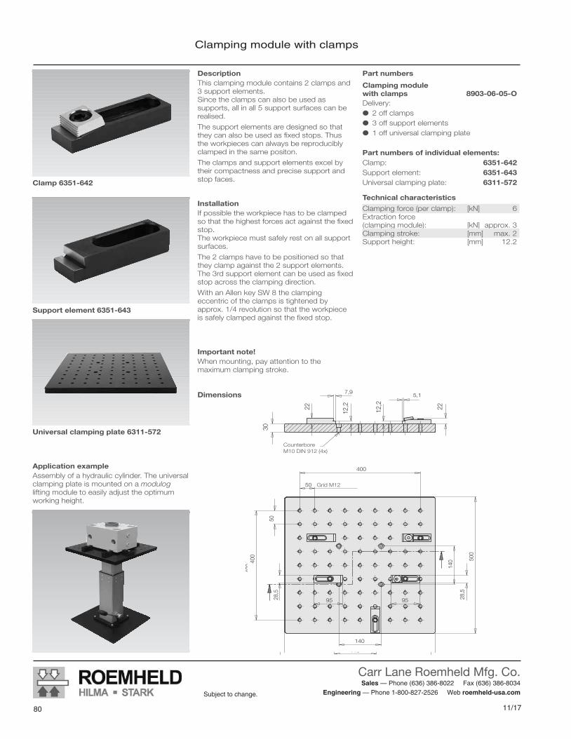
11/17
Carr Lane Roemheld Mfg. Co. Sales — Phone (636) 386-8022 Fax (636) 386-8034
Engineering — Phone 1-800-827-2526 Web roemheld-usa.comSubject to change.
808/16 79
Subject to change.
CARR LANE ROEMHELD MFG. CO.Sales — Phone (636) 386-8022 Fax (636) 386-8034
Engineering — Phone 1-800-827-2526 Web www.carrlaneroemheld.com
Clamping module with clamps
Subject to change without prior noticeM 8.300 / 9-08 E2
Clamping module with clamps
DescriptionThis clamping module contains 2 clamps and3 support elements. Since the clamps can also be used as supports, all in all 5 support surfaces can berealised.
The support elements are designed so thatthey can also be used as fixed stops. Thus the workpieces can always be reproduciblyclamped in the same positon.
The clamps and support elements excel bytheir compactness and precise support andstop faces.
InstallationIf possible the workpiece has to be clampedso that the highest forces act against the fixedstop. The workpiece must safely rest on all supportsurfaces.
The 2 clamps have to be positioned so thatthey clamp against the 2 support elements. The 3rd support element can be used as fixedstop across the clamping direction.
With an Allen key SW 8 the clamping eccentric of the clamps is tightened by approx. 1/4 revolution so that the workpiece is safely clamped against the fixed stop.
Clamping force (per clamp): [kN] 6Extraction force (clamping module): [kN] approx. 3 Clamping stroke: [mm] max. 2Support height: [mm] 12.2
Technical characteristics
400
50
500
500
400
50
7,95,1
22
140
140
12,2
12,222
30
28,5
28,5
9595
Dimensions
Important note!When mounting, pay attention to the maximum clamping stroke.
Application exampleAssembly of a hydraulic cylinder. The universalclamping plate is mounted on a moduloglifting module to easily adjust the optimumworking height.
Part numbers
Clamping module with clamps 8903-06-05-ODelivery: 2 off clamps 3 off support elements 1 off universal clamping plate
Part numbers of individual elements:Clamp: 6351-642Support element: 6351-643Universal clamping plate: 6311-572Clamp 6351-642
Support element 6351-643
Universal clamping plate 6311-572
Grid M12
Counterbore M10 DIN 912 (4x)

81
Carr Lane Roemheld Mfg. Co. Sales — Phone (636) 386-8022 Fax (636) 386-8034
Engineering — Phone 1-800-827-2526 Web roemheld-usa.comSubject to change.
11/1780 8/16
Subject to change.
CARR LANE ROEMHELD MFG. CO.Sales — Phone (636) 386-8022 Fax (636) 386-8034
Engineering — Phone 1-800-827-2526 Web www.carrlaneroemheld.com
Clamping module with swing clamps
Subject to change without prior noticeM 8.300 / 9-08 E3
Clamping module with swing clamps
DescriptionThis clamping module contains 4 swingclamps and 4 jack screws.The height of the clamping points of the swingclamps as well as the support height of thejack screws can be adjusted. This allows clamping of workpieces with support points in different heights. If the adjusting range is not sufficient, it can be enlarged by means of the accessory heightcylinder.
The clamping module with mechanical swingclamps excels by its flexibility and variety.
InstallationFirst the 4 jack screws are positioned to theappropriate height and then locked with anopen-end wrench SW36/SW30. The workpiece must safely rest on the supportsurfaces.
The 4 swing clamps have to be positioned sothat they clamp against the 4 jack screws. For clamping the clamping arms are manuallyswung above the clamping points. By operation of the clamping lever the clampingprocess is effected.
Technical characteristics
Dimensions
Part numbers
Clamping module with swing clamps 8902-10-08-MDelivery: 4 off swing clamps 4 off jack screws 1 off universal clamping plate
Part numbers individual elements:Swing clamp: 6351-640Jack screw: 6351-641Universal clamping plate: 6311-572
Important note!When mounting, pay attention to the maximum clamping stroke.
Accessory
Height cylinder 50 mmPart-number 6311-632
400
50
500
140
140
500
400
50
55 100
30
SW 36SW 36
Grid M12
68 +
30
mm
stro
ke
50 +
20
mm
stro
ke
134
(+ 3
0 m
m)
Max. clamping force (per swing clamp): [kN] 10 Extraction force (clamping module): [kN] > 10Clamping stroke: [mm] max. 1.5Basic height: [mm] 68 up to 98Support height: [mm] 50 up to 70
Swing clamp 6351-640
Jack screw 6351-641
Universal clamping plate 6311-572
50
M12
SW 36
M12
Counterbore M10 DIN 912 (4x)
SW 30

11/17
Carr Lane Roemheld Mfg. Co. Sales — Phone (636) 386-8022 Fax (636) 386-8034
Engineering — Phone 1-800-827-2526 Web roemheld-usa.comSubject to change.
828/16 81
Subject to change.
M 8.301Issue 9-08 E
Clamping modules - hydraulicHydraulic clamps with universal clamping plate and screw pump,max. clamping force 2.5 kN
modulogClamping modules- hydraulic
M 8.301Issue 9-08 E
Clamping modules - hydraulicHydraulic clamps with universal clamping plate and screw pump, max. clamping force 2.5 kN
Subject to change without prior notice
Römheld GmbH · Postfach 1253 · 35317 Laubach, Germany · Tel.: +49 (0) 6405 / 89-0 · Fax: +49 (0) 6405 / 89-211 Actual issue see www.roemheld.com
MountingThe clamping modules are screwed onto thegrid of the universal clamping plate withsocket head cap screws M12. The screwshave to be tightened with 80 Nm.
The screw pump is fixed with 2 socket headcap screws M8 at the bottom side of the universal clamping plate.
The universal clamping plate can be mountedwith 4 socket head cap screws M10 with flathead on other modulog modules.
Advantages Quicker and simpler clamping process
Uniform, reproducible clamping force byhydraulic clamping
Quick and easy retrofitting
Complete sets including universal clamping plate
Every point on the universal clamping plate is approachable with the clampingelements
Easy handling for retrofitting due to universal clamping plate made of aluminium
Easy fixing of the universal clamping plateon other modulog modules by the modulog interface
Clamping module with hydraulic clamps,universalclamping plate and screw pumpMax. clamping force: 2.5 kNMax. clamping stroke: 5 mmOperation with wrenchPart-no. 8903-02-04-H
Universal clamping platewith grid 50 mm – M12with modulog interface140 x 140 mm - counterbore for DIN 912 M10
Screw pumpMax. operating pressure: 500 barFunction: single actingOperation with wrench
ApplicationWith modulog clamping modules workpiecesfor manual assembly operations are easily andreliably positioned, fixed and clamped.Thus the fitter can exert forces on the workpiece without displacing it. The quality of the assembly process will beimproved.
DescriptionThe modulog clamping module consists of 2 clamping elements, which are connected byhydraulic hoses to a screw pump. For eachclamping element a corresponding fixed stopcan be positioned on the universal clampingplate.
The universal clamping plate is provided with a grid for mounting of the clamping elements.This allows flexible positioning of the clampingelements for clamping of very different workpieces.
Also the screw pump is fixed on the universalclamping plate.
The universal clamping plate is equipped with a 140 x140 modulog interface in the centre,so that it can be easily mounted on other modulog modules. Combined with moduloglifting or rotating modules the workpiece canbe moved to the ergonomically ideal height orrotating position.
The elements are also available as componentparts. The kit contains the complete system,filled with hydraulic oil and bleeded, withscrew pump kit and clamping elements.
Principal use Assembly of heavy components
Assembly of frequently changing components
Workshop applications
Clamping during test cycles
Machining of cylinder heads
Assembly of electric motors
MaterialClamping elements: high-tensile aluminium,
steel, partially hardenedUniversal clamping plate: high-tensile aluminiumScrew pump: steel
Important note!For dimensioning of the clamps it has to be distinguished if the forces act against a fixedstop or if clamping forces are used by friction.
Hydraulic circuit diagram
Fixed stop
Hydraulic clamp
Hydraulichose 0.75 m
Hydraulic hose 0.5 m
Screw pump
Clamping module with hydraulic clamps
CARR LANE ROEMHELD MFG. CO.Sales — Phone (636) 386-8022 Fax (636) 386-8034
Engineering — Phone 1-800-827-2526 Web www.carrlaneroemheld.com

83
Carr Lane Roemheld Mfg. Co. Sales — Phone (636) 386-8022 Fax (636) 386-8034
Engineering — Phone 1-800-827-2526 Web roemheld-usa.comSubject to change.
11/1782 8/16
Subject to change.
Clamping module with hydraulic clamps
Subject to change without prior noticeM 8.301 / 9-08 E2
Clamping module with hydraulic clamps
DescriptionThis clamping module contains 2 hydraulically-operated hydraulic clamps and 2 fixed stops.Both hydraulic clamps are clamped and unclamped with the screw pump.
The hydraulic clamps excel by their compactness and their simple operation.
Installation and operationIf possible the workpiece has to be clampedso that the highest forces act against the fixedstop. The workpiece must safely rest.
The screw pump is operated with as socket or a wrench SW 13 and thus the workpiece issafely clamped against the 2 fixed stops.
Function: single actingClamping force (per hydraulic clamp): [kN] 2.5 Clamping stroke: [mm] max. 5 Max. operating pressure: [bar] 500Hose nominal diameter: ND 4
Technical characteristicsImportant notes!When mounting, pay attention to the maximum clamping stroke.The maximum clamping force is obtained withmaximum operating pressure of the screwpump. The required torque at the screw pumpis 53 Nm. (see diagram)
Part numbers
Clamping module with hydraulic clamps 8903-02-04-HDelivery: 2 off hydraulic clamps 2 off fixed stops 1 off universal clamping plate 1 off screw pump kit including
2 hydraulic hoses with fittings
Part numbers individual elements:Hydraulic clamp: 6505-339Fixed stop: 6505-340Universal clamping plate: 6311-572Screw pump kit: 6505-341
Hydraulic clamp 6505-339
Fixed stop 6505-340
Universal clamping plate 6311-572
Screw pump of the kit 6505-341
400
50
500
140
140 50
0
400
5030
25 251414
50
94 78
44
73
Dimensions
Fixation screw pump with2 flat nuts
G 1/8 on the backside
Grid M12
2 x G 1/4 at the side
SW 1
3
Counterbore M10 DIN 912 (4x)
Fixed stop Hydraulic clamp
Screw pump
0 10 20 30 40 50 60
0,5
1,0
1,5
2,0
2,5
0
Cla
mpi
ng fo
rce
[kN
]
Torque [Nm]
Operating torques at the screw pump
Accessory
Height platePart-no. 6311-633
104016
7350
12,5
CARR LANE ROEMHELD MFG. CO.Sales — Phone (636) 386-8022 Fax (636) 386-8034
Engineering — Phone 1-800-827-2526 Web www.carrlaneroemheld.com

11/17
Carr Lane Roemheld Mfg. Co. Sales — Phone (636) 386-8022 Fax (636) 386-8034
Engineering — Phone 1-800-827-2526 Web roemheld-usa.comSubject to change.
848/16 83
Subject to change.
CARR LANE ROEMHELD MFG. CO.Sales — Phone (636) 386-8022 Fax (636) 386-8034
Engineering — Phone 1-800-827-2526 Web www.carrlaneroemheld.com
Quick-Change Mounting PlateWith zero point clamping system SPEEDY easy clickfor modulog interfaces
M8.302Issue 8-14 E
140 ±0,1
40 ±0,1
170 ±0,2
45 ±
0,1
Ø10
g6
18
Ø17
(4x)
11
Ø257,8 12
5,8
-0,2
16 ±
0,2
(13,
8)
5 x 45°
70 ±0,1
Ø10
,5 (4
x)
SPEEDY easy click
Accessory: Draw-in nipple Part no. 6200-776
Fixation at M12internal thread orby screw M10DIN 7991
Ø22
±0.
01 in
stal
latio
n di
men
sion
G1/
8 x
9 de
epPn
eum
atic
con
nect
ion
"Unc
lam
ping
"
10 ±0.2 milled to 9 +0.5 deep
9 ±0.1 milled to 4.5 +0.2 deep Exemplary base plate with Contour for snap lockas per DIN 6310Base plate (workpiece holder, provided by the customer)
Snap lock DIN 6310Snapper with spring is used as fall protection
Radial positioningLocation bolt and support bolt DIN 6321, 90° adjusted to draw-in nipple
Quick-changing mounting platewith SPEEDY easy click
Workpiece change
Workpiece engaged
ApplicationThe quick-change mounting plate can be mounted onto all modulog modules and devices with interface 140 x 140 mm.The built-in STARK zero point clamping sys-tem SPEEDY easy click allows a very fast workpiece change. A prerequisite is that the workpieces are mounted on base plates which are equipped with a draw-in nipple for the SPEEDY easy click.This system is particularly suitable, •when workpieces must be frequently changed very quickly at the assembly sta-tion. •when different workpieces or parts families are to be routed through one assembly sta-tion. •when workpieces are to be routed through several assembly stations. •when the workpiece with the required base plate is still manually tradable.
DescriptionThe quick-change mounting plate is designed as adaptor plate with connecting dimensions of the modulog interface 140 x 140.A STARK zero point clamping system SPEEDY easy click is installed in the centre.This is a fast-closing clamp plate that engages immediately and clamps without energy supply. For unclamping a pneumatic connec-tion is required. The required draw-in nipple is mounted on the base plate for the workpiece to be clamped. The radial positioning is made by a location bolt. A suitable drill bush is embedded in the base plate. In addition, there is a snapper installed to secure the workpiece against fall-ing out after the pneumatic unclamping of the zero point clamping element.
Advantages modulog interface Workpiece change in seconds by SPEEDY easy click Engages immediately without any energy supply! Immediate build up of the clamping force 5 kN Max. retention force 10 kN Pneumatics for unclamping available every-where Radial positioning by locating bolts Snapper as a safety against falling out in the changing position
Technical dataClamping force (traction) approx. [kN] 5
Retention force maxi. [kN] 10Force to engage approx. [N] 80Pneumatic unclamping pressure [bar] 3 – 8
Clamping time approx. [s] 0.1Unclamping time approx. [s] 0.1Admissible workpiece weight [kg] 100Admissible side load [kN] 2.5Admissible radial torque [Nm] 200Repeatability [mm] 0.01Weight, approx. [kg] 8.2AccessoriesDraw-in nipple (1 piece) 6200-776
Quick-Change Mounting Platewith zero point clamping system SPEEDY easy clickfor modulog interfaces
M 8.302Issue 8-14 E
Combinable with the modules • Lifting module Shop Floor as per data sheet M 4.301
•Rotating module with flow power as per data sheet M 1.202
modulog interface • 140 x 140 - M10
modulog Quick-change mounting plate for SPEEDY easy click
Part no. 890301P
Subject to modifications
Actual issue see www.roemheld.comRömheld GmbH · Postfach 1253 · 35317 Laubach, Germany · Tel.: +49 (0) 6405 / 89-0 · Fax: +49 (0) 6405 / 89-211
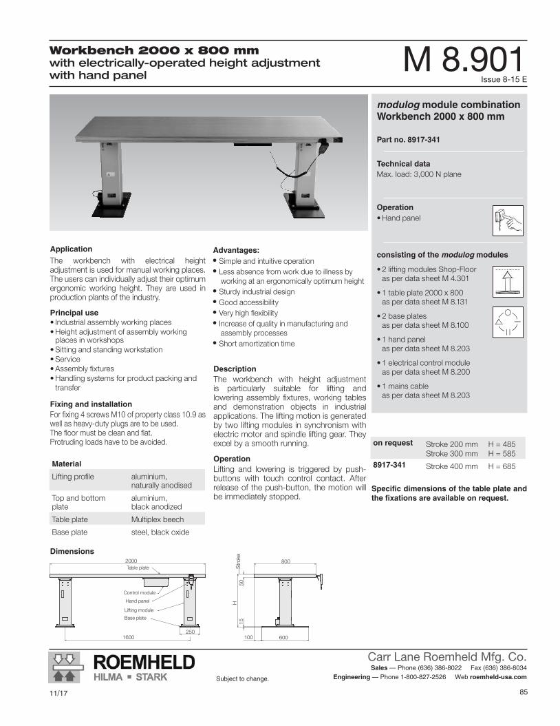
85
Carr Lane Roemheld Mfg. Co. Sales — Phone (636) 386-8022 Fax (636) 386-8034
Engineering — Phone 1-800-827-2526 Web roemheld-usa.comSubject to change.
11/1784 8/16
Subject to change.
M 8.901Issue 8-15 E
Workbench 2000 x 800 mmwith electrically-operated height adjustment with hand panel
CARR LANE ROEMHELD MFG. CO.Sales — Phone (636) 386-8022 Fax (636) 386-8034
Engineering — Phone 1-800-827-2526 Web www.carrlaneroemheld.com
modulog module combination Workbench 2000 x 800 mm
Part no. 8917-341
Technical data Max. load: 3,000 N plane
Operation•Hand panel
consisting of the modulog modules
•2 lifting modules Shop-Floor as per data sheet M 4.301
•1 table plate 2000 x 800 as per data sheet M 8.131
•2 base plates as per data sheet M 8.100
•1 hand panel as per data sheet M 8.203
•1 electrical control module as per data sheet M 8.200
•1 mains cable as per data sheet M 8.203
Application
The workbench with electrical height adjustment is used for manual working places. The users can individually adjust their optimum ergonomic working height. They are used in production plants of the industry.
Principal use•Industrial assembly working places•Height adjustment of assembly working
places in workshops•Sitting and standing workstation•Service•Assembly fixtures•Handling systems for product packing and
transfer
Fixing and installationForfixing4screwsM10ofpropertyclass10.9aswell as heavy-duty plugs are to be used. Thefloormustbecleanandflat.Protruding loads have to be avoided.
Material
Lifting profile aluminium, naturally anodised
Top and bottom plate
aluminium, black anodized
Table plate Multiplex beech
Base plate steel, black oxide
DescriptionThe workbench with height adjustment is particularly suitable for lifting and loweringassembly fixtures,working tablesand demonstration objects in industrial applications. The lifting motion is generated by two lifting modules in synchronism with electric motor and spindle lifting gear. They excel by a smooth running.
OperationLifting and lowering is triggered by push-buttons with touch control contact. After release of the push-button, the motion will be immediately stopped.
Dimensions
on request Stroke 200 mmStroke 300 mm
H = 485H = 585
8917-341 Stroke 400 mm H = 685
2000
2501600 100
800
1550
600
HH
ub
Table plate
Control module
Hand panel
Lifting module
Base plate
Stro
ke
Advantages:• Simple and intuitive operation• Less absence from work due to illness by
working at an ergonomically optimum height• Sturdy industrial design• Good accessibility• Very high flexibility• Increase of quality in manufacturing and
assembly processes• Short amortization time
Specific dimensions of the table plate and the fixations are available on request.

11/17
Carr Lane Roemheld Mfg. Co. Sales — Phone (636) 386-8022 Fax (636) 386-8034
Engineering — Phone 1-800-827-2526 Web roemheld-usa.comSubject to change.
86
• Ergonomic, space-saving and efficient handling of components• Low space requirement for easy integration into existing work/assembly
areas• Tilting (0-90°) and turning (360°) of products of any shape• Movement and positioning of the workpiece near its center of gravity
for mobility and security against tipping• Quiet electric drives (230 V) with very low power consumption• Holding brakes for maintaining a permanently stable work/assembly
position• Extremely clean operation – no leakage• Dramatically reduced times for working and assembly
Centrick Multi-Axis PositionerFor Heavy Load Assembly
Center of Gravity Is Nearly Stationery
Products up to 4,400 lbs can be tilted 90° and rotated 360°

87
Carr Lane Roemheld Mfg. Co. Sales — Phone (636) 386-8022 Fax (636) 386-8034
Engineering — Phone 1-800-827-2526 Web roemheld-usa.comSubject to change.
11/17
Centrick Rotating and Tilting ManipulatorElectrically operated tilting, rotating and lifting of workpiecesmax. loads 500 and 2000 kg
M9.201Issue 11-17 E
ApplicationCentrick manipulators are used for electrical-ly operated tilting, rotating and lifting of heavy workpieces or fixtures in the assembly. Workpieces or fixtures can be easily placed in the optimum position and working is facilitated.
Typical applications are assembly and welding works on: •motors • gears • vehicle cabs • chassis components of commercial and rail vehicles •pumps and compressors
VersionsTwo basic versions are available: A500 and A2000 for loads up to 500 kg or 2000 kg.The 90° tilting function is a standard feature, the rotating and lifting function can be option-ally selected.
Advantages Tilting (0…90°) and rotating (continuously) products of any shape around their centre of gravity! Ergonomic, space-saving and efficient handling of the component Low space requirement for integration in existing work/assembly areas Mobile and tilt resistant by movement and positioning of the workpiece near its centre of gravity Lowest drive performance of the low-noise electric drives (230V) Stable working/assembly positions by holding brakes Very clean operation – no leakages Drastic working / assembly time reduction Reduction of handling accidents resulting in costly downtimes Increased motivation of employees Integration in line and cycle assembly processes is possible (Industry 4.0)
DescriptionCentrick is an innovative manipulator for opti-mum positioning workpieces in up to 3 axis.
Tilting by 90°The patented tilting kinematics with virtual cen-tre of rotation is unique. The workpiece centre of gravity remains virtually unchanged in its po-sition during tiltingThus, tilting is balanced and can be effected with a small power rating in an energy-saving way.In addition, less work space is required and the stability is increased. Increased safety at work is the result.
Rotating by 360°The rotating function enables the continuous rotation of workpieces. Media supply through the rotating plate is available as an option.
LiftingThe version A500 has a compact scissors lifting adjustment with a stroke of 310 mm, the version A2000 is equipped with a stable column lifting adjustment with a stroke of 700 mm.
Tilting function
Centrick changes the workpiece side. The workpiece remains in unchanged position in space, but the assembly side is tilted by 90°.
• high stability • mobile application on rollers is possible • less space required • no compensation stroke required
Adaptation of the working heightAlso without lifting function, the basic variants can be delivered with customised basic height.
OperationThree electrical operating units are available to operate the Centrick: • two-hand enabling switch with cable • touch panel (automatic control) • remote control
VariantsCentrick manipulators are available in many variants as presented on the following pages.On request, customised adaptations can be carried out.
Centrick Rotating and Tilting ManipulatorElectrically operated tilting, rotating and lifting of workpieces max. loads 500 and 2000 kg
M 9.201Issue 11-17 E
Subject to modificationsActual issue see www.roemheld-group.com
Römheld GmbH · Postfach 1253 · 35317 Laubach, Germany · Tel.: +49 (0) 6405 / 89-0 · Fax: +49 (0) 6405 / 89-211 · [email protected]

11/17
Carr Lane Roemheld Mfg. Co. Sales — Phone (636) 386-8022 Fax (636) 386-8034
Engineering — Phone 1-800-827-2526 Web roemheld-usa.comSubject to change.
88
A500 A2000Max. working load [kg] 500 2000Rating - rotating and tilting [kW] 2 x 0.25 1.1 and 0.55Rating - lifting [kW] 1.5 2.2Supply voltage [VAC] 230 230Lifting speed [mm/s] 9.2 11.7Tilting angle [°] 0 – 90 0 – 90Tilting speed [°/s] approx. 10 approx. 3.5Rotation angle [°] 360 continuously 360 continuouslyRotation speed [r.p.m.] approx. 3 approx. 1.5Positioning accuracy * [°] ± 1 ± 1Empty weight (without lifting function) [kg] 350 750Empty weight (with lifting function) [kg] 400 on request
* only relevant for version with touch panel (code letter P)
650C A 0 X K - X X X - E X 0 X 0
Code for part number of version A A 500
Centrick
Height adapter (c) 0 = (standard)1 = 75 mm2 = 175 mm3 = 275 mm4 = 375 mm
Foot design F = base frame with adjustable feetH = base frame with adjustable feet,
with scissors lifting table, 300 mm strokeK = compact: version F rotated by 180°
(anchoring to the ground is always required)R = base frame on rollers Ø 80 mm (standard)V = base frame on rollers Ø 80 mm,
with scissors lifting table, 300 mm Hub
Supply voltage 0 = 230 V AC
Rotation axis D = 360° continuous rotation (standard)♦ = 360° continuous rotation,
with 10 mm hollow shaft♦ = without rotation axis, rigid cross beam
Operating elements B = cable remote control (standard)P = touch panel with setting and
automatic mode♦ = radio remote control
Safety equipment 0 = without working place related
safety equipment (standard)A = area scanner in the working area
and safety fence on 3 sides♦ = safety fence on 3 sides
Version A500
650C B 0 X K - X X X - E 0 0 X 0
Code for part number of version A A 2000
Centrick
Foot design F = base frame with adjustable feet (standard)♦ = base frame mounted on lift mast,
700 mm stroke♦ = base frame with air cushionR = base frame on rollers Ø 100 mm
Supply voltage 0 = 230 V AC♦ = 400 V / 3 P
Rotation axis M = 360° continuous rotation,
with 50 mm hollow shaft (standard)♦ = without rotation axis, rigid cross beam
Operating elements B = cable remote control (standard)♦ = touch panel with setting and
automatic mode
Safety equipment 0 = without (standard)A = area scanner in the working area
and safety fence on 3 sides♦ = safety fence on 3 sides
Version A2000
♦ = available on request
♦ = available on request
Technical dataCode for part numbers
Subject to modificationsM 9.201 / 11 -17 E
2 Actual issue see www.roemheld-group.com Römheld GmbH

89
Carr Lane Roemheld Mfg. Co. Sales — Phone (636) 386-8022 Fax (636) 386-8034
Engineering — Phone 1-800-827-2526 Web roemheld-usa.comSubject to change.
11/17
A500 A500H A500P A2000Exterior dimensions: (BxT) [mm] 1315x1210 1315x1210 1536x1536 1750x1500Tilting radius: (a) [mm] 217 217 217 303Height - core unit: (b) [mm] 438 438 438 417Height - height adapter: (c) [mm] 0-375 0-375 0-375 0Height - foot (base frame): (d) [mm] 121 121 121 121
Height - roller or adjustable foot: (e) [mm] roller 130; adjustable foot 50
roller 130; adjustable foot 50
roller 130; adjustable foot 50
roller 130; adjustable foot 50
Basic height - upper edge: Horizontal flange: (b – e) [mm] = (b – e) = (b – e) = (b – e) = (b – e)
Basic height - axle centre: vertically tilted rotation axis: (a – e) [mm] = (a – e) = (a – e) = (a – e) = (a – e)
Top viewSide viewFront view
217
1210
1315
(a)
559
+ c
Motion centre tilting axis
A500 with scissors lifting table: A500H
Stro
ke 3
10
121
438
130
217
559
+ c
1210
= T
1315 = B
(a)
(b)
(c)
(d)
(e)
A500
Motion centre tilting axis
A500 with automatic control: A500P
1600
1656
5082
6 +
c
217
c
1536
1400
1400
1536
(a)
(e)
Touch panelSafety fence
Motion centre tilting axis
5057
2
1500
1750
303
1680
(a)
(e)
A2000
Motion centre tilting axis
Dimensions
Subject to modificationsM 9.201 / 11 -17 E
Römheld GmbH Actual issue see www.roemheld-group.com 3

11/17
Carr Lane Roemheld Mfg. Co. Sales — Phone (636) 386-8022 Fax (636) 386-8034
Engineering — Phone 1-800-827-2526 Web roemheld-usa.comSubject to change.
90
Centrick A2000Maximum admissible eccentricity of the working load with reference to the rotation axisRotating
0
400
800
1200
1600
2000
0 200 400 600 800 1000 1200 1400 1600
Wor
king
load
[kg]
Eccentricity of the working load [mm]
Centrick A2000Admissible working load as a function of the distanceof the working load’s centre of gravity over the gear rimTilting
0
400
800
1200
1600
2000
0 200 400 600 800 1000 1200 1400Distance of the working load’s centre of gravity over the gear rim [mm]
Wor
king
load
[kg]
Centrick A500Admissible working load as a function of the heightof the working load’s centre of gravity over the connecting flangeTilting
0
100
200
300
400
500
0 100 200 300 400 500 600 700
Wor
king
load
[kg]
Height of the working load’s centre of gravity [mm]
Centrick A500Maximum admissible eccentricity of the working load with reference to the rotation axisRotating
0
100
200
300
400
500
0 100 200 300 400 500 600 700
Wor
king
load
[kg]
Eccentricity of the working load [mm]
Application examples
6767
M16
Ø 124
Ø 94,75
Ø 482
Ø 410
R227,5
M12
Flange A500 Flange A2000
DiagramsApplication examples
Subject to modificationsM 9.201 / 11 -17 E
4 Actual issue see www.roemheld-group.com Römheld GmbH
Centrick A2000Maximum admissible eccentricity of the working load with reference to the rotation axisRotating
0
400
800
1200
1600
2000
0 200 400 600 800 1000 1200 1400 1600
Wor
king
load
[kg]
Eccentricity of the working load [mm]
Centrick A2000Admissible working load as a function of the distanceof the working load’s centre of gravity over the gear rimTilting
0
400
800
1200
1600
2000
0 200 400 600 800 1000 1200 1400Distance of the working load’s centre of gravity over the gear rim [mm]
Wor
king
load
[kg]
Centrick A500Admissible working load as a function of the heightof the working load’s centre of gravity over the connecting flangeTilting
0
100
200
300
400
500
0 100 200 300 400 500 600 700
Wor
king
load
[kg]
Height of the working load’s centre of gravity [mm]
Centrick A500Maximum admissible eccentricity of the working load with reference to the rotation axisRotating
0
100
200
300
400
500
0 100 200 300 400 500 600 700
Wor
king
load
[kg]
Eccentricity of the working load [mm]
Application examples
67
67
M16
Ø 124
Ø 94,75
Ø 482
Ø 410
R227,5
M12
Flange A500 Flange A2000
DiagramsApplication examples
Subject to modificationsM 9.201 / 11 -17 E
4 Actual issue see www.roemheld-group.com Römheld GmbH
Centrick A2000Maximum admissible eccentricity of the working load with reference to the rotation axisRotating
0
400
800
1200
1600
2000
0 200 400 600 800 1000 1200 1400 1600
Wor
king
load
[kg]
Eccentricity of the working load [mm]
Centrick A2000Admissible working load as a function of the distanceof the working load’s centre of gravity over the gear rimTilting
0
400
800
1200
1600
2000
0 200 400 600 800 1000 1200 1400Distance of the working load’s centre of gravity over the gear rim [mm]
Wor
king
load
[kg]
Centrick A500Admissible working load as a function of the heightof the working load’s centre of gravity over the connecting flangeTilting
0
100
200
300
400
500
0 100 200 300 400 500 600 700
Wor
king
load
[kg]
Height of the working load’s centre of gravity [mm]
Centrick A500Maximum admissible eccentricity of the working load with reference to the rotation axisRotating
0
100
200
300
400
500
0 100 200 300 400 500 600 700
Wor
king
load
[kg]
Eccentricity of the working load [mm]
Application examples
67
67
M16
Ø 124
Ø 94,75
Ø 482
Ø 410
R227,5
M12
Flange A500 Flange A2000
DiagramsApplication examples
Subject to modificationsM 9.201 / 11 -17 E
4 Actual issue see www.roemheld-group.com Römheld GmbH

91
Carr Lane Roemheld Mfg. Co. Sales — Phone (636) 386-8022 Fax (636) 386-8034
Engineering — Phone 1-800-827-2526 Web roemheld-usa.comSubject to change.
11/17
Challenge: Thermo Fisher Scientific, a global market leader in laboratory technology, designed new incubators for medical engineering and health research, to cultivate human and animal cells. Target customers were universities, research labs and others in the industry. Preassembly of the incubators required a lot of handling and was physically very demanding, requiring numerous rotations.
Solution: The company used Modular Units for Assembly from Carr Lane Roemheld, which can be combined to lift, tilt, rotate or move, with horizontal and vertical rotation, to increase productivity and reduce operator fatigue.
Ergonomically designed production line
Thermo Fisher Scientific developed an ergonomic production line for the manual assembly of a new series of incubators. Health-conscious workstation design was a top priority, in addition to process and product quality.
The new “Heracell Vios” incubators are for medical engineering and health research, where they are used for cultivating human and animal cells. Target customers are universities, research labs and the medical industry.
Thermo Fisher’s world headquarters are near Boston, MA, but variations of the incubators were being assembled in the company’s plant near Frankfurt, Germany. Apart from two sizes with 42 and 63 gallons of useful space, variations included bactericidal and fungicidal models of copper, incubators with a stainless steel inner, and for different gases and varying sensor technology.
Thermo Fisher’s new incubator is the successor of the model “Heracell” of which 75,000 units were sold in 15 years. The new series, launched in September 2014, is distinct in its optimized control behavior, improved protection against contamination and facilitated operation.
Assembly workstations: from prototype to production line
Thermo Fisher Scientific worked with ROEMHELD experts for the new workstations. Headquartered in Laubach, Germany, ROEMHELD (represented in North America by Carr Lane Roemheld of Fenton, Missouri), has provided assembly and handling of laboratory equipment to Thermo Fisher since 2009.
Carr Lane Roemheld’s modular units for assembly and handling consist of numerous modules that provide for the optimum and ergonomic positioning of objects for manual assembly. Horizontal and vertical rotation, tilting, lifting, placement and movement are the basic manipulations. The units can be combined into a modular system with application flexibility and variably combinable components for loads from 22 to 1325 lbs. Operation can be either manually on the module directly, or electrically via levers or buttons.
The latest development is a rotary module with media feed-ducts. Among other advantages, these allow for the hydraulic, electrical or pneumatic operation of devices clamped by zero-point clamping systems without complex boring.
The focus is on ergonomics
Technical Head Felix Pergande is very satisfied. “ROEMHELD intensely and dedicatedly responds to our individual requirements. In addition, their products are very reliable and can be configured according to our requirements - we do not have to buy anything ready-made.”
Ergonomics were the top priority for the new manual
Modular Units Maximize Ergonomics,Efficiency in Manual Workstations
“An ergonomic workstation like this is invaluable. It is good for the back, neck, and shoulders and is a noticeable relief.
The body feels it immediately.”
The rotary module has indices which may be
released in steps of 45° by two foot switches.
Carr Lane Roemheld In the News...
(continued on next page)

11/17
Carr Lane Roemheld Mfg. Co. Sales — Phone (636) 386-8022 Fax (636) 386-8034
Engineering — Phone 1-800-827-2526 Web roemheld-usa.comSubject to change.
92
assembly workstation. The earlier incubator series had been assembled on height-adjustable tables, but later units weighing around 40 lbs. had to be moved manually without any auxiliary equipment. “For this reason, preassembly of the inner containers required a lot of handling and was physically more demanding,” says Production Resources Engineer Stefan Kämmerer.
Open to the front, the inside casing is approx. 28 in. high and 18 in. wide for the 42 gallon incubator type, and is manufactured in Thermo Fisher’s own sheet workshop. In one to two shifts as required, 8 of the plant’s 150 employees cover all 5 sides with heater foils, requiring the container to be rotated several times. Apart from this, a sensor and a fixture have to be mounted. The entire process takes about 45 minutes before insulation is attached and the outside
casing is assembled over it.
Assembly line with four manual workstations
ROEMHELD designed a line of four assembly workstations, comprised of an electronic Shop-Floor lift module with a stroke of 8 in., which can be lifted and lowered by a pushbutton, and a rotary module. This rotary module is provided with indices which may be released manually in steps of 45°; for this purpose, the fitter can use two foot
switches without having to walk around the container. “For efficiency, the fitters had the idea of a second foot switch; this suggestion could rapidly be implemented by ROEMHELD,” Kämmerer recalled. After the design completion of the assembly workstations, he ordered and assembled the ROEMHELD components.
All parties were satisfied with the workstation design. Pergande emphasizes the excellent ergonomics, and sees an evident improvement in product quality: “The clear position fixation and the defined handling by means of the 45° indices noticeably reduced the risk of dents in the container.” According to Pergande, time savings and cost reduction are not high priorities in this design, though both are achieved. He emphasizes that the ergonomic design of the workstations contributes to protecting the employees’
health and that “the absence of an employee costs money, because either we cannot produce or we have to assign a replacement.” As a consequence, less rejects and healthier employees contribute to cost savings and enhance Thermo Fisher’s success as a market leader.
The company is now designing other manual workstations using the modular units. Equipment fitter Steffen Hillesheim remarked, “An ergonomic workstation with useful features like this is invaluable. It is good for the back, neck, and shoulders and is a noticeable relief. The body feels it immediately.” The standard interface conception of the modular units allows for the flexible and uncomplicated planning of future workstations, and Hillesheim said it has also helped assembly workstations in complying with the latest occupational health and safety regulations.
ROEMHELD, represented in North America by Carr Lane Roemheld of Fenton, Missouri, is one of the world’s market and quality leaders for solutions in industrial production, assembly, clamping and drive technology.
In addition to assembly components, the company also offers a host of power workholding devices, machine vises, and zero point mounting systems for CNC machining, as well as die, mold and tool clamping systems for presses, die casting, injection molding and compression molding machines.
To protect the work surfaces, a clamping device with
brushes on bearing surfaces holds inner containers.
Electronic modules have push-button lift, and rotary
modules are operated by two foot switches.
An employee covers five sides with heater foils, so
the container has to be rotated several times.
(continued from previous page)

Carr Lane Roemheld Mfg. Co.
OUR STORYIn 1982 an independent joint venture was established to marry the proven product expertise of Roemheld with the marketing know-how and distribution network of Carr Lane Manufacturing. This partnership now offers to the American manufacturer the complete benefits of the finest in international assembly and handling, as well as power workholding, combined with the best in local service and support.
After initial tests by many companies, both small and large, the word had spread confirming the quality and reliability obtained when using Roemheld products.
We invite you to review this catalog in depth and to call us with any questions about your applications. We at Carr Lane Roemheld welcome the opportunity to help you manufacture your quality product in the most productive way possible — with the world’s most dependable assembly and handling equipment.
Founded in 1952 in St. Louis, Missouri by Earl E. Walker to make standardized tooling components, Carr Lane Manufacturing has grown, through constant innovation, to become the foremost supplier to the American Machine Tool Industry. Now the most complete line available, Carr Lane Manufacturing offers Jig and Fixture Components, Toggle Clamps, Hoist Rings, Alignment Pins, Drill Bushings, Spring Plungers, and Modular Fixturing. Setting the standard for American Tool Engineers, Carr Lane Manufacturing’s catalog is recognized as the manufacturing engineer’s tooling reference.
Drawing upon a centuries-old tradition of German craftsmanship, metalworking was already well established in Laubach, Germany when the Romheld family began to manage operations in 1870. Development of the hydraulic workholding components began in the early 1960’s and soon grew to dominate the European market.
Today, Roemheld GmbH is by far the world leader in this productivity-enhancing technology, offering a tremendous range of types and sizes of superior design and the highest quality.
WE CAN HANDLE YOUR
ASSEMBLY!
View assembly products at: www.roemheld-usa.com
Fenton, MO 63026(636) 386-8022
Increase Productivity In Your Assembly Area!
OUR STORY WE CAN PRECISION MACHINE VISES INCREASE PRODUCTIVITY
• Reduce set up time by as much as 90% with zero point mounting
• Existing fixtures can be easily adapted
• Highly accurate positioning and repeatability
• Increased productivity
Zero Point Mounting System for Quick Change Fixturing
REDUCE SET-UP AND DOWNTIME!
View Zero Point Mounting at:
www.roemheld-usa.com
• Fast payback• Set-up times slashed• Fixture life extended
Zero Point Mounting
REDUCE SET-UP AND DOWNTIME!
This comprehensive system utilizes clamping components and insertion nipples, which provide an immediate zero point orientation.
Use in Conjunction with the Zero Point Mounting System for Faster, More Accurate Fixture Set Ups
Fenton, MO 63026(636) 386-8022
Your Assembly Area!
Linear ActuatorsControl, adjust and move with your choice of electric or hydraulic linear actuators.
Centrick Workpiece PositionerFor Heavy Loads
Assembles products up to 4,400 lbs,tilts up to 90° and rotates 360°.
Centrick is quiet, requires just 230 V and little space.
Modular UnitsCombine units for
safe, efficient handling. Achieve rotating, tilting
and lifting of workpieces, and use with carts, floor modules, plates, clamps,
or adjustable tables.

Linear Actuators Modular Units for Assembly & Handling Assembly Tables
CARR
LANE
ROEMHELD
MFG
CO
ASSY
12
2017
Drive, Assembly and Handling Products
Authorized Distributor:
Carr Lane Roemheld Mfg. Co.927 Horan Drive Fenton, MO 63026
Phone (636) 386-8022 Fax (636) 386-8034Free Engineering Support 1-800-827-2526
www.roemheld-usa.com
Connect with us: COPYRIGHT © 2017 CARR LANE ROEMHELD MANUFACTURING CO. PRINTED IN U.S.A. ASSY-1217