Study on Industrial Engineering in Woven Garments Production
ORIGINAL ARTICLE
Drilling of woven glass fiber-reinforced
plastic—an experimental and finite element study
Nilanjan Das Chakladar & Surjya K. Pal &
Parthasarathi Mandal
Received: 28 July 2010 /Accepted: 9 May 2011# Springer-Verlag London Limited 2011
Abstract Drilling in woven fiber-reinforced plastics is a
well-known practice in modern-day manufacturing. The
high fracture toughness of woven fiber-based composites
over unidirectional counterparts is increasing demand in
aviation and electronics industries. Hence, failure of
these materials at harsh environments is a matter of
concern. Very few numerical studies on drilling of these
composites have been carried out; hence, the present
scope may be considered as a trial de novo. Delamina-
tion was studied in the present work at different feed–
speed combinations. Drilling responses were estimated
using finite element as a numerical simulation tool. An
equivalent elastic macromechanical model was assumed
for the woven composite workpiece. A 3D drill bit was
modeled using commercial CAD package Pro-Engineer
and Ansys Autodyn was used as the solver environment.
The simulation and validation experiments were carried
out at planned feed–speed combinations. The effect of
process parameters on exit and entry delamination is also
documented. The thrust determined by finite element
techniques showed good prediction with the experimental
results.
Keywords Glass fiber-reinforced polymer (GFRP) .
Drilling . Delamination
Nomenclature
h Helix angle (degree)
l Pitch of helix (millimeter)
lmin Minimum characteristic dimension of an element
(millimeter)
p Half-point angle (degree)
r Instantaneous radius (millimeter)
Δt Time step (second)
C Tensor modulus (megapascals)
D Drill diameter (millimeter)
Dexit del Maximum exit delaminated diameter (millimeter)
Dhole Hole diameter (millimeter)
E Modulus of elasticity (gigapascals)
E11 Elastic modulus along 11 (longitudinal) direction
(gigapascals)
E22 Elastic modulus along 22 (transverse) direction
(gigapascals)
E33 Elastic modulus along 33 (thickness) direction
(gigapascals)
G12 Shear modulus along 12 plane (gigapascals)
G23 Shear modulus along 23 plane (gigapascals)
G13 Shear modulus along 13 plane (gigapascals)
R Drill radius (millimeter)
W Web thickness (millimeter) " Strain rate (millimeter/millimeter/second)
ν12 Poisson’s ratio along 12 (−)
ν31 Poisson’s ratio along 31 (−)
ν23 Poisson’s ratio along 23 (−)
ρ Density (kilogram per cubic meter)
[σ]n Calculated stress at nth cycle (megapascals)
1 Introduction
Machining composites is a prime concern in modern-day
manufacturing due to non-homogeneity/anisotropy inmaterial
N. D. Chakladar : S. K. Pal (*)
Department of Mechanical Engineering,
Indian Institute of Technology,
Kharagpur 721 302, India
e-mail: [email protected]
P. Mandal
School of Mechanical, Aerospace and Civil Engineering,
The University of Manchester,
Manchester, UK
Int J Adv Manuf Technol
DOI 10.1007/s00170-011-3386-3

properties. Making holes in fiber-reinforced plastic (FRP) are
one of the important applications—hence, drilling of FRP is
quite significant. From bolting assemblies in aviation indus-
tries to printed wiring boards in electronics, FRPs are used for
high-specific strength and fracture toughness. Typically
uncoated high-speed steel drill bits are used for conventional
drilling of FRP, while cemented carbide drill bits are used for
high-speed drilling. The FRPs are often used to reinforce steel
structures by bolting arrangement. But to assemble these bolts,
both steel and FRP structures are to be drilled, where during
drilling due to material characteristics of FRP the drill bit
rapidly wears which is a preliminary cause for FRP
delamination. Drilling is itself a highly complicated dynamic
process involving complex geometrical interactions, elasto-
plastic failures, and friction. The same drill exhibits extrusion
at the chisel edge and cutting action at the cutting lips leading
to oblique cutting (due to change of rake and inclination
angle) at the cutting lips and orthogonal cutting at the chisel
edge. Hence, the basic requirement is to find out number of
holes to be drilled with a fresh drill bit on FRPs and propose an
optimum design and manufacturing of the drill bit. To design
such a drill bit, prediction of wear and estimation of drilling
response like thrust are indispensable.
FRP had its vital applications during post World War II
in boat hulls, minesweeping vessels, bath tubs and covers,
pressure vessels, submarine parts, aircraft components, etc.
Since 1990, the thrust and cutting forces in drilling of
unidirectional FRP composites are modeled and validated
keeping in mind the basic idea of evaluating force through
circular plate bending theories [1, 2]. The properties of
woven composites make them more challenging for
numerical modeling, compared to its unidirectional coun-
terpart for same number of plies, material, and binding
matrix. Meanwhile in 1996, the variation of thrust and
torque with change in fiber angle for unidirectional
composites was reported after taking video images through
high-speed cameras at the onset of delamination [3]. In
2004, conventional drilling on composites was compared
with oscillatory drilling and delayed tool wear was inferred
with the oscillatory technique [4]. The extent of delamina-
tion in unidirectional carbon fiber based composite was
analyzed using different types of drill—twist drill, saw drill,
and candle stick drill where delamination due to candle
stick drill was concluded to be minimum [5]. In recent
years, effects of high speed in drilling of glass fiber-
reinforced polymer (GFRP) were also studied and a model
for adjusted delamination factor was introduced that
considered a dimensionless factor compensating the total
extent of delamination along the periphery [6].
A finite element analysis was carried out in 1992 to
predict the load causing delamination in a quasi-isotropic
graphite epoxy laminate with or without backing [7]. For
angle ply laminates, a thrust force model was proposed
along depth of the drilled hole in 1994 [8]. A quasi-3D
orthotropic model was developed for estimation of element
stiffness matrix and push-out delamination in the model
was showed by the deletion of beam elements [9]. Later,
six-node hexahedral element was considered to trace
effective pattern of delamination than predicted by 20-
node shell element [10]. However, the interlayer fracture
toughness which was unknown till 2001 was finally
analyzed by considering a double-beam cantilever structure
for the composite plate to come up with interlayer
separation [11]. Thus, the free-edge delamination of every
laminate was investigated through evaluating the interlaminar
tensile and compressive stresses [12].
The need for improved tool geometry for minimum
delamination and hence minimum wear has led the present
authors to begin this novel investigation of the machining
responses while drilling woven composites using finite
element techniques. But drilling being a very complicated
machining process, it is difficult to address its geometry by
an equivalent 2D plane strain model unlike orthogonal
turning. Hence, near-precise modeling of drill bit is taken
into consideration. We have tried to consider finite
element modeling parameters realistic with the experi-
mental setup and loading and boundary conditions for
good prediction. The present scope is restricted to
drilling thrust as the machining response as push-out/
exit delamination is primarily responsible for catastrophic
failure of these composites.
2 Experimental investigation
To observe the effect of process parameters on drilling thrust
and torque and delamination, experimental studies were
undertaken. A piezoelectric drill dynamometer (Kistler,
9272A), charge amplifier (Kistler, 5070A), and data acquisi-
tion card (NI, 6210) were used to capture and save signals
using LabVIEW 7.1. The GFRP plate (100×50×9 mm) was
not directly placed over the dynamometer but in between two
mild steel (MS) plates with a central hole of 20-mm diameter.
The MS plates were bolted together to ensure no relative
movement as shown in Fig. 1.
Experiments were performed in Agni BMV 45 T20 CNC
Machining Centre with simple computer numerical control
codes suffice to carry out drilling at different speed–feed
combinations. Finally, a MATLAB program [13] was
written to find out the average drilling thrust force during
the steady cutting period. This program took care of zero
offset in the following way. The user selected two points in
the fluctuating base voltage before the rise of signal and
similar two points after the voltage drops, i.e., after hole
machining, from which the average base voltage line was
computed. Further, two extreme points were selected in the
Int J Adv Manuf Technol

steady zone and mean is evaluated of all signals lying
between them. But this was not the true mean value for
response; hence, it was compensated with zero offset
depending whether the average baseline was above zero
or below and finally this compensated average during
steady cutting period multiplied with appropriate conver-
sion factor (change in voltage to change in force (N))
gave corresponding drilling responses. The experimental
studies were performed using two different types of drill
bit—high-speed steel (HSS) and carbide as shown in
Fig. 2. The specifications of HSS and carbide are listed in
Table 1.
The workpiece used is GFRP with woven E-glass
thermosetting epoxy laminate structure. The fiber strands
in every layer of GFRP were distributed in two sets—one
interweaving orthogonal to the other. The specifications of
workpiece are listed (obtained from manufacturer’s catalog,
Sunrisefrp, Pune) in Table 2. The feed speed combinations
are shown in Table 3.
The experimental setup has been depicted in the form of
block diagram in Fig. 3 to identify the signal capturing and
processing technique.
3 Geometric modeling of 3D drill bit
The accurate estimation of thrust force largely depends on
precise modeling of drill bit and the work material. The
geometry of chisel edge is the prime concern so far as thrust
force is considered yet the fiber and matrix modeling need
equal care.
Y-axis Common perpendicular intersecting the
extensions of cutting edges (see Fig. 4)
Z-axis Parallel to the longitudinal axis of the drill
X-axis Orthogonal to Y- and Z- axes
One quarter of the flute shape was formulated in the
following polar equation [14] –
y ¼ sin"1 W
2rþ
ffiffiffiffiffiffiffiffiffiffiffiffiffiffiffiffiffiffiffi
r2 " ðW2
Þ2q
Rtan h cot p ð1Þ
Equation 1 was used as the parametric polar equation in
Pro-Engineer [15], where r was varied from W/2 to R (half
of diameter of the drill). Thus, one quarter of the flute shape
was produced in first quadrant of XY plane. The generated
area was then mirrored about X and Y axis to develop the
2D surface in XY plane. The helix equation was paramet-
rically written as follows:
r ¼ R
q ¼ "360tn
z ¼ "ltn;
ð2Þ
where n=number of turns in the helix, l=pitch of the helix,
t=0–1.
Fig. 1 a Work holding fixture
and b dynamometer
Fig. 2 a HSS and b carbide
drill bits
Int J Adv Manuf Technol

Further, this flute profile was cut helically from the full-
extruded part of the drill along the following curve
Z f lute ¼ tan h
r& Z ð3Þ
h ¼ tan"1 2pr
lð4Þ
where, Zflute stands for longitudinal polar coordinate of
helical flute.
Once the flute profile was finished, the flank shape was
estimated through flank grinding assuming the grinding
wheel was rotated about a fixed axis to form a “grinding
cone” of cone angle α. To generate two flank surfaces, the
grinding was performed twice from two symmetric
positions to determine the right and left cones [16].
Flank surfaces are assumed to be the parts of the frustum
of grinding cones. The three flank-grinding parameters
were f, d, and s, where f was the rotation of coordinate
system of the grinding cone such that the outer profile of
the cone smoothly could meet the desired flank surface, d
was the vertical distance from the chisel edge to the origin
of newly rotated coordinate system, and finally the vertex
was shifted to the right by a distance s in the Y-axis to
generate right flank surface as listed in Table 4. The
different steps for modeling of drill bit in Pro-Engineer are
shown in Fig. 4.
Similarly, it was the case with other flank surface with Z
coordinate of the cone remaining same and interchanging
the sign of X and Y coordinates. The schematic of drill
modeling has been shown through the basics of drill
grinding in Fig. 5.
After the virtual cone was generated, the profile was
“revolved cut” from the earlier swept profile to obtain one
flank surface. Since the margin was not considered in the
present study, the final drill bit was modeled after two
revolve cuts.
4 Geometric modeling of workpiece
In this research, delamination or chip formation was not
taken into account; hence, an elastic macromechanical
model for a woven composite was developed. The
thickness of the workpiece model is kept at 2 mm such
that at least one revolution of drill could be traced because
maximum feed considered is 1.0 mm/rev. The outer
dimensions of the geometric model are assumed to be a
square domain of 20×20 mm keeping in mind the boundary
conditions for experimental setup. Preliminary simulation
studies with cylindrical domain revealed severe distor-
tions on the boundaries for a circular model of workpiece
due to the interference of stress waves leading to
nonconvergence of the solution. These wave modes from
FE analysis affected the stability of workpiece geometry.
Hence for simplicity and avoiding such discrepancies, the
workpiece in this work has been simplified with a
rectangular block.
5 Finite element modeling
The finite element modeling is a well-established method
for analyzing static or dynamic, linear or nonlinear
responses on bodies subjected to varying loads. Solving
problems that involve complex geometries, loading, bound-
ary conditions, and complex contacts has made finite
element an acceptable numerical simulation technique in
Table 1 Specifications of HSS and carbide drill bit
Specifications High-speed steel Carbide
Density (kg/m3) 7,860 11,560
Drill diameter (mm) 5 5
Helix angle (°) 30 30
Point angle (°) 118 130
Chisel edge radius (mm) 0.65 0.7
Chisel edge angle (°) 135 135
Lip relief angle (°) 12 12
Table 2 Specifications of GFRP workpiece
Specifications GFRP
Specific gravity 1.68
Water absorption (% by weight) 0.07–0.08
Glass content (% by weight) 65–75
Fiber orientation 0°/90°
Table 3 Feed-speed combinations for experimental and simulation
studies. For each type of drill bit there are eight feed–speed
combinations
Feed
(mm/rev)
Speed
(m/min)
Type of drill bit
0.25
0.50 45 High speed steel (ISO 235/1, AISI T4)
0.75 65 Carbide (ISO B978A03000, KC 7315)
1.00
Int J Adv Manuf Technol

this field. Machining is such a complex analysis domain. To
simplify the finite element analysis and save computation
time, some important assumptions are considered, which
may not fully simulate the realistic situation but suffice to
judge the drilling phenomenon. The assumptions are stated
below:
(a) The tool was considered as rigid.
Fig. 3 Experimental block
diagram
Fig. 4 Steps for modeling drill bit. a Flute cross-section, b helix profile of drill bit, c Boolean subtraction of helical flute, d axis of revolution and face
of grinding cone, and e close-up view of chisel edge
Int J Adv Manuf Technol
(b) In experimental setup, mild steel plates were kept at
the top and bottom of the work plate with a
centrally located hole of diameter 20 mm. Since it
can be ensured that no large deformation would take
place at the periphery of this hole while drilling a
hole of 5 mm, hence, for finite element study, a 20-
mm square plate was considered with all the four
outer boundary planes constrained in all directions
including rotations.
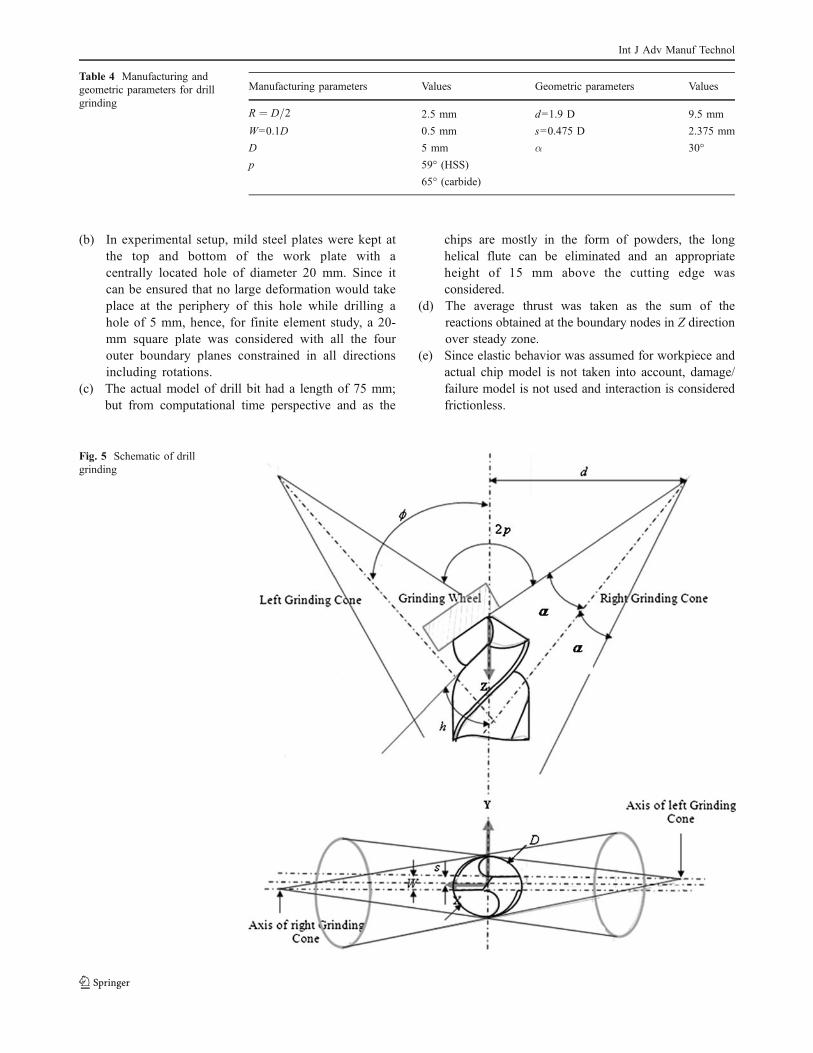
(c) The actual model of drill bit had a length of 75 mm;
but from computational time perspective and as the
chips are mostly in the form of powders, the long
helical flute can be eliminated and an appropriate
height of 15 mm above the cutting edge was
considered.
(d) The average thrust was taken as the sum of the
reactions obtained at the boundary nodes in Z direction
over steady zone.
(e) Since elastic behavior was assumed for workpiece and
actual chip model is not taken into account, damage/
failure model is not used and interaction is considered
frictionless.
Fig. 5 Schematic of drill
grinding
Manufacturing parameters Values Geometric parameters Values
R ¼ D=2 2.5 mm d=1.9 D 9.5 mm
W=0.1D 0.5 mm s=0.475 D 2.375 mm
D 5 mm α 30°
p 59° (HSS)
65° (carbide)
Table 4 Manufacturing and
geometric parameters for drill
grinding
Int J Adv Manuf Technol

5.1 Meshing of drill bit and work
The tool geometry was exported from computer-aided
design package in Initial Graphics Exchange Specification
format to Ansys Workbench v12.0.1 for meshing. The tool
was meshed with four-node linear tetrahedral rigid
elements of average element size 0.4 mm. A mesh
refinement was done only at the chisel edge to accurately
identify the displacement field at the edge of contact with
a refinement ratio (coarse/fine, 1.0:0.5). Total number of
elements used to mesh the tool is 8,376. The work was
meshed with 27,530 ten-noded (four corner nodes and six
mid-side nodes) tetrahedral elements of average dimension
0.2 mm.
5.2 Material constitutive model
The material model used for workpiece was orthotropic
elastic. The data used for orthotropic model follows in
Table 5 [17]:
A macromechanical approach was used to predict thrust
during drilling the composite material. The anisotropic
material was represented by an equivalent homogenous
model for the present study. This can be justified as chip
formation is not modeled.
As epoxy resin matrix is of thermosetting type, it shows
mostly glassy phase in the machining domain hence the
material deformation can well be considered within elastic
regime. So the material model has been chosen orthotropic
and elastic for the workpiece.
Summerscales rule of equivalence was used to find
equivalent bulk modulus for an orthotropic material [18]
required to compute incremental time step for the finite
element analysis.
Keq ¼3
ffiffiffiffiffiffiffiffiffiffiffiffiffiffiffiffiffiffiffiffiffiffiffi
E11:E22:E33p
3ð1 " 2:3ffiffiffiffiffiffiffiffiffiffiffiffiffiffiffiffiffiffiffiffiffi
n12:n31:n23p Þ ¼ 10:387GPa ð5Þ
Equation 5 reduces to traditional isotropic form when
E11=E22=E33 and ν12=ν31=ν23.
Constitutive equation for incremental stress update
scheme shown in Eq. 6 [19]:
½s)nþ1 ¼ ½s)n þ ½C)½ ")$t ð6Þ
S ¼ C"1 ¼
1
E11
"n12
E11
"n31
E330 0 0
"n12
E11
1
E22
"n23
E220 0 0
"n31
E33
"n23
E22
1
E330 0 0
0 0 01
2G12
0 0
0 0 0 01
2G23
0
0 0 0 0 01
2G31
2
6
6
6
6
6
6
6
6
6
6
6
6
6
6
6
6
6
6
6
4
3
7
7
7
7
7
7
7
7
7
7
7
7
7
7
7
7
7
7
7
5
ð7Þ
5.3 Solver methodology
The present research work incorporated a new explicit
remeshing scheme to control hourglassing while using
reduced integration mid-side-noded elements which is
commercially available in FE package Ansys Autodyn
12.0.1. Traditionally, the literature has documented use of
Arbitrary Lagrangian Eulerian solver for machining or large
strain rate (large deformation) problems to control high
mesh distortion. But it is seen that such solvers take high
computational time and effort. Moreover, such algorithms
involve lot of other parameters like remesh sweep, number
of iterations per increment, advection parameters, and so
on. As a result, proper choice of these factors is equally
important. The solver technique utilized in present study
was average nodal pressure (ANP) technique. The method-
ology incorporated in this strategy was as follows.
For a standard four-noded tetrahedron, initial geometry
of element (e) was interpolated using isoparametric coor-
dinates (ξ1, ξ2, ξ3) as
X ðeÞ ¼X
4
a¼1
Naðx1; x2; x3ÞXa ð8Þ
where Na denotes the shape function for local node a which
varies from 1 to 4 [20]. Later, a 10-noded quadratic
tetrahedron was considered to incorporate the remeshing
technique as shown in Fig. 6a.
The solver also took care of lumped mass matrix
typically employed in explicit dynamic applications. Here,
the governing equations at any instant of time was
represented by nodal equilibrium equation for a given
mesh node a is
Maaa ¼ Fa " Ta ð9Þ
Ma ¼X
ma
e¼1
MaðeÞ ð10Þ
Table 5 Constitutive properties for woven GFRP composite
Elastic modulus (GPa) Poisson’s ratios Shear modulus (GPa)
Notations Values Notations Values Notations Values
E11 21 ν12 0.26 G12 1.52
E22 21 ν23 0.26 G23 1.52
E33 7 ν13 0.30 G13 2.65
Int J Adv Manuf Technol
MaðeÞ ¼
Z
V ðeÞ
roNadV ¼ 1
4ro
ðeÞV ðeÞ ð11Þ
where, Marepresents assembled lumped mass at node a,
Faequivalent nodal external force, Tais the equivalent nodal
internal force due to body stress, aais the acceleration vector
of node a, ρo is density, and V(e) is the elemental volume.
Each elemental contribution was attributed by integrat-
ing shape function corresponding for node a over mass of
the element to give lumped nodal mass and finally average
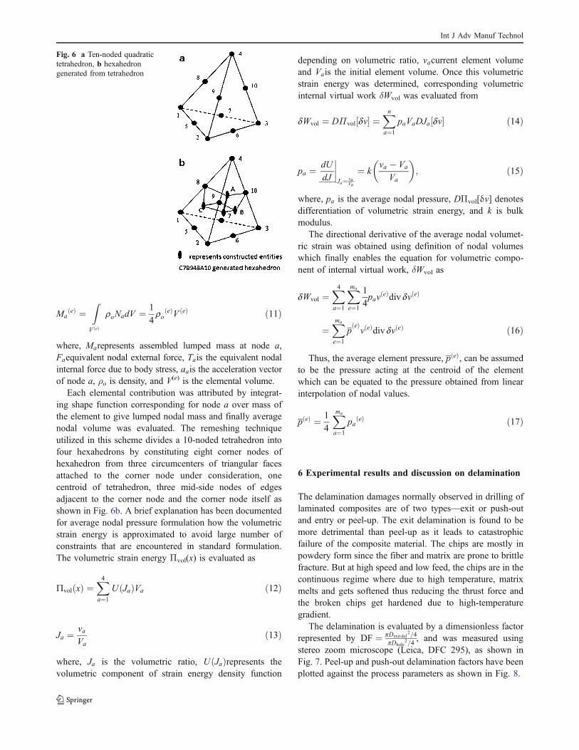
nodal volume was evaluated. The remeshing technique
utilized in this scheme divides a 10-noded tetrahedron into
four hexahedrons by constituting eight corner nodes of
hexahedron from three circumcenters of triangular faces
attached to the corner node under consideration, one
centroid of tetrahedron, three mid-side nodes of edges
adjacent to the corner node and the corner node itself as
shown in Fig. 6b. A brief explanation has been documented
for average nodal pressure formulation how the volumetric
strain energy is approximated to avoid large number of
constraints that are encountered in standard formulation.
The volumetric strain energy Πvol(x) is evaluated as
9volðxÞ ¼X
4
a¼1
UðJaÞVa ð12Þ
Ja ¼ va
Va
ð13Þ
where, Ja is the volumetric ratio, UðJaÞrepresents the
volumetric component of strain energy density function
depending on volumetric ratio, vacurrent element volume
and Vais the initial element volume. Once this volumetric
strain energy was determined, corresponding volumetric
internal virtual work δWvol was evaluated from
dWvol ¼ DΠvol½dv) ¼X
n
a¼1
paVaDJa½dv) ð14Þ
pa ¼ dU
dJ
*
*
*
*
Ja¼ vaVa
¼ kva " Va
Va
+ ,
; ð15Þ
where, pa is the average nodal pressure, DΠvol[δv] denotes
differentiation of volumetric strain energy, and k is bulk
modulus.
The directional derivative of the average nodal volumet-
ric strain was obtained using definition of nodal volumes
which finally enables the equation for volumetric compo-
nent of internal virtual work, δWvol as
dWvol ¼X
4
a¼1
X
ma
e¼1
1
4pav
ðeÞdiv dvðeÞ
¼X
ma
e¼1
pðeÞvðeÞdiv dvðeÞ ð16Þ
Thus, the average element pressure, pðeÞ, can be assumedto be the pressure acting at the centroid of the element
which can be equated to the pressure obtained from linear
interpolation of nodal values.
pðeÞ ¼ 1
4
X
ma
a¼1
paðeÞ ð17Þ
6 Experimental results and discussion on delamination
The delamination damages normally observed in drilling of
laminated composites are of two types—exit or push-out
and entry or peel-up. The exit delamination is found to be
more detrimental than peel-up as it leads to catastrophic
failure of the composite material. The chips are mostly in
powdery form since the fiber and matrix are prone to brittle
fracture. But at high speed and low feed, the chips are in the
continuous regime where due to high temperature, matrix
melts and gets softened thus reducing the thrust force and
the broken chips get hardened due to high-temperature
gradient.
The delamination is evaluated by a dimensionless factor
represented by DF ¼ pDexit del2=4
pDhole2=4
, and was measured using
stereo zoom microscope (Leica, DFC 295), as shown in
Fig. 7. Peel-up and push-out delamination factors have been
plotted against the process parameters as shown in Fig. 8.
Fig. 6 a Ten-noded quadratic
tetrahedron, b hexahedron
generated from tetrahedron
Int J Adv Manuf Technol

Carbide tools are more preferable for high speed
machining than HSS for their hot hardness and material
rigidity which reduces the responses, and hence delamina-
tion reduces in case of carbide than HSS. In Fig. 8a, at high
cutting velocity and higher feed, the powdery chips are
found to get hardened and thus clog with the penetration of
Fig. 7 Measurement of delami-
nation at Vc=45 m/min and s=
0.5 mm/rev using carbide drill
bit
Fig. 8 a Exit delamination versus feed for HSS at Vc=45 and 65 m/
min. b Exit delamination versus feed for carbide at Vc=45 and 65 m/
min
Fig. 9 a Peel-up delamination versus feed for HSS at Vc=45 and
65 m/min. b Peel-up delamination versus feed for carbide at Vc=45
and 65 m/min
Int J Adv Manuf Technol
drill increasing thrust and hence exit delamination. But
contrary to tradition, the higher values of delamination at
high feeds in Fig. 8b, signify the effect of drill point
geometry into picture other than material properties of
carbide. Because the higher the point angle, the higher is
the push-out delamination. While in Fig. 9a, b, peel-up
delaminations showed gradual increasing trend as it is
mostly influenced by rotational speed.
7 Experimental versus finite element results
and discussion
The material model in the finite element analysis is
assumed as elastic; hence, only thrust force can be
captured numerically. From previous studies, it is well
documented that the thrust force can be captured by
elastic bending of material under the type of loading it is
subjected to. The estimated thrust is considered to be the
sum of reactions of all boundary nodes along Z direction
(opposite to direction of feed) during steady cutting
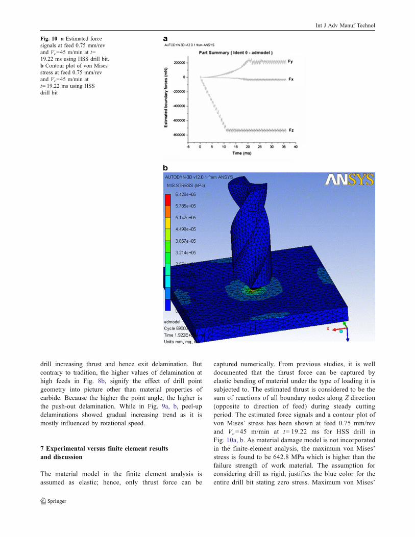
period. The estimated force signals and a contour plot of
von Mises’ stress has been shown at feed 0.75 mm/rev
and Vc=45 m/min at t=19.22 ms for HSS drill in
Fig. 10a, b. As material damage model is not incorporated
in the finite-element analysis, the maximum von Mises’
stress is found to be 642.8 MPa which is higher than the
failure strength of work material. The assumption for
considering drill as rigid, justifies the blue color for the
entire drill bit stating zero stress. Maximum von Mises’
Fig. 10 a Estimated force
signals at feed 0.75 mm/rev
and Vc=45 m/min at t=
19.22 ms using HSS drill bit.
b Contour plot of von Mises'
stress at feed 0.75 mm/rev
and Vc=45 m/min at
t=19.22 ms using HSS
drill bit
Int J Adv Manuf Technol

stress occurs at the point of interaction of chisel edge and
work material.
The comparison plots for experimental and finite
element results show a near-estimate of drilling thrust with
deviations ranging from 10% to 21% for lower cutting
speeds of 45 m/min (Fig. 11a for HSS, Fig. 11b for carbide)
using both the drill bits whilst 6–27% for higher cutting
speed of 65 m/min as in Fig. 12a for HSS, and Fig. 12b for
carbide. This deviations are due to important reasons like
material constitutive properties are taken from literature,
precise modeling of chisel edge and elastic material model
for composites. In Fig. 13, two comparisons have been
shown for change of simulated average thrust force with
change in cutting speed and change in point angle of
carbide drill bit. The graph shows at maximum cutting
speed and minimum point angle the fiber rupture by the
Fig. 11 a Comparison plots of thrust force for HSS drill bit at Vc=45 m/
min. b Comparison plots of thrust force for carbide drill bit at Vc=45 m/
min
Fig. 12 a Comparison plots of thrust force for HSS drill bit at Vc=65 m/
min. b Comparison plots of thrust force for carbide drill bit at Vc=65 m/min
Fig. 13 Comparison plots of simulated thrust force for carbide drill
bit with varying cutting speed and point angles
Int J Adv Manuf Technol
carbide drill bit is quicker with much reduced thrust force
which accounts to the material properties of the drill bit and
geometrical specification of drill angles. The thrust values
at Vc=65 m/min for 118° point angle in Fig. 13 are less
than that for 130° point angle which in turn are lower than
the values seen in Fig. 12a, b. Although, at higher values of
feed, problems like mesh distortions and hourglassing did
affect the gradual trend in the simulated results. These
inferences revalidate that carbide drills are more preferable
in comparison to HSS drill bits during drilling of GFRP.
8 Conclusion and future scope
Among 16 holes drilled in the workpiece with HSS drill bit,
the holes for Vc=45 and 65 m/min with same feed of
0.25 mm/rev showed minimum delamination (peel-up and
push-out). But the rest from feed 0.5–1.0 mm/rev showed
significant changes indicating that the tool has already
started to wear; i.e., if a fresh drill bit is able to make a
single hole, then the number of drills required is equal to
the number of holes to be drilled or number of times the
tool has to be reground. The rest 16 holes drilled with
carbide drill bit showed comparatively less delamination
than with HSS due to reduced thrust at same feed–speed
combinations. High fracture toughness of work material has
become the key reason behind drill wear, specifically at
chisel edge which ultimately aggravates delamination and
hence strength of the work material. So the present scope is
a forerunner in achieving the same goal but for woven
composites.
Though as a whole, the finite element analysis of drilling
woven composites is highly complicated, the element shape
function and the boundary conditions are simplified to save
computation time. The motion constraints to workpiece and
tool are kept as in experimental setup. A near-accurate 3D
drill model has been developed based on available drill
grinding techniques. The material model has been consid-
ered elastic which accounts to a close estimate of thrust
within about 80–90% of the experimental values. An
equivalent macromechanical model has been represented
for the composite material which is sufficient to investigate
the drilling responses. The ANP technique as finite element
solver is found to work well with the present nonlinear
analysis. As the material model is assumed as elastic,
cutting action could not be predicted. Elastoplastic material
model is essential to simulate actual cutting and chip
formation finally leading to modeling of delamination.
Softwares like Ultimatte AdvantEdge do simulate such
elastoplastic deformation mechanisms but presently for
metals. Hence, modeling such deformation problems can
be accounted in future with proper subroutines to take care
anisotropic failure phenomenon. Since the drill is consid-
ered rigid in the present study, the elements meshing the
drill help only to compute mass inertia for finite element
analysis. The drill profile acts only as a displacement field
hence constitutive properties are not required. Modeling
drill wear with deformable tool will include constitutive
properties that can be kept as future scope.
References
1. Reedy ED, Mello FJ (1986) Modeling delamination growth in
composites. Sandia National Laboratories, Albuquerque, NM,
USA
2. Ho-cheng H, Dharan CKH (1990) Delamination during drilling in
composite laminates. J Eng Ind 112:236–239
3. DiPaolo G, Kapoor SG, Devor RE (1996) An experimental
investigation of the crack growth phenomenon for drilling of fibre-
reinforced composite materials. ASME J Engg Ind 118:104–110
4. Ramkumar J, Aravindan S, Malhotra SK, Krishnamurthy R
(2004) An enhancement of the machining performance of GFRP
by oscillatory drilling. Int J Adv Manuf Tech 23:240–244
5. Hocheng H, Tsao CC (2003) Comprehensive analysis of delamina-
tion in drilling of composite materials with various drill bits. J Mat
Proc Tech 140:335–339
6. Rubio JC, Abrao AM, Faria PE, Correia AE, Davim JP (2008)
Effects of high speed in the drilling of glass fibre reinforced
plastic: evaluation of the delamination factor. Int J Mach Tool
Manuf 48:715–720
7. Sadat AB, Chan WS, Wang BP (1992) Delamination of graphite/
epoxy laminate during drilling operation. J Energy Resour
Technol 114:139–141
8. Jain S, Yang DCH (1994) Delamination of free drilling of
composite laminates. J Eng Ind 116:475–481
9. Nishiwaki T, Yokoyama A, Maekawa ZI, Hamada H (1995) A
new numerical modeling for laminated composites. J Compos
Struct 32:641–647
10. Gruttmann F, Wagner W (2001) A finite element model for the
analysis of delaminations in FRP-Shells, Trends in Computational
Structural Mechanics, International Center for Numerical Methods
in Engineering (CIMNE) Barcelona, 307–316.
11. Tanzawa Y, Watanabe N, Ishikawa T (2001) FEM simulation of
modified DCB test for 3D orthogonal interlocked fabric compo-
sites. Compos Sci Technol 61:1097–1107
12. Goerguelue U (2009) Investigation of free edge delamination.
Available from: http://www.gorgulu-home.com/Index_files/Pages/
Useful_Notes/studies/Useful_notes/composites/Investigation_of_
free_edge_delamination.pdf. Accessed 04 Aug 2009.
13. Matlab 7.1.0.246(R14), Mathworks Inc.
14. Vijayaraghavan A, Dornfeld DA (2007) Automated drill modeling
for drilling process simulation. J Comput Inf Sci Engg 7(3):276–282
15. Pro-Engineer v2.0.
16. Kyratsis P, Bilalis N, Antoniadis A (2009) CAD based predictive
models of the undeformed chip geometry in drilling. World Acad
Sci Eng Technol 52:318–324
17. Sundarraja MC, Rajamohan S (2008) Flexural strengthening effect
on RC beams by bonded composite fabrics. J Reinf Plast Compos
27:1497–1513. doi:10.1177/0731684407081377
18. http://www.tech.plym.ac.uk/sme/MATS324/MATS324A2%20E-
G-nu.htm#K. Accessed on 08 Oct 2009.
19. Ansys Workbench 12.0.1 and Ansys Autodyn 12.0.1.
20. Bonet J, Burton AJ (1998) A simple average nodal pressure
tetrahedral element for incompressible and nearly incompressible
dynamic explicit applications. Comm Num Meth Engg 14:437–449
Int J Adv Manuf Technol
Copyright © 2022 FDOKUMEN