DR RY SYS STEMS S TECH HNOLO OGIES
100
14 30 US HIGH DR HWAY 45 N RY SYS Tech P MACH N, VIENNA, STEMS hnology for MOSA DST 1 RODUC HINE SE , ILLINOIS, www.drysy S TECH a cleaner e IC POT 18.5T- CT HAN ERIAL # , 62995 PH ystemstech.co HNOLO environmen TASH PH NDLER #M600 HONE 618-6 om OGIES nt 0019 58-3000 FA S ® AX 618-658 8-3002
-
Upload
khangminh22 -
Category
Documents
-
view
2 -
download
0
Transcript of DR RY SYS STEMS S TECH HNOLO OGIES

14
30 US HIGH
DR
HWAY 45 N
RY SYS Tech
P
MACH
N VIENNA
STEMShnology for
MOSA
DST 1
RODUC
HINE SE
ILLINOISwwwdrysy
S TECH a cleaner e
IC POT
185T-
CT HAN
ERIAL
62995 PHystemstechco
HNOLOenvironmen
TASH
PH
NDLER
M600
HONE 618-6om
OGIESnt
0019
58-3000 FA
Sreg
AX 618-658
8-3002
In DS
--------
M5 TR FIL MA CU DS
----
14
dex for S
ST PARTS DR M277-00 M302-00 M348-00 M348-00 M348-00 M348-00 M348-00 M348-00
500894 OUTB
RANSMISSION
LTER LIST
ACHINE OILS
UMMINS ENG
ST OPERATIO M301-01 M301-01 M301-01 M301-02
30 US HIGH
DR
SN M600
RAWINGS ndash 6-03 WATER3-01 CO SAM1-01 HYDRA1-01 HYDRA2-02 ELECTR3-01 COOLIN4-02 MACHI4-02 MACHI
BY ENGINE K
N CONVERT
GINE FAULT C
ON AND MAIN6-11 ON BOA8-01 CO SAM9-01 PRE-OP1-01 COOLIN
HWAY 45 N
RY SYS Tech
0019 PRO
R INJECTION MPLING SYSTAULIC DIAGRAAULIC DIAGRARICAL SCHEMNG SYSTEM NE COMPONNE COMPON
KIT
TER PARTS
CODES
NTENANCE INARD CLEANINMPLING PROP INSPECTIONG SYSTEM F
N VIENNA
STEMShnology for
ODUCT H
SYSTEM 12TEM AM SHEET 1AM SHEET 2MATIC
ENTS SHEETENTS SHEET
NDEX ndash NG FOR OUT
OCEDURE NS FILL PROCED
ILLINOISwwwdrysy
S TECH a cleaner e
HANDLER
2 V
1 2
T 1 T 2
TBY MACHINE
DURE
62995 PHystemstechco
HNOLOenvironmen
Rndash
E
HONE 618-6om
OGIESnt
58-3000 F
Sreg
FAX 618-6588-3002
M500894 OUTBY KIT
Item Component Item Description UOM Quan
10 M168‐717‐02 BOTTLE COOLANT RECOVERY 2 Gal EA 1
40 M191‐208‐02 TURBOCHARGERCOVER PLATE COATING Cummins QSB45 170HEA 1
50 M191‐209‐02 MANIFOLD COATING EA 1
60 M239‐551‐01 SWITCH MAGNETIC ‐ 12V 30sec Delay EA 1
70 M265‐715‐30 FAN 26IN PUSHER EA 1
80 M270‐609‐01 SWITCH BATTERY DISCONNECT EA 1
90 M270‐610‐01 FACE PLATE Battery Disconnect EA 1
100 M270‐612‐01 SWITCH PUSHPULL RED KNOB Double Stack EA 2
110 M277‐550‐01 GAUGE EXHAUST TEMPERATURE wshutdown switch EA 1
120 M30‐411‐01R FILTER EXHAUST 16 EA 1
130 M313‐301‐01 HEAT EXCHANGER EA 1
140 M318‐714‐01 SOLENOID SWITCH 12V EA 1
150 M320‐759‐01 HUMP HOSE 3 CAC EA 4
160 M320‐760‐01 HOSE CLAMP 2 34 ‐ 3 58 Constant Torque EA 8
170 M38‐710‐02 SURGE TANK EA 1
180 M500‐238‐01 ENG SPEC CUMMINS QSB45 EA 1
190 M500‐506‐01 SWITCH PUSHBUTTON MOMENTARY EA 1
200 M500‐514‐01 SNUBBER GAUGE EA 2
210 M500‐551‐01 ALTERNATOR PIGTAIL EA 1
220 M500‐552‐01 PEDAL ELECTRONIC ACCELERATOR Cummins EA 1
230 M500‐553‐01 POWERVIEW EA 1
240 M500‐557‐01 CIRCUIT BREAKER 120A Sealed Manual Reset EA 1
250 M502‐543‐01 HOSE 316X716 MULTI‐PURPOSE hose FT 30
260 M502‐560‐01 HARNESS CUMMINS QSB45QSB67 EA 1
270 M502‐590‐01 CIRCUIT BREAKER 105 AMP Sealed Manual Reset EA 1
280 M503‐523‐01 RELAY GRID HEATER 12V EA 1
290 M503‐530‐01 SWITCH START amp IGNITION EA 1
320 M503‐570‐01 CIRCUIT BREAKER 20 AMP MANUAL RESET EA 1
330 M503‐571‐01 GAUGE CONVERTOR TEMP MECHANICAL EA 1
340 M192‐571‐01 GAUGE TRANS CLUTCH PRESSURE EA 1
350 M504‐587‐01 CIRCUIT BREAKER STARTER 250A With Enclosure and ConnectorsEA 1
360 M506‐540‐01 ENCLOSURE BOX 95 X 72 X 51 NEMA 4X EA 1
370 M59‐591‐01 KIT OUTBY RAW EXHAUST PORT EA 1
390 M80‐511‐01 HORN 12V EA 1
400 M270‐605‐01 CABLE 8 RED FT 50
410 M270‐608‐01 CABLE 6 RED FT 50
430 M507‐573‐01 KIT WATER INJECTION 12V EA 1
440 M250‐724‐01 OIL COOLER WATER COOLED 6DIA X 30 EA 1
450 M281‐430‐01 FILTER HOUSING 16 wlever clamps inlet flange EA 1
460 M600‐519‐01 BRASS PLUG HEX HD 18NPT EA 5
470 M600‐521‐01 BRASS PLUG HEX HD 14NPT EA 3
480 M600‐526‐01 BRASS TEE 18NPT FXMXF EA 2
490 M600‐563‐01 BRASS BARB MALE 38 X 18NPT EA 5
500 M600‐570‐01 BRASS BARB MALE 34 X 34NPT EA 2
510 M600‐573‐01 BRASS BARB MALE 34 X 12NPT EA 2
520 M600‐576‐01 BRASS BARB ELBOW 38 X 18 NPT EA 5
530 M600‐704‐01 HOSE CONNECTOR 1 34 X 2 EA 1
540 M600‐706‐01 HOSE RUBBER 58 X 34 90DEG EA 1
550 M600‐711‐01 HOSE CONNECTOR 2 X 2 12 EA 2
560 M600‐727‐01 HOSE CLAMP 1 14 ‐ 2 14 EA 8
570 M600‐728‐01 HOSE CLAMP 2‐3IN EA 30
580 M600‐729‐01 HOSE CLAMP 12 ‐ 1316IN EA 15
590 M600‐730‐01 HOSE CLAMP 78 ‐ 1 14IN EA 6
600 M600‐735‐01 HOSE RUBBER 34 ID 106 OD FT 20
610 M600‐738‐01 ELBOW RUBBER 2 EA 4
620 M600‐751‐01 HOSE HEATER 38 ID EA 30
630 M600‐716‐01 HOSE RUBBER 2X3 4 PLY EA 1
640 M320‐215‐01 TUBING STRAIGHT EXHAUST 3X14GA Aluminnized 10 length EA 1
650 M30‐543‐01 GAUGE EXHAUST BACKPRESSURE EA 1
660 M30‐544‐01 GAUGE INTAKE VACUUM EA 1
740 M270‐426‐01 ELBOW SHORT RADIUS 90DEG 3 EA 4
750 M292‐218‐01 CLAMP U‐BOLT HEAVY‐DUTY 4 EA 1
760 M296‐716‐01 PIPE CONNECTION 2 EA 1
770 M292‐210‐02 CATALYST COATED 85 EA 1
790 M506‐539‐01 3 12 FLEX PIPE EA 1
800 M292‐223‐01 REDUCER ID‐ID 4‐35 EA 1
810 M257‐210‐01 ADAPTER EXHAUST 3 12 ‐ 3 ID‐OD EA 1
820 M320‐203‐01 ELBOW SHORT RADIUS 90DEG 35 EA 2
830 M348‐705‐01C RADIATOR ASSY EA 1
850 M348‐003‐01 COOLING SCHEMATIC DW 1
860 M302‐003‐01 CO SAMPLING SYSTEM DW 1
870 M292‐212‐01 FLANGE OUTLET CATALYST EA 2
880 M250‐733‐01 FAN HUB ADAPTER EA 1
890 M261‐535‐01 HEADLIGHT 1224V LED WWEATHERPAK PIGTAIL EA 6
900 M192‐572‐01 GAUGE OIL PRESSURE MECHANICAL EA 1
910 M508‐518‐01 CIRCUIT BREAKER 15A MANUAL RESET EA 9
920 M508‐518‐02 CIRCUIT BREAKER BOOT ‐ CLEAR 38‐24 THD EA 6
930 M509‐567‐01 SWITCH 2 POSITION OIL‐TIGHT WASHDOWN EA 4
940 M509‐568‐01 PANEL LIGHT LED GREEN EA 1
950 M509‐569‐01 CIRCUIT BREAKER 50 AMPS MANUAL RESET EA 1
MODEL NO R32421-630PT3
PART NO Prototype
DATE 11 September 2012
FRONT OUTPUT FLANGE BI-DIRECTIONAL PTO FLANGE FLANGE 247029 FLANGE
NUT 215634 NUT
WASHER 231916 WASHER
O-RING 76K328 O-RING
UNI-DIRECTIONAL PTO FLANGE FLANGE
NUT
WASHER
O-RING
INPUT FLANGE REAR OUTPUT FLANGE FLANGE 214985 FLANGE 247049
NUT 216058 NUT 215634
WASHER 102745 WASHER 231916
O-RING 76K220 O-RING 76K328
INPUT FLANGE FLANGE
NUT
WASHER
O-RING
C
A PUMP DRIVE ASSrsquoY (includes the following)
PUMP DRIVE ASSrsquoY (includes the following)
SNAP RING (INNER)
SNAP RING (INNER)
SNAP RING (OUTER)
SNAP RING (OUTER)
PUMP DRIVE SLEEVE POSITION
GRP ndash 000 (REV 0101)
MHR-28000
MHR-32000
R R-28000
R-32000
HR-28000
HR-32000
PDF processed with CutePDF evaluation edition wwwCutePDFcom
SPECIAL PARTS SECTION
R32421-630PT3
Prototype for Dry Systems
GRP ITEM QTY PART NO DESCRIPTION
32286 27 1 231878 Bearing Cap
32286 28 1 239927 Output Shaft Gear
PARTS NOT ILLUSTRATED
SPICER OFF-HIGHWAY PRODUCTS
DIVISION
Page 1
PDF processed with CutePDF evaluation edition wwwCutePDFcom
Converter Cover Sheet
0401
Model C3237-PT5
Part No Prototype Date 12-26-2013
250 PSI
248142
214985
Charging Pump GPM 21
Offset Drive
Flange Location
Pump Drive
Position A
Regulating Valve Pressure
Inline Drive Flange Location
Spacer Used WO
Lockup
Lockup
Spacer
Breather Part
Pump Drive
Position B
Pump Drive
Position C
Flange Part
Flange Part
PDF processed with CutePDF evaluation edition wwwCutePDFcomPDF processed with CutePDF evaluation edition wwwCutePDFcomPDF processed with CutePDF evaluation edition wwwCutePDFcom
SPECIAL PARTS SECTION
C3237-PT5
Prototype for Dry Systems
QTY PART NO DESCRIPTION
1 214985 6C Output Flange
PARTS NOT ILLUSTRATED
1 248142 Check Valve Breather
2 235262 Pump Drive Sleeves
2 235961 Gasket
SPICER OFF-HIGHWAY PRODUCTS
DIVISION
Page 1
PDF processed with CutePDF evaluation edition wwwCutePDFcom
DS QU
14
ST 185T-PH
UANTITY
1
1
1
1
1
1 1
2
1
1
30 US HIGH
DR
H FILTER
PART N
M503
M503
M503
M250
M250
M30-
M350
M192
M192
M192
HWAY 45 N
RY SYS Tech
LIST (CUM
NUMBER
3-573-01
3-575-01
3-576-01
0-592-02
0-592-03
-411-01R
0-591-01
2-566-02
2-540-02
2-555-02
N VIENNA
STEMShnology for
MMINS 45)
ILLINOISwwwdrysy
S TECH a cleaner e
)
DES
ENGINE
FUEL FI
FUEL W
AIR FILT
AIR FILT
EXHAUS
TRANSM
HYDRA
BRAKE
MAIN H
62995 PHystemstechco
HNOLOenvironmen
SCRIPTION
E OIL FILTE
ILTER
WATER SE
TER ndash PRIM
TER ndash SAFE
ST FILTER
MISSION FI
AULIC RETU
HYD HIGH
HYD HIGH P
HONE 618-6om
OGIESnt
ER
PARATOR
MARY ELEM
ETY ELEM
ILTER
URN FILTE
H PRESSUR
PRESSURE
658-3000 F
Sreg
MENT
MENT
ER
RE FILTER
E FILTER
FAX 618-658-3002
DS CU DA JO HY CH PA
14
ST 185T-PH
UMMINS Q
ANA POWE
OHN DEERE
YDRAULIC
HASSIS GR
ARK BRAKE
30 US HIGH
DR
H SHELL O
SB 45 ENG
ERSHIFT TR
E AXLEShellip
C OILhelliphelliphellip
EASEhelliphelliphellip
Ehelliphelliphelliphelliphellip
HWAY 45 N
RY SYS Tech
OILS FLUID
GINE OILhellip
RANSMISSI
helliphelliphelliphelliphellip
helliphelliphelliphelliphelliphellip
helliphelliphelliphelliphellip
helliphelliphelliphelliphellip
N VIENNA
STEMShnology for
DS LIST
helliphelliphelliphellipSH
IONhelliphellipSH
helliphelliphelliphelliphellipSH
helliphelliphelliphellipS
helliphelliphelliphellipSH
helliphelliphelliphellip S
ILLINOISwwwdrysy
S TECH a cleaner e
HELL ROTE
HELL DONA
HELL DON
HELL TELL
HELL SUPE
HELL DON
62995 PHystemstechco
HNOLOenvironmen
ELLA 15W-
AX TC 30
NAX TD
LUS 68
ER DUTY G
NAX TD
HONE 618-6om
OGIESnt
-40
GREASE 2
58-3000 F
Sreg
FAX 618-6588-3002
AEB1560 Page 147 of 157
Appendix B SAE Diagnostic Trouble Codes and Cummins Fault Codes
-tl 0 u-3 shy
z Il ltIl en M 0gt
Ii L1shy
M
0 15 U Q
E -
J1939 SPN Description Cummins Description
111 629 12 Red Controller 1 Engine Control MOdule Critical internal failure - Bad intelliqent Device or Component
115 612 2 Red System Diagnostic Code 2
Engine SpeedPosition Sensor Circuit lost both of two signals from the magnetic pickup sensor - Data Erratic Intermittent or incorrect
122 102 3 Amber Boost Pressure Intake Manifold Pressure Sensor Circuit - Voltage Above Normal or Shorted to High Source
123 102 4 Amber Boosl Pressure Intake Manifold Pressure Sensor Circuit - Voltage Below Normal or Shorted to Low Source
124 102 16 Amber Boost Pressure
Intake Manifold 1 Pressure - Data Valid but Above Normal Operational Range - Moderately Severe Level
131 91 3 Red Accelerator Pedal Position Accelerator Pedal or Lever Position Sensor Circuit shyVoltage Above Normal or Shorted to High Source
132 91 4 Red Accelerator Pedal Position Accelerator Pedal or Lever Position Sensor Circuit shyVoltage Below Normal or Shorted to Low Source
133 974 3 Red Remote Accelerator
Remote Accelerator Pedal or Lever Position Sensor Circuit - Voltage Above Normal or Shorted to High Source
I 134 974 4 Red Remote Accelerator
Remote Accelerator Pedal or Lever Position Sensor Circuil - Voltage Below Normal or Shorted to Low Source
135 100 3 Amber EnQine Oil Pressure Oil Pressure Sensor Circuit - Voltage Above Normal or Shorted to HiClh Source
141 100 4 Amber Engine Oil Pressure Oil Pressure Sensor Circuit - Voltage Below Normal or Shorted to Low Source
143 100 18 Amber Engine Oil Pressure Oil Pressure Low - Data Valid but Below Normal Operational Range - Moderately Severe Level
144 110 3 Amber Engine Coolant Temperature Coolant Temperature Sensor Circuit - Voltage Above Normal or Shorted to High Source
145 110 4 Amber Engine Coolant Temperature Coolant Temperature Sensor Circuit - Voltage Below Normal or Shorted to Low Source
146 110 16 Amber EnQine Coolant Temperature
Coolant Temperature High - Data Valid but Above Normal Operational Range - Moderately Severe Level
147 91 1 Red Accelerator Pedal Position Accelerator Pedal or Lever Position Sensor Circuit shyAbnormal Frequency Pulse WiJJlh or Periae
148 91 0 Red Accelerator Pedal Position Accelerator Pedal or Lever Position Sensor Circuit shyAbnormal Frequency Pulse Width or Period
151 110 0 Red Engine Coolant Temperature Coolant Temperature Low - Data Valid but Above Normal Operational Range - Most Severe Level
153 105 3 Amber Intake Manifold 1 Temp Intake Manifold Air Temperature Sensor Circuit-Voltage Above Normal or Shorted to High Source
154 105 4 Amber Intake Manifold 1 Temp Intake Manifold Air Temperature Sensor Circuit-Voltage Below Normal or Shoried to Low Source
155 105 0 Red Intake ManifOld 1 Temp
Intake Manifold Air Temperature High - Data Valid but Above Normal Operational Range - Most Severe Level
187 3510 4 Amber 5 Volts DC Supply Sensor Supply Voltage 2 Circuit - Voltage Below Normal or Shorted to Low Source
I
AEB1560 Page 148 of 157
193 520199 3 Amber Cruise Control Cruise Control (Resistive) Signal Circuit - Voltage Above Normal or Shorted to High Source
194 520199 4 Amber Cruise Conlrol Cruise Control (Resistive) Signal Circuit - Voltage Below Normal or Shorted to Low Source
195 111 3 Amber Coolant Level Coolant Level Sensor Circuit - Voltage Above Normal or Shorted to High Source
196 111 4 Amber Coolant Level Coolant Level Sensor Circuit - Voltage Below Normal or Shorted to Low Source
197 111 18 Amber Coolant Levet Coolant Levet - Data Valid but Below Normal Operational Range - Moderately Severe Level
199 1661 4 Amber Engine Automatic Start Lamp Engine Automatic Start Lamp Driver Circuit shyVoltage Above Normal or Shorted to High Source
211 1484 31 None J1939 Error Additional Auxiliary Diagnostic Codes logged middot Condition Exists
212 175 3 Amber Oil Temp_erature Engine Oil Temperature Sensor 1 Circuit middot Voltage Above Normal or Shorted to High Source
213 175 4 Amber Oil Temperature Engine Oil Temperature Sensor 1 Circuitmiddot Voltage Below Normal or Shorted to Low Source
214 175 0 Red Oil Temperature Engine Oil Temperalure - Dala Valid but Above Normal Operational Rangemiddot Most Severe Level
221 108 3 Amber Baromelric Pressure Barometric Pressure Sensor Circuit - Voltage Above Normal or Shorted to High Source
222 108 4 Amber Barometric Pressure Barometric Pressure Sensor Circuit - Voltage Below Normal or Shorted to Low Source
227 35t O 3 Amber 5 Volts DC Supply Sensor Supply Voltage 2 Circuit - Voltage Above Normal or Shorted to High Source
231 109 3 Amber Coolant Pressure Coolant Pressure Sensor Circuit - Voltage Above Normal or Shorted to High Source
232 109 4 Amber Coolant Pressure Coolant Pressure Sensor Circuitmiddot Voltage BelOW Normal or Shorted to Low Source
233 109 18 Amber Cool ant Pressu re Coolant Pressuremiddot Data Valid but Below Normat Operational Rangemiddot Moderately Severe Level
234 190 0 Red Engine Speed Engine Speed Highmiddot Data Valid but Above Normal Operational Rangemiddot Most Severe Level
235 111 1 Red Coolant Level Coolant Level Lowmiddot Data Valid but Below Normal Operational Range - Most Severe Level
237 644 2 Amber Ex1emal Speed tnput Ex1ernal Speed Input (Multiple Unit Synchronization) bull Data Erratic Intermittent or Incorrect
238 3511 4 Amber System Diagnostic code 1 Sensor Suppty Voltage 3 Circuit - Voltage Below Normal or Shorted to Low Source
239 3511 3 Amber System Diagnostic code 2 Sensor Supply Voltage 3 Circuit - Voltage Above Normal or Shorted to High Source
241 84 2 Amber Wheel-based Vehicle Speed Vehicle Speed Sensor Circuit - Data Erralic tntermlttent or Incorrecl
242 84 10 Amber Wheel middotbased Vehicle Speed Vehicle Speed Sensor Circuit tampering has been detected - Abnormal R ate of Change
244 623 4 Amber Red Stop Lamp Red Stop Lamp Driver Clrcuil Voltage Below Normal or Shorted to Low Source
245 647 4 Amber Fan Clutch OulDut Device Driver Fan Control Circuitmiddot Voltage Below Normat or Shorted to Low Source
249 171 3 Amber Ambient Air Temperature Ambient Air Temperature Sensor Circuit middot Voltage Above Normal or Shorted to High Source
256 171 4 Amber Ambient Air Temperature Ambient Air Temperature Sensor Circuitmiddot Voltage Betow Normal or Shorted to Low Source
261 174 16 Amber Fuel Temperature
Engine Fuel Temperature - Data Valid but Above Normal Operational Rangemiddot Moderately Severe Level
AEB1560 Page 149 of 157
263 174 3 Amber Fuel Temperature Engine Fuel Temperature Sensor 1 Circuit - Voltage Above Normal or Shorted to Hioh Source
265 174 4 Amber Fuel Temperature Engine Fuel Temperature Sensor 1 Circuit - Voltage Below Normal or Shorted to Low Source
268 94 2 Amber Fuel Delivery Pressure Fuel Pressure Sensor Circuit - Data Erratic Intermittent or Incorrect
271 1347 4 Amber Fuel Pump Pressurizing Assembly 1 High Fuel Pressure Solenoid Valve Circuit - Voltage Below Normal or Shorted to Low Source
272 1347 3 Amber Fuel Pump Pressurizing Assembly 1 High Fuel Pressure Solenoid Valve Circuit - Voltage Above Normal or Shorted to High Source
281 1347 7 Amber Fuel Pump PressurizingAssembly 1
High Fuel Pressure Solenoid Valve 1 - Mechanical System Not Responding Properly or Out of Adjustment
284 1043 4 Amber Internal Sensor Voltage Supply
Engine SpeedPosition Sensor (Crankshaft) Supply Voltage Circuit - Voltage Below Normal or Shorted to Low Source
285 639 9 Amber SAE J1939 Datalink SAE J1939 Multiplexing PGN Timeout Error-Abnormal Update Rale
286 639 13 Amber SAE J1939 Datalink SAE J1939 Multiplexing Configuration Error - Out of Calibration
287
288
91
974
19
19
Red Accelerator Pedal Position
Remote Accelerator
SAE J1939 Multiplexing Accelerator Pedal or Lever Sensor System Error - Received Network Data In Error
SAE J1939 Multiplexing Remote Accelerator Pedal or Lever Data Error - Received Network Data In ErrorRed
292 441 14 Red Auxiliary Temperature 1 Auxiliary Temperature Sensor Input 1 - Special Instructions
293 441 3 Amber OEM Temperature Auxiliary Temperature Sensor Input 1 Circuil shyVoltage Above Normal or Shorted to High Source
294 441 4 Amber OEM Temperature Auxiliary Temperature Sensor Input 1 Circuit-Voltage Below Normal or Shorted to Low Source
295 108 2 Amber Baromelric Pressure Barometric Pressure Sensor Circuit - Data Erratic tntermittent or Incorrect
296 1388 14 Red Auxiliary Pressure Auxiliary Pressure Sensor Input 1 - Special Instructions
297 1388 3 Amber Auxiliary Pressure Auxiliary Pressure Sensor Input 2 Circuil - Voltage Above Normal or Shorted to High Source
298 1388 4 Amber Auxiliary Pressure Auxiliary Pressure Sensor Input 2 Circuit -Voltage Below Normal or Shorted to Low Source
319
322
251
651
2
5
Maint Real Time Clock Power
tnjector Cylinder 01
Real Time Clock Power Interrupt - Data Erralic Intermittenl or Incorrect
Injector Solenoid Cylinder 1 Circuit - Current Below Normal or Open Circuit Amber
323 655 5 Amber Injector Cylinder 05 Injector Solenoid Cylinder 5 Circuit- Current Below Normal or Open Circuit
324 653 5 Amber Injector Cylinder 03 Injector Solenoid Cylinder 3 Circuit - Current Below Normal or Open Circuit
325 656 5 Amber Injector Cylinder 06 Injector Solenoid Cylinder 6 Circuit - Current Below Normal or Open Circuit
331 652 5 Amber Injector Cylinder 02 Injector Solenoid Cylinder 2 Circuit - Current Below Normal or Open Circuit
332 654 5 Amber Injector Cylinder 04 Injector Solenoid Cylinder 4 Circuit - Current Below Normal or Open Circuit
334 110 2 Amber Enqine Coolant Temperature Coolant Temperature Sensor Circuit - Data Erratic Intermittent or Incorrect
AEB1560 Page 150 of 157
I I
I
338 1267 3 Amber Vehicle Accessories Relay Driver
Idle Shutdown Vehicle Accessories Relay Driver Circuit - Voltage Above Normal or Shoned to High Source
I 339 1267 4 Amber Vehicle Accessories Relay Driver
Idle Shutdown Vehicle Accessories Relay Driver Circuit - Voltage Below Normal or Shorted to Low Source
341 630 2 Amber Calibration Memory Engine Control Module data lost - Data Erratic Intermittent or Incorrect
342 630 13 Red Calibration Memory Electronic Calibration Code Incompatibility - Out of Calibration
343 629 12 Amber Controller 1 Engine Control Module Warning internal hardware failure - Bad Intellic)ent Device or Component
I
349 191 16 Amber Transmission Output Shaft Speed
Transmission Output Shaft Speed - Data Valid but Above Normal Operational Range - Moderately Severe Level
351 627 12 Amber Controller 1 Injector Power Supply - Bad Intelligent Device or Component
352 3509 4 Amber 5 Volts DC Supply Sensor Supply Voltage 1 Circuit - Voltage Below Normal or Shoned to Low Source
386 3509 3 Amber 5 Volts DC Supply Sensor Supply Voltage 1 Circuit - Voltage Above Normal or Shoned to High Source
415 100 1 Red Engine Oil Pressure Oil Pressure Low - Data Valid but Below Normal Operational Range - Most Severe Level
418 97 15 Main Water in Fuel Indicator Water in Fuel Indicator High Data Valid but Above Normal Operational Range - Least Severe Level
422 111 2 Amber Coolant Level Coolant Levelmiddot Data Erratic Intermittent or Incorrect
425 175 2 Amber Oil Temperature Engine Oil Temperaturemiddot Data Erratic Intermrttent or Incorrect
428 97 3 Amber Water in Fuel Indicator Water in Fuel Sensor Circuit - Voltage Above Normal or Shorted to High Source
I 429 97 4 Amber Water in Fuel Indicator Water in Fuel Sensor Circuit - Voltage Below Normal or Shorted to Low Source
I 431 558 2 Amber Accelerator Pedal Low Idle Switch Accelerator Pedal or Lever Idle Validation Circuit shyData ErratiC Intermittenl or Incorrect
432 558 13 Red Accelerator Pedal Low Idle Switch Accelerator Pedal or Lever Idle Validation Circuit shyOut of Calibration
435 100 2 Amber Engine Oil Pressure Oil Pressure Sensor Circuitmiddot Data Erratic Intermittent or Incorrect
441 168 18 Amber Etectrical Potential (Volti3fle)
Battery 1 Voltage Low - Data Valid but Below Normal Operational Range - Moderately Severe Level
442 168 16 Amber Electrical Potential (Voltage)
Battery 1 Voltage High - Data Valid but Above Normal Operational Range - Moderately Severe Level
449 157 a Red Injector Metering Rail 1 Pressure Fuel Pressure Highmiddot Data Valid but Above Normal Operational Range - Moderately Severe Level
451 157 3 Amber Injector Metering Rail 1 Pressure Injector Metering Rail 1 Pressure Sensor Circuitmiddot Voltage Above Normal or Shoned to High Source
452 157 4 Amber Iniector Metering Rail 1 Pressure Injector Metering Rail 1 Pressure Sensor Circuitmiddot Voltage Below Normal or Shorted to Low Source
488 105 16 Amber Intake Manifold
Intake Manifold 1 Temperaturemiddot Data Valid but Above Normal Operational Range - Moderately Severe Level
489 191 18 Amber Transmission Output Shalt Speed
Transmiss ion Output Shalt Speed Data Valid but Below Normal Operational Range - Moderately Severe Level
AEB1560 Page 151 of 157
I 497 1377 2 Amber Switch Circuit Multiple Unit Synchronization Switch Circuil - Data Erratic Intermittent or Incorrect
523 611 2 Amber System Diagnostic code 1 OEM Intermediate (PTO) Speed switch Validalion shyData Erratic Intermillent or Incorrect
I
527 702 3 Amber Circuit - Voltage Auxiliary InputOulput 2 Circuil - Voltage Above Normal or Shorted to High Source
528 93 2 Amber Switch - Data Auxiliary Altemate Torque Validation Switch - Data Erratic Intermittent or Incorrect
529 703 3 Amber Circuit - VoltltlJLe Auxiliary InpuVOutput 3 Circuit - Voltage Above Normal or Shorted to High Source
546 94 3 Amber Fuel Delivery Pressure Fuel Delivery Pressure Sensor Circuit - Voltage Above Normal or Shorted to High Source
I 547 94 4 Amber Fuel Delivery Pressure Fuel Delivery Pressure Sensor Circuit - Voltage Below Normal or Shorted to Low Source
551 558 4 Amber Accelerator Pedal Low Idle Switch Accelerator Pedal or Lever Idle Validation Circuit shyVoltage Below Normal or Shorted to Low Source
553 157 16 Amber Injeclor Melering Rail 1 Pressure
Injector Metering Rail 1 Pressure High - Data Valid but Above Normal Operational Range - Moderately Severe Level
554 157 2 Amber Injector Meterinltl Rail 1 Pressure Fuel Pressure Sensor Error - Data Erratic Intermittent or Incorrecl
559 157 18 Amber Injector Metering Rail 1 Pressure
Injector Metering Rail 1 Pressure Low - Data Valid but Below Normal Operational Range - Moderately Severe Level
584 677 3 Amber Slarter Solenoid Lockout Relay Driver Circuit Slarter Relay Circuil - Voltage Above Normal or Shorted to High Source
585 677 4 Amber Starter Solenoid Lockout Relay Driver Circuit Starter Relay Circuit - Voltage Below Normal or Shorted to Low Source
595 103 16 Amber Turbocharger 1 Speed
Turbocharger 1 Speed High - Data Valid but Above Normal Operational Range - Moderately Severe Level
596 167 16 Amber Alternate Potential lvolt~
Electrical Charging System Voltage High - Data Valid but Above Normal Operational Range -Moderately Severe Level
597 167 18 Amber Allernate Potential (voltage)
Electrical Charging System Voltage Low - Data Valid bul Below Normal Operational Range -Moderately Severe Level
598 167 1 Red Alternate Potential (voltage)
Electrical Charging Syslem Voltage Low - Data Valid but Below Normal Operational Range - Most Severe Level
599 640 14 Red Engine External Protection Input Auxiliary Commanded Dual Output Shutdown -Spedal Instructions
649 1378 31 Maint Engine Oi l Change Interval Change Lubricating Oil and Filter - Condition Exists
687 103 18 Amber Turbocharger 1 Speed
Turbocharger 1 Speed Low - Data Valid but Below Normal Operalional Range - Moderately Severe Level
689 190 2 Amber Engine Speed Primary Engine Speed Sensor Error - Data Erratic Intermillent or Incorrecl
691 1172 3 Amber Turbocharger 1 Compressor Inlet Temperature
Turbocharger 1 Compressor Inlet Temperature Sensor Circuit - Voltage Above Normal or Shorted to I-ligh Source
692 1172 4 Amber Turbocharger 1 Compressor Inlet Temperature
Turbocharger 1 Compressor Inlel Temperature Sensor Circuit - Vollage Below Normal or Shorted to Low Source
697 1136 3 Amber Sensor Circuit - Voltaltle ECM Inlernal Temperature Sensor Circuit - Voltage Above Normal or Shoned 10 High Source
698 1136 4 Amber Sensor Circuil bull Voltaltle ECM Intemal Temperalure Sensor Circuil - Voltage Below Normal or Shoned 10 Low Source
AEB15 60 Page 1 52 of 1 57
719 22 3 Amber Crankcase Pressure Extended Crankcase Blow-by Pressure Circuit -Voltage Above Normal or Shorted to High Source
729 22 4 Amber Crankcase Pressure Extended Crankcase BlOW-by Pressure Circuit shyVoltage Below Normal or Shorted to Low Source
731
757
723
2802
7
31
Amber
Amber
Engine Speed Sensor 2
Electronic Control Module
Engine SpeedlPosition 2 mechanical misalignment between camshaft and crankshaft sensors-Mechanical System Not Responding Properly or Out of Adjustment
Electronic Control Module data lost - Condition Exists
778 723 2 Amber Engine Speed Sensor 2 Engine Speed Sensor (Camshaft) Error - Data Erratic Intermittent or tncorrect
779 703 11 Amber Auxiliary Equipment Sensor Input Waming Auxiliary Equipment Sensor Input 3 (OEM Switch) - Root Cause Not Known
951 166 2 None Cylinder Power Cylinder Power Imbala nce Between Cylinders shyData Erratic IntermiHent or Incorrect
1117 627 2 None Power Supply Power Lost With Ignition On - Data Erratic Intermittent or Incorrect
1139 651 7 Amber Injector Cylinder 01 Injector Cylinder 1 - Mechanical System Not Respondinq Properl~or Out 01 Adjustment
1141 652 7 Amber Injector Cylinder 02 Injector Cylinder 2 - Me chanical System Not Respondinq Property or Out of Adjustment
1142 653 7 Amber Injector Cylinder 03 Injector Cylinder 3 - Mechanical System Not Responding Properly or Out of Adjustment
1143 654 7 Amber Iniector Cylinder 04 Injector Cylinder 4 - Mech anical System Not Responding Property or Out of Ad justmen t
1144 655 7 Amber Injector Cylinder 05 Injector Cy1 inder 5 - Mechanical System Not Responding Property or Out of Ad justment
1145 656 7 Amber Injector Cylinder 06 Injector Cylinder 6 - Mechanical System Not Respondinq Property or Out of Adiustment
1239 2623 3 Amber Accelerator Pedal Position Accelerator Pedal or Lever Position Sensor 2 Cincuit - Voltaqe Above Normal or Shorted to Hiqh Source
1241 2623 4 Amber Accelerator Pedal Position Accelerator Pedal or Lever Position Sensor 2 Circuit - Voltage Below Normal or Shorted to Low Source
1242 91 2 Red Accelerator Pedal Position Accelerator Pedal or Lever Position Sensor 1 and 2 - Data Erratic Intermittent or Incorre ct
1256 1563 2 Amber Control Module Identifi cation Input State Control Module Identification Input State Error shyData Erratic Intermittent or Incorrect
1257 1563 2 Red Control Module Identification Input State Control Module Identificat ion Input State Error shyData Erratic Intermittent or Incorrect
1852 97 16 Amber Water in Fuel Indicator
Water in Fuel Indicator - Data Valid but Above Normal Operational Range - Moderately Severe Level
1911 157 0 Amber Injector Metering Rait
Injector Metering Ra il 1 Pressure - Data Val id but Above No rmal Operational Range - Most Severe Level
2111 52 3 Amber Coolant Temperature Coolant Temperature 2 Sensor Circuit - Vo ltage AbOve Normal or Shorted to Hiqh Source
2112 52 4 Amber Coolant Temperature Coolant Temperature 2 Sensor Circuit - Volt age Below Normal or Shorted to Low Source
211 3 52 16 Amber Coolant Temperature
Coolant Temperature 2 - Data Valid but Above Normal Operational Range - Moderately Severe Level
2114 52 0 Red Coolant Temperature Coolant Temperature 2 - Data Valid bu t Above Normal Operational Range - Most Severe Level
2115 2981 3 Amber Coolant Pressure Coolant Pressure 2 Circuit- Voltage Above Normal or Shorted to High Source
AEB1560 Page 153 of 157
Coolant Pressure 2 CirculI Voltage Below Normal 4 Amber Coolant Pressure or Shorted to Low Source
Coolant Pressure
3 Amber ut 1
4
2185 3512 3 Amber
2186 35 S code 1
2195 703 14 Red Auxilia ment Sensor
Fuel Pump Delivery Pressure Data Valid but Below Normal Operational Range Moderalely Severe
2215 94 18 Amber Fuel Delive Pressure Level
Fuel Pump Delivery Pressure - Data Valid but Above Normal Operational Range Moderately
2216 94 Amber Fuel Delive Pressure Severe Level
ECM Memory (RAM) Corruption shy2217 630 31 Amber CalibraUon Memo
Injector Metering Rail 1 Pressure - Data Valid but Below Normal Operational Range - Most Severe
2249 157 Amber Level
Fuel Pump Delivery Pressure - Data Valid but Above Normal Operational Range - Leasl Severe
2261 94 15 Mainl Fuel Delive Pressure Level
Fuel Pump Delivery Pressure Data Valid but Below 94 17 Maint Fuel Deiive Pressure Normal Ooeralional Ran emiddot Least Severe Level
2263 1800 16 Amber Batte
2264 1800 18 Amber Batie
2265 1075 3 Amber Electric Lift Pum ine Fuel
2266 4 Amber Electric Lift Pum ine Fue
Fuel Inlet Meter Device - Data Valid but Above Normal Operational Range - Moderately Severe
2292 611 16 Amber Fuel Inlet Meter Device Level
Fuel Inlet MeIer Device flow demand lower than expected - Data Valid but Below Normal Operal
2293 611 18 Amber Fuel Inlet Meter Device Ran e - Moderatel Severe Level
2311 633 31 Amber Fuel Control Valve 1
I POSition Sensor 1 2321 190 2
2322 723 2
Turbocharger speed invatid rate of change d 2345 103 10 Amber - Abnormal Rate of Chan e
Turbine Inlel Temperature Data Valid but Above Normal
2346 2789 15 None e Lea sl Severe Level
2347 2790 15 None
AEB1560 Page 154 of 157
2363 1073 4 Amber Engine Compression Brake Output 2 Engine Brake Actuator Circuit 2 - Voltage Below Normal or Shorted to Low Source
2365 1112 4 Amber Engine Brake Output 3 Engine Brake Actuator Driver Output 3 Circuit shyVoltage Below Normal or Shorted to Low Source
I2367 1073 3 Amber Engine Compression Brake Ou~ut 2 Engine Brake Actuator Circuit 2 - Voltage Above Normal or Shorted to High Source
2368 1112 3 Amber EnQine Brake Output 3 Engine Brake Actuator Driver 3 Circurt - Voltage Above Normal or Shorted to High Source
I 2372 95 16 Amber Engine Fuel Filler DiHerential Pressure
Fuel Filter DiHerential Pressure - Data Valid but Above Normal Operational Range - Moderately Severe Level
2373 1209 3 Amber Exhaust Gas Pressure Exhaust Gas Pressure Sensor Circuit - Voltage Above Normal or Shorted to High Source
2374 1209 4 Amber Exhaust Gas Pressure Exhaust Gas Pressure Sensor Circuit - Voltage Betow Normal or Shorted to Low Source
2375 412 3 Amber Exhaust Gas Recirculation Temperature
Exhausl Gas Recirculation Temperature Sensor CirCUIt - Voltage Above Normat or Shorted to High Source
2376 412 4 Amber Exhaust Gas Recirculation Temperature
Exhaust Gas Recirculation Temperature Sensor Circuit - Voltage Below Normal or Shorted to Low Source
2377 647 3 Amber Fan Clutch Output Device Driver Fan Control Circuit - Voltage Above Normal or Shorted to High Source
2425 730 4 Intake Air Heater 2 Intake Air Healer 2 Circuit - Voltage Below Normal or Shorted to Low Source
2426 730 3 Intake Air Heater 2 Intake Air Heater 2 Circuit - Voltage Above Normal or Shorted to High Source
2555 729 3 Amber Inlet Air Heater Driver 1 Intake Air Heater 1 Circuit - Voltage Above Normat or Shorted to High Source
2556 729 4 Amber Intet Air Heater Driver 1 Intake Air Heater 1 Circuit - Voltage Below Nonnal or Shorted to Low Source
2557 697 3 Amber Auxiliary PWM Driver 1 Auxiliary PWM Driver 1 - Voltage Above Normal or Shorted to Hiq h Source
2558 697 4 Amber Auxiliary PWM Driver 1 Auxiliary PWM Driver 1 - Voltage Below Normal or Shorted to Low Source
2963 110 15 None Engine Coolant Temperature
Engine Coolant Temperature High - Dala Valid but Above Normal Operational Range - Least Severe Level
2973 102 2 Amber Boost Pressure Intake Manifold Pressure Sensor Circuitmiddot Data Erratic Intermittent or Incorrect
DRY SYSTEMS TECHNOLOGIESreg Technology for a cleaner environment
DST Operation and Maintenance Index ndash M301-016-11 ON BOARD CLEANING SYSTEM FOR OUTBY MACHINE M301-018-01 CO SAMPLING PROCEDURE M301-019-01 PRE-OP INSPECTIONS M301-021-01 COOLING SYSTEM FILLING PROCEDURE
1430 US HIGHWAY 45 N VIENNA ILLINOIS 62995 PHONE 618-658-3000 FAX 618-658-3002 wwwdrysystemstechcom
DDRRYY SSYYSSTTEEMMSS TTEECCHHNNOOLLOOGGIIEESSregreg
OOPPEERRAATTIIOONN AANNDD MMAAIINNTTEENNAANNCCEE MMAANNUUAALL
DDSSTT DDRRYY SSYYSSTTEEMMregreg
SSEECCTTIIOONN AA OONN BBOOAARRDD CCLLEEAANNIINNGG SSYYSSTTEEMM
FFOORR OOUUTTBBYY MMAACCHHIINNEE
MM330011--001166--1111
DRY SYSTEMS TECHNOLOGIES 8102 Lemont Road Suite 700
WOODRIDGE IL 60517 USA Phone 630-427-2051 Fax 630-427-1036
E-mail engdrysystemstechcom
DATED MARCH 2007 6 Pages
DDRRYY SSYYSSTTEEMMSS TTEECCHHNNOOLLOOGGIIEESS 8102 Lemont Road Suite 700 Woodridge Illinois 60517 USA
Phone 630-427-2051 Fax 630-427-1036 EE--mmaaiill eennggddrryyssyysstteemmsstteecchhccoomm
OPERATION AND MAINTENANCE MANUAL PART A M301-016-11 INSTRUCTIONS FOR USING THE ON-BOARD CLEANING SYSTEM AND FOR REPLACING THE EXHAUST PARTICULATE FILTER
Background
The Dry Systemtrade supplied by Dry Systems Technologiesreg consists of a unique patented arrangement of components that provide a diesel power package and superior emissions reduction from diesel engines The system can operate at very minimal maintenance but requires some attention by the operator to maintain its permissibility and clean exhaust The Dry Systemtrade is fitted with a tube-and-shell heat exchanger It reduces the exhaust temperature from about 950-1150deg F in the manifold to a safe temperature of less than 300deg F before exhausting to the atmosphere Because of the rapid cooling of the exhaust gases inside the heat exchanger the airborne sub-micron diesel particles agglomerate (cling to each other) and form larger particles However some of these particles attach themselves to the cold tube walls where they accumulate over time This process is completely normal as part of the operation of the Dry Systemtrade or any system that cools the exhaust gases After the particle accumulation has reached a certain thickness the tubes become partially restricted and both exhaust backpressure and temperature increase The exhaust backpressure and the exhaust gas temperature can be monitored on the exhaust-backpressure gauge and the exhaust-temperature gauge which are conveniently mounted in the operatorrsquos compartment It is the responsibility of the operator to monitor the exhaust backpressure and exhaust temperature gauges frequently while operating the diesel machine
Activating the On-board Cleaning System Once the exhaust backpressure increases the removal of these internal deposits is necessary to maintain a clean and safe exhaust system The Dry Systemtrade is equipped with a patented On-board Cleaning Systemtrade that allows removal of the soot deposits while operating the machine The On-board Cleaning Systemtrade consists of a small water supply bottle a metered actuator and an injection nozzle The 1 quart (1 liter) water bottle is located inside the engine compartment contains several shifts supply and must be filled with clean water (such as bottled water or drinking water) only The injection nozzle is located near the inlet of the heat exchanger A cab mounted push button or valve is all the operator needs to perform the cleaning process while operating the machine When activated (for five seconds) by the operator with the cab-mounted push button a very small metered amount of water is injected into the hot exhaust inlet of the heat exchanger The water flashes into steam and expands to more than 200 times of its original volume This sudden pressure rise (and not the water itself) causes the soot deposit to dislodge from the tube walls to be carried downstream by the exhaust gas to the particulate filter where it is trapped
Part A On-Board Cleaning and Filter Change Page 2
DDRRYY SSYYSSTTEEMMSS TTEECCHHNNOOLLOOGGIIEESS 8102 Lemont Road Suite 700 Woodridge Illinois 60517 USA
Phone 630-427-2051 Fax 630-427-1036 EE--mmaaiill eennggddrryyssyysstteemmsstteecchhccoomm
OPERATION AND MAINTENANCE MANUAL PART A M301-016-11 INSTRUCTIONS FOR USING THE ON-BOARD CLEANING SYSTEM AND FOR REPLACING THE EXHAUST PARTICULATE FILTER
This procedure is the most important action the operator has to take Neglect of this operation will cause high exhaust backpressure which will inevitably lead to reduced filter life and triggering of the safety shut-down system Using the On-board Cleaning Systemtrade properly is the responsibility of the machine operator There will be no visible water vapor or smoke emitted from the exhaust system while the on-board cleaning system is activated The only indication to verify proper injection is to monitor the exhaust gauges Initially the exhaust backpressure will rise followed by a drop to below its starting point There should also be a small simultaneous reduction in exhaust gas temperature The most effective time to activate the On-board Cleaning Systemtrade is when the engine is hot and under load At a minimum the On-board Cleaning Systemtrade should be activated twice each operating shift and while the engine is hot and working hard There is no harm done if the On-board Cleaning System is used more often except that the water supply gets depleted quicker The On-board Cleaning Systemtrade will not function on a cold engine or at idle Using the on-board cleaning system on a cold engine and without load on the engine is ineffective Do not activate the On-board Cleaning Systemtrade on a cold engine Frequent use of the on-board cleaning system is a very important step to keep the DST Management System operating efficiently and safely The amount of water that is injected is metered by the five seconds that the button is held The On-board Cleaning System is ready for use immediately after release of the electric push button that is located in the operatorrsquos compartment
It is the responsibility of the operator to activate the On-board Cleaning System at least twice a shift with the engine hot and under load more often if judged necessary It is safe to activate the On-board Cleaning System in any part of the mine where diesel equipment may be operated
Part A On-Board Cleaning and Filter Change Page 3
DDRRYY SSYYSSTTEEMMSS TTEECCHHNNOOLLOOGGIIEESS 8102 Lemont Road Suite 700 Woodridge Illinois 60517 USA
Phone 630-427-2051 Fax 630-427-1036 EE--mmaaiill eennggddrryyssyysstteemmsstteecchhccoomm
OPERATION AND MAINTENANCE MANUAL PART A M301-016-11 INSTRUCTIONS FOR USING THE ON-BOARD CLEANING SYSTEM AND FOR REPLACING THE EXHAUST PARTICULATE FILTER
Diagnosing High Exhaust Backpressure The typical life cycle of the Disposable Exhaust Particulate Filter (DPM Filter) can range from 40-100 hours depending on the operating cycle of the machine Once the exhaust system backpressure can no longer be reduced by the On-board Cleaning Systemtrade the DPM Filter maybe loaded to its capacity Before changing the filter a quick diagnostic test should be performed to determine if the filter is fully loaded or if the heat exchanger is fouled and needs flushing An optional diagnostic gauge that measures the differential pressure across the heat exchanger is installed inside the engine compartment The reading of this gauge together with the backpressure gauge taken under full engine speed and no load (high idle) can be used to determine the next action
bull A reading of the backpressure gauge at or near the maximum combined with a pressure differential across the heat exchanger (diagnostic gauge) in the range of 8-12rdquo WG is an indication of a loaded filter The next step should be to exchange the loaded exhaust particulate filter with a clean exhaust particulate filter
bull A reading of the backpressure gauge at or near the maximum combined with a pressure differential
across the heat exchanger (diagnostic gauge) greater than 20rdquo WG is an indication of excessive soot deposit in the heat exchanger The higher the reading on the diagnostic gauge the more soot has built up inside the heat exchanger THIS MAY BE AN INDICATION THAT THE ON-BOARD CLEANING SYSTEM HAS NOT BEEN USED PROPERLY OR FREQUENTLY ENOUGH As a first step the On-board Cleaning System should be used (with the engine hot and under load) to see if the pressure across the heat exchanger can be reduced
bull If the backpressure in the heat exchanger can not be reduced significantly the next step should be to
schedule the machine for flushing of the exhaust system by a trained and qualified mechanic
bull REF MWM 916 The maximum allowable exhaust backpressure is 40rdquo WG Caterpillar 3300 PCNA The maximum allowable exhaust backpressure is 34rdquo WG Caterpillar 3300 PCTA C-10 The maximum allowable exhaust backpressure is 27rdquo WG Cummins C83 The maximum allowable exhaust backpressure is 41rdquo WG Isuzu 6BG1 The maximum allowable exhaust backpressure is 41rdquo WG
It is the responsibility of the operator to perform the initial diagnostic test It is safe to activate the on-board cleaning system in any part of the mine where diesel equipment may be operated Any flushing operation must be scheduled through maintenance
Part A On-Board Cleaning and Filter Change Page 4
DDRRYY SSYYSSTTEEMMSS TTEECCHHNNOOLLOOGGIIEESS 8102 Lemont Road Suite 700 Woodridge Illinois 60517 USA
Phone 630-427-2051 Fax 630-427-1036 EE--mmaaiill eennggddrryyssyysstteemmsstteecchhccoomm
OPERATION AND MAINTENANCE MANUAL PART A M301-016-11 INSTRUCTIONS FOR USING THE ON-BOARD CLEANING SYSTEM AND FOR REPLACING THE EXHAUST PARTICULATE FILTER
Flushing of the System If the On-board Cleaning Systemtrade is used as described above and if engine operation under light load and excessive idling are minimized flushing of the exhaust system should seldom become necessary Flushing of the exhaust system must be performed by a trained and qualified mechanic and at an approved location Should flushing become necessary keep in mind that this not the same as on-board cleaning Flushing of the DST Dry Systemtrade is performed by attaching an external water supply hose to the connecting port Unlike during On-board Cleaningtrade that uses only a few ounces of water significant amounts (several gallons) of water are passed through the exhaust system during flushing operation This will remove the soot deposited inside the heat exchanger that is not removed during On-board Cleaningtrade Flushing may be performed during any time of the operating cycle but only at a suitable location as follows
bull The machine MUST be located at an outby area of the mine or a shop bull Ventilation in the area should be into the return air bull Water must be available at the area bull Remove the exhaust filter according to the ldquoParticulate Filter replacing procedurerdquo and make provisions
to capture water from the filter housing bull Attach the external water hook-up to the system bull Start the engine make sure it is up to operating temperature bull Run the engine at high idle speed and record the heat exchanger differential pressure bull At high idle speed open the water valve to allow continuous water-flow through the water injector for
about 1- 2 minutes bull Close the water valve and continue running the engine for 3-5 minutes to allow the exhaust system to
dry out Check for the change in the heat exchanger differential pressure gauge A normal reading would be 8-14rdquo WG A higher reading indicates that there still are soot deposits inside the system
bull If needed repeat the flushing as described above bull If successful install a new exhaust filter according to the ldquoExhaust Filter replacing procedurerdquo
Do not perform the flushing procedure underground without a filter in place or if there are indications that the filter has become damaged during the flushing Flushing without a particulate filter installed must be performed as follows
bull Remove the particulate filter and provide for some means to capture the water from the exhaust system bull Re-install the lid to the filter housing bull Make sure there is proper ventilation to remove the unfiltered diesel exhaust from the work area
Part A On-Board Cleaning and Filter Change Page 5
DDRRYY SSYYSSTTEEMMSS TTEECCHHNNOOLLOOGGIIEESS 8102 Lemont Road Suite 700 Woodridge Illinois 60517 USA
Phone 630-427-2051 Fax 630-427-1036 EE--mmaaiill ddrryyssyysstteemmsstteecchhccoomm
OPERATION AND MAINTENANCE MANUAL PART A M301-016-11 INSTRUCTIONS FOR USING THE ON-BOARD CLEANING SYSTEM AND FOR REPLACING THE EXHAUST PARTICULATE FILTER
bull Install the external water hook-up to the system bull Set the brakes and start the engine make sure it is up to operating temperature bull Run the engine at high idle speed and record the heat exchanger differential pressure bull At high idle speed open the water valve to allow continuous water-flow through the water injector until
the water out of the exhaust system is clear (Typically 10-15 minutes) bull Close the water valve and continue running the engine for 5 minutes to allow the exhaust system to dry
out Check for the change in the heat exchanger differential pressure gauge A normal reading is 8-12rdquo bull If successful install a new particulate filter according to the ldquoParticulate Filter replacing procedurerdquo
Do not perform the flushing procedure without proper ventilation and without a provision to capture the soot and water from the exhaust
Procedure to replacing the Particulate Filter Replacing the DST particulate filter may be performed in any part of the mine where diesel equipment can be operated The diesel engine must be stopped during the entire time while the exhaust filter is being replaced Proceed as follows
bull Open the lid to the exhaust particulate filter housing bull Release the manual clamp or clamping cylinders with the valve at the end of the filter housing bull Remove the new exhaust filter from its shipping box and inspect for damage from shipping and
handling bull Remove the loaded exhaust filter from the filter housing inspect for obvious damage or leaks and place
into the empty shipping box and mark the box with ldquoUsedrdquo or ldquoDirtyrdquo Do not grip on the inside of the filter where the soot is deposited Gloves should be worn while handling the dirty filter
bull Check the inside of the exhaust filter housing Report any soot deposits to the Maintenance Department bull Inspect the seal groove inside the filter housing Make sure there are no remains of seal material or other
matter in the seal groove If necessary remove any remains with a screwdriver or similar tool bull Insert the clean exhaust filter after visual inspections for damage and seal bull Set the manual clamp or clamping cylinders with the valve at the end of the filter housing bull Close the lid to the exhaust filter housing bull Remove the box with the used filter according to disposal procedures at the mine bull Start the engine and check the exhaust backpressure at high idle to be in the normal range
Part A On-Board Cleaning and Filter Change Page 6
DDRRYY SSYYSSTTEEMMSS TTEECCHHNNOOLLOOGGIIEESSregreg
OOPPEERRAATTIIOONN AANNDD MMAAIINNTTEENNAANNCCEE MMAANNUUAALL
DDSSTT DDRRYY SSYYSSTTEEMMregreg
SSEECCTTIIOONN CC CCOO SSAAMMPPLLIINNGG PPRROOCCEEDDUURREE
To be performed by a trained and qualified mechanic
MM330011--001188--0011
DRY SYSTEMS TECHNOLOGIES 8102 Lemont Road Suite 700
WOODRIDGE IL 60517 USA Phone 630-427-2051 Fax 630-427-1036
E-mail engdrysystemstechcom
REVISION 01 DATED DECEMBER 2002 8 Pages
DDRRYY SSYYSSTTEEMMSS TTEECCHHNNOOLLOOGGIIEESS 8102 Lemont Road Suite 700 Woodridge Illinois 60517 USA
Phone 630-427-2051 Fax 630-427-1036 EE--mmaaiill eennggddrryyssyysstteemmsstteecchhccoomm
OPERATION AND MAINTENANCE MANUAL PART C M301-018-01 CO (Carbon Monoxide) SAMPLING INSTRUCTIONS FOR THE DST DRY SYSTEMtrade
Background
MSHA requires that the engine-out untreated Carbon Monoxide of all Inby and heavy-duty Outby engines be checked weekly The following is the applicable text (excerpts) that may be found in the MSHA 30 CFR Part 751914 (g) Regulations The test for untreated (engine out) CO emissions is mandatory and will also provide excellent feedback to the mechanic on the engine condition
sect751914 Maintenance of diesel-powered Equipment
(a) Diesel-powered equipment shall be maintained in approved and safe condition or removed from service
(b) Maintenance and repairs of approved features and those features required by Sections 751909 and 751910 on diesel-powered equipment shall be made only by a person qualified under Section 751915
(c) helliphellip (d) helliphellip (e) helliphellip (f) helliphellip
(g) Undiluted exhaust emissions of diesel engines in diesel-powered equipment approved under part 36 and heavy-duty non-permissible diesel- powered equipment as defined in Section 751908(a) in use in underground coal mines shall be tested and evaluated weekly by a person who is trained to perform this task The mine operator shall develop and implement written standard operating procedures for such testing and evaluation that specify the following
(1) The method of achieving a repeatable loaded engine operating condition for each type of equipment
(2) Sampling and analytical methods (including calibration of instrumentation) that are capable of accurately detecting carbon monoxide in the expected concentrations
(3) The method of evaluation and interpretation of the results
(4) The concentration or changes in concentration of carbon monoxide that will indicate a change in engine performance Carbon monoxide concentration shall not exceed 2500 parts per million
(5) The maintenance of records necessary to track engine performance
Part C CO Sampling Instructions Page 2
DDRRYY SSYYSSTTEEMMSS TTEECCHHNNOOLLOOGGIIEESS 8102 Lemont Road Suite 700 Woodridge Illinois 60517 USA
Phone 630-427-2051 Fax 630-427-1036 EE--mmaaiill eennggddrryyssyysstteemmsstteecchhccoomm
OPERATION AND MAINTENANCE MANUAL PART C CO (Carbon Monoxide) SAMPLING INSTRUCTIONS FOR THE DST DRY SYSTEMtrade The reasons for monitoring Engine-out CO Emissions CO sampling became a mandatory procedure when MSHA released the new Part 75 regulations It was introduced to ensure that diesel engines are operated in ldquoas-approvedrdquo condition and settings In most instances when a diesel engine develops a problem the CO output will increase Other emissions do not necessarily follow the same trend Under normal operating conditions (at torque stall) CO output ranging from 200-300 ppm should be expected from a MWM D916-6 engine 300-400 ppm for a Caterpillar 3300 engine Whenever abnormally high CO is observed an engine problem should be suspected because CO increases when an engine develops a fault Increased CO will not pinpoint to a specific problem but based on past experience the following may have happened (In order of probability)
bull The Intake Air Cleaner is plugged causing too high an intake air restriction and air starvation of the engine This makes the engine run too rich (A plugged intake air cleaner is the cause in more than frac34 of all cases)
bull Fuel injector problems which could be a bad spray pattern of an injector and cause incomplete combustion
bull Improper fuel pump adjustment by having the fuel pump adjusted too rich or not properly de-rated for the operating altitude This makes the engine run too rich
bull Mechanical problems with the engine such as bad valve seals leaking piston rings low compression or similar problems (Not frequent cause)
bull The exhaust system is restricted causing too high a backpressure CO (Carbon Monoxide) is an excellent diagnostic tool for the maintenance department to detect engine problems before they lead to failures It has been used successfully by many mines in a similar way as oil analysis The main purpose of CO sampling is to minimize exposure of the operator and other personnel to diesel exhaust
The reasons for monitoring treated CO Emissions (after catalyst) (Optional) The DST Dry Systemtrade is fitted with a catalyst that will reduce CO by up to 90 at exhaust temperatures above 300degF A typical treated CO level in the exhaust is 20-40 ppm If the catalyst would develop a problem the treated CO levels will increase significantly Therefore whenever there is higher than normal CO a problem with the catalyst should be suspected If the treated CO levels are continuously greater than 100 ppm the catalyst must be removed and checked for fouling
Part C CO Sampling Instructions Page 3
DDRRYY SSYYSSTTEEMMSS TTEECCHHNNOOLLOOGGIIEESS 8102 Lemont Road Suite 700 Woodridge Illinois 60517 USA
Phone 630-427-2051 Fax 630-427-1036 EE--mmaaiill eennggddrryyssyysstteemmsstteecchhccoomm
OPERATION AND MAINTENANCE MANUAL PART C M301-018-01 CO (Carbon Monoxide) SAMPLING INSTRUCTIONS FOR THE DST DRY SYSTEMtrade
Permanently Installed CO Sampling Ports To simplify this mandatory procedure Dry Systems Technologiesreg developed and offers a permanently installed and MSHA Certified (31D126) Flameproof Porttrade assembly All hardware remains permanently mounted in the exhaust system and on the machine Drawn through a flameproof port a cooling tube and a connecting hose the exhaust gas portion for sampling is routed to the operatorrsquos cab There a soot filter and a water separator condition the exhaust gas to be suitable for CO sampling with simple hand held instruments A quick connect coupling is permanently mounted inside the operatorrsquos cab and allows the sampling from the safe location inside the operatorrsquos cab The mating coupler is attached to the CO sampling instrument Only one person is required to sample the CO An optional Catalyst ndash out sampler may also be provided
Figure 1 Sampling Schematic for untreated and (Optional) treated CO
Part C CO Sampling Instructions Page 4
DDRRYY SSYYSSTTEEMMSS TTEECCHHNNOOLLOOGGIIEESS 8102 Lemont Road Suite 700 Woodridge Illinois 60517 USA
Phone 630-427-2051 Fax 630-427-1036 EE--mmaaiill eennggddrryyssyysstteemmsstteecchhccoomm
OPERATION AND MAINTENANCE MANUAL PART C M301-018-01 CO (Carbon Monoxide) SAMPLING INSTRUCTIONS FOR THE DST DRY SYSTEMtrade CO Sampling Procedure The following is the standard procedure to obtain an accurate and repeatable CO sample
bull Place the machine in a safe location make sure the area in front of the machine is clear and there is sufficient ventilation air Sampling can be conducted in any area of the mine
bull Set the brakes and start the engine as outlined in the Operation and Maintenance Manual bull Allow the engine to warm up to normal operating temperature Taking the CO samples on a cold engine
would provide incorrect results bull Check all operating gauges to be in the normal operating range The coolant temperature must be no
lower than 170degF If the intake restriction is greater than 25rdquo WG or the exhaust backpressure is greater than 35rdquo WG perform the necessary maintenance before proceeding
bull Attach the CO Sampling Device to the quick connect port labeled ldquoEngine Outrdquo in the operatorrsquos cab bull Re-check that the areas in front and behind of the machine are clear and that the parking brakes are set bull Put the transmission into the highest gear and apply full throttle bull Monitor the reading on CO Sampling Device After about 45-90 seconds the CO indication starts rising
Allow this to continue until the CO indication stabilizes bull Start recording (5) separate sequential readings in one-minute intervals Monitor the torque converter
temperature while taking the samples The intervals between the samples may have to be shortened to prevent overheating during the test Do not allow the torque converter temperature to exceed the safe range
bull Stop sampling after (5) readings or before if the torque converter fluid gets too hot bull Slow the engine to low idle put the transmission into neutral then put the engine into high idle (without
load) for about one minute to cool down the torque converter and the engine coolant bull Remove the instrument and enter the CO readings on the report bull Attach the CO Sampling Device to the Optional quick connect port labeled ldquoCatalyzedrdquo in the operatorrsquos
cab bull Re-check that the areas in front and behind of the machine are clear and that the parking brakes are set bull Put the transmission into the highest gear and apply full throttle bull Monitor the reading on CO Sampling Device After about 45-90 seconds the CO indication starts rising
Allow this to continue until the CO indication stabilizes bull Start recording (5) separate sequential readings in one-minute intervals Monitor the torque converter
temperature while taking the samples The intervals between the samples may have to be shortened to prevent overheating during the test Do not allow the torque converter temperature to exceed the safe range
bull Stop sampling after (5) readings or before if the torque converter fluid gets too hot bull Slow the engine to low idle put the transmission into neutral then put into high idle for about one
minute to cool the torque converter and the engine coolant bull Remove the instrument and record the CO readings on the report
Part C CO Sampling Instructions Page 5
DDRRYY SSYYSSTTEEMMSS TTEECCHHNNOOLLOOGGIIEESS 8102 Lemont Road Suite 700 Woodridge Illinois 60517 USA
Phone 630-427-2051 Fax 630-427-1036 EE--mmaaiill eennggddrryyssyysstteemmsstteecchhccoomm
OPERATION AND MAINTENANCE MANUAL PART C M301-018-01 CO (Carbon Monoxide) SAMPLING INSTRUCTIONS FOR THE DST DRY SYSTEMtrade
CO Sampling Instruments One of the advantages of the permanently installed CO sampling port system is that it conditions the exhaust gas where it can be monitored with inexpensive handheld instruments The gas is cooled and filter for this purpose There are three single gas (CO only) instruments that are readily available relatively inexpensive and have acceptable accuracy and reliability
bull ECOM EM bull Industrial Scientific CO 260 bull Industrial Scientific CO 262
More expensive instruments can be used if they are available to the mine but provide not advantage Handheld multi-gas instruments have been evaluated and did not have the necessary accuracy and reliability to be recommended Handheld multi-gas instrument are fitted with very small sensors that tend to foul up in a very short period of time The above listed handheld single gas instruments are fitted with larger sensors that hold up better
Keep in mind that ALL instruments require periodic re-calibration The calibration date is usually stated on a label attached to the instrument Unless stated otherwise we recommend calibration at least twice a year or whenever inaccuracy is suspected
Maintenance of the Flameproof Ports When hot exhaust gas is drawn through small internal passages of the flameproof port and the cooling tube it is cooled down and some soot will deposit inside the ports and the tubes This is unavoidable When there is excessive soot inside the port it will plug As result no sample can be drawn and there is no indication on the CO instrument As first corrective step rotate the stem at the end of the flameproof port If this does not clear the passage the flameproof port must be removed disassembled and both port and cooling tube cleaned with solvent Make sure all solvent is cleaned off and the components are dry before reinstallation The filter and water separator remove soot and water that would otherwise damage the sampling head inside the CO sampling instrument Periodically the filter cartridge should be replaced We recommend twice a year when the machine is in normal use Failure to replace the filter will result in shorter sampler head life
Part C CO Sampling Instructions Page 6
DDRRYY SSYYSSTTEEMMSS TTEECCHHNNOOLLOOGGIIEESS 8102 Lemont Road Suite 700 Woodridge Illinois 60517 USA
Phone 630-427-2051 Fax 630-427-1036 EE--mmaaiill eennggddrryyssyysstteemmsstteecchhccoomm
OPERATION AND MAINTENANCE MANUAL PART C M301-018-01 CO (Carbon Monoxide) SAMPLING INSTRUCTIONS FOR THE DST DRY SYSTEMtrade
Figure 2 Components of Flameproof Port Installation
Top left Intake restriction gauge and flameproof port for intake restriction Top right Port for exhaust backpressure and CO sampling Cooling tube (May be coiled or straight tube) Center Exhaust backpressure gauge water separatorfilter (sample conditioner) and Quick Coupler Bottom Matching quick coupler for CO instrument
Part C CO Sampling Instructions Page 7
DDRRYY SSYYSSTTEEMMSS TTEECCHHNNOOLLOOGGIIEESS 8102 Lemont Road Suite 700 Woodridge Illinois 60517 USA
Phone 630-427-2051 Fax 630-427-1036 EE--mmaaiill eennggddrryyssyysstteemmsstteecchhccoomm
OPERATION AND MAINTENANCE MANUAL PART C M301-018-01 CO (Carbon Monoxide) SAMPLING INSTRUCTIONS FOR THE DST DRY SYSTEMtrade
Record Keeping (Sample Form) The following is a sample form to record the CO readings
Mine Name Engine Model Engine Serial No Machine Model Machine Serial Number Mine Machine ID Mechanic Date Engine hours Baseline
for reference
1 Sample
2 Sample
3 Sample
4 Sample
5 Sample
Average
CO Engine-out
ppm
Coolant degF Exhaust degF Torque Converter
degF
Engine Speed rpm
CO Catalyzed
ppm
Coolant degF Exhaust degF Torque Converter
degF
Engine Speed rpm Signature helliphelliphelliphelliphelliphelliphelliphelliphelliphelliphelliphelliphelliphelliphelliphelliphelliphelliphelliphelliphelliphelliphelliphellip
Part C CO Sampling Instructions Page 8
DDRRYY SSYYSSTTEEMMSS TTEECCHHNNOOLLOOGGIIEESSregreg
OOPPEERRAATTIIOONN AANNDD MMAAIINNTTEENNAANNCCEE MMAANNUUAALL
DDSSTT DDRRYY SSYYSSTTEEMMregreg
SSEECCTTIIOONN DD PPRREE--OOPP IINNSSPPEECCTTIIOONNSS
To be performed by the machine operator
MM330011--001199--0011
DRY SYSTEMS TECHNOLOGIES 8102 Lemont Road Suite 700
WOODRIDGE IL 60517 USA Phone 630-427-2051 Fax 630-427-1036
E-mail engdrysystemstechcom
REVISION 01 DATED DECEMBER 2002 3 Pages
DDRRYY SSYYSSTTEEMMSS TTEECCHHNNOOLLOOGGIIEESS 8102 Lemont Road Suite 700 Woodridge Illinois 60517 USA
Phone 630-427-2051 Fax 630-427-1036 EE--mmaaiill eennggddrryyssyysstteemmsstteecchhccoomm
OPERATION AND MAINTENANCE MANUAL PART D M301-019-01 PRE-OPERATING INSPECTION FOR THE DST DRY SYSTEMtrade
MSHA Requirements
The Part 75 MSHA regulations require that the machine operator performs a walk-around inspection of the machine before it is operated The following is the text from the MSHA 30 CFR Part 751914(e) regulations pertinent to this pre-op inspection
MSHA 30 CFR Part 751914 Maintenance of diesel-powered equipment (a) Diesel-powered equipment shall be maintained in approved and safe condition or removed from service (b) Maintenance and repairs of approved features and those features required by Sections 751909 and 751910 on diesel-powered equipment shall be made only by a person qualified under Section 751915 (c) hellip (d) hellip (e) Mobile diesel-powered equipment that is to be used during a shift shall be visually examined by the equipment operator before being placed in operation Equipment defects affecting safety shall be reported promptly to the mine operator Note MSHA text is provided for reference only Refer to the official MSHA published regulations
DST Dry Systemtrade Inspection Requirements
The DST Dry Systemtrade requires very little maintenance when compared with water scrubbers The pre-op inspection is required by MSHA to ensure there is no damage to the DST Dry Systemtrade and all components are properly in place It is not necessary to perform flushing and refilling of the DST Dry Systemtrade as necessary with water scrubbers There are no floats or water level sensors that must be checked
The following form is intended to guide the operator through the walk-around inspection Please refer also to any machine inspection procedures in the OEM manual as the following page refers ONLY to the DST Dry Systemtrade
Part D Pre-operation Inspection Page 2
DDRRYY SSYYSSTTEEMMSS TTEECCHHNNOOLLOOGGIIEESS 8102 Lemont Road Suite 700 Woodridge Illinois 60517 USA
Phone 630-427-2051 Fax 630-427-1036 EE--mmaaiill eennggddrryyssyysstteemmsstteecchhccoomm
OPERATION AND MAINTENANCE MANUAL PART D M301-019-01 PRE-OPERATING INSPECTION FOR THE DST DRY SYSTEMtrade
Dry Systemtrade Pre-operation Checklist
OPERATORrsquoS PRE-OP CHECKLIST FOR THE DST SYSTEM DE-ENERGIZED WALK-AROUND INSPECTION PERFORMED BEFORE EACH SHIFT
ITEM DESCRIPTION COMPLETED 1 Make certain equipment is in a safe condition and in a safe area prior to
the inspection
2 Make sure the machine is clean and free of accumulations of combustibles
3 Check the DST Dry Systemtrade for external damage and to determine that all components are in place and not damaged
4 Look for loose or missing DST components and loose or missing hardware
5 Look for gas leakage at each flange connection of the DST Dry Systemtrade 6 Inspect the bellows assembly for external damage or leakage 7 Check for damaged coolant hoses vent hoses and coolant leaks 8 The surge tank must be completely full DO NOT OPEN RADIATOR CAP
IF HOT
9 Check the coolant overflow bottle Coolant must be between upper and lower marks Add coolant mix if needed
10 Check the radiator cap on top of the surge tank to be in place and tightened
11 Check the radiator core for obstructions plugging damage and leaks 12 Check the fan for broken or missing blades 13 Check all belts to be properly tightened and in good condition 14 Check the water level in the tank for the on-board cleaning system and
top off with clean bottled water if necessary
15 Check all gauges for external damage 16 Replace all lids and secure all access doors as needed 17 Complete this form and place in operatorrsquos cab 18 Report all damage or problems to Maintenance for further action
Name helliphelliphelliphelliphelliphelliphelliphelliphelliphelliphelliphelliphelliphelliphelliphelliphelliphellip Date helliphelliphelliphelliphelliphelliphelliphelliphelliphelliphellip
Part D Pre-operation Inspection Page 3
DDRRYY SSYYSSTTEEMMSS TTEECCHHNNOOLLOOGGIIEESSregreg
OOPPEERRAATTIIOONN AANNDD MMAAIINNTTEENNAANNCCEE MMAANNUUAALL
DDSSTT DDRRYY SSYYSSTTEEMMregreg
SSEECCTTIIOONN FF CCOOOOLLIINNGG SSYYSSTTEEMM FFIILLLLIINNGG
PPRROOCCEEDDUURREE To be performed by the machine operator
MM330011--002211--0011
DRY SYSTEMS TECHNOLOGIES
8102 Lemont Road Suite 700 WOODRIDGE IL 60517 USA
Phone 630-427-2051 Fax 630-427-1036 E-mail engdrysystemstechcom
REVISION 01 DATED DECEMBER 2002 2 Pages
DDRRYY SSYYSSTTEEMMSS TTEECCHHNNOOLLOOGGIIEESS 8102 Lemont Road Woodridge Illinois 60517 USA
Phone 630-427-2051 Fax 630-427-1036 EE--mmaaiill eennggddrryyssyysstteemmsstteecchhccoomm
OPERATION AND MAINTENANCE MANUAL PART F M301-021-01 COOLING SYSTEM FILLING PROCEDURE FOR THE DST DRY SYSTEMtrade The DST Dry Systemtrade is fitted with a cooling system that incorporates a surge tank a recovery bottle and several vent lines to assure that the system has no trapped air The system is self purging once it is filled initially As with all cooling systems a mixture of 50 ethylene glycol and 50 treated (clean) water should be used for best performance Never add untreated mine water to the cooling system The following is the filling procedure for the system COOLING SYSTEM FILLING PROCEDURE
bull Carefully open the pressure cap on the surge tank after the system has cooled down and is not under pressure (There is no radiator cap on the radiator itself) CAUTION DO NOT ATTEMPT TO OPEN PRESSURE CAP WHEN COOLANT IS STILL HOT OR UNDER PRESSURE INJURY OR BURNS COULD RESULT
bull Fill a mixture of 50 Ethylene Glycol and 50 filtered water into the surge tank until the tank is completely full and the vent lines (38rdquo clear hoses) are filled with coolant
bull Replace the pressure cap firmly and start the engine Idle for 1-2 minutes to purge the remaining air from the system Check for leaks
bull Carefully open the pressure cap on the surge tank and top off the surge tank with a mixture of 50 Ethylene Glycol and 50 filtered water
bull Repeat steps 3 and 4 if necessary bull Replace the pressure cap firmly Fill the overflow bottle half way with a mixture of 50 Ethylene Glycol
and 50 filtered water bull Check the coolant level after about one hour of operation If coolant is significantly lower the cause for
the coolant loss must be investigated A normal loss in coolant due to temperature changes will be compensated by a rise or drop of the coolant in the overflow bottle The surge tank should never contain air
CAUTION DO NOT ATTEMPT TO OPEN PRESSURE CAP WHEN COOLANT IS STILL HOT OR UNDER PRESSURE INJURY OR BURNS COULD RESULT DO NOT OPERATE SYSTEM WITH LOW COOLANT ENGINE DAMAGE MAY RESULT USE ONLY A MIXTURE OF 50 ETHYLENE GLYCOL AND 50 CLEAN (FILTERED) WATER AS COOLANT NEVER ADD MINE WATER TO THE COOLING SYSTEM
Part F Cooling System Filling Procedure Page 2

SPECIAL PARTS SECTION
R32421-630PT3
Prototype for Dry Systems
GRP ITEM QTY PART NO DESCRIPTION
32286 27 1 231878 Bearing Cap
32286 28 1 239927 Output Shaft Gear
PARTS NOT ILLUSTRATED
SPICER OFF-HIGHWAY PRODUCTS
DIVISION
Page 1
PDF processed with CutePDF evaluation edition wwwCutePDFcom
Converter Cover Sheet
0401
Model C3237-PT5
Part No Prototype Date 12-26-2013
250 PSI
248142
214985
Charging Pump GPM 21
Offset Drive
Flange Location
Pump Drive
Position A
Regulating Valve Pressure
Inline Drive Flange Location
Spacer Used WO
Lockup
Lockup
Spacer
Breather Part
Pump Drive
Position B
Pump Drive
Position C
Flange Part
Flange Part
PDF processed with CutePDF evaluation edition wwwCutePDFcomPDF processed with CutePDF evaluation edition wwwCutePDFcomPDF processed with CutePDF evaluation edition wwwCutePDFcom
SPECIAL PARTS SECTION
C3237-PT5
Prototype for Dry Systems
QTY PART NO DESCRIPTION
1 214985 6C Output Flange
PARTS NOT ILLUSTRATED
1 248142 Check Valve Breather
2 235262 Pump Drive Sleeves
2 235961 Gasket
SPICER OFF-HIGHWAY PRODUCTS
DIVISION
Page 1
PDF processed with CutePDF evaluation edition wwwCutePDFcom
DS QU
14
ST 185T-PH
UANTITY
1
1
1
1
1
1 1
2
1
1
30 US HIGH
DR
H FILTER
PART N
M503
M503
M503
M250
M250
M30-
M350
M192
M192
M192
HWAY 45 N
RY SYS Tech
LIST (CUM
NUMBER
3-573-01
3-575-01
3-576-01
0-592-02
0-592-03
-411-01R
0-591-01
2-566-02
2-540-02
2-555-02
N VIENNA
STEMShnology for
MMINS 45)
ILLINOISwwwdrysy
S TECH a cleaner e
)
DES
ENGINE
FUEL FI
FUEL W
AIR FILT
AIR FILT
EXHAUS
TRANSM
HYDRA
BRAKE
MAIN H
62995 PHystemstechco
HNOLOenvironmen
SCRIPTION
E OIL FILTE
ILTER
WATER SE
TER ndash PRIM
TER ndash SAFE
ST FILTER
MISSION FI
AULIC RETU
HYD HIGH
HYD HIGH P
HONE 618-6om
OGIESnt
ER
PARATOR
MARY ELEM
ETY ELEM
ILTER
URN FILTE
H PRESSUR
PRESSURE
658-3000 F
Sreg
MENT
MENT
ER
RE FILTER
E FILTER
FAX 618-658-3002
DS CU DA JO HY CH PA
14
ST 185T-PH
UMMINS Q
ANA POWE
OHN DEERE
YDRAULIC
HASSIS GR
ARK BRAKE
30 US HIGH
DR
H SHELL O
SB 45 ENG
ERSHIFT TR
E AXLEShellip
C OILhelliphelliphellip
EASEhelliphelliphellip
Ehelliphelliphelliphelliphellip
HWAY 45 N
RY SYS Tech
OILS FLUID
GINE OILhellip
RANSMISSI
helliphelliphelliphelliphellip
helliphelliphelliphelliphelliphellip
helliphelliphelliphelliphellip
helliphelliphelliphelliphellip
N VIENNA
STEMShnology for
DS LIST
helliphelliphelliphellipSH
IONhelliphellipSH
helliphelliphelliphelliphellipSH
helliphelliphelliphellipS
helliphelliphelliphellipSH
helliphelliphelliphellip S
ILLINOISwwwdrysy
S TECH a cleaner e
HELL ROTE
HELL DONA
HELL DON
HELL TELL
HELL SUPE
HELL DON
62995 PHystemstechco
HNOLOenvironmen
ELLA 15W-
AX TC 30
NAX TD
LUS 68
ER DUTY G
NAX TD
HONE 618-6om
OGIESnt
-40
GREASE 2
58-3000 F
Sreg
FAX 618-6588-3002
AEB1560 Page 147 of 157
Appendix B SAE Diagnostic Trouble Codes and Cummins Fault Codes
-tl 0 u-3 shy
z Il ltIl en M 0gt
Ii L1shy
M
0 15 U Q
E -
J1939 SPN Description Cummins Description
111 629 12 Red Controller 1 Engine Control MOdule Critical internal failure - Bad intelliqent Device or Component
115 612 2 Red System Diagnostic Code 2
Engine SpeedPosition Sensor Circuit lost both of two signals from the magnetic pickup sensor - Data Erratic Intermittent or incorrect
122 102 3 Amber Boost Pressure Intake Manifold Pressure Sensor Circuit - Voltage Above Normal or Shorted to High Source
123 102 4 Amber Boosl Pressure Intake Manifold Pressure Sensor Circuit - Voltage Below Normal or Shorted to Low Source
124 102 16 Amber Boost Pressure
Intake Manifold 1 Pressure - Data Valid but Above Normal Operational Range - Moderately Severe Level
131 91 3 Red Accelerator Pedal Position Accelerator Pedal or Lever Position Sensor Circuit shyVoltage Above Normal or Shorted to High Source
132 91 4 Red Accelerator Pedal Position Accelerator Pedal or Lever Position Sensor Circuit shyVoltage Below Normal or Shorted to Low Source
133 974 3 Red Remote Accelerator
Remote Accelerator Pedal or Lever Position Sensor Circuit - Voltage Above Normal or Shorted to High Source
I 134 974 4 Red Remote Accelerator
Remote Accelerator Pedal or Lever Position Sensor Circuil - Voltage Below Normal or Shorted to Low Source
135 100 3 Amber EnQine Oil Pressure Oil Pressure Sensor Circuit - Voltage Above Normal or Shorted to HiClh Source
141 100 4 Amber Engine Oil Pressure Oil Pressure Sensor Circuit - Voltage Below Normal or Shorted to Low Source
143 100 18 Amber Engine Oil Pressure Oil Pressure Low - Data Valid but Below Normal Operational Range - Moderately Severe Level
144 110 3 Amber Engine Coolant Temperature Coolant Temperature Sensor Circuit - Voltage Above Normal or Shorted to High Source
145 110 4 Amber Engine Coolant Temperature Coolant Temperature Sensor Circuit - Voltage Below Normal or Shorted to Low Source
146 110 16 Amber EnQine Coolant Temperature
Coolant Temperature High - Data Valid but Above Normal Operational Range - Moderately Severe Level
147 91 1 Red Accelerator Pedal Position Accelerator Pedal or Lever Position Sensor Circuit shyAbnormal Frequency Pulse WiJJlh or Periae
148 91 0 Red Accelerator Pedal Position Accelerator Pedal or Lever Position Sensor Circuit shyAbnormal Frequency Pulse Width or Period
151 110 0 Red Engine Coolant Temperature Coolant Temperature Low - Data Valid but Above Normal Operational Range - Most Severe Level
153 105 3 Amber Intake Manifold 1 Temp Intake Manifold Air Temperature Sensor Circuit-Voltage Above Normal or Shorted to High Source
154 105 4 Amber Intake Manifold 1 Temp Intake Manifold Air Temperature Sensor Circuit-Voltage Below Normal or Shoried to Low Source
155 105 0 Red Intake ManifOld 1 Temp
Intake Manifold Air Temperature High - Data Valid but Above Normal Operational Range - Most Severe Level
187 3510 4 Amber 5 Volts DC Supply Sensor Supply Voltage 2 Circuit - Voltage Below Normal or Shorted to Low Source
I
AEB1560 Page 148 of 157
193 520199 3 Amber Cruise Control Cruise Control (Resistive) Signal Circuit - Voltage Above Normal or Shorted to High Source
194 520199 4 Amber Cruise Conlrol Cruise Control (Resistive) Signal Circuit - Voltage Below Normal or Shorted to Low Source
195 111 3 Amber Coolant Level Coolant Level Sensor Circuit - Voltage Above Normal or Shorted to High Source
196 111 4 Amber Coolant Level Coolant Level Sensor Circuit - Voltage Below Normal or Shorted to Low Source
197 111 18 Amber Coolant Levet Coolant Levet - Data Valid but Below Normal Operational Range - Moderately Severe Level
199 1661 4 Amber Engine Automatic Start Lamp Engine Automatic Start Lamp Driver Circuit shyVoltage Above Normal or Shorted to High Source
211 1484 31 None J1939 Error Additional Auxiliary Diagnostic Codes logged middot Condition Exists
212 175 3 Amber Oil Temp_erature Engine Oil Temperature Sensor 1 Circuit middot Voltage Above Normal or Shorted to High Source
213 175 4 Amber Oil Temperature Engine Oil Temperature Sensor 1 Circuitmiddot Voltage Below Normal or Shorted to Low Source
214 175 0 Red Oil Temperature Engine Oil Temperalure - Dala Valid but Above Normal Operational Rangemiddot Most Severe Level
221 108 3 Amber Baromelric Pressure Barometric Pressure Sensor Circuit - Voltage Above Normal or Shorted to High Source
222 108 4 Amber Barometric Pressure Barometric Pressure Sensor Circuit - Voltage Below Normal or Shorted to Low Source
227 35t O 3 Amber 5 Volts DC Supply Sensor Supply Voltage 2 Circuit - Voltage Above Normal or Shorted to High Source
231 109 3 Amber Coolant Pressure Coolant Pressure Sensor Circuit - Voltage Above Normal or Shorted to High Source
232 109 4 Amber Coolant Pressure Coolant Pressure Sensor Circuitmiddot Voltage BelOW Normal or Shorted to Low Source
233 109 18 Amber Cool ant Pressu re Coolant Pressuremiddot Data Valid but Below Normat Operational Rangemiddot Moderately Severe Level
234 190 0 Red Engine Speed Engine Speed Highmiddot Data Valid but Above Normal Operational Rangemiddot Most Severe Level
235 111 1 Red Coolant Level Coolant Level Lowmiddot Data Valid but Below Normal Operational Range - Most Severe Level
237 644 2 Amber Ex1emal Speed tnput Ex1ernal Speed Input (Multiple Unit Synchronization) bull Data Erratic Intermittent or Incorrect
238 3511 4 Amber System Diagnostic code 1 Sensor Suppty Voltage 3 Circuit - Voltage Below Normal or Shorted to Low Source
239 3511 3 Amber System Diagnostic code 2 Sensor Supply Voltage 3 Circuit - Voltage Above Normal or Shorted to High Source
241 84 2 Amber Wheel-based Vehicle Speed Vehicle Speed Sensor Circuit - Data Erralic tntermlttent or Incorrecl
242 84 10 Amber Wheel middotbased Vehicle Speed Vehicle Speed Sensor Circuit tampering has been detected - Abnormal R ate of Change
244 623 4 Amber Red Stop Lamp Red Stop Lamp Driver Clrcuil Voltage Below Normal or Shorted to Low Source
245 647 4 Amber Fan Clutch OulDut Device Driver Fan Control Circuitmiddot Voltage Below Normat or Shorted to Low Source
249 171 3 Amber Ambient Air Temperature Ambient Air Temperature Sensor Circuit middot Voltage Above Normal or Shorted to High Source
256 171 4 Amber Ambient Air Temperature Ambient Air Temperature Sensor Circuitmiddot Voltage Betow Normal or Shorted to Low Source
261 174 16 Amber Fuel Temperature
Engine Fuel Temperature - Data Valid but Above Normal Operational Rangemiddot Moderately Severe Level
AEB1560 Page 149 of 157
263 174 3 Amber Fuel Temperature Engine Fuel Temperature Sensor 1 Circuit - Voltage Above Normal or Shorted to Hioh Source
265 174 4 Amber Fuel Temperature Engine Fuel Temperature Sensor 1 Circuit - Voltage Below Normal or Shorted to Low Source
268 94 2 Amber Fuel Delivery Pressure Fuel Pressure Sensor Circuit - Data Erratic Intermittent or Incorrect
271 1347 4 Amber Fuel Pump Pressurizing Assembly 1 High Fuel Pressure Solenoid Valve Circuit - Voltage Below Normal or Shorted to Low Source
272 1347 3 Amber Fuel Pump Pressurizing Assembly 1 High Fuel Pressure Solenoid Valve Circuit - Voltage Above Normal or Shorted to High Source
281 1347 7 Amber Fuel Pump PressurizingAssembly 1
High Fuel Pressure Solenoid Valve 1 - Mechanical System Not Responding Properly or Out of Adjustment
284 1043 4 Amber Internal Sensor Voltage Supply
Engine SpeedPosition Sensor (Crankshaft) Supply Voltage Circuit - Voltage Below Normal or Shorted to Low Source
285 639 9 Amber SAE J1939 Datalink SAE J1939 Multiplexing PGN Timeout Error-Abnormal Update Rale
286 639 13 Amber SAE J1939 Datalink SAE J1939 Multiplexing Configuration Error - Out of Calibration
287
288
91
974
19
19
Red Accelerator Pedal Position
Remote Accelerator
SAE J1939 Multiplexing Accelerator Pedal or Lever Sensor System Error - Received Network Data In Error
SAE J1939 Multiplexing Remote Accelerator Pedal or Lever Data Error - Received Network Data In ErrorRed
292 441 14 Red Auxiliary Temperature 1 Auxiliary Temperature Sensor Input 1 - Special Instructions
293 441 3 Amber OEM Temperature Auxiliary Temperature Sensor Input 1 Circuil shyVoltage Above Normal or Shorted to High Source
294 441 4 Amber OEM Temperature Auxiliary Temperature Sensor Input 1 Circuit-Voltage Below Normal or Shorted to Low Source
295 108 2 Amber Baromelric Pressure Barometric Pressure Sensor Circuit - Data Erratic tntermittent or Incorrect
296 1388 14 Red Auxiliary Pressure Auxiliary Pressure Sensor Input 1 - Special Instructions
297 1388 3 Amber Auxiliary Pressure Auxiliary Pressure Sensor Input 2 Circuil - Voltage Above Normal or Shorted to High Source
298 1388 4 Amber Auxiliary Pressure Auxiliary Pressure Sensor Input 2 Circuit -Voltage Below Normal or Shorted to Low Source
319
322
251
651
2
5
Maint Real Time Clock Power
tnjector Cylinder 01
Real Time Clock Power Interrupt - Data Erralic Intermittenl or Incorrect
Injector Solenoid Cylinder 1 Circuit - Current Below Normal or Open Circuit Amber
323 655 5 Amber Injector Cylinder 05 Injector Solenoid Cylinder 5 Circuit- Current Below Normal or Open Circuit
324 653 5 Amber Injector Cylinder 03 Injector Solenoid Cylinder 3 Circuit - Current Below Normal or Open Circuit
325 656 5 Amber Injector Cylinder 06 Injector Solenoid Cylinder 6 Circuit - Current Below Normal or Open Circuit
331 652 5 Amber Injector Cylinder 02 Injector Solenoid Cylinder 2 Circuit - Current Below Normal or Open Circuit
332 654 5 Amber Injector Cylinder 04 Injector Solenoid Cylinder 4 Circuit - Current Below Normal or Open Circuit
334 110 2 Amber Enqine Coolant Temperature Coolant Temperature Sensor Circuit - Data Erratic Intermittent or Incorrect
AEB1560 Page 150 of 157
I I
I
338 1267 3 Amber Vehicle Accessories Relay Driver
Idle Shutdown Vehicle Accessories Relay Driver Circuit - Voltage Above Normal or Shoned to High Source
I 339 1267 4 Amber Vehicle Accessories Relay Driver
Idle Shutdown Vehicle Accessories Relay Driver Circuit - Voltage Below Normal or Shorted to Low Source
341 630 2 Amber Calibration Memory Engine Control Module data lost - Data Erratic Intermittent or Incorrect
342 630 13 Red Calibration Memory Electronic Calibration Code Incompatibility - Out of Calibration
343 629 12 Amber Controller 1 Engine Control Module Warning internal hardware failure - Bad Intellic)ent Device or Component
I
349 191 16 Amber Transmission Output Shaft Speed
Transmission Output Shaft Speed - Data Valid but Above Normal Operational Range - Moderately Severe Level
351 627 12 Amber Controller 1 Injector Power Supply - Bad Intelligent Device or Component
352 3509 4 Amber 5 Volts DC Supply Sensor Supply Voltage 1 Circuit - Voltage Below Normal or Shoned to Low Source
386 3509 3 Amber 5 Volts DC Supply Sensor Supply Voltage 1 Circuit - Voltage Above Normal or Shoned to High Source
415 100 1 Red Engine Oil Pressure Oil Pressure Low - Data Valid but Below Normal Operational Range - Most Severe Level
418 97 15 Main Water in Fuel Indicator Water in Fuel Indicator High Data Valid but Above Normal Operational Range - Least Severe Level
422 111 2 Amber Coolant Level Coolant Levelmiddot Data Erratic Intermittent or Incorrect
425 175 2 Amber Oil Temperature Engine Oil Temperaturemiddot Data Erratic Intermrttent or Incorrect
428 97 3 Amber Water in Fuel Indicator Water in Fuel Sensor Circuit - Voltage Above Normal or Shorted to High Source
I 429 97 4 Amber Water in Fuel Indicator Water in Fuel Sensor Circuit - Voltage Below Normal or Shorted to Low Source
I 431 558 2 Amber Accelerator Pedal Low Idle Switch Accelerator Pedal or Lever Idle Validation Circuit shyData ErratiC Intermittenl or Incorrect
432 558 13 Red Accelerator Pedal Low Idle Switch Accelerator Pedal or Lever Idle Validation Circuit shyOut of Calibration
435 100 2 Amber Engine Oil Pressure Oil Pressure Sensor Circuitmiddot Data Erratic Intermittent or Incorrect
441 168 18 Amber Etectrical Potential (Volti3fle)
Battery 1 Voltage Low - Data Valid but Below Normal Operational Range - Moderately Severe Level
442 168 16 Amber Electrical Potential (Voltage)
Battery 1 Voltage High - Data Valid but Above Normal Operational Range - Moderately Severe Level
449 157 a Red Injector Metering Rail 1 Pressure Fuel Pressure Highmiddot Data Valid but Above Normal Operational Range - Moderately Severe Level
451 157 3 Amber Injector Metering Rail 1 Pressure Injector Metering Rail 1 Pressure Sensor Circuitmiddot Voltage Above Normal or Shoned to High Source
452 157 4 Amber Iniector Metering Rail 1 Pressure Injector Metering Rail 1 Pressure Sensor Circuitmiddot Voltage Below Normal or Shorted to Low Source
488 105 16 Amber Intake Manifold
Intake Manifold 1 Temperaturemiddot Data Valid but Above Normal Operational Range - Moderately Severe Level
489 191 18 Amber Transmission Output Shalt Speed
Transmiss ion Output Shalt Speed Data Valid but Below Normal Operational Range - Moderately Severe Level
AEB1560 Page 151 of 157
I 497 1377 2 Amber Switch Circuit Multiple Unit Synchronization Switch Circuil - Data Erratic Intermittent or Incorrect
523 611 2 Amber System Diagnostic code 1 OEM Intermediate (PTO) Speed switch Validalion shyData Erratic Intermillent or Incorrect
I
527 702 3 Amber Circuit - Voltage Auxiliary InputOulput 2 Circuil - Voltage Above Normal or Shorted to High Source
528 93 2 Amber Switch - Data Auxiliary Altemate Torque Validation Switch - Data Erratic Intermittent or Incorrect
529 703 3 Amber Circuit - VoltltlJLe Auxiliary InpuVOutput 3 Circuit - Voltage Above Normal or Shorted to High Source
546 94 3 Amber Fuel Delivery Pressure Fuel Delivery Pressure Sensor Circuit - Voltage Above Normal or Shorted to High Source
I 547 94 4 Amber Fuel Delivery Pressure Fuel Delivery Pressure Sensor Circuit - Voltage Below Normal or Shorted to Low Source
551 558 4 Amber Accelerator Pedal Low Idle Switch Accelerator Pedal or Lever Idle Validation Circuit shyVoltage Below Normal or Shorted to Low Source
553 157 16 Amber Injeclor Melering Rail 1 Pressure
Injector Metering Rail 1 Pressure High - Data Valid but Above Normal Operational Range - Moderately Severe Level
554 157 2 Amber Injector Meterinltl Rail 1 Pressure Fuel Pressure Sensor Error - Data Erratic Intermittent or Incorrecl
559 157 18 Amber Injector Metering Rail 1 Pressure
Injector Metering Rail 1 Pressure Low - Data Valid but Below Normal Operational Range - Moderately Severe Level
584 677 3 Amber Slarter Solenoid Lockout Relay Driver Circuit Slarter Relay Circuil - Voltage Above Normal or Shorted to High Source
585 677 4 Amber Starter Solenoid Lockout Relay Driver Circuit Starter Relay Circuit - Voltage Below Normal or Shorted to Low Source
595 103 16 Amber Turbocharger 1 Speed
Turbocharger 1 Speed High - Data Valid but Above Normal Operational Range - Moderately Severe Level
596 167 16 Amber Alternate Potential lvolt~
Electrical Charging System Voltage High - Data Valid but Above Normal Operational Range -Moderately Severe Level
597 167 18 Amber Allernate Potential (voltage)
Electrical Charging System Voltage Low - Data Valid bul Below Normal Operational Range -Moderately Severe Level
598 167 1 Red Alternate Potential (voltage)
Electrical Charging Syslem Voltage Low - Data Valid but Below Normal Operational Range - Most Severe Level
599 640 14 Red Engine External Protection Input Auxiliary Commanded Dual Output Shutdown -Spedal Instructions
649 1378 31 Maint Engine Oi l Change Interval Change Lubricating Oil and Filter - Condition Exists
687 103 18 Amber Turbocharger 1 Speed
Turbocharger 1 Speed Low - Data Valid but Below Normal Operalional Range - Moderately Severe Level
689 190 2 Amber Engine Speed Primary Engine Speed Sensor Error - Data Erratic Intermillent or Incorrecl
691 1172 3 Amber Turbocharger 1 Compressor Inlet Temperature
Turbocharger 1 Compressor Inlet Temperature Sensor Circuit - Voltage Above Normal or Shorted to I-ligh Source
692 1172 4 Amber Turbocharger 1 Compressor Inlet Temperature
Turbocharger 1 Compressor Inlel Temperature Sensor Circuit - Vollage Below Normal or Shorted to Low Source
697 1136 3 Amber Sensor Circuit - Voltaltle ECM Inlernal Temperature Sensor Circuit - Voltage Above Normal or Shoned 10 High Source
698 1136 4 Amber Sensor Circuil bull Voltaltle ECM Intemal Temperalure Sensor Circuil - Voltage Below Normal or Shoned 10 Low Source
AEB15 60 Page 1 52 of 1 57
719 22 3 Amber Crankcase Pressure Extended Crankcase Blow-by Pressure Circuit -Voltage Above Normal or Shorted to High Source
729 22 4 Amber Crankcase Pressure Extended Crankcase BlOW-by Pressure Circuit shyVoltage Below Normal or Shorted to Low Source
731
757
723
2802
7
31
Amber
Amber
Engine Speed Sensor 2
Electronic Control Module
Engine SpeedlPosition 2 mechanical misalignment between camshaft and crankshaft sensors-Mechanical System Not Responding Properly or Out of Adjustment
Electronic Control Module data lost - Condition Exists
778 723 2 Amber Engine Speed Sensor 2 Engine Speed Sensor (Camshaft) Error - Data Erratic Intermittent or tncorrect
779 703 11 Amber Auxiliary Equipment Sensor Input Waming Auxiliary Equipment Sensor Input 3 (OEM Switch) - Root Cause Not Known
951 166 2 None Cylinder Power Cylinder Power Imbala nce Between Cylinders shyData Erratic IntermiHent or Incorrect
1117 627 2 None Power Supply Power Lost With Ignition On - Data Erratic Intermittent or Incorrect
1139 651 7 Amber Injector Cylinder 01 Injector Cylinder 1 - Mechanical System Not Respondinq Properl~or Out 01 Adjustment
1141 652 7 Amber Injector Cylinder 02 Injector Cylinder 2 - Me chanical System Not Respondinq Property or Out of Adjustment
1142 653 7 Amber Injector Cylinder 03 Injector Cylinder 3 - Mechanical System Not Responding Properly or Out of Adjustment
1143 654 7 Amber Iniector Cylinder 04 Injector Cylinder 4 - Mech anical System Not Responding Property or Out of Ad justmen t
1144 655 7 Amber Injector Cylinder 05 Injector Cy1 inder 5 - Mechanical System Not Responding Property or Out of Ad justment
1145 656 7 Amber Injector Cylinder 06 Injector Cylinder 6 - Mechanical System Not Respondinq Property or Out of Adiustment
1239 2623 3 Amber Accelerator Pedal Position Accelerator Pedal or Lever Position Sensor 2 Cincuit - Voltaqe Above Normal or Shorted to Hiqh Source
1241 2623 4 Amber Accelerator Pedal Position Accelerator Pedal or Lever Position Sensor 2 Circuit - Voltage Below Normal or Shorted to Low Source
1242 91 2 Red Accelerator Pedal Position Accelerator Pedal or Lever Position Sensor 1 and 2 - Data Erratic Intermittent or Incorre ct
1256 1563 2 Amber Control Module Identifi cation Input State Control Module Identification Input State Error shyData Erratic Intermittent or Incorrect
1257 1563 2 Red Control Module Identification Input State Control Module Identificat ion Input State Error shyData Erratic Intermittent or Incorrect
1852 97 16 Amber Water in Fuel Indicator
Water in Fuel Indicator - Data Valid but Above Normal Operational Range - Moderately Severe Level
1911 157 0 Amber Injector Metering Rait
Injector Metering Ra il 1 Pressure - Data Val id but Above No rmal Operational Range - Most Severe Level
2111 52 3 Amber Coolant Temperature Coolant Temperature 2 Sensor Circuit - Vo ltage AbOve Normal or Shorted to Hiqh Source
2112 52 4 Amber Coolant Temperature Coolant Temperature 2 Sensor Circuit - Volt age Below Normal or Shorted to Low Source
211 3 52 16 Amber Coolant Temperature
Coolant Temperature 2 - Data Valid but Above Normal Operational Range - Moderately Severe Level
2114 52 0 Red Coolant Temperature Coolant Temperature 2 - Data Valid bu t Above Normal Operational Range - Most Severe Level
2115 2981 3 Amber Coolant Pressure Coolant Pressure 2 Circuit- Voltage Above Normal or Shorted to High Source
AEB1560 Page 153 of 157
Coolant Pressure 2 CirculI Voltage Below Normal 4 Amber Coolant Pressure or Shorted to Low Source
Coolant Pressure
3 Amber ut 1
4
2185 3512 3 Amber
2186 35 S code 1
2195 703 14 Red Auxilia ment Sensor
Fuel Pump Delivery Pressure Data Valid but Below Normal Operational Range Moderalely Severe
2215 94 18 Amber Fuel Delive Pressure Level
Fuel Pump Delivery Pressure - Data Valid but Above Normal Operational Range Moderately
2216 94 Amber Fuel Delive Pressure Severe Level
ECM Memory (RAM) Corruption shy2217 630 31 Amber CalibraUon Memo
Injector Metering Rail 1 Pressure - Data Valid but Below Normal Operational Range - Most Severe
2249 157 Amber Level
Fuel Pump Delivery Pressure - Data Valid but Above Normal Operational Range - Leasl Severe
2261 94 15 Mainl Fuel Delive Pressure Level
Fuel Pump Delivery Pressure Data Valid but Below 94 17 Maint Fuel Deiive Pressure Normal Ooeralional Ran emiddot Least Severe Level
2263 1800 16 Amber Batte
2264 1800 18 Amber Batie
2265 1075 3 Amber Electric Lift Pum ine Fuel
2266 4 Amber Electric Lift Pum ine Fue
Fuel Inlet Meter Device - Data Valid but Above Normal Operational Range - Moderately Severe
2292 611 16 Amber Fuel Inlet Meter Device Level
Fuel Inlet MeIer Device flow demand lower than expected - Data Valid but Below Normal Operal
2293 611 18 Amber Fuel Inlet Meter Device Ran e - Moderatel Severe Level
2311 633 31 Amber Fuel Control Valve 1
I POSition Sensor 1 2321 190 2
2322 723 2
Turbocharger speed invatid rate of change d 2345 103 10 Amber - Abnormal Rate of Chan e
Turbine Inlel Temperature Data Valid but Above Normal
2346 2789 15 None e Lea sl Severe Level
2347 2790 15 None
AEB1560 Page 154 of 157
2363 1073 4 Amber Engine Compression Brake Output 2 Engine Brake Actuator Circuit 2 - Voltage Below Normal or Shorted to Low Source
2365 1112 4 Amber Engine Brake Output 3 Engine Brake Actuator Driver Output 3 Circuit shyVoltage Below Normal or Shorted to Low Source
I2367 1073 3 Amber Engine Compression Brake Ou~ut 2 Engine Brake Actuator Circuit 2 - Voltage Above Normal or Shorted to High Source
2368 1112 3 Amber EnQine Brake Output 3 Engine Brake Actuator Driver 3 Circurt - Voltage Above Normal or Shorted to High Source
I 2372 95 16 Amber Engine Fuel Filler DiHerential Pressure
Fuel Filter DiHerential Pressure - Data Valid but Above Normal Operational Range - Moderately Severe Level
2373 1209 3 Amber Exhaust Gas Pressure Exhaust Gas Pressure Sensor Circuit - Voltage Above Normal or Shorted to High Source
2374 1209 4 Amber Exhaust Gas Pressure Exhaust Gas Pressure Sensor Circuit - Voltage Betow Normal or Shorted to Low Source
2375 412 3 Amber Exhaust Gas Recirculation Temperature
Exhausl Gas Recirculation Temperature Sensor CirCUIt - Voltage Above Normat or Shorted to High Source
2376 412 4 Amber Exhaust Gas Recirculation Temperature
Exhaust Gas Recirculation Temperature Sensor Circuit - Voltage Below Normal or Shorted to Low Source
2377 647 3 Amber Fan Clutch Output Device Driver Fan Control Circuit - Voltage Above Normal or Shorted to High Source
2425 730 4 Intake Air Heater 2 Intake Air Healer 2 Circuit - Voltage Below Normal or Shorted to Low Source
2426 730 3 Intake Air Heater 2 Intake Air Heater 2 Circuit - Voltage Above Normal or Shorted to High Source
2555 729 3 Amber Inlet Air Heater Driver 1 Intake Air Heater 1 Circuit - Voltage Above Normat or Shorted to High Source
2556 729 4 Amber Intet Air Heater Driver 1 Intake Air Heater 1 Circuit - Voltage Below Nonnal or Shorted to Low Source
2557 697 3 Amber Auxiliary PWM Driver 1 Auxiliary PWM Driver 1 - Voltage Above Normal or Shorted to Hiq h Source
2558 697 4 Amber Auxiliary PWM Driver 1 Auxiliary PWM Driver 1 - Voltage Below Normal or Shorted to Low Source
2963 110 15 None Engine Coolant Temperature
Engine Coolant Temperature High - Dala Valid but Above Normal Operational Range - Least Severe Level
2973 102 2 Amber Boost Pressure Intake Manifold Pressure Sensor Circuitmiddot Data Erratic Intermittent or Incorrect
DRY SYSTEMS TECHNOLOGIESreg Technology for a cleaner environment
DST Operation and Maintenance Index ndash M301-016-11 ON BOARD CLEANING SYSTEM FOR OUTBY MACHINE M301-018-01 CO SAMPLING PROCEDURE M301-019-01 PRE-OP INSPECTIONS M301-021-01 COOLING SYSTEM FILLING PROCEDURE
1430 US HIGHWAY 45 N VIENNA ILLINOIS 62995 PHONE 618-658-3000 FAX 618-658-3002 wwwdrysystemstechcom
DDRRYY SSYYSSTTEEMMSS TTEECCHHNNOOLLOOGGIIEESSregreg
OOPPEERRAATTIIOONN AANNDD MMAAIINNTTEENNAANNCCEE MMAANNUUAALL
DDSSTT DDRRYY SSYYSSTTEEMMregreg
SSEECCTTIIOONN AA OONN BBOOAARRDD CCLLEEAANNIINNGG SSYYSSTTEEMM
FFOORR OOUUTTBBYY MMAACCHHIINNEE
MM330011--001166--1111
DRY SYSTEMS TECHNOLOGIES 8102 Lemont Road Suite 700
WOODRIDGE IL 60517 USA Phone 630-427-2051 Fax 630-427-1036
E-mail engdrysystemstechcom
DATED MARCH 2007 6 Pages
DDRRYY SSYYSSTTEEMMSS TTEECCHHNNOOLLOOGGIIEESS 8102 Lemont Road Suite 700 Woodridge Illinois 60517 USA
Phone 630-427-2051 Fax 630-427-1036 EE--mmaaiill eennggddrryyssyysstteemmsstteecchhccoomm
OPERATION AND MAINTENANCE MANUAL PART A M301-016-11 INSTRUCTIONS FOR USING THE ON-BOARD CLEANING SYSTEM AND FOR REPLACING THE EXHAUST PARTICULATE FILTER
Background
The Dry Systemtrade supplied by Dry Systems Technologiesreg consists of a unique patented arrangement of components that provide a diesel power package and superior emissions reduction from diesel engines The system can operate at very minimal maintenance but requires some attention by the operator to maintain its permissibility and clean exhaust The Dry Systemtrade is fitted with a tube-and-shell heat exchanger It reduces the exhaust temperature from about 950-1150deg F in the manifold to a safe temperature of less than 300deg F before exhausting to the atmosphere Because of the rapid cooling of the exhaust gases inside the heat exchanger the airborne sub-micron diesel particles agglomerate (cling to each other) and form larger particles However some of these particles attach themselves to the cold tube walls where they accumulate over time This process is completely normal as part of the operation of the Dry Systemtrade or any system that cools the exhaust gases After the particle accumulation has reached a certain thickness the tubes become partially restricted and both exhaust backpressure and temperature increase The exhaust backpressure and the exhaust gas temperature can be monitored on the exhaust-backpressure gauge and the exhaust-temperature gauge which are conveniently mounted in the operatorrsquos compartment It is the responsibility of the operator to monitor the exhaust backpressure and exhaust temperature gauges frequently while operating the diesel machine
Activating the On-board Cleaning System Once the exhaust backpressure increases the removal of these internal deposits is necessary to maintain a clean and safe exhaust system The Dry Systemtrade is equipped with a patented On-board Cleaning Systemtrade that allows removal of the soot deposits while operating the machine The On-board Cleaning Systemtrade consists of a small water supply bottle a metered actuator and an injection nozzle The 1 quart (1 liter) water bottle is located inside the engine compartment contains several shifts supply and must be filled with clean water (such as bottled water or drinking water) only The injection nozzle is located near the inlet of the heat exchanger A cab mounted push button or valve is all the operator needs to perform the cleaning process while operating the machine When activated (for five seconds) by the operator with the cab-mounted push button a very small metered amount of water is injected into the hot exhaust inlet of the heat exchanger The water flashes into steam and expands to more than 200 times of its original volume This sudden pressure rise (and not the water itself) causes the soot deposit to dislodge from the tube walls to be carried downstream by the exhaust gas to the particulate filter where it is trapped
Part A On-Board Cleaning and Filter Change Page 2
DDRRYY SSYYSSTTEEMMSS TTEECCHHNNOOLLOOGGIIEESS 8102 Lemont Road Suite 700 Woodridge Illinois 60517 USA
Phone 630-427-2051 Fax 630-427-1036 EE--mmaaiill eennggddrryyssyysstteemmsstteecchhccoomm
OPERATION AND MAINTENANCE MANUAL PART A M301-016-11 INSTRUCTIONS FOR USING THE ON-BOARD CLEANING SYSTEM AND FOR REPLACING THE EXHAUST PARTICULATE FILTER
This procedure is the most important action the operator has to take Neglect of this operation will cause high exhaust backpressure which will inevitably lead to reduced filter life and triggering of the safety shut-down system Using the On-board Cleaning Systemtrade properly is the responsibility of the machine operator There will be no visible water vapor or smoke emitted from the exhaust system while the on-board cleaning system is activated The only indication to verify proper injection is to monitor the exhaust gauges Initially the exhaust backpressure will rise followed by a drop to below its starting point There should also be a small simultaneous reduction in exhaust gas temperature The most effective time to activate the On-board Cleaning Systemtrade is when the engine is hot and under load At a minimum the On-board Cleaning Systemtrade should be activated twice each operating shift and while the engine is hot and working hard There is no harm done if the On-board Cleaning System is used more often except that the water supply gets depleted quicker The On-board Cleaning Systemtrade will not function on a cold engine or at idle Using the on-board cleaning system on a cold engine and without load on the engine is ineffective Do not activate the On-board Cleaning Systemtrade on a cold engine Frequent use of the on-board cleaning system is a very important step to keep the DST Management System operating efficiently and safely The amount of water that is injected is metered by the five seconds that the button is held The On-board Cleaning System is ready for use immediately after release of the electric push button that is located in the operatorrsquos compartment
It is the responsibility of the operator to activate the On-board Cleaning System at least twice a shift with the engine hot and under load more often if judged necessary It is safe to activate the On-board Cleaning System in any part of the mine where diesel equipment may be operated
Part A On-Board Cleaning and Filter Change Page 3
DDRRYY SSYYSSTTEEMMSS TTEECCHHNNOOLLOOGGIIEESS 8102 Lemont Road Suite 700 Woodridge Illinois 60517 USA
Phone 630-427-2051 Fax 630-427-1036 EE--mmaaiill eennggddrryyssyysstteemmsstteecchhccoomm
OPERATION AND MAINTENANCE MANUAL PART A M301-016-11 INSTRUCTIONS FOR USING THE ON-BOARD CLEANING SYSTEM AND FOR REPLACING THE EXHAUST PARTICULATE FILTER
Diagnosing High Exhaust Backpressure The typical life cycle of the Disposable Exhaust Particulate Filter (DPM Filter) can range from 40-100 hours depending on the operating cycle of the machine Once the exhaust system backpressure can no longer be reduced by the On-board Cleaning Systemtrade the DPM Filter maybe loaded to its capacity Before changing the filter a quick diagnostic test should be performed to determine if the filter is fully loaded or if the heat exchanger is fouled and needs flushing An optional diagnostic gauge that measures the differential pressure across the heat exchanger is installed inside the engine compartment The reading of this gauge together with the backpressure gauge taken under full engine speed and no load (high idle) can be used to determine the next action
bull A reading of the backpressure gauge at or near the maximum combined with a pressure differential across the heat exchanger (diagnostic gauge) in the range of 8-12rdquo WG is an indication of a loaded filter The next step should be to exchange the loaded exhaust particulate filter with a clean exhaust particulate filter
bull A reading of the backpressure gauge at or near the maximum combined with a pressure differential
across the heat exchanger (diagnostic gauge) greater than 20rdquo WG is an indication of excessive soot deposit in the heat exchanger The higher the reading on the diagnostic gauge the more soot has built up inside the heat exchanger THIS MAY BE AN INDICATION THAT THE ON-BOARD CLEANING SYSTEM HAS NOT BEEN USED PROPERLY OR FREQUENTLY ENOUGH As a first step the On-board Cleaning System should be used (with the engine hot and under load) to see if the pressure across the heat exchanger can be reduced
bull If the backpressure in the heat exchanger can not be reduced significantly the next step should be to
schedule the machine for flushing of the exhaust system by a trained and qualified mechanic
bull REF MWM 916 The maximum allowable exhaust backpressure is 40rdquo WG Caterpillar 3300 PCNA The maximum allowable exhaust backpressure is 34rdquo WG Caterpillar 3300 PCTA C-10 The maximum allowable exhaust backpressure is 27rdquo WG Cummins C83 The maximum allowable exhaust backpressure is 41rdquo WG Isuzu 6BG1 The maximum allowable exhaust backpressure is 41rdquo WG
It is the responsibility of the operator to perform the initial diagnostic test It is safe to activate the on-board cleaning system in any part of the mine where diesel equipment may be operated Any flushing operation must be scheduled through maintenance
Part A On-Board Cleaning and Filter Change Page 4
DDRRYY SSYYSSTTEEMMSS TTEECCHHNNOOLLOOGGIIEESS 8102 Lemont Road Suite 700 Woodridge Illinois 60517 USA
Phone 630-427-2051 Fax 630-427-1036 EE--mmaaiill eennggddrryyssyysstteemmsstteecchhccoomm
OPERATION AND MAINTENANCE MANUAL PART A M301-016-11 INSTRUCTIONS FOR USING THE ON-BOARD CLEANING SYSTEM AND FOR REPLACING THE EXHAUST PARTICULATE FILTER
Flushing of the System If the On-board Cleaning Systemtrade is used as described above and if engine operation under light load and excessive idling are minimized flushing of the exhaust system should seldom become necessary Flushing of the exhaust system must be performed by a trained and qualified mechanic and at an approved location Should flushing become necessary keep in mind that this not the same as on-board cleaning Flushing of the DST Dry Systemtrade is performed by attaching an external water supply hose to the connecting port Unlike during On-board Cleaningtrade that uses only a few ounces of water significant amounts (several gallons) of water are passed through the exhaust system during flushing operation This will remove the soot deposited inside the heat exchanger that is not removed during On-board Cleaningtrade Flushing may be performed during any time of the operating cycle but only at a suitable location as follows
bull The machine MUST be located at an outby area of the mine or a shop bull Ventilation in the area should be into the return air bull Water must be available at the area bull Remove the exhaust filter according to the ldquoParticulate Filter replacing procedurerdquo and make provisions
to capture water from the filter housing bull Attach the external water hook-up to the system bull Start the engine make sure it is up to operating temperature bull Run the engine at high idle speed and record the heat exchanger differential pressure bull At high idle speed open the water valve to allow continuous water-flow through the water injector for
about 1- 2 minutes bull Close the water valve and continue running the engine for 3-5 minutes to allow the exhaust system to
dry out Check for the change in the heat exchanger differential pressure gauge A normal reading would be 8-14rdquo WG A higher reading indicates that there still are soot deposits inside the system
bull If needed repeat the flushing as described above bull If successful install a new exhaust filter according to the ldquoExhaust Filter replacing procedurerdquo
Do not perform the flushing procedure underground without a filter in place or if there are indications that the filter has become damaged during the flushing Flushing without a particulate filter installed must be performed as follows
bull Remove the particulate filter and provide for some means to capture the water from the exhaust system bull Re-install the lid to the filter housing bull Make sure there is proper ventilation to remove the unfiltered diesel exhaust from the work area
Part A On-Board Cleaning and Filter Change Page 5
DDRRYY SSYYSSTTEEMMSS TTEECCHHNNOOLLOOGGIIEESS 8102 Lemont Road Suite 700 Woodridge Illinois 60517 USA
Phone 630-427-2051 Fax 630-427-1036 EE--mmaaiill ddrryyssyysstteemmsstteecchhccoomm
OPERATION AND MAINTENANCE MANUAL PART A M301-016-11 INSTRUCTIONS FOR USING THE ON-BOARD CLEANING SYSTEM AND FOR REPLACING THE EXHAUST PARTICULATE FILTER
bull Install the external water hook-up to the system bull Set the brakes and start the engine make sure it is up to operating temperature bull Run the engine at high idle speed and record the heat exchanger differential pressure bull At high idle speed open the water valve to allow continuous water-flow through the water injector until
the water out of the exhaust system is clear (Typically 10-15 minutes) bull Close the water valve and continue running the engine for 5 minutes to allow the exhaust system to dry
out Check for the change in the heat exchanger differential pressure gauge A normal reading is 8-12rdquo bull If successful install a new particulate filter according to the ldquoParticulate Filter replacing procedurerdquo
Do not perform the flushing procedure without proper ventilation and without a provision to capture the soot and water from the exhaust
Procedure to replacing the Particulate Filter Replacing the DST particulate filter may be performed in any part of the mine where diesel equipment can be operated The diesel engine must be stopped during the entire time while the exhaust filter is being replaced Proceed as follows
bull Open the lid to the exhaust particulate filter housing bull Release the manual clamp or clamping cylinders with the valve at the end of the filter housing bull Remove the new exhaust filter from its shipping box and inspect for damage from shipping and
handling bull Remove the loaded exhaust filter from the filter housing inspect for obvious damage or leaks and place
into the empty shipping box and mark the box with ldquoUsedrdquo or ldquoDirtyrdquo Do not grip on the inside of the filter where the soot is deposited Gloves should be worn while handling the dirty filter
bull Check the inside of the exhaust filter housing Report any soot deposits to the Maintenance Department bull Inspect the seal groove inside the filter housing Make sure there are no remains of seal material or other
matter in the seal groove If necessary remove any remains with a screwdriver or similar tool bull Insert the clean exhaust filter after visual inspections for damage and seal bull Set the manual clamp or clamping cylinders with the valve at the end of the filter housing bull Close the lid to the exhaust filter housing bull Remove the box with the used filter according to disposal procedures at the mine bull Start the engine and check the exhaust backpressure at high idle to be in the normal range
Part A On-Board Cleaning and Filter Change Page 6
DDRRYY SSYYSSTTEEMMSS TTEECCHHNNOOLLOOGGIIEESSregreg
OOPPEERRAATTIIOONN AANNDD MMAAIINNTTEENNAANNCCEE MMAANNUUAALL
DDSSTT DDRRYY SSYYSSTTEEMMregreg
SSEECCTTIIOONN CC CCOO SSAAMMPPLLIINNGG PPRROOCCEEDDUURREE
To be performed by a trained and qualified mechanic
MM330011--001188--0011
DRY SYSTEMS TECHNOLOGIES 8102 Lemont Road Suite 700
WOODRIDGE IL 60517 USA Phone 630-427-2051 Fax 630-427-1036
E-mail engdrysystemstechcom
REVISION 01 DATED DECEMBER 2002 8 Pages
DDRRYY SSYYSSTTEEMMSS TTEECCHHNNOOLLOOGGIIEESS 8102 Lemont Road Suite 700 Woodridge Illinois 60517 USA
Phone 630-427-2051 Fax 630-427-1036 EE--mmaaiill eennggddrryyssyysstteemmsstteecchhccoomm
OPERATION AND MAINTENANCE MANUAL PART C M301-018-01 CO (Carbon Monoxide) SAMPLING INSTRUCTIONS FOR THE DST DRY SYSTEMtrade
Background
MSHA requires that the engine-out untreated Carbon Monoxide of all Inby and heavy-duty Outby engines be checked weekly The following is the applicable text (excerpts) that may be found in the MSHA 30 CFR Part 751914 (g) Regulations The test for untreated (engine out) CO emissions is mandatory and will also provide excellent feedback to the mechanic on the engine condition
sect751914 Maintenance of diesel-powered Equipment
(a) Diesel-powered equipment shall be maintained in approved and safe condition or removed from service
(b) Maintenance and repairs of approved features and those features required by Sections 751909 and 751910 on diesel-powered equipment shall be made only by a person qualified under Section 751915
(c) helliphellip (d) helliphellip (e) helliphellip (f) helliphellip
(g) Undiluted exhaust emissions of diesel engines in diesel-powered equipment approved under part 36 and heavy-duty non-permissible diesel- powered equipment as defined in Section 751908(a) in use in underground coal mines shall be tested and evaluated weekly by a person who is trained to perform this task The mine operator shall develop and implement written standard operating procedures for such testing and evaluation that specify the following
(1) The method of achieving a repeatable loaded engine operating condition for each type of equipment
(2) Sampling and analytical methods (including calibration of instrumentation) that are capable of accurately detecting carbon monoxide in the expected concentrations
(3) The method of evaluation and interpretation of the results
(4) The concentration or changes in concentration of carbon monoxide that will indicate a change in engine performance Carbon monoxide concentration shall not exceed 2500 parts per million
(5) The maintenance of records necessary to track engine performance
Part C CO Sampling Instructions Page 2
DDRRYY SSYYSSTTEEMMSS TTEECCHHNNOOLLOOGGIIEESS 8102 Lemont Road Suite 700 Woodridge Illinois 60517 USA
Phone 630-427-2051 Fax 630-427-1036 EE--mmaaiill eennggddrryyssyysstteemmsstteecchhccoomm
OPERATION AND MAINTENANCE MANUAL PART C CO (Carbon Monoxide) SAMPLING INSTRUCTIONS FOR THE DST DRY SYSTEMtrade The reasons for monitoring Engine-out CO Emissions CO sampling became a mandatory procedure when MSHA released the new Part 75 regulations It was introduced to ensure that diesel engines are operated in ldquoas-approvedrdquo condition and settings In most instances when a diesel engine develops a problem the CO output will increase Other emissions do not necessarily follow the same trend Under normal operating conditions (at torque stall) CO output ranging from 200-300 ppm should be expected from a MWM D916-6 engine 300-400 ppm for a Caterpillar 3300 engine Whenever abnormally high CO is observed an engine problem should be suspected because CO increases when an engine develops a fault Increased CO will not pinpoint to a specific problem but based on past experience the following may have happened (In order of probability)
bull The Intake Air Cleaner is plugged causing too high an intake air restriction and air starvation of the engine This makes the engine run too rich (A plugged intake air cleaner is the cause in more than frac34 of all cases)
bull Fuel injector problems which could be a bad spray pattern of an injector and cause incomplete combustion
bull Improper fuel pump adjustment by having the fuel pump adjusted too rich or not properly de-rated for the operating altitude This makes the engine run too rich
bull Mechanical problems with the engine such as bad valve seals leaking piston rings low compression or similar problems (Not frequent cause)
bull The exhaust system is restricted causing too high a backpressure CO (Carbon Monoxide) is an excellent diagnostic tool for the maintenance department to detect engine problems before they lead to failures It has been used successfully by many mines in a similar way as oil analysis The main purpose of CO sampling is to minimize exposure of the operator and other personnel to diesel exhaust
The reasons for monitoring treated CO Emissions (after catalyst) (Optional) The DST Dry Systemtrade is fitted with a catalyst that will reduce CO by up to 90 at exhaust temperatures above 300degF A typical treated CO level in the exhaust is 20-40 ppm If the catalyst would develop a problem the treated CO levels will increase significantly Therefore whenever there is higher than normal CO a problem with the catalyst should be suspected If the treated CO levels are continuously greater than 100 ppm the catalyst must be removed and checked for fouling
Part C CO Sampling Instructions Page 3
DDRRYY SSYYSSTTEEMMSS TTEECCHHNNOOLLOOGGIIEESS 8102 Lemont Road Suite 700 Woodridge Illinois 60517 USA
Phone 630-427-2051 Fax 630-427-1036 EE--mmaaiill eennggddrryyssyysstteemmsstteecchhccoomm
OPERATION AND MAINTENANCE MANUAL PART C M301-018-01 CO (Carbon Monoxide) SAMPLING INSTRUCTIONS FOR THE DST DRY SYSTEMtrade
Permanently Installed CO Sampling Ports To simplify this mandatory procedure Dry Systems Technologiesreg developed and offers a permanently installed and MSHA Certified (31D126) Flameproof Porttrade assembly All hardware remains permanently mounted in the exhaust system and on the machine Drawn through a flameproof port a cooling tube and a connecting hose the exhaust gas portion for sampling is routed to the operatorrsquos cab There a soot filter and a water separator condition the exhaust gas to be suitable for CO sampling with simple hand held instruments A quick connect coupling is permanently mounted inside the operatorrsquos cab and allows the sampling from the safe location inside the operatorrsquos cab The mating coupler is attached to the CO sampling instrument Only one person is required to sample the CO An optional Catalyst ndash out sampler may also be provided
Figure 1 Sampling Schematic for untreated and (Optional) treated CO
Part C CO Sampling Instructions Page 4
DDRRYY SSYYSSTTEEMMSS TTEECCHHNNOOLLOOGGIIEESS 8102 Lemont Road Suite 700 Woodridge Illinois 60517 USA
Phone 630-427-2051 Fax 630-427-1036 EE--mmaaiill eennggddrryyssyysstteemmsstteecchhccoomm
OPERATION AND MAINTENANCE MANUAL PART C M301-018-01 CO (Carbon Monoxide) SAMPLING INSTRUCTIONS FOR THE DST DRY SYSTEMtrade CO Sampling Procedure The following is the standard procedure to obtain an accurate and repeatable CO sample
bull Place the machine in a safe location make sure the area in front of the machine is clear and there is sufficient ventilation air Sampling can be conducted in any area of the mine
bull Set the brakes and start the engine as outlined in the Operation and Maintenance Manual bull Allow the engine to warm up to normal operating temperature Taking the CO samples on a cold engine
would provide incorrect results bull Check all operating gauges to be in the normal operating range The coolant temperature must be no
lower than 170degF If the intake restriction is greater than 25rdquo WG or the exhaust backpressure is greater than 35rdquo WG perform the necessary maintenance before proceeding
bull Attach the CO Sampling Device to the quick connect port labeled ldquoEngine Outrdquo in the operatorrsquos cab bull Re-check that the areas in front and behind of the machine are clear and that the parking brakes are set bull Put the transmission into the highest gear and apply full throttle bull Monitor the reading on CO Sampling Device After about 45-90 seconds the CO indication starts rising
Allow this to continue until the CO indication stabilizes bull Start recording (5) separate sequential readings in one-minute intervals Monitor the torque converter
temperature while taking the samples The intervals between the samples may have to be shortened to prevent overheating during the test Do not allow the torque converter temperature to exceed the safe range
bull Stop sampling after (5) readings or before if the torque converter fluid gets too hot bull Slow the engine to low idle put the transmission into neutral then put the engine into high idle (without
load) for about one minute to cool down the torque converter and the engine coolant bull Remove the instrument and enter the CO readings on the report bull Attach the CO Sampling Device to the Optional quick connect port labeled ldquoCatalyzedrdquo in the operatorrsquos
cab bull Re-check that the areas in front and behind of the machine are clear and that the parking brakes are set bull Put the transmission into the highest gear and apply full throttle bull Monitor the reading on CO Sampling Device After about 45-90 seconds the CO indication starts rising
Allow this to continue until the CO indication stabilizes bull Start recording (5) separate sequential readings in one-minute intervals Monitor the torque converter
temperature while taking the samples The intervals between the samples may have to be shortened to prevent overheating during the test Do not allow the torque converter temperature to exceed the safe range
bull Stop sampling after (5) readings or before if the torque converter fluid gets too hot bull Slow the engine to low idle put the transmission into neutral then put into high idle for about one
minute to cool the torque converter and the engine coolant bull Remove the instrument and record the CO readings on the report
Part C CO Sampling Instructions Page 5
DDRRYY SSYYSSTTEEMMSS TTEECCHHNNOOLLOOGGIIEESS 8102 Lemont Road Suite 700 Woodridge Illinois 60517 USA
Phone 630-427-2051 Fax 630-427-1036 EE--mmaaiill eennggddrryyssyysstteemmsstteecchhccoomm
OPERATION AND MAINTENANCE MANUAL PART C M301-018-01 CO (Carbon Monoxide) SAMPLING INSTRUCTIONS FOR THE DST DRY SYSTEMtrade
CO Sampling Instruments One of the advantages of the permanently installed CO sampling port system is that it conditions the exhaust gas where it can be monitored with inexpensive handheld instruments The gas is cooled and filter for this purpose There are three single gas (CO only) instruments that are readily available relatively inexpensive and have acceptable accuracy and reliability
bull ECOM EM bull Industrial Scientific CO 260 bull Industrial Scientific CO 262
More expensive instruments can be used if they are available to the mine but provide not advantage Handheld multi-gas instruments have been evaluated and did not have the necessary accuracy and reliability to be recommended Handheld multi-gas instrument are fitted with very small sensors that tend to foul up in a very short period of time The above listed handheld single gas instruments are fitted with larger sensors that hold up better
Keep in mind that ALL instruments require periodic re-calibration The calibration date is usually stated on a label attached to the instrument Unless stated otherwise we recommend calibration at least twice a year or whenever inaccuracy is suspected
Maintenance of the Flameproof Ports When hot exhaust gas is drawn through small internal passages of the flameproof port and the cooling tube it is cooled down and some soot will deposit inside the ports and the tubes This is unavoidable When there is excessive soot inside the port it will plug As result no sample can be drawn and there is no indication on the CO instrument As first corrective step rotate the stem at the end of the flameproof port If this does not clear the passage the flameproof port must be removed disassembled and both port and cooling tube cleaned with solvent Make sure all solvent is cleaned off and the components are dry before reinstallation The filter and water separator remove soot and water that would otherwise damage the sampling head inside the CO sampling instrument Periodically the filter cartridge should be replaced We recommend twice a year when the machine is in normal use Failure to replace the filter will result in shorter sampler head life
Part C CO Sampling Instructions Page 6
DDRRYY SSYYSSTTEEMMSS TTEECCHHNNOOLLOOGGIIEESS 8102 Lemont Road Suite 700 Woodridge Illinois 60517 USA
Phone 630-427-2051 Fax 630-427-1036 EE--mmaaiill eennggddrryyssyysstteemmsstteecchhccoomm
OPERATION AND MAINTENANCE MANUAL PART C M301-018-01 CO (Carbon Monoxide) SAMPLING INSTRUCTIONS FOR THE DST DRY SYSTEMtrade
Figure 2 Components of Flameproof Port Installation
Top left Intake restriction gauge and flameproof port for intake restriction Top right Port for exhaust backpressure and CO sampling Cooling tube (May be coiled or straight tube) Center Exhaust backpressure gauge water separatorfilter (sample conditioner) and Quick Coupler Bottom Matching quick coupler for CO instrument
Part C CO Sampling Instructions Page 7
DDRRYY SSYYSSTTEEMMSS TTEECCHHNNOOLLOOGGIIEESS 8102 Lemont Road Suite 700 Woodridge Illinois 60517 USA
Phone 630-427-2051 Fax 630-427-1036 EE--mmaaiill eennggddrryyssyysstteemmsstteecchhccoomm
OPERATION AND MAINTENANCE MANUAL PART C M301-018-01 CO (Carbon Monoxide) SAMPLING INSTRUCTIONS FOR THE DST DRY SYSTEMtrade
Record Keeping (Sample Form) The following is a sample form to record the CO readings
Mine Name Engine Model Engine Serial No Machine Model Machine Serial Number Mine Machine ID Mechanic Date Engine hours Baseline
for reference
1 Sample
2 Sample
3 Sample
4 Sample
5 Sample
Average
CO Engine-out
ppm
Coolant degF Exhaust degF Torque Converter
degF
Engine Speed rpm
CO Catalyzed
ppm
Coolant degF Exhaust degF Torque Converter
degF
Engine Speed rpm Signature helliphelliphelliphelliphelliphelliphelliphelliphelliphelliphelliphelliphelliphelliphelliphelliphelliphelliphelliphelliphelliphelliphelliphellip
Part C CO Sampling Instructions Page 8
DDRRYY SSYYSSTTEEMMSS TTEECCHHNNOOLLOOGGIIEESSregreg
OOPPEERRAATTIIOONN AANNDD MMAAIINNTTEENNAANNCCEE MMAANNUUAALL
DDSSTT DDRRYY SSYYSSTTEEMMregreg
SSEECCTTIIOONN DD PPRREE--OOPP IINNSSPPEECCTTIIOONNSS
To be performed by the machine operator
MM330011--001199--0011
DRY SYSTEMS TECHNOLOGIES 8102 Lemont Road Suite 700
WOODRIDGE IL 60517 USA Phone 630-427-2051 Fax 630-427-1036
E-mail engdrysystemstechcom
REVISION 01 DATED DECEMBER 2002 3 Pages
DDRRYY SSYYSSTTEEMMSS TTEECCHHNNOOLLOOGGIIEESS 8102 Lemont Road Suite 700 Woodridge Illinois 60517 USA
Phone 630-427-2051 Fax 630-427-1036 EE--mmaaiill eennggddrryyssyysstteemmsstteecchhccoomm
OPERATION AND MAINTENANCE MANUAL PART D M301-019-01 PRE-OPERATING INSPECTION FOR THE DST DRY SYSTEMtrade
MSHA Requirements
The Part 75 MSHA regulations require that the machine operator performs a walk-around inspection of the machine before it is operated The following is the text from the MSHA 30 CFR Part 751914(e) regulations pertinent to this pre-op inspection
MSHA 30 CFR Part 751914 Maintenance of diesel-powered equipment (a) Diesel-powered equipment shall be maintained in approved and safe condition or removed from service (b) Maintenance and repairs of approved features and those features required by Sections 751909 and 751910 on diesel-powered equipment shall be made only by a person qualified under Section 751915 (c) hellip (d) hellip (e) Mobile diesel-powered equipment that is to be used during a shift shall be visually examined by the equipment operator before being placed in operation Equipment defects affecting safety shall be reported promptly to the mine operator Note MSHA text is provided for reference only Refer to the official MSHA published regulations
DST Dry Systemtrade Inspection Requirements
The DST Dry Systemtrade requires very little maintenance when compared with water scrubbers The pre-op inspection is required by MSHA to ensure there is no damage to the DST Dry Systemtrade and all components are properly in place It is not necessary to perform flushing and refilling of the DST Dry Systemtrade as necessary with water scrubbers There are no floats or water level sensors that must be checked
The following form is intended to guide the operator through the walk-around inspection Please refer also to any machine inspection procedures in the OEM manual as the following page refers ONLY to the DST Dry Systemtrade
Part D Pre-operation Inspection Page 2
DDRRYY SSYYSSTTEEMMSS TTEECCHHNNOOLLOOGGIIEESS 8102 Lemont Road Suite 700 Woodridge Illinois 60517 USA
Phone 630-427-2051 Fax 630-427-1036 EE--mmaaiill eennggddrryyssyysstteemmsstteecchhccoomm
OPERATION AND MAINTENANCE MANUAL PART D M301-019-01 PRE-OPERATING INSPECTION FOR THE DST DRY SYSTEMtrade
Dry Systemtrade Pre-operation Checklist
OPERATORrsquoS PRE-OP CHECKLIST FOR THE DST SYSTEM DE-ENERGIZED WALK-AROUND INSPECTION PERFORMED BEFORE EACH SHIFT
ITEM DESCRIPTION COMPLETED 1 Make certain equipment is in a safe condition and in a safe area prior to
the inspection
2 Make sure the machine is clean and free of accumulations of combustibles
3 Check the DST Dry Systemtrade for external damage and to determine that all components are in place and not damaged
4 Look for loose or missing DST components and loose or missing hardware
5 Look for gas leakage at each flange connection of the DST Dry Systemtrade 6 Inspect the bellows assembly for external damage or leakage 7 Check for damaged coolant hoses vent hoses and coolant leaks 8 The surge tank must be completely full DO NOT OPEN RADIATOR CAP
IF HOT
9 Check the coolant overflow bottle Coolant must be between upper and lower marks Add coolant mix if needed
10 Check the radiator cap on top of the surge tank to be in place and tightened
11 Check the radiator core for obstructions plugging damage and leaks 12 Check the fan for broken or missing blades 13 Check all belts to be properly tightened and in good condition 14 Check the water level in the tank for the on-board cleaning system and
top off with clean bottled water if necessary
15 Check all gauges for external damage 16 Replace all lids and secure all access doors as needed 17 Complete this form and place in operatorrsquos cab 18 Report all damage or problems to Maintenance for further action
Name helliphelliphelliphelliphelliphelliphelliphelliphelliphelliphelliphelliphelliphelliphelliphelliphelliphellip Date helliphelliphelliphelliphelliphelliphelliphelliphelliphelliphellip
Part D Pre-operation Inspection Page 3
DDRRYY SSYYSSTTEEMMSS TTEECCHHNNOOLLOOGGIIEESSregreg
OOPPEERRAATTIIOONN AANNDD MMAAIINNTTEENNAANNCCEE MMAANNUUAALL
DDSSTT DDRRYY SSYYSSTTEEMMregreg
SSEECCTTIIOONN FF CCOOOOLLIINNGG SSYYSSTTEEMM FFIILLLLIINNGG
PPRROOCCEEDDUURREE To be performed by the machine operator
MM330011--002211--0011
DRY SYSTEMS TECHNOLOGIES
8102 Lemont Road Suite 700 WOODRIDGE IL 60517 USA
Phone 630-427-2051 Fax 630-427-1036 E-mail engdrysystemstechcom
REVISION 01 DATED DECEMBER 2002 2 Pages
DDRRYY SSYYSSTTEEMMSS TTEECCHHNNOOLLOOGGIIEESS 8102 Lemont Road Woodridge Illinois 60517 USA
Phone 630-427-2051 Fax 630-427-1036 EE--mmaaiill eennggddrryyssyysstteemmsstteecchhccoomm
OPERATION AND MAINTENANCE MANUAL PART F M301-021-01 COOLING SYSTEM FILLING PROCEDURE FOR THE DST DRY SYSTEMtrade The DST Dry Systemtrade is fitted with a cooling system that incorporates a surge tank a recovery bottle and several vent lines to assure that the system has no trapped air The system is self purging once it is filled initially As with all cooling systems a mixture of 50 ethylene glycol and 50 treated (clean) water should be used for best performance Never add untreated mine water to the cooling system The following is the filling procedure for the system COOLING SYSTEM FILLING PROCEDURE
bull Carefully open the pressure cap on the surge tank after the system has cooled down and is not under pressure (There is no radiator cap on the radiator itself) CAUTION DO NOT ATTEMPT TO OPEN PRESSURE CAP WHEN COOLANT IS STILL HOT OR UNDER PRESSURE INJURY OR BURNS COULD RESULT
bull Fill a mixture of 50 Ethylene Glycol and 50 filtered water into the surge tank until the tank is completely full and the vent lines (38rdquo clear hoses) are filled with coolant
bull Replace the pressure cap firmly and start the engine Idle for 1-2 minutes to purge the remaining air from the system Check for leaks
bull Carefully open the pressure cap on the surge tank and top off the surge tank with a mixture of 50 Ethylene Glycol and 50 filtered water
bull Repeat steps 3 and 4 if necessary bull Replace the pressure cap firmly Fill the overflow bottle half way with a mixture of 50 Ethylene Glycol
and 50 filtered water bull Check the coolant level after about one hour of operation If coolant is significantly lower the cause for
the coolant loss must be investigated A normal loss in coolant due to temperature changes will be compensated by a rise or drop of the coolant in the overflow bottle The surge tank should never contain air
CAUTION DO NOT ATTEMPT TO OPEN PRESSURE CAP WHEN COOLANT IS STILL HOT OR UNDER PRESSURE INJURY OR BURNS COULD RESULT DO NOT OPERATE SYSTEM WITH LOW COOLANT ENGINE DAMAGE MAY RESULT USE ONLY A MIXTURE OF 50 ETHYLENE GLYCOL AND 50 CLEAN (FILTERED) WATER AS COOLANT NEVER ADD MINE WATER TO THE COOLING SYSTEM
Part F Cooling System Filling Procedure Page 2

PDF processed with CutePDF evaluation edition wwwCutePDFcom
Converter Cover Sheet
0401
Model C3237-PT5
Part No Prototype Date 12-26-2013
250 PSI
248142
214985
Charging Pump GPM 21
Offset Drive
Flange Location
Pump Drive
Position A
Regulating Valve Pressure
Inline Drive Flange Location
Spacer Used WO
Lockup
Lockup
Spacer
Breather Part
Pump Drive
Position B
Pump Drive
Position C
Flange Part
Flange Part
PDF processed with CutePDF evaluation edition wwwCutePDFcomPDF processed with CutePDF evaluation edition wwwCutePDFcomPDF processed with CutePDF evaluation edition wwwCutePDFcom
SPECIAL PARTS SECTION
C3237-PT5
Prototype for Dry Systems
QTY PART NO DESCRIPTION
1 214985 6C Output Flange
PARTS NOT ILLUSTRATED
1 248142 Check Valve Breather
2 235262 Pump Drive Sleeves
2 235961 Gasket
SPICER OFF-HIGHWAY PRODUCTS
DIVISION
Page 1
PDF processed with CutePDF evaluation edition wwwCutePDFcom
DS QU
14
ST 185T-PH
UANTITY
1
1
1
1
1
1 1
2
1
1
30 US HIGH
DR
H FILTER
PART N
M503
M503
M503
M250
M250
M30-
M350
M192
M192
M192
HWAY 45 N
RY SYS Tech
LIST (CUM
NUMBER
3-573-01
3-575-01
3-576-01
0-592-02
0-592-03
-411-01R
0-591-01
2-566-02
2-540-02
2-555-02
N VIENNA
STEMShnology for
MMINS 45)
ILLINOISwwwdrysy
S TECH a cleaner e
)
DES
ENGINE
FUEL FI
FUEL W
AIR FILT
AIR FILT
EXHAUS
TRANSM
HYDRA
BRAKE
MAIN H
62995 PHystemstechco
HNOLOenvironmen
SCRIPTION
E OIL FILTE
ILTER
WATER SE
TER ndash PRIM
TER ndash SAFE
ST FILTER
MISSION FI
AULIC RETU
HYD HIGH
HYD HIGH P
HONE 618-6om
OGIESnt
ER
PARATOR
MARY ELEM
ETY ELEM
ILTER
URN FILTE
H PRESSUR
PRESSURE
658-3000 F
Sreg
MENT
MENT
ER
RE FILTER
E FILTER
FAX 618-658-3002
DS CU DA JO HY CH PA
14
ST 185T-PH
UMMINS Q
ANA POWE
OHN DEERE
YDRAULIC
HASSIS GR
ARK BRAKE
30 US HIGH
DR
H SHELL O
SB 45 ENG
ERSHIFT TR
E AXLEShellip
C OILhelliphelliphellip
EASEhelliphelliphellip
Ehelliphelliphelliphelliphellip
HWAY 45 N
RY SYS Tech
OILS FLUID
GINE OILhellip
RANSMISSI
helliphelliphelliphelliphellip
helliphelliphelliphelliphelliphellip
helliphelliphelliphelliphellip
helliphelliphelliphelliphellip
N VIENNA
STEMShnology for
DS LIST
helliphelliphelliphellipSH
IONhelliphellipSH
helliphelliphelliphelliphellipSH
helliphelliphelliphellipS
helliphelliphelliphellipSH
helliphelliphelliphellip S
ILLINOISwwwdrysy
S TECH a cleaner e
HELL ROTE
HELL DONA
HELL DON
HELL TELL
HELL SUPE
HELL DON
62995 PHystemstechco
HNOLOenvironmen
ELLA 15W-
AX TC 30
NAX TD
LUS 68
ER DUTY G
NAX TD
HONE 618-6om
OGIESnt
-40
GREASE 2
58-3000 F
Sreg
FAX 618-6588-3002
AEB1560 Page 147 of 157
Appendix B SAE Diagnostic Trouble Codes and Cummins Fault Codes
-tl 0 u-3 shy
z Il ltIl en M 0gt
Ii L1shy
M
0 15 U Q
E -
J1939 SPN Description Cummins Description
111 629 12 Red Controller 1 Engine Control MOdule Critical internal failure - Bad intelliqent Device or Component
115 612 2 Red System Diagnostic Code 2
Engine SpeedPosition Sensor Circuit lost both of two signals from the magnetic pickup sensor - Data Erratic Intermittent or incorrect
122 102 3 Amber Boost Pressure Intake Manifold Pressure Sensor Circuit - Voltage Above Normal or Shorted to High Source
123 102 4 Amber Boosl Pressure Intake Manifold Pressure Sensor Circuit - Voltage Below Normal or Shorted to Low Source
124 102 16 Amber Boost Pressure
Intake Manifold 1 Pressure - Data Valid but Above Normal Operational Range - Moderately Severe Level
131 91 3 Red Accelerator Pedal Position Accelerator Pedal or Lever Position Sensor Circuit shyVoltage Above Normal or Shorted to High Source
132 91 4 Red Accelerator Pedal Position Accelerator Pedal or Lever Position Sensor Circuit shyVoltage Below Normal or Shorted to Low Source
133 974 3 Red Remote Accelerator
Remote Accelerator Pedal or Lever Position Sensor Circuit - Voltage Above Normal or Shorted to High Source
I 134 974 4 Red Remote Accelerator
Remote Accelerator Pedal or Lever Position Sensor Circuil - Voltage Below Normal or Shorted to Low Source
135 100 3 Amber EnQine Oil Pressure Oil Pressure Sensor Circuit - Voltage Above Normal or Shorted to HiClh Source
141 100 4 Amber Engine Oil Pressure Oil Pressure Sensor Circuit - Voltage Below Normal or Shorted to Low Source
143 100 18 Amber Engine Oil Pressure Oil Pressure Low - Data Valid but Below Normal Operational Range - Moderately Severe Level
144 110 3 Amber Engine Coolant Temperature Coolant Temperature Sensor Circuit - Voltage Above Normal or Shorted to High Source
145 110 4 Amber Engine Coolant Temperature Coolant Temperature Sensor Circuit - Voltage Below Normal or Shorted to Low Source
146 110 16 Amber EnQine Coolant Temperature
Coolant Temperature High - Data Valid but Above Normal Operational Range - Moderately Severe Level
147 91 1 Red Accelerator Pedal Position Accelerator Pedal or Lever Position Sensor Circuit shyAbnormal Frequency Pulse WiJJlh or Periae
148 91 0 Red Accelerator Pedal Position Accelerator Pedal or Lever Position Sensor Circuit shyAbnormal Frequency Pulse Width or Period
151 110 0 Red Engine Coolant Temperature Coolant Temperature Low - Data Valid but Above Normal Operational Range - Most Severe Level
153 105 3 Amber Intake Manifold 1 Temp Intake Manifold Air Temperature Sensor Circuit-Voltage Above Normal or Shorted to High Source
154 105 4 Amber Intake Manifold 1 Temp Intake Manifold Air Temperature Sensor Circuit-Voltage Below Normal or Shoried to Low Source
155 105 0 Red Intake ManifOld 1 Temp
Intake Manifold Air Temperature High - Data Valid but Above Normal Operational Range - Most Severe Level
187 3510 4 Amber 5 Volts DC Supply Sensor Supply Voltage 2 Circuit - Voltage Below Normal or Shorted to Low Source
I
AEB1560 Page 148 of 157
193 520199 3 Amber Cruise Control Cruise Control (Resistive) Signal Circuit - Voltage Above Normal or Shorted to High Source
194 520199 4 Amber Cruise Conlrol Cruise Control (Resistive) Signal Circuit - Voltage Below Normal or Shorted to Low Source
195 111 3 Amber Coolant Level Coolant Level Sensor Circuit - Voltage Above Normal or Shorted to High Source
196 111 4 Amber Coolant Level Coolant Level Sensor Circuit - Voltage Below Normal or Shorted to Low Source
197 111 18 Amber Coolant Levet Coolant Levet - Data Valid but Below Normal Operational Range - Moderately Severe Level
199 1661 4 Amber Engine Automatic Start Lamp Engine Automatic Start Lamp Driver Circuit shyVoltage Above Normal or Shorted to High Source
211 1484 31 None J1939 Error Additional Auxiliary Diagnostic Codes logged middot Condition Exists
212 175 3 Amber Oil Temp_erature Engine Oil Temperature Sensor 1 Circuit middot Voltage Above Normal or Shorted to High Source
213 175 4 Amber Oil Temperature Engine Oil Temperature Sensor 1 Circuitmiddot Voltage Below Normal or Shorted to Low Source
214 175 0 Red Oil Temperature Engine Oil Temperalure - Dala Valid but Above Normal Operational Rangemiddot Most Severe Level
221 108 3 Amber Baromelric Pressure Barometric Pressure Sensor Circuit - Voltage Above Normal or Shorted to High Source
222 108 4 Amber Barometric Pressure Barometric Pressure Sensor Circuit - Voltage Below Normal or Shorted to Low Source
227 35t O 3 Amber 5 Volts DC Supply Sensor Supply Voltage 2 Circuit - Voltage Above Normal or Shorted to High Source
231 109 3 Amber Coolant Pressure Coolant Pressure Sensor Circuit - Voltage Above Normal or Shorted to High Source
232 109 4 Amber Coolant Pressure Coolant Pressure Sensor Circuitmiddot Voltage BelOW Normal or Shorted to Low Source
233 109 18 Amber Cool ant Pressu re Coolant Pressuremiddot Data Valid but Below Normat Operational Rangemiddot Moderately Severe Level
234 190 0 Red Engine Speed Engine Speed Highmiddot Data Valid but Above Normal Operational Rangemiddot Most Severe Level
235 111 1 Red Coolant Level Coolant Level Lowmiddot Data Valid but Below Normal Operational Range - Most Severe Level
237 644 2 Amber Ex1emal Speed tnput Ex1ernal Speed Input (Multiple Unit Synchronization) bull Data Erratic Intermittent or Incorrect
238 3511 4 Amber System Diagnostic code 1 Sensor Suppty Voltage 3 Circuit - Voltage Below Normal or Shorted to Low Source
239 3511 3 Amber System Diagnostic code 2 Sensor Supply Voltage 3 Circuit - Voltage Above Normal or Shorted to High Source
241 84 2 Amber Wheel-based Vehicle Speed Vehicle Speed Sensor Circuit - Data Erralic tntermlttent or Incorrecl
242 84 10 Amber Wheel middotbased Vehicle Speed Vehicle Speed Sensor Circuit tampering has been detected - Abnormal R ate of Change
244 623 4 Amber Red Stop Lamp Red Stop Lamp Driver Clrcuil Voltage Below Normal or Shorted to Low Source
245 647 4 Amber Fan Clutch OulDut Device Driver Fan Control Circuitmiddot Voltage Below Normat or Shorted to Low Source
249 171 3 Amber Ambient Air Temperature Ambient Air Temperature Sensor Circuit middot Voltage Above Normal or Shorted to High Source
256 171 4 Amber Ambient Air Temperature Ambient Air Temperature Sensor Circuitmiddot Voltage Betow Normal or Shorted to Low Source
261 174 16 Amber Fuel Temperature
Engine Fuel Temperature - Data Valid but Above Normal Operational Rangemiddot Moderately Severe Level
AEB1560 Page 149 of 157
263 174 3 Amber Fuel Temperature Engine Fuel Temperature Sensor 1 Circuit - Voltage Above Normal or Shorted to Hioh Source
265 174 4 Amber Fuel Temperature Engine Fuel Temperature Sensor 1 Circuit - Voltage Below Normal or Shorted to Low Source
268 94 2 Amber Fuel Delivery Pressure Fuel Pressure Sensor Circuit - Data Erratic Intermittent or Incorrect
271 1347 4 Amber Fuel Pump Pressurizing Assembly 1 High Fuel Pressure Solenoid Valve Circuit - Voltage Below Normal or Shorted to Low Source
272 1347 3 Amber Fuel Pump Pressurizing Assembly 1 High Fuel Pressure Solenoid Valve Circuit - Voltage Above Normal or Shorted to High Source
281 1347 7 Amber Fuel Pump PressurizingAssembly 1
High Fuel Pressure Solenoid Valve 1 - Mechanical System Not Responding Properly or Out of Adjustment
284 1043 4 Amber Internal Sensor Voltage Supply
Engine SpeedPosition Sensor (Crankshaft) Supply Voltage Circuit - Voltage Below Normal or Shorted to Low Source
285 639 9 Amber SAE J1939 Datalink SAE J1939 Multiplexing PGN Timeout Error-Abnormal Update Rale
286 639 13 Amber SAE J1939 Datalink SAE J1939 Multiplexing Configuration Error - Out of Calibration
287
288
91
974
19
19
Red Accelerator Pedal Position
Remote Accelerator
SAE J1939 Multiplexing Accelerator Pedal or Lever Sensor System Error - Received Network Data In Error
SAE J1939 Multiplexing Remote Accelerator Pedal or Lever Data Error - Received Network Data In ErrorRed
292 441 14 Red Auxiliary Temperature 1 Auxiliary Temperature Sensor Input 1 - Special Instructions
293 441 3 Amber OEM Temperature Auxiliary Temperature Sensor Input 1 Circuil shyVoltage Above Normal or Shorted to High Source
294 441 4 Amber OEM Temperature Auxiliary Temperature Sensor Input 1 Circuit-Voltage Below Normal or Shorted to Low Source
295 108 2 Amber Baromelric Pressure Barometric Pressure Sensor Circuit - Data Erratic tntermittent or Incorrect
296 1388 14 Red Auxiliary Pressure Auxiliary Pressure Sensor Input 1 - Special Instructions
297 1388 3 Amber Auxiliary Pressure Auxiliary Pressure Sensor Input 2 Circuil - Voltage Above Normal or Shorted to High Source
298 1388 4 Amber Auxiliary Pressure Auxiliary Pressure Sensor Input 2 Circuit -Voltage Below Normal or Shorted to Low Source
319
322
251
651
2
5
Maint Real Time Clock Power
tnjector Cylinder 01
Real Time Clock Power Interrupt - Data Erralic Intermittenl or Incorrect
Injector Solenoid Cylinder 1 Circuit - Current Below Normal or Open Circuit Amber
323 655 5 Amber Injector Cylinder 05 Injector Solenoid Cylinder 5 Circuit- Current Below Normal or Open Circuit
324 653 5 Amber Injector Cylinder 03 Injector Solenoid Cylinder 3 Circuit - Current Below Normal or Open Circuit
325 656 5 Amber Injector Cylinder 06 Injector Solenoid Cylinder 6 Circuit - Current Below Normal or Open Circuit
331 652 5 Amber Injector Cylinder 02 Injector Solenoid Cylinder 2 Circuit - Current Below Normal or Open Circuit
332 654 5 Amber Injector Cylinder 04 Injector Solenoid Cylinder 4 Circuit - Current Below Normal or Open Circuit
334 110 2 Amber Enqine Coolant Temperature Coolant Temperature Sensor Circuit - Data Erratic Intermittent or Incorrect
AEB1560 Page 150 of 157
I I
I
338 1267 3 Amber Vehicle Accessories Relay Driver
Idle Shutdown Vehicle Accessories Relay Driver Circuit - Voltage Above Normal or Shoned to High Source
I 339 1267 4 Amber Vehicle Accessories Relay Driver
Idle Shutdown Vehicle Accessories Relay Driver Circuit - Voltage Below Normal or Shorted to Low Source
341 630 2 Amber Calibration Memory Engine Control Module data lost - Data Erratic Intermittent or Incorrect
342 630 13 Red Calibration Memory Electronic Calibration Code Incompatibility - Out of Calibration
343 629 12 Amber Controller 1 Engine Control Module Warning internal hardware failure - Bad Intellic)ent Device or Component
I
349 191 16 Amber Transmission Output Shaft Speed
Transmission Output Shaft Speed - Data Valid but Above Normal Operational Range - Moderately Severe Level
351 627 12 Amber Controller 1 Injector Power Supply - Bad Intelligent Device or Component
352 3509 4 Amber 5 Volts DC Supply Sensor Supply Voltage 1 Circuit - Voltage Below Normal or Shoned to Low Source
386 3509 3 Amber 5 Volts DC Supply Sensor Supply Voltage 1 Circuit - Voltage Above Normal or Shoned to High Source
415 100 1 Red Engine Oil Pressure Oil Pressure Low - Data Valid but Below Normal Operational Range - Most Severe Level
418 97 15 Main Water in Fuel Indicator Water in Fuel Indicator High Data Valid but Above Normal Operational Range - Least Severe Level
422 111 2 Amber Coolant Level Coolant Levelmiddot Data Erratic Intermittent or Incorrect
425 175 2 Amber Oil Temperature Engine Oil Temperaturemiddot Data Erratic Intermrttent or Incorrect
428 97 3 Amber Water in Fuel Indicator Water in Fuel Sensor Circuit - Voltage Above Normal or Shorted to High Source
I 429 97 4 Amber Water in Fuel Indicator Water in Fuel Sensor Circuit - Voltage Below Normal or Shorted to Low Source
I 431 558 2 Amber Accelerator Pedal Low Idle Switch Accelerator Pedal or Lever Idle Validation Circuit shyData ErratiC Intermittenl or Incorrect
432 558 13 Red Accelerator Pedal Low Idle Switch Accelerator Pedal or Lever Idle Validation Circuit shyOut of Calibration
435 100 2 Amber Engine Oil Pressure Oil Pressure Sensor Circuitmiddot Data Erratic Intermittent or Incorrect
441 168 18 Amber Etectrical Potential (Volti3fle)
Battery 1 Voltage Low - Data Valid but Below Normal Operational Range - Moderately Severe Level
442 168 16 Amber Electrical Potential (Voltage)
Battery 1 Voltage High - Data Valid but Above Normal Operational Range - Moderately Severe Level
449 157 a Red Injector Metering Rail 1 Pressure Fuel Pressure Highmiddot Data Valid but Above Normal Operational Range - Moderately Severe Level
451 157 3 Amber Injector Metering Rail 1 Pressure Injector Metering Rail 1 Pressure Sensor Circuitmiddot Voltage Above Normal or Shoned to High Source
452 157 4 Amber Iniector Metering Rail 1 Pressure Injector Metering Rail 1 Pressure Sensor Circuitmiddot Voltage Below Normal or Shorted to Low Source
488 105 16 Amber Intake Manifold
Intake Manifold 1 Temperaturemiddot Data Valid but Above Normal Operational Range - Moderately Severe Level
489 191 18 Amber Transmission Output Shalt Speed
Transmiss ion Output Shalt Speed Data Valid but Below Normal Operational Range - Moderately Severe Level
AEB1560 Page 151 of 157
I 497 1377 2 Amber Switch Circuit Multiple Unit Synchronization Switch Circuil - Data Erratic Intermittent or Incorrect
523 611 2 Amber System Diagnostic code 1 OEM Intermediate (PTO) Speed switch Validalion shyData Erratic Intermillent or Incorrect
I
527 702 3 Amber Circuit - Voltage Auxiliary InputOulput 2 Circuil - Voltage Above Normal or Shorted to High Source
528 93 2 Amber Switch - Data Auxiliary Altemate Torque Validation Switch - Data Erratic Intermittent or Incorrect
529 703 3 Amber Circuit - VoltltlJLe Auxiliary InpuVOutput 3 Circuit - Voltage Above Normal or Shorted to High Source
546 94 3 Amber Fuel Delivery Pressure Fuel Delivery Pressure Sensor Circuit - Voltage Above Normal or Shorted to High Source
I 547 94 4 Amber Fuel Delivery Pressure Fuel Delivery Pressure Sensor Circuit - Voltage Below Normal or Shorted to Low Source
551 558 4 Amber Accelerator Pedal Low Idle Switch Accelerator Pedal or Lever Idle Validation Circuit shyVoltage Below Normal or Shorted to Low Source
553 157 16 Amber Injeclor Melering Rail 1 Pressure
Injector Metering Rail 1 Pressure High - Data Valid but Above Normal Operational Range - Moderately Severe Level
554 157 2 Amber Injector Meterinltl Rail 1 Pressure Fuel Pressure Sensor Error - Data Erratic Intermittent or Incorrecl
559 157 18 Amber Injector Metering Rail 1 Pressure
Injector Metering Rail 1 Pressure Low - Data Valid but Below Normal Operational Range - Moderately Severe Level
584 677 3 Amber Slarter Solenoid Lockout Relay Driver Circuit Slarter Relay Circuil - Voltage Above Normal or Shorted to High Source
585 677 4 Amber Starter Solenoid Lockout Relay Driver Circuit Starter Relay Circuit - Voltage Below Normal or Shorted to Low Source
595 103 16 Amber Turbocharger 1 Speed
Turbocharger 1 Speed High - Data Valid but Above Normal Operational Range - Moderately Severe Level
596 167 16 Amber Alternate Potential lvolt~
Electrical Charging System Voltage High - Data Valid but Above Normal Operational Range -Moderately Severe Level
597 167 18 Amber Allernate Potential (voltage)
Electrical Charging System Voltage Low - Data Valid bul Below Normal Operational Range -Moderately Severe Level
598 167 1 Red Alternate Potential (voltage)
Electrical Charging Syslem Voltage Low - Data Valid but Below Normal Operational Range - Most Severe Level
599 640 14 Red Engine External Protection Input Auxiliary Commanded Dual Output Shutdown -Spedal Instructions
649 1378 31 Maint Engine Oi l Change Interval Change Lubricating Oil and Filter - Condition Exists
687 103 18 Amber Turbocharger 1 Speed
Turbocharger 1 Speed Low - Data Valid but Below Normal Operalional Range - Moderately Severe Level
689 190 2 Amber Engine Speed Primary Engine Speed Sensor Error - Data Erratic Intermillent or Incorrecl
691 1172 3 Amber Turbocharger 1 Compressor Inlet Temperature
Turbocharger 1 Compressor Inlet Temperature Sensor Circuit - Voltage Above Normal or Shorted to I-ligh Source
692 1172 4 Amber Turbocharger 1 Compressor Inlet Temperature
Turbocharger 1 Compressor Inlel Temperature Sensor Circuit - Vollage Below Normal or Shorted to Low Source
697 1136 3 Amber Sensor Circuit - Voltaltle ECM Inlernal Temperature Sensor Circuit - Voltage Above Normal or Shoned 10 High Source
698 1136 4 Amber Sensor Circuil bull Voltaltle ECM Intemal Temperalure Sensor Circuil - Voltage Below Normal or Shoned 10 Low Source
AEB15 60 Page 1 52 of 1 57
719 22 3 Amber Crankcase Pressure Extended Crankcase Blow-by Pressure Circuit -Voltage Above Normal or Shorted to High Source
729 22 4 Amber Crankcase Pressure Extended Crankcase BlOW-by Pressure Circuit shyVoltage Below Normal or Shorted to Low Source
731
757
723
2802
7
31
Amber
Amber
Engine Speed Sensor 2
Electronic Control Module
Engine SpeedlPosition 2 mechanical misalignment between camshaft and crankshaft sensors-Mechanical System Not Responding Properly or Out of Adjustment
Electronic Control Module data lost - Condition Exists
778 723 2 Amber Engine Speed Sensor 2 Engine Speed Sensor (Camshaft) Error - Data Erratic Intermittent or tncorrect
779 703 11 Amber Auxiliary Equipment Sensor Input Waming Auxiliary Equipment Sensor Input 3 (OEM Switch) - Root Cause Not Known
951 166 2 None Cylinder Power Cylinder Power Imbala nce Between Cylinders shyData Erratic IntermiHent or Incorrect
1117 627 2 None Power Supply Power Lost With Ignition On - Data Erratic Intermittent or Incorrect
1139 651 7 Amber Injector Cylinder 01 Injector Cylinder 1 - Mechanical System Not Respondinq Properl~or Out 01 Adjustment
1141 652 7 Amber Injector Cylinder 02 Injector Cylinder 2 - Me chanical System Not Respondinq Property or Out of Adjustment
1142 653 7 Amber Injector Cylinder 03 Injector Cylinder 3 - Mechanical System Not Responding Properly or Out of Adjustment
1143 654 7 Amber Iniector Cylinder 04 Injector Cylinder 4 - Mech anical System Not Responding Property or Out of Ad justmen t
1144 655 7 Amber Injector Cylinder 05 Injector Cy1 inder 5 - Mechanical System Not Responding Property or Out of Ad justment
1145 656 7 Amber Injector Cylinder 06 Injector Cylinder 6 - Mechanical System Not Respondinq Property or Out of Adiustment
1239 2623 3 Amber Accelerator Pedal Position Accelerator Pedal or Lever Position Sensor 2 Cincuit - Voltaqe Above Normal or Shorted to Hiqh Source
1241 2623 4 Amber Accelerator Pedal Position Accelerator Pedal or Lever Position Sensor 2 Circuit - Voltage Below Normal or Shorted to Low Source
1242 91 2 Red Accelerator Pedal Position Accelerator Pedal or Lever Position Sensor 1 and 2 - Data Erratic Intermittent or Incorre ct
1256 1563 2 Amber Control Module Identifi cation Input State Control Module Identification Input State Error shyData Erratic Intermittent or Incorrect
1257 1563 2 Red Control Module Identification Input State Control Module Identificat ion Input State Error shyData Erratic Intermittent or Incorrect
1852 97 16 Amber Water in Fuel Indicator
Water in Fuel Indicator - Data Valid but Above Normal Operational Range - Moderately Severe Level
1911 157 0 Amber Injector Metering Rait
Injector Metering Ra il 1 Pressure - Data Val id but Above No rmal Operational Range - Most Severe Level
2111 52 3 Amber Coolant Temperature Coolant Temperature 2 Sensor Circuit - Vo ltage AbOve Normal or Shorted to Hiqh Source
2112 52 4 Amber Coolant Temperature Coolant Temperature 2 Sensor Circuit - Volt age Below Normal or Shorted to Low Source
211 3 52 16 Amber Coolant Temperature
Coolant Temperature 2 - Data Valid but Above Normal Operational Range - Moderately Severe Level
2114 52 0 Red Coolant Temperature Coolant Temperature 2 - Data Valid bu t Above Normal Operational Range - Most Severe Level
2115 2981 3 Amber Coolant Pressure Coolant Pressure 2 Circuit- Voltage Above Normal or Shorted to High Source
AEB1560 Page 153 of 157
Coolant Pressure 2 CirculI Voltage Below Normal 4 Amber Coolant Pressure or Shorted to Low Source
Coolant Pressure
3 Amber ut 1
4
2185 3512 3 Amber
2186 35 S code 1
2195 703 14 Red Auxilia ment Sensor
Fuel Pump Delivery Pressure Data Valid but Below Normal Operational Range Moderalely Severe
2215 94 18 Amber Fuel Delive Pressure Level
Fuel Pump Delivery Pressure - Data Valid but Above Normal Operational Range Moderately
2216 94 Amber Fuel Delive Pressure Severe Level
ECM Memory (RAM) Corruption shy2217 630 31 Amber CalibraUon Memo
Injector Metering Rail 1 Pressure - Data Valid but Below Normal Operational Range - Most Severe
2249 157 Amber Level
Fuel Pump Delivery Pressure - Data Valid but Above Normal Operational Range - Leasl Severe
2261 94 15 Mainl Fuel Delive Pressure Level
Fuel Pump Delivery Pressure Data Valid but Below 94 17 Maint Fuel Deiive Pressure Normal Ooeralional Ran emiddot Least Severe Level
2263 1800 16 Amber Batte
2264 1800 18 Amber Batie
2265 1075 3 Amber Electric Lift Pum ine Fuel
2266 4 Amber Electric Lift Pum ine Fue
Fuel Inlet Meter Device - Data Valid but Above Normal Operational Range - Moderately Severe
2292 611 16 Amber Fuel Inlet Meter Device Level
Fuel Inlet MeIer Device flow demand lower than expected - Data Valid but Below Normal Operal
2293 611 18 Amber Fuel Inlet Meter Device Ran e - Moderatel Severe Level
2311 633 31 Amber Fuel Control Valve 1
I POSition Sensor 1 2321 190 2
2322 723 2
Turbocharger speed invatid rate of change d 2345 103 10 Amber - Abnormal Rate of Chan e
Turbine Inlel Temperature Data Valid but Above Normal
2346 2789 15 None e Lea sl Severe Level
2347 2790 15 None
AEB1560 Page 154 of 157
2363 1073 4 Amber Engine Compression Brake Output 2 Engine Brake Actuator Circuit 2 - Voltage Below Normal or Shorted to Low Source
2365 1112 4 Amber Engine Brake Output 3 Engine Brake Actuator Driver Output 3 Circuit shyVoltage Below Normal or Shorted to Low Source
I2367 1073 3 Amber Engine Compression Brake Ou~ut 2 Engine Brake Actuator Circuit 2 - Voltage Above Normal or Shorted to High Source
2368 1112 3 Amber EnQine Brake Output 3 Engine Brake Actuator Driver 3 Circurt - Voltage Above Normal or Shorted to High Source
I 2372 95 16 Amber Engine Fuel Filler DiHerential Pressure
Fuel Filter DiHerential Pressure - Data Valid but Above Normal Operational Range - Moderately Severe Level
2373 1209 3 Amber Exhaust Gas Pressure Exhaust Gas Pressure Sensor Circuit - Voltage Above Normal or Shorted to High Source
2374 1209 4 Amber Exhaust Gas Pressure Exhaust Gas Pressure Sensor Circuit - Voltage Betow Normal or Shorted to Low Source
2375 412 3 Amber Exhaust Gas Recirculation Temperature
Exhausl Gas Recirculation Temperature Sensor CirCUIt - Voltage Above Normat or Shorted to High Source
2376 412 4 Amber Exhaust Gas Recirculation Temperature
Exhaust Gas Recirculation Temperature Sensor Circuit - Voltage Below Normal or Shorted to Low Source
2377 647 3 Amber Fan Clutch Output Device Driver Fan Control Circuit - Voltage Above Normal or Shorted to High Source
2425 730 4 Intake Air Heater 2 Intake Air Healer 2 Circuit - Voltage Below Normal or Shorted to Low Source
2426 730 3 Intake Air Heater 2 Intake Air Heater 2 Circuit - Voltage Above Normal or Shorted to High Source
2555 729 3 Amber Inlet Air Heater Driver 1 Intake Air Heater 1 Circuit - Voltage Above Normat or Shorted to High Source
2556 729 4 Amber Intet Air Heater Driver 1 Intake Air Heater 1 Circuit - Voltage Below Nonnal or Shorted to Low Source
2557 697 3 Amber Auxiliary PWM Driver 1 Auxiliary PWM Driver 1 - Voltage Above Normal or Shorted to Hiq h Source
2558 697 4 Amber Auxiliary PWM Driver 1 Auxiliary PWM Driver 1 - Voltage Below Normal or Shorted to Low Source
2963 110 15 None Engine Coolant Temperature
Engine Coolant Temperature High - Dala Valid but Above Normal Operational Range - Least Severe Level
2973 102 2 Amber Boost Pressure Intake Manifold Pressure Sensor Circuitmiddot Data Erratic Intermittent or Incorrect
DRY SYSTEMS TECHNOLOGIESreg Technology for a cleaner environment
DST Operation and Maintenance Index ndash M301-016-11 ON BOARD CLEANING SYSTEM FOR OUTBY MACHINE M301-018-01 CO SAMPLING PROCEDURE M301-019-01 PRE-OP INSPECTIONS M301-021-01 COOLING SYSTEM FILLING PROCEDURE
1430 US HIGHWAY 45 N VIENNA ILLINOIS 62995 PHONE 618-658-3000 FAX 618-658-3002 wwwdrysystemstechcom
DDRRYY SSYYSSTTEEMMSS TTEECCHHNNOOLLOOGGIIEESSregreg
OOPPEERRAATTIIOONN AANNDD MMAAIINNTTEENNAANNCCEE MMAANNUUAALL
DDSSTT DDRRYY SSYYSSTTEEMMregreg
SSEECCTTIIOONN AA OONN BBOOAARRDD CCLLEEAANNIINNGG SSYYSSTTEEMM
FFOORR OOUUTTBBYY MMAACCHHIINNEE
MM330011--001166--1111
DRY SYSTEMS TECHNOLOGIES 8102 Lemont Road Suite 700
WOODRIDGE IL 60517 USA Phone 630-427-2051 Fax 630-427-1036
E-mail engdrysystemstechcom
DATED MARCH 2007 6 Pages
DDRRYY SSYYSSTTEEMMSS TTEECCHHNNOOLLOOGGIIEESS 8102 Lemont Road Suite 700 Woodridge Illinois 60517 USA
Phone 630-427-2051 Fax 630-427-1036 EE--mmaaiill eennggddrryyssyysstteemmsstteecchhccoomm
OPERATION AND MAINTENANCE MANUAL PART A M301-016-11 INSTRUCTIONS FOR USING THE ON-BOARD CLEANING SYSTEM AND FOR REPLACING THE EXHAUST PARTICULATE FILTER
Background
The Dry Systemtrade supplied by Dry Systems Technologiesreg consists of a unique patented arrangement of components that provide a diesel power package and superior emissions reduction from diesel engines The system can operate at very minimal maintenance but requires some attention by the operator to maintain its permissibility and clean exhaust The Dry Systemtrade is fitted with a tube-and-shell heat exchanger It reduces the exhaust temperature from about 950-1150deg F in the manifold to a safe temperature of less than 300deg F before exhausting to the atmosphere Because of the rapid cooling of the exhaust gases inside the heat exchanger the airborne sub-micron diesel particles agglomerate (cling to each other) and form larger particles However some of these particles attach themselves to the cold tube walls where they accumulate over time This process is completely normal as part of the operation of the Dry Systemtrade or any system that cools the exhaust gases After the particle accumulation has reached a certain thickness the tubes become partially restricted and both exhaust backpressure and temperature increase The exhaust backpressure and the exhaust gas temperature can be monitored on the exhaust-backpressure gauge and the exhaust-temperature gauge which are conveniently mounted in the operatorrsquos compartment It is the responsibility of the operator to monitor the exhaust backpressure and exhaust temperature gauges frequently while operating the diesel machine
Activating the On-board Cleaning System Once the exhaust backpressure increases the removal of these internal deposits is necessary to maintain a clean and safe exhaust system The Dry Systemtrade is equipped with a patented On-board Cleaning Systemtrade that allows removal of the soot deposits while operating the machine The On-board Cleaning Systemtrade consists of a small water supply bottle a metered actuator and an injection nozzle The 1 quart (1 liter) water bottle is located inside the engine compartment contains several shifts supply and must be filled with clean water (such as bottled water or drinking water) only The injection nozzle is located near the inlet of the heat exchanger A cab mounted push button or valve is all the operator needs to perform the cleaning process while operating the machine When activated (for five seconds) by the operator with the cab-mounted push button a very small metered amount of water is injected into the hot exhaust inlet of the heat exchanger The water flashes into steam and expands to more than 200 times of its original volume This sudden pressure rise (and not the water itself) causes the soot deposit to dislodge from the tube walls to be carried downstream by the exhaust gas to the particulate filter where it is trapped
Part A On-Board Cleaning and Filter Change Page 2
DDRRYY SSYYSSTTEEMMSS TTEECCHHNNOOLLOOGGIIEESS 8102 Lemont Road Suite 700 Woodridge Illinois 60517 USA
Phone 630-427-2051 Fax 630-427-1036 EE--mmaaiill eennggddrryyssyysstteemmsstteecchhccoomm
OPERATION AND MAINTENANCE MANUAL PART A M301-016-11 INSTRUCTIONS FOR USING THE ON-BOARD CLEANING SYSTEM AND FOR REPLACING THE EXHAUST PARTICULATE FILTER
This procedure is the most important action the operator has to take Neglect of this operation will cause high exhaust backpressure which will inevitably lead to reduced filter life and triggering of the safety shut-down system Using the On-board Cleaning Systemtrade properly is the responsibility of the machine operator There will be no visible water vapor or smoke emitted from the exhaust system while the on-board cleaning system is activated The only indication to verify proper injection is to monitor the exhaust gauges Initially the exhaust backpressure will rise followed by a drop to below its starting point There should also be a small simultaneous reduction in exhaust gas temperature The most effective time to activate the On-board Cleaning Systemtrade is when the engine is hot and under load At a minimum the On-board Cleaning Systemtrade should be activated twice each operating shift and while the engine is hot and working hard There is no harm done if the On-board Cleaning System is used more often except that the water supply gets depleted quicker The On-board Cleaning Systemtrade will not function on a cold engine or at idle Using the on-board cleaning system on a cold engine and without load on the engine is ineffective Do not activate the On-board Cleaning Systemtrade on a cold engine Frequent use of the on-board cleaning system is a very important step to keep the DST Management System operating efficiently and safely The amount of water that is injected is metered by the five seconds that the button is held The On-board Cleaning System is ready for use immediately after release of the electric push button that is located in the operatorrsquos compartment
It is the responsibility of the operator to activate the On-board Cleaning System at least twice a shift with the engine hot and under load more often if judged necessary It is safe to activate the On-board Cleaning System in any part of the mine where diesel equipment may be operated
Part A On-Board Cleaning and Filter Change Page 3
DDRRYY SSYYSSTTEEMMSS TTEECCHHNNOOLLOOGGIIEESS 8102 Lemont Road Suite 700 Woodridge Illinois 60517 USA
Phone 630-427-2051 Fax 630-427-1036 EE--mmaaiill eennggddrryyssyysstteemmsstteecchhccoomm
OPERATION AND MAINTENANCE MANUAL PART A M301-016-11 INSTRUCTIONS FOR USING THE ON-BOARD CLEANING SYSTEM AND FOR REPLACING THE EXHAUST PARTICULATE FILTER
Diagnosing High Exhaust Backpressure The typical life cycle of the Disposable Exhaust Particulate Filter (DPM Filter) can range from 40-100 hours depending on the operating cycle of the machine Once the exhaust system backpressure can no longer be reduced by the On-board Cleaning Systemtrade the DPM Filter maybe loaded to its capacity Before changing the filter a quick diagnostic test should be performed to determine if the filter is fully loaded or if the heat exchanger is fouled and needs flushing An optional diagnostic gauge that measures the differential pressure across the heat exchanger is installed inside the engine compartment The reading of this gauge together with the backpressure gauge taken under full engine speed and no load (high idle) can be used to determine the next action
bull A reading of the backpressure gauge at or near the maximum combined with a pressure differential across the heat exchanger (diagnostic gauge) in the range of 8-12rdquo WG is an indication of a loaded filter The next step should be to exchange the loaded exhaust particulate filter with a clean exhaust particulate filter
bull A reading of the backpressure gauge at or near the maximum combined with a pressure differential
across the heat exchanger (diagnostic gauge) greater than 20rdquo WG is an indication of excessive soot deposit in the heat exchanger The higher the reading on the diagnostic gauge the more soot has built up inside the heat exchanger THIS MAY BE AN INDICATION THAT THE ON-BOARD CLEANING SYSTEM HAS NOT BEEN USED PROPERLY OR FREQUENTLY ENOUGH As a first step the On-board Cleaning System should be used (with the engine hot and under load) to see if the pressure across the heat exchanger can be reduced
bull If the backpressure in the heat exchanger can not be reduced significantly the next step should be to
schedule the machine for flushing of the exhaust system by a trained and qualified mechanic
bull REF MWM 916 The maximum allowable exhaust backpressure is 40rdquo WG Caterpillar 3300 PCNA The maximum allowable exhaust backpressure is 34rdquo WG Caterpillar 3300 PCTA C-10 The maximum allowable exhaust backpressure is 27rdquo WG Cummins C83 The maximum allowable exhaust backpressure is 41rdquo WG Isuzu 6BG1 The maximum allowable exhaust backpressure is 41rdquo WG
It is the responsibility of the operator to perform the initial diagnostic test It is safe to activate the on-board cleaning system in any part of the mine where diesel equipment may be operated Any flushing operation must be scheduled through maintenance
Part A On-Board Cleaning and Filter Change Page 4
DDRRYY SSYYSSTTEEMMSS TTEECCHHNNOOLLOOGGIIEESS 8102 Lemont Road Suite 700 Woodridge Illinois 60517 USA
Phone 630-427-2051 Fax 630-427-1036 EE--mmaaiill eennggddrryyssyysstteemmsstteecchhccoomm
OPERATION AND MAINTENANCE MANUAL PART A M301-016-11 INSTRUCTIONS FOR USING THE ON-BOARD CLEANING SYSTEM AND FOR REPLACING THE EXHAUST PARTICULATE FILTER
Flushing of the System If the On-board Cleaning Systemtrade is used as described above and if engine operation under light load and excessive idling are minimized flushing of the exhaust system should seldom become necessary Flushing of the exhaust system must be performed by a trained and qualified mechanic and at an approved location Should flushing become necessary keep in mind that this not the same as on-board cleaning Flushing of the DST Dry Systemtrade is performed by attaching an external water supply hose to the connecting port Unlike during On-board Cleaningtrade that uses only a few ounces of water significant amounts (several gallons) of water are passed through the exhaust system during flushing operation This will remove the soot deposited inside the heat exchanger that is not removed during On-board Cleaningtrade Flushing may be performed during any time of the operating cycle but only at a suitable location as follows
bull The machine MUST be located at an outby area of the mine or a shop bull Ventilation in the area should be into the return air bull Water must be available at the area bull Remove the exhaust filter according to the ldquoParticulate Filter replacing procedurerdquo and make provisions
to capture water from the filter housing bull Attach the external water hook-up to the system bull Start the engine make sure it is up to operating temperature bull Run the engine at high idle speed and record the heat exchanger differential pressure bull At high idle speed open the water valve to allow continuous water-flow through the water injector for
about 1- 2 minutes bull Close the water valve and continue running the engine for 3-5 minutes to allow the exhaust system to
dry out Check for the change in the heat exchanger differential pressure gauge A normal reading would be 8-14rdquo WG A higher reading indicates that there still are soot deposits inside the system
bull If needed repeat the flushing as described above bull If successful install a new exhaust filter according to the ldquoExhaust Filter replacing procedurerdquo
Do not perform the flushing procedure underground without a filter in place or if there are indications that the filter has become damaged during the flushing Flushing without a particulate filter installed must be performed as follows
bull Remove the particulate filter and provide for some means to capture the water from the exhaust system bull Re-install the lid to the filter housing bull Make sure there is proper ventilation to remove the unfiltered diesel exhaust from the work area
Part A On-Board Cleaning and Filter Change Page 5
DDRRYY SSYYSSTTEEMMSS TTEECCHHNNOOLLOOGGIIEESS 8102 Lemont Road Suite 700 Woodridge Illinois 60517 USA
Phone 630-427-2051 Fax 630-427-1036 EE--mmaaiill ddrryyssyysstteemmsstteecchhccoomm
OPERATION AND MAINTENANCE MANUAL PART A M301-016-11 INSTRUCTIONS FOR USING THE ON-BOARD CLEANING SYSTEM AND FOR REPLACING THE EXHAUST PARTICULATE FILTER
bull Install the external water hook-up to the system bull Set the brakes and start the engine make sure it is up to operating temperature bull Run the engine at high idle speed and record the heat exchanger differential pressure bull At high idle speed open the water valve to allow continuous water-flow through the water injector until
the water out of the exhaust system is clear (Typically 10-15 minutes) bull Close the water valve and continue running the engine for 5 minutes to allow the exhaust system to dry
out Check for the change in the heat exchanger differential pressure gauge A normal reading is 8-12rdquo bull If successful install a new particulate filter according to the ldquoParticulate Filter replacing procedurerdquo
Do not perform the flushing procedure without proper ventilation and without a provision to capture the soot and water from the exhaust
Procedure to replacing the Particulate Filter Replacing the DST particulate filter may be performed in any part of the mine where diesel equipment can be operated The diesel engine must be stopped during the entire time while the exhaust filter is being replaced Proceed as follows
bull Open the lid to the exhaust particulate filter housing bull Release the manual clamp or clamping cylinders with the valve at the end of the filter housing bull Remove the new exhaust filter from its shipping box and inspect for damage from shipping and
handling bull Remove the loaded exhaust filter from the filter housing inspect for obvious damage or leaks and place
into the empty shipping box and mark the box with ldquoUsedrdquo or ldquoDirtyrdquo Do not grip on the inside of the filter where the soot is deposited Gloves should be worn while handling the dirty filter
bull Check the inside of the exhaust filter housing Report any soot deposits to the Maintenance Department bull Inspect the seal groove inside the filter housing Make sure there are no remains of seal material or other
matter in the seal groove If necessary remove any remains with a screwdriver or similar tool bull Insert the clean exhaust filter after visual inspections for damage and seal bull Set the manual clamp or clamping cylinders with the valve at the end of the filter housing bull Close the lid to the exhaust filter housing bull Remove the box with the used filter according to disposal procedures at the mine bull Start the engine and check the exhaust backpressure at high idle to be in the normal range
Part A On-Board Cleaning and Filter Change Page 6
DDRRYY SSYYSSTTEEMMSS TTEECCHHNNOOLLOOGGIIEESSregreg
OOPPEERRAATTIIOONN AANNDD MMAAIINNTTEENNAANNCCEE MMAANNUUAALL
DDSSTT DDRRYY SSYYSSTTEEMMregreg
SSEECCTTIIOONN CC CCOO SSAAMMPPLLIINNGG PPRROOCCEEDDUURREE
To be performed by a trained and qualified mechanic
MM330011--001188--0011
DRY SYSTEMS TECHNOLOGIES 8102 Lemont Road Suite 700
WOODRIDGE IL 60517 USA Phone 630-427-2051 Fax 630-427-1036
E-mail engdrysystemstechcom
REVISION 01 DATED DECEMBER 2002 8 Pages
DDRRYY SSYYSSTTEEMMSS TTEECCHHNNOOLLOOGGIIEESS 8102 Lemont Road Suite 700 Woodridge Illinois 60517 USA
Phone 630-427-2051 Fax 630-427-1036 EE--mmaaiill eennggddrryyssyysstteemmsstteecchhccoomm
OPERATION AND MAINTENANCE MANUAL PART C M301-018-01 CO (Carbon Monoxide) SAMPLING INSTRUCTIONS FOR THE DST DRY SYSTEMtrade
Background
MSHA requires that the engine-out untreated Carbon Monoxide of all Inby and heavy-duty Outby engines be checked weekly The following is the applicable text (excerpts) that may be found in the MSHA 30 CFR Part 751914 (g) Regulations The test for untreated (engine out) CO emissions is mandatory and will also provide excellent feedback to the mechanic on the engine condition
sect751914 Maintenance of diesel-powered Equipment
(a) Diesel-powered equipment shall be maintained in approved and safe condition or removed from service
(b) Maintenance and repairs of approved features and those features required by Sections 751909 and 751910 on diesel-powered equipment shall be made only by a person qualified under Section 751915
(c) helliphellip (d) helliphellip (e) helliphellip (f) helliphellip
(g) Undiluted exhaust emissions of diesel engines in diesel-powered equipment approved under part 36 and heavy-duty non-permissible diesel- powered equipment as defined in Section 751908(a) in use in underground coal mines shall be tested and evaluated weekly by a person who is trained to perform this task The mine operator shall develop and implement written standard operating procedures for such testing and evaluation that specify the following
(1) The method of achieving a repeatable loaded engine operating condition for each type of equipment
(2) Sampling and analytical methods (including calibration of instrumentation) that are capable of accurately detecting carbon monoxide in the expected concentrations
(3) The method of evaluation and interpretation of the results
(4) The concentration or changes in concentration of carbon monoxide that will indicate a change in engine performance Carbon monoxide concentration shall not exceed 2500 parts per million
(5) The maintenance of records necessary to track engine performance
Part C CO Sampling Instructions Page 2
DDRRYY SSYYSSTTEEMMSS TTEECCHHNNOOLLOOGGIIEESS 8102 Lemont Road Suite 700 Woodridge Illinois 60517 USA
Phone 630-427-2051 Fax 630-427-1036 EE--mmaaiill eennggddrryyssyysstteemmsstteecchhccoomm
OPERATION AND MAINTENANCE MANUAL PART C CO (Carbon Monoxide) SAMPLING INSTRUCTIONS FOR THE DST DRY SYSTEMtrade The reasons for monitoring Engine-out CO Emissions CO sampling became a mandatory procedure when MSHA released the new Part 75 regulations It was introduced to ensure that diesel engines are operated in ldquoas-approvedrdquo condition and settings In most instances when a diesel engine develops a problem the CO output will increase Other emissions do not necessarily follow the same trend Under normal operating conditions (at torque stall) CO output ranging from 200-300 ppm should be expected from a MWM D916-6 engine 300-400 ppm for a Caterpillar 3300 engine Whenever abnormally high CO is observed an engine problem should be suspected because CO increases when an engine develops a fault Increased CO will not pinpoint to a specific problem but based on past experience the following may have happened (In order of probability)
bull The Intake Air Cleaner is plugged causing too high an intake air restriction and air starvation of the engine This makes the engine run too rich (A plugged intake air cleaner is the cause in more than frac34 of all cases)
bull Fuel injector problems which could be a bad spray pattern of an injector and cause incomplete combustion
bull Improper fuel pump adjustment by having the fuel pump adjusted too rich or not properly de-rated for the operating altitude This makes the engine run too rich
bull Mechanical problems with the engine such as bad valve seals leaking piston rings low compression or similar problems (Not frequent cause)
bull The exhaust system is restricted causing too high a backpressure CO (Carbon Monoxide) is an excellent diagnostic tool for the maintenance department to detect engine problems before they lead to failures It has been used successfully by many mines in a similar way as oil analysis The main purpose of CO sampling is to minimize exposure of the operator and other personnel to diesel exhaust
The reasons for monitoring treated CO Emissions (after catalyst) (Optional) The DST Dry Systemtrade is fitted with a catalyst that will reduce CO by up to 90 at exhaust temperatures above 300degF A typical treated CO level in the exhaust is 20-40 ppm If the catalyst would develop a problem the treated CO levels will increase significantly Therefore whenever there is higher than normal CO a problem with the catalyst should be suspected If the treated CO levels are continuously greater than 100 ppm the catalyst must be removed and checked for fouling
Part C CO Sampling Instructions Page 3
DDRRYY SSYYSSTTEEMMSS TTEECCHHNNOOLLOOGGIIEESS 8102 Lemont Road Suite 700 Woodridge Illinois 60517 USA
Phone 630-427-2051 Fax 630-427-1036 EE--mmaaiill eennggddrryyssyysstteemmsstteecchhccoomm
OPERATION AND MAINTENANCE MANUAL PART C M301-018-01 CO (Carbon Monoxide) SAMPLING INSTRUCTIONS FOR THE DST DRY SYSTEMtrade
Permanently Installed CO Sampling Ports To simplify this mandatory procedure Dry Systems Technologiesreg developed and offers a permanently installed and MSHA Certified (31D126) Flameproof Porttrade assembly All hardware remains permanently mounted in the exhaust system and on the machine Drawn through a flameproof port a cooling tube and a connecting hose the exhaust gas portion for sampling is routed to the operatorrsquos cab There a soot filter and a water separator condition the exhaust gas to be suitable for CO sampling with simple hand held instruments A quick connect coupling is permanently mounted inside the operatorrsquos cab and allows the sampling from the safe location inside the operatorrsquos cab The mating coupler is attached to the CO sampling instrument Only one person is required to sample the CO An optional Catalyst ndash out sampler may also be provided
Figure 1 Sampling Schematic for untreated and (Optional) treated CO
Part C CO Sampling Instructions Page 4
DDRRYY SSYYSSTTEEMMSS TTEECCHHNNOOLLOOGGIIEESS 8102 Lemont Road Suite 700 Woodridge Illinois 60517 USA
Phone 630-427-2051 Fax 630-427-1036 EE--mmaaiill eennggddrryyssyysstteemmsstteecchhccoomm
OPERATION AND MAINTENANCE MANUAL PART C M301-018-01 CO (Carbon Monoxide) SAMPLING INSTRUCTIONS FOR THE DST DRY SYSTEMtrade CO Sampling Procedure The following is the standard procedure to obtain an accurate and repeatable CO sample
bull Place the machine in a safe location make sure the area in front of the machine is clear and there is sufficient ventilation air Sampling can be conducted in any area of the mine
bull Set the brakes and start the engine as outlined in the Operation and Maintenance Manual bull Allow the engine to warm up to normal operating temperature Taking the CO samples on a cold engine
would provide incorrect results bull Check all operating gauges to be in the normal operating range The coolant temperature must be no
lower than 170degF If the intake restriction is greater than 25rdquo WG or the exhaust backpressure is greater than 35rdquo WG perform the necessary maintenance before proceeding
bull Attach the CO Sampling Device to the quick connect port labeled ldquoEngine Outrdquo in the operatorrsquos cab bull Re-check that the areas in front and behind of the machine are clear and that the parking brakes are set bull Put the transmission into the highest gear and apply full throttle bull Monitor the reading on CO Sampling Device After about 45-90 seconds the CO indication starts rising
Allow this to continue until the CO indication stabilizes bull Start recording (5) separate sequential readings in one-minute intervals Monitor the torque converter
temperature while taking the samples The intervals between the samples may have to be shortened to prevent overheating during the test Do not allow the torque converter temperature to exceed the safe range
bull Stop sampling after (5) readings or before if the torque converter fluid gets too hot bull Slow the engine to low idle put the transmission into neutral then put the engine into high idle (without
load) for about one minute to cool down the torque converter and the engine coolant bull Remove the instrument and enter the CO readings on the report bull Attach the CO Sampling Device to the Optional quick connect port labeled ldquoCatalyzedrdquo in the operatorrsquos
cab bull Re-check that the areas in front and behind of the machine are clear and that the parking brakes are set bull Put the transmission into the highest gear and apply full throttle bull Monitor the reading on CO Sampling Device After about 45-90 seconds the CO indication starts rising
Allow this to continue until the CO indication stabilizes bull Start recording (5) separate sequential readings in one-minute intervals Monitor the torque converter
temperature while taking the samples The intervals between the samples may have to be shortened to prevent overheating during the test Do not allow the torque converter temperature to exceed the safe range
bull Stop sampling after (5) readings or before if the torque converter fluid gets too hot bull Slow the engine to low idle put the transmission into neutral then put into high idle for about one
minute to cool the torque converter and the engine coolant bull Remove the instrument and record the CO readings on the report
Part C CO Sampling Instructions Page 5
DDRRYY SSYYSSTTEEMMSS TTEECCHHNNOOLLOOGGIIEESS 8102 Lemont Road Suite 700 Woodridge Illinois 60517 USA
Phone 630-427-2051 Fax 630-427-1036 EE--mmaaiill eennggddrryyssyysstteemmsstteecchhccoomm
OPERATION AND MAINTENANCE MANUAL PART C M301-018-01 CO (Carbon Monoxide) SAMPLING INSTRUCTIONS FOR THE DST DRY SYSTEMtrade
CO Sampling Instruments One of the advantages of the permanently installed CO sampling port system is that it conditions the exhaust gas where it can be monitored with inexpensive handheld instruments The gas is cooled and filter for this purpose There are three single gas (CO only) instruments that are readily available relatively inexpensive and have acceptable accuracy and reliability
bull ECOM EM bull Industrial Scientific CO 260 bull Industrial Scientific CO 262
More expensive instruments can be used if they are available to the mine but provide not advantage Handheld multi-gas instruments have been evaluated and did not have the necessary accuracy and reliability to be recommended Handheld multi-gas instrument are fitted with very small sensors that tend to foul up in a very short period of time The above listed handheld single gas instruments are fitted with larger sensors that hold up better
Keep in mind that ALL instruments require periodic re-calibration The calibration date is usually stated on a label attached to the instrument Unless stated otherwise we recommend calibration at least twice a year or whenever inaccuracy is suspected
Maintenance of the Flameproof Ports When hot exhaust gas is drawn through small internal passages of the flameproof port and the cooling tube it is cooled down and some soot will deposit inside the ports and the tubes This is unavoidable When there is excessive soot inside the port it will plug As result no sample can be drawn and there is no indication on the CO instrument As first corrective step rotate the stem at the end of the flameproof port If this does not clear the passage the flameproof port must be removed disassembled and both port and cooling tube cleaned with solvent Make sure all solvent is cleaned off and the components are dry before reinstallation The filter and water separator remove soot and water that would otherwise damage the sampling head inside the CO sampling instrument Periodically the filter cartridge should be replaced We recommend twice a year when the machine is in normal use Failure to replace the filter will result in shorter sampler head life
Part C CO Sampling Instructions Page 6
DDRRYY SSYYSSTTEEMMSS TTEECCHHNNOOLLOOGGIIEESS 8102 Lemont Road Suite 700 Woodridge Illinois 60517 USA
Phone 630-427-2051 Fax 630-427-1036 EE--mmaaiill eennggddrryyssyysstteemmsstteecchhccoomm
OPERATION AND MAINTENANCE MANUAL PART C M301-018-01 CO (Carbon Monoxide) SAMPLING INSTRUCTIONS FOR THE DST DRY SYSTEMtrade
Figure 2 Components of Flameproof Port Installation
Top left Intake restriction gauge and flameproof port for intake restriction Top right Port for exhaust backpressure and CO sampling Cooling tube (May be coiled or straight tube) Center Exhaust backpressure gauge water separatorfilter (sample conditioner) and Quick Coupler Bottom Matching quick coupler for CO instrument
Part C CO Sampling Instructions Page 7
DDRRYY SSYYSSTTEEMMSS TTEECCHHNNOOLLOOGGIIEESS 8102 Lemont Road Suite 700 Woodridge Illinois 60517 USA
Phone 630-427-2051 Fax 630-427-1036 EE--mmaaiill eennggddrryyssyysstteemmsstteecchhccoomm
OPERATION AND MAINTENANCE MANUAL PART C M301-018-01 CO (Carbon Monoxide) SAMPLING INSTRUCTIONS FOR THE DST DRY SYSTEMtrade
Record Keeping (Sample Form) The following is a sample form to record the CO readings
Mine Name Engine Model Engine Serial No Machine Model Machine Serial Number Mine Machine ID Mechanic Date Engine hours Baseline
for reference
1 Sample
2 Sample
3 Sample
4 Sample
5 Sample
Average
CO Engine-out
ppm
Coolant degF Exhaust degF Torque Converter
degF
Engine Speed rpm
CO Catalyzed
ppm
Coolant degF Exhaust degF Torque Converter
degF
Engine Speed rpm Signature helliphelliphelliphelliphelliphelliphelliphelliphelliphelliphelliphelliphelliphelliphelliphelliphelliphelliphelliphelliphelliphelliphelliphellip
Part C CO Sampling Instructions Page 8
DDRRYY SSYYSSTTEEMMSS TTEECCHHNNOOLLOOGGIIEESSregreg
OOPPEERRAATTIIOONN AANNDD MMAAIINNTTEENNAANNCCEE MMAANNUUAALL
DDSSTT DDRRYY SSYYSSTTEEMMregreg
SSEECCTTIIOONN DD PPRREE--OOPP IINNSSPPEECCTTIIOONNSS
To be performed by the machine operator
MM330011--001199--0011
DRY SYSTEMS TECHNOLOGIES 8102 Lemont Road Suite 700
WOODRIDGE IL 60517 USA Phone 630-427-2051 Fax 630-427-1036
E-mail engdrysystemstechcom
REVISION 01 DATED DECEMBER 2002 3 Pages
DDRRYY SSYYSSTTEEMMSS TTEECCHHNNOOLLOOGGIIEESS 8102 Lemont Road Suite 700 Woodridge Illinois 60517 USA
Phone 630-427-2051 Fax 630-427-1036 EE--mmaaiill eennggddrryyssyysstteemmsstteecchhccoomm
OPERATION AND MAINTENANCE MANUAL PART D M301-019-01 PRE-OPERATING INSPECTION FOR THE DST DRY SYSTEMtrade
MSHA Requirements
The Part 75 MSHA regulations require that the machine operator performs a walk-around inspection of the machine before it is operated The following is the text from the MSHA 30 CFR Part 751914(e) regulations pertinent to this pre-op inspection
MSHA 30 CFR Part 751914 Maintenance of diesel-powered equipment (a) Diesel-powered equipment shall be maintained in approved and safe condition or removed from service (b) Maintenance and repairs of approved features and those features required by Sections 751909 and 751910 on diesel-powered equipment shall be made only by a person qualified under Section 751915 (c) hellip (d) hellip (e) Mobile diesel-powered equipment that is to be used during a shift shall be visually examined by the equipment operator before being placed in operation Equipment defects affecting safety shall be reported promptly to the mine operator Note MSHA text is provided for reference only Refer to the official MSHA published regulations
DST Dry Systemtrade Inspection Requirements
The DST Dry Systemtrade requires very little maintenance when compared with water scrubbers The pre-op inspection is required by MSHA to ensure there is no damage to the DST Dry Systemtrade and all components are properly in place It is not necessary to perform flushing and refilling of the DST Dry Systemtrade as necessary with water scrubbers There are no floats or water level sensors that must be checked
The following form is intended to guide the operator through the walk-around inspection Please refer also to any machine inspection procedures in the OEM manual as the following page refers ONLY to the DST Dry Systemtrade
Part D Pre-operation Inspection Page 2
DDRRYY SSYYSSTTEEMMSS TTEECCHHNNOOLLOOGGIIEESS 8102 Lemont Road Suite 700 Woodridge Illinois 60517 USA
Phone 630-427-2051 Fax 630-427-1036 EE--mmaaiill eennggddrryyssyysstteemmsstteecchhccoomm
OPERATION AND MAINTENANCE MANUAL PART D M301-019-01 PRE-OPERATING INSPECTION FOR THE DST DRY SYSTEMtrade
Dry Systemtrade Pre-operation Checklist
OPERATORrsquoS PRE-OP CHECKLIST FOR THE DST SYSTEM DE-ENERGIZED WALK-AROUND INSPECTION PERFORMED BEFORE EACH SHIFT
ITEM DESCRIPTION COMPLETED 1 Make certain equipment is in a safe condition and in a safe area prior to
the inspection
2 Make sure the machine is clean and free of accumulations of combustibles
3 Check the DST Dry Systemtrade for external damage and to determine that all components are in place and not damaged
4 Look for loose or missing DST components and loose or missing hardware
5 Look for gas leakage at each flange connection of the DST Dry Systemtrade 6 Inspect the bellows assembly for external damage or leakage 7 Check for damaged coolant hoses vent hoses and coolant leaks 8 The surge tank must be completely full DO NOT OPEN RADIATOR CAP
IF HOT
9 Check the coolant overflow bottle Coolant must be between upper and lower marks Add coolant mix if needed
10 Check the radiator cap on top of the surge tank to be in place and tightened
11 Check the radiator core for obstructions plugging damage and leaks 12 Check the fan for broken or missing blades 13 Check all belts to be properly tightened and in good condition 14 Check the water level in the tank for the on-board cleaning system and
top off with clean bottled water if necessary
15 Check all gauges for external damage 16 Replace all lids and secure all access doors as needed 17 Complete this form and place in operatorrsquos cab 18 Report all damage or problems to Maintenance for further action
Name helliphelliphelliphelliphelliphelliphelliphelliphelliphelliphelliphelliphelliphelliphelliphelliphelliphellip Date helliphelliphelliphelliphelliphelliphelliphelliphelliphelliphellip
Part D Pre-operation Inspection Page 3
DDRRYY SSYYSSTTEEMMSS TTEECCHHNNOOLLOOGGIIEESSregreg
OOPPEERRAATTIIOONN AANNDD MMAAIINNTTEENNAANNCCEE MMAANNUUAALL
DDSSTT DDRRYY SSYYSSTTEEMMregreg
SSEECCTTIIOONN FF CCOOOOLLIINNGG SSYYSSTTEEMM FFIILLLLIINNGG
PPRROOCCEEDDUURREE To be performed by the machine operator
MM330011--002211--0011
DRY SYSTEMS TECHNOLOGIES
8102 Lemont Road Suite 700 WOODRIDGE IL 60517 USA
Phone 630-427-2051 Fax 630-427-1036 E-mail engdrysystemstechcom
REVISION 01 DATED DECEMBER 2002 2 Pages
DDRRYY SSYYSSTTEEMMSS TTEECCHHNNOOLLOOGGIIEESS 8102 Lemont Road Woodridge Illinois 60517 USA
Phone 630-427-2051 Fax 630-427-1036 EE--mmaaiill eennggddrryyssyysstteemmsstteecchhccoomm
OPERATION AND MAINTENANCE MANUAL PART F M301-021-01 COOLING SYSTEM FILLING PROCEDURE FOR THE DST DRY SYSTEMtrade The DST Dry Systemtrade is fitted with a cooling system that incorporates a surge tank a recovery bottle and several vent lines to assure that the system has no trapped air The system is self purging once it is filled initially As with all cooling systems a mixture of 50 ethylene glycol and 50 treated (clean) water should be used for best performance Never add untreated mine water to the cooling system The following is the filling procedure for the system COOLING SYSTEM FILLING PROCEDURE
bull Carefully open the pressure cap on the surge tank after the system has cooled down and is not under pressure (There is no radiator cap on the radiator itself) CAUTION DO NOT ATTEMPT TO OPEN PRESSURE CAP WHEN COOLANT IS STILL HOT OR UNDER PRESSURE INJURY OR BURNS COULD RESULT
bull Fill a mixture of 50 Ethylene Glycol and 50 filtered water into the surge tank until the tank is completely full and the vent lines (38rdquo clear hoses) are filled with coolant
bull Replace the pressure cap firmly and start the engine Idle for 1-2 minutes to purge the remaining air from the system Check for leaks
bull Carefully open the pressure cap on the surge tank and top off the surge tank with a mixture of 50 Ethylene Glycol and 50 filtered water
bull Repeat steps 3 and 4 if necessary bull Replace the pressure cap firmly Fill the overflow bottle half way with a mixture of 50 Ethylene Glycol
and 50 filtered water bull Check the coolant level after about one hour of operation If coolant is significantly lower the cause for
the coolant loss must be investigated A normal loss in coolant due to temperature changes will be compensated by a rise or drop of the coolant in the overflow bottle The surge tank should never contain air
CAUTION DO NOT ATTEMPT TO OPEN PRESSURE CAP WHEN COOLANT IS STILL HOT OR UNDER PRESSURE INJURY OR BURNS COULD RESULT DO NOT OPERATE SYSTEM WITH LOW COOLANT ENGINE DAMAGE MAY RESULT USE ONLY A MIXTURE OF 50 ETHYLENE GLYCOL AND 50 CLEAN (FILTERED) WATER AS COOLANT NEVER ADD MINE WATER TO THE COOLING SYSTEM
Part F Cooling System Filling Procedure Page 2
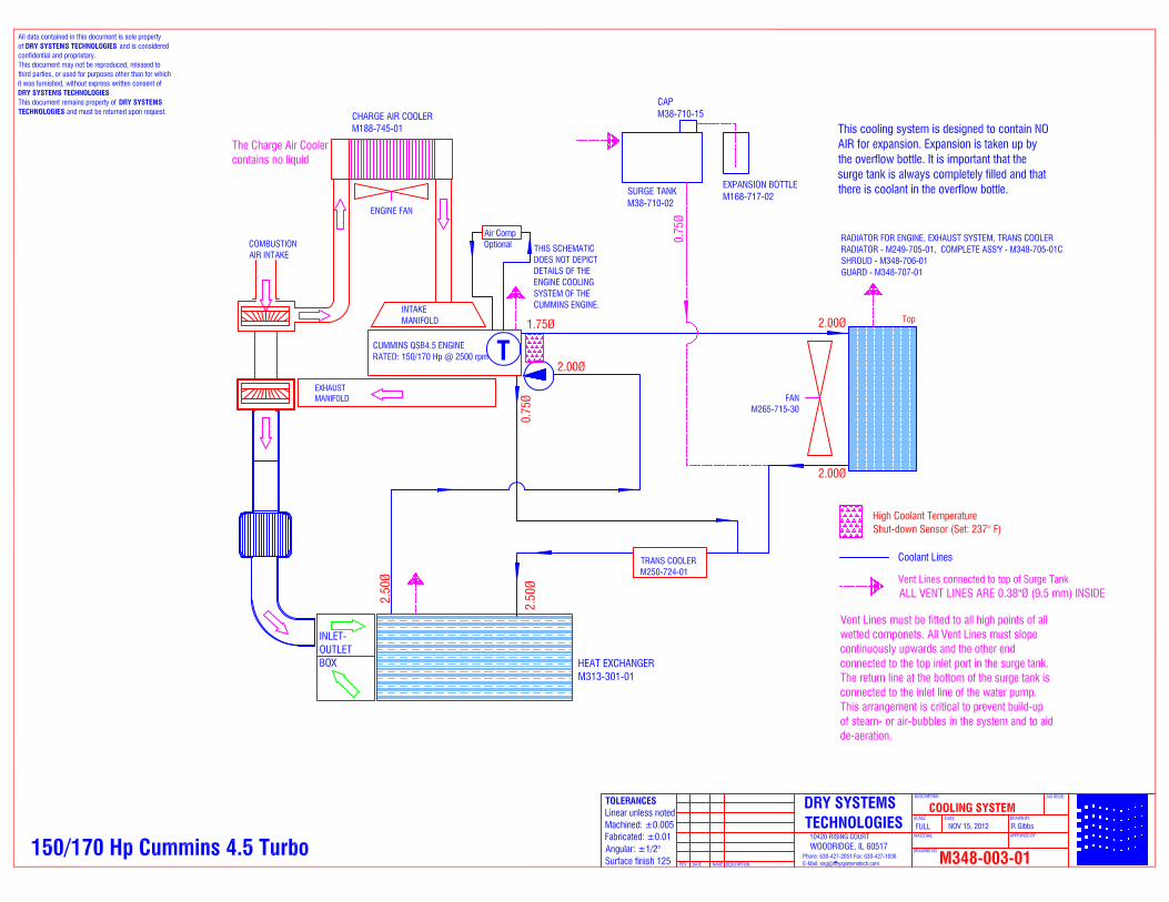
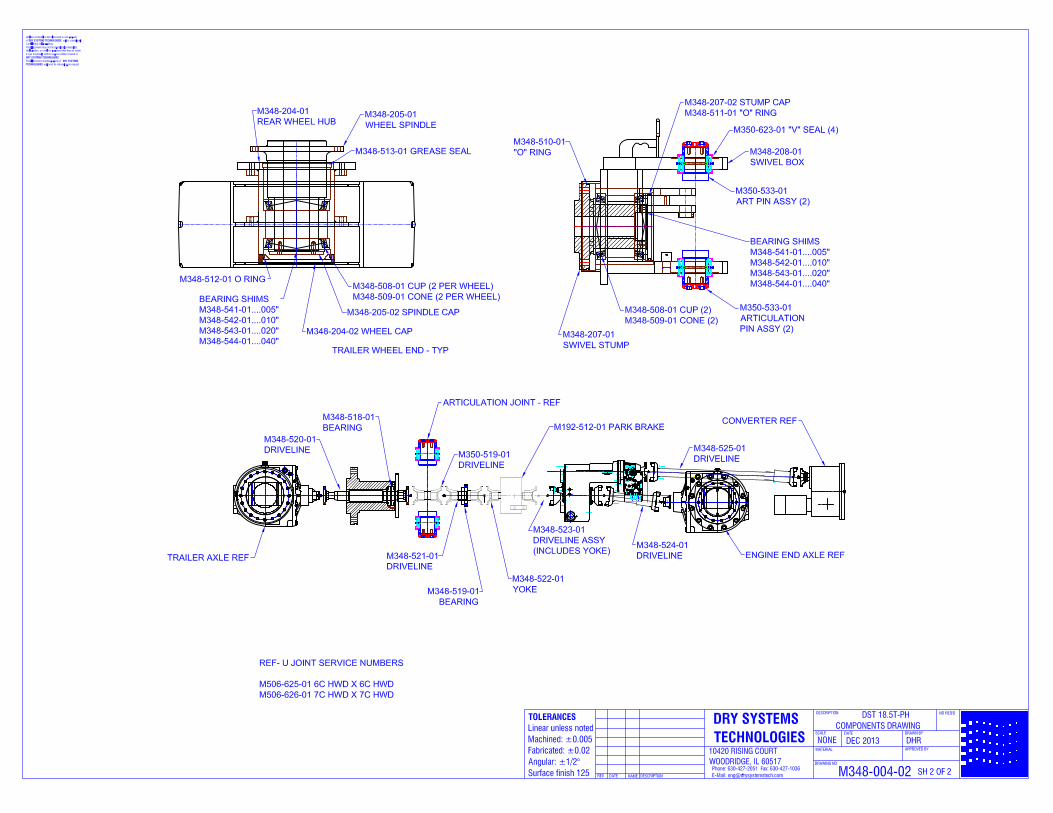

I
AEB1560 Page 148 of 157
193 520199 3 Amber Cruise Control Cruise Control (Resistive) Signal Circuit - Voltage Above Normal or Shorted to High Source
194 520199 4 Amber Cruise Conlrol Cruise Control (Resistive) Signal Circuit - Voltage Below Normal or Shorted to Low Source
195 111 3 Amber Coolant Level Coolant Level Sensor Circuit - Voltage Above Normal or Shorted to High Source
196 111 4 Amber Coolant Level Coolant Level Sensor Circuit - Voltage Below Normal or Shorted to Low Source
197 111 18 Amber Coolant Levet Coolant Levet - Data Valid but Below Normal Operational Range - Moderately Severe Level
199 1661 4 Amber Engine Automatic Start Lamp Engine Automatic Start Lamp Driver Circuit shyVoltage Above Normal or Shorted to High Source
211 1484 31 None J1939 Error Additional Auxiliary Diagnostic Codes logged middot Condition Exists
212 175 3 Amber Oil Temp_erature Engine Oil Temperature Sensor 1 Circuit middot Voltage Above Normal or Shorted to High Source
213 175 4 Amber Oil Temperature Engine Oil Temperature Sensor 1 Circuitmiddot Voltage Below Normal or Shorted to Low Source
214 175 0 Red Oil Temperature Engine Oil Temperalure - Dala Valid but Above Normal Operational Rangemiddot Most Severe Level
221 108 3 Amber Baromelric Pressure Barometric Pressure Sensor Circuit - Voltage Above Normal or Shorted to High Source
222 108 4 Amber Barometric Pressure Barometric Pressure Sensor Circuit - Voltage Below Normal or Shorted to Low Source
227 35t O 3 Amber 5 Volts DC Supply Sensor Supply Voltage 2 Circuit - Voltage Above Normal or Shorted to High Source
231 109 3 Amber Coolant Pressure Coolant Pressure Sensor Circuit - Voltage Above Normal or Shorted to High Source
232 109 4 Amber Coolant Pressure Coolant Pressure Sensor Circuitmiddot Voltage BelOW Normal or Shorted to Low Source
233 109 18 Amber Cool ant Pressu re Coolant Pressuremiddot Data Valid but Below Normat Operational Rangemiddot Moderately Severe Level
234 190 0 Red Engine Speed Engine Speed Highmiddot Data Valid but Above Normal Operational Rangemiddot Most Severe Level
235 111 1 Red Coolant Level Coolant Level Lowmiddot Data Valid but Below Normal Operational Range - Most Severe Level
237 644 2 Amber Ex1emal Speed tnput Ex1ernal Speed Input (Multiple Unit Synchronization) bull Data Erratic Intermittent or Incorrect
238 3511 4 Amber System Diagnostic code 1 Sensor Suppty Voltage 3 Circuit - Voltage Below Normal or Shorted to Low Source
239 3511 3 Amber System Diagnostic code 2 Sensor Supply Voltage 3 Circuit - Voltage Above Normal or Shorted to High Source
241 84 2 Amber Wheel-based Vehicle Speed Vehicle Speed Sensor Circuit - Data Erralic tntermlttent or Incorrecl
242 84 10 Amber Wheel middotbased Vehicle Speed Vehicle Speed Sensor Circuit tampering has been detected - Abnormal R ate of Change
244 623 4 Amber Red Stop Lamp Red Stop Lamp Driver Clrcuil Voltage Below Normal or Shorted to Low Source
245 647 4 Amber Fan Clutch OulDut Device Driver Fan Control Circuitmiddot Voltage Below Normat or Shorted to Low Source
249 171 3 Amber Ambient Air Temperature Ambient Air Temperature Sensor Circuit middot Voltage Above Normal or Shorted to High Source
256 171 4 Amber Ambient Air Temperature Ambient Air Temperature Sensor Circuitmiddot Voltage Betow Normal or Shorted to Low Source
261 174 16 Amber Fuel Temperature
Engine Fuel Temperature - Data Valid but Above Normal Operational Rangemiddot Moderately Severe Level
AEB1560 Page 149 of 157
263 174 3 Amber Fuel Temperature Engine Fuel Temperature Sensor 1 Circuit - Voltage Above Normal or Shorted to Hioh Source
265 174 4 Amber Fuel Temperature Engine Fuel Temperature Sensor 1 Circuit - Voltage Below Normal or Shorted to Low Source
268 94 2 Amber Fuel Delivery Pressure Fuel Pressure Sensor Circuit - Data Erratic Intermittent or Incorrect
271 1347 4 Amber Fuel Pump Pressurizing Assembly 1 High Fuel Pressure Solenoid Valve Circuit - Voltage Below Normal or Shorted to Low Source
272 1347 3 Amber Fuel Pump Pressurizing Assembly 1 High Fuel Pressure Solenoid Valve Circuit - Voltage Above Normal or Shorted to High Source
281 1347 7 Amber Fuel Pump PressurizingAssembly 1
High Fuel Pressure Solenoid Valve 1 - Mechanical System Not Responding Properly or Out of Adjustment
284 1043 4 Amber Internal Sensor Voltage Supply
Engine SpeedPosition Sensor (Crankshaft) Supply Voltage Circuit - Voltage Below Normal or Shorted to Low Source
285 639 9 Amber SAE J1939 Datalink SAE J1939 Multiplexing PGN Timeout Error-Abnormal Update Rale
286 639 13 Amber SAE J1939 Datalink SAE J1939 Multiplexing Configuration Error - Out of Calibration
287
288
91
974
19
19
Red Accelerator Pedal Position
Remote Accelerator
SAE J1939 Multiplexing Accelerator Pedal or Lever Sensor System Error - Received Network Data In Error
SAE J1939 Multiplexing Remote Accelerator Pedal or Lever Data Error - Received Network Data In ErrorRed
292 441 14 Red Auxiliary Temperature 1 Auxiliary Temperature Sensor Input 1 - Special Instructions
293 441 3 Amber OEM Temperature Auxiliary Temperature Sensor Input 1 Circuil shyVoltage Above Normal or Shorted to High Source
294 441 4 Amber OEM Temperature Auxiliary Temperature Sensor Input 1 Circuit-Voltage Below Normal or Shorted to Low Source
295 108 2 Amber Baromelric Pressure Barometric Pressure Sensor Circuit - Data Erratic tntermittent or Incorrect
296 1388 14 Red Auxiliary Pressure Auxiliary Pressure Sensor Input 1 - Special Instructions
297 1388 3 Amber Auxiliary Pressure Auxiliary Pressure Sensor Input 2 Circuil - Voltage Above Normal or Shorted to High Source
298 1388 4 Amber Auxiliary Pressure Auxiliary Pressure Sensor Input 2 Circuit -Voltage Below Normal or Shorted to Low Source
319
322
251
651
2
5
Maint Real Time Clock Power
tnjector Cylinder 01
Real Time Clock Power Interrupt - Data Erralic Intermittenl or Incorrect
Injector Solenoid Cylinder 1 Circuit - Current Below Normal or Open Circuit Amber
323 655 5 Amber Injector Cylinder 05 Injector Solenoid Cylinder 5 Circuit- Current Below Normal or Open Circuit
324 653 5 Amber Injector Cylinder 03 Injector Solenoid Cylinder 3 Circuit - Current Below Normal or Open Circuit
325 656 5 Amber Injector Cylinder 06 Injector Solenoid Cylinder 6 Circuit - Current Below Normal or Open Circuit
331 652 5 Amber Injector Cylinder 02 Injector Solenoid Cylinder 2 Circuit - Current Below Normal or Open Circuit
332 654 5 Amber Injector Cylinder 04 Injector Solenoid Cylinder 4 Circuit - Current Below Normal or Open Circuit
334 110 2 Amber Enqine Coolant Temperature Coolant Temperature Sensor Circuit - Data Erratic Intermittent or Incorrect
AEB1560 Page 150 of 157
I I
I
338 1267 3 Amber Vehicle Accessories Relay Driver
Idle Shutdown Vehicle Accessories Relay Driver Circuit - Voltage Above Normal or Shoned to High Source
I 339 1267 4 Amber Vehicle Accessories Relay Driver
Idle Shutdown Vehicle Accessories Relay Driver Circuit - Voltage Below Normal or Shorted to Low Source
341 630 2 Amber Calibration Memory Engine Control Module data lost - Data Erratic Intermittent or Incorrect
342 630 13 Red Calibration Memory Electronic Calibration Code Incompatibility - Out of Calibration
343 629 12 Amber Controller 1 Engine Control Module Warning internal hardware failure - Bad Intellic)ent Device or Component
I
349 191 16 Amber Transmission Output Shaft Speed
Transmission Output Shaft Speed - Data Valid but Above Normal Operational Range - Moderately Severe Level
351 627 12 Amber Controller 1 Injector Power Supply - Bad Intelligent Device or Component
352 3509 4 Amber 5 Volts DC Supply Sensor Supply Voltage 1 Circuit - Voltage Below Normal or Shoned to Low Source
386 3509 3 Amber 5 Volts DC Supply Sensor Supply Voltage 1 Circuit - Voltage Above Normal or Shoned to High Source
415 100 1 Red Engine Oil Pressure Oil Pressure Low - Data Valid but Below Normal Operational Range - Most Severe Level
418 97 15 Main Water in Fuel Indicator Water in Fuel Indicator High Data Valid but Above Normal Operational Range - Least Severe Level
422 111 2 Amber Coolant Level Coolant Levelmiddot Data Erratic Intermittent or Incorrect
425 175 2 Amber Oil Temperature Engine Oil Temperaturemiddot Data Erratic Intermrttent or Incorrect
428 97 3 Amber Water in Fuel Indicator Water in Fuel Sensor Circuit - Voltage Above Normal or Shorted to High Source
I 429 97 4 Amber Water in Fuel Indicator Water in Fuel Sensor Circuit - Voltage Below Normal or Shorted to Low Source
I 431 558 2 Amber Accelerator Pedal Low Idle Switch Accelerator Pedal or Lever Idle Validation Circuit shyData ErratiC Intermittenl or Incorrect
432 558 13 Red Accelerator Pedal Low Idle Switch Accelerator Pedal or Lever Idle Validation Circuit shyOut of Calibration
435 100 2 Amber Engine Oil Pressure Oil Pressure Sensor Circuitmiddot Data Erratic Intermittent or Incorrect
441 168 18 Amber Etectrical Potential (Volti3fle)
Battery 1 Voltage Low - Data Valid but Below Normal Operational Range - Moderately Severe Level
442 168 16 Amber Electrical Potential (Voltage)
Battery 1 Voltage High - Data Valid but Above Normal Operational Range - Moderately Severe Level
449 157 a Red Injector Metering Rail 1 Pressure Fuel Pressure Highmiddot Data Valid but Above Normal Operational Range - Moderately Severe Level
451 157 3 Amber Injector Metering Rail 1 Pressure Injector Metering Rail 1 Pressure Sensor Circuitmiddot Voltage Above Normal or Shoned to High Source
452 157 4 Amber Iniector Metering Rail 1 Pressure Injector Metering Rail 1 Pressure Sensor Circuitmiddot Voltage Below Normal or Shorted to Low Source
488 105 16 Amber Intake Manifold
Intake Manifold 1 Temperaturemiddot Data Valid but Above Normal Operational Range - Moderately Severe Level
489 191 18 Amber Transmission Output Shalt Speed
Transmiss ion Output Shalt Speed Data Valid but Below Normal Operational Range - Moderately Severe Level
AEB1560 Page 151 of 157
I 497 1377 2 Amber Switch Circuit Multiple Unit Synchronization Switch Circuil - Data Erratic Intermittent or Incorrect
523 611 2 Amber System Diagnostic code 1 OEM Intermediate (PTO) Speed switch Validalion shyData Erratic Intermillent or Incorrect
I
527 702 3 Amber Circuit - Voltage Auxiliary InputOulput 2 Circuil - Voltage Above Normal or Shorted to High Source
528 93 2 Amber Switch - Data Auxiliary Altemate Torque Validation Switch - Data Erratic Intermittent or Incorrect
529 703 3 Amber Circuit - VoltltlJLe Auxiliary InpuVOutput 3 Circuit - Voltage Above Normal or Shorted to High Source
546 94 3 Amber Fuel Delivery Pressure Fuel Delivery Pressure Sensor Circuit - Voltage Above Normal or Shorted to High Source
I 547 94 4 Amber Fuel Delivery Pressure Fuel Delivery Pressure Sensor Circuit - Voltage Below Normal or Shorted to Low Source
551 558 4 Amber Accelerator Pedal Low Idle Switch Accelerator Pedal or Lever Idle Validation Circuit shyVoltage Below Normal or Shorted to Low Source
553 157 16 Amber Injeclor Melering Rail 1 Pressure
Injector Metering Rail 1 Pressure High - Data Valid but Above Normal Operational Range - Moderately Severe Level
554 157 2 Amber Injector Meterinltl Rail 1 Pressure Fuel Pressure Sensor Error - Data Erratic Intermittent or Incorrecl
559 157 18 Amber Injector Metering Rail 1 Pressure
Injector Metering Rail 1 Pressure Low - Data Valid but Below Normal Operational Range - Moderately Severe Level
584 677 3 Amber Slarter Solenoid Lockout Relay Driver Circuit Slarter Relay Circuil - Voltage Above Normal or Shorted to High Source
585 677 4 Amber Starter Solenoid Lockout Relay Driver Circuit Starter Relay Circuit - Voltage Below Normal or Shorted to Low Source
595 103 16 Amber Turbocharger 1 Speed
Turbocharger 1 Speed High - Data Valid but Above Normal Operational Range - Moderately Severe Level
596 167 16 Amber Alternate Potential lvolt~
Electrical Charging System Voltage High - Data Valid but Above Normal Operational Range -Moderately Severe Level
597 167 18 Amber Allernate Potential (voltage)
Electrical Charging System Voltage Low - Data Valid bul Below Normal Operational Range -Moderately Severe Level
598 167 1 Red Alternate Potential (voltage)
Electrical Charging Syslem Voltage Low - Data Valid but Below Normal Operational Range - Most Severe Level
599 640 14 Red Engine External Protection Input Auxiliary Commanded Dual Output Shutdown -Spedal Instructions
649 1378 31 Maint Engine Oi l Change Interval Change Lubricating Oil and Filter - Condition Exists
687 103 18 Amber Turbocharger 1 Speed
Turbocharger 1 Speed Low - Data Valid but Below Normal Operalional Range - Moderately Severe Level
689 190 2 Amber Engine Speed Primary Engine Speed Sensor Error - Data Erratic Intermillent or Incorrecl
691 1172 3 Amber Turbocharger 1 Compressor Inlet Temperature
Turbocharger 1 Compressor Inlet Temperature Sensor Circuit - Voltage Above Normal or Shorted to I-ligh Source
692 1172 4 Amber Turbocharger 1 Compressor Inlet Temperature
Turbocharger 1 Compressor Inlel Temperature Sensor Circuit - Vollage Below Normal or Shorted to Low Source
697 1136 3 Amber Sensor Circuit - Voltaltle ECM Inlernal Temperature Sensor Circuit - Voltage Above Normal or Shoned 10 High Source
698 1136 4 Amber Sensor Circuil bull Voltaltle ECM Intemal Temperalure Sensor Circuil - Voltage Below Normal or Shoned 10 Low Source
AEB15 60 Page 1 52 of 1 57
719 22 3 Amber Crankcase Pressure Extended Crankcase Blow-by Pressure Circuit -Voltage Above Normal or Shorted to High Source
729 22 4 Amber Crankcase Pressure Extended Crankcase BlOW-by Pressure Circuit shyVoltage Below Normal or Shorted to Low Source
731
757
723
2802
7
31
Amber
Amber
Engine Speed Sensor 2
Electronic Control Module
Engine SpeedlPosition 2 mechanical misalignment between camshaft and crankshaft sensors-Mechanical System Not Responding Properly or Out of Adjustment
Electronic Control Module data lost - Condition Exists
778 723 2 Amber Engine Speed Sensor 2 Engine Speed Sensor (Camshaft) Error - Data Erratic Intermittent or tncorrect
779 703 11 Amber Auxiliary Equipment Sensor Input Waming Auxiliary Equipment Sensor Input 3 (OEM Switch) - Root Cause Not Known
951 166 2 None Cylinder Power Cylinder Power Imbala nce Between Cylinders shyData Erratic IntermiHent or Incorrect
1117 627 2 None Power Supply Power Lost With Ignition On - Data Erratic Intermittent or Incorrect
1139 651 7 Amber Injector Cylinder 01 Injector Cylinder 1 - Mechanical System Not Respondinq Properl~or Out 01 Adjustment
1141 652 7 Amber Injector Cylinder 02 Injector Cylinder 2 - Me chanical System Not Respondinq Property or Out of Adjustment
1142 653 7 Amber Injector Cylinder 03 Injector Cylinder 3 - Mechanical System Not Responding Properly or Out of Adjustment
1143 654 7 Amber Iniector Cylinder 04 Injector Cylinder 4 - Mech anical System Not Responding Property or Out of Ad justmen t
1144 655 7 Amber Injector Cylinder 05 Injector Cy1 inder 5 - Mechanical System Not Responding Property or Out of Ad justment
1145 656 7 Amber Injector Cylinder 06 Injector Cylinder 6 - Mechanical System Not Respondinq Property or Out of Adiustment
1239 2623 3 Amber Accelerator Pedal Position Accelerator Pedal or Lever Position Sensor 2 Cincuit - Voltaqe Above Normal or Shorted to Hiqh Source
1241 2623 4 Amber Accelerator Pedal Position Accelerator Pedal or Lever Position Sensor 2 Circuit - Voltage Below Normal or Shorted to Low Source
1242 91 2 Red Accelerator Pedal Position Accelerator Pedal or Lever Position Sensor 1 and 2 - Data Erratic Intermittent or Incorre ct
1256 1563 2 Amber Control Module Identifi cation Input State Control Module Identification Input State Error shyData Erratic Intermittent or Incorrect
1257 1563 2 Red Control Module Identification Input State Control Module Identificat ion Input State Error shyData Erratic Intermittent or Incorrect
1852 97 16 Amber Water in Fuel Indicator
Water in Fuel Indicator - Data Valid but Above Normal Operational Range - Moderately Severe Level
1911 157 0 Amber Injector Metering Rait
Injector Metering Ra il 1 Pressure - Data Val id but Above No rmal Operational Range - Most Severe Level
2111 52 3 Amber Coolant Temperature Coolant Temperature 2 Sensor Circuit - Vo ltage AbOve Normal or Shorted to Hiqh Source
2112 52 4 Amber Coolant Temperature Coolant Temperature 2 Sensor Circuit - Volt age Below Normal or Shorted to Low Source
211 3 52 16 Amber Coolant Temperature
Coolant Temperature 2 - Data Valid but Above Normal Operational Range - Moderately Severe Level
2114 52 0 Red Coolant Temperature Coolant Temperature 2 - Data Valid bu t Above Normal Operational Range - Most Severe Level
2115 2981 3 Amber Coolant Pressure Coolant Pressure 2 Circuit- Voltage Above Normal or Shorted to High Source
AEB1560 Page 153 of 157
Coolant Pressure 2 CirculI Voltage Below Normal 4 Amber Coolant Pressure or Shorted to Low Source
Coolant Pressure
3 Amber ut 1
4
2185 3512 3 Amber
2186 35 S code 1
2195 703 14 Red Auxilia ment Sensor
Fuel Pump Delivery Pressure Data Valid but Below Normal Operational Range Moderalely Severe
2215 94 18 Amber Fuel Delive Pressure Level
Fuel Pump Delivery Pressure - Data Valid but Above Normal Operational Range Moderately
2216 94 Amber Fuel Delive Pressure Severe Level
ECM Memory (RAM) Corruption shy2217 630 31 Amber CalibraUon Memo
Injector Metering Rail 1 Pressure - Data Valid but Below Normal Operational Range - Most Severe
2249 157 Amber Level
Fuel Pump Delivery Pressure - Data Valid but Above Normal Operational Range - Leasl Severe
2261 94 15 Mainl Fuel Delive Pressure Level
Fuel Pump Delivery Pressure Data Valid but Below 94 17 Maint Fuel Deiive Pressure Normal Ooeralional Ran emiddot Least Severe Level
2263 1800 16 Amber Batte
2264 1800 18 Amber Batie
2265 1075 3 Amber Electric Lift Pum ine Fuel
2266 4 Amber Electric Lift Pum ine Fue
Fuel Inlet Meter Device - Data Valid but Above Normal Operational Range - Moderately Severe
2292 611 16 Amber Fuel Inlet Meter Device Level
Fuel Inlet MeIer Device flow demand lower than expected - Data Valid but Below Normal Operal
2293 611 18 Amber Fuel Inlet Meter Device Ran e - Moderatel Severe Level
2311 633 31 Amber Fuel Control Valve 1
I POSition Sensor 1 2321 190 2
2322 723 2
Turbocharger speed invatid rate of change d 2345 103 10 Amber - Abnormal Rate of Chan e
Turbine Inlel Temperature Data Valid but Above Normal
2346 2789 15 None e Lea sl Severe Level
2347 2790 15 None
AEB1560 Page 154 of 157
2363 1073 4 Amber Engine Compression Brake Output 2 Engine Brake Actuator Circuit 2 - Voltage Below Normal or Shorted to Low Source
2365 1112 4 Amber Engine Brake Output 3 Engine Brake Actuator Driver Output 3 Circuit shyVoltage Below Normal or Shorted to Low Source
I2367 1073 3 Amber Engine Compression Brake Ou~ut 2 Engine Brake Actuator Circuit 2 - Voltage Above Normal or Shorted to High Source
2368 1112 3 Amber EnQine Brake Output 3 Engine Brake Actuator Driver 3 Circurt - Voltage Above Normal or Shorted to High Source
I 2372 95 16 Amber Engine Fuel Filler DiHerential Pressure
Fuel Filter DiHerential Pressure - Data Valid but Above Normal Operational Range - Moderately Severe Level
2373 1209 3 Amber Exhaust Gas Pressure Exhaust Gas Pressure Sensor Circuit - Voltage Above Normal or Shorted to High Source
2374 1209 4 Amber Exhaust Gas Pressure Exhaust Gas Pressure Sensor Circuit - Voltage Betow Normal or Shorted to Low Source
2375 412 3 Amber Exhaust Gas Recirculation Temperature
Exhausl Gas Recirculation Temperature Sensor CirCUIt - Voltage Above Normat or Shorted to High Source
2376 412 4 Amber Exhaust Gas Recirculation Temperature
Exhaust Gas Recirculation Temperature Sensor Circuit - Voltage Below Normal or Shorted to Low Source
2377 647 3 Amber Fan Clutch Output Device Driver Fan Control Circuit - Voltage Above Normal or Shorted to High Source
2425 730 4 Intake Air Heater 2 Intake Air Healer 2 Circuit - Voltage Below Normal or Shorted to Low Source
2426 730 3 Intake Air Heater 2 Intake Air Heater 2 Circuit - Voltage Above Normal or Shorted to High Source
2555 729 3 Amber Inlet Air Heater Driver 1 Intake Air Heater 1 Circuit - Voltage Above Normat or Shorted to High Source
2556 729 4 Amber Intet Air Heater Driver 1 Intake Air Heater 1 Circuit - Voltage Below Nonnal or Shorted to Low Source
2557 697 3 Amber Auxiliary PWM Driver 1 Auxiliary PWM Driver 1 - Voltage Above Normal or Shorted to Hiq h Source
2558 697 4 Amber Auxiliary PWM Driver 1 Auxiliary PWM Driver 1 - Voltage Below Normal or Shorted to Low Source
2963 110 15 None Engine Coolant Temperature
Engine Coolant Temperature High - Dala Valid but Above Normal Operational Range - Least Severe Level
2973 102 2 Amber Boost Pressure Intake Manifold Pressure Sensor Circuitmiddot Data Erratic Intermittent or Incorrect
DRY SYSTEMS TECHNOLOGIESreg Technology for a cleaner environment
DST Operation and Maintenance Index ndash M301-016-11 ON BOARD CLEANING SYSTEM FOR OUTBY MACHINE M301-018-01 CO SAMPLING PROCEDURE M301-019-01 PRE-OP INSPECTIONS M301-021-01 COOLING SYSTEM FILLING PROCEDURE
1430 US HIGHWAY 45 N VIENNA ILLINOIS 62995 PHONE 618-658-3000 FAX 618-658-3002 wwwdrysystemstechcom
DDRRYY SSYYSSTTEEMMSS TTEECCHHNNOOLLOOGGIIEESSregreg
OOPPEERRAATTIIOONN AANNDD MMAAIINNTTEENNAANNCCEE MMAANNUUAALL
DDSSTT DDRRYY SSYYSSTTEEMMregreg
SSEECCTTIIOONN AA OONN BBOOAARRDD CCLLEEAANNIINNGG SSYYSSTTEEMM
FFOORR OOUUTTBBYY MMAACCHHIINNEE
MM330011--001166--1111
DRY SYSTEMS TECHNOLOGIES 8102 Lemont Road Suite 700
WOODRIDGE IL 60517 USA Phone 630-427-2051 Fax 630-427-1036
E-mail engdrysystemstechcom
DATED MARCH 2007 6 Pages
DDRRYY SSYYSSTTEEMMSS TTEECCHHNNOOLLOOGGIIEESS 8102 Lemont Road Suite 700 Woodridge Illinois 60517 USA
Phone 630-427-2051 Fax 630-427-1036 EE--mmaaiill eennggddrryyssyysstteemmsstteecchhccoomm
OPERATION AND MAINTENANCE MANUAL PART A M301-016-11 INSTRUCTIONS FOR USING THE ON-BOARD CLEANING SYSTEM AND FOR REPLACING THE EXHAUST PARTICULATE FILTER
Background
The Dry Systemtrade supplied by Dry Systems Technologiesreg consists of a unique patented arrangement of components that provide a diesel power package and superior emissions reduction from diesel engines The system can operate at very minimal maintenance but requires some attention by the operator to maintain its permissibility and clean exhaust The Dry Systemtrade is fitted with a tube-and-shell heat exchanger It reduces the exhaust temperature from about 950-1150deg F in the manifold to a safe temperature of less than 300deg F before exhausting to the atmosphere Because of the rapid cooling of the exhaust gases inside the heat exchanger the airborne sub-micron diesel particles agglomerate (cling to each other) and form larger particles However some of these particles attach themselves to the cold tube walls where they accumulate over time This process is completely normal as part of the operation of the Dry Systemtrade or any system that cools the exhaust gases After the particle accumulation has reached a certain thickness the tubes become partially restricted and both exhaust backpressure and temperature increase The exhaust backpressure and the exhaust gas temperature can be monitored on the exhaust-backpressure gauge and the exhaust-temperature gauge which are conveniently mounted in the operatorrsquos compartment It is the responsibility of the operator to monitor the exhaust backpressure and exhaust temperature gauges frequently while operating the diesel machine
Activating the On-board Cleaning System Once the exhaust backpressure increases the removal of these internal deposits is necessary to maintain a clean and safe exhaust system The Dry Systemtrade is equipped with a patented On-board Cleaning Systemtrade that allows removal of the soot deposits while operating the machine The On-board Cleaning Systemtrade consists of a small water supply bottle a metered actuator and an injection nozzle The 1 quart (1 liter) water bottle is located inside the engine compartment contains several shifts supply and must be filled with clean water (such as bottled water or drinking water) only The injection nozzle is located near the inlet of the heat exchanger A cab mounted push button or valve is all the operator needs to perform the cleaning process while operating the machine When activated (for five seconds) by the operator with the cab-mounted push button a very small metered amount of water is injected into the hot exhaust inlet of the heat exchanger The water flashes into steam and expands to more than 200 times of its original volume This sudden pressure rise (and not the water itself) causes the soot deposit to dislodge from the tube walls to be carried downstream by the exhaust gas to the particulate filter where it is trapped
Part A On-Board Cleaning and Filter Change Page 2
DDRRYY SSYYSSTTEEMMSS TTEECCHHNNOOLLOOGGIIEESS 8102 Lemont Road Suite 700 Woodridge Illinois 60517 USA
Phone 630-427-2051 Fax 630-427-1036 EE--mmaaiill eennggddrryyssyysstteemmsstteecchhccoomm
OPERATION AND MAINTENANCE MANUAL PART A M301-016-11 INSTRUCTIONS FOR USING THE ON-BOARD CLEANING SYSTEM AND FOR REPLACING THE EXHAUST PARTICULATE FILTER
This procedure is the most important action the operator has to take Neglect of this operation will cause high exhaust backpressure which will inevitably lead to reduced filter life and triggering of the safety shut-down system Using the On-board Cleaning Systemtrade properly is the responsibility of the machine operator There will be no visible water vapor or smoke emitted from the exhaust system while the on-board cleaning system is activated The only indication to verify proper injection is to monitor the exhaust gauges Initially the exhaust backpressure will rise followed by a drop to below its starting point There should also be a small simultaneous reduction in exhaust gas temperature The most effective time to activate the On-board Cleaning Systemtrade is when the engine is hot and under load At a minimum the On-board Cleaning Systemtrade should be activated twice each operating shift and while the engine is hot and working hard There is no harm done if the On-board Cleaning System is used more often except that the water supply gets depleted quicker The On-board Cleaning Systemtrade will not function on a cold engine or at idle Using the on-board cleaning system on a cold engine and without load on the engine is ineffective Do not activate the On-board Cleaning Systemtrade on a cold engine Frequent use of the on-board cleaning system is a very important step to keep the DST Management System operating efficiently and safely The amount of water that is injected is metered by the five seconds that the button is held The On-board Cleaning System is ready for use immediately after release of the electric push button that is located in the operatorrsquos compartment
It is the responsibility of the operator to activate the On-board Cleaning System at least twice a shift with the engine hot and under load more often if judged necessary It is safe to activate the On-board Cleaning System in any part of the mine where diesel equipment may be operated
Part A On-Board Cleaning and Filter Change Page 3
DDRRYY SSYYSSTTEEMMSS TTEECCHHNNOOLLOOGGIIEESS 8102 Lemont Road Suite 700 Woodridge Illinois 60517 USA
Phone 630-427-2051 Fax 630-427-1036 EE--mmaaiill eennggddrryyssyysstteemmsstteecchhccoomm
OPERATION AND MAINTENANCE MANUAL PART A M301-016-11 INSTRUCTIONS FOR USING THE ON-BOARD CLEANING SYSTEM AND FOR REPLACING THE EXHAUST PARTICULATE FILTER
Diagnosing High Exhaust Backpressure The typical life cycle of the Disposable Exhaust Particulate Filter (DPM Filter) can range from 40-100 hours depending on the operating cycle of the machine Once the exhaust system backpressure can no longer be reduced by the On-board Cleaning Systemtrade the DPM Filter maybe loaded to its capacity Before changing the filter a quick diagnostic test should be performed to determine if the filter is fully loaded or if the heat exchanger is fouled and needs flushing An optional diagnostic gauge that measures the differential pressure across the heat exchanger is installed inside the engine compartment The reading of this gauge together with the backpressure gauge taken under full engine speed and no load (high idle) can be used to determine the next action
bull A reading of the backpressure gauge at or near the maximum combined with a pressure differential across the heat exchanger (diagnostic gauge) in the range of 8-12rdquo WG is an indication of a loaded filter The next step should be to exchange the loaded exhaust particulate filter with a clean exhaust particulate filter
bull A reading of the backpressure gauge at or near the maximum combined with a pressure differential
across the heat exchanger (diagnostic gauge) greater than 20rdquo WG is an indication of excessive soot deposit in the heat exchanger The higher the reading on the diagnostic gauge the more soot has built up inside the heat exchanger THIS MAY BE AN INDICATION THAT THE ON-BOARD CLEANING SYSTEM HAS NOT BEEN USED PROPERLY OR FREQUENTLY ENOUGH As a first step the On-board Cleaning System should be used (with the engine hot and under load) to see if the pressure across the heat exchanger can be reduced
bull If the backpressure in the heat exchanger can not be reduced significantly the next step should be to
schedule the machine for flushing of the exhaust system by a trained and qualified mechanic
bull REF MWM 916 The maximum allowable exhaust backpressure is 40rdquo WG Caterpillar 3300 PCNA The maximum allowable exhaust backpressure is 34rdquo WG Caterpillar 3300 PCTA C-10 The maximum allowable exhaust backpressure is 27rdquo WG Cummins C83 The maximum allowable exhaust backpressure is 41rdquo WG Isuzu 6BG1 The maximum allowable exhaust backpressure is 41rdquo WG
It is the responsibility of the operator to perform the initial diagnostic test It is safe to activate the on-board cleaning system in any part of the mine where diesel equipment may be operated Any flushing operation must be scheduled through maintenance
Part A On-Board Cleaning and Filter Change Page 4
DDRRYY SSYYSSTTEEMMSS TTEECCHHNNOOLLOOGGIIEESS 8102 Lemont Road Suite 700 Woodridge Illinois 60517 USA
Phone 630-427-2051 Fax 630-427-1036 EE--mmaaiill eennggddrryyssyysstteemmsstteecchhccoomm
OPERATION AND MAINTENANCE MANUAL PART A M301-016-11 INSTRUCTIONS FOR USING THE ON-BOARD CLEANING SYSTEM AND FOR REPLACING THE EXHAUST PARTICULATE FILTER
Flushing of the System If the On-board Cleaning Systemtrade is used as described above and if engine operation under light load and excessive idling are minimized flushing of the exhaust system should seldom become necessary Flushing of the exhaust system must be performed by a trained and qualified mechanic and at an approved location Should flushing become necessary keep in mind that this not the same as on-board cleaning Flushing of the DST Dry Systemtrade is performed by attaching an external water supply hose to the connecting port Unlike during On-board Cleaningtrade that uses only a few ounces of water significant amounts (several gallons) of water are passed through the exhaust system during flushing operation This will remove the soot deposited inside the heat exchanger that is not removed during On-board Cleaningtrade Flushing may be performed during any time of the operating cycle but only at a suitable location as follows
bull The machine MUST be located at an outby area of the mine or a shop bull Ventilation in the area should be into the return air bull Water must be available at the area bull Remove the exhaust filter according to the ldquoParticulate Filter replacing procedurerdquo and make provisions
to capture water from the filter housing bull Attach the external water hook-up to the system bull Start the engine make sure it is up to operating temperature bull Run the engine at high idle speed and record the heat exchanger differential pressure bull At high idle speed open the water valve to allow continuous water-flow through the water injector for
about 1- 2 minutes bull Close the water valve and continue running the engine for 3-5 minutes to allow the exhaust system to
dry out Check for the change in the heat exchanger differential pressure gauge A normal reading would be 8-14rdquo WG A higher reading indicates that there still are soot deposits inside the system
bull If needed repeat the flushing as described above bull If successful install a new exhaust filter according to the ldquoExhaust Filter replacing procedurerdquo
Do not perform the flushing procedure underground without a filter in place or if there are indications that the filter has become damaged during the flushing Flushing without a particulate filter installed must be performed as follows
bull Remove the particulate filter and provide for some means to capture the water from the exhaust system bull Re-install the lid to the filter housing bull Make sure there is proper ventilation to remove the unfiltered diesel exhaust from the work area
Part A On-Board Cleaning and Filter Change Page 5
DDRRYY SSYYSSTTEEMMSS TTEECCHHNNOOLLOOGGIIEESS 8102 Lemont Road Suite 700 Woodridge Illinois 60517 USA
Phone 630-427-2051 Fax 630-427-1036 EE--mmaaiill ddrryyssyysstteemmsstteecchhccoomm
OPERATION AND MAINTENANCE MANUAL PART A M301-016-11 INSTRUCTIONS FOR USING THE ON-BOARD CLEANING SYSTEM AND FOR REPLACING THE EXHAUST PARTICULATE FILTER
bull Install the external water hook-up to the system bull Set the brakes and start the engine make sure it is up to operating temperature bull Run the engine at high idle speed and record the heat exchanger differential pressure bull At high idle speed open the water valve to allow continuous water-flow through the water injector until
the water out of the exhaust system is clear (Typically 10-15 minutes) bull Close the water valve and continue running the engine for 5 minutes to allow the exhaust system to dry
out Check for the change in the heat exchanger differential pressure gauge A normal reading is 8-12rdquo bull If successful install a new particulate filter according to the ldquoParticulate Filter replacing procedurerdquo
Do not perform the flushing procedure without proper ventilation and without a provision to capture the soot and water from the exhaust
Procedure to replacing the Particulate Filter Replacing the DST particulate filter may be performed in any part of the mine where diesel equipment can be operated The diesel engine must be stopped during the entire time while the exhaust filter is being replaced Proceed as follows
bull Open the lid to the exhaust particulate filter housing bull Release the manual clamp or clamping cylinders with the valve at the end of the filter housing bull Remove the new exhaust filter from its shipping box and inspect for damage from shipping and
handling bull Remove the loaded exhaust filter from the filter housing inspect for obvious damage or leaks and place
into the empty shipping box and mark the box with ldquoUsedrdquo or ldquoDirtyrdquo Do not grip on the inside of the filter where the soot is deposited Gloves should be worn while handling the dirty filter
bull Check the inside of the exhaust filter housing Report any soot deposits to the Maintenance Department bull Inspect the seal groove inside the filter housing Make sure there are no remains of seal material or other
matter in the seal groove If necessary remove any remains with a screwdriver or similar tool bull Insert the clean exhaust filter after visual inspections for damage and seal bull Set the manual clamp or clamping cylinders with the valve at the end of the filter housing bull Close the lid to the exhaust filter housing bull Remove the box with the used filter according to disposal procedures at the mine bull Start the engine and check the exhaust backpressure at high idle to be in the normal range
Part A On-Board Cleaning and Filter Change Page 6
DDRRYY SSYYSSTTEEMMSS TTEECCHHNNOOLLOOGGIIEESSregreg
OOPPEERRAATTIIOONN AANNDD MMAAIINNTTEENNAANNCCEE MMAANNUUAALL
DDSSTT DDRRYY SSYYSSTTEEMMregreg
SSEECCTTIIOONN CC CCOO SSAAMMPPLLIINNGG PPRROOCCEEDDUURREE
To be performed by a trained and qualified mechanic
MM330011--001188--0011
DRY SYSTEMS TECHNOLOGIES 8102 Lemont Road Suite 700
WOODRIDGE IL 60517 USA Phone 630-427-2051 Fax 630-427-1036
E-mail engdrysystemstechcom
REVISION 01 DATED DECEMBER 2002 8 Pages
DDRRYY SSYYSSTTEEMMSS TTEECCHHNNOOLLOOGGIIEESS 8102 Lemont Road Suite 700 Woodridge Illinois 60517 USA
Phone 630-427-2051 Fax 630-427-1036 EE--mmaaiill eennggddrryyssyysstteemmsstteecchhccoomm
OPERATION AND MAINTENANCE MANUAL PART C M301-018-01 CO (Carbon Monoxide) SAMPLING INSTRUCTIONS FOR THE DST DRY SYSTEMtrade
Background
MSHA requires that the engine-out untreated Carbon Monoxide of all Inby and heavy-duty Outby engines be checked weekly The following is the applicable text (excerpts) that may be found in the MSHA 30 CFR Part 751914 (g) Regulations The test for untreated (engine out) CO emissions is mandatory and will also provide excellent feedback to the mechanic on the engine condition
sect751914 Maintenance of diesel-powered Equipment
(a) Diesel-powered equipment shall be maintained in approved and safe condition or removed from service
(b) Maintenance and repairs of approved features and those features required by Sections 751909 and 751910 on diesel-powered equipment shall be made only by a person qualified under Section 751915
(c) helliphellip (d) helliphellip (e) helliphellip (f) helliphellip
(g) Undiluted exhaust emissions of diesel engines in diesel-powered equipment approved under part 36 and heavy-duty non-permissible diesel- powered equipment as defined in Section 751908(a) in use in underground coal mines shall be tested and evaluated weekly by a person who is trained to perform this task The mine operator shall develop and implement written standard operating procedures for such testing and evaluation that specify the following
(1) The method of achieving a repeatable loaded engine operating condition for each type of equipment
(2) Sampling and analytical methods (including calibration of instrumentation) that are capable of accurately detecting carbon monoxide in the expected concentrations
(3) The method of evaluation and interpretation of the results
(4) The concentration or changes in concentration of carbon monoxide that will indicate a change in engine performance Carbon monoxide concentration shall not exceed 2500 parts per million
(5) The maintenance of records necessary to track engine performance
Part C CO Sampling Instructions Page 2
DDRRYY SSYYSSTTEEMMSS TTEECCHHNNOOLLOOGGIIEESS 8102 Lemont Road Suite 700 Woodridge Illinois 60517 USA
Phone 630-427-2051 Fax 630-427-1036 EE--mmaaiill eennggddrryyssyysstteemmsstteecchhccoomm
OPERATION AND MAINTENANCE MANUAL PART C CO (Carbon Monoxide) SAMPLING INSTRUCTIONS FOR THE DST DRY SYSTEMtrade The reasons for monitoring Engine-out CO Emissions CO sampling became a mandatory procedure when MSHA released the new Part 75 regulations It was introduced to ensure that diesel engines are operated in ldquoas-approvedrdquo condition and settings In most instances when a diesel engine develops a problem the CO output will increase Other emissions do not necessarily follow the same trend Under normal operating conditions (at torque stall) CO output ranging from 200-300 ppm should be expected from a MWM D916-6 engine 300-400 ppm for a Caterpillar 3300 engine Whenever abnormally high CO is observed an engine problem should be suspected because CO increases when an engine develops a fault Increased CO will not pinpoint to a specific problem but based on past experience the following may have happened (In order of probability)
bull The Intake Air Cleaner is plugged causing too high an intake air restriction and air starvation of the engine This makes the engine run too rich (A plugged intake air cleaner is the cause in more than frac34 of all cases)
bull Fuel injector problems which could be a bad spray pattern of an injector and cause incomplete combustion
bull Improper fuel pump adjustment by having the fuel pump adjusted too rich or not properly de-rated for the operating altitude This makes the engine run too rich
bull Mechanical problems with the engine such as bad valve seals leaking piston rings low compression or similar problems (Not frequent cause)
bull The exhaust system is restricted causing too high a backpressure CO (Carbon Monoxide) is an excellent diagnostic tool for the maintenance department to detect engine problems before they lead to failures It has been used successfully by many mines in a similar way as oil analysis The main purpose of CO sampling is to minimize exposure of the operator and other personnel to diesel exhaust
The reasons for monitoring treated CO Emissions (after catalyst) (Optional) The DST Dry Systemtrade is fitted with a catalyst that will reduce CO by up to 90 at exhaust temperatures above 300degF A typical treated CO level in the exhaust is 20-40 ppm If the catalyst would develop a problem the treated CO levels will increase significantly Therefore whenever there is higher than normal CO a problem with the catalyst should be suspected If the treated CO levels are continuously greater than 100 ppm the catalyst must be removed and checked for fouling
Part C CO Sampling Instructions Page 3
DDRRYY SSYYSSTTEEMMSS TTEECCHHNNOOLLOOGGIIEESS 8102 Lemont Road Suite 700 Woodridge Illinois 60517 USA
Phone 630-427-2051 Fax 630-427-1036 EE--mmaaiill eennggddrryyssyysstteemmsstteecchhccoomm
OPERATION AND MAINTENANCE MANUAL PART C M301-018-01 CO (Carbon Monoxide) SAMPLING INSTRUCTIONS FOR THE DST DRY SYSTEMtrade
Permanently Installed CO Sampling Ports To simplify this mandatory procedure Dry Systems Technologiesreg developed and offers a permanently installed and MSHA Certified (31D126) Flameproof Porttrade assembly All hardware remains permanently mounted in the exhaust system and on the machine Drawn through a flameproof port a cooling tube and a connecting hose the exhaust gas portion for sampling is routed to the operatorrsquos cab There a soot filter and a water separator condition the exhaust gas to be suitable for CO sampling with simple hand held instruments A quick connect coupling is permanently mounted inside the operatorrsquos cab and allows the sampling from the safe location inside the operatorrsquos cab The mating coupler is attached to the CO sampling instrument Only one person is required to sample the CO An optional Catalyst ndash out sampler may also be provided
Figure 1 Sampling Schematic for untreated and (Optional) treated CO
Part C CO Sampling Instructions Page 4
DDRRYY SSYYSSTTEEMMSS TTEECCHHNNOOLLOOGGIIEESS 8102 Lemont Road Suite 700 Woodridge Illinois 60517 USA
Phone 630-427-2051 Fax 630-427-1036 EE--mmaaiill eennggddrryyssyysstteemmsstteecchhccoomm
OPERATION AND MAINTENANCE MANUAL PART C M301-018-01 CO (Carbon Monoxide) SAMPLING INSTRUCTIONS FOR THE DST DRY SYSTEMtrade CO Sampling Procedure The following is the standard procedure to obtain an accurate and repeatable CO sample
bull Place the machine in a safe location make sure the area in front of the machine is clear and there is sufficient ventilation air Sampling can be conducted in any area of the mine
bull Set the brakes and start the engine as outlined in the Operation and Maintenance Manual bull Allow the engine to warm up to normal operating temperature Taking the CO samples on a cold engine
would provide incorrect results bull Check all operating gauges to be in the normal operating range The coolant temperature must be no
lower than 170degF If the intake restriction is greater than 25rdquo WG or the exhaust backpressure is greater than 35rdquo WG perform the necessary maintenance before proceeding
bull Attach the CO Sampling Device to the quick connect port labeled ldquoEngine Outrdquo in the operatorrsquos cab bull Re-check that the areas in front and behind of the machine are clear and that the parking brakes are set bull Put the transmission into the highest gear and apply full throttle bull Monitor the reading on CO Sampling Device After about 45-90 seconds the CO indication starts rising
Allow this to continue until the CO indication stabilizes bull Start recording (5) separate sequential readings in one-minute intervals Monitor the torque converter
temperature while taking the samples The intervals between the samples may have to be shortened to prevent overheating during the test Do not allow the torque converter temperature to exceed the safe range
bull Stop sampling after (5) readings or before if the torque converter fluid gets too hot bull Slow the engine to low idle put the transmission into neutral then put the engine into high idle (without
load) for about one minute to cool down the torque converter and the engine coolant bull Remove the instrument and enter the CO readings on the report bull Attach the CO Sampling Device to the Optional quick connect port labeled ldquoCatalyzedrdquo in the operatorrsquos
cab bull Re-check that the areas in front and behind of the machine are clear and that the parking brakes are set bull Put the transmission into the highest gear and apply full throttle bull Monitor the reading on CO Sampling Device After about 45-90 seconds the CO indication starts rising
Allow this to continue until the CO indication stabilizes bull Start recording (5) separate sequential readings in one-minute intervals Monitor the torque converter
temperature while taking the samples The intervals between the samples may have to be shortened to prevent overheating during the test Do not allow the torque converter temperature to exceed the safe range
bull Stop sampling after (5) readings or before if the torque converter fluid gets too hot bull Slow the engine to low idle put the transmission into neutral then put into high idle for about one
minute to cool the torque converter and the engine coolant bull Remove the instrument and record the CO readings on the report
Part C CO Sampling Instructions Page 5
DDRRYY SSYYSSTTEEMMSS TTEECCHHNNOOLLOOGGIIEESS 8102 Lemont Road Suite 700 Woodridge Illinois 60517 USA
Phone 630-427-2051 Fax 630-427-1036 EE--mmaaiill eennggddrryyssyysstteemmsstteecchhccoomm
OPERATION AND MAINTENANCE MANUAL PART C M301-018-01 CO (Carbon Monoxide) SAMPLING INSTRUCTIONS FOR THE DST DRY SYSTEMtrade
CO Sampling Instruments One of the advantages of the permanently installed CO sampling port system is that it conditions the exhaust gas where it can be monitored with inexpensive handheld instruments The gas is cooled and filter for this purpose There are three single gas (CO only) instruments that are readily available relatively inexpensive and have acceptable accuracy and reliability
bull ECOM EM bull Industrial Scientific CO 260 bull Industrial Scientific CO 262
More expensive instruments can be used if they are available to the mine but provide not advantage Handheld multi-gas instruments have been evaluated and did not have the necessary accuracy and reliability to be recommended Handheld multi-gas instrument are fitted with very small sensors that tend to foul up in a very short period of time The above listed handheld single gas instruments are fitted with larger sensors that hold up better
Keep in mind that ALL instruments require periodic re-calibration The calibration date is usually stated on a label attached to the instrument Unless stated otherwise we recommend calibration at least twice a year or whenever inaccuracy is suspected
Maintenance of the Flameproof Ports When hot exhaust gas is drawn through small internal passages of the flameproof port and the cooling tube it is cooled down and some soot will deposit inside the ports and the tubes This is unavoidable When there is excessive soot inside the port it will plug As result no sample can be drawn and there is no indication on the CO instrument As first corrective step rotate the stem at the end of the flameproof port If this does not clear the passage the flameproof port must be removed disassembled and both port and cooling tube cleaned with solvent Make sure all solvent is cleaned off and the components are dry before reinstallation The filter and water separator remove soot and water that would otherwise damage the sampling head inside the CO sampling instrument Periodically the filter cartridge should be replaced We recommend twice a year when the machine is in normal use Failure to replace the filter will result in shorter sampler head life
Part C CO Sampling Instructions Page 6
DDRRYY SSYYSSTTEEMMSS TTEECCHHNNOOLLOOGGIIEESS 8102 Lemont Road Suite 700 Woodridge Illinois 60517 USA
Phone 630-427-2051 Fax 630-427-1036 EE--mmaaiill eennggddrryyssyysstteemmsstteecchhccoomm
OPERATION AND MAINTENANCE MANUAL PART C M301-018-01 CO (Carbon Monoxide) SAMPLING INSTRUCTIONS FOR THE DST DRY SYSTEMtrade
Figure 2 Components of Flameproof Port Installation
Top left Intake restriction gauge and flameproof port for intake restriction Top right Port for exhaust backpressure and CO sampling Cooling tube (May be coiled or straight tube) Center Exhaust backpressure gauge water separatorfilter (sample conditioner) and Quick Coupler Bottom Matching quick coupler for CO instrument
Part C CO Sampling Instructions Page 7
DDRRYY SSYYSSTTEEMMSS TTEECCHHNNOOLLOOGGIIEESS 8102 Lemont Road Suite 700 Woodridge Illinois 60517 USA
Phone 630-427-2051 Fax 630-427-1036 EE--mmaaiill eennggddrryyssyysstteemmsstteecchhccoomm
OPERATION AND MAINTENANCE MANUAL PART C M301-018-01 CO (Carbon Monoxide) SAMPLING INSTRUCTIONS FOR THE DST DRY SYSTEMtrade
Record Keeping (Sample Form) The following is a sample form to record the CO readings
Mine Name Engine Model Engine Serial No Machine Model Machine Serial Number Mine Machine ID Mechanic Date Engine hours Baseline
for reference
1 Sample
2 Sample
3 Sample
4 Sample
5 Sample
Average
CO Engine-out
ppm
Coolant degF Exhaust degF Torque Converter
degF
Engine Speed rpm
CO Catalyzed
ppm
Coolant degF Exhaust degF Torque Converter
degF
Engine Speed rpm Signature helliphelliphelliphelliphelliphelliphelliphelliphelliphelliphelliphelliphelliphelliphelliphelliphelliphelliphelliphelliphelliphelliphelliphellip
Part C CO Sampling Instructions Page 8
DDRRYY SSYYSSTTEEMMSS TTEECCHHNNOOLLOOGGIIEESSregreg
OOPPEERRAATTIIOONN AANNDD MMAAIINNTTEENNAANNCCEE MMAANNUUAALL
DDSSTT DDRRYY SSYYSSTTEEMMregreg
SSEECCTTIIOONN DD PPRREE--OOPP IINNSSPPEECCTTIIOONNSS
To be performed by the machine operator
MM330011--001199--0011
DRY SYSTEMS TECHNOLOGIES 8102 Lemont Road Suite 700
WOODRIDGE IL 60517 USA Phone 630-427-2051 Fax 630-427-1036
E-mail engdrysystemstechcom
REVISION 01 DATED DECEMBER 2002 3 Pages
DDRRYY SSYYSSTTEEMMSS TTEECCHHNNOOLLOOGGIIEESS 8102 Lemont Road Suite 700 Woodridge Illinois 60517 USA
Phone 630-427-2051 Fax 630-427-1036 EE--mmaaiill eennggddrryyssyysstteemmsstteecchhccoomm
OPERATION AND MAINTENANCE MANUAL PART D M301-019-01 PRE-OPERATING INSPECTION FOR THE DST DRY SYSTEMtrade
MSHA Requirements
The Part 75 MSHA regulations require that the machine operator performs a walk-around inspection of the machine before it is operated The following is the text from the MSHA 30 CFR Part 751914(e) regulations pertinent to this pre-op inspection
MSHA 30 CFR Part 751914 Maintenance of diesel-powered equipment (a) Diesel-powered equipment shall be maintained in approved and safe condition or removed from service (b) Maintenance and repairs of approved features and those features required by Sections 751909 and 751910 on diesel-powered equipment shall be made only by a person qualified under Section 751915 (c) hellip (d) hellip (e) Mobile diesel-powered equipment that is to be used during a shift shall be visually examined by the equipment operator before being placed in operation Equipment defects affecting safety shall be reported promptly to the mine operator Note MSHA text is provided for reference only Refer to the official MSHA published regulations
DST Dry Systemtrade Inspection Requirements
The DST Dry Systemtrade requires very little maintenance when compared with water scrubbers The pre-op inspection is required by MSHA to ensure there is no damage to the DST Dry Systemtrade and all components are properly in place It is not necessary to perform flushing and refilling of the DST Dry Systemtrade as necessary with water scrubbers There are no floats or water level sensors that must be checked
The following form is intended to guide the operator through the walk-around inspection Please refer also to any machine inspection procedures in the OEM manual as the following page refers ONLY to the DST Dry Systemtrade
Part D Pre-operation Inspection Page 2
DDRRYY SSYYSSTTEEMMSS TTEECCHHNNOOLLOOGGIIEESS 8102 Lemont Road Suite 700 Woodridge Illinois 60517 USA
Phone 630-427-2051 Fax 630-427-1036 EE--mmaaiill eennggddrryyssyysstteemmsstteecchhccoomm
OPERATION AND MAINTENANCE MANUAL PART D M301-019-01 PRE-OPERATING INSPECTION FOR THE DST DRY SYSTEMtrade
Dry Systemtrade Pre-operation Checklist
OPERATORrsquoS PRE-OP CHECKLIST FOR THE DST SYSTEM DE-ENERGIZED WALK-AROUND INSPECTION PERFORMED BEFORE EACH SHIFT
ITEM DESCRIPTION COMPLETED 1 Make certain equipment is in a safe condition and in a safe area prior to
the inspection
2 Make sure the machine is clean and free of accumulations of combustibles
3 Check the DST Dry Systemtrade for external damage and to determine that all components are in place and not damaged
4 Look for loose or missing DST components and loose or missing hardware
5 Look for gas leakage at each flange connection of the DST Dry Systemtrade 6 Inspect the bellows assembly for external damage or leakage 7 Check for damaged coolant hoses vent hoses and coolant leaks 8 The surge tank must be completely full DO NOT OPEN RADIATOR CAP
IF HOT
9 Check the coolant overflow bottle Coolant must be between upper and lower marks Add coolant mix if needed
10 Check the radiator cap on top of the surge tank to be in place and tightened
11 Check the radiator core for obstructions plugging damage and leaks 12 Check the fan for broken or missing blades 13 Check all belts to be properly tightened and in good condition 14 Check the water level in the tank for the on-board cleaning system and
top off with clean bottled water if necessary
15 Check all gauges for external damage 16 Replace all lids and secure all access doors as needed 17 Complete this form and place in operatorrsquos cab 18 Report all damage or problems to Maintenance for further action
Name helliphelliphelliphelliphelliphelliphelliphelliphelliphelliphelliphelliphelliphelliphelliphelliphelliphellip Date helliphelliphelliphelliphelliphelliphelliphelliphelliphelliphellip
Part D Pre-operation Inspection Page 3
DDRRYY SSYYSSTTEEMMSS TTEECCHHNNOOLLOOGGIIEESSregreg
OOPPEERRAATTIIOONN AANNDD MMAAIINNTTEENNAANNCCEE MMAANNUUAALL
DDSSTT DDRRYY SSYYSSTTEEMMregreg
SSEECCTTIIOONN FF CCOOOOLLIINNGG SSYYSSTTEEMM FFIILLLLIINNGG
PPRROOCCEEDDUURREE To be performed by the machine operator
MM330011--002211--0011
DRY SYSTEMS TECHNOLOGIES
8102 Lemont Road Suite 700 WOODRIDGE IL 60517 USA
Phone 630-427-2051 Fax 630-427-1036 E-mail engdrysystemstechcom
REVISION 01 DATED DECEMBER 2002 2 Pages
DDRRYY SSYYSSTTEEMMSS TTEECCHHNNOOLLOOGGIIEESS 8102 Lemont Road Woodridge Illinois 60517 USA
Phone 630-427-2051 Fax 630-427-1036 EE--mmaaiill eennggddrryyssyysstteemmsstteecchhccoomm
OPERATION AND MAINTENANCE MANUAL PART F M301-021-01 COOLING SYSTEM FILLING PROCEDURE FOR THE DST DRY SYSTEMtrade The DST Dry Systemtrade is fitted with a cooling system that incorporates a surge tank a recovery bottle and several vent lines to assure that the system has no trapped air The system is self purging once it is filled initially As with all cooling systems a mixture of 50 ethylene glycol and 50 treated (clean) water should be used for best performance Never add untreated mine water to the cooling system The following is the filling procedure for the system COOLING SYSTEM FILLING PROCEDURE
bull Carefully open the pressure cap on the surge tank after the system has cooled down and is not under pressure (There is no radiator cap on the radiator itself) CAUTION DO NOT ATTEMPT TO OPEN PRESSURE CAP WHEN COOLANT IS STILL HOT OR UNDER PRESSURE INJURY OR BURNS COULD RESULT
bull Fill a mixture of 50 Ethylene Glycol and 50 filtered water into the surge tank until the tank is completely full and the vent lines (38rdquo clear hoses) are filled with coolant
bull Replace the pressure cap firmly and start the engine Idle for 1-2 minutes to purge the remaining air from the system Check for leaks
bull Carefully open the pressure cap on the surge tank and top off the surge tank with a mixture of 50 Ethylene Glycol and 50 filtered water
bull Repeat steps 3 and 4 if necessary bull Replace the pressure cap firmly Fill the overflow bottle half way with a mixture of 50 Ethylene Glycol
and 50 filtered water bull Check the coolant level after about one hour of operation If coolant is significantly lower the cause for
the coolant loss must be investigated A normal loss in coolant due to temperature changes will be compensated by a rise or drop of the coolant in the overflow bottle The surge tank should never contain air
CAUTION DO NOT ATTEMPT TO OPEN PRESSURE CAP WHEN COOLANT IS STILL HOT OR UNDER PRESSURE INJURY OR BURNS COULD RESULT DO NOT OPERATE SYSTEM WITH LOW COOLANT ENGINE DAMAGE MAY RESULT USE ONLY A MIXTURE OF 50 ETHYLENE GLYCOL AND 50 CLEAN (FILTERED) WATER AS COOLANT NEVER ADD MINE WATER TO THE COOLING SYSTEM
Part F Cooling System Filling Procedure Page 2
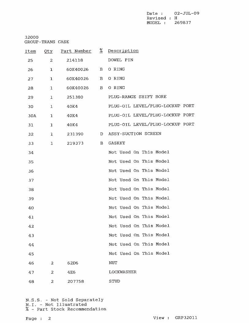

DDRRYY SSYYSSTTEEMMSS TTEECCHHNNOOLLOOGGIIEESSregreg
OOPPEERRAATTIIOONN AANNDD MMAAIINNTTEENNAANNCCEE MMAANNUUAALL
DDSSTT DDRRYY SSYYSSTTEEMMregreg
SSEECCTTIIOONN AA OONN BBOOAARRDD CCLLEEAANNIINNGG SSYYSSTTEEMM
FFOORR OOUUTTBBYY MMAACCHHIINNEE
MM330011--001166--1111
DRY SYSTEMS TECHNOLOGIES 8102 Lemont Road Suite 700
WOODRIDGE IL 60517 USA Phone 630-427-2051 Fax 630-427-1036
E-mail engdrysystemstechcom
DATED MARCH 2007 6 Pages
DDRRYY SSYYSSTTEEMMSS TTEECCHHNNOOLLOOGGIIEESS 8102 Lemont Road Suite 700 Woodridge Illinois 60517 USA
Phone 630-427-2051 Fax 630-427-1036 EE--mmaaiill eennggddrryyssyysstteemmsstteecchhccoomm
OPERATION AND MAINTENANCE MANUAL PART A M301-016-11 INSTRUCTIONS FOR USING THE ON-BOARD CLEANING SYSTEM AND FOR REPLACING THE EXHAUST PARTICULATE FILTER
Background
The Dry Systemtrade supplied by Dry Systems Technologiesreg consists of a unique patented arrangement of components that provide a diesel power package and superior emissions reduction from diesel engines The system can operate at very minimal maintenance but requires some attention by the operator to maintain its permissibility and clean exhaust The Dry Systemtrade is fitted with a tube-and-shell heat exchanger It reduces the exhaust temperature from about 950-1150deg F in the manifold to a safe temperature of less than 300deg F before exhausting to the atmosphere Because of the rapid cooling of the exhaust gases inside the heat exchanger the airborne sub-micron diesel particles agglomerate (cling to each other) and form larger particles However some of these particles attach themselves to the cold tube walls where they accumulate over time This process is completely normal as part of the operation of the Dry Systemtrade or any system that cools the exhaust gases After the particle accumulation has reached a certain thickness the tubes become partially restricted and both exhaust backpressure and temperature increase The exhaust backpressure and the exhaust gas temperature can be monitored on the exhaust-backpressure gauge and the exhaust-temperature gauge which are conveniently mounted in the operatorrsquos compartment It is the responsibility of the operator to monitor the exhaust backpressure and exhaust temperature gauges frequently while operating the diesel machine
Activating the On-board Cleaning System Once the exhaust backpressure increases the removal of these internal deposits is necessary to maintain a clean and safe exhaust system The Dry Systemtrade is equipped with a patented On-board Cleaning Systemtrade that allows removal of the soot deposits while operating the machine The On-board Cleaning Systemtrade consists of a small water supply bottle a metered actuator and an injection nozzle The 1 quart (1 liter) water bottle is located inside the engine compartment contains several shifts supply and must be filled with clean water (such as bottled water or drinking water) only The injection nozzle is located near the inlet of the heat exchanger A cab mounted push button or valve is all the operator needs to perform the cleaning process while operating the machine When activated (for five seconds) by the operator with the cab-mounted push button a very small metered amount of water is injected into the hot exhaust inlet of the heat exchanger The water flashes into steam and expands to more than 200 times of its original volume This sudden pressure rise (and not the water itself) causes the soot deposit to dislodge from the tube walls to be carried downstream by the exhaust gas to the particulate filter where it is trapped
Part A On-Board Cleaning and Filter Change Page 2
DDRRYY SSYYSSTTEEMMSS TTEECCHHNNOOLLOOGGIIEESS 8102 Lemont Road Suite 700 Woodridge Illinois 60517 USA
Phone 630-427-2051 Fax 630-427-1036 EE--mmaaiill eennggddrryyssyysstteemmsstteecchhccoomm
OPERATION AND MAINTENANCE MANUAL PART A M301-016-11 INSTRUCTIONS FOR USING THE ON-BOARD CLEANING SYSTEM AND FOR REPLACING THE EXHAUST PARTICULATE FILTER
This procedure is the most important action the operator has to take Neglect of this operation will cause high exhaust backpressure which will inevitably lead to reduced filter life and triggering of the safety shut-down system Using the On-board Cleaning Systemtrade properly is the responsibility of the machine operator There will be no visible water vapor or smoke emitted from the exhaust system while the on-board cleaning system is activated The only indication to verify proper injection is to monitor the exhaust gauges Initially the exhaust backpressure will rise followed by a drop to below its starting point There should also be a small simultaneous reduction in exhaust gas temperature The most effective time to activate the On-board Cleaning Systemtrade is when the engine is hot and under load At a minimum the On-board Cleaning Systemtrade should be activated twice each operating shift and while the engine is hot and working hard There is no harm done if the On-board Cleaning System is used more often except that the water supply gets depleted quicker The On-board Cleaning Systemtrade will not function on a cold engine or at idle Using the on-board cleaning system on a cold engine and without load on the engine is ineffective Do not activate the On-board Cleaning Systemtrade on a cold engine Frequent use of the on-board cleaning system is a very important step to keep the DST Management System operating efficiently and safely The amount of water that is injected is metered by the five seconds that the button is held The On-board Cleaning System is ready for use immediately after release of the electric push button that is located in the operatorrsquos compartment
It is the responsibility of the operator to activate the On-board Cleaning System at least twice a shift with the engine hot and under load more often if judged necessary It is safe to activate the On-board Cleaning System in any part of the mine where diesel equipment may be operated
Part A On-Board Cleaning and Filter Change Page 3
DDRRYY SSYYSSTTEEMMSS TTEECCHHNNOOLLOOGGIIEESS 8102 Lemont Road Suite 700 Woodridge Illinois 60517 USA
Phone 630-427-2051 Fax 630-427-1036 EE--mmaaiill eennggddrryyssyysstteemmsstteecchhccoomm
OPERATION AND MAINTENANCE MANUAL PART A M301-016-11 INSTRUCTIONS FOR USING THE ON-BOARD CLEANING SYSTEM AND FOR REPLACING THE EXHAUST PARTICULATE FILTER
Diagnosing High Exhaust Backpressure The typical life cycle of the Disposable Exhaust Particulate Filter (DPM Filter) can range from 40-100 hours depending on the operating cycle of the machine Once the exhaust system backpressure can no longer be reduced by the On-board Cleaning Systemtrade the DPM Filter maybe loaded to its capacity Before changing the filter a quick diagnostic test should be performed to determine if the filter is fully loaded or if the heat exchanger is fouled and needs flushing An optional diagnostic gauge that measures the differential pressure across the heat exchanger is installed inside the engine compartment The reading of this gauge together with the backpressure gauge taken under full engine speed and no load (high idle) can be used to determine the next action
bull A reading of the backpressure gauge at or near the maximum combined with a pressure differential across the heat exchanger (diagnostic gauge) in the range of 8-12rdquo WG is an indication of a loaded filter The next step should be to exchange the loaded exhaust particulate filter with a clean exhaust particulate filter
bull A reading of the backpressure gauge at or near the maximum combined with a pressure differential
across the heat exchanger (diagnostic gauge) greater than 20rdquo WG is an indication of excessive soot deposit in the heat exchanger The higher the reading on the diagnostic gauge the more soot has built up inside the heat exchanger THIS MAY BE AN INDICATION THAT THE ON-BOARD CLEANING SYSTEM HAS NOT BEEN USED PROPERLY OR FREQUENTLY ENOUGH As a first step the On-board Cleaning System should be used (with the engine hot and under load) to see if the pressure across the heat exchanger can be reduced
bull If the backpressure in the heat exchanger can not be reduced significantly the next step should be to
schedule the machine for flushing of the exhaust system by a trained and qualified mechanic
bull REF MWM 916 The maximum allowable exhaust backpressure is 40rdquo WG Caterpillar 3300 PCNA The maximum allowable exhaust backpressure is 34rdquo WG Caterpillar 3300 PCTA C-10 The maximum allowable exhaust backpressure is 27rdquo WG Cummins C83 The maximum allowable exhaust backpressure is 41rdquo WG Isuzu 6BG1 The maximum allowable exhaust backpressure is 41rdquo WG
It is the responsibility of the operator to perform the initial diagnostic test It is safe to activate the on-board cleaning system in any part of the mine where diesel equipment may be operated Any flushing operation must be scheduled through maintenance
Part A On-Board Cleaning and Filter Change Page 4
DDRRYY SSYYSSTTEEMMSS TTEECCHHNNOOLLOOGGIIEESS 8102 Lemont Road Suite 700 Woodridge Illinois 60517 USA
Phone 630-427-2051 Fax 630-427-1036 EE--mmaaiill eennggddrryyssyysstteemmsstteecchhccoomm
OPERATION AND MAINTENANCE MANUAL PART A M301-016-11 INSTRUCTIONS FOR USING THE ON-BOARD CLEANING SYSTEM AND FOR REPLACING THE EXHAUST PARTICULATE FILTER
Flushing of the System If the On-board Cleaning Systemtrade is used as described above and if engine operation under light load and excessive idling are minimized flushing of the exhaust system should seldom become necessary Flushing of the exhaust system must be performed by a trained and qualified mechanic and at an approved location Should flushing become necessary keep in mind that this not the same as on-board cleaning Flushing of the DST Dry Systemtrade is performed by attaching an external water supply hose to the connecting port Unlike during On-board Cleaningtrade that uses only a few ounces of water significant amounts (several gallons) of water are passed through the exhaust system during flushing operation This will remove the soot deposited inside the heat exchanger that is not removed during On-board Cleaningtrade Flushing may be performed during any time of the operating cycle but only at a suitable location as follows
bull The machine MUST be located at an outby area of the mine or a shop bull Ventilation in the area should be into the return air bull Water must be available at the area bull Remove the exhaust filter according to the ldquoParticulate Filter replacing procedurerdquo and make provisions
to capture water from the filter housing bull Attach the external water hook-up to the system bull Start the engine make sure it is up to operating temperature bull Run the engine at high idle speed and record the heat exchanger differential pressure bull At high idle speed open the water valve to allow continuous water-flow through the water injector for
about 1- 2 minutes bull Close the water valve and continue running the engine for 3-5 minutes to allow the exhaust system to
dry out Check for the change in the heat exchanger differential pressure gauge A normal reading would be 8-14rdquo WG A higher reading indicates that there still are soot deposits inside the system
bull If needed repeat the flushing as described above bull If successful install a new exhaust filter according to the ldquoExhaust Filter replacing procedurerdquo
Do not perform the flushing procedure underground without a filter in place or if there are indications that the filter has become damaged during the flushing Flushing without a particulate filter installed must be performed as follows
bull Remove the particulate filter and provide for some means to capture the water from the exhaust system bull Re-install the lid to the filter housing bull Make sure there is proper ventilation to remove the unfiltered diesel exhaust from the work area
Part A On-Board Cleaning and Filter Change Page 5
DDRRYY SSYYSSTTEEMMSS TTEECCHHNNOOLLOOGGIIEESS 8102 Lemont Road Suite 700 Woodridge Illinois 60517 USA
Phone 630-427-2051 Fax 630-427-1036 EE--mmaaiill ddrryyssyysstteemmsstteecchhccoomm
OPERATION AND MAINTENANCE MANUAL PART A M301-016-11 INSTRUCTIONS FOR USING THE ON-BOARD CLEANING SYSTEM AND FOR REPLACING THE EXHAUST PARTICULATE FILTER
bull Install the external water hook-up to the system bull Set the brakes and start the engine make sure it is up to operating temperature bull Run the engine at high idle speed and record the heat exchanger differential pressure bull At high idle speed open the water valve to allow continuous water-flow through the water injector until
the water out of the exhaust system is clear (Typically 10-15 minutes) bull Close the water valve and continue running the engine for 5 minutes to allow the exhaust system to dry
out Check for the change in the heat exchanger differential pressure gauge A normal reading is 8-12rdquo bull If successful install a new particulate filter according to the ldquoParticulate Filter replacing procedurerdquo
Do not perform the flushing procedure without proper ventilation and without a provision to capture the soot and water from the exhaust
Procedure to replacing the Particulate Filter Replacing the DST particulate filter may be performed in any part of the mine where diesel equipment can be operated The diesel engine must be stopped during the entire time while the exhaust filter is being replaced Proceed as follows
bull Open the lid to the exhaust particulate filter housing bull Release the manual clamp or clamping cylinders with the valve at the end of the filter housing bull Remove the new exhaust filter from its shipping box and inspect for damage from shipping and
handling bull Remove the loaded exhaust filter from the filter housing inspect for obvious damage or leaks and place
into the empty shipping box and mark the box with ldquoUsedrdquo or ldquoDirtyrdquo Do not grip on the inside of the filter where the soot is deposited Gloves should be worn while handling the dirty filter
bull Check the inside of the exhaust filter housing Report any soot deposits to the Maintenance Department bull Inspect the seal groove inside the filter housing Make sure there are no remains of seal material or other
matter in the seal groove If necessary remove any remains with a screwdriver or similar tool bull Insert the clean exhaust filter after visual inspections for damage and seal bull Set the manual clamp or clamping cylinders with the valve at the end of the filter housing bull Close the lid to the exhaust filter housing bull Remove the box with the used filter according to disposal procedures at the mine bull Start the engine and check the exhaust backpressure at high idle to be in the normal range
Part A On-Board Cleaning and Filter Change Page 6
DDRRYY SSYYSSTTEEMMSS TTEECCHHNNOOLLOOGGIIEESSregreg
OOPPEERRAATTIIOONN AANNDD MMAAIINNTTEENNAANNCCEE MMAANNUUAALL
DDSSTT DDRRYY SSYYSSTTEEMMregreg
SSEECCTTIIOONN CC CCOO SSAAMMPPLLIINNGG PPRROOCCEEDDUURREE
To be performed by a trained and qualified mechanic
MM330011--001188--0011
DRY SYSTEMS TECHNOLOGIES 8102 Lemont Road Suite 700
WOODRIDGE IL 60517 USA Phone 630-427-2051 Fax 630-427-1036
E-mail engdrysystemstechcom
REVISION 01 DATED DECEMBER 2002 8 Pages
DDRRYY SSYYSSTTEEMMSS TTEECCHHNNOOLLOOGGIIEESS 8102 Lemont Road Suite 700 Woodridge Illinois 60517 USA
Phone 630-427-2051 Fax 630-427-1036 EE--mmaaiill eennggddrryyssyysstteemmsstteecchhccoomm
OPERATION AND MAINTENANCE MANUAL PART C M301-018-01 CO (Carbon Monoxide) SAMPLING INSTRUCTIONS FOR THE DST DRY SYSTEMtrade
Background
MSHA requires that the engine-out untreated Carbon Monoxide of all Inby and heavy-duty Outby engines be checked weekly The following is the applicable text (excerpts) that may be found in the MSHA 30 CFR Part 751914 (g) Regulations The test for untreated (engine out) CO emissions is mandatory and will also provide excellent feedback to the mechanic on the engine condition
sect751914 Maintenance of diesel-powered Equipment
(a) Diesel-powered equipment shall be maintained in approved and safe condition or removed from service
(b) Maintenance and repairs of approved features and those features required by Sections 751909 and 751910 on diesel-powered equipment shall be made only by a person qualified under Section 751915
(c) helliphellip (d) helliphellip (e) helliphellip (f) helliphellip
(g) Undiluted exhaust emissions of diesel engines in diesel-powered equipment approved under part 36 and heavy-duty non-permissible diesel- powered equipment as defined in Section 751908(a) in use in underground coal mines shall be tested and evaluated weekly by a person who is trained to perform this task The mine operator shall develop and implement written standard operating procedures for such testing and evaluation that specify the following
(1) The method of achieving a repeatable loaded engine operating condition for each type of equipment
(2) Sampling and analytical methods (including calibration of instrumentation) that are capable of accurately detecting carbon monoxide in the expected concentrations
(3) The method of evaluation and interpretation of the results
(4) The concentration or changes in concentration of carbon monoxide that will indicate a change in engine performance Carbon monoxide concentration shall not exceed 2500 parts per million
(5) The maintenance of records necessary to track engine performance
Part C CO Sampling Instructions Page 2
DDRRYY SSYYSSTTEEMMSS TTEECCHHNNOOLLOOGGIIEESS 8102 Lemont Road Suite 700 Woodridge Illinois 60517 USA
Phone 630-427-2051 Fax 630-427-1036 EE--mmaaiill eennggddrryyssyysstteemmsstteecchhccoomm
OPERATION AND MAINTENANCE MANUAL PART C CO (Carbon Monoxide) SAMPLING INSTRUCTIONS FOR THE DST DRY SYSTEMtrade The reasons for monitoring Engine-out CO Emissions CO sampling became a mandatory procedure when MSHA released the new Part 75 regulations It was introduced to ensure that diesel engines are operated in ldquoas-approvedrdquo condition and settings In most instances when a diesel engine develops a problem the CO output will increase Other emissions do not necessarily follow the same trend Under normal operating conditions (at torque stall) CO output ranging from 200-300 ppm should be expected from a MWM D916-6 engine 300-400 ppm for a Caterpillar 3300 engine Whenever abnormally high CO is observed an engine problem should be suspected because CO increases when an engine develops a fault Increased CO will not pinpoint to a specific problem but based on past experience the following may have happened (In order of probability)
bull The Intake Air Cleaner is plugged causing too high an intake air restriction and air starvation of the engine This makes the engine run too rich (A plugged intake air cleaner is the cause in more than frac34 of all cases)
bull Fuel injector problems which could be a bad spray pattern of an injector and cause incomplete combustion
bull Improper fuel pump adjustment by having the fuel pump adjusted too rich or not properly de-rated for the operating altitude This makes the engine run too rich
bull Mechanical problems with the engine such as bad valve seals leaking piston rings low compression or similar problems (Not frequent cause)
bull The exhaust system is restricted causing too high a backpressure CO (Carbon Monoxide) is an excellent diagnostic tool for the maintenance department to detect engine problems before they lead to failures It has been used successfully by many mines in a similar way as oil analysis The main purpose of CO sampling is to minimize exposure of the operator and other personnel to diesel exhaust
The reasons for monitoring treated CO Emissions (after catalyst) (Optional) The DST Dry Systemtrade is fitted with a catalyst that will reduce CO by up to 90 at exhaust temperatures above 300degF A typical treated CO level in the exhaust is 20-40 ppm If the catalyst would develop a problem the treated CO levels will increase significantly Therefore whenever there is higher than normal CO a problem with the catalyst should be suspected If the treated CO levels are continuously greater than 100 ppm the catalyst must be removed and checked for fouling
Part C CO Sampling Instructions Page 3
DDRRYY SSYYSSTTEEMMSS TTEECCHHNNOOLLOOGGIIEESS 8102 Lemont Road Suite 700 Woodridge Illinois 60517 USA
Phone 630-427-2051 Fax 630-427-1036 EE--mmaaiill eennggddrryyssyysstteemmsstteecchhccoomm
OPERATION AND MAINTENANCE MANUAL PART C M301-018-01 CO (Carbon Monoxide) SAMPLING INSTRUCTIONS FOR THE DST DRY SYSTEMtrade
Permanently Installed CO Sampling Ports To simplify this mandatory procedure Dry Systems Technologiesreg developed and offers a permanently installed and MSHA Certified (31D126) Flameproof Porttrade assembly All hardware remains permanently mounted in the exhaust system and on the machine Drawn through a flameproof port a cooling tube and a connecting hose the exhaust gas portion for sampling is routed to the operatorrsquos cab There a soot filter and a water separator condition the exhaust gas to be suitable for CO sampling with simple hand held instruments A quick connect coupling is permanently mounted inside the operatorrsquos cab and allows the sampling from the safe location inside the operatorrsquos cab The mating coupler is attached to the CO sampling instrument Only one person is required to sample the CO An optional Catalyst ndash out sampler may also be provided
Figure 1 Sampling Schematic for untreated and (Optional) treated CO
Part C CO Sampling Instructions Page 4
DDRRYY SSYYSSTTEEMMSS TTEECCHHNNOOLLOOGGIIEESS 8102 Lemont Road Suite 700 Woodridge Illinois 60517 USA
Phone 630-427-2051 Fax 630-427-1036 EE--mmaaiill eennggddrryyssyysstteemmsstteecchhccoomm
OPERATION AND MAINTENANCE MANUAL PART C M301-018-01 CO (Carbon Monoxide) SAMPLING INSTRUCTIONS FOR THE DST DRY SYSTEMtrade CO Sampling Procedure The following is the standard procedure to obtain an accurate and repeatable CO sample
bull Place the machine in a safe location make sure the area in front of the machine is clear and there is sufficient ventilation air Sampling can be conducted in any area of the mine
bull Set the brakes and start the engine as outlined in the Operation and Maintenance Manual bull Allow the engine to warm up to normal operating temperature Taking the CO samples on a cold engine
would provide incorrect results bull Check all operating gauges to be in the normal operating range The coolant temperature must be no
lower than 170degF If the intake restriction is greater than 25rdquo WG or the exhaust backpressure is greater than 35rdquo WG perform the necessary maintenance before proceeding
bull Attach the CO Sampling Device to the quick connect port labeled ldquoEngine Outrdquo in the operatorrsquos cab bull Re-check that the areas in front and behind of the machine are clear and that the parking brakes are set bull Put the transmission into the highest gear and apply full throttle bull Monitor the reading on CO Sampling Device After about 45-90 seconds the CO indication starts rising
Allow this to continue until the CO indication stabilizes bull Start recording (5) separate sequential readings in one-minute intervals Monitor the torque converter
temperature while taking the samples The intervals between the samples may have to be shortened to prevent overheating during the test Do not allow the torque converter temperature to exceed the safe range
bull Stop sampling after (5) readings or before if the torque converter fluid gets too hot bull Slow the engine to low idle put the transmission into neutral then put the engine into high idle (without
load) for about one minute to cool down the torque converter and the engine coolant bull Remove the instrument and enter the CO readings on the report bull Attach the CO Sampling Device to the Optional quick connect port labeled ldquoCatalyzedrdquo in the operatorrsquos
cab bull Re-check that the areas in front and behind of the machine are clear and that the parking brakes are set bull Put the transmission into the highest gear and apply full throttle bull Monitor the reading on CO Sampling Device After about 45-90 seconds the CO indication starts rising
Allow this to continue until the CO indication stabilizes bull Start recording (5) separate sequential readings in one-minute intervals Monitor the torque converter
temperature while taking the samples The intervals between the samples may have to be shortened to prevent overheating during the test Do not allow the torque converter temperature to exceed the safe range
bull Stop sampling after (5) readings or before if the torque converter fluid gets too hot bull Slow the engine to low idle put the transmission into neutral then put into high idle for about one
minute to cool the torque converter and the engine coolant bull Remove the instrument and record the CO readings on the report
Part C CO Sampling Instructions Page 5
DDRRYY SSYYSSTTEEMMSS TTEECCHHNNOOLLOOGGIIEESS 8102 Lemont Road Suite 700 Woodridge Illinois 60517 USA
Phone 630-427-2051 Fax 630-427-1036 EE--mmaaiill eennggddrryyssyysstteemmsstteecchhccoomm
OPERATION AND MAINTENANCE MANUAL PART C M301-018-01 CO (Carbon Monoxide) SAMPLING INSTRUCTIONS FOR THE DST DRY SYSTEMtrade
CO Sampling Instruments One of the advantages of the permanently installed CO sampling port system is that it conditions the exhaust gas where it can be monitored with inexpensive handheld instruments The gas is cooled and filter for this purpose There are three single gas (CO only) instruments that are readily available relatively inexpensive and have acceptable accuracy and reliability
bull ECOM EM bull Industrial Scientific CO 260 bull Industrial Scientific CO 262
More expensive instruments can be used if they are available to the mine but provide not advantage Handheld multi-gas instruments have been evaluated and did not have the necessary accuracy and reliability to be recommended Handheld multi-gas instrument are fitted with very small sensors that tend to foul up in a very short period of time The above listed handheld single gas instruments are fitted with larger sensors that hold up better
Keep in mind that ALL instruments require periodic re-calibration The calibration date is usually stated on a label attached to the instrument Unless stated otherwise we recommend calibration at least twice a year or whenever inaccuracy is suspected
Maintenance of the Flameproof Ports When hot exhaust gas is drawn through small internal passages of the flameproof port and the cooling tube it is cooled down and some soot will deposit inside the ports and the tubes This is unavoidable When there is excessive soot inside the port it will plug As result no sample can be drawn and there is no indication on the CO instrument As first corrective step rotate the stem at the end of the flameproof port If this does not clear the passage the flameproof port must be removed disassembled and both port and cooling tube cleaned with solvent Make sure all solvent is cleaned off and the components are dry before reinstallation The filter and water separator remove soot and water that would otherwise damage the sampling head inside the CO sampling instrument Periodically the filter cartridge should be replaced We recommend twice a year when the machine is in normal use Failure to replace the filter will result in shorter sampler head life
Part C CO Sampling Instructions Page 6
DDRRYY SSYYSSTTEEMMSS TTEECCHHNNOOLLOOGGIIEESS 8102 Lemont Road Suite 700 Woodridge Illinois 60517 USA
Phone 630-427-2051 Fax 630-427-1036 EE--mmaaiill eennggddrryyssyysstteemmsstteecchhccoomm
OPERATION AND MAINTENANCE MANUAL PART C M301-018-01 CO (Carbon Monoxide) SAMPLING INSTRUCTIONS FOR THE DST DRY SYSTEMtrade
Figure 2 Components of Flameproof Port Installation
Top left Intake restriction gauge and flameproof port for intake restriction Top right Port for exhaust backpressure and CO sampling Cooling tube (May be coiled or straight tube) Center Exhaust backpressure gauge water separatorfilter (sample conditioner) and Quick Coupler Bottom Matching quick coupler for CO instrument
Part C CO Sampling Instructions Page 7
DDRRYY SSYYSSTTEEMMSS TTEECCHHNNOOLLOOGGIIEESS 8102 Lemont Road Suite 700 Woodridge Illinois 60517 USA
Phone 630-427-2051 Fax 630-427-1036 EE--mmaaiill eennggddrryyssyysstteemmsstteecchhccoomm
OPERATION AND MAINTENANCE MANUAL PART C M301-018-01 CO (Carbon Monoxide) SAMPLING INSTRUCTIONS FOR THE DST DRY SYSTEMtrade
Record Keeping (Sample Form) The following is a sample form to record the CO readings
Mine Name Engine Model Engine Serial No Machine Model Machine Serial Number Mine Machine ID Mechanic Date Engine hours Baseline
for reference
1 Sample
2 Sample
3 Sample
4 Sample
5 Sample
Average
CO Engine-out
ppm
Coolant degF Exhaust degF Torque Converter
degF
Engine Speed rpm
CO Catalyzed
ppm
Coolant degF Exhaust degF Torque Converter
degF
Engine Speed rpm Signature helliphelliphelliphelliphelliphelliphelliphelliphelliphelliphelliphelliphelliphelliphelliphelliphelliphelliphelliphelliphelliphelliphelliphellip
Part C CO Sampling Instructions Page 8
DDRRYY SSYYSSTTEEMMSS TTEECCHHNNOOLLOOGGIIEESSregreg
OOPPEERRAATTIIOONN AANNDD MMAAIINNTTEENNAANNCCEE MMAANNUUAALL
DDSSTT DDRRYY SSYYSSTTEEMMregreg
SSEECCTTIIOONN DD PPRREE--OOPP IINNSSPPEECCTTIIOONNSS
To be performed by the machine operator
MM330011--001199--0011
DRY SYSTEMS TECHNOLOGIES 8102 Lemont Road Suite 700
WOODRIDGE IL 60517 USA Phone 630-427-2051 Fax 630-427-1036
E-mail engdrysystemstechcom
REVISION 01 DATED DECEMBER 2002 3 Pages
DDRRYY SSYYSSTTEEMMSS TTEECCHHNNOOLLOOGGIIEESS 8102 Lemont Road Suite 700 Woodridge Illinois 60517 USA
Phone 630-427-2051 Fax 630-427-1036 EE--mmaaiill eennggddrryyssyysstteemmsstteecchhccoomm
OPERATION AND MAINTENANCE MANUAL PART D M301-019-01 PRE-OPERATING INSPECTION FOR THE DST DRY SYSTEMtrade
MSHA Requirements
The Part 75 MSHA regulations require that the machine operator performs a walk-around inspection of the machine before it is operated The following is the text from the MSHA 30 CFR Part 751914(e) regulations pertinent to this pre-op inspection
MSHA 30 CFR Part 751914 Maintenance of diesel-powered equipment (a) Diesel-powered equipment shall be maintained in approved and safe condition or removed from service (b) Maintenance and repairs of approved features and those features required by Sections 751909 and 751910 on diesel-powered equipment shall be made only by a person qualified under Section 751915 (c) hellip (d) hellip (e) Mobile diesel-powered equipment that is to be used during a shift shall be visually examined by the equipment operator before being placed in operation Equipment defects affecting safety shall be reported promptly to the mine operator Note MSHA text is provided for reference only Refer to the official MSHA published regulations
DST Dry Systemtrade Inspection Requirements
The DST Dry Systemtrade requires very little maintenance when compared with water scrubbers The pre-op inspection is required by MSHA to ensure there is no damage to the DST Dry Systemtrade and all components are properly in place It is not necessary to perform flushing and refilling of the DST Dry Systemtrade as necessary with water scrubbers There are no floats or water level sensors that must be checked
The following form is intended to guide the operator through the walk-around inspection Please refer also to any machine inspection procedures in the OEM manual as the following page refers ONLY to the DST Dry Systemtrade
Part D Pre-operation Inspection Page 2
DDRRYY SSYYSSTTEEMMSS TTEECCHHNNOOLLOOGGIIEESS 8102 Lemont Road Suite 700 Woodridge Illinois 60517 USA
Phone 630-427-2051 Fax 630-427-1036 EE--mmaaiill eennggddrryyssyysstteemmsstteecchhccoomm
OPERATION AND MAINTENANCE MANUAL PART D M301-019-01 PRE-OPERATING INSPECTION FOR THE DST DRY SYSTEMtrade
Dry Systemtrade Pre-operation Checklist
OPERATORrsquoS PRE-OP CHECKLIST FOR THE DST SYSTEM DE-ENERGIZED WALK-AROUND INSPECTION PERFORMED BEFORE EACH SHIFT
ITEM DESCRIPTION COMPLETED 1 Make certain equipment is in a safe condition and in a safe area prior to
the inspection
2 Make sure the machine is clean and free of accumulations of combustibles
3 Check the DST Dry Systemtrade for external damage and to determine that all components are in place and not damaged
4 Look for loose or missing DST components and loose or missing hardware
5 Look for gas leakage at each flange connection of the DST Dry Systemtrade 6 Inspect the bellows assembly for external damage or leakage 7 Check for damaged coolant hoses vent hoses and coolant leaks 8 The surge tank must be completely full DO NOT OPEN RADIATOR CAP
IF HOT
9 Check the coolant overflow bottle Coolant must be between upper and lower marks Add coolant mix if needed
10 Check the radiator cap on top of the surge tank to be in place and tightened
11 Check the radiator core for obstructions plugging damage and leaks 12 Check the fan for broken or missing blades 13 Check all belts to be properly tightened and in good condition 14 Check the water level in the tank for the on-board cleaning system and
top off with clean bottled water if necessary
15 Check all gauges for external damage 16 Replace all lids and secure all access doors as needed 17 Complete this form and place in operatorrsquos cab 18 Report all damage or problems to Maintenance for further action
Name helliphelliphelliphelliphelliphelliphelliphelliphelliphelliphelliphelliphelliphelliphelliphelliphelliphellip Date helliphelliphelliphelliphelliphelliphelliphelliphelliphelliphellip
Part D Pre-operation Inspection Page 3
DDRRYY SSYYSSTTEEMMSS TTEECCHHNNOOLLOOGGIIEESSregreg
OOPPEERRAATTIIOONN AANNDD MMAAIINNTTEENNAANNCCEE MMAANNUUAALL
DDSSTT DDRRYY SSYYSSTTEEMMregreg
SSEECCTTIIOONN FF CCOOOOLLIINNGG SSYYSSTTEEMM FFIILLLLIINNGG
PPRROOCCEEDDUURREE To be performed by the machine operator
MM330011--002211--0011
DRY SYSTEMS TECHNOLOGIES
8102 Lemont Road Suite 700 WOODRIDGE IL 60517 USA
Phone 630-427-2051 Fax 630-427-1036 E-mail engdrysystemstechcom
REVISION 01 DATED DECEMBER 2002 2 Pages
DDRRYY SSYYSSTTEEMMSS TTEECCHHNNOOLLOOGGIIEESS 8102 Lemont Road Woodridge Illinois 60517 USA
Phone 630-427-2051 Fax 630-427-1036 EE--mmaaiill eennggddrryyssyysstteemmsstteecchhccoomm
OPERATION AND MAINTENANCE MANUAL PART F M301-021-01 COOLING SYSTEM FILLING PROCEDURE FOR THE DST DRY SYSTEMtrade The DST Dry Systemtrade is fitted with a cooling system that incorporates a surge tank a recovery bottle and several vent lines to assure that the system has no trapped air The system is self purging once it is filled initially As with all cooling systems a mixture of 50 ethylene glycol and 50 treated (clean) water should be used for best performance Never add untreated mine water to the cooling system The following is the filling procedure for the system COOLING SYSTEM FILLING PROCEDURE
bull Carefully open the pressure cap on the surge tank after the system has cooled down and is not under pressure (There is no radiator cap on the radiator itself) CAUTION DO NOT ATTEMPT TO OPEN PRESSURE CAP WHEN COOLANT IS STILL HOT OR UNDER PRESSURE INJURY OR BURNS COULD RESULT
bull Fill a mixture of 50 Ethylene Glycol and 50 filtered water into the surge tank until the tank is completely full and the vent lines (38rdquo clear hoses) are filled with coolant
bull Replace the pressure cap firmly and start the engine Idle for 1-2 minutes to purge the remaining air from the system Check for leaks
bull Carefully open the pressure cap on the surge tank and top off the surge tank with a mixture of 50 Ethylene Glycol and 50 filtered water
bull Repeat steps 3 and 4 if necessary bull Replace the pressure cap firmly Fill the overflow bottle half way with a mixture of 50 Ethylene Glycol
and 50 filtered water bull Check the coolant level after about one hour of operation If coolant is significantly lower the cause for
the coolant loss must be investigated A normal loss in coolant due to temperature changes will be compensated by a rise or drop of the coolant in the overflow bottle The surge tank should never contain air
CAUTION DO NOT ATTEMPT TO OPEN PRESSURE CAP WHEN COOLANT IS STILL HOT OR UNDER PRESSURE INJURY OR BURNS COULD RESULT DO NOT OPERATE SYSTEM WITH LOW COOLANT ENGINE DAMAGE MAY RESULT USE ONLY A MIXTURE OF 50 ETHYLENE GLYCOL AND 50 CLEAN (FILTERED) WATER AS COOLANT NEVER ADD MINE WATER TO THE COOLING SYSTEM
Part F Cooling System Filling Procedure Page 2

DDRRYY SSYYSSTTEEMMSS TTEECCHHNNOOLLOOGGIIEESS 8102 Lemont Road Suite 700 Woodridge Illinois 60517 USA
Phone 630-427-2051 Fax 630-427-1036 EE--mmaaiill eennggddrryyssyysstteemmsstteecchhccoomm
OPERATION AND MAINTENANCE MANUAL PART A M301-016-11 INSTRUCTIONS FOR USING THE ON-BOARD CLEANING SYSTEM AND FOR REPLACING THE EXHAUST PARTICULATE FILTER
Background
The Dry Systemtrade supplied by Dry Systems Technologiesreg consists of a unique patented arrangement of components that provide a diesel power package and superior emissions reduction from diesel engines The system can operate at very minimal maintenance but requires some attention by the operator to maintain its permissibility and clean exhaust The Dry Systemtrade is fitted with a tube-and-shell heat exchanger It reduces the exhaust temperature from about 950-1150deg F in the manifold to a safe temperature of less than 300deg F before exhausting to the atmosphere Because of the rapid cooling of the exhaust gases inside the heat exchanger the airborne sub-micron diesel particles agglomerate (cling to each other) and form larger particles However some of these particles attach themselves to the cold tube walls where they accumulate over time This process is completely normal as part of the operation of the Dry Systemtrade or any system that cools the exhaust gases After the particle accumulation has reached a certain thickness the tubes become partially restricted and both exhaust backpressure and temperature increase The exhaust backpressure and the exhaust gas temperature can be monitored on the exhaust-backpressure gauge and the exhaust-temperature gauge which are conveniently mounted in the operatorrsquos compartment It is the responsibility of the operator to monitor the exhaust backpressure and exhaust temperature gauges frequently while operating the diesel machine
Activating the On-board Cleaning System Once the exhaust backpressure increases the removal of these internal deposits is necessary to maintain a clean and safe exhaust system The Dry Systemtrade is equipped with a patented On-board Cleaning Systemtrade that allows removal of the soot deposits while operating the machine The On-board Cleaning Systemtrade consists of a small water supply bottle a metered actuator and an injection nozzle The 1 quart (1 liter) water bottle is located inside the engine compartment contains several shifts supply and must be filled with clean water (such as bottled water or drinking water) only The injection nozzle is located near the inlet of the heat exchanger A cab mounted push button or valve is all the operator needs to perform the cleaning process while operating the machine When activated (for five seconds) by the operator with the cab-mounted push button a very small metered amount of water is injected into the hot exhaust inlet of the heat exchanger The water flashes into steam and expands to more than 200 times of its original volume This sudden pressure rise (and not the water itself) causes the soot deposit to dislodge from the tube walls to be carried downstream by the exhaust gas to the particulate filter where it is trapped
Part A On-Board Cleaning and Filter Change Page 2
DDRRYY SSYYSSTTEEMMSS TTEECCHHNNOOLLOOGGIIEESS 8102 Lemont Road Suite 700 Woodridge Illinois 60517 USA
Phone 630-427-2051 Fax 630-427-1036 EE--mmaaiill eennggddrryyssyysstteemmsstteecchhccoomm
OPERATION AND MAINTENANCE MANUAL PART A M301-016-11 INSTRUCTIONS FOR USING THE ON-BOARD CLEANING SYSTEM AND FOR REPLACING THE EXHAUST PARTICULATE FILTER
This procedure is the most important action the operator has to take Neglect of this operation will cause high exhaust backpressure which will inevitably lead to reduced filter life and triggering of the safety shut-down system Using the On-board Cleaning Systemtrade properly is the responsibility of the machine operator There will be no visible water vapor or smoke emitted from the exhaust system while the on-board cleaning system is activated The only indication to verify proper injection is to monitor the exhaust gauges Initially the exhaust backpressure will rise followed by a drop to below its starting point There should also be a small simultaneous reduction in exhaust gas temperature The most effective time to activate the On-board Cleaning Systemtrade is when the engine is hot and under load At a minimum the On-board Cleaning Systemtrade should be activated twice each operating shift and while the engine is hot and working hard There is no harm done if the On-board Cleaning System is used more often except that the water supply gets depleted quicker The On-board Cleaning Systemtrade will not function on a cold engine or at idle Using the on-board cleaning system on a cold engine and without load on the engine is ineffective Do not activate the On-board Cleaning Systemtrade on a cold engine Frequent use of the on-board cleaning system is a very important step to keep the DST Management System operating efficiently and safely The amount of water that is injected is metered by the five seconds that the button is held The On-board Cleaning System is ready for use immediately after release of the electric push button that is located in the operatorrsquos compartment
It is the responsibility of the operator to activate the On-board Cleaning System at least twice a shift with the engine hot and under load more often if judged necessary It is safe to activate the On-board Cleaning System in any part of the mine where diesel equipment may be operated
Part A On-Board Cleaning and Filter Change Page 3
DDRRYY SSYYSSTTEEMMSS TTEECCHHNNOOLLOOGGIIEESS 8102 Lemont Road Suite 700 Woodridge Illinois 60517 USA
Phone 630-427-2051 Fax 630-427-1036 EE--mmaaiill eennggddrryyssyysstteemmsstteecchhccoomm
OPERATION AND MAINTENANCE MANUAL PART A M301-016-11 INSTRUCTIONS FOR USING THE ON-BOARD CLEANING SYSTEM AND FOR REPLACING THE EXHAUST PARTICULATE FILTER
Diagnosing High Exhaust Backpressure The typical life cycle of the Disposable Exhaust Particulate Filter (DPM Filter) can range from 40-100 hours depending on the operating cycle of the machine Once the exhaust system backpressure can no longer be reduced by the On-board Cleaning Systemtrade the DPM Filter maybe loaded to its capacity Before changing the filter a quick diagnostic test should be performed to determine if the filter is fully loaded or if the heat exchanger is fouled and needs flushing An optional diagnostic gauge that measures the differential pressure across the heat exchanger is installed inside the engine compartment The reading of this gauge together with the backpressure gauge taken under full engine speed and no load (high idle) can be used to determine the next action
bull A reading of the backpressure gauge at or near the maximum combined with a pressure differential across the heat exchanger (diagnostic gauge) in the range of 8-12rdquo WG is an indication of a loaded filter The next step should be to exchange the loaded exhaust particulate filter with a clean exhaust particulate filter
bull A reading of the backpressure gauge at or near the maximum combined with a pressure differential
across the heat exchanger (diagnostic gauge) greater than 20rdquo WG is an indication of excessive soot deposit in the heat exchanger The higher the reading on the diagnostic gauge the more soot has built up inside the heat exchanger THIS MAY BE AN INDICATION THAT THE ON-BOARD CLEANING SYSTEM HAS NOT BEEN USED PROPERLY OR FREQUENTLY ENOUGH As a first step the On-board Cleaning System should be used (with the engine hot and under load) to see if the pressure across the heat exchanger can be reduced
bull If the backpressure in the heat exchanger can not be reduced significantly the next step should be to
schedule the machine for flushing of the exhaust system by a trained and qualified mechanic
bull REF MWM 916 The maximum allowable exhaust backpressure is 40rdquo WG Caterpillar 3300 PCNA The maximum allowable exhaust backpressure is 34rdquo WG Caterpillar 3300 PCTA C-10 The maximum allowable exhaust backpressure is 27rdquo WG Cummins C83 The maximum allowable exhaust backpressure is 41rdquo WG Isuzu 6BG1 The maximum allowable exhaust backpressure is 41rdquo WG
It is the responsibility of the operator to perform the initial diagnostic test It is safe to activate the on-board cleaning system in any part of the mine where diesel equipment may be operated Any flushing operation must be scheduled through maintenance
Part A On-Board Cleaning and Filter Change Page 4
DDRRYY SSYYSSTTEEMMSS TTEECCHHNNOOLLOOGGIIEESS 8102 Lemont Road Suite 700 Woodridge Illinois 60517 USA
Phone 630-427-2051 Fax 630-427-1036 EE--mmaaiill eennggddrryyssyysstteemmsstteecchhccoomm
OPERATION AND MAINTENANCE MANUAL PART A M301-016-11 INSTRUCTIONS FOR USING THE ON-BOARD CLEANING SYSTEM AND FOR REPLACING THE EXHAUST PARTICULATE FILTER
Flushing of the System If the On-board Cleaning Systemtrade is used as described above and if engine operation under light load and excessive idling are minimized flushing of the exhaust system should seldom become necessary Flushing of the exhaust system must be performed by a trained and qualified mechanic and at an approved location Should flushing become necessary keep in mind that this not the same as on-board cleaning Flushing of the DST Dry Systemtrade is performed by attaching an external water supply hose to the connecting port Unlike during On-board Cleaningtrade that uses only a few ounces of water significant amounts (several gallons) of water are passed through the exhaust system during flushing operation This will remove the soot deposited inside the heat exchanger that is not removed during On-board Cleaningtrade Flushing may be performed during any time of the operating cycle but only at a suitable location as follows
bull The machine MUST be located at an outby area of the mine or a shop bull Ventilation in the area should be into the return air bull Water must be available at the area bull Remove the exhaust filter according to the ldquoParticulate Filter replacing procedurerdquo and make provisions
to capture water from the filter housing bull Attach the external water hook-up to the system bull Start the engine make sure it is up to operating temperature bull Run the engine at high idle speed and record the heat exchanger differential pressure bull At high idle speed open the water valve to allow continuous water-flow through the water injector for
about 1- 2 minutes bull Close the water valve and continue running the engine for 3-5 minutes to allow the exhaust system to
dry out Check for the change in the heat exchanger differential pressure gauge A normal reading would be 8-14rdquo WG A higher reading indicates that there still are soot deposits inside the system
bull If needed repeat the flushing as described above bull If successful install a new exhaust filter according to the ldquoExhaust Filter replacing procedurerdquo
Do not perform the flushing procedure underground without a filter in place or if there are indications that the filter has become damaged during the flushing Flushing without a particulate filter installed must be performed as follows
bull Remove the particulate filter and provide for some means to capture the water from the exhaust system bull Re-install the lid to the filter housing bull Make sure there is proper ventilation to remove the unfiltered diesel exhaust from the work area
Part A On-Board Cleaning and Filter Change Page 5
DDRRYY SSYYSSTTEEMMSS TTEECCHHNNOOLLOOGGIIEESS 8102 Lemont Road Suite 700 Woodridge Illinois 60517 USA
Phone 630-427-2051 Fax 630-427-1036 EE--mmaaiill ddrryyssyysstteemmsstteecchhccoomm
OPERATION AND MAINTENANCE MANUAL PART A M301-016-11 INSTRUCTIONS FOR USING THE ON-BOARD CLEANING SYSTEM AND FOR REPLACING THE EXHAUST PARTICULATE FILTER
bull Install the external water hook-up to the system bull Set the brakes and start the engine make sure it is up to operating temperature bull Run the engine at high idle speed and record the heat exchanger differential pressure bull At high idle speed open the water valve to allow continuous water-flow through the water injector until
the water out of the exhaust system is clear (Typically 10-15 minutes) bull Close the water valve and continue running the engine for 5 minutes to allow the exhaust system to dry
out Check for the change in the heat exchanger differential pressure gauge A normal reading is 8-12rdquo bull If successful install a new particulate filter according to the ldquoParticulate Filter replacing procedurerdquo
Do not perform the flushing procedure without proper ventilation and without a provision to capture the soot and water from the exhaust
Procedure to replacing the Particulate Filter Replacing the DST particulate filter may be performed in any part of the mine where diesel equipment can be operated The diesel engine must be stopped during the entire time while the exhaust filter is being replaced Proceed as follows
bull Open the lid to the exhaust particulate filter housing bull Release the manual clamp or clamping cylinders with the valve at the end of the filter housing bull Remove the new exhaust filter from its shipping box and inspect for damage from shipping and
handling bull Remove the loaded exhaust filter from the filter housing inspect for obvious damage or leaks and place
into the empty shipping box and mark the box with ldquoUsedrdquo or ldquoDirtyrdquo Do not grip on the inside of the filter where the soot is deposited Gloves should be worn while handling the dirty filter
bull Check the inside of the exhaust filter housing Report any soot deposits to the Maintenance Department bull Inspect the seal groove inside the filter housing Make sure there are no remains of seal material or other
matter in the seal groove If necessary remove any remains with a screwdriver or similar tool bull Insert the clean exhaust filter after visual inspections for damage and seal bull Set the manual clamp or clamping cylinders with the valve at the end of the filter housing bull Close the lid to the exhaust filter housing bull Remove the box with the used filter according to disposal procedures at the mine bull Start the engine and check the exhaust backpressure at high idle to be in the normal range
Part A On-Board Cleaning and Filter Change Page 6
DDRRYY SSYYSSTTEEMMSS TTEECCHHNNOOLLOOGGIIEESSregreg
OOPPEERRAATTIIOONN AANNDD MMAAIINNTTEENNAANNCCEE MMAANNUUAALL
DDSSTT DDRRYY SSYYSSTTEEMMregreg
SSEECCTTIIOONN CC CCOO SSAAMMPPLLIINNGG PPRROOCCEEDDUURREE
To be performed by a trained and qualified mechanic
MM330011--001188--0011
DRY SYSTEMS TECHNOLOGIES 8102 Lemont Road Suite 700
WOODRIDGE IL 60517 USA Phone 630-427-2051 Fax 630-427-1036
E-mail engdrysystemstechcom
REVISION 01 DATED DECEMBER 2002 8 Pages
DDRRYY SSYYSSTTEEMMSS TTEECCHHNNOOLLOOGGIIEESS 8102 Lemont Road Suite 700 Woodridge Illinois 60517 USA
Phone 630-427-2051 Fax 630-427-1036 EE--mmaaiill eennggddrryyssyysstteemmsstteecchhccoomm
OPERATION AND MAINTENANCE MANUAL PART C M301-018-01 CO (Carbon Monoxide) SAMPLING INSTRUCTIONS FOR THE DST DRY SYSTEMtrade
Background
MSHA requires that the engine-out untreated Carbon Monoxide of all Inby and heavy-duty Outby engines be checked weekly The following is the applicable text (excerpts) that may be found in the MSHA 30 CFR Part 751914 (g) Regulations The test for untreated (engine out) CO emissions is mandatory and will also provide excellent feedback to the mechanic on the engine condition
sect751914 Maintenance of diesel-powered Equipment
(a) Diesel-powered equipment shall be maintained in approved and safe condition or removed from service
(b) Maintenance and repairs of approved features and those features required by Sections 751909 and 751910 on diesel-powered equipment shall be made only by a person qualified under Section 751915
(c) helliphellip (d) helliphellip (e) helliphellip (f) helliphellip
(g) Undiluted exhaust emissions of diesel engines in diesel-powered equipment approved under part 36 and heavy-duty non-permissible diesel- powered equipment as defined in Section 751908(a) in use in underground coal mines shall be tested and evaluated weekly by a person who is trained to perform this task The mine operator shall develop and implement written standard operating procedures for such testing and evaluation that specify the following
(1) The method of achieving a repeatable loaded engine operating condition for each type of equipment
(2) Sampling and analytical methods (including calibration of instrumentation) that are capable of accurately detecting carbon monoxide in the expected concentrations
(3) The method of evaluation and interpretation of the results
(4) The concentration or changes in concentration of carbon monoxide that will indicate a change in engine performance Carbon monoxide concentration shall not exceed 2500 parts per million
(5) The maintenance of records necessary to track engine performance
Part C CO Sampling Instructions Page 2
DDRRYY SSYYSSTTEEMMSS TTEECCHHNNOOLLOOGGIIEESS 8102 Lemont Road Suite 700 Woodridge Illinois 60517 USA
Phone 630-427-2051 Fax 630-427-1036 EE--mmaaiill eennggddrryyssyysstteemmsstteecchhccoomm
OPERATION AND MAINTENANCE MANUAL PART C CO (Carbon Monoxide) SAMPLING INSTRUCTIONS FOR THE DST DRY SYSTEMtrade The reasons for monitoring Engine-out CO Emissions CO sampling became a mandatory procedure when MSHA released the new Part 75 regulations It was introduced to ensure that diesel engines are operated in ldquoas-approvedrdquo condition and settings In most instances when a diesel engine develops a problem the CO output will increase Other emissions do not necessarily follow the same trend Under normal operating conditions (at torque stall) CO output ranging from 200-300 ppm should be expected from a MWM D916-6 engine 300-400 ppm for a Caterpillar 3300 engine Whenever abnormally high CO is observed an engine problem should be suspected because CO increases when an engine develops a fault Increased CO will not pinpoint to a specific problem but based on past experience the following may have happened (In order of probability)
bull The Intake Air Cleaner is plugged causing too high an intake air restriction and air starvation of the engine This makes the engine run too rich (A plugged intake air cleaner is the cause in more than frac34 of all cases)
bull Fuel injector problems which could be a bad spray pattern of an injector and cause incomplete combustion
bull Improper fuel pump adjustment by having the fuel pump adjusted too rich or not properly de-rated for the operating altitude This makes the engine run too rich
bull Mechanical problems with the engine such as bad valve seals leaking piston rings low compression or similar problems (Not frequent cause)
bull The exhaust system is restricted causing too high a backpressure CO (Carbon Monoxide) is an excellent diagnostic tool for the maintenance department to detect engine problems before they lead to failures It has been used successfully by many mines in a similar way as oil analysis The main purpose of CO sampling is to minimize exposure of the operator and other personnel to diesel exhaust
The reasons for monitoring treated CO Emissions (after catalyst) (Optional) The DST Dry Systemtrade is fitted with a catalyst that will reduce CO by up to 90 at exhaust temperatures above 300degF A typical treated CO level in the exhaust is 20-40 ppm If the catalyst would develop a problem the treated CO levels will increase significantly Therefore whenever there is higher than normal CO a problem with the catalyst should be suspected If the treated CO levels are continuously greater than 100 ppm the catalyst must be removed and checked for fouling
Part C CO Sampling Instructions Page 3
DDRRYY SSYYSSTTEEMMSS TTEECCHHNNOOLLOOGGIIEESS 8102 Lemont Road Suite 700 Woodridge Illinois 60517 USA
Phone 630-427-2051 Fax 630-427-1036 EE--mmaaiill eennggddrryyssyysstteemmsstteecchhccoomm
OPERATION AND MAINTENANCE MANUAL PART C M301-018-01 CO (Carbon Monoxide) SAMPLING INSTRUCTIONS FOR THE DST DRY SYSTEMtrade
Permanently Installed CO Sampling Ports To simplify this mandatory procedure Dry Systems Technologiesreg developed and offers a permanently installed and MSHA Certified (31D126) Flameproof Porttrade assembly All hardware remains permanently mounted in the exhaust system and on the machine Drawn through a flameproof port a cooling tube and a connecting hose the exhaust gas portion for sampling is routed to the operatorrsquos cab There a soot filter and a water separator condition the exhaust gas to be suitable for CO sampling with simple hand held instruments A quick connect coupling is permanently mounted inside the operatorrsquos cab and allows the sampling from the safe location inside the operatorrsquos cab The mating coupler is attached to the CO sampling instrument Only one person is required to sample the CO An optional Catalyst ndash out sampler may also be provided
Figure 1 Sampling Schematic for untreated and (Optional) treated CO
Part C CO Sampling Instructions Page 4
DDRRYY SSYYSSTTEEMMSS TTEECCHHNNOOLLOOGGIIEESS 8102 Lemont Road Suite 700 Woodridge Illinois 60517 USA
Phone 630-427-2051 Fax 630-427-1036 EE--mmaaiill eennggddrryyssyysstteemmsstteecchhccoomm
OPERATION AND MAINTENANCE MANUAL PART C M301-018-01 CO (Carbon Monoxide) SAMPLING INSTRUCTIONS FOR THE DST DRY SYSTEMtrade CO Sampling Procedure The following is the standard procedure to obtain an accurate and repeatable CO sample
bull Place the machine in a safe location make sure the area in front of the machine is clear and there is sufficient ventilation air Sampling can be conducted in any area of the mine
bull Set the brakes and start the engine as outlined in the Operation and Maintenance Manual bull Allow the engine to warm up to normal operating temperature Taking the CO samples on a cold engine
would provide incorrect results bull Check all operating gauges to be in the normal operating range The coolant temperature must be no
lower than 170degF If the intake restriction is greater than 25rdquo WG or the exhaust backpressure is greater than 35rdquo WG perform the necessary maintenance before proceeding
bull Attach the CO Sampling Device to the quick connect port labeled ldquoEngine Outrdquo in the operatorrsquos cab bull Re-check that the areas in front and behind of the machine are clear and that the parking brakes are set bull Put the transmission into the highest gear and apply full throttle bull Monitor the reading on CO Sampling Device After about 45-90 seconds the CO indication starts rising
Allow this to continue until the CO indication stabilizes bull Start recording (5) separate sequential readings in one-minute intervals Monitor the torque converter
temperature while taking the samples The intervals between the samples may have to be shortened to prevent overheating during the test Do not allow the torque converter temperature to exceed the safe range
bull Stop sampling after (5) readings or before if the torque converter fluid gets too hot bull Slow the engine to low idle put the transmission into neutral then put the engine into high idle (without
load) for about one minute to cool down the torque converter and the engine coolant bull Remove the instrument and enter the CO readings on the report bull Attach the CO Sampling Device to the Optional quick connect port labeled ldquoCatalyzedrdquo in the operatorrsquos
cab bull Re-check that the areas in front and behind of the machine are clear and that the parking brakes are set bull Put the transmission into the highest gear and apply full throttle bull Monitor the reading on CO Sampling Device After about 45-90 seconds the CO indication starts rising
Allow this to continue until the CO indication stabilizes bull Start recording (5) separate sequential readings in one-minute intervals Monitor the torque converter
temperature while taking the samples The intervals between the samples may have to be shortened to prevent overheating during the test Do not allow the torque converter temperature to exceed the safe range
bull Stop sampling after (5) readings or before if the torque converter fluid gets too hot bull Slow the engine to low idle put the transmission into neutral then put into high idle for about one
minute to cool the torque converter and the engine coolant bull Remove the instrument and record the CO readings on the report
Part C CO Sampling Instructions Page 5
DDRRYY SSYYSSTTEEMMSS TTEECCHHNNOOLLOOGGIIEESS 8102 Lemont Road Suite 700 Woodridge Illinois 60517 USA
Phone 630-427-2051 Fax 630-427-1036 EE--mmaaiill eennggddrryyssyysstteemmsstteecchhccoomm
OPERATION AND MAINTENANCE MANUAL PART C M301-018-01 CO (Carbon Monoxide) SAMPLING INSTRUCTIONS FOR THE DST DRY SYSTEMtrade
CO Sampling Instruments One of the advantages of the permanently installed CO sampling port system is that it conditions the exhaust gas where it can be monitored with inexpensive handheld instruments The gas is cooled and filter for this purpose There are three single gas (CO only) instruments that are readily available relatively inexpensive and have acceptable accuracy and reliability
bull ECOM EM bull Industrial Scientific CO 260 bull Industrial Scientific CO 262
More expensive instruments can be used if they are available to the mine but provide not advantage Handheld multi-gas instruments have been evaluated and did not have the necessary accuracy and reliability to be recommended Handheld multi-gas instrument are fitted with very small sensors that tend to foul up in a very short period of time The above listed handheld single gas instruments are fitted with larger sensors that hold up better
Keep in mind that ALL instruments require periodic re-calibration The calibration date is usually stated on a label attached to the instrument Unless stated otherwise we recommend calibration at least twice a year or whenever inaccuracy is suspected
Maintenance of the Flameproof Ports When hot exhaust gas is drawn through small internal passages of the flameproof port and the cooling tube it is cooled down and some soot will deposit inside the ports and the tubes This is unavoidable When there is excessive soot inside the port it will plug As result no sample can be drawn and there is no indication on the CO instrument As first corrective step rotate the stem at the end of the flameproof port If this does not clear the passage the flameproof port must be removed disassembled and both port and cooling tube cleaned with solvent Make sure all solvent is cleaned off and the components are dry before reinstallation The filter and water separator remove soot and water that would otherwise damage the sampling head inside the CO sampling instrument Periodically the filter cartridge should be replaced We recommend twice a year when the machine is in normal use Failure to replace the filter will result in shorter sampler head life
Part C CO Sampling Instructions Page 6
DDRRYY SSYYSSTTEEMMSS TTEECCHHNNOOLLOOGGIIEESS 8102 Lemont Road Suite 700 Woodridge Illinois 60517 USA
Phone 630-427-2051 Fax 630-427-1036 EE--mmaaiill eennggddrryyssyysstteemmsstteecchhccoomm
OPERATION AND MAINTENANCE MANUAL PART C M301-018-01 CO (Carbon Monoxide) SAMPLING INSTRUCTIONS FOR THE DST DRY SYSTEMtrade
Figure 2 Components of Flameproof Port Installation
Top left Intake restriction gauge and flameproof port for intake restriction Top right Port for exhaust backpressure and CO sampling Cooling tube (May be coiled or straight tube) Center Exhaust backpressure gauge water separatorfilter (sample conditioner) and Quick Coupler Bottom Matching quick coupler for CO instrument
Part C CO Sampling Instructions Page 7
DDRRYY SSYYSSTTEEMMSS TTEECCHHNNOOLLOOGGIIEESS 8102 Lemont Road Suite 700 Woodridge Illinois 60517 USA
Phone 630-427-2051 Fax 630-427-1036 EE--mmaaiill eennggddrryyssyysstteemmsstteecchhccoomm
OPERATION AND MAINTENANCE MANUAL PART C M301-018-01 CO (Carbon Monoxide) SAMPLING INSTRUCTIONS FOR THE DST DRY SYSTEMtrade
Record Keeping (Sample Form) The following is a sample form to record the CO readings
Mine Name Engine Model Engine Serial No Machine Model Machine Serial Number Mine Machine ID Mechanic Date Engine hours Baseline
for reference
1 Sample
2 Sample
3 Sample
4 Sample
5 Sample
Average
CO Engine-out
ppm
Coolant degF Exhaust degF Torque Converter
degF
Engine Speed rpm
CO Catalyzed
ppm
Coolant degF Exhaust degF Torque Converter
degF
Engine Speed rpm Signature helliphelliphelliphelliphelliphelliphelliphelliphelliphelliphelliphelliphelliphelliphelliphelliphelliphelliphelliphelliphelliphelliphelliphellip
Part C CO Sampling Instructions Page 8
DDRRYY SSYYSSTTEEMMSS TTEECCHHNNOOLLOOGGIIEESSregreg
OOPPEERRAATTIIOONN AANNDD MMAAIINNTTEENNAANNCCEE MMAANNUUAALL
DDSSTT DDRRYY SSYYSSTTEEMMregreg
SSEECCTTIIOONN DD PPRREE--OOPP IINNSSPPEECCTTIIOONNSS
To be performed by the machine operator
MM330011--001199--0011
DRY SYSTEMS TECHNOLOGIES 8102 Lemont Road Suite 700
WOODRIDGE IL 60517 USA Phone 630-427-2051 Fax 630-427-1036
E-mail engdrysystemstechcom
REVISION 01 DATED DECEMBER 2002 3 Pages
DDRRYY SSYYSSTTEEMMSS TTEECCHHNNOOLLOOGGIIEESS 8102 Lemont Road Suite 700 Woodridge Illinois 60517 USA
Phone 630-427-2051 Fax 630-427-1036 EE--mmaaiill eennggddrryyssyysstteemmsstteecchhccoomm
OPERATION AND MAINTENANCE MANUAL PART D M301-019-01 PRE-OPERATING INSPECTION FOR THE DST DRY SYSTEMtrade
MSHA Requirements
The Part 75 MSHA regulations require that the machine operator performs a walk-around inspection of the machine before it is operated The following is the text from the MSHA 30 CFR Part 751914(e) regulations pertinent to this pre-op inspection
MSHA 30 CFR Part 751914 Maintenance of diesel-powered equipment (a) Diesel-powered equipment shall be maintained in approved and safe condition or removed from service (b) Maintenance and repairs of approved features and those features required by Sections 751909 and 751910 on diesel-powered equipment shall be made only by a person qualified under Section 751915 (c) hellip (d) hellip (e) Mobile diesel-powered equipment that is to be used during a shift shall be visually examined by the equipment operator before being placed in operation Equipment defects affecting safety shall be reported promptly to the mine operator Note MSHA text is provided for reference only Refer to the official MSHA published regulations
DST Dry Systemtrade Inspection Requirements
The DST Dry Systemtrade requires very little maintenance when compared with water scrubbers The pre-op inspection is required by MSHA to ensure there is no damage to the DST Dry Systemtrade and all components are properly in place It is not necessary to perform flushing and refilling of the DST Dry Systemtrade as necessary with water scrubbers There are no floats or water level sensors that must be checked
The following form is intended to guide the operator through the walk-around inspection Please refer also to any machine inspection procedures in the OEM manual as the following page refers ONLY to the DST Dry Systemtrade
Part D Pre-operation Inspection Page 2
DDRRYY SSYYSSTTEEMMSS TTEECCHHNNOOLLOOGGIIEESS 8102 Lemont Road Suite 700 Woodridge Illinois 60517 USA
Phone 630-427-2051 Fax 630-427-1036 EE--mmaaiill eennggddrryyssyysstteemmsstteecchhccoomm
OPERATION AND MAINTENANCE MANUAL PART D M301-019-01 PRE-OPERATING INSPECTION FOR THE DST DRY SYSTEMtrade
Dry Systemtrade Pre-operation Checklist
OPERATORrsquoS PRE-OP CHECKLIST FOR THE DST SYSTEM DE-ENERGIZED WALK-AROUND INSPECTION PERFORMED BEFORE EACH SHIFT
ITEM DESCRIPTION COMPLETED 1 Make certain equipment is in a safe condition and in a safe area prior to
the inspection
2 Make sure the machine is clean and free of accumulations of combustibles
3 Check the DST Dry Systemtrade for external damage and to determine that all components are in place and not damaged
4 Look for loose or missing DST components and loose or missing hardware
5 Look for gas leakage at each flange connection of the DST Dry Systemtrade 6 Inspect the bellows assembly for external damage or leakage 7 Check for damaged coolant hoses vent hoses and coolant leaks 8 The surge tank must be completely full DO NOT OPEN RADIATOR CAP
IF HOT
9 Check the coolant overflow bottle Coolant must be between upper and lower marks Add coolant mix if needed
10 Check the radiator cap on top of the surge tank to be in place and tightened
11 Check the radiator core for obstructions plugging damage and leaks 12 Check the fan for broken or missing blades 13 Check all belts to be properly tightened and in good condition 14 Check the water level in the tank for the on-board cleaning system and
top off with clean bottled water if necessary
15 Check all gauges for external damage 16 Replace all lids and secure all access doors as needed 17 Complete this form and place in operatorrsquos cab 18 Report all damage or problems to Maintenance for further action
Name helliphelliphelliphelliphelliphelliphelliphelliphelliphelliphelliphelliphelliphelliphelliphelliphelliphellip Date helliphelliphelliphelliphelliphelliphelliphelliphelliphelliphellip
Part D Pre-operation Inspection Page 3
DDRRYY SSYYSSTTEEMMSS TTEECCHHNNOOLLOOGGIIEESSregreg
OOPPEERRAATTIIOONN AANNDD MMAAIINNTTEENNAANNCCEE MMAANNUUAALL
DDSSTT DDRRYY SSYYSSTTEEMMregreg
SSEECCTTIIOONN FF CCOOOOLLIINNGG SSYYSSTTEEMM FFIILLLLIINNGG
PPRROOCCEEDDUURREE To be performed by the machine operator
MM330011--002211--0011
DRY SYSTEMS TECHNOLOGIES
8102 Lemont Road Suite 700 WOODRIDGE IL 60517 USA
Phone 630-427-2051 Fax 630-427-1036 E-mail engdrysystemstechcom
REVISION 01 DATED DECEMBER 2002 2 Pages
DDRRYY SSYYSSTTEEMMSS TTEECCHHNNOOLLOOGGIIEESS 8102 Lemont Road Woodridge Illinois 60517 USA
Phone 630-427-2051 Fax 630-427-1036 EE--mmaaiill eennggddrryyssyysstteemmsstteecchhccoomm
OPERATION AND MAINTENANCE MANUAL PART F M301-021-01 COOLING SYSTEM FILLING PROCEDURE FOR THE DST DRY SYSTEMtrade The DST Dry Systemtrade is fitted with a cooling system that incorporates a surge tank a recovery bottle and several vent lines to assure that the system has no trapped air The system is self purging once it is filled initially As with all cooling systems a mixture of 50 ethylene glycol and 50 treated (clean) water should be used for best performance Never add untreated mine water to the cooling system The following is the filling procedure for the system COOLING SYSTEM FILLING PROCEDURE
bull Carefully open the pressure cap on the surge tank after the system has cooled down and is not under pressure (There is no radiator cap on the radiator itself) CAUTION DO NOT ATTEMPT TO OPEN PRESSURE CAP WHEN COOLANT IS STILL HOT OR UNDER PRESSURE INJURY OR BURNS COULD RESULT
bull Fill a mixture of 50 Ethylene Glycol and 50 filtered water into the surge tank until the tank is completely full and the vent lines (38rdquo clear hoses) are filled with coolant
bull Replace the pressure cap firmly and start the engine Idle for 1-2 minutes to purge the remaining air from the system Check for leaks
bull Carefully open the pressure cap on the surge tank and top off the surge tank with a mixture of 50 Ethylene Glycol and 50 filtered water
bull Repeat steps 3 and 4 if necessary bull Replace the pressure cap firmly Fill the overflow bottle half way with a mixture of 50 Ethylene Glycol
and 50 filtered water bull Check the coolant level after about one hour of operation If coolant is significantly lower the cause for
the coolant loss must be investigated A normal loss in coolant due to temperature changes will be compensated by a rise or drop of the coolant in the overflow bottle The surge tank should never contain air
CAUTION DO NOT ATTEMPT TO OPEN PRESSURE CAP WHEN COOLANT IS STILL HOT OR UNDER PRESSURE INJURY OR BURNS COULD RESULT DO NOT OPERATE SYSTEM WITH LOW COOLANT ENGINE DAMAGE MAY RESULT USE ONLY A MIXTURE OF 50 ETHYLENE GLYCOL AND 50 CLEAN (FILTERED) WATER AS COOLANT NEVER ADD MINE WATER TO THE COOLING SYSTEM
Part F Cooling System Filling Procedure Page 2

DDRRYY SSYYSSTTEEMMSS TTEECCHHNNOOLLOOGGIIEESS 8102 Lemont Road Suite 700 Woodridge Illinois 60517 USA
Phone 630-427-2051 Fax 630-427-1036 EE--mmaaiill eennggddrryyssyysstteemmsstteecchhccoomm
OPERATION AND MAINTENANCE MANUAL PART A M301-016-11 INSTRUCTIONS FOR USING THE ON-BOARD CLEANING SYSTEM AND FOR REPLACING THE EXHAUST PARTICULATE FILTER
Flushing of the System If the On-board Cleaning Systemtrade is used as described above and if engine operation under light load and excessive idling are minimized flushing of the exhaust system should seldom become necessary Flushing of the exhaust system must be performed by a trained and qualified mechanic and at an approved location Should flushing become necessary keep in mind that this not the same as on-board cleaning Flushing of the DST Dry Systemtrade is performed by attaching an external water supply hose to the connecting port Unlike during On-board Cleaningtrade that uses only a few ounces of water significant amounts (several gallons) of water are passed through the exhaust system during flushing operation This will remove the soot deposited inside the heat exchanger that is not removed during On-board Cleaningtrade Flushing may be performed during any time of the operating cycle but only at a suitable location as follows
bull The machine MUST be located at an outby area of the mine or a shop bull Ventilation in the area should be into the return air bull Water must be available at the area bull Remove the exhaust filter according to the ldquoParticulate Filter replacing procedurerdquo and make provisions
to capture water from the filter housing bull Attach the external water hook-up to the system bull Start the engine make sure it is up to operating temperature bull Run the engine at high idle speed and record the heat exchanger differential pressure bull At high idle speed open the water valve to allow continuous water-flow through the water injector for
about 1- 2 minutes bull Close the water valve and continue running the engine for 3-5 minutes to allow the exhaust system to
dry out Check for the change in the heat exchanger differential pressure gauge A normal reading would be 8-14rdquo WG A higher reading indicates that there still are soot deposits inside the system
bull If needed repeat the flushing as described above bull If successful install a new exhaust filter according to the ldquoExhaust Filter replacing procedurerdquo
Do not perform the flushing procedure underground without a filter in place or if there are indications that the filter has become damaged during the flushing Flushing without a particulate filter installed must be performed as follows
bull Remove the particulate filter and provide for some means to capture the water from the exhaust system bull Re-install the lid to the filter housing bull Make sure there is proper ventilation to remove the unfiltered diesel exhaust from the work area
Part A On-Board Cleaning and Filter Change Page 5
DDRRYY SSYYSSTTEEMMSS TTEECCHHNNOOLLOOGGIIEESS 8102 Lemont Road Suite 700 Woodridge Illinois 60517 USA
Phone 630-427-2051 Fax 630-427-1036 EE--mmaaiill ddrryyssyysstteemmsstteecchhccoomm
OPERATION AND MAINTENANCE MANUAL PART A M301-016-11 INSTRUCTIONS FOR USING THE ON-BOARD CLEANING SYSTEM AND FOR REPLACING THE EXHAUST PARTICULATE FILTER
bull Install the external water hook-up to the system bull Set the brakes and start the engine make sure it is up to operating temperature bull Run the engine at high idle speed and record the heat exchanger differential pressure bull At high idle speed open the water valve to allow continuous water-flow through the water injector until
the water out of the exhaust system is clear (Typically 10-15 minutes) bull Close the water valve and continue running the engine for 5 minutes to allow the exhaust system to dry
out Check for the change in the heat exchanger differential pressure gauge A normal reading is 8-12rdquo bull If successful install a new particulate filter according to the ldquoParticulate Filter replacing procedurerdquo
Do not perform the flushing procedure without proper ventilation and without a provision to capture the soot and water from the exhaust
Procedure to replacing the Particulate Filter Replacing the DST particulate filter may be performed in any part of the mine where diesel equipment can be operated The diesel engine must be stopped during the entire time while the exhaust filter is being replaced Proceed as follows
bull Open the lid to the exhaust particulate filter housing bull Release the manual clamp or clamping cylinders with the valve at the end of the filter housing bull Remove the new exhaust filter from its shipping box and inspect for damage from shipping and
handling bull Remove the loaded exhaust filter from the filter housing inspect for obvious damage or leaks and place
into the empty shipping box and mark the box with ldquoUsedrdquo or ldquoDirtyrdquo Do not grip on the inside of the filter where the soot is deposited Gloves should be worn while handling the dirty filter
bull Check the inside of the exhaust filter housing Report any soot deposits to the Maintenance Department bull Inspect the seal groove inside the filter housing Make sure there are no remains of seal material or other
matter in the seal groove If necessary remove any remains with a screwdriver or similar tool bull Insert the clean exhaust filter after visual inspections for damage and seal bull Set the manual clamp or clamping cylinders with the valve at the end of the filter housing bull Close the lid to the exhaust filter housing bull Remove the box with the used filter according to disposal procedures at the mine bull Start the engine and check the exhaust backpressure at high idle to be in the normal range
Part A On-Board Cleaning and Filter Change Page 6
DDRRYY SSYYSSTTEEMMSS TTEECCHHNNOOLLOOGGIIEESSregreg
OOPPEERRAATTIIOONN AANNDD MMAAIINNTTEENNAANNCCEE MMAANNUUAALL
DDSSTT DDRRYY SSYYSSTTEEMMregreg
SSEECCTTIIOONN CC CCOO SSAAMMPPLLIINNGG PPRROOCCEEDDUURREE
To be performed by a trained and qualified mechanic
MM330011--001188--0011
DRY SYSTEMS TECHNOLOGIES 8102 Lemont Road Suite 700
WOODRIDGE IL 60517 USA Phone 630-427-2051 Fax 630-427-1036
E-mail engdrysystemstechcom
REVISION 01 DATED DECEMBER 2002 8 Pages
DDRRYY SSYYSSTTEEMMSS TTEECCHHNNOOLLOOGGIIEESS 8102 Lemont Road Suite 700 Woodridge Illinois 60517 USA
Phone 630-427-2051 Fax 630-427-1036 EE--mmaaiill eennggddrryyssyysstteemmsstteecchhccoomm
OPERATION AND MAINTENANCE MANUAL PART C M301-018-01 CO (Carbon Monoxide) SAMPLING INSTRUCTIONS FOR THE DST DRY SYSTEMtrade
Background
MSHA requires that the engine-out untreated Carbon Monoxide of all Inby and heavy-duty Outby engines be checked weekly The following is the applicable text (excerpts) that may be found in the MSHA 30 CFR Part 751914 (g) Regulations The test for untreated (engine out) CO emissions is mandatory and will also provide excellent feedback to the mechanic on the engine condition
sect751914 Maintenance of diesel-powered Equipment
(a) Diesel-powered equipment shall be maintained in approved and safe condition or removed from service
(b) Maintenance and repairs of approved features and those features required by Sections 751909 and 751910 on diesel-powered equipment shall be made only by a person qualified under Section 751915
(c) helliphellip (d) helliphellip (e) helliphellip (f) helliphellip
(g) Undiluted exhaust emissions of diesel engines in diesel-powered equipment approved under part 36 and heavy-duty non-permissible diesel- powered equipment as defined in Section 751908(a) in use in underground coal mines shall be tested and evaluated weekly by a person who is trained to perform this task The mine operator shall develop and implement written standard operating procedures for such testing and evaluation that specify the following
(1) The method of achieving a repeatable loaded engine operating condition for each type of equipment
(2) Sampling and analytical methods (including calibration of instrumentation) that are capable of accurately detecting carbon monoxide in the expected concentrations
(3) The method of evaluation and interpretation of the results
(4) The concentration or changes in concentration of carbon monoxide that will indicate a change in engine performance Carbon monoxide concentration shall not exceed 2500 parts per million
(5) The maintenance of records necessary to track engine performance
Part C CO Sampling Instructions Page 2
DDRRYY SSYYSSTTEEMMSS TTEECCHHNNOOLLOOGGIIEESS 8102 Lemont Road Suite 700 Woodridge Illinois 60517 USA
Phone 630-427-2051 Fax 630-427-1036 EE--mmaaiill eennggddrryyssyysstteemmsstteecchhccoomm
OPERATION AND MAINTENANCE MANUAL PART C CO (Carbon Monoxide) SAMPLING INSTRUCTIONS FOR THE DST DRY SYSTEMtrade The reasons for monitoring Engine-out CO Emissions CO sampling became a mandatory procedure when MSHA released the new Part 75 regulations It was introduced to ensure that diesel engines are operated in ldquoas-approvedrdquo condition and settings In most instances when a diesel engine develops a problem the CO output will increase Other emissions do not necessarily follow the same trend Under normal operating conditions (at torque stall) CO output ranging from 200-300 ppm should be expected from a MWM D916-6 engine 300-400 ppm for a Caterpillar 3300 engine Whenever abnormally high CO is observed an engine problem should be suspected because CO increases when an engine develops a fault Increased CO will not pinpoint to a specific problem but based on past experience the following may have happened (In order of probability)
bull The Intake Air Cleaner is plugged causing too high an intake air restriction and air starvation of the engine This makes the engine run too rich (A plugged intake air cleaner is the cause in more than frac34 of all cases)
bull Fuel injector problems which could be a bad spray pattern of an injector and cause incomplete combustion
bull Improper fuel pump adjustment by having the fuel pump adjusted too rich or not properly de-rated for the operating altitude This makes the engine run too rich
bull Mechanical problems with the engine such as bad valve seals leaking piston rings low compression or similar problems (Not frequent cause)
bull The exhaust system is restricted causing too high a backpressure CO (Carbon Monoxide) is an excellent diagnostic tool for the maintenance department to detect engine problems before they lead to failures It has been used successfully by many mines in a similar way as oil analysis The main purpose of CO sampling is to minimize exposure of the operator and other personnel to diesel exhaust
The reasons for monitoring treated CO Emissions (after catalyst) (Optional) The DST Dry Systemtrade is fitted with a catalyst that will reduce CO by up to 90 at exhaust temperatures above 300degF A typical treated CO level in the exhaust is 20-40 ppm If the catalyst would develop a problem the treated CO levels will increase significantly Therefore whenever there is higher than normal CO a problem with the catalyst should be suspected If the treated CO levels are continuously greater than 100 ppm the catalyst must be removed and checked for fouling
Part C CO Sampling Instructions Page 3
DDRRYY SSYYSSTTEEMMSS TTEECCHHNNOOLLOOGGIIEESS 8102 Lemont Road Suite 700 Woodridge Illinois 60517 USA
Phone 630-427-2051 Fax 630-427-1036 EE--mmaaiill eennggddrryyssyysstteemmsstteecchhccoomm
OPERATION AND MAINTENANCE MANUAL PART C M301-018-01 CO (Carbon Monoxide) SAMPLING INSTRUCTIONS FOR THE DST DRY SYSTEMtrade
Permanently Installed CO Sampling Ports To simplify this mandatory procedure Dry Systems Technologiesreg developed and offers a permanently installed and MSHA Certified (31D126) Flameproof Porttrade assembly All hardware remains permanently mounted in the exhaust system and on the machine Drawn through a flameproof port a cooling tube and a connecting hose the exhaust gas portion for sampling is routed to the operatorrsquos cab There a soot filter and a water separator condition the exhaust gas to be suitable for CO sampling with simple hand held instruments A quick connect coupling is permanently mounted inside the operatorrsquos cab and allows the sampling from the safe location inside the operatorrsquos cab The mating coupler is attached to the CO sampling instrument Only one person is required to sample the CO An optional Catalyst ndash out sampler may also be provided
Figure 1 Sampling Schematic for untreated and (Optional) treated CO
Part C CO Sampling Instructions Page 4
DDRRYY SSYYSSTTEEMMSS TTEECCHHNNOOLLOOGGIIEESS 8102 Lemont Road Suite 700 Woodridge Illinois 60517 USA
Phone 630-427-2051 Fax 630-427-1036 EE--mmaaiill eennggddrryyssyysstteemmsstteecchhccoomm
OPERATION AND MAINTENANCE MANUAL PART C M301-018-01 CO (Carbon Monoxide) SAMPLING INSTRUCTIONS FOR THE DST DRY SYSTEMtrade CO Sampling Procedure The following is the standard procedure to obtain an accurate and repeatable CO sample
bull Place the machine in a safe location make sure the area in front of the machine is clear and there is sufficient ventilation air Sampling can be conducted in any area of the mine
bull Set the brakes and start the engine as outlined in the Operation and Maintenance Manual bull Allow the engine to warm up to normal operating temperature Taking the CO samples on a cold engine
would provide incorrect results bull Check all operating gauges to be in the normal operating range The coolant temperature must be no
lower than 170degF If the intake restriction is greater than 25rdquo WG or the exhaust backpressure is greater than 35rdquo WG perform the necessary maintenance before proceeding
bull Attach the CO Sampling Device to the quick connect port labeled ldquoEngine Outrdquo in the operatorrsquos cab bull Re-check that the areas in front and behind of the machine are clear and that the parking brakes are set bull Put the transmission into the highest gear and apply full throttle bull Monitor the reading on CO Sampling Device After about 45-90 seconds the CO indication starts rising
Allow this to continue until the CO indication stabilizes bull Start recording (5) separate sequential readings in one-minute intervals Monitor the torque converter
temperature while taking the samples The intervals between the samples may have to be shortened to prevent overheating during the test Do not allow the torque converter temperature to exceed the safe range
bull Stop sampling after (5) readings or before if the torque converter fluid gets too hot bull Slow the engine to low idle put the transmission into neutral then put the engine into high idle (without
load) for about one minute to cool down the torque converter and the engine coolant bull Remove the instrument and enter the CO readings on the report bull Attach the CO Sampling Device to the Optional quick connect port labeled ldquoCatalyzedrdquo in the operatorrsquos
cab bull Re-check that the areas in front and behind of the machine are clear and that the parking brakes are set bull Put the transmission into the highest gear and apply full throttle bull Monitor the reading on CO Sampling Device After about 45-90 seconds the CO indication starts rising
Allow this to continue until the CO indication stabilizes bull Start recording (5) separate sequential readings in one-minute intervals Monitor the torque converter
temperature while taking the samples The intervals between the samples may have to be shortened to prevent overheating during the test Do not allow the torque converter temperature to exceed the safe range
bull Stop sampling after (5) readings or before if the torque converter fluid gets too hot bull Slow the engine to low idle put the transmission into neutral then put into high idle for about one
minute to cool the torque converter and the engine coolant bull Remove the instrument and record the CO readings on the report
Part C CO Sampling Instructions Page 5
DDRRYY SSYYSSTTEEMMSS TTEECCHHNNOOLLOOGGIIEESS 8102 Lemont Road Suite 700 Woodridge Illinois 60517 USA
Phone 630-427-2051 Fax 630-427-1036 EE--mmaaiill eennggddrryyssyysstteemmsstteecchhccoomm
OPERATION AND MAINTENANCE MANUAL PART C M301-018-01 CO (Carbon Monoxide) SAMPLING INSTRUCTIONS FOR THE DST DRY SYSTEMtrade
CO Sampling Instruments One of the advantages of the permanently installed CO sampling port system is that it conditions the exhaust gas where it can be monitored with inexpensive handheld instruments The gas is cooled and filter for this purpose There are three single gas (CO only) instruments that are readily available relatively inexpensive and have acceptable accuracy and reliability
bull ECOM EM bull Industrial Scientific CO 260 bull Industrial Scientific CO 262
More expensive instruments can be used if they are available to the mine but provide not advantage Handheld multi-gas instruments have been evaluated and did not have the necessary accuracy and reliability to be recommended Handheld multi-gas instrument are fitted with very small sensors that tend to foul up in a very short period of time The above listed handheld single gas instruments are fitted with larger sensors that hold up better
Keep in mind that ALL instruments require periodic re-calibration The calibration date is usually stated on a label attached to the instrument Unless stated otherwise we recommend calibration at least twice a year or whenever inaccuracy is suspected
Maintenance of the Flameproof Ports When hot exhaust gas is drawn through small internal passages of the flameproof port and the cooling tube it is cooled down and some soot will deposit inside the ports and the tubes This is unavoidable When there is excessive soot inside the port it will plug As result no sample can be drawn and there is no indication on the CO instrument As first corrective step rotate the stem at the end of the flameproof port If this does not clear the passage the flameproof port must be removed disassembled and both port and cooling tube cleaned with solvent Make sure all solvent is cleaned off and the components are dry before reinstallation The filter and water separator remove soot and water that would otherwise damage the sampling head inside the CO sampling instrument Periodically the filter cartridge should be replaced We recommend twice a year when the machine is in normal use Failure to replace the filter will result in shorter sampler head life
Part C CO Sampling Instructions Page 6
DDRRYY SSYYSSTTEEMMSS TTEECCHHNNOOLLOOGGIIEESS 8102 Lemont Road Suite 700 Woodridge Illinois 60517 USA
Phone 630-427-2051 Fax 630-427-1036 EE--mmaaiill eennggddrryyssyysstteemmsstteecchhccoomm
OPERATION AND MAINTENANCE MANUAL PART C M301-018-01 CO (Carbon Monoxide) SAMPLING INSTRUCTIONS FOR THE DST DRY SYSTEMtrade
Figure 2 Components of Flameproof Port Installation
Top left Intake restriction gauge and flameproof port for intake restriction Top right Port for exhaust backpressure and CO sampling Cooling tube (May be coiled or straight tube) Center Exhaust backpressure gauge water separatorfilter (sample conditioner) and Quick Coupler Bottom Matching quick coupler for CO instrument
Part C CO Sampling Instructions Page 7
DDRRYY SSYYSSTTEEMMSS TTEECCHHNNOOLLOOGGIIEESS 8102 Lemont Road Suite 700 Woodridge Illinois 60517 USA
Phone 630-427-2051 Fax 630-427-1036 EE--mmaaiill eennggddrryyssyysstteemmsstteecchhccoomm
OPERATION AND MAINTENANCE MANUAL PART C M301-018-01 CO (Carbon Monoxide) SAMPLING INSTRUCTIONS FOR THE DST DRY SYSTEMtrade
Record Keeping (Sample Form) The following is a sample form to record the CO readings
Mine Name Engine Model Engine Serial No Machine Model Machine Serial Number Mine Machine ID Mechanic Date Engine hours Baseline
for reference
1 Sample
2 Sample
3 Sample
4 Sample
5 Sample
Average
CO Engine-out
ppm
Coolant degF Exhaust degF Torque Converter
degF
Engine Speed rpm
CO Catalyzed
ppm
Coolant degF Exhaust degF Torque Converter
degF
Engine Speed rpm Signature helliphelliphelliphelliphelliphelliphelliphelliphelliphelliphelliphelliphelliphelliphelliphelliphelliphelliphelliphelliphelliphelliphelliphellip
Part C CO Sampling Instructions Page 8
DDRRYY SSYYSSTTEEMMSS TTEECCHHNNOOLLOOGGIIEESSregreg
OOPPEERRAATTIIOONN AANNDD MMAAIINNTTEENNAANNCCEE MMAANNUUAALL
DDSSTT DDRRYY SSYYSSTTEEMMregreg
SSEECCTTIIOONN DD PPRREE--OOPP IINNSSPPEECCTTIIOONNSS
To be performed by the machine operator
MM330011--001199--0011
DRY SYSTEMS TECHNOLOGIES 8102 Lemont Road Suite 700
WOODRIDGE IL 60517 USA Phone 630-427-2051 Fax 630-427-1036
E-mail engdrysystemstechcom
REVISION 01 DATED DECEMBER 2002 3 Pages
DDRRYY SSYYSSTTEEMMSS TTEECCHHNNOOLLOOGGIIEESS 8102 Lemont Road Suite 700 Woodridge Illinois 60517 USA
Phone 630-427-2051 Fax 630-427-1036 EE--mmaaiill eennggddrryyssyysstteemmsstteecchhccoomm
OPERATION AND MAINTENANCE MANUAL PART D M301-019-01 PRE-OPERATING INSPECTION FOR THE DST DRY SYSTEMtrade
MSHA Requirements
The Part 75 MSHA regulations require that the machine operator performs a walk-around inspection of the machine before it is operated The following is the text from the MSHA 30 CFR Part 751914(e) regulations pertinent to this pre-op inspection
MSHA 30 CFR Part 751914 Maintenance of diesel-powered equipment (a) Diesel-powered equipment shall be maintained in approved and safe condition or removed from service (b) Maintenance and repairs of approved features and those features required by Sections 751909 and 751910 on diesel-powered equipment shall be made only by a person qualified under Section 751915 (c) hellip (d) hellip (e) Mobile diesel-powered equipment that is to be used during a shift shall be visually examined by the equipment operator before being placed in operation Equipment defects affecting safety shall be reported promptly to the mine operator Note MSHA text is provided for reference only Refer to the official MSHA published regulations
DST Dry Systemtrade Inspection Requirements
The DST Dry Systemtrade requires very little maintenance when compared with water scrubbers The pre-op inspection is required by MSHA to ensure there is no damage to the DST Dry Systemtrade and all components are properly in place It is not necessary to perform flushing and refilling of the DST Dry Systemtrade as necessary with water scrubbers There are no floats or water level sensors that must be checked
The following form is intended to guide the operator through the walk-around inspection Please refer also to any machine inspection procedures in the OEM manual as the following page refers ONLY to the DST Dry Systemtrade
Part D Pre-operation Inspection Page 2
DDRRYY SSYYSSTTEEMMSS TTEECCHHNNOOLLOOGGIIEESS 8102 Lemont Road Suite 700 Woodridge Illinois 60517 USA
Phone 630-427-2051 Fax 630-427-1036 EE--mmaaiill eennggddrryyssyysstteemmsstteecchhccoomm
OPERATION AND MAINTENANCE MANUAL PART D M301-019-01 PRE-OPERATING INSPECTION FOR THE DST DRY SYSTEMtrade
Dry Systemtrade Pre-operation Checklist
OPERATORrsquoS PRE-OP CHECKLIST FOR THE DST SYSTEM DE-ENERGIZED WALK-AROUND INSPECTION PERFORMED BEFORE EACH SHIFT
ITEM DESCRIPTION COMPLETED 1 Make certain equipment is in a safe condition and in a safe area prior to
the inspection
2 Make sure the machine is clean and free of accumulations of combustibles
3 Check the DST Dry Systemtrade for external damage and to determine that all components are in place and not damaged
4 Look for loose or missing DST components and loose or missing hardware
5 Look for gas leakage at each flange connection of the DST Dry Systemtrade 6 Inspect the bellows assembly for external damage or leakage 7 Check for damaged coolant hoses vent hoses and coolant leaks 8 The surge tank must be completely full DO NOT OPEN RADIATOR CAP
IF HOT
9 Check the coolant overflow bottle Coolant must be between upper and lower marks Add coolant mix if needed
10 Check the radiator cap on top of the surge tank to be in place and tightened
11 Check the radiator core for obstructions plugging damage and leaks 12 Check the fan for broken or missing blades 13 Check all belts to be properly tightened and in good condition 14 Check the water level in the tank for the on-board cleaning system and
top off with clean bottled water if necessary
15 Check all gauges for external damage 16 Replace all lids and secure all access doors as needed 17 Complete this form and place in operatorrsquos cab 18 Report all damage or problems to Maintenance for further action
Name helliphelliphelliphelliphelliphelliphelliphelliphelliphelliphelliphelliphelliphelliphelliphelliphelliphellip Date helliphelliphelliphelliphelliphelliphelliphelliphelliphelliphellip
Part D Pre-operation Inspection Page 3
DDRRYY SSYYSSTTEEMMSS TTEECCHHNNOOLLOOGGIIEESSregreg
OOPPEERRAATTIIOONN AANNDD MMAAIINNTTEENNAANNCCEE MMAANNUUAALL
DDSSTT DDRRYY SSYYSSTTEEMMregreg
SSEECCTTIIOONN FF CCOOOOLLIINNGG SSYYSSTTEEMM FFIILLLLIINNGG
PPRROOCCEEDDUURREE To be performed by the machine operator
MM330011--002211--0011
DRY SYSTEMS TECHNOLOGIES
8102 Lemont Road Suite 700 WOODRIDGE IL 60517 USA
Phone 630-427-2051 Fax 630-427-1036 E-mail engdrysystemstechcom
REVISION 01 DATED DECEMBER 2002 2 Pages
DDRRYY SSYYSSTTEEMMSS TTEECCHHNNOOLLOOGGIIEESS 8102 Lemont Road Woodridge Illinois 60517 USA
Phone 630-427-2051 Fax 630-427-1036 EE--mmaaiill eennggddrryyssyysstteemmsstteecchhccoomm
OPERATION AND MAINTENANCE MANUAL PART F M301-021-01 COOLING SYSTEM FILLING PROCEDURE FOR THE DST DRY SYSTEMtrade The DST Dry Systemtrade is fitted with a cooling system that incorporates a surge tank a recovery bottle and several vent lines to assure that the system has no trapped air The system is self purging once it is filled initially As with all cooling systems a mixture of 50 ethylene glycol and 50 treated (clean) water should be used for best performance Never add untreated mine water to the cooling system The following is the filling procedure for the system COOLING SYSTEM FILLING PROCEDURE
bull Carefully open the pressure cap on the surge tank after the system has cooled down and is not under pressure (There is no radiator cap on the radiator itself) CAUTION DO NOT ATTEMPT TO OPEN PRESSURE CAP WHEN COOLANT IS STILL HOT OR UNDER PRESSURE INJURY OR BURNS COULD RESULT
bull Fill a mixture of 50 Ethylene Glycol and 50 filtered water into the surge tank until the tank is completely full and the vent lines (38rdquo clear hoses) are filled with coolant
bull Replace the pressure cap firmly and start the engine Idle for 1-2 minutes to purge the remaining air from the system Check for leaks
bull Carefully open the pressure cap on the surge tank and top off the surge tank with a mixture of 50 Ethylene Glycol and 50 filtered water
bull Repeat steps 3 and 4 if necessary bull Replace the pressure cap firmly Fill the overflow bottle half way with a mixture of 50 Ethylene Glycol
and 50 filtered water bull Check the coolant level after about one hour of operation If coolant is significantly lower the cause for
the coolant loss must be investigated A normal loss in coolant due to temperature changes will be compensated by a rise or drop of the coolant in the overflow bottle The surge tank should never contain air
CAUTION DO NOT ATTEMPT TO OPEN PRESSURE CAP WHEN COOLANT IS STILL HOT OR UNDER PRESSURE INJURY OR BURNS COULD RESULT DO NOT OPERATE SYSTEM WITH LOW COOLANT ENGINE DAMAGE MAY RESULT USE ONLY A MIXTURE OF 50 ETHYLENE GLYCOL AND 50 CLEAN (FILTERED) WATER AS COOLANT NEVER ADD MINE WATER TO THE COOLING SYSTEM
Part F Cooling System Filling Procedure Page 2

DDRRYY SSYYSSTTEEMMSS TTEECCHHNNOOLLOOGGIIEESS 8102 Lemont Road Suite 700 Woodridge Illinois 60517 USA
Phone 630-427-2051 Fax 630-427-1036 EE--mmaaiill ddrryyssyysstteemmsstteecchhccoomm
OPERATION AND MAINTENANCE MANUAL PART A M301-016-11 INSTRUCTIONS FOR USING THE ON-BOARD CLEANING SYSTEM AND FOR REPLACING THE EXHAUST PARTICULATE FILTER
bull Install the external water hook-up to the system bull Set the brakes and start the engine make sure it is up to operating temperature bull Run the engine at high idle speed and record the heat exchanger differential pressure bull At high idle speed open the water valve to allow continuous water-flow through the water injector until
the water out of the exhaust system is clear (Typically 10-15 minutes) bull Close the water valve and continue running the engine for 5 minutes to allow the exhaust system to dry
out Check for the change in the heat exchanger differential pressure gauge A normal reading is 8-12rdquo bull If successful install a new particulate filter according to the ldquoParticulate Filter replacing procedurerdquo
Do not perform the flushing procedure without proper ventilation and without a provision to capture the soot and water from the exhaust
Procedure to replacing the Particulate Filter Replacing the DST particulate filter may be performed in any part of the mine where diesel equipment can be operated The diesel engine must be stopped during the entire time while the exhaust filter is being replaced Proceed as follows
bull Open the lid to the exhaust particulate filter housing bull Release the manual clamp or clamping cylinders with the valve at the end of the filter housing bull Remove the new exhaust filter from its shipping box and inspect for damage from shipping and
handling bull Remove the loaded exhaust filter from the filter housing inspect for obvious damage or leaks and place
into the empty shipping box and mark the box with ldquoUsedrdquo or ldquoDirtyrdquo Do not grip on the inside of the filter where the soot is deposited Gloves should be worn while handling the dirty filter
bull Check the inside of the exhaust filter housing Report any soot deposits to the Maintenance Department bull Inspect the seal groove inside the filter housing Make sure there are no remains of seal material or other
matter in the seal groove If necessary remove any remains with a screwdriver or similar tool bull Insert the clean exhaust filter after visual inspections for damage and seal bull Set the manual clamp or clamping cylinders with the valve at the end of the filter housing bull Close the lid to the exhaust filter housing bull Remove the box with the used filter according to disposal procedures at the mine bull Start the engine and check the exhaust backpressure at high idle to be in the normal range
Part A On-Board Cleaning and Filter Change Page 6
DDRRYY SSYYSSTTEEMMSS TTEECCHHNNOOLLOOGGIIEESSregreg
OOPPEERRAATTIIOONN AANNDD MMAAIINNTTEENNAANNCCEE MMAANNUUAALL
DDSSTT DDRRYY SSYYSSTTEEMMregreg
SSEECCTTIIOONN CC CCOO SSAAMMPPLLIINNGG PPRROOCCEEDDUURREE
To be performed by a trained and qualified mechanic
MM330011--001188--0011
DRY SYSTEMS TECHNOLOGIES 8102 Lemont Road Suite 700
WOODRIDGE IL 60517 USA Phone 630-427-2051 Fax 630-427-1036
E-mail engdrysystemstechcom
REVISION 01 DATED DECEMBER 2002 8 Pages
DDRRYY SSYYSSTTEEMMSS TTEECCHHNNOOLLOOGGIIEESS 8102 Lemont Road Suite 700 Woodridge Illinois 60517 USA
Phone 630-427-2051 Fax 630-427-1036 EE--mmaaiill eennggddrryyssyysstteemmsstteecchhccoomm
OPERATION AND MAINTENANCE MANUAL PART C M301-018-01 CO (Carbon Monoxide) SAMPLING INSTRUCTIONS FOR THE DST DRY SYSTEMtrade
Background
MSHA requires that the engine-out untreated Carbon Monoxide of all Inby and heavy-duty Outby engines be checked weekly The following is the applicable text (excerpts) that may be found in the MSHA 30 CFR Part 751914 (g) Regulations The test for untreated (engine out) CO emissions is mandatory and will also provide excellent feedback to the mechanic on the engine condition
sect751914 Maintenance of diesel-powered Equipment
(a) Diesel-powered equipment shall be maintained in approved and safe condition or removed from service
(b) Maintenance and repairs of approved features and those features required by Sections 751909 and 751910 on diesel-powered equipment shall be made only by a person qualified under Section 751915
(c) helliphellip (d) helliphellip (e) helliphellip (f) helliphellip
(g) Undiluted exhaust emissions of diesel engines in diesel-powered equipment approved under part 36 and heavy-duty non-permissible diesel- powered equipment as defined in Section 751908(a) in use in underground coal mines shall be tested and evaluated weekly by a person who is trained to perform this task The mine operator shall develop and implement written standard operating procedures for such testing and evaluation that specify the following
(1) The method of achieving a repeatable loaded engine operating condition for each type of equipment
(2) Sampling and analytical methods (including calibration of instrumentation) that are capable of accurately detecting carbon monoxide in the expected concentrations
(3) The method of evaluation and interpretation of the results
(4) The concentration or changes in concentration of carbon monoxide that will indicate a change in engine performance Carbon monoxide concentration shall not exceed 2500 parts per million
(5) The maintenance of records necessary to track engine performance
Part C CO Sampling Instructions Page 2
DDRRYY SSYYSSTTEEMMSS TTEECCHHNNOOLLOOGGIIEESS 8102 Lemont Road Suite 700 Woodridge Illinois 60517 USA
Phone 630-427-2051 Fax 630-427-1036 EE--mmaaiill eennggddrryyssyysstteemmsstteecchhccoomm
OPERATION AND MAINTENANCE MANUAL PART C CO (Carbon Monoxide) SAMPLING INSTRUCTIONS FOR THE DST DRY SYSTEMtrade The reasons for monitoring Engine-out CO Emissions CO sampling became a mandatory procedure when MSHA released the new Part 75 regulations It was introduced to ensure that diesel engines are operated in ldquoas-approvedrdquo condition and settings In most instances when a diesel engine develops a problem the CO output will increase Other emissions do not necessarily follow the same trend Under normal operating conditions (at torque stall) CO output ranging from 200-300 ppm should be expected from a MWM D916-6 engine 300-400 ppm for a Caterpillar 3300 engine Whenever abnormally high CO is observed an engine problem should be suspected because CO increases when an engine develops a fault Increased CO will not pinpoint to a specific problem but based on past experience the following may have happened (In order of probability)
bull The Intake Air Cleaner is plugged causing too high an intake air restriction and air starvation of the engine This makes the engine run too rich (A plugged intake air cleaner is the cause in more than frac34 of all cases)
bull Fuel injector problems which could be a bad spray pattern of an injector and cause incomplete combustion
bull Improper fuel pump adjustment by having the fuel pump adjusted too rich or not properly de-rated for the operating altitude This makes the engine run too rich
bull Mechanical problems with the engine such as bad valve seals leaking piston rings low compression or similar problems (Not frequent cause)
bull The exhaust system is restricted causing too high a backpressure CO (Carbon Monoxide) is an excellent diagnostic tool for the maintenance department to detect engine problems before they lead to failures It has been used successfully by many mines in a similar way as oil analysis The main purpose of CO sampling is to minimize exposure of the operator and other personnel to diesel exhaust
The reasons for monitoring treated CO Emissions (after catalyst) (Optional) The DST Dry Systemtrade is fitted with a catalyst that will reduce CO by up to 90 at exhaust temperatures above 300degF A typical treated CO level in the exhaust is 20-40 ppm If the catalyst would develop a problem the treated CO levels will increase significantly Therefore whenever there is higher than normal CO a problem with the catalyst should be suspected If the treated CO levels are continuously greater than 100 ppm the catalyst must be removed and checked for fouling
Part C CO Sampling Instructions Page 3
DDRRYY SSYYSSTTEEMMSS TTEECCHHNNOOLLOOGGIIEESS 8102 Lemont Road Suite 700 Woodridge Illinois 60517 USA
Phone 630-427-2051 Fax 630-427-1036 EE--mmaaiill eennggddrryyssyysstteemmsstteecchhccoomm
OPERATION AND MAINTENANCE MANUAL PART C M301-018-01 CO (Carbon Monoxide) SAMPLING INSTRUCTIONS FOR THE DST DRY SYSTEMtrade
Permanently Installed CO Sampling Ports To simplify this mandatory procedure Dry Systems Technologiesreg developed and offers a permanently installed and MSHA Certified (31D126) Flameproof Porttrade assembly All hardware remains permanently mounted in the exhaust system and on the machine Drawn through a flameproof port a cooling tube and a connecting hose the exhaust gas portion for sampling is routed to the operatorrsquos cab There a soot filter and a water separator condition the exhaust gas to be suitable for CO sampling with simple hand held instruments A quick connect coupling is permanently mounted inside the operatorrsquos cab and allows the sampling from the safe location inside the operatorrsquos cab The mating coupler is attached to the CO sampling instrument Only one person is required to sample the CO An optional Catalyst ndash out sampler may also be provided
Figure 1 Sampling Schematic for untreated and (Optional) treated CO
Part C CO Sampling Instructions Page 4
DDRRYY SSYYSSTTEEMMSS TTEECCHHNNOOLLOOGGIIEESS 8102 Lemont Road Suite 700 Woodridge Illinois 60517 USA
Phone 630-427-2051 Fax 630-427-1036 EE--mmaaiill eennggddrryyssyysstteemmsstteecchhccoomm
OPERATION AND MAINTENANCE MANUAL PART C M301-018-01 CO (Carbon Monoxide) SAMPLING INSTRUCTIONS FOR THE DST DRY SYSTEMtrade CO Sampling Procedure The following is the standard procedure to obtain an accurate and repeatable CO sample
bull Place the machine in a safe location make sure the area in front of the machine is clear and there is sufficient ventilation air Sampling can be conducted in any area of the mine
bull Set the brakes and start the engine as outlined in the Operation and Maintenance Manual bull Allow the engine to warm up to normal operating temperature Taking the CO samples on a cold engine
would provide incorrect results bull Check all operating gauges to be in the normal operating range The coolant temperature must be no
lower than 170degF If the intake restriction is greater than 25rdquo WG or the exhaust backpressure is greater than 35rdquo WG perform the necessary maintenance before proceeding
bull Attach the CO Sampling Device to the quick connect port labeled ldquoEngine Outrdquo in the operatorrsquos cab bull Re-check that the areas in front and behind of the machine are clear and that the parking brakes are set bull Put the transmission into the highest gear and apply full throttle bull Monitor the reading on CO Sampling Device After about 45-90 seconds the CO indication starts rising
Allow this to continue until the CO indication stabilizes bull Start recording (5) separate sequential readings in one-minute intervals Monitor the torque converter
temperature while taking the samples The intervals between the samples may have to be shortened to prevent overheating during the test Do not allow the torque converter temperature to exceed the safe range
bull Stop sampling after (5) readings or before if the torque converter fluid gets too hot bull Slow the engine to low idle put the transmission into neutral then put the engine into high idle (without
load) for about one minute to cool down the torque converter and the engine coolant bull Remove the instrument and enter the CO readings on the report bull Attach the CO Sampling Device to the Optional quick connect port labeled ldquoCatalyzedrdquo in the operatorrsquos
cab bull Re-check that the areas in front and behind of the machine are clear and that the parking brakes are set bull Put the transmission into the highest gear and apply full throttle bull Monitor the reading on CO Sampling Device After about 45-90 seconds the CO indication starts rising
Allow this to continue until the CO indication stabilizes bull Start recording (5) separate sequential readings in one-minute intervals Monitor the torque converter
temperature while taking the samples The intervals between the samples may have to be shortened to prevent overheating during the test Do not allow the torque converter temperature to exceed the safe range
bull Stop sampling after (5) readings or before if the torque converter fluid gets too hot bull Slow the engine to low idle put the transmission into neutral then put into high idle for about one
minute to cool the torque converter and the engine coolant bull Remove the instrument and record the CO readings on the report
Part C CO Sampling Instructions Page 5
DDRRYY SSYYSSTTEEMMSS TTEECCHHNNOOLLOOGGIIEESS 8102 Lemont Road Suite 700 Woodridge Illinois 60517 USA
Phone 630-427-2051 Fax 630-427-1036 EE--mmaaiill eennggddrryyssyysstteemmsstteecchhccoomm
OPERATION AND MAINTENANCE MANUAL PART C M301-018-01 CO (Carbon Monoxide) SAMPLING INSTRUCTIONS FOR THE DST DRY SYSTEMtrade
CO Sampling Instruments One of the advantages of the permanently installed CO sampling port system is that it conditions the exhaust gas where it can be monitored with inexpensive handheld instruments The gas is cooled and filter for this purpose There are three single gas (CO only) instruments that are readily available relatively inexpensive and have acceptable accuracy and reliability
bull ECOM EM bull Industrial Scientific CO 260 bull Industrial Scientific CO 262
More expensive instruments can be used if they are available to the mine but provide not advantage Handheld multi-gas instruments have been evaluated and did not have the necessary accuracy and reliability to be recommended Handheld multi-gas instrument are fitted with very small sensors that tend to foul up in a very short period of time The above listed handheld single gas instruments are fitted with larger sensors that hold up better
Keep in mind that ALL instruments require periodic re-calibration The calibration date is usually stated on a label attached to the instrument Unless stated otherwise we recommend calibration at least twice a year or whenever inaccuracy is suspected
Maintenance of the Flameproof Ports When hot exhaust gas is drawn through small internal passages of the flameproof port and the cooling tube it is cooled down and some soot will deposit inside the ports and the tubes This is unavoidable When there is excessive soot inside the port it will plug As result no sample can be drawn and there is no indication on the CO instrument As first corrective step rotate the stem at the end of the flameproof port If this does not clear the passage the flameproof port must be removed disassembled and both port and cooling tube cleaned with solvent Make sure all solvent is cleaned off and the components are dry before reinstallation The filter and water separator remove soot and water that would otherwise damage the sampling head inside the CO sampling instrument Periodically the filter cartridge should be replaced We recommend twice a year when the machine is in normal use Failure to replace the filter will result in shorter sampler head life
Part C CO Sampling Instructions Page 6
DDRRYY SSYYSSTTEEMMSS TTEECCHHNNOOLLOOGGIIEESS 8102 Lemont Road Suite 700 Woodridge Illinois 60517 USA
Phone 630-427-2051 Fax 630-427-1036 EE--mmaaiill eennggddrryyssyysstteemmsstteecchhccoomm
OPERATION AND MAINTENANCE MANUAL PART C M301-018-01 CO (Carbon Monoxide) SAMPLING INSTRUCTIONS FOR THE DST DRY SYSTEMtrade
Figure 2 Components of Flameproof Port Installation
Top left Intake restriction gauge and flameproof port for intake restriction Top right Port for exhaust backpressure and CO sampling Cooling tube (May be coiled or straight tube) Center Exhaust backpressure gauge water separatorfilter (sample conditioner) and Quick Coupler Bottom Matching quick coupler for CO instrument
Part C CO Sampling Instructions Page 7
DDRRYY SSYYSSTTEEMMSS TTEECCHHNNOOLLOOGGIIEESS 8102 Lemont Road Suite 700 Woodridge Illinois 60517 USA
Phone 630-427-2051 Fax 630-427-1036 EE--mmaaiill eennggddrryyssyysstteemmsstteecchhccoomm
OPERATION AND MAINTENANCE MANUAL PART C M301-018-01 CO (Carbon Monoxide) SAMPLING INSTRUCTIONS FOR THE DST DRY SYSTEMtrade
Record Keeping (Sample Form) The following is a sample form to record the CO readings
Mine Name Engine Model Engine Serial No Machine Model Machine Serial Number Mine Machine ID Mechanic Date Engine hours Baseline
for reference
1 Sample
2 Sample
3 Sample
4 Sample
5 Sample
Average
CO Engine-out
ppm
Coolant degF Exhaust degF Torque Converter
degF
Engine Speed rpm
CO Catalyzed
ppm
Coolant degF Exhaust degF Torque Converter
degF
Engine Speed rpm Signature helliphelliphelliphelliphelliphelliphelliphelliphelliphelliphelliphelliphelliphelliphelliphelliphelliphelliphelliphelliphelliphelliphelliphellip
Part C CO Sampling Instructions Page 8
DDRRYY SSYYSSTTEEMMSS TTEECCHHNNOOLLOOGGIIEESSregreg
OOPPEERRAATTIIOONN AANNDD MMAAIINNTTEENNAANNCCEE MMAANNUUAALL
DDSSTT DDRRYY SSYYSSTTEEMMregreg
SSEECCTTIIOONN DD PPRREE--OOPP IINNSSPPEECCTTIIOONNSS
To be performed by the machine operator
MM330011--001199--0011
DRY SYSTEMS TECHNOLOGIES 8102 Lemont Road Suite 700
WOODRIDGE IL 60517 USA Phone 630-427-2051 Fax 630-427-1036
E-mail engdrysystemstechcom
REVISION 01 DATED DECEMBER 2002 3 Pages
DDRRYY SSYYSSTTEEMMSS TTEECCHHNNOOLLOOGGIIEESS 8102 Lemont Road Suite 700 Woodridge Illinois 60517 USA
Phone 630-427-2051 Fax 630-427-1036 EE--mmaaiill eennggddrryyssyysstteemmsstteecchhccoomm
OPERATION AND MAINTENANCE MANUAL PART D M301-019-01 PRE-OPERATING INSPECTION FOR THE DST DRY SYSTEMtrade
MSHA Requirements
The Part 75 MSHA regulations require that the machine operator performs a walk-around inspection of the machine before it is operated The following is the text from the MSHA 30 CFR Part 751914(e) regulations pertinent to this pre-op inspection
MSHA 30 CFR Part 751914 Maintenance of diesel-powered equipment (a) Diesel-powered equipment shall be maintained in approved and safe condition or removed from service (b) Maintenance and repairs of approved features and those features required by Sections 751909 and 751910 on diesel-powered equipment shall be made only by a person qualified under Section 751915 (c) hellip (d) hellip (e) Mobile diesel-powered equipment that is to be used during a shift shall be visually examined by the equipment operator before being placed in operation Equipment defects affecting safety shall be reported promptly to the mine operator Note MSHA text is provided for reference only Refer to the official MSHA published regulations
DST Dry Systemtrade Inspection Requirements
The DST Dry Systemtrade requires very little maintenance when compared with water scrubbers The pre-op inspection is required by MSHA to ensure there is no damage to the DST Dry Systemtrade and all components are properly in place It is not necessary to perform flushing and refilling of the DST Dry Systemtrade as necessary with water scrubbers There are no floats or water level sensors that must be checked
The following form is intended to guide the operator through the walk-around inspection Please refer also to any machine inspection procedures in the OEM manual as the following page refers ONLY to the DST Dry Systemtrade
Part D Pre-operation Inspection Page 2
DDRRYY SSYYSSTTEEMMSS TTEECCHHNNOOLLOOGGIIEESS 8102 Lemont Road Suite 700 Woodridge Illinois 60517 USA
Phone 630-427-2051 Fax 630-427-1036 EE--mmaaiill eennggddrryyssyysstteemmsstteecchhccoomm
OPERATION AND MAINTENANCE MANUAL PART D M301-019-01 PRE-OPERATING INSPECTION FOR THE DST DRY SYSTEMtrade
Dry Systemtrade Pre-operation Checklist
OPERATORrsquoS PRE-OP CHECKLIST FOR THE DST SYSTEM DE-ENERGIZED WALK-AROUND INSPECTION PERFORMED BEFORE EACH SHIFT
ITEM DESCRIPTION COMPLETED 1 Make certain equipment is in a safe condition and in a safe area prior to
the inspection
2 Make sure the machine is clean and free of accumulations of combustibles
3 Check the DST Dry Systemtrade for external damage and to determine that all components are in place and not damaged
4 Look for loose or missing DST components and loose or missing hardware
5 Look for gas leakage at each flange connection of the DST Dry Systemtrade 6 Inspect the bellows assembly for external damage or leakage 7 Check for damaged coolant hoses vent hoses and coolant leaks 8 The surge tank must be completely full DO NOT OPEN RADIATOR CAP
IF HOT
9 Check the coolant overflow bottle Coolant must be between upper and lower marks Add coolant mix if needed
10 Check the radiator cap on top of the surge tank to be in place and tightened
11 Check the radiator core for obstructions plugging damage and leaks 12 Check the fan for broken or missing blades 13 Check all belts to be properly tightened and in good condition 14 Check the water level in the tank for the on-board cleaning system and
top off with clean bottled water if necessary
15 Check all gauges for external damage 16 Replace all lids and secure all access doors as needed 17 Complete this form and place in operatorrsquos cab 18 Report all damage or problems to Maintenance for further action
Name helliphelliphelliphelliphelliphelliphelliphelliphelliphelliphelliphelliphelliphelliphelliphelliphelliphellip Date helliphelliphelliphelliphelliphelliphelliphelliphelliphelliphellip
Part D Pre-operation Inspection Page 3
DDRRYY SSYYSSTTEEMMSS TTEECCHHNNOOLLOOGGIIEESSregreg
OOPPEERRAATTIIOONN AANNDD MMAAIINNTTEENNAANNCCEE MMAANNUUAALL
DDSSTT DDRRYY SSYYSSTTEEMMregreg
SSEECCTTIIOONN FF CCOOOOLLIINNGG SSYYSSTTEEMM FFIILLLLIINNGG
PPRROOCCEEDDUURREE To be performed by the machine operator
MM330011--002211--0011
DRY SYSTEMS TECHNOLOGIES
8102 Lemont Road Suite 700 WOODRIDGE IL 60517 USA
Phone 630-427-2051 Fax 630-427-1036 E-mail engdrysystemstechcom
REVISION 01 DATED DECEMBER 2002 2 Pages
DDRRYY SSYYSSTTEEMMSS TTEECCHHNNOOLLOOGGIIEESS 8102 Lemont Road Woodridge Illinois 60517 USA
Phone 630-427-2051 Fax 630-427-1036 EE--mmaaiill eennggddrryyssyysstteemmsstteecchhccoomm
OPERATION AND MAINTENANCE MANUAL PART F M301-021-01 COOLING SYSTEM FILLING PROCEDURE FOR THE DST DRY SYSTEMtrade The DST Dry Systemtrade is fitted with a cooling system that incorporates a surge tank a recovery bottle and several vent lines to assure that the system has no trapped air The system is self purging once it is filled initially As with all cooling systems a mixture of 50 ethylene glycol and 50 treated (clean) water should be used for best performance Never add untreated mine water to the cooling system The following is the filling procedure for the system COOLING SYSTEM FILLING PROCEDURE
bull Carefully open the pressure cap on the surge tank after the system has cooled down and is not under pressure (There is no radiator cap on the radiator itself) CAUTION DO NOT ATTEMPT TO OPEN PRESSURE CAP WHEN COOLANT IS STILL HOT OR UNDER PRESSURE INJURY OR BURNS COULD RESULT
bull Fill a mixture of 50 Ethylene Glycol and 50 filtered water into the surge tank until the tank is completely full and the vent lines (38rdquo clear hoses) are filled with coolant
bull Replace the pressure cap firmly and start the engine Idle for 1-2 minutes to purge the remaining air from the system Check for leaks
bull Carefully open the pressure cap on the surge tank and top off the surge tank with a mixture of 50 Ethylene Glycol and 50 filtered water
bull Repeat steps 3 and 4 if necessary bull Replace the pressure cap firmly Fill the overflow bottle half way with a mixture of 50 Ethylene Glycol
and 50 filtered water bull Check the coolant level after about one hour of operation If coolant is significantly lower the cause for
the coolant loss must be investigated A normal loss in coolant due to temperature changes will be compensated by a rise or drop of the coolant in the overflow bottle The surge tank should never contain air
CAUTION DO NOT ATTEMPT TO OPEN PRESSURE CAP WHEN COOLANT IS STILL HOT OR UNDER PRESSURE INJURY OR BURNS COULD RESULT DO NOT OPERATE SYSTEM WITH LOW COOLANT ENGINE DAMAGE MAY RESULT USE ONLY A MIXTURE OF 50 ETHYLENE GLYCOL AND 50 CLEAN (FILTERED) WATER AS COOLANT NEVER ADD MINE WATER TO THE COOLING SYSTEM
Part F Cooling System Filling Procedure Page 2

DDRRYY SSYYSSTTEEMMSS TTEECCHHNNOOLLOOGGIIEESSregreg
OOPPEERRAATTIIOONN AANNDD MMAAIINNTTEENNAANNCCEE MMAANNUUAALL
DDSSTT DDRRYY SSYYSSTTEEMMregreg
SSEECCTTIIOONN CC CCOO SSAAMMPPLLIINNGG PPRROOCCEEDDUURREE
To be performed by a trained and qualified mechanic
MM330011--001188--0011
DRY SYSTEMS TECHNOLOGIES 8102 Lemont Road Suite 700
WOODRIDGE IL 60517 USA Phone 630-427-2051 Fax 630-427-1036
E-mail engdrysystemstechcom
REVISION 01 DATED DECEMBER 2002 8 Pages
DDRRYY SSYYSSTTEEMMSS TTEECCHHNNOOLLOOGGIIEESS 8102 Lemont Road Suite 700 Woodridge Illinois 60517 USA
Phone 630-427-2051 Fax 630-427-1036 EE--mmaaiill eennggddrryyssyysstteemmsstteecchhccoomm
OPERATION AND MAINTENANCE MANUAL PART C M301-018-01 CO (Carbon Monoxide) SAMPLING INSTRUCTIONS FOR THE DST DRY SYSTEMtrade
Background
MSHA requires that the engine-out untreated Carbon Monoxide of all Inby and heavy-duty Outby engines be checked weekly The following is the applicable text (excerpts) that may be found in the MSHA 30 CFR Part 751914 (g) Regulations The test for untreated (engine out) CO emissions is mandatory and will also provide excellent feedback to the mechanic on the engine condition
sect751914 Maintenance of diesel-powered Equipment
(a) Diesel-powered equipment shall be maintained in approved and safe condition or removed from service
(b) Maintenance and repairs of approved features and those features required by Sections 751909 and 751910 on diesel-powered equipment shall be made only by a person qualified under Section 751915
(c) helliphellip (d) helliphellip (e) helliphellip (f) helliphellip
(g) Undiluted exhaust emissions of diesel engines in diesel-powered equipment approved under part 36 and heavy-duty non-permissible diesel- powered equipment as defined in Section 751908(a) in use in underground coal mines shall be tested and evaluated weekly by a person who is trained to perform this task The mine operator shall develop and implement written standard operating procedures for such testing and evaluation that specify the following
(1) The method of achieving a repeatable loaded engine operating condition for each type of equipment
(2) Sampling and analytical methods (including calibration of instrumentation) that are capable of accurately detecting carbon monoxide in the expected concentrations
(3) The method of evaluation and interpretation of the results
(4) The concentration or changes in concentration of carbon monoxide that will indicate a change in engine performance Carbon monoxide concentration shall not exceed 2500 parts per million
(5) The maintenance of records necessary to track engine performance
Part C CO Sampling Instructions Page 2
DDRRYY SSYYSSTTEEMMSS TTEECCHHNNOOLLOOGGIIEESS 8102 Lemont Road Suite 700 Woodridge Illinois 60517 USA
Phone 630-427-2051 Fax 630-427-1036 EE--mmaaiill eennggddrryyssyysstteemmsstteecchhccoomm
OPERATION AND MAINTENANCE MANUAL PART C CO (Carbon Monoxide) SAMPLING INSTRUCTIONS FOR THE DST DRY SYSTEMtrade The reasons for monitoring Engine-out CO Emissions CO sampling became a mandatory procedure when MSHA released the new Part 75 regulations It was introduced to ensure that diesel engines are operated in ldquoas-approvedrdquo condition and settings In most instances when a diesel engine develops a problem the CO output will increase Other emissions do not necessarily follow the same trend Under normal operating conditions (at torque stall) CO output ranging from 200-300 ppm should be expected from a MWM D916-6 engine 300-400 ppm for a Caterpillar 3300 engine Whenever abnormally high CO is observed an engine problem should be suspected because CO increases when an engine develops a fault Increased CO will not pinpoint to a specific problem but based on past experience the following may have happened (In order of probability)
bull The Intake Air Cleaner is plugged causing too high an intake air restriction and air starvation of the engine This makes the engine run too rich (A plugged intake air cleaner is the cause in more than frac34 of all cases)
bull Fuel injector problems which could be a bad spray pattern of an injector and cause incomplete combustion
bull Improper fuel pump adjustment by having the fuel pump adjusted too rich or not properly de-rated for the operating altitude This makes the engine run too rich
bull Mechanical problems with the engine such as bad valve seals leaking piston rings low compression or similar problems (Not frequent cause)
bull The exhaust system is restricted causing too high a backpressure CO (Carbon Monoxide) is an excellent diagnostic tool for the maintenance department to detect engine problems before they lead to failures It has been used successfully by many mines in a similar way as oil analysis The main purpose of CO sampling is to minimize exposure of the operator and other personnel to diesel exhaust
The reasons for monitoring treated CO Emissions (after catalyst) (Optional) The DST Dry Systemtrade is fitted with a catalyst that will reduce CO by up to 90 at exhaust temperatures above 300degF A typical treated CO level in the exhaust is 20-40 ppm If the catalyst would develop a problem the treated CO levels will increase significantly Therefore whenever there is higher than normal CO a problem with the catalyst should be suspected If the treated CO levels are continuously greater than 100 ppm the catalyst must be removed and checked for fouling
Part C CO Sampling Instructions Page 3
DDRRYY SSYYSSTTEEMMSS TTEECCHHNNOOLLOOGGIIEESS 8102 Lemont Road Suite 700 Woodridge Illinois 60517 USA
Phone 630-427-2051 Fax 630-427-1036 EE--mmaaiill eennggddrryyssyysstteemmsstteecchhccoomm
OPERATION AND MAINTENANCE MANUAL PART C M301-018-01 CO (Carbon Monoxide) SAMPLING INSTRUCTIONS FOR THE DST DRY SYSTEMtrade
Permanently Installed CO Sampling Ports To simplify this mandatory procedure Dry Systems Technologiesreg developed and offers a permanently installed and MSHA Certified (31D126) Flameproof Porttrade assembly All hardware remains permanently mounted in the exhaust system and on the machine Drawn through a flameproof port a cooling tube and a connecting hose the exhaust gas portion for sampling is routed to the operatorrsquos cab There a soot filter and a water separator condition the exhaust gas to be suitable for CO sampling with simple hand held instruments A quick connect coupling is permanently mounted inside the operatorrsquos cab and allows the sampling from the safe location inside the operatorrsquos cab The mating coupler is attached to the CO sampling instrument Only one person is required to sample the CO An optional Catalyst ndash out sampler may also be provided
Figure 1 Sampling Schematic for untreated and (Optional) treated CO
Part C CO Sampling Instructions Page 4
DDRRYY SSYYSSTTEEMMSS TTEECCHHNNOOLLOOGGIIEESS 8102 Lemont Road Suite 700 Woodridge Illinois 60517 USA
Phone 630-427-2051 Fax 630-427-1036 EE--mmaaiill eennggddrryyssyysstteemmsstteecchhccoomm
OPERATION AND MAINTENANCE MANUAL PART C M301-018-01 CO (Carbon Monoxide) SAMPLING INSTRUCTIONS FOR THE DST DRY SYSTEMtrade CO Sampling Procedure The following is the standard procedure to obtain an accurate and repeatable CO sample
bull Place the machine in a safe location make sure the area in front of the machine is clear and there is sufficient ventilation air Sampling can be conducted in any area of the mine
bull Set the brakes and start the engine as outlined in the Operation and Maintenance Manual bull Allow the engine to warm up to normal operating temperature Taking the CO samples on a cold engine
would provide incorrect results bull Check all operating gauges to be in the normal operating range The coolant temperature must be no
lower than 170degF If the intake restriction is greater than 25rdquo WG or the exhaust backpressure is greater than 35rdquo WG perform the necessary maintenance before proceeding
bull Attach the CO Sampling Device to the quick connect port labeled ldquoEngine Outrdquo in the operatorrsquos cab bull Re-check that the areas in front and behind of the machine are clear and that the parking brakes are set bull Put the transmission into the highest gear and apply full throttle bull Monitor the reading on CO Sampling Device After about 45-90 seconds the CO indication starts rising
Allow this to continue until the CO indication stabilizes bull Start recording (5) separate sequential readings in one-minute intervals Monitor the torque converter
temperature while taking the samples The intervals between the samples may have to be shortened to prevent overheating during the test Do not allow the torque converter temperature to exceed the safe range
bull Stop sampling after (5) readings or before if the torque converter fluid gets too hot bull Slow the engine to low idle put the transmission into neutral then put the engine into high idle (without
load) for about one minute to cool down the torque converter and the engine coolant bull Remove the instrument and enter the CO readings on the report bull Attach the CO Sampling Device to the Optional quick connect port labeled ldquoCatalyzedrdquo in the operatorrsquos
cab bull Re-check that the areas in front and behind of the machine are clear and that the parking brakes are set bull Put the transmission into the highest gear and apply full throttle bull Monitor the reading on CO Sampling Device After about 45-90 seconds the CO indication starts rising
Allow this to continue until the CO indication stabilizes bull Start recording (5) separate sequential readings in one-minute intervals Monitor the torque converter
temperature while taking the samples The intervals between the samples may have to be shortened to prevent overheating during the test Do not allow the torque converter temperature to exceed the safe range
bull Stop sampling after (5) readings or before if the torque converter fluid gets too hot bull Slow the engine to low idle put the transmission into neutral then put into high idle for about one
minute to cool the torque converter and the engine coolant bull Remove the instrument and record the CO readings on the report
Part C CO Sampling Instructions Page 5
DDRRYY SSYYSSTTEEMMSS TTEECCHHNNOOLLOOGGIIEESS 8102 Lemont Road Suite 700 Woodridge Illinois 60517 USA
Phone 630-427-2051 Fax 630-427-1036 EE--mmaaiill eennggddrryyssyysstteemmsstteecchhccoomm
OPERATION AND MAINTENANCE MANUAL PART C M301-018-01 CO (Carbon Monoxide) SAMPLING INSTRUCTIONS FOR THE DST DRY SYSTEMtrade
CO Sampling Instruments One of the advantages of the permanently installed CO sampling port system is that it conditions the exhaust gas where it can be monitored with inexpensive handheld instruments The gas is cooled and filter for this purpose There are three single gas (CO only) instruments that are readily available relatively inexpensive and have acceptable accuracy and reliability
bull ECOM EM bull Industrial Scientific CO 260 bull Industrial Scientific CO 262
More expensive instruments can be used if they are available to the mine but provide not advantage Handheld multi-gas instruments have been evaluated and did not have the necessary accuracy and reliability to be recommended Handheld multi-gas instrument are fitted with very small sensors that tend to foul up in a very short period of time The above listed handheld single gas instruments are fitted with larger sensors that hold up better
Keep in mind that ALL instruments require periodic re-calibration The calibration date is usually stated on a label attached to the instrument Unless stated otherwise we recommend calibration at least twice a year or whenever inaccuracy is suspected
Maintenance of the Flameproof Ports When hot exhaust gas is drawn through small internal passages of the flameproof port and the cooling tube it is cooled down and some soot will deposit inside the ports and the tubes This is unavoidable When there is excessive soot inside the port it will plug As result no sample can be drawn and there is no indication on the CO instrument As first corrective step rotate the stem at the end of the flameproof port If this does not clear the passage the flameproof port must be removed disassembled and both port and cooling tube cleaned with solvent Make sure all solvent is cleaned off and the components are dry before reinstallation The filter and water separator remove soot and water that would otherwise damage the sampling head inside the CO sampling instrument Periodically the filter cartridge should be replaced We recommend twice a year when the machine is in normal use Failure to replace the filter will result in shorter sampler head life
Part C CO Sampling Instructions Page 6
DDRRYY SSYYSSTTEEMMSS TTEECCHHNNOOLLOOGGIIEESS 8102 Lemont Road Suite 700 Woodridge Illinois 60517 USA
Phone 630-427-2051 Fax 630-427-1036 EE--mmaaiill eennggddrryyssyysstteemmsstteecchhccoomm
OPERATION AND MAINTENANCE MANUAL PART C M301-018-01 CO (Carbon Monoxide) SAMPLING INSTRUCTIONS FOR THE DST DRY SYSTEMtrade
Figure 2 Components of Flameproof Port Installation
Top left Intake restriction gauge and flameproof port for intake restriction Top right Port for exhaust backpressure and CO sampling Cooling tube (May be coiled or straight tube) Center Exhaust backpressure gauge water separatorfilter (sample conditioner) and Quick Coupler Bottom Matching quick coupler for CO instrument
Part C CO Sampling Instructions Page 7
DDRRYY SSYYSSTTEEMMSS TTEECCHHNNOOLLOOGGIIEESS 8102 Lemont Road Suite 700 Woodridge Illinois 60517 USA
Phone 630-427-2051 Fax 630-427-1036 EE--mmaaiill eennggddrryyssyysstteemmsstteecchhccoomm
OPERATION AND MAINTENANCE MANUAL PART C M301-018-01 CO (Carbon Monoxide) SAMPLING INSTRUCTIONS FOR THE DST DRY SYSTEMtrade
Record Keeping (Sample Form) The following is a sample form to record the CO readings
Mine Name Engine Model Engine Serial No Machine Model Machine Serial Number Mine Machine ID Mechanic Date Engine hours Baseline
for reference
1 Sample
2 Sample
3 Sample
4 Sample
5 Sample
Average
CO Engine-out
ppm
Coolant degF Exhaust degF Torque Converter
degF
Engine Speed rpm
CO Catalyzed
ppm
Coolant degF Exhaust degF Torque Converter
degF
Engine Speed rpm Signature helliphelliphelliphelliphelliphelliphelliphelliphelliphelliphelliphelliphelliphelliphelliphelliphelliphelliphelliphelliphelliphelliphelliphellip
Part C CO Sampling Instructions Page 8
DDRRYY SSYYSSTTEEMMSS TTEECCHHNNOOLLOOGGIIEESSregreg
OOPPEERRAATTIIOONN AANNDD MMAAIINNTTEENNAANNCCEE MMAANNUUAALL
DDSSTT DDRRYY SSYYSSTTEEMMregreg
SSEECCTTIIOONN DD PPRREE--OOPP IINNSSPPEECCTTIIOONNSS
To be performed by the machine operator
MM330011--001199--0011
DRY SYSTEMS TECHNOLOGIES 8102 Lemont Road Suite 700
WOODRIDGE IL 60517 USA Phone 630-427-2051 Fax 630-427-1036
E-mail engdrysystemstechcom
REVISION 01 DATED DECEMBER 2002 3 Pages
DDRRYY SSYYSSTTEEMMSS TTEECCHHNNOOLLOOGGIIEESS 8102 Lemont Road Suite 700 Woodridge Illinois 60517 USA
Phone 630-427-2051 Fax 630-427-1036 EE--mmaaiill eennggddrryyssyysstteemmsstteecchhccoomm
OPERATION AND MAINTENANCE MANUAL PART D M301-019-01 PRE-OPERATING INSPECTION FOR THE DST DRY SYSTEMtrade
MSHA Requirements
The Part 75 MSHA regulations require that the machine operator performs a walk-around inspection of the machine before it is operated The following is the text from the MSHA 30 CFR Part 751914(e) regulations pertinent to this pre-op inspection
MSHA 30 CFR Part 751914 Maintenance of diesel-powered equipment (a) Diesel-powered equipment shall be maintained in approved and safe condition or removed from service (b) Maintenance and repairs of approved features and those features required by Sections 751909 and 751910 on diesel-powered equipment shall be made only by a person qualified under Section 751915 (c) hellip (d) hellip (e) Mobile diesel-powered equipment that is to be used during a shift shall be visually examined by the equipment operator before being placed in operation Equipment defects affecting safety shall be reported promptly to the mine operator Note MSHA text is provided for reference only Refer to the official MSHA published regulations
DST Dry Systemtrade Inspection Requirements
The DST Dry Systemtrade requires very little maintenance when compared with water scrubbers The pre-op inspection is required by MSHA to ensure there is no damage to the DST Dry Systemtrade and all components are properly in place It is not necessary to perform flushing and refilling of the DST Dry Systemtrade as necessary with water scrubbers There are no floats or water level sensors that must be checked
The following form is intended to guide the operator through the walk-around inspection Please refer also to any machine inspection procedures in the OEM manual as the following page refers ONLY to the DST Dry Systemtrade
Part D Pre-operation Inspection Page 2
DDRRYY SSYYSSTTEEMMSS TTEECCHHNNOOLLOOGGIIEESS 8102 Lemont Road Suite 700 Woodridge Illinois 60517 USA
Phone 630-427-2051 Fax 630-427-1036 EE--mmaaiill eennggddrryyssyysstteemmsstteecchhccoomm
OPERATION AND MAINTENANCE MANUAL PART D M301-019-01 PRE-OPERATING INSPECTION FOR THE DST DRY SYSTEMtrade
Dry Systemtrade Pre-operation Checklist
OPERATORrsquoS PRE-OP CHECKLIST FOR THE DST SYSTEM DE-ENERGIZED WALK-AROUND INSPECTION PERFORMED BEFORE EACH SHIFT
ITEM DESCRIPTION COMPLETED 1 Make certain equipment is in a safe condition and in a safe area prior to
the inspection
2 Make sure the machine is clean and free of accumulations of combustibles
3 Check the DST Dry Systemtrade for external damage and to determine that all components are in place and not damaged
4 Look for loose or missing DST components and loose or missing hardware
5 Look for gas leakage at each flange connection of the DST Dry Systemtrade 6 Inspect the bellows assembly for external damage or leakage 7 Check for damaged coolant hoses vent hoses and coolant leaks 8 The surge tank must be completely full DO NOT OPEN RADIATOR CAP
IF HOT
9 Check the coolant overflow bottle Coolant must be between upper and lower marks Add coolant mix if needed
10 Check the radiator cap on top of the surge tank to be in place and tightened
11 Check the radiator core for obstructions plugging damage and leaks 12 Check the fan for broken or missing blades 13 Check all belts to be properly tightened and in good condition 14 Check the water level in the tank for the on-board cleaning system and
top off with clean bottled water if necessary
15 Check all gauges for external damage 16 Replace all lids and secure all access doors as needed 17 Complete this form and place in operatorrsquos cab 18 Report all damage or problems to Maintenance for further action
Name helliphelliphelliphelliphelliphelliphelliphelliphelliphelliphelliphelliphelliphelliphelliphelliphelliphellip Date helliphelliphelliphelliphelliphelliphelliphelliphelliphelliphellip
Part D Pre-operation Inspection Page 3
DDRRYY SSYYSSTTEEMMSS TTEECCHHNNOOLLOOGGIIEESSregreg
OOPPEERRAATTIIOONN AANNDD MMAAIINNTTEENNAANNCCEE MMAANNUUAALL
DDSSTT DDRRYY SSYYSSTTEEMMregreg
SSEECCTTIIOONN FF CCOOOOLLIINNGG SSYYSSTTEEMM FFIILLLLIINNGG
PPRROOCCEEDDUURREE To be performed by the machine operator
MM330011--002211--0011
DRY SYSTEMS TECHNOLOGIES
8102 Lemont Road Suite 700 WOODRIDGE IL 60517 USA
Phone 630-427-2051 Fax 630-427-1036 E-mail engdrysystemstechcom
REVISION 01 DATED DECEMBER 2002 2 Pages
DDRRYY SSYYSSTTEEMMSS TTEECCHHNNOOLLOOGGIIEESS 8102 Lemont Road Woodridge Illinois 60517 USA
Phone 630-427-2051 Fax 630-427-1036 EE--mmaaiill eennggddrryyssyysstteemmsstteecchhccoomm
OPERATION AND MAINTENANCE MANUAL PART F M301-021-01 COOLING SYSTEM FILLING PROCEDURE FOR THE DST DRY SYSTEMtrade The DST Dry Systemtrade is fitted with a cooling system that incorporates a surge tank a recovery bottle and several vent lines to assure that the system has no trapped air The system is self purging once it is filled initially As with all cooling systems a mixture of 50 ethylene glycol and 50 treated (clean) water should be used for best performance Never add untreated mine water to the cooling system The following is the filling procedure for the system COOLING SYSTEM FILLING PROCEDURE
bull Carefully open the pressure cap on the surge tank after the system has cooled down and is not under pressure (There is no radiator cap on the radiator itself) CAUTION DO NOT ATTEMPT TO OPEN PRESSURE CAP WHEN COOLANT IS STILL HOT OR UNDER PRESSURE INJURY OR BURNS COULD RESULT
bull Fill a mixture of 50 Ethylene Glycol and 50 filtered water into the surge tank until the tank is completely full and the vent lines (38rdquo clear hoses) are filled with coolant
bull Replace the pressure cap firmly and start the engine Idle for 1-2 minutes to purge the remaining air from the system Check for leaks
bull Carefully open the pressure cap on the surge tank and top off the surge tank with a mixture of 50 Ethylene Glycol and 50 filtered water
bull Repeat steps 3 and 4 if necessary bull Replace the pressure cap firmly Fill the overflow bottle half way with a mixture of 50 Ethylene Glycol
and 50 filtered water bull Check the coolant level after about one hour of operation If coolant is significantly lower the cause for
the coolant loss must be investigated A normal loss in coolant due to temperature changes will be compensated by a rise or drop of the coolant in the overflow bottle The surge tank should never contain air
CAUTION DO NOT ATTEMPT TO OPEN PRESSURE CAP WHEN COOLANT IS STILL HOT OR UNDER PRESSURE INJURY OR BURNS COULD RESULT DO NOT OPERATE SYSTEM WITH LOW COOLANT ENGINE DAMAGE MAY RESULT USE ONLY A MIXTURE OF 50 ETHYLENE GLYCOL AND 50 CLEAN (FILTERED) WATER AS COOLANT NEVER ADD MINE WATER TO THE COOLING SYSTEM
Part F Cooling System Filling Procedure Page 2

DDRRYY SSYYSSTTEEMMSS TTEECCHHNNOOLLOOGGIIEESS 8102 Lemont Road Suite 700 Woodridge Illinois 60517 USA
Phone 630-427-2051 Fax 630-427-1036 EE--mmaaiill eennggddrryyssyysstteemmsstteecchhccoomm
OPERATION AND MAINTENANCE MANUAL PART C M301-018-01 CO (Carbon Monoxide) SAMPLING INSTRUCTIONS FOR THE DST DRY SYSTEMtrade
Background
MSHA requires that the engine-out untreated Carbon Monoxide of all Inby and heavy-duty Outby engines be checked weekly The following is the applicable text (excerpts) that may be found in the MSHA 30 CFR Part 751914 (g) Regulations The test for untreated (engine out) CO emissions is mandatory and will also provide excellent feedback to the mechanic on the engine condition
sect751914 Maintenance of diesel-powered Equipment
(a) Diesel-powered equipment shall be maintained in approved and safe condition or removed from service
(b) Maintenance and repairs of approved features and those features required by Sections 751909 and 751910 on diesel-powered equipment shall be made only by a person qualified under Section 751915
(c) helliphellip (d) helliphellip (e) helliphellip (f) helliphellip
(g) Undiluted exhaust emissions of diesel engines in diesel-powered equipment approved under part 36 and heavy-duty non-permissible diesel- powered equipment as defined in Section 751908(a) in use in underground coal mines shall be tested and evaluated weekly by a person who is trained to perform this task The mine operator shall develop and implement written standard operating procedures for such testing and evaluation that specify the following
(1) The method of achieving a repeatable loaded engine operating condition for each type of equipment
(2) Sampling and analytical methods (including calibration of instrumentation) that are capable of accurately detecting carbon monoxide in the expected concentrations
(3) The method of evaluation and interpretation of the results
(4) The concentration or changes in concentration of carbon monoxide that will indicate a change in engine performance Carbon monoxide concentration shall not exceed 2500 parts per million
(5) The maintenance of records necessary to track engine performance
Part C CO Sampling Instructions Page 2
DDRRYY SSYYSSTTEEMMSS TTEECCHHNNOOLLOOGGIIEESS 8102 Lemont Road Suite 700 Woodridge Illinois 60517 USA
Phone 630-427-2051 Fax 630-427-1036 EE--mmaaiill eennggddrryyssyysstteemmsstteecchhccoomm
OPERATION AND MAINTENANCE MANUAL PART C CO (Carbon Monoxide) SAMPLING INSTRUCTIONS FOR THE DST DRY SYSTEMtrade The reasons for monitoring Engine-out CO Emissions CO sampling became a mandatory procedure when MSHA released the new Part 75 regulations It was introduced to ensure that diesel engines are operated in ldquoas-approvedrdquo condition and settings In most instances when a diesel engine develops a problem the CO output will increase Other emissions do not necessarily follow the same trend Under normal operating conditions (at torque stall) CO output ranging from 200-300 ppm should be expected from a MWM D916-6 engine 300-400 ppm for a Caterpillar 3300 engine Whenever abnormally high CO is observed an engine problem should be suspected because CO increases when an engine develops a fault Increased CO will not pinpoint to a specific problem but based on past experience the following may have happened (In order of probability)
bull The Intake Air Cleaner is plugged causing too high an intake air restriction and air starvation of the engine This makes the engine run too rich (A plugged intake air cleaner is the cause in more than frac34 of all cases)
bull Fuel injector problems which could be a bad spray pattern of an injector and cause incomplete combustion
bull Improper fuel pump adjustment by having the fuel pump adjusted too rich or not properly de-rated for the operating altitude This makes the engine run too rich
bull Mechanical problems with the engine such as bad valve seals leaking piston rings low compression or similar problems (Not frequent cause)
bull The exhaust system is restricted causing too high a backpressure CO (Carbon Monoxide) is an excellent diagnostic tool for the maintenance department to detect engine problems before they lead to failures It has been used successfully by many mines in a similar way as oil analysis The main purpose of CO sampling is to minimize exposure of the operator and other personnel to diesel exhaust
The reasons for monitoring treated CO Emissions (after catalyst) (Optional) The DST Dry Systemtrade is fitted with a catalyst that will reduce CO by up to 90 at exhaust temperatures above 300degF A typical treated CO level in the exhaust is 20-40 ppm If the catalyst would develop a problem the treated CO levels will increase significantly Therefore whenever there is higher than normal CO a problem with the catalyst should be suspected If the treated CO levels are continuously greater than 100 ppm the catalyst must be removed and checked for fouling
Part C CO Sampling Instructions Page 3
DDRRYY SSYYSSTTEEMMSS TTEECCHHNNOOLLOOGGIIEESS 8102 Lemont Road Suite 700 Woodridge Illinois 60517 USA
Phone 630-427-2051 Fax 630-427-1036 EE--mmaaiill eennggddrryyssyysstteemmsstteecchhccoomm
OPERATION AND MAINTENANCE MANUAL PART C M301-018-01 CO (Carbon Monoxide) SAMPLING INSTRUCTIONS FOR THE DST DRY SYSTEMtrade
Permanently Installed CO Sampling Ports To simplify this mandatory procedure Dry Systems Technologiesreg developed and offers a permanently installed and MSHA Certified (31D126) Flameproof Porttrade assembly All hardware remains permanently mounted in the exhaust system and on the machine Drawn through a flameproof port a cooling tube and a connecting hose the exhaust gas portion for sampling is routed to the operatorrsquos cab There a soot filter and a water separator condition the exhaust gas to be suitable for CO sampling with simple hand held instruments A quick connect coupling is permanently mounted inside the operatorrsquos cab and allows the sampling from the safe location inside the operatorrsquos cab The mating coupler is attached to the CO sampling instrument Only one person is required to sample the CO An optional Catalyst ndash out sampler may also be provided
Figure 1 Sampling Schematic for untreated and (Optional) treated CO
Part C CO Sampling Instructions Page 4
DDRRYY SSYYSSTTEEMMSS TTEECCHHNNOOLLOOGGIIEESS 8102 Lemont Road Suite 700 Woodridge Illinois 60517 USA
Phone 630-427-2051 Fax 630-427-1036 EE--mmaaiill eennggddrryyssyysstteemmsstteecchhccoomm
OPERATION AND MAINTENANCE MANUAL PART C M301-018-01 CO (Carbon Monoxide) SAMPLING INSTRUCTIONS FOR THE DST DRY SYSTEMtrade CO Sampling Procedure The following is the standard procedure to obtain an accurate and repeatable CO sample
bull Place the machine in a safe location make sure the area in front of the machine is clear and there is sufficient ventilation air Sampling can be conducted in any area of the mine
bull Set the brakes and start the engine as outlined in the Operation and Maintenance Manual bull Allow the engine to warm up to normal operating temperature Taking the CO samples on a cold engine
would provide incorrect results bull Check all operating gauges to be in the normal operating range The coolant temperature must be no
lower than 170degF If the intake restriction is greater than 25rdquo WG or the exhaust backpressure is greater than 35rdquo WG perform the necessary maintenance before proceeding
bull Attach the CO Sampling Device to the quick connect port labeled ldquoEngine Outrdquo in the operatorrsquos cab bull Re-check that the areas in front and behind of the machine are clear and that the parking brakes are set bull Put the transmission into the highest gear and apply full throttle bull Monitor the reading on CO Sampling Device After about 45-90 seconds the CO indication starts rising
Allow this to continue until the CO indication stabilizes bull Start recording (5) separate sequential readings in one-minute intervals Monitor the torque converter
temperature while taking the samples The intervals between the samples may have to be shortened to prevent overheating during the test Do not allow the torque converter temperature to exceed the safe range
bull Stop sampling after (5) readings or before if the torque converter fluid gets too hot bull Slow the engine to low idle put the transmission into neutral then put the engine into high idle (without
load) for about one minute to cool down the torque converter and the engine coolant bull Remove the instrument and enter the CO readings on the report bull Attach the CO Sampling Device to the Optional quick connect port labeled ldquoCatalyzedrdquo in the operatorrsquos
cab bull Re-check that the areas in front and behind of the machine are clear and that the parking brakes are set bull Put the transmission into the highest gear and apply full throttle bull Monitor the reading on CO Sampling Device After about 45-90 seconds the CO indication starts rising
Allow this to continue until the CO indication stabilizes bull Start recording (5) separate sequential readings in one-minute intervals Monitor the torque converter
temperature while taking the samples The intervals between the samples may have to be shortened to prevent overheating during the test Do not allow the torque converter temperature to exceed the safe range
bull Stop sampling after (5) readings or before if the torque converter fluid gets too hot bull Slow the engine to low idle put the transmission into neutral then put into high idle for about one
minute to cool the torque converter and the engine coolant bull Remove the instrument and record the CO readings on the report
Part C CO Sampling Instructions Page 5
DDRRYY SSYYSSTTEEMMSS TTEECCHHNNOOLLOOGGIIEESS 8102 Lemont Road Suite 700 Woodridge Illinois 60517 USA
Phone 630-427-2051 Fax 630-427-1036 EE--mmaaiill eennggddrryyssyysstteemmsstteecchhccoomm
OPERATION AND MAINTENANCE MANUAL PART C M301-018-01 CO (Carbon Monoxide) SAMPLING INSTRUCTIONS FOR THE DST DRY SYSTEMtrade
CO Sampling Instruments One of the advantages of the permanently installed CO sampling port system is that it conditions the exhaust gas where it can be monitored with inexpensive handheld instruments The gas is cooled and filter for this purpose There are three single gas (CO only) instruments that are readily available relatively inexpensive and have acceptable accuracy and reliability
bull ECOM EM bull Industrial Scientific CO 260 bull Industrial Scientific CO 262
More expensive instruments can be used if they are available to the mine but provide not advantage Handheld multi-gas instruments have been evaluated and did not have the necessary accuracy and reliability to be recommended Handheld multi-gas instrument are fitted with very small sensors that tend to foul up in a very short period of time The above listed handheld single gas instruments are fitted with larger sensors that hold up better
Keep in mind that ALL instruments require periodic re-calibration The calibration date is usually stated on a label attached to the instrument Unless stated otherwise we recommend calibration at least twice a year or whenever inaccuracy is suspected
Maintenance of the Flameproof Ports When hot exhaust gas is drawn through small internal passages of the flameproof port and the cooling tube it is cooled down and some soot will deposit inside the ports and the tubes This is unavoidable When there is excessive soot inside the port it will plug As result no sample can be drawn and there is no indication on the CO instrument As first corrective step rotate the stem at the end of the flameproof port If this does not clear the passage the flameproof port must be removed disassembled and both port and cooling tube cleaned with solvent Make sure all solvent is cleaned off and the components are dry before reinstallation The filter and water separator remove soot and water that would otherwise damage the sampling head inside the CO sampling instrument Periodically the filter cartridge should be replaced We recommend twice a year when the machine is in normal use Failure to replace the filter will result in shorter sampler head life
Part C CO Sampling Instructions Page 6
DDRRYY SSYYSSTTEEMMSS TTEECCHHNNOOLLOOGGIIEESS 8102 Lemont Road Suite 700 Woodridge Illinois 60517 USA
Phone 630-427-2051 Fax 630-427-1036 EE--mmaaiill eennggddrryyssyysstteemmsstteecchhccoomm
OPERATION AND MAINTENANCE MANUAL PART C M301-018-01 CO (Carbon Monoxide) SAMPLING INSTRUCTIONS FOR THE DST DRY SYSTEMtrade
Figure 2 Components of Flameproof Port Installation
Top left Intake restriction gauge and flameproof port for intake restriction Top right Port for exhaust backpressure and CO sampling Cooling tube (May be coiled or straight tube) Center Exhaust backpressure gauge water separatorfilter (sample conditioner) and Quick Coupler Bottom Matching quick coupler for CO instrument
Part C CO Sampling Instructions Page 7
DDRRYY SSYYSSTTEEMMSS TTEECCHHNNOOLLOOGGIIEESS 8102 Lemont Road Suite 700 Woodridge Illinois 60517 USA
Phone 630-427-2051 Fax 630-427-1036 EE--mmaaiill eennggddrryyssyysstteemmsstteecchhccoomm
OPERATION AND MAINTENANCE MANUAL PART C M301-018-01 CO (Carbon Monoxide) SAMPLING INSTRUCTIONS FOR THE DST DRY SYSTEMtrade
Record Keeping (Sample Form) The following is a sample form to record the CO readings
Mine Name Engine Model Engine Serial No Machine Model Machine Serial Number Mine Machine ID Mechanic Date Engine hours Baseline
for reference
1 Sample
2 Sample
3 Sample
4 Sample
5 Sample
Average
CO Engine-out
ppm
Coolant degF Exhaust degF Torque Converter
degF
Engine Speed rpm
CO Catalyzed
ppm
Coolant degF Exhaust degF Torque Converter
degF
Engine Speed rpm Signature helliphelliphelliphelliphelliphelliphelliphelliphelliphelliphelliphelliphelliphelliphelliphelliphelliphelliphelliphelliphelliphelliphelliphellip
Part C CO Sampling Instructions Page 8
DDRRYY SSYYSSTTEEMMSS TTEECCHHNNOOLLOOGGIIEESSregreg
OOPPEERRAATTIIOONN AANNDD MMAAIINNTTEENNAANNCCEE MMAANNUUAALL
DDSSTT DDRRYY SSYYSSTTEEMMregreg
SSEECCTTIIOONN DD PPRREE--OOPP IINNSSPPEECCTTIIOONNSS
To be performed by the machine operator
MM330011--001199--0011
DRY SYSTEMS TECHNOLOGIES 8102 Lemont Road Suite 700
WOODRIDGE IL 60517 USA Phone 630-427-2051 Fax 630-427-1036
E-mail engdrysystemstechcom
REVISION 01 DATED DECEMBER 2002 3 Pages
DDRRYY SSYYSSTTEEMMSS TTEECCHHNNOOLLOOGGIIEESS 8102 Lemont Road Suite 700 Woodridge Illinois 60517 USA
Phone 630-427-2051 Fax 630-427-1036 EE--mmaaiill eennggddrryyssyysstteemmsstteecchhccoomm
OPERATION AND MAINTENANCE MANUAL PART D M301-019-01 PRE-OPERATING INSPECTION FOR THE DST DRY SYSTEMtrade
MSHA Requirements
The Part 75 MSHA regulations require that the machine operator performs a walk-around inspection of the machine before it is operated The following is the text from the MSHA 30 CFR Part 751914(e) regulations pertinent to this pre-op inspection
MSHA 30 CFR Part 751914 Maintenance of diesel-powered equipment (a) Diesel-powered equipment shall be maintained in approved and safe condition or removed from service (b) Maintenance and repairs of approved features and those features required by Sections 751909 and 751910 on diesel-powered equipment shall be made only by a person qualified under Section 751915 (c) hellip (d) hellip (e) Mobile diesel-powered equipment that is to be used during a shift shall be visually examined by the equipment operator before being placed in operation Equipment defects affecting safety shall be reported promptly to the mine operator Note MSHA text is provided for reference only Refer to the official MSHA published regulations
DST Dry Systemtrade Inspection Requirements
The DST Dry Systemtrade requires very little maintenance when compared with water scrubbers The pre-op inspection is required by MSHA to ensure there is no damage to the DST Dry Systemtrade and all components are properly in place It is not necessary to perform flushing and refilling of the DST Dry Systemtrade as necessary with water scrubbers There are no floats or water level sensors that must be checked
The following form is intended to guide the operator through the walk-around inspection Please refer also to any machine inspection procedures in the OEM manual as the following page refers ONLY to the DST Dry Systemtrade
Part D Pre-operation Inspection Page 2
DDRRYY SSYYSSTTEEMMSS TTEECCHHNNOOLLOOGGIIEESS 8102 Lemont Road Suite 700 Woodridge Illinois 60517 USA
Phone 630-427-2051 Fax 630-427-1036 EE--mmaaiill eennggddrryyssyysstteemmsstteecchhccoomm
OPERATION AND MAINTENANCE MANUAL PART D M301-019-01 PRE-OPERATING INSPECTION FOR THE DST DRY SYSTEMtrade
Dry Systemtrade Pre-operation Checklist
OPERATORrsquoS PRE-OP CHECKLIST FOR THE DST SYSTEM DE-ENERGIZED WALK-AROUND INSPECTION PERFORMED BEFORE EACH SHIFT
ITEM DESCRIPTION COMPLETED 1 Make certain equipment is in a safe condition and in a safe area prior to
the inspection
2 Make sure the machine is clean and free of accumulations of combustibles
3 Check the DST Dry Systemtrade for external damage and to determine that all components are in place and not damaged
4 Look for loose or missing DST components and loose or missing hardware
5 Look for gas leakage at each flange connection of the DST Dry Systemtrade 6 Inspect the bellows assembly for external damage or leakage 7 Check for damaged coolant hoses vent hoses and coolant leaks 8 The surge tank must be completely full DO NOT OPEN RADIATOR CAP
IF HOT
9 Check the coolant overflow bottle Coolant must be between upper and lower marks Add coolant mix if needed
10 Check the radiator cap on top of the surge tank to be in place and tightened
11 Check the radiator core for obstructions plugging damage and leaks 12 Check the fan for broken or missing blades 13 Check all belts to be properly tightened and in good condition 14 Check the water level in the tank for the on-board cleaning system and
top off with clean bottled water if necessary
15 Check all gauges for external damage 16 Replace all lids and secure all access doors as needed 17 Complete this form and place in operatorrsquos cab 18 Report all damage or problems to Maintenance for further action
Name helliphelliphelliphelliphelliphelliphelliphelliphelliphelliphelliphelliphelliphelliphelliphelliphelliphellip Date helliphelliphelliphelliphelliphelliphelliphelliphelliphelliphellip
Part D Pre-operation Inspection Page 3
DDRRYY SSYYSSTTEEMMSS TTEECCHHNNOOLLOOGGIIEESSregreg
OOPPEERRAATTIIOONN AANNDD MMAAIINNTTEENNAANNCCEE MMAANNUUAALL
DDSSTT DDRRYY SSYYSSTTEEMMregreg
SSEECCTTIIOONN FF CCOOOOLLIINNGG SSYYSSTTEEMM FFIILLLLIINNGG
PPRROOCCEEDDUURREE To be performed by the machine operator
MM330011--002211--0011
DRY SYSTEMS TECHNOLOGIES
8102 Lemont Road Suite 700 WOODRIDGE IL 60517 USA
Phone 630-427-2051 Fax 630-427-1036 E-mail engdrysystemstechcom
REVISION 01 DATED DECEMBER 2002 2 Pages
DDRRYY SSYYSSTTEEMMSS TTEECCHHNNOOLLOOGGIIEESS 8102 Lemont Road Woodridge Illinois 60517 USA
Phone 630-427-2051 Fax 630-427-1036 EE--mmaaiill eennggddrryyssyysstteemmsstteecchhccoomm
OPERATION AND MAINTENANCE MANUAL PART F M301-021-01 COOLING SYSTEM FILLING PROCEDURE FOR THE DST DRY SYSTEMtrade The DST Dry Systemtrade is fitted with a cooling system that incorporates a surge tank a recovery bottle and several vent lines to assure that the system has no trapped air The system is self purging once it is filled initially As with all cooling systems a mixture of 50 ethylene glycol and 50 treated (clean) water should be used for best performance Never add untreated mine water to the cooling system The following is the filling procedure for the system COOLING SYSTEM FILLING PROCEDURE
bull Carefully open the pressure cap on the surge tank after the system has cooled down and is not under pressure (There is no radiator cap on the radiator itself) CAUTION DO NOT ATTEMPT TO OPEN PRESSURE CAP WHEN COOLANT IS STILL HOT OR UNDER PRESSURE INJURY OR BURNS COULD RESULT
bull Fill a mixture of 50 Ethylene Glycol and 50 filtered water into the surge tank until the tank is completely full and the vent lines (38rdquo clear hoses) are filled with coolant
bull Replace the pressure cap firmly and start the engine Idle for 1-2 minutes to purge the remaining air from the system Check for leaks
bull Carefully open the pressure cap on the surge tank and top off the surge tank with a mixture of 50 Ethylene Glycol and 50 filtered water
bull Repeat steps 3 and 4 if necessary bull Replace the pressure cap firmly Fill the overflow bottle half way with a mixture of 50 Ethylene Glycol
and 50 filtered water bull Check the coolant level after about one hour of operation If coolant is significantly lower the cause for
the coolant loss must be investigated A normal loss in coolant due to temperature changes will be compensated by a rise or drop of the coolant in the overflow bottle The surge tank should never contain air
CAUTION DO NOT ATTEMPT TO OPEN PRESSURE CAP WHEN COOLANT IS STILL HOT OR UNDER PRESSURE INJURY OR BURNS COULD RESULT DO NOT OPERATE SYSTEM WITH LOW COOLANT ENGINE DAMAGE MAY RESULT USE ONLY A MIXTURE OF 50 ETHYLENE GLYCOL AND 50 CLEAN (FILTERED) WATER AS COOLANT NEVER ADD MINE WATER TO THE COOLING SYSTEM
Part F Cooling System Filling Procedure Page 2

DDRRYY SSYYSSTTEEMMSS TTEECCHHNNOOLLOOGGIIEESS 8102 Lemont Road Suite 700 Woodridge Illinois 60517 USA
Phone 630-427-2051 Fax 630-427-1036 EE--mmaaiill eennggddrryyssyysstteemmsstteecchhccoomm
OPERATION AND MAINTENANCE MANUAL PART C M301-018-01 CO (Carbon Monoxide) SAMPLING INSTRUCTIONS FOR THE DST DRY SYSTEMtrade
Permanently Installed CO Sampling Ports To simplify this mandatory procedure Dry Systems Technologiesreg developed and offers a permanently installed and MSHA Certified (31D126) Flameproof Porttrade assembly All hardware remains permanently mounted in the exhaust system and on the machine Drawn through a flameproof port a cooling tube and a connecting hose the exhaust gas portion for sampling is routed to the operatorrsquos cab There a soot filter and a water separator condition the exhaust gas to be suitable for CO sampling with simple hand held instruments A quick connect coupling is permanently mounted inside the operatorrsquos cab and allows the sampling from the safe location inside the operatorrsquos cab The mating coupler is attached to the CO sampling instrument Only one person is required to sample the CO An optional Catalyst ndash out sampler may also be provided
Figure 1 Sampling Schematic for untreated and (Optional) treated CO
Part C CO Sampling Instructions Page 4
DDRRYY SSYYSSTTEEMMSS TTEECCHHNNOOLLOOGGIIEESS 8102 Lemont Road Suite 700 Woodridge Illinois 60517 USA
Phone 630-427-2051 Fax 630-427-1036 EE--mmaaiill eennggddrryyssyysstteemmsstteecchhccoomm
OPERATION AND MAINTENANCE MANUAL PART C M301-018-01 CO (Carbon Monoxide) SAMPLING INSTRUCTIONS FOR THE DST DRY SYSTEMtrade CO Sampling Procedure The following is the standard procedure to obtain an accurate and repeatable CO sample
bull Place the machine in a safe location make sure the area in front of the machine is clear and there is sufficient ventilation air Sampling can be conducted in any area of the mine
bull Set the brakes and start the engine as outlined in the Operation and Maintenance Manual bull Allow the engine to warm up to normal operating temperature Taking the CO samples on a cold engine
would provide incorrect results bull Check all operating gauges to be in the normal operating range The coolant temperature must be no
lower than 170degF If the intake restriction is greater than 25rdquo WG or the exhaust backpressure is greater than 35rdquo WG perform the necessary maintenance before proceeding
bull Attach the CO Sampling Device to the quick connect port labeled ldquoEngine Outrdquo in the operatorrsquos cab bull Re-check that the areas in front and behind of the machine are clear and that the parking brakes are set bull Put the transmission into the highest gear and apply full throttle bull Monitor the reading on CO Sampling Device After about 45-90 seconds the CO indication starts rising
Allow this to continue until the CO indication stabilizes bull Start recording (5) separate sequential readings in one-minute intervals Monitor the torque converter
temperature while taking the samples The intervals between the samples may have to be shortened to prevent overheating during the test Do not allow the torque converter temperature to exceed the safe range
bull Stop sampling after (5) readings or before if the torque converter fluid gets too hot bull Slow the engine to low idle put the transmission into neutral then put the engine into high idle (without
load) for about one minute to cool down the torque converter and the engine coolant bull Remove the instrument and enter the CO readings on the report bull Attach the CO Sampling Device to the Optional quick connect port labeled ldquoCatalyzedrdquo in the operatorrsquos
cab bull Re-check that the areas in front and behind of the machine are clear and that the parking brakes are set bull Put the transmission into the highest gear and apply full throttle bull Monitor the reading on CO Sampling Device After about 45-90 seconds the CO indication starts rising
Allow this to continue until the CO indication stabilizes bull Start recording (5) separate sequential readings in one-minute intervals Monitor the torque converter
temperature while taking the samples The intervals between the samples may have to be shortened to prevent overheating during the test Do not allow the torque converter temperature to exceed the safe range
bull Stop sampling after (5) readings or before if the torque converter fluid gets too hot bull Slow the engine to low idle put the transmission into neutral then put into high idle for about one
minute to cool the torque converter and the engine coolant bull Remove the instrument and record the CO readings on the report
Part C CO Sampling Instructions Page 5
DDRRYY SSYYSSTTEEMMSS TTEECCHHNNOOLLOOGGIIEESS 8102 Lemont Road Suite 700 Woodridge Illinois 60517 USA
Phone 630-427-2051 Fax 630-427-1036 EE--mmaaiill eennggddrryyssyysstteemmsstteecchhccoomm
OPERATION AND MAINTENANCE MANUAL PART C M301-018-01 CO (Carbon Monoxide) SAMPLING INSTRUCTIONS FOR THE DST DRY SYSTEMtrade
CO Sampling Instruments One of the advantages of the permanently installed CO sampling port system is that it conditions the exhaust gas where it can be monitored with inexpensive handheld instruments The gas is cooled and filter for this purpose There are three single gas (CO only) instruments that are readily available relatively inexpensive and have acceptable accuracy and reliability
bull ECOM EM bull Industrial Scientific CO 260 bull Industrial Scientific CO 262
More expensive instruments can be used if they are available to the mine but provide not advantage Handheld multi-gas instruments have been evaluated and did not have the necessary accuracy and reliability to be recommended Handheld multi-gas instrument are fitted with very small sensors that tend to foul up in a very short period of time The above listed handheld single gas instruments are fitted with larger sensors that hold up better
Keep in mind that ALL instruments require periodic re-calibration The calibration date is usually stated on a label attached to the instrument Unless stated otherwise we recommend calibration at least twice a year or whenever inaccuracy is suspected
Maintenance of the Flameproof Ports When hot exhaust gas is drawn through small internal passages of the flameproof port and the cooling tube it is cooled down and some soot will deposit inside the ports and the tubes This is unavoidable When there is excessive soot inside the port it will plug As result no sample can be drawn and there is no indication on the CO instrument As first corrective step rotate the stem at the end of the flameproof port If this does not clear the passage the flameproof port must be removed disassembled and both port and cooling tube cleaned with solvent Make sure all solvent is cleaned off and the components are dry before reinstallation The filter and water separator remove soot and water that would otherwise damage the sampling head inside the CO sampling instrument Periodically the filter cartridge should be replaced We recommend twice a year when the machine is in normal use Failure to replace the filter will result in shorter sampler head life
Part C CO Sampling Instructions Page 6
DDRRYY SSYYSSTTEEMMSS TTEECCHHNNOOLLOOGGIIEESS 8102 Lemont Road Suite 700 Woodridge Illinois 60517 USA
Phone 630-427-2051 Fax 630-427-1036 EE--mmaaiill eennggddrryyssyysstteemmsstteecchhccoomm
OPERATION AND MAINTENANCE MANUAL PART C M301-018-01 CO (Carbon Monoxide) SAMPLING INSTRUCTIONS FOR THE DST DRY SYSTEMtrade
Figure 2 Components of Flameproof Port Installation
Top left Intake restriction gauge and flameproof port for intake restriction Top right Port for exhaust backpressure and CO sampling Cooling tube (May be coiled or straight tube) Center Exhaust backpressure gauge water separatorfilter (sample conditioner) and Quick Coupler Bottom Matching quick coupler for CO instrument
Part C CO Sampling Instructions Page 7
DDRRYY SSYYSSTTEEMMSS TTEECCHHNNOOLLOOGGIIEESS 8102 Lemont Road Suite 700 Woodridge Illinois 60517 USA
Phone 630-427-2051 Fax 630-427-1036 EE--mmaaiill eennggddrryyssyysstteemmsstteecchhccoomm
OPERATION AND MAINTENANCE MANUAL PART C M301-018-01 CO (Carbon Monoxide) SAMPLING INSTRUCTIONS FOR THE DST DRY SYSTEMtrade
Record Keeping (Sample Form) The following is a sample form to record the CO readings
Mine Name Engine Model Engine Serial No Machine Model Machine Serial Number Mine Machine ID Mechanic Date Engine hours Baseline
for reference
1 Sample
2 Sample
3 Sample
4 Sample
5 Sample
Average
CO Engine-out
ppm
Coolant degF Exhaust degF Torque Converter
degF
Engine Speed rpm
CO Catalyzed
ppm
Coolant degF Exhaust degF Torque Converter
degF
Engine Speed rpm Signature helliphelliphelliphelliphelliphelliphelliphelliphelliphelliphelliphelliphelliphelliphelliphelliphelliphelliphelliphelliphelliphelliphelliphellip
Part C CO Sampling Instructions Page 8
DDRRYY SSYYSSTTEEMMSS TTEECCHHNNOOLLOOGGIIEESSregreg
OOPPEERRAATTIIOONN AANNDD MMAAIINNTTEENNAANNCCEE MMAANNUUAALL
DDSSTT DDRRYY SSYYSSTTEEMMregreg
SSEECCTTIIOONN DD PPRREE--OOPP IINNSSPPEECCTTIIOONNSS
To be performed by the machine operator
MM330011--001199--0011
DRY SYSTEMS TECHNOLOGIES 8102 Lemont Road Suite 700
WOODRIDGE IL 60517 USA Phone 630-427-2051 Fax 630-427-1036
E-mail engdrysystemstechcom
REVISION 01 DATED DECEMBER 2002 3 Pages
DDRRYY SSYYSSTTEEMMSS TTEECCHHNNOOLLOOGGIIEESS 8102 Lemont Road Suite 700 Woodridge Illinois 60517 USA
Phone 630-427-2051 Fax 630-427-1036 EE--mmaaiill eennggddrryyssyysstteemmsstteecchhccoomm
OPERATION AND MAINTENANCE MANUAL PART D M301-019-01 PRE-OPERATING INSPECTION FOR THE DST DRY SYSTEMtrade
MSHA Requirements
The Part 75 MSHA regulations require that the machine operator performs a walk-around inspection of the machine before it is operated The following is the text from the MSHA 30 CFR Part 751914(e) regulations pertinent to this pre-op inspection
MSHA 30 CFR Part 751914 Maintenance of diesel-powered equipment (a) Diesel-powered equipment shall be maintained in approved and safe condition or removed from service (b) Maintenance and repairs of approved features and those features required by Sections 751909 and 751910 on diesel-powered equipment shall be made only by a person qualified under Section 751915 (c) hellip (d) hellip (e) Mobile diesel-powered equipment that is to be used during a shift shall be visually examined by the equipment operator before being placed in operation Equipment defects affecting safety shall be reported promptly to the mine operator Note MSHA text is provided for reference only Refer to the official MSHA published regulations
DST Dry Systemtrade Inspection Requirements
The DST Dry Systemtrade requires very little maintenance when compared with water scrubbers The pre-op inspection is required by MSHA to ensure there is no damage to the DST Dry Systemtrade and all components are properly in place It is not necessary to perform flushing and refilling of the DST Dry Systemtrade as necessary with water scrubbers There are no floats or water level sensors that must be checked
The following form is intended to guide the operator through the walk-around inspection Please refer also to any machine inspection procedures in the OEM manual as the following page refers ONLY to the DST Dry Systemtrade
Part D Pre-operation Inspection Page 2
DDRRYY SSYYSSTTEEMMSS TTEECCHHNNOOLLOOGGIIEESS 8102 Lemont Road Suite 700 Woodridge Illinois 60517 USA
Phone 630-427-2051 Fax 630-427-1036 EE--mmaaiill eennggddrryyssyysstteemmsstteecchhccoomm
OPERATION AND MAINTENANCE MANUAL PART D M301-019-01 PRE-OPERATING INSPECTION FOR THE DST DRY SYSTEMtrade
Dry Systemtrade Pre-operation Checklist
OPERATORrsquoS PRE-OP CHECKLIST FOR THE DST SYSTEM DE-ENERGIZED WALK-AROUND INSPECTION PERFORMED BEFORE EACH SHIFT
ITEM DESCRIPTION COMPLETED 1 Make certain equipment is in a safe condition and in a safe area prior to
the inspection
2 Make sure the machine is clean and free of accumulations of combustibles
3 Check the DST Dry Systemtrade for external damage and to determine that all components are in place and not damaged
4 Look for loose or missing DST components and loose or missing hardware
5 Look for gas leakage at each flange connection of the DST Dry Systemtrade 6 Inspect the bellows assembly for external damage or leakage 7 Check for damaged coolant hoses vent hoses and coolant leaks 8 The surge tank must be completely full DO NOT OPEN RADIATOR CAP
IF HOT
9 Check the coolant overflow bottle Coolant must be between upper and lower marks Add coolant mix if needed
10 Check the radiator cap on top of the surge tank to be in place and tightened
11 Check the radiator core for obstructions plugging damage and leaks 12 Check the fan for broken or missing blades 13 Check all belts to be properly tightened and in good condition 14 Check the water level in the tank for the on-board cleaning system and
top off with clean bottled water if necessary
15 Check all gauges for external damage 16 Replace all lids and secure all access doors as needed 17 Complete this form and place in operatorrsquos cab 18 Report all damage or problems to Maintenance for further action
Name helliphelliphelliphelliphelliphelliphelliphelliphelliphelliphelliphelliphelliphelliphelliphelliphelliphellip Date helliphelliphelliphelliphelliphelliphelliphelliphelliphelliphellip
Part D Pre-operation Inspection Page 3
DDRRYY SSYYSSTTEEMMSS TTEECCHHNNOOLLOOGGIIEESSregreg
OOPPEERRAATTIIOONN AANNDD MMAAIINNTTEENNAANNCCEE MMAANNUUAALL
DDSSTT DDRRYY SSYYSSTTEEMMregreg
SSEECCTTIIOONN FF CCOOOOLLIINNGG SSYYSSTTEEMM FFIILLLLIINNGG
PPRROOCCEEDDUURREE To be performed by the machine operator
MM330011--002211--0011
DRY SYSTEMS TECHNOLOGIES
8102 Lemont Road Suite 700 WOODRIDGE IL 60517 USA
Phone 630-427-2051 Fax 630-427-1036 E-mail engdrysystemstechcom
REVISION 01 DATED DECEMBER 2002 2 Pages
DDRRYY SSYYSSTTEEMMSS TTEECCHHNNOOLLOOGGIIEESS 8102 Lemont Road Woodridge Illinois 60517 USA
Phone 630-427-2051 Fax 630-427-1036 EE--mmaaiill eennggddrryyssyysstteemmsstteecchhccoomm
OPERATION AND MAINTENANCE MANUAL PART F M301-021-01 COOLING SYSTEM FILLING PROCEDURE FOR THE DST DRY SYSTEMtrade The DST Dry Systemtrade is fitted with a cooling system that incorporates a surge tank a recovery bottle and several vent lines to assure that the system has no trapped air The system is self purging once it is filled initially As with all cooling systems a mixture of 50 ethylene glycol and 50 treated (clean) water should be used for best performance Never add untreated mine water to the cooling system The following is the filling procedure for the system COOLING SYSTEM FILLING PROCEDURE
bull Carefully open the pressure cap on the surge tank after the system has cooled down and is not under pressure (There is no radiator cap on the radiator itself) CAUTION DO NOT ATTEMPT TO OPEN PRESSURE CAP WHEN COOLANT IS STILL HOT OR UNDER PRESSURE INJURY OR BURNS COULD RESULT
bull Fill a mixture of 50 Ethylene Glycol and 50 filtered water into the surge tank until the tank is completely full and the vent lines (38rdquo clear hoses) are filled with coolant
bull Replace the pressure cap firmly and start the engine Idle for 1-2 minutes to purge the remaining air from the system Check for leaks
bull Carefully open the pressure cap on the surge tank and top off the surge tank with a mixture of 50 Ethylene Glycol and 50 filtered water
bull Repeat steps 3 and 4 if necessary bull Replace the pressure cap firmly Fill the overflow bottle half way with a mixture of 50 Ethylene Glycol
and 50 filtered water bull Check the coolant level after about one hour of operation If coolant is significantly lower the cause for
the coolant loss must be investigated A normal loss in coolant due to temperature changes will be compensated by a rise or drop of the coolant in the overflow bottle The surge tank should never contain air
CAUTION DO NOT ATTEMPT TO OPEN PRESSURE CAP WHEN COOLANT IS STILL HOT OR UNDER PRESSURE INJURY OR BURNS COULD RESULT DO NOT OPERATE SYSTEM WITH LOW COOLANT ENGINE DAMAGE MAY RESULT USE ONLY A MIXTURE OF 50 ETHYLENE GLYCOL AND 50 CLEAN (FILTERED) WATER AS COOLANT NEVER ADD MINE WATER TO THE COOLING SYSTEM
Part F Cooling System Filling Procedure Page 2

DDRRYY SSYYSSTTEEMMSS TTEECCHHNNOOLLOOGGIIEESS 8102 Lemont Road Suite 700 Woodridge Illinois 60517 USA
Phone 630-427-2051 Fax 630-427-1036 EE--mmaaiill eennggddrryyssyysstteemmsstteecchhccoomm
OPERATION AND MAINTENANCE MANUAL PART C M301-018-01 CO (Carbon Monoxide) SAMPLING INSTRUCTIONS FOR THE DST DRY SYSTEMtrade
Record Keeping (Sample Form) The following is a sample form to record the CO readings
Mine Name Engine Model Engine Serial No Machine Model Machine Serial Number Mine Machine ID Mechanic Date Engine hours Baseline
for reference
1 Sample
2 Sample
3 Sample
4 Sample
5 Sample
Average
CO Engine-out
ppm
Coolant degF Exhaust degF Torque Converter
degF
Engine Speed rpm
CO Catalyzed
ppm
Coolant degF Exhaust degF Torque Converter
degF
Engine Speed rpm Signature helliphelliphelliphelliphelliphelliphelliphelliphelliphelliphelliphelliphelliphelliphelliphelliphelliphelliphelliphelliphelliphelliphelliphellip
Part C CO Sampling Instructions Page 8
DDRRYY SSYYSSTTEEMMSS TTEECCHHNNOOLLOOGGIIEESSregreg
OOPPEERRAATTIIOONN AANNDD MMAAIINNTTEENNAANNCCEE MMAANNUUAALL
DDSSTT DDRRYY SSYYSSTTEEMMregreg
SSEECCTTIIOONN DD PPRREE--OOPP IINNSSPPEECCTTIIOONNSS
To be performed by the machine operator
MM330011--001199--0011
DRY SYSTEMS TECHNOLOGIES 8102 Lemont Road Suite 700
WOODRIDGE IL 60517 USA Phone 630-427-2051 Fax 630-427-1036
E-mail engdrysystemstechcom
REVISION 01 DATED DECEMBER 2002 3 Pages
DDRRYY SSYYSSTTEEMMSS TTEECCHHNNOOLLOOGGIIEESS 8102 Lemont Road Suite 700 Woodridge Illinois 60517 USA
Phone 630-427-2051 Fax 630-427-1036 EE--mmaaiill eennggddrryyssyysstteemmsstteecchhccoomm
OPERATION AND MAINTENANCE MANUAL PART D M301-019-01 PRE-OPERATING INSPECTION FOR THE DST DRY SYSTEMtrade
MSHA Requirements
The Part 75 MSHA regulations require that the machine operator performs a walk-around inspection of the machine before it is operated The following is the text from the MSHA 30 CFR Part 751914(e) regulations pertinent to this pre-op inspection
MSHA 30 CFR Part 751914 Maintenance of diesel-powered equipment (a) Diesel-powered equipment shall be maintained in approved and safe condition or removed from service (b) Maintenance and repairs of approved features and those features required by Sections 751909 and 751910 on diesel-powered equipment shall be made only by a person qualified under Section 751915 (c) hellip (d) hellip (e) Mobile diesel-powered equipment that is to be used during a shift shall be visually examined by the equipment operator before being placed in operation Equipment defects affecting safety shall be reported promptly to the mine operator Note MSHA text is provided for reference only Refer to the official MSHA published regulations
DST Dry Systemtrade Inspection Requirements
The DST Dry Systemtrade requires very little maintenance when compared with water scrubbers The pre-op inspection is required by MSHA to ensure there is no damage to the DST Dry Systemtrade and all components are properly in place It is not necessary to perform flushing and refilling of the DST Dry Systemtrade as necessary with water scrubbers There are no floats or water level sensors that must be checked
The following form is intended to guide the operator through the walk-around inspection Please refer also to any machine inspection procedures in the OEM manual as the following page refers ONLY to the DST Dry Systemtrade
Part D Pre-operation Inspection Page 2
DDRRYY SSYYSSTTEEMMSS TTEECCHHNNOOLLOOGGIIEESS 8102 Lemont Road Suite 700 Woodridge Illinois 60517 USA
Phone 630-427-2051 Fax 630-427-1036 EE--mmaaiill eennggddrryyssyysstteemmsstteecchhccoomm
OPERATION AND MAINTENANCE MANUAL PART D M301-019-01 PRE-OPERATING INSPECTION FOR THE DST DRY SYSTEMtrade
Dry Systemtrade Pre-operation Checklist
OPERATORrsquoS PRE-OP CHECKLIST FOR THE DST SYSTEM DE-ENERGIZED WALK-AROUND INSPECTION PERFORMED BEFORE EACH SHIFT
ITEM DESCRIPTION COMPLETED 1 Make certain equipment is in a safe condition and in a safe area prior to
the inspection
2 Make sure the machine is clean and free of accumulations of combustibles
3 Check the DST Dry Systemtrade for external damage and to determine that all components are in place and not damaged
4 Look for loose or missing DST components and loose or missing hardware
5 Look for gas leakage at each flange connection of the DST Dry Systemtrade 6 Inspect the bellows assembly for external damage or leakage 7 Check for damaged coolant hoses vent hoses and coolant leaks 8 The surge tank must be completely full DO NOT OPEN RADIATOR CAP
IF HOT
9 Check the coolant overflow bottle Coolant must be between upper and lower marks Add coolant mix if needed
10 Check the radiator cap on top of the surge tank to be in place and tightened
11 Check the radiator core for obstructions plugging damage and leaks 12 Check the fan for broken or missing blades 13 Check all belts to be properly tightened and in good condition 14 Check the water level in the tank for the on-board cleaning system and
top off with clean bottled water if necessary
15 Check all gauges for external damage 16 Replace all lids and secure all access doors as needed 17 Complete this form and place in operatorrsquos cab 18 Report all damage or problems to Maintenance for further action
Name helliphelliphelliphelliphelliphelliphelliphelliphelliphelliphelliphelliphelliphelliphelliphelliphelliphellip Date helliphelliphelliphelliphelliphelliphelliphelliphelliphelliphellip
Part D Pre-operation Inspection Page 3
DDRRYY SSYYSSTTEEMMSS TTEECCHHNNOOLLOOGGIIEESSregreg
OOPPEERRAATTIIOONN AANNDD MMAAIINNTTEENNAANNCCEE MMAANNUUAALL
DDSSTT DDRRYY SSYYSSTTEEMMregreg
SSEECCTTIIOONN FF CCOOOOLLIINNGG SSYYSSTTEEMM FFIILLLLIINNGG
PPRROOCCEEDDUURREE To be performed by the machine operator
MM330011--002211--0011
DRY SYSTEMS TECHNOLOGIES
8102 Lemont Road Suite 700 WOODRIDGE IL 60517 USA
Phone 630-427-2051 Fax 630-427-1036 E-mail engdrysystemstechcom
REVISION 01 DATED DECEMBER 2002 2 Pages
DDRRYY SSYYSSTTEEMMSS TTEECCHHNNOOLLOOGGIIEESS 8102 Lemont Road Woodridge Illinois 60517 USA
Phone 630-427-2051 Fax 630-427-1036 EE--mmaaiill eennggddrryyssyysstteemmsstteecchhccoomm
OPERATION AND MAINTENANCE MANUAL PART F M301-021-01 COOLING SYSTEM FILLING PROCEDURE FOR THE DST DRY SYSTEMtrade The DST Dry Systemtrade is fitted with a cooling system that incorporates a surge tank a recovery bottle and several vent lines to assure that the system has no trapped air The system is self purging once it is filled initially As with all cooling systems a mixture of 50 ethylene glycol and 50 treated (clean) water should be used for best performance Never add untreated mine water to the cooling system The following is the filling procedure for the system COOLING SYSTEM FILLING PROCEDURE
bull Carefully open the pressure cap on the surge tank after the system has cooled down and is not under pressure (There is no radiator cap on the radiator itself) CAUTION DO NOT ATTEMPT TO OPEN PRESSURE CAP WHEN COOLANT IS STILL HOT OR UNDER PRESSURE INJURY OR BURNS COULD RESULT
bull Fill a mixture of 50 Ethylene Glycol and 50 filtered water into the surge tank until the tank is completely full and the vent lines (38rdquo clear hoses) are filled with coolant
bull Replace the pressure cap firmly and start the engine Idle for 1-2 minutes to purge the remaining air from the system Check for leaks
bull Carefully open the pressure cap on the surge tank and top off the surge tank with a mixture of 50 Ethylene Glycol and 50 filtered water
bull Repeat steps 3 and 4 if necessary bull Replace the pressure cap firmly Fill the overflow bottle half way with a mixture of 50 Ethylene Glycol
and 50 filtered water bull Check the coolant level after about one hour of operation If coolant is significantly lower the cause for
the coolant loss must be investigated A normal loss in coolant due to temperature changes will be compensated by a rise or drop of the coolant in the overflow bottle The surge tank should never contain air
CAUTION DO NOT ATTEMPT TO OPEN PRESSURE CAP WHEN COOLANT IS STILL HOT OR UNDER PRESSURE INJURY OR BURNS COULD RESULT DO NOT OPERATE SYSTEM WITH LOW COOLANT ENGINE DAMAGE MAY RESULT USE ONLY A MIXTURE OF 50 ETHYLENE GLYCOL AND 50 CLEAN (FILTERED) WATER AS COOLANT NEVER ADD MINE WATER TO THE COOLING SYSTEM
Part F Cooling System Filling Procedure Page 2

DDRRYY SSYYSSTTEEMMSS TTEECCHHNNOOLLOOGGIIEESSregreg
OOPPEERRAATTIIOONN AANNDD MMAAIINNTTEENNAANNCCEE MMAANNUUAALL
DDSSTT DDRRYY SSYYSSTTEEMMregreg
SSEECCTTIIOONN DD PPRREE--OOPP IINNSSPPEECCTTIIOONNSS
To be performed by the machine operator
MM330011--001199--0011
DRY SYSTEMS TECHNOLOGIES 8102 Lemont Road Suite 700
WOODRIDGE IL 60517 USA Phone 630-427-2051 Fax 630-427-1036
E-mail engdrysystemstechcom
REVISION 01 DATED DECEMBER 2002 3 Pages
DDRRYY SSYYSSTTEEMMSS TTEECCHHNNOOLLOOGGIIEESS 8102 Lemont Road Suite 700 Woodridge Illinois 60517 USA
Phone 630-427-2051 Fax 630-427-1036 EE--mmaaiill eennggddrryyssyysstteemmsstteecchhccoomm
OPERATION AND MAINTENANCE MANUAL PART D M301-019-01 PRE-OPERATING INSPECTION FOR THE DST DRY SYSTEMtrade
MSHA Requirements
The Part 75 MSHA regulations require that the machine operator performs a walk-around inspection of the machine before it is operated The following is the text from the MSHA 30 CFR Part 751914(e) regulations pertinent to this pre-op inspection
MSHA 30 CFR Part 751914 Maintenance of diesel-powered equipment (a) Diesel-powered equipment shall be maintained in approved and safe condition or removed from service (b) Maintenance and repairs of approved features and those features required by Sections 751909 and 751910 on diesel-powered equipment shall be made only by a person qualified under Section 751915 (c) hellip (d) hellip (e) Mobile diesel-powered equipment that is to be used during a shift shall be visually examined by the equipment operator before being placed in operation Equipment defects affecting safety shall be reported promptly to the mine operator Note MSHA text is provided for reference only Refer to the official MSHA published regulations
DST Dry Systemtrade Inspection Requirements
The DST Dry Systemtrade requires very little maintenance when compared with water scrubbers The pre-op inspection is required by MSHA to ensure there is no damage to the DST Dry Systemtrade and all components are properly in place It is not necessary to perform flushing and refilling of the DST Dry Systemtrade as necessary with water scrubbers There are no floats or water level sensors that must be checked
The following form is intended to guide the operator through the walk-around inspection Please refer also to any machine inspection procedures in the OEM manual as the following page refers ONLY to the DST Dry Systemtrade
Part D Pre-operation Inspection Page 2
DDRRYY SSYYSSTTEEMMSS TTEECCHHNNOOLLOOGGIIEESS 8102 Lemont Road Suite 700 Woodridge Illinois 60517 USA
Phone 630-427-2051 Fax 630-427-1036 EE--mmaaiill eennggddrryyssyysstteemmsstteecchhccoomm
OPERATION AND MAINTENANCE MANUAL PART D M301-019-01 PRE-OPERATING INSPECTION FOR THE DST DRY SYSTEMtrade
Dry Systemtrade Pre-operation Checklist
OPERATORrsquoS PRE-OP CHECKLIST FOR THE DST SYSTEM DE-ENERGIZED WALK-AROUND INSPECTION PERFORMED BEFORE EACH SHIFT
ITEM DESCRIPTION COMPLETED 1 Make certain equipment is in a safe condition and in a safe area prior to
the inspection
2 Make sure the machine is clean and free of accumulations of combustibles
3 Check the DST Dry Systemtrade for external damage and to determine that all components are in place and not damaged
4 Look for loose or missing DST components and loose or missing hardware
5 Look for gas leakage at each flange connection of the DST Dry Systemtrade 6 Inspect the bellows assembly for external damage or leakage 7 Check for damaged coolant hoses vent hoses and coolant leaks 8 The surge tank must be completely full DO NOT OPEN RADIATOR CAP
IF HOT
9 Check the coolant overflow bottle Coolant must be between upper and lower marks Add coolant mix if needed
10 Check the radiator cap on top of the surge tank to be in place and tightened
11 Check the radiator core for obstructions plugging damage and leaks 12 Check the fan for broken or missing blades 13 Check all belts to be properly tightened and in good condition 14 Check the water level in the tank for the on-board cleaning system and
top off with clean bottled water if necessary
15 Check all gauges for external damage 16 Replace all lids and secure all access doors as needed 17 Complete this form and place in operatorrsquos cab 18 Report all damage or problems to Maintenance for further action
Name helliphelliphelliphelliphelliphelliphelliphelliphelliphelliphelliphelliphelliphelliphelliphelliphelliphellip Date helliphelliphelliphelliphelliphelliphelliphelliphelliphelliphellip
Part D Pre-operation Inspection Page 3
DDRRYY SSYYSSTTEEMMSS TTEECCHHNNOOLLOOGGIIEESSregreg
OOPPEERRAATTIIOONN AANNDD MMAAIINNTTEENNAANNCCEE MMAANNUUAALL
DDSSTT DDRRYY SSYYSSTTEEMMregreg
SSEECCTTIIOONN FF CCOOOOLLIINNGG SSYYSSTTEEMM FFIILLLLIINNGG
PPRROOCCEEDDUURREE To be performed by the machine operator
MM330011--002211--0011
DRY SYSTEMS TECHNOLOGIES
8102 Lemont Road Suite 700 WOODRIDGE IL 60517 USA
Phone 630-427-2051 Fax 630-427-1036 E-mail engdrysystemstechcom
REVISION 01 DATED DECEMBER 2002 2 Pages
DDRRYY SSYYSSTTEEMMSS TTEECCHHNNOOLLOOGGIIEESS 8102 Lemont Road Woodridge Illinois 60517 USA
Phone 630-427-2051 Fax 630-427-1036 EE--mmaaiill eennggddrryyssyysstteemmsstteecchhccoomm
OPERATION AND MAINTENANCE MANUAL PART F M301-021-01 COOLING SYSTEM FILLING PROCEDURE FOR THE DST DRY SYSTEMtrade The DST Dry Systemtrade is fitted with a cooling system that incorporates a surge tank a recovery bottle and several vent lines to assure that the system has no trapped air The system is self purging once it is filled initially As with all cooling systems a mixture of 50 ethylene glycol and 50 treated (clean) water should be used for best performance Never add untreated mine water to the cooling system The following is the filling procedure for the system COOLING SYSTEM FILLING PROCEDURE
bull Carefully open the pressure cap on the surge tank after the system has cooled down and is not under pressure (There is no radiator cap on the radiator itself) CAUTION DO NOT ATTEMPT TO OPEN PRESSURE CAP WHEN COOLANT IS STILL HOT OR UNDER PRESSURE INJURY OR BURNS COULD RESULT
bull Fill a mixture of 50 Ethylene Glycol and 50 filtered water into the surge tank until the tank is completely full and the vent lines (38rdquo clear hoses) are filled with coolant
bull Replace the pressure cap firmly and start the engine Idle for 1-2 minutes to purge the remaining air from the system Check for leaks
bull Carefully open the pressure cap on the surge tank and top off the surge tank with a mixture of 50 Ethylene Glycol and 50 filtered water
bull Repeat steps 3 and 4 if necessary bull Replace the pressure cap firmly Fill the overflow bottle half way with a mixture of 50 Ethylene Glycol
and 50 filtered water bull Check the coolant level after about one hour of operation If coolant is significantly lower the cause for
the coolant loss must be investigated A normal loss in coolant due to temperature changes will be compensated by a rise or drop of the coolant in the overflow bottle The surge tank should never contain air
CAUTION DO NOT ATTEMPT TO OPEN PRESSURE CAP WHEN COOLANT IS STILL HOT OR UNDER PRESSURE INJURY OR BURNS COULD RESULT DO NOT OPERATE SYSTEM WITH LOW COOLANT ENGINE DAMAGE MAY RESULT USE ONLY A MIXTURE OF 50 ETHYLENE GLYCOL AND 50 CLEAN (FILTERED) WATER AS COOLANT NEVER ADD MINE WATER TO THE COOLING SYSTEM
Part F Cooling System Filling Procedure Page 2

DDRRYY SSYYSSTTEEMMSS TTEECCHHNNOOLLOOGGIIEESS 8102 Lemont Road Suite 700 Woodridge Illinois 60517 USA
Phone 630-427-2051 Fax 630-427-1036 EE--mmaaiill eennggddrryyssyysstteemmsstteecchhccoomm
OPERATION AND MAINTENANCE MANUAL PART D M301-019-01 PRE-OPERATING INSPECTION FOR THE DST DRY SYSTEMtrade
MSHA Requirements
The Part 75 MSHA regulations require that the machine operator performs a walk-around inspection of the machine before it is operated The following is the text from the MSHA 30 CFR Part 751914(e) regulations pertinent to this pre-op inspection
MSHA 30 CFR Part 751914 Maintenance of diesel-powered equipment (a) Diesel-powered equipment shall be maintained in approved and safe condition or removed from service (b) Maintenance and repairs of approved features and those features required by Sections 751909 and 751910 on diesel-powered equipment shall be made only by a person qualified under Section 751915 (c) hellip (d) hellip (e) Mobile diesel-powered equipment that is to be used during a shift shall be visually examined by the equipment operator before being placed in operation Equipment defects affecting safety shall be reported promptly to the mine operator Note MSHA text is provided for reference only Refer to the official MSHA published regulations
DST Dry Systemtrade Inspection Requirements
The DST Dry Systemtrade requires very little maintenance when compared with water scrubbers The pre-op inspection is required by MSHA to ensure there is no damage to the DST Dry Systemtrade and all components are properly in place It is not necessary to perform flushing and refilling of the DST Dry Systemtrade as necessary with water scrubbers There are no floats or water level sensors that must be checked
The following form is intended to guide the operator through the walk-around inspection Please refer also to any machine inspection procedures in the OEM manual as the following page refers ONLY to the DST Dry Systemtrade
Part D Pre-operation Inspection Page 2
DDRRYY SSYYSSTTEEMMSS TTEECCHHNNOOLLOOGGIIEESS 8102 Lemont Road Suite 700 Woodridge Illinois 60517 USA
Phone 630-427-2051 Fax 630-427-1036 EE--mmaaiill eennggddrryyssyysstteemmsstteecchhccoomm
OPERATION AND MAINTENANCE MANUAL PART D M301-019-01 PRE-OPERATING INSPECTION FOR THE DST DRY SYSTEMtrade
Dry Systemtrade Pre-operation Checklist
OPERATORrsquoS PRE-OP CHECKLIST FOR THE DST SYSTEM DE-ENERGIZED WALK-AROUND INSPECTION PERFORMED BEFORE EACH SHIFT
ITEM DESCRIPTION COMPLETED 1 Make certain equipment is in a safe condition and in a safe area prior to
the inspection
2 Make sure the machine is clean and free of accumulations of combustibles
3 Check the DST Dry Systemtrade for external damage and to determine that all components are in place and not damaged
4 Look for loose or missing DST components and loose or missing hardware
5 Look for gas leakage at each flange connection of the DST Dry Systemtrade 6 Inspect the bellows assembly for external damage or leakage 7 Check for damaged coolant hoses vent hoses and coolant leaks 8 The surge tank must be completely full DO NOT OPEN RADIATOR CAP
IF HOT
9 Check the coolant overflow bottle Coolant must be between upper and lower marks Add coolant mix if needed
10 Check the radiator cap on top of the surge tank to be in place and tightened
11 Check the radiator core for obstructions plugging damage and leaks 12 Check the fan for broken or missing blades 13 Check all belts to be properly tightened and in good condition 14 Check the water level in the tank for the on-board cleaning system and
top off with clean bottled water if necessary
15 Check all gauges for external damage 16 Replace all lids and secure all access doors as needed 17 Complete this form and place in operatorrsquos cab 18 Report all damage or problems to Maintenance for further action
Name helliphelliphelliphelliphelliphelliphelliphelliphelliphelliphelliphelliphelliphelliphelliphelliphelliphellip Date helliphelliphelliphelliphelliphelliphelliphelliphelliphelliphellip
Part D Pre-operation Inspection Page 3
DDRRYY SSYYSSTTEEMMSS TTEECCHHNNOOLLOOGGIIEESSregreg
OOPPEERRAATTIIOONN AANNDD MMAAIINNTTEENNAANNCCEE MMAANNUUAALL
DDSSTT DDRRYY SSYYSSTTEEMMregreg
SSEECCTTIIOONN FF CCOOOOLLIINNGG SSYYSSTTEEMM FFIILLLLIINNGG
PPRROOCCEEDDUURREE To be performed by the machine operator
MM330011--002211--0011
DRY SYSTEMS TECHNOLOGIES
8102 Lemont Road Suite 700 WOODRIDGE IL 60517 USA
Phone 630-427-2051 Fax 630-427-1036 E-mail engdrysystemstechcom
REVISION 01 DATED DECEMBER 2002 2 Pages
DDRRYY SSYYSSTTEEMMSS TTEECCHHNNOOLLOOGGIIEESS 8102 Lemont Road Woodridge Illinois 60517 USA
Phone 630-427-2051 Fax 630-427-1036 EE--mmaaiill eennggddrryyssyysstteemmsstteecchhccoomm
OPERATION AND MAINTENANCE MANUAL PART F M301-021-01 COOLING SYSTEM FILLING PROCEDURE FOR THE DST DRY SYSTEMtrade The DST Dry Systemtrade is fitted with a cooling system that incorporates a surge tank a recovery bottle and several vent lines to assure that the system has no trapped air The system is self purging once it is filled initially As with all cooling systems a mixture of 50 ethylene glycol and 50 treated (clean) water should be used for best performance Never add untreated mine water to the cooling system The following is the filling procedure for the system COOLING SYSTEM FILLING PROCEDURE
bull Carefully open the pressure cap on the surge tank after the system has cooled down and is not under pressure (There is no radiator cap on the radiator itself) CAUTION DO NOT ATTEMPT TO OPEN PRESSURE CAP WHEN COOLANT IS STILL HOT OR UNDER PRESSURE INJURY OR BURNS COULD RESULT
bull Fill a mixture of 50 Ethylene Glycol and 50 filtered water into the surge tank until the tank is completely full and the vent lines (38rdquo clear hoses) are filled with coolant
bull Replace the pressure cap firmly and start the engine Idle for 1-2 minutes to purge the remaining air from the system Check for leaks
bull Carefully open the pressure cap on the surge tank and top off the surge tank with a mixture of 50 Ethylene Glycol and 50 filtered water
bull Repeat steps 3 and 4 if necessary bull Replace the pressure cap firmly Fill the overflow bottle half way with a mixture of 50 Ethylene Glycol
and 50 filtered water bull Check the coolant level after about one hour of operation If coolant is significantly lower the cause for
the coolant loss must be investigated A normal loss in coolant due to temperature changes will be compensated by a rise or drop of the coolant in the overflow bottle The surge tank should never contain air
CAUTION DO NOT ATTEMPT TO OPEN PRESSURE CAP WHEN COOLANT IS STILL HOT OR UNDER PRESSURE INJURY OR BURNS COULD RESULT DO NOT OPERATE SYSTEM WITH LOW COOLANT ENGINE DAMAGE MAY RESULT USE ONLY A MIXTURE OF 50 ETHYLENE GLYCOL AND 50 CLEAN (FILTERED) WATER AS COOLANT NEVER ADD MINE WATER TO THE COOLING SYSTEM
Part F Cooling System Filling Procedure Page 2
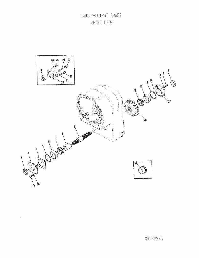
DDRRYY SSYYSSTTEEMMSS TTEECCHHNNOOLLOOGGIIEESS 8102 Lemont Road Suite 700 Woodridge Illinois 60517 USA
Phone 630-427-2051 Fax 630-427-1036 EE--mmaaiill eennggddrryyssyysstteemmsstteecchhccoomm
OPERATION AND MAINTENANCE MANUAL PART D M301-019-01 PRE-OPERATING INSPECTION FOR THE DST DRY SYSTEMtrade
Dry Systemtrade Pre-operation Checklist
OPERATORrsquoS PRE-OP CHECKLIST FOR THE DST SYSTEM DE-ENERGIZED WALK-AROUND INSPECTION PERFORMED BEFORE EACH SHIFT
ITEM DESCRIPTION COMPLETED 1 Make certain equipment is in a safe condition and in a safe area prior to
the inspection
2 Make sure the machine is clean and free of accumulations of combustibles
3 Check the DST Dry Systemtrade for external damage and to determine that all components are in place and not damaged
4 Look for loose or missing DST components and loose or missing hardware
5 Look for gas leakage at each flange connection of the DST Dry Systemtrade 6 Inspect the bellows assembly for external damage or leakage 7 Check for damaged coolant hoses vent hoses and coolant leaks 8 The surge tank must be completely full DO NOT OPEN RADIATOR CAP
IF HOT
9 Check the coolant overflow bottle Coolant must be between upper and lower marks Add coolant mix if needed
10 Check the radiator cap on top of the surge tank to be in place and tightened
11 Check the radiator core for obstructions plugging damage and leaks 12 Check the fan for broken or missing blades 13 Check all belts to be properly tightened and in good condition 14 Check the water level in the tank for the on-board cleaning system and
top off with clean bottled water if necessary
15 Check all gauges for external damage 16 Replace all lids and secure all access doors as needed 17 Complete this form and place in operatorrsquos cab 18 Report all damage or problems to Maintenance for further action
Name helliphelliphelliphelliphelliphelliphelliphelliphelliphelliphelliphelliphelliphelliphelliphelliphelliphellip Date helliphelliphelliphelliphelliphelliphelliphelliphelliphelliphellip
Part D Pre-operation Inspection Page 3
DDRRYY SSYYSSTTEEMMSS TTEECCHHNNOOLLOOGGIIEESSregreg
OOPPEERRAATTIIOONN AANNDD MMAAIINNTTEENNAANNCCEE MMAANNUUAALL
DDSSTT DDRRYY SSYYSSTTEEMMregreg
SSEECCTTIIOONN FF CCOOOOLLIINNGG SSYYSSTTEEMM FFIILLLLIINNGG
PPRROOCCEEDDUURREE To be performed by the machine operator
MM330011--002211--0011
DRY SYSTEMS TECHNOLOGIES
8102 Lemont Road Suite 700 WOODRIDGE IL 60517 USA
Phone 630-427-2051 Fax 630-427-1036 E-mail engdrysystemstechcom
REVISION 01 DATED DECEMBER 2002 2 Pages
DDRRYY SSYYSSTTEEMMSS TTEECCHHNNOOLLOOGGIIEESS 8102 Lemont Road Woodridge Illinois 60517 USA
Phone 630-427-2051 Fax 630-427-1036 EE--mmaaiill eennggddrryyssyysstteemmsstteecchhccoomm
OPERATION AND MAINTENANCE MANUAL PART F M301-021-01 COOLING SYSTEM FILLING PROCEDURE FOR THE DST DRY SYSTEMtrade The DST Dry Systemtrade is fitted with a cooling system that incorporates a surge tank a recovery bottle and several vent lines to assure that the system has no trapped air The system is self purging once it is filled initially As with all cooling systems a mixture of 50 ethylene glycol and 50 treated (clean) water should be used for best performance Never add untreated mine water to the cooling system The following is the filling procedure for the system COOLING SYSTEM FILLING PROCEDURE
bull Carefully open the pressure cap on the surge tank after the system has cooled down and is not under pressure (There is no radiator cap on the radiator itself) CAUTION DO NOT ATTEMPT TO OPEN PRESSURE CAP WHEN COOLANT IS STILL HOT OR UNDER PRESSURE INJURY OR BURNS COULD RESULT
bull Fill a mixture of 50 Ethylene Glycol and 50 filtered water into the surge tank until the tank is completely full and the vent lines (38rdquo clear hoses) are filled with coolant
bull Replace the pressure cap firmly and start the engine Idle for 1-2 minutes to purge the remaining air from the system Check for leaks
bull Carefully open the pressure cap on the surge tank and top off the surge tank with a mixture of 50 Ethylene Glycol and 50 filtered water
bull Repeat steps 3 and 4 if necessary bull Replace the pressure cap firmly Fill the overflow bottle half way with a mixture of 50 Ethylene Glycol
and 50 filtered water bull Check the coolant level after about one hour of operation If coolant is significantly lower the cause for
the coolant loss must be investigated A normal loss in coolant due to temperature changes will be compensated by a rise or drop of the coolant in the overflow bottle The surge tank should never contain air
CAUTION DO NOT ATTEMPT TO OPEN PRESSURE CAP WHEN COOLANT IS STILL HOT OR UNDER PRESSURE INJURY OR BURNS COULD RESULT DO NOT OPERATE SYSTEM WITH LOW COOLANT ENGINE DAMAGE MAY RESULT USE ONLY A MIXTURE OF 50 ETHYLENE GLYCOL AND 50 CLEAN (FILTERED) WATER AS COOLANT NEVER ADD MINE WATER TO THE COOLING SYSTEM
Part F Cooling System Filling Procedure Page 2