
dowell division of dow chemical usa
222
DOWELL DIVISION OF DOW CHEMICAL U.S.A. P.O. Box 2710 Tulsa, Oklahoma 7410 * (918) 250-4200 B. W.I . P. ES-i SEALING CONSIDERATIONS February 9, 1983
-
Upload
khangminh22 -
Category
Documents
-
view
3 -
download
0
Transcript of dowell division of dow chemical usa
DOWELL DIVISION OF DOW CHEMICAL U.S.A.P.O. Box 2710 Tulsa, Oklahoma 7410 * (918) 250-4200
B. W.I . P.
ES-i SEALING
CONSIDERATIONS
February 9, 1983

INTRODUCTION
Based on personal experience, I foresee no reason why theproposed BWIP shaft seal materials will not be stable duringthe life of a nuclear waste repository - 75 to 100 years.
Listed below is some information which strengthens my beliefthat the current state of the art is satisfactory for use inconstructing and operating a nuclear waste repository.
Discussion:Expanding Cement - GeneralExpanding Cement - Case HistoriesGovernmental and Private Sector StudiesCSR - GeneralCSR - Case HistoriesQuestions and Answers
Articles:"New Cementing Process For Big Pipe In A Salt Plug""Improved Bonding and Zone Isolation With A NewExpanding Cement""New Expanding Cement Promotes Better Bonding""Drips or Blasts - Chemical Seal Ring Stops Wateror Gas"
Dowell Literature:Discontinued Technical Report - "Dowell Chemical SealRing and Dowell Chemical Seal Ring Gasket"Technical Information Sheet - "Dowell Chemical SealRing""Regulated Fill-Up Cement Controls Slurry Loss ForMore Predictable Fill-Up"
L. D. Boughton
EXPANDING CEMENTS - GENERAL
The first known shaft use of an expanding cement with calciumaluminum sulfate hydrate producing the expansion was in com-pleting the Project Dribble nuclear emplacement shaft. Aluminumpowder has been used to generate gas in a cement slurry in anattempt to produce expansion, as well as various salts to pro-duce expansion.
Several shafts had been drilled in the Tatum Dome, Mississippi,for the Project Dribble event. The primary cementing operationsdid not produce a dry seal as required. The event called for anabsolutely dry environment. Over 50 remedial squeeze operationsusing various cement systems and plastics did not produce a drytest.
Chem-Comp cement, at the time (1964), was beginning to be usedby the construction industry. This manufactured specialty cementis designed to chemically compensate for the shrinkage due toatmospheric drying. When placed in a humid environment it doesnot dry and consequently has a net expansion.
Dowell was called in, studied the Project Dribble problem andrecommended a twofold approach. First was to use an expandingcement, and secondly to develop and use a unique chemical sealantas a backup to the expanding cement.
Due to the relative short storage life of unmixed Chem-Comp,limited production facilities, and to realize better qualitycontrol, Dowell developed a family of two expanding systems whichhave been named Regulated Fill Cement (RFC) and Self Stress.RFC is a thixotropic cement while Self Stress is not.
RFC was developed and first used in 1967. Industry recognizedthe merit of this cement system and immediately put it into use.It continues to be used as a cost effective well completion aid.Over 10,100 RFC jobs have been performed in the past two yearsin the US alone. Thousands more were performed by Dowell ofCanada and Dowell Schlumberger throughout the remainder of thefree world.
RFC is blended in the Dowell bulk plant servicing the particularcementing operation. The formulation is within prescribed limitsand is designed for the specific operation.
EXPANDING CEMENT - CASE HISTORIES
1. Tatum Salt Dome, Mississippi. Project Dribble 1964. Saltformation. The integrity of the shaft permitted it to beused as an emplacement hole for two separate nuclearevents. Refer to the enclosed article "New CementingProcess For Big Pipe In A Salt Plug" for details.
2. New Jersey - mined anhydrous ammonia storage cavern accessshaft in 1965. A 42-inch shaft liner was sealed in a56-inch hole drilled to 340 feet in mica gneiss. Expand-ing cement along with CSR was used to complete the shaft.No water leaked into the cavern nor ammonia out of thecavern which was mined in the gneiss.
3. Ambrosia Lake, New Mexico - in the late 60's. Shoot andGrout service was utilized to rubblize the Dakota forma-tion to intersect natural fractures. The natural fracturesin the Dakota have tremendous flow capacities in this area.The fractures, man-made and natural, were sealed with RFC.
The 16-foot diameter shaft was air drilled to over 800feet, with some misting from ungrouted formations towardtotal depth. A steel liner was grouted and the shaft putinto duty as a production shaft.
4. Nuclear Emplacement Shaft - Central Nevada SupplementalTest Site.
5. Several Nuclear Emplacement Shafts on Pahute Mesa, NevadaTest Site.
6. Nuclear Emplacement Shaft on Amchitka Island. Grout linescould not be used below a bubble in the shaft lining. Tworemedial pressure grouting jobs obtained a dry test.
7. Three Uranium Mine Shafts near Crown Point, New Mexicowere not put into mining use due to depressed price ofyellow coke - 1980.
8. Lead Mine Shaft near Ellington, Missouri was declared "bone"dry after opening the shaft below the liner - 1982.
9. Mined Product Storage Cavern Shafts throughout the US, pri-marily for LPG storage.
10. Numerous reservoir-type gas storage wells.
11. Bunker Hill Lead Mine Shaft in Missouri. Used to seal an86-inch liner in a 108-inch shaft to 1450 feet - 1967.

GOVERNMENTAL AND PRIVATE SECTOR STUDIES
Dowell has conducted studies for governmental agencies. Ourevaluation of these study results confirms the writer's opinionthat RFC will meet the requirements imposed in operating anuclear repository in basalt formations.
1. Subcontract No. 78X-15966C. A laboratory study ofprospective materials for use in sealing boreholes inthe vicinity of nuclear waste repositories. Subcon-tract to Union Carbide Corp., Nuclear Division, OakRidge, Tennessee.
2. Subcontract 78X033542C. Sealing AEC #1 Well, Lyons,Kansas. Utilize results obtained under Subcontract78X-15966C to seal a borehole. Subcontract to UnionCarbide Corp., Nuclear Division, Oak Ridge, Tennessee.
3. DOE Contract No. DE-AC02-77ET28324 for "Development ofGeothermal Well Completion Systems - Final Report" -Report No. COO/4190-9, March 1981.
We have provided materials for testing by several agenciesor their subcontractors but in turn have not received reportsfrom them.
W.E.S. has conducted studies of expanding cements (Chem-Comp, Dowell RFC and Dowell Self Stress - all of which arein the same family). Studies were conducted for the AECat Mercury, Tonopah, and Amchitka and for Sandia in theCarlsbad waste study and possibly others. Penn State,Arizona State and private labs have conducted studies oftheir own design and their own formulations using expandingcement components furnished by Dowell. We are not providedwith copies of their findings.
In addition to the above, there are many scientific booksdealing with cement and concrete. Many deal with expandingcement in which calcium aluminum sulfate hydrate is pro-ducing the expansion. Taylor's comments regarding sulfateground water follows.
"It has been argued that concrete which has expanded mightchange its dimensions further or lose strength, when exposedto aggressive chemical agents such as ground waters containingsulfate ions, or even milder influences such as atmosphericcarbon dioxide. In the former case this might be due tofurther calcium aluminum sulfate hydrate formation and in thelatter case to its destruction by carbonation. There islittle practical evidence to support these fears, which seemcontradicted by the stability of supersulfated cement con-crete when exposed to these agents."

GENERAL - CSR
CSR is a dispersion of a water-sensitive, high molecular-weight polymer in a glycerine, glycol mixture. A watersoluble chromium compound crosslinks the polymer dispersion.
CSR was developed in 1964. We do not know of any acceleratedtests that can be utilized to determine the durability of thematerial. Unfortunately it appears the only durability testis of necessity the actual project itself.
Some test results are included in the enclosed sales litera-ture and articles. These are concerned primarily with short-term performance.
CSR was designed to function as a gasket. In a shaft thesteel liner and drilled formation provide radial confinementwhile concrete or cement provides the vertical confinement.The CSR must be placed opposite impermeable formations withno vertical fractures so as to eliminate vertical flow throughdrilled formations as well as through the shaft wall-shaftliner annulus.
The confining cement or concrete must be of adequate verticalextent to achieve the desired gasketing action. Taking intoaccount possible cracking of cement, as in a breakout, anextent of 50 feet of cement above and below 20 feet of CSRmay be in order. A sufficient body of cement is required incase remedial operations are required. It is a considerationto safe mining operations.

CSR CASE HISTORIES
Dowell Chemical Seal Ring was developed in 1964 to solve ashaft sealing problem encountered by the AEC in attemptingto complete a nuclear emplacement shaft for Project Dribbleat the Tatum Dome in Mississippi. Since then CSR has beenused for mine shaft seals and construction shaft seals.Case histories are cited as follows:
1. AEC nuclear emplacement hole for Project Dribble.The cavern created by the first test was dry due tothe integrity of the shaft seal. The shaft servedas an emplacement hole for a second nuclear eventand remained dry even after the second shot. CSRwas used in conjunction with expanding cement.
2. Anhydrous ammonia storage cavern mined in a granitegneiss formation in New Jersey. CSR was successfullyused in conjunction with expanding cement. The cavernis operational.
3. CSR along with cement was next used to seal a con-ventionally sunken shaft used to mine an LPG storagecavern in shale. The shaft was sealed and the cavernwas put into operation.
4. CSR was used to stem nuclear weapon tests shot atNTS and Amchitka.
5. CSR was introduced to the Canadian potash industry inthe late 60's. The first use was a cautious seal ofCSR backed up by the standard pikotage seal. Pikotagehad been used for decades to seal the top and bottomof cast iron tubbing installed opposite aquifers bythe Germans. Subsequent usage of CSR in potash mineshafts in Saskatchewan, England and Brazil has elimi-nated the use of pikotage at a major savings to theowners. In two instances an initial small leak wasdetected and pressure grouted to achieve a completelydry test. All of the mines are fully operational.

Canadian operations include:
Alwinsal - Bottom seal in conjunctionwith pikotage 1967
Sylvite - Salt protection ring in eachof two shafts 1969
PCA -500' 1976
1700' below frozen Blairmorewith no pikotage 1977
1400' above frozen Blairmorewith no pikotage 1977
2700' 1978
Allan - Replaced asphalt seal ofbottom catch ring 1968
Allan - One seal above and one belowthe Blairmore with no pikotage 1980
PCA - Catch ring 1969
Noranda - One seal above and one below Latethe Blairmore along with pikotage 60's
Whitby Chemical, Whitby, England - Seal Lateassemblies in two potash mine shafts 60's
Norsk Hydro, Norway - Two seals in anLPG cavern 1968
6. CSR was used to seal bulkheads in the formerMorton Salt Co., Weeks Island, LA mine during itsconversion for SPR usage. Crude oil is being pumpedinto the mine which will eventually hold some 60-70million barrels of crude oil.
7. CSR was recently used to seal a mined storage cavernshaft in Taiwan, a salt mine in Southern Louisianaand a cast iron tubbing section in a German coalmine.
8. Three intervals of CSR were installed in the W.I.P.P.shaft near Carlsbad.

QUESTIONS AND ANSWERS
1. Q. What accelerated laboratory aging tests can beconducted within a six-month time period tosimulate a 75-year time period?
A. An extensive review of the problem indicates to usthat a credible short-term accelerated test of CSRis not possible. Unfortunately the test is theactual operation itself which therefore places apremium on case histories of a material only 19years old.
A. Accelerated aging tests of cement systems havecredibility, within limits. It is known in generalterms that cement will not suffer strength retro-gression from temperatures of less than 230'F andthat specific additives will prevent strengthretrogression due to temperatures in excess of500 0F.
Similar cement systems can be manufactured to besulfate resistant or through the use of additivessuch as in RFC a cement system can be made sulfateresistant. In neither case can the life expectancybe quantified with accuracy.
2. Q. Have shafts been successfully sealed under environ-mental surroundings similar to BWIP?
A. We are not aware of any shafts completed in basaltformations. Shafts have been completed in morehostile environments - both temperature and for-mation waters. AEC operations involved shaftscompleted in tuff and ryholite.
The physical characteristics of drilled formationssuch as vertical permeability, fractures, vugs andfissures, degree of consolidation, etc. have moreof a bearing on water shut-off than does the chemicalcomposition of other than soluble (evaporite) for-mations.

3. Q. What specific laboratory tests have been conductedand what are the results?
A. (1) Cement specimens were exposed to flowinggeothermal brines at 1500 to 1700C for upto 17 months. The brines were extremelycorrosive, typically containing about 27,000mg/L total dissolved solids. High concen-trations of CO2 and so4 were also present.
The results showed that, in general, normaldensity (14.5-16.0 ppg) portland cement-basedsystems with low permeability performed sat-isfactorily.
(2) Numerous studies have produced and confirmedthe merit of systems which are resistant tosulfate attack.
(3) No accelerated CSR stability tests have beenconducted. Confined samples prepared in 1964remain stable. Unconfined samples of CSR ina large excess of water having a range of pHfrom 2 to 12 gradually disintegrate as citedin tests conducted by Rockwell.
(4) Physical tests of CSR and their results arecontained in the paper titled "New CementingProcess For Big Pipe In A Salt Plug" and inthe discontinued Technical Bulletin titled"Dowell Chemical Seal Ring and Dowell ChemicalSeal Ring Gasket."
COMMENT:
During the entire operating life of the repository, the shaftwill be open and repairs can be effected if necessary. Inthe installation of the final seal a section of the liningwill be removed and a different seal material will be used.

Expandinig cement, chemical seal, aerated fluid
successful with 20-inch casing to 2,200 feet
L. D. Boughton, Engineer Dowell Division of Dow Chemical Co., Tulsa
T. B. Dellinger, Assistant Chief Drilling Engineer,Fenix & Scisson, Inc., Tulsa
formations overlying the salt and bythe need to positively seal the casingin salt and air drill below the casing.
Tatum dome geology. Figure 1shows the general geology of theTatum Dome. The top of the saltplug is about 1,500 feet below the sur-face. A 500-600-foot thick caprockcovers the salt. The upper section ofthe caprock is highly fractured, vugu-lar limestone about 150 feet thick, andthc lower section is anhydrite Theanhydritc-salt contact is "mushy" andhas been the interval of lost circula-tion in several of the holes drilled forProject Dribble.
Five major fresh water aquifershave been identified in the formationsoverlying the caprock. Communica-tion exists between most of the aqui-fers and the caprock. The static fluid
level is about 150 feet from the stir-face.
Over-all program design. Successof Project Dribble depends on posi-tive exclusion of fluids from an open
bore hole in the salt below the cas-ing. After casing was cemented in thesalt plug, the hole was evacuated anddeepened by air drilling. During thisand subsequent operations, the holemust remain completely dry.
A NEW CEMENTING PROCESS, Usingexpanding cement and a special chemical seal, has proved successful in ce-menting large-diameter casing in salt
plug at the Tatum Salt Dome nearHattiesburg, Miss.
THe process involved the usc of twonew cementing materials, and was ap-
plied in the primary cementing of 20-inch casing in a 28-inch hole for Proj-ect Dribble, code name for a series of(ests being conducted by the AtomicEnergy Commission.
This is believed to be the first suc-cessful primary cementing job undersuch conditions, either in salt-mining
operations or prior AEC operations.Careful preplanning and engineering,as well as use of the new materials, ledto the success of the operation.
The usual problems encountered incementing casing in a drilled hole in-crease greatly as casin, size increases.Expansion and contraction of the cas-ing due to pressure and temperaturechanges become, critical with large di-ameter casing,, and must be controlledto some degree if satisfactory bondingis to be obtained.
Cementing problems at ProjectDribble were compounded by the ex-istence of several major aquifers in the
LOCALAQUIFER
[COULD NOT BE CONVERTED INTO SEARCHABLE TEXT]

[COULD NOT BE CONVERTED INTO SEARCHABLE TEXT]

[COULD NOT BE CONVERTED INTO SEARCHABLE TEXT]

[COULD NOT BE CONVERTED INTO SEARCHABLE TEXT]

IMPROVED BONDING AND ZONE ISOLATION WITH ANEW EXPANDING CEMENT
T. J. GRIFFIN and L. B. SPANGLEDowell Div., Dow Chemnical Co.
[COULD NOT BE CONVERTED TO SEARCHABLE TEXT]

A micro-annulus of 0.002 to 0.003 inch would showintermediate to poor bonding on a bond log.4 Gascould readily pass through such an annulus if suchconditions existed.
A mud film on the pipe and formation, tar,paraffin, and mill scale can also cause incompletebonding. Shrinkage and cracking of the cementsheath are other instances leading to the formationof a micro-annulus. Cementing dry formations,such as ones encountered in air, gas, or mist drillingcan result in a water loss to the formation as thecement is setting, resulting in shrinkage of thecement.5
PAST METHODS OF PREVENTINGMICRO-ANNULUS FORMATION
In the past, several expanding cement systemswere used to prevent or reduce micro-annulusformation. One of these involves the use of salt inPortland cement to produce a cement whichexpands more than the neat cement. These systemsrely on crystalline growth for expansion. 6 Thisexpansion occurs as the result of water being takenup during cement hydration, causing the salt tobecome supersaturated and to crystallize. Aproblem with this type of system is that exposure toformation waters which are not salt-saturated mayallow leaching of the salt from the cement, causingcontraction of the cement and an increase in itspermeability.
Another cement system used to prevent micro-annulus formation is ChemComp* expandingcement."' This is a patented system developed toovercome the dry-shrinkage problem associatedwith conventional Portland cement which shrinksbecause of evaporation of water from the cement orconcrete as it sets. The system was adapted for oilfield use with very good results under mostconditions.9
Unfortunately, this cement has limited storagelife and does not respond well to oil-well cementadditives. Also, it is only manufactured at a fewlocations and is not readily available in most oil andgas well producing areas.
NEW TECHNOLOGY: EXPANDING CEMENT
A new product which creates a self-stress in thecement has been developed to fill the need for anexpanding cement. This "self-stress" cement
expands after the cement has- set and before itdevelops its complete compressive strength. Itoccurs while it is still pliable. Consequently. thiscement maintains its integrity yet expands tomaintain a tight fit around the casing as it shrinks.This prevents the formation of a micro-annulus andexerts pressure on any mud film, scale or tar whichmay be left on the casing. It sometimes penetratesthe scale or film by crystalline growth of the cement.This maintenance of a tight fit results in a positiveseal and superior bonding (Figure 2).
GOOD CEMENT BOND
FIGURE 2-EXPANDING CEMENTS MAINTAIN TIGHT FITAROUND CASING AS IT SHRINKS, THUS PREVENTING
FORMATION OF A MICRO-ANNULUS.
Dowell's self-stress cement composition is moreversatile than the commercial expanding' cementdescribed earlier, because it responds 'well toconventional oil-well cementing additives. As aresult of this, it can be used in almost anycircumstance where an expanding cement Would beadvantageous and other properties are desirable inthe cementing system. An added benefit of thesystem is that the expansive reaction providesresistance to attack by sulfate waters.
LABORATORY DATA
Laboratory testing of the Dowell self-siresscement system indicates it is very suitable for use inoil and gas well cementing. Tests conducted confirmthat it will respond adequately to retarders used inhigh temperature cementing. Figure 3 shows acomparison of the viscosity curves of two systemsretarded for four hours pumping time at 3021FBHCT (16,000 ft casing schedule). Both systemscontained silica for control of strength retrogressionand an 0.8-percent high temperature retarder. Otherresults of thickening time testing are shown in Table
22 SOUTHWESTERN PE PETROLEUM SHORT COURSE

TABLE I -THICKENING TIME&COMPRESSIVE STRENGTH OF SELF-STRESS CEMENT SYSTEMS RETARDED FOR
DOWNHOLE CONDITION
Other AdditivesThickening Time
(Hr:Min)Compressive Strength (psi)
8 Hr 24 Hr
Thickening time at 80'F, BHCT (Scd 1); compressive strength at 950F, BHST
[COULD NOT BE CONVERTED TO SEARCHABLE TEXT]
I along with compressive strength data for the samesystems.
Compressive strength testing indicates that theDowell self-stress cement system, although mixedwith more water, develops early compressivestrength at a faster rate than comparable neatcement systems (Table 2). The six-hour compressivestrength of a self-stress cement system prepared
PAN AMERICAN CONSISOMETER TEST AT 16 100 PSI
100BEARDEN UNITS
OF CONSISTENCY
from Class C cement cured at 801F developedgreater strength than a Class C cement (which is ahigh early strength cement) cured under the sameconditions. The neat cement systems will rapidlyovertake the self-stress cement system incompressive strength as indicated by the Class Gcement in Table 2. These neat cement systemsdevelop higher ultimate compressive strength thanthe self-stress system, but the ultimate strength ofself-stress is more than adequate for almost allapplications. Plug cementing is an exception to thisbecause development of very high strengths in shortperiods of time is desirable. Ultimate compressivestrength of the self-stress system is in the range of2500-5000 psi, depending on the cement used,amount of mix water, and other factors.
Figure 4 shows expansion data of Dowell self-stress cement compared to neat cement.ChemComp cement, and salt-saturated Portlandcement. Normally, the self-stress system expands in

the range of 0.20-0.50 percent, depending on
chemical factors (variations in cement), degree of
retardation, and temperature. Salt systems used asexpanding cement expand from 0.10 to 0.16 percentcompared to neat cement which expands 0.02 to
0.08 percent, again depending on some of the samefactors. Expansion occurs fro mthe time the cement
is first mixed with water. the desirable expansion isprimarily that which occurs after thee cement reaches
a ridgid state and will no flow or move as it expands.It is then necessary to design expanding cement
systems to have a minimum pumping time plus aworkable safety factor in order to take advantage of
as much expansion as possible.

hole. Bottom-hole temperature was in the range of190^200oF. Following cementing, the liners werepressure tested and logged to evaluate the cementjob. Quite often, the pressure test indicatesincomplete seal at the top of the liner and the bondlog indicated poor cement bond. Similar treatmentswith self-stress cement have shown excellent results.Pressure tests showed a positive seal at the liner topand bond logs indicated good bonding.
These results are typical of those achieved whenDowell self-stress cement is used to overcomeproblems of zone isolation and bonding due tomicro-annulus formation.
CONCLUSION
Like any advance in technology, a self-stresscementing system is no cure-all. It must be designedfor the conditions of the well, and it must be appliedusing the best placement techniques well conditionswill allow. It is one more step toward getting theoptimum results from oil or gas well cementing.
REFERENCES
I . Suman, G. O., Jr. and Ellis. R. C.: "Cementing Oil andGas Wells - Part 4". World Oils Cementing Handbook(1977) 32-40.
2. Tiplitz, A. J. and Hassenbroek. W. E.: "An Investiga-tion of Oil Well Cementing", Drilling and Production
Practice. American Petroleum Institute (1946) 76-103.3. Griffin, '. J., Jr. and Root. R. L.: "Cementing Spacers
and Washes Improve Production', Oil & Gas Journal(Sept. 12, 1977) 115-122.
4. Kozik, H. G.: "Notes on Cement Bond Logging",Squeeze Cementing Symposium, Tulsa (Dec. 1977).
5. Setter. N. and Roy, D. M. P.: "Mechanical Features ofChemical Shrinkage of Cement Paste", Cement andConcrete Research. Volume 8 (1978) 623-634.
6. Hansen. W. C.: "Crystal Growth as a Source ofExpansion in Portland Cement Concrete", AmericanSociety for Testing and Materials, Proceedings,Volume 63 (1963) 932-945.
7. Klein, A.: "Calcium Alumino-Sulfate and ExpansiveCements Containing Same", US. Patent 3.155,526:(Nov. 3, 1964).
8. Klein, A. and Troxell, G. E.: "Studies of CalciumSulfoaluminate Admixtures for Expansive Cements",
American Society for Testing and Materials,Proceedings, Volume 58 (1958) 986-1008.
9. Root, R. L. and Calvert, D. G.: "The Real Story ofCement Expansion", SPE 3346, Presented at SPERocky Mountain Regional Meeting, Billings, Montana(June 1971).
ACKNOWLEDGMENTSThe authors thank Dowell Division of The Dow
Chemical Company for permission to publish thiswork. We would also like to thank our colleagueswho have assisted in the testing and gathering ofdata for this work.
SOUTHWESTERN PETROLEUM SHORT COURSE 25
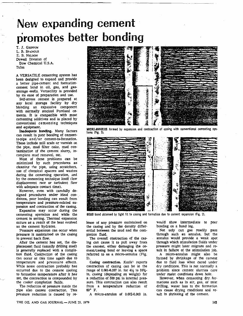
New expanding cementpromotes better bonding
T. J. GRIFFINL. B. SPANGLEE. B. NELSONDowell Division of
Dow Chemical U.S.A.Tulsa
A VERSATILE cementing system hasbeen designed to expand and providea better pipe-cement and formation-cement bond in oil, gas, and gas-storage-wells. Versatility is providedby its ease of preparation and use.
Self-stress cement is prepared atany local storage facility by dryblending an expansive componentwith normally stocked Portland ce-ments. It is compatible with mostcementing additives and is placed byconventional cementing techniquesand equipment.
Inadequate bonding. Many factorscan result in poor bonding of cement-to-pipe and/or cement-to-formation.These include mill scale or varnish onthe pipe, mud filter cake, mud con-tamination of the cement slurry, in-complete mud removal, etc.
Most of these problems can beminimized by such procedures ascleaning the pipe, using scratchers,use of chemical spacers and washesduring the cementing operation, andby the cementing technique itself (lowdisplacement rate or turbulent flowwith adequate contact time).
However, even with carefully de-signed procedures under ideal con-ditions, poor bonding can result fromtemperature and pressure-related ex-pansion and contraction of the casing.
Expansion may occur during thecementing operation and while thecement is setting. Thermal expansionoccurs as a result of the heat evolvedas the cement hydrates.
Pressure expansion can occur whenpressure is maintained on the casingto prevent back flow.
After the cement has set, the dis-placement fluid (usually drilling mud)is generally replaced with a comple-tion fluid. Contraction of the casingcan occur at this time again due totemperature and pressure effects.While some contraction probably hasoccurred due to the cement coolingto formation temperature after it hasset, the contraction is compounded bythe cooler completion fluids.
The reduction of pressure inside thepipe also causes contraction. Thispressure reduction is caused by re-
MlCRO-ANNULUS formed by expansion and contraction of casing with conventional cementing sys-tems (Fig. 1).
GOOD bond obtained by tight fit to casing and formation due to cement expansion (Fig. 2).
lease of any pressure maintained onthe casing and by the density differ-ential between the mud and the com-pletion fluid.
The overall contraction of the cas-ing can cause it to pull away fromthe cement, either damaging the ce-ment/casing bond or leaving a spacereferred to as a micro-annulus (Fig.1).
Casing contraction. Kozik' reportscontraction of casing can be in therange of 0.001-0.007 in. for 41/2 to 103/4-in. casing (depending on weight) fora reduction of 500 psi in internal pres-sure. This contraction can also resultfrom a temperature reduction of60° F.
A micro-annulus of 0.002-0.003 in.
would show intermediate to poorbonding on a bond log.
Not only can gas readily passthrough such an annulus, but theannulus would provide a weak spotthrough which stimulation fluids underpressure might later migrate and re-sult in failure of the stimulation job.
A micro-annulus might also beformed by shrinkage of the cementdue to fluid loss when cured underdry conditions. This is not normally aproblem since cement slurries cureunder moist conditions down hole.
However, when cementing dry for-mations such as in air, gas, or mistdrilling, water loss to the formationcan cause drying conditions and re-sult in shrinking of the cement.
THE OIL AND GAS JOURNAL -JUNE 25, 1979 143

Fig. 3
Expansion comparison Expansion with time
Previous expanding cements. It hasbeen recognized for many years thatan expanding cement might compen-sate for casing contraction and main-tain a tight fit between casing andcement and formation and cement asshown in Fig. 2.
In the mid 19605, two types of ex-panding cements were introduced tothe oil industry and met with con-siderable success.
The benefits derived from the useof these expanding cements in termsof improved bond logs are well es-tablished.2 3 The two systems usedwere ChemComp (trademark of theChemically Prestressed ConcreteCorp.) and salt-saturated cement sys-tems. 2 3 4
Major problems, however, have pre-vented these cements from beingwidely used and the full potential ofexpanding cements has never beenfully realized. The commercial ex-panding cements did not respond wellto retarders and often there was in-sufficient time to permit their use athigher temperatures.
Other. problems were short storagelife, requirements for separate stor-age facilities, and limited availabilitysince they were manufactured in onlya few areas.
Problems encountered with some ofthe salt-saturated cements were main-ly fluid-loss control.
Self-stress cement systems. In orderto take advantage of cement expan-sion, Dowell has developed a newproduct which creates a self-stress inthe cement. This cement expandsafter its initial set but before it hasdeveloped its complete compressivestrength.
In other words, expansion occurswhile the cement is still pliable. Thus,the cement can maintain its integrityyet expand to maintain a tight fitaround the casing as it contracts.
It exerts pressure on any mud film,scale, or tar which may be left onthe pipe and can penetrate the scale
or film by crystalline growth.Many people believe that little ad-
hesive bond exists between cementand formation.
Filter cake and adverse fluids, suchas oil in the pay zone, minimize thistype of bond.
If this is the case, then the sealbetween the formation and cement isprobably due to the set cement follow-ing the contour of irregularities in theborehole and in the formations. Undersuch conditions, expanding cementcould be highly advantageous.
Since self-stress exhibits a high de-gree of expanison, it maintains a tightfit not only against the casing butagainst the formation as well. Thus,it provides a more positive seal be-tween cement and formation and re-duces the possibility of interzonal com-munication (Fig. 2).
It also overcomes many of the prob-lems associated with the older com-mercial expanding cements.
Since it is prepared from mostbrands of Portland cement already in-ventoried at cementing locations, thereare no storage or availability prob-lems.
The self-stress system is also com-patible with conventional cementingadditives. It responds well to retard-ers and can be used over a widetemperature range.
An added benefit of the self-stresssystem is that the expansive reactionprovides resistance to attack by sul-fate waters.
This greatly reduces the possibilityof cement deterioration and subse-quent casing corrosion.
Laboratory data. Laboratory testingof the new system indicates that it issuitable for oil and gas well cement-ing.
Ultimate compressive strength ofthe system is in the range of 2,500-5,000 psi depending on the cementused and amount of mix water. Thisis more than adequate for almostall applications.
Other tests conducted with the self-stress system indicate that it respondsadequately to retarders and can beused in high-temperature cementingapplications.
Results of the thickening time teof several different self-stress systemare shown in Table 1 along -"th com-pressive strength data for the samesystems.
Comparative expansion data for aneat, a salt-saturated, and a self-stress slurry are shown in Fig. 3. Fig.4 shows expansion data of self-stresscement compared to neat cement,ChemComp expanding cement, andsalt-saturated Portland cement.
Usually the expansion of the self-stress system is in the range of0.20 to 0.50% depending on chemicalfactors (variation in cement), degreeof retardation, and temperature con-ditions.
Salt systems used as expandingcements expand from 0.10-0.16% com-pared to neat cement which expands0.02-0.08%, again depending on someof the same factors.
Expansion actually starts when thecement is first mixed with water.However, the usable expansion isprimarily that which occurs after theslurry reaches a rigid state and willnot flow or move. It is important todesign expanding cement systemswith a minimum of pumping titplus a realistic safety factor, in or.to take advantage of as much ex-pansion as possible.
Field applications. Self-stress ce-
144 THE OIL AND GAS JOURNAL -JUNE 25, 1979

BOND log from Hockley Co., Tex. (Fig, 5).
Table I
Lab data on self-stress slurriesThickening
Cement Density, Other time, -Compressive strength, psi-,class lb/gal additives (hr:min) 8 hr 24 hr
Thickening time at 800 F., BHCT (scd 1); compressive strength at 950 F. BHSTA 14.8 .... +6:00 170 780H 14.8 +6:00 95 450G 14.8 +6:00 295 1,370
Thickening time at 140° F., BHCT (scd 5); compressive strength at 2000 F. BHSTA 14.8 2:03 2,000 2,895A 15.1 Salt-saturated +6:00 1,065 1,545A 14.9 50:50 Fly ash 2:18 955 1,600H 15.0 35% silica +
0.5% retarder +6:00 Not set 1,925
Thickening time at 1970 F., BHCT (scd 7); compressive strength at 2600 F. BHSTA 15.0 35% silica +
0.5% retarder 3:23 2,080 3,280A 15.0 35% silica +
0.5% Diacel LWL 5:17 1,745 2,440A 15.0 35% silica +
0.5% HT retarder' 4:43t 2,055 3,405H 15.0 35% silica +
0.5% retarder 4:47 925 2,400G 15.0 35% silica +
0.5% retarder 4:38 1,655 3,650
HT-high temperature retarder. tThickening time at 233 BHCT (schedule 8).
The system has been used in vir-tually all types of cementing opera-tions including shallow gas storagewells, long strings, and deep liners.The following case histories demon-strate the value of expanding cementin specific applications.
Case history 1. Operators in Calla-han Co., West Texas, have long haddifficulty in obtaining good bondingas indicated by bond logs. ChemCompcement was used successfully tosolve this problem until its manufac-ture was discontinued in this area.
Self-stress has since been used innumerous jobs, and bond logs indicateexcellent results. These wells arefrom 2,0004,000 ft deep with bottom-hole temperatures from 110-1200 F.
Case history 2. Hockley Co., Tex.,is another area where poor bondingwas common. Fig. 5 is a bond log ofa well in this area which was cement-ed with self-stress cement.
Excellent bonding of both pipe-to-cement and cement-to-formation is in-dicated. The pipe-cement bond line isdifficult to discern since it lies direct-ly on the base line throughout theinterval except for an occasionalsmall deviation.
Case history 3. In Custer Co., Okla.,it is common practice to set 600-1,000ft of 27%-in. liner in 434-in. hole todepths between 10,000 and 11,000 ft.Bottom-hole temperature is in therange of 190-2000 F. Following ce-menting, the liners are pressure testedand bond logs are run to evaluate thecement job.
Frequently in the past, the pressuretest had indicated an incomplete sealat the top of the liner and a squeezejob has been required. The bond logshave also indicated poor bonding.
Following cementing with self-stresscement, however, pressure tests haveshown a positive seal at the liner topand bond logs have indicated goodbonding.
Summary. Self-stress cement is aversatile new expanding cement withsix advantages over other expandingcement systems.
Expansion properties are better thanthose of commercially available ex-panding cements. This expansion isfar superior to that of salt-saturatedsystems.
Self-stress cement is prepared fromPortland cement normally stocked ata cementing facility, so there is nostorage life or availability problem.
The material is compatible withconventional cement retarders and isapplicable over a wide temperaturerange.
Most cement additives, such as dis-persants, fluid-loss additives, and ex-
ment systems are used in the field inthe same manner as conventional ce-ment systems. The dry ingredientsare blended with API Portland cementat the service company's bulk blend-ing location. After being transportedto the well site, it is mixed in thesame manner as conventional slurriesand pumped according to any desiredcementing technique.
These systems have been used in
more than 200 jobs and under avariety of conditions throughout theU.S. and Canada. Excellent resultshave been obtained in all areas in-cluding those where, in the past, bondlogs have indicated little or no bond.
Well depths where self-stress hasbeen used have ranged from less than1,000 ft to greater than 10,000 ft.
Bottom-hole temperatures haveranged from 950 F. to over 2500 F.
146 THE OIL AND GAS JOURNAL-JUNE 25, 1979

Hi-FlexPowertrak
21/2 Hydraulic Hose.Nothing on the
market cancompare.
Now Powertrak hose is available in 21/2"lengths up to 60 feet - Special cable con-struction for pulsing pressures up to 2800psi.
Like other Hi-Flex Powertrak hoses, the 2½/2"bend radius and weight per foot makes iteasy to work with and longer lived. Nothingelse in the field today can compare.
Powertrak - We don't care what you do withit - Hang it - Bend it - Beat it. The more youuse it, the more you'll appreciate it.
Available from stock -
Call or write
Hi-Flex International, Inc. Phone inquiries2001 Lowell Avenue (814) 833-2666
Erie, PA 16506 Telex: 914-457
hiflex

For immediateanswers,call these experts.EASTERN ZONE OFFICESYork Div. Borg-Warner Corp.
* P.O. Box 509970 Pulaski Dr.King of Prussia, PA 19406(Telephone: 2151337-1900)(Telex: 84-6307)
R. W. Rose, Zone Mgr.J. E. Ferguson, Sales Eng.R. C. Nadler, Sales Eng.H. B. Turner, Sales Eng.
* 155 Willowbrook Blvd.Wayne, NJ 07470(Telephone: 2011785-9590)
T. W. McCann, Dist. Mgr.M. Kalish, Sales Eng.
* 645 Pressley Rd.Suite 0Charlotte, NC 28210(Telephone: 704/527-3740)(Telex: 57-2493)
E. J. Robinson, Sales Eng.
tenders, can be used effectively inself-stress systems.
Better fluid-loss control can be ob-tained than is available in salt-expand-ing systems.
Finally, it is sulfate resistant.While self-stress cement is an im-
portant technological advance, it isno cure-all. However, when properlydesigned and applied with good ce-menting techniques, it can providesuperior bonding and zone isolation inmany situations.
AcknowledgementThe authors wish to thank the
Dowell Division of Dow ChemicalU.S.A. for permission to publish thisarticle.
ReferencesI. Kozik, H. G., "Notes on cement bond
logging," Squeeze cementing symposium,Tulsa, Okla., 1977:
2. Carter, L. G., Waggoner, H. F., andGeorge, C., "Expanding cements for pri-mary cementing," JPT, May 1966.
3. Parker, P. N. and Wahl, W. W.,"Expanding cement-A new development inwell cementing," JPT, May 1966,
4. Klein, A., U.S. Patent 3,155,526, "Cal-cium sulfoaluminate and expansive cementscontaining same," Nov. 3, 1964.
The authors . . .
IN NATURAL GASCOULD VERY WELLMEAN EXPENSIVE
PLANT SHUTDOWNS.
GEOMET,INCORPORATED
SUPPLIESANALYTICAL SERVICES,
INSTRUMENTS,SIMPLIFIED SAMPLING,AND FIELD SERVICES
FOR MERCURYDETECTION ANDQUANTITATION.
CENTRAL ZONE OFFICESYork Div. Borg-Warner Corp.
* 7077 N. Lincoln Ave.Chicago, IL 60646(Telephone: 3121677-0300)(Telex: 25-3561)
H. J. Kroll, Zone Mgr.J. M. Forti, Sales Eng.J. D. Sites, Sales Eng.
* 9000 Bank St.Valley View, OH 44125(Telephone: 216/447-0696)(Telex: 98-0574)
* 11645 Northline industrial Dr.Maryland Heights, MO 63043(Telephone: 314/567-5684)(Telex: 44-2451)
J. R. Betzold, Sales Eng.
SOUTHWESTERN ZONE OFFICEYork Div. Borg-Warner Corp.
* 5610 Forney Dr.P.O. Box 36426Houston, TX 77036(Telephone: 713/782-5200)(Telex: 77-5329)
J. R. Tacquard, Zone Mgr.R. J. Cross, Sales Eng.R. 0. Fell, Sales Eng.G. W. York, Sales Eng.
T. J. Griffin
WESTERN ZONE OFFICESYork Div. Borg-Warner Corp.
* 16350 Manning WayCerritos, CA 90701(Telephone: 213/926-0861)(Telex:.67-4510)
G. G. Neuberger, Zone Mgr.P. A. LeBlanc, Sales Eng.S. B. Weeks, Sales Eng.
* 1035 64th Ave., S.E.Calgary, Alberta, Canada T2H2J7(Telephone: 403/252-3386)(Telex: 03-824834)
R. J. Cassady, Sales Eng.
T. J. Griffin is a seniorresearch chemist inDowell's Treating Serv-ices Laboratory, Tulsa.He is responsible forthe development andfield testing of newcementing and sandcontrol products. Hehas written severalpapers on the technol-ogy of down hole fluidsystems. Griffin is a1967 graduate of WakeForest.
L. B. Spangle
E. B. Nelson
MEXICO* A. Castner (Telephone 905/566-5088)
L. B. (Lloyd} Spangle is a research chemist,Dowell, Tulsa. In his 18 years with Dowell,he has worked on virtually every phase ofcementing and cement products. Spangle didmuch of the laboratory work on the newexpanding cement. He is currently involvedin evaluation of cements by the thermalanalytical approach.
E. B. Nelson is a research chemist, Dowell,Tulsa. His research currently involves retard-ers for high-temperature application, and basicstudies concerning cement chemistry. Nelsonhas been with Dowell 2 years since his grad-uation with BS and MS degrees in chemistryfrom Colorado School of Mines.
LONDONPARISMANNHEIMPLUS OTHER MAJOR CITIES WORLDWIDE.
YORKTHE OIL AND GAS JOURNAL-JUNE 25, 1979 151

Epoxy aids large engine foundationsJ. MICHAEL SWEENYCreole Production Services Inc.Houston
A NEW hydrid foundation groutingsystem has been developed for sta-tionary engines. It employs the bestof the old grouting systems used forboth marine and stationary engines.
The new system, which uses epoxyto cap the concrete foundation andepoxy chocks to support the unit, is aresult of 50 years' evolution of grout-ing system design for both concreteblock and steel beam foundations.
History. Experience with engine andcompressor installation in both ma-rine and petroleum industries has re-vealed advantages and disadvantagesof a variety of foundation designs.
While the hybrid system essentiallyborrows much from the marine de-signs, an understanding of all thesystems is necessary to appreciatethe new design.
Marine engines. Marine engineshave typically been installed on largeI-beams in the ships' hulls. Adequatesupport was afforded, but the beamsurfaces were not smooth enough tooffer intimate contact with the milledbottom of the engine.
This problem and the problem ofalignment were overcome by using"chocks," which are shim plates1-2 in. thick located at each anchorbolt. The earliest marine engines usedsteel chocks which were hand-fittedby master craftsmen in a slow, tediousoperation of filing and bluing.
To realign the engines, the chockscould be removed and their thicknesschanged.
Later, chocks made of type metalwere employed. Type-metal is a lead-based alloy which does not shrinkwhen it solidifies and is used to casttype for printing. The engine wasaligned with wedges or jack screws,and asbestos or clay dams were con-structed around each anchor bolt tocontain the molten metal until it solidi-fied.
The type metal technique performedsatisfactorily, but it involved the safe-ty hazards associated with handlinghot metal. This metal also tended topound out because of the cyclic load-ing.
In 1963, a specially formulated epoxycompound began to be used in thesame manner as type metal. Thisepoxy chocking compound gained wideacceptance because it was safer to
REGROUTING 8,400-hp diesel engine foundationgrout epoxy, and epoxy concrete sealer.
work with than type metal. Althoughepoxy does not have compressivestrength as high as type metal, thesize of the chocks can be increased toachieve acceptable unit loadings.
Epoxy chocks are used extensivelyin the marine industry. So far theyhave not been widely employed by thepetroleum industry for stationary en-gines.
Stationary engines. Stationary en-gines are normally installed on con-crete foundations with grouting sys-tems using either sand and cementgrout, or a cement grout with metalfiller, or epoxy grout.
In the earliest type of grouting, sand
using hybrid design. Top to bottom, chock epoxy,
Fig.
Hybrid grouting system
152 THE OIL AND GAS JOURNAL-JUNE 25, 1979

Drips or Blasts-Chemical Seal Ring Stops Water or Gas;
S.A. Pence, Jr.Senior Research ChemistDowell Division of the Dow Chemical Company
Tulsa Oklahoma
ABSTRACT
A unique polymer sealant, placed as a pumpableslurry with ordinary well-cementing equipment, isdescribed. The patented composition sets into a
firm insoluble elastomer which forms gas andwater-tight seals between shaft walls and shaft lin-ings. Because the sealant swells when contacted byformation waters, it is able to protect potable
ater zones from gas stored in mined caverns whileat the same time preventing migration of waterinto the cavern. It has also been used as a stemmingmaterial in nuclear device emplacement holeswhere it is the key material preventing escape ofradioactive gases to the atmosphere. The material isalso available in the form of prefabricated gasketswhich can be compounded and molded to serve a
wide range of applications.The forerunner of this family of sealants was
invented to stop water from entering a nuclear testhole in Mississippi.That successful job sparked a
series of more and more difficult applications byimaginative engineers, and the products used today
moved to to meet their requirements.
INTRODUCTION
During the completion of a hole drilled into theSaltDome water, from many overlying
continued to "dribble" through the frac-in the caprock and made it impossible to ob-
a dry shaft in the salt. Remedial work withnot solved the problem and, since the
below had to be air drilled in order to providedry emolacement for a nuclear device, the success
"Project Dribble" was at stake.The solution to this critical problem was a
pumpable slurry which set up into a water-swellable elastomer and formed a self-sealing ringin the annulus between the formation and the steelcasing. This so-called Chemical Seal Ring not onlycompletely isolated the aquifers, but has withstoodthe shock of two nuclear detonations without fail-ing.
Since then Chemical Seal Ring has successfullyprevented the escape of radioactive gases throughthe tamped column above many nuclear devicestested underground. It has also efficiently keptwater out of mined caverns used to store naturalgas and liquified ammonia. A major use was in con-fining high-pressure aquifers so that mine shaftscould be dug into the rich potash deposits of Sas-katchewan.
Prefabricated gaskets of Chemical Seal Ringpromise to make construction of water-tight steeltunnel and mine-shaft linings easier and less ex-Densive.
The materials for Chemical Seal Ring are mixedand placed, batchwise or continuously, with reg-ular oil-well cementing trucks. The resulting slurry,
after a controlled thickening or working time,sets,if a predictable time, into a rubber-like solid. When
the proper cross-linking additives are used, Chem-ical Seal Ring has the unique property of swelling,
by imbibing water, but not dissolving. Thus, whenproperly confined, Chemical Seal Ring forms a
permanent self-actuating seal.Prefabricated gaskets are made by adding suit-
able fillers and curing the slurry, in molds, undercontrolled conditions. Joints, and bolted flangesfor tunnel and mine-shaft linings have been sealedwith Chemical Seal Ring gaskets and have
453

454 Drips or Blasts-Chemical Seal Ring Stops Water or Gas
withstood 1400 psi water pressure duringlong-term tests. Specially designed seals have with-stood cyclic tests where the maximum water pres-sure was 4500 psi.
PROPERTIES OF CHEMICALSEAL RING
In general there are two types of Chemical SealRing placeable as a pumpable slurry: (1) a compo-sition intended primarily for sealing gas, and (2) acomposition intended for sealing water as well asgas. Each can be modified to control loss of fluidsto formations by including an inert material suchas silica flour.
The solid component is a linear polyacrylamide.The mixing fluid consists of polyhydric alcoholsand water. When a Chemical Seal Ring must perma-nently seal off water, a cross-linking agent is dis-solved in the water.
Slurries have an initial viscosity of about 5 to 15poise, depending on the temperature, when mixed.The compositions are varied, with the mixingtemperature, to provide a working time of about30 minutes. The setting time, arbitrarily 10,000poise, or the time other operations may be re-sumed, varies between 2 and 4 hours depending onthe temperature where the slurry has been placed.
Prefabricated gaskets are made by curing a com-position that is augmented with polymer, filler andcross-linker under controlled conditions. The gas-kets produced can be molded in any desired shapeor stock can be cut and ground, like rubber, forcustom fitting.
After setting, both the slurry and gasket com-positions will swell several hundred percent if im-
mersed unconfined in water (Fig. 1). This occurs athigh water pressures as well as at ordinary pres-
sures. Uncross-linked compositions will, of course,eventually go into complete solution; however,Chemical Seal Ring slurries and gaskets contain across-linking system. Thus, the cross-linked Chemical
Seal Ring will swell only until tensile and swell.ing forces are equal and will not dissolve. The
behavior is similar to a sponge.Table 1 gives some of the physical properties of
a typical gasket composition (CSRG-201) and atypical slurry composition (CSR-300) after aging30 days at ambient temperature.
Life expectancy of Chemical Seal Ring is ofinterest. Since the material is relatively new, bytime standards, and
Figure 1. Swelling of Chemical Seal Ring after 40 hours at zero and1000 psi Top, CSR-300 Bottom, CSRG-201.
the range of pH between 2 and12 the sealant only swells as if it were in water. Infact, formulations having acceptable propertieshave been made using 10% sulfuric acid instead ofwater as part of the mixing fluid.
Several important features of Chemical SealRing stem from the nature of the chemicals used inits manufacture. A corrosion inhibitor preventsrust wherever the sealant is in contact with iron.This is extremely important in mine shafts.
Gaskets in the warehouse need only be pro-tected from rain-normal humidity does not resultin noticeable dimension increase. In tropical stor-age, however, dimensional changes may occur; but,the pliability and compressibility allows gaskets tobe used with no more trouble than that given byany other prefabricated sealing material.
With regard to possible fire hazard, thepolyhydric alcohols used apparently become anintegral part of the cured polymer, because nofluid can be squeezed out by any mechanical pres-sure. Furthermore, a standard method of flame

Orips or Blasts-CHemical Seal Ring Stops Water or Gas
Table 1. Properties of Chemical Seal Ring Formulations.
Specimen CSRG-201Thickness ASTM Gasket
Property (inches) Method System
Tensile Strength, psi 1/8 041266 61Tensile Strength, psi 1/4 0412-66 80
Elongation % 1/8 0412-66 118Elongation,% 1/4 D412-66 137Secant Modulus, 2%
Elongation, psi 1/4 D638-64T 151Shear Strength, psi 1/2 D73246 192Tear Resistance, lb/in 1/8 01004-66 13.1Tear Resistance, lb/in 1/2 01004-66 14.7Hardness, Shore A 1/2 D2240-64 30Thermal Conductivity, Dow Heat
BTU-inLhr.°F Ft2 1 Meter 3.3
Compressive Strength, psi at:5% deformation 1 0695-63 7.3
10%def ormation 1 0695-63 15.025% deformation 1 D695-63 44.0Compressive Modulus, psi 1 D695-63. 146Resistivity, ohm-cm 1/4 D257 2.7 x 10⁷Compressibility, in/in/psi - -Density, gm/cu cm - 1.367
455
CSR-300SlurrySystem
testing (ASTM D1692-59T) has shown that thegasket is self-extinguishing. "Samples tend to burn
only on the exterior and would not flame-propagate after removal of the flame source."
, setting of Chemical Seal Ring does not releaseany measurable heat. Thus, large pours are no
problem in this respect. Thickening time controlmethods have been developed which allow slurries
to be placed at ambient temperatures from 40°F to
application of Chemical Seal Ring slurry assingular seal in, for example a mine shaft willapplication of good enineering design _
Fgure 2. Length of Chemical Seal Ring required for the pressure todrop to zero psi.

456 Drips or Blasts-Chemical Seal Ring Stops Water or Gas[COULD NOT BE CONVERTED TO SEARCHABLE TEXT]
[CASE HISTORIES
The following case histories have been selectedto give a historical as well as technical introductionto Chemical Seal Ring applications:
Project dribble.One of the early uses of Chemical Seal Ring was
in cementing 20-inch casing in a 28-inch hole incompetent salt stock at the Tatum Salt Dome nearHattiesburg, Mississippi (Dillinger and Boughton,1965). Many overlying aquifers and a fracturedcaprock had made it impossible to obtain a dryshaft in the salt. Since the rest of the hole was tobe air drilled to provide a dry emplacement fordetonating a nuclear device, the success of the en-tire project was at stake. Many remedial squeezejobs with cement and other sealants had failed toobtain a dry shaft. The Dowell Division of DowChemical Company, however, quickly developed asolution to the problem.
*A new sealant (Eilers and Parks, 1967), placed asshown in Figure 3, resulted in a completely dryshaft.
A nuclear device was detonated in the salt andthe shaft still was dry. Later operations in the shaftwore a hole through the casing opposite thesealant, but no leak occurred. After a steel linerwas set and cemented to cover the hole, a seconddevice was detonated in the cavity formed by thefIrst shot. The shaft remained dry and is dry at thepresent time, almost five years later.
Project long shot.Another special Chemical Seal Ring composition
was developed to prevent radioactive gases fromventing through the stemming column above an 30kiloton nuclear device fired on Amchitka Island in
The composition previously used in ProjectDribble was impractical for use in cold climates;therefore, different materials had to be used.Enough materials to make 500 gallons on the job
Figure 3. Drawing of placement of Chemical Seal Ring at the TatumSalt Dome.
were flown from Tulsa, Oklahoma to the islandand a Dowell chemist supervised the mixing andplacing of the sealant in the hole-four days beforethe detonation. The device was at a depth of 2,300feet in a 32 inch casing. The stemming columnconsisted of layers of sand and cement topped offwith a 10 foot "cork" of chemical sealant whichworked perfectly.
Neuada test site applications.
Since the successful use of Chemical Seal Ring atAmchitka Island, many jobs using continuously im-proved compositions, have been done for theAtomic Energy Commission at the Nevada TestSite. Probably the largest of these jobs was done inFebruary, 1966. A total of 17,000 gallons was suc-cessfully used to seal a 12-ft diameter hole. In thistest, no leak developed even when the entiresystem dropped 100 feet to form a huge craterafter the device had detonated.
Natural gas storage cavern.
The first non-atomic application of ChemicalSeal Ring was done in the 10 foot diameter access

Drips or Blasts-Chemical Sea! Ring Stops Water or Gas 457
hole to a cavern mined for storing natural gas. Thejob was done in November, 1965, in northern
Illinois The customer had completed the first stageof cement in the annulus between 30 inch casingand the 10 foot diameter hole through which thecavern had been mined. Sheet iron was used toform 8 inch thick X 3 foot deep molds around the30 inch casing and on the periphery of the hole. Atotal of 750 gallons of Chemical Seal Ring slurrywas mixed and pumped, with an ordinary oil wellcementing truck, to fill these molds. After theslurry was set, the balance of the hole was filledwith concrete.
The two doughnut-shaped seals in this shaftserve to keep gas from seeping up the annulus to awater zone which furnished potable water to theareas nearby. At the same time, of course, thesealant also prevents migration of the water downinto the cavern.
Liquid ammonia storage cavern.
In 1966 the vent and access shafts at DuPont'sRepauno Plant in Gibbstown, N.J., were sealedwith a Chemical Seal Ring composition designed towithstand liquid ammonia at -280F (Better Living,1968).
The access hole contains about 340 feet of 42"casing. The Chemical Seal Ring was placed in theannulus, through 2 inch grout lines, and confinedabove and below with portland cements. The 1,174gallons of Chemical Seal Ring used formed a 25foot long seal which has the dual job of keepingwater from seeping down and keeping ammonia gasfrom leaking upward through the annulus.
Chemical Seal Ring in potash mining.In February of 1967, 3,420 gallons of a new
type of Chemical Seal Ring (S-A. Pence, U.S.Patent, 1968) were poured into the annulus be-
tween an 18 foot I.D. mine shaft lining and a saltformation about 2,870 feet below the surface as
known in Figure 4. After the lining had been builtup to 1,882 feet, another 1,225 gallons of Chem-
ical Seal ring was placed as shown in Figure 5.although some repair grouting was necessary, itfelt that the use of Chemical Seal Ring con-
greatly towards the successful driving of a(storck, 1968). this mine produced its
of potash in October of 1968.
SUMMARY
A unique polymer sealant, placed as a pumpableslurry with ordinary well-cementing equipment, is
described. The patented composition sets into a
Figure 4. Installation of Chemical Seal Ring in a2870 feet.
Figure 5. Installation of Chemical Seal Ring in a potash mine at1332 feet. 5

458
firm insoluble elastomer which forms gas andwater-tight seals between shaft walls and shaft lin-ings. Because the sealant swells when contacted byformation waters, it is able to protect potablewater zones from gas stored in mined caverns whileat the same time preventing migration of waterinto the cavern. It has also been used as a stemmingmaterial in nuclear device emplacement holeswhere it is the key material preventing escape ofradioactive gases to the atmosphere. The material isalso available in the form of prefabricated gasketswhich can be compounded and molded to serve awide range of applications.
The forerunner of this family of sealants wasinvented to stop water from entering a nuclear testhole in Mississippi. That successful job sparked aseries of more and more difficult applications byimaginative engineers, and the products used todayevolved to meet their requirements.
Drips or Blasts-Chemical Seal Ring Stops Water or Gas
REFERENCES
Better Living, Sept./Oct. 1968, p. 11-13.
T.B., and Boughton, L.D., 1965, "Unique MaterialsMix Used to Seal Large Diameter Casing inBorehole,"E. &M.J., v. 166, no. 6, p. 114-118.
Eilers, L.H., and Parks, C.F., February 28, 1967,U.S. Patent 3,306,871.
Pence, S.A., Jr., October 1, 1968, Can. Pat. No.795,843. U. S. 3, 5oZ, 149
Storck, U., 1968, "First Use of Double Steel andConcrete Sandwich Lining for Keeping HighPressure Water Out of a Potash Shaft," Paper no.28, 70th Annual Mtg. The Canadian Institute ofMining and Metallurgy, Vancouver, B.C., April1968.
ACKNOWLEDGEMENT
The author wishes to express his appreciation tothe Dowell Division of The Dow Chemical Com-pany for permission to publish this paper.
[COULD NOT BE CONVERTED TO SEARCHABLE TEXT[

TABLE OF CONTENTS
PageIntroduction. . . . . . . . . . . . . . . . . . . . . . . . . . . 3
I. Description of Dowell Chemical Seal Ring (300 system). . . . . .. 4
II. Description of Dowell Chemical Seal Ring Gasket (201 system) . . 5
III. Technical Discussion. . . . . . . . . . . . . . . . . . . . . . . 8
Mixing. . . . . . . . . . . . . . . . . . . . . . . . . . . . . . 8
Viscosity . . . . . . . . . . . . . . . . . . . . . . . . . . . . 9
Heat of Reaction. . . . . . . . . . .. . . . . . . . . . . . .
Thickening and Setting Times. . . . . . . . . . . . . . . . . . . 9
Seal Height vs. Pressure Drop . . . . . . . . . . . . . . . . . . 9
Effect of Aggregate on Seal Ring Height vs. Pressure Drop . . . . 12
Resistance to Extrusion . . . . . . . . . . . . . . . . . . . . . 13
Typical Sunken-Shaft Seal Assembly. . . . . . . . . . . . . . . . 13
IV. Safety. . . . . . . . . . . . . . . . . . . . . . . . . . . . . . 13
V. Case Histories. . . . . . . . . . . . . . . . . . . . . . . . . . 15
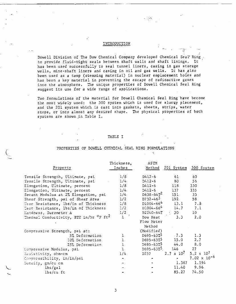
INTRODUCTION
Dowell Division of The Dow Chemical Company developed Chemical Seal Ring
to provide fluid-tight seals between shaft walls and shaft linings. It
has been used successfully to seal tunnel liners, casing in gas storage
wells, mine-shaft liners and casing in oil and gas wells. It has also
been used as a tamp (stemming material) in nuclear emplacement holes andhas been a key material in preventing the escape of radioactive gasesinto the atmosphere. The unique properties of Dowell Chemical Seal Ring
suggest its use for a wide range of applications.
Two formulations of the material for Dowell Chemical Seal Ring have become
the most widely used: the 300 system which is used for slurry placement,
and the 201 system which is cast into gaskets, sheets, strips, water
stops, or into almost any desired shape. The physical properties of bothsystems are shownin Table I.
TABLE I
PROPERTIES OF DOWELL CHEMICAL SEAL RING FORMULATIONS
PropertyThickness,
InchesASTMMethod 201 System 300 System
Tensile Strength, Ultimate, psiTensile Strength, Ultimate, psiElongation, Ultimate, percentElongation, Ultimate, percentSecant Modulus at 2% Elongation, psiShear Strength, psi of Shear AreaYear Resistance, lbs/in of Thicknessear Resistance, lbs/in of Thickness
Hardness Durometer AThermal Conductivity, BTU in/hr OF ft 2
Compressive Strength, psi at:5% Deformation
10% Deformation25% Deformation
Compressive Modulus, psiResistivity ohm-cm
Compresibility in/in/psiDensity gm/cu cm
lbs/gallbs/cu ft
1/81/41/81/41/41/21/81/21/2
1
11i1
1/4
D412-6D412-6D412-6D412-6D638-64T2
D732-46 3
D1004-66 4
D1004-664
D2240-64TDow Heat
Flow MeterMethod
(Modified)
[could not be converted to searchable text]

I. Description of Dowell Chemical Ring (300 system)Chemical SEal Ring is an elastic, polymeric seal. It can be mixedand placed as a slurry which sets into a rubber-like material.Figure 1 shows a sample of Chemical Seal Ring which has swelled tomore than 150 percent of its original volume by imbibing water. Itis still an integral, sealing material in its swollen state. Thissingle property sets Dowell CHemical Seal Ring apart from other
sealing materials.
Figure L. Sample of Dowell Chemical Seal Ring which has swelled tomore than 150 percent oF its original volume by imbibingwater.
Life expectancy of set Chemical Seal Ring is of interest. Since thematerial is relatively new, by time standards, there is no method for
determining how long it will actually last. Accelerated tests haveBeen under way in concentrated environments of acid, caustic, brines,ozone, ammonia, hydrocarbons fresh water for periods ranging
from 90 days to four years. In all these tests, Chemical Seal Ringhas maintained its integrity and sealing properties without apparent
deterioration. Extrapolated values from these tests show that thematerial should last indefinetely. In fact, the chemistry of the
4

reaction by which Chemical Seal Ring is formed indicates permanency.The cross-linkage of the molecules is permanent and the materialshould be inert to further reaction.
In an actual case, Dowell Chemical Seal Ring was placed in a shaftin the Tatum Salt Dome in 1964. It has remained intact under themost severe conditions that could be imposed. This particularapplication is described later as a case history.
In casing and shaft-lining applications, Chemical Seal Ring normallyis used in conjunction with more conventional sealants, such as cement.
The cement provides support for the liner while Chemical Seal Ringprovides the seal. Temperature and pressure changes during cementingoperations cause the liners to expand and contract. This expansionand contraction often causes a micro-annulus, or channel, to formbetween the liner and the cement or the shaft wall and the cement.Great quantities of water or other fluids can flow through even thesmallest channels. Chemical Seal Ring, spotted in the proper placein the cement column, is pliable enough to accommodate expansion andcontraction while providing a positive seal. Further, any waterflowing through the channel will be imbibed by the Chemical SealRing, causing it to swell and seal even tighter.
II. Description of Dowell Chemical Seal Ring Gasket (201 system)
Dowell Chemical Seal Ring Gaskets are manufactured from a uniquepolymer which swells in water. This polymer is chemically cross-linked during formation of the gasket. The result is a three-dimensional network of polymer molecules which has adequate physicalstrength, yet retains the property of swelling in water.
When a Dowell Chemical Seal Ring Gasket is confined in the flangedjoints of a tunnel or mine-shaft lining, the rubber-like natureof the material makes it possible to assemble an air-tight, aswell as a water-tight, structure. Thi-s property can help, forinstance, to minimize air-compressing costs while driving a tunnelunder a river. Furthermore, any tendency for water to leak throughjoints containing Chemical Seal Ring Gasket is immediately counteracted,since gasket material swells tighter and blocks the leakage path.
Several important features or Dowell Chemical Seal Ring Gasket stemfrom the nature of the chemicals used in its manufacture. A corrosioninhibitor prevents rust wherever Dowell Chemical Seal Ring Gasketis in contact with iron. A standard method of flame testing (ASTMD1692-59T) shows that Dowell Chemical Seal Ring Gasket is self-extinguishing. "Samples tend to burn only on the exterior and wouldnot flame-propogate after removal of the flame source."
5

The pressure-sealing ability of Dowell Chemical Seal Ring Gasketdepends on good seal design practices. Figure 2 is a schematicdrawing of test apparatus used to pressure test Chemical SealRing Gasket in the laboratory. Under conditions shown here(without back-up shims), gasket successfully sealed pressures of.
1200 psi for extended periods with no leak. With a back-up shim,
pressures in excess of 4500 psi were sealed.
Seal Ring
Figure 2. Schematic drawing of apparatus used to pressure test DowellChemical Seal Ring Gasket in the laboratory.
Figure 3 is a photograph of a full-scale model of the T-joints thatwill exist in a tunnel or mine-shaft lining built up of segments andrings. The T-joint is considered the critical leakage location.Long-term tests of such joints are presently being conducted byCommercial Shearing and Stamping Company, a leading supplier ofunderground supports with over 47 years of experience in the designand manufacture of steel supports for tunnels, shafts, and caissonsthroughout the free world. The joints are presently holding 1400psi water pressure with no leaks or failures. These tests havenow been in progress for months and are continuing.
Should a shaft lining containing Dowell Chemical Seal Ring Gasket everleak after installation, several methods of repair exist. First, be-cause the material swells in water, it is self-healing and furtherrepair-efforts may not be required. Time-lapse movies of very large,deliberately formed, leakage paths (Figure 4) have been made whilewater was pumped through them. Chemical Seal Ring Gasket not only with-stood the flow of water, but swelled to shut off the leak. Swellingcontinued thereafter so that the self-repaired leak would hold more andmore pressure.
6

Figure 3. Photograph of a full-scale model of the T-joints that willexist in a tunnel or mine-shaft lining built up of segmentsand rings.
TEST APPARATUS
H20 @ 45 psi
Square Grooves
Figure 4. Test apparatus used to determine self-healing properties ofChemical Seal Ring..
7
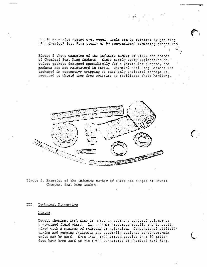
Should extensive damage ever occur, leaks can be repaired by groutingwith Chemical Seal Ring slurry or by conventional cementing procedures.
Figure 5 shows examples of the infinite number of sizes and shapesof Chemical Seal Ring Gaskets. Since nearly every application re-quires gaskets designed specifically for a particular purpose, thegaskets are not maintained in stock. Chemical Seal Ring Gaskets arepackaged in protective wrapping so that only sheltered storage isrequired to shield them from moisture to facilitate their handling.
TII. Technical Discussion
Dowell Chemical Seal Ring is mixed by adding a powdered polymer toa premixed fluid phase. The polymer disperses readily and is easilymixed with a minimum of stirring or agitation. Conventional oilfield
mixing and pumping equipment and specially designed continuous-mixunits can be used. Even hand-drill-driven paddles in a 50-gallondrum have been used to mix small quantities of Chemical Seal Ring.
Q

Viscosity
Chemical Seal Ring slurry viscosity varies with the formulation, butis relatively low. The five-minute viscosity of a typical slurry isabout 4 poises. By comparison, a cement grout (5.2 gallons of waterper sack of cement) has a viscosity of approximately 15 poises.
Heat of Reaction
Setting of the Chemical Seal Ring is not an exothermic reaction.The heat of reaction is negligible; viz., it is too low to measureby ordinary laboratory tests. Monolithic pours thus create noproblems in this respect.
Thickening and Setting Times
Thickening time and setting time of Chemical Seal Ring arecontrolled by adding a catalyst to the slurry during mixing.Thickening time is that time required for the slurry to reach aviscosity equivalent to 100 poise as measured in a standard cementthickening time tester. This is also the working time because athigher viscosities the slurry cannot be easily moved or placed.The amount of catalyst, then, is based on the working time requiredand the temperature. Setting time is defined as that time aftermixing which is required for the slurry to reach a viscosity of10,000 poises. Cement grout, concrete and stemming sand can allbe placed on top of the Chemical Seal Ring when its viscosity hasreached 10,000 poises. Setting time is also directly related tothe amount of catalyst used.
Slurries with a temperature of 400F to 1200F are routinely used withpredictable thickening and setting times. Laboratory tests areconducted to determine the required amount of catalyst and thickeningand setting times in those cases where-the slurry temperatures willfall outside this range.
Seal Height vs. Pressure Drop
One of the many series of tests conducted todefine and understandChemical Seal Ring properties, involved the determination of pressuredrop per foot of Chemical Seal Ring height. Various sizes of pipeswere filled with 20 feet of Chemicak Seal Ring slurry. Pressuregauges were installed every two feet. Water pressure was appliedto the confined Chemical Seal Ring for short-term and intermediate-term tests. These data, using a typical Chemical Seal Ringformulation, are presented in Figure 8. It shows the length ofChemical Seal Ring required for the pressure to drop to 0 psi.
9

LENGTH CHEMICAL SEAL RING REQUIRED
2000
1600
LENGTH-FEET
Figure 8. Graph showing the length of Dowellfor the pressure to drop to 0 psi.
Effect of Aggregate on Seal Ring Height
Chemical Seal Ring required
vs. Pressure Drop
The previously discussed pressure-drop tests indicate that thepressure is dissipated over a shorter interval in smaller pipe.This finding was as expected. Tests were conducted to determineif incorporating coarse aggregate would produce the same effectas reducing the cross-sectional area of Chemical Seal Ring.
The addition of two parts of 3/4-inch to 1-1/2-inch aggregateto one part Chemical Seal Ring was tested. Test data indicatethat height of aggregate-Chemical Seal Ring need be approximatelyone-third that of Chemical Seal Ring alone to dissipate a giveninput pressure
The use of aggregate offers two advantages. The prime advantageis that the volume of Chemical Seal Ring, hence cost, issubstantially reduced. The second advantage is in placing a sealopposite frozen formations, such as those encountered when
freeze-sinking through the Blairmore in Saskatchewan. A heated
12
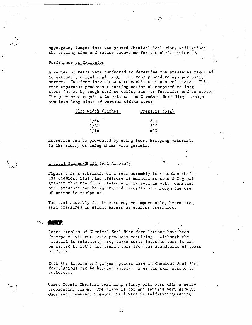
aggregate, dumped into the poured Chemical Seal Ring, will reducethe setting time and reduce down-time for the shaft sinker.
Resistance to Extrusion
A series of tests were conducted to determine the pressures requiredto extrude Chemical Seal Ring. The test procedure was purposelysevere. Two-inch-long slots were machined in a steel plate. Thistest apparatus produces a cutting action as compared to longslots formed by rough surface walls, such as formation and concrete.The pressures required to extrude the Chemical Seal Ring throughtwo-inch-long slots of various widths were:
Slot Width (inches) Pressure (psi)
1/64 6001/32 5001/16 400
Extrusion can be prevented by using inert bridging materialsin the slurry or using shims with gaskets.
Typical Sunken-Shaft Seal Assembly
Figure 9 is a schematic of a seal assembly in a sunken shaft.The Chemical Seal Ring pressure is maintained some 200 + psigreater than the fluid pressure it is sealing off. Constantseal pressure can be maintained manually or through the useof automatic equipment.
The seal assembly is, in essence, an impermeable, hydraulicseal pressured in slight excess of aquifer pressures.
IV.
Large samples of Chemical Seal Ring formulations have beendecomposed without toxic products resulting. Although thematerial is relatively new, these tests indicate that it canbe heated to 500'F and remain safe from the standpoint of toxicproducts.
Both the liquids and polymer powder used in Chemical Seal Ringformulations can be handled safely. Eyes and skin should beprotected.
Unset Dowell Chemical Seal Ring slurry will burn with a self-propagating flame. The flame is low and spreads very slowly.Once set, however, Chemical Seal Ring is self-extinguishing.
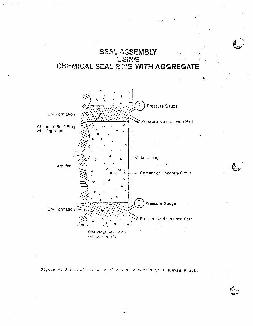
SEAL ASSEMBLYUSING
CHEMICAL SEAL RING WITH AGGREGATE
Dry Formation
Chemical Seal Ringwith Aggregate
Aquifer
Dry Formation
I) Pressure Gauge
Pressure Maintenance Port
Meta;l Lining
Cement or Concrete Grout
Pressure Gauge
Pressure Maintenance Port
Chemical Seal Ringwith Aggrerite
Figure 9. Schematic drawing of a seal assembLy in a sunken shaft.
4

V. Case Histories
Dowell Chemical Seal Ring has proved highly successful in a widevariety of sealing uses. These include stemming undergroundnuclear tests to prevent escape of radioactive gases; annularseals and water stops in Canadian potash mine shafts; and sealsin anhydrous ammonia storage caverns, LPG storage caverns,salt mines and reservoir gas storage wells.
One of the early uses of Chemical Seal Ring was to seal largediameter pipe in competent salt stock at the Tatuin Salt Dome nearHattiesburg, Mississippi. Many overlying aquifers and a fracturedcaprock had made it impossible to obtain a dry shaft in the salt.Many remedial squeeze jobs with cement also failed to obtain adry shaft. Chemical Seal Ring, placed as shown in Figure 10,
29" i.d casing
9
Figure 10. Drawing of placement technique for Dowell Chemical Seal Ringused to seal large-diameter pipe at the Tatum Salt Dome.
resulted in a completely dry shaft. A nuclear device was
detonated in the salt about four months later and the shaft still
remained dry. During an extensive testing period following thedetonation, many tools and devices were run in the shaft. Thisresulted in a hole in the casing opposite the Chemical Seal Ring.A steel liner was run and cemented to cover the hole. Subsequently,a second nuclear device was detonated in the cavity created by thefirst shot. The shaft still remained dry and is dry at the presenttime, nearly four years later.
A more recent use of Dowell Chemical Seal Ring has been in aCanadian potash mine shaft in Saskatchewan. This shaft was sunkto a depth of 3300 feet by the freeze method. The seal was placedto insure that no water bypassed a water-collecting ring placedopposite a salt formation. The seals successfully preventedwater migration in the annulus of this shaft.
16
5
TECHNICAL INFORMATION SHEET
DOWELL CHEMICAL SEAL RING
Chemical Seal Ring is a unique grouting materialsuccessfully being used in demanding applica-tions to seal against the migration of aqueousfluids and low-pressure gases. Its chief applica-tions are in conjunction with cement grouts forsealing shaft liners. Shafts drilled or sunk throughsoluble formations (rock salt and potash) as wellas shale, sand and lime formations have beensealed using staged applications of cement andChemical Seal Ring. Critical applications requiringa total seal have used DOWELL Chemical SealRing. Chemical Seal Ring has been used in con-junction with the Strategic Petroleum ReservePrograms, nuclear emplacement shafts, evaporitemine shafts and mined storage cavern shafts.
Chemical Seal Ring is truly unique. It is mixed as aslurry with controlled setting properties. It is placedby either pumping through grout or tremie pipes ordraining or pouring from buckets lowered to aGalloway work stage. It fills the void to be sealedwith a set material with most of the properties of anatural rubber. An additional prime property is thatunconfined Chemical Seal Ring imbibes aqueousfluids, including brines, and physically becomeslarger. Thus, confined Chemical Seal Ring pro-vides a tighter, positive seal when contacted withaqueous fluids.
TYPICAL PHYSICAL PROPERTIES
Slurry
Form and Color - Pourable, Yellow-Green
Density - 9.95 lb/gal at 70OF
Cured Solid
Form and Color - Gunmetal Gray Rubber
Tensile Strength -80 psi ultimate; /4-in. thickness
Elongation - 137% ultimate
Hardness - 30 Durometer A
Tear Resistance - 14.7 Ib/in. of thickness
Swelling Capacity - greater than 50% dimen-sional increase when exposed to aqueous fluids
COMPOSITION
Chemical Seal Ring slurry consists of a dispersionof a water-sensitive, high-molecular-weight poly-mer in a hygroscopic organic liquid. A water-soluble chromium compound crcsslinks the poly-mer dispersion.
A cured Chemical Seal Ring resists biodegrada-tion, and is considered to have a permanency atleast equal to that of cement.
DISCUSSION
Repeated efforts with conventional cements andplastic grouts failed to provide the water-tight sealrequired for the nuclear placement shaft drilledinto the Tatum Sait Dome. Chemical Seal Ringwas developed to solve this and similar types ofproblem applications.
In the Tatum Salt Dome application, conventionalcements were used to fill most of the annularspace between the steel shaft liner and rock-saltformation. Chemical Seal Ring slurry was pumpedto form a water-expanding gasket opposite therock-salt formation in a zone below the aquifers.This successful application in 1 964 has been fol-lowed by similar demanding uses throughout theFree World. The properties of Chemical Seal Ringwhich made these applications successful include
Density - 9.95 lb/galDOWELL DIVISION OF DOW CHEMICAL U.S.A.. AN OPERATING UNIT OF THE DOW CHEMICAL COMPANY, HOUSTON. TEXAS 77042

the following.
* A pumpable slurry with controllable settingtimes between 40° to 100OF.
* The slurry neither shrinks nor expands uponsetting.
* Set Chemical Seal Ring imbibes aqueousfluids (even saturated brines) with dimensionalenlargement that provides a positive water-tight seal.
* Set Chemical Seal Ring is flexible and geo-logic shifts have not been reported to havedamaged the seals.
Chemical Seal Ring has been cast in molds toform water-expandable gaskets. The shape of thegasket can be varied and extenders, such as finesand, have been used. Applications of such gas-kets include plugs for core holes and as water-expandable packers for groundwater monitoringwells,
SERVICE
Dowell provides Chemical Seal Ring service whichcomprises job design, materials. personnel, mix-ing and pumping of the slurry to the operator's
surface conveyance (bucket, tremie or grout pipe).When water exists in the void to be sealed, a liquidwash (compatible with Chemical Seal Ring) isused ahead to displace the water. The wash isalso used to displace Chemical Seal Ring slurryfrom tremie or grout pipe.
CASE HISTORIES
* Nuclear detonations in Nevada and Amchitkawere stemmed with Chemical Seal Ring.
* Potash mine shafts sunk through the Blare-more (Canada) aquifer are routinely beingsealed with Chemical Seal Ring.
* Rock-salt mines in Louisiana are completedwith Chemical Seal Ring to prevent flooding byoverlying water zones.
AVAILABILITY
Chemical Seal Ring material and some uses arepatented by Dowell and the material is availablefrom any service district within the United States. Itis available from Dowell-Schlumberger servicelocations throughout the non-Communist world.
NOTICE: THIS INFORMATION IS PRESENTED IN GOOD FAITH, BUT NO WARRANTY IS GIVEN AND DOWELL ASSUMES NOLIABILITY FOR ADVICE OR RECOMMENDATIONS MADE CONCERNING RESULTS TO BE OBTAINED FROM THE USE OF ANYDOWELL PRODUCT OR SERVICE. FREEDOM FROM PATENTS OF THE DOW CHEMICAL COMPANY OR OTHERS IS NOT TO BEINFERRED
TSL-3559 07827.5M100162000 Printed in U.S.A
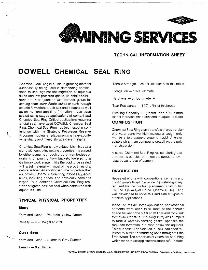
TECHNICAL INFORMATION SHEET
DOWELL CHEMICAL SEAL RING
Chemical Seal Ring is a unique grouting materialsuccessfully being used in demanding applica-tions to seal against the migration of aqueousfluids and low-pressure gases. Its chief applica-tions are in conjunction with cement grouts forsealing shaft liners. Shafts drilled or sunk throughsoluble formations (rock salt and potash) as wellas shale, sand and lime formations have beensealed using staged applications of cement andChemical Seal Ring. Critical applications requiringa total seal have used DOWELL Chemical SealRing. Chemical Seal Ring has been used in con-junction with the Strategic Petroleum ReservePrograms, nuclear emplacement shafts, evaporitemine shafts and mined storage cavern shafts.
Chemical Seal Ring is truly unique. It is mixed as aslurry with controlled setting properties. It is placedby either pumping through grout or tremie pipes ordraining or pouring from buckets lowered to aGalloway work stage. It fills the void to be sealedwith a set material with most of the properties of anatural rubber An additional prime property is thatunconfined Chemical Seal Ring imbibes aqueousfluids, including brines, and physically becomeslarger. Thus, confined Chemical Seal Ring pro-vides a tighter, positive seal when contacted withaqueous fluids.
TYPICAL PHYSICAL PROPERTIES
Slurry
Form and Color - Pourable, Yellow-Green
Density - 9.95 lb/gal at 700 F
Cured Solid
Form and Color - Gunmetal Gray Rubber
Tensile Strength -80 psi ultimate; '/4-in. thickness
Elongation - 137% ultimate
Hardness - 30 Durometer A
Tear Resistance - 1 4.7 lb/in. of thickness
Swelling Capacity - greater than 50% dimen-sional increase when exposed to aqueous fluids
COMPOSITION
Chemical Seal Ring slurry consists of a dispersionof a water-sensitive, high-molecular-weight poly-mer in a hygroscopic organic liquid. A water-soluble chromium compound crosslinks the poly-mer dispersion.
A cured Chemical Seal Ring resists biodegrada-tion. and is considered to have a permanency atleast equal to that of cement.
DISCUSSION
Repeated efforts with conventional cements andplastic grouts failed to provide the water-tight sealrequired for the nuclear placement shaft drilledinto the Tatum Salt Dome. Chemical Seal Ringwas developed to solve this and similar types ofproblem applications.
In the Tatum Salt Dome application, conventionalcements were used to fill most of the annularspace between the steel shaft liner and rock-saltformation. Chemical Seal Ring slurry was pumpedto form a water-expanding gasket opposite therock-salt formation in a zone below the aquifers.This successful application in 1964 has been fol-lowed by similar demanding uses throughout theFree World. The properties of Chemical Seal Ringwhich made these applications successful include
Density - 9.95 lb/galDOWELL DIVISION OF DOW CHEMICAL U.S.A., AN OPERATING UNIT OF THE DOW CHEMICAL COMPANY, HOUSTON, TEXAS 77042
the following.
* A pumpable slurry with controllable settingtimes between 40° to 1 00F.
* The slurry neither shrinks nor expands uponsetting.
* Set Chemical Seal Ring imbibes aqueousfluids (even saturated brines) with dimensionalenlargement that provides a positive water-tight seal.
* Set Chemical Seal Ring is flexible and geo-logic shifts have not been reported to havedamaged the seals.
Chemical Seal Ring has been cast in molds toform water-expandable gaskets. The shape of thegasket can be varied and extenders, such as finesand, have been used. Applications of such gas-kets include plugs for core holes and as water-expandable packers for groundwater monitoringwells.
SERVICE
Dowell provides Chemical Seal Ring service whichcomprises job design. materials, personnel, mix-ing and pumping of the slurry to the operator's
surface conveyance (bucket, tremie or grout pipe).When water exists in the void to be sealed, a liquidwash (compatible with Chemical Seal Ring) isused ahead to displace the water. The wash isalso used to displace Chemical Seal Ring slurryfrom tremie or grout pipe.
CASE HISTORIES
* Nuclear detonations in Nevada and Amchitkawere stemmed with Chemical Seal Ring.
* Potash mine shafts sunk through the Blare-more (Canada) aquifer are routinely beingsealed with Chemical Seal Ring.
* Rock-salt mines in Louisiana are completedwith Chemical Seal Ring to prevent flooding byoverlying water zones.
AVAILABILITY
Chemical Seal Ring material and some uses arepatented by Dowell and the material is availablefrom any service district within the United States. itis available from Dowell-Schlumberger servicelocations throughout the non-Communist world.
NOTICE: THIS INFORMATION IS PRESENTED IN GOOD FAITH. BUT NO WARRANTY IS GIVEN AND DOWELL ASSUMES NOLIABILITY FOR ADVICE OR RECOMMENDATIONS MADE CONCERNING RESULTS TO BE OBTAINED FROM THE USE OF ANYDOWELL PRODUCT OR SERVICE. FREEDOM FROM PATENTS OF THE DOW CHEMICAL COMPANY OR OTHERS IS NOT TO BEINFERRED.
TSL-3559 07827.5M100162000 Printed In U S.A
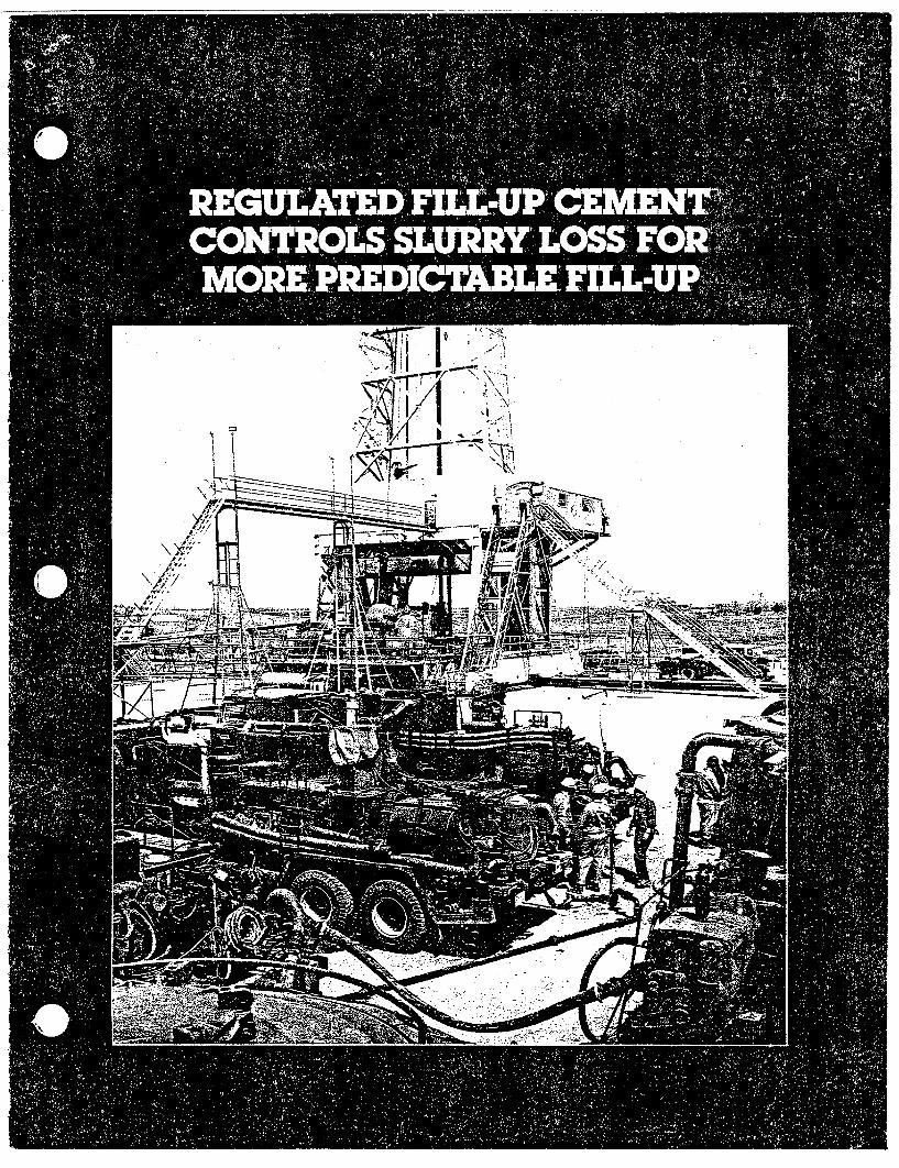

How it worksThe specially designed slurriesused in Regulated Fill-up Cementservice are thixotropic. That is,they are thin when mixed andpumped, but gel quickly into arigid state when pumping stops.They are self-supporting in thisstate, but become fluid againwhen enough force is applied tomove the slurry. These qualitiesare summarized in the name of theslurries, Regulated Fill-up Cement.
Why it worksSince the Regulated Fill-upCement slurries are thixotropic,they will in a sense transferhydrostatic pressures to the pipeand walls of the formation ratherthan to the bottom of the hole. Thisproperty cannot be shown onconventional viscosimeters;however, a Dowell designedapparatus was made to show thisreduction of hydrostatic pressure.
FIGURE 1
1. Thin when mixed. 2 Rigid when pumping stops.
Figure 1 contains the results ofthe measured hydrostatic pressurewith time for a Class A portlandmixed at 15.5 15.5lb/gal and RegulatedFill-up Cement. The tests wereperformed at 700F. As shown,there was a rapid reduction in thehydrostatic pressure exerted bythe Regulated Fill-up Cement ascompared to the Class A portlandcement.
Advantages1. It limits or prevents the loss of
slurry into weak and highlypermeable zones.
2. It provides more predictablefill-up.
3. It decreases the need for stagecementing or the use ofmechanical devices such asbaskets.
4. It provides high yield slurries(with no water separation).
5. It is highly resistant to mudcontamination.
6. It is highly resistant to diluting orcutting by water or gas.
7. It provides better bonding dueto its expanding properties.
8. It is comparable to conventionalhigh-sulfate resistant cements.
4. Thin when pumping is resumed.3. Fluid again when force applied.

How it has been usedA large cavern fissure belowsurface pipe caused a series ofproblems in a Sandoval County,New Mexico, geothermal well.While trying to realign joints ofintermediate pipe, the operatorknocked three holes in the casingopposite the cavern. Attempts tofill the cavern with mud wereunsuccessful. The self-supportingquality of Regulated Fill-upCement, however, enabled Dowellto bridge the fissure. After thecementing job, drilling wasresumed with full returns.
Cementing by a competitor hadsplit the formation and pluggedfractures on wells in the Mt.Pleasant field of Pennsylvania. Ontheir first job in the field, the Dowellteam designed a cementingsystem based upon RegulatedFill-up Cement. Used after washesand spacers, the Regulated Fill-upCement prevented slurry migrationinto fractures and protected thehighly permeable zones. After thejob, the operator was able tofracture three zones in his wellsuccessfully.
An operator in the GibsonCounty, Indiana, area needed acement that would maintaincirculation to the surface andreduce waiting time before drillingout. Regulated Fill-up Cementgave him the predictable fill-upand bond properties he asked for,plus good setting time. He wasable to start drilling from under thesurface pipe in only three hours.
Wells in the Jasper County,Illinois area often requiredsqueeze jobs following primarycementing jobs. Dowellrecommended using its SLOFLO'cementing service, a patentedtechnique. DOWELL Spacer 1000
was used to clean up the wellbore, followed by Regulated Fill-upCement containing Cellophaneflakes. The recommendationresulted in successful completionof the well without a squeeze joband in a good bond log.
The Regulated Fill-up Cementsystem is not a low fluid loss slurrybut has been used in carefullycontrolled squeeze jobs to plughigh pressure zones. The high gelstrength helps to prevent feedbackof the slurry. This application has
been used quite frequently in theMidwestern areas of the UnitedStates.
Applications other thancementing oil and gas wells areoccurring more frequently.Because of Regulated Fill-upCement gel characteristics, thesystem was utilized in rip-rapgrouting on high water drainageslopes. The geliing prevented thecement from flowing to the bottomof the slope and also limitedpenetration depth into the soil.
SLURRY PROPERTIES OF REGULATED FILL-UP CEMENTCOMPARED TO A CONVENTIONAL SYSTEMCement Percent RF Percent Percent Water SSystem Component Accelerator Water Gal/sk
1 0 0 46 5.202 12 3 60 6.783 12 3 64 7.204 12 1 68 7.705 10 0 70 7.90
lurry WeightLb/Gal
15.614.914.61 4.414.2
Slurry YieldFtxrSk
1.181 481.541.581.60
BHST (Hr.)
PERFORMANCE DATA OF REGULATED FILL-UP CEMENTWell Thickening Compressive Strengths (psi) at
Cement Conditions (¢f) TimeSystem SHCT BHST at SHCT 7 18 24
1 113 170 +4:00 325 1750 29002 70 60 3:10 105 360 5153 80 95 1:50 500 1240 13304 103 140 2:00 520 1000 11505 125 200 3:15 930 1725 2200
EXPANDING PROPERTIES OF REGULATED F!LL-UP CEMENTCOMPARED TO CONVENTIONAL SYSTEM
Cement Percent Linear E xpansion Cement PoSystem Days 0 psi 100PF System Days
Class 1 .020 Class 1A 2 .023 A 246% 3 .032 i-10% RF 3Water 5 .032 5
7 .034 +1% 7
Percent Linear Expansion
Trademark of The Dow Chemical Company

API permeability measurements studies of cements must take intoTo those accustomed toconstruction cement systems andtesting, the high water to cementratio of Regulated Fill-up Cementsystems might seem to indicate aset product having a highpermeability. If the complicatedcrystalline and gel structures areknown, and considered, it can berealized how the permeability willbe of the same order of magnitudeas conventional systems. Also thesystem is designed to make theset product sulfate resistant.Permeability and/or porosity
account the fact that any air dryingof the set product at any time willresult in loss of hydrate water,collapse of gel structures andpossibly cause microcracking ofthe set cement. This behavior iswell documented in publishedcement literature. The permeabilityvalues tabulated below wereobtained using the procedure asoutlined by API standards.Distilled water was used as thetest fluid. The cement sampleswere cured under pressure tosimulate well conditions.
PERMEABILITY PROPERTIES OF REGULATED FILL-UPCEMENT COMPARED TO OTHER CEMENT SYSTEMS
Percent Slurry WeightCement System Water (Lb/Gal}
Class A 46.0 15.6Regulated Fill-up Cement 60.0 14 9Regulated Fill-up Cement 64.0 14.6Regulated Fill-up Cement 70.0 14.250:50 Pozzolan: Class A - 2% Gel 57.0 14.2
Permeability,md (to water)
0.00010. 00380.00360.00500.0200
.
DOWELL DIVISION OF DOW CHEMICAL U.S.A., HOUSTON, TEXAS 77042AN OPERATING UNIT OF THE DOW CHEMICAL COMPANY
-Trademark of The Dow Chemicai Company
Notice: The information in this folder is presented in good faith, but no warranty is given andDowell assumes no liability for advice or recommendations made concerning results to beobtained from the use of any Dowell product or service. Freedom from patents of The DowChemical Company or others is not to be inferred.
TSL-4CC7 LITHO IN U.S.A.0823M

[could not be converted to searchable text]
Reasons & ESR No.
All Design Review CommentsRELEASE STAMP
Incorporated Per DR-B314-82-17DISTRIBUTION T. L. Walton (1 cont, 2 info) M. T. Black (1 cont, 1 info)L. K. Aldrich (HS&E) R. L. Edler (40-Procurement) R. E. BrooksH. W. Brandt M. F. NicolP. K. Brockman (15 XR Dist. #5?) p.j. Reder (EQ only)R. W. Carlson W. F. Toddish (Orig.) Work completed
OFFICIALLY RELEASED
1982 DEC 29 PM 1: 25DUE Richland, WA BD-6400-093.1 (N-2-82)

Rev. 0, 12-17-82
SPECIFICATION TITLE PAGE
SPECIFICATION NO. B-314-P-S28005
QA LEVEL I
PROCUREMENT SPECIFICATION FOR
72" ID STEEL CASING
BWIP EXPLORATORY SHAFT
PROJECT B-314
Prepared By:
Kaiser Engineers, Inc./Parsons Brinckerhoff Quade & Douglas, Inc.
For the U.S. Department of Energy
Contract No. DE-AC06-80RL10000
Specifications Engineer
ROCKWELL HANFORD OPERATIONS:
THIS DOCUMENT NOT COMPLETEWITHOUT THESE ATTACHMENTS

B-314-P-S28005Rev. 0
TABLE OF CONTENTS
SUBJECT Page
1.0 SCOPE 11.1 Work Included 11.2 Work Not Included 1
2.0 GENERAL PROVISIONS 12.1 Applicable Codes, Standards, and Publications 12.2 Drawings and Attachments 32.3 Definitions 32.4 Quality Assurance 52.5 Inspection Program 62.6 Records and Submittals 72.7 Nonconforming Conditions 8
3.0 TECHNICAL PROVISIONS 93.1 Materials 93.2 Fabrication 103.3 Welding 113.4 Tolerances 133.5 Identification Marking 16
4.0 NONDESTRUCTIVE EXAMINATION AND VISUAL INSPECTION 174.1 Continuous Slot Channel 174.2 Lifting Lug and Stiffener Rings 174.3 Casing Seams 174.4 Radiography 174.5 Magnetic Particle Examination 184.6 Visual Inspection 184.7 Witnessing by Inspector 18
5.0 SHOP DRAWINGS 195.1 Fabrication Drawings 195.2 Packaging and Shipping Drawings 195.3 Acceptance of Shop Drawings 19
6.0 PACKING, HANDLING, SHIPPING, AND STORING 196.1 Casing Protection 196.2 Supports 196.3 Tack Welding 196.4 End Protection 196.5 Shipping Release 196.6 Off-Loading and Storing Procedure 206.7 Acceptance at Site 20
Appendix A Bidder and Seller Information RequirementsAppendix B Information Required for Quality Control Program
BWIP17H: 12/16/82
Page ii

B-314-P-S28005Rev. 0
72" ID STEEL CASING
1.0 SCOPE
This Specification describes the requirements for the fabrication anddelivery to the project site of ninety-eight (98) welded steel 72-inchinside diameter shaft casing units, and associated grout guides, andguide plates; ventilation and dewatering lines and fittings; supportplates, centralizers, and skid plates.
1.1 Work Included
1.1.1 Labor
1.1.2 Tools, materials, and equipment
1.1.3. Fabrication
1.1.4 Testing
1.1.5 Records Management
1.1.6 Packaging
1.1.7 Transporting to site
1.1.8 Offloading at site
1.1.9 Placing in storage at site
1.2 Work Not Included
1.2.1 Maintenance in storage
2.0 GENERAL PROVISIONS
2.1 Applicable Codes, Standards, and Publications
Work performed and materials furnished under this Specificationshall conform to the requirements of the documents listed below, tothe extent specified herein. In the event of conflict betweenapplicable requirements of two or more of those documents, the moststringent requirement shall apply.
ANSI, American National Standards Institute
B2.1 1968,
B16.11-1973,
B16.9-1978,
Pipe Threads (Except Dryseal)
Forged Steel Fittings, Socket-Welding and Threaded
Factory-Made Wrought Steel Buttwelding Fittings
Page 1 of 20

B-314-P-S28005Rev. 0
NQA-1-1979, Quality Assurance Program Requirements for NuclearPower Plants
N45.2.2-1978, Packaging, Shipping, Receiving, Storage and Han-dling of Items for Nuclear Power Plants
N45.2.15-1981 Hoisting, Rigging and Transporting of Items atNuclear Power Plants
API, American Petroleum Institute
Spec. 5A, March Casing, Tubing, and Drill Pipe1979 w/Supple-ment 1, March 1980
ASTM, American Society for Testing and Materials
A 53-77a Pipe, Steel, Black and Hot-Dipped Zinc CoatedWelded and Seamless
A 570-79 Hot-Rolled Carbon Steel Sheet and Strip, Struc-tural Quality
A 588-81 High-Strength Low-Alloy Structural Steel with50,000 psi Minimum Yield Point to 4 in Thick
E 165-75 Liquid Penetrant Inspection Method
E 709-80 Magnetic Particle Examination
ASME, American Society of Mechanical EngineersBoiler and Pressure Vessel Code as amended through 1981
Section V, Nondestructive Examination
Section VIII, Pressure Vessels, Division 1
Section IX, Welding and Brazing Qualifications
AWS, American Welding Society
A3.0-80 Welding Terms and Definitions
D1.1-82 Structural Welding Code - Steel
DOE, U. S. Department of Energy
HS-BP-8002, Supplier Acceptance Data Package (ADP)
Page 2 of 20
B-314-P-S28005Rev. 0
2.2 Drawings and Attachments
2.2.1 Drawings
The drawings listed in the "Purchase Order" are incorporatedand made a part of this Specification:
2.2.2 Attachments
The following listed attachments are incorporated and made apart of this Specification:
Appendix A "Bidder and Seller InformationRequirements" with attachedsubmittal matrix.
Appendix B "Information Required forQuality Control Program."
2.3 Definitions
2.3.1 Unit
"Unit" shall mean a prefabricated casing assembly, of lengthindicated on the Drawings, consisting of a string of canswith attached circumferential external stiffener and liftinglug rings and internal continuous-slot channels, with endsof unit suitably prepared for field welding, and individu-ally identified by a mark number.
2.3.2 Can
"Can" shall mean the single rolled element of a casing unit.
2.3.3 Subassembly
"Subassembly" shall mean two or more cans of the casingstring but less than a unit.
2.3.4 Stiffener
"Stiffener" shall mean the circumferential solid bar rein-forcing rib welded to the outside of each unit.
2.3.5 Inspection Port
"Inspection port" shall mean the plugged opening in thecasing plate required for placing a radioactive source foruse in radiographic examination.
Page 3 of 20

B-314-P-S28005Rev. 0
2.3.6 Lifting Lug Ring
"Lifting lug ring" shall mean the the circumferential solidbar rib welded to each unit to provide a lifting shoulder.
2.3.7 Grout Guide
"Grout guide" shall mean the slotted vertical piping that isto be attached (by Others) to the outside of the casing toprovide a conduit for placing grout.
2.3.8 Continuous-Slot Channel
"Continuous-slot channel" shall mean the rings, with formedchannel cross section, welded to the inside of each unit forsupporting piping to be furnished and installed by Others.
2.3.9 Ventilation Line
"Ventilation line" shall mean the vertical piping that is tobe attached (by Others) to the outside of the casing forsupplying ventilation air to the bottom of the casing.
2.3.10 Dewatering Line
"Dewatering line" shall mean the vertical piping that is tobe attached (by Others) to the outside of the casing forremoval of water from the bottom of the casing.
2.3.11 Porthole
"Porthole" shall mean the hole through the casing plate, andthe associated plugs, provided for examination of the strataoutside the casing.
2.3.12 Hold Point
"Hold point" shall mean that activity in the production se-quence where work shall not proceed without written releaseby the Inspector.
2.3.13 Witness Point
"Witness point" shall mean that activity in the productionsequence scheduled for surveillance by the Inspector wherework may proceed upon verbal release by the Inspector orupon the expiration of a one hour wait for inspection fromthe scheduled time.
Page 4 of 20
B-314-P-S28005Rev. 0
2.3.14 Purchaser
"Purchaser" shall mean the U.S. Department of Energy or itsappointed representative.
2.3.15 Engineer
"Engineer" shall mean the Purchaser's appointedrepresentative authorized to act on technical matters asspecified herein and to assure compliance with the require-ments of this Specification and the Drawings.
2.3.16 Inspector
"Inspector" shall mean those persons or agencies appointedby the Purchaser to conduct quality control surveillance,audits and inspection activities of the fabrication processand to authorize release for shipment.
2.3.17 Supplier
"Supplier" shall mean the party responsible for the fabrica-tion and delivery of the units.
2.3.18 The applicable definitions contained in the following publi-cations shall also pertain:
a. ANSI NQA-1, Supplement S-1
b. AWS A3.0
2.4 Quality Assurance
2.4.1 The products furnished hereunder are to be components of astructure classified Level I for nuclear safety purposes andare therefore subject to the requirements of a qualityassurance program established and implemented in accordancewith ANSI NQA-1, ANSI N45.2.2, and ANSI N45.2.15.
2.4.2 Each bidder shall submit with the proposal one copy of hisquality assurance program and quality control manual,approved internally, for review and evaluation as to hisacceptability as a qualified vendor of Level I components.
2.4.3 Supplier shall be responsible for assuring that his sub-contractors' quality-assurance/quality control programs arein compliance with the Specifications. Subcontractingshall conform to the provisions of ANSI NQA-1, BasicRequirements 4 and 7, and Supplements 4S-1 and 7S-1.
Page 5 of 20

B-314-P-S28005Rev. 0
2.4.4 Subsequent to the notice to proceed, the Purchaser willprovide the Supplier comments on the quality assuranceprogram and the quality control manual submitted with thebid. Prior to the start of fabrication, the Supplier shallre-submit the program and manual incorporating the Purchasercomments. At this time, a joint Purchaser/Supplier qualityassurance coordinating meeting shall be conducted to clarifyrequirements and acceptance criteria. Upon acceptance bythe Purchaser of the program and manual, as revised, theSupplier shall proceed with fabrication in accordance withthe provisions of the program and accepted procedures.
2.4.5 The minimum information required for the quality controlprogram is contained in the listing attached as Appendix B.
2.5 Inspection Program
2.5.1 The Supplier shall be responsible for the physical perfor-mance and documentation of all required in-process inspec-tion, testing, and other quality control functions duringthe manufacture of the casing units.
2.5.2 The Inspector will perform the surveillance inspection andaudits of all required documentation and in-process opera-tions of manufacturing, fabrication, shipment, and qualityassurance to ensure compliance with the requirements herein.
2.5.3 The Purchaser will identify to the Supplier the authorizedagencies and individuals who will perform inspection sur-veillance and audit functions.
2.5.4 The Work will be inspected by the Supplier and the Inspectorduring fabrication, packaging, shipment, and placement instorage. The Supplier shall furnish all facilities, tools,jigs, gauges, materials, and personnel necessary for inspec-tion. This shall include personnel, equipment, and mate-rials required to perform nondestructive examinations.Supplier's inspection and test personnel shall be certifiedand qualified in accordance with ANSI NQA-1 and Supplement2S-1. Supplier's non destructive examination personnelshall be certified and qualified in accordance with ANSINQA-l, Supplement 2S-2. The Inspector shall have access toall areas of the Supplier's and his subcontractors' plantsconcerned with the supply, fabrication, and shipment of thecasing and its components. Inspection by the Inspectorshall not relieve the Supplier of his responsibility toprovide casing that complies with the requirements of theSpecification and the Drawings.
2.5.5 An inspection plan incorporating hold points and witnesspoints shall be developed by the Supplier and submitted tothe Purchaser, within four weeks from notice to proceed, forreview, comment, and acceptance. The inspection plan shall
Page 6 of 20

B-314-P-S28005Rev. 0
be subject to the Purchaser's review for conformance to theaccepted quality assurance program and incorporation of holdand witness points. Fabrication shall not commence prior toacceptance of the inspection plan by the Purchaser. Theinspection plan shall identify pertinent manufacturing andtesting operations and steps critical to quality control.The following shall be included as minimum hold points:
a. Initial forming of each plate, stiffener, and liftinglug ring
b. Initial welding of each weldment
c. Initial positioning and alignment of each stiffener andlifting lug ring
d. Any non-destructive examination
e. Preparation for shipment.
2.6 Records and Submittals
2.6.1 The Supplier shall establish and maintain a records systemin accordance with ANSI NQA-1, Basic Requirement 17 andSupplement 17S-1. This system shall be incorporated intothe Supplier's quality assurance program and submitted forthe Purchaser's review and acceptance. The records systemshall provide complete traceability of all materials,equipment, workmanship, quality controls, and handling ofeach unit. All documentation shall be clear, legible, andof suitable quality for microfilming and for long termstorage. Complete traceability for welds shall include thefollowing:
a. Each weld shall be identified by a weld number, usingpaint or crayon. Weld numbers shall not be duplicated.
b. Inspection reports and radiographs shall include weldnumber identification.
c. Inspection reports shall be accompanied by weld identi-fication drawings which define location of the weld.
2.6.2 The Supplier shall obtain, maintain, and submit to thePurchaser the following:
2.6.2.1 Steel plate, pipe, and fittings mill-test certifiedreports to include heat number, chemical composi-tion, ASTM/ANSI/API grade, and tensile testresults.
Page 7 of 20

B-314-P-S28005Rev. 0
2.6.2.2 Welding electrode and flux manufacturers' certifiedmaterial test reports, including the heat numberand AWS specification.
2.6.2.3 Welder and welding machine operator test resultrecords. Format shall be as shown in the acceptedquality control manual.
2.6.2.4 Welding procedure specifications and qualificationrecords in the format as shown in the acceptedquality control manual.
2.6.2.5 Nondestructive examination procedures in the formatas shown in the accepted quality control manual.
2.6.2.6 Completed weld report for each casing unit coveringall completed welds and containing all the informa-tion necessary to verify the quality of the weldand welded material. Radiographs with completedreport form and other nondestructive examinationreports shall be included. The reports shall be inthe format shown in the accepted quality controlmanual.
2.6.2.7 Certification documentation for non-destructive ex-amination personnel and inspection and test per-sonnel per ANSI NQA-1, Supplements 2S-1 and 2S-2,as applicable.
2.6.2.8 A listing of the completed units that indicates themost suitable fit-up sequence for field assembly ofa continuous casing string based on compatibilityof rim configuration for field welding. This bestfit listing shall be called the unit matching list.
2.6.2.9 Supplier's certificate of compliance that thedelivered fabricated product meets the requirementsof the Specification and Drawing.
2.6.3 The Supplier shall submit the information listed inAppendix A, "Bidder and Seller Information Requirements" andthe attached submittal matrix.
2.6.4 All Supplier final data shall be submitted in accordancewith DOE HS-BP-8002.
2.7 Nonconforming Conditions
The Supplier shall identify each nonconforming condition relative tothis Specification and the Drawings and shall notify the Purchaserand Engineer of each such condition. Disposition to "use as is" orto "repair" for each nonconforming condition shall require approvalby the Purchaser/Engineer as a condition of acceptance of the work.
Page 8 of 20

B-314-P-S28005Rev. 0
3.0 TECHNICAL PROVISIONS
3.1 Materials
3.1.1 Casing, Hemispherical Head, Stiffeners, Lifting Lug Rings,and reinforcement pads.
Steel plate and bar stock shall conform to ASTM A 588, Gradeoptional, normalized.
3.1.2 Grout Guides
The materials for the grout guides shall conform to thefollowing:
3.1.2.1 Grout guide pipe: ASTM A 53, Schedule 40, black,type F.
3.1.2.2 Support plates and guide plates: ASTM A 588, Gradeoptional.
3.1.3 Ventilation and Dewatering Lines
The materials for the ventilation and dewatering lines shallconform to the following:
3.1.3.1 Ventilation and dewatering line pipes and slipcollars: API Spec. 5A, Grade J-55, Casing.
3.1.3.2 Elbows: ANSI B16.9 long radius buttwelding 900elbow for Schedule 160 pipe.
3.1.3.3 Reducers: ANSI B16.9 buttwelding reducer forSchedule 160 pipe.
3.1.3.4 Support plates and skid plates: ASTM A 588, Gradeoptional.
3.1.4 Inspection Port
The materials for the inspection part shall conform to thefollowing:
3.1.4.1 Body: Forged steel coupling per ANSI B16.11 orsteel conforming to ASTM A 588 with threads forplug.
3.1.4.2 Plug: ANSI B16.11
Page 9 of 20

B-314-P-S28005Rev. 0
3.1.5 Continuous-Slot Channel
The continuous-slot channel shall be a commercial standardproduct fabricated from ASTM A 570, Grade C steel, withplain finish.
3.1.6 Centralizers
Steel plate conforming to ASTM A 588, Grade optional
3.1.7 Filler Metals
Filler metals for arc welding shall conform to Tables 4.1.1and 4.1.4 of AWS Dl.l. Material selected shall be identi-fied in the weld procedures submittal. Filler metals andfluxes shall be traceable from purchase order toconsumption.
3.1.8 Porthole
The materials* for the porthole shall conform to thefollowing:
3.1.8.1 Body: Forged steel or steel conforming toASTM A 588, with threads for plugs as shown on theDrawing.
3.1.8.2 Plugs: ANSI B16.11.
3.2 Fabrication
3.2.1 Plate Thickness
Prior to processing each plate, thickness measurements shallbe recorded and shall be made available for examination bythe Inspector. Each plate shall be measured, with a micro-meter or ultrasonic devices at each corner and not less than2 points equally spaced on each edge of the plate. Platesshall be ordered to, and shall be not more than 0.010"below, the nominal thickness indicated in the schedule onthe Drawing.
3.2.2 Plate Dimensions
Selection of plate width and length shall be commensuratewith the casing dimensions specified.
3.2.3 Plate Identification
Each plate shall be marked with an identification number,using steel low-stress (interrupted dot) stamps with
Page 10 of 20

B-314-P-S28005Rev. 0
1/2-inch-high characters, for the purpose of in-processidentification of cans. Marking shall be in a locationwhich will not be obscured by subsequent processing.Marking shall be circled with a high-contrast paint.
3.3 Welding
3.3.1 Welding Processes
The fusion welding processes for the weld fabrication of theunits shall be as permitted by AWS Dl.l and ASME Boiler andPressure Vessel Code, Section IX.
3.3.2 Weld Joint Root Beads
The back side of every longitudinal and circumferentialplate weld root bead shall be mechanically cleaned or airarc gouged to clean metal prior to the deposition of addi-tional weld metal.
3.3.3 Preparation for Welding
3.3.3.1 The edges of plates shall be formed to accommodatethe applicable welding condition. All projectingburrs shall be removed. Hammering shall not beused to shape the edges preparatory to welding.
3.3.3.2 Surfaces to be welded shall be clean and smooth.Petroleum products shall not be used as cleaner onsurfaces to be welded.
3.3.4 Qualifications
Welding procedure specifications shall be prepared, and theprocedures, welders, and welding operators used for thefabrication of casing shall be qualified as specifiedherein. No previous procedure, welder, or welding operatorqualification will be accepted. Production welds shall notbe used to qualify weld procedures, welders, or weldingoperators. All procedure and performance qualificationwelds and tests shall be subject to witness by theInspector. The Inspector shall be notified 48 hours inadvance of qualification activities to permit him to attend.
3.3.4.1 Welding procedure specifications (WPS) shall beprepared in accordance with AWS Dl.l, Section 5.The WPS shall include all essential and non-essential variables. All welding parameters shallbe recorded in the WPS, with special considerationto joint configuration dimensions and weld metaldeposition.
Page 11 of 20

B-314-P-S28005Rev. 0
3.3.4.2 Welding procedures shall be qualified in accordancewith AWS Dl.l, Section 5, Part B, except asfollows:
a. Qualification test specimens shall be radio-graphically examined and accepted in accordancewith ASME Boiler and Pressure Vessel Code,Section VIII, Division 1, Articles UW51 a andb. Radiographic examination is in addition toapplicable guided bend tests.
b. Guided bend tests are required for procedurequalification for plate thicknesses of 3/4" andthinner, and shall include both face and rootbends. The acceptance criteria for quided bendtests shall be in accordance with ASME Boilerand Pressure Vessel Code, Section IX.
c. The base metal used in procedure qualificationtests shall be of the same specification andgrade as specified in the ContractSpecification.
3.3.4.3 Welders and welding operators shall be qualifiedprior to production welding. Qualification shallbe in accordance with AWS Dl.l, Section 5, Part Cor Part D as applicable, except as follows:
a. Qualification test specimens shall be radio-graphically examined and accepted in accordancewith ASME Boiler and Pressure Vessel Code,Section VIII, Division 1, Articles UW51 a andb.
b. Guided bend test specimens shall be tested inaccordance with AWS Dl.l, Section 5, Part C orD as applicable, and ASME Boiler and PressureVessel Code, Section IX. Acceptance Criteriashall be in accordance with ASME Boiler andPressure Vessel Code, Section IX.
3.3.4.4 Procedure, welder, and welding operator qualifica-tion records shall be maintained including certi-fied radiographic examination report, radiographicfilm, and qualification report for each welder andwelding operator including his/her uniqueidentifier.
3.3.4.5 When there is a specific reason, as determined bythe Inspector, to question the ability of a welder,welding operator, or welding equipment to consis-tently produce welds that meet the specifications,
Page 12 of 20

B-314-P-S28005Rev. 0
the welder or welding operator shall be requal-ified. If the welder or welding operator continuesto produce welds that do not meet the specifica-tions, the Supplier shall, at the request of theInspector, remove the welder, welding operator, orwelding equipment from the job.
3.3.5 Weld Quality and Workmanship
3.3.5.1 Weld Type
Weld type shall be as shown on the Drawing.
3.3.5.2 Stress Risers
Visually discernable stress risers upon weld orparent metal surfaces, i.e. sharp and abruptchanges in weld bead geometry, laminations, inclu-sions, open porosity, arc starts, cold laps, lackof fusion, parent metal damage caused by removal oftemporary appurtenances, chisel marks, or gouges,are not acceptable and shall be repaired prior tofinal inspection. Repair of welds shall be inaccordance with the methods permitted by AWS Dl.lArticle 3.7, except that oxygen gouging shall notbe used on normalized steel.
3.3.5.3 Undercuts
Weld undercuts shall be rejected except, inter-mittent undercuts (6" long in 24" of weld) having asmooth and gradual transition and having a depth of1/32" or less are acceptable.
3.3.5.4 Acceptance Standards
Weld acceptance shall be in accordance with thecriteria for workmanship and nondestructive exami-nation as specified herein and in Sections V andVIII of the ASME Boiler and Pressure Vessel Codeand in AWS Dl.1, Section 8, Part D for the inspec-tion and examination methods used.
3.4 Tolerances
Casing assembly shall be fabricated to the following tolerances andas shown on the Drawings. Tolerances not specified otherwise shallbe ± 1/8".
3.4.1 Weld Joint Root Openings
Longitudinal and circumferential plate welds shall have theoption of a root gap ranging up to 3/16" maximum.
Page 13 of 20

B-314-P-S28005Rev. 0
3.4.2 Staggered Welds
Longitudinal welds of cans in a casing subassembly shall bestaggered circumferentially a minimum of 24".
3.4.3 Mismatch
The mismatch of the interior surfaces of abutting cans shallnot exceed 1/16" along the longitudinal weld seam nor 1/8"along the circumferential weld seam.
3.4.4 Unit Straightness
Completed casing unit shall be straight, with walls parallelto the axis of the casing within a tolerance not exceeding3/16" in 10' when measured from a reference line parallel tothe axis.
3.4.5 Section Ends
3.4.5.1 The planes of the ends of the casing unit shall benormal to a line parallel to the axis of the casingsection with a tolerance of ± 15 minutes of arc atall locations on the circumference.
3.4.5.2 The maximum gap between the end of the unit and aplane surface pressed against the end of the unitshall be 1/8 inch.
3.4.6 Fillet Weld Size
Close fitup is required at those joints where fillet welds(except for lifting lug rings and stiffener) are applied inorder to insure full fusion welds at the bottom of thefillet. Fillet weld fit-up shall be in accordance withAWS Dl.l, Section 3.0. Fillet weld specified size is aminimum. For lifting lug rings and stiffener, if the gap atany point between the shell and lifting lug ring orstiffener exceeds 1/16 inch but is less than 1/8 inch, itwill be acceptable providing that the fillet weld size isincreased 1/16 inch throughout 3600. Gaps exceeding1/16 inch on lifting lug rings shall be indentified inSupplier's inspection report.
3.4.7 Lifting Lug Rings
The uppermost ring on a casing unit is the lifting lug ringfor that section of casing. The plane of the bottom edge ofeach lifting lug ring shall be parallel with the plane ofthe top of the casing unit within 1/8". The angle betweenthe casing and the lower surface of the lifting lug ringshall be 900 +3°/-0O°
Page 14 of 20
B-314-P-S28005Rev. 0
3.4.8 Ring Closure Welds
There shall be a maximum of 2 closure welds for eachstiffener ring and lifting lug ring. Closure welds may bemade before installation of rings if shrink-fit installationis employed; however, if rings are installed in sections,closure welds shall be made after the attachment weld.
3.4.9 Casing Unit Length
The finished length for each casing unit may vary ± 1/8"from the nominal lengths indicated on the Drawings.
3.4.10 Weld Reinforcement
Weld reinforcement of inside diameter welds shall not exceed3/32" for plate thickness of 3/16" to 1" and 1/8" for platethickness of 1" to 2", and shall be smoothly blended fromweld metal to parent metal. Outside diameter weld rein-forcement shall' not exceed 1/4" and shall be smoothlyblended from weld metal to the parent metal.
3.4.11 Casing Unit Diameter and Out-of-Roundness Tolerances
Casing units shall be manufactured to the followingtolerances:
a. The diameter as determined by a circumferential mea-surement with a i tape may be 1/4" over to 0" less thanthe sum of the nominal diameter plus twice the nominalplate thickness indicated on the Drawings.
b. The difference between the maximum and minimum diameter(out-of-roundness) at any cross section shall notexceed 3/8".
c. Circumferential and diametral measurements shall bemade at the end of each casing unit and at not lessthan 7 points approximately equally spaced between theends of the unit with the measuring points to be se-lected by the Inspector.
3.4.12 Tapered Transition
The lower edge of the lowest can in the bottom casing unitshall have a tapered transition, for the weld joint with theabutting hemispherical end, as shown on the Drawings and inaccordance with Article UW-9(c) of Section VIII of the ASMEBoiler and Pressure Vessel Code.
Page 15 of 20

B-314-P-S28005Rev. 0
3.4.13 Hemispherical End Tolerances
The hemispherical end shall be manufactured to the followingtolerances:
a. The hemispherical shape shall conform to the require-ments of Article UG-81(a) of Section VIII of the ASMEBoiler and Pressure Vessel Code.
b. The diameter and out-of-roundness tolerances at theskirt (i.e., at the edge to be welded to the abuttingcan of the casing unit) shall be the same as specifiedabove for the casing unit.
c. The weld joint root gap between abutting segments (ifhead is not formed in one piece) and between the skirtand the abutting can of the casing unit shall be thesame as specified above for "Weld Joint Root Openings"of casing units.
d. The mismatch of the interior surfaces of abuttingsegments shall not exceed 1/16", and the mismatch ofthe interior surfaces of the skirt and the abutting canof the casing unit shall not exceed 1/8".
3.5 Identification Marking
3.5.1 Welding Operator Identification
All welds shall bear the welding operator's identificationmark. Such identification shall be located on surface(exterior or interior) from which welding is performedadjacent to the weld but not closer than 1" from the heataffected area. Steel stamps employed shall imprint aradius, not a sharp notch.
3.5.2 Casing Unit
3.5.2.1 Data Required
Each completed casing unit shall be marked on theinside, 6" from each end as follows:
a. Using metal stamps having numerals and lettersnot less than 3/8" high, denote Supplier, ASTMdesignation of base metal, and total calculatedweight of completed unit in pounds.
b. Using a paint stencilling system which yieldsnot less than 1" high figures and letters,denote the internal diameter, wall thickness,length in feet and decimal, and purchase ordernumber. The stencilling shall be placed upon
Page 16 of 20
B-314-P-S28005Rev. 0
clean base metal free of scale, rust, or otherforeign matter. Color of the stencilling shallbe in contrast to the base metal.
3.5.2.2 Mark and Unit Matching Identification
Each completed casing unit shall bear a free-handapplied mark and unit matching identificationlocated at each end of the unit on the inside andoutside surface. In addition each end of each unitshall be match marked to correlate with the infor-mation in the Unit Matching List showing mostsuitable fit-up sequence for field assembly. Suchmark identification shall be placed at a distancefrom each end to permit ready visibility to theviewer without entry into the casing. The markidentification may be applied with a paint spraygun, aerosol can or brush and shall be not lessthan 1811 in height. The mark identification shallbe a number as shown on the Drawing and assigned bythe Supplier.
4.0 NON-DESTRUCTIVE EXAMINATION AND VISUAL INSPECTION
4.1 Continuous-Slot Channel
Fillet and closure welds for continuous-slot channel rings shall be100% visually inspected.
4.2 Lifting Lug and Stiffener Rings
Welds on rings shall be examined as follows:
4.2.1 Closure welds for lifting lug rings and for stiffener ringsshall be 100% magnetic particle examined.
4.2.2 Fillet and groove welds for lifting lug rings and stiffenerrings shall be 100% magnetic particle examined.
4.3 Casing Seams and Casing Penetrations
All longitudinal and circumferential plate welds and welds atpenetrations through the casing shall be 100% radiographicinspected. Radiographic film shall be placed so that the weld seamis centered on the film. Reinforcement pad to casing fillet weldsshall be 100% magnetic particle and visually inspected.
4.4 Radiography
4.4.1 The radiographic inspections shall be performed as stipu-lated for technique and quality in Paragraph UW51,Section VIII, ASME Boiler and Pressure Vessel Code
Page 17 of 20
B-314-P-S28005Rev. 0
4.4.2 If adjacent areas of a weld are covered on separate radio-graphs, each radiograph shall provide at least 2 inches ofweld coverage overlap with the adjacent radiograph(s).
4.4.3 Exposed radiographic film that is defective shall be basisfor rejection of the film, and repeating the radiographicinspection of the weld.
4.5 Magnetic Particle Examination
4.5.1 Groove and fillet welds on lifting lug rings and stiffenersshall be 100% magnetic particle inspected at the root bead,at one half weld thickness on lifting lug rings only, andafter all grinding or machining is complete. Closure weldson lifting lug rings and stiffeners shall be 100% magneticparticle inspected at the root bead and at each 10% of weldthickness thereafter. The magnetic particle inspectionshall be in accordance with ASTM E 709 using the DC prodmethod, and ASME Section V, Standard SE 109.
4.5.2 The quality acceptance standard shall be as specified inSection 3.3, "Welding," herein.
4.5.3 Surface imperfection interpretations in dispute with themagnetic particle inspection indications shall be verifiedby an alternate nondestructive examination method as deter-mined by the Inspector.
4.6 Visual Inspection
4.6.1 Visual inspection shall be performed during all in-processfabrication operation and upon all completed welds. Visiblydiscernable weld defects shall be repaired and visuallyreinspected prior to the application of other non-destructive examination procedures.
4.6.2 The Inspector may request additional non-destructiveexamination when the structural integrity of a repair is inquestion.
4.6.3 Standards of acceptance shall be as specified inSection 3.3, "Welding," herein and in AWS Dl.l, Section 3,and Section 8, Part D.
4.7 Witnessing by Inspector
The Inspector may witness any or all nondestructive examinations ofwelds. When the Inspector disagrees with the performance of anynondestructive examination, or with the Supplier's acceptance ofexamination results, the decision of the Inspector will be final.
Page 18 of 20
B-314-P-S28005Rev. 0
5.0 SHOP DRAWINGS
5.1 Fabrication Drawings
The Supplier shall provide detailed shop drawings reflecting all theinformation and data pertinent to fabrication and related qualitycontrol. Submittal shall be made at least 15 working days prior toscheduled start of fabrication. The Purchaser will review andcomment on the drawings. Appendix A pertains.
5.2 Packaging and Shipping Drawings
The Supplier shall provide detailed drawings of casing supports,surface protection, and shipping bracing of the finished unit.Special rigging or handling requirements shall also be shown andspecified. Submittal shall be made 60 working days prior toscheduled shipment of the first unit. Appendix A pertains.
5.3 Acceptance of Shop Drawings
The Purchaser's acceptance of any shop drawing or other comment thatdirects the Supplier to proceed on technical matters does not re-lieve the Supplier of his responsibility for supplying the casingunits in conformance with the Specification, the Drawing, and thePurchase order.
6.0 PACKING, HANDLING, SHIPPING, AND STORING
6.1 Casing Protection
The Supplier shall take necessary precautions to prevent damage tothe casing units during handling, loading/offloading, and tran-sporting. The provisions of ANSI N45.2.2 shall be complied with.
6.2 Supports
Suitable mechanical supports and other devices as required shall beprovided for each casing unit to maintain dimensions within speci-fied tolerances and to prevent deformation during handling, loading,transporting, offloading, and storing.
6.3 Tack Welding
Tack welding of supports and protective devices on the units will bepermitted only as indicated on the accepted packaging and shippingdrawings submittal.
6.4 End Protection
Both ends of each completed casing unit shall be mechanicallycleaned to parent metal for a distance of not less than 1", in-ternally and externally, beyond the terminating ends of weld jointpreparation. Cleaned areas shall be masked with a material of the
Page 19 of 20

B-314-P-S28005Rev. 0
type accepted on the packaging and shipping drawings submittal toprotect the ends from corrosion and damage in transit and instorage. The masking material shall be readily removable whenpreparing the casing units for field welding.
6.5 Shipping Release
No loading for shipment shall commence prior to the issuance of awritten release for shipping by the Inspector. Nonconforming prod-ucts shall not be shipped.
6.6 Off-Loading and Storing Procedure
The Supplier shall provide a procedure for off-loading and storingat the destination. Procedure shall be submitted for Purchaser'sreview and comment 60 working days prior to scheduled delivery date.Storage will be in the vicinity of the exploratory shaft site at anarea designated by the Purchaser. Handling and storage proceduresshall be in accordance with ANSI N45.2.15.
6.7 Acceptance at Site
Products furnished hereunder will be subject to re-inspection upondelivery at the site, before being off-loaded from the transportvehicle(s). Non-conforming products shall not be off-loaded noraccepted for delivery. Conforming products will be accepted fordelivery, off-loading, and placing in storage.
BWIP17I: 12/17/82
Page 20 of 20

B-314-P-S28005APPENDIX A, Sheet 1 of 3
BIDDER AND SELLER INFORMATION REQUIREMENTS
BY SELLER[COULD NOT BE CONVERTED TO SEARCHABLE TEXT]
[
Page A-1

B-314-P-S28005APPENDIX A, Sheet 2 of 3
DEFINITIONS
1 DRAWING LIST AND SCHEDULE A complete list of all drawings and data by titlethat the bidder expects to furnish on this order. Schedule to show in weeksafter award, submittal of each type of review and certified drawings.
2. DIMENSIONED OUTLINE DRAWINGS AND/OR CATALOG INFORMATION Drawings to scale show-inq one relative size, contiguration and location of all material to be fur-nished. Show two or more views of unit, clearances and area required foroperation and maintenance. Show unit in relation to nearby structures and otherequipment or operating floor, location of utility connections and direction ofrotation, if applicable. When submitting data for "off the shelf"equipment/materials, catalog cuts and information are acceptable provided theyare submitted in ample detail.
7. SCHEMATIC PIPING DIAGRAMS Show equipment to be interconnected, flow quantities,pipe sizes, valves and instruments.
4. ELECTRICAL AND INSTRUMENTATION INFORMATION Show all data pertaining to instru-mentation, control and power electrical equipment. Include "one-line",elementary' wiring, panel interior wiring and exterior Interconnection wiring,
dimensioned outlines of enclosures with raceway entries shown.
S. SHOP DETAIL DRAWINGS Show all necessary details and data required for fabrica-tion and maintenance. For structural details show all connections and membersizes.
6. FOUNDATION OUTLINE AND ANCHOR BOLT LOCATIONS Show all data required for founda-tion design including location, blockouts, embedded items, grout required, andsize, type and projection of anchor bolts.
7. LOAD DIAGRAMS Show total static and dynamic loads and load centers.
8. DATA SHEETS Sheets shall be completed for the equipment proposed with all in-formation noted thereon.
9. PERFORMANCE SATA AND CURVES
10. CERTIFIED TEST AND INSPECTION REPORTS Reports by recognized commercial labora-tories of indicated chemical and physical tests of materials as required by thespecifications. "In addition where applicable, weld inspection and stressrelieving records and code nameplate rubbings shall be furnished.
11. BILLS or MATERIAL Show for each unit: item no., shop order no., mark or name,part no., or pattern no., and drawing reference.
12. INSTALLATION INSTRUCTIONS Complete, detailed and sequenced instructions fororiginal installation and for removals and replacements as well as erectioninformation.
13. MAINTENANCE AND OPERATING MANUALS Complete installation, starting and operatinginstructions, Complete descriptions of preventive and repair maintenance,including detailed lubrication chart showing every lubrication point, grade oflubricant, lubrication schedule and amount of oil or grease required for refillafter drainage. manuals include parts list with recommended spares.
14. NAMEPLATE DATA AND MOTOR LIST
15. CALCULATIONS Shall be checked and stamped by a registered professionalengineer, licensed to practice in the state where installation occurs.
16. PRELIMINARY DESIGN DRAWINGS Seller provided design services such as pre-engineered buildings, silos and other structures, conveyor systems, bins andchute design, large ductwork and supports.
17. FINAL DESIGN DRAWINGS Same as Item No. 16.
INSTRUCTIONS
1. DIMENSIONS Shown on all but schematic drawings and diagrams shall be in feetand inches, unless noted otherwise.
2. CERTIFIED DRAWINGS Shall be so marked by Seller. They shall conform toSeller's drawings as finally accepted by the Purchaser and shalt be forwarded atcommencement of manufacture. The drawings shall be revised and resubmitted toreflect any changes approved during the manufacturing period.
3. REPRODUCIBLE PERMANENT PRINTS Shall be cloth. *Chronaflex. or "MYLAR", Theyshall depict the material as shipped and shall be forwarded upon completion ofshipment.
Page A-2

RECORDS AND SUBMITTALS
Drawings
Procedures
Manuals
Records
Certificates
Plans
List
Formats
Schedules
LEGEND: a. Submit to Owner for review and concurrence prior to fabrication
b. Submit to Owner for review and concurrence prior to shipment
c. Submit upon delivery.
B-314-P-S28005
APPENDIX B
INFORMATION REQUIRED FOR QUALITY CONTROL PROGRAM
1. Identification of organizations/personnel responsible for the performanceand verification of activities affecting the quality of the work and itsconformance to Specification and Drawing requirements.
2. Material storage facilities and weather protection.
3. Methods of controlling and measuring material dimensions.
4. Material records and marking system.
5. Non-destructive examination and quality control personnel qualificationand certification program.
6. Identification of organizations/personnel responsible for control ofspecial processes such as welding and non-destructive examination.
7. Identification of organizations/personnel responsible for welding proce-dure, welding operator, and welder qualification and tests.
8. Quality control manual containing all policies, assignments of respon-sibility, procedures, forms, and controls.
9. In progress and final inspection procedures.
10. Document and record controls.
11. Control of nonconformances.
BWIP17J: 12/10/82
B-1

DOE
72" Casing: Further changes to welding and to casing end J. A. Acsaipreparation. *R. D. Hudson
See Attachment. (BWIP-8014) pages 2/3/83 H. W. Brandt
P. K. BrockmanM. F. NicolP. J. RederB. K. Schroeder*W. F. TodishR. M. Ybarra
-t

B-314-046Page 2 of 9
SPECIFICATION NO. B-314-P-S28005, REV. 0
Para. 1.0 - Delete "and associated grout guides,"
Para 1.1.8 - Delete entire paragraph.
Para 1.1.9 - Delete entire paragraph.
Page 2 - Delete reference to Section VIII and IX of the ASME Code andN45.2.15 - 1981.
Para 2.2.1 - Delete this entire section and replace with the following:
2.2.1 Drawings
The following listed design drawings are incorporatedand made a part of this specification:
NUMBER TITLE
H8-S20901 72" I.D. CasingH8-S20902 72" I.D. Casing Utilities LayoutH8-S20903 72" I.D. Casing Utilities Details
Para 2.2.2 - Add "Appendix C: Sketch of utility collar, 1/4" plug, and5" plug. (Details later)"
Para 2.4.1 - Delete "ANSI N45.2.15.
Para 3.1.1 - Replace "optional" with "supplied by purchaser"
Para 3.1.2 - Delete entire paragraph and replace with:
"3.1.2 Support Plates: ASTM A588, Grade supplied bypurchaser."
Para 3.1.3.1 - Add "and free of mill varnish."
Para 3.1 .3.2 - Replace entire paragraph with
Para 3.1.3.3 - Delete entire paragraph.
Para 3.1.3.3 Delete entire paragraph
Para 3.1.5 - Delete entire paragraph.
Para 3.1.6 - Replace "optional" with "supplied by purchaser".
Para 3.3.1 - Delete the words "and ASME boiler and Pressure VesselCode, Section IX."
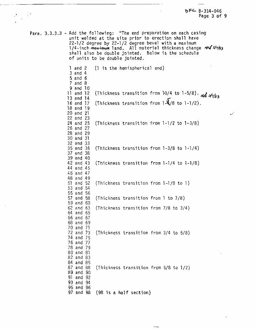
B-314-046Page 3 of 9
Para. 3.3.3.3 - Add the following: "The end preparation on each casingunit welded at the site prior to erection shall have22-1/2 degree by 22-1/2 degree bevel with a maximum1/4-inch maximum land. All material thickness changeshall also be double jointed. Below is the scheduleof units to be double jointed.
[could not be converted to searchable text]
[
(Thickness transition from
(Thickness transition from
1-3/4 to 1-5/8).
(Thickness transition from 1-1/2 to 1-3/8)
(Thickness transition from 1-3/8 to 1-1/4)
(Thickness transition from 1-1/4 to 1-1/8)
(Thickness transition from 1-1/8 to 1)
(Thickness transition from 1 to 7/8)
(Thickness transition from 7/8 to 3/4)
(Thickness transition from 3/4 to 5/8)
(Thickness transition from 5/8 to 1/2)
(98 is a half section)

- B-314-046Page 4 of 9
The following units will be jointed under the rig atboth ends using a single bevel as shown on detailof drawing H8-S20901.
1534
Para 3.3.4 - Delete the words - "No previous procedure, welder, or weldingoperator qualification will be accepted."
Replace the above words with - "Previous welder or welderoperator qualifications will be acceptable only if qualificationwas performed within 90 days prior to start of actual produc-tion welding for this contract."
Para 3.3.4.2 - Delete entire paragraph, including Subsections a, b, and cand replace with the following: "Welding procedures shall bequalified in accordance with AWD Dl.l, Section 5, Part A andPart B."
Para 3.3.4.3 - Delete entire paragraph, Tncluding Subsections a and b andreplace with the following: "Welder and welder operatorsshall be qualified prior to production welding. Qualificationshall be in accordance with AWS Dl.l, Section 5, Part A,Part E, and Part C or D as applicable."
Para 3.3.5.4 -
Para 3.4.5.3 -
Delete entire paragraph and replace with the following: "Weldacceptance shall be in accordance with the criteria establishedin AWS Dl.1, Section 3 and Section 8, Part A and Part D. NDEtechniques are as established in paragraphs 4.4, 4.5, and 4.6."
The fabricator is responsible to machine the ends of designatedabutting units such that the following field assembly tolerancescan be achieved without additional machining:
1. The mismatch of the interior surfaces of designatedabutting units shall not exceed 1/8" along with cir-cumferential weld seam.
-NOTE-
The interior of the units will not be accessible to thefield assembly personnel. Therefore, a diagram of re-quired external mismatch measurements to achieve theinternal mismatch tolerance shall be included with theoverall documentation of each unit.

B-314-046Page 5 of 9
2. The maximum gap between designated abutting unitsshall not exceed 1/8" when the designated abuttingunits are aligned to meet the linearity requirementbelow.
3.4.5.4 Add "The section straightness, measured across the ends of twodesigned abutting units, shall be walls parallel to the
axis of the assembled sections within a tolerance notexceeding 3/16" in 10' when measured from a reference lineparallel to the axis."
Para 3.4.10 - Delete entire paragraph and replace with the following:
Max. Thickness ofReinforcement, in.Material Thickness, in.
Less3/32OverOverOverOverOverOver
than 3/32to 3/16, incl.3/16 to 1, incl.1 to 2, incl.2 to 3, incl.3 to 4, incl.4 to 5, incl.5
1/321/163/321/85/327/321/45/16
Para 3.4.11 Add subparagraph d:
"d. Internal supports shall not be used as an aid to attainthe Out-Of-Roundness Tolerances."
Para 3.4.12 -
Para 3.4.13 -
Delete entire paragraph and replace with the following:"Transition of thickness shall be in accordance with AWS Dl.l,Section 10, Part C, paragraph 10.11."
Delete entire paragraph and replace with the following:"The inner surface of a torispherical, toriconical, hemi-spherical, or ellipsoidal head shall neither deviate outsideof the specified shape by more than 1-1/4% of D nor insidethe specified shape by more than 5/8% of D, where D is thenominal inside diameter of the vessel. Such deviations shallbe measured perpendicular to the specified shape and shall notbe abrupt. The knuckle radius shall not be less than thatspecified.
Para 4.1 - Delete entire paragraph.

DFC. B-314-046Page 6 of 9
Para 4.4.1 - Delete entire paragraph and replace with the following:"All welded joints to be radiographed shall be examined inaccordance with ASME Section V, Article 2 except as specifiedbelow.
a. A complete set of radiographs and records, as described in,T-292 and T-293 of Article 2 of Section V, for each jobshall be retained by the Manufacturer and kept on file fora period of at least 5 years.
b. The fabricator shall certify that personnel performingradiographic examinations have been qualified and certifiedin accordance with SNT-TC-lA (1975) for the techniqueand methods used.
c. The requirements of T-251 of Article 2 of Section V areto be used only as a guide. Final acceptance of radio-graphs shall be based on the ability to see the prescribed
penetrameter image and the specified hole.
d. Sections of welds that are shown by radiography to haveany of the imperfection identified in paragraph 3.3.5.4shall be judged unacceptable and shall be repaired usingan approved weld repair procedure in accordance withparagraph 3.3.5.2 and re-radiographed.
Para 4.5.1
Para 4.5.2
Para 4.6.1
Para 4.6.3
Para 6.2 -
Para 6.4 -
- Delete entire last sentence and replace with: "The magneticparticle inspection shall be in accordance with ASME Section V,Article 7 using the DC prod method.
- Delete entire paragraph and replace with: "The QualityAcceptable standard shall be as specified in paragraph 3.3.5.4."
- Delete entire first sentence and replace with: "Visualinspection shall be performed during all in-process fabricationoperations, including all tack welds and all completed welds."
- Delete entire sentence and replace with: "The QualityAcceptenace standard shall be as specified in paragraph 3.3.5.4."
Add: "Mechanical supports shall not be used to attain theOut-Of-Roundness Tolerances specified in paragraph 3.4.11."
Add to the end of the paragraph: "Masking tape shall not beused."
Para 6.6 - Delete entire paragraph.
Para 6.7 - Add in first sentence that inspection will be by the purchaser.

- B-314-046Page 7 of 9
Appendix A, Sheet 1, Item #15 - Delete the word calculations and add thefollowing as a submittal requirement:
"Temporary attachment and removal procedure"
Item #30 - Delete off-loading and storageprocedures.Item #10 - Delete certified test andinspection reports for weld backing ring.
Attachment A, Sheet 3 - Delete last column.Delete column entitled "Handling and Storage"
JUSTIFICATION
° Prequalified procedures have been used for welding inside nuclear reactorcontainment vessels. For example, at Satsop III-the main steam whiprestraints. Prequalified procedures are permitted by AWS Dl.1 for50,000 psi tensile stress material. The credibility of overall weldingprogram is established through the welder qualification program, not theprocedure qualification.
° The AWS Dl.l code allows eithertest, it does not require both.establish the qualifications of
the guided bend test or the radiographicThe radiographic test is definitive to
the welders.
o ASME Secton IX addresses welder procedure qualification and does not byitself consist of a welding code. AWS requires welders to be testedfor the position to be welded.
o All other changes are for clarity or a change in scope or plans.
Drawing H8-S20901
Section D - Delete this section detail. Slot channel will be field installedduring shaft guides installation. This reduces 360 degree channelrequirement to approximately 90 degrees.
Detail 2 - Replace Detail 2 with Figure 1 (attached)
Detail 3 - (1) Delete reference to 3 inch NP threads, All threads shall be2 inch. Justification: uniformity.
(2) Delete "Mark No. A and B and Mark No. C to P" and 5" DIA".Justification: Same as above.
(3) Install inspection ports (one per 80 foot) section accordingto the schedule shown in paragraph 3.3.3.3 of specificationB-314-P-S28005. Justification: A substantial cost savingsis realized by eliminating 46 inspection ports.
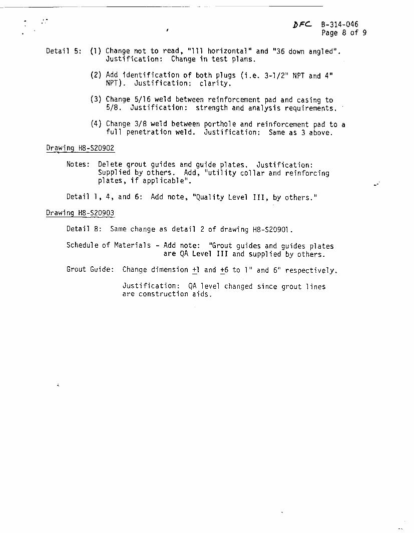
DFC. B-314-046Page 8 of 9
Detail 5: (1) Change not to read, "111 horizontal" and "36 down angled".Justification: Change in test plans.
(2) Add identification of both plugs (i.e. 3-1/2" NPT and 4"NPT). Justification: clarity.
(3) Change 5/16 weld between reinforcement pad and casing to5/8. Justification: strength and analysis requirements.
(4) Change 3/8 weld between porthole and reinforcement pad to afull penetration weld. Justification: Same as 3 above.
Drawing H8-S20902
Notes: Delete grout guides and guide plates. Justification:Supplied by others. Add, "utility collar and reinforcingplates, if applicable".
Detail 1, 4, and 6: Add note, "Quality Level III, by others."
Drawing H8-S20903
Detail 8: Same change as detail 2 of drawing H8-S20901.
Schedule of Materials - Add note: "Grout guides and guides platesare QA Level III and supplied by others.
Grout Guide: Change dimension +1 and +6 to 1" and 6" respectively.
Justification: QA level changed since grout linesare construction aids.

[could not be converted to searchable text]
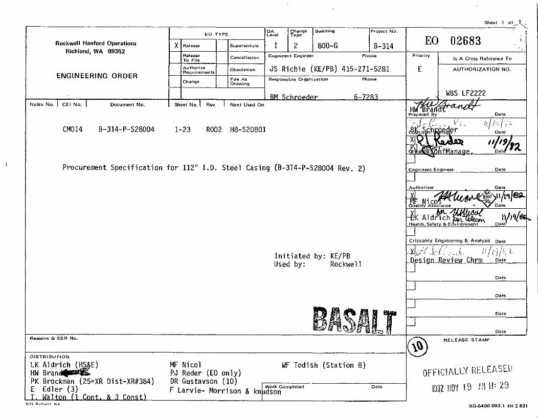
Sheet 1 of 1
B-314Rockwell Hanford OperationsRichland, WA 99352
ENGINEERING ORDER
EO 02683X IRelease Supersedure
ReleaseTo File Cancellation Cognizant Engineer Phone
Procurement Specification for 112" I.D. Steel Casing (B-314-P-S28004 Rev. 2)
Initiated by: KE/PBUsed by: Rockwell
Reasons & ESR No.
DISTRIBUTION
LK Aldrich (HS&E) MF Nicol WF Todish (Station 8)
PK Brockman (25=XR Dist-XR#384) DR Gustavson (10)E Edler (3) F Larvie- Morrison & knudsonT. Walton (1 Cont. & 3 Const)
RELEASE STAMP

Rev. 2, 11/17/82
SPECIFICATION TITLE PAGE
SPECIFICATION NO. B-314-P-S28004
QA LEVEL I
PROCUREMENT SPECIFICATION FOR
112" ID STEEL CASING
BWIP EXPLORATORY SHAFTPROJECT B-314
Pepared By:
Kaiser Engineers, Inc./Parsons Brinckerhoff Quade & Douglas, Inc.
For the U.S. Department of Energy
Contract No. DE-AC06-80RL10000
ROCKWELL HANFORD OPERATIONS:
Released for Procurement:

B-314-P-S28004Rev. 2
TABLE OF CONTENTS
Subject Page
1.0 SCOPE 11.1 Work Included 11.2 Work Not Included 1
2.0 GENERAL PROVISIONS 12.1 Applicable Codes, Standards, and Publications 12.2 Drawings and Attachments 22.3 Definitions 32.4 Quality Assurance 42.5 Inspection Program 52.6 Records and Submittals 6
3.0 TECHNICAL PROVISIONS 73.1/ Materials 73.2 Fabrication 83.3 Welding 93.4 Tolerances 113.5 Identification Marking 13
4.0 NONDESTRUCTIVE EXAMINATION 144.1 Lifting Lug and Stiffener Rings 144.2 Casing Seams 154.3 Radiography 154.4 Magnetic Particle Examination 154.5 Visual Inspection 15
5.0 SHOP DRAWINGS 165.1 Fabrication Drawings 165.2 Packaging and Shipping Drawings 165.3 Acceptance of Shop Drawings 16
6.0 PACKAGING, HANDLING, SHIPPING, AND STORING 166.1 Casing Protection 166.2 Supports 166.3 Tack Welding 166.4 End Protection 176.5 Shipping Release 176.6 Off-Loading and Storage 17
Appendix A Bidder and Seller Information Requirements A-1Appendix B Information Required for Quality Control Program B-1
Page ii I

B-314-P-S28004Rev. 2
112" ID STEEL CASING
1.0 SCOPE
This Specification describes the requirements for the fabrication anddelivery to the project site of seventeen (17) welded steel 112 inchinside diameter shaft casing units, and associated grout guides, supportplates, and weld backing strips.
1.1 Work Included
1.1.1 Labor
1.1.2 Tools, materials, and equipment
1.1.3. Fabrication
1.1.4 Testing
1.1.5 Records Management
1.1.6 Packaging
1.1.7 Transportation
1.1.8 Offloading
1.1.9 Placing in storage
1.2 Work Not Included
1.2.1 Maintenance in storage
2.0 GENERAL PROVISIONS
2.1 Applicable Codes, Standards, and Publications
Work performed and materials furnished under this Specificationshall conform to the requirements of the documents listed below, tothe extent specified herein. In the event of conflict betweenapplicable requirements of two or more of these documents, the moststringent requirement shall apply.
ANSI. American National Standards Institute
B16.11-1973, Forged Steel Fittings, Socket-Welding and Threaded
NQA-1-1979, Quality Assurance Program Requirements for NuclearPower Plants
N45.2.2-1978, Packaging, Shipping, Receiving, Storage and Han-dling of Items for Nuclear Power Plants
Page 1 of 17 I
B-314-P-S28004Rev. 2
N45.2.15-1981 Hoisting, Rigging and Transporting of Items atNuclear Power Plants
ASTM, American Society for Testing and Materials
A 36-77a Structural Steel
A 53-77a Pipe, Steel, Black and Hot-Dipped Zinc CoatedWelded and Seamless
A 441-79 High-Strength Low-Alloy Structural ManganeseVanadium Steel
E 165-75 Liquid Penetrant Inspection Method
E 709-80 Magnetic Particle Examination
ASME, American Society of Mechanical EngineersBoiler and Pressure Vessel Code as amended through 1981
Section V, Nondestructive Examination
Section VIII, Pressure Vessels, Division 1
Section IX, Welding and Brazing Qualifications
AWS, American Welding Society
A3.0 Welding Terms and Definitions, 1980
Dl.l Structural Welding Code - Steel, 1982
DOE, U. S. Department of Energy
HS-BP-8002, Supplier Acceptance Data Package (ADP)
2.2 Drawings and Attachments
2.2.1 Drawings
The following listed design drawings are incorporated andmade a part of this Specification:
Number Title
H8-S20801 112" I.D. Casing
H8-S20802 112" I.D. CasingGrout Guide andDetails
Page 2 of 17

B-314-P-S28004Rev. 2
2.2.2 Attachments
The following listed attachments are incorporated and made apart of this Specification:
Appendix A "Bidder and Seller InformationRequirements" with attachedsubmittal matrix.
Appendix B "Information Required forQuality Control Program."
2.3 Definitions
2.3.1 Unit
"Unit" shall mean a prefabricated casing assembly, of lengthindicated on the Drawings,/ consisting of a string of canswith attached circumferential stiffeners and lifting lugring, with ends suitably prepared for field welding, andindividually identified by a mark number.
2.3.2 Can
"Can" shall mean the single rolled element of a casing unit.
2.3.3 Subassembly
"Subassembly" shall mean two or more cans of the casingstring but less than a unit.
2.3.4 Stiffener
"Stiffener" shall mean the circumferential solid bar rein-forcing rib welded to the outside of the unit.
2.3.5 Inspection Port
"Inspection port" shall mean the capped opening in thecasing plate required for placing a radioactive source foruse in radiographic examination.
2.3.6 Lifting Lug Ring
"Lifting lug ring" shall mean the the circumferential solidbar rib placed on each unit to provide a lifting shoulder.
2.3.7 Grout Guide
"Grout guide" shall mean the slotted vertical piping that isto be attached to the side of the casing to provide a con-duit for placing grout.
Page 3 of 17

B-314-P-S28004Rev. 2
2.3.8 Hold Point
"Hold point" shall mean that activity in the production se-quence where work shall not proceed without written releaseby the Inspector.
2.3.9 Witness Point
"Witness point" shall mean that activity in the productionsequence scheduled for surveillance by the Inspector wherework may proceed upon verbal release by the Inspector orupon the expiration of a one hour wait for inspection fromthe scheduled time.
2.3.10 Purchaser
"Purchaser" shall mean the U.S. Department of Energy or itsappointed representative.
2.3.11 Inspector
"Inspector" shall mean those persons or agencies appointedby the Owner to conduct quality control surveillance auditsand inspection activities of the fabrication process and toauthorize release for shipment.
2.3.12 Supplier
"Supplier" shall mean the party responsible for the fabrica-tion and delivery of the units.
2.3.13 The applicable definitions contained in the following publi-cations shall also pertain:
a. ANSI NQA-1, Supplement S-1
b. AWS A3.0
2.4 Quality Assurance
2.4.1 The casing units are to be components of a structure classi-fied Level I for nuclear safety purposes and are thereforesubject to the requirements of a quality assurance programestablished and implemented in accordance with ANSI NQA-1,ANSI N45.2.2, and ANSI N45.2.15.
2.4.2 Each bidder shall submit with the proposal one copy of hisquality assurance program and quality control manual forreview and evaluation as to his acceptability as a qualifiedvendor of Level I components.
2.4.3 Supplier shall be responsible for assuring that his sub-contractors' quality-assurance/quality control programs are
Page 4 of 17
B-314-P-S28004Rev. 2
in compliance with the Specifications. Subcontractingshall conform to the provisions of ANSI NQA-1, BasicRequirements 4 and 7, and Supplements 4S-1 and 7S-1.
2.4.4 Subsequent to the notice to proceed, the Purchaser willprovide the Supplier comments on the quality assuranceprogram and the quality control manual submitted with thebid. Prior to the start of fabrication, the Supplier shallre-submit the program and manual incorporating the Purchasercomments. At this time, a joint Purchaser/Supplier qualityassurance coordinating meeting shall be conducted to clarifyrequirements and acceptance criteria. Upon acceptance bythe Purchaser of the program and manual, as revised, theSupplier shall proceed with fabrication in accordance withthe provisions of the program and accepted procedures.
2.4.5 The minimum information required for the quality controlprogram is contained in the listing attached as Appendix B.
2.5 Inspection Program
2.5.1 The Supplier shall be responsible for the physical perfor-mance and documentation of all required in-process inspec-tion, testing, and other quality control functions duringthe manufacture of the casing units.
2.5.2 The Inspector will perform the surveillance inspection andaudit of all required documentation and in-process opera-tions of manufacturing, fabrication, shipment, and qualityassurance to ensure compliance with the requirements herein.
2.5.3 The Purchaser will identify to the Supplier the authorizedagencies and individuals who will perform inspection sur-veillance and audit functions.
2.5.4 The Work will be inspected by the Supplier and the Inspectorduring fabrication, packaging, shipment, and placement instorage. The Supplier shall furnish all facilities, tools,jigs, gauges, materials, and personnel necessary for inspec-tion. This shall include personnel, equipment, and mate-rials required to perform nondestructive examinations.Supplier's inspectors and test personnel shall be certifiedand qualified in accordance with ANSI NQA-1, Supplement 2S-land Appendix 2A-1. Supplier's nondestructive examinationpersonnel shall be certified and qualified in accordancewith ANSI NQA-l, Supplement 2S-2. The Inspector shall haveaccess to all areas of the Supplier's and his subcontrac-tors' plants concerned with the supply, fabrication, andshipment of the casing and its components. Inspection bythe Inspector shall not relieve the Supplier of his res-ponsibility to provide casing that complies with therequirements of the Specification and the Drawings.
Page 5 of 17

B-314-P-S28004Rev. 2
2.5.5 An inspection plan incorporating hold points and witnesspoints shall be developed by the Supplier and submitted tothe Purchaser, within four weeks from notice to proceed, forreview, comment, and acceptance. The inspection plan shallbe subject to the Purchaser's review for conformance to theaccepted quality assurance program and incorporation of holdand witness points. Fabrication shall not commence prior toacceptance of the inspection plan by the Purchaser. Theinspection plan shall identify pertinent manufacturing andtesting operations and steps critical to quality control.The following shall be included as minimum hold points:
a. Initial forming of each plate, stiffener, and liftinglug ring
b. Initial welding of each weldment
c. Any non-destructive examination
d. Preparation for shipment.
2.6 Records and Submittals
2.6.1 The Supplier shall establish and maintain a records systemin accordance with ANSI NQA-1, Basic Requirement 17,Supplement 17S-1, and Appendix 17A-1. This system shall beincorporated into the Supplier's quality assurance programand submitted for -he Purchaser's review and acceptance.The records system shall provide complete traceability ofall materials, equipment, workmanship, quality controls, andhandling of each unit. All documentation shall be clear,legible, and of suitable quality for microfilming and forlong term storage.
2.6.2 The Supplier shall obtain, maintain, and submit to thePurchaser the following:
2.6.2.1 Steel plate, pipe, and fittings mill-test certi-fied reports to include heat number, chemicalcomposition, ASTM/ANSI grade, and tensile testresults.
2.6.2.2 Welding electrode and flux manufacturers' materialcertification, including the heat number and AWSspecification.
2.6.2.3 Welder and welding machine operator test resultrecords. Format shall be as shown in the acceptedquality control manual.
Page 6 of 17
B-314-P-S28004Rev. 2
2.6.2.4 Welding procedure specifications and qualificationrecords in the format as shown in the acceptedquality control manual.
2.6.2.5 Completed weld report for each casing unit coveringall completed welds and containing all the informa-tion necessary to verify the quality of the weldand welded material. Radiographs with completedreport form and other nondestructive examinationreports shall be included. The reports shall be inthe format shown in the accepted quality controlmanual.
2.6.2.6 Certification documentation for non-destructive ex-amination and inspection and test personnel perANSI NQA-1, Supplements 2S-1, 2S-2, andAppendix 2A-1 as applicable.
2.6.2.7 A listing of the completed units that indicates themost suitable fit-up sequence for field assembly ofa continuous casing string based on compatibilityof rim configuration for field welding. This bestfit listing shall be called the unit matching list.
2.6.2.8 Supplier's certificate of compliance that thedelivered fabricated product meets the requirementsof the Specification and Drawing.
2.6.3 The Supplier shall submit the information listed inAppendix A, "Bidder and Seller Information Requirements" andthe attached submittal matrix.
2.6.4 All Supplier final data shall be submitted in accordancewith DOE HS-8002.
3.0 TECHNICAL PROVISIONS
3.1 Materials
3.1.1 Casing, Stiffeners, and Lifting Lug Rings
Steel plate and bar stock shall conform to ASTM A 441 orA 36.
3.1.2 Grout Guides
The materials for the grout guides shall conform to thefollowing:
3.1.2.1 Grout guide pipe: ASTM A 53, Schedule 40, black,type F
Page 7 of 17

B-314-P-S28004Rev. 2
3.1.2.2 Grout guide splice pipe: ASTM A 53, Schedule 40,black, Type F
3.1.2.3 Support plate: ASTM A 36
3.1.2.4 Guide plate: ASTM A 36
3.1.3 Inspection Port
The inspection port shall be a forged steel half-couplingwith plug of quality, configuration, and threads as stipu-lated in ANSI B16.11 and as shown on the Drawing.
3.1.4 Filler Metals
Filler metals for arc welding shall conform to Table 4.1.1,AWS Dl.l. Material selected shall be identified in the weldprocedures submittal. Filler metals and fluxes shall betraceable from purchase order to consumption.
3.1.5 Weld Backing
The weld backing ring shall be as shown on the Drawing andshall consist of ASTM A 441 steel or a material of equalchemical and mechanical properties as accepted by thePurchaser. Backing rings shall be traceable from purchaseorder to consumption.
3.2 Fabrication
3.2.1 Plate Thickness
Prior to processing each plate, thickness measurements shallbe recorded and shall be made available for examination bythe Inspector. Each plate shall be measured, with a micro-meter or ultrasonic devices at each corner and not less than2 points equally spaced on each edge of the plate. Platesshall be ordered to, and shall be not more than 0.010"below, the nominal thickness indicated in the schedule onthe Drawing.
3.2.2 Plate Dimensions
Selection of plate width and length shall be commensuratewith the casing dimensions specified.
3.2.3 Plate Identification
Each plate shall be marked with an identification number,using steel stamps with 1/2-inch-high characters, for thepurpose of in-process identification of cans.
Page 8 of 17
B-314-P-S28004Rev. 2
3.3 Welding
3.3.1 Welding Processes
The fusion welding processes for the weld fabrication of theunits shall be as permitted by AWS Dl.l and ASME Boiler andPressure Vessel Code, Section IX.
3.3.2 Weld Joint Root Beads
The back side of every longitudinal and circumferentialplate weld root bead shall be mechanically cleaned or airarc gouged to clean metal prior to the deposition of addi-tional weld metal.
3.3.3 Preparation for Welding
3.3.3.1 The edges of plates shall be formed to comply withthe applicable weld procedure specification jointconfiguration. All projecting burrs shall beremoved. Hammering shall not be used to shape theedges preparatory to welding.
3.3.3.2 Surfaces to be welded shall be clean, smooth, andfree of deleterious metal Petroleum products shallnot be used as cleaner on surfaces to be welded.
3.3.4 Qualifications 'Welding procedure specifications shall be prepared, andprocedures, welders, and welding operators used for thefabrication of casing shall be qualified as specifiedherein. No previous procedure, welder, or welding operatorqualification will be accepted. Production welds shall notbe used to qualify weld procedures, welders, or weldingoperators. All procedure and performance qualificationwelds and tests shall be subject to witness by theInspector. The Inspector shall be notified 48 hours inadvance of qualification activities to permit him to attend.
3.3.4.1 Welding procedure specifications (WPS) shall beprepared in accordance with AWS Dl.l, Section 5.The WPS shall include all essential and non-essential variables. All welding parameters shallbe recorded in the WPS, with special considerationto joint configuration dimensions and weld metaldeposition.
Page 9 of 17

B-314-P-S28004Rev. 2
3.3.4.2 Welding procedures shall be qualified in accordancewith ASW D1.1, Section 5, Part B, except asfollows:
a. Qualification test specimens shall be radio-graphically examined and accepted in accordancewith ASME Boiler and Pressure Vessel Code,Section VIII, Division 1, Articles UW51 a andb. Radiographic examination is in addition toapplicable guided bend tests.
b. Guided bend tests are required for procedurequalification for plate thicknesses of 3/4" andthinner, and shall include both face and rootbends. The acceptance criteria for quided bendtests shall be in accordance with ASME Boilerand Pressure Vessel Code, Section IX.
c. The base metal used in procedure qualificationtests shall be of the same specification andgrade as specified in the ContractSpecification.
3.3.4.3 Welders and welding operators shall be qualifiedprior to production welding. Qualification shallbe in accordance with AWS D1.1, Section 5, Part Cor Part D as applicable, except as follows:
a. Qualification test specimens shall be radio-graphically examined and accepted in accordancewith ASME Boiler and Pressure Vessel Code,Section VIII, Division 1, Articles UW51 a andb.
b. Guided bend test specimens shall be tested inaccordance with AWS D1.1, Section 5, Part C orD as applicable, and ASME Boiler and PressureVessel Code, Section IX. Acceptance Criteriashall be in accordance with ASME Boiler andPressure Vessel Code, Section IX.
3.3.4.4 Procedure, welder, and welding operator qualifica-tion records shall be maintained including certi-fied radiographic examination report, radiographicfilm, and qualification report for each welder andwelding operator including his/her uniqueidentifier.
3.3.4.5 When there is a specific reason, as determined bythe Inspector, to question the ability of a welder,welding operator, or welding equipment to consis-tently produce welds that meet the specifications,
Page 10 of 17

B-314-P-S28004Rev. 2
the welder or welding operator shall be requali-fied. If the welder or welding operator continuesto produce welds that do not meet the specifica-tions, the Supplier shall, at the request of theInspector, remove the welder, welding operator, orwelding equipment from the job.
3.3.5 Weld Quality and Workmanship
3.3.5.1 Weld Type
Weld type shall be as shown on the Drawing.
3.3.5.2 Stress Risers
Visually discernable stress risers upon weld orparent metal surfaces; i.e. sharp and abruptchanges in weld bead geometry, laminations, inclu-sions, open porosity, arc starts, cold laps, lackof fusion, parent metal damage caused by removal oftemporary appurtenances, chisel marks or gouges arenot acceptable and shall be repaired by weldingprior to final inspection.
3.3.5.3 Undercuts
Weld undercuts shall be rejected, except thatintermittent undercuts (6" long in 24" of weld)having a smooth and gradual transition and having adepth of 1/32" or less are acceptable.
3.3.5.4 Acceptance Standards
Weld acceptance shall be in accordance with thecriteria for workmanship and nondestructive exami-nation as specified herein and in Sections V andVIII of the ASME Boiler and Pressure Vessel Codeand in AWS Dl.l, Section 5, Part C, and Section 8,Part D for the inspection and examination methodsused.
3.4 Tolerances
Casing assembly shall be fabricated to the following tolerances andas shown on the Drawings. Tolerances not specified otherwise shallbe ± 1/8".
3.4.1 Weld Joint Root Openings
Longitudinal and circumferential plate welds shall have theoption of a root gap ranging up to 3/16" maximum.
Page 11 of 17 |
B-314-P-S28004Rev. 2
3.4.2 Staggered Welds
Longitudinal welds of cans in a casing subassembly shall bestaggered circumferentially a minimum of 24".
3.4.3 Mismatch
Longitudinal weld seam abutting edges of cans shall notexceed 1/16" mismatch. Circumferential weld seam abuttingedges shall not exceed 1/8" mismatch.
3.4.4 Unit Straightness
Completed casing unit shall be straight, with walls parallelto the axis of the casing. The variation in straightness ofcasing when measured from a reference line parallel to theaxis shall not exceed 3/16" in 10 ft.
3.4.5 Section Ends
3.4.5.1 The planes of the ends of the casing unit shall benormal to a line parallel to the axis of the casingsection with a tolerance of ± 15 minutes of arc atall locations on the circumference.
3.4.5.2 The maximum gap between the end of the unit and aplane surface pressed against the end of the unitshall be 1/8."
3.4.6 Fillet Weld Size
Close fitup is required at those joints where fillet weldsare applied in order to insure full fusion welds at thebottom of the fillet. Fillet weld specified size is aminimum. If at any point, the gap between the shell andlifting lug ring or stiffener exceeds 1/16 inch but is lessthan 1/8 inch, it will be acceptable providing that thefillet weld size is increased 1/16 inch throughout 3600.Gaps exceeding 1/16 inch on lifting lug rings shall beindentified in Supplier's inspection report.
3.4.7 Lifting Lug Rings
The uppermost ring on a casing unit is the lifting lug ringfor that section of casing. The plane of the bottom edge ofeach lifting lug ring shall be parallel with the plane ofthe top of the casing unit within 1/8". The cross sectionof the lifting lug ring stock shall not vary in rectangu-larity by 1/32" difference in length of the diagonals.
Page 12 of 17

B-314-P-S28004Rev. 2
3.4.8 Ring Closure Welds
Closure welds for stiffener rings and lifting lug ringsshall be made after the attachment weld. There shall be amaximum of 2 closure welds per ring.
3.4.9 Casing Unit Length
The finished length for each casing unit may vary ± 1" fromthe nominal lengths indicated on the Drawings.
3.4.10 Weld Reinforcement
Weld reinforcement of inside diameter welds shall not exceed3/32" for plate thickness of 3/16" to 1" and 1/8" for platethickness of 1" to 2", and shall be smoothly blended fromweld metal to parent metal. Outside diameter weld rein-forcement shall not exceed 1/4" and shall be feather edgedto the parent metal.
3.4.11 Diameter and Out-of-Roundness Tolerances
Casing units shall be manufactured to the following dia-metric tolerances:
(a) The diameter as determined by a circumferential mea-surement with a i tape may be 1/4" over to 0" less thanthe sum of the nominal diameter, plus twice the nominalplate thickness indicated on the Drawings.
(b) The internal diameter of the casing unit shall be notless than 111-11/16 inches nor more than112-5/16 inches.
(c) Circumferential and diametric measurements shall bemade at the end of each casing unit and at not lessthan 7 points approximately equally spaced between theends of the unit with the measuring points to be se-lected by the Inspector.
3.5 Identification Marking
3.5.1 Welding Operator Identification
All welds shall bear the welding operator's identificationmark. Such identification shall be located adjacent to theweld but not closer than 1" from the heat affected area.Steel stamps employed shall imprint a radius, not a sharpnotch.
Page 13 of 17
B-314-P-S28004Rev. 2
3.5.2 Casing Unit
3.5.2.1 Data Required
Each completed casing unit shall be marked on theinside, 6" from each end as follows:
a. Using metal stamps having numerals and lettersnot less than 3/8" high, denote Supplier, ASTMdesignation of base metal, and total calculatedweight of completed unit in pounds.
b. Using a paint stencilling system which yieldsnot less than 1" high figures and letters,denote the internal diameter, wall thickness,length in feet and decimal, and purchase ordernumber. The stencilling shall be placed uponclean base metal free of scale, rust, or otherforeign matter. Color of the stencilling shallbe in contrast to the base metal.
3.5.2.2 Mark Identification
Each completed casing unit shall bear a free-handapplied mark identification located at each end ofthe unit on the inside and outside surface. Inaddition, each end of each unit shall be matchmarked to correlate with the information in theUnit Matching List showing most suitable fit-upsequence for field assembly. Such mark identifi-cation shall be placed at a distance from each endto permit ready visibility to the viewer withoutentry into the casing. The mark identification maybe applied with a paint spray gun, aerosol can orbrush and shall be not less than 18" in height.The number shall be a number as shown on theDrawing and assigned by the Supplier.
4.0 NON-DESTRUCTIVE EXAMINATION
4.1 Lifting Lug and Stiffener Rings
Welds on rings shall be examined as follows:
4.1.1 Closure welds for lifting lug rings and for stiffener ringsshall be 100% magnetic particle examined.
4.1.2 Fillet and groove welds for lifting lug rings and stiffenerrings shall be 100% magnetic particle examined.
Page 14 of 17

B-314-P-S28004Rev. 2
4.2 Casing Seams
All longitudinal and circumferential plate welds including intersec-tions in the casing shall be 100% radiographic inspected. Radio-graphic film shall be placed so that the weld seam is centered onthe film.
4.3 Radiography
4.3.1 The radiographic inspections shall be performed as stipu-lated for technique and quality in Paragraph UW51,Section VIII, ASME Boiler and Pressure Vessel Code
4.3.2 Each radiographic film shall show not less than one foot ofweld.
4.3.3 Exposed radiographic film that is defective shall be basisfor rejection of the film, and repeating the radiographicinspection of the weld.
4.4 Magnetic Particle Examination
4.4.1 Groove and fillet welds on lifting lug rings and stiffenersshall by 100% magnetic particle inspected at the root bead,at one half weld thickness, and after all grinding ormachining is complete. The magnetic particle inspectionshall be in accordance with ASTM E 709 using the DC prodmethod, and ASME Section V, Standard SE 109.
4.4.2 The quality acceptance standard shall be as specified inSection 3.3, "Welding," herein.
4.4.3 Surface imperfection interpretations in dispute with themagnetic particle inspection indications shall be verifiedby an alternate nondestructive examination method as deter-mined by the Inspector.
4.5 Visual Inspection
4.5.1 Visual inspection shall be performed upon all in-processoperation and completed welds. Visibly discernable weldrejections which are readily repairable without adverseeffect to the weld or parent metal shall be repaired priorto the application of non-destructive examinationprocedures.
4.5.2 Weld repairs necessitated by visual inspection shall bevisually reexamined subsequent to the repairs. TheInspector will request a radiographic examination when thestructural integrity of a repair is in question.
4.5.3 Standards of acceptance shall be as specified inSection 3.3, "Welding," herein and in AWS Dl.l.
Page 15 of 17

B-314-P-S28004Rev. 2
5.0 SHOP DRAWINGS
5.1 Fabrication Drawings
The Supplier shall provide detailed shop drawings reflecting all theinformation and data pertinent to fabrication and related qualitycontrol. Submittal shall be made 10 working days prior to scheduledstart of fabrication. The Owner will review and comment on thedrawings. Appendix A pertains.
5.2 Packaging and Shipping Drawings
The Supplier shall provide detailed drawings of casing supports,surface protection, and shipping bracing of the finished unit.Special rigging or handling requirements shall also be shown.Submittal shall be made 60 working days prior to scheduled comple-tion of the first unit. Appendix A pertains.
5.3 Acceptance of Shop Drawings
The Purchaser's acceptance of any shop drawing or other comment thatdirects the Supplier to proceed on technical matters does not re-lieve the Supplier of his responsibility for supplying the casingunits in conformance with the Specification, the Drawing, and thePurchase order.
6.0 PACKAGING, HANDLING, SHIPPING, AND STORING
6.1 Casing Protection
The Supplier shall take necessary precautions to prevent damage tothe casing units during handling, loading/offloading, and tran-sporting. The provisions of ANSI N45.2.2 shall be complied with.
6.2 Supports
Suitable mechanical supports and other devices as required shall beprovided for each casing unit to maintain dimensions within speci-fied tolerances and to prevent deformation during handling, loading,transporting, offloading, and storing.
6.3 Tack Welding
Tack welding of supports and protective devices on the units will bepermitted only as indicated on the accepted packaging and shippingdrawings submittal.
Page 16 of 17 |

B-314-P-S28004Rev. 2
6.4 End Protection
Both ends of each completed casing unit shall be mechanicallycleaned to parent metal for a distance of not less than 1", inter-nally and externally, beyond the terminating ends of weld joint pre-paration. Cleaned areas shall be masked with a tape of the type ac-cepted on the packaging and shipping drawings submittal to protectthe ends from corrosion and damage in transit and in storage.
6.5 Shipping Release
No loading for shipment shall commence prior to the issuance of awritten release for shipping by the Inspector. Nonconforming prod-ucts shall not be shipped.
6.6 Off-Loading and Storing
The Supplier shall provide a procedure for off-loading and storingat the destination. Procedure shall be submitted for Purchaser'sreview and comment 60 working days prior to scheduled delivery date.Storage will be in the vicinity of the exploratory shaft site atan area designated by the Purchaser. Handling and storage pro-cedures shall be in accordance with ANSI N45.2.15.
BWIPOlJ: 11/17/82
Page 17 of 17

B-314-P-S28004Rev. 2
APPENDIX A (Sheet 1 of 3)
BIDDER AND SELLER INFORMATION REQUIREMENTS
See Next Page for Definitions and InstructionsPage A-1

B-3 14-P-S28004APPENDIX A (Sheet 2 of 3) Rev. 2
DEFINITIONS
1. DRAWING LIST AND SCHEDULE A complete list of all drawings and data by titlethat the bidder expects to furnish on this order. Schedule to show, in weeksafter award, submittal of each type of review and certified drawings.
2. DIMENSIONED OUTLINE DRAWINGS AND/OR CATALOG INFORMATION Drawings to scale show-ing the relative size, configuration, and location to all material to be fur-nished. Show two or more views of unit, clearances and area required foroperation and maintenance. Show unit in relation to nearby structures and otherequipment or operating floor, location of utility connections and direction ofrotation, if applicable. When submitting data for "off the shelf'equipment/materials, catalog cuts and information are acceptable provided theyare submitted in ample detail.
3. SCHEMATIC PIPING DIAGRAMS Show equipment to be interconnected, flow quantities,pipe sizes, valves and instruments.
4. ELECTRICAL AND INSTRUMENTATION INFORMATION Show all data pertaining to instru-mentation, control and power electrical equipment. Include "one-line",elementary' wiring, panel interior wiring and exterior interconnection wiring,
dimensioned outlines of enclosures with raceway entries shown.
S. SHOP DETAIL DRAWINGS Show all necessary details and data required for fabrica-tion and maintenance. For structural details show all connections and membersizes.
6. FOUNDATION OUTLINE AND ANCHOR BOLT LOCATIONS Show all data required for founda-tion design including location, blockouts, embedded items, grout required, andsize, type and projection of anchor bolts.
7. LOAD DIAGRAMS Show total static and dynamic loads and load centers.
8. DATA SHEETS Sheets shall be completed for the equipment proposed with all in-formation noted thereon.
9. PERFORMANCE DATA AND CURVES
10. CERTIFIED TEST AND INSPECTION REPORTS Reports by recognized commercial labora-tories of indicated chemical and physical tests of materials as required by thespecifications. In addition where applicable, weld inspection and stressrelieving records and code nameplate rubbings shall be furnished.
11. BILLS OF MATERIAL Show for each unit: item no., shop order no., mark or name,part no., or pattern no., and drawing reference.
12. INSTALLATION INSTRUCTIONS Complete, detailed and sequenced instructions fororiginal installation and for removals and replacements as well as erectioninformation.
13. MAINTENANCE AND OPERATING MANUALS Complete installation, starting and operatinginstructions. Complete descriptions of preventive and repair maintenance,including detailed lubrication chart showing every lubrication point, grade oflubricant, lubrication schedule and amount of oil or grease required for refillafter drainage. Manuals include parts list with recommended spares.
14. NAMEPLATE DATA AND MOTOR LIST
15. CALCULATIONS Shall be checked and stamped by a registered professionalengineer, licensed to practice in the state where installation occurs.
16. PRELIMINARY DESIGN DRAWINGS Seller provided design services such as pre-engineered buildings, silos and other structures, conveyor systems, bins andchute design, large ductwork and supports.
17. FINAL DESIGN DRAWINGS Same as Item No. 16.
INSTRUCTIONS
1. DIMENSIONS Shown on all but schematic drawings and diagrams shall be in feetand inches, unless noted otherwise.
2. CERTIFIED DRAWINGS Shall be so marked by Seller. They shall conform toSeller's drawings as finally accepted by the Purchaser and shall be forwarded atcommencement of manufacture. The drawings shall be revised and resubmitted toreflect any changes approved during the manufacturing period.
3. REPRODUCIBLE PERMANENT PRINTS Shall be cloth, "Chronaflex", or "Mylar". Theyshall depict the material as shipped and shall be forwarded upon completion ofshipment.
Page A-2

RECORDS AND SUBMITTALS
Drawings
Procedures
Manuals
Records
Certificates
Plans
LEGEND: a. Submit to Owner for review and concurrence prior to fabrication
b. Submit to Owner for review and concurrence prior to shipment
c. Submit upon delivery.

B-314-P-S28004Rev. 2
APPENDIX B (Sheet 1 of 1)
INFORMATION REQUIRED FOR QUALITY CONTROL PROGRAM
1. Quality control department organization, responsibilities, andauthorities.
2. Material storage facilities and weather protection.
3. Methods of measuring material dimensions.
4. Material records and marking system.
5. Personnel qualification and certification program.
6. Employee or independent firm responsible for weld procedure speci-fications and tests.
7. Employee or independent firm responsible for welding operator andwelder qualification and tests.
8. Quality control manual containing all policies, assignments ofresposnibility, procedures, forms, and controls.
9. Employee or firm designated to perform radiographic inspection andradiographic interpretation. Include experience summary of person-nel if they are employees, and records of qualification.
10. Employees performing other nondestructive testing and their experi-ence, and records of qualification.
11. In progress and final inspection procedures.
12. Document and record controls.
BWIPOlM: 05/17/82
Page B-1

[COULD NOT BE CONVERTED TO SEARCHABLE TEXT]
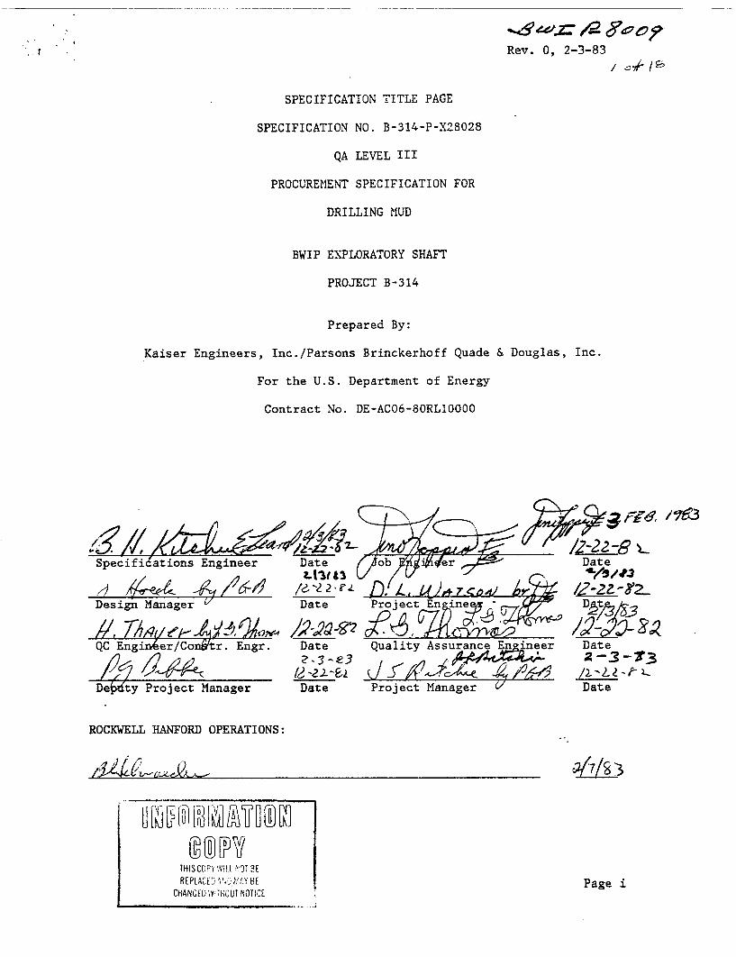
Rev. 0 2-3-83
SPECIFICATION TITLE PAGE
SPECIFICATION NO. B-314-P-X28028
QA LEVEL III
PROCUREMENT SPECIFICATION FOR
DRILLING MUD
BWIP EXPLORATORY SHAFT
PROJECT B-314
Prepared By:
Kaiser Engineers, Inc./Parsons Brinckerhoff Quade & Douglas, Inc.
For the U.S. Department of Energy
Contract No. DE-AC06-80RLIOOOO
Specific
ROCKWELL HANFORD OPERATIONS:
Page i

B-314-P-X28028Rev. 0
DRILLING MUD
TABLE OF CONTENTS
Page
1.0 SCOPE 1
1.1 Work Included in Drilling Mud Subcontractors Work Scope 11.2 Work Provided by Contractor 1
2.0 GENERAL PROVISIONS 1
2.1 Cited References 12.2 Drawings and Attachments 22.3 Definitions 22.4 Records and Submittals 52.5 Nonconforming Conditions 6
3.0 TECHNICAL PROVISIONS 6
3.1 Components 63.2 Manufacturing 63.3 Quality Control 63.4 Identification 7
4.0 ADDITIVES EXAMINATION 7
4.1 Testing Methods 74.2 Specific Tests and Criteria 7
5.0 PACKAGING, HANDLING, SHIPPING AND STORAGE 7
5.1 Packaging 75.2 Container Protection 75.3 Content 75.4 Storage 85.5 Acceptance at Site 85.6 Payment for Additives 8
6.0 DRILLING FLUID ADDITIVES PROGRAM 8
6.1 Program Development 86.2 Program Implementation 8
Page ii

B-314-P-X28028Rev. 0.
TABLE OF CONTENTS (Cont)
7.0 FLUID LOSS AND CAVING CONTROL
8.0 JOB SITE EXAMINATIONS
8.1 Daily Job Site Tests and Measurements8.2 Other Job Site Tests and Measurements8.3 Objectives
9.0 OPERATING DRILLING FLUID SYSTEM
9
9
101112
13
Appendix A Bidder and Seller Information Requirements
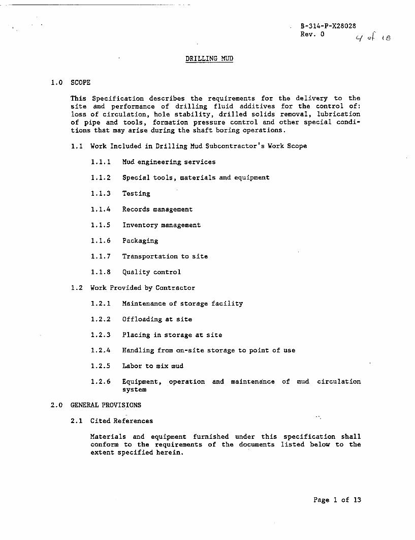
B-314-P-X28028Rev. 0
DRILLING MUD
1.0 SCOPE
This Specification describes the requirements for the delivery to thesite and performance of drilling fluid additives for the control of:loss of circulation, hole stability, drilled solids removal, lubricationof pipe and tools, formation pressure control and other special condi-tions that may arise during the shaft boring operations.
1.1 Work Included in Drilling Mud Subcontractor's Work Scope
1.1.1 Mud engineering services
1.1.2 Special tools, materials and equipment
1.1.3 Testing
1.1.4 Records management
1.1.5 Inventory management
1.1.6 Packaging
1.1.7 Transportation to site
1.1.8 Quality control
1.2 Work Provided by Contractor
1.2.1 Maintenance of storage facility
1.2.2 Offloading at site
1.2.3 Placing in storage at site
1.2.4 Handling from on-site storage to point of use
1.2.5 Labor to mix mud
1.2.6 Equipment, operation and maintenance of mud circulationsystem
2.0 GENERAL PROVISIONS
2.1 Cited References
Materials and equipment furnished under this specification shallconform to the requirements of the documents listed below to theextent specified herein.
Page 1 of 13

B-314-P-X28028Rev. 0
MAGCOBAR DIVISION, DRESSER INDUSTRIES
Drilling Fluids Handbook, 1981
API, American Petroleum Institute
Spec. 13A-79, Specification for Oil Well Drilling Fluid Materials
RP 13B-82, Standard Procedures for Testing Drilling Fluids, 1982
Bul 13F-78, Bulletin on Oil and Gas Well Drilling Fluid Chemicals
2.2 Drawings and Attachments
2.2.1 Drawings
Drawings (if any) listed in the "Purchase Order" are part ofthis Specification.
2.2.2 Attachments
The following listed attachment is incorporated as a part ofthis specification.
Appendix A Bidder and Seller InformationRequirements
2.3 Definitions
2.3.1 Annular
Ring-shaped. The space between casing and the wall of thehole or between drill pipe and casing is an annular space.
2.3.2 Attapulgite Clay
Clay mineral characterized by rod or lath shaped crystals.Used primarily for increasing fluid viscosity in saltsolutions.
2.3.3 Barite-Barytes-Heavy Spar
Natural barium sulphate. Occurs in white, grayish, green-ish, and redish ores or crystalline masses.
2.3.4 Bentonite
A highly plastic, highly colloidal clay, largely made up ofthe mineral montmorillonite.
Page 2 of 13

B-314-P-X28028Rev. 0
2.3.5 Boring
Synonumous with the term drilling.
2.3.6 Centipoise (CP)
A unit of viscosity equal to 0.01 poise. A poise = 1 gram/sec cm. The viscosity of water at 200C is 1.005 centipoises.
2.3.7 Contractor
The organization responsible to the Owner for the construc-tion and construction management of the Exploratory Shaft,Phase I.
2.3.8 Detergent
Water soluble organic chemical used to emulsify oils, holdparticles in suspension and as a wetting agent.
2.3.9 Down Hole
The area from the collar or begining of the hole in the earthto its end or termination.
2.3.10 Drilled Solids
Particles of formation dislodged by the drill bit that areentrained in the drilling fluid.
2.3.11 Drilling Fluid Additives/Mud
Chemicals and organic or inorganic additives used with water,brine or a similar fluid vehicle to control various para-meters of the down hole environment during both the activeand dormant phases of a hole boring program.
2.3.12 Filter Cake Thickness/Filtration Property
The measure of the thickness of the filter cake deposited bya drilling fluid against a porous medium. Cake thicknessand filtrate loss constitute the determining factors of fil-tration property.
2.3.13 Gel
A colloidal suspension in such a state that shearing stressesbelow a certain finite value fail to produce permanent defor-mation. The minimum shearing stress that will produce perma-nent deformation is known as the Shear or Gel Strength ofthe gel. Gels commonly occur when the dispersed colloidalparticles have a great affinity for the dispersing medium.Gels commonly occur with bentonite in water.
Page 3 of 13

B-314-P-X28028Rev. 0
2.3.14 Lost Circulation Material
Plugging agent added to the drilling fluid for the purposeof plugging pores on voids in the geologic formations tocontrol excessive circulation loss.
2.3.15 Mud Engineer
A specialist in the testing, preparation, design, applica-tion, use and treatment of drilling fluids and those organicand inorganic materials which are used to supplement and/orenhance these fluids for the purpose of advancing and sup-porting a bored hole in a rock or mineral medium. He willbe a representative of the Subcontractor. The Mud Engineershall be responsible for the administration of the drillingfluids program specified herein.
2.3.16 Owner
The U.S. Department of Energy (DOE) or its appointedrepresentative.
2.3.17 Plastic Viscosity
The part of flow resistance in a mud which represents mech-anical friction (1) between solids in the mud, (2) betweenthe solids and the liquid which surrounds them, and (3) ofthe shearing of the liquid itself. Plastic viscosity ismeasured in centipoise.
2.3.18 Polymer
A substance composed of giant molecules that have been formedby the union of a considerable number of simple molecules.The number of simple molecules may vary from two to hundredsto thousands. The simple molecules (monomers) which poly-merize may be all alike or of many varieties.
2.3.19 Rheometer
Instrument used to measure Theological properties of a fluid;alternatively Fann VG meter.
2.3.20 Sand Content
Usually expressed as the percentage bulk volume Qf sand in adrilling fluid.
2.3.21 Sepiolite Clay
Chain-lattice clay mineral often occurring in fibrous mattedcrystals. Use to increase fluid viscosity.
Page 4 of 13
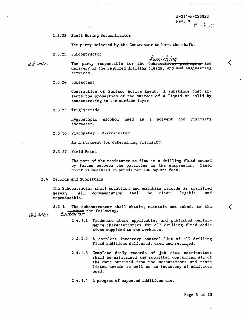
B-314-P-X28028Rev. 0
2.3.22 Shaft Boring Subcontractor
The party selected by the Contractor to bore the shaft.
2.3.23 Subcontractor
The party responsible for the furnishing packaging anddelivery of the required drilling fluids, and mud engineeringservices.
2.3.24 Surfactant
Contraction of Surface Active Agent. A substance that af-fects the properties of the surface of a liquid or solid byconcentrating in the surface layer.
2.3.25 Triglyceride
Hygroscopic alcohol used as a solvent and viscosityincreaser.
2.3.26 Viscometer - Viscosimeter
An instrument for determining viscosity.
2.3.27 Yield Point
The part of the resistance to flow in a drilling fluid causedby forces between the particles in the suspension. Yieldpoint is measured in pounds per 100 square feet.
2.4 Records and Submittals
The Subcontractor shall establish and maintain records as specifiedherein. All documentation shall be clear, legible, andreproducible.
2.4.1 The subcontractor shall obtain, maintain and submit to thethe following.
2.4.1.1 Tradename where applicable, and published perfor-mance characteristics for all drilling fluid addi-tives supplied to the worksite.
2.4.1.2 A complete inventory control list of all drillingfluid additives delivered, used and returned.
2.4.1.3 Complete daily records of job site examinationsshall be maintained and submitted containing all ofthe data obtained from the measurements and testslisted herein as well as an inventory of additivesused.
2.4. 1.4 A program of expected additives use.
Page 5 of 13

B-314-P-X28028Rev. 0
2.5 Nonconforming Conditions
The Subcontractor shall identify each nonconforming condition rela-tive to this Specification and shall notify the Contractor of eachsuch condition. Disposition to "Use as supplied" or to "replace"for each nonconforming condition shall require approval by the Owneras a condition of acceptance of the additives in question.
3.0 TECHNICAL PROVISIONS
3.1 Components
3.1.1 Dry Additive Components
Dry components which may include bentonite, attapulgite clayand sepiolite clay shall conform to the specifications inAPI 13A and API 13F.
3.1.2 Fluid Additive Components
Fluid components which may include surfactants, polymers,detergents, triglycerides and alcohols shall conform tospecifications in API 13F and in the absence of specificguidelines, the Subcontractor and Owner shall develop agree-ments as to individual content, quality and reliabilityprior to shipment and delivery.
3.1.3 Other Additive Components
Any components not mentioned above shall conform to specifi-cations agreed to by the Subcontractor and Owner prior toshipment and delivery.
3.2 Manufacturing
Manufacturing procedures with regard to blending, volume percentcontent by individual ingredient and packaging shall conform toAPI 13F.
3.3 Quality Control
3.3.1 Purity
Purity of all additive ingredients shall be maintained inaccordance with API bulletins 13A and 13F.
3.3.2 Formula Control
The volume percent content of individual additive ingredi-ents shall not exceed ± 5 percent of that shown in the ge-neric additive formula provided to the Contractor. Pro-prietary formulas will be exempt from this requirement if a
Page 6 of 13

B-314-P-X28028Rev. 0
certification by the Subcontractor as to the conformity ofthe proprietary product to the above ±5 percent tolerance isprovided.
3.4 Identification
All containers and packages used for the delivery and storage ofdrilling fluids additives shall be marked with product name andweight or volume, to aid in the tracking and inventory of alladditives delivered and consumed.
4.0 ADDITIVES EXAMINATION
4.1 Testing Methods
All tests shall be conducted in accordance with the procedures out-lined in API Bulletins 13A and 13B. These tests shall be performedon those additives and their components designated in the drillingfluids program; all prior to their mixture for use during drilling.Records shall be maintained and submitted to the Owner.
4.2 Specific Tests and Criteria
The particular additive components: bentonite, attapulgite clay andsepiolite clay, if required, shall conform to those requirements setforth in API Bulletin 13A.
5.0 PACKAGING, HANDLING, SHIPPING AND STORAGE
5.1 Packaging
All packaging used to contain, store or transport drilling fluidadditives shall conform to API bulletin 13A and to manufacturer'sstandard packaging procedures. Packaging shall be designed for safetransport, handling and storage and shall prevent accidental damageand contamination under the conditions of this project. Hazardousmaterials shall appropriately marked and stored and data sheetsdefining emergency first aid procedures shall be available at thesite.
5.2 Container Protection
Substantial protection in the form of plastic shrouds, tarps orsimilar shall be used to protect all additives from the weather.
5.3 Content
Each bag or other additive container shall contain the net weightmarked thereon ± 5 percent. The average weight of 5 percent of allbags in a shipment taken at random, shall not be less than the spec-ified weight.
Page 7 of 13
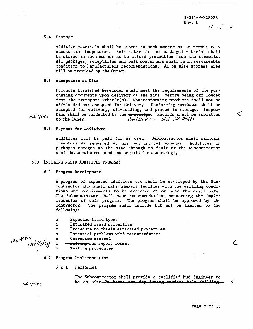
B-314-P-X28028Rev. 0
5.4 Storage
Additive materials shall be stored in such manner as to permit easyaccess for inspection. Bulk materials and packaged material shallbe stored in such manner as to afford protection from the elements.All packages, receptacles and bulk containers shall be in serviceablecondition to Manufacturers recommendations. An on site storage areawill be provided by the Owner.
5.5 Acceptance at Site
Products furnished hereunder shall meet the requirements of the pur-chasing documents upon delivery at the site, before being off-loadedfrom the transport vehicle(s). Non-conforming products shall not beoff-loaded nor accepted for delivery. Conforming products shall beaccepted for delivery, off-loading, and placed in storage. Inspec-tion shall be conducted by the Inspector. Records shall be submittedto the Owner.
5.6 Payment for Additives
Additives will be paid for as used. Subcontractor shall maintaininventory as required at his own initial expense. Additives inpackages damaged at the site through no fault of the Subcontractorshall be considered used and be paid for accordingly.
6.0 DRILLING FLUID ADDITIVES PROGRAM
6.1 Program Development
A program of expected additives use shall be developed by the Sub-contractor who shall make himself familiar with the drilling condi-tions and requirements to be expected at or near the drill site.The Subcontractor shall make recommendations concerning the imple-mentation of this program. The program shall be approved by theContractor. The program shall include but not be limited to thefollowing:
o Expected fluid typeso Estimated fluid propertieso Procedure to obtain estimated propertieso Potential problems with recommendation
Corrosion controlDriving mud report format
o Testing procedures
6.2 Program Implementation
6.2.1 Personnel
The Subcontractor shall provide a qualified Mud Engineer tobe on site 24 hours per day during surface hole drilling,
Page 8 of 13

B-314-P-X28028Rev. 0
and on site or on call 24 hours per day at the discretion ofand upon request by the Contractor, during other drilling,casing running or cementing operations.
6.2.2 Supply of Material
The completed program shall be examined by the Subcontractorand the Contractor to develop a minimum inventory of addi-tives for initial stocking at the site. The Mud Engineershall monitor the use of materials and make recommend stock-ing of additional material as required, for the Contractor'sapproval.
6.2.3 Changes in Mud Program
The Mud Engineer shall monitor the performance of the drill-ing fluid, including the maintenance of fluid properties andindications of circulation loss, and shall make recommen-dations regarding the make-up of the drilling fluid asrequired or requested by the Contractor, for the Contractor'sapproval.
7.0 FLUID LOSS AND CAVING CONTROL
7.1 In the event of excessive drilling fluid loss in the borehole, andafter reasonable efforts have been expended to stop or reduce thefluid loss by means of lost circulation materials, the Contractormay direct the placement of a cement plug in the borehole.
7.2 In the event of excessive hole instability or caving, and afterreasonable efforts have been expended to maintain hole stability byuse of drilling fluid additives, the Contractor may direct theplacement of a cement plug in the borehole.
7.3 The placement of a cement plug in the borehole would be performed by othersunder the provisions of the Casing Cementing Specification(B-314-C-X28048).
8.0 JOB SITE EXAMINATIONS
In support of the drilling fluid additives program, the data described inSection 8.1 data shall be determined and collected by the Mud Engineerduring all phases of active hole boring. Testing and measurements shallalso include selected tests from section 8.2 as required and authorized.A record of such tests shall be submitted to the Contractor. All toolsand equipment required for testing shall be provided by the Subcontractor.The method of execution for each test can be found in either the MagcobarDivision of Dresser Industries Drilling Fluid Handbook or the appropriateAPI publication unless the method is inherently obvious.
Page 9 of 13

B-314-P-X28028Rev. 0
In addition to the tests and measurements described in Section 8.1 and8.2, which may be submitted on the Subcontractor's standard daily drillingmud report form, the Subcontractor shall report any abnormal conditionsor problems, including period circulation losses, and measures taken toremedy such conditions.
8.1 Daily Job Site Tests and Measurements
8.1.1 Location
The location from which the drilling fluid sample is takenwheather flow line, pit or tank shall be noted.
8.1.2 Time
The time of sampling shall be recorded. This time of sam-pling shall be at or near the same hour each day.
8.1.3 Temperature
The temperature of the drilling fluid sample shall berecorded along with all other tests and measurements. Thetemperature shall be recorded in degrees Fahrenheit.
8.1.4 Depth
The bore hole depth shall be measured from the collar atground level and shall be recorded at 6:00 a.m. each day.
8.1.5 Weight
The weight of the circulating drilling fluid shall be mea-sured in pounds per gallon (ppg) with a mud balance scale.
8.1.6 Viscosity (Marsh Funnel Test)
Viscosity tests on the circulating fluid shall be conducteddaily using the Marsh Funnel Viscometer.
8.1.7 Water Loss
Water loss (filtration property) shall be measured dailyusing a standard filter press device.
8.1.8 Filter Cake
Filter cake thickness shall be measured daily and shall bedefined as the thickness of residual solids on the filterpaper following the filter press water loss determination.
Page 10 of 13

B-314-P-X28028Rev. 0
8.1.9 pH
pH readings shall be recorded daily using an approved pHmeter.
8.1.10 Gel Strength
During operation, the design mix as well as the fluid in useshall be tested.
Two gel strength values are to be recorded daily: first, aninitial measurement and second, a ten minute measurement.Both measurements shall be recorded using a rheometer.
8.1.11 Percent Solids
Percent solids shall be recorded daily using a retort kitand appropriate formula.
8.1.12 Percent Sand
The sand content of the drilling fluid shall be recordeddaily using a sandscreen analysis set.
8.1.13 Chemical Analysis
Specific individual chemical analysis shall be selected, asrequired, by the Mud Engineer, for performance on a dailybasis.
8.1.14 Plastic Viscosity
Plastic viscosity shall be recorded daily with a Fann V-Gmeter or its equivalent.
8.1.15 Yield Point
Yield point shall be recorded daily with a Fann V-G meter orits equivalent.
8.2 Other Job Site Tests and Measurements
The following tests and measurements may be conducted on an "asneeded" basis as recommended by the Mud Engineer and authorized bythe Contractor.
8.2.1 Resistivity
Resistivity shall be measured in ohm-meters. The sampletemperature shall be recorded for correction purposes.
Page 11 of 13

B-314-P-X28028Rev. 0
8.2.2 Emulsion Stability
The stability of emulsions of water in oil shall be measuredusing an emulsion tester.
8.2.3 Chemical Analysis
The drilling fluid may be subject to the following chemicalanalyses which have proved useful in the engineering ofdrilling fluids (procedures for each of these can be foundin API RP 13B):
a. Chloride
b. Alkalinity and Lime Content
c. Alternate filtrate alkalinity
d. Total hardness
e. Calcium
f. Cation exchange capacity
g. Soluable carbonates in water based fluids
8.2.4 Corrosion
Corrosion shall be measured by means of test coupons in-stalled on the air pipe and the bit body and then visuallyexamined after an API-specified period of time, or by otherapproved method.
8.2.5 Lubricity
Lubricity, if required, shall be measured with suitableequipment as described in the Magcobar Division of DresserIndustries Drilling Fluid Handbook.
8.3 Objectives
The tests and measurements outlined under 8.1 and 8.2 above shall beconducted to provide support for the developed drilling fluid pro-gram and to detect and eliminate any problems that may arise duringthe shaft boring operation.
Page 12 of 13

B-314-P-X28028Rev. 0
9.0 OPERATING DRILLING FLUID SYSTEM
The system for cleaning and maintaining the drilling fluid will be anopen pit, gravity settling system. It will be provided, operated andmaintained under the provisions of Specification No. B-314-C-X28018,Shaft Drilling and Rig Services. The Subcontractor shall assist in thedesign of the circulation system and shall review the system for adequacy.The system shall be subject to approval by the Contractor.
BWSPO1B: 2/3/83
Page 13 of 13
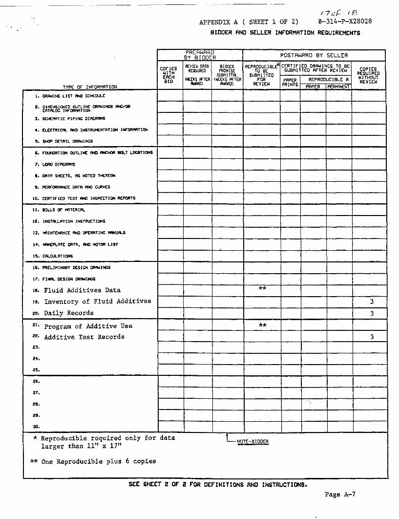
17of18APPENDIX A ( SHEET 1 OF 2) B-314-P-X28028
BIDDER AND SELLER INFORMATION REQUIREMENTS
[COULD NOT BE CONVERTED TO SEARCHABLE TEXT]
[Page A-7

APPENDIX A (SHEET 2 OF 2) B-314-P-X28028DEFINITIONS
1. DRAWING LIST AND SCHEDULE A complete list of all drawings and data by titlethat the Bidder expects to furnish on this order. Schedule to show, in weeksafter award, submittal of each type of review and certified drawings.
2. DIMENSIONED OUTLINE DRAWINGS AND/OR CATALOG INFORMATION Drawings to scale show-ing the relative size, configuration, and location of all material to be fur-nished. Show two or more views of unit, clearances and area required foroperation and maintenance. Show unit in relation to nearby structures and otherequipment or operating floor, location of utility connections and direction ofrotation, If applicable. When submitting data for off the shelf"equipment/materials, catalog cuts and information are acceptable provided theyare submitted in ample detail.
3. SCHEMATIC PIPING DIAGRAMS Show equipment to be interconnected, flow quantities,pipe sizes, valves and instruments.
4. ELECTRICAL AND INSTRUMENTATION INFORMATION Show all data pertaining to instru-mentation, control and power electrical equipment. Include "one-line,"elementary" wiring, panel interior wiring and exterior interconnection wiring,dimensioned outlines of enclosures with raceway entries shown.
5. SHOP DETAIL DRAWINGS Show all necessary details and data required for fabrica-tion and maintenance. For structural details show all connections and membersizes.
6. FOUNDATION OUTLINE AND ANCHOR BOLT LOCATIONS Show all data required for founda-tion design including location, blockouts, embedded items, grout required, andsize, type and projection of anchor bolts.
7. LOAD DIAGRAMS Show total static and dynamic loads and load centers.
8. DATA SHEETS Sheets shall be completed for the equipment proposed with all in-formation noted thereon.
9. PERFORMANCE DATA AND CURVES
10. CERTIFIED TEST AND INSPECTION REPORTS Reports by recognized commercial labora-tories of indicated chemical and physical tests of materials as required by thespecifications. In addition where applicable, weld inspection and stressrelieving records and code nameplate rubbings shall be furnished.
11. BILLS OF MATERIAL Show for each unit: item no., shop order no., mark or name,part no., or pattern no., and drawing reference.
12. INSTALLATION INSTRUCTIONS Complete, detailed and sequenced instructions fororiginal installation and for removals and replacements as well as erectioninformation.
13. MAINTENANCE AND OPERATING MANUALS Complete installation, starting and operatinginstructions. Complete descriptions of preventive and repair maintenance,including detailed lubrication chart showing every lubrication point, grade oflubricant, lubrication schedule and amount of oil or grease required for refillafter drainage. Manuals include parts list with recommended spares.
14. NAMEPLATE DATA AND MOTOR LIST
I5. CALCULATIONS Shall be checked and stamped by a registered professionalengineer, licensed to practice in the state where installation occurs.
16. PRELIMINARY DESIGN DRAWINGS Seller provided design services such as pre-engineered buildings, silos and other structures, conveyor systems, bins andchute design, large ductwork and supports.
17. FINAL DESIGN DRAWINGS Same as Item No. 16.
INSTRUCTIONS
1 DIMENSIONS Shown on all but schematic drawings and diagrams shall be in feetand inches, unless noted otherwise.
2. CERTIFIED DRAWINGS Shall be so marked by Seller. They shall conform toSeller's drawings as finally accepted by the Purchaser and shall be forwarded atcommencement of manufacture. The drawings shall be revised and resubmitted toreflect any changes approved during the manufacturing period.
3. REPRODUCIBLE PERMANENT PRINTS Shall be cloth, Chronaflex", or "Mylar" Theyshall depict the material as shipped and shall be forwarded upon completion ofshipment.
4. EQUIPMENT NUMBERS Shall be used for reference and identifica-tion of the units on all data required hereunder.
Page A-2
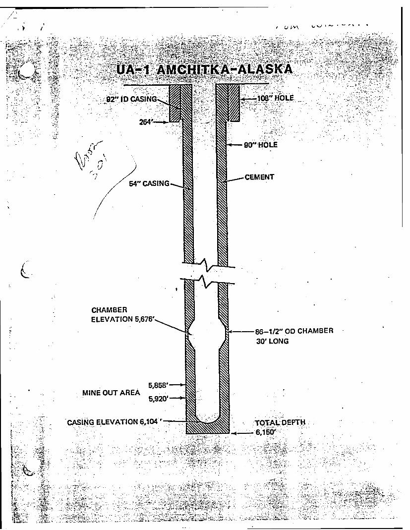
[could not be converted to searchable text]
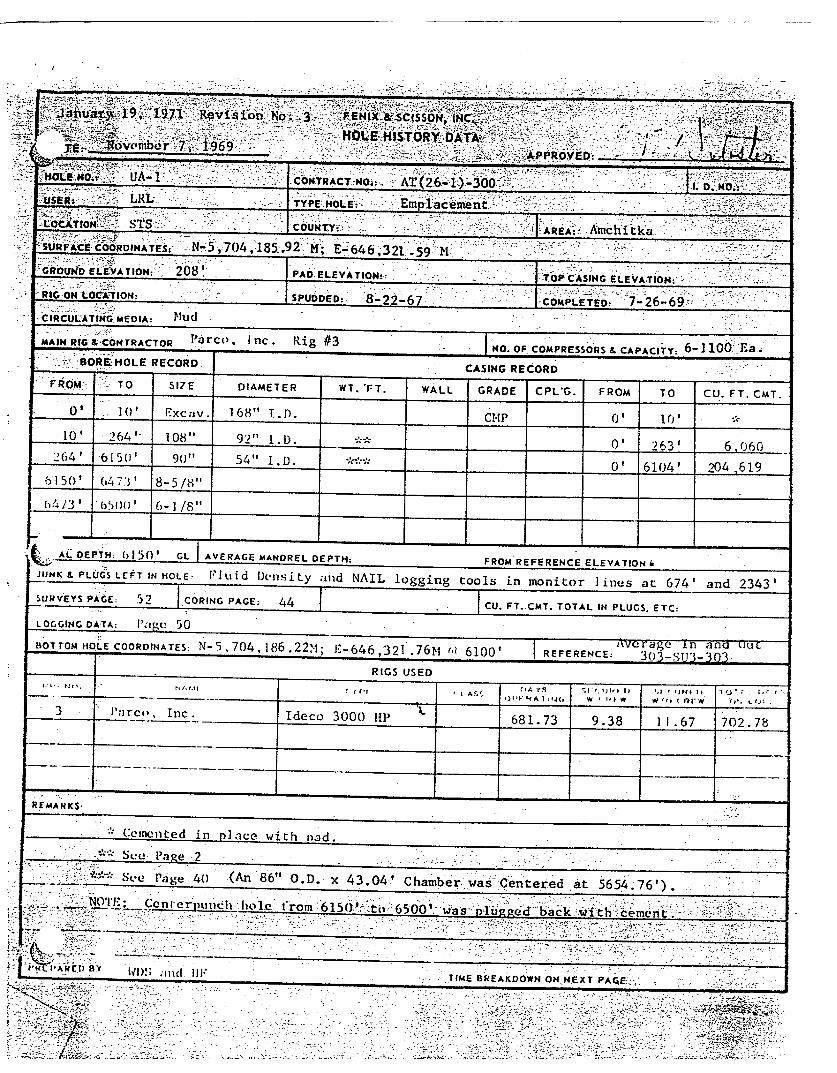
[COULD NOT BE CONVERTED TO SEARCHABLE TEXT]

[COULD NOT BE CONVERTED TO SEARCHABLE TEXT]

[COULD NOT BE CONVERTED TO SEARCHABLE TEXT]
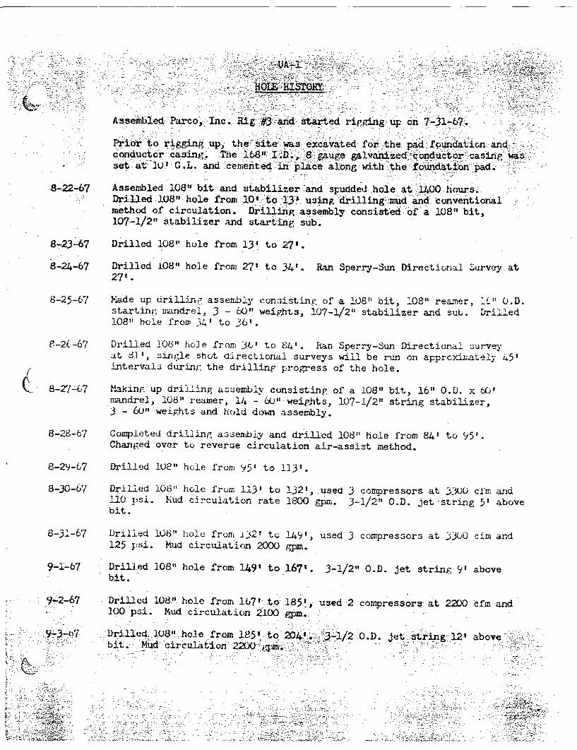
[COULD NOT BE CONVERTED TO SEARCHABLE TEXT]

[COULD NOT BE CONVERTED TO SEARCHABLE TEXT]

[COULD NOT BE CONVERTED TO SEARCHABLE TEXT]

[COULD NOT BE CONVERTED TO SEARCHABLE TEXT]

[COULD NOT BE CONVERTED TO SEARCHABLE TEXT]

11-12-67 Drilled 90" hole from 1576' to 1590'.
11-13-67 Drilled 90"1 hole from 1590 to 1611.
11-14-67 Drilled 90" hole from 1611 to 1636'. Air pressure 150 psi.
11-15-67 Drilled 90" hole from 1636' to 1646'.
11-16-67 Ran bit #11 at 1646'. Drilled 90" hole from 1646' to 1648'. Airpressure 105 psi, 3-1/2" O.D. jet string length 256'.
11-17-67 Drilled 90" hole from 1648' to 1666'. Air pressure 105 psi to 140 psi.3-1/2" O.D. Jet string length changed to 346'.
11-18-67 Drilled 90" hole from 1666' to 1696'.
C. 11-19-67 Drilled 90" hole from 1696' to 1718'.
11-20-67 Drilled 90" hole from 1718' to 1744'.
11-21-6c7 Drilled 90" hole from 1744' to 1767'. Air pressure 170 psi. >-1/2"O.D. jet string length 437'.
11-22-67 Drilled 90 " hole from 1767' to 1780'. Ran bit #2 at 1780', had 1'of fill on trip. Air pressure 180 psi.
11-23-67 Drilled 90" hole from 1780' to 1796'.
11-24-67 Drillea 90" hole from 1796' to 1820'. Used 2 compressors 170 to 180psi and 2200 cfm. Mud circulation rate 3220 gpm. 3-1/2" O.D. jetstring length 437'.
11-25-67 Drilled 90" hole from 1820' to 1845'.
11-26-67 Drilled 90" hole from 1845' to 1853'. Cleaned out pump suctions andmanifolds.
11 27-67 Drilled 90" hole from 1853' to 1856'. Cleaned out mud pits and pumpsuctions.

[could not be converted to searchable text]

[could not be converted to searchable text]
12-27-67

UA-lHole. History
Drilled 50" hole from 2753' to 27641. Ran bit #18 at 2755', had Ie offill on trip. Used 3 to 5 compressors at 3300 cfm to 5500 cfm and 200psi to 240 psi. Mud circulation rate 3525 gpm. .3-1/2" O.D. Jet stringlength 533'.
1-11-68
1 -12-68
1 -13-68
Drilled 90" hole from 2764' to 2788'. Air pressure 240 psi to 245 psi,mud circulation rate 3570 gpm.
Drilled 90" hole from 2788' to 2811'.
Drilled 90" hole from 2811' to 2833'.
Drilled 90" hole from 2833' to 2855'.
Drilled 90"s hole from 2855' to 2872', started losing mud, estimatedfluid 1oss 15,000 barrels. Mixed lost circulation materials. Fluidloss was 29 inches per minute with pumps off.
Mixed mud and lost circulation materials. Fluid level dropped 24in 5-1/2 hours.
1-17-68 Ran drilling assembly in hole (bit #19), cleaned out 5' of fill andbit plugged. Losing fluid at 1-3/4 barrels per minute. Buildingmud volume.
1-18-68 Drilled 90" hole from 2872' to 2875', drilling on boulders, bitplugging. Used 3 compressors at 3300 cfm and 190 psi to 200 p3i.Mud circulation rate 3000 gpm. 3-1/2" O.D. jet string length 533'.Drilled 90" hole from 2875' to 2879', drilling on boulders, bitplugging. No fluid lost at 1800 hours.
Drilled 900" hole from 2879' to 2884', drilling on boulders, bitplugging. Changed from 3 to 2 compressors at 2200 cfm and 200.psi.Lost 1000 barrels of mud in 12 hours at 0600 hours.
Drilled 90" hole from 28848 to 2889, drilling on boulders, bitplugging. Mud circulation: rate 2700 gpm.

UA-1Hole History
[could not be converted to searchable text]

[could not be converted to searchable text]

Hole history
[could not be converted to searchable text]
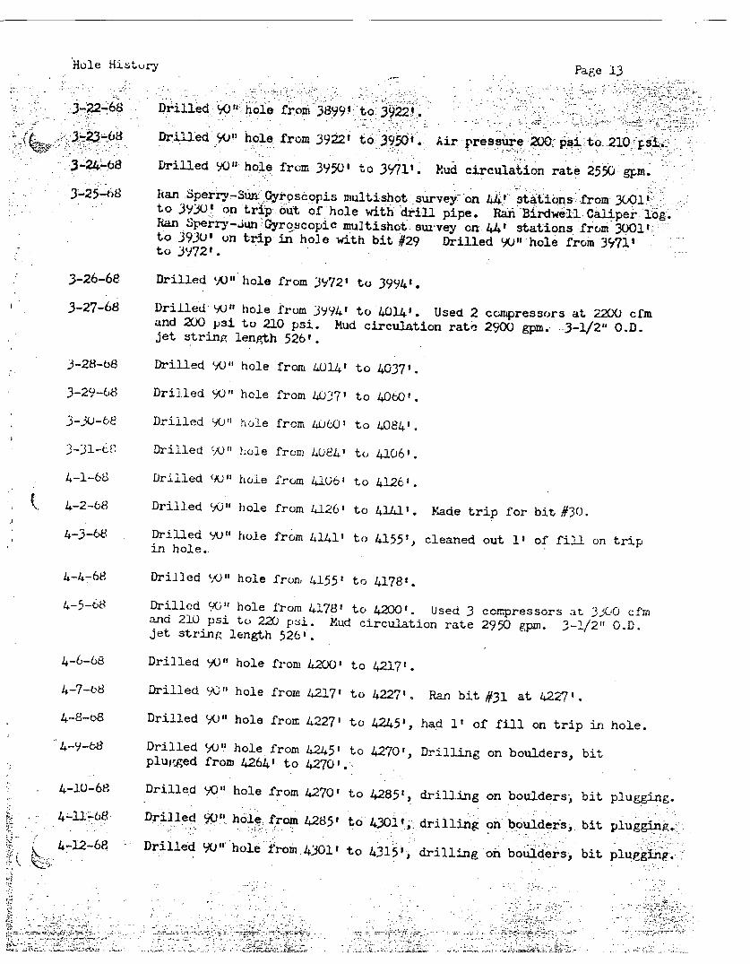
Hole History Page 13
3-22-68 Drilled 90" hole from 3899' to 3922'.
[could not be converted to searchable text]

UA-1hole history
ran bit #32 at 4315', :cleaned out 4' of fill. Drilled 90" hole from4315' to 4319'.
Drilled 90" hole from 4319' to 4334', bit plugging.Drilled 90" hole from 4334' to 4349', drilling on boulders, bitplugging.
Drilled 90" hole from 4349' to 4367.'.
Drilled 90" hole from 4367' to 4380', drilling on boulders, bitplugging.
Drilled 90" hole from 4380' to 4391'. Ran bit #33 at 4391', cleanedout 4' of fill on trip.
Cleaned out fill and drilled 90" hole from 4391' to 4406'.Drilled 90" hole from 4406' to 4427', drilling on boulders, bit. pluggingDrilled 90" hole from 4427' to 4436', bit pluggin.. Boulders fell inhole while drilling at 4435'. had 2' of fill.Cleaned out fill and unplugged bit. Drilled 90- hole from 436,' to4451'.
Drilled 90" hole from 4451' to 4468', drilling on boulders between4464' and 4468.'. Used 3 compressors at 3300 cfm and 210 psi to 220psi. Mud circulation rate 2050 gpm. 3-1/2" 0.D. jet string length526'.

Hole History.
[COULD NOT BE CONVERTED TO SEARCHABLE TEXT]
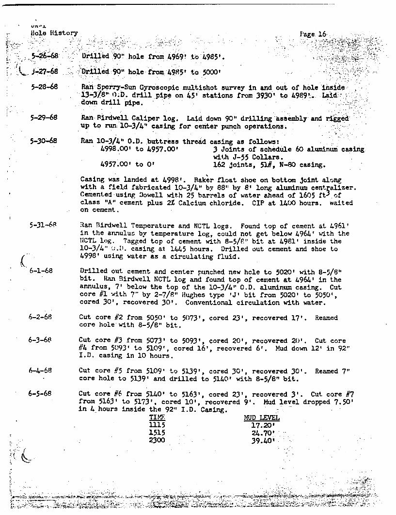
Hole History
Casing was landed at 4998'. baker float shoe on bottom joint alongwith a field fabricated 10-3/4" by 88' by 8' long aluminum centralizer.Cemented using Dowell with 25 barrels of water ahead of 1605 ft 3 ofclass "A" cement plus 2Z Calcium chloride. CIP at 1400 hours. waitedon cement.
Ian Birdwell Temperature and NCTL logs. Found top of cement at 4961'in the annulus by temperature log, could not get below 4964' with the
NCTL log. Tagged top of cement with 8-5/8" bit at 4981' inside the10-3/4" 0.0. casing at 1445 hours. Drilled out cement and shoe to4998' using water as a circulating fluid.
Drilled out cement and center punched new hole to 5020' with 8-5/8"bit. Ran Birdwell NCTL log and found top of cement at 4964' in theannulus, 7' below the top of the 10-3/4" O.D. aluminum casing. Cutcore #1 with 7" by 2-7/8" Hughes type 'J' bit from 5020' to 5050',cored 30', recovered 30'. Conventional circulation with water.
Cut core #2 from 5050' to 5073', cored 23', recovered 17'. Reamedcore hole with 8-5/8" bit.
Cut core #3 from 5073' to 5093', cored 20', recovered 20'. Cut core#4 from 5093t to 5109', cored 16', recovered 6'. Mud down 12' in 92"I.D. casing in 10 hours.
6-1-68
6-2-68
6-3-68
6-4-68
6-5-68
Cut core #5 from 5109' to 5139', cored 30', recovered 30'.core hole to 5139' and drilled to 5140' with 8-5/8" bit.
Reamed 7"
Cut core #6 from 5140' to 5163', cored 23', recovered 3'. Cut core #7from 5163' to 5173', cored 10', recovered 9'. Mud level dropped 7.50'in 4 hours inside the 92" I.D. Casing.

UA-1Hole History0
Page 17[could not be converted to searchable text]


[could not be converted to searchable text]

[could not be converted to searchable text]


Cleaned out bridges at 4644', cleaned out fill to top of cement at 4921',drilled cement and casing from 4921' to 4931', casing shot off at 4925'.Used air assist reverse circulation with mud.
Drilled cement and 10-3/411 O.D. casing from 4931' to 49541.
Pulled bit to unplug, made repairs to rotary beam and ran back in hole.
Measured in hole and made 5' depth correction, cleaned out fi11 from 4956'to 4960', drilled cement and 10-3/4" O.D. casing from 4960' to 4981' with90" bit.
Drilled cement and 10-3/4" casing from 4981' to 5000' and new hole from5000' to 5007', with 90" bit.
Ran tit #43, cleaned out 3' of fill and drilled 90" hole from 5007' to5019)'. Circulated 2950 grpm mud and 3300 cfm air at 200 psi using 3
compressors 3-1/2" O.D. jet string length 530'.
8-19-68
8-22--68
[could not be converted to searchable text]

Page 23
[could not be converted to searchable text]
]

UA-1Hole History Page 24
(/-19-68 Drilled 8-5/8" hole from 5760' to 5894', had 19' of fill after bit changeat 5818'.
9-20-68 Drilled 8-5/8" hole from 5894' to 5940'. Ran Sperry-Sun survey to checkbottom hole location. Ran Birdwell Caliper log and started hydrologicaltesting.
9-21-68 Completed hydrologic test, cleaned out 31 of fill and cut core #75 using6-1/8" Willisms Diamond bit from 5940' to 59601, cored 20t, recovered 201.Cut core #76 from 5960' to 5965'.
9-22-68 Core #76, cored 5', recovered 51. Cut core #77 from 5964', cored 10',recovered 81. Cut core #78 from 59743 to 59793, cored 5', recovered 53.Cut core #79 from 5979' to 5988', cored 9', recovered 9'. Reamed 6-1/8"core hole from 5940' to 5944' with 8-5/8" bit.
9-23-68 Reamed core hole to 5980' with 8-5/8" bit, cut core #80 from 5988' to 60121,cored 24', recovered 4-1/2X. Cut core #81 from 6012' to 6025', cored '13',recovered 13'.
9-24-68 Cut core #82 from 6025' to 6032', cored 7', recovered 7'. Correctedmeasurements and cut core #83 from 6033' to 6039', cored 6', recovered6'. Reamed 6-1/8" core hole to 6039' with 8-5/8" bit.Deviation Survey: 3/4° at 6038'.
9-25-08 Cut core #84 from 6039' to 6048', cored 9', recovered 9'. Cut core #85from 6048' to 6060', cored 12', recovered 12'. Cut core #86 from 6060'to 6063', cored 3', recovered 11. Cut core #87 from 6063' to 6065'.
9-26-68 Completed core #87 from 6065' to 6090', cored 27', recovered 27'. Cutcore 1/88 from 6090' to 6107', cored 17', recovered 17'. Reamed 6-1/8"core hole to 6107' with 8-5/8k' bit.
09 -27-68 Ran Sperry-sun survey. Ran Birdwell Caliper log and started hydrologicLest.Deviation survey: 1/2* at 6107'.
9-28-68 completed test and cut core #89 from 6107' to 6110', cored 3', recovered2-1/:'. Cut core #90 from 6110' to 6130'.
9-29 -68 Core #90, cored 20', recovered 20'. Cut core #91 from 61301 to 6146'.
Core #91 cored 16', recovered 15'. Cut core /92 from 6146' to 6157',cored 11', recovered 11'. Reamed 6-1/8" core hole to 8-5/8" to 6157'.
10-1-68 Cut core #93 from 6157' to 6166', cored 9', recovered 8-1/2'. Cut core#94 from 6166' to 61761, cored 10', recovered 10'. Cut core ;95 from
6176' to 61 84', cored 8' recovered 7'.Deviation survey: 1/20 at 6156'.

Hole History[COULD NOT BE CONVERTED TO SEARCHABLE TEXT]
[

UA-IHole History Page 26
10-14-68 Reamed core Sole to 6369' with 8-5/8" bit. Cleaned out 4' of fill andcut core #115 from 6369' to 6377', cored 81, recovered 8'. Cut core #116
FROM 6377' to 6389'.
10-15-68 completed core #116 from 6389' to 63931, cored 16', recovered 16'. Cutcore #117 from 6393' to 6413', cored 20', recovered 12-1/2'. Reamed6-1/8" core hole to 8-5/8" from 6369' to 6407'.
10-16-68 Completed reaming core hole to 64131 with 8-5/8" bit. Cut core #118 from6413' to 6430', cored 17', recovered 17'. Cut core #119 from 6430' to6437'. Deviation survey: 1/20 at 64131.
10-17-68 Core #119, cut 7' recovered 7'. Reamed 6-1/8" core hole to 6437' with8-5/8" bit. Cut core #120 from 6437' to 6453', cored 16', recovered 5'.
10-18-68 Cleaned out 12' of fill and cut core #121 from 6453' to 6473 ' , cored 20',recovered 2-1/2'. Reamed 6-1/8" core hole to 6473' with 8-5/8" bit.
Fluid level in annulus at 150'.Deviation survey: 1/2° at 6473'.
1-19-68 Cleaned out 10' of fill and cut core 1122 from 6473' to 6485 cored12', recovered 12'. Cut core #123 from 6485' to 6493', cored recovered
[couldnot be converted to searchable text]
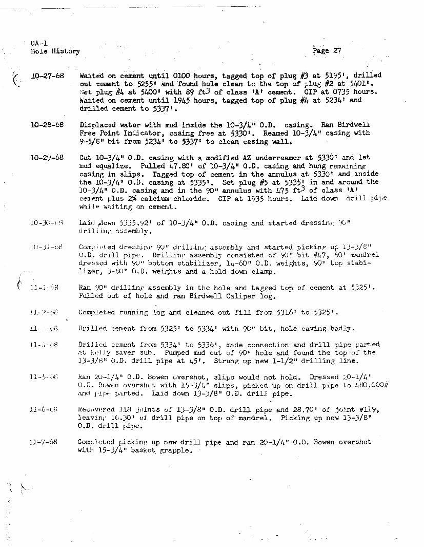
UA-lHole History Page 27
10-27-68 Waited on cement until 0100 hours, tagged top of plug #3 at 5195', drilledout cement to 5255' and-found hole clean te the top of plug #2 at 5401'.Set plug-#4 at 5400' with 89 £t3 of class "A" cement. CIP at 0735 hours.Waited on cement until 1945 hours, tagged top of plug #4 at 5234' anddrilled cement to 5337'.
10-28-68 Displaced water with mud inside the 10-3/4" O.D. casing. Ran BirdwellFree Point Indicator, casing free at 5330'. Reamed 10-3/4" casing with9-5/8" bit from 52341 to 5337' to clean casing wall.
10-29-68 Cut 10-3/4" O.D. casing with a modified AZ underreamer at 5330' and letmud equalize. Pulled 47.80' of 10-3/4" O.D. casing and hung remainingcasing in slips. Tagged top of cement in the annulus at 5330' and insidethe 10-3/4" O.D. casing at 5335'. Set plug #5 at 5335' in and around the10-3/4" O.D. casing and in the 90" annulus with 475 ft 3 of class 'A'cement plus 2% calcium chloride. CIP at 1935 hours. Laid down drill pipewhile waiting on cement.
10-30-68 Laid down 5335.92' of 10-3/4" O.D. casing and started dressing 90"drilling assembly.
00-30-68 completed dressing 90" drilling assembly and started picking up 13-3/8"O.D. drill pipe. Drilling assembly consisted of 90" bit #47, 60' mandreldressed with 90' bottom stabilizer, 14-60" O.D. weights, 90" top stabi-lizer, 3-60" O.D. weights and a hold down clamp.
- , Ran 90" drilling assembly in the hole and tagged top of cement at 5325'.Pulled out of hole and ran Birdwell Caliper log.
11-2-68 Completed running log and cleaned out fill from 5316' to 5325'.[COULD NOT BE CONVERTED TO SEARCHABLE TEXT]

UA-1Hole History Page 28
1-8-68 Tagged top of fish at 5226.44', did not attempt to latch-on. Pull out ofhole and left the following fishing tools in the hole, 1 -8O" 0.D. Bowenovershot skirt (5.51') 1 -20-3/8" O.D. overshot bowl (2.44') 1 -20", O.D.extension (31.55') extension had parted in a collar.
11-9-68 Ran 60" tar impresson block, tagged top of top fish at 5226.291. Topof bottom fish at 5257.20' indicating overshot is 61 down on bottomfish. Impresson block indicated fish may be laying off center.
11-10-68 Standby ready until 1600 hours and started in hole with 80" Globe basketon a bent joint of 13-3/8" O.D. drill pipe.
11-11-68 Rotated basket once on fish and fishing tools dropped 5' to 5231.291.Pulled out of hole, recovered fishing tools lost in hole.
11-12-68 Ran 20-1/4" Bowen overshot with 80" skirt, 15-3/4" control mill and 15-3/4"grapple. Tagged top of fish at 5265.99', could not catch fish.
11-1)-O8 Pulled out of hole, no recovery. Started running. Globe basket modifiedinto a milling tool.
11 -14-68 SHut down because of high winds.
ll-15-68 Rig repairs. Completed going in hole with modified Globe basket.Tagged top of fish at 5265.11', milled on fish from 5265' to 5272'and started out of hole.
11 -16-68 Completed trip out of hole, ran 20-1/4" O.D. Bowen overshot. Went overfish at 5270.73', rotated tools and Went to 5274.03'. Pulled out ofhole, no recovery. Some indication of tools going by fish on the out-side of the 80" O.D. skirt.
12 -17-68 Ran 20-1/4" O.D. Bowen overshot with 56" O.D. skirt, unable to locatefish. Went to 5304.93' before taking weight. Pulled out of hole, over-shot appeared to have gone to the retainer clamp on the mandrel.
l1-18-68 ran 20-1/4" O.D. Bowen overshot with 80" skirt and 13-3/8" box grapplewith 13-3/8" mill control guide, skirt dressed with tungsten carbide.Ran fishing tools to top of fish at 5265.11'. Set down to 5269.93' with150,O000 of weight. Skirt showed no markings on the outside, showedmarks 2.80' up inside of the skirt, bottom had marks 1/2" wide by 1/4"deep.
ll-l9-68 ran 20-1/4" O.D. Bowen overshot with 20-1/2" skirt with 13-3/8" basketgrapple with 13-3/8" mill control guide on a bent joint of 13-3/8" O.D.drill pipe. Did not contact fish, went to 5303' before taking weight.ran 80" O.D. Globe basket with fingers removed and modified for milling.Milled on fish from 5265.11'.

UA-1Hole History Page 29
11-20-68 Milled on fish to 5281.41t. Pulled out of hole, bottom of mill grooved3/16" wide by 3/16" deep. Outside-flenge where tools bolted togetherwas polished without cuts. Some wear showed on tungsten carbide on theinside but no cuts. Shut down waiting on impression block.
11-21-68 Waited on impression block and ran 20-1/4" O.D. Bowen overshot with15-1/2" grapple with 15-3/4" mill control guide on a bent joint of 13-3/8"O.D. drill pipe, tried to find top of fish.
11-22-68 Tried to find top of fish from 5272' to 5284'. Pulled out of hole, over-shot showed no markings. Ran 88"' O.D. lead impression block, set downon fish at 5277.42' with 25,000# of weight, picked up, rotated 180- andset down again.
11-23-68 Pulled out of hole, no marks on face of impression block, 2 marks 180apart on side of block approximately 5/8" wide by 1/2" deep. Shut downwaiting on fishing tools.
11-24-68 Ran 20-1/4" O.D. Bowen overshot with 15-1/2" basket grapple and 15-3/4"mill control with field fabricated wall hook and guide on bottom of theovershot. Hook was made on the bottom of a 24" O.D. by 22" I.D. casingguide with a 2" thick by 6" wide steel plate flaring out from the casingto a maximum of 47"' from the centerline of the casing. Ran tool to5283.96', hooked around fish or mandrel with 3/4" round of torque andworked up to 5271.96'. Released torque and pulled out of hole. Markingsindicated fish was inside of bowl.
11-25-68 Ran 88" O.D. impression block, tagged top of fish at 5264.40', applied10,000*# of weight to fish. Picked up and turned tool 180 , lowered to5266.10' rotary table turned indicating fish was turning downward.Pulled impression block, marks showed a portion of the 13-3/8" O.D.drill pipe. Started in hole with overshot and wall hook.
11-26-68 Contacted fish at 5267.41', lowered tool to 5309.21f, pulled up to 5303.41',had 35,000# pull before losing weight. Pulled out of hole, indicationsshowed the fish inside the overshot extension.
11-27-68 Changed out grapple and mill control guide to 13-3/8". Ran fishing toolworked overshot from 5264.50' to 5280.50', pulled up to 450,000# butslips would not hold. Pulled out of hole.
11-28-68 Changed overshot out to 14-3/4" grapple and 16" mill control guide. Ranfishing tool in hole, worked overshot from 5264.501 to 5280.50', caughtfish and worked drill pipe from 575,000# to 700,000#.
11-29- 68 Worked drill pipe from 575,000# up to 700,000# and pulled fish from hole.
11-30-68 Laid down fishing tools, recovered drilling assembly intact. Changedout drilling assembly.
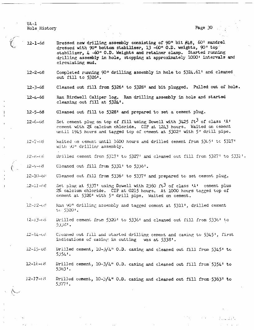
UA-lHole History Page 30
12-1-68 Dressed new drilling assembly consisting of 90" bit #48, 60' mandreldressed with 90" bottom stabilizer, 13 -60" O.D. weights, 90" top-stabilizer, 4 -60" O.D. Weights and retainer clamp. Started runningdrilling assembly in hole, stopping at approximately 1000' intervals andcirculating mud.
12-2-68 Completed running 90" drilling assembly in hole to 532-4.61' and cleanedout fill to 53261.
12-3-68 Cleaned out fill from 5326' to 53283 and bit plugged. Pulled out of hole.
12-4-68 Ran Birdwell Caliper log. Ran drilling assembly in hole and startedcleaning out fill at 5324'.
12-5-68 Cleaned out fill to 53281 and prepared to set a cement plug.
12-6-68 Set cement plug on top of fill using Dowell with 3425 ft 3 of class 'A'cement with 2% calcium chloride. CIP at 1243 hours. Waited on cementuntil 1945 hours and tagged top of cement at 5302' with 5t" drill pipe.
12-7-68 Waited on cement until 1600 hours and drilled cement from 5305' to 5317'with 90" drilling assembly.
12-8-68 Drilled cement from 53'7' to 5327' and cleaned out fill from, 53271 to 5331'.
12-9-68 Cleaned out fill front 5331' to 5336'.
12-10-68 Cleaned out fill from 5336' to 5337' and prepared to set cement plug.
12- 11-68 Set plug at 5337' using Dowell with 2360 ft3 of class 'A' cement plus2% calcium chloride. CIP at 0215 hours. At 1000 hours tagged top ofcement at 5320' with 5" drill pipe. Waited on cement.
12-12-68 Ran 90" drilling assembly and tagged cement at 5311', drilled cementto 5320'.
12-13-68 Drilled cement from 5320' to 5336' and cleaned out fill from 5336' to
12-14-68 cleaned out fill and started drilling cement and casing to 5345', firstindications of casing in cutting was at 53381.
12-15-68 Drilled cement, 10-3/4" O.D. casing and cleaned out fill from 5345' to5354'.
12-16-68 Drilled cement, 10-3/4" O.D. casing and cleaned out fill from 5354' to5363'.
12-17-68 Drilled cement, 10-3/4" .OD. casing and cleaned out fill from 5363' to5377'.

UA-1Hole History Page 31
12-18-68 Drilled cement, 10-3/4" O.D. casing and cleaned out fill from 5377' to5392'.
12-19-68 Drilled cement, 10-3/4" O.D. casing and cleaned out fill from 5392' to5404'. Drilled 90" hole from 5404' to 5406'.
12-20-68 Drilled 90" hole from 5406' to 5413', hole caving, having trouble withboulders. Circulated 2750 gpm mud and 3300 cfm air at 186 psi with 3compressors. 3-1/2" O.D. jet string length 542'.
12-21-68 Drilled 90" hole from 5413' to 5418', hole caving. Ran BirdwellCaliper log.
12-22-68 Tagged top of fill at 5412.89' with 5" drill pipe and set plug with6400 ft3 of class 'A' cement with 2% prehydrated gel and 3% calciumchloride. COP at 1815 hours. Waited on cement.
12-23-68 Tagged top of cement at 5334' at 1700 hours and pulled drill pipe outof hole.
12-24-68 Ran 90" drilling assembly with bit #49, tagged top of cement at 5338',
[COULD NOT BE CONVERTED TO SEARCHABLE TEXT]
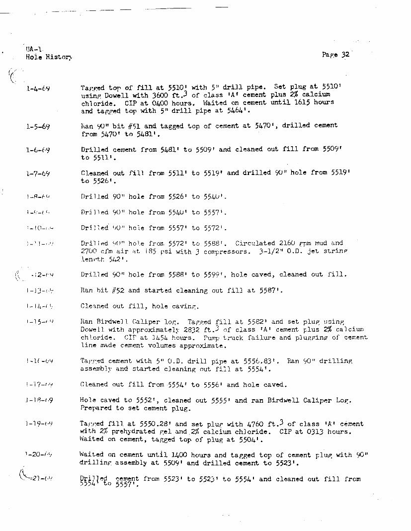
[COULD NOT BE CONVERTED TO SEARCHABLE TEXT]

UA -1Hole History Page 33
[COULD NOT BE CONVERTED TO SEARCHABLE TEXT]1-27-69
Drilled cement from 55571 to 5583' and cleaned out fill to 5568'.
Cleaned out fill from 5588' to 55961.
Cleaned out fill from 5596' to 5599' and drilled 90" from 5599' to5610'.
Drilled 90" hole from 56101 to 5618'.
Drilled 90" hole from 5618' to 5627'. Circulated 2160 gpm mud and 2700cfm air at 215 psi with 3 compressors. 3-1/2" O.D. jet string length547'.
Drilled 90" hole from 5627' to 5632'. Shut down for high winds.
Shut down for high winds.
Shut down for high winds until 1300 hours and pulled drilling assemblyfrom hole.
Ran Birdwell Caliper log, tool stopped at 5618'. Tagged top of fill at5625' and set plug using Dowell with 4860 ft.3 of class 'A' cement with6% gel and 2% calcium chloride. CIP at 1610 hours.
Waited on cement until 1630 hours. Tagged top of cement at 5579.40' andset plug with 1416 ft. 3 of class 'A' cement plus 2% calcium chloride.CIP at 1842 hours. Waited on cement.
Tagged top of cement with 5" drill pipe at 5562', pulled from hole. Ran90" bit #53 and tagged top of cement at 5565' at 1745 hours. Drilled cementto 5575'.
Drilled cement from 5575' to 5615'.
Drilled cement and fill from 5615' to 5632' and formation to 5634'.
Drilled 90" hole from 5634' to 5646'. Circulated 2160 gpm mud and 2700cfm air at 220 psi. 3-1/2" O.D. jet string length 547'.
Drilled 90" hole from 5646' to 5656', hole caving.
Drilled 90" hole from 5656' to 5670', hole cleaning up.
Drilled 90" hole from 5670' to 5692'.
Drilled 90" hole from 5692' to 5708'.
Drilled 90" hole from 5708' to 5726'.
Drilled 90" hole from 5726' to 573".

UA-1Hole History Page 34
2-11-69[COULD NOT BE CONVERTED TO SEARCHABLE TEXT]
LRan bit #54 in the hole.
Cleaned out 4" of fill and drilled 901 hole from 5737' to 5747', holecaving.
Cleaned out fill and drilled 90" hole from 5746' to 5759'.
Drilled 90" hole from 5759' to 5772'.
Drilled 90" hole from 5772' to 5777', hole caving, cleaning out fill.
Drilled 90" hole from 5777' to 5783', hole caving, cleaning out fill.
Drilled 90" hole and cleaned out fill from 5783' to 5791'.
Drilled 90"' hole from 5791' to 5802'.
Drilled 90" hole and cleaned out fill from 5802' to 5812'.
Driled 90' hole from 5812' to 5824'.
Drilled 90" hole and cleaned out fill from 5824' to 5829' .
Changed out rollers on stabilizers and ran bit #55.
Hole caved to 5815', cleaned out fill.
Cleaned out fill and drilled 90" hole from 5829' to 5834'.
Dri ied 90" hole from 5834 ' to 5853'.
Drilled 90" hole from 5853' to 5871' hole caving.
Drilled 90" hole from 5871' to 5889'.
Cleaned out fill and drilled 90" hole from 5889' to 5901'.
DrilLed 90" hole from 5901' to 5916'.
Drilled 90" hole from 5916' to 5922' and ran Birdwell Caliper log.
Completed logging. Changed out bit to #56 cleaned out 3' of fill anddrilled 90" hole from 5922' to 5927'.
Drilled 90 " hole from 5927' to 5940'. Circulated 2160 gpm mud and 2700cfm air at 220 psi. 3-1/2" O.D. jet string length 547'.
Drilled 90 " hole from 5940' to 5950'.

UA-1Hole History Page 35
[could not be converted to searchable text]3-7-69
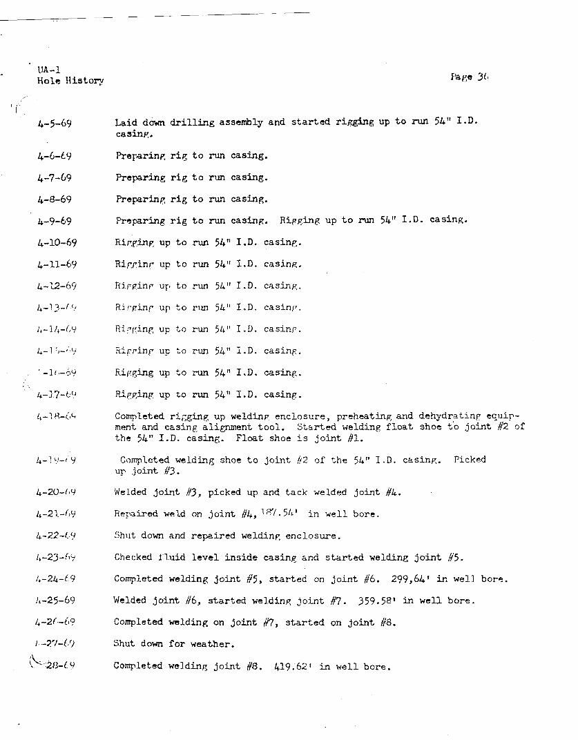
UA-1Hole History
rig to run casing.
Preparing rig to run casing.
Preparing rig to run casing.
Preparing rig to run casing. Rigging up to run 54" I.D. casing.
Ripgging up to run 54" I.D. casing.
Rigging up to run 54" I.D. casing.
Rigging up, to run 54" I.D. casing.
Rigging up to run 54" I.D. casing.
Rigging up to run 54" I.D. casino.
Rigging up to run 54" I.D. casing.
Rigging up to run 54" I.D. casing.
Rigging up to run 54" I.D. casing.
Completed rigging up welding enclosure, preheating and dehydrating ecuip-ment and casing alignment tool. Started welding float shoe to joint #2 ofthe 54" I.D. casing. Float shoe is joint 41.
Completed welding shoe to joint #2 of the 54" I.D. casing. Pickedup joint #3.
Welded joint //3, picked up and tack welded joint #4.
Repaired weld on joint #4, 18/54' in well bore.
Shut down and repaired welding enclosure.
Checked fluid level inside casing and started welding joint #5.
Completed welding joint #5, started on joint #6. 299,64' in well bore.
Welded joint A6, started welding joint #7. 359.58' in well bore.
Completed welding on joint #7, started on joint #8.
Shut down for weather.
Completed welding joint #8. 419.62' in well bore.
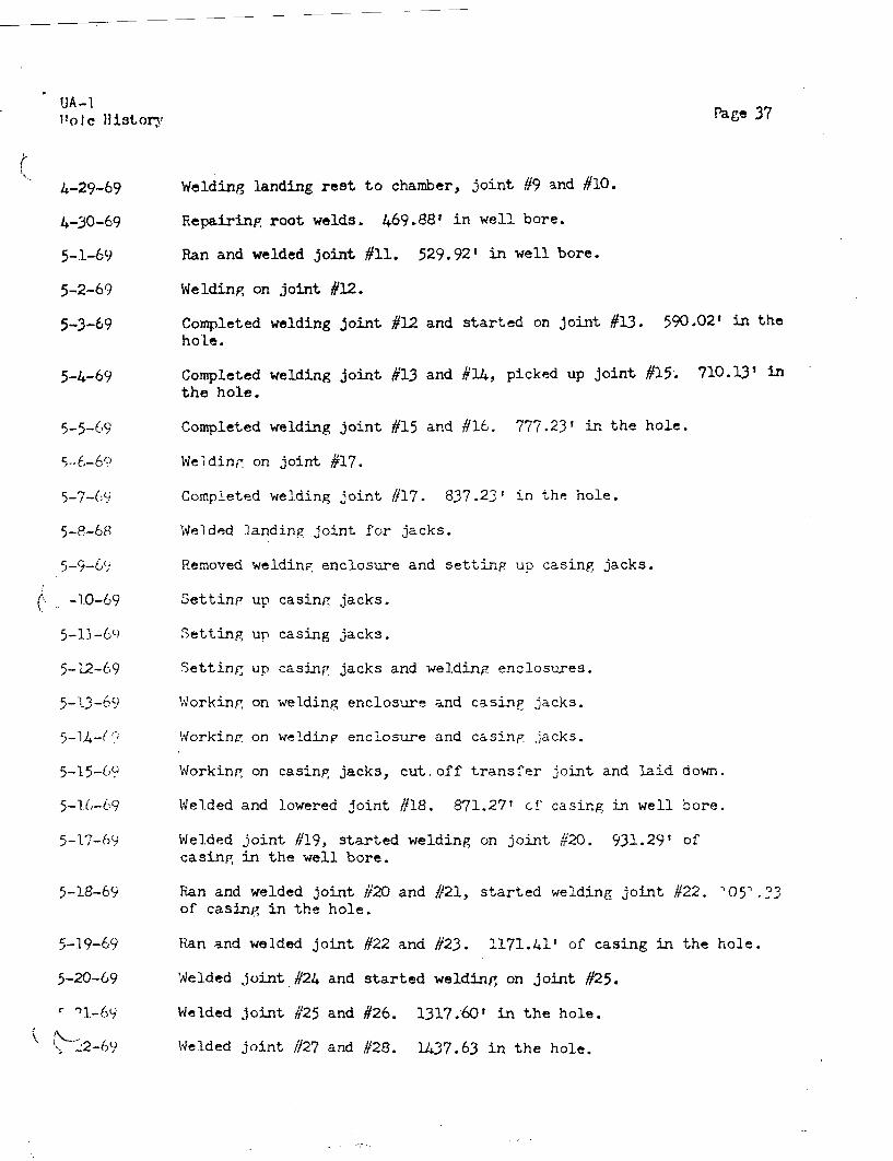
UA-I
hole historyPage 37
Welding landing rest to chamber, joint #9 and #10.
Repairing root welds. 469.88' in well bore.
Ran and welded joint #11. 529.92' in well bore.
Welding on joint #12.
Completed welding joint #12 and started on joint #13. 590.02' in thehole.
Completed welding joint #13 and #14, picked up joint #15. 710.13' inthe hole.
Completed welding joint #15 and #16. 777.23' in the hole.
Welding on joint #17.
Completed welding joint #17. 837.23' in the hole.
Welded landing Joint for jacks.
Removed welding enclosure and setting up casing jacks.
Setting up casing jacks.
Setting up casing jacks.
Setting up casing jacks and welding enclosures.
Working on welding enclosure and casing jacks.
working on welding enclosure and casing Jacks.
Working on casing jacks, cut.off transfer joint and laid down.
Welded and lowered joint #18. 871.27' of casing in well bore.
Welded joint #19, started welding on joint #20. 931.29' ofcasing in the well bore.
Ran and welded joint #20 and #21 started welding joint #22. '05'.33of casing in the hole.
Ran and welded joint #22 and #23. 1171.41' of casing in the hole.
Welded joint #24 and started welding on joint #25.
Welded joint #25 and #26. 1317.60' in the hole.
Welded joint #27 and #28. 1437.63 in the hole.

UA-1.Hole History Page 38
Welded joint #29 and #30. 1531.59' of casing in the hole.
Welded joint #31. Rigging up internal casing alignment tool. 1651.63'
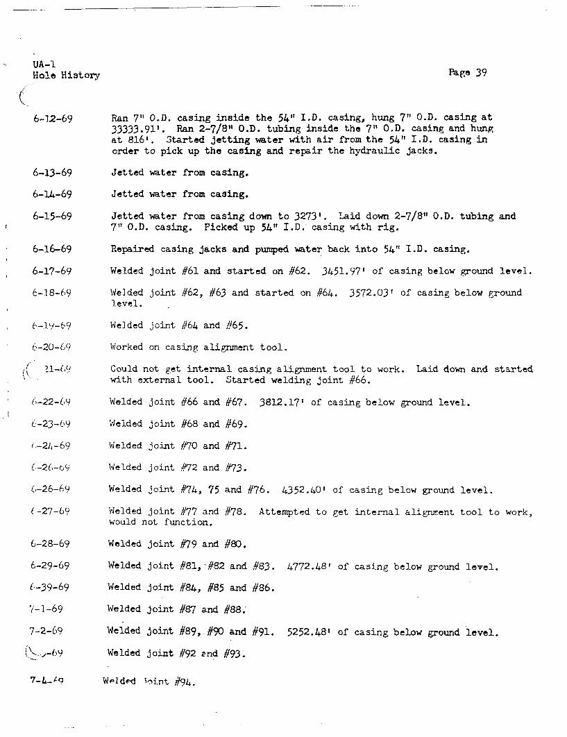
UA-1Hole History
6-12-69
6-13-69
Page 39
Ran 7" O.D. casing inside the 54" I.D. casing, hung 7" O.D. casing at33333.91'. Ran 2-7/8" O.D. tubing inside the 7" O.D. casing and hungat 816'. Started jetting water with air from the 54" I.D. casing inorder to pick up the casing and repair the hydraulic jacks.
Jetted water from casing.
Jetted water from casing.
Jetted water from casing down to 3273'. Laid down 2-7/8" O.D. tubing and7" O.D. casing. Picked up 54" I.D. casing with rig.
Repaired casing jacks and pumped water back into 54" I.D. casing.
Welded joint #61 and started on #62. 3451.97' of casing below ground level.
Welded joint #62, #63 and started on #64. 3572.03' of casing below groundlevel.
Welded joint #64 and #65.
Worked on casing alignment tool.
Could not get internal casing alignment tool to work. Laid down and startedwith external tool. Started welding joint #66.
Welded joint #66 and #67. 3812.17' of casing below ground level.
Welded joint #68 and #69.
Welded joint #70 and #71.
Welded joint #72 and #73.
Welded joint #74, 75 and #76. 4352.40' of casing below ground level.
Welded joint #77 and /78. Attempted to get internal alignment tool to work,would not function.
Welded joint #79 and #80.
Welded joint #81, #82 and #83. 4772.48' of casing below ground level.
Welded joint #84, #85 and #86.
Welded joint #87 and #88.
Welded joint #89, #90 and #91. 5252.48' of casing below ground level.
Welded joint #92 and #93.
Weldedd joint #94.

Welded joint #95, #96, #97 and started on #98. 5611.53' of casingbelow ground level.
Welded joint #98, #99, #100 and started on #101. 5852.51' of cas-ing below ground level.
Welded joint #101, #102, #103 and started on #104. 6032.57' of cas-ing below ground level.
Completed running 54" I.D. casing as follows:
No. ofJoints
WallThickness
RingSize
Ring WeightSpacing Per Foot Depth Run
5
Chamber & Landing Joint
long centered at 5856.41' and spaced 900 apart outside the casing. Three5-1/2" (.D., schedule 40 grout line guides were welded to the outside of the54" 1.D. casing. One guide was run on the V-door side (southwest) and the othertwo were run 135 from the first. The guides were run from surface to the top
xI of the chamber with one line terminating 10')' above the chamber. Two slotted

Hole History Page 41
logging monitor lines of 2-7/8" O.D. , 5.79# line pipe were run 450west of the southwest grout line guide and 1800 from the same guide.Center of 86" O.D. by 43.04' chamber at 5654.76'.
7-9-69 Rigged down welding and casing running equipment. Rigged up forcementing. Ran Birdwell Temperature and Caliper logs.
7-10-69 Ran Birdwell Caliper, Nuclear Cement Analyzer (NCA) and NAIL logs.Ran I joint of 7" O.D. , N-80, 26# casing with Baker latch-in toolon bottom and cement landing collar on top followed by 7" O.D.,J-55, 23# casing.
7-11-69 Completed running casing, landed at 6095.29'. Ran 77 joints of 7"O.D., N-80, 26# casing for jet string, landed at 6045.78' G.L.Filled 54" I.D. casing with water to 94' G.L.
7-12-69 Ran 2-7/8" O.D. tubing for air string, landed at 528.08' G.L. Latched7" O.D. casing into cement shoe. Rigged up Dowell and tested linesto 4000 psL, repaired leaks. Circulated 2000 barrels of mud at 52barrels per minute with 1000 psi. Pumped 200 barrels of water aheadof Stage #1. Mixed and pumped Stage #1 with 31,827 ft3 of expandingcement (Chem-Comp) . Displaced 7" 0. D. casing with 240 barrels ofwater. Plug set with 800 psi, float held. Monitored cement risewith Birdwell Fluid Density and NATL logs, top of cement at 5423'by log. Started cementing at 1717 hours. CIP at 2100 hours. Waitedon cement.
7-13-69 Waited on cement and picked up 2-7/8" O.D. tubing. Unlatched 7" O.D.casing from Baker shoe at 2315 hours. Laid down 15' pup joint of7" O.D. casing and cementing head.
7-14-69 Picked up 3 strings of 2-7/8" O.D. tubing for grout lines and taggedtop of cement at 5433'. Pumped 60 barrels of water ahead of Stage #2.Mixed and pumped Stage #2 down the 3 grout lines using 23,424 ft ofClass "A" cement with 22. prehydrated gel and 3°/ calcium chloride.Monitored cement rise with Birdwell Fluid Density and NAIL logs. Topcement at 4716' by log. Started cementing at 1335 hours. CIP at 1904hours. Waited on cement.
7-15-69 Started laying down 7" 0.D). casing. Waited on cement until 1330 hoursand tagged top of Stage #2 at 4727.55', 4731.18' and 4744.66' for allaverage top of 4734.46'. Pumped 60 barrels of water ahead of Stage #3.Mixed and pumped Stage #3 down 3 grout lines using 17,980 ft3 ofClass "A" cement with 2% prehydrated gel and 3% calcium chloride.Monitored cement rise with Birdwell Fluid Density and NAIL logs. Topof cement at 4150' by log. Started cementing at 1500 hours. CIP at 1825hours. Waited on cement and laid down 7" O.D. casing.
7-16-69 Waited on cement and laid down 7" O.D. casing. Tagged top of Stage #3at 4149.53', 4152.49' and 4152.91' for an average top of 4151.64'. Pumped60 barrels of water ahead of Stage #4. Mixed and pumped Stage #4 down
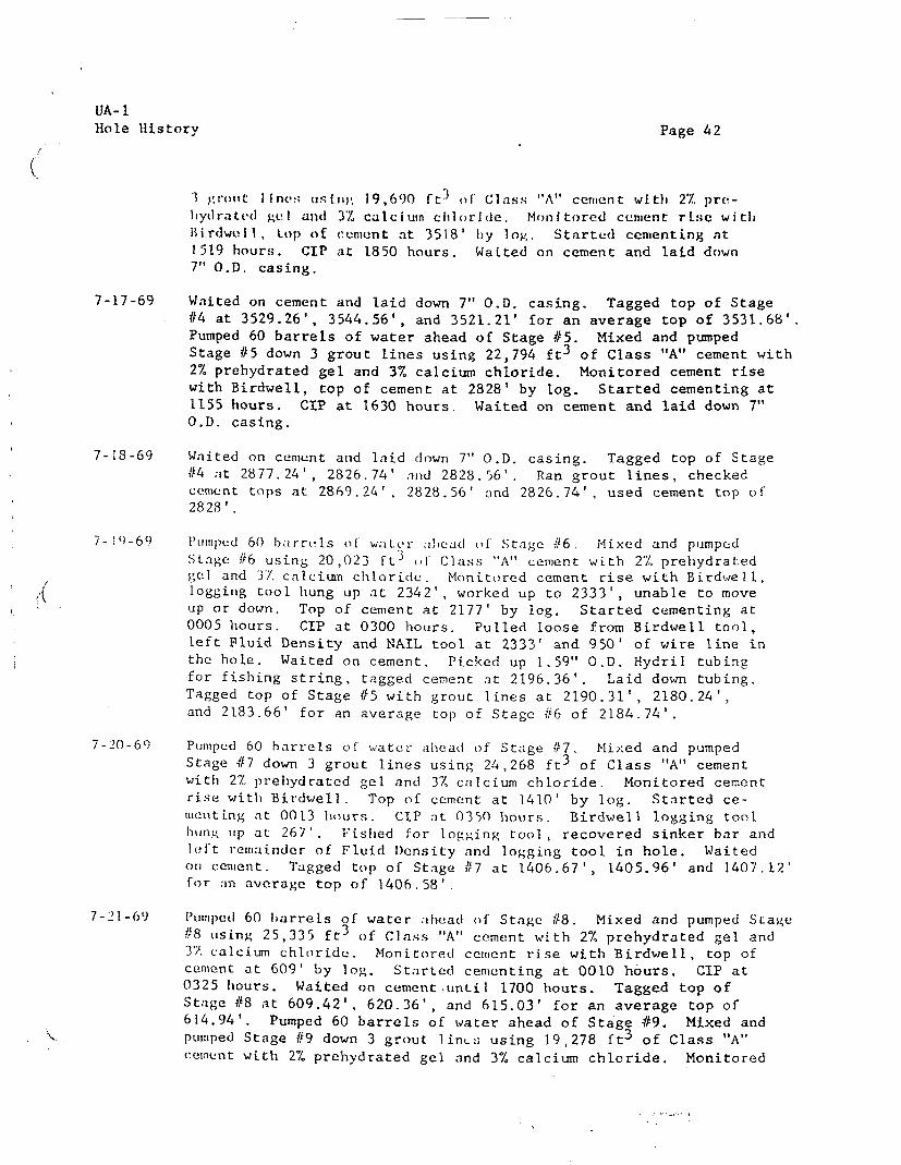
UA-IHole History Page 42
1 grout lines using 19,690 ft 3 of Class "A" cement with 2% pre-hydrated gel and 3% calcium chloride. Monitored cement rise with
Birdwell, top of cement at 3518' by log. Started cementing at1519 hours. CIP at 1850 hours. Waited on cement and laid down7" O.D. casing.
7-17-69 Waited on cement and laid down 7" O.D. casing. Tagged top of Stage#4 at 3529.26', 3544.56', and 3521.21' for an average top of 3531.68'.Pumped 60 barrels of water ahead of Stage #5. Mixed and pumpedStage #5 down 3 grout lines using 22,794 ft 3 of Class "A" cement with2% prehydrated gel and 3% calcium chloride, Monitored cement risewith Birdwell, top of cement at 2828' by log. Started cementing at1155 hours. CIP at 1630 hours. Waited on cement and laid down 7"O.D. casing.
7-18-69 Waited on cement and laid down 7" O.D. casing. Tagged top of Stage#4 at 2877.24', 2826.74' and 2828.56'. Ran grout lines, checkedcement tops at 2869.24', 2828.56' and 2826.74', used cement top of2828'.
7-19 -69 Pumped 6() barrels of water ahead of Stage #6. Mixed and pumpedStage #6 using 20,023 Ft3 of Class "A" cement with 27, prehydratedgel and 37 calcium chloride. Monitored cement rise with Birdwell,logging tool hung up at 2342', worked up to 2333', unable to moveup or down. Top of cement at 2177' by log. Started cementing at0005 hours. CIP at 0300 hours. Pulled loose from Birdwell tool,left Fluid Density and NAIL tool at 2333' and 950' of wire line inthe hole. Waited on cement. Picked up 1.59" O.D. Hydril tubingfor fishing string, tagged cement at 2196.36'. Laid down tubing.Tagged top of Stage #5 with grout lines at 2190.31', 2180.24',and 2183.66' for an average top of Stage #6 of 2184.74'.
7-20-69 Pumped 60 barrels of water ahead of Stage #'7. Mixed and pumpedStage #7 down 3 grout lines using 24,268 ft3 of Class "A" cementwith 2% prehydrated gel and 37% calcium chloride. Monitored cementrise with Birdwell. Top of cement at 1410' by log. Started ce-
menting at 0013 hours. CIP at 0350 hours. Birdwell logging toolhung tip at 267'. Fished for logging tool , recovered sinker bar and
left remainder of Fluid Density and logging tool in hole. Waitedon cement. Tagged top of Stage #7 at 1406.67', 1405.96' and 1407.12'
for an average top of 1406.58'.
7-21-69 Pumped 60 barrels of water ahead of Stage #8. Mixed and pumped Stage#8 using 25,335 ft 3 of Class "A" cement with 2% prehydrated gel and37. calcium chloride. Monitored cement rise with Birdwell, top ofcement at 609' by log. Started cementing at 0010 hours. CIP at0325 hours. Waited on cement until 1700 hours. Tagged top ofStage #8 at 609.42', 620.36', and 615.03' for an average top of614.94'. Pumped 60 barrels of water ahead of Stage #9. Mixed andpumped Stage #9 down 3 grout lines using 19,278 ft3 of Class "A"cement with 2% prehydrated gel and 3% calcium chloride. Monitored

UA- 1Hole History Page 43
cement rise with Birdwell. Cement circulated to surface. Startedcementing at 2002 hours. CIP at 2308 hours. Waited on cement.
7-22-69 Waited on cement. Ran Birdwell Gamma Ray log and located theBirdwell Fluid Density and NAIL tools at 674' and 2343'. Laiddown 7" O.D. casing.
7-23-69 Laid down 7" O.D. casing. Ran Birdwell Temperature and Caliperlogs. Ran Sperry-Sun Gyroscopic Multishot survey in and out ofthe hole on 25' stations from 0' to 3800'.
7-24-69 Completed running Sperry-Sun. Rigged down work platform, releasedpressure on casing jacks. Cut off 54" I.D. casing 2' above G.L.
7-25-69 Rigged down casing jacks and welded cap on 54" I.D. casing.
7-26-69 Released rig for demobilization at 0600 hours. Hole suspended.
8-6-69 Hole suspended from 0600 hours on 7-26-69 to 0500 hours on 8-6-69.Moved in crane and ran Birdwell Temperature log. Hole suspendedat 1730 hours.
8-11-69 Hole suspended from 1730 hours on 8-6-69 to 0745 hours on 8-11-69.Ran Sperry-Sun Gyroscopic Multishot survey in and out of the holeon 25' stations from 3800' to 6100'. No rig on hole, logged witha crane. Hole suspended at 1530 hours.
8-12-69 Hole suspended from 1530 hours on 8-11-69 to 0900 hours on 8-12-69.Ran Birdwell NCA log. No rig on hole, logged with a crane. Holesuspended at 1500 hours.
8-20-69 Hole suspended from 1500 hoursRan Birdwell Temperature log.Hole suspended at 1830 hours.
9-4-69 Hole suspended from 1830 hoursRan Birdwell Temperature log.Hole suspended at 1230 hours.
on 8-12-69 to 1200 hours on 8-2(-69.No rig on hole, logged with a crane.
on 8-20-69 to 0800 hours on 9-4-69.No rig on hole, logged with a crane.
on 9-4-69 to 0800 hours on 9-15-69.No rig on hole, logged with a crane.
on 9-15-69 to 0800 hours on 10-16-69.D. casing cover. Ran Birdwell Caliperwith a crane Replaced casing cover.
9-15-69 Hole suspended from 1230 hoursRan Birdwell Temperature log.Hole suspended at 1200 hours.
10-16-69 Hole suspended from 1200 hoursCut off lugs and removed 54" I.
log. No rig on hole, logged wiHole suspended at 1300 hours.

UA-1Hole History Page 44
CORE RECORD
CoreNo. Interval Recovery Formation
1.
2.
5020' - 5050'
5050' - 5073'
5073' - 5093'
30'
23'
20'3.
4. 5093' - 5109'
5. 5109' - 5139' 3 '
6. 5140' - 5163' 3 '
7. 5163' - 5173' 9 '
8. 5173' - 5192' 4'
9. 5193' - 5203' 9'
10. 5203' - 5208' 4½'
11.12.13.
5208'5218'5229'
5218'5229'5239'
10'5'
10'
Breccia, dark greenish gray withbasalt lithic fragments
Breccia, dark greenish gray withbasalt lithic fragments
Breccia, dark greenish gray withbasalt lithic fragments
Breccia, dark greenish gray withbasalt lithic fragments
Breccia, dark greenish gray withbasalt lithic fragments
Breccia, dark greenish gray withOasalt lithic fragments
Breccia, dark greenish gray withbasalt lithic fragments
Breccia, dark greenish gray withbasalt lithic fragments
Breccia, dark greenish gray withbasalt lithic fragments
Breccia, dark greenish gray withbasalt lithic fragments
Siltstone, greenish black, equigranularSiltstone, greenish black, equigranularBreccia, dark greenish gray, minor
siltstone bedsBreccia, dark greenish gray, minor
siltstone bedsBreccia, dark greenish gray, minor
siltstone bedsBreccia, dark greenish gray, minor
siltstone bedsBreccia, dark greenish gray, minor
siltstone bedsBreccia, dark greenish gray, minor
siltstone bedsBreccia, dark greenish gray, minorsiltstone beds
Breccia, dark greenish gray, minorsiltstone beds
Breccia, dark greenish gray, minorsiltstone beds
Breccia, dark greenish gray, minorsiltstone beds
14.
15.
5239' - 5249'
5249' - 5256'
5256' - 5267'
5267' - 5297'
9½'
7'
11'
12'
16.
17.
18. 5297' - 5307' 7 '
19. 5307' - 5317' 11/2'
20. 5317' - 5327' 3'
21. 5327' - 5337' 9'
22. 5337' - 5341' 4'

Ua-1Hole History Page 45
CoreNo.
23.
24.
25.
26.
Interval Recovery Formation
5341' - 5351'
5351' - 5374'
10'
22'
Breccia, dark greenish gray, minorsiltstone beds
Breccia, dark greenish gray, minorsiltstone beds
Basalt, greenish black, fine grained
5384'5404'5410'
5404'54 10'5434'
25'
5434' - 5440' 13'
27.
28.
29.
30.
31.
32.
33.
34.
35.
36.
37.
5440' - 5453' 4
5453' - 5463' 9'
5463' - 5474' 11'
5474' - 5484' 7'
5484' - 5494' 1'
Breccia,black,lithic
4' Breccia,black,lithic
Breccia,black,lithic
Breccia,black,lithic
Breccia,black,lithic
Breccia,black,lithic
Breccia,black,lithic
Breccia,black,lithic
Breccia,black,lithic
Breccia,black,lithic
3 1/2' Breccia,
black,lithic
Breccia,black,lithic
5494' - 5504'
dark greenish gray to greenish65% rounded to subroundedfragmentsdark greenish gray to greenish65% rounded to subroundedfragmentsdark greenish gray to greenish65% rounded to subroundedfragmentsdark greenish gray to greenish65% rounded to subroundedfragmentsdark greenish gray to greenish65% rounded to subroundedfragmentsdark greenish gray to greenish65% rounded to subroundedfragmentsdark greenish gray to greenish65% rounded to subroundedfragmentsdark greenish gray to greenish65% rounded to subroundedfragmentsdark greenish gray to greenish65% rounded to surroundedfragmentsdark greenish gray to greenish65% rounded to subroundedfragmentsdark greenish gray to greenish65% rounded to subroundedfragmentsdark greenish gray to greenish65% rounded to subroundedfragments
2
5504' - 5514' 1'
5514' - 5524'
5524' - 5534' 8
5534' - 5542' 3
5542' - 5552' 0'

Ua-1Hole History
CoreNo.
Page 46
Interval Recovery Formation
38.
39.
40.
41.
42.
43.
5552' - 5556' I'
5556' - 5566' 7'
5566' - 5571' 2 '
55711 - 5583' 11'
5583' - 5598' 3 '
5598' - 5601' 3 '
44. 5601' - 5605' 1 1/2'
45.
46.
47.
48.
49.
50.
51.
52.
5605' - 5608' 3 '
Breccia, dark greenish gray to greenishblack, 65% rounded to subroundedlithic fragments
Breccia, dark greenish gray to greenishblack, 65% rounded to subroundedlithic fragments
Breccia, dark greenish gray to greenishblack, 65% rounded to subroundedlithic fragments
Breccia, dark greenish gray to greenishblack, 65% rounded to subroundedlithic fragments
Breccia, dark greenish gray to greenishblack, 65% rounded to subrounded1ithic fragments
breccia, dark greenish gray to greenishblack, 65% rounded to subroundedlithic fragments
Breccia, dark greenish gray to greenishblack, 65% rounded to subroundedlithic fragments
Breccia, dark greenish gray to greenishblack, 65% rounded to subroundedlithic fragments
Breccia, dark greenish gray to greenishblack, 65% rounded to subroundedlithic fragments
Breccia, dark greenish gray to greenishblack, 65% rounded to subroundedlithic fragments
Breccia, dark greenish gray to greenishblack, 65% rounded to surroundedlithic fragments
Breccia, dark greenish gray to greenishblack, 65% rounded to subroundedlithic fragments
Breccia, dark greenish gray to greenishblack, 65% rounded to subroundedlithic fragments
Breccia, dark greenish gray to greenishblack, 65% rounded to surroundedlithic fragments
Breccia, dark greenish gray to greenishblack, 65% rounded to subroundedlithic fragments
5608' - 5613' 1 '
5613' - 5623' 9'
5623' - 5633' 10'
5633' - 5653' 3 '
5653' - 5663' 0'
5663' - 5673' 0'
5673' - 5683' 1

Ua-lHole History
CoreNo.
Page 47
Interval Recovery Formation
53.
54.
55.
56.
57.
58.
5683' - 5688'
5688' - 5698' 10'
5698' - 5708' 10'
5708' - 5715' 7'
5715' - 5721' 6'
5721' - 5729' 8'
Breccia,black,lithic
Breccia,black,lithic
Breccia,black,lithic
Breccia,black,lithic
Breccia,black,lithic
Breccia,blacklithic
Breccia,black,lithic
Breccia,black,lithic
Breccia,b lack,lithic
Breccia,black,lithic
Breccia,black,lithic
Breccia,black,
dark greenish gray to greenish65% rounded to subroundedfragmentsdark greenish gray to greenish65% rounded to subroundedfragmentsdark greenish gray to greenish65% rounded to subroundedfragmentsdark greenish gray to greenish65% rounded to subroundedfragmentsdark greenish gray to greenish657, rounded to subroundedfragmentsdark greenish gray to greenish
65% rounded to subroundedfragmentsdark greenish gray to greenish65% rounded to subroundedfragmentsdark greenish gray to greenish
65% rounded to subroundedfragmentsdark greenish gray to greenish65%, rounded to subroundedfragmentsdark greenish gray to greenish65%, rounded to subroundedfragmentsdark greenish gray to greenish65%. rounded to subroundedfragmentsdark greenish gray to greenish65% rounded to subrounded
59. 5729' - 5741' 12'1.'
60.
61.
62.
63.
64.
65.
66.67.68.69.70.71.
5741' - 5756' 15'
5756' - 5771' 15'
5771' - 5788' 17'
5788' - 5805' 17
5805' - 5812' 7'
lithic fragments5812'5815'5823'5833'5841'5847'5861'5879'
58 15'5819'5833'5841 '5847'5861'5879'5909'
8'6'
14'18'30'
Basalt,Basalt,Basalt,Basalt,Basalt,Basalt,Basalt,
lightlightlightlightlightlightlight
greenishgreenishgreenishgreenishgreenishgreenishgreenish
gray,gray,gray,gray,gray,gray,gray,
finefinefinefinefinefinefine
graingraingraingraingrain,graingrain

Ua-lHole
CoreNo.
History Page 48
Interval Recovery Formation
72.
73.
74.
75.
76.
77.
78.
79 .
80.
81.
82.83.84.
85.86.87.88.89.90.91.92.
93.94.95.96.97.
98.
5909' - 5925'
5925' - 5937'
5937' - 5951'
5940' - 5960'
16'
12'
14'
20'
5960' - 5965' 5'
Basalt, lightgrained
Basalt, Lightgrained
Basalt, lightgrained
Basalt, lightgrained
Basalt, lightgrained
Basalt, lightgrained
Basalt, lightgrained
Basalt, lightgrained
Basalt, lightgrained
greenish gray, fine
greenish gray, fine
greenish gray, fine
greenish gray, fine
greenish gray, ine
greenish gray, fine
greenish gray, fine
greenish gray, fine
greenish gray, fine
5965' - 5974' 8'
5974' - 5979' 5'
5979' - 5988' 9 '
5988' - 6012' 4'
6012'6024'6025'6033'6039'6041'6048'6060'6063'6090'6107'6110'6130'6146'6151'6157'6166'6176'6184'6191'6206'
-6024'- 6025'- 6032'- 6039'
- 6041'- 6048'
- 6060'- 6063'- 6090'- 6107'- 6110'- 6130'- 6146'- 6151'- 6157'- 6166'- 6176'
- 6184'- 6191'- 6206'- 6208'
13'7'6'
9'12'1'
27'17'
2''20'15'
11'8 1/2'
10'
7'7'
17'
Basalt, dark gray, dense, brittleBasalt, dark gray, dense, brittleBasalt, dark gray, dense, brittle
Breccia, dark greenish grayBreccia, dark greenish grayBreccia, dark greenish grayBreccia, dark greenish grayBreccia, dark greenish grayBreccia, dark greenish grayBreccia, dark greenish grayBasalt dike, grayish black,Basalt dike, grayish black,Breccia, dark greenish grayBreccia, dark greenish grayBreccia, dark greenish grayBreccia, dark greenish grayBreccia, dark greenish gray
aphaniticaphanitic
6208' - 6212'
Basalt, grayish black, dense, micro-crystalline ground mass, zeolitefilled amygdules
Basalt, grayish black, dense micro-crystalline ground mass, zeolitefilled amygdules
4 '

Ua-lHole History 49
CoreNo. Interval Recovery Formation
99. 6212' - 6218'
100.
101.
6218' - 6224½'
6224'.'- 6233'6233' - 6235'
6235' - 6265'
6265' - 6266'6266' - 6274'
6'
6½'
10½ '
30'
9'
Basalt, grayish black, dense micro-crystalline ground mass, zeolitefilled amygdules
Basalt, grayish black, dense micro-crystalline ground mass, zeolitefilled amygdules
102.
Breccia, dark greenishsive and competent
Breccia, dark greenishsive and competent
gray, mas-
gray, mas-
103.Basalt, dark gray, dense, microcrys-
talline, prophyritic104. 6274' - 6282'
105.
107.108.109.110.111.112.113.114.115.116.117.118.119.120.121.
6282'6289'6309'6316'6320'6327'6331'6339'6343'6353'6363'6369'6377'6393'6413'6430'6437'6453'
6288'6309'6316'6320'6327'6331'6339'6343'6353'6363'6369'6377'6393'6413'6430'6437'6453'6454'
14'20'
5'1'7'2½'7'4'7'4½'3'8'
16'12 1/2'
17'7'5'
Breccia,Breccia,Breccia,Breccia,Breccia,Breccia,Breccia,Breccia,Breccia,Breccia,Breccia,Breccia,Breccia,Breccia,Breccia,Breccia,Breccia,
darkdarkdarkdarkdarkdarkdarkdarkdarkdarkdarkdarkdarkdarkdarkdarkdark
greenishgreenishgreenishgreenishgreenishgreenishgreenishgreenish
greenishgreenishgreenishgreenishgreenishgreenishgreenishgreenishgreenish
graygraygraygraygraygraygraygraygraygraygraygraygraygraygraygraygray
6454' - 6473'
122.123.124.
6473'6485'6492'
6485'6493'6500'
12'5'8'
Basalt, dark gray to black, finegrained, dense amygdaloidal.
Breccia, dark greenish grayBreccia, dark greenish grayBreccia, dark greenish gray

Ua-lHole History Page 50
LOG INDEX SHEET
Type Log
CaliperCaliperCaliperCaliperCaliperCaliperCaliperCaliperCaliperCaliperCaliperCaliperCaliperCaliper
CaliperCaliperCaliperCaliperCaliperCaliperCaliperCaliperCaliperCaliperCaliperCaliperCaliperCaliperCaliperCaliperCaliperCaliperCaliper
Density
Date
09 -07-6710-18-6711-06-6712-08-6701-01-6801-24-6802-06-6803-25-6805-29-6806-06-6806-13-6806-20-6807 -01-6807-27 6809-09-68
09-16-6809-20-68
09-27-6810-08-68
10-20-6811-01-68
12-04-6812-21-68
01-03-6901-15-6901- 18-6901-29-6903-02-69
03-22-6907- 10-69
07-10-6907-23-6910- 16-69
10-24-68
RunNo.
123456789
101112131415161718192021222324252627282930313233
1
LogDepth
264'1148'
1505'2070'2541'2907'3068'3971'5006'5190'5405'5590'
4793'
5060'5399'
5589'5934'
6102'
6281'6458'
5320'
5324'
5411'
5508'5583'5551'5618'5914'
6145'6085'
6085'6085'6102'
6432'
DrillersDepth
264'
1150'1505'
2069'
2539'
2907'3070'3971'5000'5193'5410'5598'5805'5951'5404'
5600'5940'
6107'6289'
6500'5325'5326'5418'5519'
5599'5555'5632'5922'6150'6104'6104'6104'6104'
6500'
Interval Logged
0'200'240'200'200'200'200'210'
4000'4920'4900'4900'4900'4890'
200'5300'5350'5350'5350'5300'
0'4650'4900'4900'200'200'150'150'1 50'0'
5300'0'0'
259'1143'1500'2065'2537'2903'3063'3966'5002'5188'5402'5588'5791'5060'5395'5587'5932'6100'6278'6454'5316'5318'5406'5505'5580'5548'5614'5910'6140'6080'6080'6080'5624'
5300' - 6431'
ElectricElectric
Fluid DensityFluid Density
Fluid DensityFluid DensityFluid DensityFluid DensityFluid DensityFluid DensityFluid Density
Fluid DensityFluid Density
10-23-6810-23-68
07-12-6907-14-6907-15-6907- 15-6907-16-6907-16-6907-17-69
07-17-6907-18 -69
07-18-6907-20-69
12
123456789
1011
6442'6442'
5627'5492'4720'4720'4147'4145'3516'3412'
2825'
2828'2177'
6500'6500'
5350' - 6442'5350' - 6442'
5629'5492'4743'4723'4151'4151'3521'3521'2827'
2833'2180'
5350'4700'4100'4100'3450'3450'2800'2750'2341'
2140'1350'
- 5621'- 5388'- 4649'
- 4714'- 4096'- 4096'
- 3512'- 3408'- 2816'
- 2816'- 2171'

Ua-1Hole History Page 51
Type Log Date
NAILNAILNAILNAILNAILNAILNAILNAILNAILNAILNAILNAILNAILNAILNAILNAIL
NCANCA
07- 10-6907-10-6907-12-6907-14-6907- 15-6907-15-6907-16-6907-16-6907-16-6907-17-6907-18-6907-18-6907-20-690 7-20-690 7-21-6907-21-69
07-10-6908-12-69
RunNo.
123456789
10111213141516
12
LogDepth
5628'5628'5627'5492'4720'4720'4147'4145'3516'3412'2825'2828'2177'2177'1404'610'
6085'6085'
DrillersDepth
5629'5629'5269'5492'4743'4723'4151'4151'3521'3521'2827'2833'2180'2180'1405'
609'
Interval Logged
0'
0'5350'4700'4100'4100'3450'3450'2800'2750'2341'2140'1190'1350'
550'3'
5626'5626'5625'5390'4649'4718'4100'4100'3516'3412'2820'2820'2174'2175'1396'
520'
6104'6104'
0' - 6074'0' - 6074'
Gamma Ray Neutron 10-23-68Gamma Ray Neutron 07-22-69
Neutron/Neutron
NCTLNCTLNCTLNCTLNCTL
TemperatureTemperature
Temperature
TemperatureTemperatureTemperatureTemperatureTemperatureTempe ratureTemperature
10-24-68
09- 13-670 5-30-6805-31-6808-03-6809-13-68
0 5-30-6809- 13-6810-24-6803-24-6907-09-6907-23-6908-06-6908-20-6909-04-6909- 15-69
2
1
123
45
123456789
10
6440'
6400'
132'4964'4998'4950'5392'
4964'5391'6429'6145'5627'6097'6097'6101'6101'6101'
6500'6104'
6500'
145'5000'5022'4967'5393'
5000'5391'6500'6150'5629'6104'6104'6104'6104'6104'
5300' - 6439'0' - 2900'
5300' - 6439'
0'
4850'4900'4900'5250'
4800'5000'5300'
0'0'0'
10'0'0'
0'
130'4962'4997'49 50'5392'
4964'5391'6429'6145'5627'6097'6097'6101'6101'6101'
Velocity 10-24-68 1
3-D3-D
10-24-68 1 & 210-24-68 3 & 4
6431'
6431'6434'
6500'
6500'6500'
5250' - 6426'
5300' - 6426'5300' - 6425'.

Page 52
UA-1SPERRY-SUN GYROSCOPIC MULTISHOT SURVEY
303 - SU3 - 303 IN RUN
This survey was run on a wire line inside 54" I.D. casing.
TrueVertical DepthMeasured Depth
0'
100'200'300'400'500'600'700'800'
900'1000'1100'1200'1300'1400'1500'1600'1700'1800'1900'2000'2100'2200'2300'2400'2500'2600'2700'2800'2900'3000'3100'3200'3300'3400'3500'3600'3700'3800'3900'4000'
Latitude
0'100.00'200.00'300.00'400.00'500.00'600.00'700.00'800.00'900.00'
1000.00'1100.00'1200.00'1300.00'1400.00'1500.00'1600.00'1700.00'1800.00'1900.00'2000.00'2100.00'2200.00'2300.00'2400.00'2500.00'2600.00'2700.00'2800.00'2900.00'3000.00'3100.00'3200.00'3300.00'3400.00'3500.00'3600. 00'3700.00'3800.00'3900.00'4000.00'
0'0.10'0.23'0.27'0.29'0.31'0.33'0.36'0.44'0.49'0.45'0.37'0.37'0.33'0.34'0.28'0.26'0.29'0.35'0.32'0.31'0.37'0.37'0.39'0.32'0.31'0.32'0.32'0.36'0.31'0.27'0.25'0.09'0.09'0.12'0.08'0.05'0.12'0.06'0.02'0.02'
0'0.15'0.15'0.12'0.13'0. 13'0.00'0.07'0.04'0.15'0.28'0.31'0.31'0.24'0.48'0.43'0.44'0.49'0.42'0.52'0.38'0.47'0.48'0.69'0.79'0.93'1.06'1. 12'1.16'1.19'1.23'1.16'1.15'1.19'1.30'1.34'1.39'1.50'1.58'1.60'1.62'
Departure

UA- 1SPERRY-SUN GYROSCOPIC MULTISHOT SURVEY (CON'T)
303 - SU3 - 303 IN RUN
Measured depth
TrueVertical Depth Latitude Departure
4100'4200'4300'4400'4500'4600'
4700'4800'4900'5000'5100'5200'5300'5400'5500'5600'
5700'
5100'6000'61 00'
4100.00'4200.00'4300.00'4400.00'4500.00'4600.00'4700.00'4800.00'4900.00'5000.00'5100.00'5200.00'5300.00'5400.00'5500.00'5599. 99'5699.99'5799 .995899. 98'59939 .98'6099.98'
0.01'0.11'0.26'0.3 7'0.35'0.40'0.65'0.86'0.83'0.79'0.99'1.35'1.63'1 . 76'1 .98'1. 74'1.42'0 . 82 '0.45'0.06'0.67'
SSSSSSSSSSSSSSSSsSSNN\
1.57'1 .49'1.47'1.54'1. 67'
1.83'1.73'1 .76'
2.01 '2 .17'2.15 '2.27 '2.11'2.00'1.90 '1.32 '0.88'0 .12 '0.08'0.22'0.36'
wwwwwwwwwwww
w
w

UA- 1
BIT RECORD
Bit Depth Feet RotatingNo. Size Make Type Out Drilled Hours
1 108" Reed BHB-2 264' 254' 287-3/42 90" Reed BHB-4 511' 247' 221-1/43 90" Reed T-1 747' 236' 142-1/44 90" Reed T-1 888' 141' 97-1/25 90" Reed T-1 967' 79' 816 90" Reed T-1 1150' 183' 1657 90" Reed T-1 1265' 115' 152-1/48 90" Reed QS 1505' 240' 212-1/29 90" Reed QKC 1519' 14' 2210 90" Reed QS 1646' 127' 18311 90" Reed QS 1780' 134' 13212 90" Reed QS 1856' 76' 82-1/413 90" Reed QS 2069' 213' 193-3/414 90" Reed QS 2212' 143' 155-1/&15 90" Reed QS 2341' 129' 128-1/216 90" Reed QS 2539' 198' 187-1/417 90" Reed QH 2755' 216' 19218 90" Reed QH 2872' 117' 11219 90" Reed QH 2907' 35' 90-1/220 90" Reed QH 2913' 6' 38-1/221 90" Reed QH 3070' 157' 146-1/222 90" Reed QH 3199' 129' 203-1/223 90" Reed QH 3413' 214' 224-1/224 90" Reed QH 3453' 40' 4425 90" Reed QH 3584' 131' 143-3/426 90" Reed QH 3695' 111' 16627 90" Reed QS 3828' 133' 136-1/228 90" Reed QS 3971' 143' 142-1/429 90" Reed QS 4141' 170' 183-1/230 90" Reed QS 4227' 86' 99-3/431 90" Reed QH 4315' 88' 10332 90" Reed QH 4391' 76' 10333 90" Reed QS 4504' 113' 140-1/234 90" Reed QH 4551' 47' 6635 90" Reed QS 4601' 50' 6236 9O" Reed QS 4636' 35' 4537 90" Smith DT 4642' 6' 15-3/438 90" Reed QH 473 0' 88' 111-1/239 90" Reed QS 4818' 88' 105-1/240 90" Smith 4941 123' 9041 90" Reed QS 000' 5 9' 76-1/242 90" Reed QS 5007 7' 5-1/243 90" Smith DT 5102 95 98-1/4
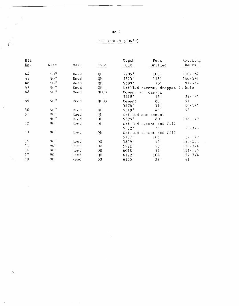
ua-1
BIIT RECORD (CON'T)
BitNo. Size Make
DepthOutTy Pe
Feet
Drilled
Rotating
Hours
4445464748
49
50
51
53
5 4
0 6
58
90"90"9"
9"
90"
90"90"
ReedReedReedReedReed
Reed
ReedRee dReed
Reed
QHQHQHQHQHOS
QH
QHQHQH
5205'5323'5399'DrilledCement:5418'Cement5474'5519'
Drilled5599'
Drilled5632'Drilled5737 '5829'5922 '6018 '6122'6150'
103'118'76'
cement, droppedand casing
13'80'56'45'
out cement80'
cement and fill33'
cement and fill
105'92 '93 '96'
104'28'
110- 1/4100- 3/491-3/4
in ho I e
29- 1/45160- 1/455
Reed
Reed
ReedReedReedReed
QS
QHQS

BIT RECORD - CENTER PUNCH
BitNo. Size Make
DepthOutType
Feet RotatingDrilled Hours Condition
1231 Rerun43 Rerun53 Rerun6
8-5 /8"8-5/8"8-5/8"8-5/8"8-5 /8"8-5/8"8-5/8"8-5/8"8-5/8"
789
101 11213141513
8-5/8"8-5/8"8-5/8"8-5/8"8-5/8"8-5/8"8-5/8"8-5/8"8-5/8"
Rerun 8-5/8"8-5/8"
Rerun 8-5/8"8-5/8"
ReedReedReedReedReedReedReedReedReed
ReedReedReedReedReedReedReedReedReedReedReedReedReed
YT1AJYHGJYHGJYTIAJYHGJYHGJYS1G
YHGJSTIAGSTIAGSTIAGSTlACYHGJYHGJ
YHCJ
YHGJYHGJYHGJYS1GJ
5020'5140'5410'5484'5698'5731'5819'5823'5951'CementDyna-Dril l.Dyna-Dri 11Dyna-DrillDyna-DrillDyna-Drill5532'5600'5818'5940'6289'6437'6473'6500'
20'120'270'74'
214'33'88'4'
128'95'
133'68'
218'217'132'148'36'27'
4-1/27-1/2
24-1/41121-3/45
11-1/21-1/4
10-1/2
2 2-3/417- 1/2384216-1/214-3/45-3/43
7
1
3456
789
1011
10 Rerun1213141516
7"
7"7"7"7"7"
7"7"
7"
6-3 /4"6-3/4"6- 13/4"6-31/4"6- 1/4 "
HughesHughesHughesHughesHughesHughesHugheshughesHughesHughesHughesHughesHughesHughesHughesHughe sHughes
J
J
JJJJJJjj
J
JJ
CORE BIT RECORD
5050'5073'5093'5109'5139'5163'5173 '5192'5208'5218'5239'5256 '5297 '5317'5337'5374'5410'
30'23'20'16 '30'23 '10 '19 '15 '10'21'17 '41'20'20'37'26'
66- 1/29- 3 /46-3 /45- 1/48
10-1/233 - 1 /23- 3 /424-1/24-1/28-1/24- 1/247- 1/45-1/2
Worn OutWorn Out
Worn Out507. Used
Worn Out85% Used
9 0% Used
507. Used
75% Used50% Used
95% Used

CORE BIT RECORD (CON'T)
BitNo.
17181920212223242526272829303127 Rerun3227 Rerun3334
:373837 Re run
394041
39 Rerun42
43
44
42 Rerun
40 Re run
45464748495051
Size
6-1/4"6-1/4"6-1/4"6-1/4"6-1/4"6-1/4"6- 1/4"6-1/4"6-1/4"
6- 1/8"
6-1/8"6-1 /4"6- 1 /4"6- 1 /40-1/4"6- 1 /8'
6- 1 /8"
6- 1/8"6- 1/8"6- 1 /8"
6- 1/8"6-1/8"6- 1/8"6-1/4"6-1/8"6- 1/8"6- 1/8"6- 1/8"6- 1/8"6- 1 /8 "6- 1/8"
6-1 /46- 1/4"
6- 1 /8"
6- 1 /8"6- 1/4"6- 1/8"6-1/4"6-1/4"6-1/8"6- 1 /4"6- 1/4 "
Make
HughesHughesHughesHughesHughesHughesHughesHughesHughesWilliamsWilliamsHughesHughesHughes
HughesWilliams
WilliamsWilliamsWilliamsWilliamsWilliamsWilliamsWilliamsHughesWilliamsWilliamsWilliamsWilliamsWIlliamsWilliamsWilliamsHughes
HughesWilliams
Williams
HughesWilliamsHughesHughesWilliams
HughesHughes
Type
JJ
JJJJJJJ.Dia.Dia.
JJ
J.
Dia.Dia.Dia.Dia.Dia.Dia.Dia.Dia.
Dia.Dia.Dia.Dia.
dia.DiaDia.J
DiaDia.
Dia.
DiaDia.J
DepthOut
5440'5484'5524'5534'5542'5552'5571'5583'5598'5604'5608'5613'5633'56635683'5688'5756'5812'5819'5833'5951'5979'5988'6012'6060'6130'6184'6212'6274'6288'6343'6353'6363'6369'6393'6413'6437'6453'6473'6485'6493'6500'
Feet RotatingDrilled Hours
30'31'40'10'
8'10'19'12'15'
6'3'5'
20'30'20'
5'68'46'
7'
10 '10'34'
9'24'47'70'
554'554'62'14'54'10'
10'6'
24'
20'24'16'20'12'
8'8'
8-3/469-3/41-3/422-3/46-1/21-3/433-1/2114-1/253-3/41-3/4
2713
22
21-1/24-3/41-3/42-1/2
11-1/42018-1/42-1/4
20-1/27
20-1/222-3/42-3/4
12-1/278-1/2476-1/41-1/21-1/2
Condition
75% Used70% Used
95% Used
Locked
Worn Out
GroovedGrooved
DroppedDroppee
5% Used

CEMENTING GRAPH UA-1Accumulated Volume in Thousend Cubic Feet Stage - Top
[could not be converted to searchable text]

UA-1
Accumulated Volume in Thousand Cubic Feet Stage - Top9 -- 0'
[COULD NOT BE CONVERTED TO SEARCHABLE TEXT]
[
Cubic Foot per Vertical Foot per Stage40 50 60
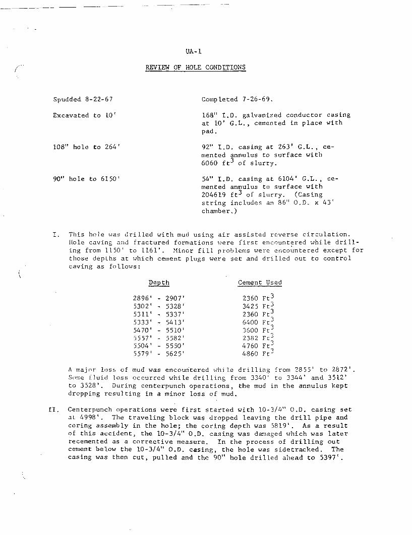
UA-1
REVIEW OF HOLE CONDITIONS
Spudded 8-22-67 Completed 7-26-69.
Excavated to 10' 168" I.D. galvanized conductor casingat 10' G.L., cemented in place withpad.
108" hole to 264'
90" hole to 6150'
92" I.D. casing at 263' G.L., ce-mented annulus to surface with6060 ft3 of slurry.
54" I.D. casing at 6104' G.L., ce-mented annulus to surface with204619 ft3 of slurry. (Casingstring includes an 86" O.D. x 43'chamber.)
I. This hole was drilled with mud using air assisted reverse circulation.Hole caving and fractured formations were first encountered while drill-ing from 1150' to 1161'. Minor fill problems were encountered except forthose depths at which cement plugs were set and drilled out to controlcaving as follows:
Depth Cement Used
2896'5302'5311'5333'5470'5557'5504'5579'
2907'5328'5337'5413'5510'5582'5550'5625'
23603425236064003600238247604860
Ft3
Ft3
Ft3
Ft3
Ft3
FT ,Ft3
Ft3
A major loss of mud was encountered while drilling from 2855' to 2872'.Some fluid loss occurred while drilling from 3340' to 3344' and 3512'to 3528'. During centerpunch operations, the mud in the annulus keptdropping resulting in a minor loss of mud.
II. Centerpunch operations were first started with 10-3/4" O.D. casing setat 4998'. The traveling block was dropped leaving the drill pipe andcoring assembly in the hole; the coring depth was 5819'. As a resultof this accident, the 10-3/4" O.D. casing was damaged which was laterrecemented as a corrective measure. In the process of drilling outcement below the 10-3/4" O.D. casing, the hole was sidetracked. Thecasing was then cut, pulled and the 90" hole drilled ahead to 5397'.

Page 2
III.
IV.
V.
Centerpunch operations were started again with the 10-3/4" O.D. casingset at 5397'. Coring and testing were completed at 6500' and the cas-ing cut and pulled. Operations were delayed on the fishing job from
6-30-68 to 7-16-68 to make rig repairs and waiting on equipment andmaterials The fish was recovered on 7-21-68.
A connection was made while drilling, out cement at a depth of 5336'and the drill pipe parted at the kelly saver sub. The drill pipe drop-ped to bottom and was found to be parted at 45' and 5226'. The fishingjob started on 11-4-68 and completed on 11-29-68, all the fish was re-covered.
Two Birdwell Fluid Density and NAIL logging tools were lost while moni-toring cement operations, one tool in each monitor line. They werelocated at 674' and 2343'
A caliper log was run prior to setting the 54" I.D. casing. The holewas slightly enlarged over the 90" bit size with the following ex-ceptions:
Interval2870' - 2894'2894' - 2937'4779' - 4988'5260' - 5306'5420' - 5442'5590' - 5633'5633' - 5662'5700' - 5830'6075' - 6104'
[COULD NOT BE CONVERTED TO SEARCHABLE TEXT]

[COULD NOT BE CONVERTED TO SEARCHABLE TEXT]
FENIX & SCISSON. INC. U.S. ATOMIC ENERGY COMMISSIONENGINEERS & CONTRACTORS NEVADA OPERATIONS OFFICE LAS VEGAS, NEVADA
LAS VEGAS, NEVADADRAWING NO.

REPLY DUE
Rockwell Hanford OperationsEnergy Systems Group
P.O. Box 800Richland, WA 99352
January 28, 1983 In reply, refer to letter #R83-0283.1
Mr. 0. L. Olson, Project ManagerBasalt Waste Isolation Project OfficeU. S. Department of EnergyRichland Operations OfficeRichland, Washington 99352
Dear Mr. Olson:
CONTINGENCY PLAN FOR ANOMALY DETECTION AND RESOLUTIONDURING EXPLORATORY SHAFT CONSTRUCTION(Contract DE-AC06-77RL01030)
Reference: (1) Letter, December 13, 1982, R. J. Gimera to0. L. Olson, "Contingency Planning for UnusualOccurrences During Exploratory Shaft Construction"
(2) Letter, January 21, 1983, R. J; Gimera to0. L. Olson, "Contingency Plan for AnomalyDetection and Resolution During ExploratoryShaft Construction"
The Reference 1 letter transmitted a plan of action for developingcontingency planning for the Exploratory Shaft (ES) constructionactivity. The Reference 2 letter submitted to the U.S. Departmentof Energy-Richland Operations Office (DOE-RL) the Contingency Planfor Anomaly Detection for ES-Phase I large hole drilling. Pleasereplace the Reference 2 letter with this transmittal. This trans-mittal contains several clarifications of the intent of contingencyplanning for ES (in the Introduction and Sections 3.5, 5.2, 5.5,12.6, and 14.6).
Additional contingency plans will be prepared and submitted toDOE-RL for Phase II of the ES construction prior to January 1984 asindicated in the referenced letter.
Very truly yours,
R. J. G era, Associate DirectorBasalt Waste Isolation Project
RJG/RMY/jh
Attachment
cc: J. H. AnttonenP. E. RasmussenJ. J. Sutey
- DOE-RL- DOE-RL- DOE-RL

CONTENTS
Page
1INTRODUCTION . . . . . . . . . . . . . . . . . . .
1.0 EXCESSIVE WALL CAVE-IN DURING SURFACE SEDIMENTPENETRATION (144 INCH ONLY) . . .. . . . . . . .
2.0 EXCESSIVE HOLE DEVIATION FROM VERTICALITY (144 INCHAND 110 INCH) . . . . . . . . . . . . . . . . . . . . . . .
3.0 DRILL STEM SEPARATION (144 INCH AND 110 INCH). . . . . . .
4.0 LACK OF ADEQUATE PENETRATION (110 INCH). . . . . . . . . .
5.0 EXCESSIVE WATER INFLOW (144 INCH AND 110 INCH) . . . . . .
6.0 DECREASED OR LACK OF RECIRCULATION (144 INCH AND110 INCH) . . . . . . . . . . . . . . . . . . . . . . . . .
7.0 EXCESSIVE NON-VERTICALITY OF LINER (144 INCH AND110 INCH). . . . . . . . . . . . . . . . . . . . . . . . .
8.0 PLUGGED OR DEFORMED GROUT LINE GUIDES (144 INCH AND110 INCH) . . . . . . . . . . . . . . . . . . . . . . . . .
9.0 INABILITY TO INSERT LINER (110 INCH) . . . . . . . . . . .
0.0 GROUT INVENTORY OUT-OF-TOLERANCE (110 INCH). . . . . . . .
1
3
5
6
7
8
9
1
11
12
13
1 5
17
11.0
12.0
13.0
14.0
INADEQUATE GROUT SEAL (110 INCH) . . . . . . . . . .
FAILURE OF PORTHOLE SEAL (110 INCH). . . . . . . . .
EXCESSIVE WATER INFLOW DURING BREAKOUT (STATION) . .
ROCK INSTABILITY AFTER BREAKOUT (STATION). . . .
.. .
. . . 19
20

CONTINGENCY PLAN FOR ANOMALY DETECTION AND RESOLUTIONEXPLORATORY SHAFT-PHASE I - PROJECT B-314
INTRODUCTION
This document describes a series of anomalies which could occurduring the construction of the Exploratory Shaft-Phase I (ES-I) facili-ties. Each event is discussed using the following outline:
1. Description2. Causes3. Resolution Alternatives4. Recovery5. Prevention6. Project Preparations
Although these potential anomalous events each involve pre-planning,it should be noted that much of the necessary pre-planning is routinelycompleted as standard and basic precautions in such construction activities.Accordingly, in most instances the impact on cost and schedule of planningfor the potential anomaly cannot realistically be separated from thecost and schedule for basic project planning activity. Perhaps thegreatest value derived in developing this contingency plan is in theincreased awareness of the importance of having skilled professionalsclosely involved in all operations in this developmental program.
The Basalt Waste Isolation Project (BWIP) wishes to emphasize that,while many anomalies may be encountered during the ES-I activities,engineering judgment was relied upon to generate a list of criticaloccurrences, i.e., "show stoppers", to focus project attention on theseand not diffuse or shield such considerations by more trivial occurrences.
1.0 "EXCESSIVE WALL CAVE-IN DURING SURFACESEDIMENT PENETRATION" (144 INCH)
1.1 DESCRIPTION
During penetration of the sediments of the first several hundredfeet, some sloughing of material from the upper wall of the deepening,unlined shaft can be expected. Normally, this sloughed material willsimply tumble through the bit collar and into the bit working area andbe appropriately ground up and entrained through the recirculationsystem. An excessive amount of sloughed material could result from acollapse of a major portion of the wall into the shaft. If a sufficientamount of material overburden were brought to bear on the bit collar, itcould conceivably overload and stop the drill rotary motion and resultin a stuck bit.
1.2 CAUSES
Such an occurrence is without precedent in shaft drilling, largelybecause normal drilling operations preclude the conditions necessary tocause the problem.
1

* During normal bit tripping, careless handling of the rig couldcause the bit to engage and damage the shaft wall, causingsignificant wall collapse.
* Improper mud maintenance could result in reduced fluid density,or in the extreme, loss of hydraulic head sufficient to losethe needed counteracting hydraulic forces which tend to keepthe shaft walls intact.
* Unusual sediment composition which tends to flow rather thanhold the cut shape.
1.3 RESOLUTION ALTERNATIVES
The generic resolution to this occurrence and for the identifiedcauses is to retain known, competent professionals and to provide themwith the appropriate tools for the job.
* A professional (driller) would not handle drill rig operationscarelessly, thus causing unusual and damaging contact of thebit with the shaft wall. However, a remote circumstance,involving separation of the drill stem during tripping can beenvisioned. The bit and remnant stem could then drop backinto the shaft, ricocheting off the shaft walls causingexcessive sloughing and cave-in. However, if the drill mudviscosity is correctly maintained, the shaft wall contactshould not result in undue material sloughing.
* A professional (mud engineer) would not allow the drill fluidcomposition to depart significantly from optimum. If wallsloughing appeared to be developing to an excess, it would bea special case of the next alternative.
* In drilling through a sediment layer which tended to floweasily into the shaft, the added material would affect therotation characteristics of the system (slowing/increasingtorque). The competent professional would perceive the changein the drilling operation (driller) and/or the mud composition(mud engineer). Mud viscosity adjustment might be a selectedresolution; alternatively, grouting of the loose layer intervalmight be a selected resolution, followed by redrilling throughthe stabilized medium.
1.4 RECOVERY
On the assumption that the drill bit becomes frozen in place andcannot be used to free itself, the preferred recovery technique is toagitate the system with mechanical and fluid activity in context withthe perceived problem. If the drill stem is intact, a push-pull technique
2

while forcing fluids through the circulation system can be initiated.If the circulation system is not functional, auxiliary circulations mustbe developed, working downward toward the frozen bit. Sufficientagitation must be achieved to develop bit movement. If the drill stemis separated but accessible, this becomes a special case of the unusualoccurrence titled, "Drill Stem Separation", discussed later. If allelse fails, material and equipment will be fished and otherwise extractedfrom the shaft and the drilling operation resumed. It is probable thatgrouting will be required to stabilize the shaft prior to continueddrilling.
1.5 PREVENTION
Prevention will be ensured through professionally conducted drillingoperations. To support and augment the drilling management system,independent, knowledgeable auditing of all operations on a routine basiswill be separately developed.
1.6 PROJECT PREPARATIONS
Activity - Appropriate section of personnel for constructionmanagement and operations.
- Careful selection of a construction quality auditingcapability.
- Timely procedure* identification and/or developmentprogram for construction management implemented in atimely fashion.
- Provide grout standby capability.
Cost - Not an incremental cost. This pre-planning isconsistent with established program/project objectivesand procedures.
Schedule - No schedule impact, for the same reasons.
2.0 "EXCESSIVE HOLE DEVIATION FROM VERTICALITY"(144 INCH AND 110 INCH)
2.1 DESCRIPTION
Shaft verticality should not deviate more than five minutes per 100feet. Accordingly, this parameter will be checked by downhole gyrocompass
*Procedures will be general in nature rather than detailed to take thefullest advantage of the professional capabilities of the constructionteam.
3

at no greater bit advance interval than 30 feet. Deviation trends willbe identified and appropriate countermeasures initiated using commondrilling procedures. Excessive hole deviation is interpreted to beidentification of a trend which if not corrected could result in axialdeflections greater than 0.38 foot in 180 feet.
2.2 CAUSES
The basic cause of hole deviation is geologic material contrastswhich present a variable resistance cross section to the advancing bit.For example, the bit could intercept an inclined interface between clayand gravel, or a fault line in hard rock. The drill train weight on thebit and the bit rotation speed are two variables which can affect theverticality trends at these resistance interfaces.
2.3 RESOLUTION ALTERNATIVES
When the trend away from verticality is identified, a combinationof operations may be required to correct the deviation as well as thetrend. Basically, the drill train is pulled up, then reinserted at ahigher rotary speed, lighter drill train weight to allow the massive bittime to grind into any eccentricities and to follow its normal, gravityguided vertical path. The bit advance through the problem area can beexpected to be slower as a result of these actions.
2.4 RECOVERY
The recovery is the same combination of actions described above asalternatives, conducted by the skilled professional.
2.5 PREVENTION
Based on principal borehole information, the intercepts of geologicstratigraphic contrasts can be anticipated. Drill string weight and bitrotary speed can be modified appropriately to minimize undesirable trenddevelopments. These techniques in conjunction with periodic gyrocompassplotting of the bit advance path ensure acceptable verticality.
2.6 PROJECT PREPARATIONS
Activity - Appropriate selection of personnel for constructionmanagement and construction operations.
- Carefully selected construction quality auditcapability.
- Availability to the driller of stratigraphic details.
4

- Timely mud analysis capability.
- Timely procedures* identification and/or developmentprogram for construction management.
Cost - Not an incremental cost. This pre-planning isconsistent with program/project objectives andprocedures.
Schedule - No schedule impact, for the same reason.
3.0 "DRILL STEM SEPARATION" (144 INCH AND 110 INCH)
3.1 DESCRIPTION
Either from tool joint backoff or from material failure, the drillstem can be accidentally separated downhole such that it is necessary toprobe downhole to locate and extract the lost string and bit.
3.2 CAUSES
* Drill stem material failure can occur as a result of metalfatigue or simply through basic material flaw.
* Tool joint backoff is commonly caused as a consequence of highbit torque which is suddenly released allowing a rapid backspinof the drill stem train. A low torque, threaded joint comesloose. This should be expected only with very long drill stemtrains and an encounter with a highly resistive bit loading.
3.3 RESOLUTION ALTERNATIVES
One resolution is available; probe for, capture, and retrieve thelost drill stem and appendages. Once the stem is located and itscondition/configuration determined, the stem is engaged by either of twotypes of grapples; one type, the overshot slips over and engages thestem; the second type, the spear inserts into and engages the stem. Theequipment is then raised for inspection and re-engagement.
3.4 RECOVERY
The selection of engaging tool (overshot or spear) is based on theexperience of the persons conducting the operation.
*Ibid.
5

3.5 PREVENTION
* Proper makeup torque using a special hydraulic torque wrench.
* Drill stem failure through flaw is a contingency which isavoided through quality control of drill stem sections. Thisis augmented operationally by inspection of equipment on anestablished schedule.
* Drill stem failure through fatigue is most likely to occur atthe threaded joints. All critical threaded joints are inspectedon a regular basis during tripping, a routine operation con-ducted every 200-300 feet of bit advance. Nascent wear willbe detected and appropriately dealt with.
* Backspin from abruptly released torsion energy is normallyavoidable by the skilled professional. Project managementattention to operating configuration (torque, drill stemlength, and bit environment) will avoid operator error such asinadvertent release of stem engagement and drive mechanism atthe drill rig, or "snagging" of drill bit in a resistivemedium under already high loading, favorable (for backspin)circumstances. In addition, the drill rig controls systemincorporates over-torque safeguards which virtually precludereaching a level of stored torsion energy sufficient tosupport a backspin of a magnitude which could separate thedrill stem.
3.6 PROJECT PREPARATIONS
Activity - Competent staffing, as described in other occurrences.
- Construction quality audit systems.
- Provisions for interface materials and equipment,such as threaded adapters to permit use of otherwiseincompatible systems, spears, and overshots.
Cost - Acquisition of threaded adapters has been includedin the basic equipment already provided for.
Schedule - Timely acquisition of fishing equipment such asspears and overshots from the Department of Energyfacilities in Nevada has been assured. Acquisitiontime will not be a significant impact on the basicfishing operation.
4.0 "LACK OF ADEQUATE PENETRATION" (110 INCH)
4.1 DESCRIPTION
Bit advance rate is slow and deemed inadequate.
6

4.2 CAUSES
* Rotary speed too slow.
* Drill string too light.
* Rock too hard for cutter head design.
4.3 RESOLUTION ALTERNATIVES
* Based on professional skills, combinations of rotation and drillstem weight can be selected to optimize bit advance rate.
* Upgrade cutter head.
* Resort to drill-blast and muck techniques to sink shaft.
4.4 RECOVERY
An optimized combination of bit rotation and drill stem weight willbe used in conjunction with augmented bit maintenance upgrade as necessaryto ensure the best possible advance rate.
4.5 PREVENTION
Prevention is through selection of bit and cutter head design forthe expected service and by skilled utilization of equipment to maintainan optimized drill advance rate.
4.6 PROJECT PREPARATIONS
None required beyond present activities.
5.0 "EXCESSIVE WATER INFLOW" (144 INCH AND 110 INCH)
5.1 DESCRIPTION
If the drilling fluid level is below the natural head on an encoun-tered aquifer, there could be a general inflow of water which coulddisturb the engineered mud equilibrium.
7

5.2 CAUSES
This circumstance has either of two origins:
* Inadvertent loss of drilling fluid level coincident withpenetrating the aquifer horizon, or
* Unexpected artesian conditions, i.e., hydraulic heads en-countered which are substantially greater than those measuredat the Reference Repository Location-2 borehole, 300 feetdistant.
Neither is considered probable.
5.3 RESOLUTION ALTERNATIVES
* The inadvertent loss of fluid head will be corrected. Grout-ing will be considered.
* For artesian conditions, the horizon will be pressure groutedto seal out the source, then re-drilled.
5.4 RECOVERY
Identical with "Resolution Alternatives" above.
5.5 PREVENTION
Skilled professionals, who will be utilized on the ES Project, willbe continuously cautioned against making the mistake of inadvertentlylowering the drilling fluid level; the principal borehole and otherexploratory penetrations of the shaft general area will be used tomonitor for such conditions as potential artesian sources.
5.6 PROJECT PREPARATIONS
No preparations are necessary beyond those already discussed andwhich are intrinsic to present program and project planning.
6.0 "DECREASED OR LACK OF RECIRCULATION" (144 INCH AND 110 INCH)
6.1 DESCRIPTION
A loss of recirculation would be seen as a lowering of the fluidlevel in the mud pits and by a change in volume/composition of thereturn fluid.
8

6.2 CAUSES
* Intersection of a highly permeable medium could cause eithersymptom.
6.3 RESOLUTION ALTERNATIVES
* Modify mud viscosity or type.
* Charge the drilling fluid with lost circulation materials(LCM) such as cedar chips and treated paper whose function isto clog porous media and thus restore recirculation.
* Quick setting grout can be injected to plug the porous horizon.The drilling can then be resumed through the grouted andsealed-off horizon.
* A combination of LCM/grout injections can be used if necessary.
6.4 RECOVERY
The recovery of circulation follows the alternatives describedabove, i.e.:
* Basic reliance is placed on adjusting the character of thedrilling fluid. If a prompt response is not evident,
* LCM's and/or grout will be injected until recirculation isestablished.
6.5 PREVENTION
Borehole stratigraphic information will permit anticipation of thehorizons where circulation may be lost. Appropriate and timely incorpora-tion of LCM's into the drilling fluid can minimize the circulationlosses.
6.6 PROJECT PREPARATION
No preparations are necessary beyond those already discussed andwhich are intrinsic to present program and project planning.
7.0 "EXCESSIVE NON-VERTICALITY OF LINER" (144 INCH AND 110 INCH)
7.1 DESCRIPTION
Excessive non-verticality of liner is construed to be a change inaxial direction of the liner which over a distance of 180 feet exceeds
9

0.38 foot axial displacement from where it would have been if exactlystraight over that same length.
7.2 CAUSES
* Cumulative alignment error of liner segments during assemblyand welding.
7.3 RESOLUTION ALTERNATIVES
There is no alternative but to correct the alignment to meettolerances.
7.4 RECOVERY
Following precision survey to establish the extent of the "fix"required, the liner will be hoisted and segments repaired as necessaryuntil they are within acceptable limits. Because the wall thicknessvaries with depth, it is impractical to provide spare liner segments.
7.5 PREVENTION
Two planned fabrication activities, precise survey of each seg-mented assembly/welding operation and sonar "tracking" of verticalityensure that excessive misalignment will not occur.
* Acquire competent professional help.
* Provide timely procedures.
* Use precision instrument sight-in of assembly, welding, andliner sinking operations.
* Verify installation alignment by sonar survey.
7.6 PROJECT PREPARATIONS
No preparations are necessary or practical beyond those alreadydiscussed and which are intrinsic to present program and project planning.However, irreparable damage to a liner segment is possible. In suchevent, the supplier would be asked to provide a substitute segment ofthe proper dimensions. Cost and schedule impact would occur, butcontingency planning will not effectively alter that fact. It is notfeasible to have spare liner segments for each of the eleven thicknesses.
10

8.0 "PLUGGED OR DEFORMED GROUT LINE GUIDES"(144 INCH AND 110 INCH)
8.1 DESCRIPTION
* Upon initial insertion of the grout lines, an obstruction maybe encountered.
* Utility lines found to be obstructed and unable to performtheir planned role.
8.2 CAUSES
During liner installation, shaft wall irregularities, sloughed wallmaterial, and/or eccentricities of the liner could cause a jamming anddeformation of the conduits and guides which were fabricated and installedwith each liner segment. A major shaft wall cave-in in conjunction withliner movement is a second scenario, for the sediment area only.
8.3 RESOLUTION ALTERNATIVES
* A mandrel or a reamer can be forced into the obstruction in anattempt to clear the channel.
* Availability of redundant grout line guides and utility conduits(three each) make it acceptable to consider abandoning adefective grout line guide.
* Following grouting, damaged lines in the grout matrix can bebored/reamed to return them to limited service.
8.4 RECOVERY
If appropriate force on the grouting line does not re-open thedamaged grout line guide, the grouting line will be withdrawn andreinserted in an acceptable alternate grout line guide. Should anacceptable alternate be unavailable, a mandrel will be used to attemptto re-open the guide sufficiently to accept the grouting line. If themandrel fails, an attempt will be made to drill through the obstructionto re-establish the grout guide channel. Redundant utility lines can bepressed into grouting service if required.
For utilities, the availability of alternate lines is necessary andplanned, including the possibility of running new utility lines down theshaft interior.
11

8.5 PREVENTION
With the use of correct mud mixtures to support the shaft wallsagainst failure, and with an essentially vertical shaft axis throughoutits length damage to the grout line guide is unlikely. The primaryprevention mode again is continued, competent construction managementspecialists on the job, including appropriate audit functions.
8.6 PROJECT PREPARATIONS
No preparations are necessary beyond those already discussed andwhich are intrinsic to present program and project planning.
9.0 "INABILITY TO INSERT LINER" (110 INCH)
9.1 DESCRIPTION
* The liner could jam during insertion.
* The liner could bottom out before fully inserted.
9.2 CAUSES
* Jamming when partially inserted could be caused byin shaft and/or liner.
eccentricities
* Rock wall failure (slip) at an incompetent or fault zone couldjam the liner.
* Failure to fully seat in the drilled shaft could be caused byexcessive material filling the over-drill pocket.
9.3 RESOLUTION ALTERNATIVES
The event is unacceptable.below.
Resolution is discussed under "Prevention"
9.4 RECOVERY
Nothwithstanding the unacceptability of the event, If it did occur,the installed liner could be segmented and removed, the obstructioneliminated, and the liner re-inserted. This contingency, however, isnot discussed further in this document.
12
9.5 PREVENTION
Eccentricities are prevented by proper shaft and liner construction,discussed elsewhere in this document as deviation from verticality forboth.
Rock wall failure of a nature to result in liner jamming is notcredible in context with the actual conduct of drilling operations.Every 200-300 feet of bit advance, the drill stem train is fully extractedfrom the shaft, maintenance on bit and stem is performed, and the drilltrain is reinstalled. These iterative passes of the working bit throughthe shaft will eliminate protuberances from the shaft wall such as froman incompetent rock horizon, or as a result of stress relief. Theiterative drill bit passes effectively prevent the indicated jamming.
The same actions ensure that little loose rock remains along thelength of the drilled shaft. The most likely places for residual looserock is at the interbed horizons. Prevention of their inadvertentdischarge of loose material into the shaft after the completion ofdrilling is implemented by either grouting the interbed on the first bitpass, or for the lesser potential interbeds mud density control. Thesedecisions and actions occur in conjunction with normal drilling operationsutilizing the experience gained from other boreholes in the area,including stratigraphic details and operational encounters.
The final prevention with regard to fully seating the liner is alsoin the planned drilling operation. The shaft is overdrilled to form a60 foot pocket expressly to have room for the loose material which maybe dislodged during liner sinking.
9.6 PROJECT PREPARATIONS
No preparations are necessary beyond those already discussed andwhich are intrinsic to present program and project planning.
10.0 "GROUT INVENTORY OUT-OF-TOLERANCE" (110 INCH)
10.1 DESCRIPTION
Based on shaft dimensions as determined by physical and/or electronicmeans, an unusual amount of grout is being absorbed without reasonable"advance" of the grout level.
10.2 CAUSES
* In-leakage could be occurring at some damaged point in theinstalled shaft system, such as a utility line, or lessprobable, the liner itself.
13

* A highly permeable (to grout) horizon could be responsibleincluding aquifers which had been stabilized by the mudprogram but unbalanced by the higher density grout.
10.3 RESOLUTION ALTERNATIVES
The initial response in any case is to shut down the grout operationand allow the installed grout sufficient time to set up. After re-examination of available information (stratigraphic in particular) adetermination of alternatives will be made. If the loss is consistentwith stratigraphic characteristics, grouting in some form can be resumedon a tentative basis. If this is not successful, an assessment of in-leakage possibilities will be made including, if necessary, probing ofthe utility conduits. (NOTE: It is most improbable that liner walldamage could occur without more significant and detectable damage to theintervening service conduits.)
10.4 RECOVERY
* If equipment/materials damage is found, appropriate blocking(stuffing) of the ruptured area(s) will be completed andgrouting operations resumed.
* If it is concluded that the grout is being lost to a highlypermeable zone, grout characterisitics will be modified and/orvarious LCM's will be introduced into the system. Iterativeinjections and set-up intervals will be tried until closure isachieved and the general grouting operation can be resumed.Grout lifts will be held to a minimum in permeable zones.
10.5 PREVENTION
Basically, with the available stratigraphic information and drillingexperience, problem areas can be defined and most of them anticipatedand eliminated during the shaft boring operations. Questionable areaswill be identified for informational support to the grouting managementoperations.
10.6 PROJECT PREPARATIONS
No preparations are necessary beyond those already discussed andwhich are intrinsic to present program and project planning.
14
11.0 "INADEQUATE GROUT SEAL" (110 INCH)
11.1 DESCRIPTION
During liner penetrations through portholes to the grouted and thenatural environment, the bond of the grout and the liner, and/or thegrout and the natural environment may be found to be inadequate. Thisfinding could be accompanied by water inflow.
11.2 CAUSES
* Grout shrinkage during curing.
* Incompatible materials at the bond surfaces. In particular,one or more of the constituents of the drilling mud may affectthe interface of grout and liner/rock.
* Defective grouting operations, resulting in ungrouted areas,particularly likely to occur in the mazes created by theconduits and other materials appended to the shaft exterior.
11.3 RESOLUTION ALTERNATIVES
Evaluation of the cause will be made:
* If found to be grout shrinkage, an investigation of extent andimpact will be completed as basis for a plan of selectivepressure grouting of the inadequately sealed areas.
* If incompatible materials at the grout interfaces are thecause, it will basically be an aggravated case of groutshrinkage. When the critical areas are defined, a pressurewashing of the critical unbonded areas will be conductedutilizing appropriate chemical solutions. When satisfactorycleanliness is achieved, selective pressure grouting will beused to close and bond the selected areas.
* Defective grouting operations resulting in unacceptablecriteria are a special case of shrinkage. After assessment ofthe extent of the problem or, more importantly, the extent ofa necessary fix, selective pressure grouting will be conductedto fill the cavities as appropriate.
11.4 RECOVERY
The key to resolution of each of the contingency problems is theassessment of extent and of the critical portions of the grout deficiency,i.e., the portions of the ungrouted system which if adequately repaired
15

will neutralize the effects of the otherwise inadequate grout seal. Theassumption made here is that isolation of the reference horizon from thenearest aquifer above and below is the shaft seal primary goal.
The primary function of thirty-six of the portholes planned for theExploratory Shaft is to verify the grout seal by means of cored pene-trations of the grout and shaft walls for detailed examination of thegrout bond at both interfaces. The selected locations and orientationsof these thirty-six portholes are keyed to the need to confirm that theshaft construction, lining, and grouting have not resulted in an undesirablegroundwater flow path to or from the reference horizon.
These portholes, in the event of seal inadequacy, are also theaccess needed for countermeasures such as cleaning and pressure grouting.
11.5 PREVENTION
Preventive measures are the subject of ongoing studies and testing.The availability of grouting materials that do not shrink is complicatedby the possibility that they may expand. Some expansion is acceptable,planned, and desirable, but at the end of that spectrum is overstressingof the shaft liner or its components.
Equally important evaluations are being made of the chemistry ofdrilling mud and of grout in context with mutual compatibility, includingthe chemistry and mechanics of rinse solutions such as might be used todisplace drilling mud in the liner-shaft annulus.
Prevention with regard to a "defective grouting operation" includes:
* Design control to guard against inherently difficult zones/areas for grout penetration, such as liner stiffeners,utility lines, etc.
* Close control of the assembly of the grout line guides toensure their orientation (slots) is correct.
* Knowledgeable (professional) grout control operations.
11.6 PROJECT PREPARATIONS
Activity - Studies/tests to ensure best selection of grouts.
- Studies/tests to ensure best selection of shaftannulus preparation for grouting, including chemicaland mechanical properties of wash solutions andsystems.
16

Cost
Schedule
- None additional. Now in progress.
- None additional. Now in progress.
12.0 "FAILURE OF PORTHOLE SEAL" (110 INCH)
12.1 DESCRIPTION
Although mechanical damage could occur as discussed under "GroutInventory Out of Tolerance", porthole seal failure is construed toinvolve only activities related to a porthole in use to penetrate thegrout and/or shaft wall with a resultant tapping of environmentalhydraulic energies.
* Failure of a tap fitting in a porthole plug or a fittedinstrument.
* Failure of a diverter assembly
- Mechanically broken- Valve seal or stuffing box failure.
* Failure of a downhole packer.
* Failure of downhole grout.
12.2 CAUSES
Most probably cause ofresult of shaft operations,instrument fitting which isshaft external environment.
failure will be mechanical damage as asuch as a dropped tool impinging a plug orinstalled to monitor or give access to the
A functional failure of a diverter assembly valve or stuffing boxseal material could occur.
An open porthole which hassystem by grout or packer could
been isolated from the exterior hydrauliclose its isolation through seal failure.
12.3 RESOLUTION ALTERNATIVES
Knowledge of the reservoir behind the hydraulic system which isinadvertently tapped by porthole seal failure is important. The assump-tion must otherwise be that it is limitless and cannot be "waited out".
The failure modes have a common resolution, i.e., installation of afully functional diverter assembly which will provide a controlledenvironment for any additional repair or maintenance needs. The worstcase is discussed under "Recovery" below.
17

12.4 RECOVERY
For low volume inflow due to seal failure, for whatever reason,involves only refitting a diverter assembly to the porthole. This canbe done with both valves open to minimize the back pressure buildup.When fully installed, the valves can be closed to regain complete sealcontrol of the porthole.
Mechanical shear failure of the diverter assembly wherein it is theonly barrier to a high potential reservoir poses the most difficultconditions for solution to "failure of porthole seal". The nature ofthe problem is removal of the broken remnant of the diverter assemblyand installation of a sound, complete assembly in its place against amajor influx of hot groundwater under high pressure.
The most direct action is to re-plug the exterior porthole opening.Sufficient hydraulic ram capability is available on the work platforms(porthole drill) to insert a specially designed plug, one with a tapered(bayonet) lead to penetrate the water stream. The plug and other supportequipment must be immediately available.
12.5 PREVENTION
Prevention is largely administrative. There should be few (if any)instances when a major aquifer will be contained only by the diverterassembly and the potential for this is predictable. Accordingly, opera-tions at such time which can conceivably cause shear failure of thediverter assembly will be given unusually close scrutiny and control.Support equipment and personnel will be available.
12.6 PROJECT PREPARATIONS
Activity - Analyze worst cases to determine the nature of thehydraulic "jet". If it is greater than the largestinflux which can be handled by the identified "lowvolume inflow" under Section 12.4 above, additionalactivity includes:
- Design and procure a porthole plug for useagainst the hot hydraulic jet.
- Design and procure an adapter for the drill ramwhich will enable positive handling of thetapered porthole plug.
- From the analysis of worst case, determine theavailable time before inundation of the worksite. This assumes an influx greater than thecapacity of the dewatering pumps (400 gpm).
18

- Prepare and demonstrate procedures for freeingthe hydraulic ram from a broken diverter assemblyincluding such impediments as the drill stemsections; loading the ram with the taperedplug; re-establishing the ram in position;installing the porthole plug.
These procedures to be executed expeditiously in anenvironment of hot water/vapor, without undue riskto personnel involved. Pending further analysis,assume a flow of 2000 gpm of 140 F water through a3.5 inch porthole exterior opening.
Cost - Analysis 1MM + $5,000 computerDesign 5MMProcurement $5,000Procedures 3MMTraining 1MM
Schedule - Analysis 1 monthDesign 3 monthsProcurement 6 monthsProcedures (1 month) concurrentTraining 1/2 month
Cumulative 10-1/2 months
It is the judgment of the BWIP engineering staff that such occurrenceis sufficiently remote that it is not cost effective to expend the fundsrequired to be prepared for such occurrence, especially in view of theuncertain elevation and hydrostatic head at which such incident mayoccur.
13.0 "EXCESSIVE WATER INFLOW DURING BREAKOUT" (STATION)
13.1 DESCRIPTION
Excessive inflow can occur in two broad fashions, from a discretesource and from general "sweating" from excavation walls. Excessiveinflow is deemed to be greater than 200 gpm, i.e., the capacity of oneof the two dewatering pumps.
13.2 CAUSES
The presence of an apparent discrete source of water of any volumewould suggest:
* Shaft seal failure
* Fault system intersecting an aquifer.
19
Generalized water inflow along cooling fractures in the rock massrequires permeabilities not expected and not characteristic of thereference horizon.
13.3 RESOLUTION ALTERNATIVES
Shaft seal failure was discussed under the heading of "InadequateGrout Seal". Breakout will not be initiated until shaft seal verifi-cation and appropriate corrective measures have been completed.
Whether apparently from shaft seal fault, or other source, thefollowing steps are probably necessary. First, the actual discretesource should be bulwarked off to temporarily reduce or eliminate theflow. Next, small holes should be drilled into the general area forconducting constant head injection tests to gain a feeling for thepressures involved and the grouting pressures needed. Third, pressuregrout the general area through the small test holes, and others asnecessary. Finally, return to the bulwarked source. Drill and testthis area to establish the degree of success in eliminating the un-desirable inflow.
13.4 RECOVERY
This process is as described as the singular alternative in Section 13.3.
13.5 PREVENTION
A more comprehensive pre-breakout test procedure might detectthe problem, but would not change the resolution. An adequate shaftseal will ensure against that source of excessive inflow and, indeed,specially prepared chemical seal rings above and below the referencehorizon will be installed with the appropriate liner sections.
13.6 PROJECT PREPARATIONS
No preparations are necessary beyond those already discussed andwhich are intrinsic to present program and project planning.
14.0 "ROCK INSTABILITY AFTER BREAKOUT"
14.1 DESCRIPTION
* Rockburst
* Rockfall.

14.2 CAUSES
* High stress ratios
* Low unconfined rock strength.
14.3 RESOLUTION ALTERNATIVES
* Rockbolts
* Shotcrete
* Stress relief drilling
* Unique supports
* General supports.
14.4 RECOVERY
* Rockburst - shotcrete, unique supports
* Rockfall - supports, grout, rockbolts.
14.5 PREVENTION
Pressure grouting of weak rock systems when identified.
14.6 PROJECT PREPARATIONS
Prior to shaft station "breakout", rock deformation instrumenta-tion will be installed in the region of the breakout excavation. Asbreakout progresses, the rock instrumentation will be monitored and,as warranted, excavation support provisions will be implemented. Shot-crete installation equipment will be planned for ready access androck bolting equipment and materials will be immediately available.Although other excavation support equipment and materials will beconsidered, they will not be immediately available as their potentialneed is judged to not warrant the expense involved.
21