Dowel action between two concretes
23
Journal of Engineering Volume 15 June 2009 Number 2 3583 DOWEL ACTION BETWEEN TWO CONCRETES ABSTRACT This paper reports eight tests in which in-plane shear forces are applied across the joint between two different concretes forming a composite action. Shear can be transmitted across the joint either by interlocking of the aggregate particles protruding from each face or by shearing of the reinforcement crossing the joint. Tests are conducted on initially cracked specimens by depending only on dowel action. The results of the tests are compared with theoretical results of the exponential equation presented by Millard and Johnson. The computer program of Al-Shaarbaf using the nonlinear behavior of concrete is used to perform the analysis with inclusion of the exponential equation for dowel action in the interface layer. The program uses 20-node brick elements with embedded bar elements. This program is also applied to Hofbeck et al. tests. The comparison shows that the experimental and the analytical results give good agreement where the difference between the two is between (2.5-5)% . The use of the exponential equation gives good results when the concrete is assumed to be initially cracked as in construction joints. تين خرسان بين الوتديفعل الصة ألخخ خشساىجىد بشخ اى اىشق أو اىشي اىقض عبشها قىت فحىص سيطج فا أجشاء ث ح ىباسصة اىشماث اباذاخو حبا بخ اىشق أقو اىقض عبش ن .شمب ىيفعو اىخنى خيفخخ ق. أجش ىيشىعابشح اه اىخسي خ اىشق أو وجه موذةعخخشققت و ارج فحىص عي ج اىسد قبو جت قذعادىت أست ىظش خائج ع فحىطاثئج اىخا ج. قىسىحذ اىفعو اى فقظ عيج اىا بشخذا اسخ فقذ حشائو ا. وىغشض أجشاء اىخحيسى وجىعخباسظش اخز بف اعشبا ش اHusain M.Husain Nazar K. Oukaili . Hakim S. Muhammed University of Baghdad, Iraq. University of Baghdad, Iraq. Najaf, Iraq
-
Upload
khangminh22 -
Category
Documents
-
view
7 -
download
0
Transcript of Dowel action between two concretes

Journal of Engineering Volume 15 June 2009 Number 2
3583
DOWEL ACTION BETWEEN TWO CONCRETES
ABSTRACT This paper reports eight tests in which in-plane shear forces are applied across the joint
between two different concretes forming a composite action. Shear can be transmitted
across the joint either by interlocking of the aggregate particles protruding from each face
or by shearing of the reinforcement crossing the joint. Tests are conducted on initially
cracked specimens by depending only on dowel action. The results of the tests are
compared with theoretical results of the exponential equation presented by Millard and
Johnson. The computer program of Al-Shaarbaf using the nonlinear behavior of concrete
is used to perform the analysis with inclusion of the exponential equation for dowel
action in the interface layer. The program uses 20-node brick elements with embedded
bar elements. This program is also applied to Hofbeck et al. tests. The comparison shows
that the experimental and the analytical results give good agreement where the difference
between the two is between (2.5-5)% . The use of the exponential equation gives good
results when the concrete is assumed to be initially cracked as in construction joints.
الفعل الوتدي بين خرسانتين ألخالصة
ح أجشاء ثات فحىص سيطج فها قىي اىقض عبش اىشق أو اىششخ اىىجىد ب خشساخ
خخيفخ نىخ ىيفعو اىشمب. ن قو اىقض عبش اىشق أا بخذاخو حبباث اىشما اىباسصة
ج اىفحىص عي ارج خشققت وعخذة مو وجه اىشق أو خاله اىخسيح اىعابش ىيشق. أجش
فقظ عي اىفعو اىىحذ. قىسج خائج اىفحىطاث ع خائج ظشت ىعادىت أست قذج قبو السد
ا شعشباف اخز بظش األعخباسوجىسى. وىغشض أجشاء اىخحيو األشائ فقذ ح اسخخذا بشاج اى
Husain M.Husain Nazar K. Oukaili . Hakim S. Muhammed
University of Baghdad, Iraq. University of Baghdad, Iraq. Najaf, Iraq

H. M. Husain Dowel action between two concretes
N. K. Oukaili
H. S. Muhammed
3584
ىعادىت أألست ىيفعو ااىىحذ ىيطبقت اىبت. ح حطبق اىسيىك اىالخط ىينىنشج وباالعخاد عي ا
عقذة ع عاطش قضبا طىسة عي فحىطاث 02اىبشاج اىز سخعو عاطش طابىقت راث
هىفبل وجاعخه. قىسج اىخائج اىخحييت اىحاىت ع خائج فحض هىفبل وجاعخه وقذ أعطج
. أ أسخعاه اىعادىت أألست عط خائج ىيطبقت اىبت عط اىخائج اىعيت واىخحييت قاست جذة
خائج جذة فقظ حا حنى اىخشسات خشققت سبقا ما ف اىفاطو األشائت.
KEYWORDS
Composite construction, Construction joints, Shear transfer, Dowel action.
INTRODUCTION
When two concretes one over the other are cast at different times, a construction joint
will exist. The medium which is separating the two dissimilar concretes during the
assemblage of precast and cast – in - place
concrete in composite construction is called interface. The highly stressed interface is a
potential failure plane, through which shear stress is transferred, and direct shear failure
may occur. Therefore an adequate reinforcement across such a plane must be provided to
prevent such type of failure. Because of the external tension, shrinkage, or accidental
causes a crack may form along such a plane even before shear occurs (13). Therefore the
design approach should consider the interface shear capacities for both the initially
uncracked and initially cracked concrete. It is commonly believed that a distinct
difference exists in shear transfer behavior between initially uncracked and cracked
specimens. The present work chooses the initially cracked model of interface because it is
well believed that initially cracked specimens are governed largely by the shear- slip
characteristics of the cracked plane (14).The interface area between different concretes in
composite structures represents an unknown medium especially in shear transfer
phenomenon. Therefore so many studies were done in this region especially the tests
which were done by Grossfield and Birnstiel (7) on T-beams with precast webs and cast-
in-place flanges. The other difficulty is how to model the behavior of concrete under the
existence of cracks and the assumption of initially cracked or uncracked specimen.
However, Table (1) shows the available models used to represent shear transfer through
interfaces in initially cracked or uncracked interfaces.
When load is applied, slip occurs between the two surfaces of concrete especially
when there is no enough reinforcement bars connecting them together. The shear transfer
is done by two mechanisms: aggregate interlock and dowel action (12). In an initially
uncracked model most of the shear force is carried by aggregate interlock (6). In an
initially cracked model, the

Journal of Engineering Volume 15 June 2009 Number 2
3585
predominant factor in transferring shear through interface is by dowel action. Therefore
the contribution of the bars in shear transfer is by their shear modulus which must be
studied and evaluated (18).
Table (1) Models of shear transfer in interfaces
Model or theory used Author
(1)Shear friction concepts (cracked and uncracked) ACI-code 318-2005 (1)
-(relying on monolithic action)
(2)Increasing roughness and interface-reinforcement Paulay et al.1974 (20) and
Percentage ratio (cracked and uncracked). Patnaik 2000 (19)
(3)Increasing concrete strength (cracked and uncracked) Walraven et al. 1987 (21)
(4)Strut-and-tie concept (uncracked) Hwang and Lee 1999 (10)
(5)Softened strut-and-tie concept (uncracked) Hwang and Lee 2000 (11)
(6)Softened truss theory (cracked) Hsu et al. 1987 (9)
(7)Shear-slip characteristics (cracked) Mattock and Hawkins 1972 (14)
(8)Smooth interface model Patnaik 2001 (17)
(9)Hybrid type finite element model Barbieri et al. 2003 (3)
(10)Elastic-plastic model (dowel action) Millard and Johnson 1984,1985 (15) (16)
(11)Two-phase model (aggregate interlock) Walraven and Reinhardt 1981 (22)
(12) Isoparametric interface element model Beer G. 1985 (4)

H. M. Husain Dowel action between two concretes
N. K. Oukaili
H. S. Muhammed
3586
SHEAR MODULUS OF DOWEL BARS
Millard and Jonhson (15, 16) proposed two equations for the dowel force by considering
the dowel bar as a beam on an elastic foundation. One of these equations is for linear
behavior 1Fd and the other is 2Fd for nonlinear behavior of materials, respectively as
follows:
25.075.175.0
1 166.0 sfs EGFd ….. (1)
)1( 2
22
Fdu
ski
eFduFd
….. (2)
where the constant term is dimensionless and :
s is the shear displacement across the interface.
fG is the foundation modulus for concrete and is given by:
cuf fG 26.126 (MPa) …..(3)
is the diameter of the bar.
sE is the elastic modulus of steel.
By dividing Eq. (1) by s , the stiffness of the dowel bar ik is governed by:
25.075.175.0166.0 sfi EGk …… (4)
When the two sides of Eq. (1) are divided by gBP. , where P is the pitch or the
spacing between the bars and gB is the width of the upper part of the precast girder
which gives the lower face of the interface, the following equation will be obtained:

Journal of Engineering Volume 15 June 2009 Number 2
3587
sBP
EG
BP
Fd
g
sf
g
*
.
166.0
.
25.075.175.0
1
….. (5)
Multiplying and dividing the right-hand side of Eq. (5) by it , the thickness
of the interface element, the following expression is obtained:
ig
isf
g t
s
BP
tEG
BP
Fd
.
166.0
.
25.075.175.0
1 …. (6)
sShearStres DOWELusGShearModul )(nShearStrai
Therefore, g
isf
DOWELBP
tEGG
.
166.025.075.175.0
…..(7)
Or, g
iiDOWEL
BP
tkG
. …… (8)
where 25.075.175.0
166.0 sfi EGk as in Eq.(4). However, the high stress
concentration in the concrete supporting the bar results in a nonlinear behavior, so that
only the initial dowel stiffness can be predicted when using this equation (16). If Eq. (2)
is differentiated with respect to s , the following equation will be obtained:
22 Fdu
sk
i
i
eksd
dFd
….. (9)
sd
dFd
2 is the nonlinear stiffness of the dowel bar which will be named ink to distinguish
it from the initial stiffness ik . Here ink is given by:

H. M. Husain Dowel action between two concretes
N. K. Oukaili
H. S. Muhammed
3588
2Fdu
sk
iin
i
ekk
….. (10)
The nonlinear shear modulus of the dowel bar ( DOWELNG ) can be
written as:
g
iinDOWELN
BP
tkG
. …. (11)
Or,g
iFdu
sk
iDOWELNBP
tekG
i
.*2
….. (12)
where 2Fdu is the ultimate shear force in the bar at which the ultimate bending moment
(Mp) is reached. Failure occurs either by tensile splitting of the concrete or when the bar
reaches its ultimate bending moment (Mp).
)1(3.1 25.02
2 ycu ffFdu ….. (13)
where cuf is the cube compressive strength of concrete, and is the ratio of
the axial stress to the yield stress of reinforcing steel ( ys ff / ).
EXPERIMENTAL WORK Millard and Johnson made so many test trials to investigate the effects of aggregate
interlock and dowel action. In their study, the governed curves were representing
aggregate interlock results, dowel action results and a combination between the two in
two papers (15) and (16). They suggested a nonlinear Equation (2) to represent the
relationship between shear load transferred through interface and the slip. This equation
is used in the present work, and to check its validity an experimental work is conducted in
this study through a series of tests.
The presented work is built on the assumption that the model is initially cracked,
therefore the tests done are with an initial crack. These tests and the equation used in the
program are for the dowel action effect only because as crack initiates aggregate interlock
effect will be low or having a value approaching to zero.
TEST SPECIMENS The samples tested were rectangular concrete prisms having dimensions 200 mm x 200
mm in section and 500 mm length. The prism was divided into three parts through the use
of a separation layer of thin polythene sheeting to eliminate aggregate interlock effects.
Journal of Engineering Volume 15 June 2009 Number 2
3589
200mm
200mm
150mm 200mm 150mm
4 bars of mm8 or mm12
Four bars were used to represent the effect of dowel action which are erected in positions
in the mold at 5 cms from each side. Details of the specimen shape and dimensions are
shown in Fig. (1) and Photo (1).
The middle prism is fabricated with a concrete having a cube compressive
strength of 55 MPa (using rapid hardening cement) to simulate or represent the
prestressed concrete, while the side prisms are made of concrete with cube compressive
strength of 35 MPa for the representation of the slab concrete. The details of mix ratios
are shown in Table (2) of Ref.(16). The middle prism is cast after fixing four deformed
steel bars throughout the prisms length to represent dowels. The steel bars which are
provided used as dowels are of the same bar diameter in each test. Four of the tests are
with mm8 bars and other four tests with mm12 bars. After 24 hours, the mold of side
parts are removed and replaced by a layer of polythene sheeting to represent the interface
layer, then the side prisms are cast.
Fig.(1): Push – off test specimen

H. M. Husain Dowel action between two concretes
N. K. Oukaili
H. S. Muhammed
3590
PHOTO (1) Middle prism and dowel bars used in the test
Mix No. Target
strength
(N/mm2)
Cement
content
(kg/m3)
Water
content
(kg/m3)
Fine
aggregate
content
(kg/m3)
Coarse
aggregate
content
(kg/m3)
1 35 300 180 701 1194
2 55 436 205 615 1094
The material properties are shown in Table (3). In 21 days of curing (14 days in
water and in 7 days in air curing), the specimens were erected on a prepared frame fixed
on a universal testing machine to conduct the test. Details of tests are shown in Fig. (2).
Table (3): Material properties used in the tests (16)
Concrete used Cube
compressive
strength
cuf (N/mm2)
Tensile strength
ctf
cuct ff 02.08.2
(N/mm2)
Steel used
mm12 mm8
yf sE yf
sE
(N/mm2) (N/mm2) (N/mm2) (N/mm2)
Middle prism 55 3.9 435 196000 485 196000
Edge prisms 35 3.5 --------- -------- ------- --------
The load was applied incrementally to the middle prism from the bottom to push
it up while the side prisms were fixed and no movement was allowed for them. The
corresponding slip was measured through two dial gauges. The record comprises shear
load transferred through the interface and slip.
Table (2): Concrete mix designs (16)

Journal of Engineering Volume 15 June 2009 Number 2
3591
Slip measurement gauge
Movable head for load application
Load
Fig.( 2): Instrumentation and test of push-off specimens
RESULTS OF EXPERIMENTAL WORK
The results of the tests are shown in Table (4) for the dowel bars of mmm8 and for
mm12 and compared with the results of Equation (2).
Figs. (3 and 4) show the relation between the shear force and the slip for two cases of
dowel bar diameters selected )8( mm and )12( mm .These relationships are
represented in terms of shear force and slip for simplicity. It can be represented also by a
relationship between the shear stress (which is mentioned also in Table (4)) and the slip.
The shear stress, is defined as the total shear load transmitted by the reinforcement
divided by the area of the crack. The area of the crack is represented by the area of the
adjacent faces of the concrete prisms (200mmx200mm). It can be shown from the figures
that increasing the diameter of the bars resulted in a higher shear stiffness and ultimate
stress. Failure occurred not by splitting but by crushing of the concrete (Photos 2, 3, and
4). It is likely that the axial tension caused some localized damage and softening to the
concrete so that there was a reduction in the splitting stresses below the bar at the crack
(joint) face. The shear loading itself will also cause further damage to the concrete. This
is likely to reduce the effectiveness of the tensile anchorage of the bar within the concrete
and could explain why the crack became wider as shear loading was applied, Photo (4),
even though no overriding of the crack faces was expected.
Push-off specimen

H. M. Husain Dowel action between two concretes
N. K. Oukaili
H. S. Muhammed
3592
Fig. (3) shows a comparison between the experimental and the analytical results
governed by eq. (2) for bar of mm8 diameter (shear force transferred by dowel action
with slip). At the same time the relationship between shear stress (transferred through

Journal of Engineering Volume 15 June 2009 Number 2
3593
0 1 2 3 4 5
Slip(mm)
0
4000
8000
12000
She
ar
forc
e (
N)
Millard-Johnson Eq.(5.1) results.
Experimental results using dowel bars of 8mm diameter.
interface by dowel action) and slip is explained in Fig. (5). The results give good
comparison where most of the curve points coincided. In Figs. (4 and 6) the experimental
and the analytical results of the tests using bar of mm12 diameter are shown. The
results here give accurate coincidence with the others compared with the test of mm8
bars. This surely explains the truth that the shear stress transmitted by dowels is increased
by increasing the area of dowel bars or the number of these dowel bars. The nonlinear
shear stiffness of the dowel action specimens may be attributed to one or both of two
causes. The first cause is splitting or crushing of the concrete supporting the bar and the
second cause is the plastic yielding of the dowel bars.
Fig.(3)Comparison between experimental and Millard-Johnson Equation (2) results
using dowels of 8mm diameter bars

H. M. Husain Dowel action between two concretes
N. K. Oukaili
H. S. Muhammed
3594
0.00 0.50 1.00 1.50 2.00 2.50
Slip (mm)
0.00
20000.00
40000.00
60000.00
80000.00
100000.00
She
ar fo
rce
(N)
Millard-Johnson Eq.(5.1) results.
Experimental results using dowel bars of 12mm diameter.
Fig.(4) Comparison between experimental and Millard-Johnson Equation(2) results
using dowels of 12mm diameter bars
0.00 1.00 2.00 3.00 4.00 5.00
Slip (mm)
0.00
0.10
0.20
0.30
She
ar s
tres
s (M
Pa)
Millard-Johnson Eq. results
Experimental results
Fig.(5) Comparison between Millard-Johnson Equation
results of shear stress-slip and experimental results using dowels of 8mm diameter

Journal of Engineering Volume 15 June 2009 Number 2
3595
0.00 0.50 1.00 1.50 2.00 2.50
Slip (mm)
0.00
0.50
1.00
1.50
2.00
2.50
She
ar s
tres
s (M
Pa)
Millard-Johnson Eq. results
Experimental results
Fig.(6) Comparison between Millard-Johnson Equation results of shear stress-slip
and experimental results using dowels of 12mm diameter
Photos (2, 3, and 4) show the failure mode of the specimens using dowel bars of
8mm diameter. It is clear from the pictures that the cracks are due to crushing of concrete
near or under the dowel bars because of the reduction in splitting stresses under the bars.
Photos (5, 6 and 7) are for dowel bars of 12 mm diameter. In these photos the same type
of failure is repeated here with wider and more severe cracks.
PHOTO (2) Specimen with 8mm dowel bars after test

H. M. Husain Dowel action between two concretes
N. K. Oukaili
H. S. Muhammed
3596
PHOTO(3) Edge cracks with 8mm bars diameter specimens
PHOTO (4) Cracks in the face with 8mm bars specimens
PHOTO (5) Crushing failure of specimens with 12mm bars.

Journal of Engineering Volume 15 June 2009 Number 2
3597
PHOTO (6) Face cracks with 12mmbars specimens
PHOTO (7) Upper and side cracks with 12 bars mm specimens
Finite element analysis of Hofbeck et al. reinforced concrete push-off
specimens
The aim of the push-off tests which were done by Hofbeck et al. (8) was to study the
transfer of shear across the interface between a precast prestressed girder and a cast -in –
place slab. A typical specimen is shown in Fig. (7). Hofbeck et al. (8) tested thirty-eight
specimens, some with and some without a pre-existing crack along the shear plane. 20-
node brick elements of Al-Shaarbaf (2) for concrete with embedded bar elements were
used in the present work. Also the interface was considered as a brick element with an

H. M. Husain Dowel action between two concretes
N. K. Oukaili
H. S. Muhammed
3598
No.10 stirrups
127
19
a
Shear plane
No. 10 mm stirrup
All dimensions are in mms.
existing crack or initially cracked. Details of dimensions and reinforcement of push-off
test are shown in Fig. (7).
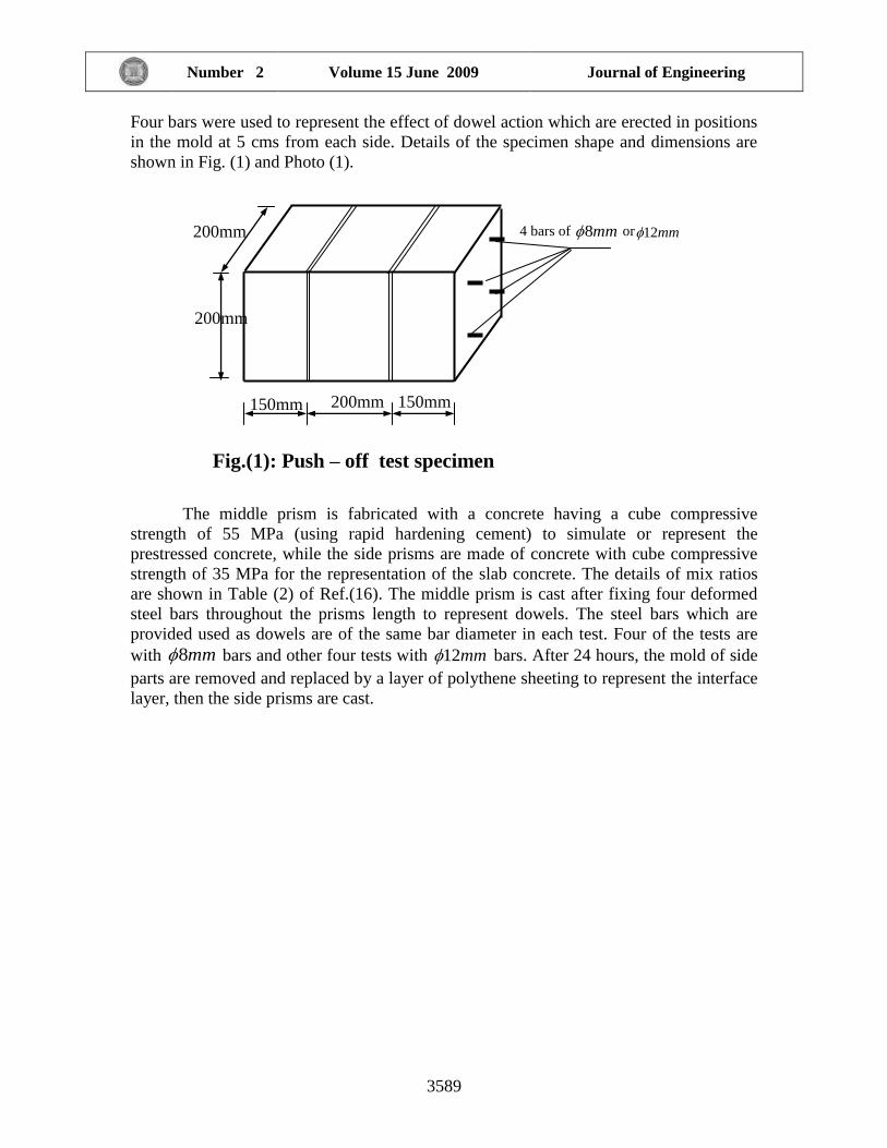
Material properties and the additional material parameters used in the finite
element analysis are listed in Table (5)
.
Table(5) Material Properties and additional material parameters of push-off
specimen
Fig.(7) Dimensions and reinforcement details of push-off specimen.
Sec. a-a
V Y
127 127
127
127
254
19
127 127
a
V
X
4 No. 16
mm
8 No. 13
mm
Journal of Engineering Volume 15 June 2009 Number 2
3599
Concrete ( interface also included )
cE Young’s modulus (MPa) 25200
cf (Hofbeck et al.
test ) (8)
Compressive strength (MPa) 26.9
tf Tensile strength (MPa) 2.7
* Poisson’s ration 0.2
Reinforcing steel
sE * Young’s modulus (MPa) 200000
yf
Yield stress (MPa) No .10mm 349
No .13mm 325
No .16mm 292
Tension stiffening parameters
1
Rate of stress release as the crack widens. 41
2
The sudden loss of stress at the instant of cracking. 0.6
Shear retention parameters
1
Rate of decay of shear stiffness as the crack widens. 10
2
The sudden loss in shear stiffness at the instant of
cracking.
0.9
3
Residual shear stiffness due to the dowel action. 0.1
(*) Assumed values

H. M. Husain Dowel action between two concretes
N. K. Oukaili
H. S. Muhammed
3600
Finite element idealization of push-off specimen of Hofbeck et al.
The specimen which is considered by Hofbeck et al., as an initially cracked specimen is
tested here. It is discretized into nine brick elements, one of them is the interface (element
N0.5), Fig. (8).
Fig .(8) Finite element mesh used for push-off specimen of Hofbeck et al in the
present study
The interface element has a thickness of (0.01-0.1) b, where b is the length of the
face adjacent to interface, Desai et al. (5). Therefore, depending on the previous
assumption the thickness of the interface is taken to be 3mm (0.1b).
Viewing
y
x
z
El.1 Element 4 8
9
Element 7
Element 2
Element 3
Element 6
Element 5

Journal of Engineering Volume 15 June 2009 Number 2
3601
The distribution of the nodes in the 20 – noded brick elements is as shown in
Fig. (9).
Fig. (9) Distribution of nodes on the 20- noded brick element of the test
specimen
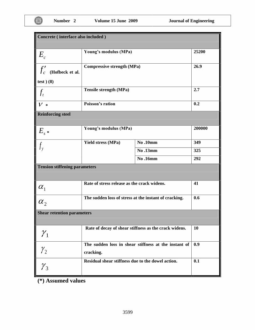
RESULTS OF THE ANALYSIS OF PUSH-OFF SPECIMEN.
In the analysis of push-off specimen tested by Hofbeck et al. (9), the interface model used
is where dowels are used. The nonlinear Equation (11) of the shear modulus is added and
contributed in the constitutive matrix D . The results of the analytical load-slip relation
by finite elements are shown in Fig. (10) which are compared with the experimental
results. The figure indicates good agreement throughout the entire range of load – slip
behavior. The numerical ultimate load is (222.25 kN), while the experimental ultimate
load is (222.3 kN).
H. M. Husain Dowel action between two concretes
N. K. Oukaili
H. S. Muhammed
3602
0.00 0.20 0.40 0.60 0.80
Slip in (mm)
0.00
50.00
100.00
150.00
200.00
250.00
App
lied
load
V in
(kN
)
Analytical
Experimental (40)
Fig. (10) Experimental and analytical load-slip curves of Hofbeck et al.(8) push-off
specimen using Millard-Johnson nonlinear equation of dowel action
Fig. (11) shows the analytical results compared with the experimental results when the
model of linear Equation (6), proposed by Millard and Johnson (16), is used. It is clear
that there would be a difference larger than that shown in Fig. (10) when Millard-Johnson
nonlinear equation is used, where the ultimate analytical load obtained is (224.875
kN).The ratio of the predicted load to the corresponding experimental load is (1.01158).
Therefore it is preferable to use the Millard-Johnson nonlinear equation because the
ultimate shear values in experimental and analytical results coincide. Besides it is well
known that the relation between shear force transmitted through an interface and the slip
is always of exponential form which coincides with that of Millard-Johnson equation.

Journal of Engineering Volume 15 June 2009 Number 2
3603
0.00 0.10 0.20 0.30 0.40 0.50 0.60 0.70
Slip in (mm)
0.00
20.00
40.00
60.00
80.00
100.00
120.00
140.00
160.00
180.00
200.00
220.00
240.00
Ap
plie
d lo
ad
V in
(kN
)
Comparison between analytical and exp resultsusing Millard linear equation of dowel shear modulus
ANLYTICAL
EXPERIMENTAL
Fig. (11)Experimental and analytical load-slip curves of Hofbeck et al. for push-off
specimen using Millard-Johnson linear equation of dowel shear modulus
CONCLUSIONS
The conclusions which can be deduced are listed herein:
1- The exponential equation presented by Millard-Johnson to represent the shear transfer
through interface with slip by dowel action is sufficiently accurate. When comparing the
results of this equation with the results of tests done in the present work and in Hofbeck
et al. work, the two give good and reasonable comparison where the difference between
analytical and experimental work is between 2.5% and 5% for 8mm and 12mm bars
respectively.
2-The exponential equation is used only for initially cracked specimens because as crack
initiates, the transfer of shear is achieved mostly by dowel bars and hardly by aggregate
interlock.
3- As the area or number of dowels are increased the slip is decreased and that is due to
the contribution of the bar stiffness in the overall stiffness of the member.
4-It is suggested to reach to a certain equation representing the shear transfer through
interface by combined aggregate interlock and dowel action .

H. M. Husain Dowel action between two concretes
N. K. Oukaili
H. S. Muhammed
3604
REFERENCES
-. ACI (2005), Building Code requirements for structural concrete: ACI Committee 318-
05. Farmington Hills: American Concrete Institute.
- Al-Shaarbaf,I.A.S., “Three dimensional non-linear finite element analysis of reinforced
concrete beams in torsion”. Ph.D. Thesis, University of Bradford, U.K., 1990.
- Barbieri R.A., Gastal F.P.S.L. and Filho A.C., “Numerical model of prestressed
composite concrete flexural members”, J. of Advanced Concrete Technology, Vol. 1,
No.2, July 2003, Japan Concrete Institute.
- Beer G., “An isoparametric joint/interface element for finite element analysis”, Int. J.
for Numerical Methods in Engineering, Vol.21, 1985.
- Desai C.S., Zaman M.M., Lightner J.G. and Siriwardane H.J.,
“Thin-layer element for interfaces and joints”, Int. J. for Numerical and Analytical
Methods in Geomechanics, Vol.8, 1984.
- Fardis M.N. and Buyukozturk O., “Shear transfer model for reinforced concrete”, J. of
the Engineering Mechanics Division, ASCE, Apr.1979.
- Grossfield B. and Birnstiel C., “Tests on T-beams with precast webs and cast-in-place
flanges”, ACI J., Proceedings, V.59, No.6, June 1962.
- Hofbeck J.A., Ibrahim I.O. and Mattock A.H., “Shear transfer in reinforced concrete”,
ACI J., Feb.1969.
- Hsu T.T.C., Mau S.T. and Chen B., “Theory of shear transfer strength of reinforced
concrete”, ACI Struct. J., 84(2), 1987.
- Hwang S.J. and Lee H.J., “Analytical model for predicting shear strengths for exterior
reinforced concrete beam-column joints for seismic resistance”, ACI Struct. J., 95(5),
1999.
- Hwang S.J. and Lee H.J., “Analytical model for predicting shear strengths for interior
reinforced concrete beam-column joints for seismic resistance”, ACI Struct. J., 97(1),
2000.
- Loove R.E. and Patnaik A.K., “Horizontal shear strength of composite concrete beams
with a rough interface”, PCI J., January-February 1994.
- Mast R.F., “Auxiliary reinforcement in concrete connections”, J.Struct. Div., Proc.,
ASCE, 94(6), 1968.

Journal of Engineering Volume 15 June 2009 Number 2
3605
- Mattock A.H. and Hawkins N.M.,”Shear transfer in reinforced concrete –recent
research”, PCI J., March-April 1972.
- Millard S.G. and Johnson R.P., “Shear transfer across cracks in reinforced concrete due
to aggregate interlock and to dowel action”, Magazine of concrete
research,Vol.36,No.126, March 1984.
- Millard S.G. and Johnson R.P., “Shear transfer in cracked reinforced concrete”,
Magazine of Concrete Research, Vol.37, No.130, March 1985.
- Patnaik A.K., “Behavior of composite concrete beams with smooth interfaces”, Journal
of Structural Engineering, ASCE, Vol.127, No.4, paper No.22384, April 2001.
- Patnaik A.K., “Longitudinal shear strength of composite beams with a rough interface
and no ties”, Australian J. Struct. Engrg. 1(3), 1999.
- Patnaik A.K., “Discussion of „Evaluation of ACI 318-95 shear friction provisions‟ by R.
Valluvan, M.E. Kerger and Jirsa J.O.”,ACI J., May-June 2000.
- Paulay T., Park R. and Philips M.H., “Horizontal construction joints in cast-in –place
reinforced concrete”, Shear in Reinforced Concrete, SP-42, ACI, Farmington Hills,
Michigan, 1974.
- Walraven J.C.,Frenay J. and Pruijssers A., “Influence of concrete strength and load
history on the shear friction capacity of concrete members”, PCI J.,21(1),1987.
- Walraven J.C. and Reinhardt H.W., “Concrete Mechanics-Part A: Theory and
experiments on the mechanical behavior of cracks in plain and reinforced concrete
subjected to shear loading”, Hron.Vol.26, No.1A, 1981, pp 1-68.