Double-integrating-sphere system for measuring the optical properties of tissue
12
Double-integrating-sphere system for measuring the optical properties of tissue John W. Pickering, Scott A. Prahl, Niek van Wieringen, Johan F. Beek, Henricus J. C. M. Sterenborg, and Martin J. C. van Gemert A system is described and evaluated for the simultaneous measurement of the intrinsic optical properties of tissue: the scattering coefficient, the absorption coefficient, and the anisotropy factor. This system synthesizes the theory of two integrating spheres and an intervening scattering sample with the inverse adding-doubling algorithm, which employs the adding-doubling solution of the radiative transfer equation to determine the optical properties from the measurement of the light flux within each sphere and of the unscattered transmission. The optical properties may be determined simultaneously, which allows for measurements to be made while the sample undergoes heating, chemical change, or some other external stimulus. An experimental validation of the system with tissue phantoms resulted in the determination of the optical properties with a < 5% deviation when the optical density was between 1 and 10 and the albedo was between 0.4 and 0.95. Key words: Optical properties, absorption coefficient, scattering coefficient, anisotropy factor, integrat- ing sphere, adding-doubling, tissue optics. 1. Introduction With progress in laser medicine there is an ever- increasing need to provide accurate measurements of the optical properties of biological tissues. The pur- pose of this paper is to present a synthesis of what we believe is the most appropriate solution to the radia- tive transfer equation' with a measuring technique that allows the accurate and simultaneous determina- tion of the (in vitro) absorption and scattering coeffi- cients and the anisotropy of scattering. Cheong et al. 2 provided a list of optical properties measured by a variety of techniques. These tech- niques and their associated advantages and disadvan- tages were also discussed. The extreme variation in the properties of some tissues measured by different techniques (assuming that no gross errors were made) may be attributed to differences between in vivo and in vitro measurements, differences in radiative trans- fer models, differences in tissue preparation, or differ- When this research was done the authors were with the Laser Centre, Academic Medical Centre, Meibergdreef 9, 1105 AZ, Amster- dam, The Netherlands. S. A. Prahl is now with Wellman Labora- tories of Photomedicine, Massachusetts General Hospital, Boston, Massachusetts 02114. Received 12 November 1991. 0003-6935/93/040399-12$05.00/0. © 1993 Optical Society of America. ences in measuring techniques (with the possibility of systematic errors). Light propagation in turbid media is characterized by the absorption coefficient p.a, the scattering coeffi- cient p,, the scattering phase function, the refractive index, and the surface conditions (rough or smooth). The measurement of refractive indices and surface conditions is important when light distributions near boundaries are considered, and measuring tech- niques that are radically different from those dis- cussed here are required; thus we shall not consider them further. 3 The direct phase-function measurements per- formed by goniometry on thin slices of tissue have established the preference for the Henyey-Green- stein phase function, which describes the forward- scattering nature of most tissues.> 7 This phase function may be described by the average cosine of the scattering angle, the anisotropy factor g, where g = 0 denotes isotropic scattering and g = 1 is totally forward scattering. The method used in this paper enables the calculation of the anisotropy under the assumption of the Henyey-Greenstein phase func- tion. In vivo measurements are the most immediately applicable to dosimetry; yet they present techniques that provide only limited information on optical properties. Interstitial fiber techniques (invasive) give the effective attenuation coefficient Peff and 1 February 1993 / Vol. 32, No. 4 / APPLIED OPTICS 399
Transcript of Double-integrating-sphere system for measuring the optical properties of tissue

Double-integrating-sphere system for measuringthe optical properties of tissue
John W. Pickering, Scott A. Prahl, Niek van Wieringen, Johan F. Beek,Henricus J. C. M. Sterenborg, and Martin J. C. van Gemert
A system is described and evaluated for the simultaneous measurement of the intrinsic optical propertiesof tissue: the scattering coefficient, the absorption coefficient, and the anisotropy factor. This systemsynthesizes the theory of two integrating spheres and an intervening scattering sample with the inverseadding-doubling algorithm, which employs the adding-doubling solution of the radiative transferequation to determine the optical properties from the measurement of the light flux within each sphereand of the unscattered transmission. The optical properties may be determined simultaneously, whichallows for measurements to be made while the sample undergoes heating, chemical change, or some otherexternal stimulus. An experimental validation of the system with tissue phantoms resulted in thedetermination of the optical properties with a < 5% deviation when the optical density was between 1 and10 and the albedo was between 0.4 and 0.95.
Key words: Optical properties, absorption coefficient, scattering coefficient, anisotropy factor, integrat-ing sphere, adding-doubling, tissue optics.
1. IntroductionWith progress in laser medicine there is an ever-increasing need to provide accurate measurements ofthe optical properties of biological tissues. The pur-pose of this paper is to present a synthesis of what webelieve is the most appropriate solution to the radia-tive transfer equation' with a measuring techniquethat allows the accurate and simultaneous determina-tion of the (in vitro) absorption and scattering coeffi-cients and the anisotropy of scattering.
Cheong et al.2 provided a list of optical propertiesmeasured by a variety of techniques. These tech-niques and their associated advantages and disadvan-tages were also discussed. The extreme variation inthe properties of some tissues measured by differenttechniques (assuming that no gross errors were made)may be attributed to differences between in vivo andin vitro measurements, differences in radiative trans-fer models, differences in tissue preparation, or differ-
When this research was done the authors were with the LaserCentre, Academic Medical Centre, Meibergdreef 9, 1105 AZ, Amster-dam, The Netherlands. S. A. Prahl is now with Wellman Labora-tories of Photomedicine, Massachusetts General Hospital, Boston,Massachusetts 02114.
Received 12 November 1991.0003-6935/93/040399-12$05.00/0.© 1993 Optical Society of America.
ences in measuring techniques (with the possibility ofsystematic errors).
Light propagation in turbid media is characterizedby the absorption coefficient p.a, the scattering coeffi-cient p,, the scattering phase function, the refractiveindex, and the surface conditions (rough or smooth).
The measurement of refractive indices and surfaceconditions is important when light distributions nearboundaries are considered, and measuring tech-niques that are radically different from those dis-cussed here are required; thus we shall not considerthem further.3
The direct phase-function measurements per-formed by goniometry on thin slices of tissue haveestablished the preference for the Henyey-Green-stein phase function, which describes the forward-scattering nature of most tissues.>7 This phasefunction may be described by the average cosine ofthe scattering angle, the anisotropy factor g, whereg = 0 denotes isotropic scattering and g = 1 is totallyforward scattering. The method used in this paperenables the calculation of the anisotropy under theassumption of the Henyey-Greenstein phase func-tion.
In vivo measurements are the most immediatelyapplicable to dosimetry; yet they present techniquesthat provide only limited information on opticalproperties. Interstitial fiber techniques (invasive)give the effective attenuation coefficient Peff and
1 February 1993 / Vol. 32, No. 4 / APPLIED OPTICS 399

sometimes the absorption pa and reduced scatteringcoefficient [' = pU(1 - g)].8 -10 Reflectance andtransmittance measurements as a function of sourceand detector position allow similarly the determina-tion of p,, and pF'."1" 2 Several new techniques areunder development that also yield optical properties;in particular, photoacoustic spectroscopyl3"14 yieldsp,,, and time-of-flight measurements 5"16 and pulsedphotothermal radiometry17" 8 yield [u,' and p1a.
In vitro measurements have the advantage over invivo measurements in that the effect of individualtissue structures (for example, the epidermis and thedermis instead of the entire skin) may be evaluated.However, they are also subject to preparation artifacts.Other than the goniometric measurements the major-ity of techniques involve the use of integrating spheresto measure reflection and transmission.
The theory and practicality of integrating spheresfor measuring the reflectance of a sample have beenstudied extensively.19-23 Much of this knowledge isstill applicable to transmission measurements. 24
The measurements of the reflection, the total trans-mission, and the sample thickness allow the determi-nation of qua and pU'. The additional measurement ofthe collimated transmission allows the separation ofthe reduced scattering coefficient into the scatteringcoefficient and the anisotropy. This measurementhas been made often with a separate, thinner, samplebecause of the difficulties in detecting small quanti-ties of light. However, if the measurements of reflec-tion and diffuse and collimated transmission are allmade from one sample placed between two integrat-ing spheres, as described in this paper, all threeoptical properties may be deduced simultaneously.Our principal reason for developing this system forthe simultaneous determination of optical propertiesis that it allows the investigation of the changes inoptical properties during the application of heat.Furthermore, such a system requires only the mini-mal preparation of one tissue sample. We shalldescribe the practicalities of this system including themethodology of determining the influence of thesphere parameters, taking into account the exchangeof light between the spheres,2 5 avoiding light lossesfrom the sample, the overall accuracy to which opticalproperties can be determined, and the importance ofan accurate collimated transmission measurement.In addition, if collimated transmission measurementsare impractical (for example, with optically thicksamples), we show that it is more accurate to usecollimated incident light as opposed to diffuse inci-dent light for reflection and total transmission mea-surements.
To determine the optical properties from the mea-sured light flux in the two spheres and the collimatedtransmitted light flux, we use an iterative methodwith the adding-doubling solution of the radiativetransfer equation. This inverse adding-doubling al-gorithm is discussed in a sister paper.' Briefly wechose this solution because it allows the use ofcollimated and diffuse incident light, is applicable
with slab geometry, can account for boundary condi-tions, and is relatively fast in computation. Pleasenote that, because our goal is to obtain the absorptionand scattering characteristics of the tissue, we do notattempt to calculate the percentage of light reflectedor transmitted by the sample, but rather we calculatethe expected flux in each sphere with the adding-doubling algorithm and by using the sphere formulasdescribed in Section 2. We compare this with themeasured fluxes. When they do not match, a newset of optical properties is used to recalculate thefluxes, and these are once more compared with themeasured fluxes. This iterative process continuesuntil the experimental and calculated fluxes match,giving the optical properties of the sample.
2. Integrating-Sphere TheoryAlthough the integrating-sphere theory has beenstudied extensively, we introduce the formulas appli-cable for the single integrating sphere and discusshow they extend to double integrating spheres. (Themathematical part of this theory has been describedin another paper.25) Sphere formulas for both dif-fuse incident and collimated incident light are givensince they are necessary for understanding the proce-dures for calibrating the spheres (Section 3).
A. Single-Sphere TheoryTo measure the reflected and transmitted light from asample, we situated it at, respectively, the exit orentrance port of a sphere. Normally the detector issituated on the inner sphere surface. Often tissue isplaced between glass plates to prevent dehydration, toprovide mechanical support, and to minimize surfaceeffects. The influence of these plates on the reflectedand transmitted light may be calculated.' However,the theory requires that no directly reflected light(Fresnel reflected) from the sample irradiates thedetector; therefore a baffle is placed between thesample and the detector (Fig. 1).
The integrating-sphere theory accounts for thelosses caused by absorption from the sphere wall andlight escaping the sphere. The power detected de-pends on the total light remaining within the sphereand on the relative (to the total sphere area) size ofthe detector.1825
For a single-sphere reflectance measurement usingdiffuse irradiance of the sample [generated by thelight entering the sphere irradiating the sphere wall;Fig. 1(a)], the power detected on the inner surface ofthe sphere is
b,(1 - Rd A,
1 -b 2 Rd (1)
where P is the power of the incident light, Rd is thediffuse reflectance of the sample for diffuse irradi-ance, A, is the sample area, A is the inner surface areaof the complete sphere, and the sphere constants b,
400 APPLIED OPTICS / Vol. 32, No. 4 / 1 February 1993

Sample
Detector
(a) (b)
Detector
(C)
Fig. 1. (a) Diffuse light may irradiate the sample through the beam first irradiating the sidewall of the sphere. (b) Alternativelycollimated light may directly irradiate the sample. In all cases a baffle is placed between the sample and the detector to prevent detection ofspecularly reflected light. In the double-sphere system the sample is placed between the spheres, and the unscattered collimatedtransmitted light is permitted to leave the system (c).
and b2 are defined as
AB m A, 1b, m- b 2 = 4 1 ' (2)bl=A 1 - m ' b A 1 - m (2
where m is the diffuse reflectance factor of the spherewall, A8 is the area of the detector, a is the fraction ofthe total sphere area occupied by the sphere wall,
a=[A-(As + As + Aa)]/A. (3)
(Aa is the sum of the area of all other apertures in thesphere wall.) The term (1 - RdAS/A) accounts forthe presence of a baffle between the detector andsample [see Eq. (4b) in Ref. 25]. For the spheresdiscussed in this paper this results in at most a 3%correction, which, compared with other sources ofuncertainty, is small (see Sections 4 and 5) andtherefore for the sake of clarity is not included in therest of this paper.
For collimated light that is first incident on thesample [Fig. 1(b)] the detected power is
_ bl(Rcd + R,) P1- 2Rd
where R~d is the diffuse reflectance of the sample forcollimated irradiance and Rc is the specular (unscat-tered) Fresnel reflection of the sample for collimatedirradiance. (Note that if this light is permitted topass out of the sphere, this term is zero.)
For a sample located at the entrance port of asphere and for diffuse irradiance, the detected poweris
Pd = _b2R. P' (5)
where Td is the coefficient of transmittance for diffuseirradiance. For collimated irradiance the detectedpower is
Pd b 1(Tl( + TCd) P' (6)1 -b 2 Rd(6
where Tcd is the diffuse transmittance for collimatedirradiance and T is the collimated (unscattered)transmittance for collimated irradiance. (Note thatif the collimated light is permitted to pass out of thesphere, this term is zero.)
If a nonisotropic detector is used as an alternativeto a baffle (i.e., a detector such as a fiber optic thatdetects only light that is coming from part of thesphere wall, a part not containing the sample), theequations are identical with the exception of bl, whichis smaller by a factor depending on the fraction of thesphere wall from where the detector receives light.25
B. Double-Sphere TheoryThe double-sphere system consists of two sphereswith the sample placed between them [Fig. 1(c)].The two spheres may be of different geometries andwith different surface reflectances. The only require-ment are that the sample ports be the same area A,and shape and that the reflectance and transmittancefactors of the sample be independent of the side of thesample at which the light is incident. If light irradi-ates the sample in the first sphere (called the reflec-tance sphere), a portion of this light will be transmit-ted through the sample to the second sphere (thetransmittance sphere). Some of the light within thetransmittance sphere will irradiate the sample (theback of the sample), and some of this light will betransmitted back into the reflectance sphere; thus thesignal in the reflectance sphere is increased. Someof this additional light is then (re)transmitted to thetransmittance sphere, and the signal in the transmit-tance sphere is increased. This process of the trans-mission of an ever-decreasing portion of the lightback and forth through the sample continues until allthe light has been absorbed or lost from the spheres.The net effect is to increase the signal in both spheresover the single-sphere case. In the following equa-tions the nomenclature is identical to that of thesingle-sphere equations with the addition of an extrasubscript, r or t, to identify the parameters associatedwith either the reflectance or transmittance spheres,respectively.
1 February 1993 / Vol. 32, No. 4 / APPLIED OPTICS 401
Sample

For diffuse light incident on the sample in thereflectance sphere (generated by collimated light thatis first incident on the sphere wall), the power col-lected in the reflectance sphere is
Pd = - bir(1 b2 tRd) (7)(1 -b 2rRd)( - b2 tRd) - b2 rb 2 tTd2P (
and the power detected in the transmittance sphere is
b=tb2rmr,(tTdd (1 - b2rRd)(1 - b2 tRd) - b2 b2 tTd2 (
For collimated light incident on the sample withinthe reflectance sphere the power detected in thereflectance sphere is
k -0
2r-d)U. -
These equations, as for the single-sphere equa-tions, account for the losses within the spheresthrough absorption by the wall and losses throughthe apertures. However, because of the exchange oflight between the spheres each equation must ac-count for light losses within both spheres. Theselosses will also depend on the amount of light trans-mitted through the sample; thus the power within thereflectance sphere not only depends on the coeffi-cients of reflectance but also on the coefficients oftransmittance. This coupling of the reflection andtransmission coefficients implies that they cannot bedetermined analytically from the measurement of thesphere powers for either of the incident light geome-tries (diffuse or collimated).
3. Measurement Techniques and Sphere Constants
A. Making Relative MeasurementsThe voltage recorded by the detector (usually aphotodiode or a photomultiplier tube) on the innersurface of each of the spheres is proportional to thetotal power incident on the detector Pd so that
V= KPd, (11)
where K depends on the characteristics of the detector.In practice there is a background signal or voltage VO
depending on the noise in the detection system and onthe presence of stray light. Therefore we may rear-range Eq. (11) to be
1Pd = (V - 1O).12
Finding the reflection and transmission coefficientsof the sample from measurements of the voltageknolwedge of the sphere constants (b1, b2, a, A, s, andm), the initial power, and the detector constant K.Furthermore, there are as many as six unknowncoefficients [R,, Rd, Red, T0, Td, Ted; see Eqs. (9) and(10)]. The measurement of the collimated transmit-tance with a third detector at a distance from thesecond sphere yields T,:
(9)
(10)0
2tgd) -0 2r0
2t'd
c Vc-v,O = Vc%,1 K,,ref - lK,,refo
(13)
where V, is the voltage recorded with the sample inplace between the spheres and Vcref is the voltagerecorded without the sample in place. V,0 = VK,ref isthe background signal with the light source extin-guished. Note that the factor K is eliminated fromthis equation.
The specular reflection coefficient R, may be calcu-lated from Fresnel's equations. This leaves at mostthe diffuse reflection of collimated irradiance Rcd, thediffuse reflection of diffuse irradiance Rd, the diffusetransmission of collimated irradiance Td, and thediffuse transmission of diffuse irradiance Td to bedetermined from the voltages measured within thetwo spheres. The diffuse reflection (or transmis-sion) coefficient of the collimated irradiance is aspecial case of the coefficient for diffuse irradiance.(Only one incident direction is considered.) Someradiative transfer models, such as adding-doubling,are able to couple the two coefficients because themodel is able to consider the direction of the incidentlight. Therefore there remain only two unknowns(because of the tissue) requiring only the measure-ment of the voltages in the two spheres. The otherunknowns, P, K, and the sphere constants, may bemeasured or eliminated through the procedures de-scribed below.
402 APPLIED OPTICS / Vol. 32, No. 4 / 1 February 1993
Pd bjj[(R + t,Rd)(l -b2tRd) + tb2tTd(Tcd + tTC]P,
Pd = (1 - b2rRd)(1 - b2tRd) - b2 b2tTd2
and the power detected in the transmittance sphere is
pd - blt[(T + tTCd)(l - b2rRd) + tb2rTd(Rcd + MrRc)]P- 7 T- \I~ I1
(12)
The power P of the incident beam can be measureddirectly, but for convenience we took measurementsthat are relative to the power that we detected byusing a standard reference plate (which is diffuselyreflecting with reflection coefficient Rref) in the posi-tion of the reflecting sample. Therefore for thisreference plate the power incident on the detector is
Pd,ref = P4)(RrefX A, A, Aa, m), (14)
where the function 4) is constant for a given spheregeometry and reference plates. Furthermore thisfunction depends on whether collimated or diffuselight is incident on the reference plate.
By combining Eq. (12) and (14), we may write
P dref (Vre Vre (15)
where Vref is the voltage measured with the referenceplate in position and VrefO is the background measure-ment with no reference plate.
Combining Eqs. (12) and (15) gives the ratio of thedetected power to the incident power as
_P_ (V -VO)P 4 (Vref - VrefO)= % (16)
which is independent of the constant K.From the equations for the detected power [Eqs. (1)
and (4)-(10)] we note that
P oc b (17)
Therefore we may define b1 as
1b, _ b, - (18)
Thus the need to measure the power is eliminated,and the reflectance of the sample can be obtainedfrom the measurement of the four voltages (V, V0,Vref, Vref 0) and knowledge of the sphere constants.However, it is necessary that all measurements madewith the sample and the reference plate be made withthe same incident power. This is a requirement ofEq. (18).
We can write Eqs. (1) and (4)-(10) in terms of Vq% byutilizing the above definition of b, and replacing Pd /Pby V%. The measurements required to measure V.%for the reflectance and each of the transmittances aresummarized in Table 1. Note that where there is aneed to distinguish between the voltages measuredwithin the reflectance sphere and those measuredwith the transmittance spheres, they have an addi-tional subscript of r and t, respectively. Further-more all reference voltages in the transmittancesphere must be made in the absence of the reflectancesphere and with the sphere rotated so that the theexit port in the double-sphere geometry becomes theentrance port.
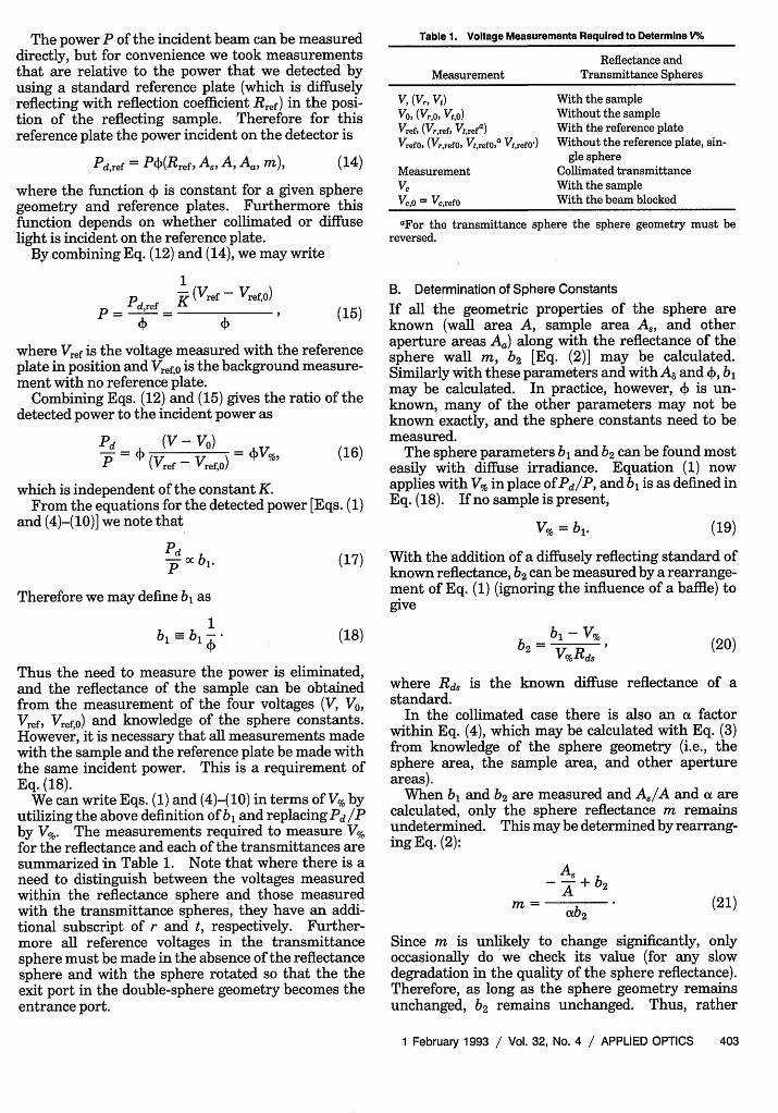
Table 1. Voltage Measurements Required to Determine V%
Reflectance andMeasurement Transmittance Spheres
V, (VI, Vt) With the sampleVo, (Vr,'0 Vt,o) Without the sampleVref, (Vr,ref, Vt,refa) With the reference plateVref0, (V,,refO, VtrefO,a Vtrefo') Without the reference plate, sin-
gle sphereMeasurement Collimated transmittanceVc With the sampleVc'o = VcrefO With the beam blocked
aFor the transmittance sphere the sphere geometry must bereversed.
B. Determination of Sphere Constants
If all the geometric properties of the sphere areknown (wall area A, sample area A8 , and otheraperture areas Aa) along with the reflectance of thesphere wall m, b2 [Eq. (2)] may be calculated.Similarly with these parameters and with As and 4), b,may be calculated. In practice, however, 4) is un-known, many of the other parameters may not beknown exactly, and the sphere constants need to bemeasured.
The sphere parameters b, and b2 can be found mosteasily with diffuse irradiance. Equation (1) nowapplies with V% in place of Pd/P, and b, is as defined inEq. (18). If no sample is present,
V% = b1. (19)
With the addition of a diffusely reflecting standard ofknown reflectance, b2 can be measured by a rearrange-ment of Eq. (1) (ignoring the influence of a baffle) togive
b= - V%
b2 =V%Rd., (20)
where Rd, is the known diffuse reflectance of astandard.
In the collimated case there is also an a factorwithin Eq. (4), which may be calculated with Eq. (3)from knowledge of the sphere geometry (i.e., thesphere area, the sample area, and other apertureareas).
When b, and b2 are measured and A 8/A and a arecalculated, only the sphere reflectance m remainsundetermined. This may be determined by rearrang-ing Eq. (2):
As-A + b2
(21)
Since m is unlikely to change significantly, onlyoccasionally do we check its value (for any slowdegradation in the quality of the sphere reflectance).Therefore, as long as the sphere geometry remainsunchanged, b2 remains unchanged. Thus, rather
1 February 1993 / Vol. 32, No. 4 / APPLIED OPTICS 403

than measuring b2 each time, we use a previouslydetermined value and calculate b, by a rearrangementof Eq. (4):
b = kRds (1 - b2RdS), (22)
where V% is measured with a standard diffuse reflec-tion plate of known reflectance Rd, and collimatedincident light. The specularly reflected light R isassumed to be lost through the entrance port. Alsothe diffuse reflectance of collimated incident light ofthe standard Rcd, and diffuse reflectance of diffuseincident light Rd, are assumed to be identical. (Wemeasured the difference for our standards, the Lab-sphere SRS-010 series, to be < 1.5%.)
With the sphere constants and the measurementsthat give V,% Vt%, and VC%, we can iterate the albedo a,optical depth , and anisotropy g of the sample byusing the inverse adding-doubling solution to pro-duce calculated values of V% within a minimum errorto be the same as the measured values.' From thealbedo, the optical depth, and thickness d of thesample, the scattering and absorption coefficients canbe determined:
T(1-a)Pa d
aTRs d -=
4. Theoretical UncertaintiesIn this section we discuss the theoretical accuracy towhich the reflection and transmission of a sample canbe measured. This illustrates that greater accuracycan be obtained when collimated rather than diffuseirradiance is used. Note that to find the opticalproperties of a sample we do not normally calculatethe reflectance and transmittance explicitly as ex-plained in Section 1 and in Ref. 1.
Equation (1) may be rearranged to give the diffusereflectance
d A 1 VI,, (24)
b, A- b2 V%
To estimate the uncertainty in Rd for an uncertainty
in the measured variables (Xi = bl, V%, s, A, b2), weapply
(,Rd) 2 = (dd AX). (25)
Table 2 gives the percentage uncertainty in Rd atRd = 0.4 for 1%, 2%, 5%, and 10% uncertainties in allthe other variables. This shows that the uncer-tainty in reflectance is due primarily to uncertaintiesin b, and in V%. The overall uncertainty is propor-tional to the measurement uncertainties.
Similarly the diffuse reflectance and its uncertaintycan be calculated for collimated incident light. Anadditional uncertainty is included to account for theassumption that the diffuse reflection of collimatedincident light is the same as the diffuse reflection ofdiffuse incident light. Figure 2 shows the uncer-tainty in Rd for a 1% uncertainty in all the variablesfor both diffuse and collimated incident light within asingle sphere. Collimated irradiance gives a muchmore accurate measurement of the reflectance.
We may explain the difference in terms of a signal-to-noise ratio. In the diffuse case there is a signalregistered by the detector due to the light within thesphere even when no sample is present. This signalis proportional to b. The presence of a diffuselyreflecting sample will increase this signal by a factorof 1/(1 - b2Rd) [Eq. (1)]. Since b2 is typically 0.25,the maximum factor by which the signal can increase(the 100% reflecting sample) is 1.33. Thus all mea-surements are made with a high background signal.Noise in this background signal, especially with low-reflectance samples, will result in uncertainties in thecalculation of the reflectance. In the collimated casethe sample reflectance acts as the source, and there isno independent background signal.
The uncertainty in transmittance depends weaklyon the uncertainty in reflectance [Eqs. (5) and (6)] butis approximately just the sum of the uncertainty inthe transmittance sphere b and V%.
With the double integrating spheres the uncertain-ties calculated for the single spheres will also apply.In the reflectance sphere there will be an additionaluncertainty caused by the signal returning from thetransmittance sphere through the sample. For colli-mated irradiance this signal is not directly propor-
Table 2. Effect of the Change in Each Variable on the Reflectance for a Given Uncertainty in that Variable at Rd = 0.41, A,/A = 0.03, b, = 0.8, b2 = 0.25and for Diffuse Incident Lighta
Uncertainty i( Axi i) Uncertaintyin Xi (%) Xi = b Xi = b2 Xi = A,/A Xi = V% (ARd )
2in Rd (%)
1 0.00163 0.00002 0 0.00163 0.00327 142 0.00650 0.00008 0 0.00650 0.0131 285 0.0406 0.00053 0.000006 0.0406 0.0818 70
10 0.163 0.0021 0.000024 0.163 0.327 140
aUsing (ARd) 2 = 1J[(0Rd/aXi )AXi]2.
404 APPLIED OPTICS / Vol. 32, No. 4 / 1 February 1993

.5
.It
a
60-
50-
40
30
20
10-
Single sphere diffuse
Double spherecollimated
Single spherecollimated
o , =0.0 0.1 0.2 0.3 0.4 0.5 0.6 0.7 0.8 0.9 1.0
Rd
Fig. 2. Uncertainty in the calculated reflectance is always great-est when the reflectance (and hence the signal) is low. For a singlesphere diffuse irradiation leads to a much greater uncertainty inthe reflectance than collimated irradiation because there is a signalgenerated prior to the reflection by the sample. With the double-sphere system the uncertainty in reflectance is increased becauseof the exchange of light between the spheres, but it is still smallestfor collimated irradiation, and this uncertainty is smaller than fordiffuse irradiation in the single sphere.
tional to the reflectance of the sample (but rather thetransmittance) and is maximal when there is noabsorption (Rd = 1 - Td). This leads to a greateruncertainty in reflectance than with the single spherebut still much less uncertainty than with diffuseirradiance. (This worst case is included in Fig. 2.)
The preference for collimated irradiance was firstdiscussed by Taylor in 1920.19 At that time theproduction of a narrow collimated beam (required forsmall samples) of sufficient intensity was often notpractical. Until recently models of radiative trans-fer have relied on the assumption of diffuse irradiance.The advent of lasers and radiative transfer modelsable to cope with collimated irradiance has, in ouropinion, rendered the use of diffuse irradiance obso-lete given the greater uncertainties involved.
5. PracticalitiesWhile the theory in the sections above will enable thereader to make measurements with the double inte-grating spheres, there are a number of practicalaspects related to the design and method of operationof the equipment that require discussion. Sincecollimated irradiance gives more accurate measure-ments, the following sections consider collimatedirradiance only.
A. Sample SizeLoss of light through the sides of the sample andsample holder will erroneously increase the calcu-lated absorption coefficient. This loss depends onthe physical size and geometry of the sample, the sizeof the incident beam, and the optical properties of thesample.
As a highly forward scattering and weakly absorb-ing liquid, Intralipid-10% was used in various dilu-tions to mimic a range of optical depths of tissue.Previous research has established the optical proper-ties of Intralipid at 633 nm.10 ,26,27
We measured the total light collected for four
different combinations of sample port diameters h(10, 19, or 25 mm) and sample thickness d (0.5 or 1.0mm) with a 1-mm-diameter He-Ne laser (Uniphase1105).
Light loss was greatest, by as much as 30%, for asmall sample port diameter (10 mm) and intermedi-ate optical depths.2-8 For greater optical depths (atthe same port diameter) the lost light is reducedbecause the scattering is sufficient to prevent a greattransport of light to the sample sides. Similarly witha larger port there is reduced light loss. For a 1-mmsample thickness and 25-mm port diameter the lightloss was negligible over the optical depth range from 0to 54.
B. Collimated Detector DistanceThe collimated detector measuring unscattered trans-mitted light V,% is situated behind the exit port of thetransmittance sphere. If this detector is close to theport, it will detect not only unscattered light but alsolight that has undergone only a few scattering eventsand possibly some of the diffuse light (as a result ofreflections within the sphere) lost through the port.The farther the detector is from the port the lessscattered light we detected, depending on the detectorsize (we used 3-mm-square photodiodes from Tele-funken, BPW 34) and the optical depth of the sample.
To find a distance at which virtually all the scat-tered light has been eliminated from the collimatedsignal, we measured VC% with a 5-mW He-Ne laser(Uniphase 1105) as a function of the distance fromthe sample (Intralipid-10%) and for three differentoptical depths of the sample (T = 5, 7, 10). At anygiven detector distance the higher the optical depththe greater the scattered light contribution to thecollimated signal. For optical depths of <10 andany distance exceeding 60 cm, the error in VC% was<5%.
The collimated transmission measurement deter-mines directly the optical depth of the sample. Theinverse adding-doubling program with the measure-ments within the two spheres will determine theunique albedo and anisotropy.' Without the colli-mated transmission measurement only the reducedalbedo and reduced optical depths may be calculated.
C. Sample HoldersA glass (or quartz) sample holder provides mechanicalstability and serves to minimize rough surface effects.A drop of water (or some neutral buffered solution)prevents refractive-index mismatches between thesample and glass.
Sometimes with coherent collimated light there isinterference from the glass slides. This occurs withtwo parallel slides when the reflection from the airglass surface and the glass sample surface are suchthat for certain directions of the incident light con-structive or destructive interference may occur (whichis similar to a Fabry-Perot interferometer). Wefound that this interference experimentally has aconsiderable effect on the signal from the reflected
1 February 1993 / Vol. 32, No. 4 / APPLIED OPTICS 405

light. The problem may be overcome by the utiliza-tion of slides with nonparallel surfaces or optical flats.
D. Background MeasurementsWith our technique we measure with a lock-in am-pliflier and a chopped irradiance. This all but elimi-nates any background signal from extraneous lightsources. Therefore, the measurement of V0, thebackground signal, in each of the spheres is madewhile the light source is on and no sample is present.Occasionally the background signals measured in thedouble-sphere configuration (V,,0 and V) can becomparable with the signal when the sample is pre-sent; almost invariably this is a result of poor collima-tion of the beam (such as when nonlaser sources orlaser light from a fiber is used). These backgroundsignals are directly proportional to the total sourcepower. Furthermore, the background signal for thereference measurements (Vrrefo and Vtrefo) made in asingle-sphere configuration is always lower. We con-clude that this noise is due principally to the diver-gence of the beam, which results in some light hittingthe back wall of the transmittance sphere rather thanexiting the port through which the collimated signalis measured. However, in the presence of a samplethis noise will be reduced because of the absorbanceand scattering of the sample. To correct for thisnoise we must calculate the exchange of light betweenthe spheres for this noise.
If we redefine V% as
V% V - Vdark (26)
where Vdark is the signal measured with the lightsource blocked. V and V% may then be correctedby
Vcorrected = Vr,% - FlVr,ref0% - F2Vt,ref0'%, (27)
V corrected t% = Vt% - F3Vr,refO% - F4Vt,refO'%) (28)
where all measurements are given relative to thereference plate measurement [Eq. (26)], Vr,ref0% ismeasured with the reflectance sphere in positionwithout the transmittance sphere, and Vtref0'% ismeasured with the transmittance sphere in positionwithout the reflectance sphere. (Note that this isdifferent from V,refO where the sphere is rotated; seeSection 3.) The correction factors F1 to F4 accountfor the exchange of light between the spheres throughthe sample. The noise signals in each sphere may beconsidered to be diffuse light sources, and thereforethe correction factors may be calculated under theassumption that the sample has been illuminated inthe reflectance sphere with a relative power Vrref0%and in the transmittance sphere with a relative powerof TVtref0%. The T factor is included because theunscattered light contributing to the noise in thetransmittance sphere will have been attenuatedthrough scattering and absorption by the sample.For the corrections arising from the noise in the
reflection sphere we use the equations for the ex-change of light between the two spheres and fordiffuse irradiance [Eqs. (7) and (8)] divided by theequation that describes the power detected owing tocollimated light being incident on the sphere wall [Eq.(1)] so that
(1 - b2rRd)(1 - b2tRd)
(1 - b2 ,Rd)(1 - b2tRd) - b2 b2 tTd2'(29)
F3 = (1 - b2rRd) bljb 2 ,m,(XtTd
blr (1 - b2rRd)(1 - b2 tRd) - b2 b2 tTd 2
(30)
The correction factors arising from the noise in thetransmittance sphere may be calculated in a similarmanner by including the T, factor and swapping ther's and t's:
Tc(1 - b2tRd)
F2 = blt
blrb2tmtaXrTd
(1 - b 2tRd)(1 -b 2 Rd) -b 2 tb2 Td2
T(1 - b2tRd)( - b2rRd)
F4 (1 - b2tRd)(1 - b2rRd) - b2 tb2 Td2
(31)
(32)
Note that this correction is normally not signifi-cant, as for most samples, and especially with well-collimated sources, Vr >> V > Vr,ref0, Vt,ref0' and Vt>> Vt, > Vr,ref0, Vt,ref0'. Only in examples of highattenuation of the light by the sample and relativelypoor collimation is it necessary to make this correc-tion.
6. Experimental ValidationTo validate the proposed method of measuring opticalproperties in combination with the inverse adding-doubling algorithm, we attempted to measure theoptical properties of tissue phantoms over a widerange of albedos and optical depths. The two phan-tom materials chosen were Intralipid-10% and EvansBlue.26 27 These were chosen because their opticalproperties permit simulation of tissue. Intralipid-10% is forward scattering (g 0.7) and at 632.8 nmis a very weakly absorbing liquid (see Table 4 below).Evans Blue (515 mg in 1 L of isotonic phosphatebuffer or 515 mg in 1 L of NaCl buffer) is a weaklyscattering and highly absorbing liquid at 632.8 nm.Mixtures of these solutions provide samples with avariety of albedos a and optical depths T. The absorp-tion coefficient and scattering coefficient may becalculated as is described by Eqs. (24) and (25). Theanisotropy of the phantom cannot be changed.However, it (g 0.7) is similar to the anisotropy ofmost tissues that we measured with other techniques(whereg 0.7-0.95).
406 APPLIED OPTICS / Vol. 32, No. 4 / 1 February 1993
Transmittance spherecollimateddetector
Loi mpl Vi Ve Vr
wch BoxLock-In apile'7fier ,' .
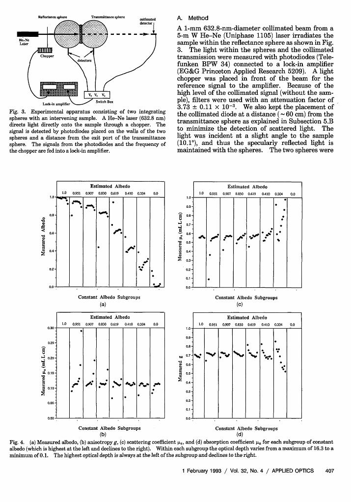
Fig. 3. Experimental apparatus consisting of two integratingspheres with an intervening sample. A He-Ne laser (632.8 nm)directs light directly onto the sample through a chopper. Thesignal is detected by photodiodes placed on the walls of the twospheres and a distance from the exit port of the transmittancesphere. The signals from the photodiodes and the frequency ofthe chopper are fed into a lock-in amplifier.
A. Method
A 1-mm 632.8-nm-diameter collimated beam from a5-m W He-Ne (Uniphase 1105) laser irradiates thesample within the reflectance sphere as shown in Fig.3. The light within the spheres and the collimatedtransmission were measured with photodiodes (Tele-funken BPW 34) connected to a lock-in amplifier(EG&G Princeton Applied Research 5209). A lightchopper was placed in front of the beam for thereference signal to the amplifier. Because of thehigh level of the collimated signal (without the sam-ple), filters were used with an attenuation factor of3.73 + 0.11 x 10⁻³. We also kept the placement ofthe collimated diode at a distance (- 60 cm) from thetransmittance sphere as explained in Subsection 5.Bto minimize the detection of scattered light. Thelight was incident at a slight angle to the sample(10.10), and thus the specularly reflected light ismaintained with the spheres. The two spheres were
0.8 9
0.6 -t
0.4
0.2
0.0 ~ ~ ~ ~ ~ 9
Constant Albedo Subgroups
(a)
Estimated Albedo
1.0 0.951 0.907 0.830 0.619 0.410 0.204 0.00.30 …_
0.25
0.20
0.15
0.10 :' 1 a"'
0.05
i6a4
'aar
E
C)
Ca
a
Constant Albedo Subgroups(b)
1.0
Estimated Albedo
0.951 0.907 0.830 0.619 0.410 0.204 0.0
0.9
0.8
0.7-
0.5
0.4
0.3
0.2
0.1
0.0* - - -- - -
Constant Albedo Subgroups(C)
Estimated Albedo1.0 0.951 0.907 0.830 0.619 0.410 0.204 0.0
1.0* - - - - - -
0.9
0.89 9
0.6
0.5
0.4-
0.3-
0.2
0.1
Constant Albedo Subgroups(d)
Fig. 4. (a) Measured albedo, (b) anisotropy g, (c) scattering coefficient pAs, and (d) absorption coefficient p. for each subgroup of constantalbedo (which is highest at the left and declines to the right). Within each subgroup the optical depth varies from a maximum of 16.3 to aminimum of 0.1. The highest optical depth is always at the left of the subgroup and declines to the right.
1 February 1993 / Vol. 32, No. 4 / APPLIED OPTICS 407
Estimated Albedo1.0 0.951 0.907 0.830 0.619 0.410 0.204 0.0
0Sa.0
'a
'i
laE
Reflectance sphere

Table 3. Accuracy to Which Optical Properties Can Be Determined
AccuracyRestrictions
in lis in Ila in gOptical Depth Albedo (%) (%) (%)
1 < T < 10 0.4 < a < 0.95 <5 <5 <5(0.4 < V3% <5 x 10⁻⁵) a < 0.4 >5 <5 >5
a > 0.95 <5 >5 <5
geometrically identical with an inner surface area Aof 148 ± 1 cm2, a sample area A, of 4.90 ± 0.06 cm2, adetector area A8 of 0.09 ± 0.02 cm2, and a total otheraperture area of 0.33 0.01 cm2. The reflectancesphere had a surface reflectance mr of 0.912 ± 0.005and the transmittance sphere mt of 0.915 ± 0.005.
Eighty different phantoms were made in subgroupsof fixed albedo (with the same ratio of scatterer toabsorber) and varying optical depth (differing dilution).The albedo subgroups were estimated to have albedosof 0, 0.204, 0.410, 0.619, 0.830, 0.907, 0.951, 1.0.At each albedo there were 10 optical depths thatvaried from 0.1 to 16.3 but were concentrated in the1-10 range. The thickness of the sample holder was1.0 mm, and the reference plate was Rref = 0.92 ±0.02.
All phantoms of an albedo subgroup maintain thesame albedo because the basic solution is just dilutedso that a different optical depth is obtained. Theinaccuracy within the construction of the phantomswas at most 1% except for the two most dilutedphantoms (lowest optical depth) of each subgroupwhen it was 3%.
B. ResultsIn Figs. 4(a)-4(d) the subgroup with the highestalbedo is always on the left and the albedo decreasesto the right. The leftmost subgroup consists ofIntralipid-10% only (which is assumed to be scatteredonly and therefore with an estimated albedo of 1), andthe rightmost subgroup is Evans Blue (which isassumed to be absorbing only and therefore with anestimated albedo of 0). Within each subgroup the
highest optical depth is the leftmost experiment, andthe optical depth decreases to the right.
Figure 4 shows the albedo, anistotropy, scatteringcoefficient, and absorption coefficient for each experi-ment. For the majority of points within each sub-group the measured albedo is constant [Figure 4(a)].Similarly within each subgroup and between eachsubgroup the measured anisotropy, scattering coeffi-cient (per unit concentration), and absorption coeffi-cient (per unit concentration) are constant as wouldbe expected [Figs. 4(b)-4(d), respectively]. The great-est deviations from the constant values appear tooccur when the albedo is very large or very small orwithin a subgroup when the optical depth is verylarge or very small.
The average values of the optical properties for allconverging data points are as follow:
g = 0.70 - 0.05,
= (0.6 ± 0.1) mL-1 L cm',
Iao = (0.12 ± 0.03) mL-1 L cm-1 .
Using pure solutions of Intralipid-10% or of EvansBlue, we may measure the scattering and absorptioncoefficient by measurement of the collimated lightalone. These measurements yield
1i,, = (0.56 ± 0.03) mL-1 L cm-',
Wa = (0.115 ± 0.002) mL-1 L cm-'
which are in good agreement with the average valuesdetermined by the adding-doubling method.
For every data point the relative deviation fromthe mean may be calculated [deviation = 100%x (x - x)/x]. For each of the optical properties thedeviation as 5% is given in Table 3 as a function ofthe albedo and optical depth. The anisotropy, scat-tering, and absorption coefficients were all deter-mined with a < 5% deviation when the optical depthwas between 1 and 10 and the albedo was between 0.4and 0.95.
Table 4. Optical Properties of Tissue Phantoms
Intralipid-10%
l1aa Evans BlueWavelength - Ia
Source (nm) (x10-2) (x- 4 ) g (X- 2)
Van Staveren et al.b 632.8 47.6 ± 0.9 1.49 ± 0.04 0.768 ± 0.006Moes et al.c 632.8 38.6 ± 0.4 5.7 ± 1.5 0.71 ± 0.03 7.60 ± 0.05Marijnissen and Stard 630 55.0 0.83This worke 632.8 57 ± 13 0.70 ± 0.05 11.5 ± 2.4This workf 632.8 56.1 ± 2.8 11.5 ± 0.2
aIn units of mL' L cm-'.bRef. 27.cRef. 26.dRef. 10.eSmall spheres, 80 phantoms total.fCollimated transimission mneasuremients only.
408 APPLIED OPTICS / Vol. 32, No. 4 / 1 February 1993

The measured optical properties of Intralipid-10%and Evans Blue compare favorably with measure-ments made with other techniques (Table 4).
7. DiscussionThe theory of the integrating sphere allows thedescription of uncertainties in the reflectance andtransmittance measurements of a sample. Theseuncertainties suggest that collimated incident light ispreferential to diffuse incident light. Furthermore,the additional measurement of the transmitted colli-mated light, together with the inverse adding-doubling algorithm, permits the determination of thethree intrinsic properties of the issue, absorptioncoefficient pIa, scattering coefficient Cus, and anistropyfactor g.
The double integrating spheres, without significantloss of accuracy, allow the simultaneous measure-ment of the optical properties, which is a requirementif the tissue is to undergo some external stimulussuch as heating.
One should use a large sample diameter comparedwith the beam diameter to avoid light loss throughthe side of the sample and by light transport down theglass slide (an 25-mm aperture for a 1-mm diame-ter beam). Thus the sample area is large enoughthat we avoid the light loss problem; yet it is smallcompared with the surface area of the sphere. (Asample area that is large compared with the surfacearea of the sphere, > 5%, introduces further geomet-ric irregularities not accounted for in the theory ofdouble integrating spheres.25
For coherent collimated light the problem of inter-ference caused by the glass slides may be overcomewith wedge-shaped slides.
The phantom measurements (Intralipid-10% andEvans Blue) in conjunction with the inverse adding-doubling algorithm enabled the determination of allthree optical properties to better than 5% accuracywhen the optical depth was between 1 and 10 and thealbedo was between 0.4 and 0.95. The inaccuraciesat greater optical depths were due to the difficulties inobtaining accurate collimated transmission measure-ments. This is a limitation in our detecting systemrather than in the methodology. The employment ofa photomultiplier rather than a photodiode could beexpected to improve this measurement. For lowalbedos and low optical depths the inaccuracy in theresults may be due to the uncertainties that arisewhen the reflectance is low (see Fig. 3 and Section 4).Furthermore, at low optical depths the scatteredreflected and transmitted light may not be totallydiffuse (Lambertian) as was assumed in the calcula-tions for the integrating spheres.25 This may lead toa greater loss of light through the entrance port of thereflectance sphere and the exit port of the transmit-tance sphere than is accounted for.
Finally we recommend this method (in conjunctionwith the inverse adding-doubling algorithm) for itsrelative speed of calculation as well as its ability forsimultaneous calculation of [uwa, pus andg.
These investigations are in the program of theFoundation for Fundamental Research into Matterand have been supported by The Netherlands Technol-ogy Foundation grant VNS88.1426. We gratefullyacknowledge the technical assistance of A. Steenbeekand M. Geerts.
References1. S. A. Prahl, M. J. C. van Gemert, and A. J. Welch, "Determin-
ing the optical properties of turbid media using the adding-doubling method," Appl. Opt. 32, 559-568 (1993).
2. W.-F. Cheong, S. A. Prahl, and A. J. Welch, "A review of theoptical properties of biological tissues," IEEE J. QuantumElectron. 26, 2166-2185 (1990).
3. F. P. Bolin, L. E. Preuss, R. C. Taylor, and R. J. Ference,"Refractive index of some mammalian tissues using a fiber-optic cladding method," Appl. Opt. 28, 2297-2303 (1989).
4. S. L. Jacques, C. A. Alter, and S. A. Prahl, "Angular depen-dence of He-Ne laser light scattering by human dermis,"Lasers Life Sci. 4, 309-333 (1987).
5. S. T. Flock, B. C. Wilson, and M. S. Patterson, "Totalattenuation coefficients and scattering phase functions oftissues and phantom materials at 633 nm," Med. Phys. 14,835-841 (1987).
6. R. Marchesini, A. Bertoni, S. Andreola, E. Melloni, and A. E.Sichirollo, "Extinction and absorption coefficients and scatter-ing phase functions of human tissues in vitro," Appl. Opt. 28,2318-2324 (1989).
7. J. R. Zijp and J. J. Ten Bosch, "Angular dependence ofHeNe-laser light scattering by bovine and human dentine,"Arch. Oral Biol. 36, 283-289 (1991).
8. L. 0. Svassand and R. Ellingsen, "Optical properties of humanbrain," Photochem. Photobiol. 38, 293-299 (1983).
9. B. C. Wilson, W. P. Jeeves, and D. M. Lowe, "In vivo andpostmortem measurements of the attenuation spectra of lightin mammalian tissues," Photochem. Photobiol. 42, 153-162(1985).
10. J. P. A. Marijnissen and W. M. Star, "Quantitative lightdosimetry in vitro and in vivo," Lasers Med. Sci. 2, 235-242(1987).
11. R. A. J. Groenhuis, J. J. Ten Bosch, and H. A. Ferwerda,"Scattering and absorption of turbid materials determinedfrom reflection measurements. 2: measuring method andcalibration," Appl. Opt. 22, 2463-2467 (1983).
12. J. M. Schmitt, G. X. Zhou, E. C. Walker, and R. T. Wall,"Multilayer model of photon diffusion in skin," J. Opt. Soc.Am. A 7, 2141-2153 (1990).
13. J. S. Macleod, D. Blanc, and M. J. Cottes, "Measurement of theoptical absorption coefficients at 1.06 lm of various tissuesusing the photoacoustic effect," Lasers Surg. Med. 8, 143 (A)(1988).
14. U. Bernini, M. Marotta, G. Martino, and P. Russo, "Spectropho-toacoustic method for quantitative estimation of haem proteincontent in wet tissue," Phys. Med. Biol. 36, 391-396 (1991).
15. M. S. Patterson, B. Chance, and B. C. Wilson, "Time resolvedreflectance and transmittance for the noninvasive measure-ment of tissue optical properties," Appl. Opt. 28, 2331-2336(1989).
16. K. M. Yoo, F. Liu, and R. R. Alfano, "Angle and time resolvedstudies of backscattering of light from biological tissues," in-Laser-Tissue Interaction, S. L. Jacques, ed., Proc. Soc. Photo-Opt. Instrum. Eng. 1202, 260-271 (1990).
17. F. H. Long, N. S. Nishioha, and T. F. Deutsch, "Measurementof the optical and thermal properties of biliary calculi usingpulsed photothermal radiometry," Lasers Surg. Med. 7, 461-466 (1987).
18. S. A. Prahl, I. A. Vitkin, U. Bruggemann, B. C. Wilson, and
1 February 1993 / Vol. 32, No. 4 / APPLIED OPTICS 409

R. R. Anderson, "Determination of optical properties of turbidmedia using pulsed photothermal radiometry," Phys. Med.Biol. 37, 1203-1218 (1991).
19. A. H. Taylor, "The measurement of diffuse reflection factorsand a new absolute reflectometer," J. Opt. Soc. Am. 4, 9-23(1920).
20. J. A. Jacquez and H. F. Kuppenheim, "Theory of integratingsphere," J. Opt. Soc. Am. 45, 460-470 (1954).
21. G. E. Miller and A. J. Sant, "Incomplete integrating sphere,"J. Opt. Soc. Am. 48, 828-831 (1958).
22. D. G. Goebel. "Generalized integrating-sphere theory," Appl.Opt. 6, 125-128 (1967).
23. F. J. J. Clarke and J. A. Compton, "Correction methods forintegrating sphere measurements of hemispherical re-flectance," Color Res. Appl. 11, 253-262 (1986).
24. A. Roos, "Interpretation of integrating sphere signal outputfor nonideal transmitting samples," Appl. Opt. 30, 468-474(1991).
25. J. W. Pickering, C. J. M. Moes, H. J. C. M. Sterenborg, S. A.Prahl, and M. J. C. van Gemert, "Two integrating sphereswith an intervening scattering sample," J. Opt. Soc. Am. A 9,621-631 (1992).
26. C. J. M. Moes, M. J. C. van Gemert, W. M. Star, J. P. A.Marijnissen, and S. A. Prahl, "Measurement and calculationsof the energy and fluence rate in scattering and absorbingphantom at 633 nm," Appl. Opt. 28, 2292-2296 (1988).
27. H. J. van Staveren, C. J. M. Moes, J. van Marle, S. A. Prahl,and M. J. C. van Gemert, "Light scattering in Intralipid-10%in the wavelength range 400-1100 nm," Appl. Opt. 30,4507-4514(1991)
410 APPLIED OPTICS / Vol. 32, No. 4 / 1 February 1993