Do design variations in the artificial disc influence cervical spine biomechanics? A finite element...
10
ORIGINAL ARTICLE Do design variations in the artificial disc influence cervical spine biomechanics? A finite element investigation Ahmad Faizan • Vijay K. Goel • Steven R. Garfin • Christopher M. Bono • Hassan Serhan • Ashok Biyani • Hossein Elgafy • Manoj Krishna • Tai Friesem Received: 29 December 2008 / Revised: 19 October 2009 / Accepted: 3 November 2009 / Published online: 21 November 2009 Ó The Author(s) 2009. This article is published with open access at Springerlink.com Abstract Various ball and socket-type designs of cervi- cal artificial discs are in use or under investigation. Many artificial disc designs claim to restore the normal kine- matics of the cervical spine. What differentiates one type of design from another design is currently not well under- stood. In this study, authors examined various clinically relevant parameters using a finite element model of C3–C7 cervical spine to study the effects of variations of ball and socket disc designs. Four variations of ball and socket-type artificial disc were placed at the C5–C6 level in an experimentally validated finite element model. Biome- chanical effects of the shape (oval vs. spherical ball) and location (inferior vs. superior ball) were studied in detail. Range of motion, facet loading, implant stresses and capsule ligament strains were computed to investigate the influence of disc designs on resulting biomechanics. Motions at the implant level tended to increase following disc replacement. No major kinematic differences were observed among the disc designs tested. However, implant stresses were substantially higher in the spherical designs when compared to the oval designs. For both spherical and oval designs, the facet loads were lower for the designs with an inferior ball component. The capsule ligament strains were lower for the oval design with an inferior ball component. Overall, the oval design with an inferior ball component, produced motion, facet loads, implant stresses and capsule ligament strains closest to the intact spine, which may be key to long-term implant survival. Keywords Cervical Á Disc replacement Á Finite element Á Biomechanics Á Design variation Introduction Ball and socket (B&S) shape designs are common for total disc replacement (TDR) in the spine [6, 7, 21]. Many of the B&S type designs are under investigation for their potential to preserve normal physiologic motion and circumventing accelerated disc degeneration at adjacent levels. The articulation between the ball and socket components of the artificial disc plays an important role in determining the success and survival of the implant. This articulation may utilize a hemispherical ball component rolling over a matched socket component (e.g. Prodisc-C, Synthes Spine Solutions, West Chester, PA). Other variations of the spherical design, such as oval-shaped designs are also feasible. Yet, another design may utilize a hemispherical or oval-shaped ball component articulating with the curved A. Faizan Á V. K. Goel (&) Á A. Biyani Á H. Elgafy Engineering Center for Orthopaedic Research Excellence (E-CORE), Departments of Bioengineering and Orthopaedic Surgery, 5046 NI, MS 303, Colleges of Engineering and Medicine, University of Toledo, Toledo, OH 43606, USA e-mail: [email protected] A. Faizan e-mail: [email protected] S. R. Garfin Department of Orthopaedics, University of California, San Diego, San Diego, CA, USA C. M. Bono Brigham and Women’s Hospital, Harvard Medical School, Boston, MA, USA H. Serhan DePuy Spine, Raynham, MA, USA M. Krishna Á T. Friesem The University Hospital of North Tees, Stockton-on-Tees, UK 123 Eur Spine J (2012) 21 (Suppl 5):S653–S662 DOI 10.1007/s00586-009-1211-6
-
Upload
independent -
Category
Documents
-
view
2 -
download
0
Transcript of Do design variations in the artificial disc influence cervical spine biomechanics? A finite element...

ORIGINAL ARTICLE
Do design variations in the artificial disc influence cervical spinebiomechanics? A finite element investigation
Ahmad Faizan • Vijay K. Goel • Steven R. Garfin • Christopher M. Bono •
Hassan Serhan • Ashok Biyani • Hossein Elgafy • Manoj Krishna • Tai Friesem
Received: 29 December 2008 / Revised: 19 October 2009 / Accepted: 3 November 2009 / Published online: 21 November 2009
� The Author(s) 2009. This article is published with open access at Springerlink.com
Abstract Various ball and socket-type designs of cervi-
cal artificial discs are in use or under investigation. Many
artificial disc designs claim to restore the normal kine-
matics of the cervical spine. What differentiates one type of
design from another design is currently not well under-
stood. In this study, authors examined various clinically
relevant parameters using a finite element model of C3–C7
cervical spine to study the effects of variations of ball and
socket disc designs. Four variations of ball and socket-type
artificial disc were placed at the C5–C6 level in an
experimentally validated finite element model. Biome-
chanical effects of the shape (oval vs. spherical ball) and
location (inferior vs. superior ball) were studied in detail.
Range of motion, facet loading, implant stresses and
capsule ligament strains were computed to investigate the
influence of disc designs on resulting biomechanics.
Motions at the implant level tended to increase following
disc replacement. No major kinematic differences were
observed among the disc designs tested. However, implant
stresses were substantially higher in the spherical designs
when compared to the oval designs. For both spherical and
oval designs, the facet loads were lower for the designs
with an inferior ball component. The capsule ligament
strains were lower for the oval design with an inferior ball
component. Overall, the oval design with an inferior ball
component, produced motion, facet loads, implant stresses
and capsule ligament strains closest to the intact spine,
which may be key to long-term implant survival.
Keywords Cervical � Disc replacement � Finite element �Biomechanics � Design variation
Introduction
Ball and socket (B&S) shape designs are common for total
disc replacement (TDR) in the spine [6, 7, 21]. Many of the
B&S type designs are under investigation for their potential
to preserve normal physiologic motion and circumventing
accelerated disc degeneration at adjacent levels. The
articulation between the ball and socket components of the
artificial disc plays an important role in determining
the success and survival of the implant. This articulation
may utilize a hemispherical ball component rolling over a
matched socket component (e.g. Prodisc-C, Synthes Spine
Solutions, West Chester, PA). Other variations of the
spherical design, such as oval-shaped designs are also
feasible. Yet, another design may utilize a hemispherical or
oval-shaped ball component articulating with the curved
A. Faizan � V. K. Goel (&) � A. Biyani � H. Elgafy
Engineering Center for Orthopaedic Research Excellence
(E-CORE), Departments of Bioengineering and Orthopaedic
Surgery, 5046 NI, MS 303, Colleges of Engineering and
Medicine, University of Toledo, Toledo, OH 43606, USA
e-mail: [email protected]
A. Faizan
e-mail: [email protected]
S. R. Garfin
Department of Orthopaedics,
University of California, San Diego,
San Diego, CA, USA
C. M. Bono
Brigham and Women’s Hospital, Harvard Medical School,
Boston, MA, USA
H. Serhan
DePuy Spine, Raynham, MA, USA
M. Krishna � T. Friesem
The University Hospital of North Tees, Stockton-on-Tees, UK
123
Eur Spine J (2012) 21 (Suppl 5):S653–S662
DOI 10.1007/s00586-009-1211-6

surface of the socket component, where both the bearing
surfaces may not exactly match (e.g. Prestige, Medtronic
Sofamor Danek, Memphis, TN). The biomechanical
response of cervical spine after implantation with varia-
tions of B&S design could be expected to vary. However,
to the author’s knowledge, there are no previous studies
delineating the biomechanical effects following implanta-
tion with variations of B&S type cervical disc replacement.
DiAngelo et al. [7, 21] studied the cervical spine bio-
mechanics following the implantation of a ball and socket-
type disc arthroplasty (Prodisc-C, Synthes Spine Solutions,
West Chester, PA) using human cadaver spines. DiAngelo
et al. [6] conducted a similar study using a variation of ball
and socket design (Prestige ST Cervical Disc System,
Medtronic Sofamor Danek, Memphis, TN). The design
allowed for some translational motion between the implant’s
components along with the typical rotational motion. These
authors compared the biomechanical response of the intact,
fused and artificial disc implanted cervical spine.
A recent finite element modeling-based study conducted
by Rousseau et al. [22] utilized a C5–C6 motion segment
to study the biomechanical differences following implan-
tation of artificial discs. A ball-and-socket artificial disc
was placed in a validated three-dimensional nonlinear finite
element model of the cervical spine (posterior geometric
center, large radius). The model was loaded in flexion,
extension, lateral bending and axial torsion (40 N com-
pression ? 1.6 Nm of moment). They also investigated
two variant designs: anterior center and small radius. The
intervertebral range of motion, the mean center of rotation
and the contact forces in the facet joints and in the bearing
surface of the prosthesis were investigated. The authors
demonstrated that the range of motion was similar with all
the prosthesis. The facet loads were found to be below the
normal values for posterior center and large disc design.
These authors did not quantify the adjacent level effects as
they used a functional spine unit model to study three types
of typical ball and socket designs (having matching
spherical ball and socket components). Also, switching the
inferior and superior components of the implant might have
significant effects on the biomechanics as well. Such
variations were not investigated by these authors.
The purpose of this study was to investigate the bio-
mechanical effects of shape (oval vs. spherical ball) and
location (inferior vs. superior ball) of various cervical
artificial disc replacements. The parameters measured were
range of motion, hybrid moments, facet loading, implant
stresses and facet capsule ligament strains.
Materials and methods
An experimentally validated, three-dimensional, ligamen-
tous, finite element model of the C3–C7 cervical spine
segments was used for this study, Fig. 1. This previously
developed and validated model has been used to address
various clinically relevant issues relating to lower cervical
spine in prior studies [5, 9, 12, 23].
C3–C7 cervical spine model formulation
The intact finite element model contained 24,732 nodes
and 21,895 elements. The vertebral body consisted of a thin
cortical shell surrounding a softer cancellous core, both of
which were interposed between inferior and superior end-
plates. The cortical region of the vertebral body was
Fig. 1 FE models of the C3–C7
cervical spine and a typical
artificial disc implanted at C5–
C6
S654 Eur Spine J (2012) 21 (Suppl 5):S653–S662
123

modeled as a 0.5 mm (average) thick shell surrounding a
softer cancellous core. The posterior region of the model
was assigned attributes which lay between those of the
cortical and cancellous regions. Three-dimensional, iso-
parametric solid elements were used to define the osseous
geometry, Table 1.
The facet joints were modeled using surface definitions,
where initial surface gaps between each facet region were
assumed to be 0.5 mm based upon CT imaging and dis-
section procedures. A ‘‘softened contact’’ parameter was
assigned to the interface which allowed for an exponen-
tially increasing modulus as the gap distance between the
inferior and superior facets decreased, simulating the
presence of cartilage in the facet region. The facets were
oriented at 45� approximately from the horizontal plane,
with some variation in the sagittal plane alignment,
according to CT geometry. The facets were also of varying
curvatures from right to left sides, indicating the possibility
of varying contact during right or left loading modalities
from the right to left facets.
The annulus fibrosis was modeled as a composite con-
figuration wherein a series of fibers simulating the lamellae
of the disc were embedded in a ground substance sur-
rounding a more gelatinous nucleus region. Each layer of
ground substance contained two alternating layers of fibers
arranged at ±65� from the transverse plane with an overall
fiber content of 20% of the annular volume assumed [4,
20]. The fibers were modeled utilizing the ‘‘rebar’’
parameter available in the ABAQUS program. Addition-
ally, a ‘‘no compression’’ option was enforced, thereby
allowing the fiber elements to only be active in tension, to
adequately model the role of the fibers within the inter-
vertebral disc. The ground substance of the annulus was
modeled using three-dimensional, 8-nodal ‘‘brick’’ ele-
ments (C3D8). The nucleus pulposus was modeled as an
incompressible fluid using a fluid definition available in
ABAQUS.
Luschka’s joints were modeled as well. These were
simulated around the area of the uncinate processes by
creating a space between the annulus horizontal layers
around the uncinate processes and placing gap elements in
the resulting fissures. The elements adjacent to the fissures
were reinforced with fibers which were aligned approxi-
mately parallel to the fissure to adequately model Lusc-
hka’s joints.
The ligaments of the lower cervical spine included the
anterior longitudinal ligament (ALL), posterior longitudi-
nal ligament (PLL), interspinous ligament (ISL), ligamen-
tum flavum (LF) and the capsular ligaments (CAP). The
ligaments were modeled using three-dimensional truss
elements (T3D2). These elastic elements were allowed to
behave nonlinearly via a ‘‘hypoelastic’’ option. This option
also allowed a ‘‘neutral zone’’ to be incorporated in which
the ligament provided little stability under minimally
applied external loads.
Disc arthroplasty model formulation
Two basic B&S disc design types were modeled and placed
at C5–C6 level in ABAQUS 6.7 program (Dassault
Systemes, Providence, RI, USA). For each design, one
component possessed a hemisphere-shaped ball or an oval-
shaped ball while the other component possessed a corre-
sponding socket-type profile for a smooth articulation. The
profiles of the superior and inferior components were not
exactly matching. Hence, they did not snugly fit into each
other, Fig. 2. The shape of the ball components gave rise to
two different types of implants (spherical or oval shape).
Moreover, two additional types of designs were formulated
by exchanging the superior and inferior components
Table 1 Material properties and model characteristics of the C3–C7 cervical spine model
Element group name Number of
elements
Element
type
Young’s modulus
(MPa)
Poisson’s
ratio
Cross sectional
area (mm2)
Cortical bone 1,440 C3D8 10,000 0.3 –
Cancellous bone 6,480 C3D8 450 0.25 –
Posterior bone 4,364 C3D8 3,500 0.25 –
Annulus ground substance 3,744 C3D8 4.2 0.25 –
Annulus fibers – Rebar 450 0.45 –
Facet joints – Surface Softened—3,500 – –
Ligaments 1,326 T3D2 NA NA –
Anterior longitudinal ligament (ALL) 672 T3D2 15 (\12%); 30 ([12%) 0.3 33
Posterior longitudinal ligament (PLL) 480 T3D2 10 (\12%); 20 ([12%) 0.3 33
Ligamentum flavum (LF) 20 T3D2 7 (\12%); 30 ([12%) 0.3 50.1
Interspinous ligament (ISL) 16 T3D2 5 (\25%); 10 ([25%) 0.3 13
Capsular ligament (CAP) 138 T3D2 15 (20–40%); 30 ([40%) 0.3 46.6
Eur Spine J (2012) 21 (Suppl 5):S653–S662 S655
123

(inferior or superior ball component). Therefore, these
combinations produced four different variations of disc
designs, Fig. 3
1. Design with superior component having a spherical-
shaped ball design (SPH-S)
2. Design with inferior component having a spherical-
shaped ball design (SPH-I)
3. Design with superior component having a oval-shaped
ball design (OVL-S)
4. Design with inferior component having a oval-shaped
ball design (OVL-I)
The implant components were assigned the material
properties of titanium (Young’s modulus 115GPa and
Poisson’s ratio 0.34).
TDR surgery simulations
The intact C3–C7 model was modified to accommodate the
disc implants at C5–C6 level. The anterior longitudinal
ligament was removed first. Then an anterior window was
created by removal of anterior part of annulus fibrosus.
Next, the nucleus was removed completely to create space
for the disc implant. The posterior part of annulus and
posterior longitudinal ligament were also resected to sim-
ulate a typical decompression. Lateral structures, such as
the lateral parts of annulus and uncinate processes were left
intact. Implant mesh was created using tetrahedral
elements.
Interactions, loading and boundary conditions
Both the superior and inferior components of the implants
were attached to the respective endplates of the vertebral
bodies to simulate solid incorporation. In ABAQUS 6.7,
this was achieved by using the ‘‘tie’’ command which made
sure that there was no relative motion between the two
surfaces. A ‘‘hard contact’’ command with a friction
coefficient of 0.1 was defined between the two metallic
components of the implant to simulate a realistic articula-
tion between the superior and inferior components
(Coulomb’s law with slip). Finally, the bottom of the C7
vertebra was fixed in all degrees of freedom.
A follower load of 75 N was applied using a set of
springs (with nonlinear load vs. displacement behavior) on
the models to simulate the muscle forces and the weight of
the head. These load values were close to values (73.6 N)
reported in literature [18, 19]. The advantage of application
of a follower load through springs was that it made sure
that there was ‘‘no rotation’’ of the spine after follower load
application. This was achieved by using two springs
attached on each of the four motion segments. The springs
were attached at the left and right sides of each vertebral
body. These springs passed through the flexion–extension
a bball socket ball socket posterior
Fig. 2 a Spherical disc design components; b oval disc design components
Fig. 3 Cross sectional view of
the different designs, a SPH-S;
b SPH-I; c OVL-S; d OVL-I. In
the spherical designs (SPH-I
and SPH-S), small radius ball
component articulated with
socket component. On the other
hand, in the oval designs (OVL-
I and OVL-S), large radius ball
component articulated with a
nonconforming socket
component
S656 Eur Spine J (2012) 21 (Suppl 5):S653–S662
123
center of rotation (in sagittal plane) of the motion seg-
ments. This produced a ‘‘no rotation’’ scenario after fol-
lower load application. Once activated, these springs
applied a constant preload of 75 N throughout the simu-
lation. Along with the follower load, a moment of 1.5 Nm
was also applied at the top of C3 vertebra to simulate
extension (ext), flexion (flex), lateral bending (lb) and axial
rotation (ar) motions in the intact spine. In contrast, for the
disc implanted models, hybrid-type loading was applied
[13]. Under hybrid loading, increasing moments were
applied until the overall motion (C3–C7) of the disc
implanted model was equal to that in the intact model
motion [13]. This ensured that total overall motions across
C3–C7 were equal for all models; however, the individual
motion segments could have different motions (e.g. C5–C6
motion could be different for each model). The hybrid
moment required to achieve the intact motion was recorded
in all the cases. Range of motion, hybrid moments, facet
loading, implant stresses and facet capsule ligament strains
were compared among various designs.
Results
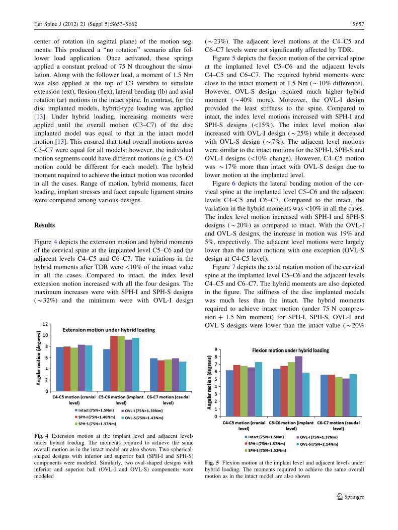
Figure 4 depicts the extension motion and hybrid moments
of the cervical spine at the implanted level C5–C6 and the
adjacent levels C4–C5 and C6–C7. The variations in the
hybrid moments after TDR were \10% of the intact value
in all the cases. Compared to intact, the index level
extension motion increased with all the four designs. The
maximum increases were with SPH-I and SPH-S designs
(*32%) and the minimum were with OVL-I design
(*23%). The adjacent level motions at the C4–C5 and
C6–C7 levels were not significantly affected by TDR.
Figure 5 depicts the flexion motion of the cervical spine
at the implanted level C5–C6 and the adjacent levels
C4–C5 and C6–C7. The required hybrid moments were
close to the intact moment of 1.5 Nm (*10% difference).
However, OVL-S design required much higher hybrid
moment (*40% more). Moreover, the OVL-I design
provided the least stiffness to the spine. Compared to
intact, the index level motions increased with SPH-I and
SPH-S designs (\15%). The index level motion also
increased with OVL-I design (*25%) while it decreased
with OVL-S design (*7%). The adjacent level motions
were similar to the intact motions for the SPH-I, SPH-S and
OVL-I designs (\10% change). However, C4–C5 motion
was *17% more than intact with OVL-S design due to
lower motion at the implanted level.
Figure 6 depicts the lateral bending motion of the cer-
vical spine at the implanted level C5–C6 and the adjacent
levels C4–C5 and C6–C7. Compared to the intact, the
variation in the hybrid moments was\10% in all the cases.
The index level motion increased with SPH-I and SPH-S
designs (*20%) as compared to intact. With the OVL-I
and OVL-S designs, the increase in motion was 19% and
5%, respectively. The adjacent level motions were largely
lower than the intact motions with one exception (OVL-S
design at C4-C5 level).
Figure 7 depicts the axial rotation motion of the cervical
spine at the implanted level C5–C6 and the adjacent levels
C4–C5 and C6–C7. The hybrid moments are also depicted
in the figure. The stiffness of the disc implanted models
was much less than the intact. The hybrid moments
required to achieve intact motion (under 75 N compres-
sion ? 1.5 Nm moment) for SPH-I, SPH-S, OVL-I and
OVL-S designs were lower than the intact value (*20%
Fig. 4 Extension motion at the implant level and adjacent levels
under hybrid loading. The moments required to achieve the same
overall motion as in the intact model are also shown. Two spherical-
shaped designs with inferior and superior ball (SPH-I and SPH-S)
components were modeled. Similarly, two oval-shaped designs with
inferior and superior ball (OVL-I and OVL-S) components were
modeled
Fig. 5 Flexion motion at the implant level and adjacent levels under
hybrid loading. The moments required to achieve the same overall
motion as in the intact model are also shown
Eur Spine J (2012) 21 (Suppl 5):S653–S662 S657
123

lower). The index level motions increased from 20 to 25%
approximately in all the designs as compared to intact. The
adjacent level motions did not show any significant
increase compared to the intact values.
Figure 8 depicts the facet loads under hybrid loading
conditions at the implanted level C5–C6. The facet loads
were highest during extension motion in all the cases. Total
C5–C6 extension facet loads for intact, SPH-I, SPH-S,
OVL-I and OVL-S designs were 91 N, 76 N, 106 N, 69 N
and 70 N, respectively. The facet loads were zero during
flexion motion in all the cases. During lateral bending, the
total facet loads for intact, SPH-I, SPH-S, OVL-I and
OVL-S designs were 43 N, 30 N, 36 N, 48 N and 62 N,
respectively. In axial rotation, the corresponding facet
loads were 31 N, 34 N, 36 N, 32 N and 26 N, respectively.
Under hybrid loading, the maximum implant stresses
(Von Mises) varied among various models, Fig. 9. SPH-I
design led to highest implant stresses, especially during
flexion and lateral bending motions (maximum of
221 MPa). Maximum implant stresses with SPH-S were
lower (maximum of 150 MPa). Similarly, the implant
stress values were lower for the oval designs in most cases
(maximum of 100 MPa for OVL-I and 115 MPa for OVL-
S designs).
The maximum facet capsule ligament strains are
reported in Fig. 10. During extension motion, the maxi-
mum capsule strains were similar to intact in all the models
(*25%) except with the SPH-I design, where maximum
strain was 42%. During flexion motion, maximum strains
were close to the intact (*45%) except with the OVL-S
design, where maximum strain increased to 58%. During
Fig. 6 Lateral bending motion at the implant level and adjacent
levels under hybrid loading. The moments required to achieve the
same overall motion as in the intact model are also shown
Fig. 7 Axial rotation motion at the implant level and adjacent levels
under hybrid loading. The moments required to achieve the same
overall motion as in the intact model are also shown
Fig. 8 Magnitudes of FE predicted facet loads (N) in various models.
Facet loads were zero in all the models in flexion. Two spherical-
shaped designs with inferior and superior ball (SPH-I and SPH-S)
components were modeled. Similarly, two oval-shaped designs with
inferior and superior ball (OVL-I and OVL-S) components were
modeled
Fig. 9 Maximum Von Mises stresses (MPa) in the implants under
hybrid loading. Two spherical-shaped designs with inferior and
superior ball (SPH-I and SPH-S) components were modeled. Simi-
larly, two oval-shaped designs with inferior and superior ball (OVL-I
and OVL-S) components were modeled
S658 Eur Spine J (2012) 21 (Suppl 5):S653–S662
123

lateral bending and axial rotation motions, the maximum
capsule strains were lower than those during flexion
motion. The maximum strain did not increase beyond 40%
during lateral bending and axial rotation motions.
Discussion
Variations of ball and socket-type designs for the cervical
artificial discs are already in use. However, there is limited
published data comparing the biomechanics of cervical
spine implanted with various types of disc designs. Many
of the previous in vitro studies concerning TDR were
conducted as part of the FDA approval process, focusing
primarily on comparisons between specific types of TDR
with the fusion system. The present FE studies provide
useful data for quantification of the kinetic and stress dif-
ferences (large or small) among various disc designs.
Motion data
Several previous biomechanical studies have confirmed
that cervical arthroplasty devices preserve motion much
better than fusion [3, 6, 7, 21]. These authors examined
specific types of disc implant [6, 7, 11, 14, 15, 21]; with the
exception of Rousseau et al. [22], who investigated three
types of matching ball and socket designs.
In the present study, we used hybrid loading protocol to
simulate in vivo loading conditions. We found that the
implanted level extension motions were higher than the
intact motion while hybrid moments were lower than
the intact moment during extension motion. This indicates
that the TDR implanted spine becomes less stiff compared
to the intact spine during extension. The spherical design
allowed for more extension motion than the oval design
(32% vs. 23% increase as compared to intact). Moreover,
switching the inferior and superior components had smaller
effect (\5% change) on the oval design, and it had no
significant effect on the spherical design. The spherical
designs (both SPH-I and SPH-S) are assembled in such a
way that during extension motion, the components act as
matching ball and socket parts which facilitate ‘‘pure’’
rotation motion, Fig. 3. The rotational motion is the same
whether the design is SPH-I or SPH-S. This explains why
switching of components does not have any substantial
effect on extension motion for the spherical designs. The
adjacent level motions were not much affected either.
The implanted level flexion motions also increased
following TDR, except with the OVL-S design. Designs
with room for anterior–posterior translation motion
allowed for higher flexion motion. For instance, among the
SPH-I and SPH-S designs, SPH-S design allowed for
greater motion than the SPH-I design (*10%) owing to the
availability of translational motion along with the rotation
motion, Fig. 3. For the oval designs, the flexion motions
demonstrated much larger effects of switching of the
components.
During lateral bending, switching of components did not
affect the implanted level motions for the spherical designs
(similar to extension). In contrast, switching of components
affected the motion for the oval designs (*13% change).
Unlike the spherical design, the oval design utilizes a larger
radius ball component articulating on a nonconforming
socket component. Such characteristics of the oval design
lead to larger changes in the motion when the superior and
inferior components are switched.
During axial rotation, the stiffness of the disc implanted
models was the lowest (*20% lower hybrid moment). The
shapes of the ball components (spherical or oval) appeared
to have very small effect on the implant level motions.
Switching components (inferior or superior ball) had small
effect in both the spherical and oval designs (*5% change
in motion).
No increases in motion were found at C3–C4 level. This
indicates that none of the discs will have any adverse effect
on the health of the C3–C4 disc.
The motion data is in line with the results of the study
conducted by Rousseau et al. [22] who demonstrated that
implanted level motion increased after disc arthroplasty.
However, no major inter implant difference in motion were
found.
Facet load data
Following TDR, the C5–C6 level facet loads were less than
the intact facet load values in most cases. During extension
motion, the total facet loads increased only with SPH-S
design (*17%). During flexion, the facets were moving
away from each other. Due to the absence of contact
between the superior and inferior facets, the facets did not
Fig. 10 Maximum capsular ligament strain (%) under hybrid loading
in various models. Two spherical-shaped designs with inferior and
superior ball (SPH-I and SPH-S) components were modeled. Simi-
larly, two oval-shaped designs with inferior and superior ball (OVL-I
and OVL-S) components were modeled
Eur Spine J (2012) 21 (Suppl 5):S653–S662 S659
123

demonstrate any loading in flexion. During lateral bending
motion, the facet loads at the implanted level were similar
to or lower than the intact values in SPH-I, SPH-S and
OVL-I designs. With these three designs, the implant level
facet loads were distributed on both the facets during lat-
eral bending. Such distribution was unlike the distribution
in the intact model, where only left facets were loaded
during left bending. This suggests that TDR may also alter
the distribution of loads on the left and right facet joints.
Nevertheless, the facet load values were lower than the
intact with the above three designs. With the OVL-S
design, the facet loads increased in lateral bending
(*44%). The facet loads during axial rotation were similar
to intact for all the disc designs. Overall, the disc designs
with inferior ball components led to lower facet loading
(SPH-I and OVL-I). The facet loads in left and right
bending and in left and right rotation were similar in
magnitude and distribution. Moreover, none of the disc
designs increased the facet loads at the adjacent levels.
Therefore, adjacent level facet degeneration may not be a
major concern following disc replacement.
Chang et al. [3] found that following TDR, the facet
loads increased at the index level in all the bending modes.
However, maximum increase in the facet loads was during
extension motion. Metzger et al. [17] also conducted
in vitro studies to investigate the changes in the facet load
profile with the variation in the device positioning in the
disc space. The authors found that facet forces were sen-
sitive to the device placement location and thereby indi-
cated that improper positioning could potentially lead to
higher facet loads following TDR. In contrast, a similar
study conducted by Steiber et al. [24] using ovine spines
demonstrated no significant increase in the facet loading
following TDR. Our data suggests that under hybrid
loading conditions TDR maintains total facet loads similar
to the intact facet loads—with lower facet loads for the
SPH-I and OVL-I designs. The clinical implications of the
disc arthroplasty induced increase in the facet loads indi-
cate a need for more in vivo studies. Long-term clinical
follow ups of the disc implant recipients may provide
insight into the issue.
Maximum capsule ligament strain
The higher capsule ligament strain may also cause facet-
related pain due to the presence of pain receptors in them.
Under hybrid loading conditions, the capsules were stret-
ched maximum during flexion motion. In general, OVL-S
design led to higher capsule strains while the OVL-I design
led to capsule strains similar to intact. SPH-I and SPH-S
designs led to strains similar to intact—except for the SPH-I
design in extension—which demonstrated a sharp increase
in the capsule strains.
The facet capsule injuries are studied in hyperextension
(such as whiplash) and they are known to cause facet-
related pain [16, 25, 26]. Such studies have demonstrated
that the capsule ligaments rupture at mean strain values
greater than 100%. The strain values predicted in this study
are much lower than those. We believe that during normal
activities following TDR, the facet capsule will not be
stretched as much as that during whiplash.
Implant stresses
The stresses in the implant under physiological loading
conditions govern the long-term wear pattern of the disc
implants. The repetitive higher stresses in the implant may
cause localized wear of the implant leading to alteration in
the articulation between the superior and inferior compo-
nents. The altered articulation, if significant, may alter the
biomechanics of the involved segment as well.
The maximum implant stresses varied with all the four
designs. Significantly higher stresses in the spherical
designs may lead to higher wear rate of these implants.
Oval designs (OVL-I and OVL-S), owing to their non-
conforming ball and socket components led to much lower
stresses. These designs may be more robust in long term.
The maximum von Mises stresses in the disc implants
were lower than the yield (*350–400 MPa) and fatigue
strengths (*250 MPa at 10 million cycles) of titanium in
all the models for all the four designs. It suggests that
implant failure may not be a possibility in cervical TDR.
Few previous studies have investigated the wear of disc
implants in cervical spine, they demonstrated that artificial
disc wear did not occur to harmful levels [1, 2].
Assumptions and limitations of the study
Although extra care was taken during implant placement
and analysis, the FE models have many limitations, just
like the cadaver studies and like studies published by
others, that should be kept in mind while interpreting the
results of the present study. The FE model results are
strong functions of the inputs, such as material properties,
loading conditions and implant locations, etc. The cervical
biomechanics are expected to be affected by alteration in
the location of the implant in the disc space. For example,
by shifting the implant in the anterior, posterior or in the
lateral directions, or by changing the orientation of the
implant in the disc space, the resulting biomechanics might
get influenced as predicted by the studies in both lumbar
and cervical spine [8, 10]. This opens a new area of
exploration which has not been studied in cervical spine
thoroughly. Anterior longitudinal ligament was removed in
all the disc replacement models; however, no scar tissue
formation was simulated. Formation of scar tissue might
S660 Eur Spine J (2012) 21 (Suppl 5):S653–S662
123

further reduce the inter-implant differences as shown by
our previous study concerning lumbar disc arthroplasty [8].
Application of preload may also affect the final results
significantly. We applied the preload using set of springs
that maintained the ‘‘no rotation’’ of the motion segments
in the intact spine. However, following TDR, the applica-
tion of muscle forces may not be similar to the intact spine.
It is possible that various muscles would respond in a
different manner after TDR surgery when compared to a
normal spine. For the current study, we used the same
preload locations and magnitude in all the cases in order to
be consistent. Such issues give a different dimension to the
biomechanics of cervical spine following TDR surgery,
just like the lumbar procedures. Additionally, application
of preload during lateral bending and axial rotation motions
might have affected the results as well. This is because the
‘‘no rotation’’ was maintained in the sagittal plane while
lateral bending and axial rotation motions occur out of this
plane.
The articulation between the two components of the disc
implant was modeled as hard contact with a friction coef-
ficient of 0.1 which may vary in vivo. However, this is a
comparative study and the variations caused by frictional
factors or material properties are expected to induce the
similar effects in all the disc designs. In our sensitivity
analyses, where we varied the coefficient of friction
between 0.05 and 0.15, we did not find any drastic differ-
ences in the motion behavior and the stress pattern due to
variation in friction.
A single set of material properties was studied. Simi-
larly, effects of artificial disc only at C5–C6 level were
investigated. Variation in above parameters may have
influence on the results; however, we believe that the
tendencies will be similar to the presented results.
Conclusions
The present study highlighted that cervical TDR do
‘‘maintain’’ the implanted level motion and also the normal
motion at adjacent levels. Under hybrid loading, there were
no major differences in the motion of the cervical spine
implanted with four different designs of artificial disc. The
facet loads were close to intact for the SPH-I and OVL-I
designs. The implant stresses were lower for OVL-I and
OVL-S designs. Nevertheless, the implant stresses were
lower than the yield and fatigue strengths of material in all
the cases. Capsule ligament strains were closer to intact
with the OVL-I design. Although the motions were similar
for all the four designs; the facet loading, implant stress
and ligament strain data suggest that OVL-I design may be
more successful in long term. The favorable biomechanics
of OVL-I design may be attributed to its shape, larger
radius and the assembly configuration. Moreover, as more
clinical data is collected on Prestige and Prodisc-C (designs
similar to studied here), a correlation could be established
between the present biomechanical results and the clinical
outcomes.
Acknowledgment The study was partially funded by a grant from
DePuy Spine, Raynham, MA.
Conflict of interest statement None of the authors has any
potential conflict of interest.
Open Access This article is distributed under the terms of the
Creative Commons Attribution Noncommercial License which per-
mits any noncommercial use, distribution, and reproduction in any
medium, provided the original author(s) and source are credited.
References
1. Anderson PARJP, Bryan VE, Carlson CS (2003) Wear analysis of
the Bryan cervical disc prosthesis. Spine 28(20):S186–S194
2. Anderson PA, Sasso RC, Rouleau JP, Carlson CS, Goffin J (2004)
The Bryan cervical disc: wear properties and early clinical
results. Spine J 4(6 Suppl):303S–309S
3. Chang UK, Kim DH, Lee MC, Willenberg R, Kim SH, Lim J
(2007) Changes in adjacent-level disc pressure and facet joint
force after cervical arthroplasty compared with cervical discec-
tomy and fusion. J Neurosurg Spine 7(1):33–39
4. Clausen JD (1996) Experimental and theoretical investigation of
cervical spine biomechanics: effects of injury and stabilization.
PhD, University of Iowa, Iowa City
5. Clausen JD, Goel VK, Traynelis VC, Scifert J (1997) Uncinate
processes and Luschka joints influence the biomechanics of the
cervical spine: quantification using a finite element model of the
C5–C6 segment. J Orthop Res 15(3):342–347
6. DiAngelo DJ, Roberston JT, Metcalf NH, McVay BJ, Davis RC
(2003) Biomechanical testing of an artificial cervical joint and an
anterior cervical plate. J Spinal Disord Tech 16(4):314–323
7. DiAngelo DJ, Foley KT, Morrow BR, Schwab JS, Song J, Ger-
man JW, Blair E (2004) In vitro biomechanics of cervical disc
arthroplasty with the ProDisc-C total disc implant. Neurosurg
Focus 17(3):E7
8. Dooris AP, Goel VK, Grosland NM, Gilbertson LG, Wilder DG
(2001) Load-sharing between anterior and posterior elements in a
lumbar motion segment implanted with an artificial disc. Spine
26(6):E122–E129
9. Faizan A (2008) Investigation into cervical spine biomechanics
following total disc replacement. PhD, University of Toledo,
Toledo
10. Faizan A, Goel V, Krishna M, Friesem T (2008) Placement of
artificial disc affects the biomechanics of the cervical spine: a
finite element investigation. Spine Arthroplasty Society, Miami,
Florida
11. Galbusera F, Fantigrossi A, Raimondi MT, Sassi M, Fornari M,
Assietti R (2006) Biomechanics of the C5–C6 spinal unit before
and after placement of a disc prosthesis. Biomech Model Me-
chanobiol 5(4):253–261
12. Goel VK, Clausen JD (1998) Prediction of load sharing among
spinal components of a C5–C6 motion segment using the finite
element approach. Spine 23(6):684–691
13. Goel VK, Grauer JN, Patel T, Biyani A, Sairyo K, Vishnubhotla
S, Matyas A, Cowgill I, Shaw M, Long R, Dick D, Panjabi MM,
Eur Spine J (2012) 21 (Suppl 5):S653–S662 S661
123
Serhan H (2005) Effects of charite artificial disc on the implanted
and adjacent spinal segments mechanics using a hybrid testing
protocol. Spine 30(24):2755–2764
14. Goffin J, Casey A, Kehr P, Liebig K, Lind B, Logroscino C,
Pointillart V, Van Calenbergh F, van Loon J (2002) Preliminary
clinical experience with the Bryan cervical disc prosthesis.
Neurosurgery 51(3):840–845 discussion 845–847
15. Ha SK (2006) Finite element modeling of multi-level cervical
spinal segments (C3–C6) and biomechanical analysis of an
elastomer-type prosthetic disc. Med Eng Phys 28(6):534–541
16. Ivancic PC, Ito S, Tominaga Y, Rubin W, Coe MP, Ndu AB,
Carlson EJ, Panjabi MM (2008) Whiplash causes increased laxity
of cervical capsular ligament. Clin Biomech Bristol Avon
23(2):159–165
17. Metzger MF, BJ, Acosta FL, Buckley JM, O’Reilly OM, Lotz JL
(2008) Facet forces sensitive to total disc replacement device
position. Orthopedics Research Society, San Francisco, CA
18. Moroney SP, Schultz AB, Miller JA, Andersson GB (1988) Load-
displacement properties of lower cervical spine motion segments.
J Biomech 21(9):769–779
19. Onan OA, Heggeness MH, Hipp JA (1998) A motion analysis of
the cervical facet joint. Spine 23(4):430–439
20. Pooni JS, Hukins DW, Harris PF, Hilton RC, Davies KE (1986)
Comparison of the structure of human intervertebral discs in the
cervical, thoracic and lumbar regions of the spine. Surg Radiol
Anat 8(3):175–182
21. Puttlitz CM, DiAngelo DJ (2005) Cervical spine arthroplasty
biomechanics. Neurosurg Clin N Am 16(4):589–594
22. Rousseau MA, Bonnet X, Skalli W (2008) Influence of the
geometry of a ball-and-socket intervertebral prosthesis at the
cervical spine: a finite element study. Spine 33(1):E10–E14
23. Scifert JL (2000) Biomechanical investigations of the lower
cervical spine. PhD, University of Iowa, Iowa city
24. Stieber J, Quirno M, Kang M, Valdevit A, Errico TJ (2008) The
facet joint loading profile of a cervical intervertebral disc
replacement. Orthopedic Research Society, San Francisco, CA
25. Winkelstein BA, Nightingale RW, Richardson WJ, Myers BS
(2000) The cervical facet capsule and its role in whiplash injury:
a biomechanical investigation. Spine 25(10):1238–1246
26. Yoganandan N, Kumaresan S, Pintar FA (2000) Geometric and
mechanical properties of human cervical spine ligaments.
J Biomech Eng 122(6):623–629
S662 Eur Spine J (2012) 21 (Suppl 5):S653–S662
123