Disclosure to Promote the Right To Information
15
Disclosure to Promote the Right To Information Whereas the Parliament of India has set out to provide a practical regime of right to information for citizens to secure access to information under the control of public authorities, in order to promote transparency and accountability in the working of every public authority, and whereas the attached publication of the Bureau of Indian Standards is of particular interest to the public, particularly disadvantaged communities and those engaged in the pursuit of education and knowledge, the attached public safety standard is made available to promote the timely dissemination of this information in an accurate manner to the public. इंटरनेट मानक “!ान $ एक न’ भारत का +नम-ण” Satyanarayan Gangaram Pitroda “Invent a New India Using Knowledge” “प0रा1 को छोड न’ 5 तरफ” Jawaharlal Nehru “Step Out From the Old to the New” “जान1 का अ+धकार, जी1 का अ+धकार” Mazdoor Kisan Shakti Sangathan “The Right to Information, The Right to Live” “!ान एक ऐसा खजाना > जो कभी च0राया नहB जा सकता ह ै” Bhartṛhari—Nītiśatakam “Knowledge is such a treasure which cannot be stolen” IS 10095 (1982): Guidelines for selection of tipplers for broad gauge open railway wagons [MED 7: Material Handling Systems and Equipment]
Transcript of Disclosure to Promote the Right To Information

Disclosure to Promote the Right To Information
Whereas the Parliament of India has set out to provide a practical regime of right to information for citizens to secure access to information under the control of public authorities, in order to promote transparency and accountability in the working of every public authority, and whereas the attached publication of the Bureau of Indian Standards is of particular interest to the public, particularly disadvantaged communities and those engaged in the pursuit of education and knowledge, the attached public safety standard is made available to promote the timely dissemination of this information in an accurate manner to the public.
इंटरनेट मानक
“!ान $ एक न' भारत का +नम-ण”Satyanarayan Gangaram Pitroda
“Invent a New India Using Knowledge”
“प0रा1 को छोड न' 5 तरफ”Jawaharlal Nehru
“Step Out From the Old to the New”
“जान1 का अ+धकार, जी1 का अ+धकार”Mazdoor Kisan Shakti Sangathan
“The Right to Information, The Right to Live”
“!ान एक ऐसा खजाना > जो कभी च0राया नहB जा सकता है”Bhartṛhari—Nītiśatakam
“Knowledge is such a treasure which cannot be stolen”
“Invent a New India Using Knowledge”
है”ह”ह
IS 10095 (1982): Guidelines for selection of tipplers forbroad gauge open railway wagons [MED 7: Material HandlingSystems and Equipment]

UDC 625.245’63 ( 026) IS: 10095-1982
Indian Standard
GUIDELINES FOR SELECTION OF TIPPLERS FOR BROAD GAUGE OPEN RAILWAY WAGONS
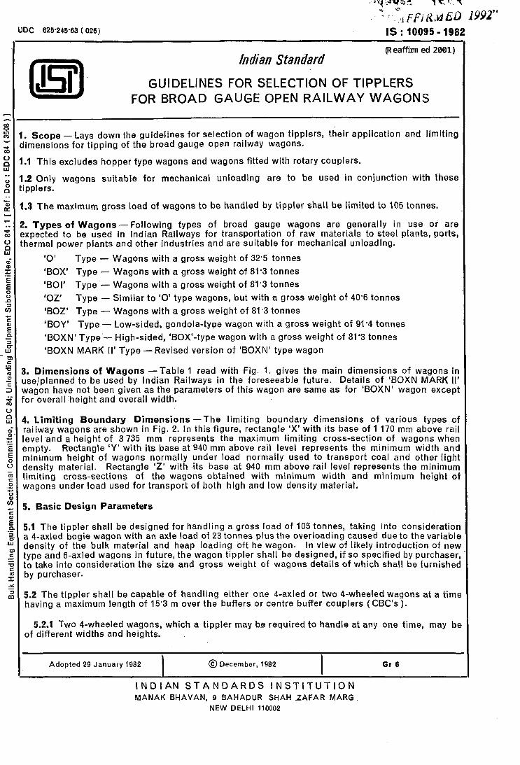
. Scope - Lays down the guidelines for selection of wagon tipplers, keir application and limiting Iimensions for tipping of the broad gauge open railway wagons.
.I This excludes hopper type wagons and wagons fitted with rotary couplers.
.2 Only wagons suitable for mechanical unloading are to be used in conjunction with these ipplers.
.3 The maximum gross load of wagons to be handled by tippler shall be limited to 105 tonnes.
!. Types of Wagons - following types of broad gauge wagons are generally in use or are Fxpected to be used in Indian Railways for transportation of raw materials to steel plants, ports, hermal power plants and other industries and are suitable for mechanical unloading.
‘0’ Type - Wagons with a gross weight of 32.5 tonnes
‘BOX’ Type - Wagons with a gross weight of 81.3 tonnes
‘BOI’ Type - Wagons with a gross weight of 81.3 tonnes
‘OZ’ Type - Similar to ‘0’ type wagons, but with a gross weight of 40’6 tonnes
‘BOZ’ Type - Wagons with a gross weight of 81.3 tonnes
‘BOY’ Type - Low-sided, gondola-type wagon with a gross weight of 91’4 tonnes
‘BOXN’ Type - High-sided, ‘BOX’-type wagon with a gross weight of 81’3 tonnes
‘BOXN MARK II’ Type - Revised version of ‘BOXN’ type wagon
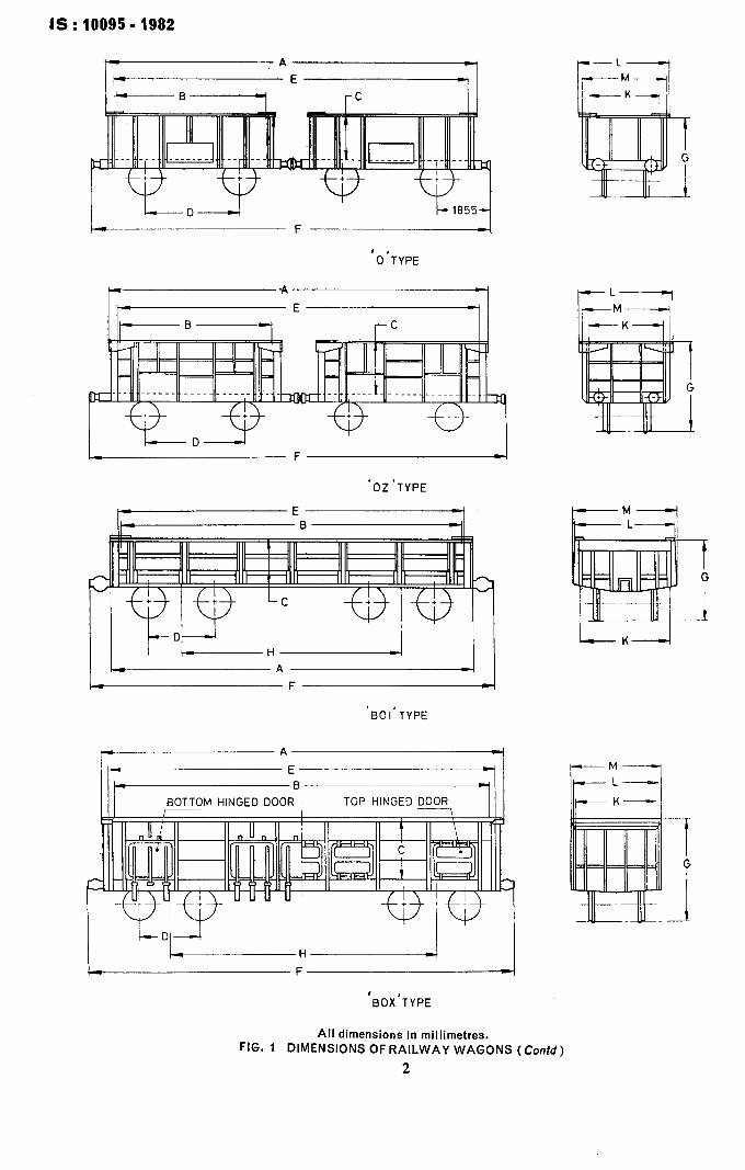
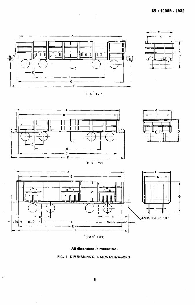
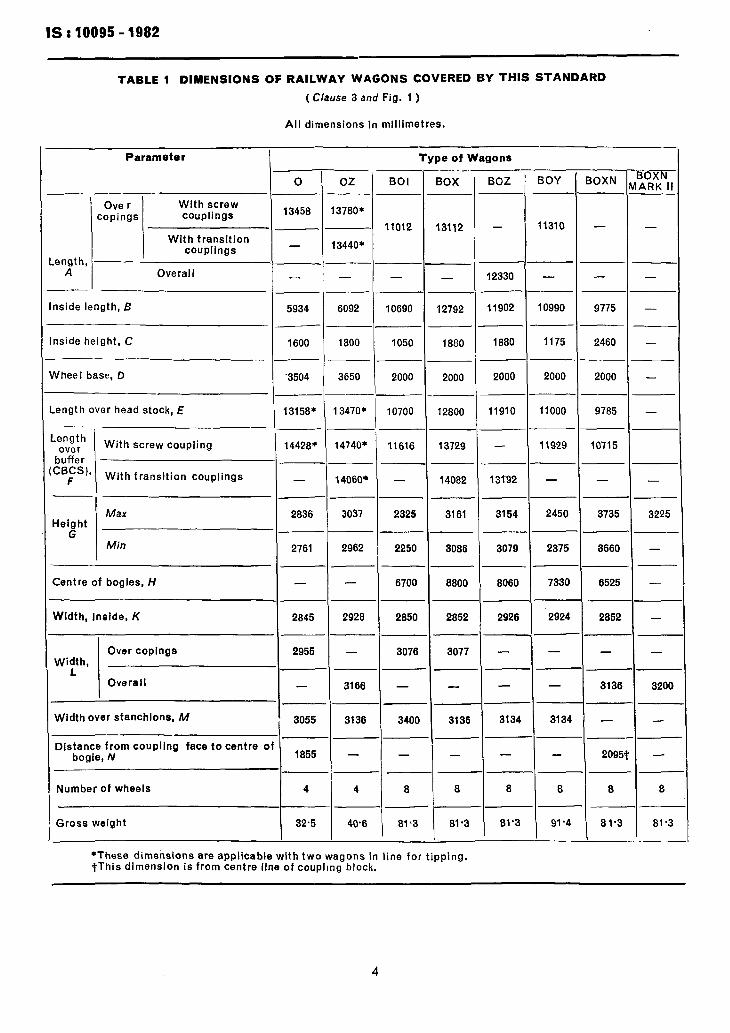
5. Dimensions of Wagons -Table 1 read with Fig. 1. gives the main dimensions of wagons in Ase/planned to be used by Indian Railways in the foreseeable future. Details of ‘BOXN MARK II’ wagon have not been given as the parameters of this wagon are same as for ‘BOXN’ wagon except ‘or overall height and overall width.
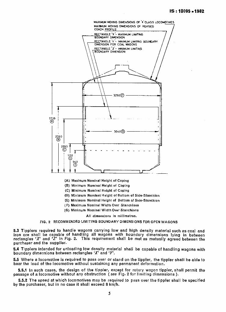
1. Limiting Boundary Dimensions -The limiting boundary dimensions of various types ~of railway wagons are shown in Fig. 2. In this figure, rectangle ‘X’ with its base of 1 170 mm above rail leveland a height of 3735 mm represents the maximum limiting cross-section of wagons when empty. R&angle ‘Y’ with its base at 940 mm above rail level represents the minimum width and minimum height of wagons normally under load normally used to transport coal and other light density material. Rectangle 'Z' with its base at 940 mm above rail level represents the minimum limiting cross-sections of the wagons obtained with minimum width and minimum height oi wagons under load used for transport of both hlgh and low density material.
5. Basic Design Parameters
5.1 The tippler shall be designed for handling a gross load of 105 tonnes, taking into consideration a 4-axled bogie wagon with an axle load of 23 tonnes plus the overloading caused due to the variable density of the bulk material and heap loading oft he wagon. In view of likely introdu~ction of new type and 6-axled wagons in future, the wagon tippler shall be designed, if so specified by purchaser, to take into consideration the size and gross weight of wagons details of which shall be furnishec by purchaser.
5.2 The tippler shall be capable of handling either one 4-axled or two 4-wheeled wagons at a timr having a maximum length of 15’3 m over the buffers or centre buffer couplers ( CBC’s ).
5.2.1 TWO 4-wheeled wagons, which a tippler may be required to handle at any one time, may bc of different widths and heights.
Adopted 29 January 1982 I
@December, 1982 I
Gr 6
INDIAN STANDARDS INSTITUTION MANAK BHAVAN, 9 BAHADUR SHAH _ZAFAR MARG
NEW DELHI 110002
IS : 10095 - 1982
‘O’TYPE
‘OZ’TYPE
/.*-II /--F--I
‘BOI’TYPE
III - BOTTOM HINGED DOOR TOP HINGED DOOR II I
lI~ll”“lll III
/ y+q-iyg--- -
I c-Dl-4 I I I /__~_ H-i I LF--I
-K-I
‘BOX’TYPE
All dimensions in millimetres. FIG. 1 DIMENSIONS OF RAILWAY WAGONS (Contd)
2
IS: lDO95- 1982
‘BOZ’ TYPE
‘BOY’ TYPE
I -t \
h
-1
--I -KK
-F---
’ BOXN’ TYPE
G
All dimensions in millimetres.
FIG. 1 DIMENSIONS OF RAILWAY WAGONS
3
IS : 10095 - 1982
TABLE 1 DIMENSIONS OF RAILWAY WAGONS COVERED BY THIS STANDARD
(Clause 3 and Fig. 1 )
All dimensions in millimetres.
-. - Type of Wagons Parameter
i- r- _
-
_
--
--
--
- .
--
-0
- _
-_
-..
-.
-.
-.
-
-
BOI
11012
-
10690
1050
2000
10700
11616
2325
2250
6700
2850
3076
3400
-
8 8
--
BOXN IARK I
-
BOZ BOY
I ._ _ _ _- -_ _- -- -_ -. - - -
11310
12330
11902
-
10990
_-
--
- _
- _
-
-_
-.
-
-
-
1880
2000
1175
11910
-
2000
11000
11929
13192
3154
3079
2450
2375
8060 7330
2926 2924
-
- -
E _-
._
- -
--
_-
--
--
_-
--
--
--
-_
-_
-_
-_ 3134
I 3134
--
I 8 I 8 I-
81’3 I
91.4
-
IOXN N
-
-
.-
9775
2460
2000
9785 -
10715
-
3735 3225
3660
6525
2852
-
-_
--
- -
--
--._
-_
-_
-_
t -
-.
-
- -
3136 3200
-
2095
8
81.3
0
13458
-
-
5934
1600
~3504
13158*
14428+
-
2836
2761
-
2845
2955
-
3055
1855
4
32.5
oz -- 13780*
BOX
13112
13440*
- -
6092 12792
1890 1880
3650
13470*
._
1
.-
_-
-_
--
-_
--
_-
-.
--
-_
-.
-.
.-
.-
_-
-
-_
-_
_-
- .
- _
- _
-
-
12800
14740* 13729
14060’ 14082
3037 3161
2962 3086
- 8800
2928 2852
-
3166
3077
-
3136 3136
- -
4
40’6 81.3 81.3
.- -
~-
-
-
-
-
-
-
__
- _
-_
t’ -_
--
I -
Ove r copings
With screw couplings
With transition couplings
ength, A Overall
nside length, B
-.
nside height, C
Yheel base, D
.ength over head stock, E
___
.ength over
buffer CBCS),
F
With screw coupling
With transition couplings
M&X Height
G Min
Centre of bogies, H
Width, Inside, K
_
Over copings Width,
L Overall
Width over stanchions, M
Distance from coupling face to centre o bogie, N
Number of wheels
Gross weight
*These dimensions are applicable with two wagons in line for tipping. tThis dimension is from centre line of coupling block.
4
ts . . 10095 * 1982
MAXIMUM MOVING DIMENSIONS OF ‘X’CLASS LOCOMOTIVES
MAXIMUM MOVING OIMENSIONS OF REVISED COACH PROFILE 7 RECTANGLE ‘X ‘- MAXIMUM Ll!+JTlNG BOUNDARY DIMENSION
RFCTANGLE ‘V ‘- MINIMUM LIMITING BOUNDARY OIMENSION FOR COAL WAGONS
RECTANGLE ‘Z’- MINIMUM LIMITING
t
3735
0
.
I
I
3OLO@ - 2760
,
@ I
8
t t tt u ’ (A) Maximum Nominal Height of Coping
(6) Minimum Nominal Height of Coping
(C) Minimum Nominal Height of Coping
(D) Minimum Nominal Height of Bottom of Side-Stanchion
(E) Minimum Nominal Height of Bottom of Side-Stanchion
(F) Maximum Nominal Width Over Stanchions
(6) Minimum Nominal Width Over Stanchions
Ail dimensions in miiiimetres.
FIG. 2 RECOMMENDED LIMITING BOUNDARY DIMENSIONS FOR OPEN WAGONS
5.3 Tipplers required to handle wagons carrying low -and high density material such as coal and jron ore shall be capable of handling all wagons with boundary dimensions lying in between rectangles ‘X’ and ‘Z’ in Fig. 2. purchaser and the supplier.
This requirement shall be met as mutually agreed between the
-5.4 Tipplers intended for unloading low density material shall be capable of handling wagons with boundary dimensions between rectangles ‘X’ and I-Y’,
5.5 Where a locomotive is required to pass over or stand on the tippler, the tippler shall be able to bear the load of the locomotive without sustaining any permanent deformation,
55.1 In such cases, the design of the tippler, except for rotary wagon tippler, shall permit the passage of a locomotive without any obstruction ( see Fig. 2 for limiting dimensions ).
5.5.2 The speed at which locomotives may be required to pass over the tippler shall be specified by the purchaser, but in no case it shall exceed 8 km/h.
5
6. Types of Tipplers
Sids Dischgrge -Wagons secured in running direction and tilted to one side to fully empty \ the contents from the top of the wagons. The minimum angle of tipping shall
be 140”.
Rotary : -Wagons supported transversely and held vertically, and rotated to fully empty the contents from the top of the wagons. The minimum angle of rotation shall be 160’.
Note-The minimum angle of tippinQ stated above may be increased, depending upon the characteristic of the material, if so specified by the purchaser.
7. Field of Application
7.1 Side Discharge Tipplers - Side discharge tipplers shall normally be considered for use when:
a) The material is comparatively free flowing:
b) The tippling cycle of tippler is not less than three minutes;
c) Locomotive is essentially required to pass over tipple,r; and
d) Depth of underground hopper is required to be restricted.
7.2 Rotary Tipplers - The rotary tippler shall normally be considered for use when:
a) The material is not comparatively free flowing;
b) The tippling cycle of tippler is not less than 1’5 minutes;
cl Locomotive is not essentially required to pass over tippler; and
4 Depth of underground hopper is not required to be restricted.
Note-The tippling cycle comprises clamping the wagon(s), tilting, dumping, returning back to normal and declamping of wagon(s).
8. General Requirements
8.1 The design and construction of components of tipplers and auxiliary (optional ) handling equipment coming into contact with any part of wagon shall be such as to ensure that no damage whatsoever is caused to the wagon equipment or its paint.
8.2 The top clamping pressure shall be such as will hold the wagons firmly in position on rails and keep the bearing brasses and running gear from getting dislodged without causing any deformation to the wagon structure.
8.2.1 The top clamping arrangsment shall be such that the clamping pressure on the top copings of the wagon remains within reasonable limits, so as not to cause damage to the wagon. The force exerted by the compressed spring shall be nominal enough to keep the springs in position and to avoid them being dislodged.
8.3 Adequate compensating measures shall be taken in top and side bolsters to cope with manu- facturing imperfections within the permissible limits in the top copings and side stanchions of the wagon, so that clamping pressure on the contacting area on the side and top of the wagon is uniformly distributed.
8.4 The
a)
0)
side supports for tipplers shalU meet the following requirements:
The side support shall consist of a longitudinal beam which shall be as long as the longest wagon to be tipped. This beam may be generally continuous or non-continuous.
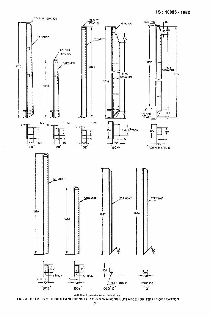
The side support shall be articulated, so that it can take the tapered as well as parallel stanchions on the body of the wagons. Alternatively, the cradle shall be articulated on trunnion to achieve this. The details of the stanchions are given in Fig. 3.
6
IS : 10095 4982 TO SUIT ISMC 100
r
TO SUIT ISMC 100
j:
1 STRAIGH r
ISMCJ
1 1950
2130
TO SUIT
il 2040
: STRAIGHT
:
r
I
:
--1120!-- ‘BOXN MARK II’ ‘601 ‘BOX’
I-
2130 I 1426
1
STRAIGHT TRAIGHT i”
A. -2
170 4Fi 6 THICK THICK 6
100
‘BOZ * ‘BOY’
IUI 4lOu--
L_ -BULB ANGLE ISMC 100
OLD’ 0’ . , 0
All dimensions in miliimetres.
FIG. 3 DETAILS OF SIDE STANCHIONS FOR OPEN WAGONS SUITABLE FOR TIPPER OPERATION
7
IS t 10095 - 1982
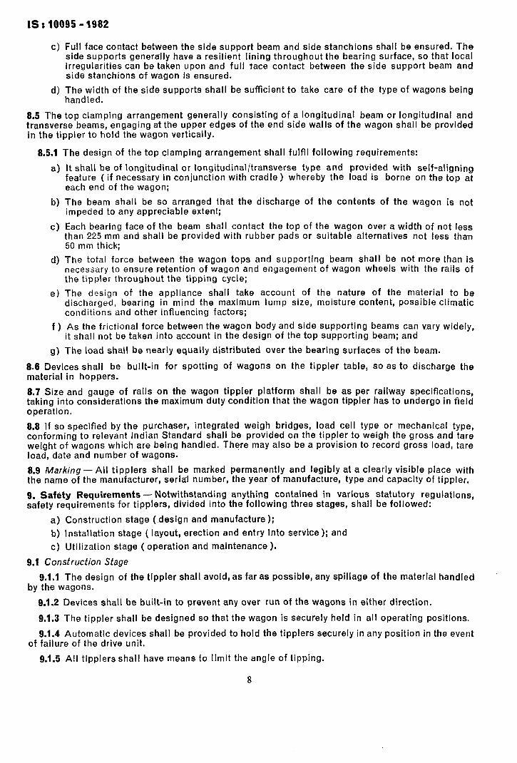
c) Full face contact between the side support beam and side stanchions shall be ensured. The side supports generally have a resilient lining throughout the bearing surface, so that local irregularities can be taken upon and full tace contact between the side support beam and side stanchions of wagon is ensured.
d) ;rahnedy;;th of the side supports shall be sufficient to take care of the type of wagons being
85 The top clamping arrangement generally consisting of a longitudinal beam or longitudinal and transverse beams, engaging at the upper edges of the end side walls of the wagon shall be provided in the tippler to hold the wagon vertically.
8.5.1 The design of the top clamping arrangement shall fulfil following requirements:
a) It shall be of longitudinal or longitudinal/transverse type and provided with self-aligning feature ( if necessary in conjunction with cradle) whereby the load is borne on the top at each end of the wagon;
b) The beam shall be so arranged that the discharge of the contents of the wagon is not impeded to any appreciable extent;
c) Each bearing face of the beam shall contact the top of the wagon over a width of not less than 225 mm and shall be provided with rubber pads or suitable alternatives not less than 50 mm thick;
d) The total force between the wagon tops and supporting beam shall be not more than is necessary to ensure retention of wagon and engagement of wagon wheels with the rails of the tippler throughout the tipping cycle;
e) The design of the appliance shall take account of the nature of the material to be discharged, bearing in mind the maximum lump size, moisture content, possible climatic conditions and other influencing factors;
f ) As the frictional force between the wagon body and side supporting beams can vary widely, it shall not be taken into account in the design of the top supporting beam; and
g) The load shall be nearly equally distributed over the bearing surfaces of the beam.
8.8 Devices shall be built-in for spotting Of wagons on the tippler table, so as to discharge the material in hoppers.
8.7 Size and gauge of rails on the wagon tippler platform shall be as per railway specifications, taking into considerations the maximum duty condition that the wagon tippler has to undergo in field operation.
8.8 If so specified by the purchaser, integrated weigh bridges, load cell type or mechanical type, conforming to relevant Indian Standard shall be provided on the tippler to weigh the gross and tare weight of wagons which are being handled. There may also be a provision to record gross load, tare load, date and number of wagons.
8.9 Marking - All tipplers shall be marked permanently and legibly at a clearly visible place with the name of the manufacturer, serial number, the year of manufacture, type and capacity of tippler.
9. Safety Requirements - Notwithstanding anything contained fin various statutory regulations, safety requirements for tipplers, divided into the following three stages, shall be followed:
a) Construction stage ( design and manufacture );
b) Installation stage ( layout, erection and entry into service); and
c) Utilization stage ( operation and maintenance ).
9.1 Construction Stage
9.1.1 The design of the tippler shall avoid, as far as possible, any spillage of the material handled by the wagons.
9.1.2 Devices shall be built-in to prevent any over run of the wagons in either direction.
9.1.3 The tippler shall be designed so that the wagon is securely held in all operating positions.
9.1.4 Automatic devices shall be provided to hold the tipplers securely in any position in the event of failure of the drive unit.
9.1.5 All tipplers shall have means to limit the angle of tipping.
8
IS: 10095- 1982
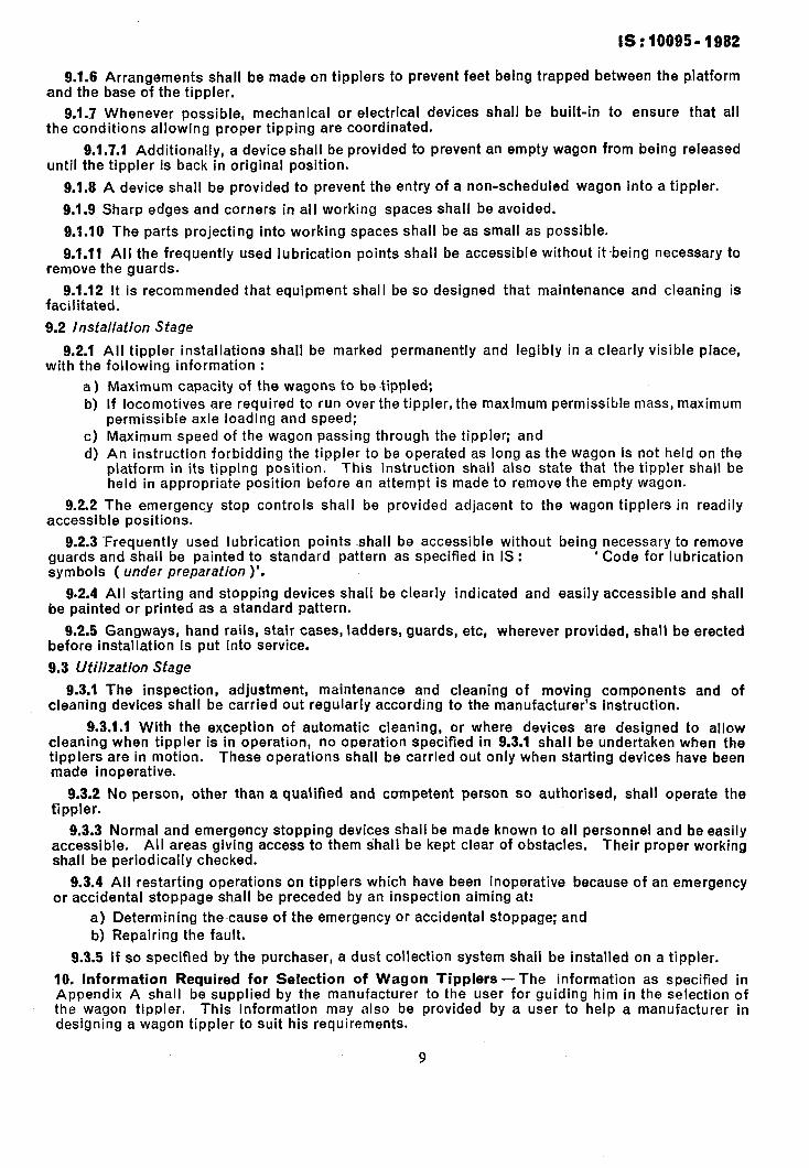
9.1.6 Arrangements shall be made ontipplers to prevent feet being trapped between the platform and the base of the tippler.
9.1.7 Whenever possible, mechanical or electrical devices shall be built-in to ensure that all the conditions allowing proper tipping are coordinated.
9.1.7.1 Additionally, a device shall be provided to prevent an empty wagon from being released until the tippler is back in original position.
9.1.6 A device shall be provided to prevent the entry of a non-scheduled wagon into a tippler.
9.1.9 Sharp edges and corners in all working spaces shall be avoided.
9.1.10 The parts projecting into working spaces shall be as small as possible.
9.1.11 All the frequently used lubrication points shall be accessible without itbeing necessary to remove the guards.
9.1.12 It is recommended that equipment shall be so designed that maintenance and cleaning is facilitated.
9.2 Installation Stage
9.2.1 All tippler installations shall be marked permanently and legibly in a clearly visible place, with the following information :
a) Maximum capacity of the wagons to be tippled: b) If locomotives are required to run over the tippler, the maximum permissible mass, maximum
permissible axle loading and speed; c) Maximum speed of the wagon passing through the tippler; and d) An instruction forbidding the tippler to be operated as long as the wagon is not held on the
platform in its tipping position. This instruction shall also state that the tippler shall be held in appropriate position before an attempt is made to remove the empty wagon.
9.2.2 The emergency stop controls shall be provided adjacent to the wagon tipplers in readily accessible positions.
9.2.3 -Frequently used lubrication points shall be accessible without being necessary to remove guards and shall be painted to standard pattern as specified in IS : ’ Code for lubrication symbols ( under preparation )‘.
9.2.4 All starting and stopping devices shall be clearly indicated and easily accessible and shall be painted or printed as a standard pattern.
9.2.5 Gangways, hand rails, stair cases, ladders, guards, etc, wherever provided, shall be erected before installation is put into service.
9.3 Utilization Stage
9.3.1 The inspection, adjustment, maintenance and cleaning of moving components and of cleaning devices shall be carried out regularly according to the manufacturer’s instruction.
9.3.1.1 With the exception of automatic cleaning, or where devices are designed to allow cleaning when tippler is in operation, no operation specified in ~9.3.1 shall be undertaken when the tipplers are in motion. These operations shall be carried out only when starting devices have been made inoperative.
9.3.2 No person, other than a qualified and competent person so authorised, shall operate the tippler.
9.3.3 Normal and emergency stopping devices shall be made known to all personnel and be easily accessible. All areas giving access to them shall be kept clear of obstacles. Their proper working shall be periodically checked.
9.3.4 All restarting operations on tipplers which have been inoperative because of an emergency or accidental stoppage shall be preceded by an inspection aiming at:
a) Determining the~cause of the emergency or accidental stoppage; and b) Repairing the fault.
9.3.5 If so specified by the purchaser, a dust collection system shall be installed on a tippler.
10. Information Required for Selection of Wagon Tipplers- The information as specified in Appendix A shall be supplied by the manufacturer to the user for guiding him in the selection of the wagon tippler. This information may also be provided by a user to help a manufacturer in designing a wagon tippler to suit his requirements.
9
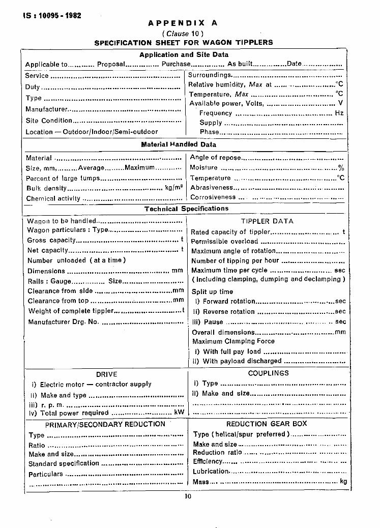
IS : 10095 - 1982 APPENDIX A
( Clause 10 ) SPECIFICATION SHEET FOR WAGON TIPPLERS
Application and Site Data applicable to... . . . . . . . . . Proposal . . . . . . . . . . . . . . . Purchase . . . . . . . . . . . . . . . As built . . . . . . _ _....... Date... . . . . . . .._......
iervice . . . . . . . . . . . . . . . . . . . . . . . . . . . . . . . . . . . . . . . . . . . . . . . . . . . . . . . . . Surroundings . . . . . . . . . . . . . . . . . . . . . . * . . . . . . . . . . . . . . . . . . . . . . . . . .
)uty Relative humidity, Max at . . . . . . -. “C . . . . . . . . . . . . . . . . . . . . . . . . . . . . . . . . . . . . . . . . . . . . . . . . . . . . . . . . . . . . . . ._....... . . . . . . . .
Me Temperature, Max . . . . . . . . . . . . . . . . . . . . . . . . . . . . . . . . . . . . “C
. . . . . . . . . . . . . . . . . . . . . . . . . . . . . . . . . . . . . . . . . . . . . . . . . . . . . . . . . . . . Available power, Volts V
Ilanufacturer , . . . . . . . . . . . . . . . . . . . . . . . . . . _ . . .
. . . . . . . . . . . . . . . . . . . . . . . . . . . . . . . . . . . . . . . . . . . . . . . . . . Frequency . .._...._.._... _ . . . . . . . . . . . . . . . . . . . . . . . . . . Hz
iite Condition . . . . . . . . . . . . . . . . . . . . . . . . . . . . . . . . . . . . . . . . . . . . . . . . SUPPlY . . . . . . . . . . . . . . . . . . . . . . . . . . . . . . . . . . . . . . . . . . . . . _ . . . . . .
.ocation --Outdoor/Indoor/Semi-outdoor Phase . . . . . . . . . . . . . . . . . . . . . . . . . . . . . . . . . . . . . ._ . . . . . . . . . . . . . . .
Material Handled Data
naterial * . . . . . . . . . . . . . . . . . . . . . . . . . . . . . . . . . . . . . . . . . . . . . . . . . . . . . . . Angle of repose . . . . . . . . . . . . . . . . . . . . . . . . . . . . . . . . . . . . . . . . . . . . .
iize, mm ,... . . . . ..Average . . . . . . . . . Maximum . . . . . . . . . . . . Moisture . . . . . . . . . _ _...................._................... %
‘ercent of large lumps . . . ..* . . . . . . . . * . . . . . . . . . . . . . . . . . . . . . Temperature . . . . . . . . . . . . . . . . . . . . . . . . . . . . . . . . . . . . . . . . . . . . “C 3ulk density . . . . . . . . . . . . . . . . . . . . . . . . . . . . . . . . . . . . . . . . . . kg/m8 Abrasiveness... . . . . . . . . . . . . . . . . . . . . . . . . . . . . . . . . . . _ . . . . . . . . . .
Chemical activity . . . . . . . . . . . . . . . . . . . . . . . . . . . . . . . . . . . . . . . . . . . . Corrosiveness . . . . . . ..- . . . . . . . . . _._ . . . . . . . . . . . . . ._. . ..___
Technical Specifications
Wagon to ba handled . . . . . . . . . . . . . . . . . . . . . . . . . . . . . . . . . . . . . . TIPPLER DATA
Nagon particulars : Type . . ..,..... . . . . . . . . . . . . . . . . . . . . . . . Rated capacity of tippler..., . . . . . . . . . . . . . . . . . . . . . . . . . . I Sross capacity . . . . . . . . . . . . . . . . . . . . . . . . . . . . . . , . . . . . . . . . . . . . . t Permissible overload . . . . . . . . . . . . . . . . . . . . . . . . . . . . . . . . . . . . .
Net capacity . . . . . . . . . . . . . . . . . . . . . . . . . . . . . . . . . . . . . . . . . . . . . . . . t Maximum angle of rotation . . . . . . . . . . . . . . . . . . . . . . . . . . . . . .
Number unloaded (at a time) Number of tipping per hour . . . . . . . . . . c . . . . . . . . . . . . . . . . .
Dimensions . . . . . . . . . . . . . . . . . . . . . . . . . . . . . . . . . . . . . . . . . . . . . mm Maximum time per cycle . . . . . . . . . . . . . . . . . . . . . . . . . __ set
Rails : Gauge . . . . . . . . . . . . . . . Size . . . . . . . . . . . . . . . . . . . . . . . . . . . ( Including clamping, dumping and declamping )
Clearance from side . . . . . . . . . . . . . . . . . . . . . . . . . . . . . . . . . . mm Split up time
Clearance from top . . . . . . . . . . . . . . . . . . . . . . . . . . . . . . . . . . . mm i) Forward rotation . . . . . . . . . . . . . . . . . . . . . . . . . . . . . . . . . . . set
Weight of complete tippler . . . . . . . . . . . . . . . . . . . . . . . . f..“. t ii) Reverse rotation . . . . . . . . . . . . . . . . . . . . . . . . . . . . . . . . . . set
Manufacturer Drg. No. . . . . . . . . . . . . . . . . . . . . . . . . . . . . . . . . . . . . Iii) Pause *.. . . . . . . . - . . . . . . . . . . . . . . . . . . . . . . . ..__ ._.._ sac
Overall dimensions . . . . . . . . . . . . . . . . * . . . . . . . . . . . . . . ..I _ mm
Maximum Clamping Force
i) With ~full pay load . . . . . . . . . . . . . . . . . . . . . . . . . . - . . . . . . . . .
4) With payload discharged . . . . . . . . . . . . . . . . . . . . . . ..-...
DRIVE COUPLINGS
i) Electric motor - contractor supply 0 Type . . . . . . . . . . . . . . . . . . . . . . . . . . . . . . . . . . . . . . . . . . . . . . . . . . . . . . .
ii) Make and type ii) Make and size . . . . . . . . . . . . . . . . . . . . . . . . . . . . . . . . . . . . . . . . . . . . . . . . . . . , . . . . . . . . . . . . . . . . . . . . . . . . . . . . . . . .
iii) r. p. m. . . . . . . . . . . . . . . . . . . . . . i . . . . . . . . . . . . . . . . . . . . . . . . . . . . . . ..-. . . . . .I_ .I.................... . . . . . . . . . . . . . .._... - . . . . . . . . . . . .
iv) Total power required . . . . . . . . . . . . . . . . . . . . . . . . . . . kW . . . . . . . . .._ . . .._. .__. . . . . . . . . . . . . . . . . . . . . . _... . . . . . - . . . . . . . . . . . . .
PRIMARY/SECONDARY’REDUCTION REDUCTION GEAR BOX
Type ,.‘................................. . . . . . . . . . . . . ---..-..... Type ( helical/spur preferred ) . . . . . . . . . . . . . . . . . . . . . . . . .
Ratio . . . . . . . . . . . . . . . . . . . . . . . . . . . . . . . . . . . . . . . . . . . . . . . . . . . . . . . . . . . . Make and size . . . . . . . . . . . . . . . . . . . . . . . . . . . . . . . . . . . . . . . . . . . . .
Make and size Reduction ratio....... . . . . . . . . . . . . . . . . . . . . . . . . . . . . . . . . . . . . . . . . . . . . . . . . . . . . . . . . . . . . . . . . . . . . . . . . - . . . . . . . . . . . .
Standard specification Efficiency....... . . . . . . . . . . . . . . . . . . . . . . . . . . . . . . . . . . . . . . . . . . . . . . . . . . . . . . . . .- . . . . . . . . . . . . . . . . . . . . . . . .
Particulars Lubrication..... . . ._....................... . . . . . . . . . . . . . . . . . .._ _ . . . . . . . . . . . . . . . . . . . . . . . . . . . . . . . . . . . . . . . . . . . . . . . . . . .
._ ,..............., . . . . . . . . . --... . . . . . . . . . . . . . . . . . . . . . . . . . . . . . . - Mass . . . . . . . . . . . . . . . . . . . . . . . . . . . . . . . . . . . . . . . . . . . . . . . . . . . . . . . kg
10
IS : 10095 - 1982
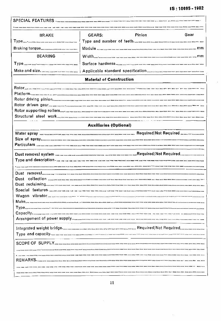
IPECIAL FEATURES ................ _. .............................................................. ..“. ......................
.........................................................................................................................................
BRAKE GEARS: Pinion Gear
-ype ........................................ Type and number of teeth ....................................................
lraking torque ........................... Module ............................. ............................................. mm
BEARING Width.. .......................................................................... mm
rype.. ...................................... Surface hardness ...................................... . ...........................
lnake and size ............................ Applicable standard specification ..........................................
Material of Construction
iotor ... _ .............................................................................................................................
4atform ............................................................... u.. ..............................................................
iotor driving pinion ................................................................................................................
iotor dr~iven gear ............................................................................... . ............. -. .......... -*- ...
?otor supporting rollers ..........................................................................................................
Structural steel work ...........................................................................................................
Auxiliaries (Optional)
Water spray ........................................................... -. ......... Required/Not Required ..................
Size of spray , ..................................... . .................................................................................
Particulars ................................................................................................ I.. .......................
Dust removal system ............................................................ Required/Not Required.. ................
Type and description ........................ ._ ............... .u . ....... .a.. ........... . ....................................
............. I.. ........................................................................... -....-. ............ ..C ........................
Dust removal ........................................................................................................................
Dust collection , ..................................................................................................................
Dust reclaiming .....................................................................................................................
Special features. ..................................................................................................................
Wagon vibrator.. ..................................................................................................................
Make ....................................................................................................................................
Type .....................................................................................................................................
Capacity .............................................................................................................................
Arrangement of power supply ..................................................................................................
Integrated weight bridge. ...................................................... Required/Not Required ..................
Type and capacity. ..................................................................................................................
SCOPE OF SUPPLY ...............................................................................................................
...........................................................................................................................................
....................................................... .I.. ...............................................................................
REMARKS .............................................................................................................................
.........................................................................................................................................
........................ _. ........................... . .....................................................................................
-~ ? ~ ._ _ ’
IS: 10095 - 1982
EXPLANATORY NOTE
This Indian Standard covers the requirement to be followed by the manufacturers of wagon tipplers used to unload loaded wagons of Indian Railways. These wagons are normally required by heavy industries such as steel plants, cement plants, thermal power stations and mineral bene- fication plants to transport raw materials used by these plants. These raw materials are required by these plants in huge quantities with an uninterrupted supply, so that the plants achieve optimum efficiency.
The transport of raw materials to plants is done by Indian Railways through the use of ‘ open ’ or ‘ closed ’ wagons. The ‘ open ’ wagons have been designed for ease in unloading for obtaining optimum efficiency and are, therefore, largely used for transportation of raw materials like ores, coal, etc. Various types of ‘open’ wagons used for transportation of raw material have been included in 2. The ‘ open ’ wagons covered by this standard also include a new ’ BOXN Mark II ’ type of wagon which is expected to be used by Indian Railways in near future. This is an improvement on ordinary ‘ BOXN ’ type of wagon and has same parameters as those of ‘ BOXN ’ except for overall height and overall width.
Another type of ‘ open ’ wagon being termed as ‘ 6-axled Wagon ’ is also likely to be intro- duced by Indian Railways. It is a low-sided, gondola wagon with a gross weight of 138 tonnes. The use of this wagon will require a wagon tippler to be designed for a gross load of 150 tonnes with an overall platform length of 18 m to accomodate this wagon. This type of wagon has been kept out of scope of this standard. It is, therefore, desired that in case the use of this wagon is anticipated, the information pertaining to its use shall be provided in Appendix A, so that a manufacturer is able to design his tippler accordingly.
The requirements of large quantities of raw materials with uninterrupted.suppIy can be met by Indian Railways only if loaded wagons are emptied by the plants in the minimum possible time. This can be achieved through the use of wagon tipplers at the plants, The use of wagon tipplers also have the added advantages of saving in manpower and space required for unloading and storage of raw material.
The use of wagon tipplers also raises the question of proper maintenance of tipplers because any defect in the installation, operation and maintenance of tipplers may damage the wagons which normally are the property of Indian Railways while tippling equipment belong to the owners of the plant. For this purpose, Indian Railways desire that details of the wagon tippler and its ancilliary handling equipment for placing and withdrawing the wagon on and off the tippler, shall be forwarded by the prospective owner to the Director General (Wagon ), Research, Design and Standards Organization, Lucknow 226 011 through the General Manager ( Mech ) of the concerned zonal railway having jurisdiction over the site of commissioning of the tipplers. The proposed equipment will be examined by tne Chief Mechanical Engineer of the railway concerned and who in turn would forward the same to the Director General ( Wagons), RDSO, Lucknow along with his recommendations and comments based on the experience gained by him with similar type of equipment earlier.
In the preparation of this standard considerable assistance has been derived from the following:
IS0 1819-1977 ‘ Continuous mechanical handling equipment - Safety Code - General rules ’ issued by the International Organization for Standardization
IS0 3265-1974 ‘ Continuous mechanical handling equipment for loose bulk materials - Wagon tipplers handling rail borne wagons ( rotary, side discharge and end discharge)-Safety code’ issued by the International Organization for Standardizatibn
UIC Code 504 OR ‘Conditions to be complied with in the construction and use of appliances for shunting and handling wagons ’ issued by the International Union of Railways
Code of Practice CP2 ‘ For the installation of appliances handling wagons and similar type rolling stock required to travel over the British Railway System ’ issued by the British Railway Board, Doncaster
Technical Pamphlet No. G-33 (RFV-I ) ‘ Tipplers, rotary dumpers for B. G. open wagons’ issued by the Research, Designs and Standards Organization, Ministry of Railways, Lucknow.
12
Printed at New India Printing Press. Khurla. India