Development of Scott Transformer Model in Electromagnetic ...
17
applied sciences Article Development of Scott Transformer Model in Electromagnetic Transients Programs for Real-Time Simulations Choongman Lee, Gyu-Jung Cho and Joorak Kim * Citation: Lee, C.; Cho, G.-J.; Kim, J. Development of Scott Transformer Model in Electromagnetic Transients Programs for Real-Time Simulations. Appl. Sci. 2021, 11, 5752. https:// doi.org/10.3390/app11125752 Academic Editors: Matti Lehtonen and Giovanni Petrone Received: 13 April 2021 Accepted: 17 June 2021 Published: 21 June 2021 Publisher’s Note: MDPI stays neutral with regard to jurisdictional claims in published maps and institutional affil- iations. Copyright: © 2021 by the authors. Licensee MDPI, Basel, Switzerland. This article is an open access article distributed under the terms and conditions of the Creative Commons Attribution (CC BY) license (https:// creativecommons.org/licenses/by/ 4.0/). Korea Railroad Research Institute, Uiwang 16105, Korea; [email protected] (C.L.); [email protected] (G.-J.C.) * Correspondence: [email protected]; Tel.: +82-31-460-5411 Abstract: This paper presents a Scott transformer model to be applied in electromagnetic transients (EMT) programs, particularly in the absence of a detailed Scott transformer model for performing real-time simulations (RTS). Regarding a Scott transformer, a common topology for converting a three- phase network into two single-phase networks, the transformer model in EMT programs is essential to simulate large-scale electric railway systems. A code-based model has been developed to simulate the transformer in RTS directly and contain the transformer’s actual impedance characteristics. By establishing a mathematical foundation with the current injection method, we presented a matrix representation in conjunction with a network solution of EMT programs. The proposed model can handle more practical parameters of Scott transformers with a relatively low computational load. Thus, it supports the flexible computation of real-time simulators with a finite number of processor units. The accuracy of the model is verified by simulating it and comparing the simulation results with an industrial transformer’s certified performance. Furthermore, a case study involving a comparison of the results with the field measurement data of an actual Korean railway system demonstrated the efficacy of the model. Keywords: Scott transformer; electric railway system; real-time simulation 1. Introduction As electric railway systems have been widely employed around the world, various concerns regarding electric power systems have emerged. Since electric railway systems intermittently consume huge amounts of active and reactive power, they hinder load forecasting for power system operators and raise power quality problems such as harmon- ics, flickers, and negative-sequence currents in the three-phase balanced systems [1–6]. In severe cases, this might threaten the stability of the whole electric power system. Thus, it is essential to develop a model of an electric railway system, calculate the power flows, and analyze the effect on the transmission network [7–12]. The electromagnetic transients (EMT) program has been widely used to investigate power quality phenomena in the elec- tric railway system [1,10,13,14]. Furthermore, real-time simulations (RTS) have attracted attention for power system analysis to handle problems closer to the real world [15–19]. In particular, RTS can be utilized to perform a hardware-in-loop (HIL) test for reactive power compensation systems and the coordination of protection systems [19–23]. In South Korea, large-scale real-time simulators are being used to investigate the effect of moving loads and the performance of the protection system. Among the power quality problems, three-phase unbalance is one of the critical problems that the electric railway system causes on a balanced AC network. Since many electric railway systems act as a strong single-phase load, specially connected transformers such as the Scott, Le Blanc, Woodbridge, and V-connected transformers are required to deliver the power from the transmission network to the railway system [23–26]. Commonly, the Scott transformer has been employed to convert three-phase to two single-phases and maintain the three-phase balance [27–30]. Appl. Sci. 2021, 11, 5752. https://doi.org/10.3390/app11125752 https://www.mdpi.com/journal/applsci
-
Upload
khangminh22 -
Category
Documents
-
view
1 -
download
0
Transcript of Development of Scott Transformer Model in Electromagnetic ...

applied sciences
Article
Development of Scott Transformer Model in ElectromagneticTransients Programs for Real-Time Simulations
Choongman Lee, Gyu-Jung Cho and Joorak Kim *
Citation: Lee, C.; Cho, G.-J.; Kim, J.
Development of Scott Transformer
Model in Electromagnetic Transients
Programs for Real-Time Simulations.
Appl. Sci. 2021, 11, 5752. https://
doi.org/10.3390/app11125752
Academic Editors: Matti Lehtonen
and Giovanni Petrone
Received: 13 April 2021
Accepted: 17 June 2021
Published: 21 June 2021
Publisher’s Note: MDPI stays neutral
with regard to jurisdictional claims in
published maps and institutional affil-
iations.
Copyright: © 2021 by the authors.
Licensee MDPI, Basel, Switzerland.
This article is an open access article
distributed under the terms and
conditions of the Creative Commons
Attribution (CC BY) license (https://
creativecommons.org/licenses/by/
4.0/).
Korea Railroad Research Institute, Uiwang 16105, Korea; [email protected] (C.L.); [email protected] (G.-J.C.)* Correspondence: [email protected]; Tel.: +82-31-460-5411
Abstract: This paper presents a Scott transformer model to be applied in electromagnetic transients(EMT) programs, particularly in the absence of a detailed Scott transformer model for performingreal-time simulations (RTS). Regarding a Scott transformer, a common topology for converting a three-phase network into two single-phase networks, the transformer model in EMT programs is essentialto simulate large-scale electric railway systems. A code-based model has been developed to simulatethe transformer in RTS directly and contain the transformer’s actual impedance characteristics.By establishing a mathematical foundation with the current injection method, we presented a matrixrepresentation in conjunction with a network solution of EMT programs. The proposed modelcan handle more practical parameters of Scott transformers with a relatively low computationalload. Thus, it supports the flexible computation of real-time simulators with a finite number ofprocessor units. The accuracy of the model is verified by simulating it and comparing the simulationresults with an industrial transformer’s certified performance. Furthermore, a case study involvinga comparison of the results with the field measurement data of an actual Korean railway systemdemonstrated the efficacy of the model.
Keywords: Scott transformer; electric railway system; real-time simulation
1. Introduction
As electric railway systems have been widely employed around the world, variousconcerns regarding electric power systems have emerged. Since electric railway systemsintermittently consume huge amounts of active and reactive power, they hinder loadforecasting for power system operators and raise power quality problems such as harmon-ics, flickers, and negative-sequence currents in the three-phase balanced systems [1–6].In severe cases, this might threaten the stability of the whole electric power system. Thus,it is essential to develop a model of an electric railway system, calculate the power flows,and analyze the effect on the transmission network [7–12]. The electromagnetic transients(EMT) program has been widely used to investigate power quality phenomena in the elec-tric railway system [1,10,13,14]. Furthermore, real-time simulations (RTS) have attractedattention for power system analysis to handle problems closer to the real world [15–19]. Inparticular, RTS can be utilized to perform a hardware-in-loop (HIL) test for reactive powercompensation systems and the coordination of protection systems [19–23]. In South Korea,large-scale real-time simulators are being used to investigate the effect of moving loadsand the performance of the protection system.
Among the power quality problems, three-phase unbalance is one of the criticalproblems that the electric railway system causes on a balanced AC network. Since manyelectric railway systems act as a strong single-phase load, specially connected transformerssuch as the Scott, Le Blanc, Woodbridge, and V-connected transformers are required todeliver the power from the transmission network to the railway system [23–26]. Commonly,the Scott transformer has been employed to convert three-phase to two single-phases andmaintain the three-phase balance [27–30].
Appl. Sci. 2021, 11, 5752. https://doi.org/10.3390/app11125752 https://www.mdpi.com/journal/applsci

Appl. Sci. 2021, 11, 5752 2 of 17
Thus, the Scott transformer model is necessary to perform an EMT study for an electricrailway system. The problem is that the transformer model is rarely included in the libraryprovided by general EMT programs. Many users combine two transformer models tohandle the problem, i.e., a single-phase transformer and a three-winding transformer toimplement the Scott connection [10,13,25,26].
In fact, the Scott transformer model has recently been added to the library providedby the EMT program for real-time digital simulators (RSCAD). However, the model cannotset the actual parameters of Scott transformers, such as the leakage reactance of two phases.Accordingly, it cannot accurately involve the Scott transformer’s detailed characteristics,which are essential for simulating the electric railway system. Due to the incomplete model,voltage and current unbalance problems were repeatedly observed in RTS. To addressthis concern, we formed a Scott transformer by connecting two transformer models in theRSCAD Substep library in the same way as previously mentioned.
When it comes to RTS for electric railway systems, it should be noted that the railwaysystem components, including power electronics-based apparatus and moving loads,require heavier computational resources. However, the Substep library models shouldcompletely occupy one of the processor units of real-time simulators. As for the approachesusing two transformer models in the Substep library to implement the Scott connections,the limitations of the processor resources become a concern when it comes to executingRTS for electric railway systems.
To overcome the limitations above, we developed a Scott transformer model linked toC source code with a mathematical foundation. It has the following advantages:
• Conveniently embodying the Scott transformer in EMT programs (rather than twotransformer models);
• Addressing the detailed impedance characteristics of the Scott transformer, includingthe leakage reactance of M- and T-phases;
• Facilitating flexible computation in terms of real-time simulation of large-scale systemsowing to the lighter computational burden of the proposed model.
The rest of the paper is organized as follows. Section 2 introduces the general structureof a Scott connection and the limitations of the conventional Scott model for RTS. Section 3provides the mathematical foundation and presents a Scott transformer model using thecurrent injection method. In addition, we discuss the computational resources of RTS whenusing the Scott transformer model in Section 3. In Section 4, the simulation results verify theproposed model’s accuracy by comparing the results with the certified performance of anindustrial product. Furthermore, the efficacy of the model is demonstrated by comparingit with field data of an actual Korean railway system.
2. Scott Transformer Model for Real-Time Simulation2.1. Scott Transformer
Specially connected transformers are essential to delivering power from an AC trans-mission network to electrical railway system. These apparatuses such as Scott, Le Blanc,and Woodbridge are used to transform the three-phase transmission structure of the gridinto two single-phases. As a common connection, two single-phases (M-phase and T-phase)are connected to the three-phase network using a Scott transformer as shown in Figure 1.

Appl. Sci. 2021, 11, 5752 3 of 17
Figure 1. The basic structure of Scott transformer.
A separate library model is highly required to form a Scott connection in the EMTstudy for the electric railway system. However, the Scott transformer model is rarelyincluded in the library provided by general EMT programs. Many users combined a single-phase transformer and a three-winding transformer to implement the Scott connection asshown in Figure 2 [10,13,25,26].
Figure 2. Scott connection using a single-phase transformer and a single-phase three-winding transformer.
Let the turn ratio of the primary side to the secondary side of the Scott transformerbe k = (N1/N2). Then, the relationship between transformer voltage and current can beexpressed as follows [3]:
VABVBCVCA
=
√
3k2 − k
20 k−√
3k2 − k
2
[ VTVM
],
IAIBIC
=
2√3k
0
− 1√3k
1k
− 1√3k− 1
k
[ ITIM
](1)
If the magnitude of three-phase current in Equation (1) is denoted as I and identicalloads are connected to M- and T-phases, the induced current is derived as
IT =√
3kI2 ∠0
IM =√
3kI2 ∠90
(2)
that is, currents of identical magnitude but the phase difference of 90 flow in the secondaryside of the Scott transformer. The three-phase current of the primary side achieves thebalanced state as follows:
IA = I∠0
IB = I∠− 120
IC = I∠120(3)
Appl. Sci. 2021, 11, 5752 4 of 17
In other words, when an identical load is connected to the M- and T-phases of theScott transformer, we obtain currents with equal magnitude and a phase difference of 90
flow in these phases. Accordingly, balanced currents with equal magnitude and a phasedifference of 120 flow in the three-phase side are obtained.
When it comes to industrial transformer certification, the characteristics of M- and T-phases must be tested separately. In the same manner, while configuring a Scott transformerwith two transformers, each transformer’s parameters must be set in detail to contain thecharacteristics of M- and T-phases, respectively.
2.2. Scott Transformer Model for the Real-Time Simulator
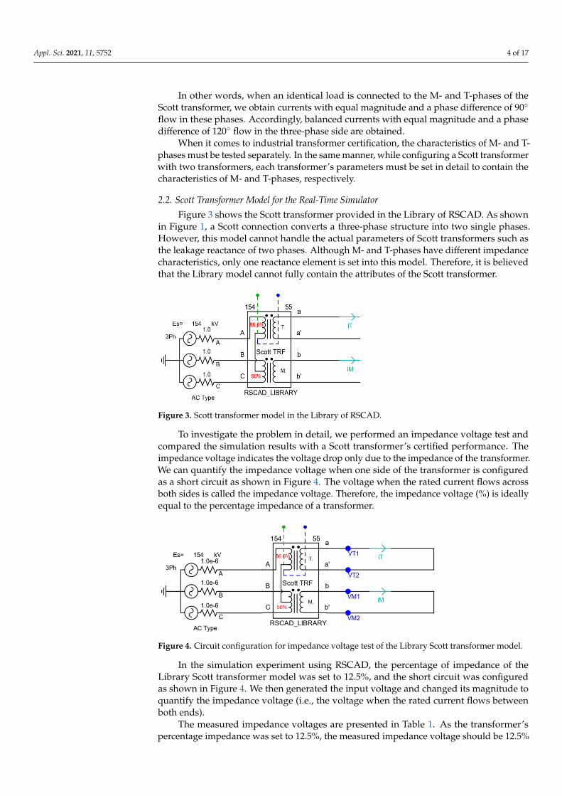
Figure 3 shows the Scott transformer provided in the Library of RSCAD. As shownin Figure 1, a Scott connection converts a three-phase structure into two single phases.However, this model cannot handle the actual parameters of Scott transformers such asthe leakage reactance of two phases. Although M- and T-phases have different impedancecharacteristics, only one reactance element is set into this model. Therefore, it is believedthat the Library model cannot fully contain the attributes of the Scott transformer.
Figure 3. Scott transformer model in the Library of RSCAD.
To investigate the problem in detail, we performed an impedance voltage test andcompared the simulation results with a Scott transformer’s certified performance. Theimpedance voltage indicates the voltage drop only due to the impedance of the transformer.We can quantify the impedance voltage when one side of the transformer is configuredas a short circuit as shown in Figure 4. The voltage when the rated current flows acrossboth sides is called the impedance voltage. Therefore, the impedance voltage (%) is ideallyequal to the percentage impedance of a transformer.
Figure 4. Circuit configuration for impedance voltage test of the Library Scott transformer model.
In the simulation experiment using RSCAD, the percentage of impedance of theLibrary Scott transformer model was set to 12.5%, and the short circuit was configuredas shown in Figure 4. We then generated the input voltage and changed its magnitude toquantify the impedance voltage (i.e., the voltage when the rated current flows betweenboth ends).
The measured impedance voltages are presented in Table 1. As the transformer’spercentage impedance was set to 12.5%, the measured impedance voltage should be 12.5%

Appl. Sci. 2021, 11, 5752 5 of 17
in the normal condition. However, the Library Scott transformer’s impedance voltages(8.49% and 11.36%) differed significantly compared to the theoretical value as representedin Table 1. Furthermore, when the library model is used, both sides of the transformer areexpected to maintain the balanced condition following Equations (2) and (3). However,Figure 5a shows that an unbalanced current flowed in the three phases. Although thecurrents flowing in M- and T-phases had a normal phase difference (90), the two currentsdiffered in magnitude, as shown in Figure 5b. To sum up, impedance voltage tests showthat the Library model cannot accurately simulate the Scott transformer.
Table 1. Impedance voltage test results of the Library Scott transformer model when the inputparameter (percent impedance, %Z) is set as 12.5%.
M-Phase T-Phase
Transformer percentimpedance setting 12.5%
Impedance voltage 13.08 kV (8.49%) 11.75 kV (11.36%)
Figure 5. Impedance voltage test result for the Library Scott transformer model: (a) unbalanced three-phase current waveform; (b) unbalanced M- and T-phase current waveforms and vector representation.
3. Development of Scott Transformer with Electromagnetic Transients Program3.1. Electromagnetic Transients Modeling
To address the limitation of the Library model illustrated in Section 2.2, we developeda Scott transformer model that can be seamlessly integrated into various EMT programs.In other words, the proposed model is based on the current injection method so that it canbe easily solved in general EMT programs [14,31].

Appl. Sci. 2021, 11, 5752 6 of 17
3.1.1. Matrix Representation for EMT Programs
The generalized equivalent circuit of a single-phase transformer is represented inFigure 6. Based on the circuit above, the terminal voltages can be expressed as follows:[
v1(t)v2(t)
]=
[R1 00 R2
][i1(t)i2(t)
]+
[L1+Lm Lm
Lm L2+Lm
]ddt
[i1(t)i2(t)
](4)
To explain the n-winding transformer, it can be reorganized as follows, including theresistance matrix R and the inductance matrix L [14].
v1(t)v2(t)
...vn(t)
=
R11 0 · · · 00 R22 · · · 0...
......
...0 0 · · · Rnn
︸ ︷︷ ︸
R
i1(t)i2(t)
...in(t)
+
L11 L12 · · · L1nL21 L22 · · · L2n
......
......
Ln1 Ln2 · · · Lnn
︸ ︷︷ ︸
L
ddt
i1(t)i2(t)
...in(t)
(5)
Consequently, the matrix representation for the n-winding transformer is presented as(5). Then, the voltage and current values are calculated and updated in each solution timestep for the EMT program of the corresponding network.
Figure 6. Configuration of an equivalent circuit for a single-phase transformer.
3.1.2. Current Injection Model for Scott Transformer
Considering the n-winding transformer in (5), the voltage and current input matricesare defined as follows:
[v(t)]=[
v1(t) v2(t) · · · vn(t)]T
[i(t)]=[
i1(t) i2(t) · · · in(t)]T (6)
Subsequently, to include the matrices R and L, the voltage and current are defined asEquation (7) based on Equation (5).
[v(t)]=[R][i(t)]+[L]ddt[i(t)] (7)
Adjusting these equations to EMT programs, the matrix representation of the trans-former can be represented by being numerically integrated over a time step using trape-zoidal integration.
Then, the voltage and current in Equation (7) can be reorganized as:
[v(t)] + [v(t− ∆t)]2
∆t = [R][i(t)] + [i(t− ∆t)]
2∆t + [L][[i(t)]− [i(t− ∆t)]] (8)
Appl. Sci. 2021, 11, 5752 7 of 17
It can be represented in the form of the current injection model as follows [14]:[[R]
∆t2
+ [L]][i(t)] +
[[R]
∆t2− [L]
][i(t− ∆t)] =
∆t2[v(t)]− ∆t
2[v(t− ∆t)] (9)
Equation (9) can be rearranged to express it as a conductance matrix G:
[i(t)] =[[R]∆t
2 + [L]]−1 ∆t
2 [v(t)]−[[R]∆t
2 + [L]]−1 ∆t
2 [v(t− ∆t)]
−[[R]∆t
2 + [L]]−1[
[R]∆t2 − [L]
][i(t− ∆t)]
(10)
Consequently, it can be formed as follows:
[i(t)] = [G][v(t)] + [ih(t)] (11)
where [G] =[[R]∆t
2 + [L]]−1 ∆t
2 , [ih(t)] = [G][[v(t− ∆t)]−
[[R]− [L] 2
∆t][i(t− ∆t)]
]G is
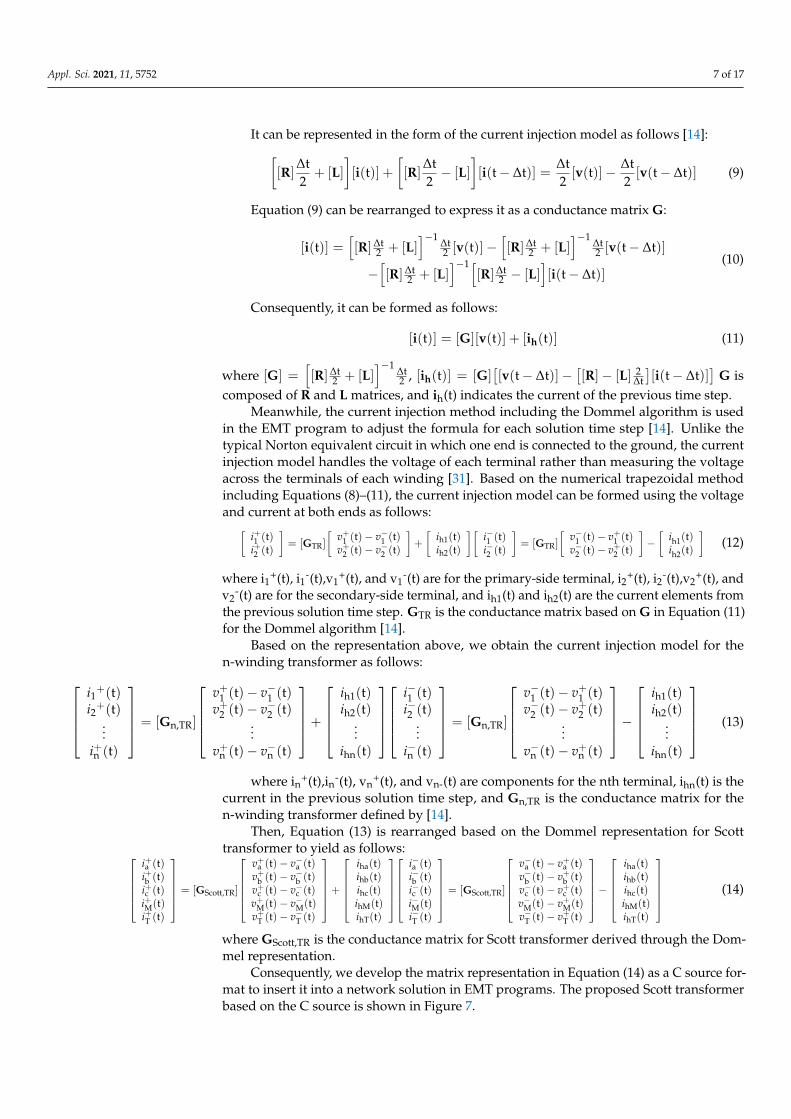
composed of R and L matrices, and ih(t) indicates the current of the previous time step.Meanwhile, the current injection method including the Dommel algorithm is used
in the EMT program to adjust the formula for each solution time step [14]. Unlike thetypical Norton equivalent circuit in which one end is connected to the ground, the currentinjection model handles the voltage of each terminal rather than measuring the voltageacross the terminals of each winding [31]. Based on the numerical trapezoidal methodincluding Equations (8)–(11), the current injection model can be formed using the voltageand current at both ends as follows:[
i+1 (t)i+2 (t)
]= [GTR]
[v+1 (t)− v−1 (t)v+2 (t)− v−2 (t)
]+
[ih1(t)ih2(t)
][i−1 (t)i−2 (t)
]= [GTR]
[v−1 (t)− v+1 (t)v−2 (t)− v+2 (t)
]−[
ih1(t)ih2(t)
](12)
where i1+(t), i1-(t),v1+(t), and v1
-(t) are for the primary-side terminal, i2+(t), i2-(t),v2+(t), and
v2-(t) are for the secondary-side terminal, and ih1(t) and ih2(t) are the current elements from
the previous solution time step. GTR is the conductance matrix based on G in Equation (11)for the Dommel algorithm [14].
Based on the representation above, we obtain the current injection model for then-winding transformer as follows:
i1+(t)i2+(t)
...i+n (t)
= [Gn,TR]
v+1 (t)− v−1 (t)v+2 (t)− v−2 (t)
...v+n (t)− v−n (t)
+
ih1(t)ih2(t)
...ihn(t)
i−1 (t)i−2 (t)
...i−n (t)
= [Gn,TR]
v−1 (t)− v+1 (t)v−2 (t)− v+2 (t)
...v−n (t)− v+n (t)
−
ih1(t)ih2(t)
...ihn(t)
(13)
where in+(t),in-(t), vn+(t), and vn-(t) are components for the nth terminal, ihn(t) is the
current in the previous solution time step, and Gn,TR is the conductance matrix for then-winding transformer defined by [14].
Then, Equation (13) is rearranged based on the Dommel representation for Scotttransformer to yield as follows:
i+a (t)i+b (t)i+c (t)i+M(t)i+T (t)
= [GScott,TR]
v+a (t)− v−a (t)v+b (t)− v−b (t)v+c (t)− v−c (t)v+M(t)− v−M(t)v+T (t)− v−T (t)
+
iha(t)ihb(t)ihc(t)ihM(t)ihT(t)
i−a (t)i−b (t)i−c (t)i−M(t)i−T (t)
= [GScott,TR]
v−a (t)− v+a (t)v−b (t)− v+b (t)v−c (t)− v+c (t)v−M(t)− v+M(t)v−T (t)− v+T (t)
−
iha(t)ihb(t)ihc(t)ihM(t)ihT(t)
(14)
where GScott,TR is the conductance matrix for Scott transformer derived through the Dom-mel representation.
Consequently, we develop the matrix representation in Equation (14) as a C source for-mat to insert it into a network solution in EMT programs. The proposed Scott transformerbased on the C source is shown in Figure 7.

Appl. Sci. 2021, 11, 5752 8 of 17
Figure 7. The proposed Scott transformer model linked to C source code in RSCAD.
3.2. Computational Load for Simulations of Electric Railway System
As an EMT program does not provide a Scott transformer model, many users combinea single-phase transformer and a three-winding transformer to form the Scott connectionas shown in Figure 2. In RSCAD, the Scott transformer can also be configured using twotransformers as shown in Figure 8.
Figure 8. Scott connection using a single-phase transformer and a single-phase three-windingtransformer in the Substep library.
Note that the network solution must be computed with the Substep, which performsas many operations as an integer multiplied by the main time step. This is because themodel in Figure 8 uses a transformer in the Substep Library. For instance, if the main timestep is 50 µs, the time step of Substep can be 25 µs or smaller. This increases the totalcomputational load of real-time simulators. Moreover, it should be noted that the Substepmodel entirely occupies one of the processor units as shown in Figure 9a. This implies thata processor unit would be occupied entirely even when only one Scott transformer is to beutilized. This increases the total computational load and lowers the computation efficiency.
In contrast, since the proposed model was formed as a C source, it can be easilyutilized at any time step. Furthermore, the computational load can be decreased and thecomputation efficiency increased. Figure 9b shows that approximately 5% of the totalcomputational load is utilized by this model.
It is necessary to compare the computational load utilized by the Substep model andthe proposed model since the simulation of a large-scale electric railway system requires alarge number of computations, such as those for accurately finding the state of each facilityand for simulating moving vehicles. Suppose the elements incur a large computationalload in scenarios where the number of processor units in a real-time digital simulator islimited. In that case, these can pose a problem for the RTS study for the electric railwaysystem.
Regarding this, the proposed Scott transformer model can enhance the flexibility ofcomputational resources while simulating a large-scale electric railway system (see Figure 9).

Appl. Sci. 2021, 11, 5752 9 of 17
Figure 9. Comparison between computational loads of (a) Scott connection using the Substep librarymodels (processor assignment for Scott connection using a single-phase transformer and 3-windingtransformer from the Substep library) and (b) the proposed Scott transformer (processor assignmentfor Scott connection based on the proposed model).
4. Simulation Results4.1. Impedance Voltage Tests
In this section, we present the simulation results using a real-time digital simulator(RTDS) to verify the effectiveness of the proposed model. To begin with, we tried to verifythe model’s accuracy through an impedance voltage test. The equivalent circuit for theimpedance voltage test of the proposed transformer was organized as shown in Figure 10.The parameters in Table 2 are identical to those of the transformer certified by the KoreaElectrotechnology Research Institute (KERI). After we set the input parameter as Table 2,the impedance voltage test was performed.
Figure 10. An equivalent circuit diagram for impedance voltage test.

Appl. Sci. 2021, 11, 5752 10 of 17
Table 2. Detailed parameters of Scott transformer (identical to those of the transformer certifiedby KERI).
Parameter Value
Transformer rating 45 MVA
Rated voltage 154 kV/55 kV
T-side leakage reactance(Single-phase transformer) 12.5%
T-side resistance 0.2%
M-side leakage reactance(Single-phase 3-winding transformer) 12.5%
M-side resistance 0.2%
Note that the currents in M- and T-phases became unbalanced in the impedancevoltage test of the RSCAD Library model as shown in Figure 5. By comparison, in theresults shown in Figure 11, both sides of the proposed model are in a balanced state. As atransformer parameter, the measured impedance voltage in Table 3 is identical to theleakage value (12.5%) input. Thus, the effectiveness of the model is demonstrated by thefact that the three-phase structure was accurately converted to two single phases (i.e., M-and T-phases), and the balance of each phase was maintained.
Figure 11. Result of impedance voltage test for the proposed Scott transformer: (a) three-phase current waveforms; (b) M-and T-phase current waveforms and vector representation.
Table 3. Result of impedance voltage test (a comparison of the result with the certified test report ofan actual Scott transformer by KERI).
Certified Test Result Results with the Proposed Model
Impedance voltage 19.25 kV 19.25 kV
M-phase current (RMS) 0.4090 kA 0.4089 kA
T-phase current (RMS) 0.4090 kA 0.4091 kA
HV side current (RMS) 0.1687 kA 0.1688 kA
4.2. Short-Circuit Tests
The short-circuit test is a representative procedure that is performed for assessing atransformer’s characteristics. Note that owing to the limitation of the system configurationfor the generation of a rated voltage (154 kV) on the high-voltage (HV) side, a rated voltage(55 kV) was formed on the low-voltage (LV) side, whereas the HV side was configuredas a short circuit as shown in Figure 12. We measured the short-circuit current when the

Appl. Sci. 2021, 11, 5752 11 of 17
switching operation occurs, while the rated voltage is formed on the LV side shown inFigure 12.
Figure 12. Circuit diagram for short-circuit test of the Scott transformer.
Figure 13a shows the short-circuit current waveform when the T side is configured asan open circuit and voltage is generated on the M side. The actual waveform of the short-circuit current of the transformer certified by KERI is shown in Figure 13b. As illustrated,the waveform of the short-circuit current for the proposed model is similar to that of theactual short-circuit current. In addition, the peak and RMS current values are almost equalto those shown in Table 4.
Figure 13. M-phase short-circuit test results of Scott transformer (comparison between short-circuittest results obtained by RTDS and those in the certified test report by KERI): (a) waveform ofshort-circuit test result of the proposed Scott transformer, obtained by RTDS simulation (M-phase);(b) waveform in the certified test report (M-phase).

Appl. Sci. 2021, 11, 5752 12 of 17
Table 4. M-phase short-circuit test result of Scott transformer (comparison between short-circuit testresults obtained by RTDS and those in the certified test report).
Certified Test Result Using ProposedModel Error
Voltage 55 kV 55 kV
Current (RMS) 3.178 kA 3.174 kA 0.12%
Current (Peak) 8.104 kA 8.125 kA −0.25%
Similarly, Figure 14 shows the short-circuit current waveform when the M side wasconfigured as an open circuit and voltage was generated on the T side. Figure 14 andTable 5 show that the test result for the proposed transformer model is identical to thatpresented in the certified test report of KERI.
Figure 14. T-phase short-circuit test result of Scott transformer (comparison between short-circuittest results obtained by RTDS and those in the certified test report by KERI): (a) waveform of theshort-circuit test result of the proposed Scott transformer (T-phase); (b) waveform in the certified testreport (T-phase).
Table 5. T-phase short-circuit test result of Scott transformer (comparison between short-circuit testresults obtained by RTDS and those in the certified test report).
Certified Test Result Using Proposed Model Error
Voltage 55 kV 55 kV
Current (RMS) 3.125 kA 3.125 kA 0.001%
Current (Peak) 7.969 kA 7.967 kA 0.002%
Appl. Sci. 2021, 11, 5752 13 of 17
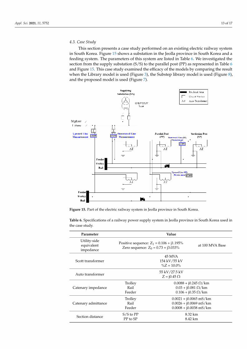
4.3. Case Study
This section presents a case study performed on an existing electric railway systemin South Korea. Figure 15 shows a substation in the Jeolla province in South Korea and afeeding system. The parameters of this system are listed in Table 6. We investigated thesection from the supply substation (S/S) to the parallel post (PP) as represented in Table 6and Figure 15. This case study examined the efficacy of the models by comparing the resultwhen the Library model is used (Figure 3), the Substep library model is used (Figure 8),and the proposed model is used (Figure 7).
Figure 15. Part of the electric railway system in Jeolla province in South Korea.
Table 6. Specifications of a railway power supply system in Jeolla province in South Korea used inthe case study.
Parameter Value
Utility-sideequivalentimpedance
Positive sequence: Z1 = 0.106 + j1.195%Zero sequence: Z0 = 0.73 + j3.033% at 100 MVA Base
Scott transformer45 MVA
154 kV/55 kV%Z = 10.0%
Auto transformer 55 kV/27.5 kVZ = j0.45 Ω
Catenary impedanceTrolley
RailFeeder
0.0088 + j0.245 Ω/km0.03 + j0.081 Ω/km0.106 + j0.35 Ω/km
Catenary admittanceTrolley
RailFeeder
0.0021 + j0.0065 mS/km0.0026 + j0.0069 mS/km0.0008 + j0.0038 mS/km
Section distance S/S to PPPP to SP
8.32 km8.42 km

Appl. Sci. 2021, 11, 5752 14 of 17
The case study system was set in RTDS to evaluate a system condition at a specifictime. We measured each feeder’s voltage, current, and active power using the CT and PTat 6:14:03 AM in an existing system. Then, we compared the measurement values withevaluated values by the simulations. The comparison results are summarized in Table 7.
Table 7. Case study result (comparison of actual measurement data with the RTDS simulation results obtained using eachmodel (the Substep model, the proposed model, and the Library model)).
S/S SP
Time6:14:03 AM
UpwardLine
Voltage(kV)
DownwardLine
Voltage(kV)
UpwardLine
Current(kA)
DownwardLine
Current(kA)
UpwardLine
Power(MW)
DownwardLine
Power(MW)
UpwardLine
Voltage(kV)
DownwardLine
Voltage(kV)
ActualMeasurement 48.552 48.570 0.3501 0.3520 16.5850 16.6245 47.3179 47.3215
Substep Model 49.22 49.22 0.3528 0.3549 16.74 16.78 48.03 48.03
ProposedModel 49.11 49.11 0.352 0.3541 16.67 16.70 47.92 47.92
Library Model 52.75 52.75 0.3781 0.3803 19.22 19.26 51.46 51.46
The measurement points (Upward Line and Downward Line in S/S and SP) aremarked in blue in Figure 15. It is observed that the results of using the Substep modeland the proposed model are similar to the actual measurement data. On the other hand,the results of the Library model differ significantly from the actual measurement data.In addition, Figure 16 compares the accuracy of the results obtained using each modelwith the actual measurements (Table 7). The accuracy is remarkably low when the Librarymodel was utilized as shown in Figure 16.
Figure 16. Comparison of accuracy between the simulation results of each model and the actual measurement data.
As mentioned in Section 3.2, it should be emphasized that RTS for electric railwaysystems requires heavy computational resources. The problem is that the Substep librarymodels should completely occupy one of the processor units of real-time simulators (seeFigures 9a and 17a). This hinders the flexible calculation of processor units of real-timesimulations. In contrast, the proposed model occupied only 5% of a processor unit asshown in Figure 17b. With the Substep model, the overall RTS should occupy four coresof an RTDS as shown in Figure 17a. In contrast, the RTS with the proposed model holdsfewer cores as shown in Figure 17b. Consequently, the proposed model achieved lowerabsolute computational load and higher flexibility in the use of the processor unit whileconfiguring a large-scale electric railway system.

Appl. Sci. 2021, 11, 5752 15 of 17
Figure 17. Processor assignment of the RTDS for the case study: (a) processor assignment when the Scott Connection isconfigured using the Substep model; (b) processor assignment using the proposed model.
5. Conclusions
A precise Scott transformer model with a lighter computational burden is presented inthis paper. The limitation of the existing Library model in RSCAD was revealed and provedexperimentally. To overcome it and facilitate a system modeling procedure, the authorsdeveloped the Scott transformer model based on C source for EMT programs includingRTS. The proposed model can be seamlessly integrated with the network solution programssince it is based on the current injection model, which is the most common method forEMT study. Furthermore, a code-based model can directly form the Scott connection inRTS and handle the impedance characteristics closer to the real world. The accuracy andefficacy of the proposed model are thoroughly demonstrated by following the same testprocedure as a certified transformer test. In addition, it is confirmed that the computationalburden becomes lighter, and the flexibility of the overall RTS computation has been notablyimproved. Therefore, it is believed that the proposed Scott transformer model will be ofimmediate help in modeling and studying the electric railway system.
Author Contributions: C.L. has developed the model and conducted simulation studies and writtenthe paper with support of G.-J.C. under supervision of the corresponding author, J.K. All authorshave read and agreed to the published version of the manuscript.

Appl. Sci. 2021, 11, 5752 16 of 17
Funding: This research was funded by the Ministry of Land, Infrastructure and Transport’s RailwayTechnology Research Project, “Development of Real Time Simulator and Analysis Model for RailwayPower System”: 21RTRP-B146034-04.
Institutional Review Board Statement: Not applicable.
Informed Consent Statement: Not applicable.
Data Availability Statement: Not applicable.
Conflicts of Interest: The authors declare no conflict of interest.
References1. Lee, H.; Lee, C.; Jang, G.; Kwon, S. Harmonic Analysis of the Korean High-Speed Railway Using the Eight-Port Representation
Model. IEEE Trans. Power Deliv. 2006, 21, 979–986. [CrossRef]2. Kneschke, T.A. Control of Utility System Unbalance Caused by Single-phase Electric Traction. IEEE Trans. Ind. Appl. 1985,
21, 1559–1570. [CrossRef]3. Huang, C.-P.; Wu, C.-J.; Chuang, Y.-S.; Peng, S.-K.; Yen, J.-L.; Han, M.-H. Loading Characteristics Analysis of Specially Connected
Transformers Using Various Power Factor Definitions. IEEE Trans. Power Deliv. 2006, 21, 1406–1413. [CrossRef]4. Tanta, M.; Pinto, J.G.; Monteiro, V.; Martins, A.P.; Carvalho, A.S.; Afonso, J.L. Topologies and Operation Modes of Rail Power
Conditioners in AC Traction Grids: Review and Comprehensive Comparison. Energies 2020, 13, 2151. [CrossRef]5. Mousavi Gazafrudi, S.M.; Tabakhpour Langerudy, A.; Fuchs, E.F.; Al-Haddad, K. Power Quality Issues in Railway Electrification:
A Comprehensive Perspective. IEEE Trans. Ind. Electron. 2015, 62, 3081–3090. [CrossRef]6. Chen, S.-L.; Li, R.-J.; Hsi, P.-H. Traction System Unbalance Problem-Analysis Methodologies. IEEE Trans. Power Deliv. 2004,
19, 1877–1883. [CrossRef]7. Brenna, M.; Foiadelli, F.; Zaninelli, D. Electromagnetic Model of High Speed Railway Lines for Power Quality Studies. IEEE Trans.
Power Syst. 2010, 25, 1301–1308. [CrossRef]8. Chymera, M.Z.; Renfrew, A.C.; Barnes, M.; Holden, J. Modeling Electrified Transit Systems. IEEE Trans. Veh. Technol. 2010,
59, 2748–2756. [CrossRef]9. Sainz, L.; Monjo, L.; Riera, S.; Pedra, J. Study of the Steinmetz Circuit Influence on ac Traction System Resonance. IEEE Trans.
Power Deliv. 2012, 27, 2295–2303. [CrossRef]10. Guihua, H.; Weirong, C.; Yankun, L.; Yang, Z. Simulation of Traction Transformer Based on PSCAD/EMTDC. In Proceedings of
the IEEE Power Engineering and Automation Conference, Wuhan, China, 8–9 September 2011; pp. 132–135.11. Chen, T.H. Simplified Models of Electric Substations for Three-Phase Power-Flow Studies. In Proceedings of the 1994 IEEE
Industry Applications Society Annual Meeting, Denver, CO, USA, 2–6 October 1994; Volume 3, pp. 2245–2248.12. Langerudy, A.T.; Mariscotti, A.; Abolhassani, M.A. Power Quality Conditioning in Railway Electrification: A Comparative Study.
IEEE Trans. Veh. Technol. 2017, 66, 6653–6662. [CrossRef]13. Li, M.; He, J.; Le, Y.; Bo, Z.Q.; Klimek, A. Developments in Digital Simulation of Traction Transformer. In Proceedings of the 43rd
International Universities Power Engineering Conference, Padua, Italy, 1–4 September 2008; pp. 1–4.14. Dommel, E.W. Electromagnetic Transients Program (EMTP) Theory Book; Bonneville Power Administration: Portland, OH, USA,
1987.15. Shu, Z.; Xie, S.; Lu, K.; Zhao, Y.; Nan, X.; Qiu, D.; Zhou, F.; Gao, S.; Li, Q. Digital Detection, Control, and Distribution System for
Co-Phase Traction Power Supply Application. IEEE Trans. Ind. Electron. 2013, 60, 1831–1839. [CrossRef]16. Busco, B.; Marino, P.; Porzio, M.; Schiavo, R.; Vasca, F. Digital Control and Simulation for Power Electronic Apparatus in Dual
Voltage Railway Locomotive. IEEE Trans. Power Electron. 2003, 18, 1146–1157. [CrossRef]17. McLaren, P.G.; Kuél, R.; Wierckx, R.; Giesbrecht, J.; Arendt, L. A Real Time Digital Simulator for Testing Relays. IEEE Trans. Power
Deliv. 1992, 7, 207–213. [CrossRef]18. Avalos, A.; Zamora, A.; Escamilla, O.; Paternina, M.R.A. Real-Time Hardware-In-the-Loop Implementation for Power Systems
Protection. In Proceedings of the 2018 IEEE PES Transmission & Distribution Conference and Exhibition—Latin America(T&D-LA), Lima, Peru, 18–21 September 2018.
19. Ho, J.-M.; Tsou, T.-L. The Effect Analysis and Simulation Test of Harmonics on Differential Protection of Scott Transformers. InProceedings of the 2001 IEEE Porto Power Tech. Proceedings (Cat No. 01EX502), Porto, Portugal, 10–13 September 2001; p. 5.
20. El-Sadek, M.Z. Static VAR Compensation for Phase Balancing and Power Factor Improvement of Single Phase Train Loads. Electr.Mach. Power Syst. 1998, 26, 347–361. [CrossRef]
21. Wen-Shyan, C.; Jyh-Cherng, G. A New Hybrid SVC Scheme with Scott Transformer for Balance Improvement. In Proceedings ofthe Rail Conference, Atlanta, GA, USA, 4–6 April 2006; pp. 217–224.
22. Wong, C.K.; Dai, N.Y.; Wong, M.C.; Lao, K.W. Hybrid Power Quality Conditioner for Co-Phase Power Supply System in ElectrifiedRailway. IET Power Electron. 2012, 5, 1084–1094.
23. Chen, B.K.; Guo, B.S. Three Phase Models of Specially Connected Transformers. IEEE Trans. Power Deliv. 1996, 11, 323–330.[CrossRef]

Appl. Sci. 2021, 11, 5752 17 of 17
24. Fukala, B.; Palecek, J. Comparison of Schemes of Traction Transformer Stations in Terms of Their Impact on the Asymmetry in thePower Supply System. In Proceedings of the 2014 15th International Scientific Conference on Electric Power Engineering (EPE),Brno-Bystrc, Czech Republic, 12–14 May 2014; pp. 207–210.
25. Firat, G.; Yang, G.; Al-Ali, H.A.H. Comparative Study of Different Transformer Connections for Railway Power Supply Mitigationof Voltage Unbalance. In Proceedings of the IET Conference, Hong Kong, China, 8–12 November 2015.
26. Santiyanon, D.; Hongesombut, K.; Srisonphan, S. Simulation on Voltage Unbalance Reduction in Railway Electrification Systemby Different Special Transformers. Procedia Comput. Sci. 2016, 86, 373–376. [CrossRef]
27. Richardson, D.V. Rotating Electric Machinery and Transformer Technology; Reston Publishing Company: Reston, VA, USA, 1978;pp. 418–423.
28. Kosow, I.L. Electric Machinery and Transformer; Prentice Hall: Upper Saddle River, NJ, USA, 1991; pp. 559–562.29. Brittain, J.C.; Scott, C.F. A Pioneer in Electrical Power Engineering. IEEE Ind. Appl. Mag. 2002, 8, 6–8. [CrossRef]30. Aihara, Y.; Miyazawa, R.; Koizumi, H. A Study on the Effect of the Scott Transformer on the Three-Phase Unbalance in Distribution
Network with Single-Phase Generators. In Proceedings of the 3rd IEEE International Symposium on Power Electronics forDistributed Generation Systems (PEDG), Aalborg, Denmark, 25–28 June 2012; pp. 283–290.
31. Watson, N.; Arrillaga, J. Power Systems Electromagnetic Transients Simulation; IET: Stevenage, UK, 2003.