Development of 3D Model Reconstruction and Terrain Registration Technology Using Satelliate Images
18
Development of 3D Model Reconstruction and Terrain Registration Technology Using Satelliate Images Won Seok, Seo Chang Geol Yoon, Jae Seok Jang, Seon Ho Oh and Soon Ki Jung Virtual Reality Laboratory, Department of Computer Engineering, Kyungpook National University, Daegu, Korea Abstract With the increasing demands for 3D building information, an effective method for extraction of 3D building is necessary. From the practical usage point of view, an interactive system for 3D building modeling for satellite images based on a semi- automatic method is presented. In order to model a 3D building and minimize user interaction, we utilize geometric features of the satellite image and the geometric relationship among the building, the building shadow, the positions of the sun and the satellite. Key words: High-Resolution Satellite Image, Building Reconstruction, Interactive Modeling, Image-based Modeling and Rendering 1 Motivation A commercial high-resolution satellite imagery (Quickbird,IKONOS ) offers spatial information for a wide variety of mapping and GIS applications. Ex- traction of 3D building information from high resolution satellite image is one of the most active research topics. Many commercial products support manual building modeling approach (Google Sketchup, Canoma, LIBAT, 3D Studio Max, Maya,. . . ). But these products absolutely depend on user manual con- trol. Therefore, building modeling tasks is very time consuming. Furthermore, these products do not assure sufficient accuracy for unknown size buildings in the satellite image. Many researchers suggest for reconstructing 3D building model from single image [1, 2]. [1] proposed a building detection system from a single intensity image. The limitation of this method is detecting rectilinear buildings with flat A Previous Project of Virtual Reality Laboratory Jan 2007 - Dec 2008
Transcript of Development of 3D Model Reconstruction and Terrain Registration Technology Using Satelliate Images

Development of 3D Model Reconstruction and
Terrain Registration Technology Using
Satelliate Images
Won Seok, Seo Chang Geol Yoon, Jae Seok Jang, Seon Ho Oh and Soon Ki Jung
Virtual Reality Laboratory, Department of Computer Engineering, Kyungpook
National University, Daegu, Korea
Abstract
With the increasing demands for 3D building information, an effective method forextraction of 3D building is necessary. From the practical usage point of view, aninteractive system for 3D building modeling for satellite images based on a semi-automatic method is presented. In order to model a 3D building and minimize userinteraction, we utilize geometric features of the satellite image and the geometricrelationship among the building, the building shadow, the positions of the sun andthe satellite.
Key words: High-Resolution Satellite Image, Building Reconstruction, InteractiveModeling, Image-based Modeling and Rendering
1 Motivation
A commercial high-resolution satellite imagery (Quickbird,IKONOS ) offersspatial information for a wide variety of mapping and GIS applications. Ex-traction of 3D building information from high resolution satellite image is oneof the most active research topics. Many commercial products support manualbuilding modeling approach (Google Sketchup, Canoma, LIBAT, 3D Studio
Max, Maya,. . . ). But these products absolutely depend on user manual con-trol. Therefore, building modeling tasks is very time consuming. Furthermore,these products do not assure sufficient accuracy for unknown size buildings inthe satellite image.
Many researchers suggest for reconstructing 3D building model from singleimage [1, 2]. [1] proposed a building detection system from a single intensityimage. The limitation of this method is detecting rectilinear buildings with flat
A Previous Project of Virtual Reality Laboratory Jan 2007 - Dec 2008
roofs. [2] proposed an automatic model-based building detection method basedon segmentation. However, the current computer vision method still cannotextract only the required information from general images [3]. Hence the userinteraction is required for reconstructing accurate 3D building models.
We suggest a system for large-scale 3D building modeling from satellite im-ages in semi-automatic approach. The primary approach is user assisted roofextraction and hypothesis, but the result can be refined by the minimal userinteraction. The shadow and the footprint of the building are used to esti-mate the building height. After estimating height information, the functionsbased on euler operator enable complex building modeling as well as minimizeuser interaction. Therefore, the proposed system can reconstruct 3D buildingmodels that have arbitrary shape with the minimum user interaction.
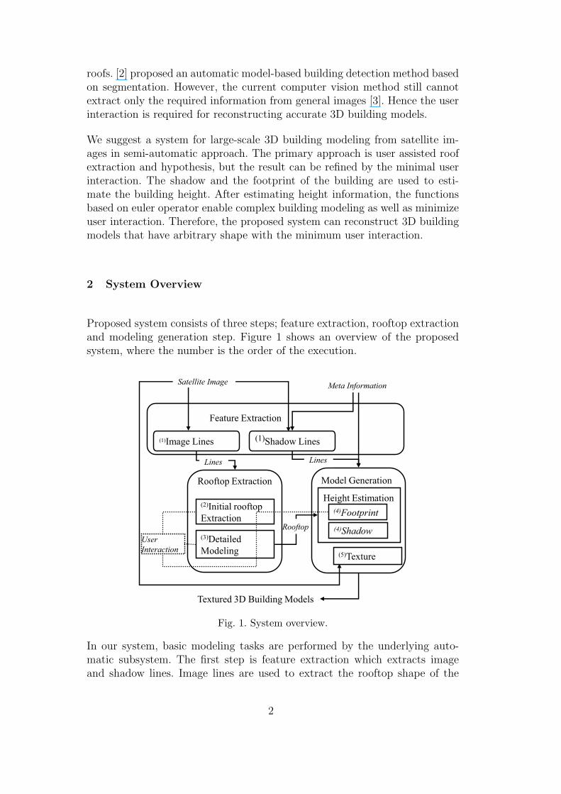
2 System Overview
Proposed system consists of three steps; feature extraction, rooftop extractionand modeling generation step. Figure 1 shows an overview of the proposedsystem, where the number is the order of the execution.
(1)Image Lines
Textured 3D Building Models
Satellite Image Meta Information
Rooftop
Rooftop Extraction Model GenerationHeight Estimation
(5)Texture
(3)Detailed Modeling
UserInteraction
LinesLines
Feature Extraction
(1)Shadow Lines
(2)Initial rooftop Extraction
(4)Footprint(4)Shadow
Fig. 1. System overview.
In our system, basic modeling tasks are performed by the underlying auto-matic subsystem. The first step is feature extraction which extracts imageand shadow lines. Image lines are used to extract the rooftop shape of the
2

building and shadow lines are used to estimate the height of the building afterrooftop extraction.
The second step is rooftop extraction which extracts the rooftop shape of thebuilding. The user interaction is used for acquiring the initial rooftop shape.This step assumes that building consists of a simple polyhedron and verticalwalls. The next step, detailed modeling handles complex or multi-componentof structure and non-relinear shapes. The current computer vision method stillcannot extract only the required edge from general images [3]. Therefore, thesimple user interaction is used for the accurate and detailed rooftop shape ofthe buildings.
The third step is modeling which estimates the height of the building. Theunderlying approach uses shadow line and rooftop edges which extracted infeature extraction step. In this case, the height of the building easily recoveredby using the meta information, such as sun and satellite angle. If the shadowis not existed, the footprint of the building is used. User interaction helps usto estimate the height of the building.
3 Feature Extraction
3.1 Meta information and Geometry
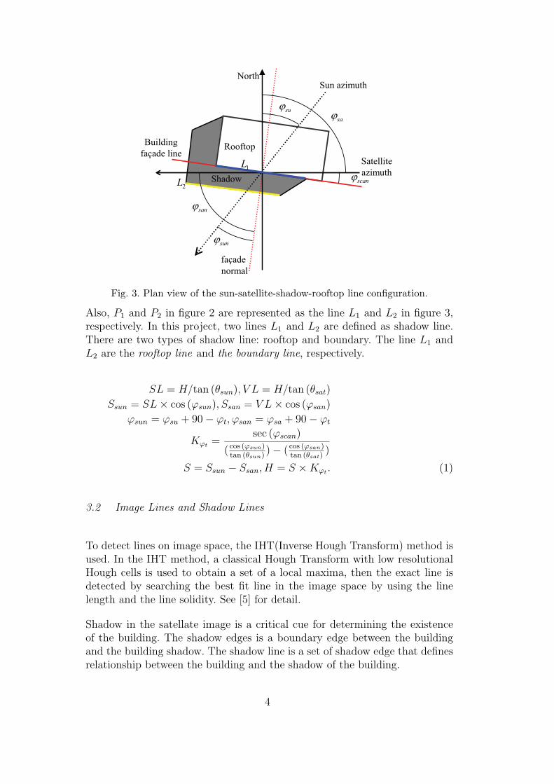
Our system uses meta information(the sun position and a satellite position)for modeling 3D building. Figure 2 shows the geometry relationship amongbuilding, shadow, satellite and the sun. Our system determines the height ofthe building from the geometry relationship.
H
VLSL
satq sunq
SunSatellite
1P 2P
P
Fig. 2. The geometry relationship among building, shadow, satellite and the sun.
The height of the building is computed from the difference between VL and SL
under the footprint of the building is on the ground. The height H is computedfrom equation 1. The equation 1 and figure 3 are derived from [4].
3
Sun azimuthNorth
Satelliteazimuth
Buildingfaçade line
façade normal
Shadow
Rooftop
scanj1L
2L
sanj
sunj
sujsaj
Fig. 3. Plan view of the sun-satellite-shadow-rooftop line configuration.
Also, P1 and P2 in figure 2 are represented as the line L1 and L2 in figure 3,respectively. In this project, two lines L1 and L2 are defined as shadow line.There are two types of shadow line: rooftop and boundary. The line L1 andL2 are the rooftop line and the boundary line, respectively.
SL = H/tan (θsun), V L = H/tan (θsat)
Ssun = SL × cos (ϕsun), Ssan = V L × cos (ϕsan)
ϕsun = ϕsu + 90 − ϕt, ϕsan = ϕsa + 90 − ϕt
Kϕt=
sec (ϕscan)
( cos (ϕsun)tan (θsun)
) − ( cos (ϕsan)tan (θsat)
)
S = Ssun − Ssan, H = S × Kϕt. (1)
3.2 Image Lines and Shadow Lines
To detect lines on image space, the IHT(Inverse Hough Transform) method isused. In the IHT method, a classical Hough Transform with low resolutionalHough cells is used to obtain a set of a local maxima, then the exact line isdetected by searching the best fit line in the image space by using the linelength and the line solidity. See [5] for detail.
Shadow in the satellate image is a critical cue for determining the existenceof the building. The shadow edges is a boundary edge between the buildingand the building shadow. The shadow line is a set of shadow edge that definesrelationship between the building and the shadow of the building.
4

To extract shadow line, shadowness [6] is obtained from SRI(Spectral RatioImage) [7]. The shadow region is extracted from [8]’s method. Ane then theshadow edge is computed with the geometry relationship among the directionof the satellite, the sun and the building position in each shadow region.
To extract the shadow edge, eight sections are used. The normal direction forthe direction of the sun is computed given the direction of the sun as shownin Figure 4. The edges that have the direction 5,4,3,2 and 1 are considered asrooftop edges for computing rooftop line. The edges that have the direction5,6,7,0 and 1 are considered as boundary edges for computing boundary line.And then shadow lines are extracted by using the IHT.
0
12
3
4
5 67
normalto sun direction
gradient direction
Shadow
Rooftop
1L
2L
Fig. 4. Classification of edges.
After executing the algorithm, two or the more rooftop line is detected asshown in Figure 4. Therefore, the selection of boundary and rooftop line isneeded. To do this, we analyze the impact of the satellite azimuth in estimationthe height of the building. Here, the impact of the satellite azimuth is the angleϕscan between the facade line and satellite azimuth as shown in figure 3. Figure5 shows the impact of the satellite azimuth with one pixel on image space inestimation the height of the building. From analysis ϕscan in the range of 70o
to 110o should be avoided. Therefore the rooftop line L1 is selected in figure4.
4 Rootfop Extraction
4.1 Initial Rooftop
The extraction or detection of building rooftop is studied on Computer Visionand Photogrammetry for decades. However, it is not simple and the currentcomputer vision method still cannot extract only the required informationfrom general images. Therefore, we use user-assisted approach. To do this,our system provides drawing function( line, arc, circle .. ) that supports the
5
0 20 40 60 80 100 120 140 160 180
0
1
2
3
4
5x 10⁴
¥õscan in degree
Varia
tion
of h
eight
mul
tiplie
r K¥õ t
0 20 40 600
5
10
15
20
120 140 160 1800
5
10
15
20
Fig. 5. the impact of the satellite azimuth in estimation the height of the building.
snapping function based on GUI(graphic user interface) environment.
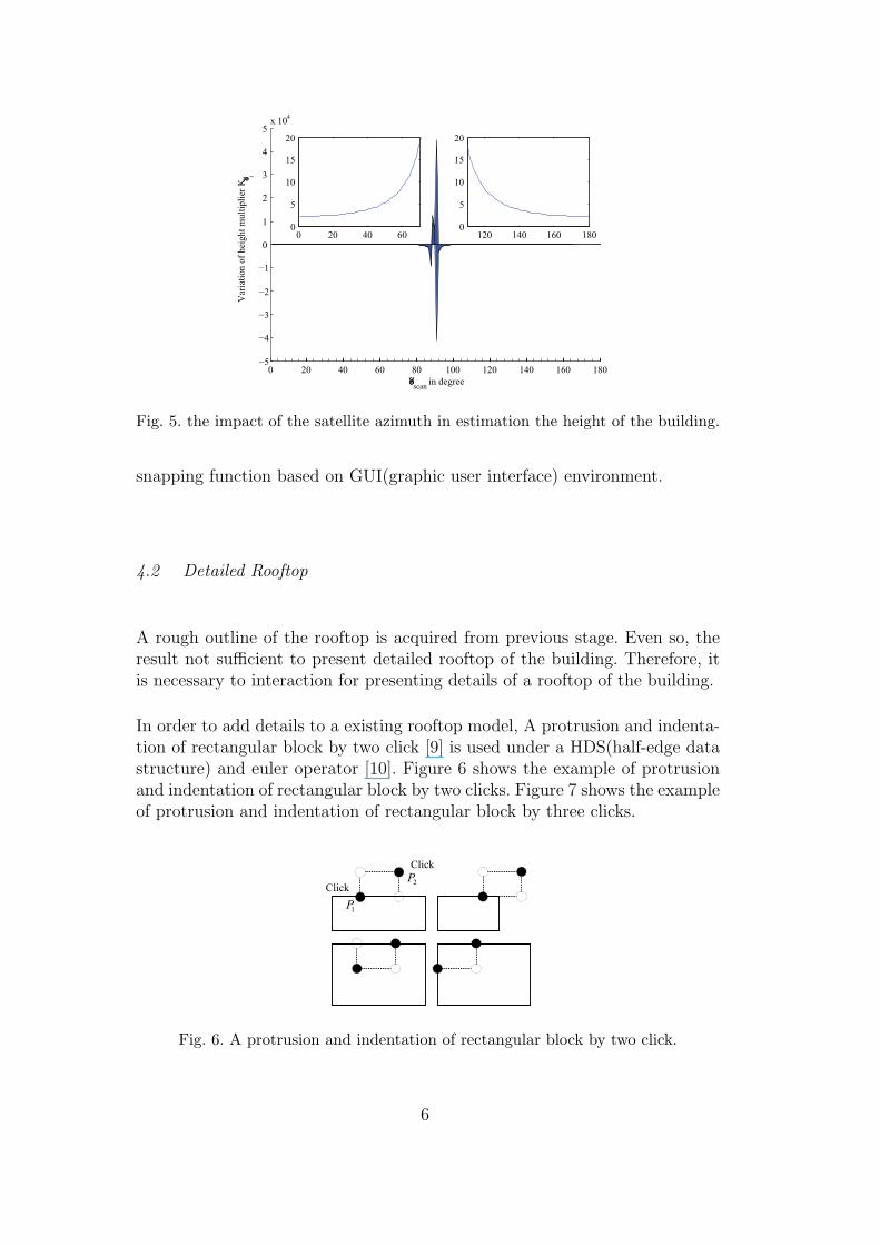
4.2 Detailed Rooftop
A rough outline of the rooftop is acquired from previous stage. Even so, theresult not sufficient to present detailed rooftop of the building. Therefore, itis necessary to interaction for presenting details of a rooftop of the building.
In order to add details to a existing rooftop model, A protrusion and indenta-tion of rectangular block by two click [9] is used under a HDS(half-edge datastructure) and euler operator [10]. Figure 6 shows the example of protrusionand indentation of rectangular block by two clicks. Figure 7 shows the exampleof protrusion and indentation of rectangular block by three clicks.
Click
Click
1P
2P
Fig. 6. A protrusion and indentation of rectangular block by two click.
6

Click
Fig. 7. A protrusion and indentation of arc and circle block by clicks.
5 Model Generation
5.1 Height Estimation based on Shadow
After rooftop extraction, the height of the building is estimated by usingequation 1 in section 3 , where the footprint of the building is on the ground.
After computing the height of the building, however, the position of buildingis not same as rooftop. Therefore, compensation of the building position isneeded.
The estimation of building position is shown in Figure 8. In the previous step,we obtain the building height. From the direction of the satellite, we can esti-mate the building position. The projected distance L of the building height His inverse proportion to tan(θsat). And the length of the motion vector ~d is sameas L. Therefore, the building is moved by (Hsin(φsa)/tan(θsat), Hcos(φsa)/tan(θsat)).
saj
footprint
rooftopH
)tan(/ satHL q=
satq
)cos,sin(
sa
sa
LLd
jj=
r
sajsatL jsin
LdL sa
=r
where,cosj
Fig. 8. Estimation of building position.
7
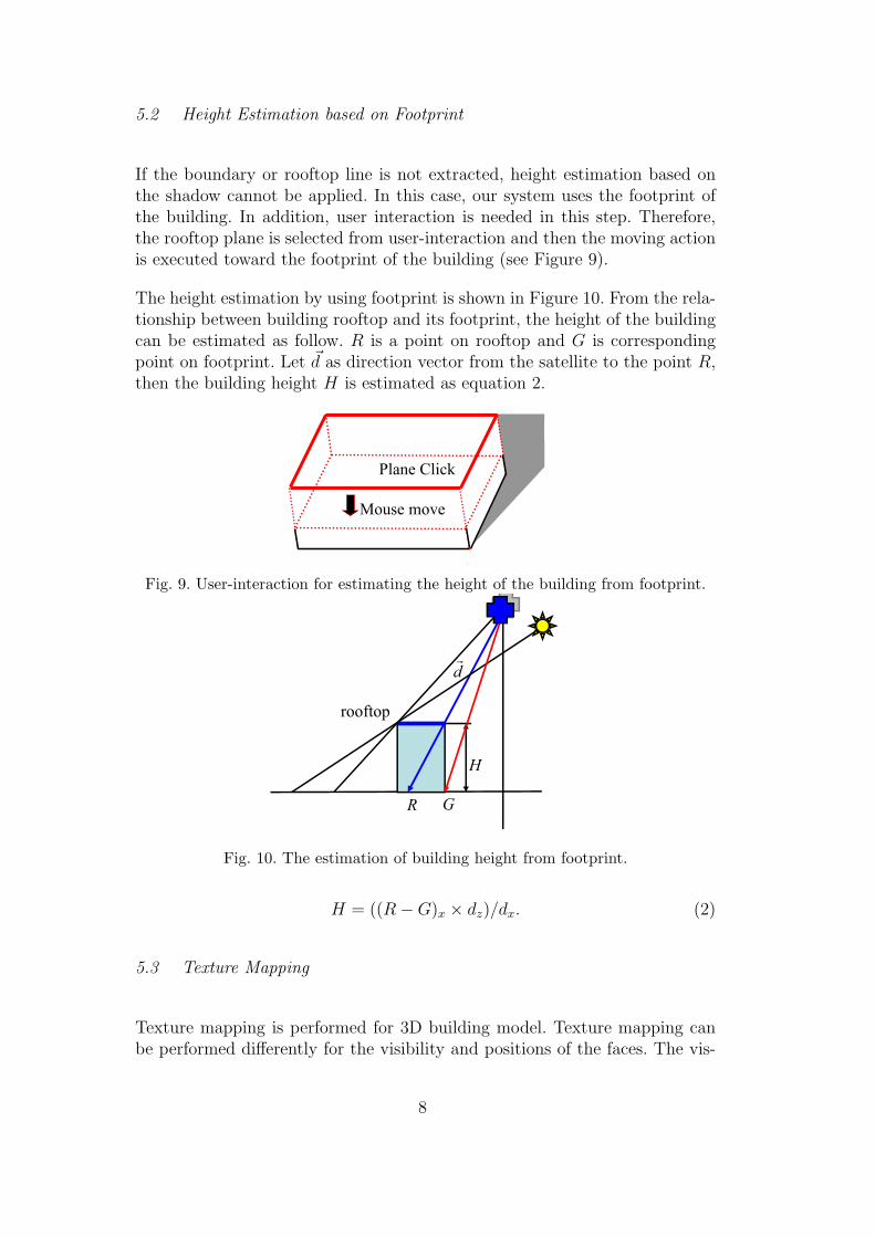
5.2 Height Estimation based on Footprint
If the boundary or rooftop line is not extracted, height estimation based onthe shadow cannot be applied. In this case, our system uses the footprint ofthe building. In addition, user interaction is needed in this step. Therefore,the rooftop plane is selected from user-interaction and then the moving actionis executed toward the footprint of the building (see Figure 9).
The height estimation by using footprint is shown in Figure 10. From the rela-tionship between building rooftop and its footprint, the height of the buildingcan be estimated as follow. R is a point on rooftop and G is correspondingpoint on footprint. Let ~d as direction vector from the satellite to the point R,then the building height H is estimated as equation 2.
Plane Click
Mouse move
Fig. 9. User-interaction for estimating the height of the building from footprint.
rooftop
R G
H
dr
Fig. 10. The estimation of building height from footprint.
H = ((R − G)x × dz)/dx. (2)
5.3 Texture Mapping
Texture mapping is performed for 3D building model. Texture mapping canbe performed differently for the visibility and positions of the faces. The vis-
8

ible face can be separated into rooftop and facade face. The texture of therooftop is defined as a region inside of rooftop in the image before applyingcompensation. For facade faces, the texture is determined as the image regionbetween G2 and G′
2 as shown is Figure 11. G2 is one of the vertices belongsto rooftop before applying compensation, and G′
2 is one of the vertices afterapplying compensation. For invisible face, duplicating to appropriate textureof visible face is selected.
2G
2G¢ façade (visible)
façade (invisible)
rooftop (visible)
Fig. 11. Texture mapping overview.
However, the textures obtained from the satellite image has relatively poorquality. Especially the texture of the facade is very poor. If the ground imagesare available, it is applied to facade texture. Another approach the predefinedtexture template is used.
5.4 Detailed Modeling
After height estimation, 3D building models are generated. However, it isnot sufficient to present whole building in detail now and then. To present adetailed building model, simple user interaction is used.
In order to refine a simple buiding model, we use some operators such as push-pull and offset. We can use push-pull operator to push and pull faces to addvolume to or subtract volume from models. The offset operator can be used tocreate copies of faces at a uniform distance from the originals. We can offsetedges of faces either inside or outside of the original face, and it will alwayscreate a new face. Figure 12 shows push-pull and offset operators.
In the case of building has multi-layer, we extract rooftop and estimate itsheight based on underlying layer as previous stages. Alternatively, we can usethe push-pull operator to create volume. An example of multi-layer buildingmodeling is shown in Figure 13. If the rooftop of the building has wall, wecan use push-pull and offset operators together. We can make copy of a roof
9

Click
MouseMove
Fig. 12. User interaction for detailed 3D modeling, (a) push-pull operator and (b)offset operator.
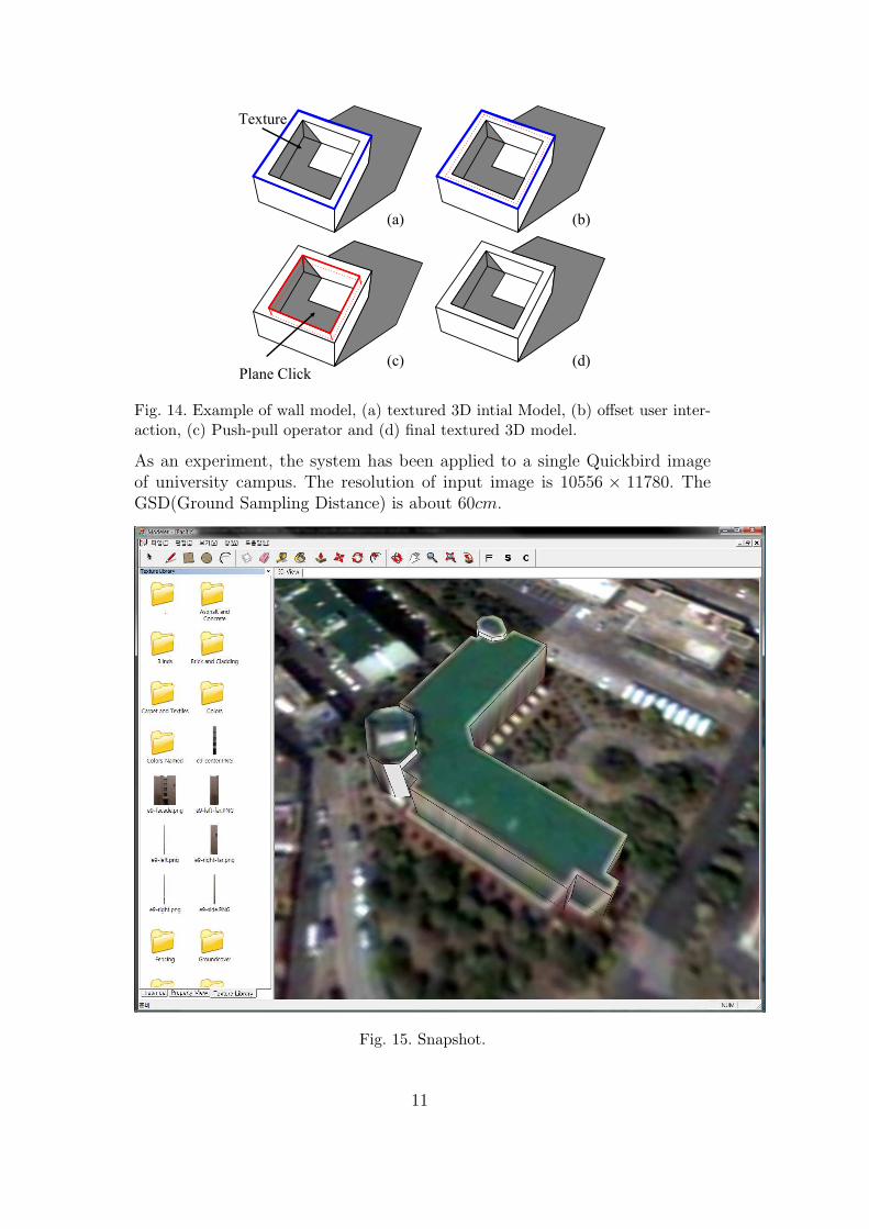
by offset operator, then we push down inner face by push-pull operator. Anexample of wall model is shown in Figure 14.
Plane Click
Click
Texture
(b)(a)
(c) (d)
Fig. 13. Example of multi-layer building model, (a) textured 3D intial Model, (b)two click user interaction, (c) Push-pull operator and (d) final textured 3D model.
6 Experimental results
The system for modeling is a graphic user interface written in Visual Studio.Net 2005 running on a 3.0GHZ dual core AMD processor, Nvidia Geforce8600 GT and Window Vista. Figure 15 shows the proposed system based onGUI interface. This system provides drawing function( line, arc, circle... ),modification function( push-pull, offset, move... ) , navigation function andetc. . .
10
Plane Click
Texture
(b)(a)
(c) (d)
Fig. 14. Example of wall model, (a) textured 3D intial Model, (b) offset user inter-action, (c) Push-pull operator and (d) final textured 3D model.
As an experiment, the system has been applied to a single Quickbird imageof university campus. The resolution of input image is 10556 × 11780. TheGSD(Ground Sampling Distance) is about 60cm.
Fig. 15. Snapshot.
11
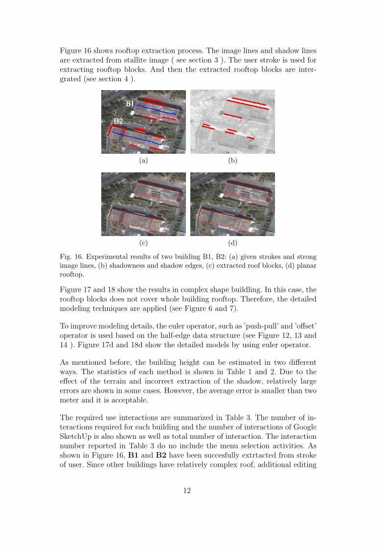
Figure 16 shows rooftop extraction process. The image lines and shadow linesare extracted from stallite image ( see section 3 ). The user stroke is used forextracting rooftop blocks. And then the extracted rooftop blocks are inter-grated (see section 4 ).
(a) (b)
(c) (d)
Fig. 16. Experimental results of two building B1, B2: (a) given strokes and strongimage lines, (b) shadowness and shadow edges, (c) extracted roof blocks, (d) planarrooftop.
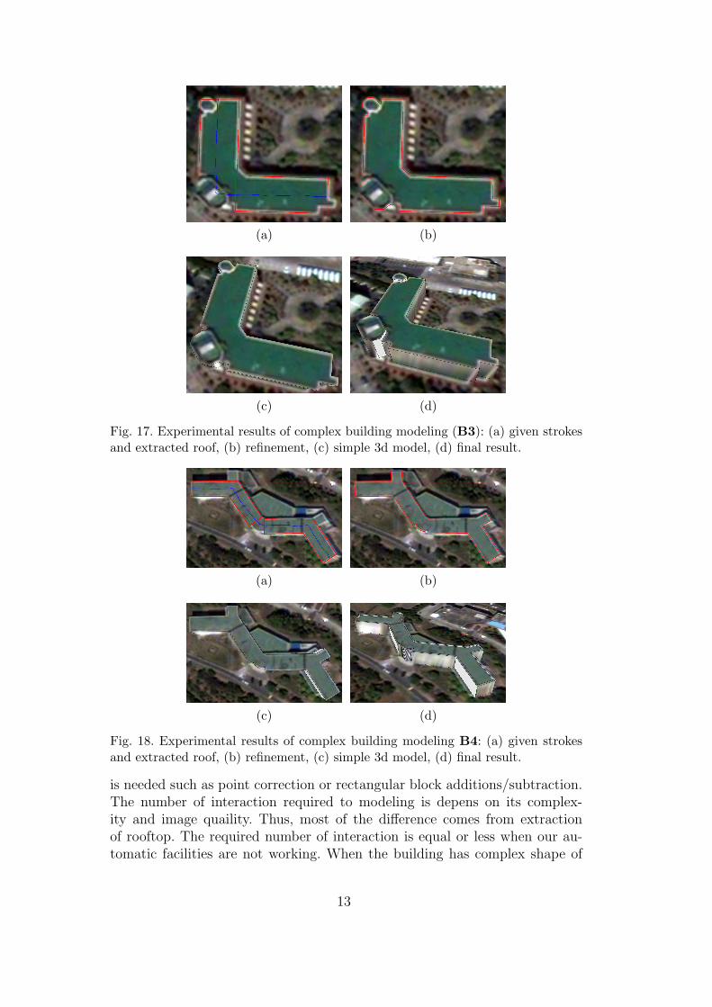
Figure 17 and 18 show the results in complex shape buildling. In this case, therooftop blocks does not cover whole building rooftop. Therefore, the detailedmodeling techniques are applied (see Figure 6 and 7).
To improve modeling details, the euler operator, such as ’push-pull’ and ’offset’operator is used based on the half-edge data structure (see Figure 12, 13 and14 ). Figure 17d and 18d show the detailed models by using euler operator.
As mentioned before, the building height can be estimated in two differentways. The statistics of each method is shown in Table 1 and 2. Due to theeffect of the terrain and incorrect extraction of the shadow, relatively largeerrors are shown in some cases. However, the average error is smaller than twometer and it is acceptable.
The required use interactions are summarized in Table 3. The number of in-teractions required for each building and the number of interactions of GoogleSketchUp is also shown as well as total number of interaction. The interactionnumber reported in Table 3 do no include the menu selection activities. Asshown in Figure 16, B1 and B2 have been succesfully extrtacted from strokeof user. Since other buildings have relatively complex roof, additional editing
12
(a) (b)
(c) (d)
Fig. 17. Experimental results of complex building modeling (B3): (a) given strokesand extracted roof, (b) refinement, (c) simple 3d model, (d) final result.
(a) (b)
(c) (d)
Fig. 18. Experimental results of complex building modeling B4: (a) given strokesand extracted roof, (b) refinement, (c) simple 3d model, (d) final result.
is needed such as point correction or rectangular block additions/subtraction.The number of interaction required to modeling is depens on its complex-ity and image quaility. Thus, most of the difference comes from extractionof rooftop. The required number of interaction is equal or less when our au-tomatic facilities are not working. When the building has complex shape of
13
Table 1Statistics for the height estimation from footprint.
Building ID Estimation (m) Measure (m) Error (m)
B1 18.978213 18 0.978313
B2 14.893698 15 -0.106402
B3 10.27628 10.65 -0.37372
B5 20.816373 20.6 0.216373
Table 2Statistics for the height estimation from shadow.
Building ID Estimation (m) Measure (m) Error (m)
B1 18.009554 18 0.009554
B2 15.021973 15 0.021973
B3 10.0410435 10.65 -0.60897
B5 20.236648 20.6 -0.36335
rooftop, the difference of interaction will be increased.
Table 3Number of interaction for Figure 16, 18, 19.
Building ID Task Our Sketchup
B1Roof 1 4
Height estimation 0 1
Total 1 5
B2
Roof 1 8
Roof editing 4
Height estimation 0 1
Total 5 9
B3
Roof 1 20
Roof editing 6
Height estimation 0 1
Refinement 2 2
Total 9 23
Once the building model has been reconstructed, the facade of the buildingis rectified for purpose of obtaining the high quality facade texture from theground images. The figure 19 shows this process. Figure 20 show the finalresults with textures.
14

(a) (b)
Fig. 19. Texture mapping from texture template (B5).
7 Conclusions
We have proposed an approach to extracting 3D building model from satelliteimage based on the user interaction and features extracted from an image andmeta information. Proposed system extracts features such as shadowness, im-age lines and shadow edges from a given satellite image and meta information.And utilize them to extract a rooftop of the building with user interaction.Estimating the height of the building is performed by shadow information au-tomatically. Finally, we obtain 3D model of the building by extruding rooftopwith the height of the building. With the further addition of properly de-signed user interfaces and complete editing facilities, our system can be smartto make it possible to extract models in a less laborious and more productiveways. Future work will deal with curved structures and terrain information.In addition, we will increase reliability of rooftop extraction.
15

(a)
(b)
Fig. 20. Final results: (a) top view, (b) arbitrary view with ground textures.
16
8 Publication
Seon ho Oh, Kyung ho Jang, Soon ki Jung, ”Large-Scale Building ModelingSystem Based on Satellite Image”, The 8th International Conference on Ap-plications and Principles of Information Science, pp.83 86, Okinawa, Japan,JAN 2009.
Jae Seok Jang, Kwang Hee Won, Kyung Ho Jang, Soon Ki Jung, ”ShadowAnlaysis of Satellite Images for 3D Building Reconstruction”, The 7th Inter-national Conference on Applications and Principles of Information Science,pp.59 62, Auckland, New Zealand, JAN 2008.
오선호, 정순기, 김상희, 김정환, ”위성영상을 이용한 건물 모델링 및 지형정합 시스템”, KCC2008, 2008.06.30.
오선호,Seonho Oh,장재석,Jaeseok Jang,장경호,Kyungho Jang,정순기,SoonkiJung, ”Footprint와그림자를이용한위성영상의건물모델링시스템”, HCI2008학술대회논문집,강원도휘닉스파크컨벤션센터, 2008년 2월 13일 2월 15일.
Seonho Oh, Jaeseok Jang, Kyungho Jang, Soon Ki Jung, ”Building ModelingSystem on Satellite Image using Footprint and Shadow”, GRAVIKON2008,2008.04.24.
Jae Seok Jang, Kwang Hee Won, Kyoung Ho Jang, Soon Ki Jung, ”ShadowAnalysis of Satellite Images for 3D Building”, GRAVIKON2008, 2008.04.24.
서원석 윤창걸 장재석 정순기 김상희, ”위성 단영상을 이용한 3차원 건물정보의 추출”, 한국군사과학기술학회, 한국해양대학교, 2007년 8월 16일 8월 17일.
오선호장경호정순기, ”Half-edge자료구조기반의위성영상의건물모델링소프트웨어”,한국군사과학기술학회,한국해양대학교, 2007년 8월 16일 8월17일.
Acknowledgments.
This work is supported by DAPA, ADD and Brain Korea 21. This documentalso submitted on Pacific Graphics 2009.
References
[1] C. Lin and R. Nevatia, “Building detection and description from a singleintensity image,” Comput. Vis. Image Underst., vol. 72, no. 2, pp. 101–121,
17

1998.
[2] K. Karantzalos and N. Paragios, “Automatic model-based building detectionfrom single panchromatic high resolution images,” 2008, p. B3a: 127 ff.
[3] Z. Li, J. Liu, and X. Tang, “Shape from regularities for interactive3d reconstruction of piecewise planar objects from single images,” inMULTIMEDIA ’06: Proceedings of the 14th annual ACM international
conference on Multimedia. New York, NY, USA: ACM, 2006, pp. 85–88.
[4] V. Shettigara and G. Sumerling, “Height determination of extended objectsusing shadows in spot images,” Photogrammetric Engineering and Remote
Sensing, vol. 64, no. 1, pp. 35–44, 1998.
[5] J*, “anonymity for blind review,” Pattern Recognition Letters, 2009.
[6] N. Otsu, “A threshold selection method from gray-level histograms,” IEEE
Transactions on Systems Man and Cybernetics, vol. 9, no. 1, pp. 62–66, 1979.
[7] V. Tsai, “A comparative study on shadow compensation of color aerial images ininvariant color models,” IEEE Transactions on Geoscience and Remote Sensing,vol. 44, no. 6, pp. 1661–1671, 2006.
[8] A. Polidorio, F. Flores, N. Imai, A. Tommaselli, and C. Franco, “Automaticshadow segmentation in aerial color images,” Computer Graphics and Image
Processing, 2003. SIBGRAPI 2003. XVI Brazilian Symposium on, pp. 270–277,2003.
[9] S. C. Lee, A. Huertas, and R. Nevatia, “Modeling 3-d complex buildings withuser assistance,” Applications of Computer Vision, IEEE Workshop on, vol. 0,p. 170, 2000.
[10] M. Mantyla, An introduction to solid modeling. New York, NY, USA: ComputerScience Press, Inc., 1987.
18