Design of Machine Elements (ME30109) - Amazon AWS
34
BY: Dr. Rahul Kumar Assistant Professor (Dept. of Mechanical Engineering) C. V. Raman Global University, Bhubaneswar Design of Machine Elements (ME30109)
-
Upload
khangminh22 -
Category
Documents
-
view
0 -
download
0
Transcript of Design of Machine Elements (ME30109) - Amazon AWS

BY: Dr. Rahul KumarAssistant Professor
(Dept. of Mechanical Engineering)
C. V. Raman Global University, Bhubaneswar
Design of Machine Elements
(ME30109)

Overview
Design of Machine Elements 2
The main objective of the course is to build a strongfoundation and to acquaint the students with the:
1 Fundamentals and the phases of machine design.
2 Understanding on the process of material selection and design.
3 Use of design data books & various codes of practice.
4 Concepts of strength design related to various machine elements.
5 Design methodology for simple joints, couplings, fasteners, leversand springs under static loading.

Overview
Design of Machine Elements 3
CO1 Explain basic principles in the design of machine elements
& apply them effectively from material selection to design
analysis using design data book to interpret standardized
data.
CO2 Design and analyze permanent and temporary joints under
various loading conditions.
CO3 Design and analyze power transmission shafts and couplings with
different geometrical features under various loading conditions.
CO4 Explain various thread forms and design power screws.
CO5 Identify types of springs & levers and perform design analysis.

Overview
Design of Machine Elements 4
Unit 1• Fundamentals of Machine Design
Unit 2• Design of Temporary and Permanent Joints
Unit 3• Design of Shaft, Keys and Couplings
Unit 4• Design of Power Screws and Threaded joints
Unit 5• Design of Mechanical Springs and levers

Topics to be covered:
Stress and deflection equations forhelical compression Springs, Typesof ends, Design of helicalcompression and tension springs,Helical torsion Spring, Surge insprings, Design of semi-ellipticalleaf springs
Overview
Design of Machine Elements 5
Unit 5 • Springs
Topics to be covered (by self):

References:
“Mechanical Engineerng Design”, J.E. Shigley, C.R. Mischke, R.G. Budynas andK.J. Nisbett, Tata McGraw-Hill , 8th Edition, 2008
“Design of Machine Elements”, V.B. Bhandari, Tata McGraw-Hill, 3rd Edition, 2010.T3. “A Text Book of Machine Design”,
R.S. Khurmi and J.K. Gupta, S. Chand Publication, 14th Edition, 2005.
Design Hand Book”, S.M. Jalaluddin; Anuradha Agencies Publications.
Overview
Design of Machine Elements 6
Unit 4 • Power Screws and Threaded joints

Unit 5
Design of Machine Elements
Unit 5 • Springs
STYLES OF END

Unit 5
Design of Machine Elements
Unit 5 • Springs
STRESS AND DEFLECTION EQUATIONS
There are two basic equations for the design of helical springs, viz.,
load-stress equation and load-deflection equation.
The torsional moment
The torsional shear stress in
the bar is

Unit 5
Design of Machine Elements
Unit 5 • Springs
STRESS AND DEFLECTION EQUATIONS
When the equivalent bar is bent in the form of helical coil, there are
additional stresses on account of following two factors:
There is direct or transverse shear stress in the spring wire.
When the bar is bent in the form of coil, the length of the inside
fibre is less than the length of the outside fibre. This results in stress
concentration at the inside fibre of the coil.
The resultant stress consists of superimposition of torsional shear
stress, direct shear stress and additional stresses due to the curvature of
the coil.

Unit 5
Design of Machine Elements
Unit 5 • Springs
STRESS AND DEFLECTION EQUATIONS
Pure Torsional
Stress
Direct Shear Stress
Combined Pure Torsional, Direct Shear
Stress and Stress due to curvature

Unit 5
Design of Machine Elements
Unit 5 • Springs
STRESS AND DEFLECTION EQUATIONS
The combined effect of these two factors
The direct shear stress in the bar is
The resultant shear stress in the spring wire is

Unit 5
Design of Machine Elements
Unit 5 • Springs
STRESS AND DEFLECTION EQUATIONS
The shear stress correction factor (Ks) is defined as
Substituting the above equation in the expression
AM Wahl derived the equation for resultant stress, which includes
torsional shear stress, direct shear stress and stress concentration due
to curvature

Unit 5
Design of Machine Elements
Unit 5 • Springs
STRESS AND DEFLECTION EQUATIONS
The angle of twist for the equivalent bar
The axial deflection of the spring, for small values of angle of twist is

Unit 5
Design of Machine Elements
Unit 5 • Springs
STRESS AND DEFLECTION EQUATIONS
The rate of spring (k) is given by
DESIGN OF HELICAL SPRINGS
STEP 1: For the given application, estimate the maximum spring force
(P) and the corresponding required deflection (d) of the spring. In some
cases, maximum spring force (P) and stiffness k, which is (P/d), are
specified

Unit 5
Design of Machine Elements
Unit 5 • Springs
DESIGN OF HELICAL SPRINGS
STEP 2: Select a suitable spring material and find out ultimate tensile
strength (Sut) from the data.
Calculate the permissible shear stress for the spring wire by following
relationship:
STEP 3: Assume a suitable value for the spring index (C).
For industrial applications, the spring index varies from 8 to 10. A
spring index of 8 is considered as a good value. The spring index for
springs in valves and clutches is 5.

Unit 5
Design of Machine Elements
Unit 5 • Springs
DESIGN OF HELICAL SPRINGS
STEP 4: Calculate the Wahl factor
STEP 5: Determine wire diameter (d)
STEP 6: Determine mean coil diameter (D)
STEP 7: Determine the number of active coils (N)
STEP 8: Decide the style of ends for the spring depending upon the
configuration of the application. Determine the number of inactive coils.
Adding active and inactive coils, find out the total number of coils (Nt)

Unit 5
Design of Machine Elements
Unit 5 • Springs
DESIGN OF HELICAL SPRINGS
STEP 9: Determine the solid length of the spring
STEP 10: Determine the actual deflection of the spring
STEP 11: Assume a gap of 0.5 to 2 mm between adjacent coils, when
the spring is under the action of maximum load. The total axial gap
between coils is given by,
Total gap = (Nt – 1) * gap between two adjacent coils
STEP 12: Determine the free length of the spring

Unit 5
Design of Machine Elements
Unit 5 • Springs
DESIGN OF HELICAL SPRINGS
STEP 13: Determine the pitch of the coil
STEP 14: Determine the rate of spring
Question1 : It is required to design a helical compression spring subjected
to a maximum force of 1250 N. The deflection of the spring corresponding
to the maximum force should be approximately 30 mm. The spring index
can be taken as 6. The spring is made of patented and cold-drawn steel wire.
The ultimate tensile strength and modulus of rigidity of the spring material
are 1090 and 81370 MPa respectively. The permissible shear stress for the
spring wire should be taken as 50% of the ultimate tensile strength.

Unit 5
Design of Machine Elements
Unit 5 • Springs
DESIGN OF HELICAL SPRINGS
Question 2: A helical compression spring, made of circular wire, is
subjected to an axial force, which varies from 2.5 kN to 3.5 kN. Over this
range of force, the deflection of the spring should be approximately 5 mm.
The spring index can be taken as 5. The spring has square and ground ends.
The spring is made of patented and cold-drawn steel wire with ultimate
tensile strength of 1050 MPa and modulus of rigidity of 81370 MPa. The
permissible shear stress for the spring wire should be taken as 50% of the
ultimate tensile strength.

Unit 5
Design of Machine Elements
Unit 5 • Springs
DESIGN OF LEAF SPRINGS
Multi-leaf springs are widely used for the suspension of cars, trucks and
railway wagons. A multi-leaf spring consists of a series of flat plates,
usually of semi-elliptical shape

Unit 5
Design of Machine Elements
Unit 5 • Springs
DESIGN OF LEAF SPRINGS

Unit 5
Design of Machine Elements
Unit 5 • Springs
DESIGN OF LEAF SPRINGS
Graduated-length Leaves as Triangular Plate

Unit 5
Design of Machine Elements
Unit 5 • Springs
DESIGN OF LEAF SPRINGS
Extra full-length leaves asrectangular plate

Unit 5
Design of Machine Elements
Unit 5 • Springs
DESIGN OF LEAF SPRINGS
Since the deflection of full-length leaves is equal to the deflection of
graduated- length leaves
NOTE: It is seen from the above equations that bending stresses in full-
length leaves are 50% more than those in graduated-length leaves.

Unit 5
Design of Machine Elements
Unit 5 • Springs
DESIGN OF LEAF SPRINGS
The deflection at the end of the spring is determined from

Unit 5
Design of Machine Elements
Unit 5 • Springs
NIPPING OF LEAF SPRINGS
As discussed in the previous section, the stresses in extra full-length
leaves are 50% more than the stresses in graduated-length leaves. One
of the methods of equalising the stresses in different leaves is to pre-
stress the spring. The pre-stressing is achieved by bending the leaves
to different radii of curvature, before they are assembled with the
centre clip.

Unit 5
Design of Machine Elements
Unit 5 • Springs
NIPPING OF LEAF SPRINGS

Unit 5
Design of Machine Elements
Unit 5 • Springs
NIPPING OF LEAF SPRINGS
Under the maximum force P, the deflection of graduated-length leaves
will exceed the deflection of extra full-length leaves by an amount
equal to the initial nip C
The initial pre-load Pi required to close the gap C between the extra
full-length leaves and graduated length leaves is determined by
considering the initial deflection of leaves

Unit 5
Design of Machine Elements
Unit 5 • Springs
NIPPING OF LEAF SPRINGS
The resultant stress in the extra
full-length leaves is obtained by
superimposing the stresses due to
initial pre-load (Pi) and the
external force (P)
Unit 5
Design of Machine Elements
Unit 5 • Springs
NIPPING OF LEAF SPRINGS
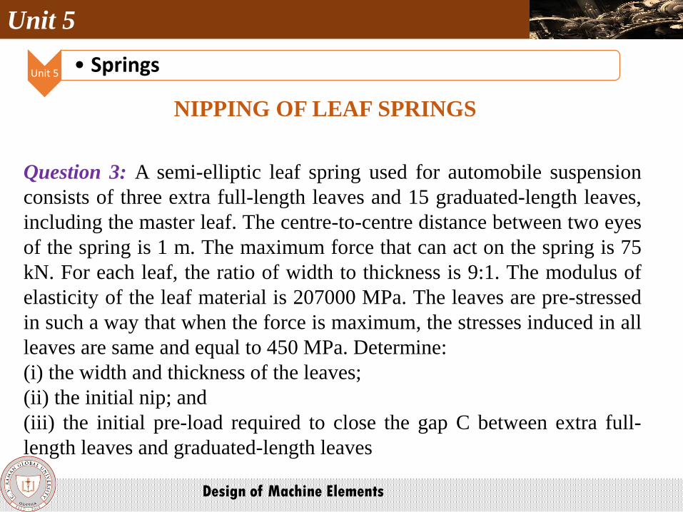
Question 3: A semi-elliptic leaf spring used for automobile suspension
consists of three extra full-length leaves and 15 graduated-length leaves,
including the master leaf. The centre-to-centre distance between two eyes
of the spring is 1 m. The maximum force that can act on the spring is 75
kN. For each leaf, the ratio of width to thickness is 9:1. The modulus of
elasticity of the leaf material is 207000 MPa. The leaves are pre-stressed
in such a way that when the force is maximum, the stresses induced in all
leaves are same and equal to 450 MPa. Determine:
(i) the width and thickness of the leaves;
(ii) the initial nip; and
(iii) the initial pre-load required to close the gap C between extra full-
length leaves and graduated-length leaves

Unit 5
Design of Machine Elements
Unit 5 • Springs
SURGE OF SPRINGS
When the natural frequency of vibrations of the spring coincides with
the frequency of external periodic force, which acts on it, resonance
occurs. In this state, the spring is subjected to a wave of successive
compressions of coils that travels from one end to the other and back.
This type of vibratory motion is called ‘surge’ of spring. Surge is found
in valve springs, which are subjected to periodic force.
The natural frequency of helical compression springs held between two
parallel plates is given by

Unit 5
Design of Machine Elements
Unit 5 • Springs
SURGE OF SPRINGS
The natural frequency of helical compression springs with one end on
the flat plate and the other end free, supporting the external force is
given by
Surge in springs is avoided by the following methods:
(i) The spring is designed in such a way that the natural frequency of the
spring is 15 to 20 times the frequency of excitation of the external force

Unit 5
Design of Machine Elements
Unit 5 • Springs
SURGE OF SPRINGS
Surge in springs is avoided by the following methods:
(ii) The spring is provided with friction dampers on central coils. This
prevents propagation of surge wave.
(iii) A spring made of stranded wire reduces the surge.

Any suggestions and Queries?????????