
DESIGN OF COLD GAS PROPULSION SYSTEM FOR A CUBESAT
33
Design of Cold Gas Propulsion System for a CubeSat Surmit Bhui, Sumana Mukherjee, Sabina Mehra. Guide – Dr. Ugur Guven Page 1 Minor Project Report on DESIGN OF COLD GAS PROPULSION SYSTEM FOR A CUBESAT Submitted by: Surmit Bhui (R290211026) Sumana Mukherjee (R290211025) Sabina Mehra (R290211030) B. Tech. Aerospace Engineering Batch: 2011-15 Department of Aerospace Engineering College of Engineering Studies (COES) University of Petroleum & Energy Studies (UPES), Dehradun May 2014
-
Upload
united-nations -
Category
Documents
-
view
2 -
download
0
Transcript of DESIGN OF COLD GAS PROPULSION SYSTEM FOR A CUBESAT
Design of Cold Gas Propulsion System for a CubeSat
Surmit Bhui, Sumana Mukherjee, Sabina Mehra. Guide – Dr. Ugur Guven Page 1
Minor Project Report
on
DESIGN OF COLD GAS PROPULSION SYSTEM FOR A CUBESAT
Submitted by:
Surmit Bhui (R290211026)
Sumana Mukherjee (R290211025)
Sabina Mehra (R290211030)
B. Tech. Aerospace Engineering
Batch: 2011-15
Department of Aerospace Engineering
College of Engineering Studies (COES)
University of Petroleum & Energy Studies (UPES), Dehradun
May 2014
Design of Cold Gas Propulsion System for a CubeSat
Surmit Bhui, Sumana Mukherjee, Sabina Mehra. Guide – Dr. Ugur Guven Page 2
CERTIFICATE
I hereby certify that the work which is being presented in the project report entitled
“Design of Cold Gas Propulsion System for a Cubesat” in partial fulfilment of the
requirements for the satisfactory performance for Minor Project, third year, submitted in
the Department of Aerospace Engineering, University of Petroleum and Energy Studies,
Dehradun is an authentic record of my own work carried out during a period from July
2013 to December 2013.
Submitted By: Submitted To:
Surmit Bhui (R290211026)
Sumana Mukherjee (R290211025) Dr. Ugur Guven
Sabina Mehra (R290211030)
B.Tech. Aerospace Engineering
2011-2015
This is to certify that the above statement made by the candidate is correct to the best of
my knowledge.
Design of Cold Gas Propulsion System for a CubeSat
Surmit Bhui, Sumana Mukherjee, Sabina Mehra. Guide – Dr. Ugur Guven Page 3
ABSTRACT
Cubesats have become quite popular especially among university students as these
miniaturized satellites help them in carrying out space exploration feasibly. Till date,
cubesats have never flown in space with any well defined propulsion system. But in order
to increase mission capabilities like orbit raising and formation flying, or to perform
proximity operations, fine attitude control, drag make up and de–orbit without much
risks, it is important to use a propulsion system. Here in this report we have focused on
the use of cold gas thrusters in a cubesat.Cold gas thrusters consist of a pressurized tank
containing gaseous propellant, such as nitrogen, and a solenoid actuated valve system
leading to exit nozzles. Since the propellant is unheated and relies solely on the enthalpy
of the stored gas, the velocity at the nozzle exit is relatively low resulting in a low specific
impulse, typically around 60 sec, useful for small attitude adjustments and low ΔV
maneuvers. However, the power level, pressure, and weight required in the vessel are
though less, but still higher than the Cubesat Specifications provided by the CalPoly.
Rather than relying on high-pressure chambers, we propose the use of solid gas
cartridges, which upon ignition by lasers can be released into a chamber in the gaseous
form, from which nitrogen can be drawn for propulsive use. Moreover since only a
fraction of the propellant is used for propulsion use, it helps in reducing the tank size and
minimizes the risk of leakage and pressure limitations, with reduction in mass by around
20%. This way a suitable propulsion system for a cubesat can be developed which renders
increased performance with respect to mission capabilities without increasing the overall
mass of the satellite. The idea would also prove to be of much benefit for industries which
are planning future cubesat missions.
Design of Cold Gas Propulsion System for a CubeSat
Surmit Bhui, Sumana Mukherjee, Sabina Mehra. Guide – Dr. Ugur Guven Page 4
ACKNOWLEDGEMENTS
This project would not have been possible without the assistance from our mentor Dr.
Ugur Guven, Professor,UPES.
We wish to thank Mr. Linsu Sebastian, Mr. Pawan Kumar Nanduri and Mr. A.J. Arun
Jeya Prakash, Department of Aerospace Engineering, UPES for their constant support
and motivation for this project.
Also, we are indebted for the feedback and positive response from Mr. Vikrant Narang,
Student, International Space University, Dr. Megan Kane, NanoSatisfi, USA, Dr. Mart
Noorma, Head of Space Technology Department, Tartu Observatory and various
professionals and distinguished delegates from all over the world at 2013 International
Astronautical Congress, Beijing, China.
Design of Cold Gas Propulsion System for a CubeSat
Surmit Bhui, Sumana Mukherjee, Sabina Mehra. Guide – Dr. Ugur Guven Page 5
TABLE OF CONTENTS
1. Introduction……………………………………………………………………...09
2. 2.1Aim…………………………………………………………………………...11
2.2Objective……………………………………………………………………...11
3. Methodology
3.1 Semi-Conductor Laser……………………………………………………….12
3.2 Solid Nitrogen – The Propellant……………………………………………..14
3.2.1 Gas Properties ……………………………………………………….15
3.3 Hose………………………………………………………………………….16
3.4 Suction Chamber
3.4.1Solenoid Valves………………………………………………………...17
3.4.2 Actuator………………………………………………………………..18
3.4.3 Nozzle………………………………………………………………….19
3.5 CAD Model………………………………………………………………….20
3.6 Calculations……………...…………………………………………………..21
4. Literature Review
4.1 Pulsed Plasma Thrusters……………………………………………………..24
4.2 Resistojet……………………………………………………………………..25
4.3 Cold gas Propulsion………………………………………………………….26
4.4 Research done by TNO………………………………………………………27
4.4.1 Cool Gas Generators………………………………………………...27
4.5 Modifications in the system…………………………………………………27
5. Results and Discussions………………………………………………………….29
6. Future work………………………………………………………………………31
7. References………………………………………………………………………..32
Design of Cold Gas Propulsion System for a CubeSat
Surmit Bhui, Sumana Mukherjee, Sabina Mehra. Guide – Dr. Ugur Guven Page 6
LIST OF FIGURES
1. Fig 4.1 – Physical Origin of gain in a Semiconductor (Page 14)
2. Fig 4.2 – Semiconductor Diode Laser ( Page 14)
3. Fig 4.3 – Solid Nitrogen (Page 15)
4. Fig 4.4 – Rubber Hose Pipe (Page 17)
5. Fig 4.5 – Electric Actuator (Page 18)
6. Fig 4.6 – CAD Model ( Page 20)
7. Fig 5.1 – Pulsed Plasma Thruster (Page 24)
8. Fig 5.2 – Resistojet (Page 24)
9. Fig 5.3 – Cool Gas Generator (Page 26)
Design of Cold Gas Propulsion System for a CubeSat
Surmit Bhui, Sumana Mukherjee, Sabina Mehra. Guide – Dr. Ugur Guven Page 7
ABBREVIATIONS USED
1. Ft. = Feet
2. Fig. - Figure
3. Sec. = Second
4. m = meter
5. m1 = Initial Mass of Propellant
6. m2 = Final Mass of Propellant
7. Isp = Specific Impulse
8. W.R = Weight Ratio
9. LEO = Low Earth Orbit
10. ∆V = Delta-Velocity ( change in velocity )
Design of Cold Gas Propulsion System for a CubeSat
Surmit Bhui, Sumana Mukherjee, Sabina Mehra. Guide – Dr. Ugur Guven Page 8
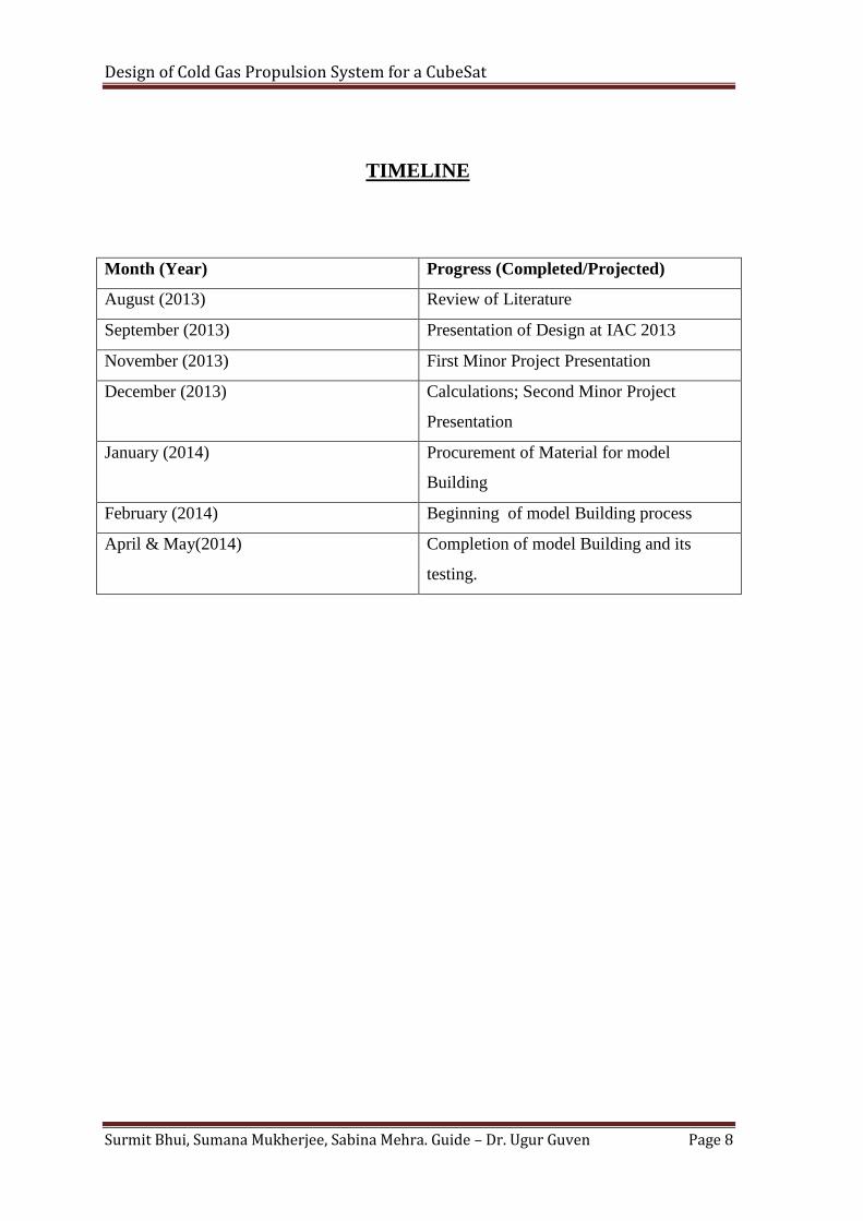
TIMELINE
Month (Year) Progress (Completed/Projected)
August (2013) Review of Literature
September (2013) Presentation of Design at IAC 2013
November (2013) First Minor Project Presentation
December (2013) Calculations; Second Minor Project
Presentation
January (2014) Procurement of Material for model
Building
February (2014) Beginning of model Building process
April & May(2014) Completion of model Building and its
testing.
Design of Cold Gas Propulsion System for a CubeSat
Surmit Bhui, Sumana Mukherjee, Sabina Mehra. Guide – Dr. Ugur Guven Page 9
CHAPTER 1:
INTRODUCTION
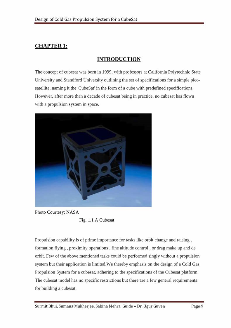
The concept of cubesat was born in 1999, with professors at California Polytechnic State
University and Standford University outlining the set of specifications for a simple pico-
satellite, naming it the 'CubeSat' in the form of a cube with predefined specifications.
However, after more than a decade of cubesat being in practice, no cubesat has flown
with a propulsion system in space.
Photo Courtesy: NASA
Fig. 1.1 A Cubesat
Propulsion capability is of prime importance for tasks like orbit change and raising ,
formation flying , proximity operations , fine altitude control , or drag make up and de
orbit. Few of the above mentioned tasks could be performed singly without a propulsion
system but their application is limited.We thereby emphasis on the design of a Cold Gas
Propulsion System for a cubesat, adhering to the specifications of the Cubesat platform.
The cubesat model has no specific restrictions but there are a few general requirements
for building a cubesat.
Design of Cold Gas Propulsion System for a CubeSat
Surmit Bhui, Sumana Mukherjee, Sabina Mehra. Guide – Dr. Ugur Guven Page 10
These requirements have been defined by Professors at the Stanford University and
California Polytechnic University and are as follows:
1. The vessel should have a maximum pressure of 1.2 ATM and a factor of safety
not less than 4.
2. Limitations on the pressure at which propellant can be stored also limit the
specific impulse (Isp) and thrust capabilities as the thrust level relies heavily on
the storage of pressure
3. Also , pyrotechnics of any kind are not allowed on board a CubeSat as they are
used as igniters for a chemical propulsion system
4. Further restrictions in use of hazardous materials imply the limit on allowable
propellant type.
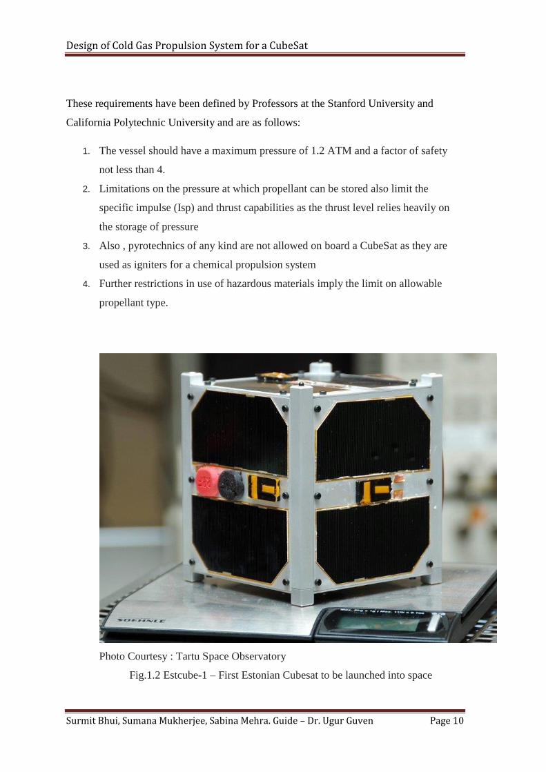
Photo Courtesy : Tartu Space Observatory
Fig.1.2 Estcube-1 – First Estonian Cubesat to be launched into space
Design of Cold Gas Propulsion System for a CubeSat
Surmit Bhui, Sumana Mukherjee, Sabina Mehra. Guide – Dr. Ugur Guven Page 11
CHAPTER 2:
2.1 AIM:-
To design and test an original Cold Gas Propulsion System for a cubesat.
2.2 OBJECTIVE:-
The main objective of the idea to design a Cold Gas Propulsion System is for the
full utilization of the CubeSat Platform innovatively and efficiently.
Various Operations like Orbital Change, Proximity Operations, fine Attitude
Control and de-orbit can be achieved with a Cubesat with propulsion capabilities.
Design of Cold Gas Propulsion System for a CubeSat
Surmit Bhui, Sumana Mukherjee, Sabina Mehra. Guide – Dr. Ugur Guven Page 12
Chapter 3:
METHODOLOGY
For building the original system, 3D prototyping is used. The thruster is manufactured in
a couple of weeks using the stereolithography (SLA) process. The entire thruster,
including the main tank, all secondary tanks, internal piping, and converging-diverging
nozzle, is encased in one block of plastic. By the stereolithography process, parts can be
printed in layers with a thickness of as little as 0.1 mm . With such capability, extremely
precise features can be built into the design such as a converging-diverging thruster
nozzle. But since the use of such expensive rapid prototyping process is beyond the scope
of our minor project , we intend to build the prototype using the prototyping processes
available at hand , i.e. at the CAM labs at the University.
A serious risk involved in using plastic for the components is that Laser can burn the
plastic material since the latter would absorb energy from the semiconductor laser.
Therefore, fiber composites might be used for the actual cold gas propulsion system since
it is non-corrosive as well as lightweight. But just for the purpose of building the
prototype, plastic could be used.
3.1Semi Conductor Laser :
One of the major advantages of using semiconductor laser is that they are comparatively
cheap and compact in size.They consist of complex multi-layer structures requiring
nanometer scale accuracy and an elaborate design.
A semiconductor laser is a solid-state device that consists of two outer semiconductor
layers separated by a middle layer and generates laser radiation when charge carriers of
opposite polarity, one each from the top and bottom layers, meet in the middle layer.
Semiconductor lasers are lasers based on semiconductor gain media, where optical gain is
usually achieved by stimulated emission at an interband transition under conditions of a
high carrier density in the conduction band.
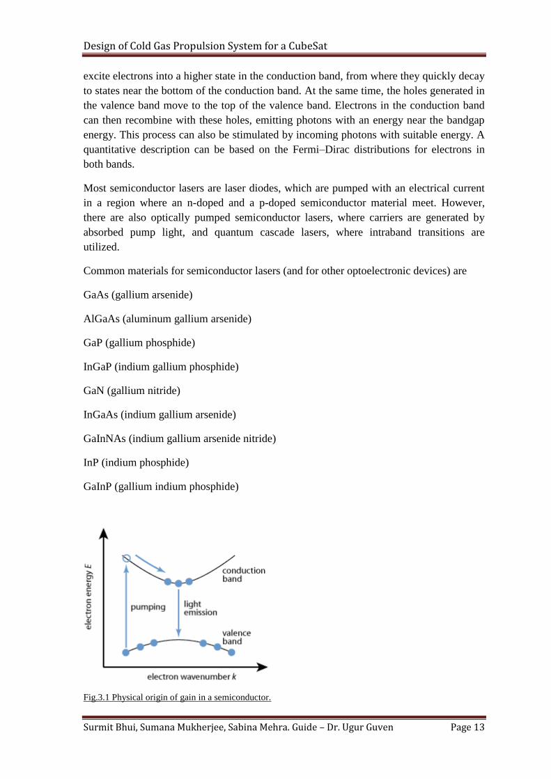
The physical origin of gain in a semiconductor (for the usual case of an interband
transition) is illustrated in Figure 1. Without pumping, most of the electrons are in the
valence band. A pump beam with a photon energy slightly above the bandgap energy can
Design of Cold Gas Propulsion System for a CubeSat
Surmit Bhui, Sumana Mukherjee, Sabina Mehra. Guide – Dr. Ugur Guven Page 13
excite electrons into a higher state in the conduction band, from where they quickly decay
to states near the bottom of the conduction band. At the same time, the holes generated in
the valence band move to the top of the valence band. Electrons in the conduction band
can then recombine with these holes, emitting photons with an energy near the bandgap
energy. This process can also be stimulated by incoming photons with suitable energy. A
quantitative description can be based on the Fermi–Dirac distributions for electrons in
both bands.
Most semiconductor lasers are laser diodes, which are pumped with an electrical current
in a region where an n-doped and a p-doped semiconductor material meet. However,
there are also optically pumped semiconductor lasers, where carriers are generated by
absorbed pump light, and quantum cascade lasers, where intraband transitions are
utilized.
Common materials for semiconductor lasers (and for other optoelectronic devices) are
GaAs (gallium arsenide)
AlGaAs (aluminum gallium arsenide)
GaP (gallium phosphide)
InGaP (indium gallium phosphide)
GaN (gallium nitride)
InGaAs (indium gallium arsenide)
GaInNAs (indium gallium arsenide nitride)
InP (indium phosphide)
GaInP (gallium indium phosphide)
Fig.3.1 Physical origin of gain in a semiconductor.

Design of Cold Gas Propulsion System for a CubeSat
Surmit Bhui, Sumana Mukherjee, Sabina Mehra. Guide – Dr. Ugur Guven Page 14
Fig.3.2 Semiconductor Diode Laser
According to studies, the amount of power required for decomposing solid nitrogen
propellant is around 2.5 W which is available from any of the semiconductor lasers and
can be susscessfully used in the prototype.
3.2 Solid Nitrogen - The Propellant
Nitrogen is mainly found in the atmosphere, where it accounts for 78 % by volume of the
air we breath. But nitrogen is also found:
- in the Earth's crust, to a limited extent (in the form of nitrates, etc.),
- in organic form (in the living or dead plants and organisms which form humus)
- and in mineral form (ammonia), and thus contributes to soil fertility. In gaseous form,
nitrogen is a neutral and colorless gas. It is inerting and does not sustain life.
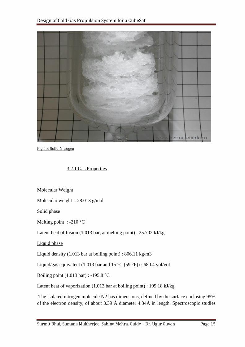
Liquid nitrogen can easily be converted to a solid by placing it in a vacuum chamber
pumped by a rotary vacuum pump. Liquid nitrogen freezes at 63 K (−210 °C; −346 °F).
Under normal atmospheric pressure, nitrogen can exist as a liquid between the
temperatures of 63 K and 77.2 K(-346°F and -320.44°F). Below 63 K, nitrogen freezes
and becomes a solid. Above 77.2 K, nitrogen boils and becomes a gas.
It has been experimentally proved that solid nitrogen can be produced and stored at a
pressure of .124 atmosphere or 94.24 torr which needs to be maintained within the
chamber where the propellant is to be kept. the solid nitrogen would be wound around a
rod and would be rotated at a low rpm to allow the decomposition of the solid propellant
by the impingement of semiconductor laser onto it. The solid nitrogen will slowly get
decomposed into gaseous nitrogen which would pass through the hose pipe to the suction
chamber.
Design of Cold Gas Propulsion System for a CubeSat
Surmit Bhui, Sumana Mukherjee, Sabina Mehra. Guide – Dr. Ugur Guven Page 15
Fig.4,3 Solid Nitrogen
3.2.1 Gas Properties
Molecular Weight
Molecular weight : 28.013 g/mol
Solid phase
Melting point : -210 °C
Latent heat of fusion (1,013 bar, at melting point) : 25.702 kJ/kg
Liquid phase
Liquid density (1.013 bar at boiling point) : 806.11 kg/m3
Liquid/gas equivalent (1.013 bar and 15 °C (59 °F)) : 680.4 vol/vol
Boiling point (1.013 bar) : -195.8 °C
Latent heat of vaporization (1.013 bar at boiling point) : 199.18 kJ/kg
The isolated nitrogen molecule N2 has dimensions, defined by the surface enclosing 95%
of the electron density, of about 3.39 Å diameter 4.34Å in length. Spectroscopic studies
Design of Cold Gas Propulsion System for a CubeSat
Surmit Bhui, Sumana Mukherjee, Sabina Mehra. Guide – Dr. Ugur Guven Page 16
of the vibrational (stretch) modes of the molecule indicate that in the condensed states the
molecule is slightly distorted by interactions with neighbouring molecules.
Nitrogen exists as two stable isotopes - 99.63% is 14N with nuclear spin 1 and 0.37% is
15N with spin 1/2. With such a small fraction of 15N2 the properties of solid, natural N2
and solid pure 14N2 are virtually indistinguishable.
3.3 HOSE
A hose is a flexible hollow tube designed to carry fluids from one location to another.
Hoses are also sometimes called pipes (the word pipe usually refers to a rigid tube,
whereas a hose is usually a flexible one), or more generally tubing. The shape of a hose is
usually cylindrical (having a circular cross section). Hoses are made from one or a
combination of many different materials. Applications mostly use nylon, polyurethane,
polyethylene, PVC, or synthetic or natural rubbers, based on the environment and
pressure rating needed. In recent years, hoses can also be manufactured from special
grades of polyethylene (LDPE and especially LLDPE). Other hose materials include
PTFE (Teflon), stainless steel and other metals.
To achieve a better pressure resistance hoses can be reinforced with fibers or steel cord.
Commonly used reinforcement methods are braiding, spiralling, knitting and wrapping of
fabric plies. The reinfocement increases the pressure resistance but also the stiffness. To
obtain flexibility corrugations or bellows are used. Usually circumferential or helical
reinforcement rings are applied to maintain these corrugated or bellowed structures under
internal pressure.
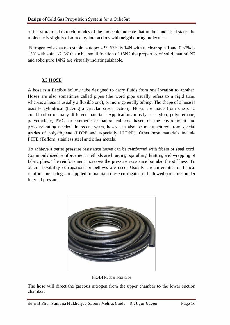
Fig.4.4 Rubber hose pipe
The hose will direct the gaseous nitrogen from the upper chamber to the lower suction
chamber.

Design of Cold Gas Propulsion System for a CubeSat
Surmit Bhui, Sumana Mukherjee, Sabina Mehra. Guide – Dr. Ugur Guven Page 17
3.4 Suction Chamber
The suction chamber is placed downstream of the hose pipe where the gaseous nitrogen
will enter and will be finally used for propulsion. The pressure within the suction
chamber would be lower than that in the upper chamber so that the gas can flow through
the hose due to the pressure difference in the two chambers. The suction chamber will
consist of solenoid valves, actuators and end with the nozzle.
3.4.1 Solenoid valves
A solenoid valve is an electromechanical device used for controlling liquid or gas flow.
The solenid valve is controlled by electrical current, which is run through a coil. When
the coil is energized, a magnetic field is created, causing a plunger inside the coil to
move. Depending on the design of the valve, the plunger will either open solenoid valve
pictureor close the valve. When electrical current is removed from the coil, the valve will
return to its de-energized state.In direct-acting solenoid valves, the plunger directly opens
and closes an orifice inside the valve. In pilot-operated valves (also called the servo-type),
the plunger opens and closes a pilot orifice. The inletline pressure, which is led through
the pilot orifice, opens and closes the valve seal.The most common solenoid valve has
two ports: an inlet port and an outlet port. Advanced desigs may have three or more ports.
Some designs utilize a manifold-type design.Solenoid valves make automation of fluid
and gas control possible. Modern solenoid valves offer fast operation, high reliability,
long service life, and compact design.
3.4.2 Actuator
An actuator is a type of motor for moving or controlling a mechanism or system. It is
operated by a source of energy, typically electric current, hydraulic fluid pressure, or
pneumatic pressure, and converts that energy into motion. An actuator is the mechanism
by which a control system acts upon an environment. The control system can be simple (a
fixed mechanical or electronic system), software-based (e.g. a printer driver, robot control
system), or a human or other agent.
A hydraulic actuator consists of a cylinder or fluid motor that uses hydraulic power to
facilitate mechanical operation. The mechanical motion gives an output in terms of linear,
rotary or oscillatory motion. Because liquid cannot be compressed, a hydraulic actuator
can exert considerable force, but is limited in acceleration and speed.
A pneumatic actuator converts energy formed by compressed air at high pressure into
either linear or rotary motion. Pneumatic energy is desirable for main engine controls
because it can quickly respond in starting and stopping as the power source does not need
to be stored in reserve for operation.
An electric actuator is powered by motor that converts electrical energy to mechanical
torque. The electrical energy is used to actuate equipment such as multi-turn valves. It is
one of the cleanest and most readily available forms of actuator because it does not
involve oil.
Design of Cold Gas Propulsion System for a CubeSat
Surmit Bhui, Sumana Mukherjee, Sabina Mehra. Guide – Dr. Ugur Guven Page 18
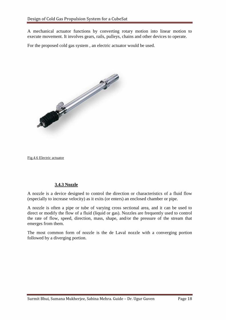
A mechanical actuator functions by converting rotary motion into linear motion to
execute movement. It involves gears, rails, pulleys, chains and other devices to operate.
For the proposed cold gas system , an electric actuator would be used.
Fig.4.6 Electric actuator
3.4.3 Nozzle
A nozzle is a device designed to control the direction or characteristics of a fluid flow
(especially to increase velocity) as it exits (or enters) an enclosed chamber or pipe.
A nozzle is often a pipe or tube of varying cross sectional area, and it can be used to
direct or modify the flow of a fluid (liquid or gas). Nozzles are frequently used to control
the rate of flow, speed, direction, mass, shape, and/or the pressure of the stream that
emerges from them.
The most common form of nozzle is the de Laval nozzle with a converging portion
followed by a diverging portion.
Design of Cold Gas Propulsion System for a CubeSat
Surmit Bhui, Sumana Mukherjee, Sabina Mehra. Guide – Dr. Ugur Guven Page 19
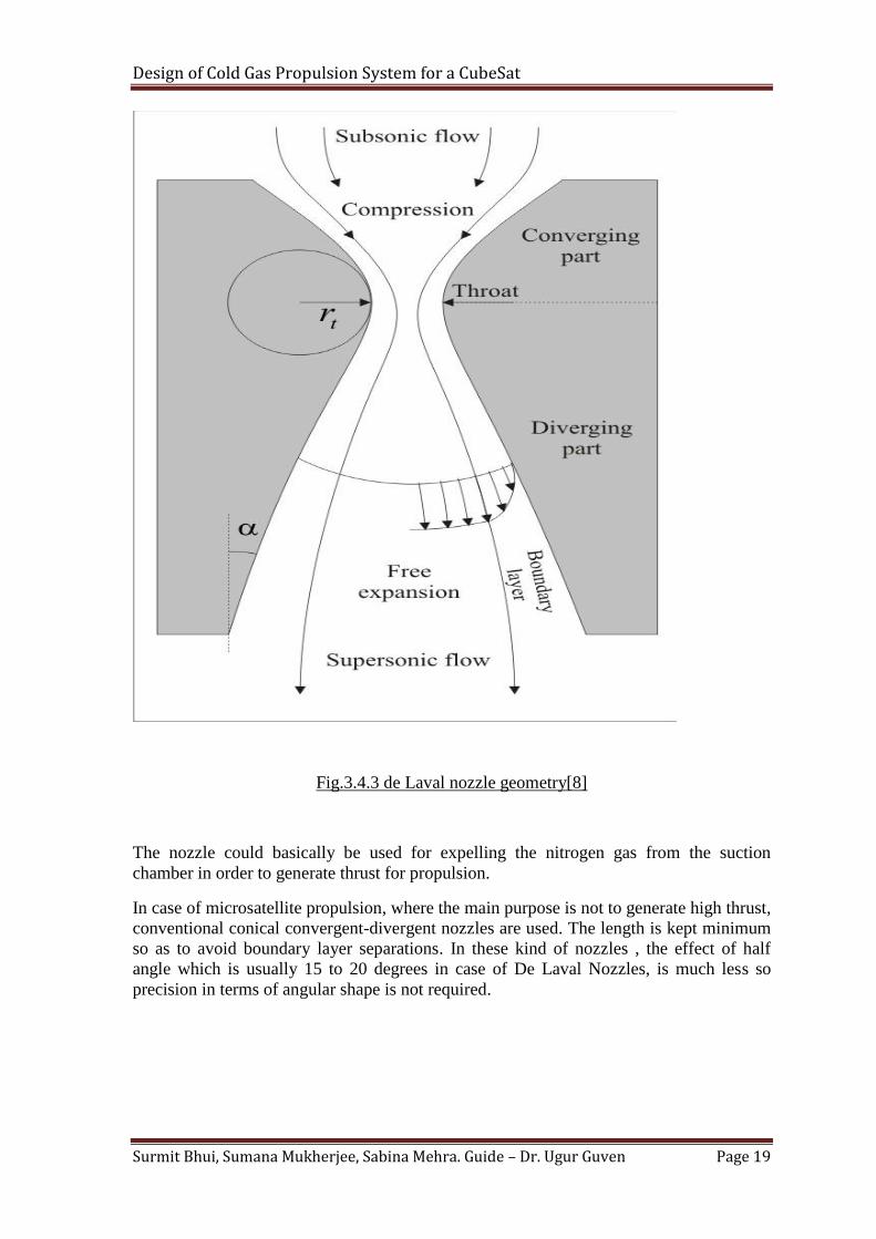
Fig.3.4.3 de Laval nozzle geometry[8]
The nozzle could basically be used for expelling the nitrogen gas from the suction
chamber in order to generate thrust for propulsion.
In case of microsatellite propulsion, where the main purpose is not to generate high thrust,
conventional conical convergent-divergent nozzles are used. The length is kept minimum
so as to avoid boundary layer separations. In these kind of nozzles , the effect of half
angle which is usually 15 to 20 degrees in case of De Laval Nozzles, is much less so
precision in terms of angular shape is not required.
Design of Cold Gas Propulsion System for a CubeSat
Surmit Bhui, Sumana Mukherjee, Sabina Mehra. Guide – Dr. Ugur Guven Page 20
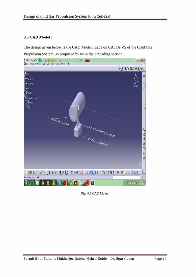
3.5 CAD Model :
The design given below is the CAD Model, made on CATIA V5 of the Cold Gas
Propulsion System, as proposed by us in the preceding section.
Fig. 4.6 CAD Model

Design of Cold Gas Propulsion System for a CubeSat
Surmit Bhui, Sumana Mukherjee, Sabina Mehra. Guide – Dr. Ugur Guven Page 21
3.6 Calculations :
For any propulsion system to be onboard a space vehicle, a few specific performance
parameters must be considered like :
1. Specific Impulse (Isp) - Itis a way to describe the efficiency
of rocket and jet engines. It represents the force with respect to the amount
of propellant used per unit time. If the "amount" of propellant is given in
terms of mass (such as in kilograms), then specific impulse has units
of velocity. If it is given in terms of weight (such as in kiloponds or newtons),
then specific impulse has units of time.
2. Delta V (∆V) - In astrodynamics a Δv or delta-v is a scalar which takes units
of speed. It is a measure of the amount of "effort" that is needed to change
from one trajectory to another by making an orbital maneuver. Delta-v is
produced by the use of propellant by reaction engines to produce a thrust that
accelerates the vehicle.
3. Mass Of Propellant (m) - The mass of the propellant is a very important
factor in determining the performance capabilities of a space bound vehicle.
The initial mass is designated as m1 and final mass as m2.
4. Weight Ratio (W.R) - The ratio of initial and final mass is referred to as the
weight ratio.
Considering Low Earth Orbit (L.E.O) at an altitude of 200 km, the value of acceleration
due to gravity (g) can be calculated as :
( )
(
)
(1)
Where, g(h)= Acceleration due to gravity at point h=200 km
R = Radius of Earth = 6371 km
g = 9.822 m/sec2
Therefore, g(h) = 9.22 m/sec2
Design of Cold Gas Propulsion System for a CubeSat
Surmit Bhui, Sumana Mukherjee, Sabina Mehra. Guide – Dr. Ugur Guven Page 22
Even though the value of g in LEO is appreciably high, yet the condition of microgravity
exists in the region. The reason being the value of g is cancelled and compensated by the
centripetal acceleration provided by the orbital motion of the satellite.
The approximate velocity of a satellite in the orbit is 25,580 ft/sec. The expression for
centripetal acceleration is given by:
Substituting the values in the expression;
a = 8.95 m/sec
2
Hence, the net amount of acceleration in the orbital region = 0.38 m/sec
2 , a very low
amount to experience the effect of weight.
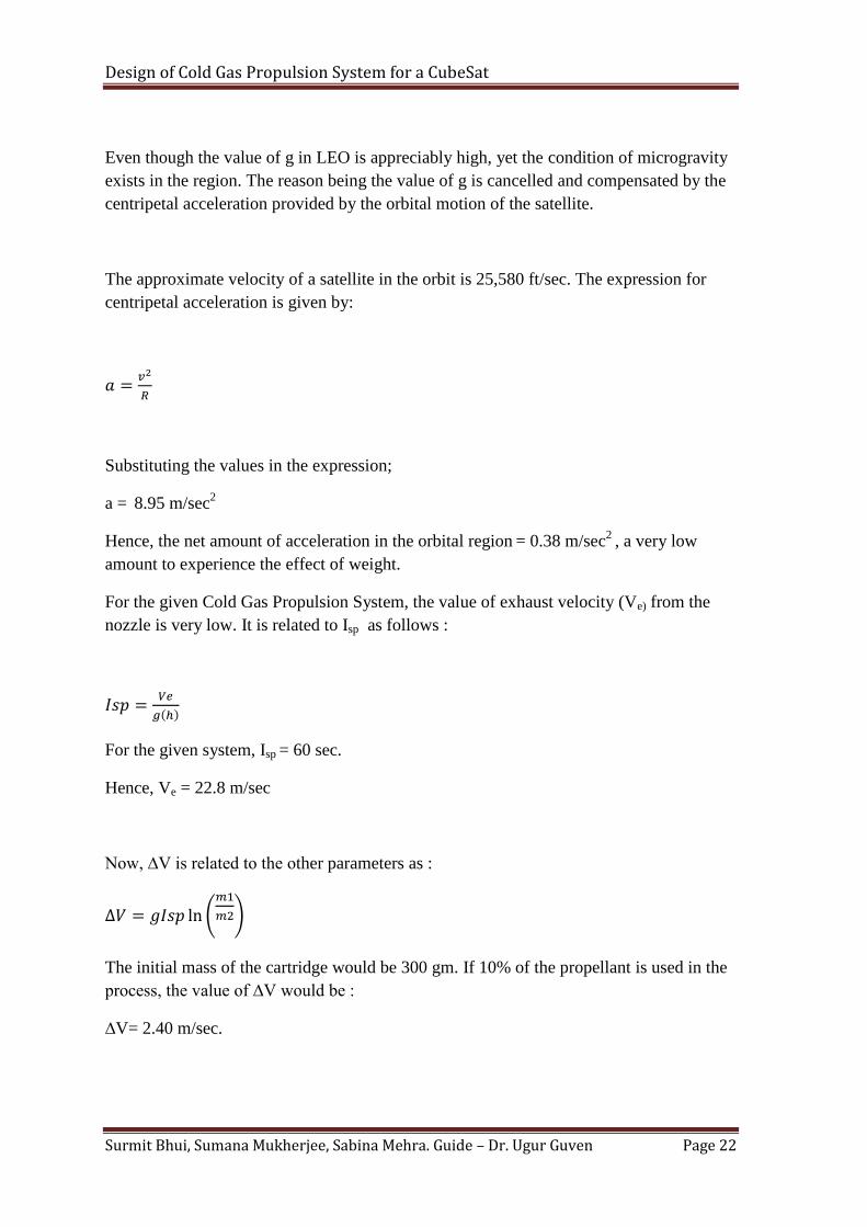
For the given Cold Gas Propulsion System, the value of exhaust velocity (Ve) from the
nozzle is very low. It is related to Isp as follows :
( )
For the given system, Isp = 60 sec.
Hence, Ve = 22.8 m/sec
Now, ∆V is related to the other parameters as :
(
)
The initial mass of the cartridge would be 300 gm. If 10% of the propellant is used in the
process, the value of ∆V would be :
∆V= 2.40 m/sec.

Design of Cold Gas Propulsion System for a CubeSat
Surmit Bhui, Sumana Mukherjee, Sabina Mehra. Guide – Dr. Ugur Guven Page 23
Since the value of ∆V is very low, more number of cartridges are required which are
joined together to the suction chamber. Using four such cartridges containing the
propellant and using up 10% of the propellant;
∆V= 4x2.40 = 9.60 m/sec.
Hence, at operations where more propellant is required the other cartridges can be used to
provide additional value of ∆V and accomplish the maneuver.
Design of Cold Gas Propulsion System for a CubeSat
Surmit Bhui, Sumana Mukherjee, Sabina Mehra. Guide – Dr. Ugur Guven Page 24
CHAPTER 4:
LITERATURE REVIEW
CubeSats are often not placed in ideal orbits for their scientific payload simply because
they are transported to their orbit as “stowaways” on a launch vehicle designed to
transport a larger space vehicle whose orbital considerations take precedence. The
ability to maneuver from these non-ideal orbits would greatly extend the capabilities of
CubeSats. There have been various methods devised andformulated to be used on a
Cubesat. Some of them are :
4.1 Pulsed Plasma Thruster
A Pulsed Plasma Thruster (PPT), also known as a plasma jet engine, is a form of electric
spacecraft propulsion. PPTs are generally considered the simplest form of electric
spacecraft propulsion and were the first form of electric propulsion to be flown in space,
having flown on two Soviet probes (Zond 2 and Zond 3) starting in 1964. PPTs are
generally flown on spacecraft with a surplus of electricity from abundantly available solar
energy.
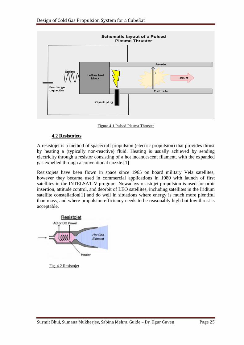
Most PPTs use a solid material (normally PTFE, more commonly known as Teflon) for
propellant, although a minority use liquid or gaseous propellants. The first stage in PPT
operation involves an arc of electricity passing through the fuel, causing ablation and
sublimation of the fuel. The heat generated by this arc causes the resultant gas to turn into
plasma, thereby creating a charged gas cloud. Due to the force of the ablation, the plasma
is propelled at low speed between two charged plates (an anode and cathode). Since the
plasma is charged, the fuel effectively completes the circuit between the two plates,
allowing a current to flow through the plasma. This flow of electrons generates a strong
electromagnetic field which then exerts a Lorentz force on the plasma, accelerating the
plasma out of the PPT exhaust at high velocity. The pulsing occurs due to the time needed
to recharge the plates following each burst of fuel, and the time between each arc. The
frequency of pulsing is normally very high and so it generates an almost continuous and
smooth thrust. While the thrust is very low, a PPT can operate continuously for extended
periods of time, yielding a large final acceleration.
The energy used in each pulse is stored in a capacitor.By varying the time between each
capacitor discharge, the thrust and power draw of the PPT can be varied allowing
versatile use of the system.
Design of Cold Gas Propulsion System for a CubeSat
Surmit Bhui, Sumana Mukherjee, Sabina Mehra. Guide – Dr. Ugur Guven Page 25
Figure 4.1 Pulsed Plasma Thruster
4.2 Resistojets
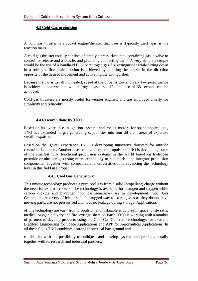
A resistojet is a method of spacecraft propulsion (electric propulsion) that provides thrust
by heating a (typically non-reactive) fluid. Heating is usually achieved by sending
electricity through a resistor consisting of a hot incandescent filament, with the expanded
gas expelled through a conventional nozzle.[1]
Resistojets have been flown in space since 1965 on board military Vela satellites,
however they became used in commercial applications in 1980 with launch of first
satellites in the INTELSAT-V program. Nowadays resistojet propulsion is used for orbit
insertion, attitude control, and deorbit of LEO satellites, including satellites in the Iridium
satellite constellation[1] and do well in situations where energy is much more plentiful
than mass, and where propulsion efficiency needs to be reasonably high but low thrust is
acceptable.
Fig. 4.2 Resistojet
Design of Cold Gas Propulsion System for a CubeSat
Surmit Bhui, Sumana Mukherjee, Sabina Mehra. Guide – Dr. Ugur Guven Page 26
4.3 Cold Gas propulsion
A cold gas thruster is a rocket engine/thruster that uses a (typically inert) gas as the
reaction mass.
A cold gas thruster usually consists of simply a pressurized tank containing gas, a valve to
control its release and a nozzle, and plumbing connecting them. A very simple example
would be the use of a handheld CO2 or nitrogen gas fire extinguisher while sitting down
in a rolling office chair; motion is achieved by pointing the nozzle in the direction
opposite of the desired movement and activating the extinguisher.
Because the gas is usually unheated, speed at the throat is low and very low performance
is achieved; in a vacuum with nitrogen gas a specific impulse of 68 seconds can be
achieved.
Cold gas thrusters are mostly useful for vernier engines, and are employed chiefly for
simplicity and reliability.
4.4 Research done by TNO
Based on its experience in ignition systems and rocket motors for space applications,
TNO has expanded its gas generating capabilities into four different areas of expertise
Small Propulsion
Based on the igniter experience TNO is developing innovative thrusters for attitude
control of launchers. Another research area is micro propulsion. TNO is developing some
of the smallest fully functional propulsion systems in the world based on hydrogen
peroxide or nitrogen gas using micro technology to miniaturise and integrate propulsion
components. Together with companies and universities it is advancing the technology
level in this field in Europe.
4.4.1 Cool Gas Generators:
This unique technology produces a pure cool gas from a solid (propellant) charge without
the need for external coolers. The technology is available for nitrogen and oxygen while
carbon dioxide and hydrogen cool gas generators are in development. Cool Gas
Generators are a very efficient, safe and rugged way to store gasses as they do not have
moving parts, are not pressurised and have no leakage during storage. Applications
of this technology are vast: from propulsion and inflatable structures in space to life rafts,
medical oxygen delivery and fire extinguishers on Earth. TNO is working with a number
of partners to develop products using the Cool Gas Generator technology, for example
Bradford Engineering for Space Applications and APP for Aeronautical Applications. In
all these fields TNO combines a strong theoretical background and
capabilities with the possibility to build,test and develop systems and products usually
together with its research and industrial partners.
Design of Cold Gas Propulsion System for a CubeSat
Surmit Bhui, Sumana Mukherjee, Sabina Mehra. Guide – Dr. Ugur Guven Page 27
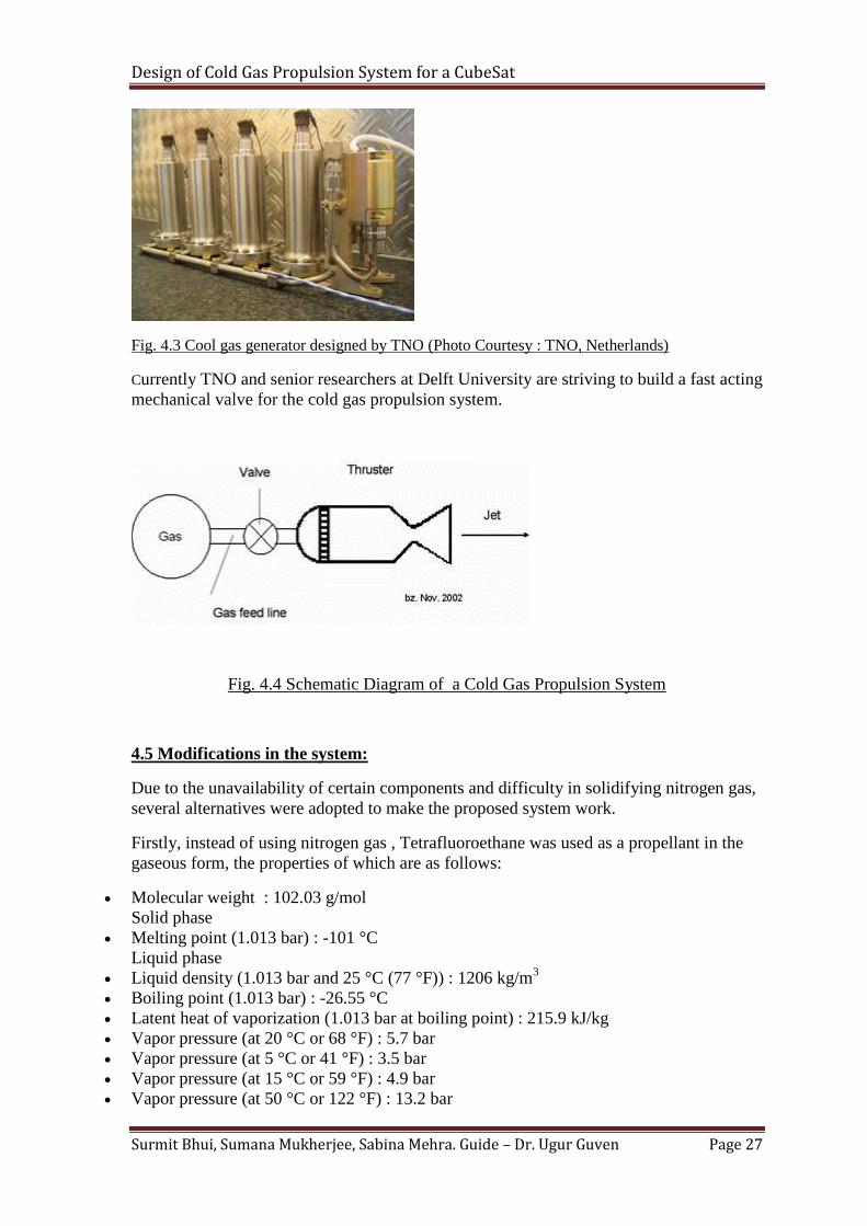
Fig. 4.3 Cool gas generator designed by TNO (Photo Courtesy : TNO, Netherlands)
Currently TNO and senior researchers at Delft University are striving to build a fast acting
mechanical valve for the cold gas propulsion system.
Fig. 4.4 Schematic Diagram of a Cold Gas Propulsion System
4.5 Modifications in the system:
Due to the unavailability of certain components and difficulty in solidifying nitrogen gas,
several alternatives were adopted to make the proposed system work.
Firstly, instead of using nitrogen gas , Tetrafluoroethane was used as a propellant in the
gaseous form, the properties of which are as follows:
Molecular weight : 102.03 g/mol
Solid phase
Melting point (1.013 bar) : -101 °C
Liquid phase
Liquid density (1.013 bar and 25 °C (77 °F)) : 1206 kg/m3
Boiling point (1.013 bar) : -26.55 °C
Latent heat of vaporization (1.013 bar at boiling point) : 215.9 kJ/kg
Vapor pressure (at 20 °C or 68 °F) : 5.7 bar
Vapor pressure (at 5 °C or 41 °F) : 3.5 bar
Vapor pressure (at 15 °C or 59 °F) : 4.9 bar
Vapor pressure (at 50 °C or 122 °F) : 13.2 bar
Design of Cold Gas Propulsion System for a CubeSat
Surmit Bhui, Sumana Mukherjee, Sabina Mehra. Guide – Dr. Ugur Guven Page 28
Critical temperature : 100.95 °C
Critical pressure : 40.6 bar
Critical density : 512 kg/m3
Triple point
Triple point temperature : -103.3 °C
Gaseous phase
Gas density (1.013 bar at boiling point) : 5.28 kg/m3
Gas density (1.013 bar and 15 °C (59 °F)) : 4.25 kg/m3
Compressibility Factor (Z) (1.013 bar and 15 °C (59 °F)) : 1
Specific gravity : 3.25
Specific volume (1.013 bar and 15 °C (59 °F)) : 0.235 m3/kg
Heat capacity at constant pressure (Cp) (1.013 bar and 25 °C (77 °F)) : 0.08754
kJ/(mol.K)
Miscellaneous
Solubility in water (1.013 bar and 25 °C (77 °F)) : 0.21 vol/vol
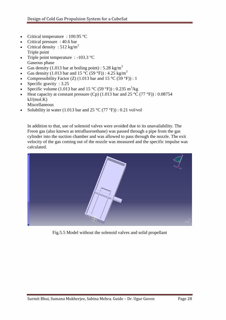
In addition to that, use of solenoid valves were avoided due to its unavailability. The
Freon gas (also known as tetrafluoroethane) was passed through a pipe from the gas
cylinder into the suction chamber and was allowed to pass through the nozzle. The exit
velocity of the gas coming out of the nozzle was measured and the specific impulse was
calculated.
Fig.5.5 Model without the solenoid valves and solid propellant
Design of Cold Gas Propulsion System for a CubeSat
Surmit Bhui, Sumana Mukherjee, Sabina Mehra. Guide – Dr. Ugur Guven Page 29
CHAPTER 5:
RESULTS AND DISCUSSIONS
The exit velocity of the gas was calculated using pitot tube fitted at the nozzle end.
The difference in pressure in the manometer gave the velocity :
V=(2(p0-p)/density of air)^1/2.
The exit velocity was found out to be
The exit velocity in turn gives specific impulse, Isp= V/g
The specific impulse was found to be
which is close enough to that required in a cubesat.
Design of Cold Gas Propulsion System for a CubeSat
Surmit Bhui, Sumana Mukherjee, Sabina Mehra. Guide – Dr. Ugur Guven Page 30
Chapter 6:
FUTURE WORK
We look forward to carry this research on this cold gas propulsion system for Cubesats
and nanosatellites in order to make orbital maneuvers, formation flying, etc. and most
importantly de-orbiting possible to deal with problems of space debris. The model
presented as a part of this project is only to check the feasibility of the system. We have
been lucky enough to receive an internship opportunity at the Tartu Space Observatory,
Estonia where we would be working on a flight model of this system under Dr. Mart
Noorma. As interns at the observatory and as part of the Estonian student satellite
program, our prime focus would be on the feasibility of the system which would fly
onboard a Cubesat named Estcube-2. This would present the right set of circumstances to
get hands-on experience on the industry model of this propulsion system. We hope to
exploit this opportunity to learn the intricacies and complexities of a flight model in order
to develop our system.
Design of Cold Gas Propulsion System for a CubeSat
Surmit Bhui, Sumana Mukherjee, Sabina Mehra. Guide – Dr. Ugur Guven Page 31
CHAPTER 7:
CONCLUSION
With major space actors and organizations realizing the huge potential for manufacturing
Cubesats, the use of a propulsion system is inevitable, and with the weight constraint
upto approximately 4kg, the cold gas propulsion system provides the most viable
option to be used on a 3U Cubesat, without compromising on the structural integrity and
performance capabilities of the microsatellite. The study has emphasized the practicality
and the usability of such a system. To the best of the knowledge of our team, the use of
lasers for initiating the system and the internal design of the system has not been
implemented in any system

Design of Cold Gas Propulsion System for a CubeSat
Surmit Bhui, Sumana Mukherjee, Sabina Mehra. Guide – Dr. Ugur Guven Page 32
CHAPTER 8:
REFERENCES
[1]Cote, K., Gabriel, J., Patel, B., Ridley, N., Taillafer, Z., & Tetreault, S.
(n.d.).Mechanical,Power and Propulsion subsystem Design for A Cubesat. Worcester
Polytechnic Institute.
[2]Cubesat Design Specification Rev. 12. (n.d.). Calpoly SLO: California Polytechnic
State University.
[3]Mueller, J., Hofer, R., & Ziemer, J. (n.d.). Survey of Propulsion Technologies
Applicable To Cubesats. Pasadena, CA: Jet Propulsion Laboratory, California Institute Of
Technology.
[4]Nothnagel, S. L. (2009). Development of A Cold Gas Propulsion System for the
TALARIS Hopper. University of Southern California.
[5]Sanders, B., Schuurbiers, C., Vliet, L. v., & Nardini, F. T. (2010). ResultsOf
Qualification and Flight Tests of Cool Gas Generators. Space Propulsion Conference.
San Sebastian,Spain.
[6]Zaken, K. (n.d.). Innovative Plug and Play Micropropulsion Systems. Retrieved
August 30, 2013, from www.tno.nl: http://www.tno.nl/gasgenerators.
[7] http://eprints.eemcs.utwente.nl/14567/01/PMME_45.pdf

Design of Cold Gas Propulsion System for a CubeSat
Surmit Bhui, Sumana Mukherjee, Sabina Mehra. Guide – Dr. Ugur Guven Page 33