Department of Chemical Engineering, Veer Surendra Sai ...
17
Department of Chemical Engineering, Veer Surendra Sai University of Technology, Burla 1 FUEL TECHNOLOGY-2 LAB MANUAL LIST OF EXPERIMENT: 1. To determine the viscosity of the given oil sample using Engler’s viscometer 2. To determine the Cloud point and Pour point of a given fuel / lubricant / oil using Cloud and Pour point apparatus 3. To determine the Flash and Fire point of the given sample of oil using Pensky Marten’s apparatus 4. To determine the carbon residue of the given sample of lubricating oil / fuel using Conradson Apparatus 5. To determine the Smoke point of a given oil using smoke point apparatus. 6. To determine the Acid value of a given oil 7. To determine the aniline point of a given oil / fuel EXPERIMENT-1
-
Upload
khangminh22 -
Category
Documents
-
view
2 -
download
0
Transcript of Department of Chemical Engineering, Veer Surendra Sai ...
Department of Chemical Engineering, Veer Surendra Sai University of Technology, Burla
1
FUEL TECHNOLOGY-2
LAB MANUAL
LIST OF EXPERIMENT:
1. To determine the viscosity of the given oil sample using Engler’s viscometer
2. To determine the Cloud point and Pour point of a given fuel / lubricant / oil using
Cloud and Pour point apparatus
3. To determine the Flash and Fire point of the given sample of oil using Pensky
Marten’s apparatus
4. To determine the carbon residue of the given sample of lubricating oil / fuel using
Conradson Apparatus
5. To determine the Smoke point of a given oil using smoke point apparatus.
6. To determine the Acid value of a given oil
7. To determine the aniline point of a given oil / fuel
EXPERIMENT-1
Department of Chemical Engineering, Veer Surendra Sai University of Technology, Burla
2
AIM OF THE EXPERIMENT: To determine the viscosity of the given oil sample using
Engler’s viscometer
APPARATUS REQUIRED:
1. Engler’s Viscometer
2. Stop watch
3. Thermometer
4. Measuring flask
SAMPLE REQUIRED: Fuel oil
THEORY:
The viscosity of given oil is determined as the time of flow in Engler’s seconds. The viscosity
of a fluid indicates the resistance offered to shear under laminar condition. Dynamic viscosity
of a fluid is the tangential force on unit area of either of two parallel planes at unit distance
apart when the space between the plates moves relative to the other with unit velocity in its
own plane. The unit of dynamic viscosity is dyne-sec/cm2. Kinematic viscosity of a fluid is
equal to the ratio of the dynamic viscosity and density of the fluid. The unit of kinematic
viscosity is cm2/sec.
DESCRIPTION:
Engler’s viscometer consists of a water bath and oil bath, both provided with two
thermometers inside them. There is an ebonite valve stick, which is located at center of oil
bath to flow of oil through the orifice. A heater with regulator is fixed for heating purpose.
PROCEDURE:
1. Clean the oil cup with a suitable solvent thoroughly and dry it using soft tissue paper.
2. Keep the ebonite valve stick in its position so as to keep the orifice closed.
3. The water is taken into the water bath and the oil whose viscosity is to be determined
is taken into the oil cup up to the mark.
4. Before switch on the electric supply, at room temp note down the time taken in
Engler’s seconds for a collection of 200 cc of oil with a stopwatch.
5. Heat the bath and continuously stir it taking care to see that heating of the bath is done
in a careful and controlled manner.
Department of Chemical Engineering, Veer Surendra Sai University of Technology, Burla
3
6. When the desired temperature is reached, place the cleaned 200 cc Flask below the
orifice in position.
7. Remove the ebonite valve stick and simultaneously start a stopwatch. Note the time
collection of oil up to the 200 cc mark. During the collection of oil don’t stir the bath.
8. Repeat the process at various temperatures.
OBSERVATIONS:
Sl no Oil temp. (℃) Time for collecting
50 cc of oil sec
Kinematic
viscosity
٧=(A*t)-(B/t)
cm2/sec
Density
(Ꝭ )
gm/sec
Absolute
Viscosity
μ=٧*Ꝭ
dyne=sec/cm2
Where A=0.0026 cm2/sec2 & B=1.8 cm2
GRAPHS TO BE DRAWN
1. Engler’s seconds vs. temperature
2. Kinematic Viscosity vs. temperature
3. Absolute Viscosity vs. temperature
PRECAUTIONS
1. Stir the water continuously so that the temp of the oil and water are equal.
2. Before collecting the oil at a temp., check whether the oil is up to the indicator in the
oil cup.
3. Always take the readings at a stable temp.
4. Ensure proper setting of the Ebonite stick to avoid leakage.
RESULTS
Department of Chemical Engineering, Veer Surendra Sai University of Technology, Burla
4
Variation of Engle’s seconds, Absolute viscosity and kinematic viscosity with temp., were
observed and found to be decreasing with temp.
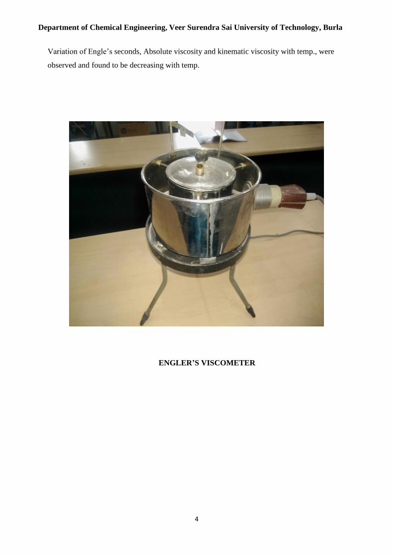
ENGLER’S VISCOMETER
Department of Chemical Engineering, Veer Surendra Sai University of Technology, Burla
5
EXPERIMENT-2
AIM OF THE EXPERIMENT: To determine the cloud point and pour point of a given fuel
/ lubricant / oil using cloud and pour point apparatus
APPARATUS REQUIRED:
1. Cloud and pour point
2. Digital temp thermometer
SAMPLE REQUIRED: fuel oil
THEORY:
CLOUD POINT: The temperature expressed to the nearest degree centigrade, at which a
cloud or haze appear when the oil is cooled under prescribed conditions.
POUR POINT: The lowest temp., expressed as a multiple of 3℃, at which the oil is
observed to flow when cooled & examined under prescribed conditions.
PROCEDURE:
CLOUD POINT:
1. Bring the sample to a temperature of at least 15 ℃ above the approximate cloud
point and pour point it into the jar to a height of 51 to 57 mm.
2. Close the jar with the cock so that the temp bulb rests on the centre of the bottom
of the jar.
3. Fit the gasket on to the jar 25 mm from the bottom and insert the jar into gasket.
4. Support the jacket and jar in a vertical position in the bath so that not more than
25mm projects from the cooling medium.
5. At each thermometer reading of one degree centigrade, remove the jar from the
jacket quickly but without disturbing the oil, inspect the material for cloud, and
replace the jar, this complete operation shall not take more than 3 sec.
6. If the sample does not show a cloud when it has been cooled 10 ℃ place the jar
and jacket in another bath maintained at a temp of -15 ℃ to -18 ℃.
7. If the sample does not show a cloud when it has been cooled to -7 ℃. Place the jar
and jacket in another bath maintained at a temp. Of -32 ℃ to -35 ℃.
Department of Chemical Engineering, Veer Surendra Sai University of Technology, Burla
6
8. When an inspection of the sample first reveals a distinct cloudiness or haze at the
bottom of the jar, record the reading of the thermometer as the cloud point after
correcting the thermometer errors if necessary.
POUR POINT:
1. The sample has cooled enough to allow the formation of the crystals.
2. Maintain the bath temp at -1 ℃ to 2 ℃.
3. Support the jacket and jar in a vertical position in the bath so that not more than
25mm projects from the cooling medium.
4. Beginning at a temp 12 ℃ above the expected pour point, at each thermometer
reading which is a multiple of 3 ℃ remove the jar from the jacket carefully, and tilt it
just enough to see whether the oil will move and the replace it, this complete
operation shall not take more than 3 sec.
5. As soon as the sample ceases to flow when the jar is titled, hold the jar in horizontal
position for exactly 5 sec.
6. If the sample shows any movement replace the jar in the jacket and cool down the
sample for another 3 ℃. If the oil shows no movement during the 5 sec, record the
reading of the thermometer.
7. Add 3 ℃ to the temp recorded above and corrected for thermometer errors if
necessary, and note down the result as the pour point.
OBSERVATIONS:
OIL CLOUD POINT(℃) POUR POINT (℃)
PRECAUTIONS:
1. The disc, the gasket, and jacket shall be kept clean and dry.
2. Don’t disturb the mass of sample nor don’t permit the thermometer to shift in the
sample. Any disturbance of the spongy network of crystals will lead to false results.
Department of Chemical Engineering, Veer Surendra Sai University of Technology, Burla
7
RESULTS:
For a given sample of oil, the cloud & pour points are _____ and_______
respectively.
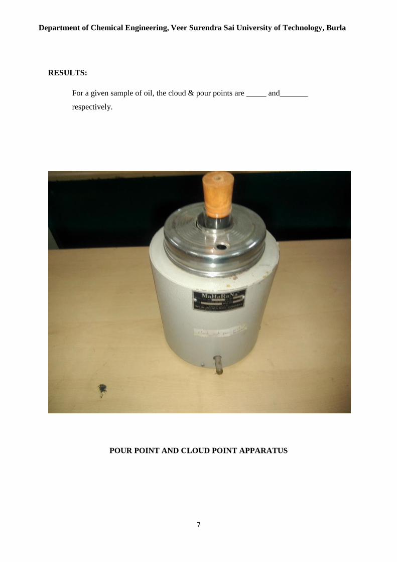
POUR POINT AND CLOUD POINT APPARATUS
Department of Chemical Engineering, Veer Surendra Sai University of Technology, Burla
8
EXPERIMENT-3
AIM OF THE EXPERIMENT: To determine the Flash point and Fire point of the given
sample of oil using Pensky Marten’s apparatus.
APPARATUS REQUIRED:
1. Pensky Marten’s apparatus.
2. Thermometer
SAMPLE REQUIRED: Fuel oil
THEORY:
This method determines the closed cup and open cup flash and fire points of petroleum
products and mixtures to ascertain and mixtures to ascertain whether they give off
inflammable vapours below a certain temperature.
FLASH POINT: It is the lowest temperature of the oil at which application of test flame
causes the vapour above the sample to ignite with a distinct flash inside the cup.
FIRE POINT: It is the lowest temperature of the oil, at which, application of test flame
causes burning for a period of about five seconds.
DESCRIPTIONS:
The apparatus consists of a brass cup and cover fitted with shutter mechanism without shutter
mechanism (open cup), test flame arrangement, hand stirrer (closed cup), thermometer
socket, etc., heated with energy regulator, a thermometer socket made of copper.
PROCEDURE:
1. Clean the oil cup thoroughly and fill the oil cup with the sample oil to be tested up to
the mark.
2. Insert the thermometer into the oil cup through a provision, which measures the rise
of oil temp.
3. Using the Energy regulator, control; the power supply given to the heater and rate of
heating.
4. The oil is heated slowly when temp of oil rises; it is checked for the flash point for
every one-degree rise in temp.
Department of Chemical Engineering, Veer Surendra Sai University of Technology, Burla
9
5. After determining the flash point, the heating shall be further continued. The temp. at
which time of flame application which causes burning for a period at least 5 seconds
shall be recorded as the fire point.
6. Repeat the experiment 2 to 3 times with fresh sample of the same oil.
7. Take the average value of flash and fire points.
OBSERVATIONS:
Sample oil Flash point (℃) Fire point (℃)
RESULT:
The flash point is observed at ---------℃.
The fire point is observed at-----------℃.
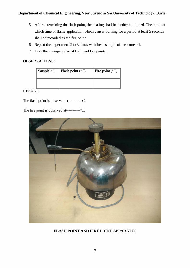
FLASH POINT AND FIRE POINT APPARATUS
Department of Chemical Engineering, Veer Surendra Sai University of Technology, Burla
10
EXPERIMENT-4
AIM OF THE EXPERIMENTS: To determine the carbon residue of the given sample of
lubricating oil/fuel.
APPARATUS REQUIRED:
1. Carbon residue (Conradson) apparatus
2. Analytical balance with Weight box
SAMPLE REQUIRED: Fuel oil
THEORY:
Most of the lubricant oils are containing high percentage of carbon in combined form and
fuels containing less percentage of carbon in combined form. On heating, they decompose
depositing a certain amount of carbon. The deposition of such carbon in machine is
intolerable, particularly in internal combustion engines and air compressors. A good lubricant
should deposit least amount of the carbon in use.
PROCEDURE:
1. The weighed porcelain or silica crucible with approximately 2 grams of sample is
placed in the centre of skid more crucible.
2. The skid more crucible is provided with lid, having a small tube type opening for the
escape of volatile matter.
3. The combination is then placed in wrought iron crucible covered with chimney
shaped iron hood.
4. The wrought iron crucible is heated slowly till flame appears. Slow heating continues
for 5 minutes more.
5. Finally, strong heating is done for about 15 minutes till vapours of all volatile matter
are burnt completely.
6. Apparatus is then allowed to cool and weight of residue left is determined.
7. The result is expressed as percentage of the original weight of oil taken.
OBSERVATIONS:
1. Weight of the crucible w1 = gms
2. Weight of the crucible with oil w2 = gms

Department of Chemical Engineering, Veer Surendra Sai University of Technology, Burla
11
3. Weight of crucible with residue w3 = gms
Percentage of carbon residue = (weight of residue/original weight of sample) *100
= [(w3-w1)/ (w2-w1)] *100
RESULT:
The percentage of carbon present in given sample of lubricating oil is ______%
CONRADSON APPARATUS

Department of Chemical Engineering, Veer Surendra Sai University of Technology, Burla
12
EXPERIMENT-5
AIM OF THE EXPERIMENT: To determine the Smoke point of a given oil using Smoke
point apparatus.
APPARATUS REQUIRED:
1. Smoke point apparatus
2. Thermometer
SAMPLE REQUIRED: Fuel oil
THEORY:
The smoke point, also referred to as the burning point, is the temperature at which an oil or
fat begins to produce a continuous bluish smoke that becomes clearly visible, dependent upon
specific and defined conditions. The smoke point of oil is the temperature at which the oil
starts to smoke. ... The smoke point of oil is important because no one wants to burn their oil.
Smoke point is related to the hydrocarbon composition of kerosene - it is highest with
paraffin’s, considerably lower with naphthenic and very much lower with aromatics.
The smoke point is also an indication of the tendency to smoke when the flame is smaller
than the maximum stipulated size.
PROCEDURE:
1. A 126 mm long dried wick is socked in the sample and placed in the wick tube of
the candle.
2. A 10-20 ml of prepared sample is introduced at room temp into the dry candle.
3. The wick tube is placed in the candle firmly with taking care of the candle air vent
is free from fuel. A new clean, sharp razor is used to cut the wick at the face of the
holder and remove wisps and frayed ends.
4. T he candle is lighted and the wick adjusted so that the flame is approximately
10mm high with 5min.
5. After burning, the candle raised until a smoke tail appears, then the candle is
lowered slowly through several stages of flame appear once.
6. The maximum height of flame that can be achieved without smoking is
determined to the nearest 0.5mm.

Department of Chemical Engineering, Veer Surendra Sai University of Technology, Burla
13
7. The candle is removed from the lamp arise with heptanes and purged with air to
make ready for re-use.
RESULT:
In this experiment we have to record the height of the flame, when we raise the candle until a
smoky tail appears then lower the flame slowly until the smoky tail disappears.
To eliminate errors due to parallax, the eye of the observer shall be slightly to one side of the
centreline, so that a reflected image of the flame is seen on the scale on one side of the central
vertical white line. We have recorded the following records;
CALCULATIONS:
For kerosene:
Record of height in mm (1) =x mm
Record of height in mm (2) = y mm
Record of height in mm (3) =z mm
The avg of records= (x+y+z)/3 mm
Smoking tendency=320/smoke point
DISCUSSION:
From the above experiment we have to find the smoking tendency of the given oil is __.
SMOKE POINT APPARATUS

Department of Chemical Engineering, Veer Surendra Sai University of Technology, Burla
14
EXPERIMENT-6
AIM OF THE EXPERIMENT: To determine the acid value of a given oil
CHEMICALS REQUIRED:
1. 1N KOH Solution
2. Neutral ethyl alcohol
3. phenolphthalein indicator
APPARATUS REQUIRED:
1. Test tube
2. measuring cylinder
3. watch bath
4. Test tube holder
5. Stirrer
SAMPLE REQUIRED: Fuel oil
PRINCIPLE:
The acid value of lubricating oil is defined as the number of milligrams of potassium
hydroxide required to neutralise the free acid present in 1 gm of the oil. The presence of
mineral acid presence in lubricating oil is so rare that it is almost necessary to look for it
unless the oil is refined in a faulty manner. Free organic acid or acidic bodies are always
found in lubricating oil, whether they are pure mineral oil, compound oils with fatty oils. In
unused refined petroleum oil, the quantity is in variably negligible. When fatty acids are
present on the case of used oils, the acid content should be determined not because it gives
any direct evidence of corrosion hazard, but to sound a warning that a corrosion test might be
revealing. In good lubricating oil the acid value should be very low (<0.1). Increase in acid
value should be taken as an indicator of oxidation of the oil which may lead to gum and
sludge formation besides corrosion. The acid value of fatty oils may vary from 0.2 to 50 and
it shows the extent of hydrolysis of glycerol ester of the oil.
PROCEDURE:
1.5 gm of oil was weighted out accurately under test into a 250 ml conical flask.
2.50 ml of neutral alcohol was added to it.

Department of Chemical Engineering, Veer Surendra Sai University of Technology, Burla
15
3. The flask was heated over a water bath for about 30 minutes.
4. The flask was cooled and added a few drops of phenolphthalein indicator.
5. Then it was titrated with 1N KOH solution until a faint permanent pink colour appeared at
the end point.
CHEMICAL REACTION:
C17H35COOH+KOH=C17H35COOK+H2O
TABULATION:
SL.NO IBR FBR DIFFERENCE REMARKS
CALCULATION:
ACID VALUE = (No of ml of 1N KOH run down/wt. of oil taken in gms) *56
Where 56 represent the amount of KOH in mg present per each ml of 1N KOH solution.
CONCLUSION:
From the above experiment it is found that the acid value of the given oil sample is _____.
Department of Chemical Engineering, Veer Surendra Sai University of Technology, Burla
16
EXPERIMENT-7
AIM OF THE EXPERIMENT: To determine the Aniline point of a given lubricating oil.
CHEMICAL REQUIRED:
Aniline
APPARATUS REQUIRED:
1. Test tube
2. Measuring cylinder
3. water bath
4. test tube holder
5. stirrer
6. thermometer
SAMPLE REQUIRED: Fuel oil
THEORY:
Aniline point of oil is defined as the minimum equilibrium temperature for equal volumes of
aniline and the oil. In other words, it is the least temp at which the oil is completely miscible
with an equal volume of freshly distilled aniline.
Aromatic hydrocarbons have a tendency to dissolve natural and certain types
of synthetic rubber. Aniline point of lubricating oil is a measure of its aromatic content and
hence it gives an indication of the possible tendency of deteriation of oil when it comes into
contact with rubber seals used in the system to prevent leakages. Thus the lower the aniline
point of lubricating oil, the more severe will be its attack on the rubber sealing. Obviously a
higher aniline point is describing for lubricating oil, because it means that the oil contains
lower percentage of aromatic hydrocarbons.
PROCEDURE:
1.4ml of aniline and diesel oil are taken in a test tube and poured into a boiling tube.
2. A stirrer is used to mix the mixture while it is placed in a hot water bath.
3. The boiling tube is taken out and noticed from time to time after periodic intervals.
Department of Chemical Engineering, Veer Surendra Sai University of Technology, Burla
17
4. When the haziness forms over the entire solution leading to a homogeneous colour, the
temperature of the solution just at the surface is noted.
RESULT:
The aniline point of diesel was found out to be _____.
CONCLUSION:
Since aromatic dissolve aniline more readily than paraffin’s, the higher aniline point lowers
the aromatics and higher the paraffin content with high cetane number making the oil suitable
for use in diesel engine.
Hence, higher the aniline point betters the diesel oil and the lubricant.