
Definition and use of Computation Independent Models in an MDA-based groupware development process
19
Science of Computer Programming 66 (2007) 25–43 www.elsevier.com/locate/scico Definition and use of Computation Independent Models in an MDA-based groupware development process Jos´ e Luis Garrido a,* , Manuel Noguera a , Miguel Gonz´ alez b , Mar´ ıa V. Hurtado a , Mar´ ıa L. Rodr´ ıguez a a University of Granada, Department of Software Engineering, E.T.S.I.I., c/Saucedo Aranda s/n, 18071 Granada, Spain b Autonomous University of Madrid, Information Technologies, E.P.S., c/Tom´ as y Valiente 11, 28049 Madrid, Spain Received 15 March 2006; received in revised form 31 August 2006; accepted 13 October 2006 Available online 22 December 2006 Abstract Groupware systems allow users to be part of a shared environment in order to carry out groupwork. Members of a group belong to organizations in which each one fulfils general and specific enterprise objectives. This paper presents a proposal, from the perspective of the CSCW (Computer-Supported Cooperative Work) systems, for modelling enterprise organization and developing groupware applications. This research work focuses on two specific models for the proposal: a conceptual domain model formalized through a domain ontology, and a system model built using a UML-based notation. The second stems from the first and each provides a Computation Independent View (CIV) with different objectives. Respectively, they allow a common vocabulary for knowledge sharing to be established, and organization functional requirements to be specified, particularly those concerning communication, coordination and collaboration. Furthermore, these models are part of a concrete MDA-based development process of groupware applications that is also introduced. c 2006 Elsevier B.V. All rights reserved. Keywords: CSCW; Groupware development process; MDA; Ontology; OWL; UML; Enterprise modeling; Software models 1. Introduction Computer-Supported Cooperative Work (CSCW) [23] studies and analyzes coordination mechanisms for effective human communication and collaboration and also the technological systems supporting them. CSCW systems play an important role in enabling business application integration across organizations, since most enterprises are involved in cooperation processes and are also technology dependent. Nowadays, in order to stay competitive, enterprises must be capable of quickly adapting their business processes to the new dynamic environments [3]. In addition, as a result of technological evolution, enterprises must continuously rethink their business designs, and change their models taking into account new challenges (technology, interoperation, cooperation, etc.) [11]. Social, organizational and technological aspects influence functional requirements of a software system to be developed. * Corresponding author. E-mail addresses: [email protected] (J.L. Garrido), [email protected] (M. Noguera), [email protected] (M. Gonz´ alez), [email protected] (M.V. Hurtado), [email protected] (M.L. Rodr´ ıguez). 0167-6423/$ - see front matter c 2006 Elsevier B.V. All rights reserved. doi:10.1016/j.scico.2006.10.008
-
Upload
independent -
Category
Documents
-
view
1 -
download
0
Transcript of Definition and use of Computation Independent Models in an MDA-based groupware development process

Science of Computer Programming 66 (2007) 25–43www.elsevier.com/locate/scico
Definition and use of Computation Independent Models in anMDA-based groupware development process
Jose Luis Garridoa,∗, Manuel Nogueraa, Miguel Gonzalezb, Marıa V. Hurtadoa,Marıa L. Rodrıgueza
a University of Granada, Department of Software Engineering, E.T.S.I.I., c/Saucedo Aranda s/n, 18071 Granada, Spainb Autonomous University of Madrid, Information Technologies, E.P.S., c/Tomas y Valiente 11, 28049 Madrid, Spain
Received 15 March 2006; received in revised form 31 August 2006; accepted 13 October 2006Available online 22 December 2006
Abstract
Groupware systems allow users to be part of a shared environment in order to carry out groupwork. Members of a groupbelong to organizations in which each one fulfils general and specific enterprise objectives. This paper presents a proposal,from the perspective of the CSCW (Computer-Supported Cooperative Work) systems, for modelling enterprise organization anddeveloping groupware applications. This research work focuses on two specific models for the proposal: a conceptual domain modelformalized through a domain ontology, and a system model built using a UML-based notation. The second stems from the first andeach provides a Computation Independent View (CIV) with different objectives. Respectively, they allow a common vocabularyfor knowledge sharing to be established, and organization functional requirements to be specified, particularly those concerningcommunication, coordination and collaboration. Furthermore, these models are part of a concrete MDA-based development processof groupware applications that is also introduced.c© 2006 Elsevier B.V. All rights reserved.
Keywords: CSCW; Groupware development process; MDA; Ontology; OWL; UML; Enterprise modeling; Software models
1. Introduction
Computer-Supported Cooperative Work (CSCW) [23] studies and analyzes coordination mechanisms for effectivehuman communication and collaboration and also the technological systems supporting them. CSCW systems play animportant role in enabling business application integration across organizations, since most enterprises are involvedin cooperation processes and are also technology dependent. Nowadays, in order to stay competitive, enterprises mustbe capable of quickly adapting their business processes to the new dynamic environments [3]. In addition, as a resultof technological evolution, enterprises must continuously rethink their business designs, and change their modelstaking into account new challenges (technology, interoperation, cooperation, etc.) [11]. Social, organizational andtechnological aspects influence functional requirements of a software system to be developed.
∗ Corresponding author.E-mail addresses: [email protected] (J.L. Garrido), [email protected] (M. Noguera), [email protected] (M. Gonzalez),
[email protected] (M.V. Hurtado), [email protected] (M.L. Rodrıguez).
0167-6423/$ - see front matter c© 2006 Elsevier B.V. All rights reserved.doi:10.1016/j.scico.2006.10.008

26 J.L. Garrido et al. / Science of Computer Programming 66 (2007) 25–43
Groupware has been defined [15] as “a computer-based system that supports groups of people engaged in acommon task (or goal) and that provides an interface to a shared environment”. Groupwork is performed by usersusing distributed and powered groupware systems. These systems may be implemented by means of many currenttechnologies (Internet, wireless networks, mobile code, ubiquitous computing, etc.) that promote their use in differentcontexts. The main functional requirements in the development of groupware applications are related to the followingkey areas [15]:
• Communication. This activity emphasizes the exchange of information.• Collaboration. This is an inherent activity in the group context.• Coordination. This is related to the integration and harmonious adjustment of the individual work effort towards
the accomplishment of a greater goal.
On the other hand, the inherent complexity of CSCW systems requires a great deal of effort in specifications anddevelopment [20]. The development of groupware systems is more difficult than that of a single-user application.Consequently, methodologies and implementation techniques aimed at enhancing group interaction activities shouldtherefore be applied. Model-Driven Development (MDD) [1] has been advocated by academia and industry for manyyears. Most of the popular and widely-used software engineering methodologies use models as the primary tool fordeveloping software; hence this can claim to follow an MDD approach. MDD can be defined as “an approach tosoftware development where extensive models are created before source code is written” [7]. By considering modelsas first-class entities, MDD aims at reducing the complexity of software production. A primary example of MDD isthe Model-Driven Architecture (MDA) initiative of the Object Management Group (OMG) [36].
This paper presents a proposal for modelling enterprises and developing groupware applications from theperspective of the CSCW systems under a concrete MDA-based development process. We argue that special emphasisshould be placed on the first stages of this process especially in order to (1) provide conceptual and system models,i.e. Computation Independent Models (CIMs) [36], and (2) define connections between these CIMs and softwaremodels. This entails sharing information about how an enterprise is organized (static description of its structure) andrelevant aspects of its behaviour (dynamics, member responsibility changes, etc.). Two concrete kinds of CIMs areprovided: ontology-based CIMs consisting of a conceptual domain model formalized through a domain ontologyand concretized for each particular system using an application ontology [25]; and a system model built by using aUML-based CIM. The first allows a common vocabulary to be established (thereby enabling knowledge to be shared)and the system description to be validated automatically. The second CIM allows specifying functional requirements(especially those focusing on communication, coordination and collaboration) in a more flexible way through anaccepted standard (UML), in order to state clear connections between system models and software architecturalmodels [16]. The objective is to facilitate the subsequent software development.
The remainder of the paper is organized as follows. Section 2 presents a brief introduction to the MDA approach.Section 3 describes the starting point for our proposal on the basis of a conceptual domain model and its formalization.Section 4 describes a method for translating the previous conceptual model into a system model closer to thedevelopment of groupware applications. It is illustrated by means of an enterprise case study. Section 5 introducesthe concrete MDA-based development process. Section 6 presents work in progress intended to carry out connectionswith another MDA/UML-based development standard in order to obtain additional benefits of our proposal. The finalsection summarizes the main contributions.
2. Introduction to MDA
MDA [36] is an approach to the development, integration and interoperability of IT (Information Technology)systems. It distinguishes between models designed independently of any technical considerations of the underlyingplatform, i.e. PIM (Platform Independent Model), and models that include such considerations, i.e. PSM (PlatformSpecific Model). In addition, at a higher level of abstraction, OMG defines Computation Independent Models(CIMs) [36] which focus on the domain rather than on showing details of the system structure. They provide avocabulary familiar to the practitioners of the domain in question.
Although MDA supports the elaboration of sophisticated models describing (at various levels of abstraction) theapplications to be developed, it does not include, however, precise rules or guidelines explaining how software

J.L. Garrido et al. / Science of Computer Programming 66 (2007) 25–43 27
engineers can use them [36]. Consequently, in order to address software development for these systems, concretecontributions should be proposed.
To ensure a model-driven approach for software development, standards for representing a variety of specificmodels are being used or have emerged. Examples of such standards are UML (Unified Modeling Language) [40],MOF (Meta-Object Facility) [37], SPEM (Software Process Engineering Metamodel) [39], EDOC (Enterprise-Distributed Object Computing) [35], etc. In addition, a large number of MDA-compliant tools have been developedproviding developers with the capacity to operate on models [7]. In this context, the proposal that we will presentin the following sections centres on the definition and use of concrete CIMs as part of an MDA-based developmentprocess.
3. Conceptual framework
3.1. Foundations
One key issue in the business process modelling that may entail important time-savings is enterprise informationmodelling. Although enterprise modelling embraces various aspects (marketing, costs, strategy, etc.) [24], the focusis usually on describing how an organization is structured and operates. An enterprise model can be defined as“a computational representation of the structure, activities, processes, information, people, behaviour, goals andconstraints of a business, government or other enterprises” [17]. Due to the nature of the cooperation processes, theseshould be integrated into an enterprise activity model which, in turn, might be directly connected to an organizationmodel [20]. Nevertheless, a variety of terms are often used interchangeably to describe cooperative environment andorganization functions. People involved in developing complex systems (as CSCW systems are) do not often agree onthe terms used to talk about the entities that may appear in the organization. Furthermore, even when the same termsare used, the meanings associated with them may differ, i.e. the semantics.
A conceptual framework is therefore needed to exchange business process specifications between businesspeople and software engineers using a common vocabulary. The resulting specification must be sufficiently clear,unambiguous and readily translatable into other representations. A conceptual framework is also useful for developersand stakeholders to discuss what entities may appear in this kind of systems. Methodologies aimed at enhancingthis representation should be applied. The AMENITIES methodology [20] (intended to analyze, design and developcooperative systems) is based on behaviour and task models. Most of the concepts present in an enterprise model areincluded in the conceptual framework provided by this methodology.
The use of ontologies to formalize a conceptual framework (such as the one provided by AMENITIES) improvesboth the system description and the enterprise modelling. It enables a common vocabulary, knowledge to beshared [16] and the reasoning about the entities described [5]. We have distinguished between the domain and theapplication level [25] in the ontology design.
In the following subsections, we present the AMENITIES conceptual framework. This is considered as aconceptual domain model. Then, we formalize this model (using a domain ontology) and instantiate it for eachparticular CSCW system (using application ontologies).
3.2. Definition of the conceptual framework
The conceptual framework proposed in AMENITIES can be represented using a UML class diagram (seeFig. 1) [20]. It establishes the basis for a common understanding between the different participants involved in thetask of specifying how an enterprise is organized and operates. It is important to note that in addition to identifyingthe entities of a cooperative system and their relations, the methodology provides the way of modeling the groupworkitself. This conceptual framework is considered to be a pattern that includes the main common concepts present inCSCW systems, as well as the relationships between these concepts.
According to this conceptual framework, an action is an atomic unit of work. Its event-driven execution mayrequire/modify/generate explicit information. A subactivity is a set of related subactivities and/or actions. A task is aset of subactivities intended to achieve certain goals. A role is a designator for a set of related tasks to be carried out.An actor is a user, program, or entity with certain acquired capabilities (skills, category and so forth) that can play a

28 J.L. Garrido et al. / Science of Computer Programming 66 (2007) 25–43
Fig. 1. AMENITIES conceptual framework for cooperative systems.
role in executing (using devices) or being responsible for actions. A group performs certain subactivities dependingon interaction protocols. A cooperative task is one that must be carried out by more than one actor, playing either thesame or different roles. A group is a set of actors playing roles and organized around one or more cooperative tasks.A group may be comprised of related subgroups. A law is a limitation or constraint imposed by the system that allowsthe set of possible behaviour to be adjusted dynamically. An organization consists of a set of related roles. Finally, acooperative system consists of organizations, groups, laws, events and devices.
3.3. Formalization of the conceptual domain model in a domain ontology
The representations provided by the UML class diagrams are semi-formal and some explanatory texts should beattached. Furthermore, a representation such as a class diagram is not suitable for machine processing and validation,not to mention textual descriptions. Neither do graphical representations nor natural language specifications (possiblystored in different formats) facilitate interoperability.
In this respect, ontologies and languages developed for the semantic web (e.g. XML-schema [48], RDF [44]and OWL [42]) are proving to be a good tool for formalizing the information description in a machine-processablemanner [31,42] and separating domain knowledge from operational concerns. As far as business process modelling isconcerned, the enterprise model can be formalized using some of the languages mentioned above.
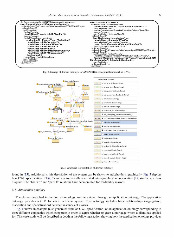
Fig. 2 shows an excerpt from the domain ontology definition for the conceptual domain model in OWL [42,30]: acooperative system is formed by a set of artifacts, events, groups, laws, etc.; a role is a set with at least one task; also,a role is part of an organization. Statements concerning this appear in bold-type.
The notion of class and relation is shared with that of UML. However, the treatment and modelling differ somewhat.For example, in UML, associations cannot be defined as standalone entities, while in OWL they are defined asinstances of a particular class called “Property”. In recent years there has been a lot of work concerning the mappingsbetween elements in both paradigms [38]. Further details and foundations of how this can be accomplished can be
J.L. Garrido et al. / Science of Computer Programming 66 (2007) 25–43 29
Fig. 2. Excerpt of domain ontology for AMENITIES conceptual framework in OWL.
Fig. 3. Graphical representation of domain ontology.
found in [13]. Additionally, this description of the system can be shown to stakeholders, graphically. Fig. 3 depictshow OWL specification of Fig. 2 can be automatically translated into a graphical representation [28] similar to a classdiagram. The “hasPart” and “partOf” relations have been omitted for readability reasons.
3.4. Application ontology
The classes described in the domain ontology are instantiated through an application ontology. The applicationontology provides a CIM for each particular system. This ontology includes basic relationships (aggregation,association and specialization) between instances of classes.
Fig. 4 shows an example (also generated from an OWL specification) of an application ontology corresponding tothree different companies which cooperate in order to agree whether to grant a mortgage which a client has appliedfor. This case study will be described in depth in the following section showing how the application ontology provides

30 J.L. Garrido et al. / Science of Computer Programming 66 (2007) 25–43
Fig. 4. Example of application ontology obtained from a domain ontology.
the basis for a different system representation more suitable for use in a software development process. Fig. 4 is anontology-based model which makes explicit the instances that form part of the proposed cooperative system accordingto the conceptual domain model of Figs. 1 and 3.
4. The UML-based cooperative model
4.1. Motivations and foundations
The ontologies introduced in the previous section serve as a formal substrate against which to validate the elementsto be added to the system description. The aim behind the development of groupware applications is to supportprocesses based on interactions between cooperating users.
From the point of view of the software development, as part of the requirement modelling, these interactionprocesses might be described using, for example, workflows and/or role models, and allow stakeholders and developersto discuss and negotiate requirements. In order to address these issues, a system model, called Cooperative Model(COMO), is proposed. This system model describes the system regardless of its implementation and therefore it alsoturns out to be another CIM called COMO-CIM.
Most of the interaction processes expressed in this system model are covered by the ontology-based CIMs ofSection 3, and the mutual correspondences are shown in the following subsections. However, more development-oriented aspects such as subactivity/action ordering (to be defined in tasks) and event sequence are not addressed inthe ontology-based CIMs. That is why the COMO-CIM is useful for specifying a system from the point of view ofits structure and behavior. The proposed COMO-UML notation [18] is based on UML state and activity diagrams(notations specially used for specifying software artifacts), and it is basically a graphical notation (operational) thatintegrates small declarative sections. Classes and associations in COMO-UML preserve the same semantics as inUML. The operational semantics for the COMO-UML notation using the CPN (Coloured Petri Nets) formalismis described in [19]. This semantics enables the verification of certain system properties (deadlocks, liveness,etc.).

J.L. Garrido et al. / Science of Computer Programming 66 (2007) 25–43 31
Table 1Correspondences between the ontology-based domain model elements and the COMO-UML elements
4.2. Method
In order to translate an application ontology into its corresponding COMO-CIM, which will be hierarchicallystructured, we propose a simple method based on the concepts and relationships of the domain ontology. This methodconsists of the four following steps: specification of the organization, role definition, task definition and specificationof interaction protocols. Only for the first step, the main correspondences between both types of CIMs are describedin detail.
4.2.1. Specification of the organizationThis reflects the organization structure and constraints on the actors’ behaviour. A company’s internal structure is
based on organizational roles that must be identified. In addition, in relation to coordination requirements, relevantrelationships between roles are identified on the basis of constraints imposed by company rules and/or goals.Laws represent these constraints that the organization imposes to control role changes. Laws may also interrogatecapabilities, which state skills/categories that actors have acquired. Both concepts are very helpful when definingand analyzing possible organization strategies (e.g. behaviour patterns) and group dynamics (representing groupbehaviour).
The previous domain ontology is reused in order to automatically generate this new representation. To achieve this,translation schemes between these different models must be clearly established. Table 1 shows some correspondencesrelated to the specification of the organization between the elements in both types of model.
All the classes in the OWL ontology are mapped onto classes of the COMO-UML notation. The OWL Roleclass is mapped onto the COMO-UML Role class. The same is for the class Law. Additional classes and relations(properties in the OWL jargon) must be defined with respect to the 3-ary association connect (two roles, source anddestination, and the law which governs the transition between them). This is because OWL language does not providethe necessary vocabulary so that n-ary relations may be defined [34]. In this case we have defined one fictitious class(RoleConnection Relation) and two fictitious properties (role value and connection law) which link the subject of therelation (the source role) with its objects (the target role and the law that rules the change).
4.2.2. Role definitionEach organization divides the workload among its members, whereas each role establishes a connection between
these and specific tasks (individual and/or cooperative). This step is intended to define each previous role by the set of

32 J.L. Garrido et al. / Science of Computer Programming 66 (2007) 25–43
Fig. 5. Organization diagrams.
tasks that can/must be performed. The tasks involved are specified by taking into account relevant requirements thatmight affect the participants’ behaviour. For instance, relevant information would be the event that triggers a task orinterrupts it when it is being performed (denoting task priorities).
4.2.3. Task definitionTasks define work that can be directly identified in relation to individual or group goals. In this step, each previously
specified task is broken down into related subactivities. They describe cognitive capabilities that participants need toaccomplish work. Each subactivity/action includes the specification of those responsible and optional roles needed toaccomplish it.
4.2.4. Specification of interaction protocolsIn this last step, the interaction protocols in the above task definition are described. In each non-structured
collaborative activity, the type of protocol used to accomplish this objective between participants is explicitly specified.The identification of such protocols is extremely helpful since they identify system requirements such as type ofcommunication required (synchronous and asynchronous) and type of communication channel (link, mailbox, etc.)for supporting collaboration.
4.3. Case study
We illustrate the previous method for obtaining the COMO-CIM using the above mentioned case study (i.e. threecompanies that cooperate in order to agree whether to grant a mortgage). This model stems from the applicationontology shown in Fig. 4 using the COMO-UML notation. Again, only for the specification of the organization, themain correspondences between the main elements are described in detail.
4.3.1. OrganizationsThe case study comprises three organizations: branch, valuation office and notary’s office. The organization
diagrams obtained are shown in Fig. 5.

J.L. Garrido et al. / Science of Computer Programming 66 (2007) 25–43 33
Table 2Specification of the organization (application ontology level)
For instance, the branch organization has three specialities: (bankManager, headOfRisk and teller) and one groupwith four members specified for each role as multiplicity value (one playing role bankManager, one playing theheadOfRisk role and two more playing the teller role). Initially, laws (identified as [<law>]) checking capabilities(identified as <capability>?), e.g. [bankManager?] determine the role that is played by each member accordingto his/her professional category, specialization, etc. Members may dynamically change roles that they play as aresult of various circumstances. One example of this requirement is that the organization imposes laws such as[Absent(bankManager)], i.e. the actor playing the role headOfRisk can become the bankManager if the manageris absent.
In relation to the correspondences between the conceptual domain elements and the COMO-UML elements(see Table 1), the Table 2 shows how it is specified that an actor playing the role headOfRisk may startplaying the role bankManager when the actor playing this last role is absent. This consists of a 3-ary relationcomprising the source role, the target role and the law which rules the transition. It can be identified as theelement roleConnection Relation 1, an instance of the fictitious class RoleConnection Relation (see Section 4.2.1). Itimplements the connection between the roles headOfRisk and bankManager through the fictitious relations role value,with the value bankManager, and connection law, with the value bankManagerAbsent. This constraint has also beenhighlighted in the graphical representation of the ontology-based application model (see Fig. 4).
4.3.2. RolesFig. 6 shows two obtained role definitions from the application ontology, i.e. the roles headOfRisk and valuer which
belong to different organizations, respectively, branch and valuationOffice. The common task they are all involved inis the cooperative task mortgageGranting. This form of specification allows us to associate different context elements(events, actions, number of members) for each role involved in the same task. In this example, all roles (includingthis task) specify that no explicit event is required to be triggered, but at the same time, the organization requiresthat first, the mortgage has been applied for (law [mortgageApplied]), so that the task can be started. In addition,

34 J.L. Garrido et al. / Science of Computer Programming 66 (2007) 25–43
Fig. 6. Role diagrams.
for the role headOfRisk, when task mortgageGranting is being performed, it could be interrupted if a new clientarrives at the office (individual task serveClient). The number of members required for the same cooperative task isspecified with the multiplicity value associated with each occurrence of that task for each role (one headOfRisk and onevaluer).
4.3.3. TasksAs an example of mapping between models, Fig. 7 shows the task mortgageGranting. Since this is a cooperative
task requiring more than one participant to accomplish it, it specifies that a collaboration requirement be satisfied.The COMO-UML notation enables us to specify temporal-ordered constraints of subactivities/actions by means ofsequential (arrows) and concurrent (thick bars) constructions. Bifurcations (labelled with a diamond) denote a decisionpoint. The current ontology-based models do not address the specification of this kind of information.
A subactivity is to be described in more detail. This notation assigns roles to subactivities/actions. Eachsubactivity/action includes the specification of those responsible roles needed to accomplish it. Task definition mayalso include relevant requirements about the task:
• information to be needed and used, even in a required status (e.g. valuationReport)• coordination mechanisms• organization politics (decision making, protocols, workload, etc.).
4.3.4. Interaction protocolsIn order to carry out non-structured work, the interaction protocols between participants must be identified and
associated to the corresponding subactivities. The role specification for each subactivity/action may comprise one ofthe following operators: optionally ([]), addition (+), inclusive-OR (|) and exclusive-OR (X ). For instance, in Fig. 7a decision-making (subactivity decideConcession) is performed by both the bankManager and headOfRisk. For this,they use a conversational protocol, face-to-face (synchronous communication) and a shared workspace where requiredinformation is available.
5. A systematic development process
In order to reach the objective of stating clear connection between previous CIMs and software models, this sectionproposes the MDA-based development process for groupware applications. It is made concrete defining specific MDAartifacts to be applied.
5.1. General scheme
The development process is depicted in Fig. 8, which is described below according to its correspondence withphases in a general software development process [10,47]. This process includes in its early phases the previouslyintroduced CIM models, and in subsequent phases, connections with architectural software models already applied toreal developments of groupware applications [21].

J.L. Garrido et al. / Science of Computer Programming 66 (2007) 25–43 35
Fig. 7. Task diagram.
5.1.1. Requirements engineeringRequirements engineering is defined as “a systematic process of developing requirements through an iterative,
cooperative process of analyzing the problem, documenting the resulting observations in a variety of representationformats, and checking the accuracy of the understanding gained” [43]. Certain stages of the process such as analysis,viability and modelling, should provide a full description of requirements, including functional and non-functionalrequirements to be satisfied. Requirements engineering also embraces the development of abstract system models(like part of a detailed system specification) [33].
The starting point for this phase is the domain ontology described in Section 3. This model is assumed as the firstCIM in the process whose instances are defined as application ontologies. The development of the models to be builtin subsequent phases stems from the translation of each particular application ontology into an MOF-compliant model(i.e. the UML-based cooperative model introduced in Section 4). This is accomplished by the definition of a UMLprofile for standardizing the COMO-UML notation used. Although the resulting model continues to be another CIMmodel, this translation enables us to connect easily system models with software development models [8], since theselast models might use the UML standard modelling language [16]. The output of this requirement phase will be a CIM,above called COMO-CIM. Since this CIM is a system model centred on specifying functional requirements, it includesparts to be identified directly with cooperative processes which must be supported by groupware applications/tools.

36 J.L. Garrido et al. / Science of Computer Programming 66 (2007) 25–43
Fig. 8. MDA scheme for developing groupware applications.
5.1.2. Architectural designAn architectural design is defined [45] as the design of “the overall structure of the software and the ways in
which that structure provides conceptual integrity for the system”. The design of this architecture “occupies a pivotalposition in software engineering” [12]. An architectural design [26] might specify the following basic elements:subsystems, components, interactions, ports, etc. Subsequently, architectural design is the next phase to address inthe development process. In this way, the COMO-CIM must then be marked by taking into account an abstract PDM(Platform Description Model) [6] in order to provide a logical view for the architectural design [21].
This marking phase allows us to link domain elements (roles, cooperative tasks, etc.) represented in the COMO-CIM with architectural software elements. For example, let us consider information about the role (bankManager) thatan actor must play in order to carry out the specific subactivity of approving the granting of a mortgage (giveApproval).This would result in a requirement to be satisfied by a groupware application if its software implementation isrequired. The resulting PIM (Platform Independent Model) [2] is stereotyped as <<marked>> and named COMO-PIM (COoperative MOdel-Platform Independent Model). This PIM represents architectural design aspects such aswhat subsystem will be in charge of implementing previous functional requirement.
5.1.3. Detailed design and implementationThe following step corresponds with a detailed design phase since architectural PIMs even exclude platform-
specific details. Therefore, another marking step (according to specific PDM) is required in order to obtain a PSM. Forexample, an implementation of a groupware application using a Jini platform [21] must add the marks corresponding

J.L. Garrido et al. / Science of Computer Programming 66 (2007) 25–43 37
Table 3AMENITIES Profile: Stereotypes
Amenities diagram type Stereotype UML metaclass (base) Parent
Organizations
OrganizationSpec StateMachine N/ARole State N/AComputerRole State RoleLaw Constraint N/ABA Transition Transition N/ATask State N/ACoop-Task State TaskAME Action Activity N/A
Task, sub-activities and interactions
ResponsableSpec Class N/AUnitOfWork ExecutableNode N/AAME SubActivity ExecutableNode UnitOfWorkAME Action ExecutableNode UnitOfWorkLocalCondition Class N/ATeam Class N/ARoleBinding Class N/ACommunication Req Class N/AInteraction ProtocolSpec Class N/A
to the Jini [46] architectural paradigm, such as “services”, “leasing”, “principals”, or “events”. Finally, this PSMshall be used to generate groupware applications. This result is called by some authors [4,8] as Platform SpecificImplementation (PSI).
The system could be implemented in any other specific platform because MDA process would allow generatingdifferent PSMs depending on each final implementation platform. In addition, as MDA promotes, it is possible torestart this process at any phase using the corresponding generated model.
5.2. MDA artefacts
For standardization of the COMO-CIM we have chosen profiling as an alternative in order to extend UMLmetamodels. This is because it is a simple, direct and effective mechanism for capturing domain specific characteristicsin the form of models [2,8]. The profile is based on UML 2.0 Superstructure [40] and it has been divided into threegroups of use on the basis of the main diagrams provided by the COMO-UML notation:
– Organizations (specification of organizations, bidirectional and additive transitions, etc.)– Roles (cooperative tasks, events, etc.)– Tasks, subactivities and interactions (subactivity, units of work, communication requirements, etc.).
Tables 3 and 4 are respectively, a summary of the main stereotypes and tagged values defining this profile.Fig. 9 shows the relationships between the profile and the UML metamodel packages [40]:
• The Kernel, “represents the core modelling concepts of the UML, including classes, associations and packages”.InformationObject, Capacity and Law stereotypes are based on this package.
• The PrimitiveTypes “have been defined for use in the specification of the UML metamodel. These include primitivetypes such as Integer, Boolean and String”. We have used these for tagged values (e.g. the IsInterruptByAny andIsAdditive booleans).
• The BasicActivities, “supports modelling of traditional sequential flow charts. It includes control sequencing”.Additionally, IntermediateActivities provides concurrent control and data flow (e.g. JoinNode, ForkNode) andStructuredActivities, i.e. the traditional structured programming constructs (e.g. ConditionalNode, LoopNode).
• Communications, BasicBehaviours and BehaviourStateMachines introduce the different mechanisms to specifybehaviours such as automata and Petri-net. For example, the BehaviourStateMachines package provides keyelements like StateMachine, State and Transition which are the basis for OrganizationSpec, Role and BA Transitionstereotypes.

38 J.L. Garrido et al. / Science of Computer Programming 66 (2007) 25–43
Table 4AMENITIES Profile: Tagged values
Amenities diagram type Tag Stereotype Type Multiplicity
OrganizationsMultiplicity Role Multiplicity 1IsBidirectional BA Transition Boolean 1IsAdditive BA Transition Boolean 1
Roles
Multiplicity Coop-Task Multiplicity element 1IsInterrupt ByAny Interruptible-Task Bolean 1Interruptby set Interruptible-Task Task 0..nActions InformationObject AME Action 0..nInformation AME Action InformationObject 1..n
Task, sub-activities and interactions
Makes ResponsableSpec UnitOfWork 1..nComment UnitOfWork Comment 1Responsables UnitOfWork ResponsableSpec 0..nCommRequires Team CommunicationReq 1..n
Fig. 9. Relation between Amenities Profile and UML 2.0 packages.
As defined by MDA, the transformation between models (i.e. from CIM to PIM, and from PIM to PSM) needsthe source model to be marked according to the mapping defined for the target model [36]. Then, once thisprofile has been defined, we establish their correspondence with a software architectural model that is technologyindependent and specially devised for developing groupware applications. This architectural design proposal promotesthe division/partitioning of the whole system into components (called subsystems) to facilitate its development,evolution and maintenance [21] (see Fig. 10). The Identification (users’ access control), Metainformation (metadatamanagement) and Awareness (contextual information) subsystems are always present for every groupware application.The application subsystem is obviously specific and is to be developed for each particular groupware application.
Table 5 shows basic mappings from some elements of Amenities Profile (for CIMs) and this target architecture(for PIMs). Concretely, Role and AME subactivity stereotypes, respectively representing organizational and activityconcerns, are considered to be translated into crucial architectural elements like components and subsystems.
With this mapping, a software architect can take the appropriate design decisions in order to accommodate thedomain requirements and architectural restrictions [14]. We make it by means of properties such as Arch name,to name the target element to generate, and Subsystem type to indicate where to locate the element within a finalsystem subdivision. In addition, several transformations could be automatic. This is the case for the Role to Classmapping which forces the obtained class to be encapsulated within the MetaInformation subsystem. In this way, thissubsystem would be in charge of storing certain information specified for the system (possible roles to be played, lawsconstraining role changes, etc.) and supports all the functionality for managing metadata (new roles acquired, lawsapplied by the organization, etc.).

J.L. Garrido et al. / Science of Computer Programming 66 (2007) 25–43 39
Fig. 10. Architecture for groupware application: component view.
Table 5Example of mapping from CIM to PIM
Stereotype/Metamodelelement
Added at Target architectural element Map comment See associated properties
Role CIM <<Class>> The <<subsystem>>
component containingthis element will be“MetaInformation”
Arch name
AMEsubactivity CIM N/A The <<subsystem>>
component containingthis element will be inthe set: (Identification,
Awareness,Application)
Subsystem Type, Arch name
Arch name(property)
CIM to PIMmapping
If subsystem type notin (“Identification”,
“Awareness”,“MetaInformation”)
gives the value ofattribute “name”, else
nothing.
It defines the name ofthe target architectural
element.
Subsystem type(property)
CIM to PIMmapping
If subsystem type in(“Identification”,
“Awareness”,“MetaInformation”)
gives the value ofattribute “name”.
It defines the name ofthe target architectural
element.
5.3. Applying MDA to the case study
An example of use of this profile for the roles and transitions in the organization valuationOffice is shown in Fig. 11.It should be noted that the characteristics which are not present in UML, such as additive transitions, are obtained bymeans of tagged values such as IsBidirectional and IsAdditive. It is worth mentioning how the lack of current industryprofiles covering all of these topics due to their more general aim (e.g. the EDOC Profile) made it necessary to adoptan ad hoc proposal for CSCW systems.
Then, considering this valuationOffice organization from the COMO-CIM and using the mapping (see Table 5) tothe software architecture, the Director and Valuer roles would be transformed into two classes (entities belonging tometaInformation subsystem) with the same names by setting its Arch name property.
We also show how we have addressed the specification of mortgageGranting cooperative task (see Fig. 7).Elements like decideConcession, giveApproval and prepareDocuments subactivities, which can’t be translatedautomatically to an architecture, must be marked (see Fig. 12) with Subsystem type property in order to decide

40 J.L. Garrido et al. / Science of Computer Programming 66 (2007) 25–43
Fig. 11. valuationOffice organization instance: stereotypes values within COMO-CIM.
Fig. 12. Stereotyped subactivity instances after an architectural marking step.
whether they belong to a general purpose subsystem like Identification and Awareness or to a concrete Applicationsubsystem. In this case, the two first subactivities could have been marked with Subsystem type=“Application” andArch name=“DecisionSupport” meaning its functionality would be included in the same Application subsystem.This facilitates the coordination in order to reach the needed decisions by means of a shared workplace, for instance.The architect can decide that the third subactivity prepareDocument would be supported by means of a single-userpublication tool. Thus, the marking would differ in Arch name property, for example with “IndividualEditor” as value.
Once every relevant element has been marked (if not automatic mapping associated) to pass into the next phase,those marks would be processed in order to compose the corresponding target model (Architectural-PIM).
The next step, “detailed design and implementation”, continues in the same way to complete the developmentprocess. We have achieved successful experiences by using the data-driven programming model provided by theJavaSpaces technology (based on Jini [46] and which implements the Linda coordination model [9]): a collaborativeappointment book application for groupwork has been implemented [21]. There exist several similar experiences,which resolve these steps with other technological platforms (e.g. by using CORBA [32]).
6. Future work
Future work is targeted in four directions to complete the current proposal on the basis of its main weak points. Thefirst target is improving CIMs in order to achieve an automatic translation between ontology-based and UML-basedCIMs. For example, to enable the specification of temporal-ordered constraints of subactivities/actions in ontology-based CIMs. Currently this is only supported in UML-based CIMs. Some properties and expressive power of theUML-based cooperative model, such as those concerning task and event sequence, are not present in our domain andapplication ontologies and must be described in a more specific task ontology. Moreover, another approach would beto address the development phase connecting the ontologies with the software architecture directly.
Second, we consider EDOC in architectural and detailed design phases. This OMG proposal “simplifies thedevelopment of enterprise distributed component-based systems by means of a modelling framework conforming

J.L. Garrido et al. / Science of Computer Programming 66 (2007) 25–43 41
Table 6Architecture for groupware and EDOC
Our architectural proposal for groupware EDOC Aspects
Yes Yes PIM orientedNo Yes (e.g. FCM, J2EE, CORBA) (PSM) technology mappingsYes Yes Component-basedYes Yes RM-ODP computational viewpointNo Yes (ECA entities profile) RM-ODP information viewpointYes (identification, awareness and metainformation subsystems) No CSCW orientedNo Yes (OMG’s) Standard
to MDA” [35]. The EDOC Profile provides a set of profile elements whose core is a technology independentprofile, the Enterprise Collaboration Architecture (ECA) [41]. Seven significant aspects lead us to consider EDOCas one interesting alternative. Table 6 shows a comparative between the architectural proposal for groupware (usedin Section 5.2) and EDOC. Note that the standardization is a strong point in EDOC since it uses the conceptualframework provided by the Reference Model of Open Distributed Processing (RM-ODP) [27]. However, EDOC aimsfor universality so that it lacks specific groupware-oriented artefacts, unlike our proposal.
Third, the aim is clearly to identify the requirements of the system so that it can follow the life of each requirement,in both a forwards and backwards direction in order to maintain an adequate requirements traceability.
Finally, we plan to incorporate quality evaluation in our proposal. To achieve this goal, it is necessary to identifythe key issues in both development and evaluation processes in order to provide criteria that allow selection techniquesto be applied.
7. Conclusions
In this paper, we have addressed the issue of connecting enterprise models to software models. A conceptualdomain model has been formalized using ontology-based models. This conceptual domain model provides a commonvocabulary of concepts and relations to be used in the specification of some aspects present in enterprise models. Inaddition, using ontologies enables changes in the description of a class to be documented (i.e. if it is incompatiblewith a previous version) and to state the mappings between the classes described in different models (i.e. if they areequivalent, disjoint, etc.). While the first is useful for questions of maintenance and evolution, the second is usefulfor questions of reuse and interoperability. At the same time, the underlying application ontology helps validate thesystem.
In order to translate the ontology-based models into system models which enable functional requirements of thesoftware to be developed, a correspondence between the elements in the different types of models has been defined.The system model represents the system on the basis of its structure and behaviour. The expressive power of theused notation (COMO-UML), promoting participatory design, makes it easy for stakeholders to be involved in therequirement negotiation process. Several approaches and standards, such as BPMN (Business Process ModelingNotation), UML and so forth, have been proposed for business process modelling from the business analyst’s pointof view [22]. In particular, BPMN defines a BPD (Business Process Diagram) slanted to workflow descriptions formodelling private and collaborative (B2B) business processes [29]. In comparison with the COMO-UML and theseother notations, the former additionally includes other modelling aspects [18]:
• Dynamic changes related to some classes in the problem domain, for example, the role played by an actormay change throughout a real situation and can be specified using the COMO-UML organization diagrams (seeSection 4.3.1).
• Advanced specification (using operators such as optionally, exclusive-or and so forth) of different roleresponsibilities or functional capabilities in performing subactivities/actions. This is an extension to BPD andUML swimlanes (see Section 4.3.4).
• The possibility of specifying that tasks may be interrupted and which the interruptible tasks are. It influences howan actor is involved in concurrent work.
42 J.L. Garrido et al. / Science of Computer Programming 66 (2007) 25–43
• Use of interaction protocol for specifying main interaction characteristics between actors that collaborate byperforming non-structured work. These characteristics help to determine requirements for particular tools to beused in supporting collaboration processes (see Section 4.3.4).
Finally, likewise BPML (Business Process Modeling Language) by BPMN and other competing standards such asBPEL4WS (Business Process Execution Language for Web Services), in our case a concrete MDA-based developmentprocess has been introduced intended to support the generation of required groupware applications in a softwaredevelopment process. As far as this process is concerned, a conceptual framework is the starting point for creating twotypes of CIMs with different objectives. The formalization of the conceptual model itself is the first CIM. The finalobjective of this process is to state clear connections between the different parts of these CIMs models and softwaremodels which would fulfil specified requirements. For that purpose, several MDA artifacts have been created (a UMLprofile) and used (a groupware architecture, specific development platforms such as JavaSpaces, etc.). The profilehas been defined for a UML-based notation called COMO-UML and used to create an MDA-compliant CIM model.In other words, the UML language is extended to a CSCW domain specific modelling language; in [16] a method isdescribed in order to restrict the syntax of UML for domain modeling. We argue that this proposal also helps to reducethe gap between requirement modelling and the subsequent software implementation because the same language isused to model the CSCW system as well as the software in it. Benefits have also become apparent from the experienceacquired in the development of real groupware applications. However, the process has not been applied strictly due tothe lack of CASE tools (still not developed).
Acknowledgement
This research is partially supported by the R+D project TIN2004-08000-C03-02 of the Spanish MCYT.
References
[1] J. Aagedal, I. Solheim, New roles in model-driven development, in: 2nd European Workshop on MDA, Technical Report No. 17-04, September2004.
[2] M.S. Abdullah, A. Evans, I. Benest, C. Kimble, Developing a UML profile for modelling knowledge-based systems, in: Proceedings ofModel-Driven Architecture: Foundations and Applications, MDAFA 2004, 2004, pp. 202–216.
[3] L.F. Andrade, J.L. Fiadeiro, Agility through coordination, Information Systems 27 (2002) 411–424.[4] J.P.A. Almeida, L. Ferreira Pires, M. van Sinderen, D. Quartel, A Systematic approach to platform-independent design based on the service
concept, In: Proceedings Seventh IEEE International Conference on Enterprise Distributed Object Computing, EDOC 2003, Brisbane,Australia, September 2003, pp. 112–123.
[5] F. Baader, D. Calvanese, D. McGuineness, D. Nardi, P. Patel-Schneider, The Description Logic Handbook, Cambridge University Press, 2003.[6] A. Belangour, J. Bezivin, M. Fredj, Towards Platform Independence: a MDA Organization, INRIA ATLAS de l’Universite de Nantes, France,
LGI-ENSIAS Rabat, Maroc, 2002.[7] R. Bendraou, P. Desfray, M.P. Gervais, MDA components: A flexible way for implementing the MDA approach, in: ECMDA-FA 2005,
in: LNCS, vol. 3748, 2005, pp. 59–73.[8] T. Bloomfield, MDA, Meta-modelling and model transformation: Introducing new technology into the defence industry, in: ECMDA-FA
2005, pp. 9–18.[9] N. Carriero, D. Gelernter, Linda in context, Communications of the ACM 32 (4) (1989) 444–458.
[10] J. Castro, M. Kolp, J. Mylopoulos, Towards requirements-driven information systems engineering: The TROPOS project, Information Systems27 (2002) 365–389.
[11] H.-M. Chen, R. Kazman, A. Garg, BITAM: An engineering-principled method for managing misalignments between business and ITarchitectures, Science of Computer Programming 57 (2005) 5–26.
[12] L. Chung, D. Gross, E. Yu, Architectural design to meet stakeholder requirements, in: P. Donohue (Ed.), Software Architecture, KluwerAcademic, San Antonio, TX, 1999, pp. 545–564.
[13] D. Djuric, MDA-based ontology infrastructure, Computer Science and Information Systems (ComSIS) 1 (1) (2004) 91–116.[14] M. Eichberg, MDA and programming languages, in: J. Bettin, G. van Emde Boas, C. Cleaveland, K. Czarnecki (Eds.), Workshop Generative
Techniques in the Context of Model-driven Architecture, OOPSLA 2002, November, 2002.[15] C.A. Ellis, S.J. Gibbs, G.L. Rein, Groupware: Some issues and experiences, Communications of the ACM 34 (1) (1991) 38–58.[16] J. Evermann, Y. Wand, Toward formalizing domain modeling semantics in language syntax, IEEE Transactions on Software Engineering 31
(1) (2005).[17] M.S. Fox, M. Gruninger, On ontologies and enterprise modelling, in: Proceedings of the International Conference on Enterprise Integration
Modelling Technology 97, Springer Verlag, 1997.[18] J.L. Garrido, Especificacion de la notacion COMO-UML, Tech. Rep. No. LSI-2003-2, Granada, Spain, University of Granada, Departamento
de Lenguajes y Sistemas Informaticos, 2003.

J.L. Garrido et al. / Science of Computer Programming 66 (2007) 25–43 43
[19] J.L. Garrido, M. Gea, A Coloured Petri Net formalisation for a UML-based notation applied to cooperative system modeling, in: P. Forbrig,et al. (Eds.), Interactive Systems — Design, Specification and Verification, in: LNCS, vol. 2545, Springer, 2002, pp. 16–28.
[20] J.L. Garrido, M. Gea, M.L. Rodrıguez, Requirements engineering in cooperative systems, in: Requirements Engineering for SociotechnicalSystems, Idea Group, Inc., USA, 2005 (Chapter XIV).
[21] J.L. Garrido, P. Padereswki, M.L. Rodrıguez, M.J. Hornos, M. Noguera, A software architecture intended to design high quality groupwareapplications, in: Proc. of the 4th International Workshop on System/Software Architectures, IWSSA’05, Las Vegas, USA, June 2005.
[22] P. Green, M. Rosemann, M. Indulska, C. Manning, Candidate interoperability standards: An ontological overlap analysis, Data KnowledgeEngineering (2006), doi:10.1016/j.datak.2006.08.004.
[23] S. Greenberg, Computer-Supported Cooperative Work and Groupware, Academic Press Ltd., London, UK, 1991.[24] M. Gruninger, K. Atefi, M.S. Fox, Ontologies to support process integration in enterprise engineering, Computational and Mathematical
Organization Theory 6 (4) (2000) 381–394.[25] N. Guarino, Formal ontology and information systems, in: N. Guarino (Ed.), Proceedings of FOIS’98, Trento, Italy, June, 1998, IOS Press,
Amsterdam, 1998, pp. 3–15.[26] C. Hofmeister, R.L. Nord, D. Soni, Describing software architecture with UML, in: Proceedings of the First IFIP Working Conference on
Software Architecture, WICSA1, San Antonio, TX, February 1999.[27] ISO/IEC 10746-1, 2, 3, 4 | ITU-T Recommendation X.901, X.902, X.903, X.904, “Open Distributed Processing - Reference Model”, OMG,
1995–1998.[28] Jambalaya 2.2.0 build 15 2005/07/07 15:04, The Jambalaya Project, More info at http://www.thechiselgroup.org/jambalaya.[29] J.Y. Jung, H. Kim, S.H. Kang, Standards-based approaches to B2B workflow integration, Computers & Industrial Engineering 51 (2) (2006)
321–334.[30] H. Knublauch, R.W. Fergerson, N.F. Noy, M. Musen, The Protege OWL Plugin: An open development environment for semantic web
applications, in: LNCS, vol. 3298, 2004, pp. 229–243.[31] I. Lera, C. Juiz, R. Puigjaner, Performance-related ontologies and semantic web applications for on-line performance assessment of intelligent
systems, Science of Computer Programming 61 (2006) 27–37.[32] R. Maciel, et al., An MDA domain specific architecture to provide interoperability among collaborative environments, in: 19◦ Brazilian
Symposium on Software Engineering, 2005.[33] L.A. Macaulay, Requirements Engineering, Springer, 1996.[34] N. Noy, A. Rector, Defining n-ary relations on the semantic web, Editor’s draft 7 September 2005.
http://smi-web.stanford.edu/people/noy/nAryRelations/n-aryRelations-2nd-WD.html.[35] Object Management Group (OMG): UML Profile for Enterprise Distributed Object Computing (EDOC), OMG Document ptc/02-02-05, 2002.[36] Object Mangagement Group: Model Driven Architecture (MDA) Guide, v1.0.1, OMG, omg/03-06-01.[37] Object Management Group: Meta Object Facility (MOF) specification. OMG Document formal/2002-04-03.[38] Object Management Group: Ontology Definition Metamodel (ODM). Sixth revised submission to OMG/ RFP ad/2003-03-40, document/05-
08-01.[39] Object Management Group: Software Process engineering metamodel v1.1 (SPEM), formal/05-01-06, January 2005.[40] Object Management Group: Unified Modelling Language (UML) 2.0 Superstructure Specification, August 2003. Ptc/03-08-02, pp. 455–510.[41] Object Management Group (OMG): UML Profile for ECA v1.0. formal/04-02-05, February 2004.[42] M.K. Smith, C. Welty, and D.L. McGuinness, (Eds.), OWL Web Ontology Language Guide, W3C Recommendation, 10 February 2004,
http://www.w3.org/TR/2004/REC-owl-guide-20040210/. Latest version available at http://www.w3.org/TR/owl-guide/.[43] K. Pohl, The three dimensions of requirements engineering, in: Proc. 5th Int. Conf. of Advanced Information Systems Engineering 1993,
Paris, Springer, Berlin, 1993, pp. 275–292.[44] G. Klyne, J. Carroll (Eds.), Resource Description Framework (RDF): Concepts and abstract syntax, W3C Recommendation, 10 February
2004, http://www.w3.org/TR/rdf-concepts/.[45] M. Shaw, D. Garlan, Formulations and formalisms in software architecture, in: J. van Leeuwen (Ed.), Computer Science Today: Recent Trends
and Developments, in: Lecture Notes in Computer Science, vol. 1000, Springer-Verlag, Berlin, 1995.[46] Sun Microsystems: Jini Network Technology. http://www.sun.com/software/jini/index.html.[47] C.R. Turner, A. Fuggetta, L. Lavazza, A.L. Wolf, A conceptual basis for feature engineering, The Journal of Systems and Software 49 (1999).[48] D.C. Fallside, (Ed.), XML Schema Part 0: Primer, W3C, 2 May 2001. See http://www.w3.org/TR/2004/REC-xmlschema-0-
20041028/primer.html.