
Deen Dayal Upadhyaya College
57
DEEN DAYAL UPADHYAYA COLLEGE (UNIVERSITY OF DELHI) Sector 3, Dwarka, NEW DELHI-110078 Telephone Nos.: 011-25090381, 25099380 http://www.dducollegedu.ac.in TENDER DOCUMENT Ref. No.: DDUC/Tender/2017/1 Dated: 2/1/2017 The Deen Dayal Upadhyaya College invites sealed tenders/bids/quotations from reputed Original Equipment Manufacturers (OEM) or Authorized Distributors of OEM for the supply and installation of Sports equipment‟s for college gymnasium, and the Scientific Instruments/ items required for the laboratories of Department of Physics, Electronics, Chemistry, and Botany. (Schedule of Tender) Attach a DD/Pay order for Rs.500/- favouring, Principal Deen Dayal Upadhyaya College, towards the cost of tender document (along with Technical bid) The tenders must reach the Section Officer (Administration Section), Room No. 20, Ground Floor, Deen Dayal Upadhyaya College Sector 3, Dwarka, New Delhi-110078 by 11:30 AM, 27 th January, 2017 (Friday) during office hours. Date of Issue of tender document 2 th January 2017 (Monday) Ref. No. of this tender DDUC/Tender/2017/1 Tender Submission Dates All working days from 4 th January 2017 to 25 th January, 2017 (Wednesday) during office hours (9:00 AM to 5:00 PM) and/or on 27 th January, 2017 (Friday) (From 9:00 AM to 11:30 AM) Last Date and Time for submission of tender 27 th January, 2017 (Friday) by 11:30 AM Availability of tender document The College website http://www.dducollegedu.ac.in Date, Time & Venue of Technical Bid Opening 27th January, 2017 (Friday) at 12:30 PM in the Room No. 313, 3rd Floor, Deen Dayal Upadhyaya College Sector 3, Dwarka, New Delhi-110078 Address for Communication and submission of Tender Document Principal, Deen Dayal Upadhyaya College, Sector 3, Dwarka, New Delhi-110078
-
Upload
khangminh22 -
Category
Documents
-
view
8 -
download
0
Transcript of Deen Dayal Upadhyaya College
DEEN DAYAL UPADHYAYA COLLEGE (UNIVERSITY OF DELHI)
Sector 3, Dwarka, NEW DELHI-110078
Telephone Nos.: 011-25090381, 25099380 http://www.dducollegedu.ac.in
TENDER DOCUMENT
Ref. No.: DDUC/Tender/2017/1 Dated: 2/1/2017
The Deen Dayal Upadhyaya College invites sealed tenders/bids/quotations from
reputed Original Equipment Manufacturers (OEM) or Authorized Distributors of
OEM for the supply and installation of Sports equipment‟s for college
gymnasium, and the Scientific Instruments/ items required for the laboratories of
Department of Physics, Electronics, Chemistry, and Botany.
(Schedule of Tender)
Attach a DD/Pay order for Rs.500/- favouring, Principal Deen Dayal Upadhyaya College, towards the cost of tender document (along with Technical bid) The tenders must reach the Section Officer (Administration Section), Room No. 20, Ground Floor, Deen Dayal Upadhyaya College Sector 3, Dwarka, New Delhi-110078 by 11:30 AM, 27
th January, 2017 (Friday) during office hours.
Date of Issue of tender document 2th
January 2017 (Monday)
Ref. No. of this tender DDUC/Tender/2017/1
Tender Submission Dates All working days from 4th
January 2017 to 25th
January,
2017 (Wednesday) during office hours (9:00 AM to 5:00
PM) and/or on 27th
January, 2017 (Friday) (From 9:00
AM to 11:30 AM) Last Date and Time for submission of tender
27th
January, 2017 (Friday) by 11:30 AM
Availability of tender document The College website http://www.dducollegedu.ac.in
Date, Time & Venue of Technical Bid Opening
27th January, 2017 (Friday) at 12:30 PM in the Room No. 313, 3rd Floor, Deen Dayal Upadhyaya College Sector 3, Dwarka, New Delhi-110078
Address for Communication and
submission of Tender Document
Principal, Deen Dayal Upadhyaya College,
Sector 3, Dwarka, New Delhi-110078
2
Terms and Conditions of the Tender
1. Eligibility Criteria
• The vendor should have reputed background and should be established in the business
for at least 5 years. The turnover of the vendor should be at least Rs.1 Crore during the
three years out of the last five years.
• Vendor must be a registered corporate entity in India. In case of companies incorporated
outside India, they should mention an authorized service entity that would provide post
purchase services on behalf of its principal.
• Vendor should have been making profits during at least 3 years out of last 5 years.
Audited Balance sheet and Profit and Loss account (amount in Rupees) for last three
years should be submitted. In addition, The College may ask for Income Tax Returns of
the vendors if it deems necessary.
• Vendor should have executed at least 3 projects in the last five years for the equipment
quoted to the Universities, Research Institutes or Colleges of repute in the Country.
Documentary evidence is to be submitted for these 3 projects with contact details,
name, Tel Nos. and Fax. Nos. of the previous customers. A complete list of all other
places where similar systems have been supplied by the vendor is also preferred.
2. Two Bid System Tender
Separate Technical and Commercial Bids duly sealed and super-scribed ''Quotations for
Refer Annexure VIII-A to Annexure VIII-E'' shall be submitted. Our Reference Number and date should be written on the envelopes.
1. ''Technical and commercial Bids'' to be submitted in separate sealed envelopes.
Both the- envelops must be enclosed in a single big sealed envelope. Each one of
the-envelops should be super-scribed with our reference number and due date given
above along with the product name. 2. The technical bids will be opened individually, and examined for short listing the
vendors, and the commercial bids of only those vendors who have qualified technically will be opened and compared.
The tender not submitted in the prescribed formats or incomplete in detail is liable for
rejection. The Deen Dayal Upadhyaya College1 is not responsible for non-receipt of
quotation within the specified date and time due to any reason including postal holidays
or delays.
ENVELOPE I (Technical Offer): The Technical offer should be complete in all respects and contain all information asked for, except prices. The Technical offer should include all details of specifications asked for in Annexure VIII A to VIII E. For example, Technical Offer should mention that 3 Years Warranty Period is included in the Commercial offer, without mentioning the actual amounts in the Technical offer. The suggested format for submission of technical offer is as follows:
1 For the purposes of this Tender document the phrase “The College” means “Deen Dayal Upadhyaya College”.
3
• All documents & certificates listed under ''Eligibility Criteria'' on page No. 2 of this
tender document to be attached by the Vendor.
• Covering letter as per Annexure I
• Earnest Money Deposit (EMD) DD/Pay order and details as per Annexure-II
• Attach a DD/Pay order for Rs.500/- favouring, Principal Deen Dayal Upadhyaya
College, towards the cost of tender document and details as per Annexure-II
• Manufacturer's Authorization Form (if applicable) as per Annexure III
• The Company profile as per Annexure IV and Annexure IVA
• Details of 3 major projects / Colleges/ Universities/ Research Institutes, as per
Annexure V
• Details of Support / Service Centers as per Annexure VI
• Vendor's Financial Details (audited balance sheets etc.) and other supporting
documents, as asked in the tender document.
• Warranty compliance statement in Annexure VII
• Technical Offer for the listed items and instruments given in Annexure VIIIA to
VIIIE with all the columns filled in. This should not contain any price information.
Each of the Annexures VIII A to VIII E and its details are to be bundled / stapled
separately.
• Deviation table as per Annexure IX and Annexure IXA.
• Technical Documentation (Printed product Brochures and all technical leaflets, etc.) to
be attached compulsorily with the Technical offer.
ENVELOPE II (Commercial Offer):
The Commercial Offer (C.O) should give all relevant price information as per Annexure X.
The Bid Form must be filled in completely, without any errors, erasures or alterations. The
Commercial offer must not contradict the technical offer in any way.
3. Documentation
The vendor shall furnish, as part of its tender offer, documents establishing the vendor's
eligibility to participate in the tender and its qualifications to perform the Contract. The
documentary evidence of the vendor's qualifications to perform the Contract, shall establish to
The College's satisfaction that the vendor is eligible as per the criteria outlined in the Eligibility
Criteria at Clause 1 on page 2.
4. Nontransferable Tender
This tender document is non-transferable. Any change in the constitution of the firm, etc. shall
be notified forthwith by the contractor in writing to the tendering authority and such change
shall not relieve any former member of the firm, etc., from any liability under the contract.
No new partner / partners shall be accepted in the firm by the contractor in respect of the contract unless he / they agree to abide by all its terms and conditions, and deposits with the tendering authority a written agreement to this effect. The contractor's receipt for acknowledgement or that of any partners subsequently accepted as above shall bind all of them and will be sufficient discharge for any of the purpose of the contract.
4
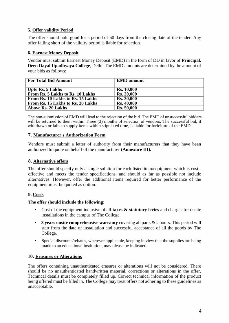
5. Offer validity Period
The offer should hold good for a period of 60 days from the closing date of the tender. Any
offer falling short of the validity period is liable for rejection.
6. Earnest Money Deposit
Vendor must submit Earnest Money Deposit (EMD) in the form of DD in favor of Principal,
Deen Dayal Upadhyaya College, Delhi. The EMD amounts are determined by the amount of
your bids as follows:
For Total Bid Amount
EMD amount
Upto Rs. 5 Lakhs Rs. 10,000 From Rs. 5 Lakhs to Rs. 10 Lakhs Rs. 20,000 From Rs. 10 Lakhs to Rs. 15 Lakhs Rs. 30,000 From Rs. 15 Lakhs to Rs. 20 Lakhs Rs. 40,000 Above Rs. 20 Lakhs Rs. 50,000 The non-submission of EMD will lead to the rejection of the bid. The EMD of unsuccessful bidders will be returned to them within Three (3) months of selection of vendors. The successful bid, if withdrawn or fails to supply items within stipulated time, is liable for forfeiture of the EMD. 7. Manufacturer's Authorization Form
Vendors must submit a letter of authority from their manufacturers that they have been
authorized to quote on behalf of the manufacturer (Annexure III).
8. Alternative offers
The offer should specify only a single solution for each listed item/equipment which is cost -
effective and meets the tender specifications, and should as far as possible not include
alternatives. However, offer the additional items required for better performance of the
equipment must be quoted as option.
9. Costs
The offer should include the following:
• Cost of the equipment inclusive of all taxes & statutory levies and charges for onsite
installations in the campus of The College.
• 3 years onsite comprehensive warranty covering all parts & labours. This period will
start from the date of installation and successful acceptance of all the goods by The
College.
• Special discounts/rebates, wherever applicable, keeping in view that the supplies are being
made to an educational institution, may please be indicated.
10. Erasures or Alterations
The offers containing unauthenticated erasures or alterations will not be considered. There should be no unauthenticated handwritten material, corrections or alterations in the offer. Technical details must be completely filled up. Correct technical information of the product being offered must be filled in. The College may treat offers not adhering to these guidelines as unacceptable.
5
11. Modifications and Withdrawal of Offers
The vendor may modify or withdraw its offer after its submission, provided that written notice of the modification or withdrawal is received by The College prior to the closing date and time prescribed for submission of offers. No offer can be modified by the vendor, subsequent to the closing date and time for submission of offers. In the event of withdrawal of the offer by successful bidders, the EMD will not be refunded by The College.
12. Preliminary Scrutiny
The College will scrutinize the offers to determine whether they are complete, whether any
errors have been made in the offer, whether the required technical documentation has been
furnished, whether the documents have been properly signed, and whether items are quoted as
per the schedule. The College may, at its discretion, waive any minor nonconformity or any
minor irregularity in an offer. This shall be binding on all vendors and The College reserves the
right for such waivers.
13. Clarification of Offers
To assist in the scrutiny, evaluation and comparison of offers, The College may, at its
discretion, can ask some or all vendors for clarification of their offer. The request for such
clarifications and the response will necessarily be in writing. If deemed necessary, the vendor
is required to give a presentation / arrange a demo of the items offered at the venue decided by
The College.
14. Technical Inspection and Performance Evaluation
The College reserves its right to carry out a technical inspection and performance evaluation of equipment offered by short listed vendors.
15. Verification
The College reserves the right to verify any or all statements made by the vendor in the tender
document, and to inspect the vendor's facilities, if necessary, to establish to its satisfaction
about the vendor's capacity to perform the job.
16. Pre-dispatch Inspection
If considered necessary, The College, will inspect any, or all of the equipment at vendor's
manufacturing site before shipment to verify that the equipment shipped to The College is as
per the technical specification specified in the purchase agreement
The College may opt for third party confirmation for specifications of the product. In case the
specification does not meet the requirements the party has to bear the expense for subsequent
testing at their own risk and cost.
17. No Commitment to Accept Lowest or Any Tender
The College shall be under no obligation to accept the lowest or any other offer received in
response to this tender notice and shall be entitled to reject any or all offers including those
received late or incomplete offers without assigning any reason whatsoever. The College
reserves the right to make any changes in the terms and conditions of purchase. The College
will not be obliged to meet and have discussions with any vendor, and or to listen to any
representations.
6
18. Short-listing of Vendors
The College will create a shortlist of technically qualifying vendors and the commercial offers
of only these vendors will be opened. After opening the Commercial Offers of the short-listed
vendors, if there is a discrepancy between words and figures, the amount indicated in words
will prevail.
19. Award Criteria
This common tender has been issued purely for the convenience of The College. The
evaluation of the tender will be carried by The College, and the contract will be awarded to the
technically and commercially qualifying individually award contract for each of the equipment
that is to be purchased.
20. Delivery & Installation Period
The College would like to have the following time schedule for completion of the activities
from the date of placement of orders.
a) Delivery: 4-6 weeks
Installation, testing and setting up the unit for continuous operation: 4 weeks from the
date of delivery.
b) The tenderer shall be responsible for proper packing so as to avoid damage under
normal conditions of transport by sea, rail and road or air and delivery of the material in
good condition to the consignee at destination. In the event of any loss, damage,
breakage or leakage or any shortage the tenderer shall be liable to make good such loss
and shortage found at the checking / inspection of the material by the consignee. No
extra cost on such account shall be admissible.
21. Performance Bank Guarantee
The selected vendors shall furnish 10% of the value of purchase order in the form of
Performance Bank Guarantee issued by a Scheduled Bank for a period of three year. The
period of three years will commence only after date of installation. Performance Bank
Guarantee has to be deposited before release of payment.
22. Payment Terms
Payment will be made to the vendor after delivery and installation for all items at the scheduled
destinations.
For imported items the payments will be made as per standard procedure.
23. Completeness of the contract
The contract will be deemed as incomplete if any component of the hardware, software, or any
documentation / media relating thereto is not delivered, or is delivered but not installed and /or
not operational or not acceptable to the Indenter after acceptance testing / examination. In such
an event, the supply and installation will be termed as incomplete and it will not be accepted
and the warranty period will not commence. The Warranty period will commence only on
acceptance (based on acceptance test) of equipment by the Indenter.
7
24. Warranty
A. The 3 years onsite comprehensive warranty covering all parts & labor from the date of
successful installation of the systems in the College. During the warranty period, the
vendor will have to undertake comprehensive maintenance of the entire equipment,
including hardware, software, equipment and accessories supplied by the vendor at the
site of installation.
B. The vendor should have service center in Delhi (or if not in Delhi should carry the
faulty instrument to the service center at its own cost) to ensure that the equipment is
attended within a period of few days after the complaint is lodged.
C. The Vendor shall be fully responsible for the manufacturer's warranty for all
equipment, accessories, spare parts etc. against any defects arising from design,
material, manufacturing, workmanship, or any act or omission of the manufacturer /
Vendor or any defect that may develop under normal use of supplied equipment during
the warranty period.
D. The tenderer shall also be responsible to ensure adequate regular supply of spare parts
needed for a specific type of machinery and equipments whether under their annual
maintenance and repairs rate contract or otherwise.
Besides the above, the vendor will have to confirm the terms and conditions of warranty in
Annexure VII.
25. Liquidated Damages for delayed supply
If the vendor fails to deliver any or all of the equipment or does not perform the services within
the time period(s) specified in the Contract, The College shall, without prejudice to its other
remedies under the Contract, deduct from the Contract price, as liquidated damages, a sum
equivalent to 2.0 percent of the price of the undelivered items the stipulated rate for each week
or part thereof during which the delivery of such items may be delayed subject to a maximum
limit of 10 percent of the stipulated price of the items so undelivered. Such penalty is to be
deducted always from the bills of the firm OR to purchase elsewhere or from the Security
Deposit on the account and risk of the vendor. Once maximum of the damages above is
reached, the Indenter/purchaser may consider termination of the Contract and delisting the
vendor on account and risk of the vendor.
26. Order Cancellation
The College also reserves the right to cancel the order in the event of one or more of the
following circumstances:
• Delay in delivery and installation beyond a period of 6 weeks from the date of opening
of Letter of Credit, or issue of Purchase order whichever is later.
• Serious discrepancy in hardware noticed during the pre-dispatch inspection, if any.
• Breach by the tenderer of any of the terms and conditions of the tender.
• Any action by the vendor which is in breach of law or accepted practices in
commercial transactions
• If the Vendor goes into liquidation voluntarily or otherwise
• In addition to the cancellation of purchase order, The College reserves the right to forfeit
the Performance guarantee submitted to The College by the Vendor and delisting the
vendor.
8
27. Indemnity to Bank
The Vendor should furnish a photocopy of the Agreement with their Principals in respect of all
products offered. Further, the vendor shall indemnify The College and keep indemnified
against any loss or damage that The College may sustain on account of any violation of patents,
trademark etc., by the vendor in respect of the products supplied.
28. Guarantees
The equipment must conform to the highest quality and standard. All equipment, hardware and
related software, must be supplied with their original and complete printed documentation.
Consistency must be maintained for the entire lot of the equipment offered. All the required
quantity of an item in schedule of requirement must be of the same brand and same model
number. Part numbers also must be same for all pieces of an item. The Vendor should not
substitute any internal components or subsystems of equipment by similar items from a
different manufacturer. All the equipment and peripherals should be supplied with the relevant
interface cables.
29. Quantity of Items to be Purchased
The college reserves the right to increase or decrease the number of units to be purchased at the
time of placing the purchase order. The college also reserves the right not to purchase items
listed in the tender document. If the order is placed in excess of the quantities shown in the
tender notice, the tenderer shall be bound to meet the requirement. Repeat orders may also be
placed on the rates and conditions given in the tender provided that the period is not more than
6 months from the date of the purchase order.
30. Publicity
Any publicity by the vendor in which the name of The College is to be used should be done only with the explicit written permission of The College.
31. Force Majeure
The vendor shall not be liable for forfeiture of its performance security, liquidated damages or termination for default, if and to the extent that its delay in performance or other failure to perform its obligations under the contract is the result of an event of force Majeure. For purposes of this Clause, "Force Majeure" means an event beyond the control of the Vendor and not involving the vendor's fault or negligence and not foreseeable. Such events may include, but are not limited to, Acts of God or of public enemy, acts of Government of India in their sovereign capacity, acts of war, acts of The College in fires, floods and freight embargoes.
If a Force Majeure situation arises, the Vendor shall promptly notify The College in writing of such conditions and the cause thereof within twenty calendar days unless otherwise directed by The College in writing, the Vendor shall continue to perform it's obligations under the Contract as far as it is reasonably practical, and shall seek all reasonable alternative means for performance not prevented by the Force Majeure event. In such a case, the time for performance shall be extended by a period(s) not less than the duration of such delay. If the duration of delay continues beyond a period of three months, The College and the vendor shall hold consultations with each other in an endeavor to find a solution to the problem. Notwithstanding above, the decision of The College shall be final and binding on the vendor.
9
32. Resolution of Disputes
The College and the vendor shall make every effort to resolve amicably, by direct informal negotiation, any disagreement or dispute arising between them under or in connection with the contract. If after thirty days from the commencement of such informal negotiations, The College and the Vendor have been unable to resolve amicably a contract dispute; either party may require that the dispute be referred for resolution by formal arbitration. The Principal,
Deen Dayal Upadhyaya College, shall appoint a Sole Arbitrator of the dispute who will not be related to the contract and whose decision shall be final and binding.
33. Jurisdiction
Any dispute arising out of this purchase shall be under the jurisdiction of the courts of Delhi.
34. Income Tax may be deducted at source as per rules.
35. Vendors may be subject to a financial viability check and may be required to take out a
director's, bank, or corporate guarantee.
10
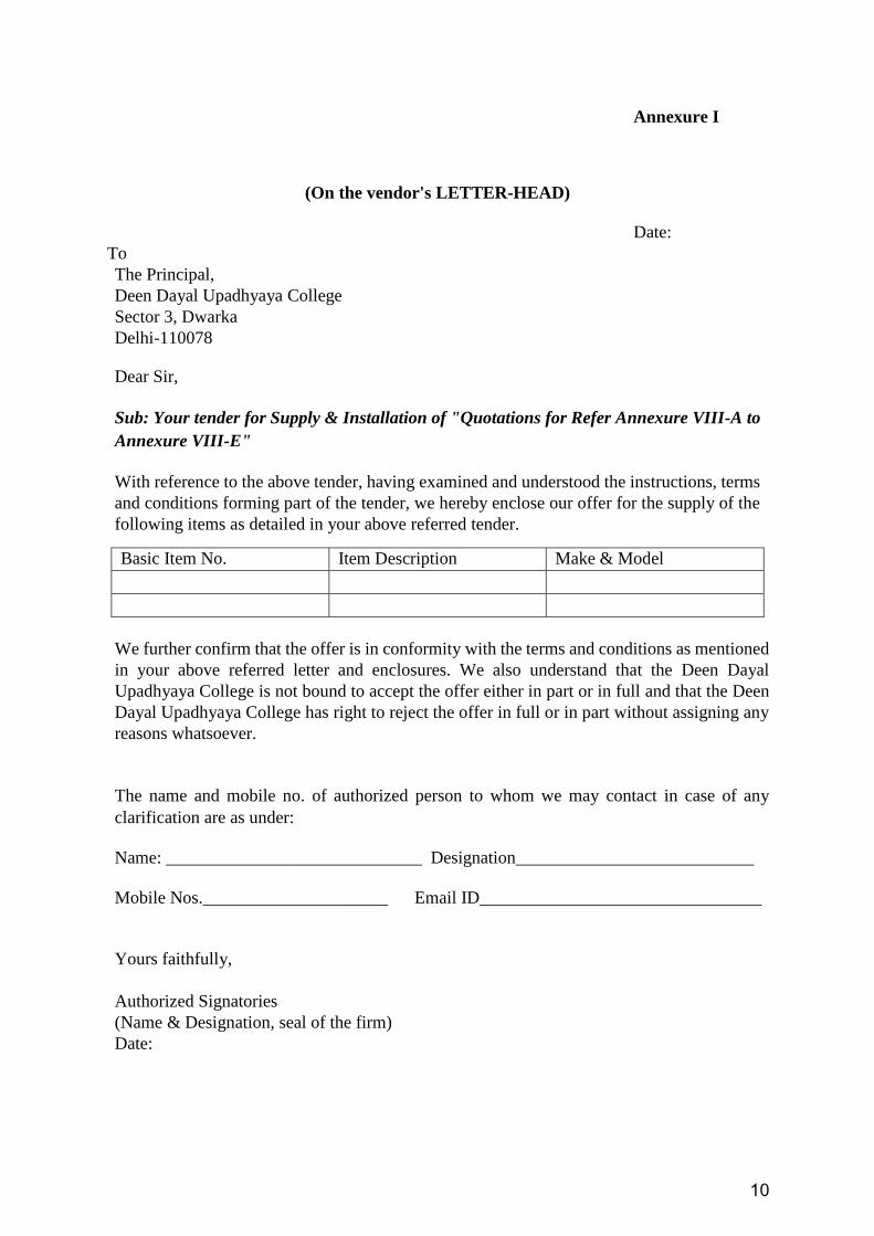
Annexure I
(On the vendor's LETTER-HEAD)
Date:
To
The Principal,
Deen Dayal Upadhyaya College
Sector 3, Dwarka
Delhi-110078
Dear Sir,
Sub: Your tender for Supply & Installation of "Quotations for Refer Annexure VIII-A to
Annexure VIII-E"
With reference to the above tender, having examined and understood the instructions, terms
and conditions forming part of the tender, we hereby enclose our offer for the supply of the
following items as detailed in your above referred tender.
We further confirm that the offer is in conformity with the terms and conditions as mentioned
in your above referred letter and enclosures. We also understand that the Deen Dayal
Upadhyaya College is not bound to accept the offer either in part or in full and that the Deen
Dayal Upadhyaya College has right to reject the offer in full or in part without assigning any
reasons whatsoever.
The name and mobile no. of authorized person to whom we may contact in case of any
clarification are as under:
Name: _____________________________ Designation___________________________
Mobile Nos._____________________ Email ID________________________________
Yours faithfully,
Authorized Signatories
(Name & Designation, seal of the firm)
Date:
Basic Item No. Item Description Make & Model
11
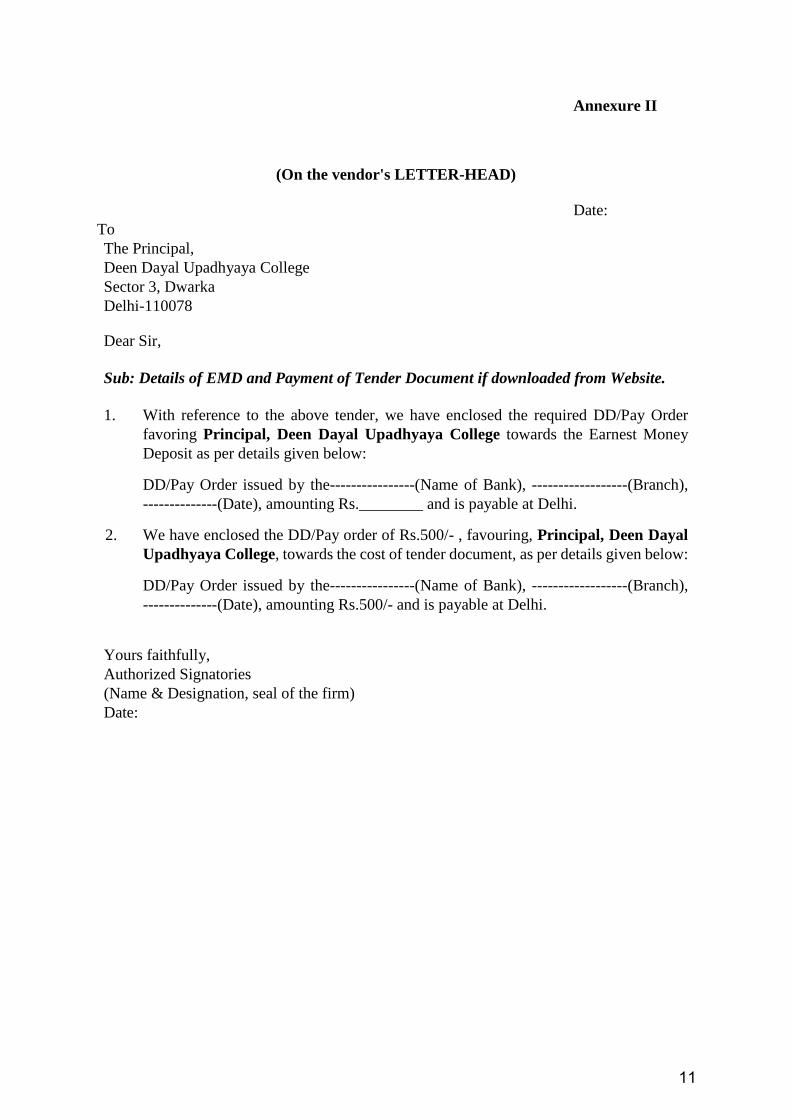
Annexure II
(On the vendor's LETTER-HEAD)
Date:
To
The Principal,
Deen Dayal Upadhyaya College
Sector 3, Dwarka
Delhi-110078
Dear Sir,
Sub: Details of EMD and Payment of Tender Document if downloaded from Website.
1. With reference to the above tender, we have enclosed the required DD/Pay Order
favoring Principal, Deen Dayal Upadhyaya College towards the Earnest Money
Deposit as per details given below:
DD/Pay Order issued by the----------------(Name of Bank), ------------------(Branch),
--------------(Date), amounting Rs.________ and is payable at Delhi.
2. We have enclosed the DD/Pay order of Rs.500/- , favouring, Principal, Deen Dayal
Upadhyaya College, towards the cost of tender document, as per details given below:
DD/Pay Order issued by the----------------(Name of Bank), ------------------(Branch),
--------------(Date), amounting Rs.500/- and is payable at Delhi.
Yours faithfully,
Authorized Signatories
(Name & Designation, seal of the firm)
Date:
12
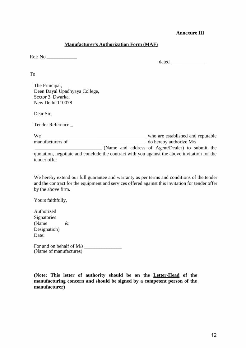
Annexure III
Manufacturer's Authorization Form (MAF)
Ref: No. ____________ dated ______________
To
The Principal,
Deen Dayal Upadhyaya College,
Sector 3, Dwarka,
New Delhi-110078
Dear Sir,
Tender Reference _
We __________________________________________ who are established and reputable
manufacturers of _______________________________ do hereby authorize M/s
___________________________ (Name and address of Agent/Dealer) to submit the
quotation, negotiate and conclude the contract with you against the above invitation for the
tender offer
We hereby extend our full guarantee and warranty as per terms and conditions of the tender
and the contract for the equipment and services offered against this invitation for tender offer
by the above firm.
Yours faithfully,
Authorized
Signatories
(Name &
Designation)
Date:
For and on behalf of M/s _______________ (Name of manufactures)
(Note: This letter of authority should be on the Letter-Head of the
manufacturing concern and should be signed by a competent person of the
manufacturer)
13
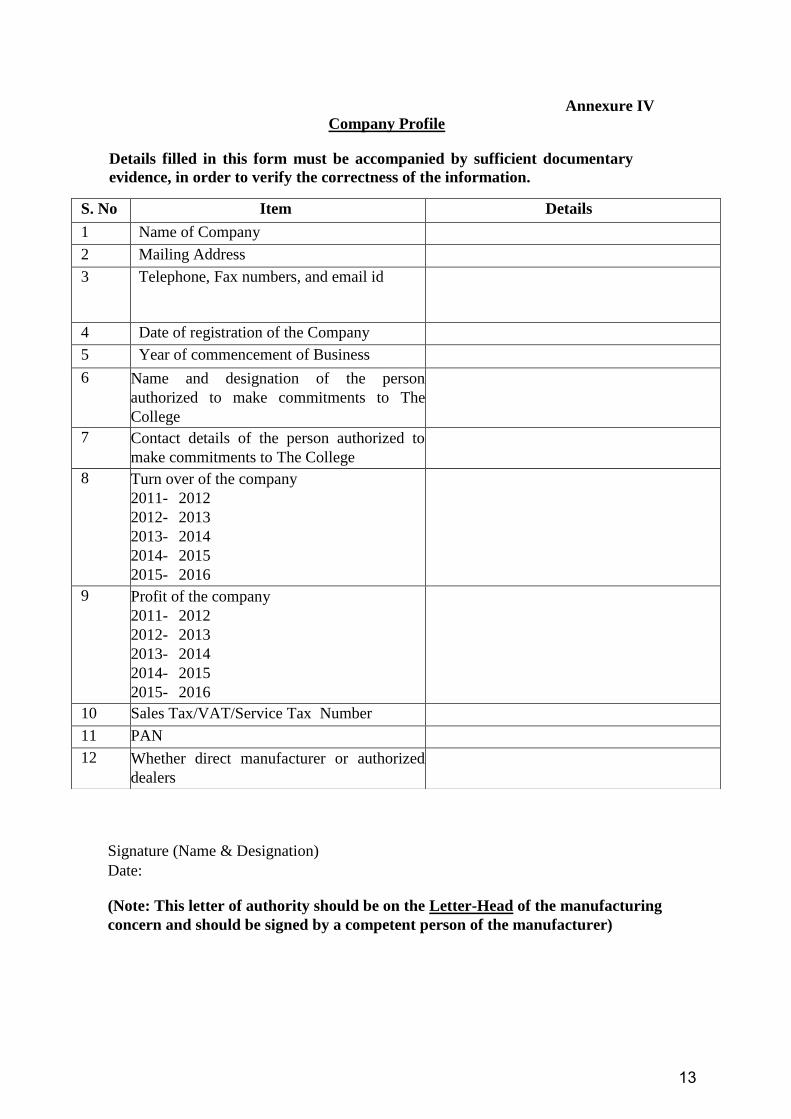
Annexure IV
Company Profile
Details filled in this form must be accompanied by sufficient documentary
evidence, in order to verify the correctness of the information.
Signature (Name & Designation)
Date:
(Note: This letter of authority should be on the Letter-Head of the manufacturing
concern and should be signed by a competent person of the manufacturer)
S. No Item Details
1 Name of Company
2 Mailing Address
3 Telephone, Fax numbers, and email id
4 Date of registration of the Company
5 Year of commencement of Business
6 Name and designation of the person
authorized to make commitments to The
College
7 Contact details of the person authorized to
make commitments to The College
8 Turn over of the company
2011- 2012
2012- 2013
2013- 2014
2014- 2015
2015- 2016
9 Profit of the company
2011- 2012
2012- 2013
2013- 2014
2014- 2015
2015- 2016
10 Sales Tax/VAT/Service Tax Number
11 PAN
12 Whether direct manufacturer or authorized
dealers
14
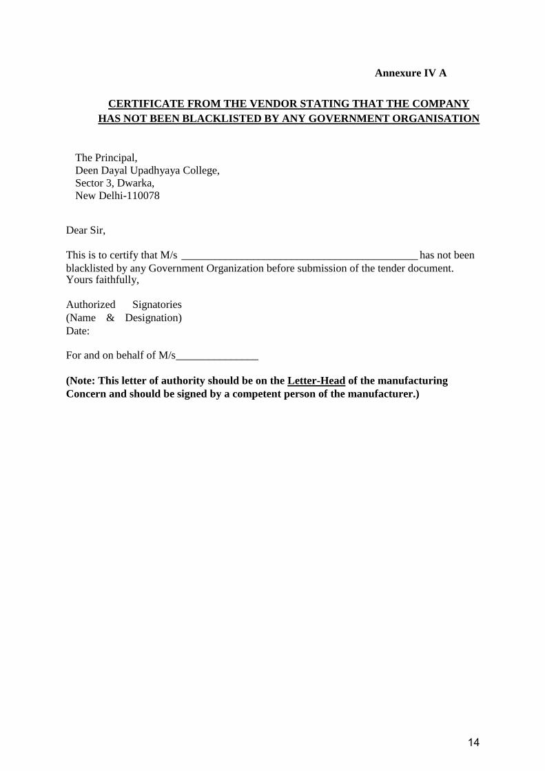
Annexure IV A
CERTIFICATE FROM THE VENDOR STATING THAT THE COMPANY
HAS NOT BEEN BLACKLISTED BY ANY GOVERNMENT ORGANISATION
The Principal,
Deen Dayal Upadhyaya College,
Sector 3, Dwarka,
New Delhi-110078
Dear Sir,
This is to certify that M/s ___________________________________________ has not been
blacklisted by any Government Organization before submission of the tender document. Yours faithfully,
Authorized Signatories
(Name & Designation)
Date:
For and on behalf of M/s _______________
(Note: This letter of authority should be on the Letter-Head of the manufacturing
Concern and should be signed by a competent person of the manufacturer.)

15
Annexure V
To
The Principal,
Deen Dayal Upadhyaya College,
Sector 3, Dwarka,
New Delhi-110078 Dear Sir,
We hereby certify that we have executed the following 3 projects to completion on the
similar items as offered in the present tender to other Government
organizations/Educational Institutions/Universities/Govt. Research Organizations.
Note: Please quote only those projects which are of substantial value.
Name of the Vendor _______________________________________________
Signature (Name & Designation) Date:
(Note: This letter of authority should be on the Letter-Head of the manufacturing
Concern and should be signed by a competent person of the manufacturer.)
S. No. Name of the
Client
Equipment Clients Contact Details (Including
Name, E-mail, Phone and Fax No. and
Proper Address
Remarks
16
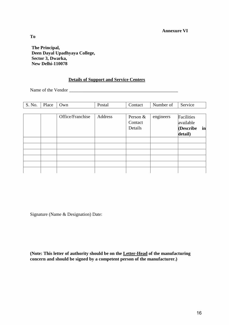
Annexure VI
To
The Principal,
Deen Dayal Upadhyaya College,
Sector 3, Dwarka,
New Delhi-110078
Details of Support and Service Centers
Name of the Vendor _______________________________________________
Signature (Name & Designation) Date:
(Note: This letter of authority should be on the Letter-Head of the manufacturing
concern and should be signed by a competent person of the manufacturer.)
S. No. Place Own Postal Contact Number of Service
Office/Franchise Address Person &
Contact
Details
engineers Facilities
available
(Describe in
detail)

17
Annexure VII
Warranty Compliance Statement
The Principal,
Deen Dayal Upadhyaya College,
Sector 3, Dwarka,
New Delhi-110078
Dear Sir,
Subject: Supply & Installation of ...........................................................
This bears reference to our quotation Ref _________________ Dated __________ .
We warrant that everything to be supplied by us shall be brand new, free from all defects and
faults in material, workmanship and manufacture and shall be of the highest grade, quality and
consistent with the established standards for materials specification, drawings or samples, if
any, and shall operate properly. We shall be fully responsible for its efficient operation.
We also confirm that all service related complaints will be attended within few working days
period of 3 hours after the complaint is lodged.
During the warranty period in case of failing to repair the machine, we will provide a stand-by
arrangement till the equipment is repaired.
Yours faithfully
Signature (Name & Designation) Date:
18
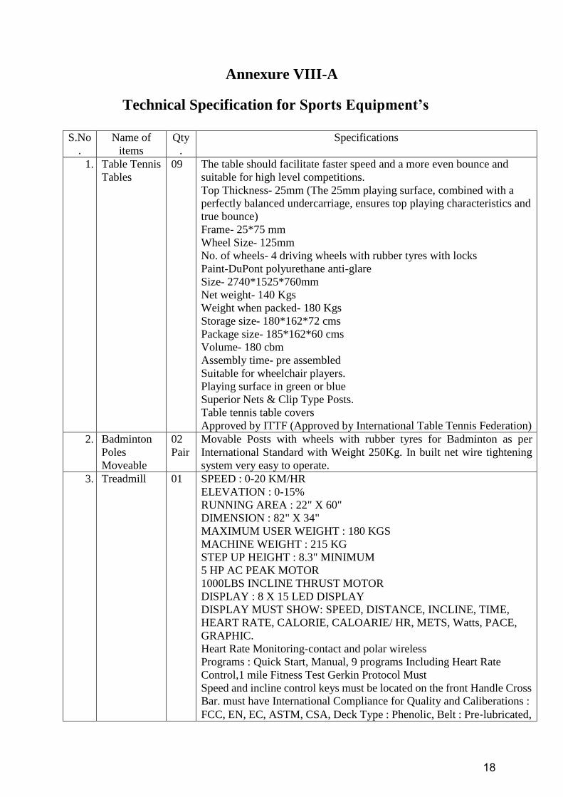
Annexure VIII-A
Technical Specification for Sports Equipment’s
S.No
.
Name of
items
Qty
.
Specifications
1. Table Tennis
Tables
09 The table should facilitate faster speed and a more even bounce and
suitable for high level competitions.
Top Thickness- 25mm (The 25mm playing surface, combined with a
perfectly balanced undercarriage, ensures top playing characteristics and
true bounce)
Frame- 25*75 mm
Wheel Size- 125mm
No. of wheels- 4 driving wheels with rubber tyres with locks
Paint-DuPont polyurethane anti-glare
Size- 2740*1525*760mm
Net weight- 140 Kgs
Weight when packed- 180 Kgs
Storage size- 180*162*72 cms
Package size- 185*162*60 cms
Volume- 180 cbm
Assembly time- pre assembled
Suitable for wheelchair players.
Playing surface in green or blue
Superior Nets & Clip Type Posts.
Table tennis table covers
Approved by ITTF (Approved by International Table Tennis Federation)
2. Badminton
Poles
Moveable
02
Pair
Movable Posts with wheels with rubber tyres for Badminton as per
International Standard with Weight 250Kg. In built net wire tightening
system very easy to operate.
3. Treadmill 01 SPEED : 0-20 KM/HR
ELEVATION : 0-15%
RUNNING AREA : 22" X 60"
DIMENSION : 82" X 34"
MAXIMUM USER WEIGHT : 180 KGS
MACHINE WEIGHT : 215 KG
STEP UP HEIGHT : 8.3" MINIMUM
5 HP AC PEAK MOTOR
1000LBS INCLINE THRUST MOTOR
DISPLAY : 8 X 15 LED DISPLAY
DISPLAY MUST SHOW: SPEED, DISTANCE, INCLINE, TIME,
HEART RATE, CALORIE, CALOARIE/ HR, METS, Watts, PACE,
GRAPHIC.
Heart Rate Monitoring-contact and polar wireless
Programs : Quick Start, Manual, 9 programs Including Heart Rate
Control,1 mile Fitness Test Gerkin Protocol Must
Speed and incline control keys must be located on the front Handle Cross
Bar. must have International Compliance for Quality and Caliberations :
FCC, EN, EC, ASTM, CSA, Deck Type : Phenolic, Belt : Pre‐lubricated,
19
multi‐ply polyester, Intelligent Suspension system/Technology is
required.
In Deck: The point of Landing must be soft, Mid-point of Deck Firm and
Rear Deck must be Stable, The Side Foot Rails Must be Made in Mild
Steel and of plastic. Innovative and exclusive mobility/ transportation
wheels for easy movement. ARMZ stability bars for added security.
Ergonomically designed bars for added security and comfort. It helps to
burn more calories while holding on an incline. Quick reference codes to
provide users with easy access to equipment information and workout
using smartphone mobile devises. Connectivity: made for Ipod and
Iphone.
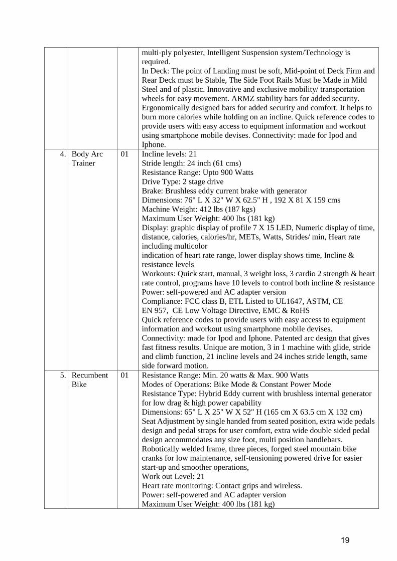
4. Body Arc
Trainer
01 Incline levels: 21
Stride length: 24 inch (61 cms)
Resistance Range: Upto 900 Watts
Drive Type: 2 stage drive
Brake: Brushless eddy current brake with generator
Dimensions: 76" L X 32" W X 62.5" H , 192 X 81 X 159 cms
Machine Weight: 412 lbs (187 kgs)
Maximum User Weight: 400 lbs (181 kg)
Display: graphic display of profile 7 X 15 LED, Numeric display of time,
distance, calories, calories/hr, METs, Watts, Strides/ min, Heart rate
including multicolor
indication of heart rate range, lower display shows time, Incline &
resistance levels
Workouts: Quick start, manual, 3 weight loss, 3 cardio 2 strength & heart
rate control, programs have 10 levels to control both incline & resistance
Power: self-powered and AC adapter version
Compliance: FCC class B, ETL Listed to UL1647, ASTM, CE
EN 957, CE Low Voltage Directive, EMC & RoHS
Quick reference codes to provide users with easy access to equipment
information and workout using smartphone mobile devises.
Connectivity: made for Ipod and Iphone. Patented arc design that gives
fast fitness results. Unique are motion, 3 in 1 machine with glide, stride
and climb function, 21 incline levels and 24 inches stride length, same
side forward motion.
5. Recumbent
Bike
01 Resistance Range: Min. 20 watts & Max. 900 Watts
Modes of Operations: Bike Mode & Constant Power Mode
Resistance Type: Hybrid Eddy current with brushless internal generator
for low drag & high power capability
Dimensions: 65" L X 25" W X 52" H (165 cm X 63.5 cm X 132 cm)
Seat Adjustment by single handed from seated position, extra wide pedals
design and pedal straps for user comfort, extra wide double sided pedal
design accommodates any size foot, multi position handlebars.
Robotically welded frame, three pieces, forged steel mountain bike
cranks for low maintenance, self-tensioning powered drive for easier
start-up and smoother operations,
Work out Level: 21
Heart rate monitoring: Contact grips and wireless.
Power: self-powered and AC adapter version
Maximum User Weight: 400 lbs (181 kg)
20
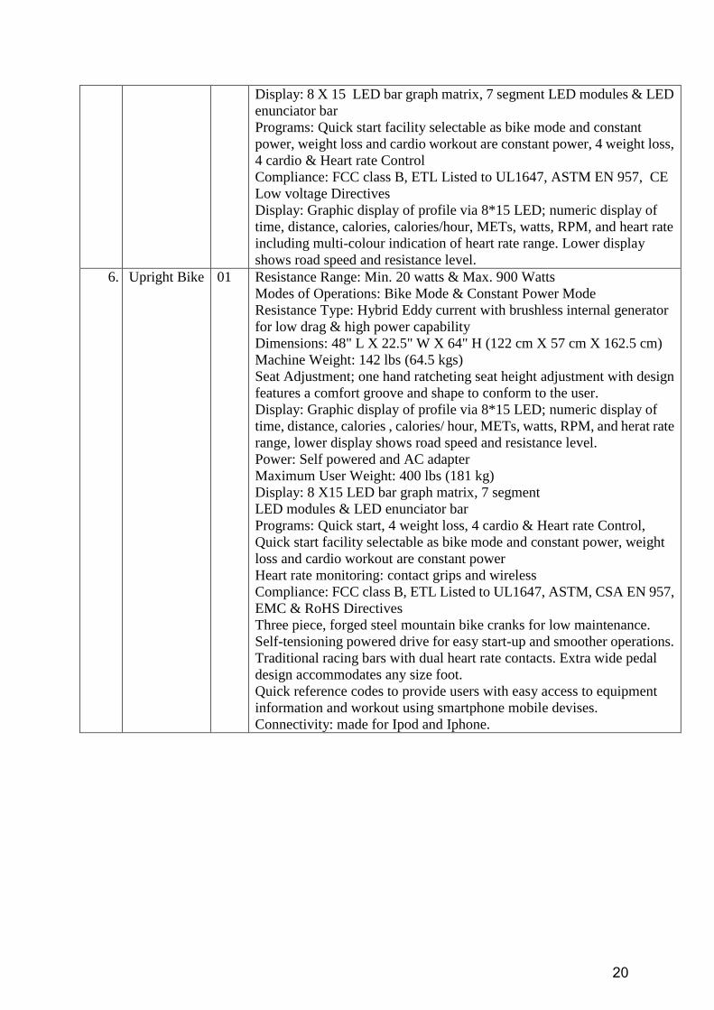
Display: 8 X 15 LED bar graph matrix, 7 segment LED modules & LED
enunciator bar
Programs: Quick start facility selectable as bike mode and constant
power, weight loss and cardio workout are constant power, 4 weight loss,
4 cardio & Heart rate Control
Compliance: FCC class B, ETL Listed to UL1647, ASTM EN 957, CE
Low voltage Directives
Display: Graphic display of profile via 8*15 LED; numeric display of
time, distance, calories, calories/hour, METs, watts, RPM, and heart rate
including multi-colour indication of heart rate range. Lower display
shows road speed and resistance level.
6. Upright Bike 01 Resistance Range: Min. 20 watts & Max. 900 Watts
Modes of Operations: Bike Mode & Constant Power Mode
Resistance Type: Hybrid Eddy current with brushless internal generator
for low drag & high power capability
Dimensions: 48" L X 22.5" W X 64" H (122 cm X 57 cm X 162.5 cm)
Machine Weight: 142 lbs (64.5 kgs)
Seat Adjustment; one hand ratcheting seat height adjustment with design
features a comfort groove and shape to conform to the user.
Display: Graphic display of profile via 8*15 LED; numeric display of
time, distance, calories , calories/ hour, METs, watts, RPM, and herat rate
range, lower display shows road speed and resistance level.
Power: Self powered and AC adapter
Maximum User Weight: 400 lbs (181 kg)
Display: 8 X15 LED bar graph matrix, 7 segment
LED modules & LED enunciator bar
Programs: Quick start, 4 weight loss, 4 cardio & Heart rate Control,
Quick start facility selectable as bike mode and constant power, weight
loss and cardio workout are constant power
Heart rate monitoring: contact grips and wireless
Compliance: FCC class B, ETL Listed to UL1647, ASTM, CSA EN 957,
EMC & RoHS Directives
Three piece, forged steel mountain bike cranks for low maintenance.
Self-tensioning powered drive for easy start-up and smoother operations.
Traditional racing bars with dual heart rate contacts. Extra wide pedal
design accommodates any size foot.
Quick reference codes to provide users with easy access to equipment
information and workout using smartphone mobile devises.
Connectivity: made for Ipod and Iphone.
21
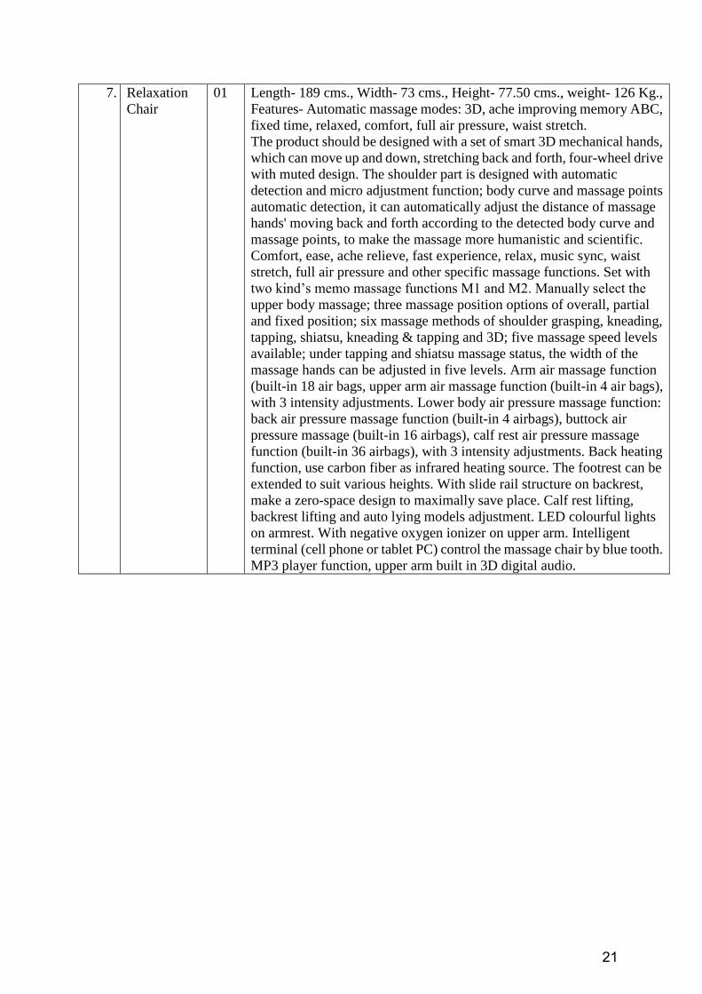
7. Relaxation
Chair
01 Length- 189 cms., Width- 73 cms., Height- 77.50 cms., weight- 126 Kg.,
Features- Automatic massage modes: 3D, ache improving memory ABC,
fixed time, relaxed, comfort, full air pressure, waist stretch.
The product should be designed with a set of smart 3D mechanical hands,
which can move up and down, stretching back and forth, four-wheel drive
with muted design. The shoulder part is designed with automatic
detection and micro adjustment function; body curve and massage points
automatic detection, it can automatically adjust the distance of massage
hands' moving back and forth according to the detected body curve and
massage points, to make the massage more humanistic and scientific.
Comfort, ease, ache relieve, fast experience, relax, music sync, waist
stretch, full air pressure and other specific massage functions. Set with
two kind‟s memo massage functions M1 and M2. Manually select the
upper body massage; three massage position options of overall, partial
and fixed position; six massage methods of shoulder grasping, kneading,
tapping, shiatsu, kneading & tapping and 3D; five massage speed levels
available; under tapping and shiatsu massage status, the width of the
massage hands can be adjusted in five levels. Arm air massage function
(built-in 18 air bags, upper arm air massage function (built-in 4 air bags),
with 3 intensity adjustments. Lower body air pressure massage function:
back air pressure massage function (built-in 4 airbags), buttock air
pressure massage (built-in 16 airbags), calf rest air pressure massage
function (built-in 36 airbags), with 3 intensity adjustments. Back heating
function, use carbon fiber as infrared heating source. The footrest can be
extended to suit various heights. With slide rail structure on backrest,
make a zero-space design to maximally save place. Calf rest lifting,
backrest lifting and auto lying models adjustment. LED colourful lights
on armrest. With negative oxygen ionizer on upper arm. Intelligent
terminal (cell phone or tablet PC) control the massage chair by blue tooth.
MP3 player function, upper arm built in 3D digital audio.
22
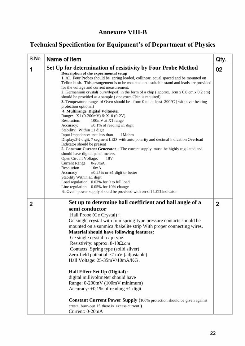
Annexure VIII-B
Technical Specification for Equipment’s of Department of Physics
S.No Name of Item Qty.
1 Set Up for determination of resistivity by Four Probe Method Description of the experimental setup
1. All Four Probes should be spring loaded, collinear, equal spaced and be mounted on
Teflon bush. This arrangement is to be mounted on a suitable stand and leads are provided
for the voltage and current measurement.
2. Germanium crystal( pure/doped) in the form of a chip ( approx. 1cm x 0.8 cm x 0.2 cm)
should be provided as a sample ( one extra Chip is required)
3. Temperature range of Oven should be from 0 to at least 200°C ( with over heating
protection optional)
4. Multirange Digital Voltmeter
Range: X1 (0-200mV) & X10 (0-2V)
Resolution: 100mV at X1 range
Accuracy: ±0.1% of reading ±1 digit
Stability: Within ±1 digit
Input Impedance: not less than 1Mohm
Display:3½ digit, 7 segment LED with auto polarity and decimal indication Overload
Indicator should be present
5. Constant Current Generator. : The current supply must be highly regulated and
should have digital panel meters.
Open Circuit Voltage: 18V
Current Range 0-20mA
Resolution 10mA
Accuracy ±0.25% or ±1 digit or better
Stability Within ±1 digit
Load regulation 0.03% for 0 to full load
Line regulation 0.05% for 10% change
6. Oven power supply should be provided with on-off LED indicator
02
2 Set up to determine hall coefficient and hall angle of a
semi conductor
Hall Probe (Ge Crystal) :
Ge single crystal with four spring-type pressure contacts should be
mounted on a sunmica /bakelite strip With proper connecting wires.
Material should have following features: Ge single crystal n / p type
Resistivity: approx. 8-10Ω.cm
Contacts: Spring type (solid silver)
Zero-field potential: <1mV (adjustable)
Hall Voltage: 25-35mV/10mA/KG .
Hall Effect Set Up (Digital) : digital millivoltmeter should have
Range: 0-200mV (100mV minimum)
Accuracy: ±0.1% of reading ±1 digit
Constant Current Power Supply (100% protection should be given against
crystal burn-out If there is excess current.) Current: 0-20mA
2
23
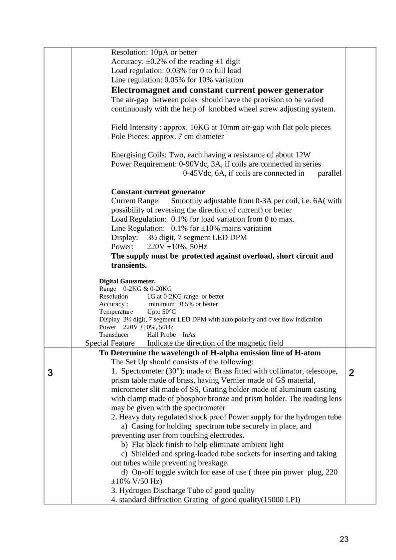
Resolution: 10µA or better
Accuracy: ±0.2% of the reading ±1 digit
Load regulation: 0.03% for 0 to full load
Line regulation: 0.05% for 10% variation
Electromagnet and constant current power generator
The air-gap between poles should have the provision to be varied
continuously with the help of knobbed wheel screw adjusting system.
Field Intensity : approx. 10KG at 10mm air-gap with flat pole pieces
Pole Pieces: approx. 7 cm diameter
Energising Coils: Two, each having a resistance of about 12W
Power Requirement: 0-90Vdc, 3A, if coils are connected in series
0-45Vdc, 6A, if coils are connected in parallel
Constant current generator Current Range: Smoothly adjustable from 0-3A per coil, i.e. 6A( with
possibility of reversing the direction of current) or better
Load Regulation: 0.1% for load variation from 0 to max.
Line Regulation: 0.1% for ±10% mains variation
Display: 3½ digit, 7 segment LED DPM
Power: 220V ±10%, 50Hz
The supply must be protected against overload, short circuit and
transients.
Digital Gaussmeter, Range 0-2KG & 0-20KG
Resolution 1G at 0-2KG range or better
Accuracy : minimum ±0.5% or better
Temperature Upto 50°C
Display 3½ digit, 7 segment LED DPM with auto polarity and over flow indication
Power 220V ±10%, 50Hz
Transducer Hall Probe – InAs Special Feature Indicate the direction of the magnetic field
3
To Determine the wavelength of H-alpha emission line of H-atom
The Set Up should consists of the following:
1. Spectrometer (30"): made of Brass fitted with collimator, telescope,
prism table made of brass, having Vernier made of GS material,
micrometer slit made of SS, Grating holder made of aluminum casting
with clamp made of phosphor bronze and prism holder. The reading lens
may be given with the spectrometer
2. Heavy duty regulated shock proof Power supply for the hydrogen tube
a) Casing for holding spectrum tube securely in place, and
preventing user from touching electrodes.
b) Flat black finish to help eliminate ambient light
c) Shielded and spring-loaded tube sockets for inserting and taking
out tubes while preventing breakage.
d) On-off toggle switch for ease of use ( three pin power plug, 220
±10% V/50 Hz)
3. Hydrogen Discharge Tube of good quality
4. standard diffraction Grating of good quality(15000 LPI)
2
24
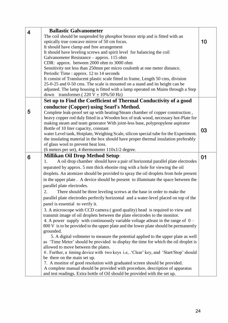
4 Ballastic Galvanometer The coil should be suspended by phosphor bronze strip and is fitted with an
optically true concave mirror of 50 cm focus.
It should have clamp and free arrangement
It should have leveling screws and spirit level for balancing the coil
Galvanometer Resistance – approx. 115 ohm
CDR: approx. between 2000 ohm to 3000 ohm
Sensitivity not less than 250mm per micro coulomb at one meter distance.
Periodic Time : approx. 12 to 14 seconds
It consist of Translucent plastic scale fitted in frame, Length 50 cms, division
25-0-25 and 0-50 cms. The scale is mounted on a stand and its height can be
adjusted. The lamp housing is fitted with a lamp operated on Mains through a Step
down transformer.( 220 V ± 10%/50 Hz)
10
5
Set up to Find the Coefficient of Thermal Conductivity of a good
conductor (Copper) using Searl's Method. Complete leak-proof set up with heating/Steam chamber of copper construction ,
heavy copper rod duly fitted in a Wooden box of teak wood, necessary hot-Plate for
making steam and team generator With joint-less base, polypropylene aspirator
Bottle of 10 liter capacity, constant
water Level tank, Hotplate, Weighing Scale, silicon special tube for the Experiment.
the insulating material in the box should have proper thermal insulation preferably
of glass wool to prevent heat loss.
(6 meters per set), 4 thermometer 110x1/2 degree.
03
6 Millikan Oil Drop Method Setup:
1. A oil drop chamber should have a pair of horizontal parallel plate electrodes
separated by approx. 5 mm thick ebonite ring with a hole for viewing the oil
droplets. An atomizer should be provided to spray the oil droplets from hole present
in the upper plate . A device should be present to illuminate the space between the
parallel plate electrodes.
2. There should be three leveling screws at the base in order to make the
parallel plate electrodes perfectly horizontal and a water-level placed on top of the
panel is essential to verify it.
3. A microscope with CCD camera ( good quality) head is required to view and
transmit image of oil droplets between the plate electrodes to the monitor.
4. A power supply with continuously variable voltage atleast in the range of 0 –
800 V is to be provided to the upper plate and the lower plate should be permanently
grounded.
5. A digital voltmeter to measure the potential applied to the upper plate as well
as „Time Meter‟ should be provided to display the time for which the oil droplet is
allowed to move between the plates.
6 . Further, a timing device with two keys i.e, .„Clear‟ key, and „Start/Stop‟ should
be there on the main set up.
7. A monitor of good resolution with graduated screen should be provided.
A complete manual should be provided with procedure, description of apparatus
and test readings. Extra bottle of Oil should be provided with the set up.
01
25
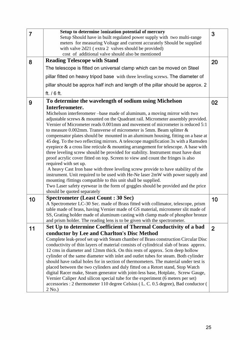
7 Setup to determine Ionization potential of mercury
Setup Should have in built regulated power supply with two multi-range
meters for measuring Voltage and current accurately Should be supplied
with valve 2d21 ( extra 2 valves should be provided)
cost of additional valve should also be mentioned
3
8 Reading Telescope with Stand
The telescope is fitted on universal clamp which can be moved on Steel
pillar fitted on heavy tripod base with three leveling screws. The diameter of
pillar should be approx half inch and length of the pillar should be approx. 2
ft. / 6 ft.
20
9 To determine the wavelength of sodium using Michelson
Interferometer. Michelson interferometer –base made of aluminum, a moving mirror with two
adjustable screws & mounted on the Quadrant rail. Micrometer assembly provided.
Vernier of Micrometer reads 0.001mm and movement of micrometer is reduced 5:1
to measure 0.002mm. Transverse of micrometer is 5mm. Beam splitter &
compensator plates should be mounted in an aluminum housing, fitting on a base at
45 deg. To the two reflecting mirrors. A telescope magnification 3x with a Ramsden
eyepiece & a cross line reticule & mounting arrangement for telescope. A base with
three leveling screw should be provided for stability. Instrument must have dust
proof acrylic cover fitted on top. Screen to view and count the fringes is also
required with set up.
A heavy Cast Iron base with three leveling screw provide to have stability of the
instrument. Unit required to be used with He-Ne laser 2mW with power supply and
mounting /fittings compatible to this unit shall be supplied.
Two Laser safety eyewear in the form of goggles should be provided and the price
should be quoted separately
02
10 Spectrometer (Least Count : 30 Sec) A Spectrometer LC-30 Sec. made of Brass fitted with collimator, telescope, prism
table made of brass, having Vernier made of GS material, micrometer slit made of
SS, Grating holder made of aluminum casting with clamp made of phosphor bronze
and prism holder. The reading lens is to be given with the spectrometer.
10
11 Set Up to determine Coefficient of Thermal Conductivity of a bad
conductor by Lee and Charlton's Disc Method Complete leak-proof set up with Steam chamber of Brass construction Circular Disc
conductivity of thin layers of material consists of cylindrical slab of brass approx.
12 cms in diameter and 12mm thick. On this rests of approx. 5cm deep hollow
cylinder of the same diameter with inlet and outlet tubes for steam. Both cylinder
should have radial holes for in section of thermometers. The material under test is
placed between the two cylinders and duly fitted on a Retort stand, Stop Watch
digital Racer make, Steam generator with joint-less base, Hotplate, Screw Gauge,
Vernier Caliper And silicon special tube for the experiment (6 meters per set)
accessories : 2 thermometer 110 degree Celsius ( L. C. 0.5 degree), Bad conductor (
2 No.)
2
26
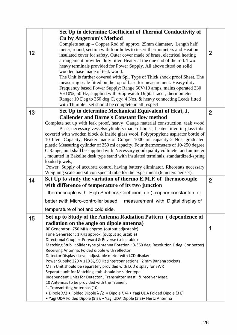
12
Set Up to determine Coefficient of Thermal Conductivity of
Cu by Angstrom's Method Complete set up – Copper Rod of approx. 25mm diameter, Length half
meter, round, section with four holes to insert thermometers and Heat on
insulated cover for safety. Outer cover made of brass, electrical heating
arrangement provided duly fitted Heater at the one end of the rod. Two
heavy terminals provided for Power Supply. All above fitted on solid
wooden base made of teak wood.
The Unit is further covered with Spl. Type of Thick shock proof Sheet. The
measuring scale fitted on the top of base for measurement. Heavy duty
Frequency based Power Supply: Range 50V/10 amps, mains operated 230
V±10%, 50 Hz, supplied with Stop watch-Digital-racer, thermometer
Range: 10 Deg to 360 deg C, qty: 4 Nos. & heavy connecting Leads fitted
with Thimble . set should be complete in all respect
2
13 Set Up to determine Mechanical Equivalent of Heat, J,
Callender and Barne's Constant flow method Complete set up with leak proof, heavy Gauge material construction, teak wood
Base, necessary vessels/cylinders made of brass, heater fitted in glass tube
covered with wooden block & inside glass wool, Polypropylene aspirator bottle of
10 liter Capacity, Beaker made of Copper 1000 ml capacity-2 Nos, graduated
plastic Measuring cylinder of 250 ml capacity, Four thermometers of 10-250 degree
C Range, unit shall be supplied with Necessary good quality voltmeter and ammeter
, mounted in Bakelite desk type stand with insulated terminals, standardized-spring
loaded jewels,
Power Supply of accurate control having battery eliminator, Rheostats necessary
Weighing scale and silicon special tube for the experiment (6 meters per set).
2
14 Set Up to study the variation of thermo E.M.F. of thermocouple
with difference of temperature of its two junction
thermocouple with High Seebeck Coefficient i.e ( copper constanton or
better )with Micro-controller based measurement with Digital display of
temperature of hot and cold side.
2
15 Set up to Study of the Antenna Radiation Pattern ( dependence of
radiation on the angle on dipole antenna) RF Generator : 750 MHz approx. (output adjustable) Tone Generator : 1 KHz approx. (output adjustable) Directional Coupler Forward & Reverse (selectable) Matching Stub : Slider type ;Antenna Rotation : 0-360 deg. Resolution 1 deg. ( or better) Receiving Antenna: Folded dipole with reflector Detector Display : Level adjustable meter with LCD display Power Supply: 220 V ±10 %, 50 Hz ;Interconnections : 2 mm Banana sockets Main Unit should be separately provided with LCD display for SWR Separate unit for Matching stub should be slider type Independent Units for Detector , Transmitter mast , & receiver Mast. 10 Antennas to be provided with the Trainer . 1. Transmitting Antennas (10) • Dipole λ/2 • Folded Dipole λ /2 • Dipole λ /4 • Yagi UDA Folded Dipole (3 E) • Yagi UDA Folded Dipole (5 E); • Yagi UDA Dipole (5 E)• Hertz Antenna
1

27
• Loop Antenna •Log periodic antenna • Helix Antenna & Detector antenna
Accessories : 1. Detector Antenna folded dipole 2. Current Probe ; 3. Mounting
stands ; 4. BNC-Tee 5. BNC-BNC adapter M ; 6. BNC-BNC adapter F 7.
BNC-BNC cable ; 8. Aligner ;9. Operating manual 10. Matching stub ; 11.
Radiation Pattern Plotting Software 12. Polar graph (2 types) ; 13. Antenna
fabrication kit 14. Power cord ; 15 VIP Carrying case for access .
Software: Should be supplied with simulation & basic technology
associated with the teaching of antennas ( Basic theory & simulation
based on Antenna radiation patterns, power patterns, directivity, gain
beam width , polarization etc. different classification of antennas and types
of antennas). Software should be provided on USB drive which should act as
a hardware lock also. Hard copy of complete manual regarding the procedure
may also be provided.
16
Set up to Study of Microwave wave and its propagation (
reflection, refraction, polarization and double slit interference )
Setup should be complete with Transmission, Reception and Measurement of
Microwave Power with all accessories required.
Digital displays should be provided for relative strength measurement of
microwave. Set up should have facility for experiments of Reflection, Refraction,
Polarization and Interference etc.
Audio / Voice communication facility should be provided
Detector probe should be provided for field detection
Accessories should be provided packed in a carrying case
Frequency of Operation : 10 GHz (approx);Power of Transmission : 10 -15 mW (
approx.)
Operating Voltage : 8 V (approx)
Antennas for Transmission & Reception : Horn type
Ganiometer Scale : 0° - 360° ; Tone Generator : 1 KHz Frequency
Transmitter and Receiver arm length : 49 cm each (approx)
Power Display : Digital, Relative Measurements
Power Supply : 230 V ±10%, 50 Hz
Accessories : Microwave Transmitter & Receiver , Transmitter & receiver Arms
Ganiometer Base Unit , Detector Probe , Prism
Metal Plates of different dimensions , Partial Reflectors
Din Connectors Cables , Metal Plate holder ,Polarization Grille , Prism Stand , Mini
Microphone
Software: Should be supplied with simulation & technology linked with teaching of
Microwave technology ( theory & simulation based on Electromagnetic waves ,
Modes of Propagation , types of waveguides, Microwave tubes , active & Passive
components). Software should be provided on USB drive which should act as
a hardware lock also . Hard copy of complete manual should be provided
1
28
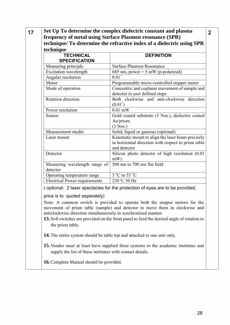
17 Set Up To determine the complex dielectric constant and plasma
frequency of metal using Surface Plasmon resonance (SPR)
technique/ To determine the refractive index of a dielectric using SPR
technique
TECHNICAL SPECIFICATION
DEFINITION
Measuring principle Surface Plasmon Resonance
Excitation wavelength 685 nm, power = 5 mW (p-polarized)
Angular resolution 0.01
Motor Programmable micro-controlled stepper motor
Mode of operation Concentric and coplanar movement of sample and
detector in user defined steps
Rotation direction Both clockwise and anti-clockwise direction
(0.01ᴼ)
Power resolution 0.01 mW
Sensor Gold coated substrate (3 Nos.), dielectric coated
Au/prism
(3 Nos.)
Measurement media Solid, liquid or gaseous (optional)
Laser mount Kinematic mount to align the laser beam precisely
in horizontal direction with respect to prism table
and detector
Detector Silicon photo detector of high resolution (0.01
mW)
Measuring wavelength range of
detector
500 nm to 700 nm flat field
Operating temperature range 5 oC to 55
oC
Electrical Power requirements 230 V, 50 Hz
( optional: 2 laser spectacles for the protection of eyes are to be provided,
price is to quoted separately)
Note: A common switch is provided to operate both the stepper motors for the
movement of prism table (sample) and detector to move them in clockwise and
anticlockwise direction simultaneously in synchronized manner.
13. Soft switches are provided on the front panel to feed the desired angle of rotation to
the prism table.
14. The entire system should be table top and attached to one unit only.
15. Vendor must at least have supplied three systems to the academic institutes and
supply the list of these institutes with contact details.
16. Complete Manual should be provided.
2
29
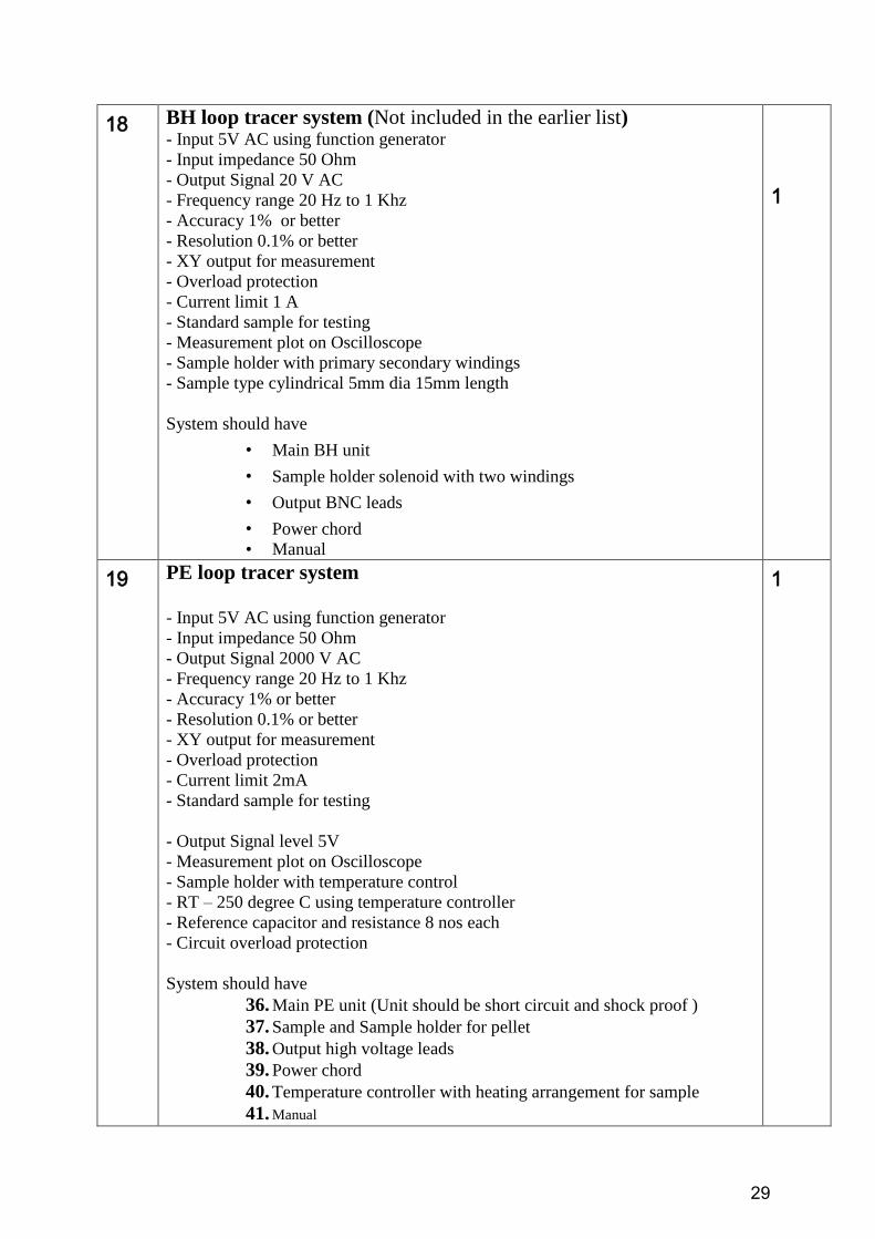
18 BH loop tracer system (Not included in the earlier list)
- Input 5V AC using function generator
- Input impedance 50 Ohm
- Output Signal 20 V AC
- Frequency range 20 Hz to 1 Khz
- Accuracy 1% or better
- Resolution 0.1% or better
- XY output for measurement
- Overload protection
- Current limit 1 A
- Standard sample for testing
- Measurement plot on Oscilloscope
- Sample holder with primary secondary windings
- Sample type cylindrical 5mm dia 15mm length
System should have
• Main BH unit
• Sample holder solenoid with two windings
• Output BNC leads
• Power chord
• Manual
1
19 PE loop tracer system
- Input 5V AC using function generator
- Input impedance 50 Ohm
- Output Signal 2000 V AC
- Frequency range 20 Hz to 1 Khz
- Accuracy 1% or better
- Resolution 0.1% or better
- XY output for measurement
- Overload protection
- Current limit 2mA
- Standard sample for testing
- Output Signal level 5V
- Measurement plot on Oscilloscope
- Sample holder with temperature control
- RT – 250 degree C using temperature controller
- Reference capacitor and resistance 8 nos each
- Circuit overload protection
System should have
36. Main PE unit (Unit should be short circuit and shock proof )
37. Sample and Sample holder for pellet
38. Output high voltage leads
39. Power chord
40. Temperature controller with heating arrangement for sample
41. Manual
1
30
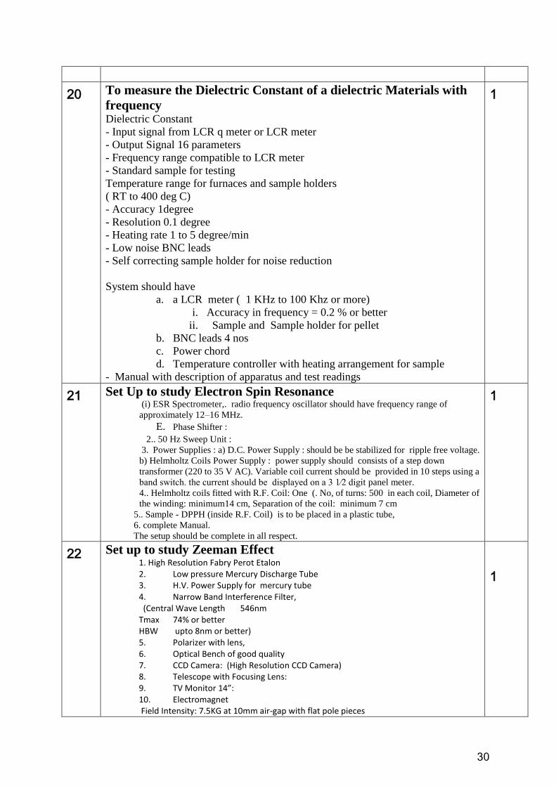
20 To measure the Dielectric Constant of a dielectric Materials with
frequency
Dielectric Constant
- Input signal from LCR q meter or LCR meter
- Output Signal 16 parameters
- Frequency range compatible to LCR meter
- Standard sample for testing
Temperature range for furnaces and sample holders
( RT to 400 deg C)
- Accuracy 1degree
- Resolution 0.1 degree
- Heating rate 1 to 5 degree/min
- Low noise BNC leads
- Self correcting sample holder for noise reduction
System should have
a. a LCR meter ( 1 KHz to 100 Khz or more)
i. Accuracy in frequency = 0.2 % or better
ii. Sample and Sample holder for pellet
b. BNC leads 4 nos
c. Power chord
d. Temperature controller with heating arrangement for sample
- Manual with description of apparatus and test readings
1
21 Set Up to study Electron Spin Resonance
(i) ESR Spectrometer,. radio frequency oscillator should have frequency range of
approximately 12–16 MHz.
E. Phase Shifter :
2.. 50 Hz Sweep Unit :
3. Power Supplies : a) D.C. Power Supply : should be be stabilized for ripple free voltage.
b) Helmholtz Coils Power Supply : power supply should consists of a step down
transformer (220 to 35 V AC). Variable coil current should be provided in 10 steps using a
band switch. the current should be displayed on a 3 1⁄2 digit panel meter.
4.. Helmholtz coils fitted with R.F. Coil: One (. No, of turns: 500 in each coil, Diameter of
the winding: minimum14 cm, Separation of the coil: minimum 7 cm
5.. Sample - DPPH (inside R.F. Coil) is to be placed in a plastic tube,
6. complete Manual.
The setup should be complete in all respect.
1
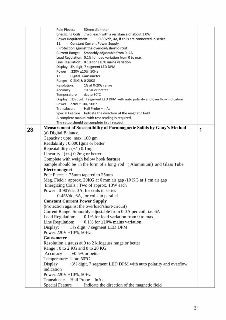
22 Set up to study Zeeman Effect
1. High Resolution Fabry Perot Etalon 2. Low pressure Mercury Discharge Tube 3. H.V. Power Supply for mercury tube 4. Narrow Band Interference Filter, (Central Wave Length 546nm Tmax 74% or better HBW upto 8nm or better) 5. Polarizer with lens, 6. Optical Bench of good quality 7. CCD Camera: (High Resolution CCD Camera) 8. Telescope with Focusing Lens: 9. TV Monitor 14”: 10. Electromagnet Field Intensity: 7.5KG at 10mm air-gap with flat pole pieces
1
31
Pole Pieces: 50mm diameter Energizing Coils :Two, each with a resistance of about 3.0W Power Requirement :0-30Vdc, 4A, if coils are connected in series 11. Constant Current Power Supply ( Protection against the overload/short-circuit) Current Range: Smoothly adjustable from 0–4A Load Regulation: 0.1% for load variation from 0 to max. Line Regulation: 0.1% for ±10% mains variation Display: 3½ digit, 7 segment LED DPM Power :220V ±10%, 50Hz 12. Digital Gaussmeter Range: 0-2KG & 0-20KG Resolution: 1G at 0-2KG range Accuracy: ±0.5% or better Temperature :Upto 50°C Display :3½ digit, 7 segment LED DPM with auto polarity and over flow indication Power 220V ±10%, 50Hz Transducer: Hall Probe – InAs Special Feature Indicate the direction of the magnetic field A complete manual with test reading is required. The setup should be complete in all respect.
23 Measurement of Susceptibility of Paramagnetic Solids by Gouy’s Method (a) Digital Balance,
Capacity : upto max. 100 gm
Readability : 0.0001gms or better
Repeatability : (+/-) 0.1mg
Linearity : (+/-) 0.2mg or better
Complete with weigh below hook feature
Sample should be in the form of a long rod ( Aluminium) and Glass Tube
Electromagnet Pole Pieces : 75mm tapered to 25mm
Mag. Field : approx. 20KG at 6 mm air gap /10 KG at 1 cm air gap
Energizing Coils : Two of approx. 13W each
Power : 0-90Vdc, 3A, for coils in series
0-45Vdc, 6A, for coils in parallel
Constant Current Power Supply
(Protection against the overload/short-circuit)
Current Range :Smoothly adjustable from 0-3A per coil, i.e. 6A
Load Regulation: 0.1% for load variation from 0 to max.
Line Regulation: 0.1% for ±10% mains variation
Display: 3½ digit, 7 segment LED DPM
Power: 220V ±10%, 50Hz
Gaussmeter Resolution:1 gauss at 0 to 2 kilogauss range or better
Range : 0 to 2 KG and 0 to 20 KG
Accuracy :±0.5% or better
Temperature: Upto 50°C
Display :3½ digit, 7 segment LED DPM with auto polarity and overflow
indication
Power: 220V ±10%, 50Hz
Transducer: Hall Probe – InAs
Special Feature Indicate the direction of the magnetic field
1
32
The whole set should be covered in cabin for safety. It should be complete in all
respect.
24 MEASUREMENT OF SUSCEPTIBILITY OF PARAMAGNETIC
SOLUTION BY QUINCKE’S TUBE METHOD Quincke‟s U tube of borosil with wooden stand ( with 2 extra tubes and stand)
Beaker: Graduated- Borosil- 500ml & 100ml.Each Unit – 2 Nos.
Measuring Cylinder: Poly Plastic – 250 ml-Qty: 1 no per set.
Filter Paper: 5 Sets per unit packed.
Funnel:Made of Glass- Borosil. Qty: 2 Nos Per unit
Sample: MnSO4 2H2O , R D bottle
Electromagnet Field Intensity approx. 7.5 KG at 10mm air-gap with flat pole pieces
Pole Pieces: 50mm diameter
Energizing Coils Two, each with a resistance of about 3.0W
Power Requirement 0-30Vdc, 4A, if coils are connected in series
Constant Current Power Supply,
Current Range: 0–4A
Load Regulation :0.1% for load variation from 0 to max.
Line Regulation 0.1% for ±10% mains variation
Display 3½ digit, 7 segment LED DPM
Power 220V ±10%, 50Hz
Protection against the overload/short-circuit
Digital Gauss meter, Range 0-2KG & 0-20KG
Resolution 1G at 0-2KG range or better
Accuracy : minimum ±0.5% or better
Temperature Upto 50°C
Display 3½ digit, 7 segment LED DPM with auto polarity and over flow
indication
Power 220V ±10%, 50Hz
Transducer Hall Probe – InAs
Special Feature Indicate the direction of the magnetic field
Travelling Microscope(Horizontal and Vertical) The bed is of heavy casting,
thoroughly aged, machined and is fitted with leveling screws.
True achromatic objective with 7.5cm focusing distance
(ii) 10X Ramsden eyepiece with fine cross wire
Scale and Vernier (i) Horizontal scale: 20cm divided at 0.5mm interval (ii) Vertical
scale: 15cm divided at 0.5mm interval (iii) Venier scales: 50 divisions with a least
count of 0.01mm
The set up is to be complete in all respect.
1
25
Set Up To verify the Stefan`s law of radiation and to determine Stefan’s
constant (Using silver constantan thermocouple) Setup – having Blackened hollow metal hemispherical body, fixed on wooden
frame provided with three legs for stability, on top whole for thermometer , supplied
with accessories – as Spot Reflecting Galvanometer- Res: 125 ohms, AC Working
voltage -230V/50Hz, A constantan-Silver thermo couple Size one meter, fixed in
glass tube with rubber cork, Steam Generator-2ltrs Cap, single Joint less made of
Copper, a Resistance box, plug type range 1-10000 ohms, Silver disc provided with
stand and connecting wires.
( extra thermocouple of silver constantan should be provided with cost should be
1
33
quoted separately)
26 Set up to determine the angular spread of He-Ne Laser using diffraction
grating. Basic unit – with He-Ne Laser with power supply -2 mW, One screen, a
meter scale, Travelling Microscope and a Rod Type optical bench with Saddles. (
optional: 2 laser spectacles to be provided, to be quoted separately )
1
27 Set up to determine absorption lines in the rotational spectrum of Iodine
Vapour. Set up consist of Spectrometer LC: 20 Sec – base made of solid aluminum casting.
Locking nut,bush, fine motion screws and leveling screws provided. Spindle &
central assembly made of brass. Inbuilt light arrangement provide on Vernier and
main scale. Prism table made of brass provide with spring leveling and manual
locking screw provide for fine circular motion. Telescope and collimator with rack
and pinion fine and coarse motion made of brass. scale/Vernier made of GS
material. Achromatic objective. FL 230mm , Ramsden eye-piece –lens holder of
brass, magnification 8x, Reticule-90 deg. Cross etched on grounded glass,
Micrometer slit assembly made of Stainless steel, strip and slit aperture made of
brass supplied with prism holder made of brass and grating holder made of
aluminum casting with clamps made of phosphor bronze.
Should be Supplied with all accessories – Diffraction Grating 15000 LPI, having
Spl type of T shape Benchmade of MS material with leveling Screws with uprights,
light source with light holder made of metal, Iodine Glass Tube duly top covered for
safety for student having centrally heating arrangement inbuilt with Lens holder
made of brass, tube size -half meter approx.. AC Power Supply, Mortar & Pestle for
Iodine, One small Pack of Iodine wafers, Brush for cleaning the tube.
One extra spare tube should be provided with the set-up.
( cost of extra tube should be quoted separately )
2
28 Determination of Planck's Constant and Work Function of Materials by
Photoelectric Effect 1. Photo Sensitive Device : Vacuum photo tube.
2. Light source : Halogen tungsten lamp 12V/35W.
3. Colour Filters : 635nm, 570nm, 540nm, 500nm & 460nm.
Accelerating Voltage : Regulated Voltage Power Supply,
Output: ± 15 V continuously variable through multi-turn pot
Display : 3½ digit 7-segment LED
Accuracy : ± 0.2% or better
Current Detecting Unit : Digital Nano ammeter
Range : 1000 mA, 100 mA, 10 mA & 1mA with 100 % over ranging facility
Resolution : 1nA at 1 mA range or better
Display : 3½ digit 7-segment LED
Accuracy : ±0.2% or better
6. Power Requirement : 220V ± 10%, 50Hz.
7. Optical Bench : The light source can be moved along it to adjust the distance
between light source and phototube scale length is 400 mm. A drawtube is provided
to install colour filter, a focus lens is fixed in the back end.
2
29 Set up to find the Inductance of the Coil using Anderson's Bridge Method Set up should consist of the following:
Main Features:
R = The Decade resistance dials having range X1000 ohms, X100 ohms and X10
ohms.
r= three more decades of same value as in R.
3
34
S.= Two decade resistance dials having range x10 ohms and 0.1 ohms.
P=Q=Two fixed resistances of 1000 ohms each.
C=Two fixed standard capacitor. ( in micro F)
L=Three unknown inductances ( in milli H). Inbuilt AC Supply frequency 1KHz,
5Volts D.C. Supply, galvanometer for DC Balance supplied with Head phone for
AC/ With one electronic null Detector with sensitivity knob and selection switch
marked with A.C. & D.C. both.
Additional features optional - having arrangement to connect with CRO to have
results- see picture attached herewith.
Circuit is engraved and the components are mounted on the top of sun mica bakelite
sheet. Patch cord suitable to the terminals are supplied with the board. A complete
working manual containing theory circuit details and operating instruction is
supplied with the experimental board. With on/off switch with indicating lamp
30 Set up to compare the capacitance using De Sauty's Bridge Method Set-up should consist of the following.
Main Features:
R1 = Three Decade resistance dials having range X1000 ohms, X100 ohms and X10
ohms.
R2= Three more decades of same value as in R1
.C1= Single decade Capacitance dial range of x 0.1 microfd.
C2= Four unknown Capacitors fixed on the board. ( Optional: should have the
provision on the board that extra Unknown C can be added or removed )
Inbuilt AC Supply frequency 1KHz, 10Volts ( peak to peak) D.C. Supply supplied
with Head phone/electronic null detector with sensitivity knob.
Circuit is engraved and the components are mounted on the top of sun mica bakelite
sheet. Patch cord suitable to the terminals are supplied with the board. A complete
working manual containing theory circuit details and operating instruction is
supplied with the experimental board. With on/off switch with indicating lamp
. Additional features optional- having arrangement to connect with CRO to have
results
3
31 Set Up To study the polarization of light by reflection and determine the
polarizing angle for air-glass interface with :
Prism 01
Spectrometer :A Spectrometer LC-30 Sec. made of Brass fitted with collimator,
telescope, prism table made of brass, having Vernier made of GS material,
micrometer slit made of SS, Grating holder made of aluminum casting with clamp
made of phosphor bronze and prism holder. The reading lens may be given with the
spectrometer.
Device to measure Photocurrent at micro ampere level ( or with better precision)
with digital display, which can be fitted in eyepiece of telescope .
1
32
E/M APPARATUS by magnetic focusing method Set Up CRT (1-1.5ft long, Power Supply with short circuit protection, Voltage Range:
0-1500V, Current Range: 0-3Amp), Compass Box, Solid heavy base (metallic) with
scale provided at base with proper insulation.
02
33
To determine the Coupling Coefficient of a Piezoelectric crystal D33 meter
- Input 5V AC
- Input impedance 50 Ohm
- Output Signal 5V AC
- Frequency range 520 Hz to 1 Khz
01
35
- Accuracy 1% or better
- Resolution 0.1%
- Output for measurement in DPM
- Standard sample for testing
System should have
- Main D33 unit ( The unit should be shock proof)
- sample and Sample holder for pellet
- Output leads
- Power chord
- Manual
34 To study the elliptical Polarized light using Babinet Compensator
(Not included in the earlier list)
Polarizer and analyzer made of Polaroid sheet should be mounted in rotators
graduated in 36 0°( Least count of rotation 1°). A Rectangular Box with
micrometer head having one quartz wedge mounted on running slide and other
quartz is fixed to it.
Quartz wave plate should be mounted in a rotator graduated in 360° (LC 1°)
SOURCE
i) Table lamp superior quality
ii) Sodium Vapour Lamp with choke and enclosure
1
35
To study V-I characteristics of PN Diode, and Light Emitting Diode.
1. Diodes: Rectifier-4007 (Si), Signal diode-1N34 (Ge), Zener 4.7V and LED
2. Digital milliammeter 0-20mA(with minimum least count 0.01mA) and 0 -2mA
(with min least count 0.001mA),
3. Digital Voltmeter 0-20V (with min Least count 0.01 V)
4. It should have regulated continuous and short circuit proof power supply
3
36
Set up to verify the Thevenin, Norton, Superposition, and Maximum power
theorem.
1. Digital milliammeter 0-200mA(with minimum least count 0.1mA),
2. Digital Voltmeter 0-20V (with minimum Least count 0.01 V)
3. It should have regulated, short circuit proof and continuously variable voltage and
current power supply suitable to the circuit board.
3
37
Set up to find the Q-factor and resonance frequency of Series and Parallel LCR
circuit.
1. Inductance (of five different range of milli henry order) made of pot ferrite cores
and capacitances( five to six different capacitors of the order of nano farad) of low
loss factors, Resistance (of the order of 10 ohm, 100ohm , 500(approx)ohm, 1 k
ohm)
2. Digital milliammeter 0-200mA (with minimum least count 0.1mA), 20mA(with
minimum least count 0.01mA) and 0 -2mA (with minimum least count 0.001mA),
3. Digital Voltmeter 0-20V (with minimum Least count 0.01 V)
3
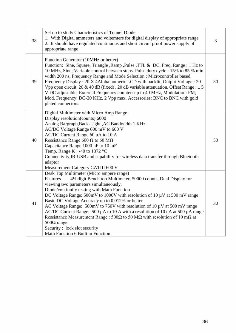
36
38
Set up to study Characteristics of Tunnel Diode
1. With Digital ammeters and voltemters for digital display of appropriate range
2. It should have regulated continuous and short circuit proof power supply of
appropriate range
3
39
Function Generator (10MHz or better)
Function: Sine, Square, Triangle ,Ramp ,Pulse ,TTL & DC, Freq. Range : 1 Hz to
10 MHz, Sine; Variable control between steps. Pulse duty cycle : 15% to 85 % min
width 200 ns, Frequency Range and Mode Selection : Microcontroller based,
Frequency Display : 20 X 4Alpha numeric LCD with backlit, Output Voltage : 20
Vpp open circuit, 20 & 40 dB (fixed) , 20 dB variable attenuation, Offset Range : ± 5
V DC adjustable, External Frequency counter: up to 40 MHz, Modulation: FM,
Mod. Frequency: DC-20 KHz, 2 Vpp max. Accessories: BNC to BNC with gold
plated connectors.
30
40
Digital Multimeter with Micro Amp Range
Display resolution(counts) 6000
Analog Bargraph,Back-Light ,AC Bandwidth 1 KHz
AC/DC Voltage Range 600 mV to 600 V
AC/DC Current Range 60 μA to 10 A
Ressistance Range 600 Ω to 60 MΩ
Capacitance Range 1000 nF to 10 mF
Temp. Range K : -40 to 1372 °C
Connectivity,IR-USB and capability for wireless data transfer through Bluetooth
adaptor
Measurement Category CATIII 600 V
50
41
Desk Top Multimeter (Micro ampere range)
Features 4½ digit Bench top Multimeter, 50000 counts, Dual Display for
viewing two parameters simultaneously,
Diode/continuity testing with Math Function
DC Voltage Range: 500mV to 1000V with resolution of 10 µV at 500 mV range
Basic DC Voltage Accuracy up to 0.012% or better
AC Voltage Range: 500mV to 750V with resolution of 10 µV at 500 mV range
AC/DC Current Range: 500 µA to 10 A with a resolution of 10 nA at 500 µA range
Ressistance Measurement Range : 500Ω to 50 MΩ with resolution of 10 mΩ at
500Ω range
Security : lock slot security
Math Function 6 Built in Function
30
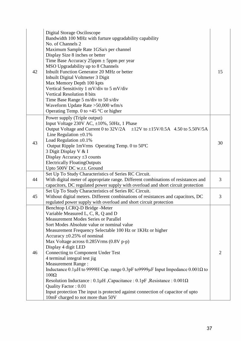
37
42
Digital Storage Osciloscope
Bandwidth 100 MHz with furture upgradability capability
No. of Channels 2
Maximum Sample Rate 1GSa/s per channel
Display Size 8 inches or better
Time Base Accuracy 25ppm ± 5ppm per year
MSO Upgradability up to 8 Channels
Inbuilt Function Generator 20 MHz or better
Inbuilt Digital Voltmeter 3 Digit
Max Memory Depth 100 kpts
Vertical Sensitivity 1 mV/div to 5 mV/div
Vertical Resolution 8 bits
Time Base Range 5 ns/div to 50 s/div
Waveform Update Rate >50,000 wfm/s
Operating Temp. 0 to +45 °C or higher
15
43
Power supply (Triple output)
Input Voltage 230V AC, ±10%, 50Hz, 1 Phase
Output Voltage and Current 0 to 32V/2A ±12V to ±15V/0.5A 4.50 to 5.50V/5A
Line Regulation ±0.1%
Load Regulation ±0.1%
Output Ripple 1mVrms Operating Temp. 0 to 50ºC
3 Digit Display V & I
Display Accuracy ±3 counts
Electrically FloatingOutputs
Upto 500V DC w.r.t. Ground
30
44
Set Up To Study Characteristics of Series RC Circuit.
With digital meter of appropriate range. Different combinations of resistances and
capacitors, DC regulated power supply with overload and short circuit protection
3
45
Set Up To Study Characteristics of Series RC Circuit.
Without digital meters. Different combinations of resistances and capacitors, DC
regulated power supply with overload and short circuit protection
3
46
Benchtop LCRQ-D Bridge -Meter
Variable Measured L, C, R, Q and D
Measurement Modes Series or Parallel
Sort Modes Absolute value or nominal value
Measurement Frequency Selectable 100 Hz or 1KHz or higher
Accuracy ±0.25% of nominal
Max Voltage across 0.285Vrms (0.8V p-p)
Display 4 digit LED
Connecting to Component Under Test
4 terminal integral test jig
Measurement Range :
Inductance 0.1µH to 9999H Cap. range 0.3pF to9999µF Input Impedance 0.001Ω to
100Ω
Resolution Inductance : 0.1µH ,Capacitance : 0.1pF ,Resistance : 0.001Ω
Quality Factor : 0.01
Input protection The input is protected against connection of capacitor of upto
10mF charged to not more than 50V
2
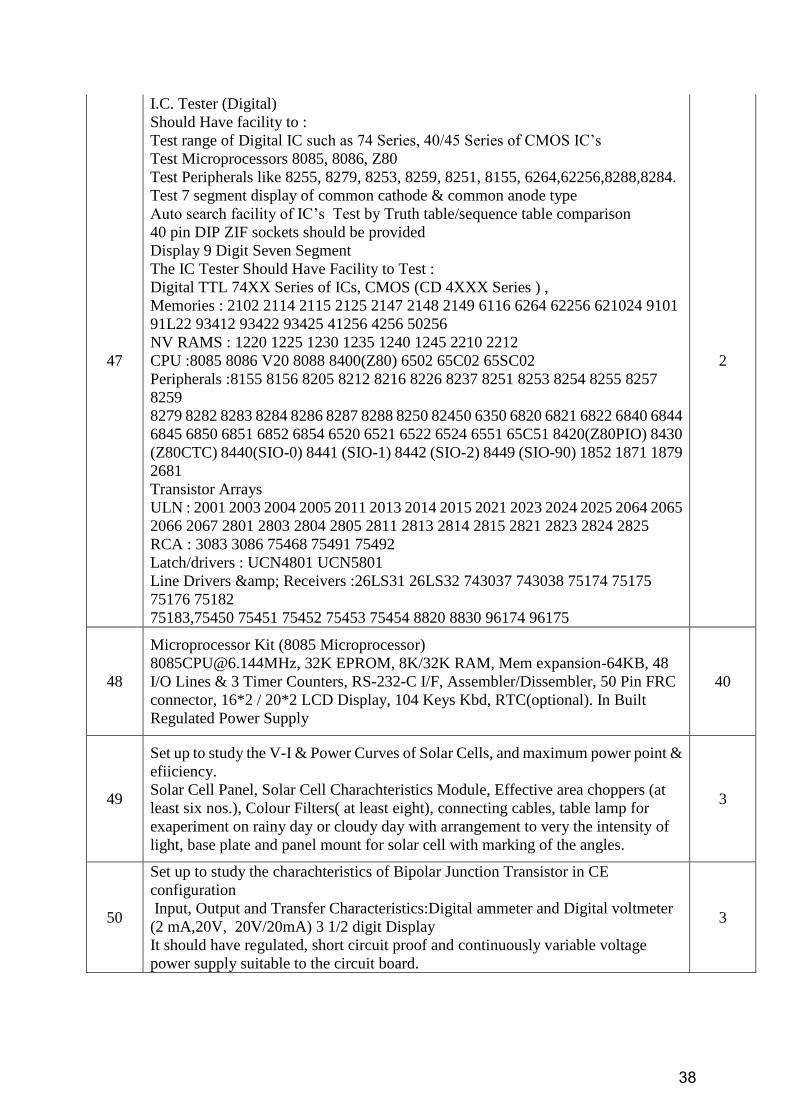
38
47
I.C. Tester (Digital)
Should Have facility to :
Test range of Digital IC such as 74 Series, 40/45 Series of CMOS IC‟s
Test Microprocessors 8085, 8086, Z80
Test Peripherals like 8255, 8279, 8253, 8259, 8251, 8155, 6264,62256,8288,8284.
Test 7 segment display of common cathode & common anode type
Auto search facility of IC‟s Test by Truth table/sequence table comparison
40 pin DIP ZIF sockets should be provided
Display 9 Digit Seven Segment
The IC Tester Should Have Facility to Test :
Digital TTL 74XX Series of ICs, CMOS (CD 4XXX Series ) ,
Memories : 2102 2114 2115 2125 2147 2148 2149 6116 6264 62256 621024 9101
91L22 93412 93422 93425 41256 4256 50256
NV RAMS : 1220 1225 1230 1235 1240 1245 2210 2212
CPU :8085 8086 V20 8088 8400(Z80) 6502 65C02 65SC02
Peripherals :8155 8156 8205 8212 8216 8226 8237 8251 8253 8254 8255 8257
8259
8279 8282 8283 8284 8286 8287 8288 8250 82450 6350 6820 6821 6822 6840 6844
6845 6850 6851 6852 6854 6520 6521 6522 6524 6551 65C51 8420(Z80PIO) 8430
(Z80CTC) 8440(SIO-0) 8441 (SIO-1) 8442 (SIO-2) 8449 (SIO-90) 1852 1871 1879
2681
Transistor Arrays
ULN : 2001 2003 2004 2005 2011 2013 2014 2015 2021 2023 2024 2025 2064 2065
2066 2067 2801 2803 2804 2805 2811 2813 2814 2815 2821 2823 2824 2825
RCA : 3083 3086 75468 75491 75492
Latch/drivers : UCN4801 UCN5801
Line Drivers & Receivers :26LS31 26LS32 743037 743038 75174 75175
75176 75182
75183,75450 75451 75452 75453 75454 8820 8830 96174 96175
2
48
Microprocessor Kit (8085 Microprocessor)
[email protected], 32K EPROM, 8K/32K RAM, Mem expansion-64KB, 48
I/O Lines & 3 Timer Counters, RS-232-C I/F, Assembler/Dissembler, 50 Pin FRC
connector, 16*2 / 20*2 LCD Display, 104 Keys Kbd, RTC(optional). In Built
Regulated Power Supply
40
49
Set up to study the V-I & Power Curves of Solar Cells, and maximum power point &
efiiciency.
Solar Cell Panel, Solar Cell Charachteristics Module, Effective area choppers (at
least six nos.), Colour Filters( at least eight), connecting cables, table lamp for
exaperiment on rainy day or cloudy day with arrangement to very the intensity of
light, base plate and panel mount for solar cell with marking of the angles.
3
50
Set up to study the charachteristics of Bipolar Junction Transistor in CE
configuration
Input, Output and Transfer Characteristics:Digital ammeter and Digital voltmeter
(2 mA,20V, 20V/20mA) 3 1/2 digit Display
It should have regulated, short circuit proof and continuously variable voltage
power supply suitable to the circuit board.
3
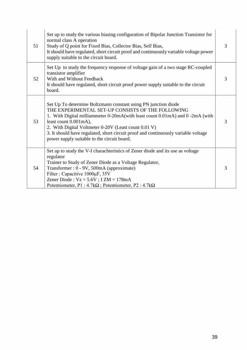
39
51
Set up to study the various biasing configuration of Bipolar Junction Transistor for
normal class A operation
Study of Q point for Fixed Bias, Collector Bias, Self Bias,
It should have regulated, short circuit proof and continuously variable voltage power
supply suitable to the circuit board.
3
52
Set Up to study the frequency response of voltage gain of a two stage RC-coupled
transistor amplifier
With and Without Feedback
It should have regulated, short circuit proof power supply suitable to the circuit
board.
3
53
Set Up To determine Boltzmann constant using PN junction diode
THE EXPERIMENTAL SET-UP CONSISTS OF THE FOLLOWING
1. With Digital milliammeter 0-20mA(with least count 0.01mA) and 0 -2mA (with
least count 0.001mA),
2. With Digital Voltmeter 0-20V (Least count 0.01 V)
3. It should have regulated, short circuit proof and continuously variable voltage
power supply suitable to the circuit board.
3
54
Set up to study the V-I charachteristics of Zener diode and its use as voltage
regulator
Trainer to Study of Zener Diode as a Voltage Regulator,
Transformer : 0 - 9V, 500mA (approximate)
Filter : Capacitive 1000μF, 35V
Zener Diode : Vz = 5.6V ; I ZM = 178mA
Potentiometer, P1 : 4.7kΩ ; Potentiometer, P2 : 4.7kΩ
3
40
Annexure VIII-C
Technical Specification for Equipment’s of Department of Electronics
S.No Name of items with specification Qty.
Reqd.
1.
Desauty’s & Schering Bridge Setup
Should Have separate Blocks for Desauty & Schearing Bridge
Should Have Built in Sine wave generator :
Frequency range : 1 KHz ; Amplitude control output : Sine wave : Up to
15 Vpp
Digital Meter : 200 mV as null detector ; Fuse : 500 mA, slow blow
Unknown Capacitors : 0.1 µF, 0.22 µF, 0.47µF
Mains : 100-230V AC, 50 Hz
Trainer should be on Legend PCB with no components on the top of
board. Housed in a Moulded case with moulded cover on top.
3
2.
Set up to determine the resolving Power and Dispersive Power of
Diffraction and material of the given Prism with Spectrometer
Set up – A Spectrometer LC-20 Sec. base made of Solid Aluminum
casting. Locking nut, bush, fine motion screws and leveling screws
provided.
Spindle & central assembly made of brass.
Inbuilt light arrangement provide on Vernier and main scale.
Prism table made of brass provide with spring leveling and manual
locking screw provide for fine circular motion. Scale / Vernier made of
GS material.
Achromat objective, FL 230mm, Ramsden eye-piece, lens holder of
brass, magnification 8x, Reticule-90 deg. Cross etched on grounded
glass,
Micrometer slit assembly made of Stainless steel, strip and slit aperture
made of brass supplied with prism holder made of brass and grating
holder made of aluminum casting with clamps made of phosphor
bronze.
Supplied with all accessories. Spectrometer provided with light
arrangement, sprit level, diffraction Grating – 15000LPI, Sodium light
source set up-having sodium lamp, wooden box having three slits &
transformer & Magnifier. Qty - Spectrometer – 1 No., Diffracting
Grating -15000 LPI - 2 Nos, Crown Glass Prism, Size: 38x38mm – 2
Nos. , Sodium Lamp only – 2 Nos., Micrometer Slit-1 No-Extra,
Magnifier LED-1 No & EDF Prism -38x38mm -1 no.
2
3.
SCR Trainer Kit - Trainer should have :
On Board DIAC, TRIAC & SCR.
Fixed DC power supply : +15V, Regulated ; ± 35V, Regulated
DIAC : DB3 ; TRIAC : BT136 & SCR : TYN616
Resistor Bank
M.F.R. 2.2K 1% 1/4W (3 Nos.) ;M.F.R. 470E 1% 1/4W (3 Nos.)
M.F.R. 1K 1% 5W (3 Nos.) ; M.F.R. 4.7K 1% 5W (3 Nos.)
M.F.R. 1K 1% 10W (3 Nos.)
3
41
Variable Resistance bank : 5K 10 turn Potentiometer (2 Nos.)
Digital Voltmeter : 0V to 99V ;Digital Ammeter : 0mA to 20mA
Bread Board : Dimension (mm) : 175 x 61 x 10
Distribution strips : 2 ; Distribution holes : 200
Terminal Strips : 1 ; Terminal holes : 640
Mains power supply : 100-230V ±10%, 50Hz
Trainer should be on Legend PCB with no components on the top of
board. Housed in a plastic case with cover attached .Inside of cover
should contain details/diagrammatic details based on SCR,DIAC &
TRIAC.
4.
Set to determine wavelength of Sodium Light using Newton’s Ring
Apparatus.
Set up – with Bridge type microscope Dovetailed cast iron carriage slides
on a heavy cast iron base. Carriage must Have locking arrangement to
arrest Coarse motion when fine motion screw is used. Locking &
unlocking, motion in the total traverse provide for slow Motion screw. It is
use for Microscope in either vertical or horizontal plane. Horizontal
transverse 160mm, least Count 0.01mm, working distance 75mm Eyepiece
8x Ramsden, reticle 90 deg. Cross, total magnification 16x, Newton‟s
Ring apparatus – Plano convex lens of 63mm dia and 200mm f.l. with
Circular plane glass plate of equal Diameter, both mounted in a Bakelite
Frame with three adjustable screws, for making proper contact for
centering Newton‟s Ring apparatus, light reflecting Unit fitted on wooden
frame, A Spherometer made of Brass, Wooden base for set up & Sodium
light Source- consist of Sodium Lamp-35Watts, Transformer and Wooden
box having three side slits.
Bridge Type Microscope–1 No. Newton‟s Ring Apparatus–2 Nos. Light
Reflecting Unit-1 No, Spherometer-1 no , Sodium Lamp only – 2 Nos.
Wooden Table/Choki -1 no. Sodium Light Source–1Set, Magnifier-LED-1
No, Table Lamp-1 no.
2
5.
To determine the wavelength of sodium using Michelson
Interferometer.
Setup should consist of :
Michelson interferometer – base made of aluminum, a moving
mirror with two adjustable screws & mounted on the Quadrant rail.
Micrometer assembly provided. Vernier of Micrometer should read
0.001mm and movement of micrometer should be reduced to 5:1 so
as to measure 0.002mm. Transverse of micrometer should be 5mm.
Beam splitter & compensator plates mounted in an aluminum
housing, fitting on a base at 45 deg. to the two reflecting mirrors.
A telescope magnification 3x with a Ramsden eyepiece & a cross
line reticule & mounting arrangement for telescope.
A base with three leveling screw should be provided for stability.
Instrument must have dust proof acrylic cover fitted on top.
A heavy Cast Iron base with three leveling screw to be provided to
have stability of the instrument.
Sodium Light Source-35Wats consist of Sodium Lamp-35w,
Transformer and Wooden Box having three side Slits.
Qty of Items to be supplied - Michelson Interferometer - 1 No, Dust Proof
2
42
Acrylic Cover & Cast Iron Base with leveling screws, Sodium Light
Source - complete with Sodium Lamp-35w, Transformer and Metal Box
having One side Slit.
6.
Transducers Trainers:
Measurement of Displacement using LVDT
Measurement Range:20 mm (1=10 mm)
Excitation Frequency:4 KHz (approx..) ; Excitation Voltage:4 Vp-p
(approx.)
Sensitivity:10 m V DC/mm ; Linear Range:Full Scale
Signal conditioner Output:0.1 V DC for maximum displacement
Display :3 ½ Digit LED with polarity Indicator
Micrometer Scale:25 mm ; Micrometer Least Count:0.01 mm
Test Point:8 ; Interconnections: 2mm Patch cords : 2 mm banana
stackable
Accessories included: Mains cord, E-Manual
To study strain measurement using strain gauges and cantilever
Assembly.
Strain Gauge (350):4 Nos. Gauge factor:2.1
Maximum bearable weight:500 gms.
Cantilever material: Stainless Steel ;Cantilever width :2.5 cm ;
Cantilever thickness:0.16 cm ;Cantilever length:20 cm
Bridge Voltage: + 8 V DC ; Bridge configuration :Full Bridge
Display:3 ½ Digit LED ; Test Points:8 Nos. ;
Optical sensor/ Transducer Trainer
The trainer should be able to perform following experiments:
Plot the characteristics of Optical sensors/ transducers like Photovoltaic
cell, Photo transistor, Pin Photodiode & Photoconductive cell .Study of
Signal conditioning circuitry required for above transducers
Transducers : 4 Nos.
Photoconductive Cell 2) Photovoltaic Cell 3) Phototransistor 4) PIN
Photodiode
Light Source : Filament Lamp
Signal Conditioning Circuitry : 1) Power Amplifier , 2) Current
Amplifier 3) DC Amplifier 4) Comparator 5) Electronic Switch 6)
Buffer
Input Circuits : Rotary and Slide Potentiometers; Output circuits :
Relay & Buffer
Temperature Transducer Trainer Kit -
Trainer kit should have :
On board signal conditioning circuitry containing (Instrumentation
Amplifier, X100 Amplifier, DC Amplifier, Comparator, Electronic
Switch, Input Circuits : Rotary & Slide Potentiometers), Built-in DC
power supply,
Transducers : N.T.C. Thermistor, Platinum R.T.D., K Type
Thermocouple, IC Temperature Sensor;
Heating Element : Wire wound resistance 47Ω, 7 W
Input Circuits : Rotary & Slide Potentiometers
Output Circuits : Relay & Buzzer;
4
43
Common specifications for all modules
Interconnections: 2mm Patch cords : 2 mm banana stackable
Power Requirement:220V + 10%,50 Hz,3VA
Accessories Included :Mains cord, E-Manual, Standard Weights
Trainer should be encased in a plastic molded box ,with no circuitry
components on the top of board only block diagram &
LVDT/Adjustment presets & Cantilever/Relay should be provided on
top of trainer .
7.
Measurement Bridges
a)Wheatstone Bridge /Post office Box Trainer
Trainer should have on board
DC Power Supply : 5V ; Galvanometer Deflection : 30 – 0 – 30 ;
Resistance : 80 ohms ; Unknown Resistance : Type : Variable ; Range :
0 – 10 Kohms
Wire Samples : Constantan : 1 meter ; Nichrome : 1 meter
Mains Supply : 90 - 275V, 50Hz ; ; Fuse : 500 mA
b) Kelvin Bridge Trainer
Trainer should have on board
DC Power Supply : +5V
Known Resistance : R1=100KΩ, 20KΩ, 10KΩ ; R3=1KΩ, 200Ω,
100Ω
Unknown Resistance : 0.3Ω, 0.4Ω, 0.8Ω ;
DPM : 2V LED Display for Null Detection.
Power Supply : 220V ±10%, 50Hz
Trainer should be on Legend PCB with no components on the top of
board. Housed in a Moulded case with moulded cover on top. Coloured
Wall chart describing various Bridges should be supplied with above
set of Bridges.
4
8.
Band Gap & Resistivity of a Germanium crystal by four probe
method
Four individually spring loaded probe arrangement should be
provided , Collinear and equally spaced probes should be provided
LCD Display for simultaneous measurement of voltage, current and
temperature. The probes should be mounted in a Teflon bush,
which ensure a good electrical insulation between the probes; PC
Interfacing and supporting software should be provided
Four Probes : Contacts : Spring loaded ; Space between Probes : 2
mm ±2% ;
Probes : Collinear
Sample :Material : Germanium Crystal ;Type :N/ P type
Oven :Max. Temp. :150°C; Heater Resistance : 45 Ω ; Heater
Voltage : 45 V (approx.)
Measurement Unit :Display : LCD 16 x 2 Characters ;Range : 0-2 V
Constant Current Generator : Current Range : 0 to 20 mA ;
Resolution:1 mA, Open Circuit Voltage : 18 V
Oven Power Supply :Input : 230 V AC ±10%, 50 Hz
4
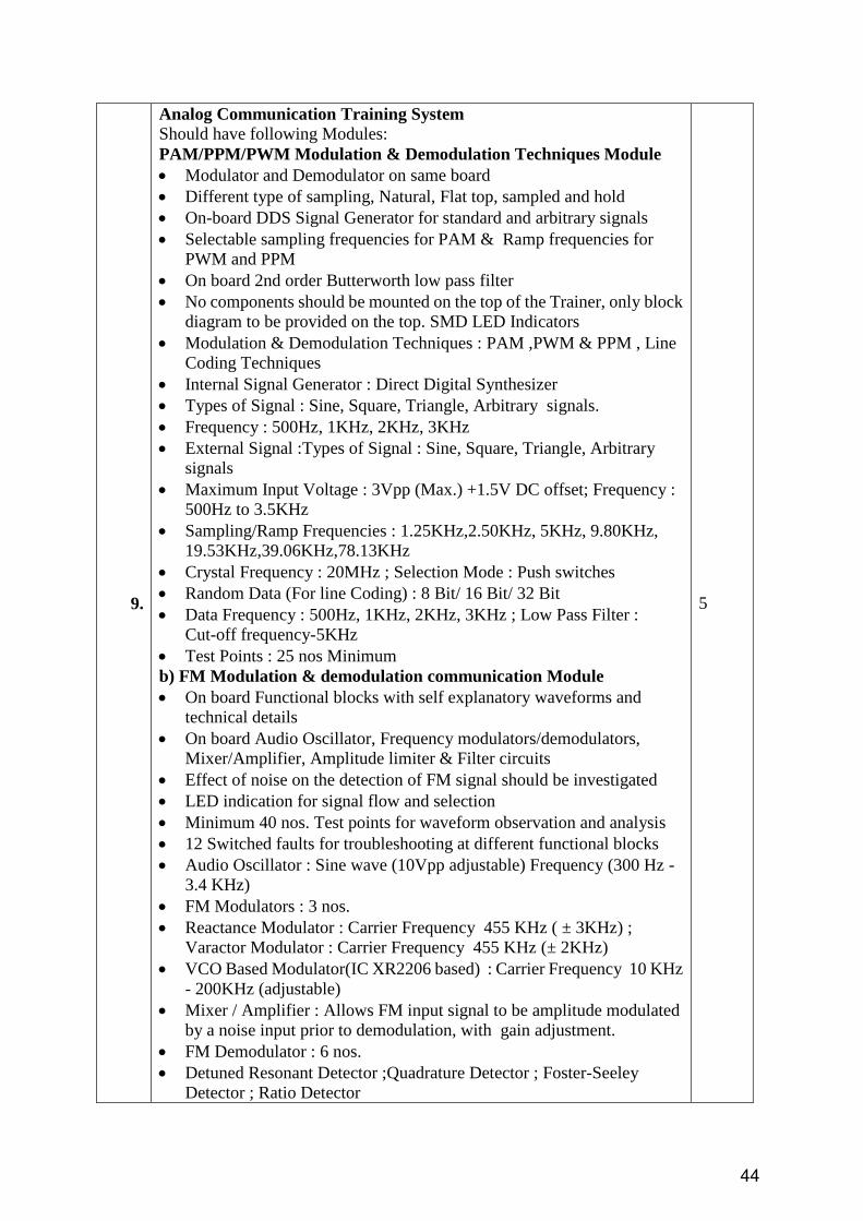
44
9.
Analog Communication Training System
Should have following Modules:
PAM/PPM/PWM Modulation & Demodulation Techniques Module
Modulator and Demodulator on same board
Different type of sampling, Natural, Flat top, sampled and hold
On-board DDS Signal Generator for standard and arbitrary signals
Selectable sampling frequencies for PAM & Ramp frequencies for
PWM and PPM
On board 2nd order Butterworth low pass filter
No components should be mounted on the top of the Trainer, only block
diagram to be provided on the top. SMD LED Indicators
Modulation & Demodulation Techniques : PAM ,PWM & PPM , Line
Coding Techniques
Internal Signal Generator : Direct Digital Synthesizer
Types of Signal : Sine, Square, Triangle, Arbitrary signals.
Frequency : 500Hz, 1KHz, 2KHz, 3KHz
External Signal :Types of Signal : Sine, Square, Triangle, Arbitrary
signals
Maximum Input Voltage : 3Vpp (Max.) +1.5V DC offset; Frequency :
500Hz to 3.5KHz
Sampling/Ramp Frequencies : 1.25KHz,2.50KHz, 5KHz, 9.80KHz,
19.53KHz,39.06KHz,78.13KHz
Crystal Frequency : 20MHz ; Selection Mode : Push switches
Random Data (For line Coding) : 8 Bit/ 16 Bit/ 32 Bit
Data Frequency : 500Hz, 1KHz, 2KHz, 3KHz ; Low Pass Filter :
Cut-off frequency-5KHz
Test Points : 25 nos Minimum
b) FM Modulation & demodulation communication Module
On board Functional blocks with self explanatory waveforms and
technical details
On board Audio Oscillator, Frequency modulators/demodulators,
Mixer/Amplifier, Amplitude limiter & Filter circuits
Effect of noise on the detection of FM signal should be investigated
LED indication for signal flow and selection
Minimum 40 nos. Test points for waveform observation and analysis
12 Switched faults for troubleshooting at different functional blocks
Audio Oscillator : Sine wave (10Vpp adjustable) Frequency (300 Hz -
3.4 KHz)
FM Modulators : 3 nos.
Reactance Modulator : Carrier Frequency 455 KHz ( ± 3KHz) ;
Varactor Modulator : Carrier Frequency 455 KHz (± 2KHz)
VCO Based Modulator(IC XR2206 based) : Carrier Frequency 10 KHz
- 200KHz (adjustable)
Mixer / Amplifier : Allows FM input signal to be amplitude modulated
by a noise input prior to demodulation, with gain adjustment.
FM Demodulator : 6 nos.
Detuned Resonant Detector ;Quadrature Detector ; Foster-Seeley
Detector ; Ratio Detector
5
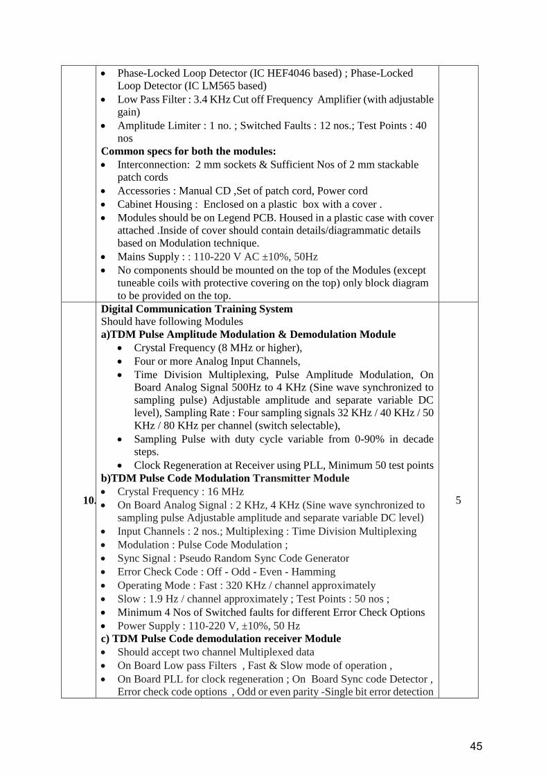
45
Phase-Locked Loop Detector (IC HEF4046 based) ; Phase-Locked
Loop Detector (IC LM565 based)
Low Pass Filter : 3.4 KHz Cut off Frequency Amplifier (with adjustable
gain)
Amplitude Limiter : 1 no. ; Switched Faults : 12 nos.; Test Points : 40
nos
Common specs for both the modules:
Interconnection: 2 mm sockets & Sufficient Nos of 2 mm stackable
patch cords
Accessories : Manual CD ,Set of patch cord, Power cord
Cabinet Housing : Enclosed on a plastic box with a cover .
Modules should be on Legend PCB. Housed in a plastic case with cover
attached .Inside of cover should contain details/diagrammatic details
based on Modulation technique.
Mains Supply : : 110-220 V AC ±10%, 50Hz
No components should be mounted on the top of the Modules (except
tuneable coils with protective covering on the top) only block diagram
to be provided on the top.
10.
Digital Communication Training System
Should have following Modules
a)TDM Pulse Amplitude Modulation & Demodulation Module
Crystal Frequency (8 MHz or higher),
Four or more Analog Input Channels,
Time Division Multiplexing, Pulse Amplitude Modulation, On
Board Analog Signal 500Hz to 4 KHz (Sine wave synchronized to
sampling pulse) Adjustable amplitude and separate variable DC
level), Sampling Rate : Four sampling signals 32 KHz / 40 KHz / 50
KHz / 80 KHz per channel (switch selectable),
Sampling Pulse with duty cycle variable from 0-90% in decade
steps.
Clock Regeneration at Receiver using PLL, Minimum 50 test points
b)TDM Pulse Code Modulation Transmitter Module
Crystal Frequency : 16 MHz
On Board Analog Signal : 2 KHz, 4 KHz (Sine wave synchronized to
sampling pulse Adjustable amplitude and separate variable DC level)
Input Channels : 2 nos.; Multiplexing : Time Division Multiplexing
Modulation : Pulse Code Modulation ;
Sync Signal : Pseudo Random Sync Code Generator
Error Check Code : Off - Odd - Even - Hamming
Operating Mode : Fast : 320 KHz / channel approximately
Slow : 1.9 Hz / channel approximately ; Test Points : 50 nos ;
Minimum 4 Nos of Switched faults for different Error Check Options
Power Supply : 110-220 V, ±10%, 50 Hz
c) TDM Pulse Code demodulation receiver Module
Should accept two channel Multiplexed data
On Board Low pass Filters , Fast & Slow mode of operation ,
On Board PLL for clock regeneration ; On Board Sync code Detector ,
Error check code options , Odd or even parity -Single bit error detection
5
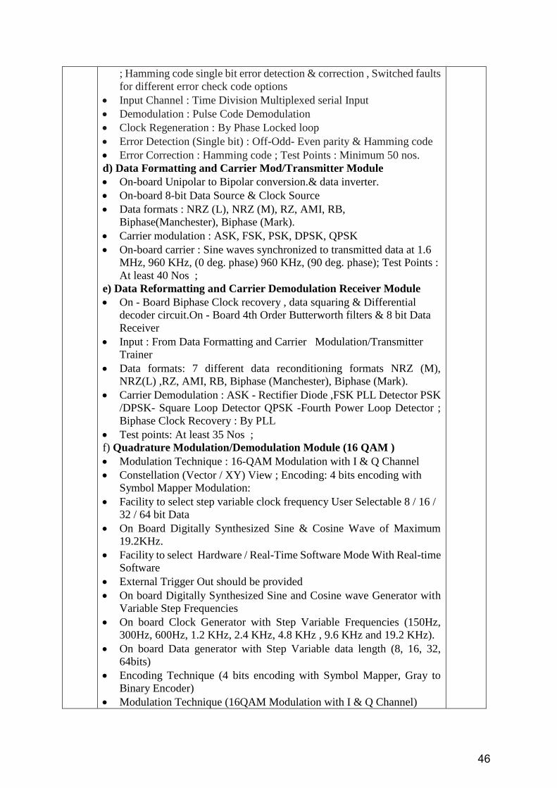
46
; Hamming code single bit error detection & correction , Switched faults
for different error check code options
Input Channel : Time Division Multiplexed serial Input
Demodulation : Pulse Code Demodulation
Clock Regeneration : By Phase Locked loop
Error Detection (Single bit) : Off-Odd- Even parity & Hamming code
Error Correction : Hamming code ; Test Points : Minimum 50 nos.
d) Data Formatting and Carrier Mod/Transmitter Module
On-board Unipolar to Bipolar conversion.& data inverter.
On-board 8-bit Data Source & Clock Source
Data formats : NRZ (L), NRZ (M), RZ, AMI, RB,
Biphase(Manchester), Biphase (Mark).
Carrier modulation : ASK, FSK, PSK, DPSK, QPSK
On-board carrier : Sine waves synchronized to transmitted data at 1.6
MHz, 960 KHz, (0 deg. phase) 960 KHz, (90 deg. phase); Test Points :
At least 40 Nos ;
e) Data Reformatting and Carrier Demodulation Receiver Module
On - Board Biphase Clock recovery , data squaring & Differential
decoder circuit.On - Board 4th Order Butterworth filters & 8 bit Data
Receiver
Input : From Data Formatting and Carrier Modulation/Transmitter
Trainer
Data formats: 7 different data reconditioning formats NRZ (M),
NRZ(L) ,RZ, AMI, RB, Biphase (Manchester), Biphase (Mark).
Carrier Demodulation : ASK - Rectifier Diode ,FSK PLL Detector PSK
/DPSK- Square Loop Detector QPSK -Fourth Power Loop Detector ;
Biphase Clock Recovery : By PLL
Test points: At least 35 Nos ;
f) Quadrature Modulation/Demodulation Module (16 QAM )
Modulation Technique : 16-QAM Modulation with I & Q Channel
Constellation (Vector / XY) View ; Encoding: 4 bits encoding with
Symbol Mapper Modulation:
Facility to select step variable clock frequency User Selectable 8 / 16 /
32 / 64 bit Data
On Board Digitally Synthesized Sine & Cosine Wave of Maximum
19.2KHz.
Facility to select Hardware / Real-Time Software Mode With Real-time
Software
External Trigger Out should be provided
On board Digitally Synthesized Sine and Cosine wave Generator with
Variable Step Frequencies
On board Clock Generator with Step Variable Frequencies (150Hz,
300Hz, 600Hz, 1.2 KHz, 2.4 KHz, 4.8 KHz , 9.6 KHz and 19.2 KHz).
On board Data generator with Step Variable data length (8, 16, 32,
64bits)
Encoding Technique (4 bits encoding with Symbol Mapper, Gray to
Binary Encoder)
Modulation Technique (16QAM Modulation with I & Q Channel)
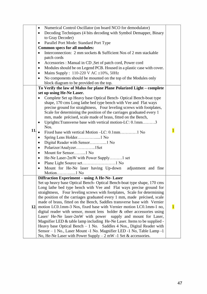
47
Numerical Control Oscillator (on board NCO for demodulator)
Decoding Techniques (4 bits decoding with Symbol Demapper, Binary
to Gray Decoder)
Parallel Port Mode: Standard Port Type
Common specs for all modules:
Interconnection: 2 mm sockets & Sufficient Nos of 2 mm stackable
patch cords
Accessories : Manual in CD ,Set of patch cord, Power cord
Modules should be on Legend PCB. Housed in a plastic case with cover.
Mains Supply : 110-220 V AC ±10%, 50Hz
No components should be mounted on the top of the Modules only
block diagram to be provided on the top.
11.
To Verify the law of Malus for plane Plane Polarized Light – complete
set up using He-Ne Laser.
Complete Set up Heavy base Optical Bench- Optical Bench-boat type
shape, 170 cms Long lathe bed type bench with Vee and Flat ways
precise ground for straightness, Four leveling screws with footplates,
Scale for determining the position of the carriages graduated every 1
mm, made précised, scale made of brass, fitted on the Bench,
Uprights:Transverse base with vertical motion-LC: 0.1mm………3
Nos.
Fixed base with vertical Motion –LC: 0.1mm…………1 No
Spring Lens Holder…….…….....1 No
Digital Reader with Sensor………....1 No
Polarizer/Analyzer…………..1Set
Mount for Sensor……...1 No
He-Ne Laser-2mW with Power Supply………1 set
Plane Light Source set……………………1 No
Mount for He-Ne laser having Up-down adjustment and fine
Motion………......1 No
1
12.
Diffraction Experiment – using A He-Ne- Laser
Set up heavy base Optical Bench- Optical Bench-boat type shape, 170 cms
Long lathe bed type bench with Vee and Flat ways precise ground for
straightness, Four leveling screws with footplates, Scale for determining
the position of the carriages graduated every 1 mm, made précised, scale
made of brass, fitted on the Bench, Saddles transverse base with Vernier
motion LC0.1mm-3 Nos, fixed base with Vernier motion LC0.1mm-1 no,
digital reader with sensor, mount lens holder & other accessories using
Laser/ He-Ne laser-2mW with power supply and mount for Laser,
Magnifier LED & table lamp including He-Ne Laser. Items to be supplied -
Heavy base Optical Bench – 1 No. Saddles 4 Nos., Digital Reader with
Sensor – 1 No., Laser Mount -1 No. Magnifier LED -1 No, Table Lamp -1
No, He-Ne Laser with Power Supply – 2 mW -1 Set & accessories.
1
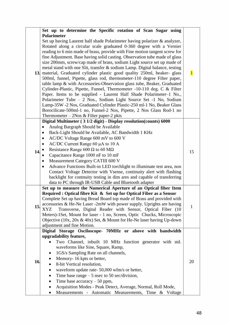
48
13.
Set up to determine the Specific rotation of Scan Sugar using
Polarimeter
Set up having Laurent half shade Polarimeter having polarizer & analyzer,
Rotated along a circular scale graduated 0-360 degree with a Vernier
reading to 6 min made of brass, provide with Fine motion tangent screw for
fine Adjustment. Base having solid casting. Observation tube made of glass
size 200mm, screw/cap made of brass, sodium Light source set up made of
metal stand with one Slit, transfer & sodium Lamp. Digital balance, testing
material, Graduated cylinder plastic good quality 250ml, beaker- glass
500ml, funnel, Pipette, glass rod, thermometer-110 degree Filter paper,
table lamp & with Accessories-Observation glass tube, Beaker, Graduated
Cylinder-Plastic, Pipette, Funnel, Thermometer -10-110 deg. C & Filter
Paper. Items to be supplied - Laurent Half Shade Polarimeter–1 No.,
Polarimeter Tube – 2 Nos., Sodium Light Source Set -1 No, Sodium
Lamp-35W -2 Nos, Graduated Cylinder Plastic-250 ml-1 No, Beaker Glass
Borocilicate-500ml-1 no, Funnel-2 Nos, Pipette, 2 Nos Glass Rod-1 no
Thermometer – 2Nos & Filter paper-2 pkts
1
14.
Digital Multimeter ( 3 1/2 digit) - Display resolution(counts) 6000
Analog Bargraph Should be Available
Back-Light Should be Available, AC Bandwidth 1 KHz
AC/DC Voltage Range 600 mV to 600 V
AC/DC Current Range 60 μA to 10 A
Resistance Range 600 Ω to 60 MΩ
Capacitance Range 1000 nF to 10 mF
Measurement Category CATIII 600 V
Advance Functions Built-in LED torchlight to illuminate test area, non
Contact Voltage Detector with Vsense, continuity alert with flashing
backlight for contnuity testing in dim ares and capable of transferring
data to PC through IR-USB Cable and Bluetooth adapter
15
15.
Set up to measure the Numerical Aperture of an Optical fiber Item
Required : Optical fibre Kit & Set up for Optical Fiber as a Sensor
Complete Set up having Bread Board top made of Brass and provided with
accessories & He-Ne Laser -2mW with power supply. Uprights are having
XYZ Transverse, Digital Reader with Sensor, Optical Fiber (10
Meters)-1Set, Mount for laser - 1 no, Screen, Optic Chucks, Microscopic
Objective (10x, 20x & 40x) Set, & Mount for He-Ne laser having Up-down
adjustment and fine Motion.
1
16.
Digital Storage Osciloscope- 70MHz or above with bandwidth
upgradability feature,
Two Channel, inbuilt 10 MHz function generator with std.
waveforms like Sine, Square, Ramp,
1GS/s Sampling Rate on all channels,
Memory- 16 kpts or better,
8-bit Vertical resolution,
waveform update rate- 50,000 wfm/s or better,
Time base range – 5 nsec to 50 sec/division,
Time base accuracy – 50 ppm,
Acquisition Modes - Peak Detect, Average, Normal, Roll Mode,
Measurements - Automatic Measurements, Time & Voltage
20
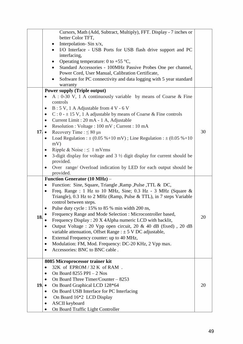
49
Cursors, Math (Add, Subtract, Multiply), FFT. Display - 7 inches or
better Color TFT,
Interpolation- Sin x/x,
I/O Interface - USB Ports for USB flash drive support and PC
interfacing,
Operating temperature: 0 to +55 °C,
Standard Accessories - 100MHz Passive Probes One per channel,
Power Cord, User Manual, Calibration Certificate,
Software for PC connectivity and data logging with 5 year standard
warranty
17.
Power supply (Triple output)
A : 0-30 V, 1 A continuously variable by means of Coarse & Fine
controls
B : 5 V, 1 A Adjustable from 4 V - 6 V
C : 0 - ± 15 V, 1 A adjustable by means of Coarse & Fine controls
Current Limit : 20 mA - 1 A, Adjustable
Resolution : Voltage : 100 mV ; Current : 10 mA
Recovery Time : ≤ 80 μs
Load Regulation : ± (0.05 %+10 mV) ; Line Regulation : ± (0.05 %+10
mV)
Ripple & Noise : ≤ 1 mVrms
3-digit display for voltage and 3 ½ digit display for current should be
provided.
Over range/ Overload indication by LED for each output should be
provided.
30
18.
Function Generator (10 MHz) –
Function: Sine, Square, Triangle ,Ramp ,Pulse ,TTL & DC,
Freq. Range : 1 Hz to 10 MHz, Sine; 0.3 Hz - 3 MHz (Square &
Triangle), 0.3 Hz to 2 MHz (Ramp, Pulse & TTL), in 7 steps Variable
control between steps.
Pulse duty cycle : 15% to 85 % min width 200 ns,
Frequency Range and Mode Selection : Microcontroller based,
Frequency Display : 20 X 4Alpha numeric LCD with backlit,
Output Voltage : 20 Vpp open circuit, 20 & 40 dB (fixed) , 20 dB
variable attenuation, Offset Range : ± 5 V DC adjustable,
External Frequency counter: up to 40 MHz,
Modulation: FM, Mod. Frequency: DC-20 KHz, 2 Vpp max.
Accessories: BNC to BNC cable .
20
19.
8085 Microprocessor trainer kit
32K of EPROM / 32 K of RAM .
On Board 8255 PPI – 2 Nos
On Board Three Timer/Counter – 8253
On Board Graphical LCD 128*64
On Board USB Interface for PC Interfacing
On Board 16*2 LCD Display
ASCII keyboard
On Board Traffic Light Controller
20

50
On Board Stepper Motor Interface
On Board Digital Output LED- 8 Nos
On Board Digital input –8 Nos
Allows on board Assembly language programming
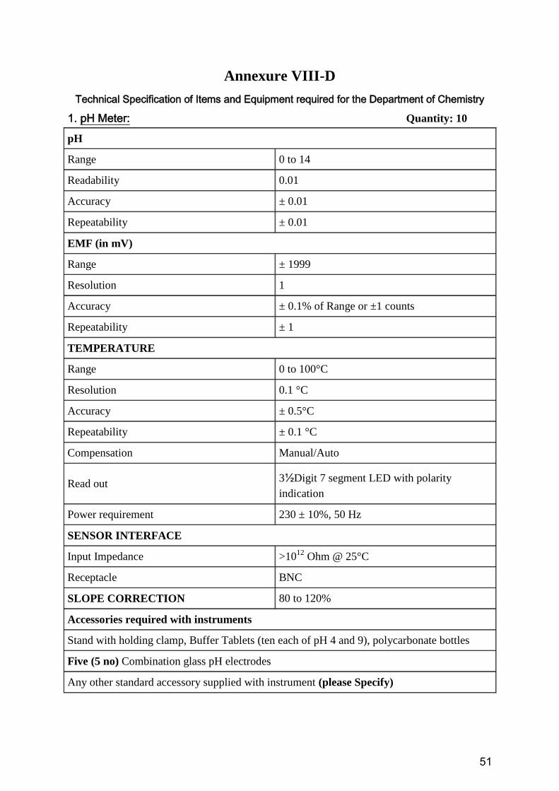
51
Annexure VIII-D
Technical Specification of Items and Equipment required for the Department of Chemistry
1. pH Meter: Quantity: 10
pH
Range 0 to 14
Readability 0.01
Accuracy ± 0.01
Repeatability ± 0.01
EMF (in mV)
Range ± 1999
Resolution 1
Accuracy ± 0.1% of Range or ±1 counts
Repeatability ± 1
TEMPERATURE
Range 0 to 100°C
Resolution 0.1 °C
Accuracy ± 0.5°C
Repeatability ± 0.1 °C
Compensation Manual/Auto
Read out 3½Digit 7 segment LED with polarity
indication
Power requirement 230 ± 10%, 50 Hz
SENSOR INTERFACE
Input Impedance >1012
Ohm @ 25°C
Receptacle BNC
SLOPE CORRECTION 80 to 120%
Accessories required with instruments
Stand with holding clamp, Buffer Tablets (ten each of pH 4 and 9), polycarbonate bottles
Five (5 no) Combination glass pH electrodes
Any other standard accessory supplied with instrument (please Specify)
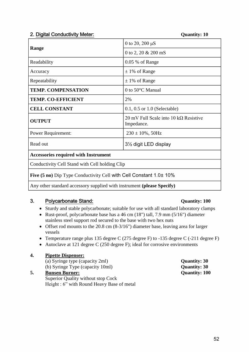
52
2. Digital Conductivity Meter: Quantity: 10
Range 0 to 20, 200 μS
0 to 2, 20 & 200 mS
Readability 0.05 % of Range
Accuracy ± 1% of Range
Repeatability ± 1% of Range
TEMP. COMPENSATION 0 to 50°C Manual
TEMP. CO-EFFICIENT 2%
CELL CONSTANT 0.1, 0.5 or 1.0 (Selectable)
OUTPUT 20 mV Full Scale into 10 kΩ Resistive
Impedance.
Power Requirement: 230 ± 10%, 50Hz
Read out 3½ digit LED display
Accessories required with Instrument
Conductivity Cell Stand with Cell holding Clip
Five (5 no) Dip Type Conductivity Cell with Cell Constant 1.0± 10%
Any other standard accessory supplied with instrument (please Specify)
3. Polycarbonate Stand: Quantity: 100
Sturdy and stable polycarbonate; suitable for use with all standard laboratory clamps
Rust-proof, polycarbonate base has a 46 cm (18") tall, 7.9 mm (5/16") diameter
stainless steel support rod secured to the base with two hex nuts
Offset rod mounts to the 20.8 cm (8-3/16") diameter base, leaving area for larger
vessels
Temperature range plus 135 degree C (275 degree F) to -135 degree C (-211 degree F)
Autoclave at 121 degree C (250 degree F); ideal for corrosive environments
4. Pipette Dispenser: (a) Syringe type (capacity 2ml) Quantity: 30
(b) Syringe Type (capacity 10ml) Quantity: 30
5. Bunsen Burner: Quantity: 100
Superior Quality without stop Cock
Height : 6” with Round Heavy Base of metal

53
Annexure VIII-E
Technical Specification for Equipment’s of Department of Botany
S.N. Name of the Items Required
Quantity
Specifications
1 Microscope Electronic 35
Binocular Head: Siedentopf Observation head
inclined at 30° rotatable at 360°,Diopter
adjustment ring on ocular tube. (±5);
Interpupillary distance from 48mm to 75mm,
Eyepiece ( Anti fungus coated):Wide Field
10X (paired) F.O.V 20mm,Objectives (Anti
Mold & Anti fungus coated): S Plan
Achromatic 4X,S Plan Achromatic 10X, S
Plan Achromatic 40X(S.L.);S Plan
Achromatic 100X Oil(S.L.); Mechanical
Body:Co-axial focusing system.
PRE-FOCUSING LEVER & TENSION
ADJUSTMENT RING, Reverse angel
quadruple nosepiece revolves on ball bearing;
Double plate mechanical stage size 140mm X
132mm having low positioned co-axial
controls. Coarse stroke 37.7mm/rotation, fine
division 0.002mm, Cross travel 78mm X
54mmmm; Sub Stage Condenser: Abbe
condenser N.A.1.25 with adjustable iris
diaphragm; Illumination System:The
illuminator incorporates 3W LED lamp and
has adjustable brightness; Accessories: Dust
cover, operating manual, guarantee card, blue
filter and Styrofoam molded pack.
2 Water bath 2
Digital Temperature Control, Double Walled,
Double Eliment, Max. Temperature Range
1000C
3 Centrifuge Machine
Ultra 1
RPM: 22,000rpm (approx); RCF: 53,029 xg;
Max. capacity: 1,000ml x 4; Time: 99hrs
59min 59sec; Display: RPM, RCF, Time,
Temperature, Program, Temp.Limit,
Accel/Decel, Rotor Number,Rotor Radius;
Accel/Decel: 10 step; Temperature: -10 C~ 40
C; Motor: AC Induction Motor; Power supply:
220V, 60Hz, single phase; Dimension: 668W
x 801D x 891H/mm (approx)
4 Soil Thermometer 2 Metal Cone, Digital
5 Hot Air Ovens 2 Digital Temperature Control, Fan
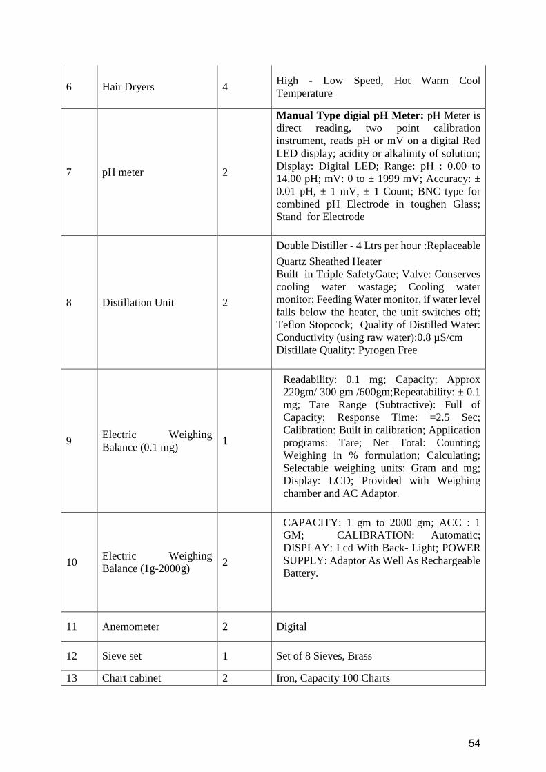
54
6 Hair Dryers 4 High - Low Speed, Hot Warm Cool
Temperature
7 pH meter 2
Manual Type digial pH Meter: pH Meter is
direct reading, two point calibration
instrument, reads pH or mV on a digital Red
LED display; acidity or alkalinity of solution;
Display: Digital LED; Range: pH : 0.00 to
14.00 pH; mV: 0 to ± 1999 mV; Accuracy: ±
0.01 pH, ± 1 mV, ± 1 Count; BNC type for
combined pH Electrode in toughen Glass;
Stand for Electrode
8 Distillation Unit 2
Double Distiller - 4 Ltrs per hour :Replaceable
Quartz Sheathed Heater
Built in Triple SafetyGate; Valve: Conserves
cooling water wastage; Cooling water
monitor; Feeding Water monitor, if water level
falls below the heater, the unit switches off;
Teflon Stopcock; Quality of Distilled Water:
Conductivity (using raw water):0.8 µS/cm
Distillate Quality: Pyrogen Free
9 Electric Weighing
Balance (0.1 mg) 1
Readability: 0.1 mg; Capacity: Approx
220gm/ 300 gm /600gm;Repeatability: ± 0.1
mg; Tare Range (Subtractive): Full of
Capacity; Response Time: =2.5 Sec;
Calibration: Built in calibration; Application
programs: Tare; Net Total: Counting;
Weighing in % formulation; Calculating;
Selectable weighing units: Gram and mg;
Display: LCD; Provided with Weighing
chamber and AC Adaptor.
10 Electric Weighing
Balance (1g-2000g) 2
CAPACITY: 1 gm to 2000 gm; ACC : 1
GM; CALIBRATION: Automatic;
DISPLAY: Lcd With Back- Light; POWER
SUPPLY: Adaptor As Well As Rechargeable
Battery.
11 Anemometer 2 Digital
12 Sieve set 1 Set of 8 Sieves, Brass
13 Chart cabinet 2 Iron, Capacity 100 Charts
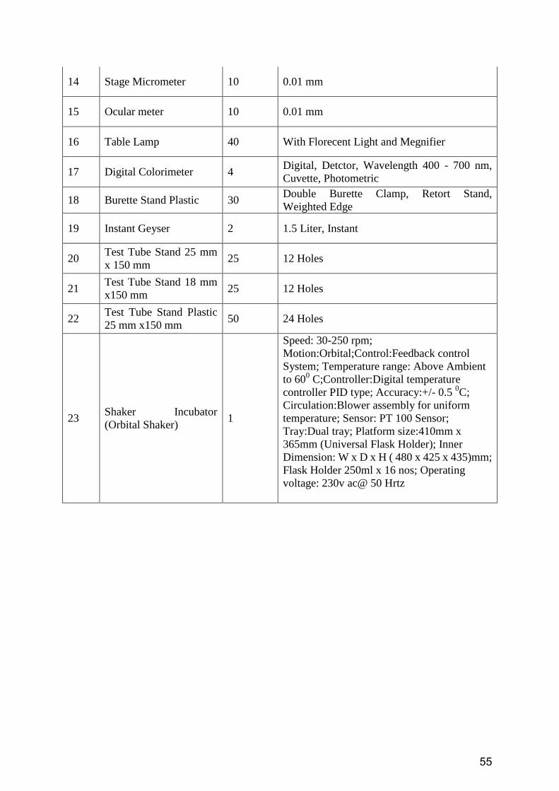
55
14 Stage Micrometer 10 0.01 mm
15 Ocular meter 10 0.01 mm
16 Table Lamp 40 With Florecent Light and Megnifier
17 Digital Colorimeter 4 Digital, Detctor, Wavelength 400 - 700 nm,
Cuvette, Photometric
18 Burette Stand Plastic 30 Double Burette Clamp, Retort Stand,
Weighted Edge
19 Instant Geyser 2 1.5 Liter, Instant
20 Test Tube Stand 25 mm
x 150 mm 25 12 Holes
21 Test Tube Stand 18 mm
x150 mm 25 12 Holes
22 Test Tube Stand Plastic
25 mm x150 mm 50 24 Holes
23 Shaker Incubator
(Orbital Shaker) 1
Speed: 30-250 rpm;
Motion:Orbital;Control:Feedback control
System; Temperature range: Above Ambient
to 600 C;Controller:Digital temperature
controller PID type; Accuracy:+/- 0.5 0C;
Circulation:Blower assembly for uniform
temperature; Sensor: PT 100 Sensor;
Tray:Dual tray; Platform size:410mm x
365mm (Universal Flask Holder); Inner
Dimension: W x D x H ( 480 x 425 x 435)mm;
Flask Holder 250ml x 16 nos; Operating
voltage: 230v ac@ 50 Hrtz
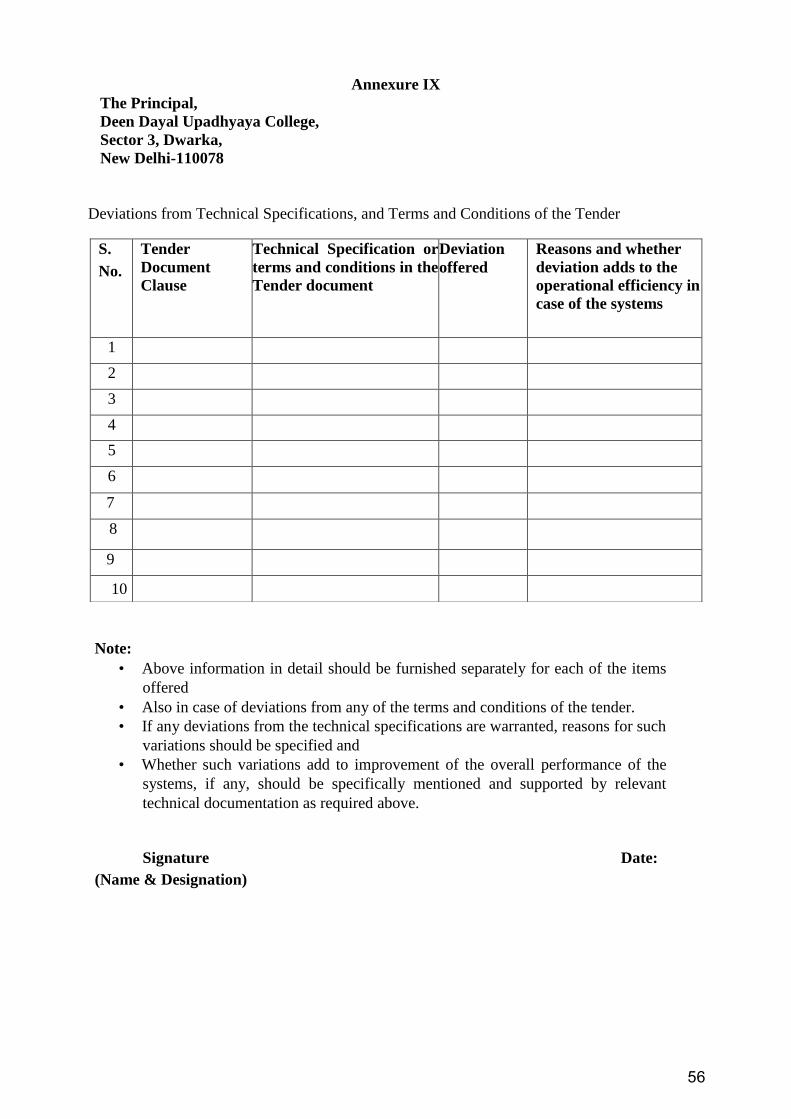
56
Annexure IX
The Principal,
Deen Dayal Upadhyaya College,
Sector 3, Dwarka,
New Delhi-110078
Deviations from Technical Specifications, and Terms and Conditions of the Tender
Note:
• Above information in detail should be furnished separately for each of the items
offered
• Also in case of deviations from any of the terms and conditions of the tender.
• If any deviations from the technical specifications are warranted, reasons for such
variations should be specified and
• Whether such variations add to improvement of the overall performance of the
systems, if any, should be specifically mentioned and supported by relevant
technical documentation as required above.
Signature Date:
(Name & Designation)
S.
No.
Tender
Document
Clause
Technical Specification or
terms and conditions in the
Tender document
Deviation
offered
Reasons and whether
deviation adds to the
operational efficiency in
case of the systems
1
2
3
4
5
6
7
8
9
10
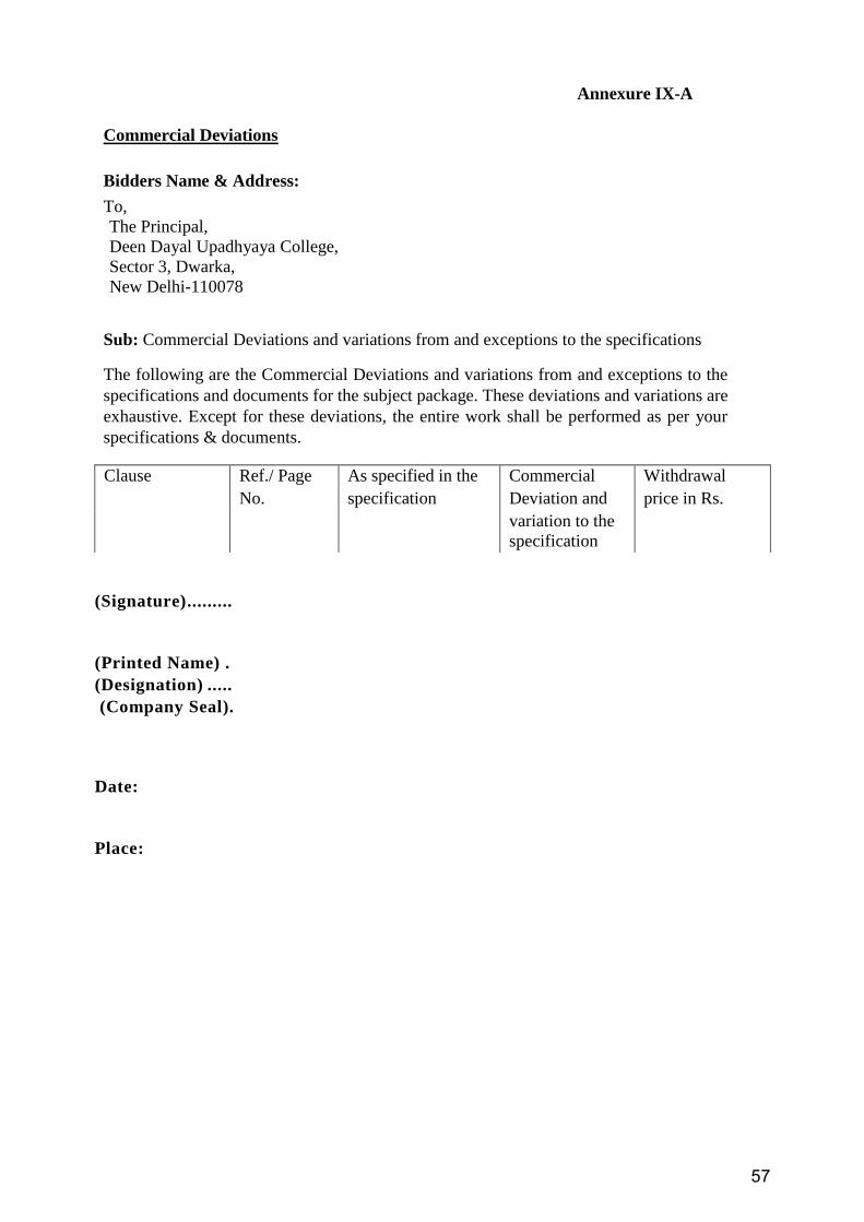
57
Annexure IX-A
Commercial Deviations
Bidders Name & Address:
To,
The Principal,
Deen Dayal Upadhyaya College,
Sector 3, Dwarka,
New Delhi-110078
Sub: Commercial Deviations and variations from and exceptions to the specifications
The following are the Commercial Deviations and variations from and exceptions to the
specifications and documents for the subject package. These deviations and variations are
exhaustive. Except for these deviations, the entire work shall be performed as per your
specifications & documents.
(Signature) .........
(Printed Name) .
(Designation) .....
(Company Seal).
Date:
Place:
Clause Ref./ Page As specified in the Commercial Withdrawal
No. specification Deviation and price in Rs.
variation to the
specification