decd_2046.pdf - Ptolomeo Unam
384
( ·,:: . 'r IFACILDL TAO DE BINIGEINIDEIFUA ILD.INI.A.M. DDVDSDOINI DE EDILDCACDOINI COINITDINIILDA FACULTAD DE INGENIERIA U.N.A.M. DIVISION DE EDUCACION CONTINUA CENTRO DE INFORMACION Y DOCUMENTACION "ING. BRUNO MASCANZONI" E1 Centro de Información y lng. Bruno Mascanzoni tiene por objetivo satisfacer las necesidades de actualización y proporcionar una adecuada información que permita a los ingenieros, profesores y alumnos estar al tanto del estado actual del conocimiento sobre temas específicos, enfatizando las investigaciones de vanguardia de los campos de la ingeniería, tanto nacionales como extranjeras. Es por ello que se pone a disposición de los asistentes a los cursos de la DECFI, así como del público en general los siguientes servicios: • Préstamo interno. • Préstamo externo. · • Préstamo interbibliotecario. • Servicio de fotocopiado. • Consulta a los bancos de datos: librunam, seriunam en cd-rom. Los materiales a disposición son: • Libros. • Tesis de posgrado. • Noticias técnicas. • Publicaciones pariódicas. • Publicaciones de la Academia Mexicana de Ingeniería. • Notas de los cursos que se han impartido de 1980 a la fecha. En las áreas de ingeniería industrial, civil, electrónica, ciencias de la tierra, computación y, mecánica y eléctrica. El CID se encuentra ubicado en el mezzanine del Palacio de Minería, lado oriente. El horario de servicio es de 10:00 a 19:30 horas de lunes a viernes. Palacio de Minería Calle de Tacuba 5 Primer piso Oeleg. Cuauhtemoc 06000 Mexico, D.F. APDO. Postal M-2285 Telefonos: 512-ll955 512-5121 521-7335 521-1987 Fax 510-0573 · 521-4020 AL26
-
Upload
khangminh22 -
Category
Documents
-
view
0 -
download
0
Transcript of decd_2046.pdf - Ptolomeo Unam

. - .
(
·,:: . 'r ~:
IFACILDL TAO DE BINIGEINIDEIFUA ILD.INI.A.M. DDVDSDOINI DE EDILDCACDOINI COINITDINIILDA
FACULTAD DE INGENIERIA U.N.A.M. DIVISION DE EDUCACION CONTINUA
CENTRO DE INFORMACION Y DOCUMENTACION
"ING. BRUNO MASCANZONI"
E1 Centro de Información y Documenta~ión lng. Bruno Mascanzoni tiene por
objetivo satisfacer las necesidades de actualización y proporcionar una
adecuada información que permita a los ingenieros, profesores y alumnos estar
al tanto del estado actual del conocimiento sobre temas específicos,
enfatizando las investigaciones de vanguardia de los campos de la ingeniería,
tanto nacionales como extranjeras.
Es por ello que se pone a disposición de los asistentes a los cursos de la DECFI,
así como del público en general los siguientes servicios:
• Préstamo interno.
• Préstamo externo. ·
• Préstamo interbibliotecario.
• Servicio de fotocopiado.
• Consulta a los bancos de datos: librunam, seriunam en cd-rom.
Los materiales a disposición son:
• Libros.
• Tesis de posgrado.
• Noticias técnicas.
• Publicaciones pariódicas.
• Publicaciones de la Academia Mexicana de Ingeniería.
• Notas de los cursos que se han impartido de 1980 a la fecha.
En las áreas de ingeniería industrial, civil, electrónica, ciencias de la tierra,
computación y, mecánica y eléctrica.
El CID se encuentra ubicado en el mezzanine del Palacio de Minería, lado
oriente.
El horario de servicio es de 10:00 a 19:30 horas de lunes a viernes. Palacio de Minería Calle de Tacuba 5 Primer piso Oeleg. Cuauhtemoc 06000 Mexico, D.F. APDO. Postal M-2285
Telefonos: 512-ll955 512-5121 521-7335 521-1987 Fax 510-0573 · 521-4020 AL26

•
FACUL;TAD DE INGENIEAIA U.N.A.M. DIVBSION DE EDUCACION CONTINUA
A LOS ASISTENTES A LOS CURSOS
Las autoridades de la Facultad de Ingeniería, por conducto del jefe de la
División de Educación Continua, otorgan una constancia de asistencia a
quienes cumplan con los requisitos establecidos para cada curso.
El control de asistencia se llevará a cabo a través de la persona que le entregó
las notas. Las inasistencias serán computadas por las autoridades de la
División, con el fin de entregarle constancia solamente a loa alumnos que
tengan un mínimo de so•/o de asistencias.
Pedimos a loa asistentes recoger su constancia el día de la clausura. Estas se
retendrán por el periodo de un año, pasado este tiempo la DECFI no se hará
responsable de este documento .
Se recomienda a los asistentes participar activamente con sus ideas y
experiencias, pues los' cursos que ofrece la División están planeados para que
los profesores expongan una tesis, pero sobre todo, para que coordinen las
opiniones de todos los interesados, constituyendo verdaderos seminarios.
Es muy importante que todos los asistentes llenen y entreguen su hoja de
inscripción al inicio del curso, información que servirá para integrar un
directorio de asistentes, que se entregará oportunamente.
Con el objeto de mejorar los servicios que la División de Educación Continua
ofrece, al final del curso "deberán entregar la evaluación a través de un
cuestionario diseñado para emitir juicios anónimos.
Se recomienda llenar dicha evaluación conforme los profesores impartan sus
clases, a efecto de no llenar en la última sesión las evaluaciones y con esto
sean más fehacientes sus apreciaciones.
Palacio de Minería Calle de Tacuba 5 Telefonos: 512-8955
Atentamente
División de Educación Continua.
Primer piso Deleg. Cuauhtemoc 06000 México, D.F. APDO. Postal M·2285 5!2·5!2! 521-7335 521·1987 Fax 510-0573 521-4020 Al26

PALACIO DE MINERIA n n TI TI • n - - " n n n r - - n n n - -
< 1-
~ ® o
z w ~ :::! u.. w \ 1 "' / \ 1 -!
~ z '( " / \ 1 o PATIO PRINCIPAL ¡::;
1 \ ;, ¡¡; / " o .. 1 \ / " 1
)( 1 UJ
" --1
:.• . CALLE TACUBA
PLANTA BAJA MEZZANINNE

.,
PALACIO og MINERIA - - - - - - - - - - - - - - - - -11 11 11 11 1 1 11 11 ' 11 11 ·11 1 1 11 11 11 -
• C-11
• C-10
ler. PISO
ACADEMIA 1 INGENIERIA
CALLE TACUBA
• C-9
GUÍA DE LOCALIZACIÓN !.ACCESO
2. BffiLIOTECA IUSTÓRICA
3. LIBRERÍA UNAM
4. CENTRO DE INFORMACIÓN Y DOCUMENTACIÓN "ING. BRUNO MASCANZONI"
5. PROGRAMA DE APOYO A LA TITULACIÓN
6. OFICINAS GENERALES
7. ENTREGA DE MATERIAL Y CONTROL DE ASISTENCIA
8. SALA DE DESCANSO
SANITARIOS
* AULAS
DMSIÓN DE EDUCACIÓN CONfiNUA ' ' .
' FACULTAD DE INGENIERIA U.N.A.M. CURSOS ABIERfOS
· .. ·(-}·· . _.' -.·

.. '1
-
DIVISION DE EDUCACION CONTINUA . FACULTAD DE INGENIERIA; UNAM
CURSOS ABIERTOS
CURSO: CC059 Bedes de Alto Desempeño: A'Drl, Fnale ,BeJay • SwitchiDg. Fast y FECHA: 8 al U de septiembre de 1991
EVALUACIÓN DEL PERSONAL DOCENTE (ESCALA DE EVALUACIÓN 1 A 10)
CONFERENCISTA llOMINIO USO DE AYUDAS COMUNICACION PUNTUALIDAD
DEL TEMA AUDIOVISUALES GON EL ASISTENTE
ING. SAUL MAGA~A CISNEROS
ING. JUAN CARLOS MAGA~ A C.
SR. ADRIAN MAGA~A CISNEROS
-' --- ----- --·
··-----·
-------
Promedto
EVALUACIÓN DE LA ENSEÑMJZA ----CONCePTO CAt1r
ORGANIZACION '(DESARROLLO DEL CUH00
GRADO DE PROFUNDIDAD DEL CURSO
ACTUALIZACION DEL CURSO
APLICACIÓN PRACTICA DEL CURSO PromediO ----EVALUACIÓN DEL CURSO CONCEPTO CALIF
CUMPLIMIENTO DE LOS OBJETIVOS DEL CURSO
CONTINUIDAD EN LOS TEMAS
CALIDAD DEL MATERIAL DIDÁCTICO UTILIZADO Promedio ----Evaluación total del curso ____ _ Continúa ... 2

-.
1. ¿Le agrado su e;lancí;; en la División de Educación Continua?
SI NO
Sí indica que 'NO" ?ína porque:
2. Medía a tro•¡(:s del cual se enteró del curso:
Penódíco Excé/sior
Periódico La Jornada
Folleto anual
Folleto del curso
Gacela UNAM
Rev1sias técnu.:as
Otro medio (Indique cual)
3. ¿Que cambios sugeriría al curso para mejorarlo?
4. ¿Recomendaría el curso a olra(s) persona(s) ?
SI NO
S.¿Qué cursos sugiere que Imparta la D1visíón de Educación Continua?
6. Otras sugerencias:

FACUL TAO DE INGENIEAIA U.N.A.M. DIVISION DE EDUCACION CONTINUA
DIPLOIUADO DE REDES LAlf DE IIICROC<»>PUTADORAS
IIODULO IV
REDES DE ALTO DES1131PERO. ATitl. FRAilE, REI..AY. SlOTCWNG. FAST Y EHTERNET. FDDI-U
8 al 12 de septiembre de 1997
DIRECTORIO DE PROFESORES
DIG. SAUL ltiAGABA CISREROS
DIG • .JUAN CARLOS lriAGÁRA CISNEROS
SR. ADRIAN 1r1AGA9A CISNEROS
CONSULTORES ICDIEX. S.A. DE C.V • . AV. UNIVERSIDAD No. 1810. :_ A - 1
COL. ROMERO DE TERREROS DELEGACION COYOACAN C.P. 04310 MEXICO, D.F. TEL: 659 86 34 FAX: 658 37 26
'pmc.
•.. ,
Palacio de Mmeria Calle de Tacuba S Pnmcr p1so Deleg Cuauhlemoc C6000. Me11co. O F. APDO. Postal M·2285 Telelonos: 512-6955 512·5121 521·7335 521-19117 Fu 510-Q!;ll 521-~020 AL 26

FACUL TAO DE INGENIEAIA U.N.A.M. DIVISION DE EDUCACION CONTINUA
DIPLOtiADO DE REDES LAR DE IIICBOCOIIriPUTADORAS
IIODOLO IV
REDES DE ALTO DESIIlliii'ERO. ATII. FRAJUE, RELAY. S111TCmlfG. FAST Y EIITERifET. FDDI-D
lllATJtRIAL DIDACTICO
SEPTIEtiBRE DE 1997
Palacro de Mrnena C1lre a e T acuba) ~"11"!'~ prsc De re; Cua.:ntemoc 06000 Mexrco. O F ;.,q·,(; F'ostal M-228: Tololono• 512-6955 512-5121 521-llll 521-191l7 Fu 510-(1':;71 521·4010 Ac 1'

. 1
REDES DE ALTO DESEMPEÑO; FAST ETHERNET, FDDI~I. "SWITCHING", ATM Y FRAME RELAY
MODULO IV (Rad)
PRESENTACION
La constante evolución en las tecnologlas de tas Redes de Cómputo y las Comunicaciones, ha pennitldo que el que hacer del hombre en este campo, cada dla acorte el tiempo, mejore la seguridad en sus aplrcacrones e. tncremente su productividad.
A partrr de que las computadoras tUVIeron una represantacrón sena a nrvel de escritono (PC's-1980), en seguida se tuvo la neces~dad de conectarlas para compartir y explotar recursos naciendo asilas Redes locales (LAN's} en su primera generación (1980~2). Después abundaron estas nuevas herramientas de la computacrón e rnformétrca y por la necesrdad de rnterconectar estas LAN"s en el srgurente paso surgreron las Redes de segunda generación (1985), apareciendo para ese fin los puentes (Bridges), que con sus lrmrtantes tecnológicas de entonces. dreron la oportunidad de eficrentar y amphar la cobertura de las Redes, mterconectándolas 1nclus1ve, con topologlas heterogéneas.
Fueron necesanos aproximadamente c1nco anos para que la evoluc1ón de los puentes. bnndara la tecnologla adecuada para que la interconeXIón de las Redes. contara con la efic1enc1a de los ruteadores, m1smos que resoMeron el problema del tráfico multipunto. desarrollando asl las Redes de tercera ge~eración {1990)
Esta marcada evoluc1ón en la tecnolog1a de las Redes a fdo acompaflada de un arto desarrollo en los medios de telecomunicaCIOnes como l'loy lo son ISDN y B..&SDN los cuales nos ofrecen 1ntegrac1ón de mUttlples serv1c1os (voz, datos. imagen y sonido) grac1as a sus amphos anchos de banda. Combinando ambas 1novac1ones. surgen fuertemente a partir de 1995, las. Redes de Alto Desempel'\o que definm . a las Redes de cuarta generación caractenzadas por una tecnologla de conmutac1ón (Switchmg), los serv1c1os de Cell Relay que denvan en la tecnologla ATM, la evoluc1ón de protocolos ampliamente d1fund1dos como X.25 hacia Frame Relay y finalmente el desarrollo· de las tecnologlas trad1c1ona1es Ethernet y FDDI, hac1a Fast Ethernet y FDDI-U
Considerando que esta breve presentaCión no permrte abundar y detallar més sobre este tema que es amplio y enervante. se observa entonces que las Redes actuales
con sus etemet Itas de comunicación. Implican una sen e de tecnologlas y arquitecturas modernas y avanzadas. que generan Ul necesidad del COnocimiento y dommio de las mtsmaS, y esto es Imperante!. Se 'requtere por lo tanto, de especialistas y e¡ecubvos bien capacitados y bien informados respectivamente, para un soporte técnico y toma de decisiones adecuados en este profundo y apasionanle campo de las Redes.
Conscientes de la necesidad de formar espec1al1stas altamente capacitados, que puedan responder al reto que representan la Redes de Atto Desempeflo, ofrecemos este curso como un módulo més del Diplomado, ylo como una oportunidad de actualización, tratando de lograr los sigutentes
OBJETIVOS
Introducir a los participantes en las tecnologlas de lOs SeMclOS Integrados de Redes Digitales de Banda Ancha (B·ISDN) y dar a conocer los está:ndares y protocolos de las diferentes tecnologlas y serv~c1os avanzados de este recurso.
Lograr en los particrpantes la capacidad de ponderar y definir tos principios báSICOS para seleccionar los Sistemas de banda ancha adecuados para las necesrdades de cada proyecto, y asl mismo. el hábrto del anahsis de los productos que ofrece el mercado actuaL
Tratar que con los antecedentes y conceptos bás1cos de la lecnologla y serviciOS 'SWITCHING', CELL RELAY, . ATM y FRAME RELAY queden b1en mstalados en los participantes.
Lograr que con apoyo en una termlnologla y drCCIOnano de Siglas. se domine la defimc1ón de cada acrónrmo. a efecto de elimmar dudas.
Pugnar por lograr el apoyo necesano donde se puedan estudrar casos reales y sea factible mostrar la rntegrac1ón de vanos . sistemas con base en laS tecnolog1as · menc1onadas
A QUIEN VA DIRIGIDO
A todOS aquellos profesionales y profesiomstas que por sus neceSidades laborales. estén Involucrados con laS Redes de Cómputo y requreran actualizarse en las Redes de Alto Desemper"'o, y a los EJecutivos que necesiten bases técnrcas en su responsabilidad de toma de deCrsiones
REQUISITOS .
Los participantes deben tener conocimientos en Redes (LAN) de Cómputo (s1n ser hmrtante) y de preferencia también, conoc1mrentos de Comumcacrones D1g1tales ·
DURACION
La durac16n del presente módulo es de 20 hrs

•.
1
REDES DE ALTO DESEMPEÑO; FAST ETHERNET, FDDI-U, "SWITCHING", ATMY
FRAME RELAY
M O O U LO IV (Rad)
TEMARIO
r
Q 1.- FAST ETHERNET Q 4.-ATM
-1J 1 ntroducción -'11 Ethernet 1 OBaseT -'11 Introducción -'11 Características de 1 OOBaseT -'0 Componentes -'11 Estándares y Normalización -'0 Servicios -'11 Tipos de cableado -'11 Estructura de la celda -'11 Características de los dispositivos Fast- -'11 Modelo B-ISDN
Ethemet -'11 Redes Conmutadas -'11 Alternativas de implementación
Q 2.- FDDI, FDDI 11
-'11 Introducción -'11 Antecedentes de FDDI -'11 Características
--'11 Fibras ópticas -- -- ---- - - --'11 Backbones -'0 Funcionamiento "J Dispositivos -'0 Normalización "J Antecedentes de FDDI 11 -'0 Características -'11 Funcionamiento -'11 Normalización
Q 3.- SWITCHES
-'0 Introducción "C Características "i': Tecnología Store and Forward -'0 Tecnología Cut-Through -'0 Switchs ATM Ji'; Switchs Ethernet
-'11 Niveles de adaptación, convergencia y físico
"1i Aplicaciones y casos de estudio
Q 5.- FRAME RELAY
-'11 Introducción -'11 Tecnologías antecesoras
-- --'11-Terminología y funcion~miento----- - - --- -- - ----- --'11 Estructura de trame --'0 Administración de la congestión -'0 Técnicas de reducción de trafico -'0 Interfaces de administración local -':i Estándares -'11 Aplicaciones y casos de estudio
Q 6.- APLICACIONES
-'0 Redes Virtuales -'11 Redes Multimedia -'0 Vídeo Conferencia -'11 Integración total de Redes;
L.AN=MAN=WAN=GAN

'
INTRODUCCION

·. ; -
NuEvAs TECNoloqiAs ~------....
dE REdES dE COMpUTAdORAS-- 1995
- '1

~ : ~ESAR§DE ~ : TE;NOL;GIA D~ RED~S -1 LAN'S Virtuales 1
LAN'S de Alto Desempeflo
. ~INTERNET 1
LAN'S Switches
1 L.AN'S Routers r · 1 LAN'S Bridges J
1 LAN'S
1980 1985 o 1995 1996

t
Redes de alto desempeño
• FDDI, FDDI - 11 • FAST ETHERNET
• TECNOLOGIA SWITCHING
•ATM . • FRAME RELA Y
• 8 - ISND
..
~· REDES
~.REDES
VIRTUALES
MULTIMEDIA VIDEOCONFERENCIAS
REDES \ . LAN = MAN = WAN = GAN

TECjiJOLOGIAS EN SISTEMAS DE BANDA ANCHA
COMUNICACION DIGITAL
Q BANDABASE
Q BANDA ANCHA
1-2

TECNOLOGIAS EN SISTEMAS DE BANDA ANCHA
BANDA BASE Características: Q Un solo canal Q Bajocosto Q Se modula y demodula la señal Q Utilizada por los estándares actuales
de REDES locales
1-3

•
· TECNOLOGIAS EN SISTEMAS DE BANDA ANCHA
BANDA ANCHA Características: ¡;¡ Varios Canales Paralelos ¡;¡ Multiplexaje por Frecuencia ¡;¡ -(>Un canal de Transmisión ¡;¡ <!-Un Canal de Recepción
1-4

TECNOLOGIAS EN SISTEMAS DE BANDA AN~HA
SERVICIOS CONMUTADOS DE ALTA VELOCIDAD
Alta Velocidad:
Q .. ISDN lntegrated Service Digital Networ1<
Q B-ISDN Broadband-lntegrated Service Digital Networ1<
1-5

TECNOLOGIAS EN SISTEMAS DE BANDA ANCHA
ISDN Acceso a los servicios de telecomunicaciones sin ISDN
/
1-6

TECNOLOGIAS EN SISTEMAS DE BANDA ANCHA
ISDN Acceso a los servicios de telecomunicaciones con ISDN
1-7

TECNOLOGIAS EN SISTEMAS DE BANDA ANCHA
ISDN
Acceso Básico
rtN,------'
Cental
RDSI
1-8

:
TECNOLOGIAS EN SISTEMAS DE BANDA ANCHA
ISDN
Acceso Primario
Gental
RDSI
' '
1-9
1 :_
TECNOLOGIAS EN SISTEMAS DE BANDA ANCHA
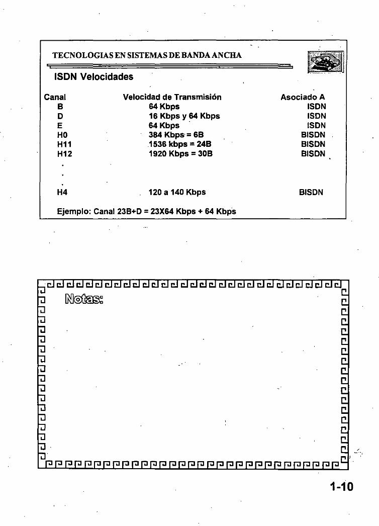
ISDN Velocidades
Canal 8 D E HO H11 H12
H4
Velocidad de Transmisión 64Kbps 16 Kbps y 64 Kbps 64 Kbps · 384 Kbps = 68 .1536 kbps = 248 1920 Kbps = 308
120 a 140 Kbps
Ejemplo: Canal 23B+D = 23X64 Kbps + 64 Kbps
Asociado A ISDN ISDN ISDN
81SDN 81SDN 81SDN
81SDN
1-10

TECNOLOGIAS EN SISTEMAS DE BANDA ANCHA
INTRODUCCION
lUIR 1980 1985
••ca m
1990. 1995 1996
1-11

TECNOLOGIAS EN SISTEMAS DE BANDA ANCHA
Redas ele alto dasampafto
o FDDI, FDDI - 11 . o FAST ETHERNET
o TECNOLOGIA SWITCHING o ATM o FRAME RELAY o B -ISDN
REDES VIRTUALES
REDES MULTIMEDIA VIDEOCONFERENCIAS
REDES
LAN = MAN = WAN = GAN
1-12

TECNOLOGIAS EN SISTEMAS DE BANDA ANCHA
B-ISDN. Estándares
Q En 1988 se establece la recomendación 1.121 del CCITT.
Q En 1990 el grupo de estudio XVIII aprueba 13 recomendaciones básicas, entre ellas:
-'e Aspectos generales de B-ISDN -'e Servicios específicos de Red -'e Características fundamentales de ATM -'El Aplicaciones ATM -'El Operación y mantenimiento de los accesos a B-ISDN
Q A partir de 1992, se han generado nuevas recomendaciones y grupos de estudio, entre ellas la 1.113 de vocabulario y términos.
2-1

'
TECNOLOGIAS EN SISTEMAS DE BANDA ANCHA
A nivel mundial
CCITT ISO
En Europa
CEPT
ETSI
En Estados Unidos
ANSI El A BELLCORE
Comité Consultivo Internacional de Telegrafla y Telefonía Internacional Standard& Organizstión
European Conference of Posta and Telecommunications Administrations European Telecommunlcstions Standard& lnstitute
American Nstional Standard lnstltute Electronic Industries Associstion Bell Communicstions Research
2-2

.. ,
TECNOLOGIAS EN SISTEMAS DE BANDA ANCHA
8-ISDN.- INTRODUCCION
Diseñada para soportar conmutación de acuerdo a lá demanda y conexiones en banda ancha tanto permanentes como semipermanentes para las aplicaciones punto-a-punto y punto-a-multipu~to.
Soporta servicios de conmutación de circúitos y de conmutación de paquetes, aplicaciones "single media", "mixed-media" y "multimedia".
2-3

..
TECNOLOGIAS EN SISTEMAS DE BANDA ANCHA
BISDN .- CARACTERISTICAS
Conexiones conmutadas por demanda en Banda Ancha
Q Permanentes
Q Semipermanentes
Aplicaciones ..
Q Punto a punto
Q Punto a multipunto
2-4

TECNOLOGIAS EN SISTEMAS DE BANDA ANCHA
BISDN .- CARACTERtSTICAS
Modos de Conmutación
!O! Paquetes !O! Circuitos.
' Naturaleza de Servicios
!O! "Connection - oriented" · !O! "Connectionless"
Configuraciones
!O! Unidireccionales !O! Bidireccionales
2-5

TECNOLOGIAS EN SISTEMAS DE BANDA ANCHA
BISDN. Características Tráfico
Q Velocidad constante CBR (Constant Bit 'Rate)
'1J Sin negociación de velocidad
Q Velocidad variable VBR (~ariable Bit Rate)
'1J Con negociación de velocidad
2-6

TECNOLOGIAS EN SISTEMAS DE BANDA ANCHA
BISDN CARACTERISITCAS ¡;;¡ Conmutación por demanda
¡;;¡ Conexiones permanentes y semimermanentes
. -t Punto a Punto -t Punto a multipunto
¡;;¡ Conmutación de paquetes y conmutación de circuitos
-t Single media -t Mexed media -t Multimedia -t "Conection less" y "Conection-oriented" -t VBR yCBR
2-7

TECNOLOGIAS EN SISTEMAS DE BANDA ANCHA
ISDN.- TERMINOLOGIA:
Q Grupos Funcionales.
Q Puntos de referencia.
2-8

TECNOLOGIAS EN SISTEMAS DE BANDA ANCHA
ISDN.- TERMINOLOGIA:
Grupos Funcionales.
'1l Tenninadores de Red 1 (NT1). Funciones equivalen~es a las del nivel 1 del modelo de referencia OSI.
'1l Teminadores de Red 2 (NT2) Funciones equivalentes a las de los niveles 1, 2 y 3 del modelo OSI.
'1l Equipo Tenninal (TE) Teléfonos digitales, Equipos tenninales de datos y estaciones de trabajo que integran. voz y datos.

TECNOLOGIAS EN SISTEMAS DE BANDA ANCHA
ISDN.- TERMINOLOGIA:
Grupos Funcionales.
-1! Equipo terminal tipo 2 (TE2) Equipo terminal con interfaces no-ISDN
-1! Adaptador terminal (TA) Grupo funcional que incluye las funciones para conectar equipo TE2 dentro de ISDN.
2-10

.. · TECNOLOGIAS EN SISTEMAS DE BANDA ANCHA
ISDN.- TERMINOLOGJA:
Puntos de Referencia:
R: lnteñace funcional entre un grupo TE2 y un T A.
T: lnteñace entre el equipo NT2 y' el NT1.
S: lnteñace entre equipos de usuario como pueden ser los TAo los TE1 y el equipo NT2.
U: lnteñace del lado de la red del equipo NT1.
2-11

TECNOLOGIAS EN SISTEMAS DE BANDA ANCHA
ISDN.- TERMINOLOGIA:
+ Referanca polnt
O Funcional group
TA: Terminal Adaptor TE: Terminal Equlpmant NT: Networtc Termlnation
Central Office

TECNOLOGIAS EN SISTEMAS DE BANDA ANCHA
ISDN.- EQUIPO
Canales de Acceso:
.!EJ Canal 8: 64Kbps para voz, datos en conmutación de circuitos o datos en conmutación de paquetes (B= bearer "portadora")
.!EJ Canal D: 16 ó 64Kbps.para señalización, control o información del cliente en paquetes (D=delta) .
.!EJ Canal H: 384Kbps (HO), 1,536Mbps (H11) ó 1,920 Mbps (H12) para teleconferencias, datos en alta velocidad o audio de alta calidad.
2-13

TECNOLOGIAS EN SISTEMAS DE BANDA ANCHA
ISDN.- EQUIPO
U NI: User Network Interface
"D 8asic Rate Access (o BRI basic rate interface). Interface de usuario que provee 2. canales 8 y un canal O (28+0).
~ Primary Rate Access (o PRI primary rate interface) Interface de usuario que provee 23 canales 8 y un canal O
(238+0).
~ Para canales H se prévee que en el futuro se utlice una interface de red tipo H+O.
2-14

REDES DE ALTO DESEMPEÑO
1.- FAST ETHERNET
- - - - - - - -- - - - - - --
«', ··- ' - . .. ~ - .. . ;~, . : ..
. ' : .. :e- ·: :' .. :::· ------- ''::.:
..... - .... ·,, .. •' .

Fast Ethernet
REQUERIMENTQS DE ALTA VELOCIDAD Y SOLUCIONES PROPUESTAS.
Día con día, cada vez más usuarios de PC's se agregan a las redes. Al final de 1994 solo el 40% de las PC ·s en el mundo estaban conectadas en redes. Al mismo tiempo, la tecnología estaba logrando avances significativos como el lanzamiento comercial de el INTEL PENTIUM y tecnologías como POWER PC, tecnologías de sistemas de almacenamiento en· disco duro avanzadas que decrementaban los costos, con el objeto de dar potencia a aplicaciones de redes basadas en PC ·s de propósito critico, aplicaciones que hasta recientemente han sido posibles solo en un mainframe.
La capacidad de las PC's ha crecido en forma exponencial, al igual que las aplicaciones que corren en éstas, por lo que las tecnologías para conectar las PC ·s entre si, emp1ezan a ser un factor determinante en la funcionalidad de las redes locales.
Aunque no todos los usuarios requ1eren una red con capacidad de 100 mbps. muchas aplicaciones "lan-intens1ve .. ya empujan los 10 mbps existentes y pueden beneficiarse con la tecnología actual de 100 mbps
Surgieron aplicaciones de datos intensivos como multimedia, trabajo en grupo y bases de datos cliente-servidor, que pronto harán de los 1 OOmbps parte critica de la mayoría de las Lan ·s
Así mismo, como los servidores de red son ahora mas poderosos, han sido reubicados de conexiones locales a centrales de datos, dond-e necesitan conexiones de alta velocidad a 100 mbps al "backbone" para proporcionar capacidad centralizada al costo óptimo.
¿Que tecnología está mejor situada dentro del crecimiento de los requerimientos de a~a velocidad de las redes de hoy?
.FE-2

La respuesta depende del usuari¡~ y de las necesidades de la red. FAST ETHERNET es una excelente alternativa por las siguientes mzones:
ventajas de Fast Ethernet
o Alto rendimiento. ..
o Tecnología basada en estándares.
o Migración a costo aceptable con méximó aprovechamiento del equipo ya existente ( infraestructura de cableado, sistemas de administración de red etc ... )
o Soporte de los principales vendedores en todas las áreas de productos de red.
o Costo óptimo.
~ Alto rendimiento.
Una de las mejores razones para cambiar a fast ethemet para grupos de trabajo, es la disponibilidad de manejo de ambas demandas agregadas, de una red multiusuario y el excesivq_ tráfico ocasionado por el alto desempeño de las PC ·s y las sofisticadas aplicaciones empleadas. Fast Ethernet es la solución óptima para grupos de trabajo.
~ Tecnología basada en estándares. ---- - - - -
Fast Ethernet está diseñada para ser la evolución más directa y Sini¡;ie.de ethÉimet 1o.tíase-T,-ia clave de su simplicidad es que fas! ethemet usa csma/cd definido en el media access control.
. El 100 base-T es una versión escalada del (M.A.C.), usado· en ethemet convencional, sólo que más rápido, es la m1sma tecnología robusta, confiable y económica usada por 40 millones de_ usuarios hasta hoy, lo que es más, la m1sma compatibilidad entre 10 base-T y 100 base-T penníte la fácil migración a conexiones de alta velocidad sin cambiar el cableado, depurando técnicas de administración de red y más.
Adicionalmente. ambas tecnologías ofrecen ambientes compartidos con conexiones ethemet compartidas o conmutadas penni!lendo 10 O 10_0 mbps a todas las estaciones conectadas al hub, esto es ·ideal para grupos de trabajo de tamaño mediano con incrementos de demanda de ancho de banda ocasionales, ethemet compartido delibera el ancho de banda a un costo muy bajo.
Ambientes conmutados proveen el máximo ancho de banda para cada puerto conmutado del hub. Para grupos de trabajo grandes con demanda agregada que excede los 100 mbps, ethemet conmutado es la mejor solución
~ Costo efectivo de migración.
Como el protocolo natural de 1 O base-T, virtualmente no cambia en fas! ethemet, éste puede ser introducido fácilmente en ambientes de ethemet estandar. la migración es simple y económica en
. muchos aspectos importantes.
~FE-3

,.
o Las especificaciones de el cableado para red 1 00 base-T permiten a fast ethemet correr en la mayoría de cableados comunes en ethemet, incluso categorías 3,4 y 5 de utp, stp y fibra óptica.
o Experiencia administrativa. los administradores pueden relevar en ambientes 100 base-T con herramientas de análisis de red familiares.
o La administración informática se traduce fácilmente de ethemet a 1 OMBPS a redes fast ethemet lo que s•gnifica recapacitación mínima del personal de administración y mantenimiento de la red.
Sottwaré de administración. Las redes fast ethemet pueden ser administradas con un protocolo simple como smnp.
Soporte de software. El software de aplicación y manejo de redes no cambia en redes 1 oo base-T.
Migración flexible. Adaptadores autosensibles de velocidad dual pueden correr a 1 O ó 100 mbps en el medio existente, al igual que los concentradores con 1 O 100 mbps permiten el cambio dependiendo de la transmisión que se esté realizando
~ Soporte de los principales fabricantes.
Fast ethemet es soportado por más de 60 fabricantes importantes, incluyendo empresas líder en adaptadores, conmutadores, estaciones de trabajo y empresas de semiconductores como 3Com, SMC, lntel, Sun Microsystems y Synoptics que empezaron a comercializar productos interoperables a fines de 1994.
Estas empresas son miembros de la Fast Ethernet Alliance (FEA), un consorcio cuyo objetivo es acelerar la tecnología fast ethemet a través de la Norma 802.3 del IEEE. Además la FEA estableció procedimientos de prueba y estándares para asegurar la interoperabilidad para los fabricantes de productos 100 Base-T.
~ Valor óptimo.
Como la-estandarización progresa ráp1damente:y los prodúctos estarán disponibles por una gran vanedad de fabricantes, el precio/desempeño de fast ethemet estará regido por la competitividad de las tecnologías de alta velocidad.
Al principio, los precios de fast ethemet superaban 1 O veces el desempeño por menos de la mitad del costo por conexión. Ahora los prec1os"están casi a la par de la tecnología de 10 Base-T y aún tienen las ventajas sobre otras tecnologías no ethemet.
~ La tecnología tras fast ethemet.
.FE-4
.·

Fast etllemet es una extensión del estandar existente 802.3 del IEEE, la nueva tecnología usa el mismo control (Media Access Control), de 802.3 conectado a través de otro control (Media lndependient Interface), a otros tres controles de nivel físico, la especificación de M. l. l.. es similar a. la AUI de 1 O mbps y proporciona una sola interface que puede soportar transceivers externos con alguna de las especificaciones 100 Base-T.
100 base-T soporta tres especificaciones: 100 baseTx, 100 base T4 y 100 base Fx, el estándar 100 base-T, también define una interface para concentrador universal y una interface de manejo.
En el diseño del MAC para 100 base-T. el IEEE reduce el tiempo de transmisión de cada bit. del MAC de 10 mbps de csma/cd muttiplicado por un factor de 10 proporcionando turbo velocidad al paquete. Desde que el MAC esté especificado. de manera independiente de la velocidad, la funcionalidad en el formato del paquete no cambia, la longitud, el control de errores y la información de manejo son idénticos a 10 Base-T.
· ~ Alternativas de cableado.
o 100 base-T soporta 3 especificaciones físicas.
o 100 Base Tx: Cable UTP o STP de un par trenzado eia 568 o categoría 5 para datos.
o 100 Base T4: Cable UTP de 4 pares trenzados para voz y datos categoría 3, 4 ó 5.
o 1 00 Base Fx: sistema estándar de 2 fibras ópticas.
·La flexibilidad de estas especificai:iones.pefmite lf100 base-T. implementar un ambiente de cable· 10 Base-T virtual, permitiendo a los usuarios conservar la infraestructura de cableado mientras emigran a fast ethemet.
Las especificaciones 100 base Tx y 100 Base T4, juntas cubren todas las especificaciones de cableado que existen para redes 1 O Base-T, las especificaciones fast ethernet pueden ser mezcladas e interconectadas a un hub como lo hacen las especificaciones 1 O Base-T.
1 DO Base Tx está basado en la especificación PMD (Physical Media Dependen!), desarrollada por el ansi x3t9.5, éste combina el MAC escalado con los m1smos chips del transceiver y el PHY desarrollados para FDDI y CDDI. Como estos chips están disponibles y el estándar de señalización está completo, 100 Base-T ofrece una solución ·de tecnología aprobada y basada en estandares y soporta ambientes de cableado 10 Base-T.
1 DO Base-T permite transmisión a través de cable UTP 5 instalado virtualmente eh las redes nuevas."-
100 Base T4 es una tecnología de señal desarrollada por 3Com y otros miembros de Fast Ethernet Alliance para manejar las necesidades de cableado UTP 3 instalado en la mayoría de las antigüas redes basadas en 10 Base-T. esta lecnología.perrnite a 100 Base-T correr sobre cableados UTP 3, 4 ó 5 permitiendo a las redes con cableado UTP 5 moverse a la tecnología de 1 DO Base-T sin tener que recablear.
.FE-5

100 Base FX es una especificaCión para fibra, ideal para grandes distancias o BackBones o ambientes sujetos a inteñerencia eléctrica.
~ Auto-Negociación 1 O /100 MBPS
Para facilitar la migración de 10 a 100 MBPS el estándar 100 Base-T. incluye un sensor automático de velocidad, esta función opCional permite transmitir a 1 O o 1 oo MBPS con comunicación automática disponible en ambos casos.
Auto-Negociación es usado en adapladores 10/100 MBPS este proceso se da fuera de banda sin interposición. de señal, para comenzar, una estación 100 Base-T advierte sus capacidades enviando un barrido de pulsos de prueba para verificar la integridad del enlace llamados FAST LINK PULSE, generados automáticamente al encender el equipo.
Si la estación receptora es un hub con capacidad 1 O Base-T únicamente, el segmento operará a 10 MBPS, pero si el hub soporta 100 Base-T. este será censado por el FLP y usara el algoritmo de auto-negociación para determinar la mayor velocidad posible en el segmento, y enviar FLP's al adaptador para poner ambos dispositivos en modo 1 00 Base-T.
El cambio ocurre automáticamente sin intervención manual o de software, (una RED o un segmento de RED puede ser forzado a operar a 1 O MBPS a través de un manejo de mayor jerarquía, aunque éste sea capaz de trabajar a 100 MBPS, si asi se desea.)
~ REGLAS DE TOPOLOGIA.
Fas! Ethernet preserva la longitud crit1ca de 100 metros para cable UTP, como resultado del MAC escalado de la inteñace Ethernet.
Otras reglas topológicas de 100 MBPS son diferentes de las reglas Ethernet.
La figura 3 ilustra la clave de las reglas topológicas 1.0 Base-T y muestra ejemplos de como éstas permiten la interconexión en gran escala. ·
La máxima distancia en cable UTP es 100 metros igual que en 1 O Base-T.
O En UTP se perm1ten máx1mo 2 concentradores y una distancia total de 205 mts.
O En topologías con un solo repetidor un segmento de fibra óptica de hasta 225 metros, puede conectarse a un backbone colapsado.
O Conexiones MAC to MAC, Switch to Switch. o End Station to Switch, se usan segmentos de hasta 450 mts .. de fibra óptica bajo 100 Base FX .
• FE-6
o Para distancias muy largas una versión completamente duplex de1 00 Base FX puede ser usada para conectar dos disposnivos a más de 2 KM de distancia.
Al principio, estas reglas topológicas pudieron parecer restrictivas , pero ahora en las redes con backbone, que usan fibra óptica , concentradores y/o ruteadores o puentes, Fast Ethernet puede ser fácilmente implementado en redes de gran escala o corporativas.
Q:, ETAPAS DE MIGRACION.
La migración hacia fast ethemet está determinada en etapas, permitiendo al Administrador de la RED emigrar fast ethemet cuando y donde lo necesne.
Aquí tenemos una secuencia típica.
o Determine el tipo de cableado instalado, si este es categoría 5, se usan adaptadores1 00 Base TX, las categorías 3 ó 4 requieren adaptadores 1 00 Base-T4.
o Instale adaptadores de velocidad dual1 o /1 od MBPS en PC ·s nuevas; para prepararse a la migración de la nueva tecnología, las PC ·s deben estar configuradas con adaptadores de velocidad dual, entonces podrán soportar ethemet compartido, ethemet conmutado, fast ethemet y aún tast ethemet conmutado.
~o Instale concentradores 1 00 Base-T conforme el número de pc··s se incremente, o conforme el tráfico de la RED empiece a crecer, comience la migración con hubs de velocidad dual, use un puente 1 O 1 100 MBPS para nodos que trabajen aún con 1 O Base-T.
O Instale hubs conmutados 10/100 MBPS para las PC's que ya existen en la RED, para usarse con las PC ·s que no requieren tanta velocidad de comunicación, que además, necesilan conectarse a backbones o servidores a alta velocidad, el úmco cambio requerido en las conexiones ethemet 1 O BaseT compartido a los puertos conmutados 10/100 MBPS.
o Extienda 100 Base-T a los backbonés. Conecte ·los grupos de trabajo y servidores a un backbone de alta velocidad, un puente o un ruteador con capacidad fast ethemet.
.FE-7

REDES DE ALTO DESEMPEÑO
2.-FDDI, FDDI 11
•
: : -~-:
... .. . .. : -~:: ., : .... :.: . .L::;

FDDI
CJCJCJ¿JCJCJclclclCJcl.
Fiber Distributed Data Interface
Red anillo Token-Passing 100 Mb/s con redundancia. · (ANSI-X3T9)
·. Anillr "'~rincipal = Conexión Punto a Punto entre
nodos para transmisión de datos Anillo .:iecundario = Transmisión de datos/respaldo · del anillo principal en caso de
falla FDDI proveé comunicaciones par conmutación de . paquetes y transmisión de datos en tiempo real.
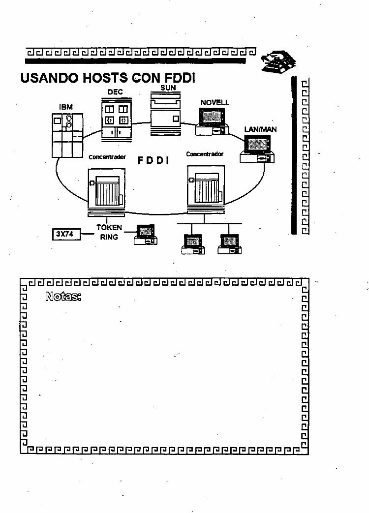
USANDO HOSTS CON F •
18M
F D D 1 Concentrador
~RING

¿¡ ¿¡ ¿¡ ¿¡ ¿j ¿¡ ¿¡ ¿¡ ¿j ¿¡ CJ ¿¡ ¿¡ ¿¡ cl ¿j cl cl ¿¡ ti) C!1 C!1 ¿¡ ~ C!1 ¿¡ •.
FDDI
ESTACIONES
Tipo· Clase A: Se conecta directamente al anillo doble
·. . Tipo Clase B: Se conectan al concentrador puertos mtlltiples
en Red estrella o Estaciones m posibilidad de conexión sencilla. Los concentradores pueden ser conectados en cascada.
FDDI-

·-
cldclCJCJCJ CJcl ¿¡¿¡ dCJCJCJ CJCJCJCJ E:JE:J CJC::IL dCJ cl •
FDDI ' . CONSIDERACONES
Manejo
SMT (Interface Sfii!MP) Estadística de las estaciones reset. Soport.e para deshabilitar. · ·
cg; 300KM-180Miles ~
El control es critic~ para las Redes de gran tamaño y capacidad.

¿¡ ¿¡ ¿¡ ¿¡ ¿¡ ¿¡ cl cl cl cl cl cl cl cl cl ¿¡ cl cl cl cl cl cl cl cl cl ¿¡ •
FDDI .
• FDDI Ofrece hasta 1000 conexiones físicas (500 Estaciones) y una distancia total d~ 200 Km. de extremo a extremo.
• La distancia máXima entre. nodos activos es la de 2 Km
• Abras Opticas emple~das:
A) Fibra.tipo unimodo. con gran ancho de banda (GHz) y largas distancias (2o-So Km)
B) Fibra tipo multimódo. Fibras con nucleo 5o-62.5 Micras.y Medianas distancias (1 o-20 Km.) a 1300
• nanometros.

¿¡¿¡a a a a¿¡¿¡¿¡¿¡¿¡¿¡¿¡¿¡ CJCJCJC!J ¿¡¿¡ CJ clc:J CJCJ CJ •
FDDI
TOKEN-PASSING ofrece una transmisión de datos más eficiente.
ya que conforme aumeñta el tráfico se requiere un mayor ancho
de banda. TRT 85 %.
CSMA/CD Resulta más eficiente cuando se utiliza un menor
ancho de banda.

* FDDI emplea una codificación 481. t.asa de transmisión a 1 o o Mb/-125 Mhz 80% de eficiencia en el ancho de banda .
~ETHERNET YTOKEN-RING emplea una codificación Manchester
· *Tasa de transmisión- ETHERNET: - TOKEN-RING
lOMb/s-20 Mhz 16Mb/s-32 Mhz
50% DE EFICIENCIA EN EL ANCHO DE BANDA
··~ ' " '.w .. :
.. :
' .... ~
'" .

¿¡ ¿¡ CJ CJ CJ ti] cl cl ti] CJ cl cl cl cl cl CJ CJ CJ cl cl cl cl cl í:Jcl cl • .
FDDI
FDDI: VS TOKEN- RING 16MB/S
" Reloj distribuido recuperación { Monitor Activo de.errores
" Doble anillo
* Rotación del "TOKEN•
* úso de Fibra Optica
{ Anillo Sencillo
{ Sistema de reservación por prioridad
{ Uso de Par Trenzado/Abra Optica .

QFIBRAS OPTICAS
Hasta hace cerca de una década, las comunicaciones fueron ·realizadas a través de medios como cable coaxial o cable telefónico, Desde hace algunos años y ahora más fuerte que nunca se introduce un nuevo medio de comunicación: las fibras ópticas.
El uso de la luz como un medio de comunicación no es nuevo. El fuego fué usado como señal de comunicación en los amaneceres de la historia humana. La clave Morse fue utilizada particularmente en comunicaciones de una embarcación a otra usando espejos para refle¡ar la luz y transmitir señales. ·
En 1860 Alejandro Graham Bell demostró la transmisión de voz usando espejos.
Estos vibraban debido a las ondas sonoras generadas por la voz, de manera que la luz refle¡ada por lós espejos era modulada por el sonido. La luz modulada en el receptor era enfocada en una lámina de Selenio, la resistencia de la lámina y su respectiva corriente variaba con los cambios ~e intensidad de la luz incidente. Esta corriente se aplicaba a un dispositivo parecido a un altavoz moderno. Todos estos métodos dependían del medio ambiente y solo cubrían distancias pequeñas y para aplicaciones visuales en línea directa, en 1960 con la invención del láser, el interés por la comunicación luminosa tomo fuerza, aunque, contando con el láser, los métodos de comunicación por luz al aire libre segúian dependiendo del ambiente y limitados en alcance.
El primer intento para transmitir a larga distancia a través de fibra de vidrio fue realizado en 1966, pero las excesivas impurezas de la fibra de vidno generaban grandes péndidas de energia de la luz que viajaba a través de ésta. La transmisión seguía limitada en distancia, además de que el tamaño de los lasers con que se contaba en aquel tiempo hacían muy dificil el acoplamiento de la energía luminosa en las· fibras de manera eficiente.
Con el desarrollo del diodo láser, del diodo LEO, y más !ande la introducción de alta purezá, llegó la era de la comunicación por fibra: transmisión a largas distancias sin la necesidad de reamplificar la señal.
La historia del desarrollo de la tecnologia de fibra óptica se centra en aplicaciones de comunicación y desarrollo e Investigación gubernamental, los avances mas ,significativos se lograron recientemente en la década de los 70's y los ao·s, aunque la teoria general de la propagación de la luz se desarrolló a lo largo de muchos años de investigaciones intentos y fracasos.
Una fibra óptica es una delgada varilla transparente hecha de vidrio o plástico puro, a través del cual la luz puede propagarse con una péndida de señal muy baja, la estructura de una fibra óptica moderna consiste en el tubo de vidrio delgado recubierto por otro material con distintas
.FDDI-2

..
características ópticas, éste ev~a que la señal que viaja a través de la fibra óptica se refracte fuera de la misma ocasionando pérdidas en la señal.
El uso de fibra óptica para transm~ir señales de comunicación tiene muchas ventajas importantes sobre los medios de comunicación convencionales:
o La baja pérdida en la energía de la señal.
o La baja tasa de distorsión en los pulsos de la señal transmitida.
o El ancho de banda es mucho mayor que en UTP o coaxial.
·O No es susceptible de ruido o interferencia eléctrica o electromagnética. o Es muy segura, no es ·posible "robarse" la señal de la fibra óptica.
o Soporta ambientes hoStiles, contaminación, salinidad, humedad o radiación. Es inmune.
o No existe una conexión eléctrica entre receptor y transmisor.
O El costo de la fibra óptica es casi el mismo que el del cable coaxial.
o Las velocidades de transmisión son muy altas. - - - - - ~- - - . - - - - - --- - - . -
Recientes desarrollos han permitido fibras ópticas con 0.2 dB de atenuación por kilómetro, además de los desarrollos de equipos para trabajar con fibra óptica con capacidad de operación de hasta 1 Ghz y mas de 3000 canales de comunicación individuales.
Las fibras ópt1cas se clasifican en dos tipos: unimodo y multimodo. Llamadas así por el número de modos de propagación de la longitud de onda de operación
-~ Fibra multimodo
Es un tipo de fibra en la cual hay más de un modo de propagación de señal. Van desde las que tienen dos modos hasta cientos de modos de propagación. Las aplicaciones típicas de estas fibras son la telecomunicación con anchos de banda de 1 a 2 Ghz, cableado de inmuebles, con anchos de banda de 500 a 1 000 Mhz y enlaces donde la potencia y el ancho de banda son necesarios, generalmente 50 a 1 00 Mhz son suficientes.
~ Fibra unimodo
La fibra unimodo es fabricada con los mismos materiales y bajo los mismos procesos que las fibras multimodo, la diferencia es el tamaño del centro de la fibra que es mas pequeño y ·la cantidad de impurezas que es diferente a la fibra multimodo, hace la diferencia de características de operación.
S\ FDDI·3

Las siguientes tablas ofrecen un panorama general de características
~ Dimensiones
Fibra óptica Tipo diámetro del núcleo diámetro del revestimiento longitud de onda i (micras) (micras) (Nanometros}
unimodo 8.10 125 1300,1500 multimodo 50 125 850,1300
~ cuadro comparativo de atenuación.
Medio de comunicación Tipo Longitud de onda Atenuación (dB 1 Km.) o Frecuencia
COAXIAL 100 Mhz 61 Fibra Optica Multimodo 850 Nm 2.4- 3.2 Fibra Optica Multimodo 300 Nm 1.0-1.5 Fibra Optica Unimodo 1300 Nm menor a 0.5 Fibra Optica Unimodo 1300 Nm menor a 0.25
~ Distancias máximas cubiertas por un segmento de linea de comunicación
Medio de comunicación Tipo Distancia máxima sin repetidor (Mts) 1 (Rango dinámico típico 35 dB}
COAXIAL 570 Fibra óptica Multimodo a 850 Nm 10,000 Fibra óptica Multimodo a 1300 Nm 20, 000 Fibra óptica Unimodo a 1300 Nm 60,000 Fibra óptica Unimodo a 1550 N m 120, 000
ASPECTO DE LA FIBRA OPTICA
.FDDI-4

existe una gran variedad de presentaciones para fibras ópticas dependiendo de las apiJcaciones.
: lil:!.~~ . - . . .
: lM•n "'ot>d>;!~~~~m .-t.~~~~'~ ftllm~~r-:
CABLE DE FIBRA OPTICA PARA ESTRUCTURA
TUBO DE FIBRA OPTICA DE USO INDUSTRIAL
~ CONECTORES DE FIBRA OPTICA.
Son dispositivos de unión, que realizan la función de acoplamiento entre dos fibras ópticas o en los extremos de éstas, permitiendo un fácil manejo, instalación y mantenimiento de la fibra óptica.
FDDI-S

Los parámetros que definen la calidad de un conector para un sistema de transmisfón dado son los siguientes:
O Pérdida por inserción.
o Facilidad para su ensamble y montaje.
O Estabilidad al ambiente.
o Confiabilidad.
O Inserción de perturbaciones al sistema.
O Costo.
Aunque normalmente es imposible optimizar todos los parámetros, la elección de un conector es el resultado de un balance de necesidades específicas, debe tenerse el cuidado no solo de seleccionar el conector adecuado, sino que también debe ponerse especial atención en el momento del manejo y ensamble de los conectores.
Q FDDI
La nuevas tecnologías de interconexión de redes tienden al uso de la fibra óptica, como medio de comunicación, tiene una capacidad de transmisión de datos y de seguridad muy altas. Las fibras ópticas pueden soportar transmisiones de varios cientos de Mbps. Los cableados por medio de fibra óptica pueden soportar grandes distancias sin necesidad de repetidores, además· de ser un medio inmune a la interferencia electromagnética.
Los costos de conexión con fibra óptica son típicamente altos, pero podemos esperar que estos precios bajen significativamente en los próximos años.
Ya existen en el mercado, proveedores que cuentan con las tarjetas necesarias para poder realizar conexiones con fibra óptica para las topologías Ethernet y Token Ring.
Muchas compañías están optando por la fibra óptica por diversas razones, entre ellas está la velocidad de transmisión de la que es capaz. Por ejemplo, FDDI1 soporta velocidades de transmisión de hasta 100 Mbits por segundo. En comparación con Ethernet que transmite a 1 O Mbits por segundo o Token Ring que transmite a 4 ó 16 Mbits por segundo.
El comité 802.6 de la IEEE ha adoptado estándares para redes de área metropolitana, y el American National Standars lnstitute ha desarrollado los estándares FDDI y FDDI-11 .
Además, la fibra óptica tiende a ser más segura que el cableado de cobre. Una red interconectada por medio de fibra óptica puede trabajar cerca de equipo eléctrico altamente sensible sin interferir uno con el otro. Un cable de fibra óptica entre dos edificios no atraerá rayos como el cable de éobre.
1 Fiber Distributed Data Interface
.FDDI-6

:·-
Al hablar de redes interconectadas por medio de fibra óptica, generalmente se está hablando de FDDI, diversos productos capaces de soportar FDDI han estado saliendo lentamente al mercado y se han dejado ver en diversas exposiciones de computadoras.
Como Token Ring, FDDI usa una topología con forma de anillo y un Token eléctrico para pasar el control de la red de una estación a otra, más no es compatible con Token Ring.
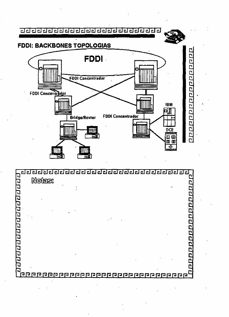
La mayor parte de las redes actuales con FDDI usan un doble anillo en donde cada nodo se une a los dos anillos independientes, transmitiendo los datos en sentidos opuestos. Esta configuración mejora la velocidad de transmisión así como la confiabilidad de la red, pero es muy caro.
Hasta ahora, FDDI se ha usado para interconeotar PC's de alta velocidad o estaciones de trabajo con redes, o bien como backbone para interconectar estaciones más lentas, de igual manera que una carretera une los diferentes pueblos. Conectarse a FDDI es caro, dado el alto costo de los componentes ópticos, así como el costo del transreceptor y los integrados necesarios para FDDI, Debido a sus características de ancho de banda, la fibra óptica se usa principalmente para backbones (que es un segmento que une varias redes locales) .
Existe también FDDI-11 que es una segunda versión de FDDI que nos permite transmitir voz y video además de datos. De manera distinta a FDDI que tiene un reloj corriendo de manera independiente, FDDI-11 tendrá un marco de 125 microsegundos, permitiendo ser sincronizado con la red de comunicaciones.
.FDDI-7

. FAQ'S sobre FDDI y FDDI-11
Q. Wbat does FDDI stand for? Fiber Distributed Data Interface
Q. What· is the difference between FDDI and FDDI-U? Both FDDI and FDDI-II runs at 100M bits/sec on the fiber. FDDI can transpon both async and sync types of frames. FDDI-II has a new mode of operation called Hybrid Mode. Hybrid mode uses a 125usec cycle structure to transpon isochronus traffic, in addition to sync/async frames. FDDI and FDDI-II stations can be operated in the same ring only in Basic mode.
Q. Wbat is the name of the standards and where can 1 get them? ANSI X3 T9. 5 standards
American National Standards Institute 1430 Broadway, New York, NY 10018, USA Attention: Sales Dept.
- IEEE Standards IEEE Service Center 445 Hoes Lane, Piscataway, NJ 08855, USA
- X3T9.5 Documents · Global Engineering Documents (USA) 1-800-854-7179
Q. Wbat are other good sources of printed information? - FDDI Technology and Applications: Edited Mirchandani and Khanna - Handbook of Computer Communications Standards Vol 2: By Stallings - Cal! up DEC to ask for the frée FDDI tutoría! book , Dig up 1986-1992 issue ofiEE Local Computer Network Conference
Q. l've heard that FDDI uses a token passing scheme for access arbitration, how does this work?
A token is a normal FDDI frame with a fixed format. The station waits until a token comes by, grabs the token, transmits the the frames and release the token. The amount of frames that can be transmitted is determined by timers in the M A E: protocol chips.
[You really need a diagram for the station and/or topology.]
Q. l've heard that FDDI is a counter-rotating ring, what does this mean? FDDI is a dual ring technology. And each ring is running in the opposite direction to improve fault recovery.
Q. What is a dual ring of trees? See the diagram.

Q. What is dual homing? When a DAS is connected to two concentrator pons, it is called dual-homing. One pon is the active link, where data is transmitted and the other pon is a hot standby. The hot standby will constantly testing the link and will kick in if the active link failed or disconnected. The B-pon in a DAS is the active pon and the A -pon is the hot -standby.
Q. What is a DAS? DAS (Dual Attach Station) is a station with two peer pons (A-Pon and B-Pon). The A-pon is going to the B-Pon of another DAS, and the B-pon is going to connect to the A-Pon the yet another DAS. ie:
+--->lA Bl------> lA Bl-----> lA Bl----+ 1 +--1---------.1 <------1---------1 <-----1---------1 <-+ 1 1 1 1 1 1 + --------------------------------------------------+ 1
+ ------------------------------------------------------+
Q. What is a SAS? SAS (Single Attach Station) is a station with one peer pon (S-Pon). It is usually connected to the M-Pon of a concentrator.
Q. What is a wrapped ring? When a link in the dual-ring is broken or not connected, the two adj pons connecting to the borken link will be disconnected and the both stations enter !he wrap state: .. _ _ __
Wrap Wrap
+--->lA BI-X X-> lA Bl-----> lA Bl----+ 1 + --1---------1 < ------1---------1 < -----1---------1 <-+ 1 1 1 1 1
·1 + --------------------------------------------------+ 1 + ------------------------------------------------------ +
Q. Do 1 need a conceOtrator port for each workstation, or can woi-kstations be
chained together? Usually you will need a concentrator pon (M-Pon) to connect each SAS. DAS can be hooked up to the main rings or concentrator ·pon(s).
Q. lf 1 use a concentrator, what are the advantages/disadvantages? Advantages: Fault tolerance. When a link breaks, the ring can be segmented. A concentrator can just bypass the problem pon and avoid most segmentatíons. It also gives you better physical planning. Usually people prefer tree physical topology. Generally star configuration of a concentrator system is easier to troubleshoot.
\

Disadvatages: A concentrator represents a single point of failure. There may al so be more costly.
yo u can build a tree as deep as yo u want. We ha ve a Q. Can 1 cascade concentrators? Are there limitations as to how many? Y es. And dual-rings of concentrator here connecting machine rooms and wiring rooms. And from the there we connect to other concentrators to different offices. Then we have a concentrator in the lab to different machines. There is a maximum of 500 stations on an FDDI LAN.
Q. What is a bypass and what are the issues in having or not having one? Bypass is a ($600-$1200) device that is used to skip a station on the ring if it is turned off. Therefore, you don't need to use concentrator to avoid the segmentation problems. One problem with them is that they increase the db loss of the fiber, so you can't have too many of them (3 activated in a row maximum. 1 believe).
Q. What are the minimum/maximum distances on fiber runs? no min, 2 km max for multimode fiber. 20 km max (may be as high as 60km, we're not sure) for single mode fiber. 500 m for the new Low Cost Fiber.
Q. What are the types of fiber that are supported? Multimode (62.51125 micron graded index multimode fiber)
and other fiber like 50/125. 851125. 1001140 allowed Single mode (8-10 micron) The new Low Cost Fiber (plastics?) standard.
Q. l've hear of FDDI over Copper, what type of cable does this scheme use? Type 1 STP - distance between connections must be less than 100 m Category 5 UTP - distance between connections must be less than 100 m
(The ANSI standard for STP and UTP is incomplete, but a number of companies are already shipping proprietary twisted-pair solutions until the standard is completed, which is expected later this year.)
? Q. ls there any advantage to seperating the fiber pairs (will the ring work better if only one strand is broken on a DAS connection?)
Q. 1 have ethernet, can 1 bridge/route between the 2 topologies? Y es. But from what we are hearing sorne protocols are having problems.
Only TCP/IP is handling frarne fragmemation correctly. (See below). It should also be noted that frarne fragmentation will not work for DECNET, IPX, LAT, Appletalk, NETBEUI etc. IP is the only protocol that has a standard method of fragmenting.
Other protocols destined for Ethernet Lans must stay below the 1500 MTU.

Q. l've heard that there is a frame length difference, what are the issues and problems here?
FDDI frames has a max size of 4500 bytes and Enet only 1500 bytes. Therefore your bridge or rmiter needs to be smart enough to fragment the packets (eg into smaller IP fragments). Or you need to reduce your frame size to 1500 bytes (of data).
Q. What does an FDDI frame look like? PA Preamble (11)
(8 or more ldle symbol pairs) SD Starting Delimiter (JK)
(J followed by K control symbol) FC Frame Control (nn)
(Tell you if it is a token, MAC frame, LLC frame, SMT frame, frame priority, sync or async)
DA Destination Address (nn) (6 bytes of MAC Address in MSb first format)
SA Source Addrewss (nn) (6 bytes of MAC Address of this station)
INFO lnformation field (nn) · (Varibale Length. Usually starts with LLC header, then SNAP field, then the payload eg IP packet)
ED Ending Delimiter (T) (one T control symbol)
FS Frame Status (EAC) (Three symbols of status of Error, Address _match, and Copied. Each symbol is either SET or RESET. eg lf EAC = = RSS, then then frame has no error, sorne station on the ring matched the DA.-an(l sorne station on the ring copied the frame into its buffer.
Q. So FDDI is 100 Megbits per second, what is the practica! maximum bps? Depends. You can get aggregate usage up to 95Mbit/s with no
problem. But 75Mbps is pretty good. Actually, this question depends so much on how you construct your test, what equipment you use, etc, that the best idea is to Jet the user decide.
Q. What happens when 1 bridge between a 100 Mbps FDDI and a IOMbps ethernet if the FDDI traffic destined for the ethernet gets above 8 Mb¡is? 1 O Mbps?
After the buffer fills Frames start dropping. This is not a problem unique to FDDI however. Consider ethemet to TI, or multiple ethemets to a single ethemet.
Q, What is the latency across a bridgeirouter? (Y es 1 know that different vendors are different, but what is a the window?)
No idea.

Q. Are there FDDI repeaters? Y es. But it is nota standard yet. A group in the ANSI committee is Iooking into making FDDI repeater a standard. Other compaoies Iike ODS has something Iike simgle mode to multimode converter.
Q. What type of test and troubie shooting equipment is available for FDDI? Digital Technology Inc (DTI), W&D, HP, and Tekelec all seii FDDI analyzers. The Sniffer from Network General also has a module that works with the NPl FDDI Cards. SGI has a nice looking ringmap prograrn. IBM has a product called DatagLANce. Most Ethernet
tools will also work with FDDI in the protocollevel. Also a optical time domain ref!ectometer (TDR) is recommended for db loss checking and distance measurements, though it has been reponed that an FDDI. link tester is less expensive and will do the job.
Q. What about network station management? Does FDDI support SNMP? Y es. There is a FDDI-SNMP MIB translation from the SNMP working group.
Q. What is a beaconing ring? Does FDDI beacon? Beacon is a special frarne that FDDI MAC sends when something is very wrong. Wlien Beaconing for a while, SMT will kick in trying to detect and salve the problem.
Q. How about interoperabiiity, does one manufacture's equipment work with others?
Just Iike any networking products, Ethernet, Token, FDDI, ATM, there is a possibility that one vendar does not work with another. But most of the equipment shipping today is tested at Interüp. UNH or ANTC, are this is the equipment that will ineet the minimum interoperability requirements. Ask the vendar what type of testing they did and ask them to ship you a system for field trial befare you pay big bucks for it.
Q. Can 1 inteñace FDDI to a PC (ISA Bus), PC (EISA Bus), PC (Micro channel Bus), Macintosh, Son workstation, DECstation 5000, NEXT computer, Silicon Graphics, Cisco router, WeiiFleet router, SNA gateway (McData), other?
Y es. 1 arn not sure if NeXT has any FDDI adaptar software. l:Íut there are -s different NuBus FDDI cards in the market. But FDDI adaptors are available for aii other buses or vendors.
Q. What is the maximum time a station has lo wait for media access. What type of appiications care?
MaxTime = -(#of stations * T_neg) (T _ neg ist the negotiated target token rotation time) Usually this won't happened. It is only a very very heavily loaded ring but the station be waiting for that long. If this is the case. then change the T _request of the station to sorne lower value (eg 8 msec).

Q. Can 1 bridge/route TCPIP, SNA, Novell, Sun protocols, DecNet, Banyan Vines, Appletalk, X windows, LAT?
Y es for IP, Novell, DecNet, X windows. Don't know about the others.
Q. What are the applications that would nse FDDI's bandwidth? Basically anything will be at leas! a bit faster. From NFS to images transmission. Even if a single station cannot take advantage of the lOOM bit/sec, the aggregate bandwidtlt will help a lot if your Ethernet is saturated. However, note that though FDDI has higher bandwidth than ethemet, the signals travel at the same speed. The propogation of a signal on the transmission line is !he same for ethemet, token ring, and FDDI.
Q. What are the effects of powering off a workstation on a DAS or SAS connection? Depends. Let's do SAS first, it is easier. lf aSAS is connected toa concentrator, then the concentrator will bypass the SAS connection using an intemal data path. lf the DAS is connected !o a concentractor, then the concentrator will also bypass the DAS. lf the DAS is connected to the trunk rings without using an optical bypass switch, then the trunk ring will wrap. lf multiple stations power off on the trunk rings, then the rign will be badly segmented. Now if the DAS is using an optical bypass switch, the switch will kick in and preven! the ring from wrapping.
Q. What are the effects of disconnecting the fiber on a DAS or SAS ---~o~~ectiofl?-- -- ------ ~ ------------
SAS connecting to concentrator: Same as above.
DAS dual-borne toa concentrator: lf A-port fiber breaks, no effect on B port since A port is a backup port. (And SMT will NOT send out alert msg.) lf B-port fiber breaks, A-port will kick in. complete PCM and be used as the primary connection.
DAS on trunk rings, with no optical bypass: lf one fiber breaks, then the ring will wrap. If both fibers break, ring will wrap, station won't be communicate.
DAS on trunk rings using optical bypass: If one fiber between bypass and the next station breaks, then
the ring will wrap. If both fibers between bypass and the next station break, ring
will wrap, station won't be able to communicate. If one fiber between bypass and the host station breaks,.then
the ring will wrap. lf two fiber between bypass and the host statton breaks, then
the ring will wrap.

Q. What is one recommended topolpgy? Connect backbone concentrators and ring monitors to the trnnk rings, and connect all the workgroup concentrators and users stations to the backbone concentrators. Connect bridges and routers to backbone concentrators using dual-homing.
Q. What is Gracefullnsertion? Should 1 demand it from my vendors? Graceful Insertion is a method to insert a station (ora tree) in a concentrator without losing any data frames (and not going into Ring_ Non_ Op mode). The theory goes as Graceful lnsertion can minimize ring non_ op and losing frame, therefore it saves you transmission timeout of lost frame in upper !ayer protocol (eg TCP) and retransmission effort. The following is the counter argument: Gracefullnsertion can hold up the ring for more time that the FDDI ring non-op recovery time. And Upper !ayer protocol is designed to perform frame recovery and retransmission anyway. And no vendor can gaurantee 100% Graceful lnsertion anyway. Should I get Graceful Insertion in my concentrators? If it is free, take it. You are going to get ring_ op no matter what (eg insertion in the trunk ring and station power down).
Q. Is there a Graceful De-insertion? No.
Q. Can you name a few FDDI Concentrator vendors? · IBM, Optical Data System, Synüptics, Cabletron, DEC,
Chipcom, NPI, Synernetics, 3Com, Interphase, Ungermann-Bass, Timeplex, Crescendo/Cisco, Sumitomo etc ... (vendors feel free to email meto be included here)
Q. Can 1 run FDDI on electrical cable? DEC is already sell a FDDI link that runs on coax. ANSI IS currently finishing up the TP-FDDI Standard for
running FDDI on twisted-pair media (Category 5 Cable). ANSI is also working on a standard (long term TP working group)
lo run FDDI on telephone cable. [Please comment.] IBM and a group of vendors (SynOptics, National Semiconductor ... )
promote SDDI that runs FDDI on Shielded Twisted-Pair cable. (lhis is incomplete), there is much work being done on FDDI over various types of electrical cable. most notably lwisted pair.
Q. What does SMT stand for? Wbat does it do? Do 1 need it? Station ManagemenT (SMT). 11 is part of the ANSI FDDI Standards that provides link-leve! management for FDDI. SMT is a !ow-level protocol that addresses the manageÍnent of FDDI functions provided by the MAC, PHY. and PMD. 11 performs functions like ring recovery, frame leve! management, link control, etc. Every stations on FDDI need to have SMT. The lates! version of the SMT standard is version 7 .3, but most vendors ship products with SMT version 6.2.

Q. Who supports FDDI-U? National Semiconductor Corp, IBM, Apple Computer, XDI, Alpha Inc, etc
Q. Who is working on Synchronous frame type utilitization? Alpha, IBM, and many more companies. Try to contact [email protected] and warren@lgevm2. vnet.ibm.com. They are working with a group of companies to define the usage of SYNC frame in FDDI-! rings.
Q. Can 1 connect two Single attach stations togetber and forrn a two stations ring without a concentrator?
yes. You can do that if both stations support the S-S pon connection. Most vendors support the S-S connections.
Q. What are ports? What are the different type of ports? A pon is the basically the fiber optic connector on the card. FDDI SMT defines 4 types of ports (A, B, M, S). A dual-attach station has two ports, one A-pon and one B-port. A single attaéh station has only one pon (S-port). A concentrator will have many M-pon for connecting to other stations' A, B or S-ports.
Q. What are the port connection rules? When connecting DASs, one should connectthe A-port of one station 10 the B-port of another. S-port on the SAS is to connect to the M =por! on the concentraiOrs. A and B-port on DASs can also connect to the M-pon of concentrator. But M-ports of the concentrator will not connect to each other. In moredet.i.il, SMT suggésted tihe foflowing rules:- ~
A B M S
A. B M S
+ +
+
+
+ + X
+ +
= = > ' +' is the preferred connection = = > '-' connection has possible problems, and a vendar can
choose 10 disable that connection in the default configuration = = > 'X' indicates a legal connection and will be rejected

REDES DE ALTO DESEMPEÑO
4.- ATM
....
;

2
A TM and Cell Relay Service
1.1 lntroduction
1.1.1 Background
Asynchron<;ms transfer mode (ATM), as the term is used in current parlance, refers to a high-bandwidth, low-delay switching and multiplexing technology that is now becoming available for botli public and prívate networks. ATM principies and ATM-based platforms form the foundation for the delivery of a varietY ofhigh-speed digital communication services aimed at corporate users of high-speed data, LANs interconnection, imaging, and multimedia applications. Residential applications, such as video distribution, videotelephony, and other information-based services, are also planned. ATM is the technology of choice for evolving broadband integrated services digital network (B-ISDN) public networks, for next-generation LANs, and for highspeed seamless interconnection of LANs and WANs. ATM supports transmission speeds of 155 Mbits/s and 622 Mbits/s, and will be able to support speeds as high as 1 O Gbits/s in the future. Networks operating at these speeds have been called gigabit networks. As an option, ATM will operate at the DS3 (45 Mbits/s) rate; sorne proponents are also looking at operating at the DSl (1.544 Mbits/s) rate. While ATM in the strict sense is
- simply a Data LÍilk Úyer protocol, ATf,[aiid lts -many suppori:ing staridards,- -specifications, and agreements constitute a platform supporting the inte¡,JTated · delivery of a variety of switched high-speed digital services.
Cell relay service (CRS) is one of the key new services enabled by ATM. CRS can be utilized for enterprise networks that use completely prívate communication facilities, use completely public communication facilities, or use a hybrid arrangement. It can support a variety of evolving corporate applications, such as desk-to-desk videoconferencing of remote parties, access to remote multimedia video servers (for example, for network-based client/server video systems), multimedia conferencing, multimedia massaging, distance leaming, business imaging (including CAD/CAM), animation, and cooperative work (for example, joint document editing). CRS is one of three "fastpacket" technologies, that ha ve entered the scene in the 1990s [ the other two are frame relay service and Switched Multimegabit Data Service (SMDS)]. A generic ATM platform supports all of these fastpacket services (namely, it can support cell relay service, frame relay service, and SMDS), as well as circuit emulation service. ·

3
1993 saw the culmination of nine years of ATM standards-making efforts .. Work started in 1984 and experienced an acceleration in the late 1980s and early 1990s. With the ITU-TS (International Telecommunications Union Telecommunication Standardization) standards and the ATM Forum implementers' agreements, both of which were finalized in 1993, the technology is ready for introduction in the corporate environment. In particular, a user-network interface (UNI) specification that supports switched cell re la y service as well as the critica! point -to-multipoint connectivity, important for new applications, has been finalized (multiservice UNis are also contemplated). In 1993, the ATM Forum also published a broadband intercarrier interface (B-ICI) specification; this specification is equally critica! for wide-area network (WAN) inter-LATA service. At press time, a variety of vendors were readying end-user prqducts for 1994 market introduction; sorne prototype products have been on the market since the early 1990s. A number of carriers either already provide services or are poised to do so in the immediate future.
A key aspect of B-ISDN in general and ATM in particular is the support of a wide range of data, video, . and voice applications in the same public network. An important element of service integration is the provision of a: range of services using a limited number of connection types and multipurpose user-network interfaces. ATM supports both nonswitched permanent virtual connections (PVCs) and switched virtual connections (SVCs). In a PVC service, virtual connections, between endpoints in a. customer's network are established at service subscription time through a provisioning process; these connections or paths can be changed via a subsequent provisioning process or via a customer network management (CNM) application. In SVC, the virtual connections are established as needed (that is, in real time) through a signaling capability. ATM supports services requiring both circuit-mode and packet-mode information transfer capabilities. ATM can be used to support both connection-oriented ( e.g., frame relay service) and connectionless services (e.g., SMDS).
1.1.2 Course of Investigation: applying ATM to enterprise networks
This book is aimed at corporate practitioners who may be interested in determining how they can deploy ATM and cell relay technolO!,'Y in their networks at an early time and reap the benefits. The purpose of this first chapter is to provide an overview of key ATM/cell relay service concepts. These concepts will be revisited in more depth in the chapters that follow.

4
The book has four majar segments: (1) platform technology applicable to all B-ISDN services, (2) cell relay service, (3) inteiWorking and support of basic multimedia, and (4) use ofATM in corporate enterprise networks. Table 1.1 provides a roadmap ofthis investigation.
The text is not a research monograph on open technical issues related to ATM, such as traffic deseriptors, ingress/egress traffic policing, objectoriented signaling, etc. A literature search undertaken in the spring of 1993 showed that about 5000 papers and trade articles have been written on ATM in the previous nine years, including Refs. 7 through 15. The purpose of this . book, therefore, is to stick to the facts and avoid unnecessary hype. There are a few books already available, but these tend to focus on protocol issues. This text aims at a balance between standards, platforms, inteiWorking, and, most important, deployment issues.
In summary, a network supporting cell relay service accepts user data _units (called cells) formatted according to a certain layout and sends these data units in a connection-oriented manner (i.e., via a fixed established path), with sequentiality of delivery, toa remate recipient (or recipients). Every so often a cell may be dropped by the network to deal with network congestion; however, this is a very rare event. The user needs a.signaling mechanism in order to tell the network what he or she needs. The signaling mechanism consists of a Data Link Layer capability (where the Data Link Layer has been partitioned into four sublayers) and an application-level call-control layer. ATM switches and other network elements suppcnting cell relay service-cim also support other fastpacket services. If the user wishes to use A TM to achieve a circuit-emulated service, certain adaptation protocols in the user equipment will be required. Other adaptation protocols in the user equipment are also needed to obtain fastpacket services over an ATM platform. ATM supports certain operations and maintenance procedures that enable both the usei- and the provider to monitor the "health" of the network. Figure 1.1 is a physical view of an ATM network.
A glossary of sorne of the key ATM and related concepts, based on a variety of ATM standards and documents, is given in Table 1.2
1.1.3 Early corporate applications of ATM
Table 1.3 depicts sorne of the proposed applications for ATM/cell relay seTVIce.

5
TABLE 1.1 Areas oflnvestigation In This Text
l. ATM and cell relay service: an overview
2. ATM platform aspects and ATM proper
3. ATM Adaptation Layer
4. Signaling
5. Cell relay service-a formal definition
6. Cell relay service-traffic and performance issues
7. Support offastpacket services and CPE
8. ATM interworking: support of basic multimedia
9. Third-generation LANs
10. Network management
11. Typical user equipment and public carrier service availability
12. How to rnigrate a pre-ATM enterprise network to CRS
1.2 Basic A TM Concepts
1.2.1 A TM protocol model: an overview
ATM' s funciionality corresponds to the Physical Layer and part of the Data Link Layer of the Open Systems Interconnection Reference Model (OSIRM). This protocol functionality must be implemented in appropriate user equipment (for example, routers, hubs, and multiplexers) and in appropriate network elements (for example, switches and service multiplexers). A cell is a block of information of short fixed le~gth (53 octets) that is composed of an "overhead" section and a payload section (5 of the 53 octets are for overhead and 48 are for user information), as shown in Fig. ·1.2. Effectively, the cell corresponds to the Data Link Layer frame that is taken as the atomic building blcick of the cell relay serVice. The term cell re/ay is used because A TM transports user ce lis reliably and expeditiously across the network to their destination. A TM is a transfer mode in which the information is organized · into cells; it is asynchronous in the sense that the recurren ce of

., .
6
cells containing information from · an individual user 1s not necessarily periodic.
Priva te ATM NNI
Pri ate Private switch switch
Public ATM UNI
B-ICI
Public ATM UNI
Private ATM UNI
Private switch
Pre,-------, ATM
'----! BTA f---1--l
IC BSS
Figure 1.1 A physical view of an ATM/CRS private/public network. BSS = broadband switching system (B-ISDN switch); BTA = broadband terminal adapter; B-ISSI =
broadband interswitching system interface; BICI = broadband intercarrier interface; LEC = local exch<)nge carrier; IC = interexchange carrier.
14---~-~=~~ATM- header --------1~---ATM payload ---41•1 Octet 1 Octet 48
lnformation
87654321
S egmented higher - layer -1 information.. headers
· · and Ir ailcrs
Figure 1.2 A TM celllayout
The ATM architecture utilizes a logical protocol model to describe the functionality it supports. The ATM logical model is composed of a User Plan e, a Control Plane, and a Management Plane. The U ser Plan e with its layered structure, supports user information transfer. Above the Physical Layer, the A TM Layer pro vides information trarrsfer for all appiications the user may contemplate; the ATM Adaptation Layer (AAL), along with associated services and · protocols, provides service-dependent functions to the layer above the AAL

7
TABLE 1.2 Glossary of Key A TM Terms AAL- A !ayer that adapts higher-layer user protocols (e.g., TC/IP,
APPN) to the ATM protocol (!ayer). AAL connection An association established by the AAL between two or
more next higher layer entities. Asynchronous time-division A multiplexing technique in which a transmission capability multiplexing is organized in a priori unassigned time slots. The time slots
are assigned to cells upon request of each application's instantaneous real need.
Asynchronous transfer mode A transfer mode in which the infonnation is organized into cells. It is asynchronous in the sense that the recur rence of cells containing infonnation from an individual user is not necessarily periodic.
A TM Layer connection An association established by the ATM Layer to support communication between two or more A TM service users (i.e., between two or more next higher !ayer entities or between two or more ATM management entities). The communication over an ATM Layer connection may be either it is bidirectional or unidirectional. When it is bidirectional, two VCCs are used. When it is unidirectional,
A TM Layer link
ATM link ATM peer-to-peer connection A TM traffic descriptor
ATM user-user connection
Broadband
Call
Cell Cell delay variation
only one VCC is used. · A section of an ATM Layer connection between two adjacent active ATM Layer entities (ATM entities). A virtual path link (VPL) ora virtual channellink (VCL). A virtual channel connection (VCC) or a virtual path. connection (VPC). A generic list of traffic parameters that can be used to capture the intrinsic traffic characteristics of a requested ATM connection An association establishe.d by the A TM Layer to support communication between two or more A TM service users [i.e., between two or more next-higher-layer entities or between two or mor.e ATM management (ATMM) entities]. The_ commuoication over an ATM Layer connection may be either . bidirectional or unidirectional. When it is bidirectional, two VCCs are used. When it is unidirec tional, only one VCC is used. A service or system requiring transmission channels capable of supporting rates greater than the Integrated Service Digital Network (ISDN) primary rate. An association between two or more users or between a user and a network entity that is established by the use of network capabilities. This association may have zero or more connections. A TM Layer pro toco! data u ni t. A quantification of variability m cell delay for an A TM Layer connection.

8
TABLE 1.2 Glossary ofKey ATM Terms (continued) Cell header A TM Layer protocol control infonnation. Cellloss ratio The ratio ofthe nutnber of cells "lost" by the network (i.e.,
cells transmitted into the network but not received at the egress ofthe network) to the number ofcells transmitted to the network.
Cell transfer delay The transit delay of an ATM cell successfully passed between two designated boundaries.
Connection The concatenation o fA TM Layer links in arder to pro vide
Connection admission control (CAC)
Connection endpoint (CE)
Connectiori endpoint identifier (CEI) Corresponding entities Header
Layer connection
Layer entity Layer function Layer service
Layer user data
Multipoint access
Multipoint-to-multipoint connection
Multipoint-to-point connection
Network node interface (NNI)
an end-to-end infonnation transfer capability to access points. The procedure u sed to decide if a request for an A TM connection can be accepted based on the attributes of both the requested connection and the existing connections. A terminator at one end of a !ayer connection within a SAP. Identifier of a CE that can be used to identifY the connection ata SAP. Peer entities with a lower-layer connection among them. Protocol control infonnation located at the beginning of a protocol data unit. A capability that enables two remote peers at the same !ayer to exchange infonnation.· An active element within a !ayer. A part of the activity of the !ayer entities. A capability of a !ayer and the layers beneath it that is provided to the upper-layer entities at the boundary between the !ayer and the next higher !ayer. Data transferred between cürresponding entities on behalf of the upper-layer or !ayer management entities for which they are providing services. U ser access in. which more than one terminal equipment (TE) is supported by a single network tennination A collection of associated ATM VC or VP links and their associated endpoint nodes, with the following properties: ( 1) Al! N nodes in the connection, called endpoints, serve as root nodes in a point-to-multipoint connection to all of the (N - 1) remaining endpoints. (2) Each of the endpoints on the connection can send infonnation directly to any other endpoint [the receiving endpoint .cannot distinguish which of the endpoints is sending infonnation without additional (e.g., higher-Jayer) information]. A multipoint-to-point connection where the bandwidth from the root nade to the Jeaf nodes is zero, and the return bandwidth from the Jeaf no de to the root no de is nonzero. The interface between two network nodes.

9
TABLE 1.2 Glossary ofKey ATM Tenns (continued) Operation and maintenance A cell that contains ATM Layer Management (LM) (OAM) cell information. It · does not form part of the upper-layer
Peer entities Physical Layer (PHY) connection
Point-to-multipoint connection
Point-to-point connection Primitive
Protocol
Protocol control informa tion (PCI)
Protocol data unit (PDU)
Relaying
Service access point (SAP)
Service data unit (SDU)
Source traffic descriptor
information transfer. Entities within the same !ayer. An association established by the PHY between · two or more ATM, entities. A PHY connection consists of the concatenation of PHY links in order to provide an end-toend transfer capability to PHY SAPs. A collection of associated ATM VC or VP links, with associated endpoint nodes, with the following properties: ( 1) One ATM link, called the roo! link, serves as the root in a simple tree topology. When the root node sends information, al! of the remaining nodes on the connection, called Leaf Nodes, receive copies ofthe information (2) Each of the leaf nodes on the connection can send information directly to the root node. The root node cannot distinguish which leaf is sending information without additional (higher-layer) information (3) The leaf nodes cannot communicate with one another directly with this connection type. A connection with only two endpoints. An abstract, implementation-independent interaction between a !ayer service user and a !ayer service provider or between a !ayer and the Management Plane. A set of rules and formats (semantic and syntactic) that determines the communication behavior of !ayer entities in the performance of the !ayer functions. Information exchanged between corresponding entities, using a lower-layer connection, to coordinate their joint operation. A unit of data specifiecj in a !ayer protocol and consisting of protocol control information and !ayer user data. A function of a !ayer by means of which a !ayer entity receives data from a corresponding entity and transmits them to another corresponding entity. The point at which an entity of a !ayer provides services to its !ayer management entity or to an entity of the next higher !ayer. A unit of interface information whose identity is preserved from one end of a !ayer connection to the other. A set of trafhc parameters belonging to the A TM traffic descriptor used during the connection setup to capture the intrinsic traffic characteristics of the connection requested by the source.

10
TABLE 1.2 Glossary ofKey ATM Ternts (continued) Structured data transfer The transfer of AAL user inforrnation supported by ihe
CBR AAL when the AAL user data transferred by theAAL are organized into data blocks with a fixed length
Sublayer Switched connection Symmetric connection
Traffic parameter
Trailer Transit delay
Unstructured data transfer
Virtual channel (VC)
Virtual channel connection (VCC)
Virtual channellink (VCL)
·Virtual path (VP) Virtual path connection (VPC) Virtual path link (VPL)
corresponding to an integral number of octets. A logical subdivision of a !ayer. A connection established via signaling. A connection with the same bandwidth value specified for both directions. A parameter for specifYing a particular traffic aspect of a connection. Protocol control information located at the end of a PDU. The time difference between the instant at which the first • bit of a PDU crosses one designated boundary and the instant at which the last bit of the same PDU crosses a second designated boundary. The transfer of AAL user information supported by the CBR AAL when the AAL user data transferred by the AAL are not organized into data blocks. A communication channel that provides for the sequential unidirectional transpon of A TM cells. A concatenation of VCLs that extends between the points where the ATM service users access the ATM Layer. The points at which the ATM cell payload is passed to or received from the user of the ATM Layer (i.e., a higher !ayer or A TM management entity) for processing signifY the endpoints of a VCC. VCCs are unidirectional. A means of unidireciional transpon of ATM cells between the point where a VCI value is assigned and the point where that value is translated or removed. A unidirectionallogical association or bundle of V Cs. A concatenation of VPLs between virtual path terminators (VPTs). VPCs are unidirectional. A means of unidirectional transpon of ATM cells between the point where a VPI value is assigned and the point where that value is translated or removed.
In approximate tenns, the AAL supplies the balance of the Data Link Layer not included in the A TM Layer. The AAL supports error checking, multiplexing, segmentation, and reassembly. lt is generally implemented in user equipment but may occasionally be impleménted in the network at an interworking (i.e., protocol conversion) point. The Control Plane also has a layered architecture and supports the call control and connection functions. The Control Plane uses AAL capabilities as seen in Fig. 1.3; the layer above the AAL in the Control Plane provides call control and connection control.

-. '
11
TABLE 1.3 Possible early applications of ATM in real enviroments (partiallist)
Application W AN interconnection of existing enterprise network W AN interconnection of existing LAN, especially FDDI (fiber distributed data interface) LANs W AN interconnection of mainframe and supercomputer channel W AN interconnection of ATM-based LANs
Advantages of ATM use issues High bandwidth; switched Unknown cost; geographic serv1ce availability; equipment availability
High bandwidth; switched Unknown cost; geographic service availability
High bandwidth; only service that supports required throughput (200 Mbits/s), switched service High bandwidth; switched service; multipoint connectivity
Unknown cost; geographic availability; equipment availability
N ew application, not widely deployed; unproven business need; unknown cost; geographic aváilability
Support of distributed High bandwidth; switched New application, not widely deployed; unproven business need; unknown cost; geographic availability
multimedia · service; multipoint
Support of statewide distance leaming with two way video
Support of videoconferencing (including desktop · video)
Residential distribution of video (video dial tone)
connectivity
High bandwidth; switched service; multipoint· connectivity
High bandwidth; switched service; multipoint connectivity
High bandwidth; switched service; multipoint connectivity
New application, not widely deployed; unproven market; other solutions exist; unknown cost; geographic availability Not widely deployed; unproven market; other solutions exist, particularly at lower end (e.g, 384 Kbits/s H.200 video); unknown cost; geographic availability Unproven market., other solutions exist, particularly CA TV, expensive for this market; needs MPEG JI (Motion Picture Expert Group) hardware; geographic availability
It deals with the signaling necessary to set up, supervise, and release connections. The Management Plane provides network supervJsiOn functions. It provides two types of functions: Layer Management and Plane Management. Plane Management performs management functions related to the system as a whole and provides coordination among al! planes, Layer Management performs management functions relating to resources and parameters residing in. its protocol entities. See Fig. 1.3. (The vanous protocols identified in this figure will be discussed at length la ter.)
..

U ser plan e
Co
U ser Equipment
Upper layers [e.g., TCP/IP, AALI '
ATM
SONET. DS3, DS1
ntrol 0.93B (0.2~31 1 plane SCF, SSCOP,
ALL5 CP. ATM '
SONET. DS3,DS1
M a nagement B-LMI and/or SNMP plan e
ATM
SONET. DS3, DS1
Network Switch
Upper layers -• (e.g .. TCP/IP, AALI
• ATM -. SONET, DS3, DS1 -
• 0.93B (032931 1 -• SCF. SSCOP. . ML5 CP. ATM -
SONET, DS3, DS1 -B-LMI and/or SNMP
ATM
SONET DS3, DS1
UNI
Figure 1.3 Planes constituting the A TM protocol model.
12
As noted in this description, four User Plane protocol layers are needed to undertake communication in an ATM-based environment:
l. A !ayer below the ATM Layer, corresponding to the Physical Layer. The function of the Physical Layer is to manage the actual medium~dependent transmission. Synchronous Optical Network (SONET) is the technology of choice for speeds greater than 45 Mbits/s.
2. The ATM Layer (equating approximately, for comparison, to the upper part of a LAN's medium access control !ayer), which has been found to
· meet specified objectives of throughput, scalability, interworking, and consistency with intemational standards. The function of the A TM !ayer is to provide efficient multiplexing and switching, using cell relay mechanisms.
3. The !ayer abo ve the ATM Layer, that is, the AAL. The function of the AAL is to insulate the upper layers of the user's application protocols [e.g., TCP/IP (Transmission Control ProtocoVIntemet Protocol)] from the details ofthe ATM mechanism.
4. Upper layers, as needed. These include TCP/IP, IBM APPN, OSI TP, etc.

. ·.
13
Severallayers are needed in the Control Plane. Early PVC service users do not need the signaling stack in the Control Plane (this situation is analogous to the early PVC frarne relay environrnent). SVC service needs both an information transfer protocol stack and a companion signaling protocol stack.
ATM is intended to support a variety of user needs, including highspeed data, video, and multimedia applications. These applications have varying quality of service (QOS) requirements. For exarnple, video-based services have stringent delay, delay variation, and cell loss goals, while other applications have different QOS requirements. Carriers are proposing to support a number of service classes in order to tailor cell i:elay to avariety of business applications. In particular, there have been proposals to support a ''guaranteed" anda "best efforts" class.
1.2.2 Classes of A TM applications.
Two main service categories of ATM have been identified (from the network point of view): (1) interactive broadband service and (2) distributive broadband service. See table 1.4.
1.2.3 Virtual conneetions
Justas in traditional packet switching or frarne relay, information in ATM is sent between two points not over a dedicated, physically owned facility, but over a shared facility composed ofvirtual channels. Each user is assured that, although other users or other channels belonging to the same user may be present, the user's data can be reliably, rapidly, and securely transmitted over the network in a manner consistent with the subscribed quality of service.
· The user's data is associated with a specified virtual channel. A TM' s "sharing" is not the sarne as a random access technique used in LAN s, where there· are no guarantees as to how long it can· take for a data block to be transmitted: in ATM, cells coming from the user ata stipulated (subscription) rate are, with a very high probability and with low del ay, "!,'Uaranteed" delivery at the other end, almost as if the user had a dedicated line between the two points. Of course, the user does not, in fact, have such a dedicated (and expensive) end-to-end facility, but it will seem that way to users and applications on the network. Cell relay service allows for a dynarnic transfer rate, specified on a per-call basis. Transfer capacity is assi!,'lled by negotiation and is based on the source requirements and the available network capacity. Cell sequence integrity on a virtual channel connection is preserved by ATM .

14
Cells are identified and switched by means of the !abe! in the header, as seen in Fig. 1.2. In ATM, a virtual channel (VC) is used to describe unidirectional transport of ATM cells associated by a comrnon unique identifier value, called the. virtual channel identijier (VCI). Even though a channel is unidirectional, the channel identifiers are assigned bidirectionally. The bandwidth in the return direction may be assigned symrnetrically, or asymrnetrically, or it could be zero. A virtual path (VP) is used to describe unidirectional transport of ATM cells belonging to virtual channels that are associated by a comrnon identifier vah.ie, called the virtual path identifier (VPI). See Fig. 1.4.
VPis are viewed by sorne as a mechanism for hierarchical addressing. In theory, the VPVVCI address space allows up to 16 million virtual connections over a single interface; however, most vendors are building equipment supporting (a minimum of) 4096 channels on the user's interface. Note that these labels are only locally significant (ata given interface). They may lindergo remapping in the network; however, there is an end-to-end identification ofthe user's stream so that data can flow reliably. Also note that on the network trunk side more than "4096 channels per interface are supported.
Figure 1.5 illustrates how the VPUVCI field is used in an ATM WAN. Figure 1.6 depicts the relationship of VPs and VCs as they might be utilized in an enterprise network.
Physic81 link
Figure 1.4 Relationship ofVCs VPs
(possibly 8 single l8cility. e.g .. 8 hub)
VP

15
TABLE 1.4 Broadband Service Supported by ATM/Cell Relay Interactive services Conversational services provide the means for bidirectional
communication with real-time, end-to-end information transfer between users or between users and servers. Information flow may be bidirectional simmetric or bidirectional asymmetric. Examples: High speed data transmission, image transmission, videotelephony, and videoconferencing.
Messaging servtces provide user-to-user communication between individual users via. storage units with store-and-forward, mailbox, aml/or message handling (e.g., information editing, processing, and conversion) functions. Examples: Message handling services and mail services for moving pictures (films), store-and-forward image and audio information.
Retrieval services allow users to retrieve information stored in information repositories (information is sent to the user on demand only). The time at which an information sequence is to start is under the control of the use. Examples: Film, high-resolution images, information on CD-ROMs,. and audio information.
Distributive services Distribution services without user individual presentation control' provide a continuous flow of information that is distributed from a central source to an unlimited number of authorized receivers connected to the network. The user can access this flow of information without having to determine at which instant the distribution of a string of information will be started. The user cannot control the start and order of the presentation of the broadcast information, so that depending on the point in time of the user's access, the information will not be presented from its beginning. Examples: broadcast of television and audio programs.
Distribution services with user individual presenta/ion control provide information distribution from a central source to a large number of users. lnformation is rendered as a sequence of information entities with cyclical repetition. The user has individual access to the cyclically distributed information, and can control the start and order of presentation. Example: broadcast videography.
1.3 ATM Protocols: An Introductory Overview
Figure 1.7 depicts the cell relay protocol. environment, which is a particularization of the more general B-ISDN protocol model described

16
earlier. The user's equipment must implement these protocols, as must the network elements to which the user connects. Sorne of the key functions of each !ayer are described next.
r-------, VPI = 37 VCI = 88
./ ATM device
Routing table
In Out
VPI VCI VPI VCI
37 88 66 109 70 90 80 1 DO
ATM device
\
lntegr8ted access
L-..----' VPI = 70 VCI = 90
ATM swllch
ATM switch
Figure 1.5 Ilustrative use of VPis and YCis
1.3.1 Physical Layer functions
RoutJng table
Out
VPI VCI
66 109 85 95 111 112 113 114
In Out VPI VCI
50 45 117 118
ATM device
ATM f-----1 device
VPI = 50 VCI = 55
The Physical Layer consists oftwo logical sublayers: the Physical MediumDependent (PMD) Sublayer and the Transmission Convergence (TC) Sublayer. The PMD includes only physical medium-dependent functions. It provides bit transmission capability, including bit transfer, bit alignment, !in e coding, and electrical-optical conversion. The Transmission Convergence Sublayer performs the functions required to transform a flow of cells into a flow of information (i.e., bits) that can be transmitted and received over a physical medium. Transmission Convergence functions in elude · (1) transmission frame generation and recovery, (2) transmission frame adaptation, (3) cell delineation, (4) header error control (I-IEC) sequence generation and cell header verification, and ( 5) cell rate decoupling.

Mon:tor Trariit~nal. LAN
US€(S A7Mrr.I:X or swtcl'l 1.-f---...J
wnrk!'ilt::~:)(U';'i
17
Figure 1.6 Example ofuse ofVPs and VCs in an enterprise network (broadband switches not shown for simplicity). Note: VPs and VCs can be preprovisioned (PVCs) or ondemand (SVC whit signaling)
The transmission frame adaptation function performs the actions that are necessary to structure the cell flow according to the payload structure of the transmission frame (transmit direction) and to extract this cell flow out of the transmission frame (receive direction). In the United States, the transmission frame requires · SONET envelopes above 45 Mbits/s. Cell delineation
· prepares the cell flow in arder to enable the receiving side to recover cell boundaries. In the transmit direction, the payload of the ATM cell is scrambled. In the receive direction, cell boundaries are identified and confirmed, and the cell flow is descrambled. The HEC mechanism covers the entire cell header, which is available to this !ayer by the time the cell is passed down to it. The code used for this function is capable of either singlebit correction or multiple-bit error detection. The transmitting side computes the HEC field value. Cell rate decoupling includes insertion and suppression of idle cells, in arder to adapt the rate of valid ATM cells to the payload capacity of the transmission system. ·

OSI éma ¡;,-,k laver
OS: Pf'Y
--~·. ,---~----User plan.; --/' ' t /
,--
r,Tf~ .... '"f:;/ .. e,I!':L T~/DSl ~ T 1/DSt TJICS3 . ' f3tDS3 f30NET ', SONET
' , .......... Usn>·nc~ or'S .......
mter1ace .... ..., - .. _ ~ .. _ ------ .....
Control p:anc
User-ndwcrk ' ........ interface --. ------ ~· .-
---
·' •'
', ' ' '
18
Figure l. 7 CRS environment, protocol view. Top· U ser Plane (information flow). Bottom: Control Plane (signaling).
The service data units crossing the boundary between the ATM Layer and the Physical Layer constitute a flow of valid cells. The ATM Layer is unique, that is, independent of 'the underlying Physical Layer. The data flow inserted in the_ transmission system payload is physical medium-independent; the Physical Layer merges the ATM cell flow with the appropriate information for cell delineation, according to the cell delineationmechanism.
The transfer capacity at the UNI is155.52 Mbits/s, with a cell-fill capacity of 149.76 Mbits/s because of Physical Layer framing overhead. Since the ATM cell has 5 octets of overhead, the 48-octet information field quates to a maximum of 135.631 Mbits/s of actual user information. A second UNI interface is defined at 622.08 Mbits/s, with a ~ervice bit rate of approximately 600 Mbits/s. Access at these rates requires a fiber-based loop. Other UNis at the DS3 rate and perhaps at the DS 1 rate are also being contemplated in the United Stlates. The DS 1 UNI is discussed in the context of an electrical interface (TI); so is the DS3 UNI.

19
1.3.2 A TM Layer functions
A TM supports a flexible transfer capability common to a11 sefVJces, including connectionless services (if these are provided). The transport functions of the ATM Layer are independent of the Physical Layer · implementation. As noted, connection identifiers are assigned to. each link of a connection when required and are released when no longer needed. The label in each ATM ce11 is used to explicitly identify the veto which the ce11s belong. The !abe! consists of two parts: the ver and the VPI. A Vei identifies a particular Ve link for a given virtual path connection (refer to Fig. 1.6). A specific value of ver is assigned each time a ve is switched in the network. With this in mind; a Ve can be defined as a unidirectional capability for the transport of ATM ce11s between two consecutive A TM entities where the ver value is translated. A ve link is originated or terminated by the assignment or removal ofthe ver value.
The functions of ATM include the fo11owing
Cell multiplexing and demultiplexing. In the transmit direction, the ce11 multiplexing function combines ce11s from individual VPs and Ves into a noncontinuous composite ce11 flow. In the receive direction, the cel1 demultiplexing function directs individual ce11s from a noncontinuous composite ce11 flow to the appropriate VP or Ve.
Virtual path identifier and virtual channel identifier translation. This function occurs at ATM switching points and/or cross-connect nades. The value of the VPr and/or ver field of each incoming ATM ce11 is mapped into a .new VPI and/or ver value (this mapping ·function could be nu11).
Cell header generation 1 extraction. These functions apply at points where the ATM Layer is terminated (e.g., ·user's equipment). The header error control field is used for error management of the header. In the transmit direction, the cell header generation function receives cell payload inforrnation from a higher !ayer and generates an appropriate A TM cell header except for the HEC sequence (which is considered a Physical Layer function). In the receive direction, the ce11 header extraction function removes the A TM cell header and passes the ce11 inforrnation field to a higher !ayer.
For the UNI, as can be seen in Fig. 1.2, 24 bits are available for cell routing: 8 bits for the VPI and 16 bits for the Vei. Three bits are available for
20
payload type identification; this is used to provide an indication of whether the cell payload contains user information or network information. In user information cells, the payload consists of user information and, optionally, service adaptatiori function information. In network information cells, the payload does not form part of the user's information transfer. The header error control field consists of 8 bits.
The initial thinking was that if the cell loss priority (CLP) is set by the user · (CLP value is 1), the cell is subject to' discard, depending on the network
( congestion) conditions. If the CLP is not set (CLP value is 0), the cell has higher priority. More recent thinking proposes not making use of this bit on
· the part ofthe user (i.e., it must always be set to O by the user). ATM is discussed further in Chap. 2.
1.3.3 ATM Adaptation Layer
Additional functionality on top of the ATM Layer (i.e., in the ATM Adaptation Layer) may have to be provided by the user (or interworking) equipment to accommodate various services. The ATM Adaptation Layer enhances the services provided by the ATM Layer to support the functions required by the next higher !ayer. The AAL function is typically implemented in the user's equipment, and the protocol fields it requires are nested within the cells' payload ..
The AAL performs functions required by the User, Control, and Management Planes and supports the mapping between the ATM Layer and the next higher !ayer. Note that a different instance of the AAL functionality is required in each plane. The AAL supports multiple protocols to fit the needs of the different users; hence, it is service-dependent (namely, the functions performed in the AAL depend upon the higher-layer requirements). The AAL isolates the higher layers from the specific characteristics of the A TM Layer by mapping the higher-layer protocol data units into the information field of the A TM cell and viceversa. The AAL entities exchange information with the peer AAL entities to support the AAL functions.
The AAL functions are organized in two lo~:,rical sublayers, the Convergence Sublayer (CS) and the Segmentation and Reassembly Sublayer (SAR). The function of the CS is to provide the AAL service to the !ayer above it; this sublayer is service-dependent. The functions ofthe SAR are (1) segmentation of higher-layer information into a size suitable for the information field of an ATM cell and (2) reassembly of the contents of ATM cell information fields into higher !ayer information.

21
Connections in an ATM network support both circuit-mode and packetmode (connection-oriented and cohnectionless) services of a single medium and/or rnixed media· and multimedia. ATM supports two types of traffic: constant bit rate (CBR) and variable bit rate (VBR). CBR transfer rate parameters for on-demand services are negot.iated at call setup time. (Changes to traffic rates during the call may eventually be negotiated through the signaling mechanism; however, initial deployments will not support renegotiation of bit rates.) CBR transfer rate parameters for permanent services are agreed upon with the carrier from which the user obtains service. This service would be used, for example, to transrnit real-time video. VBR services are described by a number of traffic-related parameters (rninimum capacity, maximum capacity, burst length, etc.). VBR suj:Jports packet like traffic (e.g., variable-rate video, LAN interconnection, etc.). Th~ AAL protocols are used to support these different connection types.
In order to minirnize the number of AAL protocols, however, a service classification is defined based on the following three parameters: (1) the timing relation between source and destination (required or not required), (2) the bit rate ( constant or variable, already discussed), and (3) the connection· mode (connection-oriented or connectionless). Other parameters, such as assurance of the communication, are treated as quality of service parameters, and therefore do not lead to different service classes for the AAL. The five classes of application are:
Class A service is an on-demand, connection oriented, constant-bit rate ATM transport service. It has end-to-end timing requirements. This service requires stringent cell loss, cell del ay, and cell delay, variation performance. The user chooses the desired bandwidth and the appropriate QOS during the signaling phase of an SVC call to establish a Class A connection (in the PVC case, this is prenegotiated). This service can provide the equivalent of a traditional dedicated line and may be used for videoconferencing, multimedia, etc.
Class B service is not currently defined by formal agreements. Eventually it may be used for (unbuffered) compressed video.
Class C service is an on-demand, connection-oriented, variable-bitrate A TM transport service. It has no end-to-end timing requirements. The user chooses the desired bandwidth and QOS during the signaling phase of an SVC call to establish the conilection.
Class D service is a connectionless service. lt has no end-to-end timing requirements. The user supplies independent data units that are delivered by the network to the destination specified in the data unit. SMDS is an example of a Class D service.

22
Class X service is an on-demand, corinection-oriented ATM transport service where the AAL, traffic type (VBR or CBR), and timing requirements are user~defined (i.e., transparent to the network). The user chooses only the desired bandwidth and QOS during the signaling phase of an SVC call to establish a Class X conne~tion (in the PVC case, this is prenegotiated).
Three AAL protocols have been defined in support of these User Plane applications: AAL Type 1, AAL Type 3/4, and AAL Type 5. Type 1 supports Class A, Type 3/4 supports Class D, and Type 5 supports Class X. It appears that the computer communication cmnmunity (e.g., LAN and multiplexing equipment) will use_ AAL Type 5. Additionally, the ATM service 1ikely to be available first (and the one supported by evolving computer equipment vendors) is Class X (that is, cell relay service).
Note that two stacks must be implemented in the user's equipment in order to obtain VCs on demand (i.e., SVC service) from the network. With this capability, the user can set up and take down multiple connections at will. The Control Plane needs its own AAL; there has been agreement to use AAL 5 in the Control Plane. Initially only PVC service will be available in the United States. In this mode, the Control Plane stack is not required, and the desired connections are established at service initiation time and remain active for the duration of the service contract. Al so note that AAL functions (SAR and CS) must be provided by the user equipment (except in the case where the network provides interworking functions). Additionally, the user equipment must be able to assemble and disassemble cells (i.e., run the ATM protocol).
AAL is discussed further in Chap. 3. Signaling is discussed in Chap. 4.
1.4 Multiservice A TM Platforms
SMDS and frame relay PVC are currently available fastpacket services. SMDS is a high-performance, packet-switched public data service being deployed by the Regional Bell Operating Companies (RBOCs), GTE, and SNET in the United States. SMDS is also being deployed in Europe. Frame relay PVC is a public data service that is widely available today and is expected to be deployed by all RBOCs and most interexchange carriers by · the end of 1994.
Frame relay SVC should be available in the 1994 - 1995 time frame. ATM is a switching and multiplexing technology that IS being embraced worldwide by a wide spectrurn of carriers and suppliers. This new technology can switch and transport voice, data, and

video at very high speeds in a local or wide area. What is the relationship of SMDS and frame relay to ATM?
23
SMDS and frame relay are carrier services, whereas ATM is a technology, as indicated at·the beginning of this chapter. ATM will be used by carriers to provide SMDS, frame relay, and other services, including cell relay service (a fastpacket service based on the native ATM bearer
. service capabilities). Customers who deploy SMDS or frame relay now will be able to take advantage ofthe benefits of ATM technology without changing the services they use as carriers upgrade their networks to ATM. The customer's investment in SMDS or frame relay equipment and applications is thus preserved. 17
·
SMDS is based on well-defined specifications and provides switched, LAN-like transport across a wide area.1 SMDS service features include a large maximum packet size, an addressing structure that enables data transfer ainong all SMDS customers, the ability to send the same SMDS packet to severa! destinations by specifying one address (group addressing), address screening, and strict quality of service values. As ATM technology is deployed within public carrier networks, SMDS service features will not change. The current SMDS interface between the customer and the network uses an access pro toco! based on the IEEE 802.6 standard. As ATM technology is deployed, this ex:isting SMDS interface will be maintained. The published ' requirements for ATM switching and transmission technology specify that the existing well-defined SMDS communications interface with the customer must be supported by ATM. When a carrierintroduces ATM-based switching _ systems, customers need not see any effect on their SMDS service. Any technology conversion will be made within the carrier networks. Thus, customers reap the benefits of the latest technology development; while maintaining a consistency and continuity in the service they already employ. Because ATM and IEEE 802.6 technology are both ceÍl based and have the same size cells, such conversion will be facilitated. 17
In addition, with the introduction of ATM, SMDS can be combined with otcer services over a new ATM multiservice communications interface. In this case, the communications interface between the customer and the network is based ón ATM protocols for all the services on the multiservice interface, including SMDS and frame relay service. This combination was foreseen in the development of ATM standards. In fact, AAL 3/4 (the ATM Adaptation Layer for SMDS) was specifically designed by ITU-T to carry connectionless services like SMDS. Figure 1.8 depicts the typical platform configuration for carrier-provided ATM-based services.
With its large capacity and multiservice capability, ATM provides SMDS with a faster and more scalable technology platform whose cost can be shared among multiple services. SMDS, along with frame relay PVC, is encouraging the use of high-speed, wide-area public networking in the United S tates. SMDS and frame relay provide ATM

24
Public WAN ATM ATM access
ATM switching system SMDS access device r-
ATM ATM access ATM access • device DS3 or higher
SMDS access [: • -
~ •
• SMDS • router SMDS access • DS1 and DS3 1\B-ICI Frame relay
Frame relay access ·
router
F~ Frame relay access Public WAN ATM switching system access al OS1
Multiservice platform (interexchange carrier)
ATM access
SMDS access
• •
~CI •
Frame relay access
Figure 1.8 Multiservice broadband switching system. B-ISSI =·broadband interswitching system interface; B-ICI = broadband interexchange carrier interface.
with significant revenue-producing services that willjustify its deployment and allow users and carriers to benefit from the multiservice technology platform.
Frame relay PVC will be a key low-cost, low-overhead broadband data service available in public networks for at least the rest of this decade. The service is currently provided via b.oth frame and ATM switching platforms; ATM simply provides a faster, more scalable platform, as
1~ . discussed, for SMDS. It appears that frame relay PVC access rates will probably not be extended beyond DS3 (currently, the standards and. the deployed services only cover speeds up to 2.048 Mbits/s). This presents the PVC-oriented customer with the possibility of needing to interwork emerging cell relay PVC service with frame relay PVC service. If a user requires PVC service at access speeds of DS3 and above (for example, to aggregate traffic), it is likely that the user will use the ATM cell relay PVC service. This is because customer premises equipment with high-speed wide-area interfaces (e.g., routers) will use ATM technology, thus making cell relay PVC a good choice. As new applications are developed that require these speeds, it is likely that cell relay

25
PVC service will need to interwork with the users'large installed base oflower-speed wide-area networks for years to come. 'lb meet this need to interwork, the Frame Relay Forum, the ATM Forum, and standards bodies are working on specifications to assurethe smooth interworking ofthese services (ITU-T 1.555,'in particular).
For the same reasons that carriers are choosing ATM technology (i.e., speed and flexibility), workstation, computer, hub, and LAN manufacturera are turning to ATM for their next-generation networking needs. This is happening because current networks based on Ethernet, FDDI, etc., have limitations when handling the multimedia communications (video, voice, and data) that will flow among future workstations in a nefwork .. These manufacturera see global multimedia communications among de·vices as essential. 'lb meet these networking needs, future workstations and computers will transport user information inATM cells. Public carriers will offer cell relay service that will transportATM cells across metropolitan area networks (MANs), across WANs, and internationally as networks evolve. Cell relay service is targeted initially toward high-end users with multimedia needs to transport video, voice, and data across their WANs. When ATM technology extends from the desktop and throughout the network, cell relay service will join SMDS and frame relay as another service that data communications managers can use to support evolving high-bandwidth corporate applications.
Cell relay service is described in Chaps. 5 and 6. Additional aspects of fastpacket are covered in Chap. 7.
1.5 Commercial Availability of ATM Equipment and Network Services
. As with any other service, at least three parties are needed to make this technology a commercial reality (if any ofthese three partí es fails to support the ser.'Íce, the service will not see any measurable commercial deployment): (1) carriers musfdeploy the service, (2) equipment manufacturera must bring user products to the market: and (3) users must be willing to incorporate the service in their networks. (Sorne observers add two more forces: agencies supporting R&D and standardization, and the trade press to "educate" the end users.) The early phases of ATM research, including al! of the work already accomplished in standards organizations (that is, the tapies treated in Chaps. 2 through 10 ofthis book), cover the first item. The industry activity discussed briefly below and in Chap. 11 covers the second item. The user analysis that will follow (not covered
*In order for item 1 to occur, sorne vendors must bring out network products; this point refers to user products (see ISDN switches versus availability of cost-effective tenninal adapters).

26
in this book), where users assess applicability, cost, support of embedded base, and manageability, all ofit in situ, in their own environment (rather than in a multicolor brochure), covers the third item.
The paragraphs to follow describe industry activities that show encouraging signs of the acceptance of cell relay as a commercially viable networking technology. However, ·as with all new technologies, there are a number ofpotential hurdles and roadblocks that can delay or deter its success. History has shown that in spite ofindustry standards, interoperability problems can exist if different manufacturers implement subsets (or supersets) of the required networking features. Networking hardware may preceed the availability ofsoftware applications designed to exploit the networking power of ATM, and this may slow user acceptance of cell relay. In addition, advances in existing technologies (e.g., the emergence of "fast" Ethernet) may extend the life cycle of existing products and slow the acceptance of new technologies. These challenges must be met to make ATM cell relay a long-term commercial success.
Vendors are in the process ofbringing products to the market. By 1994 there already were severa! vendors of ATM hubs and a dozen vendors of ATM workstation plug-ins. Sorne equipment vendors are building stand-alone premises switches; others are adding switching capabilities to their hubs and at the same time are developing ATM adapter cards for workstations to allow them to connect to the hub. Sorne are also working on bridge-router cards for ATM hubs that enable Ethernet LANs to connect to ATM. About three dozen vendors had announced firm equipment plans by publication time. Over 32.0 companies ha ve joined the ATM Forum, which is an organization whose goal is to expedite and facilita te the introduction of ATM-based services. PC/workstation cards are expected to become available for about $1000 per port, although the initial cost was in the $2800-5000 range.
Carriers are deploying broadband switching systems (BSSs) based on ATM .technology to support a variety of services. As noted earlier, ATM is designed to be a multi-service platform. For example, frame relay and SMDS will be early services supported on these platforms; another early service is cell relay service, which allows users to conmict their ATM equipment using the native ATM bearer service.
Early entrants, including Adaptive, AT&T Network Systems, Cabletron, Digital Equipment Corporation, Fore Systems, Fujitsu, GDC, Hughes, Newbridge, Stratacom, Sun, SynOptics, and Wellfleet, were demonstrating ready or near-ready products for a variety of user networking needs in 1994. The first products· were targeted to the local connectivity environment, but WAN products are also expected soon. Additionally, about a dozen vendors ha ve working carrier-grade switching products.

27
Hubs and switches to support the bandwidth-intensive applications listed earlier, such as video, are becoming available. Typical premises switches now support 8 to 16 155-Mbits/s p<;>rts over shielded twisted pair or multimode fibers [lower speeds (45 or 100 Mbits/s) are also supported]. Sorne systems can grow to 100 ports. Typical backplane throughput ranges from 1 or 2 Gbits/s, up to 10 Gbits/s. A number of these products support not only PVC but also SVC; sorne also support multipoint SVC service. Products already on the market (e.g., from Hughes LAN, Synoptics, Newbridge, Adaptive, Fore Systems, etc.) are priced as low as $1500 per port. Sorne ofthe hubs also actas multiprotocol routers, either (1) accepting ATM devices internally for WAN interconnection over SMDS and frame relay networks, (2) accepting ATM devices internally for WAN interconnection over a cell relay network, or (3) accepting traditional devices internally for WAN interconnection',over a cell relay network (these are stand-alone ATM mul-tiprotocol routers). '
One majar push now is in the network management arena. U sers need the capability to integra te the support of ATM products into the overall enterprise network, specifically the corporate management system.' Sorne typical features recently introduced include automatic reconfiguration of virtual connections in case of failure, loopback support, performance and configuration management, and Simple Network Management Protocol (SNMP) functionality [ with prívate management information base (MIB) extensions].
Interface cards for high-end workstations (e.g., SPARCstation) are also appearing (e.g., Synoptics, Adaptive, etc.). These typically support 45 Mbits/s (D83) on twisted-pair cable and 100 or 155 Mbits/s on multimode fiber, consistent with the ATM Forum specification. Sorne even support prototype 155-Mbits/s connectivity on shielded twisted pair. These boards are already available for as little as $1250.
Specifically for WAN cell relay service, Sprint has already demonstrated a prototype service operating at the DS3 rate. A three-phase approach has been announced publicly by the company. Phase 1 (1993) entails frame relay interconnectivity with local exchange carriers, Phase 2 (1993-1994) supports PVC cell relay service at the DS3 rate, and Phase 3 (1994-1995) enhances the Cell Relay Service to 155 Mbits/s. AT&T, Wiltel, BellSouth, NYNEX, and Pacific Bell ha ve also announced deployment plans for ATM platforms and for cell relay service. There is strong support for the introduction of cell relay service at the locallevel. Now users can expect public cell relay service in a number of key metropolitan areas.
In addition to the international and domestic standards, additional details and clarifications are needed to enable the deployment of the technology. 'lb this end, in 1992, Bellcore completed generic require-

28
ments that suppliers need in order to start building ATM equipment that will enable the BOCs to offer PVC cell relay services. Work on generic requirements for ATM equipment that provides SVC cell relay was completed at Bellcore in 1994. In particular, Bellcore has already published (preliminary) requirements to define nationally consistent
-cell relay PVC exchange and cell relay PVC exchange access services, including
"Cell Relay PVC Exchange Service," 1993 [CR PVC exchange service is a public cell relay intra-LATA serví ce offering from local exchange carriers (LECs)]
"Cell Relay PVC Exchange Access CRS (XA-CRS)," 1993 [a PVC XA-CRS is provided by an LEC to an interexchange carrier (IC) in support of the IC's ínter-LATA cell relay PVC offering]
"Cell Relay SVC Exchange Service," 1993
The Framework Advisories, Technical Advisories, and Thchnical Re-- quirements can be used by (1) LECs interested in providing nationally cons"istent cell relay PVC exchange service to their customers, (2) suppliers of ATM equipment in the local customer environment (e.g., ATM LA,Ns, ATM routers, ATM DSUs, ATM switches), and (3) suppliers of ATM equipment in LEC networks.
The development ofnationally consistent LEC cell relay (as well as an exchange access cell relay) service is critica! to provide a consistent set of service features and service operations for customers who will want to use the service on a national basis. The following phases of nationally consistent service have been advanced. It is possible that LECs may be offering "pre-nationally consistent" cell relay PVC to meet customers' near-term demand for the service i11 the late 199'3-early 1994 period. These carriers are expected to support a nationally consistent cell relay PVC exchange service at sorne point thereafter.
• Phase 1.0: Nationally consistent cell relay PVC exchange service based on a core set of service features by the fourth quarter of 1994. The core set is proposed to be a subset of the preliminary generic requirements published by Bellcore in 1993.
• Phase 2.0: Nationally consistent cell relay PVC exchange service based on generic requirements published by Bellcore in 1994 by the second quarter of 1995. Phase 2.0 builds on the capabilities of Phase 1.0 and supports expanded capabilities in sorne areas, such as traffic management, congestion management, and customer netwórk management.

29
• -phase 3.0: This will see the initial support ofa cell relay SVC exchange sorvico in mid to late 1995 based on generic requirements expected to be publíshed in 1994.
Figure 1.9 depicts the set ofBellcore generic requirements in support of ATM, SMDS, cell relay, and frame relay. 17 These arejust sorne ofthe key documents that forro the foundation for ATM. Standards bodies such as the ITU-T and ANSI (American National Standards Institute) TlSl, and industry bodies such as the ATM Forum and the Frame Relay Forum also publish related documents.
1.6 Typical Examples of Cell Relay Usage in an Enterprise Context
1.6.1 Front-end and back-end usages
Cell relay/ATM is being contemplated at the local-area network level as well as the wide-area network level. Several approaches have been followed by vendors: ·
Customer network management (CNM) r------
Exchange access _____ -j- operations management
TA-1237 (SMDS) L_ _ __;<_XA_O_M...,;l:..__.-.J TR-1 062 (SMDS) TA·11t7(ATM) TA-1371 (trame relay) TA-1114 (ATM & cell relay)
TR-1064 & TA-1235 (SMDS) TA-1379 (Frame relay) Signaling network
SNI
TR-246 update (557 protocol) TA-1417 (8-ISUP) T A-1431 (Net. signaling)
B-ICI
SMDS PVC trame TA-1115 (lntertace/operations) TR-772 ralay TA-1112 (Phys.layer) TR-774 TA-1327 TA-1113(Protocols)
FA UNI TR-775 TR-1369 TA-1238 (SMOS) Other 1-+-'-'-'-""-"----1 TA-1059 TR-1370 TA-1409 (PVC CR5) carrier's
~..-....;;.;..~__¡ TR-1369 TR-1060 network
TA-1061 1---"I:::::C::_I ---+-'--1 TR- 1063 L-----' TR-1060(SMDS)
1-+-----1 Broadband switching NNI ~..-....;;.;....::....__¡ ATM UNI system (BSS) 1---.....!::!!!!.---'--l---\
TA-1113 (Protocols) TA-111 0 PVC cell relay TR-1370 (PVC trame rala y)
TA·1112 (Phys. layar) TA-1248 TA-1408 1---::::B-:::IS:::S:::,I __ +--i TA-1248 (Ops.) GR 1120 T 409
• ' --'-'A"'·-"1 =-i TA-1113 (Protocols) L..----' T A-1111 (Signaling) r TA-1408 (PVC CRS) SVC cell relay TA-1112 (Phys. layar) TA-1501 (SVC CRS) TA-1501 TA-1118 (lntartace) L--===::::::::!.1 TA-1119 (Operations)
BSS
Figura 1.9 ATM, SMDS, cell relay, and PVC frame relay generic requirements.
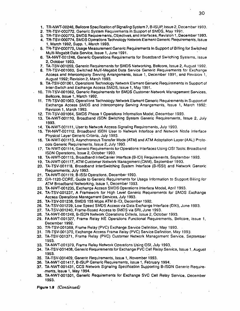
30
1. TR-NWT-00246, Ballcora Spacification of Slgnallng Systam 7. B-ISUP, issua 2, Decambar 1993. 2. TR-TSV-000772, Ganeric System Requirements in Support of SMDS, May 1991. 3. TA·TSV-000773, SMDS Requirements, Objectives, and Interfaces, Revislon 1, December 1993. 4. TR-TSV-000774, SMDS Operatlons Technoiogy Network Element Generic Requirements, issue
1, March 1992, Supp. 1, March 1993. 5. TR-TSV-000775, Usage Measurement Generlc Requirements in Support of Billing for Switched
Muiti-Megabit Data Servica, lssue 1, June 1991. 6. TA-NWT-001248, Generic Operations Requirements for Broadband Switching Systems. issue
2, October 1993. 7. TA-TSV-Q01 059, Generic Requirements for SMDS Networking, Ballcore, issua 2, August 1992. 8. TR-TSV-Q01060, Switchad Multi-Megabit Data Sarvice Generic Requiraments far Exchange
Accass and lntercompany Serving Arrangemetnts, issua 1, December 1991, and Revisian 1, August 1992; Ravision 2, March 1993.
9. TA-TSV-001061, Oparations Technoiogy Network Element Generic Requirements in Support af tnter-Switch and Exchange Access SMDS, lssue 1, May 1991.
10. TR-TSV-001062, Generic Requirements for SMDS Customer Natwork Managament Servicas, Ballcora, Jssua 1, March 1992.
11. TR· TSV-001 063, Oparations Tachnoiogy Network E lamen! Generic Requirements in S uppart al Exchanga Access SMDS and intercompany Serving Arrangements, issue 1, March 1992; Revision 1, March 1993.
12. TR-TSV-001064, SMDS Phase 1 Operations inforrnation Modei, December 1993. 13. TA-NWT-001110, Broadband ISDN Switching System Generic Requirements, issue 2. July
1993. 14. TA-NWT-00 1111, U ser to Network Access Signaiing Requirements, July 1993. 15. TR-NWT-001112, Broadband ISDN Usar lo Natwark interiaca and Network Nade interiace
Physical Layar Ganeric Criteria, July 1993. 16. TA·NWT-Q01113, Asynchronous Transfer Mode (ATM) and ATM Adaptation Layer (AAL) Prato
cols Genaric Requirements, issue 2, July 1993. 17. TA·NWT-001114, Genaric Requirerrients for Operations lnteriacas Using OSI Tools: Broadband
ISDN Operations, issue 2, October 1993. 18. TA-NWT-001115, Broadband interCarrier interiace (B·iCi) Requiremants, Septamber 1993. 19. TA-NWT-001117, ATM Customar Network Management (CNM), September 1993. 20. TA-TSV-001118, Broadband interSwitching System interiaca (B-iSSi) and Network Generic
Raquiramants, July 1993. 21. TA-NWT-001119, B-iSSi Oparations. December 1993. 22. GR-1120-CORE, Guida to Generic Requirements lar Usage information to Support Billing for
ATM Broadband Networking, issue 1, December 1993. 23. TA-NWT-001235, Exchange Access SMDS Operations intariace Modal, April1993. 24. TA-TSV-001237, A Framework for High Leval Generic Requirements for SMDS Exchange
Accass Operations Management Services, July 1993. 25. TA-TSV-Q01238, SMDS 155 Mbps ATM B-ICI, December 1992. 26. TA-TSV-001239, Low Speed SMDS Access via Data Exchange interface (DXI), June 1993. 27. TA-TSV-001240, Frame-Based Access lo SMDS via SRI, June 1993. 28 . .TA-NWT-001248, 8-iSDN Network_ Operations Criteria, issue 2, October 1993. 29. FA·NWT-Q01327, Frame Relay NE Operations Functionai Requirements. Bellcore, issue 1,
December 1992. 30. TR-TSV-001369, Frame Relay (PVC) Exchange Service Delinition, May 1993. 31. TR-TSV-001370, Exchange Access Frama Relay (PVC) Service Definition, May 1993. 32. TA-TSV-001371, Frame Relay (PVC) Customer Network Management Sarvice, September
1993. 33. TA-NWT-001379, Frame Relay Network Operations Using OSI, July 1993. 34. TA·TSV-001408, Ganeric Requirements for Exchange PVC Cell Reiay Service, issue 1, August
1993. 35. TA-TSV-001409, Generic Requirements, issua 1, November 1993. 36. TA-NWT-001417, B·iSUP Generic Requirements, issue 1, February 1994. 37. TA-NWT-001431, CCS Network Signaling Specification Supporting S-ISDN Generic Require
. ments, issua 1, May 1994. 38. TA-NWT-001501, Generic Requirements for Exchange SVC Call Reiay Servica, December
1993.
Figure 1.9 (Continued)

31
l. Use of ATM technology between traditionallocal or re mote LAN hubs; Fig. 1.10 shows a éase ofinterconnection ofremote hubs. (The LAN hubs are implicit in th4o' Ugure.)
2. Introduction of ATM cards on traditional routers for access toa public cell relay service (see Fig. 1.11).
3. Introduction of ATM-based LAN hubs, extending ATM all the way to the desktop, for front-end applications (see Fig. 1.12).
4. Development of private-enterprise ATM switches to support generic corporate networking.
5. Development of carrier-grade multiservice ATM switch es (al so known as broadband switching systems) to support services such as cell relay service, frame relay service, and SMDS.
, 6. Development of related equipment (for example, Fig. 1.13 depicts
usage in a channel extension environment).
Sorne industry proponents expect to see Fortune 1000 users passing the majority oftheir LAN-to-WAN traffic through premises-based ATM switches by 1997. Approximately 50 percent ofthe ATM traffic in these companies is expected to be in support ofLAN interconnection, for LANs serving traditional business applications, and for traditional enterprise data applications, such as mainframe channel extension; the other 50 percent ofthe traffic is expected to be split fairly evenly among application supporting real-time video, imaging, real-time voice, and multimedia.
Traditional LAN Traditional LAN
.....-- Router -"\ Router .....--r- f-
ATM ATM 1 ) - engine -
0-~' -
.....
ATM
Private engine
ATM c., switch Traditional LAN Traditional LAN
r-- Router Routar
f-
/'/ ATM ATM -- -: angina angina
1
"Figure 1.10 Private ATM technology to interconnect dispersed LAN hubs. ATM engine = the logic implementing ATM, control, and, optionally, user plane protocols.

Ethernet
Router
Public network
Ethernet
Router
ATM engine
Ethernet Ro u ter
Figure 1.11 Routers used in conjunction with a public cell relay service. ATM engine . = the logic implementing ATM, control, and, optionally, user plane protocola.
32
Figure 1.14 depicts a typical "full-blown" ATM/cell relay arrangement for both WAN and LAN applications. This supports ATM to the desktop for such applications as desk-to-desk videoconferencing and multimerua. Figure 1.15 depicts an example ofthe protocol machinery across a router/public switch arrangement that is expected to be a common deployment sceniu1.o in client/server environments. Figure 1.16 depicts an example in
ATM angina
ATM wiring hub (switch)
Flgure1.12 ATM to the desktop.

Host (like a 3090J)
Controller
Moin Pata CGntor
Host (example: ES/9000)
~;.._ ____ _,_ Remete ¡..,-<,......._, Site
ESCON L2 ATM ·
ESCONL1 PHV
Commlmications adaptar
ATM SONET
Flgu,... 1.13 Channel extension via ATM seryices.
33
a vjdeoconferencing application, also from a protocolpoint ofview. Figure 1.15 shows an example in a corporate network supporting business imaging.
Figure 1.18 depicts a .more complete enterpriséwise use of cell relay service, while employing a public WAN CRS network. For this example, ATM-ready workstations and devices connected toan ATM-based hub with ATM WAN router capabilities (the router could also be a separate device) can get direct access to the ATM WAN. Sorne of the hub and router vendors are taking'this path to the market. The figure also shows that traditional LAN usets can employ an ATM-ready router to obtain the benefit of cell relay WAN services without having to replace their

ATM engine
ATM wiring hub (switch)
ATM engine
ATMwiring hub (switch)
Public network
Figure 1.14 Example ofusage of ATM in an enterprise network.
34
desktops or in-house wiring. It also depicts another route to the market, followed by sorne ofthe more sophisticated multiplexer manufacturers: The multiplexer can connect traditional data devices, mainframe chann.els, and video to a cell relay WAN network by supporting ATM on the trunk side. Sorne of these multiplexers also support traditional LANs on the house side over a frame relay interface. (Note: Carrier-deployed ATM "service nodes" in close proximity of the user location but on the ·
-:-¡ :' / (_ /
'~

35
-API- -API-
~ t '
Upper layers Upper layers
TCP TCP IP ~ ....... IP
IP conv. fun. / " jp
conv. fun. LLC. LLC 1 \ LLC LLC AAL 5 AALS MAC ATM ;41 ~ ATMIATM ATMIATM ¡4-~ ATM MAC MAC
PHY ~ PHYIPHY PHYIPHY .y. MAC PHY
Client A TM-configured Cell ralay natwork A TM-configured Servar router routar
Figure 1.15 Typical corporate application fróm a protocol-stack point of view. conv.fun. = convergence function.
:ietwork side of the interface support these same services plus LAN emulation service.)
Figure 1:19 depicts sorne user applications of cell relay service in the case where the user wants to develop a prívate .ATM/cell relay service WAN. Note the need to (1)install privately managed switches, (2) use dedicated high-speed WAN. lines, and (3) backhaul remote locations to a remote switching si te. Public cell relay service may prove less demanding in terms of users' responsibility. Hybrid arrangements ar<l also possible.
1.6.2 Clientlserver lssues
The client/server architecture being put in place in many organizations is truly distributed in the sense that the corporate user has access to· data regardless of where the data are Iocated, be they on a system in another campus, another city, another state, or another continent. Client/server applications require extensive interchange of data blocks, often entailing multiple transactions. Low end-to-end delay is critica! in making client/server computing possible.19
.Applications requiring large transfers (e.g., 50-100 kbits) are not unusual in these environments, particularly for imaging video, and
Video-camera
/Codee
Communication handler
Control Upper Upper plana layers layers
(poss1bly (possibly r No! par! of CRS null) null)
AAL 1
'Par! of CAS
Communication handlar M .1 on1 or
Control plana Upper Uppar
layers layers (possibly (possibly
null) null)
Codee\
Figure 1.16 Example ofvideo application over ATM/cell relay arrangement.

36
Central site · 45 Mbps LAN 155 Mbps . . 1------iCell relaYI-f-h 622 Mbps
wmng router hub
Printer Viewing workstations lndex/keyword
File servar, file server optical jukebox,
read function
Remole site
PVC/SVC cell relay network
LAN wiringl------jCell relay hub router
Printer Viewing workstations
Remole site
Printer Viewing workstations
Figure 1.17 Use of ATM/cell relay to support imaging.
45 Mbps 155 Mbps 622 Mbps
multimedia applications (the last two applications also ha ve stringent delay sensitivities). A 100-MByte data unit across the application programming interface (API) running on a remotely located LAN-resident server is segmented into approximately 60 Ethernet frames. Each Ethernet frame is then segmented into approximately 30 cells by an ATM-configured router for delivery over a public cell relay network.
Sorne wish to clarify the implications of the interplay between the network(or private ATM switch) performance in terms of cellloss/mutilation, response time, latency, and the end-to-end error correction protocols (e.g., included in TCP). For example, if one of the 29 cells that
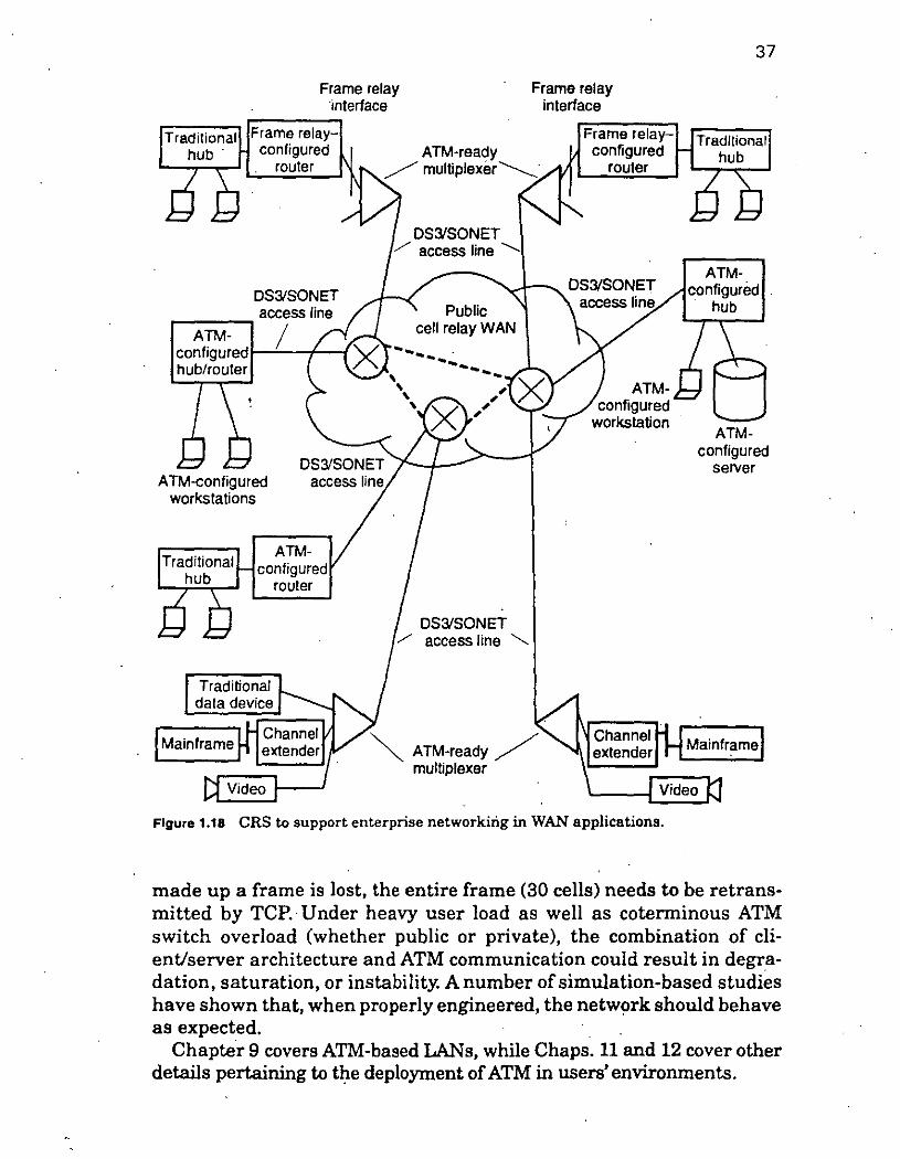
Frame relay ·interface
Frame relay interface
37
,....-----, Traditional Frame relay-
hub · configurad ATM-ready Frame relay- Tradllional
configurad hub router
DS31SONET
ATMconfigured 1---'---f--f hub/router
A TM-configured workstations
Traditional hub
Mainframe
Video
ATM-
/ multiplexar----------
DS31SONET / access line '-
DS31SONET / access lina ""-.
~ ATM-ready / multiplexar
router
Figure 1.18 CRS to support enterprise networkirig in WAN applications.
ATMconfigured
servar
made up a frame is lost, the entire frame (30 cells) needs to be retransmitted by TCP. · Under heavy user load as well as coterminous ATM switch overload (whether public or private), the combination of clientlserver architecture and ATM communication could result in degradation, saturation, or instability. A number of simulation-based studies ha ve shown that, when properly engineered, the network should behave as expected.
Chapter 9 covers ATM-based LANs, while Chaps. 11 and 12 cover other details pertaining to the deployment of ATM in users' environments.

User location A . ,.------------, Carrier's facilities
ATM-confrgured t-------------, hublrouter Dedicated
A TM-configured workstations
switch
Usar location C Priva te ATM
ATM-ready mu~iplexer
DS3s or other high-speed facilities
""'------------~
Usar location· O ·
ATMconligured
hub
ATM-configured workstatron
ATM-
38
Dedicated DS3s or other high-speed facilities
configurad
User location E
ATM-ready multiplexar
Video
servar
Figure 1.19 CRS to support enterprise networkingin WAN applications (priva te network).
1.7 The Value of Standards
lt is a well-known fact that standards benefit not only an industry but an en tire economy. Many industries would not ha ve arisen (e.g., the VCR industry, the CD audio industry, television, radio, etc.) if it were not for standards. Standards·make a leve! playing field, fostering competition; this is in contrast to vendor proprietary approaches, where only those vendors have access toa market or have disproportionate control ofit. However, for a standard to be effective, it must be widely available, without restrictions on promulgation, discussion, commentary, proliferation, distribution, and duplication. In our opinion, a standard is not an open standard if it is restricted, copyrighted, or patented, if it represents someone's intellectual property, or if it is "owned" by someone (sounds mighty close to a proprietary system to us!) because all ofthese factors frustrate the exact purpose for which the standard aims to exist (or has a reason to exist). There is much discussion at large about "free trade," "free movement of information," and "lack of censorship."
39
Standards are developed by industry consensus. This means. that . representatives from many companies, typically severa! dozen, have input into the standard. These proceedings can go on for years, and the representatives ofthese companies travel to many meetings andinvest company resources back home to work on technical issues, prepare contributions, review contributions, and act as editors, chairs, etc. In the end, no one individual or institution should be able to claim ownership. There must be a free flow of specification information. Developers must be able to obtain copies. Programmers must be able to use the material. Documentarles must be able to write down the standard and comment on how they implemented various aspects. Educators must be able to discuss the.standard and promulga te it to users. Otherwise, such a standard m ay go nowhere, as many examples ofvoluminous standards from the (late) 1980s illustrate.
Given this philosophical imperative, and in spite of the less than eloquent case made in these terse paragraphs, we have taken the approach of discussing here, in this text, the dozens of standards that support cell relay service and ATM, regardless of their source. In the end, all stand to benefit from such oper and uninhibited discussion at the birth ofthis new technology. Since this book is only a brief synopsis. ofthe estimated 15 cubic feet ofstandards material that forms the basis for ATM (ITU-T, ANSI TlSl, ATM Forum, Frame Relay Forum, Bellcore, and other documents), the reader is constantly referred to the original documents for the full-scale detail. In particular, developers, who stand· to benefit commercially from their efforts, should definitely refer to the original documentation for the necessary level of detail. The purpose of this book is strictly pedagogical and for the end user. Each of the more than 100 documents alluded to earlier can be obtained from the original source for $100 or less.
· References
· l. D. Minoli, Enterprise Networking-Fractional TI to SONET, Frame Relay to BISDN, Artech House, Norwood, Mass., 1993. ·
2. D. Minoli, 1st, 2nd, and Next Generation LANs, McGraw-Hill, New York, 1994.
3. D. Minoli, Imaging in Corporate Environments: Technology and Communication, McGraw-Hill, New York, 1994.
4. D. Minoli and B. Keinath, Distributed Multimedia: Through Broadband Communication Services, Artech House, Norwood, Mass., 1994.
5. D. Minoli et al., ATM Layer Bearer Service/Cell Relay Service Ext~nded Stage 1 Description for Public Service Offerings, T1S1.5/93-021, February 1993.

40
6. TlS1.5/93-52, Broadband Aspects of ISDN Baseline Document, TJSJ Technical Subcommittee, August 1990, ChiefEditor: Erwin Fandrich.
7. D. Minoli, "The N ew Wide Are a Technologies: SMDS and E-ISDN," Network Computing, pp. 88fT., August 1991. 1
8. D. Minoli, "Understanding ATM-:-Part 1," Network Computing, pp. 128fT., Oct. 15, 1992.
9. D. Minoli, "Understanding ATM-Part 2," Network Computing, pp. 156fT., Nov. 15, 1992.
10. D. Minoli, "Third-Generation LANs," UNIX Expo 92 Proceedings, Bruno · Blemheim Inc., Fort Lee, N.J., 1992.
11. D. Minoli, "Third Generation LANs," Proceedings of Texpro 1993, PacificBell, San Francisco, April1993.
12. D. Minoli, "Cell Relay and ATM," WAN Insert to Network Computing and Communications Week, pp. 22 ff., August 1993.
13. D. Minoli, "WideArea Networking for Multimedia?", WAN Insert toNetwork Computing and Communications Week, pp. 60fT., August 1993.
14. D. Minoli, "Broadband Integrated Services Digital Network," Data pro Com. munications Series: Broadband Networking, Report #2890, April 1992.
15. D. Minoli, "ATM and Cell Relay Concepts," Datapro Communications Series: Broadband Networking, Report #2880, April 1992.
16. J. T. Johnson, "Applications Catch Up to ATM," Data Communications, pp. 41-42, July 1993.
17. F. Gratzer and S. Walters, "ATM and Fast Pa&et Services-Perfect 'lbgether," Bellcore DIGEST, vol. 10 (6), pp. 3fT., 1993.
18. D. Minoli, "Designing Scalable Networks," Network World Collaboration, pp. 17fT., January 10, 1994.
19. D. Minoli,Analyzing Outsourcing: Reengineering Informal ion and Communication Systems, McGraw-Hill, New York, 1995.

41
Asynchronous Transfer Mode
As noted in Chap. 1, ATM is a new transport and switching technology that can be used in a variety of telecommunications and computing environments. ATM is a cell-based technology, designed to support user applications requiring high-bandwidth, high-performance transport and switching. This chapter provides a summary description of the peer-to-peer ATM protocol at the user-network interface in support of cell relay service and other ATM capabilities. It describes functionality in the User Plane, tbereby enabling a PVC service. The addition of· Control Plane support enables the user to obtain an SVC service; the operation of the ATM Layer in the Control Plane is nearly identical to that of the U ser Plane (the Control Plane functionality is discussed in Chap. 4). Sorne aspects ofthe underlying transport mechanism are alsobriefly covered at the end ofthe chapter.
A description of general aspects of the access interface{s) between the user and the network is followed by a desci'iption ofthe protocol across such an interface. The protocols and related requirements are associated with two functional OSIRM layers: the Data Link Layer and the Physical Layer. Figure 2.1 depicts this peer-to-peer protocol view of the service. Figure 2.2 depicts communication through a set of network peers. As described in ITU-T Recommendation X.210, Open Systems Interconnection, Layer Service Definition Conuentions, 1 the service def1ned at the Data Link Layer also relies on the capabilities of the Physical Layer. This view of cell relay service in general and of the ATM protocol in particular establishes requirements on what an entity in the ATM Layer (whether the entity is in the network or in the user's equipment),
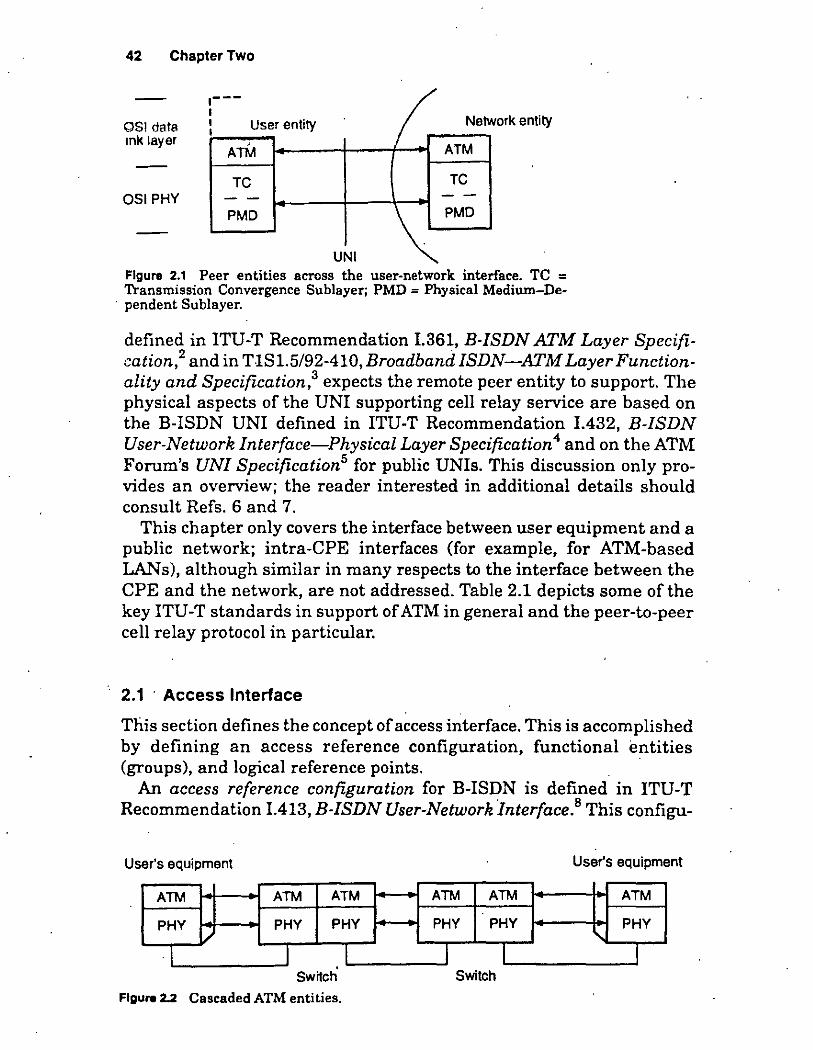
42 Chapter Two
OSI data mk layer
OSIPHY
~---1 1 User entity 1
ArM
TC --PMD
ork entity Ir Nem
ATM
TC --
UNI
\;PMD
Figure 2.1 Peer entities across the user-network interface. TC = Transmission Convergence Sublayer; PMD = Physical Medium-De
. pendent Sublayer.
defined in ITU-T Recommendation 1.361, E-ISDN ATM Layer Specification,2 and in T-181.5/92-410, EroadbandiSDN-ATM Layer Functionality and Specification,3 expects the remote peer entity to support. The physical aspects of the UNI supporting cell relay service are based on the B-ISDN UNI defined in ITU-T Recommendation 1.432, E-ISDN User-Network Interface-Physical Layer Specification 4 and on the ATM Forum's UN! Specification5 for public UNls. This discussion only provides an overview; the reader interested in additional details should consult Refs. 6 and 7.
This chapter only covers the interface between user equipment anda public network; intra-CPE interfaces (for example, for ATM-based LANs), although similar in many respects to the interface between the CPE and the network, are not addressed. Table 2.1 depicts sorne ofthe key ITU-T standards in support of ATM in general and the peer-to-peer cell relay protocol in particular.
2.1 · Access Interface
This section defines the concept of access interface. This is accom plished by defining an access reference configuration, functional entities (groups), and logical reference points.
An access reference configuration for B-ISDN is defined in ITU-T Recommendation 1.413, E-ISDN User-Network Interface.8 This configu-
User's equipment
ATM ATM ATM
PHY PHY PHY /
1 l 1 Swijch
Figure 2.2 Cascaded ATM entities.
User's equipment
ATM ATM ATM
PHY PHY PHY
' 1 l 1 Switch

. •'•
Asynchronous Transfer Moda . 43
TABLE 2.1 Key ITU·T Standards In Support of ATM
F.811
F.812
1.113
1.121R
1.150
1.211
1.311
1.321
1.327
1.356
1.361
1.362
1.363
1.371
1.374
1.413
1.432
1.555
1.555
1.610
I.cls .
Q.93B (now Q.2931)
Q.SAAL 1 and 2 (now Q.2110 and Q.2130)
B-ISDN Connection-Oriented Bearer Service
B·ISDN Connectionleas Baarer Service
B-ISDN Vocabulary of Terrns
Broadbaod Aspects of!SDN [Basic Principies and Evolu-tion) ·
B-ISDN ATM Functional Characteristics
B-ISDN Service Aspects
B-ISDN General Network Aspects
B-ISDN Protocol Reference Model and Its Applications
B-ISDN Functional Architecture Aspects
Quality of Service Configuration and Principies
B-ISDN ATM Layer Specification
B-ISDN AAL Functiónal Description
B-ISDN AAL Specification
Traffic Control and Resource Management
Network Capabilities to Support Multimedia
B-ISDNUN1
B-ISDN UN! Physical
lnterworking with Frame Relay
Interworking with ISDN
B-ISDN OAM Principies
Support for Connectionless Data Service on B-ISDN
B-ISDN Call Control
Signaling AALs [Q.2110, Service-Specific Connection: Oriented Protocol (SSCOPl; Q.2130, Service-Specific Coordination Function (SSCF)]
ration forms the basis for the definition of access interfaces supporting cell relay service.
Functional entities are logical abstractions offunctions typically found in network equipment and in users' equipment, al so known as customer premises equipment (CPE). Public network switch-termination func: tions are modeled by the broadband line terminator/exchange terminator (B-LT/ET) functional group. The CPE is modeled by the broadband network termination 2 (B-NT2) functional group; NT2 functions include concentration, switching, and resource management. Broadban:d network termination 1 (B-NTl) functions support line termination, line maintenance, and performance monitoring. The broadband terminal

44 Chapter Two
1 B-TA )f--11-8~1 B-NT2 )1--T+r---l¡ B-NT1 )1--u+r---i¡ 6-LT/ET) Logical view
CPE multiplexar/
End switchlhub/ system router
1 1
UNI
Broadband switch
Apossible physical real.ization
Agure2.3 B-ISDN access reference configurations. B-TA= broadband terminal adapter.
equipment, such as a workstation, is modeled by the broadband terminal equipment (E-TE) functional group.
Logical reference points are defined between E-ISDN functional entities. TB is the logical reference point between a E-NT2 anda E-NTl. UB is the logical reference point between a E-NT1 anda E-LT/ET. In this description, the UNI is associated with the UB reference point. See Fig. 2.3.
Note: This description only covers the case where there is a single E-NT2 (however, severa! E-TEs may be connected to the B-NT2). The case where the E-NT2 is null and there are severa! B-TEs connected to a single UNI is not addressed in the initial view of ATM services in the United States.
2.2 ATM-Level Protocol
2.2.1 Overview
UNI protocols define the way in which users communicate. with the public network for the purpose of accessing the service provided by the network. Figure 2.4 illustrates the E-ISDN Protocol Reference Model, which is the basis for the protocols that operate across the UNI (this is another common way to represent the protocol model of Fig. 1.3). The B-ISDN Protocol Reference Model is described in ITU-T Recommendation 1.121. This model is made up ofthree planes, already discussed in Chap. 1: the U ser Plan e, the Control Plane, and the Management Plane. Table 2.2 provides a summary ofthe functions súpported by each plane.
The UNI specified at this level includes the functions associated with the U ser Plane at the Physical Layer and the ATM Layer. The Physical Layer provides access to the physical medium for the transport of ATM cells. It includes methods for mapping cells to the physical medium (i.e., the Transport Convergence Sublayer) and methods dependent on the physical medium (i.e., the Physical Medium-Dependent Sublayer). The ATM layer provides for the transport of cells between end-user locations. An ATM cell contains a header that contains control information, iden-

Asynchronous Transfer Mode 45
Plane management
Higher layers Higher layers
ATM adaptation tayers
flf7:TiTI Protocoltayers relevan! to liiSi3l cell retay serv1ce .
Figure 2.4 B-ISDN protocol reference model.
tifies the type of cell, and contains routing information that identifies a logical channel (i.e., a VPC or a VCC) over which the cell is to be forwarded.
The interactions of each protocollayer with other layers and with its own layer management are described in terms ofprimitives. Primitives describe abstractly the logical exchange of information and control
TABL!' 2.2 Functlons of Varlous Planes of the Protocol Model
UserPlane
Control Plane
Management Plane
Provides for the transfer of end-user information. It consists ofthe Physical Layer and theATM Lnyer. The model also includes ATM Adaptation Layers and higher layers necessary for each end-user application. (Because these layers are specific to each application, they are not part ofthe cell relay service described here and in Chap. 5.)
Provides for the transfer of information to support connection establishment and control functions necessary for providing switched services. The Control Plan e shares the ATM and· Physical Layer with the U ser Plane. Also, it contains AAL procedures and higher-layer signaling protocola. The Control Plane is discussed in Chap. 5.
Provides for operations and management functions and the capability to exchange informotion between the U ser and the Control Planes. The Management Plane is made up of the Layer Management (for layer-specific management functions such as detection of failures and protocol abnormalities) and the Plane Management (for management and coordination functions related to the complete system). The Management Plane is discussed in Chap. 10.
.··1
'·"''

46 Chapter Two
through a service 'access point, while not imposing any constraint on the implementation. Figures 2.5, 2.6, and 2.7 depict sorne aspects of this protocolJnnchiJwry.
2.2.2 ATM Layer
The ATM Layer provides for the transport of flxed-size cells between end-user locations. It is implemented in users' equipment (workstations, routers, private switches, etc.) and in network equipment. ATM cells from end users are forwarded across virtual connections through the public network. These connections are provided at subscription time or in real time vi a signaling (as described in Chap. 4). The ATM Layer also · · provides multiplexing functions to allow the establishment ofmultiple connections across a single UNI.
(N -1)-PCI
\ Layer management !--'"'=:::. )
entity
(N)-PDU
(N)-Iayer
(N - 1 )-layar
(N- 1)-SDU
(N- 1 )- (N- 1)-service service ·
user u ser
.request .confirm
.indication .response
(N)-Iayer ..-!'\ 1 ¡-.
1\ ...... V(N -1)-SAP \
~ li(N -1)-SAP
(N - 1 )-layar
1 ~ - --1 L-----------1
(N - 1 )-service provider
rlgure2.5 SAPs (top) and primitives (bottom). SAP = service access point; PDU =pro toco! data unit; SDU = service data unit; PCI = protocol control information.
'~;

Segmentation Reassembly Reassembly error
detection Message ID mul~plexing
CeH multiplexing CeH relaying .Interface
identification
HEC generation HEC verification Line coding CeH framing/
recovery Bit timing Physical medium interface
DeviceA (e.g., premisas ATM swttch)
Upper layers (e.g., TCP/IP or equivalen!)
Q) ()
~-AAL !ayer, Q)
en
t•~ ¡::-ATM layar
Q)
en
Q) ()
-~-Physical !ayer
Q)
en Transmission convergence -------
Physical medium dependen!
Asynchronous Transfer Mode 47
Device B · (e.g., workstation/peripheral,
premises ATM swrtch, or BISDN switch)
Uppar layars (B.g., TCP/IP or equivalen!)
Paar-to-peer protocol
Peer-t<>:paer AAL !ayer
prolocol
ATM !ayer Peer-to-pear
protocol
. Pear-to-peer Physicallayer
protocol Transmission convergence
-------Physical medium dependen!
e Fiber, twisted-pair (premisas only)
Figura 2.6 ATM protocola.
Servlce provlded to the upper layer. The ATM-Layer service is based on flxed-size ATM service data units which consist of 48 octets. It pro vides for the transparent transfer of ATM SDUs between communicating peer upper-layer entities. To accomplish this, the ATM Layer genera tes a 53-octet ATM cell by prepending a 5-octet header to the ATM SDU. The header contains routing and protocol control information. The . interaction between the ATM Layer and its serv1ce users· is implemented by the primitives shown in Table 2.3.
Servlce expected from the lower layer. The ATM Layer expects the Physical Layer to support the transparent transport of ATM cells between peer ATM entities. The exchange of information between the ATM Layer and the Physical Layer is implemented by the primitives shown in Table 2.4. The PHY-SDU parameter in these primitives contains the 53-octet cell to be transmitted between peer ATM entities.

48 Chapter Two
AALSDU 9
AAL
AAL PDU ,.---+, (ATM SDU) '----f
ATM
ATMPDU ~ (PHY SDU) '----f (1C SDU, In particular)
PHY:TC
ATM SAP
PHY SAP
Figure 2.7 Pertinent ATM SAPs.
ATM cell format. The ATM cell format used across the UNI is shown in Fig. 2.8 (which is another way oflooking at Fig. 1.2). Table 2.5 describes the meaning of the fields.
End-to-end operations administration and maintenance capabilities need to be supported. For VPs, operation functions are supported via specially marked ATM cells, which are transmitted over VCs with specific VCI values· (these are known as F4 flows). For VCs, operation functions are supported via cells marked with an appropriate codepoint in the Payload Type Indicator field (these are known as F5 flows). The functions supported are shown in Table 2.6. Figure 2.9 illustrates the difference between these two OAM flows.
Table 2.7 provides the encoding for the PTI field. Code point lOOB (B = binary) indicates a segment OAM F4 cell flow used to monitor the status of a segment within the virtual connection. Code point 101B indica tesan end-to-end OAM F5 cell flow used to monitor the status of a connection end to end. Code point llOB is reserved for future traffic control and resource manageinent procedures.
•VCI is 4 for end-to·end operations and 3 for segment inforrnation.

TABLE 2.3 ATM Layer Prlmltlves '
ATM-DATA.request (ATM_SDU, Submitted_Loss_Priority, Congestion_lndication, SDU_Type)
ATM-DATA.indication (ATM_SDU, Received_Loss_Priority, Congestion_lndica-· tion, SDU_Type)
Description o{ parameters:
Asynchronous Transfer Mode 49
U sed to request transmission of an ATM SDU across a VPC or VCC toa peer entity
Used by the ATM Layer to indicate to the service user the arrival of an ATM cell
ATM_SDU: The 48 octets of inforrnation to be transferrcd by thc ATM Laycr betwecn pecr communicating upper-layer entities. ·
Submitted_Loss_Priority: The relative importance ofthe ATM_SDU containcd in this primi·· tive. Two values are possible. A value of"high" indicates that the resulting ATM cell has higher (or equivalent) loas priority than a cell with a value of"low." A high vnlue mny be translated to a cellloss priority value ofO in the cell header. Similarly, a Jow value m ay be translatcd toa CLP value of 1 in the cell header.
Congestion_lndication: This parameter indica tes whether this cell has passcd through one or more network nades experiencing congestion. lt has two values: True or Fa! se.
SDU_Type: This parameter indicates the type of SDU to be transferred between peer upper !ayer entities. lt can take only two values, O and 1, and its use is as determined by the highcr · !ayer. For example, AAL Type 5 sets SDU_Type to 1 to indica te the last cell of a framc. In other words, this field is currently used by the AAL Type 5 Common Pnrt protocol to d1stinguish between cells thatcontain the last segment ofan AAL Type 5 Comnion Part PDU and thosc that do not. AAL Type 1 and AAL Type 3/4 always set the bit toO.
Received_Loss_Priority: This parameter indica tes the CLP field inarking of thc rccc1vcd ATM_PDU. Two values are possible. A value of"high" indica tes that the rcccivcd ATM ccll has higher (or equivalent) loss priority than a cell with a value of "low." A high valuc may be translated to 8 cell loss priority V8lue of O in the cell hender. Similarly, 8 !ow valuc m ay be transl8ted toa CLP V8lue of 1 in the cell header.
ATM Layer procedures. This section summarizes the functions performed by ATM !ayer entities.
ATM sendlng procedures. These procedures are performed by an ATM entity to send ATM cells to a peer ATM entity. The procedures are organized according to the categories offunctions performed by the ATM Layer. ·
ATM [ayer connections. As described earlier, the ATM service is provided by means ofvirtual connections. For the PVC cell relay service, connections are established at subscription time. For SVC serv1ce,
TABLE 2.4 Physlcal Layer Prlmltlves
PHY-DATA.request (PHY _SDU)
PHY-DATA.indic8tion (PHY_SDU)
Requests the Physical Layer to transport 8n ATM cell between peer ATM ent1ties over 8n existing connection.
lndic8tes to the ATM Layer that an ATM cell has been received over an existing connection.

50 Chapter Two
Bits 8 7 6 5 4 3 2 1 '
GFC VPI
VPI VCI
VCI
VCI PTI icLP
HEC
1
2 .!!!
3 .!!! 8
4
5
Figure 2.8 ATM cell forma t.
connections are established by a signaling mechanism. As will be seen in Chap. 4, about one dozen parameters need to be specified to describe a connection (for example, called party, bandwidth, quality of service, etc.).
Cell rate decoupling. A sending ATM entity must add unassigned cells to the assigned cell stream to be transmitted, so.that a continuous cell stream matching the line rate ofthe UNI is provided to the Physical Layer. This is necessary in order for the Physical Layer to perform adequate cell delinea~ion functions. Unassigned cells are empty cells which ha ve the first 4 octets of the cell header encoded as depicted in Fig. 2.10. Unassigned cells do not carry information. Therefore, they must be extracted at the receiving ATM entity and not passed to the upper !ayer.
Loss priority indicaiion. Traffic management functions may use tagging as a way to control traffic entering the network across the UNI. The network may choose to tag cells that violate a traffic descriptor for the connection by setting the CLP bit to l. If cell discarding is necessary, these cells would be discarded first. Sorne traffic IIlanageroent procedures are discussed in Chap. 6.
ATM recelvlng procedures. This section describes the procedures an ATM entity executes when receiving an ATM cell to ensure its proper processing. These procedures include the provision for sequenced processing of ATM cells which arrive across a virtual connection.
Sequenced ATAf processing. ATM cells received across a virtual connection must be processed in sequence to ensure adequate service to the higher layers.
Cell validation procedures. The cell validation procedures determine whether a received cell is an unassigned cell and detect invalid header patterns. These procedures also detect cells received with inactive VPINCI values (e.g., VPINCI values which identify inactive connections). Unassigned' cells and cells found to be in error are discarded. .

TABLE 2.5 ATM Cell Flelds
Generic Flow Control (GFC)
Virtual Path IdentifierNirtual Channel Identifier
Payload Type IndicaiDr (PTI)
Cell Losa Priority
Header Error Control
Asynchronous Tra!"sfer Mode 51
The 4-bit GFC field has only local s•gnificance and may be used to provide standardized local furictions at the customer si te (e.g., passive bus support); the field is ignored and may be overwritten by the pubHe network.
The 24-bit VPINCI field indica tes the virtual connection over which a cell 1s to be forwarded. The number of connections needed across the UN! is less than 22
\
therefore, only sorne bits of the VPI and VCI subfields are used. Those bits are called allocated bits, and al! other bits in the VPINCI field are set toO. A VPI val u e ofO is not available for user-to-user virtual path identification. Similarly, a VCI value ofO is not available for user-to-user virtual channel identification.
The 3-bit PTI field indica tes whether the cell contains user information or !ayer management information. Code points 000 to 011 indica te user information; these PTI values identify two types of end-user infonnation and whether the cell has experienced congestion (the two types of information are used by the end-user application). For user data, the public nctwork does not change the SDU_Type indicnted by the PTI field. The public network can, however, change the PTI value from Congestion_Experienced = False to Congestion_Experienced = True. Code points 100 to 111 identify different types of operations flows. See Table 2.7.
This 1-bit field allows the user ID indica te t.he relative cellloss priority of the cell. The network may attempt ID provide a higher cellloss priority (or equivalent) force lis marked with high priority !.han for ce lis marked with low priority. The current view is ID only Jet the user set CLP ID the value O.
The 8-bit HEC field is used by the Physical Layer to detect transmi.ssiol) errors in the cell header and in sorne cases for cell delineation.
Cell discrimination based on PTI value. A receiving ATM Layer entity processes cells according to the type ofpayload they contain as indicated by the value in the PTI field. User cells (PTI values 000-100) are forwarded across the appropriate virtual channel. If neces-

52 Chapter Two
TABLE 2.6 Layer Management Functlons lncluded In Cell Relay Servlce
Fault mona¡ement funclions
Performance management functions
· Activationldeactivation
Alann surveillance: AIS (alann indication signa!)
Alarm surveillance: FERF (far-end receive failure; now known as remete defect indicator)
Connectivity verification: cell loopback continuity check
Forward monitoring Backward reporting Monitoring!reporting
Performance monitoring Continuity check
sary, PTI values may be modified to indicate whether the cell experienced congestion.
Layer Management cells (PTI values of 101-111) are used to provide various operations flows to support functions like performance monitoring and trouble sectionalization. CPE supporting the UNI is not required to support these operations flows. However, network equipment must support them so that it can interface with end-user equipment supporting these functions. (This topic is revisited in Chap. 10.)
2.2.3 Layer Management
There are two types ofinteractions between the ATM entity and the ATM Management entity. One interaction is for the exchange of local information between these two entities. The primitives are showri in Table 2.8 (the parameters are not shown for simplicity). The other interaction is for peer-to-peer communication between ATM Management entities. The primitives for this interaction are shown in Table 2.9. For more details, refer to Ref. 2, 5, or 6. (Th.is tapie is revisited in Chap. 10.)
.SegmeniVP OAMF4
/ flows ~ ~-----4 ~----~
1 1 [ 1
End-to-end VC OAM FS flows
Figure 2.1 OAM F4.and F5 flows.
1 1

TABLE 2.7 PTI Code Polnts
PI'I code point
000
001
010
011
100
101
110
111
2.2.4 Physlcal Layer
Asynchronous Transfer Mode 53
Meaning
U ser data-SDU_Type O, no congestion experienced
U ser data-SDU_Type 1, no congestion experienced
U ser data-SDU_Type O, congestion experienced
User data-SDU_Type 1, congestion experienced
Segment OAM F5 flow cell
End-to-end "OAM F5 flow cell
Reserved for future traffic control and resource management functions
Reserved for future use
Although the emphasis of this chapter is on the ATM Layer, a brief discussion ofthe underlying Physical Layer is also provided. Figure 2. U depicts sorne ofthe key Physical Layer protocols supported.
As noted, the Physical Layer is made up of two sublayers: the Transmission Convergence Sublayer and the Physical Medium-Dependent Sublayer. The TC Sublayer "maps" the ce!! stream to the underlying framing mechanism ofthe physical transmission facility and genera tes the required protocol control information for the Physical Layer (e.g., SONET overhead octets). It also genera tes the HEC. The PMD Si.Iblayer deals with the electrical or optical aspects ofthe physical interface (e.g., timing, power, jitter).
The UNI providing the service's access interface includes the physical characteristics of facilities that provide actual realizations of the U8 reference point. In practica! terms, this access interface specifies the means and characteristics of the connection mechanism between CPE supporting ce!! relay service and a LEC's switch providing the same service. UNis are specified by characteristics such as physical and electromagnetidoptical characteristics, channel structures and access
+-------------4 octets -------------
GFC VPI VCI
AAAA Os Os
. A: This bit is available for use by appropriate A TM !ayer function. X: This bit is a don"t cara bit.
Figure 2.1 O First four octets of cell header for unassigned celia.
PTI
XXX

54 Chapter Two
TABLE 2.8 ATM Management Prlmltlves for Local Communlcatlon
ATMM-MONITOR.indication
ATMM-ASSIGN.request
ATMM-ASSIGN.confirm
ATMM-REMOVE.request
ATMM-REMOVE.confirm
ATMM-ERROR.indication
ATMM-PARAMETER·CHANGE.request
Issued by.an ATM Layer Management en· tity to deliver the content of an ATM_PDU received by the A'l'M ent.ity, to facili~te an OAM function
Issued by an ATM Layer Management entity to request the establishment of an ATMlink
Issued by an ATM Layer Management entity to confirm the establishment of an ATM link
Issued by an ATM Layer Management en· tity to request the release of an ATM link
Issued by an ATM Layer Management en· tity to confirm the release of an ATM link
Issued by an ATM Layer Management entity to indicate an error and invoke appropriate management actions
Issued by an ATM Layer Managcment entity to request a change in a parameter of theATMlink
capabilities, user-network protocols, maintenance and operations characteristics, performance characteristics, and service characteristics.
The physical access channel for ATM-based fastpacket services such as cell relay service supports one ofthe following access rates: 622.080 Mbits/s (future); 155.520 Mbits/s; 44.736 Mbits/s; 1.544 Mbits/s (perhaps in the future). The corresponding. channel signa! formats are STS-12c (Synchronous Transport Signal Levell2, concatenated), STS-3c, DS3 (Digital Signal Level 3), and DSI.
Physlcai-Layer mapplngs. The mapping ofcells onto the DSl, DS3, and SONET STS-3c has also been defined.9 Sorne key aspects ofhow cells are inserted over the underlying framing mechanism are discussed below.
TABLE 2.9 ATM Management Peer-to-Peer Prlmltlves
ATMM·DATA.request (ATM_SDU, Sub· mitted_Loss_Priority, PHY_CEI(s)) ·
ATMM-DATA.indication (ATM_SDU, Received_Loss_Priority, PHY_CEI, Conges· tion_Indication)
Note: CEI ia the connection endpoint identifier.
Issued by an ATM Layer Manageme~t entity to request transfer of a management ATM_SDU
Issued to an ATM Layer Management entity to indicate the arrival of a managementATM_SDU

Adapta non !ayer
"Cor data
e· link
Asynchronous Transfer Mode 55
gpSAR ::¡c._ ooV) Cells
ATM \ A ~ . 1 \ 2/ \ -~
SMDS T1 SMDS T3 ATM ATM TAXI FCS ETSI ·
PLCP PLCP PLCP duact
block block frnmmg (HEC)
TC
///\ ~- 1 \
051 DS3 SONET SONET FDDI FCS Europoan framing tram!ng STS-3c STS·12c PMD PMD E 1.E3.E4
PMD
Figure2.11 Key Physical Layer protocols supported. PLCP = Physical Layer convergcnce procedure; FCS = fiber channel standard; FDDI= fiber distributed data interface; ETSI = European Telecommunications Standards Institute.
The chal!enge at the receiving end is to extract the ceJI from the underlying frame, that is, to establish cell boundaries.
Mapplng of ATM cells lnto 1544-kbiVs OSI frame. Frame forma t. The multiframe structure for the 24-frame multiframe as described in ITU-T Recommendation G.704 is used. The ATM cell is mapped into bits 2 to 193 (i.e., time slots 1 to 24 described in Recommendation G. 704) of the . . .
1544-kbit/s frame, with the oi:tet structure of the cell aligned with the octet structure ofthe frame (however, the start ofthe ceJI can be át any octet in the DSl payload; (see Fig. 2.12).
Cell rate adaption. The cell rate ad~ption to the payload capacity of the frames is performed by the insertion of id le cells, as described in ITU-T Recommendation !.432, when valid cells are not available from the ATM Layer.
Header error control generation. The Header Error Control value is generated and inserted in the specific field in compliance·with ITU-T Recommendation 1.432. ·
Scrambling ofthe ATM cell payload (optional). As an option, the ATM cell payload (48 bytes) can be scrambled befare it is mapped into the 1544-kbit/s signa!. In the re verse operation, following termination.
*As ofpress time, however, standards.for the delivery of ATM over a DSl access were still being investigated.

56 . Chapter Two
Octet 24
r
Octet 5
Octet 4
Octet 3
Octet 2
Octet 1
Framing bit
Figure 2.12 Direct mapping ofcella onto DSl frame (example).

Asynchronous Trimsfer Mode 57
of the 1544-kbit/s signa!, the ATM cell payload is descrambled before being passed to the ATM Layer. The self-synchronizing scrambler with the generator polynomial.:é3 + 1 is used. · .
Cell delineation. Cell delineation is performed using the header error control mechanism as defined in ITU-T Recommendation !.432. This direct mapping approach means that the algorithm parses 5 octets on the fly until a 5-octet boundary is found through the HEC procedure. Once the header boundary is found, the rest of the cell boundary is established by counting 48 additional octets. · Cell header verification and extraction. The cell header verification. is performed in compliance with ITU-T Recommendation 1.432. Only valid cells are P!lSsed to the ATM Layer.
Mapplng of ATM cells lnto 44,736-kbltls 053 trame
Frame format. The multiframe format at 44,736 kbits/s, as described in ITU-T Recommendation G.704, is used.
Two mappings are available:
l. Physical Layer Convergence Pro toco! (PLCP)-based mapping of ATM cells, derived from SMDS principies
2. A direct (HEC-based) mapping, established in 1993
This discussion focuses on PLCP, since the direct mapping is similar to the DS1 mapping.
The ATM PLCP defines a mapping of ATM ce lis onto existing 44,736-kbit/s facilities. The DS3 PLCP consists of a 125-J..Ls frame within a standard 44,736-kbit/s payload. Note that thére is no fixed relationship between the PLCP frame and the 44, 736-kbit/s frame; i.e., the PLCP r:m . .
begin anywhere inside the 44,736-kbit/s payload. The PLCP frame, Fig. 2.13, consists of 12 rows of ATM cells, each preceded by 4 octets of overhead. Nibble stuffing is required after the twelfth cell to fill the 125-J..Ls PLCP frame. Although the PLCP is not aligned with the 44,736-kbit/s framing bits, the octets in the PLCP frame are nibble-a!Ígned with the 44,736-kbit/s payload envelope. Nibbles begin after the control bits (F, X, P, C, or M) ofthe 44, 736-kbit/s frame. The stuffbits are never used in the 44,736-kbits/s, i.e., the payload is always inserted. The reader interested in a detailed explanation ofthe DS3 framing format m ay refer to Ref.10 or other material. Octets in the PLCP frame are described in the following sections.
Cell rate adaption. The cell rate adaption to the payload capacity of the PLCP frame is performed by the insertion ofidle cells, as described in ITU~T Recommendation 1.432, when no válid cells are available from the ATM Layer.

58 Chapter Two
PLCP Framing POI POH (1 octet) (1 octet) (1 octet) (1 octet)
A1 A:? P11 Z6 . - .
A1 A2. P10 Z6 A1 A2 P09 Z4
A1 A2 POS Z3
A1 A2 P07 Z2
A1 A2 P06 Z1
A1 A2 POS X
A1 A2 P04 61
A1 A2 P03 G1
A1 A2 P02 X
A1 A2 P01 X
A1 A2 POO C1
PLCP payload (53 octets)
Rrst ATM cell .
Second ATM eall
Third ATM cell
Eleventh ATM cell
Twelfth A TM cell
(13 or 14 nibbles)
Trailer J
Figure 2.13 PLCP frame. POI= path overhead indicator; POH = path overhead; BIP-8 = bit interleaved parity-8; X= unassigned (receiver to ignore). [Note: Order and transmission of all PLCP bits and octets are from left to right and top to bottom. This figure shows the most significant bit (.MSB) on the left and the least significant bit (LSB) on the right.]
Header error control generation. The HEC generation is based on the algorithm described in ITU-T Recommenc~ation 1.432.
Cell delineation. Since the ce lis are in predetermined locations within the PLCP, framing on the 44, 736-kbitls signa] and then on the PLCP is sufficient to delinea te cells.
Cell header verification and extraction. The cell header verification is consistent with ITU-T Recommendation !.432. Only valid cells are passed to the ATM Layer.
PLCP overhead utilization. The following PLCP overhead byteslnibbles are activated across the UNI:
• Al: Frame alignment
• A2: Frame alignment
• Bl: PLCP path error monitoring
• C 1: Cycle/stuff counter
• Gl: PLCP path status
• Px: Path overhead identifier
• Zx: Growth octets
• Trailer nibbles
Frame alignment (Al, A2). The PLCP framing octets use the same framing pattern: Al= 11110110, A2 = 00101000.
PLCP path error monitoring (Bl). The BIP-8 field supports path error monitoring, and is calculated over a 12 x 54 octet structure

.Asynchronous Transfer Mode 59
consisting ofthe POR field and the associated ATM cells (648 octets) of the previous PLCP frame.
Cycle 1 stuff counter (Cl) ... The cycle/stu!f counter pro vides a nibblestufling opportunity cycle and length indicator for the PLCP frame. A stufling opportunity occurs every third frame of a three-frame (375-J.LS) stuffing cycle. The value ofthe Cl code is used asan indication of the phase of the 375 J.LS stuffing opportunity cycle, as follows:
· ·C1 code Frame phase of cycle Trailer length
11111111 1 13 00000000 2 14 01100110 3 (no stum 13 10011001 3 (stuiD 14
Notice that a trailer containing 13 nibbles is used in the first frame ofthe 375 ms stuffing opportunity cycle. A trailer of 14 nibbles is used in the second frame. The third frame provides a nibble-stuffing opportunity. A trailer containing 14 nibbles is used in the third frame if a stuff occurs. If it does not, the trailer will contain 13 nibbles.
PLCP path status (Gl). The PLCP path status is allocated to convey the received PLCP status and performance to the transmitting far end. This octet permits the status of the full receive/transmit PLCP path to be monitored at either end of the path.
Path overhead identifier (POO-Pll). The path overhead identifier (POI) indexes the adjacent path overhead (POR) octet of the PLCP.
Growth octets. These are reserved for future use. The receiver ignores the values contained in these fields.
Trailer nibbles. The contentof each ofthe 13 or 14 trailer nibbles is 1100.
Other Mapplngs. Other mapping:> ha ve been defined. Direct mappings for El, DS2, and STS-3c are available.4 . · . i
References
l. ITU-T Recommendation X.210, Open Systems Interconnection, Layer Serv· ice Definition Convention, Geneva, Switzerland, 1989.
2. ITU-T Recommendation 1.361, B·ISDN ATM Layer Specification, Geneva, Switzerland, June 1992.
3. TlS1.5/92-410, Broadband ISDN-ATM Layer Functionality and Specifi· cation," August 1992.
· 4. ITU-T Recommendation 1.432, B-ISDN User-Network lnterface-Physical Layer Specification, Geneva, Switzerland, June 1992.

60 Chapter Two
5. ATM Forum, ATM User-Network Interface Specification, Version 3.0, August, 1993.
6. Bel!core, Asynchronous Transfer Mode (ATM) and ATM Adaptation Layer (AAL) Protocols Generic Requirements, TA-NWT-001113, Issue 2, July 1993.
7. ANSI Tl.ATM-1993, Broadband ISDN-ATM Layer Functionality and Specification, New York.
8. ITU-T Recommendation 1.413, B-ISDN User-Network Interface, Geneva, Switzerland, 1991.
9 .. ITU Draft Recommendation G.804,ATM Cell Mapping into Plesiochronous Digital Hierarchy, Geneva, Switzerland, February 1993.
10. D. Minoli, Enterprise Networking-Fractional Tl to SONET, Frame Relay to BISDN, Artech House, Norwood, Mass., 1993.

ATM Adaptation Layer
3.1 lntroduction
As discussed in the previous two chapters, the Protocol Reference Model applicable to both the U ser Plane and the Control Plane (see Fig. 3.1) is · divided into three protocol layers: the Physical Layer, the ATM Layer, and the AAL and Service·Specifi.c Layers.
• The Physical Layer provides the ATM Layer with access to the physical transmission medium. Its functions include tr~nsmission of bits across the physical medium, timing recovery, line coding, cell delineation, cell scramblíng and descramblíng, and generation and checking ofthe header error control.
• The ATM Layer provides for the transport of ATM cells between the endpoints of a virtual connection. It is the basis for native cell relay · service as well as other services. ATM cells are delivered across the network in the same sequence they are received from the CPE.
• The AAL maps the upper-layer data into cells for transport across the network. The Service-Specific Layers perform application-dependent processing and functions.
This chapter focuses on AAL protocols. As noted, the AAL performs the functions necessary to adapt the capabilities provided by the ATM Layer to the needs ofhigher-layer applications using CRS or other ATM-based services.1
-4 AALs are typically imp!E~mented in end user equipment, as shown, for example, in Fig. 1.16, but can also (occasionally) be found in the network, as seenlater. The functions ofthe AAL include segmentation and reassembly of the higher-layer data units and mapping them into the .

62 Chapter Three
·A./IJ.... and service~peclfic layers
ATM layer
Physicallayer (PHY)
Figure 3.1 Protocol reference model.
flxed-length payload of the ATM cells. Effectively, AAL protocols allow a user with sorne preexisting application, say using TCPIIP, to get the . benefits of ATM. 'lb date, three AAL protocol types ha ve been standardized: AAL Type 1 for circuit emulation (or CBR) services, and AAL Type 3/4 and A,AL Type 5 for VBR services. A number of service-specific parts have also been standardized. For many years "AAL" meant segmentation/reassembly and error detection only. With the recent inclusion of service-specific functions into the AAL, the functionality has been signillcantly increased. 'I\vo examples of service-speciflc parts are briefly discussed at the end of this chapter. In AAL Type 1, 1 octet of the cell payload is reserved for control; the remainin~ 47 octets are utilized for user information. AAL Type 3/4 reserves 4 octets of each cell payload for control use. AAL Type 5 provides all48 octets of each cell (except for the last cell of a higher-layer packet; see Sec. 3.5.2) for user information.
Note: In this discussion, the term user is employed consistent with protocol parlance, unless noted otherwise. Namely, it represents the (protocol) entity just above the AAL Layer; it does not refer to the ultimate user of the (corporate) network. Such a corporate user would access ATM through the top ofthe protocol stack, e.g., via an application such as E-mail over TCPIIP over ATM.
Recall, for positioning, as we proceed, that AAL provides the balance of capabilities to "fill out" part, but not all, ofthe Data Link Layer in the OSIRM. Typically the stack {AAL, ATM, PHY} runs just under the Logical Link Control of a traditional LAN, or directly under TCPIIP in an ATM-based LAN or ATM-based WAN.
The novice reader may choose to skip this chapter on first reading; alternatively, the reader may read the first few sections to understand what the AAL aims at doing, without concentrating on how it does it.
3.2 AAL Model
Architecturally, the AAL is a }ayer between the ATM Layer and the "serví ce }ayer" (the service !ayer is shown in Fig. 3.5). The purpose of the ATM Adaptation Layer is to provide the necessary functions to support the .
. ' service !ayer that are not provided by the ATM Layer. The functions " ·'>~

A TM Adaptatlpn Layer 63
provided by the AÁL depend u pon the service. VBR users may require su eh functions as PDU delimitation, bit error detection and correction, and cell loss detection. CBR users typically require source clock frequency recovery and detection and possible replacement oflost cells.
Figure 3.2 depicts the positioning of the AAL in the context of the corporate user equipment. AAL. capabilities can al so be used at an interworking point in the carrier's network, as shown in Fig. 3.3 (this topic is reexamined in Chap. 7). FigU.re 3.4 shows a classification of services that has been used for specifying ATM Adaptation Layers for . different services.
Five AAL protocol types to support the following services are covered . in this chapter:
• CBR service using the AAL 1 protocol
• VBR service using the AAL 3/4 Common Part protocol
• VBR service using the AAL 5 Common Part pro toco!
• Frame relay service (the Frame Relay Service-Specific AAL protocol;· which utilizes the AAL 5 Common Part protocol)
• UNI signaling service (the UNI Signaling AAL protocol, which utilizes the AAL 5 Common Part protocol)
The AAL for VBR services consists oftwo parts: a Common Part (CP) and a Service-Specific Part (SSP). The SSP is used to provide those additional capabilities, beyond those provided by the CP, that are necessary to support the user ofthe AAL. For sorne applications the SSP may be "null"; in these cases, the user of the AAL utilizes the AAL Common Part (AALCP) directly. For all AAL types, the AAL receives information from the ATM Layer in the form of 48-octet ATM service data units (ATM_SDU). The AAL passes information to the ATM Layer in the form ofa 48-octet ATM_SDU: Figure 3.5 depicts sorne ofthe more common protocol arrangements.
Section 3.3 discusses the AAL description for Class 1 (e.g., circuit emulation services), and Sec. 3.4 discusses the AAL description for Class
User device U.ser device (worl<station) Local A TM switch BISDN Local A TM switch (workstation)
(if any) publíc switch (if any) AAL AAL
ATM ATM IATM ATM ATM ATM ~TIA ATM
PHY PHY PHY PHY PHY PHY PHY PHY
Figure 3.2 The positioning of AAL in CPE.
'i

64 Chapter Three
1 w F
1 w F
Frame relaying terminal ~ ----elass e - message mode unassured operation
Frame relaying tenninal
Upper -------------------------------------------------------------layers
0.922 0.922 0.922 CORE CORE CORE
Physical Phyoical Phyoical
0.922 CORE
Phyoical
FR-SSCS -----------CPCS
SAR
ATM
Physical
r---~------------------
H ATM ATM •
H Physical 1 Physrcalf-
1 w F
~~~~~ CPCS 0.922 0.922 0.922 ---- CORE CORE CORE SAR
ATM Physical Phyoical Physical Physrcal
Frame relay ~........... / FR/B-ISDN tenninal ~ / terminal
e1ass e - message moda unassured operation
Upper --------------------------------------------- Upper layers layers
FR-SSCS ------------------ FR·SSCS 0.922 0.922 0.922 0.922 ----------- - ~~~~- ------------------ CPCS CORE CORE CORE CORE --------
SAR SAR ATM ---i ATM 1 ATM --- ATM
Phyoical - Physical Physical - Physrcal Physical f--i Phys~call Physical Phys1ca1
Figure 3.3 U se of AAL protocols at interworking points.
upper layers
0.922 CORE
Physical
3/4 (e.g., connectionless data services, such as SMDS). Maximum commonality between Class 4 and Class 3 (e.g., connection-oriented data services) AALs has been sought, ·and people now refer to this AAL as AAL 3/4. The AAL specification for Class 2 services (e.g., variable-bitrate video services) may occur at a future date. Section 3.5 describes AAL 5, Sec. 3.6 covers the Frame Relay Service-Specific AAL, and Sec. 3.7 briefly covers the signaling AAL. ·
.3.3 AAL Type 1
3.3.1 Overvlew
One of the serví ces possible with an ATM platform is emulation of a dedicated line (typically at 1.544 or 45 Mbits/s}. This type of service is also known as Class A or CBR service. 'lb support CBR services, an adaptation layer is required in the user's equipment for the necessary

ATM Adaptatlon Layer 65
'
Attributes Class 1 Class 2 Class3 Class4
Timing between Relatad Nonrelated source and destmalion
Bit rate Constan! Variable
Connection mode Connection-oriented Connection-less
Figura 3.4 Classification of services for AAL specification. Examples of services: Class 1, circuit emulation; Class 2, variable bit rate video; Class 3, connection-oriented data; Class 4, support of connectionless data transfer; Clase X, unrestricted.
functions that cannot be provided by the ATM cell header. Sorne characteristics and functions that rnay be needed for an efficient and reliable transport of CBR services are identified below.
ldeally, CBR services carried over an ATM-based network should appear to the corporate user as equivalent to CBR services provided by the circuit switched or dedicated network. Sorne characteristics ofthese CBR services are
l. Maintenance of tirning inforrnation
2. Reliable transmission with negligible refrarnes
3. Path performance rnonitoring capability
CBR services with the above characteristics can be provided by assigning the following functions for the CBR Adaptation Layer:
l. Lost cell detection
2. Synchronization
3. Performance monitoring
(These functions may not be required by all the CBR services.) Therefore, the CBR AAL perforrns the functions necessary to match
the service provided by the ATM Layer to the CBR services required by its service user. It provides for the transfer of AAL_SDUs carrying information of an AAL user supporting constant-bit-rate services. This layer is service-specific, with the rnain goal of supporting services that

66 Chapter Three
-
Hig her layers TCPIIP OSI IPX DecNet Apple ARP UDC Tal k
1 1 1 1 1 1 1
SNAP
Ene apsulation /
LLC NLPID
/
~~~-~¿ ~--- --· ices l Frame·1 1 Cell 1 1 Circu~ 1
SMDS 1 relay 1 · 1 relay 1 l emulatron l rvice
Serv
"Se laye ... SIPL~ tr\ t~~~~ ·-- .--.J e.g., CBR. dedicated line,
Ada ptation
-
re" "Co dat a lrnk
f!l~SAR ::;a. Ul ¡¡;Ceils
video, ISDN, voice
""' ~\
~ Nun¡sscs Null SSCS - es 1{) M
CPCS ..J CPCS Null ..J --' ~ ~ ~ SAR SAR SAR
--- ~ \ 1 ~__\/
ATM
Figure 3.5 Support ofuser app!ications. CPCS = common part CS; SSCS = service-specific CS; LLC = logicallink control; SNAP = Subnetwork Access Protocol; NLPID = Network Layer Protocol ID.
have specific delay, jitter, and timing requirements, such as circuit emulation. It provides timing recovery, synchronization, and indication oflost information.
The AAL 1 functions are grouped into Segmentation and Reassembly Sublayer functions and Convergence Sublayer functions. The existing agreements in ITU-T Recommendation 1.363 and the ANSI CBR AAL Standard3 provide two basic modes of operation for the CBR AAL:
• Unstructured data transfer (UDT)
• Structured data transfer (SDT)

ATM Adaptatlos:J Layer 67
When the UDT mode is operational, the AAL protocol assumes that · the incoming data from theAAL user are a bit stream with an associated bit clock. When the SDT mode is operational, the AAL protocol nssumcs that the incoming information is octet blocks of a fixed length (such as an n x 64 kbitls channel with 8-kHz integrity) with an associated dock. While the SDT mode of operation has not been completely spccified in the standards, a substantial enough body of agreements exists to assume that by the end of1994 a complete'SDT mechanism will be defined.
3.3.2 CBR AAL servlces
AAL Type 1 servlces and functlons. The eBR AAL functions are grouped into two sublayers, the SAR Sublayer and the eonvergence Sublayer. The SAR is responsible for the transport and bit error detection (and possibly correction) ores protocol control information. The es performs a set of service-related functions. It blocks and deblocks AAL_SDUs, counting the blocks, modulo 8, as it genera tes or recei.ves them. Also, it maintains bit count integrit); genera tes timing information (ifrequired), recovers timing, genera tes and recovers data structure information (if required), and detects and genera tes indi· cations to the AAL management (AALM) entity of error conditions or signalloss. The es may receive reference dock information from the AALM entity which is responsible for managing the AAL resources and parameters used by the AAL entity. The services provided by AAL Type 1 .to the AAL user are
• Transfer of service data units with a constant source bit rate and the delivery oftherri with the sa¡ne bit rate
• Transfer oftiminginformation between the source and the destination
• Transfer of structure information between the source and the destination
• Indication oflost or errored information that is not recovered by AAL Type 1, if needed
Specifically, the functions are:
l. Segmentation and reassembly of user information
2. Handling of cell de la y variation
3. Handling of cell payload assembly de la y
4. Handling of lost and misinserted cells
5. Source dock recovery at the receiver
6. Recovery of the source data structure at the receiver

68 Chapter Three
7. Monitoring of AAL-Pei for bit errors
8. Handling of AAL-Pel bit errors
9. Monitoring of the user ini'ormatlon nóld fol' bit QN'ors and pollliibltl corrective actions ·
SAR functlons. The SAR functions are
• Mapping between the es_PDU and the SAR_PDU (the SAR Sublayer at the transmitting end accepts a 47-octet block of data from the es and then prepends a 1-octet SAR.:_PDU header to each block to form the SAR_PDU).
• Ind.icating the existence of a es function (the SAR can ind.icate the existence of a es function; the use ofthe indication mechanism is optional).
• Sequence numbering (for each SAR_PDU payload, the SAR sublayer receives a sequence number value from the eS).
• . Error protection (the sequence number and the eSI bits are protected).
A buffer is used to handle cell del ay variation. When cells are lost, it may ·be necessary to insert an appropriate number of dummy SAR_PDUs. Figure 3.6 depicts the AAL Type 1 frame layout.
Convergence Sublayer functlons. The functions of the CS are
• Handling of cell délay variation for delivery of AAL_SDUs to the AAL user ata constant bit rate (the es !ayer may need a clock der.ived at the Sg or Tg interface to support this function).
• Processing the sequence count to detect cellloss and misinsertion.
• Providing the mechanism for timing information transfer for AAL users requiring recovery of so urce dock frequency at the destination
· end.
Sequence count field CRC field
SN field SNP field SAR·PDU payload
4 bits 4 bits 47 octets
SAR-PDU header
SAR-PDU (48 octets)
Figure 3.S AAL Type 1 frame layout. SN = sequence number; SNP .. séquence number · protection; CSI .. Convergence Sublayer indication. ·

ATM Adapt~¡~tlon Layer 69
• Providing the transfer of Structure information between source and destination for sorne AAL users.
• Supparting forward error correction (pnrticularly for video)
For those AAL users that require transfer of structured data [e.g., 8-kHz structured data for circuit-mode bearer services for 64-kbitJsbased ISDN (see ehap. 8)], the Structure parameter is used. This parameter can be used when the usér data stream to be transferred to the peer AAL entity is organized into groups of bits. The length of the structured block is fixed for each instan ce ofthe AAL service. The length is an integer m u! tiple of8 bits. An example ofthe use ofthis parameter. is to support circuit-mode services ofthe 64-kbit/s-based ISDN. The two values of the Structure. parameter are
Start. This value is used when the DATA is the first part of a structured ·block, which can be composed of consecutive data segments.
Continuation. Thi·s value is used ~hen the value Start is not applicable.
The use ofthe Structure parameter depends on the type of AAL service provided; its use is agreed upon prior to or at the connection estab
. lishment between the AAL user and the AAL. !.363 notes that "for certain applications such as speech, sorne SAR
functions may not be needed." For example, 1.363 provides the following guidance for es for voice-band signa! transport [ which is a specific example of eBR service (see e ha p. 8)):
• HanrJling of AAL user information. The lerigth ofthe AAL_SDU (i.e., the information provided to the AAL by the upper-layer protocols) is 1 octet (for comparison, the SAR_PDU is 4 7 octets).
• Handling o{ cell delay var.iation. ·A buffer of appropriate size is used to support this function.
• Handling o{ lost and misinserted cells. The detection of lost and inserted cells, ifneeded, may be provided by processing the sequence count values. The monitoring of the buffer filllevel can' al so provide an indication oflost and misinserted cells. Detected misinserted cells are discarded.
Pand non-P formats. The 47-octet SAR_PDU payload used by es has two formats called non-P and P formats, as seen in Fig. 3.7. These are used t.o support transfer ofinformation with Structure.
Note that in the non-P fonnat, the entire CS_PDU is filled with user information.

70 Chapter Three
CSI=O
Non-P formal AAL user information (47 octets) r-s"'A'R~P-ou-, 1 header ".--------~---------------~
SAR-PDU payload (47 octets)
CSI = 1' ¡-------~---.--------------, 1 SAR-PDU Pointer P format• AAL user information (46 octets) 1 header (1 octet) ·--------~-~~------------~
' SAR-PDU payload (47 octets)
• Used when the SAR·PDU SN =O, 2, 4, or 6
Figure 3.7 Non-P and P formats.
Partlally fllled cells. !.363 notes that SAR_PDU payload may be filled only partiallywith user data in order to reduce the cell payload assembly delay. In this case, the number of leading octets utilized for user information in each SAR_PDU payload is a constant that is determined by the allowable cell payload assembly delay. The remainder of the SAR_PDU payload consists of dummy octets.
Clocklng Jssues. Besides the UDT/SDT issues discussed earlier, the other basic CBR service attribute that determines the AAL functionality required to support a service is the status ofthe CBR service dock:5
• Synchronous
• Asynchronous
Since the service dock is assumed to be frequency-locked toa network dock in the synchronous case, its recovery is done directly with a dock available from the network. For an asynchronous service dock, the AAL provides a method for recovering the source dock at the receiver. Two methods are available, the synchronous residual time stamp (SRTS) method and the adaptive dock method. The SRTS method is used to recover clocks with tight tolerance andjitter requirements, such as DSl or DS3 clocks. The adaptive clock recovery method has not been described in enough detail to determine what types of service clocks are supported [presumably less accurate clocks with looser low-frequency jitter (i.e., wander) specifications] or what, if any, added agreements are needed. However, since adaptive clock recovery is common in user equipment, this method i!l assumed to be available.
The support of DSl and DS3 CBR service

ATM Adaptatlon Layer 71
• Usés the entire 47-octetinformation payload available with the basic CBR AAL protocol.
• Uses the UDT mode of operation.
• Uses the SRTS method of timing recovery, if the semce dock is asynchronous.
• Maintains bit count integrity by inserting the appropriate alarm indication signa! for the service supported as a DS 1 and DS3 error control measure.
3.3.3 CBR AAL mechanlsm
The CBR AAL provides its service over preestablished AAL connections. The establishment and initialization of an AAL connection is performed through the AALM. The transfer capacity of each connection and other connection characteristics are negotiated prior to or at connection establishment (the CBR AAL is not directly involved in the negotiation process, which may be performed by management or signaling). The AAL receives from its service user a constan t-rate bit stream with a dock. It provides to its service user this constan t-rate bit stream with the same clock. The CBR service dock can be either synchronous or asynchronous relative to the network clock. The CBR service is caBed synchronous if its service dock is frequency-locked to the network dock. Otherwise, the CBR service is called asynchronous.
The service provided by the AAL consists of its own capability plus the capability ofthe ATM Layer and the Physical Layer. This service is provided to the AAL user (e.g., an entity in an upper layer or in the Management Plane). The service definition is based on a set of service primitives that describe in an abstract manner the logical exchange of information and control. Functions performed by the CBRAAL entities are shown in Table 3.1. ·
The logical exchange of information between the AAL and the AAL user is represented by two primitives, as shown in Table 3.2.
Servlce expected from the ATM Layer. The AAL expects the ATM Layer to provide for the transparent and sequential transfer of AAL data units, each of length 48 octets, between communicating AAL entities over an ATM Layer connection, at a negotiated bandwidth and QOS. The ATM Layer transfers the information in the arder in which it was delivered to the ATM Layer and provides no retransmission oflost or corrupted information.

72 Chapter Three
TABLE 3.1 Functlons Performed by CBR AAL
D.,tedion and reporting oflost SAR_PDUs Detecta discontinuity fn the sequen ce count values ofthe SAR_PDUs and sen ses buffer underflow and overflow conditions.
Detection and correction of SAR_PDU Detects bit errors in the SAR_PDU header header error and possibly correcta a 1-bit error.
Bit count integrity Genera tes dummy information units to replace lost AAL_SDUs to be passed to the AAL user in an AAL-DATA.indication.
Residual time stamp (RTS) generation Encodes source service clock timing information for transport to the receiving AAL entity. •
Source clock recovery Recovers the CBR service source clac k.
Blocking Maps AAL_SDUs into the payload of a CS_PDU.
Deblocking Reconstructs the AAL_SDU from the received SAR_PDUs and genera tes the AALDATA. indication primitive.
Structure pointer generation and extraction Encodes in a 1-octet structure pointer field ·at the sending AALentity the information about periodic octet-based block structures present in AAL-DATA.request primitivas. The receiving AAL entity extracts the structure pointer received in the CS_PDU header field to verify locally generated block structure.
•Refer to Ref. 3 for a description ofthe time stamp mechimism.
lnteractlons between the SAR and the Convergence Sublayer. The logical exchange of information between the SAR and the Convergence Sublayer is represented by the primitives ofTable 3.3.
lnteractlng wlth the Management Plane. The AALM entities in the Management Plan e perform the management functions specific to the AAL. Also, the AALM entities, in conjunction with the Plane Management, provide coordination of the local interactions between the User Plane and the Control Plane across the !ayers.
The AAL entities provide the AALM entities with the information required for error processing or abnormal condition handling, such as indication oflost or misdelivered SAR_PDUs and indication of errored SAR_PDU headers.

TABLE 3.2 Prlmltlves for CBR AAL
AAL-DATA.request (AAL_SDU, Struc· ture)
AAL-DATA.indication (AAL_SDU, Struc· ture, Status)
Description of parameters:
ATM Adaptallon Layer 73
This pririlitive is issued by an AAL user entity to request the transfer of an AAL_SDU to its peer entity over an existing AAL connection. The time interval between two consecutive AAL-DATA.request primitives is constant anda function ofthe specific AAL service provided to the AAL user.
This primitive is issued to an AAL user entity to notify the arrival of an AAL_SDU over an existing AAL connection. In the. absence of error, the AAL_SDU is the same as the AAL_SDU sent bythe peer AAL u ser entity in the corresponding AAL-DATA.request. The time interval between two consecutive AAL-DATA.indication primitives is constant and a function of the specific AAL serví ce provided to the AAL user.
AAL_SDU: This parameter contains 1 bit of AAL user data to be transferred by the AAL. between two communication AAL user peer entities.
Structure: This parameter is used to indicate the beginning or continuation of a block of AAL_SDUs when providing for the transfer ofa structured bit stream bctween communicatmg AAL user peer entities (structured data transfer service). The lcngth of the blocks is constant for ench instance of the AAL service and is a multiple of 8 bits. This para meter takes onc of the following two values: Start and Continuation. lt is set to Start whencver the AAL_SDU bcing passed in the same primitive is the first bit of a block of a structured bit stream. Otherwise, it is set to Continuation. This parameter is used only when SDT service is supported.
Status: This parameter indica tes whether the AAL_SDU being pnsscd in thc same indication primitive is judged to be nonerrored or errored. lt takes one of the following two val u es: Va lid or Invalid. The Invalid value may also indica te that thc AAL_SDU being passed is a dummy value. The use ofthis parameter and the choice ofthe dummy value depcnd on the specific service provided.
TABLE 3.3 SAR Prlmltlves
SAR-DATA.invoke (CSDATA, SCVAL, CSIVAL)
SAR-DATA.signal (CSDATA, SNeK, SeVAL, CSIVAL)
Description ofparameters:
This primitive is issucd by the sending es entity to the sending SAR entity lo request the transfer ofa CSDATA to its pecr entity.
This primitive is issued by the recciving SAR entity to the receiving es entity to notify it of the arrival of a eSDATA from ils peer es entity.
CSDATA: This parameter representa the interface data unit exchanged betwecn the SAR entity and the CS entity. It contains the 47-octet CS_PDU.
SCVAL: This 3-bit parameter contains the value of the sequence count associated with the CS_PDU contained in the CSDATA parameter.
CSIVAL: This 1-bit parameter contains the value ofthe CSI bit. SNCK: This parameter is generated by the receiving SAR entity. lt represents the results of
the sequence numberprotection error check over the SAR_PDU header. lt can assume the values of SN-Valid and SN-lnvalid.

74 Chapter Three
. 3.4 ATM Adaptation Layer Functions for VBR (or Bursty Data) Servlces
As seen in Fig. 3.5, AAL functions for VBR services such as SMDS and frame relay consist of a set of core functions and a set of optional functions. This AAL is now commonly referred to as AAL Type 3/4. As an example, SMDS over ATM uses AAL Type 3/4. The purpose of the ATM Adaptation Layer Type 4/3 Common Part (CPAAL3/4) protocol is to support the upper-layer data transfer needs while using the service ofthe ATM Layer. This protocol provides for the transport ofvariablelength frames (up to 65,535 octets ·in length) with error detection. The CPAAL3/4 provides service over preestablished connections. Termination of a CPAAL3/4 connection also coincides with termination of an ATM Layer service. The establishment and initialization of a CPAAL3/4 connection is performed by interaction with CPAAL3/4 Layer Management entities. There is a dual view ofthe AAL3/4 Layer.
l. View in terms of Service-Specific Parts and Common Part, as shown in the left-hand side of Fig. 3.8. Core functions are required by all bursty data applications; these functions are kr10wn as CP. Optional SSPs are selected as needed. For sorne applications the SSP is null, implying that the user of the AAL3/4 Layer utilizes the Common Part directly.
2. View in terms of a combination of SAR, the Common Part of the Convergence Sublayer, and SSP, as shown in the right-hand side ofFig. 3.8. SAR and the Common Part of the Convergence Sublayer taken together make up the CP; the Common Part of CS and SSP together form the CS. In other words, the Convergence Sublayer has been
"Se.rvice !ayer"
AA L3/4
ATM
AAL 314 primitiVes .
+ +
SSP Null
eommon part primitives ·
"
AAL3(4 common part (ePAAL314)
' ' .
1 '
SSP (also known as service-specific
. es (SSeS)J
1 eommon part of es (e PeS) 1 lsAR (segmentation and reassembly)l
Flgu .. 3.8 Model of AAL3/4. Left: CP/SSP view; right: eS/SAR view.
>-:

ATM Adaptallon Layer 75
USER_PDU
User layer
Convergence sublayer (CS)
CS_PDU CS_payload PAD CS_PDU CS_PDUs header trarler
daptation \ /~ :s:--- ~ A la yer \ 1 ~ ~ -------~ SAR_PDU SAR_PDU SAR_PDU SAR_PDU SAR_PDU SAR_PDU SAR_PDU SAR_PDU SAR_PDU
header payload ~ailer header payload trailer heaoor payload trarlor
SA~sublayer (SAR) 1 ~ ~ .SAR_PDUs j_ ATM "' 1· -......., "'-.. layer Cell Cell Cell CeO Cell Cell
header payload header payload ·······-·· header payload
Figure 3.9 Adaptatión Layer model for bursty data services. N_Cells
subdivided into the eommon Part es (ePeS) and the Service-Specific es (SSeS). In this view, functions are provided by the operation oftwo logical sublayers, the es and the SAR. Figure 3.9 shows the operation of AAL3/4 in terms ofthe PDUs.
The SAR Sublayer is common to all VER services using AAL3/4, whereas the eonvergence Sublayer provides additional, service-specific functions (note that sorne VER services may use AAL5). The functions of the eommon Part are clearly common by definition. In addition to
. this, achieving the maximum commonality in the eonvergence Sub! ayer protocol for bursty data services has also been anobjective, as implied in Fig. 3.5. For these services, the user pi-esents a variable-size PDU for transmission across the ATM network. The transmission is accomplished by using fixed-length cells to transport data in ATM, as discussed in ehap. 2. At the receiving end ofthe ATM connection, the user !ayer receives the PDU that has been reassembled by the SAR and es protocols.
The discussion that follows looks at AAL3/4 first from a ep point of view (the left-hand model in Fig. 3.8), then from the SAR point of view (the right-hand si de ofFig. 3.8). As noted, the functions ofthe ePAAL3/4 in this view ha ve been grouped into two sub!ayers: ePAAL3/4 Segmentation and Reassembly (ePAAL3/4_8AR) and ePAAL3/4 eonvergence Sublayer (ePAAL3/4_eS). The ePAAL3/4_SAR deals principal!y with the segmentation and reassembly of data units so that they can be

.76 Chapter Three
mapped into fixed-length payloads of the ATM cells, while the CPAAL3/4_CS deals mainly with checking missassembled CPAAL3/4_CS_PDUs.
CPAAL3/4 Layer Management is responsible for the following capabilities: assignment of the CPAAL3/4 association necessary for the establishment of CPAAL3/4 connections between peer CPAAL3/4 en ti
. ties, resetting the parameters and state variables associated with a CPAAL3/4 connection between peer CPAAL3/4 entities, and monitoring performance for the quality of the · ATM connection service provided through notification of errors.
3.4.1 Servlces provlded to the upper layer
The CPAAL3/4 provides, on behalf of its user, for the sequen tia! and transparent transfer ofvariable-length, octet-aligned CPAAL3/4_SDUs from one corresponding CPAAL3/4 peer to one or more CPAAL3/4 peers. The service is unassured: CPAAL3/4_SDUs may be lost or corrupted. Lost or corrupted CPAAL3/4_SDUs are not recovered by the CPAAL3/4. As an option, corrupted CPAAL3/4_SDUs may be delivered to the remate peer with an indication of the error (this option is known as corrupted data delivery option). .
Specifically, the functions performed by the CPAAL3/4 are6
• Data transfer between CPAAL3/4 peers
• Preservation of CPAAL3/4_SDUs (delineation and transparency of CPAAL3/4_SDUs)
• CPAAL3/4_SDU segmentation
• CPAAL3/4.:..SDU reassembly
• Error detection and handling (detects and handles bit errors, lost or gained information, and incorrectly assembled CPAAL3/4_SDUs)
• Multiplexing and demultiplexing (optional multiplexing of multiple CPAAL3/4 connections or interleaving of CPAAL3/4_CS_PDUs)
• Abort (termination of task in case of partially transmittedlreceived CPAAL3/4_SDUs)
• Pipelining (forwarding PDUs befare the entire PDU is received)
This !ayer provides its user two services:
l. Message-mode service: In this service mode, the CPAAL3/4_SDU passed across the CPAAL3/4 interface is exactly equal to one CPAAL3/4 interface data unit (CPAAL3/4_IDU), as seen in Fig. 3.10.

ATM Adaptatlon Layer 77
1 1 CPAAL314_SDU
User ol CPAAL314
1 1
1 1 CPAAL3/4 interface
CPAAL3/4_1DU
CPAAL314 1 1
1 Headerl Payload 1 Tmiler 1
1~ CPAAL314_CS_PDU
Figure 3.10 Message·mode service.
2. Streaming-mode service: In this service mode, the CPAAL3/4_SDU is .. passedacrosstheCPAAL3/4interfaceusingoneormoreCPAAL3/4_lDUs. (IDUs are interface data units.) The transfer of these CPAAL3/4_1DUs across the CPAAL3/4 interface may occur separated in time. This se~ce may pipeline the CPAAL3/4_SDU, that is, initiate the information transfertothepeerCPAAL3/4entitybeforeithasthecompleteCPAAL3/4_SDU available. This service includes án abort capability which discards a CPAAL3/4...:SDU that is partially transferred across the CPAAL3/4 in ter-
. face. All the CPAAL3/4_IDUs belonging to a single CPAAL3/4_SDU are transferred in one CPAAL314_PDU. See Fig. 3.11.
The primitives to support the service provided by the AAL are as follows (not all primitives are required by al! services-e.g., ABORT is not used in message-mode service):.
l. CPAAL3/4-UNITDATA.invoke (ID, M, ML, LP, en• 2. CPAAL3/4-UNITDATA.signal (ID, M, ML, RS, LP, Cl)*
3. CPAAL3/4-U-ABORT.invoke
4. CPAAL3/4-U-ABORT.signal
5. CPAAL3/4-P-ÁBORT.signal
Note: Ifthe SSP is null, then .invoke can. be equated to .request and .signa! can be equated to .indication. If the SSP is not null, then the function of the SSP is in fact used to map the .invoke to a .request and
•The items in parentheses are parameters-see Table 3.4.
,,

78 Chapter Three
U~er of CPAAL314
CPAAL314_SDU
1 1 · 1 1 1 CP AAL314 interface
----- ~PMll'4_10U CPAAL:Y4_1DU • • • CPML3/.4_10\J -----
CPAAL3/4
1 Header 1 Payload l Trailar 1
i-ol•>------ CPAAL314_CS_PDU -----<•o-11 ---·--
Figure 3.11 Streaming-mode service.
1 1
the .signa! to an .indication. Table 3.4 provides additional information . on these primitives.
Servlces trom the ATM Layer. The CPAAL3/4 expectS the ATM Layer (discussed in Chap. 2) to provide for the transparent and sequential transport of 48-octet CPAAL3/4 data units (that is, CPAAL3/4_SAR_PDUs) between communicating CPAAL3/4 peers over preestablished connections ata negotiated QOS. The information is transferred to the ATM Layer in the arder in which it is to be sent, with no retransmission of lost or córrupted information.
lnteractlon wlth CPAAL3/4 Management entltles. Management information is exchanged using five management primitives. See Ref. 4 for details.
3.4.2 SAR Sublayer functlons
There is a single SAR function for all bursty data services. Hence, the SAR control fields that appear in each cell payload must be the same, regardless of the service and whether or not the fields are used by a particular application. A single SAR for these services leads to lower overall costsfor equipment ¡:iroviders and network providers, and hence for end users (e.g., diagnostic generation, testing, and maintenance are simpler when only a single SAR function is used for all services).
The SAR control fields include the following:6
Segment_Type field to identify the cell payload as being beginning of message (BOM), continuation of message (COM), end of message · (EOM), or only a single-segment message (SSM).

TABLE 3.4 CPAAL314 Prlmltlves
CPAAL3/4-UNITDATA.invoke
CPML3/4-UNITDATA.signal
CPAAL3/4-U-ABORT.invoke
CPAAL3/4-U-ABORT.signal
CPAAL3/4-P-ABORT.signal
Description of parameters:
A TM Adaptatlon Layer 79
Issued by a CPAAL3/4 entity to request the transfor of a CPAAL3/4_IDU ovcr an exiat· ing CPAAL3/4 corrnection. This IDU is not subject to any flow control and is always transmitted. The transfer of the IDU is subject to the service mode being used (message versus streamingl.
Issued to a CPAAL3/4 entity to indicate the arrival of a CPAAL3/4_JDU over an existing CPAAL3/4 connection.
Issued by a CPAAL3/4 entity using streaming-mode service to request the termination of a CPAAL3/4_SDU that has been partially transferred. The issue of this primitive also causes the generation of an abort message by the CPAAL3/4 to its peer entity if the transmission of the message has already started. (This primitive is not used in message mode.)
Issued by a CPAAL3/4 entity using streaming-mode service to indicate the t'ermination of .a partially delivered CPAAL3/4_SDU by instruction from ita peer entity. (This primitive is not used in mcssage mode.)
lssued by a CPAAL3/4 entity using streaming-mode scrvice to indicnte to ita user that a partially delivered CPAAL-3/4_SDU is to be discarded beca use of the occurrence of sorne error; it has local significance. (This primitiva is not used in message mode.)
ID (Interface data): This parameter contains the ·interface data unit (CPAAL3/4_1DUl exchanged between CPAAL3/4 entibes [it may be the en tire CPAAL3/4_SDU (message mode) or segmenta (streaming mode)].
M (more): Used only in streaming mode to indica te whether the CPAAL3/4.JDU communicated in the ID para meter contains the ending segment ofthe CPAAL3/4_PDU (=0) or does not (=1).
ML (maximum length): U sed only in streaming m o de to indica te the maximum length of the CPAAL3/4_SDU; it has values from O to 65,535.
RS (reception status): lndicates that the CPAAL3/4_IDU delivered m ay be corrupted. LP (loss priority): Indicates the losa priority assigned to the CPAAL3/4_SDU: Two levels of
priority are supported, but how lo map this parometer to and from the ATM_Submit· ted_Loss_Priority (discussed in Chap. 2) has not yet been worked out. · CI (congestion indication): lndicates the detection of congestion experienced by the received
CPAAL314_SDU.

80 Chapter Three
S~quence_Number field to improve the reassembly error detection process. Message_ID (M_ID) field, which, for connectionless scrvil.:es, allows for the collection ofthe cell payloads that make up a CS PDU.
Cell Fill field that allows the identification of the fill within a cell payload. It can be used to locate the last octet in the end of message cell. The last octet in the EOM cell could also be identified from the length field associated with the PDU; additionally, data pipelining could be provided by a series of partially filled single-segment message cells. However, in the latter case, significant additional processing is required to reconstruct the original data unit coropared with the case where partial fills are indicated by a cell-associated length field.
Error Control field which provides error detection capabilities across the adaptation header and the information payload. The error check is made across all48 octets irrespective ofwhether the cell is fully or partially filled.
On transmission, the process is used by the sending CPAAL3/4 entity. The SAR Sublayer accepts variable-length CPAAL3/4_CS_PDUs from the Convergence Sublayer and maps each CPAAL3/4_CS_PDU into a sequence of CPAAL3/4_SAR_PDUs, by placing at most 44 octets of the. CPAAL3/4_CS_PDU into a CPAAL3/4_SAR_PDU payload, along with additional control information, described below, used to verify the integrity of the CPAAL3/4_SAR_PDU payload on reception and to control the reassembly process. The sending CPAAL3/4 entity transfers the CPAAL3/4_SAR_PDUs to the ATM Layer for delivery across the network. ·
On reception, CPAAL3/4_SAR_PDUs are validated, and the user data in the CPAAL3/4_SAR_?DU (note that a CPAAL3/4~SAR_PDU can be partially filled) are passed to the Convergence Sublayer.
3.4.3 Convergen ce Sublayer functlons
On transmission, the Convergence Sublayer accepts variable-length user protocol data units (USER_PDUs) frorri the service layer. The Convergence Sublayer prepends a 32-bit header to the USER_PDU, then appends from O to 3 pad octets to the USER_PDU to build it out to an integral multiple of 32 bits. Next, it appends a 32-bit trailer to the concatenated header, USER_PDU, and pad structure. This colÍection (the header, USER_PDU, pad, and trailer) is referred to as a CPAAL3/4_CS_PDU. The header and trailer fields are used to detect loss of data and to perform additional functions as required by the service user. After appending the trailer, the Convergence Sublayer pa'sses the CPAAL3/4_CS_PDU to the SAR Sublayer for segmentation and then transmission.6
·

A TM Adaptatlon Layer 81
On reception, the Convergence Sublayer validates the collection o'r CPAAL3/4_SAR_PDU payloads received from the SAR Sublayer by using the information contained in thc Convergence Sublnyer header and trailer. It removes the pad octets, if any, and presents the validated CPAAL3/4_CS_PDU payload to the user (i.e., the service !ayer). ·
3.4.4 SAR Sublayer flelds and format
The SAR Sublayer functions are implemented using a 2-octet adaptation header and a 2-octet adaptation trailer. The header and trailer, together with 44 octets ofuser information, make up the payload ofthe ATM cell. The sizes and positions of the fields are given in Fig. 3.12. The use of the error control field for error detection is mandatory. The 10-bit CRC has the capability of single-bit error correction o ver the 48 octets. If the underlying transmission system produces single-bit errors, error correction may be applied at the receiver.
Figure 3.12 shows the CPAAL3/4_SAR_PDU componen.ts of the Adaptatio'n Layer, which include a SAR_PDU_Header and an SAR_PDU_Trailer. These two fields encapsulate the SAR_PDU_Payload, which contains a portian ofthe CPAAL3/4_CS_PDU.
The SAR_PDU_Header is subdivided into thrce fields: a Scgment_Type field, a Sequence_Number field, anda Message Identification (MID) field. The SAR_PDU_Trailer is subdivided into two ficlds: a Payload_Length field anda Payload CRC fiel d. Details ofthe purpose and encoding of each subfield follow. 6
Segment_ Type subfleld. The 2-bit Segment_ Type subfield is u sed to indicate whether a CPAAL3/4_SAR_PDU is a BOM, COM, EOM, or .
· SSM. Table 3.5 shows the encodings for the Segment_ Type subficld.
Sequence_Number subfield. Four-bits are allocatcd to the SAR_PDU Sequence_Number (SAR_SN) subfield, allowing the streams of
SAR_PDU SAR_PDU SAR_PDU header payload trailer
(2-octet) (44-octet) (2-octet)
/ ~ \ Segment Sequence MID Payload Payload
type number ( 1 O·blt) length CRC (2-bit) (4-bit) (6-bit) ( 1 O-bit)
Figure 3.12 CPAAL3/4_SAR_PDU Sublayer fonnat of AAL. MID = message identifier, or multiplexing identifier.

82 Chapter Three
TABLE 3.5 Encodlng of the Segment Type Subfleld
Segment_Type
BOM COM EOM SSM
Encoding
10 00 01 11
CPAAL3/4_SAR_PDUs and CPAAL3/4_CS_PDUs to be numbered modulo 16. The SAR_SN is set to all Os for the first CPAAL3/4_SAR_PDU associated with a given CPAAL3/4_CS_PDU (i.e., the BOM). For each succeeding CPAAL3/4_SAR_PDU ofthat CPAAL314_CS_PDU, the SAR_SN is incremented by'1 relative to the SAR_SN ofthe previous CPAAL3/4_SAR_PDU ofthe CPAAL3/4_CS_PDU. When reassembli,g a CPAAL314_CS_PDU, a state variable is maintained that indicates the value ofthe next expected SAR_SN for the CPAAL3/4_CS_PDU. Ifthe value ofthe received SAR_SN differs from the expected value, tbe CPAAL3/4_SAR_PDU is dropped, the partially reassembled errored CPAAL3/4_CS_PDU is discarded, and any following CPAAL3/4_SAR_PDUs associated with this corrupted CPAAL314_CS_PDU are dropped.
The use ofthis function allows the detection ofmost consecutive losses of COM cells as soon as the following COM or · EOM cell of the CPAAL3/4_CS_PDU is received. If the number of COMs of a given CPAAL3/4_CS_PDU that is lost is an integer multiple of16, the SAR_SN cannot detect them. Therefore, the use of the length field at the CS
. Sublayer is still required to detect any modulo 16 consecutive losses of CPAAL3/4_SAR_PDUs that may occur during situations like network congestion or protection switching events.
In addition, the use ofthis function will allow for immédiate detection of most cases of cell insertion.
The use of Sequence_Number to detect situations in which two CPAAL3/4_CS...;.PDUs are inadvertently merged into one and the resulting length matches the length field in the CPAAL3/4_CS_PDU trailer is weak. This is dueto the fact that this error event requires that the lengths of the original CPAAL3/4_CS_PDUs be the same. This implies that the same number of CPAAL3/4_SAR_PDUs will probably be required to transport two CPAAL3/4_CS_PDUs. There-. fore, the SAR_SNs of the received CPAAL3/4_SAR_PDUs will probably be consecutive, and so the SAR Sublayer will not detect this error event. As a result, the use of the Etag at the CS Sublayer is still required.

ATM Adaptatlon Layer 83
Message Jdentlflcatlon (MIO) subfleld. The lO-bit MID subfield is used to reassemble CPAAL3/4_SAR_PDUs into CPAAL3/4_CS.:...PDUs. All CPAAL3/4_SAR_PDUs of a given CPAAL3/4_CS_PDU will ha ve the same MID. Note that this provides the basis for reassembly of discrete connectionless packets. Use of this subfield as the basis for a multiplexing or reassembly capability for connection-oriented services is for further study.
Payload_Length subfleld. The 6-bit Payload_Length subfield is ceded with ·tbe number of octets from the CPAAL3/4_CS_PDU that are in
. cluded in the current CPAAL3/4_SAR_PDU. This number has a value between O and 44 inclusive. This subfield is binary coded with the most significant bit left-justified. BOM and COM cells take the val u e 44; EOM cells take the values 4, 8, ... , 44; SSM cells take the values 8, 12, ... , 44.
SAR_PDU_Payload. The CPAAL3/4_CS_PDU is left-justified in the SAR_PDU_Payload of the CPAAL3/4_SAR_PDU. Any part of the SAR_PDU_Payload that is not filled with CS information shall be coded as zeros.
Payload_CRC subfleld. The lO-bit Payload_CRC subfield is filled with the value ofa CRC calculation that is performed over the en tire contents ofthe CPAAL3/4_SAR_PDU payload, including the SAR_PDU_Header, the SAR_PDU_Payload, andthe SAR_PDU_Trailer. The CRC-10 generating polynomial has the capability of single-bit error correction over the CPAAL3/4_SAR_PDU. The following generator polynomial is used to calculate the Payload_CRC:
G(x) = x 10 +x3 + 1
The CRC remainder is placed in the CRC subfield with the most significant bit left-justified in the CRC subfield.
Header Trailer ¡· ' Payload ·¡ CPI Btag BASize U ser information 1 0 AL Etag Length
(t octet) (1 octal) (2 octets) (from so-<:alled : <t: (1 octet) (1 octet) (2 octets) "service layer") 1 o.;
Error Buffer checking allocation Alignment Error checking
Figura 3.13 CPAAL3/4_CS_PDU Sublayer format of AAL.

84 Chapter Three
3.4.5 Convergence Sublayer flelds and format
Figure 3.13 depicts the Convergence Sublayer format ofthe AAL3/4. There are two Adaptation Layer control fields: the CS_PDU_Header
and the CS_PDU_Trailer, both of which are 4 octets long. The CS_PDU_Header and CS_PDU_Trailer encapsulate the user's protocol data units (USER_PDU). In addition, there may be from Oto 3 pad octets added to align the CPAAL3/4_CS_PDU with a 32-bit boundary.
The CS_PDU_Header is subdivided into three fields: an 8-bit Common Part Indicator field, an 8-bit BeginningTag(Btag) field, anda 16-bit Buffer Allocation size (BAsize) field. Likewise, the CS_PDU_Trailer is also subdivided into three fields: an 8-bit filler field, an 8-bit End Tag (Etag) field, anda 16-bit Length field.6
Common Part lndlcator subfleld. The 8-bit Common Part Indicator (CPI) subfield is used to identify the message type, i.e., to interpret subsequent fields for the CPAAL3/4-CS functions in the CPAAL3/4_CS_PDU header and trailer. It also indica tes the counting unit for the values specified in the BAsize and Length fields.
CS_PDU Header-Btag subfleld. For a given CPAAL3/4_CS_PDU, the · same value appears in the 8-bit Btag field of the CS_PDU_Header and in the Etag field in the CS_PDU_Trailer. This al!ows the identification of a BOM segment and an EOM segment, and hence all intervening COM segments, as be!onging to the same CPAAL3/4_CS_PDU. This correlation is required to implement segment loss detection over a CPAAL3/4_CS_PDU. As each CPAAL3/4_CS_PDU is transmitted, the Etag value is changed so that the entire range ofEtag field values (Oto 255) is cycled through befo re reuse to aid in this segment loss protection.
BAslze subfleld. The 16-bit Buffer Allocation size (BAsize) subfield is used to predict the buffer requirements for the CPAAL3/4_CS_PDU. Therefore, it must be greater than or equal to the true CPAAL3/4_CS_PDU length. This field is binary coded with the most significant bit left-justified in the subfield. If message-mode service is b.eing provided, the BAsize value is encoded to be equal to the length of the USER_PDU field contained in the CPAAL3/4_CS_PDU Payload field. If streaming-mode service is being provided, the BAsize value is encoded to be equal to the maximum length of the CPAAL3/4_SDU.
USER_PDU fleld. The variáble-length USER_PDU field contains user information. It contains the CPAAL3/4_SDU. It is octet aligned, as it is
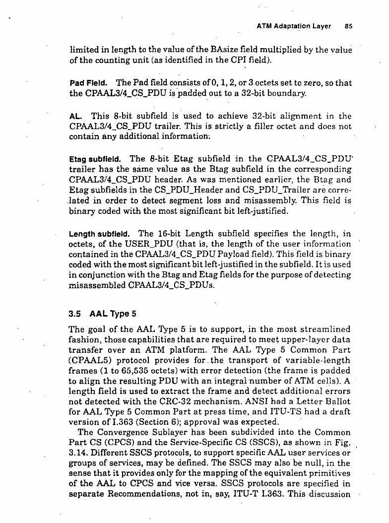
ATM Adaptallon Layer 85
limited in length to the value ofthe BAsize field multiplied by the value ofthe counting unit (as identified in the ePI field).
Pad Fleld. The Pad field consista ofO, 1, 2, or 3 octets set to zero, so that the ePAAL3/4_eS_PDU is ·padded out to a 32-bit boundary.
AL. This 8-bit subfield is used to achieve 32-bit alignment in the ePAAL3/4_eS_PDU trailer. This is strictly a filler octet and doca not contain any additional information~
Etag subfleld. The 8-bit Etag subfield in the ePAAL3/4_eS_PDU· trailer has the same value as the Btag suhfield in the corresponding ePAAL3/4_eS_PDU header. As was mentioned earlicr, the Btag and Etag subfields in the CS_PDU_Header and es_PDU_Trailer aré corre.lated in arder to detect segment loss and misassembly. This field is binary coded with the most significant bit left-justified.
Length subfleld. The 16-bit Length subfield specifies the length, in octets, of the USER_PDU (that is, the length of the user information contained in the CPAAL3/4_eS_PD[T Payload field). This field is binary coded with the most significant bit left-justified in the subfield. It is used in conjunction with the Btag and Etag fiel da for the purpose of detecting misassembled ePAAL3/4_CS_PDUs.
3.5 AAL Type 5
The goal of the AAL Type 5 is to support, in the most streamlined fashion, those capabilities that are required to meet upper-laycr data transfer over an ATM platform. The AAL Type 5 eommon Part (ePAAL5) pro toco! provides for. the transport of variable-length frames (1 to 65,535 octets) with error detection (the frame is padded to align the resulting PDU with an integral number of ATM ce lis). A length field is used to extract the frame and detect additional errors not detected with the CRe-32 mechanism. ANSI had a Letter Ballot for AAL Type 5 Common Part at presa time, and ITU-TS hada draft version of !.363 (Section 6); approval was expected.
The eonvergence Sublayer has been subdivided into the eommon Pal,"t es (ePeS) and the Service-Specific es (SSeS), as shown in Fig. 3.14. Different SSeS protocola, to support specific AAL user services or groups of services, may be defined. The SSCS may a]so be null, in the sense that it provides only for the mapping ofthe equivalent primitives of the AAL to CPCS and vice versa. SSCS protocola are specified in separate Recommendations, not in, say, ITU-T !.363. This discussion
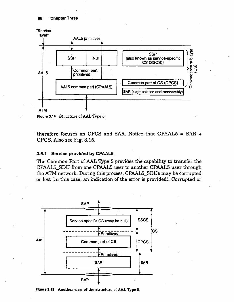
86 Chapter Three
"Servlce layer"
AALS
ATM
AALS .. tiv prrm1 es
+ +
SSP Null
eommon par! primitivas
AAL5 common part (ePAALS)
Figure 3.14 Structure of AAL Type 5.
1 '
SSP [also known as service-specific
es (SSeS))
>-~
. 1 eommon part of es (ePeS) 1 lsAR (segmentation and reassembly)l
· therefore focuses on CPCS and SAR. Notice that CPAAL5 = SAR + CPCS. Also see Fig. 3.15.
3.5.1 Servlce provlded by CPAAL5 .
The Common Part of AAL Type 5 provides the capability to transfer the CPAAL5_SDU from one CPAAL5 user to another CPAAL5 user through the ATM network. During this process, CPAAL5_SDUs may be corrupted or lost (in this case, an indication of the error is provided). Corrupted or
SAP .
SeNice-specific es (may be null) sses
------------}Pnññi~e;------ es
AA L eommon part of es e PeS
------------}~~tives _____ ·sAR SAR
SAP -
Figure 3.15 Another view ofthe structure of AAL Type 5.

ATM Adaptatlon Layer 87
Iost CPAAL5_SDUs are not recovered by CPAAL5. CPAAL5 supports a. message mode and a streaming mode. The message-mode service, streaming-mode service, and assured and nonassured operations as defined below for CPAAL5 are identical to those def¡.ned for AAL Type 3/4.
l. Message-mode service. The CPAALS_SDU is passed across the CPAAL5 interface in exactly one Common Part AAL interface data unit (CPAAL5_IDU). This service provides the transport of fixed-size or variable-length CPAAL5_SDUs.
a. In the case of small fiXed-size CPAAL5_SDUs, an interna! blocking/deblocking function in the SSCS may be applied; it provides the transport of one or more fixed-size CPAAL5_SDUs in one SSCS_PDU.
b. In the case of variable-length CPAAL5_SDUs, an interna! CPAAL5_SDU message segmentationlreassembling function in the SSCS may be applied. In this case, a single CPAALS_SDU is transferred in one or more SSCS_PDUs.
c. Where the above options are not used, a single CPAALS_SDU is transferred in one SSCS_PDU. When the SSCS is null, the CPAAL5_SDU is mapped to one CPCS_SDU.
2. Streaming-mode service. The CPAAL5j3DU is passed across the CPAAL5 interface in one or more CPAAL5_IDUs. The transfer of these CPAAL5_IDUs across the CPAAL5 interface may occur separated in time. This service provides the transport of variable-length CPAAL5_SDUs. Streaming-mode service includes an abort serví ce by which the discarding of an CPAAL5_SDU that has been partially transferred across the AAL interface can be requested.
a. An interna! CPÁAL5_SDU message segmentationlreassembling function in the SSCS may be applied. In this case, all the CPAAL5_IDUs belonging to a single CPAALS_SDU are transferred in Ol)e or more SSCS_PDUs.
b. An interna! pipelining function may be applied. It provides the means by which the sending CPAALS entity initiates the transfer to the receiving CPAALS entity befare it has the complete CPAAL5_SDU available.
c. Where option a is not used, all the CPAALS_IDUs belonging to a single CPAAL5_SDU are transferred in one SSCS_PDU. When the SSCS is null, the CPAALS_IDUs belonging to a single CPAALS_SDU are mapped to one CPCS_SDU.
Both modes ofservice may ofTer the following peer-to-peer operational procedures:

88 Chapter Three
• Assured operations. Every assured CPAAL5_SDU is delivered with exactly the data content that the user sent. The assured service is provided by retransmission of missing or corruptcd SSCS_PDUs. Flow control is provided as a mandatory feature. The assured operation may be restricted to point-to-point AAL connections.
• Nonassured operations. Integral CPAAL5_SDUs may be lo~t or corrupted. Lost and corrupted CPAAL5_SDUs will not be corrected by retransmission. An optional feature may be provided' to allow cor- · rupted CPAAL5_SDUs to be delivered to the user (i.e., optional error discard). Flow control may be provided as an option.
Descrlptlon of AAL connectlons. The CPAAL5 provides the capability to transfer the CPAAL5_SDU from one AAL5-SAP to another AAL5-SAP through the ATM network. CPAAL5 users have the ability to select a given AAL5-SAP associated with the QOS 'required to transport that . CPAAL5_SDU (for example, delay- and loss-sensitive QOS).
The CPAAL5 in nonassured operation also provides the capability to transfer the CPAAL5_SDUs from one AAL5-SAP to more than one AAL5-SAP through the ATM network.
CPAAL5 makes use ofthe service provided by the underlying ATM Layer. Multiple AAL connections may be associated with a single ATM-Layer connection, allowing multiplexing at the AAL; however, if multiplexing is used in the. AAL, it occurs in the SSCS. The AAL user selects the QOS provided by the AAL through the choice of the AAL5-SAP used for data transfer .
. Prlmltlves for the AAL. These primitives are service-specific and are contained in separate Recommendations on SSCS protocols.
The SSCS may be null, in the sense that it provides only for the mapping ofthe equivalent primitives ofthe AAL to CPCS and vice versa. In this case, the primitives for the AAL are equivalent to those for the CPCS but are identified as CPAAL5-UNITDATA.request, CPAAL5-UNITDATA.indication, CPAAL5-U-Abort.request, CPAAL5-UAbort.indication, and CPML5-P-Abort.indication, consistent with the primitive naming convention atan SAP.
Prlmltlves for the CPCS of the AA L. As there is no SAP between the sublayers of the AAL5, the primitives are caBed .invoke and .signal instead of the conventional .request and .indication to highlight the absence of the SAP. ·
' CPCS-UNITDATA.Invoke and CPC5-UNITDATA.slgnal. These primitives are used for data transfer. The following parameters are defined:

ATM Adaptatlon Layer 89
• Interface data (ID). This parameter specifies the interface data unit exchanged between the CPCS and the SSCS entity. The ID is an integral multiple of 1 octet. If the CPCS entity is operating in message-mode service, the ID represents a complete CPCS_SDU; when operating in streaming-mode service, the ID does not necessarily reptesent a complete CPCS_SDU.
• More (M). In message-mode service, this parameter is not used. In streaming-mode service, this paran:ieter specifies whether the interface data communicated contains a beginning/continuation of a CPCS_SDU or the end of a complete CPCS_SDU.
· • CPCS loss priority (CPCS-LP). This parameter indica tes the loss priority for the associated CPCS_SDU. It can take only two values, one for high priority and the other for low priority. The use of this parameter in streaming mode is for further study. This parameter is mapped to and from the SAR-LP parameter.
• CPCS congestion indication (CPCS-CI). This parameter indica tes that · the associated CPCS_SDU has experienced congestion. The use ofthis
parameter in streaming mode is for further study. This parameter is mapped to and from the SAR-CI parameter.
• CPCS user-to-user indication (CPCS-UU). This parameter is transparently transported by the CPCS between peer CPCS users.
• Reception status (RS). This parameter indicates that the associatcd CPCS_SDU delivered may be corrupted. This parameter is utilized only if the corrupted data delivery option is use d.
Depending on the service mode (message- or streaming-mode service, discarding or delivery of errored information), not all parameters are required.
CPCS-U-Abort.lnvoke and CPCS-U-Abort.slgnal. These primitives are used by the CPCS user to invoke the abort service. They are al so used to signa! to the CPCS user that a partially delivered CPCS_SDU is to be discarded by instruction from its peer entity. No parameters are defined. These primitives are not used in message mode.
CPCS-P-Abort.slgnal. This primitive is used by the CPCS entity to signa! to its user that a partially delivered CPCS_SDU is to be discarded because of the occurrence of sorne error in the CPCS or below. No parameters are defined. This primitive is not used in message mode.
Prlmltlves for the SAR sublayer of the AAL. These pi:imitives model the exchange ofinformation between the SAR sublayer and the CPCS.

· 90 · Chapter Three
As there is no SAP between the sublayers ofthe AAL5, the primitives are called .invoke and .signa! instead of the '<onventional .request and .iridication to highlight the absence ofthe SAP.
SAR-UNITDATA.Invoke and SAR-UNITDATA.slgnal. These primitives are used for data transfer. The following parameters are defined:
• Interface data (ID). This parameter specifies the interface data unit exchanged between the SAR and the CPCS entity. The ID is an integral multiple of 48 octets. It does not necessarily represent a complete SAR_SDU.
• More (M). This parameter specifies whether the interface data communicated contains the end ofthe SAR_SDU.
• SAR loss priority CSAR-LP). This parameter indica tes the loss priority for the associated SAR interface data. It can take on two values, one for high priority and the other for low priority .. This parameter is mapped to the ATM Layer's submitted loss priority parameter and from the ATM Layer's received loss priority parameter.
• SAR congestion indication (SAR-Cl). This parameter indicates whether the associated SAR interface data has experienced congestion. This parameter is mapped.to and from the ATM Layer's congestion indication parameter.
3.5.2 Functions, structure, and coding of AALS
Functions of the SAR Sublayer. The SAR Sublayer functions are performed on an SAR_PDU basis. The SAR Sublayer accepts variable-length SAR_SDUs which are integral multiples of 48 octets from the CPCS and generates SAR_PDUs containing 48 octets of SAR_SDU data. It supports the preservation of SAR_SDUs by providing for an "end of SAR_SDU" indication.
SAR_PDU structure and coding. The SAR Sublayer function utilizes the ATM-Layer-user-to-ATM-Layer-user (AUU) parameter of the ATM Layer primitives to indicate that a SAR_PDU contains the end of a
---------.------------------------------------~ L~e~~:~dj~!~~~~--------------s_A_R ___ Po_u __ p_ay_lo_a_d--------------~
SAR_PDU
Figure 3.18 SAR_PDU fonnat for AAL5. [No~: The payload type (PT) field belongs to the ATM header. It conveys the value ofthe AUU parameter end-to-end.]

ATM Adaptat.lon Layer 91
SAR_SDU. A SAR_PDU where the value of the AUU parameter is ·1 indicates the end ofa SAR_SDU; a value ofO indicates the beginning or continuation of a SAR_SDU. The structure of thc SAR_PDU is shown in Fig. 3.16.
Convergence Sublayer. The CPCS has the following serv1ce characteristics.
• Nonassured data transfer of user data frames with any length measured in octets from 1 to 65,5~5octets.
• The CPCS connection will be established by management or by the · Control Plane.
• Error detection and indication (bit error and cellloss or gain).
• CPCS_SDU sequence integrity on each CPCS connection.
Functlons of the CPCS. The CPCS functions are 'performe d · per CPCS_PDU. The CPCS provides severa! functions in support of the CPCS service user. The functions provided depend on whether the CPCS service user is.operating in message or streaming mode.
l. Message mode service. The CPCS_SDU is passed across the CPCS interface in exactly one CPCS-IDU. This service provides the transport ofa single CPCS_SDU in one CPCS_PDU.
2. Streaming mode service. The CPCS_SDU is passed across the CPCS . interface in one or more CPCS-IDUs. The transfer ofthese CPCS-IDUs across the CPCS interface may occur separat.ed in t.ime. This service provides the transport of all the CPCS-IDUs belonging to a single CPCS_SDU into one CPCS_PDU. An interna! pipelining funct.ion in.the CPCS may be applied which provides the means by which the sending CPCS entity initiates the transfer to'the receiving CPCS entity befare it has the complete CPCS_SDU available. Streaming-mode service includes an abort service by which the discarding of a CPCS_SDU partially transferred across the interface can be requested.
Note: At the sending side, parts of the CPCS_PDU may have to be bufTered if the restriction "interface data are a multiple of 48 octets" . cannot be satisfied.
'The functions implemented by ihe CPCS include:
l. Preservation of CPCS_SDU. This funetion provides for the delineation and transparency of CPCS_SDUs.
2. Preservation of CPCS user-to-user information. This function pro'vides for the transparent transfer ofCPCS user-to-usei- information.

92 Chapter Three
3. Error detection and handling. This function provides for the detéction and handling ofCPCS_PDU corruption. Corrupted CPCS_SDUs are either discarded or optionally delivercd to the SSCS. The procedures for delivery of corrupted CPCS_SDUs are for further study. When delivering errored information to the CPCS user, an error indication is associated with the delivery. Examples of detected errors would include received length and CPCS_PDU Length field mismatch including buffer overflow, an improperly formatted CPCS_PDU, and CPCS CRC errors.
4. Abort. This function provides for the means to aborta partially transmitted CPCS_SDU. This function is indicated in the Length field.
5. Padding. A padding function provides for 48-octet alignment of the CPCS_PDU trailer.
CPCS structure and codlng. The CPCS functions require an 8-octet CPCS_PDU trailer. The CPCS_PDU trailer is always located in the last 8 octets ofthe last SAR_PDU ofthe CPCS.:_PDU. Therefore, a padding field provides for a 48-octet alignment of the CPCS_PDU. The
Bit position ~ 32
1 Most-significant octet ( octet 1)
User data (0-65,535 octets)
-
' t"-
PAD (D-47 octets)
1
'
::: ~
1
:::~ (aligns CPAALS_POU on 48-octet boundary) ::: :::: M-1 u u 1 CPI J Length
M CRC-32
1 32-brt word number
Least-slgnifiCant · octet .
Figure 3.17 CPAAL5_FDU.

ATM Adapt~tlon Layer 93
CPCS-PDU payload (CPCS_SOU) CPCS-PDU trailer
lO 65,535 octets
Cyclic redundancy check
Figure 3.18 CPAAL5_PDU, another view.
CPCS_PDU trailer, the padding field, and the CPCS_PDU payload make up the CPcs_pnu.
The coding of the CPCS_PDU conforms to the coding conventions specified in 2.1 ofRecommendation 1.361. See Figs. 3.17 and 3.18.
l. CPCS_pDU payload. The CPCS_PDU payload is the CPCS_SDU.
2. Padding (Pad) field. Between the end ofthe CPCS_PDU payload and the CPCS_PDU trailer, there will be from Oto 4 7 unused octets. These unused octets are called the padding (Pad) field; they are strictly u sed
. as filler octets and do not convey any information. Any coding is acceptable. This padding field complements the CPCS_PDU (including CPCS_PDU payload, padding field, and CPCS_PDU trailer) toan integral multiple of 48 octets.
3. CPCS User-to-User Indication (CPCS-UU) field. The CPCS-UU field is used to transparently transfer CPCS user-to-user information .
. 4. (Jommon Part lndicator (CPI) fiel d. One of the functions of the CPI field is to align the CPCS.:..PDU trailer to 64 bits. Other functions are for further study. Possible additional functions may include identification of Layer Management messages. When only the 64-bit aEgnment function is used, this field is code.d as zero.
5. Length field. The Length field is used to encocle the length of the CPCS_PDU payload field. The Length field value is also used by the
. receiver to detect the loss or gain ofinformation. The length is binary coded as number of octets. A Length field coded as zero is used for the abort function.
6. CRC field. The CRC-32 is used to detect bit errors in the CPCS_PDU. The CRC field is filled with the value of a CRC calculation which is performed over the entire contents of the CPCS_PDU, including the CPCS_PDV payload, the Pad field, and the first 4 octets ofthe CPCS_PDU trailer. The CRC field shall contain the 1s complement of the sum (modulo 2) of

94 Chapter Three
a. The re~ainder of .rk*(.r31 + .r30 + ... + .r + 1) divided (modulo 2) by
the generator polynomial, where k is the number of bits of the information over which the CRC is ealculated.
b. The remainder ofthe division (modulo 2) by the generator polynomial of the product of .r32 and the information over which the CRC is calculated.
The CRC-32 generator polynomial is:
G(x) = .r32 + x26 + x23 + x22 + x16 + x12 + xu + x10 + x8 + x7·
+ X5 + .r4 + .r2 +X+ 1
The result of the CRC calculation is placed with the least significan t bit right-justified in the CRC field.
As a typical implementation at the transmitter, the initial content of the register of the device coniputing the remainder of the division is preset to all 1s and is then modified by division by the generator polynomial (as described above) ofthe information over which the CRC is to be calculated; the 1s complement ofthe resulting remainder is put into the CRC field.
As a typical implementation at the receiver, the initial content of the register of the device computing the remainder of the division is preset to all 1s. The final remainder, after multiplication by x32 and then division (modulo 2) by the generator polynomial of the serial incoming CPCS_PDU, will be (in the absence of errors)
C{x) = X 31 +X 30 +X 26 +X 25 +X 24 +X 18 +X 15 + .r 14 + .r 12
+X 11 +X 10 +X 8 +X 6 +X 5 +X 4'+ X 3 +X+ 1
3.6 Frame Relay Service-Specific AAL
The Frame Relay Service-Specific ATM Adaptation Layer Convergence Sublayer (FR-SSCS) is positioned in the upper part ofthe ATM Adaptation Layer; it is located above the CPAAL5, as shown in Figs. 3.19 and 3.20. It is an example of an SSP. The purpose of the FR-SSCS protocol at an ATM CPE (that is, user's equipment) is to emulate the Frame Relaying Bearer Service CFRBS) in an ATM-based network (Fig. 3.19). On network nodes, the FR-SSCS is used for interworking between an ATM-based network and a Q.922-based Frame Relaying Network (Fig. 3.20).
The FR-SSCS protocol provides for the transport of variable-length frames with error detection. • The FR~SSCS provides its service over
"This diBCUBsion is based on Ref. 4.

ATM Adaptatlon Layer 9
"Service iayer"
DL-GORE . Tves pnm11 Dl-CORE-SAP __!_
T
Frame-relaying servic&-specific convergence sub layar (FR-SSCS)
Common part AAL5 primitivas
Fram&-relaying service-speciflc convergence sublayer (FR-SSCS)
1 Common part of CS (CPCS) 1 AAL5 common part (CPAALS)
lsAR (sagmentation and reassembly)l
ATM-SAP
ATM
DL-CORE SAP
DL-CORE-DAT A.requesff f DL-CORE-DA TA.indication
Frame-relaying service-specific convergence sublayer (FR-SSCS)
CPCS..UN ITDATA.invoka CPCS..UNITDATA.signal
AAL5 common part (CPAALS)
ATM-DATA.request li ATM-DAT A.mdical1on
ATM-SAP
Figure 3.19 AAL5 for interworking offrame relay and ATM (in CPE).
>-
~ "' :0 "' "' .,-0(1') eü <D-Ol ¡¡; > e o
(.)
preestab!ished connections with negotiated traffic parameters. An FRSSCS connection represents the segment of an end-to-end Jrame relay (FR) connection over B-ISDN. At an ATM-based B-TE, the FR-SSCS connection is terminated at the point of termination of the FR-SSCS service and represents one end ofthe FR connection. Optionally, multiplexing may be performed at the FR-SSCS, allowing various FR-SSCS connections to be associated with a single CPAAL5 connection (and with the corresponding ATM connection). FR-SSCS connections within a CPAAL5 connection are uniquely identified by data link conriection identifiers (DLCis). The establishment (or provisioning) and initialization of an FR-SSCS connection is performed by interaction with FRSSCS Layer Management (MFR-SSCS) entities. The traffic parameters of each FR-SSCS connection are detennined at the time of its estab-
,,

96 Chapter Three
FR-IWP
IWF-DATA.indicalion 0.922 CORE
A.request
Frame-relaylng servlce-specifiC convergence sublayer (FR-SSCS)
CPCS-UNITDATA.signal IWF-DAT
CP CS-UNITOA TA.invoke
AAL5 common part (CPAAL5)
ATM-DATA.requeslt _!_ ATM-OATA.indication
ATM-SAP
Figure 3.20 AAL5 for interworking of frame relay and ATM (in a network element supporting an interworking function). FR-IWP = frame re! ay interworking point.
>
lishment. The negotiated traffic parameters are bounded by the ATM Layer/CPAAL5 connection .characteristics.
The FR-SSCS can indicate to its user that the receiver FR_SSCS_PDU has experienced congestion (forward congestion) or that an FR_SSCS_PDU traveling in the opposite (sending) direction has experienced congestion (backward congestion). The FR-SSCS allows for two discard eligibility priorities. The FR-SSCS user can request the discard eligibility (loss priority) associated with each FR_SSCS_SDU. The FR-SSCS uses the CPAAL5 message-mode service without the corrupted data delivery option and preserves the FR_SSCS_SDU sequence integrity.
The MFR-SSCS is responsible for the following actions: assignment of the FR_SSCS association necessary for the establishment or provisioning ofFR-SSCS connections between peer FR-SSCS entities, resetting the parameters and state var-iables associated with a FR-SSCS connection when required, releasing the association created for a FRSSCS connection between peer FR-SSCS entities, and performance monitoring of the quality of the FR-SSCS connection service provided through notification of errors (i.e., FR_SSCS_PDU discards resulting from errors in the FR_SSCS_PDU).
Servlce provlded by the FR·SSCS. The FR-SSCS provides services to (1) the core service user (upper layer) at ATM-based B-TEs or (2) the Q.922-CORE Data Link Layer (Q.922-DLL) on network nodes at ínter· working functions (IWFs) points. Only itero (1) is covered here.
The FR-SSCS provides the ,capability to transfer variable-length octet-aligned FR_SSCS_SDUs from one or more FR_SSCS users. The FR-SSCS Sublayer preserves the FR_SSCS_SDU sequence integrity · .
<~~ '"

. ATM Adaptatlon Layer 97
within an FR-SSCS connection. During this process, FR_SSCS_SDUs may be lost or corrupted. Lost or corrupte.d FR_SSCS_SDUs are not recovered by the FR-SSCS. The FR-SSCS uses CPAAL5 message-mode service without the corrupted data delivery option.
FR-SSCS functlons. The functions provided by the FR_SSCS include
Multiplexing 1 demultiplexing. This function provides for the optional multiplexing and demultiplexing of FR-SSCS connections into a single CPAAL5 connection. The number of FR-SSCS conriections supported over a CPAAL5 connection is defined at connection estab~ lishment or provisioning. The default number of FR-SSCS connections when multiplexing is not supported is l. Within a given FR-SSCS connection, sequence integrity is preserved.
Inspection ofthe FR_SSCS_PDU length. This function inspects the FR_SSCS_PDU to ensure that it consists of an integral riumber of octets and to ensure that it is neither too long nor too short.
Congestion control. These functions provide the means to notify the ·end user that congestion avoidance procedures should be initiated,
TABLE 3.6 OL-CORE Prlmltlves
D L-e ORE-DATA. re que s t. (DL_eORE_User_Data, Discard_Eligibili ty, D L_ e O RE_Service_ U ser _Protocol_Control_Information)
D L- C O RE -DATA. indica ti o n (DL_eORE_User_Data, Congestion_Encountered_Backward, eongestion_Encountered_Forward, DL_CORE_Service_User_Protocol_Information)
Description of parameters: ,
This primitive is received from the FRSSCS user to request the transfer of an FR_SSCS_SDU over the associated FRSSeS connection.
This primitive is used to the FR-SSCS u ser to indicate the arrival of an FR_:SSCS_SDU from the associated connection.
DL_CORE_User_Data:This parameter spedfies the FR_SSCS_SDU transponed bctween the FR-SSCS user and the FR-SSCS. This parameter is octet-aligned and can range from 1 lo a. maximum of at least 4096 octets in length.
Discard_Eligibility: This parameter indica tes the Joss priority assigned lo the FR_SSCS_SDU. Two Jevels of priority are identified: High and Low. A value of High indicates that the FR_SSCS_SDU may experience a better quality ofservice with respect lo loss (i.e., minimalloss) than if the Discard_Eiigibility parameter were set to Low.
DL_CORE_Service_Prolocoi_Information: This parameter specifies a 1-bit FR-SSCS/Q.922-DLL user control information lo be transparently transferred between FR-SSC::SIQ.922-DLL usera.
Congestion_Encountered_Backward: This parameter indicates that an FR_SSCS_SDU has experienced congestion in the opposite (sending) direction, and therefore that an FR_SSCS_SDU sent on the corresponding connection may encounteT congested resources. This para meter may take on two values: True or False. A value of True indicates that an FR_SSCS_SDU has experienced congestion in the opposite (sending) direction of the connection.
Congestion_Encountered_Forward: ·This parameter indicates that the received FR_SSCS_SDU has experienced congestion. This para meter m ay take two val u es: True or False. A value ofTrue indicatea that the FR_SSCS_SDU has experienced congestion.
'· J "

98 Chapter Three
where applicable (congestion control forward and congestion control backward). In addition, the functions pro-.:ide the rneans for the end user and/or the network to indica te what frames should be discarded in a congestion situation._
Prlmltlves. The information exchanged between the FR-SSCS and its user (for ATM-based B-TEs) is modeled by the primitives of Table 3.6 (which are the same DL-CORE primitives in Annex C ofiTU-T Recommendation 1.233.1).
Servlces expected from the CPAALS. The FR-SSCS expects the CPAAL5 to provide the ca.pability to transfer variable-length (from 3 to a maximum of at least 4100 octets) octet-aligned FR_SSCS_SDUs, with error detection ."<nd in sequence, between communicating FR-SSCS entities. Lost or corrupted FR_SSCS_PDUs are not expected to be recovered by the CPAAL5. Multicast services, derived from the ATM Layer, are expected.
The FR-SSCS entity expects the CPAAL5 to provide each FR_SSCS_PDU (CPAAL5_SDU) with the CP _Congestion_Indication (True or False) set to the value ofthe Congestion_Indication received by the ATM Layer with the last ATM_SDU conforming to the CPAAL5_SDU; and with the CP_Loss_Priority set to either Low, if any ofthe ATM_SDUs conforming to the CPAAL5_SDU was received with the Received_Loss_Priority parameter set to Low, or High otherwise.
The FR-SSCS entity passes each FR_SSCS_PDU (CPAAL5_SDU) with the CP _Loss_Priority set to the value of the Discard_Eligibility parameter received from the upper !ayer or the Q.922-DLL (High or Low), the CP _Congestion_Indication (True or False) always set to False, and the User_User_Indication parameter always set to zero.
3.7 Signallng ATM Adaptation Layer (SAAL)
This section describes the Signaling ATM Adaptation Layer (SAAL) for use at the UNI. SAAL is used in the Control Plane. (This topic could al so have been treated in the next chapter, but it was decided to include it here with other AALs.) ·
The SAAL resides between the ATM Layer and Q.2931 in the user's equipment, specifically in the software implementing the Control Plane (i.e., the signaling capability). The purpose ofthe SAAL is to provide reliable transport of Q.2931 messages between peer Q.2931 entities (e.g., ATM switch and host) over the ATM Layer. The SAAL is composed of two sublayers, a Common Part and a Service-Specific

Servicespecific
convergence .sublayer
AAL · functions
Common part AAL
functions
l_ ___________ _
ATM Adaptatlon Layer 99
1 Primitivas
-----«-- --1-- :::;;.------------
Service-specific coordination function
(SSCF)
Service-specific Peer-to-peer connection-oriented
peer-to-peer protocol messages (SSCOP)
Common part AAL ' peer-to-peer protocol Peer-to-peer
(CP-AAL) messages
1 ---- --- 1---3· -----------
1 Primitivas
Figure 3.21 SAAL structure. (Note: This figure represents the allocation offunctions and is not in tended to illustrate sublayers as defined by OSI modeling principies.)
Part. The Service-SpecificPart is further subdivided into a Service-Spe. cific Coordination Function (SSCF) anda Service-Specific ConnectionOriented Protocol (SSCOP). Figure 3.21 illustrates the structure ofthe SAAL.5
The SAAL for supporting signaling uses the protocol structure illustrated in Fig. 3.21. The Common Part AAL protocol provides unassured information transfer anda mechanism for detecting corruptlon .ofSDUs. The AAL Type 5 Common Part protocol is used to support signaling. The AAL Type 5 Common Part protocol is specified in Draft Recommendation 1.363.
The SAAL for supporting signaling at the UNI uses the AAL Type 5 Common Part protocol, discussed above, as specified in Re f. 7 with minar amendments. 8
¡

100 Chapter Three
The Service-Specific Connection-Oriented Protocol (SSCOP) resides in the Service-Specific Convergence Sublayer (SSCS) of the SAAL. SSCOP is used to transfer variable-length service data units (SDUs) between users of SSCOP. SSCOP provides for the recovery of lost or corrupted SDUs. SSCOP is specified in ITU-T Recommendation Q.2110.9
The SAAL for supporting signaling utilizes SSCOP as specified in Q.2110.
9 .
An SSCF maps the service of SSCOP to the needs of the SSCF user. Different SSCFs may be defined to support the needs of different AAL users. The SSCF used to support Q.93B at the UNI is specified in ITU-T Recommendation Q.2130._10
The externa! behavior of the SAAL at the UNI appears as if the UNI SSCF specified in Q.213010 were implemented.
References
l. CCITT 1.362, B-ISDN AAL Functional Description, Geneva, Switzerland, 1992.
2. CCITT 1.363, B-ISDN AAL Specification, Geneva, Switzerland, 1992.
3. A.."l"SI Tl.BCR-199x, Broadband ISDN-ATM Adaptation Layer for Constant Bit Rate Services Functionality Specification, New York, Nov. 13, 1992.
4. Bellcore, Asynchronous Transfer Mode (ATM) and ATM Adaptation Layer (AAL) Protocols Generic Requirements, TA-NWT-001113, Issue 2, July 1993.
5. B. Kittams, Bellcore, personal communication, May 1993.
6. TISI.5/93-52, Broadband Aspects of ISDN Baseline Document, TIS1 Technical Subcommittee, August 1990, Chief Editor: Rajeev Sinha. Reissued February 1993, Chief Editor: Erwin Fandrich.
7. CCITT Document TD-XVIII/10 (AAL5), "AAL Type 5; Draft Recommendation Text for Section 6 of I.363,ft Geneva, Switzerland, Jan. 29, 1993.
8. ATM Forum, ATM User-Network Interface Specification, Version 3.0, August 1993.
9. !TU Document DT/1113-28 [Q.SAAL1 (now Q.2110)], Service-Specific Connection-Oriented Protocol (SSCOP) Specification, Geneva, · Switzerland, May 17, 1993.
10. !TU Document DT/1113-XX [Q.SAAL2 (now Q.2130)], Service-Specific Connection-Oriented Protocol (SSCOP) Specification, Geneva, Switzerland, M ay 17, 1993.

·Catálogo de Redes·
Primavera/Verano de 1995

ATM de Digital: Cumplimiento de estándares y características innovadoras
Los clientes escogen la tecnotogra del modo de
transferencra asíncrona (ATM. Asynchronous Transfer Mode). poraue tes oermrte beneficiarse de la autoprsta oe rnformacrón ráorda y ae gran
volumen Ahora. puede estar seguro de contar con
redes ronustas y escataoles ae alto rendrmrento y con un servrcro garantrzado con el
GIGAswrtch/ATM de Olgrtal para backbones de
redes tocares y gruoos de traba¡o de alto
reMmer~:o El srstema GIGAsWltchiATM
proporcrona ur') ancho de banda agregado de
10.4 Gb/s rmolantado en un conmutador de barras.
cruzadas de no bloqueo El srstema
GiGAswrtch/ATM irene 14 ranuras. Una se utlfrza
para funoones oc gestron y 13 para taqetas de
lineas. Cada tar¡eta de linea admrte cuatro puertos
de l1bra mult1modc SONET /S OH de 155 Mb/s
En el futuro. los puertos T3/E3 y otros mea1os para
155 Mb/s (fibra de modo stmple y cable de cobre
de ca; trenzaao sm apantallar [Categor1a 5])
tamb1en estaran sooortaaos Así. el stsrema
GIGAswnch/ATM soporta en la actualidad hasta
52 puertos Estara d1spon1ble una tar¡eta de línea
SOr-JET /SDH de 622 Mb/s, soportando un puerto
de 622 Mots Hasta trece ouer:os de 622 Mb/s
pueden cont1gurarse en el conmutador. Se
sooonaran comb1nac1ones de 622, 155 y T3/E3
FLOWmaster
El s1s:ema G!GAsw1tchfATM a e 01Q1tal orooorCiona
conmutac1on de Tasa de B1ts Cons:an1e fCBR).
Tasa oe g,¡<; Vanao1e (VBR) y Tasa ae 81ts
DISDOnlb~e (ABA) El tra:1c0 CSR V VBR se ptan1hca
meo1ante reservas. lo aue orooorc1ona un ancho ae banda garant1zaao El tráf1co ABA ut1hza ranuras
ce'ulares s1n as1gnar o ranuras aue estaban
reservaaas oero no usadas. por el tréf1co
garan:,zado Con el mecan1smo ae control oe flup oc FLOWmaster ae OIQI!al. mnguna celula
ABP oe ese en tace se oerdera a causa ae co..,gest1ones. por 10 oue aueaa aseguraDa la
estabd1cao de la red
Los conmutadores ATM de otros faor,ca:ltes usan tecn:cas de mn,mzaCion ae oerd1:::a ce células
casadas en el max1mo es:uerzo S1n embargo. Tos
eslue~zos continuados para re:ransrn.t'r paquetes
en reces congeStionadas crearan aun mas tra~1co
y congeS110r.. y pueoen oa• lugar a! "COlapse
ae1 rend•rn•ento'
¡:LOWmaster es el esauema ae control de
conges;,on con rne¡ores orestactones aentro del
se:::1o• para LANs ATM En e! Juturo. el SIStema
GlGAsw1tch/ATM tamb•en soportara el futuro
estancar cel ATM For~m re!atrvo al con:rol ae flu¡o
casado e., ta vetoc1dad _ Grac1as al diSeño versátil
de FLOWmaster. FLOWmas1er y el control de tlu¡o
oasaco en velOCidad operaran ¡untos
SWITCHmaster
El s1stema GIGAsw.:cn/ATM de OIQI!al asegura una
conmutac1ón s1n bloaueos. usanco la gestión
avanzada ae cotas SWITCHmaster La tunc1ór.
SWITCHmaster em::~1ea la técmca oatentada oor
Q,g,tal Parallel tnte•a:::t1Ve Matcn1ng para asegurarse
de aue las células se transmnen 1an Pronto como
sea cos1ble. s1n esperar la entrega ae !Odas las
celufas 'caoecera de hnea" Con Paratlel Jnteract1ve
Ma:cn1ng. las células a!rn~cenadas en colas de
e"1trada. no sólo la pnmera celula. se hacen
corresoonder con el ouer:o oe salida aproo,aao.
pe•m¡lienao aue el srstema GIGAsw,tch/ATM ut11ice
ef1cazmen:e la estructura ae1 conmutador. 1nc1uso
cuando haya contenc1on La tunCton
SWITCHmaster de D1g1tal orooorc1ona mas de un
95% ae ut1l:zac1on oe la estructura del conmutador.
s1 se comoara con una utilización t•o1ca ,nfer1or al
60%, oo; oarte ae los sts:emas que no aborden el
b•oaueo ae las caoe::::eras ce linea
Facn de ge.ttonar y mantener
Las características ae autocoohgurac10n.
reconllg:.Jrac1ón y rou!lng dmam:co cel s1stema
GIGASW1tch/ATM hacen pos1ble una utihzacton
de la 1ed más et1caz y reducen el esfuerzo
manual necesano cue deoe llevar a cabo el
admn1strador ae la red
. CARACTERISTtCAS
• Stn pén:Lda de (du!J.<
• Sm colapsos dd rend•m•l·nw
• Utiliuaón Je h rstrur:mJ del ummutadCir con un .Lito ~rado ck ¿ICII.C'lll
• Sobresaliente rel~c1on preurv r<·:1U1m1cntC1
• Auroconft¡rur;Jclnn !~ car,"'tcrí~tiC:! dt• autoc:onf!pJrariñn dd mtcrn.1 Gl( ;,h"·uch/ATM ofreced n::~JSII'l,> ;lii!Offi:ÍIICO Jr J1recÓoOe"S ,\ r,\'i. y aprende autnmáucameme !J !npolo~ta de IJ red Si falla un enl11cl!' ft51CO, d rnnmutador re~.:cmltgur.tr.J l.a red 5eE!ÚJ'I d upo de fallo, t:unbt~n de fonna autom>incJ.
• Equilibno-dc car¡::J~ a! rlc¡:::1r una n.na f1~10:~ rntr~ un onElC"~ y un destmo. el ~~~u·ma GIGAswitch/ATM deg¡rá el ml:~re m~:nm car¡.:ado pl!ra d nuev" orcuiro vmual (\'()
• Houtmg dinámico cu:mJo se ~t.í confii!UrMJCI un ctrC'Ulto t•tnual conmutado, el s1stem~ GIGAswiich!AThl unh:ura un algornmo que busque prunero la nna más r.iptd:~ p;Jr J enc.tmm:lr d circuito vmual. v htto;.c;Jrá una ruta alreroattva, si fulera necesanll,.

El conmutador ATM de alto rendimiento con el control de flujo FLOWmaster™ mantiene sus redes a la altura de la demanda
GIGAswitchTJrll ATM ¿Su conm~ador ATM es una carga para la red? Srn un mecanismo ae control ae fluJO adecua· ao que rmptda la conges!lón en su red ATM,
su conmutador ATM podna causar oroblemas.
Las pérdrdas de células debrdas a congesttón oblrgan a reenvrar paquetes enteros de rnlormacron - emoeorando ta conorctOn ae congesllon oe
su red El nuevo GIGAs'Mtch/ATM es el pnmer conmutador ATM con control de flu¡o FLOWmaster
FLOWmaster le asegura·el fluJO mtl>umo de tráfrco en el ancho de banda necesano. stn pérdrda de células
1Pero eso no es todo' La cal1dad de serv~cro oue le proDOI'CIOna nuestro nuevo GIGAswltch!ATM está
garantrzaoa poraue este conmutador ATM sooorta tráfrco con una tasa de orts constante y con tasa de
bits vanaole Y ademas. es oostble aef1n1r sus pro
PIOS l1m1tes de Jatenc1a
< ' cARACTERISTtCAS
•Conmuwior J~ barus mJLHlJ• dt· !LI.¡ GO, . conSWJTCHmaw:rT~ - roerr.-u~ una .JI ::1~\ll':l ceroma al~~~
•Soporta ATM Forurn l 1:-.ll \'J (1, l<tJporte d~ f:rm111rc VI.! pan UN!lll. GramO< \'tm:3!~ Perma11emo. CtrctutOii \inw.les Corunuu.~ ({)2Qj] 1, Tai.i d~ Bns Constante (CBR), Tasa de B1t~ \'anJble 1\'RR • 1 T.~.~a éc Bm Dlsporublc (ABRl
• PNNJ.Phasc Orruis Dm:ur.1r \'C H.ouu:-~¡:
• E.scalabb· de. 4 a 5~ ouen0~ ~0'\IT:SD!! !~5 Mh1~
~~'%~~~~r,~\~~~};~~n~':';~~%'W~f:~~c~:~.r:~:.~~:~·~~~i~~u¡¡~~y:: :;:"' ~ > .. ~>'Z<<'.~~~X'-~(U~_$~Y~~6i>t:.., ... ~,~A,,fi, _.>.:', '""'¡,'"~'"' ,. , .. >·V<•'',~, ., ..... ~ ·" .· ~ :
Chasts .. ~I~Aswrtchi~!M. s1n tar¡etas de linea.~t de ahme0tac1ón DAGGA·CA
~IGA.sw~~~T.~. tal']~!!! ~e.lí~ea .~~ 4 pu~~os •. 1 ~~.~b/~ MMF (~áxtm.o 13. e~ chaSIS) DAGGL·AA
. Fuente. d.~ .~l!mentación de 20A (CA) para GIG~swttch
Fuente .~e .. ~ltmentact6n d~ 48V (CC)
• P1da pat separado el cable ÍJe a/tmentac¡Qr¡ especi/ICO de cada pa,s
DEFGB·DB•
DEFGB·BA•
Conectividad TURBOchannel a ATM para sistemas DEC 3000 AXP
El ATMworks ™ 750
S• desea aar sooor1e a entamas chente/serv•dor y prectsa conex.ones de red de alto rend1m•enro
sobre redes ATM, el nuevo adaptador de
ATM TURBOchanner ae D:g1tal es exactamente lo
cue usted esiaba esoera~do Corr.bma la ootencia ae nuestros ststemas DEC 3CXXl AAP {las esta
Clones oe trabara oe sooremesa y ae peaestal más tap10as del mundo) con la revoluCJOI'kHia tecno1og1a de redes ATM ae oanca ancha
¿Por qué los sistemas AXP DEC 3000 Los SIStemas DEC 30JO AXP comp•ten perfectamente con ros cn•os J'!"láS rap1dos del mundo. S1 se ullhzan como servJaores. estos SIStemas aprovechan ras ven.ta]as de la reo ATM ae banda
ancna para se"':'1r a múltiPles clientes. reducienao la congest10n de red y retardos
¿Por qué ATMworks 750,1a tarjeta · Interfaz ATM?
Las redes ATM son reoes de alto rend1mtento. que permten un raordo 1ntercamb10 ae catos con
una bara latenc1a S• ut1l1za sus Sistemas con aphcac•ones mu1t1med1a en reo se benef1c1ara
enorme mente de lns D8S1:Jihaaaes de las reces ATM. deb•ao a s:.t u·,cno d..: oanoa garnnt~7aco
y la ba¡a Jatenc1a e u::: pe•mtc transm1w y rec1b1r
con et,cac1a 1mápcnc'> il el de rentes 01Stanc1aS
Juntas comb1nan 1a ve:o::,aad v ta ootencr:J. lo
cuat StQn,iJc<:l que 02:'-l uo.r.::c se an~en de oat en par !as ouerta:-; ili !u;u·o {jr. 1.1 1n1o•ma11Ca
• Vdood.ad de mJ ATM m /1\b'~ !OOl
• Amudura SONET/SDH
• Soporu f\JVd 5 ATM de Adapucmn !o\/\Dl
• Soporu !024 Can.1b Vm;.~.¡lc; !\'C1
• Sopona control dt· tl1,11n fl0\\-:11Jstc· 1" de ])l¡.:uJl. que dun~ las pCrd1rl~\ de álulas y op1l;nm JJ unl,¡r,aciÓn Je la red
•,:
"

•
linkSwitch • 500 Ethernet
SuperStack • Worligroup Swrtch
LinkSwitch 1000 Ethernet/
Fast Ethernet SuperStack
Workgroup Swrtch
LinkSwitch 1200 Ethernet/FDDI
SuperStack Workgroup Switch
linkSwitch 2200 Ethernet/FDDI
SuperStack Workgroup Switch
LinkSwitch 2700 Ethernet/ATM
SuperStack Workgroup Swrtch
LinkSwitch 1200 Modules for the
Lrn<Builder" MSH' Hub
LANplex• 2016 Ethernet
Workgroup Switch
LANplex 2500 Ethernet/FDDI
Oepartmenral Sw1tch
LANplex 6000 Ethernet/FDDI/
Token Ring Data Center Switch
CELLplex· 7000 ATM Backbone
Swrtch
CELLplex 7200 Ethernet/ATM
Departmental Switch

SUPEII' IITACIL.
< .. -·
: > ' ,... • •• : ; .: : .;
A TM is an advanced switching
technology that can boost network
bandwidth to 155 Mbps and beyond
while enhancing management
flexibility with virtual LANs. This
exceptional performance and
manageability is accomplished with a
cell-based data communications
technology.
Cell switching greatly reduces
latency - the delay between when a
device receives a data packet and
when the packet is forwarded to its
destination- by dividing the pack
ets into fixed-length cells. The um
fonn. 53-byte size of A TM ce lis
make them easier to process
!han variable-length packets. Cell
switching also results in less
variation in delay. which facilitates
real-time traffic such as full-motion
video transmissions.
Unlike conventional LAN switching
technologies, A TM is connection
oriented. This means that A TM
devices must interact with A TM
switches to establish communication
paths befare transmitting data.
To allow conventional LANs to
interconnect with ATM, the ATM
Forum has ratified the LAN
Emulation standard. LAN Emulation
enables intemetworking of A TM.
Ethernet. and Token Ring dcvices, as
well as vinual connections among
ATM devices, so that groups using
this facility can be linked across the
enterprise regardless of where the
devices are located. These nrtual
LANs are especially beneficia! in.
organizauons where moves and
changes are common. or where
groups of users m scpa.rate location:\
need to communicate with each othcr
and share resources.
LAf'.: Emulation also pfotects current
investmem in network equipment and
protocols. lntegrated LAN/A TM
switches can use LAN EmulatiOn to
provide full connecuvity among
A TM and legacy LAN dev1ces.
Furthemnore. popular protocols such
as IP and IPX can opcrate on a
heterogeneous network without
modification.
3Com A TM switchcs offer vou
exceptionally low-cost. rcliable ATM
connectivity that lets you enhance
performance incremcntally. only on
!hose parts of the network that need it.
Whether you wam to m1grate your
entire building backhonc to A TM for
increased aggregate bandwidth, or
you need to extend a single high
speed ATM link from a workgroup to
a supcrserver. thcrc LS a 3Com switch
to suit the task. Non-blocking
architecturc across thc product line
ensures full data rotes between ATM
and Ethernet or other LAN
technologies. so you don't ha veto
implemcnt expensivc upgrades at the
desktop.
' '' f.
"'1
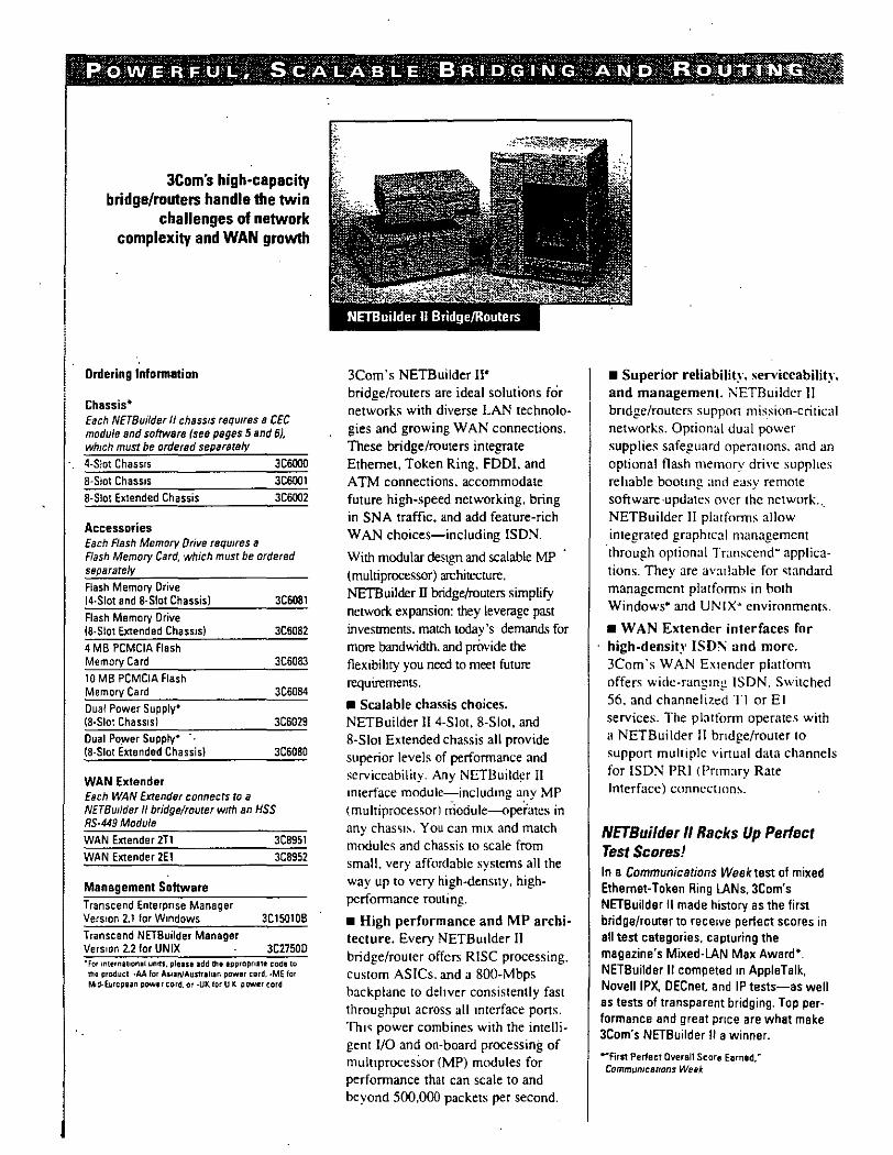
JCom's high-capacity bridge/routers handle the twin
challenges of network complexity and WAN growth
1· Ordering lnfonnation
' ¡ Chassis* Ea eh NETBuifder IJ chass1s reqwres a CEC module and software (sea psges 5 snd 6), wh1ch must be ordered separata/y
4-S!ot Chassrs 3C6(J(J{)
8-S!ot Chassrs 3C6001
8-Siot Extended Chassis 3C6002
Accessories Ea eh Flash Memory Orive requ1res a Flash Memory Card, which must be arde red separately
Flash Memory Orive 14-Siot and 8-Siot Chassisl 3C6081
Flash Memory Orive (8-Siot Extended Chassrs) 3C6082
4MB PCMCIA flash Memory Card 3C6083
10MB PCMCIA flash Memory Card 3C6084 Dual Power Suppty• (8-Siot Chass1sl 3C6029 Dual Po.wer Suppty• (8-Siot Extended Chassisl JCSOBO
WAN Extender Ea eh WAN Extender connects ro a NETBu!lder 11 bridge/router w1th an HSS RS-449 Module
WAN Extender 2T1
WAN Extender 2E1
Management Software Transcend Enterpnse Manager Vers10n 2.1 lar Wmdows
T ranscend NETBuilder Manager Vers1on 22 for UNIX
3CB951 3C8952
3C150108
3C27500 "For 1nternauonal uMs. pleue add tht apprapnate coda to rha producl ·AA lar Allln/Auntlhln paWflr card. ·ME lar Md-Eurcpun power cord. or -UK lor U K power card
3Com 's NETBuilder 11' bridge/routers are ideal solutions for networks with diverse LAN technologies and growing WAN connections. These bridge/routers integrate Ethernet, Token Ring. FDDI. and ATM connections. accommodate future high-speed networking. bring in SNA traffic, and add feature-rich W AN choices-including ISDN.
With modular destgn and scalable MP (multiprocessor) architecture. NETBuilder I1 bridge/router.; simplify
network expansion: they leverage past investment<. match today 's demand< for more bandwidth. and próvide the flexibihty you need to meet future requirements.
• Scalable chassis choices. NETBuilder II 4-Siot. 8-Siot, and 8-Siot Extended chassis all provide superior levels of performance and scrviceability. Any NETBuildcr II mterface module-includmg any MP (multiprocessorl rÓodule--ope~ates in any chas'iJ~. You can m1x and match modules and chassis to scale from small. very affordable systems all the way up to very high-densny, highperformance routing.
• High performance and MP architecture. Every NETBuilder II bridge/routcr offers RISC processing. custom ASICs. and a 800-Mbps backplanc to dehver consistently fast throughput across all mterface pons. Th1'i power combines with the intelligent I/0 and on-board processing of mulllprocessor (MP) modules for performance that can scale to and beyond 500,000 packets per second.
• Superior reliabilit~·. serviceabilitJ. and management. NETBuildcr II bndge/routers suppon mis.sion-critical networks. Optional dual power supplies safeguard operat10ns. and an optional flash memory drive supphcs re hable bootmg and easy remote software ·updates m·cr thc network ... NETBuilder II platfonns allow integrated graph1cal management
·through optional Transcend· applica
tions. They are avatlable for '\tandard management platfonns in tmth Windows• and UNIX"' environments.
• W AN Extender interfaces for high-density ISD:\ and more. 3Com's WAN Extender platfom1 offers widc-rangmg ISDN, Switched 56. and channelized TI or El services. The platform operate.~ with a NETBuilder II hndge/router to suppon multiplc virtual data channels for ISDN PRI <Pnmary Rate Interface) conncct10n~.
NETBuilder 11 Racks Up Perfect Test Scores! In a Communications Week test ol mixed Ethernet-Token Ring lANs, 3Com's NETBuilder 11 made history as the first bridge/router to rece1ve pertect seo res in all test categories, capturing the magazine's Mixed-LAN Max Award*. NETBuilder 11 competed m AppleTalk, NoveiiiPX. OECnet, and IP tests-as well as tests of transparent bridging. Top per
formance and great pnce are what make 3Com's NETBuilder 11 a winner.
-First Perfeet Overall Score Earnad.~ Commumcattons Week

NETBuilder II modules easily match networkmg needs. From highperformancc CommunicatJons Engine Cards (CECsl to LAN.and WAN imerfaces-mcluding MP (multiprocessor) modules w1th on-board processing-you can choose the right combination of ports and power for any level of service.
• Powerful CEC choices. NETBuilder 11 CECs come with highspeed memory options-12 M B or 20 MB-to match software requirements. The right choice depends on currem and expected communication needs. To accommodate network growth. the 12 MB CEC expands to 20 MB capability at any lime.
• S_calable performance. For performance that keeps on growmg. inswll MP modules. They interoperate with the NETBuilder 11 CEC to increase throughput as you increasc pons. Thc on-board. RISC-based AMO 29030 CPU_ nfnoads critica! (llrermg and forwar.dmg decJSJons from the CEC to boost overall ~ystem performance.
• Simplified changes. Our mlerface module~ are a brecze lO change. You can u-.e any module m any NETBulldcr Il chas~l~. and you can' add. ~wap. or remove any interface module while other modules keep running. That"!-.> why the interface modules are easy lO servtce. with a 1ypical mean time to rcpair (MTTRl of under a minute.
• Popular LAN interfaces. Customer-installable interface modules.include a full array of popular LAN connections. Three Ethernet modules offer cabling choices (thick. thin, fiber. twistedpair) and pon density for any configuration. The Token Ring module also provides a choice of interfaces-DB-9 or RJ-45-and software-selectable 4 or 16 Mbps operation. Four FDDI modules give you every combination of mulllmode and single-mode fiber for smgle-MAC. single-attached or dual-attached stations.
• Complete W AN connections. NETBuilder 11 HSS (high-speed sena!) modules provide one W AN pon (V.35. RS-232. RS-449. or G.703) or three WAN pons (V.35. RS-232. RS-449. or X.21 via a three-port breakout cable).
The 3Com NETBuilder 11 HSSI (h•gh-.,peed sena! mterface) module implements WAN or ATM connectlons of up to SONET OC-1 (52 Mbps). including T3/E3 raJes.
Communications Engine Cards (CECs) and hot-swappable interface modules supply scalable power and port capacity
Ordering lnfonnation
NETBuilder 11 Communications Engine Card (CEC) Modules CEC Module !12 MBI 3C6010A CEC 20MB Module 3C60t2 CEC 8MB Memory Expansion Kit• 3C6011 CEC 20MB Module Trade-Up Kit• 3P6013
NETBuilder IILAN Modules MP Ethernet 6-Port lOBASE-T Module 3C6060 Ethernet 2-Port IOBASE-Fl Module 3C6026 Ethernet Module 3C6021 Token Amg Module 3C6023A Mult1mode FDDI Module 3C6020B Smgle-Mode FDDI Module 3C6050A Smgle-Mode/Mult1mode FDDI Module 3C605tA Mult1mode/Smgle-Mode FDDI Module 3C6052A
NETBuilder 11 WAN Modules HSS V.JS/RS-232 Module 3C6022A HSS RS-449 Module 3C6024 HSS G.703 Module 3C6025 HSS 3-Port V 35 Module 3C6040 HSS 3-Pon RS-232 Module 3C6041 HSS 3-Port RS-449 Module 3C6042 HSS 3-Pon X 21 Module 3C6043 HSSI Module 3C6028 •Tha E.rpans1on (,1 IS jor n&w CEC~ 13C601GA) end tht Trade-Up K111s !or earhe1 models (3C60101
'Con1ac1 vour loca13Com represen!allve about G 703 serv1ces
. '
.•

~SUPER ~STACK
A stackable, cell-based Ethernet switch with
a high-speed ATM port for workgroups
Ordering lnlormstion
linkSwttch 2700 (no ATM interface) 3C32701
linkSwitch 2700 IOC-3c single mode short-reach ATM interface) 3C32711
linkSwltch 2700 IOC-3C single mode long-reach ATM Interface) 3C32712
lmkSwitch 2700 IOC-3c mutt1mode ATM mtertace) 3C32700
LinkSwitch 2700 IDS-3 ATM mterface) 3C32710 LmkSwltch 2700 {TLI) 3C32730
'
linkSwitch 2700
LinkSwitch 2700 is ideal for Ethernet
workgroups and small departmental
LANs that need an advanced switch
ing engme for high-bandwidth
networking. The switch ts equipped
with 12 switched Ethernet pons anda
high-speed A TM pon, allowing you
to configure conventional or virtual
switched Ethernet workgroups. and to
extend a high-throughput downlink to
a centralized ATM switch.
• Leading-edge technolog_,·. 3Com's
ZtpChip· ASIC delivers cell-based,
wire-speed Ethernet swltchi!'lg at
780.000 cells per second, guaranteeing
full 1 O Mbps on all Ethernet pons.
• Choice of A TM interfaces. The
A TM port can accoffimodate an
OC-3c 155 Mbps SONET/SDH
(Synchronous Optical Networking/
Synchronous Digital Hierarchy) inter
face for local and collapsed backbone
ATf\1 connecuvity. ora DS-3 45
Mbps mterface for w1de area links.
• Two switching modes. Two
sofrware-selectable sw!tchil')g options
are available- cut-through and
store-and-forward- so you can
adapt the device easily to your
spccific requiremenb.
• Virtual LANs. LAN Emulation
client functions and SVC signaling
allow you to creatc virtual LANs
that are indcpcndcnt of physical.
location.
• SuperStack support. You can use
LinkSwitch 2700 in a SuperStac~
system and manag:e it With Transcend
applications.
• Future-proofing. Thc Ethernet
ports opcrate e ven tf thc ATM pon
isn 't conf1gured. permmmg yo u to
implcment Ethernet switching now
and make ATM conncctions whcn
you need them. Thus. you can
migrate to higher i\ TM bandwidth
while preserving your investment.
• U-turn support. Packets moving
from onc·Ethcmct port to anothcr are
switchcd dircctly, rathcr than passing
through thc ATM por: first.
• A TM switching for the
LinkBuilder' MsH· hub. A module
that providcs thc functionahty of the
LinkSwitch 2700 Ethernet/ATM
switch will be available for 3Com's
LinkBuilder MSH multi-services hub
in late 1995.

. "'""~ ,, ~ !'TI8 1\11 B A e K B O N E 5 W 1 Te H . - . :_ .-> > ·--:-.~-
The key building block for creating an ATM
campus backbone
Ordering lnlormstion
Chassis CELlplex 7000 (chassis with switching engine, 1 power supply, and fan unit) CELLplex 7000 (chassis onlyJ CELLplex 7000 Redundan! Power Supply CELLplex 7000 Redundan! Sw1tchmg Engine CEllptex Replacement Fan Umt
3C37000
3C37007
3C37010
3C37016 3C37030
. ATM Interface Cards and Modules CELLplex 7000 Interface Card
· (4-port. OC-3c smgte moda, short reachl 3C37050 CEllple1 7000 Interface Card {4-port. OC-3c single mode, long reachl 3C37051 CEllplex 7000 Interface Card (4-port, OC-3c multimode) 3C37052 CELlplex 7000 Interface Card (4-port, DS-31 3C37053 CELLplex 7000 Interface Card In o modules) 3C37005 CELLplex 7000 Physical Module 11 OC-3c smgle mode shon reachl 3C37058 CELLplex 7000 Physical Module (1 OC-3c smgle moda long reach) 3C37059 CELlplex 7000 Physical Module (1 OC-3c multimode) 3C37060 CELlplex 7000 Physical Module 11 DS-31 3C37061 CELLplex 7000 Interface Card Blank Panel 3C3704
CELLplex 7000 has all the power,
tlexibility, and robustness necessary
to switch traffic on a mission-critical
A TM backbone. Supponing 4 to 16
A TM pons, the 16 x 16 CELLplex
7000 switching engine delivers full
rate, non-blocking A TM performance
that relieves backbone congestion.
• State-of-the-art ATM switching.
The CELLplex 7000 cut-through, sclf
routing switching engine is
built around a 20.48 Gbps backplanc
with a sw1tchmg fabnc that can SWitch
up to 2.56 Gbps of traftic. Each pon
supp(>ns up to 4096 point-to-point or
point-to-mulupoint vutual channel
connections. A -separate on-board i960
RISC processor handles advanced
software features.
• Modular flexibility. You can add
up to four 4·port interface cards to
the chassis. allowing you to configure
410 16 ATM ports in cost-effective
increments ..
• Choice of A TM interfaces. Each ·
card accornrnodates cither OC-3c 155
Mbps SONET/SDH interfaces for local
or collapsed backbone connectivity. or
DS-3 45 Mbps mterfaces for W M
hnks and single-mode fiber (available
in late 1995).
• Robust and reliable. To ensurc
uptime for critical applications,
CELLplex 7000 is designed to be ·
fully redundan!. with optional dual
power supplics and redundan!
switching engines. All modules are
hot-swappablc for continuous
operation.
• Trame management. Rate.based
now control provides congestion
·management.
• lntegrated management. Full
SNMP managcment is provided,
including support for Transcend
applications.
• Investment protection. The high
pcrformance. passive backplane
allows you 10 expand pon denslty
and bandwidth.
• Switched virtual channels. SVCs
are supported via Q.2931 signaling
with the capability 10 support ATM
Forum UNI 3.0 and UNI 3.1.
ATM Forum lntenm lnter-Switch
Signaling·PrOJocol is also supportcd.
• LAN Emulation Service. The
,CELLplex 7000 provides the LECS.
LES. and BUS scrvices for LAN
Emulation.

The CELLplex 7200 integrales
Ethernet and ATM at full wire speed
to rcmove traffic bottlenccks in dep;u1mental LANs, particularly
collapscd ba~.:kboncs. Thc switch
accommodates up to 48 "rull-rate
swilched Ethernet porlS integratcd
with four ATM ports, or altcrnativcly
up to eight ATM pons in ATM-only
configurations.
• Powerful swilching engine. The
CELLplex 7200 8 x 8 swuching
enginc combine~ with 3Com 's
ZipChip custom Ethernei/ATM
processor lo dcliver full-rate, non
blocking switching on all Ethernet
and A TM pons- ¡¡t Óver 780,000
ce lis per second.
• Flexible ATM interfaces. Each
interface card accommodatcs eithcr
OC-3c !55 Mbps SONET/SDH inter
faces for local or collapscd backbonc
connectivity, or DS-3 45 Mbps
interfaces for W AN links.
• Virtual LANs. You can create
virtual workgroups based on a variety
of logical relationships rather than
fixcd physic;,1l conncctions.
• Uptimc insurancc. A redundan!
chassis with optional dual power supphcs ensurcs that thc switch
has no single point of failure. Hot
swappable modules help mamtain
continuous opcrat10n. cnsuring
rapid delivcry of your crit1cal
nctwork traffic.
• Trame managemcnt. Rate-based
now control provides congeslion
managcmcnt.
• Switching options. Two
softwarc-sclcctablc options -
cuHhrough and storc-and-forward
- allow you to adapt 10 ;pccific
nctwork rcqutrcmcnt~.
• Futurc-proof. /\ pa~sivc backplanc
with a. 10.24 Gbps capacity permits
you to upgrade to higher pon
densllies and data rates.
lntegrated Ethernet/ATM switching for high-bandwidth LAN backbones
Drdsring lnformation
Chassis CEllptex 7200 Chassis (chass•s w1th SWltchmg engine, 1 power supply, and fan umt) CELLptex 7200 fchassis only)
CEllplex 7200 Redundant Power Supply
CELLplex 7200 Redundant Switching Engine
CEllplex Replacement Fan Umt
ATM Interface Cards CELLplex 7200 Interface Card (2-port. OC-3c multimode)
CEllplex 7200 Interface Card 12·po~. DS·JI CEUplex 7200 Interface Card (12-port Ethernet. 1 OC-3c multimode)
CELlplex 7200 Interface Card 112·po~ Ethernet, 1 DS·JI CEllplex 7200 Interface Card Blank Panel
JCJ7200
JCJ7207
JCJ7210
JCJ7216 JCJ70JO
JCJ7050
JCJ7051
JCJ7260
JCJ7261
JCJ7021

Product Line Brochure Cisco LAN Switching Products
The Emergence of the New Wiring Closet The demand for more bandwidth and throughput in today's congested networks is as clear as the factors driving it. Among these factors are the increasing power of desktop processors and the requirements of client/server and emerging multimedia apphcations. The need for increased performance to the desktop is promptmg network managers to replace hubs tn their wiring closets with s':Vitches, thereby protecting existing wiring investments while boosting neÍwork performance with dedicated bandwidth to the desktop for each user.
Coinciding with the wiring closet evolution is asimila; trend in the network backbone. Here, users are collapsing router backbones with switches to increase the aggregate transport capacity of existing
networks. The role of Asynchronous Transfer Mode (ATM) is also increasing as a result of standard1zmg protocols such as LAN emulation that enable ATM devices to coextst wtth users· ex1sting LAN
technologies.
Cisco Systems recognizes that any strategy for meeting flexible . performance is essentially a plan for migrating from today's world
of shared mediato switched internetwork solutwns that promote the expansion of switchmg tecilnology throughout the network. Cisco supports this migration with a comprehensive family of I.AN switching, ATM switching, and switch management products. These products, m conjunction with Cisco routers traditionally used for protoco! management, deliver next-generation desktop and enterprise
solutions to connect users over collapsed or distributed backbones.
CIICDSYSlfMI

Cisco LAN .Switching Products: Catalyst 0000
Tbe Catalyst Famlly of Moltilayer Switches: Optlmlzed for Flexible Wuing Closets The first member of the Catalyst family, introduced in March 1994,
. addressed the increasing needs of clienVserver applications by boosting the performance of multisegment hubs and dedicating bandwidth to servers. In less !han one year, the Catalyst 1200 acquired a 20 percent share of the switching marke~ according to market projections. The Catalyst 5000, introduced in March 1995, represents the next-generation switching system for the wiring closet with dedicated bandwidth to the desktop. The Catalyst family gives users the scalability to build large switched internetworks with multilayer intelligence.
The Cisco Catalyst 5000: The Nert Generation of · Multilayer JAN Slritcbing The Catalyst 5000 is a modular switching platform that will meet the ever-changing needs of today's high-performance, bandwidthintensive, multiple-media network switching applications. Dedicated bandWidth is delivered to users through multiple-media switching options that encompass 10-Mbps Etherne~ 100-Mbps Ethernet, and ATM, with future capability for switched FDDI and switched Token Ring.
Multiple Switching Options Ctsco Systems· Catalyst 5000 serves the needs of multtple medta nerwo.-ll swttchrng appllcanons wtth opt10ns that mcludc 10 Mt:f;s Etnernet. 100-Mcos Etnernet. switched f oken Rmg, SWI!thed f"OOI. and ATM
As networks migrate to higher-speed technologies such as Fast Ethernet and ATM, the long-term viability of the Catalyst 5000 is enhanced by me slots that provide configuration flexibility. The firstslot contains a Supervisor Engine that en~bles aggregate switthing and switth management The remaining four slots supporta growing combination of switching modules that include switched IOBaseTIIOBa.seFL, switched 100-Mbps Fast Ethernet, and an ATM LAN emulation module. This mix of interface and backbone modules allows the Catalyst 5000 to integrate the b~d.est range of environments in the industry, providing a cohesive network solution anda migration path to switched ATM-based networks while leveraging infrastructure investments.
ATM backbone access is achieved through an ATM LAN emulation module that allows applications based on standard protocols such as TCPIIP~ Novell NetWare, DECne~ and AppleTalk to run unchanged over ATM networks. An innovative design executes ATM protocols as onboard processor-executable code, ensuring compatibility with future software versions.

Because many of today's organizations experience significan! personnel relocations every year, the CatalystSOOO gives users the ftexibility to support the fonnation of VLANs withio and between Catalyst 5000 switches and across the intemetwork, spanning routers andA TM. The architecture wiil scale to support up lo
1024 VLANs and can be defined and maintained across platfonns through ATM or 100-Mbps links.
Unlilre traditional shared hubs, the CatalystSOOO architecture is designed and optimized for switehing. The Catalyst SOOO's switehing backplane operátes at1.2 gigabits per second (Gbps) and pmvides nonblocking peñormance for all switched 10-Mbps Ethernet inteñaces. The in tema! switching architecture of the CatalystSOOO supports multiple media options including Etheme~ Fast Etheme~ 100BaseVG-Anyi.AN, Token Ring, FDDI, and ATM. A dedicated management bus provides distributed access lo all switching modules for monitoring peñormance, controUing configuration and VLANs, and updating operational software for each module.
Catalyst 5000 OITers Maximum Port Deusity The Catalyst 5000 platform leatures a h1ghly scalabla an:hltecture rhat provides malimum performance to largo workgrnup:;
Cata..,5000 toATM
ATM. ialho Ellllnpñse Bockbooe lightStream Farnity
Unique Traffic Management Support for traffic management by switches is one of the most importan! attributes of a scalable switched intemetwork, and the CatalystSOOO includes severa! key traffic mana¡¡ement features. A large, 192-kilobyte (KB) buffer en sures adequate port buffermg for workgroup applications without dropping information during peak traffic periods. Tri-leve! priori !y on the backplane en sures that delay-sensitive applications receive the necessary priority on a port-by-port basis.
With increasing support for high-peñormance, high port density, multimedia solutions, the Catalyst5000 architecture has the foundation lo support the growing needs of business networks today and into the future.
Catalyst 5000 toATM
Tagbt latqratioa witb Roater for Scalable lnternetworlcing
FDDI, Fast Ethernet, A TM
Up to 74 ports
Up to 7 4 ports Swrtched 100-Mbps Ethernet Configurations
Catalvst 5000 100 Mt:ps
Up to 97 oorts
Catalyst 5000 100 Mcps

Cisco LAN Switching Products: Catalyst óOOO
Basic Piatform
Standards·Based Interfaces
Feature
Medular, five-ll.ot chassis
Fits standard 19-inch rack: raci-mounting hardware and cable guides induded
Fault-tolerant power supphes
Switch interface moduJes
Spetialized SupervisorEngme module has hardwarHased switching engine, bridge address tab'e for a maximum of 16,000 MAC addresses, twtliOO.. Mbp5 Fast Ethernet uplints, anda network management processor
Hot-swap ofpower supplies and modules
lntemal .irchltecture
1.2-Gbps switchmg backplane
Three levels of priority on the data-swltchmg backplane
Custom app\icatton-specific mtegrated c¡rcuit (ASIC) development
SWitched 10-Mbps Ethernet
24 interfaces of 10BaseT per module
12 mterfaces of 10B.aseFL on fiber per module
Switched 100-Mbps Ethernet
Functlon
Supports ~uired supe:rvisorengine and tour additional modules '
Compatible with emting wiring dosel rack; mountJ at front or rur of dJassiJ
Offers one or two 376-watt power suppUes with auto-sensing .
Offers wide variety of interface c:hoices induding IG-Mbps and 100-Mbps Ethernet ond ATM; Token Ring and CDDWDDI to bt: added in future reieases
Dehvers ~r 1 million pps, low latency, low-cost switching for desktop and backbone applicatiolll; fulllocal and remole management
Enab\es users to add, move, or change modules any time wlthout bringing down the Catalyst 5000 or loting oonnectivity with other network dev1ce1
Single switch1ng back:plane accommodates Ethernet and ATM sLmultaneously (FDDI and Token Rmg in future releases)
Forwanb more than 1 million 64-byte Ethernet pa.ckets (equates to nanb1ocbng an:hitecture for lOO 10-Mbps Ethernet interfaces at wire speed)
Acrommodates teeh.nolog¡es that implement prioritiation ac:hemes, such as ATM, IOOVG-AnyUN. and Token Ring; enables user to define higherpnority on a per-inteña.ce basis; allows any interface to reach the highest priority when its buffer reaches capacity
Uses a custom ASIC contro!ler on each Ethernet interface
Offers ch01ce of Category 3 unshielded twJ.sted pan (UTP) cable (lOSasen and fiber-optic cable (lOSasen); supports both full- and half-duplex operation
Uses femaJ:e R.J-21 c_onnectors
Uses female RJ-21 amnectors
Offers choice af Category 5 TJI'P cable and, m the future, fiber-optic cable for IOOBuePX and Category 3l!T'P for IOOSaseTXand lOOBueVGAnyl.AN); aupport5 both full- and half-duplex operation: aupports auto-sensing between 100-Mbps Ethernet
Benellt
AUIIWI usen flexibility to add. or mix and match modules as needed ·
Ensuro ease of installation in winng doset and data center
lncreases reliability
Acrommodates aiJ lAN and ATM technologies
Provides a completely manageable switchmg 1)'1tem that delivers high-peñonnance switching for'e\'en tbe most demanding wortgroup applic:ations
lncreases reliabihty by reductn~ downt1me
Delivers a single-system solut10n for all current desktop switr.hing neeCs \\lth a migration path toATM
Designed to meet the demands of a fully popu1ated, 10-Mbps system Wlth al\ interfaces operating at wtre speed (each interface communicates with only one other mterface)
Accammodates bursty traffic andprevents hLgherlayer protocol tlme-outs by givmg the interface the highest priority on the bus until trB.ffic is reduced; allows managers to pnoritize data transmission to crihcal resources. such as servers or remole routers
Lowers cost pcr sw1trhed interfB.ce to the user, enables state-of-the art features such as VLANs
Eases mtegration mto existing installed base of 10-Mbps Ethernet hubs and adapters by preservtng wiring hardware and application investment. leverages existmg UTP support; allows long- . distan ce nms with fiber across a campus; increues capacity with full-dup1ex operation
Hlgh denaity,Jow cost per Interface connet:l:lon into existing telco-a:mfigured wiring
Higher density than competiton
En sures compatibility with a lal!e number of 100-Mbps Ethernet hubs and adapten: uses costeffective UTP for deaktop connectivity; allows long-d1stance runs with fiber across a campus in full-duplex mode; increues capacity with foil· dup1exmode
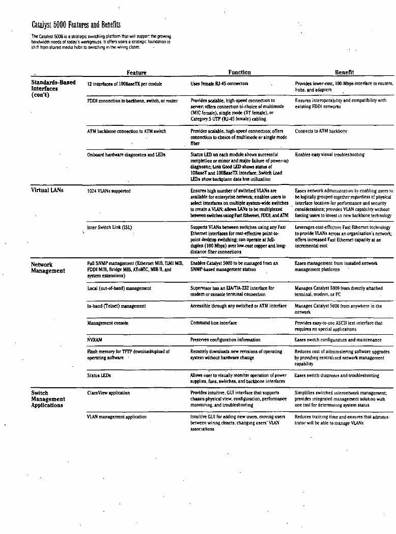
cataJyst 5000 Featuns and Benefits The Catalyst 5000 is a strategic sw•tching platform that Wlll support me growmg bandwidttl needs of today's wortgroups lt offers I.IS9rs a strateg1c found¡Jllon te sh1ft trom shared medLa hubs to swttch1ng m tM winng closet.
SlaDdanls-Ba.sed Interfaces (con'!)
VIrtual LANs
Network Maoagement
Switch Management Appllcatlons
Feature
12 interfaces of lOOBueTX per module
FDDI connection to bac:kbone, switch, or router
ATM backbone coonection to ATM switch
Onboan:l hardware d.iagoosttcs and LEDs
1024 VIANs supported
lnter Switch Unk (ISL)
Full SNMP m.anagement (Ethernet M18, ILMI MlB, PDDI MIB, Bridge MIB,AToMIC, MIB R, and system extensioDJ)
Local (out-of-band) managemenl
ln-band (Telnet) m.anagement
Management console
Flash memory for TfTP downlo.atiílpload of . operating software
Status LEDs
CiscoView applic.ation
VI.AN management application
Function
Uses fenWe RJ--45 connecton
Provides scalable, high-speed amnect10n lo ser.oer; offen ronnedton tó choice of multimode (MIC female),singte mode (ST female), cr Category 5 t.mt {RJ45 female) cabling
Prov:ides sealable. high-speed connect10n; offers connection to tboice of multimode or single mode fiber
St&tus LED oo each module shows successful completion or minar and major fa.ilure of power-up diagnosbc; Link Good lED sbows status of lOBaseT and lOOBueTX interface; Switdt lAad lEDs show batkplane data bus utiliution
Beneflt
Provides lower<OSt, 100-Mbps interface to routers, hubs. and adapters
Ensures interoperab1hty end C(lffipéltibility v.1th existing FDDI networks
Connect.s to ATM backbor:tc
Enables easy visualtroub!eshootmg
Ensures high numberofrwitched VIANs are Ea.ses network admtnlstratton by enabltng users to available for enterprise networi:; enables users to be logically grouped together regardless of physical seJect interfaces on multipie system-wide switdtes interface location for perfonnance and security to create a VLAN; aUows IANs to be mu1tiplexed · eonsiderations; proVJdes VLAN capabthty wtthout between switr.hes usiog Fast Dhemet, IDDI, andATM forring users to invest m new backbone technology
Supports VLANs between rwitches using any Fast Ethernet interfaces for cost-effedi.Yt: point-topoint desktop IWitcbin¡; can operate at fullduplex (1 00 Mbps) ~:M:r low-cost copper and longdistance fiber eonnections
Enables Catalyst 5000 to be managed from an SNMP-based management stahon
Supemsor has an ELVTIA-232 interface for modem or eoflS(Ile termina) conned.Jon
A.ccessible through any swit.ched or ATM interface
Command !me interface
Preserves configurallon informAI..ion
Remotely downloads new revlsions of operating system without hardware change
AJiows u ser to visual! y monitor operalion or power supphes, fans. switches. and backbone interfaces
Pruvides intuillvt, GUI interface that supports dwsis physical view, configuration, perfonnance momtonng, and troubleshoot1ng
lntuitive GUI for adding new users. movmg users between winng dosets, changmg users' VUN assoc1ations
Leverages cost-effedtve Fast Ethernet technology to provide Vl.ANs across an organi.r.ation's network; offers increased Fast Ethernet capacity atan incremental eost
Eases management from installed network management platfonns
Manages Catalyst 5000 from du~ctly attached tenninal. modem. or PC
Manages Catalyst 5000 from anywhere in the network
Provides e.asy-to-use ASCII text mterface that requires no special apphcat1ons
Ea5es sw1tch configuratJon and maintenance
Reduces cost of admimstenng software upgrades by provuhng centrahzed network management capabil1ty
Eases switch diaRDOSJS and troubleshooting
Simplifies swilched mtemetwork management; provides mtegrated management solut1on wtlh one too! for detenmmng system status
Reduces trainmg time and ensures thal admmJS· trator wlll be able to manage VlANs

• 3Com Strategic Directions
High-Performance Scalable Networking with Routed ATJ\~-
' ' ..
Ríght~Sizing .the B.andwidth in Today's l'iletworks

•
High-Performance Scalable Networking·With RóutedATM
... ·. '··· .. ·· ..
. ... '
Executive siiiillliarY Planning for High Bandwidth Dernand
Customer Guidelines
High-Perforrnance Sca!able Networking
Today's Collapsed Bacldxme Al;:hitecrure
HPSN Stage l: Enhancing the Collapsed Backbone
2
2
2
4
withAdditional~orizontaland Vertical LANs · 5
Overéomíng Coóstrnints on Downlinks . 5
Port Grouping for VirtuaÚ.ANs and Workgroups ·· 5
Creating Routing Ousters with Switching 6
HPSN Stage 2: Creating High-Speed Downlinks to
lncrease Bandwidth and Reduce Segmentation 6
Route Caching for Scalable Routing 7
LinkSwitch for Connections Between Segments 7
High-Speed Downlinks Using a Switching Hub and Bridge/Router 7
A TM as a Downlink Technology 8
· · CellBuilder· fór A 1M Con~ersion 8
Jote grating Meshed Campus Backbones withA TM Switching 9
HPSN Stage 3: Enhancing theCollapsed Backbone with Routed ATM 9
Route Determínation for A TM End Systems
Managing the Network
Today's Foundation for HPSN Migration
Summary
Glos."")'
For More lnfonnarion
9
10
10
11
12
12

Planning for High Bandwidth Demaild
Enterprise networks linking desktop and mobile computer clients with serven; and other computing resources are critica! to the information flow witlún many oftoday's companies.
However, demand for more capacity is beginning to strain the capabilities of these networks. As current technologies are pushed to their linúts, MIS managers are under pressure to pro vide usen; with more bandwidth while continuing to preserve and optinúze ex.isting investments.
A network manager planning to meet bandwidth dernand by expanding an ex.isting network or designing a new one must answer a number of critica! questions:
2
• Which high-speed technologies will best meet network requirements for various parts of the network now and in the furure?
• How should this technology be implementedwith mixed-media hubs, switches, multiplexen;, routers, or a.combination of products?
• Can higher bandwidth be provided for backbones, servers, and client PCs at a reasonable cost, and without introducing unnecessary complexity?
• Will usen; of new technologies be able to . communicate transparently with existing LAN users?
• How can the network be optinúzed for new client-server applications?
• And, most importantly, how can this núgration to higher performance be accomplished without disrupting the existing network and sacrificing productivity?
Customer Gtiidelines In formulating its performance núgration strategy,
3Com fo!lowed certain guidelines articulated by network managers in diverse companies and organizations:
• Deploy new teehnology only in the parts of the network where it is needed.
• Migrate the network in a series of steps at núnimal incremental cost.
• Implement new capabilities by building on earlier enhancements with no loss of functionality.
• Maintain seamless connectivity tluoughout the configuration.
• Simplify the task of managing the network.
3Com assinúlated these guidelines into a comprchensive and balanced strategy that is both technically sound and responsive to long-term requirements. ·
High-Performance Scalable Networking
With 3Com's HPSN strategy, network planners can:
• Build on both curren! and emerging LAN technologies to meet present and future needs.
• Implement lower-latency connectivity systems in the workgroup and campus backbone for better performance.
• Scale network performance to meet specific business requirements.
• Extend t!Je reach of toda y· s LAN resources by dramatically reducing the cost and complexity of providing remole and WAN con- · nections across the enterprise.
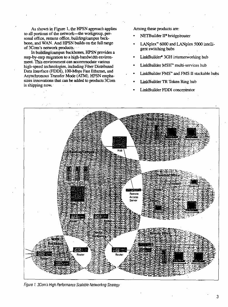
As shown in Figure 1, the HPSN approach applies to all portions of the network-the workgroup, personal office, remo te office, building/campus backbone, and WAN. And HPSN builds on the full range of 3Com 's network products. ·
In building/campus backbones, HPSN pro vides a step-by-step migration to.a higb-bandwidth environment 1bis environmentcan aa:ommodate various higb-speed tecbnologies, including Fiber Distributed Data Interface (FDDn, 100-Mbps Fast Ethernet, and Asynchronous Transfer Mode (ATM). HPSN emphasizes innovations that can be added to products 3Com is shipping now. ·
Figure 1. 3Com's H1gh Performance Scalable Networlong Strategy
Among these products are:
• NETBuilder ne bridge!router
• LANplex~ 6000 and LANplex 5000 intelligent switching hubs
• LinkBuilde¡4 3GH intemetworking hub
• LinkBuilder MSW multi-services hub
• LinkBuilder FMSN and FMS Il stackable hubs
• LinkB.uilder TR Token Ring hub
• LinkBuilder FDDI conce¡1trator
3
' .
•'
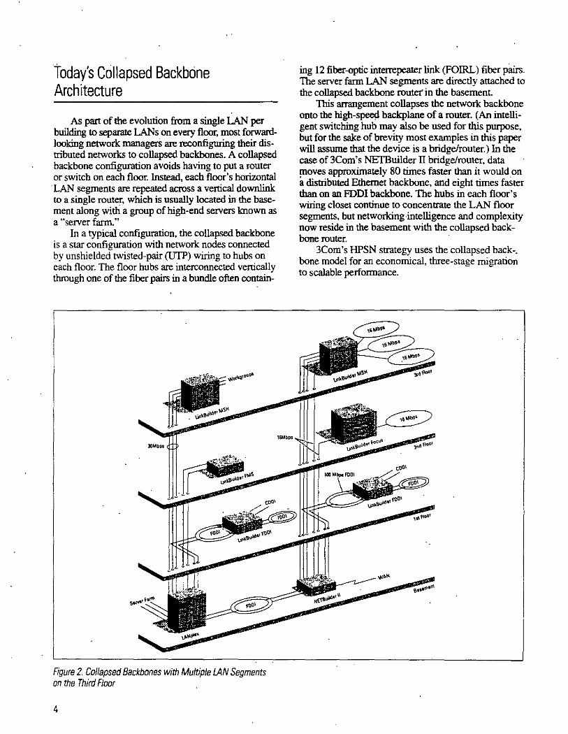
today's Collapsed Backbcine Architecture
As part of the evolution from a single LAN per building to separate LANson every floor, I:JlOSt fo~ardlooking network managers are reconfigunng therr distributed networks to collapsed backbones. A collapsed backbone configuration avoids having to put a router or switch on each floor. lnstead, each floor's horiwntal
· LAN segments are repeated across a vertic~ downlink to a single router, which is usually located m the basement along witli a group of high-end servers known as a "server farro.."
In a typical configuration, the col!apsed backbone is a star configuration with network nodes connected by unshielded twisted-pair (UTP) wiring to hubs on each floor. The floor hubs are interconnected verncally through one of the fiber pairs in a bundle often contain-
Figure 2. Ca/lapsed Backbanes with Multip/e LAN Segments on the Third F/aar
4
ing 12 fiber-<J¡Jtic interrepeater link (FOIRL) fiber paus. The server farm LAN segments are directly attached to the collapsed backbone route!' in the basement
This arrangement collapses the network backbone onto the high-s~ backplane of a router. ~An intelligent switching hub may also be used for this purpose, but for the sake of brevity most examples m this paper will assurne that the device is a bridge/router.) In the case of 3Com's NETBuilder II bridge/router, data moves approximately 80 times faster than it wouldon a distributed Ethernet backbone, and eight times faster than on an FDDI backbone. The hubs in each floor's wiring closet continue to concentrare the LAN floo~ segments, but networking intelligence and compleXIty now reside in the basement w•th the collapsed backbone router.
3Corn's HPSN strategy uses the collapsed back-. bone rnodel for an economical, three-stage migration to scalable performance.

HPSN Stage 1 : Enhancing the Collapsed Backbone with Additional Horizontal and Vertical LANs
As the demand for bandwidth grows, a perlonnance bottleneck can quickly result if all the users on one floor share a single LAN. A collapsed backbone can split users across multiple LANs because each new horizontal LAN segment can extend vertically to a collapsed backbone router por! using a separate fiber downlink. Tiús effectively scales the bandwidth of the vertical cabling infrastructiJre inproportion to the number of horizontal LAN floor segments:. •. ·
Figure 2 depicts two possible config'urations of this type, one using a NETBtillder II bridge/router as the backbone device and one using a LANplex intelligent switching hub. In each configuration, three horiwntal.
· LAN segments are deployed on the third floor. Tiús increases floor bandwidth by a factor of three, each with its own downlink to the router.
Overcoming Constraints on Downlinks Additional vertical downlinks do not usually require
new cabling installation, since most buildings have spare fiber pairs in each floor's bundle. But one constraint on the addition of downlinks is the router's port capacity. The manager must make sure that the collapsed backbone device has enough ports to handle both curren! and near-term future downlinks from the floors. Of course, multiple collapsed backbone routers can always be located together. · · · · ·
Anothel" limiting factor on the number of downlinks is increased complexity. Segmeotation irnproves performance, but it also means there are more LANs to manage. For example, if IP is used as a network !ayer protocol, each new segment requires its own IP network number. complicating administration aod depleting the organization's allotroent ofiP numbers.
To reduce complexity, the manager could, for example, group the downlinks associated with the three third-floor segments and connect them toa bridge, which in tum would be connected to a port on the router or switching hub. Bridging the three grouped LAN segments in Figure 2 into one logical w.orkgroup requires only a single IP. network number, and the router insulates this group of LANs from the others.
However, this solution requires an extra bridge, adding to the delay in the vertical infrastructure. Furthermore, unless the port connecting the externa! bridge to the router is equivalen! in speed to the three downlinks, the bridge traffic may become congested. A further consideration is that adding a higb-speed link between the externa! bridge and router increases cost.
Port Grouping for Virtual LANs and Workgroups These problems with bridging may be resolved by
adding a port grouping feature to the collapsed backbooe ronter, providing the bridging function interna!! y between the three downlinks.
Since the "port" to the router is interna!, there is no additional delay because its speed is proportional to the speed of the three downlinks. The three grouped LAN segments are referred to as a virrual IAN. A virtual workgroup is defined by the collection· of nodes or end systems attached to the grouped LAN segments.
A virtual LAN that takes up more than one port on the bridgelrouter looks like a single LAN to the netwmk But because the administrator can still route traffic between virtual LANs, port grouping retains the advantages of full multiprotócol routing. Furthermore, since port grouping is.provided in a router. techmques lik:e' proxy address resolution protocols (ARPs) can reduce broadcast/multicast traffié within the virtual LAN.
NfTBuol4er U
F1gure 3. Example of Virtual Workgroups w1thm a Building
Figure 3 shows an example of multiple virtual workgroups. In this example, the engineering, marketing, and finance groups are kept separate (insulated by a "frrewall") to isolate data resources and manage traffic between these virtual LANs. Using port grouping, al! of the engineering LAN segment' are combined into a single virtual workgroup, evcn though they are physically divided into three segments spread across two floors. The virtual workgroup is assigned a single IP network number instead of three diffcrent numbers.

Creating virtual workgroups using a single IP network number (because they are on the same virtual LAN) mitigares the complexity of segmentation on the floors (because there is no need to change end-system addresses). It also saves management time-for instance, workgroups can be "soft" configured in the NETBuilder 11 without changes to the physical plant
Creating Routing Clusters with Switching When network traffic proliferates between the
buildings in a campus environment, the result is an increase in demand for bandwidth on the campus backbone. Network managers often respond by connecting buildings with a single, shared 1 00-Mbps FDDI network.
As. the network grows, however, each building may ha ve hundreds of devices contending for bandwidth on the single, shared interbuilding backbone. Another problem is that users and workgroups often need to be relocated within the campus, while the server they primarily communicate with remains in á central server farm in another building. As a consequence, the campus backbonebecomes a traffic bottleneck.
Building 3
•
Figure 4. Three Altematives far lmplementing Campus Rauter Clusters with lANplex lntelligent Switching Hubs
To accommodate growth and alleviate congestion. a switching bub such as 3Coní s LANplex can be used to create router clusters-private, high-speed switched links to each building. LANplex devices allow each building to have a private link comprised of either a 10-Mbps Ethernet or 100-Mbps FDDI. Another approach is to use ATM cell switches and the ATM DXI interface on the routers. The ATM DXI interface ~1 accommodate speeds up to 52 Mbps, full duplex. Figure 4 shows three ·alternative campus backbone configurations that can yield a significan! improvement in performance compared to a single FDDI backbone link.
HPSN Stage 2: Creating High-Speed Downlinks To lncrease Bandwidth and · Reduce Segmentation
Increasing bandwidth within the workgroups means increasing LAN segmentation on the floors. But, eventually, the adrniuistrator runs out of spare
Building 3 .
Building 1
~uildingl

1 1
fiber cabling in the building riser, or uses up all the physical ports on the router.
TI!is dilemma rnay be resolved by using a single high-speed downlink to replace multiple slower LAN segment downlinks. The manager can continue to increase overall network performance by means of additional horizontal floor segmentation without the
· need to change hardware or software at each desktop. To support high-speed downlinks, the per-port
frame processing performance of the collapsed backbone needs to be increased by approximately a factor of 1 O. There are nurnerous ways to accomplish this performance scaling. All of them require distributing sorne leve! of routing functionálity within the colla¡:>sed backbone router.
Route Caching for Scalable RoutiÍig · The preferred way to scale performánce. is to dis
tribute oruy the simpler higb-performance frame forwarding logic to the port interface cards, otberwise known as the pon switching engines, and to centralize the complex mute determination logic.in a central routing engine.
Tiris is termed an "advise-and-consent" approach because the first time a destination is "seen" by a port switching engine, the central routing engine determines the route and tells the switching engine how to forward subsequent frames with the same destination. The port switching engine thus performs the forwarding operation with the advice and consent of the centr.il routing eng1ne.
The port switching ehgine remembers the routing information in a route cache. Route caching adopts many of the caching principies used to speed memory access in mainframe virtual memory caching schernes, but with one significan! advantage: Each switching engine is responsible for routing only the frames from end systems associated with the attached dowruinks. Therefore. each port switching engine "sees" oruy a few mutes compared to the total number of routes available lo the central switching engine. Also, from the perspective of the port switching engine, the routes the end systems use do not change frequently.
As a result, the switching engine's cache hit ratio (the rate at which references to the faster-access cache memory are successful) o ver a 24-hour period is likely to be very el ose to 100 percent Witb route caching, the frarne-forwarding capacity scales proportionally to the number of high-speed downlinks .
. LinkSwitch for Connections Between Segments High-speed downlink support also requires sorne
Jevel of intemetworking on the !loor for attaching Ethernet and Token Ring LAN segments. The chal
·Ienge is to move simple, low-cost internetworking
functionality-a form of LAN switching that 3Com calls LiJ.tkSwitch~ technology-to the floor without giving up the full-function benefits of a collapsed backbone router.
LinkSwitch is an extension of the advise-and-consent technique. It behaves like a NETBuilder II port switching engine for its attached LAN segments. Like the port switching engine, if it knows the route. it handles the forwarding of frames independently with the advice and consent of the central routing engine in the collapsed backbnne routér. ·
LinkSwitch technology is planned for release as a set of modules in the LinkBuilder MSH in !Qte 1994.
High-Speed Downlinks Using a Switching Hub and Bridge/Router
Figure 5 shows an example of a muque higb-speed downlink solution using a LANplex switching hub and a NETBuilder II bridge/router. The LANplex provides FDDI downlinks configured as three FDDI segments, with each segment defining a separate workgroup. Each high-end server in the server farm is attached to the FDDI seginent associated with its prirnary workgroup by means of bridge-per-port or FDDI concentration within the switching hub.
Figure 5. High-Speed Down/inks from Ethernet LANs through a LANplex to a NETBuilder 11

The NETBuilder II provides full-function routing between the three FDDI segments andan FDDI campus backbone. The result is three extremely higb-speed workgroups within a building with complete firewall protection between them and the campus backbone. Performance is scaled by distributing intraworkgroup frame-forwarding to the LANplex switcb, whi!e l!Ssigning the much more complex route determination logic to the NETBuilder II.
Today, FDDI is the only standard higb-speed LAN technology that can be deployed as a downlink for interconnecting both Ethernet and Token Ring LAN segments. However, in the near future 1 00-Mbps Fast Ethernet will also be available. Fast Ethernet will support low-cost, 100-Mbps workgroup and downlink connections over existing Ethernet cabling.
ATM as a Downlink Technology One issue tbat will eventually ha ve to· be resolved
with regard to LAN downlinks is the fact that all the segrnents switched into the downlink must use the same network number, or they must have a full-function router at botll ends. Certainly multiple downlinks may be used, but even this approach will present a density problern as the number of LAN segments increases.
The 155-Mbps rnultimode fiber interface specified by the ATM Forum is an ideal technology for enltancing the speed of downlinks. ATM offers a number of advantages to managers looking for a higb-bandwidth alternative tbat can handle advanced network applications and growth in the future.
Because the identity of a LAN segrnent can be retained by mapping it to an individual virtual channel, a single ATM downlink can forward frarnes from LAN segments associated with multiple network numbers. ATM allows for considerably more LAN segmentation without using up fiber cabling pairs. A single ATM link will easily support 15 to 30 Ethernet or 10 to 20 16-Mbps Token Ring LANs on each floor.
If each LAN segment is mapped toa different virtual channel within the downlink, every segment can be identified by the router. NETBuilder II can now perform virtual channel grouping, allowing tbe administrator to create virtual LANs justas tbougb each segment had its own downlink. The ATM downlink, which uses existing multimode fiber-optic cabling in the building riser, may be implernented by simply adding new modules to the collapsed backbone router. and adding new modules to chassis-based hubs or new units to hub stacks.
LAN downlinks transrnit variable-size frarnes, and consequently ha ve variable delay-known as latency. PJM downlinks overcome latency by segrnenting frarnes into short, fixed-length blocks called cells. Data, real-time voice, and video transrnissioits can all be transrnitted together through an ATM pipeline.
o
Latency can also be rninimized at the router once the frarnes have been segrnented into cells. Since aJl the routing information is normally contained in the first cell, the frarne-forwarding decision does not ha ve to wait until all the cells have been received, especially if the destination port is also an ATM interface. 3Com calls this cut-througb routing technique stream routing. When strearn routing is cornbined with route caching, it is possible to reduce latency in the network significantly.
CeiiBuilder for ATM Conversion 3Com will support ATM downlinks using
CellBuilder technology within LinkBuilder MSH and LinkBuilder FMS hubs, converting Ethernet and Token Riflg frarnes into ATM cells for transrnission across the ATM downlink. When cells are received frorn the ATM downlink, 3Corn's Cel!Builder technology perforrns the reverse process, reassernbling the ATM cells into LAN frames for transrnission to the stations:* Figure 6 illustrates this conversion process for an ATM downlink on a building backbone.
LmkBu1lder MSH/FMS Hub
NETBullder IIJLANplex 6000
Figure 6. Cei/Builder Suppart far LAN Segments an an ATM Dawnltnk 1n a Buikhng
• CeiiButlder uses the ATM forum standard multimode htlcr U ser Network Interface iiJNI) toexchange cellsacrossthe ATM downhnk.. And rt uses the lmemational Telecommun~tatlon Union ITU-TS standard ATM adaptatJon AAI..5 protocol lar ATM segmentatJOn and reassembly

lntegrating IÍIIeshed Campus Backbones with ATM Switching
Forward-looking network p!anners may choose to !ay the foundation for ATM downlink and desktop connections by deploying ATM switching in the campus interbuilding backbones as a way to create router clusters. The NETBuilder II bridgelrouter's multimode · fiber A1M module interface supports meshed campus backbones with speeds of !55 Mbps. ATM provides low-latency, high-speed switching between buildings, while NETBuilder II and LANplex switches segment existing LANs; . · · ·
This campus baekbOÍle will have a very high aggregate bandwidth, witli data rátes measurable in tens of gigabits per second. A bandv¡jdth ofthis magnitude could serve up to 20,000 Ethernet nodes.
F1gure 7. Using ATM Switr:hing to Cross-Connect lAN Segments. · and Router Clusters to Bui/d an ATM Campus Backbone
HPSN Stage 3: Enhancing the Collapsed Backbone with Routed ATM
The standards-compliant ATM downlink described in the previous section can be connected to an ATM cell switch, giving the adrninistrator the ability to crossconnect each virtual channel, and therefore each LAN segment, to a specific route( or router pon. Such an arrangement is shown in Figure 7.
Cross-connecting LAN segments improves performance because the traffic load is shared across routers. Splitting traffic across routers and hubs also has the advantage of protecting the network against componen! failures. Furthermore, "homing" of segments is possible-for example, the LAN segments making up a vinual workgroup can al! be directed. or homed, to a single router. That way, the administrator can change the homing segments without having to alter the physical network.
Route Determination for ATM End Systems There are two major functional components of an
A1M switch. The first is cell forwarding, or digital cross-connect logic, which to date has received most of the attention. In general, once a vinual channel has been established, ATM switches have exceptional high-speed, low-latency ce!! forwarding capabilities.
The other functional componen! of an ATM sw1tch . is route detennination, which sets up the vinual chaoneis. In current LAN environments, route determination is handled automatically by the routing engine in the collapsed backbone router. This leve! of automatic functionality is also needed in the ATM environment.
Since end systerns use many different protocol stacks-common examples being TCPIIP, IPX, AppleTalk~ and DECnet•-the route determination function needs to be protocol-dependent. The easiest way to accomplish this is by adding ATM to the extensively developed multiprotocol route-determination logic residing in the switching engine of the collapsed backbone router. Standardized methods for route determination are expected to emerge frorn work being conducted by the ATM Forum on LAN emulation, and by the Internet Engineering Task Force (IETF) on routing over ATM.
......
;

Figure 8 illustrates how J'JM route determination works. An J'JM end system establishes a virtual channel to the collapsed backbone router and transmits its route determination frames (for example, ARP frames for IP) across this virtual channel.
Figure B. ATM Switching with the ATM End System Functionmg as a Switching Engine and the Routér Acting as a Routing Engine
If the destination system identified in the route determination frame is attached to the same switch (that is, it has a virtual channel to the router), the rout-. ing engine in the router helps set up a virtual channel between the two end systems for direct comrnunication. Otherwise, the routing engine helps set up a virtual channel between the requesting ATM station and the collapsed backbone router, which in tum forwards frames to and from the end system. This end system could be either at the local LAN or at a remote site.
From an arehitectural perspective, then, ATM switching is an extension of the advise-and-consent technique: A central routing engine works in tandem with a switching engine 10 optimize network throughput
Managing the Network
HPSN implements 3Com's Transcend~ family of network applications. The Transcend management architecture goes beyond individual devices to. control logical systems made up of al! the devices in a particular workgroup, building, campus, remote office, or WAN. The administrator can manage logically connected groups of nodes as a single entity, rather than having to correlate information from hundreds of dispersed devices.
The an:hi~ takes advantage of 3Com's breadth of current products and SmartAgent~ intelligent device agents, while also supporting Simple N etwork Management Protocol (SNMP) compliant products from other vendors. More intelligence can be added in the future to automate management tasks.
Because an SNMP Management lnforrnation Base (MIB) for ATM is being defined by the Internet Engineering Task Force, incorporating ATM in Transcend applications will be straightforward. Transcend applications run on most popular management platforms, including S un 's SunNet~ Manager and Hewlett-Packard's OpenView~
Today's Foundation for HPSN Migration
3Com's HPSN migration strategy involves an evolution of the network, not just the upgrading of individual network components. As each new capability is added 10 one area of the network, complementary capabilities are already in place in other areas. By orchestrating network change in this way, you can maximize your retum on investrnent for each improvement 3Com is uniquely positioned to support this migration process because the 3Com product line spans the entire network-from local workgroups, to campus backbones. to remote users.
Equally critica! to cost-effectivc performance migration is the ability to expand the capability of the network by adding new functionality to the devices that ha ve already been installed. As this paper points out, 3Com products shipping today have this expansion capability. These future-proofed products allow the network manager to establish the foundation for performance migration while still protecting network investrnents, both now and in the ycars to come.

A3Com Super. Pro file
'

Oklahoma Telemed1cine Network
The Power of a New Medica/ Techno/ogy
Experts m the field note that the image
oriented nature of medicine makes the
application of telemedicme the ideal
prcscription for improvmg rural h~lth
care and lowering costs. In essence, the
network becomes .directly involved in
the diagnostl(: process. which has a sig
nilicani bearing on the cost and timcliness
of sub~equent treatment.
Telemed1cine is also in step with the
growing emphasis on prevcntive care. a
componen! found in most broad health
care reform proposals. By allowing the
rural patient's primary care physiCian to
supervise and dircct care-giving locally,
rather than referring the patient immedi
ately to a regional hospital. telemedicinc
aids in the early detcction of illnesses
and helps speed diagnosis. And the con
venicnce of local care encourages patients
to vi-;11 their local doctor more often for
routme check-ups-brmging expert care
gJvers at the reg1onal hosp1Lal into the
loop at the earliest diagnostic stagcs.
Recent results from a relemedicine
system m Georgia demonstrate the tcch
nology \ promi~c:' patient tnmsfers from
rural facilitieo;; to r~g1onal or urban centen~
were reduced by S5 perc:ent. saving patlcnts
hoth time and money. and more impor
tantly. reducing delays in treatment.
Telemedicine is simply an application
of a wide-area networkmg infrastructure.
A basic telcmedicme system incorporates
image-gmhenng and tmage-transmission
hardware. including wide-area links
hetween remate s1tes and larger reg1onal
cemcrs.
The Oklahoma Telcmedicine Network,
deslgned and installed by systems intc
grator CPI/MicroAge, relies on 3Com 's
high-petformance routers at t~e larger .
reg10nal hospitals. Each rural hospital is
equipped with a 3Com i¡,motc officemutcr
for handling transmissions over the net
work's T-1 lines.
The mdiology application configured
by CPI/MicroAge at each rural site relies
on a S un' workstation anda Kodak'
image scanner that digitizes x-rays and
transfers them to a color screen with a
2.000 x 2.500 pixel resolution in about
five minutes.
At each rural hospital a 3Com hub
provides wiring concentration as part of
3Com 's SuperStack" system architecture
for building completely stackable. cost
effective networks. Apple Macintosh'
computers at each si te carry basic admin
istmtive productivny applications. as well
as Lotus Notes· software for ínter-hospital
communicauons. And 3Com \ Tra111cend ..
software provides the necessary central
izcd management fl>r the en u re network.
Evolution of the Oklahoma Telemedicine Network
The Oklahoma Telemedicine Nctwork
(OfN) began as a state-funded pilot
project at the University of Oklahoma ·,
Health Sc~ences Center.
In that inuial test. six· rural hospitals
were linked to the Umveo;ity to validate the
tclemedicinc concept. lnterest grew-and
so did the number of rural hospitals seek
mg to JOin the network, bringmg the total
to 38. In addition. more than 15 regional
hospltals are also panicipatmg.
The full rollout of the OTN is receiving
federal support. Seeing telemedicine as a
viable economic developmenr too! for rural
communities. the U.S. Deparrment of Com
merc:e allocated 54.5 milhon in block grants
to fund the first two year< ot' the project.
Money that typically was dcdicated to
building local road<.; and bndge!.<. i!.<. com
mined instead to supp011ing a ne" kínd of
infrastrucrure investment.-a rurdl mfor
mation highway.
These grants are supporting the mral
hospitals · involvement. \\hile thc reg10nal
medica! centers are pm1ictpating at the1r
own cost. Within two yeal":\. savings from
the network are e\.pectcd to cover the cost~
of involvement for the rural hospitals-a'
they gain the ability to treat more patients
locally.
The three pnmaro goals or thc network 's
initial application were access, dccision
support :md usef'ulncss. <nd Gene Hopper.
director of the Oklahoma Telemedicmc
Networ'-.
."'Rural providers are 1~olated. and
med1cine change; rap1dly." she sa1d "1l1ey
wanted more suppon for the demions
they were makmg ~lhout treatment. And
rural pmfelis1onab are trying to provide
excellent care with mmJmal re<.;ources.
A teleconferencing too! that phys1cians
would u~e ont:e a weck d1d not meetthe
rural hospital\ primal}' need:·

In shon. ruml healthcare provider.;
needed access to infonnation wherever it
resided-and access on their own tenns.
''With these fundamental needs in mind:·
Hopper said. "mdiology was the logical
first choice among applications:'
Without the network. rural patients can
expect to wait three to five days befare their.
x-my film can be read by a board-cenified
radiologist at the reg10nal hospital. The
. OTN promises to reduce that tumaround.
time to just 15 minutes in emergency si tu·
auon> and less than an hour in non-life
threatening situations.
But Hopper added that tele-rndiology
is "just the tip of the iceberg. We'lllook
into tele-cardiology, tele-dennatology
and many other medica! applications:·
she said. "We can also use it for educa·
tion. and access to enormous information
resources like phannaceutical databases
and litenuure services~·
Basic electronic communication via
e-mail is viewed as another important
advamage. raising the leve! of commu
nic:auon hetween colleagues and rural
agencie~. And in managed-care environ
ments. where cost savings are key to the
organizat1on 's success. the network has
potential for increasmg administrativc
efficiencies and helping hospital officiids
evaluare costs and procedures.
"What we can do with this mfra<truc
ture is unlimited:· Hopper said. "Our
funding, however. is not-so we staned
with rad1ology." ·
Building the Ok/ahoma Te/emedicine Network: lnitial Project lmplementation In the fir.,t phase of the OTN project.
38 smaller rural hospitals will connect
to larger. full-service. regional healthcare
facilities and to each other via a statewide
WAN over T-1 lines. First to go on-line is
the rndiology-imaging application. which
will reduce the time needed for proper
evaluation of x-rnys from severa! days to
about 15 minutes.
Each rurdl si te has a 3Com router,
3Com hub, a Sun workstation. Kodak
image scanner and Macintosh computers.
The 3Com solutions are pan of the inno
vative SuperStack system of complete! y
stackable remote-site and depanmemal
networks. SuperStack system solutions
include 1,1¡ iring concemration. bridgiñg.
routing. LAN switching. redundan! power
supplies and SDLC convers¡on-all
designed to be economical and easy to
install and manage. And 3Com 's Boundary
RoUiing · system software centraliz.es com
plexity in 3Com NETBuilder U 'route"
at hub sites where suppon IS provided. So
access can be extended w up w 10 times
as many sites a'i with tradnidnal routers
witliout any added admimstrative demands.
Building the Oklahoma Telemedicine Network: Future Plans Addihonal application> are e\pected to he
made 'J,VaJlable ~ users become familiar
with !he system. As Hopper noted. nearly ·
any image-ba<ed diagnosllc procedure can
be carried over the networl- At the same
time. with tmditional bamers removed,
the network should introduce a new leve!
of competition for cenam medica\ services.
"Now geographics are moot:· noted
David Blankenshtp. project manager for
CPl/MicroAge. "Anvonc m Oklahoma
can provJde the >..-ray rc:.~dmg service.
So it 's gomg to fo~ter commerce whlic
\owenng cosb-~md i1's gomg to chang.c
the way hospuals operate:·
•.

In this environment. the rural hospital
could dnve expansion of the network
just as much as the regional hospitals.
Blankenship predicts.
"Regional hospitals reali"' there are
a lot of services they could provide via
this mfrastructure:· he said. ''For instance.
after·hours cardiac momtoring toa 40-bed
rural hospital that can't afford to staff the .
facihty."
··we anlicipate the regional hospitals
being creative with new applications:·
he added. "Then the OTN will mush
room atan exponential rate-in si tes
and applications:·
Exploring the Possibilities In the future. the OTN infrastructure
will provide easier. fa~ter access to vital
patient records. no maner whtch network
facihty the patient chooses to visit. This
application can reduce paperwork. thus
allowing healthcare professionals to
devote more time to treatment. rather
than chasmg records. Individual physi
cians · oflices wtll also be able to hnk to the
nctworh.. using solutions ~uch a<; 3Com 's
AccessBuilder: for dialing in to gain ea~ y
network access.
Other partners mvolved in the OTN
pro.wct inciudc: Access Radiology. Apple
.(omputcr. AT&T. Kodak Health Imaging
Systems and Lotus Dcvelopment.

Telemedicine network promises better and faster care for-less money In recent years, landmark developments in medica!
technology have changed the face of healthcare across
the United S tates. The effects of many of these break
throughs however, have had relatively linle irnpact in
many rural coinmunities, which are too far removed
from urban centers where the most sophisticated tech
nologies are supported by larger populations and greater
economies of scale.
A comerstone of most reform initiatives today
is expanded access-putting more people in touch
with better care. Today, in rural America, the State of
Oklahoma. CPI/MicroAge, 3Com and other solutions
suppliers are joining forces to bring that goal within
reach~through an application of wide-area network
ing technology known as telemedicine.
Telemedicine allows seasoned medica! specialists to
pay "electronic house calls" to even the smallest rural
hospitals and clinics. Network links can send x-rays
and other clinical irnages great distances in a maner of
minutes, allowing rural patients and their doctors to
tap medical resources and experts once reachable only
through lengthy travel.
The Oklahoma Telemedicine Network (OTN)
believed to be the largest in the nation, has continued to
be a trailblazer in this rapidly-evolving network appli
cation. Developed under the auspices of the Health
Sciences Center at the University of Oklahoma. the
OTN is moving healthcare reform forward today in
the state 's rural areas.
And at the heart of this network are preven. practica!
remote-site networking solutions from 3Com.
Representing a revolution in the deliver:y of rural
healthcare, the OTN promises to accomplish many of
the primary objectives for overall healthcare reform:
• Improved care; as rural residents gain access to experienced specialists hundreds of miles away, without leaving their borne communities.
• Lower costs for treatmenl
. • Less time between diagnosis and delivery of treatmenl
• Expanded opportunities for training ~nd continuing education of rural medical professionals.
...

f El Grupo Financiero Probllrsa
(GFP), es un Caso de Exito Internacional para Cisco Systems de México, dado que es la primera Institución Financiera en integrar Tecnología ATM en su operación de Redes.
Con el fm de dar a conocer en el campo práctico . las ventajas de las aplicaciones de la Tecnología ATM, entrevistamos al Ingeniero Jorge Macías,
·subdirector de Telecomunicaciones y al Ingeniero Fernando Krasovsky, Gerente de Implantación de Proyectos del GFP.
Los antecedentes de equipo Cisco en el GFP datan desde principios de 1993, cuando este grupo financiero desarrolló la estrategia de consolidar en un solo centro de cómputo la operación de la totalidad de sus sucursales y oficinas operativas, lo que representó un alto grado de complejidad en términos de la integración y conectividad de distintas plataformas Y redes. A través de ruteadores Cisco del tipo AGS se hizo posible resolver estos problemas, además de mejorar los niveles de disponibilidad mediante el uso de medios redundantes en puntos críticos, aprovechando las características de comunicación atómica propias de esta tecnología.
·La red de ProburSa, es decir, la red principal o backbone, tiene comunicación
Edificio 1 • l)))))))] 34 l\llbps
ATM
155 Mbps
Cisco Lighstream 7000 100
Edificio 2
f
entre sus sucursales y grandes plaias por medio de RDI y satélite. A su vez, cuentan con rutas de respaldo por cada uno de sus enlaces, v están basadas· por completo en RuteadÓres Cisco. La finalidad de la Tecnología ATM en la red, es la de comunicar a altas velocidades (]55 Mbps) los dos edificios corporativos del Grupo Financiero: el Montes Urales I v el nuevo edificio Montes Urales 11, a tra.vés de un backbone. Ambos corporativos t1enen comumcación ATM por medio de dos Switches AtOO Cisco v Ruteadores Cisco 7000. Como todas las aphcacwnes .se comunican bajo ATM, y la pérdida de los enlaces puede ser bastante crítica, se ha colocado una trayectoria principal de fibra óptica con un réspaldo por mi.cro-ondas, sobre el mismo concepto de ATM
Por su parte el esquema qu~..· tu~nen funcwnando los Ruteadores 7000 hacia los Switches ATM, está estableCJdo por la tarjeta ATM Interface Processor. El computador central es un 9121, con sistemas AS/400 v comumcación con el computador Tand~m de la Bols.:1 Mexicana de Valores (BMV). ·
Primer esquema de funcionamiento
El esquema que se planteó fue de dos anillos por piso, cada uno con dos Token Rings de diferentes Ruteadores 7000 Cada anillo cuenta, además, con una llcf!<tda por fibra óptica y la otra por cobre Esto muestra
Cisco 7000
Llghstream 100
Cisco 7000
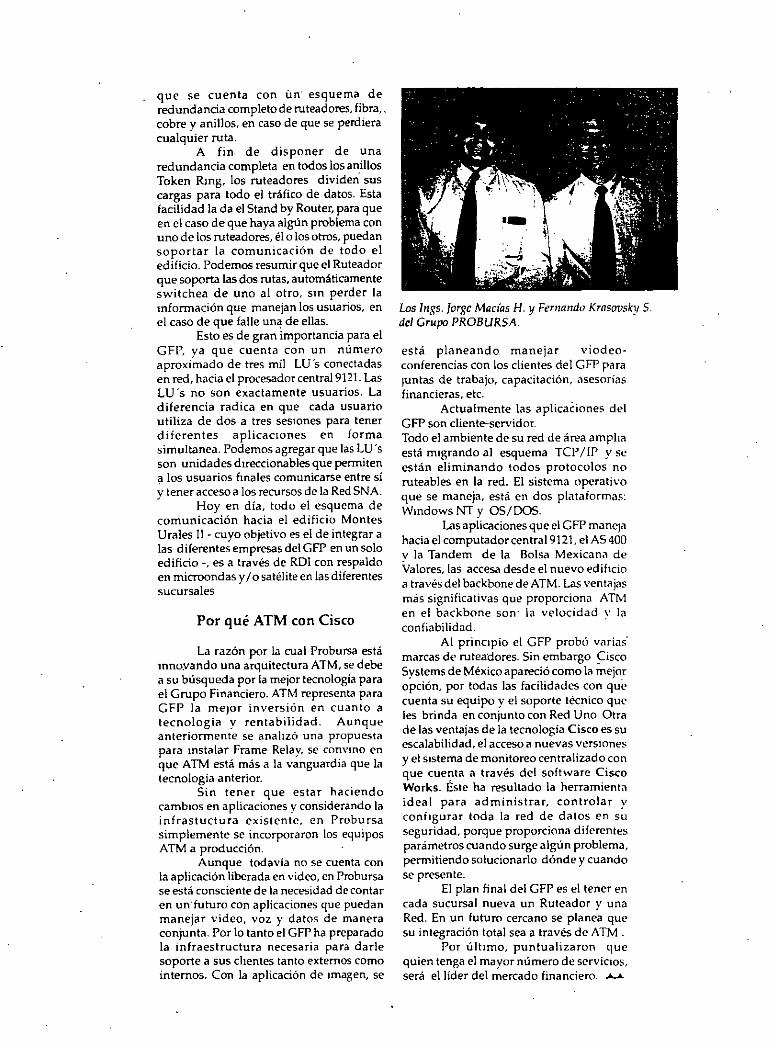
que se cuenta con ún· esquema de redundancia completo de ruteadores, fibra,. cobre y aniUos, en caso de que se perdiera cualquier ruta.
A fin. de disponer de una redundancia completa en todos los an_illos Token Rmg, los ruteadores dividen sus cargas para todo el tráfico de datos. Esta facilidad la da el Stand by Router, para que en el caso de que haya algún problema con uno de los ruteadores, él o los otros, puedan soportar la comunicación de todo el edificio. Podemos resumir que el Ruteador que soporta las dos rutas, automáticamente switchea de uno al otro, sm perder la mforrnación que manejan los usuarios, en el caso de que falle un~ de ellas.
Esto es de gran importancia para el GFP, ya que cuenta con un número aproximado de tres mil LU's conectadas en red, hacia el procesador centra19121. Las LU's no son exactamente usuarios. La diferencia radica en que cada usuario utiliza de dos a tres seswnes para tener diferentes aplicaciOnes en forma simultanea. Podemos agregar que las LU's son unidades dtreccionables que permiten a los usuarios fmales comunicarse entre sí ~tener acceso a los recursos de la Red SNA. .. Hoy en día, todo el esquema de comunicación hacia el edificio Montes Urales 11- cuyo objetivo es el de integrar a las diferentes empresas del GFP en un solo edificio-, es a través de RDI con respaldo en microondas y 1 o satélite en las diferentes sucursales
Por qué ATM con Cisco
La razón por la cual Probursa está mnoyando una arquitectura ATM, se debe a su búsqueda por la mejor tecnología para el Grupo Financiero. ATM representa para GFP la meJor inversión en cuanto a tecnología y rentabilidad. Aunque anteriormente se anahzó una propuesta para mstalar Frame Relay. se convmo en que A Th1 está más a la vanguardia que la tecnología anterior.
Sin tener que estar haciendo cambios en aplicaciones y considerando la infrastuctura existente, en Probursa simplemente se incorporaron los equipos ATM a producción.
Aunque todavía no se cuenta con la aplicación liberada en video, en Probursa se está consciente de la necesidad de contar en un· futuro con aplicaciones que puedan manejar video, voz y datos de manera conjunta. Por lo tanto el GFP ha preparado la infraestructura necesaria para darle soporte a sus chentes tanto externos como internos. Con la aplicación de Imagen, se
Los lngs. Jorge Madas H. y Fernando Krasavsky S. del Grupo PROBURSA.
está planeando manejar viodeoconferencias con los clientes de 1 GFP para ¡untas de trabajo, capacitación, asesorías financieras, etc.
Actualmente las aplicaCiones del GFP son diente-servidor. Todo el ambiente de su red de área amplia está migrando al esquema TCP 1 lP y se están eliminando todos protocolos no ruteables en la red. El sistema operativo que se maneja, está en dos plataformas: Wmdows NT y 05/DOS.
Las aplicaciones que el GFP mane¡a hacia el computadorcentral9121, el AS 400 v la Tandem de la Bolsa Mexicana de Valores, las accesa desde el nuevo edificio a través del backbone de ATM. Las ventajas más significativas que proporciona ATtv1 en el backbone son: la velocidad y la confiabilidad.
Al principio el GFP probó varias· marcas de rutea'dores. Sin embargo ~isco Systems de México apareció como la mejor opción, por todas las facilidades con quC cuenta su equipo y el soporte técnico que les brinda en conjunto con Red Uno Otra de-las ventajas de la tecnología Cisco es su escalabilidad, el acceso a nuevas versmnes y el Sistema de monitoreo centralizado con que cuenta a través del software Cisco Works. Éste ha resultado la herramient<l ideal para administrar, controlar y configurar toda la red de datos en su seguridad, porque proporciona diferentes parámetros cuando surge algún problema, permitiendo solucionarlo dónde y cuando se presente.
El plan final del GFP es el tener en cada sucursal nueva un Ruteador y una Red. En un futuro cercano se planea que su integración total sea a través de ATM.
Por último, puntualizaron que quien tenga el mayor número de serviciOs, será el líder del mercado financiero . ..4....L
TECNOLOGIAS EN SISTEMAS DE BANDA ANCHA
A TM Protocolos
Q Nivel Físico
JO " Physical Medium-Dependent " ( PMD )
JO " Transmissíon Convergence " ( TC )
4- 12

TECNOLOGIAS EN SISTEMAS DE BANDA ANCHA
A TM Protocolos
~ Sub nivel PMD
.-11 Transferencia de bits
-11 Alineación de bits
· -11 Codificación en linea
-11 Conversión Electro-óptica
4- 13

TECNOLOGIAS EN SISTEMAS DE BANDA ANCHA
· ATM Protocolos
Q Subnivel TC
'1J Generación, transmisión y recup~ración del Frame
'1J Adaptación de Frame
'1J Delineación de la celda
'1J Cabecera de control de error (HEC)
'1J Desacoplamiento de la taza de celdas
..
4- 14

TECNOLOGIAS EN SISTEMAS DE BANDA ANCHA
ATM Protocolos
Q Nivel ATM
Las funciones de transporte del nivel ATM son independientes · del nivel físico, razón por la cual se requieren identificadores de conexión, los cuales indican los canales virtuales y la ruta virtual que debe seguir cada celda.
4- 15

TECNOLOGIAS EN SISTEMAS DE BANDA ANCHA
ATM Protocolo
·~ve
Un canal virtual es el enlace que esté entre 2 puntos, está conformado por un Vel (Virtual ehannel ldentifier) y un VPI ( Virtual Path ldentifier), donde el ve1 determina enlace particular ve para una determinada ruta virtual identificada con un VPI.
4- 16

TECNOLOGIAS EN SISTEMAS DE BANDA ANCHA
ATM Canales y Rutas Virtuales
Network (publlc or prtvate)
(possibty a single faclllty. e.g .• a hub)
VP
4-17

TECNOLOGIAS EN SISTEMAS DE BANDA ANCHA
ATM Canales
y
Rutas Virtuales
4-18

TECNOLOGIAS EN SISTEMAS DE BANDA ANCHA
ATM Protocolos
~ Funciones del nivel ATM
-11 Multiplexaje y demultiplexación de celdas
-11 Traducción de VCis y VPis
-11 Generación y extracción de la cabecera de la celda

TECNOLOGIAS EN SISTEMAS DE BANDA ANCHA
ATM Protocolos
Q Ruteo de las Celdas
Dentro de la UNI existen 24 bits destinados al ruteo de la celda:
~ 8 bits para asignar un VPI
~ 16 bits para asignar un VCI
3 más se destinan . para la descripción del contenido de la zona de carga, esto es se determina si el contenido es información de la red o del usuario, y 8 más se destinan para el HEC.
4-20

TECNOLOGIAS EN SISTEMAS DE BANDA ANCHA
ATM Protocolos
Q Nivel de adaptación ATM
También llamado " AAL ", es el encar gado de brindar . el soporte necesario a los niveles superiores, es decir
de convertir los datos de niveles superiores-en bloques de información para las celdas. ·

TECNOLOGIAS EN SISTEMAS DE BANDA ANCHA
ATM Protcolos
Q Nivel AAL
Es requerido por los 3 planos, el de control, el de administración y el del usuario aunque las funciones que realiza dentro de cada una de ellos son diferentes.

" TECNOLOGIAS EN SISTEMAS DE BANDA ANCHA
ATM Protocolos
~Nivel AAL
Sus funciones están organizadas en dos subniveles
-11 Convergencia (CS)
-1J Segmentación y reensamblaje (SAR)

TECNOLOGIAS EN SISTEMAS DE BANDA ANCHA
A TM Protocolos Q Nivel AAL
Tiene 5 clases de aplicación o servicio:
-11 Clase A: .orientado a conexión, CBR
4'1 Clase B: no definido
-11 Clase C: orientado a conexión, VBR
-11 Clase D: orientado a No-conexión
-11 Clase X: orientado a conexión CBR o VBR definidos por el usuario

TECNOLOGIAS EN SISTEMAS DE BANDA ANCHA
ATM Protocolos
l!!l Nivel AAL
Según su aplicación se definen los siguientes tipos en el plano del usuario: ·
"'el AAL tipo 1 para clase A
"'el AAL tipo 3/4 para clase D
"'el AAL tipo 5 para clase X
4..25

TECNOLOGIAS EN SISTEMAS DE BANDA ANCHA
-,_. .,..
---·~naw • ....-o~
~,,_,_._. :~~·;;,.•m~.:.-•"'----• • c.ll ,.....ealdilmultlpll ..
·c.o-···--· ·--~ .......... Trw__.,• ·=~ . .....,._.lmedlum
L
--........ ....................
..
4-26

TECNOLOGIAS EN SISTEMAS DE BANDA ANCHA
ATM Ejemplo
-API- -API- ' ,¡. ,¡.
Upper layen; Uppr layen
TCP TCP IP IP
IP / "" IP
con.fun. conv. tun. LLC u. e u. e LLC AAL 5 AALS
MAC AT .. I+¡AT .. IAT .. I.-..¡A~~~ 1~ A~ "AC MAC PHY "AC ~~PHY¡PHY¡.-.. PHY PHY ~ PHY
~ell relay network
·l
4-27

TECNOLOGIAS EN SISTEMAS DE BANDA ANCHA
ATM Ejemplo
Communlcation handler Communicatlon handler Video-< Monlt
7"'" u.,.. u.,.. Control Control u..,. u..,.. Codee\
~~i: c-. - plan e plane -· -(po .. ibl;r ·~~ - ·--... , - r No part of CRS """ ... ,
AAL1 " ML1
.,
AJM ~ j ATW ATW +-+ ATM ATW l <t- AJM
PHY PHY 1*1 ATM 1 ATM 1+-+ 1 AJM 1 ATM 1 <--- PHY PHY
1 1 1 1 1 1 1 1
'L-"" SMtch
P.-cCRS
4-28

REDES DE ALTO DESEMPEÑO
5.- FRAME RELAY
•
·-- E~i ·-----~:·- ·: :-H .. ,: ' __ .; ; ;; ~
·... , .... ~~ :· .:.:: •..

Frame Re/ay Technology and Services
Frame relay'_ concepts, technologies, and services are recciving considerable attcntion in the vendor, carrier, and user communities. Thc combincd framc rclay and SMDS market is expected lo exceed $1.2 billion by 1995, making thcsc importan! new fields. This chapter provides a detailed view of many of thc unucrlying framc relay principies, issues, and concepts. 2 Sorne basic frame rclay conccpts wcrc described in Chapter 1, which the readcr m ay want to rcvicw al this juncturc. Frame relay can be dcployed in a prívate nctwork, or, as already alluded to at thc end of the preceding chapter. the service can be obtaineu from a public nctwork. Each approach has advantages and disauvantagcs within thc framcwork of a coiporate enterprisewide network. In the following, the tcrm "framc rclay" rcfcrs generically to either the service or thc supporting technology. ucpcnuing on thc contcxt; usually "frame relay service" refers lo a public carrier sc.rvicc. whilc "framc relay technology" implies platforms for private network solutions. ·
This chapter aims at answering questions such as When does framc relay make sense? Should the user deploy a prívate framc relay nctwork or employ carriers' services? When is PVC service adequate and when is SVC desirablc? Is LAN traffic leaving a high-throughput router really bursty? When is it bettcr to use other technologies? Basic frame relay concepts are introduced and the intcrrelationship with cell relay is discussed (Section 11.2). Bcncfits of f ramc rclay in both prívate and public networks are identified (Scction 11.3). Framc rclay standards are surveyed (Section 11.4). Steps for deployment of thc tcchnology in corporate n.etworks are described (Section 11.5). Carrier services and cquipment availability are surveyed (Sections 11.6, 11.7. and 11.8).
1A frame in thJs context is a data link !ayer cnnstrüct. Thc "frames" discusscd in Chartcrs 2 through 9 werc phys•callaycr constructs. There is no relationship between thc two conccpts. Thc tcrm "relaying" is used by CCITT. 2Some portions of this chapter are based on AT&T product literature fll.l J
579

580
11.1 BACKGROUND
Framc relay is a reccntly introduccd multiplcxed data nctworking capability supporting conncctivity hetween user equipmcnt (routers and nodal processors/fast packct switches) and bctwccn user equipment and carriers' frame .relay network cquipment (i.e .. switchcs). The frame relay protocol only supports data transmission over a connection-oricntcd path; ii enables the transmission of variable-length data units over an assigned virtual connection.' Compared to traditional packetswitchcd serviccs. framc relay can reduce network delays, provide more efficicnt bandwidth utilization.- and decrcase communication equipment cost. Traditional packct serviccs typically introduce a 200-ms network del ay or more ( 40 to 60 ms pcr llop to handle error correction and control on a hop-by-hop basis). whcreas with frame rclay that network de la y can be reduced. to about 20 to 40 ms [11.2]:
As is the case in X.25, frame rclay standards ~pecify the uscr interface .to a device or network supporting the service. N ame! y, it specifies the UN!. This interface is called frame relay interface (FRI). A FRI supports access speeds of 56 kbps. N x 64 kbps. and 1.544 Mbps (2.048 Mbps in Europe) [11.3-11.5]. Sorne vendors are attempting to extend the spced to 45 Mbps. The .•.ervice can be deployed (1)· in a point-to-point link fashion between two routers. (2) using customcr-owned framc re la y nodal processors (frame relay switches which employ cell relay on the trunk/NNI side'). and (3) using a earrier-provided service. Table 11.1 provides a summary of key features of a frame relay network [11.6]. Figure 11.1 depicts ihc technology at the logical levcl.
11.1.1 Usage of the Technology-An Overview
Framc rclay functions supporting the FRI necd to 'be added to user equipment such as routers. Tl multiplexcrs, FEPs. PADs and so on. in order to be connccted to a prívate or public frame relay netw~rk. Al this time. frame relay technology is bcing applied mostly to LAN interconnéction cnvironments. Existing routers are casily upgradcd to support thc FRI. lf commercially successful, public framc relay service m ay supplant X.25 service in the U .S. as a public switched service by the mid-1990s. The frame relay market was expected to reach $210 million by 1993 and $R50 million hy 1995 [11.7]. For comparison, thc SMDS market is expected to reach $500 million by 1995, and BISDN (for data applications) would reach $500 million by 1997 [11.8].
In sorne cases. asynchronous terminals may also be supported by a frame relay network; synchronous SNA terminals or other devices (e;g., a front~end
'sorne carly trials of N x 64-kbps video were undertaken in !992. 4 lnstead of using ccll rclay on the trunk side. sorne switches use frarne relay instead. In _!he long run, . most switches will probably rnigrate lo the cell relay NNL

'
Table 11.1 Summnry of Key Features of a Framc Rclay Nct work
• Standardized by CCIIT and ANSI standards · • Only "core" functions are providcd by thc nctwárk • Network does not guarantee delivcry of data • Protocols in- user's equipment is responsible f~r retransmitting d¿tta that is lo!<.t. mi!ooroutc..·t.J. or.
discarded by the network 'because of congestion · • Frames are transported transparcntly (only label. congcstion birs. ami framc t..'ht:ek Sl.'t.¡ut..·nc..·t.· m«:
modified by network) •. Network detects (but does not corree!) transmission. formal, and opcrational crrors • Network does not acknowledge or retransmit frames • Delivers frames in sequence
Swltchlng/Transport Fabric
UNI UNI
FRI FRI
t C.ll-baaod (protorrod) or tramo-baood; prlvately-ownld equ~ment or carrier~wned equlpment
Figure 11.1 A logical view of frame relay communication.
581
proc·essor) can also use frame relay. In these cases, an appropriatc frame rclay handler (similar to a PAD but only supporting a .laycr 2 FRI to the network) is required. In terms of quality of service, the delay incurred by thc nccdcd protocol conversion to support these devices (which is similar to the delay through a PAD in an X.25 environment) is not eliminated by frarne relay technology, exccpt possibly to reduce queueing time tow¡ud the switch,· givcn lower network congestion. The delay through such a frame relay handler is determined by the acccss spced of the user's line, plus the handler's processing time. For cxample, if the user's frame from a synchronous terminal éontained 262 octets and the access'line was 9,600 bps, the initial frame relay "framing" delay would be 219 ms; the "deframing" delay would also be 219 ms. If the access speed is 56 kbps, the figure would be 37 ms. This framingldeframing de la y is in a!idition to the frame relay network delay. ·'
51n a cell-based switchingltransport platform, as soon as a frame starts lo arrive at a switch, it is · immediately reduced to cells "on-the-fly."

' . '
"
582
From thc uscr pcrspectivc, any delay is importan! regardlcss of whethcr thc dclav is generated by the frame relay network or by the access apparatus to the fram~ relay network (whether in a PC, a terminal adapter, ora PAD-Iike device). This last issue was never properly appreciated by the packet equipment .vendors. and is the reason why packet technology did not see much penetration in the missioncritical synchronous networks of the 1980s.
In order to get maximum benefit from frame relay without having to incur large communication or equipment charges (i.e., for dedicated TI links between site·s. or for the dcployment of user-owned frame re! ay nodal processors), the service needs to be provided by a carrier. The seven BOCs and severa! value-added carriers ha ve announced frame re la y services in the U .S. Carrier networks based on frame relay provide communications at up to 1.544 Mbps (in the U .S.), shared bandwidth on demand, and multiple user sessions over a single access line. The use of a router equipped with a frame relay interface over a dedicated end-to-end Tl link is not econcimically advantageous compared to a non-frame relay solution. and. in fact, may affect response time. A carrier, on the other hand, can multiplex the traffic of onc user with that of other users, and can therefore pass back to the users thc · economic advantages of bandwidth sharing, much the same way X.25 or FTI provides su eh economic cfficiencies. Without carriers or priva te switch es, dcdicated TI links betwecn two sites to be interconnected are needed, regardless of the protocolused over the link. However, it should be noted that when using an IXC or VAN service. the user needs a dedicated Tl or 56-kbps link to thc IXC's or V AN's POP. lf the LEC serving the user's location provides the service, the dcdicated TI is rcquired only to the serving CO.
A sccond way to bcnefit from frame relay is to use it in conjunction with a frame rclay nodal processor (variously known as "corporate backbone network switch ... "fast-packet backbone multiplexer," or "frame relay handlcr"), first dcscribcd in Chapter 6. Sorne corporate networks already deployed this tcchnology in thc late 1980s in the form of fast packet multiplcxers. Inthis case, the scrvice can oftcn be cost-effcctive. smce the user can obtain from the backbonc bandwidth on clemand. rather than un a preallocated (and inefficient) basis. The "saved" bandwidth is then available to other users of the same backbone, in theory minimizing the amount of ncw raw bandwidth the corporation needs to acquire from a carrier in thc form of additional TI or FTJ links. Withf'nt a nodal processor using ccll rclay principies, dynamic bandwidth allocation is not easily achicvable. So me proccssors use f~amc re la y on the NNI; fine-grain multiplexing is more diflicult, particularly in mixed-media and multimedia applications (next-generation LANs use ccll principies to support multimedia, as discussed in the previous chapter). In the private nctwork application, the user.leases from a carrier private lines bctwcen the remole devices and the nodal processors, and between the nodal processors; the uscr employs frame relay to statistically multiplex traffic in a stan-

. 5113
dardizcd way, in ordcr to achicvc bcttcr utilization of thc (now comnwn) iransmission resources. The nodal processors must be houscd in sclectcd uscr locat.ions.
Frame relay supports bursty traffic at mcdium spceds. Conscqucntly. manv of the applications now advanced by vendors for frame rclay scrviccs are fcas¡hJc more in view of the increased throughput ·¡md reduccd network latcncy comparcd to X.25 networks than any other ncw intrinsic featurc of framc rclay.
· 11.1.2 Sorne Motivations for Frame Relay Services
As indicatcd, the curren! majar application of frame relay is for LAN intcrconnection. A combination of recent trends has forccd LAN managers to invcst¡gatc new approaches in arder to provide connectivity at reasonablc pricc:
• In 1989, only two out of ten corporatc tcrminals. PCs. and workstations wcrc connectcd toa LAN. By 1993 eight out of ten tcrminals will requirc to he connected toa LAN ]11.9].
• Business shifts to accommodate the "lnformation Agc" havc forccd companies to rely in greater measure on data collcction. proccssing, ami di,tribution. For many such companics. thc ratio of terminals to employccs is approaching 1, and in sorne cases it is cven cxcccds l. Chaptcr 1 airead y discussed sorne of thesc trcnds.
• In an effort lo be more efficient, find a chcapcr work force and rcach ¡!lohal markets, companies are moving toward distributcd data proccssing. Employees are distrihuted in smallcr work groups locatcd around .town or ~1round the coumry. closer to thc resourccs and to thc markcts. Y el. more than e ver, they need to be tightly connected through a reliahlc and easy-to-usc cntcrprisewidc network.
Thesc trends havc led to the following sequcncc of cvcnh:
l. lntroduction of more tcrminals. 2. lntroduction of more LANs to support thc incrcased number of tcrminals. 3. 1nterconnection of these LANs. including thosc that havc emerged in gco
graphically dispersed buildings around thc country. In 1l)l)l, an cstimatcd 65% ofthe top 5.000 U.S. companics had LAN interconncction nccds cxtending beyond a building; that number is expected lo grow to H5'1r.· by 1995 ]11.10. 11.11].
The traditional WAN approach of connccting a fcw LANs with ·routcrs ovcr dedicated point-to-point lincs is no longcr adcquatc in an environmcnt of many remole LANs. Sorne actual networks can havc as many as 600 or ROO routcrs ]11.12). LAN managers have sought solutions !ha!' reduce the numbcr of dcdicatcd lines in arder to keep transmission costs down, and at the same time incrcase

584
flcxibility and makc nctwork managcmcnt e as y. lt almost sounds likc the perfect W AN environmcnt fo'r packet switching technology. but not exactly. Packet switching allows users to be easily added and interconnected while following open international standan.ls. But packet switching has traditionally been slow and the throughput has hcen limitcd." These limitations are becoming more accentuated with thc ncw LAN applications, which may involve graphics, multimedia, desktop publishing. bulk file transfer. and other data-intensive requirements. This has lead to thc dcvclopment of two solutions specifically aimed at LANs: frame relay and SMDS (SMDS is discussed in Chapter 12).
Frame relay is an early 1990s technology allowing users of multiplc routers . to connect thcm in an cffective manncr. 1t follows open standards and improves throughput. whilc at the same time reducing the end-to-end delay (throughput can be incrcased ur· to three ordcrs of magnitude). When used in a prívate network cmploying a cell re la y platform. it allows the LAN manager to rapidly meet the l evolving high-speed LAN interconnection needs of the corporation. and do so in a cost-effective manner. The same can be said when using a public network frame relay service.
As discussed in Chaptcr l. the business trend i~ toward interconnection of all company resources into a seamless enterprisewide network. Ho~evcr. such interconnection can become prohibitively expensive. unlcss it is done correctly. Corporations also see the emergcnce of new LAN applications in the 1990s. which must be supportcd by the cnterprisewide network. New high-bandwidth applica~ tions dicta te the introduction of new high-capacity digital services and technologies in the corporate nctwork: Scc Table 11.2. compiled from a variety of sources. including 111. JO. 11.11]. High end-to-end throughput, low latency. cost-effective handwidth on demand. and any-to-any connectivity are the order of the da y. A
· major c'volution in thc way corporations connect their computers and the everubiquitous PC is already cvident in progressive companies. Now, new cquipment and new communications services allow corporations to redesign their nctworks and o;avc moncy. while at the same time in crease their capabilities and work force productivity. The kcy to achicving these communication goals in a prívate nctwork cnvironment is framc rclay over a cell relay platform, or a high-capacity public switc:hed scrvicc likc framc relay (and SMDS).
The ncw tcchnologics nceded to support thc evolving corporatc environment, howcvcr. cannot be introduccd m a vacuum. It would be easy to deploy an optimal state-of-thc-art network whcn·the LAN manager could throw away everything and start completely from scratch. In times of cost-containment, though. the LAN
"Packct switchm~ and othcr stati~tical mult1plcxing schemcs do fullfil thc role of supporting error-free . tranc;mi.s,ion of a.synchronous traffzc frnm "dumh" terminals (or dcvices and PCs cmulating "dumb"
terminals). ""'hich have no error protection' of thcir own-a frame relay service would he a mismatch in this environmcnt.
..
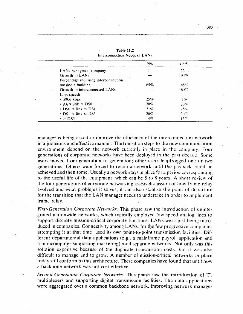
Table 11.2 lntcrconncction Nccús of LAN'
LAN..; pcr typ1cal company Growth in LAN~ Perccntagc requiring intcrconnection outsidc a hulld1ng Growth in interconncctcd LA Ns Link spccds • $9.6 khps • 9.6,;; link ,;; DSO • OSO,;; link,;; DSI • DSI < link,;; DS3
• > DS.1
/W/
11
~5%
25% J00í· 21 '}(, 20% 4~·;
I'JCJ5
H5r,'J,,
ló()~:(
~IJ''í.·
IY.~;.
585
manager is being askcd to improve the cfficicncy of thc intcrconncction nctwork in a judicious and effcctive manncr. The transition stcps to thc ncw cornmunication cnvironmcnt dcpcnd on thc network currcntly in place in thc company. Four generations of corporate nctworks have bccn tlcployctl¡in thc past tlccatlc. Somc users moved from generation to gcneration; othcr uscrs lcapfroggctl onc or two generations. Othcrs wcre forced to rctain a nctwork until thc payback cotdtl he achieved antl then sorne. Usually a nctwork stays in place for a pcriotl wrrc,pontling to thc useful lifc of thc cquipmcnt. which can he 5 to l\ ycars. A short rcvicw of thc four generations of corporate nctworking assists discussion of how framc re la y evolvcd and what problems it salves; it can also c'tahlish thc point of dcparture for the transition that the LAN manager nceds to undcrtakc in ordcr to implcrncnt frame relay.
First-Generation Corporate Networks. Thi~ phasc saw thc introduction of unintcgrated nationwidc nctworks. which typically cmployctl low-spcctl analog lincs to support discrcte mission-critical corporate functions. LANs wcrc just hcing introduccd in companics. Conncctivity among LANs. for thc few progrcssivc companics attcmpting it at that time, used its own point-to-point transrnission facilities. Diffcrent departmental data applications (e.g., a mainframe payroll application and a rninicomputer supporting marketing) uscd scparatc nctworks. Not only was this solution cxpcnsive bccausc of the duplicate transmission cosh. but it was also difficult to managc and to grow. A nurnbcr of mission-critical networks in place today still conform to this architecture. Thcsc companies havc found that until now a backbone network was not cost-effective.
Second-Generation Corporate Networks. This phasc saw the introduction of TI multiplexers and supporting digital transrnission facilities. Thc data applications were aggregated over a common backbone network, improving nctwork manage-

586
mcnt. simplifying thc topology and reducing thc communications cost. A few traditional analog iines are enough to justify the cost of a high-speed digital link. as discusscd elsewherc in this book. making this transition a popular upgrade in the rccent pasl. Voicc traffic was also carricd by the backbonc. One of the shortcomings of this approach. however. is that the LAN interconnection traffic. now gro"v.:ing. usually rcmaincd separa te. perpetuating. the problem of overlay networks. This was typically úue to rcstrictions of the byte-interleaved multiplexer (namely. the · inability to support dynamic traffic for bursty users) and interface problems. A numbcr of mission-critical networks in place toda y still conform to this architecture:
Third Generation Corporate Networks. In the immeúiate past, Tl multiplexers ha ve started to support LAN interconnection traffic. The traffic is assigned. a fixed amount of TDM bandwidth ·over the corporate backbone network. Although this approach to LAN interconnection had severa! advantages compared to the previous arrangemcnt. it also had a number of disadvantages. Consider N nodes with high peak-lo-average (bursty) traffic needing to be supported by an enterprise network. A mesh nctwork providing full interconnection between key nodesmay havc bee·n installcd in many .companics. as shown in Figure 11.2. This arrangement can be cxpcnsivc duc to thc number of communications links. For example, fivc locations rcquirc 10 Tl links and six locations require 15 links. The addition of a new backhone node also requires the introduction of many new links. Less than fully
•lgure ll.Z Trad1tional LAN connectivi\y.

5/li
intcrconnectcd router nctworks are usually not thc hcst answcr to th.: intL·rconncction requirement, since this tandem arrangcmcnt affect~ th.: cnd-tlH'nd dl'i:1Y and complicates nctwork managcmcnt. Additionally. ami pnhap' L·qualh· imp<~rtant. thc bandwidth is no! cfficicntly allocatcd hy using thc TDI\1 tcrhniqliL'' c·<~nlmon to the equipment supporting.this typc of nctwork. A~ a ~lwrt-tnm ~olutl<'ll. companies sought to keep thc numbcr of dcsignatcd first-ticr locations IH:cdln!! lull interconnection down toa small numher. typically hctwccn thrcc ami -;ix. thcrch,· limiting the number of rcquired links. Many companics ha ve the~c typc' ol nct '' ork' toda y. partieularly for mission-critical applications. ' _ Sorne LAN managers. undcrstanding thc intuitivc advantagc ol p;1ckct '" ltching. chose to rely on a private (or puhlic) packehwitchcd nctwork In lntnwlln,·ct the multitude of user routers. Thcse packct networks typically introduce :1 l<'lllcrto-routcr dclay on the order of 200 ms or more. This dl'iay is duc to ( 1) ¡Hntovol proccssing at intermediary nodcs and· (2) thc hop-by-hop. error co1 rcct1on ami control used hy packet networks. In addition to the dcl<~y. thc throughput o! thc''L' networks is not sufficient to support tod<~y'S application-;. That i' w\1\· a m·" tc·L·hnology is needed.
Frmrth Generation Corporate Networks. Figure 11.2 dcpictcd ;1 comnHlll L'tlnliguration of user environments of thc recen! past. Thc figure makc~ thc L·h.ilkngL· ol a LAN manager obvious-what is needed is a tcchnologv for high L'IHI-to-L·nd throughput. low latcncy. cost-cffcctive hantlwidth on dcmand. and anv-to-:nl\ connectivity. The restrictions discussed ahnvc of many of thc cxi,tinJ.! unintc¡olat,·d nctworks. or of the integrated networks using TDM tcchnolo¡ov. ha-; lc·d to thc developmcnt of the frame relay concept. trame re\;¡y -;t;llldards. and '"1'1"'1'1 ing frame relay hardware. Such framc relay solutions are now cmcrglll[! :11HI ;¡¡,- composcd of the following three componcnts (scc Figure 11 .. 1 ):
• A high-throughput nodal processor huilt from thc ground up. un:dkctcd hy TDM rcstrictions, which supports high-spccd switching to facliitatc hl¡oh\ndto-cnd throughput. This nodal proccssor w;" callcd a "corporaiL' h;ICkhoiH: nctwork switch" in Chaptcr 6; as discusscd thcn:. it was i111tially mcd in thc TI multiplexer contcxt. but is now making a strong appcarancc in thc LAN context. This nodal proccssor can also he providcd by a carricr. supporting a "switching" function at the CO.
• Standard high-spced interfaces to the bridgciroutcrs to facilitatc thc intc~
cnnncction of cquipmcnt from a varicty of vcndors. Thi-; opcn (standard) interface hascd on the conccpt of packct switching is a framc rclay interface.
• Standard high-speed interfaces betwcen nodal proccssor~. supporting ccll relaying and switching.
Since corporate resources are incrcasingly being deploy~d on LANs, including the users, the mainframes. and the data bases. and since routers havc taken on the function of the TI multiplexers in a number of environments, this intcrcon-

588
FRNP: F~ame Re!ay Nodal Processor
Figure 11.3 Us~ of frame re la y nodal processors for a private frame relay network.
nection solution is the onc being contemplated for the enterprisewide networks of thc !990s by many progressive companies. Fewer and shorter TI or FTI links can be u sed bctween the users and the nodal processor, thereby reducing communication costs.
11.2 BASIC FRAME RELA Y AND CELL RELA Y CONCEPTS
Bcforc addrcssing how framc re la y technology can be deployed in an enterpriscwide multiroutcr environmcnt, we must address sorne of the technical details [ 11.13]. Tablc 11.3 providcs a miniglossary of key tcrms. As this discussion proceeds, it should he rcmcmbcred that all high-speed lincs used in frame relay, eithcr for acccss or bctween switches, are unchannclized FTI, TI, or T3 lines, discusscd in thc rcst of the book (T3 m ay be u sed on the trunk si de).
11.2.1 Frames
A frame is a block of user data, as created by the data link !ayer (!ayer 2). lt consists of a flag, a header, an·information fie1d, anda trailer. Different data link.

Table 11.3 Miniglossary of Frnme Rclay Tcrms
589
Access Rote. The rate of the access channel employcd by the uscr's cquipmcnt (measur~d in hit' pcr second). The spced of thc access channel determines how rapidly thc cnd-u,cr can scnd data to thc nodal proccssor or nctwork.
American National Standards Jnstitute. An organization that accrcdits gnÍup' dcvcloping U .S. standards required for commercc. One such group js thc Exchangc Carricrs Standard!-> Assoe~ation, whieh devclopcd the Tl.606, Tl.617. and TI.61R for framc rclay (abo'"" C:haptcr.l).
· Asynchronous Transfer Mode. A packet switching tcchniquc devclopcd by CCITT which uses packets of fixed length, rcsulting in lower processing and highcr spccds. Also know as ccll rclay (sce Chapter 10).
Bandwidth. The communications capacity (mcasured in h1ts pcr sccond) of a tran~mi .. "iion hnc or J
path through a nctwork.
Backward Explicit Congestion Notification lndicator. A hit in thc framc sct hy thc nctwork tn not1fy the user·s equipmcnt that congcstion avoidance proccdurcs shouid he initiatcd in ordcr to hmit thc amount of traffic injectcd into the network or sent to thc nodal procc~snr. Thc f1cld 1s sct m a fr<~mc going in the opposite direction of the congestion (i.e .. it 1s scnt to the origiriattun). lt b s1mdar tn a "slowdown" signal.
Bursty Traffic. Traffic whcrc thc ratio of the maximum inten!o.ity to thc average intcn~ity i!-. vcry hi!!h ("'10). Typical of sorne LAN cnvironments.
Consultati"e Committee on lnternational Telephony and Telegraphy. A Unitcd Nations orgamzation which devclops intcrnational standards and interfaces for tclccommunicatinns. Thc framc relay standards are based on underlaying CCITT standards (also scc Chaptcr 1).
Cell. A fixcd-length packet of uscr data (payload) plus an ovcrhcad. A ccll i< usual! y 'n"'"· being 5:1 octets or less.
Cell Rela)". A high-bandwidth. low-delay switchmg and multiplcxing packct tcchnolo~v rcqu~rcd to implcmcnt a framc rci:Jy nctwork m an cff¡c¡cnt manncr. Trunk tran..,mJs~inn tcchniquc u..,cJ hy
nodal proccssors. Al so known as A TM.
Committ~d lnformation Rafe (CIR). Spccifie~ thc amount of bandwidth guarantccd to a u..,cr betwccn any to points. CIR can he as high as thc acccss ratc. If thc CIR 1s cxcccdcd, thc framc rclay dcv¡cc can scnd the data. but it should set thc DE bu to md1cate that thc data can he discardcd if nccessary.
Core Functions. Data link layer functions !-.Upportc;d hy.framc rclay. Cure functions mcludc framc dclimiting. alignmcnt. and transparency; frame multiplcxmgidcmultiplexing '"ing thc atldrc<> ficld; and dctcctaon of transmission errors.
Data Link Connection ldenlifier (DLCI). A f1cld in thc framc·indicatmg a particular. log1cal hnk ovcr which the frame should be transmitted. The field has local significancc. sincc it can he changcd by thc nodal processors as thc frame traverscs a smglc-nodc nctwork (thc mput DLCI \S mappc.d to an output DLCI). Multinode networks may "pipeline" cclls to thc nctwork cdgc,. In th" ca,c, virtual channel identifiers are used and remappcd. Access DLCis are assigncd by thc nctwork manager, while trunk VCis are allocatcd d)'namically. Toward thc nctwork. thc nod~tl procc..,..,or associatcs cach VCI with the physacal address of thc tr.unk ovcr'wluch thc framc nccd~ to he transmitted to reach lts ultamate destmataon. Toward th~ user. VCis are associated with thc physical linc supporting the DLCI identifying the user
Data Link Layer. OSIRM layer 2 functionality. responsihle for·rcliablc transmission ovcr a single communication link. 1t combines data bns into a block callcd a "frame" and adds a framc check sequence to allow detection of bit errors at the remate point.

590
Tibie ll.l Continued
Discard Eligibility lndicator. A field in the frame set by the user's equipment to indicate that the frame can he discarded if needed in case of congestion, in order to maintain the committed throughput.
Fast Packel. A term for various streamlined pacltet technologies. now synonymous with cell relay. Supports rcduced functionality compared to X.25 pacltet switching," so that it can opera te at much higher speeds.
Forward Explicil Congestion Notificalion lndicator. A field in the frame set by the networlt or nodal processor to notify downstream equipment andlor the destination equipment that congestion avoidance procedures should be initiated. The field is set in a frame in the direct1on of the destination. lt is similar toa "hold-on" signal for received frames, as well as a destination "slowdown" signa! for traffic from the destination.
Frame. A block of user data, as created by the data link !ayer. It consists of á nag, a header, an information field, and a trailcr.
Frame Relay. A 1990s packet-based high-speed technology that provides for dynamic bandwidth allocation with high throughput and low delay to support the increasing amount of bursty traffic in the corporate environment. Frame relay defines a standardized format tor data link !ayer frames transm1tted over a network of interconnected LANs.
Frame Relay Assembler/Disassembler. A device or capability allowing non-trame relay terminals, typically in a non-LAN environment (e.g., SNA) to be carried in a trame relay network.
Frame Relay Interface. A standardized interface between custonier equipment and a nodal processor or a frame relay network. A two·layer protocol stack interface capability implemented at both endpomts of a link.
Error Correction. In frame rclay. error correction and retransmission are done m the user equipment. The network can detect errors, but the correction is relcgated to the end systems.
Link Aceess Procedure F. The data link !ayer protocol used in frame relay. lt is specified hy ANSI Tl.6!8-1991 and is similar to CCITT 0.922 Annex A. It is a sl.immed-down protocol supporting core functions-only. lt is based on ISDN's LAP-O protocol.
Link Access Procedure f·Core. That subset o! LAP-F used in frame relay.
Local Management hiterface (LMI). A specification for use by frame relay products which defines a method of cxchanging status informatlon between the user device and the network. It is used to manage PVCs and is spccificd in ANSI's TI.617. -- · ·
Mullicas!. An LMI option that allows a frame relay device to broadcast frames to multiple destinations.
Nodal Pro..,;sor. A frame relay processor is a switch that "connects" users, tacilitating any-to-any conncctivity Conncctions are accomplished in real time over !he PVC (evcutually over an SVC). Tablcs are maintamed by the node lo facilitate the connections.
Open Systems lnterconnedion Reference Model. A model for data communications interconnecuon which maps functions necessary for undertaking orderly communication to one of seven hiC:rarchical layers.
Permanent Virtual Cirruits (PVC). A logical link or path between the originating and terminating routers. No resources are allocated to the link unless data is actually being sent. The link is set up by the administrator and remains in place for however long it is needed (days, months, or years).
Roaler. A device operating at the network !ayer of the OSIRM, used by a LAN to access other LANs ·across a variety o! WANs.

Tablc 11.3 Continucd
.591
Systems Network Architecture. A nctwork architecturc uscd m IBM m.·towork~ IT1 support of ml'"ion
critical functions. Originally. thc architcciUrc was·~arictly hicrarchical .mU cmploycd frunt-cnd proccssors and cluster controllcrs. It is now movinp. toward a pccr-to-pccr archiHxturc. \upportinc LAN acccss to the mainframc. · o
Switched Virtual Cirruit. A virtual circuit that is sct up on a call-hy-call ha,¡,_ A futurc trame n:lay . scrvJcc .. of particular importance to públic fmme rclay nctwnrh.
Time~Division Multiplexing. A tratlitional !"Cthod of comtnnJng multiplc ~JmultanctJUS ch:Jnncl~o. {Jvc.:r a single tran!<lmission path by assigning discrctc t1me slot!<. to cach channd. lt n:.,.ults in incfflcicnt
handwidth allocation, in bursty cnv1ronmcnt~.
Virtual Circuit. A JogiCal connection c!'ltahlishcd through ¡_¡ framc n:l<ty or pad,et netwnr~. Frann:.., 01
packcts are routed through thc nctwork in an onlcr·prcscrving tran~kr. Thc conncctum ¡.., ..;¡mil.lr to a dcdicated line betwccn thc cndpoints.
Virtuai.Circuit ldentificr (VCI). A lahcl uscd by a ccll ~witch to idcntify ccfl.., hdon!!ing to a gJ\'Cn
uscr. VCis have local significance (scc Chapter 10).
layers crea te different frames; differcnces manifest thernsclvcs in tcrrm of thc ficlds. their positions, and thcir lengths. The logicallink control suhlaycr of ~~ LAN crea tes a frame of particular interest, sin ce it is thc frame that is involvcd in thc transrni,,ion of data over a network of interconnected LANs. Frarnc rclay scrvicc has a spccific frame forma!, describcd below and expanded upon in Section 11.4.2.
11.2.2 Frame Relay
Frame rclay is a new packct-hased high-spccd tcchnology. lt providc' for dynamic bandwidth allocation with high throughput and low delay to support thc incrcasing amount of hursty traffic in the corporate cnvironmcnt. Framc rclay defines a staildardizcd formal for data link !ayer framcs .. which are transrnittcd ovcr a nctwork of inter·connected LANs or over a public network. A framc rclay framc is assemhlcd by user equipmerit and is interpreted by framc relay nodal prncessors oro in cases where there are no processors, by the remole routcr. Thc fr<Jmc rclay framc is shown in Figure 11.4. Frame relay is based on the 19RR and 19lJ2 CCITI stand<Jrds and recent ANSI extensions. clarifications, and rcfincmcnts for the U .S. markct. particularly for private nonswitched access. Therc is now wide vendor support nf frame relay standards.
Frame relay may be thought of as a streamlined version of X.25 that can be implemented on or integrated onto a routcr. Figure 11.5 depicts this simplification [ 11.'4, 11.14]. Streamlining is accomplished by stripping away all of !he X.25 nctwork !ayer (!ayer 3), adding a statistical multiplexing ca¡iability via individually addressed trames to the data link layer, and reducing the functionality of layer 2 by removing

591
1 oetet 2 oct•t•
Flag ~oFNIId 01111110,
8 7 6 5
· 1DLCI (h;~h order)
1
1 _l _¡_ 1 1 1 OLCI {Jow order)
1 1 1
01
8 7 6 5
1 1 1 OLCI (l·ugh order)
1 ' .
1DLCI
1 1
1 r 1 1 1 1 DLCI (low order)
' ' 1
or
8 7 6 5
1 1 1 DLCI {l'l•gh orde1)
1 1 1 1DLCI
1 1
1 1 1 1 1 1 OLCI
1 1 1
OLCI (low arder)
1 1 1
upto 1118 octatt•
1 mfom+n F~ld
• 3
' . 1
FECN BECN
• 3
1 1
FECN BECN
1 ' '
• 3
1 T
FECN BECN
1 ' '
1 ' '
J octetl
Framo 1cneck
Seq~ence
2
C/R EA C>'1 o
DE EA 1
2
C/R EA C>'1 o
DE EA o
EA 1
2
C/R EA C>'1 o
DE EA o
-EA o
EA 1
1 odet
Flag
01111110
CIR: Bit intended to support a commandlresponse JndJCahon. The use ol th1s lietd 1s apphcation spec•fc
EA: Address lield extension b1t
DE: Oiscard elig•bilrty 1nd1Cator
BECN: Backward exphc:it congestion nOtifiCation
FECN: Forward explicit congest•on notthcallon
DLCI: Data link connectJon ldentJfler
"ANSI speetliea 40S6 but some vendors may use the h1gher value. m1mmum length. 262
Figure 11.4 Frame and address field formal (LAP·F/ANSI Tl.618-1191; CCITT Q_922 Annex A).
error correction and retransmission capabilities. Error detection is retained and errored frames are discarded by the frame relay network. Frame reJa y can provide both a PVC and a SVC service: · . , .;~;~f

Data Link Layar
Network Layer
Framo Rolay
Error Rocovory
Error ROCOYOry
Error -ry
Error Rocovory
Yoo
Figure 11.5 Comparison of frame relay protocol state diagram with the one for X.25.
·593
594
lnitially, frame relay was develóped asan ISDN packet servicc, with a logically separate control plane for SVC management' and user plane. In the control plane, all signaling capabilities for call control, parameter negotiation, etc .. would be based on a set of protocols common to all ISDN services. As currently evolving at thc U. S. commercial leve!, frame relay service does not support a logically separate control plane; in fact, no call setup mechanisms are supported, even "inbanct·: (as would be the case for X.25 SVC packet switching). Public SVC frame relay m ay become available in 1994 or 1995. Curren ti y, there is no network equipment to support user-to-network or network-to-network SVC signaling, and there. is no SVC user equipment. This implies that the service now only supports PVCs predefined by the network administrator, and that all frames follow the same ro u te to the destination .
. Permanent virtual circuits establish a fixed path through the network so that a message or file can be reassembled quickly by the receiving end. Frames are passed across the network with minimal processing by the network nodes. All of the bandwidth on the physical path of the frame is available for the duration of the frame. The result is a high-speed, low-delay, bandwidth-on-demand network well suited for LAN-to-LAN traffic. Frame relay has the advantage of providing linc consolidation and, hence. reduced equipment expenditures. It has the inherent multiplexing capability where one physical access can support up to 1,024 logical connections (in actual implementations, however, the number of logical channels is usually much smaller, say, 32 for physical and/or performance reasons 11 1.2, 11.15]). The PVC approach does not support an addressing apparatus adequate to support a switched service.
11.2.3 Frame Relay Interfaces
Like X.25. framc rclay spccifics the interface between customer equipmcnt and the nc_twork (i.e., the UNI ). whethcr thenetwork is public or priva te. This interface spccification is described in generalities in CCITT Recommendation 1.122 of 1988. 1.122 describes the unacknowledged order-preserving transfer of data units from thc network side of a user-network interface to the network side of the other usernetwork interface. A frame relay interface is a two-layer protocol stack capability implcmented at both endpoints of a link (i.e., by the user equipment and by the network's nodal proccssor). Frame relay interfaces rely on (1) the existing intelligence of end-user equipment. such as routers. to run the protocol; (2) today's higher quality digital transmission facilities; and (3) error detection, correction, and recovery at thc higher end-system layers (transport !ayer, or even at the ultima te application leve!) (11.13).
The frame formal for data transfer is based on a subset of 0.921 (LAP-D),. but extended with the flow control fields. The protocol is now known as Link_:

595
Access Procedure F-Core (LAP-F Core) and is defined in ANSI Tl.618-1991; it is also defined in CCITT's 0.922 Annex A, adopted in 1992. 0.922/LAP-F (ISDN Data Link Layer Specification for Frame Mode Bearer Services) is a full data link !ayer protocol in its own right; it was adopted in 1991. Frame rclay uses thc suhset called LAP-F Core. LAP-F functions like windowing and error correction are not included in the coresubset [11.16]. A 1992 CCITT protocol extended from 0.931. called 0.933, is to be used to support SVC service.
As implied in Figure 11.1, a network platform is needed to route and forward frames receivedover the UNI conforming to the FRI specification. This. platform is composed of one or more nodal processors (whether owned by the user or by a carrier).
11.2.4 Error Correction
In frame relay, error·correction and retransmission are done in the user equipment. The network can detect errors, but the correction is relcgated to the end-systcms. Error conditions include lost, duplicated, misdelivered, discarded. ami out-of· sequence frames: recovcry from these error conditions must be pcrformcd hy thc user's equipment, which must be appropriately configurcd to support thcsc tasks. This does not require any additional functionality, which most intclligcnt cquipment,like LAN routers. has today. Furthermore, with today's highcr quality thgital transmission facilities and the migration to fibcr, it is unlikcly that many frames will be received in error, requiring end-to-end rctransmission. Error-pronc circuits of the past necessitated complex error checking and rccovcry proccdurcs at cach node of a network. The X.25 packet standards assume that thc transmission media is intrinsically error-prone, and in order to guarant'ee an acccptablc levé! of cnd-
. to-end quality, error management is pcrformed at evcry link by a fairly sophisticated but resource-intcnsive data link protocol, as illustratcd in Figure 11.5. With a highquaiity. fiber-based communication infrastructure becoming commonplacc. many of the error correction and retransmission capabilities of X.25 can be safely climinated [11.17].
Since error correction and flow control are handlcd al thc endpoints. frame relay expedites the process of routing packets through a series of switches to a remote location by eliminating the need for each switch to check each packet and correct those in error. This error treatment increases performance and reduces bandwidth requirements, which in turn can reduce communications i:osts [ 11.18, ll.i9].
In the past, when transmission errors were common, it was not cfficicnt to require the transport layer (whose job it is to guarantee ultimate end-to-cnd reliability) to keep track of unacknowledged PDUs. Instead, the data link !ayer, closer to where the problem had its roots, ~as responsible for the correction task. It turns

~-·;- ~
596
out in the final analysis that when the probability of error over a link is relatively high. it is better to do error correction on a link-by-link basis (i.e., at the data link !ayer): as measured by the amount of network bandwidth required to successfully send a PDU (although it may, in fact, have been faster todo it end to end, as we show below). When íhe probability of error is low, it is better to do error correction end to end (i.e .• at the transport !ayer) .. In other words, for the same amount of network bandwidth, the PDU gets delivered faster by doing the error management end to end; in addition, the nodal processors can be cheaper, since they need to uildertake fewer tasks.
Tables 11.4, 11.5, and 11.6 provide a numerical example of a simplified model to illustrate the point (the reader may choose to skip ahead to Section 11.2.5, if desired). In each case, a three-link path is studied. In the first case, the probability of link success Ís 0.9, in the second case it is 0.99, and in the third case it is 0.999 (the same probability for all three links is used for ~implicity). The tables (almost precise! y) compute the expected bandwidth to deliver a corree! PDU with link-bylink correction and with end-to-end correction. The expected delay· to delivcr a corree! PDU with link-by-link correction and with end-to-end correction is also computed. Before discussing briefly how the ta_bles an. derived, let us focus on the results. The following summary emerges: ·
Expected Expected Expected Expected Bandwidth Bandwidth De/ay De/ay
(1-b-1) (e·t·e) (1-b-1) (e-t-e)
Link success probability: O. 9 3.30674 4.02831 0.66135 0.53711 0.99 3.03027 3.09182 0.60606 0.41224 0.999 3.00300 3.00902 0.60060 0.40120
As the probability of successful transmission over a link increases, the cxpected bandwidth approaches three units in the link-by-link case: one unit for the first link. onc unit for the second link, and one unit for the third link. When the probagility is lower, thc expected bandwidth goes up beca use of the required retransmissions. (Sorne PDUs will require no retransmissions, while others will requirc a few retransmissions. On the average, 3.3 units of bandwidth would be requircd for the 0.9 case; since the example is fairly realistic, the "overhead" bandwidth is rather small. To iliustrate the point more pedagogically it would be necessary to use a failure value of 0.5.) Note that, in the endcto-end correction case, considerably more expected bandwidth to successfully transmit a PDU would be required when the probability of link failure is relatively high ( 4.02 units versus 3.30 units for the link-by-link case). However, as the probability of success increases to O. 999, effectively the same expected bandwidth is required by both methods (3.009 units versus 3.003 units). More bandwidth is required in the end-to-end: correction case when the BER is ·high, because the distant n,ode would have to g,~4

597
Table 11.4 Del ay and Throughput Comparison Whcn Prohability of Succcssful Path Trammi"ion b 11.4
Probab1lity of transmission success over a hnk: 0.9 Transmission dclay (umts): 0.1 Node delay for error management (units): 0.1
Total Units of Bándwidrh Expected
Required for /Jamlwulth Link-by-Link (Unk-l>v· E111l-10-End F.xpccted
Link 1 Link 2 Link 3 Corrcction l'rohahiliry Lmk) l>elav Oc/ay
S S s 3 O. 7291111 2.1X7011 11.61111 11.437411
f.s S S 4 11.1172911 11.2lJI611 II.XIIII 11 115X32 S f.s S 4 11.117290 11.2'111>11 II.XIXI O 05X32
S S f.s 4 0.072911 0.2'111>0 O.XOII 0.115~32
f.s f.s S 5 !UKJ729 11.113645 1 .!XIII 0.110729
f.s S f.s 5 O. IKI729 11.11364'i I.IKIII 11.1111724
S f.s Cs 5 II.!KJ729 O.OJM:'i I.IXKI II.IXI729
f.f.s S S 5 O.IXJ729 II.IIJM:'i I.!MKl II!KI72'1
S f.f.s S 5 O.IXJ729 • 0.03645 1 .111111 11 !KI729
S S f.f.s 5 11.1111729 0.11364'i I.OIXI 11 110729
f.f.f.s S S 6 II.!XI07) 11.0114.17 1.21111 11 IIIIIIX7
S f. f.f .s S 6 o.mo73 O.IXI437 1.21XI O II!XIX7
S S f.f .f .s 6 O.IXKl73 11.110437 l. 21111 O IIIIIIX7
f.f.s f.s S 6 11.mon ll.IKI437 1 21111 11 IIIIIIX7
f.f.s S f.s 6 O.!KI073 0.011437 l. 21111 II.IKKIX7
S f.f.s f.s 6 O.IKKl7J 11.11114.17 1.2110 II.IKIIIX7
0995RI4 3.3116744 II.M> 1:15
Toral Un(ts of Bandwtdth Expccred
Required for Bundwidth Link-by-Link !Lmk-hv- End-ro-/~·mt Etprned
1st Pass 2nd Pa.'\S Jrd Pass Correction Probabitity Lmk 1 /)e/av De lar
s.s.s 3 0.729!Kl 2.1H700 11.4 o 291611 s.s.f s.f.s f.s.s s.f.f f.s.f f.f.s f.f.f >any f s,s.s 6 0.19756 l. IR535. II.R O. 1 'iROS >any f any f s.s.s 9 0.05354 ·11.4R 1 H5 1.2 IUIM25 >any f any f any f 12 0.01451 0.17411 1.6 \ () 02321
0.99461 . 4.02831 11.53711
s = success f = failure
C.¡- : ·- .-· ....

598
Table ll.S Dclay and Throughput Comparison Whcn Probability of SÚccessful Path Transmission ls 0.99
Probahility of transmi.ssion success over a link: 0.99 Transmission dclay (units): 0.1 Nodc dci"Y for error m"nagemcnt (units): 0.1
Total Units of Bandwidth Expected
Required for Bandwidth Link-by-Link (Link-by- End-to-End Expected
Lmk 1 Link 2 Link 3 Correction Probability Lmk) De/ay De/ay
S S S 3 0.97030 2.9Hl90 0.600 0.58218 f.s S S 4 0.1Xl970 0.03881 0.800 0.00776 S f.s S 4 O.!l0970 0.03881 0.800 0.00776 S S f.s 4 0.1Kl970 0.03881 0.800 O.fXl776 f.s f.s S 5 0.1Xl010 O.IK)()49 1.000 o . 0001 o f.s S f.s S 0.0001 o O.!KKl49 1.000 O.O!Xll O S f.s f.s S O.IKJ010 O.IXKl49 l.IKlO 0.00010 f.f.s S S 5 0.0001 o O.IK)()49 l.OIXJ O.IKlO 10 S f.f.s S 5 0.00010 0.1Xlll49 1.000 0.00010 S S f.f.s 5 O.!XJ010 O.!KKl49 I.IKXJ 0.00010 f.f.f.s S S 6 O.O<XlOO 0.001)()1 1.200 O. IKliXXI S f.f.f.s S 6 O.O<XK)() O.OIKKll 1.200 O.IXliXXl S S f.f.f.s 6 o. ()()(X)() O.OO!Xll 1.21)() O.OIXliXl f.f.s f., S 6 O.!XXXKl O.!XKl01 1.200 O.OIKliXl (.f .S S f.s 6 O.IXliXKl O.OIXKll 1.200 O.fXliXlO S f.f.s f.s 6 O. O<XXXl 0.00001 1.200 O.IXlOOO
0.999996 3.030279 0.60606
Toral Units of Bandwidth Expected
Requtred for Bandwidth End-tn- End (End-ro- End-to-End Expected
lst PaB 2nd Pass Jnl Pass ('orrrctiorr Probnbility End) De/ay De/ay
s.s.s 3 0.97030 2.91090 0.4 0.38812 S .S .f s.f.s f.s.s s.f.f f.s.f f.f.s f.f.f >any f s.s.s 6 0.02882 0.17291 0.8 0.02306 >any f any f s.s.s 9 O.!XXl86 O.!XJ770 1.2 IUXJ!03 >any f any f any f 12 O.O<XXl3 O.!Xl031 1.6 0.0<Xl04
l.llOO<Xl 3.09182 0.41224
s = success f = failure

599
Table 11.6 Delay and Thtoughput Comparison Whcn Probahility of Succc~slul Path Trom ... mi, .... ion b o tll)l)
Probabilily of lransmission success ovcr a link: 0 .. 999 Transmission dclay (unils): 0.1 Nodc delay for error managemcnl (unils): (J.I
Total UnitJ of Bandwultlr Expect(•c/
Required for /Jandwtllth Link-hy-Link 1 L111k-hy· Fml-lo-l:"n d . ¡.. t Jll'CI('d
Link 1 Link 2 Link 3 Correctwn Prohahility Link) 1 )e/ a\' /Jcfo,·
S S S 3 0.99700 2. Y9 1111 o. 1>1111 O :'tJS~tl
f.s S S 4 0.0011111 o 00399 O.XIIII II.IHHIXII
S f.s S 4 O.IKJIOO O.Oo:199 11 xoo 11 IHHIXII
S S f.s 4 O IXIIOO 0.011399 O. HIJO 11 IHHIXII
f.s f.s S 5 O.IHKJIKJ O.OOIKIO 1 0110 11 1111111111
f.s S f.s 5 O.OOOIUJ 0.011000 1 .111111 11 111 1111 K 1
S f.s f.s 5 O.IXIIIOO 11.00000 1.0110 11 1 JI JI JI H 1
f.f.s S S 5 O 0001K) o 0()()00 1.1HIO IIIIIIIIIHI
S f.f,s S 5 O.OOIIIMJ o. 000110 1.1HIO () 1 )f )f )f 111
S S f.f.s 5 O.IXXKHJ (). 011000 1 .111111 11 11111 11 H 1
f.f.f.s S S 6 0.1111111111 O.IHIIJIIII 1.21111 11 1 )f )f 11111
S f.f.f,s S 6 1 0.001100 0.0110110 1.21111 llllllf)()IJ
S S f.f.f,s 6 IJ. 0110011 IJ OIIIXIO 1 21111 111)()()1111
f.f.s f.s S 6 0.0110011 O.IHJIJIJO l. 21111 11 111 )( )f )f 1
f.f.s S f.s ó O.OIIIKIII 11 ()()IX)() 1.21111 11 1 11 K 11 111
S f.f.s f.s 6 O.OIHIOIJ 0.0001111 1 . 21111 11 1 )f JI 11111
3.0030113 1J 61 H lflll
Toral UnirJ of Randwidth Expcctcd
Rcqwred for Bmulwidrh End-to-End ( l: . ."wl-to- /:" n d -to -1: 11( 1 1:.\¡)('t ll'd
Jst Pas.\ · 2nd Pass 3rd Pa.u Correctwn Prohahility E mi) 1 )t'/ay 1 )¡•/m·
s.s.s 3 0.997lKJ 2.99101 0.4 11.39XXII s.s.f s. f.s f.s.s d.f f.s.f f.f.s f.f.f >any f s.s.s 6 0.00299 0.01793 11 R 11.1102]9 >any f any f s.s.s 9 O.OlHKll O.IKJOOR 1.2 O.IKJIIOI >any f any f any f 12 O.IXKJOO IJ.OlXXXJ l.ó O .11111 X JO
I.OIKKliJ 3.00902 0.411120
s ;. success f = failure
;).53

6(}()
back all the way to the origination (severa! hops away) and tie up resources across the network. For example, if a PDU has successfully traversed two hops and then fails on the last hop. the resources required for a corree! reception under the hopby-hop method would be B + B + (B + B); under the end-to-end method it would be (B+B+B)+B+B+B.
In each case. the time required to suecessfully senda corree! PDU decreases as the probability of corree! transmission o ver a link increases. However, the end- · to-end correction case was (in this .case) always superior in terms of speed (0.66 units for link-by-link versus 0.54 units at 0.9, and 0.60 units for link-by-link versus 0.40 at 0.999; individuals engineering packet-switched networks have trade-off bandwidth efficiency in favor of end-to-end response time). The data make clear that if the probability of link error is low, it is possible to relega te error correction to the endpoints of the network without negatively impacting the· throughput, while substantially improving response time. The additiqnal delay in a traditional packetswitched network is incurred in having to manage error situations at each hop instead of just doing it once at the endpoints, as illustrated in Figure 11.5. (This moré efficient use of bandwidth is not by itself responsible for the increased throughput of a frame re la y network; the increased throughput facilitating TI access.is due to the fact that faster switches are u sed.)
What this analysis should also make clear is that, in single-switch frame relay applications. as sorne vendors are suggesting for private frame relay networks, the advantages gained hy relegating the error management to the endpoints are minimal. if they exist at al l. The path and !he link are nearly identical in an environment where the framc re la y routers are conncctcd through a single nodal processor, and are cxactly identical when two frame relay routers are connected directly with a TI line. In fact. the overhead incurred in segmenting and reassembling a 1,500-octet Ethernet frame into 70 or so cells may practically wash away any gain from streamlining the error management procedure (at leas! in a single-nade frame relay network ).
Sorne explanation of thc model of Tables 11.4, 11.5, and 11.6 follows. Let p be the probability ofsuccessful transmission over a single link. In the link-by-link error procedure. a PDU is successfully transmitted if it is successful over the first, second. and third link. The probability of this event is p x p x p = p'. In this case. one unit of bandwidth is expanded over the first link, one unit over the second link. and onc unit over the third link, for a total of three units. The delay is (T + P) + (T + P) + (T + P), where T is the transmission time and P is the protocol processing time. The model proceeds by looking at all (in actuality, the most significan!) other events. For example, there eould be an unsuccessful transmission over the first link, followed by a successful retransmission and two other transmissions. The probability of this is (1 - p) x p x p x p = (1 - p)p'. In this case, two units of bandwidth are expanded over the first link, one unit over the second link, and one unit over the third link, for a total of four units. The delay is [(T + .

.6()/
P) + (T + P)j + (T + P) + (T + P). Othcr cases are shown in thc tahk (\1\1 -1':~ or more of all cases are accounted for in the tables). Finally. thc cxpcctcd handwidth value is calculated as
PRmcl X Bandwidth"'"' + PR""' X Bandwidth,.",.' + · · ·
and the expected delay is calculatcd as
where PR, = Probability of combined event x. The second p:nt of thc t:J!Jic calculates the same factors when the error processing is done end lo cnd. !!ere a transmission is successful only if successful ovcr thc first. sccond. :tnd third link~. The probability of this is p x p x p= p'. In this case. one unit of h:111dwidth i'. expanded over the first link, one unit over the second link. ami onc unit ovcr the third link. for a total of three units. The delay is (T) + (T) + (T + 1'). whcrc T is the transmission time and Pis the protocol proccssing time (in this case. 1' could be incurred by ·the end-user equipmcnt, but it still impacts thc rcsp<1nsc time: in addition, P here is smallcr than in the prcvious case). Thc mod<.:l procccth by Jooking at all (in actuality. the most significan!) othcr cvcnts. Any link f:tilmc kad~ toan end-to-end retransmission. Events such as s.s.f or s.f.s m f.,.s m s.f.f or r.,.r or f.f.s or f.f.f (s = success. f = failurc) fall into this catcgmy (in pr:tctic:tl tcnm. an errored framc is not actually transmittccl-.the prescription shown dcscriht:' an aposteriori probabilistic characterization). Each of thcse case' would he loli<m ed by a second phase. which, it is hoped, would be of the form s.s.s. Thc prohahility of this is (1 - p') X p x p x p. In this case. as many as thn:c units of bandwidth are expandcd in thc first case, plus thrcc units in the sccond phasc. for a total of six units. Thc cicla y is 2*j(T) + (T) + (T + P)i. Othcr case' :tr1: ~lwwn in· thc tablc.(\1\1.4% or.more of al! cases are accountcd for in thc tahlcs). Finally. thc expectcd bandwiclth usage and cicla y are calculatcd as dcscrihcd abo ve.
Public framc reJa y networks must be clcsigncd with quality of 'crvicc in mind. Sorne of the parameters bcing cliscusscd are
Ratio of nondelivcred PDUs to total PDUs :s 10 '. Ratio of errorcd PDUs to total PDUs :s 10 "· Ratio of misdclivcred PDUs to tótal PDUs :s 10 '. Ratio of duplicate PDUs to total PDUs :s 10 ''.
(Today's frame rclay nctworks do not yct mect thesc goals.) lf thc nctwork is not ·properly cngineercd from a traffic pcrspective (i.e .. insufficicnt trunk bandwiclth is providecl) and unreliable flow control proccclures are uscd. the number of nctwork-discardecl frames could.become significan!; this issuc will he reexamined la ter. In addition to thc quality of service mcasures with refcrcnce to error conditions,

.%1
601
carricrs aim for an cnd·to-end delay of about 250 ms per average frame (1.000 octets) over a DSO access line and 20 rns over a DSl access line. Carriers have the opportunity of tariffing a leve! of service or network delay (11.2). Since frarne rclay will not work too well ovcr noisy lines (e.g., in sorne countries outside thc U.S.). it will not have the international reach of traditional packet switching.
11.2.5 Frame Relay Processors
A frame rclay processor is a switch that "connects" users, facilitating any-to-any connectivity. Connections are accomplished in real time over the PVC (the PVC itself, however, had to be previously established). The frarne relay interface is only a dcfinition of what the data strearn into the frarne relay network looks Iikc. Equipment in the forrn of nodal processors is needed in the nctwork (private or public) to make the frarne relay concept a reality. Like a packet switch, a frarnc relay nodal processor supports a virtual connection. Tables are maintained by the node that tell the node the physical port on which an incorning frame rnust be transmitted. For users terminating on the same no de. the frames are directly sent to the destination by checking the ad.dress and deterrnining which physical port needs to receive the data. For uscrs terrninating on two different nodes, the data must be sent over the appropriate trunk to the destination nodc for ultima te dclivery. Centralized administration of the backbone network routing tablcs and thc natural port sharing arid multiplexing attributcs of frame relay makc· network growth managcablc and simple. According to sorne obscrvers, the annual demand for fast packet framc rclay technology will surpass TDM-based Tl rnultiplexer systems by 1995 (11.20].
1L2.6 Frame Relay Networks
Framc rclay networks can be private, public, or hybrid. A network consists of (1) user cquipment supporting the frame relay interface, (2) one or more frame relay processors owncd by the user or a carrier, and (3) communication links betwecn the users and .the. nodal processors and between the processors (links betwccn thc nodal proccssors are owncd by the carrier in a public network). Thc user equipmcnt typically consists of appropriately configured LAN routers. The nodal processors interpret the frame and transmit them (using cells or, in sorne cases, frames), rnaking the conccpt of frame rclay a rcality. Figure 11.6 shows an exarnple of a (public) frame relay network: frarnes traverse a fixed PVC path through thc network, although transmission resources (including bandwidth) are not dedicated to each virtual connection. , ...
.. ~· .. :,~

PVO - -~------1
1
1
Frame Ralay Natwortt 1 1 PVC
1 1
1 PVC_,"\
/ /
"Pvc ' '\
Figure 11.6 A (public) framc relay nctwork.
11.2.7 Transmission Mode
Frama Ralay Hosl Handlar
603
Frame relay is a connection-oriented technology. Traditionally. CCriT. thc original frame relay standardization body. has pursued a connection-oricntcJ philosophy. Connection-oriented service involves a. conncction establishment pha~c. a Jata transfer phase, anda connection termination phase. A logical connection is sct up between end-systems prior to exchanging data. These phascs Jdinc the scquencc of events, ensuring successful data transmission. Sequencing of data." flow control, and transparent error handling are sorne of the capabilitics typically inhcrcnt. in the service. The call sctup .phase (as would be the case in thc SVC environment) adds sume delay to each call, but it facilitates dynamic connectivity. For today's pcrmanent virtual circuit-bascd frame relay, setup is done once by the system administration on behalf of the user. The PVC approach implies the allocation of sorne resources-like table entries-regardless of the real-time user traffic condition). Since the PVC is established at subscription time, there is no need for realtime signaling in this type of service (there may be status signaling. but this ts unrelated to the establishment o( the channel).

6()4
In :1 t:ótHIO:Ctionlcss service, such as SMDS, each data unit is independently routed to the destination; no connection-establishment activities are required, since each data unit is independent of the previous or subsequent one. Connectionlessmode service provides for unit data transfer without regarding the establishment or maintenance of connections. This is advantageous in interenterprise applications. Each unit of data contains the addressing information and the data itsclf. The responsibility of ensuring that the message gets at the other hand is shifted up from the data link !ayer to higher layers, where the integrity check is done only once,
. instead of being done at ( every) lower !ayer. Connectionless communication is now a very common technique, and is found, for example, in LANs. Since SMDS is also connectionless, the two technologies can interwork in an optimized fashion.
11.2.8 PVC Establishment in Private Networks
The backbone frame relay processors typically have a centralized network management terminal to provision connections. The manager specifies the endpoints (i.e., the two routers for which a PVC is desired). The network managemcnt system will then automatically build a path between the nodes (and, hence, thc cndpoints) and inform all nodes in the network of the route. Sorne processors requirc·manual entry of the entire routing path in the various tables. This path will be used for al! subscquent transmission betwcen the specified endpoints. The manager can also specify alternate logical/physical routers to deal with node or trunk failurc (user acccss line failure cannot be dealt with by this method).
11.2.9 Frame Relay Protocol Stack and Protocols
Figure 11.7 depicts a typical frame relay network protocol architecture. These stacks must 'be implcmented in the uscr equipment and .. in thc nodal processors· in order to implement frame relay. In the example, them are two PC users on two geographically scparate LANs. These LANs would access the frame relay node via routers configured to tcrminatc thc frame re! ay interface. There are two PC users on the two remote LANs. Three network nodes have been provisioned to logically interconnect the end-user equipment via permanent virtual circuits. Nodes 1 and 3 termina te thc end-user equipment directly over a linkwith a frame re! ay interface. They must support segmentation functions like CS and SAR ( discussed in Chapter 10) in order to accommodate cell-based transmission within the network.
Standards work for frame relay started in 1986; work accelerated in 1989, after the publication of the first CCITT frame relay standards. CCITT's Q.922 and ANSI's Tl.618, Tl.617 Annex B, and Tl.617 Annex D describe the UNI. Transfer of PDUs is based on Core Aspects of LAP-F protocol (ANSI Tl.618). LAP-F equates to Q.922 and to the older "1.441• Core" defined in the 1988 version of

User'• PC P01n1 •
AppUcal"n
Presentatlon
Sess10n Frame relay natwoñl.
Frame relay-c:onfigurod Cell relay network
Transport Router NetWortt layer peet-to-peer protoool 1'4 • • • • •
Networt.. N- Notwo<1< CSISAR
LLC' LLC LAPF Coro LAPFCore Coll(•)
MAC MAC WAN Phy1 WANPhys WAN Pl"lys
Framo relay noclal proc::essor 11
• ~1
- CSISAR
C.R(•) LAPF Coro
f·~ ... --·~ Framo rolay nodal pmcossor 13
CS · Coll..,.rgonce Sublayer SAA: S~mentaton and Reassombly
(•) ATM or .....-.dof'·ptOpn.taty
Frame relay UNI
Figure 11.7 Protocol stacks in a frame relaylccll rclay nctwork.
Sogmentatcn ·and Reassemb!V
Collj•) Cell(•) ~ WAN Phys WAN Phys -
CeO rolay NNI
Frama relay nodal processor 12
Framo rolay-conlgurad Routar
Networlt Ne!W'Ofk
L.APF Coro LLC
MAC WAN Phys
Cell rala y NNI
User's PC Pomt y
App!iCil!IO,'l
Present;1t•on
Sess•on
Transpon
Netw"•~
LLC
MAC
605
1.122. PVC managemcnt functions are includcd in T!.617 Anncx D; many fcaturcs of the local managcmcnt interface (LMI) specification wcrc initially proposcd hy vendors and by the frame relay forum.
Table 11.7 summarizes the status of the standards. Tl.606 providcs a dcscription of the frame relay service. It was approved in 1990 by ANSI. Thc· cquivalcnt CCITT recommendation, 1.233, was in the final stages of approval. Tl.606 Addcn-
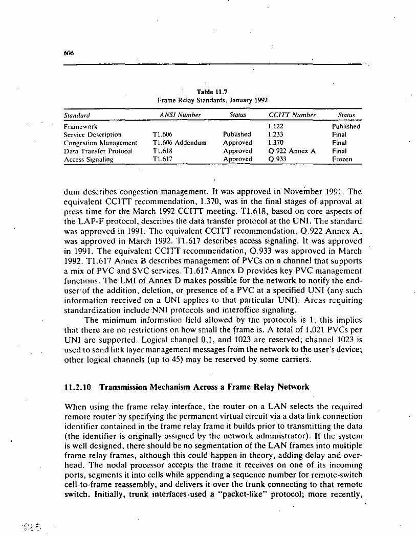
606
Table 11.7 Frame Relay Standards, January 1992
Standard ANSI Number Status CCITT Number Status
Framc'-"ork 1.122 Published Servicc Dcscription Tl.606 Published 1.233 Final Congestion Management Tl.606 Addendum Approved 1.370 Final Data Transfcr Protocol Tl.618 Approved Q.922 Annex A Final Acccss Signaling Tl.617 Approved 0.933 Frozcn
dum describes congestion management. It was approvcd in Noveinber 1991. The equivalen! CCITT recommendation, 1.370, was in the final stages of approval at press time for th'e March 1992 CCITT meeting. T1.618, based on core aspects of the LAP-F protocol. describes the data transfer protecol at thc UN!. The standard was approved in 1991. The equivalen! <:;CITT recommendation, Q.922 Anncx A, was approved in March 1992. T1.617 describes access signaling. It was approved in 1991. The equivalen! CCITT recommeridation, 0.933 was approved in March 1992. Tl.617 Annex B describes management of PVCs on a channel that supports a mix of PVC and SVC scrvices. T1.617 Anncx D provides key PVC managcment functions. The LMI of Annex D makes possible for the network to notify the enduser of the addition, deletion. or presence of a PVC ata specified UN! (any such information received on a UN! applies to that particular UN!). Arcas requiring standardization include·NNI protocols and interoffice signaling.
The minimum information field allowed by the protocols is 1; this implies that there are no rcstrictions on how small the frame is. A total of 1,021 PVCs per UN! are supported. Logical channel 0,1, and 1023 are reserved; channel 1023 is uscd to send link !ayer management messages from the network to the user's dcvice; other logical channels (up to 45) may be reserved by sorne carriers.
11.2.10 Transmission Mechanism Across a Frame Relay Network
When using the frame relay interface, the router on a LAN selects the required remote router by spccifying thc permanent virtual circuit via a data link connection idcntificr contained in the frame relay frame it builds prior to transmitting the data (the identifier is originally assigned by the network administrator). If the system is well designed, there should be no segmentation of the LAN frames into multiple framc relay frames, although this could happen in theory, adding del ay and overhead. The nodal processor accepts the frame it receives on one of its incoming ports, segments it into cells while appending a sequence number for remote-switch cell-to-frame reassembly, and delivers it over the trunk connecting to that remate switch. Initially, trunk interfaces-used a "packet-like" protocol; more recently,

·607
products are moving in the direction of CCITI's ATM ce lis standards. Thc switch must segmcnt incoming frame relay framcs for dclivery through thc ccll formal. beca use these frames can be long while ce lis are m u eh shortcr; for cxamplc. CCITT's standards specify cells with 48.octcts for thc payload and five extra cclls for overhead, as discussed in Chapter 10. As indicatcd. the network does not worry about error correction. N.odal processors do, howcvcr. check thc frame check· scqucncc (FCS7
) codc of a rcceivcd frame. lf the frame is found in error, it is dropped without further processing (refer again tu Figure 11.5). ·
Every network necds to ensure that traffic is routcd reliably from thc source to the destination. In a frame relay nctwork, routing of thc framc> frorn thc various routers is determined by the DLCI of the frame un a givcn user-nctwork interface. Nodes use the DLCI to determine the frame's destination. Thc DLCI is not an address of the destination. since it may changc as thc framc travels through the network (i.e .. the DLCI has local significancc only). lnstcad, it idcntifics thc logical connection between an element in the network and the next elcrncnt in thc nctwork (i.e.; endpoint and nodal processor. and nodal processor and cndpoint: routing between nodal processors is accomplished through the YCI). Sce Figure 11.8 for an example. The routing table entries for permanent virtual circuit scrvice are populated via the network managcment system. and routing is not dctcrrnined on a "per-call" basis as in X.25 SYC service. In the exarnple of Figure 11.7
• The network !ayer in thc PC at location x (typically part of the TCI'/1 P stack) looks in thc routing table for thc Úddress associated with thc de,tin:1tion application, known at the sending end by sorne logical narnc. say. y. The table indicatcs that the local router must be specifically addresscd fm thc selected destination.
• Upon reception ofthe frame, the routerchecks its routing tablcs to determine . the local DLCI needed to be appended to the frame in order to reach remole
destinati(m y. • The router's data link !ayer places thc information in a framc n:lay frame
anél sends it to node J. with the DLCI label properly appended tti thc information.
• Node 1 recognizes the DLCI associated with an existing logical path through the network. lf the frame is not in error and it has a val id DLCI. it is scgmcnted into ce lis which are subsequcntly identified by a node-<Jssigned YCI and othcr SAR mcchnanisms (sorne nodal processors forward entire frames without scgmentation; the advantagcs of ccll relay NNis over framc rclay NNis are discussed in Section 11.2.14). The cells are scnt on to nodc 2 and from thcrc to node 3. Othcrwise. it discards the frame.
7This acronym and thc Fiber Channcl Srandard acronym introduccd in Chaptcr 1 clc<~rly rcfcr to d1ffcfcnt concepts.

608
--p1-DLCI(] --vcq 1 --p2--
DLCI(] -oLCI( --p3--VCI(] --VCI(]
-·p1·· DLCI25 .,..VCix
--p3-VCix
--ver y
VCip --vcrq
--p1-DLCI45 -ver y
DLCI49 -vcrq
-p1·DLCI33 --vcrp
--p2-DLCI29
-DLCI43
Generic Routing Tab'- Ro~ing Table R1 Routlng Tabla R2 Routlng Tabkl R3 Routing Tabla R4
. figure 11.8 Mapping of DLCis in a frame relay network.
• Node 3 reassembles ·thc cells into the frame using the VCI and other SAR mcchanisms; the nade then passes the frame over the access line that ter-minales in thc cquipmcnt supporting application y. ·
• Upon receipt, the router forwards the information to the PC. In turn, the data is sent from the PC's data link !ayer to application y via the transport, session, and prcscntation layers.
The nodal processors do not ha ve to read the variable-length frame to achieve ·. switching; instead, the DLCI is sufficient to allow the edge processors to make the ·:1
'·;.,<¿~

( . (.., 'f
609
necessary routing decisions. Figure 11.9 shows one physic<il rcalization of thc protoco! architecture of Figure 11.7 in order to illustratc routing of framcs throug:h a private frame relay network. The DLCI may be reuscd by virtual circuits that do not share one or both endpoints.
In fact, Figure 11.8 implies that the routing is more complex than thc short discussion given above, sincc therc is an intcrplay bctwccn DLCI, thc ccll"s VCI (or equivalen! vendor-proprictary indicator), and ultimatc trunks. Thrcc aspccts of routing exist:
• An association betwcen thc locally significan! DLCI and thc ccll"s VCI (and the other way around). This occurs at origination and dcstination nodal proccssors.
Dastination 1 Oastinatlon 2 Oestinatlon 3
1 DLCI • 001 11 DLCI· 010 11 DLCI· 011 1
Oestination 3
' ' ' ' ' Nodal Procassor '"1 o""L'"'c""1-.-=o""1 1'"'l ' ...... ,-__ .....
Oastination 1
Oastma11on 2
Router
Note: In acruallty, OLCia only hav. localalgnlficance and can be alterad during transmission. ·
Figure 11.9 Routing in a private frame relay network.

610
• Remapping of a ver to another ver. As discussed in ehapter 10, this occurs whenever there are ATM switching points (a specific ver has no end-to-end significance if the virtual channel connection is switched; the ver could rcmain thc same end to end if the virtual connection is provided on a semipcrmanent basis). This occurs at intermediate nodes.
• Association bctween a local OLer and a OLer of a user connected to the samc nodal processor.
This in turn raises severa! questions pertaining to vendors' implemcntation of the frame relay/cell relay processors:
l. Are tandcm nodal processors allowed, or must nodal processors be connected with direct trunks?
2. Does a tandem nodal processor have to reassemble cells back irito frames, or are the ce lis relayed ("pipelined") directly as needed?
3. How does a nodal processor treat an incoming frame destined for a user directly connected to the same processors? N ame! y, is segmentation required?
These q ucstions ha ve a critica! impact on the end-to-end del ay of the frame relay nctwork. Just thc initial scgmentation and the re;note reasscmbly can alrcady be significan!; any intermediary reassembly impacts the grade of service further. Figure 11.7 depicted a scenario where the frame is segmented by the first processor handling it (node 1), and then sent downstream toa tandem processor (node 2), which accepts cells as such and transmits them along individually and discretely, without intermediary reassembly (Figure 12.3 shows an example of a segmentation process similar to thc one discussed here). The frame is reassemblcd only by the dcstination node (node 3). Note that Figure 11.7 did not show SAR!eS function at nóde. 2. This would happen if the nodal processor followed cell relay/switching
· A TM principies; such a processor would typically serve a variety of end-user strcams, sorne of which could be digitized video, sorne could be digitized voice, and sorne could be frame relay information. Notiée that, at the very least, the use of tandems implies having to incur the irunk transmission time twice. It is conceivable that if a nodal processor does not follow ccll relay/switching principies, each frame must be assembled and disassembled by each nodal processor in the path.
11.2.11 eongestion Management
Users, LAN managers in particular, may worry about migrating traffic away from dedicated interrouter links they have used until now and onto a network based on high-speed packet technology. However, this is not an insurmountable problem,
· since frame relay has (in principie) a way to manage and control congestion [11.21]. ':¡ The frame relay network compased of the nodal processors, private or public,.\Yl
.. .-.·•·ill . . ,1,.rt•

" .' . '·'
6/1
attends to this by first using congestion notification strategies and then by sclcctively discarding frames when needed to relieve congcstion. Congcstion control mcchanisms are utilized to treat users fairly and to protcct the network and uscrs oy localizing the congestion within the nctwork.
The congestion notification takes place whcn a nctwork nodc determines that it is becoming congested. It sets the forward explicit congestion notifica! ion (FECN) bit in \he frames as it sends them to thc destination router (scc Figure 11.4 ). It also sets the backward explicit congestion notification (BECN) hii in thc framcs
· destined for the source router. Upon receipt of thesc framcs. thc sourcc and destination routers are expected to initiatc proccdurcs to throttlc oack thc traffic offcred to the network. lf congestion continucs to incrcasc dcspitc using congcstion notification, the network will begin to discard eligihlc framcs and will put thc congestion localization procedures into effcct. Thc nctwork of nodal proccssors sclccts frames for discard by looking at thc discard cligibility (DE) bit in cach frame to see if it has been set by thc routcr. lf it is sct. thcn thc nctwork discards the associated frame. These procedures continuc until thc congcstion subsidcs.
One issue, however, is if and how thc routcr can cnforcc throttling back to thc PCs originating thc traffic. Hence, the importan! yucstion lo ask about a framc relay router, a nodal processor. and a carricr scrvicc, is whcthcr or not thc full congestion control apparatus specified by thc standard is implcmcntcd in cach of these devices. Congestion in public framc rclay nctworks will be discusscd in a later section.
11.2.12 Quality of Service
Multirouter networks using frame relay interfaces providc for propcr frame sequcncing and minimize the likclihood of misdelivered frames. This is accornplishcd by thc nodal proccssors by using the conncction-oricntcd PVC scrvicc. Thc same predetermined logical path is used by the nodes for all framcs using thc samc DLCI ón a given acccss interface. Rccovcry from errorcd framcs is accomplishcd by the end-user equipment, since the network will detcct and discard all errorcd frames.
11.2.13 Cell Relay
· A cell is a fixed-length packet of uscr data (payload) plus an ovcrhcad, usually small, of 53 bytes or less. Cell relay is a high-bandwidth, low-dclay switching and multiplexing packet technology ( discussed in Chaptcr JO) which is rcquired to implement a frame relay network in an efficicnt manner, particularly for mixcdmedia and multimedia applications. The international cell relay standard. ATM. was also discussed at length in the previous chapter. With cell relay, information

. C) ·11 e·- 1
612
10 be lransfcrred is packelized inlo fixed-size cells. The term "cell relay" and the lerm "cell switching;' are both used by the BISDN community [11.22). (Sorne distinctions are possible, although we use the term interchangeably: cell relay can refer to an environment of PYCs whcre cells are simply relayed along the same path according to sorne static incoming-to-outgoing trunk association; cell switching can refer to a SVC environment where cells are dynamically switchcd according lo a nearly-real-time incoming-to-outgoing trunk association created by the uscr vía a signaling process.) Yendors tend to use the term "cell relay switch" (or node) when their equipment does not implement the CCITT ATM standard, but a proprictary standard. If the CCITT standard is implemented, they typically refer to the equipmcnt as an "A TM switch."
Ce lis are identified and switched by means of a YCINPI label in the hcader. A number of functions of the layer 2 protocol are removed to the cdge of the backbone. while "core capabilities" are supported directly by the cell switches, in addition to !ayer 1 functions (clocking, bit encoding, physical medium connection). Ce lis allocated lo thc same connection may exhibit an irregular rccurrence pattern, sincc cclls are filled according to the actuai demand. Cell relay allows for capacity allocalion on demand, so thc bit rate per connection can be chosen flexibly. In addition. the actual "channel mix" at the interface can change dynamically. The cell hcader (such as the ATM's header) lypically contains a label and an error detcclion field; error delection· is confined to the header. The label is uscd for channel idcntification. in place of the positional methodology for assignment of octets, inhcrent in the traditional TDM Tlrf3 systcms. Cell relay is similar to packet switching. but with thc following diffcrences: (1) protocols are simplified and (2) cells (packels) have a fixcd and smalllcngth. allowing high speed switching nodes; switching dccisions are straightforward and many functions are impiemented in hardware. Cell relay is critica! to the dcployment of frame relay, and only those nodal processors implemcnting it give the users the full advantages of thc · new technology.
Onc complication of using cell relay at the NNI instead of using framc rclay at thc NNI has todo with nctwork discard'options. A packet-based frame switching nodal processor (e.g., Netrix. BT Tymnet, and others) can discard a: frame found to be in error or. in case of civerload, a frame designated as eligible for discard by the uscr. In fast packct/ccll rclay platforms, the framc loses its identity in transit (sincc it is pipclined and only rcassemblcd at the remote nodal processor, notan intermcdiary processor). The 'issuc then arises of what to "throw away" in case of congcstion; although a framc might havc bcen segmentcd into, say, 30 cclls, throwing away 30 random cclls might imply corrupting the integrity of 30 framcs. not (just) one frame, as might havc been the intention of the nctwork. As a practica! solution. manufacturers of cell-based nodal processors put greater emphasis on designing their processors to avoid a congestion statc rather then on how to deal

613
with congestion after it arises (systems with frame rclay-bascd NNis tcnd todo thc opposit~). Hence, these processors have enough buffering to absorh user's input data during an interval of network congestion instead of having to start forwarding ofthat data into the network, just to find íatcr that sorne, ce lis werc lost. necessitating sorne remedia! action (this is analogous to the airline industry principie of holding planes on the ground if congestion exists rather than launching thc planc and thcn. having to hold it while in transit).
11-2-14 Cell Relay Platforrns for Frarne Relay
"Frame relay" switches, airead y identified as nodal proccssors, necd to be deployed in order to properly allocate bandwidth on a dynamic basis (alternativcly, this can be achieved by using the frame relay facilities of a carrier). lt is critica! that a framc relay nodal processor support a dynamic view of the data heing transferred through it; citherwise, the user will not obtain the full benefit possible with thc technology. Without a cell-based switch, dynamic bandwidth allocation is not easily achicvable. Figure 10.19 clearly indicated three modes of deploying frame relay in a corporate environment. The simples! way is to upgrade the routers with a frarne rclay board and retain the existing point-to-point infrastructure. This approach does not provide any consequential advantage over the existing environment [11.3, 11.4].
Frame relay describes an interface specification; nodal processor equipment vendors can still use proprietary interna! protocols. This is similar to the X. 25 case. where packet switches support a standardized interface. but use interna! transport, routing, and flow control protocols. This forces a user wanting to establish a priva te network to use the equipmcnt from the samc vendor throughout the nctwork. By contrast, thc cell switching technology spccificd in ATM is open by design ..
Many clistomcrs deploy high-capacity circuits to meet peak traffic ( and performance goals); however, OSI lines uscd exclusively for data are rcportcJ by sorne to be only loaded at 15% or less [11.2, 11.23, 11.24]. Dynamic bandwidth allocation rcquires the incorporation of cell relay in the nodal processor to handle communication over the trunks (another way would be to cmploy a frainc switching nodal fabric, but the granularity or cfficiency of the multiplexing can be significantly lower). Dynamic bandwidth allocation is done by designing the nodal processor from the ground up and eliminating any fixed-bandwidth constra.ints imposeJ by a TDM nodal architecture. No interna! blocking should be allowed in the switch, and queuing must be eliminated or at least minimized. Vcndors which have expcrimented with these architectures ovcr the past few years are in a position to incorporatc these ground-breaking architectures in the products they manufacture. TDM and cell relay can be viewed at two ends of a spectrum: it is not possible to take full advantage of cell relay if the node has interna! and/or externa! TDM structural

o. 1 .,_ o{ T -·
614
restrictions. Beca use of the efficient multiplexing possible with cell reluy, dynamic bandwidth allocation, so importan! to bursty users, particularly in the LAN ro u ter environment, is achieved.
Uscrs with a mix of bursty traffic may find it advantageous to upgrade Tl equipment that uses time-division multiplexing to cell re la y platform. The drawback
· of traditional TDM techniques is 'that users must allocate portions of the Tl circuit to individual channels, each supporting transmission of a specific data source. Since that bandwidth is allocated to only one" user, it remains unused when it is not needcd by that one user. Simply retrofitting a circuit-switched TDM-based Tl rriultiplexer with frame relay UNis does not deliver the intrinsic benefits of frame relay, any more than simply replacing a standard router with one supporting frame relay while still,using a point-to-point Tlline would. With circuit switching systems. the u ser has to preallocate sorne ( or all) bandwidth to the frame re la y service, whether that bandwidth will be used or not. An efficient utilization of the technology over a prívate backbone network requires a nodal processor with interna! fast packet technology. namely. a processor which employs cell relay technólogy. In this case, letting all applications compete for the backbcíne bandwidth allows them to access the entire bandwidth when anyone has data to transmit, not only on the trunk side but also on the access sidc, since frame relay supports multiple PVCs on one physical link. On the other hand, a frame relay application on a circuit-switched multiplexer can only access sorne fraction of the total bandwidth.
Whcn a network is properly designed, the full bandwidth of the frallle rclay interface can be available to any application that requires it for rclatively longduration bursts of data, as may be the case for interconnected LANs. These applications m ay require that the network nodes support bursts occupying thc full access bandwidth for intervals of up to 10 seconds or more in arder to support transfer of large files or interactive traffic.
Thcre are economic advantages of using the combination of framc relay acccss and a cell-bascd backbone network. Using frame relay tcchnology in conjunction with a ccll-based backbone multiplexcr as an upgrade of an existing prívate corporate backbonc can be cost-effcctive, since the uscr can obtain from the backbone needcd bandwidth on demand, rathcr than on a fixed (and inefficient) basis. The "savcd" bandwidth is then available to other users.of the same backbone. in thcory minimizing the amount of new raw bandwidth the firm needs to acquirc from a carrier in the form of additional TI or Ffl links. As an alterna ti ve stratcgy, the servicc from a carricr can be uscd. Although nodal processors can also support non-frame relay traffic (c.g., voice or video). the two technologics togethcr. cell relay and frame re la y, promisc to increase throughput between locations that ha ve large amounts of bursty traffic.
One may wondcr why it is beneficia! to utilize segmentation of a frame into many (up to 133) ce lis and, con~cquently, why a ccll-based platform is superior to a framc switching technology in the nodal processor. Thc explanation follows .. :}
··~~'~ ::,$ -~.
():). lj _, • 1
.615
Frame rclay is a data·only protocol; it is intcndcd to support HDLC-typc traffic (e.g. LAN packets). Its main focus is on data scrviccs. Ccll rclay (fast packet) switches, on the other hand. can also handle voice and video. For examplc. voicc "frames" may be as small as onc octct. Thcrcforc. should a uscr"s nced he strictly LAN intcrconncction. thcn a framc switching technology with FRis on hoth the access and on the trunk sidc. might. in fact, be superior in terms of performance. Howcvcr, if the uscr al so contemplates supporting voicc and video. thc best solution
· is to use a cell relay platform that supports FRI for LAN access. smilc othcr access protocol for voicc and for video, anda cell method on thc trunk sidc. As covered in the previous chapter, the ATM cell proccdurc is hcing introduccd under BISDN to support all media, including voicc. data. and video. Multiplcxcr vcndors view frame relay asan access protocol; thc ccll relay/fast packet backbonc JS viewed as giving the user better control ovcr thc quality of service of the path and facilitating a mix of traffic [1 1.15].
11.3 BENEFITS OF FRAME RELA Y
11.3.1 Deployment Approaches
About 75% of large (Fortunc 1500) companies hada dozcn or more hridgcs interconnccted via DSI lines in 1990 [ 1 U\]. That numhcr is likely to reach 1110% by 1993. However, as discussed earlier. private networks hased on dedicatcd lincs tend to become impractical when therc is a largc numher of remole data sources/ sinks generating hursty traffic. Thc numbcr of links grows quadraticallv with thc numbcr of sites to he interconncctcd. In addition. thc intcrconncction capacity needs to be highcr; this incrcase in the spccd is oftcn dictatcd by applications requiring more data to be transacted, as well by the numbcr of uscrs of thc scrvice of intcrconnection [11.17, 11.25-11.28]. This implies that fairly cxpensivc links are required.
Five classes of solutions are available:
l. Instead of connccting all routcrs with a fully interconnectcd network. sorne routcrs are connectcd in tandcm. While this reduces the numhcr of links. it introduces extra end-to-cnd dclay and incrcases nodal processing (rcquiring more machine cycles).
2. Deploy a privatc framc relay nctwork using frame rclay nodal proccssor(s). Instead of physical point-to-point links. this approach only Tcquires connecting the routers to the nodal processor(s) wit~ a single physical link. Connection between various routers is accomplished with PVCs (illustrated in Figure 11.3).
3. Use a PVC-based carrier-provided frame · relay network. Instead of many .physical point-to-point links, this approach only requires eonnecting the rou-

6-'~'-;..;_k·.
:..\ 1 .....
616
ters to the carrier's switch with a single physical link. Connection betwcen various routers is accomplished with PVCs that are established at service subscription (see, for example, Figure 11.6).
4. Use a hybrid configuration. A cluster of sites employ private frame relay; other sites take advantage of public trame relay services.
5. Use a SVC-based carrier-provided frame relay network. Instead of inany physical point-to-point links, this approach only requires connecting the routers to the carrier's switch with a single physical link. Connection between various routers is accomplished as needed by establishing a real-time SVC, which is in existence only for the duration of the session. Figure 11.10 illustrates this approach.
The evolution in the private environment involves using nodal processors which provide FRis to the routers and use cell re la y/ A TM technology betwcen nodes. (As' indicated, it would be technically possible to also use frame relay techniques between the switches, as, in fact; two frame relay routers connccted by a dedicated T1 link use, and as sorne vendor architectures based on traditional packet engines do, but this approach has not seen major commercial realization.) Although frame re la y remains a connection-oriented service, there are still' advan-
Fipre 11.10 A SVC·based frame relay nctwork.
Frame Relay Handler
Hosl
Router
.:-.'!-,
'.:~~

617 .
tages in connecting LANs through frame relay rather than X.25 packet switching. In particular, when using X.25 service, routers had to cncapsulatc LAN traffic in the X.25 packet, imposing substantial performance degradation. Fwme rclay. on the other hand, incurs little overhead and allows for· a numher of protocols to be transported transparently [ 11.21).
In view of the growth in the population of LANs. carricrs are readying thcmselves to provide public PVC-based frame relay data scrvices that support highcapacity access/throughput, coupled with the universal acccss. survivability. cconomies of scale, and efficiency availablc through rcsourcc sharing. Chaptcr 1 provided information on the time frame of frame re la y dcployrncnt in corporal e nctworks. SVC-based frame rclay can havc sorne advantages, but it also has sorne limitations. First, thé scrvice may becomc availablc only la ter in thc dccadc. Sccnnd. a uscr needing to send data to sorne remole uscr on anothcr LAN may not be willing to incur the call setup time cach time a session is rcquircd. The way somc pcople have gotten around the setup time issue in packet-switched networks is to use long-duration SVCs; these are set up once and kept active for an appropriatc amount of time, such as a day.
Sorne mers may deploy hybrid frame rclay networks. Thcse uscrs could use · their own frame rclay backbone connecting majar sitcs and use a public frarnc relay network to connect secondary sites. lnterworking issues have 10 be resolved befare this approach can be realized in practice.
11.3.2 Benelits of Frame Relay in Private Nelworks
In thc business and economic landscape of thc 1990s it is prudent for thc communication manager lo look at nctworking solutions that will not have lo be discardcd aftcr a couple of years lo keep up with network growth or highcr spccd nctworking needs or tcchnologics. Sorne wJdal proccssors now on thc markct only support data. Othcr nodal proccssors support data. voice, and video. Beca use nodal proccssors bascd on ccll switching utilizc backbonc facilities bcttcr than cxisting
) static channel banks or circuir switching TI multiplcxcrs (and also existing X.25 switchcs), ihc dcployment of thesc mixcd-mcdia nodal processors in a privatc network bcnefits uscrs that need to connect LANs 9vcr intcgratcd backboncs supporting a varicty of othcr traffic. Users with LAN traffic only rnay chnosc dataonly nodal processors. The financia! advantage of a frame re la y nctwork be comes more markcd when thc number of routers is high (half a dozen lo a dozcn. or more) and when thc distanccs bctwcen routers is considerable (hundrcds or thousands of milcs-if the routers are all located within a small gcographic arca, such as a city, a county, ora LATA, thc economic advantage of elimination lincs is lcss conspicuous). Table 11.8 summarizes sorne of the benefits.

618
Port and link shanng Bandwidth on dcmand High throughput-and low delay Easc of network expansion
Table 11.8 Sorné Benefits of Frame Relay
Ease of transition from existing router nctworks Easc of transition from any existing ne_twork Cohcsivencss and symbiosis with LANs Simplificd network administration Standards-based Economic advantages (in a vanety of sltuations)
Port and Link Sharing
Among the advantages of frame relay is its ability to statistically multiplex frames from multiple LANs al one location onto a single user network interface and associated communication link. Frames going to multiple destinations can share the same router port. The frame relay interface to the nodal processor provides for the end-user equipment the capability to place frames destined for different nctwork endpoints onto the same network access line by using the DLCI mechanism. This accomplishes port sharing and allows each frame to have use of the entire bandwidth of the access line when there is a frame to be sent. Further efficicncies are gained on the backbone network interconnecting the nodal processors by combining the traffic from multiple routers onto the_ network trunks using efficient cell/ ATM protocols. Instead of having to purchase more expensive multiport routers that otherwise would be needed, simpler point-to-point routers can be used.
Bandwidth on Demand
All of the handwidth on the frame relay access interface can be available to the end-user system .when it necds to transmit data across the network. The nodal processor can be optioned to accept, under conditions of slack, all the incoming traffic from one user up to thc full access speed. Alternatively, the nodal proccssor can be optioned to accept up to sorne prenegotiated rate less than the full access speed. but more than the average user requirement. For example, the access line could be a TI facility; the user's average input could be 128 kbps. The nodal processor could be optioned to accept an instantaneous input (over a short horizon, say, 10 seconds) of 512 kbps.

6/9
Improved Use of Bandwidih
Dynamic bandwidth allocation reduces the aggregate backbone transmission bandwidth the manager needs to secure from a carrier, which would otherwise be nceded without it. Additional transmission resources contribute to a dircct incrca~e in transmission cost. For example, if six uscrs need a maximum of 512 kbps. two Tls would be required under TDM, although 'their aver;1ge rate may oi1ly be 12R khps. · With frame relay, one Tl (5 x 128k + 512k) should suffice if tlic traffic is truly random. The upgrade of an existing backbone network with a prívate framc rclay· network can save, according to sorne early uscrs, 20% of thc total network bandwidth [11.29].
High Throughput and Low De/ay
Sin ce all of the bandwidth is availablc, high throughput is possiblc. Mini mal del ay is encountered within the backbone network, sincc therc is littlc protocol processing required with frame relay. Cell-based nodal proccssors, particularly thosc cmploying the latest high-powcr microprocessors, are fast. Thc switching dccisions hascd on the cell header are simple and direct. For example, sorne studics have shown that with a prívate X.25 with 56-kbps access, it took 4 minutes to transmit a benchmark file; with a frame relav nctwork bascd on a TI backbonc ami acccsscd with a 56-kbps line, the file could be transmitted in 45 scconds [ 11.29[.
Ease of Network Expansion
Network expansion is straightforward with framc relay. Adding a ncw routcr to the nctwork requires only the assignment of an access port on thc nctwork nodc, and the interconncction of the router with the nctwork nodal proccssor via thc appropriatc transmission facility. The intcrconncction of thc ncw router with thc cxisting routcrs is accomplished by logically provisioning thc network u si ng a ccntralized network managcment system. The ccll-based protocol> uscd hy vendors toda y could lend themselves to migration to the standard A TM ccll forma t. This migration will permit the nodal proccssors to support sorne of thc ncw.high-spced services bcing developcd by carriers. Thus, both framc relay and acccss to thcsc highcr spccd serviccs can be supportcd on thc samc backbonc.
Ease of Transition From Existing Router Networks
Existing routers typically need only a software upgrade to implcmcnt thc framc relay interface. Once this is done, the routers can be re-homed on the ncw fr¡¡mc relay backbone.

610 .
Ease of Transition From Any Existing Network
lt was .indicated above that many users still ha ve networks that were pul in place a fcw years ago. A frame rclay network can easily be deployed, no mattcr what thc uscr baseline is, as will be discussed in more detail later.
Cohesiveness and Symbiosis With LANs
Frame relay technology is similar in sorne aspects to the data link !ayer discipline of a LAN. Sin ce the data need to lea ve the LAN and travel over a WAN, it is desirable to use a WAN technology that has an affinity with thc LAN tcchnology. This minimizes the amount of protocol conversionlremapping which would otherwise be needed.
Simplified Network Administra/ion
Severa! recent studics have indicated that, when considering thc true corporate cost of communication, 30% to 50% of the network expense corresponds to operation and administration efforts, commonly known as network managemcnt. Any tool or systcm that improves the way network management is done is a wclcome and cost-saving fcaturc. Administration in frame relay can be performed from a central nctwork management and administrative system. Moves, changcs, and additions to the nctwork are typically handled through an automatic permanent virtual. circuit provisioning capability within the system. ·
Stahdards-Based.
Thc framc rclay PVC UN! is an accepted and stable ANSI ancl CCITT standard, with widc support from both user equipment and network system vcndors.
Vendar Support
Over thrcc dozcn vendors support frame relay. Thesc vendors includc routcr manufacturcrs, TI multiplexcr vendors, PAD developers, nodal processor and switch providcrs, and carriers. Frame rclay routers cost from $400 to $15,000, depending on vendar and features, compared to a standard router. Nodal processors cost from $20,000 to $50,000, depending on vendar and features.

.611
Saving Communications Costs With Nada! Processors
Perhaps the most significant benefit is that the use of frame rclay ovcr a ccll rclay platform can, in the right circumstances, save moncy for thc multiroutcr LAN manager. Private networks based on dedicatcd lincs become cxpensivc when therc is a large number of remate data sources/sinks generating bursty traffic. Initially, users may have employed dedieated Iines operating at 19.2 khps. 56 khps. Frl, and TI speeds to interconnect" LANs; this increase in thc spccd is oftcn dictated by applications requiring more data to he transacted, and by thc numhcr of uscrs using the service of interconnection. As the numher of LANs grows. this proliferation of Tl lines becomes impractical from both a cost and managemcnt perspective.
The topic of economics is always a complex issue. A dctailed example of an economic analysis in the presence of nocla! processors in an enterprise network was provided in Chapter 6, which the reader may wish to review at this point. 1t was shown that a private frame relay network can be cost-effective compared to a full mesh network at the same link speed. To undertake a cost analysis of a private frame re la y network, the LAN manager should first calcula te the nctwork cost with traditional connectivity and then thc cost of using frame rclay technology. Thc process starts by determining the location of the sites to be intcrconnectcd. Sitcs can be identified by vertical and horizontal (V&H) coordinates. The V&l-ls allow the manager to obtain the distance of al! sites and, hencc, the length of thc rcquircd · \ communication links. A TI (or Frl) local loop must be costed out using thc local exchange carrier's tariffs; these tariffs may be different at each sitc. Thcn thc cost of thc access facility between the serving CO and thc interexchange carricr's POP must be calculated. 8oth the distance and the tariff may be sitc-dcpcndcnt. Final! y, the cost· of the set of required long-distance TI links can be ubtaincd using thc interexchange carrier's tariff.
The cost of thc framc relay altcrnative is calculatcd·as follows (rcfcr to Figure 11.3 as a guide). One or more centrally located sites are chosen where the nocla! processurs will be Iocated; the V&Hs of the nodes are noted' (this choice may he subject toan optimization procedure). The cost of thc nocla! backbonc network is determined by deciding what the rcquired nodal connectivity will be, and thcn by costing out the transmission facilities (this will involve a TI or FTl loop, an acccss facility to the POP, the long-distance trunks, and the .rcmote acccss and loops). The cost of the router acccss suhnetwork is calculatcd next. This involvcs first determining which nodal processor each routcr will be homcd to. Then thc cost of the transmission link between the router and the nodal processor is calculatcd (this also will involve a TI or Frl loop, an access facility to the POP, thc long link, and the re mote access and loops). The ( amortized) cost of the nocla! processors and the.routers' upgrade must also be included. The total cost is obtained by adding all of these factors.

622
Tahle 11.9 assesses the effectiveness of frame relay as a function of the geographic scope. This example is based on the baseline network discussed. in Section 6.5, which should be reviewed at this point if there are questions ahout topologies. backbone milcages, etc. As can be seen from this table, the savings due to frame relay become less signifiCan! as the network gets geographi¡;ally smaller: a nationwide (prívate) frame relay network costs 0.40 times as much as a mesh point-to-point solutiori, while a statewide network costs 0.61 times as much as a mesh point-to-point solution, implying less dramatic savings.
Table 11.10 undertakes a similar study, where there is only one nodal processor with no backbone (as sorne vendors of priva te frame relay networks are suggesting. particularly in the LAN interconnection context). Figure 11.11 depicts the topology, showing a centrally located nodal processor; all assumptions are similar to the previous case. The following eonclusion emerges: for national networks, the one-node frame relay solution is slightly more expensive compared to the three-node solution; for regional and statewide networks the one-node solution is somewhat less .expensive campa red to the three-node solution ( oS20% less).
Figure 1 l. 12 depicts a one-node solution where the nade is collocated with one of the routers (in a central location). Here, on•: less access line is required. However, as the figure shows, most other locations need longer access lines compared to the case of Figure 11.11. In this particular case, the total milcage is slightly reduced (from 4,800 for the baseline case of Figure 11.11, to 4,600), implying that there would be a small decrease in the total cost. The decrease is composed of three factors: (1) less !XC mileage, reducing the cost by an amount proportional to the mileage charge times the difference in mileage; (2) since there is an !XC "ramp up" on the T1 tariff of approximately $2,100 (for the first mile), this expense disappe.ars when one line is eliminated; and (3) one LATA line (premises to POP) is eliminated. The national, regional, large-state, and medium-state numbers are $58,050, $44,250, $30,450, and $23,550, repectively; this is an 8% to 10% reduction compared to the previous case. lt should be noted, however, that this saving will becomc lcss importan!, diminish, and, in fact, cven disappear as the number of routers increases, if thcse routers are widely dispersed.
· If there were severa! routers clustered in one location, collocation ofthe nodal processor at that location would superficially appear beneficia!, bccause multiple lines could be eliminated from that location to the centrally located nodal processor. However, since frame relay allows multiple PVCs on a single physical line, this saving is more apparent than real. Figure 11.13 shows one example (which we worked out on a paper plate with ruler-but we could as well have used trigo- ' nometry). The results depend on many factors: are the routers located on a circular path, an elliptical path? How many routers are collocated? The example demonstrates that, in fact, it would be better to locate the nodal processor at a central :· location. In Case A of the figure, the total mileage would be 10M (M = miles) if) the nodal processor were centrally located, and 12M if it were placed in one rout~~

C¡? '· d ( \-:--"
"
Table 11.9 eost-EffectJvencss of a Thrce-Nodc Fivc/Six Routcr Nctwork as a
Function of the Nctwork Gcogn1phical Scopc
National Network (all IXC distances of baseline multiplied by 1.5)
Cost of POP /OC Case• Loops Accrsx Cusl
A with Tls $4,500 $6.200 $139.21Kl B with Tls $6,750 $9.300 $205.21Kl ewithTis $2.250 $3,100 S 31.8tKl D with Tls $2.700 $3.720 $ 41.41Ml
Re~ional Network (e.g., northeast network) (Baseline-See Chapter 6 for assumptions)
Cost of POP Case Loops Access /OC
A with Tls $4,500 $6.21Xl $100,81Xl B with Tls $6,750 $9.31Kl $148,800 e with Tls $2.250 $3,100 $ 25,200 D with Tls $2,71Kl $3.720 $ 32.41Ml
Statewide Network, Large State (AII IXC distances of baseline divided by 2)
Cost of POP Case Loops Access /OC
A with Tls $4.500 $6.200 $ 62,41Kl B with Tls $6.750 $9.300 $ 92.41KI e with Tls $2.250 S3,100 S 18.61Kl D with Tls $2.700 $3,720 $ 23,400
Statewide Network, Medium State (AII IXC distances of baseline divided by 4)
Cost of POI' Case Loops A e cess
A with Tls S4.51KI S6.200 B with Tls $6.750 S9.300 e with Tls $2.250 S3,100 D with Tls S2.700 $3.720
A = Five routcrs without framc rclay B = Six routcrs without framc relay e = Fivc routers with frame relay D = Six routcrs with framc relay
/OC
S 43.200 $ 64,21KI S 15.300 S 18,900
Nouters, Fl'S
$ 833 $ o $1.1Kl0 $ o $ 917 $2.350 S I.IIKI $2.350
Roulers FPS
$ 833 $ ()
S I.!XlO $ o $ 917 $2.350 $1.100 $2,350
Routrrs FI'S
$ 833 $ o SI.OIKI $ o $ 917 $2.350 S l. !lXI $2.350
Router!J FPS
$ 833 S o SI.IKIU S o $ 917 $2.350 S 1,100 S2.350
/Jack/)(me Cost
$ o $ o $20.71Ml $20,71Kl
Backhone Co\t
S o $ o $1ó.21Kl $16,21KI
/Jackhom· Cosr
$ o $ 11 $ 11.700 $11.71Kl
/Jackhone Co.H
$ 11 $ o S 9.450 $ 9,450
(")Refcr to corresponding example in ehaptcr 6 for all assumpt1ons and topologies.
623
rma/
SI 50. 7:n $222.250 $ 61.11.7 $ 71.Y70
Total
$112.333 $1 ó5 .X 50 $ 511.017 $ 5XA711
"! otal
$ 7.1.'133 $1119.450 $ 38.917 S 44.970
Total
$ 54.733 $ 81,2511 $ 33.367 $ 38.220
j

;1. (· -:--.- . -
614
Table 11.10 eost-Effcctiveness of a One-Node Fivc-Routcr Network as a
Function of the Network Geographical Scope
Natinnal Network (AII IXC distances of baseline mulliplied by 1.5)
Cost of POP /OC Total Case• Loops Acass Cost Routers FPS Cost
A with Tls $4.500 $6.200 $139,200 $833 $ o $150.733 e with T1s ' $2,250 $3,100 $ 55,200 $917 $783 $ 62,250
Regional Network (e.g., northeast network) (Baseline)
Cost of POP Total Case ~Loops Access /OC Routers FPS Cost
A with T1s $4,500 $6,200 $100,800 $833 $ o $112,333 e with T1s $2,250 $3,100 $ 40,800 $917 $783 $ 47,850
Statewide Network, Large Stale (AU IX e distances of baseline divided by 2)
Cost of POP Total Case Loops Access /OC Routers FPS Cost
A with Tls $4.500 $6,200 $ 62,400 $833 S o $ 73,933 e wilh Tls $2.250 $3,100 $ 26,400 $917 $783 $ 33,450
Stalewide Network, Medium Stale ( AU IX C distances of baseline divided by 4)
Cost of POP Total Case Loops Access !OC Routers FPS Cost
A with Tls $4.500 $6.200 $ 43,200 $833 $ o S 54,733 e with T1s $2,250 $3,100 $ 19,200 $917 $783 $ 26,250
A :;;:: Five routcrs wathout frame relay C = Five routers with frame relay • Rcfcr to corrcsponding example in Chapter 6 fOr all assumptions on tariff and to Figure 1 L 11 for baseline topo1ogy.
Iocation (Case A'). What happens if sorne routers are clustered? lf separate lines toa centrallocation (Case B) were used, it would still take 10M of circuit; however, sin ce m u !tiple PVCs can be put on a single link ( assuming that the performance issue was appropriately handled), 6M of circuits is sufficient (Case C). Locating the nodal processor at the location with severa! routers (Case B ') only cuts the circuit length to 7M, which is more than with the centrally located nodal processor.
It is difficult to draw general conclusions about the cost-effectiveness of priva te.{<; frame relay networks ( except that they are cheaper than full mesh networksi';<:¡ because the problem is highly multidimensional (50 to 100 dimensions or more) '
.,;;~-t~'

¡.O.•\ .'·: ¿''1
PartA
Ten access llnes
Total circuit milaage: 12,800 miles
Part B: Adding a routor
Fiva T1 accesa tinas and ona nodal processor
Total circuit mileage: 4,800 miles
t·;: .. ·Figure 11.11 Economícs of a síngle-node trame relay network. r~-s.:: .
'625

616·
Four T1 access lines and ene noda/ processor
Total clrcuit.tnilaaga: 4,600 miles
sao miles
1600 miles
Figure ll.U Collocating a single note with a site with a router.
Also, in addition to transmission costs, sorne of the other factors that LAN managers and nctwork designers take into account in selecting a network architecture include network reliability, network availability, case of network management, compatibility with open international standards, case of network upgradeability, initial costs. migration costs, growth capabilities for both traffic and sites, integration with embedded base·, and vendors' .technology support. However, recurring transmission charges continue to be a visible componen! of any calculation assessing the desirability of a network redesign. Where is a frame relay network particularly cost-effective? In trying to draw sorne general cónclusions, the answer is when one or more of the following apply:
• There is a large number of.remote sites (half a dozen or more). The larger the number of sites, the more cost-effective frame relay will be.
• The remole sites are highly dispersed (at least regionally or nationally). The . higher the combined network mileage, the more cost-effective frame relay will be. This implies that national-scope networks are reasonably suited to a .. , prívate frame relay technology. · .. i~
• The traffic is highly bursty. This occurs when traffic leaving the router is~~if' small and occurs in jusi a few instances during the day (not all traffic leaving{
.· . ~

Rauter
Routor M
Case A: Total Mileage: 10M
Routar
Routor M
Case 8: Total Mileage: 10M
CasaC: Total Milaaga: 6M
Routor
M
access
Case A': Total Mileage: 12M
Total Milaage· 7M
Figure 11.13 The geometry of locating the nodal processor.
. 627
2M

e¡ p:;. t>-'•; 1
618
a routcr is bursty-as the utilization of the router approaches 100% the traffic will become more predictable). Alternatively, this occurs when the applications transact large amounts of data al discrete instances (e.g .. file transfcr).
• There are multiple LANs at a site which, for whatever rcasons. are not interconnected with each other, and yet all need to reach thc network. This takcs advantage of frame relay's ability to place multiple logical chaimcls over a single physical channel. lf there are D remole destinations and N unconnected LANs, D x N virtual channels are rcquired (if the various local LANs were airead y interconnected with bridges, then the number of required virtual channels is only D).
• New sites/routcrs are added to the network with relatively high frequcncy (say, once every six months or more frequently).
• The links between the routers have relatively low speed (ITl ), and more bandwidth appears to be required. Upgrading the ITI mesh topology links to full Tl facilities may be very expensivc. Nodal processors can mercase throughput for less money than would otherwise be needed.
From a carrier's perspective, frame relay service will impact prívate linc services the most; less irnpact is expected on public packet networks (since these either address themsclves to lower speeds, orto international destinations) and on SMDS services (since these provide higher speed, are connectionless, and support true switching capabilities).
11.3.3 Benefits in Public Networks
Sorne carricrs and vendors ha ve madc cornmitments to frarne relay, othcrs carriers . ha ve rnade plans to deploy ccll relay' and severa) carriers are pursuing both tcchnologics (including the sevcn BOCs). Sorne view the two approaches as cornplernentary. others as compctitive. Frame relay service and cell relay scrvice are dcsigned to rneet differcnt objectivcs, and hcnce IÍave evolved in diffcrent directions." A categorization in thc public network cnvironrnent is as follows [11.30]:
• Frame relay is a mediurn- to high-speed (DSO-DSl) data interface for prívate networks which is being implemented at this time. Sorne observers bclieve that frarne rclay may in fact ha ve rnarket irnportance at the OSO levcl.
• Ccll relay/switching is a high- or very-high-speed switching service capable of supporting public BISO N and SMDS networks. Cell switching supports 155-Mbps, 622-Mbps, and eventually higher SONET/SDH rates.
""Cell relay scrvice" refers lo providing a ceii/BISDN UN l. nota cell in the NNI. as we ha ve discussed :';i;. ·so far. (In the private network environment. corporate backbone network switches supponing LAN ¡S) applications typically use a FRI UNJ and 'a cell NNJ.) · .. . · · : ·. ··; · · : · . . . · . ,,-;,.~~i~

629.
Framc rclay carricrs providc intra-LATA, inter-LATA, and intcrnational service. U .S. frame re! ay networks can be classified as priva te nctworks ( discusscd
· above), IXC networks, VAN networks, and LEC networks. Sorne of thc bcncfits of using public frame relay networks aré· covercd ncxt.
Majar Reduction in Transmission Costs
Based on curren! tariffs, the transmission cost can be rcduccd as much· as 70°-i· compared toa mesh network. This topic will be revisitcd in a latcr scction.
Low Startup Cost
The only expenditurcs in beginning to use a public nctwork are thc upgradc of thc routers to support the FRI; this can be accomplished for about $1,000 pcr routcr. Sorne carriers even supply a frame relay-ready router to gct the uscr going. In other cases, the networks provide frame relay PAD functions, so that traditional devices (such as SNA terminals) can be supportcd dircctly. In contras! with priva te frame relay networks, there are no expenses for nodal proccssors and thc communication backbone infrastructure.
Ability to Support a Variety of User Equipment
LANs, terminals, front-end processors, and evcn X.25 equipment can be supportcd by the public networks.
Ability to Transmit lnstantaneous Bursts Exceeding the Throughput C/ass
At the establishment of a PVC, the uscr can sclcct a throughput class. A public frame relay network allows the uscr to exceed. on an instantancous basis. thc selected class (up to the maximum acccss spccd) without furthcr ncgotiation with thc nctwork. If the nctwork has spare capacity at that point, it will transport thcse additional bursts. For example, if thc throughput class (also called "committcd information ratt;") is 512 kbps, and the uscr has a TI acccss linc, short-duration bursts up to 1.544 Mbps can be prcsented to the network. A fcw vcndors havc announced plans to offer frame relay products supporting access spccds of 45 Mbps (these include Coral Network Corporation, Newbridge, and StrataCom).
Multiple scrvice providers may have to be involved when frame rclay scrvices cross LATA or national boundaries. Although standardization of frame rchly protocols makes the interworking between local exchange carriers, interexchange carriers, and international carriers feasible in principie, administrative, billing, and
)

630
operational issues make the delivery of a nationwide multicarrier service a nontrivial effort. likely to take time [I1.17):
11.3.4 Other LAN lnterconnection Solutions
lt was pointed out in Chapter 1 that many services could be applied to a communication problem. and that the number of such solutions is increasing. In addition to prívate frame· relay, a number of other evolving technologies could be applied to the multirouter LAN interconnection problem, implying that the user should not feel compelled to instantly·redesign the network to deploy frame relay. However. each approach has advantages and disadvantages.
The fact that direct connections with many dedicated TI lines are expcnsive could be mitigated with the use of Ffi lines in liw. of the TI fines. While this solution lowers the transmission cost, it also greatly impacts performance. since a router link no longer has access to the 1.544-Mbps bandwidth when it necds to send an instantaneous burst; instead, it only has access to a fraction, which could be as low as l/24th. Another option would be to use switched Tl.
The use of public frame relay would bring sorne of the benefits of prívate frame relay. Initially, however, the public service máy be limited only to the major cities (40 by the end of 1993). Then, unless the local exchange carriers also support the service in the access segment. a dedicated TI line to the interexchange carrier's POP will be required; this could be expensive, although, in sorne cases, the frame relay carriers absorb the cost. In addition, there will be usage charges, which are not present in the prívate network solution. Network management will also be more difficult. although capabilities are being put in place.
SMDS is also available for LAN interconnection. SMDS supports a UNI at 45 Mbps (T3); this may be appropriate for CAD/CAM and other imaging applications. T3 service, however, requires the installation of a fiber to eacli LAN location, unless CO-based multiplexing of TI lines into T3 lines is used.
TDM-based TI multiplexers supporting a traditional backbone could also be uscd, but in order to guarantec the grade of serví ce to a very bursty uscr, a large portion of bandwidth must be statically allocated to each router; this would accommodate short, intensive bursts. The problem with this approach is that the large amount of allocated bandwidth is not utilized, except on a short basis, and yet cannot be made available to any other user when not being put to useful work. This results in the need for more transmission bandwidth, contributing toa direct in crease in transmission eost. In sorne cases, however, this bandwidth may in fact be available for "free" and could therefore be used. This could be the case, for example, where a user replaced five TI lines for a T3 line costing just as much, making 23 TI lines available for additional usage.
As a specific example, assi.mie that a user had three major sites with three . multiplexers, all of which are connected with four Tllines, each costing, say, $3,000 ;

200
631
a month. Assume that more applications are coming on board, requiring sorne additional bandwidth. One option would be to replace the existing multiplexers with nodal processors and retain the four Tl lines; better bandwidth utilization may suffice to carry the new applications; This would cost $150,000 ($50,000 each), but would also need staff retraining and new management tools. A second approach would be to retain the three multiplexers, upgradc them forT3 usage (say, $15,000), and replace each of the four Tllines with"a T3 line costing, say, $15,000 a month. Here the incremental communication cost would be $9,000 a month, implying that it is cheaper to retain the TDM multiplexers for up to 15 months ($9,000 x 15 +. 15,000) compared to a nodal processor replacement. In addition to the fact that vast amounts of additional "free" bandwidth is available, no staff retraining and no new management tools are necessary.
11.4. FRAME RELA Y PROTOCOLS AND STANDARDS
This section provides more details on frame relay standards.
11.4.1 CCITT View
One of the goals of the recen! CCITT work has been to align sorne of thc availahle data communications protocols and offer recommendations for a sct of cfficient network services that can then be built upon by user cquipmcnt. Onc aspcct of these new services is the separation of the control information from thc uscr information into logically separate (but not necessarily physically scparatc) paths. as is the case in ISDN. Another aspect of the goal was to simplify the nctwork protocols. Simplification, as provided by frame re la y, allows the realization of serviccs that are superior in terms of delay and throughput than existing services, since thcre is much less per-frame processing on the part of the network.
In most existing networks (e.g., X.25 networks, SNA networks. and analog voice networks), there is no clear end-to-end distinction between thc logical control path and the data path. A clase coupling between information and control limits the flexibility needed to support new services and new signaling and transpon needs. Separation, the goál of frame re la y as originally conceived, has the following benefits [11.31]:
• There is the potential for the integration of signaling for voice, data, and other media. This is importan! for future multimedia services.
• Since the information path does not have to support control, its logic can be · substantially simplified. This implies that the hardware will be chcaper and faster.
• Independent optimization of the two paths can be accommodated.
The major characteristics of ISDN's frame relay are out-of-band call control
301
632 '
and link !ayer multiplexing. Under ISDN, all the new packet services, partiCular! y the SVC services, have the following characteristics:
l. All control procedures, if needed, are performed in a logically separate manner (channel) using protocol procedures that are integrated across all telecommunications services. Consequently, Recommendations 1.430 and 1.431 provides the !ayer 1 protocol for the control channel; Recommendations 1.441 and 1.451 are extended as the !ayer 2 and 3 protocols, respectively (LAP-F/ 0.922 and 0.933). In the case of PVCs, no real-time call establishment is necessary and any parameters are agreed on at subscription time.
2. The data transfer procedures share the same layer 1 functions based on ' Recommendations 1.430 and 1.431. The data transfer may use any channel on which the u ser implements at least the lower part ( the core functions) of 1.441* (LAP-F). I441* is the generic protocol terminology of 1.122-1988 (namely, 1.441 appropriately extended to frame relay).
The separation can occur in a number of ways, including (1) on a physically" separate interface, and (2) on another logical chañnel within the same interface (e.g., a time slot or the D-channel). ·
CCITT 1.122 recognizes two frame relay implementations: a switched implementation under the auspices of ISDN, using the CCITT 0.933 protocol for call setup, and a PVC implementation. The PVC does not require call setup and call termination, but is obviously not as efficient in re so urce utilization as S V C. 1.122 is an access standard; on the trunk side no restriction is imposed (same as in ISDN). As discussed, the trunk side is typically cell-based.
The term re/ay implies that the !ayer 2 data frame is not terminated and/or processed at the endpoints of each link in the network, but is relaycd to the dcstination, as is the case in a LAN. In contras! with X.25-based packet switching, in frame relay the "physicalline between nodes consists of multiple data links, each identifiable by information in the data link frame. Unlike the (X.25-based) X.31 packet-mode services, frame relay services (SVC in particular) integrate more completely with ISDN services because of the out-of-band procedures for connection control.
In X.25, multiplexing is achieved through the use of logical packet Iayer channels; hence, the network !ayer provides switching. In frame relay, switching is accomplished at the data link !ayer, and link !ayer multiplexing is used in the user's plane to facilita te sharing of bandwidth among multiple users. Switching in the data link !ayer is achieved by binding the DLCis to routing informatioh at intermediary nodes to forma set of network-edge to network-"edge logical paths [11.31). Multiplexing is done through the statistical multiplexing of different data link connections on the same physical channel, as specified in LAP-F Core/0.922. Frame relay service is based on the frame struc~ure originally employed by the ISDN D-channel
.. ; ~ . •, ( '
;-"' .· ·, ¡-_¡.· ~' '¡ ,•

633
LAP-D, which provides statistical multiplexing of differen! user data streams within the data link !ayer (!ayer 2).
Put slightly differently; a feature 9f frame relay is to havc thc virtual circuit identifier, currently implemented in the network !ayer of X.25. positioncd at thc data link !ayer so that switching can be accomplished more easily. In thc X.25 environment, when a data call is established the virtual circuit indicator is negotiatcd and used for the duration of the call to route packets through the network. 1 n a layered protocol erivironment . .layer n + 1 protocol information is cnvclopcd insidc
·!ayer n information. The network !ayer routing indicator is envclopcd within thc !ayer 2 headers/trailers, which must be processed befo re it ca!l be exposed. This processing involves more thán just stripping the header/trailer; for example. it involvés error detection and correction. In LANs, thc routing of the data units is accomplished directly at !ayer 2; the data frames are supplicd with a 48-bit dcstination address, which is readily available and which is used to physically routc thc data to the intended destination. Also, there is no error rccovery in a LAN as a packet flows by a station on its way a long the bus or ring. In frame relay. only the lower sublayer of !ayer 2, consisting of such core functions as frame dclimiting. multiplexing, and error detection. are terminated by a nctwork at the uscr-nctwork interface. The upper procedural sublayer of !ayer 2. with functions such as error recovery and flow control, operates between users on an end-to-cnd basis. In this sense, a user's data transfer protocol is transparent toa network.
Limiting !ayer 2 functionality to thc core functions implies that thc user"s FRI functions can be implemented in hardware rather than in software. improving throughput/delay characteristics al the interface. Frames with error are identificd and discarded. and the network boundary entities or, more commonly. uscr cquipment are expected to recover vía upper !ayer protocols (with clcancr fiber-hased circuits .. BER is much improved). The data link !ayer core functions are
• Frame delimiting, alignment. ·and transparency. • Frame multiplexing/demultiplexing using the address field. • Inspection of the frame to ensure that is consists of an intcger numhcr of
octets prior to zero bit insertion or following zcro bit extraction. • Inspection of the frame to ensure that it is neither too long not too short. • Detection of transmission errors.
Frame relay implements only the core functions on a link-by-lir)k basis; the othcr functions, particularly error recovery. are done on an end-to-end basis. Indeed, the capabilitics provided by the transport !ayer protocol accommodatc this tra.nsfer of responsibilities to the boundaries of the network. On the user side, beyond the frame relay interface with the network, the user can employ any endsystem-to-end-system protocol.

r) ... , ~
• 1.! .. , - --
634
Protocol standardization work followed the publication of 1.122 in 1988. Additional supporting standardization was needed befare the service could be offcred . in a carrier/vendor-independent fashion. As initially defined by CCIIT, core func-
. tions do not include flow control. The addendum to ANSI's Tl.606 now defines congestion management strategies; it covers both network and · end-user mcchanisms and responsibilities to avoid or recover from periods of congestion. Additional standards remained to be developed in 1992 and beyond, particularly in support of interconnection of frame relay networks from different carriers (i.e., national and/or interriational interworking) and SVC service.
Family of Services . '
1.122-1988 describes a family of frame relay services. The purpose of defining a family of services, instead of a single service, was to provide a degree of flcxibility in arder to choose the best service based on the requirement of the application. Elements of this family are distinguished by the difference in degree of protocol support. Another way of looking at this is !he differe-;~t levels ·of protocol termination al the network edges after call establishment. Figure 11.14 depicts different protocol breakpoints, or points at which a network can termínate the protocols in support of the requested bearer service (11.31].
CCIIT, in Recommendation 1.122 ("Framework for providing additional packet mode bearer services"), describes three frame relay services." Refer to
Control Plana User Plane
U ser Upper layers Spociliod
Notwor1< layor 1.451 U ser Spoclfiod
. UP of 1 .... 1" Data link layer 1 .... 1" ¡----·-
Coro
Physicallayer U30/U31 1.4301U31
,,_.
Noto: 1 . ._. 1 • now hu mllorlallnd lnto 0.11221\.AP-F
Figure 11.14 1.122 frame relay protocol specification.

r; Ql.' J 1
. 635
Figure 11.15, which retains the originall.122 protocol terminology (1.441* is 1.441/ 0.921, extended to cover 1.122 requirements; this is 0.922).
l. Frame relaying 1 (FR-1) (no functions above core data link functions are terminated by the network; if needed, such functions are tcrminatcd only end to end). The basic service provided is the unacknowlcdgcd transfcr of frames from S/T network boundary to S/T nctwork boundary. Any uscrselected end-to-end data link !ayer above the corc functio'ns can be uscd. More specifically: • It preserves frame order as given at one S/T referencc point if and whcn
the frames are delivered at the other end. (Since thc network docs not termínate the upper part of 1.441 */LAP-F, sequencc numbcrs are not kcpt bythe network; networks should be implemented in a way that, in principie, frame order is preserved.)
• It detects transmission, formal, and operational errors. • Frames are transported transparently (in the network); only thc addrcss
and FCS field may be modified (sorne bits being defined in the addrcss field for congestion control m ay al so be modified).
• It does not acknowledge frames (within the network). 2. Frame relaying 2 (FR-2) (no functions above the core data link functions are
terminated by the network; 1.441* (i.e., LAP-F) upper functions are tcrminated only at the end points). The basic servicc providcd is an unacknowledged transfer of frames from S/T to SIT rcference point. The uppcr part of 1.441* is used end to end; however, the network only supports thc corc functions. More specifically: . • It preserves frame order as givcn at one S/T rcfcrcnce point if ami whcn
the frames are delivcred at the other end. (Sincc thc nctwork docs not termina te the upper part of 1.441* (i.e., LAP-F), scqucncc numbcrs are not kept by the network; nctworks should be implementcd in a way that, in principie, frame order is preservcd.) .
• . It detects transmission, formal, aild operational errors. • Frames are transponed transparently in the nctwork; only the address and
FCS field may be modified. • It does not acknowledge frames (within the network). • Normally, the only frames received by a user are thosc sent by the distan!
u ser. 3. Frame switching: the full Recommendation 1.441* (i.c., LAP-F) protocol is
terminated by the network. The user's data link !ayer protocol must be 1.441* (i.e., LAP-F), and is fully terminated by the network (only the nctwork !ayer and the upper layers are end to end).
In summary, Figure 11.16, from 1.122, shows the partition of the data link !ayer in the frame relay environment. For both FR-1 and FR-2, the network sup-

636
User Plan•
Frame ralaying 1 Usar u-
Uppar layers SpocHied Specliod
Networi( !ayer Usar u..
Spocified Specliod
Data link !ayer Usar Spocified U..Spodfiod f- -
Coro Cera Coro Coro
Physieallayar 1.430/1.431 1.43011.431 1.430/1.431 1.43011.431
Usar Equ1pment Notworlc Notwork Usar Equ"""'nl
Usar Plana u~er Ptane
Frama relaying 2 Usar u-
Uppor layers .SpocHied Specliod
Network layar U ser u-
SpoeHied Specliod
Oa1a link layar
~part ~.uf,! f-9t.JM1° Coro Coro Coro Coro
Physrcallayer 1.43011.431 1.430/1.431 1.430/1.431 1.43011.431
Usar Equ1pment Network Network UserEqu~
Usar Plana Usar Plane
Frame swrtching Usar u-
Upper layers Spocffied Specliod
Natwork layar Usar u-
SpocHiod Specliod
Data link layar L.wt• I..ut• 1.441. 1.4-tt•
Physicallayer · L43011.431 1:43011.431 1.43011.431 1.43011.431
User Equlpmen1 Notwork Notwark
Notas:
(1) Coroluncti:>ns aro,_ dofined In LAP·F Coro (0.922 Annox A)· Thoy aro buod on L.AP·D prindploo
(2) 1.441°.0.922
Figure 11.15 Frame relay 1, frame relay 2, and frame switching, originall.122 view.

637
~
1'-' ~ - ~ 1'-' ~
~ Upper Uppar
0.933 Layers Layers 0.933
Usar Terminal Networi<.
0.922 Fundions, Py Fundions, Pz
0.922
Px Pw
1.430/431 1.430/431 1.43(11431 !430/431
UNI (ISDN S/T)
Usar Equipment Nelwork EqUipment
Px Py Pw Pz
Frama ralay 1 1.441* Cora User spec~iad 1.441. Core No partner
Frama ralay 2 1.441* Cora 1.441' Upper 1.441* Cora No partner
Frame swrtch1ng 1.441. Coro 1.441• Upper 1.441• Core 1441. Upper
1.441• Cera • LAP·F Core 1.441• Upper -LAP·F ·mmus• LAP-F Core
Figure 11.16 Protocols stacks for various rramc rclay scrviccs.
ports only thc "core" aspects of thc data link protocol 1.441 * (i.c., "Corc Part of 1.441*" or "LAP-F Corc"). The user's equipment in FR-1 has a protocol partncr with thc network supporting the "Core Par! of 1.441." What thc cquipment supports cnd to end above core aspccts is a user's option. Hencc, thc "rcmaindcr" of thc data link !ayer functions abovc thc core.functions and thc upper.laycrs necd to be defined by a set of uscr-provided pccr-to-pccr protocols. In FR-I..thc nctwork has no knowlcdge of the end-to-end protocol. The uscr's cquipmcnt in FR-2 terminales the full data link protocol (i.e., 1.441*. which is composcd of thc "Corc Par! of 1.441*" plus "Upper Part of 1.441*"). Thc uscr equipmcnt must havc a protocol partner with the network supporting the "Core Part of 1.441," and it mus! ha ve a protocol partner end to end supporting the balance of the data link !ayer. namcly, the "Upper Part of 1.441*" (upper layers are user-defined). In frame switching,

638
the user equipment must have a full protocol·partner with the network suppqrting the entire data link !ayer, 1.441*.
The core functions are sufficient to transfer data during the data transfer phase (i.e., after the call has been established either in real time-SVC-or by an administrative process-PVC); only frames with valid formal and valid address are delivered. Data link !ayer functions not specified by the frame relay service
· (FR-1, FR-2, or frame switching), as well <!S the network and upper !ayer functions, are transparent to the network, being implemented end to end in the end-systems. For example, in addition to the data link layer multiplexing, which is provided by the. network over the UNI, a user may also choose to perform network layer . multiplexing. This implies that a given frame relay connection supports data for multiple end-users; this multiplexing, however, is transparent to the network (11.31]. ,
At the UNI (seen from the network), there are no significant differences between FR-1 and FR-2. Differences are visible, however, to the end-systems' network !ayer: depending on the data link !ayer used, different OSI services are provided to the network !ayer. In FR-2 and frame switching·, the network !ayer services are specified by 0.922; for FR-1, the data link !ayer service is specified according to the user's choice of protocol. Because of this choice, there can be differences in performance between FR-1 and FR-2.
To use a frame relay network, the user's protocol-specific frames are encapsulated in the 0.922 Annex A frames, as shown in Figure 11.17. Any data link layer protocol with error recovery (HDLC, SDLC, LAP-B, LAP-O, LLC) can be cncapsulated and transmitted over the network. Such encapsulation must be done by the user's equipment.
11.4.2 ANSI Frame Relay Standardization Efforts
Severa! documents have recently been issued by ANSI in reference to frame relay servicc in the U .S. [ 11.32-11.37]. These were identified earlier in Table 11.7. Two key standards are Tl.606 and Tl.618.
The data transfer phase of the frame re la y bearer service is defined in T1.606-1990. This document specifies a framework for frame relaying service in terms of user-network interface .requirements and internetworking requirements (11.38]. Both interworking with X.25 and interworking between frame relaying service is included in this standard. .
The protocol needcd to support frame relay is dcfined in T\.618-1991 (LAPF Core ). The protocol opera tes at the lowest sublayer of the data link !ayer and is based or. the core subset of T1.602 (LAP-O). The frame relay data transfer protocol defined in Tl.618/LAP-F Core is intended to support multiple simultaneous end-user PVCs, possibly using different protocols within a single physical

Examinedlprooeaaed by tramo retay nodal procesaor
lgnored by
Examlnedlprooessed by trame relay nodal processor
trame' ralay nodal processor
Frame Ralay Frame
Flag
•01111110
.. ... l l
1 Addrass riald lntorma~o~ Fiald
1
or,
or,
l ) t t
lAP-B llAP·B 1 Addrass Control Packat
SDLC 1 SDLC 1 Address Control
SDLC Frama
Figure 11.17 Encapsulatíon of user's protocols withín framc relay.
Frame1Check
Seq¡anca Flag
01111110
X.25
SDLC
lAN LLC and MAC
·639
channcl. This protocol providcs transparcnt transfer of uscr data and docs not restrict the contents, format, or coding of the information, or intcrprct thc structure·.
Frame Re/ay Frame Scructure
The frame relay framc formal was shown in Figure 11.4. The field shown tn thc figure are described below.
Flag Sequence. All frames start and end with the flag sequence consisting of one O bit followed by six contiguous 1 bits and one O bit. The flag prcceding the address field is defined as the opening flag. The flag following the FCS field is dcfined as

640
the closing flag. Thc dosing flag may also serve as the opening and must be able to accommodate reception of one or more consecutive flags.
Address Field. The address field (more precisely, routing label) consists of at least ·10 bits over two octets. as illustrated in Figure 11.4, but m ay optionally be extended up to four octets. To support a larger DLCI address range, the three-octet or fouroctet addrcss fields may be supported at the user-network interface or the nctworknetwork interface based on bilateral agreement.
Control Field (CIR). There is no control function for frame relay core services. The field is not used by the network and is passed transparently between user equipment for application-specific uses. This bit is used in protocols such as LAPO to indicate that the frame is a command or a response.
FECN. This bit is set to 1 by the network to notify the user receiving the frame that the frame has been delivered through a congested path in the network. This implies that insufficient network resources are available to continue handling the traffic at the curren! rate. Two actions could ensue ( depending on the user's equipment capabilities):
l. .The inbound traffic. if any, from the destination (i.e., the traffic going in the opposite direction of the received frame) should be temporarily reduccd.
2. Thc destination should be willing to entera "hold-on" or "wait" state, since traffic may arrive at longer intervals than otherwise expected.
B ECN. This bit is set to 1 by the network to notify the u ser that traffic sen! in thc opposite direction to the frame with the bit set may pass through a congestcd path. Consequcntly, the sending equipment should reduce its inbound traffic to the destination, if there is any. Figure 11.18 depicts the operation of thc FECN and BECN.
FECN·O 1
.. Sending
Equipmen1 1---1 .. F"lpre 11.18 FECN and BECN action.
Congested portien of . network
FECN • 1 1
\--••~1 Receiving ~-~ Equipment ..
BECN-0 1

?lü
641
EA. EA is used as an expailsion bit indicating that the DLCI is longer than 10 bits.
DE. DE is the discard eligibiliiy bit set by the user to inform thc network that in case of congestion this frame can be dropped befare other framcs not so indicatcd are touched.
Frame Re/ay Informa/ion Field. The frame relay information ficld follows thc · address field and precedes the frame check sequence. Thc contcnts of thc uscr data field consists of an integral number of octets (no partial octcts). Thc dcfault information field size to be supported by nctworks is 262 octcts; othcr valucs are negotiatcd between users and networks and bctwecn nctworks. Thc support of a maximum value of 8,189 octets is suggested for applications such as LAN intcrconnection to preven! the need for scgmentation and reasscmbly by thc uscr cquipment (however, the usage of a cell-based nodal proccssor runs countcr to this philosophy). The frame length can be variable. Tablc 11.18, shown latcr. dcpicts sorne of the maximum framc lengths suppórted by various vcndors. Sin ce thc 1 hbit FCS specified for frame relay can dctect errors in framcs of lcngths up to 4,0')6 octets, sorne are recommending that only this maximum be actually allowcd: otherwise the network cannot e ven detect erro red framcs 111. ó j.
Frame Checking Sequence Field. The FCS field is a 16-bit CRC scqucncc uscd to determine the integrity of the information.
Transparency. A transmitting data link !ayer entity must examine thc framc contcnt between the opening and closing flag sequenccs (addr.css, framc rclay information, and FCS ficlds), and must inscrt a O bit after al! scc¡ucnccs of fivc contiguous 1 bits (including the last five bits of the FCS) to ensure that a flag oran abort scqucncc is not simulated within the frame. A rcceiving data link !ayer cntity must examine the frame contents betwcen thc opening and closing flag (fivc contiguous 1 bits).
Order of Bit Transmission. Thc octcts are transmittcd in asccnding numcncal ordcr. Insidc an octet, bit 1 is the first bit to he transmitted.
Jnvalid Frames. An invalid frame is a frame that
l. Is not propcrly boundcd by two tlags (e.g., a frame abort), or 2. Has fewer than five octets between tlags (note: if thcrc is no information
field, thc frame has four octets and thc frame will be considcred invalid), or 3. Contains more than 8,193 octets between tlags, or 4. Docs not consist of an integral number of octets prior to O bit inscrtion or
following O bit extraction, or 5. Contains a frame check sequence error, or 6. Contains a single octet address field, or 7. Contains a data link conncction identifier that is not rccognizcd by the nct
work.

.?\\
642
If tht! frame received by the network is too long, the network may either
l. Discard the frame. 2. Send part of the frame toward the destination u ser and then abort the frame,
or 3. Send the frame toward the destination user with invalid FCS.
Selection of one or more of these behaviors is an option for designers of frame re la y network equipment, and is not subject to further standardization. Users cannot not make any assumption asto which of these actions the network will takc. In addition, the network may optionally clear the frame relay call if the number or frequency of excessively long frames exceeds a network-specified threshold. Invalid frames are discarded without notification to the sender. No action is taken as a result of t'hat frame.
Frame Abort. Receipt of sevcn or more contiguous 1 bits is interpreted asan abort, and the data link !ayer ignores the frame currently being received.
11.4.3 lndustry Efforts
1990 saw a number of vendors backing an interim joint frame relay specification in an effort to ensure sorne degree of interoperability of new products then being developed. Digital Equipment Corp., Cisco Systems, Inc., Northern Telecom, Inc., and StrataCom, Jnc., jointly developed the frame relay specification on which product development could be based until national and international standards beco me availablc [ 11.39, 11.40]. Eventually, o ver 65 vendors agreed to suppport this de facto standard (11.41]. More complete ANSI/CCITT standards are now available. In fact, most aspccts of this interim specification found their way into the ANSI standards. The nccd to offer intcroperable frame re! ay products is critica!, and vcndors realize that users may not be willing to deploy technologies that lock them in with systems that could becomc obsolcte in a year or two. Agreement on framc relay implemcntation specifications facilitates the emergence of cquipment forma varicty of vendors, allowing flexibility in user choices (11.40]. Vendors are trying to avoid the implemcntation problems that were experienced in thc early 1980s whcn X.25 packet switching products started to enter the market. Incompatible implementations of X.25 still abound to this day.
The ear\y joint specification was based on the ANSI standard, but it had sorne additional managcment features and broadcasting [11.40]. For cxample, it inc\uded capabilities for congestion control; it also supported automatic reconfiguration of devices with a frame relay interface and the ability to detect faults. Features inc\uded (11.42) .
l. Support for a global addre.ssing convention to identify a specific end-device. ;:_, .. ,: :)~~
3f.2.
643
2. Multicast capability to scnd framcs to all dcvices that bclong to a "multicast group."
3. Flow control for prcventing congestion in a frame relay network. 4. Extensions to the LMI. · 5. Asynchronous status updates (asynchronous notification by the network to
thc user's equipment of a change in. DLCI status).
This specification defined these enhanccments in the form of"a new protocol and a new set of messages to makc the configuration and maintenance of PYCs easier. The pro toco! describes a LMI which is applicahlc betwcen the nctwork and · the user's equipment (i.c., at the UN!). Thc LMI transfcrs mcssagcs that providc notification by thc nctwork to the user of the presence of an active DLCI. notification of the removal or failure of a DLCI, and real-time monitoring of thc status of the physical and logicallink betwcen the network and each uscr devicc. In othcr words, thc LMI salves the issue of a "keep-alive signa!" bctwecn thc network and the user's equipment. It also provides capabilitics for downloading logical link addrcsses from the network to the user's equipment. Also, as indicatcd. a multicast facility for case of address resolution by bridges and routcrs is includcd ]11.43]. (Additional aspects of LMI are discussed in the next scction.) Thcsc fcaturcs are now included in the ANSI standards.
This vendor cooperation led to anothcr dcvelopmcnt. On 15 July 19<Jl. thc Frame Relay Forum held its initial annual meeting. At that time, 52 companics joined the Forum; membership has increased since thcn. Thc Framc Rclay Forum was formed to promote the acceptance and implementation of framc rclay hascd on national and international standards. Membership in thc nonprofit organization is open, and organizations may participa te cither as voting members oras ob~crvcrs [11.44). The Forum has three working groups:
l. Market Development and Education. 2~ Technical. 3. Interoperability and Testing.
The Market Devclopment and Education Committee has as a goal thc devcl- · opmént of the market for framc relay produets, serviccs, and applications. The Technical Committec providcs a liaison to the standards groups and rclatcd tcchnical organizations, such as ANSI/ECSA, CCITT, ETSI. and thc Internet Engineering Task Force. The lnteroperability and Tcsting Committcc aims at promoting efficient and effcctive methods of testing and certification of fram¡; rclay conformancc and interoperability. It works with manufacturers of test equipmcnt. with public frame rclay carriers, and with third-party test laboratorics. Thc Forum has adópted an implementcr's agrcement which identifies thc guidclines ·vcndors should follow in devcloping frame relay equipment. lt also has contracted with the NIUF to develop a software test set based on the implementer's agrccment. so that
644 .
prospective vendors, carriers, and users can undertake conformance testing. Approximately 500 items need to be tested to verify compatibility.
The importance of conformance and conformance testing cannot be overemphasizcd. Already, in early 1992.-carriers testing frame relay equipment werc rcporting that "many vendors ha ve improperly implemented frame relay protocols'' [ 11.'45]. Frame Re la y Forum efforts underway at press time included network-tonetwork interface implementation agreements, SVC specification, multiprotocol interconnection of data terminals, and, possibly, a standard for packetized voice ov.er a frame relay network.
11.4.4 Carrier-Specific Extensions and LMI
Many portions of the vendors' extensions for network management, particularly the LMI's local in-channel signaling, have subsequently been incorporated in the ANSI standards (ANSI Tl.617 Annex D, Additional Procedures for PVC's Using Unnumbered Information Frames). The LMI specification describes a protocol and associated procedures operating at the UNI to handle network managemcnt functions. The featurcs of a nctwork that supports LMI includc notification to thc user of the addition. deletion, and presence. of a PVC in the network, and notification to the user of end-to-end availability of a PVC [11.6]. Vendors are working on implementing support of Annex D. In addition, a standard to support X.25 ovcr a public frame relay network has evolved. The LMI pro toco! consists of an exchangc of mcssages between the u ser and the local acccss no de of the network. ·
The LMI pro toco! is bascd on a polling scheme-the user's cquipmcnt (router) polls thc network to obtain status information for the PVCs defined over a givcn UNI interface. The uscr device issucs a Status Enquiry mcssage and the network responds with a Status mcssage. Figure 11.19 provides an illustration of !he process. Thc LMI uses a connectionlcss data link protocol based on 0.921/LAP-D, making thc procedure casy to implemcnt. At !ayer 3, 0.931 messagcs are uscd, as in ISDN.
Anncx D of T1.617 specifies procedures for the following tasks:
• Addition or deletion of a PVC. • Status determination (availability/unavailability) of a configurcd PVC. • Local in-channel signaling for link reliability errors. • Local in-channel signaling for link protocol errors.
Data Link Layer
Thc LMI data link !ayer conforms toa subsct of LAP-D. Only unnumbered information frames are used. The poli bit is set to O, and the control field is coded as 00000011. The DLCI is set to 6 (see Figure 11.20).

Status Enquiry (Link lntegrity Venfication) ..
Sen'd1ng Equ1pment
Status (Lmk lntegrity Venhcation)
Phys1cal Access Lmk PVC LMI
- Physical Trunk ...........__. Interna! Network Management Link
Notes:
notif¡cation
(t) Other Status Enquiry includes a FuJI Status request.
Processor \-"'<!--! Rece1vmg
Equipment
Commun1cation or user's equipment fallure
{2) A correspondmg LMI capab!l'lty (not shown) ex1sts al the destmat'1on end
Figure 11.19 LMI environment.
' 645
The DLCI is spccified in bits 3 through R of thc sccond octct. and bits 5 through 8 of thc third octet (the lcftmost bit is bit R; thc· rightmost bit is bit 1 ). The mcssage ficld must contain the LMI Protocol Discriminator sct to 00001001 in thc LAP-O framc; it is used by thc uscr-nctwork call control to distinguish this mcssagc from other mcssagcs. Thc Call Rcfercncc is sct to thc dummy 00000000. A Locking Shift field is also required; it is uscd to idcntify codcscts (currcntly only codcset 5 is supported).
Management Layer
This !ayer consists of two facets: (1) thc formal of the mcssagc field, including Information Elements; and (2) thc mcssagc functional dcscription.
An entire LMI message always fits an entirc LAP-D framc. Thc lnformation Elcments have specific formats. The formats are specified by thc bit inappings for various functions (these are not furthcr describcd here; see,-for an examplc, 111.6, 11.36]).
The Link Integrity Verification Status Enquiry from thc user and thc Status message from the network allow both thc user and the nctwork to determine link reliability errors (physical faults) and protocol errors. The Full Status Report has

3\5
646
o Fla
Managemant OLCI
1
Management DLCI
o U nnumbtred info frama
o Prctoextl discriminator for LMI
o Cal! Referance
o Flag
Figure 11.20 Data link )ayer formal of LMI messages.
o
o
o
o
a PYC Status lnformation Element that allows the user to detect the addition of a PVC, the deletion of a PVC, the availability of a configured PYC, and the unavailability of a configured PVC. A user's frame relay device (e.g., a frame relay capable router) periodically issues a Status Enquiry message for the network's Full Status Report to determine when a PVC has become active or inactive. The reports are exchanged using DLCI O. Full Status Reporting (PVC Status and Link Integrity Verification Information Element) is employed to report communication or remole user equipment failure to the local user. This procedure can also be used to signa! a trunk or nodal processor failute.

~¡· ..• :: ~
647.
The LMI messages a.nd sorne related lnformation Elements are shown in Table 11.11. These proeedures are driven by a set of parameters that are established at subscription. Table 11.12 depiets sorne key parameters. Additional procedural
. details, not covered here, are required to undertake thc network managcmcnt functions.
On the topic of network management, it is worth noting that protocol analyzers supporting frame relay were beginning to appear in 1992 from a few vendors; howe.ver, they were initially rather expensive ($15,000 range).
11.5 IMPLEMENTING FRAME RELA Y IN A PRIVA TE CORPORATE NETWORK
Users of dedicated LAN internetworking links may want to examine traffic loads to determine if frame relay and cell relaylfast packet will be economically beneficia l. Users with little LAN interconnection traffie but with considerable traditional data traffic may be better off using a TDM-based TI multiplexer, whilc !hose with higher LAN volumes may want to replace TDM multiplexers with processors (or multiplexers) supporting framc rclay over a ccll relay platform.
To maximize the benefit of frame re la y tcchnology in a. priva te nctwork environment without having to incur large communication charges (i.c., for dedicated Tl links between sites), thc service nceds to be providcd by a backbonc network configured with nodal processors that support dynamic bandwidth allocation via cell relay. The use of a router equippcd with a framc rclay interface
Messagcs: STATUS
STATUS ENQUIRY
Information Elements: REPORTTYPE
LINK INTEGRITY VERIFICA TION
PVC STATUS
Table ll.ll LM 1 Messagcs
Scnt from the network lo uscr dcvicc in response tu a Status Enqu¡ry. Has Message Typc ficld of 01111101. Used by thc routcr or frame rclay dcv1cc to rcqucst statu~ informal ion. Actual configuration and status mformatton is containcd 10 thc lnformatlon Elements. Has Mcssagc Type field of 011 10101.
Uscd to indicate either the type of cnquiry rcqucstcd hy thc uscr's framc rclay de vice or thc contents of thc Status mcssagc rcturncd by thc nctwork. It can be a Full Status ora Link Intcgrity Vcrificat10n only. Used to exchangc scquencc numbers bctwecn nctwork and uscr cquipmcnt on a pcriodic .basis to indicate to cach othcr that thcy are active and opcrational. Prcsent in a Status mcssage and is scnt by thc nctwork to notify thc uscr's frame rclay dcvicc of the configuration and status of an cxisting PVC; thc PVC is identified at the LMI UNI by the DLCI.

?¡:J. -· 1
648
Table ll.l:Z LMI Parameters
Full Polling Cycle: This parameter describes the number of polling cycles between Full Status Rcports. 1t is sct by the uscr and has range of 1 to 255, with a default value of 6.
Error Threshold: Number of reliability or protocol crrors befare a PVC or a user device is dcclarcd inactivc. lt is set by both the network and the user and has a range of 1 to 10, with a default valuc of 3.
Monitored Events Count: This parameter specifies the size of the window that is employcd by thc nctwork or u ser to determine if a PVC or user device is active. After a PVC or device is dcclared inactivc, the nctwork waits a number of successful poli cycles specified by this parameter befare it is declared active again. 1t has a range of 1 to 10. with a dcfault value of 4.
Link lntegrity Verification Timer: This paramcter indicates how frequently the user should scnd a Status Enquiry. lt is set by the user. lt has a range of S to 30 seconds, with a default value of 10.
Polling Verificatio'n Timer: This parameter indicates the interval of time the network should wait between Status Enquiry messages; if no messages are received._ the network posts an error. It is set by the network. lt can range from S to 30 seconds and has a default value of 1S seconds.
over a dcdicated TI link is not advantageous compan:d to a traditional non-frame relay solution. Sorne carly users of frame relay took this route, but they are now finding that the nodal processor is an integral componen! of a dynamic bandwidth network: a backbone network can multiplex the traffic of one uscr with that of othcr uscrs, rcalizing thc economic advantages of bandwidth sharing, much thc same way an X.25 prívate packet.network provided such economic efficicncies for low-bandwidth uscrs.
Thcrcfore, ( 1) the availability of a cell backbone and (2) the addition of framc relay interface capability to user's equipment ·(usually with a plug-in card plus appropriatc software) will facilitate deploymcnt of the new technology for LAN interconnection usage within a corporation. Each uscr device will require only one physical connection to thc nctwork instead of multiple conncctions. In addition, data transmission ovcr thcse pcrmancnt virtual circuits can vary dynamically as nccded (up to the maximum acccss spced, i.e., 1.544 Mbps).
11.5.1 lmplementation Steps
It is straightforward to migrate from Íhe current router network configuration to a frame relay-based network solution. There are two main arcas that necd to be addressed:
• Network nodes. • ·Router upgrades.

649
Backbone Networking Nodes-lnstallation
It is necessary ta install nades that suppart frame relay uscr-nctwork interfaces ünd use cell-based backbanes. Migration from the cxisting nctwork to thc framc relay configuration can be done in an arganizcd, stcp-by-step fashion. This willminimizc disruptians ta LAN applicatians and end-users by permitting the changes to he made an a schedulcd basis [ 1 J. 13]. ·
Router Upgrades to Support the Frame Re/ay llllerfuce
Upgradc af the routcr is ncedcd to implcmcnt the frame relay interface to the netwark nade. This is usually in the farm of a low-cast software upgrade offered by most rauter vendors. Costly hardware replacement is not usually ncccssary. since the existing communication chips on the routers are typically reusable for frame relay. Even more significan! is the fact that thc end-user applications do not ha ve 'ta be madified to accommodate framc relay.
11.5.2 Migration From Existing Baseline
Different users find themselves in differcnt situations. Sorne still ha ve unintcgrated networks without backbones (generation 1 ). Others ha ve a classical hackhonc network for inquiry/response applications, hut the LAN traffic is not intcgrated (generatian 2). Sorne have a TDM-hased backbone network wh1ch providcs fixed bandwidth to most applications af thc cnterprise, including LANs (gcncration 3). Fnime relay over cell relay can he beneficia! hl allthrec classcs of uscrs. Naturally, each netwark has different levels af migration and immediate payback by undcrtakin'g this transition.
Unintegruted Networks Without Backbones (Generution 1)
Uscrs of these networks stand ta get the major quantum advantagc from frame relay. First, many discrete low-speed lines are replaced with fewer high-quality TI lines, which in itsclf can be cheapcr and easier to manage. Secondly .lhc advantages af dynamic bandwidth allacation reduce the transmission bandwidth that would atherwise be needed; additional transmission resaurces contrihutc to a dircct increase in transmission cost. To migrate toa frame relay nctwork. the user needs ta deploy the necessary number af nodal pracessors, upgrade the terminal equipment far frame relay (this cauld be done using a terminal server on a LAN and
650
thcn using a framc rclay routcr), and install the high-speed and backbone transmission infrastructure.
Classical Backbone Networks, LAN Traffic Not Integrated (Generation 2)
. These networks benefit from the introduction of frame relay because bandwidth can be better utilized, postponing or eve·n eliminating the need to upgrade the transmission lines to eithcr multiple Tls or T3s. In fact, it may even be possiblc to re place sorne TI s lines with less expensive FTI lines. To migra te to a frame relay network. the user needs to replace the TDM-based fixed-allocation multiplcxers with nodal processors and connect the LANs to the same structure. Usuallv. the transmission facilities making up the backbone network remain in place. eliminating expensive installation charges for communication upgrades.
TDM-Based Backbone With Fixed Bandwidth (Generation 3)
Thcse networks are the easiest to upgrade by simply replacing the TDMs with frame relay hardware. The network runs better and is more efficient.
Some Evolving lssues
Two importan! issues need to be fully resolved before the introduction of frame rclay services in mission-critical applications can be fully rationalized. Thesc issues affect priva te nctworks but are also importan! in public networks. They are network management and congestion control.
Users need to be able to monitor traffic, establish PYCs, obtain managcment reports, undertake fault management, do traffic engineering, rearrange cxisting PYCs, and so on. Nodal proccssors supporting prívate frame relay networks come with a variety of network managcment interface tools, but may or may not implement the full Annex D LMI apparatus. However. public services may not match this level of network managemcnt richness in tcrms of front-end fu.nctions like graphics, rcports, mcnu-driven commands. and so on. Users are also looking to integrare the LAN and WAN managcmcnt system.
Congcstion control rcmains a critica! issue. Congcstion.rcsults whcn the combincd request for bandwidth from al! users exceeds what the network can provide. Total network bandwidth is ultimatcly determined by the number and sizc of the trunks bctwecn the carrier's or uscr's nodes. Congestion becomes more likcly as thc numbcr of subscribcrs increases. Sorne arguc that "when congcstion starts to occur, people will ha ve significan! problems ... users' expectations for frame re la y are too high" [I 1.46].

~-"o -..:'e·.
651
Vcndors' initial approachcs to thc congcstion issuc has not satisfactorily solvcd the problem the way the implementation of thc full ANSI apparatus end to ·cnd would. For example, sorne provide large buffers in the nodal processors for storing trames that cannot be immediately sent.· Howevcr, networks su eh as SNA retransmit data if it is not acknowledged within a given time interval: hcncc. the dclay seen by the FEP because of the buffering can cause it to send more· data. which is exaetly the opposite of what is needcd in the congestion statc. Others use somc
.of the congestion techniques employed in X.25. However. this docs not go to thc source of the problem, which is thc throttling back of the input traffic. Othcrs dcal with the problem by over:enginecring thc nctwork (rcportcdly. this includes BT North America, Sprint Data Group. and MCI Communications IJ1.46]). This approach is not cost-effective for prívate network solutions.
With the mechanism provided in thc frame relay standard. nodal proccssors can send notifications to the attachcd routers and Othcr dcviccs to slow thcm down. The routcr in turn has to be able to inform thc cnd-uscr gcncrating thc traffic (such as a uscr, a host, or a file server) to slow down. According to obscrvcrs. cnd-toend cooperation is 2 or 3 years away (i.e., it will be achicvcd in 1993 to 1994):
11.5.3 Topologies and Support of Non-LAN Traffic
Equipmcnt is appearing on thc market to conncct 3270 SN A and Bisync tcrminab to a frame rclay nctwork. Sec Figure 11.21 for an example of this application. Users want to be able to combine SNA traffic with other traffic ovcr a \VAN using a common technology like frame re la y [ 11.29]. Any savings in transmission could be ncutralized by the nced to maintain two or more scparate nctworks, staffs. management tools, etc. [ 11.47]. Uscrs want to support an cntcrpri~cwidc nctwork
Framo Ratay Natwork
3270 tarminals
Figure 11.21 Use of frame relay in an SNA environment.
Frama Relay Hosl Adapl9t
SNA
Host

3~\
65Z
with as few technologies as possible; hence, the issue of whcther frame relay can support multiple corporate applications emerges. While many users are migrating to LAN-based SNA configurations, facilitating the direct usage of frame relay. sorne SNA traffic remains on the large embedded base of traditional cluster controllcrs.
A number of vendors are introducing standalone frame relay adapters to support non-LAN traffic (see Figure 11.22). With these PAD-Iike systems. SNA multidrop lines between the the JBM FEP and the remole cluster controllers can be rcplaced with frame relay PVCs. Other vendors are incorporating the adaptation function directly in the nodal processors. SDLC frames are passed across the network in a prcdetermined PVC by assigning the destination of the frame on a per-port basis .• sorne public networks also provide PAD-Iike functions.
11.5.4 Enterprisewide Use of Frame Relay
This section looks at frame relay from an enterprisewide perspcctive. Because equipment based on frame relay over a mixed-media cell relay platform utilizes backbone facilities better than existing circuit switching Tl multiplexers, · frame relay bencfit users that want to connect LANs over integratcd backbones whilc supporting a variety of other traffic (to take advantage of resourcc sharing). But uscrs that simply want or need to provide high-spced links bctwcen remole LANs may be bcttcr off using FT1, TI, FT3, or even T31inks [11.19]. According to sorne observcrs; most users need to transporta mix of datá, voice, and video; hcnce they may find it difficult to cost-justify building a pure frame relay network solely dedicated to LAN traffic [ 11.19]. More expensive ·nodal processors al so support voice arrd video.
Two views on framc relay pcnetration exist: those who sec framc relay deployed mostly in prívate networks, and !hose who believe carriers will make major inroads. A 1991 study found that 37% of Fortune 1000 companies intcrviewed were planning to use public frame relay services, 24% wcre planning to use prívate framc relay, 24% use hybrid networks, and the balance (15%) were not sure. Given the outsourcing trends discussed elsewhere in this book and the plcthora of reasonably priccd carrier frame relay services appearing on the market, public and/ or hybrid application of the technology may in fact be the route to frame relay deployment. Table 11.13 summarizes possible strategies.
Figure 11.23 depicts a number of traditional LAN interconnection methods [11.25]. Part A of the figure shows a TI line totally dedicated to routcrs. Part B of the figure shows a typical arrangcment where a fixed portion of bandwidth from a TI multiplexer is employed for LAN usage; this is typically 56/64 kbps. Part C shows a sophisticated TI multiplexer which, includes an integrated bridge; a fixed portion of bandwidth on the TI multiplexer is used. This usage of a TI multiplexer .

Ethernet Routar
Access L10e
Cluster Controllar
location 3
Public Frama Ralay Natwork
Mainframa 11
SNA
Locatlon 4
Ma1nlrame 112
SNA
locat10n S
Figure 11.22 Supporting an en1crprisewidc ne1work with frame rclay.
653
Routar
was already discussed in Chapter 6. Note that thrcc logically distinct componcnts are required: a router, a multiplcxer, anda line dcdicated end to end.
Figure 11.24 shows sorne cxamples of LAN interconncction options using private network frame relay technology. PartA shows the use of a TI line dedicated toa new router system that incorporales frame relay. Part B shows the case whcre a fixed portion of bandwidth from a Tl multiplexer is employcd to connect a ro u ter

654
Table 11.13 Possible Strategies for Deployment of Frame Relay
Private Network lmplemcntation • Ovcr a point-to-point line. connecting two routers directly • Single-node data-only processor supporting ·LAN traffic • Single- or multiple-node mixed-media processor(s) sup¡iorting enterprisewide networking Public Network lmplementation • Data-only service for LANs or other devices (through PADs) Hybrid Network Jmplementation • Data-only service with private proccssors, while using public network to reach secondary si tes • Mixcd-media cnvironment with privatc processors, while using public network to carry data
system which incorpora tes frame relay. Part e is a diagram of a TI multiplexer which includes an integrated frame relay card but not a router; a fixed portion of bandwidth from the TI multiplexer ·is employed. These three scenarios are likely to represen! the early usage of the technology. Note that, as in Figure 11.23, three logically distinct components are required: a frame re la y configured router, a multiplexer, and a line dedicated end to end.
Figure Il.25 shows other examples of possible interconnection options using frame relay. Part A shows a TI multiplexer which includes an integrated router which uses frame relay; a fixed portion of the TI bandwidth is employed. Part B depicts a situation where various streams run into a multiplexer where the trunk side uses frame relay (pursued mostly by packet switch vendors). Part e is the same as the previous case, but the trunk si de uses cell re la y and the trunk bandwidth is managed in fast packet mode. Here is where frame relay starts to offer advantages.
Figure 11.26 depicts a more sophisticated usage of frame relay. Part A demonstrates a prívate network using frame relay networkwide to achieve efficiency. PADs may be rcquired to support non-LAN devices. A separate network for vbice and video is required. Part B depicts the use of a mixed-media nodal processor, which also supports nondata applications. Part C of the figure shows a public frame relay network whcre multiple users share the network. PADs may be required. A separate nctwork for voice and video is generally.required. In this "optimal case," the user uses a routcr that implements the frame relay interface specification; but instend of obtaining a high-capacity line dedicated end to end, the user only gets the high-capacity line to the eo. or POP (at both ends). By connecting to the carrier frame re la y scrvice, the carrier provides the multiplexing, releasing the users from that invcstment [ 11.2]. Note parenthetically that if the two endpoints termina te on the same CO (e.g., if they are in relative proximity within a city), then the bandwidth saving advantage disappears. When connected with a carrier frame relay

7 e¡'\ -·e-,
(a)
(b)
Host
(e)
Host
BridgeJRouter
PBX
lntegrated bridga/routar Card
PBX
DOS, FT1, or T1
FT1,or T1
T1 Mux
FT1;or Tt
Bridga/Rou1ar
Tt Mux
PBX
lntegrated
1 bridga/routar Card
PBX
Host
Host
655
Figure 11.23 Traditional LAN interconncction methods: (a) TI hnc dcdH:atcd to hrid~c/router ~y ... tcm: (b) a fixcd portion of handwidth from a TI mux is cmploycd: (e) TI mux indudc~ i.n intcgrated bridge, a fixcd portian of bandwidth from a TI' mux ~~ cmploycd.

. '
656
{a)
{b)
HoS1
{e)
HoS1
Routar wi'lh frama ralay interface
DOS, FT1, 01 TI
Frarne Relay
Interface (FRI)
FRboS
Router wfl:h trame r•ay lnlar1ace
Roltlar ,-.,;,T,;,1 ,;;M.,;,ux_, wlth tramo rolay
Interface
PBX
TDM-manogod FT1 or T1
L--::::-:-:~--'·(n slcns tor trama ralay channal;
mux traatl channal as bit straam)
lntoorated Frama.Ralay Card FRI FRI
~ Routar
TI Jw4ux
PBX
L.y==-J TDM-manogod FT1 or T1
(n llotJ for trama ralay channal:
mux traats channal u bit straam)
FRboS
PBX Hosl
lrrtogra!od Frama Relay Card
PBX Host.
Fi!i!:Urt" ll.Z4 LAN inrcrconncctton option~ using frame relay: (a) TI linc dedicated to hndgc/routcr systcm which rncorroratcs trame relay: (h) a faxed portian of bandwidth from a TI mux is cmploycd to conncct a hridge/rouler system ·which incorpora tes trame re la y; (e) TI mux incluúcs an rnrcgrared frame relay card bul no a bridge, a fixed porlion of bandwidlh from a TI mux rs cmployed. (S: Standard) ·

- ( .._ .(";>
(a)
Host
(b)
Host
(e)
Host
lntegrated Routar with Frama Rolay Card
" lntegrated Routor wil:h
IDM-managed FTt or Tt
l-:fiL----i.n slots tor frame'---~,--1
PBX
Host
T1 Mux
Host
relay channal; mux treats channel
as bit straam)
C.ll relay. managed FT1 01 T1
PBX
Host
Host '
657
Host
Host
Host
Figure 11.25 LAN intcrconnection options using framc relay: (a) TI mux includcs an integratcd brid~e which uses frame relay. a fixed portian of bandwidth from a TI mux mux 1s employed; (b) various streams run into the frame relay-corifigured mux. thc trunk sidc uses framc relay (this configurattOn used mostly by packct·based architcctures-scc Scction !I.R.3); (e) same as prev10us case. but the trunk side uses cell relay.

-.e ;
658
(a) Voloolllldoa-
1---t- ------------------- PBX
USERO
Figure li.Z6 lnterconnectton options usong trame rclay: (a) a prívate network utilizcs framc relay tÓ achievc cfficiency, PADs may be required. A separare network for voice and video is rcquircd.
service, the routers see no difference compared to a private line. One of the advantages of this arrangement (but also shared by traditional packet switching and SMDS) is that if any part of the interoffice network fails, the carricr may be able to automatically recover or reroute. If this is done in real time, the user would be unaware of the failure event.
11.5.5 Practica! Comparison of lnterconnection Technologies
Frame relay fits in a continUl.¡m between private lines, SMDS, and BISO N services. Sorne users are planning to incorporate frame relay technology in their private

tramo rolay inl.-face
USERE'
HoSI
659
Figure li.26 (Continued) lntcrconnccllon options using framc rclay: (h) a privatc nctwork utiilzmg mixed-media nodal proccssors.
networks. In the public arena. the progression of scrviccs in tcrms of complcxity and availability will be framc relay, SMDS, and ATM/BISDN. Expcns prcdict that it is likely that frame relay tcchnology may be dcploycd in thc samc way that X.25 was: first on large prívate nctworks and thcn with carricrs. Tahlc 11.14 summarizcs the frame rclayiccll rclay cnvironmcnt by highlighting thc UNI/NNI charactcristics.
The evolution toward SMDS seems cicar. While routcr~ h<:~vc hccn quotcd as passing in the neighborhood of 10,000 !O 20.000 packcts pcr sccond, thc lates! generation of bridgcs and routcrs now bcginning to beco me availahic proccss 50;000 to 500,000 packets per sccond [11.8. 11.48, 11.49]. This mcans that wh!lc framc reiay may be adequate for sorne LAN intcrnctworking applications, othcr applications may need higher speeds, as provided by SMDS. Exampic of thcsc applications include CAD/CAM, medica! imaging, heavy-use dcsktop publishing, and

- . 0
(e)
1/olool\lldeo -1---i--------------------
Oirod framo rolay interface
Ol:har oompan.-slusers
Single channal
USERA'
Has!
Figure 1L26 (Continued) I~tcrconnection options using frame relay: (e) use of a public frame relay network to achicve efflcicncy, PADs may be required. Multiple users share thc network. A scp;:tra.te network for voice ~nd video is requircd.
animation. FDDI systems may become more prevalen! now that the FDDI standards are practically complete and given that FDDI may actually be deliverable 0ver twisted-pair. In addition. work has been underway to allow FDDI to intcrwork with SONET. implying that there may be an ímpetus to their introduction (i.e .. the user does not require dedicated fiber, but can use facilities from the public network). This in· turn may require high-throughput internetworking. 1t is not clear that a 1.544-Mbps service can bridge LANs operating at 100 Mbps. Fór sorne users, FDDI rates are too low (e.g., in ·supercomputer environments, discussed in Chapter l).
At the pure technical leve!, since frame relay is a connection-oriented technology and LANs are connectionless, the ideal way to interconnect LANs is with

Tahle 11.14 Churllctcritutinn ur Vnrinu~ 1 ligh·Sf'ccU Tcchnolo!!i'-·'
Network
Private data-only nodal processors ·
Privatc voice/data nodal processors
Public frame relay networks
SMDS
BISDNiccll rclay scrvicc
.. Not commercially implcmcnted
.. Bcyond 1992 to 1'193
UNI
FRI FRI FRI FRI
FRJ plus voirc. viLico, anú othcr data mtcrfacc~
FRI rlu~ \'OICC. vu.lco. <tnd othcr data intcrf<~CC!>. , FR 1 pi u e;; voicc. video. <.~nd othcr data int crf LICCS
FRI
SNI
ATM
NNI
TIJM Ccll FRI' ATM ..
TDM
Cdl
AHf''
66/
Ca rnl' r- rntL' rnal
(cdl "'XI ~f)
a conncctionlcss nctwork-based scn·icc (such as SMDS) Jll.5.0J. Also. it is Jcsirablc lo avoid needing lo devclop entire tcchnologics. and Jcploy nctworks whrch ca ter lo a single application (c.g .. just for LAN intcrconncction). Framc rclav. :1' currcntly bcing standardizcd and dcploycd hy carricrs. is dcsigncd for data cornrnunications only. as a long ovcrduc improvcnicnt of traditional X.2.'i packct switcl11ng. Cell relay (BISDN UNI) is spcciftcally dcstgncd to support thc sophisticatcd mix of scrviccs likely to he prcscnt in an organizatton of thc I'JlJOs: Jata. votcc. tacsnnilc. high-quality imagc and graphtcs. intcgratcd mcssaging. and video.
Table 11.15 compares X.25. TDM multiplcxcrs. nativc trame rclav. framc rclay ovcr a fas! packct switch platform. SMDS. and A TM from a scrvtcc pcrspcctive (also scc JIU21).
Sorne uscrs are rcportcdly conccrned that thc push for dcploymcnt of trame rclay is eoming from vendors rathcr than from nctwork managers iJnd uscrs. Sorne users characterize frame relay as "more hypc than.neccssity," sincc cxisttng cquipmcnt can answer equally wellthe needs of strcam traffic iJnd data traffic with high autocorrelation (such as in file transfer) JI 1.51]. The promises of "scanilcss" LA"N
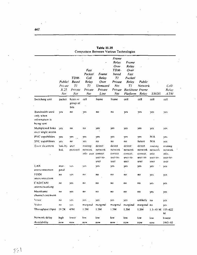
,. ... - .
662
Switchmg unit
Bandw1dth uscd
onl~ "'hcn
mformJIIlln is
lx-mg scnt
Multiplc1(cd hnks
0\cr <;ingle acccss
PVC' capahilifics
SVC capa1'1ilities
ErrtH ti-c..ltmcnt
lA N
1ntcrn,nncct1on
FDDI
tnll'fl'lln':li:CIIOO
C"AD:CAM
lnternct\o\OTir..•ng
Mamframc
channd c:..tcn,•on
Voll'c
~ako
Throu~hput ( hps 1
NL'I\o\url·dday
A\·a•lahtlity
Pub/id Pril·arc X.25 Nct
packct
y es
y es
y es
y es
lml..-h~·
lml..
mar-
r:mal
no
no
nn
no
nn
1~ :!K
h•gh
now
Table 11.15 Comp:.1rison Between Various Technologies
Frame Re/ay Frame O ver Re/ay
Fas/ TDM- O ver Packeti Frame based Fas/
TDM- Ce// Re/ay TI Packetl Based Re/ay Over Privare Re/ay Public
TI TI Unmuxed Net TI Network Ce//! Pril·ate Pri\•ate Privare Private Backbone Frame Retar
Nct Net Line Net Platform Re/ay SMDS ATM
hytc" nr ce\1 fmme frame cell cell ccll ccll
~roup of
bits
no y es no no y es y es ycs ycs
nn no y es y es y es y es y es y e<;
y es y es y es ycs y es y es N/ A y e~
no ycs no no no future N/ A y es
U<;l.'f rout1n~: dctect: dctcct dctcct· dctcct routm¡_.: routm~
protocol 0('1\HHJ... nctwurk nctv.nrk nctwork nctwork nctwor'\.. nctworlo.
1nfo U\Cf CtlTTCCI corrcct cnrn:ct. cnrrcct. mto. tnfo: u:-.cr·IO· U~CT·IO· ll"CT·IO· USCT·fO· u~cr·tO· U\CT·IO·
U'>CT u~cr u ser u-.er u ser u ... cr
~e' ~es y es y es y es y es y es y es
~c-. no no no no no y es y es
y es no no no no no y e:-. y es
y es nn no no no no y es y es
~ C\ yco; y es y es y es unlikely no y es
y c.<. marg.m<~l m..~rgmal m<~r~mal m.1rginal mar~ mal no y e' 4~M 1.5M UM 15M 1.5M 1.5M 1.5-45 M 155-622
M
lnwcr lnv. low low low low low lowcst
00\o\ now now now now now now 1993-95

663
'•
intcrconncction cannot be dclivcrcd in full by fr<unc rclay bccausc of thc spccd limitations, and beca use it is a connection-oricntcd tcchnnlogy.
11.6 FRAME RELA Y EQUIPMENT
In a private frame relay network. thc nodal proccssor is thc most critica! componen t. With a low-capacity processor. framc rclay will not support thc rcqu1rcd throughput. A cell relay-based platform with cffcctivc nctwork managcmcnt toob i' t he type of equipment end-users are looking for. ·
A high-throughput nodal processor built from thc ground up. unafkctcu bv TDM restrictions. which supports high-spccd switching to facilitatc high cnu-toend throughput. low latency. and any-to-any conncctivity is rcquircd to Jcm·c thc advantages that frame relay promiscs. A fas! interna! procc,sor must be tN~d to sustain the switching· at the leve! rcquircd by thc ncw routcrs now rcaching thc market and by the data-intcnsivc user applications .
. The nodal processors must support standard high-spccd inll:rfaces tll thc routers to facilitatc the interconncction of equipmcnt from a varietv of vcndors. This open frame relay interface should support a full TI ratc in ordcr to properly interwork with existing router systems now deployed on dcdicatcd TI lines (sorne pwcessors do not support a full TI). lt is importan! that an adcquatc nurnher of PVC,; per frame relay interface he supportcd. A restrictivc numhcr of I'VC\ ddcats the link and port sharing hencfits of frame relay. ·
The nodal processors rnust support standard high--;pccd interfaces hct\\'ccn nodal processors to provide cell relay ami switching. Thc fkxibilitv of hc·1ng ahk to support fractional TI or full TI rates for the trunks i' nccc"ary in order to f1nc tune the network to thc actual traffic p_atterns tlf th.c corporation. (jcncrally. not alllocations in a company have thc sarnc incoming and/or outgoing traf!Jc vol u mes. Hencc. the ability to he ahle to utilizc a mix of Tls ami f-TI trunk' is an 1rnportant cost-saving featurc. Usuallv it i' hcth.Tto use outhoard CSU.-. so that !he LAN manager can optimize thc investment necdcd to ohtain thc app.ropriatc link management fcatures without duplication. The choice of the CSU can be lmkctl with the TI channel at hand: for cxarnplc. a link may or may not ~upport BXZS. ami so the CSU can be chosen appropriatcly. In addition. thc failurc of thc CSU .. possibly incapacitating a path. can he mitigatcd hy thc use ot a sparc CSU. which is more difficult todo when thc CSU is intcgrated with othcr hardware. 1 n addition. a nodal processor should not impose topological constramts in tcrms of thc nurnhcr of nodes which can he supported.
Not cvery uscr device in an existmg user network can he rctroflttcd with a $1.000 frame rclay board. A nodal proccssor should, thercfore, support dcv!Cc' such as asynchronous terminals. synchronous terminals. and X.25 streams for those

664
situations whcre thc framc relay interface is not available or will be installed at a future date.
A sophisticated network management capability is required to facilita te PVC establishment and to undcrtake al! the necessary monitoring functions so importan! in mission-critical enterprise networks. Á centralized system with access to thc entirc network through a distributed architecture is desirable. Graphical workstations with windows and user-friendly interfaces are a clear advantage. A rich feature set for fault. performance, accounting, security, and configuration management is. an importan! business advantage.
Sincc thc state of thc art is not going to stand still, the nodal processor must. be able to grow with new needs. features, and tcchnologies. Sorne examples are thc ability to migrate to BISDN, support SVCs, and deploy more data-intensive network management facilities in support of tighter control. The issue of congcstion control is critica! in order for the LAN-manager 10 guarantee a grade of scrvice to thc user community. A nodal processor should support the full ANSI congestion mechanism in ordér to achieve this goal.
ll.7 CARRIER SERVICES
Severa! carriers now provide or plan to provide public frame relay serviccs. Not only is it importan! that the service be available from a carrier, but it is also critica! that the scrvice be tariffed in a competitive way if users are to make invcstments for migration to the new technology. This section examines sorne issues pcrtaining to the public service.
ll. 7.1 Congestion Control lssues for Public Networks
As indicated. in frame relay thc entire ba.ndwidth. up to thc maximum acccss speed. can be madc available to a single user during peak periods. A problem may arise in the network if many users require this bandwidth simultaneousiy. as might be thc case when LANs from multiple organizations ( or departments within an organization) are terminated on thc nctwork. Thc frame relay network must be able · to dctcct any overload condition and quickly initiate corrective actions.
Congcstion control (also known as flow control) is alrcady needcd in traditional public packet nctworks. but in a frame relay n'etwork its need is more critica! duc t.o thc performance objectives of the latter, and the greater acccss spced. In X.25 nctworks, the access speed is normally much lower than the speed and capacity of the backbone. lt is unlikely that a single device would ever monopolize the backbone. In a LAN intcrconnection/frame relay environment, the routers seen as an ·ensemble may transmit a combined rate which might approach the capacity
·;, ·.·

665
of the backbone itself. A single router may flood the backbonc; this in turn will starve other circuits of bandwidth.
Temporary conditions of overload occur in any wcll-utilizcd nctwork. Nctworks which ncvcr expcrience tcmporary ovcrloads mav in fact oc undcrutilizcd. Over-engineering, however, is not a desirablc way to handlc congcstion control because such an approach is not cost-cffc"ctive. Ignoring thc issuc of congcstion is · also undesirable, sincc, in effcct, it mean~ not capitalizing on thc full potcntial of frame relay~ In private networks; transmission costs are a major componen! of any· design evaluation, and most of the benefits of frame rclay technology are los! if implcmcnting it demands thc leasing of cxccssive amounts of oandwidth [ 11.21 ¡. The challenge is not how to preclude any temporary eongestion. out how to rcact to it when it occurs. Ovcr-enginecring or, bettcr yet. relying on st<llistical averaging to obtain the most efficient utilization of deployed resources m ay be an approach that is· via,ble in a public network environmcnt. givcn the large populat10n of potential users.
The ANSI standards specify explicit congestion control notification bits and a congestion notification control message. Thc importan! fields in the addrcss portian of the frame reJa y formal are the FECN, BECN, and DE. dcscrihcd carlicr. In the ANSI standard, each of thc individual virtual circuits in a framc rclay connection (if the user and/or topological implemcntation calls for multiplc PVCs over a physical link) can be independently throttlcd back. To he fa ir. thc· sourccs that contribute the most to the congestion should be slowcd down thc most. whilc sources contributing less traffic should he slowed down lcss. Hcncc. thc nctwork must be ahle to idcntify which PVCs over a physical link or. ocyond thc acccss portion. in the network are responsihlc for monopolizing rcsources.
Both the user's equipment and the switch should oc ah le to rcspond to congcstion control actions implied by the congestion control fields. For cxamplc. during pcriods of heavy load, the network could signa! !he uscr's cquipmcnt. hv 'ctting the congestion bit, to reduce the traffic arrival rate; when thc ovcrload situa!Hlll dissipates, the opposite act10n could be aéhicvcd by setting the congcstion hit hack to normal. In sorne situations. the user's equipment could be ovcrlnadcd; for cxamplc, a LAN gateway may he scrvicing anothcr uscr and may not he ahlc lo absorb heavy loads of traffic coming from thc network. He re, the uscr's cq uipment mus! be able to throttle the network.
The ANSI standards a!so providc for a DE capability to discard sorne frames if the initial congestion control actions do not corree! thc situation. The network should not be designcd to discard frames indiscriminatcly: it is faircr to discard framcs from the users who contributed the most to the congestion. lf thc implcmentation supports the DE fiel d. this can be accomplishcd cquitably. since the user's equipment can indicare which frames shou!d be discardcd first. Thc DE capability makes it possible for the user to temporarily scnd more framcs than it is allowed on the average. The network will forward thcse framcs if it has the

-;¡ ~,-. . ·• ~
666
capacity to do so; but if the network is overloaded, frames with the DE bit set will be discarded first [ 11.21 J.
Sorne networkfequipment vendors may implement a simple flow control pro~ cedure, rather than the full ANSI capability.·For routers incapable of implementing the control mechanism of the ANSI Annex D specification, a simplified X-on/Xoff form of flow control is allowed by LMI. The optional flow controllimits transmission in the direction of the n·etwork, but not the reciproca! way. In the view of observers. while this approach is useful, backbone frame relay networks must also implement the full ANSI mechanisms; otherwise, the network will not be able to control effectively overloads from these devices.
Implicit Congestion Notification (to the transport !ayer of the ultimate user equipment. i.e., the PC) occurs when the user's end-to-end protocol determines that data been lost. Actions to deal with.Implicit Congestion Notifications usually take higher priority than Explicit Congestion Notifications. The former is normally handled by the ultimate equipment; the latter is handled first by the router and subsequently by the ultimate equipment. The network may indicate to the user's router that the data may be about to traverse a congested path by the FECN/ BECN bits previously discussed. The user response to these congestion notifications is dependen! on the type of notification and the frequency in which they are received [11.6].
· To reduce oscillations possibly due to transient congestion conditions, a congestion monitoring period (CMP) can be established by the user's router to track the frequency of Explicit Congestion Notifications received. This CMP is typically defined as four times the round trip del ay through the network. Thc CMP starts u pon receipt of a frame with the BECN or. FECN bit set, or if thc logical link is turrently recovering from a congcstion state. In a windowing environment, two window rotations may be used to measure thc CMP instead of four times the round-trip delay. Thé user's router receiving the FECN bit set in half or more of thc 'trames rcceived during the CMP should start throttling data in the direction of the reccived frame. Since ·data at any given time is typically wcightcd in the dircction opposite of the frame '>"ith the BECN bit set, thc BECN indication is likely to occur less frequcntly than the FECN indication. The user's equipment should thereforé start throttling data in the opposite direction of the rcceivcd frame when thc first indication of BECN is received [11.6] .
. During data transfer, one of the following four states is active. Typical carricrsuggcsted actions are [ 11.6] .
l. Data throttling due to 1mplicit Congestion Notification. Whcn a framc has bcen los!. as seen from !he cnd-to-end protocols, the data flow should typically be rcduced by approximately one-fourth of curren! flow. Data should not be throttled below the minimum end-to-end protocol flow (e.g., minimum window size).
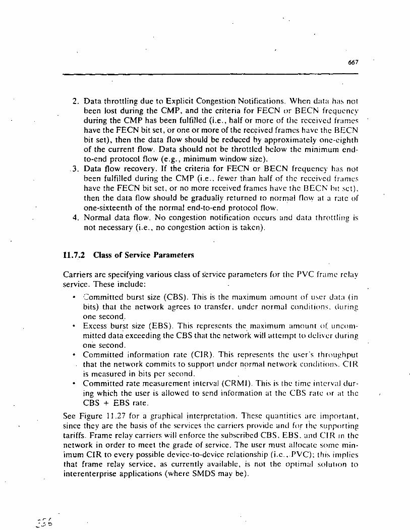
667
2. Data throttling dueto Explicit Congestion Notifications. Whcn data ha; not been lost during the CMP, and the criteria for FECN or BECN frcqucncy during the CMP has been fulfilled (i.e., half or more of thc rcccivcd frarncs have the FECN bit set, Or one or more of thc received frarncs ha ve thc BECN bit set), then the data flow should be reduccd by approximatcly onc-cighth of the curren! flow. Data should not be throttlcd bclow thc mínimum cndto-end protocol flow (e.g., mínimum window sizc) .
. 3. Data flow recovery. If the criteria for FECN or BECN frcqucncy has not been fulfilled during the CMP (i.e .. fewcr than half of thc rcccivcd framcs havc the FECN bit sct. or no more rcceived framcs havc thc BECN hit sct). then the data flow should be gradually returned to normal flow at a ratc of one-sixteenth of the normal end-to-end protocol tlow.
4. Normal data tlow. No congcstion notification occurs and data throttling is not necessary (i.e., no congestion action is takcn).
11.7.2 Class of Service Parameters
Carriers are specifying various class of s·ervicc paramctcrs for thc PVC framc rclay service. These includc:
• -:::ornmitted burst size (CBS). This is thc maximum amount of u'cr data (in bits) that the network agrces to transfer. undcr normal conditions. during onc second.
• Excess burst size (EBS). This rcprcscnts thc_ maximurn amount of. uncommitted data exceeding the CBS that thc nctwork will attcrnpt to dcli\'t:r during one sccond.
• Committed information ratc (CIR). This rcprescnts thc uscr·s throughput that the network commits to support undcr normal nctwork condition,. CI R is mcasurcd in bits pcr sccond.
• Committed rate measurcment intcrval (CRMI). This is thc time intcrval during which the user is allowcd to send information at thc CBS ratc or al thc CBS + EBS rate.
See Figure 11.27 for a graphical interprctation. Thcsc quantitics are importan!, since thcy are the basis of thc scrviccs thc carricrs providc and for thc supporting tariffs. Frame rclay carricrs will enforcc thc suhscribcd CBS. EBS. and CIR m thc network in arder to mcet thc grade of scrvicc. The uscr must allocatc sorne mínimum CJR to evcry possible devicc-to-dcvicc rclationship (i.c. ,.PVC); thi' implics that frame relay scrvice, as currcntly availablc, is not the optimal solut•on to interenterprise applications (where SMDS may be).

668
Traffic (Ms)
H
,
Traffic (bits)
2
H
3 4
CIR throughput
lnstantaneous ~al
Access Rate
CIR
H
Time
5 6 7 8 9 10,1 12 13 (seconds)
Cumula1ive Arrival
Case 3 Case 2 Case 1
Case 1: Al 1·4 and t-5 the netwoñ( onty supponed CIR
Case 2: Al 1•'* the network only SupJ)Ofted C!R, bUt al 1·5 an excess burst rate was supported
Case 3: At 1•4 and t.S the network aupponed an aocess burSt rato
, 2 3 4 5 6 7 8 9 10,, 12 13
Time (seconds)
Figure 11.27 Traffic arnval and trcatment in a frame relay nctwork.
11.7.3 An Example.of Designing Networks With Public Frame Relay
A study of frame relay tariffs at press time revealed that each frame relay carrier had a different pricing scheme. Not only are these pricing schemes complicated, but a reliable comparison between services is difficult. lt is almos! impossible to generalize about the cost of frame re la y servtces from one carrier to another, .

) ? ~
' 669
especially when using published priccs (sorne carricrs ·avoid puhli~hing gcncric tariffs; while nondominant carríers are not obligated to puhlish tariffs. such. puhJication would certainly help the user choose a service/carricr) r 11.52. 11.5Jj.
While sorne carricrs offer flat pricing. othcrs offcr pricing hascd on thc numhcr · of user locations. the amount of bandwidth. and distance betwccn thc carricr's
POP and thc user.'s location. Sorne carriers sum the hand~idths dcfined on all thc network PVCs (whether actually in use or not). Sorne add a surchargc for any data that needs to be delivered ovcr a user channel exceeding 1 )iOO miles (prcsumahly this is related to the fact that the propagation time slows down thc dclivcry of thc data to the user. implying added nctwork rcsponsihility). Many havc acccss fine charges. although _sorne hide ( absorh) that cost.
A published comparison among three carricrs for scrvicc in four citics (Chicago, New York. Dalias, and Los Angeles) is shown in Tahlc 11.16 [ 11 .52j. Thc table shows that there is a lot of variability in thc cost. and a rational cornparison is difficult.
One conclusion that does emerge is that frame rclay scrvicc is chcaper than fully interconnecting all locations with point-to-point high-specd digital llncs. A public frame relay network gcncrally costs ahout a third of a fully intcrconnccted mesh network. Assuming that the carricr has a servicc POP in all LATAs wherc the user has traffic sources/sinks. thc cost-cffcctivncss of thc framc relay ,ofution increascs as thc number of si tes to be conncctcd incrcases. In addition. )(,. and 64-kbps framc re! ay scrvices are universal! y chcapcr than comparable X.25 st:rviccs. which frame relay can replace in a numbcr of situations (c.g .. LAN interconncction). "'
Table 11.17 compares a puhlic framc rclay nctwork with FTI cfkctivc throughput (the physical acccss fine may in fact havc to he a TI fine). a tr;~dJtional mesh FTl nctwork, and a priva te onc-node frarnc rclay nctwork. Figure 11 .2X
CompuScrvc Srrmt Standard Srrmt Rcscrved Srnnt Hybrid \Vdtcl
Tahle 11.16 A Cost Companson Bctwccn framc Rclay Scn,icco; (Janu:1ry ll.llJ2)
S::!J. !~O Sl2.2nll to $13.3711 (dcrcnding on usagc volumc) SJfl.JIKI $1 ~.~211 $1G.h20 lest•matcd)
Covcragc: Ch1cago. l'<cw York. Dalias. Los Angeles Acccss (physical TI): $1.300 Access (logical): 1.024 Mbps PVC: 51 2 kbps
111Some carriers report that many users in fact employ the service at thc 64-kbps ratc.
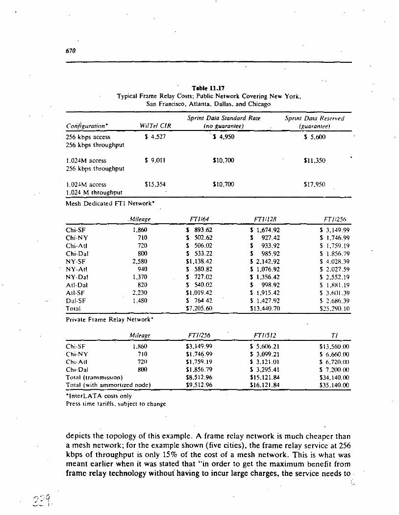
tí:~· q .::___. 1.
670
Table 11.17 Typical Frame Relay Costs; Public Network Covering New York,
San Francisco, Atlanta. Dalias. and Chicago
Sprint Dala S1andard Ra1e Spnnt Data Resen•ed Corlfiguration• Wi/Tel CIR (no guara mee) (guaralllce)
256 kbps access S 4.527 . S 4,950 S 5,600 256 kbps throughput
J.024M access S 9.011 $10,700 SI1.350 256 kbps throughput
1. 024M access $15.354 S10,700 $17.950 1.024 M throughput
Mesh Dcdicated FT1 Network'
.Mileage FT/164 FT/1128 FTI 1256
Chi·S·F 1,860 S 893.62 S 1,674.92 $ 3,149.99 Chi-NY 710 S 502.62 S 927.42 $ 1.746.99 Chi-A!I 720 S 506.02 $ 933.92 $ 1.759.19 Chi-Dal 800 S 533.22 S 985.92 $ 1.856. 79 NY-SF 2,580 $1,138.42 S 2.142.92 $ 4.028.39 NY-Atl 940 S 580.82 S 1,076.92 $ 2.027.59 NY-Dal 1.370 S 727.02 S 1.356.42 $ 2.552.19 Ati-Dal 820 S 540.02 $ 998.92 $ 1.881.19 Ati-SF 2.230 $1.019.42 S 1.915.42 $ 3.601.39 Dai-SF 1.480 S 764 42 S 1.427.92 $ 2.6K6.39 Total S7.205.60 S13.440.70 $25.290. JO
Priva te Frame Relay Network'
M1leage FT/1256 FT/1512 TI
Chi-SF 1.860 $3,149.99 S 5,606.21 $13.560.00 Chi-NY 710 $1.746.99 $ 3,099.21 S 6.660.00 Ch•·Atl 720 $1.759.19 S 3,121.01 $ 6.720.1KI Ch•·Dal 800 Sl.856.79 S 3,295.41 S 7.200 00 Total (1ransmass1on) $8,512.96 Sl5.121.84 $34.140.00 Total (with ammoruzed nodc) $9,512.96 S16.121.84 $35.140.00
'lnterLATA costs only Prcss lime tariffs. subject to change
depicts the topology of this example. A frame relay network is much cheaper than a mesh network; for the example shown (five cities), the frame relay service at 256 kbps of throughput is only 15% of the cost of a mesh network. This is what was meant earlier when it was stated that "in order to get the maximum benefit from frame relay technology withoui having to incur large charges, the service needs to .

")t'D .:;1
San Franc:isoo
San FrallClSCC
256 Kbps
256 Kbps
Public Fr~me Rol ay Network
Dalias
Chicago
Pr1Yat8
Frame Relay Network
N x 256 Kbps (N • 1. 2. 3, 4)
Dalias
67/
New Yon.:
Atlanta
Now Y cric:
Naw York
Allanta
Figure 11.28 Comparing a public frame relay network with a mesh network and Wllh a privatc frame relay network.

-.' lj \
671
be provided by a carrici"." The public frame relay network is only 25% (or lcss) of the cost of an appropriately configured private frame relay network. Note.that in the public frame re la y network, the throughput for each PVC from San Francisco, for example, could be 265 kbps. This implies that the private frame relay version must use a Ff1 link to the node (which in this example was placed in Chicago). which should be 1.024 kbps as a "conservative" design, or at least 512 kbps as an "average" design. ·
One issue not clear from Table 11.17 is quality of service. In the full mesh network. the end-to-end delay approximately equals one transmission time. For example, if the mesh network used Ff256 and the user's (ethernet) frame was 1.500 octets. then !he delay would be 0.047 seconds. In the one-node priva te frame re la y network, the delay would be 0.104 seconds, since the transmission time mus! be incurred twice, and there is nodal protocol processing ·delay (which we have assumed at 0.010 seconds). If two backbone nodes must be traversed (and it is assumed that the backbone link is also 256 kbps, the nodal protocol processing delay is 0.010, and the frame-to-cell and cell-to-frame assembly is 0.020 seconds), the total end-to-end delay would be 0.181, approaching the notorious de la y incurred through a satellite link.
· This example should make clear what this entire book has tried to do: there is no uniquely superior answer toa corporate networking problem. Each solution has advantages and disadvantages. A mesh network is more expensive, but the grade of service is better. A public frame reJa y network is cheaper, but therc is more nctwork deJa y. the service m ay not be available at all si tes, and dedicated TI access lines are still required. A private frame relay network is cheapcr than a mesh nctwork. whilc costing more. than a public network; this solution. howcver. requircs the user to purchase ncw equipment and to manage it. Anothcr factor to take into.consideration is the cost of the "access." If the carrier has a POP in the LATA(s) in question. that cost equals the cost of a TI facility between the user"s loc~tion and ·the POP. If the carrier only has a few nades· across the country~ as is currently the case. the user may have to incur the cost of the T1 line to reach the switch; this could be hundreds of miles (sorne· carriers pickup the cost of the access up to sorne distance).
The author is of the opinion that a practitioner may be hard pressed to try to rationalize why Company X (which may be profiled in a trade press magazine. or dcscrihcd by collcagues) u sed a given tcchnology. Likely, Company X u sed a .tcchnology beca use of ( 1) how well a vendor m a de the case for the tcchnology they selL or (2) sorne senior manager in the company was "sold'.' by a trade press article which highlighted the advantages of a technology without ever describing its drawbacks (as is thc practice), or point out the fact that the utility is highly dependen! on the user's specific em·'-~nment (ultimately, trade press magazines are influenced by the companies supporting them through their advertisement dollars).

673
11.8 FRAME RELA Y PRODUCT A VAILABILITY
Vendors started to embrace frame relay tcchnology in 1990. and cquipmcnt was appearing in 1991. As of press time. at lcast thrcc dozcn vcndors havc annnunccd frame reta y cquipment and/or scrvices ( 11.54]. For sorne vendors. such as thusc offering internetworking produets. adding frame reta y support m ay rcquire a simple software upgrade of the hardware. since bridgcs and routcrs are a\rcady bascd on paeket architectures. The same HDLC chips current\y uscd on thc communication 'side can be micro-programmed for framc rclay [ 11.25(. Thc first wavc of framc relay products must at leas! provide support for !he acccss protocol. congcst ion management .. and the status of PVCs. From a uscr's pcrspcctivc. in ordcr to dcploy the equipment in the critica( path of thc corporation·~ ability to comluct hu-;inc,s. robust and sophisticated network managemcnt capahilitics must a\so he in place This section provides a partial survey of sorne frame rclay products in ordcr to reinforce the fact that the tcchnology is quickly matcrializing and that u-;crs can begin to study if and how frame relay cari tru\y hencfit thcir bottom ·lincs in tcrms of decreasing their communications budget. This information will cvolvc nvcr time.
11.8.1 TI Multiplexers and Nodal Processor Manufacturers
Vendors of TI multiplexcrs hascd on circuit switchmg TDI'v1 architccturc' nccd mure work to transition to framc relay than vcndors alrcady support1ng l;1st p;1ckct switching. These vendurs necd tn add a ce\\ cn¡,!lnc to support trame rcl:l\' in an effcctive manner: sorne havc done so. whilc othcrs are in thc procc-;s of doing -,o. See Table 11.18. which providcs a varicty of othcr product information (hascd partially. on [11.551). Two approachcs wcrc uscd in thc carly 19l)!), as a short-tcrm solution. short of a total architcctural rcdc,ign. Thc first approach is too! fcr fr:m1c rclay modules. or hoards. for cxisting circuJt-switchcd multiplcxcrs. Thc .'ccond approa~:h is to use a front-cnd framc relay.dcvclopctl hy anothcr vcndnr or stratcgic partncr. With ncar-tcrm solutions. thc TI multiplcxcr may typicallv onh· allocatc a dcfinite amount of bandwidth for framc rc\ay support. and thcrc mav he performance and throughput problcms. In thc long tcrm. traditional TI cquipmcnt will have to be rcdcsigned to mcorporatc fabrics which can cxploit fully thc adv~mtages of ccll switching. An importan! considcration is congcstion control. Somc vendors have cxpcricncc in this arena. and othcrs may not. In particular. vcndors of packet switching equipment have dcalt with this issuc for ycars; vcndors o! TI multiplexers have gencrallv not had a nccd to dcal with it. Thcsc products are typically used for prívate framc n:lay networks. althuugh thc more ~ophi-;ticatcd cquipment (e.g .. StrataCom's IPX) can a\so be uscd tn huild puhlic nctworks.
StrataCom's IPX Fast Packct multiplcxcr has suppnrtcd a ccll n:lay cnginc since the mid-1980s [11.20]. To support frame rclay, thc IPX requircd a so!twarc

? L\ 'J. ~ -'
674
Table 11.18 Partial List of Frame Relay Nodal Processo111
M in Max Access Lines Frame, Frame,
Vtndor Product Octets Octtts 64 kbps 512 kbps TI N NI'
Ainnet FRNS7000 5 1,600 63 32 8 Arpanet datagram Dowty . FPX 2000 1 4.096 120 80 40 FR Hughes Network FRS 9000 1 2,100 384 128 32 FR NET 7 2,112 220 150 150 FR Netrix #1-ISS 1 4.096 300 48 16 FR Ncwbridge 3600 IFS 1 8.200 30 4 FR NTI SiDMS 5 2.106 14,000 2,448 612 ccii/ATM
DPN-100 1 2,048 NTI"s UTP StrataCom • 1PX 32 5 4,506 80 80 20 cell Telematics NET-25 5 4,096 64 16 16 Telematics" TNP Timplex Frame 5 1,600 12 12 12 FR
Scrver US Sprint TP4900 8,189 528 66 22 FR
"FR = Frame relay
upgrade and frame relay cards (while routers typically already have HDLC cards, T1 rnultiplexers usually do not). Early support included Cisco routers [11.39]. The frame relay card. accepts frame relay frames and segments thern into 24-byte ce lis that can be transmitted over the StrataCom's proprietary T1 backbonc. Uscrs are not forced to dedícate bandwidth to the frame relay services a priori and on a preallocated basis. Each frame relay board (dubbed FRI-lM) consists of a V.35_ interface with four ports and costs $12,000. Initially the UNI was not supported at the full Tl!E 1 rate (it supported 1.024 Mbps), but as of 1992 these access rates are supported (using boards dubbed FRI-2M, which cost $14,000) [11.56]. Carriers reported to use StrataCom's equipment include AT&T, WilTel, CompuServe, National Telecom Corp. (Canada), and Telecom Finland. The IPX switch also supports voice, and is therefore a mixed-media nodal processo.r (prívate implementations can support voice and data; but, to date, publi2 implernentations using the lPX only support data). Between the end of 1990 and the end of 1991, StrataCom sold 2,000 frame relay ports [11.57]. In 1990, StrataCom and DEC announced an equity agreement: resulting in DEC's worldwide distribution of StJataCom's IPX systems [ 11.58]. ·
AT &Ts BNS-1000 Fast Packet Switch is a multiport data-only switch supporting frame re la y on the DTE user si de and cell re la y on the network si de. ANSI and CCITT standards are supported on the access side (T1.606). Access rates can be as high as a full TI or El (2.048 for European operation), or can be a standard subrate (11.59]. Preprovisioned PVCs' operation through the BNS-1000 makes network administration simple and eliminates the delay associated with call setup,

.... ; :_: . i ¡-
675
which is otherwise needed. Standard physical access-sidc interfaces are supportcd. including CCITT V.35, EIA RS-449, and EIA RS-232. At thc uppcr protocol layers. the node transparently supports TCP/IP and othcr LAN industry stand;mk BNS-1000 nodes connect with other nodcs.over carrier-providcd TI orE 1 links. or prívate fiber. Cell relay is used on thc network sidc. Whcn widc-area confi¡!u· rations require multiple nodes, a node-to-nodc maintcnancc channcl up to -1-1 kbp~ is available to support the user's managcmcnt rcquircments. The nodal proccssor can be configured as a frame relay switch in an cxisting multiplc rou.tcr cnvironmcnt; alternatively, when used in conjunction with thc A T &T LCS200 Nctwork Routcr and LCSJOO Network Gatcway products, it can be configurcd as a complete 'irtual prívate network platform for wide-arca LAN intcrconncction. Thc sw1tch achJcvcs high reliability using both hardware and software redundancy for call proccssing. Automatic alternate routing is supportcd on thc backbone sidc. In thc cvcnt of failure or high incidence of fault occurrence on links bctween nodcs. thc Scssion Maintenance feature automatically detects trunk failurcs and rcroutcs tr;¡ffic to_ alternate trunks. using previously unassigned bandwidth. Existing and rcroutcd traffic can sharc the samc trunk. Thc proccss of dctcction. bandwidth ncgotiations. and route switching is accomplishcd w1thin 10 scconds. Rcrnutcd tr;¡ffic can be moved back to its original path whcn thc faulty link is rcstorcd. Thc ""itch suppmh over 30.000 endpoints simultancously ( 15.000 two-way conncctions). ovcr a pn\'atc nctwork. in a nonblocking modc. lt c;¡n switch and forward 4-1.11110 packcts per second. The hardware is scalablc in tcrms of thc numbcr of framc rcla\' intcrf<Kc> the individual nodes support in modules of four ports !11.1!. Thc BNS-111110 is aimed at prívate frame rclav networks: a switch for puhlic nctworks. thc BNS-2000. is also available from thc manufacturer. although thc empha~is of thc I<Jtter is on SMDS.
Nctwork Equipment Technologics was rcptntcd to he looking at dcsigning a frame rclay interface for its 1 ntcgratcd D1gital Network Exchan¡!C ( 1 DN X) T 1 mutiplex product. The company was planning to offer first a proprict;¡r\' IDNX board that incorporales the functions of a routcr and a high-pcrformancc p<1ckct switch to support direct LAN connections on thc TI multiplexer. Thc card would la ter be adaptcd to support frame rclav [ 11.5UJ.
GDC has made publiccommitmcnts toa framc rclay interface to thc Mc¡!amux TMS TI multiplexer. In addition to thc new interface. thc cquipment mternal hus was to he enhanced lo support both a circuJt-switched as wcll as a packct-sw'itched architecturc. lt was planning on combining elcments of TDM/circuit switching with framc re la y and ccll switching [ 11 .20J.
Ncwbridge has announccd framc rclay surport through a new Di~trihuted .Communications Processor module of its 3600 MainStrect Bandwidth Manager TI multiplexer. The product formats data from attachcd LAN~ into the framc rclav format and passes the data unchanged over the circuit-switched prívate backbone. lnitially, backbone bandwidth was allocated among TDM data. voice applications,
676
and frarne rclay datn in a prcdctcrrnined way rather than dynarnically (this is 'truc of all circuit-switched T1 rnultiplexers).
Motorola Codex has also announced frarne relay suppport in its product line: the 6290 Series TI Multiplexer. the 6525 Paeket Switch. and.the 6507 multifunction PAD. The frarne relay interface fór the 6290 is irnplemented using a two-card sct: a four-port V .35 interface anda frame re la y PAD. The cost of upgrading an existing
· nodc is in the $20.000 range, while the cost of a new 6290 equipped with frame relay interfaces starts at around $40.000. The 6290 can be managed using an OSI- · based systern. The 6525 packet switch can grow in 6-port increments up to a total of -18 ports: like most switchcs. it supports both dialup asynchronous terminals and access over a dedicatcd line. Adding the frame relay interface to an existing 6525 enables users to create X.25 subnetworks that feed into the 6290 fast packet backbone. Beginning in !991. the frarne relay interface beca me standard equipment on the packet switch; thc switch upgrade costs in the neighborhood of $5.000. The frame relay software supports up to 32 logical links over a single physical connection. The 6507 PAD supports ports individually operating distinct protocols. including Bisync/SNA. frarne re la y. and asynchronous dialup. The PAD can be connectcd
· to etther the 6525 packct switch or the 6290 fast packet switch, and it costs in thc neighborhood of $2.000 [11.15].
Timeplex announced support of frame relay in both its internetworking and rnultiplexing product line [11.12]. The FrameServer System can be uscd either as a standalone frarne relay nodal processor or in conjunction with the Link multiplcxerfamily. Thc processor is quoted at $14.000 to 25.000. A framc re la y capability for the router product linc has also appeared. allowing routers to connect to a puhlic .or privare frame relay network. SNA traffic can also be consolid~tcd for transpon over the WAN framc rclay network. The capability costs in the $1.000 rangc ¡tl.l2].
Other vendors with frame equipmcnt includc ]11.50] Coral Network Corporation and Hughes Network Systems; this· list is likely to grow over time.
11.8.2 Router Manufacturers
1\lanv router vcndors now support frame telay interfaces. including 3Com. ACC. AT&T. Cisco Systems. CrossComm Corp .. DEC. Hughes, Proteon. RAD. Sun Microsystems. Synüptics. Timeplex, Vitalink Communications.· and Wellfleet [ 1!.60]. Sorne routers can be upgraded using a framc re la y software module; these range in price from $750 to $4.000. Sorne routers support both frame relay and SMDS. Most routcrs support ANSI LMI (Annex B and/or D).
--·l '

677
11.8.3 Packet Switch Manufacturers
Traditional packet switch rnanufacturcrs are also positioned. in thcory. to ~upport frarne rclay, but they need to upgrade thcir switchcs to support highcr 'rcct.ls. These vendors ha ve not rnade rnajor breakthroughs in spccds in the past dccadc.
· and sorne observers question their ability to respond to the ncw cnvironmcnt. Bursty applications in LAN interconneclion require DSI or DS3 spccds to achicvc optirnal operation in today's environrnent of "nctwork cornputing." file transfcrs. graphics, and decision support systems (such as sprcaushcct applications). Tt~is
type of equiprnent tends to use FRI at thc NNI. rathcr than ccll rctay (futurc rnigration is possible). Sorne vcndors are described bclow.
Northern Telecorn announced a frarnc relay interface for thc DPN- 100 packct switch. The switch can be used to support hybrid public/privatc nctworks. A frarnc relay capability for Northern's CO switchcs. DataSPAN. is also avaitablc. DataSPAN's offering has been developcd to rctain cornpatibility with thc inqallcd base of CO switching equiprnent (both local and toll officcs). DataSPAN is not an adjunct frarne relay switch. which could introduce OAM&P cornplcxitics for thc carrier. lnstead, the frarne relay fabric can be intcgratcd on an cxisting switch. sharing cornrnon equipment, interfaces. and operations systcms. Dat;1SI'AN is based on the Link Peripheral Processor of a DMS SuperNodc. Thc Link Pcri pheral Processor serves a variety of functions, including ISDN D-channet packct handlcr. Signaling Systern 7 rnessage processor, and frame rclay handlcr. Anv DMS-100. DMS-200, or DMS-250 switch in the network can be upgradcd to Dl'v!S SupcrNode. To add frame relay service. appropriate interface cards are put in front of. and new software is pul into. the Link Peripheral Processnr 1 1 1 .2. 11.17]. Northcrn's irnplementation provides the PVC version of thc scrvice. but an ISDN.'SVC vcrsion is under devetoprnent [11.61]. Each frarnc relay interface can acccpt an unchannelized OSI signa! ora channelized OSI representmg 24 individual 56 kbps. On thc ·trunk sidc, DataSPAN operates in a cell switching mode. Thc uscr's mcssagc arrives at thc switch in a frame conforming to thc framc rclay spccification: thc switch segments the frame into cells artd transmits thcm across thc intcrofficc facilities. At the remotc end. the cells are rcassembled into frames whilc guaranteeing order preservation. For the applications requiring speeus in the '1.6-kbps range. DataSPAN may be connected toa 56-kbps service (DOS or ISDN). Thcsc interfaces are supported via standard DMS SupcrNodc Copper periphcrals: thc lower speed circuits are rnultiplexcd into channelizeu DS!s and conncctcd to units on the Link Periphcral Processor. Many LECs and IXCs are equipping thc1r DMS SupcrNodcs with Link Peripheral Proccssors to implcment Signaling Systcm 7 capabilities [11.18, 11.62]. A tria! with NYNEX for the frarne relay interface on the DMS-100 and DMS-250 was planned for 1991.
BBN Cornrnunications was bringing out in 1992 a high-end packct switch ·Supporting frarne relay. The new T/300 Packet Switching Nodc supports up to 77
? /1 / .... ~ ~· ¡v

678
ports (14 of which c~n he trunks and the other access ¡:iorts) at speeds from 9.6 kbps to 1.544 Mbps. The T/300 being tested in 1991 was reportcd to offer a· fivefold improvement performance compared to BBN's existing X.25 packet switch. the C/300 (11.63]. The T/300 uses a bus that can be upgraded to provide more power when needed through a serial 110 processor. From one to four processors. all working independently for fault tolerancy, can be used. A frame re la y interface was planned for thc end of 1991. The basic price is $45,000. BBN was also working on a cell relay/switching to support LAN interconnection and imaging. The ccll relay switch will use the busless architecture developed for use in the TC/2000 parallel computer, where multiple processor cards are linked using an interna! packet switch. The system is upward scalable. since the fixed-resource bus is replaced by the packet switch,which in turn can be upgraded.
Other vendors include Amnet Inc., Dowty, Hughes, Netrix Corporation. and Telematics (see Table 11.18).
11.8.4 Front-End Processor and Host Access Manufacturers
IBM has introduced a frame relay interface for the 3745 FEP; this includcs both the hardware upgrade and the appropriate network control program (NCP) software [ 11.47. 1 1.64]. A number of vendors provide SNA frame relay adapters. including Frame Re la y Technologies. lnc .. Motorola Codex, Sync Research. and StrataCom. M-ultiprotocol PADs are providcd. among others, by Dynatech Communications. FastComm. GDC. Hughes Network Systems, Memotedfeleglobe, and Sync Rescarch.
11.8 .S· Carriers
Uscrs can· access a carricr through an access line of various speeds up to TI. Most carricrs offcr a committed information rate (CIR) serVice. CIR specifies thc mínimum amount of handwidth guaranteed to ·a user between any two pomts; CIR can he as high as the acccss rate (refer back to Section 11.7.2 for a dcfinition of CIR). Carricrs offer a CIR subscription and let the user bid for more bandwidth. up to thc full acccss speed. on a network contention basis. lf the CIR is exceeded, the user's frame rclay dcvice can send the data, but it should set thc DE bit 10
indica te the data can he discarded if necessary. Sorne carriers also provide a nonguarantccd service. whcre thc entire bandwidth is available on a contention basis. Service is typically tariffed as (I) a flat rate, (2) a flat rate with a usage fee, and (3) a straight usage fe e." Flat-rate pricing charges for two components (both of
11Thc tariff structures currently, in placé are limi¡ed by the nctwork cquipme~t providmg thc servicc.
For instance. those nctworks us1ng the StrataCom multiplcxer cannot gather usage data and are therefore timited lO nat•ratc pricong. us Spnnt's Tates use a nat rate plus a usagc fee ..
¡1 ,,
'¡ -\: .._. \-
679
which are typically user-selectable): acccss port specd and bandwidth of thc nctwork edge-tp-edge conncction.
At press time, a number of carricrs. including Sprint Data Group. WilTcl. AT&T, CompuScrve, BT North Amcrica, NYNEX. Pacific Bcll. Southwc<;tcrn Bell, U S WEST, Cable & Wireless. lnfonct Scrviccs Corp .. Graphnct. MCI Communications, and thc BOCs were providing (or plan to providc) puhlic framc relay serví ce in the U .S. [ 11.65J.
WiiTel was the first providcr of public framc rclay scrvii:cs. with scrvicc starting in March 1991 and covering approximatcly 100 citics. lts infra<tructurc i' bascd on StrataCom IPX multiplcxcrs (nodal proccs,ors) (11.56J. WilPack is r·nccd at a flat rate bascd on thc access port spccd and thc total Cl R out of ca eh nmlc [ 11.66]. Table 11.17 is based on publishcd tariff data at prcss time (se e Ftgurc 11.28). Original access specds werc 56. 64.256. and 1.02-1 khps: acccss spcClb now include 384 kbps. 512 kbps. 768 kbps, 1.544 Mhps. and 2.04X Mbps.
In late 1990. Sprint Data Group announccd a plan to provtdc framc rclay services. Sprint Data Group. formerly Tclenct Communications Corp .. startcd to offer the service throughout its international nctwork by carly 1 YLJ2. Thc snvicc can be obtained on a usage-hased plan (standard pricing). a flat-ratc plan ( rcscrvcd pricing), arid on a hybrid pricing plan fi1.52J. Sprint Data's framc rclay scrvicc is based on an upgraded version of thc company's TP4900 packct switch ami was scheduled to be generally availahlc in the 1hird quartcr of IYlJI through more than 200 Sprint Data points of prcscnce in thc US .. Japan. and thc U.K. Thc nctwork uses thc TP7900 Fast Packct Multiplexer as the nodal proccssor. Once dcriPvcd. the switches will he ablc to simultaneously support framc rclav and X.2~ traffic. Users are ablc to access the service with TI links. 56-khps DDS. ami N x h-1-khps fractional TI links. Thc TP4YOOO pcrforms PAD functions to conncct async. SNA. and X.25 dcviccs to the frame rclay nclwork. Bcsidcs lhc public swilched scrvicc. Sprint Data rlans to scll framc relay-equirpcd packcl switchcs lo cumpanics wilh prívate data networks. valuc-addcd nclwork opcrators. and forcign Prrs !JJ.(,7¡.
CompuScrvc. lnc .. supports acccss al 56 kbps and N x M khps (N = l. 4. 16). Scrvicc has bccn availablc since Octohcr 1'191. Framc-Nct. a' lhc scrvtcc i' called, is based on ovcr 50 IPX nodcs. CIR rangcs from 4 to 512 kbps. Thcy also serve London. Frankfurt. and Toronto. Pricing is bascd on lhc acccss spccd and the total framc bandwidth aii(Kation (FBA). FBA is thc cnmhtncd bamhvidlh of all PYCs emanating from any acccss point. For examplc. if thc acccss is 25(, khp.;. and threc PYCs are dcfincd. cach at M kbps. lhcn thc FBA is 1'12 khps. Thcré is a surchargc for every site more than 1.800 miles from thc point of origin. G•vcn an access of 1.048 Mbps. the FBA chargcs rangc from $1.200 for 64 kbps to $5.-165 for 2.048 Mbps. Supported cquipmcnt includcs 3Com. ACC. Cisco. Fastcom. Sync Research, Synoptics, and Wcllflect.

680
BT North America supports access at 56 kbps and 64 kbps. BT's ExpressLanc frame re la y service is available in 160 U .S. cities,. starting in September 1991. The company offers servicc to four European countries. A flat domestic chargc of $2.100 pcr month in eludes a frame relay-configured router, software, dcdicated port acccss at the 56/64 kbps, an access linc up to 60 miles long, and unlimited framc transmissiem. Users that already have equipment can also obtain the service on an unbundled basis. Supported equipment includes ACC and Cisco routers. Prices for international service ranged from $3,000 to $4,600. Initially, BT focused on providing scrvicc at the OSO leve! [ 11.68, 11.69].
Cable & Wireless was planning an international service for North America. Europe. and thc Far East by 1992. The network was expectéd to have 17 nades (based on Northern Telecom's DPN-100 switches) in Europe, seven in the U.S., one in Hong Kong, and one in Japan (in 1993). U.S. users can access thc servicc from 70 local POPs connected with the switches in Atlanta, Chicago. Dalias. Los Angeles. New York. San Francisco, and Washington (11.65]. Access includes 56 kbps. N x 64 kbps.Tl. andEl.
NYNEX sces framc relay as a complement to SMDS. Thc company was planning a frame relay tria! in 1991. The carrier was planning a tariffcd offcring by thc middle of 1992 [ 11.18]. Northern Telecom is supplying the cquipment to support the scrvice. The company is currently installing a SuperNode processor on a DMS-100 switch anda link peripheral processor to support trame relay for thc interna! tria!. NYNEX was planning to offer acccss at 56 kbps and 1.544 Mbps. SMDS is also being tested in 1991, and service is eiq)ccted to be availablc in 1992 [ 11.62].
Southwestern Bcll Telephonc undertook a laboratory tria! in 1991 to 1992 using ,Northern·s DMS-100 CO switch connccted toa DataSpan frame relay proccssor. Tariffs wc.re hcing fi.lcd in 1992 for metropolitan arcas of Texas. Oklahoma, Missouri. Kansas. and Arkansas.
·At lntcrop 92 thc scven BOCs. Cincinnati Bcll. and Southern Ncw England Tclcphonc announccd that 10 addition to having SMDS gcnerally deploycd by thc middlc of 1993. thcy will also provide frame relay scrvicc.
AT&Ts framc rclay scrvice was schcdulcd for mid-1992 [11.56]. Thc service is known as lntcrSpan Framc Rclay Service and supports 56-kbps and N x 64-kbps (N = 1 to 24) acccss. A T &T rccently extended service tose ven Europcan countries. including the U K. francc. Germany. and Spain. Graphnet, In c., supports acccss at N x 64 kbps (N = l. 2. 4); the company offcrs scrvice to London. París. and Toronto. lnfonct was plannmg coverage to 11 countries by the end of 1992 [ 11.65]. MCI Communications was planning scrvicc inauguration by the middlc of 1992. using thc Mctropolitan Arca Nctwork Switching System cquipmcnt from Siemens Stombcrg-Carlson. This system is a. cell-based switch capable of supporting both voice and data [ 11.70].
.--·
681
Bell Canada has already undertaken a frame relay tria! using Northcrn Tclc- . com DMS-100 switch es. The tri al began by phasing in framc relay. going from conventional circuit-mode connectivity between the hridgcs to logical links undcr frame relay. The .introduction of frame rclay in uscrs.· cnvironmcnts was rcportcd to be simple and transparent (framc relay was seen asan cvolution. nota rcvolution. for users and developers alike). The ability of framc rclay hridgcs to continuc to work in existing contexts, such as prívate line, could case the transition to framc relay by decoupling the modification of the routers from the changing of thcir conncctivity to the logicallinks of a frame rclay servicc. The conclw,ions wcrc.: that. in general , users should expect higher performance with framc rclay comparcd to X.25 services, due to less tandeming and the potentially highcr spccds in both access and trunking. Frame relay providcs a balance bctwcen functionalitv and speed that is reasonably suited to the need of LAN bridges for W AN conncctivity [11.71].
National Telecom announced a public frame rclay servicc in Canada, callcd FrameWork, for late 1992. Five cities were to be covercd initially. with cxtcnsion to 13 cities by 1993 [11.56]. The company was planning to offer CIR from 9.6 kbps to 512 kbps.
Other value-added network providcrs wcrc expcctcd to announcc thc introduction of a public switched framc relay scrvice in carly 1992, with scrvicc availability in late 1992 or 1993. For example, cight intcrnational carricrs had plans to offer servicc in 1992 [11.41]. This implics that uscrs will havc more carricrs to choose from. more cities from which they can gct acccss to thc scrvicc. ami pricc competition. Carncrs offcring X.25 packet-switchcd, wanting to upgradc intcrpacket switch links from 56 kbps to 1.544 kbps. secm to havc fcw options but to embrace frame rclay.[II.72].
As of early 1992, customcr pressure rcportedly forced sorne carricrs providing early frame relay services to sharply reduce .the price, incrcase acccss spccds. and introduce long-term contracts and discount options [ll.óó]. A 25r!r rcduction in tariff was announced by at leas! one carrier.
11.9 THE ISSUE OF TRAFFICBURSTINESS
Oftcn enough, to make sales pitches for frame relay and/or fast packct ~witching tcchnology. the traffic stream is labeled as "(highly) bursty. ·· lf point sourccs indeed needed bandwidth from a nodal processor. then they might prcscnt a hursty arrival. However. if the traffic is aggregated over a LAN of 20. 50, or 100 uscrs. thc combined "internetworking" traffic channeled óvcr the router to thc communication link (or facility) is much more predictable than stated by vendors trying to (o ver )sell frame relay products.
681
Thc burstincss assumption can be fallacious in at least two key ways, which we describe below. We spare th·e reader a theoretical treatment based on queueing theory to show that aggregated traffic is much less bursty than the arrival traffic.
· Burstincss is measured in a number of ways, including looking at the correlation of the traffic. One simple way is to look at the ratio of the mean rate to the maximum rate.
The output of many queueing systems, particularly the M/D/1 (say, a router connected toa IT1 link), follow a fairly deterministic distribution. While thc length of a file ( or transaction) at the application !ayer of the Open Systems Intercorrncction Reference Model may in fact be random (say, for example, following the exponential distribution), at the data link !ayer the message is fitted into a number of fixed-length frames. Since these frames must share the common bandwidth of the underlying• LAN, which is a deterministic server with service time
Frame length in bits/channel bandwidth in bits
the arrival rate of these frames at a router would be at fairly deterministic time instances. particularly at high utilization. Aggregation and the law of large numbcrs make the burstiness nature of traffic a questionable issue. In addition. corporatc traffic is highly correlated in the time domain. For example, at the end of a wcck, month, or quartcr. many workers may be trying to produce reports, upload files, distribute data. and so on.
Consider the following simple example. A user at a PC on a LAN works for 15 minutes to prepare three e-mail messages intended for three users in another city. all on a remole LAN. Assume that the user types 10 words per minute, including think time. and sends each message at its completion, at the end of thc S-minute intervals. The traffic then looks like Figure 11.29, partA. The average would be 6,000/15 or 400 bits per minute; this compares with the bursty arrival of 2.000 bits at thé end of the 5th, 10th, and 15th minute. The peak is fivc times the average rate.
Now consider four othcr users (for a total of five), all on the LAN, and all undertaking the same task (say, for example, a pool of clerks-in fact, in a production mode. there could be dozens of users). Then, assuming thc traditional traffic arrival assumptions. thc traffic profile would be as shown in Figure 1 1.29, part B. Thc average is now 2.000 bits per minute and the peak is 2.000 bits per mm u te. The burstiness went down to 1 .O (it would indeed be advantageous if thc issue of correlated arrivals were considered instead of independent arrivals. but the Iiterature on such topic is rather meager). E ven assuming that the traffic "doubled up" as shown in Figure 1 1.29, part C (which is a statistically unlikely event), the average would be 2.000 bits per minute; and the peak would be 4,000 bits per minute, with a burstiness factor of 2.0. .,
Therefore, aggregated trafflc is less bursty than individual user traffic. The :~: traffic leaving the router is aggregated and its burstiness should be relatively lo,\Vj

-)~ r-, ... ,_......._ _
_. .... --
(a)
(b)
(e)
Figure 11.29
Traffic inblto
Ave- 400
2
Traffic in bits
3 • 1
Peak • Sx1 Ox5x8 -2000
5 6 7 8
Ave - 2000 Peak • 2000
1 1
9 10 11 12 13 1' 15 16
111111111111111 2 3 • 5 6 7 8 9 '" 11 12 13 14 15 16
Traffic tn brts Peak. 4000
1 1 1 1 1 1 1 Ave • 2000
1 1 1 1 1 1 1 1 2 3 • 5 6 7 8 9 10 11 12 13 1. 15 16
Burstiness trcnds as the numbcr of users increascs.
683
Time
Tima
T1ma
at high utilization. This traffic pattern could makc framc rclay not much superior to a well-tuned TDM system. Thcre is currcntly very little literaturc on traffic profiles for LAN environments; see Fowler [11.73] for one recent articlc.
REFERENCES
(11.1] The Frame Re/ay Allernall•·e. A Network Manager's Cuide to Understandm¡;, Evaltwtm¡;, and Jmplementing a Privatt Frame Re/ay Network, Documcnt 55-300-915. AT&T Nctwork Systems.
(11.2] F. S. Knight, "Northem to Supply Carriers with Frame Relay," Business Commumcatiom . Review, September 1990, p. 81.

: = :2 ,____ ..__.·-
684
(11.~1
11 lAj
ll1.5J
11Lnl 11 1.7J 11 U!J
11 1.9J ll!.IOj lli.IIJ (11.12]
111.131 111.1~1 ll!.l5j
(11.161 111.171 I11.1Rj
111 191
(11.201
1"-"lJ
1"-""1 I11.23J Ji1.24j
111.251
111.21>1
111.271
I11.2XJ
I11.29J
111 .:ICIJ I11.31J
ll1.3cJ
D. Min<lli, "To~hnolngy OveNiew: Frnme Relay," Datapro Report CA09-020-501, ianuary 1991. D. Minoli, '"l}le New Wide Area Networking Technologies: Frame Relay," Network Com-puting. May 1991. pp. 102 ff. . o·. Minoli. '"The New Wide Arca Networking Technologies: SMDS and B!SDN." Network Compwin¡¡. August 1991. pp. 88.ff. "US Sprint Frame Relay Service lnlerface." Document Number 5136.03, July 1991. LAN Ncwslettcr. lnformallon Gatekeepers. August 1991. J. McOuillan. "Broadband Networking Survey.'' Business Communicalions R~view, Decetnber 1990. pp. ló ff. Net\\'ork World. 14 October 1991. p. 21. Conneclicul Rescorch. lnc .. Giaslonburry, <:;T. 1991 Markct Rcport. Broadhand Networking News, Phillips Publishing, Deccmber 1991. B. Schultz and J.T. Mulqueen, "Timeplex's Frame-Relay Set," Communications Week. 7 October 1991. p. 8. B. Kcinath. Bellcore. personal communicacion. November 1991. Tire Buyerú Guide 10 Frame Re/ay Networking. Netnx. Herndon, VA. 1991. F. S. Knight, ··codcx Launches Frame Relay." Busin.ss Communicatians Rev~ew, Dcccmbcr 1990. p. 70. B. Amin-Salehi. Bcllcore. personal communication. January 1992. S. Flemmg. '"Frame Relay: !he Nctwork-Based Solution." Telephany. 19 Novembcr 1990. K. Killettc. '"Be lis Prcp to Offer Frame Relay Scrvices." Cammunications Week. 23 Scptcmber 1991. pp. 1 ff. J. Brown. '"Frame Relay. Fast Packel Not Suited for All LAN Users." Network World. 13 August 1990. p. 2. B. Schultz. '"Looking Beyond TI." Communicarions Week. 15 Octobcr 1990. pp 1:1 ff. H. Optlcrbcck. "Framc Rclay Nclworks: Notas Simple as Thcy Seem,'' Data Comnwmcarwns. Dcccmbcr 19911. pp. 1119 ff. Y. Chmg. Bcllcorc. personal communication. January 1991 J Brackctl. '"Fa•t Packet Swtlchmg: A Tuconal."' Telecommumcatwns. Novcmbcr I98R. B. Bhushan. '"Framc Rclay. Fast Packel. and Packet Switching-Convergence or Coexistcncc?" Telecommunications .. Dcccmbcr 1990. pp. 51 ff. D. Mmoli. ""lnlernccworking LANs: Repealers. Bridges. Routcrs & Gateways," Network Com· p11111r~. Octobcr 1990. pp. 9ó ff. D. Minoh. "Connccting LAN" to W AN$, Low Specd. Non-Switched Solutions. ·· Nctwork Com¡wting. Novcmhcr llJYO. pp. Kó ff. D. Minoh. ''lntcrconncctmg LANs ovcr a W1de Arca: High Spccd. Non-sw1tchcd Solutions." NctH"ork Compuwrg. Dccembcr 1990. pp. 82 ff. D. Mmoh. "lntcrconnccting LANs over a Wide Arca: Switchcd Solutions," Network Com· p111i11~. February 1991. pp. Rl ff. B. Schultz. ··Transporl May Work For Wide Arca SNA.'" Communications Week. 18 November 1991. p. l. J. McQuillcn. "Cell Rclay Swilcbing."' Data Commu11icatwns. Scplcmber 1991. pp. SR ff. 'Vt'. S Lai .. ··Pad.ct Modc Scrviccs: From X.25 to Framc Relaying." Computer Communications. 1 Fcbruary 1989. pp. 10 ff. /ntrgrated Sen·ius D1g1ta/ Network (/SDN)-Archit~ctura/ Framework and Services Description for Framr-Rtlaying Btarrr Srrvice. ANSI Tl.606-1990, American Nacional Standards lnstitute. New York."

-- 1\ - •. "1 --
685
(11.33) Addend~<m to T/.606-/ntcgrat<d Servire.• Di¡¡ital N<twork (/SDNI-Arrlritrrturul Framrll'nrk and Services Description for Frame-Relaying Bearer Service, ANSI Tl.óOó-I'Nil Addcndum, American National Standards Institute, New York.
[11.34) Digital Subscriber Signaling System No. 1-Layer 3 Si¡¡nalmg Specification fnr Crrcuit Swu,·ircd Bearer Service, ANSI Tl.607-1991. American National Standards lnstllutc. Ncw Yor~
(11.35) Signaling Specification for Frame Re/ay Bearer Sen-ice. ANSI Tl.617-19~1. A menean N at«mal Standards lnstitute, New York.
[11.36) Additional Proceduresfor PVC's Using Unnumbered lnformatinn Frames. ANSI Tl.617-l~~l · Annex D, American National Standards lnstitutc, Ncw York.
[ 11.37) /nregrated Services Digital Network ( ISDN)-Core Aspccts of Framc f'rotorn/s for Use 11'11/r
Frame Re/ay Bearer SerVIce, ANSI TI.61R-1991, American National Standards ln,tltutc. Ncw York.
[11.38) Network Wor/d, 10 September 1990, p. l. [ 11.39) Network World, 15 October 1990. p. 68. [11.40) Joint News Release: Northern Telecom, Digital, StrataCom. C.sco Systcms. Scptcmhcr 4.
1990. [11.41) Broadband Networking News, Phillips Pub1ishing, Novcmbcr 1'1~1. [ 11.42) Frame Relay Specification with Extensions. Revision l. U, DEC. Northcrn Tdccom. StrataCom.
cisco Systems, 18 September 1990. (11.43) B. Schultz, "Frame Relay Taking Shape," Communicmiom Week. 1~ Dcccrnhcr 19~0. r- 2H. (11.44] T.H. Jones. "The Frame Relay Forum," Ru.nncss Commwticatums Rn·rcn·. Octohcr I(}YI
(Framc Rc1ay lnsert). (11.45} J. T. Mulqueen. "Kinks Show Up in Framc Rclay Gcar:· Cmnmrmicatirm.\ H'cck. (, Janu;•ry
1992. (11.46) P. Desmond, "Net C~ntro1 lssues Cloud Frame Re la y." Nmmrk World. 2 Dcc-cmhcr 1 9'11.
pp. 1 ff ¡ 11.47} B. Schultz. "Routmg SNA Ovcr Framc Re la y Nctwork~.·· Cummwzicarwm W{·ck. -l Ntlvcmbcr
1991. p. 21. [ 11.48J 1 .M. McQuzllan. "Broadband Nctworks-Thc End of Oi .. t<mcc ... /)altl Comm11mcrmom. Junl'
1990. (11.49) M. Molloy. "Wellfleet Offers Up Gigabit·Spccd Routcr." Nctwnrk \llorld. Y Scptcmhcr 1Y'Il.
pp. 1 ff. . [ 11.50) P. Desmond, "Frame Relay Standards Gct TI Mux Makcrs' Backing." Ncrwork 1\'nrld. 11
June 19'10. p. 2. ¡11.51J B. Schultz, "'Jury Out on Framc Rclay." Communtcatum.\ Weck. JCJ Det·emher JlJtJO. r. 21 [ 11.52} . E. Herman, ''Pncing: Thc Hardcst Part ... Commlmtcarwns ~\'cck. 2 Dccemhcr 19lJ l. rp. 1 ff [ 11.53) P. Desmond. "Ncw Framc Re la y Procmg Lcts Uscrs Sllc up Scrv1cc,," Nct<.-urk \\'orle/. 14
October 1991, pp. 1 ff. (11.541 LAN Ncwsletter, lnformatlon Gatckccpcr>. Octobcr 19'!1. [ 11.55) Broadba11d NetworkinR Ncws, Ph1llips Publishmg, Fcbruary 19Y2. (11.56) P. Desmond. "StrataCom Mux to Support llighcr Spced Framc Rclay." Ncth'ork World. 16
Decembcr 1991. pp. 4 ff. (11.57) StrataCom Prcss Release. 111 Deccmbcr 1991. (11.5R) StrataCom/DEC Press Rclcase. 18 Junc 1990. (11.59} B. Schultz, ··A T &T Nctwork Systems lntros Products for Connccting LAN~." Commumcatinn~
Week, 14 October 1991. p. 29. (11.60) StrataCom Press Rclcasc. 26 February 1990. (11.611 P. Desmond, "NTI Arrs ISDN Interface for Frame Reta y Module," Network World. 21 Octobcr
1991, p. 19. (11.62) Communícations Week, 24 September 1990. p. 67.

.· .. : :.
TECNOLOGIAS EN SISTEMAS DE BANDA ANCHA
TECNOLOGIAS "FAST-PACKET"
Q, CRS (Cell Relay Service)
Q Frame Relay
Q SMDS (Switched Multimegabit Data Service)
3-1

TECNOLOGIAS EN SISTEMAS DE BANDA ANCHA
'•
FRAME RELAY
Se estima que el mercado conjunto de Frame Relay y SMDS (Switched Multimegabit Data Service) sobrepasan los $1.2 billones de dólares en 1995 en los Estados Unidos.
f~'
~·
3-2

TECNOLOGIAS EN SISTEMAS DE BANDA ANCHA ·
FRAME RELAY
Q, Frame.- Bloque de información de longitud variable enviado a un medio de transmisión como unidad de la capa de enlace del modelo OSI (nivel 2). Consiste de una bandera, una cabecera, un campo de Información y un "Trailer''
1 octet 2 octets up to 8189 octets• 2 octets
lnformation
01111110
Frame Chek Sequence
1 octet
3-3

TECNOLOGIAS EN SISTEMAS DE BANDA ANCHA
FRAME RELAY
Frame Relay es una nueva tecnología de alta velocidad basada en paquetes, con asignación dinámica del ancho de banda, alto rendimiento y bajo retardo, para soportar el incremento del tráfico de información en ambientes corporativos. Frame Relay define un formato estandarizado para· los "Frames" de nivel de "data link", los cuales son transmitidos sobre una red de LANs interconectadas o sobre una red pública de datos. Un " Frame" es ensamblado por el equipo terminal del usuario y es interpretado por los procesadores nodales de Frame Relay o en su caso por ruteadores remotos.
3-4

TECNOLOGIAS EN SISTEMAS DE BANDA ANCHA
FRAME RELAY
Características:
4l Soporta solo transmisión de datos
'1i La transmisión se establece por unidades de datos de longitud variable ("Frames").
'1i Se establecen conexiones virtuales
-'il Comparado con la tecnología tradicional de conmutación de paquetes, reduce significativamente los retardos en la transmisión.
-':l Más eficiente en el uso del ancho de Banda
4l Decrementa costos en los equipos de comunicación
~-~1
3-5

TECNOLOGIAS EN SISTEMAS DE BANDA ANCHA
FRAME RELAY
Eficiencia:
En los servicios tradicionales de conmutación de paquetes los retardos que se introducen en la red, son de 200 ms o más. En redes Frame Relay se reducen de 20 a 40 ms.
lm~ ~ . -·-·····-
3-6

TECNOLOGIAS EN SISTEMAS DE BANDA ANCHA
FRAME RELAY
Velocidad:
¡;;;¡, FRI.- Frame Relay 'Interface
Soporta velocidades de:
"'El 56 Kbps "'El N x 64 Kbps "'El 1,544 Mbps "'El 2,048 Mbps (Europa) "'El 45 Mbps (Algunos fabricantes)
• ,,
' ' ' '' 1
. -
3-7

-. (. ,. ..: ~
TECNOLOGIAS EN SISTEMAS DE BANDA ANCHA
FRAME RELAY Tecnología anterior:
Se requíere de 9 canales T1
3-8

TECNOLOGIAS EN SISTEMAS DE BANDA ANCHA
FRAME RELAY. · Tecnología Frame Relay
F=rame relay
""'
Se requiere un canal T1 o FT1
3-9

TECNOLOGIAS EN SISTEMAS DE BANDA ANCHA
FRAME RELAY
Frame y Formato del campo de direcciones
1 ... ~ 1 OClltl up lO 1111 oet"'•
1 ·~ 1 ~:·F" .. Id 1 Wo~~-~
7 • 7 S • ' ~CI {h•~ order)
1 1 1
1 _l 1
6LCIIV;Jw orcler) 1 ¡ FECN IBECN
_L
" • 7 • • '
1DLC1 (1'119'1 ordar)
1 1 1
1 1DLCI
1 1 FECN BECN
1 1 ' OLCI (low ordtr) ·,
• • ' 10tC1 (h1~ Or\Mr)
1
_l --'-1 ' [)I.CI HCN BECN
' 1
0LCI
1 1
1 1
OL::t¡low orótlr)
1 1
....... ·-:"""'* ... _.
' CIR ,. <>'1 o
DE EA 1
2
CIR EA 0'1 o
DE EA o
EA 1
CIR EA 0'1 o
DE EA o
EA o
EA 1
10dol
~
01111110
C/R: 811 11111~ lO .upp011 1 COrrrNnd/rpPOn.ll ll'láOC:IIIOon, Tntl
USI ol th11 ! .. Id 11 &ppiiCIIhon SJ)ICihC
EA: AddNnl .. ld n'lantiOII bll
DE O•.:ard ahg.blbty lodoc:&tor
BECN; Backwa~ axploert c:cng15t1on notllot.allon
~ECN· FOtWard axpli::• congestiOf'l not~ICa1•on
DLCI: Data hnk COMtlctiOl\ dtintlt,.r
3-10

TECNOLOGIAS EN SISTEMAS DE BANDA ANCHA
FRAME RELAY
Comparación con X.25
OmUnl<
"'"
·-- =--
3-11

TECNOLOGIAS EN SISTEMAS DE BANDA ANCHA
X.25 -t::> FRAME RELAY
X.25 Packet Switching
Frame Relay Fast Packet Swítching
3-12

TECNOLOGIAS EN SISTEMAS DE BANDA ANCHA • .. ' j
EVOLUCION FRAME RELAY
1990-1992
Protocol X.25 --e:> Frame Relay
Switching Packet Switching Packet Switching Technology
1993 -1995
Protocol Frame Relay Frame Relay
.
Switching Packet Switching --e:> Fast Packet Switching
Techoology
3-13

"76)! ' '
TECNOLOGIAS EN SISTEMAS DE BANDA ANCHA
FRAME RELAY
Corrección de Errores:
Cuando en la red se detectan errores la corrección es relegada a los sistemas terminales. Las condiciones de error incluyen pérdida, duplicación, descartación, pérdida de secuencia de los frames. La forrna de recuperación de errores puede medir el rendimiento de los equipos.
Estadísticamente se ha comprobado que la probabilidad de falla en un frame es del orden del 0.9%.
3-14

TECNOLOGIAS EN SISTEMAS DE BANDA ANCHA ' . .. . ¡
~-~ FRAME RELAY TIPOS DE SERVICIOS
~ SVC Semipermanet!S witched Virtual C ircuit
JEJ Asignación dinámica de rutas
~ PVC Permanet Virtual C ircuit
'1'i Configuración estáticas de rutas
3-15

TECNOLOGIAS EN SISTEMAS DE BANDA ANCHA
FRAME RELAY
Conceptos:
¡;;¡, Frame Relay Processors
¡;;¡, Frame Relay Nodal Processors
Q Frame Relay Networks
"C Pública "C Privada "' Híbrida
3-16

~ 11 ~- '
TECNOLOGIAS EN SISTEMAS DE BANDA ANCHA
FRAME RELAY Red Pública
--~e __ ----::;;/
/ /
Fr•mc Rct-v Nctwurk / / PVC
/ /
/
3-17
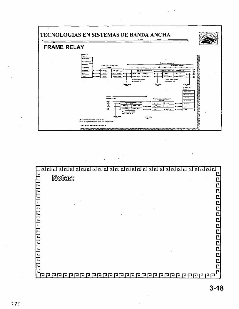
FRAME RELAY • ' !
! . . !
TECNOLOGIAS EN SISTEMAS DE BANDA ANCHA
=:~ ·-·-- ; ~. _... ... --· ~,
.. ____ _..,.,.
3-18
-· "1 r· - 7 .

TECNOLOGIAS EN SISTEMAS DE BANDA ANCHA
FRAME RELAY Red Pública
3-19
.. ' -. " .

CURSO:TECNOLOGIAS EN SISTEMAS DE BANDAANCHA
AJo~SULTC>RES lij! u lij! r:.o V ~ S.A. 0 = 0 ü:'0, ~ ~ DE ~ 1 1 ~ ~· e ~ ~~ c.v. INGENIERIA COMPUTACION INFORMATICA
ACRONIMOS Y TERMINO LOGIA
Basado En Las Normas Internacionales CCITT, ANSI

·~ '-l
W BASES l'énsc StarLAN
111 BASE2 Véase Cheapemet
1(1 BASES Espectficación de capa fistca (physical Layer) de banda base (bascband) IEEE 802.3 similar a Ethernet. que emplea cable coaxial gmcso y que functona a 10 Mbps.
1(1 BROADJ6 Especificación de banda amplta (broadband) IEEE 802.3 que emplea cable coaxial gmcso y que funciona a lO Mbps
1(1 BASF.T Especificación IEEE Rll2 3 que emplea cable de par trenzado (twistcd pair) snnplc y que funciona a lO Mbps.
A & 8 bit signahng. Señalización de b1ts A & B Proccdunicnto empleado en la mayoría de los sitios de transmisión TI. en el cual un bit de cada sexto marco o trama (framc) de cada uno de los 2-l subcanalcs se usa para información de scl1alinción de supervisión
AllM Asynchronous Balanced Mode· Modo balanceado asincrónico Modo de comunicación HDLC (y su protocolo dcri\'ado) que maneJa comunicacio~lcs de punto a punto entre nodos cquivnlcntcs (pccr) para dos estaciones, en donde cual~uicra de ellas puede miciar la transmisión.
abstrac:t .'J·ntax S1ntaxis abstracta Descripción de una estructura de datos independiente de la codificación y del tipo de hardware. ·
access-group Suborden de la interfaz Cisco que aplica una lista de acceso a una interfaz.
aci:ess-/ist Lista de acceso. Lista que los enrutadores Cisco emplean para controlar el a~ceso desde o hac1a el enmtador para servicios ,·arios (por eJemplo. para impedir que paquetes con una c1erta dirección IP salgan de una interfaz en particular del servidor de la red).
acc<'.<.< mcthnd Método de acceso Soft"are de un procesador SNA que controla el OuJo de inform:1ción a traYés de la red En gencrnl se refiere a la forma en qne Jos dispositi,·os de la red tienen acceso a ella.
accmmting management Administración de·cuentas Una de las ctnco categorías de administración de redes definidas por ISO para el manejo de redes OSI. Los subsistemas ~e administración de cuentas son responsables de recolectar los datos de la red que se refieren al uso de los recursos
ACF ;;Jdvanced Commumcations Func~ton: Función de comunicación avan7ada. COttjttnto.de productos SNA que ofrecen procesamiento distribuido y comparación de recursos.
ACFINCP Advanced Cnmmunications FunctionNetwork Control Program: Función de comunicación avanzada /Programa de control de redes. Programa principal de control de redes SNA. Reside en el controlador de comunicaciones y sirve como interfaz con los métodos de acceso SNA en el procesador principal para · controlar las comunicaciones de la red.
ACK Abreviatura de acknowledgmcnt (acuse de recibo). Normalmente se envían ACK's de un disposith~o a otro de la red para indicar que ocurrió algún suceso (por ejemplo, la recepción de un mensaje).
ACSE Assnciat10n Control Service Flement.- Elemento de servicio de control de asociación. Convención OSI empleada para establecer, mantener o terminar una concx1ón entre dos aplicaciones
active hub {Véase hub: concentrador). Dispositivo de varios puertos que amplifica señales de transmisión de una red local, LAN.
adapter Adaptador. Tarjeta de una PC, normalmente instalada dentro de la máquina, que ofrece capacidades de comunicación de red desde y haciá la computadora. Suele usarse también en lugar del término NI C.
adaptive routing Enrolamiento adaptable. Véase cnrutamiento dinámico.
ADCCP Advanced Data Cnmmunications Controll'rotocol: Protocolo de control avanzado para comunicactón de datos. Protocolo ANSI estándar para control de enlaces de datos que funciona en el nivel de bits.
addreu Dtrccción. Estructura de datos empleada para identificar una entidad úmca, como algún. proceso o la localización de una red
1

')
'-1 addre.u ma.tk Carátula o máscara de la dirección Combinación de bJIS empleada para des1gnar ·las b1ts de direcciÓn de la subred dentro de la dirección del protocolo de una red.
addre.u re.tolution Resolución de dirección Suele referirse a un método para resolver diferencias entre diferentes esquemas de dJrcccwnamicnto. Por otra parte, especifica un método para hacer corresponder las direcciones del nivel J del modelo OSI (capa de red: network layer) con las dclmvcl 2 (capa de enlace o de comunicación de datos· link layer)
adjacency Adyacencia Rclac1ón formada entre cnmtadorcs cercanos seleccionados y nodos tcrnimalcs con el propósito de intercambiar información de cnmtanucnto. La adyacencia se basa en el uso de un segmento. fisJco común.
adjacent nodes Nodos adyacentes En SNA. nodos conectados a algún otro en forma duce! a. sin nodos mtcnncd1os En DECnct y OSI, los nodos ~dy~centes son aquellos que comp~rten un segmento común (Ethernet. FDDI. Token Rmg)
atlmini.flratiJ•a tliMance D1stanc1a ~dnunlstratl\·a. Med1da de la contahilidad de una fuente de informaCión sobre mtas En los cnmtadores C1sco, la d1stanc1a administrali\'a se expresa corno un \alar numénco entre O y 255 (nuentras más alto sea el valor. menor es la contabilidad).
ADPCI\1 Adnpln·e D~lferentw/l'u/.,e Code Afndulatwn Modulación diferencial adaptable codificada por pulsos Procedimiento mcdmntc el cual se emplea la alta correlación estadística entre muestras consccutiv~s de \'OZ para cre~r una escala de cuanti~ación variable (o adaptable¡ Con ADPCM se pueden codificar muestras analógicas de voz en forma de señales d1gitales de buena calidad. advertising anuncios Método con el que los enrutadores mantienen listas de rutas utihzahlcs, enviando actualizaciones de enrutamiento o de servicio en períodos especificados de liempo.
adyacencia Véase adjacency .
agenl Agente Soflware que procesa pedidaS y dé\uelve respuestas en alguna aplicación. En los ststemas de adn11nistración de redes Jos agentes residen en todos los d1sposlii\OS bajo control y reportan los \':llores de las \'anables especificadas a las estacmnes de administraCión. En las arquitecturas C1sco un agente es una tarjeta indi\'idual de procesador que ofrece una o varias interfaces fis1cas.
AGS Advanced Gat~w~y 5,'erver.- Servidor de intercomunicación avan1..ado. Nombre del énrutador/puente Cisco de 9 ranuras (slots).
AGS + Ad1•nnced Gatewny Server Plus· enrutadorlpuente Cisco de 9 ranuras con un módulo cBus de conmutación. Cinco de las ranuras se. conectan al cBus.
AIS Alarm Indica/ion Si¡?,nnl: Señal de alarma. En TI es una señal de bits en uno que se trasmite en lugar de la señal normal para mantener continuidad en la transm1sión e indicar a la terminal de recepción que hubo una falla de transmisión locali7.ada en, o antes de, la terminal de transmisión.
alarm Alarma Mensaje que avisa al operador o administrador sobre problemas en la red
A-Law Ley-A. Estándar de compresión y expansión (companding) empleado por CCITI para la conversión entre señales analógicas y digitales en sistemas PCM. Se usa más bien en las redes telefónicas europeas y es similar al estándar norteamericano mu-law (ley-mu).
alert Alerta En NetView, es un registro que indica al operador de la red la existencia de un problema que debe ser atendido en el punto de control.
algorithm Algoritmo. Reglas o procesos bien definidos para alcan1.ar la solución de un problema.
algoritmo Véase algorithm
alignment error Error de alineación. En las redes IEEE 802.3, es un error que ocurre cuando el número total de bits de un marco o trama (frame) no es múltiplo de ocho. Los errores de alineación normalmente son causados por daños a la trama debidos a colisiones.
ALOIIA Técnica de ·control de accesos para sistemas de transmisión que permite a múltiples estaciones transmitir simultáneamente. En el sislema ALOHA las estaciones transmiten cuando tienen datos que mandar, y las transmisiones que no tuvieron acuse de recibo se repiten.
Al\1 Amplitud modulada Técnica de modulación en la que la información se conduce mediante la amplitud de la señal portadora
2

amplitude Aniplllud. Elm:iximo \·alar de una forma de onda analógicot o dig1tal.
analog tran.rmi.uinn TransmiSIÓn analógica. Transmisión de seilales. med1ante cables o por el aire, en la Cllétl se conduce la 111formnc1ón mediante la variación de alguna combinaciÓn de la amplitud de la seiial, su frecuencia y su fase
ancho Je banda Véase bandWidth
anfitrión Véase host.
ANSI American Nntwnnl Standard.\·/nstilutC'· lnstiluto nacional norteamericano de estándares Instancia coordinadora de gmpos \Oiuntanos'de fijación de estándares en los Estados Unidos ANSI es miembro de ISO (lntcrnational Org;mi7ation for Standanzation: Organinc1ón internacional para la estandarización)
anuncios Véase ad\'Cr11sement
API Applic;1tion Programming interface: Interfaz para programas de aplicación. Especificación de comenciones de 1\;unadas a funciones p;ua definir la interfaz con un serv1cio.
A pollo Domain ConJunto potcntodo de protocolos de red desarrollado por la compallía Apollo Computcr para comunicaciones en rectes Apollo.
ApplcTalk Serie de protocolos de comunicaciones relacionados creado y mantenidos por la compañia·Apple Computer AclUalmente existen dos fases 1 y 11. La f.1se 11. que inchl) e maneJO de mterconc:x1ón entre redes es la versión más reciente.
application /ayer Capa de aplicación. Capa 7 del modelo de referencia OSI. Está implantado en varias aplicaciones de red. como correo clcctrómco, transferencia de archi\'OS y emulaciÓn de terminales -
app/iqué Aplicación Placa de montaje que contiene conectores de hard\\arc para fijarse a la red. Las placas tr.aducen y com·•crtcn las señales de comunicaciones tipo serie en las que espera el cst;índar de comunicación escogido (por ejemplo. RS-232. V 35).
APPC Advanccd Pecr-to-Peer Communications: Comunicación avanzada entre nodos similares o equivalentes. Esquema SNA de comunicaciones de IBM que permite comunicar directamente aplicaciones equl\'alentes SNA.
APPN Aclvancccl Pccr-to-l'eer Nctworking: Redes avanzadas entre nodos equivalen\CS Esquema SNA de IBM que ofrece procesamiento distribuido basado en nodos de red de Tipo 2.1 y LU 6 2
árbol abarcador Véase spanning trec.
arca Arca. Conjunto lógico de segmentos conectados por enrutadores y que están basados en los estándares ISO CLNS, DECnet o OSPF.
ARCNET AttachcJ Rcsourcc Computcr Network· Red de computadoras con recursos asignados Red local (LAN) de tipo token bus a 2 5 Mbps desarrollada a finales de los años 70 e inicios de los 80 por la empresa Datapoint Corporation. Sus principales características son su sencillez, facilidad de uso y relativa economía.
ARM Asynchronous Response MoJe: Modo de respuesta asincrónico. Modo de comunicación HDLC con un primario y al menos un secundario, donde el primario o cualquiera de los secundarios puede iniciar las transmisioncs.ARPAddrcss Resolution Protocol: Protocolo de resolución de direcciones. Protocolo Internet usado para ligar una dirección IP a direcciones Ethernet 1 802.2 . Está definido en el documento RFC 826.
ARPA Véase DARPA.
ARPANET Red pionera de conmutación de paquetes (packct switching) · desarrollada al inicio de los años 70 por la empresa BBN y financiada por la agencia ARPA (luego DARPA). ARPANET se convirtió luego en "lntemct". El término ARPANET desapareció oficialmente en 1990.
ARQ Automat¡c Repeat Rcquest: Pedido autómático de repetición. Técnica de comumcacioncs en la cual el receptor detecta errores y solicita retransmisiones.
AS :lutonomous .\~ystem· Sistema autónomo. ConJunto de redes bajo administración común y 911e comparten una estrategia común de enmtamicnto. A un sistema autónomo debe dársele un número úmco de 16 bits asignado por c_l Centro de Información sobre Redes (NIC) de la agcnc1a DDN. ·
3
,, 1. ' .
ASCII :1 meriCan .\'tandard (,(){/e {r1r ln(nrmation /nterchange · CáciiJ!.o estándar nortamericano para intercambio de mformac1ón. Código de ocho b1ts para representar caracteres que emplea siete bits más paridad
ASM Scmdor de terminales CISCO en chasis A
ASN.t Abstr:1ct Syntax Notation Onc. Notac1ón de sintaxis abstracta número uno Lenguaje OSI para dcscríbar lipes de datos en forma ondcpcndícntc de cstmcturas computaciOnales y técnicas de representación Orgam:~aCIÓTl Internacional de Estandarización. Estándar Internacional 882-t, diciembre, 1987. Véase también BER.
a.'iynchrnnou.fi transmissmn TransmiSIÓn asincrómca Opcrac1ón de un SIStema de red en el cual los acontecimientos suceden sin cst:u sincromzados por un reloJ En tales sistcm:lS. los caracteres mdl\ 1dualcs suelen cst:ir encapsulados en bits de control llamados de arr~nquc y de parada. que des1gnan clmicio y el final de los caracteres
ATOM .·L~\nchronouf; 1'11ne /Jii'IS/on .\fult1plennR Multiplexajc asincrónico por di\'Jsión de tiempo. Método de cm io de 1nfonnac1ón que emplea clnl.ulllplexaje usual por di\'ISión de tiempo (TDM). pero en donde se as1gnan ranuras de tiempo cuando se requieren, en lugar de preas1gnarlas a tranSmisores específicos
ATG Address Translatwn (fateway· Intercomunicador traductor de direcciones. Función de sofiwarc para cnmtanucnto DECnct que CISCO emplea para lograr que el cnmtador' maneJe va11.t~ redes DECnet independientes. y para establecer traducción de direcciones especificada por el usuario para nodos seleccmnados entre redes.
ATMAs1nchronous Transfer,\/ode: Modo de transferencia asíncróníco Estándar CCITI' para retransmisión de celdas (ccll relay) en el cual la mformacíón para diferentes lipes de servicios (l'oz, ndco. datos) se transmite en pcquc11as celdas de tamaño lijo También, modo de transmisión BISDN en el cual se usn una \'ersión acelerada del multíplcxajc asíncróníco per dí,·ísíón de tícmpe (ATDM) para tr:msfcrir flujos múltiples de información en un can;1l de comunic;1ción
attenuation AtenU;'lC.IÓn Pérdida de energía en l;1 seilal de conHIIliC:JCJÓn.
AUI Attachment .C!mt Interface: Interfaz de unidad de vinculación. Cable IEEE 802.3 que conecta la unidad de acceso al medio (MAU: Medía Access Unit) al dispositivo en red. El térmiño AUI también se puede usar para referirse al conector del panel trasero principal al que se puede lijar el cable AUI.
authority zone Zona de autoridad. Relativa a DNS, sección del nombre del árbol del dominio en el cual el nombre de un s~mdor es autoridad.
automatic cal/ reconnect Rcconexíón automática de llamada. Capacidad de pcrnutír rccnrntamícnto automático de llamadas en una linea troncal diferente de la que falló.
autonomous confederation Confederación autónoma. Grupo de sistemas autónomos que confian más en s~ información de red y de enrutamicnto que en la que reciben de otros sistemas o confcdcraciories autónornas.autonomous switching Conmutación autónoma. Caractcristíca de los enmtadorcs Cisco que ofrece un procesamiento más rápido de paquetes al pcrnutar que el cBus conmute paquetes en forma independiente, sin mtcrrumpar al procesador del sistema.
backbone network Red fundamental. Actúa como conducto primario (o "espina dorsal") de tráfico que usualmente viene de, o va hacia, otras redes.
back channel Canal secundario. Empleado para enviar datos en dirección opuesta a la del canal pnmario. Los canales secundarios suelen usarSe para enviar información de control. Mediante ellos, la información puede enviarse aunque el canal prímano falle. También llamado canal en reversa.
back door route Ruta secundaría alterna hacia una red no local (especificada per un IPG) que debe ser usada per un enrutador de frontera. Los enrutadorcs Cisco pcrm1ten la especificación de rutas secundarías alternas mediante una variación de la suborden nctwork.
back end Nodo o programa que ofrece scmcíos a un front end. Véase t~mbíén cliente y servidor.
backoffEI retraso (usualmente aiCatorío) en la retransmisión causado per los protocolos de competencia por el control de acceso al medio de transmisión, luc'go de que un nodo que intentaba transmitir detectó una portadora en el canal físic~.
4

' l 1 •. 1
~' /Jack pre.ssure Propagación en scnlido inverso de la 111fonnación del congcstlonamicnlo de la red en 1111;1 lntcrconc'-IÓn
backll'ard channel 1-'énse back channcl.
backward /earning Aprcnd17ajc en reversa. Proceso mcdwntc el cual se conjetura la existencia de información al suponer condiciOne" de una red simctrica Por ejemplo. s1 se supone que el nodo A rcc1bc 1111 paquétc del mnlo JI mediante el intermediario C. entonces el algoritmo de cnrutanucnto de aprcndi1ajc en reversa supondrá que A puede. en forma óptima. llegar a ll a través del nodo C.
balanced configuration C'onfigurac!Óil balanceada En IIDLC. una configuración de red punto a punto con dos estaciones combmadas
ha/un lla/anced, unhalanced- babnccado. dcsbalanccado Disposlll\'O empleado para igualar lmpcdanctas entre una linea balanceada~ una desbalanccada: normalmente entre par trcm·ado y cable coa="- tal
banda ba:11e 1 ·ea.\'(' bascband
bandwithh Ancho de banda. Dtfcrcncia entre la frccuencta más alta y la más baJa de las scJialcs de una red Tamb1én dcscnbc la capac_1dad establecida de un protocolo o un medto dados para una red
bandwidth re.servation Reservactón de ancho de banda En líneas conmutadas. característica que permite rcsen·ar el ancho de banda de la llamada para llamadas de alta priondad o de alto ancho de banda.
BARRnct 11ay Area Regumal Research Network~. Red para investigación en la región de la bahía de San Francisco. La red fundamental (backbonc) BARRnct está compuesta por cuatro campus de la Universidad de California (Davis, Bcrkclcy. Santa Cmz y San Francisco) por la Umvcrsidad de Stanford. el Laboratorio Nacional Lawrcnce Livcrmorc y por el Centro de ln\'estigaciones Ames de la NASA.
ha.sehand Randa base CaractcristtGI de la tecnología de redes en· donde sólo se emplea una frecuencia portadora La banda base se diferencia de la banda amplia (broadband). en la cual se emplean múlttples frecuenctas portadoras. Ethernet es un ejemplo de red en banda base
basic rate interface Interfaz de tasa básica. Interfaz ISDN (lntegratcd Scrviccs Digllal Nctwork: Red digital de servicios integrados) compuesta de 28 + ID canales.
baud Unidad de velocidad de señalización igual al nilmcro de condiCiones discretas o sucesos en la señal por segundo.· Los bauds son equivalentes a los bits por segundo cuando cada suceso en la señal !epresenta exactamente un bit.
BBN Bolt Bemnek y Nell'mnn, Inc. Compañía de Massachusctts, responsable del desarrollo y mantenimiento de los sistemas primanos de enlace de ARPANET (y luego, de Internet).
B Channel Canal B. En ISDN. un canal full duplcx de 64 Kbps, empleado para enviar datos de usuarios
beacon Boya, faro. Marco (framc) de Token Ring de IBM que indica algún problema serio en el anillo (ring), tal como 11~1 cable cortaclo.
Bcllcore 1920 Organización que efectúa labores de investigación y desarrollo para las compañías regionales de la empresa Bcll.
Bcllman-Ford routíng algoríthm Algoritmo de cnmtamiento BellmanFord. También conocido como algoritmo de vector de distancias. Clase de algoritmos de cnmtamiento que itera sobre el número de saltos (hops) en una mta para encontrar el árbol abarcador (spanning trce) más corto. El algoritmo pide que cada cnmtador envíe únicamente a sus vecinos su tabla de rutas completa cada vez que se actualiza. Estos algoritmos pueden caer en ciclos, pero computacionalmcnte son más sencillos que los de llpo estado de enlace, link-state.
BER Base lóncoding Rules. Reglas básicas de codificación. Reglas para codificar las unidades de datos descritas en ASN. 1 Las siglas también significan bit error ratc. tasa de error de bits, que se refiere al número de bits erróneos recibidos.
BERT B1t F.rror !late Tester Device: Dispositivo para pmcba de tasa de errores de bits. Determina la tasa de error de hits en un canal de comunicaciones
Bcst cffnrt dcli\·cr)' Entrega lo mejor postblc. Característica deJos sistemas de redes que no emplean un sistema elabor:-tdo de verificación que garant1cc el manejo<:onfiablc de información
5

,,
JJGP llorder Gatei1·ay Protocol protocolo de intcrcomunJGICiÓll de frontera Protocolo de cnmtamicnto de intcrdommios que es un reemplazo potencial de EGP (Exlerior Galeway Prolocol) BGP esl:i deflmdo por el documenlo RFC 11115, hecho por un empleado de CISCO y uno de IBM
big-endian Método de almOiccnar o transmitir información en el cual el bit o byte más significati\'O se préscnta primero Véase tamb1én littlc-cnd1an.
binar-y Binario. Sistema de numeración caractcrii'ado por unos Y ceros (on )'off, si y no).
hinary synchronou.f cnmmunication Comunicación banaria smcrónica Prolocolo de enlace de dalas por caracleres que se emplea en aplicaciones halfduplcx Se conoce sunplcmcntc como bis)·nc.
biphate coding Cmlifkaciún bifa'ic. Esquema de cod•ficaCIÓII bipolar originalmente dcs<Jrrollndo pa~n su uso en Ethernet. Ln mformac1ón del reloj se incluye. y se obtiene. del fluJO de datos smcrón1co sin neces1dad de señales extras de reloj La seilóll b1fasc no contiene encrgia de corncnte directa.
bipolar Bipolar. Que llene pol<mdadcs negar ha~ positiva_
BISIJN Broadband ISDN -de banda amplia Esl:indares de comunicaciones que se desarrollan para maneJar aplicaciOnes de gran ancho de band<1, tales como video.
bisync Véase b1naf)· synchronous i:omrnumcation
bit binary digit dígito binario. Unidades empleadas en el s1stema de numcracion btnario. Pueden ser O ó 1.
bit error rate Tasa de error de b1ts. Porcentaje de bits transnulldos que se rec1bcn con error
BITNET llemuse lt's 1ime ,\'efllork Red de "la es !lempo" Red académica de baja \'eloc1dad y bajo costo que consiste pnmordialmcnte en computadoras grandes lB M Y lineas dedicadas de 9600 bps El modo princ1pal de lrabaJO en csla red es RJE (Remole Job Enlry En! rada remola de lrabaJOS) ReCicnlcmcnle la red se fusionó con CSNET (Compuler + Se~ence Nel\\ork) para formar CREN (Corpora11on for Research and Educalional Nelworkmg)
/Jit-oriented protocol Prolocolo por bils. Clase de prolocolos de comunicaciones de la capa de enlace (link !ayer) que pueden transmilir marcos (frames) sin preocupación de sus conlenidos. Comparados con los protocolos por byles, éstos son más eficienles y conlables, y ofrecen operación full duplex.
hit rate Tasa de bils. Veloc1dad a la que se transmilen los bits, normalmenle expresada en bils por segundo (bps).
black hole Agujero negro. Término de enrulamicnlo aplicado a alguna área de los SISiemas de redes a donde enlran paqueles pero ya no salen. debido a condiciones adversas o a una mala configuración del sislema en alguna parte de la red.blockingBioqueo. En un sislema de conmulación, condición en donde ya no hay lrayeclorias para complelar un circuilo. Generalmenle. ellérmino se emplea para describir una siluación en la cual una acllvidad no puede iniciar sino hasta que otra ha terminado.
Block Mulliplexer Channel Canal de mulliplexaje de bloque. Canallipo IBM que realiza el esl:indar norteamericano FIPS-60. también se conoce .como el canal OEMI y elmulliplexor de bloque 370, o canal mux de bloque. ·
BNC connector Coneclor BNC. Coneclor eslándar empleado para ligar el cable coaxiai1EEE802.3 IOBASEZ a un receptor o transmisor.
BOC /Je/1 Operating Company. Las compañías lelefónicas locales que exislian en las siele regiones de los Eslados Unidos anles de que se diera la orden legal de que la compañia A T &T se desmembrara
BooiP Prolocolo empleado por un nodo dc.la red para delerminar la dirección IP de sus inlerfaces Elhernel, para poder arrancar con la operación inicial (bool) de la red.
Boot PROM lloot l'rogrnmmahle Read-Only Memorv: Circuitode memoria de sólo lectura para iniciar operaciOnes Circuito de unrt tarjeta que contiene las inslrucciones ejeculables de arranque (boot) para un disposilivo compulacional.
horder ¡:atttway Intercomunicación de frontera. Enmtador que se comunica con olros en sistemas autonomos (AS)
6

\j ._, Jloundaryfunction Func1ón de linutcs. C:-~pacidad que tienen los nodos de sub:írca SNA para ntanCJ:lT protocolos p;tra nodos pcrifér~cos ;1signados. Suele encontrarse en los disposilit·os IBM 3745
BPOU Bnd~e /'rotocol /Jata 1 'm t.\ U111dodes de dolos poro protocolos de puente Poquele de protocolo helio de árbol oborcodor (spanning tree). Véase también PDU
BRI Véase Interfaz de lasa bástca (Baste Rale Interface)
britlge Puente Dispos1ti\'O que conecta dos segmentos de unrt red y p<1sa paquetes entre ellos. Los puentes operan en el nivel 2 del modelo de referencia ISO (cilpa de Cnlacc de datos hnk !ayer) y no son sensibles a los protocolos de niveles supcnorcs.
bridge-group Suborden de puenteo de C1sco que as1gna interfaces de la red a gmpos particulares del árbol ab;uc:-~dor. Pueden ser compatibles con los cst:índ:1rcs IEEE X02 1 o de DEC
Dbroadh.and Oanda amplia. En contrapoSICión con la banda base (~aseband). es un sistema de transmisión que rm1l11plcxa \·ari<1s se1ialcs independientes en un solo cable. En la terminología de las tclecomumcacioncs. se refiere a cualquier canal que tenga un ancho de bonda ma)or que el requerido pora lransmllir t·oz (4 Kllz) En la terminología de las redes locales. se reliere a un cable coax1al que maneja señoles de tipo o na lógico ·
hroaclca.ft D1fus1ón o mensaje público Mens;1je en\'lado a todos los destinos dentro de una red
broadcast addre.u Dirección para difusión DJTección reservada para rCalizar envíos simultáneos a todas las estaciones de una red.
broadcast .ftorm Disturbios por difusión. Acontecinuento indeseable en una red, en el cu:1l se envían muchas difusiones a la ve/., empleando para ello·cons1derable ancho de band:1 y. normalmente. causando además intermpciones en la red
JJSC ·¡ 'énsecomu n 1caci ónbi na riasi ncr ón 1 ca( l3 i na ryS~ nch ronousC o m m un 1 ca 1 ion)
buffer Amortiguamiento. Zona Temporal de almaccnamiemo empleada
poro el manejo de datos lronsilorios Los buffers suelen emplearse para compensar los diferencias de vclocidod de procesamiento entre dispositivos de la red. Las enusiones rápidas de datos se almacenan en un buffer llasta que los pueda procesar el dispositivo que funciona más lentamente.
bu.< topology Topología de bus. Arquitectura LAN lineal en la cual las transmisiones de las estaciones de la red se propagan a lo largo de todo el medio de comunicación y son recibidas por todas las demás estaciones.
bypass mode Modo de operación en redes FDDI y Token Rinden el cual se ha desinsertado (o desviado) una interfaz del anillo.
byte Término genérico que se refiere a una serie de dígitos binarios consecutivos con los que se trabaja como si fueran una unidad: un eJemplo son los bytes de 8 bt!S
bbyte-oriented protocol Protocolo por bytes. Clase de protocolo de comUnicaciones de la capa de enlace que emplean un caracter existente específico para· delimitar marcos (frames) Este tipo de protocolos practicamenle ha sido reempla7"1do por los de manejo de bits.
cal/ priori/y Prioridad de llamada -Prioridad asignada a cada puerto de los ctrcuitos conmutados. La prioridad define el orden en el cual se rcconeclan las llamadas. También define cuáles llamadas se efectuarán durante una reservación· de ancho de banda .
cal/ setup time Tiempo de establecimiento de llamada Tiempo requerido para establecer una llamada conmutada entre dispositivos DTE.
catenet Red en la cual las computadoras que actúan como anfitriones están conectadas a diversas redes, que a su vez están conectadas con enrutadores. Internet es un importante ejemplo de una red tipo calenet.
CATV Cable Television: Televisión por cable. Anteriormente llamada Communily Anlenna Telcvision (televisión por antena comunal). Sistema de comunicaciOnes en el cual se transmiten varios canales con programación a las casas, empleando cable cooxial de banda amplia.
chu.< Tecnologio de canol (bus) de medto Gtgabil por segundo; patentada, desarrollada y distribuida por Cisco Syslems, lnc
7

cBu.~ Controller l·Case Switch Proccssor
CCITT Comité Consul!i\'O Internacional de Telegrafla )'Telefonía (Siglas en francés). Organizació~ internaciOnal que desarrolla estándares de comunicaciones, como la recomendación X.25.
ces Common ( 'hanne/ .\'ignahn?. SeTlalilaCIÓII de canal común. Sistema de señalizaciÓn usado por muchas redes telefómcas. que separa la mformación de seslalización de los datos de usuano.
crll re/ay Transm1s1ón por celdas Tecnología de redes basada en el uso de ¡ tCI1os paquetes de tamallo fijo. llamados celdas 1 as celdas contienen un
llkntificador que espcc1fica el fluJO de datos al que p~:ncnecen Como son de tamaño fijo. el hardware puede procesarlas y conmutarlas a muy altr~s velocidades. Este mé!odo es la hase de muchos protocolos de red de al! a veloc1dad. incluyendo IEEE 802 6. DQDfl. ATM y el pro loco lo de lll!crfat SMDS
cellular radio Rr~d10 cclulr~r Tecnología que emplea transmisiOnes de racho para logr;¡r acceso a la red telefónica. El serv1cio se ofrece en una célula (á re;¡) particul;¡r mediante un tmnsnusor de baja potencia
centre:c PIJX meJorado que tamb1én ofrece marCaJe dnecto e identificación automática del PBX que llamó. La palabra se refiere a un producto específico de la
· empresa AT &T.
CEPT Conference Europcctic des Postes el tclecommumcat10ns: AsociaciÓn de 26 oficinas de correos y tclccomumcaciones europeas que hace recomendaciones a la CCITI sobre especificación de comumcacioncs.
CERFnct Calijórnia l:.ducatwn ancl Research Foundation Network: Red de la fundación pam la educac1ón y la im·esligacJón del eslado de Cahfornia Red basada en TCPIIP que opem en el sur de Cahfornia e inlerconecla muchos centros de cducílción supcnor, diseñada Para el avr~nce de la Ciencia y la educación mcdmntc las COT1llllliCaCIOileS.
CGS Compacl Gale\\ay Scr\'cr Sen 1dor de inlercmmmJGlCión comp~clo Nombre del enrulador/pucnle Cisco de 2 ranuras (slols)
Chaining Encadenamiento Concepto de SNA en donde las unidades de pedJdo/respucsla (RU) se agrupan para propÓS!Ios de recuperación de errores.
channe/ Canal. Línea de comunicaciones En algunos entornos se pueden mul!iplcxar varios canales en un solo cable El término también se refiere al conduelo ospeciflco en! re computadoras grandes y sus periféricos.
CHAOSnct Prolocolo de redes desarrollado en el MIT (Massachusens lnslilule of Technology) y empleado fundamentalmente por la comunidad académica de la inlchgencia ar!ificial.
cheapernet Término empleado en la industria para referirse al estándar IEEE 802.3 IOBASE2 o al cable especificado en ese estándar. Thinnet, que también se refiere a ese estándar, especifica una versión más delgada y barata de cable Ethernet.
checksum Suma de control. Método para verificar la integridad de los dalas transmitidos. Es un número entero calculado a partir de una secuencia de octetos por medio de una serie de operaciones aritméticas. El valor se recalcula en el lado del receptor y, se compara para verificarlo.
choke packet Paquete de sofocamiento Paque.te que se envía a un transmisor para indicar que exisle congestionamiento y que se debe reducir el volumen de envíos.
CJCS Customer !nformntwn Control System: Sistema de Control sobre información de clientes. Subsistema de aplicación IBM que permite que las transacciones que llegan de terminales remotas sean procesadas por las aplicaciones de los usuarios.
circuit switching Circuitos conmutados. Sistema de conmutación en el que debe cxis!ir un circuito flsico dedicado enlre el emisor y el receptor durante la llamada. De amplio uso en la red telefónica, los circuitos conmutados se contrastan con los métodos de competencia (conlen!ion) y token passing para acceso al canal, y con la conmutación de paquetes (packet swi!ching) como técnica de conmutación. ·
Clas.• of serví ce Clase de scrvJcio. En forma general, se refiere a cómo manejar un paquete El lipa de scf\'ÍCJO (TOS) IP es una clase de se"·icio. En SNA, la clase de scrncio es In dcs1gnación de las carac1crls1icas de control de trayectona de la red, incluyendo la seguridad de la lrayécloria. el ancho de banda y las pnondades dependiendo del se"·icio,requerido
8

·¡
" dient Cliente Nodo o programa de sofiwarc que requiere SCI"\'ICIOS de un scrYidor. Véase lnmbién bnck cnd ·
circuit circuito. En.lacc de comumcacioncs entre dos o más puntos
client-server Computing Computación en modo chcntc-scrYidor. Término empleado· pnrn describir sisrcmns de redes de proccsnmicnlo dislribmdo en donde lns responsabilidades de lns 1rnnsncc10ncs se dmdcn en dos partes- el clicnlc (fronl cnd) y el servidor (bnck cnd) Ambos lérminos se pueden aplicar lanlo n programas como a dispositivos de cómputo. Véase tamb1én pccr- to-pccr computing. (computación entre nodos equivalentes).
clu.Uer Control/a Controlador de cúmulos. En términos generales se refiere a un d1spositivo inteligente que orrccc las conexiones de un cúmulo de tcrminnlcs a un enlace de datos En SNA, se refiere a un d1sposlll\'O programnblc que controla las operaciOnes de E/S de los d1spositi\OS asociados. normalmente un IBM 1174 ó 3274
CMIP/CMIS (:ommon ,\/anagemenllnjhrmmion fJroroco/JCommon ,\/ana~emcnt lnformarwn 5iernces. Protocolo para manejo comUn de mformac1ón/Servicios para · manejo común de información mterfa1. OSI de manejo de servicios/protocolos de red crcndn y cslnndnrizndo por ISO para manCJnr redes hclcrogéncns.
CMOTCMIP ovcr (sobre) TCP Uso del prolocolo ct'c maneJO de redes OSI (CMIP) sobre lns cnpns de prolocolo lnlcrncl (TCP/IP)
CMT Cnnnectinn 1\fanagenient· Manejo de conexiOnes Proceso FDDI que se encarga de In lrnnsición del anillo cnlrc sus estados (apagado, act1vo. concclado, etc), como se define en In especificación X3T9.5
CO Central OJ]ice Oficina ccnrrnl Oficmn de In compañia lclcfónicn local n In cual se conectan todos los loops (ciclos) de una cie11a área y en la cual ocurre la conmutación de los circuitos de las líneas abonadas
communitr Comunidad En SNMP. gmpo lógico de diSposilivos manejados y de cst<lcmncs NMS en el mis111o donunio admimstratJ\'O
companding Contracción formada con los procesos opuestos compression (compresión) y cxpnnsion (cxpnns1ón) Parte del proceso PCM en el que los valores· de muestras de señales analógicas se redondean en térm.inos lógicos a valores discretos de escala de ntcrvalos dentro de una escala no lineal. El número de inlcrvalo decimal se codifica cnlonces en su equivalente binario antes de In transmisión El proceso se invierte en la terminal receptora empleando la misma escala no lineal.
·coaxial cable Cable coaxial. Cable consistente en un conductor cilíndrico externo hueco que cubre a un alambre conductor único. Suelen emplearse dos tipos de cable coaxial para lns redes loen les: cable de 50 Ohms, para señales digilalcs, y cable de 75 Ohms, para señales analógicas y para señales digitales de alta velocidad.
CO/JEC Coder-!Jecoder. Codificador-decodificador. Dispositivo que normalm~nte Cmplea modulación codificada por pulsos para transformar voz analógica en un tren de bits y viceversa.
compression Comprcs1ón. Paso de los datos por un algoritmo que reduce el espacio/ancho de banda requerido para almaccnar/lransmitir el conjunto de datos. Véase también expansion.
coding Codificaéión. Técnicas eléctricas usadas para conducir señales binarias.
compuerta Véase gatcway.
common carrier Portador común. Compañía particular que tiene licencia para ofrecer servicios de comunicaciones al público a precios regulados
concentrador Véase concentrator.
concentrator Conce11-trador Dispositivo que· sirve como centro de una red con topología tipo cslrella. También se refiere a un dispositivo que conlicnc múlliplcs módulos de equipos de redes
common channel s1gnalmg Señalización de -canal común Uso exclusivo de algún canal específico para lle\'ar mformación de señali?ación a los demás canales del gn1p0
9

•,•
" 1: configuration management ManeJo de configuración. Una de cinco c:1tcgorías de m;~ncJo de redes dcfirudos por ISO para el maneJo de rcdcsOSl. Los subsistemas de manejo de configuración son los responsables de detectar y determinar el estado de la red.
comunicación Comunicación. Transmisión de 1nrormac1Ón
communication controller Controlador de comunicaciOnes. En SNA. nodo de subárea que conliene un programa NCP. Normalmenle es un disposilivo lB M 3745.
conge.stion CongcstionamiCnto Tráfico cxccsh·o en la red.
connec1ionles.s Sin conexiOnes Térrmno empleado para describir transrcrcncias de datos sin la existencia de un circuito \'lrtual
COS ( 'orporatwn for ( Jprn .\)·sti'm'l- Corporación para sistemas abiertos. organización que promueve el uso de protocolos OSI mediante pruebas de aceptación. certificación y otras acll\'ldadcs relaciOnadas
conmutación de paqut"les 1 (;ase packct switching.
COS/NE Corporntmn fór Open .\\'.\fctwo /nterconncction Networktn}.! m ·Furope·
Corporación para mterconexión de redes de sistemélc;' abiertos en Europél Proyecto europeo, l11~anciado por la Comunidad Económica Europea. EC, para constmir una red de comumcaciones entre entidades c1entificas e industnales en Europa connection'-oriented Por conexión Ténmno empleado pena descnbir transferencias de datos postcnorcs al establcCJmicnto de un circuito virtual
CONP/CONS Conneclion-Onellled Nelwork Prolocol/ Connect10n Orienled Network SerYice Pro1ocolo/semc10 OSI qne ofrece operaciOnes por conexión a protocolos de las capas superiores
count lo injinity Cuenta hasla el infinilo Problema que puede ocurrir en algorilmos de enrulamienlo de convergencia lenla, donde los enmladores
·incrementan secuencialmente la cuen1.1 de trn~ celos (hop count) hacJa algunas redes especificas hasla que (lipicamcnle) se imponga algún limile a1bi1rario
cnn.mle Consola. DTE a través del cual se ingresan órdenes a una m;iquma anfitriona
CPE Customer fremises Equipment: Equipo en las instalaciones del cliente. Equipo terminal, tal como tenninales, teléfonos y modems, proporcionados por la compañía telefónica, que se instalan en el local del cliente y se conectan a la red de teléfonos.
contention Compelencn Método de acceso en el cual los dispositivos de la red compiten por los derechos de acceso al medio fisico. Véase también token pas'sing.
CPT Cisco Protocol Tran.•lator- Traductor de prolocolos Cisco. Producto Cisco, en chasis C, que traduce (aclúa como intercomunicador) entre protocolos diversos.
convergence Convergencia. Capacidad (y velocidad con la cual se logra) de un grupo de dispositivos de inlerconexión de redes que ejecutan un protocolo especifico de enru1am1en1o, para coincidir en la delerminación de la topología de las interconexiones luego de que ésta cambió:
CRC Cyclic Redundancy Test: Prueba cíclica de redundancia. Técnica de verificación de errores en la cual el receptor del marco (frame) calcula el residuo de div1dir el contenido del marco entre un divisor binano primo (a lo cual a llama CRC) y lo compara con el valor previo que el nodo emisor almacenó en el marco mismo.
conversa/ion Conversación En SNA, una Sesión LU 6.2 entre dos veces también se programas de transacciones.
core gateway Serv1dor de intercomunicación básic~. Enrutadores
primarios en Internet. El cenlro de operaciones de red Internet de la compaftía BBN les da servicio.
CREN The Corporal IOn for Jlesearch and Educational Networking. Corporación de redes educalivas y de investigación Resultado de la fusión de BITNET y CSNET.
cros.s talk Diafonía Energía de interferencia transferida de un circuito a olro.CSC/3Tarjela de procesamiento Cisco basada en un microprocesador MC68020 de )O Mllz Véase procesador de rula.
(:SMA/CD Cmner Sense :\!ult1ple Access w1th ( 'o/11\um /Jetectwn. Acceso múluple con delección de pm1adora y delección de colisiOnes. Mecanismo de
10

• 1
) ., acceso al canal en el cual los dispositivos que desean transmitir pnmcro. verifican la existencia de ponadora en el canal ·si no se detecta ponador,1 en un cierto lapso, los dispositivps pueden transnullr. Si dos de ellos transmiten a la vez, ocurre una colisión, que es detectada por dtspositivos especiales, que entonces retardan la retransmisión durante un periodo aleatono. El acceso CSMNCD es empleado por Ethernet y por IEEE 802.3.
CSC-ENVM C'tsco env¡ronmental momtor carel. Tarjctp monitora del entorno, para el chasis AGS+, que detecta las condiciones de \'oltaje y temperatura para garanli~:ar una adecuada suspcnstón forzosa de las operaciones en el caso de condiciones anótitalas en el sistema.
CSC-FCIT Tarjeta de interrat. FDDI de Cisco con puenteo con traducción (translational bridging).
CSNE1' Computer '·";c1ence Network. Gran ínter-red que conststc primordialmente en universidades, centros de investigación e intereses comerciales CSNET se rusionó con BITNET para rom1ar.CREN.
CSC-MC Tarjeta de memoria Cisco con 32 kilobytes de memoria. La tarjeta CSCMC proporciona al cnruta~Or Casco info~mación no .vol<itil de configuración
CSU Channel Sen•1ce Un/l. Unidad de servicio al canal. Dispositivo de mterraz digital que conecta equipos terminales de usuario al ciclo (loop) telerónico digital local.
CSC-MC+ Tarjeta de memoria Cisco que contiene circuitos de memoria RAM no volátil para almacenar la información de la configuración y que usa tecnología Flash EPROM para guardar el software de SIStema operati\'O
CTS Clear to Semi.- Preparado para transmisión Circuito en la especificación RS-232 que se activa cuando el DCE (equipo de comunicación de datos) está listo para aceptar datos del DTE (cqmpo ternunal)
CSC-MCI Tarjeta de interraz Cisco con intcrraces para di\'ersos tipos de medios (por ejemplo, Ethernet y lineas serie).
CSC-MEC Tarjeta de interrat. C1sco con 2, 4 6 o puertos Ethernet.
CSC-RI6 Tarjeta de mterfaz Cisco que maneja Token Ring de 4 ó 16 Mbps.
CSC-SCI Tarjeta de interfaz Cisco que maneja cuatro puenos de interraz serie sincrónica con \'elocidadcs de transmisión de hasta 4 Mbps cada una.
data Unk control/ayer Capa de control de enlace de datos. Capa 2 del modelo de arquitectura S NA.
04 rraming Marcos tipo D4. Formato de los marcos (rrames) usados por la mayoria de los sistemas de 1.5H Mbps.
data link /ayer Capa de enlace de datos. Capa 2 del modelo de rererencia OSI, que toma un mcdm de transnusión de datos y lo transforma en un canal que, desde el punto de vista de la capa de red: network layer, está libre de errores de transmisión. Los servicios princapalcs de la capa de comunicación o enlace de datos son el direccionarmento. la detección de errores y el control del nujo.DATANET IPSN importante de los Paises Bajos.
DARPA Defense Advanced Research ProJeCIS Agem:y Agencia de proyectos avan1..ados de invcstigacaón para la defensa Agencia de gobicq1o de loS EEUU _que financió la investigación y el desarrollo de Internet.
DARPA Internet Véase Internet
DATAPAC Gran PSN canadiense.
DAS Dual Attach Station: Estación asignada doble En FDDI, estac1ón /Jatapak Red pública de conmutaciÓn de paquetes de los paises nórdicos. conectada a ambos anillos ·
data Unk Sumidero de datos Eqmpo de redes que acepta transmisiones de datos
data channcl Canal de datos En SNA, dispositivo que conecta el procesador y la memoria central con los pcriféncos. Véase canal
IJatex-1 Red pública alemana de circuitos conmutados
data flow control/ayer Capa de control de flujo de datos. Capa 5 del modelo de arqwtectura SNA. ·
Datex-p Red pública alemana de conmutaciÓn de paquetes
11

., '· tla_ta¡:ram Datagrama Agrupamiento lógJco de información cnv1ada como umdad
de la capa de red (nctwork !ayer) en un mediO de transmisión, sin el cstablcciTmcnto previo de un c~rcullo \'Írtual Los términos paquete, mnrco. (framc), segmento y mcns;uc también se emplean para dcscnbir agrupaciones lógicas de mfmmación en varios niveles del modelo de referencia OSI y en otras ;írcas de la tecnología Los datagramas·Jp son las unirladcs primarias de información en Internet.
/)('A Dcfcnsc Communications Agcncy. Agcnc1a de comumcacmncs de la defensa. Organit.ación del gobierno de los Estados Un1dos 1esponsable de las redes DDN tales como MILNET
IJCE Data Communications Eqmpmcnt. Equipo de comunicación de datos (según El A). o Data CirCuit·Tcrminating Equipmcnt: Equipo terminal de circuitos de datos (según CCITT) DISpositivos y conexiones de una red de comumcaciones que conectan el circUito de comumcación con el dispositivo terminal (DTE). Un modem puede ser considerado como DCE.
. datagrama Véase datagram.
D Channel Canal ISDN full dúplex de .J6 Kbps (tasa básica) o de 64 Kbps (tasa primaria)
IJDN Defense Data Network.- Red de datos de la defensa La sección MILNET y otras partes asociadas de Internet que conectan instalaciones militares.
DDN X-25 Protocolo del Departamento de la Ddensa de los Estados Unidos muy similafa X.25 y que es empleado en comumcaciones de la red DDN.
DECnet Grupo de productos de comunicaciones (mcluyendo protocolos) desarrollados y mantenidos por D1g1tal Equipment Corporation (DEC) La versión más reciente es DECnet Phase V, que está basada fundamentalmente en los · protocolos OSI
DECnet routin~ Introducido en DECnet Phase 111. es el esquema propiO de enrutamiento de DEC. En DECnet Phase V. completó la trans1c1ón a los protocolos de enrutamiento OSI (ES-IS y ISIS).dedicated hne Linea dedicada. Linea de comunicaciones que no es conmutada. Cuando la linea no es prop1edad del usuario suele emplearse el término leased line: linea arrendada. '
de Jacto .<landarrl Estándar definido por el uso más que por decreto oficial; estándar por omisión o por default.
default route Ruta por omisión Entrada de la tabla de rutas empleada para dirigir los marcos (frames) para los cuales no ex1ste un trayecto (hop) explic1tamente definido
De jure standard Estándar por decreto ofic1al
Jemarc Punto de demarcación entre eqUipo de Portadora y equipo telefónico pnvado (CPE)
demodula/ion Demodulación. Proceso de devolver una señal modulada a su forma ongmal. Los modems hacen la demodulación tomando una seftal analógica y tegresándola a su forma digital originaL
demultiplex Verbo en inglés que denota la acc1ón de separar .vanos fluJOS de salida a partir de una entrada común .
DES Estándar de codificación de datos Algoritmo cnptográfico eStándar desarrollado por la Oficina Nac10nal de Estándares de los Estados Unidos.
de.<ignated router Enrutador designado. En OSPF, cada red multiacceso con al menos dos enrutadorcs conectados llene un cnrutadpr designado, que genera un anunciO de estado de enlace para la red multaacceso y t1cne otras responsabilidades especiales en la ejecuciÓn del protocolo. El enrutador designado es elegido con el protocolo Helio OSPF El concepto de enrutador deSignado permite una reducción en el número de adyacencias requendas en una red mult1acceso, lo cual a su vel reduce el tráfico de protocolos de enrutamiento y el tamai1o de 1~ bas·e de datos de la topología.
destination atldren Dnección destino Dirección de un dispositivo de recepción de la red.
device DlspoSitii'O. Entid,1d que puede tener 11cceso a la red. Se emplea en forma intercambiable con nodo.
dial backup Respaldo de marcaJe. Característica de los enrutadores Cisco que ofrece proteCCIÓn contra fallas de la red WAN al pernullr que el admi¡ustrador
12

configure una línea sene de respaldo mediante una conexión de c1rcu1to conmutado.
IJLC Data l.mk Control Layer: Capa de control de enlace de datos. Capa SNA responsable de la transmisrón de daros entre dos nodos, empleando un enlace fisico
di.\tance vector routing algorithm Algoritmo de.enmtam1ento de vector de distancias. Véase Beliman-Ford routing algorithm
dial-on-demand routing Enrutamiento por llamadas pedidas. Característica de los cnrotadorcs Ctsco que ofrece conexiones por pedido a la red en un entorno que use la red pública comutada (PSTN)
IJLCI Data Link Conncction ldcnllficr , ldenllficador de coneXJón de enlace de datos. Valor Frame Rclay (retransmisión de marcos) que 1dentilica una concx1ón lógica
dial-up line Linea de II<Ímada. Circuito de comumcacioncs establecido con una conexión de circuito conmutado empleando la red telefónica
UNA Digital Network A rchttecture· Arqnitectura digital de red. Arquitectura de las redes de la compañia Digital Eqnipmcnl Corporation Se emplea elténnino DECnct para referirse a los productos DNA (que incluyen protocolos de comunicaciones).
differential encoding Codificación diferencial Técmca de codificación digital en la que un valor bmario se denota por un cambio de señal más que por un nivel particular de la señal.
llifferential Manchester encoding Codificación difcrcnc~al Manchcstcr Esquema de codificación digital en el qne se emplea una transición duranlc el bll para sc¡ial de reloj, y donde una transición al 1mcio de licmpo de cada b1t denota un cero Es el esquema de codificación empl,cado por las redes IEEE 802.5/Token Ring.
DNS Dommn Name Syslem· S1stcma de nombre de domimo. Nombre de Sistema ·distribuido usado en Internet
DoD Department ofdefense: Departamento (o ministerio) de la Defensa de los Estados Unidos. Organización de gobierno responsable de la defensa del país El DoD frecuentemente ha financiado desarrollos de protocolos de comunicaciones
llijkstra's algorithnÍ Algontmo de Dijkstra Algontmo de enrolamiento de trayectoria mínima que itera sobre la longitud del camino para determinar el árbol abarcador (spanning tree) de trayectoria mínima. Es de uso común en los algoritmos de estado de enlace. Véase también algontmo de enrutamiento BellmanFord.
domain Dominio. En Internet. porc1ón de un árbol de jerarquía de nombres En SNA es un SSCP y los recursos que controla. En IS-IS, nn conjunto lógico de redes. "Dominio" hace referencia ·a un sistema de redes desarrollado por la empresa Apollo Computers (qne ahora es parte de Hcwlett-Packard) para uso en sus estaciones de traba_¡o de ingeniería.
dirección Véase address.
directory service.f Servic1os de directorio. Servicios para auxiliar a los dispositivos de la red para localizar proveedores de servicios
llOMPAC Gran PSN de la Guayana francesa
dmvnlink station Estación de enlace. Véase estación terrena.
DTE Data terminal Eqwpment· Equipo terminal de datos. Parte de una estaCIÓn de datos que sirve como fuente o desuno de los datos, o ambos, y que ofrece las funciones de control de comunicación de datos de acuerdo con los protocolos. DTE incluye computadoras, traductores de protocolo y multiplexores
DQDB Dtstnbuted Queue Dual !Jus· Canal dual de cola distribuida. Protocolo de comunicaciones propuesto por el comité IEEE 802,6 para uso en redes metropolitanas (MAN).
llTR Data Temunal Readv. Terminal de datos lista Circuito RS-232 que se activa para avisar al DCE cuando el DTE está listo para enviar y rec1bir datos
drop Punto de enlace Lugar de un canal mulllpunto en donde se hace una conex1ón a un dispositivo de la red
drop cable Cable de punto de enlace Cable corto que conecta un disposlii\'O de la red (como una computadora) a un med1o fisico. Véase AUI.
13

·• . -, dual/S-/S Véase mtegrated IS ·IS _, t~rnamic adtlre.'is re!wlution Resolución dlllámica de direcciOnes Uso de un protocolo de rcsoluciói1 de dirccCIOIIl:S para determinar y almacenar mformación de direcciones que se sohclla.
DS-1 Di~ital (trcmsmi.nion) .~)·stem 1: ·sistema (de transmisiones) digital l. o Digital Stgnallevell: Señal dtgttal de mvel 1 Tém\1110 empleado para referirse a la setial digttal de 1 56 Mbps (E E U U ) 6 2 048 (Europa)quc maneja el ststema de portadora TI.
d_~·namic routing Enmtamicnto dm:imico. Enmtamicnto que se ajusta en forma automática a camb1os de tráfico o de topología de la red
DS-J Digital (transmissum) .~l'.\lem 3 Sistema (de trans.nusioncs) d1gital 3, o Dtgllal Stgnal lcvel 3 Señal dtgttal de tuvel J Término empleado para referirse a la setial digital de ~4 Mbps que maneja el ststema de portadora TJ
DSP Domain Specrfic l'art- Parte de dominio especifico Parte de la dirección CLNS que contiene el tdentificador de área. el tdcntificador de estación y el byte selector DSR Data Se/ Readv· Equipo para datos listo. CirC\tito de interfaz RS-232 que se activa cuando el DCE está cnccndtdo y listo para usarse. DSU Data Semce Un/l. Unidad de servicio de datos Dísposiuvo empleado en la transmisión digital para conectar un CSU a un DTE
error-correcting codc Código de corrección de errores. Código con la suficiente mteligcncia y dotado con la sufic~ente informactón de scíi1l11.ación para pcnmtir la detección 'Y corrección de muchos errores en el lado receptor.
EARN Europea" Academtc Research Network- Red Europea de investigación académica. Red que conecta univcrstdadcs e institutos de investigación
error-detecting code Código de detección de errores Código que puede detectar errores de transnusión mediante el análisis de los datos rcctbidos, basado en el grado de adh~sión a guías estructurales apropiadas que tengan
EBCDIC Extended /Jmary Codee/ Dectmallnterchallge Cude. Código extendido de intercambio decimal codificado en binario Código de _caracteres de 8 bits
desarrollado por 1 BM para representación de datos en sus grandes sistemas de . cómputo.
ES-IS End System to lntcrmcdtate Systcm: De sistema final a sistema intcrmcdto. Protocolo OSI que define la forma en que los ststcmas finales (anfitriones) se presentan a los sistemas intermedios (cnrutadores)
E Channcl Canal de control ISDN de conmutactón de circuitos de 6~ Kpbs
Ethernet Especificación de red LAN de banda base inventada por la corporactón Xcrox y desarrollada en forma conJunta por Xcrox, lntcl y Digital Equipmcnt Corporatwn. Las redes Ethernet operan a 10 megabits por segundo utilizando CSMA/CD sobre cable coaxial. Es sinular a una serie de estándares producidos por IEEE y conocidos como IEEE 802.3.
echoplex Modo en el que los caracteres del teclado se despliegan como ceo en la pantalla de la terminar, una vez que la señal apropiada del otro extremo de la linea regresa para indicar ql)e se rec1b1eron correctamente.
ECMA European Computer ¡\{anufacturers Associa/1011: Asociación de fabricantes europeos de computadoras Grupo de dtstnbuidores europeos que han hecho trabajo importante de estandarización OSI.
EtherTalk Protocolos ApplcTalk que funcion:ui en Ethernet.
EDI E/ectromc /Jata /nterchange. lntcrcambío electrónico de datos Comunicación electrónica de datos operacionales tales corno pedidos y facturas entre organt7.3CIOlleS
ETSJ European Te/ecommumcatum Standards /nsfitute. Instituto europeo de estándares de telecomumcacioncs Organización creada por los PTr europeos y la Comumdad Europea para proponer estándares de telecomunicaciOnes para Europa.
error control Control de errores Técnica para asegurar que las transmi~iones de la fuente sean rectbidas en el destino sin errores.
EUnet Red UNIX europea dtscñada para ofrecer serYicios de mtcrconcxión y de correo electrónico que comen;ó como extensión de USENET
Euronet Esquema de redes propuesto por los paises del mercado común europeo.
14

., ·1 event Suceso. ·acontecimiento. Mensaje de la red que ind1ca 1rrcgulandadcs
operacionales en Jos clcmcnlos fisicos de una red. o la rcspticsta ante la ocurrencia de una tarea significativa, que normalnicntc.cs el cumplimiento de un pedido de información •
EXEC Término que Cisco emplea para des1gnar al software que· paquete a lravés del enrutador. interpreta las órdenes en los productos Cisco.
cxpansion Expansión El paso de datos comprimidos a través de un algoritmo que los restituye a su tamaño onginal. Véase también compression.
Explorer frame Marco de exploración Marco que envía un dispositivo de la red en un entorno de puenteo de rutas fuente (sourcc routc bridging) pa'ra determinar la ruta óptima hac1a otro dispositivo de liJ red.
exterior gateway protocol Protocolo de servidor de mtcrconcxión externo Cualquier protocolo de interconeXIón de redes empleado para intercambiar información de rutas enlre sistemas autónomos No debe confundme con EGP. que es una instancia particular de uno de ellos
expedited delivery En forma general, se refiere a una opc1ón propuesta por una capa específica de un protocolo mediante la cual se pode a otras capas de protocolos (o a la misma capa del protocolo en otro disposotivo de la red) el manejo más rápido de ciertos datos específicos Exphcit route Ruta explícita En SNA, ruta de una ' subárea fuente a una subárea destino, especoficada por una hsta de nodos de subárea y por grupos de transmisiones (transmission groups) que las coneqan
Jan-out unit Unidad de frente de salida Dospositivo que permite que múltiples dispositivos se comun1quen.
fault management Manejo de fallas. Una de cinco categorías de manejo de redes definida por ISO para redes OSI. El maneJO de fallas uotenta asegurar que las fallas en L1 red se detecten y controlen.
FCC Federal Communications Comnusswn. Com1sión federal de comumcaciones Agencia del gobierno de los Estados Unidos que supervisa, licencia y controla estándares de transmisión electrónica y electromagnética
FCS Frame Chec;k 5ieqUence· Secuencia de verificación de marcos. Término HDLC adoptado por las s•gmentes capas de enlace de los protocolos que se refiere a los caracteres extra que se añaden al marco para propósitos de control de errores.
FDDI Fiber /Jistnbuted Data Interface· Interfaz de datos distribuidos por fibra. Est:índar defimdo por ANSI que especofica una red token passing de lOO Mbps empleando cable de fibra óptica
FJJM Frequency Division Multiplexing· Multiplexación por división de frecuencia. Técmca en la que en un solo cable se puede asignar a la mformación de múltiples canales un ancho de banda basado en la frecuencia.
Jast switching Conmutación rápida característica que maneja Cisco, en la cual se usa una memoria ráp1da caché de ruta para acelerar el paso del paquete atravez del enmtador.
FEP Front Fncl Processor: Procesador frontal. D1spositivo o tarjeta que ofrece a un dispos1t1vo capacidades de interfaz de red. En SNA, nonnalmente es un dispositivo 3745.
flash update Actualiza~ión inmediilta. Actualtzac1ón de enrutamiento enviada asincrómcamente en respuesta a un cambio en la topología de la red. Las actualizaciones de enrutamicnto normales se envían a intervalos fijos
fiber-optic cable Cable de fibra óptica. Medio OeXJble y delgado capaz de conducir transmisiones de luz modulada. Comparado con otros medios de transmisión, el cable de fibra óptica es más caro, no es sensible a la interferencia electromagnética y es capaz de mayores velocidades de maneJo de datos.
flootling Inundación, Técnica de cnrutarniento en la que la información de enrutamiento que rectbc el dispositivo enrutador se manda por cada una de sus Interfaces, exceptuando (normalmente) la intcrf;"ll. por la cual se recibió. Flow control Control de Oujo. TécniCa para asegurar que una entidad transmisora no abrume a una entidad receptora con datos.
file tran.ifer Transrcrcncia de arch1vos. Una de las aplicaciOnes de redes más populares, en la que se llevan arch1vos de un dJspositi\·o de la red~ otro
15

) FNC Federal Networkmg Councll: Consejo federal de redes. Grupo responsable de asesorar y coordinar las necesidades de redes de las agencias federales de los Estados Unidos
ji/ter Filtro En forma genérica, se refiere a un proceso o d1sposllivo que filtro la información que le llega, permitiendo sólo el paso de alg1·111 subconJunto de dla que tenga ci~rtas características. En NctCcntral de _Cisco, se tr:tta de una funcJón que l11mta los datos que le llegan para transferirlos a NctVicw.
FOIRI. F1her-Opi1C lnler-llepealer l.mk Enlace ínter- repetidor de fibra óptica Metodología de señalización de fibra óptica basada en la especificación de fibra óptica IEEE 802.3
fonJ•artl chunnel Canal de avance Tra)CCtona de comunicaciones que lleva mformación del imc~ador de la llamada a quien se llamó
firmware Instrucciones de software que rcs1dcn permanente o scnupcrmancntcmcntc en ROM
fonvarding Envio. La expediCIÓn de un marco (frame) hac1a su dcstmo ultimo por medio de un d1sposit1vo de intcrcomumcación entre redes
jlapping Aleteo Problema de enmtamicnto en el que la rota anunc1ada entre dos nodos alterna (aletea) de ida)' vuelta entre dos traycctonas, debido a un problema que causa fallas intermitentes en la interfaz.
fourier transfnrm Transformada de Founer. Técnica empleada para evaluar la importancia de diversos ciclos de frecuencia en un patrón de senes de t1empo
Flash EPROM Nueva tecnología de PROM (Programmablc Rcad-Only Mcmory) desarrollada por lntel y licencrada a otras compaliias de, semiconductores Es un medio de almacenamiento no volául que se puede borrar)' rcprogramar eléctricamente en el circuito. Se emplea en los enrutadorcs C1sco para lograr la carga inicial y la subsecuente retención de la información de configuración en forma no vol:illl
frttgment Fragmento. Parte de un paquete (packet) mayor que se ha partido en unidades· más pequeñas.
fragmentatinn Fragmentación. Proceso de partir un paquete en unidades menores cuando se transnute en un medio de redes que no maneja el tamaño original del paquete.
ruzzball Sistema de cómputo DIZ LS-11 que ejecuta software de servidor de mtercomunic01ciones IP. NFSnet usó estos sistemas como conmutadores fundamentales de paquetes
frame Marco Agrupanuento lóg1co de infonnaCJón enviado a un medio de transmisión como una mudad de la capa de enlace (hnk !ayer). Los términos paquete, datagrama, segmento y mensaje tamb1én se emplean para describir agrupamientos lóg1cos de información en vanas capas del modelo de refcrcncra OSI y en círculos técnicos
frame re/ay Retransmisión de marcos Protocolo empleado en la interfaz entre dispositivos de usuario (por eJemplo, máquinas anfitriones)' enrutadorcs) y equipo de redes (por CJClllplo, nodos de conmutaciÓn). Es más eficiente que X.25 , protocolo del Cual genc'ralmente se considera como reempiazo.
frequency Frecuencia Mcd1da en llcrtz (llz), es el número de ciclos de una señal de corriente alterna por unidad de tiempo
front end Nodo o programa que s~liCita serviciOs de un back end Véase también cliente y scn·idor
FTAM File Tramfer, Access ami AlanaKement: Transferencia, acceso y manejo de archivos Aplicación OSI desarrollada para mtcrcambio y maneJo de archivos en red
FTP 1·1/e Tran.\fer Protocol: Protocolo de transferencia de archivos Protocolo de aplicación IP para transferir archivos entre nodos de la red
fu// duplex Capac1dad de transmisión simultánea de datos en ambas direcciones
GOSJP (;ol'ernmen/1 OSI l'rvjile. Perfil OSI de gob1crno. EspecificaciÓn de gestión para protocolos OSI en el gob1erno de los Estados Unidos A través de GOSIP, el gobierno detcrnuna el que todas las agencias federales se estandaricen en OSI e implanten SIStemas basados en esos c~tándares en la medida en que se puedan obtener en forma comerCial.
16

·, .. "' G. 7113 Espec1ficac1ón eléctnca y mec:ímca CCITT para conexiones entreeqnipo de
tclecomumcacioncs y DTE.
grade of .•ervice Grado de serv1c10 Medida de la cahdad del serviciO telefónico basada en la probabilidad de que una llamada reciba se1ial de ocupado durante la hora pico del dia.
gateway Compuerta o servidor de intercomunicaCIÓn En la comunidad IP el térnuno se refería a un dispositivo de enrutamiento. Ahora se prefiere el término enn11ador (rouler) para describu los nodos que hacen esta func1ón, y la palabra galeway se refiere a un d1sposiii\'O de propósito especial que efectúa una conversión de información de nivel de capa 7 de una pila de protocolos a otra, como lo hace el producto Cisco CPT.
groutÍd stution EstaciÓn terrena. Conjunto de equipo de comunicacaones dtseñado para recibir (y usualmente transmitir) señales desde/hacia satélites También llamada downlink station. estación de enlace.
gateway host Serv1doi de intercomunicación anfitnón. En SNA, nodo anfitrión que contiene un servidor de intercomunicación SSCP
group address Dirección de grupo DireCCIÓn única qu~ se refiere a múltiples dispositivos de la red Smónimo de mullicas! address(dirección múlliple).
gateway NCP Servidor de intercomunicación NCR Programa de control de redes (Network Control Program) que conecta dos o más redes SNA y traduce las direcciones para permitir sesiones de tráfico entre redes
guard band Banda de guardia Frecuencia libre entre dos canales de comumcaciones, que los separa para prevenir interferencia mutua.
geosynchrÓnous orbit Orbita geosincrónica. Término referido a la órbita de un satélite en la cual su velocidad es igual a la de rotación terrestre, lo cual lo mantiene estacionario relatavo a una posición sobre la superficte de la tierra. Las órbitas geosincrónicas requieren una posición de aproximadamente 23,000 mill~s. (37,000 Km) sobre la superficie del globo. sobre el ecuador
GGP Gateway-to-(fateway Pro loco/- Protocolo de servidor a servidor de inlercomumcaciones. Protocolo MILNET que espec1fica la forma en que los
servidores (o los enruladores) básicos (corc galeway) deben intercambiar información sobre rutas y alcances. El protocolo GGP usa un algoritmo distribuido de camino más corto
. half duplex Capacidad de transmitir datos en sólo una dirección a la vez.
half gal<'>l'ay Medio gateway. Lileralmenle, dispos1t11'o que efectúa las funcwnes de medio servidor d~ intercomunicaciones, pues éstos suelen dividirse en dos mitades funcionales para facilitar su d1seño y manteninuento.
handset Parle del teléfono que contiene el micrófono y la bocina, y que se toma con la mano durante su uso.
handshake Secuencia de mensaje~ que dos o más dispositivos de la red intercambian para asegurar smcromzac1ón en la transmisión
hardware adtlress Dirección de hardware También conocida como physical address. dirección fisica o MAC-Layer address darecc1ón de la capa de control de acceso. Capa de enlace de datos asociada con un dispositivo p~rticular de la red. Contrasta con una dirección o protocolo de red, que es una dirección de la capa de red (network Layer).
lf Channel Canal H. Canal ISDN primano full duplcx que opera a 3K4 Kbps.
HDII IIDLC D1stant l/ust. Anfitrión remoto HDLC. Forma de e¡ecular el protocolo 1822 sobre enlaces sene sincrómcos en lugar de sobre hardware especial 1822. HDH es esencialmente hcaders (encabetados) 1822 y datos encapsulados en paquetes LAPB (X. 25 mvel 2)
IIDLC lhgh-level Data l.mk Control Control de enlace de datos de allo nivel. Protocolo de capa de enlace ISO estándar por bits de uso común, derivado de SDLC. Especifica un método de encapsulamiento de datos en enlaces serie sincrónicos El serv1cio IIDLC de Cisco sólo maneja la creación de marcos y funciones de suma de control (checksum)
headentl El punto terminal de una red broadband (de banda amplia). Todas las estaciones transnuten hacia ese punto, para que luego éste transmita hac1a las estaciones destino.
17

("
-!...: hcutler Encahc~:ado InformaciÓn de control que se ailadc a los datos antes de \ "J encapsularlos para su transmiSIÓn en la red.
heurtheat Latido Véase SQE
JI ELLO Protocolo de enrutanuento empleado pnncipalmente por los nodos NSFncl Pcrímtc a conmutadores contables descubrir mtas de retraso mímmo Por otro lado, el protocolo Helio (sin relación con IIELLO de NSFnet) es cmpbdo por Sistemas OSPF para establecer y mantener relaciOnes de vec111dad.
IIEMS /il¡¿h-level Fntily Management Svstem: Sistema de manejo de entidades de alto nivel. Interesante protocolo de maneJo de redes que fue candidato para estandarización en Internet hasta que sus diSCI1adorcs lo rct~raron dur<tntc el proceso de cvaluac1ón. en deferencia para SGMP y CMOT. IIEPnet lli¡¿h-Jcnergy Phystcs network· Red de fisica de altas energias. Red de investigación originada en los Estados Unidos. y que se ha extendido a muchos de los lugares en donde se hace investigación en fisica de altas energías. Los sitios más conocidos en los que se usa incluyen al L1boratorio Nacional Argonnc, al Laboratono Nacional de Brookhaven. el Laboratorio Lawrence Berkeley y el Centro del Acelerador Lineal de Stanford (SLAC).
' llcrtz Abrcnado como "llz"; medida de frecuencia o de ancho de banda. Sinónimo de ciclos/segundo.
HP Probe Véase probe.
HSCI High-Specd Commumcations interface: Interfaz de comunicaciones de alta veloc1dad._ Controlador dcsarnillado y distribuido por Cisco Se trata de una interfaz de un solo puerto que ofrece capacidades de comunicación smcrómca scnc full duplcx hasta a52 Mbps. Se mstala en cnrutadorcs CISCO
heterogeneous nctwork Red heterogéneo. Red consistente en d1spositi\'OS disímiles que ejecutan protocolos d1similcs y que en muchos casos manqan func10nes o aplicaciones disímiles.
hierarchical routing Enrutainicnto jerárquico Enrutanucnto basado en un Sistema de direccionamiento jcrárqmco. Por ejemplo, los algoritmos de en ruta miento IP emplean direcciones IP, que contJCncn números de la red, números de máquinas anfitriones y (posiblemente) números de subredcs.
HSS/ High-Speed Serial Interface. Interfaz serie de alta velocidad Estándar de redes para comunicaciones senc de alta vcloc1dad (hasta 52 Mbps) sobre enlaces. WAN.
hub Concentrador. En forma genérica, térmmo que describe un dispositivo que sirve como centro de una red con topología de estrella En la termmologia Ethernet/IEEE 8112 3 se refiere a un repelldor mulllpuerto, que a veces también se conoce como conccntrator(conccntrador}. Eltérnuno tamb1én se usa para el dispositivo de hardware/software que contiene múltiples módulos indcpcndJcntcs, aunque conectados, de equipo de redes e interconexión entre redes Los concentradores pueden ser acti\'OS (que repiten las señales que les llegan) o pas1vos (que no rcp1ten. sino sólo reparten las sclialcs que les llegan).
11/PP/ High-Pcrforrnancc Parallcllntcrface: Interfaz paralela de alto rcndinucnto. Estandar de interfaz de alto rcndinucnto definido en el estándar ANSI X3T9 3188-023.
holddowns SuJeciones. Característica de algunos protocolos de enrutamiento en los que se imp1de que las actuahzacmnes regulares de rutas equivocadamente reinstalen una ruta que ha fallado.
hop count Cuenta de trayecto Métrica de enrutamiento usada para med1r la· distanCia entre una fuente y un desuno. Cada hop cqutvale al paso de un packet (paquete) por un cnrutador.
hybrid network Red híbrida Ténmno usado para describn una interconexión entre redes hecha con más de un tipo de tecnología de redes. que inchiyc LAN y W AN.
host Anfitnón. Sistema de cómputo en una red Es similar a Jos términos dev1cc (dispositivo) o nodc (nodo), excepto que usualmente 1mplica un Sistema de cómputo, nucntras que d1spoSlli\'O y nodo generalmente se aplican a cualquier sistema en red, que incluye terminal servers (servidores de terminales) y enrutadores.
host node Nodo anfitrión. Nodo de sub:irca SNA que cont1en_e un SSCP
18

'l .. ~ IEEE 802.2 Protocolo LAN de IEEE que especifica la implantaciÓn de la subcapa 1.>• de control de enlace lógico de la capa de enlace. Se encarga del manejo de errores,
creación de marcos y flujo de control, es interfaz de servicio con la capa 3 Se emplea en redes LAN tales como IEEE802.3 e IEEE 802.5.
/A/1 Internet Activitics Board. Grupo de actividades de Internet. Investigadores de interconexiOnes entre redes que se rclmcn regularmente para discutir asuntos pertinentes de Internet. El gmpo define políticas de Internet mediante decisiones y asignación de fuerzas de trabaJo para asuntos varios.
IEEI): 802.3 Protocolo LAN de IEEE que especifica la 1mplantac1ón de la capa fis1ca y de la subcapa MAC de la capa de enlace. Uulíza accesos CSMNCD en vanas velocidades usando varios med1os fisicos Una variante fiSica de IEEE 802 3 (IOBASE5) es muy similar a Ethernet.
ICMP Protocolo mtcrnct de control de mensaJeS Protocolo de la capa de red que permite que los paquetes de mensajes reporten errores e Información relevante al procesamiento de paquetes IP Está documentado en RFC 792.
IEEE 8112.4 Protocolo LAN de IEEE que especifica la implantación de la capa fisica y de la subcapa MAC de la capa de enlace. Ut1liza acceso token passing sobre una topología de bus.
IDP lnitial Domaín Part: Sección imcial de domímo. Parte de una dirección CLNS que contiene un identificador de autoridad y de formato. y un identificador de dominio.
IEEE 802.5 Protocolo LAN de IEEE que específica la implantación de la capa fisica y de la subcapa MAC de la capa de enlace. Utiliza acceso token passing a 4 ó 16 Mbps sobre cable de par trenzado blindado y es muy similar.a Token Ríng de lB M.
IDPR lntcrdomain Policy Routing· Política de enmtanucnto intcrdominios. Protocolo experimental de cnfutamicnto entre domnuos que intercambia políticas entre sistemas autónomos en forma dinám1ca. IDPR encapsula el tráfico de los sistemas ínter-autónomos y lo en ruta de acuerdo con las políticas de cada sistema autónomo a lo largo del trayecto. Actualmente es una propuesta de IETF
IEEE 8112.6 Especificación IEEE de red de área metropolitana (Mctropolitan Arca Nctwork. MAN) basada en tccnolozía DQDB
IETF Internet Engi.rccring Task Force. Fuerza de trabaJO de mgenicría Internet. Eqmpo de trabajo IAB que consiste en más de 40 gmpos responsables de asuntos ingemcrilcs Internet solubles a corto plazo.
IDRP IS-IS !nterdnmain Rnuting. Pro toco/- Protocolo de enrutamicnto interdominios IS-IS. Protocolo OSI que cspcc1fica cómo se comunican cnmta¡!orcs con enmtadores en diferentes dominios
IFIP Internatwnal Federal ion for !nform~twn Prncessmg. Federación internacional de procesamiento de información. Organización de investigacióÓ que realit.a trabajos de pre- estandarización OSI. Entre sus logros se encuentra la Normalización del modelo original MHS.
IEEE lnstllute ofEicctrica/ and Electrnmc Fngmeers Instituto de mgcnieros eléctricos y electrónicos Organ1zación profesional que define estándares de redes. Los estándares LAN de IEEE son los predominantes en la actualidad, e incluy¡;!n protocolos sinularcs o virtualmente cqUJvalentcs a Ethernet Y Token Ring.
INTAP !nternperability Technology Associatwn for Informa/ion Prncessing: Asociación de tecnología de mtcropératividad para procesamiento de información. Organi1.1ción técnica creada para dfisarrollar perfiles OSI japoneses y pruebas de aceptación
JGP lnlerwr (Jateway Prntocol: Protocolo de servidores de intercomunicación internos. Protocolo Internet usado para intercambiO de información de enrolamiento en un sistema autónomo. Ejemplos usuales de IGP Internet son IGRP, RIPy OSPF
lnlegrated IS-IS Protocolo de cnmtanucnto basado en el protocolo OSI de cnrutamicnto IS-IS y que además se maneja en redes IP u otras. Las implantaciones de IS-IS integrado envían soltunente un conjunto de actuali;raciones de
· enmtamiento, por lo cual resulta más eficiente que dos unplantac10nes separadas. Antes se conocía como Dual IS-IS.
IGRP lntenor Gateway, Routin~ Protocol. Protocolo de enmtarmento de servidores de intercomunicación il_llernos. IGP desarrollado por C1sco para resolver problemas relativos a enrutadores en redes grandes y heterogCneas
19
'·· JG.\' Jntegratecl ( Tateway Server· Servidor de intcrcomumcac!Ón integrado Enmtador/pucntc Cisco integrado de configuración fiJa
ft~lerfaz ConexiÓn entre dos sistemas o dispositivos En la terminología de cnrutadorcs, es una concxaón de la red También se refiere a la frontera entre capas adyacentes del modelo OSI En telefonía, es una frontera compartida que está definida por características de interconexión flsica comunes, características de la se1lal y sigmficados de las sellales intercambiadas.
IMP Interface Aleimge J>rocessor: Procesador de interfaz de mensajes. Nombre que anteriormente tenían los conmutadores de paquetes de Internet. Ahora se llaman packet-switched nades (nodos de paquetes conmutados), packet swiiches (conmutadores de paquetes) o S\\'ltches(conmutadores)
interference Interferencia Ruido mdcscado en el canal de comumcae~ón. in-band signaling ScñalifaCIÓn en banda. TransmiSIÓn dentro de una gama de frecuencias normalmente empleada para tran~nutir infonnac1ón Contrasta con outof-band s1gnaling (señalización fuera de banda). que usa frecuencias fuera de la gama normal de las empleadas para transfenr información
intermedíate system Sistema intermedio. Nodo de cnrutanuento en una red OSI.
lnternational Standards Organization OrganllaCIÓn internacional de estándares. Expansión errónea del acrónimo ISO.
infrared lnfrarroj~ Ondas electromagnéticas con gama de frecuencias por encima de las microondas pero abaJO del espectro vis1ble. Recién comienzan a surgir sistemas LAN basados en esta tecnología.
Internet Término empleado para referirse al sistema de interconexión de redes mús grande del mundo, que conecta nodos de redes en todo el planeta, y que desarrolló una ~'cultura .. basada en simplicidad, investigación y estandarizaciÓn fundamentada en el uso real. Buena parte de la tecnología de punta en redes vino de esta comunidad Internet evolucionó a partir de ARPANET
/NOC /nterm;t Netwnrk Operations Center.· Centro de operaciOnes de redes Internet Gmpo de BBN que, en los i1Uc1os de Internet. controlaba) supen·isaba los enrutadores y sen•idorcs de interconexión pnmanos
Internet address D~rección Internet También llamada "d1rección IP", es una d~rección de 32 bus asignada a máquinas anfitriones que emplean TCPIIP La· dirección se escribe como cuatro octetos separados con puntos (fom1ato decimal con punto). formados por la sección dc.Ia red, una sección opcwnal de subred y una
. secc1ón del anfitrión.
JPX tnlernetworkmg l'acket I~Xchange: Intercambio de paquetes de interconexión de redes Protocolo Novell de capa 3, sinillar a XNS e IP que se emplea en redes NetWare
IRN lntermedwte Routing Node· Nodo de enmtamiento intermedio. En SNA, un nodo de subárea con capacidades de enrutamicnto intermedio.
internetwork Redes interconectadas Conjunto de redes interconectadas por enmtadores y que en forma genérica funciona como una sola A veces se le llama mtemct, lo cual no debe confund~rse con la palabra Internet.
/RTF Internet Research 7'ask Force. Equipo de trabaJo para investigación en Internet. Comumdad de investigadores en redes con interés en mterconexión de redes. Está.cm¡umdado por el gmpo de gobierno en mvestigación Internet (Internet Rcsearch Steering Group: IRSG).
internetworking Interconexión de r~dcs Térnuno gcnénco usado para referirse a la industria que surgió alrededor del problema de conectar redes El término se puede refenr tanto a productos como a procedimientos y tecnologías.
l.<arithmic jlow control Flujo de control isaritmico. Técnica de nujo de control en donde los permisos para transnutir viaJan a lo largo de la red. La poses1ón de uno de ellos posibilita el derecho a transnuur
interoperabili~v lnteroperabilidad. Capac1dad para comunicar equipos de computación de diversos fabncantes medtante una red
JSIJN Integrated Sen·1ces Digital Network: Red digital de sen·1c1os inlr,erados. Protocolos de comunicación propuestos por las compailías telefónicas para lograr que las redes de teléfono transmitan datos, voz y otros materiales de la fuente.
intr11-area routing Enrutamiento entre :ireas. Ténmno empleado en los enrutadores DECnet para describir enmtaimcnto dentro de un área
20

•.! '.)
. ~' JI' Internet Protocol Protocolo Internet. Protocolo de capa 3 (capa de red) que contiene mfonnac1ón de direccionamiento y de control para permitir el · cnrutamienlo de paquetes Está documentado en RFC 79 l. ·
/S-/S Intcrmcdialc System lo lnlermédialc Syslcnr Sistema intermedio a sistema intermedio. Protocolo Jerárquico de cnrutamienlo OSI de estado de enlace (hnkstate), basado en cnrulanucnto DECnct Phase V, en donde los sistemas mlcrmcdios {enmtadores) mtercambmn información basada en una sola mét~ica. para determinar la topología de la red.
/P address Dirección IP. Véase Internet address
ISO JnternaJumal Or!{amzallon for ,)'Jandan;atwn. Orgamzac1ón iriternac1onal para la estandarización Orgaruzación mternacional responsable de una amplia gama de estándares, mcluyendo aquellos relevantes para las redes. ISO la es responsable del modelo de refercnciablc redes más popular. el modelo de referencia OSI JPSO IP Securily Optww Opción de seguridad IP Parte del protocolo Internet (IP) que define niveles de seguridad basados en las interfaces.
isochronous transmisión Transmisión 1socrónica. Transmisión asincrónica (startstop) sobre un enlace de datos sincrónico. En telefonía. 1socrónico implica un muestreo de bits de tasa constante, y se conoce como la mversa de la transmiSIÓn asincrónica
ISO DE ISO Development Environment Entorno de desarrollo ISO. Implantación popular de las capas superiores ISO en una pila ~e protocolo TCPIIP
jabber Balbuceo Condición de error en la cual un dispositivo de la red conlinuanicnlc transmite "basura" a la red. En IEEE 802 3 se refiere a un paquete de datos cuya longitud excede a la prescrita en el estándar.
JANET Joint Acadermc Network: Red académica conjunta. Red universnaria en el Reino Unido.
jiner Distorsión de las lineas de comunicación analógicas causada por una variación en las posiciones de referencia temporal de una seilal. Puede causar pérdida de datos, particularmente a altas velocidades
JUNETjapan UNIX Network: Red japonesa de Unix La red nacional no comercial más grande del Japón, diseñada para promover las comunicaciones entre investigadores japoneses y extranjeros.
JVNCnet Jo/m von Neummm Center Network Centro de redes John von Neumann. Red regional compuesta de enlaces TI y enlaces serie más lentos, que ofrece servicios de red de mvel medio en localidades del Noroeste de los Estados Umdos.
LA SER [,,ght Amplifica/ion hy Slllnulated F.mission of Radwtwn: Amplificación de luz por enusión estimulada de radiaciones. Dispositivo analógico de transmisión en el cual un material activo adecuado es excitado por un estímulo externo para producir un estrecho haz de luz coherente, que puede ser modulado en pulsos para transmitir datos. Las redes basadas en tecnología láser están apenas comenzando, pero parecen prometedoras debido a anchos de banda potencialmente amplios y a una relativa resistencia a la interferencia
LAN Local Area Network. Red de área local. Red que cubre un área geográfica relatJvamcnlc pequeña (usualmente no mayor que un gmpo local de edificios). Comparadas con las redes WAN, las redes LAN suelen caracterizarse por velocidades de transferencia de datos relativamente altas y una relativamente baja incidencia de errores.
LAT Local Area Transport· Transporte de área local. Protocolo de terminal virtual de red desarrollado por Digital Eqmpmenl Corporalion
LAN Manager Sistema de archivos distribuidos desarrollado y manejado por Microsoft.
LATA Local Access ami Transporl IÍrea Área de transporte y acceso Área de marcaje telefónico atendida por una sola compal1ía telefónica local Las llamadas dentro de un área LATA se conocen como llamadas locales Hay más de cien de estas áreas en los Estados Unidos
LAN Nelwork Manager Paquete de manejo Token Ring y source-bridge local ofrecido por IBM. Normalmente opera en una PC y verifica los puentes de nrtas fuente (source-roulc bridges) y los dispositivos Token Rmg, y puede pasar mensajes de alerta a N el View
21
•

.~ lcuscd line Línea arrendada o pnvada Línea de transmisión reservada por un '-J portador de conmmcacwnes para uso pnvado de un cliente
LAN Scrwr Sistema de archi\'OS d1stnbuido denvado de LAN Manager, desarrollado y manejado por IBM
leve/ 1 route Ruta de nivel 1 Ruta OSI o DECnet dentro de. un área
JAP/l/,mk .'1ccrss l)rocedure: 13alanccd· Procedtnucnto balanceado de acceso de enlace Denvado de IIDLC, es una \'erslón ccrrr X.25 de un protocolo de enlace de datos por b1ts.
leve/ 2 roule Ruta de mvel 2 Ruta OSI o DECnet entre áreas.
LAPO l.mk Access Pro/neo//): Protocolo D de acceso de enlace. Protocolo ISDN de capa de enlace (link layer) para el canal D Se derivó del protocolo LAPB CCITT X 25 y está diseñado primordialmente para satisfacer los requerimientos de señalización del acceso básico ISDN Está definido por las recomendaciOnes Q 920 y Q 921 de CCITT
/ine Línea. En forma genérica se refiere a lo m1smo que hnk (enlace). En SNA, es una conexión a la red
line conditioning Acondicionamiento de línea. Uso de equipo, en líneas de voz arrendadas. para meJOrar las características analógicas. permitiendo así mayores velocidades de transmisión.
line driver Dtspositivo maneJador de la línea. Convertidor de setlallamphfieador poco costoso que acondiciona las seílales digitales para garanttzar una transmisión confiable a largas distancias.
line or sight Linea de vista Característica de ciertos sistemas de transmisión. como el láser, las microondas y los sistemas infrarroJOS, en donde no puede existtr obstmcción en el camino directo entre el transmisor y el receptor.
line turnarmmtl Tiempo de cambiO en la línea Tiempo requendo para cambtar la dirección de la transmisión de datos en una línea de teléfono
Link Enlace. Canal de comunicaciones de la Ted consistente en un circuito o una trayectoria de transmisión, mcluido el equipo existente entre el transmisor y el receptor. Suele usarse para referirse a una conexión en una red WAN.
Link layer Capa de enlace. Véase data Link layer.
link-.,lale. Ro11ting a/goyithm Algoritmo de estado de enlace, Algontmo de cnmtamiento ¡;;n el que cada enrutador difunde a todos los nodos la mformac1ón del costo de acceso a cada uno de sus \'Ccmos. Estos algontmos crean una v1sta consistente de la red y por ello no son propc~sos a caer en ciclos de enrolamiento, aunque logran esto a costa de una relativamente mayor dificultad computaciOnal y de un tráfico un tanto más diseminado (en comparación con los algoritmos de cnrutamiento de vector de dlstmtcms). Véase tamb1én Bellman-Ford routing algorithm.
linle-endian Método de almacenar o transnutir datos en el cual se presenta primero el bit o byte menos significativo Véase también big endian.
LLC Logica/ l.mk Control Control lógico de enlace Subcapa de la capa de enlace OSI definida la IEEE. Se encarga del control de errores, control de nuJO y creación de marcos. El protocolo LLC más usado es IEEE 802 2, que incluye variantes sin y COn COlleXJÓII.
LM/XLAN Manager for UNIX L,AN Manager para entornos UNIX.
LNMLAN Network A!onager. Manejador de redes LAN Producto de IBM para el manejo de un conjunto de puentes de rutas ruente (source route) y sus entornos Token Ring.
· load balancing Balanceo de carga. En enrutamiento se refiere a la capacidad de un enmtador para distnbUir el tráfico a todos sus puertos de la red que estén a la misma distancia de·la dirección de destino Los buenos algontmos de balanceo de cargas usan información sobre la veloc1dad de la linea)' sobre su contabilidad. El balanceo de la carga mcremento la utilización de los segmentos de la red y aumentan el ancho de banda efectivo de la red.
local acknowletlgment acuse de rcctbo local Método en el cual un nodo tntermedJO de la red. tal como un ~nrutador C1sco. termina una ses1ón de la capa de
22

" _o enlace de datos para una máquma anfitriona final El uso de estos acuses de recibo ':
1 locales reduce la sobrecarga de la red y por tanto el riesgo d<; interrupciones
local hritlge Puente local Puente que da rectamente interconecta redes en la misma área gcogr:ífica.
Inca/loop Ctclo local. La línea que va de las Instalaciones del abonado del teléfono a la oficina central (CO) de la compañia tclcfómca.
Loca/1'alk Pro10colo de red de banda base CSMNCA de 230 Kpbs patentado por Apple
/ogical channel Canal lógico. Trayectoria de comunicaciones no dedicada, para conmutación de paquetes, entre dos o más nodos de la red Mediante conmutaci(m de paquetes pueden cxistn vanos canales lógicos simultáneamente en un mismo canal fisico. loop Ciclo. Ruta en la cual los paquetes nunca llegan a su destino sino que sólo recorren un ctclo o bucle a trarés de una serie constante de nodos de la red
loopback test Prueba de Ciclos. Pmcba en la cual se envían y regresan señales hacia la fuente en algún punto del trayecto de comumcacaoncs. Suelen emplearse para probar qué tan utilizables son las interfaces de la red.
Uf Logical Unil: Unidad lógica Componente primario de SNA. Ttpo de unidad direccionable (NAU) que permite a los usuarios finales comunicarse entre si y tener acceso a los recursos de la red SN A
q¡ 6.2 Lng¡ca/ l/ni/6:2: Unidad lógica 6.2 Unidad lógica que gobierna las comunicaciones SNA entre nodos equivalentes (pecr-to-peer) Mane¡a comunicaciones en general entre programas en un entorno de procesamiento distribmdo.
MAC subh(ver Atedia Access Control sub/ayer Subcapa de control de acceso al medio. Como está definida por la IEEE, se trata de la porción ba¡a de la capa de enlace de datos del modelo OSI. La subcapa MAC se éncarga de los asuntos de acceso al medio de comunicaciones, como por ejemplo determinar sí se usará token passmg (paso de estafeta) o contention (competcncta).
MAN Aietropuhtan Area Network: Red de área metropolitana. En ténmnos generales se refiere a una red que ocupa un área metropolitana, geográficamente
máyor que la ocupada por una red local (LAN), pero menor que la de una red amplia (WAN). Véase también DQDB.
managed object Objeto de manejo En manejo de redes se refiere a un dispositivo de la red que es tratado por un protocolo de manejo de la red. management serv1ces Scrv1cios de manejo. Funciones SNA distribuidas entre componentes de la red para manejar y controlar una red SNA.
Manchester encmling CodificaciÓn Manchcstcr. Esquema decodificación d1gital en el que se emplea una transición durante el bit para señal de reloj, y donde una transición a alto durante la pmnera mitad delttcmpo del bit denota un uno. Es el esquema de codtficación empleado por IEEE 802.3/Ethernet.
MAP Manufacturing Automation Protocol: Protocolo de manufactura automática Arquitectura de red creada por la empresa General Motors para sallsfacer las necesidades específicas de la fábnca. Especifica una red local (LAN) token-passing smular a IEEE 802 4.
marco Véase frame.
MAU MedJUm A ttachment llnlf (IUcF 802.3): Unidad de vtnculación, o Multistation Access Unit (IEEE 802.5): Unidad de acceso a estaciones múlttplcs. En el pnmer caso, es un dispositivo' que realiza las functoncs de la capa 1 de IEEE 802.3 , que incluyen la detecctón de colisiones y la inyección de bits a la red. Una unidad MAU se conoce como transccivcr (transmisor/receptor) en la especificación Ethernet. En el segundo caso (a veces llamadas tambtén MSAU para que no se confundan con las primeras), se trata de concentradores de cables a los cuales se conectan los nodos de token nng.
MCI Compañta de telecomunicaciones que compite con AT&T y con U.S print en el mercado de suscriptores de servicio a larga distancia.
media MediOs, Plural de mcd11tm, en mglés Entorno flsico mcdzantc el cual pasan las señales de transmisión Los mcdtos usuales en redes so el cable coaxial, la fibra
- ópuca y la atmósfera
/lfes.•age Mensaje Agmpamic nto lógtco de información en la capa de aplicación (aphcactón laycr). Véase también paékct, framc. scgment) datagram.
23
'·.
. ) o •']
nu•5mge ,\wttchmg Conmutación de mensajes' Técnica de conmutaCIÓn que wmsmitc mensajes de nodo a nodo en una red. El mensaJe se almacena en cada nodo hasta que llega el momento en que se consigue envío Véase también packct sw1tchmg y ctrcuit
M GS Af1d:.\'ize (iateway ,\'c;n•er.- Scl"\'ldor de intcrcomumcacioncs de tamaílo medio. Enrutador/puente Cisco de 4 ranuras
M liS Alessa¡?,e handlm?. Svste1w sistema e manejo de mensajes Recomendación CCI-IT X.400 que ofrece servicios de mensajes paro comunicacoones dostribuidas NetWare MHS es una entidad diferente (aunque similar) que también ofrece manejo de mensajes distribuida por la empresa Novell
1\-118 Afann¡.:ement /nfiJrmatwn /Jase. Base de manejo de información Base de datos de información sobre manejo de objetos. a la que se puede tener acceso mediante protocolos de manejo de red tales como SNMP y CMIP.
M/C Media Interface Connector: Conector FDDI que es un estándar por dcf.1ult.
microwave Microondas. Ondas electromagnéticas en la gama de 1 a 30 Gigahcrtz. Las redes basadas en Microondas constituye una naciente tecnología que gana campo debido a su alto ancho de banda y su relativamente bajo costo.
midsplit Sistema de cable de banda amplia (broadband) en el que las frecuencias disponibles se d1v1den en dos grupos. uno para transm1sión y otro Para recepción
· MILNET Mohtary Nctwork.Rcd militar Véase DON.
Modelo de referencia OS/I'éase OSI Rcference Modcl.
MODEM Modulator-Demndulator.- Modulador-demodulador. Dispositi\'o que convoerte señales dogitales a una forma adecuada para transmisión sobre mcdoos de comunicación analógicos, y viceversa ·
multicast atltlress Dirección múltiple Dirección que se refiere a múltoples dispositivos de la red. Sinóni'mo de group address (dorccción de grupo)
mádem eliminator Eliminador de módem. D1sposit1\'o que pernute la conex1ón de dos dispositi\'OS DTE son el empleo de modcms
Multihomed host anfitnón múltiple. Máquina anfitriona asignada a múlliples segmentos nsiCOS de )a red. modulation Modulación Proceso por el cual se transforman las características de las señales para representar información Los t1pos de modulación incluyen frccuencoa modulada (FM), en donde scoiales de diferentes frecuencias representan valores de datos diferentes, y amphtud modulada (AM), en donde la amplitud de la serlal varía para representar diferentes valores de datos.
multimotlefiher Fobra multimodal Fibra que maneja la propagacoón de múltiples patrones de campo electromagnétiCO.
múltiple tlomain Netwnrk Red de domuuo múltiple Red SNA con múltiples SSCP.
MOP Alaíntenance Operat1'un l'rotoco/' Protocolo de operaciones de mantenimiento Protocolo DEC, un subconjunto de 1 cual maneja Cisco, que ofrece una forma de realizar operaciones prumti\'aS de mantemmiento en sistemas DECnct. Por ejemplo, puede usarse MOP para pasar una copoa de la imagen de un sistema a una estación de trabélJO sin discos.
múltiplex La colocación de múltiples señales en un solo canal
multipoint line Línea multipunto. También llamada multidrop line. línea de múltiples puntos de enlace. Línea de comunicaciones con rnúlliples puntos de acceso al cable.
MSAU Afultlslatwn Access Umt- Unidad de acceso a estaciones múltiples ·Véase MAU.
multivendor network Red de varios fabricantes Red que utiliza eql~ipo de más de un fabncante. Estas redes llenen m:ís problemas de compatibilidad que las de un solo fabncante o distnbuidor.
MSM Servidor de tcrmonalcs Cisco basado en un chasos M.
MTU A4áxunum 7'ran.mus.\ion UnJt.- Unidad de transmisión máxima. Se refiere al paquete de tamaño máximo, en b)1eS, que una mterfa1. en particular puede manejar.
mu-law Ley m u Estándar de compresión y e.,pansoón (companding) norteamericano usado en conversiones entre señales analógiC<!S y digllalcs en sostemas PCM ·
24

',) o NCC Véase NOC.
NCP Network Control ProJ.!rmn Programa de control de la red En SNA, se refiere a los programas que asignan mtas y controlan el nujo de datos entre un controlador de comunicaciones (en el cual residen) y otros recursos de la red
N·l Red universitaria japonesa que interconecta mamframcs (grandes colnputadoras) mediante X.25.
NACSIS Natwnnl Cen/e rfor Sc1ence Jnfnrmatton .~vstems: Centro naciOnal de sistemas de informaciÓn sobre c1cncia. Red japonesa considerada sucesora de N- l. NDJS Network /Jrn•er Interface .\jn!cification Especificación de interfaz del manejador de la red. Producida por M1crosoft, es la especificación de un manejador de disposlti\'OS para tarJetas NI C. de !lpo general e mdependiente del hardware y los protocolos.
Nagle'.• algorithni Algoritmo de Nagle Se trata en realidad de dos algoritmos diferentes de control de conges!lon<umento que se pueden emplear en redes basadas en TCP. Un algortimo reduce la ventana de envíos m1cntras que el otro !muta los datagramas pcque~os
neighboring routers Rutcadorcs \'Ccinos. En OSPF, se refiere a dos enrutadores que tienen interfaces a una red común En redes de acceso múltiple, los vecinos se descubren en forma dinámica med1ante el protocolo Helio de OSPF.
name resolution Resolución de nombres. En forma general, el proceso de asociar un nombre con una localidad de la red
NET Network f:ntlfy Tit/e: Titulo de entidad de red. Direcciones de la red defimdas por la arquitectura de redes ISO y empleadas en redes basadas en CLNS.
name server Servidor de nombres. Servtdor que la red ofrece para rcsol\'er nombres de la red y asociarlos con localidades (direcciones) de la red.
narrowband Véase baseband.
NetBTOS Network Basic lnput!Output S1•stem. Sistema básico de entrada/salida de red. Interfaz de la capa de ses1ón para redes de PC, produc1da por IBM y M1crosoft ·
NAU Network Addressahle Unit. ·unidad direccionable en la red. Término SNA para las entidades direccionables Entre los ejemplos se incluye PU, LU y SSCR.
NetCentral Producto de software de Cisco que ofrece una herramienta de alto rendimiento para el manejo de interconexión de redes diversas. NetCentral está basado en SNMP y una base de datos relacionar de Sybase, y opera en estaciones de trabajo Sun
NA UN Nearest Act1ve Upstream Neighbor Vecmo acti\'O más cercano a la fuente. En redes Token Ringo IEEE 802 5 se refiere al dispositivo de la red que aún está activo y que es el más cercano al que actúa como punto de referencia. NctVicw ArqUitectura y apllcacJOncs relaciOnadas con manejo de redes IBM.
NetWare Desarrollado y distnbuido por Novell, lnc, se trata del sistema de archivos distribuidos más popular en la actualidad Ofrece acceso transparente a archivos remotos y muchos otros scn·tciOs distribuidos de redes.
network Red. Conjunto de computadoras y otros dispositivos que son capaces de comunicarse entre sí cmp!Carido un medio reticular.
Procedure Call Llamada remota a procedimientos), y otros. Esos protocolos son parte de una arquitectura mayor que la empresa Sun noinbra como ONC (Üpen Network Computmg).
Nehvork address Dirección de la red. También llamada protocolo de la red (Network protocol), es una dirección de la capa de red (network layer) que se refiere a un dispositivo lógico, no fis1co, de la red. ·
NIC Network Interface Controller. Controlador de mterfaz de red, o Network Interface Card. Tarjeta de interfaz de red. Véase adapter También es el acrónimo de Network lnformation Center: Centro de mformac1ón de redes. Existen muchos centros de información de redes para la comumdad Internet que ofrecen asesoría a usuarios, documentación, capacitación y otros sefncios
network adrmmstrator Administrador de la red. Persona que ayuda a mantener la red network analyzer Anali;ador de la red Dispositivo de hardware/ software que ofrece algunas caractcrísttcas de solución de problemas de la red, incluidos decodificadores de paquetes de protocolos específicOs, pmebas de errores prcprogramadas, filtrado y transmiSIÓn de paquetes
25

·" ' .. ) u
N-ISDN Narrow-band ISDN. ISDN de banda angosta.
NIST Na!wnallns!l!u!e ofSlandards and Technology. lnslilu!o nacional de cst:índarcs. estándares y tccnolog1it gobierno de
Network lnformatirm Center Centro de 111formnción sobre redes Localidad que controla el acceso a los RFC y m<is ntformación soln~.: Internet Normalmente se conuL.C como NI C.
N !liS Network Managemen! Sta! ion Estación de manejo de red ·Sistema responsable del manejo de al melios una parte de la red. Generalmente se
trata de una computadora poderosa y b1cn equipada como por cjcmpro unn estación de trabajo de ingemería. con pantalla de coloide al!a resolución, gran can!rdad de mCrnoria y de espacio en disco y un .procesador rápi~o Las NMS se comunican con agentes para llc\'ar el control de las cstadísllc;¡s y recursos de la red.
Network /ayer Capa de red. Capa J del modelo de referencia OSI. La capa 3 es en donde ocurre el cnrutamicnto.
network management Manejo de red. Término gcncrico que dcscnbc sistemas o accion!'<: CJIIC ayudan a mankncr, car:1ctcrizar o arreglar una red. Es un tópico impollan!e en el campo m:is general de las redes
NMVT Network Afana¡{ement !··ector Transport Transporte vectorial para manejo de red Mensaje SNA compuesto de una serie de vectores con información específica sobre el·manejo de la red.
NOC Network Operattons Center.- Centro de operaciones de red Organización o sitio respOnsable del mantenimiento de una red
Node Nodo. Término genérico que se refiere a una entidad que puede tener acceso a una red Se usa también el !érnuno device: dispositivo.
noise Ruido. Señales indeseadas en el canal de comunicaciones.
Northwest Ne! Red del noroeste. Red regional financiada por NSF que da sen'rcio al noroeste de los Estados Unidos, Alaska, Montana y Dakoto del Norte Conecta todas las principales universidades de la región y muchas imponames industrias, tales como Bocing y Sequenlial Computer
NO.\' Network Operatmg .))·stem: Sistema opcrati\'O de red. Término genérico para referirse a lo que Cn realidad son SIStemas distribuidos de archivos Ejemplos de esto incluyen Ne!Ware, VI N-ES de Banyan, NFS y LAN Manager.
NPDN Red pública de conmutación de circuitos a baja velocidad en los paises nórdic_os.
nu/1 modem Modem nulo Pequeña caja o cable usado para conectar dispositiVOS dnectamcnte más que mediante una red.
Numeris Red púbhca ISDN en Francia
Nyquist Samp/ing Theorem Teorema de muestreo de Nyquis!. Teorema demostrado por ll. Nyquisl que mdrca que es posrble reconstruir señales analógicas a part1r de muestras si se toman suficientes de ellas
NYSER Ne! Red del Estado de Nueya York con una red fundamental (backbonc) TI que interconecta la NSF, muchas universidades y varios complejos comerciales.
OSI Open .):vstem /nterconnectum: Interconexión ab1erta de sistemas Programa internacional de es!andari?ación, apoyado por ISO y CCITI, para desarrollar estándares para redes de datos Facilita la interopcrabilidad de eqmpos hechos por diversos fabricantes.
object instunce instancia de objeto. Término de manejo de redes referente a una ms!ancia de un !rpo de objeto al que se ha asignado a un valor.
OSINET Asociacrón internacional diseñada para promover a OSI en arqui!ec!uras de diversos fabncantes
ODA Office DocumentArcJutecture· Arquitectura de documentos de oficina Estándar OSI que especifica cómo lransnu!rr documentos electrónicamente.
OSI Reference A!odel Modelo de referencia OSI Modelo de arquilec!w:r de redes desarrollado por ISO y CCI'IT. Consiste en sre!e capas. cada una de las cuales cspcc1fica funciones particulares de la red, tales corno direccionamiento. control de OuJO. control de errores, encapsulamiento. transferencia confiable de mensajes y. muchas otras La capa más al!atapplicauon layer capa de aplicación) es la más cercana alusuano La capa más baja (physicallayer. capa fisica) es la más cercana
26

,_ a la tecnología del medio ftsico El modelo de referencia OSI es umversalmente l_:J usado como método de enseñar y entender la funcionalidad de las redes
OIM OSI/ntemet Management· ManeJO Internet OSI. Grupo de trabajo para la cspcciticacion de formas en que pueden usarse protocolos de maneJo de red OSI en redes TCP/1 P.
ONC Open Network Computmg. Computación en redes ab1cnas. Arquitectura de aplicaciones distnbuidas fundada por la empresa Sun M1crosystcms y actualmente controlada por un consorcio encabezado por Sun Los protocolos NFS son parte de O N C.
OSPF Open Shortest Path l·irst· La trayectoria abierta más corta primero. Algoritmo de enrolamiento jerárquico IGP de estado de enlace propuesto como sucesor de RIP en la comunidad Internet. Sus características Incluyen enn1tam1ento de costo mímmo. enrutam1ento de camino m~ltiple y balanceo de cargas Se den va de una versión inicial del protocolo OSI IS-IS
Open a":hitecture Arquitectura abierta. Arquitectura para la cual terceros pueden desarrollar productos legalmente, y de la que existen especificaciones de dominio público.
Outframe Outstanding frames Marcos pendientes, Máximo número de marcos pendientes permitidos 'en un semdor SN A PU2 en algún momento
Open circuit Circuito abJerto. Trayectoria cortada en. un medio de ~ransmisión. Normalmente unp1dc la comumcación en la red.
out-of-hand Signaling Señalii'llCJÓn fuera de banda. T ransmis1ón que usa frecuencias o canales fuera de los empleados para transferencia de información Suele usarse para reporte de errores en situaciones en las que la señalización dentro de banda puede ser afectada por los problemas que la red esté experimentado.
optical jiher Fibra óptica. Véase tibcr-optic cable.
l'acing Paso. Término empleado por IBM para el control de tluJO. Véase tlow control.
: ~
packet Paquete Agrupamiento lógico de información que incluye un encabezado (header) y (normalmente) datos del usuario. Véase también frame, datagram, segment, mcssage
packet buffer Buffer de paquetes. Véase buffer.
packet switchitrg ConmutaciÓn de paquetes Red en la cual los nodos companen el ancho de banda porque mandan unidades lóg1cas de información (packets) en forma intermitente En contraste, una red de conmutación de circuitos (circuit switching) dcd1ca un circuito a la vez para la transmisión de datos
PACNET Red de paquetes de Nueva Zelanda.
PAIJ Packet Assembler!Disassembler.- Ensamblador/desensamblador de paquetes. Dispositivo usado para conectar dispos1livos simples (como por ejemplo, terminales que trabaJan en mOdo de caracteres) que no tienen capacidad de ensamblar ni desensamblar paquetes, a redes X.25 El PAD mve como buffer paia datos enviados entre las máquinas anfitnones y las tcrmnmles en una red X.25, como se define en las recomendaciones CCITT X.3, X 28 y X.29
PAM Pulse .4mphtude Modulation· Amplitud modulada por pulsos. Esquema de modulación en el cual se hace que la onda moduladora module la amplitud de un tren de pulsos.
PCM Pulse Code Modula/ion ModulaciÓn por cód1go de pulsos. Transmisión de información analógica en forma digital mediante muestreo y codificación con un número lijo de bits
paquete Véase packct.
Parallel transmi.~sion Transmisión paralela. Tmnsmisión simultánea de todos los b1ts que forman un byte o un carácter. Véase también scnal transm1s1ón :transmisión serie
Parity check verificación de paridad Proceso para ,·criticarla mtcgridad de un carácter Cons1stc en ailadir un bit que hacm que el número total de b1ts bina nos en 1 en un caráclcr o en una palabra (excluyendo al bu de paridad) sea impar (en "odd paruy" pandad impar) o par (en "evcn paruy" paridad par).
27

·- Path control/ayer Capa de control de trayectoria. Capa 3 en el modelo a1quJtectónico SNA Se trata de la capa SNA que enruta paquetes en una interconexión entre redes
puth control network Red de control de traycctonas. Concepto SNA consistente en componentes de menor nivel que controlan el cnmtamicnto y el flujo de datos a través de una red SNA. y que mancpn la transmisión fis1ca de datos entre los nodos SNA CoiJtrasta con las NAU, que ofrecen servicios de m:is alto nh'CI
PBX Pnvale /Jranch ¡~·xchanf{e: Conmutador pnvado. Conmutador telefónico en las instalaciorics del usuario.
PCI/'roto~ol Omtrollnfimnotwn - Información de control de protocolo El equivalente OSI del término "header": encabezado. Es la informaciÓn de control que se áñade a los datos del usuarJo para formar un paquete OSI
pila de protocolos l'éase Protocol stack
pre.<entation lurer Capa de presentación Capa 6 del modelo de referencia OSI. Esta capa de encarga de la sintaxis de los datos intercambiados entre dos entidades de la capa de aplicación.
ping Silbido. Aviso de paquete lntemet. Se refiere al mensaJe de eco ICMP y a su contestaciÓn. Suele usarse para probar el grado de alcance de un dispositivo de la red.
Presenta/ion ._\'ervices /ayer Capa de prcs~ntac1ón de servicios Capa 6 del modelo arquitectónico SNA. Véase presentatJOn !ayer.
pingponging Frase usada para describir las acciones de un paquete en un ciclo (loop) de enrutamiento de dos nodos.
PRJ Pnmarv Rate Interface: Interfaz de tasa pnmaria. Interfaz ISDN de acceso a la tasa primaria Este acceso consiste en un único canal D de 64 Kbps mús 2J (en el caso de 1.56 Mbps) ó 30 (en el caso de 2 048 Mbps) canales B para voz o datos.
poison rever.'ie updates ActuahzacJOncs en reversa. ActualizacJOncs de cnrutamiCnto que mdican cspccificamcntc que una red o subrcd es inalc;uuablc. en lugar de simplemente implicarlo al no ancluirla en las actualuacioncs. Estas actuali1.aciones se em'ian para acabar con Ciclos grandes de enmtanuento. Bajo el
supuesto de que mayores métricas de bits de la capa de enlace, tales como HDLC y SDLC, es la estación que enmtamicnto normalmente indican la existencia de ciclos de enrutamiento (loops), los protocolos IGRP de Cisco envían actualizaciOnes en reversa si una métrica de cnrutamicnto se ha incrementado en un factor de 1 ~ 1 o más-polling solicitud de datos mediante encuestas. Método de acceso en el cual un dispositivo primario de la red averigua, en orden. SI los secundarios tienen datos por transrniur Las solicitudes, averiguaciOnes o encuestas suceden en forma de mensajes a cada secundario. Jo cual les da el derecho de transnutn.
print .\~erver Servidor de impresoras Sistema de computación en red que rec1bc, maneja y ejecuta (o envía para su ejecución) los pedidos de -impres1ón de otros dispositivos de la red
port Pueno Interfaz en un dispositivo de Interconexión de redes (como por CJemplo un enrutador) En terminología IP, pueno también se usa para espcc1ficar el proceso de reccpc1ón de las capas superiores.
PPP PomHo~/'omt /'rotocol. Protocolo de punto a punto Sucesor de SLIP, este protocolo ofrece conexiones de enrutador a enrutador y de anfitnón a red empleando circuitos sincrónicos y asincrómcos. Véase también SLIP.
probe Protocolo de resolución de direcciones desarrollado por llewlctt-Packard.
propagation de/ay Tiempo de propagación. Tiempo requendo para que los datos en una red viajen desde el origen hasta el destino final.
protocol- Protocolo Descnpción formal de un conjunto de reglas y convenciOnes que gobiernan la forma en la que los d1spos1l1\ u::. Jc una red intercambian información
PSTN PubiJc Sw1tched Telcphone Network. Red pública telefónica conmutada Se refiere a la red telefónica
protocol address Dirección de protocolo Véase network address
protocol stack Pila de protocolos Capas de software de protocolo relacionadas que JUntas funciOnan para rcali1.ar una arquitectura específica de comunicaciones. Los eJemplos incluyen AppleTalk. DECn~t y muchos otros
28

-!..: PlJ 2.1 l'hy.Hcal Umt 2.1 Umdad física 2 ·• ' ( l.)
Tipo de PU que se puede conectar d1rectamente a otros nodos PU 2 l.
protocol tran ... lator Traductor de protocolos. Dispositi\'o o software de la red que convierte de un protocolo a otro sumlar. Por ejemplo, el CPT Cisco efectúa conversiones entre X.25, PAD y Tclnet.
puente Véa.1e bndge.
PUP PARC Umversall'rorocol: Protocolo universal PARC. Protocolo desarrollado en el Centro de Investigaciones Xerox de Palo Alto, California, y que es similar a IP.
proxy Apoderad. Entidad que. por moll\'os de eficiencia, esencialmente ocupa el lugar de otra.
PVC Permanent V1rtual ClrCUit: Circuito JX!rmancnte \'lrtnal En forma genérica se refiere a un cirCUitO virtual cst;:!blccid9 en forma permanente Los PVC ahorran ancho de banda asociado con el establecimiento y eh mi nación del circuito en sHuacioncs en do~1dc ciertos cucuitos virtuales deben existir todo el ltcmpo
Proxy ARP Vanación del protocolo ARPen el que un dispositivo de otro fabricante (por ejemplo, un enrutador) se hace pasar como un nodo final enviando al anfitrión que lo solicita una respuesta ARPa cargo de ese nodo final (que tal.vez no sepa cómo usar el enrutador). Esto puede ahorrar costos al drsnunuir el uso del ancho de banda en recursos caros, tales como los enlaces W AN de baja velocidad
PSN Packer Swach Node Nodo de conmutador de paquetes. Conmutador de . paquetes Internet. También se refiere a un nodo de conmutación en la arquitectura
X.25. Usualmente, el PSN es un DCE (Data Communication Equipment. Equipo de comunicación de datos) que permite conexión a un DTE (Data Terminal Equipment. Equipo terminal de datos). Véase también X-25. El acrónimo también se usa comúnmente como expansión de "packet-switched network": red de paquetes
· conmutados
QOS Qualiry <ifS'en•rce. Cahdad del servicio. Medrda del desemper1o de un sistema de transm1s1ón que consi~era la cahdad de la transmisión y la disponibili(lad del servicio.
.·,·
query Pregunta. Mensaje usado (usualmente en uri protocolo de preguntarespuesta) para preguntar el 1·alor de alguna vanablc o serie de variables.
queue Cola. En forma gen~rica se refiere a una lista ordenada de elementos que esperan procesamiento. En enrutamiento indica un conjunto pendiente de paquetes que esperan ser enviados a una interfaz del enrutador.
queueing thcor)' Teoría de colas. Prmcipios científicos que gobiernan la formac1ón o falla de formac1ón de congestiona miento en una red o en una mtcrfaz.
RACE Programa europeo de investigación y desarrollo en comunicaciones avanzadas. Proyecto desarrollado por la comunidad europea para el desarrollo de capacidades de red de banda amplia
RADIO AUSTRIA PSN austriaco
RARE Reseaux A.,socles pour la Recherche Europeene: Asociación europea de universidades y centros de investigación d1señada para promover una infraestructura de telecomunicaciones avan:~..ada en la comunid~d científica europea.
RARP Reverse Address Re.,olutwn Protoco/' Protocolo inverso de resoh1c1ón de direcciones. El inverso lógico de ARP, que ofrece un método de encontrar direcciones IP basado en direcciones del medto.
RBOC Regwna/ /Je/1 Operarrng Company: Compañía operadora regional Bell. Una de las siete cornpar1ias telefónicas creadas luego de la separacrón de AT &Ten 19R4. A veces también se conocen como Regronal Belllloldrng Companres. Véase también BOC.
rea.uembly Reensamblc La reconstllución de un datagrama IP en el destmo luego de que se fragmentó en la fuente o en un nodo intermedio
red Véase network.
redirect Redirigir. Parte de los protocolos ICMP y ES- IS que permite a un enrutador a,·isar a la máquina anfitriona que sería más efectivo usar otro enmtador.
retlirector Redirector. Software que mtercepta los pedidos de recursos en una computadora y analiza sus requenmientos de acceso remoto. Si hace falta acceso
29

remoto para s;itisfaccr el pedido. el rcdircctor forma una RPC y la manda al protocolo de software de las capas inferiores para que se transnuta en la red hasta el nodo que puede satisfacer el pedido
RF Radio Frequency: Radiofrecuencia Término genérico que se refiere a las frecuencias que corfcspondCn:a las transmisiones de radio La televisión por cable y las redes de banda amplía usan'tccnologia RF.
RFC Request For Comnii?ill.\=: Solicitud de comentanos. Documentos crnplcndos como el medio primario de-comunicaCIÓn de mformac1ón sobre Internet Algunos RFC son designados por IAB como "Estándares lntemct" La mayoría documentan especificaciones de protocolos, como Tclnc! y FTP, aunque algunos son en broma o de carácter histórico. Están d1sponiblcs a !ra\'éS de los Centros de Información de la Red Internet
redistribution Rcdtslribución. El permitir que la mformactón de cnrutamicnto descubierta mcd1an!e algún protocolo de cnrutanucn!o sea distribuida en los mensajes de actualización de otro protocolo de enrutamiento
redundancy Redundancia En !clcfonia, es la parte de la información total contenida en un mensaje que se puedC Cluninar sin pérd1da de mformación o significado cscnc1al. En cori1pu!ación, son los elementos múl!iplcs (redundantes) de un sistema que efectúan la misma función.
RG-58 Cable coaxoal de 50 Ohms de impedancia Es empleado por IOBASE2 de IEEE 8023.
RG-62 Cable coaxoal de 93 Ohms de impedancia Es empleado por ARCnct.
re/ay Relevador. Terminología OSI para el dispos1t1vo que conecta dos o m:is redes o sistemas de redes. Un relevador de la capa 2 es un puente Un rclcvador de la capa 3 es un enrutador.
RIF_ Routing Informa/Ion /'ield. Campo de información de enrutamicnto Campo en el encabezado IEEE 802 5 que es empleado por un puente de mta fuente (sourceroute bridge) para determinar el segmento de la red Token R1ng por el que debe transitar un paquete. El RIF cons1ste en un número de anillo y de puente. adcm:is de otra información
remole britlge Puente remoto. Puente que conecta segmentos físicamente d1ferentes de la red mediante enlaces WAN.
repealer Repetidor Disposiii\'O que regenera y propaga se11a1es eléctricas entre dos segmentos de la red. ·
RIP Routíng Informa! ion Protocol. Protocolo de información de enrutam1ento. IGP proporcionado con los sistemas UNIX de Bcrkclcy Es el IGP más común en Internet.
Requesi/Re.•ponse Unit Umdad de pedido/respuesta. Véase RU
R ing group Grupo de anillo Conjunto de intcrf.1ccs Token Rong en uno o más cnrutadorcs Cisco, que son part·c de una red Token Rong con puentes.
reverso channel Canal en reversa Véase back. channel.
rou/e extension Extensión de ruta. En SNA, trayectoria del nodo de subárea de dcstono, a través del equ1po periférico, a un NAU
Ring latency Espera en el anillo. Tiempo rcqucndo para que una señal se propague una vez alrededor de un anollo en una red Token Ringo IEEE 802.5.
route processor Procesador de ruta En la arquitectura de hardware Cisco. es una tarjeta de procesador que determina mtas y ejecuta procesos de configuración, seguridad, contab1lodad, corrección de errores y manejo de red. También es llamado procesor supervisor El equ1po CSC/3 es un procesador de rula
ring topology Topología de anillo. Topología en la que la red constste en una s~ric de repetidores conectados entre sí por enlaces de transnusión un!dirccc10nal para formar un anillo cerrado único Cada estación en la red se conecta con un repetidor.
· R.J-11 Conectores estándar de 4 hilos para lineas tclcfómcas.
router Enm!ador. D1sposi!I\'O de la capa 3 OSI que puede dcc1dir cu:il de varios camonos debe seguir el tráfico de la red, basándose en alguna métrica óptima También se conoce como gatcway: servador de intercomunicaciones (aunque esta dcfimción de gateway ya e<ISI no se usa). Los cnrutadores envían paquetes de una red a otra. basados en la 111formac1Ón de la capa de red
30

. )
1. TI
R.J-45 Conectores estándar de 8 hilos para redes 10 BASES de IEEE 802,3(StarLAN) También se usan como lineas de teléfono en algunos casos.
RJE Remole Job Hntry: Entrada remota de trabajos. Acrónimo ideado por IBM que se refiere a una aplicac1ón por lotes (batch) en lugar de a una de tipo mteraclivo En IÓS entornos RJE se someten los trabajos a la computadora y los resultados se reciben después, ·
routing Enmtamiento. Proceso de encontrar un camino hacia el anfitnón de destino. En las grandes redes el enrutamiento es muy complejo debido a los muchos destinos mtermedios potenciales que un paquete puede alcanzar antes de llegar a su anfitrión de destino
rlogin Programa de emulación de terminales, similar a Tclnct, que se orr1ccc en la
mayoría de los sistemas.UNIX. · . \
1
routing britlge Puente cnmtador Puente de la capa MAC que usa méto~os de la capa de red para determinar la topología de la red 1
ROSE Remole Operatwns .'··ierv;ce Elcmcnt - Elemento de servicio de opcrlc10ncs remotas Es el mecanismo RPC de OSI usado por varios protocolos de aplitación de red OSI.
Route Ruta. Trayectoria o cammo a través de una mtCrc·oncxión de redes
routing protocol Protocolo de enmtamicnto. Protocolo que hace cnnttamicnto mediante la implantación de un algoritmo espeCifico. Ejemplos de protocolos de
·enrutamiento son RIP, OSPF e IGRP. ·' '·'
Routed protoco/ Protocolo enrutado. Protocolo que puede ser en rutado por un cnmtador. Para cnrutarlo, el cnrutador debe entender la interconexión lógica entre redes como la percibe el protocolo Ejemplos de protocolos enrutados incluyen DECnet, Applc Talk e IP
. routing table Tabla de enmtamiento Tabla almacenada en un enrutador o en algún otro dispositivo de las redes. q1le lleva cuenta de las rutas (y, en algunos casos: de su métnca) hacia destinos part!Clllarcs en la red
Sine Transport Transporte SDLC. Caracterísllca de los enrutadores Cisco mediante la cual es posible integrar diferentes entornos en una sola red cmprcsanal
'!•j:.
..,,.
amplia de alta velocidad. Los enrutadores Cisco pueden hacer pasar el tráfico SDLC original a tra\'és de enlaces serie de punto a punto, y multiplexan el demás _ tráfico de protocolo sobre los m1smos enlaces. Esos enrutadores también pueden encapsular marcos SDLC dentro de datagramas 1 P para iransportarlos a redes arbitrarias (que no sean SDLC).
.mmpling rafe tasa de muestreo. Tasa a la cual se toman muestras de la amplitud. de alguna forma de onda en particular.
SAP Servíce Access 1'01nt: Punto de acceso al servicio Interfaz entre capas OSI adyacentes. También se refiere a Service Advertisement Protocol: Protocolo de anuncao de scn.'lcios, un protocolo Novcll mediante el cual se hacen conocados a los clientes recursos de la red tales como servidores.
SDLLC Característica mediante la cual se reali'"' una traducc1ón entre SDLC e IEEE 8022 tipo 2.
secondary statíon Estacaón secundaria En protocolos de capa de cn!acc sincrónicos por bits, como BDLC, es una estación que responde a las órdenes de una ·cstac•ón pnmaria. Véase primary statmn.
SAPONET-PPSN de Sudáfrica.
satcllitc commumcations Comunicacione~ por satélite. Uso de satéhtes en órbita geoestacionaria para transmitir datos entre múltiples estaciones terrenas La~
comunicaciones por satélite ofrecen gran ancho de banda,costo no relacionado con la distancia entre las estaciones tcrrCnas, retardos de propagación relativamente grandes, y capacidad de d1fusión(broadcast)
security management Manejo de la seguridad. Una de las cinco categorías de manejo de redes defimda por ISO para el manejo de redes OSI. Los subsistemas de maneJo de la segundad son responsables de controlar el acceso a los recursos de la red.
segment Segmento Término usado en la espccllicnclón de TCP para describir una unidad de m formación de la capa de transporte
SC/ Seriai-Port Communicat10ns Interface. lntcrfa; de puerto sene de comunicac10m:s. Tarjeta de interfaz de cnmtador C1sco con conCxiones tipo scne
31
.. . .- .

'- serial tran.~mi.uion Transm1s1ón serie. Método de transm1s1ón en el cual los bits del v ·canicter de datos se transmiten secuencialmente en un canal. Véase también ) .
parallel transmisswn.
SJJLC Synchronous Dala Link Control: Control sincrómco de enlace de datos Protocolo IBM sincrónico por bits dc.la capa de enlace que ha dado lugar a numerosos protocolos smulares. incluyendo IIDLC y LAPI3
server Servidor Nodo o programad~ software que ofrece servicios a un cliente Véase tambtén back end y,clienl.
Service Advertisement Protocol Protocolo de anunciO de servicios. Véase SAP
service point Punto de serv1c1o. l1lterfaz NetCentral de NetYiew, capaz de enviar aJenas de eqUipo desconocido para el· entorno SNA
si.itema auttJnomo h~ase 1L\'
slíding window flmv control Control de O u jo de ventana movible Método de control de nujo en el que el receptor da al transmisor pcrmisode transnutir datos hasta que la ventana se llene. Cuando esto sucede, el transmisor debe detenerse hasta que el receptor anuncie una ventana mayor. TCP. otros protocolos de transporte y vanos protocolos de la capa de enlace usan este método de control de fluJo.
servidor Véase server.
session SeSIÓn cOnjunto de transacciones relacionadas que suceden entre dos o más dispositivos de la red. En SNA, es una conexión lóg1ca que permite a dos unidades NAU comunicarse entre si
SLIP Seriall.me IP: IP de línea serie. Protocolo lnternctusado para eJecutar IP en líneas lipa serie, como las de los circuitos telefónicos
session /ayer Capa de sesión Capa 5 del modelo de referenc•a OSI. Coord111a las actividades de la sestón entre aplicaciones, mcluyendo control de errores del nivel de aplicación, control de dtálogos y llam·adas remotas a procedtmientos.
sloned ring Anillo ranurado. Arquitectura LAN basada en una topología de anillo en donde éste se divide en ranuras que circulan continuamente. Las ranuras pueden estar llenas o vacías, y las transmisiones deben comenzar al inicio de una ranura . .. ,
shielded cable Cable blindado. Cable con una capa de aislamiento para reducir la interferencia electromagnética (EMl)
.\'M ll ServerMessage 13/ock · Bloque de mensajes de servidor. Protocolo de stslema de archtvos usado en LAN M_anager y similares para empacar datos e intercambiar información con otros sistemas
shortestpath routing Enmtam1ento de camino mínimo Enmtall)tcnto que mediante la aplicación de un algoritmo minumza el costo de la distancta o de la trayectoria.
SMDS Swttched Afultime¡<abtl Data Servtce: Servicio de datos conmutados multimegabit. Tecnología WAN basada en datagramas y que emplea conmutación de paquetes a alta velocidad. Es ofrecida por las compañías telefónicas
signaling Scllalización. Proceso de enviar una señal de transmistón en un medio fisico para propósitos de comunicación.
simplex tran.~mission Transmisión simplcx. TransmisiÓn de datos en una sola dirección.
SMI Struclure vf Afanagement Jnformatwn: Información de estructura de manejo Documento (RFC 1155) que especifica reglas usadas para definir manejo de objetos en la base M lB. ·
single mode jiber Fibra de modo único. Fibra de dtámetro relativamente angosto, a través de la cual sólo se propaga un modo Ttene un ancho de banda mayor que la fibra multmtodal, pero requiere una fuente de luz de espectro reducido (por ejemplo, un láser)
SMT Statwn A1ana~ement- Manejo de la cstactón Parte de la especificaCIÓn FDDI que maneJa estaciones en el amllo, como se define en la especificactón XJT9.5
SMTP Sunple Afatl Tran.l[er l'rotoco/: Protocolo sencillo de transferenwt de correo Protocolo Internet que ofrece servtcios de correo elcctrómco
SONET Srnchronou.\ Opttcal Netwnrk. Red ópltca smcrónica Red sincrómca de alta velocidad (hasta 2 5 GbpS) aprobada como est:indar mternaciCUJal en l9HH Las
32

'· cornp;uiias regionales Bell (RBOC) pueden volverlo popular corno el srsterna d.e ' l lrtlllsmisioncs de SMDS. ~~
SNA .r..,:vslems Network A rchllecturc· Arqtutcctura de redes de sistemas. Arquitectura grande, compleja y con ~lúlt1plcs características, desarrollada en la década de 1970 por IBM:
source addres."i D~rccción fucntl! Dirección de 'un dispositivo dc_la red que hace envíos.
S NAOS SNA /)¡sfnhui/On Sen•1ces: Servicros de distribución SNA. Junto· con · Document lnterchange Archllecturc (DI A) Arqurte.ctura de intercambio de documentos, y Distributed Data Managernent (DDM)· Manejo de datos distribuidos, es una de las tres arqmtccturas de servicios de transacción SNA Ofrece distribución asincrónica de .mformación entre usuar.ios finales.
source-route bridging Puenteo de mtas fuente Método de puenteo originado por IBM en el cual la mta completa ti un destino se predetermina en tacmpo real antes· del envio de datos al destino Esto es en contraste con transparent bridging. puenteo transparente. en donde el Puenteo ocurre trayecto (hop) por trayecto. Tarnbén conocido por las siglas SRB, es más popular en las redes Token Ring.
SNAP Sub Network Access l'rntncol. Protocolo de acceso a subred Protocolo lntemet que opera entre una entidad de red el sistema final;· y especrfica un método estándar para encapsular datagramas IP y mensajes ARPen redes IEEE. La entidad SNAP en el sistema final hace uso de los servicios de la subred y efectúa tres funciOnes clave: transfcrenda de datos, manejo de concxioncs'y scl_cccJón de la calidad del servicio.
source-route translational bridging Puenteo de rutas fuente con traducción. A veces conocido como. SRITLB, es 'un método de Puenteo en el cual las estaciones de rutas fuente pueden comunicarse con estaciones de puente transparentes con el auxilio de un puente intermedio.
source-route transparent bridging Puenteo transparente de futas fuente Esquema de Puenteo propuesto por IBM, que mtenta reunir las dos estrategias prevalecientes de Puenteo (transparente; y de mtas.fuente) .. SRT, como a veces se le conoce. emplea ambas tecnologías en un m1smo dispositivo para Satisfacer las necesidades de todos los nodos finales. No se hace traducción entre los protocolos de Puenteo, a diferencia de lo que sucede con SOU[Ce-route translational bndging (SRITLB)
,·;.
',_ ·.
SNI SNA Neh••o;k lnterconnectwn· Interconexión SNA de red Servidor de intercomunicación (gatcway) IBM que conecta múltiples redes SNA SNl\lP Srmple Network Afmwgcment Protocol. Protocolo simple de maneJO de redes. El protocolo de manejo de redes Internet. Ofrece medios para seguir y determinar la configuración de la red y los parámetros al tiempo de ejecucrón
SPAN ,C.,'pnce Phystcs Ana(l'·''s Network: Red de análisis de·fis1ca espacial Red de comparación de datos para proyectos e, instalaciOnes de la NASA, con e.xtenswncs a Japón, Canadá y muchos paises europeos.
socket Receptáculo. Estmctura de software que opera como punto final de comumcaciones en un dispositivo de red.
span Tramo. Linea de transmrsión digital full dúplex entre dos medios digitales.
SRT Véase source-route transparent bridging.
SRJTLB Véase source-routc translational bridging
spanning tree Arbol abarcador. Subconjunto sin ciclos . de la topología de una red.
SSCP System Sen/Ices Control Puml Punto de control de los serviciOs del sastema. Punto focal en una red SNA para el manejo de la configuración, que coordina al operador de la red y los pedidos de determinación de problemas, y que ofrece serviciOs de directono y otros servicios de scsaón para los usuarios finales de la red.
' spanning tree algorithm Algoritmo de árbol abarcador Algoritmo. cuya versrón original fue inventada por DEC, usado para impedir ciclos de puenteo mediante la creación de un árbol abarcador Está documentado en la especificacrón IEEE 802.ld, aunque en realidad el algoritmo de DEC y el algoritmo IEEE 802.1 d no son el mismo ni son compatibles.
SSCP-PU scssíon Sesrón SSCP-PU Sesión empleada por SNA para pernutrr que un SSCP mane¡e los recursos de un nodo a través de la PU Los SSCP pueden 'enviar pedidos y recrbir respuestas de nodos individuales para controlar la configuración de la red
33

¡.
terminalserver Servidor de tcrnunalcs Procesador de comunicaciones que conecta .J dispositivos asincrónicos a una red LAN o W AN mediante soft\\·arc emulador de
tcnmnalcs y de redes. Token Ficha Marco (framc) de información de control cuya posesión da a un dJsposit1vo de la red el derecho a transnutir.
Token h~.'i- Arq~ilccliiTá dltr~(fLAN qiic 'emplea' a·cccSo llpo token passmg en una topolog_ÍJI de bus. Esta arqwtcctura es la base de la éspcéJficacJón LAN IEEE 802.,4.
l• '.
terminator Tcnninador. RCSi'Stcnéia cl~ctri'ca al final de una línea de tmnsmisión, que absoibc las s~ftaféS,' C~'itandÓ así {luc rébotcn y sC3n' oídas de llUC\'0 por las cstadoncs de la red. · "'; 1 • • • ·"
Token passing Paso de ficiÍa~ Mét-odó de acces;, en el cuallosdispositivos de la red tienen acceso al mcdmlrlSico en Un órdén dcfini&l por la posesión de un pcquelio marco (frame) llamado token (ficha) Véase también contention y circuit switching.
.., '
Token Ring Red LAN ti¡Ío token-passing desarrollada y manejadá por·IBM' Es muy similar a la red LAN IEEE 802 5
TIIEnet Texas /flgher Eclu~ation Network.- Red de educaciÓn superior de Texas. Red regional compuesta de más de 60 instituciones acadénucas y de invcstigacaón del estado de Texas. ·
TOP Techmca/ Office Prptocol: .Protocolo técnico de oficina Arquitectura para comunicacaoncs'dc ofi'C"{n3'basada en OSI y dcSaT'iollada por la compañia Bochíg.
·' .. ·: . ...- ' ' ' : . r
)'hinnet Véase Cheapcrnet . . •: , .
throughput ProducdÓn .. trabajo útJI Cantidad de ;~f~ri'nacJón.que llega. y ·posiblemente pasa. a un'punto en particular en un sistema de red.
topología de bus Véase.bus.topology. ' .. ,_ ·. ....... . '.'' "
topology Topología. Arreglo fisico de los nodos y el medio de la red dentro de una estructura empresarial de red
TOS Type ofSemce. Tipo de servic1o. Véase class of se!\'ice.
TPII Tra11.1port l'rotocol C/ass O· Protocolo de transporte de clase 0., Protocolo de transporte OSI sin conexiones para uso en subrcdes contables defimdas por ISO 8073
TP.J Transport Protocol Class 4: Protocolo de transporte de clase 4 Protocolo de transporte OSI con conexiones definido por ISO 8073.
trailer Elemento de la cola. Información de control añadida a los datos en un paquete:
··.: '·
tran~d~Íián TransaCción Unidad de proccsmmcnto de comunicaciones oricnt:ida haci.alos resultados.
:-. .. ¡·
transa'ctiOn· Sén·iccS layer capa de scr\·icu)s de 'transacciones ca·pa icn el riiodclo· de arquitectura SNA. Véáse apphcation layer.
transceivcr Transmisor/receptor. Véase MAU.
transceiver cable Cable Transmisor/receptor. Véase drop cable y AUI. '. ,.... .
transit bridging Puenteo de tránsito Puenteo que emplea encapsulamiento para enviar un marco (framé) ~ritrc dos redes snmlarcs, pasando por una red diferente.
• ¡ 1 '
translation bridging Puenteo ·con tradUcción. Puenteo entre rcdCs con protocolos . ... • ... ,.," f.
'de sub"!lpa MAC diferentes.
ir~ñsmisión analógica Véas'c 1analog transmiSs10n . . . 1tÍ'.~nSmisió~ asincrónica 1V¿asc asynchronous tmnsmiSSIOII
:Úansmi.uion c:ontr'ollaj•er Capa de control de transnus10ncs. Capa 4 del modelo de ~rquitcctura SNA. Es la responsable de establecer. mantcr!CT y terminar las
36

/
seSIOIIeS SNA, de secuenCiar los IÍleiiSaJeS de datos, y del flUJO de COntrol de la sesión.
tran.'lmission groUp Gmpo de transmisiÓn En cnrutamicnto SNA, es uno o más cnk1ccs paralelos de comumcación que se tratan corno una entidad de
. . .. ' ('. ! 'l : .
C01111101C3CIOOCS. "
",,,; ''iH f,/!i•,' : '· .. {"' :¡." ;,!; , ! '' ":, •:·
1 • , ;¡ '•. I;,,J ...• , · · · · ·: .¡ ·
TRANSPAC Red iiÍ1portanie de paquetes de datos 'franécsá' · transparent bridging Puenteo transparente. Esquema di: puenteo preferido por redes Ethernet y IEEE 8Ú2 J , en el cual los puentes pasan los marcos un trayecto (hop) a la vez, basados en ,tablas que asocian nodos terminales con puertos del
. '. 1' '" J ·~ • • • • • ·--puente. Se llama·asl porque la pr_cscncm_dc los puentes es transparente para los nodos terminales de la red. .. ' " ' ... '
transport /ayer. Capa de transporte. Capa 4 dCl modelo de rcfcrcncm OSI. Es la responsable de la comunicación conli_abÍC entre nodos tcrnunalcs de la red. Rcali7.a los cOntroles de Oujo y de crrorCs y suele usar cucuitos virtuales para asegurar entrega confiable de dato~ .. : .. : traps Tr~mpas Mensajes no solicitad~s· cn\·iados p<i·rdn'agcntc· SNMP' ¡,·un · sistema de manejo de red (NMS) que ind1can la ocurrencia de un acontccmuento significativo.
.,· .. ; ,., ., ··-.; .
tree topology Topologi~.d~:iirboi . .''i'opologiá LAN'snniíar a la de bus, excepto que las redes tipo árbol si pucddí contcn~r ramas.''Como en la topológia de bus~ las··· transmisiones de una estación se propagan por todo el medio y son rcc1bidas por todas las otras estaciones.
TRouter Producto de cis~ó'cap:iz de dar servicio dc'cnriúador y de'tcrmiíiál.. . . 1' ..... ':'": ·•:; l· . J.t; ;·
trunk Troncal. Canal de idnsmisilm que ci:ÍiiC.Cia dos dispositi\;os de conmutación.
Twisted jJair Par trcn1.ado. Medio de transmisión de rclat1va baja vcloc1dad que consiste en dos cabicsalsi~dos: c11 forma' de ésp1raL 'Los cables pueden o no estar bl1ndados. Es nn~}· éoinílti cn·apllc3cioncs dc'tclcforií<i y cada \'CZ más usual'cn redes de datos.
' ... •; 'll!fl•¡: .. ¡,.' ,. ' l '.··
TYMNÉT PSN. públicci ifii¡Í(Jriantc en los Éstados Unidos. .•• ¡
...... : ... . ¡. ,; '.
. '~ '' . l'- '.
,·,
Type 1 operation Operación t1p0 1 Operación sin conexiones IEEE 802 2 (LLC).
Type :Z operation Operación tipo 2. Operación con conexiones IEEE 802.2 (LLC).
fJ'P'! of service routing Enmtamicnto de tipo de servicio. Esquema de cnmtamicnto en el cual se escoge una trayectoria en la interconexión de redes dependiendo de las cbraácristicas de las subredes involucradas y de los paquetes, ~demás del camino más éorto al dcstmo .. UDP User /Jatagram Protr~col. Protocolo de datagrama de usuario. Protocolo sin cÓncxión de la capidié tr\wsporte que pertenece a la familia de protocolos Internet.
VLP.Upper ltfver'Protocó( Protocolo de nivel superior. Protocolo que está más arnba en el modelo de referencia OSI que el punto actual de referencia. Suele usarse pira rcférirsc al Siguiente protocolo máS alto en una cierta pila de protocolOS.
. ''t. jjf• ;,; ... , .. ~· ..
UltraNet Red de muy alta velocidad ( llS. Mbps) desarrollada y distribuida por Ultra Network Tcchnologics·
.. ··¡·.'
unbalanced conjiguration Configuración desbalanccada. Configuración HDLC con u~a estación pnmari3'y rilúliip!'es'c'Staciones secundarias.
unicast address la red.
unipolar Unipolir. Litérahúente signilicá-una ·sola polaridad. Es la característica Ciéctridrftindamental dd'IaS Sb1a1Cs·lnternas en los Cqwpos de comunicaciones digitales. En contraste con bipolar
unitjigáiir';Gánancia unitaria En redes de banda amplia (broadband), es el balance enlie'j¡érdida y ganancia de sc11al a través de los amplificadores.
UNMA Umfied Network ¡\fanagement Arch1tecture. Arquitectura umficada de manejo de redes. Arqmtectura de maneJO de redes de AT&T.
Unnumberedframes Marcos s1n numeración. Marcos HDLC usados para propósitos de mantcnnmcnto, incluyendo el arranque y ternunación de enlaces y la especificación de modos
:· . :.
USENET Iniciada en 1979. es una de las redes cooperatl\·as más ant1guas y grandes, con m;_ís de 10,000 anfitnoncs y un cuarto de n11llón de usuanos- Su princiP.al scmcio es news, un servicio de conferencias distribuidas UUCPUNIX-to-... ,,. -/~~~ . '
' - ~
37

UNIX Copy Prog¡a_m. ·Programa de copias de UNIX a U!-HX. Protocolo empleado para comunicaCion~s cntre~s~te~_s:.\{~l~-qu~ -~oope_ran. También-se-refiere~ una red basada en \Ji\'lX, ccrcanamente·asocia&.,ceori~SENET:--
. :~·,· . •, . • • ·-·-•· . . .: •• .<,?,·_:, '.C ',' ._ : •. :,(_ :: • .• · -~·.;:~~-~~~- . -
V.H lnteñaz de ~ap~ fliica.comúnmente empleada .:n .miÍé:hos-países. Muy similar a EIA·232D ):.R.S:.232C.,,:. :·;,..,.... .. . . .... C•
. ' - -· •·ector Vector Segmento.'dc.datos de un mensajeSNA. Está compuesto por un campo de longit~d. una lla.·e. que describe!t!l:tipo de .~cctor, y los datos especificas del \'CCto~. . . • . · .:.~.. . .
Vl;-iES brtuol Nel'uork Syst~m· Sistema de red \'irtual. NOS desarrollado)' distribuido por Banyan Systems ... v ''· · . ~: .. ·. :· .·. '"·
~·irtual circuit Circui~o virtual. Circuito lógico-formado para asegurar comunicación confaable entre dos,¡lispositi\'05 de la·l'l!d. ·. · ., .-..
''irtual route Ruta virtu~l. Tenninología SNA para circuito \.irtual. Es una conexión lógica entre dos no{ios de~.subárea· que se realiza fisicamente comO una ruta explícita p~nicular.:· :\~ ,1 • ·p_. .... o-
VTP V~rtua/ Terminq/.P~otocol: Protocolo de terminal \Írtual. Aplicación ISO para establecer una co~~ión· é!e te-rminal Yirtual en una red.
WA:'i Wide-Aréa Network: Red de área amplia. Red que ocupa un area geográfica amplia. Véase:tambie~,LAN )' 1\!AN.
wideband Banda' amplia. Véase broadband.
H·ir;ng cfosd !:uarto de: conexiones. Cuarto disecado espe.:ificamente para el cablea4o de redes de \'OZ y.datos. Sin·e como punto de unión para·los cables.~ equipo Hue sc.us~n para interconectar d¡spositi\'OS. :·. ·
WISC;-iET Red 'rCP/lP.en Wisconsin, E.E.U.U., que conecta 27 insialaciones de iJ Uni\'ersidad áe Wísconsin además de varias instituciones pri\'adas Los enlaces son a 56 Kbps Y. JI. , . · .11.' ·,";,,-.. • ... '·
. ' ~. .. ¡_ ' •• ' • ¡
X.ll Recomendactón CCITT que define un protocolo de comunicaciones entre redes de circuitqs conmUI,~s y disposith'05 de. usuario . . .. ~' . . . .
·~í•V -.~-~¡,;~,;t_4~:· ~-;-· .. >· ... .·, .
' •'
X.25 Recomendación CCITT que define el formato de los paquetes para transferencias de datos en redes públicas de datos. Muchos establecimientos tienen redes X·25 que les dan at:ceso a t~it'tales remotas. Esas redes se pueden usar para otros tipos de datos. incluyendo .los protocolos lntemtt;DtCnet y XNS.
X.28 Recomendación CCITT que define la'intcñaz terminai-PAD . -..
X.29 Recomendación CCITT que delin~ la inteñaz PAD-computadora. . ' . :
X:J Recómendaciori'CCITT que define \'arios parámetros PAD. ,· .'' r .~, (• ' '•
X319.5 Número asignado al.grupo de trabajo del comité de acreditación de estándares para su documento interno de trabajo que describe la inteñaz de datos distri\luida por libra Véase FDDI.·
X.400 Recomendación CCM que define y especifica un estándar para transferencias de éorreo electrónico. :
'•.' : ·.· X.SÓO Recomendación CCITT.que define y especifica un estándar para el. máí\teiain:'iento de archi\'os y directorios distribuidos ·
~· ; . . '. ~ .
Xid ~ease termid
XDMCP Protocolo de control de X Display M~nager: Protocolo usado . .
'Xl'lS Xcrox Network Systems: Sistemas de red Xerox Grupo de protocolos originolmente dascñados por Xero.x PARC Muchas compañías de redes de PC, como Ungermann·Bass, No\'ell, Banyan y JCom. usaban o actualmente usan \'ariar.ui'S'de XNS como pila de protocolos pnmarios de transporte
': ' .
XRemote-Protocolo desarrollado especifacaniente para optimizar el manejo de X Windo,\'i en enlaces de cómunic;fcrón serie ··
·- ~ ' , ..... ~ ·.
X Hirido"·s Sistema gráfico y de \'cotanas dist_ributdo, multitarea, independiente de fos disp'osill\'OS, y transparéntc a la red, originalmente desarrollado por el ~T para comunicaciones entre terminales X y estaciones de trabajo UNIX. ..
Zone En Apple Tal k, grupo lógico de dispositi\OS de red.
38
' "-/ ¡