dd.036 eng r(1) dock leveler power pack manual
12
DD.036 ENG R(1) MINI POWER PACKS DD.036 ENG R(1) DOCK LEVELER POWER PACK MANUAL Attention! Before starting the hydraulic power pack operation, it is necessary to get acquainted with all the recommendations included in this manual. The producer does not bear any responsibility for damages occurred because of improper operation of hydraulic power pack or constructive changes.
-
Upload
khangminh22 -
Category
Documents
-
view
0 -
download
0
Transcript of dd.036 eng r(1) dock leveler power pack manual

DD.036 ENG R(1)
MINI POWER PACKS
DD.036 ENG R(1) DOCK LEVELER POWER PACK MANUAL
Attention! Before starting the hydraulic power pack operation, it is necessary to get
acquainted with all the recommendations included in this manual. The producer
does not bear any responsibility for damages occurred because of improper
operation of hydraulic power pack or constructive changes.

DD.036 ENG R(1)
CONTENTS
I. SECTION A: GENERAL DATA A1 PRODUCER
A2 INTRODUCTION
A3 PRODUCT CLAIMS
A4 LABEL
A5 APPLICATIONS
A6 PRODUCTION CONDITIONS AND REQUIREMENTS
A7 TECHNICAL CHARACTERISTIC
A8 NOISE CHARACTERISTIC
A9 WORKING LIQUID
II. SECTION B: SAFETY TECHNICS B1 RULES FOR TECHNICAL SAFETY
III. SECTION C: DESCRIPTION OF THE HYDRAULIC POWER PACK C1 MAIN PARTS
C2 ELECTRICAL PARTS
IV. SECTION D: WORKING WITH HYDRAULIC POWER PACK
V. SECTION E: POWER PACK ASSEMBLY E1 REQUIREMENTS OF THE WORKING AREA
E2 TRANSPORT OF THE HYDRAULIC POWER PACK
E3 POWER PACK PROTECTION
E4 CONNECTING PORTS
E5 CONNECTION TO HYDRAULIC SYSTEM
E6 CONNECTION TO ELECTRICAL SYSTEM
VI. SECTION F: MAINTENANCE OF THE HYDRAULIC POWER PACK F1 CLEANING OF THE POWER PACK
F2 PRESSURE ADJUSTMENT
F3 PROBLEM SOLVING
VII. SECTION G: WARRANTY

DD.036 ENG R(1)
SECTION A: GENERAL DATA
A1 PRODUCER
HYDRO-PACK Mühendislik Makina Hidrolik San. ve Tic. Ltd. Şti.
Sanayi Mah. İzmit San. Sit. 13. Cad. No: 315 İç kapı no: 54 İzmit, Kocaeli, Turkey
Tel: +90 262 335 23 42 Fax: +90 262 335 23 62
E-mail: [email protected] Web: www.hydropack.com.tr
A2 INTRODUCTION
The present manual of operation is intended for users of hydraulic dock leveler power packs. It
contents the necessary information for assembly, inital starting into actuation, maintenance, correct and
safety work with the hydraulıc power packs.
During the compiling of this manual the experience of the producing company and its specialists are
taken into consideration. With special responsibility it is recommended that our indications to be followed up
in the part treating the safety precautions at work with the machine.
The operations that request disassembly and assembly of the power pack and electric elements have
to be implemented by only qualified and authorized specialists. The repair works and adjustments that are
not included in this manual should not be carried out.
A3 PRODUCT CLAIMS
At occurrence of technical problem, please contact technical department of Hydropack.
([email protected]) Please send us an e-mail or call with us regarding your claim. Please also provide
us the following information so that we can help you better:
• Code of power pack which is on label (Label is located on oil tank.)
• Working voltage and frequency
• Working pressure
• Displacement of the pump
• Date of production
• Detailed description of the claim
• Working time of the power unit

DD.036 ENG R(1)
A4 LABEL
Technical information of power pack (Such as motor power, pump displacement, oil tank size, etc.)
can be seen on label. Label is located on oil tank.
Photo 1. Label of power unit
A5 APPLICATIONS
The hydraulic power pack is intended for integration in hydraulic system of dock levelers. HP DL WP
models can be used where both ramp and lip cylinders are single acting or where ramp cylinder is single, lip
cylinder is double acting.
2/2 cartridge valve has two options, normally closed or normally open. This choice is made according
to customer request. This valve is used for emergency stop. In addition, the system that doesn’t need an
emergency stop, this valve can be eliminated.
A6 WORKING CONDITIONS AND REQUIREMENTS
The hydraulic power pack is intended to be used in covered premises as well as at open area at
ambient temperature of - 25 to +50°C. Air humidity up to 80 %.
A7 TECHNICAL CHARACTERISTIC
The power packs are designed and accomplished so that they provide flow from 0,75 L/min to 27
L/min depending on selected electric motor (0.37 kW up to 4 kW) and hydraulic pump (0,5 cc/rev up to 9
cc/rev) Working pressure is from 40 to 220 bar depends on the size of the selected components.
A8 NOISE CHARACTERISTIC
The hydraulic power pack does not emit noise higher than 85 dB in accordance to EN 60034–9.
A9 WORKING LIQUID
The oil tank must be filled with new, filtered mineral based ISO 6743/4 fluid. Hydraulic oils at mineral
or synthetic base with viscosity rate from 15 to 68 cST at temperature of 40 oC. Hydraulic fluid may change
regarding working climate. Please do not use motor oil, diesel oil or water as fluid in the system. Class of
filtration -9 NAS 1638.
Hydraulic fluid should be changed after 6 months or 1 year depends on usage in application. (After
initial 100 operation hours, afterwards once every 3000 hours is recommended.) Suction filter needs to be
cleaned as well.If there is decrease on fluid level, additional oil should be put in.

DD.036 ENG R(1)
SECTION B: SAFETY TECHNICS
B1 RULES FOR TECHNICAL SAFETY
To work with the power pack it could be allowed only personel who is acknowledged with the rules for
actuation of electrical equipments and equipments working under pressure.
For safety functioning of the hydraulic power pack it is necessary to be kept the following rules:
• It is not allowed an actuation of the power pack with replaced cap of the terminal connecting box of
the motor or using connectors on the coils of the solenoid valves that are not of the same type like
these with which the power pack is accomplished.
• The connection has to be done from a qualified electrician. During the connection it should be
observed the direction of rotation of the electric motor ( the arrow at the cover of the electric motor
indicates the correct direction of rotation)
• Hydraulic connection must be carried out carefully. There are letters on top of the main manifold. “A”
refers to ramp cylinder port and “B” refers to lip cylinder port. (“C” port is blind plugged if both cylinders
are single acting.)
• The selection of the pipelines must be complied with the system pressure and flow rate.
• The tube connectors must be fixed tightly. It should not be allowed any fluid leakage at the outer
surfaces. Proper sealing elements should be used.
• It is not permitted the replacement of the air breather with plug.
• It is not permitted pressure relief valve readjustment to a higher pressure.
• The power pack must be fixed to a basement or to a stable frame.
• It is not allowed the power pack use in explosion – hazardous and combustable environment.
• Lack of oil may cause damage to hydraulic pump.
• Mono phase and three phase AC motor terminal box covers should be closed.
• Rotation of the AC motor from fan side view must be left (CCW) rotation.
• Insulated cables must be used in connection.
• Power pack assembly should not be carried out in watery environment.
• There are breathers with red color on oil tanks. Blind plugs should not assemble on these breathers.
• Hose diameters should not be too small.
SECTION C: DESCRIPTION OF THE HYDRAULIC POWER PACK
C1 MAIN PARTS
The power pack is consisted on the following main elements:
• Electric motor
• Central manifold
• Hydraulic gear pump
• Oil tank
• Filter
DD.036 ENG R(1)
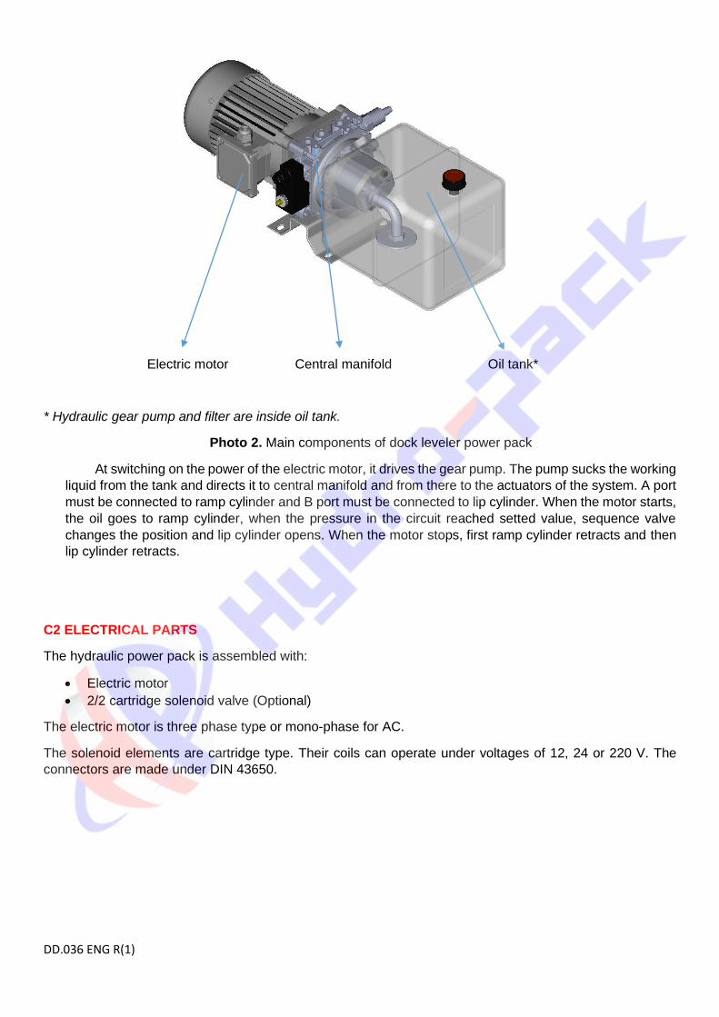
Electric motor Central manifold Oil tank*
* Hydraulic gear pump and filter are inside oil tank.
Photo 2. Main components of dock leveler power pack
At switching on the power of the electric motor, it drives the gear pump. The pump sucks the working
liquid from the tank and directs it to central manifold and from there to the actuators of the system. A port
must be connected to ramp cylinder and B port must be connected to lip cylinder. When the motor starts,
the oil goes to ramp cylinder, when the pressure in the circuit reached setted value, sequence valve
changes the position and lip cylinder opens. When the motor stops, first ramp cylinder retracts and then
lip cylinder retracts.
C2 ELECTRICAL PARTS
The hydraulic power pack is assembled with:
• Electric motor
• 2/2 cartridge solenoid valve (Optional)
The electric motor is three phase type or mono-phase for AC.
The solenoid elements are cartridge type. Their coils can operate under voltages of 12, 24 or 220 V. The
connectors are made under DIN 43650.

DD.036 ENG R(1)
SECTION D: WORKING WITH HYDRAULIC POWER PACK
The power pack work is determined by the machine at which it is integrated. During operation of power
pack it is not allowed the presence of leakage of working fluid on the outside surfaces. The power pack is
switched when the motor is supplied with the necessary voltage. The control is effected by proper
combination of switching on the motor and the solenoid valves.
SECTION E: POWER PACK ASSEMBLY
E1 REQUIREMENT OF THE WORKING AREA
The power pack must be mounted using M10 holes if there is no mounting bracket. The working area
around the power pack must be free and an access to the oil filler, to the valves and the unloading throttle
has to be ensured. The power packs must not be placed in closed areas that may prevent its cooling. The
power pack should not contact with any parts that may vibrate and transmit noise.
E2 TRANSPORT OF THE HYDRAULIC POWER PACK
The power pack can be transported with any kind of covered transport. At its transporting it should be observed the recommendations on the carton. If there is oil inside the tank during transportation, air breather should be replaced with blind plug or oil should be pour out before transport.
E3 POWER PACK PROTECTION
The hydraulic power pack is taken out of the carton. The polyethylene packing is removed of it. The safety plugs are replaced of the supply ports.
E4 CONNECTING PORTS
There are three letters on main manifold which refer to ramp port (A) lip port (B) where both cylinders
are single acting. In this case, (C) port is blind plugged.
If lip cylinder is double acting, (B) port is connected to inlet (to extend) and (C) port is connected to
outlet (to retract) of lip cylinder. (A) port is connected to ramp cylinder. All ports are G 1/4’’ as standard. Max.
tightening torque for fittings is 50 Nm.
Port B Port C Port A
Photo 3. Connection ports on central manifold

DD.036 ENG R(1)
E5 CONNECTION TO HYDRAULIC SYSTEM
The pipelines from the power pack are connected to actuators in the system. Hydraulic circuit and
technical information can be found on technical drawing. After the final installation of the power pack, the
clean working liquid is poured into the tank to the indicated level. Please clean all hydraulic parts concerned
before mounting. Please check the oil level in the tank after initial operation.
E6 CONNECTION TO ELECTRICAL SYSTEM
The cap of the motor terminal connecting box is removed. The nuts of the terminals are unscrewed.
The cable shoes are connected to the terminals. Then the nuts are screwed and reliably tighten. The motor
is nullified. The cap is placed at the terminal connecting box. The coils of the solenoid valves are connected
in the analogical manner. Motor rotation must be checked carefully. Electric motor rotation from fan side must
be left. (CCW)
The connecting of the power pack to the electrical system should be done by a certified electrician as
the rules for safety work with electrical equipments should be observed. Please refer to producer for electrical
schema. After electrical connection has been made, please check the motor rotation by executing short
pulses of correct rotation – max. 1 second each.
Grounding 3rd phase 2nd phase 1st phase
Photo 4. Connection on 380 V AC three phase motors
Phase Neutral
Photo 5. Connection on 220 V AC mono phase motors*
* If mono phase motor operates in wrong direction, please kindly check instructions located on terminal box
cover to make it correct rotation.

DD.036 ENG R(1)
SECTION F MAINTENANCE OF THE HYDRAULIC POWER PACK
F1 CLEANING OF THE POWER PACK
The cleaning of the power pack is made by textile cloth without using any cleaning substances or
solvents. The cloth should not left any filaments on the treated surfaces. Once yearly it is necessary changing
oil and flushing tank. Oil change is done in the following way:
• The pressure is unloaded in the system.
• The power pack is switched off from the electric installation.
• The pipelines are disassembed. The screws by which the power pack is fixed to the basement
are unscrewed.
• The power pack is placed vertically on the tank and the fixing screws are unscrewed.
• The electric motor is placed outside together with the central manifold and the pump. The old
oil is poured out and the internal surface of the tank is cleaned. The suction filter is cleaned
also.
After cleaning, the electric motor with the central manifold are placed on the tank. The fixing screws
and the bracket are screwed. The assembled power pack is installed on its working position. The working
liquid is poured up to the indicated level. The air breather must be closed firmly. The pipelines are assembled
and the power pack is connected to electrical system in accordance to the way of application.
Dirty oil sharply decreases the life time of power pack.
F2 PRESSURE ADJUSTMENT
The pressure adjustment in the hydraulic power pack is made by means of pressure relief valve which is built
in on main manifold.
• Setting of pressure relief valve is 150 bar
• Setting of pressure sequence valve is 90 bar
Photo 6. Pressure relief valve, sequence valve, logic valve and flow control valve for lip cylinder retract
Sequence valve
Pressure relief valve
Flow control valve
for lip cylinder
Logic valve

DD.036 ENG R(1)
* This cartridge valve can be normally open upon customer request.
Photo 7. Pilot operated check valve, normally closed cartridge valve and flow control valve for ramp
cylinder retract
Factory setting of the power packs can usually meet the requirements of most field applications. Users must
be cautious when resetting the settings on the manifold. Loose lock nut of pressure relief valve. Adjusting
screw is turned clockwise to increase pressure setting or anti-clockwise to decrease pressure setting.
Sequence valve pressure can be set in similar manner.
Lowering speed of the platform and lip can be increased/decreased by turning the corresponding flow
control valve in CCW/CW direction. Turn the needle 15° each time.
Attention! Please do not pass max. working pressure indicated on technical drawing.
2/2 normally closed
directional control valve*
Pilot operated check valve
Flow control valve for ramp
cylinder

DD.036 ENG R(1)
F3 PROBLEM SOLVING
PROBLEM REASONS METHOD OF ELIMINATION
Motor doesn't run. • Wrong motor wiring • Check and correct wiring
Motor runs, cylinders don't move. • Wrong motor wiring
• Pilot operated check valve has contaminant inside.
• Check and correct wiring
• Clean the valve
Cylinders don't retract • Solenoid valve is being
energised
• Flow control valve is closed
• Check and correct the wiring
• Adjust the flow control valve
Not sufficient pressure
• Lack of oil inside the tank
• Damaged pressure relief valve
• Damaged solenoid operated valve
• Damaged Hydraulic pump
• Filter is blocked
• Air on suction line
• The oil is filled up
• Readjustment of the relief valve
• Replacement
• Replacement
• Replacement
• Elimination of the air
Non-performance of the function
• Damaged solenoid operated valve
• Damaged shuttle valve
• Damaged pressure relief valve
• Damaged sequence valve
• Damaged pilot operated control valve
• Replacement
Gear pump does not operate properly
• Air inside the system
• Lack of oil inside the tank
• Elimination of the air
• The oil is filled up
Ramp cylinder is too slow • Flow control adjustment is not
correct • Re-adjustment of flow control
valve
Lip cylinder doesn’t close properly
• Pilot operated check valve problem
• Flow control valve adjustment is not correct
• Lip cylinder problem
• Replacement
• Re-adjustment of flow control valve – it shouldn’t be totally closed
• Inspection of lip cylinder
Lip does not rise
• Relief valve pressure is too low.
• Sequence valve pressure is too high
• Logic valve has contaminant inside.
• Increase the relief pressure.
• Decrease the sequence valve pressure.
• Clean the valve
Platform and lip rise simultaneously when motor runs
• Sequence valve pressure is too low
• Increase sequence valve pressure
All power packs are tested 100% before delivery to customer. Please kindly contact us for all questions.

DD.036 ENG R(1)
SECTION G WARRANTY
The producer guarantees the conformance of the product to the standard and technical
documentation and its work capability at actuation complied with the present manual.
Please do not take out product label on oil tank during warranty period.
The guarantee period is 12 months from the date of starting in operation, but not more than 18 months
from the purchase date.
The producer undertakes to eliminate the defects occurred because of its fault.
The guarantee conditions are not be carried out if the user has made a repair without permission and
has not kept the clauses mentioned in the present manual.
The guarantee engagements of the producer will be implemented in its factory or in authorized service
by it.
PRODUCT CODE HPP …
SERIAL NO
DATE OF PRODUCTION
Warranty is only valid on document which has date, stamp and signature information.
RELEASE DATE:
STAMP AND SIGNATURE
HYDRO-PACK Mühendislik Makina Hidrolik San. ve Tic. Ltd. Şti.
Sanayi Mah. İzmit San. Sit. 13. Cad. No: 315 İç kapı no: 54 İzmit, Kocaeli, Türkey
Tel: +90 262 335 23 42 Fax: +90 262 335 23 62
E-mail: [email protected] Web: www.hydropack.com.tr


![[DD]Complete_Arcane.pdf - thyamath.com](https://static.fdokumen.com/doc/165x107/63162c3cc72bc2f2dd04fc6d/ddcompletearcanepdf-thyamathcom.jpg)