DAVID ARONSON
9
Nov. 3, 1964 D. ARONSON 3,154,930 REFRIGERATION APPARATUS Filed Oct. 1, 1962 2 Sheets-Sheet 1 COQLING' TuWER DAVID ARONSON INVENTOR. BY ‘ h’ 4%
-
Upload
khangminh22 -
Category
Documents
-
view
0 -
download
0
Transcript of DAVID ARONSON
Nov. 3, 1964 D. ARONSON 3,154,930 REFRIGERATION APPARATUS
Filed Oct. 1, 1962 2 Sheets-Sheet 1
COQLING' TuWER
DAVID ARONSON INVENTOR.
BY ‘ h’ 4%

3,154,930 Nov. 3, 1964 D. ARONSON
REFRIGERATION APPARATUS
2 Sheets-Sheet 2 Filed Oct. 1, 1962
I
I3
/IO
N I A O O
“on on 6o
0 4 q
o a c on
\o o \2/ A/ o
..
,o/r o oo low m o R
o o
on \U o o m 1/ Am a E
In 4/T R3 o 00 T6
\ M 6 .Nu( a 0 Am)
0 R o 6 E0 “NW u/!% o M G o n m(
D
.R 0 A we "a E
w 0a V S no
No B o. E m
D
o n a o
C
/
I2.
. 1
7 S
PuMP us)
REFRIG. ABSORBER PUMP
(1'')
Fl G. 2
DAVID ARONSON INVENTOR.
I )4 . ML, BY
J

United States Patent 1
3,154,939 REFRIGERATIGN APPARATUS
David Aronson, Upper Montclair, N.J., assignor to Worthington Corporation, Harrison, N.J., a corporation of Delaware ,
Filed Oct. 1, 1962, Ser. No. 227,368 18 Claims. (Cl. 62-143)
This invention relates to refrigeration apparatus having improved design and construction features. It relates in particular to a vacuum absorption'machine which em ploys as the circulating absorbent a brine solution con sisting of a hydrophilic salt in water which absorbs refrig erant water. A salt brine as the absorbent in such an apparatus is
found to be quite effective but often entails operating dif?~ culty in that crystallization is likely to occur. Crystalli zation of the absorbent solution in the system may occur under varied circumstances. When it does take place, crystals tend to accumulate in particular parts of the machine and thus interrupt free circulation of refrigerant. Crystallization normally occurs during the shut-down period, that is, when the temperature of the entire system is lowered su?iciently' so that salt in the solution crystal lizes. It also occurs frequently in a heat exchanger when air passing over the exchange surface is sufficiently cold to lower the ‘temperature of the strong solution in the heat exchanger below the crystallization point. Su?icient air’ leakage into the normally closed absorption system causes partial loss of vacuum and consequently overload of the system; this also may. lead to formation of hydrate crystals.
Normally, the basic units of an absorption system con sist of an absorber, a generator, a condenser, an evap~ orator and a heat exchanger. These elements are con nected by suitable piping, pumping and associated control means to de?ne a closed refrigerant system. The respec tive elements as shown extensively by the prior .art may be interconnected into a single unit or alternatively they may be interconnected or physically disposed as separate individual units. As a matter of practicality and to pro vide a commercial package, the units are preferably ar ranged in such manner as to take up as little volume as possible for the amount of refrigeration produced. The present invention includes a new and novel ar
rangement of elements in an absorption machine utilizing a saline solution in such manner (as to permit more ecoT nomical and e?lcient use of space, and to reduce the haz ards of crystallization. This result is achieved primarily through the arrangement of the absorber and the genera tor which are disposed to encourage refrigerant in the system to gravitate downwardly toward the generator regardless of the load imposed on the unit. Cooperative with this arrangement of parts is the unique control sys~ tern which automatically adjusts the ?ow rate of solution through the system by varying solution density in ac cordance with the load being imposed on the machine.
It is therefore a primary object of the invention to pro vide an absorption apparatus including essentially an ab sorber, a generator, a condenser, an evaporator and a heat exchanger connected in a novel circuit arrangement for circulating saline solution, which elements are physi cally arranged to de?ne a simple compact unit. A further objective is to provide an absorption unit of
the type described which employs a saline solution with water as the refrigerant component, said unit being ar ranged to facilitate start-up and shutdown of the ma~ chine while minimizing crystallizing problems normally associated with the use of a saline type absorbent.
It is a still further object of the invention to provide an absorption unit of the. type described which includes means for gravitational ?ow of solution to the generator
5
10
15
25
30
35
40
1 3,154,933 Patented Nov. 3, 1964
2 to avoid crystallization particularly in the absorber sec tion during shutdown.
It is a still further object to provide an apparatus of the type described in which a control means causes the rate of solution ?ow through the system to adjust auto matically in accordance with the heat input to the gen erator.
I Other objects of the invention not speci?cally men tioned will become clear to one skilled in the art from the following description made in conjunction with the draw ings, in which: '
In the drawings: ‘ ,
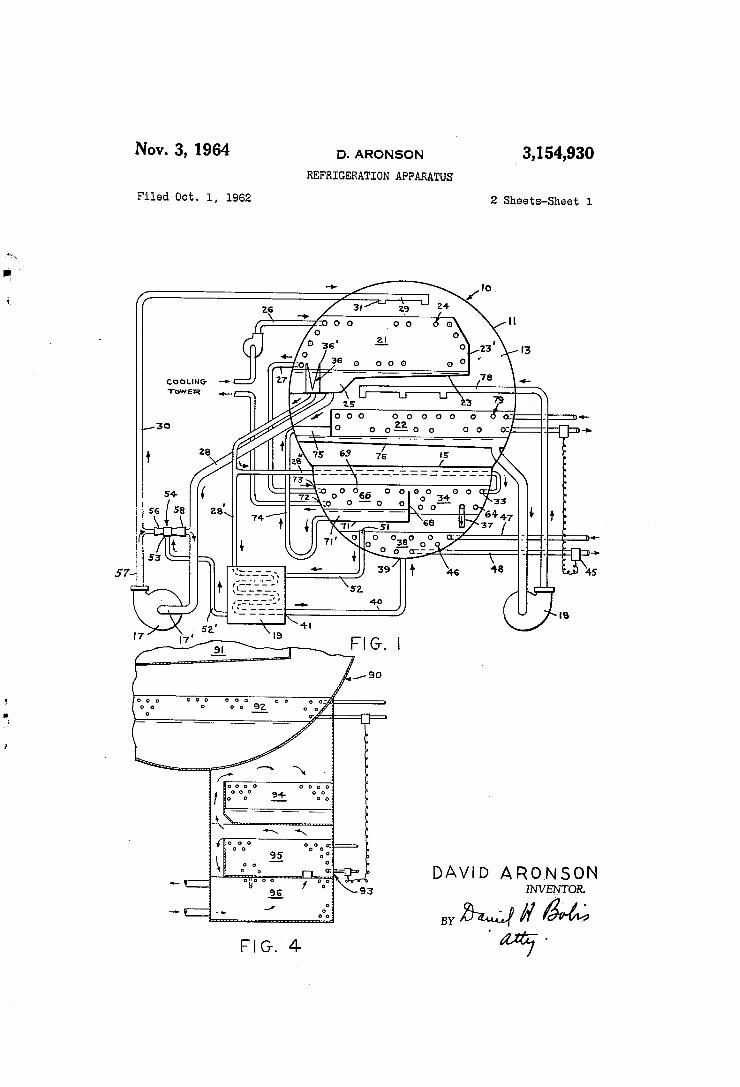
FIGURE 1 is a diagrammatic view of the absorption unit. . ‘
FIGURE 2 is a side elevation view in partial cross .sec tion illustrating diagrammatically the arrangement of parts in the refrigeration system. FIGURE ,3 is a segmentary view in cross
over?ow portion of the absorber. ' ,
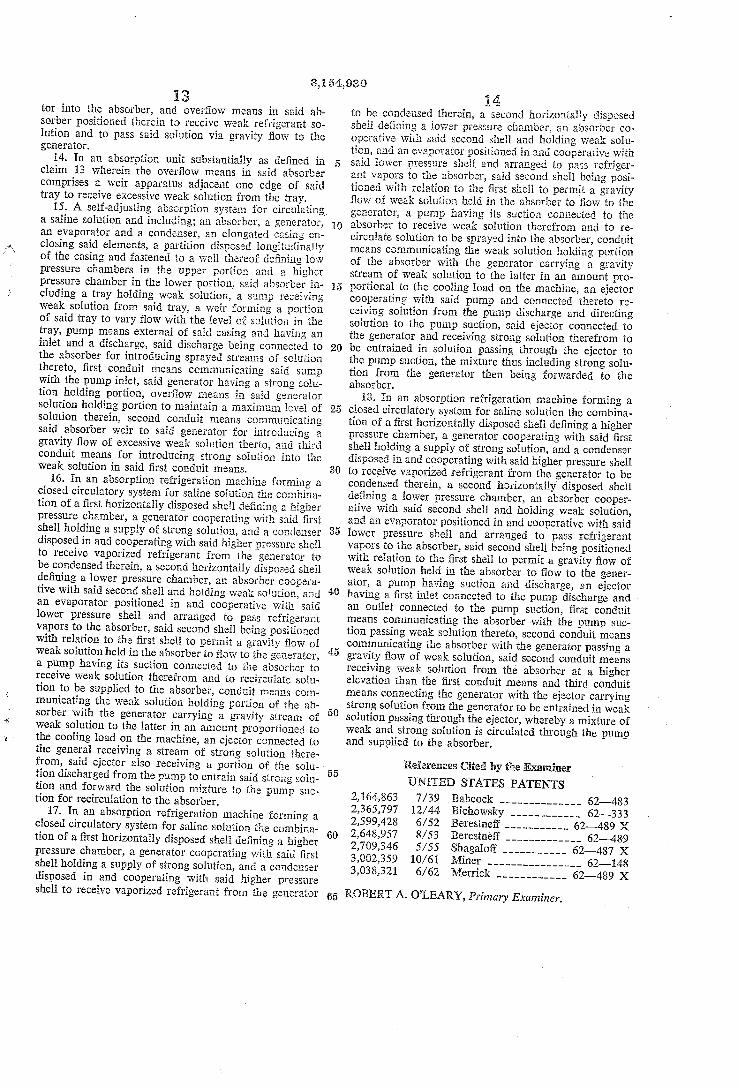
FIGURE 4 is a sideelevation view in partial‘ cross sec tion of an alternate arrangement of essentialjelements in cluding enclosing "shells. ' '
The invention in brief contemplates a novel absorption apparatus or refrigeration system including essentially an ‘absorber, a generator, a condenser, an evaporator or chill er and a heat exchanger contained within evacuated shells and spatially arranged to provide a compact, e?icient unit. The respective components are contained in ‘suit able high or low absolute pressure casings in accordance with the function of the particular element in the sys tem. To utilize the presently disclosed control features, the absorber is positioned above and connected with the
section of the‘
‘generator permitting a gravitational flow of weak solu ‘tion from the absorber to ‘the generator to concentrate brine solution. -l' ' ' ' ' .
In the present embodiment of the invention the ab ‘sorber and the evaporator are disposed within a ?rst low pressure shell enclosure whereby water vapor may ?ow to the absorber and be contacted by sprayed streams of a brine solution. Condenser and generator elements are
. positioned in a high pressure second ‘shell enclosure and
45
55
60
65
70
relatively disposed with respect to each other to pass vaporized refrigerant to the condenser. In the generator refrigerant water vapors are boiled from Weak brine solu tion for the purpose of concentrating the latter. Vapor driven from the brine solution being concentrated is con densed in the indirectly cooled condenser located in the ‘high pressure shell. Flow of condensate is then upward from the high pressure shell to the low pressure shell.
Condensate formed in the condenser pan is directed to the low pressure side of the system for cooling the chiller by evaporation. The quantity of refrigerant circulated over heat transfer elements or tubes in the chiller, and the quantity of brine circulated over tubes in the absor ber, is in excess of that required for evaporation or ab sorption in the respective units. Such excess circulation is deemed essential for, the purpose of wetting all heat exchange surfaces through which heat transfer must be made to chilled water or cooling water respectively. The concentration of brine may be controlled by introduction of strong solution to the absorber through supplementary pumping means or by an ejector cooperative with pump ing means'to draw concentrated solution into the weak solution circulatory system.
_ Means is also provided for gravity feeding a stream of weak solution from the absorber to the generator for the purpose of concentrating the solution. This ?ow to the generator is varied as required to hold the concentration of absorbent at that value necessary to meet cooling load imposed on the machine. Since ‘no surge or storage tank .for absorbent exists in the system, the withdrawal of weak solution from the absorber automatically results in its

3,154,930 3
replacement by strong solution, although such replace ment may not be on an equivalent one-to-one basis. The apparatus and its mode of operation is herein de
scribed in terms of high and low pressures. This termi nology is merely for the purpose of comparative identi? cation since in actuality this unit operates under vacuum. For example, under standard conditions, pressure in the absorber will approximately 0.3 inch mercury whereas that in the generator-condenser high pressure section will be about 3.0 inches mercury.
In the following description reference is made to the preferred absorbent as being a lithium bromide Water solution. It is understood though that other similar hy drophilic saline solutions may be employed, with water being used as the refrigerant. In the various sectors of the cycle, solution will undergo changes and will be found in varied degrees of concentration. For example, the term weak solution as will be hereinafter usedde?nes a condition when the solution contains a large amount of refrigerant and is thus characterized by very weak absorb ing properties. The term strong solution on the other hand implies a condition in which there is a relatively low refrigerant content and consequently high absorption‘ capability. Under normal operating conditions weak solution will
enter the generator at a concentration of from 55 to 61% and leave at about 66% concentration. It should be understood that any salt in the refrigerant is present only as‘ contaminant and ‘diminishes performance. Sys tems may however be designed to use a very weak brine to avoid freezing, but for normal air conditioning such is not the case. The condenser and evaporator will hold essentially pure refrigerant. The absorber includes a spray of solution and also a pool of the solution in con centrations varying from about 55% to 63%. It is further understood that as a matter of practicality the solution may also contain a small amount of a compat ible rust inhibitor to avoid undue corrosion of metallic parts in the machine.
Referring to the drawings, FIGURES l and 2 illus trate diagrammatically an absorption unit 16 of the type presently contemplated which includes an elongated shell '11 supported by legs 12 ?xed to the underside. The shell 11 may be a unitary, elongated body horizontally dis posed, and preferably of welded construction having end plates including removable access openings, de?ning an air tight inner enclosure. Alternatively, the shell may consist of a plurality of elongated adjacently disposed shell-like bodies so constructed and arranged to de?ne a compact unit. As shown, the present embodiment includes a single
shell 11 having an upper chamber 13 and a lower cham ber 14 separated by a pressure-tight partition 15 welded or fastened along opposite edges to the shell wall. Fastened externally to the shell or to support members are pumps 17 and 18 and a heat exchanger 19 which through suitable conduit means are in communication with elements contained within the shell.
Referring to FIGURES 1 and 2, absorber 21 and evaporator 22 are shown positioned in the upper or lower pressure chamber 13 of shell 11. Absorber 21 includes a liquid-holding tray-like receptacle 23 having an up turned edge 23', positioned substantially horizontally of the shell and extending the length thereof. Tray 23 includes a solution holding sump 25 and is welded along one side to the inner wall of shell 11. The upturned edge 23’ is spaced inwardly of the shell wall forming a spray guard and vapor guide. As shown, a cooling coil or tube bundle 24 positioned above tray ‘23 is provided with inlet 26 and outlet 27 for circulating water or other cooling ?uid. This cooling water is then conducted to the tube side of the condenser and subsequently circulated through a cooling tower.
Conduit 28 connected with liquid holding sump 25 directs weak solution by gravity feed to inlet 17’ of the
10
15
20
25
30
35
50
55
60
70
75
A absorber circulating pump 17 which in turn circulates weak solution by way of loop 30 to manifold 29 posi tioned above tube bundle 24. Spray nozzles 31 inserted in manifold 29 direct streams of brine solution into heat exchange contact with the surface of tube bundle 24 effecting heat transfer to cooling water circulating there through. This circulation of brine from the absorber into spray manifold 29 is a continuous process, the weak brine solution being supplemented by the addition of strong solution drawn from the generator as will be hereinafter described.
Referring to FIGURE 3, also associated with tray 23 in absorber 21 is a liquid over?ow or weir arrange ment 36 connected to conduit 28' and positioned to re ceive an over?ow of weak solution from tray 23. This weir arrangement is an integral part of the absorber control system to pass an amount of solution there through in accordance with the load being imposed on the machine. The Weir as shown communicates through conduit 28' directly to heat exchanger 19 positioned at the lower part of the machine. Weir 36 is also com municated through a second parallel conduit 28" con nected to conduit 28’ with desuperheater 34 to preheat Weak solution prior to introduction into the generator. As shown in the drawings, weir 36 is at a su?iciently
high level in the lower pressure absorber 21 to permit a gravity ?ow down into the higher pressure generator. This difference in height is essential to account for the normal differential in operating pressures between ab sorber and generator and also to overcome frictional resistance of the piping and heat exchangers between the said parts. ' An embodiment of weir 36 as shown in FIGURE 3,
may consist of an upright tubular element threaded to the upper end of conduit 28'. A plurality of inlet open ings 36' transversing the wall of said element are so ar ranged and of such shape as to provide an increasing how of solution therethrough as the height of solution in sump 25 increases. tioned above the sump base to assure that some solution will always be present in the sump for circulation to absorber‘pump 17 even at minimum or no load condi tions.
According to the invention absorber 21 is positioned in the upper portion of lower pressure chamber 13. Therefore conduit 28' leading to heat exchanger 19 will require no pumping means but will be fed merely through the gravity head resulting from the difference in eleva tion of the absorber 21 above generator 38. In order to overcome an expected generator head pressure of about 3.0 inches of mercury, as contrasted with the reduced pressure in the absorber, a minimum head diiference is maintained. While theoretically no maximum pressure differential is prescribed, it is found that between the level of strong solution in the generator and the level of weak solution in the absorber at least about 2.5 feet should be maintained.
Generator 38 is located at the lower part of chamber 14 in shell 11, said shell thus de?ning a reservoir or pool for holding substantially the entire volume of ab sorbent brine solution in the system. This higher pres sure portion of the system is normally maintained dur ing operation at the above mentioned 3.0 inches of mercury pressure. A heating coil or tube bundle 46 cooperative with shell 11 is provided with inlet header 47 and outlet header 48 for circulating stream from a boiler or other heat source of supply exterior to the absorption machine.
Control means such as a remotely operable valve 45 is interposed in the steam loop return leg to vary the out?ow of steam condensate from coil 46 in response to the load imposed on the absorber. Valve 45 may be controlled by sensing or monitoring means communi cated with the chilled water coil to sense the condition of water leaving the evaporator.
The lowest portion of inlets 36’ are posi—

3,154,930
The steam loop generally consists of tubes supported ‘in the generator liquid holding portion, carrying steam at a temperature of about 240° F. into the generator 38 vfor the purpose of heating or boiling weak solution con tained therein. Such boiling permits vaporous refriger ant, that is water vapor, to rise from the generator and pass into heat exchange contact with the desuperheater coil 34 positioned thereabove, and then to pass on to the condenser. ~
As water vapor is driven from the weak solution, residual solution in the generator becomes more con centrated and is conducted through an over?ow means 51 communicated by conduit, 52 to the heat exchanger,
10
and thence through conduit 52’ to ejector 54. f Ejector I 54 is arranged and operated in conjunction with absorber circulating pump 17 and is preferably connected across the pump so that ejector inlet 56 communicates with the pump discharge 57, and ejector outlet 58 communicates with the pump suction 17'. a ‘ Y '
The over?ow device 51 in the generator is so posi tioned as to maintain 1a substantially constant level of solution in the generator regardless of solution vboiling rate. Although this liquid level will be maintained rela tively constant, within slight limitations depending on ‘the load, the rate of over?ow of concentrated solution into heat exchanger 19 will increase as the ‘load on the ma— chine increases, due to'the coacting operation of weir 36 which serves to vary the feed rate to generator 38 in ac cordance with liquid level in absorber holding sump 25‘. The liquid level in holding ‘sump 25 will rise as the boil ing rate in generator 38 increases because of the increase .in volume of solution in generator resulting from the increased fraction of steam bubbles in the solution. ‘For the purpose of illustration, the total mass o-fsolution in absorber 21 and in generator 38 may be considered ‘constant. Hence when thespeci?c volume of ?uid in the generator 38‘ increases, the mass of solution in the gen erator 38 must decrease, and in turn the mass and volume of solution in the absorber must increase.‘ ‘This increase ‘in volume of solution in absorber 21 results in the in crease in liquid level in absorber holding sump'25, which ‘produces the change in flow rate mentioned above.
I This explanation must be modi?ed by 'the' considera tion ‘that the concentration of solution in absorber and generator is subject to change with load conditions of the system. At light load the concentration ofsolution in the generator 38 and in the absorber will tend to be higher than at heavy load conditions. will shift the control characteristics of the Weir 36. The recycle rate of solution from absorber 21 to generator 38 is not sharp ly critical in terms of process requirements so that sec ondary in?uences can be tolerated without upsetting the basic machine control.
Concentrated brine is drawn to ejector suction inlet 53 through heat ‘exchanger 19 for introduction into the ab sorbent pump circuit to combine with a ?ow of weak solution in lines 28 and 30 comprising the external ab sorption circulating loop. Mixed solution is then car ried to the upper part of the absorber to be sprayed into contact with refrigerant vapors.
It may readily be seen that by positioning generator 38 ,at the lowest portion of the shell 11, or if in a diiferent shell, substantially below the absorber solution level, an advantage is gained over what has been taught by the prior art. Most notably,’ brine solution will flow by gravity downward to accumulate in the generator 38. ,Further, solution in the various pipes and conduits con necting the respective components will also gravitate-to ,ward the bottom of the machine. This is especially true and bene?cial when the absorber is subject to emergency shut-down due to a power failure or other such contin gency in that a gradual lowering of the temperature of the solution will not prompt crystallization throughout ,the machine but rather will permit such to occur only at
15
25
40
45
.50
55
V60
70
7.5
a limited number of places including perhaps the generator.
In that generator 38 is directly connected through coil 46 to the heat supply, there will be a minimum delay in starting up the machine since heat directed into the gen erator will be concentrated on the major portion of the solution. Thus, any crystallization vwill be overcome rapidly and result in a normally trouble-free start~up.
Since generator 38 in eitect functions as an accumula tor for at'least ‘a large portion of solution in the entire circuit, automaticv control of the machine in response to load variations will be re?ected in the generator by a change in boiling rate and solution density. Increase or decrease in the boiling rate of the solutionas required will be such as to bring the system into balance with the de'mandplaced thereon. ' I
Desuperheater 34 consisting of a tube bundle 64 is sup ported above and laterally to one side of generator 38 in the higher pressure section of shell 11. Inlet 33 of de superheater coil is connected through conduit 28" to con duit 28' to receive a portion of the ?ow ofweak solution from the :weir 36. This ?ow in passing through the de superheater coil receives heat by transfer from upwardly passing hot vaporous refrigerant prior-to the latter en ,tering condenser 66. Heated solution in coil 64-, is then "directed through‘ conduit 37 into generator 38 for boiling.
While the desuperheater is not considered essential to ‘operation of the system, it is found when employed as herein‘ described to increase overall e?iciency of the ab sorption unit by conserving heat which could be otherwise wasted. . The desuperheater, as with previously described tube bundle elements, extends substantially longitudinal ly_ within elongated shell 11 and is carried by support brackets to de?ne a passage’for hotrefrig'e'nant vapors 'enteringthe condenser. .
Condenser 66 is likewise positioned in the higher pres sure lower portion 14of shell 11 above generator 38. _T he condenser includes a receptaclev or tray-like element 71 extending longitudinally of the shell and fastened to the ,Wall thereof for holding condensate. An upturned flange, 68 at the tray inner edge forms a vapor guide means adjacent the desuperheater‘tube 64 for directing .desuperheated vapor onto the top of the condenser tube bundle 69. and also forms the side of refrigerant reservoir 71?. Condenser 66 may be of the single or multi-pass type as required.‘ vTube bundle 69'is providedwith inlet and outlet heads 72 and 73 which communicate with a source of condenser water or cooling ?uid which as previ ously noted may ?ow directly through the absorber coil 24 or be'passed to a cooling tower or other heat ex change Ineans'. Y " V
Evaporator 22' ‘as shown in FIGURES l and 2 is posi tioned in the lower pressure upper portion 13 of shell. 11 ‘extending in, a transverse direction immediately below ab sorber 21. VA, loop conduit 74 is in communication with the condenser tray 711590 receive condensate and-pass vsame upwardly for ?ashinginto evaporator 22. This loop-as shown may be positioned external to the shell 11 and functions as a seal to prevent or at least limit en itrance of steam from the condenser to the low pressure evaporator. Normally, saturated condensate will be forced upwardsjby the high condenser pressure and will enter the evaporator. “Entering condensate will , then flash resulting in about 9% of steam entering with liquid.
Itpis understood that the light differential which exists between condenser 66 and evaporator 22 is such thatthe condenser pressure will be sufficiently great to overcome the head differential and frictional resistance .to force refrigerant water up into ?ash chamber 75 from which the refrigerant may then be'introduced directly into the
v evaporator.
As a structural expedient this head difference between evaporator and condenser should not exceed about two feet and may be much‘less depending on other structural features of the machine. 1 7' e ' - i

3,154,930 7
Evaporator or chiller 22 includes a tray-like.receptacle 76 having upturned lateral edges extending transversely of the shell 11 and fastened above partition 15 to hold a pool of refrigerant. Conduit means connected to tray 76 communicates the refrigerant pool with pump 18 for cir culating refrigerant to manifold header 78 positioned above the evaporator tube bundle 79. Tube bundle is positioned directly over tray 76 to receive a spray of liquid refrigerant from nozzles in the manifold and is connected to the supply of liquid to be chilled. For this purpose manifold nozzles are positioned in the evaporator upper portion .to direct refrigerant ‘onto the surface of tube bundle 79 to achieve maximum tube surface wetting and maximum evaporation effect. Tube bundle 79 is provided with suitable irlet and outlet means connected to the supply of chilled liquid.
This chilled liquid is generally maintained within the range of about 45 to 55° F. and used primarily for air conditioning but is adaptable for use to other applications. Since the condition of chilled water is a reasonable meas ure of the load imposed on the absorption unit suitable temperature responsive means may be connected to the chiller circuit with means as previously mentioned for controlling operation of the steam condensate valve 45 in accordance with the load imposed on the machine. While the absorption machine and disposition of major
components have been described in connection with essen tially a single shell design having a pressure wall sepa rating the high pressure section from the low pressure section, it is not intended that the invention be contingent wholly on the shell con?guration.
For example, the herein disclosed principles can be embodied in an arrangement of two distinctly separated shells for high and low pressures, interconnected by suit able conduit means. As shown in FIGURE 4 for example, the arrangement may embody a cylindrical upper shell $0 housing the absorber 91 above the evaporator 92. T he lower, high pressure shell 93 comprises an elongated
rectangular closed chamber having longitudinal compart ments. Condenser 94 is positioned in the top compart ment adjacent the intermediate positioned generator 95. Heat exchanger '96 in the bottom compartment is again disposed to receive conducted heat from the generator. The pumping and piping means by which the absorber
elements are connected is similar to what has been dis closed with respect to the previously described arrange ment. This phase of the machine will therefore require no further elaboration. '
It is readily seen however that the latter embodiment of the invention provides a compact grouping which is easily enclosed to form a unitary machine.
Operation and Control
The presently disclosed arrangement of components per mits the use of several means by which control of the machine might be accomplished. A preferred means as herein indicated consists of the introduction of a con trolled amount of steam into the generator in accordance with the load being imposed on the unit. Novelty in the vcontrol system resides in the means by which such in troduction of heat to the generator is automatically utilized to provide a variable flow rate of solution through the system by way of a variable density pool of solution in the generator. The following description directed to the mode of oper
ation will be made as related to a system in which steam is introduced into the generator under a head of about 12 psi. gauge, and waterpis the ?uid to be chilled to about 45° F. Under normal operating conditions, water to be chilled
will be circulated through tube bundle 79 in chiller 22 communicated externally of casing 11 to a supply of water. Temperature sensing means in the downstream leg may include any of a number of commercial devices prsently on the open market for the purpose and con
10
15
20
30
35
40
45
50
55
60
65
75
8 tinuously monitors the condition of water in the outlet side of tube bundle 79. . The temperature sensing mechanism includes for ex
ample an electrical, pneumatic or mechanical connection, which cooperates with valve 45 interposed in the down stream leg of steam coil 46. Valve 45 is operable prefer ably automatically to vary the egress of condensate from tube bundle '46 in response to variations registered in the temperature sensing means. Tube bundle 46 is arranged in the generator and so connected to the steam line that steam enters the tubes and condenser. Valve 45 is inter posed in the steam loop return line to vary the flow of steam in response to the load imposed on the absorber. Valve 45 may be controlled by sensing or monitoring means communicated with the chilled water coil to sense the condition of water leaving the evaporator. This ar rangement is effect inactivates a portion of the tube bundle 46 to decrease the available heattransfer surface thereof. That is, when valve 45 is throttled down, condensate forming in the lower tubes of tube bundle 46 blocks further flow of steam and thus limits the heat transfer portion to those tubes in the upper portion of the tube bundle. At start-up of the machine, valve 45 is set fully open to
provide maximum steam flow to heat the solution con tained in the generator‘ 38. After a shut-down, virtually all of the solution will normally have drained to the ‘ generator and thus restrict crystallization on cooling vdown to this portion of the system. With introduction of steam, the brine solution will eventually reach the brine boiling point. A portion of the solution will then be boiled out and vapor passed upwardly into contact with desuperheater tubes 64 and flow thence to condenser 66. Under a steady load condition, the amount of heat
passed into the generator 38 will be sufficient to main tain a steady solution boiling rate. This steady state for any particular load is achieved by means of the combined effect of reduced density of brine in the generator leading to increased quantity of brine in the absorber and thus greater ?owof weak solution across the absorber weir 36. For an intermediary load, this rate will be such that for purposes of description it could be said that about half the solution is in the lower pressure shell whilerthe remaining half is in the higher pressure portion. At maximum load on the other hand virtually all the solution will be in the upper low pressure absorber and evaporator while the generatorvholds a relatively small proportion..
S?lf-balancing of the system to adjust for these varying load conditions is achieved as follows. If a heavier load is suddenly put on the machine while running at a par ticular rate, until the solution flow rate adjusts itself, the output temperature of chilled water will rise. This change in temperature will be detected in the downstream leg of coil 79 and thus effect an increased steam con densate rate through valve 45 whereby a more rapid rate of solution ?ow through the entire system is initiated. At the higher rate of boil, solution in the generator will
become less dense by virtue of intense bubble formation. To maintain the desired generator liquid level, strong solu tion will now flow through over?ow arrangement 51 and pass through heat exchanger 19. This strong or concen trated over?ow solution from the generator is now fed to suction inlet 53 of ejector 54 for injection into the absorption refrigerant circulation loop thus compensating for the over?ow from absorber to generator. The absorbent loop 3t) during any load operation will
circulate weak refrigerant from absorber sump 25 through pump 17 and thence to spray manifold 29 for reintroduc— tion as sprays to the absorber upper portion. Part of this flow is directed through ejector 54 connected across pump 17 to induce strong solution from heat exchanger 19 into the weak solution stream in the absorbent circuit. This mixing in effect concentrates the solution being sprayed into the absorber. For efficient operation, the rate of ?ow of brine sprayed into the absorber is main

3,154,930
tained in excess of what is required to absorb vaporous water entering the absorber from the evaporator.
Consequently, under increasing load conditions, the rate of absorbent introduction for absorbing refrigerant vapor will become increased. The weak solution thereby formed will build up in the absorber tray 23 and in sump 25.‘ Gravity ?ow of weak solution from sump 25 through conduit 28 will be relatively constant to supply a steady circulatory ?ow. Excessive weak solution built up in tray 23 will enter the over?ow weir 36. Weak solution ?owing over weir 36 ?ows under gravity
head in two streams, one stream through conduit 28’ passes directly to heat exchanger 19; the other stream is directed through conduit 28" to the inlet of desuperheater coil 64. It is seen then that for varied load conditions only a single self-adjustment in the cycle is made eifecting heat input to bring the system into balance with the load. This single valve adjustment is normally fully automatic and constitutes the sole moving part of the control system which could cause an inadvertent misfunction.
' In the instant control arrangement as previously noted, boiling of brine in the generator causes a portion of solu tion to pass off in vapor phase thus concentrating the brine remaining in the generator which will ?ow through ejector 54. Water vapor rising through the desuperheater 34 will transfer heat to weak solution passing there through from the absorber. This heat transfer lowers the temperature of the Water vapor entering the upper portion of condenser 66 prior to contact with condenser coil 69. .
Condenser coil 69 circulates condensing water or liquid in a closed circuit with the absorber coil 24. The pres sure in this high pressure section of the system will be approximately 3.0 inches of mercury or thereabouts. From tray 71 in the condenser 66 where condensed water vapor passes, said refrigerant is directed into the seal conduit 74 having a loop section extending below the level of the condenser in order to maintain a liquid trap and thus minimize passage of steam to the evaporator 22. From loop 74 liquid refrigerant entering the low pres
sure circuit will ?ash cool into evaporator 22 containing chiller coil 79. This ?ashing of refrigerant into the evaporator serves to chill the refrigerant therein to a tem perature of about 40° _F. Tray 76 in the evaporator holds a pool of liquid refrigerant for circulation through re frigerant pump 18 to spray nozzles positioned above coil. 79. As refrigerant is sprayed over the surfaces of tube bundle 79, the tubes are maintained in the condition of being continuously wetted thus assuring an ei?cient heat transfer condition. Contact of refrigerant with the sur4 faces of coil 79 causes the refrigerant to vaporize as a result of heat being drawn from the chilled water. 7 The amount of refrigerant introduced to the evaporator both by circulation through the spray nozzles or through ?ash ing is in excess of the requirements for vaporizing, but is needed to wet all heat transfer surfaces. Vapor from evaporator 22 will rise and be directed
along the lower surface of tray 23, against the wall of shell 11,- and passed upwardly into absorber 21. In the low pressure absorber,‘ the temperature and pressure are, sufficiently depressed to draw vapor from the evaporator. Brine being directed from spray nozzles 31,0nto the sur face of tube bundle 24 mixes with entering refrigerant vapor. During absorption, the vapor condenses, gives off heat of condensation and further dilutes the solution which now accumulates in tray 23. The heat given oif by condensing vapors is carried away by water or other ?uid circulatory means through coil 24 which then as previously mentioned may be directed to condenser coil 69. .
The advantages realized by the‘present arrangement and the solution density control system based thereon are wide in their implications. Primarily, the unique arrangement substantially avoids inconveniences in opera~ tion arising from crystallization of solution in the ma
15
20
25
30
- means including a pump having a suction connected to.
35
40
45
55
65
70
75
. a a _ 1O .
chine due to either emergency or normal shutdown. Further, the number of working parts or moving parts is reduced by elimination of at least one pump, a feature which reduces maintenance costs as well as original costs. Also, the arrangement ?ow control means in both the generator and the absorber is such to assure completely automatic adjustment of the system to any variation in load imposed thereon. '
' It is understood that certain changes and modi?cations may be made in the disclosed method and apparatus by those skilled in the art without departing from the spirit and scope of the invention. What is claimed is: , 1. An absorption refrigeration machine of the vac
uum type connected to form a closed saline solution cir culatory system comprising; a ?rst horizontally disposed elongated shell de?ning a higher pressure chamber, a generator cooperating with said shell holding a supply of strong solution, and a condenser disposed in and co~ operating with said higher pressure shell to receive vapor ized refrigerant from the generator to be condensed therein, a second horizontally disposed elongated shell de?ning a lower pressure chamber, an absorber coopera tive with said second. elongated shell and holding weak. solution, and an evaporator positioned in and cooperative with said lower pressure shell and arranged to pass refrig erant vapors to the absorber, said second shell being posi tioned with relation to the ?rst shell to permit a gravity ?ow of weak solution from the absorber to the generator, conduit means communicating the weak solution holding portion of said absorber with the generator ‘for conduct ing said gravity ?ow, of weak solution, and pumping
said absorber and to said generator respectively and re ceiving streams of solution therefrom, said pump having a discharge outlet connected to said absorber and passing said solution thereto. »
' 2. In an absorption refrigeration machine substantially as de?ned in claim 1 wherein the second shell de?ning a low’ pressure chamber is positioned above said ?rst shell de?ning a high pressure chamber to permit gravity flow of weak solution held in the absorber to pass to the gener ator against the high pressure of said ?rst shell.,
3. In an absorption refrigeration machine substantially as de?ned in claim 1 wherein said low pressure second shell is positioned above the high pressure ?rst shell a su?‘icient distance such that the level of weak solution held, in the'absorber is above the level of strong solution held in the generator a distance not substantially less than about S'feet. _
.4. An absorption refrigeration machine de?ning a closed saline solution circulatory system comprising; a generator holding a pool of strong refrigerant solution to 'be vaporized, a. condenser to receiverefrigerant vapors from the generator and to condense the same, an elon gated high pressure shell enclosing said generator and said condenser, an absorber holding a supply of weak refrigerant solution, an evaporator ?ashing refrigerant ‘received from the condenser and having cooling coils therein forrcircul‘ating chilled liquid, an elongated low pressure shell enclosing said absorber and said evapora tor, said high and low pressure shells respectively being arranged relative to each other such that the absorber in said low pressure shell is positioned at an elevation suf ?ciently ‘above said generator that the level of weak refrigerant solution in the absorber is above the surface of strong solution in the generator thus permitting a gravity ?ow tothe latter, a pump circuit including a pump means communicated with said absorber liquid holding portion to receive a continuous stream of weak solution and to. spray said solution into the absorber, ?rst conduit means communicating the weak solution hold ing portion of said absorber with the pump and forming a portion of said pumping circuit, second conduit means communicating the weak refrigerant holding portion of

3,154,930. 1 1
said absorber with the generator, and third conduit means communicating the strong solution holding portion of said generator with the pump circuit. to introduce a ?ow of strong solution into the stream of weak solution inrsaid’ pumping circuit.
5. An absorption refrigeration machine de?ning a closed. saline solution circulatory system comprising a generator holding a pool' of absorbent solution to- be concentrated by vaporization, a condenser to receive re frigerant vapors from the generator and to condense same, an elongated high pressure shell enclosing said generator and condenser respectively, an absorber holding a supply of weak solution, an evaporator ?ashing refrig erant received from the condenser and having cooling coils therein for circulating chilled liquid, an elongated low pressure shell enclosing said absorber and evaporator, said high and low pressure shells being arranged relative to each other. such that the absorber in said low pressure shell is positioned at an elevation su?iciently above said generator that they level of weak refrigerant solution in the absorber is above the surface of strong solution in the generator thus permitting a gravity ?ow of solution to the latter, a pumping circuit including a pump communi cated with said absorber liquid holding portion to receive a continuous stream of Weak solution and to spray said solution into the absorber, a ?rst conduit forming a part of said pumping circuit and communicating the solution holding portion of said absorber with the pump suction overflow means positioned insaid absorber and having an inlet dispose d to receive liquid not passed to said ?rst conduit, second conduit means communicating said over flow means with said generator for delivering a stream of weak refrigerant thereto, and a third conduit com municating the strong solution holding portion of said‘ generator withthe pumping circuit to introduce a stream of strong solution to the weak solution in. said" pumping circuit.
6.. An absorption refrigeration machine defining’ a closed saline solution circulatory system comprising; a generator holding a pool of absorbent solution to be concentrated by vaporization, a condenser to receive refrigerant vapors from the generator and to condense the same, an elongated high pressure shell enclosing said generator and condenser, an absorber holding a supply of Weak solution, an evaporator ?ashing refrigerant re ceived from the condenser and having cooling coils there in for circulating chilled liquid, an elongated low pressure shell enclosing said absorber and‘ evaporator, said-high pressure and low pressure shells being. arranged relative to each other such that the absorber in said low pressure shell is positioned at an elevation sufficiently above said generator that the level of weak refrigerant solution in the absorber is above the surface of strong solution held in the generator permitting a gravity ?ow of said weak so lution to the latter, a pumping circuit includinga pump having a suction side communicated with said absorber liquid‘ holding portion to receive a continuous stream of weak solution aud'to spray said solution into the absorb er, over?ow means in said’ absorber having an inlet posi— tioned to receive liquid not passed to said pumping circuit, a ?rst conduit cornmunicatingthe weak solution holding portion of said absorber with the pump inlet and forming a part of said pumping circuit, a second conduit communi cating said over?ow means in the absorber with the gener ator to. conduct gravity. ?ow of weak solution to latter, over?ow means positioned in saidgenerator to maintain a maximum level'of strong solutionmaintained therein, and‘ third conduit means communicating said over?ow means in said generator with said pumping circuit to introduce a stream of strong solution into the weak solution circulat ing. in said. pumping circuit.
7. In an absorption refrigeration machine substantially as defined in claim 4-wherein the absorber and the evapo ratorpositioned'in the low- pressure shell are so disposed that the evaporator is/beneath the absorber.
10
20
25
30
50
55.
60
65
70
75
12 8. In an absorption refrigeration machine substantiallyv
as de?ned in claim 4 wherein the. condenser and thegen erator heldin said‘high pressure chamber are so disposed‘ that’ the condenser is positioned’ above the‘ generator.
9; In an absorption refrigeration machine substantially as de?ned'in claim. 4 wherein said‘ second conduit means. and third‘ conduit means are positioned'in heat exchange. contact within‘ a heat exchanger.
10. In an absorption refrigeration machine substan tially as de?ned in claim. 4 wherein. the pumping circuit includes a pump having inletand' outlet, the inlet com municated' with the weak solutionv holding. portion of‘ said absorber, said pump outlet communicated with the absorber for: introducing streams of weak. refrigerant‘ thereto, ejector means disposed in said‘ pumping circuit across said pump, and said third conduit communicates. the strongsolution holdingportion of said‘ generator with? the suction inlet of said ejector.
11‘. In an‘ absorption refrigerationsystem employinga saline‘ solution refrigerant, an- elongated casing, having. end panels ?xed thereto forming a pressure tight enclo sure, a partition. extending longitudially of. the casing‘ and‘ having the. edges thereof. fastened to'the casing. wall. de?ning upper- and? lower chambers, a generator and a condenser positioned in the lower chamber, said gener ator havinga portion holding a pool of concentrated so- ' lution, and over?ow means positioned in said generator for receiving a portion of said solution, an evaporator» and an absorber positioned in the upper of said cham bers, said absorber having a tray holding Weak solution, an outlet, and over?ow means'communicated with said tray and having an outlet positioned above said'tray out let, a pumping circuit having a pump connected-to receive. weak solution from said‘ absorber tray, and. to introduce streams of weak solution into the upper portion. of vsaid absorber, ?rst conduit means communicating. said ab sorber tray with the pump inlet, second conduit‘ means communicating said absorber over?ow‘ means‘ to said generator, and third conduit means communicating the generator. over?ow to the pumping circuit for introducing a stream of concentrated solution into for mixture with the weak solutionin said pumping circuit.
12; In an absorption refrigeration system substantially as described‘in claim 11 in which the absorber over?ow. means includes a weir arrangement having an- over?ow. lip positioned above said'tray outlet at-a heightto. pro vide a maximum amount of solution in said absorben tray.
13. In an absorption refrigeration system employing a saline. solution refrigerant, anelongated casing-having; end‘ panels ?xed' thereto and" forming av pressure tight enclosure,,a partition extending longitudinally ofv the cas ing, and havingthe edges thereof fastened'tothe. walls of. said casingde?ningan upper low pressure chamber'and a lower high pressure chamber, an absorber and an evap orator positioned in the. upper low pressure chamber, a generator and. condenser positioned in. the lower high pressure chamber,‘ said. evaporator includingv a. coil for‘ circulating chilled water. and. positioned-to contact streams. of refrigerant passed over said coil, temperature monitor ing means positioned. in the downstream-side of said-coil. circulating chilled. water, said-generator including a- coil having- an. inlet. connected. to a source. of steann. ?ow control‘ means . positioned. in. the downstream . leg of.‘ said‘ coil for varying therbaclc pressuretherein and-controlling the ?owv oflsteam through the coil, means communicating. said. valve. with. said- temperature: monitoring, means in‘ the chilled water coil. to‘adjust the. flowv of steam into. saidgenerator coil‘in accordancewith the outlet tempera ture of water in said chilled coil, a ?rst over?ow means. positioned in said- generator’ and having an opening‘v to receive solution contained therein‘ and to maintain‘ said. solution at a predetermined height, pumping means com municating said over?ow means with said absorber for introducing‘ said concentrated solution from the genera~
a
3,154,930 33
tor into the absorber, and overflow means in said ab sorber positioned therein to receive weak refrigerant so lution and to pass said solution via gravity ?ow to the generator.
14. In an absorption unit substantially as de?ned in claim 13 wherein the over?ow means in said absorber comprises a weir apparatus adjacent one edge of said tray to receive excessive weak solution from the tray.
15. A self-adjusting absorption system for circulating, a saline solution and including; an absorber, a generator, an evaporator and a condenser, an elongated casing en closing said elements, a partition disposed longitudinally of the casing and fastened to a wall thereof de?ning low pressure chambers in the upper portion and a higher pressure chamber in the lower portion, said absorber in cluding a tray holding weak solution, a sump receiving weak solution from said tray, a weir forming a portion of said tray to vary ?ow with the level of solution in the tray, pump means external of said casing and having an inlet and a discharge, said discharge being connected to the absorber for introducing sprayed streams of solution thereto, ?rst conduit means communicating said sump with the pump inlet, said generator having a strong solu tion holding portion, overflow means in said generator solution holding portion to maintain a maximum level of solution therein, second conduit means communicating said absorber weir to said generator for introducing a gravity ?ow of excessive Weak solution therto, and third conduit means for introducing strong solution into the weak solution in said ?rst conduit means.
16. In an absorption refrigeration machine forming a closed circulatory system for saline solution the combina tion of a ?rst horizontally disposed shell de?ning a higher pressure chamber, a generator cooperating with said ?rst shell holding a supply of strong solution, and a condenser disposed in and cooperating with said higher pressure shell to receive vaporized refrigerant from the generator to be condensed therein, a second horizontally disposed shell de?ning a lower pressure chamber, an absorber coopera tive with said second shell and holding weal; solution, and an evaporator positioned in and cooperative with said lower pressure shell and arranged to pass refrigerant vapors to the absorber, said second shell being positioned with relation to the ?rst shell to permit a gravity flow of weak solution held in the absorber to ?ow to the generator, a pump having its suction connected to the absorber to receive weak solution therefrom and to recirculate solu tion to be supplied to the absorber, conduit means com municating the weak solution holdino portion of the ab sorber with the generator carrying a gravity stream of weak solution to the latter in an amount proportioned to the cooling load on the machine, an ejector connected to the general receiving a stream of strong solution there from, said ejector also receiving a portion of the solu tion discharged from the pump to entrain said strong solu tion and forward the solution mixture to the pump suc tion for recirculation to the absorber.
17. In an absorption refrigeration machine forming a closed circulatory system for saline solution the combina tion of a ?rst horizontally disposed shell de?ning a higher pressure chamber, a generator cooperating with said ?rst shell holding a supply of strong solution, and a condenser disposed in and cooperating with said higher pressure shell to receive vaporized refrigerant from the generator
10
15
20
25
35
55
60
65
ill to be condensed therein, a second horizontally disposed shell de?ning a lower pressure chamber, an absorber co operative with said second shell and holding weak solu tion, and an evaporator positioned in and cooperative with said lower pressure shell and arranged to pass refriger ant vapors to the absorber, said second shell being posi tinned with relation to the ?rst shell to permit a gravity flow or" weak solution held in the absorber to ?ow to the generator, a having its suction connected to the absorber to receive weal; solution therefrom and to re circulate solution to be sprayed into the absorber, conduit means communicating the weak solution holding portion of the absorber with the generator carryinv a gravity stream of weak solution to the latter in an amount pro portional to the cooling load on the machine, an ejector cooperating with said pump and connected thereto re ceiving solution from the pump discharge and directing solution to the pump suction, said ejector connected to the generator and receiving strong solution therefrom to be entrained in solution passing through the ejector to the pump suction, the mixture thus including strong solu tion from the generator then being forwarded to the absorber.
18. in an absorption refrigeration machine forming a closed circulatory system for saline solution the combina tion of a ?rst horizontally disposed shell de?ning a higher pressure chamber, a generator cooperating with said ?rst shell holding a supply of strong solution, and a condenser disposed in and cooperating with said higher pressure shell to receive vaporized refrigerant from the generator to be condensed therein, a second horizontally disposed shell de?ning a lower pressure chamber, an absorber cooper ative with said second shell and holding weak solution, and an evaporator positioned in and cooperative with said lower pressure shell and arranged to pass refrigerant vapors to the absorber, said second shell being positioned with relation to the ?rst shell to permit a gravity ?ow of weak solution held in the absorber to flow to the gener ator, a pump having suction and discharge, an ejector having a first inlet connected to the pump discharge and an outlet connected to the pump suction, ?rst conduit means communicating the absorber with the pump suc tion passing weak solution thereto, second conduit means , communicating the absorber with the generator passing a gravity ?ow of weak solution, said second conduit means receiving weak solution from the absorber at a higher elevation than the ?rst conduit means and third conduit means connecting the generator with the ejector carrying strong solution from the generator to be entrained in weak solution passing through the ejector, whereby a mixture of weak and strong solution is circulated through the pump and supplied to the absorber.
References ?tted by the Examiner
UNITED STATES PATENTS 2,164,863 7/39 Babcock ____________ __ 62-483 2,365,797 12/44 Bichowsky __________ __ 62-333 2,599,428 6/52 Berestne? ________ __ 62-489 X 2,648,957 8/53 Berestnelf ___________ __ 62-489 2,709,346 5/55 Shagalo?‘ _________ __ 62-487 X 3,002,359 10/61 Miner _____ __ ____ 62-148
3,038,321 6/62 Merrick __________ __ 62-489 X
RGBERT A. O’LEARY, Primary Examiner.