Datex-Ohmeda S/5TM NeuroMuscular Transmission Module ...
30
Datex-Ohmeda S/5 TM NeuroMuscular Transmission Module, M-NMT (Rev. 02) Technical Reference Manual Slot All specifications are subject to change without notice. Document No. 800 1018-1 June 2001 Datex-Ohmeda Inc. 3030 Ohmeda Drive 53707-7550 MADISON, WIS USA Tel. +1-608-221 1551, Fax +1-608-222 9147 www.us.datex-ohmeda.com Datex-Ohmeda Division, Instrumentarium Corp. P.O. Box 900, FIN-00031 DATEX-OHMEDA, FINLAND Tel. +358 10 394 11 Fax +358 9 146 3310 www.datex-ohmeda.com Instrumentarium Corp. All rights reserved.
-
Upload
khangminh22 -
Category
Documents
-
view
6 -
download
0
Transcript of Datex-Ohmeda S/5TM NeuroMuscular Transmission Module ...

Datex-Ohmeda
S/5TM NeuroMuscular Transmission Module, M-NMT (Rev. 02)
Technical Reference Manual Slot
All specifications are subject to change without notice.
Document No. 800 1018-1
June 2001
Datex-Ohmeda Inc.3030 Ohmeda Drive53707-7550 MADISON, WIS
USATel. +1-608-221 1551, Fax +1-608-222 9147
www.us.datex-ohmeda.com
Datex-Ohmeda Division,Instrumentarium Corp.
P.O. Box 900, FIN-00031DATEX-OHMEDA, FINLAND
Tel. +358 10 394 11 Fax +358 9 146 3310www.datex-ohmeda.com
Instrumentarium Corp. All rights reserved.


Table of contents
Document No. 800 1018-1
i
TABLE OF CONTENTS
NeuroMuscular Transmission Module, M-NMT
TABLE OF CONTENTS i
TABLE OF FIGURES ii
Introduction 1
1 Specifications 21.1 General specifications ..............................................................................................................................21.2 Technical specifications............................................................................................................................2
1.2.1 NMT.................................................................................................................................................21.2.2 Stimulator........................................................................................................................................21.2.3 Regional block mode........................................................................................................................2
2 Functional description 32.1 Measurement principle .............................................................................................................................3
2.1.1 Nerve stimulation .............................................................................................................................32.1.2 Response.........................................................................................................................................42.1.3 Regional block .................................................................................................................................4
2.2 Main components.....................................................................................................................................42.2.1 NMT board .......................................................................................................................................4
2.3 Connectors and signals.............................................................................................................................62.3.1 Module bus connector ......................................................................................................................62.3.2 Front panel connector.......................................................................................................................7
3 Service procedures 83.1 General service information.......................................................................................................................83.2 Service check ...........................................................................................................................................9
3.2.1 Recommended tools ........................................................................................................................93.3 Disassembly and reassembly ..................................................................................................................13
4 Troubleshooting 144.1 Troubleshooting chart .............................................................................................................................144.2 Troubleshooting flowchart .......................................................................................................................15
5 Service Menu 165.1 NMT menu..............................................................................................................................................17
6 Spare parts 196.1 Spare part list .........................................................................................................................................19
6.1.1 NMT Module, M-NMT rev. 00...........................................................................................................196.1.2 NMT Module, M-NMT rev. 01...........................................................................................................196.1.3 NMT Module, M-NMT rev. 02...........................................................................................................196.1.4 Front panel stickers for AS/3 modules (square buttons) ...................................................................206.1.5 Front panel stickers for S/5 modules (round buttons).......................................................................20
7 Earlier revisions 21
APPENDIX A 23
Datex-Ohmeda S/5 monitors
Document No. 800 1018-1
ii
Service check form A-1
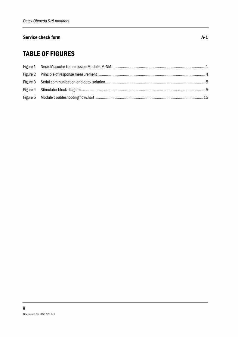
TABLE OF FIGURES
Figure 1 NeuroMuscular Transmission Module, M-NMT ....................................................................................... 1
Figure 2 Principle of response measurement ...................................................................................................... 4
Figure 3 Serial communication and opto isolation............................................................................................... 5
Figure 4 Stimulator block diagram...................................................................................................................... 5
Figure 5 Module troubleshooting flowchart .......................................................................................................15

NeuroMuscular Transmission Module, M-NMT
Document No. 800 1018-1
1
INTRODUCTION
This section provides information for the maintenance and service of the NeuroMuscularTransmission Module, M-NMT. The M-NMT module is a single width plug-in module designed foruse with the S/5 Anesthesia and Compact Anesthesia Monitors. The module contains peripheralnerve stimulation and response measurement which supports electromyography EMG. The modulecan also be used as a nerve locator for regional nerve blocking with a regional block cable.However, in this case there is no response measurement.
Figure 1 NeuroMuscular Transmission Module, M-NMT
Datex-Ohmeda S/5 monitors
Document No. 800 1018-1
2
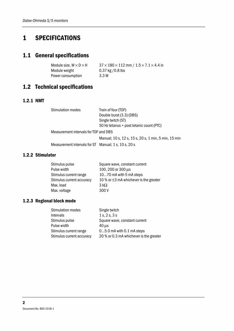
1 SPECIFICATIONS
1.1 General specifications
Module size, W × D × H 37 × 180 × 112 mm / 1.5 × 7.1 × 4.4 inModule weight 0.37 kg /0.8 lbsPower consumption 3.3 W
1.2 Technical specifications
1.2.1 NMT
Stimulation modes Train of four (TOF)Double burst (3.3) (DBS)Single twitch (ST)50 Hz tetanus + post tetanic count (PTC)
Measurement intervals for TOF and DBS
Manual; 10 s, 12 s, 15 s, 20 s, 1 min, 5 min, 15 min
Measurement intervals for ST Manual; 1 s, 10 s, 20 s
1.2.2 Stimulator
Stimulus pulse Square wave, constant currentPulse width 100, 200 or 300 µsStimulus current range 10...70 mA with 5 mA stepsStimulus current accuracy 10 % or ±3 mA whichever is the greaterMax. load 3 kΩMax. voltage 300 V
1.2.3 Regional block mode
Stimulation modes Single twitchIntervals 1 s, 2 s, 3 sStimulus pulse Square wave, constant currentPulse width 40 µsStimulus current range 0...5.0 mA with 0.1 mA stepsStimulus current accuracy 20 % or 0.3 mA whichever is the greater

NeuroMuscular Transmission Module, M-NMT
Document No. 800 1018-1
3
2 FUNCTIONAL DESCRIPTION
2.1 Measurement principle
2.1.1 Nerve stimulation
There are three stimulus modes in the NeuroMuscular Transmission Module: Train of Four (TOF),Double Burst 3,3 (DBS) and Single Twitch (ST).
In the Train of Four stimulus mode, four stimulation pulses are generated at 0.5 second intervals.The response is measured after each stimulus and the ratio of the fourth and first response of theTOF sequence is calculated (TOF%).
NOTE: If the first response does not exceed a certain signal level, TOF% is not calculated due topoor accuracy.
Double burst (3,3) stimulation includes two bursts with a 750 ms interval. Both bursts consist ofthree pulses separated by 20 ms intervals. The responses of both bursts are measured, and theratio of the second and first response is calculated (DBS%). EMG responses are measuredimmediately after the first stimulus pulse of both bursts.
In Single Twitch stimulation, one stimulation pulse is generated. The response is measured afterthe stimulus. In order to prevent decurarization of the stimulated area, the measurement isautomatically stopped after 5 minutes stimulation in 1 sec cycle time.
Tetanic/PTC
Tetanic/PTC (Post Tetanic Count) can measure deeper relaxation than TOF. The tetanic stimulationis produced when Start is chosen under Tetanic/PTC. The length of stimulation is 5 seconds. Thestimulation generates pulses with a frequency of 50 Hz and with a selected pulse width andcurrent. After tetanic stimulation and a three second delay, Single Twitch stimulation is producedto detect the post tetanic count (PTC). PTC describes the number of responses detected aftertetanic stimulation. If there is no response, the measurement will be stopped. If responses will notfade away, a maximum of 20 responses will be calculated. If more can be detected, the PTC valueis displayed only as '> 20' and measurement will be stopped. If the TOF, DBS or ST measurementcycle was on when tetanic stimulation started, the cycle will continue after the PTC. Aftercompleting the PTC measurement during 1 minute TOF, DBS or another PTC measurement is notpossible. This is to avoid erroneous readings due to post tetanic potentiation.
Datex-Ohmeda S/5 monitors
Document No. 800 1018-1
4
2.1.2 Response
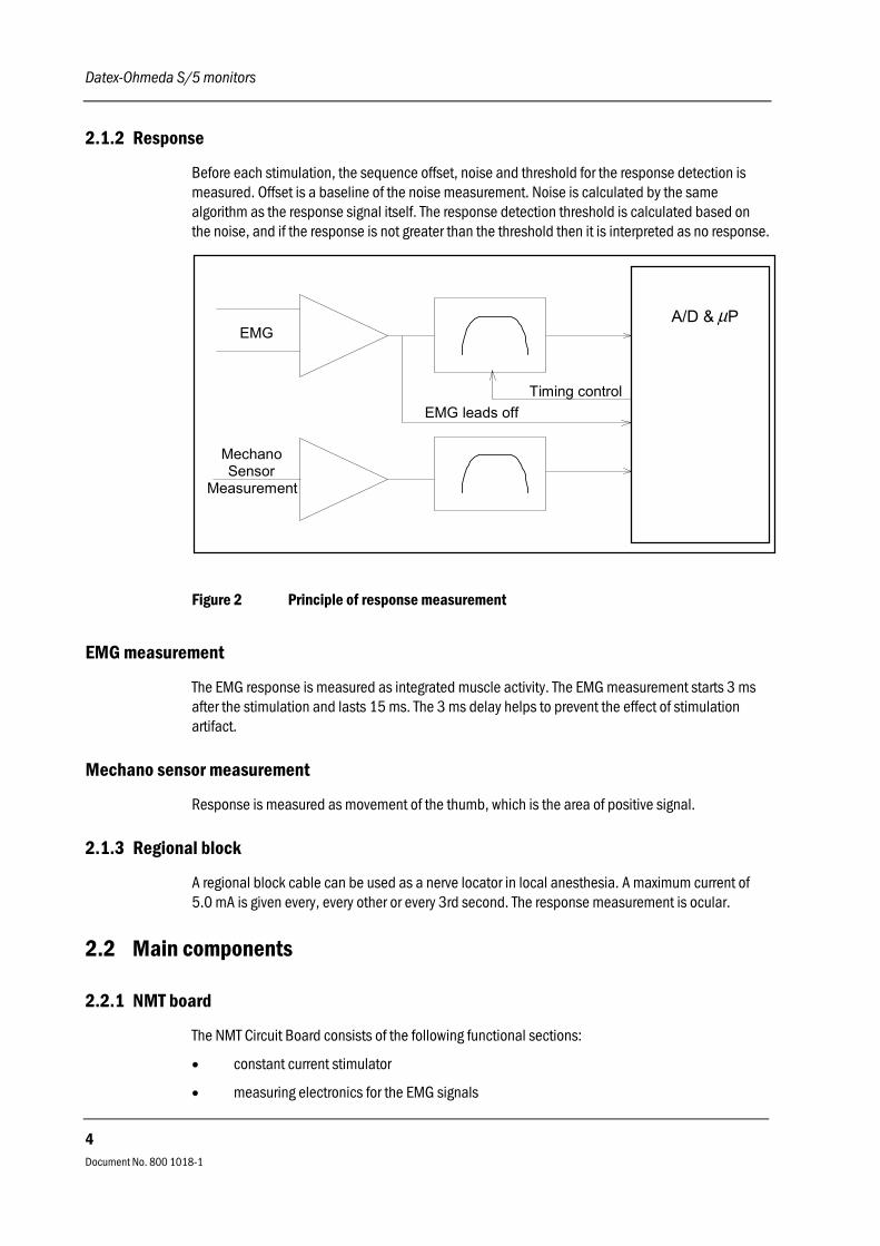
Before each stimulation, the sequence offset, noise and threshold for the response detection ismeasured. Offset is a baseline of the noise measurement. Noise is calculated by the samealgorithm as the response signal itself. The response detection threshold is calculated based onthe noise, and if the response is not greater than the threshold then it is interpreted as no response.
EMG
MechanoSensor
Measurement
EMG leads offTiming control
A/D & Pµ
Figure 2 Principle of response measurement
EMG measurement
The EMG response is measured as integrated muscle activity. The EMG measurement starts 3 msafter the stimulation and lasts 15 ms. The 3 ms delay helps to prevent the effect of stimulationartifact.
Mechano sensor measurement
Response is measured as movement of the thumb, which is the area of positive signal.
2.1.3 Regional block
A regional block cable can be used as a nerve locator in local anesthesia. A maximum current of5.0 mA is given every, every other or every 3rd second. The response measurement is ocular.
2.2 Main components
2.2.1 NMT board
The NMT Circuit Board consists of the following functional sections:
• constant current stimulator
• measuring electronics for the EMG signals

NeuroMuscular Transmission Module, M-NMT
Document No. 800 1018-1
5
• microprocessor for the stimulation and measuring control, and for counting the measuringresults
• serial communication
The serial bus speed is 500 kbps and the bus itself is half duplex, i.e. data can be transferred inboth directions but only one way at a time.
Serial communication
Figure 3 Serial communication and opto isolation
Stimulator
The constant current stimulator generates pulses whose amplitude is independent of the load. Themain components of the stimulator are a transformer, a capacitor and a transistor. The transformerproduces a high voltage which charges the capacitor and the transistor adjusts the pulse width andamplitude of the current.
Patient Constant currentgenerator
Power supply
Currentadjustment
Current control
Continuousstimulationcongestion
80C196KDPWM
HSO
Figure 4 Stimulator block diagram

Datex-Ohmeda S/5 monitors
Document No. 800 1018-1
6
2.3 Connectors and signals
2.3.1 Module bus connector
13 11425
Table 1 Module bus connector (X1)
Pin No. I/O Signal
1 I RESET_RS485
2 I -15 VDC
3 I +15 VDIRTY
4 I +15 VDC
5 I/O -DATA_RS485
6 I/O DATA_RS485
7 - Ground & Shield
8 I -RESET_RS485
9 I CTSB
10 O RTSB
11 I RXDB
12 O TXDB
13 - Ground & Shield
14 I +32 VDIRTY
15 I GroundDIRTY
16 I CTSC
17 O RTSC
18 I RXDC
19 O TXDC
20 - ON/STANDBY
21 - PWM_ECG
22 - RXDD_RS232
23 - TXDD_RS232
24 I +5 VDC
25 I +5 VDC

NeuroMuscular Transmission Module, M-NMT
Document No. 800 1018-1
7
2.3.2 Front panel connector
NMT connector (NMT)
Pin No. Signal
6
8
9
0
1
24
5
7
312345678910
EMG Signal +EMG Signal -Not UsedStimulus +Stimulus -GroundNot ConnectedSensor Identification+5 VMechanical Signal
Datex-Ohmeda S/5 monitors
Document No. 800 1018-1
8
3 SERVICE PROCEDURES
3.1 General service information
Field service of the NeuroMuscular Transmission Module, M-NMT, is limited to replacing faultycircuit boards or mechanical parts. Faulty circuit boards should be returned to Datex-Ohmeda forrepair.
Datex-Ohmeda is always available for service advice. Please provide the unit serial number, fulltype designation, and a detailed description of the fault.
The Datex-Ohmeda NMT Stimulator (order code 871251) is recommended for functional checks.
CAUTION Only trained personnel with appropriate equipment should perform the tests and repairs outlined inthis section. Unauthorized service may void warranty of the unit.
NeuroMuscular Transmission Module, M-NMT
Document No. 800 1018-1
9
3.2 Service check
These instructions include complete procedures for a service check. The service check isrecommended to be performed after any service repair. However, the service check procedures canalso be used for determining possible failures.
The procedures should be performed in ascending order.
The instructions include a check form (Appendix A) which should be filled in when performing theprocedures.
The mark in the instructions means that the check form should be signed after performing
the procedure.
The procedures are designed for monitors with S/5 monitor software of revision 01. However, mostof the procedures also apply to monitors, which contain some other monitor softwaretype/revision.
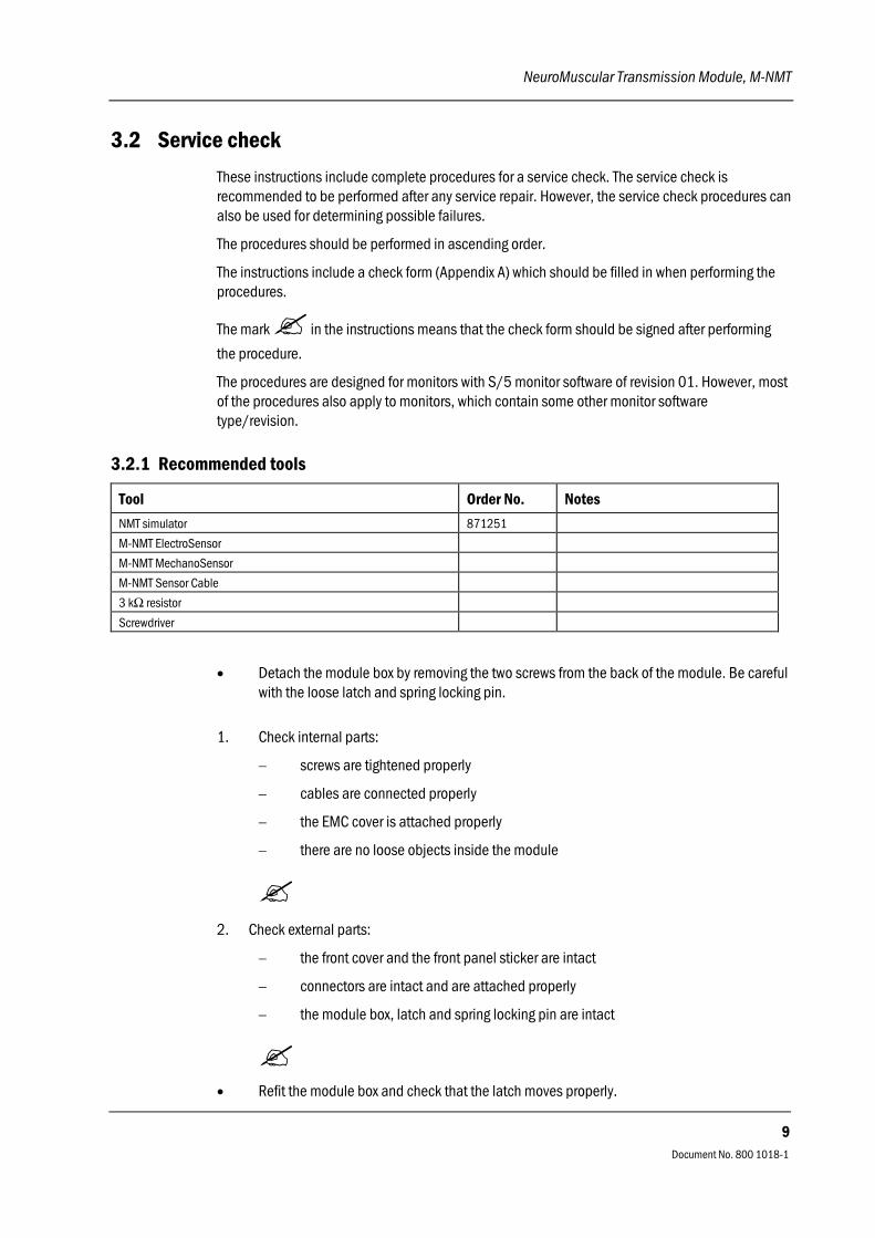
3.2.1 Recommended tools
Tool Order No. Notes
NMT simulator 871251
M-NMT ElectroSensor
M-NMT MechanoSensor
M-NMT Sensor Cable
3 kΩ resistor
Screwdriver
• Detach the module box by removing the two screws from the back of the module. Be carefulwith the loose latch and spring locking pin.
1. Check internal parts:
− screws are tightened properly
− cables are connected properly
− the EMC cover is attached properly
− there are no loose objects inside the module
2. Check external parts:
− the front cover and the front panel sticker are intact
− connectors are intact and are attached properly
− the module box, latch and spring locking pin are intact
• Refit the module box and check that the latch moves properly.
Datex-Ohmeda S/5 monitors
Document No. 800 1018-1
10
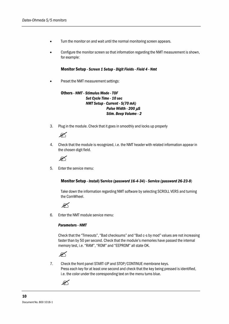
• Turn the monitor on and wait until the normal monitoring screen appears.
• Configure the monitor screen so that information regarding the NMT measurement is shown,for example:
Monitor Setup - Screen 1 Setup - Digit Fields - Field 4 - Nmt
• Preset the NMT measurement settings:
Others - NMT - Stimulus Mode - TOF Set Cycle Time - 10 sec NMT Setup - Current - S(70 mA)
Pulse Width - 200 µµµµS Stim. Beep Volume - 2
3. Plug in the module. Check that it goes in smoothly and locks up properly
4. Check that the module is recognized, i.e. the NMT header with related information appear inthe chosen digit field.
5. Enter the service menu:
Monitor Setup - Install/Service (password 16-4-34) - Service (password 26-23-8)
Take down the information regarding NMT software by selecting SCROLL VERS and turningthe ComWheel.
6. Enter the NMT module service menu:
Parameters - NMT
Check that the “Timeouts”, “Bad checksums” and “Bad c-s by mod” values are not increasingfaster than by 50 per second. Check that the module’s memories have passed the internalmemory test, i.e. “RAM”, “ROM” and “EEPROM” all state OK.
7. Check the front panel START-UP and STOP/CONTINUE membrane keys.Press each key for at least one second and check that the key being pressed is identified,i.e. the color under the corresponding text on the menu turns blue.

NeuroMuscular Transmission Module, M-NMT
Document No. 800 1018-1
11
8. Check that the message “Cable off” is shown in the digit field and that “Cable” in the servicemenu states OFF.
Plug the M-NMT Sensor Cable with the M-NMT ElectroSensor into front panel connectorNMT. Check that the message in the digit field changes to “Measurement OFF” and “Cable”on the service menu states EMG and ELECTR. OFF.
9. Perform the stimulus current test.
Connect a 3 kΩ resistor between the ElectroSensor’s stimulus electrode leads (brown andwhite).
Start the test by highlighting START CURR. TEST on the service menu and pressing theComWheel. Check that the test was successful with all three test currents, i.e. the “Currenttest (mA):” on the menu states 30 OK, 50 OK and 70 OK.
• Connect the M-NMT ElectroSensor leads to the NMT simulator. Set the switch on thesimulator to “Fade off” and turn the knob to “max”. Check “Cable” on the service menu nowstates only EMG.
10. Start NMT measurement (TOF) by pressing the START-UP key on the module.
When the message “Supramax search” changes to “Setting reference” in the digit field,check that the supramaximal current detected is less than 70 mA, i.e. the “Current set”value on the service menu is less than 700.
11. Check that the module gives four successive stimulus pulses with 10 second intervals. Asmall asterisk () should be shown in the digit field during each of the stimulus pulses andsimultaneous sound signals should be heard from the loudspeaker.
Check that on the service menu the values for “T1%”, “T2%”, “T3%”, “T4%” and “Ratio%”are all within 950-1059.
Check also that in the digit field the “TOF%” value is within 95-105, “Count” is 4 and “T1%”is within 95-105.
12. Check that the “Noise” value on the service menu stays under 50.
13. Change the stimulus pulse width to 100 µs through the NMT service menu:
NMT Setup - Pulse Width - 100 µµµµS

Datex-Ohmeda S/5 monitors
Document No. 800 1018-1
12
Check that the “TOF%” value is still within 95-105, “Count” is 4 and “T1%” is within 95-105in the digit field.
Check the same parameters with a stimulus pulse width of 300 µs.
14. Turn the knob on the NMT simulator to “0”.
Check that on the service menu the values for “T1%”, “T2%”, “T3%”, “T4%” turn to 0 and the“Ratio%” states - - -. In the digit field “TOF%” should also state - - - , and “Count” and “T1%”should show 0.
Turn the NMT simulator knob back to “max”.
15. Change the stimulus mode to Double Burst Stimulation (DBS) through the service menu:
NMT Setup - Stimulus Mode - DBS
Check that the module now gives only two stimulus pulses with a 10 seconds interval.
Check that on the service menu the values for “T1%”, “T2%”, and “Ratio%” are still within950-1059. In the digit field the “DBS%” value should be within 95-105, “Count” is 2 and“T1%” is within 95-105.
16. Change the stimulus mode to Single Twitch Stimulation (ST):
NMT Setup - Stimulus Mode - ST
Check that the module starts to give only one stimulus pulse with a 1 second interval. Notethe time when the ST stimulation started.
Check that on the service menu the value for “T1%” is within 950-1059. In the digit field the“Count” value should be 1 and “T1%” within 95-105.Let the monitor continue to give single twitch stimulation.
17. Check that the NMT measurement stops and the message “Measurement OFF” appears inthe digit field for NMT five minutes after the start of the ST stimulation.
18. Replace the M-NMT ElectroSensor with the M-NMT MechanoSensor and check that “Cable”on the service menu states PIEZO.

NeuroMuscular Transmission Module, M-NMT
Document No. 800 1018-1
13
19. Perform an electrical safety check and a leakage current test.
20. Check that the module functions normally after performing the electrical safety check.
21. Clean the module with suitable detergent.
• Fill in all necessary documents.
3.3 Disassembly and reassembly
Disassemble the NeuroMuscular Transmission Module, M-NMT, in the following way. See theexploded view of the module.
1. Remove the two screws from the back of the module.
2. Pull the module box slowly rearward and detach it from main body. Be careful with the looselatch and spring locking pin.
3. Detach the NMT board by removing the two screws located near the front panel frame,disconnect the cables and pull out the front panel frame.
To reassemble the module, reverse the order of the disassembly steps.
CAUTION When reassembling the module, make sure that the cables are reconnectedproperly.

Datex-Ohmeda S/5 monitors
Document No. 800 1018-1
14
4 TROUBLESHOOTING
4.1 Troubleshooting chart
Trouble Cause Treatment
Check the stimulus electrodes.
EMG electrode off.
Loose electrodes or loose stimulusclip.
Change or attach the electrodes orclip.
Supramax. not found. Loose electrodes or loose stimulusclip.
Stimulus electrodes attached towrong place.
Patient is relaxated.
Change or attach the electrodes orclip.
Change the place of the stimuluselectrode.
Response too weak. Loose stimulus electrodes.
Measuring electrodes attached towrong place.
Patient is relaxated.
Change or attach the electrodes.
Change the place of the meas.electrodes.
Ref. not stable. Patient is relaxated.
Movement artifact.

NeuroMuscular Transmission Module, M-NMT
Document No. 800 1018-1
15
4.2 Troubleshooting flowchart
no
Possible fault in NMT module
Open NMT Service Menu
Check Timeouts, Bad checksums,Bad c-s by mod
Check RAM,ROM,EEPROM
Check that sensor is identified
Connect ElectroSensor to NMTstimulator and start measurement
Check front panel key functions
Fault not in NMT module
Replace the original sensor Connect the connectorReplace the original
NMT input board
Replace the original sensor
Replace the original NMT inputboard
Replace the original sensor
Replace the original NMT sensorcable
Replace the original NMT inputboard
Replace the original keypad
Connect the keypad
Replace the original NMT sensorcable
Replace the originalNMT sensor cable
Does another modulework in the same slot?
Does the test pass withanother sensor?
Does the test pass withanother NMT sensor
cable?
Are the NMT input boardwires connected?
Does the test passwith another NMT
input board?
Does the test pass withanother sensor?
Does the test pass withanother NMT sensor
cable?
Does the test pass withanother sensor?
Does the test pass withanother NMT input
board?
Does the test pass withanother NMT sensor
cable
Does the test pass withanother NMT input
board?
Is the keypadconnected?
Does the test pass withanother keypad?
Test stimulus current
OK? Replace NMT board
no
yes
yes
OK?
OK?
yes
yesyes yes no yes
no
OK?
Responses OK?
OK?
yes
yes
yes
yes
yes
yes
yes
no
yes
no
no
no
noyes
no
no
no
no
no
yesno
no yesno
no
no
Replace NMT board
Replace NMT board
Replace NMT board
Replace NMT board
Replace NMT board
Figure 5 Module troubleshooting flowchart

Datex-Ohmeda S/5 monitors
Document No. 800 1018-1
16
5 SERVICE MENU
1. Press the Monitor Setup key.
2. Select Install/Service (password 16-4-34).
3. Select Service (password 26-23-8).
4. Select Parameters.
5. Select NMT.
NeuroMuscular Transmission Module, M-NMT
Document No. 800 1018-1
17
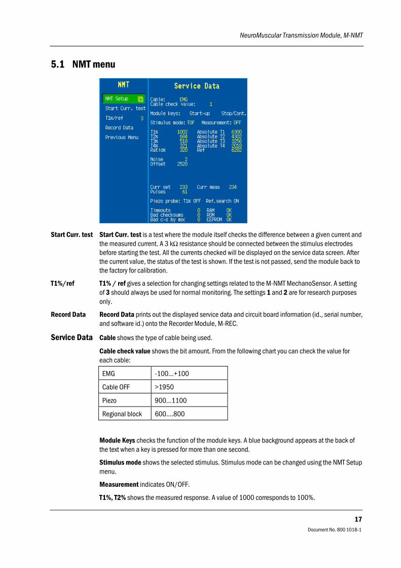
5.1 NMT menu
Start Curr. test Start Curr. test is a test where the module itself checks the difference between a given current andthe measured current. A 3 kΩ resistance should be connected between the stimulus electrodesbefore starting the test. All the currents checked will be displayed on the service data screen. Afterthe current value, the status of the test is shown. If the test is not passed, send the module back tothe factory for calibration.
T1%/ref T1% / ref gives a selection for changing settings related to the M-NMT MechanoSensor. A settingof 3 should always be used for normal monitoring. The settings 1 and 2 are for research purposesonly.
Record Data Record Data prints out the displayed service data and circuit board information (id., serial number,and software id.) onto the Recorder Module, M-REC.
Service Data Cable shows the type of cable being used.
Cable check value shows the bit amount. From the following chart you can check the value foreach cable:
EMG -100...+100
Cable OFF >1950
Piezo 900...1100
Regional block 600....800
Module Keys checks the function of the module keys. A blue background appears at the back ofthe text when a key is pressed for more than one second.
Stimulus mode shows the selected stimulus. Stimulus mode can be changed using the NMT Setupmenu.
Measurement indicates ON/OFF.
T1%, T2% shows the measured response. A value of 1000 corresponds to 100%.

Datex-Ohmeda S/5 monitors
Document No. 800 1018-1
18
Absolute T1, T2 shows the voltage measured from the A/D converter.
Noise indicates the interference just before the measurement. A typical value is <10.
Offset is an average of the noise measurement. A typical value is 510.
Curr set is the selected current, a value of 700 corresponds to 70 mA.
Curr meas is the measured current, a value of 700 corresponds to 70 mA.
Pulses indicates pulses the module has produced.
Piezo probe T1% and ref. search shows information related to the MechanoSensor settings.
Timeouts is a cumulative number that indicates how many times the module has not responded tothe monitor's inquiry.
Bad checksums is a cumulative number that indicates how many times communication from themodule to the monitor has failed.Bad c-s by mod is a cumulative number that indicates how many communication errors themodule has detected.The monitor starts counting these items at power up and resets to zero at power off. The non-zerovalues do not indicate a failure, but the continuous counting (more than 50 per second) indicateseither serial communication failure, or module not in place. Also, other modules can causecommunication errors that cause these numbers to rise.
RAM indicates the state of the RAM memory.ROM indicates whether the checksum in the EPROM is in accordance with the software calculatedvalue.EEPROM indicates if the values stored in the permanent memory are valid.The state is either OK, Fail or ? (module not in place or a communication error).

NeuroMuscular Transmission Module, M-NMT
Document No. 800 1018-1
19
6 SPARE PARTS
6.1 Spare part listNOTE: Accessories are listed in the Patient Monitor Supplies and Accessories.
6.1.1 NMT Module, M-NMT rev. 00
4
1
2
3
5
6 7 8 9 10 11 12 13
Item Description Order No. Item Description Order No.
1 Module box (single width) 886167 8 NMT board, M-NMT (Rev. 00-01) *887487
2 Latch 879181 9 EMC cover, M-NMT 886320
3 Spring pin 879182 10 Cross cylinder-head screw M3x12 628700
4 Cross recess screw M3x8 black 616215 11 NMT input board 887184
5 Front panel unit, M-NMT 887186 12 Membrane keypad 880101
6 Cross cylinder-head screw M3x6 61721 13 Front panel sticker, see 6.1.3 -
7 Metal frame 879184 - - -
The front panel unit includes the connector and input board.* this part is recommended for stock
6.1.2 NMT Module, M-NMT rev. 01
No new spare parts.
6.1.3 NMT Module, M-NMT rev. 02
No new spare parts.
Datex-Ohmeda S/5 monitors
Document No. 800 1018-1
20
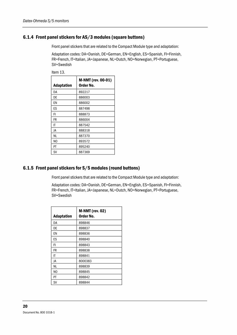
6.1.4 Front panel stickers for AS/3 modules (square buttons)
Front panel stickers that are related to the Compact Module type and adaptation:
Adaptation codes: DA=Danish, DE=German, EN=English, ES=Spanish, FI=Finnish,FR=French, IT=Italian, JA=Japanese, NL=Dutch, NO=Norwegian, PT=Portuguese,SV=Swedish
Item 13.
AdaptationM-NMT (rev. 00-01)Order No.
DA 892217
DE 886003
EN 886002
ES 887498
FI 888873
FR 886004
IT 887542
JA 888318
NL 887370
NO 893572
PT 895240
SV 887369
6.1.5 Front panel stickers for S/5 modules (round buttons)
Front panel stickers that are related to the Compact Module type and adaptation:
Adaptation codes: DA=Danish, DE=German, EN=English, ES=Spanish, FI=Finnish,FR=French, IT=Italian, JA=Japanese, NL=Dutch, NO=Norwegian, PT=Portuguese,SV=Swedish
AdaptationM-NMT (rev. 02)Order No.
DA 898846
DE 898837
EN 898836
ES 898840
FI 898843
FR 898838
IT 898841
JA 8000383
NL 898839
NO 898845
PT 898842
SV 898844

NeuroMuscular Transmission Module, M-NMT
Document No. 800 1018-1
21
7 EARLIER REVISIONS
This manual also supports earlier module revision 00.

Datex-Ohmeda S/5 monitors
Document No. 800 1018-1
22

APPENDIX A, Service Check Form, M-NMT
Document No. 800 1018-1
23
APPENDIX A

Datex-Ohmeda S/5 monitors
24
Document No. 800 1018-1

APPENDIX A, Service Check Form, M-NMT
A-1(2)
Document No. 800 1018-1
SERVICE CHECK FORM
NeuroMuscular Transmission Module, M-NMT
Customer
Service Module type S/N
Service engineer Date
OK = Test OK N.A. = Test not applicable Fail = Test Failed
OK N.A. Fail OK N.A. Fail
1. Internal parts 2. External parts
3. Installation 4. Recognition
5. Module software NMT
6. Communication andmemories
7. Membrane keys
8. ElectroSensorrecognition
9. Stimulus current test
10. Supramaximal current < 70 mA
11. TOF measurement with NMT simulator
T1% 950-1059
T2% 950-1059
T3% 950-1059
T4% 950-1059
Ratio% 950-1059
TOF% 95-105
Count 4
T1% 95-105
12. Noise < 50

Datex-Ohmeda S/5 monitors
A-2(2)
Document No. 800 1018-1
13. Stimulus pulse width
100 µs 300 µs Allowed range
TOF% 95-105
Count 4
T1% 95-105
OK N.A. Fail
14. No response
15. DBS measurement with NMT simulator
T1% 950-1059
T2% 950-1059
Ratio% 950-1059
DBS% 95-105
Count 2
T1% 95-105
16. ST measurement with NMT simulator
T1% 950-1059
Count 1
T1% 95-105
17. Automatic measurement off 18. MechanoSensorrecognition
19. Electrical safety check 20. Functioning afterelectrical safetycheck
21. Final cleaning
Notes
Used Spare Parts
Signature