DATA STORAGE HIERARCHY SYSTEMS FOR DATA BASE ...
320
DATA STORAGE HIERARCHY SYSTEMS FOR DATA BASE COMPUTERS by Chat-Yu Lam B.Sc. Massachusetts Institute of (1974) M.Sc. Northwestern (1976) Technology University SUBMITTED IN PARTIAL FULFILLMENT OF THE REQUIREMENTS FOR THE DEGREE OF DOCTOR OF PHILOSOPHY at the MASSACHUSETTS INSTITUTE OF TECHNOLOGY (August, 1979) Chat-Yu Lam 1979 Signature of Author Sloan School of Management, ^ I August 1, 1979 nl Certified by ..... ...... ..- .- ................-................ Thesis Supervisor Accepted by ................................................ Chairman, Department Committee - /-111
-
Upload
khangminh22 -
Category
Documents
-
view
1 -
download
0
Transcript of DATA STORAGE HIERARCHY SYSTEMS FOR DATA BASE ...

DATA STORAGE HIERARCHY SYSTEMS FOR
DATA BASE COMPUTERS
by
Chat-Yu Lam
B.Sc. Massachusetts Institute of(1974)
M.Sc. Northwestern(1976)
Technology
University
SUBMITTED IN PARTIAL FULFILLMENTOF THE REQUIREMENTS FOR THE
DEGREE OF
DOCTOR OF PHILOSOPHY
at the
MASSACHUSETTS INSTITUTE OF TECHNOLOGY
(August, 1979)
Chat-Yu Lam 1979
Signature of AuthorSloan School of Management,
^ I
August 1, 1979
nl
Certified by ..... ...... ..- .- ................-................Thesis Supervisor
Accepted by ................................................Chairman, Department Committee
- /-111

Data Storage Hierarchy Systems forData Base Computers
byChat-Yu Lam
Submitted to the Alfred P. Sloan School of Managementon August 1979 in partial fulfillment of the requirements
for the degree of Doctor of Philosophy
ABSTRACT
The need for efficient storage and processing of verylarge databases to support decision-making coupled withadvances in computer hardware and software technology havemade research and development of specialized architecturesfor database management a very attractive and importantarea.
The INFOPLEX data base computer proposed by Madnickapplies the theory of hierarchical decomposition to obtain aspecialized architecture for database management withsubstantial improvements in performance and reliability overconventional architectures. The storage subsystem ofINFOPLEX is realized using a data storage hierarchy. A datastorage hierarchy is a storage subsystem designedspecifically for managing the storage and retrieval of verylarge databases using storage devices with differentcost/performance characteristics arranged in a hierarchy.It makes use of locality of data references to realize a lowcost storage subsystem with very large capacity and smallaccess time.
As part of the INFOPLEX research effort, this thesis isfocused on the study of high performance, highly reliabledata storage hierarchy systems. Concepts of the INFOPLEXdata base computer are refined and new concepts of datastorage hierarchy systems are developed. A preliminarydesign of a general structure for the INFOPLEX data storagehierarchy system is proposed.
Theories of data storage hierarchy systems are developed.Madnick's model of a generalized storage hierarchy isextended and formalized for data storage hierarchy systems.The Least Recently Used (LRU) algorithm is extended toincorporate the read-through strategy and page overflowstrategies to obtain four classes of data movementalgorithms. These algorithms are formally defined.Important performance and reliability properties of data
-2-

storage hierarchy systems that make use of these algorithmsare identified and analyzed in detail. It is proved inTheorems 1 and 2 that depending on the relative sizes of thestorage levels and the algorithms used, it is not alwayspossible to guarantee that the contents of a given storagelevel 'i' is a superset of the contents of its immediatehigher storage level 'i-l', i.e., multi-level inclusion(MLI) does not hold. Necessary and sufficient conditionsfor MLI to hold are identified and proven in Theorems 3 and4. A property related to MLI is the multi-level overflowinclusion (MLOI) property. MLOI holds if an overflow pagefrom storage level 'i' is always found to already exist instorage level 'i+l'. A data storage hierarchy avoidscascaded references to lower storage levels if MLOI holds.Necessary and sufficient conditions for the MLOI to hold areidentified and proven in Theorems 5 and 6. It is possiblethat increasing the sizes of intermediate storage levels mayactually increase the number of references to lower storagelevels, resulting in decreased performance. This isreferred to as the multi-level paging anomaly (MLPA).Conditions necessary to avoid MLPA are identified and provenin Theorems 7 and 8.
A sinlified structure of the INFOPLEX data storagehie:-rchy is rived from its general structure. Protocolsfor supporting tile read-through and store-behind algorithmsare specified. Two simulation models of this system aredeveloped. The first .s - incorporates one functionalprocessor and three storage levels. Results from this modelprovide significant insights to the design and itsalgorithms and reveals a potential deadlock in the buffermanagement schemes. The second model corrects thispotential deadlock and also incroproates five functionalprocessors and four storage levels. Results from this modelshow that the store-behind operation may be a significantsystem bottleneck because of the multi-level inclusionrequirement of the data storage hierarchy. By using moreparallelism in the lower storage levels and by using smallerblock sizes it is possible to obtain a well-balanced systemwhich is capable of supporting the storage referencesgenerated by the INFOPLEX functional hierarchy. The effectsof using projected 1985 technology for the data storagehierarchy are also assessed.
Thesis SCprv<-ar: Prof. Stuart E. MadnickAssociate Professor of Management ScienceM.I.T. Sloan School of Management
-3-

ACKNOWLEDGMENT
I would like to sincerely thank the following individualswho helped and encouraged me in carrying out this work.
My thesis advisor, Prof. Stuart Madnick, has been a greatteacher and a concerned and understanding advisor. He hasspent considerable time and effort supervising this thesis.It is a priviledge to be his student.
Members of my thesis committee, Prof. John Little, Prof.Hoo-min Toong, and Dr. Ugo Gagliardi, have taken time inspite of their tight schedules to review this work. I amtruely grateful for their interest and enthusiasm.
My colleagues, Sid Huff and Mike Abraham, have at varioustimes suffered through some of my ill-formed ideas. Theirpatience is greatly appreciated.
My wife, Elizabeth, has stood by me throughout this workwith her patience, encouragements and care. She makes allthis worthwhile.
I would like to acknowledge the sources of funding forthis work, and for my doctoral studies.
This research is funded by the National ScienceFoundation Grant No. MCS77-20829 and by the Navy ElectronicsSystems Command Contract No. N00039-78-G-0160.
My doctoral studies have been made possible by the abovefundings, several Sloan School tuition fellowships, an IBMInformation Systems Fellowship, and research funds from theNEEMIS Project and the RADC Decision Support SystemsProject. I am grateful for these financial support.
A large portion of this thesis was typed by WaterlooSCRIPT. Chapter 4 was typed by Marilyn Whatmough and PortiaSmith who have been kind enough to undertake this task thatnobody else would, due to the large number of mathematicalsymbols in the chapter.
-4-

TABLE OF CONTENTS
Chapter page
I. INTRODUCTION AND PLAN OF THESIS . . . . . . . . . . 9
Introduction . . . . 9
Related Research . . .. ... ........ 11New Instructions Through Microprogramming . . 14Storage Hierarchy Optimization . . . . . . . 15Intelligent Controllers . . . . . . . . . . . 16Back-end Processors . . . . . . . . . . . . . 18Data Base Computers . . . . . . . . . . . . . 19
Research Goals and Accomplishments . . . . . . . 22Structure of Thesis . . . . . . . .. ...... 25
Chapter 2 : The INFOPLEX Data Base ComputerArchitecture . . ..... . ....... 26
Chapter 3 : A General Structure of theINFOPLEX Data Storage Hierarchy . . . . 26
Chapter 4 : Modelling and Analysis of DataStorage Hierarchy Systems . . . . . . . 26
Chapter 5 : Design of the DSH-ll Data StorageHierarchy System .... . . . . . . .27
Chapter 6 : Simulation Studies of the DSH-llData Storage Hierarchy System . . . . . 27
Chapter 7 : Discussions and Conclusions . . . 28
II. THE INFOPLEX DATA BASE COMPUTER ARCHITECTURE . . . 29
Introduction...... . . . . . . . . ... . . 29The INFOPLEX Functional Hierarchy . .. ..... .31
Rationale for Functional Decomposition . . 32Example of a Functional Decomposition . . . 33
Entities and Entity Sets . . . . . . . . . 33Binary Relations . . . . . . . . . . . . . 35N-ary Relations . . . . .. . . ..... 37Links Among N-ary Relations . . . . ... 41Virtual Information . . . .. . . . . . . 42Data Verification and Access Control . . . 44High-level Language Interface . . . . . . 48
INFOPLEX's Approach to FunctionalDecomposition . . . . . . . . . . . . . 51
The INFOPLEX Data Storage Hierarchy . . . . . . 53Rationale for a Storage Hierarchy . . . . . . 53
- 5 -

Example of a Physical Decomposition . . . . . 56General Structure . .. .. . . . ..... .56Storage Devices . . . . . . . . . . . . . 60Strategies for Information Movement . . . 61
INFOPLEX's Approach to PhysicalDecomposition . . . . . . . . . . . . . 69
Research Issues Addressed in This Thesis . . . . 69
III. A GENERAL STRUCTURE OF THE INFOPLEX DATA STORAGEHIERARCHY . . . . . . . . . . . . . . . . . . 71
Introduction . . . . . . . . . . . . . . . . . . 71Design Objectives . . . . . . . . . . . . . . . 71
Virtual Address Space . . . . . . . . . . . . 72Very Large Address Space . . . . . . . . . . 72Permanent Data Storage . . . . . . . . . . . 73Support Multiple Processors . . . . . . . . . 73Generalized Multi-level Storage System 74Direct Inter-level Data Transfer .... .... .74High performance . . . . . . . . . . . . . . 75Availability . . . . . . . . . . . . . . . . 75Modularity . . . . . . . . . . . . . . . . . 76Low Cost . . . . . . . . . . . . . . . . . . 77
e-n-ral Structure of DSH-1 . .. .. ....... 77ThL DSH-1 Interface . . . . . . . . . . . . . 79The HBighest Performance Storage Level - L(l) 83A Typical otoragp Level - L(i) ....... 85
Further Design, T s- , . .... ........ 86Support of Read and Write Operations 87
Multiple Cache Consistency . . . . . . . . 87Bus Communication Protocols . . . . . . . 88Multiple Directory Update . . . . . . . . 89Multiple Resource Arbitration . . . . . . 89Transaction Handling . . . . . . . . . . . 89
Multiple Data Redundancy Properties . . . . . 90Automatic Data Repair Algorithms . . . . . . 90Performance Evaluation . . . . . . . . . . . 91
Summary . . . . . . . . . . . . . . . . . . . . 91
IV. MODELLING AND ANALYSIS OF DATA STORAGE HIERARCHYSYSTEMS . . . . . . . . . . . . . . . . . . . 93
Introduction . . . . - - - - - * - - - - - - - - 93Research on Storage Hierarchy Systems &. .. .. 94Model of a Data Storage Hierarchy . . . - - -. 96
Storage Management Algorithms . . . . - - -. 98i Model of a Data Storage Hierarchy . . . 105
Formal Definitions of Storage ManagementAlgorithms . . . - - - - - - - - - - - 107
Properties of Data Storage Hierarchy Systems . - 112Summary of Properties . . . . . . . . . . . . 117

Derivation of Properties . . . . . . . . . .122Summary . . . . . . . . . . . . . . . . . . . 150
V. DESIGN OF THE DSH-ll DATA STORAGE HIERARCHY SYSTEM
Introduction . . . ... . ........ . 151Structure of DSH-ll ... . ........ 151
The DSH-ll Interface . ......... 153The Highest Performance Storage Level
A Typical Storage Level - L(i).. 155Algorithms for Supporting the Read Operation 156
The Read-Through Operation . ....... 156Overflow Handling......... . . . .. . 159Pathological Cases of Read-Through . . . . 160
Racing Requests . . . . . . . . . . . . 160Erronous Overflow . . . . . . . . ... 161Overflow to a Partially-assembled Block 162
Transactions to Handle the Read Operation . 163The read-through Transaction . . . . . . 165The retrieve Transaction . . . . . . . . 166The read-response-out Transaction . 167The read-response-packet Transaction 168The read-response-in Transaction . . . . 169The store Transaction . . . . . . . . . 171The overflow Transaction . . . . . . . . 171
Algorithms to Support the Write Operation . . 172The Store-Behind Operation . . . . . . . . 172Lost Updates . . . . . . ......... 178Transactions to Support the Write Operation 178
The store-behind Transaction . . . . . . 181The update Transaction . . . . . . . . . 182The ack-store-behind Transaction . . . . 182
Multi-level Inclusion Properties . . . . . . . 183Importance of MLI . . . . . . . . . . . . . 183A Model of DSH-ll . ... ......... 184MLI Properties of DSH-ll. ........ 186
Summary . . . . . . . . . . . . . . . . . . . 187
VI. SIMULATION STUDIES OF THE DSH-ll DATA STORAGEHIERARCHY SYSTEM . . . . . . . . . . . . . 189
Introduction ........... .... . ......... .189A Simulation Model of DSH-ll The PlL3 Model 191
An Illustration of the DSH-ll Algorithms 191The PlL3 Model Parameters . . . . . . . . . 194
Simulation Results of the PlL3 Model ..... 195Preliminary Studies Using the PlL3 Model . 195More Extensive Studies Using the PlL3 Model 201A Plausible Theory of Operation . . . . . . 205Verification of Theory with Data . . . . . 207
- 7 -

Deadlock-free Buffer Management Schemes . . .A Deadlock-free Buffer Allocation Algorithm
Another Simulation Model of DSH-ll : The P5L4Model . . . . . . .
The P5L4 Model and its Parameters.... . .Preliminary Studies Using the P5L4 ModelTuning the P5L4 Model . . . . . . .Comparing the Performance of DSH-ll
1979 and 1985 Technologies .Summary . . . . . . . . . . . . . . .
using. . .
VII. DISCUSSIONS AND CONCLUSIONS . . . .
Introduction . . . . . . . . . .Summary of Thesis . . . . . . .Directions for Further Research
REFERENCES . . . . . . . . . . . . . . .
Appendix
A. LIS2TNG OF THE PlL3 MODEL . . . . .
B. FLOW CHART u? THE P5L4 MODEL . . .
C. LISTING OF THE 5T EL . . . . .
- 8 -
210211
216217220227
230234
235
235236238
241
page
249
272
291

Chapter I
INTRODUCTION AND PLAN OF THESIS
1.1 INTRODUCTION
The effective and efficient storage and processing of
very large data bases to support better decision-making has
been a major concern of modern organizations. Though
advances in computer technology are impressive, the rate of
growth of information processing in organizations is
increasing even more rapidly. A key technological advance
in providing better information processing systems is the
development of Data Base Management Systems (DBMS's) (Mar-
tin, 1975). Most organizations today make use of some kind
of DBMS for handling their large databases. Efforts to
develop even more effective DBMS's remain very active and
important (Mohan, 1978).
Current DBMS's are capable of handling large databases on
the order of trillion bits of data (Simonson and Alsbrooks,
1975), and are capable of handling query rates of up to one
hundred queries per second (Abe, 1977). Due to the increas-
ing need for better information, and the declining costs of
processors and storage devices, it is expected that future
- 9 -

high performance DBMS's will be required to handle query
rates and provide storage capacities several orders of mag-
nitude higher than today's (Madnick, 1977). Furthermore,
with such high query rates (generated by terminal users as
well as directly from other computers), it is essential that
a DBMS maintains non-stop operation (Computerworld, 1976).
Thus, guaranteeing the reliability of the DBMS becomes very
difficult.
Current improvements in processor and storage device
technology alone do not seem to be able to meet these orders
of magnitude improvements in performance and reliability.
The nex section reviews several research efforts aimed at
modifying the t-enventional computer architecture for better
information handling. One such research effort is the INFO-
PLEX Project (Lam and Madnick, 1979). The INFOPLEX approach
to obtaining a high performance, highly reliable DBMS is to
design a new computer specifically for data management.
This thesis is a study of the storage subsystem of the INFO-
PLEX data base computer. Research goals and specific accom-
plishments of this thesis will be described in a following
section. The structure of this thesis is then described.
- 10 -

1.2 RELATED RESEARCH
In the past, computers were designed primarily for numer-
ical computation. We now find that processing of large
databases has become a major, if not dominant, component of
computer usage. However, current computer structures still
have the 'von Neumann' structure of twenty years ago. As
Mueller (Mueller, 1976), President of System Development
Corporation, noted: 'the computer industry has gone through
three generations of development to perfect machines optim-
ized for 10 percent of the workload'. It is not surprising
then, that many organizations find their supercomputers run-
ning 'out of steam' as new applications with large databases
are installed.
Figure 1.1 illustrates a simplified typical computer
architecture. It consists of a processor directly accessing
a main memory (with access time in the order of microse-
conds), an I/O processor that controls the movement of data
between main memory and secondary storage devices, an I/O
controller and its associated secondary storage devices
(with access times in the order of milliseconds). Current
DBMS's are software systems that reside in the main memory
together with other software subsystems and application pro-
grams. To provide a high level view of data for application
programs a DBMS has to manage all the data residing in sec-
- 11 -

CENTRAL
PROCESSOR
MAIN
MEMORY
Figure 1.1 A Typical Computer Architecture
-12-

ondary storage devices and coordinate all the data movement
and processing activities. Two potential deficiencies of
adapting the conventional computer architecture for data
base management become evident. First, the processor
becomes strained as new functions are added to the DBMS.
These new functions include high level language support,
better security and data integrity mechanisms, support of
multiple data models, ... , and so on. Second, due to the
large differential in access times of main memory and secon-
dary storage devices (referred to as the 'access gap'), the
speed of processing becomes limited by how fast'useful data
can be brought into main memory from secondary storage dev-
ices. Thus, many organizations find the performance of
their data management system either limited by the available
processor cycles or limited by the speed of I/O operations,
depending on the DBMS used and the applications supported.
These problems have been recognized for some time. Cur-
rent advances in LSI technology make it feasible to consider
new software and hardware architectures to overcome the
above deficiencies. Several such approaches are discussed
below.
- 13 -

1.2.1 New Instructions Through Microprogramming
Conventional processor instructions are usually not well
suited to the requirements of database management systems.
Using firmware, it is possible to augment or enhance the
instructions thus effectively increase the efficiency of the
processor. This approach has been adopted in several sys-
tems. One of the earliest efforts occurred as part of the
LISTAR information retrieval system developed at M.I.T.'s
Lincoln Laboratory (Armenti et al., 1970), where several
frequently used operations, such as a generalized List
Search operation, were incorporated into the microcode of an
IBM System/360 Model 67 computer. The Honeywell H60/64 uses
special instructions to perform data format conversion and
hashing corresponding to frequently used subroutines of
Honeywell's IDS database system (Bachman, 1975). More
recently the IBM System/38 (Soltis and Hoffman, 1979) was
announced with microcode to perform much of the operating
system and data management functions. The performance
advantages of this approach are highly dependent upon the
frequency of use of the new instructions and the extent to
which they fit into the design of the overall database sys-
tem software.
- 14 -

1.2.2 Storage Hierarchy Optimization
It is possible to close the 'access gap' between main
memory and secondary storage devices by using a more conti-
nuous storage hierarchy, thus improving the performance of
the storage subsystem.
Madnick (Madnick, 1973) proposed a model of a generalized
storage hierarchy system and its data movement algorithms.
This storage hierarchy makes use of multiple page sizes
across the storage levels for high performance and maintains
multiple data redundancy across the storage levels for high
performance and high reliability. This type of storage
hierarchy systems have great potentials as storage subsys-
tems for high performance, highly reliable DBMS's. Unfortu-
nately, the lack of better understanding of this type of
storage hierarchy systems is a major obstacle in the devel-
opment of practical storage subsystems in spite of the fact
that a continuous spectrum of storage devices with different
cost/performance characteristics will persist (Dennis et.
al., 1978; Hoagland, 1979; Smith, 1978a).
There has been much work on studying storage hierarchy
systems and their algorithms. We shall review these work in
a later chapter. These studies usually do not consider the
effects of multiple page sizes across different storage lev-
els, nor the problems of providing multiple data redundancy
- 15 -

across the storage levels, as in the system proposed by
Madnick. Developing theories for generalized storage hier-
archy systems specifically for managing large database
remains a challenge.
1.2.3 Intelligent Controllers
Another approach to improving information processing
efficiency is to use intelligent controllers. The control-
ler provides an interface between the main memory and the
devices. Recently, more and more intelligence has been
introduced into these controllers. For example, many con-
trollers can perform the search key operation themselves
(Ahern et al., 1972; Lang et al., 1977). Since only
selected data items are brought to the main memory, the I/O
traffic is reduced and the efficiency of the storage subsys-
tem is increased.
Two major types of intelligent controllers have emerged.
The first type specializes in automating the data transfer
between the storage devices, i.e., the physical storage man-
agement functions. For example, IBM's 3850 Mass Storage
System (Johnson, 1975) uses an intelligent controller to
automatically transfer data between high-capacity, slow-
speed tape cartridges and medium-capacity, fast moving-head
disks. Thus, the processor is relieved of the burden to
manage these data movements.
- 16 -

The second type of intelligent controllers is designed to
handle some of the logical storage management functions,
such as searching for a specific data record based on a key.
This latter type of device is sometimes referred to as a
database computer, and is often used to perform associative
or parallel searching (Langdon, 1978). Most parallel asso-
ciative search strategies are based on a head-per-track sto-
rage device technology (for example, magnetic drums, LSI
shift registers, and magnetic bubbles) and a multitude of
comparators. As each data record rotates, either mechani-
cally or electronically, past a read/write head, it is com-
pared with a match record register, called the mask. Exam-
ples of this type of intelligent controllers include CASSM
(Copeland et al., 1973; Healy et al., 1972; Su and Lipovski,
1975; Su, 1977; Su et. al., 1979), the Rotating Associative
Relational Storage (RARES) design (Lin et al., 1976), and
the Rotating Associative Processor (RAP) (Ozkarahan et al.,
1975; Schuster et al., -1976; Ozkarahan et al., 1977; Schus-
ter, 1978; Schuster, et. al., 1979).
Although the decline in the costs of comparator electron-
ics, due to advances in LSI technology, makes parallel
search strategies quite promising for the future, they are
only well suited to storage technologies that lend them-
selves to low cost read/write mechanisms, and for optimal
- 17 -

performance and operation they tend to require a fairly sim-
ple and uniform database structure (e.g., relational flat
files). To use these intelligent controllers in conjunction
with other storage devices, such as mass storage, some
"staging" mechanisms have to be used. Furthermore, these
intelligent controllers only support part of the information
management functions, much of the complex functions of lan-
guage interpretation, support of multiple user interfaces,
etc., of an information management system cannot easily be
performed in these controllers.
1.2.4 Back-end Processors
The fourth approach is to shift the entire database man-
agement function from the main computer to a dedicated com-
puter thus increasing the processor power available for per-
forming the data management function. Such a computer is
often called a back-end processor. The back-end processor
is usually a minicomputer specifically programmed to perform
all of the functions of the database management system.
Back-end processors have evolved rapidly in recent years.
Some of the earliest experimental efforts include the
loosely coupled DATACOMPUTER (Marill and Stern, 1975),
developed by the Computer Corporation of America using the
DECSystem-10 computer, and the tightly coupled XDMS (Canady
- 18 -

et al., 1974), developed by Bell Laboratories by modifying
the firmware of a Digital Scientific META-4 minicomputer.
More recent developments include the Cullinane Corporation's
IDMS on a PDP/ll compuater. Since the back-end processor is
still a conventional computer whose architecture has been
designed for computational purposes, not for information
management, its performance is still quite limited.
1.2.5 Data Base Computers
The fifth.approach to providing improved information pro-
cessing efficiency is the database computer. The difference
between this approach and the fourth approach (back-end pro-
cessor) is that the database computer has a system architec-
ture particularly suitable for database operations while a
back-end processor merely adapts a conventional computer to
database applications.
There has been relatively little research on the develop-
ment of true database computers (as opposed to work on
intelligent controllers and/or dedicated back-end processors
-- which are sometimes referred to as database computers).
Current data base computer research efforts include the DBC
(Hsiao and Kannan, 1976; Banerjee, et. al., 1978; Banerjee,
et. al., 1979) at the Ohio State University, the GDS (Hako-
zaki et al., 1977) at the Nippon Electric Co., Japan, and
- 19 -

the INFOPLEX effort at M.I.T. (Madnick, 1975b; Lam and Mad-
nick, 1979; Madnick, 1979).
Data Base Computer seems to be a long term solution to
the DBMS requirements of future computer systems. The DBC
approach at Ohio State University makes use of specialized
functional processors for performing the data management
functions thus eliminating the processor bottleneck that
exists in current DBMS's. To improve the efficiency of the
storage subsystem, the DBC makes use of the idea of a parti-
tioned content addressable memory (PCAM). The entire
address space is divided into partitions, each of which is
content addressable. To realize content addressability cost
effectively, the DBC makes use of multiple intelligent con-
trollers at the secondary storage devices.
The INFOPLEX architecture also makes use of multiple
functional processors. However, to obtain a flexible, high
performance, and highly reliable storage subsystem, INFOPLEX
makes use of a storage hierarchy system based on the Madnick
proposal (Madnick, 1973). Conceptually, the INFOPLEX data-
base computer consists of a functional hierarchy and a phy-
sical (storage) hierarchy (See Figure 1.2). The INFOPLEX
functional hierarchy is a hierarchy of specialized micropro-
cessors. It implements all the information management func-
tions of a database manager, such as query language
- 20 -

request rource
rFMNCIINAL HIERARCHY-
functional
rocessor
cluster
interlevel request queue I
level
STORAGE HIERARCHY
storage interface
dataus
level i
memory processorcluster
- level j
Figure 1.2 The INFOPLEX Structure
-21-

interpretation, security verification, and data path
accessing, etc. The hierarchy of functional processors
establishes a pipeline. Within each stage of the pipeline,
multiple processors are used to realize parallel processing
and provide multiple redundancy. The INFOPLEX storage hier-
archy is designed specifically to support the data storage
requirements of the functional hierarchy. To provide high
performance and high reliability, it makes use of a highly
parallel and reliable architecture, implements distributed
control mechanisms, and maintains multiple data redundancy.
1.3 RESEARCH GOALS AND ACCOMPLISHMENTS
This thesis is a study of the INFOPLEX data storage hier-
archy. We have studied data storage hierarchy systems from
five different and related points of view: (1) development
of concepts for INFOPLEX and data storage hierarchy systems,
(2) architectural design of data storage hierarchy systems,
(3) theoretic analysis of data storage hierarchy systems,
(4) algorithm development for data storage hierarchy sys-
tems, and (5) performance evaluation of data storage hier-
archy systems. Specific goals and accomplishments of this
thesis are listed below.
- 22 -

1. Develop and extend concepts of data base computers
and data storage hierarchy systems: Since Mad-
nick's (Madnick,1975b) proposal to develop a high
performance, highly reliable data base computer,
called INFOPLEX, there has been many alternative
approaches to develop special architectures for
data base management. We have reviewed these pro-
posals and categorized these efforts into: (1)
new instructions through microprogramming, (2)
storage hierarchy optimization, (3) intelligent
controllers, (4) back-end processor, and (5) data
base computers. Concepts of the INFOPLEX data
base computer have been refined and leads to the
development of the concept of a data storage hier-
archy.
2. Architectural design of data storage hierarchy
systems: Although storage hierarchy systems with
two or three levels are very common in current
computer systems, there is no.known storage hier-
archy with more than three storage levels that has
been designed specifically for large databases. A
preliminary design of the general structure of a
data storage hierarchy with an arbitrary number of
storage levels has been developed. This structure
- 23 -

is the basis for future designs of data storage
hierarchy systems for the INFOPLEX data base com-
puter.
3. Theoretic analysis of data storage hierarchy sys-
tems: Madnick (Madnick\-i1973) proposed the model
of a generalized storage hierarchy system that
incorporates multiple page sizes and maintains
multiple data redundancy for high performance and
high reliability. This model is extended and for-
malized for data storage hierarchy systems. The
Least Recently Used (LRU) algorithm is extended to
incorporate the read-through strategy for managing
the data movement in data storage hierarchy sys-
tems. Four classes of algorithms are obtained and
formally defined. The multi-level inclusion
(MLI), multi-level overflow inclusion (MLOI), and
multi-level paging anomaly (MLPA) properties of
data storage hierarchy systems using these algor-
ithms are analyzed in detail and formally proved
as eight theorems and nine lemmas.
4. Develop algorithms for data storage hierarchy sys-
tems: A simplified structure of the INFOPLEX data
storage hierarchy is obtained from the general
structure. Protocols to support the read-through
- 24 -

and the store-behind data movement algorithms are
developed for this structure.
5. Performance evaluation of data storage hierarchy
systems: Two GPSS/360 simulation models of the
INFOPLEX data storage hierarchy are developed.
Simulation results reveal several unexpected pro-
perties of the data storage hierarchy design and
its algorithms. A well-balanced system is used to
compare the performance differential of using
technology in 1979 versus projected technology in
1985. These simulation results indicate that the
current INFOPLEX data storage hierarchy design is
capable of supporting the read and write traffic
generated by the INFOPLEX functional hierarchy.
1.4 STRUCTURE OF THESIS
This thesis is an important step towards developing sto-
rage hierarchy systems specifically for data base computers.
Existing models of storage hierarchy systems are extended to
obtain a formal model of storage hierarchy system which
incorporates multiple page sizes and maintains multiple data
redundancy. Key properties of such systems are analyzed in
detail. Architectures of storage hierarchy systems for
INFOPLEX are developed and the performance of these designs
- 25 -

are evaluated. Details of this research are presented in
seven chapters. Chapter one is self-explainatory. The fol-
lowing outlines the contents of the other chapters.
1.4.1 Chapter 2 : The INFOPLEX Data Base ComputerArchitecture
This chapter introduces the objectives and approaches of
the INFOPLEX data base computer. Concepts and research
approaches used in the INFOPLEX functional hierarchy and the
INFOPLEX data storage hierarchy are described. This chapter
provides the background and motivation for the research on
data storage hierarchy systems.
1.4.2 Chapter 3 : A General Structure of the INFOPLEXData Storage Hierarchy
A preliminary design of the INFOPLEX data storage hier-
archy, DSH-1, is proposed. The design objectives of DSH-1
are discussed. Then the structure of DSH-1 is introduced.
This design can be used to explore design issues associated
with the INFOPLEX data storage hierarchy. Key design issues
are identified.
1.4.3 Chapter 4 : Modelling and Analysis of DataStorage Hierarchy Systems
Current research efforts in storage hierarchy systems are
briefly reviewed. A formal model of data storage hierarchy
- 26 -

systems incorporating multiple page sizes and maintain mul-
tiple data redundancy is developed. Extensions to the Least
Recently Used (LRU) algorithm are developed to incorporate
the read-through strategy. Important performance and relia-
bility properties of these systems are formally proved.
These results provide valuable insights to designing data
storage hierarchy systems. The formalisms developed provide
a solid basis for further theoretic analysis of data storage
hierarchy systems.
1.4.4 Chapter 5 : Design of the DSH-ll Data StorageHierarchy System
The general structure of the INFOPLEX data storage hier-
archy is used to derive a simpler structure, DSH-ll. This
structure is used as a basis for developing protocols for
supporting the read and write operations. Specifications
for these protocols are presented.
1.4.5 Chapter 6 : Simulation Studies of the DSH-ll DataStorage Hierarchy System
A simulation model of DSH-ll with one processor and three
storage levels is developed. Results from simulation stu-
dies using this model provide valuable insights to the
DSH-ll design and its algorithms. This knowledge is incor-
porated into another simulation model of DSH-ll that con-
sists of five processors and four storage levels. Simula-
- 27 -

tion studies from this model reveal further interesting
properties of the read-through and store-behind algorithms.
The simulation results also indicate that the current design
is capable of supporting the very high rate of storage
references generated by the INFOPLEX functional hierarchy.
1.4.6 Chapter 7 : Discussions and Conclusions
Chapter 7 summarizes this thesis and indicates fruitful
areas for further research.
- 28 -

Chapter II
THE INFOPLEX DATA BASE -COMPUTER ARCHITECTURE
2.1 INTRODUCTION
This chapter discusses the INFOPLEX data base computer
concepts and its approaches. Specific areas of contribution
of this thesis to the development of the INFOPLEX data base
computer are then listed.
The key concepts of the INFOPLEX architecture are hier-
archical decomposition and distributed control. Techniques
of hierarchical decomposition are applied to organize the
information management functions to obtain a highly modular
functional hierarchy. Each level of the functional hier-
archy is implemented using multiple microprocessors. Tech-
niques of hierarchical decomposition are also applied to
organize the storage subsystem to obtain a modular storage
hierarchy capable of supporting the storage requirements of
the functional hierarchy. Microprocessors are used at each
level of the hierarchy to implement the storage management
algorithms so the hierarchy appears as a very large, highly
reliable, high performance virtual storage space.
- 29 -

Due to the high modularity of these organizations, both
the functional hierarchy and the storage hierarchy can take
advantage of distributed control mechanisms. Each level in
a hierarchy only communicates with its adjacent levels and
each module within a level only communicates with its adja-
cent modules. Thus, no central control mechanism is neces-
sary. Distributed control enhances reli'ability since there
is no single component in the system whose failure renders
the entire system inoperative. Distributed control also
enhances performance since there is no system bottleneck as
would exist in a centrally controlled system.
A functionally decomposed hierarchy, implemented using
multiple microprocessors, can support pipeline processing
naturally. That is, multiple requests for information can
be at various stages of processing at different levels of
the hierarchy simultaneously. Such an architecture also
enhances reliability since errors can be isolated within a
level in the hierarchy thus simplifying error detection and
correction.
Parallel processing is made possible by the hierarchical
decomposition and implementation using multiple microproces-
sors. For example, there may be several identical modules
that implement the same function within a level. All these
modules can be simultaneously operating on different
- 30 -
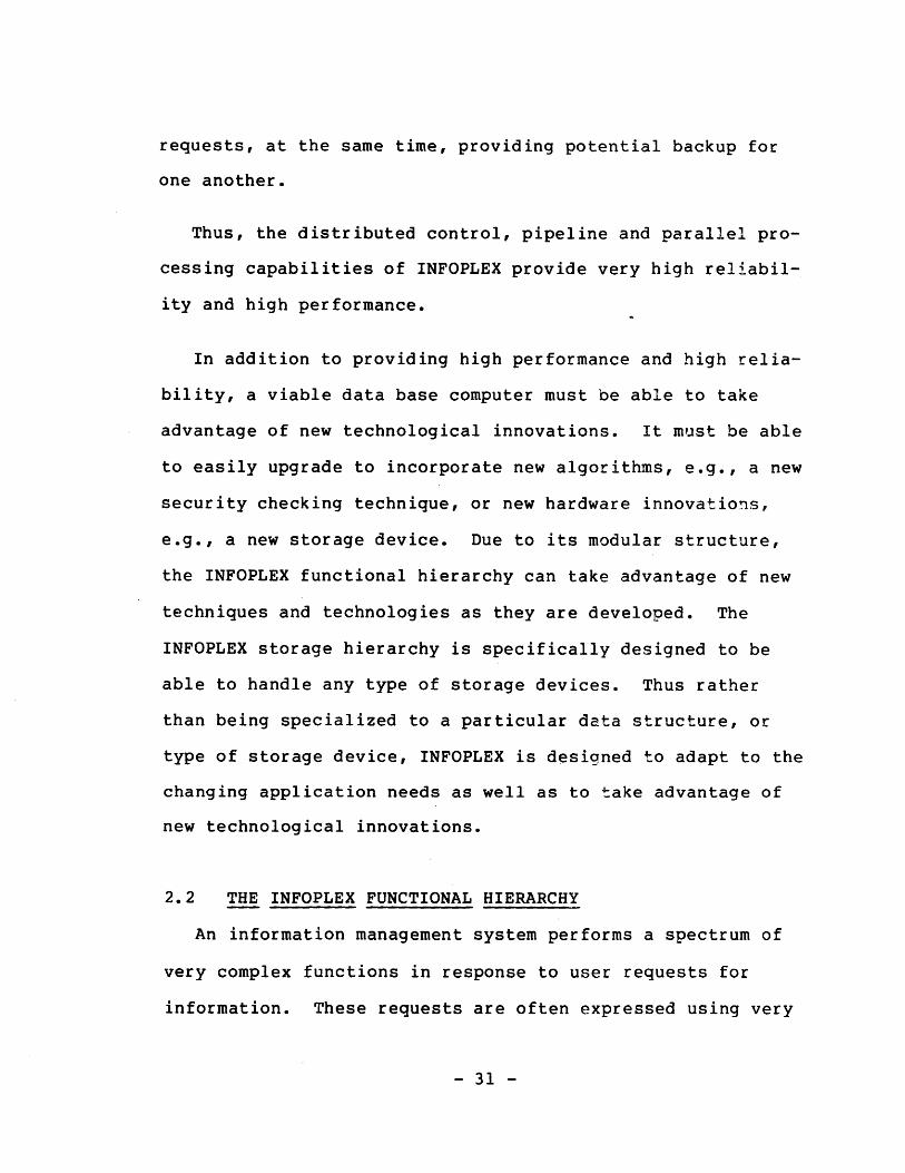
requests, at the same time, providing potential backup for
one another.
Thus, the distributed control, pipeline and parallel pro-
cessing capabilities of INFOPLEX provide very high reliabil-
ity and high performance.
In addition to providing high performance and high relia-
bility, a viable data base computer must be able to take
advantage of new technological innovations. It must be able
to easily upgrade to incorporate new algorithms, e.g., a new
security checking technique, or new hardware innovations,
e.g., a new storage device. Due to its modular structure,
the INFOPLEX functional hierarchy can take advantage of new
techniques and technologies as they are developed. The
INFOPLEX storage hierarchy is specifically designed to be
able to handle any type of storage devices. Thus rather
than being specialized to a particular data structure, or
type of storage device, INFOPLEX is designed to adapt to the
changing application needs as well as to take advantage of
new technological innovations.
2.2 THE INFOPLEX FUNCTIONAL HIERARCHY
An information management system performs a spectrum of
very complex functions in response to user requests for
information. These requests are often expressed using very
- 31 -

high level languages and often come from many different
sources simultaneously. There are many ways that these com-
plex functions can be implemented. The technique of hier-
archical functional decomposition has been found to be very
effective for advanced information systems (Donovan and
Jacoby, 1975). Similar techniques have been used success-
fully in operating systems (Dijkstra, 1968; Madnick and
Donovan, 1974), basic file systems (Madnick and Alsop, 1969;
Madnick, 1970), and a wide range of complex systems (Pattee,
1973).
This is the approach used in INFOPLEX. The information
management functions are systematically decomposed into a
functional hierarchy, referred to as the INFOPLEX functional
decomposition. The functional modules in the hierarchy are
then implemented using multiple microprocessors.
2.2.1 Rationale for Functional Decomposition
The central idea underlying the hierarchical functional
decomposition approach involves decomposing the system into
a hierarchy consisting of a number of levels, such that each
level interacts only with the levels below it in the hier-
archy. Proper selection of the hierarchy allows design or
operating problems that previously impacted the entire sys-
tem, to be isolated to one or a few specific hierarchical
levels, and thereby more easily handled (Parnas, 1976).
- 32 -

Isolating the information management functions into mini-
mally interrelated modules facilitates the use of multiple
identical modules for performing the same function, so that
reliability and parallelism are enhanced. Furthermore, this
approach provides great flexibility in the technologies used
for implementating each type of functional module. For
example, a particular data structure may be selected from a
spectrum of indexing techniques for a given module without
affecting the design of other types of modules.
2.2.2 Example of a Functional Decomposition
To illustrate the hierarchical functional decomposition
concept, a specific example of a functional decomposition is
discussed in this section. Figure 2.1 illustrates a plausi-
ble hierarchical functional decomposition. Each level of
the functional hierarchy is described below.
2.2.2.1 Entities and Entity Sets
At the most fundamental level, a database system stores
information about things, or entities. Also, it is usually
the case that entities represented in a database fall natur-
ally into logical groups, or "entity sets". The way in
which a database system (a) represents and stores informa-
tion about entities themselves, and (b) represents informa-
tion about the logical grouping of entities into entity
sets, forms the bedrock architecture of the system.
- 33 -

7
interface to highlevel languages
data verification and
access control
virtual information
links between n-ary
relations
n-ary relations
binary relations
entity sets
Figure 2.1 An Example Functional Hierarchy
-34-
7 7
1
There are many schemes available for logically and physi-
cally representing entities (i.e., coding, storing, and
addressing entities) and various algorithms for structuring
entity sets. The choice of implementation scheme at this
level affects the performance of the entire system but does
not affect how the functions of the other levels are imple-
mented.
2.2.2.2 Binary Relations
All relationships among entities can be expressed in
terms of binary relationships between pairs of entities.
This functional level makes use of the entity level con-
structs to provide a collection of binary relations (rela-
tions between pairs of entity sets). An element of a binary
relation can be viewed as a triad, consisting of a relation
identifier plus two entities, each from one of the entity
sets participating in the binary relation. Thus a binary
relation can be viewed as a collection of triads with the
same relation identifier.
Perhaps the simplest possible implementation of a set of
binary relations would be as a sequential file of triads,
for example,
(HASSALARYOF , SMITH , 1200)
(HAS SALARY OF , JONES , 1500)
- 35 -

(WORKSINDEPT SMITH , 02)
(WORKSINDEPT , JONES , 07)
The difficulties with this approach are manifest: there is
great data redundancy and thus waste of storage (the rela-
tion identifiers are stored in each triad); insertion of
additional triads would either have to be done out of order,
or else insertions and deletions would be extremely time-
consuming.
Triads could also be stored as linked lists. Alterna-
tively hashing algorithms could be employed to locate any
triad, given two of its three components. The use of linked
lists can improve access speed and reduce storage require-
ments. On the other hand, the use of hashing algorithms
would provide extremely rapid access, but would be poorer in
terms of storage space utilization.
Since a database may contain billions of triads, the log-
ical and physical structures of binary relations have seri-
ous performance implications. Many implementation schemes
for binary relations are possible. Although the choice of
these implementation schemes has various cost and perfor-
mance implications it does not affect how the functions of
the next level are implemented.
- 36 -

2.2.2.3 N-ary Relations
Conceptually, an n-ary relation may be thought of as a
table of data, with rows of the table (usually called
tuples) corresponding approximately to records in a tradi-
tional data file, and columns (or domains) corresponding to
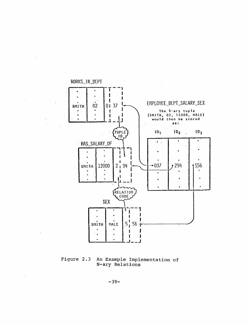
fields. Furthermore, n-ary relations may be constructed out
of sets of basic binary relations. For example, the degree
4 relation EMPLOYEE DEPT SALARY SEX, for which a typical
entry might be
(SMITH, 02, 1200, male),
is semantically equivalent to (i.e., contains the same
information as) the three binary relations WORKSINDEPT,
HASSALARYOF and SEX, as illustrated in Figure 2.2. We
could build up n-ary relation tuples out of tuple-ids of
binary relations, as illustrated in Figure 2.3. In this
approach, the original data entities (SMITH, 01, 1200,
male), would be stored in permanent binary relations, and
all other relations would be constructed out of binary tuple
ids. Tuple ids, being uniform binary numbers, are easy and
efficient to manipulate.
A number of other implementations of n-ary relations is
also possible. The point is, however, that once we have an
- 37 -

WORKSINDEPT(NAME) (DEPT
SMITH 02 -
HASSALARYOF(NAME) (SALARY)
SMITH 1200
SEX
SMITH MALE
( BINARY
EMPLOYEEDEPT_SALARY_SEX(NAME) (DEPT) (SALARY) (SEX)
( DEGREE 4 RELATION )
XI
RELATIONS )
Figure 2.2 An Example 4-ary Relation
-38-
SMITH 02 12000 MALE
,7_
WORKSINDEPT
SMITH 02
-TI
OI01
I
II
EMPLOYEELDEPTSALARYSEXThe 4-ary tuple
(SMITH, 02, 12000, MALE)would then be stored
Figure 2.3 An Example Implementation ofN-ary Relations
-39-

RELATION A
(NAME) (AGE) (SKILL) ID
SMITH 27 WELDER 2 2SMITH 27 JOINER 2
"META- RELATIOfI"COMMON_SKILL(A ID) (B ID)
Figure 2.4 Links Among N-ary Relations
-40-

efficient implementation of binary relations, general n-ary
relations may be constructed in a straightforward fashion
out of the binary relations without actually having to
retreat -- conceptually or physically -- back to the level
of basic entities or entity sets. In other words, n-ary
relation functions (to manipulate n-ary relations) can be
implemented by appropriately combining binary relation func-
tions.
2.2.2.4 Links Among N-ary Relations
The various n-ary relations in a typical database would
generally possess a number of logical interconnections. For
example, one relation might contain data on employees and
the skills each employee possesses, while another might
involve data on departments and the skills each department
requires to function. The logical relationship between the
tuples in these relations could be employed to extend the
database structure further, by incorporating a set of
"meta-relations" for storing information about such links
between the regular n-ary relations. The role of the meta-
relations would be to identify related tuples, and to pro-
vide some semantic information regarding the nature of the
interrelationships. In the example cited above, it would
make sense to establish a meta-relation connecting the
appropriate tuples in the original two relations on the
- 41 -

basis of "common skill", as shown in Figure 2.4. Under the
implementation approach illustrated in Figure 2.4, meta-re-
lations would themselves be n-ary relations. The only dif-
ference between them and regular n-ary relations-lies in the
interpretation of their entries. Therefore, all of the pre-
viously designed mechanisms for building and managing n-ary
relations could also be used with the meta-relations. Only
the interpretation of the elements within these relations
would be different.
By incorporating linking information among the different
n-ary relations in a database, either permanently or tempo-
rarily, directly into the database structure itself, it
would be possible to generate more complex systems that
would be capable of presenting different interfaces to dif-
ferent users, depending on the needs and objectives of the
users themselves.
2.2.2.5 Virtual Information
It is not always necessary, or even desirable, that a
database contain all the information that users might wish
to access. Sometimes data interrelationships are algor-
ithmic in nature, such that certain values may be unambigu-
ously derived from others that are already stored in the
database. This gives rise to the concept of "virtual"
information (Folinus et al., 1974).
- 42 -

If an employee's BIRTHDATE is stored in a database, and
the CURRENTDATE is also available, then the employee's AGE
could be calculated by a simple algorithm and need not also
be stored. If this is in fact done, then the employee's AGE
would be an example of "virtual" data -- information that
appears (to the database user) to be stored there, but which
is not actually present as an entity in the database.
There are a number of advantages to "virtualizing" data
in a database. These include:
1. Greater accuracy: for example, an employee's AGE
could be calculated as accurately as necessary if
included as virtual data, whereas it would always
be somewhat "old" if it were simply stored as a
database entity;
2. Elimination of updating: virtual data items them-
selves never need updating;
3. Reduced redundancy: including, for example,
BIRTHDATE, CURRENTDATE, and AGE as three sepa-
rate items in a database is redundant, and incon-
sistent data relationships can easily result if
some of the items are updated independently of
others;
- 43 -

4. Savings in storage: in many cases, the database
storage space required to store items such as AGE
directly would be much larger than that required
to store the coded algorithm for calculating AGE
from other data.
One way of implementing a virtual information capability is
to'extend the definition of n-ary relations to include tuple
identifiers ("ids") that would in fact not refer to binary
relation tuples, but rather would point to procedures for
calculating the virtual data items. Consider a simple
employee relation of degree four, containing real data items
NAME, BIRTHDATE, and SALARY, plus a virtual data item AGE.
The organization of this 4-tuple would then appear as in
Figure 2.5.
2.2.2.6 Data Verification and Access Control
Data verification is the process of checking entries into
a database for qualities such as reasonableness (e.g., a
person's age should be no greater than, say, 125 years), and
consistency (e.g., the sum of the months worked in various
departments by an employee should sum to the number of
months worked for the company). Access control is the pro-
cess of controlling the database with regard to data
retrieval, update, deletion, database reorganization, etc.
- 44 -

(NAME) BIRTH DATE)
SMITH 6/14/45
ID 2
0
e,
PROCEDUREFOR
CALCULATINGAGE GIVEN
BIRTH-DATE &CURRENT_DATE.
g AGE 1L----6fj
E.g., from I-Operating System CURRENDATE.
or real-timeclock
Figure 2.5 Representation of Virtual Information
-45-
IDI

(DEPT,)
Passed to procedure
Othernecessary - .
Information
A
PROCEDURE
TO VERIFY
ENTITY ON~
UPDATE OR
INSERTION
ddress "p"t
I
Appropri ateaction
Figure 2.6 An Example Data Verification Scheme
-46-
SMI T H 12000
U
(NAME)

For example, department managers may be granted authoriza-
tion to view the employee records of only the employees
working in their own departments; the database administra-
tor, on the other hand, may have access to all the records
in the database. The database administrator may also be the
only person with authority to reorganize the entire data-
base.
Access control also involves considerations such as the
identification of valid users through use of passwords and
other such techniques, mechanisms for allowing users to spe-
cify the type of access (read only, read/write, execute
only, etc.) for files, and allowing users to segment files,
so as to restrict parts of interconnected programs or data
files from certain kinds of access by certain specified
users (an example of a system that has implemented this suc-
cessfully is the MULTICS system).
Both data validity and access control could be imple-
mented in the hierarchical structure being discussed here in
a variety of ways. For example, the basic n-ary relations
could be further extended to include special control and
verification tuples. If data verification were to be per-
formed upon data entries in a certain domain of a relation,
that domain could be flagged in a "verification tuple", and
a data verification routine would be called upon data inser-
- 47 -

tion or update to check the appropriateness of each entry
(see Figure 2.6).
Similarly, control of access to various domains or tuples
could be performed by setting control bits in a special con-
trol tuple or domain, and including, for example, an address
pointer to a list of authorized user passwords, against
which the current user could be checked. These control
tuples or flag bits would serve to describe certain "views",
or combinations of data elements, that each user would be
permitted to access. Alternately, they could be used to
describe elements, domains, tuples, or entire relations that
a user was not permitted to view.
Note that these implementations would utilize the mechan-
isms employed to provide virtual information as discussed
above (i.e., certain ids are used to point to verification
procedures, as they pointed to "virtual information computa-
tion procedures" in the preceding section). Thus, the veri-
fication and access control functions can be realized in
terms of those responsible for virtual information.
2.2.2.7 High-level Language Interface
The user interface, through the data manipulation lan-
guage, basically specifies the way in which the database may
be accessed by the users. In this regard, there are three
main approaches to manipulating a database, corresponding
- 48 -

roughly to the three basic models of database organization
(network, hierarchical, and relational.):
1. An application programmer may wish to 'navigate'
(Bachman, 1975; Codasyl, 1971) a database by using
the data manipulation language to trace through
the data groupings (relations) and interconnecting
linkages (links between n-ary relations). This
approach to database manipulation is usually more
complex than some others, and demands a greater
sophistication on the part of the applications
programmer. He must, for example, be fully aware
of the existence of all the links connecting the
various data groupings, whereas this knowledge is
not necessarily demanded of programmers using
other data manipulation languages. In return for
the greater complexity, the navigational approach
usually offers greater accessing efficiency and
better overall database manipulation performance,
especially when dealing with large and complex
databases.
2. A user may wish to organize and manipulate the
database as a hierarchical tree structure, wherein
the logical interconnections between data group-
ings are always one-to-many in nature. In a
- 49 -

sense, the manipulation of a hierarchical tree
structure is a special case of the general naviga-
tional approach. Hierarchical structures do, how-
ever, allow a number of simplifications to be made
in designing the database management system, as
well as in the data manipulation language. Furth-
ermore, a surprisingly large number of situations
in the real world may be effectively represented
with a hierarchical tree data organization, so it
is worthwhile to treat hierarchical structure as
an important special case.
3. Finally, in many cases it is appropriate for the
applications programmer to access the database
directly in terms of its underlying binary or
n-ary relations (Codd, 1970; Codd, 1974). Such
"direct" manipulation may be made at a relatively
low level, in terms of individual relations and
primitive operations (using the relational alge-
bra) upon them. Alternately, a higher-level
interface could be used to translate more general-
purpose commands (using the relational calculus)
into lower-level operations. Such low-level
accessing methods generally provide greater effi-
ciency, at the expense of greater programming
detail.
- 50 -

2.2.3 INFOPLEX's Approach to Functional Decomposition
The above discussions illustrate one possible decomposi-
tion of the information management functions into hierarchi-
cal levels. Other decompositions are possible. For exam-
ple, the work of (Senko, 1976; Yeh et al., 1977; Toh et al.,
1977; ANSI, 1975) also decomposes the various information
management functions into several levels (e.g., (1) physical
data storage, (2) logical data encoding, (3) access path,
(4) internal schema, and (5) external schema). A common
weakness of these functional decompositions, including our
example decompositon, is that although any particular decom-
position may make good sense and impose a reasonable concep-
tual structure on the information management function, there
are no commonly accepted criteria with which to evaluate any
given decomposition.
A common qualitative criteria often used to decompose
complex functions into sub-modules is that of modularity. A
decomposition is considered to attain high modularity when
each individual module is internally coherent, and all the
modules are loosely coupled with one another. One of the
INFOPLEX research focuses is to develop methodologies to
formalize this notion of modularity quantitatively, and to
use it to evaluate a given decomposition, thus systematic
techniques for obtaining an optimal functional decomposition
- 51 -

of the information management functions can be developed. A
particularly promising approach for this purpose is the
Systematic Design Methodology (Huff and Madnick, 1978).
The following briefly describes this approach.
The Systematic Design Methodology approach to system
design centers on the problem of identifying a system's
modules, or "sub-problems", their functions, and their
interconnections. Using this approach, we begin with a set
of functional requirement statements for the INFOPLEX infor-
mation management functions. Each pair of requirements is
examined in turn, and a decision as to whether a significant
degree of interdependence between the two requirements
exists is made. Then the resulting information is repre-
sented as a non-directed graph structure: nodes are
requirement statements, links are assessed interdependen-
cies. The graph is then partitioned with the objective of
locating a good decomposition. An index of partition good-
ness is employed, which incorporates measures of subgraph
"strength" and "coupling". The actual goodness index is
taken as the algebraic difference between the strengths of
all the subgraphs, and the inter-subgraph couplings. That
is, M=S-C, where S is the sum of the strength measures of
all subgraphs, and C is the sum of all the inter-subgraph
couplings.
- 52 -

Once an agreeable partition is determined, the resulting
sets of requirements are interpreted as "design sub-prob-
lems". From these design sub-problems a functional hier-
archy of INFOPLEX can then be systematically derived. This
procedure is illustrated in Figure 2.7. This approach is
currently being developed in the INFOPLEX Project.
2.3 THE INFOPLEX DATA STORAGE HIERARCHY
To provide a high performance, highly reliable, and large
capacity storage system, INFOPLEX makes use of an automati-
cally managed memory hierarchy (referred to as the INFOPLEX
physical decomposition). In this section, the.rationale for
and an example of an automatic memory hierarchy are dis-
cussed. Then the. INFOPLEX approach to realize such a memory
hierarchy is also discussed.
2.3.1 Rationale for a Storage Hierarchy
The technologies that lend themselves to low cost-per-
byte storage devices (and, thereby, economical large capac-
ity storage) result in relatively slow access times. If it
was possible to produce ultra-fast limitless-capacity sto-
rage devices for miniscule cost, there would be little need
for a physical decomposition of the storage. Lacking such a
wondrous device, the requirements of high performance at low
cost are best satisfied by a mixture of technologies combin-
- 53 -

-54-
statement of informationmanagement requirements
graph
representation
graph
decomposi ti on
intepretationas design
subproblems
systematic
derivation of
functional
hierarchy
Figure 2.7 INFOPLEX's Approach to Function4lDecomposition

ing expensive high-performance devices with inexpensive
lower-performance devices.
There are many ways that such an ensemble of storage dev-
ices may be structured, but the technique of hierarchical
physical decomposition has been found to be very effective
(Madnick, 1973; Madnick, 1975a; Madnick, 1975b). Using this
technique, the ensemble of heterogeneous storage devices is
organized as a hierarchy. Information is moved between sto-
rage levels automatically depending upon actual or antici-
pated usage such that the information most likely to be
referenced in the future is kept at the highest (most easily
accessed) levels.
The effectiveness of a memory hierarchy depends heavily
on the phenomonon known as locality of reference (Denning,
1970). A memory hierarchy makes use of this property of
information reference pattern so that the information that
is used frequently would be accessible through the higher
levels of the hierarchy, giving the memory hierarchy an
expected access time close to that of the access time of the
faster memories. This approach has been used in contempo-
rary computer systems in cache memory systems (Conti, 1969),
in virtual memory demand paging systems (Bensoussan et al.,
1969; Greenberg and Webber, 1975; Hatfield, 1972; Mattson et
al., 1970; Meade, 1970), and in mass storage systems (Consi-
dine and Weis, 1969; Johnson, 1975).
- 55 -

Experimentations with physical data reference strings are
reported in (Easton, 1978; Rodriguez-Rosell, 1976; Smith,
1978b). It has been found that there is considerable
sequentiality of physical database reference in these stu-
dies. Sequentiality of references is a special form of spa-
tial locality as discussed by (Madnick, 1973). Several mea-
sures of logical database locality and experimentations with
these measures are reported in (McCabe, 1978; Robidoux,
1979). The observations from these experiments are encour-
aging. In particular they indicate that there is considera-
ble locality of database reference.
2.3.2 Example of a Physical Decomposition
We now discuss an example of a memory hierarchy, its gen-
eral structure, types of storage devices that it may employ,
and some strategies for automatic information movement in
the hierarchy.
2.3.2.1 General Structure
To the user (i.e. the lowest level of the functional
hierarchy) of the memory hierarchy, the memory appears as a
very large linear virtual address space with a small access
time. The fact that the memory is actually a hierarchy or
that a certain block of information can be obtained from a
certain level is hidden from the memory user. Figure 2.8
- 56 -

storage references
1. CACHE
2. MAIN
3. BLOCK
4. BACKING
5. SECONDARY
6. MASS
Figure 2.8 An Example Memory Hierarchy
-57-

StorageLevel
1. Cache
2. Main
3. Block
4. Backing
5. Secondary
6. Mass
RandomAccess
Time
100 ns
1 us
100 us
2 ms
25 ms
1 sec.
SequentialTransfer
Rate(bytes/sec)_
loM
16M
8m
2M
11m
1M
UnitCapacity
(bytes)
SystemPrice
(per byte)
32K 504
100512K
10M 0. 54
loM
100B
0.02*
0.0005t
Figure 2.9 Example Storage Devices
-58-

illustrates the general structure of a memory hierarchy
consisting of six levels of storage devices. Some of the
devices that can be used in these levels are discussed in
the next subsection.
The lowest level always contains all the information of
the system. A high level always contains a subset of the
information in the next lower level. To satisfy a request,
the information in the highest (most easily accessed) level
is used.
Storage reference is accomplished by supplying the memory
hierarchy with a virtual address (say a 64-bit address), the
memory hierarchy will determine where the addressed informa-
tion is physically located. The addressed information will
be moved up the memory hierarchy if it is found in other
than the highest level of the hierarchy. This implies that
there is a high variance in the access time of the memory
system. This situation is alleviated by providing multiple
ports to the memory system so that a pipeline of requests
can be processed. Furthermore, the inherent parallelism
within each memory level and among different memory levels
provides high throughput for the memory system as a whole.
Since the functional levels are designed with high parallel-
ism of operation as one of its major objectives, the proces-
sor making the request can take advantage of the high memory
- 59 -

access time variance. Various schemes are used to make the
automatic management of the memory hierarchy efficient.
Some of these strategies are discussed in a latter section.
2.3.2.2 Storage Devices
Traditionally, computer direct access storage has been
dominated by two fairly distinct technologies: (1) ferrite
core and, later, metallic oxide semiconductor (MOS) LSI
memories with microsecond access times and relatively high
costs, and (2) rotating magnetic media (magnetic drums and
disks) with access time in the range of 10 to 100 millise-
conds and relatively low costs. This has led to the separa-
tion between main storage and secondary storage devices.
Recently several new memory technologies, most notably
magnetic bubbles, electron beam addressed memories (EBAM),
and charge coupled devices (CCD), have emerged to fill the
"gap" between the two traditional memory technologies.
The evolution and increasing deployment of the above and
many other memory technologies have produced a more continu-
ous cost-performance range of storage devices, as depicted
in Figure 2.9 (Madnick, 1975a). Note that these technolo-
gies, which are arbitrarily grouped into six categories,
result in storage devices that span more than six orders of
magnitude in both random access time (from less than 100
- 60 -

nanoseconds to more than 1 second) and system price per byte
(from more than 50 cents per byte to less than 0.0005 cent).
This evolution has facilitated the choice of appropriate
cost-effective storage devices for the memory hierarchy.
For example, for the memory hierarchy discussed in the pre-
vious section, we might use a device like the IBM 3850 Mass
Storage as the mass storage, traditional moving head disks
as secondary storage, magnetic drums as backing store, CCD
or magnetic bubble as block store, core or semiconductor RAM
as main storage, and high performance semiconductor RAM as
cache.
2.3.2.3 Strategies for Information Movement
Various physical storage management and movement techni-
ques, such as page splitting, read through, and store
behind, can be distributed within the memory hierarchy.
This facilitates parallel and asynchronous operation in the
hierarchy. Furthermore, these approaches can lead to
greatly increased reliability of operation. For example,
under the read through strategy (Figure 2.10), when data
currently stored at level i (and all lower performance lev-
els) is referenced, it is automatically and simultaneously
copied and stored into all higher performance levels. The
data itself is moved between levels in standard transfer
- 61 -

(0, I)
N N(1,2)
N (2,3)
~~~1N (2,3)
Figure 2.10 Illustration of Read Through
-62-

units, also called pages, whose size N (i-1, i) depends upon
the storage level from which it is being moved.
For example, suppose that the datum "a", at level 3, is
referenced (see Figure 2.10). The block of size N(2,3) con-
taining "a" is extracted and moved up the data bus. Level 2
extracts this block of data and stores it in its memory
modules. At the same time, level 1 extracts a sub-block of
size N(1,2) containing "a" and level 0 extracts the sub-
block of size N(0,l) containing "a" from the data bus.
Hence, under the read through strategy, all upper storage
levels receive this information simultaneously. If a sto-
rage level must be removed from the system, there are no
changes needed. In this case, the information is "read
through" the level as if it didn't exist. Since all data
available at level i is also available at level i + 1 (and
all other lower performance levels), there is no information
lost. Thus, no changes are needed to any of the other sto-
rage levels or the storage management algorithms although we
would expect the performance to decrease as a result of the
missing storage level. A limited form of this reliability
strategy is employed in most current-day cache memory sys-
tems (Conti, 1969).
- 63 -

In a store behind strategy all information to be changed
is first stored in L(l), the highest performance storage
level. This information is marked "changed" and is copied
into L(2) as soon as possible, usually during a time when
there is little or no activity between L(l) and L(2). At a
later time, the information is copied from L(2) to L(3),
etc. A variation on this strategy is used in the MULTICS
Multilevel Paging Hierarchy (Greenberg and Webber, 1975).
This strategy facilitates more even usage of the bus between
levels by only scheduling data transfers between levels dur-
ing idle bus cycles. Furthermore, the time required for a
write is only limited by the speed of the highest level
memory.
The store behind strategy can be used to provide high
reliability in the storage system. Ordinarily, a changed
page is not allowed to be purged from a storage level until
the next lower level has been updated. This can be extended
to require two levels of acknowledgment. Under such a stra-
tegy, a changed page cannot be removed from L(l) until the
corresponding pages in both L(2) and L(3) have been updated.
In this way, there will be at least two copies of each
changed piece of information at levels L(i) and L(i+l) in
the hierarchy. Other than slightly delaying the time at
which a page may be purged from a level, this approach does
- 64 -

not significantly affect system performance. As a result of
this technique, if any level malfunctions, it can be removed
from the hierarchy without causing any information to be
lost. There are two exceptions to this process, L(l) and
L(n). To completely safeguard the reliability of the sys-
tem, it may be necessary to store duplicate copies of infor-
mation at these levels only.
Figure 2.11 illustrates this process. In Figure 2.11(a),
a processor stores into L(l), the corresponding page is
marked "changed" and "no lower level copy exists". Figure
2.11(b) shows in a latter time, the corresponding page in
L(2) is updated and marked "changed" and "no lower level
copy exists". An acknowledgment is sent to L(l) so that the
corresponding page is marked "one lower level copy exists".
At a later time (Figure 2.11(c)), the corresponding page in
L(3) is updated and marked "changed" and "no lower level
copy exists". An acknowledgment is sent to L(2) so that the
corresponding page is marked "one lower level copy exists".
An acknowledgment is sent to L(l) so that the corresponding
page is marked "two lower level copy exists". At this time,
the page in L(l) may be replaced if necessary, since then
there will be at least two copies of the updated information
in the lower memory levels.
- 65 -

RequestSource
N (0,1)
SL(I) .
L (2)
L (3)
Figure 2.11(a) Store Behind (a)
-66-

FRequestSour ce
Figure 2.11(b) Store Behind (b)
-67-
L (3)

RequestSource
IL V
Figure 2.11(c) Store Behind (c)
-68-

2.3.3 INFOPLEX's Approach to Physical Decomposition
In the previous section, we have illustrated an example
of a memory hierarchy that makes use of an ensemble of het-
erogeneous storage devices. Although memory hierarchies
using two or three levels of storage devices have been
implemented, no known generalized automatic memory hierarchy
has been developed.
The optimality of a memory hierarchy depends on the com-
plex interactions among the memory reference pattern, the
device characteristics, and the information movement strate-
gies. The INFOPLEX approach to this complex problem is to
empirically study and characterize data reference patterns
at several levels (e.g. transaction level, logical data
level, and physical data level), to develop various informa-
tion movement strategies, and to design a prototype memory
hierarchy. The interactions among these components can then
be systematically investigated by means of analytic models
and simulation models.
2.4 RESEARCH ISSUES ADDRESSED IN THIS THESIS
This chapter has provided the background for this thesis.
As is evident from the above discussions, there are a large
number of interesting but unresolved research problems asso-
ciated with INFOPLEX. This thesis is a key step towards
- 69 -

understanding the INFOPLEX data storage hierarchy. In par-
ticular, this thesis has made contributions in the following
areas:
1. Developed and extended concepts for the INFOPLEX
data base computer and data storage hierarchy sys-
tems.
2. Provided a theoretic foundation for analysis of
data storage hierarchy systems.
3. Formalized storage management algorithms to incor-
porate the read-through strategy.
4. Provided detail analysis of the performance and
reliability properties of data storage hierarchies
and their algorithms.
5. Designed prototype data storage hierarchy systems
for INFOPLEX.
6. Developed simulation models to obtain insights to
the data storage hierarchy designs and their
algorithms.
These are elaborated in the following chapters.
- 70 -

Chapter III
A GENERAL STRUCTURE OF THE INFOPLEX DATA STORAGE HIERARCHY
3.1 INTRODUCTION
This chapter proposes the general structure of a data
storage hierarchy system for the INFOPLEX data base compu-
ter. The design of this system is based on Madnick's pro-
posed system (Madnick, 1973). This work brings Madnick's
system one step closer to realization. In the following,
the underlying design goals of this data storage hierarchy
system will be discussed. Then the design, called DSH-1, is
introduced followed by a discussion of further design issues
that need to be addressed.
3.2 DESIGN OBJECTIVES
There are a large number of practical storage hierarchy
systems today. However, the functionality provided by each
is quite different and often falls short of our expectations
(for use as the storage subsystem of the INFOPLEX data base
computer). In the following, we discuss the underlying
design goals of DSH-1.
- 71 -

3.2.1 Virtual Address Space
DSH-1 provides a virtual address space for data storage.
Every data item in DSH-1 is byte addressable using a gener-
alized virtual address. A key advantage of a virtual
address space is that a user (a processor) of DSH-l is
relieved of all physical device concerns. In fact, the pro-
cessor accessing DSH-1 is not aware of how the virtual
address space is implemented. This latter characteristic is
quite unique since most current virtual memory systems are
simulated, at least partially, by software executed by the
processor, e.g., the IBM OS/VS system (Scherr, 1973).
3.2.2 Very Large Address Space
Early virtual memory systems were developed primarily for
program storage, hence their address spaces were quite lim-
ited, e.g., in the order of one million bytes. The MULTICS
(Greenberg and Webber, 1975) virtual memory and the IBM Sys-
tem/38 (Datamation, 1978; Soltis and Hoffman, 1979) logical
storage were developed for program as well as data file sto-
rage. These systems support a large virtual address space.
However, the size of an individual data file in MULTICS is
limited to 2**18 bytes and that in System/38 is limited to
2**24 bytes. Though these are very large address spaces, it
is expected that future systems will require online storage
capacities that are much larger. DSH-1 uses a 64-bit vir-
- 72 -

tual address. Each byte is directly addressable, hence
there is virtually no limit on the size of a logical entity
such as a data file.
3.2.3 Permanent Data Storage
Accesses to permanent data is performed by special soft-
ware routines and a special I/O processor in most virtual
memory systems. The I/O processor brings the data into the
virtual memory and writes the data back to permanent storage
when the data is updated. Systems like MULTICS and Sys-
tem/38 provide a permanent virtual data storage. Any data
in virtual memory is also in permanent storage. DSH-1 also
provides a permanent virtual data storage. Special data
integrity schemes are used to ensure that as soon as a pro-
cessor completes a write operation to a virtual location,
the effect of the write becomes permanent even in the event
of a power failure.
3.2.4 Support Multiple Processors
Most current virtual memory systems have been limited to
supporting 2 to 3 processors. It is necessary that DSH-1
support a large number of processors due to the requirements
for high performance and high availability to be discussed
below. All these processors share the same virtual data
address space. Appropriate synchronization and protection
schemes are used to ensure data integrity and security.
- 73 -

3.2.5 Generalized Multi-level Storage System
To provide a large capacity storage subsystem with.low
cost and high performance, a spectrum of storage devices
arranged in a hierarchy is used. Previous storage hierarchy
systems have been specially designed for a specific 2 or 3
levels hierarchy (e.g., cache and main memory, or main
memory and secondary storage device). Thus, it is extremely
difficult to add or remove a storage level in these systems.
DSH-1 is designed to incorporate any type of storage device
and support reconfiguration of storage levels. This charac-
teristic is particularly important in responding to new dev-
ice technologies.
3.2.6 Direct Inter-level Data Transfer
In most current storage hierarchy systems, data movement
among storage levels is performed indirectly. For example,
to move data from drum to disk in the MULTICS system, data
is read from drum into main memory by the processor which
then writes the data to disk. Recent developments in sto-
rage systems make it possible to decentralize the control of
data movement between storage devices to intelligent con-
trollers at the storage devices. For example, the IBM 3850
Mass Storage (Johnson, 1975) uses an intelligent controller
to handle data transfer between mass storage and disks, mak-
ing the 3850 appear as a very large number of virtual disks.
- 74 -

DSH-1 incorporates intelligent controllers at each storage
level to implement the algorithms for data movement among
the storage levels. Special algorithms are developed to
facilitate efficient broadcasting of data from a storage
level to all other storage levels as well as movement of
data between adjacent storage levels.
3.2.7 High performance
To support the data requirements of the functional pro-
cessors in INFOPLEX, DSH-1 is designed to handle a large
number of requests simultaneously. The operation of DSH-1
is highly parallel and asychronous. Thus, many requests may
be in different stages of completion at various storage lev-
els of DSH-l. Each processor accesses DSH-1 through a data
cache where the most frequently used data items are stored.
3.2.8 Availabli
High availability of DSH-1 is a result of a combination
of the design strategy used, hardware commonality, and spe-
cial algorithms. Key design str-ategies in DSH-1 include the
use of distributed controls and simple bus structures, both
of which contribute to the high availability of DSH-l. Mul-
tiple identical hardware components are used in parallel to
provide high performance and to ensure that no single compo-
nent is critical to system operation. Integrated into the
- 75 -

design are certain algorithms that exploit the structure of
DSH-1 to allow data redundancy and perform automatic data
repair in the event of component failure, thus diminishing
the dangers of multiple failures.
3.2.9 Modularity
DSH-1 is modular at several levels. This provides much
flexibility in system structuring. The number of processors
to be supported by DSH-1 can be varied. The number of sto-
rage levels and the type of storage devices can be chosen to
meet the particular capacity and performance requirements.
All the storage levels have very similar structures and the
same algorithm is used by the intelligent controllers at
each storage level.
Flexibility in system structuring is extended in DSH-1 to
allow for dynamic system reconfiguration. For example, a
defective storage device or storage level can be amputated
without loss of system availability.
An example of a system that also incorporates modularity
as a key design goal is the PLURIBUS (Katsuki et. al., 1978)
system. In PLURIBUS, the basic building block is a bus
module. The number of components on a bus module as well as
the number of bus modules can be easily varied to meet dif-
ferent system requirements.
- 76 -

3.2.10 Low Cost
A storage hierarchy is the lowest cost configuration to
meet the requirement of providing a large storage capacity
with high performance. DSH-1 also make use of common hard-
ware modules as the intelligent controllers at each storage
level, thus reducing hardware development cost. The modu-
larity features of DSH-1 discussed above also facilitate
system upgrading with minimum cost.
Commonality of hardware modules and flexibility of system
upgrade have been employed in many computer systems as an
effective approach to reduce cost. However, these techni-
ques are rarely applied to storage hierarchy systems. DSH-1
is a step in this direction.
Advances in storage device and processor technologies
provide great potentials for development of very effective
data storage hierarchies that incorporate the above charac-
teristics. In the next section, we describe a general
structure of such a system.
3.3 GENERAL STRUCTURE OF DSH-1
The structure of DSH-1 is illustrated in Figure 3.1. A
key design decision in DSH-1 is to make use of an asynchro-
nous time-shared bus for interconnecting multiple components
(processors and memory modules) within a storage level and
- 77 -

DC DC(
Level
L(1)
I IZT -LC
I.
S(i) SLC's P(i)
Level
L(I)
B(O) logical buses
Each has b(O) physical buses.
8(1) logical busesEach has b(1)
physical,tuses
B(i) logical buse!Each has b(i)physical buses
Figure 3.1 Structure of DSH-1
-78-

to make use of an asynchronous time-shared bus for
interconnecting all the storage levels. A key advantage of
the time-shared bus is its simplicity, flexibility, and
throughput. Two alternative approaches can be used in DSH-1
to increase the effective bandwidth of the time-shared bus.
First, a new pended-bus protocol can be used (Haagens,
1978). This asynchronous bus protocol is more efficient
than the usual time-shared bus protocols with the result
that a much larger number of components can share a single
bus. Second, multiple logical buses can be used to parti-
tion the load on the time-shared bus.
In the following subsections, we shall describe the
interface to DSH-l as seen by a functional hierarchy proces-
sor. Then the structure of DSH-1 is described by examining
its highest performance storage level and then a typical
storage level.
3.3.1 The DSH-1 Interface
To the functional hierarchy processors connected to
DSH-l, DSH-1 appears as a large multi-port main memory.
There are K memory ports, hence K processors can simultane-
ously access DSH-l.
The functional processors use a 2**V (V=64) byte virtual
address space. The instructions for each functional hier-
- 79 -

archy processor are stored in a separate 2**I byte program
memory. The program memories are not part of DSH-l. Thus,
2**I bytes of the processor's address space is mapped by the
program memories, leaving 2**V-2**I bytes of data memory to
be managed by DSH-l. This is depicted in Figures 3.2(a) and
3.2(b).
Each processor has multiple register sets to support
efficient multiprogramming. Some of the more important
registers for interfacing with DSH-1 are : (1) a V-bit
Memory Address Register (MAR) for holding the virtual
address, (2) a Memory Buffer Register (MBR) for storing the
data read from DSH-1 and to be written into DSH-l, (3) a
Memory Operation Register (MOR) indicates the particular
operation to be performed by DSH-1, (4) an Operation Status
Register (OSR) which indicates the result of a operation
performed by DSH-1, and (5) a Process Identifier Register
(PIR) which contains the Process Identifier (PID) of the
process that is currently using the processor.
A number of memory operations are possible. The key ones
are the read and write operations and the primitives for
locking a data item (such as those supporting the Test-and-
Set type of operations).
- 80 -
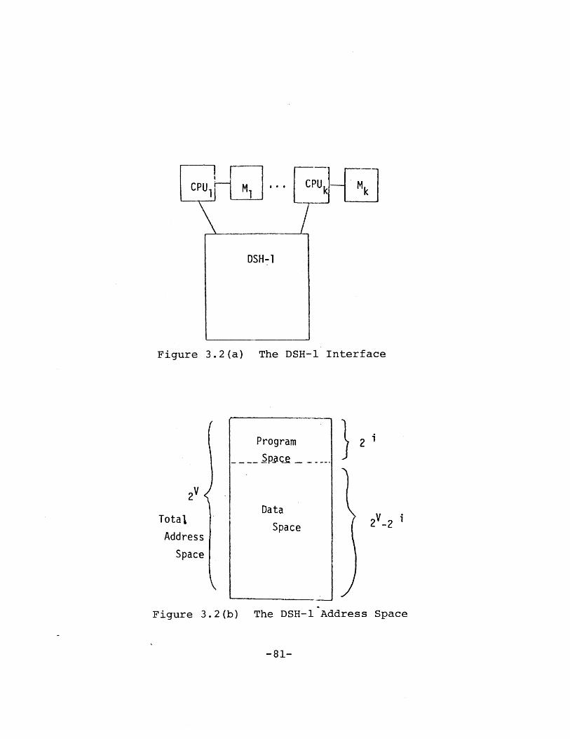
Figure 3.2(a) The DSH-1 Interface
Program
Spau --
Data
Space 2V-2 i
Figure 3.2(b) The DSH-1 Address Space
-81-
Total
Address
Space
All read and write operations to DSH-1 are performed in
the highest performance storage level, L(l). If a refer-
enced data item is not in L(l), it is brought up to L(l)
from a lower storage level via a read-through operation.
The effect of an update to a data item in L(l) is propagated
down to the lower storage levels via a number of store-be-
hind operations.
In a read operation, two results can occur depending on
the state of DSH-l. First, if the requested data is already
in L(l), the MBR is filled with the data bytes starting at
location (MAR) and the processor continues with the next
operation. Alternatively, the addressed data may not be
available in L(l). In this case, the processor is inter-
rupted, the OSR is set to indicate that it may take a while
for the read operation to complete, and the processor is
switched to another process. In the meantime, the addressed
data is copied into L(l) from a lower storage level. When
this is completed, the processor is notified of the comple-
tion of the original read operation.
Similarly, a write operation may result in two possible
responses from DSH-l. First, if the data to be updated is
already in L(l), the bytes in MBR are written to the virtual
address locations starting at (MAR), and the processor con-
tinues with the next operation. Second, a delay similar to
- 82 -

the read operation may occur (when the data to be updated is
not in L(l)), while DSH-1 retrieves the data from a lower
storage level.
This concludes a brief description of the asynchronous
DSH-1 interface, as seen by a functional hierarchy proces-
sor. Next, we examine the structure of DSH-l.
3.3.2 The Highest Performance Storage Level - L(l)
There are h storage levels in DSH-1, labelled L(l), L(2),
L(3), ... , L(h). L(l) is the highest performance storage
level. L(i) denotes a typical storage level. The structure
of L(l) is unique. The structures of all other storage lev-
els are similar.
A distinction must be made between the concept of a phy-
sical bus and a logical bus. The former refers to the
actual hardware that implements communications among levels
and within a level. A logical bus may be implemented using
one or more physical buses. Logical buses represent a par-
titioning, based upon the virtual address referenced, of the
physical buses.
Referring to Figure 3.1, L(l) consists of K memory ports
and S(l) storage level controllers (SLC's) on each of B(l)
logical local buses (i.e., S(1)*B(l) SLC's in total for this
- 83 -
level). Each memory port consists of a data cache control-
ler (DCC) and a data cache duplex (DCD). A DCC interfaces
with the functional hierarchy processor that is connected to
the memory port. A DCC also performs mapping of a virtual
address generated by the processor to a physical address in
the DCD. Another function of DCC is to interface with other
DCC's (e.g., to maintain data cache consistency), and with
SLC's on the logical bus (for communications with other sto-
rage levels).
At L(l), a SLC accepts requests to lower storage levels
from the DCC's and forwards them to a SLC at the next lower
storage level. When the responses to these requests are
ready, the SLC accepts them and sends them back to the
appropriate DCC's. The SLC's also couple the local buses to
the global buses. In essence, the SLC serves as a gateway
between levels and they contend among themselves for use of
the communication media, the logical buses.
At L(l), there are B(l) logical local buses. Each logi-
cal local bus consists of b(l) physical buses. Each logical
bus handles a partition of the addresses. For example, if
two logical buses were used, one might handle all odd num-
bered data blocks and the other would handle all the even
numbered data blocks.
- 84 -

DSH-1 has B(0) logical global buses. Each logical global
bus consists of b(0) global physical buses. The use of
address partitioning increases the effective bus bandwidth.
The use of multiple physical buses for each logical bus
enhances reliability and performance.
3.3.3 A Typical Storage Level - L(i)
A typical storage level, L(i), is divided into B(i)
address partitions. Each address partition consists of S(i)
SLC's, P(i) memory request processors (MRP's), and D(i) sto-
rage device modules (SDM's), all sharing a logical bus. A
logical bus consists of b(i) physical buses.
An SLC is the communication gateway between the
MRP's/SDM's of its level and the other storage levels.
An MRP performs the address mapping function. It con-
tains a directory of all the data maintained in the address
partition. Using this directory, an MRP can quickly deter-
mine if a virtual address corresponds to any data in the
address partition, and if so, what the real address is for
the data. This real address can be used by the correspond-
ing SDM to retrieve the data. Since each MRP contains a
copy of this directory, updates to the directory have to be
handled with care, so that all the MRP's see a consistent
copy of the directory.
- 85 -

An SDM performs the actual reading and writing of data.
It also communicates with the MRP's and the SLC's.
The SLC's, MRP's, and SDM's cooperate to handle a memory
request. An SLC communicates with other storage levels and
passes requests to an MRP to perform the address transla-
tion. The appropriate SDM is then initiated to read or
write the data. The response is then sent to another SLC at
another storage level.
3.4 FURTHER DESIGN ISSUES
The previous section describes the general structure of
DSH-l. From this general structure, a number of interesting
alternative configurations can be obtained. For example, if
all the data caches are taken away, L(l) becomes a level
with only the SLC's for communicating the requests from the
processors to the lower storage levels and for obtaining
responses from these lower storage levels. This configura-
tion eliminates the data consistency problems associated
with multiple data caches.
If we let the number of logical buses be equal to one, we
obtain the configuration without address partitioning.
Another intersting configuration is when there is only
one MRP and one SDM on a given logical bus. This configura-
- 86 -

tion eliminates the need for multiple identical directory
updates.
Thus, by varying the design parameters of DSH-1, a large
number of alternative configurations with quite different
characteristics can be obtained. The- general structure is a
valuable vehicle for investigating various design issues.
Some of the key issues are briefly introduced in the follow-
ing sections.
3.4.1 Support of Read and Write Operations
Key problems in supporting the read and write operations
in DSH-1 include : (1) data consistency in multiple data
caches, (2) protocols for communicating over the shared
bus, (3) algorithms for updating the redundant directories,
(4) algorithms for arbitrating among usage of identical
resources, such as buses, SLC's and MRP's, and (5) specify-
ing the various steps (transactions) that have to be accom-
plished to handle the read and write operations.
3.4.1.1 Multiple Cache Consistency
As illustrated in Figure 3.1, each DSH-1 memory port is a
data cache directly addressable by the processor at the
port. It is possible then, that a data item may be in sev-
eral different data caches at the same time. When the data
- 87 -

item gets updated by a processor, other processors may
reference an inconsistent copy of the data item. The multi-
ple cache consistency problem and its solutions are dis-
cussed in (Tang, 1976; Censier and Feautrier, 1978).
Three basic approaches can be used to resolve this prob-
lem in DSH-l. The first approach is to send a purge request
to all other data caches whenever a processor updates data
in its cache. The second approach is to maintain status
information about the data cache contents. Whenever there
is an update to a data item, this status information is con-
sulted and purge requests are sent only to those caches that
contain the data item being changed. The third approach is
to make use of knowledge of how the data in DSH-1 is to be
used so that the inconsistency problem can be avoided. For
example, knowledge about the interlocking scheme used to
ensure safe data sharing may be used to avoid uncessary
purge requests to other caches.
3.4.1.2 Bus Communication Protocols
In DSH-l, the buses may be used for point-to-point commu-
nication as well as for broadcast type of communications.
It is necessary to ensure that messages are sent and
received correctly. For example, L(i) broadcast data to the
upper levels and one or more of these levels may not be able
- 88 -

to accomodate the data to be received, possibly due to the
lack of buffer space. Communications protocols to handle
these situations are important.
3.4.1.3 Multiple Directory Update
Each MRP contains a directory of all the data in the
SDM's on the same bus. Multiple requests may be handled by
the MRP's. When a MRP updates its directory, other MRP's
may still reference the old copy of the directory. This is
similar but not identical to the multiple cache consistency
problem discussed above. It is necessary to maintain con-
sistency of the MRP directory states.
3.4.1.4 Multiple Resource Arbitration
Multiple identical resources (e.g., buses, MRP's, and
SLC's) are used in DSH-1 to provide parallel processing
while at the same time providing redundancy against failure.
A request for a resource can be satisfied by any one of the
resources. An arbitration scheme is required to control the
assignment of resource.
3.4.1.5 Transaction Handling
A read or a write request may go through a number of
asynchronous steps through a number of storage levels to
completion. A complication to these transactions is that
- 89 -

for high throughput, a request (or response) may be divided
into a number of messages when the request (or response) is
being transported within the hierarchy. Thus, a request (or
response) may have to be assembled, which may take an amount
of time dependent on the traffic within DSH-l. Partial
requests (responses) at a storage level require special han-
dling.
3.4.2 Multijle Data Redundancy Properties
As a result of the read-through operation, several copies
of a referenced data item exists in the DSH-1 storage lev-
els. The two-level store-behind operation also maintains at
least two copies of any updated data item in DSH-1. This is
a key reliability feature of DSH-l. It is important to know
under what conditions and using what types of algorithms can
this multiple data redundancy be maintained at all times.
3.4.3 Automatic Data Repair Algorithms
One of the benefits of maintaining redundant d-ata in
DSH-1 is that lost data due to component failures can be
reconstructed on a spare component from a copy of the lost
data. By using automatic data repair in DSH-1 the probabil-
ity of multiple data loss can be reduced.
- 90 -

Two classes of automatic data repair algorithms are pos-
sible. One strategy is to make use of the multiple data
redundancy properties of DSH-1 and to reconstruct the lost
data from its copy in a different storage level. The other
approach is to maintain duplicate copies of the data item
within a storage level and to reconstruct the lost data from
its copy in the same storage level. The latter approach is
particularly attractive for low performance devices such as
mass storage.
3.4.4 Performance Evaluation
A key issue in the DSH-1 design is predicting its perfor-
mance. In order to accomplish this, a simplified design of
DSH-1 and its algorithms can be developed. A simulation
model can then be developed for this design. Various basic
performance statistics can then be obtained under various
load assumptions. This experiment will provide insights and
directions for further design efforts.
3.5 SUMMARY
The INFOPLEX storage hierarchy is a high performance high
availability virtual memory data storage hierarchy with dis-
tributed controls for data movement and address translation.
It is designed specifically to provide a very large perman-
ent virtual address space to support multiple functional
hierarchy processors.
- 91 -

A general structure of DSH-1, the INFOPLEX storage hier-
archy has been described in this chapter. This general
structure can be used to derive a large number of alterna-
tive configurations which can be used to explore various
algorithms for data storage hierarchy systems.
A number of important design issues associated with DSH-I
are also outlined.
- 92 -

Chapter IV
MODELLING AND ANALYSIS OF DATA STORAGE HIERARCHY SYSTEMS
4.1 INTRODUCTION
This chapter is aimed at modelling data storage hierarchy
systems so as to study these systems from a theoretic point
of view. These studies provide insights to the perfromance
and reliability properties of data storage hierarchy systems
and their algorithms. These insights provide guidance to
developing effective data storage hierarchy systems.
Current research in storage hierarchy systems is reviewed
and extended. A formal model of a data storage hierarchy
which incorporates multiple page sizes and maintains multi-
ple data redundancy is developed. The LRU algorithm is
extended to include the read-through and overflow handling
strategies in a multi-level storage hierarchy. Formal
definitions for these extended algorithms are developed.
Finally, important performance and reliability properties of
data storage hierarchy systems are identified and analyzed
in detail.
- 93 -

4.2 RESEARCH ON STORAGE HIERARCHY SYSTEMS
Two and three-level memory hierarchies have been used in
practical computer systems (Conti, 1969; Johnson, 1975;
Greeberg and Webber, 1975). However, there is relatively
little experience with general hierarchical storage systems.
One major area of theoretic study of storage hierarchy
systems in the past has been the optimal placement of infor-
mation in a storage hierarchy system. Three approaches to
this problem have been used: (1) Static placement (Rama-
moorthy and Chandy, 1970; Arola and Gallo, 1971; Chen, 1973)
- this approach determines the optimal placement strategy
statically, at the initiation of the system; (2) Dynamic
placement (Lum et al, 1975; Franaszek and Bennett, 1978) -
this approach attempts to optimally place information in the
hierarchy, taking into account the dynamically changing
nature of access to information; (3) Information structur-
ing (Hatfield and Gerald, 1971; Jobnson J., 1975) - this
approach manipulates the internal structure of information
so that information items that are frequently used together
are placed adjacent to each other.
Another major area of theoretic study of storage hier-
archy systems has been the study of storage management
algorithms (Belady, 1966; Belady et al, 1969; Denning, 1970;
Mattson et al, 1970; Mattson, 1971; Hatfield, 1972; Madnick,
- 94 -

1973; Goldberg, 1974; Franklin et al, 1978). Here the study
of storage hierarchies and the study of virtual memory sys-
tems for program storage have overlapped considerably. This
is largely due the fact that most of the studies of storage
hierarchies in the past have been aimed at providing a vir-
tual memory for program storage. These studies usually do
not consider the effects of multiple page sizes across sto-
rage levels, nor the problem of providing redundant data
across storage levels as used in the system proposed by Mad-
nick (Madnick, 1973). These considerations are of great
importance for a storage hierarchy designed specifically for
very large data bases. The following sections extend theo-
ries on storage hierarchy to include systems that incorpo-
rate multiple page sizes and maintains multiple data redun-
dancy.
- 95 -

4.3 MODEL OF A DATA STORAGE HIERARCHY
A data storage hierarchy consists of h levels of storage
1 2 hdevices, M , M , ... , M . The page size of M is Q and
the size of M is mi pages each of size Qi. Q is always
an integral multiple of Q _ , for i=2,3 ... , h. The unit
i i+lof information transfer between M and M is a page, of
size Q . Figure 4.1 illustrates this model of the data
storage hierarchy.
All references are directed to M 1. The storage manage-
ment algorithms automatically transfer information among
storage levels. As a result, the data storage hierarchy
appears to the reference source as a M1 storage device
hwith the size of M
As a result of the storage management algorithms (to
be discussed next), multiple copies of the same infor-
mation may exist in different storage levels.
-96-

References
M2 Unit of data transferM '- -'between M I and M 2
.omrnon
data -- - Unit of data transferpath ---- between M2 and M3
Figure 4.1 Model of a Data Storage Hierarchy
-97-

4.3.1 Storage Management Algorithms
We shall focus our attentions on the basic algorithms
to support the read-through (Madnick, 1975) operation.
Algorithms to support other operations can be derived from
these basic algorithms.
In a read-through, the highest storage level that con-
tains the addressed information broadcasts the information
to all upper storage levels, each of which simultaneously
extracts the page (of the appropriate size) that contains
the information from the broadcast. If the addressed in-
formation is found in the highest storage level, the
read-through reduces to a simple reference to the address-
ed information in that level. Figure 4.2 illustrates the
read-through operation.
Note that in order to load a new page into a storage
level an existing page may have to be displaced from that
storage level. We refer to this phenomenon as overflow.
Hence, the basic reference cycle consists of two sub-cycles,
the read-through cycle (RT), and the overflow handling
cycle (OH), with RT preceeding OH.
For example, Figure 4.2 illustrates the basic refer-
1ence cycle to handle a reference to the page p . Duringya
the Read-Through (RT) subcycle, the highest storage level
(Mx) that contains p1 broadcasts the page containing P1ya ya
to all upper storage levels, each of which extracts the
-98-

Reference to page P
READ-THROUGH
(Page Ia
M P co
Page containing P I
cPoge/* containing
O verf low from M
P ~~,jOverflow from
Overflow f rom MMh
READ-THROUGH(RT) OVERFLOW-+IANDLINGREERNCjCCL (OH)
Ut t '-I
1.4 REFERENCE CYCLE
Figure 4.2 The Read Through Operation
-99-
y
~

page of appropriate size that contains from the broadcast.ya
As result of the Read-Through, there may be overflow from
the storage levels. These are handled in the Overflow-
Handling (OH) subcycle.
It is necessary to consider overflow handling because
it is desirable to have information overflowed from a
storage level to be in the immediate lower storage level,
which can then be viewed as an extension to the higher
storage level.
One strategy of handling overflow to meet this objec-
i i+ltive is to treat overflows from M as references to M
We refer to algorithms that incorporate this strategy as
having dynamic-overflow-placement (DOP).
Another possible overflow handling strategy is to
treat an overflow from M as a reference to Mi+1 only
when the overflow information is not already in M+ if
i+lthe overflow information is already in M , no overflow
handling is necessary. We refer to algorithms that in-
corporate this strategy as having static-overflow-place-
ment (SOP).
Let us consider the algorithms at each storage level
for selecting the page to be overflowed. Since the Least
Recently Used (LRU) algorithm (Denning, 1974; Mattson et.
al, 1970) serves as the basis for most current algorithms,
we shall consider natural extensions to LRU for managing
-100-

the storage levels in the data storage hierarchy system.
Consider the following two strategies for handling the
Read-Through Cycle. First, let every storage level above
and including the level containing the addressed infor-
mation be updated according to the LRU strategy. Thus,
all storage levels lower than the addressed information
do not know about the reference. This class of algorithms
is called LOCAL-LRU algorithm. This is illustrated in
Figure 4.3.
The other class of algorithms that we shall consider
is called GLOBAL-LRU algorithm. In this case, all storage
levels are updated according to the LRU strategy whether
or not that level actually participates in the read-
through. This is illustrated in Figure 4.4.
Although the read-through operation leaves supersets
of the page p y in all levels, the future handling ofya
each of these pages depends upon the replacement algo-
rithms used and the effects of the overflow handling. We
would like to guarantee that the contents of each storage
level, M , is always a superset of its immediately higher
level, M . This property is called Multi-Level Inclu-
sion (MLI). Conditions to guarantee MLI will be derived
in a later section.
It is not difficult to demonstrate situations where
-101-

R eference
READ-THROUGH r
I-
All theselevels arenot affected
i I
M2
__ _ My' is the highestlevel where P is found
M +
Figure 4.3 Local-LRU Algorithm
-102-
to P

READ-THROUGH
These levelsare alsoupdated asif referenceto P weremade to them
Reference to P
MI
M M is the highest- level where P is found
-A M X+I I
ill.
Figure 4.4 Global-LRU Algorithm
-103-
M

handling overflows generates references which produce
overflows, which generate yet more references. Hence
another important question to resolve is to determine
the conditions under which an overflow from M is always
found to already exist in M i+, i.e., no reference to
storage levels lower than M +l is generated as a result
of the overflow. This property is called Multi-Level
Overflow Inclusion (MLOI). Conditions to guarantee MLOI
will be derived in a later section.
We shall consider these important properties in light
of four basic algorithm alternatives based on local or
global LRU and static or dynamic overflow. Formal
definitions for these algorithms will be provided after
the basic model of the data storage hierarchy system is
introduced.
-104-

4.3.2 Basic Model of a Data Storage Hierarchy
For the purposes of this thesis, the basic model illus-
trated in Figure 4.5 is sufficient to model a data storage
hierarchy. As far as the Read-Through and Overflow-
Handling operations are concerned, this basic model is
generalizable to a h-level storage hierarchy system.
Mr can be viewed as a reservoir which contains all the
information. M is the top level. It has m pages each
of size Q . M3 (j=i+l) is the next level. It has m
pages each of size nQ where n is an integer greater than
1.
-105-

Ref erences
m; pages of size Q; each
Comm mj pages of size nQ; eachdataMpath
M r Reservoir
Figure 4.5 Basic Model of a Data Storage Hierarchy
-106-
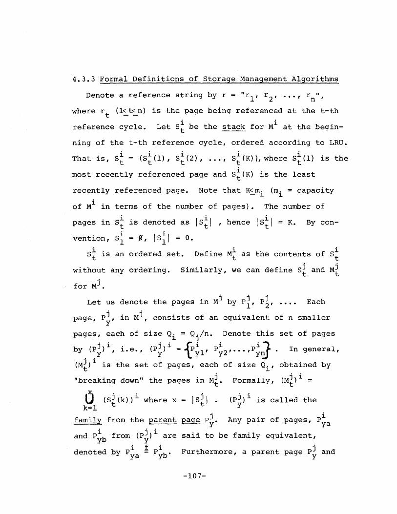
4.3.3 Formal Definitions of Storage Management Algorithms
Denote a reference string by r = "r1 , r2, ... , rni'
where rt (1<t<n) is the page being referenced at the t-th
reference cycle. Let S be the stack for M at the begin-
ning of the t-th reference cycle, ordered according to LRU.
That is, S= (S (1), S, (2), . S (K)), where S (1) is thet t t'I' t
most recently referenced page and S (K) is the least
recently referenced page. Note that K<m (m = capacity
of M1 in terms of the number of pages). The number of
pages in S is denoted as |S1 , hence IS{|j = K. By con-t
vention, SI = 0, S| 0.
St is an ordered set. Define M as the contents of S
without any ordering. Similarly, we can define SI and MIt t
for MO.
Let us denote the pages in Mi by P , P ,.... Each
page, P3, in M3, consists of an equivalent of n smallery
pages, each of size Q = Q /n. Denote this set of pages
by (P])1 , i.e., (PJ)1 = P ,P , In general,yy ~ y y2' y
(M3) is the set of pages, each of size Q., obtained byt
"breaking down" the pages in Mt. Formally, (M3)1 =t t
0 (Si(k))' where x = Is . (P) 1 is called the
1 yfamily from the parent page P . Any pair of pages, P
and Pyb from (P3) 1 are said to be family equivalent,
denoted by P P b. Furthermore, a parent page P andya y
-107-

a page P z (for l<z<n) from its family are said to beyz
corresponding pages, denoted by P = Pi.yz y
S and S are said to be in corresponding order, de-t t1 0 i
noted by St S , if St(k) S3(k) for k = 1, 2, 3, ...w,t t t
where w = min (IS{|, S |. ). Intuitively, two stacks are
in corresponding order if, for each element of the shorter
stack, there is a corresponding page in the other stack
at the same stack distance (the stack distance for page
S (k) is defined to be k).t
M and M are said to be correspondingly equivalent,t t
denoted by M t M if M M and for any k = 1, 2,
ii... ,l M |there exists x, such that S (k) 9 S (x) andt t t
S(x) S"(y) for all y / k. Intuitively, the two memo-
ries are correspondingly equivalent when each page in
one memory corresponds to exactly one page in the other
memory.
The reduced stack, S , of S is defined to be " (k)t t t
S for k = 1, ... , 5 | where jk is the minimum j
where kk-l = and 9(k) S (j for j<jIntuitively, K{ is obtained from S by collecting one
tt
page from each family existing in S , such that the page
being collected from each family is the page that has the
smallest stack distance within the family.
In the following, we define the storage management
algorithms. In each case, assume that the page referenced
-108-

at time t is Pya
LRU (S', P1 ) t= is defined as follows:---- t ya t+
Case 1: P S P = S (k):
S (x-1) , l< x<kSi (1) =tP ,S t .
t+l ya t+l i ), k<x<[t -t
Sit
Case 2: P / S :ya t
S 1 (l) = Pya S (X) = S (x-1),t+l ya t+l t
1 < x < min (m., |s + 1)- 1 t
If IS'I ='m then Pat 1 oa
LOCAL-LRU-SOP
= ( Cm.) is the over-t
flow, else there is no overflow.
(Si, S i P) (S S is definedt t ya~ t~ t+l idend
as follows:i i
Case 1: P e S :yat
S = LRU (S1 P1 )r S3t+l t ya t+1
= Sit
Case 2: P S, P3 6 S3:ya t y t
S =LRU (Si, P ), S3 =LRU (S , P3)t t ya t - t y
If there is no overflow from St
then St S ' and St S 't+l t' t+l t
If overflow from S' is the page Poat oa
then (S , S3 SOP (S i,, P3I P)t+1 t+1 - t' t' oa
defined as:
S += S,; if P0 S , then S t+ S
if P, g S, then S3o t t+l
= LRU (S3J PJ)- t' 0
-109-

Case 3:
LOCAL-LRU-DOP
P1/ Si and Pi / S :ya t y t
(handled as in Case 2)
(S,, P t I)=S+1 St1 is defined as
Case 1: P E S :ya t
S = LRU (S1, P ), S =St+l t ya t+l t
Case 2: P /S and P3 S3:ya t y t
S ,= LRU (S ,I P ), S , = LRU (S, P)tt ya' t' t y
If no overflow from S then Stt t+l
Siti
and St S 't+l t
If overflow from S is Pa thent oa
(S S ) = DOP (S , S3, P ) which ist+1' t+1 t' t oa
defined as:
S S and St+l t' t+l = LRU (SJ pJ)
- t' 0
Case 3: P S S and P] / S:ya t y t
(handled as in Case 2 above)
GLOBAL-LRU-SOP (S ,S), Pya +1' St is defined ast t ya tl t+l
follows:
S, = LRU (S' , p ) and S, LRU (S3, P ),t t ya t = t y
If no overflow from S 1 then SI =S't t~j ti
Stt+l
and
S 'i
If overflow from S is Pa then (S Si+1t oa t+l' t+l
=SOP (S ,ii S, Po)t t oa
-110-

GLOBAL-LRU-DOP (Sl, S , Py (S t+1' St ) is defined ast' t' ya tl t+l
S LRU (S P and S = LRU (S3, P3)t t ya t t y
If no overflow from S' then St S and St S't t~l t t+l t
If overflow from S is Po then (St+1, St+t. oa tl t+l
DOP (S ,,jS3,, P )-- t t oa
-111-

4.4 PROPERTIES OF DATA STORAGE HIERARCHY SYSTEMS
One of the properties of a Read-Through operation is
that it leaves a "shadow" of the referenced page (i.e.,
the corresponding pages) in all storage levels. This pro-
vides multiple redundancy for the page. Does this multiple
redundancy exist at all times? That is, if a page exists
in storage level M , will its corresponding pages always
be in all storage levels lower than M ? We refer to this
as the Multi-Level Inclusion (MLI) property. As illus-
trated in Figure 4.6 for the LOCAL-LRU algorithms and in
Figure 4.7 for the GLOBAL-LRU algorithms, it is not
always possible to guarantee that the MLI property holds.
For example, after the reference to P in Figure 4.6(a)31
the page P1 exists in M but its corresponding page P
is not found in M3 . In this chapter we shall derive the
necessary and sufficient conditions for the MLI property
to hold at all times.
Another desirable property of the data storage hierarchy
is to avoid generating references due to overflows. That
is, under what conditions will overflow pages from M
find their corresponding pages already existing in the
storage level M i+l? We refer to this as the Multi-Level
Overflow Inclusion (MLOI) property. We shall investigate
the conditions that make this property true at all times.
-112-

(a) LOCAL-LRU-SOP
(b) LOCAL- LRU-DOP
Figure 4.6 Violation of MLI by Local-LRU Algorithms
-113-

(a) GLOBAL-LRU-SOP
(b) GLOBAL-LRU-DOP
Figure 4.7 Violation of MLI by Global-LRU Algorithms
-114-

Referring to the basic model of a data storage hierarchy
in Figure 4.5, for high performance it is desirable to
minimize the number of references to Mr (the reservoir).
If we increased the number of pages in M , or in Mj, or
in both, we might expect the number of references to Mr
to decrease. As illustrated in Figure 4.8 for the LOCAL-
LRU-SOP algorithm, this is not always so, i.e., for the
same reference string, the number of references to the
reservoir actually increased from 4 to 5 after M is
increased by 1 page in size. We refer to this phenomena
as a Multi-Level Paging Anomaly (MLPA). One can easily
find situations where MLPA occurs for the other three
algorithms. Since occurrence of MLPA reduces performance
in spite of the costs of increasing memory sizes, we
would like to investigate the conditions to guarantee
that MLPA does not exist.
-115-

P2 I I I P31 1PHiP 41
P 221
P
p I
P1
P
I 1 I
I P'
overf low f rorn MI p2 1p3
reference to MZ P P Ip p
contentsof I(m =I2 P p i P
, I j I
reference to Mr
number of references to Mr 4
reference to M P11 P2I P
contents of M1 P1 1 i p 1
(mi =3 311 1
P I I 11 i
overflow from M' I I
reference to M p -
p1 1ppi I p p i Ipicontents of M 1 1 2 2 I 3 4
(m = 2) : P, .1P, P 1P ;p4 1 2 2 3
reference to Mr * '4)I
P21
p
p2
Pi4
I I '~t*,4)l* -*-p j j
number of references to M= 5
4.8 Illustration
-116-
of MLPAFigure

4.4.1 Summary of Properties
The MLI, MLOI, and MLPA properties of the data
storage hierarchy have been derived in the form of eight
theorems. These theorems are briefly explained and
summarized below and formally proven in the following
section.
Multi-Level Inclusion (MLI) : It is shown in Theorem
1 that if the number of pages in M is greater than the
number of pages in Mi (note Mi pages are larger than
those of M ), then it is not possible to guarantee MLI
for all reference strings at all times. It turns out
that using LOCAL-LRU-SOP, or LOCAL-LRU-DOP, no matter how
many pages are in Mi or M , one can always find a refer-
ence string that violates the MLI property (Theorem 2).
Using the GLOBAL-LRU algorithms, however, conditions to
guarantee MLI exist. For the GLOBAL-LRU-SOP algorithm, a
necessary and sufficient condition to guarantee that MLI
holds at all times for any reference string is that the
number of pages in M3 be greater than the number of pages
in M (Theorem 3). For the GLOBAL-LRU-DOP algorithm, a
necessary and sufficient condition to guarantee MLI is
that the number of pages in Mi be greater than or equal
to twice the number of pages in M (Theorem 4).
Multi-Level Overflow Inclusion (MLOI) : It is obvious
that if MLI cannot be guaranteed then MLOI cannot be
-117-

guaranteed. Thus, the LOCAL-LRU algorithms cannot guaran-
tee MLOI. For the GLOBAL-LRU-SOP algorithm, a necessary
and sufficient condition to guarantee MLOI is the same
condition as that to guarantee MLI (Theorem 5). For the
GLOBAL-LRU-DOP algorithm, a necessary and sufficient
condition to guarantee MLOI is that the number of pages
in Mi is strictly greater than twice the number of pages
in M (Theorem 6). Thus, for the GLOBAL-LRU-DOP algo-
rithm, guaranteeing that MLOI holds will also guarantee
that MLI will hold, but not vice versa.
Multi-Level Paging Anomaly (MLPA) : We have identified
and proved sufficiency conditions to avoid MLPA for the
GLOBAL-LRU algorithms. For the GLOBAL-LRU-SOP algorithm,
this condition is that the number of pages in MD must be
greater than the number of pages in M - before and after
any increase in the sizes of the levels (Theorem 7). For
the GLOBAL-LRU-DOP algorithm, this condition is that
the number of pages in Mi must be greater than twice the
number of pages in M before and after any increase in
the sizes of the levels (Theorem 8).
In summary, we have shown that for the LOCAL-LRU algo-
rithms, no choice of sizes for the storage levels can
guarantee that a lower storage level always contains all
the information in the higher storage levels. For the
-118-

GLOBAL-LRU algorithms, by choosing appropriate sizes for
the storage levels, we can (1) ensure that the above
inclusion property holds at all times for all reference
strings, (2) guarantee that no extra page references to
lower storage levels are generated as a result of handling
overflows, and (3) guarantee that increasing the sizes
of the storage levels does not increase the number of
references to lower storage levels. These results are
formally stated as the following eight Theorems. Formal
proofs of these Theorems are presented in the following
section.
-119-

THEOREM 1
Under LOCAL-LRU-SOP, or LOCAL-LRU-DOP, or GLOBAL-
LRU-SOP, or GLOBAL-LRU-DOP, for any m.>2, m.<m.J-1
implies 2rt, (M3) M
THEOREM 2
Under LOCAL-LRU-SOP, or LOCAL-LRU-DOP, for any
m >2, and any mi , r~t, (M3) M
THEOREM 3
Under GLOBAL-LRU-SOP, for any m.>2, r,t, (M3) 2
M iff m. > m.t 3 1
THEOREM 4
Under GLOBAL-LRU-DOP, for any m.>2,VVr,t, (M )'1- --ti
M iff m. > 2m.t J--
THEOREM 5
Under GLOBAL-LRU-SOP, for any m > 2,9 r,t, an over-
flow from M1 finds its corresponding page in M
iff m. > m.J 1
THEOREM 6
Under GLOBAL-LRU-DOP, for any m > 2, Vr,t, an
overflow from M finds its corresponding page in
mi iff m. > 2m.J 1
THEOREM 7
Let M (with m pages), Mi ( with m. pages) and Mrb A
be System A.
-120-

Let M'1 (with m.' pages), M'j (with m.' pages) and1 J
Mr be System B.
Let m' > m. and m.' > m.. Under GLOBAL-LRU-SOP,1 - ) - jfor any mi > 2, no MLPA can exist if
m. >m. and m.' > m.'
THEOREM 8
Let System A and System B be defined as in Theorem 7.
Let m.' > m. and m.' > m.. Under GLOBAL-LRU-DOP,i - i) -)J
for any mi > 2, no MLPA can exist if m. >
2m. and m.' > 2m.') 1
-121-

4.4.2 Derivation of Properties
THEOREM 1
Under LOCAL-LRU-SOP, or LOCAL-LRU-DOP, or GLOBAL-
LRU-SOP, or GLOBAL-LRU-DOP, for any m. > 2, m. < m.1 - J- i1
implies.3 r,t, (M] ) M
PROOF
Case 1 : m. < m.J lI
Consider the reference string r=" P la' 2aS2a'
(m.+1)aJ
Using any one of the algorithms, the following
stacks are obtained at t=m.+2 :J
S i= (Pi Pi P )t (m +l)a m.a''' 2a' la
JJ
S = (P3m ' .' ''' 3' 2JJ
Thus, P a M but P la ( ( 1 1 , i.e., (M3) M
Case 2: m. = m. =wJ 1
Consider the reference string r = " Pa' 2a
i "'(w+l)a
Using any one of the above algorithms, the following
stacks are obtained at t=w+2 :
S i= (P i P Pt (w+l)a' wa' 3a' 2a
S= (p] I~ pi60P3, p3)t 1 (w+)1 ' ' 3
Thus, P 1 E Mt but Pa (M) i.e., (M M2a t 2a t t - t
Q.E.D.
-122-

THEOREM 2
Under LOCAL-LRU-Sop, or LOCAL-LRU-DOP, for any
m. > 2, and any m.,3r,t, (Mi) 'Mi.t t
PROOF (For LOCAL-LRU-SOP)
For m.<m. the result follows directly from THEOREM 1.J- 1
For m.>m., using the reference stringJ 3-
r "Pi P , P , P , P i Pi ,za la za 2a' za m.a
J
the following stacks will be produced at t=2m.+lJ
S =(P P P P)t m ' za (m.-l)a' ' (m.-m.+2)a
J J J 1
S{ (P3 , P3 _,.. P3, PI)= .L m.-l' r 2' 1J J
Thus, P3 M 1 but P 1 (M3)1 i.e., (M3)1J:;M.za t za t t -to
Q.E.D.
PROOF (For LOCAL-LRU-DOP)
For mj.m. the result follows directly from THEOREM 1.
For m.>m., using the following reference stringJ l
r Pi I P , P , P i P , P i ,
za la za 2a za m.a
The following stacks will be produced at t=2m.+lJ
St m. a' za' ' (m.-m.+2)aJ ~J 3-
S3- (a1 , a 2 , ... , am.
Where for l<i<m., a ' P ... , P p , P4
JJ J-1since Pi is the only overflow from Mi.z
Thus, P C M but P / (M3), i.e., (M-)i*M tza t za t t t
Q.E.D.
-123-

THEOREM 3
Under GLOBAL-LRU-SOP, for any m. >2, V r, t, (M3)1 -1- t
M iff m.>m.t 3 1
PROOF
This proof has two parts. Part (a) to prove V r,t,
(M3)1 M 1=-> m '> mt -t J
or equivalently, m < m dr,t, (J- 1
Part (b) to prove m.>m. raVr,t, (M ) ''MJ a 't -t
PROOF of Part (a): m.< m. r,, (M)1 M1a- 1 t) t
This follows directly from THEOREM 1.
Q.E.D.
To Prove Part (b), we need the following results.
LEMMA 3.1
V r,t such that jM3| <m., if m. = m. + 1, thenJi 1ii -10 3
(a) (M ) M , and (b) St = St t'M t
PROOF of LEMMA 3.1
For t=2 (i.e., after the first reference), (a) and (b)
are true. Suppose (a) and (b) are true for t, such
that |M I< m.
Consider the next reference:
Case 1: It is a reference to M
There is no overflow from M or M,, so (a) is still
true. Since Global-LRU is used, (b) is still true.
-124-

Case 2: It is a reference to Mi:
There is no overflow from M3. If no overflow from
iM , the same arguement as Case 1 applies. If there is
overflow from M , the overflow page finds its corres-
ponding page in Mi. Since SOP is used, this overflow
can be treated as a "no-op". Thus (a) and (b) are
preserved.
Case 3: It is a reference to Mr
There is no overflow from M3 since IM +ll<m . Thus
the same reasoning as in Case 2 applies.
Q.E.D.
LEMMA 3.2
V r,t, such that IMt| = mi., if m.=m.+l thenJ J li
t ))fli
(a) (M3) .)=M, (b) S' S3, and (c) (SJ(m )) S=0
Let us denote the conditions (a) (b) and (c) jointly
as Z(t).
PROOF of LEMMA 3.2
Suppose the first time SI(m.) is filled is by thet J
t*-th reference. That is, S (m.) = 0 for all t<t*tJ
and S3(m.) Y # for all t>t*. From LEMMA 3.1 we knowt J
that (a) and (b) are true for all t<t*.
Let t =t* + 1, t2 = t* + 2, ... , etc. We shall show,
by induction on t, starting "at tl, that A(t) is true.
First we show that Z(t1 ) is true as follows:
-125-

Case 1: M e M
0 0 Si, and M3* e M1 -=)S3 (m.-l) c S (m.)t- t t = t t - t*i
As a result of the reference at t* (to Mr
St*1 = S(m.-l) and S 1*(m) overflows from M1.
This overflow page finds its corresponding apge in M.J
because there is no overflow from Mi and (a). Since
SOP is used, the overflow from M can be treated as
a "no-op". Furthermore, since Global-LRU is used,
(b) is true after the t*-th reference, (b) and
|S >|st*+1 I----(a) and (c). Thus Z (t1 ) is true.
Case 2:(M3*) . M 1 and M and M
(M )ir>M * and M Ml:1S]*(k) such that
(S, (k) )f M = 0 0 0 Si and (Sb*(k))if)M * = 0
k>|K!, | and (S{*(x)) M1 for all x where
m _1 > x >k. Thus (S3*(m _ )) ( S , = 0 (i.e., the last
page of S3 is not
S *(m ) overflows from M'. There is no overflow from
M3. Thus the overflow page from M finds its corres-
ponding page in M3. For the same reasons as in Case
1, (b) is still preserved. (b) and ISt*+1 t*+1I$
(a) and (c) are true. Thus, Z(t1 ) is true.
Assume that Z(tk) is true; to show that Z(t k+) is true,
we consider the next reference, at time tk+l:
-126-

Imagine that the last page of Sk does not exist,t k
i.e., S3t(mn) = (. If the reference at t is tot k jk+l '
a page in Mt or Mk then (a) and (b) still holdtk tkI
because Global-LRU is used and because overflow from
M finds its corresponding page in Mi (See the proof
of LEMMA 3.1).
If the reference at t is to a paqe not in M3k, thenk+l k
we can apply the agruement as that used in considering
the reference at time t above to show that Z(tk+1) is
still true.
Q.E.D.
LEMMA 3.3
V r,t, if m.=m.+l then (a) (M3) 2 M and (b) (S (mmj t -t t in
S= 0
PROOF of LEMMA 3.3
For t such that j<m(a) follows directly from
LEMMA 3.1 and (b) is true because S (m) =tJ
For t such that IM3I = m (a) and (b) follows directlyJ
from LEMMA 3.2
Q.E.D.
LEMMA 3.4
V r,t, if m.> m. than (a) (M) 1 M1 and (b)t (t
(S](in. )'lSl
-127-

PROOF of LEMMA 3.4
Let m. = i.+k. We shall prove this lemma by inductionJ 1
of k. For k=l (a) and (b) are true from LEMMA 3.3.
Suppose that (a) and (b) are true for k. Consider
m.=m.+(k+l). That is consider the effects ofJ 1
increasing Mi by 1 page in size:
Since M is unchanged, M3 (with m +k+1 pages) sees
the same reference string as Mi (with m.+k pages).
Applying the stack inclusion property (Mattson et al.,
1970), we have Mj(with m +k+1 pages)2 M (with m i+k pages).
Thus (a) is still true. Suppose (S3(m +k+))'lSli
then there is a page in M that corresponds to this
page. But Si (m +k+l) is not in M3 (with m.+k pages).t 1
This contradicts the property that (M,)',) M. Thist - te
showes that (b) is still true.
Q.E.D.
PROOF of Part (b); m >M ;4V r,t, (M ) mi:J 1 t -to
This follows directly from LEMMA 3.4.
Q.E.D.
-128-

THEOREM 4
Under GLOBAL-LRU-DOP, for any m,> 2, V r,t, (M3)-t
M iff m.>2m.t J- 1
PROOF
This proof has two parts:
Part (a): m .<2m. r,t, (M3).. M1J 1 t t
Part (b): m >2m.:: V r,t, (M-) M
PROOF of Part (a): m. < 2m. 3 r, t, (M3) 1 M1J 1 t
For m. <m. the result follows from THEOREM 1.J - 1
Consider the case for 2m. >m. >m.:1 J 1
The reference string r = "P , P(2 )ala 2a 3a' (m )
will produce the following stacks:
S = (PI P Pt (2m.)a' (2m.-1)a' '' (m,+1)a
S a, a2, a3, ... , a ) where a.'s are picked from
L and L2 alternatively, starting from L .
L= (P, P P3) and1 m (M1
L= (P PiI Pi2 2m. (2m. i-1) ' ' ''' m +1) .
1 11
If m is even, then (a , 3' am.-1) corresponds toJ
the frist m./2 elements of L and (a a, am)J
corresponds to the first m./2 elements in L . We seeJ2
that P(m.+1)a is in St but its corresponding page
is not in S (P is not in S3 since m /2 <m-).
If m is odd, then (a1, a3, am .) corresponds to the
first (m.+1)/2 elements in L and (a , 2 ,..., a m*-)
-129-

corresponds to the first (m.-l)/2 elements in L . WeJ2
see that the page P is in S but its correspond-(m.i+1)a ' t.1
ing page is not in S3 because max( (m.-1)/2) = m.-1,t i
thus, am 1 ) is at most the (M-1)-th element ofJ
L2 m -(m-1)+1 m+2.In both cases, (M ) M.
Q.E.D.
To prove Part (b), we need the following preliminary
results.
LEMMA 4.1
Under GLOBAL-LRU-DOP, for m. >2, m. >2m , a page
found at stack distance k in M implies its corres-
ponding page can be found within stack distance 2k in
M3.Mt
PROOF of LEMMA 4.1
We prove by induction on t.
At t=l, the statement is trivially true. At t=2I
(i.e., after the first reference) S (1) and itst
corresponding page are both at the beginning of the
stack, hence the induction statement is still true.
Suppose the induction statement is true at time t, i.e.,
P = S (k) 2? P can be found within stack distanceza t z
2k within S3.t
-130-
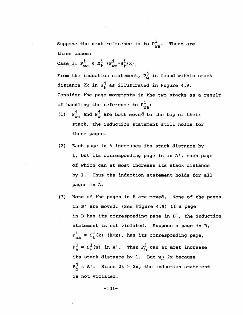
Suppose the next reference is to P . There arewa
three cases:
Case 1: P E M (P =S (x))wa t wa t
From the induction statement, Pi is found within stackw
distance 2k in S3 as illustrated in.Fugure 4.9.t
Consider the page movements in the two stacks as a result
of handling the reference to P :wa
(1) Pa and P3 are both moved to the top of theirwa wstack, the induction statement still holds for
these pages.
(2) Each page in A increases its stack distance by
1, but its corresponding page is in A', each page
of which can at most increase its stack distance
by 1. Thus the induction statement holds for all
pages in A.
(3) None of the pages in B are moved. None of the pages
in B' are moved. (See Figure 4.9) If a page
in B has its corresponding page in B', the induction
statement is not violated. Suppose a page in B,
Pa S (k) (k>x), has its corresponding page,
P= S (w) in A'. Then P3 can at most increaseb t b
its stack distance by 1. But w< 2x because
P e A'. Since 2k > 2x, the induction statementb
is not violated.
-131-

Stock distance X
MI wal
A B
Stack distance 2X
M w
A' B
Figure 4.9
-132-

Case 2: P ? M, P3 e M3wa t w t
Each page in M increases its stack distance by 1.
Each corresponding page in Mi can at most increase
its stack distance by 2, one due to the reference and
ione due to an overflow from M Hence if
Pa= S k, k <mi, then P a S (k+l), and Pi canza 't"' 3 za t+l Z
be found within stack distance 2(k+l) in Mi at time
t+l.
Case 3: P M, P IVMwa t w t
rAs a result of the read-through from M , each page
in M is increased by a stack distance of 1. That is,
i ii ifor k <mi., P = S (k) P = S t+ (k+1).
i za t za t+
Each page in Mi can at most increase its stack distance
by 2, one due to loading the referenced page and one due
to an overflow from M . Hence, the page Pi is foundz
within stack distance of 2k+2 in M3. Since max(2k+2) =
2m. <m., P3 is still in M3.z
Q.E.D.
COROLLARY to LEMMA 4.1
m.>2m. V r,t, (S3(m.)) S =#3 i t 3t
PROOF of COROLLARY
For any Pa in S1, its corresponding page can be
found within stack distance 2m in St and since
pages in S3 are unique, the information in the last
-133-

page of S is not found in St, i.e., (S (m )) S
PROOF of Part (b): m. > 2m. :p V r,t, (M3) ~ M3- 1 t - t
This follows directly from LEMMA 4.1.
Q.E.D.
-134-

THEOREM 5
Under GLOBAL-LRU-SOP, for any mi > 2, V r,t, an over-
flow from M finds its corresponding page in Mi iff
m. >m.] 3-
COROLLARY
Under GLOBAL-LRU-SOP, for any m. > 2, V r,t, an over-
flow from M finds its corresponding page in Mi iff
V r,t, (MI)'' M .t t
PROOF
This Proof has two parts as shown below.
PROOF of Part (a); m. >im. # V r,t, an overflow from M1J 1
finds its corresponding page in Mi
From LEMMA 3.4 m.> m = V r,t, (MI)' M andI i t - t
(S3(m ))'(lS? = M. Suppose the overflow from Mi,
P is caused by a reference to Mi. Then just beforeoa
P ois overflowed, P 0 exists in M . After the over-
oaflow, Po finds its corresponding page still existing
in Mi . Suppose the overflow, P , is caused by a
reference to Mr. Then just before the overflow from
M ,P exists in Mi and (S(m.))1 fl S=0 t t
the information in the last page of M3 is not M
This means that the last page of M3 is not P* , thus,
the overflow page P finds its corresponding pageoa
still in Mi after an overflow from Mi occurs.
-135-

PROOF of Part (b): m <m. -a r,t, such that an overflow
from N' does not find its corresponding page in Mj.
From THEOREM 1, m <m : r,t, (M3)'$ M 1 , then thereJ- 1t t
exists P a M and P /M3. We can find a referenceza t z
string such that at the time of the overflow of
Pa from M , P3 is still not in M3. A string ofza z
references to Mr will produce this condition. Then
at the time of overflow of P' , it will not find itsza
corresponding page in M.
Q.E.D.
-136-

THEOREM 6
Under GLOBAL-LRU-DOP, for m >2, V r,t, an overflow
from M finds its corresponding page in Mi iff m. >2m
COROLLARY
Under GLOBAL-LRU-DOP, for m. >2, V r,t, an overflow
from M finds its corresponding page in Mi implies
that V r,t, (M3)1'; M .t -to
PROOF
This proof has two parts as shown below.
PROOF of Part (a): m. >2m. da V r,t, an overflow from M1J 1
finds its corresponding page in M.
THEOREM 4 ensures that m. > 2m. =V r,t, (MI )? Mi
and LEMMA 4.1 ensures that (S (m W)) n S= we then
use the same argument as in Part (a) of THEOREM 5.
PROOF of Part (b): m. <2m.=y93 r,t, such that an overflowJ- 1
from M does not find its corresponding page in Mi.
Case 1: ml. <2m.J 1
m. <2m P' ;r,t, (MI) M1 (from the proof of part (a) ofJ 1 o t t
THEOREM 4). We then use the same argument as in Part
(b) of THEOREM 5.
Case 2: m. = 2m.J I
The reference string r = "Pla' P ' Pla 2a' (2m j a
P " will produce the following stacks(2m. +-)1a
-137-

(at t=2m.+1):
S =(P P P)t (2m.)a ' (2m.-1)a' (m.+1)a
S= (P P P P . a Pt m. 2m.' M.-l 2m.-l ''' l' m+11 1 1 1
In handling the next reference, to page P(2m.+1)a'
the pages P and PD overflow at the same(m.+1)a m.+11 1.
time, hence the overflow page P from M(m i. +1)a
does not find its corresponding page in M3.
Q.E.D.
-138-

THEOREM 7
Let M (with m. pages), Mi (with m. pages) and Mr1 J
be System A. Let M' (with m.' pages), M' (with
m.' pages)and Mr be System B. Let m.' >m. andI - I
m' > m.. Under GLOBAL-LRU-SOP, for any m >2, no
MLPA can exist if m. >m. and m.' >m.'.J li J -1
PROOF
We shall show that V r,t, (M U(M) 1 )C (M' U (M' ) )t tt t
This will ensure that no MLPA can exist.
Since m ' >m and LRU is used in M and M' , we can
apply the LRU stack inclusion property to obtain
M1 CM'.t- t
From THEOREM 5, we know that overflows from M or
from M' always find their corresponding pages in
Mj and M' respectively. Since SOP is used, these
overflows can be treated as "no-ops". Thus, Mi
and M' see the same reference string and we can
apply the LRU stack inclusion property to obtain
M3 C M'3 (since m.' >m. and LRU is used).t- t J- J
M C M' and M C M' >(M1 \ (M3) 1) (MI' I (M')1).t - t t L ) QED
Q.E.D.
-139-

THEOREM 8
Let System A and System B be defined as in THEOREM 7.
Let m' > m. and m.' > m.. Under GLOBAL-LRU-DOP, for
any m. > 2, no MLPA can exist if m. > 2mi and m.'>2mi.'.J 1 J 1
PROOF
We need the following preliminary results for this proof.
LEMMA 8.1
Let St be partitioned into two disjoint stacks, Wt andt
Vt defined as follows: W (k) = S(( for k=1,...,|Wtt t ,k tIwhere j0=O, and jk is the minimum jk>3k-1 such that3 1, i cj
P E S and P = (j)'
Vt(k) = S( for k=l, ... , |Vtj where j0=0, and
is the minimum jk > jk-l such that S , P za
S((jk). (Intuitively, Wt is the stack obtained from
S( by collecting those pages that have their corres-t
ponding pages in Mt such that the order of these pages
in S3 is preserved. V is what is left of S] aftert t t
W is formed.) Then, r,t, (a) W = I and
(b) Vt Ot where Ot is the set of pages corresponding
to all the pages that ever overflowed from M , up to
time t.
PROOF of LEMMA 8.1
From THEOREM 4, m > 2m. r,t, -(M3)1 M1. Thus,
for each page in M , its corresponding page is in M .
-140-

This set of pages in Mt is exactly Wt, and Wt S by
definition. Since the conditions for Vt and Wt are
mutually exclusive and collectively exhaustive, the
other pages in MI that are not in W are by definitiont
in Vt. Since a page in Vt does not have a correspon-
ding page in M , its corresponding page must have once
ibeen in M because of Read-Through, and later over-
flowed from M1 . Thus a page in Vt is a page in Ot'
Q.E.D.
-141-

LEMMA 8.2
Any overflow page from M3 is a page in Vt t
PROOF of LEMMA 8.2
From THEOREM 4, m > 2m r,t, (M )' 2 Mi t i
From THEOREM 6, m > 2m r,t, an overflow from M
always finds its corresponding page in Mi
An overflow from Mt is caused by a reference to Mr. An
overflow from M also implies that there is an overflowt
from Mt.
Suppose the overflow page from M3 is Pi. Also supposet 0
P3 W, i.e., P3 W ' V ' We shall show that this leads
to a contradiction.
The overflow page from M' is either P or P (yfo).t oa ya
If P o P is overflowed from M1, THEOREM 6 is vio-
lated since Po and P3 overflow at the same time sooa 0
P will not find its corresponding page in M3.
If Py P3 is overflowed from M1, THEOREM 4 is vio-
lated since after the overflow handling, there exists
a page Pob P in M1 (since P E Wt) but P is no
longer in M .
Q.E.D.
LEMMA 8.3
If there is no overflow from either MI or M'3 then
r,t, Vt and V' have the same reverse ordering.
Two stacks S and Si are in the same reverse ordering,
-142-

S ro Si, if rS (k) = rSj(k) for l<k<min (151 | Is i),
where rS denotes the stack obtained from S by rever-
sing its ordering. By convention, S ro Si if S'=0
or Si = 1
PROOF of LEMMA 8.3
To facilitate the proof, we introduce the following
definitions:
(1) The ordered parent stack, (S )j, of the stack
S is the stack of parent pages corresponding to,
and in the same ordering as, the pages in the
reduced stack, , of Si. Formally, (S1)) e
and (S ')j o
(2) Define a new binary operator, concatenation (||),
between two stacks, S and S2, to produce a new
stack, S, as follows:
S = S | where S(k)= S (k) for k=l, 2,...,ISlI
S2(k) for k=jS 1+1,...,
(|Sk L + Is 2)
(3) Define a new binary operator, ordered difference
(o), between a stack S1 and a set T, to produce
a new stack, S, as follows:
S = S o T, where S(k)=S (jk) for k=1,2,...,
(|1 - |S T )(IS i 1 j k ss'uTsuch that j0 =01 jk is the minimum j k>j k-l such
-143-

that Si (jk)A T = 0. Intuitively, S is obtained
from S by taking away those elements of S1 which
are also in T.
Figure 4.10 illustrates the LRU ordering of all Level i
pages ever referenced up to time t. Since there is no
overflow from either Mi of M' , the length of this
LRU stack is less than or equal to min(m., mi')J J)
By the definition of V, VL = (Yt 2 -
But (S' )J = (S1)1 | ( Xt o (S') )t t t - t
hence V= (Yt - (S) j( (X ) o (S'),))=_ (Yt - t
Similarly, by the definition of Vt t = (Zt -
But (Zt)j = (X t 2 (xt
Hence Vt M (X) 30(SI) 3) my )(( 30 (xl3) o (S'),)Hec t=((t - t t -
M (X)Jo(S1) J) j((Y )J0 ( (SI))V(xt)3))= (( t t - t
Xt -
Thus, the two stacks are in the same reverse ordering.
Q.E.D.
-144-

StMostrecently
referencedXt Y t Least recently
referenced
S t
Figure 4.10
-145-
z t

LEMMA 8.4
r,t, (a) M' E!Mj, (b) Vt and V are either in the
same reverse ordering or the last element of Vi is
not an element of Vt
PROOF of LEMMA 8.4
(a) and (b) are true for any time before there is
any overflow from either Mi or M'3. (a) is true
because any page ever referenced is in Level j, so
a page found in Mi is also found in M'U. (b) is
true because of the result from LEMMA 8.3.
Assume that (a) and (b) is true for t. Consider
the next reference at t+l. Suppose this reference
does not produce any overflow from either Mi or M'3
then (a) still holds because M'3 MI and M' Mt- t t -t
(See THEOREM 7). (b) still holds because overflows
from Mi and M'j are taken from the end of stacks
Vt and V3 respectively, and since there is no over-
flow from Level j, (b)'s validity is not disturbed.
Suppose this reference does produce overflow(s)
from Level j.
Case 1 : overflow from M'j, no overflow from M:
This cannot happen since overflow from M'j implies
reference to Mr which in turn implies overflow
from Mi also.
-146-

Case 2 : overflow from Mi, no overflow from M'S :
* Suppose the last element in V' is not an element
of Vt. Then starting from the end of V, if we
eliminate those elements not in Vt, the two
stacks will be in the same reverse ordering.
This follows from LEMMA 8.3 and is illustrated
in Figure 4.11. Thus we see that overflow from
MI, i.e., overflowing the last page of Vt, will
not violate (a) since this page is still in V3 .
(b) is still preserved since the last page in
V1 is still not in Vt.
* Suppose V' and V t are in the same reverse order-
ing. Then overflowing the last page of V t does
not violate (a) and results in.-the last page of
VI not in Vt.t
Case 3 : overflow from Mi and overflow from M':
" Suppose the last element in V3 is not in Vt.tt
Referring to Figure 4.11 in Case 2, we see the
result of overflowing the last element of V' and
the last element of Vt does not violate (a) and
still preserves the condition that the last
element of V is not in Vt
" Suppose V3 and V t are in the same reverse order-
ing. Then overflowing the last elements of V3
-147-

IZZIK
LIZIL
X8 X9 X7 X6 X5 X4 X3 X2 Xii
X X8 X9 X7 X6 X5 X4 X3 X2 XI
Figure 4.11
-148-
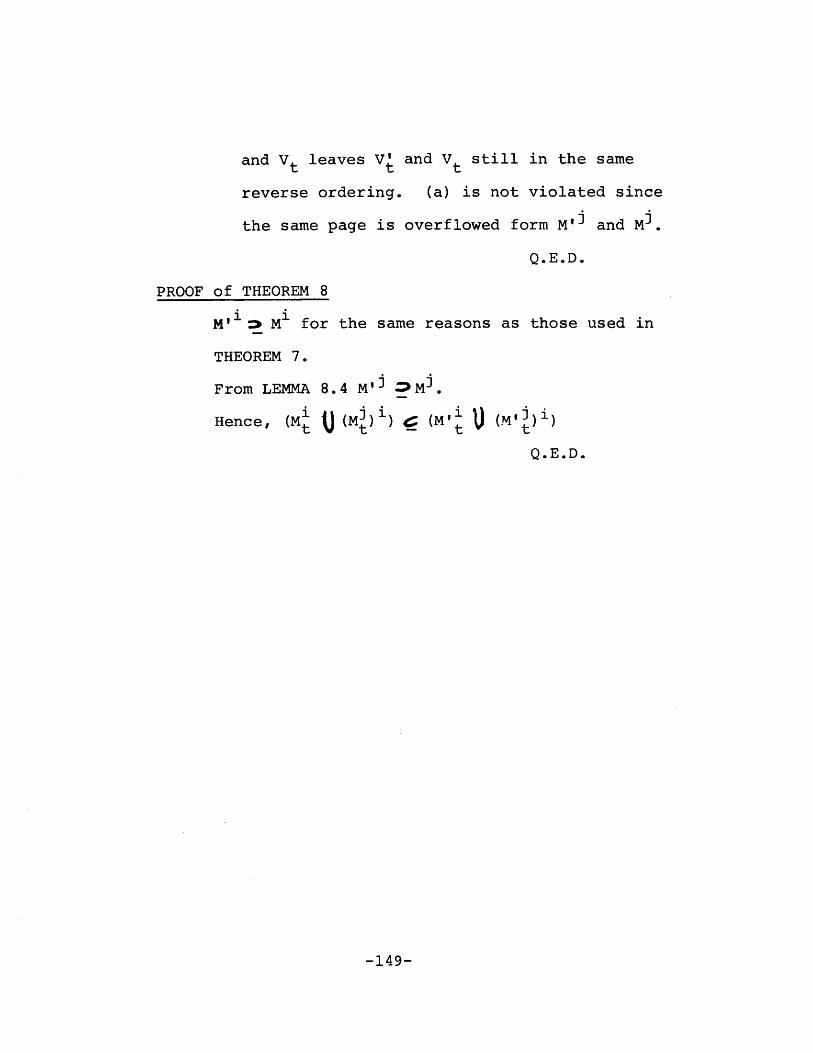
and Vt leaves V1 and Vt still in the same
reverse ordering. (a) is not violated since
the same page is overflowed form M'j and Mi.
Q.E.D.
PROOF of THEOREM 8
M"'1: M1 for the same reasons as those used in
THEOREM 7.
From LEMMA 8.4 M'j Mi.
Hence, (Mi 0 (MI) 1 )C (M' J (M'9)Q.E.D.
-149-

4.5 SUMMARY
We have developed a formal model of a data storage hier-
archy system specifically designed for very large databases.
This data storage hierarchy makes use of different page
sizes across different storage levels and maintains multiple
copies of the same information in different storage levels
of the hierarchy.
Four classes of algorithms obtained from natural exten-
sions to the LRU algorithm are formally defined and studied
in detail. Key properties of data storage hierarchy systems
that make use of these algorithms are identified and for-
mally proved.
It is found that for the LOCAL-LRU algorithms, no choice
of sizes for the storage levels can guarantee that a lower
storage level always contains all the information in the
higher storage levels. For the GLOBAL-LRU algorithms, by
choosing appropriate sizes for the storage levels, we can
(1) ensure the above multi-level inclusion property to hold
at all times for any reference string, (2) guarantee that no
extra page references to lower storage levels are generated
as a result of handling overflows, and (3) guarantee that no
multi-level paging anomaly can exist.
- 150 -

Chapter V
DESIGN OF THE DSH-ll DATA STORAGE HIERARCHY SYSTEM
5.1 INTRODUCTION
In chapter 3, DSH-1, a general structure of the INFOPLEX
data storage hierarchy system is introduced. DSH-1 incorpo-
rates novel features to enhance its reliability and perfor-
mance. Many alternative architectures of data storage hie-
rarchies can be derived from DSH-l. These structures can be
used to perform detail studies of various design issues con-
cerning data storage hierarchies.
This chapter describes a simple structure of the INFOPLEX
data storage hierarchy derived from DSH-l. This structure
is called DSH-ll and is used to develop detail protocols for
supporting the read and write operations. Multi-level
inclusion properties of DSH-ll are then discussed.
5.2 STRUCTURE OF DSH-ll
The general structure of DSH-ll is illustrated in Figure
5.1. There are h storage levels in DSH-ll, denoted by L(l),
L(2), ... , L(h). L(l) is the highest performance storage
level. L(l) consists of k memory ports. Each memory port
- 151 -

LIIImF- - --- --- -- I
cache
control er
I cacheI _____ L(1)
SLC
L(2) -
SLCSM
lobal bus -
L(h)
SLC 1 S
Figure 5.1 Structure of DSH-11
-152-
-KI

is connected to a processor. All k memory ports share the
same local bus. A storage level controller (SLC) couples
the local bus to the global bus. The global bus connects
all the storage levels.
All other storage levels have the same basic structure.
In each storage level, there is an SLC which couples the
local bus to the global bus. There is a memory request pro-
cessor (MRP) that handles requests to the storage level.
There are a number of storage device modules (SDM's) that
store the data within the storage level. The SLC, MRP, and
SDM's share the same local bus.
The number of SDM's in different storage levels may be
different. The type of storage device in the SDM's in dif-
ferent storage levels are different. For high efficiency,
the block sizes of different storage levels are different.
L(l) has a block size of q(l), L(2) has a block size of
q(2)=n(l)*q(l), and so on, where n(l), n(2), ... , n(h-1) are
non-zero integers.
5.2.1 The DSH-ll Interface
From the point of view of a processor connected to a
DSH-ll memory port, DSH-ll appears as a very large virtual
memory with 2**V bytes. The entire virtual address space is
byte addressable. The instructions for a processor are
- 153 -

stored in a local memory outside of DSH-ll. This local
memory has an address space of 2**G bytes. Hence, the
effective data address space is (2**V-2**G) bytes.
All operations on data within DSH-ll are performed in
L(l). Thus, if a referenced data item is not in L(l), it
has to be brought into L(l) from a lower storage level.
This induces a delay on the instruction comparable to a page
fault in virtual memory systems. Each processor has multi-
ple register sets to support efficient multiprogramming.
The key registers for interfacing with DSH-ll are the memory
operation register (MOR), the memory address register (MAR),
the memory buffer register (MBR), the operation status
register (OSR), and the process identification register
(PIR). The MAR is V bits wide and the MBR is n bytes wide,
where n is less than q(l), the block size of L(l).
A read operation requests n bytes of data at location
pointed to by MAR to be brought into the MBR. A write oper-
ation requests the n bytes of data in the MBR be written to
the location pointed to by the MAR. We shall assume that
the n bytes of data in a memory reference do not cross a
L(l) block boundary (If a data item crosses block boundar-
ies, multiple requests will be used so that each request
only reference data within block boundaries).
- 154 -

A read or write operation may proceed at the speed of the
L(l) devices when the referenced data is found in L(l).
Otherwise, the operation is interrupted and the processor
switches to another process while DSH-ll moves the refer-
enced data into L(l) from a lower storage level. When the
data is copied into L(l), the processor is again interrupted
to complete the operation.
5.2.2 The Highest Performance Storage Level - L(l)
As illustrated in Figure 5.1, L(l) consists of k memory
ports. Each memory port consists of a data cache controller
(DCC) and a data cache duplex (DCD). A DCC communicates
with the processor connecting to the memory port. A DCC
also maintains a directory of all data in the DCD. All k
memory ports share a local bus. The SLC serves as a gateway
for communication between L(l) and other storage levels.
5.2.3 A Typical Storage Level - L(i)
A typical storage level, L(l), consists of a number of
SDM's, an MRP, and an SLC. An SLC serves as the gateway for
communication among storage levels. The MRP services
requests to L(i). An SDM performs the actual reading and
writing of data. An SDM consists of a device controller and
the actual storage device.
- 155 -

To gain high throughput, communications over the global
bus is in standard size packets. The packet size is such
that it is sufficient for sending one L(l) data block. Com-
munications over a local bus at L(i) is also in standard
size packets. The size of a packet depends on the storage
level and is chosen so that a packet is sufficient to send a
data block of size q(i).
In the following sections, the read and write operations
are discussed in detail.
5.3 ALGORITHMS FOR SUPPORTING THE READ OPERATION
5.3.1 The Read-Through Operation
A read request is issued by a processor to its data cache
controller. The data cache controller checks its directory
to see if the requested data is in the data cache. If the
data is found in the data cache, it is retrieved and
returned to the processor. If the data is not in the data
cache, a read-through request is queued to be sent to the
next lower storage level, L(2), via the storage level con-
troller.
At a storage level, a read-through request is handled by
the memory request processor. The memory request processor
checks its directory to determine if the requested data is
in one of the storage device modules at that level. If the
data is not in the storage level, the read-through request
- 156 -

is queued to be sent to the next lower storage level via the
storage level controller.
If the data is found in a storage level, L(i), a block
containing the data is retrieved by the appropriate storage
device module and passed to the storage level controller.
The storage level controller broadcasts the block to all
upper storage levels in several standard size packets. Each
upper storage level has a buffer to receive these packets.
A storage level only collect those packets that assemble
into a sub-block of the appropriate size that contains the
requested data. This sub-block is then stored in a storage
device module.
At L(l), the sub-block containing the requested data is
stored, and the requested data is sent to the processor with
the proper identification.
Figure 5.2 illustrates the read-through operation.
Assume that DSH-ll has only three storage levels, L(l) with
block size b, L(2) with block size 2b, and L(3) with block
size 4b. Suppose a reference to a data item 'x' is found in
a block in L(3). Then the sub-block of size 2b containing
'x' is broadcasted to L(2) and L(l) simultaneously. L(2)
will accept and store the entire sub-block of size 2b. L(l)
will only accept and store a block of size b that contains
- 157 -

''I,,,,',
Figure 5.2 Illustration of Read Through
-158-
; I P '

'xI. The two sub-blocks, each of size 2b of a parent block
in L(3) are referred to as the child blocks of the parent
block.
5.3.2 Overflow Handling
To accomodate a new data block coming into a storage
level as a result of a read-through, an existing data block
may have to be evicted. The block chosen for eviction is
that which is the least recently referenced block such that
none of its child blocks is in the immediate upper storage
level. To support this scheme, each block is associated
with an Upper Storage Copy Code (USC-code). If any of the
child blocks of a data block is in the immediate upper sto-
rage level, its USC-code is set. Each time the last child
block in L(i) of a parent block in L(i+l) is evicted from
L(i), an overflow request is sent to L(i+l) to reset the
USC-code of the parent block.
Blocks in L(l) and L(2) are handled slightly differently
due to the use of data caches in L(l). Since multiple
copies of the same data block may be in different data
caches, evicting a block does not necessarily guarantee no
other copy exists in L(l). The following strategy is
adopted to overcome this difficulty. During a read-through,
the USC-code of the block in L(2) is incremented by 1. Each
- 159 -

time a block in L(l) is evicted, an overflow request is sent
to L(2) to decrement the USC-code of theicorresponding par-
ent block. This strategy does not require communications
among different data caches.
5.3.3 Pathological Cases of Read-Through
The parallel and asynchronous operations of DSH-ll and
the use of buffers at each storage level complicates algor-
ithms for handling the read operation. Pathological cases
that affect the algorithms are discussed below.
5.3.3.1 Racing Requests
Two different requests Rl and R2 may reference the same
block of data. Furthermore, these two requests may be
closed to each other such that both may be reading-through
the same block of data at some storage level. Since a data
block is transmitted in several packets asynchronously, each
packet must be appropriately identified to avoid confusion
when assembling the data sub-blocks at higher storage lev-
els.
A similar situation arises when Rl and R2 are closed
together such that R2 begins to read-through the same data
block that has just been read-through by R1. Thus a data
block arriving at a storage level may find that a copy of it
- 160 -

already exists at that storage level. In this case, the
incoming data block is ignored. At L(l), this data block is
ignored and the one in the data cache is read and returned
to the processor, since this is the most recent copy of the
data block.
5.3.3.2 Erronous Overflow
When a data block is evicted from L(i) to make room for
an incoming data block, an overflow request containing the
virtual address of the evicted data block may be generated.
The purpose of the overflow request is to inform L(i+l) that
there is no longer any data block in L(i) with the same
family address as the virtual address in the overflow
request. Hence, an overflow request is generated only when
the last member of a family in L(i) is evicted.
The overflow request has to be forwarded to the MRP at
L(i+l). At any point on the way to the MRP, a data block in
the same family as the evicted block may be read-through
into L(i). This poses the danger that when the MRP receives
the overflow request indicating that no data block in the
same family as the evicted block exists in L(i), there is
actually one such block being placed in L(i).
The following strategy is incorporated in the algorithms
that support the read-through operation to avoid such a
potential hazard,
- 161 -

1. At the time the overflow request is to be createdin L(i), a check is made to see if there is anydata block in the same family as the evicted blockthat is currently in any buffer of L(i) waiting tobe placed in L(i). If so, the overflow request isnot created.
2. At the time a new data block arrives in L(i), anyoverflow request with the same family address asthe incoming data block waiting to be sent toL(i+l) is purged.
3. When an overflow request arrives at L(i+l) fromL(i), a check is made to see if there is any datablock waiting to be sent to L(i) that has the samefamily address as the overflow request. If so,the overflow request is purged.
4. At the time a request is generated to send a datablock to L(i), any overflow request from L(i) thatis still waiting in L(i+l) that has the samefamily address as the data block to be sent toL(i) is purged.
5.3.3.3 Overflow to a Partially-assembled Block
Suppose that as a result of a read-through from L(i+2),
B(i), the only child block of B(i+l), is in L(i) and B(i+l)
is partly assembled in the buffer in L(i+l). It is possible
that B(i+l) is still partly assembled in L(i+l) when B(i) is
evicted from L(i). The overflow request will find that the
corresponding parent data block is still being assembled in
L(i+l). A solution to this difficulty is to check, at the
time of arrival of the overflow request, if there is any
incoming data block which is the target parent block of the
evicted block as indicated in the overflow request. If so,
the overflow request is held till this parent block has been
placed in a storage device.
- 162 -
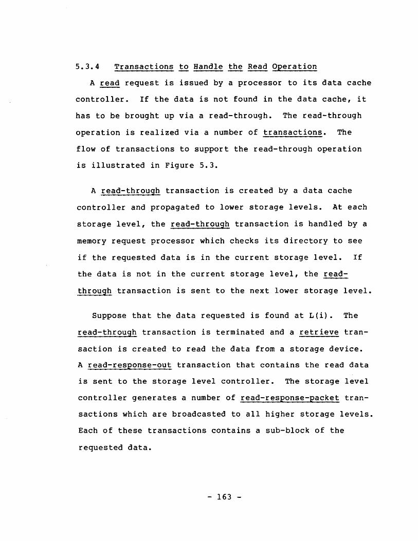
5.3.4 Transactions to Handle the Read Operation
A read request is issued by a processor to its data cache
controller. If the data is not found in the data cache, it
has to be brought up via a read-through. The read-through
operation is realized via a number of transactions. The
flow of transactions to support the read-through operation
is illustrated in Figure 5.3.
A read-through transaction is created by a data cache
controller and propagated to lower storage levels. At each
storage level, the read-through transaction is handled by a
memory request processor which checks its directory to see
if the requested data is in the current storage level. If
the data is not in the current storage level, the read-
through transaction is sent to the next lower storage level.
Suppose that the data requested is found at L(i). The
read-through transaction is terminated and a retrieve tran-
saction is created to read the data from a storage device.
A read-response-out transaction that contains the read data
is sent to the storage level controller. The storage level
controller generates a number of read-response-packet tran-
sactions which are broadcasted to all higher storage levels.
Each of these transactions contains a sub-block of the
requested data.
- 163 -

read
read-throug
(4 )
read-response-in
store
overflow
read-response-packet
Hread-resp ut'
Figure 5.3 Transactions to SupportRead Through
-164-

At each higher storage level, an appropriate number of
read-response-packet transactions are assembled into a
read-response-in transaction which contains a data block of
the appropriate size. The memory request processor obtains
free space for the new data block in the read-response-in
transaction either by using existing free space or by evict-
ing an existing block. Eviction of an existing data block
may result in an overflow transaction being sent to the next
lower storage level. At the memory request processor, the
read-response-in transaction is serviced and a store tran-
saction is created. A storage device module handles the
store transaction by writing the data to a storage device.
The following subsections describe the algorithms for
handling each of the above transactions.
5.3.4.1 The read-through Transaction
The read-through transaction is created by a data cache
controller and propagated down the storage levels via the
storage level controllers. It has the following format:
( read-through, virtual-address, process-id),
where virtual-address is the virtual address of the refer-
enced data item, and process-id consists of a CPU identifier
and a process number. It is the identifier of the process
that generated the read operation. The transaction is han-
- 165 -

dled by a memory request processor using the following
algorithm.
1. Search directory for read-through.virtual-address.
2. If not found, forward the transaction to the sto-rage level controller, which will send it to thenext lower storage level.
3. If found, suppose it is in the i-th directoryentry, and suppose directory(i).TRANSIT-code isnot set, do:
i) Set directory(i).USC-code to indicate achild block exists in the higher storagelevel for this block. If this is levelL(2), increment directory(i).USC-codeinstead of setting it.
ii) Set directory(i).HOLD-code to forbid anyoverflow to this block while the data isbeing retrieved.
iii) Create a retrieve transaction :( retrieve,virtual-address,directory(i).real-address,p-rocess-id).
iv) Send the retrieve transaction to the appro-priate storage device module.
4. If found, suppose it is in the i-th directoryentry, and suppose directory(i).TRANSIT-code isset, then hold the request and retry later. Whenthe TRANSIT-code is set, it indicates that thecorresponding data block is in transit, hence anyreference to it is not allowed.
5. End.
5.3.4.2 The retrieve Transaction
The retrieve transaction is created by a memory request
processor and handled by a storage device module as follows.
- 166 -

1. Read the data block using retrieve.real-address.
2. Create a read-response-out transaction :( read-response-out, virtual-address, process-id, data),where data is the block containing the referenceddata item.
3. Send the read-response-out transaction to the sto-rage level controller.
4. End.
5.3.4.3 The read-response-out Transaction
The read-response-out transaction is created by a storage
device module and handled by a storage level controller
using the following algorithm.
1. Purge any incoming overflow transaction that hasthe same family address as read-response-out.virtual-address.
2. Send ( update-directory, virtual-address,HOLD-code=0) to memory request processor to reset theHOLD-code, so that overflow to this block is nowallowed.
3. Broadcast the transaction ( reserve-space, virtu-al-address, process-id) to all higher storage lev-els to reserve buffer space for assemblingread-response-out.data.
4. Wait till all higer levels have acknowleged thespace reservation transaction.
5. Generate the appropriate number of ( read-res-ponse-packet, virtual-address, process-id, data,data-virtual-address) transactions. Data is astandard size sub-block and data-virtual-addressis the virtual address of this sub-block.
6. Broadcast each read-response-packet transaction toall higher storage levels.
7. End.
- 167 -

5.3.4.4 The read-response-packet Transaction
This transaction is created by a storage level controller
and broadcasted to all higher storage level controllers
where they are assembled into read-response-in transactions
to be handled by the memory request processors. Note that a
storage level only accepts those packets relevant for assem-
bling into a data block of the appropriate size, all other
associated packets are ignored. The following algorithm is
used by a storage level controller in assembling the
read-response-in transactions.
1. If this is the first packet of the assembly, do:
i) Purge any outgoing overflow transaction thathas the same family address as the blockbeing assembled.
ii) Add the packet to the assembly.
2. If this is an intermediary packet of the assembly,simply add it to the assembly.
3. If this is the last packet of the assembly, do:
i) Replace the assembly by a ( read-response-in, virtual-address, process-id, data) tran-saction. Data is the block just assembled.
ii) Send the above transaction to the memoryrequest processor.
4. End.
- 168 -

5.3.4.5 The read-response-in Transaction
This transaction is created by a storage level controller
and sent to a data cache controller (for L(l)) or to a
memory request processor (for L(2), L(3), ... ).
The following algorithm is used by a data cache control-
ler in handling this transaction.
1. Purge any outgoing overflow transaction that hasthe same family address as the block in the read-response-in transaction.
2. Search directory for read-response-in.virtual-address.
3. If found, suppose it is the i-th directory entry,do:
i) Read data from the data cache using direc-tory(i) .real-address.
ii) Send data to the processor.
iii) Increment directory(i).USC-code by 1.
4. If not found, do:
i) Select a block to be evicted (assuming thatdata cache is full). This is the leastrecently referenced block such that it isnot engaged in a stored-behind process.Suppose this block corresponds to direc-tory(i).
ii) Obtain directory(i).virtual-address, direc-tory(i).USC-code, and directory(i).real-address.
iii) Write read-response-in.data into locationdirectory(i).real-address in the data cache.
iv) Return read-response-in.data to the proces-sor.
- 169 -

v) Create ( overflow, directory(i).virtual-address, USC-code=directory(i).USC-code)transaction, send it to the storage levelcontroller.
vi) Update directory(i).virtual-address withread-response-in.virtual-address.
vii) Set directory(i).USC-code to 1.
5. End.
At a memory request processor, the read-response-in tran-
saction is handled as follows.
1. Purge any outgoing overflow transaction with thesame family address as the data block in theread-response-in transaction.
2. Search for read-response-in.virtual-address in thedirectory.
3. If not found, do:
i) Select a block to be evicted (assuming thatthe storage level is full). This is theleast recently referenced block such that itis not engaged in a store-behind process, itis not held (i.e., HOLD-code = 0), and it isnot in transit (i.e., TRANSIT-code = 0).Suppose this block corresponds to direc-tory(i).
ii) Obtain directory(i).virtual-address anddirectory(i).real-address.
iii) If the evicted block is the last of itsfamily in the storage level and that thereis no incoming block with the same familyaddress then create a ( overflow, direc-tory(i).virtual-address, USC-code=l) tran-saction. Send the transaction to the sto-rage level controller to be sent to the nextlower storage level.
iv) Set directory(i).TRANSIT-code to 1 to indi-cate the corresponding block is in transit.
- 170 -

v) Update directory(i).virtual-address withread-response-in.virtual-address.
vi) Set directory(i).USC-code to 1.
vii) Create a ( store, directory(i).real-address,data) transaction and send it to the appro-priate storage device module.
4. End.
5.3.4.6 The store Transaction
This transaction is handled by a SDM. Store.data is
placed in store.location, and a transaction ( update-direc-
tory, virtual-address, TRANSIT-code = 0) is sent to the MRP
to reset the TRANSIT-code so that references to this block
is now allowed.
5.3.4.7 The overflow Transaction
This transaction is created by a data cache controller or
a memory request processor and routed to a memory request
processor in the lower storage level via the storage level
controllers. At each stop on the way to a memory request
processor, a check is made to see if any incoming data block
has the same family address as the overflow transaction. If
so, the following algorithm is executed.
1. If the direction of flow of the overflow andread-response-in are opposite, the overflow ispurged.
2. If the direction of flow of the overflow and theread-response-out are opposite, the overflow ispurged.
- 171 -

3. If the two transactions are in the same directionof flow, the overflow is held to be processedafter the read-response-in is handled.
At a memory request processor, if the HOLD-code is set
for the parent block of the overflowed block, the overflow
transaction is purged (HOLD-code is set indicates that the
block is being retrieved by an SDM to be read-through to all
upper storage levels). Otherwise, the USC-code of the par-
ent block is decremented by overflow.USC-code.
5.4 ALGORITHMS TO SUPPORT THE WRITE OPERATION
Algorithms to support the write operation are simplified
by the multi-level inclusion properties of DSH-ll. The mul-
ti-level inclusion properties of DSH-ll guarantee that all
the data items in L(i) is contained in L(i+l). Thus, when
writing a child block in L(i) to its parent block in L(i+l),
the parent block is guaranteed to exist in L(i+l). The mul-
ti-level inclusion properties of DSH-ll will be discussed in
a later section.
5.4.1 The Store-Behind Operation
After a block is placed in a data cache as a result of a
read-through operation, its parent block exists in L(2), and
its grand-parent block exists in L(3), and so on. Due to
the multi-level inclusion properties of DSH-ll, this situa-
tion will persist as long as the block is in the data cache.
- 172 -

After a data block in a data cache is updated, it is sent
down to the next lower storage level to replace the corres-
ponding child block in its parent block. This updated par-
ent block is sent down to the next lower storage level to
update its parent block, and so on. This process is refered
to as the store-behind operation and takes place at slack
periods of system operation.
DSH-ll uses a two-level store-behind strategy. This
strategy ensures that an updated block will not be consid-
ered for eviction from a storage level until its parent and
grand-parent blocks are updated. This scheme will ensure
that at least two copies of the updated data exists in
DSH-ll at any time. To support this scheme, a Store-Behind
Code (SB-code) is associated with each data block in a sto-
rage level. The SB-code indicates the number of acknow-
ledgements from lower storage levels that the block must
receive before it can be considered for eviction.
In a write operation, the data item is written into the
data cache duplex, and the processor is notified of the com-
pletion of the write operation. we shall assume that the
data item to be written is already in L(l) (This can be
realized by reading the data item into L(l) before the write
operation). A store-behind operation is next generated by
the data cache controller and sent to the next lower storage
- 173 -

PROCESSOR
count=2 L(1 )
store-behind
L(3)
5.4(a) Illustration of Store Behind (a)
-174-
Figure

PROCESSOR
count=l
acknowledge
count=2
L(2)
-istore-behind
Figure 5.4(b) Illustration of Store Behind (b)
-175-
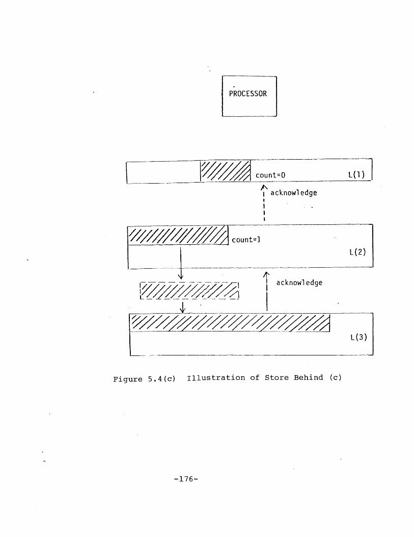
PROCESSOR
count=O
acknowledge
count=]
L(2)
acknowledge
L (3)
Figure 5.4(c) illustration of Store Behind (c)
-176-

level. The block in L(l) that has just been updated is
marked with a count of 2. This is illustrated in Figure
5.4(a).
When a store-behind operation is received in L(2), the
addressed data is written, and marked with a count of 2. An
acknowledgement is sent to the next upper storage level,
L(l), and a store-behind operation is sent to the next lower
storage level, L(3). When an acknowledgement is received at
L(l), the counter for the addressed data item is decremented
by 1, which becomes 1. This is illustrated in Figure
5.4(b).
The store-behind is handled in L(3) by updating the
appropriate data block. An acknowledgement is sent to L(2).
At L(2), the corresponding block counter is decremented by
1, which becomes 1. The acknowledgement is forwarded to
L(l). At L(l), the corresponding block counter is decre-
mented by 1 which now becomes 0, hence the block is elligi-
ble for replacement. This is illustrated in Figure 5.4(c).
Thus we see that the two-level store-behind strategy
maintains at least two copies of the written data at all
times. Furthermore, lower storage levels are updated at
slack periods of system operation, thus enhancing perfor-
mance. Detail algorithms for supporting this scheme will be
discussed in a later section.
- 177 -

5.4.2 Lost Updates
Several different updates to the same block will result
in several different store-behind requests be sent to the
next lower storage level. It is possible that these store-
behind requests arrive at the next storage level out of
sequence, resulting in lost updates.
To resolve this potential hazard, there is a time-stamp
associated with each block indicating the last time the
block was updated. There is also a time-stamp associated
with each child block of the parent block indicating the
last time the child block was updated by a store-behind
operation. A store-behind request will contain the block to
be updated and its time-stamp. This time-stamp will be com-
pared with that of the corresponding child block in the tar-
get parent block. Only when the store-behind data is more
recent will the update to the target parent block be per-
formed.
5.4.3 Transactions to Support the Write Operation
Figure 5.5 illustrates the transactions to support the
write operation. We shall assume that the target block of a
write operation already exists in a data cache. This can be
ensured by first reading the target block before issuing the
write request to the data cache. After the data is written
into a target data block in a data cache, a store-behind
- 178 -

wrte(
Istore-beh '4
Ipack,
ack-store-behind
store-behb] update I
Fiur L. rascion oSpotSoeBhn
-179-

transaction containing the updated block is sent to the next
lower storage level. The store-behind transaction is ser-
viced by the memory request processor. The memory request
processor generates an update transaction and sends it to
the appropriate storage device module. The memory request
processor also sends an ack-store-behind transaction to the
higher storage level. The storage device module handles the
update transaction by replacing the corresponding child
block in the target parent block with the data in the
store-behind transaction. Another store-behind transaction
containing the updated parent block is created and sent to
the storage level controller to be forwarded to the next
lower storage level.
A store-behind transaction is sent to the next lower sto-
rage level in several standard size packets, each corres-
ponds to a store-behind-packet transaction. At a storage
level controller, these packets are assembled into the ori-
ginal store-behind transaction. The algorithms for sending
and assembling packets are very similar to those used for
the read-through operation and will not be repeated here.
The following describes the algorithms for supporting the
above transactions to realize the write operation.
- 180 -

5.4.3.1 The store-behind Transaction
A store-behind transaction has the following format:
store-behind, virtual-address,process-iddatatime-stamp)
This transaction is handled by a memory request processor
using the following algorithm.
1. Search directory for store-behind.virtual-address.
2. If not found, hold the transaction and retry aftera time out, because the target parent block isstill being assembled in the buffer.
3. If found, compare store-behind.time-stamp with thetime-stamp of the corresponding child block of thetarget parent block.
4. If store-behind.data is more current than thechild block, do:
i) Send ( update, virtual-address, data, real-address, time-stamp-of-parent) to the appro-priate storage device module.
ii) Update the time-stamp of the child blockwith store-behind.time-stamp.
iii) Send ( ack-store-behind, virtual-address,process-id, ACK-code = 2) to the immediatehigher storage level. ACK-code indicatesthe number of levels this transaction is tobe routed upwards.
5. If store-behind.data is not more current than datain storage level, send two ( ack-store-behind,virtual-address, process-id, ACK-code = 2) to theimmediate higher storage level.
6. End.
- 181 -
5.4.3.2 The update Transaction
The update transaction is handled by a storage device
module using the following algorithm.
1. Replace the appropriate child block in the targetparent block by update.data.
2. The updated target parent block is retrieved.
3. Send ( update-directory, virtual-address, SB-code= 2) to the memory request processor to incrementSB-code of the target parent block by 2.
4. ( store-behind, virtual-address, process-id,target-parent-block, time-stamp =update.time-stamp-of-parent) is sent to the sto-rage level controller to be sent to the next lowerstorge level.
5. End.
5.4.3.3 The ack-store-behind Transaction
This transaction is handled by a memroy request proces-
sor. The algorithm used is as follows.
1. The SB-code of the corresponding block is decre-mented by 1.
2. The ack-store-behind.ACK-code is decremented by 1.
3. If ack-store-behind.ACK-code is greater than 0 theforward the ack-store-behind to the immediateupper storage level.
4. End.
- 182 -

5.5 MULTI-LEVEL INCLUSION PROPERTIES
As a result of the read-through operation, the block
read-through into L(l) leaves its 'shadow' in every lower
storage level that participated in the read-through opera-
tion. Is it true then, that a storage level, L(i), always
contains every data block in L(i-l)? When this is true,
multi-level inclusion (MLI) is said to hold.
It has been formally proved in Chapter 4 that certain
algorithms incorporating the read-through strategy can guar-
antee MLI provided that the relative sizes of the storage
levels be appropriately chosen. Furthermore, it is found
that certain other algorithms can never guarantee MLI. This
section explores the MLI properties of DSH-ll. In the fol-
lowing sections, the importance of MLI is briefly reviewed,
a model of DSH-ll is developed, and the MLI property of
DSH-ll is analyzed informally.
5.5.1 Importance of MLI
The MLI properties have important implications for the
performance and availability of DSH-ll. First, since the
block size of L(i) is larger than that of L(i-1), L(i) can
be viewed as an extension of the spatial-locality (Madnick,
1973) of L(i-l). Second, except for the lowest storage
level, each data item has at least two copies in different
- 183 -
storage levels. Hence, even the failure of an entire sto-
rage level will not result in data loss. Third, algorithms
to support the write operation is simplified if MLI holds
because a store-behind operation always finds the target
parent data block exists in a storage level.
5.5.2 A Model of DSH-ll
Figure 5.6 illustrates a model of DSH-ll. DSH-ll has h
storage levels, L(l), L(2), ... , L(h). L(l) consists of k
data caches. Each data cache consists of a buffer B(l,i),
and a storage, M(l,i). All the buffers of the data caches
are collectively denoted as B(l), and all the storage of the
data caches are collectively denoted as M(l). The size of
B(l,i) is b(l,i) number of blocks of size q(l). The size of
M(1,i) is m(l,i) number of blocks of size q(l). Hence L(l)
has b(l) = b(l,l) + b(l,2) + ... + b(l,k) blocks of buffer
space and m(l) = m(l,l) + m(1,2) + ... + m(l,k) blocks of
storage space.
A buffer is for holding data blocks coming into or going
out of the storage level. A data block may be partially
assembled in a buffer. Only data blocks in the storage
space are accounted for by the directory. Note that a buf-
fer is not used for holding transactions that do not contain
any data, e.g. an ack-store-behind transaction does not
occupy any buffer space.
- 184 -

Figure 5.6 A Model of DSH-ll
-185-
L(1)
L(2)
L(i)
L (h)

A typical storage level, L(i), consists of a buffer B(i),
and a storage, M(i). The size of B(i) is b(i) number of
blocks each of size q(i). The size of M(i) is m(i) number
of blocks each of size q(i). The block size of L(i) is
q(i), where q(i) = n(i-l)*q(i-1), for i = 2, 3, ... , h.
The n(i)'s are integers.
5.5.3 MLI Properties of DSH-ll
Based on the model in the previous section, the MLI con-
dition can be stated as follows: a data block, whole or
partially assembled, that is found in L(i) is also found in
L(i+l). This section shows that for DSH-ll, it is possible
to guarantee the following: (1) MLI holds at all times, (2)
it is always possible to find a block for eviction to make
room for an incoming block, and (3) an overflow transaction
from L(i) always finds its target parent block in L(i+l).
Proposition
Let J = i + 1. Using the algorithms described in the previ-ous sections, if m(j) is greater than m(i)+b(i) then
1. MLI holds for L(i) and L(j), i.e., any block foundin L(i) can be found in L(j),
2. If block replacement in M(j) is required, there isalways a block not in L(i) that can be consideredfor overflow, and
3. An overflow transaction from L(i) always containsthe address of a block that can be found in M(j).
Proof of Proposition
- 186 -

There are three cases:
1. There are no overflows from L(i): Since m(j) isgreater than m(i)+b(i), no overflow from L(i)implies no overflow from L(j). Thus all blockspresent in L(i) are still in L(j), i.e., (1) istrue.
2. There are overflows from L(i), no overflow fromL(j): No overflow from L(j) implies that allblocks referenced so far are still in L(j). Thusany block in L(i) is still in L(j), i.e., (1) istrue. Since any overflow from L(i) will find theblock still in L(j), (3) is true.
3. There are overflows from L(j): Consider the firstoverflow from L(j). Just before the overflow, (1)is true. Also just before the overflow, M(j) isfull. M(j) is full and m(j) is greater thanm(i)+b(i) implies that there is at least one blockin M(j) that is not in L(i) (i.e., their USC-code= 0). Choose from these blocks the least recentlyreferenced block such that its SB-code = 0. If nosuch block exists, wait, and retry later. Eventu-ally the store-behind process for these blockswill be terminated and these blocks will bereleased. Thus a block will be available foroverflow from M(j). Thus (2) is true. After theoverflow, (1) is still preserved. (1) and (2)implies (3).
If next reference causes no overflow from L(j), then the
arguement in Case 2 applies. If the next reference causes
overflow from L(j), then the arguement in Case 3 applies.
5.6 SUMMARY
The DSH-ll design, a data storage hierarchy for the INFO-
PLEX data base computer, is described. Protocols for sup-
porting the read and write operations in DSH-ll are des-
- 187 -

cribed in detail. It is then shown that DSH-ll is able to
guarantee multi-level inclusion at all times for any refer-
ence string provided that the sizes of the buffers and sto-
rage at the storage levels are chosen appropriately.
- 188 -

Chapter VI
SIMULATION STUDIES OF THE DSH-ll DATA STORAGE HIERARCHYSYSTEM
6.1 INTRODUCTION
This chapter discusses the results of a series of simula-
tion studies of the DSH-ll data storage hierarchy system.
A key objective of these simulation studies is to assess
the feasibility of supporting very large transaction rates
(millions of reads and writes per second) with good response
time (less than a millisecond) using the DSH-ll storage
hierarchy and the read-through and store-behind algorithms.
A GPSS/360 simulation model is developed for a DSH-ll
configuration with one processor and three storage levels.
The results obtained from this model are very interesting.
It is found that, at very high locality levels, when most of
the references are satisfied by the highest performance sto-
rage level, the store-behind algorithm interacts with the
DSH-ll buffer management algorithms to create a system dead-
lock. This has not been anticipated in the design of
DSH-ll, and has led to a redesign of the DSH-ll buffer man-
agement scheme.
- 189 -

Another GPSS/360 simulation model is developed for a
DSH-ll configuretion with five processors and four storage
levels. This model makes use of deadlock-free buffer man-
agement algorithms. Results from this model reveal further
interesting properties of the store-behind algorithm and of
the DSH-ll design. It is found that at high locality lev-
els, the store-behind requests form a pipeline. Thus the
rate of write operations that can be serviced is limited by
the slowest stage in the pipeline, i.e., the slowest storage
device. It is also found that a bottleneck may be developed
at the lowest level when the block size of that level is too
large.
A well-balanced system is obtained by increasing the
degree of parallelism in the lower storage levels and by
decreasing the block sizes used by these storage levels.
This system is then used as a basis to compare the perfor-
mance of the DSH-ll architecture under different technology
assumptions. It is found that using 1979 technologies, a
throughput of .7 million operations per second with mean
response time of 60 microseconds are obtained for a mix of
storage references consisting of 30 percent read requests.
Using 1985 technologies, the same storage reference mix pro-
duces a throughput of 4 million operations per second with
10 microseconds mean response time.
- 190 -

6.2 A SIMULATION MODEL OF DSH-ll : THE PlL3 MODEL
The PlL3 model of DSH-ll is a GPSS/360 model of a DSH-ll
configuration with one processor and three storage levels.
It represents a basic structure from which extensions to
include more processors and storage levels can be made. The
structure of PlL3 is illustrated in Figure 6.1(a). Each
module in Figure 6.1(a) actually consists of four queues and
a facility (Figure 6.1(b)). The facility is referred to as
the request processor (RP). There are two input queues, one
for transactions with data (the XQ), and one for transac-
tions with messages (the IQ). The two corresponding output
queues are named YQ and OQ respectively. The XQs and YQs
have limited capacity, since they are the data buffers.
There is no limit on the lengths of the IQs and the OQs.
The following example illustrates the naming conventions
used in the model. The K2 module actually consists of the
KRP2, KIQ2, KOQ2, KXQ2 and KYQ2. The current length of KXQ2
is denoted as KXL2 and the maximum allowable length of KXQ2
is denoted as KXM2.
6.2.1 An Illustration of the DSH-ll Algorithms
A listing of the PlL3 model is presented in Appendix A.
To illustrate the model logic, the following is a brief des-
cription of the path followed by a read-through transaction.
A read request (TXN) is queued in KIQ3 (the input message
- 191 -

LBUSl
LBUS2
D21
LBUS3
Figure 6.1(a) The PlL3
D32
Configuration
IQ RP 0Q
XQ YQ
Figure 6.1(b) A Module in PlL3
-192-
D22

DEGREE OF MULTIPROGRAMING OF A CPU = 20
SIZES OF DATA QUEUES (XQ AND YQ) = 10
DIRECTORY SEARCH TIME = 200 NANOSEC.
READ/WRITE TIME OF A L(1) STORAGE DEVICE = 100 NANOSEC.
READ/WRITE TIME OF A L(2) DEVICE = 1000 NANOSEC,
READ/WRITE TIME OF A L(3) DEVICE = 10000 NANOSEC.
BUS SPEED = 10 MHZ
BUS WIDTH = 8 BYTES
SIZE OF A TRANSACTION WITHOUT DATA = 8 BYTES
BLOCK SIZE AT L(1) = 8 BYTES
BLOCK SIZE AT = 128 BYTES
BLOCK SIZE AT L(3) = 1024 BYTES
% READ REQUESTS = 70%
% WRITE REQUESTS = 30%
CONDITIONAL PROB. OF FINDING DATA IN A LEVEL
GIVEN THAT THE DATA IS NOT IN ANY UPPER LEVEL = P
Figure 6.2 Input Parameters to PlL3
-193-

queue of the storage level controller at level 3). When
KRP3 is free, TXN is serviced and put into KOQ3. When LBUS3
is available, TXN is sent to RIQ3 (the input message queue
of the memory request processor at level 3) where it waits
for RRP3, the request processor. RRP3 then searches its
directory to obtain the real address for TXN. TXN is put
into ROQ3 to be sent to a storage device, say, D31. When
LBUS3 is free, TXN is sent to DIQ31 (the input meSsage queue
for device D31). TXN waits in DIQ31 for DRP31 to be free
and also for a slot in DYQ31 (the output data queue for D31)
to hold the retrieved data. When both conditions are met,
DRP31 retrieves the data and puts it in DYQ31 where it waits
for the LBUS3 to be free and for there to be a slot in KXQ3
(the input data queue of the storage level controller at
level 3) to hold the data. When both conditions are ine,
the data is sent to KXQ3. Then the data is put in KYQ3
waiting for the GBUS and for all the upper storage levels to
be free to receive the broadcast...
6.2.2 The PlL3 Model Parameters
The model is highly parametized. Parameters for the PlL3
model are chosen to reflect current (1979) processor and
storage technology. A key parameter that characterizes the
references made to DSH-ll is the locality level. The local-
ity level (P) is the condition probability that a referencric
- 194 -

is satisfied at a given storage level given that the
reference is not satisfied in all upper storage levels.
Figure 6.2 summarizes all the model parameters.
6.3 SIMULATION RESULTS OF THE PlL3 MODEL
Three different locality levels are used for the PlL3
model. The simulated time is one milisecond (one million
time units in the model). Some unusual phenomena are uncov-
ered during the analysis of these preliminary results. This
leads to more extensive simulation studies to obtain more
data points. A plausible theory is then proposed to explain
these phenomena. Detail traces of the model is used to ver-
ify the theory. The findings are discussed in the following
subsections.
6.3.1 Preliminary Studies Using the PlL3 Model
A series of three simulation studies are carried out with
three locality levels : high (P=.85), medium (P=.5), and low
(P=.2). Throughputs, mean response times and utilizations
of the facilities are summarized in Figure 6.3.
Throughput in millions transactions per second are plot-
ted against the locality levels in Figure 6.4. From Figure
6.4, it seems that a throughput of .6 million transactions
per second is the maximum that one could obtain with this
configuration.
- 195 -

Locality LevelH- o o
o Throughput per millisecond 0cn oo
GBUS UtilizationCCD
H LBUS1 Utilization
Data Cache Utilization ...0D
LBUS2 Utilization
rtD21 Utilization
0 -
LBUS3 Utilization
D31 Utilization
0 MiMean Response Time (Nsec) w %

THROUGHPUT IN 106 REQUESTS
PER SECOND
7
a5
.4l
.2
,2'
,1 .2 .3 ,' 95 .6 7 .8 91.
Figure 6.4 Throughput Vs. Locality Level(PlL3 Preliminary Results)
-197-

MEAN RESPONSE TIME INMICROSECOND
.1 .2 3 .4 5 .6 .7 .8 .9 1.0Figure 6.5 Mean Response Time Vs. Locality Level
( PlL3 Preliminary Results)
-198-
10

UTILIZATION-199-
19
6 L(3) DEVICE... --- ~
GBUS
N. DATA
LBUS1
ID- ----
CACHE
1 .2 .3 .4 .5 .6 .7 .8 .9
Figure 6.6 Utilization Vs. Locality Level(PlL3 Preliminary Results)
- -0- -,

Mean response time per transaction are plotted against
locality levels in Figure 6.5. This shows that a mean res-
ponse time of 5 micro seconds is obtainable at high locality
levels. Furthermore, as the locality level increases, there
will be more references being satisfied in the high perfor-
mance storage levels, thus the mean response time will.
decrease.
Utilizations of the various facilities are plotted
against locality levels in Figure 6.6. It can be seen from
these plots that at low locality levels, the slowest storage
level becomes a system bottleneck. At higher locality lev-
els, bus utilizations drop because most references are
satisfied by the data cache, DRPll, making the use of the
buses unnecessary except for store-behind operations.
At high locality levels, one would also expect the utili-
zation of the data cache, DRPll, to be very high. However,
this is not supported by the data. In fact, even though the
throughput at the P=.85 locality level is larger than that
at the P=.50 locality level, the DRP11 utilization actually
drops.
Examine the data more closely, another puzzle is discov-
ered. If one multiply throughput by the mean response time
divided by the maximum degree of multiprogramming, one
- 200 -

should obtain a number closed to the simulated time
(1,000,000). For the P=.20 case, this number comes out to
be 915657. For the P=.50 case, this number comes out to be
858277. But for the P=.85 case, this number is only 180027.
It is suspected that either the data is wrong or there are
some unusual blocking phenomena in the system in the P=.85
case.
6.3.2 More Extensive Studies Using the PlL3 Model
Since it is not difficult to obtain more data points by
varying the locality levels, a second series of simulations
is carried out. The results of these simulations are pre-
sented in Figure 6.7.
Throughputs are plotted against locality levels in Figure
6.8. This shows that as the locality level increases,
throughput also increases. A throughput of closed to one
million transactions per second is obtainable at about P=.80
locality level. However, after the P=.80 point, throughput
drops sharply as the locality level increases. This
requires some explaination.
In Figure 6.9, mean response time is plotted against
locality levels. This shows that as locality level
increases, mean response time decreases. This plot does not
seem to provide insight as to why throughput decrease shar-
ply after the P=.80 locality level.
- 201 -

-202-.
.95 532 .14 .03 .15 .16 .05 .21 .25 3986
.90 581 .16 .04 .17 .19 .06 .26 .42 :3957
.85 589 .23 .52 .19 .26 .09 .35 .52 6021
.80, 947 .50 .94 .31 .57 .19 .71 .99 16298
.70 811 .53 .10 .27 .65 .20 .69 1.00 23317
.65 758 .51; .10 .26 .62 .18 .68 1.00 22505
.60 698 .51 .10 .23 .63 .19 .65 1.00 27114
.50 548 .50 .10 .20 .65 .17 .62 1.00 31324
.40 456 .45 .08 .16 .63 .15 .59 1.00 i39142
.30 320 .42 .07 .12 .60 .12 .52 1.00 56908
.20 286 .42 .07 .10 .63 .11 .52 1.00 64032
C
0 4-4J 4J 4-
LiN C 0 E-r-C -r 0 C '- C --
I- C 0 0- r O O0 1-.. - - -r0-r--
4 E 4- 3 N J 4--- -r- C N
N -r- N r- N C
N - g. -L)- - O~ ~ -0
- D -- -- C Or 6
Figure 6.7 PlL3 Model - Extensive Results

-203-
THROUGHPUT IN 106 REQUESTS PER SECOND
1~
1'/
g
I
I.
0
el1 m 7 3 - m4 6 97 *1 's
Figure 6.8 Throughput Vs. Locality Level(PlL3 Extensive Results)
.9
8.
.7.
.6
.5
.4
.3
.2-
.1

-204-
RESPONSE TIME IN MICROSECOND
o>
NO0
0
.1 .2 .3 .4 .5 .6 .7 .8 .9 1.0Figure 6.9 Mean Response Time Vs. Locality Level
(PlL3 Extensive Results)
MEAN
70.
60
50.
40
30.
20.

6.3.3 A Plausible Theory of Operation
One theory to explain the sharp drop in throughput at
very high locality levels is that at such high locality lev-
els, the rate of write operations being generated is very
high. Since a write will not proceed until DRPll is free
(to write the data), and DRPll's YQ has a buffer slot (for
holding the store-behind operation), the write operation may
hold up other transactions in their use of DRPll. Since the
utilization of DRPll is very low, the blocking must be due
to the YQ being full often. Many store-behind transactions
closed togther will tend to make the YQ full often. These
blocking transactions will tend to hold up other transac-
tions hence resulting in low system throughput.
If the YQ is full often, it must be because transactions
in it cannot move on to the next facility. This will happen
if the bus LBUS1 is busy or the XQ buffer of Kl is full, or
both. From the data, we see that all the bus utilizations
are very low, hence the blocking must be due to the fact
that the XQ buffer of Kl is full often. Proceeding in this
manner, one could argue that at high locality levels, the
rate of store-behind operations is very high, which results
in store-behind transactions being backed up from a storage
device. This backing up of store-behind operations causes
long queueing delays for other transactions as well, result-
- 205 -

ing in low system throughput. This blocking situation also
prevents DRPll to be kept busy as evident from its low uti-
lization.
We can now explain why the utilization of DRPll at the
P=.85 locality level is lower than that at the P=.50 local-
ity level. At P=.85, due to the store-behind transactions
being backed up, very few acknowledgements to the store-be-
hind transactions ever return to DRPll. In the P=.50 case,
most acknowledgements to store-behind transactions return to
DRPll. Thus, even though the number of reads and writes
handled by DRPll in the P=.50 case is lower than that han-
dled by the DRPll in the P=.85 case, there are many more
acknowledgements serviced by DRPll in the P=.50 case, hence
the corresponding utilization is higher.
There are no backing up of store-behind transactions in
the low locality level cases because the rate at which they
are generated is low. Since the store-behind transactions
are separated from one another there is enough time for a
device to service a previous store-behind transaction before
another one comes along.
- 206 -

6.3.4 Verification of Theory with Data
The above theory seems to explain the phenomena well and
agrees well with the observed data. To verify the theory,
detail model traces are examined to determine the status of
the system at the time of simulation termination.
It is found that for low locality levels, there is indeed
no backing up of the store-behind transactions. There is a
backlog of requests to be processed by the lowest storage
level devices due to their large service times. For high
locality levels, starting from P=.85, store-behind transac-
tions begin to be backed up, from storage level 2. However,
the back up is due to a system deadlock developed at storage
level 2, and not due to the slower speeds of the devices, as
hypothesized above.
The deadlock at storage level 2 is illustrated in Figure
6.10. All the XQs and YQs are full. A store-behind tran-
saction in DYQ21 is waiting for LBUS2 and a KXQ2 buffer
slot. LBUS2 is free but KXQ2 buffer is full. KXQ2 will not
be cleared because KYQ2 is full. KYQ2 cannot be cleared
because both buffer of R2 are full. These buffers cannot be
cleared because DXQ21 and DYQ21 are full. DYQ21 cannot be
cleared because it is waiting for KXQ2 to be cleared. Thus
a deadlock is developed. This deadlock causes the XQs and
YQs in the upper storage levels to be gradually filled as
- 207 -

Store-behind
Store-
store-behind
xQ XQ
R2 / /R2 ,' D21
id Y-i YQ
hi nd sttS6re-behind
Fi.gure 6.10 Deadlock In PlL3 Model
-208-
I

more store-behind transactions are generated. When YQ at
DRPll is full, the system will be held up when the next
write transaction arrives.
It is interesting to note that this deadlock only occurs
at very high locality levels. This is beacuse at high
locality levels, the rate of store-behind transactions gen-
erated is very high. Comparing the P=.95 case and the P=.50
case, even though the same number of store-behind transac-
tions are generated to lower storage levels in both cases,
the rate at which they are generated in the P=.95 case is 30
times that of the P=.50 case. Store-behind transactions
sparsely separated from one another give chance for the dev-
ice to service them, therefore avoiding a deadlock. This
deadlock situation is not too different from a traffic jam
at a Boston rotary during rush hour.
In retrospect, the causes of the deadlock are due to the
rate of store-behind transactions and the use of one single
buffer for data coming into a storage level as well as for
data going out of a storage level. The potential for dead-
lock of using a common buffer was not discovered during the
design of DSH-ll due to the complex interactions of the var-
ious protocols for store-behind, read-through, and overflow
handling operations.
- 209 -

6.4 DEADLOCK-FREE BUFFER MANAGEMENT SCHEMES
In the DSH-ll simulation model, there are five types of
transactions supporting the read-through and store-behind
operations. These transactions are : read-through-request
(RR), read-through-result (RT), overflow (OV), store-behind-
request (SB), and acknowledgement (AK). Each type of tran-
saction is handled differently. Furthermore, the same type
of transaction is handled differently depending on whether
the transaction is going into or out of a storage level. A
potential deadlock exists when different transactions share
the same zuffer and their paths form a closed loop. We have
seen an example of such deadlock in the PlL3 model where SB
transactions coming into a storage level and SB transactions
going out of a storage level form a closed loop. Other
potential deadlocks exists in the PlL3 model. This section
is focused on developing deadlock-free buffer management
algorithms.
Potential deadlocks exist beacause different transaction
types share the same buffer and that the First Come First
Serve (FCFS) strategy is used for allocating buffer slots.
A simple strategy to avoid deadlock is not to allow buffer
sharing among different transaction types. No path crossing
can occur thus no loop can exist. Although this strategy is
easy to implement, it does not make optimal use of the buf-
- 210 -

fer space. Another strategy to avoid deadlock is to allow
buffer sharing, but to make use of more sophisticated buffer
allocation algorithms. One such algorithm is discussed
below.
6.4.1 A Deadlock-free Buffer Allocation Algorithm
Two types of buffers are used at each storage level, the
IN buffers and the OUT buffers. Transactions coming into
the storage level use the IN buffers and transactions going
out of the storage level use the OUT buffers. Transaction
coming into a storage level from a higher storage level are
the RR, SB, and OV transactions. Transactions coming into a
storage level from a lower storage level are the RT and AK
transactions. Similarly, transactions going out of a sto-
rage level to the next lower storage level are the RR, SB,
and OV transactions. Transactions going out of a storage
level to a higher storage level are the RT and AK transac-
tions. Each component in a storage level has an IN buffer
and an OUT buffer. This is illustrated in Figure 6.11.
The general idea of this buffer allocation scheme is not
to allow the buffers to be completely filled. When the buf-
fers are filled up to a certain level, only those transac-
tions that can be processed to completion and resulting in
freeing up buffer slots are accepted. The precise algorithm
is as follows.
- 211 -

(SB,OV,RR)
(AKRT)
(SB,,0V,RR)
storage levelcontroller.
memory request storage deviceprocessor controller
(RR,SB)
(SB,AKRT)
(AK ,RT)
Figure 6.11 A Deadlock-free Buffer Scheme
-212-

1. The size of OUT is always greater than the size of
IN.
2. Always maintain at least one empty slot in an IN
buffer.
3. Buffer-full (BF) condition is raised when the num-
ber of transactions in IN plus the number of tran-
sactions in OUT is equal to the size of OUT.
4. If BF then do not accept any RR or SB into a sto-
rage level. Only process OV, RT, and AK transac-
tions.
We now provide an informal argument to show that the
scheme described above is indeed deadlock-free. First we
have to show that the RR and SB transactions are not the
only transactions in the system when all the buffer pairs
have their BF conditions raised. Then we have to show that
processing each of 'the OV, AK and RT transactions will free
up some buffer slots thus lowering some BF conditions.
Suppose that all the BF conditions are raised. Examine
the OUT buffers of the lowest storage level. Since the size
of OUT is greater than that of IN, BF implies that there is
at least one transaction in OUT. This transaction must be
going out of the storage level to a higher storage level,
hence cannot be a RR or a SB transaction.
- 213 -

Level i-1
any transaction
--- y (9) OV terminated
Level i
any transaction
------- y(5) OV terminated
Level i+1
(1) RT
Figure 6.12 Illustration of the Deadlock-freeBuffer Scheme
-214-

Consider a RT transaction at level i+l (Figure 6.12).
(1) All upper storage level, level i and level i-l can
receive this transaction since there is always one empty
slot in each IN buffer. The departure of the RT transaction
creates an empty slot in the OUT buffer of the sender (level
i+l). (2) Level i.can now send a transaction to level i+l
which creates a slot in level i. The RT transaction can now
be serviced in level i. (3) Handling the RT transaction may
create an OV transaction in level i. Luckily there is a
buffer slot for the OV transaction in level i. (4) The OV
transaction can be sent to level i+l because there is always
a free slot in the IN buffer at level i+l. (5) The OV tran-
saction will be serviced to completion in level i+l. Hence,
there is a free slot in level i as result of these opera-
tions. (6) Now a transaction from level i-l can be sent to
level i. (7) The RT transaction can be handled in level i-l
which may create an OV transaction. (8) The OV transaction
can be sent to level i. (9) Finally, the OV transaction is
handled and terminated in level i. Thus, there is a free
buffer slot created in level i-l as a result of processing
the RT transaction.
Handling an AK transaction may generate another AK to be
sent to the immediate upper storage level. The same argu-
ment for the RT transaction can be applied to show that a
- 215 -

buffer slot will be freed up as a result of handling the AK
transaction.
It is clear from the above discussion that this buffer
management scheme requires more complex protocols among sto-
rage levels and a complex priority scheme for the transac-
tions. A key advantage of this scheme is that it makes
efficient use of buffer space since different transactions
with varying buffer space requirements can share a common
buffer pool.
6.5 ANOTHER SIMULATION MODEL OF DSH-ll : THE P5L4 MODEL
A GPSS/360 simulation model of another DSH-ll configura-
tion with five processors and four storage levels is devel-
oped. This model is referred to as the P5L4 model. This
model revised the basic logic used in the PlL3 model to use
a deadlock-free buffer management scheme and to accomodate
four additional processors and an additional storage level.
The simple scheme of using separate buffers for different
transactions is used for the P5L4 model.
The first series of studies provides further insights to
the operation of the store-behind algorithms. It also shows
that level 4 storage may be too slow and its local bus may
not have engough bandwidth to support the amount of data
transfer activities at that level.
- 216 -

The second series of studies is aimed at obtaining a
well-balanced system. The degree of parallelism in the
lower storage levels are increased and the demand on the
buses is lowered by reducing the block sizes. A well-ba-
lanced system is obtained which is then used as the basic
system to study the effect of using projected 1985 technolo-
gies for DSH-ll. Results of these studies and their analy-
sis are presented in the following sections, after a brief
introduction to the P5L4 model and its parameters.
6.5.1 The P5L4 Model and its Parameters
The structure of the P5L4 model is very similar to that
of the PlL3 model. However, the basic component of the
model is quite different. The basic component of the P5L4
model is a facility and a number of data buffers, one for
each type of transaction comming into the storage level and
going out of the storage level. Figure 6.13(a) illustrates
the DSH-ll configuration that P5L4 is modelling, and Figure
6.13(b) illustrates the basic component of the model. A
flow chart of the P5L4 model logic is presented in Appendic
B. A listing of the P5L4 model is presented in Appendix C.
The parameters used in the P5L4 model are the same as
those used in the PlL3 model with the following exceptions.
(1) There are five processors, each with 10 degrees of mul-
- 217 -

-218-
Lbusl
KI
Figure 6.13(a) The P5L4 Configuration
INdata buffers
requestprocesso
OUT
Figure 6.13(b) A Module in P5L4

DEGREE OF MULTIPROGRAMING OF A CPU =10
SIZES OF DATA BUFFERS = 10
DIRECTORY SEARCH TIME = 200 NANOSEC,
READ/WRITE TIME OF A L(1) STORAGE DEVICE = 100 NANOSEC.
READ/WRITE TIME OF A L(2) DEVICE = 1000 NANOSEC.
READ/WRITE TIME OF A L(3) DEVICE = 10000 NANOSEC.
BUS SPEED = 10 MHZ
BUS WIDTH = 8 BYTES
SIZE OF A TRANSACTION WITHOUT DATA = 8 BYTES
BLOCK SIZE AT L(1) = 8 BYTESBLOCK SIZE AT L = 128 BYTES
BLOCK SIZE AT L(3) = 1024 BYTES
% READ REQUESTS = 70%
Z WRITE REQUESTS = 30%
CONDITIONAL PRCB. OF FINDING DATA IN A LEVEL
GIVEN THAT THE DATA IS NOT IN ANY UPPER LEVEL = P
Figure 6.14 Input Parameters to the P5L4 Model
-219-

tiprogramming (as opposed to 20 in the PlL3 model). (2)
There is a new storage level with 2 storage devices having
access times 10 times higher than those of the devices in
level 3. The parameters used in the P5L4 model are summar-
ized in Figure 6.14.
6.5.2 Preliminary Studies Using the P5L4 Model
A preliminary study using the P5L4 model is carried out
using several different locality levels and using the param-
eters listed in Figure 6.14. The simulated time is one mil-
lisecond (one million model time units). Results from these
studies are summarized in Figure 6.15. Figure 6.15(a) is a
table listing the throughput, mean response time, total
transaction wait time, total transaction execution time, and
'system utilization'. System utilization is defined as the
ratio of the product of the total number of transactions
completed and the mean response time to the product of the
simulated time and the maximum number of active requests
pending at all the processors. It indicates the percentage
time that DSH-ll is busy.
Figure 6.15(b) tabulates the utilizations of the buses
and the utilizations of typical storage devices at each sto-
rage level. The utilizations of all the memory request pro-
cessors and all the the storage level controllers are very
- 220 -

-221-
(a) Throughput, Response Time, etc.
(b) Utilizations
P gbus lbus1lbus2 lbus bus4 Ll L2 L3 L4
.50 92 .06 .30 .99 .94 .02 .11 .46 .99
160 .91 .06 .31 .991 .94: .03 .11 .46 .99
.70 .91 .07 .32 .99 .941 .041.13 .52 .88
.80 .88 .05 .26 .99 .94 .04 .10 .44 .92
.95 84 .04 .21 .99 .95 .04 .06 .51 .90
Figure 6.15 Preliminary Results of P5L4 Model
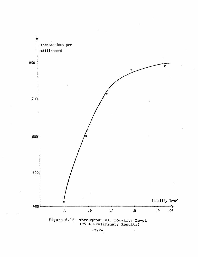
800 1
transactions per
millisecond
700-
600~
500
locality level400-
.5 .6 9 .95
Figure 6.16 Throughput Vs. Locality Level(P5L4 Preliminary Results)
-222-

mean response time(microsecond)
I
NN
'N
--0
\\
locality level
.5 .6 .7 .8 .9 .95
Figure 6.17 Mean Response Time Vs. Locality Level(P5L4 Preliminary Results)
-223-
low. Figure 6.15 (b) shows that the devices and the local
buS at level 4 are satuarated for all. locality levels. The
local bus at level 3 is saturated but the devices at level 3
are only 50 percent utilized. Saturation of level 4 at low
locality levels is due to the large number of read-through
requests that has to be handled at that level. For example,
at a locality level of .5, one-fouth of all read requests
will be serviced by level 4. This creates a heavy burden on
the level 4 devices and on its bus. At high locality lev-
els, however, the number of read-through requests directed
to level 4 is rather small. For example, at a locality
level of .8, only .8 percent of all read requests are ser-
viced by Ivel I. The saturation of level 4 at high local-
ity levels is due to t-hE store-behind requests. At hiqh
locality levels, the number of write requests are much
higher, thus there is a high demand on level 4 to service
the corresponding store--behind requests. It seems that
level 3 storage devices have the capacity to handle the
read-through and store-behind requests at all locality lev-
els. However, the local bus at level 3 is saturated at all
locality levels. The bus saturation at level 3 is possibly
due to the store-behind requests. We shall discuss ways to
eliminate these performance bottlenecks in a later section.
- 224 -

Throughput data presented in Figure 6.15(a) is plotted as
a graph in Figure 6.16. Figure 6.16 shows that throughput
rises sharply starting from the .5 locality level, then its
follows a much slower rate of increase after the .7 locality
level. At a low locality level, throughput is low since a
large proportion of the read requests has to go to the
slower storage devices. As the locality level increases, a
large proportion of requests can be handled by the higher
storage levels. The higher storage levels are not heavily
utilized, thus they can complete the requests quickly. The
faster transactions can be completed, the faster new tran-
sactions can arrive since the model is a closed one. This
explains the sharp increase in throughput between .5 and .7
locality levels.
When the locality level is high, the rate of store-behind
transactions coming into the model becomes high. Since
there is a fixed proportion of reads and writes in the
request stream, the throughput at high locality levels
becomes limited by how fast the store-behind requests can be
serviced. Thus, at high locality levels, increasing the
locality level further will not produce a dramatic increase
in throughput.
The plot of mean response time in Figure 6.17 provides
further insights to the store-behind operations. Figure
- 225 -

6.17 shows that there is a discontinuity in the mean
response time curve between .6 and .7 locality levels. The
discontinuity may be explained as follows. As the locality
level increases, the rate of store-behind transactions com-
ing into the model also increases. Read operations become a
less dominar:t factor of system performance. There is a
pipeline of buffer slots for store-behind transactions- A
write request is completed as soon as it has completed a
write to its data cache and has placed a store-behind tran-
saction in the store-behind pipeline . The store-behind
transaction flows along the pipeline until- it is serviced
and temJiated by - level 4 storage evice. If a write
reque~ canno t fda slot (>iIn the store-behind pipeline, it
has to wait. At hi locaity .e'eIs, the store-behind
pipeline is full, hence, wri: e operations tend to incure a
larger wait time waiting for pipeline slots. It seems that
the store-behind pipelip is full after the .7 locality
level, causing long wait times by transactions, hence larger
mean response times for all. locality levels higher than .7.
The store-behind pipeline is rot full for all locality lev-
els below .7. Thus transactions have smaller mean response
time in these cases. This expains the difference in behav-
ior of the two mean response time curves.
- 226 -

The data seems to support this theory. Outputs from the
simulation runs shows that the pipeline is full for all
locality levels greater than and equal to .7. The total
transaction time column in Figure 6.15(a) shows that there
is a dramatic increase in the transaction wait time for all
cases with locality level above .7. The figure also shows
that the transaction wait time is a dominant portion of the
total transaction time. Since.mean response time is the
ratio of total transaction time to total number of completed
transactions, the more than doubling of the wait time going
from .6 to .7 locality level is the key factor in the sudden
increase in mean response time. The sudden increase in wait
time is due to the fact that the pipeline is just filled up,
new transactions begin to experience prolonged delays.
These preliminary studies have provided valuable insights to
the dynamics of the store-behind operation. We now have
gained enough understanding of the model to tune it for bet-
ter performance.
6.5.3 Tuning the P5L4 Model
Our objective in this next series of studies is to try to
obtain a well-balanced system. From the preliminary stu-
dies, we know that to .:educe mean response time we have to
increase the efficiency of the store-behind pipeline. One
approach to increase the efficiency of the pipeline is to
- 227 -

increase the parallelism of the lower storage levels, so
that the service times of the stages of the pipeline are
better balanced. The preliminary studies also reveal that
our initial choice of block sizes may not be appropriate for
the system.
The approach that is taken to obtain a well-balanced sys-
tem is as follows. The locality level is fixed at .9. Then
the degree of parallelism in level 3 is increased by a fac-
tor of 5 and that of level 4 is increased by a factor of 10.
This is accomplished by decreasing the effective service
times of the devices at these levels appropriately.
Finally, Cha model is run for several choices of block sizes
for the storage levels. The simulated time for these runs
are much longer than in the preliminary studies to ensure
that steady state behavior is observed. The results
obtained are summarized in Figure 6.18.
The first study uses the same block sizes as those used
in the preliminary studies. The results of this study are
summarized in column one which clearly shows that level 4 is
the bottleneck causing the very low throughput and high mean
response time. Note that the devices are not saturated.
This indicates that the block sizes are too large thus tie-
ing up the bus at level 4 during data transfer.
- 228 -

locality level = .90
b c sies (8,128,1024) (8,64,512) (8,64,256)
i throughput 176 458 721(per _mg)
MRESP TIME(ns) 258580 96260 60940
gbus util. .62 .67 .77
lbusl util. .02 .04 .07
lbus2 . .10 .15 .26
lbus3 " .67 .71 .84
lbus4 1.00 .99 .99
L1 .01 .04 .06
L2 " .03 07
L3 " .28 .27 .28
L4 " .17 .40 .83
Figure 6.18 Tuning the P5L4 Model
-229-

In the next study, the size of data transfer between
level 2 and level 3 and that between level 3 and level 4 are
reduced by one half. The results of this study are summar-
ized in column 2. The bus at level 4 is still a bottleneck.
There is significant improvement in the utilizations of
level 4 storage devices.
Next, the size of data transfer between level 3 and level
4 is halved. This produces a fairly well-balanced system.
The tesults are summarized in column 3. A throughput of 47
million operations per second with meanresponse time of 60
microseconds is obtained. The utilizations across storage
levels are wrell-balanced comparatively.
6.5.4 Comparing the Performance of DSH-ll using 1979and 1985 Technologies
The well-balanced system obtained from the previous stu-
dies will be used as a basis for comparing the performance
of DSH-ll under 1979 and 1985 technology assumptions. The
parameters used in the 1979 case are exactly those used in
the well-balanced system of the previous studies. For the
1985 case, we will use a bus speed that is 5 times faster
than that used in the 1979 case. In general, the speeds of
the storage devices in the 1985 case will be faster. We
estimate that the level 1 storage devices will be twice as
fast in 1985 as in 1979. All other devices are estimated to
- 230 -

be 10 times faster in 1985 than in 1979. Lastly, we expect
1985 to produce better associative processors for directory
searching thus the directory search time will be reduced by
one half in 1985. These estimates will be incorproated in
the parameters for the 1985 case.
The model using 1979 technology assumptions is run for 4
different request streams with different proportions of
reads and writes. The model using 1985 technology assump-
tions is then run with the same 4 different request streams.
The locality level is fixed at .9 in both cases. The
results are summarized in Figure 6.19.
The throughputs for the two cases are plotted on the same
graph in Figure 6.20. In general, for both cases, through-
put increases as the proportion of read requests increases.
It can be inferred from the results that the throughput of
DSH-ll using 1985 technology is between 5 to 10 times better
than using 1979 technology. For a request stream with 70
percent read requests and 30 percent write requests, DSH-ll
using 1979 technology can support a throughput of .7 million
requests per second with a mean response time of 60 microse-
conds. For the same mix of requests, DSH-ll using 1985
technology can support a throughput of 4 million requests
per second with a mean response time of 10 microseconds.
- 231 -

-1~~
% read TRUPTI MRESP gbus
i(per (ns) U.i ms)
l1bus3lbusi bus11 bus4
U. U. .I
.50 450 97580 .76 .06 .25 .84 .9
.70 721 60940 .771 .07 .2611 .84 .9
.80 1559 26790 .85 .10 .34 .91 .9
.90 3239 134401 .90 .14 .93 .C
9
9
LiU.
.04
.06
L2 L3U. U.
.1 .25
.11 .28
7 .11 18 .34
7 .23 .28 .35
(a) 1979 Technology
.70 43201 9940
.80 15040 2640
.90 22760 1760
(b) 1985 Technology
Thc11hi1
.79 .07
.96 .15
.95 .16
.28
.47
.47
bus3U.
.82
lbuslU.
.99
.86 .98
.97 .92
.96 .91
LI
Up
.13
L2
U.
.05
.20 .06
.64 .14
.99 .17
Figure 6.19 Comparing Performance of P5L4Using Different Technologies
'.4U.
.67
.65
.71
.83
L3
U.
.27
.28
.38
L4
U.
.35
.34
.28
.27 .34
i

-233-
throughput(million per second)
198525
20
151
10
to
C
0%read
.5
Figure 6.20 Throughput Vs. % Read(Comparative Performace)
1979

6.6 SUMMARY
Two simulation models of the DSH-ll storage hierarchy
system are developed and used to understand the performance
characteristics of DSH-ll and its algorithms. The first
model is developed for a DSH-ll configuration with one pro-
cessor and three storage levels. Results from this model
uncovers an unsuspected deadlock potential in the DSH-ll
buffer management scheme. This leads to the development of
new buffer management schemes for DSH-ll. A second model is
developed for a DSH-ll configuration with five processors
and four storage levels. This model also makes use of a
deadlock-free buffer management scheme. Results from this
model provides :much insights to the performance implications
of the read-through and store-behind algorithms. After suf-
ficient understanding of the model is obtained, the model is
tuned for better performance. The resulting system is then
used as a basis for comparing the performance implication of
using different technology for DSH-l1.
Results from these simulation studies not only provide
valuable insights to the important dynamic behavior of
store-behind and read-through algorithms, they also provide
assurance that the DSH-ll is capable of supporting the
memory requirements of the INFOPLEX functional hierarchy.
- 234 -

Chapter VII
DISCUSSIONS AND CONCLUSIONS
7.1 INTRODUCTION
Database management is a major component of computer
usage. Adapting conventional computer architectures to sup-
port database management functions has several disadvan-
tages. Two major disadvantages have been recognized for
some time. These are (1) processor power limitation of
the conventional computer, and (2) the 'access gap' that
exists between main memory and secondary storage devices of
conventional computers.
Various approaches have been proposed to develop special-
ized architectures for database management. These
approaches have been discussed in Chapter 1. One of these
approaches is the INFOPLEX data base computer effort. INFO-
PLEX eliminates the processor power limitation by using mul-
tiple specialized functional processors and makes use of a
generalized storage hierarchy specifically designed for man-
aging very large databases. A major obstacle to realize
effective storage hierarchy systems has been the lack of
understanding of these systems and their algorithms. Previ-
- 235 -

ous studies of storage hierarchy systems have been focused
on systems with two or three storage levels, and usually for
program storage. This thesis is focused on the study of
generalized storage hierarchy systems for data storage,
referred to as data storage hierarchy systems. Theories and
models of data storage hierarchy systems are developed.
Formal definitions of data management algorithms for data
storage hierarchy systems are defined. Important properties
of data storage hierarchy systems have been analyzed in
detail to provide valuable insight for design of practical
data storage hierarchy systems. Designs for the INFOPLEX
data storage hierarchy are developed and protocols for real-
izing the read and write operations are specified. Finally,
simulation models for these designs are developed to assess
the feasibility of these designs for supporting the very
high transaction rates of INFOPLEX and to obtain better
understanding of the read-through and store-behind opera-
tions from a practical point of view.
7.2 SUMMARY OF THESIS
Chapter 1 of the thesis provides a framework for under-
standing the rationale behind various approaches to develop
specialized machines for data management. Major contribu-
tions of this thesis are also listed.
- 236 -

The background and motivation for this research is the
INFOPLEX data base computer project. Concepts of the INFO-
PLEX data base computer are presented in Chapter 2. An
example functional hierarchy and an example storage hier-
archy for INFOPLEX are used to illustrate some of these con-
cepts.
A preliminary design of the INFOPLEX data storage hier-
archy is proposed in Chapter 3. Design objectives and the
structure of the system are presented. Further design
issues that need to be resolved are also identified.
Formal modelling and analysis of data storage hierarchy
systems are presented in Chapter 4. It contains formal
proofs of the multi-level inclusion (MLI), the multi-level
overflow inclusion (MLOI), and multi-level paging anomaly
(MLPA) properties of data storage hierarchy systems.
The preliminary design of the INFOPLEX data storage hier-
archy system presented in Chapter 2 is simplified in Chapter
5. This simplified design is then used to develop protocols
for supporting the read and write operations. Specifica-
tions for these protocols are presented in Chapter 5.
A simulation model of the INFOPLEX data storage hierarchy
system with one functional processor and three storage lev-
els is developed in Chapter 6. Results from this simulation
- 237 -

model are analyzed. Insights from these analysis lead to
some design changes. Another simulation model of the INFO-
PLEX data storage hierarchy is then developed. This model
incorporates five functional processors and four storage
levels. Results from this model are analyzed and reveal
further interesting properties of the design and of the data
management algorithms. The impacts of using projected 1985
technology are also assessed.
7.3 DIRECTIONS FOR FURTHER RESEARCH
This thesis has provided a theoretic framework for formal
analysis of data storage hierarchy systems. Using this
framework, several important properties of data storage
hierarchy systems that have performance and reliability
implications are studied in detail. This work also opens up
many areas for further investigation. Do the properties of
data storage hierarchy systems proved in this thesis hold
for systems using any stack algorithm (Mattson et. al.,
1970)? What are the effects of introducing the two-level
store-behind algorithm into the system? Are the conditions
for avoiding the multi-level paging anomaly (MLPA) also
necessary conditions, i.e., what are the causes of MLPA?
These are interesting and important questions. The formal
basis developed in this thesis will be a major steping stone
toward resolving these open questions.
- 238 -

The preliminary design of the INFOPLEX data storage
hierarchy can be used to develop algorithms that improve the
efficiency and reliability of the data storage hierarchy.
The automatic data repair algorithms introduced in Chapter 3
are particularly interesting and promising. A number of
other design issues are discussed but left as open issues.
For example, the multi-cache consistency problem by itself
is a subject of great importance but still quite lacking of
theoretic basis for analysis.
The simulation results reveal several important proper-
ties of the design and of the algorithms that are quite
unexpected. The deadlock potential in the initial design
can be corrected quite easily. The fact that the store-be-
hind operation can be a system bottleneck is not anticipated
before. It has been argued in the past that store-behind
operations take place during system slack periods thus do
not adversly impact system performance. A number of alter-
native schemes can be developed to improve the efficiency of
the store-behind operation. May be we can separate the read
only data from the read/write data and keep the read/write
data higher up in the data storage hierarchy system. This
would reduce the store-behind traffic to lower storage lev-
els. The implications of this type of data management stra-
tegy remain uncharted.
- 239 -

Some of these issues are currently being addressed as
part of the INFOPLEX research effort (Abraham, 1979).
- 240 -

REFERENCES
(Abe, 1977) : Abe, Y., 'A Japanese On-line Banking System',Datamation, September 1977, 89-97.
(Abraham, 1979): Abraham, M. J., ' Properties of ReferenceAlgorithms for Multi-level Storage Hierarchies', MastersThesis, M.I.T. Sloan School of Management, Cambridge,Mass.,June 1979.
(Ahearn et. al., 1972) Ahearn, G.P., Dishon, Y., andSnively, R.N., 'Design Innovations of the IBM 3830 and2835 Storage Control Units', IBM Journal of Research andDevelopment 16, 1 (January, 1972), 11-18.
(ANSI, 1975) : ANSI, 'Interim Report of ANSI/X3/SPARC groupon Database Management Systems', ANSI, February, 1975.
(Armenti et. al., 1970) : Armenti, A., Galley, S.,Goldberg, R., Nolan, J., and Scholl, A., 'LISTAR -Lincoln Information Storage and Associatve RetrievalSystem', AFIP Conference Proceedings, 36, (1970),313-322.
(Arora and Gallo, 1971) : Arora, S.R., and Gallo, A.,'Optimal Sizing Loading and Reloading in a Multi-levelMemory Hierarchy System', Spring Joint ComputerConference, 1971, 337-344.
(Bachman, 1975) : Bachman, C., 'Trends in DatabaseManagement - 1975', AFIP Conference Proceedings, 44,(1975), 569-576.
(Banerjee et. al., 1978) : Banerjee, J., Hsiao, D.K., andBaum, R.I.,~rConcepts and Capabilities of a DatabaseComputer', ACM Trans. on Database Systems, 3, 4(December, 1978), 347-384.
(Banerjee et. al., 1979) : Banerjee, J., Hsiao, D.K., andKannan, K., 'DBC - A Database Computer for Very LargeDatabases', IEEE Trans. on Computers, C-28, 6 (June1979), 414-429.
- 241 -

(Belady, 1966) : Belady, L.A., 'A Study of ReplacementAlgorithms for a Virtual-storage Computer', IBM SystemsJournal, 5, 2, (1966), 78-101.
(Belady et. al., 1969) : Belady, L.A., Nelson, R.A., andShedler, G.S., 'An Anomaly in Space-time Characteristicsof Certain Programs Running in a Paging Machine', Comm.ACM, 12, 6, (June, 1969), 349-353.
(Bensoussan et. al., 1969): Bensoussan, A., Clingen, C.T.,and Daley, R.C., 'The MULTICS Virtual Memory', SecondSymposium on Operating Systems Principles, PrincetonUniversity, October 1969, 30-42.
(Canaday et. al., 1974) : Canaday, R.H., Harrison, R.D.,Ivie, E.L., Ryder, J.L., and Wehr, L.A., 'A Back-endComputer for Database Management', Comm. ACM, 17,10(October 1974), 575-584.
(Censier and Feautrier, 1978) : Censier, L.M., andFeautrier, P., 'A New Solution to Coherence Problems inMulticache Systems', IEEE Trans. on Computers, C-27, 12(December, 1978), 1112-1118.
(Chen, 1973) : Chen, P.P., 'Optimal File Allocation inMulti-level Storage Systems', Proceedings NationalComputer Conference, June 1973.
(Codasyl, 1971) : Codasyl, 'Data Base Task Group, April1971 Report', ACM, New York, 1971.
(Codd, 1970) : Codd, E.F., 'A Relational Model of Data forLarge Shared Data Banks', Comm. ACM, 13, 6 (June 1970),377-387.
(Codd, 1974) : Codd, E.F., 'Recent Investigations inRelational Database Systems', Information Processing 71,North Holland Publishing Company, 1974.
(Computerworld, 1976) : Computerworld, 'Reliability SeenKey to TWA Reservations System', Computerworld, September6, 1976, 22.
(Conti, 1969) : Conti, C.J., 'Concepts for Buffer Storage',IEEE Computer Group News, March 1969, 6-13.
(Considine and Weis, 1969): Considine, J.P., and Weis,A.H., 'Establishment and Maintenance of a StorageHierarchy for an Online Database Under TSS/360', FallJoint Computer Conference, 35 (1969), 433-440.
- 242 -

(Copeland et. al., 1973) : Copeland, G.P., Lipovski, G.J.,and Su, S.Y.W., 'The Architecture of CASSM: A CellularSystem for Non-numeric Processing', Proceedings of FirstAnnual Symposium on Computer Architecture, December,1973, 121-128.
(Datamation, 1978) Datamation, December, 1978, 230.
(Denning, 1970) : Denning, P.J., 'Virtual Memory', ACMComputing Surveys, 2, 3 (September 1970), 153-190.
(Dennis et. al., 1978) Dennis, J.B., Fuller, S.H.,Ackerman, W.B., Swan, R.J., and Weng, K., 'ResearchDirections in Computer Architecture', M.I.T. Laboratoryfor Computer Sciences, LCS-TM-114, September, 1978.
(Dijkstra, 1968) : Dijkstra, E.W., 'The Structure of T.H.E.Multiprogramming System', Comm. ACM, 11, 5 (May 1968).
(Donovan and Jacoby, 1975) : Donovan, J.J., and Jacoby,H.D., 'A Hierarchical Approach to Information SystemDesign', CISR-5, Sloan School of Management, MIT, January1975.
(Easton, 1978): Easton, M.C., 'Model for Database ReferenceStrings Based on Behavior of Reference Clusters', IBMJournal of Research and Development, 22, 2 (March, 1978),197-202.
(Folinus et. al., 1974) : Folinus, J.J., Madnick, S.E., andSchutzman, H., 'Virtual Information in Database Systems',Working Paper CISR-3, Sloan School of Management, MIT,July 1974.
(Franaszek and Bennett, 1978) : Franaszek, P.A., andBennett, B.T., 'Adaptive Variation of the Transfer Unitin a Storage Hierarchy', IBM Journal of Research andDevelopment, 22, 4, (July, 1978), 405-412.
(Franklin et. al., 1978) : Franklin, M.A., Graham, G.S.,and Gupta, R.K., 'Anomalies with Variable PartitionPaging Algorithms', Comm. ACM, 21, 3, (March, 1978),232-236.
(Goldberg, 1974) : Goldberg, R.P., 'The Double PagingAnomaly', Proceedings National Computer Conference, 1974,195-199.
(Greenberg and Webber, 1975) : Greenberg, B.S., and Webber,S.H., 'MULTICS Multilevel Paging Hierarchy', IEEEINTERCON, 1975.
- 243 -

(Haagens, 1978) : Haagens, R.B., 'A Bus Structure forMulti-Microprocessing', Masters Thesis, M.I.T. Departmentof Electrical Engineering, Cambridge, Mass., January,1978.
(Hakozaki et. al., 1977) : Hakozaki, K., Makino, T.,Mizuma, M., Umemura, M., and Hiyoshi, S., 'A ConceptualDesign of a Generalized Database Subsystem', Proc. VeryLarge Data Bases, 1977, 246-253.
(Hatfield, 1972) Hatfield, D.J., 'Experiments on PageSize, Program Access Patterns, and Virtual MemoryPerformance', IBM Journal of Research and Development,16, 1 (January 1972), 58-66.
(Hatfield and Gerald, 1971) : Hatfield, D.J., and Gerald,J., 'Program Restructuring for Virtual Memory', IBMSystems Journal, 10, 3, (1971), 168-192.
(Healy et. al., 1972) : Healy, L.D., Doty, K.L., andLipovski, G.J., 'The Architecture of a Context AddressedSegment Sequential Storage', AFIPS ConferenceProceedings, 41, (1972), 691-701.
(Hoagland, 1979) Hoagland, A.S., 'Storage Technology:Capabilities and Limitations', Spring COMPCON, 1979,60-64.
(Hsiao and Kannan, 1976) : Hsiao, D.K., and Kannan, K.,'The Architecture of a Database Computer - Part II: TheDesign of Structure Memory and its Related Processors',OSU-CISRC-TR-76-e, Ohio State University, December 1976.
(Huff and Madnick, 1978) : Huff, S.L., and Madnick, S.E.,'An Approach to Constructing Functional RequirementStatement's for System Architectural Design', M.I.T. SloanSchool of Management, C.I.S.R. Internal Report No.P010-7806-06, (June 1978).
(Johnson, 1975) : Johnson, C., 'IBM 3850 - Mass StorageSystem', AFIPS Conference Proceedings, 44, (1975),509-514.
(Johnson J, 1975) : Johnson, J., 'Program Restructuring forVirtual Memory Systems', MIT Project MAC, TR-148, March,1975.
- 244 -

(Katsuki et. al., 1978) : Katsuki, D., Elsam, E.S., Mann,W.F., Roberts, E.S., Robinson, J.G., Skowronski, F.S.,and Wolf, E.W., 'Pluribus - An Operational Fault-TolerantMultiprocessor', Proceedings of the IEEE, 66, 10 (October1978), 1146-1159.
(Lam and Madnick, 1979) Lam, C.Y., and Madnick, S.E.,'INFOPLEX Data Base Computer Architecture - Concepts andDirections', MIT Sloan School Working Paper No. 1046-79(also as CISR Working Paper No. 41), 1979.
(Lang et. al., 1977) : Lang, T., Nahouraii, E. Kasuga, K.and Fernadez, E.B., 'An Architectural Extension for aLarge Database System Incorporating a Processor for DiskSearch', Proc. Very Large Data Bases, 1977, 204-210.
(Langdon, 1978) : Langdon G.G. Jr., 'A Note on AssociativeProcessing for Data Management', ACM Trans. on DatabaseSystems, 3, 2 (June 1978), 148-158.
(Lin et. al., 1976) Lin, S.C., Smith, D.C.P., and.Smith,J.M. 'The Design of a Rotating Associative Memory forRelational Database Applications'. ACM Trans. onDatabase Systems, 1, 1 (March 1976), 53-75.
(Lum et. al., 1975) Lum, V.Y., Senko, M.E., Wang, C.P.,and Ling, H., 'A Cost Oriented Algorithm for Data SetAllocation in Storage Hierarchies', Comm. ACM, 18, 6,(June, 1975), 318-322.
(Madnick, 1970) Madnick, S.E., 'Design Strategies forFile Systems', MIT Project MAC Report No. TR-78, October1970.
(Madnick, 1973) Madnick, S.E., 'Storage HierarchySystems', MIT Project MAC Report No. TR-105, 1973.
(Madnick, 1975a) Madnick, S.E., 'Design of a GeneralHierarchical Storage System', IEEE INTERCON Proceedings,1975, 1-7.
(Madnick, 1975b) Madnick, S.E., 'INFOPLEX - HierarchicalDecomposition of a Large Information Management SystemUsing a Microprocessor Complex', Proceedings NationalComputer Conference, 44, (May 1975), 581-587.
(Madnick, 1977) : Madnick, S.E., 'Trends in Computers andComputing: The Information Utility', Science, 195, 4283(1973), 1191-1199.
- 245 -

(Madnick, 1979): Madnick, S.E., 'The INFOPLEX DatabaseComputer: Concepts and Directions', Proceedings IEEEComputer Conference, February 26, 1979, 168-176.
(Madnick and Alsop, 1969) : Madnick, S.E., and Alsop, J.'A Modular Approach to File System Design', Spring JointComputer Conference Proceedings, 34 (May 1969), 1-14.
(Madnick and Donovan, 1974) : Madnick, S.E., and Donovan,J.J., Operating Systems, McGraw-Hill, New York, 1974.
(Marill and Stern, 1975) : Marill, T., and Stern, D., 'TheDatacomputer - a Network Data Utility', AFIPS ConferenceProceedings, 44 (975), 389-395.
(Martin, 1975) : Martin, J., Computer Data BaseOrganization, Prentice-Hall, New York, 1975.
(Mattson, 1971) : Mattson, R.L., 'Evaluation of MultilevelMemories', IEEE Transactions on Magnetics, Vol. MAG-7,No. 4 (DEcember, 1971), 814-819.
(Mattson et. al., 1970) : Mattson, R.L., Gecsei, J., Slutz,D.R., and Traiger, I.L., 'Evaluation Techniques forStorage Hierarchies', IBM Systems Journal, 9, 2 (1970),78-117.
(McCabe, 1978): McCabe, E.J., 'Locality in Logical DatabaseSystems: A Framework for Analysis', Masters Thesis,M.I.T. Sloan School of Management, Cambridge, Mass., July1978.
(Meade, 1970): Meade, R.M., 'On Memory System Design',AFIPS Conference Proceedings, 37 (1970), 33-43.
(Mohan, 1978) : Mohan, C., 'An Overview of Recent Data BaseResearch', DATABASE, Fall 1978, 3-24.
(Mueller, 1976) : Mueller, G., Computer, 9, 12 (December1976), 100.
(Ozkarahan et. al., 1975) : Ozkarahan, E.A., Schuster,S.A., and~Smith, K.C., 'RAP - Associative Processor forData Base Management', AFIPS Conference Proceedings, 44,(1975), 379-388.
(Ozkarahan et. al., 1977) : Ozkarahan, E.A., Schuster,S.A., and Sevcik, K.C., 'Performance Evaluation of aRelational Associative Processor', ACM Trans. on DatabaseSystems, 2, 2 (June, 1977), 175-195.
- 246 -

(Parnas, 1976) : Parnas, D.L., 'On The Design andDevelopment of Program Families', IEEE Transactions onSoftware Engineering, SE-2-1, March 1976.
(Pattee, 1973) Pattee, H.H., Hierarch Theory: TheChallenge of Complex Systems, George Brazillier, NewYork, 1973.
(Ramamoothy and Chandy, 1970) : Ramamoorthy, C.V., andChandy, K.M., 'Optimization of Memory Hierarchies inMultiprogrammed Systems', Journal of the ACM, July 1970.
(Robidoux, 1979): Robidoux, S.L., 'A Closer Look atDatabase Access Patterns', Masters Thesis, M.I.T. SloanSchool of Management, Cambridge, Mass., June, 1979.
(Rodriguez-Rosell, 1976): Rodriguez-Rosell, J., 'EmpiricalData Reference Behavior in Data Base Systems', Computer,November, 1976, 9-13.
(Scherr, 1973) : Scherr, A.L., 'Functional Structure of IBMVirtual Storage Operating Systems Part II : OS/VS2-2Concepts and Philosophies', IBM Systems Journal, 12, 4(1973), 382-400.
(Schuster, 1978) : Schuster, S.A., 'Data Base Machines',Proceedings of the Conference on Computing in the 1980's,1978, 125-131.
(Schuster et. al., 1976) : Schuster, S.A., Ozkarahan, E.A.,and Smith, K.C., 'A Virtual Memory System for aRelational Associative Processor', Proceedings NationalComputer Conference, 1976, 855-862.
(Schuster et. al., 1979) : Schuster, S.A., Nguyen, H.B.,Ozkarahan, E.A., and Smith, K.C., 'RAP.2 - An AssociativeProcessor for Databases and Its Applications', IEEETrans. on Computers, C-28, 6 (June 1979), 446-458.
(Senko, 1976) : Senko, M.E., 'DIAM II: The BinaryInfological Level and its Database Language - FORAL',Proceedings of the ACM Conference on Data. March 1976,1-21.
(Simonson and Alsbrooks, 1975) : Simonson, W.E., andAlsbrooks, W.T., 'A DBMS for the U.S. Bureau of theCensus', Proc. Very Large Data Bases, 1975, 496-497.
- 247 -

(Smith, 1978a) : Smith, A.J., 'Directions for MemoryHierarchies and their Components: Research andDevelopment', IEEE Proceedings COMPSAC, 1978, Chicago,704-709.
(Smith, 1978b): Smith, A.J., 'Sequentiality and Prefetchingin Data Base Systems', ACM Trans. on Database Systems,September, 1978.
(Soltis and Hoffman, 1979) : Soltis, F.G., and Hoffman,R.L., 'Design Considerations for the IBM System/38',Spring COMPCON, 1979, 132-137.
(Su, 1977) : Su, S.Y.W., 'Associative Programming in CASSMand its Applications', Proc. Very Large Data Bases, 1977,213-228.
(Su and Lipovski, 1975) : Su, S.Y., and Lipovski, G.J.,'CASSM: A Cellular System for Very Large Databases',Proc. Very Large Data Bases, September 1975, 456-472.
(Su et. al., 1979) : Su, S.Y.W., Nguyen, L.H., Emam, A.,and Lipovski, G.J., 'The Architectural Features andImplementation Techniques of the Multicell CASSM', IEEETrans. on Computers, C-28, 6 (June 1979), 430-445.
(Tang,1976) : Tang, C.K., 'Cache System Design in theTightly Coupled Multiprocessor System', ProceedingsNational Computer Conference, 1976, 749-753.
(Toh et. al., 1977) : Toh, T., Kawazu, S., and Suzuki, K.,'Multi-Level Structures of the DBTG Data Model for anAchievement of the Physical Independence', Proc. VeryLarge Data Bases, 1977, 403-414.
(Yeh et. al., 1977) : Yeh, R.T., and Baker, J.W., 'Toward aDesign Methodology for DBMS: A Software EngineeringApproach', Proc. Very Large Data Bases, 1977, 16-27.
- 248 -

Appendix A
LISTING OF THE PlL3 MODEL
- 249 -

CONVERSATIONAL MONITOR SYSTEM
//LAM1 JOB LAM,MPROFILE='RETURN',// PROFILE=' HIGH',// TIME=2
PA SS WOD//GPSS PROC//C EXEC PGt=DAG1,TIME=2//STEPLIB DD DSN=ICTLUCK.LIBRARY.GPSS.LOAD,DISP=SHR//DOJTPUT DD SYSOUT=PRiLFILE=RETURH, DCB=BLKSIZE=931//DINTERO DD UNIT=SCRATCH,SPACE=(CYL, (1,1)) ,DCB=BLKSIZE=1880//DSYMTAB DD UNIT=SCRATCH,SPACE= (CYL, (1,1)),DCB=BLKSIZE=7112//DREPTGEN DD UNIT=SCEATCH,SPACE=(CYL, (1,1)),DCB=BLKSIZE=800//DINTWORK DD UNIT=SCRATCH,SPACE=(CYL, (1,1)),DCB=BLKSIZE=2680// PEND//STEP1 EXEC GPSS,PARM=C//DINPUT1 DD *
* *
* TRANSACTION PARAMETER USAGE* ** Pl CPU IDENTIFIER ** P2 ARRIVAL TIME ** P3 COMPLETION TIME ** P4 TOTAL EXECUTION TIME ** P5 TOTAL ELAPSED TIME ** P6 TOTAL WAIT TIME ** P7 SERVICE TIME ** P11 DUMMY ** *
*
NTXN EQU o1,X NUMBER OF TXNS PROCESSEDSUMX EQU 02,X EXECUTICN TIME OF ALL TXNSSUMo IQU 03,X QUEUE TIME OF ALL TXNSSUMW EQU 04,X ELAPSED TIME OF ALL TXNS
*
MAIMP EQU 05,X DEGREE OF CPU MULTIPLROGRAMMINGNREAD EQU 06,X PARTS IN THOUSAND OF READ TXNSNWPIT EQU 07,X PARTS IN THOUSAND OF WRITE TXNS
*PIN1 EQU 08,X PROD OF FINDING READ DATA IN L(1)PIN2 EQU 09,X PROB OF FINDING READ DATA IN L(2)PIN3 EQU 10 ,X PROD OF FINDING READ DATA IN L (3)
*
POV1 EQU 11,X PROB OF OVERFLOW FROM L(1)POV2 EQU 12,X PROD OF OVERFLOW FROM L(2)POV3 EQU 13,X PROD OF OVERFLOW FROM L(3)
*
* MAXIMUM DATA QUEUE LENGTHS ********************4***************************** ******************
DXM1I EQU 14,XDYM11 EQU 15,XDIM12 EQU 16,XDYM12 EQU 17,X
-250-
FILE: GPSS1 VS1JOB D1
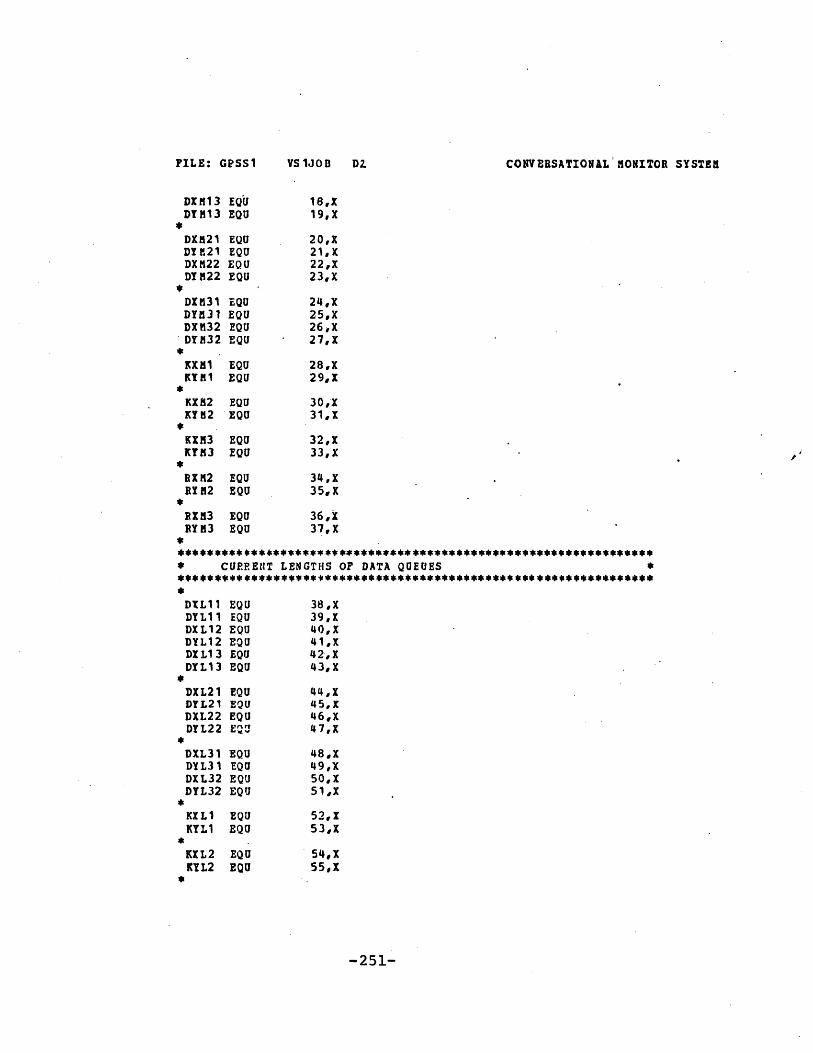
CONVERSATIONAL MONITOR SYSTEM
DXN 13 EQUDT13 EQU
*DX521 EQUDYEh2l EQUDXH22 EQUDY H22 EQU
*DIM31 EQUDY131 EQUDX?132 EQUDY32 EQU
Kl EQUEQU
KXM2 EQUKY112 EQU
KXM3KYM3
*
EQUEQU
RXN2 EQURY82 EQU
RXM3 EQUJPYK3 EQU
18,X19,X
20,X21,X22,X23, X
24,X25,X26,X27,X
28,X29,X
30,X31,X
32,X33,X
34,X35,X
36, X37,X
***** **** ******************************************************** CURRENlT LENGTHS OF DATA QUEUES *********************************$************* *** ******************
DXL11 EQUDYL11 EQUDXL12 EQUDYL12 EQUDIL13 EQUDYL13 EQU
*
DYL21 EQUDYL21 EQUDXL22 EQUDYL22 EQ a
*
DXL31 EQUDYL31 EQUDXL32 EQUJDYL32 EQU
*
KILl EQUKYLl EQU
*.
KXL2 EQUKTL2 EQU
*
38,X39,140,X41,X42-,X43,X
44,145,X46,X47,X
48,X49,X50,X51,X
52,X53,X
54,X55,X
-251-
FILE: GPSS1 VS1JOB8 Di
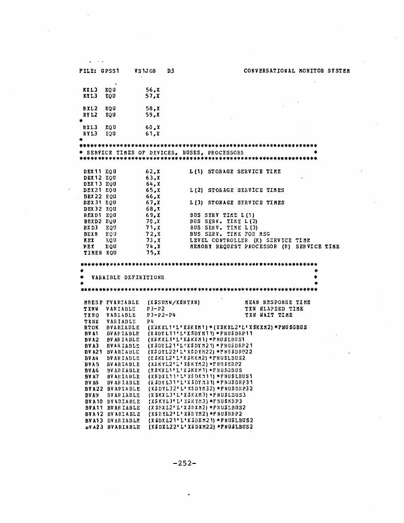
FILE: GPSS1
KXL3 EQUKYL3 EQU
RXL2 EQURYL2 EQU
*
RXL3 EQURYL3 EQU
CONVERSATIONAL MONITOR SYSTEM
56,X57,X
58,X59,X
60,X61,X
* SERVICE TIMES OF DEVICES, BUSES, PROCESSORS ****** ************************************************************
DEX11 EQU 62,X L(1) STORAGE SERVICE TIMEDEX12 EQU 63,XDEX13 EQU 64,XDEX21 EOU 65,X L(2) STORAGE SERVICE TIMESDEX22 EQU 66,XDEX31 EQU 67,X L(3) STORAGE SERVICE TIMES
68,X69,X70 X71,X7 2,X73,X74,X75,X
BUS SERV TIME L(1)BUS SERV. TIME L(2)BUS-SERV. TIME L(3)BUS SERV. TIME FOR MSGLEVEL CONTROLLER (K) SERVICEMEMORY REQUEST PROCESSOR (R)
TIMESERVICE TIME
*********4c*************************************** ****************
* VARAIBLE DEFINITIONS
(X$5UM W/X$NTXN)P3-P2
MEAN RESPONSE TIMETXN ELAPSED TIME
P3-P2-P4 TXN WAIT TIMEP4(X$KXL1'L'X$KXM1)*(X$KXL2'LIX$KXM2)*FNU$GBUS(X$DYL11'L'X$DYM11)*FNUSDRP11(X$KXL1'L'X$KXM1) *FNU$LBUS1(X-DYL21'L'X$DYM21) *FN U$DRP21(X$DYL22' L' X$DYM22) *FN$USDRP22(X$KXL2'L'X$KXM2) *FNU$LBUS2(X$KYL24L' X$KYM2) *FNU$KRP2(X$KXL1'L'X3KXM1)*FNU$GBUS(X$DXL1 1 L' X$ DX311) *FNU$LBUS1(X$DYL31'L'XSDY131) *FNU$DRP31(X$DYL32' Ll X$DYM32) *FNU$DEP32(X$KXL3'L'X$KXM3)*FNU$LBUS3(X$KYL3' L' X$KYM3) *FNU$KRP3(X$RXL2'L'X3PXM2) *FNU$LBUS2(X$RYL2L' X$rYM2) *FNU$RRP2(X$DXL21aLOX$DXM21) *FNU$LBUS2(X$DXL22'L'X$DXM22) *FNU$LBUS2
-252-
DEX32BEXD1BEXD2BXD3BEXMKEXPEXTIMER
EQUEQUEQUEQUEQUEQUEQUEQU
MRESPTXNWTXNQTXNXRTOKBV AlBVA2BVA3BVA21BV A4BVA5BVA6BVA7BV ABBVA22BVA9BVA10BVA 11BVA12BVA13oVA2 3
FVARIABLEVARIABLEVARIABLEVARIABLEBVARIABLEDVAPIABLEBVARIABLEBVARIABLEBVARIAULEBVARIABLEBVARIABLEBVARIABLEBVAEIABLEBVARIABLEBVAPIABLEBV AR IABLEBVARIABLEBVARIABLEBVARIABLEBVARIABLEBVARIABLE
VS1JiOB D3

CONVERSATIONAL MONITOR SYSTEM
BVA14 BVARIABLEBVA15 BVARIABLEBVA16 DVARIABLEBVA17 BVARIABLEBVA18 BVARIABLEBTA19 BVARIABLEBVA24 BVARIABLEBVA20 BVARIABLE
(X$KYL1'L'X$KYM1)*FNU$KRP1(X$KXL2'L X$KXM2) *FNU$GBUS(X$KXL3' L'XSKXM3) *FNU$GBUS(X$RXL3'L' X$RIM3) *FNU$LBUS3(XSEYL3'L'X$RYM3)*FNU$RRP3(XSDXL31'L'X$DXfi31)*FNUSLBUS3(X$DXL32'L'X$DXM32) *FNU$LBUS3(X$KYL1'L'X$KYN1)*FNU$NRP1
********************************************** ******************** *
* QTABLE DEFINITIONS - DISTRIBUTIONS OF QUEUE LENGTHS ** - -*
*
* FUNCTION DEFINITIONS*
VICHNV FUNCTION P1,D32,vWW11/3,WW12/4,WWW13
VICHA FUNCTION P1,D32,AAA11/3,AAA12/4,AAA13
* TABLE DEFINITIONS - DISTRIBUTIONS OF TXN ELAPSED TIME, ** WAIT TIME ** *********************************************** *******************
TlNN TABLETXKQ TABLETINX TABLE
V$TXNW, 100,100, 100V$TXNQ, 100, 100, 100V$TXNX,100,100,100
********************************************* **** ****************
* INITIALIZE CONSTANTS
X$MAXMP,20X$N1READ,700X$NWRIT,300X$PIN1,400X$PIN2,400X$PIN3,1000X$PcV1,500-X$POV2,500X$DX11, 10
DEGREE OF MULTIPROGRAMMING OF A CPU% READ TXN% WRITE TXNPROB OF FINDING READ DATA IN L(1)PROB OF NOT IN L(1) AND IN L(2)PRCB OF FINDING DATA IN L(3)PROB OF OVERFLOW FROM L(1)PROB OF OVERFLOW PROM L(2)MAXIMUM DATA QUEUE LENGTH
-253-
INITIALINITIALINITIALINITIALINITIALINITIALINITIALINITIALINITIAL
FILE: GPSS1 VS1JOB Dl

CONVERSATIONAL MONITOR SYSTEM
INITIALINITIALINITIALINITIALINITIALINITIALINITIALINITIALINITIALINITIALINITIALINITIALINITIALINITIALINITIALINITIALINITIALINITIALINITIALINITIALINITIALINITIALINITIALINITIALINITIALINITIALI NIT IA LINITIALINITIALINITIALINITIALINITIALINITIALINITIALINITIALINITIAL
X$DYm11 ,10X$DXM12, 10X$DYM12, 10X$DXM13, 10X$DYM13, 10XSDXM21, 10X$DYM21,10X$DXYM22,10X$DYM22,10X$DXM31,10X$DYM31,10X$DXM32,10X$DYM32,10'X$KXM1,10XSKYM1,10X$KXM2,10X$KYM2,10X$KXM3,10X$KYM3,10X$RXM2,10X$RYM2,10X$RXM3,10X$RYM3,10X$DEX11,100X$DEX12,100X$DEX13,100 -X.ADLX21,1000X$DEX22, 1000X3DEX31,10000X$DEX32, 10000X$BEXD1,100X$BEXD2,1600X$qEXM,100X$KEX,100X3 REX, 200X$TIMER,10C0000
ACCESS TIME
ACCESS TIME
D21
D31
IN NANOSEC
IN NANOSEC
BUS SERV. TIME IN NANOSEC
L(I) CONTR. P. SERV. TIME IN NANOSREQ. P. SERVICE TIME IN NANOSSIMULATION TIME
* ** MACRO -UTX ** *** ** **** **** ** *** *** ** *** *** ******
UTI STARTMACROSEIZE #ADEPART #BASSIGN 4+,#CASSIGN 7,;CADVANCE P7RELEASE #AENDMACRO
******* ** *** ****** *** **********
-254-
ACCESS TIME OF D11 IN NANOSEC
FILE: GPSS1 VS100B DS5

CONVERSATIONAL MONITOR SYSTEM
* ** HACRO - UQTQ ** *
UQTQ STARTMACROQUEUE #ASEIZE #BDEPART #AASSIGN 4+,#DASSIGN 7,#DADVANCE P7
-RELEASE #BQUEUE #CENDMACRO
* *
* MACRO - UQT ** ************ **************
UQT STARTHACROQUEUE #ASEIZE #BDEPART #AASSIGN 4+,#CASSIGN 7,#CADVANCE P7RELEASE #BENDMAChO
*** ********* ** **** **** **** * ****
* *
* MACRO - UQDQ ** *
UQDO STARTMACROQUEUE tATEST E #G,1SAVEVALUE #D,1SaIZE tEDEPART #ASAVEVALUE #B,1ASSIGN 4+,#FASSIGN 7,#FADVANCE P7RELEASE tEQUEUE #CENDMACRO
4*41******* *** ** ** **** *
-255-
FILE: GPSS1 VS1JOB D4

FILE: GPSS1 VS1JOB D7
* MACRO - UQD ** ****** ***4** ****************
CONVERSATIONAL MONITOR SYSTEM
UQD STARTMlACROQUEUETEST ESAVEVALUESEIZEDEPARTSAVEVALUEASSIGNASSIGNADVANCERELEASEENDMACRO
** MACRO - FINI*
FINI STAFTMACROMARKS AVEVALUES AVEVALUESAVEVALUESAVEVALUESAVEVALUETABULATETABULATETABULATEASSIGNASSIGNASSIGNASSIGNASSIGNASSIGNENDMACRO
#A#G,1#D,14E#A#B, 14+,#F7,#FP7
NTXN+, 1SU MX+,V$TXNXSUMQ+,VZTXNQSUMW+,V$TXNWMEESP,V$mBESPTXNWTXNQTXNX1,02,03,04,05,06,0
SIMULATE*************************** ********
* CPU #1
CPU1 GENERATE ,,,X$MAXMP,,,F
* START FOR CPU1 TXNS *
STAR1 PRIORITY 9MARK 2ASSIGN 1,1
SET HIGH PRIORITYARRIVAL TIME OF TINSET CPU ID = 1
-256-

CONVERSATIONAL MONITOR SYSTEM
TRANSFER .X$NREADWWW1,R.R1* ** *********************** READ TXN FROM CPU1 *
READ OR WRITE TXN?
RRR1 QUEUE DIQ1 READ TXN-SEIZE DRP11DEPART DIQlPRIORITY 0 RESET PRIORITYASSIGN 4+,X$REI TIME FOR DIRECTORY SEARCHASSIGN 7,X$REXADVANCE P7RELEASE DRP11TRANSFER .X$PIN1,NIN11,IND11 IS DATA IN L(i)?
*************** **********
* READ TXN FROM CPU1 ** IS SATISFIED IN L(l) *
IND11 ASSIGN 11,0
* READ DATA FROM D11 **********,*********** ****
DIQ11,DRP11,X$DEX11
* USE FINI MACRO ** THE TXN IS COMPLETED *
FINI MACROTRANSFER ,STAR1
*************,****** ******
* READ TXN FROM CPU1 IS ** NOT SATISFIED IN L(1) *
**** **** *** ***** *** ****
NIN11 QUEUE
THE TIN BECOMES A NEW TIN
D0011
* USE UTX TO USE ** THE LCCAL BUS LBUS1 *
UTX MACRO LBUS1,DOQ1,X$BEXMTRANSFER ,COMR GO TO COMMON CODE FOR READ
* WRITE TXN FROM CPU1 ****** ********************
WW1 QUEUE DIQl1TEST E BV$BVA1,1SAVEVALUE DYL11+,1SEIZE DRP11PRIORITY 0DEPART DIQl1
D11 OUT QUEUE AND DRP FREE?SAVE SPACE IN OUT Q
RESET PRIORITY
-257-
UQT MACRO
MIE: GPSS1 VS1JOB DS

FILE: GPSS1 VS1JOB D9
ASSIGN 4+,X$DEX11ASSIGN 7,X$DEX11ADVANCE P7RELEASE DRP11SPLIT 1,STB1
*** ****** **** **** *** ****
* WPITE TXN IS COMPLETED************************ **
FINI MACROTRANSFER ,STAR1
*************** ******** STORE-BEEIND TXN ****** ********************
STB1 QUEUE DYQ11
TEST E BV$BVA2,1SAVEVALUE KXL1+,1
CONVERSATIONAL MONITOR SYSTEM
TIEE FOR WRITING DATA
CREATE A STORE-BEHIND TXN
BECOMES A NEW TXN FROM CPU1
PUT TIN IN DATA QUEUE
Kl IN-Q AND LBUS1 FREE ?RESERVE SPACE IN IN-Q
***** ********************
* USE LBUS1 TO SEND TXN ** FPOM D11 TO K1 *
******** *** *** *** ** ****
UTX MACFOSAVEVALUETRANSFER
IBUS1,DYQ11,X$BEXD1DYL11-,1 R,CoMW T
ELEASE SPACE IN D1l0 COMMON CODE FOR WRITE
* COMMON CODE FOR ** READ TO LOWER LEVELS ** JOINED BY ALL CPUS ****************** ********
COMR ASSIGN 11,0***** ********************* USE K1 *
******* ** *** ****** ******
DUMMY STATEMENT
UQTO MACRO KIQ1,KriPl,KOQ1,XSKEX***** ********************
* USE GLOBAL BUS GBUS *
UTX MACRO GBUS,KOQ1,X$BEXM******************** *****
*USE K2 *
UQTQ MACRO KIQ2,KFRP2,KOQ2,X$KEX
* USE LOCAL BUS lBUS2 ************* *************
UTX MACRO LBUS2,KOQ2,X$BEXM********************** ***
* USE R2 TO SEE IF DATA *IS IN L(2) *
*********** ****** ********
UQT MACRO PIQ2,BRP2,X$REX
-258-

CONVERSATIONAL MONITOR SYSTEM
TRANSFER .X$VIN2,NIN2,INL2 IS DATA IN L(2)?
* DATA IS NOT FOUND IN **L(2) *
NIN2 QUEUE ROQ2
* ** ** *** **** ***** ** *****
* USE LBUS2 SEND TXN TO ** K2 *
UTX MACRO LBUS2,ROQ2,X$BEXM***** ********************
* SERVICED BY K2 ******** **** **** *** ****
UQT MACRO KIQ2,KBP2,KOQ2,XSKEX***** ***************** ***
* USE GBUS SEND TXN TO **K3 *
UTZ MACRO GBUS,KOQ2,X$DEXN
* SE1EVICED BY K3 ***** ** *** **** ** *** ****
UQTQ MACRO KIQ3,KRP3,KOQ3,XSKEX
* USE LBUS3 SEND TXN TO **R3 *
****** *** * *** **** *****
UTX MACRO LDUS3,KOQ3,X$BEXM********************** ***
* SEARCH DIRECTORY IN ** R3 FOR DATA *
UQT MACRO RIQ3,RRP3,X$REXTRANSFER ,INL3 DATA IS IN L(3)
* DATA IS FOUND IN L(2), READ THE ** DATA AND SEND IT UP TO L(1) *
INL2 QUEUE 002
*********** **************
* SEND TXN TO DEVICE ** VIA LBUS2 *
UTX MACRO LBUS2,ROQ2,X$BEXM
** **** ** * ****** ************** IS DATA IN D11 OR D12? *
-259-
FILE: GPSS1 VS1JOB Dio

CONVERSATICNAL MONITOR SYSTEM
TRANSFER .5,iRRR21,RRR22
* DATA IS IN D11 *
RRR21 QUEUE DIQ21TEST E BV$8VA3,1SAVEVALUE DYL21+,1
* ** ***** * ** *** ***** ****
* USE D21 TO RETRIEVE ** THE DATA *
TIX MACROQUEUE
TEST ESAVEVALUE
QUEUE TO RETRIEVE DATAD21 OUT-Q AND DRP21 FREE?SAVE SPACE IN D21 OUT-Q
DRP21,DIQ21,X$DEX21 RETRIEVE THE DATADYQ21 PUT DATA IN SLOT
BV$BVA4,1KXL2+, 1
K2 IN-Q AND LBUS2 FREE?RESERVE K2 IN-Q SLOT
**** *** ** ******* ** **
* USE LBUS2 SEND DATA TO ** K2 *
UTX MACRO
SAVEVALUETRANSFER
LBUS2,DYQ21, X$BEXD1
DYL21-,1,RTF2
RELEASE SLOT IN D21 OUT-QUEUETO CODE FOR READ-THROUGH FROM L(2)
* DATA IS IN D22 ****** ***************
RRR22 QUEUETEST ESAVEVALUE
UTX MACRO
QUEUETEST ESAVEVALUE
UTX MACRO
DIQ22BV$BVA21,1DYL22+,1
DRP22,DIQ22,X$DEX22
DYQ22BV$BVA4,1KXL2+,1
LBUS2,DYQ22,X$BEXD1
SAVEVALUE DYL22-,1TRANSFER ,RTF2
******** *************************** READ THROUGH PROM LEVEL L(2) **************************** ********
RTF2 ASSIGN 11o
-260-
FILE: GPSS1 VS1JOB Dil

CONVERSATIONAL MONITOR SYSTEM
* SERVICED BY K2 ******* *** *** **** **** ********
UQDQ MACRO KXQ2,KXL2-,KYQ2,KYL2+,KRP2,X$KEXBV$BVA5
TEST E BV$BVA6,1 K1 IN-Q AND GBUS FREE?SAVEVALUE KXL1+,1 RESERVE Kl IN-Q SLOT
** ****** ** ***** *** **
* USE GBUS TO SEND DATA TO**K1 ****.****************4******
UTX MACRO GBUSKYQ2,X$BEXD1SAVEVALUE KYL2-,1 RELEASE SLOT IN K2
***** ******************************
* STORE DATA INTO L(1) AS A RESULT** OF READ-THROUGH *
STOR1 ASSIGN 11,0
***** ********************
* SERVICED DY K1 *
UQD MACRO KXQ1,KXL1-,,KYL1+,KRP1,I$KEX,BVSBYA2O
* SEND TO D11 OR D12 ************ ***************** *****
SPLIT 1,FNSICHW,1TERMINATE
* STORE TO Dl *
VWl ASSIGN 11,0QUEUE KYQ1TEST E BV$BVA7,1
. SAVEVALUE DXL11+,1
* **** ****** **** ** ** *** ***
* SEND TXN TO D11 VIA ** LBUS1 *
UTX MACRO LDUS1,KYQ1,X$BEID
SAVEVALUE KYLI-,1
******** *** ***** ** ***
WHICH DATA CACHE TO GO?
WRITE TO D11
SPACE IN D11 IN-Q AND LBUS1 FREE?YES, RESERVE A SLOT
RELEASE K1 SLOT
-261-
FILE: GPSS1 VS1JOB D 12

CONVERSATIONAL MONITOR SYSTEM
* WRITE DATA TO D11 ********* 4*****l***********
UQT MACRO DXQ11,DRP11,X$DEX11
SAVEVALUE DXL11-,1TRANSFER .XSPOVINOV11OVL11 ANY OVERFLOW FROM L(1)?
* NO OVERFLOW FROM L(1) ****** ****** **************
NOVll ASSIGN 11,0
***** ********************
* THE READ TXN HAS ENDED*
FINI MACROTRANSFER STAR1
* THERE IS OVERFLOW FRCM** L(1), END THE READ ** TXN, AT THE SAME TIME ** HANDLE THE OVERFLOW ****** * ** I* ****** * ** *** ***
OVL11 SPLIT 1,OVF11 GOT. OVERLOW HANDLINGFINI MACRO AT T'E SAME TIME END THE TXN
TRANSFER ,STAR1
* OVERFLOW HANDLING FOR **D11 ** **** *** *** ** ** ***** ** ***
OVF11 ASSIGN 11,0
UQT MACRO DOQ11,LBUS1,X$BEXMTRANSFLR ,OVL1 GOTO COMMON CODE FOR OVERFLOW
* WWW12 *
* WWW13 *
NWW12 ASSIGN 11,0WWW13 ASSIGN 11,0
* COMMON CODE FOR OVERFLOW FROM ** L (1) *
-26 2-
VS1lJOB Dli:IFILE: GPSS1

CONTERSATIONAL MONITOR SYSTEM
OVLl ASSIGN 11,0
************** ********************** USE Ki, THEN GBUS, THEN K2 ** THEN LBUS2, THEN USE R2************ ***********************
UQTQ MACRO KIQ1,KRP1,KOQ1,X$
UTI MACRO GBUS,KOQ1,X$BEXM
UQTQ MACRO KIQ2,KRP2,KOQ2,X$
UTX MACRO LBUS2,KOQ2,X$BEXN
QUEUE RIQ2
UTX MACRO RRP2rBIQ2,X$REX
TERMINATE
* DATA IS FOUND IN L(3) ******** ****** ** *** ****
INL3 QUEUE EOQ3
* * *** ** ** ** ******* * *** * **
* USE LBUS3 SEND TXN TO **D31 *
UTX MACRO LBUS3,ROQ3,X$BEXH
* ** ** ****** *** ** ** *** ******
* READ FROM D31 OR D32? *
TRANSFER .5,ERR31,RRR32
* READ FROM D31 ****** ***************
RRR31 QUEUE DIQ31TEST E BV$BVA8,1SAVEVALUE DYL31+,1
* READ DATA FROM D31 ****** ********************
SPACE IN D31 OUT-Q AND DRP31 FREE?
-263-
PILE: GPSS1 VS1JOB D1S

CONVERSATIONAL MONITOR SYSTEM
UTX MACRO
QUEUETEST ESAVEVALUE
DRP31,DIQ31,X$DEX31
DYQ3 1BV$BVA9,1KXL3+,1
SPACE IN K3 IN-Q AND LBUS3 FREE?YES, RESERVE SLOT
***** *** **** **** *** ****
* USE LBUS3 SEND DATA TO ** K3 ****************.****** ****
LBUS3,DYQ31,X$BEXD2
SAVEVALUE DYL31-,1TRANSFER ,RTF3 GO TO READ-THROUGH FROM L(3)
* READ FLOM D32 *
BRR32 QUEUETEST ESAVEVALUE
UTX MACRO
Q)UEIETEST ESAVEVALUE
UTX MACRO -
DIQ32BV$BVA22,1DYL32+,1
DRP32,DIQ32,XSDEX32
DYQ32BV$IIVA9,1KXL3+,1
LBUS3,DYQ32,X$BEXD2
SAVEVALUE DYL32-,1TRANSFER ,RTF3
************ ********** *************
* READ-THROUGH FROI L(3) DATA IS ** SENT TO L(2) AND L(1) AT THE ** SAME TIME *
RTF3 ASSIGN 11,0
* SERVICED BY K3 *
UQDQ MACRO
TEST ESAVEVALUESAVEVALUE
KXQ3,KXL3-,KYQ3,KYL3+,KRP3,X$KEX,BV$BVA1O
BV$RTOK,1KXL1+,1KXL2+,1
L(1) & L(2) READY & GBUS FREE?
* BOTH L(1) AND L(2)
-264-
UTX MACRO
FILE: GPSS1 VS1JOB Dl.

CONVERSATIONAL MONITOR SYSTEM
* READY TO ACCEPT DATA ** FRO GBUS ** ** ***** *** ** **** *4'*****
UTZ MACRO GDUSKYQ3,X$BEXD2
SAVEVALUE KYL3-,1SPLIT 1,STOR1 READ-THROUGH TO L(1)
* READ-THROUGH TO L(2) *
STOR2 ASSIGN 11,0
***** ********************
* SERVICED BY K2 ***** ** ***** ** *** ** ****
00D MACRO KXQ2,KXL2-,KYQ2,KYL2+,KRP2,X$KEXDVSBVA5
TEST E BVSBVA11,1 SPACE IN R2 IN-Q AND LBUS2 FREE?SAVEVALUE EXL2+,1 YES, RESERVE SLOT
* USE LDUS2 SEND TO R2 ********************* *****
UTZ MACRO LBUS2,KYQ2,XSBEXD2
SAVEVALUE KYL2-,1 FREE SLOT.IN K2
* ** *** **** *** ***'* ** ** ***
* SERVICED BY R2 *
UQD MACRO BXQ2,RXL2-,,RYL2*RRP2,X$REX,BV$BVA12
SPLIT 1,OVH2 HANDLE ANY OVERFLON
* STORE INTO D21 OR D22? ** **** * ** **** * * *******'* * * ** * ****
TRANSFER .5,sSS21,SSS22
***** ********************
* STORE INTO D21 ****** **** **** ** *** ** ****
SSS21 QUEUE RYQ2TEST I BV$BVA13,1 D21 IN-0 AND LBUS2 FREE?SAVEVALUE DXL21+,1 YES, RESERVE THE SPACE
-265-
FILE: GPSS1 VS1JOB D16

VILE: GPSSI VS1JOB DI7
* SEND DATA TO D21 VIA BUS ****** ** ************** ***4'******
UTX MACRO
CONVERSATIONAL NOITTOR SYSTEN
LBU 52, RY02,X$8EXD2
SAVEVALUE VYL2-,1
UQOT MACPO
SAVEVALUETERMINATE
PELEASE SPACE IN R2
DXQ21,DRP21,X$DEX21
DXL?1-,1
STORE INTO D22 *
SSS22 QUEUETEST ESAVEVALUE
UTX MACRO
SAVEVALUE
UOT MACRO
SAVEVALUETERMINATE
RYQ2BV$BVA23, 1DXL22+,1
LBUS2,RYQ2,X$BEXD2
RYL2-,1
DXQ22,DRP22,X$DEX22
DXL22-,1
* HAND. ANY OVEERF. FROM 1(2) *
OVU2 TRANSFER .X$POV?,NOV2,OVL2OVL2 QUEUE ROQ2
* USE LBUS2, USE K2, USE ** GBUS, USE K3, USE LBUS3,* TIEN USE P3
UTX MACPO
UQTQ MACRO
UTX MACRO
UQTQ MACRO
UTX MACRO
UQT MACRO
******* ***
LBUS2, EOQ2,X$BEXM
KIQ2,KRP2,KOQ2,X$KEX
GBUSKOQ2,X$EBEXM
KIQ3,KRP3,KOQ3,X$KEX
LBUS3,KOQ3,X$BEXM
RIQ3,RPP3,X$REX
TERMINATE
-266-
NOV2

CONVERSATIONAL XONITOR SYSTEM
********************** ***
* COMICN CODE FOR WRITE ** TO LOWER LEVELS *
COMW ASSIGN 11,0 DUMMY STATEMENT
*** * *** ***** *** ** *** ****
* SERVICED BY K1 *
UQDQ MACRO KXQ1,KXL1-,KYQ1,KYL1+,KRP1,X$KEXBV$BVA 4
TEST E BV$BVA15,1 K2 IN-Q AND GBUS FREE?SAVEVALUE KXL2+,1
* USE GBUS ****** * *** ****** *** ** ****
UTX MACRO GBUSKYQ1,X$BEXD1SAVEVALUE KYL1-,1
* SERVICED BY K2 *
UQDQ MACRO KXQ2,KXL2-,KYQ2,KYL2+,KRP2,X$KEXBVSBVAS
TEST E BV$BVA11,1 R2 IN-Q AND LBUS2 FREE?SAVEVALUE RXL2+,1
* ** ****** **p* ** ***** ** ****
* USE LBUS2 ****** ********************
UTX MACRO LBUS2,KYQ2,X$BEXD1SAVEVALUE KYL2-,1
* *** * *********** ** ** ** ** ** SERVICED BY R2 ********* *****************
UQD MACRO RXQ2,RXL2-,,RYL2+,RRP2,X$REXBV$BVA12
* ** **** ** ** * * **** ** *** *** * ** * '***
* SERVED BY D21 OR D22? *
TRANSFER .5,SWS21,SWS22
***** *** **** **********
* SERVICED DY D21 *
-267-
FIL91': GPSS1 VS1JOB D/g

CONVERSATIONAL MONITOR SYSTEM
SVS21 QUEUE RYQ2TEST E BVSBVA13,1SAVEVALUE DXL21+,1
UTX MACRO LBUS2,RYQ2,X$BEXD1
SAVEVALUE RYL2-,1UQDQ MACRO DXQ21,DXL21-,DYQ21,DYL21+,DRP21,X$DEX21,BV$BVA3
TEST E BV$BVA4,1 K2 IN-Q AND LBUS2 FREE?SAVEVALUE KXL2+,1
*** **** ** *** ***** ** ****
* USE LDUS2 SEND TO K2 ********************* *****
UTX MACRO LBUS2,DYQ2iX$BEXD2
SAVEVALUE DYL21-,1SPLIT 1,ACK2 PREPARE TO SEND ACK TO L(1)
TRANSFER ,STD23 GO TO STORE-BEHIND TO L(3)
* **** *** **** *** ***** ** *******
* SEND ACK TO L(1) ****** *************************
ACK2 QUEUE DOQ21
UTX MACRO LBUS2,DOQ21,X$BEXM
TRANSFER ,ACK21
* SERVICED BY D22 *
SRS22 QUEUE RYQ2TEST E BV$BVA23,1SAVEVALUE DXL22+,1
UTX MACRO LBUS2,RYQ2,X$BEXD1
SAVEVALUE RYL2-,1
UQDQ MACRO DXQ22,DXL22-,DYQ22,DYL22+,DRP22,X$DEX22,BV$BVA21
TEST E BV$BVA4,1SAVEVALUE KXL2+,1
UTX MACRO LBUS2,DYQ22,XSBEXD2
SAVEVALUE DYL22-,1SPLIT 1,ACK3
-268-
FILE: GPSS1 VS1JOB Dli

CONVERSATIONAL MONITOR SYSTEM
TRANSFER ,STB23
ACK3 QUEUE DOQ22
UTX MACRO LBUS2,Do022,X$BEXM
TRANSFER ,ACK21
* STORE-BEHIND FROM ** L(2) TO L(3) *
STB23 ASSIGN 11,0
UQDQ MACRO KXQ2,KXL2-,KYQ2,KYL2+,KRP2,X$KEXBV$BVA5
TEST E BV3BVA16,1 K3 IN-Q AND GBUS FREE?SAVEVALUE KXL3+,1
UTX MACRO GBUSKYQ2,X$BEXD2
SAVEVALUE KYL2-,1
UQDQ MACRO KXQ3,KXL3-,KYQ3,KYL3+,KRP3,X$KEX,BV$BVA10
TEST E BV$BVA17,1 R3 IN-Q AND LBUS3 FREE?SAVEVALUE RXL3+,1
UTX MACRO LBUS3,KYQ3,X$BEXD2
SAVEVALUE KYL3-,1
UQD MACRO RXQ3,RXL3-,,RYL3+,RRP3,X$REXBV$BVA18
*** ** ****** * ***'*** ** *** *********
* SERVICED BY D31 OR D32? *
TRANSFER .5,SWS31,SWS32
* SERV. BY D31 ****************** 4***
SWS31 QUEUE RYQ3TEST E BV$BVA19,1SAVEVALUE DXL31+,1
UTI MACRO LBUS3,RYQ3,X$BEXD2
SAVEVALUE RYL3-,1
-269-
FILE: GPSS1 VS1JOB D2o

CONVERSATIONAL MONITOR SYSTEM
UOT MACRO DXQ31,DRP31,X$DEX31
SAVEVALUE DXL31-,1
UOT MACRO DOQ31,LBUS3,X$BEXl-TRANSFER *ACK22
*********** ****** ***
* SERV. BY D32 ****** ***************g
SNS32 QUEUE RYQ3TEST E BVSBVA24,1SAVEVALUE DXL32+,1
UTX MACRO LBUS3,RYQ3,X$BEXD2
SAVEVALUE RYL3-,1
UQT MACRO DXQ32,DRP32,X$DEX32
SAVEVALUE DXL32-,1
UQT MACRO D0032,LBUS3,X$BEXM
TRANSFER ,ACK22
*********** ************************
* ACK FROM L(2) TO L(3) *
ACK22 ASSIGN. 11,0
UQTQ MACRO KIQ3,KRP3,K003,X$KEX
UTX MACRO GBUS,KOQ3,X$BEXM
UQTQ MACRO KIQ2,KRP2,KOQ2,X$KEX
UTZ MACRO LBUS2,KO02,X$BEX
UQTQ MACRO R102,RRP2,RO02,X$REX
UTX MACRO LBUS2,ROQ2,X$BEXMTRANSFER ,ACK21
******* ****************************
* ACK FROM L(2) TO L(1) *
ACK21 ASSIGN 11,0
UQTQ MACRO KIQ2,KRP2,KOQ2,X$KEX
-270-
FILE: GPSS1 VS1JO'B D21

CONVERSATIONAL MONITOR SYSTEM
UTX MACRO
UQTQ MACRO
UTI MACROSPLITTERMINATE
AAA11 ASSIGNAAA12 ASSIGNAAA13 ASSIGN
QUEUESEIZEDEPARTASSIGNASSIGNADVANCERELEASETERMINATE
GDUSKOQ2,X$BEXM
KIQ1 ,KRP1,KOQ1,X$KEx
LBUS1, KOQ1,X$DEXN1,FN$WICHA,1
11,011,011,0DIQ1lDRP11DIQ1l4+,X$REX7,X$REXP7DEP11
******************* AAA12 *
******* ** **** ****
* AAA13
* TIMER SEGNENT - TINE UNIT IS ** ONE NANOSECOND *
GENERATETERBINATE
STARTEND
XSTIKER1
1
-271-
FILE: GPSS1 VS1JOB D22

Appendix B
FLOW CHART OF THE P5L4 MODEL
- 272 -

(star1)
(comr)
-273-

(star2)
sendstore-behind
to Ki via lbuj 1
yes
(comw)
(comr)
-274-

(star3)
(comr)
-275-

(star4)
yes
(comw)
(comr)
-276-

(star5)
(comw)
(comr)
-277-
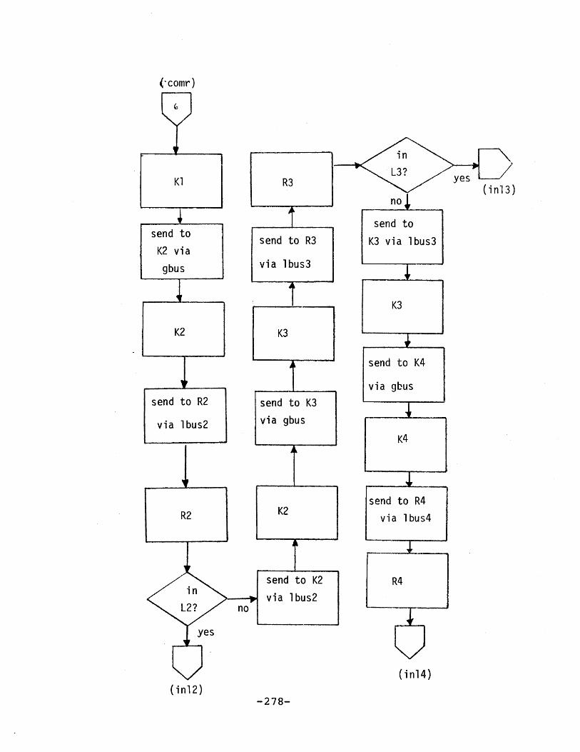
(-comr)
(in13)
(inl4)(in12)
-278-
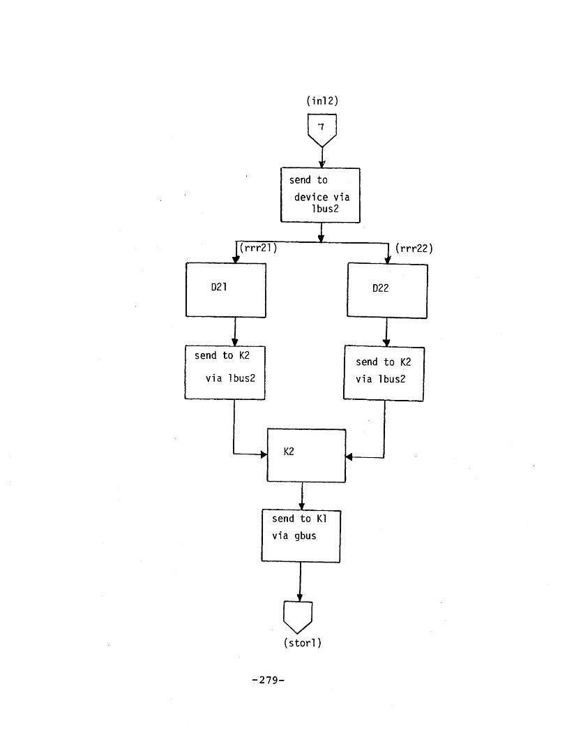
(inl2)
(rrr22)
(storl)
-279-

(www1l (wwwl 4)(www1l (wwwk )
(starl)
-280-

(inl3)
(rrr32)
(storl) (stor2)
-281-

(stor2
(sss22)
-282-

i n1 4)
-283-

(stor3)
(sss32)
-284-

(comw)
(sws2l)
-285-(stb23)
(sws22)
(ack2l)

(stb23)
(sws3l)
-286- (ack32)(stb34)

(stb34)
(sws4l)
(ack43)
-287-
sws42

(ack2l)
(aaall) (aaal2) (aaal4) (aaa15)
-288-

(ack32)
(ack2l)
-289-

(ack43)
(ack32)
-290-

Appendix C
LISTING OF THE P5L4 MODEL
- 291 -

CONVERSATIONAL MONITOR SYSTEM
//LAH4 JOB LAMMPOFILF='RETURN',// PROFILE=ILOW',// TIE=9//*PASSWOrD//GPSS PROC//C EXEC PGM=DAGO1,TIME=&TLIMIT//STEPLIB DD DSN=POTLUCK.LIBEARY.GPSS.LOADDISP=SHR//DOUTPUT DD SYSOUT=PROFILE=RETURN,DCB=BLKSIZE=931//DINTERO DD UNIT=SCBATCHSPACE=(CYL,(1,1)) ,DCB=BLKSIZE=1880//DSYMTAB DD UNIT=SCRATCH,SPACE=(CY L, (1,1)) ,DCB=BLKSIZE=7112//DR!EPTGEN DD UNIT=SCE ATCII,SPACE=(CYL, (1,1)) ,DCB=BLKSIZE800//DINTWORK DD UNIT=SCR AT CHSPACE= (CYL', (1,1) )DCB=BLKSIZE=2680// PEND//STEP1 EXEC GPSSPAR=C.,TLIMIT=9//DINPUT1 DD *
E EALLOCATE FUN,5, QUE, 10, FAC,50, BVR, 200 BLO ,2000,VAR,50.'REALLOCATE FSV,50,HSV,10,COM,40000
* * * *** ***** ** *** *** ** ****
* *
* TXN PARM USAGE *-* *
* P1 CPU ID ** P2 TXU ARRIVAL TIME** P3 TXN COMPL TIME ** P4 TXN EXEC TIME ** P11 DUMMY ** ****** ********************
** ***** *** * **** ** *** ***** *
* .0DEL COMPONENTS **A
* BUSES: GBUS, LBUS1,.. ** CACHES: D11,...D15 ** LEVEL CONTRL: K1,...K4** REQ PROCS: R2, .. R4 ** DEVICES: D21, ...D42 ** STORAGE : RI, RO ** STORAGE : SI, SO ** STORAGE : TI, TO ** STORAGE : AI, AO ** STORAGE : OI, 00 ** *
** ** *** **** *** *** ** *****
* *
* MODEL PARAMETERS ** . *
INITIAL X$AXMP,10 DEGREE OF KULTIPROG PER CPUINITIAL X$NREAD,500 - READ REQ
-292-
FILE: GPSSS4 VS1JOB D1

CONVERSATIONAL MONITOR SYSTEE
INITIALINITIALINITlALINTTIALINITIALINITIALINITIALINITIALINITIALINITIALINITIALINITIALINITIALINITIALINITIALINITIALINITIALINITIALINITIALINITIAL
X$ NWRTT,500X$PIN1,900X$PIN2,900X$PIN3,900X$PlN4,1000X$POV1,500X$POV2, 500X$POV3,500XSDEX1,10X$DEX2,100X$DEX3,200X3DEX4,1000X$BEXM,10X$BEX1,10XSBEX2,80XSBEX3,320X3REX,20X$KEX,10X$RDEX1, 30XITIMER,200000
% WRITE HEQCONDITIONAL PRO.3 OF FINDING DATAIN A LEVEL GIVEN THAT THEDATA IS NOT FOUND IN ANY UPPERLEVELPROB OF OVERFLOW
DEVICE SERVICE TIME
BUS SERVICE TINE
DIRECTORY LOOK UPCONTROLLER SERV TINELOOKUP PLUS READ TIME 0 CACHESINULATION TIME
* SAVEVALUES
* NTXN TOTAL TXN PROC. ** SUMX TOTAL EXEC TIMES ** SUMNWTOTAL WAIT TIMES ** SUMT TOTAL ELAPSED TIN** *
* **** ** **** ** * *** *****
** VARIABLES
**
FVARIABLE (X$SUMT/X$NTXN)VARIABLE P3-P2VARIABLE P3-P2-P4VARIABLE P4
MEAN RESP TIMETXN ELAPSED TIMETXN WAIT TIME.TIN EXEC TIME
TXNT TABLETXNW TABLETZNX TABLE
VSTXNT, 100, 100, 100V$TXNW, 100,100,100V$TXNX, 100,100,100
-293-
***** ******** ************
HRESPTXNTTXNNTXNK
************************** *
* TABLES ** *
FILE: GPSS54 VS1JOB D2

FILE: GPS554 VS1JOB D3 CONVERSATIONAL MONITOR SYSTEM
FUNCTIONS*-
NICHNW FUNCTION P1,DS2,WWW11/3,WWW12/4,WWW13/5,WWW14/6,WWW15
WICHA FUNCTION P1,DS2,AAA11/3,AAA12/4,AAA13/5,AAA14/6,AAA15
*STORAGE FOR L (1) * -CACHES*
STORAGE RD1,0SSD32/TI1l/SA13lSTORAGE SRD41/$Ilo/$I1oOSAD4lSTORAGE SRD51/$Ile/$I1oOSAD5l
STORAGEODEISSOAES$RID11,10/S$SID2112/S$TID1,0S$I111STRAES$RID12,10/S$SID12,21/S$TID2,10SAD21SOAES$RID13,10/S$SID13,2/S$TID1,10SAD31SOAES$RID14,10/SSSID14,20/S$TID14,10/SAD41
STOR AGE S$RID415,10/S$SID415,2/S$TID1,10SAD51
*STORAGE FOR DEVIPC * .
STOR AGE $I31/$I31/$I31/$Ivl/$RolSTORAGE SBB,0SSRl/$I~l/$l~l/$I~l
STORAGE RKSTORAGE S$RID21,10/S$SKID21,1/$TID21,10IllOS$O1,l
S$RD2,1/SS22,94 $I221

FILE: GPS554 .VS1JOB D+-
*STORAGE FOR K2vK3,K4*
STORAGESTORAGESTOR AGFSTORXGEST ORAGESTORAGE
CONVERSATIONAL MONITOR SYSTEMl
S$RIK2,1O/S$SIK2,1O/S$TIK2,1O/S$AIK2,10/S$01K2,10S$RIK3,1O/S$SIK3,1O/S$-TIK3,1O/S$AIK3,1O/S$OIK3,10S$PIK), 1O/S$S-IKl 1/S $TIK4t 1O/S$ANIK44 1O/S$OEK4, 10S$PoK2,1O/S$S0K2,1O/S$T0rK2,10/S$AOK2,10/S$00K2,,10S$PCK3, 1O/S$SOK3, 10/S$TOK3, 1O/S$AOK3, 10/S$00K3, 10S$ R 0K4 ,1O/S$SOK 4, 1/S$TOK4,10O/S $AOK4 ,10/S $00K4 , 1
*BOOLEAN VARIABLES *
*BY FOR READ-THROUGH *
RTOK2 BVkkfEABLERTOK3 BYARIABLERTOK4 BVARIABLE
*BY FOR L(l)
DKP 1DKS1T)KOlKDT11KDT 12KDT1 3KDT 14KDT1 5KDA1 1KDA12KDA13KDA1 4KDA15
DVARIABLEDVARIABL7BYARIABLEBV AKIA3L~EBVARIABLEBVAHIABLEBVARIADLE.BYAPIABLEBV AR lABLEIVARIABLEBVAPRIABLEBVARIADLEBV AR IABLE
FNU$GBUS*SNF$TIK1FNU$GBUS*SNF$TIKl*SNF$TIK2FNU$GDUS* SNF$TIK 1*SNF$TIK2*SNF$TIK3
FNU$LBUS1*SNF$ROK1FNU$LD3US 1*SNFSOK1FNU$LBUS1*SNF$OOK 1FNU$ LBUS1*SNFXTID11FNIJ$LIUS1*SNF$TID12FNUSLBUS1*SN?$TID13FNU$LBtJS1*SNF$TID14FNU$LBtJS1*SNF$TID15FNEJ$LBUS1*SNF$AID1 1FNU$ LBUS1*SNF$AID12FNU$LBEJS1*SNF$AID13FNUSLBUS1*SNF$AID14FNU$LDUS1*SNF$AID15
*BY FOR INTER LEVEL COM*
KKR12 BVARhBLEKKS12 BVAFIABLE
FN U$G BUS *5NF$ RIK 2FNU$GBU S*SNF$SIK2
-295-

FILE GPS54 S1JO D5CONVERSATIONAL MONITOR SYSTEM
KK612 BVMUIABLZKKT21 BVARIABLEKKA21 BVAFIABLEKKiE23 BYAPIABLEKKS23 IVARIABLEKK023 BJIABIABLEKKT32 BYAPIABLEKKA32 BYAPIABLEKKR34 BVAPIABLEK KS34& B'IAPLABLEJKK034 IVARIABLEKCKT43 BYAPIABLEKKA43 BYARIABLE
FNU$ GBIS*SNFPSSOK2?NU$GBUS'*SNP$TIK1FNUSGIJUS*SNF$ AIK1FNU$GBUS*SNF$RIK3FNUSGBIYS*SI4FSSIK3FNU$GBUS*SNFSOIK3FNU$GBUS*SJF$T1"K2FNIJ fGDLS*SNF$AIIC2FNU$GBUS*SNF$RIK4-FNU DGBUS*SNP$SIK4FNUSG:BUS*SNF$OI(4FNU$GBU S* SNP$TIK3FNUSG.BUS*SNF$AIK3
***** **4L*****************
* ** BY FOR L(2) OPS *** ** * * ***** ** ** * *** ** **
TPRB2 BYAPIABLEKRS2 BVARIABLZ'KET2 BVARIABLEKRA2 BVANIABLEKRO2 BVARIUkLERDR21 BVARIABLEEDS21 BVAFIABLEEDT21 BYARIABLEBDR22 BYARIABLEEDS22 BVARIABLEBDT22 BVARIABLEDKS2 BVARIABLEDKT2 BVAPIABLEDKA2 BYARIABLERKR2 IVARIABLEPK02 .DV ARIABLEPKA2 BVARIABLE
FNU$LBUS2*SNF$R1R2FI4U$fLBUS2*SNF$SIR2FNU$LBUS2*SNF$TIRt2FNU$LI3US2*SNFSAIR2FNU$LDU52*SNF$OIR2FN U$lBUS2*SNF$RID21F NU $LBIJ S2* SN? $SI D21FNU$LBUS2*SNF$TID21FNU$LBUS2*SNF$HID22FNU$ L1US2*SNFS1D22?PNU$L13fS2* SN? 5TID22FNU$LBiUS2*SNF$SOK2FN U$L BUS2* SN? $TOK2FNU$LI3US2*S NFSAOK2FNU$LBUS2*SNF$ROK2PNU$LBUS 2*SNF$00K2FNU$LBUS2*SNF$AOK2
*BV FOR L (3) OPS
KRR3 BVARIABLE1(953 BVARIABLEKRT3 BYABIABLEKRA3 DYARIABLEKP03 BYARIABLERDR31 BVARIABLERDS31 -BVAP IABLERDT31 BVARIABLERDR32 BVARIABLE'RDS32 BYARIABLERDT32 DVARIkBLE
FNU$LBUS3*SNF.$RIR3FNU$LBUS3*SNF$SIR3FNU$LBUS3*SNF$TIR3F N USLBU S3*SNF $Al 93PNU$LBUS3*SWF$01R3FNU$LBUS3*SNF$R1D31FNU$LBUS3* SNFSSID31FNU5LBUS3*SNP$T.ID31FNUSLBU S3*sN?$P1D32FNUSL13US3*SNPSSID32FNU$LBUS3*SNFSTID32
-296-
FILE: GPSS 4 VSIJOB DS'

CONVERSATIONAL MONITOR SYSTEM
DlS 3 BVARIABLE FNil$LBU.'3*SNF$SOK3DKT3 BVARIABLE FNUSLDUS3*SNF$TOK3DKA3 BVARIABLE FNU$LBUS3*SNF$AOK3PKR3 BVARIABLE FNU$LBUS3*SNF$ROK3RKA3 BVAPIABLE FNU$LBUS3*SNF$AOK3RKO3 BVARIABLE FNU$LBUS3*SNF$00K3
***** ****************4***** *
* BV FOR L(4) OPS *e- *
* ** ** ****** ** **** *** ** ***
KRR4 BVARIABLE FNU$LBUS4*SNF$PIR4KRS4 BVARIABLE FNU$LBUS4*SNF$SIR4KRO4 DVARIABLE FNU$LBUS 4*SHF$01R4RDR41 BVARIABLE FNU$LBUS4*SNF$RID41RDS41 BVARIABLE FNUSLBUS4*SNF$SID41RDR42 DVARIABLE FNU$LBUS4*SNF$RID42RDS42 BVAPIABLE FNU$LBUS4*SNF$SID42DKT4 BVARIABLE FNU$LBUS4*SNF$TOK4DKA4 BVAFIABLE FNU$LBUS4*SNF$AOK4
** ** *** *** ***** ** *** ** ***
* *
* MACROS ** *
4***** ********** I*********
* *
* MACRO -USE ** #A FACILITY ** #B USAGE TIME ** *
USE STARTMACROSEIZE #AADVANCE #BASSIGN 4+,#BRELEASE #AENDMACRO
*********** *************** *
* MACRO - SEND ** *
*#A FROM ** #B TO **#C VIA ** #D TRANSIT TIME ** #E BV FOR SEND OP ** *
-297-
FILE: GPSSS4 VS1JOB D6

CONVERSATIONAL NONITOR SYSTEM
SEND STARTAACROTEST EENTERSEIZEADVANCEASSIGNRELEASELEAVEENDIIACRO
#E,1#B#C#D4+,#D#C#A
*.************************
* BACRO - FINI
***** ********************
FINI STARTMACROMARKSAVEVALUESAVEVALUESAVEVALUESAVEVALUESAVEVALUEASSIGNASSIGNASSIGNASSIGNENDMACRO
.3NTIN+,lSUMX+,V$TXNXSUMN+,V$TXNNSUIT+,V$ TINTmRESPV$NESP1,02,0'3,04,0
BEGIN SINULATION
**--------------------------------------------------------------*
SINULATE*********************** **
* CPU #1*
RMULT
CPU1 GENERATESTAR1 PRIORITY
NARKASSIGNTRANSFER
RRR1 TRANSFER
3,5,7,9,11,13,15,17
,,,X$MAXMP, ,,F9 SET HIGH P FOR NEW TIN2 ARRIVAL TINE1,1 CPU ID.X$NREAD,WWW1,RRR1.X$PIN1,NIN11,RIN11
* ** DATA IS IN DATA CACHE *
-298-
FILE: GPSS&-4 VS1JOB D7

CONVERSATIONAL MONITOR SYSTEM
RIN11 ENTER RID11USE MACRO DRP11,X$RDEX1
LEAVE RID11FINI MACRO
TRANSFER ,STAR1
**** * * **** ***************
* *
* DATA IS NOT IN CACHE ** ****** ************4********
NIN11 ENTER,USE, MACRO
PRIORITYSEND MACRO
PUT TXN IN READ REQ BUFFERSEARCH AND READ CACHEFREE BUFFER
A NEW TXN
RIDl1 PUT IN READ REQ BUFFERDRP11,X$REX SEARCH DIRECTORY0 RESET PRIORITYRID1,ROK1,LBUS1,X$BEXMBV$DKR1
TRANSFER ,COMR TO COMMON CODE FOR READ
* WRITE REQUEST TO CACHE*
WWWI ENTER
USE MACRO
SID11 PUT %(N IN WRITE REQ BUFFER
DRP11,XSRDEX1 WRIVE DATA IN CACHE
PRIORITY 0 RESET TXN PRIORITYSEND MACRO SID11,SOK1,LBUS1,X$BEX1,BV$DKS1
SPLIT 1,COMW
FINI MACRO
TRANSFER ,STAR1
***** ********************
* CPU #2
* ** ** ** ** * **** * ** ** **** **
CPU2 GENERATESTAR2 PRIORITY
MARKASSIGNTRANSFER
RRR2 TRANSFER
,,,X$MAXMP,,,F9 SET HIGH P FOR NEW TXN2 ARRIVAL TIME1,2 CPU ID.X$NREADWWW2,RRR2.X$PIN1,NIN12,IN12
-299-
A NEW TXN
FILE: GPSS54 VS1JOB D8
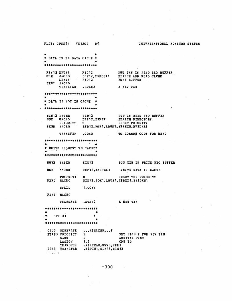
FCLLE: GPSS54 VS1JOB Di
* *
* DATA IS IN DATA CACHE ** ** **** **** *** ** *** *******
RIN12 ENTER RID12USE MACRO DRP12,X$RDEX1
LEAVE RID12FINI MACRO
TRANSFER ,STAR2
* *
* DATA IS NOT IN CACHE ** *
CONVERSATIONAL MONITOR SYSTEM
PUT TXN IN READ REQ BUFFERSEARCH AND READ CACHEFREE BUFFER
A NEW TXN
VIN12 ENTER RID12 PUT IN READ REQ BUFFERUSE MACRO DRP12,X$REX SEARCH DIRECTORY
PRIORITY 0 RESET PRIORITYSEND MACRO RID12,ROK1,LBUS1,X$BEXH.BV$DKR1
TRANSFER ,COmR TO COMMON CODE FOR READ
* ** ** *** ** ******** ******* *
* WRITE REQUEST TO CACHE** ** **** **** ** *** *** *** ***
WWW2 ENTER
USE MACRO
SID12 PUT TIN IN WRITE REQ BUFFER
DRP12,X$RDEX1 WRITE DATA IN CACHE
PRIORITY 0 RESET TXN PRIORITYSEND MACPO SID12,SOK1,LBUS1,X$BEX1,BV$DKS1
SPLIT 1,CO MW
FINI MACRO
TRANSFER ,STAR2
*** ********************** ** CPU #3 ** ** **** ** ** * * *************
A NEW TXN
CPU3 GENERATE ,,,X$MAXMP,,,FSTAR3 PRIORITY 9 SET HIGH P FOR NEW TIN
MARK 2 ARRIVAL TIMEASSIGN 1,3 CPU IDTRANSFER .X$NREAD,WWW3,PRR3
BRR3 TRANSFER .X$PIN1,NIN13,RIN13
-300-

FILE: GPSS54 VS1JOB D10
***4******* **************** *
* DATA IS IN DATA CACHE ** *.
**** **** *** **** *** ****
RIN13 ENT.ER RID13USE MACRO DRP13,X$RDEX1
LEAVE RID13FINI "ACRO
TRANSFER ,STAR3
CONVERSATIONAL MONITOR SYSTEN
PUT TXN IN READ REQ BUFFERSEARCH AND READ CACHEFREE BUFFER
A NEW TXN
* DATA IS NOT IN- CACHE ** *
NIN13 ENTER RID13 PUT IN READ REQ BUFFERUSE . MACRO DRP13,X$REX SEARCH DIRECTORY
PRIORITY C RESET PRIORITYSEND MACRO RID13,ROK1,LBUS1,X$BEXHBV$DKR1
TRANSFER ,COMR TO COMMON CODE FOR READ
* *** ******* **** ** ********* ** WRITE REQUEST TO CACHE** *********************** ***
WN3 ENTER SID13 PUT TXN IN WRITE REQ BU
USE MACRO DRP13,X$RDEX1 WRITE DATA IN CACHE
PRIORITY 0
SEND MACRO SID13,S
SPLIT 1,COmW
FINI MACRO
TRANSFER ,STAR3
*** ****************** ** CPUt'4 ** *
CPU4 GENERATE ,,,X$MAXMP,,,FSTAR4 PRIORITY 9
MARK 2
RESET-TXN PRIORITY
)K1, LBUS1,X$BEX1,BV$DKSI
SET HIGH P FOR NEW TINARRIVAL TIME
-301-
FFER

CONVERSATIONAL KONITOR SYSTEM
ASSIGN 1,4 CPU IDTRANSFER .X$NREADWW4,RRR4.
RRR4 TRANSFER .X$PIN1,NIN14,RIN14
************'I************** *
* DATA IS IN DATA CACHE ** *
EIN14 ENTER RID14 PUT TIN -IN READ REQ BUFFERUSE MACRO DRP14,X$RDEZ1 SEARCH AND READ CACHE
'LEAVE RID14 FREE BUFFERFINI MACRO
TRANSFER ,STAR4 A NEV TXN
* *
* DATA IS NOT IN CACHE ** ****** ********************
NIE14 ENTER RID14 PUT IN READ REQ BUFFERUSE MAClO DRP14,X$REX SEARCH DIRECTORY
PRIORITY 0 RESET PRIORITYSEND MACRO RID14,ROKI1,LBUS1,X$BEXM,BV$DKR1
TRANSFER ,COMR TO COMMON CODE FOR READ
* *
* WRITE REQUEST TO CACHE** ************ **************
VN94 ENTER SID14 PUT TIN IN WRITE REQ BUFFER
USE MACRO DRP14,X$RDEI1 WRITE DATA IN CACHE
PRIORITY 0 RESET TXN PRIORITY
SEND MACRO SID1l4SOK1,LBUS1,X$BEX1,BV$DKS1
SPLIT 1,COmW
7111 MACRO
TRANSFER ,STAR4 A NEW TXN
* ** CPU #5 ** ****** ********************
-302-
FILE: GPSS54 VS1JOB Dij

CONVERSATIONAL MONITOR SYSTEM
CPUS GENERATE ,,,X$MAXMP,,,FSTAR5 PRIORITY 9 SET HIGH P FOR NEW TXN
MARK 2 ARRIVAL TIMEASSIGN 1,5 CPU IDTRANSFER .X$NBEAD,WWW5,RRB5
RRRS TRANSFER .X$PIN1,NIN15,RIN15
* DATA IS IN DATA CACHE ** *
RIN15 ENTER RID15USE MACRO DRP15,X$RDEX1
LEAVE RID15FINI MACRO
TRANSFER. ,STAR5
***** ********************* ** DATA IS -NOT IN CACHE ** *
PUT TXN IN READ REQ BUFFERSEARCH AND READ CACHEFREE BUFFER
A NEW TXN
NIN15 ENTER RID15 PUT IN READ REQ BUFFERUSE MACRO DRP15,X$REX SEARCH DIRECTORY
PRIORITY 0 RESET PRIORITYSEND MACRO RID15,ROK1,LBUS1,X$BEXM,BV$DKR1
TRANSFER ,COMR TO COMMON CODE FOR READ
***** ********************
* WRITE REQUEST TO CACHE** *
MWW5 ENTER SID15 PUT TXN IN WRITE REQ BUFFER
USE Hi.CRO DRP15,X$RDEX1 WRITE DATA IN CACHE
PRIORITY 0 RESET TXN PRIORITY
SEND MACRO SID15,SOK1,LBUS1,X$BEX1,BV$DKS1
SPLIT 1,COMW
FINI MACRO
TRANSFER ,STAR5 A NEW TIN
** COMMON CODE FOR READ REQUEST
-303-
FILE: GPSSS4 VS1JOB D12

CONVERSATIONAL MONITOR SYSTEM
* **---------------------------------------------------------------*
COIR ASSIGN 11,0
USE MACRO KRP1,X$KEX
SEND MACRO ROK1,lRIK2,GBUS,X5BEXM,BV$KKR12
USE MACRO KRP2,X$KEX
SEND MACRO RIK2,RIR2,LBUS2,X$BEXMBV$KRR2
USE MACRO RRP2,X$REX
TRANSFER .X$PIN2,NIN2,RIN2'NIN2 -ASSIGN 11,0
SEND MACRO RIR2,ROK2,LUUS2,X$BEXN,BV$RKR2
USE MACRO KRP2,X$KEX
SEND MACRO ROK2,RIK3,GBUSX$BEXMBV$KKR23
USE MACRO KRP3,X$KEX
SEND MACRO RIK3,RIR3,LBUS3,X$BEXMBV$KRR3
USE MACRO RRP3,X$REX
TRANSFER .X$PIN3,NIN3,RIN3NIN3 ASSIGN 11,0
SEND MACRO RIR3,ROK3,LBUS3,X$BEXMBV$RKE3
USE MACRO KRP3,X$KEX
SEND MACRO ROK3,RIK4,GBUS,X$BEIM,BV$KKR34
USE MACRO KRP4,X$KEX
SEND MACRO RIK4,RIR4,LBUS4,X$BEXtBV$KRR4
USE MACRO RRP4,X$REX
TRANSFER ,RIN4
--------- -----------------------------------------------** - *
* READ DATA IS FOUND IN L(2) ** *
*-----------------------------------------------------------*
RIN2 TRANSFER .5,RRR21,RRR22
-304-
FILE: GPSS54 VS1JOB D13

CONVERSATIONAL MONITOR SYSTEM
* *
* DATA IS IN D21 ***
RRR21 ASSIGN 11,0
SEND MACRO RIR2,RID21,LBUS2,X$BEXH,BV$PDR21
.USE MACRO DRP21,XSDEX2
SEND MACRO RID21,TOK2;LBaS2,X$BEX1,BV$DKT2
TRANSFER ,RTF2
*4********* *************** ** DATA IS IN D22 ** ************ **4************
BRR22 ASSIGN 11,0
SEND MACRO RIR2,RID22,LBUS2,X$BEXHBV$RDR22
USE MACRO DRP22,X$DEX2
SEND MACRO RID22,TOK2,LBUS2,X$BEX1,BV$DKT2
TRANSFER ,RTF2
* ** READ-THROUGH TO L(1) ** '***** ********************
RTF2 ASSIGN 11,0
USE MACRO KRP2,X$KEX
SEND MACRO TOK2,TIK1,GBUSX$BEX1,BV$RTvOK2
*---------------------------------------------------------------** ** STORE DATA INTO L(1) AS RESULT OF A READ-THROUGH ** **----------------------------------------------------------------*
STOR1 ASSIGN 11,0
USE MACRO KRP1,X$KEX
SPLIT 1,FN$WICHW,1
-305-
FILE: GPSS54 VS1JOB Dit

CONVERSATIONAL MONITOR SYSTEM
TERHINATE
***** * ******** ***** *
* RT STORE INTO D11 ** *
vWW11 ASSIGN 11,0
SEND MACRO TIK1,TID11,LBUS1,XSBEX1,BV$KDT11
USE MACRO DRP11,X$DEX1
TRANSFER .X$POV1,NOV11,OVL11NOV11 LEAVE TID11
FINI MACRO
TRANSFER ,STAR1
OVL11 SPLIT 1tOVF11 .
FINI MACRO
TRANSFER ,STAR1OVF11 ASSIGN 11,0
SEND MACRO TID11,00KILBUS1,X$BEXM,BV$DKO1
TRANSFER ,OVL1
* **** ** **** ** ** ********* *
* RT STORE INTO D12 ** *
UVVW12 ASSIGN 11,0
SEND MACRO TIK1,TID12,LBUS1,X$BEX1,BV$KDT12
USE MACRO DRP12,X$DEX1
TRANSFER .X$POV1,NOV12,OVL12NOV12 LEAVE TID12
FINI MACRO
TRANSFER ,STAF2
OVL12 SPLIT 1,OVP12
FINI MACRO
-306-
-FILE: GPSS54 VS1JOB Di 15

CONVERSATIONAL MONITOR SYSTEM
TRANSFER ,STAR2OVF12 ASSIGN 11,0
SEND MACRO TID12,0OK1,LBUS1,X$BEXMBV$DKO1
TRANSFER ,OVL1
* *
* RT STORE INTO D13 ** ************ **************
WWW13 ASSIGN 11,0
SEND MACRO TIK1,TID13,LBUS1,X$BEX1,BV$KDT13
USE MACRO DRP13,X$DEX1
TRANSFER .X$POV1,NOV13,OVL13NOV13 LEAVE TID13
FINI MACRO
TRANSFER ,STAR3
OVL13 SPLIT 1.0VF13
FINI MACRO
TRANSFER ,STAR3OVF13 ASSIGN 11,0
SEND MACRO TID13,OOK1,LBUS1,X$BEXMBV$DKO1
- T1EANSFER ,OVL1
*********** *************** *
* RT STORE INTO D14 ** *
****** *** ****** ** *****
WWW14 ASSIGN 11,0
SEND MACRO TIK1,TID14,LBUS1,X$BEX1,BV$KDT14
USE MACRO DRP14,X$DEX1
TRANSFER .X$POV1,NOV14,OVL14NOV14 LEAVE TID14
FINI MACRO
TRANSFER ,STAR4
-307-
FILE: GPSS54 VS1JOB DIG

FILE: GPSS54 VS1JOB D17
OVL14 SPLIT 1,OVF14
FINI MACRO
TRANSFER ,STAR4OVF14 ASSIGN 11,0
SEND MACRO TID14,OOK1,LBUS1,X$BEXM,BV$DKO1
TRANSFER ,OVL1
* **** **** **** **** *** ** ***
* ** HT STORE INTO D15 ** *
WWW15 ASSIGN 11,0
SEND MACRO TIK1,TID15,LBUS1,X$BEX1,BV$KDT1
USE MACRO DRP1S,X$DEX1
TRANSFER .X$POV1,NOV15,OVL15NOV15 LEAVE TID15
FINI MACRO
TRANSFER ,STAR5
OYL15 SPLIT 1,OVF1S
FINI MACRO
TRANSFER ,STAR5OVF15 ASSIGN 11,0
SEND MACRO TID15,OOK1,LBUS1,X$BEXM,BV$DKO1
TRANSFER ,OVL1
* ** HANDLE OVF FROM L(1) ** *
OVL1 ASSIGN 11,0
USE MACRO KRP1,X$KEX
SEND MACRO OOK1,0IK2,GBUS,X$BEXM,BV$KK012
USE MACRO KRP2,X$KEX
-308-
5
CONVERSATIONAL MONITOR SYSTEM

CONVERSATIONAL MONITOR SYSTEM
SEND MACRO OIK2aOIR2,LBUS2,X$BEXMBV$KR02
USE MACRO RRP2,X$REX
LEAVE OIR2TERMINATE
*---------------------------- ------- ** ** READ DATA IS FOUND IN L(3) *
* **---------------------------------------------------------------
RIN3 TRANSFER .5,RB31,RRR32
* *
* DATA IS IN D31 *- * *
RRR31 ASSIGN 11,0
SEND MACRO RIR3,RID31,LBUS3,X$BEXMBV$RDR31
USE MACRO DRP31,X$DEX3
SEND MACRO RID31, TOK3,LBUS3,X$BEX2,BV$DKT3
TRANSFER ,RTF3
***** *********** ********** *
* DATA IS IN D32 ** ****** ********************
RRR32 ASSIGN 11,0
SEND MACRO RIR3,RID32,LBUS3,X$BEXM,BV$RDE32
USE MACRO DRP32,X$DEX3
SEND MACRO RLD32,TOK3,LBUS3,X$BEX2,BVSDKT3
TRANSFER ,RTF3
* *** ******* *** ***** *** **** *
* RT TO L(1) AND L(2) ** *-* **** **** **** **** ** *** ***
RTF3 ASSIGN 11,0
-309-
FILE:l GPSS54 VS1JOB DI8

FILE: GPSS54 VS1JOB- Dig CONVERSATIONAL MONITOR SYSTER
USE MACRO KRP3,X$KEX .
TEST E BV$FTOK3,1ENTER TIK1ENTER - TIK2SEIZE GBUSADVANCE X$BEX2ASSIGN 4+,X$BEX2
- RELEASE GBUS- LEAVE TOK3
SPLIT 1,STOR1SPLIT 1,STOR2TERMINATE
*------ ------------------------------------------------------------ *
* *
* STORE DATA INTO L(2) AS RESULT OF A READ-THROUGH* *
------------------------------------------------------- *
STOR2 ASSIGN 11,0
USE MACRO KRP2,X$KEX
SEND MACRO. TIK2,TIR2,LBUS2,X$DEX2,BVSKRT2
USE MACRO RRP2,XSREX
SPLIT 1,OVH2TRANSFER .5,SSS21,SSS22
** *** ** *** **** *** ** **** **** *
* STORE INTO D21 ** *** *** **** **** ** ***** ****
SS521 ASSIGN 11,0
SEND MACRO TIR2,TID21,LBUS2,X$BEX2,BV$RDT21
USE MACRO DRP21,X$DEX2
LEAVE TID21TERMINATE
************** ************ *..
* STORE INTO D22 ** * -* ** * **** ** *** ***** ******
SSS22 ASSIGN 11,0
-310-

CONVERSATIONAL MONITOR SYSTEM
SEND MACRO TIR2,TID22,LDUS2,X$8EX2,DV$RDT22
USE MACRO DRP22,X$DEX2
LEAVE TID22TERMINATE
* OVERFLOW HANDLING **- -
* **** *** **** ** *** *******
OTH2 TRANSFEROVL2 TEST E
ENTERSEIZEADVANCEASSIGNRELEASE
SEND MACRO
USE MACRO
SEND MACRO
USE MACRO
LEAVENOVL2 TERMINATE
.X$POV2, NOVL2,OVL2BVSRKO2,1-00K2LBUS2X$BEXM4+,X$EXNLBUS2
00K2,OIK3,GBUSX$BEXEBY$KK023
KRP3,X$KEX
OIK3,OIR3,LBUS3,X$BEX,BV$KRO3
BRP3,X$REX
OIR3
*---------------------------------------------------------------*
* ** READ DATA IS FOUND IN L(4) ** *
------------------------------------------------------------ *
RIN4 TRANSFER .5,RRR41,RRR42
* ** ****** *** ** *** ***** ***
* DATA IS IN D41 ** *
*** ** *** ***** ***** ** ****
RNR41 ASSIGN 11,o
SEND MACRO RIR4,eID41,LBUS4,X$BEXHBV$RDR41
USE MACRO DRP41,X$DEX4
SEND MACRO RID41,TOK4,LBUS4,X$BEX3,BV$DKT4
TRANSFER ,RTF4
-311-
* FILE: GPSS54 VS1JOB D20

CONVERSATIONAL MONITOR SYSTEM
********4** *************** *
* DATA IS IN D42 ** *** ** ********* * *** *******
RRR42 ASSIGN 11,0
SEND MACRO RIR4,RID42,LBUS4,X$BEX,BV$RD42
USE MACRO DRP42,X$DEX4
SEND MACRO RID42,TOK4,LBUS4,XSBE3,BV$DKT4
TRANSFER ,RTF4
*4**** ** ******* ** ********** *
* RT TO L(1),L(2),L(3) ** ****** ********************
RTF4 ASSIG 11,0-
USE MACRO KRP4,X$KEX .
TEST E BV$RTOK4,1ENTER TIKIENTER TIK2ENTER TIK3SEIZE GBUSADVANCE X$BEX3ASSIGN 4+,X$BEX3RELEASE GBUSLEAVE TOK4SPLIT 1,STOR1SPLIT 1,STCR2SPLIT 1,STOR3TERMINATE
*---------------------------------------------------------------** *
STORE INTO L(3) AS A RESULT OF READ-THROUGH ** **---------------------------------------------------------------*
STOR3 ASSIGN- 11,0
USE MACRO KRP3,XSKEX
SEND MACRO TIK3,TIR3,LBUS3,I$BE13,BV$KRT3
USE MACRO ERP3,X$REX
-312-
FILE: GPSS54 VS1JOB D 21

CONVERSATIONAL MONITOR SYSTEM
SPLIT 1,0V113TRANSFER .5,SSS31,SSS32
************I 4************** *
* STORE INTO D31 ** *
SSS31 ASSIGN 11,0
SEND MACRO TIR3,TID31,LBUS3,X$BEX3,BV$RDT31
USE MACRO DRP31,X$DEX3
LEAVE TID31- TERMINATE
* *
* STORE INTO D32 ** *
SSS32 ASSIGN 11,0
SEND MACRO TIR3,TID32,LBUS3,X$BEX3eBV$RDT32
USE MACRO DRP32,X$DSX3
LEAVE TID32TERMINATE
* OVERFLOW HANDLING ** *
OVH3 TRANSFEROVL3 TEST E
ENTERSEIZEADVANCEASSIGNRELEASE
SEND MACRO
USE MACRO
SEND MACRO
USE MACROLEAVE
.X$PCV3,NOVL3,OVL3BV$K03,1OCK3LBUS3X$BEXM4+,X$BEXMLBUS3
OOK3,0IK4,GBUSX$BEXM,BV$KKO34
KRP4,X$KEX
OIK4,OIR4,LBUS4,IX$BEXM,BV$KRO4
RRP4,X$REXOIR4
-313-
FILE: GPSS54 VS1JOD D22

CONVERSATIONAL MONITOR SYSTEM
NOVL3 TERMINATE
--------------------------------------------------* ** COMON CODE FOR STORE-BEHIND ** *
*------------------------------------------------
CONW ASSIGN 11,0
USE MACRO KRP1,X$KEX
SEND MACRO SOK1,SIK2,GBUSXSBEX1,BSVKKS12
USE MACRO KRP2,X$KEX
-SEND-- MACRO SIK2,SIR2,LBUS2,X$BEX1.BVSKR S2-
USE MACRO RRP2,X$REX
TRANSFER .5,SWS21,SWS22
* *
* SB VRITE INTO D21 ** ************ **************
SVS21 ASSIGN 11,0
SEND MACRO SIR2,SID21,LBUS2,X$BEX1,BV$RDS21
USE MACRO DEP21,X$DEX2
SEND MACRO SID21,SOK2,LBUS2,X$BEX2,BVSDKS2
SPLIT 1,STB23ENTER AOK2TRANSFER ,ACK21
****************** ******** *
* SB VRITE INTO D22 ** *--
SWS22 ASSIGN 11,0-
SEND MACRO SIR2,SID22,LBUS2,X$BEX1,BV$RDS22
USE MACRO DRP22,X$DEX2
SEND MACRO SID22,SOK2,LBUS2,XSBEX2,BV$DKS2
SPLIT 1,STB23
-314-
FILE: GPSS54 VSlJOB D23

CONVERSATIONAL MONITOR SYSTEM
ENTER AOK2TRANSFER ,ACK21
-- - - - - -- - - - - -- - - - -- -- - - - - - -- - - - - - -
* ** STORE-BEHIND TO 1(3) ** **---------------------------------------------------------------*
STB23 ASSIGN 11,0
USE MACRO KRP2,X$KEX
SEND MACRO SOK2,SIK3,GBUSX$BEX2,BV$KKS23
USE MACRO KRP3,X$KEX
SEND MACRO SIK3,SIR3,LBUS3,X$BEX2,BV$KRS3
USE MACRO PRP3,X$REX
TRANSFER .5,SWS31,SWS32
* *
* SD WRITE INTO D31 ** *********************** ***
SWS31 ASSIGN 11,0
SEND MACRO SIR3,SID31,LBUS3,X$BEX2,BV$RDS31
USE MACRO DRP31,X$BEX3
SEND MACRO SID31,SOK3,LBUS3,X$BEX3,BV$DKS3
SPLIT 1,STB34ENTER AOK3TRANSFER ,ACK32
* *
* SB WRITE INTO D32 ** *
SWS32 ASSIGN 11,0
SEND MACRO SIR3,SID32,LBUS3,X$BEX2,BV$RDS32
USE MACRO DRP32,X$DEX3
SEND MACRO SID32,SOK3,LBUS3,X$BEX3, BV$DKS3
-315-
FILE: GPSS54 VS1JOB D2-+

CONVERSATIONAL MONITOR SYSTEM
SPLIT 1,ST034ENTER AOK3TRANSFER ,ACK32
----------------------------------------------** ** -STORE-BEHIND TO L(4) ** **------------------------------------------------------- ------- *
-$TB34 ASSIGN 11,0
USE MACRO KRP3,X$KEX
SEND MACRO SOK3,SIK4,GBUSX$BEX3,BV$KKS34
USE MACRO KRP4,X$KEX
SEND MACRO SIK4,SIR4,LBUS4,X$BEX3,BV$KRS4
USE MACRO REP4,X$REX
TRANSFER .5,SWS41,SNS42
********************** **** *
* SB WRITE INTO D41 ** *
SWS41 ASSIGN 11,0 '
SEND MACRO SIR4,SID41,LBUS4,X$BEX3,BV$RDS41
OSE MACRO DRP41,X$DEX4
SEND MACRO SID41,AOK4,LBUS4,X$BEXI1,BV$DKA4
TRANSFER ,ACK43
* *-
* SB WRITE INTO D42 ** *
SVS42 ASSIGN 11,0
SEND MACRO SIR4,vSID42,LBUS4,X$BEX3,BV$RDS42
USE MACRO DRP42,X$DEX4
SEND MACRO SID42,AOK4,LBUS4,X$BEXMBVDKA4
TRANSFER ,ACK43
-316-
FILE: GPSS54 VS1JOB D 25'

CONVERSATIONAL MONITOR SYSTEM
*-------------- ------------------ *
*.*
* ACK FROM L(4) TO L(3) ** *
*------------------------------------------ d
ACK43 ASSIGN 11,0
USE MACRO KRP4,X$KEX
SEND MACRO AOK4,AIK3,GBUSXSBEXNBVSKKA43
USE MACRO KEP3,X$KEX
SEND MACRO AIK3,AIR3,LBUS3,X$DEXMBY$KRA3
USE MACRO RRP3,X$REX
* **** ** *** * *** ***** ** ***** *
* FORWARD TIlE ACK UP ** *
SEND MACRO AIR3,AOK3,LBUS3,X$BEXM,BV$RKA3
USE MACRO KRP3,X$KEX
SEND MACRO AOK3,AIK2,GBUSX$BEX,BV$KKA32
USE MACRO KRP2,X$KEX
SEND MACRO AIK2,AIR2,LBUS2,X$BEXM,DV$KRA2
USE MACRO RRP2,X$REX
LEAVE AIB2TERMINATE
--------------- --------------------------------------------** *
* ACK FROM L(3) TO L(2) ** **---------------------------------------------------------------*
ACK32 ASSIGN 11,0
USE MACRO KRP3,X$KEX
SEND MACRO AOK3,AIK2,GBUSX$BEXI,BV$KKA32
USE MACRO KRP2,X$KEX
SEND MACRO AIK2,AIR2,LBUS2,X$BEXM,BV$KRA2
-317-
PILE: GPSS54 VS1JOD D26

CONVERSATIONAL SONITOR SYSTEM
USE MACRO RRP2,X$REX
SEND MACRO AIR2,AOK2,LBUS2,X$3EXdSVSRKA2
TRANSFER ,ACK21
------------- -- **
* ACK FROM L(2) TO L(1) **
ACK21 ASSIGN 11,0
USE MACRO KRP2,X$KEX
SEND MACRO AOK2,AIK1,GBUSXSBEXBVSKKA21
USE MACRO KRP1,ISKEX
SPLIT 1,FN$VICHA,1TERMINATE
* * NL*** ***B* ********* *
* ACK HANDLED BY D11 *
***** ********************
AAA 11
S END
USE
ASSIGN
MACRO
MACRO
LEAVETERMINATE
11,0
AIK1,AID11,LBUS1,X$bEMeBV$KDA1 1
DRP11,X$REX
AID11
*** ** **** ** **** ** **4***** ** ACK HANDLED BY D12 ** * *
**** ******* **'****
AIA12
SEND
ASSIGN
MACRO
USE MACRO
11,0'
AIKl 1AID12,LBUS1,i$BEXBV$DA12
DRP12, XSREX
LEAVE AID12TERMINATE
-318-
VILE: GPSS54 VS1JOB D27

CONVERSATIONAL MONITOR SYSTEM
* ** ACK HANDLED BY D13 ** *** ** ***** ** **** ** ***** ***
AAA13 ASSIGN 11,0
SEND MACRO AIK1,AID13,LBUS1,X$BEXMBV$KDA13
USE ACRO DRP13,X$REX
LEAVE AID13TERMINATE
* *
* ACK HANDLED BY D14 ** *
AAA14 ASSIGN 11,0
SEND MACRO AIK1,AID14,LBUS1,X$BEXMBV$KDA14
USE MACRO DRP14,X$REX
LEAVE AID14TERMINATE
* *
* ACK HANDLED BY D15 ** ** ** * **** *** **** ***** ****
AAA15 ASSIGN 11,0
SEND MACRO AIK1,AID15,LBUS1,X$BEXMBV$KDA15
USE MACRO DRP15,X$REX
LEAVE AID15TERMINATE
*---------------------------------------------------------------** *
* SIMULATION CONTROL ** **------------------------------------------ ---------------- --------- -------- *
GENERATE X$TIMERTERMINATE 1START 1END
-319-
PILE'. GPSS54 VS1JOB D19

BIOGRAPHIC NOTE
Chat-Yu Lam was born in Swatow, KwuntungProvince, China, on December 18, 1951. He emigrated toHongKong in 1959 where he completed grade school at the ChiTak Public School in 1964 and completed high school at theQueen Elizabeth School in 1970.
He attended Massachusetts Institute of Technology inSeptember 1970 and graduated in June 1974 with a B.Sc. inElectrical Engineering. During this time, he was a systemsprogrammer for the M.I.T. Departmental Information Systemand was in the Cambridge Project JANUS Database ManagementSystem design team.
In September 1974 he attended Northwestern University andgraduated with a M.Sc. in Computer Science in June 1976.During this time he was also a software system analyst atA.B. Dick Company, Chicago.
He began his doctoral program at the Sloan School dfManagement, M.I.T., in September 1976, majoring inManagement Information Systems. While at the Sloan School,he was a research assistant for the NEEMIS Project, the RADCDecision Support Systems Project, and the INFOPLEX Project.He was a teaching assistant for the Database Systems,Operating Systems, and Systems Programming courses at theSloan School. He was also in the MIMS Database ManagementSystem development team at the MITROL Inc., Waltham,Massachusetts.
PUBLICATIONS
1. 'Properties of Storage Hierarchy Systems with MultiplePage Sizes and Redundant Data', ACM Trans. on DatabaseSystems, 4 3 (September 1979) (wtil S.A MadnTk)
2. 'INFOPLEX Data Base Computer Architecture - Concepts andDirections', M.I.T. Sloan School Working Paper No.1046-79 (C.I.S.R. Working Paper No. 41), 1979 (with S.Madnick)
3. 'Composite Information Systems - A New Concept inInformation Systems', M.I.T. Sloan School Working PaperNo. 993-78 (C.I.S.R. Working paper No. 35), 1978 (withS. Madnick)
4. 'The GMIS 2 Architecture', M.I.T. Energy LaboratoryWorking Paper No. MIT-EL-77-014WP, 1977 (with J. Lambet. al.)
-320-